/


Теги: weapons military affairs firearms machine rifle
Год: 1916


Текст
No. 1926
HANDBOOK OF THE
AUTOMATIC MACHINE RIFLE
CALIBER <30, MODEL OF 1909
WITH
PACK OUTFITS AND ACCESSORIES
TWENTY-TWO PLATES
MARCH 19, 1912
REVISED OCTOBER 8, 1915
REVISED JULY 31, 1916
WASHINGTON
GOVERNMENT PRINTING OFFICE
1916
= -— - =в
(Form No. 1Ю6.)
THE OFFICIAL NUMBER OF THIS COPY
is 2458
The Commanding Officer or the Post or Coast De-
fense Ordnance Officer to whom this copy is issued
will be held personally responsible for its safe-
keeping. When another officer relieves him a re-
ceipt for it by number will be taken, which should
be mailed to the CHIEF OF ORDNANCE, U. S.
Army, Washington, D. C.
NOTE.—This pamphlet may be destroyed when super-
seded by one of later date.
(2)
War Department,
Office of the Chief of Ordnance,
Washington, July 31, 1916,
This manual is published for the information and government of the Regular
Army and National Guard of the United States.
By order of the Secretary of War:
William Crozier,
Brigadier General, Chief of Ordnance^
(3)
LIST OF PLATES.
FaceS
page-:*
I. Right side view of rifle in firing position........................ 8
II. Right side view of rifle in traveling position..................... 9
III. Plan view of rifle in firing position............................. 8
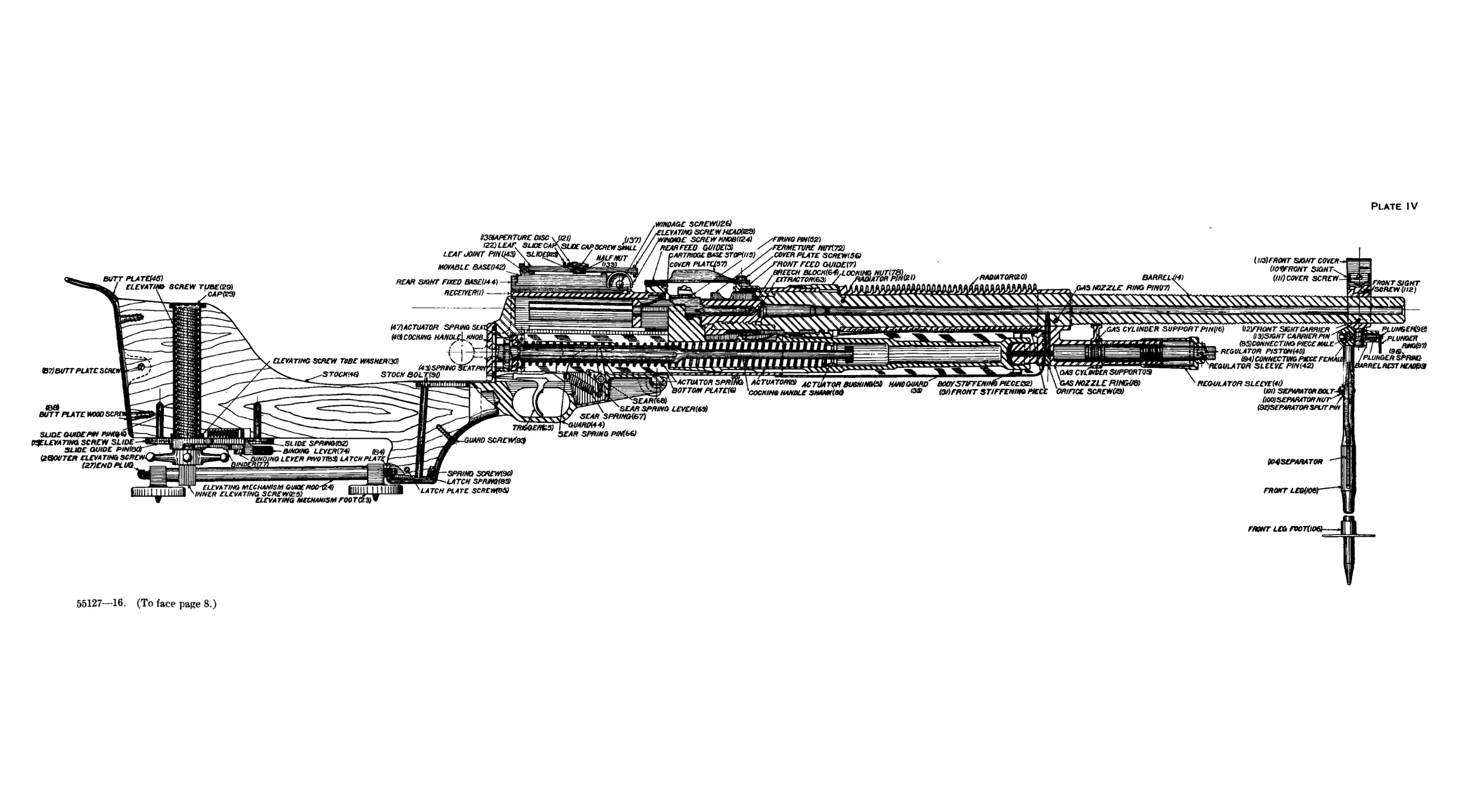
IV. Longitudinal section through rifle.................................. 8
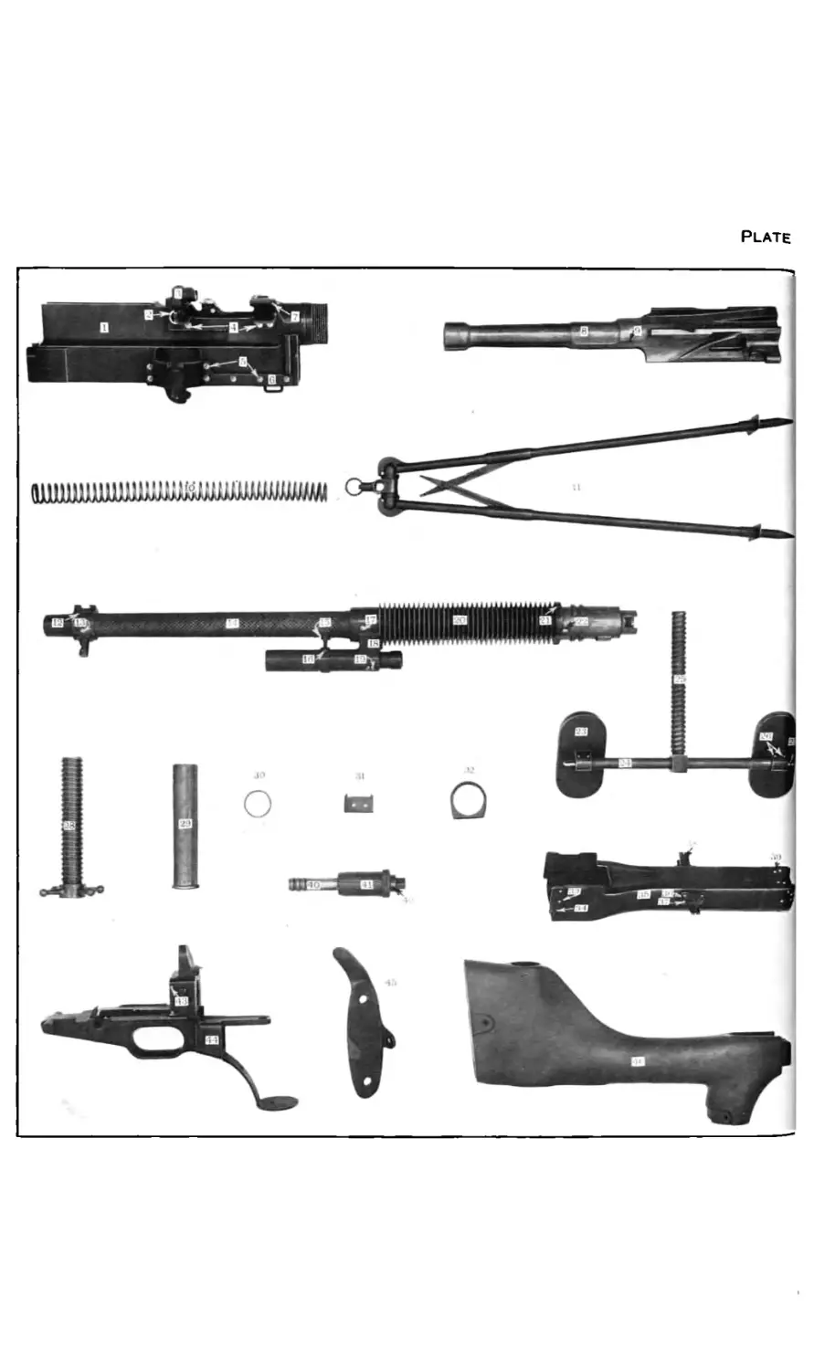
V. Component parts of rifle.......................................... 13
VI. Component parts of rifle........................................... 14
VII. Component parts of rifle.......................................... 20
VIII. Telescopic sight and pouch........................................ 46
IX. Views of telescopic sight..............‘.......................... 47
X. Tools and accessories............................................. 50
XI. Ammunition box.................................................. 51
XII. Cases............................................................. 52
XIII. Pack harness...................................................... 53
XIV. Pack harness....................................................... 54
XV. Aparejo, model of 1911, frame (right half)......................... 55
XVI. Pack, first mule (right side)...................................... 58
XVII. Pack, first mule (left side)....................................... 59
XVIII. Pack, second mule (right side).................................... 58
XIX. Pack, second mule (left side)..................................... 59
XX. Pack, third mule (right side)..................................... 58
XXI. Pack, third mule (left side)...................................... 59
XXII. Special pack equipment............................................. 60
(5)
EQUIPMENT OF MACHINE GUN COMPANY OR TROOP.
Each machine-gun company or troop is provided with four rifles,
including ammunition, spare parts, tools, and accessories, together
with the necessary packs.
The equipment for each company or troop is carried on sixteen
mules, constituting four sections of four each. The sections are
essentially complete units, although certain articles are not carried
in every section.
The equipment of each section consists of one rifle, ammunition, and
the necessary equipment for maneuvering the piece in the field.
The description is divided into the following parts:
Part I. The rifle with its ammunition and accompanying parts.
Part II. The pack harness.
Part III. The special pack equipment.
Part IV. The pioneer tools.
Part V. The total equipment of a machine-gun company or troop.
(7)
PART I. THE RIFLE WITH ITS AMMUNITION AND
ACCOMPANYING PARTS.
Description of the Automatic Machine Rifle, Caliber .30, Model
of 1909.
general.
[Plates I, II, III, and IV.]
The automatic machine rifle, caliber .30, model of 1909, belongs to
that type of automatic arms known as the gas operative. The power
that is used to operate the mechanism is obtained from a small por-
tion of the powder gases that enter through a port in the barrel after
the bullet has passed. After the first shot the rifle is self-operative,
until the ammunition in the feed strip is exhausted or until the
trigger is released.
The ballistics of the automatic machine rifle, caliber .30, model of
1909, are similar to those of the service rifle, and the data given in
the handbook of the service rifle, No. 1923, is equally applicable to
the automatic machine rifle, caliber .30, model of 1909. The bullet
suffers a slight decrease in muzzle velocity due to the gas used in
operating the rifle, but for general purposes the data quoted is suffi-
ciently accurate.
In firing, the action of the mechanism is as follows:
When the rifle is fired and the bullet has passed the gas port in the
barrel a part of the powder gas passes into the chamber of the gas-
nozzle ring, and enters the gas cup of the actuator, forcing the latter
to the rear. The actuator in recoiling compresses the actuator spring,
the cam surface cut in its upper portion engaging the lug of the fer-
meture nut, causing the latter to rotate so as to disengage its threads
from those of the breechblock. At this part of the recoil the firing
pin, which has been drawn back by the actuator, engages its upper lug
in the ramp of the receiver. The firing pin then rotates on its axis
and its upper lug comes to rest in the transverse cut of the breech-
block, thus locking the latter to the actuator. The large lug of the
actuator strikes against the shoulder of the breechblock, drawing the
latter to the rear and thereby completing the opening of the breech.
The claw of the extractor engages the groove of the cartridge case
and draws it from the chamber. During the recoil of the breech-
block the head of the cartridge case strikes against the ejector, throw-
ing the case out of the rifle through the ejection opening in the re-
ceiver. When the actuator is partly recoiled the cam surface cut on
its right side engages the upper lug of the feed piece, causing the
(8)
Plate I
Plate 11
Plate 111
Plate IV
WINDAGE SCREWG26)
LEVA17NG SCREW HEADOZS)
WMGE SCREW KN0BU24) /FIRING P/N(S2)
REAR FEED GUIDE® x FERMETURE NUT(72)
ARTRIDGE BASE STOPUlS) COVER PLATE SCREWING)
PONT FEED GUIDE17)
EECH BL0CK(G4),L00KI
RADIAT0R120)
BUTT PLATE146)
CAP(23)
STOCKS
(47) ACTUATOR SPRING SEA
&9 COCKING HANDL^KNOB
RALF NUT
BARREL^)
GAS NOZZLE RING PINU7) \
REAR SIGHT FIXED BASEU44)
RECEIVERS)
ELEVATING SCREW TUBE WASHERM
(43HSPRING Seat
STOCK BOL
(B7)BUTT PLATE SC
HARD SCREWfSQ
aHinihiiiiiiiiiii
illllllllllllllr
(B&
BUTT PLATE WOOD
INNER ELEVATING SCREW(25) —ur «
ELEVATING MECHANISM FOOTGSy*
ACTUATOR SPRING \ ACTUATOR® TUATORI
ОТТОМ PLATE(& ^COCKING HANDLE SHANK(S&
SLIDE SPRLNGfBZ
BINDING LEVER(74)
DING LEVER RMHIBS) LATCHPLA
GAS CYLINDERSUPP0RT09
GAS NOZZLE RINGOS)
ORIFICE SCREWOS)
COVER PLA
EXTRACTDRieS)
fc&APERTURE DISC
122) LEAF. SLIDE C
LEAF JOINT PIN
MOVABLE BASE(I42)
(U3) FRONT SANT COVER
(lO^FRONT SIGHT
(III) COVER SCREW
GAS CYLINDER SUPPORTPIN(I6) (I2)FRONT SIGHTCARRIER
(I3)SIGHT CARRIER PiN
fySlCQNNECTING PIECE MALE
REGULATOR PiSTON(40)
(94)CONNECT1NG PIECE FEM
REGULATOR SLEEVE PIN(42)
SLIDE GUIDEPW PJM9&
ELEVATING SCREW SLIDE
SLIDE GUIDE PIN
(ZQOUTER ELEVATING SC
(27)ENDPLUQ
SPRING SCREWOO)
LATCH SPRNHBS)
LATCH PLATE SCREWpM)
55127—16. (To face page 8.)
SEAR SPRING L£V£R(69)
SEAR SPR/NG(S7)
RD944)
SEAR SPRING P!N(b€)
REGULATOR SLEEYE(4l)
(Ю1) SEfWMTORBOLT
(100) SEPARATOR N
(9&SEPARAT0R SPOT PIN
(/04) SEPARATOR
FROfCT LEG{
FRONT SIGHT
SCREW (112)
UNGER&&
PLUNGER
PLUNGER SPRING
RELREST HEADB3
FRONT LEG FVOT(
9
latter to rotate from right to left on its axis. The feed arm of the
feed piece engages its feed lug in the central opening of the feed strip,
forcing the latter into the rifle and placing a cartridge in the loading
position in front of the chamber. The pawl of the feed-piece spring
engages in the lateral openings of the feed strip, thereby holding the
latter in place and preventing it being drawn to the right when the
feed arm of the feed piece, having advanced the feed strip one notch,
returns to its original position by sliding over the feed strip in order
to engage in the next hole. Finally, when the actuator is almost re-
coiled (supposing the rifle to be set for single shots), the sear engages
in the cocking notch of the actuator and the latter is held back ready
for the next shot.
When the trigger is pulled the sear is disengaged from the actuator,
which, now being free, is thrown forward, due to the force exerted
by the actuator spring. During this movement the actuator carries
forward the breechblock, to which it is connected by means of the
large lug of the firing pin. The breechblock strikes the cartridge,
forces it into the chamber, and the claw of the extractor engages the
groove of the cartridge case. As soon as the breechblock engages
the fermeture nut the large lug of the firing pin engages in the ramp
of the receiver, causing the firing pin to rotate so as to disengage
this lug from the transverse cut of the breechblock. The firing pin
is then free and may move forward. The actuator continues its
forward movement and its cam face engages the lug of the fermeture
nut, rotating the latter so as to cause its threads to engage with those
of the breechblock. The breech is now closed and locked. The firing
pin striking the primer fires the piece. During this forward move-
ment of the actuator, the small cam surface cut on its right side
engages the lower lug of the feed piece, causing it to rotate from left
to right. The feed arm is actuated by this movement, and its feed
glides over the feed strip and engages in the next opening of the latter,
ready to feed the feed strip another notch into tne rifle when the
actuator again recoils.
The maximum fire obtainable with this arm is about 400 shots per
minute. The rapidity of fire can be regulated to some extent by
the regulator.
The following table gives a serial list of component parts of this
rifle:
SERIAL LIST OF COMPONENT PARTS.
[? umbers before components refer to numbers shown on Plates IV, V, VI, УП, VIII, and IX. Property
classification: Class IV, section 1.1
1. Receiver. ' 6. Bottom plate.
2. Ejector bushing. 7. Front feed guide.
3. Rear feed guide. Actuator.
4. Feed-guide assembling screw (7). 9. Actuator bushing pin.
5. Bottom-plate rivet (11). j 10. Actuator spring.
10
11. Barrel rest (complete).
12. Front sight carrier.
13. Sight-carrier pin.
14. Barrel.
15. Gas-cylinder support.
16. Gas-cylinder support pin.
17. Gas-nozzle ring pin.
18. Gas-nozzle ring.
19. Orifice screw.
20. Radiator.
21. Radiator pin.
22. Locking-nut stop.
23. Elevating-mechanism feet (2).
24. Elevating-mechanism guide rod.
25. Inner elevating screw.
26. Elevating-mechanism foot pins (4).
27. End plug (2).
28. Outer elevating screw.
29. Elavating-screw tube, with cap.
30. Elevating-screw tube washer.
31. Front stiffening piece.
32. Body stiffening piece.
33. Assembling plates (2).
34. Hand-guard rivet, short (6).
35. Hand guard.
36. Catches for barrel rest leg (2).
37. Hand-guard rivet, long (8).
38. Leg catch spring (2).
39. Hand-guard rivets, short (10).
40. Regulator piston.
41. Regulator sleeve.
42. Regulator-sleeve pin.
43. Spring-seat pin (2).
44. Guard.
45. Butt plate.
46. Stock.
47. Actuator-spring seat.
48. Cocking-handle knob.
49. Cocking-handle rivet (3).
50. Cocking-handle shank.
51. Actuator bushing.
52. Firing pin.
53. Closing spring.
54. Feed-piece housing cover.
55. Feed-piece spring button (2).
56. Cover-plate screw.
56a. Cover-plate screw washer.
57. Cover plate.
58. Feed-piece spring.
59. Feed-piece spring stud.
60. Feed-piece spring-stud rivet (2).
61. Feed-piece spring-pawl rivet (2).
62. Feed-piece spring pawl.
63. Extractor.
63a. Dismounting tool (extractor).
64. Breechblock.
65. Trigger.
66. Sear-spring pin.
67. Sear spring.
68. Sear.
69. Sear-spring lever.
70. Locking screw (2).
71. Feed piece.
72. Fermeture nut.
73. Extractor spring.
74. Binder lever.
75. Elevating-screw slide.
76. Elevating-screw slide pin.
77. Binder.
78. Locking nut.
79. Hand-guard stud.
80. Slide-guide pins (2).
81. Binder spring.
82. Slide spring.
83. Binder lever pivot.
84. Latch plate.
85. Latch-plate screw.
86. Slide-guide pin pins (2).
87. Butt-plate screw.
88. Butt-plate screw, wood (2).
89. Latch spring.
90. Spring screw.
91. Stock bolt.
92. Separator split pin.
93. Guard screw.
94. Connecting piece, female.
95. Connecting piece, male.
96. Plunger spring.
97. Plunger ring.
98. Plunger.
99. Barrel-rest head.
100. Separator nut.
101. Separator bolt.
102. Separator-bolt pin.
103. Separator axis (2).
104. Separator (2).
105. Front-leg axis (2).
106. Front-leg feet (2).
107. Foot rivets (2).
108. Front leg (2).
109. Front sight.
110. Hinge pin.
111. Cover screw (2).
112. Front-sight screw.
113. Front-sight cover.
114. Cartridge-stop spring.
115. Cartridge-base stop.
116. Ejector spring.
11
117. Ejector cap.
118. Ejector.
119. Cartridge stop.
120. Cartridge-stop holder.
121. Slide cap.
122. Leaf.
123. Slide.
124. Windage-screw knob.
125. Windage-screw pin.
126. Windage screw.
127. Windage-screw spring.
128. Windage-screw collar.
129. Elevating-screw head.
130. Elevating-screw pin.
131. Elevating screw.
132. Half-nut spring.
133. Half nut.
134. Pivot.
135. Pivot spring.
136. Fixed-base screw.
137. Slide-cap screw, small.
138. Slide-cap screw, large.
139. Aperture disk.
140. Base spring.
141. Drift slide.
142. Movable base.
143. Leaf-joint pin.
144. Rear-sight fixed base.
145. Dismounting wrench.
146. Ejector key.
147. Resizing-tool frame.
148. Adjusting screws (2).
149. Resizing-tool roller.
150. Blocking screws (4).
151. Resizing-tool roller support.
152. Cleaning-rod handle and sleeve.
153. Cleaning-rod stem and sleeve.
154. Cleaning-brush holder.
155. Rammer.
156. Defective-cartridge extractor.
157. Hand extractor.
158. Screw driver.
159. Copper hammer.
160. Drift.
161. Loading-tool handle.
162. Lever axis.
163. Lever (one right, one left).
164. Loading-tool foot (2), short.
165. Pushing-bar guide slide.
166. Screw (4 long, 8 medium, 4 short).
167. Strip guide.
168. Loading-tool foot (long), 1.
169. Pushing bar.
170. Pushing-bar axis.
171. Pushing-bar guide.
172. Pliers.
173. Grease brush.
174. Cleaning brush.
175. Feed strip.
176. Oil can, including nozzle cap and
chain.
177. Gas-cylinder cleaner.
178. Cooling sponge.
179. Grease pot.
180. Sight-bracket screws (3).
181. Telescopic-sight bracket.
DETAILED DESCRIPTION OF THE RIFLE COMPONENTS.
Actuator (8).
Actuator bushing (51).
Actuator-bushing pin (9).
Actuator spring (10).
Actuator-spring seat (47).
Adjusting screws (148) (three).
Aperture disk (139).
Assembling plates (33) (two).
Barrel (14).
Barrel rest (complete) (11).
Barrel-rest head (99).
Base spring (140).
The component parts of the rifle arranged alphabetically are given
in the following list:
[Numbers after components refer to numbers shown on plates. Property classification: Class IV,
section 1.]
Binder (77).
Binder spring (81).
Binder lever (74).
Binder-lever pivot (83).
Blocking screws (150) (four).
Body-stiffening piece (32).
Bottom plate (6).
Bottom-plate rivet (5) (eleven).
Breechblock (64).
Butt plate (45).
Butt-plate screw (87).
Butt-plate screw, wood (88) (two).
12
Cartridge-base stop (115).
Cartridge stop (119).
Cartridge-stop holder (120).
Cartridge-stop spring (114).
Catches for barrel-rest leg (36) (two).
Cleaning brush (174).
Cleaning-brush holder (154).
Cleaning-rod handle and sleeve (152).
Cleaning-rod stem and sleeve (153).
Closing spring (53).
Cocking-handle knob (48).
Cocking-handle shank (50).
Cocking-handle rivet (49) (three).
Connecting piece, female (94).
Connecting piece, male (95).
Cooling sponge (178).
Copper hammer (159).
Cover plate (57).
Cover-plate screw (56).
Cover-plate screw washer (56a).
Cover screw (111) (two).
Defective-cartridge extractor (156).
Dismounting tool (extractor) (63a).
Dismounting wrench (145).
Drift (160).
Drift slide (141).
Ejector (118).
Ejector bushing (2).
Ejector cap (117).
Ejector key (146).
Ejector spring (116).
Elevating-mechanism feet (23) (two).
Elevating-mechanism foot pins (26)
(four).
Elevating-mechanism guide rod (24).
Elevating screw (131).
Elevating-screw pin (130).
Elevating-screw slide pin (76).
Elevating-screw head (129).
Elevating-screw slide (75).
Elevating-screw tube, with cap (29).
Elevating-screw tube washer (30).
End plug (27) (two).
Extractor (63).
Extractor spring (73).
Feed-guide assembling screws(4) (seven).
Feed piece (71).
Feed-piece housing cover (54).
Feed-piece spring (58).
Feed-piece spring button (55) (two).
Feed-piece spring pawl (62).
Feed-piece spring pawl rivet (61) (two).
Feed-piece spring stud rivet (60) (two).
Feed-piece spring stud (59).
I Feed strip (175).
। Fermeture nut (72).
Firing pin (52).
I Fixed-base screw (136).
Front-feed guide (7).
Front, leg (108) (two).
Front-leg axis (105) (two).
Front-leg foot (106) (two).
Foot rivets (107) (two).
Front sight (109).
Front-sight carrier (12).
Front-sight cover (113).
Front-sight screw (112).
Front-stiffening piece (31).
Gas-cylinder cleaner (177).
Gas-cylinder support (15).
Gas-cylinder support pin (16).
Gas-nozzle ring (18).
Gas-nozzle ring pin (17).
Grease brush (173).
Grease pot (179).
Guard (44).
Guard screw (93).
Half nut (133).
Half-nut spring (132).
Handle extractor (157).
Hand guard (35).
Hand-guard rivet (37) (34) (39) (twenty-
four).
Hand-guard stud (79).
Hinge pin (110).
Inner elevating screw (25).
Latch plate (84).
Latch-plate screw (85).
Latch spring (89).
Leaf (122).
Leaf-joint pin (143).
Leg-catch spring (38) (two).
Lever (1 right, 1 left) (163).
Lever axis (162).
Loading-tool foot (2) short (164).
Loading-tool foot, long (168).
Loading-tool handle (161).
Locking nut (78).
Locking-nut stop (22).
Locking screw (70) (two).
Movable base (142).
Oil can, including nozzle cap and chain
(176).
Orifice screw (19).
Outer elevating screw (28). *
Pivot(134).
Pivot spring (135).
Pliers (172).
Plate
13
Plunger (98).
Plunger ring (97).
Plunger spring (96).
Pushing bar (169).
Pushing-bar axis (170).
Pushing-bar guide (171).
Pushing-bar guide slide (165).
Radiator (20).
Radiator pin (21).
Rammer (155).
Rear feed guide (3).
Rear-sight fixed base (144).
Receiver (1).
Regulator piston (40).
Regulator sleeve (41).
Regulator-sleeve pin (42).
Resizing-tool frame (147).
Resizing-tool roller (149).
Resizing-tool roller support (151).
Screw (4 long, 8 medium, 4 short) (166).
Screw driver (158).
Sear(68).
Sear spring (67).
Sear-spring lever (69).
Sear-spring pin (66).
Separator (104) (two).
Separator axis <103).
Separator bolt. (101).
Separator-bolt pin (102).
Separator nut (100).
Separator split pin (92).
Sight-bracket screws (180) (three).
Sight-earner pin (13).
Slide (123).
Slide cap (121).
Slide-cap screw, large (138).
Slide-cap screw, small (137).
Slide-guide pin (80) (two).
’ Slide-guide pin pins (86) (two).
Slide spring (82).
Spring screw (90).
Spring-seat pin (43) (two).
Stock (-16).
Stock bolt (91).
Telescopic sight bracket (181).
Trigger (65).
Windage screw (126).
Windage-screw collar (128).
Windage-screw knob (124).
Windage-screw pin (125).
, Windage-screw spring (127 ).
These parts are assembled into the following groups: The barrel
group, the receiver group, the firing-mechanism group, the feed-
mechanism group, the locking-mechanism group, the guard group,
the stock group, the elevating-mechanism group, the hand-guard
group, the barrel-rest group, and the rear-sight group.
THE BAHREL GROUP.
[Plates V and VII.)
The barrel group contains the barrel, radiator, gas-nozzle ring,
front-sight carrier, gas-cylinder support, regulator, and front sight,
front-sight cover, front-sight screws, and cover screws.
The barrel is chambered and rifled the same as the barrel for the
United States rifle, caliber .30, model of 1903. The rear portion of
the barrel is turned down to provide seats for the radiator and the
gas-nozzle ring, and the front end for the seat for the front-sight
carrier. In rear of the radiator seat are the locking lugs, two inter-
rupted annular rings divided into three sectors, which engage in
similar lugs of the locking nut and secure the barrel to the receiver.
On the lower exterior surface of the barrel and in the rear of these
locking lugs is a small lug which fits in a slot in the receiver. This
small lug assures the alignment of the receiver and the barrel, also
°f ^le gas-nozzle ring and the actuator. The rear end of the barrel is
turned down for the fermeture nut, which fits over the end of the
14
barrel in assembling. On the upper surface of the rear end of the
barrel is a small bevel cut which guides the cartridge into the chamber,
and on the left side is the clearance cut for the claw of the extractor
and extractor housing on breechblock. A gas orifice or port is drilled
through the underside of the barrel at the seat for the gas-nozzle
ring.
The radiator is about 7j inches in length and has cut on its exterior
surface a series of deep grooves. The center of the radiator is bored
out to a diameter somewhat less than that of its seat on the barrel and
is shrunk in place and secured by the radiator pin. The bottom of
the radiator is slabbed off for clearance. To its rear end, near the
bottom, is assembled the locking-nut stop. The purpose of the radi-
ator is to aid in the rapid radiation of the heat developed during
firing.
The gas-nozzle ring is assembled to the barrel in front of the
radiator and is shrunk in place and secured by the gas-nozzle ring
pin. A small hole is drilled from the bottom of the gas-nozzle ring
to connect with the gas port in the barrel. The exterior of the hole
is closed by the orifice screw. The lear end of the lower portion of
the gas-nozzle ling is shaped to form a nozzle and the front end is
shaped to form a gas chamber. The nozzle is of circular shape to fit
the gas cup of the actuator, and through its center is drilled a small
hole into the gas chamber, intersecting the vertical hole drilled from
the bottom of the gas-nozzle ring to the gas port in the barrel. The
interior of the gas chamber is bored out and tapped near the front
end for the regulator piston, and its exterior is graduated to aid in
adjusting the regulator sleeve. On the rear upper face of the gas-
nozzle ring is a horizontal lug on which the front stiffening piece of
the hand guard rests when the latter is assembled.
The front-sight carrier is secured to the front of the barrel by the
sight-carrier pin. On the upper part of the front-sight carrier is a
dovetailed transverse slot for the front sight. In front of this slot is
drilled and tapped a hole for the front-sight screw. On the under-
side of the front-sight carrier is a pivot which provides the means for
the attachment of the barrel rest. On the front of the pivot is a
recess into which the plunger of the ban-el rest enters and secures the
latter in position.
The gas-cylinder support, designed to prevent injury to the gas-
nozzle ring during transportation, is assembled to the gas chamber
of the gas-nozzle ring, and is secured by the gas-cylinder support
pin, the ring on its lower part slipping over the gas chamber and the
U-shaped upper part resting against the barrel.
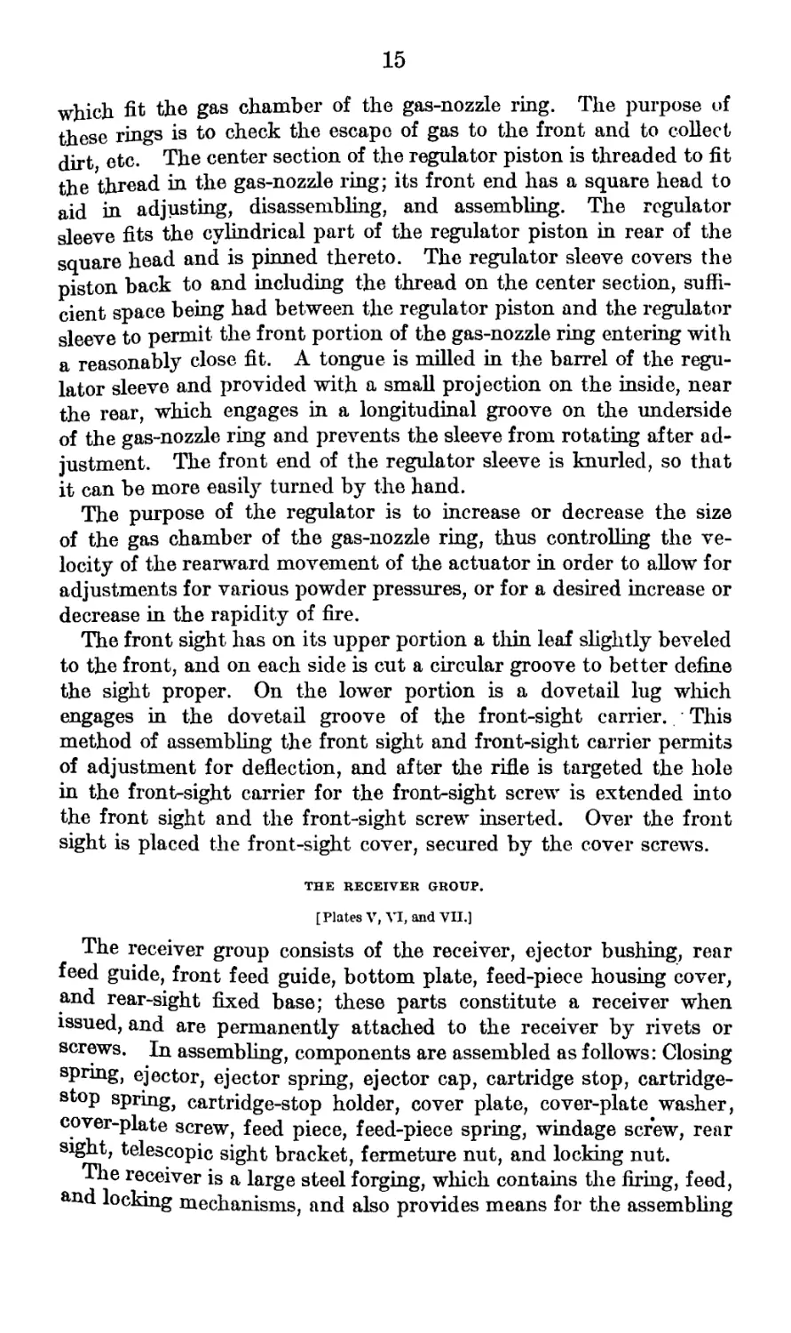
The regulator consists of the regulator sleeve secured to the regu-
lator piston by the regulator sleeve pin. The regulator piston is
a cylindrical bar having on its rear end three annular piston rings
Plate VI
15
which fit the gas chamber of the gas-nozzle ring. The purpose of
these rings is to check the escape of gas to the front and to collect
dirt etc. The center section of the regulator piston is threaded to fit
the thread in the gas-nozzle ring; its front end has a square head to
aid in adjusting, disassembling, and assembling. The regulator
sleeve fits the cylindrical part of the regulator piston in rear of the
square head and is pinned thereto. The regulator sleeve covers the
piston back to and including the thread on the center section, suffi-
cient space being had between the regulator piston and the regulator
sleeve to permit the front portion of the gas-nozzle ring entering with
a reasonably close fit. A tongue is milled in the barrel of the regu-
lator sleeve and provided with a small projection on the inside, near
the rear, which engages in a longitudinal groove on the underside
of the gas-nozzle ring and prevents the sleeve from rotating after ad-
justment. The front end of the regulator sleeve is knurled, so that
it can be more easily turned by the hand.
The purpose of the regulator is to increase or decrease the size
of the gas chamber of the gas-nozzle ring, thus controlling the ve-
locity of the rearward movement of the actuator in order to allow for
adjustments for various powder pressures, or for a desired increase or
decrease in the rapidity of fire.
The front sight has on its upper portion a thin leaf slightly beveled
to the front, and on each side is cut a circular groove to better define
the sight proper. On the lower portion is a dovetail lug which
engages in the dovetail groove of the front-sight carrier. This
method of assembling the front sight and front-sight carrier permits
of adjustment for deflection, and after the rifle is targeted the hole
in the front-sight carrier for the front-sight screw is extended into
the front sight and the front-sight screw inserted. Over the front
sight is placed the front-sight cover, secured by the cover screws.
THE RECEIVER GROUP.
[Plates V, VI, and VII.]
The receiver group consists of the receiver, ejector bushing, rear
feed guide, front feed guide, bottom plate, feed-piece housing cover,
and rear-sight fixed base; these parts constitute a receiver when
issued, and are permanently attached to the receiver by rivets or
screws. In assembling, components are assembled as follows: Closing
spring, ejector, ejector spring, ejector cap, cartridge stop, cartridge-
stop spring, cartridge-stop holder, cover plate, cover-plate washer,
cover-plate screw, feed piece, feed-piece spring, windage screw, rear
sight, telescopic sight bracket, fermeture nut, and locking nut.
The receiver is a large steel forging, which contains the firing, feed,
and locking mechanisms, and also provides means for the assembling
16
of the barrel, the guard, the hand guard, and the roar sight. In th<
front end of the receiver is drilled a large hole which is the seat foj
the fermeture nut and the barrel. A slot on the lower side of this
hole is for the purpose of locating the barrel and for assembling the
fermeture nut. In rear of this slot is a recess for the lug of the
fermeture nut. The front end of the receiver is threaded on the
exterior for the locking nut, which secures the barrel to the receiver,
In rear of the threaded section is drilled a small hole, into which
the end of the locking screw enters. On the top and directly in thf
rear are permanently assembled, by means of the feed-guide assenn
bling screws, the front and rear feed guides, between which slides the
feed strip during the firing. The front feed guide contains a narrow
slot, in which the feed strip slides, and a large opening on the righl
for the cartridges. On top and at the rigjit are two undercut slots
slightly beveled, into which is assembled the feed-piece spring. Or
the left is drilled and tapped a hole for the cover-plate screw. The
rear feed guide has a narrow slot for the feed strip and also the car
tridge opening on the right. On the left is a dovetail groove for the
cover plate and on the right the seat for the feed piece. This seal
consists of a hole drilled vertically in the rear feed guide with an
opening in its rear for assembling the feed piece. A large lug to the
left of this hole, on which the feed piece slides during the firing, and
a smaller lug on the right enclose the seat. On top to the right ol
dovetail groove is an opening under large lug through which the feed-
piece spring pawl passes in assembling.
The feed guides are braced on the left by the cover plate, which is
secured to the front feed guide by the cover-plate screw and to the
rear feed guide by the dovetail slot. The cover-plate screw is held
securely by means of a split washer under head of screw, preventing
its working loose from vibration in firing. On the front of the real
feed guide, just below and to the right of the dovetail slot, is assembled
the cartridge base stop, which limits the movement of the cartridges
to the left. In front of the rear feed guide is a tongue which enters
between the feed strip and the cartridge and forces the latter down-
ward. To the bottom and the front half of the receiver is securely
riveted the bottom plate. The latter has on its lower surface two
locking lugs, into which fits the trunnions of the guard. On top of
the receiver and directly in rear of the feed guides is an undercut
dovetail groove, in which is assembled the rear-sight fixed base, the
latter being secured in position by the fixed base screw. The rear-
sight fixed base contains the pivot lug for the movable base, the
undercut for t. windage screw and the lip on the front end of the
movable base, i nd a lug on the rear end, which forms the undercut
for the Up on the rear end of the movable base.
17
Upon its rear upper surface are two zero marks for the wind-gauge
graduations. On the left side of the receiver is the ejection opening.
Above this opening is drilled and tapped the seat for the cartridge
stop. In the rear of the ejection opening is the dovetail seat for the
telescopic sight bracket, the latter being secured to the receiver by
three sight-bracket screws. On the right side of the receiver is the
feed-piece bousing cover, which is attached to the bottom plate by
the hinge pin. The former is held in its closed position by the clos-
ing spring which is inserted in the housing of the bottom plate. In
the bottom of the housing of the bottom plate is drilled a small
vertical hole in which is insertecLthc lower end of the feed piece.
The ejector bushing is driven into a seat directly below the rear feed
guide and has an opening on its left end for the ejector, while on the
right are four small lugs, recessed to receive the lugs of the ejector cap.
The interior of the receiver has in its front section the seat for the
fermeture nut, which is beveled in the rear to insure that the ferme-
ture nut is always centered.
Within the rear section on the sides are the breechblock guide
slots, while on the top and to the left is the guide for the firing pin
which, ending in two cams, causes the firing pin to rotate in and out
of its recess in the breechblock.
In the rear and bottom part of the receiver are the locking-lug seats
for the guard.
On the left of the receiver near the rear end is a small hole, drilled
and tapped, into which is screwed the locking screw for securing the
guard to the receiver. A small slot in front holds the locking screw
in place. Two beveled undercut grooves in the front of the receiver
provide seats for the assembling of the hand guard.
THE FIRING-MECHANISM GROUP.
[Plates V and VI.]
The firing-mechanism group consists of the actuator, actuator
spring, breechblock, firing pin, extractor, and extractor spring.
The actuator is located below and parallel to the barrel and is the
piston which drives the mechanism of the rifle. It has on its upper
surface a long straight cut and in the rear two diagonal cam cuts in
which moves the lug of the fermeture nut. In the rear of these
cams is cut a deep recess in order to reduce the weight of the actua-
tor. In rear of this recess is a large lug; the center section of which
is cut away for the lower lug of the firing pin. On the front end of
the actuator is the gas cup, which fits over the nozzle end of the gas
nozzle ring. On the right side of the actuator are two cam surfaces,
upon which move the upper and lower lugs of the feed piece in re-
coiling and counterrecoiling. Near the front end of the upper cam
surface is a dismounting notch for the feed piece. On the left side
55127—16____2
18
of the actuator is the clearance cut for the trigger, and on the bottom
is the scar notch in which the sear engages when the rifle is cocked.
On the lower surface at the rear end is a slight ramp on which the sear
rides near the end of recoil. On the right and left sides, and also on the
lower surface of the actuator, are guides or bearing surfaces to con-
trol the movement of the actuator during recoil and counterrecoil.
The actuator is hollow nearly its entire length, the rear portion
forming a housing for the actuator spring. About midway between
the ends of the actuator is secured the actuator bushing. This bush-
ing, which is threaded and screwed in position and secured with a
pin, serves as the front seat for the actuator spring and also forms a
seat for the lugs on the front end of the cocking handle when the
latter is used to retract the actuator.
The actuator spring is a long spiral spring located in the interior of
the actuator, with its front end resting against the actuator bushing
and its rear end against the actuator spring seat in the guard. As the
actuator recoils, this spring is compressed and the energy stored up
is used to move the actuator forward at the end of the recoil.
The breechblock contains the firing pin, extractor, and extractor
spring. The breechblock rests on the bottom of the guide slots in the
receiver, the large lug on the actuator entering a long longitudinal slot
in the rear part of the breechblock. At the rear end and left side of
this long slot is a deep recess into which the upper lug of the firing pin
rotates whenever the breechblock is in motion. In front of this long
slot the breechblock is cut away as clearance for the cartridge stop,
while at the top and rear end of the slot is a small ramp to aid in dis-
assembling and assembling the firing pin. On the right and left sides
of the breechblock at the rear are guides that move in the guide slots
of the receiver. On the front section of the breechblock are inter-
rupted threads divided into three sectors, which engage those of the
fermeture nut and securely lock the former to the latter during firing.
On the right side of the breechblock is a long clearance cut for the
ejector. On the left-hand side of breechblock at the front end is the
housing for the extractor; under this housing at the end of the breech-
block is a stud, which acts as a seat for the curved surface on the bot-
tom of the extractor at the rear of the extractor claw, preventing
extractor from pitching too far toward center of breechblock to
readily pass over cartridge case. On the inside of the housing a
bevel cut is the working point for the bevel cut on top of the ex-
tractor when firing the rifle. The rear end of the housing forms a
seat for the shoulder on the extractor after the extractor is worn on
the bevel surface and on the bottom, thus increasing the life of the
extractor. At the rear of the housing is a slot for the extractor and
extractor spring; at the rear end of this slot is the extractor spring
seat. On he left side back of the extractoi* spring seat the breech-
19
block is cut away to facilitate the assembling and dismounting of
the extractor and extractor spring.
At the front end of the breechblock on the upper rim a shallow
seat is cut for carrying the cartridge into the chamber. The ends
of rim on each side of ejector groove are slightly closed toward
center of the breechblock to insure a good grip of cartridge case. The
front end of the breechblock is counterbored for the head of the car-
tridge, and in the center of this head space is drilled a small hole for
the firing-pin point. The interior of the breechblock is bored out
for the barrel of the firing pin.
The firing pin is seated within the breechblock. The front portion
is cylindrical, terminating at the front end of the firing-pin point,
and has on its rear end a small and a large lug. The small lug is
on the underside and rests, when assembled, in the recess of the large
lug on the upper part of the actuator. This small lug causes the
firing pin to move to the rear in the first motion of recoil. The large
lug is on the upper side and has on its top two cam cuts, which move
in the cam cuts in the receiver and serve to rotate the firing pin in
and out of the recess in the breechblock. The front shoulder of this
upper lug rests against the front of this recess during counterrecoil
and carries the breechblock forward, the upper lug on the actuator
bearing against the rear end of the barrel of the firing pin. The
bottom and rear end of the upper lug is beveled to permit assembling
and disassembling.
The extractor is an irregular bar having on the underside of its
forward end a claw and on the upper side of the forward end an
incline which seats against the underside of extractor housing of the
breechblock, when passing over rim of cartridge case. At the rear
end of the extractor is a pivot on which the extractor spring seats
and forces the extractor downward over the cartridge head. When the
breechblock strikes the cartridge in loading, the extractor is forced
backward until the claw drops into the cannelure of the cartridge.
The extractor is assembled to the breechblock by slipping the ex-
tractor spring over the pivot on the rear of the extractor, inserting
the front end of the extractor in the opening in rear of the extractor
housing and gradually forcing the extractor and spring into place
with the dismounting tool. The position of the extractor is deter-
mined by the small bevel cut on top of the extractor, the convex
cut on underside of extractor housing, and shoulder on the extractor.
When in action the pivot on the extractor is bent slightly, so the
pressure of the extractor spring forces it into proper location. The
extractor and spring may be dismounted either by use of the dis-
mounting tool or by engaging a small screw driver behind the ex-
tractor spring in the small slot provided in the extractor seat of the
breechblock.
20
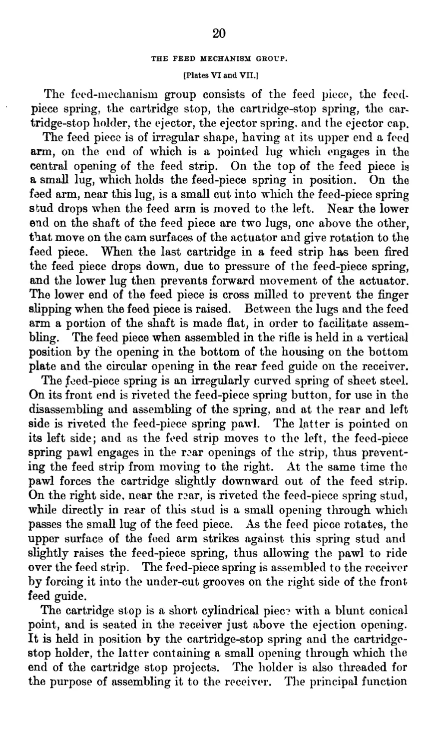
THE FEED MECHANISM GROUP.
[Plates VI and VIIJ
The feed-mechanism group consists of the feed piece, the feed-
piece spring, the cartridge stop, the cartridge-stop spring, the car-
tridge-stop holder, the ejector, the ejector spring, and the ejector cap.
The feed piece is of irregular shape, having at its upper end a feed
arm, on the end of which is a pointed lug which engages in the
central opening of the feed strip. On the top of the feed piece ig
a small lug, which holds the feed-piece spring in position. On the
feed arm, near this lug, is a small cut into which the feed-piece spring
stud drops when the feed arm is moved to the left. Near the lower
end on the shaft of the feed piece are two lugs, one above the other,
that move on the cam surfaces of the actuator and give rotation to the
feed piece. When the last cartridge in a feed strip has been fired
the feed piece drops down, due to pressure of the feed-piece spring,
and the lower lug then prevents forward movement of the actuator.
The lower end of the feed piece is cross milled to prevent the finger
slipping when the feed piece is raised. Between the lugs and the feed
arm a portion of the shaft is made flat, in order to facilitate assem-
bling. The feed piece when assembled in the rifle is held in a vertical
position by the opening in the bottom of the housing on the bottom
plate and the circular opening in the rear feed guide on the receiver.
The feed-piece spring is an irregularly curved spring of sheet steel.
On its front end is riveted the feed-piece spring button, for use in the
disassembling and assembling of the spring, and at the rear and left
side is riveted the feed-piece spring pawl. The latter is pointed on
its left side; and as the feed strip moves to the left, the feed-piece
spring pawl engages in the rear openings of the strip, thus prevent-
ing the feed strip from moving to the right. At the same time the
pawl forces the cartridge slightly downward out of the feed strip.
On the right side, near the rear, is riveted the feed-piece spring stud,
while directly in rear of this stud is a small opening through which
passes the small lug of the feed piece. As the feed piece rotates, the
upper surface of the feed arm strikes against this spring stud and
slightly raises the feed-piece spring, thus allowing the pawl to ride
over the feed strip. The feed-piece spring is assembled to the receiver
by forcing it into the under-cut grooves on the right side of the front
feed guide.
The cartridge stop is a short cylindrical piece with a blunt conical
point, and is seated in the receiver just above the ejection opening.
It is held in position by the cartridge-stop spring and the cartridge-
stop holder, the latter containing a small opening through which the
end of the cartridge stop projects. The holder is also threaded for
the purpose of assembling it to the receiver. The principal function
Plate VII
21
of the cartridge stop is to limit the movement of the cartridges to the
left and to properly align them. It also indicates, in loading,
whether or not the feed strip has been fully inserted.
The ejector is assembled in the ejector bushing of the receiver and
is held in position by the ejector spring and the ejector cap. The
ejector cap is circular in shape, having on its circumference four
small lugs which engage in corresponding slots in the ejector bush-
ing. Special attention should be paid to the assembling of the
ejector cap, being sure the small lugs on the sides of the cap are
properly located in the slots provided for them in the ejector bushing;
failure to properly locate these lugs will result in the ejector cap being
I forced outward against the feed piece and prevent the forward
movement of the firing mechanism. On the top of the ejector cap
are cut two slots at right angles to each other, into which fit the
ejector key used in dismounting and assembling. In the center of
the cap is a small hole which allows the end of the ejector to protrude.
THE LOCKING-MECHANISM GROUP.
[Plate VI.)
The locking-mechanism group is made up of the locking nut, the
fermeture nut, and the locking screws. The locking of the mechanism
by the locking nut is more permanent in its nature, while that of the
fermeture nut is a continuous locking and unlocking for each round
fired.
The locking nut is cylindrical in shape, having two interrupted
annular rings of three sectors each on the inside to provide means
for locking the barrel to the receiver. In rear of these locking rings
is cut the thread for assembling the locking nut to the receiver. Two
small recess cuts are made on the front end of the locking nut for
dismounting wrench, and also a large cut for clearance and stops for
the locking-nut stop on the radiator.
After the barrel is locked in position the locking nut is secured by
one of the locking screws, which is inserted in the small hole drilled
and tapped on the left side near the rear end of the locking nut, the
end of the locking screw entering a small hole on the left side of the
receiver directly in the rear of the threads. The other locking screw
is used for locking the guard to the receiver. In front of the lock-
ing-screw seat in the locking nut is a small lug with a shallow slot
which secures the locking screw in position. On the right side of the
ocking nut is the hand-guard stud, which holds the hand guard in
place while the barrel is being removed. The rear of the locking nut
as seven slots, which insure a tight fit on the receiver.
. J10 fermeture nut is cylindrical in shape and has on its under-
s* e a large lug which moves in the cam cuts on the upper surface of
le actuator. The front end of the fermeture nut is counterbored
22
to receive the barrel, while directly in rear are interrupted thread^
divided into three sectors for locking the breechblock. The left
sector of the fermeture nut is enlarged to allow passage of the ex.
tractor housing of the breechblock. An enlarged recess is provide^
as clearance for the extractor housing as the fermeture nut rotates
Between the lower and right-hand sectors is a deep cut which pro-
vides a cavity into which primers may drop should they become
dislodged from the cartridge case during firing. On top of the ferine
ture nut is a long longitudinal cut from the rear, providing clearance
for the cartridge in loading; near the left rear end is a semicirculai
cut, providing clearance for the front clip of the feed strip; and oi
the top and right is the clearance for the feed strip. The rear shouldei
of the fermeture nut is beveled to enter the corresponding bevel ii
the receiver. The function of the fermeture nut is to lock th<
breechblock at the instant of firing and to unlock it immediately aftei
firing. The fermeture nut is located in the forward part of th<
receiver, directly in rear of the barrel, and is held by a shoulder oi
the barrel and a similar shoulder in the receiver, so as to prevent ani
longitudinal movement but to permit of rotation about its axis.
THE GUARD GROUP.
[Plates V and VI.]
The guard group consists of the guard, actuator-spring seat, late!
spring, cocking handle, sear, sear spring, and trigger.
The guard, when assembled, closes the rear end of the receiver and
supports the stock. It is secured to the receiver by trunnions on its
front end which enter the locking lugs on the bottom plate, and also
by locking lugs on each side in the upper part of the guard near the
rear, which enter seats on the interior of the receiver. It is secured
in its seat by one of the locking screws, which enters the guard through
the locking-screw hole of the receiver. Within the guard is the
recess and seat for the sear, and in rear of this a long slot for the
trigger. Under the latter slot is the trigger bow. In the upper
part of the guard is a longitudinal hole in the top and bottom of
which are two slots, in which the actuator-spring seat is placed. The
latter is held in position by two large lugs on its perimeter and by
two spring-seat pins which are assembled to the guard directly in
front of the actuator-spring seat. Through the center of the actuator-
spring seat is drilled and slotted a small hole with two small lugs
180° apart. Through this hole passes the shank of the cocking
handle, the lugs sliding in the longitudinal grooves of the latter.
Three semicircular grooves cross the rear surface of the actuator-
spring seat, by means of which the cocking handle is locked into its
three positions. In rear of the actuator-spring seat is the locking-
lug seat of the cocking handle. Under the opening for the actuator-
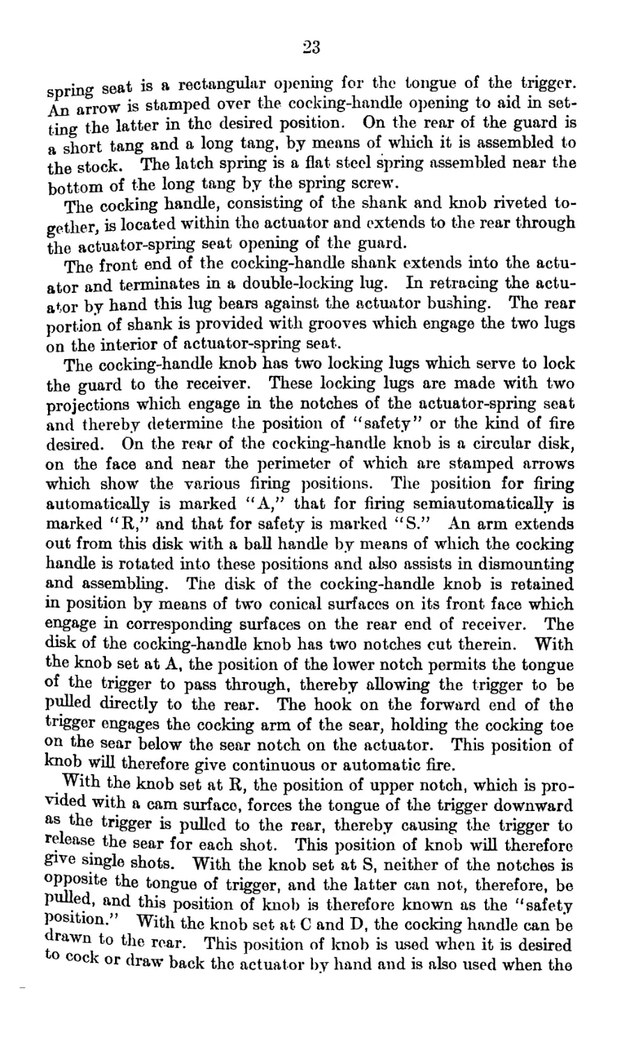
23
spring seat is a rectangular opening for the tongue of the trigger.
An arrow is stamped over the cocking-handle opening to aid in set-
ting the latter in the desired position. On the rear of the guard is
a short tang and a long tang, by means of which it is assembled to
the stock. The latch spring is a flat steel spring assembled near the
bottom of the long tang by the spring screw.
The cocking handle, consisting of the shank and knob riveted to-
gether, is located within the actuator and extends to the rear through
the actuator-spring seat opening of the guard.
The front end of the cocking-handle shank extends into the actu-
ator and terminates in a double-locking lug. In retracing the actu-
ator by hand this lug bears against the actuator bushing. The rear
portion of shank is provided with grooves which engage the two lugs
on the interior of actuator-spring seat.
The cocking-handle knob has two locking lugs which serve to lock
the guard to the receiver. These locking lugs are made with two
projections which engage in the notches of the actuator-spring seat
and thereby determine the position of “safety” or the kind of fire
desired. On the rear of the cocking-handle knob is a circular disk,
on the face and near the perimeter of which are stamped arrows
which show the various firing positions. The position for firing
automatically is marked “A,” that for firing semiautomatically is
marked “R” and that for safety is marked US.” An arm extends
out from this disk with a ball handle by means of which the cocking
handle is rotated into these positions and also assists in dismounting
and assembling. The disk of the cocking-handle knob is retained
in position by means of two conical surfaces on its front face which
engage in corresponding surfaces on the rear end of receiver. The
disk of the cocking-handle knob has two notches cut therein. With
the knob set at A, the position of the lower notch permits the tongue
of the trigger to pass through, thereby allowing the trigger to be
pulled directly to the rear. The hook on the forward end of the
trigger engages the cocking arm of the sear, holding the cocking toe
on the sear below the sear notch on the actuator. This position of
knob will therefore give continuous or automatic fire.
With the knob set at R, the position of upper notch, which is pro-
vided with a cam surface, forces the tongue of the trigger downward
as the trigger is pulled to the rear, thereby causing the trigger to
release the sear for each shot. This position of knob will therefore
give single shots. With the knob set at S, neither of the notches is
opposite the tongue of trigger, and the latter can not, therefore, be
pulled, and this position of knob is therefore known as the “ safety
position.” With the knob set at C and D, the cocking handle can be
rawn to the rear. This position of knob is used when it is desired
° cock or draw back the actuator by hand and is also used when the
24
mechanism is to be dismounted. To set for the different positions
the cocking handle is rotated until the particular letter correspond-
ing to the position desired comes opposite an arrow marked on the!
guard.
The sear is made with a knurled button head and a spindle on
which is the cocking toe, which engages in the sear notch of the1
actuator. The cocking toe has on its under side a deep recess; the
spindle is made hollow and the head countersunk in order to reduce
its weight. Underneath the cocking toe, assembled and riveted to the
spindle, is the sear spring lever, by means of which the sear spring
is attached to the sear. Between the cocking toe and the knurled
button head is the cocking arm, which stands in an upright position
when the sear is assembled in the guard. On its top is a small cut
in which the hook of the trigger arm engages. On the spindle are
two flat cuts by which the sears is dismounted and assembled.
The trigger is of irregular shape, having a trigger arm with a hook
on its forward end which engages in the cut on the cocking arm of the
sear. This arm extends to the rear sufficiently far to limit the motion
to the rear of the trigger, and is connected to the body of the trigger
by a curved arm which offsets the trigger arm to the left, so that it
will clear the actuator. The body of the trigger has a circular bevel
cut in the front end where the sear-spring pin is assembled. From
the bottom of the body extends the finger piece which passes through
the slot in the guard. On the rear of this body is a tongue having on
its upper surface a small ramp. This ramp, when the trigger is
pulled to the rear, slides into slots cut in the disk on the cocking
handle, which permits the trigger to move straight to the rear or
causes it to tilt slightly downward or prevent it moving at all. These
are the positions of automatic Л, semiautomatic 2?, and safety S,
respectively.
THE STOCK GROUP.
[Plates V and VI.J
The stock group consists of the stock, latch plate, elevating-screw
tube, and butt plate.
The stock is made of well-seasoned black walnut, cut down in front
so as not to interfere with the sighting. It has a pistol grip and is
recessed in front for the tangs of the guard, a small hole being drilled
at an angle about midway in the recess for the lower tang of the guard
for the guard screw, and a larger hole being drilled perpendicularly
through the stock near the rear end of the recess for the upper tang
for the stock bolt. In the bottom and rear of this grip is a small
recess for the end plug, a shallow groove for the latch spring, and the
seat for the latch plate, the latter being secured by the latch-plate
screw, a transverse hole being drilled for that purpose. In the
rear end of the stock is assembled the elevating-screw tube with cap,
25
n a hole drilled for this purpose, and the lower end then spun out
>ver the washer. In the bottom and rear of the stock are drilled
wo holes for the slide-guide pins and two smaller transverse holes,
through the above holes, for the slide-guide-pin pins. Between the
targe holes and in front of the elevating-screw-tube opening is cut a
small recess for the slide spring. On the front end of the stock is a
jmall tenon which extends into the guard, taking the shock of recoil in
iring.
The butt plate has two side tangs and is secured to the butt of the
itock by two butt-plate wood screws and one butt-plate screw which
masses through the tangs, holes being drilled in the rear end of the
itock for the wood screws and a smaller hole drilled through the stock
lear its rear end for the butt-plate screw. On the upper end of the
Dutt plate is a long tang for supporting the weight of the rifle on the
Bhoulder when firing without the elevating mechanism.
i
THE ELEVATING-MECHANISM GROUP.
[Plates V and VI.]
The elevating-mechanism group consists of the inner elevating
screw, the outer elevating screw, and the elevating-screw slide.
The inner elevating screw consists of the elevating-mechanism
pnde rod, the end plugs, the elevating-mechanism feet, and the inner
Elevating screw. The elevating-mechanism feet are flat pieces, ob-
long in shape, having on the top a large lug to which the elevating-
mechanism guide rod is assembled. On the underside is a large recess,
in the center of which is a small conical lug to prevent slipping. The
end plugs are notched on the top so as to engage in-the latch plate
on the stock and thereby secure the elevating mechanism when in the
traveling position. On the elevating-mechanism guide rod is assem-
bled the inner elevating screw, and to its ends are riveted, by means
of the elevating-mechanism foot pins, the end plugs and the elevating-
mechanism feet. The body of the inner elevating screw is hollow, in
order to reduce its weight, and has cut on its exterior a right-hand
thread. At the lower end is a square head, through which a small
hole has been drilled for the elevating-mechanism guide rod.
The outer elevating screw has on the exterior of its body a left-
hand thread extending nearly to the bottom. On the lower end are
our radial arms by means of which the outer elevating screw is
rotated. On the interior of the body, near the bottom, is cut a right-
and thread to fit the corresponding thread on the inner elevating
screw. Below and above this thread the interior is counterbored for
clearance.
The elevating-screw slide is designed to lock the elevating mechan-
ism when firing, and consists of the elevating-screw slide, the binder,
le inder lever, the binder-lever pivot, and binder spring. To the
26
elevating screw slide are assembled the parts just mentioned. Slightly
in the rear of its center is the elevating screw opening, the rear end
of which forms a half nut, which engages in the thread of the outer
elevating screw. In front of this opening is a dovetail groove for the
binder. In the rear end of this groove is assembled the elevating
screw slide pin against which rests the binder spring, while in the
front part is drilled a small hole for assembling the spring. In front
of the binder slot is also drilled a hole into which is driven the binder
lever pivot. Near each end of the elevating screw slide are the slots
for the two slide guide pins, which secure the elevating screw slide
to the stock. After the slide guide pins have been assembled the
slide guide-pin pins are driven transversely through the stock and
through a small hole in the slide guide pins, thereby securing the
latter in position. In the recess of the stock under the elevating
screw slide is assembled the slide spring.
The binder has on its upper side a dovetail lug containing a recess
for the binder spring and the rear end is made to fit the body of the
outer elevating screw. The binder is assembled to the elevating
screw slide by means of the dovetail lug engaging in the correspond-
ing groove on the slide.
The binder lever has on its left side a circular cam surface which
moves against the front end of the binder. In the center of the cir-
cular cam suiface is drilled a hole for the binder lever pivot, and to
the right extends the lever arm, which is curved to the front so as
to fit the finger. The rear of this arm is cross milled to aid in operat-
ing the clamping device. A small lug on the upper surface of the
binder lever limits the motion of the lever arm to the rear.
The binder lever pivot is the axis for the binder lever, and has its
upper end turned down so as to have a driving fit in the pivot hole
of the elevating screw slide, while its lower end foims an eccentric
about which the binder lever rotates; the purpose of the eccentric
being to take up the wear between the binder and the binder lever.
On the bottom or head of the pivot is stamped an arrow which indi-
cates the high point of the cam.
The outer elevating screw can be quickly inserted into or removed
from the stock by drawing the elevating screw slide to the rear by
the binder lever. In the traveling position the elevating mechanism
is secured in front by the end plug engaging the latch plate on the
stock and in the rear by the clamping device.
THE HAND-GUARD GROUP.
[Plate V.] ।
The hand-guard group consists of the hand-guard body, front and
body stiffening pieces, assembling plates, leg catches, and leg catch’
springs.
27
The hand-guard body is made from a drawn-steel tube or from
sheet steel pressed to shape and brazed. It is reinforced at the front
end by the front and the body stiffening pieces which are securely
riveted and brazed to the hand-guard body. In the forward part of
the hand-guard body are punched a number of small holes which
permit the powder gases to escape after impinging on the actuator.
On the rear end of the hand guard are riveted the two assembling
plates which seat in the undercut grooves in the front of the re-
ceiver. On each side of the hand guard are riveted the leg catches,
under which the leg-catch springs are assembled. These catches
support the front legs of the barrel rest when in the traveling posi-
tion. When assembled the hand guard is held in position by the
undercut grooves in the front of the receiver and the horizontal
lug on the upper part of the gas nozzle ring. The purpose of the hand
guard is to protect the gunner from escaping gases and also to pro-
vide protection from the moving actuator, thus insuring that all
moving parts of the rifle are inclosed.
THE BARREL-REST GROUP.
[Plates V and VI.]
The barrel-rest group is made up of the following principal parts:
The barrel-rest head, the plunger, the connecting piece male, the
connecting piece female, the front legs, the front-leg feet, and the
separators.
The barrel-rest head is a steel piece which serves as a sleeve to
the connecting pieces, male and female, and into which the plunger,
plunger ring, and plunger spring are assembled. In the body of
this head are two holes, one being a small, vertical hole for the
pivot on the front sight carrier and the other a larger transverse
hole for the male and female connecting pieces. On the top at each
side the body of the head is cut away for the lug on the top of the
front leg. In front of the pivot hole is drilled a longitudinal hole in
which is assembled the plunger and plunger spring. The plunger
secures the barrel seat to the pivot at the bottom of the front sight
carrier. The plunger is held in place by the plunger ring, the latter
being assembled through a hole in the front part of the plunger.
The connecting piece, female, is drilled and tapped on one end to
match the thread which is cut on the body of the connecting piece,
male. The outer ends of both connecting pieces are slotted for the
ront legs. The connecting pieces are assembled in the barrel-rest
ead, the front legs are then inserted into the slots and riveted in
position by the front-leg axis.
he front leg is a long bar having at the top a flat lug. A notch
theV across lug which bears against the connecting piece, and
e arrel-rest head when the front legs are extended, and a hole is
28
drilled through this lug for the front-leg axis. Above the center of
the front leg is a section, larger in diameter than the remainder of
the bar, in which is cut a deep slot for the separators, and at right
angles to this slot is drilled the separator axis hole. At the lower end
of the front leg is riveted, by the foot rivet, the front-leg foot, the
latter being made with a flat plate, which prevents the front log from
sinking in soft ground.
The separators which hold the front legs in the extended position
are riveted to the front legs by the separator axes. The separators1
are secured to each other by the separator bolt. The separator bolt
is secured by the separator nut and the latter by the separator split
pin. A small lug on the end of each separator enters a slot in the,
other separator and holds the legs extended.
THE REAR-SIGHT GROUP.
[Plate VII.]
The rear-sight group is made up of the following principal parts:
The movable base, the base spring, the leaf, the elevating screw, the
slide, the half nut, the slide cap, thq drift slide, the aperture disk, and
the windage screw.
The movable base has on its upper surface two ears in which are
the holes for the joint pin which serves as a hinge for the leaf. On
the rear end of the movable base are the wind-gauge graduations,
each point of which corresponds to a lateral deviation of 4 inches for
each 100 yards. Both ends have lips which fit the undercuts of the
fixed base, the front lip having also a worm gear for engaging the
thread of the windage screw. The base spring fits in the spring seat
of the movable base.
The leaf is graduated from 0 to 2,800 yards. On the right side of
the sighting opening in the leaf is the groove and seat for the elevat-
ing screw, which is a long, thin screw, extending from the bottom of
the sighting opening to the top of the leaf, where it is secured in the
elevating screw head by the elevating screw pin. This elevating
screw allows minute corrections for elevation and also holds the slide
in position on the leaf by means of a half nut which is seated in the
slide and the half-nut spring, the latter forcing the half nut against the
thread on the elevating screw. The outer end of this half nut is knurled,
and by pressing in on the knurled head the half nut can be released
from the elevating screw and the slide quickly raised or lowered.
The rear face of the slide is cut out for the leaf, and the drift
slide and the right half is made with a seat for the half-nut spring
and the half nut. The right and left ends are drilled and tapped for
the small slide-cap screw and the large slide-cap screw, which secure
the slide cap to the slide. The front face of the slide is slotted and
recessed for the pivot.
29
The slide cap has a circular cut in its upper surface which forms
a recess for rotating the aperture disk, and also apertures for sighting
and for reading the graduation on the leaf. The center is slotted
for the pivot. On the right and left sides are drilled the holes for
the small and large slide-cap screws. On the rear face at the bottom
of the slide cap is the open or battle sight.
The drift slide moves in the drift slots in the leaf. At the top is
a small open sight, while just below are two openings, the upper for
the pivot and circular lug on the aperture disk and the lower for a
sighting aperture. The drift slide is held in place by a lug on its
front face, which bears against the slide and by the lug which con-
tains the open sight. This latter lug extends to the rear and bears
against the top of the slide cap. On the lower edge of the open-
sight lug is another small lug, which engages in the notches on the
perimeter of the aperture disk, locking the latter in the desired
position.
The aperture disk is a circular piece containing five sight openings,
viz: Four peepholes, 0.04, 0.06, 0.08, and 0.10 inch in diameter, and
one large aperture which contains an open sight. A circular lug
on the front face engages in the central opening of the drift slide,
thus causing the aperture disk to conform to the movement of the
former. This lug is drilled and tapped for the pivot spring and the
pivot. The purpose of the pivot spring is to force the aperture disk
to the rear, so that one of the notches, which are cut on its perimeter,
will engage in the small lug on the drift slide and prevent rotation.
By pressing inward, the aperture disk can be released and rotated
until the desired aperture is opposite the sighting opening in the
drift-slide.
The windage screw consists of the windage screw, the windage
screw knob, the windage screw collar, the windage screw spring, and
the windage screw pin. It is seated in the front part of the fixed base.
DISMOUNTING AND ASSEMBLING THE RIFLE.
The rifle should not be assembled or disassembled except under
the direct supervision of an officer or a competent noncommissioned
officer.
Metal parts should not be struck directly with a hammer. If
necessary to strike any part of the rifle, interpose a buffer of wood or
C0PPer between the parts struck and the hammer.
e firing mechanism of the rifle can be disassembled with the
Г e lesting on the barrel rest and the elevating mechanism feet, but
n°T c°nvenience it should be placed on box or bench. For the ordi-
nary ^^ounting that may be necessary to replace spare parts no
renl аГе rcquire<l excGPt a dismounting wrench when it is necessary to
aeo a fermeture nut. To replace the barrel, ejector, and cartridge
30
stop, special tools arc, however, necessary, and these are furnished
with the accessories. The rifle is disassembled as follows:
(1) Let down the firing mechanism, if the rifle is cocked. Placg
the thumb of the right hand on the top of the feed-piece housing
cover and with the forefinger on the bottom of the feed piece raisq
the latter to its highest position. Set the cocking handle at any о
the positions for firing, and pull the trigger.
(2) liemove the cocking handle.—This is accomplished by rotatin|
the cocking handle until the cocking-handle knob is just beyond th
vertical position, as indicated by the arrow. Draw the cocking hand!
directly to the rear for about one-half inch and then rotate it abou
45° to the right, until the lugs of the actuator spring seat come uj
against the side of the dismounting slot in the cocking-handle shank
The cocking handle is now free to be withdrawn from the guard.
(3) Remove the guard — Unlock the guard by unscrewing the lock
ing screw on the left side of the receiver. Grasp the bottom of th
receiver in the left hand and the small of the stock with the right
then push the stock forward about three-eighths inch and thei
straight downward, and remove from the receiver.
(4) Remove the actuator spring.
(5) Withdraw the actuator from the receiver.—Insert the cocking
handle into the actuator until the lug on the front end of the cockinj
handle is engaged in the actuator bushing. Draw the actuator to th
rear.
(6) Remove the breechblock, firing pin, and extractor.—Lift th
breechblock from its seat on the actuator. Draw the firing pin to th
rear and by tapping the breechblock on its base the firing pin can bi
removed from the breechblock. The extractor and spring are re
moved by inserting the dismounting tool (claw to the front) ii
rear of the extractor spring, and then rotating the dismounting too
through an angle of 180°, at the same time pressing downward an(
backward until the spring flies out of its seat. The extractor is thei
pulled out to the rear. This is most conveniently done by holdinj
the breechblock in the left hand, head of block pointing to the front
and manipulating dismounting tool with the right hand. Care shoul<
be taken to avoid slipping of the dismounting tool, as by its careles
use a severe cut may be inflicted on the hand. In assembling th
extractor and spring it is best to so place the spring that one end о
the rear coil comes at the bottom part of the extractor spring seat, ii
the breechblock. This allows a slight opening between the upper par
of the extractor spring and extractor spring seat, so that the point о
the dismounting tool can be more readily inserted behind the spring
(7) Remove the feed-piece spring.—With the left hand raise tb
rear of the feed-piece spring until it is free of the small lug on th1
top of the feed piece. With the right hand grasp the feed-piec1
spring button and draw the spring directly to the rear. In case th1
31
• cftn not be easily removed it can be best accomplished by
gently tapping the feed-piece spring button with the handle of a
screw driver.
Care must be taken to see that the feed-piece spring pawl on the
left of the feed-piece spring is clear of the rear feed guide before
attempting to remove the spring.
(S) Remove the feed piece.—Open the feed-piece housing cover, and
raise the sight. Then grasp the feed arm of the feed piece, raise, and
rotate the latter through 180°. Remove the feed piece by withdrawing
the flattened part of the shaft through the opening in the rear feed
guide.
(9) Remove the ejector.—Release the ejector cap by pressing down-
ward with the ejector key and then rotate the cap through one-
eighth of a turn. Remove the cap and the ejector spring and then
withdraw the ejector.
(10) Remove the barrel.—This is accomplished by first unscrewing
the locking screw, three turns, which will remove the pilot on end of
locking screw from the recess in the front end of the receiver and
allow the screw to remain in the locking nut, thereby avoiding a
possible loss of time in locating the locking screw when ready to
reassemble. By means of the dismounting wrench then rotate the
locking nut to the right until the hand-guard stud on the latter strikes
against the hand guard. Grasp the barrel with the right hand and
the receiver with the left, and draw the barrel straight to the front.
Do not attempt to operate the breech mechanism when the barrel is
disengaged, since thefermeture nut is not held under this condition and
the threads of the breechblock may jam.
(11) Remove the hand guard.—Rotate the locking nut to the left
by means of the dismounting wrench, until the hand-guard stud is free
of the hand guard. Remove the hand guard from its seat in the
receiver.
(12) Unscrew and remove the locking nut from the receiver.
(13) Remove the fermeture nut.
(14) Remove the cartridge stop.—Unscrew the cartridge-stop
holder by means of the dismounting wrench. Then withdraw the
cartridge-stop spring and the cartridge stop.
(15) Remove the cover plate by unscrewing the cover-plate screw,
using the screw-driver end of the dismounting wrench. Remove the
cover-plate screw washer and drive the cover plate directly to the
front.
(16) Remove the sear, sear spring, and trigger from the guard.—
, remove ^le sear> disengage the cocking arm of the trigger from
knurled head of the latter with the left hand, the
flatt ^le rd. Then rotate and draw it outward until the
a ened portion of the sear is opposite the cut in the guard, when
e Sear таУ be lifted from its seat. The trigger is then removed by
32
drawing the latter upward* and then forward. Separate the sea
and trigger by detaching the sear spring from each.
In removing the trigger, care should be exercised that the arms о
the trigger do not become jammed or bent during dismounting, a:
this part is comparatively fragile and can be easily deformed by ex
cessive force, thus causing improper engagement of the trigger armi
with the cocking handle and soar.
(17) Remove the inner and outer elevating screws.—Release the em
plug from the latch plate by grasping the front end of the guide rot
firmly, press downward, at the same time drawing directly to th<
rear. Unlock the outer elevating screw by rotating the binder levei
from front to rear. Draw the slide by means of the binder leve]
directly to the rear. The outer elevating screw with the inner elevat
ing screw are then free to be removed from the stock.
(18) Remove the stock.—This is accomplished by removing the
stock bolt and the guard screw.
(19) Remove the elevating-screw slide.—Drive out the slide-guide-
pin pins and then remove the slide-guide pins, by prying upward
under head of slide-guide pin with end of a small screw driver, placing
some thin material between the screw driver and elevating screw
slide to avoid mutilation of the grooves for the slide-guide pin. Tb.£
slide-guide pins are slotted for the purpose of placing the pinhole
of the latter in prolongation of the pinhole in the stock.
(20) Remove the slide spring.
(21) Remove binder lever and binder.—The binder is removed by
driving out the binder lever pivot. Then remove the binder spring
by compressing the spring sufficiently to allow the pointed end of a
small wire to be inserted between the upper last coil of the spring and
edge of small hole in the slide. Pressing the wire at an angle from the
end of the spring will cause it to fly out of the slide and onto the wire,
through the small opening in the bottom of the elevating screw slide.
The binder is then easily removed.
The barrel rest, the regulator, the butt plate, the latch plate, the
latch spring, the front sight, the rear sight, and the rear-sight fixed
base can be removed without further instructions. ’
The remaining parts are riveted and pinned and should not b^
disassembled except at an armory or by a skilled workman with
proper tools.
ASSEMBLING THE RIFLE.
(1) Assemble the binder, the binder spring, the binder lever, and
the binder-lever pivot to the elevating screw slide.
(2) Assemble the butt plate, the latch plate, the elevating screw
slide, and the guard to the stock.
(3) Assemble trigger, sear spring, and sear to the guard.
(4) Assemble the closing spring, cover plate, cover-plate screw
washer, and cover-plate screw, fermeture nut, locking nut, the hand
33
guard, barrel, ejector, ejector spring, ejector cap, feed piece, feed-
piece spring, cartridge stop, cartridge-stop spring, cartridge-stop
holder, rear-sight fixed base, fixed-base screw, and rear sight to the
receiver, in the order mentioned.
On the inside of the ejector bushing between the grooves for
assembling the ejector cap are four U-shaped recesses to receive the
small lugs on the sides of the ejector cap. Care must be taken in
assembling to make sure that these small lugs are properly located in
the recesses provided for them, which can be determined by trying the
ejector cap with the ejector key. If the cap does not turn without
downward pressure the lugs are properly engaged. If the cap is not
properly located the action of the breechblock on the ejector when
firing the rifle causes the spring to force the ejector cap outward
against the feed piece at an angle which causes the ejector cap to act
as a wedge between the end of the ejector and the feed piece and will
prevent the forward movement of the firing mechanism.
Care must be taken in assembling the fermeture nut that the proper
end is inserted and that the lug is turned to the loft into the recess in
the receiver. Equal care should be given to assembling the ejector
cap.
The receiver should be assembled to the barrel before assembling
the firing mechanism to the guard. If the receiver is not assembled
to the barrel the fermeture nut is not held in place, and by letting
the firing mechanism down with the fermeture nut displaced a jam
of the teeth of either the fermeture nut or breechblock may be caused.
(5) Assemble the extractor, extractor spring and firing pin to the
breechblock and place the latter on the actuator and insert in the
receiver. In placing the breechblock on the actuator see that the
upper lug of the firing pin is in the recess on the loft of the breechblock.
In inserting the actuator care must be taken that the actuator is forced
fully home, otherwise trouble will occur in the assembling of the
guard, due to the budding of the actuator spring. While inserting
the actuator in the receiver, raise the feed piece to its highest position
with the right hand.
(6) Insert the actuator spring.—If the actuator is fully seated the
spring will not protrude beyond the receiver more than half an inch.
Should the spring extend farther, it should be taken out and the
actuator seated properly by the aid of the cocking handle. A weak
actuator spring can usually be detected by its failure to protrude
slightly beyond the rear end of the receiver when assembling.
(7) Assemble the guard.—Grasp the small of the stock with the
nght hand and the receiver with the left. Carry the guard forward
until the actuator spring rests upon the actuator-spring seat. Then,
о ding the guard as close to the receiver as possible, force the former
rward until the trunnions slip into the locking lugs on the bottom
55127—16--------з
34
plate of the receiver. At this instant, raise the guard and draw th
latter back into its seat. Care must be taken not to buckle the actu
ator spring, since this will interfere with the assembling of the соскпц
handle. In the case of a stiff spring, the cocking handle may b
partially inserted into the guard before assembling the latter.
(8) Insert the cocking handle in a manner the reverse of disassem
bling, thus locking the guard and receiving together while putting ii
the locking screw. If the locking screw is inserted before the cocking
handle, the guard is liable to slip forward slightly, allowing the sharj
end of the locking screw to shave and elongate the hole in the guard
resulting in a looseness between the guard and receiver while cockinj
the rifle by hand.
(9) Assemble the ban*ol rest and the elevating mechanism.
REPLACING EXTRACTOR OR EXTRACTOR SPRING.
The replacing of the extractor or extractor spring when the rifle i
dismounted is explained on another page. If the rifle is mountec
and it is desired to replace only the extractor or extractor spring, i
can be done as follows:
(1) Let down mechanism if the rifle is cocked.
(2) Pull back the breechblock by means of the cocking handle unti
the extractor is in the middle of the ejection opening of the receiver
(Cocking handle can be retained in this position by placing a live oi
fired cartridge between the end of cocking handle and guard so that il
is not necessary to hold it back with the hand.)
(3) Insert the dismounting tool in rear of spring and remove th<
extractor and extractor spring.
(4) Replace with new extractor, extractor spring or both, and lei
the firing mechanism go forward.
REPLACING FIRING PIN OR BREECHBLOCK.
(1) Let down the mechanism if rifle is cocked.
(2) Remove cocking handle.
(3) Remove the guard.
(4) Remove the actuator spring.
(5) Withdraw the actuator. (
(6) Remove the firing pin or breechblock and replace.
Assemble in an order the reverse of disassembling.
REPLACING THE FEED PIECE AND THE EJECTOR.
(1) Proceed as in the case of exchanging the firing pin up to an(
including the removal of the actuator.
(2) Remove the feed-piece spring.
(3) Remove the feed piece.
(4) Remove the ejector cap and spring and then replace the ejects
with a new ejector.
Assemble in an order the reverse of disassembling.
35
replacing the fermeture nut.
(1) Proceed as in the case of exchanging the firing pin, up to and
•hiding the removal of the actuator.
(2) Remove the barrel.
(3) Remove the hand guard.
(4) Remove the locking nut.
(5) Remove the fermeture nut.
(6) Replace new fermeture nut and assemble in an order the reverse
disassembling.
OPERATING THE RIFLE.
PREPARING THE RIFLE FOR FIRING.
(1) Remove rifle from the pack.
(2) Free the front legs from the leg catches on the hand guard,
rry the legs forward until they are at right angles to the barrel,
d then by a quick movement separate the legs to their full extent,
ice the legs so that the muzzle points in the desired direction and
ce the feet into the ground.
(3) Disengage the elevating-mechanism feet from the latch plate
the stock and turn them so that they will lie at right angles to
г direction of fire.
(4) Raise the rear-sight leaf. Cock the rifle by rotating the cock-
;-handle knob to the vertical position and then drawing the latter
the rear until the sear engages in the sear notch of the actuator.
(5) Push the cocking handle forward, turn to the right and set at
safety, until ready to fire.
(6) Remove the feed strips from the ammunition box and place
iveniently for loading.
FIRING.
il) Set rear sight for range and deflection.
<2) Raise the feed piece to its highest position.
k3) Load by inserting the loaded feed strip into the feed guides
i push the former to the left until the first cartridge is against the
•tridge stop, which is shown by the protrusion of the left end of
5 cartridge stop from the holder. Under normal conditions the
e will be operated by two men, one doing the firing and the other
big the loading.
[4) Unlock the elevating mechanism by rotating the binder lever
t e right and rear. Raise or lower the stock to approximately the
)per elevation. Release the elevating-screw slide, adjust the outer
vating screw to the proper elevation, and clamp by pushing the
tder lever forward.
^th^™ C0C^n^ handle to “R,” repeater, or “A,” automatic, and
5 e piece by drawing the trigger directly to the rear. By releas-
36
ing the trigger while firing, with the cocking handle set at “ A/’
firing can be stopped. The rate of fire can be controlled to sc
extent by the proper adjustment of the regulator. Upon non
conditions and for accurate firing the regulator should be so adjus
that there will be a minimum vibration. The maximum effect
the gas on the actuator occurs with the regulator set at “0.”
There is no normal setting for the regulator in the sense t]
settings for all guns under any condition may be alike. The amoi
of lubrication, wear of parts, stiffness of springs, resizing of fi
strips, temperature, and various other conditions demand t]
varying adjustments for gas be made accordingly, regardless
settings for other guns or even of previous settings for the same gj
Use only sufficient gas for the proper operation of the mechanism, q
no more. The proper setting will ordinarily be found anywhj
between (first) the smallest setting that will give sufficient ejectioi
fired cases without cutting of the ejector into their heads, and (secoi
the largest setting which will still give enough travel to the actua
to prevent automatic firing with the cocking handle at "R.”
(6) The barrel should be cooled by means of the cooling spot
after about 300 rounds of continuous firing. The rifle may be fi
1,000 rounds without cooling, without serious injury to the bar
but this should be avoided as far as possible.
PREPARING THE RIFLE FOR PACKING.
(1) Remove feed strip from rifle if partially fired. This can be
complished by first cocking the rifle, then with the right hand p
upward on the lower end of the feed piece until the pawl of the f<
piece spring is clear of the feed strip. With the left hand withd
the strip from the rifle.
(2) Let down the mechanism.
(3) Lower the rear-sight leaf.
(4) Secure the elevating mechanism in the traveling position.
(5) Close the front legs and engage the latter in the leg catc
on the hand guard,
CLEANING AND CARE OF THE RIFLE.
In order that the rifle may work smoothly it is necessary tha
be thoroughly cleaned and oiled after firing. All traces of fou
from the powder gases should be removed from those parts expfl
to them. This is especially true of an automatic rifle of this tj
The actuator and regulator piston should bo removed immedia*
and thoroughly cleaned and oiled. Warm water, with bicarbo^
of soda in solution, will aid considerably in removing the foull
The small pieces of brass, due to the shearing of the cartridge cl
37
Ounces.
... 30
... 30
... 120
the clips of the feed strip, should bo carefully removed from the
icchanism.
It has been found that a deposit of metallic fouling is left in the
ore of the rifle when ball cartridges, caliber .30, model of 1906, of
irlier manufacture, are used, and a solution for the removal of metal-
„ fouling has therefore been issued by the Ordnance Department to
J post ordnance officers for reissue to organizations in accordance
rith the following table of annual allowances:
hr a machine-gun company or troop:
Ammonium persulphate.........
Ammonium carbonate.........
Ammonia, 28 per centum.....
One ounce of ammonium persulphate, 200 grains ammonium car-
onate, 6 ounces ammonia (28 per cent), and 4 ounces water will
lake a sufficient quantity to clean 20 rifles. If no scales are available
>r weighing the ingredients, they may be measured, and the equiva-
mts are as follows:
1 ounce of ammonium persulphate equals two medium heaping spoonfuls.
200 grains ammonium carbonate equals one medium heaping spoonful.
G ounces ammonia, 28 per cent pure, equals three-eighths of a pint.
4 ounces water equals one-fourth of a pint.
The spoon referred to above is the spoon issued by the Ordnance
)epartment for the mess outfit.
The solution is made as follows:
The carbonate and persulphate should first be pulverized and
nixed together and the ammonia and water added, after which the
[fixture should be thoroughly stirred. The solution should stand
or half an hour before using. The bore of the rifle should be
lugged with a cork or wooden plug at the breech end and just below
be metallic fouling. The bore should then be filled with the solution
nd the muzzle corked or plugged. The solution should remain in
he bore for about two hours, or long enough to cut the metallic foili-
ng, after which it should be removed and canton flannel or other soft
naterial run back and forth through the bore to remove the residue,
treat сагё must be taken to remove the solution from all metallic
arts, as it may start rusting in a very short time. Special care should
e used in removing it from the breech mechanism. The solution
aay be used several times, but after it has been once used it should
P acec^ in a bottle and not mixed with any unused solution. This
*s exPensive and should be used economically. .
. le n°zzle and gas chamber of the gas-nozzle ring should be closed
,ri^Wo°den plugs before the solution is poured into the bore.
аг Ae.so^nt should be prevented from entering the orifice by keep-
P°mt uppermost during the process. In some cases it has
38
been found advisable to remove the Orifice screw and plug the ori
completely before pouring in the solvent.
If the rifle is not to be used for some time, it should be thoroug
cleaned and all the moving parts given a thin coat of cosmic. П
can be best accomplished by warming the latter and applying \\
the grease brush. Before attempting to fire the rifle, all this
should be removed, especially around the fermeture nut, others
the rifle will not function properly. The moving parts of the me
anism should then be lightly oiled before using.
Whenever it is noted that the regulator can not be rotated by ha
it should be removed by the dismounting wrench and the gas cham]
cleaned of fouling by the gas-cylinder cleaner, which is furnisl
with the accessories.
The firing pin, the breechblock, and the actuator are caseharden
and under no conditions should be touched by a file. After a sei
of firings the front of the upper lug of the firing pin may app
battered, due to that force which is required to carry the claw of I
extractor over the head of the cartridge case, which is exerted whc
on this shoulder. Should this shoulder become battered sufficient
cause the firing pin to bind in the breechblock, the former should
removed and a new firing pin inserted. To file the firing pin woi
make matters worse by exposing the soft steel beneath and increi
the trouble.
A jointed cleaning rod with six cleaning brushes is furnished w
each rifle.
Sperm oil only shall be used for lubricating metallic bearings a
contact surfaces.
GENERAL INFORMATION CONCERNING THE USE OF THE RIFLE.
In the following paragraphs the various breakages, jams, a
other difficulties experienced in the use of this rifle in service will
discussed and certain remedies therefor suggested.
(a) BREAKAGES.
There appeal's to be no doubt that a very large percentage of brcfl
ages of parts occurring in rifles in service can be traced to inexj
rience on the part of the operator in the use of a complicated machii
and in many cases to careless handling thereof without a thoron
study of the rifle itself and the information available concerning
In two very exhaustive tests of this rifle carried on under ser'1
conditions breakages were practically unknown.
Whatever the cause of the breakage may be, it is evident that
nearly all breakages a stoppage of fire is certain to occur, and d
that in many cases a serious jam will follow. For a stoppage
fire of this kind the only remedy is naturally to replace the dania$
39
nart Whether a serious jam should follow such breakage depends
almost entirely on the extent of familiarity with the construction of
the rifle by the personnel operating it, and the only suggestion that
can be offered for overcoming difficulties of this kind is to study the
rifle in all its parts and obtain extensive experience by constant prac-
tice of taking the rifle entirely apart and again assembling it.
(в) jams.
From all indications it appears that the greatest difficulty experi-
enced with the rifles in service is not due to breakages as much as it
is due to jams from other causes, and for that reason this difficulty
will be discussed in somewhat greater detail.
Except for breakages of parts it is a fact that practically all jams
can be traced to a cause that would not exist were the operator thor-
oughly familiar with the mechanism and were the parts taken care of
properly. This remark applies to a large extent to breakages also,
since these in many instances are due to careless handling.
It is therefore of the greatest importance that the mechanism
should be carefully studied, both from actual observation of the rifle
as well as from the description given in the handbook. It is essential
that, before firing, all trace of cosmic or grease should be carefully
removed. All working surfaces should then receive a light coating of
thin sperm oil. Particular care should be taken to see that no foreign
substances are located between bearing surfaces.
After careful examination of every part to see that it is thoroughly
cleaned and oiled and correctly assembled, it is then simply a question
of so adjusting the various parts that the operation is smooth and con-
tinuous. To attain this requires constant careful study and consid-
erable experience.
The most important features which would affect the proper opera-
tion of the rifle are: Gas adjustment, malfunctioning of parts, and
ammunition.
(I) Gas adjustment.—Proper adjustment of the gas is of the great-
est importance. If insufficient gas pressure is used, the rifle will not
function properly, while if too much gas is used the speed is liable to
become so great as to be dangerous. As wffl be noted from exam-
ination of the rifle, by sotting the gas regulator at zero the gas chamber
in front of the actuator is reduced to its minimum. The gas pressure
on the actuator is therefore maximum, It should be therefore ob-
served that to reduce the gas pressure it is necessary to unscrew the
regulator, thereby enlarging the gas space. As previously stated, the
amount of lubrication, wear of parts, stiffness of springs, etc., demand
at varying adjustments for gas be made accordingly.
e best method of testing the mechanism to see that the correct
as a justment is used, is to set the cocking handle at R, to insert the
40
cartridge through the ejection opening, and to fire. If the actuator
fails to return far enough to engage the sear, the gas pressure should
be increased or the reading of the gas regulator reduced; but if on
turning the gas regulator down to u0n the rifle still continues to fire
automatic (when set at UR ”) the trigger has become bent downward
It can easily be adjusted by a light rap upward on the hook with a
hammer. This should be continued until the actuator positively
engages the sear. In caiTying out this adjustment it is essential that
the cartridges be inserted through the ejection opening, since if they
were fed from the feed strip and the actuator should not return suffi-
ciently far to engage the sear there would be no means of stopping the
fire until the cartridges in the clip were used up or until a jam or
failure to feed occurred from the insufficient movement of the
actuator.
If too much gas pressure is used it will cause the rifle to race and
will give an excessive vibration. A rifle which races often causes
jams which will not occur with lower gas pressure. This is due to the
fact that cartridges will be forced down from the feed strip so rapidly
that they will interfere with the empty cartridge case before it is:
entirely ejected. Excessive gas pressure is also dangerous in that it
has been known to cause the ejector to cut small chips from the car-
tridge cases. These chips clog the mechanism and have been known
to lodge in the head of the breechblock and force against the primer, (
thus firing cartridges before the mechanism is locked. An examina-
tion of ejected cartridges will determine whether or not they strike
too violently against the ejector.
Insufficient gas pressure will cause the following difficulties:
(a) Failure to load after the first round.
(b) Firing automatically with the cocking handle set at R.
(c) Incomplete ejection.
When any of these difficulties are encountered, the gas pressure
should be increased. If the method described above is followed in
obtaining the proper gas setting, additional correction should ordi-
narily not be necessary.
(II) Malfunctioning of parts.—As stated above, if the rifle is care-
fully cleaned and kept in good condition it is believed that with ordi-
nary experience jams due to malfunctioning of some parts will not
occur except after they have become worn. If a jam does occur, the
first step is obviously to determine the exact cause thereof. This can
generally be done by careful examination of the working parts from!
the left side of the rifle.
If the rifle has become heated during firing, it should first be
cooled so that there is no possibility of a loaded cartridge in the
chamber being fired from the heat of the barrel. The inspection will
usually show whether the jam is due to improper feeding or ejection
41
of a cartridge case. If due to neither of these causes, the breechblock,
firing pin, fermeture nut, extractor, and extractor spring should be
inspected for possible breakages. In dismounting no more force
than is absolutely necessary to reduce the jam should be applied, as
excessive force is liable to damage other parts. The most difficult
jams to reduce are those caused by breaking or bending of the firing-
pin lugs. Fortunately these jams seldom occur with the firing pins
now furnished. In reducing obstinate jams it is frequently desirable
to remove both the barrel and guard from the receiver in order to
see more clearly the nature of the jam. This allows the actuator to
be tapped lightly on either end for freeing the jam. Jams due to
broken parts are rare. No specific instructions can be given to cover
all cases. A thorough familiarity with the rifle and frequent prac-
tice in assembling and disassembling are the best possible training for
removing jams of this character.
The most commom jams, caused by malfunctioning of the parts,
and their remedies are:
1. An extractor which does not work properly.—When an ex-
tractor becomes worn so that it goes forward too far in its seat on the
block, it holds the cartridge insecurely and will often drop it in the
ejection opening of the receiver before it is hit by the ejector. The
position of the extractor is controlled entirely by the inclined flat
surface of its head, which seats against a corresponding surface on
the underside of the extractor housing of the breechblock. It is
highly important that a file should never be used on this inclined
surface. An extractor which has become worn on this surface so that
it holds the cartridge insecurely must be replaced. It can not be
repaired. Occasionally an extractor will be found which fails to go
completely over the head of the cartridge each time. This will cause
jams by dropping the empty case into the ejection opening or will
fail entirely to extract the case. If this trouble develops, the faulty
extractor should be replaced.
A weak or broken extractor spring will cause a jam similar to
that described above.—Sometimes one or two coils at the rear end
of this spring will break off, and while the spring will appear perfect
to the eye, the breakage can easily be detected by pressing the ex-
tractor to the rear with the finger and noting the difference in force
lequired for that spring and a normal one.
, ^G^ure °f the cartridge to seat itself properly in front of
? breechblock.—This may be due to one of the following causes:
. Insufficient gas causing faulty ejection.—This condition results
is 5* e cartridge being held by the extractor while the next cartridge
is fo1* d°wn on it, wedging the two in the receiver. The remedy
increase the gas pressure by screwing up the regulator.
42
(b) Strong actuator spring requiring excessive gas to operate Ц
rifle.—The symptoms and remedy are the same as described in
This defect is rarely encountered.
(c) Cosmic or foreign matter in the working parts.—This cause
the rifle to work sluggishly and requires excessive gas pressure ti
operate the parts. This is a very common cause of trouble and oui
which should be continually guarded against by careful cleaning ащ
inspection.
(d) Bearing of the feed-piece spring pawl on the cover plate.—Thi
prevents the pawl from dropping into the notch of the feed strip
thereby allowing the strip to move backward so that cartridges ац
not in the proper feeding position. This defect is remedied bj
filing the pawl of the feed-piece spring until it properly engages, 01
if the feed-piece spring has become bent it can be overcome bj
straightening it, using a pair of pliers for the purpose. New fed
strips will occasionally wear a groove in the vertical face of the feed-
spring pawl. This groove should be removed by filing as soon as i|
develops, as it will cause the pawl to catch on the feed strip. Then
should be about J-inch space between the rear horizontal edge of tin
feed-spring pawl and forward edge of rear feed guide; otherwise
the pawl will not drop into the center of the opening in the feed strij
and will cause a jam.
(e) Bending of the feed strip and feed guides.—This is usually du
to a bent feed strip, and in rare cases to a bent feed guide, and cal
be remedied by straightening the strip or the guide.
(f) Cartridges held insecuerly in the feed strip.—This allows th
cartridge to leave the feed strip before the empty case is ejected an(
causes the two to wedge in the receiver. This defect is remedied bj
resizing the feed strip.
(g) ТГeakened feed-piece spring.—If the feed-piece spring does not
drop into its opening in the rear notch of the feed strip with suf-
ficient force, the cartridge is not forced down in the chamber, and
a jam similar to that described in (d) will be encountered. This
defect is seldom found. A weak feed-piece spring will fail to forc^
the feed piece down after the last shot, thereby allowing the mecha-
nism to go forward, making it necessary to cock the gun before in-
serting the next strip. Most of the jams usually attributed to a
weak feed-piece spring will be found to be due to the following
cause:
(li) Bent feed piece.—In ordinary working of the rifle or in re-
ducing a jam the feed piece may become twisted, thus causing im-
proper handling of the feed mechanism. This defect is best remedied
by inserting a new feed piece. It is possible to straighten a feed
piece, but care must be taken to insure proper timing of the feed
mechanism.
43
4 Battered or deformed firing pins or breechblocks.—This can be
detected by observing whether or not the firing pin slides freely in
the breechblock. These are seldom encountered with the new design
of breechblock and firing pin. The defective part should be replaced.
5 Firing pin being too short or its point broken off.—This can be
detected by removing the breechblock and firing pin and observing
the amount which the firing-pin point protrudes from the head of
the breechblock. This difficulty will seldom be encountered. In
such cases the firing pin should be replaced.
6. A fermeture nut which binds or rotates unduly hard will con-
sume the power of the actuator spring and will cause a misfire. This
defect seldom occurs, but should it be found it can best be corrected
by rubbing down the tight spot on the fermeture nut with a piece
of emery cloth.
7. An excessive amount of foreign substance, such as dirt or shav-
ings from the cartridge cases. It will be found that feed strips shave
very small brass pieces from the cartridges which collect in the fer-
meture nut or on the rear end of the barrel and prevent a proper
movement of the breechblock and fermeture nut, thus causing a
misfire.
8. If the edges of the barrel at the entrance to the chamber are sharp
they will shave the sides of the cartridge cases and either prevent
the cartridge from entering or increase the power required to force
the cartridge in the chamber, so much that misfires may occur
exactly as they do with a weak actuator spring or a tight fermeture
nut. These sharp edges are best removed with a small scraper or
half-round file.
(Ill) Ammunition.—It is evident that failure of ammunition to
work properly will cause a stoppage of firing. Whether the cause
of this failure is due to the ammunition itself or some other cause
should be carefully ascertained before corrective measures are ap-
plied. Under 11 malfunctioning of parts’’ are given certain points
which may be the cause of misfires and which in no way can be traced
to the ammunition. An additional reason for misfire might be a
weak actuator spring. Before deciding that this weak spring might
be the cause of the misfire care should be exercised, however, to ascer-
tain that other reasons, such as foreign matter or cosmic between
bearing surfaces, do not prevent the spring from working properly.
A weak actuator spring can actually be detected by pulling on the
cocking handle when retracting by hand. An actuator spring which
as become set is detected by its failure to reach the rear end of the
receiver when assembled. If it is found that the actuator spring is
e cause of the failure, it will ordinarily be necessary to replace it,
a t ough sometimes it is possible to stretch the spring sufficiently.
44
For perfect working of the rifle it is essential that only the best
ammunition be used. Ammunition of 1909 manufacture or earlier
should not be used, nor should reloaded ammunition of a later date
if new ammunition is available. If practicable, all ammunition
should be of the latest manufacture.
If ruptured shells occur with good ammunition, it is caused by in-
creased head space. The head space increases with the wear of the
various parts, such as the threads of the receiver, threads of the
locking nut, or threads of the breechblock and fermeture nut and
locking lugs on the barrel. The chamber becoming elongated will
result in ruptured shells. The majority of cases of increased head
space will be found to be due to the wear of the locking nut and can
be entirely overcome by replacing it with a new one. If it is found
that other parts are affected, replacement of such parts should, of
course, be made. This, however, should rarely occur.
Pierced primers cause working parts to foul badly. They are
caused by the filing pin being too long, which can be overcome by
filing a small amount from the firing-pin point, using extreme care
that too much is not removed.
(c) INABILITY TO KEEP ON TARGET DURING CONTINUOUS FIRING.
There has been experienced in service considerable difficulty in
holding the rifle on the target due to vibration when firing automati-
cally. The mount, as used in the present service rifle, was adopted
on the recommendation of the Board of Line Officers appointed to
test the original rifle and was recommended for adoption because of
its fight weight and facility for transportation.
The greater part of the difficulties can be overcome by the proper
regulation of gas. By firing only 10 or 15 shots and then relaying
the rifle no great difficulty should be experienced. At the same time,
a rapidity of fire as great as is consistent with good results should be
maintained.
If the firing is done on ground where, the support is yielding, such
as sand or gravel, it will be found that setting the front legs and ele-
vating mechanism on a piece of canvas will materially aid in steadi-
ness. There are many other schemes which have been improvised,
such as loading down the rifle with filled ammunition boxes or sand-
bags. Aril th^se are undoubtedly an aid to steadiness, but make an
added compilation and should not be necessary.
The method most commonly adopted in the service to hold the rifle
in azimuth is for the gunner to grasp the small of the stock with the
right hand, the right fore finger resting on the trigger, the piece
firmly held against the right shoulder and canted slightly to the right
to cause the inner elevating screw to bind lightly on the elevating
mechanism guide rod. The right foot of elevating mechanism can be
45
elevated slightly by placing earth or sand under it so that the piece
itself will not be canted. The left hand grasps the handle of the
outer elevating screw and is used to adjust the elevation and to steady
the piece.
Various schemes are improvised in different organizations which
will generally overcome this difficulty. One such method is the fol-
lowing: By tying a cord around the barrel rest and attaching it to
a picket pin placed as a stake 2 or 3 feet in front of the point of
attachment, the shock of recoil will be much reduced and a greater
steadiness obtained.
A leather strap has recently been issued for all rifles. By tying
this strap to the lower end of one foot of the barrel rest and passing it
through the trigger bow of the guard and securing the other end to
the other foot of the barrel rest, in such a manner that when the strap
is pulled taut the barrel rests will be inclined forward, a very secure
support for the muzzle is obtained.
Although a leather strap has been issued for this purpose, an ordi-
nary cord will answer equally as well.
From observation of the use by the service of this rifle it has been
found that in most cases the difficulties of operation and use has been
almost entirely overcome as soon as the personnel have become ac-
quainted with the mechanism and have carefully studied the various
parts and causes for possible troubles.
DESCRIPTION OF THE TELESCOPIC SIGHT, MODEL OF 1908.
[Plates VIII and IN.]
Nomenclature.
[Numbers before components refer to numbers on Plates VIII and IX. Property classification: Class VII,
section 1.]
180. Sight-bracket screws. 1 Parts of 202. Table screws.
181. Telescopic sight bracket J gun. 203. Slide.
182. Screw-driver wrench. 204. Lever spring.
183. Body. 205. Range dial.
184. Reticule holder. 206. Range-dial washer.
185. Reticule. 207. Range-dial knob.
186. Triple eye lens. 208. Spring cotter (for knob).
187. Triple eye-lens holder. 209. Catch.
188. Eye cap. 210. Catch spring.
189. Eye-cap ferrule. 211. Catch nut.
190. Focusing lot к nut. 212. Range-dial-washer pin.
191. Objective. 213. Lever.
192. Objective cell. 214. Spanner nuts.
193. Body screws. 215. Spring cotters (for nuts).
194. Prism holder. 216. Drift screw.
195. Prisms. 217. Drift-screw washer.
196. Prism cap. 218. Drift dial.
197. Prism-cap spring. 219. Drift-dial washer.
198. Prism cap. 220. Drift-dial screws.
199. Prism-cap screws. 221. Adjusting screw.
200. Wind and range table. 222. Adjusting-screw nut.
201. Drift table. 223. Drift-dial pin.
The telescopic sight consists of three essential parts, the telescope,
the lever on which the telescope is mounted by a vertical axis, and
the slide to which the lever is secured by a horizontal axis. Gradu-
ated dials provide means for turning the instrument on both of these
axes.
The telescope: In the telescope body is mounted the objective cell
for the objective, which has a clear aperture of thirteen-sixteenths
inch, a focal length of 7 inches, and gives, with the eyepiece, a power
of six diameters and a field of 4j°* The telescope is provided with
Porro erecting prisms, mounted in accurately milled recesses in the
prism holder and held in place under constant pressure by the prism-
cap springs of the prism caps, the caps being secured by the prism-
cap screws. The telescope has a reticule holder, into which is spun
the glass reticule, on which are etched vertical and horizontal cross
lines and a stadia line, the latter being so placed that it spans the
height (5 feet 8 inches) of an average man standing at a distance of
1,000 yards. The latest telescopic sights have three stadia lines for
(46)
TELESCOPIC SIGHT MODEL Oh’ 1904
TELESCOPIC SIGHT POUCH
Plate |X
47
| f qoo, 1,500, and 2,000 yards, respectively. The telescope
^аП^ап eyelens holder for the Steinheil triple achromatic eyelens.
folder has a long threaded portion which screws into the body,
Г j by which means for focusing is secured. The eyelens holder
^locked in position by the focusing lock nut and is provided with
18 eve cap of soft rubber, fastened by the eye-cap ferrule. On each
telescope is fastened, by means of table screws, the wind and range
l drift table, and on the rear face of the latest telescopes is
fastened a range plate which shows the ranges corresponding to the
three stadia lines.
' The lever supports the telescope body by means of the adjusting
screw. This screw forms a vertical axis for the telescope, and the
segmental worm gear, together with the drift screw and its graduated
drift dial, provide means for turning the telescope on this axis for
drift and wind corrections.
The slide supports the lever on the horizontal axis. The pin of
the lever engages with the internal hardened-steel cam of the range
dial, and is kept in contact with it by the lever spring. The inner
circumference of the range dial is conical and fits in a conical bear-
ing, so that it can be clamped in any desired position by tightening
the range-dial knob against the keyed range-dial washer. By turn-
ing the dial the telescope is rotated on the horizontal axis, giving the
proper depression angle for range correction.
The telescopic sight bracket is assembled to the receiver of the rifle
by means of screws. The sight is mounted on the bracket by means of
the dovetail in the slide and is held in position by means of the catch
which engages the notch in the bracket. The catch can be released by
pressing the knob.
ADJUSTMENT AND CAKE OF THE TELESCOPIC SIGHT.
For focus.—In adjusting the instrument at the factory the reticule
is set exactly in the focal plane of the objective, which has a universal
focus beyond 100 feet, and the eyepiece is set for the vision of an
average observer. Should alteration of the focus of the eyepiece be
necessary to suit special conditions, unscrew the focusing lock nut
and screw the eyepiece out or in until the cross lines of the reticule
are sharply defined, and at the same time the image of the target is
early visible. Then move the head up and down, so that the eye
W travel across the eyepiece. If the focus has been correctly
ound there will be no parallax—that is, no apparent motion of the
th°S£ ^h reference to the target when the eye moves across
6 к f°CUs being accurately adjusted, be sure to lock the
can 0nS by tightening the focusing lock nut. The rubber eye
P can now be turned without affecting the focus to any desired
48
position. If the rubber cap does not turn easily, loosen the eye-cap
ferrule and tighten it again when the adjustment is made.
For elevation.—The range dial is graduated from 0 to 3,000 yard^
by 20-yard divisions. To make elevation adjustment set the siglJ
of the rifle at 500 yards. Set the range dial of telescopic sight ai
the same range and clamp it. The cross wires of the telescopic sight
and the line of sight of the rifle through the open sight should theij
bisect the target exactly. If the cross wires of the telescopic sight
are too high, unscrew the hexagon adjusting-screw nut, using the
wrench provided with the sight, and turn the adjusting screw clock,
wise, which will cause the cross wires to drop on the target. Turning
the adjusting screw in the opposite direction will make the cross
wires rise. After the adjustment is made be sure to tighten the nut
The rifle is then fired several shots to test elevation, the necessary
correction being made by the movement of the adjusting screw until
a satisfactory elevation is obtained.
For drift.—The graduations on the drift dial correspond to 1 inch
on the target at a range of 100 yards. Turning the dial clockwise;
corrects to the right, as indicated by the letter R, and counterclock-!
wise to the left, as indicated by the letter L. There are 38 points of
left and 46 points of right drift correction. The drift dial should|
read “0” when the optical axis of the instrument is parallel with
the bore of the rifle. Should it be necessary to adjust the dial, make
the optical axis of the instrument parallel with the bore of the rifle,,
loosen the two drift-dial screws, which will permit rotating the dial
without moving the drift screw, set the dial exactly at “0,” and
clamp the screws firmly again.
CARE AND PRESERVATION.
Telescopic sights are necessarily delicate instruments and must
not be subjected to rough usage, jars, or strains. When not in use,
the telescopic sight should be kept in its case and stored in a dry
place. It should be occasionally examined to insure its not being,
corroded, and all traces of dust or moisture should be removed before
being put away. To obtain satisfactory vision the glasses should be
kept perfectly clean and dry. In case moisture collects on the
glasses, place the telescope in a gentle warmth; this is usually suffi-
cient to remove it. A piece of chamois skin or a clean linen hand-
kerchief will answer for cleaning purposes, care being taken that the
cleaning material does not contain any dirt or grit. These sights
before issue are carefully adjusted and their adjustment proven by
actual firings. The prism holder should never be opened except by
a competent person. The body of this telescope and its objective
must remain intact. The eyepiece can be removed aftei’ loosening
49
the focusing lock nut and the eyelens and reticule then cleaned.
Before incasing the prisms at the factory the interior of the body
is thoroughly cleaned and all particles of dust removed. If any
fine particles should be left in the body, or if the body should be
opened and particles enter, they will settle upon the reticule and,
when magnified by the eyelens, obscure the vision. Four small
holes are punched through the rubber eye cap to permit the escape
of air on recoil, thereby preventing suction on counter recoil.
POUCH, MODEL OF 1911, FOR TELESCOPIC SIGHT, MODEL OF 1908.
The pouch furnished for the telescopic sight is made of russet
collar leather. It is provided with a double-hook and a leather
Шар, so that it can be carried either on the cartridge belt or over
the shoulder.
AMMUNITION.
The ammunition used in this rifle is the same as that provided for
the United States rifle, caliber .30, model of 1903. It is fed into
the rifle by means of feed strips, holding 30 cartridges each. The
cartridges are located in the feed strips by means of a loading tool.
FEED STRIP.
[Plate X.l
With each rifle are furnished feed strips made of sheet steel,
spring tempered, by means of which the cartridges are fed into the
rifle. Each feed strip is designed to hold 30 cartridges.
On each strip are punched three rows of large clips, which hold
the cartridges longitudinally, and one row of small clips, which align
and hold the cartridges transversely. Ten feed strips are packed in
each ammunition box.
THE AMMUNITION BOX.
[Plate XL]
The ammunition box is designed to hold 10 loaded feed strips (300
cartridges), and is made of seasoned white oak or ash. It is about
18 inches long and nearly 8 inches wide, exterior measurement; the
ends and sides are dovetailed together, and the bottom is secured to
the former by screws. The body contains five longitudinal partitions,
ш each of which can be placed two feed strips, the feed strip being
separated at the bottom by a wooden cleat. The fid is secured to the
body by two strap hinges which extend around and are secured by
screws to three sides of the box. The lid is held in its closed position
У the lid catch. The latter is a brass L-shaped catch secured in a
rass-lid catch frame by a pin. The frame is attached to the lid by
bree rivets and a brass plate. On the interior is a spiral spring
55127—16--------4
which supports one end of the lid catch and keeps the opposite ед
engaged in the brass-box catch frame screwed to the body. В
pressing downward on the lid catch the cover can be released. Th
interior of the box is given a coat of linseed oil and its exterior j
painted olive drab. On the left end of the box and the front si<j
are leather handles secured to the box by steel copper-plated piru
The seats for the handles are recessed so the handles will be flus
with the sides of the box, ।
SPARE-BARREL CASE.
The barrel case used for carrying the spare barrel is ordinari]
carried on the animal, but may be carried by hand as well. It j
lined with sheet brass and has at its bottom a leather block calk
bottom guide, which serves to hold the barrel in place.
The lid of the case contains another leather guide designed I
support the spare barrel in any position it may assume. The hing
on the lid of the case is so located that the barrel may be withdraw
without removing the case from the hanger. The chafing strips ai
designed to prevent metal parts of the rifle hanger from damaging c
wearing the leather.
SPARE-PARTS CASE.
The spare-parts case is used for carrying certain spare parts ft
the rifle. It is made up in the form of a leather cover, a pocket d
which carries a wooden block called spare-part case packing bloch
This block is recessed and carries on the bottom side two spar
stocks and cleaning brushes, the latter being held in place by mean
of the brush slides; on the other side of this block are carried certaii
spare parts for the rifle. A duck cover is pulled tightly around th
block, which is then inserted into the leather cover. The case i
designed to be carried as a top load on the pack frame, but may bi
carried by hand by means of a convenient handle.
THE LOADING TOOL.
[Plate X.]
The strip guide of the loading tool is a large plate on which ar
two guides into which the feed strip slides. On the bottom of tin
plate are riveted one long and two short loading-tool feet, and als*
four pushing-bar guides slides, each secured by four screws. Int<
these slides are inserted the pushing-bar guides, which are securely
riveted to the pushing bar. The function of the latter is to force th*
cartridges into the feed strip. This pushing bar is actuated by 1
bent lever which rotates about the lever axis, the latter screwed #
the bottom of the strip guide. One end of the lever is slotted au<
engages the pushing-bar axis on the guides, the other end is thread^
Plate X
Plate
\°888gg8gg8888888888888888888gg<*
“88#8888888888888888888^Ж_
^ggg88888888888ggg888ggg^g^
51
and has the handle attached. The handles are made hollow in order
to reduce weight.
To use the loading tool, separate the handles to their full extent
ftnd insert a feed strip into the guides, with the edge having the
small clip toward the handles. The cartridges are then placed in the
clips and pushed forward as far as possible by hand. Then grasp the
handles, draw inward, and force the heads of the cartridges over the
small clip near the edge of the feed strip. Remove the loaded feed
strip by sliding the latter from the loading tool. The loading tool
can be used to great advantage with a number of men working, one
man with the loading tool forcing the cartridges into partially loaded
feed strips, while the others are starting the cartridges by hand into
the feed strip.
It has been found that the greatest speed in placing cartridges in
the feed strip can be obtained by removing one cartridge from each
clip, inserting it with the left hand into the strip, and at the same time
spreading the remaining four cartridges of the clip with the right hand
and thrusting them into the feed strip.. The clip can then be removed
with the right hand.
In making requisitions for spare parts for the loading tool it should
be noted that there are three lengths of screws for assembling the
pushing-bar slide guide to the strip guide, viz, long, medium, and
short, according to the thickness of the strip guide at the point of
assembling. The length desired should be stated. There are loading-
tool levers, left, and loading-tool levers, right. The kind desired
should be stated in the requisition.
THE RESIZING TOOL.
[Plate X.]
The resizing-tool frame is made with a handle at each end. In
the center is a deep cut for the feed strip, while just above is the
seat for the resizing-tool roller support. On the bottom are the four
holes for the blocking screws. The resizing-tool roller support is
assembled to the frame with two adjustment screws, the four blocking
screws abutting against the underside of the support. In the center
of the support are two lugs to which the roller and its axis are
assembled.
To use the resizing tool, loosen the adjusting screws and raise the
support if necessary, by the blocking screws, until a feed strip can be
easily inserted. The feed strip should be inserted in the open side
the support with center clips pointing to the rear. The support
should be so adjusted that the roller will force the center clip over
sufficiently so that the cartridge will be firmly held in the feed strip.
A piece of metal about the thickness of a penny (0.05) inserted under
02
the support will give the proper gage. Several trials will probably
have to be made before the proper adjustment is obtained. When a
vise is accessible, it will be found most convenient to hold the resizing
tool firmly in the vise, with a man on one side pushing the strips into
the resizing tool and another on the opposite side pulling them
through the tool.
The feed strips should be resized whenever it is noticed that the
cartridges are not being firmly held. It will usually be found best
to resize feed strips at each reloading, though some strips can be used
a number of times without resizing.
LOADING-TOOLS CASE.
This article is made of leather and carries the tools shown on page
66. It is intended to be lashed to the top of the pack frame when
on the foad, but can be carried by the soldier as well.
gunners’ pouch.
The gunners’ pouch is designed to carry the articles shown on
page 64. For transportation it is ordinarily carried in a leather
pocket on the underside of the rifle case, but in action it should be car-
ried by a soldier on his belt.
5PA£E BARREL CAdE.
PLATE XIII
PART II. —PACK HARNESS.
The group of parts of the pack outfit used for leading the animal
and carrying the load with its special holders is called the "pack
harness.” It consists of the blinder, halter bridle, corona, saddle
blanket, aparejo, sobrejalma, crupper, and aparejo cincha.
These parts are common to all aparejo outfits and may be used
without special frames for packing bundles and boxes.
BLINDER, MODEL OF 1916.
A pack mule is ordinarily blinded during harnessing and unhar-
nessing, loading and unloading. The blinder consists of an inner
and an outer piece of harness leather stitched together around the
outer edges and joined in the rear by leather thongs, the whole
shaped to fit closely around the animal’s eyes.
HALTER BRIDLE, MODEL OF 1910.
This article is designed to furnish a light, strong head harness for
a mule. When leading the animal on the march, the bit and its
straps are removed from the headstall and fastened to any convenient
place on the pack frame. The two snaps of the lead rein are then
fastened to the floating ring, the body of the rein forming a loop
convenient for holding in the hand.
In riding the animal the lead rein is used in combination with the
bit, headstall, and bit straps as a bridle.
When a mule is picketed to a line, the lead rein serves as a halter
strap.
The bit is made of nickel steel to prevent rusting.
CORONA, MODEL OF 1910.
The corona is the first piece of harness placed on the mule’s back.
It is a saddle pad made of four thicknesses of good quality gray
flannel blanket, protected from sweat by a fining of cotton duck. The
corona is made in three sizes, and each size is stenciled on the under
side to correspond with the size of the aparejo it is intended to
accompany. The width is 26 inches for all sizes. In placing the
corona it is laid well forward on the mule’s back, canvas side down,
and then slid to the rear until its front edge is just behind the point
of the withers, care being taken that the hair lies smooth beneath it.
When manufactured in quantity, 10 per cent are 58-inch, 15 per
cent 60-inch, and 75 per cent 62-inch.
(53)
54
THE SADDLE BLANKET.
The saddle blanket forms additional padding under the aparejo.
It is carried under the aparejo and over the corona.
The blanket is made of pure wool of olive-drab shade, with an
olive-brown border of two stripes. The blankets are rectanuglar,
72 by 84 inches. Each blanket has the letters “U. S.” and the
bursting shell located in the center.
APAREJO, MODEL OF 1911.
This article consists of an aparejo body and one aparejo frame.
The aparejo body is made of two rectangular pieces of leather (back
and belly pieces) sewed together along the edges and through the
middle, forming two pouches. The edges, the middle seams, and
particularly the ends are reinforced with heavy leather facings.
Handholes for stuffing are left in the belly pieces, and holes and
slits laced with thongs are made in the back pieces, so that the frame,
or parts of it, may be inserted, removed, or replaced. The carrier
pieces and front facings have lacing holes for the attachment and
adjustment of the crupper. Two steel chock staples attach the
sobrejalma and pack frame to the aparejo. The rib sticks are
furnished longer than necessary and should be sawed off to the
proper length after the boot and top sticks are firmly rammed home.
The first three sticks (starting at the front) are of uniform thickness.
The remainder are tapered to give the rear of the aparejo more
flexibility than the front. The sticks are stamped and are intended
to be arranged in a gradually diminishing thickness.
Cloth is tacked to the top stick to prevent the hay from slipping
down.
Note.—Aparejos are issued to the service with ribs in place. They
are furnished in 58, 60, and 62 inch sizes, as follows: 10 per cent, 58-
inch; 15 per cent, 60-inch; and 75 per cent, 62-inch. Should repairs
or alterations make it necessary to rib up, the butt of the fifth rib is
seated in its slot, the overlap at its slot in the top stick is marked
and cut away, and the other ribs are cut to the exact resulting length.
SOBREJALMA, MODEL OF 1910.
This article is a waterproof and wearLreducing covering for the
aparejo. It is made of one thickness of heavy cotton duck faced
around the edges on the upper side with collar leather. Two leather
reinforces are placed on the upper side to protect the duck from the
wear of the load. Holes are provided through which the chock
staples of the aparejo protrude; chock straps passing through these
chock staples hold the sobrejalma and pack frame on the aparejo.
Sobrejalmas are made in three sizes, and when manufactured in
CINCHA ROD}
-
J
55
quantity 10 per cent are 58-inch, 15 per cent 60-inch, and 75 per cent
62-inch. The size stamped on the sobrejalma is the size of the
aparejo for which it is suited.
CRUPPER, MODEL OF 1912.
The crupper is made of russet collar leather, shaped (and padded
in the middle) to fit the animal. The side pieces extend forward,
across the aparejo, and are laced to it in front and held up at rear
by latigo-leather thongs. The depth of the side pieces affords a
broad surface to bear against the animal and also prevents the crup-
per from sagging. The side pieces are reinforced with leather, and
those portions which come in contact with the animal’s flanks are
lined with duck. Cruppers are made in one size only, 78 inches long.
APAREJO CINCHA, MODEL OF 1910.
The aparejo cincha is 10 inches wide and is made of cotton duck,
folded and stitched along the middle. Both ends are faced with
leather, and the end to which the cincha strap is fastened carries a
five-sixteenth-inch steel rod in the fold of the lacing-end piece, while
the other end has a curved piece of gas pipe (cincha bar). Fifteen
inches from the strap end of the cincha a leather thong (finger loop)
is attached, which is used to carry the slack of the cincha strap. The
cincha strap is of harness leather and has a rendering ring at one end;
this end is attached to the cincha body by a latigo-leather thong.
The metal parts are either of bronze or are copper plated to prevent
rotting of the leather. The cincha is made in three sizes and when
manufactured in quantity 10 per cent are 58-inch, 15 per cent 60-inch,
and 75 per cent 62-inch. The size stamped on the cincha is the size
of the aparejo for which it is designed.
INSTRUCTIONS FOR SETTING UP THE APAREJO.
To rib up.—Unlace the slits and handholes; soak the aparejo in
tepid water for about 15 minutes; drain it and lay flat; back pieces
up; insert the boot stick and the top stick through the slit in rear
and press them to their places at the boot and the center stitch fine,
slotted sides up; insert the numbered set of nine ribs through the
slit in rear in their numerical order and seat them in that order from
collar to rear in the slots of the boot stick and top stick, butts at the
boot; secure the top of each rib as it is seated by inserting the aparejo
key at the front edge below the collar and passing it over the rib in
place; fasten the key bar to the collar by the thong.
Note.—The aparejo after being set up should under no circum-
stances be allowed to dry in the sun.
56
To fiU or pad.—Turn the aparejo over, belly pieces up; procure
about 6 pounds of long, fine, soft, elastic hay; taking a little at a
time, tease or “mix” it carefully; insert it through the handhole and
thus gradually fill the body of the aparejo with a smooth and even
layer not more than 2 inches thick.
Note.—Other filling may be used in necessity, such as moss, excel-
sior, curled hair, or sea grass; but these substitutes are difficult of
manipulation in alterations necessary to accommodate the rigging
to injuries of the mule. By teasing or “mixing” is meant the arrange-
ment of the stalks of the hay so that they will cross one another. The
body of the aparejo is that part which comes in contact with the body
of the mule. As 3 inches of the lower portion of each boot stick and
3 inches of the upper portion of each top stick must not come into
contact with the mule, no filling should be pressed under the boot
stick or within 3 inches of the center of the stitch line. The body
course tapers, however, so as to overlap the boot stick and saddle
bar, and also tapers toward front and rear.
7b face or dress.—To adjust the aparejo more accurately to the
shape of the mule, introduce filling and press it well‘into the corner
of the front boot; working toward the handhole, continue the facing
along the boot stick and front edge, gradually increasing its thick-
ness to about 1 inch at 7 inches from the corner and forming its inner
edge into the arc of a circle concentric with the handhole, the thick-
ness tapering to the ends of the arc; continue this for 3 inches more
toward the handhole, rapidly decreasing the thickness to nothing.
Proceed in exactly the same way at the collar; under no circumstances
should the collar facing reach within 7 inches of the center of the
handhole. Connect the front boot and collar facings by a dressing
along the front edge about 3 inches wide and 1 inch thick, decreasing
in thickness toward the handhole and toward the middle of the edge.
Note.—In facing up introduce the filling with the palm of the
hand up, so as not to disturb the body course. In case the leather
will not yield enough to permit the filling to be introduced well into
the corners, a tamping stick may be used to raise it. This stick, used
with the commercial aparejo, is 4 or 5 feet long, 1| inches in diameter,
wedge-shaped for 4 inches from one end, the edge of the wedge being
about i inch thick and grooved. The object of the boot facing is to
cause the boot stick to carry horizontally and parallel to the center
of the mule and to give free action to the mule’s elbow. Mules of
large barrel will require a thicker facing than described. The
object of the collar facing is to cause the saddle bar to carry horizon-
tally and parallel with the center of the mule and to protect
the mule’s withers. Mules with high withers will require a thicker
facing than that described. In setting to the shape of the mule, the
57
aparejo bends at the middle of the front edge. It is important that
the body course remain undisturbed during dressing, and that the
instructions given be carefully followed to avoid sore withers or tails
and body or belly bunches.
To attach the crupper.—Stand the aparejo on its boots in its nor-
mal position; secure a lace thong to the front hole on the upper facing
of the crupper on each side and fasten the crupper with short thongs
to the center holes of the carrier pieces on the rear of the aparejo;
pass the crupper lace thong through the second hole from the top of
the front facing of the aparejo, through the second hole of the crup-
per, through the third hole of the aparejo facing, through the fourth
hole of the crupper, and so on, finishing through the bottom holes of
the facing and crupper and tying to the crupper hole.
Note.—In lacing the crupper to the aparejo, the thong must be
passed through the holes from the outside and must not be twisted,
the lacing must not cross, and it is important that the tie be made on
the last hole of the crupper instead of the aparejo.
Guayaba, willow, dogwood, hickory, or any other wood combining
the qualities of permanent elasticity and strength may be used to
replace broken ribs. When the set-up aparejo is to be filled, no soak-
ing is necessary; instead, the belly pieces are made pliable by rubbing
with a sponge.
Mules weighing 850 to 900 pounds require a 58-inch aparejo; 1,000
pounds, 60-inch; 1,100 pounds, 62-inch.
When the mule is loaded, the cincha, in travel, should free the
elbow by about 1 inch; more than this will prevent a proper grip on
the belly.
If the boots ride high enough on the body of the mule, or if they
reach under the belly, even though they ride horizontally and parallel
to the center of the mule, the aparejo will be likely to turn easily.
This fault encourages injuriously tight cinching.
If one or both boots flare out or turn in toward the mule, cinch
sores, sore tails, or belly bunches are caused.
The width of the collar-arch clearance should be at least 5J inches.
If it is too narrow or too wide, or if the saddle bars slope downward
toward the front, there will be sores on the withers; if they slope to
the rear, there will be injuries over the loins called “kidney sores.”
If the lacing of the crupper is drawn too tight at the bottom, the
lower edge of the crupper will rub the buttocks and cause abrasions.
The object to be attained is the uniform distribution of the weight
of a load over that portion of the mule’s body which is anatomically
suited to the carrying of a burden, so that the saddle will ride with
little motion and without friction of the bearing surface on the body.
The contact of the bearing surface of the saddle must be close at all
58
points. As the mule’s body swells from front to rear, the more or less
cylindrically shaped aparejo, after the body course is laid, must be
modified by facing up so as to provide a concave surface to fit over
the convex surface. But, as the barrel of the properly conformed
mule is nearly cylindrical through the rear half or more of the con-
tact surface, no facing, as a rule, is necessary in the rear part of the
aparejo, although conformation may require it occasionally. The
above instructions were prescribed by H. W. Daly, chief packmaster,
Quartermaster’s Department.
CARE OF RUSSET LEATHER.
Leather equipments which have become wet should be dried in the
shade. Wet leather exposed to the direct rays of the sun or to the
heat of a stove or radiator becomes hard and brittle. Only cool or
lukewarm water should be used on leather; the use of hot water is pro-
hibited.
When russet-leather equipments become soiled in service they
should be cleaned by carefully washing the leather with a sponge
moistened with a heavy lather made of clean water and castile or
Frank Miller’s soap, and then rubbing vigorously with a dry cloth
until the leather is completely dry.
If the leather becomes harsh, dry, and brittle from exposure to
water or other causes, clean as above described, and while the leather
is still slightly moist apply an exceedingly light coat of neat’s-foot
oil by rubbing with a soft cloth moistened (not saturated) with the oil.
If it is found that too much oil has been used, the surplus can be
readily removed by rubbing with a sponge moistened with gasoline,
but this oil is not issued.
Where a polish is desired, the leather should first be thoroughly
cleaned and then the leather polish or dressing supplied by the Ord-
nance Department should be applied sparingly and thoroughly
rubbed in with a soft, dry cloth. Scars, cuts, or abrasions of the
leather may be improved in appearance but not obliterated by similar
use of the leather polish.
Russet leather may be cleaned, oiled, and polished as described
above, but it should be noted that if more than a light coat of oil be
given, the leather will be greatly darkened and will quickly soil the
clothing. No method of cleaning will restore the original light color
of the leather or remove stains or discolorations.
Plate XV И
fmmuril'Ort lox.
rs case.
rifle case.
pouch-
crupper,
model of
—/9/a
согола,—
model of
/9/0.
aparria
model
of/9//
cobre/dlma/
jnoda of /9/0.
yxrcf'-frame, model of/9//.
----apare/o cimda, model
r af/9/а
see/fa?.
атяшт/zbn /exes.
crupper, гпас/е/
о/79/а
—амтяит/юп /larger
77Юde/ of/9/0.
в
rnode/af/O//
согб>7?а, mode?
of/9/0.
араге/о, тхоРЬ/.
Jof /9//
У jf-R
' aoarerb с/тк/ia,
^j^laf/9/О.
dd/fde (/&fil ozcfy
Plate XIX
p/cf-ma/7ocf.-
'Sfor/ fonf/ed
s/oue/s.
ammum/ibn foxes.
crqpper; mode/о/79/6
яи
corona, mode/ of , J
/9/0 j
1
aovminzfiibn fonyen
лхх/е/ of/9//.
of/9/0.
4'
aazre/b сглс/za,
nod# of /9/0
адате/Ь, snotfe?
~ J of /9//
2-Afo/e (Le/7 side).
Plate XX l
picfef-pfr __
ordeye.
ormunz/tOT? -
faxes:
. атиитп/юп
sofae/afao,
mode? of /9/9
crupper rtodeZ
к——of/9/а
_____pacf-fTU/re,
mode? af/9//.
сотого, /rode/,
of/9/0.
apare/o fare fa,
'riodeZ of/9/0.
i_apare/o, wodeZ
' of /9//.
3^/ZuZe (faff sde).
PART III. —THE SPECIAL PACK EQUIPMENT.
This equipment includes the following:
Pack frame.
Ammunition hanger.
Rifle hanger.
Rifle case.
Broad-hatchet head case.
Cooling-sponge cover.
Rigging cover.
Picket pin and eye.
Picket rope section.
Thongs.
Plates XVI to XXI, inclusive, show the special pack equipments
with their loads attached placed on the pack harness for the first,
second, and third mules. The loads for the other mules are similar
to these except as shown in the table of equipment.
PACK FRAME.
This article consists of a framework built up of wood and metal
to carry the weight of the load and distribute it uniformly over the
carrying surface of the aparejo. It is arranged to suit the load to
be carried. To the top of the pack frame are attached four bronze
castings, known as superframes, which, when folded up, form a flat
surface for carrying boxes or packages which have flat sides, or, when
folded down, form a convenient receptacle to hold picket pins, shovels,
picket ropes, or other items of a similar nature. Four steel-loop
devices with straps are fastened to the top of the pack frame, fur-
nishing means of lashing articles to the frame. The steel arches,
with the bronze superframes, are interchangeable and may be removed,
by withdrawal of the steel pins. The sides of the pack frames are
riveted together. The hook lunges are made of forged steel and are
arranged for hanging boxes or hangers on the sides of the pack frame.
Four pack-frame staples are fastened to the brace bar and are used
for holding down side loads.
AMMUNITION HANGER.
This article consists of a light steel frame for carrying ammunition
boxes. The steel loops at the top of the hanger are elongated to
facilitate attaching the hanger to the pack frame. The straps which
lash the boxes in place are provided with quick-release devices.
Straps with quick-release devices are provided to fasten the hanger
to the pack frame.
(59)
60
RIFLE HANGER.
This article consists of a steel frame for carrying the rifle case, the
barrel case, and a box of ammunition. Quick-release devices are pro-
vided for facilitating the removal of the ammunition and the barrel
case. As the rifle case is not designed for use away from the packed
animal, it is fastened to the hanger with straps and without any means
of quick removal. Holding-down straps with quick-release devices
are provided to fasten the hanger to the frame. The quick-release
devices on the bottom straps are to facilitate the removal of the
hanger should a mule fall. Small projections on the back of the
hanger are to keep the load away from the aparejo cincha and to form
a bearing against the side braces of the pack frame.
RIFLE CASE.
This case or pouch is made of sole leather and its purpose is to pro-
tect the rifle from damage in transportation and from the weather.
It is arrange'1 in such a way that the rifle may be removed with great
ease and rapidity. The small end of the case contains an oak block
lined with brass, designed to hold the rifle in position. The cover
contains a bronze stop, designed for the same purpose. Guides are
placed at the sides to keep the rifle from touching the leather. Brass
reinforces are riveted to the inside of the case to strengthen and
stiffen it. The pouch at the bottom of the case is designed to take
the gunner’s pouch. The flap of this pouch is fastened with a billet
of leather, passing through a staple. The brass guards on the out-
side of the case are to prevent the leather from coming in contact with
the metal rifle hanger.
BROAD-HATCHET HEAD CASE.
This case, as its name implies, is designed to protect the head of
the broad hatohet and to form a convenient means of carrying that
tool. A strap with a ring is riveted to the flap of the case to form a
convenient means of lashing the broad hatchet to the top load of
the pack.
COOLING-SPONGE COVER.
This article consists of a small bag with a short length of seine
twine fastened at the bottom and a drawstring of seine twine at the
top. It is designed to protect the sponge from becoming damaged
in transportation and to prevent other adjacent articles from being
soiled by the sponge. The loops of seine twine are designed to fur-
nish a convenient means of fastening the article to the pack in
transportation.
Plate XXII
61
RIGGING COVER.
The rigging cover, made of olive-drab duck, is 43 inches wide and
long enough to cover the eight packs of two sections when in park.
PICKET PIN AND EYE.
The picket pin and eye are made of steel. One picket pin and eye
is furnished each section.
PICKET-ROPE SECTION.
This article consists of a 1-inch diameter manila rope, 25 feet long,
with a loop spliced on each end. It is designed to be stretched along
the ground and fastened at the ends with pins. The animals can
then be fastened by means of their halter-bridle reins to this rope in
the usuaA way. Three picket-rope sections are provided for each
company or troop. Two sections of rope can be fastened together
by means of the loops and a pin driven at each end. If it is necessary
to use the sections separately, a shovel or pick mattock could be
used as a “ dead man.”
PART IV. —PIONEER TOOLS.
Broad hatchets................................................... 2
Pick mattocks- .................................................... 2
Short-handled shovels.............................................. 6
Rule, 2-foot....................................................... 1
These tools are commercial articles. They are carried as pre-
scribed on Plates XVT to XXI and in the list of total equipment.
(62)
PART V.—TOTAL EQUIPMENT OF ONE MACHINE-GUN
COMPANY OR TROOP.
The following table sets forth the total equipment of one machine-
gun company or troop armed with the automatic machine rifle, caliber
.30, model of 1909. It shows, in general, where each article should be
carried, but the commander may use his discretion as to the dispo-
sition of articles for which no particular fitting or receptacle is pro-
vided.
In making requisitions for any of these parts the names used
should be those used in this table, or on the plates, or in the descrip-
tive matter of this handbook. If an article is wanted which is not
shown as a whole but shown as made up of component parts, these
component parts should be stated.
(63)
Statement of total equipment of 1 machine-gun company or troop, armed with the automatic machine rifle, caliber .30, model of 1909.
First section.
Second section.
Third section.
Fourth section.
Art icle.
Weight
of
each.
Mules.
Mules.
Mules. Mules.
12 3 4
10 11 12 13 14 15 16
Total
for
each
com-
pany
or
troop.
Property
classifica-
tion.
The rifles, with ammunition and accom-
panying parts, include—
Ammunition (300 rounds in boxp......
Ammunition box, with 10 feed strips 2..
Gunner’s pouch, with contents.......
Loading-tool case, with contents '.
Spare-parts case, with contentsA....
Cooling sponge......................
Latigo strap, i inch by 8 feet......
Spare barrel........................
Spare-barrel case3..................
Thepacksforl company or troop include—
30.00
16.95
9.08
2.68
1,200
1,800
6
1,800
1.800
6
1.200
4
1,800
6
..........1.............. 1
I 1,800, 1,800 1,200
> 61 61 4
1,800
6
1,800
6
1,800
6
1,200 1,800
6
4
1
1,800
6
*1
1,200
4
17.39
.53
.10
9.50
4.81
1
11
°
The pack harness:
Blinder.............................
Halter bridle4..................
Corona...........................
Saddle blanket...................
Sobrejalma.......................
Aparejo, including hay, 6 pounds.
Aparejo c incha..................
Crupper..........................
The special puck equipment:
Pack frame6.........................
Ammunition hanger7...............
Rifle hanger3...................
Rifle case.......................
Broad hatchet-head case.........
Cooling-sponge cover............
Picket pin and eye..............
Picket-rope section.............
Rigging cover...................
Thongs, 0.375 by 30 inches......
4.33
6.50
5.00
7.00
47.09
5.55
20.30
11.25
12.66
16. 69
.50
.11
12.38
8.20
12.50
.05
G
1
1
2
2
2
i|
6. 6
i!'
2
1
1
1
1
1
1
1
1
2
1
61 61 6
2
2
1
2
1
6
6
6l 6
1
1
1
10
16
16
16
16
16
16
16
2
2
G
G
6
2
4
4
3
2
96
55127—16-
The pioneer tools:
Broad hatchet....................
Pick mattock.....................
Short-handled shovel.............
3.00......|.......... 1
7.00......
5.00......
Total weights.....................'......... 310. 75 30». 79(295.47
Telescopic sight, model of 1908.........................................
Pouch, model of 1911 for telescopic sight, model of 1908...............
301.59,305.93)291.97 292.09' 301.59 310.75 302.79 291.97, 301.59’з09.43
I I ; i . till
307.17 292.09l 263.16
1 i
IV
9
11} VII
2
* Spare rifle.
1 The ammunition is not issued as part of the 4 rifles.
2 For the troop the load is habitually reduced by the removal of 2 boxes of ammunition,
one from each side of the mule. The full load, however, may be carried when conditions
warrant.
3 Included in list of spare parts, fools, and accessories furnished with each 4 rifles shown
on p. 66.
4 Л halter bridle includes either I leather rein or 1 rope rein; 8 leather and 8 rope reins
are supplied to each company or troop.
& The hay is not furnished with the aparejo.
One aparejo consists of—
1 aparejo body.
1 aparejo frame.
2 thongs Л by 64 inches.
2 thongs Л by 20 inches.
2 thongs A by 16 inches.
2 thongs Л by 14 inches.
One aparejo frame consists of—
1 aparejo top-stick body, right.
1 aparejo top-stick body, left.
1 aparejo boot-stick body, right.
1 aparejo boot-stick body, left.
2 aparejo keys.
2 apare.o top plates.
2 aparejo boot plates.
18 aparejo boot-stick brackets.
2 sets of aparejo ribs (10 to the sot).
IX aparejo top-stick brackets.
о top-stick body, left.
о top plates.
®One pack frame consists of—
4 pack-frame top straps.
2 pack-frame sides.
2 arches.
4 superframes.
4 pack-frame pins.
4 split pins.
4 strap-loop cle\ ises.
7 One ammunition hanger consists of—
1 ammunition hanger body.
2 holding-down straps.
2 holding-down clips.
2 0.1 by 0.5 inch strap loops.
1 ammunition-strap clasp billet (with clasp).
1 ammunition-strap buckle billet.
1 ammunition-strap loop billet.
2 ammunition-box retainers.
e One rifle hanger consists of—
1 rifle-hanger body
1 rifle-hanger case strap, front.
1 rifle-hanger case strap, rear.
2 rifle-hanger ammunition straps.
2 rifle-hanger holding-down straps (1 front and 1 rear).
2 rifle-banger hasps.
2 rifle-hanger hasp locks.
4 rifle-hanger cle\ises.
4 rifile-hanger clevis pins.
2 holding-down clips.
2 0.1 by 0.5 inch strap loops.
4 split pins.
Statement of total equipment of 1 machine-gun company or troop, armed ivith the automatic
machine rifle, caliber .30, model of 1909—’Continued.
OU
Article. In each gun- ner’s pouch. In each load- ing- tools case. In each spare- parts case. To- tal. Numbers as shown on plates. Carried on mules, Nos. i Property classifica- tion.
Class. Sec- tion.
Tools and accessories for rifles. Ammnnition boxes 86 1-16 inc.
Arm chests 2
Cooling sponges 1 4 178 1,5,9,13
Cleaning brushes 2 8 24 174 1,5,9,13
Cleaning-brush holders 1 4 154 1,5,9,13
Cleaning-rod handles (with sleeves) 1 4 152 1,5,9,13
Cleaning-rod stems (with sleeves) 1 4 153 1,5,9,13 5,13
Cut patches (cotton flannel)... 100 200
Cut patches (Tampa flannel).. 100 200 5,13
Defective cartridge extractors. Dismounting tools 1 4 156 1,5,9,13
1 4 1,5,9,13 1,5,9,13
Dismounting wrenches 1 4 H5
Drifts, bronze 1 2 160 1,9 1
Ejector keys 1 4 146 1,5,9,13 1-16 inc.
Feed strips 2 860 175
Gas-cylinder cleaners, com- plete 3 2 4 177 1,9
Grease brushes 1 2 173 1,9 ► IV 1
Grease pots 1 2 179 1,9 1
Gunnels pouches, with small- parts cases 4 1,5,9,13 1,9 I
Hammer, copper 1 2 159 1
Hand extractor 1 4 157 1,5,9,13 1,5,9,13 5,13 1 1
Latigo straps, 0.375 inch by 8 feet 4
Loading tools4 1 2
Loading tools’ case 1 2 5,13 1,5,9,13 1,5,9,13 5,13 1,5,9,13 1,5,9,13 5,13 1,5,9,13 1,5,9,13 1,9
Mittens, pair » 4
Oil cans. " 1 4 176
Pliers 1 2 172
Pouches for telescopic musket sights 4 !
Rammers 1 4 155
Resizing tools6 1 2 150 I
Screw drivers 1 1 4 158
Spare-barrel cases 4
Spare-parts cases i 2
Spare parts for rifles. Actuator springs 2 4 10 1,9
Barrels 4 14 1,5,9,13 1,9 1,5,9,13 1,5,9,13 1,5,9,13 1,5,9,13 1,5,9,13 1,5,9,13 1,5,9,13 1,9
Breechblocks with extractors and springs i 1 2 63,64 119
Cartridge stops 1 4 ।
Cartridge-stop holders 1 4 120
Cartridge-stop springs 1 1’7’7 4 114
Ejectors 1 4 118
Ejector caps 1 4 146 i
Ejector springs 1 4 116
Extractor with springs 1 4 12 63 ।
Feed pieces 2 4 71 IV i
Feed-piece springs (complete). Fermetnre nuts 2 4 55,58-62 72 1.9 1,9
I 2 4
Firing pins 1 1 6 52 . 1,5,9,13 1,9 1,9
Front sights, including covers and screws 1 2 109,111,112,113
Locking nuts 1 2 4 78
Locking screws 1 4 70 1,5,9,13 1,9 1,5,9,13 1,9
Rear sights (complete)7 i 2
Sear springs 1 4 67
Stocks 2 4 46
Spare rifle (complete) 1 i
1 Carried tied to mule in duck cover. 2 In ammunition boxes. 3 One gas-cylinder cleaner, complete, consists of— 1 gas-cylinder cleaner. 1 cleaner holder. 1 cleaner sleeve. 1 cleaner sleeve pin. < One loading tool, complete, consists of— 10 guide screws (106). Loading-tool feet (164) and (168). 2 loading-tool handles (161). 2 loading-tool levers (162). 2 loading-tool lever axes (163). 2 pushing-bar axes (170). 2 loading-tool lever washers. 1 pushing bar (169). < One loading tool,complete, consists of—Continued. 2 pushing-bar guides (171). 4 pushing-bar slides (165). 1 strip guide (167). s Carried in rifle case, loose. e One resizing tool, complete, consists of— 2 adjusting screws (148). 1 axis of roller. 4 blocking screws. 1 resizing-tool roller (151). 1 resizing-tool roller support (149). 1 resizing-tool roller frame (147). 7 A rear sight complete does not include the rear- sight fixed base and screw. The windage screw is part of rear sight, complete, but is carried in a separate compartment.
67
Statement of total equipment of 1 machine-gun company or troop, aimed with the automatic
machine rifle, caliber .30, model of 1909—Continued.
Article. Com- pany. Troop. Where carried. Property classification.
Class. Section.
Tools and accessories for packs. Broad hatchets 2 2 On mules Nos. 3,13 IV 9
Cooling-sponge covers 4 4 On mules Nos. 1, 5, 9,13 IV 1
Pick mattocks 2 2 On mules Nos. 2,14 rv 9
Picket pins and picket-pin eyes.... 4 4 On mules Nos. 3, 6,11,14 IX 5
Picket-rope sections 3 3 On mules Nos. 2,10,14 IV 9
Rigging covers 2 2 On mules Nos. 7,14 IV 1
Rule, boxwood 1 1 On person }
Shovels, short-handled 6 6 On mules Nos. 2,10 9
Supply bags 8 8 In chests for supplies.............. IV 1
Other equipment shown else- where.
Article.
No.
Where carried.
Property classi-
fication.
Class. Section.
Spare parts for harness.
Aparejo-top stick, right........................
Aparejo-stick, left.............................
Aparejo-boot stick, right.......................
Aparejo-boot stick, left........................
Aparejo ribs (set of 10)........................
Spare parte far special pack equipment.
(For pack frame.)
Side braces.....................................
Pack-frame pins.................................
Strap-loop clevises.............................
Superframes.....................................
Hook hinge......................................
Arch............................................
Side bar........................................
Brace bar.......................................
Side-bar board..................................
Brace-bar board.................................
Split pins 0.156 (A) inch by 0.625 inch.........
(For ammunition hanger.)
Rear top braces.................................
Side braces, 1 right, 1 left....................
Quick-release device............................
5-sided strap loop, with 2-strap fastener.......
Holding-down clips..............................
1.5 by 1.5 inch strap loop......................
2 by 1.25 inch strap loop, with roller and fastener...
1 by 0.5 inch strap loops.......................
(For rifle hanger.)
Upper frame brace...............................
Hanger bar......................................
Diagonal brace..................................
Frame limb, front (drilled for front and rear), with
1-inch tongueless bar buckle, assembled.
Rifle-hanger hasp...............................
Rifle-hanger hasp lock..........................
Rifle-hanger linkjclasp, and clasp plate, assembled..
Rifle-hanger clevises, with pin, assembled......
Ammunition-box rest.............................
(For rivets.)
0.187 (A) by 0.5 round-head rivets..............
0.187(A) by 0.875 round-head rivets.............
0.187(A) by 1.25 round-head rivets..............
0.25 by 0.75 round-head rivets..................
0.25 by 1.75 round-head rivets..................
In supply sack for leather
and spare parts.
2'
2
2
1
1
1
1
1
1
10
30
40
10
25
6
In chest for supplies.......
IV
. ...do.....................
1
68
Statement of total equipment of 1 machine-gun company or troop, armed with the automatic
machine rifle, caliber .30, model of 1909—Continued.
Article.
I
No.
Where carried.
Property
classification.
Class. Section.
Instruments.
Range finder, 80 cm. base, with carrying case and
tripod.............................I...............
Glasses, field, type EE (furnished by Signal Corps).
Glasses, field, type EE (or types A or B) (furnished
by Signal Corps).
Glasses, field, type C (furnished by Signal Corps)...
Article. Com- 1 рапу. | Тгоор’
MISCELLANEOUS. i
Ammunition, rounds 25,800 25.800
Chest for supplies1 1 1
Field picket fine with 5 pins2 1
Flag kits, combination standard 3 4
(furnished by Signal Corps).
Manila rope, 0.5-inch, feet1 200 200
Marking outfit, for leather 1 i
Marking outfit, for metal 1 । 1
Pin and hammer chest2 1
Pistol-cleaning kit 1 ' 1
Polo equipment, sets (see Pam- 2
phlet No. 1879).
Seal stamp 1 1
Stencil outfit 1 1
Stencils:
Canteen3 1 1 1
Haversack 8 1 1
Personal equipment2 1 1
Supply sack for leather and spare 1 1
parts.1
Supply sack for leather 1 1
Target equipment (see Pamphlet
No. 1992).
Troop pack2 1
Troop pannier2 1
Water buckets, canvas, large 2 8
Water tank 2 i
Furnished by Quartermaster Corps. 1
Kit wagon 1 1
Harness for kit wagon 1 1
Cooking utensils
Company equipage
PERSONAL EQUIPMENT.
Old-model equipment. 1
Bolo and scabbard................... I1
Bridle:
Cavalry or curb..................
Watering (issued with curb
bridle only).
Canteen, cavalry.................
Canteen straps’cavalry...........
Cartridges, ball, pistol, .45 caliber..
Cartridge belt, cavalry..........
Cartridge-belt suspenders........
Cup..............................
Currycomb........................
Fork.............................
Halter headstall.................
Halter tie-rope..................
Horse brush......................
Knife............................
Lariat...........................
Lariat strap.....................
Link.............................
<1
<1
4!
21
1
* 1
1 I
* 1 1
< 1
4 1
1
< 1
< 1
< 1
1 ----do
1 ....do
1 ....do
1 ....do
21 ....do
1 ....do
1 ....do
1 ....do
1 ....do
1 ....do
1 ....do
1 ....do
1 ....do
1 ....do
1 ....do
1 ....do
I ....do
1 (Where most convenient un- । •I less otherwise specified in ( War Department orders. , } V 1
2 do
2 do (
2 do |
Where carried. 1 1 Property classification.
Class. ! Section.
In ammunition boxes VIII "Г 1
In kit wagon IV ’ g 1
On troop pack IX VB|5
Where most convenient unless otherwise specified by War De- partment orders.
In kit wagon X ! 10
do
do 1 x. 5
On troop pack i V 1
In kit wagon X 9
Not carried IX 5
In kit wagon..................
....do........................
....do..........................
....do..........................
....do........................
....do........................
....do........................
Not carried.............. ।
On pack mule..................
On troop pack.................
....do........................
In kit wagon or on troop pack.
I
1 As prescribed in War Department I VII
orders. 1
IX i
I
IX
VIII
IX
IX
IX
IX
IX
IX
IX
5
5
2
2
2
1
5
1
5
1
5
1 Pertains to tools and accessories for pack outfits.
2 For new-model equipment only.
3 For old-model equipment only.
1 For mounted men only.
69
«. . , r pauivment of 1 machine-gun company or troop, armed with the automatic
Statement of total equ^ moM^f 2W9_Co'ntinued.
Article.
PERSONAL EQUIPMENT—COUtd. (
Old mndel equipment—Continued.
Magazines, pistol, extra.........
Magazine pocket, web, double.....
Meat can.........................
Nose bag or feed bag, with grain bag
Pistol, .45 caliber..............
Pistol holster, .45 caliber......
Picket pin.......................
Pouch for first-aid packet.......
Saddle, cavalry..................
Saddle bags, pair................
Saddle blanket...................
Spoon............................
Spurs (pair), with straps (set)..I
Surcingle........................
Blanket roll straps, set.........
Canteen haversack straps.........
Haversack........................
Pistol belt, without saber ring..
NEW MODEL EQUIPMENT.i * 3
Bolo and scabbard.
Bridle, cavalry..................
Can, bacon.......................
Can, condiment...................
Canteen..........................
Canteen cover, dismounted........
Cartridges ball, pistol,caliber .45..
Carrier strap....................
Cooling strap....................
Cup..............................
Currycomb........................
Feed bag, with grain bag.........
Fork.............................
Halter headstall.................
Halter tie-rope..................
Haversack........................
Horse brush......................
Knife............................
Lariat...........................
Lariat strap.....................
Link.............................
Magazines, pistol, extra.........
Meat can.........................
Pack carrier.....................
Picket pin.......................
Pistol, caliber .45..............
Picket-pin carrier, special......
Pistol belt, without saber ring..
Pistol holster...................
Pommel pockets..................।
Pouch for first aid..............
Ration bags......................
Ration bag retaining strap, special.
Saddle, cavalry..................
Saddle bags, pair................
Saddle, service..................
Saddle blanket...................
Spoon............................
Spurs (pair) with straps (set)...
Surcingle........................
Wire cutters.....................
HORSE EQUIPMENT.
2
1
i 1
2
1
11
20
20
20
20
1
1
21
Com-
pany.
Troop. Where carried. i Property classification.
Class. Section.
2 As prescribed in War Department. 1 VH 1 1 2
orders. 1
1 do 1 IX 2
1 do ' IX 1
1 do I bX 5
1 do VII 2
1 do 1 IX 2
1 do 1 IX 5
1 do 1 IX 1
1 do a
1 do 1 IX
1 do
1 do IX , 1
1 do IX 1 2
1 do IX ! 5
do
do } Ix i 1
. . .do
do IX 1 3
1 As prescribed in War Department VII 1 1
orders.
1 do IX I A
do
do IX 1
1 do
1 do
21 do VIII 2
..... .do
1 .do IX A
1 do - IX 1
1 do } IX
1 . ..do -
1 . ..do IX 1
do
do j IX
do Э
1 do
1 do IX 1
1 do
do I IX 5
do
2 do... VII } IX 2
1 do 1
do
1 । . ..do IX
1 | do vn 2
1 i do IX Л
1 I do IX 3
1 I do - IX 2
do - IX
1 do IX 1
1 do IX 2
do
do ;
do | IX
1 do
1 do 1
1 do IX I
1 .do IX 2
do IX Л
1 20 do X 3
As prescribed in War Department orders. IX 5
20 J
Feed bags.....................
Grain bags....................I
Horse brushes....................
Currycombs....................I
i For mounted men only.
« For dismounted men only.
з Model of 1910 equipment for Infantry and model of 1912 equipment for Cavalry.
70
Statement of total equipment of 1 machine-gun company or troop, armed with the automatic
machine rifle, caliber .30, model of 1909—Continued.
Article. Com- pany. Troop. Where carried. Property classification.
Class. Section.
SADDLER'S TOOLS.1 2 -
Awl blades, harness, assorted, Nos......
43 to 48, inclusive.
Awl, pegging............................
Awl. seat, handled......................
Carriage, pricking, 3 wheels, Nos.......
7, 8, and 10.
Compass, 6-in?h.........................
Creaser, double, lignumvitse............
Edge tool No. 1.........................
Edge tool No. 2.........................
Extra blades with followers for ........
draw gage.
Gage, draw, brass.......................
Hammer No 3, riveting...................
Hafts, patent, awl, rosewood, with .....
wrench.
Knife, round................................
Knife, splitting........................
Needle ease, leather....................
Needles, Glovers, No. 3, papers.........
Needles, harness, No. 4, papers.........
Needles, harness, No. 5, papers.........
Needles, harness, No. 6, papers.............
Nippers, cutting, 10-inch...............
Oil stone, 1.25 by 2 by 8, Washita, ....
unmountei.
Peg awl, handled, with wrench...............
Pliers, 6-in?h..............................
Punch, revolving, 4 tubes, Nos. 4, .........
5, 6, and 7.
Rivet set...............................
Round hand punches, Nos. 5, 7, 8, ......
and 10.
Rule, boxwood. 2 foot, 4 fold...............
Screwdriver, 3-mch blade....................
Sewing palm leather.........................
Shears, 10 inch, bent trimmers..............
Shoe knife, broad point.................
Shoe knife, square point....................
Slicker, steel..........................
Stitching clamp.........................
Stitching horse.........................
Thimble, best aluminum lined, steel.........
Tool bag, saddler’s.....................
Tool, claw..............................
Awl blades, harness, assorted, Nos. 3
43, 45, and 48.
Awl, seat, handled................... 1
Compass, 6-inch...................... 1
Edge tool No. 2...................... 1
Extra blades with followers for 2
draw gage.
Gage, draw, brass.................... 1
Hammer, No. 3, riveting.............. 1
Hafts, patent, awl, rosewood, with 1
wrench.
Knife, round......................... 1
Needle case, leather................. 1
Needles, harness, No. 4, papers.... 1
Needles, harness, No. 5, papers.... *1
Needles, harness, No. 6, papers.... 1
Nippers, cutting, 10-inch............ 1
Oust one, 1.25 x 2 x 8, Washita, un- 1
mounted.
Punch, revolving, 4 tubes, Nos. 4, 1
5, 6. and 7.
Punches, hand, Nos. 5 and 7.......... 2
Rivet set............................ 1
Rule, boxwood, 2-foot 4-fold..... 1
Shoe knife, square point............. 1
Stitching clamp...................... 1
Thimble, best aluminum lined, 1
steel.
Tool, claw........................... 1
Tool kit, cotton duck................ 1
12 In tool bags, saddler’s
1 .....do.............
1 .....do.............
1 .....do.............
1 .....do.............
1 .....do.............
1 .....do.............
1 .....do.............
2 .....do...............
1 .....do.............
1 .....do..............
2 .....do..............
1 .....do..............
1 .....do...............
1 .....do..............
1 I.....do..............
2 1.....do.............
2 .....do..............
2 1.....do.............
1 .....do..............
1 In chest for supplies.
1 In tool bag, saddler’s
1 .....do..............
1 .....do..............
1 .....do..............
4 .....do..............
1 .....do..............
1 .....do..............
1 .....do..............
1 .....do..............
1 .....do..............
1 1.....do.............
1 !.....do.............
1 ; In chest for supplies.
1 । In garrison........
2 ( In tool bag, saddler’s.
1 i In kit wagon.......
1 । In tool bag, saddler’s.
... In chest for supplies..
.J......do..............
..I....do..............
..!....do..............
.J.....do...............
. J....do..............
.J.....do..............
..I....do..............
.......do..............
....<|o.
.do.....
.do.....
.do.....
.....do.................
.,.do...
I...do
.do
.do
.do
,do
do
.do
.do
do
i All saddler’s tools for companies to be carried in chest for supplies.
2 Pertains to tools and accessories for pack outfits.
.71
tntal eauivment of 1 machine-gun company or troop, armed with the automatic
statement oj ^£ine ^liber .30, model о/2909—Continued.
Article.
Com-
pany.
Troop.
Where carried.
Property
classification.
Class.
Section.
blacksmith’s tools.*
Anvil, 34 pounds..........................
Apron blacksmith’s........................
Box, shoeing, leather.....................
Chisel, handled for cold iron, 1 .........
pound 6 ounces.
Clinch cutter.............................
Clinching iron............................
Creaser, steel handled....................
Cutting nipper, 14-inch...................
File, 12-inch, second cut.................
File, 8-inch, 3-square, taper.............
Fire rake.................................
Fire shovel...............................
Hammer, rounding, 2-pound, 14- ...........
inch handle.
Hammer, shoeing, 10-ounce.................
Handles, cold-chisel, spare...............
Hardie, -Л-inch shank, 1-inch bit.........
Pritchel, Л-inch flats, 9-inch............
Schaller forge............................
Schaller forge tool chest.................
Shoeing knife.............................
Shoeing pincers, 14-inch..................
Shoeing rasp, 16-inch.....................
Tongs, horseshoer’s, 18.5 ounces..........
Tool kit for Schaller Jorge...............
Vise, 2.5-inch jaws.......................
Wrench, screw, 8-inch.....................
Whetstone, 10-inch........................
BLACKSMITH’S TOOLS.i 2
Anvil, 17.5 pounds........................
Apron, leather............................
Block, anvil..............................
Box, shoeing, leather.....................
Bucket, iron..............................
Chest, anvil and block....................
Chest, forge, Cavalry.....................
Chisel, handled, for cold iron, 2 ........
pound.
File, flat, 12-inch, bastard..............
Fore punch and creaser, handled...........
Forge, Empire, portable, modified ........
for Army use.
Hammer, hand, handled, 2 pounds...........
Hammer, shoeing, 10-ounce.................
Hardie, i-inch-square shank, 1J- .........
inch bit.
Iron, clinching...........................
Knives, shoeing, bone handle..............
Knife, toe................................
Pincers, shoeing, 12-inch.................
Pritchel, 0.75-inch flats, 9-inch.........
Punch, nail...............................
Rake, fire................................
Rasp, shoeing, 16-inch....................
Shovel, fire..............................
Vise, 2|-inch jaws, IJ-inch opening.......
Wrench, forge.............................
Wrench, screw, 12-inch, solid bar.........
Tongs, horseshoer’s, 12-inch..............
MATERIALS FOR CLEANING AND
PRESERVATION.
(6 months’supply, all expendable.)
Borax, pounds, lump.......................
Brush, sash, No. 3................... 1
Brush, varnish, No. 5-0.............. 1
Cloth, emery, No. J, quire....... J
1
1
1
1
1
1
1
1
1
1
1
1
1
1
2
1
1
1
1
1
1
1
1
1
1
1
1
In Schaller forge tool chest.....
.....do......... ................
.....do..........................
.....do..........................
....do...........................
.................................do...............................
.................................do...............................
.................................do...............................
.................................do...............................
.................................do...............................
.................................do...............................
.................................do...............................
.................................do.
.....do..........................
.....do..........................
....do...........................
.................................do.
In kit wagon.....................
.....do..........................
In Schaller forge tool chest.....
....do...........................
.................................do...............................
.................................do...............................
.................................do.
In Schaller forge................
In Schaller forge tool chest.....
.....do..........................
9
1 In chest for anvil and block...
1 In Cavalry forge chest.........
1 In chest for anvil and block...
1 In kit wagon...................
1 ....do.........................
1 ____do.........................
1 ....do.........................
1 In Cavalry forge chest.........
1 ....do.........................
1 ....do.........................
1 ....do.........................
1 ....do.........................
1 ....do.........................
1 ....do.........................
1 do......................
2 .do.........................
1 ....do.........................
1 ....do.........................
X
1 ....do.........................
1 ....do.........................
1 ....do.........................
1 ....do.........................
1 In Cavalry forge chest.........
1 ....do.........................
1 ....do.........................
3 In chest for supplies............
1 .....do..........................
1 .....do..........................
1 .....do..........................
i Pertains to tools and accessories for pack outfits. ~
2 The blacksmith’s tools given in the following table are issued to Cavalry troops when equipped with
t Empire forge.
72
Statement of total equipment of 1 machine-gun company or troop, armed with the automatic
machine rifle, caliber .30, model of 1909—Continued.
Article. Com- 1 Troop. 1 Where carried. Property classification.
pany. Class. Section.
MATERIALS FOR CLEANING AND
preservation—continued.
Cloth, emery, No. 0, quire.........
Cloth, emery, No. 00, quire........
Cosmic, No. 80, soft, 1-quart cans..
Chamois skins not smaller than 13
by 17.
Dressing, russet leather, boxes...
bye, powdered, cans, 1-pound, ap-
proximate.
Naphthalene, pounds...............
Oil, linseed, boiled, gallons.....
Oil, linseed, raw, pints..........
Oil, neat’s-foot, gallons.........
Oil, sperm, gallons................
Paint, olive-drab, 3d coat, pounds..
Primer, brown enamel, quarts......
Sal soda, pounds..................
Soap, castile, pounds.............
Soap, H and H cakes, or Paco.......
Soap, saddle, Frank Miller’s,
pounds.
Sponges, 5-inch....................
Waste, cotton, pounds.............
SADDLER’S MATERIAL.
о
A
1“
5
1
15
1
3
10
4
10
30
6
1 In chest for supplies.............
1 ......do..........................
1 ......do..........................
1 ......do..........................
2 ......do..........................
2 ......do..........................
10 .....do...........................
| .....do..........................
1 ------do..........................
10 8 for troop in store............
1 In chest for supplies.............
15 .....do..........................[
1 ......do..........................
3 ......do..........................
20 .....do...........................1
3 ......do.................-.......!
40 20 for troop in store...........
70 .....do...........................
6 In canvas sack in kit wagon.......
10
<6 months’ supply, all expendable.)1
Awl blades, harness, assorted... 3
Awl haft, patent, with wrench... J 1
Buckles:
6 In chest for tools...................
1 In chest for supplies................
Bar—
f-inch. center................. 1
j-inch, tongueless......... 1
3-inch, center................. 1
f-inch, center......................
1-inch, center.....................
1-inch, Saalbach...................
IJ-inch, center................ 1
iHnch, center......................
IL inch, tongueless................
Roller—
f-inch.................................
i-inch.............................
^-inch.....................I 1
11-inch....................I 3
1^-inch....................! 1
Wire—
£-inch.............................
f-inch.....................!-------
|-inch.....................I 1
f-inch, tongueless, roller... I 1
Cincha straps, aparejo.............। 2
Cheek “D”..........................|.......
Chock plates, upper and lower...... 2
Chock staple....................... 1
Duck, cotton, olive-drab: ,
No. 8, yards....................... 4
30 _____do..........................
.........do..........................
12 .....do..........................
6 ......do..........................
3 .....do...........................
3 _____do...........................
6 .....do..........................
6 .....do...............i..........
3 .....do...........................
3 1....do.........................
6 ...do...........................
1 ....do..........................
6
10
No. 2, yards................| 4
No. 1, yards.................... 3
End buckle, 1-inch, with clip....
End clips, 14-inch...............
Foot staple:’
High.........................
Low..........................
Semicircular.................
Hooks:
Double, brass wire...........
End, brass wire..............
Gun sling....................
Wire, for link.............|
1
1
1
1
4
4
6
3
24
1
2
6
2
1
4
4
10
9
12
6
12
6
4
3
3
....do..........................
....do..........................
....do..........................
....do........................-
....do........................।
....do..........................
....do..........................
....do..........................
....do..........................
....do..........................
Supply sack for leather and spare
parts. ।
....do..........................
For company,in chest for supplies;
for troop,* in supply sack for
leather.
In chest for supplies..........
....do..........................
....do........................'
....do..........................
....do..........................
....do..........................
....do..........................
1
Id
10
73
nr ratal equipment of 1 machine-gun company or troop, armed with the automatic
statement ojioiu so, 0//9o9_Continued.
Article. Com- pany. Troop., Where carried. Property classification.
Class. Section.
saddler’s matertal—continued.
Leather:
Bridle, backs................
Collar, backs................
Hamess, pounds...............
Latigo, side.................
Loop, gun sling..................
Nails, saddle....................
Needles, harness:
No. 4, paper.................
No. 5, paper.................
No. 6, paper.................
Glovers No. 3. paper.........
Ornaments, brow band.............
Ovals:
Saddle.......................
Saddlebag....................
Pins, screw, brass, Jyinch, gross....
Rendering rings, If-inch.........
Rings:
$ inch diameter..............
1 inch diameter, rifle scabbard.
1 f inches diameter, saddle..
Ij mche« diameter, throat strap
2 inches diameter, halter....
4 inches diameter—
Cincha strap.............
Quarter strap............
D, 1 inch diameter, feed bag...
Rivets and burs, brass:
^-inch, No. 12, pounds.......
Й-inch, No. 12, pounds.......
^-inch, No. 10,oval head, pounds
1-inch, No. 8, oval head, pound.
Rope:
f-inch, halter bridle, feet..
f-inch, halter, feet.........
30
2 I
2
1
I
50
50
Screws brass, 1-inch, No. 6, gross........
Sheepskins, with wool on..................
Shields, saddle:
11-inch...................................
114-inch..............................
12-inch...............................
Snap hooks:
Canteen, cavalry..........................
Haversack......................... 2
Snaps, German: ।
J-inch................................
1-inch................................
Snaps, swivel:
Oval loop, IJinch.................. 1
l-inch, No. 16........................
Squares, halter...................... 1
Strap loops, feed-bag.....................
Studs, saddle-bag.........................
Tacks, copper, No. 12, paper..............
Tacks, copper, No. 20, paper..............
Thimble, aluminum-linea, steel............
Thread, shoe: ।
No. 3, brown, pound...........i 1
No. 10, brown, pound..........| 1
Wax, stitching, brown, pound...... J
Webbing, olive-drab:
Cotton, heavy, 1-inch, yards... 1
Halter, 1 A-in ch, yards..........। 1
Jute, 3A-inch, yards..........I 2
4
4
120
1
6
5
1
1
1
1
4
5
3
1
2
6
3
12
3
6
6
6
6
I
1
50
1,000
1
8
1
2
1
3
8
6
1
3
18
6
3
1
1
1
1
1
2
11
7
9
I In supply sack in kit wagon....
....do..........................
....do..........................
....do..........................
....do..........................'
In chest for supplies...........
....do..........................
....do..........................
....do..........................
....do..........................
....do..........................
....do........................
....do.......................।
....do.......................1
....do.......................
....do.......................।
....do.......................
....do.......................
....do.......................
....do..........................
....do..........................
....do..........................
1....do..........................
....do..........................
....do..........................
....do..........................
....do..........................
For company, in chest for supplies;
for troop, in supply sack for
leather.
, In chest for supplies..........
। 3 in chest for supplies, rest in stores
In chest for supplies..........1
I....do.........................У
•....do.........................I
i....do.........................
!....do.........................
i....do........................ ,
....do.........................
।....do.........................
'....do.........................
....do.........................
I....do.........................
1....do........................ -
1....do.........................
....do.........................
....do.........................
....do.........................'
I....do.........................
।....do.........................
....do.........................
’....do.........................
I....do.........................
10
5
9
5
10
1
10
10
5
10
5
10
74
Statement of total equipment of 1 machine-gun company or troop, armed with the automatic
machine rifle, caliber .30, model of 1909—Continued.
Article.
Com-
pany.
Troop.
Where carried.
Property,
classification.
Class. Section.
saddler’s material—continued.
For polo equipment.
Buckles:
Wire—
{-inch...
J-inch...
J-inch...
Stirrup strap
Girth. 1-inch,
, If-inch.
Rings, J inch diameter.
Web, linenr straining:
ЗД-inch, yards..........
5-inch, yards.......
2
2
12
4
2
в
4
5
7
Not cai
....do.
....do.
....do.
....do.
....do.
....do.
----do.
----do.
INDEX.
’ Page.
Accessories.................................................................. 66-67
Actuator, description...................................................... 8,17-18
Actuator spring, function....................................................... 18
Actuator-spring seat» description............................................... 18
Alphabetical list of component parts of rifle............................... 11-13
Ammunition...................................................................... 49
Ammunition box, description.................................................. 49-50
Ammunition feed strip, description.............................................. 49
Ammunition hanger, description.................................................. 59
Aparejo:
Model of 1911. description.................................................. 54
Instructions for setting up............................................ 55-58
Cincha. model of 1910, description.......................................... 55
B.
Ballistics....................................................................... 8
Barrel, description.......................................................... 13-14
Barrel case, description........................................................ 50
Barrel group, parts in....................................................... 13-15
Barrel-rest connecting piece:
Male, description............................................................ 27
Female, description......................................................t 27
Barrel-rest front leg. description.............................................. 27
Barrel-rest front-leg foot, function......................................... 27-28
Barrel-rest front-leg separator, description.................................... 28
Barrel-rest group, parts in.................................................. 27-28
Barrel-rest head, description................................................... 27
Barrel-rest plunger, location................................................. 27
Blinder, model of 1910. description............................................. 53
Bottom plate, description....................................................... 16
Breakages..................................................................... 38
Breechblock, description........................................................ 18
Broad-hatchet head case, description............................................ 60
Butt plate, description......................................................... 25
C.
Care of russet leather.......................................................... 58
Cartridge base stop, function................................................... 16
Cartridge stop, description.................................................. 20-21
Cartridge-stop holder, function................................................. 20
Cartridge-stop spring, function..................................-.............. 20
(75)
76
Page.
Cocking handle, description.................................................. 23
Cooling-sponge cover, description.......................................... 60
Corona, model of 1910, description........................................... 53
Cover plate, location........................................................ 16
Crupper, model of 1910, description.......................................... 55
E.
Ejector, location.......................................................... 21
Ejector bushing, description............................................... 21
Ejector cap, description................................................... 21
Ejector spring, function..................................................... 21
Elevating-screw binder, description.......................................... 26
Elevating-screw binder lever, description.................................... 26
Elevating-screw binder-lever pivot, description.............................. 26
Elevating-screw slide, description........................................ 25-26
Elevating-screw tube, location............................................ 24-25
Elevating-mechanism end plugs, function...................................... 25
Elevating-mechanism feet, description........................................ 25
Elevating-mechanism group, parts in....................................... 25-26
Elevating-mechanism guide rod, location.................................... 25
Equipment:
Horse.................................................................. 69
Individual personal................................................... 68-69
Instruments.............................................................. 68
Miscellaneous............................................................ 68
Total................................................................. 63-74
Extractor, description...................................................... 19
Extractor spring........................................................... 19
F.
Feed-mechanism group, parts in............................................ 20-21
Feed piece, description...................................................... 20
Feed-piece housing cover, description...................................... 17
Feed-piece spring, description............................................... 20
Feed strip................................................................... 49
Fermeture nut, description................................................ 21-22
Firing mechanism group, parts in........................................ 17-19
Filing pin, description...................................................... 19
Front feed guide, description................................................ 16
Front sight, description..................................................... 15
Front sight carrier, description........................................... 14
G.
Gas adjustment............................................................. 39-40
Gas-cylinder support, description........................................ 14-15
Gas-nozzle ring, description................................................ 14
General information...................................................... 38-46
Guard, description............................................................ 22
Guard group, parts in...................................................... 22-24
Gunner’s pouch, description................................................... 52
'll
н.
Page.
Halter bridle, model of 1910, description..................................... 53
Hand-guard assembling plates, location...................................... 27
Hand-guard body, description.................................................. 27
Hand-guard body stiffening piece, location.................................... 27
Hand-guard front stiffening piece, location................................... 27
Hand-guard group, parts in.................................................... 26
Hand-guard leg catches, function.............................................. 27
I.
Inability to keep rifle on target........................................ 44-45
Inner elevating screw, description............................................ 25
Instructions for assembling and disassembling............................ 29-34
Instruction.* for cleaning............................................... 36-38
Instructions for firing....................................................... 35
J.
Jams........................................................................ 39
L.
Latch plate, location......................................................... 24
Latch spring, location........................................................ 24
List of plates................................................................. 5
Loading tool, description.................................................. 50-51
Loading-tool case, description.............................................. 52
Locking mechanism group, parts in.......................................... 21-22
Locking nut. description...................................................... 21
Locking screws, function...................................................... 21
M.
Malfunctioning of parts.................................................. 40-44
Material, cleaning and preserving.......................................... 71-72
Material, saddler’s...................................................... 72-74
O.
Organization................................................................... 7
Outer elevating screw, description............................................ 25
Operation of rifle......................................................... 35-36
P.
Pack frames, description.................................................... 59
Pack harness............................................................... 53-55
Picket pin and eye. description............................................... 61
Picket-rope section, description............................................ 61
Pioneer’s tools........................................................... 62
Pouch, model of 1911. for telescopic sight, model of 1908..................... 49
R.
Radiator, description......................................................... 14
Rear-feed guide, description.................................................. 1G
Rear-sight aperture disk, description......................................... 29
Rear-sight drift slide, description........................................... 29
Rear-sight elevating screw, function.............................-
78
Page.
Rear-sight fixed base, description........................................... 16
Rear-sight group, parts in................................................. 28-29
Rear-sight leaf, description................................................ 28
Rear-sight movable base, description.......................................... 28
Rear-sight slide, description................................................. 28
Rear-sight slide cap, description........................................... 29
Rear-sight windage screw, location............................................ 29
Receiver group, parts in................................................ 15-17
Receiver, description.................................................. 15-16
Regulator, description..................................................... 14-15
Replacing of parts......................................................... 34-35
Resizing tool, description................................................. 51-52
Resizing of feed strip..................................................... 51-52
Rifle:
Action in firing....................................................... 8-9
Alphabetical list of component parts................................. 11-13
Assembling.............................................................32-34
Case, description..................................................... 60
Cleaning and care of...................................................36-38
Dismounting............................................................ 29-32
Dismounting and assembling, general....................................... 29
General description........................................................ 8
Hanger, description....................................................... 60
Operation—
Firing........................................................... 35-36
Packing............................................................ 36
Preparing for firing............................................... 35
Possible troubles and remedies for..................................... 38-39
Serial list of component parts...................................... 9-11
With its ammunition (parts considered under)............................... 7
Rigging cover, description.................................................... 61
S.
Saddle blanket, description................................................... 54
Sear, description............................................................. 24
Sear spring, location....................................................... 24
Serial list of component parts of rifle.................................... 9-11
Shots, number per minute....................................................... 9
Spare parts for rifle..................................................... 66
Spare-parts case, description............................................... 50
Spare parts for pack harness and tools........................................ 67
Spare parts for special pack equipment........................................ 67
Sobrejalma, model of 1910, description.................................... 54-55
Special pack equipment................................................... 59-61
Stock group, parts in...................................................... 24-25
Stock, description............................................................ 24
T.
Targets....................................................................... 68
Telescope, description (telescopic sight)..................................... 46
Telescope lever, description (telescopic sight)............................. 47
79
Page.
Telescope slide, description................................................. 47
Telescopic bracket, function................................................. 47
Telescopic sight:
Model of 1908, nomenclature.............................................. 46
Model of 1908, description.............................................46-47
Adjustment and care of, for drift........................................ 48
Adjustment and care of, for elevation.................................... 48
Adjustment and care of, for focus........................................ 47
Adjustment and care of, general........................................45-49
Telescopic sight bracket, location........................................... 47
Tools:
Blacksmith’s............................................................. 71
Rifle.................................................................... 66
Saddler’s................................................................ 70
Trigger, description......................................................... 24
War Department,
Office of the Chief of Ordnance,
Washington, July 31,1916.
March 19,1912.
Revised October 8, 1915.
Revised July 31,1916.
Form No. 1926.
Ed. July 31-16—2,500.
О