/


Теги: weapons military affairs machine gun firearms
Год: 1917


Текст
No. 1775
HANDBOOK OF THE
VICKERS MACHINE GUN
MODEL OF 1915
WITH
PACK OUTFITS AND ACCESSORIES
(SIXTEEN PLATES)
MARCH 19, 1917
WASHINGTON
GOVERNMENT PRINTING OFFICE
1917
War Department,
Office of the Chief of Ordnance,
Washington, March 19, 1917.
This manual is published for the information and government of the Regular Army
an (^National Guard of the United States.
Byjorder of the Secretary of War.
William Crozier,
Brigadier General, Chief of Ordnance.
(3)
CONTENTS.
Page.
List of plates............................................................... 7
Equipment of machine-gun company or troop.................................55-56
Description of the Vickers machine gun, general............................. 11
Serial list of component parts of the—
Gun.................................................................. 12-13
Tripod................................................................13-14
Alphabetical list of component parts of the—
Gun.................................................................. 14-15
Tripod............................................................... 15-16
Detailed description of the—
Gun...................................................................16-24
Tripod................................................................24-28
Dismounting the gun.......................................................28-30
Assembling the gun......................................................... 30
Test of the recoil spring.................................................30-31
Replace feed box............................................................ 31
Replace lock................................................................ 31
Operating the gun........................................................... 31
Preparing to fire..................................................;. 31-32
Firing.................................................................. 32
Preparing for pack....................................................32-33
Points to be attended to during firing................................. 33
Points to be attended to after firing................................... 33
Directions for recommencing firing promptly after a stoppage..........33-35
Cleaning and care of the gun............................................. 35-37
Possible troubles and their remedies......................................37-38
Breakages............................................................... 38
Jams................................................................. 38-39
Racing.................................................................. 39
Ammunition.................................................................. 39
Cartridge belts............................................................. 39
Ammunition box............................................................39-40
Belt-filling machine........................................................ 40
Alphabetical list of component parts.................................... 40
Description...........................................................40-42
Directions for setting up and using.................................. 42-43
Belt-filling machine box, description....................................... 43
Tool box, description....................................................... 43
Water box, description...................................................... 43
Arm chest, description..................................................... 43
Pack harness............................................................. 44-46
Instructions for setting up the aparejo...................................46-49
Care of leather............................................................. 49
Special pack equipment, description...................................... 50-52
Pioneer tools............................................................... 53
Signal equipment............................................................ 54
Equipment of one machine-gun company or troop.............................55-65
(5)
LIST OF PLATES.
Faces page—
I. Gun and mount.................................................... 11
II. Component parts of the gun....................................... 12
III. Component parts of the gun....................................... 13
IV. General arrangement and sectional view of the gun................. 16
V. Firing and fired positions of the gun............................. 18
VI. Recoiling and returning position.................................. 19
VII. Component parts of the tripod...................................... 24
VIII. Tripod, longitudinal section...................................... 25
IX. Belt filling machine.............................................. 40
X. Pack harness..................................................... 44
XI. Pack harness..................................................... 45
XII. Aparejo frame, model of 1911, right half.......................... 46
XIII. Mule No. 1, left side............................................ 50
XIV. Mule No. 1, right side............................................ 51
XV. Mule Nos. 4, 12, and 20, left side................................. 50
XVI. Special pack equipment............................................ 51
(7)
EQUIPMENT OF MACHINE-GUN COMPANY OR TROOP.
Each, machine-gun company or troop is provided with six guns,
including tripods, ammunition, spare parts, tools, and accessories,
together with the necessary packs.
The equipment for each organization is carried on 24 mules, consti-
tuting 6 sections of 4 each. The sections are essentially complete
units, although certain articles are not carried in every section.
The equipment of each section consists of one gun, with tripod,
ammunition, and the necessary equipment for maneuvering the piece
in the field. It is divided into the following parts:
Part I. The gun with its ammunition and accompanying parts.
Part II. The pack harness.
Part III. The special pack equipment.
Part IV. The pioneer tools.
Part V. Signal equipment.
A description of each of these parts, together with a statement of
total equipment issued to one machine-gun company or troop,
follows.
(9)
Ачгг 4
JHonnv тягоо лент пнтянзнмкпок.
6UN AND MOUNT
PART I. THE GUN WITH ITS AMMUNITION AND
ACCOMPANYING PARTS.
DESCRIPTION OF THE VICKERS MACHINE GUN, MODEL OF 1916.
GENERAL DESCRIPTION.
[Plates II to V.]
The Vickers machine gun, model of 1915, belongs to that class of
automatic guns in which the force of recoil is utilized to operate it.
After the first shot the gun is self-operative, until the ammunition
in the cartridge belt is exhausted or until the trigger is released. The
force of recoil opens the breech, extracts the empty case, and inserts
and fires the next cartridge.
The ballistics of this machine gun are similar to those of *the service
rifle and the data given in the handbook of the service rifle No. 1923
is equally applicable.
In firing, the action of the mechanism is*as follows:
The barrel and lock move to the rear a short distance. At the end
of this recoil the lock is drawn back from the chamber, thus opening
the breech and at the same time drawing a loaded cartridge from the
belt and extracting the empty case from the chamber. During the
last part of the motion of the lock the empty case and the loaded
cartridge are lowered until the latter is in line with the chamber and
the former drops to the ground. * Under the influence of a spring,
which the movement of recoil has extended, the lock is then pressed
forward, the fresh cartridge is pushed into the chamber, the belt is
fed forward one round, and the carrier and barrel finally returned to
the firing position. During the recoil the firing pin is cocked, and
unless the trigger has been released the sear is struck at the conclusion
of the movement described above, and the gun is again fired. Con-
tinuous fire is obtained, therefore, simply by keeping the trigger
pressed down after firing the first round.
' To secure efficient mechanical operation of machine guns, the
officers and noncommissioned officers assigned to supervise their
manipulation must themselves be thoroughly familiar with all
details of the construction, operation, and troubles of the gun, and
means -of keeping it continually in action, and be able to assemble
and disassemble the gun readily and personally correct all jams and
malfunctions.
(11)
12
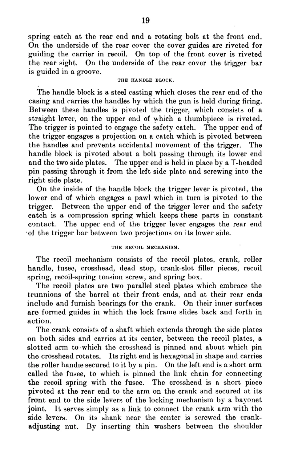
SERIAL LISTS OF COMPONENT PARTS.
THE GUN.
(Numbers before components refer to numbers shown on Plates II and V.)
4A Trunnion block. 17B Trigger bar.
5A Outside plate, right. 17C Rear cover catch.
5B Outside plate, left. 17D Rear guide stud.
6A Bottom plate. 18A Front cover.
ев Bottom plate slide. 18B Front cover catch cap.
6C Bottom plate slide stop. 18C Front cover catch snib.
6D Slide catch head. 18D Cover guide, right hand.
6E Bottom plate slide catch. 18E Cover guide, left hand.
6F Roller bracket. 18F Front cover catch bracket.
6G Outside plate filling piece. 18G Front cover catch.
6H Front cover stop. 19A Feed box.
7A Water-jacket cap. 20A Bottom pawl, left hand.
7B Steam outlet tube. 20B Bottom pawl, right hand.
7C Trunnion block distance piece. 20C Bottom pawl connecting plate.
7D Stuffing box. 20D Feed-box lever.
8A Water jacket. 20E Feed-box slide.
8B Outer steam tube. 20F Cartridge guide and stop.
8C Steam tube plug. 20G Feed-box bearing cap.
8D Inner steam tube. 20H Upper pawl, left hand.
8E Steam tube socket. 20J Upper pawl, right hand.
8F Water-jacket trough. 21A Front sight.
9A Barrel. 21C Deflection leaf.
10A Recoil plate, left hand. 21E Front-sight carrier.
10B Recoil plate, right hand. 22A Sight cam.
HA Crank. 22B Rear sight bracket.
11B Crosshead. 22C Rear sight stem.
11C Fusee link (rear). 22D Catch button.
11D Fusee link (front). 22Б Slide.
12A Roller handle. 23A Water plug.
12B eDead stop plunger. 23B Water-plug top piece.
12C Roller handle knob. 23C Stem covering.
12D Dead stop. 23D Water-plug fastening link.
12E Dead-stop bracket. 23E Water-plug fastemng ring.
12F Roller. 23F Water-jacket cap hose connection.
13A Lock frame. 23G Stem.
13B Filling piece. 23H Eyebolt.
13C Hand sear. 23J Securing S hook.
13D Tumbler. 23K Securing chain (6 links).
13E Firing pin. 23L Securing chain (12 links).
13F Safety sear. 24A Spring box.
13G Distance piece for lock frame. 24B Spring-box fixing (front).
13H Striker point. 24C Spring-box fixing (rear).
14A Side lever. 24D Fusee.
14B Lifting lever, right hand. i 24E Recoil-spring hook.
14C Lifting lever, left hand. 24F Recoil-spring nut.
14D Carrier. 1 25A Sleeve.
14E Gib. 25B Front disk.
14F Gib spring plate. 25C Muzzle attachment securing chain.
15A Handle block. 25D Securing chain ring.
15B Handle grip. 25E Muzzle gland.
15C Oil reservoir cap. 25F Front disk cap.
15D Reservoir cap washer. 25G Barrel disk.
15E Handle block oil reservoir. 25H Barrel-disk clamping screw.
15F Brush holder. 25K Follower.
15G Brush. 26B Locking pin.
16A Trigger lever. 26C Side-lever pin.
16B Trigger pawl. 26D Trigger pin.
16C Safety catch. 26E Bottom pawl rivet.
16D Thumb piece. 26F Rivet.
16E Handle block pin. 26G Rivet.
16F Trigger. 26H Bottom and outside plate rivet.
17A Rear cover. 1 2GJ Bottom and outside plate rivet.
PLATEfll.
COMPONENT PARTS OF GUN.
PLATE III.
COMPONENT PARTS OF GUN.
13
26К Dead-stop bracket and outside plate rivet.
26L Carrier supporting spring rivet.
26M Fusee rivet.
26N Chain-link rivet.
26P Lock-frame rivet.
26Q Adjusting washer (thick).
26R Adjusting washer (thin).
268 Stem washer.
26T Tension screw handle washer.
26U Water plug washer.
26V Belleville washer.
26W Deflection-screw washer.
26X Roller washer.
26Y Side lever-pin bushing.
27A Deflection-screw washer pin.
27B Rear-sight stem pin.
27C Dead-stop pin.
27D Slide-catch pin.
27E Trigger-pawl pin.
27F End-link pin.
27G Crank pin.
27H Crank-pin fastening link.
27J Upper-pawl pin.
27K Filling-piece pin.
27L Safety-sear pin.
27M Trunnion block and outside plate pin.
27N Rear rivet for rear sight.
27P Front rivet for rear sight.
27Q Cartridge guide and stop rivet.
27R Cartridge guide rivet.
27S Spring box rear stud.
27T Spring box front stud.
27U Tumbler pin.
27V Hand-sear pin.
27W Muzzle attachment stop pin.
27X Bottom pawl pin.
27Y Trunnion block and outside plate rivet.
27Z Tension-screw handle.
28A Handle block hinge pin.
28B Cover-hinge pin.
28C Rear-cover catch hinge pin.
28D Front-plug screw.
28E Steam tube front plug.
28F Front-sight carrier screw.
28G Hose-connection screw.
28H Safety-catch pin.
28J Recoil spring tension screw.
28K Screw-securing crank handle.
28L Deflection screw.
28M Trunnion block and outside plate screw.
28N Cover-hinge pin nut.
28P Sight-cam securing screw.
28Q Dead-stop plunger stop.
28R Adjusting nut.
28S Trigger-bar spring plunger.
29A Carrier supporting spring, left hand.
29В Carrier supporting spring, right hand.
29C Gib spring.
29E Rear cover catch spring.
29F Bottom-pawl spring.
29G Bullet-guide spring.
29H Upper-pawl spring.
29J Mainspring.
29K Safety-sear spring.
29L Recoil spring.
29M Dead-stop plunger spring.
29N Trigger-lever spring.
29P Trigger-bar spring.
29Q Front-cover catch snib spring.
29 R Catch-button spring.
29S Slide-catch spring.
BIA Trunnion pin.
BIB Trunnion pin collar.
BIC Trunnion pin adjusting nut.
THE TRIPOD.
[Numbers before components refer to numbers shown on Plates VII and VIII.J
4A Leg clip screw. 5M Elevating pin securing chain.
4B Pivot yoke stop screw. 6A Pintle.
4C Screw-securing trail key. 6B Traversing arm.
4D Traversing-stop screw. 6C Pivot yoke.
4E Top-carriage clamp hinge pin. 6D Pivot stud.
4F Traversing-clamp stop pin. 6G Traversing pivot.
4G Top-carriage clamp stop pin. 7A Top carriage.
4H Securing-clamp pin. 7B Top carriage clamp link.
4J Side-plate bolt. 7C Top carriage clamp hinged plate.
4K Elevating-hinge pin. 7D Top carriage clamp bushing.
4L Stop screw. 7E Top carriage clamp bolt.
4M Elevating-clamp nut. . 7F Clamp bolt handle screw eye.
4N Nut. 7G Top carriage clamp bolt handle.
4P Trail-clamp nut. 711 Securing chain (short).
4Q Pivot-stud nut. 7K Securing chain (long).
4S Link-stud nut. 7L Securing chain ring.
4T Leg-clip nut. 8A Traversing arc.
4U Side-plate bolt nut. 9A Outer trail tube.
5A Inner elevating screw. 9B Trail sleeve.
5B Outer elevating screw. 9C Trail sleeve clamp.
5C Hand wheel. 9D Stiffener.
5D Elevating nut. 9E Trail shoe.
5E Elevating clamp. 9F Inner trail tube.
5F Elevating pin. 10A Guide and distance piece rivet.
5K Elevating pin ring. ‘ 10B Socket and adjusting arc rivet.
5L Elevating pin spring. IOC Arc and distance piece rivet.
14
10D Trail rivet.
1OE Trail rivet.
1OF Seat-hinge pin.
1OG Front leg clamp plunger.
1OH Hinge-pin washer.
10J Traversing stop spring.
10К Seat packing piece.
10L Front leg clamp spring.
10M Elevated nut hinge pin key.
11A Traversing stop, left-hand.
11В Traversing stop, right-hand.
12A Side plate.
12B Top-carriage guide, right-hand.
12C Socket for trail.
12D Adjusting arc for right-hand front leg.
12E Adjusting arc for left-hand front leg.
12F Side-plate distance piece.
12G Side-plate bolt tube.
12H Top-carriage guide, left-hand.
13A Front leg.
I 13 В Front shoe.
! 13C Front leg clamp, right-hand.
' 13D Front leg clamp, left-hand.
I 13E Link.
, 13F Link stud.
13G Clip stop.
i 13H Clip distance piece.
13J Trail sleeve key.
I 13К Leg clip.
j 14A C ircular level.
। 14 В Traversing clamp.
. 14C Traversing-clamp bushing.
I 14D Traversing-clamp claw.
14E Traversing-stop plunger.
i 15A Seat.
। 15В Seat-link collar.
| 15C Seat-sliding collar.
। 15D Seat link.
I 15E Seat hinge.
ALPHABETICAL LIST OF COMPONENT PARTS.
THE GUN.
[Numbers after the components refer to numbers shown on Plates II to V.]
Adjuster nut (28R).
Adjuster washer (thick) (26Q).
Adjuster washer (thin) (26R).
Barrel (9A).
Barrel disk (25G).
Barrel-disk clamping screw (2511).
Belleville washer (26V).
Bottom and outside plate rivet (2611).
Bottom and outside plate rivet (26J).
Bottom pawl, left-hand (20A).
Bottom pawl, right-hand (20B).
Bottom pawl connecting plate (20C).
Bottom pawl pin (27X).
Bottom pawl rivet (26E).
Bottom pawl spring (29F).
Bottom plate (6A).
Bottom plate slide (6B).
Bottom plate slide catch (6E).
Bottom plate slide stop (6C).
Brush (15G).
Brush holder (15F).
Bullet-guide spring (29G).
Carrier (14D).
Carrier supporting spring, left hand (29A).
Carrier supporting spring, right hand (29B).
Carrier supporting spring rivet (26L).
Cartridge guide and stop (20F).
Cartridge guide and stop rivet (27Q).
Cartridge guide rivet (27R).
Catch button (22D).
Catch button spring (29R).
Chain-link rivet (26N).
Cover guide, left hand (18E).
Cover guide, right hand (18D).
Cover hinge pin (28B).
Cover hinge pin nut (28N).
Crank (11A).
Crank pin (27G).
Crank-pin fastening link (27H).
Crosshead (11B).
Dead stop (12D).
Dead-stop bracket (12E).
Dead-stop bracket and outside plate river(26K).
Dead-stop pin (27C).
Dead-stop plunger (12B).
Dead-stop plunger spring (29M).
Dead-stop plunger stop (28Q).
Deflection leaf (21C).
Deflection screw (28L).
Deflection screw washer (26W).
Deflection screw washer pin (27A).
Distance piece for lock frame (13G).
End link pin (27F).
Eyebolt (23H).
Feed box (19A).
Feed-box bearing cap (20G).
Feed-box lever (20D).
Feed-box slide (20E).
Filling piece (13B).
Filling piece pin (27K).
Firing pin (13E).
Follower (25K).
Front cover (18A).
Front-cover catch (18G).
Front-cover catch bracket (18F).
Front-cover catch cap (18B).
Front-cover catch snib (18C).
Front-cover catch snib spring (29Q).
j Front-cover stop (6H).
I Front disk (25B).
Front disk cap (25F).
Front plug screw (28D).
' Front rivet for rear sight (27P).
Front sight (21A).
। Front sight carrier (21E).
! Front sight carrier screw (28F).
Fusee (24D).
Fusee link (front) (11D).
, Fusee link (rear) (11C).
! Fusee rivet (26M).
! Gib(14E).
i Gib spring (29C).
| Gib spnng plate (14F).
i Hand sear (13C).
15
Hand sear pin (27V).
Handle block (15A).
Handle block hinge pin (28A).
Handle block oil reservoir (15E).
Handle block pin (16E).
Handle grip (15B).
Hose connection screw (28G).
Inner steam tube (8D).
Lifting lever, left hand (14C).
Lifting lever, right hand (14B).
Lock frame (13A).
Lock frame rivet (26P).
Locking pin (26B).
Main spring (29J).
Muzzle attachment securing chain (25C).
Muzzle attachment stop pin (27W).
Muzzle gland (25E).
Oil reservoir cap (15C).
Outer steam tube (8B).
Outside plate filling piece (6G).
Outside plate, left (5B).
Outside plate, right (5A).
Rear cover (17A).
Rear-cover catch (17C).
Rear-cover catch hinge pin (28C).
Rear-cover catch spring (29E).
Rear guide stud (17D).
Rear-sight bracket (22B).
Rear-sight stem (22C).
Rear-sight stem pin (27B).
Rear rivet for rear sight (27N).
Recoil plate, left-hand (10A).
Recoil plate, right-hand (10B).
Recoil spring (29L).
Recoil spring hook (24E).
Recoil spring nut (24F).
Recoil spring tension screw (28J).
Reservoir cap washer (15D).
Rivet (26F).
Rivet (26G).
Roller (12F).
Roller bracket (6F).
Roller handle (12A).
Roller handle knob (12C).
Roller washer (26X).
Safety catch (16C).
Safety catch pin (28H).
Safety sear (13F).
Safety sear pin (27L).
Safety sear spring (29K).
Screw securing crank handle (28K).
Securing chain (6 links) (23K).
Securing chain (12 links) (23L).
Securing chain ring (25D).
Securing S hook (23J).
Side lever (14A).
Side lever pin (26C).
Sight cam (22A).
Sight cam securing screw (28P).
Sleeve (25A).
Slide (22E).
Slide catch head (6D).
Slide catch pin (27D).
Slide catch spring (29S).
Spring box (24A).
Spring box fixing, front (24B)
Spring box fixing, rear (24C).
Spring box front stud (27T).
Spring box rear stud (27S).
Steam outlet tube (7B).
Steam tube front plug (28E).
Steam tube plug (8C).
Steam tube socket (8E).
Stem (23G).
Stem covering (23C).
Stem washer (26S).
Striker point (13H).
Stuffing box (7D).
Tension screw handle (27Z).
Tension screw handle washer (26T).
Thumb piece (16D).
Trigger (16F).
Trigger bar (17B).
Trigger bar spring (29P).
Trigger bar spring plunger (28S).
Trigger lever (16A).
Trigger lever spring (29N).
Trigger pawl (16B).
Trigger pawl pin (27E).
Trigger pin (26D).
Trunnion block (4A).
Trunnion block and outside plate pin (27M).
Trunnion block and outside plate rivet (27Y).
Trunnion block and outside plate screw (28M).
Trunnion block distance piece (7C).
Trunnion pin (BIA).
Trunnion pin adjusting nut (BIC).
Trunnion pin collar (BIB).
Tumbler (13D).
Tumbler pin (27U).
Upper pawl, left-hand (20H).
Upper pawl, right-hand (20J).
Upper pawl pin (27J).
Upper pawl spring (2911).
Water jacket (8A).
Water jacket cap (7A).
Water jacket cap hose connection (23F).
Water jacket trough (8F).
Water plug (23A).
Water plug fastening link (23D).
Water plug fastening ring (23E).
Water plug top piece (23B).
Water plug washer (26U).
THE TRIPOD.
(Numbers after components refer to numbers shown on Pls. VII and VIII.]
Adjusting arc for right-hand front leg (12D).
Adjusting arc for left-hand front leg (12E).
Arc and distance piece rivet (IOC).
Circular level (14A).
Clamp-bolt handle screw eye (7F).
Clip-distance piece (13H).
Clip stop (13G).
Elevating clamp (5E).
Elevatmg clamp nut (4M).
Elevating hinge pin (4K).
Elevating nut (5D).
Elevating nut hinge pin key (10M).
Elevating pin (5F).
Elevating pin ring (5K).
16
Elevating pin spring (5L).
Elevating pin securing chain (5M).
Front leg (13A).
Front leg clamp, right hand (13C).
Front leg clamp, leit hand (13D).
Front leg clamp plunger (10G).
Front leg clamp spring (10L).
Front shoe (13B).
Guide and distance piece rivet (10A).
Hinge-pin washer (10H).
Handwheel (5C).
Inner elevating screw (5A).
Inner trail tube (9F).
Leg clip (13K).
Leg clip nut (4T).
Leg clip screw (4A).
Link (13E).
Link stud (13F).
Link stud nut (4S).
Nut (4N).
Outer elevating screw (5B).
Outer trail tube (9A).
Pintle (6A).
Pivot stud (6D).
Pivot stud nut (4Q).
Pivot yoke (6C).
Pivot yoke stop screw (4B).
Screw securing trail key (4C).
Seat (15A).
Seat hinge (15E).
Seat hinge pin (10F).
Seat link (15D).
Seat link collar (15B).
Seat packing piece (10K).
Scat sliding collar (15C).
Securing chain (short) (7H).
Securing chain (long) (7K).
Securing chain ring (7L).
Securing clamp pin (4H).
Side plate (12A).
Side plate bolt (4J).
Side plate bolt nut (4U).
Side plate bolt tube (12G).
Side plate distance piece (12F).
Socket and adjusting arc rivet (10B).
Socket for trail (12C).
Stiffener (9D).
Stop screw (4L).
Top carriage (7A).
Top carriage clamp bolt (7E).
Top carriage clamp bolt handle (7G).
Top carriage clamp bushing (7D).
Top carriage guide, right (12B).
Top carriage guide, left (12H).
Top carriage clamp hinged plate (7C).
Top carriage clamp hinge pin (4E).
Top carriage clamp link (7B).
Top carriage clamp stop pin (4G).
Trail clamp nut (4P).
Trail rivet, short (10D).
Trail rivet, long (10E).
Trail shoe (9E).
Trail sleeve (9B).
Trail sleeve clamp (9C).
Trail sleeve key (13J).
Traversing arc (8A).
Traversing arm (6B).
Traversing clamp (14B).
Traversing clamp bushing (14C).
Traversing clamp claw (14D).
Traversing clamp stop pin (4F).
Traversing pivot (6G).
Traversing stop, left hand (HA).
Traversing stop, right hand (11B).
Traversing stop plunger (14E).
Traversing stop screw (4D).
Traversing stop spring (10J).
DETAILED DESCRIPTION OF THE GUN.
The gun consists of the following principal parts: The barrel, trun-
nion block, water jacket, condensing apparatus, water-jacket cap,
steam tube, filling and drain plugs, casing, handle block, recoil
mechanism, lock mechanism, firing mechanism, feed box, muzzle
attachment and sights.
THE BARREL.
The barrel is chambered and rifled the same as the United States
magazine rifle. On its exterior, near the muzzle and breech ends, are
turned two cylindrical bearings which rest in corresponding supports
in the trunnion block and water-jacket cap, and on these bearings
the barrel slides back and forth in action. Both bearings are packed
with asbestos to prevent water leaking from the water jacket. On
the breech end of the barrel are formed two trunnions, by which the
two recoil plates are attached to the barrel. The muzzle end is
threaded for the barrel disc. To prevent rusting from the water in
the water jacket, the exterior of the barrel is copper plated.
17
THE TRUNNION BLOCK.
The trunnion block is a steel casting, carrying at its lower end a
к through which passes the trunnion pin of the tripod. The
ftnnion pin secures the gun to its mount and forms the axis about
pich the gun is moved in elevation. The front end of the casting
I cylindrical and is threaded to receive the rear end of the water
icket. Under the circular section a drilled hole furnishes a seat for
he rear plug of the inside tube and directly in rear of this circular
betion the block is rectangular in shape and serves as the front sup-
port of the casing inclosing the lock and recoil mechanisms. A hori-
zontal hole is drilled through the rectangular part of the trunnion
block and serves as the rear support for the barrel, and back of this
in the bottom plate is the opening through which the cartridge cases
Fall.
THE WATER JACKET.
The water jacket consists of a piece of drawn-steel tubing threaded
on the exterior at each end. The rear end screws in the trunnion
block and the front end in the water-jacket cap. Near the rear end
and on the upper right-hand side is a drilled and tapped hole for the
filling plug, and near the front on the bottom a second hole is drilled
and tapped for the water plug, through which the water in the jacket
may be drawn off.
The adjustment of water jacket and trunnion block brings the
barrel, when in position, below the center of the water jacket. By
this arrangement a sufficient space above the barrel is^obtained for
the insertion of a steam exhaust consisting of an inside tube and an
outside slide. The inside tube has two holes cut in its upper side,
one near each end. A steam vent running down through the water-
jacket cap is connected with the inside tube by means of a hole in
the front plug. By this arrangement, no matter whether the piece
be horizontal or in maximum depression or elevation, steam can
always escape, as the outside slide will automatically cover the lower
opening in the tube, preventing water from entering it and will leave
the other hole open for the passage of steam from the jacket through
the tube and water-jacket cap hole to the condensing apparatus.
From the arrangement of this tube and slide, if the piece be left hori-
zontal in filling and the stopper closing the steam-escape hole in the
water-jacket cap be removed, water will issue from the water-jacket
cap hole as soon as the water jacket has been filled above the level
of the tube. This is an indication that the jacket is sufficiently full
of water. Should the stopper not be removed, the jacket may of
course be filled up to the level of the filling hole. This will do no harm,
but will result, after firing a number of rounds sufficiently to develop
86574—17-------2
18
steam pressure, in the blowing off of hot water through the water-
jacket cap hole which will continue until the level of the water in the
jacket has been reduced sufficiently to allow the free escape of steam
to the condensing apparatus or to the open air.
THE CONDENSING APPARATUS.
This consists of a hose and a water box nearly full of water. In
place of a water box, a pail, can, or a hole in the ground that will
hold water, may be used. The hose leads from the steam outlet of
the water jacket into the water, thereby condensing the steam as it
comes in contact with the water.
When a container is used, the condensed steam and water may be
returned to the water jacket of the gun and used over again.
THE WATER-JACKET CAP.
The water-jacket cap is a steel casting which screws on the front
end of the water jacket. It contains a threaded seat for the stuffing-
box follower, which forms the front support for the barrel and also
a threaded seat for the front plug on the inside tube. On the front
of the cap is screwed the follower and on top is screwed the front
sight. The water-jacket cap tube for the escape of steam, mentioned
above, is screwed into the cap and runs from the front plug hole of
the inside tinbe diagonally down to its opening at the under side of
the cap. On tue top of the cap is stamped the name, model, and
serial number of the gun.
THE FILLING PLUG.
The filling plug consists of a tapped hole in the trunnion block,
a water plug, and a chain, hook, and eyebolt for securing the plug
to the trunnion block. The construction is such as to allow the
easy unscrewing of the plug on insertion of the nozzle of the filling
cup. When the nozzle is withdrawn the plug is screwed again into
place.
THE CASING.
The casing consists of the right and left outside plates, the bottom
plate, slide, and two covers which are all made of steel. The outside
plates are slotted to permit the free movement of the projecting
parts of the recoil mechanism and to guide them in recoil. They
are drilled for the pins and rivets by which they are attached to the
handle block, trunnion block, covers, and bottom plate. The
bottom plate is of channel cross section, the side flanges providing
a support for the outside plates. The space beneath the flanges
serves as a sliding seat for the slide. On the underside are the lugs
to which the head of the elevating screw is pinned. The covers are
hinged to each other and to the side plates, and are held closed by a
/Л lluid
19
spring catch at the rear end and a rotating bolt at the front end.
On the underside of the rear cover the cover guides are riveted for
guiding the carrier in recoil. On top of the front cover is riveted
the rear sight. On the underside of the rear cover the trigger bar
is guided in a groove.
THE HANDLE BLOCK.
The handle block is a steel casting which eJoses the rear end of the
casing and carries the handles by which the gun is held during firing.
Between these handles is pivoted the trigger, which consists of a
straight lever, on the upper end of which a thumbpiece is riveted.
The trigger is pointed to engage the safety catch. The upper end of
the trigger engages a projection on a catch which is pivoted between
the handles and prevents accidental movement of the trigger. The
handle block is pivoted about a bolt passing through its lower end
and the two side plates. The upper end is held in place by a T-headed
pin passing through it from the left side plate and screwing into the
right side plate.
On the inside of the handle block the trigger lever is pivoted, the
lower end of which engages a pawl which in turn is pivoted to the
trigger. Between the upper end of the trigger lever and the safety
catch is a compression spring which keeps these parts in constant
contact. The upper end of the trigger lever engages the rear end
of the trigger bar between two projections on its lower side.
THE RECOIL MECHANISM.
The recoil mechanism consists of the recoil plates, crank, roller
handle, fusee, crosshead, dead stop, crank-slot filler pieces, recoil
spring, recoil-spring tension screw, and spring box.
The recoi] plates are two parallel steel plates which embrace the
trunnions of the barrel at their front ends, and at their rear ends
include and furnish bearings for the crank. On their inner surfaces
are formed guides in which the lock frame slides back and forth in
action.
The crank consists of a shaft which extends through the side plates
on both sides and carries at its center, between the recoil plates, a
slotted arm to which the crosshead is pinned and about which pin
the crosshead rotates. Its right end is hexagonal in shape and carries
the roller handle secured to it by a pin. On the left end is a short arm
called the fusee, to which is pinned the link chain for connecting
the recoil spring with the fusee. The crosshead is a short piece
pivoted at the rear end to the arm on the crank and secured at its
front end to the side levers of the locking mechanism by a bayonet
joint. It serves simply as a link to connect the crank arm with the
side levers. On its shank near the center is screwed the crank-
adjusting nut. By inserting thin washers between the shoulder
20
on the shank and the nut the position of the side levers with reference
to the crosshead can be varied. This causes a change in the location
of the lock frame, and by this means an accurate adjustment of the
head space required by the cartridges can be obtained. The dead
stop is a steel cam pivoted on the right side plate and serves to limit
the movement of the roller handle in counter recoil. The recoil-spring
is a helical tension spring inclosed in the spring box attached to the left
side plate by means of two small studs in front and one in the rear.
The rear end of the spring is held by two short links to the fusee and
the front end is secured to the box by means of the tension screw
threaded to the recoil-spring nut and passing through a hole in the
spring box. The tension of the recoil spring is regulated with the
tension screw which is turned by a sliding pin handle.
THE LOCK MECHANISM.
The lock mechanism is contained between the recoil plates and
consists of the lock frame, filler piece, carrier, gib, gib spring, gib-
spring plate, side levers and pins, lifting levers, firing pin and striker
point, mainspring, tumbler and pin, safety sear and pin, and hand
sear and pin. All these parts are contained in or assembled to the
lock frame. The latter is a steel forging having at its front a narrow
vertical face about 3.25 inches long in which are cut the guide ribs
which mount the carrier. The filler piece is located in the center
of the narrow vertical face. On the bottom part of the lock frame are
formed two horizontal ribs on each side that support the lock in the
recoil plates and are the bearings on which it moves during recoi].
Above these ribs the frame is slotted out horizontally to form a seat
for the firing pin. The top of these ribs form a seat for the lifting
levers.
The carrier has a vertical sliding motion on the front face of the
lock frame. Its face is provided with flanges which, with the gib
projecting through from the rear, embrace the base of the cartridge
case in the operations of withdrawing it from the belt, inserting it in
the chamber and extracting it after firing. Near the bottom a
conical hole is drilled to permit the passage of the point of the firing
pin.
The side levers consist of a fork-shaped shank, the solid end of
which is bored out to fit the crosshead, while each arm of the forked
end terminates in a lever extending upward and to the rear. The
fork embraces the lock frame, and the piece is pinned to the latter
at the front end of the fork.
The lifting levers consist of two plates pivoted near one end on a
pin. This pin passes through the rear part of the lock frame, the
lovers lying outside the frame.
The filing pin is a rectangular-shaped forging, whose front end
has the case-hardened striker point secured to it by a screw. On the
21
sides are formed parallel shoulders, by which the pin is supported in
the lock frame. The top edge is cut away irregularly, forming a
shoulder, against which the mainspring abuts, and also a bearing
for the tumbler. The latter, an L-shaped piece, is pivoted to
the lock frame at the angle. The shorter arm fits the notch in the
upper edge of the firing pin and serves to retract and hold the firing
pin in the cocked position. The longer arm is pushed up by the side
lever shank as the latter is raised in recoiling, thus forcing the shorter
arm to retract and cock the firing pin.
The mainspring is a leaf spring placed vertically in the upper part
of the lock frame, the longer end engaging a boss on the firing pin
and the shorter abutting against the hand sear. The latter is a
straight lever secured near the lower end by a pin passing through
the sides of the lock frame, and about which it rotates. The lower
end engages a notch on the tumbler, and the upper end fits into the
long slot of the trigger bar and is engaged by the front end or shoul-
der of the slot. In the firing position the side lever shank is hori-
zontal in prolongation of the crosshead. The carrier is therefore
dropped to its lowest position by the lifting levers, so that the filing-
pin hole is opposite the corresponding hole in the lock frame. Ajpon
firing, the carrier first receives the shock of recoil, distributes it
along its bearing surfaces to the lock frame, which in turn transmits
it to the side levers, side-lever shank, crosshead, crank, recoil plates,
fusee, and finally through the recoil spring to the casing and mounts
THE FIRING MECHANISM. <
The firing mechanism consists of the trigger, trigger spring, trigger-
lever safety catch, and trigger bar. As described above, the trigger
is a straight lever secured near its lower end to the handle block
by a pin, about which it rotates. The upper end engages the safety
catch, which holds it to the rear until it is released by lifting the
catch and is pressed in. The trigger bar is a long, narrow plate
lying in the channel of the rear cover plate. It contains one long
slot. The trigger spring is a small helical spring mounted on a stud
in the front face of the safety catch and tends to separate the trigger
and trigger lever. It presses /he upper part of the trigger to the
lear, so that the trigger bar can move forward under the action of
the mainspring transmitted through the hand sear and permit the
latter to engage the shoulder on the tumbler when the piece is cocked.
In continuous firing, as the trigger bar is held back by the trigger,,
the hand sear will never be able to engage the shoulder on the tum-
bler, but, being kept out of engagement, will allow the firing pin to
move forward again as soon as the cycle of movements which ends
with its cocking or retraction is completed.
22
THE FEED BOX.
The feed box is a hollow steel casting extending transversely
through the casing near its forward end. On the right side it pro-
jects beyond the casing, and its lower edge is curved to facilitate the
feeding of the cartridge belt. On the front edge of the feed box a
vertical bearing is provided in which is seated the arbor of the feed-
box lever. This lever is held in place by the feed-box bearing cap,
which slides into place after inserting the lever. At the end of the
lower arm of the lever is a stud which engages in a slot near the front
end of the left recoil plate. In the end of the upper arm of the lever
is a stud which takes a slot on the top of the feed-box slide. The
feed-box slide is a flat steel plate seated in grooves in the feed-box
casting, which permit it- to have a transverse movement. At its
right-hand end, on the underside, are formed two lugs. These lugs
are drilled for the upper pawl pin, which serves as an arbor for the
upper pawls. The long arms of the pawls are pressed downward by
a double leaf spring consisting of two parallel leaves joined at the
base and secured to the underside of the slide by an undercut lip.
Beneath the curved lower edge of the right-hand end of the feed box
are formed two lugs drilled to take the bottom pawl pin. The bottom
pawls are mounted on this pin as an arbor, their long arms projecting
through slots in the bottom of the feed box. The shorter arms are
slotted at the end in which a finger plate connecting the two arms is
riveted for easy manipulation by the- fingers. The pawls’ are kept in
position by a peculiar shaped double leaf spring mounted at the
center of the pawl pin.
The action of the feed box is as follows: During the recoil of the
parts the slot near the front end of the left recoil plate pulls the stud
on the end of the lower arm of the lever to the rear. This causes a
counterclockwise revolution of the vortical arbor of the lever, re-
sulting in throwing of the feed-box slide plate from left to right by the
upper arm, so that the pawls on the underside of the slide plate are
pushed back and engage in rear of the next cartridge in the belt.
During the counter recoil the movement is reversed, resulting in the
feeding of the next round in the belt to the position for engagement
with the carrier grooves. The under pawls prevent the movement
of the belt from left to right unless depressed from beneath by hand.
THE MUZZLE ATTACHMENT.
The muzzle attachment consists of the follower, barrel disk, front
disk, disk cap and sleeve, which are steel forgings whose functions are
to regulate the effect of recoil on the system. The barrel disk consists
of a hub which screws on the muzzle of the barrel and carries a disc
concaved to the front. The follower is secured to the water-jacket
cap by a screw thread. Through the front disk a hole is drilled
23
just large enough to permit passage of the bullet, while the sides of
the sleeve are cut away as much as possible to allow free escape of the
powder gas. The front disk cap can easily be removed when heavily
coated with the products of combustion by unscrewing the front disc
and prying it out, after which a new cap may be inserted.
SIGHTS.
The front sight, complete, is composed of the front sight, front-
sight carrier, and front-sight carrier screw.
Th2 front sight is a forged-steel piece dovetailed into the front-
sight carrier, thus allowing lateral adjustment of the sight. It is
shaded by the front-sight cover.
The rear-sight group is made up of the following principal parts:
The movable base, tbe base spring, the leaf, the elevating screw, the
slide, the hah nut, the slide cap, the drift slide, the aperture disk, and
the windage screw.
The movable base has on its upper surface two ears, in which are
the holes for the joint pin which serves as a hinge for the leaf. On
the rear end of the movable base are the wind-gauge graduations,
each point of which corresponds to a lateral deviation of 4 inches for
each 100 yards. Both ends have lips which fit the undercuts of the
fixed base, the front lip having also a worm gear for engaging the
thread of the windage screw. The base spring fits in the spring seat
of the movable base.
The rear face of the leaf is graduated from 0 to 2,600 yards and
its right edge is graduated in mils. On the right side of the sighting
opening in the leaf is the groove and seat for the elevating screw,
which is a long, thin screw, extending from the bottom of the sight-
ing opening to the top of the leaf, where it is secured in the elevating
screw head by the elevating screw pin. This elevating screw allows
minute corrections for elevation and also holds the slide in position
on the leaf by means of a half nut which is seated in the slide and
the half-nut spring, the latter forcing the half nut against the thread
on the elevating screw. The pitch of the screw is such that one com-
plete turn corresponds to a change of one mil. The outer end of
this half nut is knurled, and by pressing in on the knurled head the
half nut can be released from the elevating screw and the slide
quickly raised or lowered.
The rear face of the slide is cut out for the leaf, and the drift
slide and the right half are made with a seat for the half-nut spring
and the half nut. The right and left ends are drilled and tapped for
the small slide-cap screw and the large slide-cap screw, which secure
the slide cap to the slide. The front face of the slide is slotted and
recessed for the pivot.
24
The slide cap has a circular cut in its upper surface which forms
a recess for rotating the aperture disc, and also apertures for sighting
and for reading the graduation on the leaf. The center is slotted
for the pivot. On the right and left sides are drilled the holes for
the small and large slide-cap screws. On the rear face at the bottom
of the slide cap is the open or battle sight.
The drift slide moves in the drift slots in the leaf. At the top is
a small open sight, while just below are two openings, the upper for
the pivot and circular lug on the aperture disc and the lower for a
sighting aperture. The drift slide is held in place by a lug on its
front face, which bears against the slide and by the lug which con-
tains the open sight. This latter lug extends to the rear and bears
against the top of the slide cap. On the lower edge of the open-
sight lug is another small lug, which engages in the notches on the
perimeter of the aperture disc, locking the latter in the desired
position..
The aperture disc is a circular piece containing five sight openings,
viz: Four peepholes, 0.04, 0.06, 0.08, and 0.10 inch in diameter, and
one large aperture which contains an open sight. A circular lug
on the front face engages in the central opening of the drift slide,
thus causing the aperture disc to conform to the movement of the
former. This lug is drilled and tapped for the pivot spring and the
pivot. The purpose of the pivot spring is to force the aperture disc
to the rear, so that one of the notches, which are cut on its perimeter,
will engage in the small lug on the drift slide and prevent rotation.
By pressing inward, the aperture disc can be released and rotated
until the desired aperture is opposite the sighting opening in the
drift slide.
The windage screw consists of the windage screw, the windage
screw knob, the windage screw collar, the windage screw spring, and
the windage screw pin. It is seated in the front part of the fixed base.
DESCRIPTION OF THE TRIPOD.
[Plates VII and VIII.]
The tripod consists of the following principal parts: Front legs,
trail, seat and seat bracket, pintle and pivot, top carriage, body,
traversing mechanism and elevating mechanism.
THE FRONT LEGS.
The front legs consist each of a short length of drawn steel tubing
carrying at the upper end the link by which it is attached to the
adjusting arc and at the lower end a flattened shoe. One end of the
link is turned to fit snugly in the bore of the tubing and riveted
thereto in two places. The upper end of the link terminates in three
teeth which fit into a circular rack when adjusted for firing. When
PLATE VII.
COMPONENT PARTS OF TRIPOD.
PLATE'ШП
25
it is desired to fold the tripod for transportation or to extend the front
legs forward in carrying by hand, the slot in the link permits the
clamp to be loosened from its seat on the drum and the teeth to be
disengaged from the adjusting arc, swung around, reengaged, and
clamped.
THE TRAIL.
The trail consists of two lengths of steel tubing, called the outer
and inner trail tubes. The inner tube fits into and is riveted to a
socket, which is also riveted between two semicircular side plates,
and at its front end carries two adjusting arcs for the front legs.
The outer trail tube forms the trail clamp and holds the attachment
for the seat.
The inner tube is turned to fit closely the bore of the outer tube,
in which it has a sliding motion. This motion may be stopped and
the inner tube clamped in any position by means of the trail sleeve
clamp which is riveted to the top end of the outer tube. The sleeve
is split for a short distance back from the end, so that by tightening
the clamp the lugs are brought nearer together and the inner tube
firmly gripped.
The key inserted in the trail sleeve works in a longitudinal slot cut
in the surface of the inner tube on the underside and prevents the
tube from turning. To the rear end of the outer tube is attached
a shoe similar to those on the front legs. This construction of ,the
trail permits adjustment of its length to uneven surfaces and shorten-
ing to a minimum length for transportation. A pair of leg clips
fastened to the outer tube serves to bind securely to the trail the front
legs when the tripod is folded.
THE SEAT.
The seat is of sheet steel pressed to shape. Its front end is pivoted
to fit the seat sliding collar which slides on the trail tube. The rear
end is pivoted to the seat link, which in turn is pivoted to the seat
link collar attached to the outer trail tube.
The seat link collar is of steel and riveted near the end of the outer
tube. On the underside of the seat are two lugs of the hinge drilled
and riveted to it, the action of which is described below. For trans-
portation the scat slides forward by means of the seat sliding collar
to which it is pivoted. The rear of the seat folds down close to the
trail and the top of the seat link rests on the trail. In action the
seat is slid backward and automatically stops by the contact of the
seat link with the seat link collar.
THE PINTLE.
The pintle is a hollow steel forging which furnishes the points of
attachment for the legs and trail, the pivot for transverse movement
of the gun and top carriage, and the seat for the traversing arc.
26
In the rear of this casting are machined two surfaces inclining
outward to which the traversing arm is riveted. The upper end is
turned to form a bearing for the top carriage, traversing pivot and
yoke. The rear end of the traversing arm furnishes pivot bearings
for the elevating nut, while on the underside is the clamp for the
traversing arc, the rear edge of which is turned to an arc struck from
the center of the pintle axis and fits into a corresponding groove in
the rear of the traversing arm, thus preventing the latter from jump-
ing. The top surface of this seat is machined to form a flat bearing
surface for the rear ends of both the top carriage and the traversing
arm.
The top and front of the pintle is turned to form a vertical bearing
for the top carriage and traversing arm. In the upper part of this
bearing is pivoted the yoke.
THE TOP CARRIAGE.
The top carriage is a steel forging consisting of a hub bored out to
fit over the pintle and an arm projecting downward and to the rear,
to which the traversing arc is riveted. This arm is also gibbed to the
top carriage guide by means of the groove engaging the circular lip
on the latter. On top of the hub is the pivot yoke drilled and slotted
transversely for the trunnion pin. The gun rests between the cheeks
of this yoke supported by and rotating on the trunnion pin. One
end of this pin is bent to a sharp angle to form a handle, while the
other is threaded to receive the adjusting nut. The cheeks of the
pivot yoke arc reamed out and slotted to the size of the ends of the
pin. On mounting the gun the pin is dropped through the slots of
the pivot yoke and secured by rotating the handle, thereby tightening
the cam.
The web at the rear of the top carriage is cut away just in rear of
the hub for the top carriage clamp link, and a hole is drilled through
the horizontal web for the top carriage clamp bolt, the head of which
is fitted with a lever handle. The eccentric portion of the clamp bolt
is fitted with a bushing into a link connecting to a hinged plate. By
rotating the clamp bolt this plate is raised to engage the notches under
the top carriage guide, thereby locking the top carriage to the body.
THE BODY.
The body consists of the side plates, top carriage guides, trail
socket, distance pieces, and adjusting arcs of the front legs.
THE TRAVERSING MECHANISM.
The traversing pivot is drilled for the passage of the pivot stud
and counterbored slightly as a seat for the shoulder on it.
The traversing arm is a steel casting to one end of which is riveted
the pintle and rests upon the shoulder formed at the base of the
27
latter. Slightly in rear of this bearing, a curved slot is cut, through
which the traversing arc passes, and in rear of this slot the arm is
bent downward. At the rear end is formed a yoke in which is pivoted
the elevating nut.
In front of the elevating nut is fitted the traversing clamp, which
consists of a claw, a bushing and clamp handle. By swinging the
handle one way or the other the claw engages the under surface of the
traversing arc thereby clamping the arm stationary with the travers-
ing arc.
On each side of the traversing arm a traversing stop is fitted to
the traversing arc. This stop is fitted with a plunger, a spring and
a screw and hooks over the rear of the traversing arc. On the plunger
are found teeth to engage the teeth formed under the edge of the
traversing arc. By pinching this stop between the thumb and
forefinger of either hand it may'be disengaged and set at any desired
position on the traversing arc. When these stops are placed on the
extreme ends of the traversing arc, the traversing arm may be swung
22|° either side of center. By releasing the elevating gear an all
round training may be obtained but without any clamp.
THE ELEVATING MECHANISM.
The elevating mechanism consists principally of the outer elevating
screw, the inner elevating screw, the elevating nut, hand wheel, the
elevating clamp, the elevating nut pin, and the elevating pin.
The outer elevating screw is a steel cylinder, on which is screwed at
the upper end the handwheel, with six knobs, with which the screw
can be turned by hand. A right-hand screw thread is cut on the ex-
terior of the body and a left-hand thread is cut for a short distance
on the interior of the body. The remainder of the bore is reamed
out to a diameter large enough to clear the inner screw when in place.
The inner elevating screw is a steel forging, at the upper end of
which a T-shaped head is formed, which is drilled transversely. This
head fits between lugs on the bottom plate of the gun and is secured
to them by the elevating pin. The pin has a spring at one end which
is held in place by riveting.
On the body of the screw is cut a left-hand thread corresponding
to that on the interior of the outer screw. The lower end is drilled
and tapped axially for a stop screw, which, by closing the end of the
thread, limits the upward movement of the inner screw when it
comes in contact with the bottom of the interior thread in the outer.
The elevating nut is a long nut, carrying at its lower end a lug drilled
to take the elevating-nut pin by which it is hinged to the top carriage
and at its upper end a second lug for the elevating clamp. The bore
of the nut is threaded for the outer elevating screw for its whole
length. The threaded part is slotted longitudinally through the
28
center of the clamp lug. One side of the latter is reamed to take
the body of the clamp and the other is threaded. The clamp itself
consists of a bent handle and a body partly smooth and partly
threaded. It is inserted through the reamed portion of the lug on
the nut and screws through the threaded portion, being kept in place
by a collar and pin on the projecting end. By screwing in the clamp
still farther the two portions of the lug are brought closer together,
thus causing the nut to grip the outer elevating screw tightly and
prevent any movement of the latter.
As the inner elevating screw is prevented from turning by its
attachment to the gun and the elevating nut likewise by its attach-
ment to the carriage, it follows that rotation of the outer screw will
cause it to move either up or down in the nut and at the same the
time force the inner screw in the same direction. The elevating mech-
anism gives a range in elevation of 16°.
By disengaging the T-head of elevating screw from the bottom
cover plate the gun may be swung around a complete circle. By
swinging it around 180° the gun may be elevated to 75°, but with-
out any elevating clamp.
DISMOUNTING AND ASSEMBLING THE GUN.
TO DISMOUNT THE GUN.
The gun can be dismounted best when in position on the tripod.
(1) Raise the covers,—The rear cover by lifting the rear catch and
continuing the upward movement.
The front cover by rotating the catch halfway around and lifting
the cover.
Both covers by withdrawing the hinge pin.
(2) Remove the spring box.—To do this take it firmly by both
hands, the right hand near the rear and the left near the front of the
box. Push the box forward until the three hooks are clear of the
fastening studs. Then gradually allow the box to come to the rear,
thus relieving the tension of the recoil spring. Turn the box slightly
with the left hand until the fingers of the right hand can reach the
fusee links and release the recoil spring from the securing pin.
(3) Remove the lock.—Pull the roller handle as far backward as pos-
sible with the right hand. Grasp the carrier and lock frame with the
left hand. Rotate the handle slowly to the front with the right
hand and at the same time lift the lock frame upward and to the rear
until the face of the carrier is at an angle of 45° to the horizontal.
Continue to revolve the handle to the front and lift the carrier and
lock frame upward and backward until free from the casing. Rotate
the lock frame about 60°, thus opening the bayonet joint connecting
it with the crosshead. The lock can then be lifted free.
29
In view of the fact that the gun is expensive and that the lock is such
an important part thereof and offers such difficulties in assembling, it
should not be disassembled and assembled except under the direct super-
vision of an officer or noncommissioneed officer especially selected and
carefully instructed in the care and operation of the gun and its parts.
To disassemble the lock.—Remove the lock from the gun and, with
the handle-block pin from the handle block, press out the side-lever
pin and side-lever pin bushing, remove the side levers, lifting levers,
and slide off the carrier. Press the safety sear down and fire the lock;
then press out the tumbler pin and remove the tumbler, press out the
hand-sear pin and remove the hand sear and the main spring; press
the safety sear down and shake out the firing pin, then raise the safety
sear, unhook the same and remove it. Push out the gib-spring plate
on the carrier and remove the gib spring and the gib.
To assemble the lock.—Insert the gib and its spring in the carrier
and slide on the gib-spring plate. Slide the carrier on to the lock
frame, insert the safety sear and the firing pin, place the tumbler and
its pin, place the hand sear and its pin, and put on the lifting levers.
Put on the side levers and secure them with their pin, then ease the
firing pin right forward, insert the main spring and push it into place
(4) Remove the feed box.—Insert the fingers of both hands in the
belt openings of the box and lift the.feed box vertically out of the
outside plates.
To disassemble the feed box.—Remove the feed-box lever pin from
the feed-box lever and remove feed-box lever.
Remove feed-box slide, pull off the upper pawls and remove upper
pawl spring.
Pull out axis pin for bottom pawls and then take out bottom pawls
and spring.
To assemble the feed box.—Reverse the foregoing operations.
(5) Remove the handle block.—Withdraw the handle-block pin by
unscrewing from right plate. Then the block can be swung back.
(6) Remove the trigger bar.—Remove the rear cover catch by
unscrewing its pivot pin. The trigger bar may then be drawn with
its spring out to the rear. This does not ordinarily need to be removed.
(7) Remove right and left crank slot filler pieces.—Draw them straight
to the rear.
(8) Remove the muzzle attachment.—Remove the front disc by
unscrewing with a spanner wrench. Remove the sleeve by pulling
out its fastening spring pin. Rotate the sleeve about 60° and pull
forward. Remove the barrel disk by unscrewing the clamping screw
and sliding forward. Remove the follower by unscrewing with a
spanner from the face of water-jacket cap.
For ordinary cleaning of the gun no more dismounting is necessary.
As the recoil spring has been released, the barrel and parts connected
30
with it may be pushed forward and back a slight amount, sufficient
for cleaning and oiling.
(9) Remove the barrel and recoil plates and parts connected with
them.—Unscrew the barrel-disc locking pin with the screw driver.
The barrel disc can then be drawn from the barrel. This leaves the
barrel, recoil plates, roller handle, crank, crosshead, etc., free to be
drawn straight to the rear and removed from the casing. Care must
be observed in the withdrawal or insertion of the barrel while the
muzzle end is passing through the sliding seats and packing.
(10) Remove the recoil plates from the barrel.—With the barrel and
recoil plates removed from the casing, remove the fusee and the
crank, and the right and left recoil plates are then free to be removed
from the trunnions of the barrel.
The water jacket, trunnion block, water-jacket cap, outside plates,
bottom plate, front sight, rear sight, steam-escape system, front plug,
and set screw are not to be separated.
TO ASSEMBLE THE GUN.
1. Assemble the barrel and recoil plates and bind them together
by inserting and locking the fusee to the crank.
2. Insert the barrel and recoil plates in the casing. Push forward
slowly until the muzzle end of the barrel is seen approaching the
water-jacket cap. If the top of the left-hand recoil plate is kept
level with the bottom of the feed-box cavity in the casing, the barrel
will enter its bearing in the water-jacket cap without trouble. Push
the barrel as far to the front as it will go and screw in the follower.
3. Push on the barrel disc and secure it by putting in the barrel
disk screw.
4. Insert the sleeve and front disc, revolve 60° to the right, and
secure with the split pin.
5. Insert the right and left crank-slot filler pieces.
6. Put on the crank arm and fasten with its screw.
7. Insert the feed box.
8. Raise the handle block and lock it with the handle-block pin.
9. Hook the recoil spring to the fusee links and replace the spring
box.
10. Insert the lock frame.
11. Close the covers.
12. Throw the roller handle backward a couple of times and allow
it to snap forward to be sure that all is properly together. Also test
the trigger action.
TO TEST THE WEIGHT OF THE RECOIL SPRING AS MEASURED ON THE CRANK HANDLE.
Weigh the recoil spring with the spring balance, proceeding as
follows: First, open the rear cover and remove the lock, then place
the loop of the spring balance upon the knob of the crank handle
31
and pull vertically upward; the reading indicated when the crank
handle commences to move will be the weight of the recoil spring as
measured on the crank handle. This should be between 7 and 8
pounds.
TO REPLACE FEED BOXES.
Revolve the cover catch upward and raise the front cover as far
as possible. Insert the fingers of both hands in the belt openings of
the box and lift the feed box vertically out of the outside plates.
Take the spare feed box in the same manner and entering it carefully,
press it down gently until seated. Close and latch the cover.
TO REPLACE LOCKS.
Raise the rear cover as before. Pull the roller handle as far back-
ward as possible with the right hand and hold it in that position.
With the thumb and forefinger of the left hand grasp the carrier and
lock frame. Then allow the roller to come slowly forward, and at
the same time lift the carrier and lock frame upward and to the rear
until the face of the carrier is at an angle of about 45° to the hori-
zontal. Continue to revolve the roller handle forward and lift the
carrier and lock frame upward and backward until free from the
casing. Hold the roller handle and rotate the lock frame about 60°,
thus opening the bayonet joint connecting it with the crosshead.
The lock can then be lifted free.
Raise the shank of the crosshead to a vertical position, insert it in
the end of the side levers on the lock, and turn until the bayonet
joint is engaged. Holding the spare lock frame and carrier with the
left hand, the carrier inclining 45° to the front, rotate the crank
handle slowly backward allowing the lock to settle gradually into
place. Release the roller handle, close, and latch the cover.
OPERATING THE GUN.
PREPARING THE GUN FOR FIRING.
1. Remove the gun and tripod from pack.
2. Set up the tripod and secure the gun to the top carriage of the
tripod and connect the elevating mechanism to the gun.
3. Fill the water jacket. To do this, bring the gun to a horizontal
position and remove the filling-hole plug. Take water as free from
sediment as possible (as grit will wear copper plating off of the barrel
and allow it to rust), and, using the filling cup, insert its nozzle into
the filling cavity. Then with the thumb press down the brass button
at the top of the filling-cup stem. This will allow the water in the
cup to run out. Fill until the water runs out of the water-jacket
cap steam escape hole, when the jacket will be sufficiently filled.
Replace the filling plug.
4. Adjust the sight as required.
32
5. Insert a loaded belt from the right through the feed-box open-
ing. bullets to the front, and pull the belt by hand through from right
to left. As the parts have not yet operated by the recoil, it is neces-
sary to pull the belt to the left as far as it will go and then to hold it
in that position while the roller handle is twice thrown backward and
allowed to spring forward. The reason for this is that in inserting
the belt before firing the leading cartridge can not be pulled fully into
place, as the carrier is still in the way. By keeping up the pull on the
belt and at the same time throwing the roller handle backward and
allowing it to come forward once the carrier is withdrawn, the leading
cartridge is moved up to the position in which the carrier may take it,
and the carrier at the end of the regular cycle of movements rises and
engages the base of the cartridge. During the second cycle, if the
belt is still kept pulled to the left the leading cartridge will be intro-
duced into the chamber and the second cartridge engaged by the
carrier. If the belt is not kept pulled during the second movement of
the roller handle, only one cartridge will be engaged by the carrier,
viz, that in the chamber. If it be desired to fire only single rounds,
therefore, do not pull the belt during the second movement of the
roller handle.
FIRING.
1. Set the rear sight for range and deflection.
2. Elevate or depress the gun to the proper elevation and lock the
outer elevating screw by turning the elevating clamp screw tight.
3. Fire the gun by pressing the thumbs against the knurled sur-
face on the trigger, and at the same time pulling backward the safety
catch with the finger. This releases the trigger bar and the piece is
fired.
PREPARING THE GUN FOR PACKING.
1. Remove the cartridge belt. If the trigger is released while
unfired cartridges still remain in the belt, the mechanism is left with
one unfired cartridge in the chamber, one unfired cartridge in the
belt which the carrier has already engaged, and one cartridge in the
belt next to that referred to above engaged by the lower feed-box
pawls. The remaining cartridges in the belt are free of the mechanism.
To withdraw the belt, therefore, the following operations must be
performed: Throw the roller handle to the rear and allow it to spring
forward twice. During these movements do not press the trigger or
pull the belt through the gun. The belt will be held from slipping back
by the bottom feed-box pawls. The first throw of the roller handle
will withdraw the cartridge in the belt engaged by the carrier out of
the belt and that in the chamber out of the chamber, and will insert
the first in the chamber and the latter will drop out. The carrier
rising'at the end of the first throw will not engage a new cartridge, as
no^recoil has occurred and the pawls have not fed the belt forward.
33
The second throw withdraws the cartridge from the chamber and
drops it. The carrier now being free of cartridges, release the bottom
pawls by pressing on the bar connecting the pawls under the right-
hand side of the feed box. The belt may now be withdrawn by pulling
from left to right out of the feed box.
2. Lower the rear sight.
3. Let the water out of the water jacket. To do this, depress the
gun to maximum depression and remove the water plug on the under-
side of the jacket. The water can then be drained from the jacket.
4. Loosen the trunnion pin and remove the elevating pin.
5. Remove the gun from the tripod and place both in position on
packs.
POINTS TO BE ATTENDED TO DURING FIRING.
(a) That the hand is kept clear of the crank handle to avoid injury.
(&) See that a sufficient supply of water is kept in the water jacket
so that the barrel shall never be uncovered.
(c) That the belt is on no account pulled when the gun is firing.
(d) That the belts are refilled without delay and the boxes replaced.
(e) The men working the gun should keep under cover.
(J) Should it be necessary to take up a fresh position quickly,
remove the feed box and partly used belt from the gun and stow away.
(g) During a temporary cessation of fire it would be advisable to
remove a partly used belt and replace it by a full one.
(Л) In action, if required to remove the belt in a hurry from the
feed block, time would be saved by cutting off the empty portion.
POINTS TO BE ATTENDED TO AFTER FIRING.
(a) That the gun is unloaded.
(6) That the barrel is cleaned out and oiled immediately after
firing to prevent erosion.
(c) That the lock spring is released.
(d) That before moving, the gun is securely fixe*d by clamping the
elevating and traversing gears.
(e) That in collecting the empty cases there are no five cartridges
among them.
(/) That the lock is taken out and the carrier, firing pin, and springs
are examined to see that they are not damaged.
(N. B.—It will not be necessary to strip the lock for this.)
DIRECTIONS FOR RECOMMENCING FIRING PROMPTLY AFTER THE
OCCURRENCE OF A STOPPAGE.
The following system is based on the fact that the Vickers machine
gun, model of 1915, has the advantage of having all its mechanism
contained in two principal components, namely, the feed block and
the lock.
<86574-—17-3
34
It is to be assumed that besides the man firing there are two
gunners, one on the right and the other on the left. It is also assumed
that the spare feed block and spare lock are available.
When a stoppage occurs, it is not always necessary for the firer to
know the actual cause; it is sufficient that he should know which of
the two components is responsible for the stop, so that he can replace
it at once by the spare, and immediately resume firing.
In order to divide the work, it must be arranged that the gunner
on the right has the duty of changing the feed block. He should
keep the spare feed block, with the ammunition belt already intro-
duced, in readiness and should see that the belt is properly inserted
and that the cartridge is properly fed up, so as to be presented fairly
to the carrier. He should also be careful to see that the feed-block
lever is in the correct position to allow the feed block to be correctly
inserted in the gun.
The gunner on the left should be ready to give the firer the spare
lock, the screw driver, the clearing tool, the oil can, and the cleaning
rod. When he receives the faulty lock from the firer his first duty is
to put it in order. He should remove any cartridge that may be in
the carrier, examine the firing pin, main spring, safety sear, safety-
sear spring, carrier, gib, gib-spring side, and lifting levers, stripping
the lock if necessary.
If during the firing a stoppage occurs and the crank handle is not
down on the dead stop, the firer should try, in the first place, to press
down the crank handle. If he can do this correctly everything is in
order for continuing firing. He should be careful when pressing
down the handle to do it by means of a glancing blow rather than by
direct pressure, so that his hand may not be injured should the gun
be accidentally fired. If, however, he can not press down the
handle, he should try to turn the handle in the other direction, so as
to draw back the lock; if he can do this, he should then, pull the
ammunition belt from right to left so as to feed up a fresh cartridge,
then let go the handle and resume firing. If, however, he can not
turn the handle so as to draw back the lock, it is probable that a
cartridge case has separated and that the front part is fixed on the
following cartridge. He should then open the feed-block cover, and
the gunner at the left should then with his screw driver force the car-
tridge out of the carrier, while the firer turns the handle to draw
back the lock. Once the cartridge is clear, the firer should let go
the handle, and if it flies^back correctly into position, all is clear for
resuming firing; but should it be seen that there had been in the
carrier the base of a broken cartridge cast* and that the front portion
was not fixed on the succeeding cartridge, then the front part must
be left in the chamber and will have to be removed by the defective
35
cartridge extractor. If the firer finds that he can not push down the
handle so as to send home the lock correctly, and if on opening
the feed-block cover he sees there is not a brbken cartridge case in the
carrier, then he should try first to lift out the feed block. If he
finds that the feed block is jammed and consequently difficult to
remove, he should lift it out by force with its belt, complete,
and replace it by the spare block complete with another belt, and
then at once resume the firing. If he finds, however, that the feed
block is quite clear and correct, it is evident that the cause of the
stoppage is not there. He should then replace the feed block and
press down the carrier, while turning the handle. He should first
examine the muzzle attachment with its packing gland, taking care
to cool off the sleeve and barrel disk, if possible, by throwing some
cold water over them. The water jacket should next be examined
to see that it contains sufficient water to well cover the breech end
of the barrel.
After this he should pay attention to the following points:
(a) That the recoiling parts are well lubricated.
(6) That the recoil spring is neither too heavy nor to light.
(c) That the cartridge chamber and bore are clear.
(d) That both the front and rear covers are properly closed.
(e) That the bottom plate is completely opened so as to allow the
empty cartridges to fall out.
(/) That the gun itself has not been hit by bullets or splinters of
shell.
The particulars detailed above are comparatively simple and with
proper practice the firer will be able to resume firing with but little
difficulty and in a minimum of time should any stoppage accidentally
occur.
CLEANING AND CARE OF THE GUN.
In order that the gun may work smoothly, it is necessary that it
be thoroughly cleaned and oiled after firing. All traces of fouling
from the powder gases should be removed from those parts exposed
to them. This is especially true of an automatic gun of this type.
The lock frame and the feed box should be removed immediately and
thoroughly cleaned and oiled. Warm water, with bicarbonate of
soda in solution, will aid considerably in removing the fouling. The
small pieces of brass, due to the shearing of the cartridge cases on the
carrier, should be carefully removed from the mechanism.
It has been found that a deposit of metallic fouling is left in the
bore of the gun when ball cartridges, caliber .30, model of 1906, of
earlier manufacture are used, and a solution for the removal of metal-
lic fouling has therefore been issued bv the Ordnance Department to
36
all post ordnance officers for reissue to organizations in accordance
with the following table of annual allowances:
For a machine-gun company or troop (4 guns): Ounces.
Ammonium persulphate............................................. 30
Ammonium carbonate............................................. 30
Ammonia, 28 per cent..............................................120
One ounce of ammonium persulphate, 200 grains ammonium car-
bonate, 6 ounces ammonia (28 per cent), and 4 ounces water will
make a sufficient quantity to clean 20 guns. If no scales are available
for weighing the ingredients they may be measured, and the equiva-
lents are as follows:
1 ounce of ammonium persulphate equals 2 medium heaping spoonfuls.
200 grains ammonium carbonate equals 1 medium heaping spoonful.
6 ounces ammonia, 28 per cent pure, equals three-eighths of a pint.
4 ounces water equals one-fourth of a pint.
The spoon referred to above is the spoon issued by the Ordnance
Department for the mess outfit.
The solution is made as follows:
The carbonate and persulphate should first be pulverized and
mixed together and the ammonia and water added, after which the
mixture should be thoroughly stirred. The solution should stand
for half an hour before using. The bore of the gun should be plugged
with a cork or wooden plug at the breech end and just below the metal-
lic fouling. The bore should then be filled with the solution and the
muzzle corked or plugged. The solution should remain in the
bore for about two hours, or long enough to cut the metallic fouling,
after which it should be removed and canton flannel or other soft
material run back and forth through the bore to remove the residue.
Great care must be taken to remove the solution from all metallic
parts, as it may start rusting in a very short time. Special care
should be used in removing it from the breech mechanism. The
solution may be used several times, but after it has been once used it
should be placed in a bottle and not mixed with any unused solution.
This solvent is expensive and should be used economically.
In order to clean the bore of the barrel the cleaning rod is unbut-
toned from its position beneath the gun box cover. In cleaning
from the chamber end it is necessary to remove the lock and drop
the handle block in order to bring clear the prolongation of the axis
of the bore. This will then allow the insertion of the cleaning rod
through the barrel.
If the gun is not to be used for some time, it should be thoroughly
cleaned and all the moving parts given a thin coat of cosmic. This
can be best accomplished by warming the latter and applying with
the grease brush. Before attempting to fire the gun all this cosmic
should Ъе removed, especially around the lock frame; otherwise the
37
gun will not function properly. The moving parts of the mechanism
should then be lightly oiled before using.
No part which is casehardened should be touched with a file in an
attempt to remove burring.
Much care is needed in wrapping the packing for the front and
rear bearings of the barrel at the trunnion block and water-jacket
cap. It is done in the following manner.
For the rear bearing.—Wind the packing in the groove of the
barrel, starting in the center and winding alternate strands on each
side. As the groove fills up press the backing toward the center
by inserting a knife blade between the side of the groove and the
packing. The packing should be wound tightly until the groove is
completely filled and the packing projects slightly above the surface
of the barrel. The free end is then tucked down at the side and
beneath several of the strands to prevent unwinding.
For the front end.—With the barrel in place and the follower
removed, wind the packing around the barrel and continue pressing
the coils in with a stiff wire until the seat is filled. Then screw in
the follower. The proper amount of packing must be determined
by trial.
The packing on the barrel may now be examined and rearranged if
necessary. To examine the packing in the water-jacket cap, remove
the water-jacket cap follower, using the combined spanner tool to
unscrew it. This will leave the packing accessible.
Before assembling the mechanism all bright parts, except springs
should be lightly oiled.
Many of the parts can generally be cleaned with dry rags. All
parts, after cleaning, should be wiped with an oiled rag.
The best method of applying oil is to rub with a piece of cotton
cloth, upon which a few drops of oil have been placed, thereby
avoiding the use of an unnecessary amount of oil. This method
will, even in the absence of the oiler, serve for the working parts,
which should be kept continually oiled.
Any part that may appear to move hard can generally be freed
by the use of a little oil.
Sperm oil only shall be used for lubricating metallic bearings and
contact surfaces.
The tripod is carefully made and is an expensive accessory. It
should be studied and handled carefully to avoid replacement of
parts which might be damaged through ignorance and carelessness on
the part of the operator.
POSSIBLE TROUBLES AND THEIR REMEDIES.
With proper care and treatment this machine gun will cause but
little trouble. Before firing,, all traces of grease or cosmic should be
carefully removed from the working parts. After the gun has been
38
set up, but before the cartridge belt is inserted, work the mechanism
back and forth a number of times to insure that it functions smoothly
and freely. Any binding or sluggish working indicates that some
foreign substance is in the mechanism, and the latter should be dis-
mounted and examined for such.
When the mechanism works smoothly and the gun fails to function
properly when fired, it may be due to the amount of head space
between the carrier and trunnion block. When it is found that the
face of the carrier is so far from the chamber as to give insufficient
support to the cartridge case, or so close as to make the operations
of seating and extracting the cartridge difficult, the head space is too
great in the first case and too little in the second. The correction for
this is made on the crosshead. By adding or removing one or more
of the thin washer’s on the arm of the crosshead, the position of the
side lever with reference to the crosshead and crank is altered. This
will result in moving the lock and carrier toward or away from the
chamber. When issued, the head space will be found correct.
Abnormal pressures or the wear and tear of firing, however, may alter
the original head space. Having determined on which side the error
lies, unscrew the crank adjusting nut on the crosshead with the aid
of the combined spanner and add or remove washers. These wash-
ers are issued as spare parts and are of two thicknesses—0.005 inch
and 0.003 inch.
BREAKAGES.
There appears to be no doubt that a very large percentage of
breakages of parts occurring in guns in service can be traced to inex-
perience on the part of the operator in the use of a complicated
machine, and in many cases to careless handling thereof without a
thorough study of the gun itself and the information available con-
cerning it. In very exhaustive tests of this gun carried on under
service conditions breakages were practically unknown.
Whatever the cause of the breakage may be, it is evident that
with nearly all breakages a stoppage of fire is certain to occur, and
also that in many cases a serious jam will follow. For a stoppage
of fire of this kind the only remedy is naturally to replace the dam-
aged part. Whether a serious jam should follow such breakage
depends almost entirely on the extent of familiarity with the con-
struction of the gun by the personnel operating it, and the only sug-
gestion that can be offered for overcoming difficulties of this kind is
to study the gun in all its parts and obtain extensive experience by
constant practice of taking the gun entirely apart and again assem-
bling it.
JAMS.
From all indications it appears that the greatest difficulty experi-
enced with the guns in service is not due to breakages as much as it
is due to jams from other causes.
39
Except for breakages of parts it is a fact that practically all jams
can be traced to a cause that would not exist were the operator thor-
oughly familiar with the mechanism and were the parts taken care
of properly. This remark applies to a large extent to breakages also,
since these in many instances are due to careless handling.
It is, therefore, of the greatest importance that the mechanism
should be carefully studied, both from actual observation of the gun
as well as from the description given in the handbook. It is essential
that, before firing, all trace of cosmic or grease should be carefully
removed. All working surfaces should then receive a fight coating
of thin sperm oil. Particular care should be taken to see that no
foreign substances are located between bearing surfaces.
After careful examination of every part to see that it is thoroughly
cleaned and oiled and correctly assembled, it is then simply a ques-
tion of so adjusting the various parts that the operation is smooth
and continuous. To attain this requires constant careful study and
considerable experience.
RACING.
If the gun fires too rapidly it is possibly caused by the accumulation
of the products of combustion on the front disc cap. This can be
remedied by unscrewing the front disc and prying off the fouled cap
with a screw driver or other sharp tool and pressing on a new one
and replacing the front disc.
AMMUNITION.
The ammunition used in this gun is the same as that provided for
the United States rifle, caliber .30, model of 1903. It is fed into the
gun by means of cartridge belts, holding 250 cartridges each. The
cartridges are loaded in the belts by means of the belt-filling machine.
CARTRIDGE BELT.
The belt is formed of two pieces of flax webbing connected by brass
strips and eyelets between adjacent cartridges, every third strip pro-
jecting 0.95 inch beyond the bullet edge of the belt to guide the latter
through the feed box and belt-filling machine and to prevent side
motion of the belt in the ammunition box. The webbing is made
double thick along the bullet edge by turning one-half inch over a cot-
ton cord, which regulates the distance which the cartridges may be
inserted in the belt. A brass handle 4 inches long is attached to each
end of the belt. Each belt holds 250 cartridges.
AMMUNITION BOX.
The ammunition box is made of wood with ends and sides dove
tailed together and the bottom secured by screws. It is provided
with a hinged lid, secured by a spring catch. All parts of the box
40
are recessed so as to be flush with the surface. Ammunition should
always be loaded into belts before packing in the boxes.
THE BELT-FILLING MACHINE.
[Plates IX and X.]
The belt-filling machine is for inserting the cartridges into the belts
rapidly and evenly.
LIST OF COMPONENT PARTS.
[Numbers before components are numbers of parts per gun.]
1 belt cover.
1 belt guide.
1 body.
1 bracket.
1 cam shaft.
1 cam-shaft key.
2 chain “8” hooks.
1 clamping screw.
1 clamping-screw collar.
2 clamping-screw pin buttons.
1 connecting rod.
1 crank.
1 eyebolt.
1 feed lever.
1 feed-lever connecting rod.
1 feed-lever pin collar.
1 feed-lever roller.
1 feed pawl.
1 feed-pawl lever.
1 feed-pawl lever shaft.
1 handle.
1 handle fixing pin chain.
1 handle key.
1 hopper.
1 lifting knob.
1 locking segment.
1 locking-segment handle.
1 locking-segment handle collar.
3 nuts.
1 pin, feed lever.
1 pin, clamping screw.
2 pins, feed-lever connecting rod.
1 pin, feed-lever spring stop.
1 pin, feed pawl’
1 pin, handle fixing.
1 plunger.
1 plunger collar.
1 plunger guide.
1 plunger holder.
1 screw, belt-cover.
2 screws, belt-guide.
2 screws, cartridge guide spring.
1 screw, connection-rod.
1 screw, plunger-guide.
1 screw, plunger-holder.
1 screw, separator.
1 separator.
1 separator check nut.
: 1 separator screw head.
I 1 sleeve.
i 1 split pin, .062 (t^) x 1.
I 1 split pin, .125 x .75 (plunger collar).
I 1 split pin, .125 x 1 (feed-lever pin collar).
I 1 spring, cartridge guide.
i 1 spring, feed-lever.
1 spring, feed-pawl.
1 stem.
1 taper pin, .135 x 1.05 (feed-pawl lever).
1 washer, belt-cover spring.
DESCRIPTION.
It consists of a bronze body to which the other parts are assem-
bled, a hopper or vertical guide into which the cartridges are stripped
from the clips by hand, a bracket by which the machine is attached
to the edge of a table or board, and a crank handle for operating.
The surfaces of the body over which the belt travels are faced with
steel plates, and the holes for the different shafts are bushed with
bronze.
The principal parts which are assembled to the body are the crank,
the connecting rod, the plunger holder, plunger, cam shaft, separator,
feed lever, feed-pawl lever, feed-pawl lever shaft, feed pawl, and belt
guide. On its under side is a dovetailed seat in which the bracket
slips and is secured by a spring catch.
PLATE /X
41
The hopper is a vertical bronze trough attached to the body by a
lug on its lower end, which fits into a seat in the body. At its upper
end it is shaped to receive the cartridge clip and is provided with
vertical ribs, which engage in the cannelures in the cartridge cases and
retain them as they are stripped from the clips. The cartridges are
fed down by gravity to the separator, which inserts them successively
in the belt.
The bracket is a bronze casting on the upper part of which is a
projecting undercut lug which slips into the seat in the body. The
lower part is L-shaped and carries a clamping screw, by which the
machine is attached to a suitable support.
The mechanism is operated by the bronze crank handle which is
keyed and pinned to the crank. The pin is secured to the crank
handle by a chain and eyebolt. The crank is seated in a hole in the
body and consists of a short shaft carrying an arm at its inner end,
to which is pivoted one end of the connecting rod. The other end
of the connecting rod is pivoted to a lug on the plunger holder. This
rod is made of bronze and imparts a reciprocating motion to the
cam shaft/plunger, and separator.
The plunger holder of bronze is secured to the cam shaft by the
plunger-holder screw and has a lug on top which is bored out to form
a bearing for the plunger. The latter is of forged steel and consists
of a flat blade twisted through an angle of 90° and terminating in a
shoulder and cylindrical end, which is held in its bearing in the
holder by a collar and split pin. The plunger in its longitudinal
movement passes through a rectangular steel guide contained in the
body which, on account of the twist in the blade, causes rotation of
the latter. The inner end of the blade is rounded and pointed to
facilitate its entrance into the loops of the belt. Each loop is opened
by the blade before the bullet is forced into it by the separator.
The separator is a steel arm which is pinned to the other end of
the cam shaft. It engages the head of the lowest cartridge in the
hopper and forces it into the loop in the belt just opened by the
plunger. The length of the separator is adjusted by means of the
separator screw and its parts.
The cam shaft of forged steel is flattened for about 3 inches near the
right end. At the inner end of this surface a deep notch is cut in the
shaft, the whole forming a bearing which actuates the belt-feeding
mechanism. This mechanism consists of the feed lever of bronze,
which is pivoted to the body and carries on its short end a small steel
roller, which is pressed against the actuating surface on the cam shaft
by a spiral spring coiled around the hub of the lever. Its other end is
connected to an arm on the feed-pawl lever by the feed-lever connect-
ing rod. The feed-pawl lever is pinned on the feed-pawl lever shaft,
which is seated in a bearing in a lug formed on top of the body, and
42
the feed pawl is in turn pivoted to an arm on this shaft. The free
end of the pawl is roughened so as to engage the belt, with which it is
kept in contact by a spring in the pivot joint. The motion imparted
to the feed lever by the cam shaft results in a reciprocal motion of the
pawl, which feeds the belt forward intermittently.
Over the bullet edge of the belt seat in the body is screwed the belt
guide, a leaf spring terminating in a rounded lug, which presses down
on the belt and prevents its slipping through the machine. The car-
tridge-spring guide is another leaf spring secured in a transverse slot
in the belt seat and having a groove formed in its free end which
aligns the bullet with reference to the loop in the belt. The belt
passage in the body is covered by the belt cover, a steel plate pivoted
at one side so it can be swung out of the way when inserting or remov-
ing the belt.
The belt-filling machine, with its tools and accessories, is packed
in the belt-filling machine box.
DIRECTIONS FOR SETTING UP AND USING THE BELT-FILLING MACHINE.
To assemble the machine, first insert the bracket in its seat in the
body so that the spring catch in the latter enters its notch in the
former. Then securely fasten the machine upon the edge of a table,
bench, or other suitable support by means of the clamping screw.
Slip the handle on the crank and pin it in place. Turn the handle
until it is horizontal, pointing to the left, and, holding it in that posi-
tion, insert the lug of the hopper in its seat, the groove facing the
machine, and press it down until entirely seated.
Swing the belt cover to the left, uncovering the belt passage. Turn
the handle so that it points to the right and slightly downward, and,
holding the pawl up with one hand, push the end of the belt through
the passage with the other, the projecting brass strips pointing to
the left, until the first loop is opposite the plunger. Then let down
the pawd and swing the belt cover into place over the belt. Fill the
hopper with cartridges by stripping them from the clips directly into
the hopper. By turning the handle the cartridges will be inserted
successively in the loops.
In operating the machine it will occasionally happen, due to in-
equalities in the belt or slipping of the pawl, that a loop will not be
fed so that the plunger can enter. In that case the feed pawl should
be lifted and the belt adjusted in the proper position. If the plunger
catches on the edge of the belt or passes over it, the loop should be
opened by means of the hooked end of the clearing tool.
The feeding of the cartridges from the hopper is sometimes inter-
rupted by a wedging of the column. When this occurs a slight tap-
ping of the hopper will usually correct it.
43
To insure efficient working of the machine, all bearings should be
kept clean and properly oiled. After using, all bright parts should
be carefully cleaned and wiped with an oiled rag before replacing the
machine in its box.
BELT-FILLING MACHINE BOX.
This box is used for carrying the belt-filling machine and other
tools and spare parts. It is similar to the ammunition box in size
and construction. Packing is located on the inside to suit the vari-
ous articles carried.
To distinguish it from other boxes, it has a red band, 1 inch wide,
painted longitudinally around the box.
TOOL BOX.
This box carries tools and accessories and spare parts of the guns.
It is of the same general construction and has fastenings similar to
the ammunition box. It has packing on the inside to suit the articles
carried.
To distinguish it from the other similar boxes, it has a blue band,
1 inch wide, painted longitudinally around the box.
THE WATER BOX.
The water box is similar in size to the other boxes, but has no lid.
In its top is located a screw cap by means of which the water is put in.
Its handle and cap are recessed so as to be flush with the surface. It is
made of sheet metal. It is emptied by means of a nozzle permanently
attached and protruding underneath.
ARM CHEST.
An arm chest is supplied each gun for its safe-keeping in store or
whenever dismounted. It holds a gun, and tripod, with cleaning rod
and spare barrel, a tool box, 4 water boxes, a belt-filling machine box,
and a steam-condensing device.
PART II. PACK HARNESS.
[Plates XI, XII, and XIII.]
The group of parts of the pack outfit used for leading the animal
and carrying the load with its special holders is called the “pack
harness.” It consists of the halter bridle, corona, saddle blanket,
aparejo, sobrejalma, crupper, and aparejo cincha.
These parts are common to all aparejo outfits and may be used
without special frames for packing bundles and boxes.
HALTER BRIDLE, MODEL OF 1910.
This article is designed to furnish a light, strong head harness for a
mule. When leading the animal on the march the bit and its straps
are removed from the headstall and fastened to any convenient place
on the pack frame. The two snaps of the lead rein are then fastened
to the floating ring, the body of the rein forming a loop convenient
for holding in the hand.
In riding the animal the lead rein is used in combination with the
bit, headstall, and bit straps as a bridle.
When a mule is picketed to a line the lead rein serves as a halter
strap.
The bit is made of nickel steel, to prevent rusting.
CORONA, MODEL OF 1915.
The corona is the first piece of harness placed on the mule’s back.
It is a saddle pad made of four thicknesses of good quality gray
woolen flannel, protected from sweat by a lining of olive-drab cotton
duck and with a facing of woolen flannel 14 inches wide extending
across the width of the corona to give extra thickness at the backbone.
The corona is made in three sizes, and each size is stenciled on the
under side to correspond with the size of the aparejo it is intended to
accompany. The width is 26 inches for all sizes. In placing the
corona it is laid well forward on the mule’s back, canvas side down,
and then slid to the rear until its front edge is just behind the point of
the withers, care being taken that the hair lies smooth beneath it.
When manufactured in quantity, 10 per cent are 58-inch, 15 per
cent 60-inch, and 75 per cent 62-inch.
(44)
PLATE X.
I
£543/
PLATE XI.
254&0
45
THE SADDLE BLANKET.
xThe saddle blanket forms additional padding under the aparejo.
It is carried under the aparejo and over the corona.
The blanket is made of pure wool of olive-drab shade with an olive-
brown border of two stripes. The blankets are rectangular, 72 by 84
inches. Each blanket has the letters “U. S.” and the bursting shell
located in the center.
APAREJO, MODEL OF 1911.
This article consists of an aparejo body and an aparejo frame. The
aparejo body is made of two rectangular pieces of leather (back and
belly pieces) sewed together along the edges and through the middle,
forming two pouches. The edges, the middle seams, and particu-
larly the ends are reinforced with heavy leather facings. Hand-
holes for stuffing are left in the belly pieces, and holes and slits laced
with thongs are made in the back pieces, so that the frame or parts of
it may be inserted, removed, or replaced. The carrier pieces and front
facings have lacing holes for the attachment and adjustment of the
crupper. Two steel chock staples attach the sobrejalma and pack
frame to the aparejo. The rib sticks are furnished longer than neces-
sary, and should be sawed off to the proper length after the boot and
top sticks are firmly rammed home. The first three sticks (starting
at the front) are of uniform thickness; the remainder are tapered to
give the rear of the aparejo more flexibility than the front. The
sticks are stamped and are intended to be arranged in a gradually
diminishing thickness.
Note.—Aparejos are issued to the service with ribs in place. They
are furnished in 58, 60, and 62 inch sizes as follows: 10 per cent
58-inch; 15 per cent 60-inch, and 75 per cent 62-inch. Should
repairs or alterations make it necessary to rib up, the butt of the
fi th rib is seated in its slot, the overlap at its slot in the top stick is
marked and cut away, and the other ribs are cut to the exact resulting
length.
SOBREJALMA, MODEL OF 1910.
This article is a waterproof and wear-reducing covering for the
aparejo. It is made of one thickness of heavy cotton duck faced
around the edges on the upper side with collar leather. Two leather
reinforces are placed on the upper side to protect the duck from
the wear of the load. Holes are provided through which the chock
staples of the aparejo protrude; chock straps passing through these
chock staples hold the sobrejalma and pack frame on the aparejo.
Two supporting sticks, one at each end, serve as stiffeners and prevent
the comers from curling up when in service. Sobrej almas are made
in three sizes and when manufactured in quantity 10 per cent are
46
58-inch, 15 per cent 60-inch, and 75 per cent 62-inch. The size
stamped on the sobrejalma is the size of the aparejo, for which it is
suited.
CRUPPER, MODEL OF 1912.
The crupper is made of russet strap leather, shaped (and padded
in the middle) to fit the animal. The side pieces extend forward,
across the aparejo, and are laced to it in front and held up at rear by
latigo-leather thongs. The depth of the side pieces affords a broad
surface to bear against the animal and also prevents the crupper
from sagging. The side pieces are reinforced with leather, and those
portions which come in contact with the animal’s flanks are lined
with duck. Cruppers are now made in but one size, namely, 78
inches long.
APAREJO CINCHA, MODEL OF 1910.
The aparejo cincha is 10 inches wide and is made of cotton duck,
folded and stitched along the middle. Both ends are faced with
leather, and the end to which the cincha strap is fastened carries a
five-sixteenths-inch steel rod in the fold of the lacing-end piece, while
the other end has a curved piece of gas pipe (cincha bar). Fifteen
inches from the strap end of the cincha a leather thong (finger loop)
is attached which is used to carry the slack of the cincha strap. The
cincha strap is of harness leather and has a 4-inch nickel-steel ring at
one end; this end is attached to the cincha body by a latigo-leather
thong. The metal parts are either of bronze or are copper plated to
prevent rotting of the leather. The cincha is made in three sizes and
when manufactured in quantity, 10 per cent of 58-inch, 15 per cent of
60-inch, and 75 per cent of 62-inch. The size stamped on the cincha
is the size of the aparejo for which it is designed; the cincha body is
10 inches longer than the corresponding aparejo.
BLINDER, MODEL OF 1916.
A pack mule is ordinarily blinded during harnessing and unharness-
ing, loading, and unloading. Twenty blinders per company or troop
are provided for this purpose. The blinder is made of medium harness
leather and is shaped so as to fit closely around the animal’s eyes.
When not in use th*? blinder is ordinarily carried over the packer’s
shoulder.
INSTRUCTIONS FOR SETTING UP THE APAREJO.
To rib up.—Unlace the slits and handholes; soak the aparejo in
tepid water for about 15 minutes; drain it and lay flat, back pieces
up; insert the boot stick and the top stick through the slit in rear
and press them to their places at the boot and the center stitch line,
slotted sides up; insert the numbered set of nine ribs throu h the
PLATE XII.
TopStick Body.
Boot -Stick Body.
Boot-Stick Plate.
Ггате-Aparejo, Modelok,SI I
Right ffalfi
254-73
47
slit in rear in their numerical order and seat them in that order from
collar to rear in the slots of the boot stick and top stick, butts at the
boot; secure the top of each rib as it is seated by inserting the aparejo
key at the front edge below the collar and passing it over the rib in
place; fasten the key bar to the collar by the thong.
Note.—The aparejo after being set up should under no circum-
stances be allowed to dry in the sun.
To fill or pad.—Turn the aparejo over, belly pieces up; procure
about 6 pounds of long, fine, soft, elastic hay; taking a little at a
time, tease or “mix” it carefully; insert it through the handhole
and thus gradually fill the body of the aparejo with a smooth and
even layer not more than 2 inches thick.
Note.—Other filling may be used in necessity, such as moss, excel-
sior, curled hair, or sea grass; but these substitutes are difficult of
manipulation in alterations necessary to accommodate the rigging to
injuries of the mule. By teasing or “mixing” is meant the arrange-
ment of the stalks of the hay so that they will cross one another.
The body of the aparejo is that part which comes in contact with
the body of the mule. As 3 inches of the lower portion of each boot
stick and 3 inches of the upper portion of each top stick must not
come into contact with the mule, no filling should be pressed under
the boot stick or within 3 inches of the center of the stitch line. The
body course tapers, however, so as to overlap the boot stick and
saddle bar, and also tapers toward front and rear.
To face or dress.—To adjust the aparejo more accurately to theshape
of the mule, introduce filling and press it well into the corner of the
front boot; working toward the handhole, continue the facing along
the boot stick and front edge, gradually increasing its thickness to
about 1 inch at 7 inches from the corner and forming its* inner edge
into the arc of a circle concentric with the handhole, the thickness
tapering to the ends of the arc; continue this for 3 inches more
toward the handhole, rapidly decreasing the thickness to nothing.
Proceed in exactly the same way at the collar; under no circum-
stances should the collar facing reach within 7 inches of the center
of the handhole. Connect the front boot and collar facings by a
dressing along the front edge about 3 inches wide and 1 inch thick,
decreasing in thickness toward the handhole and toward the middle
of the edge.
Note.—In facing up, introduce the filling with the palm of the
hand up, so as not to disturb the body course. In case the leather
will not yield enough to permit the filling to be introduced well into
the corners, a tamping stick may be used to raise it. This stick,
used with the commercial aparejo, is 4 or 5 feet long, 1} inches in
diameter, wedge-shaped for 4 inches from one end, the edge of the
wedge being about I inch thick and grooved. The object of the
48
boot facing is to cause the boot stick to carry horizontally and par-
allel to the center of the mule and to give free action to the mule’s
elbow. Mules of large barrel will require a thicker facing than
described. The object of the collar facing is to cause the saddle bar
to carry horizontally and parallel with the center of the mule and
to protect the mule’s withers. Mules with high withers will require
a thicker facing than that described. In setting to the shape of the
mule, the aparejo bends at the middle of the front edge. It is
important that the body course remain undisturbed during dressing,
and that the instructions given be carefully followed to avoid sore
withers or tails and body or belly bunches.
To attach the crupper.—Stand the aparejo on its boots in its normal
position; secure a lace thong to the front hole on the upper facing
of the crupper on each side, and fasten the crupper with short thongs
to the center holes of the carrier pieces on the rear of the aparejo;
pass the crupper lace thong through the second hole from the top
of the front facing of the aparejo, through the second hole of the
crupper, through the third hole of the aparejo facing, through the
fourth hole of the crupper, and so on, finishing through the bottom
holes of the facing and crupper and tying to the crupper hole.
Note.—In lacing the crupper to the aparejo, the thong must be
passed through the holes from the outside and must not be twisted,
the lacing must not cross, and it is important that the tie be made
on the last hole of the crupper instead of the aparejo.
Guayaba, willow, dogwood, hickory, or any other wood combining
the qualities of permanent elasticity and strength may be used to
replace broken ribs. When the set-up aparejo is to be filled, no
soaking is necessary; instead, the belly pieces are made pliable by
rubbing with a sponge.
Mules weighing 850 to 900 pounds require a 58-inch aparejo; 1,000
pounds, 60-inch; 1,100 pounds, 62-inch; and for heavier mules requi-
sition should be made for larger sizes.
When the mule is loaded, the cincha, in travel, should free the
elbow by about 1 inch; more than this will prevent a proper grip on
the belly.
If the boots ride high enough on the body of the mule, or if they
reach under the belly, even though they ride horizontally and parallel
to the center of the mule, the aparejo will be likely to turn easily.
This fault encourages injuriously tight cinching.
If one or both boots flare out or turn in toward the mule, cinch
sores, sore tails, or belly bunches are caused.
The width of the collar-arch clearances should be at least 5| inches.
If it is too narrow or too wide, or if the saddle bars slope downward
toward the front, there will be sores on the withers; if they slope to
the rear, there will be injuries over the loins called u kidney sores.”
49
If the lacing of the crupper is drawn too tight at the bottom, the
lower edge of the crupper will rub the buttocks and cause abrasions.
The object to be attained is the uniform distribution of the weight
of a load over that portion of the mule’s body which is anatomically
suited to the carrying of a burden, so that the saddle will ride with
little motion and without friction of the bearing surface on the body.
The contact of the bearing surface of the saddle must be close at all
points. As the mule’s body swells from front to rear, the more or
less cylindrically shaped aparejo, after the body course is laid, must
be modified by facing up so as to provide a concave surface to fit
over the convex surface/ But, as the barrel of the properly con-
formed mule is nearly cylindrical through the rear half or more of
the contact surface, no facing, as a rule, is necessary in the rear part
of the aparejo, although conformation may require it occasionally.
The above instructions were prescribed by H. W. Daly, chief pack-
master, Quartermaster’s Department.
CARE OF RUSSET LEATHER.
In view of the value of leather equipment and due to the fact that
is is subject to rapid deterioration when not properly cared for,
especial attention should be given to this subject. The instructions
given in Ordnance Pamphlet No. 1965, Instructions for the Care and
Repair of Small-Arms and Ordnance Equipment, should be carefully
followed.
86574—17---4
PART III. THE SPECIAL PACK EQUIPMENT.
This equipment includes the following:
Rigging cover.
Picket pin and eye.
Picket rope section.
Rule, boxwood.
Steam condensing device case.
Thongs.
Pack frame.
Ammunition hanger.
Gun hanger.
Tripod hanger.
Gun case.
Tripod cover.
Broad-hatchet head case.
Plates XIV to XVII, inclusive, show the special pack equipments
with their loads attached placed on the pack harness for the first,
fourth, twelfth, and twentieth mules. The loads for the other mules
are similar to these except as shown in the table of equipment.
Photographs of various articles are shown on Plate XVII.
PACK FRAME, MODEL OF 1911.
This article consists of a framework built up of wood and metal
to carry the weight of the load and distribute it uniformly over the
carrying surface of the aparejo. It is arranged to suit the load to be
carried. To the top of the pack frame are attached four bronze
castings, known as superframes, which when folded up form a flat
surface for carrying boxes or packages which have flat sides, or
when folded down form a convenient receptacle to hold picket pins,
shovels, picket ropes, or other items of a similar nature. Four steel-
loop devices with straps are fastened to the top of the pack frame,
furnishing means of lashing articles to the frame. The steel arches,
with the bronze superframes, are interchangeable and may be re-
moved by withdrawal of the steel pins. The sides of the pack frames
are riveted together. The hook hinges are made of forged steel
and are arranged for hanging boxes or hangers on the sides of the
pack frame. Four pack-frame staples are fastened to the brace bar
and are used for holding down side loads.
AMMUNITION HANGER.
This article consists of a light steel frame for carrying ammunition
boxes. The steel loops at the top of the hanger are elongated to
facilitate attaching the hanger to the pack frame. The straps
which lash the boxes in place are provided with quick-release de-
vices. Straps with quick-release devices are provided to fasten the
hanger to the pack frame.
(50)
PLATE XIII.
PLATE XIV.
PLATE XV.
PLATE XVI.
51
GUN HANGER.
This article consists of a steel frame for carrying the gun case and
a box of ammunition. Quick-release devices are provided for fa-
cilitating the removal of the gun case and the ammunition box.
Holding-down straps with quick-release devices are provided to
fasten the hanger to the pack frame. The quick-release devices on
the bottom straps are to facilitate the removal of the hanger should
a mule fall. Small projections on the back of the hanger are to keep
the load away from the aparejo cincha and to form a bearing against
the side braces of the pack frame.
TRIPOD HANGER.
This article consists of a steel frame for carrying the tripod and
two boxes of ammunition. The tripod is held in place by means of
tripod front fastening and the tripod clamp. The tripod front
fastening has a projection which enters into the tripod trail socket,
thereby holding the tripod down in front as well as preventing mo-
tion to the front. Movement to the rear is prevented by a stop on the
tripod rear rest which engages with the sliding seat collar on the
tripod trail. The tripod legs are supported on the tripod rear rest
and are held in place by the tripod clamp. The quick-release device
which secures the tripod clamp also forms a part of the rear quick-
release device for holding the ammunition boxes in place. An addi-
tional quick-release device at the front of the hanger pertains only to
the ammunition boxes. The lower ends of the diagonal braces are
turned outward to act as stops for the ammunition boxes and to
render it possible to carry but one box in the ammunition part of the
hanger. As in the ammunition and gun hangers, holding-down
straps with quick-release devices are provided for securing the tripod
hanger to the pack frame.
GUN CASE.
This case or pouch is made of sole leather and its purpose is to
protect the gun from damage in transportation and from the weather.
It is arranged in such a way that the gun may be removed with
great ease and rapidity. The closed end of the case contains a bass-
wood packing block with a circular gain cut in it for receiving the
muzzle attachment as attached to the gun. A guide of beech or
maple is placed in the bottom of the case to prevent the gun from
touching the leather and to facilitate its insertion and removal.
Two handle retainers (aluminum castings), placed in the cover of the
case, hold the rear of the gun in position by engaging with the han-
dles. The packing block, guide and handle retainers serve to hold
the gun in a fixed position in the case. Two small leather compart-
ments are provided in the upper inside corners of the case, the one
52
in the upper comer nearest the mule for the ramrod and the one
in the other comer for the spare barrel. Brass reinforces on the
outside of the case serve to strengthen and stiffen it and to prevent
the leather from coming in contact with the metal gun hanger.
TRIPOD COVER.
Tills is a canvas cover designed to protect the tripod from dust and
the weather. It may be attached when the tripod is either re-
moved from or attached to the tripod hanger, but in the former case
the tripod legs must first be folded for packing. Two straps of
olive-drab webbing with over and under buckles are attached to the
body of the cover and serve to secure it to the tripod.
BROAD-HATCHET HEAD CASE.
This case, as its name implies, is designed to protect the head of
the broad hatchet and to form a convenient means of carrying that
tool. A strap with a ring is riveted to the flap of the case to form a
convenient means of lashing the broad hatchet to some convenient
part of the pack in transportation.
RIGGING COVER.
The rigging cover, made of olive drab duck, is 43 inches wide and
22 feet long. Three are provided for each machine gun company or
troop and are designed for covering the packs of the outfit when in
park.
PICKET PIN AND EYE.
The picket pin and eye are made of steel. Six picket pins and
eyes are furnished each company or troop.
PICKET ROPE SECTION.
This article consists of a 1-inch diameter manila rope, 25 feet
long, with a loop spliced on each end. It is designed to be stretched
along the ground and fastened at the ends with pins. The animals
can then be fastened by means of their halter-bridle reins to this
rope in the usual way. Six pins and five rope sections are provided for
each company or troop, so that when sections are used together the
end of each rope section can be secured to a pin. If it is necessary
to use the sections separately, a shovel or pick mattock could be used
as a “dead man.”
STEAM CONDENSING DEVICE CASE.
This is made of olive drab cotton duck and is of sufficient size to
carry the steam condensing device and a pair of asbestos mittens.
A leather strap with a snap at each end is attached to the back of the
case so that it may be secured to the loop clevises of the pack frame.
PART IV. PIONEER TOOLS.
Broad hatchets......................................................... 5
Pick mattocks.......................................................... 3
Short-handled shovels................................................. 6-
Rule, 2-ioot........................................................... 1
These tools are commercial articles. They are carried as pre-
scribed on Plates XII and XIV and in the list of total equipment.
(53)
PART V. SIGNAL EQUIPMENT.
(Flag kit, 2-foot.]
The flag kit is furnished by the Signal Corps and is carried on the
packs as shown in Plate XIV. Four are carried for troop and
three for company.
(54)
PART VI. EQUIPMENT OF ONE MACHINE-GUN COMPANY
OR TROOP.
The following table sets forth the total equipment of one machine-
gun company or troop armed with the Vickers machine gun, model
of 1915. It shows, in general, where each article should be carried,
but the commander may use his discretion as to the disposition of
articles for which no particular fitting or receptacle is provided, and
as to reduction in weight of load should such reduction be advisable.
In making requisitions for any of these parts the names used
should be those used in this table or on the plates or in the descriptive
matter of this handbook.^ If an article is wanted which is not shown,
as a whole, but shown as made up of component parts, these com-
ponent parts should be stated.
(55)
STATEMENT OF TOTAL EQUIPMENT OF ONE MACHINE GUN COMPANY OR TROOP ARMED WITH THE VICKERS MACHINE GUN, MODEL OF 1915.
Article. Theguns and tripods, with ammunition and accompanying parts, include: Ammunition (250 rounds in box) Weigh! of each. First sectioi Mules, 1. Second section. Third section. Fourth section. Fifth section. Mules. Sixth section. Total. Property classifica- tion.
Mules. Mules. Mules. Mules.
1 2 1,500 6 3 4 5 6 1,500 6 7 8 9 10 11 12 13 14 1,500 6 15 16 17 18 1,500 6 19 20 21 22 23 24 Class. Sec- tion. I I 1
14.13 5. 75 13.50 6.75 2.25 2. 25' 1 .75i 750 3 1,500 6 1 1.500 750 1,500 6 1,500 6 1 1 1 6 750 3 1 1,500 1 6! 1,500 6 1,500 6 1 1 1 ,...6 750 3 1.500 1.500 750 3 1,500 6 1,500 6 1 1 1 6 750 3 \500 6 1,500 6 1,500 6 1 1 1 6 31,500 126 6 6 6 126 6 6 6 6 6 6 6 6 24 24 vin |IV IV
Ammunition box 1 6 1 1 1 6 3 ' 1 ' 6 6
Belt-filling ma- chine . . . 1 1 1 1 6
Belt-filling ma- chine box । 1
Belt-filling ma- chinebox con- tents (not in- cluding belt- fi 11 i n g m a - chine) 1 Cartridge belt (empty) Cleaning rod.... Gun (jacket full of wntori _ _ - 1 i
3 1 6 6 3 i I....1 6 6 3 1 i 1 1 1 6 6 3 1 1 1 1 6 6 3 1 1 1 1 1 6 о 3 1 1 1 1 1 6 6
1 | 37.50 1 t
Mittens, asbes- tos, pairs .90) Spare barrels.... 3.65 Steam condens- I inp dp.viee 1.201 1 1 1 1 i
:::::
1 1 i
Tool box 8.00 1 1 1 1 I ! 1 1 1 , 1 1 1 1 1
Tool-box con- tents Tripod Water box (full of water) I 8.00 37.00 26.00 47.09 i t 1 1 1
1 1 1 1 1 1 1
2 1 2 1 1 2 1 2 1 2 1 2 1 2 1 2 1 2 1 2 1 2 1 2 1
The packs for 1 com- pany or troop in- clude: Pack hatness— Aparejo (in- cluding 6 pounds hay)» 1 1 1 1 1 1 1 1 1 1 1 1
a
Aparejocin- cha 4.84 1 1 1 1 1) 1 1 1 1
Corona 6. 50 1 1 1 1 1' 1 1 1 1 11
( rupper 5. 55 1 1 1 1 1 1 1 1
Halter bri-
die > 4.33 1 1 1 1 1 1 1 1 1
Saddle blan- 1
ket 5.00 1 1 1 1 1 1 1 1 1
Sobrejalma.. 7.00 1 li 1 1 1 1 1 1 1
Blinder-1 LOO
Special pack equipment— i ' i
A mm uni- 1 I
tion hang- 1 2 1
er 11.25 . - _. 2 2 1 2 1 2 2
Broad hatch-
et - he ad- I
case .<50 । --'I 1.
< run case.... 21. 00 i 1 11. ; у
Cun hanger6 Pack Irame, 14. 00 i I 1 . 1 i
model of I !
191П 20.30 i 1| 1 1 i; 1 1 I i,
Picket-pin i
body Picket-pin 11.3.8 2 । |
eye Picket-rope 1.00 ! I 2 i
section.... Rigging cover Steam con- 7.00 1 1 i1. 1 i
16.00 ! 1 । 1
densing |
device case. Thongs,0.375 .63 i 1 i. 61 i
by 36 .05 6 61 6 6 6 6 6 6
Tripod cover T r i p о d 1.13 i i. i
hanger8... P.oncer tools— 15. 50 i I 4- i
Broad 1
hatchet... Rule, box- 3.00 1
wood9 Tick mat- .18 1 1
tock Short-han- 7.00 1 1 1 1 1 l i
dled shovel 5. 00 i 1 1 . i
308 307j
Total weights. 312 307 319. 4 317 307 3ioi 1 319
1 1 1 1 1 1 1 1 1 1 1 1 1 1 1 1 1 1 1 1 1 1 1 1 1 1 1 1 1 1 1 1 1 1 1 1 1 1 1 1 1 1 1 1 1 1 1 1 1 1 1 1 1 1 1 1 1 1 1 1 1 1 1 1 1 1 1 1 1 1 1 1 1 1 1 1 1 1 1 1 1 1 1 1 1 1 1 1 1 1 24 24 24 24 24 24 20 IV IX } IV I V I
2 2 2 1 2 2 2 2 2 2 1 2 2 2 36 3
1 1 1 1 6
1 1 1 6
1 1 1 2 1 1 1 1 1 1 1 1 2 1 1 1 1 24 6 IV I
2 1 2 6
1 Г”'1 1 5
1 1 3
1 i 1 1 6
6 6 6 6 1 6 6 6 6 6 a i 6 6 6 144 6 IV I
1 1 i 6
1 i i 3 IV IX
1 X IX
1 3 1
1 1 i 6 1IV IX
308 307 319 317 1 307 307 310 314| 308 308 319 317 308 308 310
(For notes see p. 5$.)
58
Notes for Total Equipment Table.
i For troops the load is habitually reduced by the removal of two boxes of ammunition, one from each
side of the mule. The full load, however, may be carried when conditions warrant.
2 The hay is not furnished with the aparejo.
1 aparejo consists of—
1 aparejo body.
2 thongs by 64 inches.
2 thongs Л by 20 inches.
2 thongs by 16 inches.
2 thongs by 14 inches.
1 aparejo frame, consisting of—
1 aparejo top-stick body, right.
1 aparejo top-stick body, left.
1 aparejo boot-stick body, right.
1 aparejo boot-stick body, left.
2 aparejo keys.
2 aparejo top-stick plates.
2 aparejo boot-stick plates.
r- 2 sets of aparejo ribs (10 to the set).
* A halter bridle includes either one leather rein or one rope rein, 12 leather rein, and 12 rope rein are issued
to each company or troop.
< Carried by man.. Twenty provided for each company or troop.
» 1 ammunition'hanger consists of—
11 ammunition-hanger body.
2 holding-down straps.
2 holding-down clips.
2,1 by 0.5 inch strap loops.
1 ammunition strap, clasp billet (with clasp).
1 ammunition strap, buckle billet
1 ammunition billet.
• 1 gun hanger consists of—
1 gun-hanger body.
2 holding-down straps.
2 holding-down clips.
2,1 by 0.5 inch strap loops. .
71 pack frame consists of—
, 2 pack-frame sides.
2 arches.
4 superframes.
4 strap-loop clevises.
4 pack-frame pins.
4 split pins.
4 pack-frame top straps.
ft 1 tripod hanger consists of—
1 tripod hanger body.
2 holding-down straps.
2 holding-down clips.
2,1 by 0.5 inch strap loops.
» Carried on person.
59
STATEMENT OF TOTAL EQUIPMENT OF ONE MACHINE-GUN COMPANY OR TROOP
ARMED WITH THE VICKERS MACHINE GUN, MODEL OF 1915-Continued.
Articles.
In tool
box.
In belt j
filling
ma- I Total,
chine I
box. |
Property
classification.
On mule number. ।
Class. Section.
TOOLS AND ACCESSORIES FOR I
6 GUNS. '
Ammunition box containing..
1 cartridge belt.......
Belt filling machine box...
Spare part container.......
Screw driver, large........
Pliers, pair...............
Oil can, pint..............
Belt filling machine.......
Clearing tool..............
Belt repairing tool........
Cleaning rod...............
Steam condensing device....
Tool box...................
Combined spanner...........
Hammer.....................
Monkey wrench..............
Drift jstbeV round.........
Drift steel, octagonal.....
Defective cartridge extractor
Filling cups...............
Spring balance.............
Spanner, water box.........
Water box..................
6
6
6
6
6
6
6
6
6
6
6
6
6
6
6
6
6
6
6
6
6
6
126
126
6
12
12
12
12
6
6
6
6
6
6
6
6
6
6
6
6
6
6
6
24
Mittens, pairs, asbestos....................'............ 6
Arm chest............................................... 6
On all mules.........
....do...............
И, 8, 12, 16, 24............
1, 5, 9, 13, 17, 21...........
4, 8, 12, 16, 21............
2, 3, 6, 7, 10, 11, 14, 15,
17, 18, 22, 23.
In steam condensing
device case.
Not carried...........
1
STATEMENT OF TOTAL EQUIPMENT OF ONE MACHINE-GUN COMPANY OR TROOP
ARMED WITH THE VICKERS MACHINE GUN, MODEL OF 1915— Continued.
Article.
I pany. Troop.
TOOLS AND ACCESSORIES !
FOR PACK OUTFITS. I
Broad hatchet...................I
Chest for supplies..............
Manila rope, j-inch, feet.......
Pick mattock....................
Picket pin and picket-pin eye...
Picket-rope section.............
Rigging cover...................
Rule, boxwood...................
Shovel,’ short handled........1
Sfit-of blacksmith ’spools....i
Bet of saddler’s tools........।
Supply sack for leather.......|
Supply sack for leather and spare
parts. I
Supply bags.....................
Steam condensing device case....
Tripod cover....................
3
1
200'
3
6
3
1
6
1
1
1
8
6
6
3
1
200'
3
6
5
3
1
6
i
1
1
i
Where carried.
. Property
classification.
Class. Section.
On mules Nos. 5,13, 21.........
Combat wagon...................
____do.........................
On mules Nos. 1, 9,17..........
On mules Nos. 4,12, 20.........
On mules Nos. 5, 9, 13,17, 21..
On mules Nos. 8, 16, 24........
Од person......................
On mules Nos. 1, 5, 9,13,17, 21....
Schaller Jorge tt>ol West; wagon.
In toolbag Saddler’s, in wagon...
Combat wagon...................
....do.........................
8 Chest for supplies.................
6 On mules Nos. 1,5, 9,13,17, 21....
6 .....do............................
IV
IV
IV
IV
IV
IV
X
IV
X
X
IV
IV
IV
9
1
10
9
1
1
1
9
9
9
9
1
1
1
1
1
60
STATEMENT OF TOTAL EQUIPMENT OF ONE MACHINE-GUN COMPANY OR TROOP
ARMED WITH THE VICKERS MACHINE GUN, MODEL OF 1915—Continued.
Article. Num- ber. Where carried. Proj class ifi Class. >erty cation. Section.
SPARE PARTS.
FOR 6 GUNS.
Lock, complete........
Adjusting washer, thin.
Adjusting washer, thick
Asbestos packing sets..
Barrel................
Feed box, complete.............
Firing pin and striker point....
Fusee with link, complete......
Gib............................
Recoil spring, complete........
Spring, bullet guide, with screw
Spring, bottom pawl............
Spring, catch button...........
Spring, dead stop plunger......
Spring, front cover catch snib...
Spring, gib....................
Spring, main...................
Spring, rear cover catch.......
Spring, safety sear............
Spring, slide catch............
Spring, trigger bar...........
Spring, trigger lever..........
Spring, upper pawl............
Front disc cap.................
Handle block pin..............
Striker point..................
Steam-outlet plug, complete ....
Trigger-bar spring plunger.....
FOR 126 BELTS.
Brass strips, long.................
Brass strips, short................
Eyelets, long......................
Eyelets, short.....................
Eyelets, medium....................
FOR 6 BELT-FILLING MACHINES.
Springs, feed lever
Springs, feed pawl.
FOR 6 TRIPODS.
Elevating pin with spring.
FOR HARNESS.
Aparejo-top stick, right.
Aparejo-top stick, left...
Aparejo-boot stick, right
Aparejo-boot stick, left..
Aparejo ribs (set of 10)..
FOR SPECIAL PACK EQUIPMENT.
(For pack frame.)
Side braces......
Pack-frame pins...
Strap-loop clevises
8 up эг frames...
Hook hinge.......
Arch.............
Bide bar.........
Brace bar........
Side-bar board....
Brace-bar board...
Split pins, 0.156 (5/32) by 0.625 inch.........................
6
18
18
12
6
6
6
6
6
6
6
6
12
6
12
12
24
6
6
6
6
6
6
6
6
6
12
6
144
144
180
60
360
12
24
6
'In tool boxes.
On mules Nos. 1, 5, 9,13,
17, 21.
In tool boxes.
IV
In belt-filling machine
boxes.
}... .do
In tool box.
i ।
7 [In supply sack for leather i
; and spare parts. !
4
2
2
2
1
1
1
1
1
1
10
In chest for supplies.
STATEMENT OF TOTAL EQUIPMENT OF ONE MACHINE-GUN COMPANY OR TROOP
ARMED WITH THE VICKERS MACHINE GUN, MODEL OF 1915—Continued.
Article. Num-1 ber. Where carried. Property classification.
1 , Class. Section.
SPARE PARTS—Continued.
for special rack equipment—continued.
(For ammunition hanger.)
Rear top braces..................................
Side braces, 1 right, 1 left.....................
Quick-release device.............................
5-sided strap loop, with 2-strap fastener........
Holding-down clips..................................
1.5 by 1.5 inch strap loop, with rollers.........
2 by 1.25 inch strap loop, with roller and fastener.
1 by 0.5 inch strap loops...........................
(For gun hanger.)
Top clamp bar....................................
Gun clasp, with 1 by 1 inch strap loop...........
Ammunition bracket, rear (drilled for front and rear),
with 1 by 0.5 inch strap loops.
Diagonal brace...................................
Crossbar, with clamp hook link...................
Rifle hanger plate and clasp, assembled..........
Hanger clamp hook................................
4n chest for supplies......
(For tripod hanger.)
Tripod rest, rear................................. 1
Tripod clamp...................................... 2
Ammunition bracket, front, with 1 by 0.5 inch strap 2
loops.
Vertical diagonal brace (left and right).......... 2
Clamp hook strap.................................. 1
(For rivets.)
0.25 by 1.5 inch, countersunk head..............
0.187 (3/16) by 1.25 inch, round head...........
0.25 by 1.75 inch, round head...................
0.187 (3/16) by 0.625 inch, countersunk head....
0.187 (3/16) by 0.75 inch, countersunk head....
0.187 (3/16) by 0.75 inch, round head..........
0.25 by 1 inch, round head......................
INSTRUMENTS.
Range finder, 80 cm. base with carrying case, and
tripod. ‘ ।
Glasses, field type A, B, or EE, furnished by Signal I
Corps. 1
Glass, field, type C, furnished by Signal Corps.....
Article.
Com-
pany.
Troop.
I
I
I
I
i
1 IV
I
1 Where most convenient V
. unless otherwise speci- I
tied in War Department |
orders.
4 I...do..........................!
2 ....do..........................I
i > ________________ 1
I Property
classification.
Where carried. । _____ __________
Class. Section.
MISCELLANEOUS.
Ammunition, rounds Field picket line with 5 pins1 Flag kit, combination standard, (Furnished by Signal Corps.) 31,500 1 31,500 1
3 4
Pin and hammer chest1 1
Pistol-cleaning kit i 1
Polo equipment sets (sec C. U. Л. E.M.). 2
Stencil, canteen 2 1 1
Stencil, haversack 2 1 1 1
Stencil, personal equipment1 1 1
1 For new model equipment only.
In cartridge belts..............
on troop pack...................
Where most convenient, unless
otherwise specified by War De-
partment orders.
On troop pack...................
In combat wagon.................
Not carried.....................
In combat wagon.................
....do..........................
................................do.
1
5
1
9
5
2 For old model equipment only.
5
62
STATEMENT OF TOTAL EQUIPMENT OF ONE MACHINE-GUN COMPANY OR TROOP
ARMED WITH THE VICKERS MACHINE GUN, MODEL OF 1915—Continued.
Article.
Com-
pany.
I
Troop. ।
Where carried.
Property
classification.
Section.
MISCELLANEOUS—Continued.
Target equipment (see pamphlet
No. 1992).
Troop pack i..................
Troop pannier 1 2.............
Water bucketsrcanvas, large1..
Water tank >..................
Not can ied................
Combat-wagon.....
Harness for combat
wagon.
Cooking utensils...
Company equip-
age.
Furnished by
Quarter-
master
Corps.
1 On pack mule...................
1 On troop pack..................
8 ....do.........................
1 I In wagon or on troop pack....
1 ...............................
7
5
9
5
PERSONAL EQUIPMENT.
(See U. A. E. M.)
SADDLER’S TOOLS. 2
Awl blades, harness, assorted, Nos.
43 to 48, inclusive.
Awl, pegging......................
Awl г seat, handled...............
Carriage, pricking, 3 wheels, Nos.
7, 8, ana 10.
Compass, 6-ineh...................
Creaser, double, lignum-vit®......
Edge tool, No. 1..................
Edge tool, No. 2..................
Extra blades with followers for
draw gage.
Gage, draw, brass (without guard).
Hammer, No. 3, riveting.........j
Hafts, patent awl, rosewood, with I
wrench.
Handle, peg, awl, with wrench....
Knife, round......................
Knife, splitting................;
Needle case, leather............i
Needles, Glovers No. 3, papers.......
Needles, harness, No, 4, papers....
Needles, harness, No. 5, papers....
Needles, harness, No. 6, papers....
Nippers, cutting, 10-inch.........
Oilstone, 1.125 by 2 by 8 inches,
Washita, unmounted.
Pliers..........................।
Punches, revolving, 4 tubes, Nos. I
4,5, 6, and 7. ;
Rivet set.......................1
Round hand punches, Nos. 5, 7, 8,
and 10.
Rule, boxwood, 2-foot. 4-fold.....
Screw driver, 3-inch blade........
Sewing palm, leather..............
Shears, 10-inch, bent trimmers....
Shoe knife, broad point...........
Shoe knife, square point..........
Slickers, steel...................
Stitching clamp...................
Stitching horse...................
Thimbles, best aluminum-lined,
steel.
Tool bags, saddler’s..............
Tool, claw........................
1
1 1
12
1
1
1
1
1
1
1
2
1
1
2
1
1
1
1
1
2
2
2
1
1
1
1
1
4
1
1
1
1
1
1
1
1 I
12 In tool bag, saddler’s..........
1 1....do..........................
1 .....do..........................
1 .....do..........................
1 .....do..........................
1 ,....do..........................
1 ।..do..........................
1 !..do..........................
2 ।..do..........................
1 j....do..........................
1 do........................
2 ...do..........................
1 .....do..........................
1 .....do..........................
1 .....do..........................
1 .....do..........................
1 do........................
2 ...do..........................
2 .....do..........................
2 .....do..........................
1 .....do..........................
1 In chest for supplies............
1 In tool bag, saddler’s...........
1 .....do..........................
1 .....do..........................
4 .....do..........................
1 .....do..........................
1 .....do..........................
1 .....do..........................
1 .....do..........................
1 .....do..........................
1 .....do..........................
1 .....do..........................
1 I In chest for supplies........
1 ! For garrison only............
2 In tool bag, saddler’s.........
1 In wagon.........................
1 In tool bag, saddler’s...........
X
9
1 For new model equipment only.
2 Pertains to tools and accessories for pack outfits.
63
STATEMENT OF TOTAL EQUIPMENT OF ONE MACHINE-GUN COMPANY OR TROOP
ARMED WITH THE VICKERS MACHINE GUN, MODEL OF 1915—Continued.
Article. Com- pany. Troop. Where carried. Property classification.
Class. Section.
BLACKSMITH'S TOOLS.1
Anvil, 34 pounds.................
Apron, blacksmith's..............
Box, shoeing, leather............
Chisel, handled, for cold iron, 1
pound 6 ounces.
Clinch cutter....................
Clinching iron...................
Creaser, steel-handled...........
Cutting nippers, 14-inch.........
Drills, flat.l...................
File, 12-inch, second cut........
File, 8-ineh, 3-square taper.....
Fire rake.......................I
Fire shovel.....................I
Hammer, rounding, 2-pound 14-
inch handle. I
Hammer, shoeing, 10-ounces......I
Handles, cold chisel, spare......
Hardie, Tvinch shank 1-inch bit...
Pritchel, ,Vinch fiats, 9-inch...
Ratchet drill for square shank drills
Schaller forge...................
Schaller forge tool chest........
Shoeing knife....................
Shoeing pinchers, 14-inch........
Shoeing rasp, 16-mch.............
Tongs, norseshoers, 18.5 ounces....
Tool kit for Schaller forge.....’
Vise, 2.5-inch jaws..............
Whetstone, 10-inch..............|
Wrench, screw, 8-inch...........|
BLACKSMITH’S TOOLS.1 2 !
Anvil, 17.5......................
Apron, leather..................I
Block, anvil.....................
Box, shoeing, leather............
Bucket, iron.....................
Chest, anvil and block...........
Chest, forge, cavalry............
Chisel, handled, for cold iron, 2
pounds.
File, flat, 12-inch bastard......
Fore punch and creaser. handled .. 1
Forge, Empire, portable, modified |
for Armv use.
Hammer,hand,handled, 2 pounds.
Hammer, shoeing, 10 ounces.......
Hardie, |-inch square shank, 14-
inch bit.
Iron, clinching..................
Knives, shoeing, bone handle.....
Knife, toe.......................
Pinchers, shoeing, 12-inch.......1
Pritchel, 0.75-inch, flats, 9-inch....
Punch, nail......................
Rake, fire.......................
Rasp, shoeing, lo-inch...........
Shovel, fire.....................
Vise, 2}-inch jaws, ij-inch opening.
Wrench, forge....................
Wrench, screw, 12-inch, solid bar...
Tongs, horseshoer’s, 12-inch.....
1
1
1
1
1
1
1
1
1
1
I
1
1
1
1
2
1
1
1
1
1
1
1
1
1
1
1
1
1
1 In Schaller forge tool chest.....
1 ....do...........................
1 ....do...........................
1 ....do...........................
1 ....do...........................
1 ....do...........................
1 ....do..:........................
1 ....do...........................
1 Not carried in field.............
1 In Schaller forge tool chest.....
1 ....do...........................
1 ....do...........................
1 ....do...........................
1 ....do...........................
1 ....do...........................
2 ....do...........................
1 ....do...........................
1 ....do...........................
1 Not carried in field.............
1 In wagon.........................
1 ....do...........................
1 In Schaller forge tool chest.....
1 ....do...........................
1 ....do...........................
1 ....do...........................
1 ....do...........................
1 In Schaller forge................
1 In Schaller forge tool chest.....
1 ....do.............................
9
1
1
1
1
1
1
1
1
1
1
1
1
1
1
1
2
1
1
1
1
1
1
1 I
1 I
1 In chest for anvil and block.....
1 In cavalry forge chest...........
1 In chest for anvil and block.....
1 In wagon.........................
1 ....do...........................
1 In cavalry forge chest........I
1 ...do........................!
1 __do.........................1
1 ...do........................I
1 ...do........................
1 ...do........................
1 1..do.........................
1 ...do.........................
2 ...do........................
1 ...do........................
1 ..do.........................
1 ..do.........................
1 ..do.........................I
1 ..do.........................!
1 I..do.........................
1 I..do.........................
1 1..do.........................
1 ..do.........................
1 ..do.........................
1 ..do.........................
9
1 Pertains to tools and accessories for pack outfits.
’ The blacksmith’s tools given in the following table are issued to machine-gun company or troop when
equipped with the Empire forge.
64
STATEMENT OF TOTAL EQUIPMENT OF ONE MACHINE-GUN COMPANY OR TROOP
ARMED WITH THE VICKERS MACHINE GUN, MODEL OF 1915—Continued.
Article.
Com-
pany.
Troop.
Where carried.
Property
classification.
Class. Section.
MATERIALS FOR CLEANING
AND PRESERVATION.
<6 months’ supply, all expendable.)
Black adhesive tape..............
Borax, pounds....................
Brushes:
Sash, No. 3...................
Varnish, No. 5-0..............
Cloth, emery:
No. J, quires.................
No. 0, quires............>...
No. 00, quires................
Cosmic. No. 80, soft, quarts.....
Chamois skin......................
Dressing, russet leather, boxes..
Lye, powdered, 1-pound cans......
Naphthaline, pounds.............I
Oil, linseed, boiled, gallon......
Oil, linseed, raw, pints.........
Oil, neat ’s-foot, gallons.......
Oil, sperm, gallon...............
Paint, olive-drab, 3d coat,pounds..
Primer, brown enamel, quart......
Sal soda, pound..................
Soap:
Castile, pounds...............
H.and B.,cakes or “Paco”...
Saddle, Frank Miller’s, pounds.
Sponges, 5-inch..................
Waste, cotton, pounds............
SADDLER’S MATERIAL.
(6 months’ supply, all expendable.)
Awl blades, harness, assorted....
Awl bafts, patent, with wrench....
Buckles:
Bar-
g-inch, center...............
g-inch, tongueless.......|
g-inch, center...........
i-incn, center...........
1-inch, center..........I
1-inch, Saalbach.........
Ц inch, center...........
Ig-inch, center..........
IJ-inch, tongueless......
Roller—
g-inch.......................
j-inch...................
Ц-inch...................
IJ-inch..................
g-inch...................
Wire -
j-inch.......................
g-inch...................
g-inch...................
g-inch tongueless, roller....
Cincha straps, aparejo...........
Cheek “D<........................
Chock plates, upper and lower....
Chock staple.....................
Duck, cotton, olive-drab:
No. 8, yards..................
No. 2, yards..................
No. 1, yards..................
End buckle, 1-inch...............
End clip, li-inch................
Foot staple:
High..........................
Low..........................
Semicircular..................
Hook, double, brass wire.........
Hook, end, brass wire............
Hook, gunsling...................
Hook, who, for link..............
1
1
2
2
1
4
4
3
1
1
1
1
4
4
1
3
1
1
1
1
1
1
1
2
2
10
i
1
10
1
15
1
3
20
3
40
70
6
In chest for supplies............
....do............................
....do............................
....do............................
....do............................
....do............................
....do............................
....do............................
In store.........................
In chest for supplies............
....do............................
In store.........................
In chest for supplies............
....do............................
3 in chest, rest in store........
In chest for supplies............
....do............................
In store.........................
In chest for supplies............
4 carried for company, 8 for troop,
rest in store. "
In chest for supplies............
20 for troop in store, rest in chest
for supplies.
30 carried for troop, rest in store...
In supply sack in wagon..........
6 In chest for supplies..............
1 .....do............................
do
12 do
6 do
3 do
3 do
6 do
6 do
3 do
3 do
1 do
6 do
do
6 do
6 do
3 do
24 do
1 do
2 do
6 do I
2 do 1
1 do J
4 do
4 do
10 In store
9 In chest for supplies
12 do
6 do
12 do
0 do
do
4 do
3 do
3 ... .do
X
X
IV
X
X
IX
X
10
1
10
10
5
10
65
STATEMENT OF TOTAL EQUIPMENT OF ONE MACHINE-GUN COMPANY QR TROOP
ARMED WITH THE VICKERS MACHINE GUN, MODEL OF 1915--Continued.
Article.
I
I
। Com-
pany.
Where carried.
Property
classification.
Class. Section.
---------------------------------1
SADDLER’S MATERIAL—Con. |
Leather, bridle, backs................. 1 !
Leather, collar, backs................. 1 |
Leather, iiarnes*, pounds............ 30
Leather, latb.o, side....................|
Loop, guns ling..........................
Nails, saddle............................
Needles, glover’s No. 3. papers........।
Needles, harness, No. 4. paper.........|
Needles, harness, No. 5, paper...........
Needles, harness, No. 6, paper...........
Ornaments, brow band...................I
Ovals, saddle............................
Ovals, saddlebag.........................
Pins, screw, brass, if-inch, gross.......
Rendering rings, Ц-inch.............. 2
Rings, I inch diameter...................
Rings, 1 inch diameter, rifle seal)- ....
bard.
Rings, 11 inches diameter, saddle.. 1 ,
Rings, inches diameter, throat ..............
strap. • I
Rings, 2 inches diameter, halter.. . 2 [
Rings, 4 inches diameter, cincha 1
strap.
Rings, 4 inches diameter, quarter .....'
strap.
Ring, Г), 1 inch diameter, feed bag....1
Rivetsand burs, brass, jj-inch, No.......
12, pounds.
Rivetsand burs, brass. £-in?h. No........(
10, pounds. <
Rivets and burs, brass, ?-inch, No. \ [
10, oval head, pounds.
Rivetsand burs, brass, 1-inch, No........
8, oval head, pound.
Rope, Я-inch, halter bridle, feel.... 50 ।
Rope, i-inch, halter, feet............ 50 !
Screws, brass, 1-inch, No. 6, gross....I
Sheepskins, with wool on.................
Shields, saddle, 11-inch.................
Shields, saddle, 11^-inch................
Shields, saddle, 12-inch...............1
Snap hook, canteen, cavalry............j
Snap, German, J-inch...................!
Snap hook, haversack................... 2 .
Snap, swivel, oval loop, l|-inch.... 1 1.
Snap, swivel, 1-inch, No 16............i
Snap, German. 1-inch.....................
Square, halter......................... 1 ।
Strap loop, feed bag...................1
Studs, saddlebag........................
Tacks, copper, No 12,1. pound paper......
Tacks, copper, No. 20, j pound paper.....।
Thimble, aluminum-lined, steel. ............
Thread, shoe, No.3, brown, pound. J 1
Thread,shoe, No. 10, brown, pound. 1 ,
Wax. stitching, brown, pound ....; '
Webbing,olive-drab.cot ton,heavy, 1
1-inch, yards.
Webbing, ohve-drab, h liter, I1,- 1 ।
inch, yards. ‘ 1
Webbing, olive-drab, jute. 3l-inch, 2
yards. ' 1
FOR POLO IQUIPMENT. ‘ |
Buckles, wire, l-inch............I......
Buckles, wire. J-inch....................
Buckles, wire, 1-inch....................
Buckles, wire. A-in -h...................
Buckles, stirrup strap, Ц-inch...1......
Buckles, girth, 1-inch...........i......
Ring, J inch diameter............i.....:
Web, linen, straining,34-inch. yards!...... J
Web, linen, st raining. 5-inch, vards.-..
4 In supply sack for leather.........
4 ।.....do...........................
12(b ..do............................
1 .....do............................
6 In chest for supplies............1
5 .....do..........................j
1 .....do............................
1 .....do............................
1 :.....do...........................
1 .....do............................
10
о
9
5 :....do...........................
3 ...do............................
1 ...do............................
2 ...do............................
6 !....do...........................
3 ...do...........................1
12 ;....do..........................:
3 .....do..........................j
6 .....do..........................i
6 .....do..........................1
I
6 .....do..........................!
1
в :....do..........................;
*, ....do..........................i
I
1 .....do..........................'
I
1 .....do..........................i
A .....do..........................j
50 ....do..........................1
1,000 20 for company in chest for sup-
plies; rest in store.
1 In chest for supplies..............
s 1 in chest for supplies; rest in store.
1 In chest for supplies............
2 1 in chest for supplies; rest in store.!
1 In chest for supplies..............
3 .....do............................
6 .....do............................1
...........do..........................
.......................................do.
3 .....do............................
6 I....do............................,
о
10
1
6 1...do............................
3 ....do............................
1 ....do............................
1 ....do............................
1 I -.-.do..........................
1 - -.do...........................
1 ! ....do..........................
2 1 ... .do.........................
11 I ....do .........................
7 1 ....do .........................
9 .....do ...........................
10
5
10
5
86574—17----5
INDEX.
A. Page.
Ammunition.............................................................. 39
Ammunition box....................................................... 39-40
Ammunition hanger....................................................... 50
Aparejo................................................................. 45
Aparejo cincha.......................................................... 46
Aparejo, instructions for setting up..................................46-49
Arm chest............................................................... 43
B.
Ballistics............................................................. 11
Barrel.................................................................. 16
Barrel disk............................................................. 22
Belt-filling machine:
Alphabetical list of component parts................................. 40
Detailed description............................................. 40-42
Directions for setting up and using.............................. 42-43
Belt-filling machine box................................................ 43
Blinder................................................................. 46
Body.................................................................... 26
Bottom plate............................................................ 18
Broad hatchet head case................................................. 52
C.
Carrier................................................................. 20
Cartridge belt.......................................................... 39
Casing............................................................... 18-19
Condensing apparatus.................................................... 18
Corona.................................................................. 44
Cover................................................................... 52
Crank................................................................... 19
Crosshead............................................................... 19
Crupper................................................................. 46
E.
Elevating mechanism (tripod)......................................... 27-28
Elevating nut.......................................................... 27
Equipment of a machine-gun company or troop.......................... 55-65
F.
Feed box................................................................ 22
Feed box, action of..................................................... 22
Feed box, replacement of................................................ 31
Filling plug........................................................... ]8
Firing mechanism........................................................ 21
Firing pin............................................................ 21
Front legs............................................................24-25
(67)
G8
Gun: G. I’agp.
Action of, in firing................................................... 32
Alphabetical list of component parts................................ 14-15
Assembling............................................................. 30
Breakages.............................................................. 38
(are and cleaning of............................................... 35-37
Detailed description................................................ 16-24
Direction for recommencing firing promptly after the occurrence of a stop-
page. .............................................................. 33-35
Dismounting...................t..................................... 28-30
General description.................................................... 11
Jams................................................................ 38-39
Operation—
Firing............................................................. 32
Packing......................................................... 32-33
Preparing for firing............................................ 31-32
' Points to be attended to during firing................................ 33
Points to be attended to after firing.................................. 33
Possible troubles and their remedies................................ 37-38
Racing................................................................. 39
Serial list of component parts...................................... 12-13
Gun case.................................................................. 51
Gun hanger................................................................. 51
H.
Halter bridle.............................................................. 44
Handle block............................................................... 19
I.
Inner elevating screw...................................................... 27
Instruments, list of.................................................... 46-49
L.
Leather, care of russet.................................................... 49
Lifting levers............................................................. 20
Lock mechanism.......................................................... 20-21
Lock, to replace........................................................... 31
M.
Mainspring........................<........................................ 21
Muzzle attachment........................................................22-23
0.
Outside plates............................................................. 18
P.
Pack frame................................................................. 50
Pack harness, parts of..................................................... 44
Picket pin and eye......................................................... 52
Picket-rope section........................................................ 52
Pintle (tripod)......................................................... 25-26
Pioneer tools.............................................................. 53
Plates, list of............................................................. 7
R.
Recoil mechanism........................................................ 19-20
Recoil spring.............................................................. 20
Rigging cover.............................................................. 52
Rule, boxwood.............................................................. 53
69
S. J
Saddle blanket............................................................ 45
Seat (tripod)............................................................. 25
Sight, front........................................................... 23-24
Sight, rear............................................................ 23-24
Signal equipment.......................................................... 54
Sobrejalma........................................................... 45-46
Special pack equipment, parts included.................................... 50
Statement of total equipment of one machine-gun company, or troop...... 56-57
Steam-condensing device................................................... 18
Steam exhaust............................................................. 17
T.
Test of recoil spring.................................................. 30-31
Toolbox................................................................... 43
Top carriage (tripod)..................................................... 26
Trail (tripod)............................................................ 25
Traversing arm........................................................... 26
Traversing mechanism (tripod).......................................... 26-27
Trigger................................................................... 21
Trigger bar............................................................... 21
Tripod:
Alphabetical list of component parts............................... 15-16
Detailed description............................................... 24-28
Serial list of component parts..................................... 13-14
Tripod hanger............................................................. 51
Trunnion block............................................................ 17
W.
Water box................................................................. 43
Water jacket........................................................... 17-18
Water-jacket cap........................................................ 18
War Department,
Office of the Chief of Ordnance,
Washington, March 19, 1917.
Form No. 1775.
Ed. Mar. 19-17—3,000.
О