/


Теги: weapons military affairs machine gun firearms
Год: 1918


Текст
HANDBOOK OF Ш VICKERS МАС1ПНЕ 6UN
м
614
F7
c.& fi.S.S. LIBRARY
TECHNICAL TRAINING SERIES
LIBRAR
ТЕ CENTRAL SERVBE S2H03L:
?T LAVENvvCR’H, KAi.SAS
HANDBOOK OF THE
VICKERS MACHINE GUN
MODEL 1915
WITH MARK IV TRIPOD
APRIL, 1918
CARDED
Prepared and Printed by
THE INFANTRY SCHOOL OF ARMS
FORT SILL, OKLAHOMA
Authority
461.1 (OD)
3rd Ind.
War Department, A. G. 0., April 3, 1918.—To the
Commandant, Infantry School of Arms, Fort Sill,
Okla. Through the Commanding General, Fort Sill,
Okla.
1. The inclosed “Handbook of the Vickers Machine
Gun” is approved. It is desired that you print this
pamphlet and distribute it as follows:
25 copies to each division in the United States.
я*
2. In view of the fact that the Vickers gun is now
being used for training purposes only in all parts
of the army except air service, a larger edition of
this pamphlet than that above noted is not deemed
advisable at the present time.
By order of the Secretary of War:
F. W. SERVICE,
Adjutant General.
TABLE OF CONTENTS
Introduction Page
PART I
MECHANISM AND HANDLING
Description........................... 1-2
Adjustments............................. 2
Essential Parts.......................3-13
Non-recoiling Parts................ 3—8
Recoiling Parts...................8--13
Tripod................................. 13
Belt Filling Machine.................13-15
Tool Box.............................15-16
Spare Parts Instruction..............16-18
Steam Condensing Device................ 18
Detailed Operation Of The Gun In Firing . 18-24
Preliminary......................18--20
Functions Of Moving Parts.........21-24
Backward Movement..............21--23
Forward Movement..............23—24
Care And Preservation................24-28
Packing The Barrel..................... 28
Abbreviated Memory Table 29
Stripping And Assembling.............30-37
Stripping........................31--33
Assembling........................33—36
Changing Worn Or Bulged Barrels . . . 36—37
Demonstration........................37-39
Detailed Outline For Inspection .... 40-44
PART II
GUN DRILL-DISMOUNTED
Elementary Drill.....................46-60
Combined Drill.......................60-62
Rough Ground Drill...................62-65
PART III
STOPPAGES AND IMMEDIATE
ACTION
Stoppages............................65-73
Immediate Action.....................73-85
APPENDICES
Serial List Of Component Parts
Alphabetical List Of Component
Parts Of Gun......................91-96
INTRODUCTION
ЙНЕ subjects in this Handbook have
i been arranged, as nearly as possible, in
! the order in which they should be
। taught. This book does not deal with
the question of the relative importance
of the subjects a machine gunner is re-
quired to know, but it is thought advisable to men-
tion the following points:
A thorough knowledge of the gun and its every
part is so essential that great stress must be laid on
teaching its mechanism. Technical problems are
useless until members of the gun squad understand
their gun thoroughly. It is not sufficient to explain
the mechanism to the men. They must be required
to study every detail of the gun and be able to ex-
plain the function of any and all parts.
When this is accomplished they should be given
instruction in the reduction of stoppages. Actual
practice with ball ammunition is the most efficient
way to teach men to correct stoppages rapidly and
accurately. The men must be trained in immediate
action, even if ammunition is not available.
After the members of the gun squad are thor-
oughly familiar with the gun and all its good and
bad points, tactics may be considered. The drill
enumerated herein is primary in nature; it should
be performed with three distinct ideas in view:
First, to develop a high state of discipline;
second, to develop efficiency, speed, and accuracy in
handling the weapon; third, to instil in the men a
thorough knowledge of the application of fire.
No effort has been made to treat the details of
advanced drill, fire direction and control, or marks-
manship. For these details reference should be
made to the Machine Gun Drill Regulations and
such manuals as have been or will be published by
the War Department.
Handbook of Vickers Machine Gun
1
PART ONE
MECHANISM and HANDLING
Description
Type:
The Vickers Machine Gun belongs to the
recoil operative, belt fed, water cooled, heavy-
type machine gun.
Ammunition:
The ammunition used in this machine gun
is caliber .30 U.S. ammunition, manufactured
by the Frankford Arsenal.
Cooling System:
The water jacket which surrounds the
barrel holds 7У2 pints of water; this absorbs
heat from the barrel, and thus keeps its tem-
perature reduced.
Locking Mechanism:
The mechanism is locked to the barrel by
a link connection which, when straight, is on
a dead center in rear of the chamber and of-
fers a straight line resistance to the pressure
generated in the chamber.
Feeding Mechanism:
The backward and forward motion of the
barrel is transmitted by a lever to the feeding
mechanism which causes the belt to be fed
through the gun.
2
Handbook of Vickers Machine Gun
Forces Which Operate The Gun:
The operation of the gun is divided into
two movements: the movement to the rear,
and the return movement.
The movement to the rear is accomplished
by the natural recoil of the barrel, which is
movably attached to the mechanism, assisted
by the muzzle attachment which increases the
force of recoil.
The return movement is accomplished by
the recoil spring which is extended during the
movement to the rear. These two movements
cause the mechanism to perform the operations
of extracting, ejecting, loading, and firing
automatically as long as the trigger is pressed
and the ammunition is fed.
? Qas. A djustments
If the natural recoil of the barrel is not
sufficient to cause the complete movement to
the rear, the muzzle attachment is used. This
muzzle attachment causes the gas leaving the
barrel to be confined between the front disk
and the barrel disk, thus increasing the force
of recoil.
2—Recoil Spring:
Without the muzzle attachment the recoil
spring should be so adjusted that, when the rol-
ler handle is raised approximately 1 inch from
the dead stop, the tension in the spring will be
6 to 8 pounds. When the muzzle attachment
is used, the tension in the recoil spring, meas-
ured as described above, should be 8 to 10
pounds.
3—Belts:
The ammunition should be so loaded in
the belts that the points of the bullets will be
on a line with the ends of the brass strips,
Handbook of Vickers Machine Gun 3
Essential Parts
The parts of this gun are divided into:
1—Non-recoiling parts.
2—Recoiling parts.
Non-recoiling Parts
Follower
The follower is screwed into the water
jacket cap and holds the front packing in po-
sition in the stuffing box.
Sleeve
The sleeve is connected to the follower by-
interrupted annular rings and is pinned in
position by the locking pin.
Front Disk
The front disk is screwed into the front
of the sleeve. Its interior is conical in shape
in order to confine or deflect the gases escap-
ing from the muzzle. This confining of gas,
or its deflection, brings pressure to bear on the
barrel disk, thus adding considerable force to
the natural recoil of the barrel.
Front Disk Cap
The front disk cap is a tin cap placed over
the interior surface of the front disk and is
so made that it can be easily removed. When
carbon from the powder gases forms on this
cap it should be replaced by the extra one
carried with the spare parts.
Barrel Disk
The barrel disk is screwed onto the barrel
and assists in confining the gas escaping from
the muzzle.
4
Handbook of Vickers Machine Gun
Front Sight
The front sight is dovetailed into the front
sight carrier and held in position by the front
sight screw. The high point of the front sight
is to the rear.
Water Jacket
The water jacket is made of sheet steel
and corrugated to give a larger cooling surface
for the water. It is threaded and riveted onto
the trunnion block and water jacket cap and
should not be stripped.
Water Jacket Cap
The water jacket cap has four openings:
the first for the barrel, follower, etc., the second
for the front plug, the third for drainage of
the water jacket, and the fourth for the steam
to escape. This steam escape tube or opening
is connected through the front plug to the in-
ner steam tube. It is closed by inserting the
stem.
Steam Tubes
The plug at the rear end of the inner
steam tube rests in the trunnion block. The
inner steam tube is held in position by the
front plug which is screwed into the water
jacket cap.
There are three openings in this tube, two
in the upper surface of the tube in the water
jacket about two inches from the front and
rear respectively; the third opens into the
steam outlet tube in the water jacket cap.
The outer steam tube is slightly larger
than the inner tube and of such length that it
can cover only one of the upper openings in the
inner tube at a time. When the muzzle is de-
pressed, this outer tube slides forward over
the forward opening leaving the rear opening.
uncovered. In this way the steam that is gen-
Handbook of Vickers Machine Gun
5
erated passes through the rear opening, the
tube, the steam outlet tube, and out of the
water jacket. Since the front opening is closed,
there is no escape of water. When the muzzle
is elevated, the reverse occurs.
Trunnion Block
The trunnion block connects the water
jacket with the breech casing. It has a cylindri-
cal opening to receive the barrel, is cut away for
the feed box, and has a clearance cut on the
left side for the lower feed lever. To the
trunnion block are riveted the two side plates.
The trunnion pin passes through the trunnion
block distance piece.
Right Side Plate
The right side plate is riveted to the trun-
nion block and bottom plate, and has assembled
to it the dead stop bracket, dead stop, plunger
and spring. At the rear of the right side plate
is a clearance cut for the roller bracket. On
the inner side of this plate is a beveled sur-
face upon which the carrier rides. The small
groove at the rear of this beveled surface,
used for hanging the lock, prevents the
carrier from returning to the front, once it
has reached this point, unless it drops.
Left Side Plate
The left side plate has assembled to it the
two studs for the spring box fixing and the
recoil spring box. There is a clearance cut in
the rear for.the filling piece; there is also a
cam on the inner side similar to that on the
right side plate.
Front Cover
The front cover is assembled to the two
side plates by means of the cover hinge pin.
6
Handbook of Vickers Machine Gun
When down it is fastened by the front cover
catch.
Trigger Bar: Rear Cover
A small lug protrudes from the side of
the trigger bar in front of the trigger bar
spring. By means of this spring the trigger
bar is kept in its forward position. At the rear
end of the trigger bar is a lug connecting the
trigger bar to the trigger lever. At the front
end is a cut in which the hand sear rests. The
trigger bar is, therefore, a link between the
hand sear and the trigger lever.
Rear Cover Catch:
A small projection from the rear cover
catch seats under the rear cover catch spring.
This insures the cover catch engaging when
the rear cover is lowered.
Rear Cover Guides:
The front faces of the rear cover guides
form a ramp upon which the ears of the
carrier operate. This ramp forces the carrier
down in case it fails to drop of its own weight.
Half-Nut: Reab Sight
The half-nut is used for large and rapid
changes of the slide; the elevating screw for
small adjustments.
Aperture Disk:
The aperture disk is set by pressing in
the center, turning it to the desired position,
and releasing it.
Rear Sight Stop Screw:
The rear sight stop screw just to the
right of the rear sight limits the motion of
the movable base to the right. This is to pre-
vent the roller handle from striking and
breaking the rear sight.
Handbook of Vickers Machine Gun
7
Bottom Plate
The bottom plate has an elevating pin
seat bored to receive the elevating pin; it has
two slots in which the bottom plate slide fits.
Bottom Plate Slide
To the bottom plate slide are assembled
the slide catch plunger and spring. This bot-
tom plate slide, when closed, keeps dust from
getting in the mechanism. It is impossible
to operate the gun until this bottom plate slide
is completely open.
Handle Block
The handle block is assembled to the side
plates by the handle block hinge pin and the
handle block pin. To the handle block are as-
sembled the trigger, trigger pawl, trigger
lever, trigger lever spring and safety catch.
In the handles are two reservoirs for oil
and two brushes to be used in oiling the
mechanism.
Trigger Mechanism
The trigger is pivoted at the bottom; it is
connected to the trigger lever by the trigger
pawl. The top of the trigger lever is held in
its forward position by the trigger lever
spring. This insures that the trigger bar will
not be held in its rear position when the
trigger is released. The trigger lever spring,
in addition to holding the trigger lever for-
ward, forces the safety catch downward; this
prevents the trigger being pushed until the
safety catch is raised.
Feeding Mechanism
The lower feed lever connects with the
left recoil plate; the upper feed lever connects
8
Handbook of Vickers Machine Gun
with the slide. These two levers are connected
to a common shaft by a split pin.
Assembled to the slide are the upper
pawls and spring. These pawls are of different
shape and size.
The bullet guide spring is held in position
by a screw; its function is to assist the car-
tridge into the proper position for loading.
The bullet stop limits the motion of the
bullet.
The bottom pawls and spring are assem-
bled to the feed box by the bottom pawl pin.
These pawls prevent any motion of the belt
to the right.
Ammunition Belts
The belts consist of two web belts bound
together with short and long brass strips; they
hold 250 cartridges and are transported in. a
wooden ammunition box with hinged lid that
is secured by a catch. The front edge of these
web belts is folded under to cause the car-
tridge to lie horizontal in the feed box. The
long brass strips correctly adjust the belt in
the belt filling machine and assist in loading
the cartridges evenly.
Recoiling Parts
Barrel Disk
The barrel disk is screwed onto the muzzle
and assists in confining the gas which escapes
from the muzzle.
Barrel
The barrel is made of steel and tapered
except at the two points where packing is
applied. At these two points the barrel is
cylindrical. It is covered with copper to pre-
vent rust due to constant contact with water.
The rear of the barrel has two trunnion
lugs which receive the right and left recoil
plates. The entrance to the chamber is so
FEED BOX
VICKERS -30
NW1 Щ ЬЧЛ1А&ЙГ W?<JS FrAflPtS
ЫН WH Id scale
RlraiaT «т Co-urrtiv о-a лсшн« Сия School, «ялитилм txci^ao
Handbook of Vickers Machine Gun
9
arranged that the barrel can be turned upside
down without changing its relative position
with respect to the carrier.
Recoil Plates
The recoil plates are attached to the barrel
by the barrel trunnions. Near the bottom of
these plates are flanges which limit the motion
of the lock in a vertical plane. The two carrier
supporting springs near the front of the re-
coil plates insure that the carrier will remain
completely up, during and immediately after
the explosion in the chamber, until the ears
of the carrier reach the side cams.
The left recoil plate has a long arm which
connects with the lower feed lever. When the
recoil takes place this arm causes the feed
mechanism to operate.
Crank
The crank is connected through the crank
shaft to the recoil plates, roller handle, and
fusee. It has assembled to it the crosshead.
The crosshead is held in position by the crank
pin and crank pin fastening link.
Crosshead
The crosshead is knurled at the rear to
facilitate lifting it by means of the fingers.
It has a bayonet joint which connects it to the
lock and an adjusting nut under which the
washers are placed to correct for excessive
headspace.
Lock
The lock contains the loading, firing, and
extracting mechanism.
Side Lever:
The side lever is connected to the lock
frame by the side lever pin and pin bushing.
10
Handbook of Vickers Machine Gun
The side lever, when forced into the hori-
zontal position, causes the lifting levers to rise,
thus lifting the carrier and at the same time
forcing the safety sear to release the firing pin.
When the shank of the side lever is raised
from the horizontal position, it lifts the tail of
the tumbler, thus pulling the firing pin to the
rear, compressing the main spring, and cock-
ing the lock.
Carrier:
The carrier rides on the front of the lock
frame. It is forced down when the ears of the
carrier strike the rear cover guides; it is forced
up by the lifting levers.
The face of the carrier is slotted to re-
ceive the base of the cartridge. The gib is so
situated that it holds the cartridge in position
while the carrier is moving.
In rear of the gib is the gib spring
which is held in position by the gib spring
plate, the gib spring thus forces the gib to
the front. The upward movement of the
carrier is limited by the stud on the front face
of the lock frame; the downward movement
is limited by the lifting levers.
On the sides of the carrier are two
shoulders into which the carrier supporting
springs engage holding the carrier in its
highest position when the mechanism is locked
and during the first part of the movement to
the rear.
Mainspring:
The long arm of the mainspring rests in
rear of the forward shoulder of the firing pin.
The short arm of the mainspring presses
against the lower end of the hand sear. The
shape of this spring keeps it in position. It
exerts a pressure forward in the case of the
firing pin; rearward in the case of the hand
VICKERS’30
COCKED^ buyback
FORWARD Ready™hring
FIRED
Handbook of Vickers Machine Gun 11
sear. If the mainspring is kept under con-
stant tension, it will soon be weakened; there-
fore, the mainspring must be released when
the lock is not in use.
Tumbler:
The tumbler pivots on the tumbler pin.
It is provided with a lower arm which engages
an opening in the firing pin by means of
which the firing pin is moved to the rear when
the tumbler is revolved. It is also provided
with a shoulder which engages the lower end
of the hand sear when the safety sear has
been released.
Firing Pin:
The firing pin is provided on its upper
surface with a shoulder against which the
long arm of the mainspring rests, and with a
recess in which the lower arm of the tumbler
fits. On its lower surface is a shoulder which
engages the nose of the safety sear.
Safety Sear:
The safety sear is pivoted at its forward
end and is kept pressed against the firing pin
by the safety sear spring which rests against
the bottom of the lock frame. On the upper
surface of the safety sear is a nose which en-
gages the shoulder on the lower surface of the
firing pin when the firing pin is in its rearmost
position and thus prevents the firing pin from
going forward until the safety sear is released.
Hand Sear:
The hand sear pivots on the hand sear
pin. The nose of the hand sear engages the
shoulder on the tumbler when the safety sear
is released. When the hand sear is moved to
the rear by the trigger bar, the nose on the
hand sear is disengaged from the tumbler.
This permits the firing pin to move forward
under the pressure of the mainspring, the
12
Handbook of Vickers Machine Gun
tumbler revolving with it to its original posi-
tion. In automatic fire the hand sear is held
continuously to the rear and cannot engage
the shoulder on the tumbler. The firing pin is
held to the rear by the safety sear only. At
each release of the safety sear, therefore, the
firing pin is free to move forward the full
distance instead of being stopped by the nose
of the hand sear as would be the case when
firing single shots.
Fusee
The fusee has two positioning lugs of
different sizes, for this reason the fusee
can be inserted in the crank shaft in one way
only. The fusee links wind into the groove
formed by the two flanges of the fusee, and
are connected by the end link pin to the recoil
spring hook.
Recoil Spring
The recoil spring is fastened to the spring
box by the recoil spring tension screw and is
adjusted by the tension screw handle.
Roller Handle
The roller handle is assembled to the
crank shaft and is held in position by a screw.
Both the roller handle and the tail of the
roller handle are beveled. When the recoil
commences, the tail of the roller handle strikes
the roller, causes the roller handle to rotate,
lifts the crank, breaks the straight joint be-
tween the crank and crosshead, and unlocks
the mechanism.
The ramp on the roller handle proper
assists in forcing the barrel forward after the
barrel has completed its movement to the rear.
Dead Stop
The dead stop is so pivoted that when the
roller handle strikes its lower projection the
Handbook of Vickers Machine Gun IS
dead stop rotates toward the rear, engages
the roller handle, and thus prevents the roller
handle from rebounding. (The dead stop is
assisted in this movement by the plunger and
spring).
Tripod
The tripod is the same as that used by
the British Army and is called the Mark IV.
The principal parts of the tripod are:
1. Socket.
2. Tripod Head.
3. Legs (2).
4. Trail.
5. Elevating screws.
6. Elevating handwheel.
7. Traversing clamp.
8. Elevating pin.
9. Trunnion pin.
10. Leg clamps.
11. Trail clamp.
By means of the leg and trail clamps, the
legs and trail may be adjusted in any position.
The trunnion pin and elevating pin secure the
gun to the tripod. The traversing clamp holds
the crosshead in position and when tightened
stops the lateral motion of the gun.
The method of mounting the tripod is
given under Drill.
Belt Filling Machine
The belt filling machine is used to insert
the cartridges into the belt rapidly and evenly.
For transportation purposes this machine is
carried in the belt filling machine box, con-
structed similar to the ammunition and tool
boxes; it has a red stripe painted around it. The
principal parts of the belt filling machine are:
1. Body 3. Hopper
2. Bracket 4. Handle
74 Handbook of Vickers Machine Gun
To Assemble The Belt Filling
Machine
Fasten the bracket to the edge of a flat sur-
face by means of the bracket clamp. Connect
the body to the bracket and secure it by the body
clamp. Slip the handle on the crank and pin
it in place. Turn the handle until it is vertical;
holding it in that position, insert the lug
of the hopper in its seat, the groove facing
the machine, and press it down until entirely
seated.
To Load The Cartridges In The Belt
Swing the belt cover to the left, uncover-
ing the belt passage. Turn the handle so that it
points to the right and slightly downward,
holding the pawl up with one hand, push
the end of the belt through the passage with
the other (the projecting brass strips pointing
to the left) until the first loop is opposite the
separator. Then let down the pawl and swing
the belt cover into place over the belt. Fill
the hopper with cartridges by stripping them
from the clips directly into the hopper. By
turning the handle the cartridges will be in-
serted successively in the loops.
In operating the machine it will occasion-
ally happen, due to the inequalities in the belt
or the slipping of the pawl, that a loop will not
be fed so the separator can enter. In that case
the feed pawl should be lifted and the belt
adjusted in the proper position. If the separa-
tor catches on the edge of the belt or passes
over it, the loop should be opened by means
of the hooked end of the clearing tool.
The feeding of the cartridges from the
hopper is sometimes interrupted by a wedg-
ing of the column. When this occurs a slight
tapping of the hopper will usually correct it.
To insure efficient working of the machine
all bearings should be kept clean and properly
Handbook of Vickers Machine Gun
15
oiled. After using, all bright parts should be
carefully cleaned and wiped with an oiled rag
before replacing the machine in its box.
To Adjust The Belt Filling
Machine
Since cartridges will be fed into old belts
as well as new ones, there is provided a
means of adjusting the belt filling machine so
that the cartridges will be loaded evenly. (In
most handbooks the parts, separator and
plunger, have been reversed; the separator
really being the plunger and the plunger the
separator). The machine is adjusted by means
of the plunger screw and check nut so that
the cartridges will be placed evenly in the
belts. The normal adjustment of the machine
is such that the points of the bullets will be
on a line with the ends of the long brass strips.
Tool Box
The Tool Box is distinguished from other
boxes by a blue stripe It is of the same
general construction and has fastenings
similar to the ammunition box. The interior
is arranged to carry the following articles:
1 Bottom pawl spring.
1 Bullet guide spring with screw.
2 Front cover catch snib springs.
2 Gib springs.
4 Mainsprings.
1 Recoil spring, complete.
1 Rear cover catch spring.
1 Safety sear spring.
1 Slide catch spring.
1 Trigger lever spring.
1 Trigger bar spring.
1 Upper pawl spring.
1 Front disk cap.
1 Muzzle gland.
16
Handbook of Vickers Machine Gun
1 Feed box, complete.
1 Fusee with links, complete.
1 Firing pin.
1 Hammer.
1 Gib.
1 Handle block pin.
1 Lock, complete.
2 Stems, complete.
3 Adjusting washers, thick (2 small holes).
3 Adjusting washers, thin (1 small hole).
2 Sets asbestos packing.
1 Spare part container.
1 Combined spanner.
2 Steel drifts.
1 Defective cartridge extractor.
1 Filling cup.
1 Monkey wrench.
1 Oil can, pint.
1 Pair pliers.
1 Large screwdriver.
1 Spring balance.
No defective worn or broken parts should
ever be permitted in the tool box.
Spare Parts Instruction
Preliminary Remarks
1—The importance of knowing what is
and what is not carried as a spare part should
be impressed on all machine gunners.
2—It is essential to know where to find
any spare part that may be required.
3—All spare parts must be given their
proper names, the use of other names is for-
bidden.
4—A list of deficiencies should be kept
inside each box.
5—Spare parts must be kept slightly
oiled.
Handbook of Vickers Machine Gun
17
6—The necessity of checking spare
parts whenever opportunity offers must be
emphasized.
7—Breakages and losses must be re-
ported immediately.
8—Noncommissioned instructors will
check their own spare parts at the beginning
and end of the instruction, and will render a
report showing deficiencies.
How Taught
First Lesson — To teach the correct names of
spare parts.
The instructor, having laid out on a table
or waterproof sheet the whole of the con-
tents of the tool box, will teach his squad as
follows:—
(a)—Holding up each article he will call
out the correct name given to it.
(b)—The function of the spare part will
be explained.
(c)—When the whole of the spare parts
have been described by the instructor, mem-
bers of the squad will teach the names and uses
of the spare parts in a similar manner.
(d)—Instructor will test squad.
Second Lesson —To teach proper method of
packing.
The instructor will lay out on the table
or sheet the whole of the spare parts as
already described.
(a)—The instructor will teach the num-
ber of each particular spare part that is issued,
explain where they are kept, and the method
of packing them into the tool box.
(b) —The whole of the spare parts should
again be laid out on a table or sheet as already
18
Handbook of Vickers Machine Gun
described, and members of the squad called
upon to teach. Instructor will criticise.
(c)—Instructor will question squad as to
where spare parts are carried; number carried;
how packed; etc.
Steam Condensing Device
This device consists of a rubber tube bound
with wire with an arrangement by which it
may be attached to the steam outlet tube.
The purpose of this device is to conduct the
steam generated in the water jacket through
the hose into a water box, and thus prevent
the escape of steam which might disclose the
position occupied.
The water box should contain at least a
half-gallon of water. The steam is condensed
in the water box and may be used to refill the
water jacket. If no water box is available,
the end of the hose may be placed in a hole in
the ground and covered with loose dirt.
Detailed Operation Of The Gun
In Firing
To Load
With the ammunition belt in the right
hand, bullets to the front, insert the brass
tag in the feed box from the right side;
grasp this tag with the left hand and pull the
belt through the feed box as far as possible.
Pull the roller handle to the rear. This moves
the carrier away from the opening in the
feed box; the first cartridge can now be
pulled into position for loading. Pull the belt
until this cartridge is in position. Release the
roller handle. Pull the roller handle to the
rear a second time and while holding it in its
rear position, pull the belt to the left until the
next cartridge is in position for loading. Re-
Handbook of Vickers Machine Gun
19
lease the roller handle and the gun is ready
to be fired.
Explanation: When the belt is first in-
serted in the. feed box the first cartridge can-
not reach the cartridge stop because the
carrier protrudes and prevents it. By moving
the lock to the rear, the carrier moves to the
rear, drops down, and when the roller handle
is released, moves to the front, rises, and the
face of the carrier then engages the first car-
tridge in the belt. This movement is desig-
nated hereafter as the “half-load”.
When the roller handle is pulled to the
rear the second time, the carrier extracts this
first cartridge from the belt, carries it to the
rear, and lowers it into position for loading.
When the roller handle is released this car-
tridge is placed in the chamber and when
seated, approximately, the carrier rises dis-
engaging the base of this cartridge from the
gib, and engaging the next cartridge in the
belt on the face of the carrier.
To Fire
Grasp the handles with both hands lift-
ing the safety catch with the middle fingers;
press the trigger forward with the two thumbs.
This forces the trigger pawl against the lower
end of the trigger lever. The trigger lever is
pivoted; its upper end is connected to the
trigger bar. When the lower end of the trig-
ger lever is forced forward, the upper end
moves to the rear and carries the trigger bar
to the rear with it. The forward end of the
trigger bar being engaged with the tail of the
hand sear causes the hand sear to move to the
rear, thus disengaging the hand sear from the
tumbler. As the mechanism is locked, the side
lever is in the horizontal position and the safety
sear has been released from the firing pin.
20 Handbook of Vickers Machine Gun
When the tumbler is released by the hand
sear, the firing pin is forced forward by the
mainspring and strikes the primer.
To Unload
Pull the roller handle to the rear twice.
Grasp the upper and bottom pawls with
the thumb and index finger of the right
hand. Press the pawls toward each other
and pull the belt out to the right. Pull the
roller handle to the rear again and press the
thumbpiece.
Explanation: The first time the roller
handle is pulled to the rear the loaded car-
tridges in the chamber and belt, held by the
carrier, are pulled to the rear. The cartridge
that was in the chamber will ordinarily drop
out of the gun when it has cleared the
chamber.
When the roller handle is released, the
cartridge which was in the belt is now placed
in the chamber, and if the lower cartridge
has not dropped out of the carrier, it will be
forced under the trunnion block. When the
carrier rises, this cartridge is stripped from
the carrier by the trunnion block.
When the roller handle is pulled to the
rear the second time, the loaded cartridge
left in the carrier is ejected in a similar man-
ner. Since no recoil of the barrel has taken
place during these operations, the belt has not
been fed farther into the feed box, for the
reason that feeding takes place only during
recoil and counter-recoil of the barrel.
Pulling the roller handle to the rear the
third time makes certain the fact that the gun
is not loaded. The mainspring must always be
released after unloading.
Handbook of Vickers Machine Gun
21
Functions Of Moving Parts
In the following description it will be
considered that the gun is loaded and cocked.
As the natural position of the mechanism
is its forward position, the operations will be
taken up from that position and the backward
movement considered first.
The limit of the backward movement is
reached ’when the barrel is in its rearmost
position.
Backward Movement
The safety catch is released and the trig-
ger pushed forward. This forces the trigger
pawl against the lower end of the trigger
lever. As the trigger lever is pivoted it causes
the top of the trigger to move to the rear,
pulling the trigger bar to the rear. The trig-
ger bar being engaged with the tail of the
hand sear, the hand sear is pulled to the rear
and disengaged from the tumbler. The firing
pin is now released, is forced forward by
the tension of the mainspring, and strikes the
primer. The cartridge is exploded.
Action Of The Gas
When the bullet reaches the front disk,
the gas which is in rear of it strikes this
disk and is deflected against the barrel disk,
thus increasing the natural recoil due to the
explosion of the powder charge. This motion
of the barrel causes the automatic operation
of the mechanism.
Recoil Spring
The recoil of the barrel extends the recoil
spring and the rotation of the roller handle
causes the fusee links to wind up on the fusee;
the recoil spring is in this way more ex-
tended. Energy is thus stored up to cause the
22
Handbook of Vickers Machine Gun
forward movement when the backward
movement is completed.
Feed Box
The lower feed lever is carried to the rear
by the lug on the left recoil plate. This motion
is transmitted through the upper feed lever
to the slide, which moves to the right, placing
the upper pawls to the right of, and in a posi-
tion ready to feed, the next cartridge in
front of the carrier.
Roller Handle
The tail of the roller handle strikes the
roller. This causes the roller handle to rotate
upward and to the rear, while its axis is mov-
ing to the rear with the recoil plates. The
fusee links are thus wound on the fusee and
extra tension is placed on the recoil spring.
Unlocking Of The Mechanism
The rotation of the roller handle breaks
the dead center formed by the crank and
crosshead. This unlocks the mechanism;
the lock is now free to move to the rear in-
dependent of the barrel.
Cocking The Lock
The shank of the side lever lifts the tail
of the tumbler and thus pulls the firing pin to
the rear, compresses the mainspring, and per-
mits the hand sear and safety sear to engage
in the tumbler and firing pin successively.
The Carrier
The carrier extracts the empty shell from
the chamber and the loaded cartridge from the
belt; it moves to the rear until it clears the
side-cams, when it drops due to its own weight,
Handbook of Vickers Machine Gun 23
or is forced down when its ears strike the rear
cover guides. When the empty shell in the
carrier clears the chamber, it will ordinarily
drop out by its own weight.
Forward Movement
There is a short space of time when the bar-
rel is moving forward and the lock backward.
This period will be considered before the
forward movement. The lock moves to the
rear three inches, while the recoil plates and
barrel move only one inch. When the recoil
plates reach their limit, the lock still has
about one inch farther to recoil. This last part
of the recoil of the lock is caused by the
rotary motion given the roller handle and
crank, as well as the inertia of the lock.
Recoil Spring
When the limit of the backward motion
is reached, the recoil spring, being extended
by the recoil of the barrel and the rotation of
the roller handle, furnishes the energy for the
forward movement.
Feed Box
The forward movement of the recoil plates
is transmitted through the lower feed lever
and the upper feed lever to the feed box slide.
The slide is made to move to the left and the
upper pawls force the next cartridge into posi-
tion in the feed box. While this is taking
place, the lock has continued to move to the
rear and has now reached its rearmost posi-
tion.
Fusee
The fusee commences to unwind causing
the roller handle and the lock to move for-
ward.
и
Handbook of Vickers Machine Gun
The Carrier
The carrier having dropped, the live car-
tridge is now in line with the chamber. The
forward movement of the lock and the straight-
ening of the toggle joint places this cartridge
in the chamber. When this cartridge is prac-
tically seated, the side lever, working on the
lifting levers, causes the carrier to rise. As
the carrier rises, it engages the next cartridge
which is now in position in the feed box.
Locking Of The Mechanism
As the toggle joint straightens the side
lever presses down on the tail of the safety
sear disengaging the safety sear from the
firing pin. When the toggle joint becomes
straight, the mechanism is on a dead center.
Roller Handle
As the mechanism becomes locked the
roller handle strikes the rear projection of the
dead stop causing the dead stop to rotate to
the rear. The front of the roller handle is
caught by the dead stop and cannot rebound.
At this point, if the trigger has been pressed,
the firing pin is released, and the cycle of
operation is repeated.
Care And Preservation
To insure proper functioning of the mech-
anism at all times, it is essential that great
care be taken to keep the gun in good work-
ing order. In some organizations it is a habit
to permit the guns to be neglected until they
actually stop firing. This should never be al-
lowed. If the gun is in good working order,
the greatest possible care must be exercised to
insure that it will remain so.
Handbook of Vickers Machine Gun
25
Before Firing:
1—Look through the bore to see that it is
clear.
2—Oil the moving parts and bearing sur-
faces.
3—Weigh the tension of the recoil spring.
4—Test the friction in the recoiling parts.
5—Examine the packing.
6—Fill the water jacket.
7—Fill the oil can and reservoirs.
8—Examine and clean the belts.
9—Examine and oil all spare parts.
During Firing:
1—Keep the water jacket full of water.
2—Watch the belts.
3—Keep the leg and trail clamps tight.
During Cessation Of Firing:
1—Oil the gun.
2—Inspect the belt.
3—Adjust the tripod.
4—Inspect the muzzle attachment.
After Firing:
1—Clean and oil the bore.
2—Clean and oil the mechanism.
3—Release the mainspring.
4—Inspect the gun each day for several
succeeding days and clean until all signs of
powder are gone.
In Cold Weather:
1—Use J sperm oil and £ paraffin.
2—Use alcohol or glycerin in water.
3—Increase the spring tension and gas
pressure.
Care Of The Bore
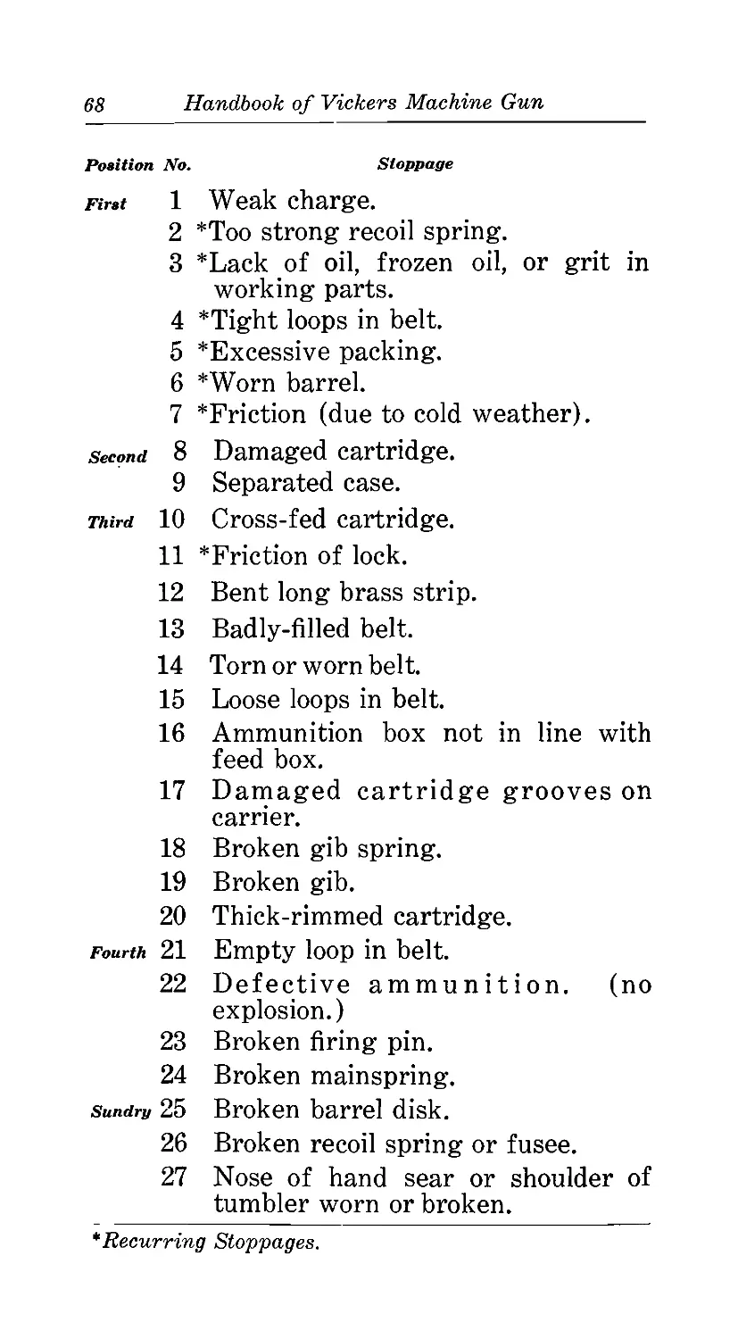
The bore of a machine gun is subject to
two kinds of fouling: 1—powder fouling; 2
—metal fouling.
26
Handbook of Vickers Machine Gun
Powder Fouling:
Due to the high pressure that is generat-
ed in the bore, powder gas is forced into the
pores of the steel. The powder fouling thus
caused cannot be removed in one cleaning. In
the field where the necessary materials are
not at hand and the gunner is limited to the
use of sperm oil, it will be necessary to clean
the bore each day for 10 days after the gun
has been fired.
To Clean Properly The Bore Of A Gun:
The materials necessary are: Caustic soda,
hot water, cleaning rod, patches, and Cosmo-
line. With a hot 20% solution of caustic soda
the bore should be swabbed out with patches
until all evidence of powder residue is remov-
ed. The rod should then be dried and a dry
patch used to dry the bore. When the bore is
thoroughly dried, use enough cosmoline to
color a patch passing this through the bore
several times. A brass rod should be used.
In order to leave the bore smooth and free
from lint, the last time the cosmoline patch is
withdrawn the rod should be turned in the
grooves while a constant pull is exerted.
The chamber should then be cleaned with
the aid of a stick or rod, after which a very
thin coat of cosmoline should be applied.
The following day the bore should be clean-
ed again as just described. Ordinarily, if the
work has been properly done, 2 thorough clean-
ings 24 hours apart will be sufficient to pre-
serve the bore. It should be inspected, how-
ever, for a few days thereafter.
If soda is not available the best substitute
is hot water. Since the water in the water
jacket is invariably hot when firing is complet-
ed, hot water can always be obtained.
Handbook of Vickers Machine Gun
27
Metal Fouling:
Metal fouling is caused by the lands strip-
ping from the bullets small particles of cupro-
nickel. Metal fouling usually appears about 4
inches back from the muzzle on the lands.
It never collects in such quantities as to affect
the accuracy of the machine gun. Ordinarily,
after it has collected to a certain amount, con-
tinued firing will blow the metal fouling out.
If, however, a gun is to be packed away
for a considerable length of time, the metal
fouling must be removed. In itself it is not
dangerous to the bore, but it covers up pow-
der fouling which will pit the bore.
To remove metal fouling, either the swab-
bing solution or the standard solution given in
the Ordnance Handbook may be used for a
temporary or permanent cleaning respectively.
A suitable solution may be made as follows:
4 spoonful ammonia persulphate.
J spoonful ammonia carbonate.
1 pint 28% ammonia.
I pint water.
To be certain that this solution will not
attack the steel of the bore, Vs spoonful potas-
sium bichromate may be added.
The spoon referred to is the one issued by
the Ordnance Department with the mess kit.
The solution is made by pulverizing the am-
monia persulphate and ammonia carbonate,
and adding the ammonia and water. If the
potassium bichromate is used it is then added
to the solution.
To Use The Solution:
Place a cork in the chamber. Stand the
barrel on end; pour the solution into the muzzle
until the bore is full. Do not permit the solu-
tion to remain in the barrel longer than 2 hours.
A small quantity of sperm oil may be put on
top of the solution to prevent the ammonia
28
Handbook of Vickers Machine Gun
from evaporating and rusting the muzzle.
While the solution is acting, small bubbles will
rise to the surface and the solution will gradu-
ally turn blue. When the bubbles stop ris-
ing to the top, it is time to remove the solu-
tion. After the solution is removed, the bore
should be thoroughly cleaned and oiled.
Packing The Barrel
Asbestos packing is applied at the muzzle
and breech ends of the barrel to prevent leak-
age from the water jacket. The amount of
packing must not be excessive, since the fric-
tion caused thereby will interfere with the ac-
tion of the mechanism; the proper amount can
only be determined by experience and trial.
Packing is issued in cords of several strands
one yard in length; one strand should be ap-
proximately sufficient to pack either the muzzle
or the breech end; it should be well saturated
with oil from the oil can before being applied.
To Pack The Breech End
Withdraw the barrel from the water jacket.
Start the center of the strand at the center of
the groove of the barrel; wind the packing
alternately on each side pressing it toward the
center with a screw-driver, knife blade or thin
piece of wood. When the groove is completely
filled, the packing should project just above
the surface of the barrel. Fasten the loose
ends by inserting them beneath the coils.
To Pack The Muzzle End
With the barrel in the water jacket wind
the packing around outer surface of muzzle
and at the same time push the coils in with
any blunt instrument which may be available.
When the seat is filled, screw in the follower
or muzzle gland and test friction of the recoil-
ing parts. If there is too much friction, re-
move one or two coils of packing.
Caution: If this front packing is too tight, the accuracy
of the machine gun will be materially influenced.
Abbreviated Memory Table Of Points To Be Attended To Before,
During, And After Firing
1 BEFORE FIRING DURING FIRING AFTER FIRING
In The Field On Target Range
Oil. Watch water supply. Unload; clear belt from feed box. Unload; clear belt from feed box and release mainspring.
Barrel disk to be screwediBelt not pulled, on tight. , Release mainspring. Oil bore and barrel disk.
Test recoiling parts. Temporary cessation, oil and change belt, etc. Clean bore. Run off water.
Weigh recoil spring. Ammunition box up and in line. Fill water jacket. Sort live cartridges from empty cases.
Examine barrel, spare parts, etc. Belts refilled. Oil. On Return To Shelter Clean gun thoroughly;
See to water supply and See clamps of trail and legs that water jacket is full, not loose. Fill reservoirs, if necessary. remove and oil outside of barrel.
Oil in reservoirs, etc. Clean bore, when possible. Weigh recoil spring. Clean and repair belts;
Examine belts. Action to be taken in Examine barrel disk. Full belt. Half load and press thumb- check spare parts. Oil.
very cold weather. Examine tripod. . piece. See ammunition is up. See water is up. Pack gun; write gun report. Clean tripod.
29
30
Handbook of Vickers Machine Gun
Stripping And Assembling
No time limit will be imposed; ability to
teach correctly how a part should be stripped
will form the basis of all stripping examina-
tions.
Points For Instructors
1 —Be fore attempting to withdraw
screwed axis pins, make certain that threads
of screw are fully unscrewed.
2—When replacing screwed axis pins do
not use force; the threads will engage without
using unnecessary pressure. If this rule is not
observed the threads (which are extremely
fine) will become so burred that it will be
impossible to replace the pin.
3—When raising rear cover do not
throw it upwards, but lift it. It is quite easy
to strain it on its hinges. Before lowering, see
that the lock is correctly in the gun.
4—Before closing front cover, see that
feed box is correctly in position, and that
front cover catch is raised.
5—When using combination tool to un-
screw barrel disk, be careful not to burr
threads of screw.
6—Do not jerk the chain when remov-
ing parts secured by chains; chains get broken
and the part eventually lost.
7—With reasonable care, defects and
breakages in machine guns should be of ex-
tremely rare occurrence. They are mostly due
to neglect of ordinary precautions.
8—Direct hammer blows must never fall
on any part of the gun. Wood must always
be placed over the part to receive blows from
hammer or mallet.
Handbook oj Vickers Machine Gun
31
Sequence Of Stripping Gun
1. Sleeve.
2. Barrel disk.
3. Feed box.
4. Lock.
5. Handle block pin.
6. Outside plate filling piece.
7. Roller bracket.
8. Recoil spring and box.
9. Fusee.
10. Recoil plates.
11. Barrel.
Sequence Of Stripping Lock
1—Cock the lock.
2—Side lever pin and pin bushing.
3—Side lever.
4—Lifting levers.
5—Carrier.
6—Release the mainspring.
7—Tumbler pin.
8—Tumbler.
9—Hand sear pin.
10—Hand sear.
11 —Mainspring.
12—Firing pin.
13—Safety sear.
Caution: If the mainspring is to be released
when out of the gun, care should be taken:
To see that the carrier is fully raised.
To keep the fingers away from under the
tail of the tumbler.
Detailed Stripping
Sleeve
Remove locking pin from sleeve with hand
or with the assistance of a screwdriver. Turn
sleeve to the left one-third of a turn and
remove to the front.
32 Handbook of Vickers Machine Gun
Barrel Disk
Unscrew barrel disk wijth combined
spanner.
Feed Box
Release front cover catch, raise front
cover, place fingers in feed box and remove
it by pulling directly upward.
Caution: In stripping, if the feed box
holds, pull the roller handle to the rear;
the feed box can then be removed easily.
Lock
Raise rear cover, pull roller handle to
the rear, grasp lock between thumb and
fingers of the left hand and raise it. Give it
one-sixth turn to the right or left and remove
from crosshead.
Caution: In stripping, if the lock holds
and will not rise, move the roller handle for-
ward or backward until it becomes free.
Handle Block Pin
Unscrew handle block pin and pull it out.
Outside Plate Filling Piece And
Roller Bracket
Lower handle block to the rear and remove
filling piece and roller -bracket.
Recoil Spring And Box
With the heel of the left hand strike the
rear of the spring box and drive it forward
until it clears the front studs; grasp the
recoil spring in the left hand; with the
index finger of the right hand separate the
recoil spring hook from the fusee link (front).
Caution: In stripping the recoil spring
box, keep the box as close to the left side
Handbook of Vickers Machine Gun
33
plate as possible until the recoil spring and
fusee link are separated.
Fusee
Turn fusee to the rear until it stops; then
pull it out to the left.
Caution: In stripping, if the fusee holds
and cannot be removed easily, hold the roller
handle down and turn the fusee to the rear.
Recoil Plates
Grasp the roller handle and pull recoil
plates, crank, barrel, etc., to the rear until
the recoil plates clear the side plates. Take
the right recoil plate in the right hand, the
left recoil plate in the left hand, and remove
them from the barrel trunnions.
Barrel
The barrel is withdrawn straight to the
rear, care being taken not to burr the threads
on the muzzle of the barrel.
Sequence Of Assembling Gun
1. Barrel.
2. Recoil plates.
3. Outside plate filling piece.
4. Roller bracket.
5. Handle block pin.
6. Fusee.
7. Recoil spring and box.
8. Lock.
9. Feed box.
10. Barrel disk.
11. Sleeve.
Sequence Of Assembling Lock
1—Safety sear.
2—Firing pin. (Until safety sear notch
engages).
3Jf Handbook of Vickers Machine Gun
3—Hand sear and pin.
4—Tumbler and pin.
5—Carrier.
6—Lifting levers.
7—Side lever.
8—Side lever pin bushing and pin.
9—Push shank of side lever down on
safety sear, pull hand sear to rear, press
tumbler down, and insert mainspring.
Detailed Assembling
Barrel
The barrel is partially inserted in the gun
with the trunnions projecting beyond the rear
of the side plates.
Recoil Plates
The right recoil plate is assembled to the
barrel trunnion; the left recoil plate to both
the barrel trunnion and the crank shaft at the
same time. The parts thus assembled are
moved forward into position in the gun.
Caution: In assembling the barrel, be
certain that the rear of the barrel is up against
the trunnion block. If it is in rear of this
position, the lower feed lever is apt to be
assembled in front of the lug on the left recoil
plate. To seat fully the barrel, in most cases,
it will be necessary to raise the crosshead in
order to clear the bottom plate slide.
Outside Plate Filling Piece
The outside plate filling piece is grasped
with the left hand, index finger on the spring
box stud, and placed in position.
Roller Bracket
The roller bracket is grasped with the
right hand, index finger on the roller, and
placed in position.
Handbook of Vickers Machine Gun
35
Handle Block Pin
The handle block is raised into position,
the handle block pin is inserted with the left
hand and screwed home.
Fusee
The fusee is grasped between the thumb
and index finger of the left hand, the thumb
being on top of the links which are wound
around the fusee. The fusee is inserted in the
crank shaft, then turned forward into the
correct position.
Note: The roller handle must be on the
dead stop.
In assembling and stripping avoid a cross
strain on the fusee links.
Recoil Spring
The recoil spring box is grasped with the
left hand so that the recoil spring hook can
be held between the thumb and index finger.
The fusee link is grasped between the
thumb and index finger of the righthand. The
recoil spring hook and fusee link are then
connected. The right hand then grasps the
rear of the spring box and the left hand the
front. The spring box is pulled forward and
connected with the spring box studs.
Lock
The crosshead is raised with the left hand;
the lock is grasped in the right with the
bottom of the lock to the front, placed on the
crosshead, and given one-sixth turn. The roller
handle is then pulled to the rear and the lock
lowered gently into position. The roller handle
is released, the rear cover fastened, and the
trigger pushed.
36
Handbook of Vickers Machine Gun
Feed Box
The feed box is grasped in both hands, the
slide being held to the left by the thumb of
the left hand. It is then lowered into position
and the front cover fastened.
Barrel Disk
The barrel disk is screwed on by hand and
then tightened with the combined spanner.
Sleeve
The sleeve held in the right hand is
placed over the follower, and given one-sixth
turn to the right; the locking pin is inserted.
Changing Worn Or Bulged Barrels
The necessity of saving water in the water
jacket entirely depends upon prevailing con-
ditions. In Egypt, Mesopotamia, East Africa,
etc., every drop of water is of value. Again,
in the heat of battle water may not be readily
available; time also may be of the utmost
importance. On the other hand, if the gun is
being stripped, in barracks or billet, there is
no necessity to save the water provided a
further supply can be easily obtained.
It has been found necessary, in order that
men may realize the importance of saving
water, to introduce the following methods of
changing a barrel.
To Remove Barrel And At The Same Time
Save Water:—
(a) —Unload.
(b) — Remove lock.
(c)—Remove muzzle attachment;remove
barrel disk.
(d)—Remove feed box.
(e) — Remove recoil spring, fusee and links.
Handbook of Vickers Machine Gun
37
(f)—Remove handle block pin; lower
handle block.
(g)—Remove outside plate filling piece
and roller bracket.
(h)— Remove elevating pin and depress
muzzle of gun.
(i)— Have an assistant hold a plug, such
as a rag, ball of waste, etc., over
muzzle of barrel.
(j)— Withdraw recoiling parts. As the
barrel is withdrawn the assistant fol-
lows the barrel with the plug and
holds it over the hole in the water
jacket cap through which the barrel
has been withdrawn,
To Assemble A Spare Barrel:
Place a plug in muzzle of new barrel. Re-
verse the above operations. When the muzzle
of the new barrel passes through the hole in
the water jacket cap, the assistant may remove
both plugs.
Alternative Method:
Proceed as for above, except that the water
may be drained into the water box from the
hole in the front of the water jacket cap. As
the water jacket has to be refilled after new
barrel is seated, this method will require more
time.
Caution: — Care must be exercised in removing
and assembling the barrel in order not to disar-
range the front and rear packing; very fre-
quently, in assembling the new barrel, the front
packing is carried out by the muzzle; if this
occurs remove packing from muzzle and repack.
Demonstration
One of the most profitable methods of
instructing men in the nomenclature and the
38
Handbook of Vickers Machine Gun
functions of the various parts of the gun is by
giving demonstrations.
An outline for such demonstration is given
below.
1. A short description of the gun covering the
following:
a—Type.
b—Ammunition used.
c—Cooling system.
d —Locking mechanism.
e—Feeding mechanism.
f—Forces that operate the mechanism.
g—Adjustments.
2. Essential parts.
a—Non-recoilmg parts.
b—Recoiling parts.
c—Detailed operation of the gun in firing.
(1) —Preliminary.
(a) — Loading the gun.
(b) — Firing the gun.
(c)—Unloading the gun.
(2)—Backward movement.
(a)—Action of the gas.
(b) — Recoil spring.
(c) — Feed box.
(d)—Roller handle.
(e) —Unlocking of the mechanism
(f) — Cocking the lock.
(g)—Carrier.
(3) —Forward movement.
(a)—Recoil spring.
(b)—Feed box.
(c) —Fusee.
(d)—Carrier.
(e) — Locking of the mechanism.
(f) — Roller handle.
These various operations can best be
illustrated as follows:
Reduce the spring tension and remove the
sleeve.
Handbook of Vickers Machine Gun
39
1—By pushing against the barrel disk the
following can be illustrated:
a—The recoil of the barrel.
b—Action in the feed box.
c—The rotation of the roller handle.
d—The unlocking of the mechanism.
e—The relative recoil of the barrel and
lock.
f—Why the lock recoils farther than the
barrel.
g—The function of the recoil spring.
h—That the inertia of the lock and roller
handle is required to complete the backward
movement.
2—Strip the gun. Assemble barrel, recoil
plates, and lock outside of the gun, and illus-
trate the following:
a—That when the roller handle is down
the toggle joint is on a dead center.
b—That the safety sear is not released
until the mechanism is locked.
c—That it is through the recoil plates that
the lock is held to the barrel.
d—That the only way in which the mech-
anism can be unlocked is by the rotation of
the roller handle.
e—That the action of the carrier support-
ing springs is to hold the carrier up when
the mechanism is locked and during the first
part of the movement to the rear.
f—That when the roller handle is rotated
to the rear the shank of the side lever lifts
the tail of the tumbler and cocks the lock.
(The pressure of the tumbler on the shank of
the side lever causes friction when the roller
handle is approximately vertical. A small
amount of friction or pressure at. this point
should not be mistaken for excessive friction
in the mechanism).
40
Handbook of Vickers Machine Gun
Detailed Outline For Inspection
The following outline for inspecting a Vick-
ers Machine Gun should be kept in mind and
followed as closely as possible.*
1 —Completely strip the gun and inspect
each part for defects.
2—Pack the barrel, assemble the gun cor-
rectly, oil all bearing surfaces, and fill the
water jacket.
3—Apply tests.
I—Completely Strip The Gun And
Inspect Each Part For
Defects
Front Sight:
Straight.
Not loose.
Rear Sight:
Half-nut should hold slide in any position.
Elevating screw should work freely.
Aperture disk should not be bent.
Pivot spring should hold aperture disk in
position.
Movable base should have no lost motion.
Muzzle Attachment:
Front disk cap should be clean.
Front disk should fit tightly.
Sleeve should not bind.
Locking pin should not pull out easily.
Follower should fit snugly.
Barrel disk should be tight.
*The inspection contemplated in this outline neces-
sitates a thorough knowledge of the sizes and shapes oj
the various parts. When in doubt, compare the part in
question with one that you know is correct.
Handbook of Vickers Machine Gun Ц
Water Jacket, Etc.
Inspect stem.
Inspect water plug (front).
See that front plug screw is in position.
Inspect water plug (rear).
Feed Box:
Slide should work freely.
Test all springs for strength.
There should be no dirt or friction in feed
box.
Lock:
Test safety sear by releasing hand sear.
Test hand sear by releasing safety sear.
There should be no friction.
Test firing pin by releasing sears to see how
far the point protrudes through the carrier.
Test gib and gib spring with cartridge.
Strip lock and inspect parts.
Rear Cover:
See that catch holds.
Trigger bar should work smoothly.
Handle Block, Etc.
See that oil is in the reservoirs and that
the caps are screwed home.
Test trigger lever spring for straightness
and strength.
The safety catch should be tested to see
that it will hold the trigger.
Threads on handle block pin should be in
good condition.
Crosshead And Crank:
Adjusting nut should be screwed down
tight.
See that crank pin fastening link is in po-
sition.
Jf.2 Handbook of Vickers Machine Gun
Recoil Spring And Fusee:
Test the strength of the recoil spring.
See that the spring box fixings are present.
See that the spring box is not bent.
Inspect fusee links for breaks and fusee
for burrs.
Recoil Plates, Etc.
Plates should be straight.
Carrier supporting springs should be stiff.
There should be no burrs on the recoil
plates.
Side Plates:
Side plates should be straight and free
from burrs.
Side cams should be smooth and free from
burrs.
Bottom Plate Slide, Etc.
There should be no friction.
Slide should open and close properly.
See that the bottom plate slide catch holds
the slide when set.
Barrel:
Should be copper coated.
Should be free from obstruction and clean.
Chamber should be round.
Bore should be inspected for corrosion.
See that the barrel fits close to the
trunnion block when it is fully forward.
Tripod:
Tripod head should fit snugly.
Traversing clamp, when tight, should stop
lateral motion.
Elevating screws should be in good con-
dition.
Handbook of Vickers Machine Gun
43
Elevating and trunnion pins should be free
from burrs.
Leg and trail clamps should be in good
condition.
II—Pack. The Barrel, Assemble The Gun
Correctly, Oil All Bearing
Surfaces, And Fill The
Water Jacket
1—Pack rear of barrel.
2—Oil and assemble barrel, recoil plates,
and crank.
3—Pack front of barrel and screw follow-
er in tight.
4—Screw barrel disk on tight and oil it.
5—Assemble front disk, front disk cap,
sleeve, and locking pin. (Oil front disk cap).
6—Test friction of recoiling parts. It
should be less than 4 pounds. (Measured by-
placing the spring balance over the roller han-
dle axis and pulling to the rear with the recoil
spring removed).
7—Assemble roller bracket, outside plate
filling piece, and handle block pin.
8—Assemble fusee and recoil spring.
9—Oil and assemble lock.
10—Oil and assemble feed box.
11—Oil front and rear cover hinge pin
and catches.
12—Oil recoil plates and side cams.
13—Oil tripod where needed.
III. Apply Tests
1—Depress the muzzle of gun to see that
outer steam tube slides freely. (It will fre-
quently become necessary during firing, in
which the muzzle is elevated or depressed, to
tap gently the water jacket in order to cause
44 Handbook of Vickers Machine Gun
the outer steam tube to function properly and
prevent loss of water).
2—Weigh recoil spring. It should be from
8 to 10 pounds when the roller handle is 1 inch
above the dead stop. (Without muzzle attach-
ment, 6 to 8 pounds).
3—Test lock for excessive head space,
a—Remove recoil spring and box.
b—Remove lock and place washer over
crosshead.
c—Replace lock; pull roller handle to
the rear.
d —Place dummy on carrier opposite
firing pin hole. (Use dummy made
from live cartridge that is not dis-
torted; on the range live cartridge
may be used).
e—Raise carrier and hold it in its high-
est position.
f—See that barrel is forward.
g—Push roller handle forward slowly.
h—The roller handle should stop short
of the dead stop and a slight tap
should be necessary to force it
down. (If the roller handle goes
onto the dead stop freely, another
washer is needed).
i—If a slight check is felt in carrying
out (h), the washer is not needed.
4— Inspect belts to see that the points of
the cartridges are even with the ends of the
brass strips. Turn a few cartridges around in
the belt to see if they fit too tightly.
5—With gun properly assembled pull
roller handle to rear until ears of carrier drop
into notches in side cams. Place thumb against
the rear of the roller handle and fingers
on the front near the lower end of roller handle;
move barrel and recoil plates backward and for-
ward several times to see that the recoiling
parts function properly.
Handbook of Vicers Machine Gun £5
PART TWO
GUN DRILL—DISMOUNTED
Drill with a gun has two objects; one is
to develop in the men speed in handling the
gun and motions that are distinct and
accurate, the other is to develop discipline
which is the most essential part of a soldier’s
training. In carrying out the directions given
in Part II the instructor must bear these two
objects in mind. The members of the gun
squad should be watched closely and required
to perform every movement with exactness
and precision, and should never be permitted to
slouch or slur any movement during the drill. It
is impossible to develop fast team work within
the squad unless every movement is watched
and disciplined exactly. When the squads have
become proficient in handling the gun in
various gun drills and team work has been
developed, instruction should be given with the
men wearing the gas mask; after which it
should be given with the men blindfolded to
accustom them to handling the gun by touch
rather than by sight.
Only elementary drills are given in this
Handbook', the more advanced drills leading to
proper tactical execution of field orders and
the details of markmanship being found else-
where. The drills are divided into:
1—Elementary Drill.
2—Combined Drill.
3—Rough Ground Drill.
46
Handbook of Vickers Machine Gun
Elementary Drill
1. Elementary Drill consists of:
a—Forming the gun squad,
b—Posting the gun squad,
c—Examining the gun.
d—Mounting the gun.
e—Dismounting the gun.
f—Loading for automatic fire.
g—Loading for single shots,
h—Laying the gun.
i—Firing the gun.
j—Suspending fire.
k—Unloading the gun.
1—Ceasing fire.
m—Going into action,
n —Coming out of action.
2. Teaching Elementary Drill.
a—Equipment required for each
squad: gun; tripod; two belts and
dummies; two ammunition boxes;
tool-box; rectangular target.
b—The gun and tripod will be placed
in line on the ground about three
paces apart and about thirty yards
from the target.
c—Tripod on the left, clamps tight,
strap around trail and buckled,
traversing clamp sufficiently tight
to prevent the tripod head from
coming out of the socket or swing-
ing laterally when the tripod is
being carried, legs and trail to the
rear, tripod head over trail.
d—Gun on the right, muzzle pointing
to the front, stem in, bottom plate
slide closed, covers locked, handle
block pin screwed home, head of
Handbook, of Vickers Machine Gun 47
handle block pin vertical, rear
sight leaf lowered with slide set
at 600, barrel disk tight, sleeve
secured with locking pin, trigger
pushed and mainspring released,
oil reservoir cap screwed home,
water jacket filled*, oil reservoirs
filled.
e—Tool box or gunner’s pouch (if
issued) beside the gun.
f—Ammunition boxes about three
paces in rear of the interval be-
tween gun and tripod.
To Form The Gun Squad
The squad consists of 1 corporal and 8
privates; it is equipped with two carts, one
carrying the gun and one the ammunition.
The corporal carries a wire cutter; No. 3, a
pick; Nos. 4, 5, and 6, shovels; and No. 8, a
hand ax. The corporal commands the squad,
No. 1 is the gunner, No. 2 is the loader, Nos.
3 and 4 are ammunition men, Nos. 5 and 6
are spare men in charge of the belt filling
station, and Nos. 7 and 8 are the drivers.
The instructor indicates the place of for-
mation, about 8 paces in rear of the gun and
commands: Fall In. At this command, the
squad assembles, as in the “School of the
Squad. ’ ’ (M. G. D. R.) The instructor then com-
mands: Call Off. Commencing at the right,
the men call off alternately, front and rear
rank: 1, 2, 3, 4, etc. (Here caution the squad
that No. 1 will repeat all subsequent verbal
orders; No. 2 will repeat all signaled orders).
*In Elementary Drill water will not be placed in
the water jacket; when the stage of combined drill has
been reached, the water Jacket will be filled.
48 Handbook of Vickers Machine Gun
To Post The Gun Squad
At the command Posts, No. 1 will
repeat the order; all men move at double
time to positions as follows: No. 1 will
pass behind the gun and fall in on the left of
the tripod; No. 2 will fall in on the right of
the gun; No. 3 will fall in on the left of the
ammunition boxes; Nos. 4, 5, and 6 will fall in
about 5 paces in rear of No. 3, No. 4 on the
right.
As soon as No. 1 gets to his position, he
will attend to the points mentioned under “c,
Teaching Elementary Drill”; and in addition,
will see that the elevating and trunnion pins
are properly in position, and that both the
elevating screws are equally exposed.
No. 2 will attend to the points mentioned
under “d, Teaching Elementary Drill”, and
will inspect the tool box to make certain that
the contents are complete. (The inspection of
the tool box is made twice only during the
drill; once by the first No. 2 and once by the
last No. 2).
No. 3 will examine each belt and see that
it is correctly placed in the box; he will then
close the box. The catch on the ammunition
box must be toward the front. He will then
report: Correct to No. 2, who will report:
Gun And Ammunition Correct to No. 1,
who in turn will report: All Correct (or
otherwise) to the instructor.
To Examine The Gun
Before proceeding with the drill the in-
structor commands: Examine The Gun.
Each man then examines the gun and equip-
ment as follows:
No. 2 examines the gun and sees that:
1—The follower is screwed home.
2—The barrel disk is tight.
Handbook of Vickers Machine Gun Jf.9
3—The stem and water plugs are in.
4—The feed box is seated and the
front cover catch turned down.
5—The sight is in working order.
6—The lock is seated and the main-
spring is released.
7—The bottom plate slide is closed.
8—The oil reservoirs are full.
No. 1 examines the tripod and sees that:
1—The legs are closely folded, strap
around trail.
2—The traversing clamp is tight.
3—The pins are in and turned down.
4—The elevating screws are exposed
the same amount.
No. 3 examines the belts and sees that:
1—The cartridges are correctly placed
and aligned.
2—The belt is packed correctly in the
box and that the lid is fastened.
As each man finishes his examination he
reports to the instructor.
To Mount The Gun
The instructor will now bring the squad to
the left of the spot where the gun is to be mount-
ed, in order that they may see all movements
clearly and listen to explanations. He will then
act as No. 1 himself giving and repeating the
command: Mount Gun. He will point out a
spot about 30 yards from the target where the
gun is to be mounted.
1. Preliminary Detailed Operation.
At the command Mount Gun, No. 1
grasps the tripod with his right hand at
the balance, steadies it with his left hand, and
moves forward at a run to the designated
position. He then places the tripod on the
ground, unclamps the legs, swings them to
50 Handbook of Vickers Machine Gun
the front and clamps them in such a position
that the socket will be upright and at a con-
venient elevation. He then sits down behind
the tripod and withdraws the elevating pin with
the right hand and the trunnion pin with the
left hand. While adjusting the tripod, the
left forearm must be supported by the left
thigh and the clamps should, if possible,
both be manipulated with the right hand.
As soon as the tripod is nearly in position,
No. 2 pushes the bottom plate slide to the rear,
grasps the right handle grip with the left
hand, passes the right hand over the water
jacket, lifts the gun so that the barrel will be
pointing to his right under his right arm,
moves forward at a run, and takes position on
the right of the tripod and facing it.
He must reach the position at the moment
No. 1 is removing the elevating and trunnion
pins. He places his right foot between the
legs of the tripod and kneels on the left knee
supporting the weight of the gun on the
right knee. With the assistance of No. 1 he
places the gun in position, inserts the trunnion
pin, and turns it down. He then removes the
stem and lies down opposite the feed box of
the gun placing the ammunition box in position
in line with the feed box.
No. 1 assists No. 2 in adjusting the gun
to the tripod and inserts the elevating pin.
After inserting the elevating pin, No. 1 will
at once level the gun, adjust the traversing
clamp to see that it is moderately tight* (for
the two and one-half mil tap), and take the
correct holdf; eyes must be directed toward
the target.
*The traversing clamp should be just tight enough
to allow the gun to traverse approxima tely two and one-
half mils to the right or the left 2vhen the handle block
is tapped by the heel of the hand. 7 See note page 51.
Handbook of Vickers Machine Gun 51
No. 3 takes 2 ammunition boxes and
places them in reach of No. 2; he then returns
to his original position. The catches of boxes
should be to the front; the boxes must not
be placed in such a position that No. 2 will
knock them over as he lies down. The ammu-
nition must be at hand by the time No. 2 re-
moves the stem.
2. Mounting In Low Position
When the men have made sufficient prog-
ress in the previous lessons, they will be
taught to mount the gun with the tripod in the
low position. It will be explained that the
low position may be necessary when only low
or no cover at all is available.
The instruction will be divided into three
methods.
First Method: When, before mounting,
the tripod is adjusted in the usual way, i. e. the
trail set at a suitable angle for the normal
sitting position.
At the command Mount Gun, No. 1 will carry
the tripod to the position indicated, place it on
the ground, lie down on the left of it with his
feet to the front, and loosen leg and trail
clamps. He will then adjust the legs by rolling
the tripod to the left and right, and raise the
socket about 1 inch from the ground; keeping
it upright he will clamp leg and trail clamps,
the trail clamp first. He will remove the
elevating and trunnion pins.
No. 2 will open the bottom plate slide and
carry the gun to the position in the usual way,
but just before he reaches it he will place the
^The correct method of holding the gun is with the
third and little fingers around the grips; middle fingers
behind the safety catch; index fingers on top of handle
block; and thumbs resting lightly on thumbpiece. When
gun is “loaded and laid" the safety catch will be
lifted with the middle fingers. (Note applies to page 50)
52
Handbook of Vickers Machine Gun
right arm under, instead of over, the water
jacket. He will then lie down and, assisted by
No. 1, will adjust the gun on the tripod. No. 1
will return the trunnion pin; No. 2 will return
the elevating pin and pull out the stem.
No. 3 will bring up the ammunition boxes
in the usual way. When the gun is mounted,
No. 1 will lie with both legs on the left of the
tripod, right foot crossed over the left, his
head and shoulders being supported by the
legs of No. 2. The left leg of No. 2 should be
well doubled up to give support to the neck of
No. 1.
When the gun is mounted, it should be
noted that the feet themselves and not the
tubular portions of the trail and legs are resting
on the ground; that the bottom of the socket is
at least 1 inch clear of the ground; and that
the clamp of the trail does not interfere with
the elevating handwheel.
Second Method: When, before mounting,
the trail of the tripod is set at an angle suit-
able for the lowest position.
The trail will be clamped at a suitable
angle, after which the instruction will follow
the same lines as in the first method. It will
not be necessary to loosen the clamp of the
trail on reaching the position.
Third Method: When, before mounting,
the trail of the tripod is set at an angle suit-
able for the lowest position and when, in
addition, the two legs, instead of being along-
side the trail, are swung forward, upward,
and backward pointing in the air.
The instruction will follow the same lines
as in the second method.
Handbook of Vickers Machine Gun
53
3. Critique.
When the gun is mounted and the Nos. 1,
2, and 3 are in position, the following points
should be criticized by the instructor:
1—Actions of numbers 1, 2, and 3 until
the gun is mounted.
2—Trail pointing to the rear and aligned
on the target.
3—Feet of legs and trail on ground
(necessary for rough ground drill).
4—Clamps of legs tight.
5—Socket upright.
6—Traversing clamp tight (this must be
tested by the instructor in the same
way that No. 1 tests it).
7—Pins in properly and turned down.
8—Elevating screws equally exposed.
9—Tripod a suitable height for the firer.
10—Gun level.
11—Stem out.
12—Front cover locked.
13 —Bottom plate slide open.
14—Rear sight leaf down, slide at 600
yards.
15—No. 1 sitting or lying and holding the
gun correctly.
16—No. 2 lying down with head below the
level of the gun, gunner’s pouch (if
issued) slung across his shoulders.
17—Ammunition box in correct position.
18—No. 3 lying down in rear and to a
flank.
When the instructor criticizes, faults
should be pointed out in such a manner that
all the squad benefits from the criticism.
54
Handbook oj Vickers Machine Gun
To Dismount The Gun
1. Preliminary Detailed Operation.
At the command Dismount Gun, No.
1 removes both pins, carries the tripod at a
run back to its original position, replaces both
pins, clamps the legs alongside the trail, and
lays the tripod on the ground on the left
of the gun. In folding the legs he first
loosens the clamps allowing the tripod to
collapse, next seizes the tripod head with both
hands and with a sharp upward, forward, and
downward movement folds the legs. He
then tightens the clamps, aligns the tripod
head over the trail, and lies down on the left
of the tripod.
No. 2 passes the ammunition box to No.
3, lifts the gun from the tripod, replaces the
stem before leaving the gun position, and
runs back to the point designated. Before
placing the gun on the ground he will close
the bottom plate slide and reset the sight at
600 yards.
No. 3 goes forward at a run to the
gun position and brings back both ammunition
boxes to the point designated.
At the beginning of this drill it is well to
divide the action of dismounting the gun into
two parts, the dismounting of the tripod being
mastered first by all members of the squad
after the instructor has shown how it is dis-
mounted. When all of the men have made
reasonable progress with the tripod, the
instructor will then continue the instruction in
dismounting the gun.
2. Dismounting From Low Position
The gun will be dismounted in the usual
way, except that all movements prior to carry-
ing the gun and tripod to the rear will be
carried out by crawling.
Handbook of Vickers Machine Gun
55
3. Critique
After the gun and tripod have been com-
pletely dismounted, the instructor will hold
a critique covering the points mentioned above
and following the general form of “3. Criti-
que” under “To Mount The Gun.”
To Load The Gun Fok
Automatic Fire
1. Automatic Fire. 2. Load.
The instructor first demonstrates the
duties of No. 1 and No. 2.
At the command Load, No. 1 holds the
roller handle in its rearmost position with the
right hand and advances his left hand to the
left of the feed box ready to grip the tag of
the belt.
No. 2 opens the ammunition box, holds
the end of the belt with his forefinger (right
hand recommended) on the brass tag at the
point where it joins the fabric and pushes the
tag of the belt through the feed box as far as
possible.
No. 1 grips the tag, then pulls the belt
through the feed box as far as possible and
releases the roller handle. He again pulls the
roller handle to the rear pulling the belt to
the left a second time as far as possible; he
again releases the roller handle. The gun is
now loaded for automatic fire; No. 1 resumes
his hold on the gun.
To Load For Single Shots
1. Single Shots. 2. Load.
At the command Load, No. 1 pulls the
roller handle to its rearmost position; No. 2
passes the tag of the belt through the feed
box; No. 1 holds the roller handle in its rear-
most position with the right hand, grasps the
56
Handbook of Vickers Machine Gun
tag of the belt with the left hand and pulls it
straight through the feed box as far as pos-
sible. He then releases the roller handle and
without pulling the belt, he again pulls the
roller handle to its rearmost position and re-
leases it. The gun is now loaded for single
shots; by bringingthe roller handle to the rear
after each shot without pulling the belt, the
gun will fire single shots,. To change from
single shots to automatic fire at any time, it
is necessary to pull the roller handle to its
rearmost position, pulTthe belt to the left, and
release the roller handle. The gun being loaded
for automatic fire, single shots may be fired
by first pulling roller handle once without
pulling belt.
To Lay The Gun
The command is given: 1. Range 800 (850
etc.). 2. Right (left) 2 (3etc.). (this being
the deflection in points of windage to the right
or left). 3. At (such an object). At the first
command, No. 1 raises the rear sight leaf
(unless the range announced is: Battle Sight,
when the battle sight will be used) and moves
the slide until it is set at the line on the leaf
corresponding to the range given. He then
sets the deflection on the wind gauge and taps
the gun over until the correct direction is ob-
tained; after which he elevates or depresses
the muzzle until the aim is correct. Should a
fairly large change in direction be necessary,
No. 1 will order No. 2 to loosen the clamp;
he will swing approximately on the target,
order No. 2 to tighten the clamp, and then lay
accurately by tapping. It is most important
that, while tapping the gun or manipulat-
ing the elevating wheel, the correct hold
Note: It is an advantage to combine the adjustment
of sights with laying the gun; therefore, instruction in
aiming should be given prior to instruction in laying
the gun.
Handbook of Vickers Machine Gun
57
be maintained. As soon as the aim is correct,
No. 1 grasps both handle grips, places his
thumbs on the thumbpiece, releases the safety-
catch, and by calling: Ready, orders No. 2 to
raise his hand. Care must be exercised to
hold the gun when No. 1 moves his head to
one side to allow the aim to be viewed by the
instructor.
To Fire The Gun
The gun being mounted and loaded, or as-
sumed to be loaded, at the command or signal
Commence Firing, No. 2 will tap No. 1 lightly
on the back and call: Fire. No. 1 will instantly
press in the trigger. He must press it in as
far as possible and must not disturb the aim
or hold while doing so. It must be pressed by
a quick and even movement of the thumbs.
The eyes must be directed at the target; any
tendency to look down at the trigger or
through the sights must be stopped.
To Suspend Firing
To suspend firing, the instructor blows a
long blast of the whistle or commands or sig-
nals: Suspend Firing. No. 2 taps No. 1 light-
ly on the back and calls: Suspend Fire. No.
1 releases the pressure on the trigger. The
gun is held loaded and in a position of readi-
ness for an instant resumption of fire.
No. 1 should check his aim and correct his
laying, if necessary; he continues his observa-
tion of the target, the aiming target, the place
at which the target disappeared, or at which
it is expected to reappear.
To Unload
At the command Unload, No. 1 will lower
the sight leaf, if it be raised, with the left
58
Handbook of Vickers Machine Gun
hand; at the same time he will pull the roller
handle to its rearmost position and immediate-
ly allow it to fly forward, repeating this
motion at least three times. He will then
press the upper and bottom pawls of the feed
box with the right hand, the upper pawls be-
ing pressed with the thumb and the bottom
pawls with the finger, taking care to keep the
hand clear of the entrance to the feed box.
No. 2 will withdraw the belt and pack it care-
fully in the box. No. 1 will then release the
mainspring by pressing the thumbpiece.
To Cease Firing
The instructor commands or signals: Cease
Firing. No. 2 will tap No. 1 lightly on the
back and call: Cease Fire. No. 1 releases the
pressure on the trigger. Nos. 1 and 2 execute
unload, except the withdrawal of the belt from
the feed box.
To Go Into Action
When the men have made sufficient prog-
ress in the foregoing lessons, they will be
exercised in combining them and going into
action. Three aiming targets will be pointed
out on the rectangular target by the instructor,
one of which should be a triangle; one, a circle;
and one, a square.
The instructor will announce the range and
target; he will then command or signal: Action.
The gun will be mounted, loaded, and laid. As
soon as No. 2 holds up his hand, the aim and
sight setting will be checked; then the
various points taught in the earlier lessons
will be criticized. No. 2 must not be allowed
to adjust the sights. Each man must per-
form the duties laid down for him in the earlier
lessons.
Handbook of Vickers Machine Gun
59
To Take The Gun Out Of Action
Three methods of taking the gun out of
action will be explained; the particular method
to be employed depends upon circumstances.
The gun commander will decide which method
to use.
The First Method: When the gun is in
action and cover exists which is too far away
to permit the gun being dragged the whole
way.
In this method the gun is unloaded
and dismounted at the position each man
carrying his own load*. In the field No. 3 might
not be required; Nos. 1 and 2 then carry the am-
munition boxes. For instructional purposes in
this method, the instructor will give the cau-
tionary words: No Cover Available before
the command: Out Of Action.
The Second Method’. When the gun must be
moved to cover before it is dismounted. The gun
will be unloaded, but the belt will be left in the
feed box; then the gun will be dragged back
to the cover the men avoiding unnecessary
exposure; there the dismounting of the gun
will be completed. For instructional purposes
the instructor will give the cautionary words:
Cover Close Behind before the command:
Out Of Action.
The Third Method: When cover is presumed
to exist too far away to permit dragging the
gun to cover but close enough to avoid the
*A convenient way to carry the tripod for any dis-
tance is with it arranged on the shoulders so that the
trail lies flat down the back while the legs are clamped
at an angle of abou t forty-five degrees with the horizontal.
60
Handbook of Vickers Machine Gun
necessity of dismounting in the open. Two
methods are open to the gun commander; the
two man load, or the three man load.t
With the two man load the gun will be
unloaded by Nos. 1 and 2; No. 1 will rise and
seize hold of the trail and left leg; No. 2 will
rise and seize hold of the right leg, the right
handle grip, and the ammunition box.
If the distance is great, the three man
load might be preferable. No. 3 is signaled:
Assemble. No. 1 seizes the trail with his left
hand; No. 2 the right leg with his right hand
and the ammunition box with the lefthand
(belt still in the feed box); No. 3 seizes the
leftdleg with his left hand.
Combined Drill
The main purpose of elementary drill is
to train Nos. 1 and 2 in their mechanical duties
within the squad; practically no mention has
been made of the duties of the other members
of the squad or the additional equipment; the
tool box or gunner’s pouch, if issued, is re-
quired only as a necessity. In combined drill
and subsequent drill, which must be progres-
sive, complete units and the complete equip-
ment are required; the corporal should com-
mand the squad; Nos. 3 and 4 should form a
short chain of supply; the other members of
t The procedure laid down for the two and three man
loads will be taught, but the squad should be warned that
there are variations that may be preferred by individ-
uals. The end to be attained in all cases is speed. For
instructional purposes the instructor will give the cau-
tionary words: Two (three) Man Load before the com-
mand: Out Of Action. He will point out where the cover
is supposed to exist.
Handbook of Vickers Machine Gun
61
the squad should be held in the immediate
rear at the belt filling station to fill belts and
replace casualties; the steam condensing de-
vice should be used; the water box should be
filled with water; two ammunition boxes and
the tool box should be with each gun; and in
the earlier lessons, the rectangular target
should be utilized.
The training of the organization, there-
fore, must be carried out as prescribed in the
Machine Gun Drill Regulations; should these
drill regulations or this handbook be silent as
to the duties of any particular man in any
particular situation, organization commanders
will use their own judgment as to the proper
procedure to carry out the spirit of these regu-
lations in training their organizations.
Instruction in machine gun signals will
have been given before combined drill is com-
menced; these signals should thereafter be
used whenever possible.
Combined drill is best taken up by platoon
commanders and best carried out with four or
more guns. The drill should foster competition
between squads.
Preliminary to this platoon drill the gun
squads should be combined to form sections
and these sections should be required to go
through the exercises given under “Gun
Drill”. In addition to the regular exercises
signals should be used to train the men in
their execution, drill of the section being one
step farther advanced than that of the squad.
Exercises should be progressive in nature.
After the section has become proficient, the
platoon should take up the following subjects
which are taught practically:
1—Execution and delivery of fire orders.
The latter is taught by calling on in-
dividual members of the organization
62
Handbook of Vickers Machine Gun
to take the place of the platoon com-
mander.
2- The designation and recognition of
targets and aiming targets.
3—Combined sights.
4—Distribution.
5 -Searching.
6—Stoppages.
7—Replacement of breakages.
8—Replacement of casualties.
Noncommissioned officer instructors
should be utilized to take time, correct mis-
takes, and report on the performance of each
detail. During combined drill, out of doors,
all men should be in the prone position, when-
ever this is possible.
First Lesson: The platoon should be drilled
in going into action, both in the normal
position and in the lowest position. Fire
orders, the replacing of casualties, and changes
in targets and sight settings should be drilled.
Second Lesson: Orders for distributed fire,
searching fire, and combined sights should be
introduced in addition to the points mentioned
in the first lesson.
Third Lesson: The supply of ammunition
and water, replacing breakages and remedying
stoppages, as well as the points dealt with in
the first two lessons, should be drilled. This
drill should also be executed in full field equip-
ment with anti-gas appliances worn by the
entire platoon.
Rough Ground Drill
1—Taught in detail to individual gun
squads.
2—The equipment required will be the
same as used for combined drill, with the excep-
tion that rectangular targets are not required.
Handbook of Vickers Machine Gun
63
3- The object of the drill is to train the
organization in placing the gun in action on
sloping ground. Throughout the drill the gun
must be mounted on a steep slope engaging
targets in the following locations: (1) down
hill; (2) up hill; (3) horizontally to the right;
(4) horizontally to the left.
The instructor in selecting ground for this
drill must actually choose sloping ground from
which service targets at a reasonable range
can be seen.
First Lesson:
1—The Instructor will demonstrate the
manner in which the tripod is mounted on all
kinds of slopes to fire in all directions; he will
show how No. 1 and No. 2 should adapt their
own positions to the ground.
2—He will then mark positions for the
gun and each member of the squad will be
trained in mounting the tripod.
The gun will not be mounted until all
men have made reasonable progress in mount-
ing the tripod.
3—He will then demonstrate the duties
of No. 2 by mounting the gun on the tripod
to fire in any direction. All men should be
trained in mounting the gun on the tripod.
4—The Instructor will then show how
Nos. 3 and 4 should make use of ground
formations to obtain cover and conceal the
lines of approach.
Second Lesson:
1—The gun, tripod, etc. with Nos. 1, 2, 3,
and 4 .will be in a position of readiness not
more than 10 yards from the selected gun
Note: It is often more convenient after the tripod has
been mounted, but before the tripod head is swung around
in the direction of the target, to have the gun mounted
and then swung around.
61f
Handbook of Vickers Machine Gun
position. The remaining men will be sent
out in the direction of the target from 100
yards to 200 yards from the selected gun posi-
tion; they will criticize the movements of
Nos. 1, 2, 3, and 4 while going into action.
Having marked the position, the instruc-
tor will designate a target giving the range and
command: Act ion. When No. 2 raises his hand
to indicate that the gun is in position, the re-
mainder of the squad will be called in and the
following points will be criticized:
a—Whether there was any unneces-
sary exposure while the gun was
being brought into action.
b—The mounting of the tripod with the
trail down hill.
c—Whether the tripod had to be altered
after the gun was mounted.
d —Positions adopted by Nos. 1 and 2
from the view point of fire, execu-
tion, exposure, and comfort.
e—Position of the ammunition box
to insure correct feed.
f—Position of No. 3 with a view to mini-
mum exposure, facility of supply,
and communication with the gun.
g—Position of No. 4 from the same
view point.
h—All the usual points which are criti-
cized during elementary drill.
2—When the men have made sufficient
progress in the above, they should be trained
in adjusting, before mounting, the position of
the trail in order that the socket will be up-
right when the tripod is mounted. When very
little alteration of the trail is necessary after
the tripod is mounted in the position, the squads
may be said to be well on the way toward pro-
ficiency.
Handbook of Vickers Machine Gun 65
The Instructor must keep clearly in mind
the fact during rough ground drill that no at-
tempt is made to introduce tactical measures;
the only object is so to train the men that they
will be able to mount the gun quickly, cor-
rectly, and without undue exposure on any
kind of ground.
PART THREE
STOPPAGES and IMMEDIATE
ACTION
Stoppages
Stoppages in the automatic action of the
gun during firing may be classed under two
main headings:
1. Temporary, which are due to;
a—Failure of some part of the gun of
which a duplicate is carried.
b—Faulty ammunition.
c—Neglect of points before or during
firing.
d—Ignorance on part of gun squad.
2. Prolonged, which are due to failure of
some part that cannot, as a rule, be
remedied by the detachment under fire
or without skilled assistance. These
necessarily put the gun out of action for a
more or less prolonged period.
Upon the knowledge and training of the
detachment depends the rapidity with which
“temporary” stoppages can be remedied.
66
Handbook of Vickers Machine Gun
Preparation Of Stoppages For
Instructional Purposes
In order that the men may obtain a high
standard of training in dealing with stoppages
and apply the correct immediate action, it is
essential that the instructor should prepare
the stoppages accurately.
General Instructions:
1—Taught to instructors and their
assistants organized as squads.
2—Squad should be seated on right side
of the gun to make certain that the
roller handle and the actions of the
instructor are the more clearly seen
by all.
3—Whenever it is necessary to release
the mainspring, with the lock out of
the gun, the carrier must be held up
to its highest point to ensure that the
firing pin hole will be opposite the fir-
ing pin.
4—The instructor should detail a member
of the squad to perform the immediate
action for each stoppage when pre-
pared.
5 - A target will be designated to the squad
at the commencement of instruction;
this will remain the target during the
drill.
6—The sight leaf will always be raised dur-
ing stoppage instruction.
Material Necessary For Teaching Purposes
1 —Gun and tripod.
2—Belt and dummy cartridges.
3—Bulged dummy.
4—Dummy cartridge with battered rim.
5—Front portions of separated cases. (One
that will remain in the chamber and one
Handbook of Vickers Machine Gun
67
that is securely telescoped on a dummy
cartridge in order to ensure that it will
not remain in the chamber).
6—Tool box.
7—Covering for roller handle.
How Taught:
1—The instructor, seated at the left of
the gun, will prepare the stoppage.
Example—Weak Charge.
a—Perform half loading motions.
b—Draw roller handle back until ears
of carrier engage with notches of
side cams.
c—Pull belt.
d —Cover roller handle.
e—Alter elevating wheel slightly.
f—Swing gun around to firer and
tighten traversing clamp.
g—Remove covering of roller handle.
The firer now commences immediate
action.
h—After firer has pressed thumbpiece,
on completion of immediate action,
the instructor verifies the aim.
2—The squad will now prepare this stop-
page; instructor will criticise.
3—Instructor will question squad. When
proficient, he will proceed to teach
the next stoppage in a similar manner.
Summary Of Causes Of Stoppages
Each instructor should have a card on
which is printed or written the stoppages
indicated below. In testing a man in prepar-
ing stoppages he hands the card to him and
orders him to prepare, say, No. 11. It is
important that the stoppages ordered to be
prepared should not be ordered in numerical
sequence.
68
Handbook of Vickers Machine Gun
Position No. Stoppage
First 1 Weak charge.
2 *Too strong recoil spring.
3 *Lack of oil, frozen oil, or grit in
working parts.
4 *Tight loops in belt.
5 *Excessive packing.
6 *Worn barrel.
7 *Friction (due to cold weather).
Second 8 Damaged cartridge.
9 Separated case.
Third 10 Cross-fed cartridge.
11 *Friction of lock.
12 Bent long brass strip.
13 Badly-filled belt.
14 Torn or worn belt.
15 Loose loops in belt.
16 Ammunition box not in line with feed box.
17 Damaged cartridge grooves on carrier.
18 Broken gib spring.
19 Broken gib.
20 Thick-rimmed cartridge.
Fourth 21 Empty loop in belt.
22 Defective ammunition. (no explosion.)
23 Broken firing pin.
24 Broken mainspring.
Sundry 25 Broken barrel disk.
26 Broken recoil spring or fusee.
27 Nose of hand sear or shoulder of tumbler worn or broken.
* Recurring Stoppages.
Handbook of Vickers Machine Gun
69
Stoppages Not Included In Immediate
Action Table But Which May Be In-
dicated By An Unusual Posi-
tion Or Action Of The
Roller Handle
1—Nose Of Hand Sear Or Shoulder Of Tumbler
Worn Or Broken. (Runaway Gun)
The gun is not controllable through the
trigger. It will fire the moment the roller
handle touches the dead stop the second time
duringloading, or, if the defect occurs during
firing, it will not stop firing when pressure on
the trigger has been released.
To remedy proceed as follows:
a—Throw filled end of belt over feed box;
this should result in a bad fault in feed,
thereby stopping the firing.
b—Pull roller handle onto roller, return
filled end of belt to correct side of feed
box, unfasten front cover catch, and
raise front cover.
c—No 2 will lift feed box to allow recoil-
ing parts to move forward. He will
release pawls and withdraw the belt
from feed box until the first cartridge
is about in line with the right side of
tripod head; he then will replace the
feed box.
d—Lower and secure front cover; let the
roller handle fly forward so as to fire
the cartridge on the face of the carrier
(should there be one). The lock can
now be changed with safety. Reload,
relay, and open fire.
e—If no spare lock is available, group the
cartridges in the belt. Half load, lay,
pull roller handle onto roller, belt to
left, take proper hold, and release roller
handle. At end of each group (e) is
repeated.
70
Handbook of Vickers Machine Gun
To prepare proceed as follows:
Give command: Load. As soon as the
roller handle touches the dead stop for the
second time, call: Gun Firing. Then command:
Suspend Firing. When firer releases his pres-
sure on the trigger, call: Gun Still Firing.
2—Broken Recoil Spring Or Fusee:
The gun will stop firing; the roller handle
will be found to be resting on the roller.
To remedy proceed as follows:
a—Return roller handle to dead stop.
b—Remove spring box and spring.
c—Remove spring from tension screw (if
fusee, remove it from recoil spring
hook).
d—Re-assemble new spring or fusee, re-
place spring box, relay, and open fire.
To prepare proceed as follows:
a—Half load.
b—Remove spring box and recoil spring.
c—Replace spring box with recoil spring
detached from fusee.
d —Pull roller handle onto roller.
e—Pull belt to left.
3. Broken Barrel Disk.
It is most probable that the gun will stop
firing with the roller handle in the third posi-
tion.
If, however, the broken fragments have
fallen out of the sleeve, a succession of first
positions will probably be the result.
It sometimes happens that the roller
handle will stop in the second position; usually
the lock cannot be raised until the recoiling
Note: A broken fusee or spring can be replaced from
spare parts.
Handbook oj Vickers Machine Gun 71
parts move forward by the removal of frag-
ments in the sleeve.
To remedy proceed as follows:
a—If feed box slide functions smoothly,
pull roller handle onto roller, clear face
of carrier, hang the lock, draw back
recoiling parts, and call: Barrel Disk.
b—No. 2 will release belt from pawls and
withdraw it until cartridges are clear
of feed box. He will then remove the
sleeve, remove broken fragments, if
any, and replace barrel disk and
sleeve. *
c—If no spare barrel disk is available, the
firer will reduce tension of recoil spring
to 5 pounds, load, relay, and commence
firing.
To prepare proceed as follows:
a—Half load.
b—Hang lock.
c—Draw back recoiling parts with the
right hand and insert a small pad or
ball of waste about one inch in thick-
ness between the barrel disk and the
front disk.
d —Pull roller handle onto roller and allow
it to move slowly forward.
How To Prepare A Belt Of Stop-
pages For The Range
General Remarks
1—Live cartridges must never be tam-
pered with, except when they are be-
ing prepared to give a separated case.
2—Stoppages must be varied.
*To prevent accident great care must be exercised
by the firer to hold the roller handle back while No. 2
is working at the muzzle.
7%
Handbook of Vickers Machine Gun
3—Do not prepare too many stoppages;
about 16 cartridges should be fired be-
tween different stoppages.
4—During preliminary instruction the
instructor acts as No. 2.
Suggested Method Of Preparing A Belt
Of Stoppages
Cartridges In Belt Stoppage Remarks
Ito 20 (1) Too strong (1) recoil spring. The recoil spring tension must be so adjusted before firing that by reducing it about 1 lb. the gun will fire correctly.
30 (2) Empty loop. (2) Have an empty loop in the belt.
46 (3) Misfire. (3) Place in belt one dummy cartridge.
61 (4) Damaged cartridge. (4) Place in belt one bulged dummy cartridge.
76 (5) Bad fault in feed. (5) Mark belt in some manner. When this part of the belt is approach- ing feed box, the instructor pulls a cartridge about a quarter of its length out of the loop.
91 (6) Separated case. (6) Place a filed car- tridge in the belt.
106 (7) Broken fir- ing pin. (7) Place in belt two dummy car- tridges.
Handbook of Vickers Machine Gun 73
107 (8) Worn nose of (8) The spare lock
hand sear. used for the
rectification of a
broken firing pin
should be so pre-
pared that the
gun will fire auto-
matically as soon
as the roller
handle touches
the dead stop for
the second time
when the gun is
being loaded.
Immediate Action
General Remarks
1—It is essential that all that is neces-
sary for correct immediate action be avail-
able.
2—The immediate action neces-
sary to remedy temporary stoppages is
indicated by the position of the roller handle
which may stop in one of four positions, known
as the first, second, third, and fourth posi-
tions.
3—The instructor prepares the stoppage
he desires as described in “Preparation Of
Stoppages”.
4—While the stoppage is being prepared
the firer should be seated on the ground behind
the gun with head turned aside; when
covering is removed from roller handle, he per-
forms the immediate action.
5—Immediate action is not considered
complete until the gun has been relayed and
fired. _____
Note: The above belt of stoppages can be repeated for
a second firer. Where many fir er s are being given in-
struction, it may be necessary to reduce the number oj
cartridges between stoppages.
74 Handbook of Vickers Machine Gun
6—After the immediate action is com-
pleted, the instructor checks the aim and
explains any errors.
7—The rear cover should never be
opened—or closed—with the lock home.
8—If the lock cannot be drawn back,
open the front cover and force down the
carrier.
9—To afford the best training in immedi-
ate action each stoppage should be prepared
to simulate a stoppage during actual firing.
10—As proficiency is attained training
should be carried out in darkness or with
the firer blindfolded.
11—The instructor must not deal with
causes of stoppages during the first stages of
instruction in immediate action.
12—The rear and front covers must al-
ways be correctly fastened when lowered
after immediate action.
13—A lock must never be changed with
cartridges on the face of the carrier.
14—The instructor must insist on cor-
rect reloading and relaying.
15—Fire must be at once opened after
immediate action, unless orders to cease fire
have been given.
16—Should it ever be necessary to re-
lease the mainspring with the lock out of the
gun, it should be done with the carrier raised
so.that the firing pin hole is opposite the
firing pin.
17—Whenever a temporary stoppage
necessitates the use of the spare lock, feed box,
etc., the part which has been replaced should
be repaired as soon as possible in order to make
it again available as a reserve.
Handbook of Vickers Machine Gun
75
How Taught
See “Preparation Of Stoppages”
1—Instructor should give definition of
immediate action. (The automatic and im-
mediate application of a probable remedy
for a stoppage, based on the position of the
roller handle.)
2—Demonstrate the four positions of
the roller handle.
3—Teach thoroughly each position of
roller handle as follows:
a—Instructor prepares stoppage and
demonstrates immediate action
for first position.
b—Explains:
(1) Pull roller handle to rear, pull
belt, release roller handle.
(2) Relay on aiming target and
open fire.
c—Each member of squad per-
forms immediate action. Instruc-
tor criticises.
d—Instructor questions squad.
When all are proficient, the instructor
teaches the second phase of the first position
in a similar manner. Exactly the same method
and sequence must be used when teaching the
other positions of the roller handle.
Immediate Action Table
The following table of temporary stop-
pages affords a clear indication of the method
to be employed in teaching the practical side
of mechanism. Column 1 shows the four
positions of the roller handle when the gun
stops firing. The first three positions may vary
slightly. These positions, which afford a ready
indication of the correct immediate action to
76
Handbook of Vickers Machine Gun
be performed, must be recognized clearly
before the instruction proceeds.
At this stage the squad should not be
required to know what these four positions
indicate. This will be explained later when
the probable causes of the stoppages are being
taught.
Column 2 deals with a detailed description
of the immediate action to be performed by the
firer (sometimes with the aid of an assistant,
designated hereafter as No. 2) as soon as the
position of the roller handle has been noted
after the gun has stopped firing.
Column 3 deals with the probable causes
of these stoppages; it is of utmost importance
that the instructor does not proceed to this
stage, until he is assured that every immedi-
ate action can be correctly and immediately
performed without the slightest hesitation.
A thorough knowledge of the causes of
temporary stoppages will not only afford a
practical knowledge of the working of the gun,
but will also be an aid in the discovery of
the cause of any unusual breakdown which
may occur.
In column 4 is explained the method for pre-
venting the recurrence of certain stoppages,
the cause of which may be only temporarily
cured by the immediate action. It will some-
times be possible to carry out these preven-
tives in two or three minutes; at other times
their execution may cause the gun to be out
of action for a longer period; but, in either
case, no skilled assistance or special appliances,
other than those carried with the machine gun
organization, will be required.
Column 5 explains methods by which the
various temporary stoppages can be simulated
for instructional purposes. It is unnecessary
to teach these methods of preparation to the
Handbook oj Vickers Machine Gun 77
machine gunner, but every instructor must
have a thorough knowledge of this column in
order to teach the machine gunner the cor-
rect immediate action for any temporary
stoppage.
Immediate Action Probable Cause Prevention Of Recurrence Method Of Preparation
Handle
© 1. Pull roller handle onto the roller, pull the belt to the left, and re- lease the roller handle. 2. If stoppage recurs, The carrier has not dropped. This may be due to: 1. Weak charge. 2 (a)Too heavy 1. Immediate action cures. 2. Attend to 1. Perform half the loading motions; pull the roller handle slowly back until the ears of the carrier have en- gaged with the notches in the side cams. Release the roller handle and pull the belt to the left. 2. To simulate a recur-
Position . repeat 1 and lighten re- coil spring by 3 half- turns. recoil spring. (b)Lack of oil in recoiling parts. (c)Grit in recoil- ing parts. (d) Excessive packing. (e)Worn barrel. (f) Tight loop in belt. (g) Frozen oil. points before and during fir- ing. rence of stoppage: Pull handle slowly until the carrier drops into the notches in the side cams. For range purposes: Increase the weight of the recoil spring.
78
Position Of Roller
Handle
Immediate Action
Probable Cause
Prevention Of
Recurrence
I
Method Of Preparation
(h) Friction due
to cold weath-
er.
Second Position.
1. Pull the г о 11 e r 1.
handle to the rear and
call out: Defective Car-
tridge Extractor, open
the rear cover, raise
lock and examine the
cartridge on the face of
the carrier. If a damag-
ed cartridge, or an un-
damaged cartridge with
the front portion of a
separated case adhering
to it, is thereon, call out:
Never mind, clear the
face of the carrier, and
reload.
(a) Damaged
cartridge.
(b) Separated j
case with 1
front portion Wote; If a succes-
fp]p<5nnnpd slon °f separated
LtJit?atupeu cases occur, extra
ОП undamag- washers must be
1. (a) Insert a bulged dum-
1. Inspect am-
munition in my cartridge as the first
belts before fir-icartridge in the belt and
line. [load.
front portion Wote; If a succes-
ed cartridge, placed on cross-
head.
Test with both
locks during ex-
amination of gun
before firing.
[load.
; For range purposes:
; Place a bulged dummy car-
: tridge in the belt.
(b) Raise cover and lift
out lock. Place a dum-
my with a separation
securely on it between the
projections of the gib. Re-
place lock, close rear cover,
and release roller handle.
Pull belt to left.
________1
Note: Use a dummy with the
front portion of a separated case
soldered on it.
Position Of Roller Handle Immediate Action Probable Cause Prevention Of Recurrence Method Of Preparation
2. If an undamaged cartridge with a portion of a separated case adhering to it is found on the carrier, clear the face of the carrier and replace the lock keeping the roller handle on the roller. Take the defective cartridge extractor and insert it in the cham- ber. Push the pin well home. Allow the lock to go forward con- trolled by hand, keep a firm pressure on the rol- ler handle, give the de- fective cartridge extrac- tor a rocking motion, withdraw the lock, strike back the handle of the 2. Separated case. Front portion re- mains in chamber. 2. Perform half loading motions, raise rear cover and lift out lock; place the front portion of a separated case over the bullet of the cartridge on the carrier and allow the lock to go slowly forward. Withdraw lock slightly to see that the portion of case remains in chamber, closerear cover, and pull belt to left. For range purposes: File a cartridge about | inch from the base, and in- sert it in the belt. Care must be taken that the cartridge is not filed too far through; there is danger of the bullet'remaining in the bar- rel.
80
Position Of Roller Handle Immediate Action Probable Cause Prevention Of Recurrence Method Of Preparation
/'"'ZZZZ©^ ЛЖj7 2/^ (<or Third Position. defective cartridge ex- tractor, withdraw it, see that the front portion of the separated case is on the defective cartridge extractor. If portion of case is with- drawn, reload; if not, repeat. 1. Slightly raise the roller handle, pull the belt to the left, release the roller handle, and then strike it down on the dead stop. 1. A cartridge is fed slightly cross- wise. 1. Examinecar- tridges in belt. 1. Perform half the load- ing motions, then pull the roller handle onto the roller, and raise the rear cover; pull the belt sufficiently to place a cartridge half way in front of the face of the carrier. Allow roller handle to go slowly forward so that it will remain in the third posi- tion; lower the rear cover gently; test roller handle.
81
Position Of Roller
Handle
Immediate Action Probable Cause Prevention Of Recurrence Method Of Preparation |
2. If stoppage recurs, oil lock and recoiling parts. 3. If 1 fails, examine feed box slide. If jamm- ed, call out: Feed Box, pull the roller handle onto the roller and hold it there. (In order to do this it may be necessary for No. 2 to force down the ears of the carrier). Unfasten front cover catch with left hand, and raise front cover to a vertical position. No. 2 raises the feed box suf- ficiently to allow the re- coiling parts to go home, releases the upper and 2. Friction of lock, etc. 3. (a) Bent or dam- aged long brass strips. (b) Badly filled belt. (c) Worn or loose belt loops. (d) Ammunition box not in line with the feed box. 2. Attend to points during firing. 3. A t te n d to points before and during fir- ing. Note: It is essential to see that the noses of bullets are even with ends of long brass strips. 2. Proceed to load, but move roller handle slowly forward the second time in order that it will remain in the third position. 3. Pull out the fourth car- tridge in the belt about half an inch. Perform half the loading motions, pull the roller handle slowly back until the ears of the carrier have engaged with the notches on the side cams. Draw the recoiling parts to the rear by forcing the knob of the roller handle forward and the tail to the rear; at the same time pull the belt to the left. Bring the roller handle onto the roller and ease forward.
82
Position Of Roller Handle Immediate Action Probable Cause Prevention Of Recurrence Method Of Preparation
bottom pawls, and withdraws the belt until the first cartridge is clear of the feed box. He then pushes the slide to the left, re- places the feed box, and rectifies the belt or car- tridges (if necessary), while the firer lowers the front cover and locks it. The firer pulls belt to left, when No. 2 is ready, and releases roller handle. For range purposes: Fill a belt unevenly, or place the box at an angle to the feed box.
83
Position Of Roller Handle Immediate Action Probable Cause Preventiou Of Recurrence Method Of Preparation
Fourth Position, \2r 4. If the slide is free, call out: Carrier and open the front cover. No. 2 forces down the ears of the carrier, while the firer pulls the roller handle onto the roller. Clear the face of the carrier and change lock. No. 2 depresses the pawls, withdraws the belt, and removes the first cartridge in the belt. Close and lock the front cover and reload. 1. Pull the roller handle onto the roller, pull the belt to the left, and release the roller handle. 4. (a) Damaged cartridge grooves on car- rier. (b) Broken gib spring. (c) Broken gib. (d) Thick rimm- ed cartridge. Note: The lock removed from the gun should be tested by No. 2 passing an empty case down face of carrier. If it jams, he passes it back to No. 3 for repairs. 1. Misfire. 4. Immediate action cures. Note: Badly filled belts are the chief cause of stoppages in the 3rd. position. 1. Immediate action cures. 4. Damage the rim of the second dummy cartridge in the belt. Proceed to load easing roller handle forward second time. For range purposes: Damage the rim of a dummy cartridge and place it in the belt. Note: This stoppage should seldom be practiced on the range, since the thickened rim may damage the grooves of the carrier. 1. Fully load with dum- my. Press trigger.
84
Position Of Roller Handle т x д „ Prevention Of j л/ n Immediate Action Probable Cause Recurrence Method Of Preparation
1 1 2. If 1 fails, change lock and reload. 3. If, when performing 1, the firer notices that more belt than usual comes through to the left, he performs the second half of the load- ing motions. 2. (a) Broken or damaged fir- ing pin. (b) broken mainspring. 3. Empty loop in the belt. (No. 2 should inform the firer when he noti- ces belt running back out of feed box). 2. Immediate action cures. 3. Inspect belts. 2. As for 1. 3. Press trigger. Insert belt in feed box until first cartridge is in line with shank of bottom pawls. For range purpose: Load with empty loop in belt.
85
86
Handbook of Vickers Machine Gun
SERIAL LIST OF COMPONENT PARTS
The Gun
4A Trunnion block.
5A Outside plate, right.
5 В Outside plate, left.
5C Side cam, left.
5D Side cam, right.
6A Elevating pin seat.
6 В Bottom plate slide.
6D Slide catch head.
6E Bottom plate slide catch.
6F Roller bracket.
6G Outside plate filling piece.
7A1 Water jacket cap.
7B Steam outlet tube.*
7C Trunnion block distance piece.
7D Stuffing box.
8A Water jacket.
8 В Outer steam tube.
8C Steam tube plug.
8D Inner steam tube.
8E Steam tube socket.
8F Water jacket trough.
9A Barrel.
10A Recoil plate, left hand.
10B Recoil plate, righthand.
11A Crank.
11В Crosshead.
11C Fusee link, rear.
11D Fusee link, front, with link pin.
12A Roller handle.
* Section A-A shews Steam Outlet Tube with its
Water Jacket Cap Hose Connection and Water Plug as
seen from the rear. The Water Jacket Cap Hose Connec-
tion is on the left side of the Water Jacket.
Handbook of Vickers Machine Gun
87
12В Dead stop plunger, (on some guns).
12 C Roller handle knob.
12D Dead stop.
12 E Dead stop bracket.
12 F Roller.
13A Lock frame.
13 В Filling piece.
13 C Hand sear.
13D Tumbler.
13E Firing pin.
13 F Safety sear.
13G Distance piece for lock frame.
13H Striker point.
14A Side lever.
14В Lifting lever, right hand.
14 C Lifting lever, left hand.
14 D Carrier.
14E Gib.
14 F Gib spring plate.
15A Handle block.
15 В Handle grip.
15 C Oil reservoir cap.
15D Reservoir cap washer.
15E Handle block oil reservoir.
15F Brush holder.
15G Brush.
16A Trigger lever.
16B Trigger pawl.
16C Safety catch.
16D Thumbpiece.
16E Handle block pin.
16F Trigger.
17A Rear cover.
17B Rear cover catch.
17C Rear cover.
17D Trigger bar.
17E Rear sight stop screw.
18A Front cover.
18E Cover guide, left hand.
18F Front cover catch bracket.
18G Front cover catch.
19A Feed box.
88
Handbook of Vickers Machine Gun
20A Bottom pawl, left hand.
20 В Bottom pawl, righthand.
20 C Bottom pawl connecting plate.
20D Feed box lever, lower.
20E Feed box slide.
20F Cartridge guide and stop.
20H Upper pawl, left hand.
20 J Upper pawl, righthand.
20K Feed box lever, upper.
21A Front sight.
21В Front sight carrier.
21D ) „ . . .
21E I Front sight carrier and cover.
23A Water plug.*
23 В Water plug top piece.
23 C Stem covering.
23D Water plug fastening link.
23 E Water plug fastening ring.
23F Water jacket cap hose connection. *
23G Stem.
23H Eyebolt.
23 J Securing S hook.
23K Securing chain (6 links).
23L Securing chain (12 links), (on some
guns).
24A Spring box.
24В Spring box fixing, front.
24 C Spring box fixing, rear.
24D Fusee.
24E Recoil spring hook.
24 F Recoil spring nut.
25A Sleeve.
25B Front disk.
25 C Muzzle attachment securing chain.
25D Securing chain ring.
25 F Front disk cap.
25G Barrel disk.
25K Follower.
* Section A-A shows Steam Outlet Tube with its
Water Jacket Cap Hose Connection and Water Plug as
seen from the rear. The Water Jacket Cap Hose Connec-
tion is on the left side of the Water Jacket.
Handbook of Vickers Machine Gun
89
26A Feed box bearing cap.
26В Locking pin.
26C Side lever pin.
26D Trigger pin.
26P Lock frame rivet.
26T Tension screw handle knob.
26U Stem covering washer.
26X Roller washer.
26Y Side lever pin bushing.
27 C Dead stop pin.
27E Trigger pawl pin.
27G Crank pin.
27U Tumbler pin.
27V Hand sear pin.
27Z Tension screw handle.
28A Handle block hinge pin.
28 В Cover hinge pin.
28 C Rear cover catch hinge pin.
28D Front plug screw.
28E Steam tube front plug.
28H Safety catch pin.
28 J Recoil spring tension screw.
28K Screw securing roller handle.
28Q Dead stop plunger stop, (on some
guns).
28R Adjusting nut.
29 C Gib spring.
29 J Mainspring.
29K Safety sear spring.
29 L Recoil spring.
29N Trigger lever spring.
BIA Trunnion pin (on some guns).
BIC Trunnion pin adjusting nut (on some
guns).
Parts Not Numbered On Plate
Bottom plate—Forms bottom of casing.
Front cover catch cap—Puri of front cover
catch.
Front cover catch snib—Part of front cover
catch.
90
Handbook of Vickers Machine Gun
Front cover catch snib spring—Part of front
cover catch.
Cover guide, right hand—Opposite cover guide,
left hand.
Muzzle gland— Used to replace follower when
muzzle attachment is not used.
Adjusting washer (thick)—On crosshead.
Adjusting washer (thin) —On crosshead.
Slide catch pin—Part of bottom plate slide
catch.
Slide catch spring—Puri of bottom plate slide
catch.
Bottom plate slide stop—Part of bottom plate
slide catch.
Crank pin fastening link—Fastens crank pin
to crank.
Upper pawl pin—Secures upper pawls.
Filling piece pin—Holds filling piece in lock
frame.
Safety sear pin—Pivot for safety sear in lock
frame.
Spring box rear stud—On outside plate filling
piece.
Spring box front studs—On outside plate, left.
Bottom pawl pin—Secures bottom pawls.
Carrier supporting spring, left hand—On re-
coil plate, left.
Carrier supporting spring, right hand—On re-
coil plate, right.
Rear cover catch spring—Bears on rear cover
catch.
Bottom pawl spring—Holds bottom pawls
against belt.
Bullet guide spring —Forms guide for nose of
bullet in feed box.
Upper pawl spring—Holds upper pawls against
belt.
Dead stop plunger spring (on some guns)
—Depressed by dead stop plunger.
Trigger bar spring—On rear cover.
Trunnion pin collar (on some guns)—On
trunnion pin.
Handbook о/ Vickers Machine Gun 91
The Rear Sight
22A 22 В 22 C 22D B2A B2C B2H B2J B2K B2M Movable base. Half-nut. Windage screw. Windage screw knob. Slide cap. Slide. Drift slide. Leaf joint pin. Elevating screw head. Leaf.
Windage screw collar—Bears against windage
screw.
Windage screw spring—Bears against wind-
age screw collar.
Elevating screw—Adjusts height of slide.
Half-nut spring—Holds half-nut against leaf.
Pivot- For aperture disk.
Pivot spring—For aperture disk.
Aperture disk—On slide.
Base spring— Holds leaf up or down.
ALPHABETICAL LIST OF COM-
PONENT PARTS OF GUN
Adjusting nut (28R)..
Adjusting washer (thick)—On crosshead.
Adjusting washer (thin)—On crosshead.
Barrel (9A).
Barrel disk (25G).
Bottom pawl, left hand (20A).
Bottom pawl, right hand (20B).
Bottom pawl connecting plate (20C).
Bottom pawl pin— Connects bottom pawls and
spring to feed box.
Bottom pawl spring- Presses bottom pawls
against belt.
Bottom plate—Forms bottom of casing.
Bottom plate slide (6B).
Bottom plate slide catch (6E).
92
Handbook of Vickers Machine Gun
Bottom plate slide stop—Part of bottom plate
slide catch.
Brush (15G).
Brush holder (15F).
Bullet guide spring—Forms guide for nose of
buUets in feed box.
Carrier (14D).
Carrier supporting spring, left hand—On re-
coil plate, left.
Carrier supporting spring, right hand—On re-
coil plate, right.
Cartridge guide and stop (20F).
Cover guide, lefthand (18E).
Cover guide, right hand—Opposite cover guide,
left hand.
Cover hinge pin (28B).
Crank (11A).
Crank pin (27G).
Crank pin fastening link—Fastens crank pin
to crank.
Crosshead (11B).
Dead stop (12D).
Dead stop bracket (12E).
Dead stop pin (27C).
Dead stop plunger (12B) (on some guns).
Dead stop plunger spring (on some guns) —
Depressed by plunger.
Dead stop plunger stop (28Q) (on some guns).
Distance piece for lock frame (13G).
Elevating pin seat (6A).
Eyebolt (23H).
Feed box (19A).
F.eed box bearing cap (26A).
Feed box lever, lower (20D).
Feed box lever, upper (20K).
Feed box slide (20E).
Filling piece (13B).
Filling piece pin—Holds filling piece in lock
frame.
Firing pin (13E).
Follower (25K).
Front cover (18A).
Handbook of Vickers Machine Gun
93
Front cover catch (18G).
Front cover catch bracket (18F).
Front cover catch cap—Part of front cover
catch.
Front cover catch snib—Part of front cover
catch.
Front cover catch snib spring—Part of front
cover catch.
Front disk (25B).
Front disk cap (25F).
Front plug screw (28D).
Front sight (21A).
Front sight carrier (21B).
Front sight carrier and cover (21D-21E).
Fusee (24D).
Fusee link, front, with link pin (11D).
Fusee link, rear (11C).
Gib (14E).
Gib spring (29C).
Gib spring plate (14F).
Hand sear (13C).
Hand sear pin (27V).
Handle block (15A).
Handle block hinge pin (28A).
Handle block oil reservoir (15E).
Handle block pin (16E).
Handle grip (15B).
Inner steam tube (8D).
Lifting lever, lefthand (14C).
Lifting lever, righthand (14B).
Lock frame (13A).
Lock frame rivet (26P).
Locking pin (26B).
Mainspring (29J).
Muzzle attachment securing chain (25C).
Muzzle gland—Used to replace follower when
muzzle attachment is not used.
Oil reservoir cap (15C).
Outer steam tube (8B).
Outside plate filling piece (6G).
Outside plate, left (5B).
Outside plate, right (5A).
94 Handbook of Vickers Machine Gun
Rear cover (17A), (17C).
Rear cover catch (17B).
Rear cover catch hinge pin (28C).
Rear cover catch spring—Bears on rear cover
catch.
Rear sight stop screw (17E).
Recoil plate, left hand (10A).
Recoil plate, right hand (10B).
Recoil spring (29L).
Recoil spring hook (24E).
Recoil spring nut (24F).
Recoil spring tension screw (28J).
Reservoir cap washer (15D).
Roller (12F).
Roller bracket (6F).
Roller handle (12A).
Roller handle knob (12C).
Roller washer (26X).
Safety catch (16C).
Safety catch pin (28H).
Safety sear (13F).
Safety sear pin—Pivot for safety sear in lock
frame.
Safety sear spring (29K).
Screw securing roller handle (28K).
Securing chain (6 links) (23K).
Securing chain (12 links) (23L). (on some
guns).
Securing chain ring (25D).
Securing S hook (23J).
Side cam, left (5C).
Side cam, right (5D).
Side lever (14A).
Side lever pin (26C).
Side lever pin bushing (26Y).
Sleeve (25A).
Slide catch head (6D).
Slide catch pin—Part of bottom plate slide
catch.
Slide catch spring—Part of bottom plate slide
catch.
Spring box (24A).
Handbook of Vickers Machine Gun 95
Spring box fixing, front (24B).
Spring box fixing, rear (24C).
Spring box front studs—On outside plate, left.
Spring box rear stud—On outside plate filling
piece.
Steam outlet tube (7B)*.
Steam tube front plug (28E).
Steam tube plug (8C).
Steam tube socket (8E).
Stem (23G).
Stem covering (23C).
Stem covering washer (26U).
Striker point (13H).
Stuffing box (7D).
Tension screw handle (27Z).
Tension screw handle knob (26T).
Thumbpiece (16D).
Trigger (16F).
Trigger bar (17D).
Trigger bar spring—On rear cover.
Trigger lever (16A).
Trigger lever spring (29N).
Trigger pawl (16B).
Trigger pawl pin (27E).
Trigger pin (26D).
Trunnion block (4A).
Trunnion block distance piece (7C).
Trunnion pin (BIA) (on some guns).
Trunnion pin adjusting nut (BIC) (on some
guns).
Trunnion pin collar (on some guns)—On trun-
nion pin.
Tumbler (13D).
Tumbler pin (27U).
Upper pawl, lefthand (20H).
Upper pawl, right hand (20J).
Upper pawl pin—Secures upper parols.
^Section A-A shows Steam Outlet Tube with its
Water Jacket Cap Hose Connection and Water Plug as
seen from the rear. The Water Jacket Cap Hose Connec-
tion is on the left side of the Water Jacket.
96 Handbook of Vickers Machine Gun
Upper pawl spring—Holds upper pawls against
belt.
Water jacket (8A).
Water jacket cap (7A1).
Water jacket cap hose connection (23F)*.
Water jacket trough (8F).
Water plug (23A) *.
Water plug fastening link (23D).
Water plug fastening ring (23E).
Water plug top piece (23B).
* Section A-A shows Steam Outlet Tube with its.
Water Jacket Cap Hose Connection and Water Plug as
seen from the rear. The Water Jacket Cap Hose Connect
tion is on the left side of the Water Jacket.