/


Теги: electrical engineering radios
Год: 1960


Текст
PRICE S1.OO
C R V S TA L
CALIBRATOR
MODEL HD-2O
ASSEMBLY AND OPERATION OF THE
HEATHKIT CRYSTAL CALIBRATOR
MODEL HD-20
SPECIFICATIONS
Frequency Coverage..........................
Crystal
Type....................................
Frequency...............................
Pin Spacing.............................
Pin Size................................
Transistor..................................
Battery Voltage.............................
Battery Life................................
Switch......................................
Dimensions..................................
Net Weight..................................
100 kc to at least 54 me, in harmonics of 100 kc.
Quartz, fundamental frequency.
100 kc ± .005%.
.486”.
.050”.
2N409.
9 volts.
6 months, normal intermittent service.
OFF-ON
2 1/2” wide x 4 1/2” high x 2 5/8” deep (overall)
9 oz.
Shipping Weight
1 lb.
Copyright 1960
Hoolh Company
10/26/62
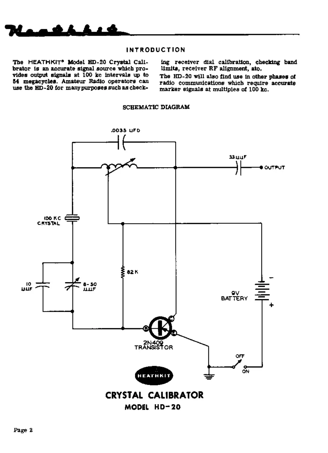
INTRODUCTION
The HEATH KIT* Model HD-20 Crystal Cali-
brator Is an accurate signal source which pro-
vides output signals at 100 kc intervals up to
54 megacycles. Amateur Radio operators can
use the HD-20 tor many purposes such as check-
ing receiver dial calibration, checking band
limits, receiver HF alignment, ato.
The HD-20 will also find use In other phases of
radio communications which require accurate
marker signals at multiples of 100 kc.
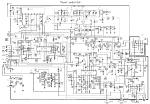
SCHEMATIC DIAGRAM
CRYSTAL CALIBRATOR
MODEL HD-20
Page 2
CIRCUIT DESCRIPTION
The Model HD-20 Crystal Calibrator is basically
a transistorized crystal controlled oscillator
employing a Junction type PNP transistor. The
Schematic Diagram shows the HD-20 circuitry
with the transistor operating in a grounded
emitter configuration,
A 100 kc tank circuit is formed by the ,003В
gfd capacitor and the slug- tuned coil. The coil
inductance is adjusted to resonate the tank circuit
for maximum output signal.
The transistor collector voltage is applied to the
tap on the tank coll. This establishes, by pro-
viding an RF ground, a point of voltage division
on the tank coil for proper positive feedback to
the base of the translator. The exact frequency
of the resulting oscillation is controlled by the
crystal which is in series with the feedback path.
At its 100 kc resonance point, the crystal pre-
sents a very low impedance to the feedback
voltage, thus anstaining oscillation at this fre-
quency.
CONSTRUCTION NOTES
This manual is supplied to assist you in every
way to complete your kit with the least possible
chance for error. The arrangement shown is
the result of extensive experimentation and
trial. If followed carefully, the result will be a
stable instrument, operating at a high degree
of depeedability. We suggest that you retain the
manual in yonr files for future reference, hoth
in the use of the instrument and for its main-
tenance,
UNPACK THE КГГ CAREFULLY AND CHECK
EACH PART AGAINST THE PARTS LIST, In SO
dotag, yon will he coms acquainted with the parts.
Refer to the charts and other Information on the
inside covers of the manual to help you identify
the components. If some shortage or parts
damage is found in checking the Parts List,
please read the REPLACEMENT section and
supply the information called for therein. Include
all inspection slips in your letter to ns.
The 62 Kft resistor sets the proper amount of
base current for a rich harmonic content in the
output signal.
The parallel combination of the 10 цц! capacitor
and the 8-50 Mgf trimmer, which ia in series
with the crystal, is used to adjust the oscillator
frequency to exactly 100 kc.
The output signal is coupled through the 33 fiyf
capacitor to a binding post located on top of the
HD-20.
Operating power is supplied by a 9-volt battery
which is connected through an OFF-ON switch
to the oscillator circuit. Due to the amount of
current required by the oscillator circuit to
provide desirable harmonics, the HD-20 should
be turned on only for actual use. This will
assure maximum battery life,
Resistors generally have a tolerance rating of
10% onless otherwise stated in the Parts List.
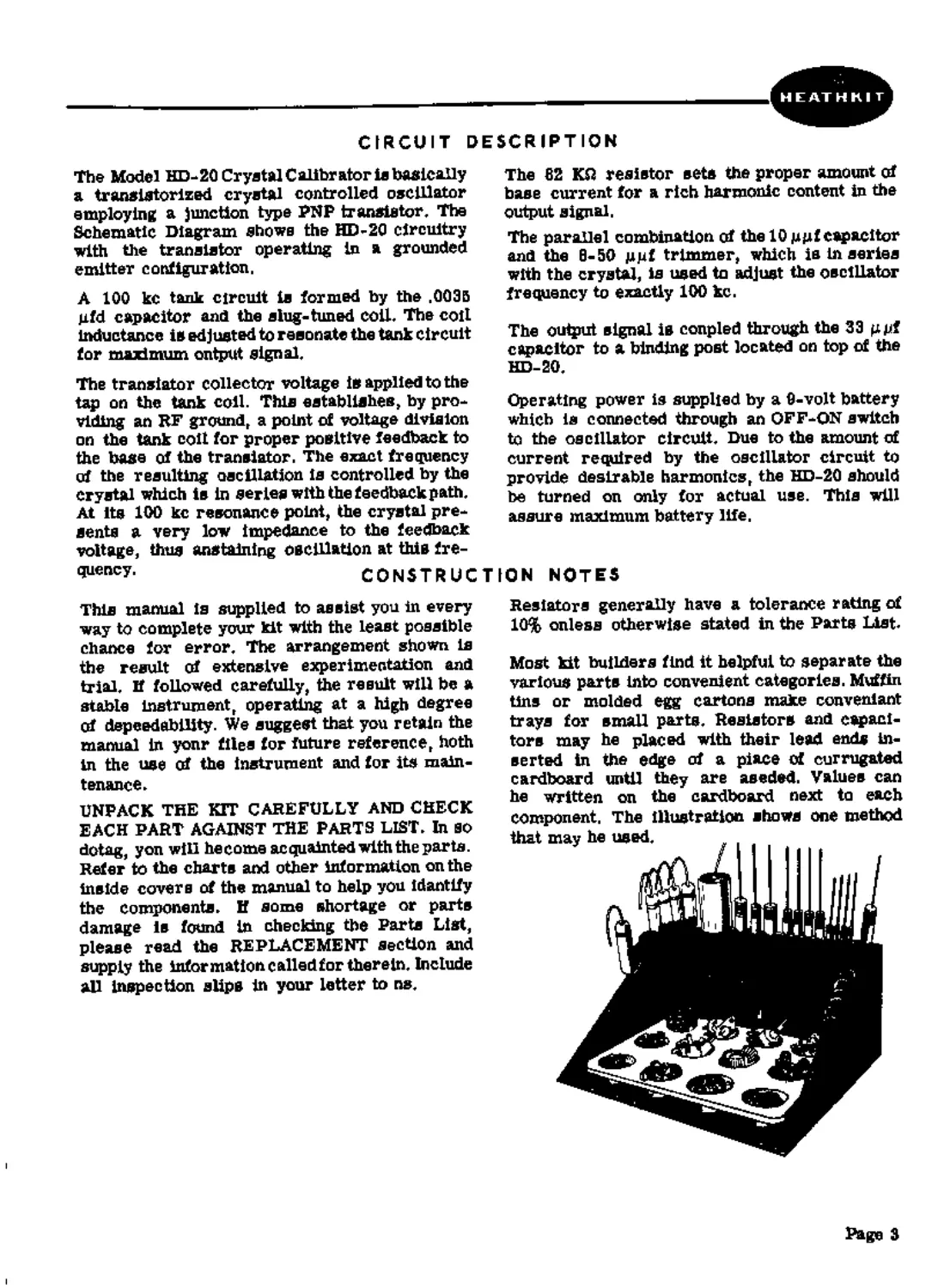
Most kit builders find it helpful to separate the
various parts into convenient categories. Muffin
tins or molded egg cartons make convenient
trays for small parts. Resistors and capaci-
tors may he placed with their lead ends in-
serted in the edge of a piece of corrugated
cardboard until they are seeded. Values can
he written on the cardboard next to each
component, The illustration shows one method
that may he used, , . . .
Page 3
PARTS LIST
PAST No, PARTS Per Kit DESCRIPTION PART PARTS NO, Per Kit DESCRIPTION
Resistor-Capacitors-Coll 1-102 1 82 КП resistor 1/2 watt (gray-red-orange) 21-3 1 10 gpf disc ceramic capacitor 21-7 1 33 gut disc ceramic Metal Parts 90-M128F 1 200-M260 1 203-M200F352 1 Cabinet shell Chassis Front panel
21-30 1 31-27 1 40-77 1 Hardware 208-2 1 250-16 1 250-34 1 250-40 10 250-56 1 252-1 10 252-3 2 252-7 1 252-15 1 253-10 1 254-1 1 354-7 8 254-0 1 259-1 1 260-10 1 capatiLui .0035 jufd disc ceramic capacitor 8-50 ^pf trimmer capacitor Coil Battery clip 6-32 x 1/8” setscrew 4-40 x 1/2*1 screw 3-48 x 1/4” screw 8-32 x 1/4*’ screw 3-48 nut 6- 32 nut 3/8»’ control nut 4-40 nut 3/8" control flat washer #8 lockwasher #3 lockwasher #4 lockwasher #6 solder lug 3/6'* control solder lug Miscellaneous 63-195 1 Switch, 2-position 73-4 1 6/16” rubber grommet 73-M16 1 length rubber gasket 76-17 2 Insulator bushing 100-M16R 1 Binding poet cap 260-29 1 Crystal clip 344-1 1 length hookup wire 404-43 1 100 kc crystal 417-27 1 2N409 translator 427-2 1 Binding poet base 432-14 1 Male battery connector 432-15 1 Female battery coanector 434-72 1 Transistor socket 434-74 1 Crystal socket 482-129 1 Knob 331-6 Solder 595-332 1 Manual A 9-volt (NEDA type No, 1600) battery should be purchased at this time for use in the completed kit.
PROPER SOLDERING TECHNIQUES
Only a small percentage of HEATH К IT* equip-
ment purchasers find It necessary to return an
Instrument for factory service. Of these instru-
ments, by far the largest portion malfunction
due to poor or improper soldering.
If terminals are bright and cleac and free of wax,
frayed Insulation and other foreign substances,
no difficulty will ba experienced In soldering.
Correctly soldered connections are essential if
the performance engineered into a kit la to he
fully realized. If you are a beginner with no
experience in soldering, la half hour’s practice
with some odd lengths ofSdre may be a worth-
while Investment.
For most wiring, a 30 to 100 watt iron or its
equivalent in a soldering gun is very satisfactory.
A Lower wattage Iron than this may not heat the
connection enough to flow the solder smoothly
over the Joint. Keep the Irca tip clean and bright
by wiping it from time to time with a cloth.
Page 4
CHASSIS WIRING AND SOLDERING
1. The wire used in the HD-20 is the type with
colored insulation (hookup wire), In pre-
paring a length of hookup wire, 1/4” of
Insulation should be removed from each end
unless directed otherwise in the construc-
tion step,
2, Leads on resistors» capacitors and similar
components are generally much longer then
they need to be to make the required con-
nections. In these cases, the leads should be
cut to proper length before the parts is added
to the chassis. In general, the leads should
be just long enough to reach their termi-
nating points.
3. Crimp or bend the lead (or leads) around the
terminal to form a good joint without re-
ly Ing on solder for physical strength. If
the wire is too large to alinw bending or If
the step states that the wire is not to be
crimped» position the wire ac thet a good
solder connection cen still be made
4. Position the work» if possible, so that gravity
will help to keep the solder where you went
CRIMP WIRES HEAT CONNECTION
5. Place a flat side of the soldering iron tip
against the joint to be soldered until it is
heated sufficiently to melt the solder.
6. Then place the solder against the heated
terminal and it will immediately flow over
the joint; use only enough solder to thor-
oughly wet the junction. It is usually not
necessary to fill the entire hole in the
terminal with solder.
7. Remove the solder and then the iron from
the completed junction. Use care not to move
the leads until the solder is solidified.
A poor or cold solder joint will usually look
crystalline and have a grainy texture, or the
solder will stand up in a blob end will not have
adhered to the joint. Such joints should be re-
heated until the solder flows smoothly over the
entire junction. In some cnses, it may be neces-
sary to add a little more solder to achieve a
smooth bright appearence.
APPLY SOLDER
ALLOW SOLDER
TO FLOW
COLD SOLDER JOINT
CONNECTION INSUFFICIENTLY
HEATED
PROPER SOLDER
CONNECTION
COLD SOLDER JOINT
CONNECTION MOVED
WHILE COO LIN О
page 5
ROSIN CORE SOLDER HAS BEEN SUPPLIED WITH THIS KIT. THIS TYPE OF SOLDER
MUST BE USED FOR ALL SOLDERING IN THIS KIT. ALL GUARANTEES ARE VOIDED
AND WE WILL NOT REPAIR OR SERVICE EQUIPMENT IN WHICH ACID CORE SOLDER
OR PASTE FLUXES HAVE BEEN USED. IF ADDITIONAL SOLDER IS NEEDED, BE SURE
TO PURCHASE ROSIN CORE (60:40 or 50-50 TIN-LEAD CONTE NT) RADIO TYPE SOLDER.
We suggest that you do the folio wing before work
is started;
1. Lay out all parts so that they are readily
available.
2. Provide yourself with good quality tools.
Basic tool requirements consist of a screw-
drive г with a 1/4" blade; a small screw
driver with a 1/8" blade; long-nose pliers;
wire cutters, preferably separate diagonal
cutters; a pen knife or a tool for stripping
insulation from wires; a soldering iron (or
gun) and rosin core solder. A set of nut
drivers and a nut starter, while not neces-
sary, will aid extensively in construction of
the kit.
STEP-BY-STEP PROCEDURE
The following instructions are presented in a
logical step-by-step sequence to enable you to
complete your kit with the least possible con-
fusion. Be sure to read each step all the way
through before beginning the specified operation.
Also read several steps ahead of the actual step
being performed. This will familiarize you with
the relationship of the subsequent operations.
When the step is completed, check it off in the
epace provided. This is particularly important
ns it may prevent errors or omissions, es-
pecially if your work is interrupted. Some kit
builders have also found it helpful to mark each
lead in colored pencil on the Pictorial as it is
added.
The abbreviation ”NS’' indicates that a con-
nection should not be soldered yet ns other
wires will be added. When the Inst wire is
installed, the terminal should be soldered and
the abbreviation "S'" is used to indicate this.
Note that a number will appear after each solder
instruction. This number indicates the number
of leads that are supposed to be connected to the
terminal in point before it is soldered. For
example, if the instruction reads, ’’Connect a
lead to lug 1 (S-2)," it will be understood that
there will be two leads connected to the terminal
at the time it is soldered.
Page 6
HEATHKIT
6-32 NUT
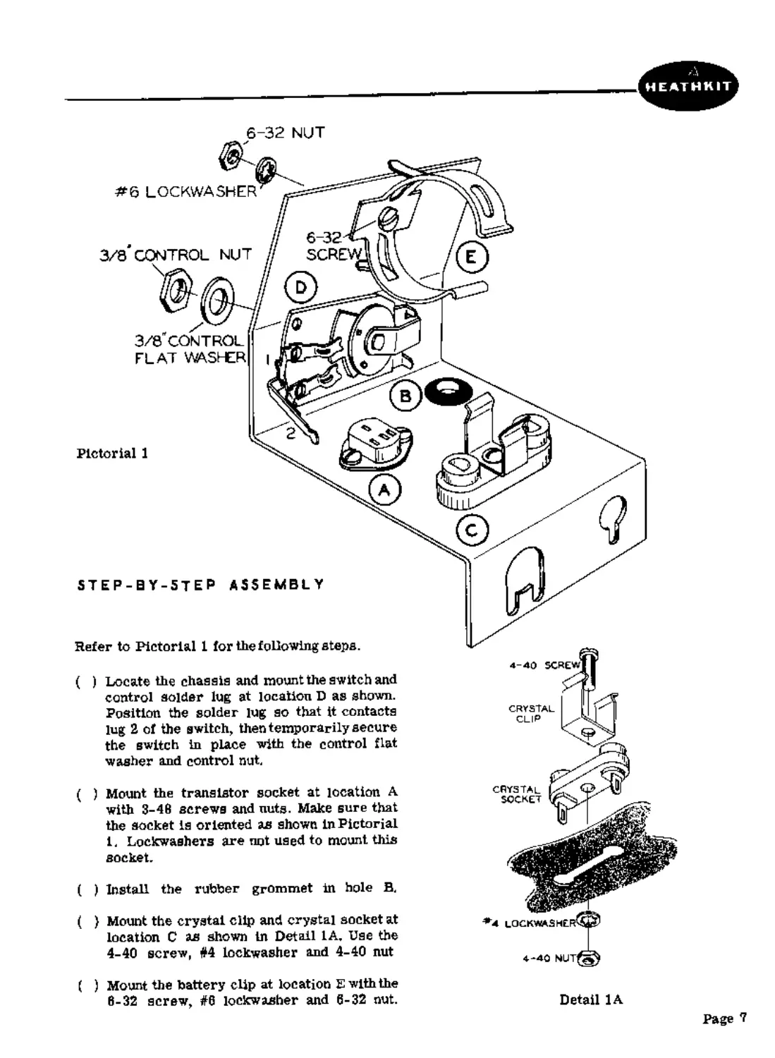
Pictorial 1
CRYSTAL
CLIP
STEP-BY-STEP ASSEMBLY
Refer to Pictorial 1 for the following steps.
4-40 screw
Install the rubber grommet in hole B.
3/8" CONTROL
FLAT WASHER
6-32
SCRE
Detail 1A
#6 LOCKWASHER
3/3 CONTROL NUT
Locate the chassis and mount the switch and
control solder lug at location D as shown.
Position the solder lug so that it contacts
lug 2 of the switch, then temporarily secure
the switch in place with the control flat
washer and control nut.
Mount the transistor socket at location A
with 3-46 screws and nuts. Make sure that
the socket is oriented as shown In Pictorial
1. Lockwashers are not used to mount this
socket.
(
CRYSTAL
SOCKET
Mount the crystal clip and crystal socket at
location C as shown In Detail 1A, Use the
4-40 screw, #4 lockwasher and 4-40 nut
( ) Mount the battery clip at location E with the
6-32 screw, #6 lockwasher and 6-32 nut.
Page 7
Pictorial 2
Page 8
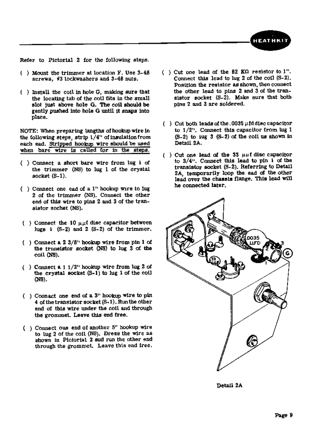
Refer to Pictorial 2 for the following steps.
( ) Mount the trimmer at location F. Use 3-48
screws, #3 lockwashers and 3-46 nuts»
( ) Install the coll in hole G, making sure that
the locating tab of the coll fits in the small
slot just above hole G» The coil should toe
gently pushed Into hole G until it snaps Into
place.
NOTE: When preparing lengths of hookup wire in
the following steps, strip l/4Tt of insulation from
each ead. Stripped hookup wire should be used
when bare wire is called for hi the steps?
( ) Connect a short bare wire from lug i of
the trimmer (NS) to lug 1 of the crystal
socket (S-l).
( ) Connect one ead of а Iм hookup wire to lug
2 of the trimmer (NS)» Connect the other
end cd this wire to pins 2 and 3 of the tran-
sistor eochet (NS)»
{ ) Connect the 10 pgf disc capacitor between
lugs i (S-2) and 2 (S-S) of the trimmer»
( ) Connect a 2 3/8'' hookup wire from pin 1 of
the trnneistor socket (NS) to lug 3 of the
coil (NS)»
( ) Connect al 1/21' hookup wire from lug 2 of
the crystal socket (S-1) to lug 1 cd the coll
(NS)»
( ) Coon act one end of a 3” hookup wire to pin
4 of the trans istor socket (8-1)»Run the othe r
end of this wire under the coil and through
the grommet. Leave this end free.
( ) Connect ous end of another 5tT hookup wire
to lug 2 of the coil (NS)» Dress the wire as
shown in Pictorial 2 sud run the other end
through the grommet» Leave this end free.
( ) Cut one lead of the B2 K£1 resistor to ltT.
Connect this lead to lug 2 of the coll (S-2),
Position the resistor as shown, then connect
the other lead to pins 2 and 3 of the tran-
sistor socket (S-2). Make sure that both
pins 2 and 3 are soldered.
( ) Cut both leads of the .0035 gfddisc capacitor
to 1/2"» Connect this capacitor from tug 1
(S-2) to lug 3 (S-2) of the coil us shown in
Detail 2A.
( ) Cut one lead of the 33 gpf disc capacitor
to 2/4". Connect this lead to pin i of the
transistor socket (S-2)» Referring to Detail
2A, temporarily loop the ead of the other
lead over the chassis flange» This lead will
he connected later»
Detail 2A
Page 9
Refer to Pictorial 3 for the following steps.
( ) Connect the wire coming through the grom-
met from the transistor socket to lug 2 of
the switch and the control solder lug (S-l),
The wire should be soldered to both lug 2
and the solder lug.
( ) Install the male (-) battery connector on the
end of the remaining wire coming through
the grommet (S-l), Crimp this connection
before soldering
( ) Connect one end of а 3м hookup wire to tug
1 of the switch (S-l),
( ) Install the female (+) battery connector on
the other end of this bare wire (S-l), Crimp
the connection before solderiog,
Page 10
HEATHKIT
Pictorial 4
Refer to Pictorial 4 for the following steps.
( ) Install the 2N409 transistor in the tran-
sistor socket. Before pushing the transistor
into place, make sure that the pins line up
properly with the socket holes.
NOTE: Make sure that the switch shaft is ro-
tated counterclockwise (OFF) before connecting
the battery. Damage to the transistor will result
if the HD-20 is turned ON without the crystal in
place.
( ) Install the 9-volt battery in the battery clip
oriented with the positive (+) end as shown,
then snap the battery connectors onto the
battery terminals. Be sure to center the
battery in the clip to avoid shorting the
terminals when the chassis is installed in the
cabinet.
( ) Install the crystal in the crystal socket.
The bottom of the crystal should snap
into the crystal clip.
Page 11
ЫЦТ
3 4Я SCHEW
INSULATOR BJ3HMS
’*3U3CXWk«-£fi
FRCt-JT P*r£j_
G*B*€T 5HELL
Pictorial 5
OUTPUT
ADJUST
e*<JNG PtMT CAP
Refer to Pictorial
for the following steps.
( ) Install the binding post base in the top of
the front panel as sbuwnin Pictorial 5. Use
two insulator bushings, a #6 solder lug and
a 6-32 nut. Make sure the #6 solder lug is
oriented toward the back of the cabinet.
Screw the binding post cap onto the binding
post base.
{ ) Secure the cabinet shell to the front panel
with 3-43 screws, #4 lockwashers and 3-48
nuts. Cut the plastic nut-starter tool in half
to aid In starting the #3 nuts on the ecrews.
Refer to Pictorial в for the following steps.
NOTE: It is important that the free lead of the
33 uuf disc capacitor he looped over the chassis
flange as abuws in Detail 2A so thet this lead
will be accessible after the chassis is installed
in the cabinet shell.
FREQUENCY
ADJUST
BtJ3№ PtM’ BASE
5
Ф
( ) Remove the control nut and flat washer
from the switch bushing and install the
chassis in the cabinet shell. The switch
shaft should extend through tbe hole In
the front panel. See that the battery con-
nectors do not short to the sides of the
cabinet shell.
Pictorial 8
( ) Secure the chassis in place with the control
flat washer and nut that were removed in the
preceding step. Make sure that the switch
does not rotate as the control nut is tight-
ened.
Page 12
( ) Install the 8-32 setscrew in the knob, then
place the knob on the switch shaft. Properly
orient the knob pointer with respect to the
OFF marking on the front panel and tighten
the setscrew.
( ) Connect the free lead of the 33 guf disc
capacitor to the solder lug mounted on
the binding post (S-1L Do cot crimp thia
lead to facilitate chassis removal later.
( ) Cut four 1/2" pieces of the rubber gasket.
Remove the backing material from one of
these pieces and stick It to one of the cor-
ners on the bottom surfane of ths cabinet
shell as shown in Pictorial 6,
( ) Similarly, stick ths other three pieces to
the remaining three corners on the bottom
of the cabinet shell.
This completes assembly of the HD-20.
ADJUSTMENT
Figure 1 sbowa several methods of making con-
nections to ths HD-20 binding post, Using one
of these methods,, connect awirefrorntheHD-20
to the "hot" antenna terminal of a radio receiver.
Referring to Pictorial 6, set the output and fre-
quency ad/u®tmants to the approximate petitions
shown which should be close to the final settings.
Turn the HD-20 GN and, with receiver BFO on,
tune the receiver slightly off zero baat with any
harmonic of the HD-20 signal and adjust the
HD-20 output adjust coil slug for the loudest
tone from the receiver's speaker or maximum
S-meter reading. This resonates the HD-20
output circuit to 100 kc.
If the receiver coverage includes 10 me, tune
in ths WAV station at 10 me. £f the receiver does
not cover 10 me, tune in a station that is known
to be operating at a frequancy which is a mul-
tiple of 100 kc. The frequency of the station
should be as high as possible, within the upper
limit of the HD-20, to provide the most accurate
results >
With the receiver BFO off, anw rotate the fre-
quency adjust trimmer on the rear of ths HD-20
for "zero beat" during the period whan no tone
modulation is appliad to the WWV carrier.
(Zero beat will be recognized as the point at
which a harmonic of 100 kc corresponds to the
frequency of the station that is tuned in, on ths
receiver. As zero beat is appronched, a tone,
decreasing in frequency, will be heard from the
receiver's speaker. To be sure that the re-
ceiver Is zeroed to the HD-20 signal and not to
a stray signal, try turning the HD-20 OFF and
then beck ON.) This adjustment sets the HD-20
oscillator exactly to 100 kc. Use either your
fingers or an Insulated screwdriver to make
thi^ odhiNtment.
To replace the battery, pull the crystal out
through the bottom opening. Pry out the bat-
tery carefully. Snap the connectors onto the new
battery and place It in the holder, taking care
that terminals and connectors do ant touch the
sides of the case. Replace the crystal.
This completes adjustment of the HD-20. If
any problem was encountered in making these
adjustments, refer to the IN CASE OF DIF-
FICULTY and SERVICE sections of this manual.
Page 13
OPERATION
The HD-20 has only one operating control which
is the OFF-ON switch To prolong battery life,
this switch should remain in the OFF position
when the HD-20 is not In actual use.
It is not considered practical to attempt to
describe all of the many possible uses of an
accurate signal source such as the HD-20,
however a few of the more popular appli-
cations are mentioned below.
The Amateur Radio operator will find use for
the HD-20 in checking Amateur band limits
This is done by connecting the HD-20 to the
receiver antenna terminal and tuning to the
IN CASE OF
1. Recheck the wiring. Trace each lead in
colored pencil on the Pictorial as it is
checked. It is frequently helpful to have a
friend check your work. Someone who is not
familiar with the unit may notice something
cussistently overlooked by the constructor,
2. It Is interesting to note that about 90% of the
kits that are returned for repair, mal-
fanction due to poor connections and solder-
ing Therefore, many troubles can be elim-
inated by reheating all connections to make
sure that they are soldered as illustrated
in the Figures found In the SOLDERING
TECHNIQUES section of this manual.
3. Make sure that the positive and negative
bettery coanectors are properly installed.
Also make sure that the battery is in good
condition.
harmonics of 100 kc which correspond to the
upper and lower frequencies of the band that is
being checked.
Other applications include receiver RF align-
ment and receiver tracking adjustments.
To prevent errors in identifying the harmonics,
the receiver or other equipment that is usad
with the HD-20 should be accurate to within
30 or 40 kc of the correct frequency. This
is especially true at higher frequencies where
the 100 kc divisions on a receiver dial are
fairly close together.
DIFFICULTY
4. Check the values of the component parts.
Be sure that the pro par part has been wired
into the circuit, as shown In the pictorial
diagrams and sis called out In the wiring
instructions.
5, Check for bits of solder, wire ends or other
foreign matter which may be lodged in lhe
wiring. Make sure no shorts exist at tran-
sistor socket.
6. Check coil continuity with a VOM, If care
is not used during coastruction, the fine
wire on the coil could be broken.
7. If HD-20 is oscillating, the bettery current
will be about 3.5 ma. Check bettery current
with a VOM and if in excess of 4 ma, adjust
the coil slug to restart oscillation.
SERVICE
If, after applying the information contafriad in
this manual nnd yonr best efforts, you are still
unable to obtain proper performance, it is sug-
gested that you take advantage of the technical
facilities which the Heath Company makes avail-
able to its customers.
The Technical Consultation Deportment Is main-
tained for your benefit. This service is available
to you at no charge. Its primary purpose is to
provide assistunce for those who encounter
difficulty in the construction, operation or
maintenance of HEATHKIT equipment. It Is not
Page 14
Intended, and is not equipped to functiou as a
general source of technical information involving
kit modifications nor anything other than the
normal and specified performance of HEATHKIT
equipment.
Although the Technical Consultants are familiar
with all details of this kit, the effectiveness of
their advice will depend entirely upon the amount
and the accuracy of the information furnlshad by
you. In a snnse, YOU MUST QUALIFY for GOOD
technical advice by helping the consultants to
help you. Please use this outline: