/


Текст
Home Built
..
"
""
"
"
,
"
...:t-
BY KURT SCHRECKLING
THE MODELLER'S WORLD
s e:::- R- f e:::- s
Home Built
MODEL
TURBINES
Home Built
MODEL
TURBINES
BY KURT SCHRECKLING
<9 Auflage 2004 by Verlag Fur Technik und Handwerk
Postfach 227q, 71'i492 Baden-Baden
Translated from the original German by Nigel Price
<9 2005 Traplet Publications LId
All rights reserved. All trademarks and registered names acknowledged. No part of this book may be copied,
reproduced or transmitted in any form without the written consent of the Publishers.
The information in this book is true to the best of our knowledge at the time of compilation. Recommendations
are made without any guarantee. implied or otherwise. on the part of the author or publisher, who also disclaim any
liability incurred in connection with the use of data or specific information contained within this publication.
Published by Traplet Publications Limited 2005
Traplet House.
pendragon Close,
Malvern,
Worcestershire. WR14 lGA
United Kingdom.
ISBN 1 900371 37 5
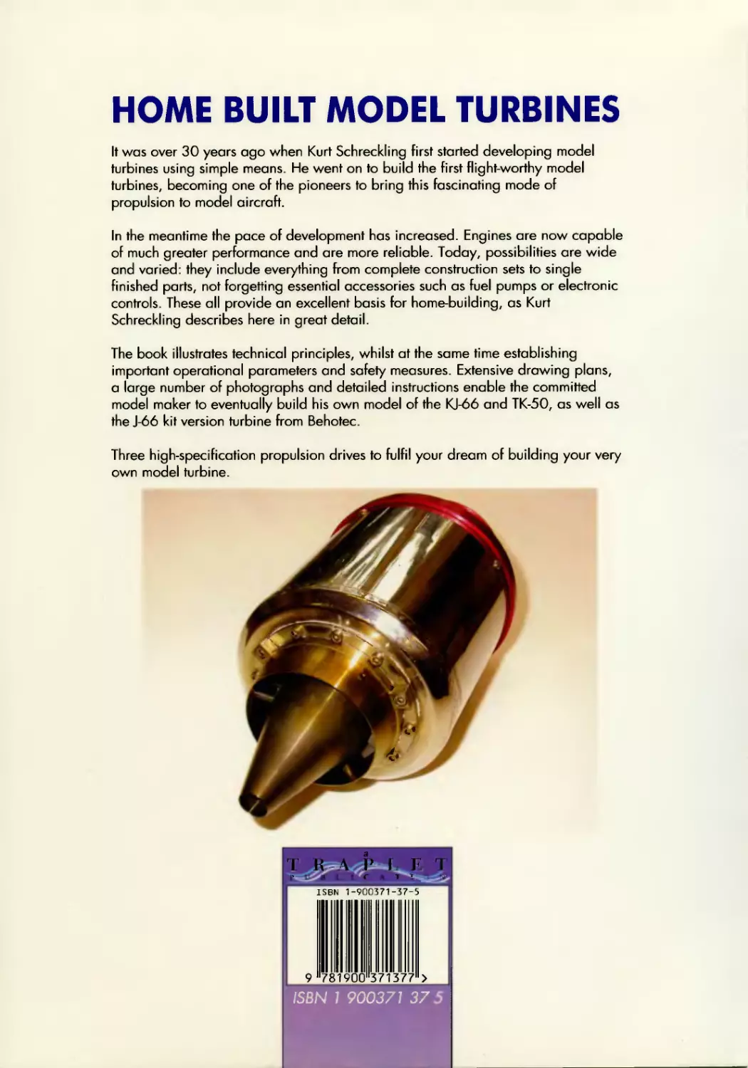
Front Cover:
"KJ66 engine designed by Kurt Schreckling and manufactured in kitfarm hv Jesus Artes".
Back Cover:
"KJ66 engine 11iewedfrom the rear".
TR-\.PLET
PUBLI<-"ATIONS
Printed by Wa Fai Graphic Arts Printing Co., Hong Kong
Contents
Foreword... ... ... ...... .... ..... ...... ...... ....... ....... .......... ............. .......... ............ .......... .......... ....... ........... ......... ............... ....................9
Chapter L Physical-Technical Principles of Model Jet Turbines .......................................................................................11
What are we talking about?....................................................................................................................... .................... .11
How does a model jet turbine work? .............................................................................................................................11
The most important physical parameters....... ............. ............. ............ .......... ........ ......... .......... ............. ....................... .11
Suitable fuels... _............................................................................................................................. .................................. .13
Description of components.................................................................................................................... ........................ .13
The cotnpressor stage......................................................................................................................... ....................... .13
The turbine stage ....... ...... .......... ........ ......... ............ .............. ........... .......... ........ .......... ....... ........................................15
Bearings, counteracting resonance vibration and lubricating the rotor...................................................................17
Combustion chamber and ignition.. ....... ........... ............... ............. .......... ........ .......... ........ ....................................... .20
The thrust nozzle ..... ....... ........... ....... ....... ............. ............ ............. ............ ........ .......... ....... ....................................... .21
Operational performance................................................................................................................... ............................ .22
Correlation of rotational velocity, air mass flow, compressor pressure, thrust and temperature ..........................22
Reactions to changes in fuel flow?.. ...... ......... ............... ............. ............ ......... ......... ......... ............. .......................... .24
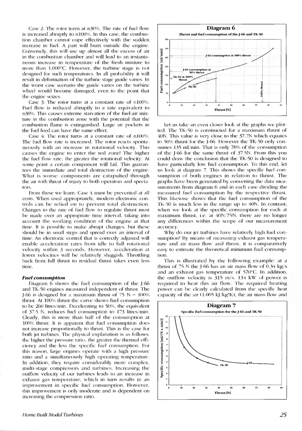
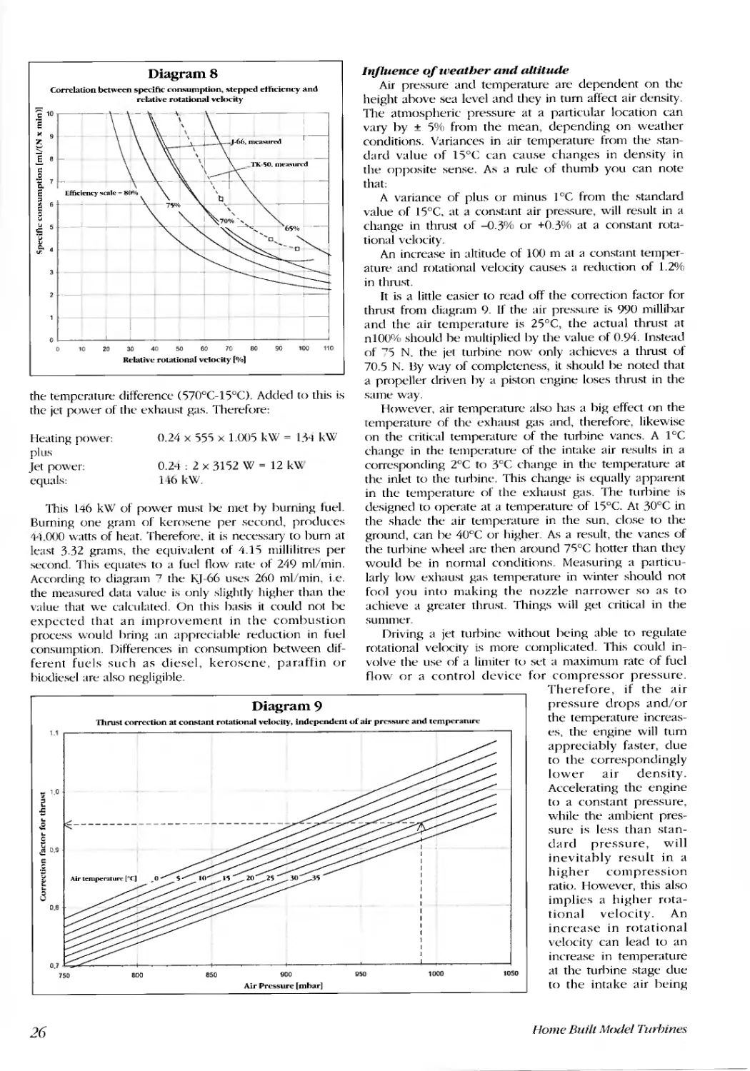
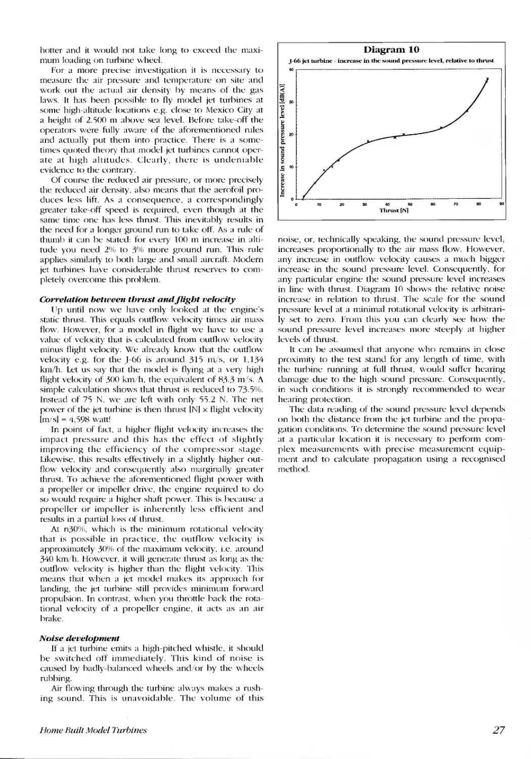
Fuel consumption................................................................................................................... ................................... .25
Influence of weather and altitude.. ...... .......... .............. ............... ........... ......... ......... .......... ............. .......................... .26
Correlation between thrust and flight velocity..........................................................................................................27
Noise development.. ........ ....... ....... ...... ......... ............... ............. ............. .......... ......... .......... ............. ................. ..........27
Chapter 2. Necessary Accessories. ........ ....... ......... ............. .............. .............. ........ ......... ............. .............................. ...... ....2R
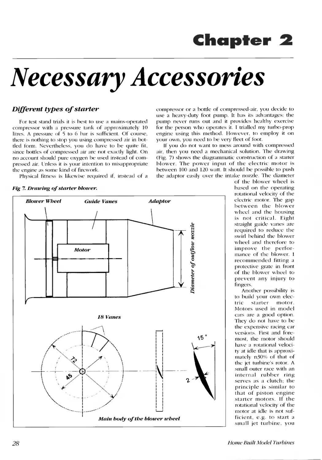
Different types of starter.... ...... ......... ....... ......... ................ ............... ............. ........ .......... ......... .......................... ..............2H
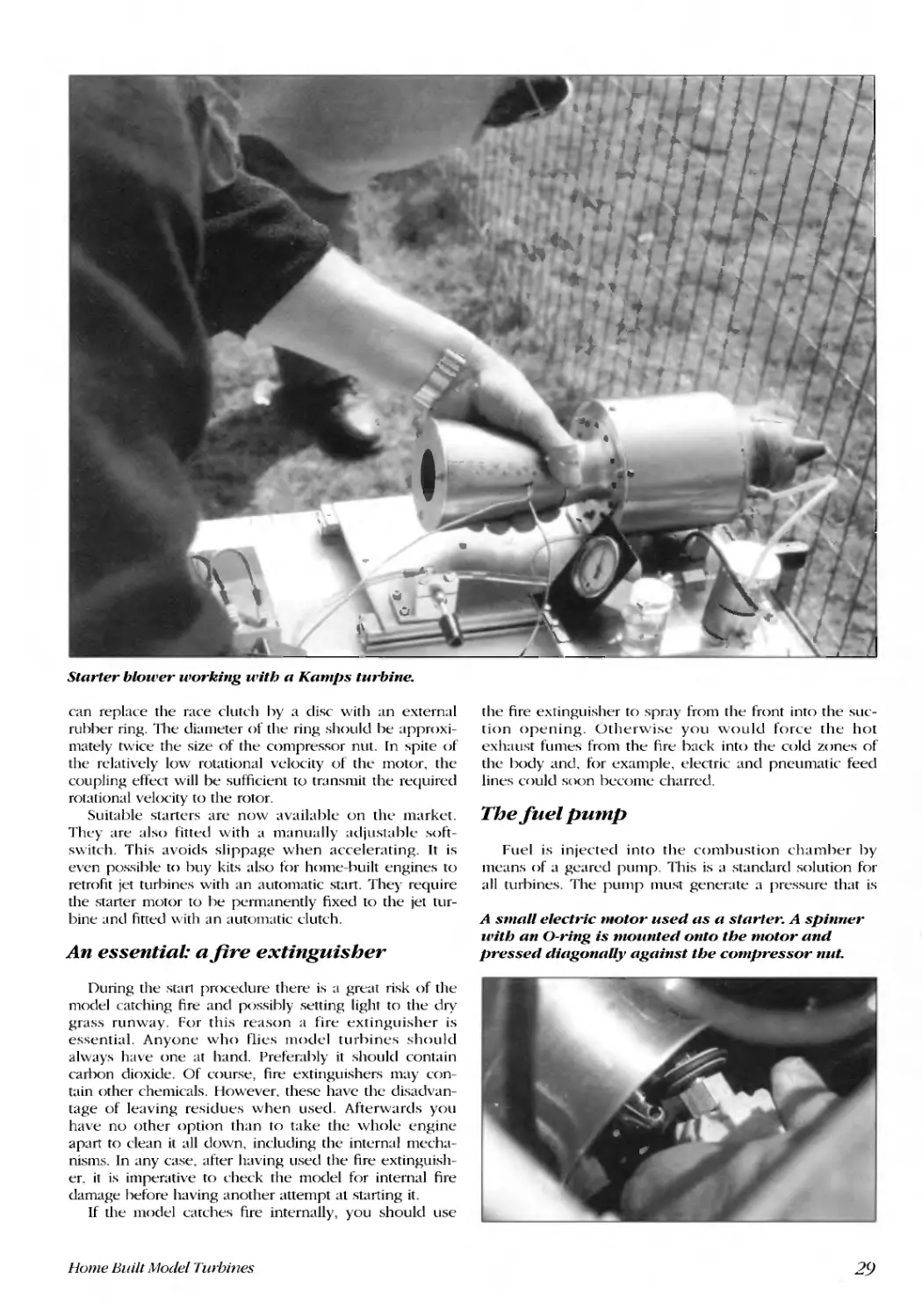
An essential: a fire extinguisher...... ........ ....... .............. .............. ............... ........ .......... ............ .......................... ............. .29
The fuel plllnp......................................................................................................................... ........................................29
Fuel tank with feed lines. ...... ....... .......... ....... ............. ................ ............. ......... .......... ............. .......................... ............. .30
Cartridge-fed auxiliary gas ... ........ ........ ......... ............. ................ ............. .......... ......... .......... ........................... ............... .30
Electrically-powered glow plug. ......... .......... ............. ............. ............. ............ .......... ............. ........................ ............... .30
Calibrating of the restrictor for the supply of lubricant.................................................................................................30
Electronic regulation and control....... ........ ............ ... ............ ............ ........... ............ ................ .......... ...................... ..... .30
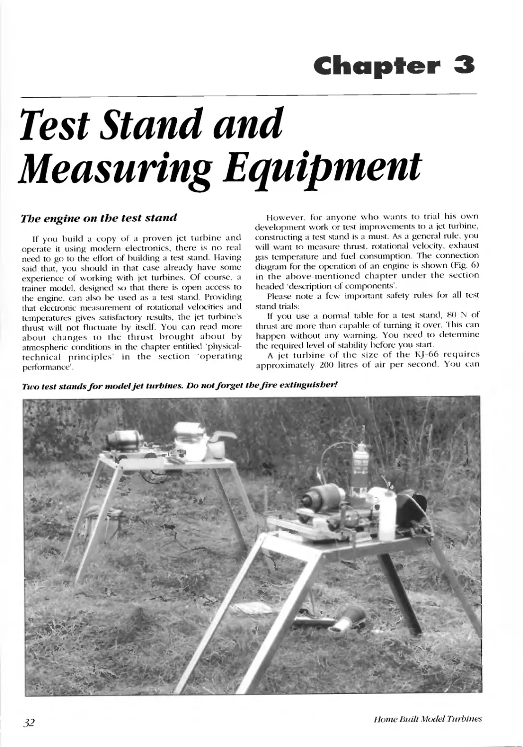
Chapter 3. Test Stand and Measuring Equipment ..............................................................................................................32
The engine on the test stand ..........................................................................................................................................32
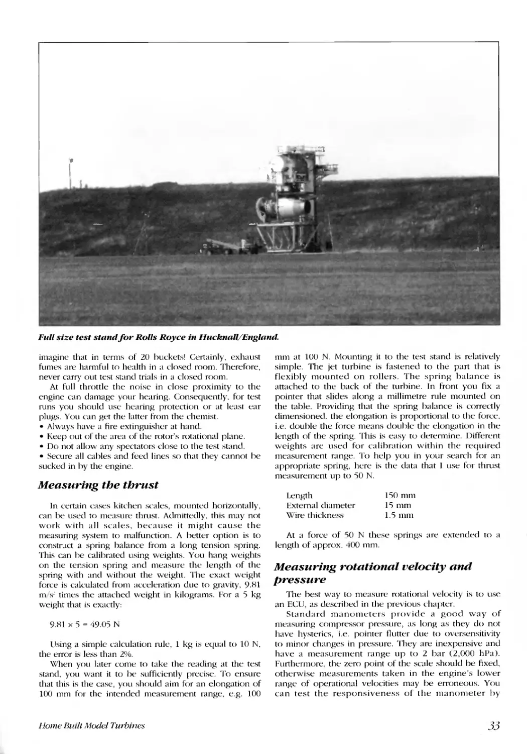
Measuring the thnlst.................. ....... .......... ............. ............. ............. ........... .............. .............. ............................... ........33
Measuring rotational velocity and pressure........ ................ .......... ............. ............ ................... ................................ .....33
Temperature measurement .............................................................................................................................. .............. .34
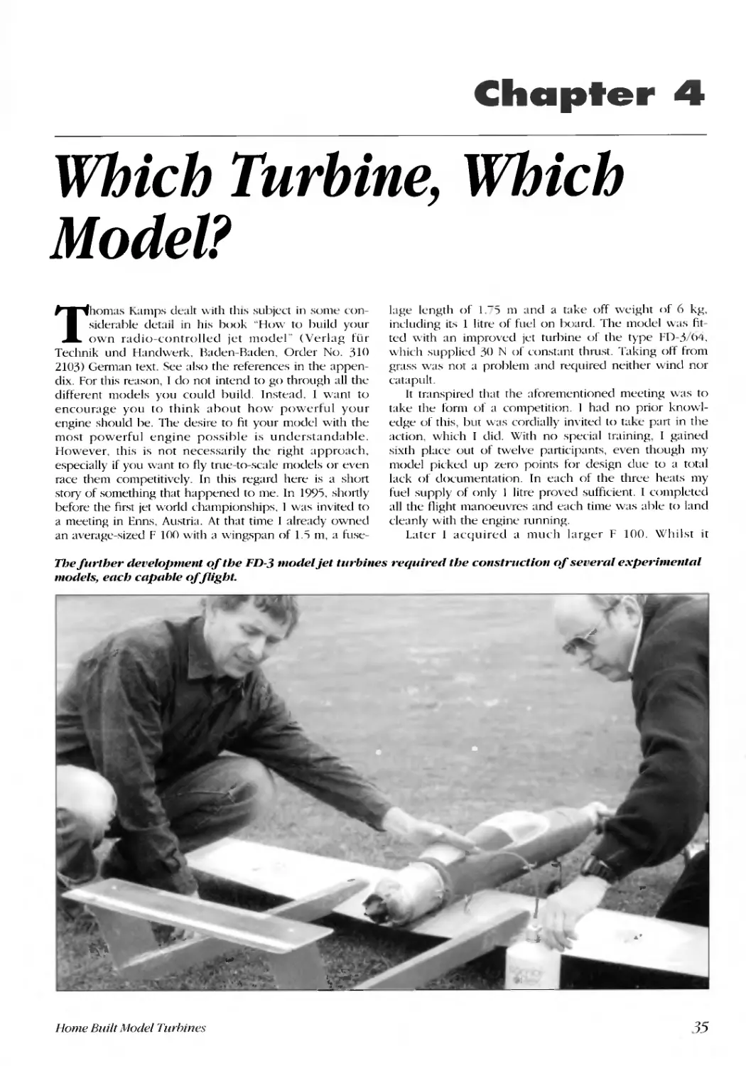
Chapter 4. Which Turbine, Which Model? ..........................................................................................................................35
Chapter 5. Home-Built Jet Engines.... .......... ............ .............. ............. .......... ............... ...................................................... ..40
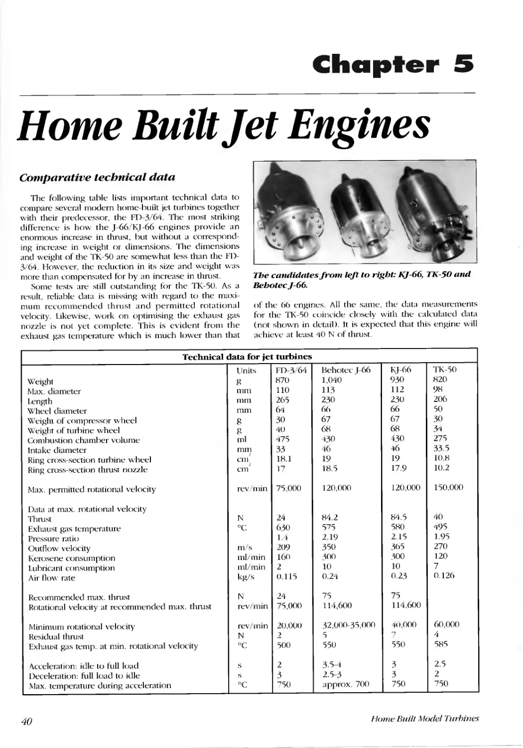
Comparative technical data ..... ...... .......... .......... ............... ........... ............... ............. ........................................................ 40
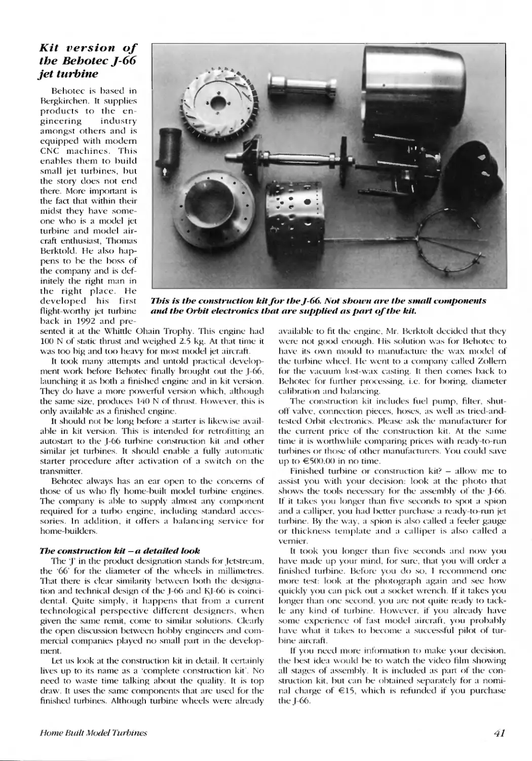
Kit version of the Behotec J-66 jet turbine .....................................................................................................................41
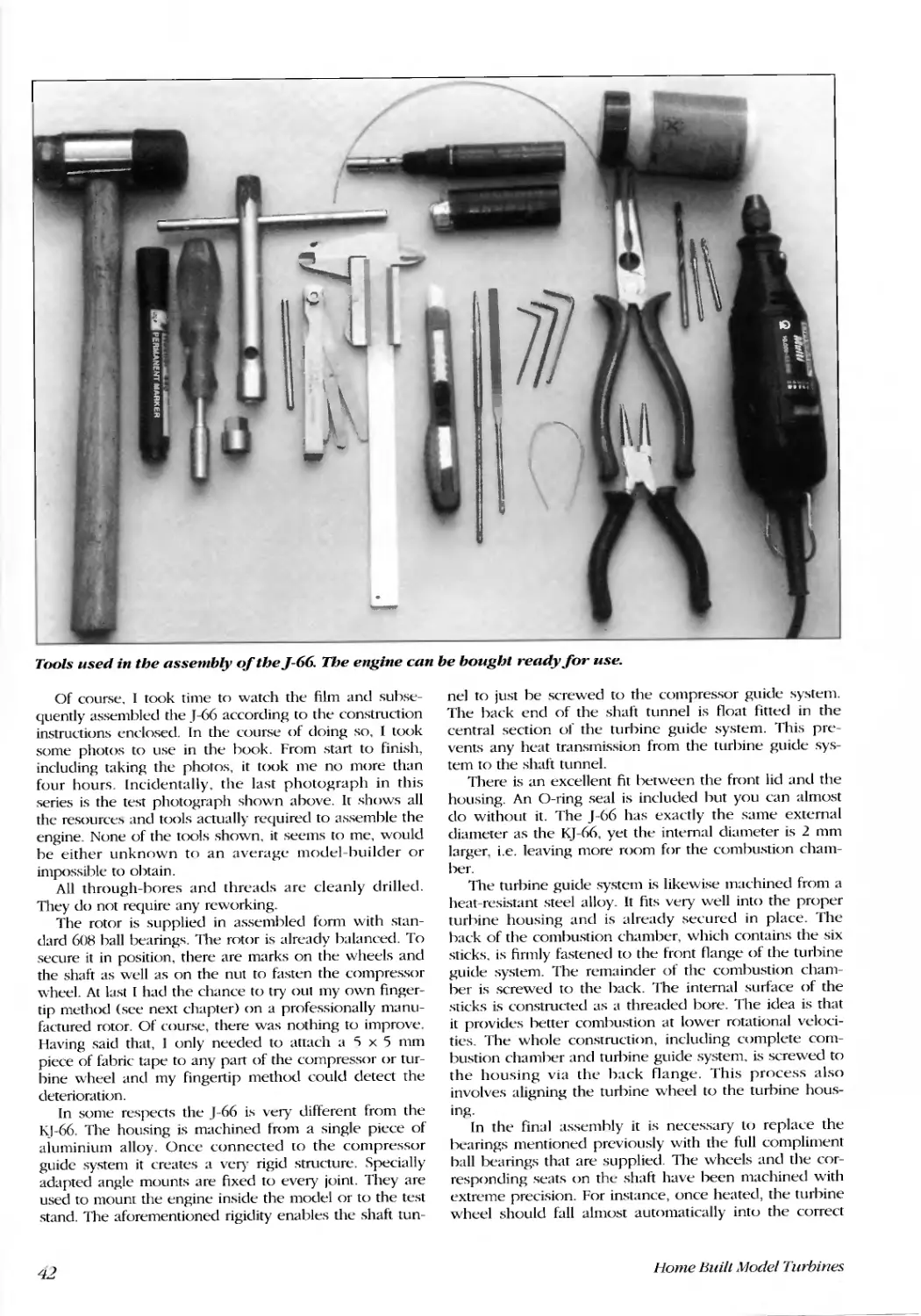
The construction kit - a detailed look.......................................................................................................................41
General points on the construction of the KJ-66 and TK-50 ........................................................................................Lt't
Balancing the rotor......................................................................................................................... ............................44
The home-built TK-'50 jet turbine, made from a thermos flask ....................................................................................44
How it evolved... ..... ........... ..... ...... ......... ................ ............ ............ ............. ....................... .............................. ..........44
Construction requirenlents................................................................................................................. ........................4'5
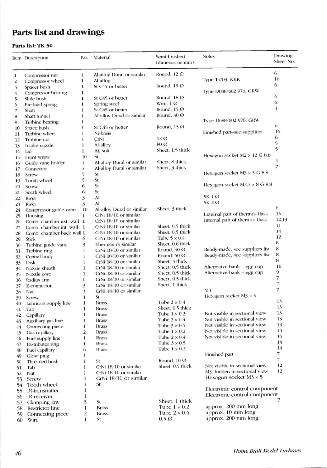
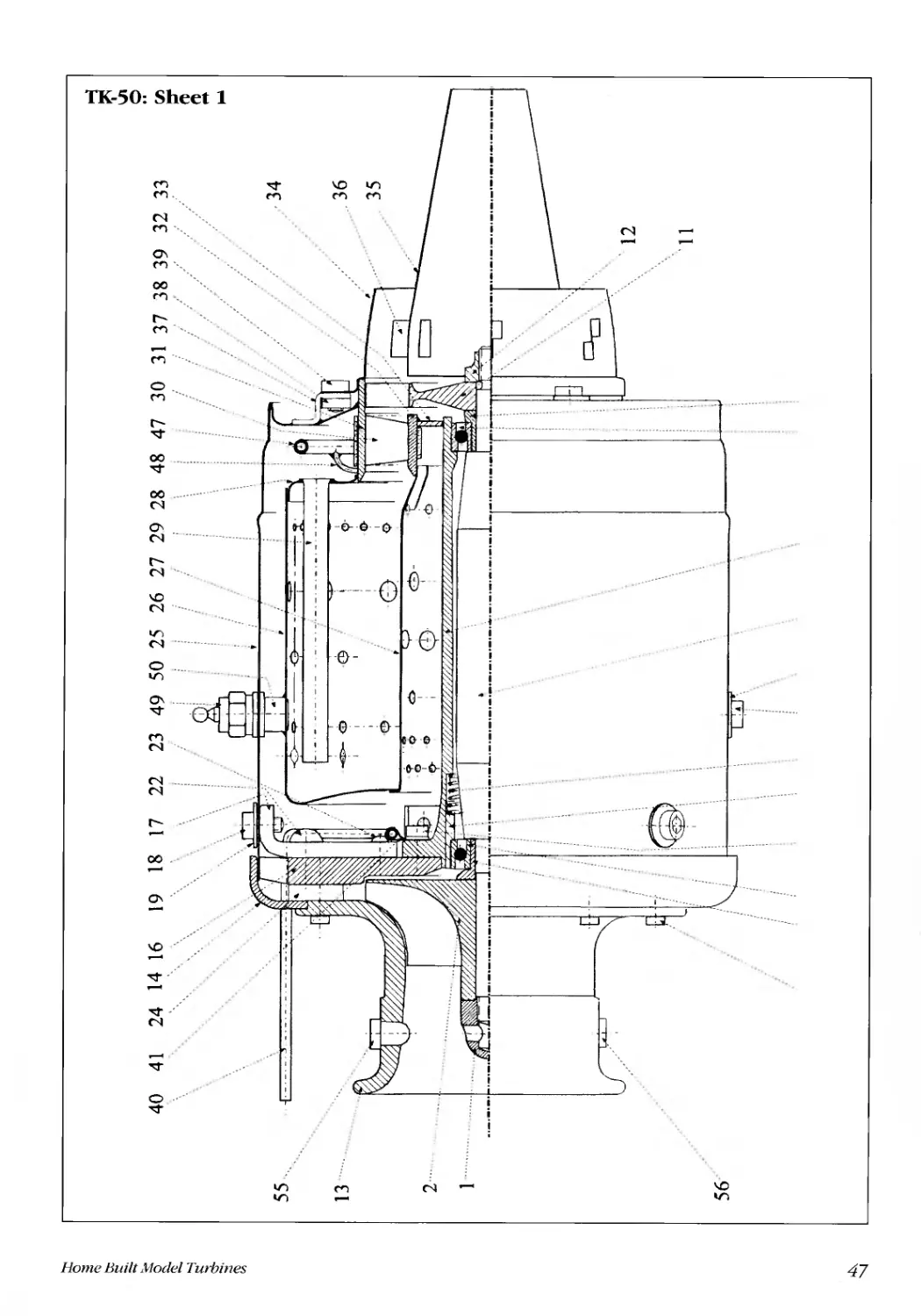
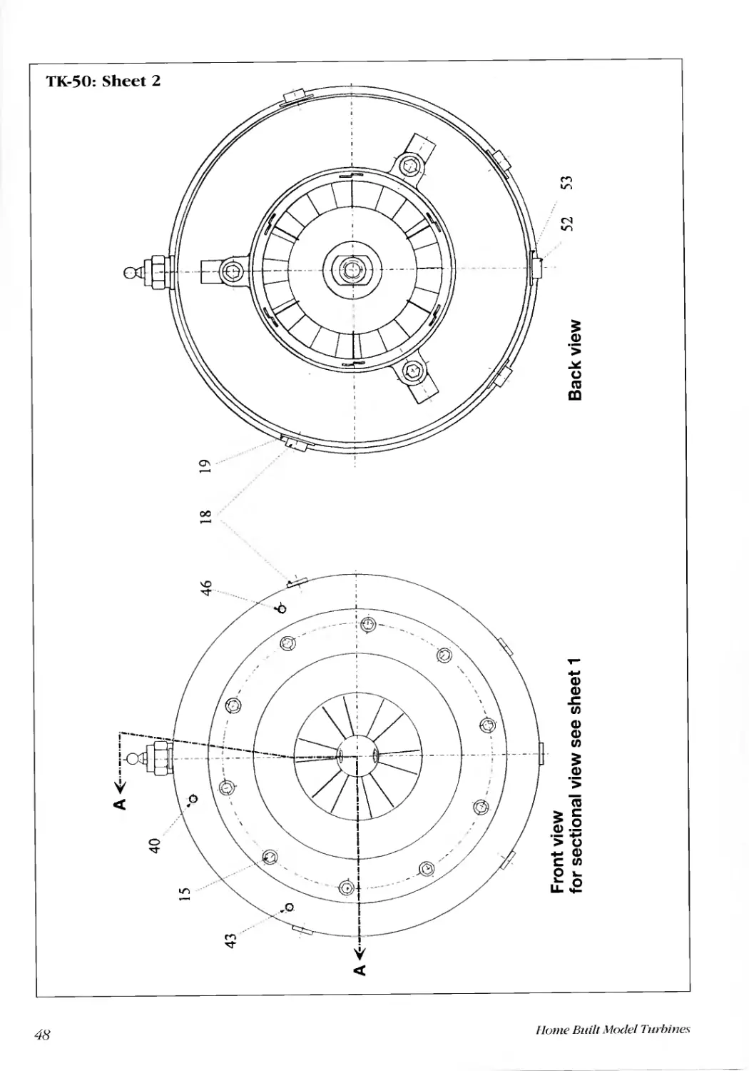
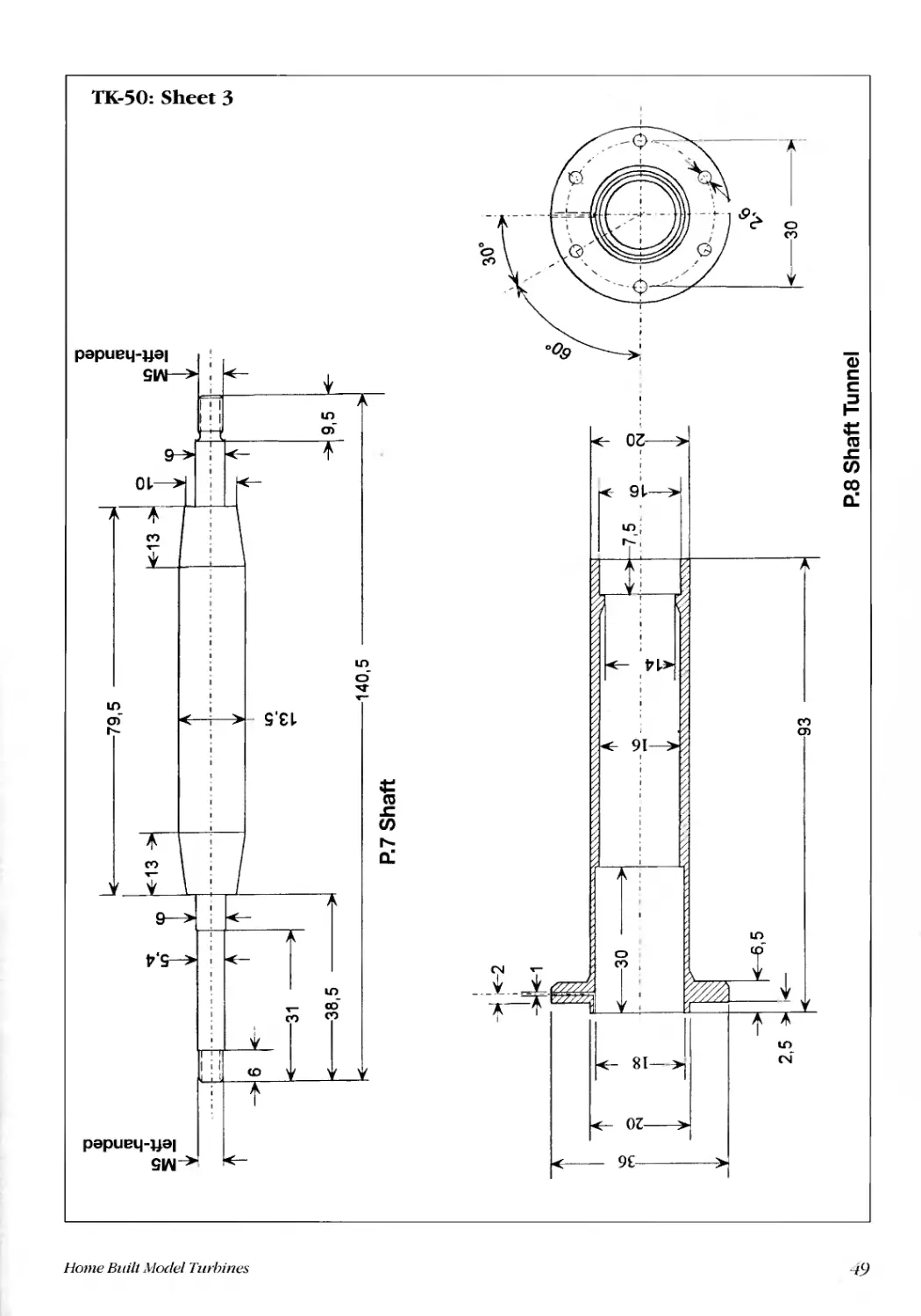
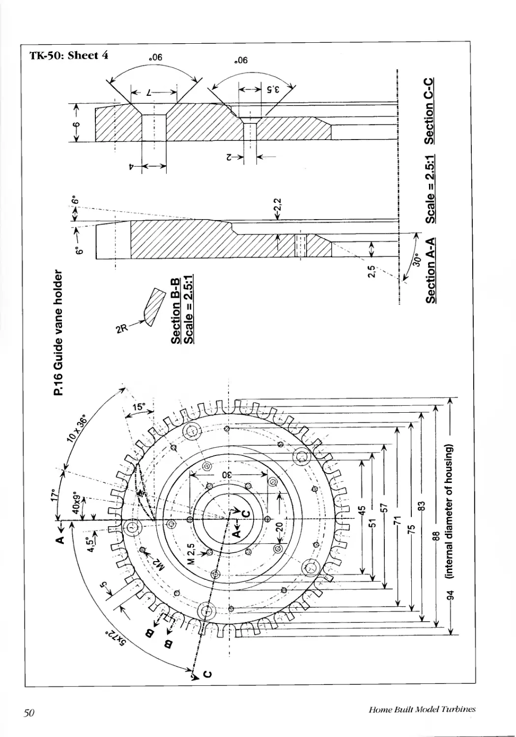
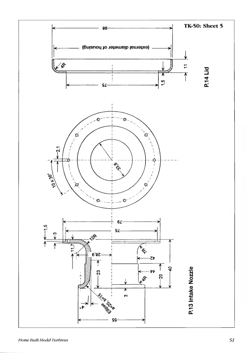
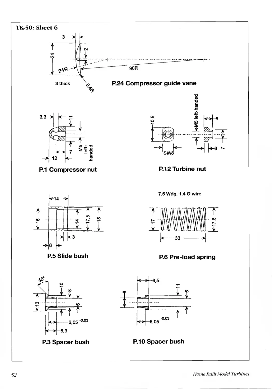
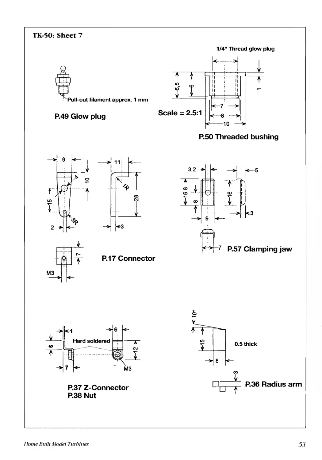
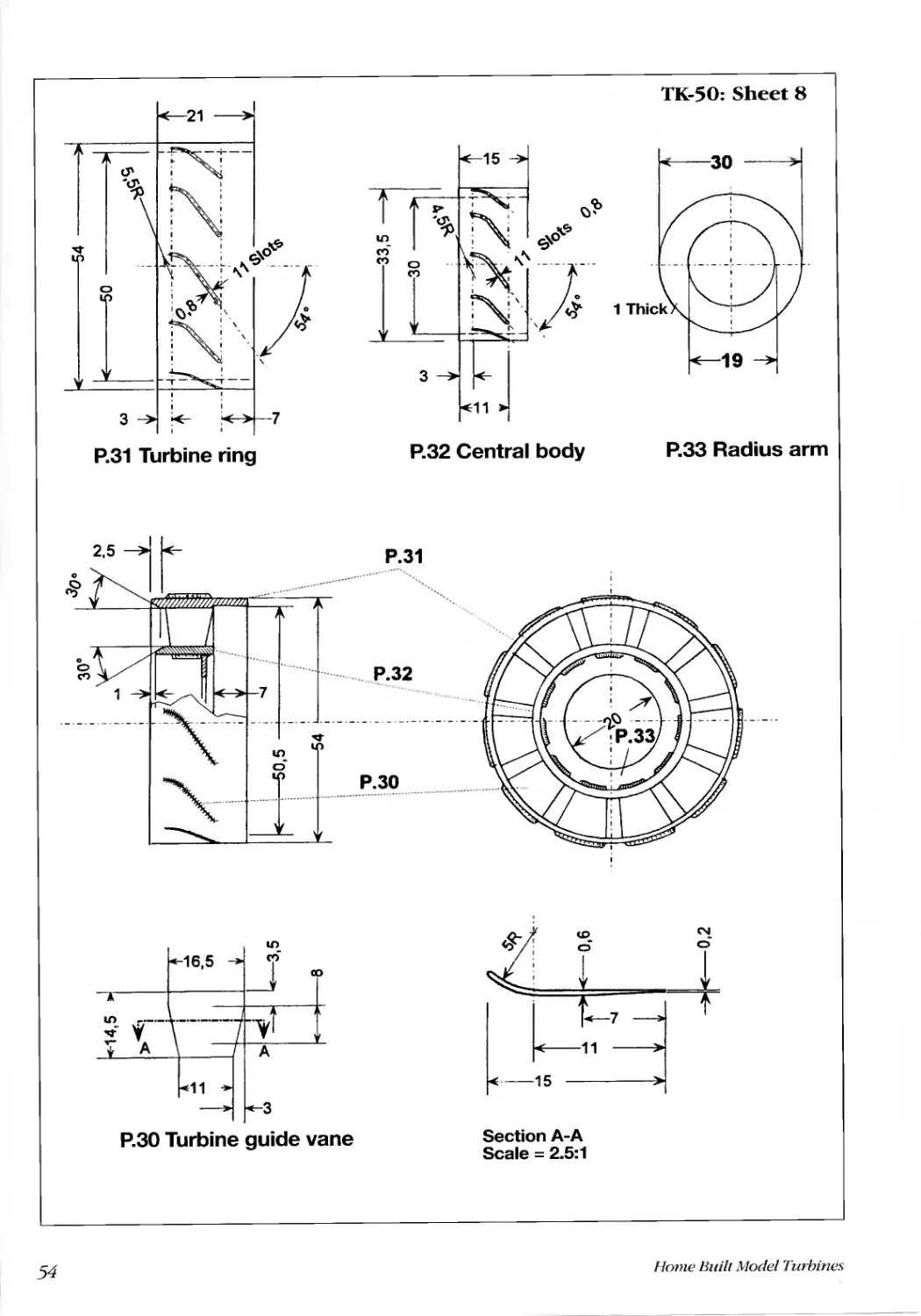
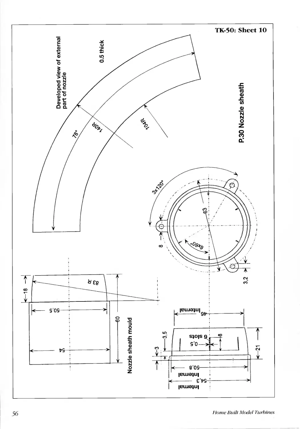
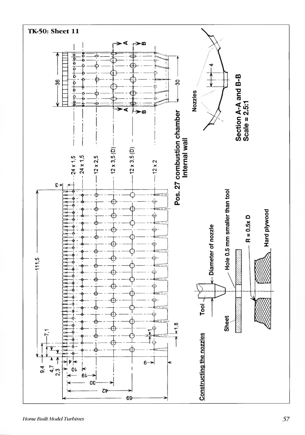
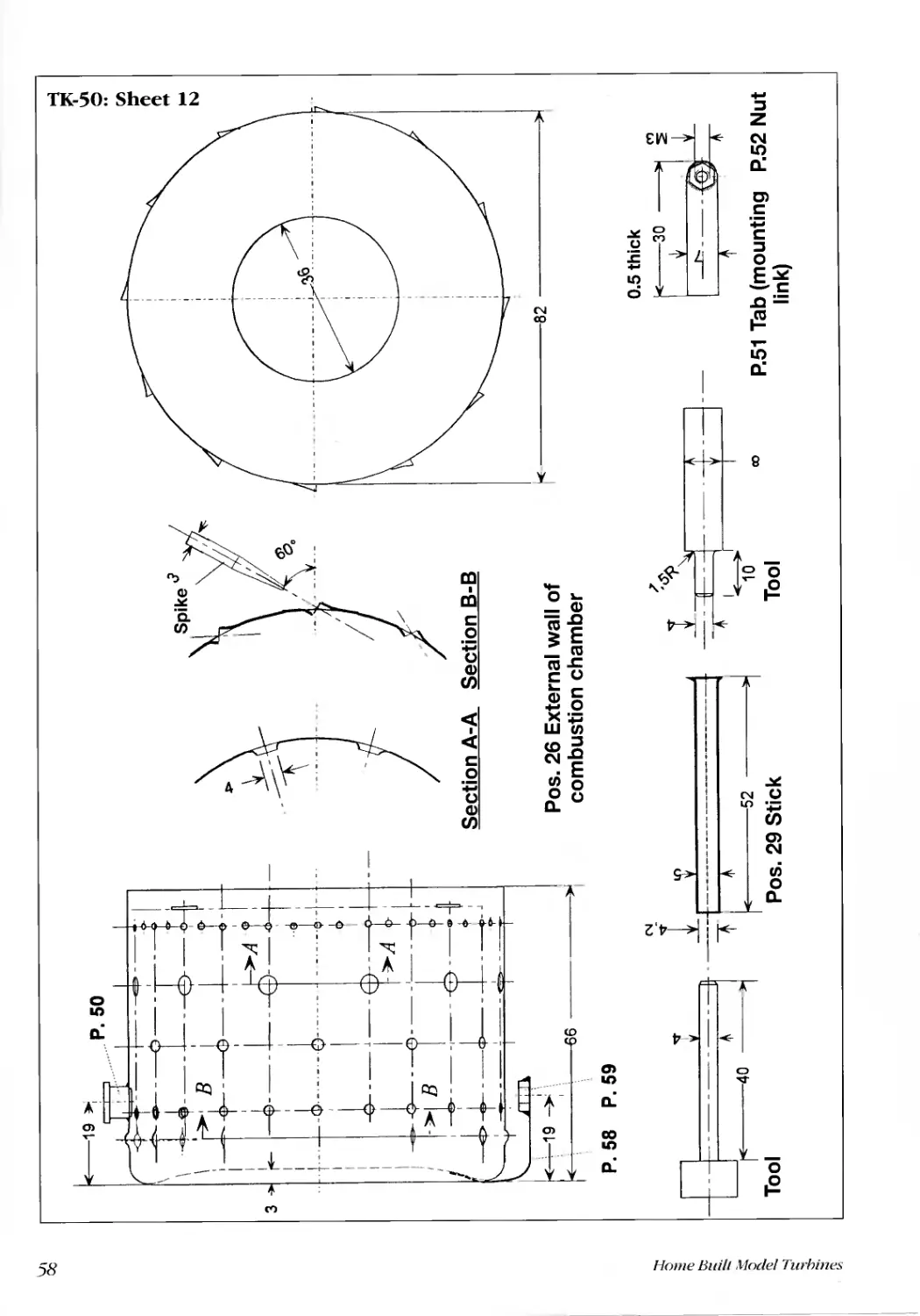
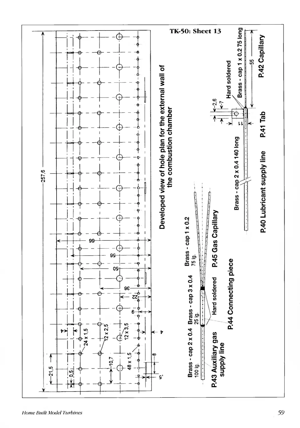
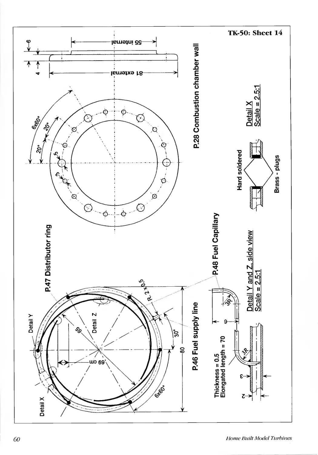
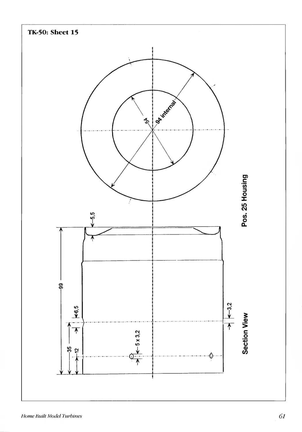
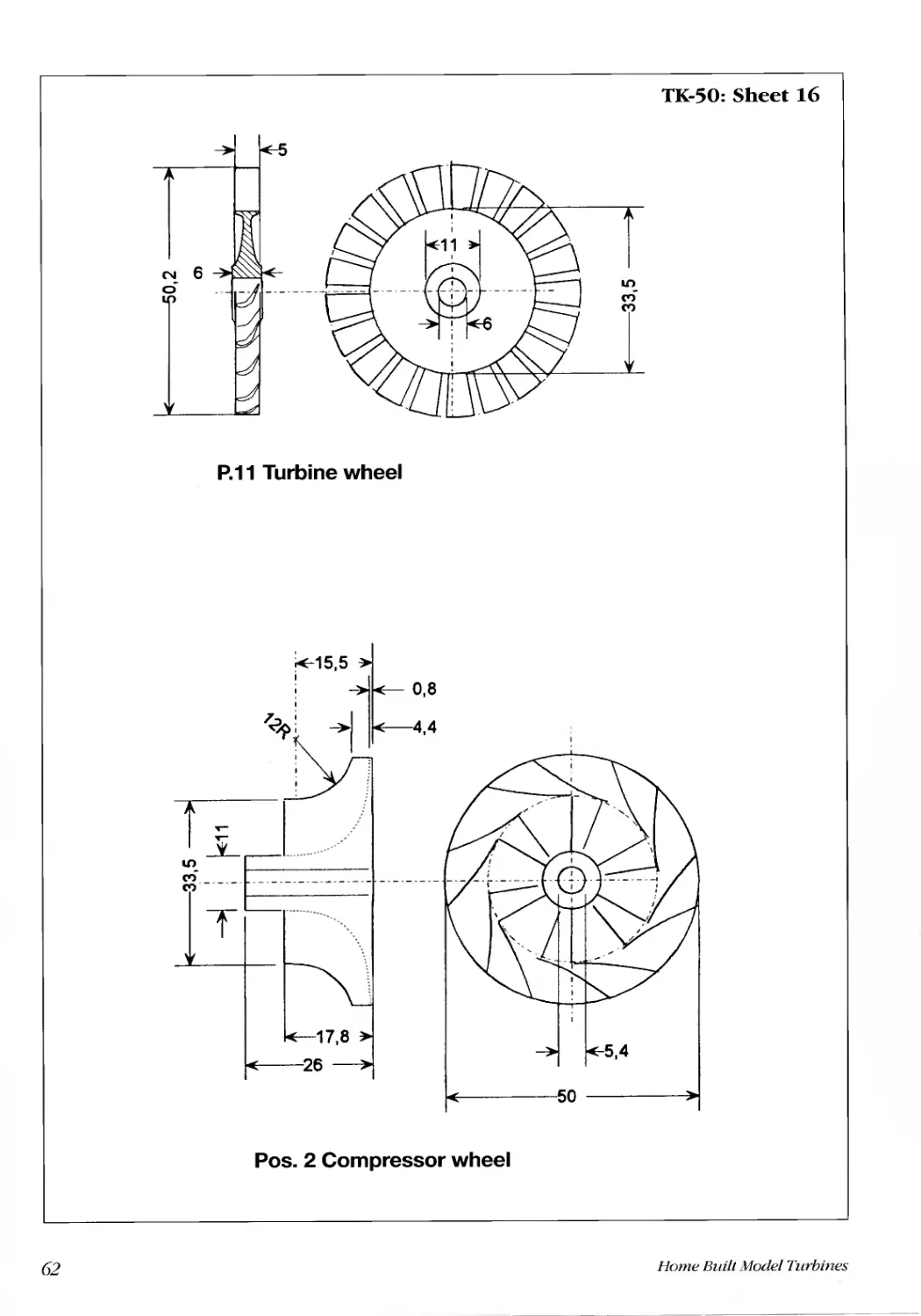
Parts list and drawings. ...... ..... ........... ......... .......... ................ ............ ............. ................ ........................................ ........."16
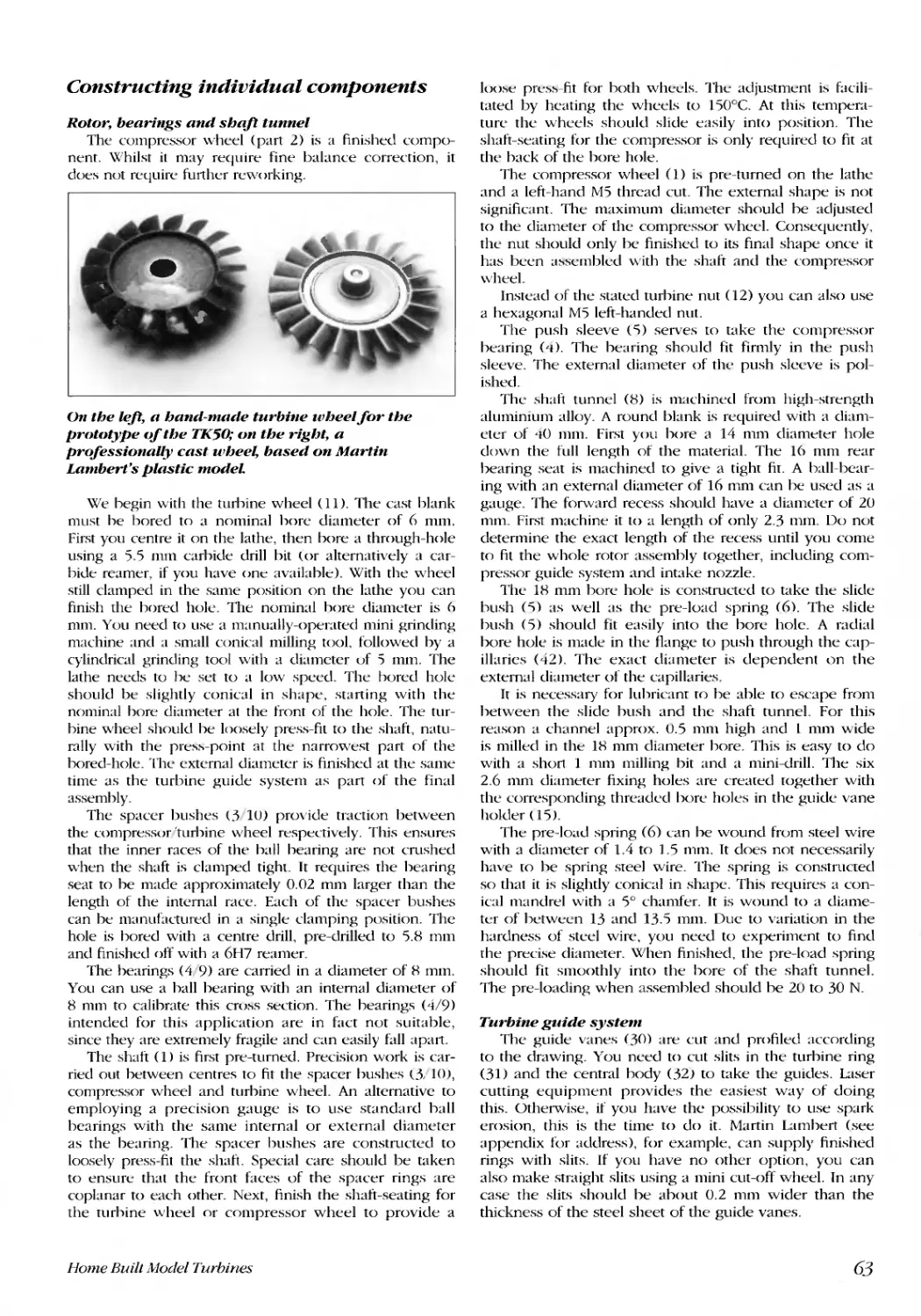
Constmcting individual components .......... .......... ............. ............ .............. ............... ................................................... .63
Rotor, bearings and shaft tunnel. ......... .......... ............ ............. ............. .................. ................................................... .63
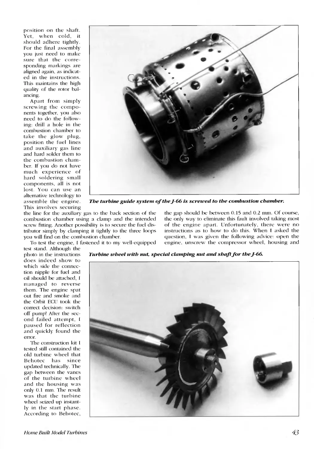
Turbine guide systenl .... ........ ...... ......... .......... ............ ............. ............. ................... .................................................. .6'3
Housing....................................................................................................................... ............................................... .64
Conlpressor guide system .... ...... ......... ......... ........... ............. ............. .................. ............................. ........ ................. .6LJ
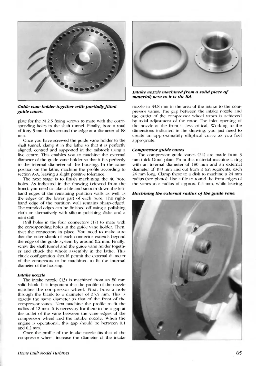
Intake nozzle........................................................................................................................ ...................................... .65
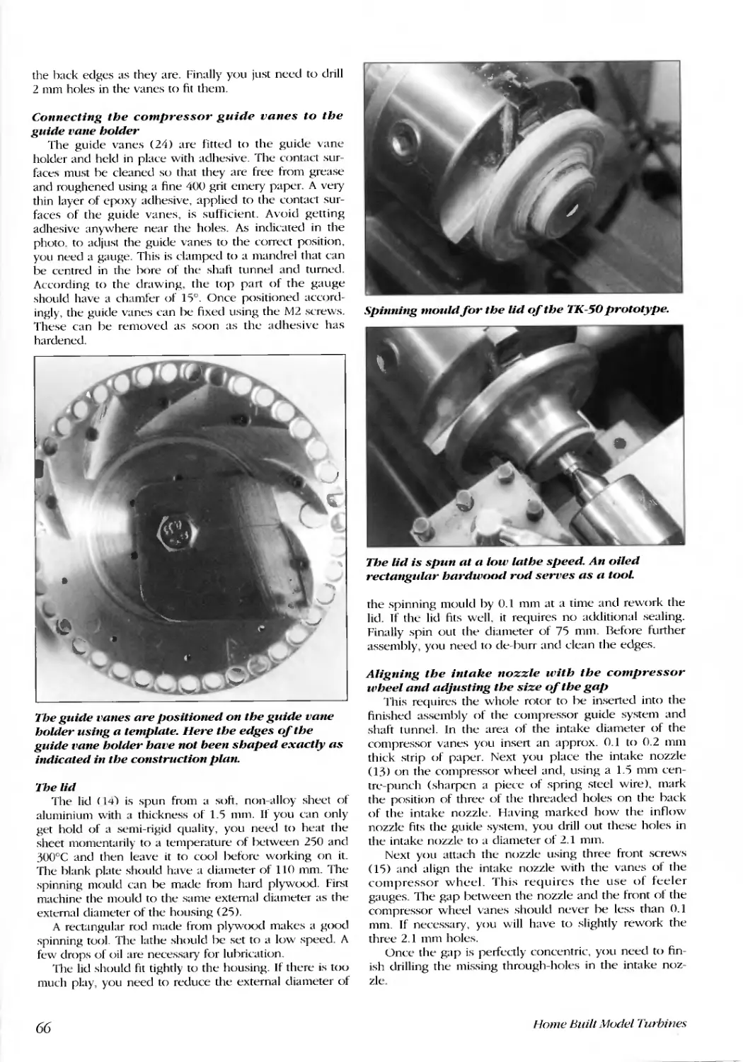
Compressor guide vanes ..... ...... ......... ........ ............. ............ .............. .................. ........................... ............................65
Connecting the compressor guide vanes to the guide vane holder ........................................................................66
The lid .............................................................................................................................. .......................................... .66
Aligning the intake nozzle with the compre or wheel and adju ting the size of the gap....................................66
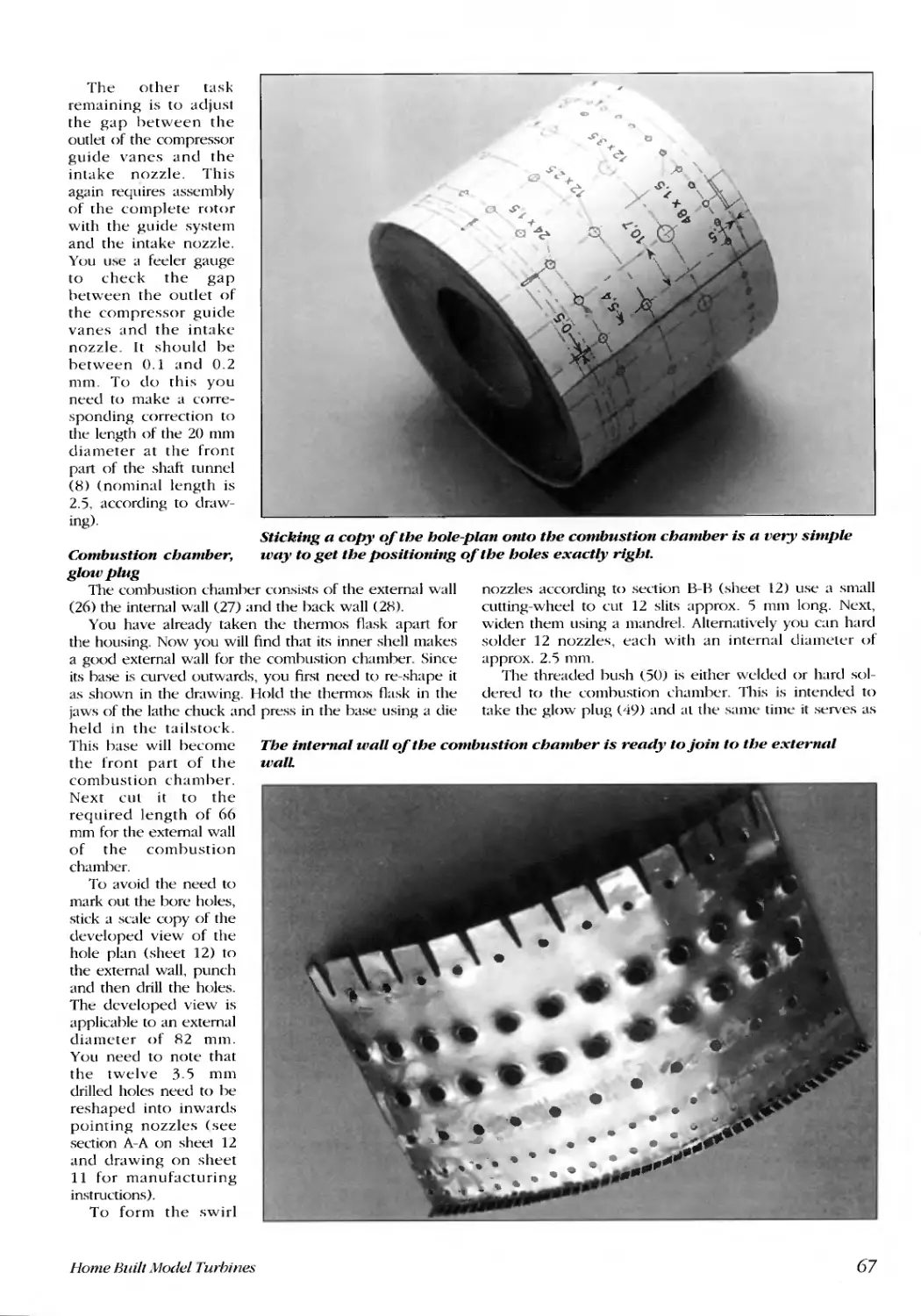
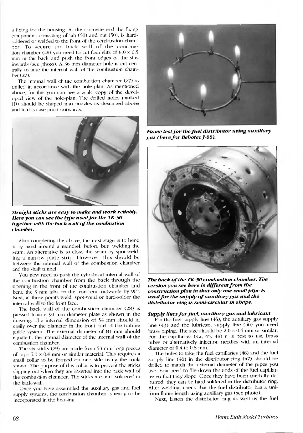
Combustion chamber. glow plug.. ....... ......... .......... .......... ........ ............... .............. ............ ............... .................. .......67
Supply lines for fuel, auxiliary gas and lubricant .....................................................................................................68
Exhaust gas nozzle..... ..... ...... ....... ........ ........ .......... .......... .......... ............. ............. ............. ............... ................ ......... .69
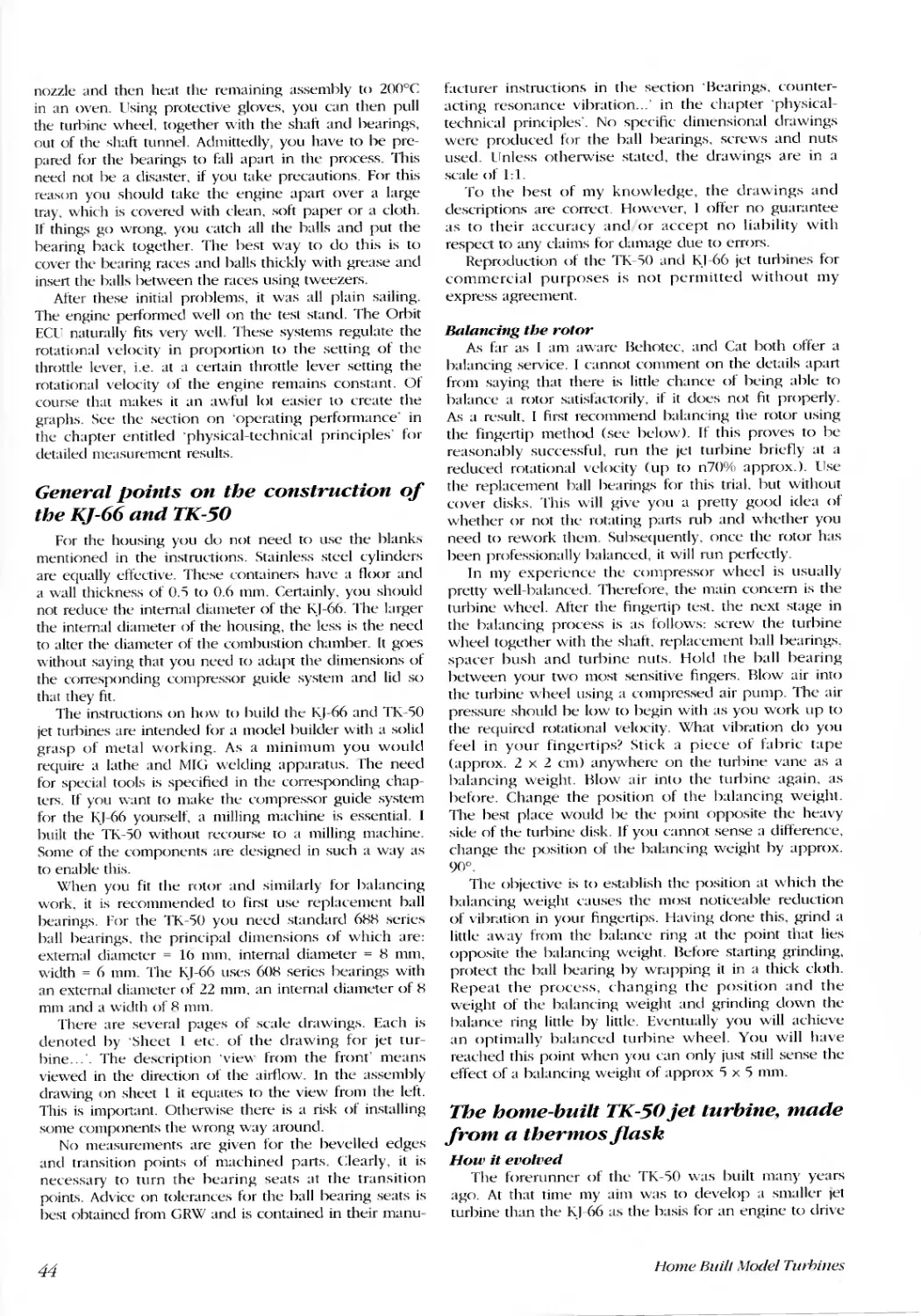
Calibrating the diameter of the turbine wheel..........................................................................................................70
Connecting the exhaust gas nozzle to the housing ..................................................................................................70
Final assembly..... ..... ..... ........... ...... ........ ........ ......... ......... ............. ............. ............. ................ ............... .....................70
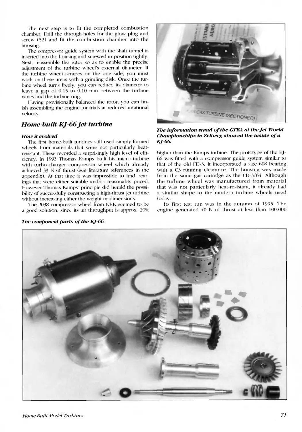
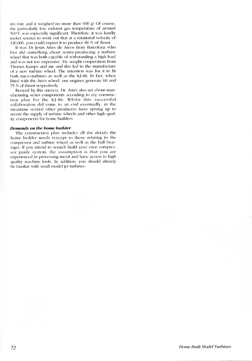
Home-built KJ-66 jet turbine .... ..... ........ ........ ......... ......... ........ ............... ............. ................ .............. ............... ...............71
How it evolved. ...... ........... ........... ....... ........ ......... .......... ............ ............. .............. ............... ................ ......................71
Demands on the home builder ...... ......... ....... ......... .......... ............. ............. ............. ................... .................. ............ .72
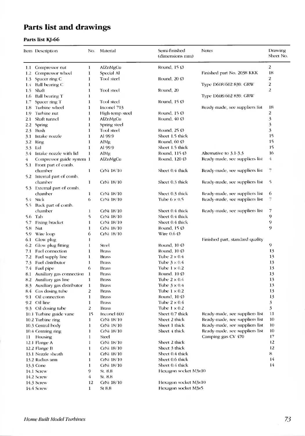
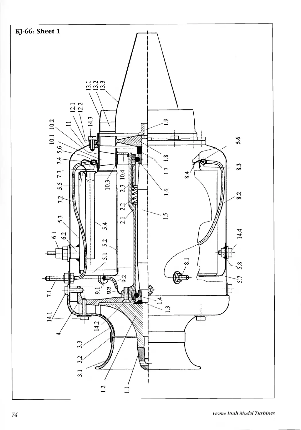
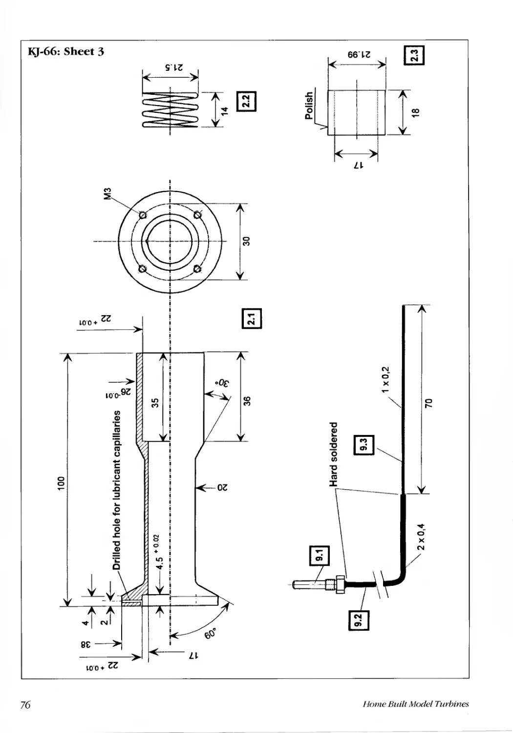
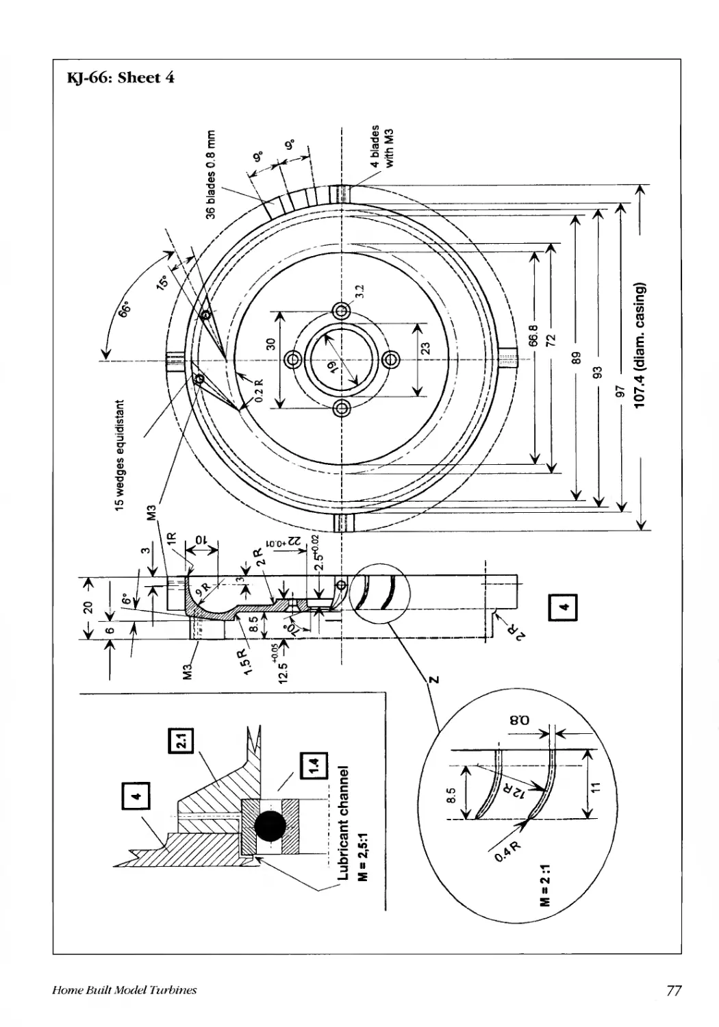
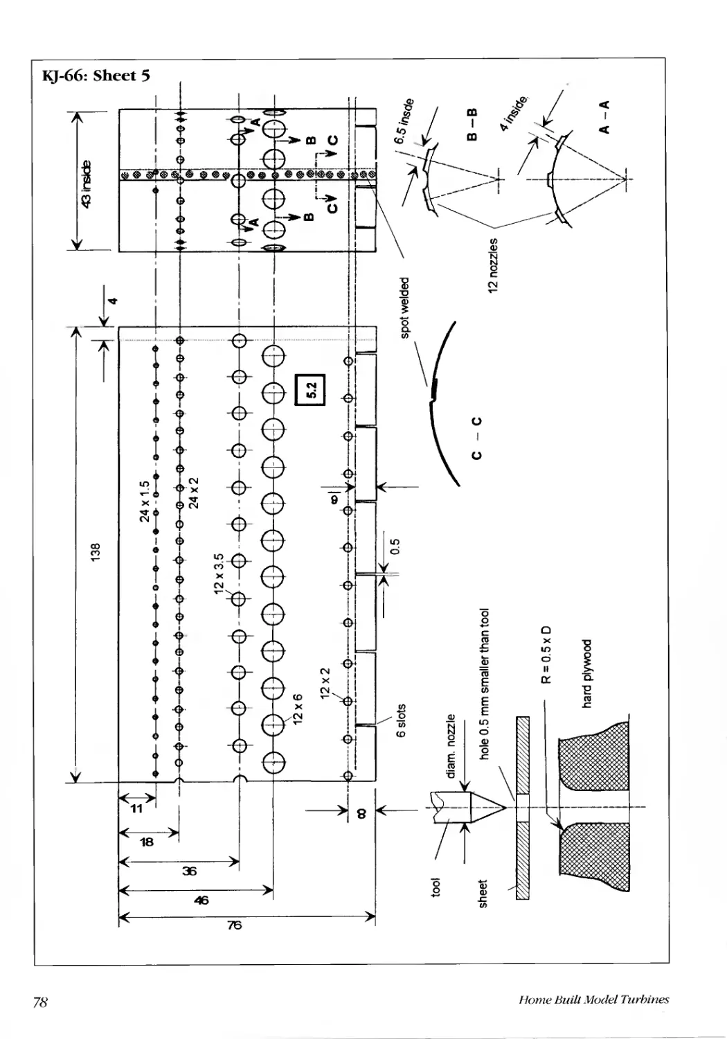
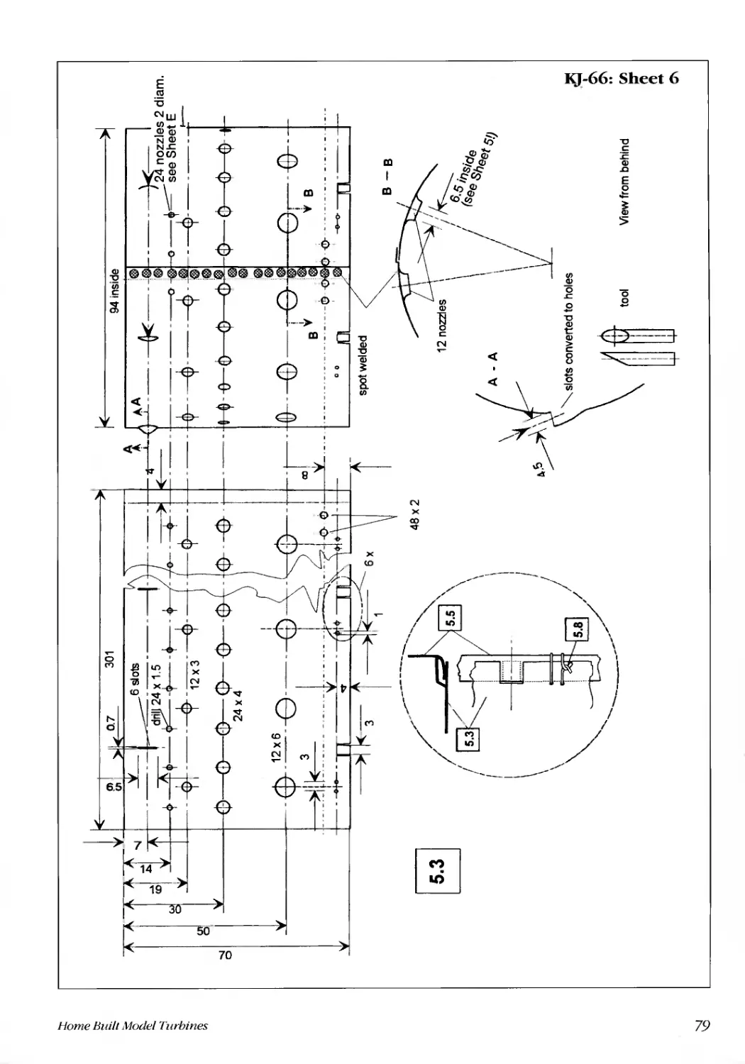
Parts list and drawings ..... ......... ....... ....... ........ ......... .......... .......... ............ .............. ............... ................. ......................... 73
Constructing individual components.. ........ ....... ........ ........... ............ ............ .............. .................. ........................ ........ ..92
Rotor (1.1 to 1.9).......................................................................................................................... ...............................92
Shaft tunnel (2.1 to 2.3) ....... .... ....... ........ ........ ........ ........ ........... .............. .............. ............ ................................ .........92
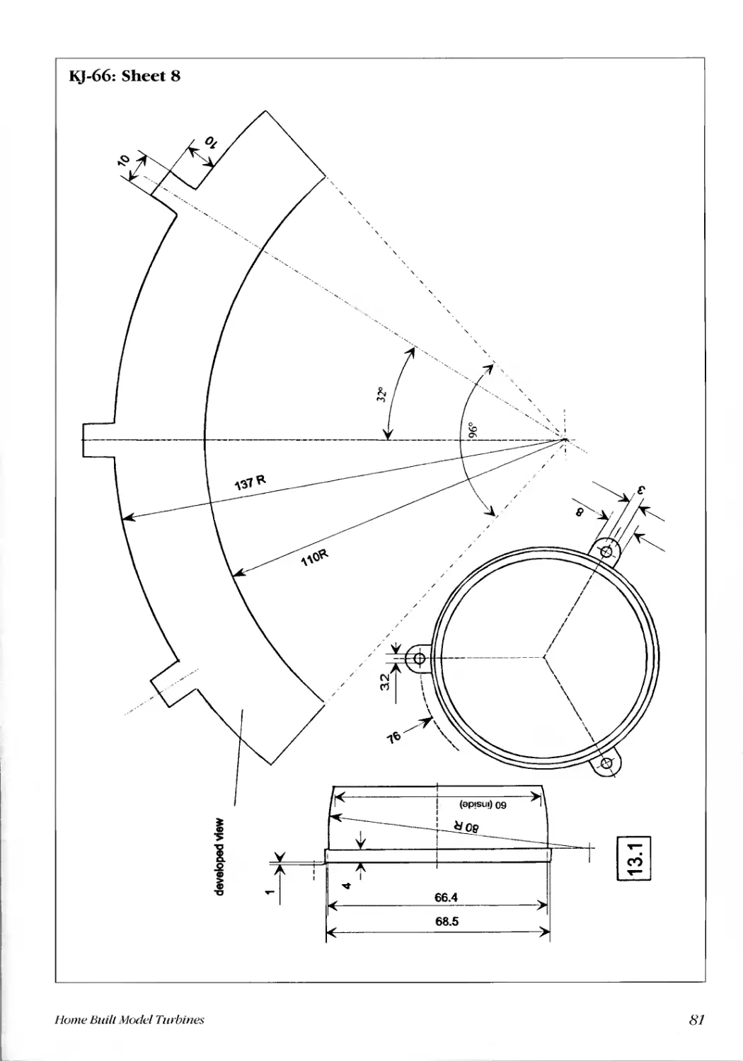
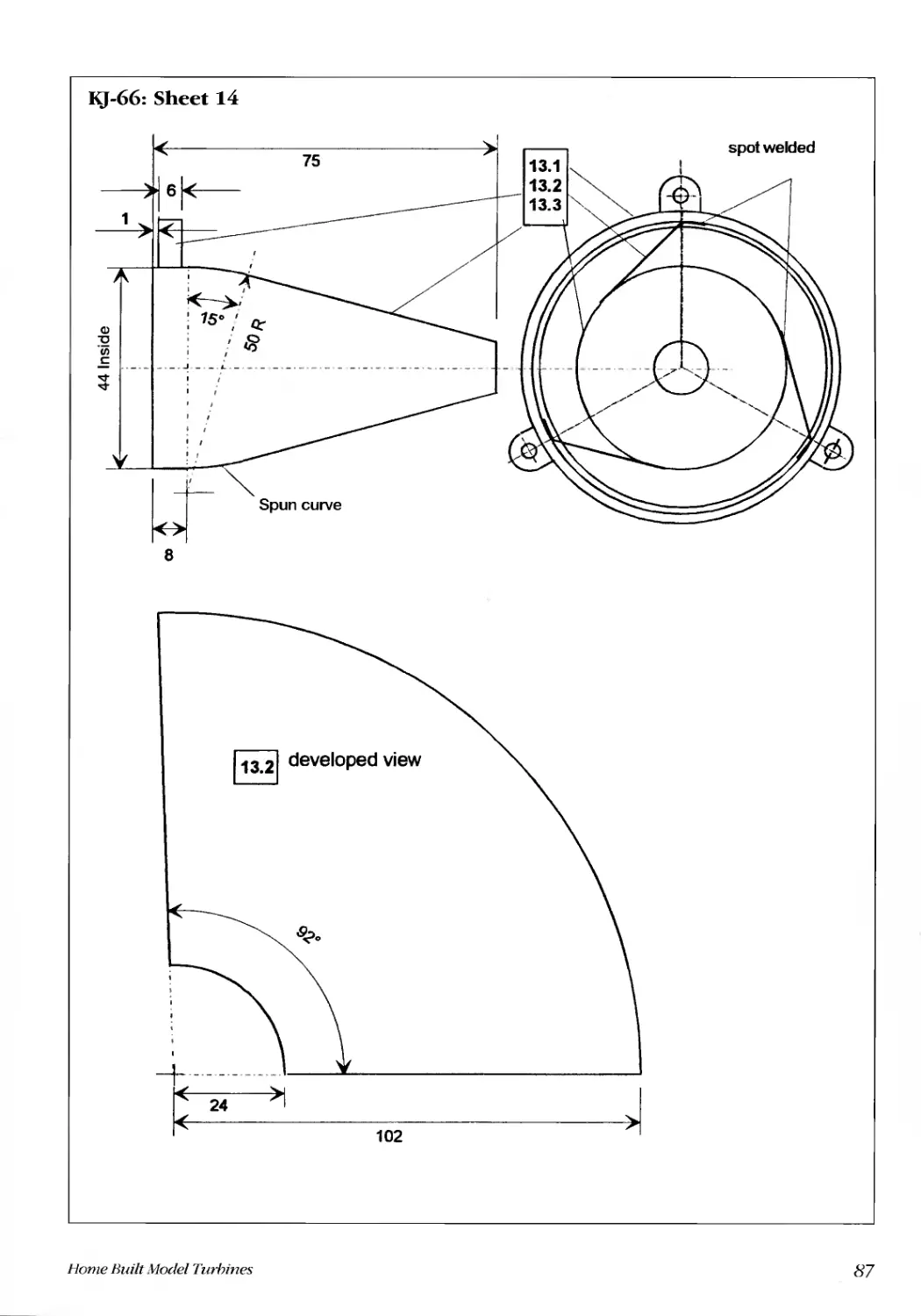
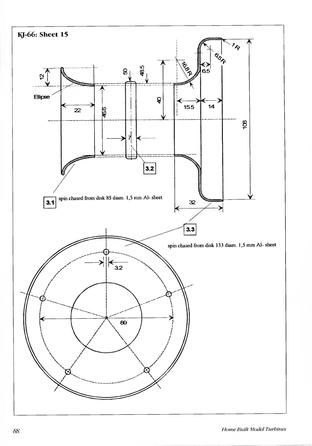
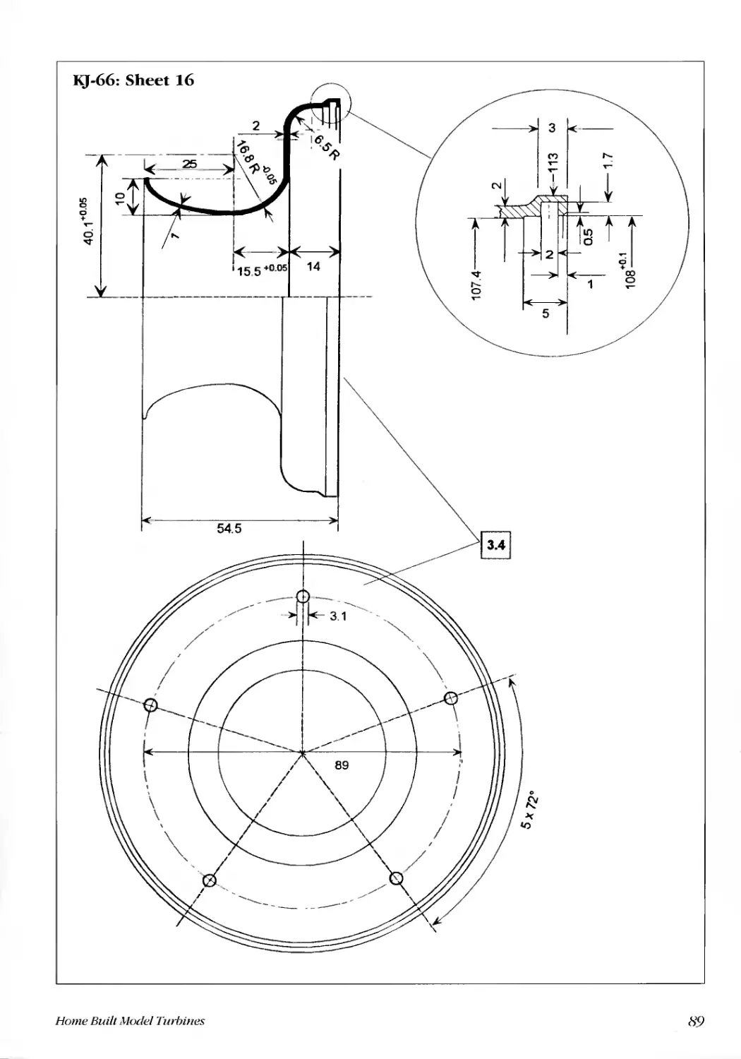
Intake nozzle and lid (3.1 to 3.3L............................................................................................................................92
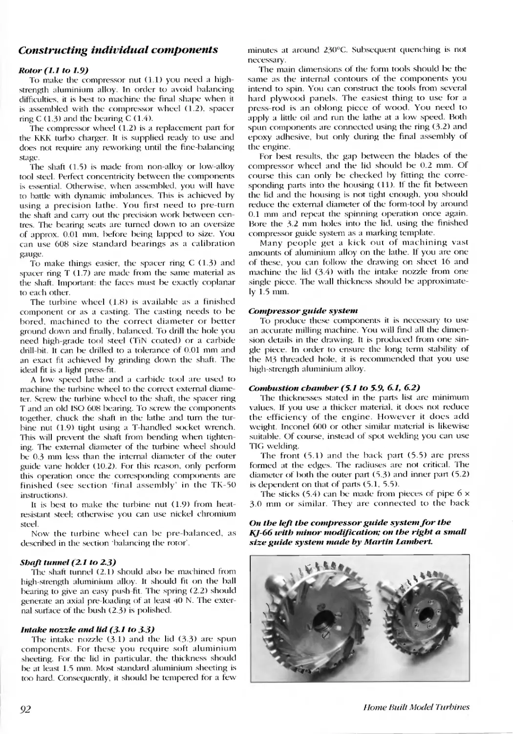
Compression guide system. ...... ...... ......... ....... ........ ....... ........... ............. ............. ............ ...................... ... ... ............... .92
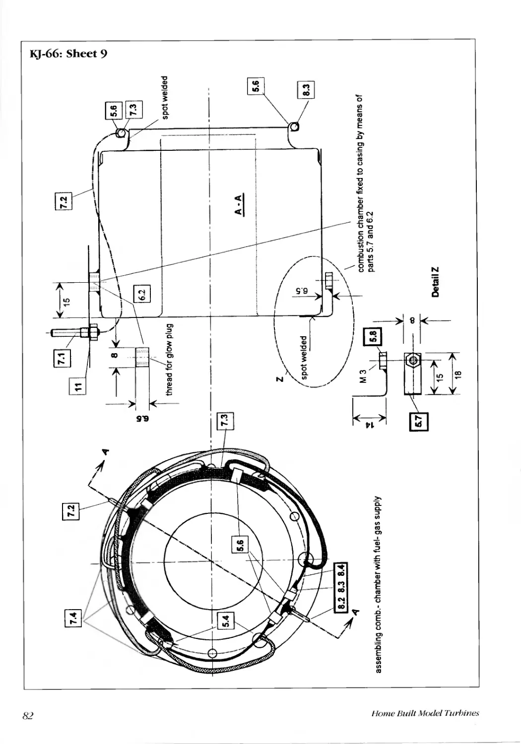
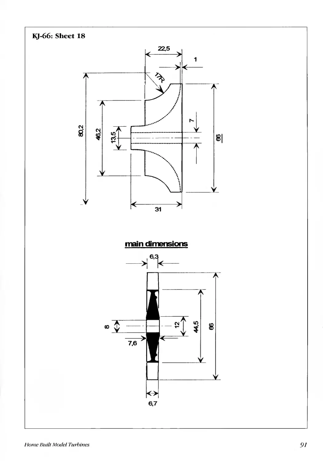
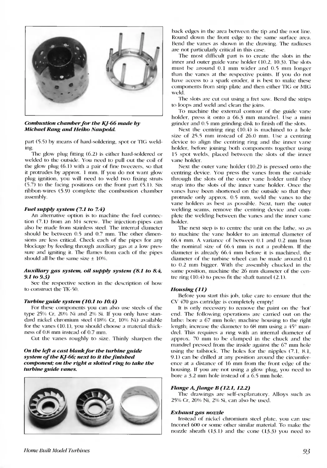
Combustion chamber (5.1 to 5.9. 6.1, 6.2) ................................................................................................................92
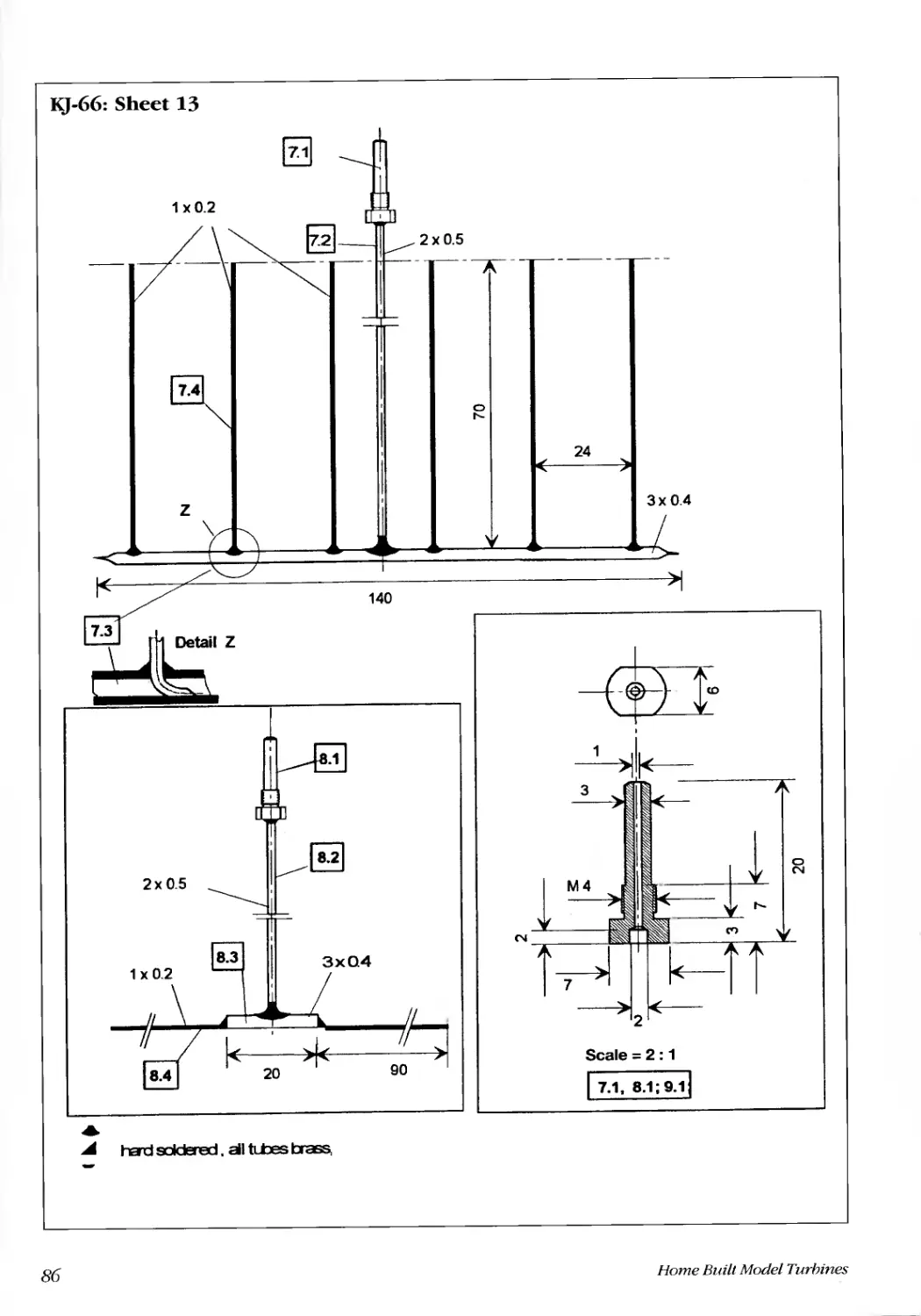
Fuel supply system (7.1 to 7.4) ..................................................................................................................................93
Auxiliary gas system, oil supply system (8.1 to 8.4.9.1 to 9.3) ...............................................................................93
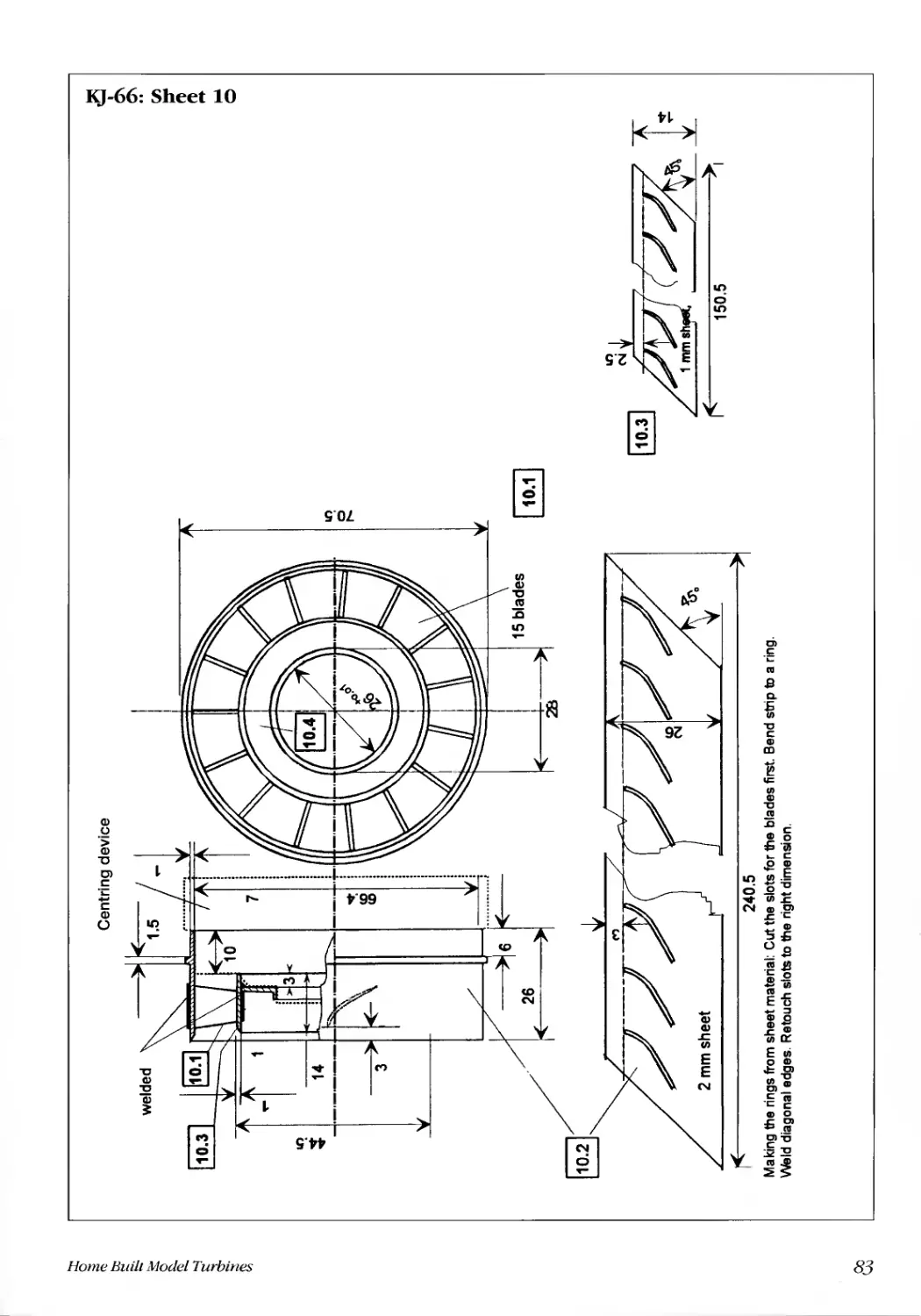
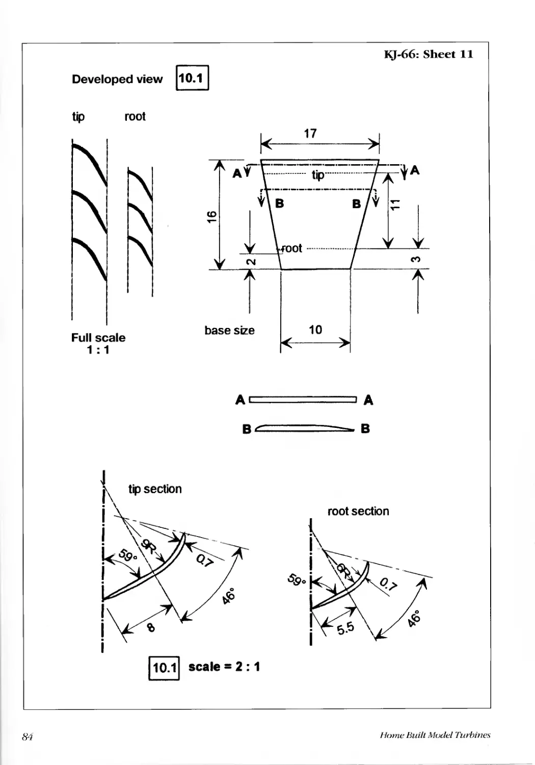
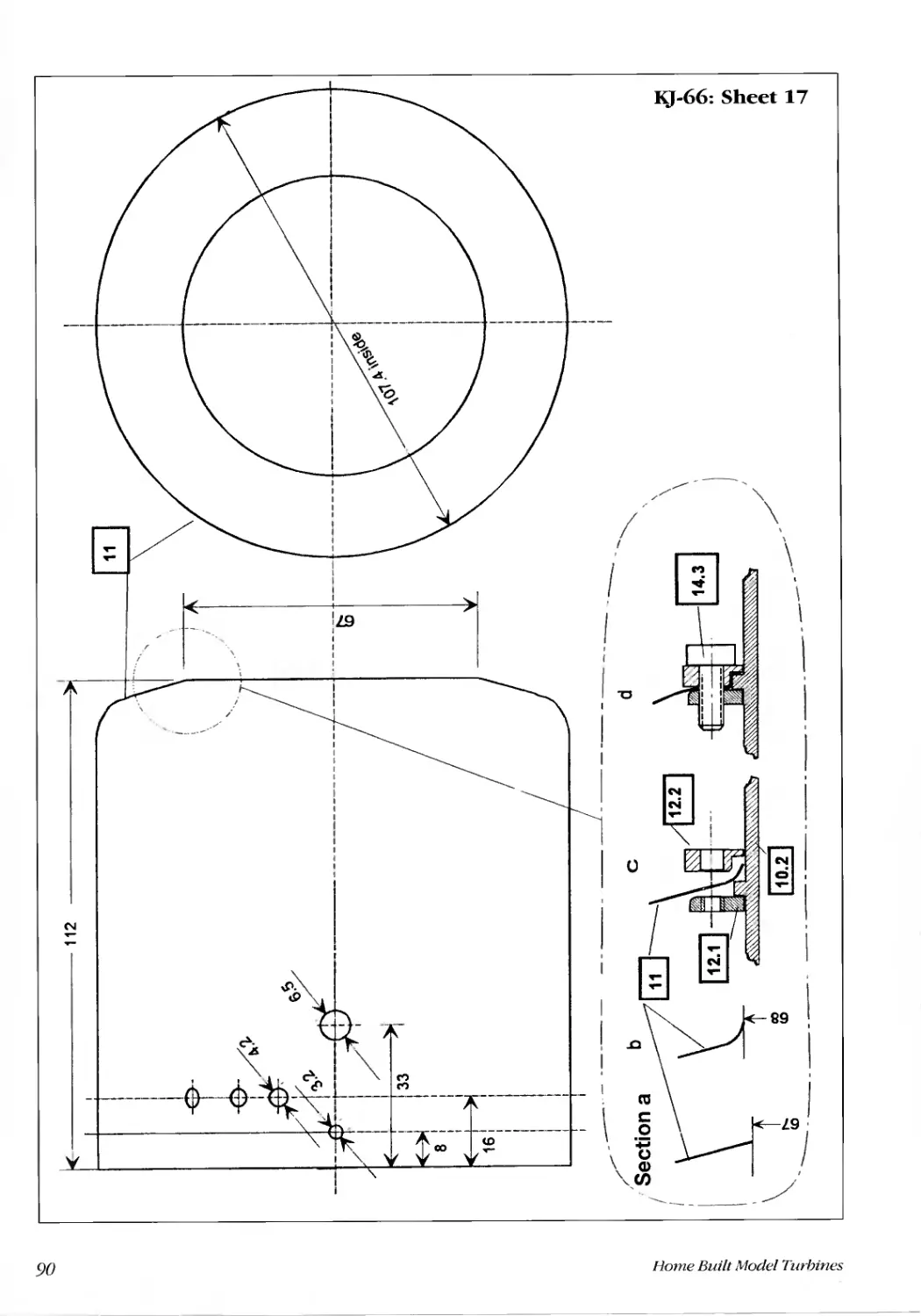
Turbine guide system (10.1 to 10.4) ..........................................................................................................................93
Housing (11) ... no... ...... ....... ........ .......... ....... ....... ..... ......... ........... .............. ........... .......... ............... ............................. .93
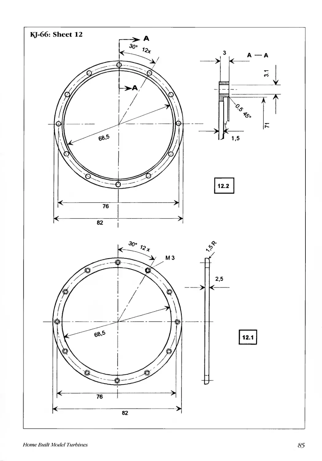
Flange A, flange B (12.1. 12.2)...................................................................................................................................93
Exhaust gas nozzle.. ........ ...... .......... .......... ....... ....... ....... .......... ............. ............ .......... ........... .............................. ......93
Final assembly...................................................................................................................... .......................................94
Chapter 6. Important Safety Instructions. .......... ....... ...... ...... .......... ........... .............. ............ .......... .................................. ....95
Danger of fire........................................................................................................................... ...................................95
Danger of sucking in foreign objects..... ....... ..... ........ ........ .......... ............. ............ ........... ............... ..................... .....95
Danger due to exhaust gases......................................................................................................................... ............95
Danger of rotating parts.......................................................................................................................... ...................95
Danger of insufficient proficiency in flying models .................................................................................................95
Chapter 7. What Does The Future Have in Store?..............................................................................................................96
Appendix ....... ....... ...... .... ...... ...... ........ ....... ....... ...... ........ ....... .......... ............. ............. ......... ............. ........................... .98
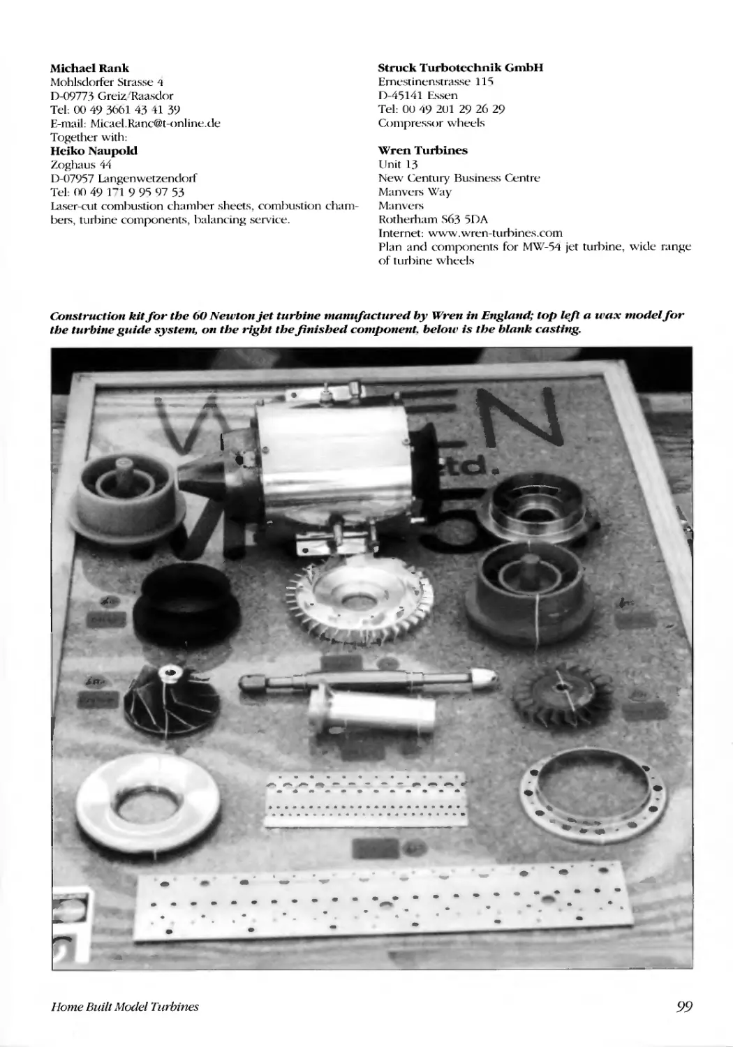
Potential suppliers .............................................................................................................................. ....................... .98
References and sources of information. ........ ...... ....... ....... ....... .......... .......... ............. ............. .............. .......................... ...100
Books. Magazines .... ..... ..... ..... ......... ........ ....... ...... ........ ......... .......... .......... ............ ............ ................... ....................100
Organisations .............................................................................................................................. ........................................101
About The Author
K lrt Schreckling was born in 1939. His first practi-
cal experience of model aircraft came at the age
)f five, when he transformed a tangled-up kite
into an aeroplane. Over the years that followed, not only
did he build a great number of model aircraft, he also
developed several of his own remote controllers.
He was aged eleven when he first saw Vampire Jet
planes in the sky. That turned out to be a defining
moment in his life. Study of a small encyclopedia gave
him the belief that he could come up with a simple way
of constructing a turbine. However. it took almost four
decades before he finally started work in earnest at ful-
filling his youthful dream. Today, people like to refer to
him as the "inventor", the "pope of turbines" or also as
the "father of turbines". None of that is really true.
Instead. he prefers to see himself as one in a long line of
fathers of model jet turbines.
He received a basic technical education and went on
to study physics at university. He then worked for 32
years as a qualified engineer for a large Rhine-based
chemical company. In his job he gained experience of
different technical areas, none of which ever involved
turbines. He was happy to take early retirement in 1999.
Having completed his book about turbo props, he
feared that he might have to retire as turbine developer
as well. However. as it turned out. this was not the case.
Kurt Schreckling cannot deny his special love of good
food. Indeed, flying model aircraft is not his only vice.
He was also tempted into off-the-wall experiments with
skis in the snow, exploring the effects of gravitational
forces. I 'p until now he has managed to come through it
all unscathed.
Home Built Model Turbines
. .,
- -
. .'
I
"
"" ../' "'-
,
. ,
-.I...
-:\'
.
.....
.JIo-,
"
:;,, -.""i
-'.
....
t .......
-
.,
S
'I
/
...
":i
1
-rJ....,
".... .-. .....----.-
j
:. . "-.
-
"'t
':I
7
Foreword
T he inventor, Dr. Hans Joachim Pabst von Ohain
(lYll-19HH), developed the first jet turbine which
flew for the first time in August 1939. I was only
three months old at the time and still in nappies. As far
as I am concerned, the hisroty of scale models of jet tur-
bines began at the end of the 19HOs. In 191'51'5 I began
putting some ideas into practice that were to produce
the first simply constructed model jet turbines capable of
flight. I described the methods and the first trials in 1992
in the first edition of the Modell-Technik-Berater No. 20
'Home-built jet turbines for model planes', published by
the 'Verlag flir Technik und Handwerk' German text.
This heralded a boom in the development of model
turbines, with strong support coming from Thomas
Kamps' book 'Model Jet Engines' published by Traplet
Publications. Of course, activity was not simply restricted
to those writing books. Uther people, all of them ama-
teur in the field. were equally busy developing model
turbines and contributing greatly to their popularity.
Rainer Binczyk. for example, travelled widely and ignit-
ed the turbine craze, particularly in Austria. The first per-
son to succumb was Hermann Mite from Graz and toda)
he is still infected with the bug. He was the first to
launch a twin-jet semi-scale model incorporating home-
built turbines. He developed a top-secret t()rmulae for
high performance compressor and turbine wheels and is
now working on a vertical take-off model with
adjustable nozzles.
Over the last five years several smaller companies
worldwide have made effective use of the work pio-
neered by these amateurs. Today they produce quite
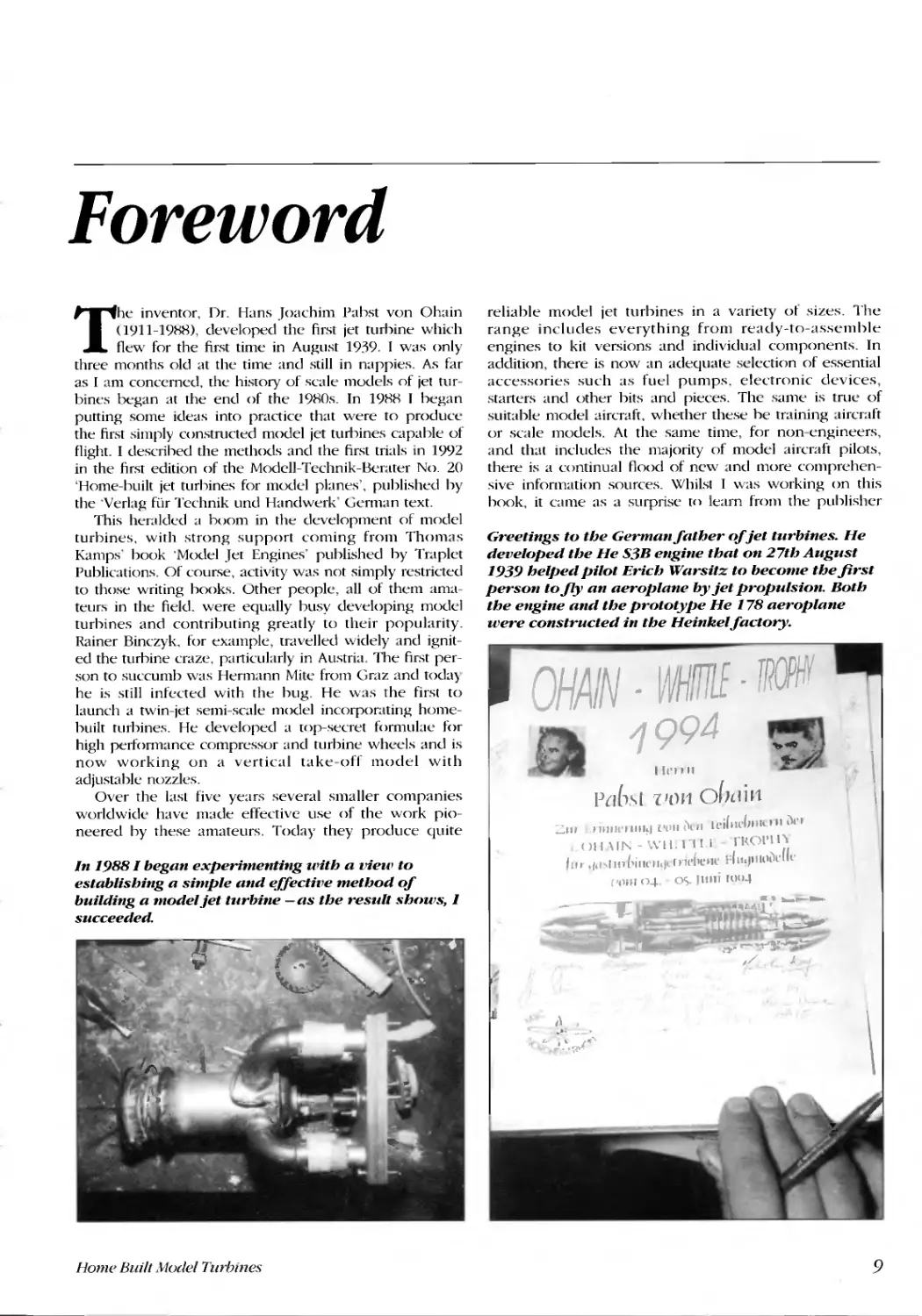
In 1988 I began experimenting with a view to
establishing a simple and effectilJe method of
building a model jet turbine -as the result shows, 1
succeeded.
!,--
'L
..., -
,
"
'"
.......
"
" '.
...
,zr
r'
'1.
f '''1
j"\
,'(
"
.
Home Built J10del Turbines
reliable model jet turbines in a variety of sizes. The
range includes everything from ready-to-assemble
engines to kit versions and individual components. In
addition, there is now an adequate selection of essential
accessories such as fuel pumps. electronic devices,
starters and other bits and pieces. The same is true of
suitable model aircraft, whether these be training aircraft
or scale models. At the same time, for non-engineers,
and that includes the majority of model aircraft pilots,
there is a continual flood of new and more comprehen-
sive information sources. Whilst I was working on this
book, it came as a surprise tn learn from the puhlisher
Greetings to the Germanfather of jet turbines. He
developed the He S3B engine that on 27th August
1939 helped pilot Erich Warsitz to become the first
person to fly an aeroplane by jet propulsion. Both
the engine and the prototype He 178 aeroplane
were constructed in the Heinkelfactory.
OHAIN
VHrrrlE - rROPHf
199 4
\
\
.,...
,.
.oo :
.... '
111'1111
P{I(1,\llllm O{wi 11
=11I '"1111" IIII!I ['ill. ii, II n'i(lle("Hu II i\!'t"
OIl\I)'.;-WI\..-I 11 fROI'II\
'11,. .,,,,'m (,jlll" hId 1"1{'('CIIl' f'llI.]III"i)clle
('(111I 0-1- OS. ]lIlli !l)"-t
.. ...........
""I ."I >\'t;
.. '_..l
;;. :.........!t..Jo-
,/1
...
j(
1\
\
...t, __
c.. ..!.". "'"
...
;.
9
L.. ...
- -
..
-
- ....
, , ""
.. -- _.J
f ) ..
.... ..
... ...,
-.... _ ,a -'
--d
-lilt
Tbe Kobler fami(}', a team of fatber alld two SOllS. At tbe Obaill Wbittle Tropby ill tbe summer of 1998 tbey
captured tbe spectators imagi1wtioll witb their three Heillkel 'Scllamallder'.
to build his own high thrust and reliable jet propubion
must come to terms with constructing to higher stan-
dards. l'nfortunately, the very simple approach, as
described in my firsl book. is no longer enough.
The chapter that explains basic principles is written
with the majority of home builders in mind, whose pro-
fessional career has not
involved any aspects of
physics or engineering
sciences. Consequently,
I do nor spend time
using formulae to dis-
cuss in detail the corre-
lation of physical
values. Indeed, this
would exceed rhe ,;cope
of this book in any case.
It is all too easy for spe-
cialists to forget that you
need years to learn the
language of formulae
and that it is not possi-
ble to adequately impart
this knowledge between
the covers of just one
book. Anyone who
wishes to learn about
theoretical principles in
more detail can find ref-
erences to the appropri-
ate literature in the
appendix. I will display
the results and calcula-
tions that are relevant
for the practical aspects
of model jet turbines in
the form of diagrams
and their practical appli-
cation.
that he was about to publish the first magazine in
German on the subject of model jet turbines and their
use: The JETMAG.
Today. of course, a model jet turbine is expecred to
he capable of a lot more than it was ten years ago. As a
result, specifications are higher and anyone who wants
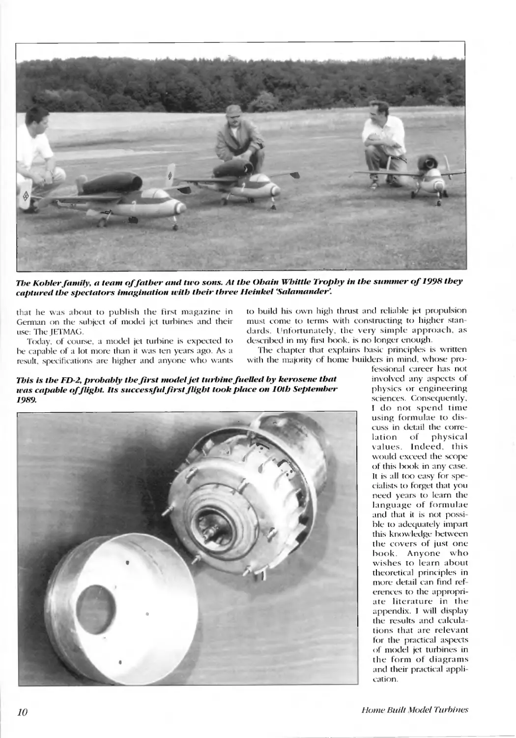
Tbis is tbe FD-2, probably tbefirst model jet turbillefuelled by keroselle tbat
ll'as capable cif fligbt. Its successfulfirstfligbt took place 01l10tb September
1989.
;.
-.
J
r
....
)
.
.
',...
."
.
\
1 ,.
J
.
.
10
Home Buill Hodel Turhines
Chapter 1
Physical- Technical
Principles of ModelJet
Turbines
What are we talking about?
It is a curiolls point of fact that you will not find the
term 'turbine' in most physics books. [n the new Fischer
encyclopedia under the entry 'turbine' is written: 'power
machine in which the energy of a flowing medium
(water, steam, gas) is transformed into useful energy;
precursors were windmills and waterwheels', Specialist
technical books on the subject explain the variety of tur-
bines in some detail under the main heading of 'flow
machines'. In Dubbel's pocket book of engineering you
find the definition: "the gas turbine is a machine that
uses heat to deliver mechanical energy (shaft power) or
thrust (e.g. aircraft engines)", Accordingly, the term 'gas
turbine' is the generic term for all types of turbo jet
engines. jet turbines as well as turbo-prop drives.
They are all deemed to be 'gas turbines'; from the
model engines such as JPX. FD. micro-turbines.
Turbomin and Pegasus as well as the KJ-66, .1-66 and TK-
50 turbo engines feawred in this book, up to and includ-
ing any such machine type that either currently exists or
is yet to be invented. They are all 'gas turbines'. and
they all generate thrust! In fact. an alternative and more
proper name for such devices is turbo air jet engines. I
prefer the term often used by experts: 'jet turbines',
Some people also call them jet engines. However, the jet
is actually just the back part of such an engine.
As you can see, we already have more than enough
definitions at our disposal. There is no need to come up
with any new definitions. Unfortunately. technical
experts do not always speak a language that is logically
correct and clear. Of course, to aid the understanding of
readers who do not have special prior knowledge. it is
essential to always state exactly what is meant by the
word 'wrbines'. Is that the complete unit. the turbine
wheel, a turbine stage or something else perhaps?
How does a model jet turbine work?
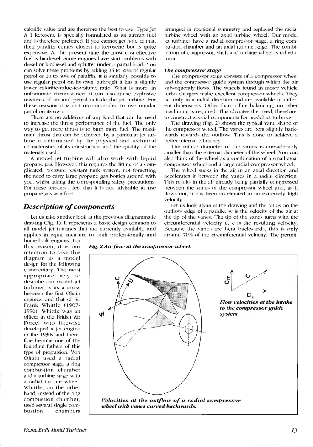
The diagram (Fig. 1) shows the typical construction in
a very simplified form. The same fundamental laws of
physics apply to model jet turbines as they do to the
large jet engines or in general to all air-breathing gas tur-
bines. The air is sucked in by the compressor wheel and
compressed. The introduction of combustion heat in the
Home Built Model Turhines
combustion chamber increases the work content of the
air i.e. the compressed and heated air can now perform
more work than was necessary to compress it. As the air
flows past the turbine wheel it gives up the energy
required to drive the compressor wheel. The excess
energy accelerates the air to very high velocity in an
axial direction opposite to the direction of flight. An
exhaust gas nozzle improves the efficiency of the
process.
The most important physical
parameters
A jet turbine generates thrust by accelerating air mass-
es. When masses of air are accelerated. they create force
effects. Forces are measured in newtons not in kilo-
grams! The force of 1 newton <signified by the letter N)
acts at the precise point in time when the mass of 1 kg
accelerates or decelerates by 1 m/s'. The change in
speed per unit of time is defined as acceleration and
measured in m/s'. Mass. i.e. the material weight of a
body. is measured in kilograms. Acceleration due to
gravity causes a fixed mass to exert a force on the sur-
face it stands on. Scales use this so-called 'weight-force'
to compare different weights. Spring balances take the
deflection of a spring and translate it into a measure-
ment on a scale. Take such a spring balance to the
moon to measure the same mass and the result would
be completely different from that on earth. even though
the mass itself would not have changed in any way,
You just have to pick up a hammer to be aware of
the very disparate forces it can generate. If you hold it
still in your hand. you just feel the weight-force. When
you take the hammer back. so as to bring it down, i.e.
when you accelerate it. dearly you must expend more
force. When the hammer strikes, it develops a force that
we are not at all able to replicate with our muscles
alone. Just try to push in a nail into a piece of wood
with your hand and you can begin to imagine the kind
of force generated by a hammer when it j,., decelerated.
In all instances the actual mass of the hammer remains
unaltered. Now let us apply our theorem that force
equals mass times acceleration to our jet turbine. For
example, an engine sucks in air at a speed of 0.25
kg/second and accelerates it at the same time to a speed
11
Glow plug
[
.
.... r
./ Distributor ring
./
Nozzle
Exhaust gasflnw
Air
-
Shaft Shaft tunnel
....
- Ballbearings
- -
[ '
Intake nozzle
Compressor wheel Compressor guide
l'anes
Combustion
chamber
Fig. 1: Diagram of a modeljet turbine.
of 400 m/s. Therdore, the static thrust is IOO N. For
those with a long memory. you can also say 10 Kp but
definitely not 10 kg! Admittedly, it is hetter to work in N
or in general in SI units. Let us cause a thrust of 100 N to
act on a model with an initial mass of 12 kg to give a
maximum possible initial acceleration of lUu -0- 12 m, s" =
8.33 m/s". This value i the true "alue. provided that the
forces associated with rolling friction and air resistance
at the start are ignored.
\'i/henever masses come together, it always results in
a change in the direction of veloCity. As a consequence,
the forces that act are what we call centrifugal forces.
111e wheels of our turbine and compressor are rotating
so quickly that they turn the air masses at a very high
velocity, resulting in high centrifugal forces. Just imag-
ine: a typical turbine wheel for a model jet turbine has a
diameter of 66 mm. The centre point of the turbine
vanes is at a diameter of SS mm. Such a vane weighs
only 1 gram. You may be already aware that such tur-
bine vanes can be driven at velocities of up to approxi-
mately 120,000 revolutions/min. This implies that the
vane hurtle at a velocity of 34S m/s. the equivalent of
1.242 km h on a circular path with a diameter of only 55
mm. So just imagine the force that ans on the connec-
tion between the turbine vane and the wheel disk - it is
4,430 N. That is approximately the same as lifting '14 ten-
litre buckets of water at the ame time. This illustrates
very dearly that the rotational velocity of a turbine
wheel does have its limits and that these must be
respected at all costs for reasons of safety.
In physics, work is determined as force times dis-
rance, measured in the direction of travel. Energy is the
ability to undertake work. To take a flying model up to
a certain height requires a specific amount of work. In
this instance the force is the weight-force of the model
and the distance up into the air. Flying over a specific
disrance in a straight line at a constant height, a model is
12
-'--
--
" ,.
.- ". --
Turbine wheel
J \...
Turbine guide vanes
--
Sticks
Housing
subject to the constant force of air re istance and the
path covered is the distance. This makes it possible to
calculate the work required. [n both cases we have only
taken into consideration the actual work that is per-
formed on the model. This effective work is generated
from the heat energy of the fuel burnt. Unfortunately.
only part of the heat energy can be transformed into
dfective work.
Power i the work divided by the time period in
which this work was completed. What is the power of a
jet turbine? There are many different ways of answering
this question:
We are interested in the power that the engine gives
to the model. This constitutes thrust times flight velocity.
As long as the model is fixed to the ground, it will not
fly no matter how high the thrust.
The power of the exhaust gas flow, also called jet-
stream power, is velocity squared, times half the mass
flow rate.
It is likewise possible to calculate the necessary ther-
mal power to be provided by the fuel, although this is
somewhat morc complicated.
Finally, a little additional effort is required to calculate
the power with which the turbine wheel drivcs the com-
pressor.
A physicist would not understand the term 'thrust-
power"; it would sound to him like a contradiction in
terms.
Suitable fuels
Most model jet turbines are pretty indiscriminating in
terms of the quality of the fuel. You can evcn go as far
as saying: you can use anything that is fluid, combustible
and not more volatile than diesel fuel. Compared to all
the other available fuels, diesel or similar materials, such
as kerosene or paraffin, have more or less the highest
Home Built Model Turbines
calorific value and are therefore the best to use. Type Jet
A ] kerosene is specially formulated as an aircraft fuel
and is therefore preferred. If you cannot get hold of that.
then paraffin comes closest to kerosene but is quite
expensive. At this present time the mosl cost-effective
fuel is biodiesel. Some engines have start problems with
diesel or biodiesel and splutter under a partial load. You
can solve these problems by adding 15 to 20010 of regular
petrol or 20 to :30% of paraffin. It is similarly possible to
use regular petrol on its own, although it has a slightly
lower calorific-value-to-volume ratio. What is more, in
unfortunate circumstances it can also cause explosive
mixtures of air and petrol outside the jet turbine. For
these reasons it is not recommended to use regular
petrol on its own.
There are no additives of any kind that can be used
to increase the thrust performance of the fuel. The only
way to get more thrust is to burn more fuel. The maxi-
mum thrust that can be achieved by a particular jet tur-
bine is determined b) the physical and technical
characteristics of its construction and the quality of the
materials used.
A model jet turbine will also work with liquid
propane gas. However, this requires the fitting of a com-
plicated, pressure resistant tank system, not forgetting
the need to carry large propane gas bottles around with
you. whilst taking the corresponding safety precautions.
For these reasons I feel that it is not advisable to use
propane gas as a fuel.
Description of components
Let us take another look at the previous diagrammatic
drawing (Fig. 1). It represents a basic design common to
all model jet turbines that are currently available and
applies in equal measure to both professionally and
home-built engines. For
this reason, it is our
intention to take this
diagram as a model
design for the following
commentary. The most
appropriate way to
describe our model jet
turbines is as a cross
between the first Ohain
engines, and that of Sir
Frank Whittle (1907-
1996). Whittle was an
officer in the British Air
Force, who likewise
developed a jet engine
in the ] 930s and there-
fore became one of the
founding fathers of this
type of propulsion. Von
Ohain used a radial
compressor stage. a ring
combustion chamber
and a turbine stage with
a radial turbine wheel.
Whittle, on the other
hand, instead of the ring
combustion chamber,
used several single com-
bustion chambers
Home Built iWodel Turhines
,lrranged in rotational symmetry and replaced the radial
turbine wheel with an axial turbine wheel. Our model
jet turbines have a radial compressor stage. a ring com-
bustion chamber and an axial turbine stage. The combi-
nation of compressor. shaft and turbine wheel is called a
rotor.
The compressor stage
The compressor stage consists of a compressor wheel
and the compressor guide system through which the air
subsequently flows. The wheels found in motor vehicle
turbo chargers make excellent compressor wheels. They
act only in a radial direction and are available in ditler-
ent dimensions. Other than a fine balancing, no other
machining is required. This obviates the need, therefore,
to construct special components for model jet turbines.
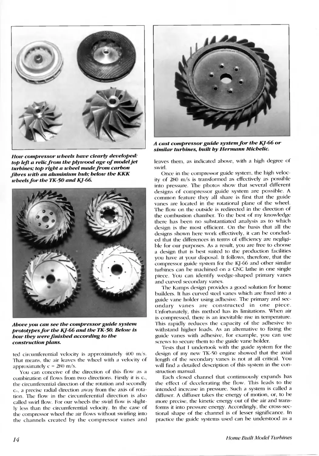
The drawing (Fig. 2) shows the typical vane shape of
the compressor wheel. The vanes are bent slightly back-
wards towards the outflow. This is done to achieve a
better internal efficiency.
The intake diameter of the vanes is considerably
smaller than the external diameter of the wheel. You can
also think of the wheel as a combination of a small axial
compressor wheel and a large radial compressor wheel.
The wheel sucks in the air in an axial direction and
accelerates it between the vanes in a radial direction.
This results in the air already being partially compressed
between the vanes of the compressor wheel and. as it
flows out, it has been accelerated to an extremely high
velocity.
Let us look again al the drawing and the ratios on the
outflow edge of a paddle. w is the velocity of the air at
the tip of the vanes. The tip of the vanes turns with the
circumferential velocity u, c is the resulting velocity.
Because the vanes are bent backwards, this is only
around 70% of the circumferential velocity. The permit-
Fig. 2 Air flow at the compressor wheel
/ @ :
- -- --rlI
Q7 --- ---
;
i
;
J i/
C u
Flow velocities at the intake
to the compressor guide
system
Velocities at the outflow of a radial compressor
wheel with vanes curoed backwards.
13
'-.....
-
.
'o'i-" -:,.':.1
..
" ,
..
...
. "\
.
......
,
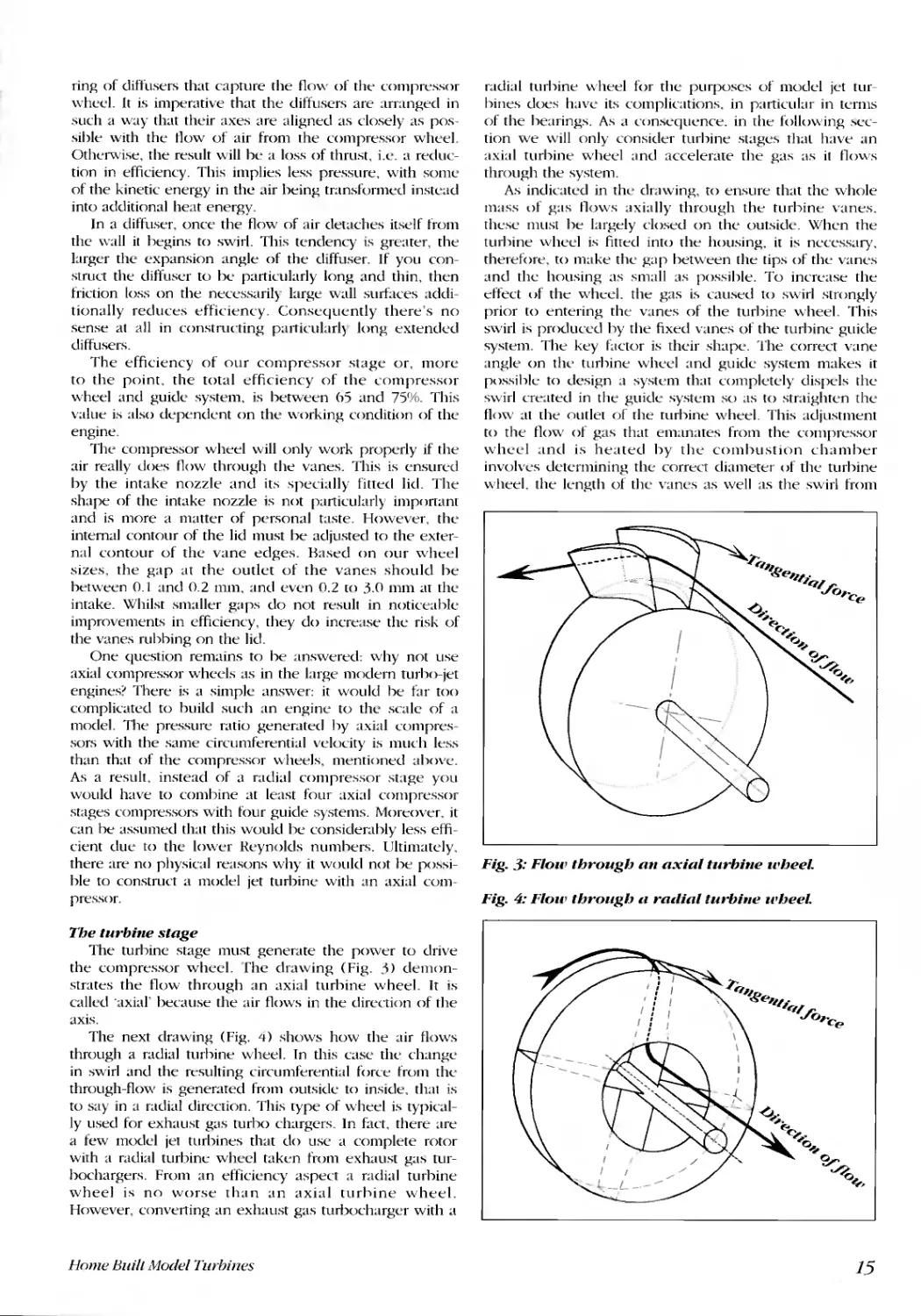
Holl' compressor wheels have clearly developed:
top left a relic from the plywood age of model jet
turbines; top right a wheel made from carbon
fibres with an aluminium hub; below the KKK
ll'heelsfor the TK-50 and KJ-66.
0
... . \'"
,
,--
..
- fl
,
.,...
..
'.
. . L
'. . "","..
\.(' .. \ .
"-
-
'.
X
\1
\
'"
\
i J I) \ '
Aboz'e you can see the compressor guide system
prototypes for the KJ-66 and the TK-50. Below is
holl' they ll'ere finished according to the
construction plans.
ted circumferential velocity is approximately lUO ITL s.
That means, the air leaves the wheel with a velocity of
approximately c = 2HO m/s.
You can conceive of the direction of this flow as a
combination of flows from two directions. Firsrly it is Cu,
the circumferential direction of the rotation and secondly
Cm, a precise radial direction away from the axis of rota-
tion. The flow in the circumferential direction is also
called swirl flow. For our wheels the swirl tlow is slight-
ly less than the circumferential velocity. In the case of
the compressor wheel the air flows without swirling into
the channels created by the compressor vanes and
14
.
r
.
.
I
'.A
.'
I.;.
A cast compressor guide system for the KJ-66 or
similar turbines, built by Hermann Michelic.
leaves them. as indicated above, with a high degree of
swirl.
Once in the compressor guide system. the high veloc-
ity of 2HO m/s is transformed as effectively as possible
into pressure. The photos show that several different
designs of compressor guide system are possible. A
common feature they all share is first that the guide
vanes are located in the rotational plane of the wheel.
The f10w on the outside is redirected in the direction of
the combustion chamber. To the best of my knowledge
there has been no substantiated analysis as to which
design is the most efficient. Un the basis that all the
designs shown here work effectively, it can be conclud-
ed that the differences in terms of efficiency are negligi-
ble for our purposes. As a result, you are free to choose
a design that is best suited to the production facilities
you have at your disposal. It follows, therefore, that the
compressor guide system for the KJ-66 and other similar
turbines can be machined on a CNC lathe in one single
piece. You can identify wedge-shaped primary vanes
and curved secundary vanes.
The Kamps design provides a good solution for home
builders. It has curved steel vanes which are fixed into a
guide vane holder using adhesive. The primary and sec-
ondary vanes are constructed in one piece.
l'nfortunately, this method has its limitations. When air
is compressed, there is an inevitable rise in temperature.
This rapidly reduces the capacity of the adhesive to
withstand higher loads. As an alternative to fixing the
guide vanes with adhesive, for example, you can use
screws to secure them to the guide vane holder.
Tests that J undertook with the guide system for the
design of my new TK-"iO engine showed that the axial
length of the secondary vanes is not at all critical. You
will find a detailed description of this system in the cun-
struction manual.
Each closed channel that continuously expands has
the effect of decelerating the flow. This leads to the
intended increase in pressure. Such a system is called a
diffuser. A diffuser takes the energy of motion, or, to be
more precise. the kinetic energy out of the air and trans-
forms it into pressure energy. Accordingly, the cross-sec-
tional shape of the channel is of lesser significance. In
practice the guide systems used can be understood as a
Home BuilllVlodel Turhines
ring of diffusers that capture the flow of the compressor
wheel. It is imperative that the diffusers are arranged in
such a way that their axes are aligned as closely as pos-
sible with the flow of air from the compressor wheel.
Otherwise, the result will be a loss of thrust, i.e. a reduc-
tion in efficiency. This implies less pressure, with some
of the kinetic energy in the .lir being transformed instead
into additional heat energy.
In a diffuser, once the flow of air detaches itself from
the wall it begins to swirl. This tendency is greater, the
larger the expansion angle of the diffuser. If you con-
struct the diffuser to be particularly long and thin, then
friction loss on the necessarily large wall surfaces addi-
tionally reduces efficiency. Consequently there's no
sense at all in constructing particular!) long extended
diffusers.
The efficiency of our compressor stage or, more
to the point. the total efficiency of the compressor
wheel and guide system, is between 65 and 75%. This
value is also dependent on the working condition of the
engine.
The compressor wheel will only work properly if the
air really does flow through the vanes. This is ensun:d
by the intake nozzle and its specially fitted lid. The
shape of the intake nozzle is not particularly important
and is more a matter of personal taste. However, the
internal contour of the lid must be adjusted to the exter-
nal contour of the vane edges. Based on our wheel
sizes. the gap at the outlet of the vanes should be
between 0.1 and 0.2 mm, and even 0.2 to 3.0 mm at the
intake. whilst smaller gaps do not result in noticeable
improvements in efficiency, they do increase the risk of
the vanes rubbing on the lid.
One question remains to be answered: why not use
axial compressor wheels as in the large modern turho-jet
engines? There is a simple answer: it would he far too
complicated to build such an engine to the scale of a
model. The pressure ratio generated by axial compres-
sors with the same circumferential velocity is much less
than that of the compressor wheels, mentioned ahove.
As a result, instead of a radial compressor stage you
would have to combine at least four axial compressor
stages compressors with four guide systems. Moreover. it
can be assumed that this would be considerably less effi-
cient due to the lower Reynolds numhers. Ultimately.
there are no physical reasons why it would not be possi-
ble to construct a model jet turbine with an axial com-
pressor.
Tbe turbine stage
The turbine stage must generate the power to drive
the compressor wheel. rhe drawing (Fig. 3) demon-
strates the flow through an axial turbine wheel. It is
called 'axial' because the air flows in the direction of the
axis.
The next drawing (Fig. 4) shows how the air flows
through a radial turhine wheel. In this case the change
in swirl and the resulting circumferential force from th(.'
through-flow is generated from outside to inside, that is
to say in a radial direction. This type of wheel is typical-
ly used for exhaust gas turho chargers. In fact, there are
a few model jet turbines that do use a complete rotor
with a radial turbin(.' wheel tak(.'n from exhaust gas tur-
bochargers. From an efficiency aspect a radial turbine
wheel is no worse than an axial turbine wheel.
However, converting an exhaust gas turbocharger with a
Home Buill Model Turbines
radial turbine wheel for the purposes of model jet tur-
bines does have its complications. in particular in terms
of the bearings. As .I consequence. in the following s(.'c-
tion we will only consider turbine stages that have an
axial turhine wheel and accelerate the gas as it flows
through the system.
As indicated in the drawing, to ensure that the whole
mass of gas flows axially through the turbine vanes.
th(.'se must be largely dosed on the outside. When the
turbine wheel is fitted into the housing, it b necessary,
therefore, to make the gap between the tips of the vanes
and the housing as small as possible. To increase the
effect of the wheel. the gas is caused to swirl strongly
prior to entering the vanes of the turbine wheel. This
swirl is produced by the fixed vanes of the turbine guide
system. The key factor is their shape. The correct vane
angle on the turbine wheel and guide system makes it
possible to design a system that completely dispels th(.'
swirl created in the guide syst(.'m so as to straighten the
tlow at the outlet of the turbine wheel. This adjustment
to the flow of gas that emanates from the compr(.'ssor
wheel and is heated by the combustion chamber
involv(.'s determining the correct diameter of th(.' turbine
wheel. the length of the vanes as well as the swirl from
r Q "
We",.
'Q/j;
o"ce
q.
.....
Q
"'"
Fig. 3: Flow tbrougb an axial turbine wbeeL
Fig. 4: Flow tbroug/:J a raclial turbine wbeeL
",
We", .
'Q/j;
o"ce
q;.
.....
o
<;,
15
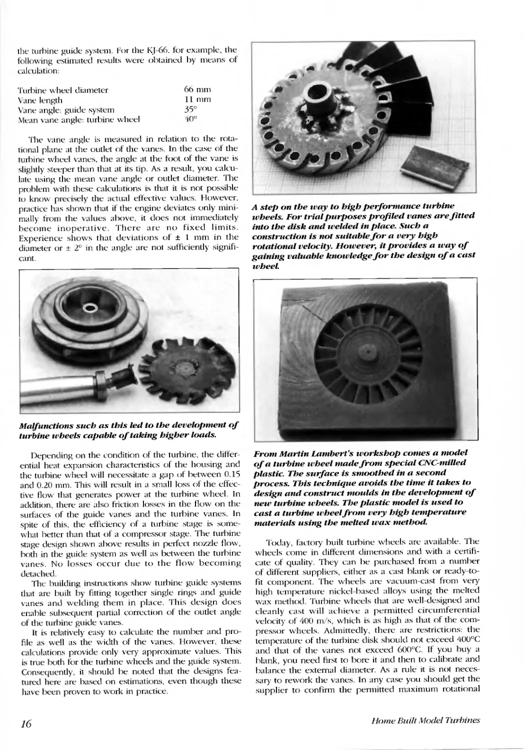
the turbine guide system. For the KJ-66. for example. the
following estimated results were obtained by means of
calculation:
Turbine wheel diameter
Vane length
Vane angle: guide system
Mean vane angle: turbine wheel
6h mm
11 mm
35°
,,0°
The vane angle is measured in relation to the rota-
tional plane at the outlet of the vanes. In the case of the
turbine wheel vanes, the angle at the foot of the vane is
slightly steeper than that at its tip. As a result, you calClI-
late using the mean vane angle or outlet diameter. The
problem with these calculations is that it is not possible
to know precisely the actual effective values. However.
practice has shown that if the engine deviates only mini-
mally from the values above, it does not immediately
become inoperative. There are no fixed limits.
Experience shows that deviations of :!: 1 mm in the
diameter or :!: 2° in the angle are not sufficiently signifi-
cant.
...
e-
'II'
..
.
......
Malfunctions such as this led to the development of
turbine wheels capable of taking higher loads.
Depending on the condition of the turbine, the differ-
ential heat expansion characteristics of the housing and
the turbine wheel will necessitate a gap of between 0.15
and 0.20 mm. This will result in a small loss of the effec-
tive flow that generates power at the turbine wheel In
addition, there are also friction losses in the flow on the
surfaces of the guide vanes and the turbine vanes. In
spite of this, the efficiency of a turbine stage is some-
what better than that of a compressor stage. The turbine
stage design shown above results in perfect nozzle flow,
both in the guide system as well as between the turbine
vanes. No losses occur due to the flow becoming
detached.
The building instructions show turbine guide systems
that arc built by fitting together single rings and guide
vanes and welding them in place. This design does
enable subsequent partial correction of the outlet angle
of the turbine guide vanes.
It is relatively easy to calculate the number and pro-
file as well as the width of the vanes. However, these
calculations provide only very approximate values. This
is true both for the turbine wheels and the guide system.
Consequently, it should be noted that the designs fea-
tured here are based on estimations, even though these
have been proven to work in practice.
16
..
.- .
.. . "- -
.. If .
. : If'
. , '.
. .tit
.
. .
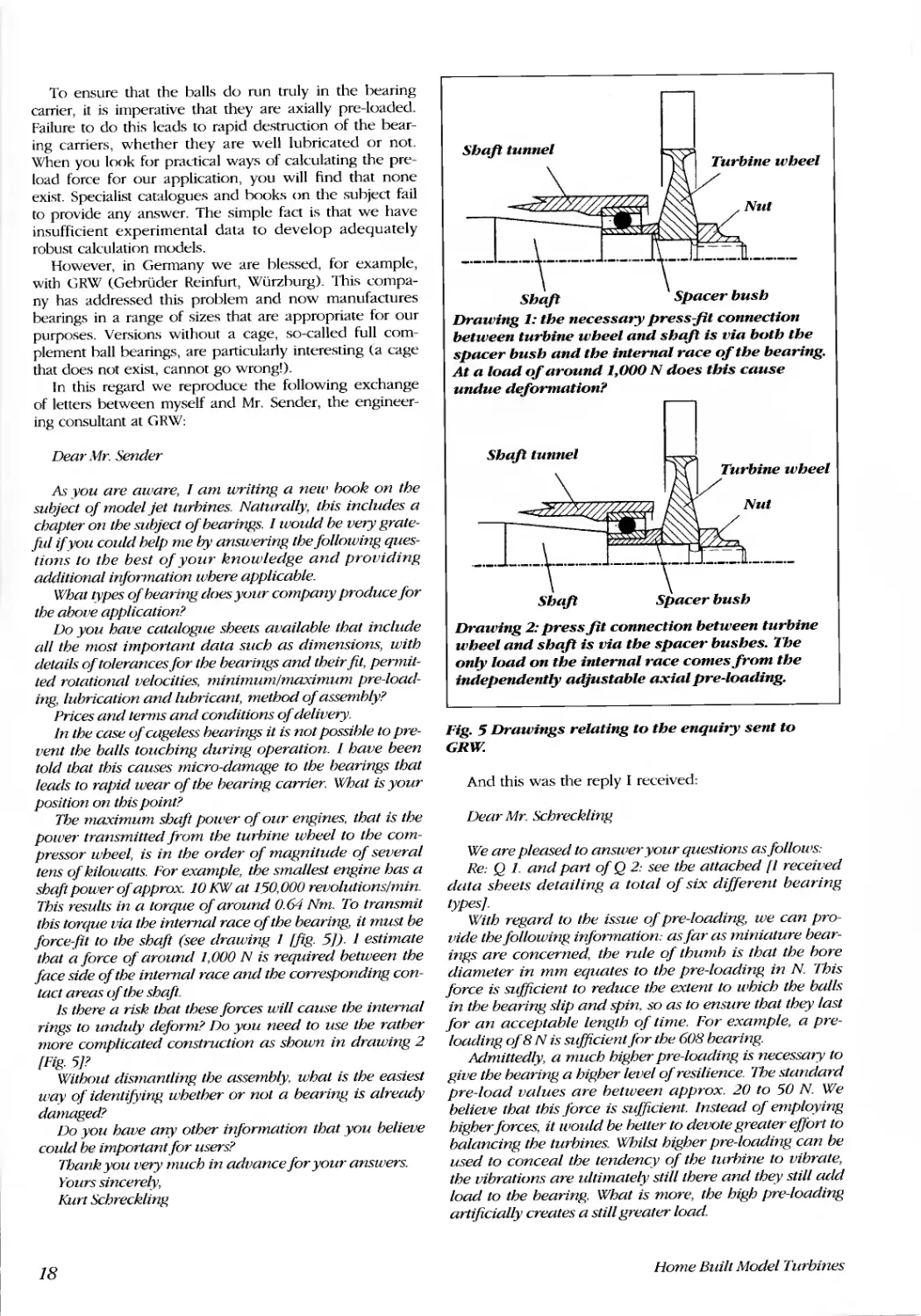
A step on the way to high performance turbine
wheels. For trial purposes profiled vanes are fitted
into the disk and welded in place. Such a
construction is not suitable for a very high
rotational velocity. However, it provides a way of
gaining valuable knowledge for the design of a cast
wheeL
"
....
L
'..
..)
i..oo
.....
,
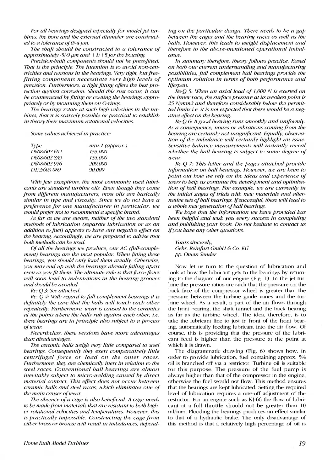
From Martin Lambert's workshop comes a model
of a turbine wheel made from special CNC-milled
plastic. The suiface is smoothed in a second
process. This technique avoids the time it takes to
design and construct moulds in the development of
neu' turbine wheels. The plastic model is used to
cast a turbine wheelfrom very high temperature
materials using the melted wax method.
Today, factory built turbine wheels are available. The
wheels come in different dimensions and with a certifi-
cate of quality. They can be purchased from a number
of different suppliers, either as a cast blank or ready-to-
fit component. The wheels are vacuum-cast from very
high temperature nickel-based alloys using the melted
wax method. Turbine wheels that are well-designed and
cleanly cast will achieve a permitted circumferential
velocity of 400 mis, which is as high as that of the com-
pressor wheels. Admittedly, there are restrictions: the
temperature of the turbine disk should not exceed 400°C
and that of the vanes not exceed 600°C. If you buy a
blank, you need first to bore it and then to calibrate and
balance the external diameter. As a rule it is not neces-
sary to rework the vanes. In any case you should get the
supplier to confirm the permitted maximum rotational
Home Built Model Turhines
Q
j
;1
'111I
...,,'
Turbines from tbe collectiolls of Lumbert ulld Scbrecklillg.
,/
)
"-r _
"
.':\
..
..
,.
On tbe left U turbille for tbe TK-50 by Murtill
Lambert, Oil tbe rigbt u rudiul turbille from a small
turbocburger.
velocity and operating temperature for the particular tur-
bine wheeL
Recently, it has also been possible to find turbine
guide systems that have heen produced as castings t(lr
the most popular sizes with a turbine wheel diameter of
66 mm.
Bearillgs, coullteractillg reSOIlUIlCe l'ibrutioll Ulld
lubricutillg tbe rotor
The shaft transmits the moment of force and hence
the power from the turbine wheel to the compressor
wheeL Looking at the design drawing. the diameter of
the shaft appears surpri ingly large. However, its very
high rigidity is necessary. Otherwise, even if the rotor
were perfectly balanced, it would still he susceptihle to
resonance vihration at high rotational velocities. As a
consequence. the maximum permitted operating rota-
Home Built .Hodel Turbines
"
t,
t)
I.
tional velocity is set at a level below the onset of reso-
nance vihration. In our huilding instructions the rotor
specification represents a suhcritical velocity. In other
words, the maximum permitted rotational velocity is
lower than the rotational velocity at which resonance
vibration occurs.
'\Iote: resonance vihration leads spontaneously to the
destruction of the engine. llnI()rtunately, it is only possi-
hIe to approximate the critical rotational velocity. As a
result it should not he specified on any account for rea-
sons of safety. Bohl and Duhhel provide a more detailed
explanation (see references in the appendix). Any of the
following changes to a given design will result in a
reduction in the critical rotational velocity and. likewise,
the permitted maximum rotational velocity:
. Reducing the diameter of the shaft.
. Making the shaft from a material with a low elasticity
modulus.
. Lengthening the shatto
· Increasing the wheel mass.
· Increasing the distance hetween the centre of gravity
of the wheel mass from the centre of the bearings.
Of course. high rotational velocities necessitate preci-
sion hall hearings. At the tart such ball hearings were so
expensive that few could afford them. We had to make
do with standard versions. All the same. with an engine
such as the KJ-(i6 it was still possible to run at rotational
velocities of as high as 90,000 revolutions/min.
Nevertheless, fitting the same jet turhine with modern
turbine wheels made from very high temperature alloys,
its capability is increased to rotational velocities of
l20,OOO revolutions/min. Indeed. the smaller TK-SO and
similar engines can even reach 1 '50,000 revolutions min.
Clearly, standard ball bearings are no longer suitable for
such applications.
17
To ensure that the balls do run truly in the bearing
carrier, it is imperative that they are axially pre-loaded.
Failure to do this leads to rapid destruction of the bear-
ing carriers, whether they are well lubricated or not.
When you look for practical ways of calculating the pre-
load force for our application, you will find that none
exist. Specialist catalogues and hooks on the subject fail
to provide any answer. The simple fact is that we have
insufficient experimental data to develop adequately
robust calculation models.
However, in Germany we are hlessed, for example,
with GRW (Gehriider Reinfurt, Wilrzburg). This compa-
ny has addressed this problem and now manufactures
bearings in a range of sizes that are appropriate for our
purposes. Versions without a cage, so-called full com-
plement ball bearings, are particularly interesting la cage
that does not exist, cannot go wrong!).
In this regard we reproduce the following exchange
of letters between myself and Mr. Sender, the engineer-
ing consultant at GRW:
Dear J1r. Sender
As you are aware, I am writing a new hook on the
subject of model jet turhines. Naturally, this includes a
chapter on the subject of bearinRs. I would be very grate-
ful if you could help me by answerinR the following ques-
tions to the best of your knowledge and providinR
additional infonnation where applicable.
What types of hearing does your company produce for
the above application?
Do you have catalogue sheets available that include
all the most important data such as dimensions, with
details of tolerances for the bearings and their fit, pennit-
ted rotational velocities, minimum/maximum pre-load-
ing, lubrication and lubricant, method of assemh y?
Prices and terms and conditions of delivery.
In the case of cageless hearings it is not possihle to pre-
vent the balls touching during operation. 1 have been
told that this causes micro-damage to the hearings that
leads to rapid wear of the hearing carrier. What is your
position on this point?
The maximum shaft power of our engines, that is the
power transmitted from the turhine wheel to the com-
pressor wheel, is in the order of magnitude of several
tens of kilowatts. For example, the smallest engine has a
shaft power of approx. 10 KW at 150,000 revolutions/min.
This results in a torque of around 0.64 Nm. To transmit
this torque via the internal race of the bearing, it must be
force-fit to the shaft (see drawing I [fig. 5j). 1 estimate
that a force of around 1,000 N is required between the
face side of the internal race and the corresponding con-
tact areas of the shaft.
Is there a risk that these forces will cause the internal
rings to unduly deform? Do you need to use the rather
more complicated construction as shown in drawing 2
[Fig. 5j?
Without dismantling the assembly, what is the easiest
way of identifying whether or not a bearing is already
damaged?
Do you have any other information that you believe
could be important for users?
Thank you very much in advance for your answers.
Yours sincere y,
Kurt Schreckling
18
-.-.- -.-.-.,-.-.-.-. .-.-.-.
Shalt Spacer bush
Drawing 1: the necessary press-jit connection
between turbine wheel and shalt is via buth the
spacer bush and the internal race of the bearing.
At a load of around 1,000 N does this cause
undue deformation?
Shalt tunnel
-.-.-.\-.-.-.-. .-.-.-.-.
Shalt Spacer bush
Drawing 2: press fit connection between turbine
wheel and shalt is via the spacer bushes. The
only load on the internal race comes from the
independently adjustable axial pre-loading.
Fig. 5 Drawings relating to the enquiry sent to
GRW:
And this was the reply I received:
Dear Mr. Schreckling
We are pleased to answer your questions as follows:
Re: Q 1. and part of Q 2: see the attached [1 received
data sheets detailing a total of six different bearing
ypesj.
With regard to the issue of pre-loading, we can pro-
vide the following infonnation: as far as miniature bear-
ings are concerned, the rule of thumh is that the hore
diameter in mm equates to the pre-loading in N. This
force is sufficient to reduce the extent to which the balls
in the bearing slip and spin. so as to ensure that they last
for an acceptable length of time. For example, a pre-
loading of 8 N is sufficient for the 608 bearing.
Mmitted y, a much higher pre-loading is necessary to
Rive the hearing a higher level of resilience. The standard
pre-load values are hetween approx. 20 to 50 N. We
believe that this .force is sufficient. Instead of employing
higher forces, it would be hetter to devote greater effort to
balancing the turbines. Whilst higher pre-loading can be
used to conceal the tendency of the turhine to vibrate,
the vibrations are ultimate y still there and they still add
load to the bearing. What is more, the high pre-loading
artificially creates a still greater load
Home Built Model Turbines
Fur all hearings designed e"pecia/ v for model jet tur-
bines, Ihe hare and Ihe exlernal diameler are conslrucl-
ed to a tulerance ofO/-q l.un.
The shaji shuuld be cunslrue/ed 10 a ,olerance of
appro."\"imalelv -5/-') l.un and + 1/ + 5 jor Ihe housing.
Precisiun-buill cumpunents should nol he press fitted.
Thai is Ihe principle. The iII/eli/ion is 10 alloid nOll-cen-
tricities and tensions in the hearings. Vel)' tight. hut free-
fitting components necessitate I'ery high lel'els of
precision. Furlhermore, a lighl .fitling c!ffel: Ihe besl pro-
tectiun against currusiun. Shuuld Ihis rust OCClll: it can
be coun/eracled b.V.fil/ing or coaling Ihe bearings appro-
primelv or bv mounling Ihem on a-rings.
The bearings rolale al such high I'elocilies in Ihe lur-
hines, Ihal i/ is scarcelv possihle or praclical 10 eSlahlish
in theOl)' their ma."\"imum rotationall'elucities.
Some I'alues achiel'ed in practice:
T.}pe
D60R/602 602
D608/602839
D60R/602976
Dl/2/6030R9
min-] (approx.)
15-).000
155,000
200,000
90,000
Wilh fell' exceptions, Ihe most cOlllllwnlv used luhri-
cants are standard turhine oils. Ellen though they come
from differell/ m{lI1l fac/llren mosl oils are basica/ v
similar in Iype and I'iscosily. Since we do nol hlll'e a
preference for one manl fae/urer in particular, we
would prefer nol 10 recommend a specific hrand
A, far as Ii'e are aware, neither of Ihe 1Ii'0 standard
methods of luhricalion (separate luhricaliOil or as an
addition to fite/) appears to hal'e lII r negatil'e effect on
Ihe bearing. According v, we are prepared 10 adl'ise Ihal
bOlh melhods can he used.
Qf all Ibe bearings we produce, our AC (filll-comple-
menl) hearings are Ihe mosl popular. When .liain!!, Ihese
bearings. you sbould on v load them a.Yia/ v. Otherwise,
you may end up wilh Ihe hearings alrea{ vfalling apan
el'en as you fit Ihem. The ultimate rule is that forcejlows
will soon lead to indenlalions in Ibe hearing groOl'es
and should be lIl l oided.
Re: Q 3: !',ee aI/ached.
Re: Q --I: With repprd 10 jidl complemelll bearings i/ is
de.finile v Ihe case Ihal Ihe halls ll'iII luuch each olher
repealed }'. Furlhermore, wear is caused 10 the ceramics
at Ibe poillls where the halls ruh agaill. 1 each other, i.e.
Ihese bearings are in principle also sulijeci 10 a process
of wear:
Nel'ertheless, Ihese l'ersions halle more adl'anlages
than disadl'antages.
The ceramic balls Il'ei!!,h I'el)' lillie compared to sleel
bearings. Consequelll v Ihev exerl comparalil'e I' little
cenlr(fil!!,al force or load on the outer races.
FllI1hermore, Ihey are chemica/ v inerl in relalion 10 Ihe
steel races. COIlI'entional ball bearings are almost
inel'Uah v subjeCl 10 micro-welding caused by direct
material contact. This ejfect does IlOt occur betll'een
ceramic balls and sleel races, Ii'hich eliminales one of
the main causes of wear.
The absence of a cage is also benefi'cial. A ca!!,e needs
10 be madeji'om malerials Ihal are resislalllio bOlh high-
er rolalionall'elocUies and lemperalures. HOII'el'er, Ibis
is praclica/ v impossible. Conslrucling Ihe cage .I;-OIn
eUber hrass or hronze Ii'ill resull in imbalance depend-
Home Built ,Hodel Furbines
ing un the particular design. There needs to be a !!,ap
helll'eell Ibe cages and tbe bearing races as well as the
balls. Howel'er, this leads to weight (Ii placemelll and
Iherefore 10 Ihe abol'e-menlioned operational imbal-
ance.
In SWl1Inlll)' therefore, tbeOl)' .lollull's practice. Based
on hath our current underslandin!!, and manufaeluring
possibililies, full complement ball bearings prOl'ide the
optimum solution in terms of bOlh performance and
I(fespall.
Re-Q 5: When an lI.yialload of 1.000 N is e:Yerted un
Ibe inner race, Ibe swjace pressure at ils weakesl poinl is
25 N/mm2 and Iherefore considerab v be/all' the permil-
led limils i.e. il is nol e-,peeled that there II 'auld be a neg-
atil'e e.ffeci on Ihe bearinp,.
Re-Q 6: A guud bearing runs smuoth }! and lll1iform v.
A a consequence, noises or I!ibrations coming from Ihe
bearing are certainl}! nol insignificant. Equa/ v, obserl'a-
tion of the imbalance will certain v bighlighl an i : ue.
SensUil!e balance measuremenls Il'ill inslantlv rel1eal
lI'helher Ihe ball bearing is subject lu sume degree uf
wea r.
Re-Q 7: This letter and Ihe pages attached prOl'ide
ir(formalion on ball bearings. However, we are keen to
point out hOIl' we re v on the ideas and e."\perience of
users to help us continue the del'elopmenl and optimisa-
tion of ball bearings. For example, we are curren/ V in
the initial stages of trials witb new maierials and aller-
natil'e sels of ball bearings. !f success.fid, these will lead to
a whole new generation of ball bearings.
We hope Ihal Ihe ir(fOrmalion we bal'e prol'ided has
been helpfid and wish you el'er)' success in compleling
and publishing your book. Do nol hesitate 10 cO/ltact us
if you hlll'e any other questions.
}'ours sincere v,
Gehr. Reinj;lrl Gmbll & Co. KG
pp. Olwin Sender
Now let us turn to the question of lubrication and
look at how the lubricant gets to the bearings by return-
ing to the diagram of our engine (Fig. 1). In the jet tur-
bine the pressure ratios are such that the pressure on the
back face of the compressor wheel is greater than the
pressure between the turbine guide vanes and the tur-
bine wheel. As a result, a part of the air flows through
the front bearing, the shaft tunnel and the back bearing
as far as the turbine wheel. The idea, therefore, is to
take the lubricant line to just in front of the front bear-
ing, automatically feeding lubricant into the air flow. Of
course, this is providing that the pressure of the lubri-
cant feed is higher than the pressure at the point at
which it is drawn.
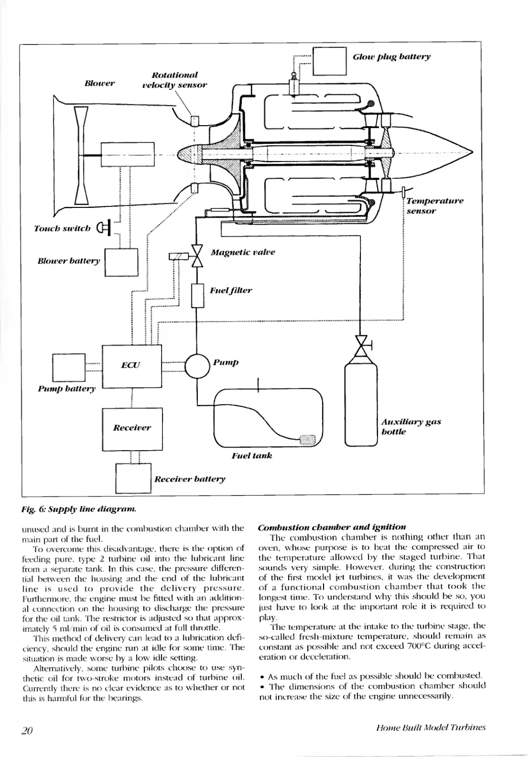
The diagrammatic drawing (Fig. 6) shows how, in
order to provide lubrication, fuel containing approx. 5%
oil is branched off via a restrictoL Turbine oil is suitable
for this purpose. The pressure of the fuel pump is
always higher than that of the compressor in the engine,
otherwise the fuel would not flow. This method ensures
that the bearings are kept lubricated. Setting the required
level of lubrication requires a one-ofT adjustment of the
restrictoL For an engine such as KJ-66 the flow of lubri-
cant at a full throttle should not be greater than 10
ml min. Flooding the bearings produces an effect similar
to that of a hydraulic brake. The only disadvantage of
this method is that a relatively high percentage of oil is
19
Blower
Rotatioll£11
..elocily \'0"
.._0"
..........
D ........ c:J u... ............
U"O"O ............
Pump battery' 1
Touch switch 0=1... 1
litoo'er bnttery 0
r. n ............
I r............
Receiver
: :
o Rerel, bntt"ry
Fig. 6: Supply line liagram.
unused and is burnt in the combu tion chamber with the
main part of the fuel.
To overcome this disadvantage, there is the option of
feeding pure. type 2 turbine oil into the lubricant line
from a separate tank. In this case. the pressure differen-
tial between the housing and the end of the lubricant
line is used to provide the delivery pressure.
Furthermore. the engine must be fitted with an addition-
al connection un the h()l\ ing to discharge the pressure
for the oil tank. The restrictor is adjusted so that approx-
imately "i ml min of oil is consumed at full throttle.
This method of delivery can lead to a lubrication defi-
ciency, should the engine run at idle for some time. The
situation is made worse by a low idle setting.
Alternatively, some turbine pilots choose to use syn-
thetic oil for two-stroke motor instead of turbine oil.
Currently there is no clear evidence as to whether or not
this is harmful for the bearings.
20
ri::::::D Glow plug battery
--.---------.-.----- - ---
[ '
Fuel tank
Temperature
sensor
Auxiliary gas
bottle
Combustion chamber and ignition
The combustion chamher is nothing other than an
oven, whose purpose is to heat the compressed air to
the temperature allowed by the staged turbine. That
sounds very simple. However. during the construction
of the first model jet turbines, it was the development
of a functional combustion chamber that took the
longest time. To understand why this should be so, you
just have to look at the important role it is required to
play.
The temperature at the intake to the turbine stage, the
so-called fresh-mixture temperature, should remain as
constant as possible and not exceed 700°C during accel-
eration or deceleration.
. A much of the fuel as possible should be combusted.
. The dimensions of the combustion chamber should
not increa e the size of the engine unnecessarily.
Home Built Model Turbines
. It hould run using fuels that are readily available such
as diesel or simibr.
· Combustion must be guaranteed at all load conditions,
i.e. the flame should not be extinguished.
. Ignition should not require any special auxiliary
means.
Let us start at the front. According to tilt' design. we
can calculate the mass flow through the engine.
Likewise we can arrive at an approximate value for the
so-called fresh-mixture temperarure, which is the tem-
perature before the entrance to the turbine stage. For an
average engine such as the KJ-66, when you calculate
the heating power. you come to a figure of approxi-
mately 140.000 watts! That is about seven times the
capacity of an oil-based hOllle central heating boiler.
Since the combustion chamber of the jet turbine has a
volume of only approx. '500 ml, the flame has to be
extremely intensive and therefore very hot.
Subsequently, the exhaust gases from this flame must be
cooled down to the temperature of the fresh-mixture
using excess air. The temperature in the flame zones
must be around r'oo°c. Clearly, it is necessary to cool
the combustion chamber. This is achieved by using that
part of the air tlow that streams along the outside of the
combustion chamber to the secondary air bore holes.
When you calculate the average flow velocity in the
flame zone, you would normally take out the flame. This
is effectively prevented by the po ition and size of the
secondary air bore holes. Part of the secondary air flow
enters in a radial direction. This is the part thaT is not
involved in the combustion process. IT is automatically
swirled towards The front and in so doing also forces hot
combustion ga es back into the flame zone. The COIll-
bustion chambers of large turbo engines likewise
employ this same effect. Whilst it is true that each tur-
bine necessitates its own particular hole geometry and
configuratlon, something that is only possible through
prolonged trial and error, it should not be forgotten that.
having estahlished the correCT hole geometry, you will
never need to reconfigure the combustion chamber
again. Of course. when you reproduce an engine to a
plan. this problem has already been solved for you.
When I built my first functional combustion chamber
for my fI)-turhines, I incorporated a convoluted vaporis-
er tube to prepare the fuel-air mixture. This system was
not particularly robust and did not last very long due to
progressive carbonisation of the fuel.
Thomas Kamps learnt from these shortcomings. He
became the first person to use so-called 'sticks'. These
took the form of small curved tubes and worked much
more effectively. Less pump pressure was required than
was the case with the vaporiser tube. For my firsT
attempt I fitted only three such tubes into the good old
FD-3/64. The result was pretty convincing. Whilst it was
apparent that three were not enough, the engine ran
without hot spots. even though it did produce a visible
white exhaust gas plume. When I used six 'sticks', the
FD-3 combustion chamber worked really well. However.
suhsequent development work was based on the Kamps
turbine, i.e. with compressor wheels from Turbo charg-
ers.
The curved sticks needed to be manufactured from a
material with a high temperature resistance. otherwise
they tended to combust rapidly. Alfred Kittelberger from
Hamburg then had The hrilliant idea of introducing The
Home Built Model Turbines
sTicks from the hack of the comhustion chamher as
straight tubes. as shown in our engine diagram (Fig. 1).
This provided a simple SoluTion to The main problem:
how to reliably develop the fuel-air mixture and at the
same time ensure near 100% fuel comhustion. Based on
experience at that time, six sticks seemed to he the opti-
mum numher.
Ignition is provided by a glow plug. The coil of the
plug proTrudes into the combustion chamber. To facili-
tate the ignition process, propane or. alternatively,
butane gas is introduced into the combustion chamber
as an auxiliary gas through two or three sticks. The sub-
sequent section entitled The start procedure' describes
this in more detail.
Likewise, you can use high-current glow plugs for the
ignition, However. this is much more complicated. What
is more, the high current can interfere with the remote
control function.
Tl:Je tl:Jrust Ilozzle
A channel that narrow creates a nozzle effect. This is
providing that the flow velocity does not exceed the
speed of sound. The speed of sound is dependent on
temperature. At an exhaust gas temperature of 600°C it
is '590 m/s. Our nozzles have an outflow velocity of
hetween 3')0 and 100 m's. which is somewhat less than
the speed of sound.
l\ nozzle has The effect of accelerating a medium. For
a given mass flo"" this produces a corresponding
increase in thrust. The energy required to do this must
come from The engine. Fitting a nozzle behind the Tur-
bine wheel automatically increases the temperature of
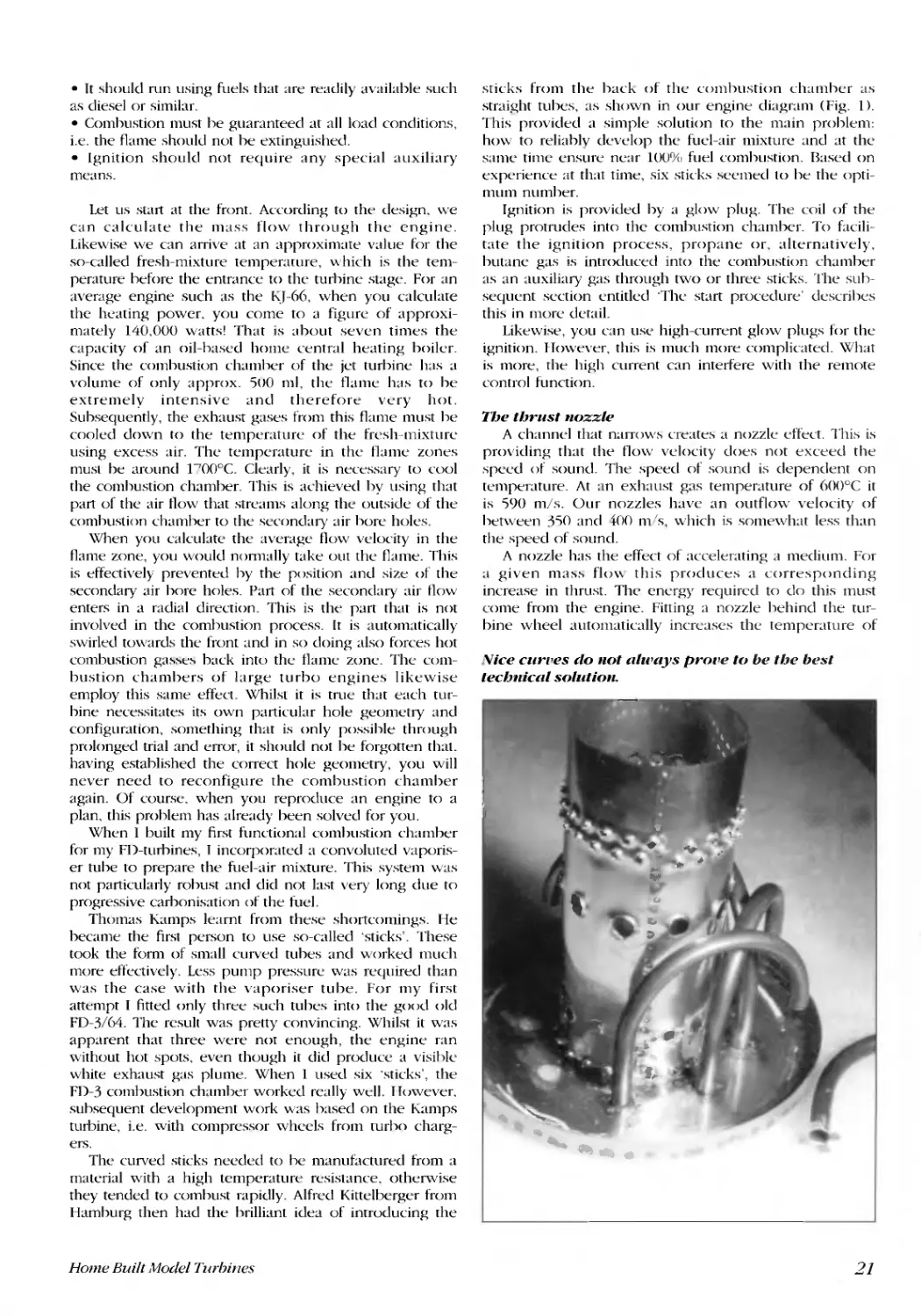
Vice curt'es do Ilot al'N'Ys pror'e to be tl:Je best
tecl:Jllicc,l solutioll.
11 .
,
. ,
,
I
... "
. "\jIo
.. #
..
'III'
, co
:>
r- _<41.
. .
f..
-",,'
" """--
',-
-....
21
the gas. Although the pressure remains constant. more
energy is made available. However, it is not possible to
keep on increasing the nozzle effect, since account must
he taken of the temperature limits, particularly with
respect to the turbine wheel. Experience shows that the
cross section of the nozzle should be approximately 10%
less than the ring cross section of the vanes of the tur-
bine wheel.
The core of the nozzle acts to prevent the exhaust
gasses swirling behind the disk of the turbine wheel.
l11is in itself results in a partial increase in thrust. The
core and sheath of the nozzle together form a ring noz-
zle. The above-mentioned 10% reduction in the nozzle
cross section results in a gain in thrust of between 30
and "10%. The reason for this may not be clear at first
sight. However, the physical explanation for this effect is
relatively simple: having passed through the nozzle the
air flow first follows the direction of the nozzle sheath,
as shown in our diagram of our engine. This implie that
the effective nozzle cross section is somewhat smaller
than would be presumed on the basis of the geometrical
cross section. This i also dependent on the shape of the
nozzle itself. The more conically the nozzle is tapered,
the greater is the nozzle effect. When it comes to design-
ing the shape of the nozzle, there is no hard and hlst
rule. You just have to remember not to exaggerate the
nozzle effect to such an extent that it exceeds the per-
mitted temperature limits of the turhine wheel.
The nozzle components can be made from stainless
steel sheeting. The connections must be welded with
shielding gas or spot-welded. In this case, hard-soldering
is not sufficiently reliable.
Heiko Hojt's SU-35 turns up the lJolume.
...
.....
Operational performance
The so-called international standard atmusphere, in
short ISA provides the basis for all calculations and mea-
surements. The ISA determines physical values as:
Air pressure:
101.3 kPa (equates to
1.013 mbar or LOU bar)
1"i°C
1.225 kglm'
Temperature:
Density:
Correlatioll of rotatiollal velocity, air mass flow,
compressor pressure, thrust alld temperature
If you want to compare rotating components of the
same shape and construction, yet of different sizes, then
it is best to calculak on the basis of circumferential
velocity. [his is the velocity at the utmost circumference
of the compressor or turbine wheel. Due to the cflect of
centrifugal forces, at the same circumferential velocity
each rotating component is subject to the same load. As
mentioned pn:viously, for our wheels the maximum per-
mitted circumferential velocity should be set at approx.
400 m/s. To make things clearer, I will begin by dealing
only with relative rotational velocities, i.e. the maximum
permissible rotational velocity is equal to 100%. I will
refer to this by its shurtened form: nl000/0. Subsequently,
the same arguments can he applied to model jet turbines
of different sizes.
Minimum rotational velocity is the lowest possible
velocity at which the turbine will still mn. This repre-
sents the bottom end of the cale and is set at around
nl00/0. Any lower and the turbine wheel would generate
-
-
----.
.
/
.If"
\ f '
\ K .'
. f
.-
...
, .'
;. C;;,.. ...-.J
i , , ". ....
.,
I.. 1! ..
"
.. r'
r
"
"
. -
'.
22
.
..
-
..
4//1-
. ..
I
0& - l
.
. ,
Home Buill Wadel Tur!Jines
in:-.ufficient power to overcome friction losses in the
bearings when mnning at acceptable temperatures in the
turbine stage. In practice the rotational velocity at idle is
set as high as n30% to n35%. n35% is more applicable to
smaller jet turbines such as the TK-50. It is easy to calcu-
late the corresponding rotational velocities measured in
revolutions per minute. Our turbine and compressor
wheels have a maximum permissible circumferential
velocity of 400 m/s. You use this figure and the chosen
wheel diameter. The table below illustrates trounded)
figures as calculated for the home-built turbines that are
described later.
One thing is obvious. As the rotational velocity
increases. so does the air-mass flow and the pressure
after the compressor stage. The air-mass flow increases
roughly proportionately to the rotational velocity. When.
for example, the compressor wheel impels 0.07 kg/s at
n30%, at nlOO% it would impel 0.23 kg/so However,
pressure increases much more rapidly. For this calcula-
tion you need to use, not the compressor pressure, but
rather what is known as the pressure ratio. Diagram 1
demonstrates the relationship between rotational velocity
and both the air mass flow and the pressure ratio. The
pressure ratio is the air pressure after the compressor
divided by the ambient air pressure. If you measure, for
example, 1.2 bar positive pressure after the compressor,
the total pressure is 2.2 bar, since the atmospheric pres-
sure at sea level is approximately 1 bar. Therefore, the
pressure ratio is 2.2 bar. This factor is non-dimensional.
For practical applications it can be noted that: the com-
pressor pressure in bar equals the pressure ratio minus
1, as long as you are at sea level. Diagram 2 shows the
results that were actually recorded for the jet turbines
KJ-66. J-66 and TK-50.
The Swiss mathematician, Leonard Euler 0707-1783),
discovered that the power generated by a compressor
wheel equals the mass flow multiplied by the circumfer-
ential velocity u of the wheel and the change in swirl.
Based on Euler's equations the power required to drive
the KJ-66 compressor wheel must be around 25,000
watt! In fact, the turbine wheel is indeed capable of
achieving this level of power. However, when throttled
back to n30%, the power reduces to only around 500
watt.
When air is compressed rapidly, it heats up. Using the
pressure values indicated in diagram 2, if we know the
efficiency of the compressor stage, we are able to calcu-
late the temperature as shown in diagram 3. It is appar-
ent that at nl00% the temperature of the compressed air
is already 120°C. This value is tme for ISA conditions
and assumes that the compressor stage operates at an
internal efficiency of 70%. If the temperature of the
intake air is higher or the compressor is less efficient,
the temperature after the compressor would be signifi-
cantly higher than 120°C. Consideration has to be given
to the fact that the only air available to cool the combus-
tion chamber and the bearings has already been pre-
heated. It is technically possible to increase the pressure
ratio by redesigning the compressor wheels. However.
Diagram 1
Air mass flow and pressure ratio in relation to relative rotational velocity
£: 200 3,0 "1:1
2.B
!i
"
...
!;
0.
'80
o
<:: '80
'40
.!O
"
... '''''
..
-=
.!S 100
...
0::
80
80
40
20
o
o w m * no
Relative rotational velocity [%]
Diagram 2
Rotational velocity and pressure ratio for the KJ-66. J-66 and TK-50
o 2
2
t2.3
"2.2
2.1
'" 2
'.9
...
1.7
'-"
,
,
...
1.2
'.1
,
o w . " H W no
Rotational velocity (1,000 rev/min)
this inevitably leads to cooling problems. particularly at
the combustion chamber.
A greater rotational velocity increases the pressure
ratio, which in turn improves the thermal efficiency of a
turbo engine. It follows that increasing rotational veloci-
ty also results in an ever steeper increase in thmst. The
graph in diagram 4 plots values measured from the
afore-mentioned jet turbines. When you compare dia-
gram 2 with diagram 4, it is apparent that thmst and
pressure increase along a similarly steep curve.
Technical reasons prevent the turbine from withstand-
ing particularly high temperatures. This is particularly
troe of the turbine stage. Clearly, the relation between
temperature and rotational velocity is of major signifi-
cance. The easiest method of establishing the tempera-
ture in the turbine stage is to measure the temperature
of the exhaust gas, since these are directly related.
Diagram 5 shows values recorded for exhaust gas tem-
perature for our turbines.
The start procedure
Starting the turbine requires the use of an auxiliary
drive to accelerate the rotor to at least nl0%. A velocity
of nl0% does not necessitate a particularly powerful
Jet turbine Wheel diameter (mm) nl0% (rev/min)
Behotec J-66 66 12,000
KJ-66 66 12,000
TK-')O ')0 1'),000
0100% (rev/min)
120,000
120,000
] ')0,000
030% (rev/min)
36,00 0
36,000
')0,000
Home Built Model Turbines
23
200,0
t 180.0
E 160,0
"
Co
E 140.0
=
120,0
100,0
-.: 80,0
..;
-..
2
.c..
....
Diagram 3
Air temperature after the compressor sta c
00,0
40,0
20,0
0,0
o 10 20 40 ro 00
Rclative rotational velocity (%)
Diagram 4
Rotational velocity and thru.. t of the KJ-66. J-66 and TK-';O
TK-SO with
n07.zle
th(nll
:1: 'C '
o ..-.-.-
o M ro _
130 140 ISO 1&0
Rotational velocity rl.OOO reV/min]
starter motor. A small electric motor with a shaft power
of 20 watt would he sufficient. provided it were coupled
directly to the rotor shaft via a slipping clutch, In any
case. turning the rotor immediately caUM: air to he
drawn into the comhustion chamber. Consequently, igni-
tion can take place as soon as the rotor starts to turn.
This produce an immediate turhine effect that in turn
lend greater force to the starter.
Experience .;hows that the comhustion chamber must
be pre-heated. This is true even if every effort is made to
inject fuel in the form of a very fine mist and likewise
applies even at the average temperatures of a central
E 500
"
.2-
c
"
Co
e..
!:i
200
f!
.c
...
'"
24
Diagram 5
Exhaust gas temperature urthe TK-50 andJ-66
J-66 with no:.t::de
---
TK-50 without nozzle
.
.
ro _ . m * - *
Rotational velocity [I.()()O rev/min]
European summer. Therefore, to produce an ignitable
mixture, the combustion chamber is heated from the
inside hy a propane-hutane gas flame (auxiliary gas
method). Within a few seconds of the introduction of
sufficient auxiliary gas the rotor will accelerate to n30%.
However, providing that the fuel is finely metered it is
possihle to switch on the fuel pump hefore the turhine
reaches n30%. At n30% the engine will he self-sustain-
ing. According to the tlow of fuel. it will continue to nm
without either auxiliary gas or starter assistance. The
supply of electricity to the glow plug can he switched
off immediately after ignition, although this is not
ahsolutely nece ary.
Ignition is also possible without using a glow or high-
current plug. At a rotational velocity of <n10% YOll intro-
duce auxiliary gas and then hold a lighter flame to the
nozzle outlet. On most occa ions a gas flame ignites at
the nozzle outlet. By adjll ting the flow of auxiliary gas it
is possible to get the tlame to jump into the combustion
chamher. This ignition method can be employed if you
have open access to the jet turbine. However, if the tur-
bine is mounted in the body of the model, you will not
he ;Ihle to see for sure wl1l:ther the flame is actually
burning in the combustion chamher or whether it only
continues to burn outside in the thrust tuhe. If the latter
is true and the pump carries on injecting fuel, the com-
hustion chamber will become flooded. This will contin-
ue until eventually the flame of auxiliary gas hurning
outside the comhustion chamber ignites the excess of
kerosene or diesel. At that point your only recourse is to
have a fire extinguisher at hand, otherwise the whole
model will be lost. In short, it is better to use a glow
plug.
Immediately prior to ignition, it is recommended that
you test the supply of lubricant to the turbine. To do
this. you need to shut off the fuel feed before it enters
the engim:. release the connections between the throttle
and engine and stalt the fud pump at reduced power.
If an engine has not run for some time, there are
occasions when it will have prohlems starting. This is
potentially caused hy viscous or sticky residues that
impede the movement of the gears. In most cases the
.;olution is to introduce a small ,I01Ount of new luhricant.
Then you hridly start the engine with auxili;uy gas, but
do not introduce any fuel. Once the hearing are lubri-
cated and warmed through, you need to wait a few min-
utes before starting the jet turbine as usual.
Reactions to clJallges infuelJloll'?
Case 1: Let us assume that the rotor run at ome
arbitrary rotational velocity within the permitted velocity
range. Fuel is supplIed at a certain rate and the exhaust
gas temperature is constant. Increasing the fuel flow rate
abruptly by a relatively small amount such as to"'., will
immediately cause the flame in the combustion chamber
to increase in size. As a result. the temperature of the
fresh mixture will increase and the rotor will accelerate.
In turn. this causes a greater intake of air and the tem-
perature drops again to approximately the same level as
before. The turbine then runs uniformly at a higher rota-
tional velocity and produces more thrust, Reducing the
rate of fuel tlow hy the same amount inverts the process.
The time it takes to accelerate or decelerate the engine is
considerably less at higher rotational velocities than it is
at around n3U%. This is due to increased thermal effi-
ciency.
Home Buill .Hodel Turhines
Case 2: The rotor turns at n3001o. The rate of fuel flow
is increased abruptly to nl00%. In this case, the combus-
tion chamber cannot cope effectively with the udden
increase in fueL A part will burn outside the engine.
Conversely, this will use up almost all the excess of air
in the comhustion chamber <1Od will lead to an instanta-
neous increase in temperature of the fresh mixture to
more than 1,000°e. However, the turbine stage is not
designed for such temperatures. In all probability it will
result in deformation of the turbine stage guide vanes. In
the worst case scenario the guide vanes on the turbine
wheel would become damaged, even to the point that
the engine seizes.
Case 3: The rotor turns at a constant rate of nl00%.
Fuel now is reduced abruptly to a rate equivalent to
n30%. This causes extreme starvation of the fuel-air mix-
ture in the combustion zone with t11(' potential that the
comhustion flame is extinguished. Large air pocket in
the fuel feed can have the same effect.
Case "I: The rotor turns at a constant rate of nluu%.
The fuel flow rate is increased. The rotor reacts sponta-
neously with an increase in rotational velocity. This
causes the engine to enter the red zone! The higher
the fuel flow rate, the greater the rotational velocity. At
some point a certain component will faiL This guaran-
tees the immediate and total destruction of the engine.
What is worse: components are catapulted through
the air with threat of injllIY to hoth operators and specta-
tors.
From these we learn: Case "I must be prevented at all
costs. When used appropriatelv, modern electronic con-
trols can be relied on to prevent total destruction.
Changes [() the rate of fuel flow to regulate thrust must
be made over an appropriate time intelval, taking into
account the working condition of the engine at that
time. It is possihle to make abrupt changes. but these
should be in small steps and spread over an intelval of
time. An electronic control that is correctly adjusted will
enable acceleration rates from idle to full rotational
velocity within 3 seconds. However, acceleration at
lower velocities will be relatively sluggish. Throttling
back from full thrust to residual thrust takes even less
time.
Fuel cOllsumptioll
Diagram 6 shows the fuel consumption of the J-66
and TK-50 engines measured independent of thrust. The
J-66 is designed for a maximum thrust of 75 N = ] 00%
thrust. At 100% thrust the curve shows fuel consumption
to be 260 litres/min. IJecelerating to 50%, the equivalent
of 3'.5 N. reduces fud consumption to 1'3 litresnnin.
Clearly, this is more than half of the consumption at
100% thrust. It is apparem that fud consumption does
not increase proportionally to thrust. TIlis is the case for
both jet turbines. The physical explanation is as follow :
the higher the pressure ratio, the greater the thermal effi-
ciency and the less the specific fuel consumption. For
this reason, large engines operate with a high pressure
ratio and a simultaneously high operating temperature.
In addition, they require considerably more complex,
multi-stage compressors and turbines. Increasing the
outflow velocity of our turbines leads to <10 increase in
exhaust gas temperature, which in turn results in an
improvement in specific fuel consumption. However,
this improvement is only moderate and is dependent on
increasing the compression ratio.
Home Buill Model Turbines
Diagram 6
Thrust and fuel consumption of the J-66 and TK-50
-""
C
"s (
::;,...
S
200
Q.
e
i1:
c
o
"
';i
"
'"
}.66consumpUon at tOCJ% Ihms! ./
e
-5
.
.
Thmst IN]
Let us take an even do er look at the graph we plot-
ted. The TK-50 is constructed for a maximum thrust of
ION. This value is very dose to the 37.7N which equates
to 50% thrust t(Jr the J-66. However the TK-50 only con-
sumes 135 ml min. That is only 7H% of the consumption
of the J-66 for the ame thrust of 37.')N. From this you
could draw the conclusion that the TK-50 is designed to
have particularly Icm fuel consumption. To this end, let
us look at diagram 7. This shows the specific fuel con-
sumption of both engines in relatIOn to thrust. The
graphs have been generated by converting the data mea-
surements from diagram 6 and in each case dividing the
measured fuel consumption by the respective thrust.
This likewise shows that the fuel consumption of the
fK-50 is much less in the range up to "ION. In contrast,
\vhen we look at the specific consumption for each at
maximum thrust, i.e. at 40N, 75N, there are no longer
any differences within the scope of our measurement
dccuracy.
Why do our jet turbines have relatively high fuel con-
sumption? By means of measuring exhaust gas tempera-
ture and air mass now and thrust, it is comparatively
easy to estimate the theoretical minimum fuel consump-
tion.
This is illustrated by the following example: at a
thrust of '5 N the J-(-,(-, has an air mass now of O.3q kg/s
and an exhaust gas temperature of 570°e. In addition,
the outflow velocity is 315 m/s. 13.i k\1C of power is
required to heat this air flow. The required heating
power can be dearly calculated from the specific heat
capacity of the air (] .005 kJ kg*K), the air mass flow and
Diagram 7
Specific fuel consumption for the: J-66 and rK-50
c "
"s 1(1
"
Z .
i .
. T
B
5
o .
"
"
<J:: ,
'u
g, 2
'"
66
.
.
10
20
30
40
50
80
Thrust IN]
25
Influence of weather and altitude
Air pressure and temperature are dependent on the
height ahove ea level and they in turn affect air density.
The atmospheric pressure at a particular location can
vary by :!: ')% from the mean, depending on weather
conditions. Variances in air temperature from the stan-
dard value of 1 ')oC can cause changes in density in
the opposite sense. As a mle of thumb you can note
that:
A variance of plus or minus ] DC from the standard
value of ] SoC. at a constant air pressure, will result in a
change in thmst of -0.3% or +0.3% at a constant rota-
tional velocity.
An increase in altitude of 100 m at a constant temper-
ature and rotational velocity causes a reduction of 1.2%
in thmst.
It is a little easier to read off the correction factor for
thrust from diagram 9. If the air pressure is 990 millibar
and the air temperature is 2S o C, the actual thmst at
n100% should be multiplied by the value of 0.94. Instead
of ...,') N. the jet turbine now only achieves a thrust of
70.5 N. By way of completeness, it should be noted that
a propeller driven by a piston engine loses thrust in the
same way.
However, air temperature also has a big effect on the
temperature of the exhaust gas and, therefore, likewise
on the critical temperature of the turhine vanes. A 1 DC
change in the temperature of the intake air results in a
corresponding 2°C to 3°C change in the temperature at
the inlet to the turbine. This change is equally apparent
in the temperature of the exhaust gas. The turbine is
designed to operate at a temperature of ] ')0c. At 30°C in
the shade the air temperature in the sun. close to the
ground, can be 40°C or higher. As a result, the vanes of
the turbine wheel are then around 7')oC hotter than they
would be in normal conditions. Measuring a partiCll-
larly low exhaust gas temperature in winter should not
fool you into making the nozzle narrower so as to
achieve a greater thmst. Things will get critical in the
sunUl1er.
Driving a jet turbine without being able to regulate
rotational velocity is more complicated. This could in-
volve the use of a limiter to set a maximum rate of fuel
flow or a control device for compressor pressure.
Therefore, if the air
pressure drops and/or
the temperature increas-
es, the engine will turn
appreciably faster, due
to the correspondingly
lower air density.
Accelerating the engine
to a constant pressure.
while the ambient pres-
sure is less than stan-
dard pressure, will
inevitably result in a
higher compression
ratio. However, this also
implies a higher rota-
tional velocity. An
increase in rotational
velocity can lead to an
increase in temperature
at the turbine stage due
to the intake air being
Diagram 8
Correlation between specific cOD.<mmption. stepped efficiency and
relative rotational velocity
5 -----+-
o
o
90
100
110
30 40 50 60 10
Relative rotational velocity [0/0]
80
10
20
the temperature ditTerence (S70°C-1')oC). Added to this is
the jet power of the exhaust gas. Therefore:
Heating power:
plus
Jet power:
equals:
0.24 x ')55 x 1.00') kW = 13 kW
0.2 : 2 x 3152 W = ]2 k\X
1i6 kW.
This 146 kW of power must be met by burning tuel.
Burning one gram of kerosene per second, produces
44.000 watts of heat. Therefore. it is necessary to burn at
least 3.32 grams, the equivalent of 4.1':; millilitres per
second. This equates to a fuel flow rate of 249 ml/min.
According to diagram"" the KJ-66 uses 260 ml/min, i.e.
the measured data value is only slightly higher than the
value that we calculated. On this basis it could not be
expected that an improvement in the combustion
proces<; would hring an 3ppreciahle reduction in fud
consumption. Differences in consumption between dif-
ferent fuels such as diesel, kerosene, paraffin or
biodiesel are 3lso negligible.
Diagram 9
Thrust correction at constant rotational velocity, independent of air pressure and temperature
1.1
... 1.0
2
-5
...
.E
...
.s
0,9
.
t:
Q
'-'
0,8
0.7
750
800
850
900
Air Pressure [mhar)
950
1000
26
1050
Home Built Model Turhines
hotter and it would not take long to exceed the maxi-
mum loading on turbine wheel.
For a more precise investigation it is nece:-.:-.ary to
measure the air pressure and temperature on site and
work out the actual air densit) hy means of the gas
laws. It has been possible to tly model jet turbines at
some high-altitude locations e.g. close to Mexico City at
a height of 2. 'i00 m above sea level. Before take-off the
operators were fully aware of the aforementioned rules
and actually put them into practice. There is a some-
times quoted theory that model jet turbines cannot oper-
ate at high altitudes. Clearly, there is undeniable
evidence to the contrary.
Of course the reduced air pressure, or more precisely
the reduced air density, also means that the aerofoil pro-
duces less lift. As a consequence, a correspondingly
greater take-off speed is required, even though at the
same time one has less thrust. This inevitably re:-.ults in
the need for a longer ground run to take off. As a rule of
thumb it can be stated: for eve!) 100 m increase in alti-
tude you need 2% to 3% more ground run. This rule
applies similarly to both large and small aircraft. Modern
jet turbines have considerable thru:-.t re:-.erves to com-
pletely overcome this problem.
Correlation between thrust and flight velocity
{Tp until now we have only looked at the engine's
static thrust. This equals outflow velocity times air mass
tlow. However, for a model in night we have to use a
value of velocity that is calculated from outtlow velocity
minus tlight velocity. We already know that the outtlow
velocity e.g. for the .1-66 is around 315 n1, s, or 1,134
km/h. Let us say that the model is tlying at a very high
tlight velocity of . OO km h, the equivalent of 83.3 m IS. "-
simple calculation shows that thrust is reduced to 73.5%.
Instead of 75 N. we arc left with only 55.2 N. The net
power of the jet turbine is then thrust [NJ x flight velocity
[n1lsJ = '1598 watt!
In point of fact, a higher flight velocity increases the
impact pressure and this has the effect of slightly
improving the efficiency of the compressor stage.
Likewise. this results effectively in a slightly higher out-
flow velocity and consequently also marginally greater
thmst. To achieve the aforementioned flight power with
a propeller or impeller drive, the engine required to do
so would require a higher shaft power. This b because a
propeller or impeller is inherently less efficient and
resulrs in a panialloss of thrust.
At n30%, which is the minimum rotational velocity
that is possible in practice, the outflow velocity is
approximately 30% of the maximum velocity. i.e. around
340 km h. However, it will generate thrust as long as the
outflow velocity is higher than the flight velocity. This
means that when a jet model make:-. its approach for
landing, the jet turbine still provIdes minimum forward
propulsion. In contrast. when you throttle hack the rota-
tional velocity of a propeller engine, it acts as an air
brake _
Noise development
If a jet turbine emits a high-pitched whistle, it should
be switched off immediately. This kind of noise is
caused by badly-balanced wheels and or hy the wheel:-.
rubbing.
Air flowing through the turbine always makes a rush-
ing sound. This is unavoidable. The volume of this
Home Built .Wadel Turbines
Diagram 10
J-66 jet turbine - increase in the sound pressure level, relative to thnIst
40
<
=
30
OJ
>-
.!:i
i::
::I
20
Q.
"0
"
::I
51
\J
.5
00
70
.5 10
00
..
10
..
40 50
Thrust IN]
20
noise, or, technically "peaking, the sound pressure level,
increases proportionally to the air mass flow. However.
any increase in outflow velocity causes a uruch bigger
increase in the sound pressure level. Consequently. for
any particular engine the sound pressure level increases
in line with thrust. Diagram 10 shows the relative noise
increase in relation to thrust. The scale for the sound
pressure level at a minimal rotational velocity is arbitrari-
ly set to zero. From this you can clearly :-.ee how the
sound pressure level increases more steeply at higher
levels of thrust.
It can be as:-.umed that anyone who remains in close
proximity to the test stand for any length of time. with
the turbine running at full thrust, would sufkr hearing
damage due to the high sound pressure. Consequently,
in such conditions it is strongly recommended to wear
hearing protection.
The data reading of the sound pressure level depends
on both the distance from the jet turbine and the propa-
gation conditions. To determine the sound pressure level
at a particular location it is necessary to perform com-
plex measurements with precise measurement equip-
ment and to calculate propagation using a recognised
method.
27
Chapter 2
Necessary Accessories
compressor or a bottle of compressed-air. you decide to
use a he l\l'-duty foot pump. It has its advantages: the
pump never runs out and it provides healthy exercise
for the person who operates it. I tria lied my turbo-prop
engine using this method. However, to employ it on
your own, you need to be very fleet of foot.
If you do not want to mess around with compressed
air. then you need a mechanical solution. The drawing
(Fig. 7) shows the diagrammatic construction of a starter
blower. The power input of the electric motor i
between 100 and 120 watt. It should be possible to push
the adaptor easily over the intake nozzle. The diameter
of the blower wheel is
based on the operating
rotational velocity of the
electric motor. The gap
between the blower
wheel and the housing
is not critical. Eight
straight guide vanes are
required to reduce the
swirl behind the blower
wheel and therefore to
improve the perfor-
mance of the blower. I
recommended fitting a
protective grate in front
of the blower wheel to
prevent any injury to
fingers.
Another possibility is
to build your own elec-
tric tarter motor.
Motors used in model
cars are a good option.
They do nol have to be
the expensive racing car
versions. First and fore-
most, the motor should
have a rotational veloci-
ty at idle that is approxi-
mately n:30% of that of
the jet turbine's rotor. A
small outer race with an
internal rubber ring
serves as a dutch; the
principle is similar to
that of piston engine
starter motors. If the
rotational velocity of the
motor at idle is not suf-
ficient, e.g. to start a
snull jet turbine, yoU
Different types of starter
For test stand trials it is best to use a mains-operated
compressor with a pressure tank of approximately 10
Iitres. A pressure of '5 to 6 bar is sufficient. Of course,
there is nothing to stop you using compressed air in bot-
tled form. T\Tevertheless, you do have to be quite fit,
since bottles of compressed air arc not exactly light. On
no account should pure oxygen be used instead of com-
pressed ,lir. l'nless it is your intention to misappropriate
the engine as some kind of firework.
Physical fitness is likewise required if. instead of a
Fig 7. Drawing of starter blower.
Blower Wbeel
Guide Vanes
Adaptor
C
;:
Motor
c
;::
C
.....
C'
;:
Q
18 Vcmes
//,----------- rz:> ' ---I., n
/"" 1- - '. I :
/"""'. I ,\ 1 i
I I' "'" \ I I
! / : / 71\ \ : I
i ' '\. I \ \ :
-r- - - -)---j\t---
1, I ; I I --
\ \ 1 . I I
\ .J. I- / ! i
, . 1 , I I
\ I. / I I
'" - t-- 0/ I I
........ i'/ ! i
--,---.--- - f - ---.--,-,/ U
I
Main body oftl:Je blower wheel
28
Home Buill.Wodel Turbines
, #'-.
.
....
1
.1
.
"\, \..
. \ oil
. U
\
Starter blower working with a Kamps turbine.
can replace the race clutch hy a disc with an external
ruhher ring. The diameter of the ring should he approxi-
mately twice the size of the compressor nut. In pite of
the relatively low rotational velocity ot thl' motor, thl'
coupling effect will be sufficient to transmit the required
rotational velocity to the rotor.
Suitable startl'rs arl' now availabk on the markl't.
They are abo fitted with a manually adjustable soft-
switch. This avoids slippage when accelerating. It is
even possihle to huy kits also for home-huilt engines to
retrofit jet turbines with an automatic start. They require
the starter motor to he pl'rmanently fixed to the jet tur-
bine and fitted with an automatic dutch.
An essential- a fire extinguisher
During the start procedure there is a great risk of the
model catching fire and possibly setting light to the dlY
grass runway. For this reason a fire extinguisher is
essential. Anyone who flies model turbines should
always have one at hand. Preferahly it should contain
carhon dioxide. Of course, fire extinguishers may con-
tain other chemicals. However. these have the disadvan-
tage of leaving residues when used. Afterwards you
have no other option than to take the whole enginl'
apart to clean it all down, including the intl'rnal mecha-
nisms. In any case, after having used the fire extinguish-
er. it is imperative to check the model for internal fire
damage before having another attempt at starting it.
If the model catches fire internally, you should use
Home Built iHodel Turbines
· J 1 { I J
.." \' t i f . J . /
".. ....." If!} ..
· ': [, I ,.
' ': . f f'r . i l ': ",
... *1 . .)......
. ,' . I' '"
"J. I.
""; ,
I J. /
. >
"-
,
f
'rj
.... f _ ,-
.>
....
.".
" .
. '
-..
,
,.
, I
',-
"
\:
............: -f'
'-
/
' - ,.
. .
/
the fire extinguisher to spray from the front into the suc-
tion opening. Utherwise you would force the hot
exhaust fume from the fire hack into the cold zones of
the hody and, for example, electric and pneumatic feed
lines could s()on hecome charred.
The fuel pump
Fuel is injected into the comhustion chamher hy
means of a gl'arl'd pump. This is a standard solution for
all turbines. The pump must generate a pressure that is
A small electric motor used tiS a starter. A spinner
with an O-ring is mounted onto the motor and
pressed diagonallJ.' against the compressor nut.
....
.
,
29
somewhar greater than the pre sure in the cumbustion
chamber and the pressure required to convey the fuel
down the feed lines and through the capillary rubes
addeu together. It is not a problem ti..Jr geared pumps to
generate adequate pressure or convey a sufficient quan-
tity of fuel. The required maximum delivery pressure is
around 4 bar. Take care! If the fuel flow is blocked, very
good, i.e. hermetically-sealed. geared pumps can cause a
very large build-up of pressure. In the worst case sce-
nario this can result in damage to connecting lines or
seals inside the pump. The standard drive for a geared
pump is a small electric motor. Like all electric motors
on board a model aircraft. it must be installed with noise
suppression. It is imperative that it is not installed in
close proximity to the receiver. The best position would
be for the pump to be lower in the model than the fuel
tank. This would avoid any possibility of suction prob-
lems. should the pump mn dry.
There are many sources that can provide ready-to-
install fuel pumps complete with drive motors that arc
fitted with noise suppression.
Fuel tank with feed lines
A good solution is to use a plastic tank with a felt
'clunk'. Its volume should be based on the size of the
engine and the desired flight time. One thousand miIIi-
litres is adequate for small jet turbines. Larger ones
would require a minimum volume of 1.500 m!. Some
models are designed in such a way that the total volume
of fuel has to be divided between several ditTerent tanks.
The fuel lines must be made of materials that are
resistant to both petrol and pressure. On the pressure
side, that is tu say between the pump outlet and the
engine, you should estimate a pressure of around 5 bar.
You can use thick-walled hoses with an internal diame-
ter of 1. 5 to 2.0 mm, the type that is used for petrol
engines. of course, it is also possible to use thin metal
pipes. You can make the hose/metal connections suffi-
ciently pressure-resistant by winding wire around the
connection.
Rubber is never permanently resistant to both petrol
and pressure. As a consequence, it is necessary to
replace the hose every two to three months.
Polyurethane connecting pipes are not particularly
heat-resistant and therefore are not really suitable for use
in proximity to the jet turbine. Our model colleagues
from the steam guild use metal fittings and glands to cre-
ate pressure-resistant fuel line that are totally plastic
free. A turbine manufacturer wiII also have a stock of
suitable fuel hoses, the corresponding quick-release cou-
plings as well as T-pieces, magnetic valves and shut-off
valves. Likewise, it is possible to use fuel filters designed
for combustion engines as well as shut-off valves with a
Teflon seat. It should be noted that fuel filters have a
high through-flow and therefore tend to get clogged in
no time at all. The solution is to fill up with pre-filtered
fue!. The restrictors are made from approx. 60 mm long
capiIIary tube {injection needles} with an internal <.liam-
eter of 0.5 to 0.6 mm. A steel wire is used to adjust the
flow resistance. Adjustment to the required resistance i
achieved by inserting the wire, to a greater or lesser dis-
tance, into the capiIIaries. In order to connect the feed
lines, the capillaries are soldered into tubes with an
external diameter of 2 to 3 mm, corresponding to the
internal diameter of the connection lines.
30
Cartridge-fed auxiliary gas
{'sing handy gas cartridges for gas torches is a
good idea. Cartridges filled with a propane/butane
mixture will also guarantee sufficient auxiliary gas
pressure even when the weather is cold. You need to
fit a nipple where the burner would normally be in
order to enable connection to the jet turbine. The vol-
ume of auxiliary gas required is minimal. providing that
you do not forget to dose the valve after starting the jet
turbine.
Electrically-powered glow plugs
TIle best ones to use are standard quality 'cold' glow
plugs. These have a spiral-wound filament which you
need to pull out slightly. To bring about ignition the fila-
ment must glow bright yellow. It is possible to check the
ignition properties before fitting the plug. This requires
the use of a gas lighter. You light it, blowout the flame
and while the gas continues to flow, you bring the glow-
ing filament towards the gas. If the glow temperature is
set correctly, it will ignite the gas emanating from the
lighter.
If you do not have an ECU (electronic control unit -
ee the section below on 'electronic regulation and con-
tro\') with a glow plug output. it would be sufficient to
use a 2 volt lead battery or two NiCd cdb with a capaci-
ty of at least 1.5 Ah connected in series. If you use NiCd
cells, you will need to incorporate a pre-resistor to
reduce the voltage slightly. An insulated two-core cable
made from 0.5 mm' wire would do the job. You just
need to find the right length by a process uf trial and
error. As a guide you can assume a length of around I
m. It goes without saying that you can also use an
adjustable current glow plug driver which you can buy
from specialist retailers.
Calibrating of the restrictor for the
supply of lubricant
It is essential that the fuel contains turbine uil at a
level of approx. -;%. Between 3 and 5% of this mixture
should be fed as a lubricant through the restrictor.
Calibration i performed at a pressure of approximately
1 bar. This is achieved with the pump under partial load.
The easiest method of calibration is to use two mea ur-
ing cylinders. Failing this. you can use a letter balance to
weigh how much fuel you collect.
After the pump has been running for 1 minute you
should measure 100 g for the main fuel flow and 3 to 5
g through the restrictor.
Electronic regulation and control
The first models that were built mcorporated nothing
more than a simple drive controller. This was all that
was needed to remotely regulate the fuel pump and
hence the thrust. The pilot had an acceleration lever. He
always had to take the working condition of the turbine
into account. Too much or too abrupt acceleration leads
inevitably to destruction of the engine. Moreover. it is
dangerous. In this case, by accelerator lever we mean
the control stick found in most motorised models and
u ed to adjust the fud flow. In a turbine the operation
flome Built Model Turhines
of the fuel pump is regulated by the accelerator channel,
in a similar way to controlling electric model aircraft
using so-called drive controllers.
There are a few mode] turbine enthusiasts who know
a thing or two about electronics. So this really gave them
something worthwhile to sink their teeth into.
Unfortunately, what first emerged appeared to seasoned
campaigners to be some kind of computer game.
Anyone who flew turbines, but did not happen to be an
electronic engineer at the same time, had no chance
However, it was not long before things changed for the
better. Today I have no compunction in recommending
that everyone. old-hands induded. uses a modern regu-
lation and control unit. We have adopted the abbreviat-
ed term for this, an ECU, from the English 'electronic
control unit'.
Modern ECUs are connected at the very least to a
temperature and rotational velocity sensor. Rotationa]
velocity sensors almost always consist of infra-red photo-
electric barriers. For temperature measurement, thermo-
couples with a thin protective tube (approx. 1.') mm
diameter) have proven a reliable solution.
The safety imperative is such that. should the "ensor
or parts of the electronics fail, the pump is automatically
switched otT and with it the engine. To provide the fuel
pump with power, you need a separate battery. The
capacity and number of cells is dependent on the drive
motor for the pump and the type uf ECl' fitted. ECUs
perform the following basic functiuns:
To be able to start the fuel pump, the rotor must be
turning and the temperature at the engine outflow must
have reached its minimum setting.
In the start pha"e the pump is automatically adjusted
in line with acceleration.
The rotational velocity of the engine is regulated
according to the setting on the acceleration lever within
the permitted range, i.e. the minimum and maximum
permitted rotational velocity can be set electronically.
During operation, both the temperature of the
exhaust gas and the rotational velocity are monitored. If
limit values are exceeded. in some cases the supply of
fuel can be cut. The temperature regulator works in the
same way, by stopping the flow of fuel. This can occur,
for example, when there are air pockets in the fuel line
that lead to combustion being extinguished.
The engine is accelerated or decelerated by changing
the position of the acceleration lever. This automatically
regulates the flow of fuel to prevent any risk of over-
heating or flame failure.
To programme and read the data generated by the
ECUs. you need to have an additional data terminal. This
does not have to be, but can be, installed on board.
Before running the jet turbine for the first time, you
should adjust the ECU not only to the turbine, but also
to the remote control equipment. This involves a rather
complicated technical procedure. However, for the ECUs
with which I am familiar, supplied by Cat/Jetronic and
Orbit, the proces" b largely automated. This include"
provision of the corresponding data terminals and, pro-
viding that you follow the operating instructions, even
those of us who are not electronic engineers, can usually
get it right first time. In any case, they are foolproof in
so far as it is impossible to destroy anything by incorrect
operation. Once they are programmed and adjusted, the
ECUs work on their own, i.e. you do not necessarily
have to switch on the data terminal when starting the
Home Built Model Turbines
engine. Nevertheless, J would recommend that you do
so.
The respective manufacturers have gune on tu intro-
duce some additional functions. When the model is not
in operation, the supply uf fuel to the engine is safely
shut otI by means of a magnetic valve. This reliably pre-
vents the engine being Hooded unintentionally when fill-
ing up with fuel.
The Orbit electronics measures the time it takes for
the rotor to stop turning after it has been deliberately
switched off. This is used to monitor the condition of the
bearings. What is more, both manufacturers enable data
terminal read-outs to be taken. even retrospectively. so
as to be able to identify operational problems such as an
unexpected engine shut-off. There is the option of fitting
the ECU with a chip for a maximum of 120,000 or
160,uOO rev/min. The 12u,000 rev/Olin are perfect for use
with engines that have a wheel diameter of 66 mm or
greater, while the 160,000 rev/min are intended for
smaller jet turbines, whose maximum permitted rotation-
al velocity is, of course, higher. However, on no account
should you misuse this higher velocity chip. Getting an
engine designed for 120.000 rev Imin to turn faster is not
a good idea.
The Jcmmic has an extremely practical range of addi-
tional functions. For example, the system enables the
fully automatic start of a jet turbme by means of its own
un-buard starter motor. This includes the power supply
to thc glow plug. There are also the options of using a
speed sensor to control the flight velocity or also to take
a read-out of the maximum flight velocity after the flight.
Another magnetic valvc can be used for the remote acti-
vation of a smoke generator.
31
Chapter 3
Test Stand and
Measuring Equipment
The engine on the test stand
If you build a copy of a proven jet turbine and
operate it using modern electronics, there is no real
need to go to the eff(m of building a te t stand. Having
said that, you should in that case already have some
experience of working with jet turbines. Of course, a
trainer model. designed so that there is open access to
the engine, can also he used as a test stand. Providing
that electronic measurement of rotational velocities and
temperatures gives satisfactOlY results, the jet turbine's
thrust will not fluctuate by itself. You can read more
about changes to the thrust brought about by
atmospheric conditions in the chapter entitled 'physical-
technical principles' in the section 'operating
performance' .
However. for anyone who wants to trial hb own
development work or test improvements to a jet turbine,
constructing a test stand is a must. As a general rule, you
will want to measure thrust. rotational velocity, exhaust
gas temperature and fuel consumption. The connection
diagram for the operation of an engine is shown (Fig. 6)
in the above-mentioned chapter under the section
headed 'description of components'.
Please note a few important safety rule for all test
stand trials:
If you use a normal table for a test stand, RO N of
thrust are more than capable of turning it over. This can
happen without any warning. You need to determine
the required level of stability before you start.
A jet turbine of the size of the KJ-66 requires
approximately 200 litres of air per second. You can
Two test stands for modeljet turbines. Do not forget the fire extinguisher!
f . ,
.... . ;". ;
.1,
.. ....
. ., 1.
_I '\,
h'''''
.,.,
.
*-
-«JI
.. ."
or
< <.. .
'.,:"
...
\,
/."
"} .'
A_ ....... -.,.....
: I
:"'-
e - '1
.
........
'..-
-
I ,
. "
"W ...
,,
,
.......
... tI "':"
i. -4>
;;;.' .. - -1
.. ....,.. 1'Q '" """:4 ..
wa"; . .. ..'"
-:!'
.
- . -.. ..
, ;l "' T¥.. :
r' .If."",.... ....-
- "" ""IIi' !' . ",..
". "... if I ," 'IT. F __--
_..-"'<t' . "" '" }...- ._
"'''Ii AI 'f.t,-.. A4m<._ .1 lib #.
]. i - - .. . . !
_.* ... ..: J'
i . -I -,,'.
;..._' '-
-t.-,. - .;.,.". ..
.. ." .." --: -: .: - I
"
.,'
....
"
,; '...
...'r: .
'-'f"
. f" . J
"','
.'. .-
u"-.
.'
.....-
32
.
.
i . .«
,......' ""
t
.
..
\'.
";'
.
..
.
.
.s
.:---.
..
..i't:' '.
i
y
" ' ::\
. -..
" '.
,
-- . -..."
IJI:"
:III
"-
-' .\,
:
.. .... .
....: -- ....
.'
:
0,,,''''
I . ..y
,- -
Jt:'...
, , : .,'
..;. '. ' I .j';""'),.
,- ."..
" J.
-.
" . ....l .
.,.'"
';"
- -"
7" . -, -'\,. '0'
"". -. '1_ -
-.."' .
,. "; ",.. &.. .<:
'. .
,
J
,
....
fI'- "..
:a
, .
. t
r
.'J
......
. ..
]
I
" ",I
. """]
1
I
...- 1
, " ....
'.,..:.' J
. -
"-
llome Built .Wodel Turbines
..::1
.
I -
k J.
;. "'
t
,.
..
II. "",'
. ,
Full size test stand for Rolls Royce in Hucknall/England.
imagine that in terms of 20 buckets! Certainly, exhaust
fumes are harmful to health in a closed room. Therefore,
never carry out test stand trials in a closed room.
At full throttle the noise in close proximity to the
engine can damage your hearing. Consequently. for test
runs you should use hearing protection or at least ear
plugs. You can get the latter from the chemist.
. Always have a fire extinguisher at hane\.
· Keep out of the area of the rotor's rotational plane.
. Do not allow any spectators close to the test stand.
· Secure all cable and feed lines so that they cannot be
sucked in by the engine.
Measuring the thrust
In certain cases kitchen scales, mounted horizontally,
can be used to measure thrusL Admittedly, this may not
work with all scales, because it might cause the
measuring system to malfunction. A better option is to
constmct a spring balance from a long tension spring.
This can be calibrated using weights. You hang weights
on the tension spring and measure the length of the
spring with and without the weight. The exact weight
force is calculated from acceleration due to gravity. 9.HI
m s' times the attached weight in kilograms. For a 5 kg
weight that is exactly:
9.HI x 5 = 49.05 f\.
Using d simple calculation rule. I kg is equal to 10 N,
the error i less than 2%.
When you later come to take the reading at the test
stand, you want it to be sufficiently precise. To ensure
that this is the case, you should aim for an elongation of
100 mm for the intended measurement range, e.g. 100
Home Built Model Turbines
111111 at 100 N. Mounting it to the test stand is relatIvely
simple. The jet turbine i fastened to the part that is
flexibly mounted on rollers. The spring balance is
attached to the back of the turbine. In from you fix a
pointer that slides along a millimetre rule mounted on
the table. Providing that the spring balance is correctly
dimensioned. the elongation is proportiunal to the force.
i.e. double the force means double the elongation in the
length of the spring. This is easy to determine. Different
weights are used for calibration within the required
measurement range. To help you in your search for an
appropriate pring, here is the data that I use for thrust
measurement up to ')0 N.
Length
External diameter
Wire thicknes
l')Omm
I')mm
1.'5 mm
At a force of ')0 N these springs are extended to a
length of approx. <-100 mm.
Measuring rotational velocity and
pressure
The best way to measure rotational velocity is to use
an ECU, as described in the previous chapter.
Standard manu meters provide d good way of
measuring compressor pressure, as long as they do not
have hysterics, i.e. pointer flutter due to oversensitivity
to minor changes in pressure. They are inexpensive and
have a measurement range up to 2 bar 12,000 hPa).
Furthermure. the zero point of the scale should be fixed.
otherwise measurements taken in the engine's lower
range of operational velocities may be erroneous. You
can test the responsiveness of the manometer by
33
blowing into it. It is only suitable it it reacts to breath
pressure. Alternatively, you can use electronic measuring
devices with a digital resolution of O.(H bar, although it
must be said that standard instruments provide a
stronger visual recognition of potential faults in the
combustion process, due to rapid pointer nutter.
Another important piece of advice on the subject of
pressure measurement: at sea level the numerical value
of the pressure ratio is one unit more than the actual
pressure measured in bar. A measurement of 1.2 bar is
the equivalent of a pressure ratio of 2.2 at sea level.
Pressure ratio is understood as a ratio between two
quantities of the same type and is therefore non-
dimensional. A turbo engine that has been designed for
a compression ratio of 2.2 should not be run to a
pressure of 2.2 bar. No maner what type of engine it is,
accelerating to a pressure of 2.2 would send it into the
red area, providing that it does not go bang first.
Modern watches with a calibrated digital display
provide a good way of measuring air pressure and
a]titude.
A manometer is also used to measure fuel pump
pressure. It should have a measurement range of c; to 6
bar. Otherwise the specification is as above.
Temperature measurement
For the practical requirements of flying, the
temperature sensor within the ECI' is sufficient. The tip
of the measurement sensor must be located a few
millimetres behind the trailing edges of the wrhine
vanes. Deviations of :!: ')ocC from the mean are normal
and not significant for night operation. However, should
you require more exact measurement uf the average
exhaust gas temperature for your own development
work, you would need to take measurements at severa]
points around the outnow plane in order to establish a
mean value. To do this you need a second digital
thermometer with a thermocouple.
34
Home Built /Wodel Turhines
Chapter 4
Which Turbine, Which
Model?
T homas Kamps dealt with this subject in some con-
siderable derail in his book "How to build your
own radio-controlled jet model" (Verlag fUr
Technik und Handwerk. Baden-Baden. Order No. 310
2103> German text. See also the references in the appen-
dix. For this reason, I do not intend to go through all the
different models you could build. Instead. I want to
encourage you to think about how powerful your
engine should be. The desire to fit your modd with the
most powerful engine possible is understandable.
However. this is nor necessarily the right approach.
especially if you want to fly true-to-scale models or even
race them competitively. In this regard here is a short
story of something that happened to me. In 199'5, shortly
before the first jet world championships. ] was invited to
a meeting in Enns. Austria. At that time I already owned
an average-sized F 100 with a wingspan of 1. ') m, a fuse-
lage length of 1.-5 m and a take off weight of 6 kg.
including it" I litre of fud on board. The model was fit-
ted with an improved jet turbine of the type FD-:$/64.
which supplied 30 N of constant thrust. Taking off from
grass was not a problem and required neither wind nor
catapult.
It transpired that the aforementioned meeting was to
take the tixm of a competition. ] had no prior knowl-
edge of this, bur was cordially invited to take part in the
action, which I die!. With no special training, I gained
sixth place out of twelve participants, even though my
model picked up zero points for design due to a total
lack of documentation. In each of the three heats my
fuel supply of only I litre proved sufficient. I completed
all the flight manoeuvres and each time was able to land
cleanly with the engine running.
Later I aCljuired a much larger F 100. Whilst it
Thefurther development of the FD-3 model jet turbines required the construction ofsel'eral e;!(perimental
models, eac1J capable of flight.
;
'.L
, .
i\.....
. ,
...
...
.' \
... ':11'
\ r;-'.
Home Built iHodel Turhines
""
.
.
.
..,
..
..
I
-..
.'
"
f
35
.
-
.
...
,...,.".",
'.
,
,
-
."
. .
. '.
'-
'-
. -i
..
- '. \ ,-
4
1'"
1-
. I'
-.;.' t
, ;;
$.
.
... --
.. .
; 1.'-"
,
,
......
, 1
'.0;
., ..,:....
...
7' 6.
Back in 1991 Rainer Binczyk had equipped this F-16 with his RB-007 engine. 32 N of thrust were sufficient
to get this 7 kg model airlJome. Later 1 used the same model for the del'elopment (!{ the KJ-66, The new
engilw was fitted in April 1997 emd it became the first semi-scale jet modelll'ill:J em obstinate tendencyfor
l'erticalJlight. It stillJlies today and will soon befitted with the more appropriate TK-50.
Inside the F-16 shou's the design of the thrust tube. Today this design is still common to most jet models
that hm'e the jet turhine incorporated inside the body of the aircraft.
..
;. .
- ..,..
.
I
---
-
,..
.,
- { ,
.
, ....
..
.-...-.. .
,...
'.r ..,..
....
..... .... Ii. ,
36 HOllie Buill .l1adel Turbines
Q)
u
c:
....
. r;;
"'........
..s
'"'....
'.. c:
Q)
u
;;
'O
2 Q)
.c:
f-o
Diagram 11
Flight data calculated for a model FIOO aircraft with a TK-50 jet turbine
40
- thrust
30
20
-+
10
o
o
50
100
150
200
250
300
Flight velocity [km/h]
Nitro DlIY, Punitz 1992. In Ibeforegrowld Hermann Micbelic's tll'injet A-IU, Clt tl:Ult time still equiPped
witb 111'0 bome-builtjet turbitles similar to tbe FD-3 type. producing appro.'.. 25 N oflbrllst.
;
...,
\t
'lI f- ; t J
.1
. I"
,
_ .t
..
-
'to.
"'
...
!
...
:.
"
....
..,
'-')r.
'\
:. .."
.
.....
- -
..... ..,.,. I
". ,
...
SOt
-
"'!":.
. """".
..
. "
I'
f
<I ..
--
-
.
--
." ..'f
.....:
. ,
,
-..'
_......
',,"
... ,-,
........ II
If<
......
-- ....,..
-.. ".l" :'
Home Built .Wadel Turhines
37
",
,"!II ....
.'11
\ ""-
"ta i
..
-
.......
.J
t
-
!t
.
r
.
"
...
I
r
---" , 4 i.
I .
.. .\. I
\
. f . r.
, .
/" .
....
I -""'" r
...
.., )
...L....
,.
...
...
Hermann Michelic starting tbe engines of bis AIO.
38
Home Built ,Hodel Turbines
...
.......
... .....
._
; .
\\
.....
.
..,.
-.
.41
.
»
.'. ,..- .,;:......
'1
.
...
i..
I
.......- .
568
" ,
!t -
....
.,\.
'.
-
,110.
V
FA. 770
--,-
...
11!..
-..._-{
"
....
"
f
-";..
......
Three al'erage-sized semi-scale jet models: in the foreground Bernd Binczyk's Skystreak. next to it, his
Starfighter. Bernd also had a big part in the F 100. All three models have 30 ,v of thrust. They fly
brilliantly and are capable of all kinds of aerobatics. Bernd has published a constructioll plan for tI:Je
Skystreak.
weighed 12 kg at take-off. thanks to the 80 N thmst from
a KJ-66, Jetcat 80 or similar, it had no problems getting
airborne. Nevertheless, it did have a much greater sur-
face area loading. So whenever I began my landing
approach to rather narrow model ,urfields, I always had
my heart in my mouth. It was for this reason that I
decided to equip myoid F 100, which I mentioned at
the start, with a small modern TK'iO jet turbine, designed
to provide 40 N of thmst. Including the on-board fuel.
the model then weighed less than () kg and the fuel was
sufficient for R minutes of flight. I calculated the follow-
ing flight data, shown in diagram 11. The data indicated
that at full thmst the maximum velocity in horizontal
flight would be almost 300 km h, This is already a lot
more than is required to reproduce a reasonably realistic
flight experience.
Engines today are capable of high levels of thmst.
Unfortunately, they also increase the temptation to over-
load the modeL In my opinion there are many reasons
why this is a risk to safety. There is something definitely
amiss with a model that has a surface area loading of
200 g'dm' more. Whilst your model may look fantastic,
when you come to fill it up for a competition and you
discover that a full tank would take it over the 20 kg
(including fuel!) weight limit, it may be that it does not
look quite that fantastic after all. Smaller jet turbines do
produce less thmst, hut they weigh less and consume
less fueL Two of them miglu prove a hener solurion,
particularly if you have a twin-engine modeL
By the way, each one of the models shown in this
book is equipped with a home-built engine. Many more
such models exist, I know. We could probably fill a
whole hook with their phoros, and what is more, home-
built engines are just as competitive. Patrick Reichstetter
has a Mirage powered by a jet turbine developed by his
father Rudi. In the World Championships of 1999 he
achieved third place in the Expert-Class and at the same
time first place in the Team Prize.
Home Built ,Hodel Turbines
Modernjet turbilles btll'e a bigb tbrust capability.
Tbis enabled the construction of larger models.
Here you can see my larger F 100 packaged up as
flight luggage.
I
I
.,
... \
t
" \ 4-5
-
- . .
:---
\
"
'IIIi ..
,t".,.
1,- . ,.:.:-,. ".
, - (-
','I.... ·
ijif
.. ....
I
I
,
I
.,
39
Chapter 5
Home Built Jet Engines
Comparative technical data
The following tanle lists important technical data to
compare several modern home-built jet turbines together
with their predecessor, the FD-:V64. The most striking
difference is how the .1-66'KJ-66 engines provide an
enormou increase in thrust, but without a correspond-
ing increase in weight or dimension . The dimensions
and weight of the TK-50 are somewhat less than the FD-
3/64. However, the reduction in its size and weight was
more than compensated for ny an increase in thrust.
Some tests are still outstanding for the TK-50. As a
result, reliable data is missing with regard tu the maxi-
mum recummended thrust and permitted rotatiunal
velocity. likewise, wurk on optimising the exhaust gas
nozzle is not yet complete. This is evident from the
exhaust gas temperature which is much lower than that
-\ .......,-
. \ \'i 9
I .
.. 0)
'>j , .1
\ --
The candidatesfrom left to right: KJ-66, TK-50 and
Behotec J-66.
of the 66 engines. All the same. the data measurements
for the TK-50 cuincide closely with the calculated data
(not shown in detail). It is expected that this engine will
achieve at least 40 N of thmsL
Technical data for jet turbines
Units FD-364 Behotec .1-66 K.1-66 TK-50
Weight g H70 1,040 930 H2O
Max. diameter nun 110 113 112 9H
Length nun 265 230 230 206
Wheel diameter mm 64 (,6 66 50
Weight of compressor wheel g 30 67 67 30
WeighT of turbine wheel g 40 6H 68 34
Combustion chamber volume ml 475 i30 130 275
Intake diameter mm 33 16 16 33.5
Ring cross-sectiun turbine wheel cm 1Rl 19 19 1O.H
Ring cross- ection thrust nozzle , 1"" 18.5 17.9 10.2
on
Max. permitted rotational velocity rev min 7'5.000 120.000 120,000 150.000
Data at max. rotational velocity
Thrust N 24 H4.2 84.5 40
Exhaust gas temperature °C 630 '575 "iHO 49"i
Pressure ratio 1.-1 2.19 2.15 1.95
Outflow velocity nl/s 209 350 3()5 270
Kerosene consumption ml/min 160 300 500 120
Lubricant consumption ml/min 2 10 10 7
Air flow rate kg/s 0.115 0.24 n.23 0.126
Recummended max. thrust N 24 75 75
Rotational velocity at recommended max. thmst rev/min 75,000 114,600 114.600
Minimum rotational velocity rev /min lO,OOO 32,OOO-3"i,OOO '1U,OOO (,() , 000
Residual thrust N 2 5 ..., 4
Exhaust gas temp. at min. rotational velocity °C 500 550 550 "iHS
....cceleration: idle to full luad s 2 3.5--1 3 2.'5
Deceleratiun: full load tu idle s 3 2. 5-3 3 2
.\lax. temperature during acceleration °C ""50 approx. 700 750 ""50
40
Home Built ,Hodel Turhines
Kit ,'ersion of
the Behotec J-66
jet turbine
.. -. ...
. ..".. ....; "
.. ""
. '\.. .
t, ... ".
.' .-
. ..
-
Behotec is based in
Bergkirchen. It supplies
products to the en-
gineering industry
amongst others and is
equipped with modern
CNC machine . Thi:-.
enables them to build
small jet turbines, but
the story does not end
there. More important is
the fact that within their
midst they have some-
one who is a model jet
turbine and model air-
craft enthusiast, Thomas
Berktold. He also hap-
pens to be the boss of
the company and is def-
initely the right man in
the right place. He
developed his first
flight-worthy jet turbine
back in 1992 and pre-
sented it at the Whittle Ohain Trophy. This engine had
100 N of static thrust and weighed 2. '5 kg. At that time it
was too big and too heavy for most model jet aircraft.
It took many attempts and untold practical develop-
ment work before Behotec finally brought out the .1-66,
launching it as both a finished engine and in kit version.
They do have a more powerful version which, although
the same size, produces 14() N of thrust. However, this is
only available as a finished engine.
It should not be long before a starter is likewbe avail-
able in kit version. This is intended for retrofitting an
autostart to the .1-66 turbine construction kit and other
similar jet turbines. It should enable a fully automatic
starter procedure after activation of a switch on the
transmitter.
Behotec always has an ear open to the concern:-. of
those of us who fly home-built model turbine engines.
The company is able to supply almost any component
required for a turbo engine, including standard acces-
sories. In addition, it offers a balancing service for
home-builders.
>,
/ ...
I ,
t
..
',
....
.---
., ..
. .....
.
.
- -
_1
"
\ .
.
e
.
.
r
.
f'I' .
"-
,
T1:Jis is t1:Je construction kit for t1:Je J-66. "'ot s1:JOll'n are t1:Je small (.'omponents
and t1:Je Orbit electronics t1:Jat are supplied as part oft1:Je kit.
T1:Je construction kit - a detailed look
The T in the product designation stands for Jetstream,
the '66' for the diameter of the wheels in millimctres.
That there is dear similarity between both the designa-
tion and technical design of the .1-66 and K.I-66 is coinci-
dental. Quite simply, it happens that from a current
technological perspective different designers, when
given the same remit, come to similar solution:-.. Clearly
the open discussion between hobby engineer:-. and com-
mercial companies played no small part in the develop-
ment.
Let us look at the construction kit in detail. It certainly
lives up to its name as a 'complete construction kit'. No
need to waste time talking about the quality. It is top
draw. It uses the same components that arc used for the
finished turbines. Although turbine wheels were already
Home Built .Wodel Turbines
available to fit the engine, Mr. Herktolt decided that they
were not good enough. His solution was for Behotec to
have its own mould to manufacture the wax model of
the turbine wheel. I Ie went to a company called Zollern
for the vacuum lost-wax casting. It then comes back to
Behotec for further processing, i.e. for boring, diameter
calibration and balancing.
The construction kit includes fuel pump, filter, shut-
off valve, connection pieces, hose:-., as well as tried-and-
te:-.ted Orbit electronics. Plea:-.e ask the manufacturer for
the current price of the construction kit. At the same
time it i:-. worthwhile comparing prices with ready-to-run
turbines or those of other manufacturers. You could save
up to €S()().()() in no time.
Finished turbine or construction kit? - allo\\ me to
a:-.sist you with your decision: look at the photo that
:-.hows the tools necess IIY for the assembly of the .1-66.
If it takes you longer than five seconds to spot a spion
and a calliper. you had better purchase a ready-to-run jet
turbine. By the way, a spion is also called a feeler gauge
or thickness template and a calliper is also called a
vernier.
It took you longer than five seconds and now you
have made up your mind, for sure, that you will order a
finished turbine. 13efore you do so, I recommend one
more test: look at the photograph again and see how
quickly you can pick out a socket wrench. If it takes you
longer than one :-.econd. you are not quite ready to tack-
le any kind of turbine. However. if you already have
some experience of fast model aircraft, you probably
have what it take:-. to become a successful pilot of tur-
bille .!Ircraft.
If you need more int(Jflllation to make your deci:-.ion.
the hest idea would be to watch the video film showing
all stages of assemhly. It is included as part of the con-
struction kit, hut Gill be obtained separately t()r a nomi-
nal charge of €15, which is refunded if you purchase
the .1-66.
41
I ..
",--
<II \\
I
' 1 7P 10
(\\A \f
-
} , ........
...".
I """\
.... J ,
"I
\ t
-
""
"
'
I
z
E.
.
J! I
m
..
--
Tools used in the assembly oftheJ-66. The engine can be bought ready for use.
Of course. I took time to watch the film and subse-
quently assembled the J-66 according (Q the construction
instructions enclosed. In the course of doing so, I took
some photos to use in the book. From start to finish,
including taking the photos, it took me no more than
four hours. Incidentally, the last photograph in this
series is the test photograph shown above. It shows all
the resource:-. and tools actually required to assemble the
engine. None of the tools shown. it seems to me, would
be either unknown to an average model-builder or
impossible to obtain.
All through-bores and threads are cleanly drilled.
They do not require any reworking.
The rotor is supplied in assembled form with stan-
dard 608 ball bearings. The rotor is already balanced. To
secure it in position, there are marks on the wheels and
the shaft as well as on the nut to fasten the compressor
wheel. At last I had the chance to try out my own finger-
tip method (see next chapter) on a professionally manu-
factured rotor. Of course, there was nothing to improve.
Having said that, I only needed to attach a 'i x 5 mm
piece of fabric tape to any pan of the compressor or tur-
bine wheel and my fingenip method could detect the
deterioration.
In some respects the J-66 is very different from the
KJ-66. The housing is machined trom a single piece of
aluminium alloy. Once connected to the compressor
guide system it creates a very rigid structure. Specially
adapted angle mounts are fixed to every joint. They are
used to mount the engine in:-.ide the model or to the test
stand. The aforementioned rigidity enables the shaft tun-
q2
nel to just be screwed to the compressor guide system.
The back end of the shaft tunnel is float fitted in the
central section of the turbine guide system. This pre-
vents any heat transmis:-.ion from the turbine guide sys-
tem to the shaft tunnel.
There is an excellent fit between the front lid and the
housing. An a-ring seal is included but you can almost
do without it. The J-66 has exactly the same external
diameter as the KJ-66, yet the internal diameter is 2 mm
larger. i.e. leaving more room for the combustion cham-
ber.
The turbine guide system is likewise machined from a
heat-resistant steel alloy. It fits very well into the proper
turbine housing and is already secured in place. The
back of the combustion chamber, which contains the six
sticks. is firmly fastened to the front flange of the turbine
guide system. The remainder of the combustion cham-
ber is screwed to the back. The internal surface of the
sticks is constructed as a threaded bore. TIle idea is that
it provides better combustion at lower rotational veloci-
ties. The whole construction, including complete com-
bustion chamber and turbine guide system. is screwed to
the housing via the back flange. This process also
involves aligning the turbine wheel to the turbine hous-
ing.
[n the final assembly it is necessary to replace the
bearings mentioned previously with the full compliment
ball bearings that are supplied. The wheels and the cor-
responding seats on the shaft have been machined with
extreme precision. For instance, once heated, the turbine
wheel should fall almost automatically into the correct
Home Huill J;Jodel Turbines
positIOn on the shaft.
Yet, when cold, it
should adhere tightly.
For the final assembly
you just need to make
sure that the corre-
sponding markings are
aligned again, as indicat-
ed in the instructions.
This maintains the high
quality of the rotor bal-
ancing.
Apart from simply
screwing the compo-
nents together, you also
need to do the follow-
ing: drill a hole in the
combustion chamber to
take the glow plug,
position the fuel lines
and auxiliary gas line
and hard solder them to
the combustion cham-
ber. If you do not have
much experience of
hard soldering small
components, all is not
lost. You can use an
alternative technology to
assemble the engine.
This involves securing
the line for the auxiliary gas to the back section of the
combustion chamber using a clamp and the intended
scre\\; fitting. Another possibility is to secure the fuel dis-
tributor simply by clamping it tightly to the three loops
you will find on the combustion chamber.
To test the engine, I fastened it to my well-equipped
test stand. Although the
photo in the instmctions
does indeed show to
which side the connec-
tion nipple for fuel and
oil should be attached, I
managed to reverse
them. The engine spat
out fire and smoke and
the Orbit ECL! took the
correct decision: switch
off pump! After the sec-
ond failed attempt, I
paused for reflection
and quickly found the
error.
The constmction kit I
tested still contained the
old turbine wheel that
Behotec has since
updated technically. The
gap between the vanes
of the turbine wheel
and the housing was
only 0.1 mm. The result
was that the turbine
wheel seized up instant-
ly in the start phase.
According [0 Behotec,
r:
"
"\
./'
""
,.
. . \
. .
. \.
.
., . :"
, "
.
... f) .
"
,
""'"
r (,
, ,
':"
The turbine guide system oftheJ-66 is screwed to the combustion chamber.
the gap should be between 0.15 and 0.2 nUll. Of course,
the only way to eliminate this fault involved raking most
of the engine apart. Unfortunately, there were no
instructions as to how to do this. When I asked the
question, I was given the following advice: open the
engine, unscrew the compressor wheel, housing and
Turbine wheel witl:J nut, special clamping nut and shaflfor theJ-66.
..
Home Built .Hodel Turbines
- .
-1
If
'l;.'
4..
43
noalc and then heat the remammg assembly to 200°C
in an oven. Using protective gloves, you can then pull
the turbine wheel. together with the shaft and bearings,
out of the shaft tunnel. Admittedly, you have to be pre-
pared for the bearings to fall apart in the process. This
need not be a disaster, if you take precautions. For this
reason you should take the engine apart over a large
tray, which is covered with clean, soft paper or a cloth.
If things go wrong, you catch all the balls and put the
bearing back together. The best way to do this is to
cover the bearing races and balls thickly with grease and
insel1 the ball between the races using tweezers.
After these initial problems, it was all plain sailing.
The engine performed well on the test stand. The Orbit
ECl' naturally fits velY well. These systems regulate the
rotational velocity in proportion to the setting of the
throttle lever, i.e. at a certain throttle lever setting the
rotational velocity of the engine remains constant. Of
course that makes it an awful lot ea ier to create the
graphs. See the section on 'operating performance' in
the chapter entitled 'physical-technical principles' for
detailed measurement results.
General points on the construction of
the KJ-66 and TK-50
For the housing you du not need to use the blank
mentioned in the instructions. Stainless steel cylinders
are equally effective. These containers have a floor and
a wall thickness of O."S to 0.6 mm. Certainly, you should
not reduce the internal diameter of the KJ-66. The larger
the internal diameter of the housing, the less is the need
to alter the diameter of the combustion chamber. [t goes
without saying that you need ro adapt the dimensions of
the corresponding compressor guide system and lid so
that they fit.
The instruction on how to build the KJ-66 and TK-SO
jet turbines are intended for a model builder with a solid
grasp of metal working. As a minimum you would
require a lathe and MIG welding apparatus. The need
for special tools is specified in the corresponding chap-
ters. If you want to make the compressor guide system
for the KJ-66 yourself, a milling machine is essential. I
built the TK-50 without recourse (0 a milling machine.
Some of the component are designed in such a way as
to enable this.
When you fit the rotor and similarly for balancing
wor\.... it is recommended to first use replacement ball
bearings. For the TK-SO you need standard 6HH erie
ball bearings, the principal dimensions of which are:
external diameter = l(J mm. internal diameter = !) mm,
width = 6 nll11. The KJ-66 uses 60H series bearings with
an external diameter of 22 nll11, an internal diameter of H
mm and a width of R mm.
There are several pages of scale drawings. Each is
denoted by 'Sheet I ete. of the drawing for jet tur-
bine..... The de cription 'view from the front' means
viewed in the direction of the airflow. In the assembly
drawing on sheet 1 it equates to the view from the left.
ll1is is important. Otherwise there is a risk of installing
some components the wrong way around.
No measurements are given for the bevelled edges
and transition points of machined parts. Clearly, it is
necessary to turn the bearing 'ieats at the transition
points. Advice on tolerances for the ball bearing seats is
best obtained from GRW and is contained in their manu-
44
facturer in tructions in the section 'Bearings. counter-
acting resonance vibration...' in the chapter 'physical-
technical principles'. No specific dimensional drawings
were produced for the ball bearings, screws and nuts
used. Unless otherwise stated. the drawings are in a
scale of l: 1.
To the best of my knowledge, the drawings and
descriptions are correct. However, I offer no guarantee
as to their accuracy and or accept no liability with
respect to any claims for damage due to errors.
Reproduction of the TK-"SO and KJ-66 jet turbines for
commercial purposes is not permitted without my
express agreement.
Balancing the rotor
As far as [ am aware Behotee. ancl Cat both offer a
balancing service. I cannot comment on the details apart
from saying that there is little chance of being able to
balance a rotor satisfactorily. if it does not fit properly.
As a result. [ first recommend balancing the rotor using
the fingertip method (see below). If this proves to be
reasonably successful, run the jet turbine briefly at a
reduced rotational velocity (up to n70% approx.J. Use
the replacement ball bearings for this trial. but without
cover disks. This will give you a pretty good idea of
whether or not the rotating parts rub and whether you
need to rework them. Subsequently, once the rotor has
been professionally balanced, it will run perfectly.
In my experience the compressor wheel is usually
pretty well-balanced. Therefore, the main concern is the
turbine wheel. After the fingertip test. the next stage in
the balancing process is as follows: screw the turbine
wheel together with the shaft. replacement ball bearings.
spacer bush and turbine nuts. Hold the ball bearing
between your two most sensitive fingers. Blow air into
the turbine wheel using a compres ed air pump. The air
pressure should be low to begin with as you work up to
the required rotational velocity. What vibration do you
fed in your fingertips? Stick a piece of fabric tape
(approx. 2 x 2 em) anywhere on the turbine vane as a
balancing weight. Blow air into the turbine again. as
before. Change the position of the balancing weight.
The best place would be the point opposite the heavy
side of the turbine disk. If you cannot sense a difference.
change the position of the balancing weight by approx.
90°.
The objective is to establish the position at which the
balancing weight causes the most noticeable reduction
of vibration in your fingertips. Having done this, grind a
little away from the balance ring at the point that lies
opposite the balancing weight. Before starting grinding,
protect the ball bearing by wrapping it in a thick cloth.
Repeat the process, changing the position ancl the
weight of the balancing weight and grinding down the
balance ring little by little. Eventually you will achieve
an optimally balanced turbine wheel. You will have
reached this point when you can only just still sense the
effect of a balancing weight of approx "S x S mm.
The home-built TK-50 jet turbine. made
from a thermos flask
How it evolved
The forerunner of the TK-SO was built many years
ago. At that time my aim was to develop a smaller jet
turbine than the KJ-66 a the basis for an engine to drive
Home Builf Model Turhilles
a :-.haft (I explain the re:-.ult:-. in detail in my book The
turboprop engine for home-built models'. See references
in the appendix).
At that time the engine had exactly the same com-
pre:-.sor wheel .IS the TK-50. The turbine wheel had a
diameter of 50 n1l11, and, admittedly. was hand made
from material that was not particularly heat-resistant. It
generated 23 N as ;1 jet turbine at around 120,OuO
rev/min. The bearings I used at that time could not with-
stand a rotational velocity that was any greater.
During the Whittle Ohain Trophy in .WOO Martin
Lambert showed me a similar jet turbine that he was
working on. He had already got as br as designing sev-
eral turbine wheel prototypes and getting them manubc-
tured professionally. These wheels were made from
materi3l with a very high heat resistance and I used one
of them and the new GRW ball bearing to construct the
TK-50. :\1artin Lambert helped me christen it: TK stands
quite simply for 'thermos tlask', the 50 indicates the
wheel diameter in millimetres.
The idea behind my design was to build a small mod-
ern jet turbine that required the use of as little machin-
ery as possible. Providing that you are not going to
attempt to break any speed records, a thrust of 40 N is
in my opinion perfectly suitable for medium-sized model
and training aircraft that are not too heavy.
I did not try to make the housing and combustion
chamber as small as possible. If you are a home-builder
and you like experimenting, this provides a certain free-
dom in the size of the rotor. The compressor guide sys-
tem is new and is comparatively easy to manufacture. It
enables you to experiment at establishing the best possi-
ble efficiency rate. You do not have to alter any compo-
nents, just the position of the guide vane:-..
Construction requirements
A precision engineering lathe is absolutely essential.
along with at least a welding device using shielding gas
(1\IIG. MAG). A simple MAG welding device wa:-. used to
create the welded joints for the prototype described in
the following senion. A TIG welding device works bet-
ter with thinner materials. Sometimes it is easier to create
a sheet joint by spot welding (power: approx. 500 V A).
In ca:-.e it i:-. not po:-.:-.ible to use a lathe to cut the thread,
you need M5 left-hand threaded taps and dies. To bore
the turbine wheel, you need a 5.5 nU11 carbide drill.
Home Built Hodel Turbines
45
Parts list and drawings
Parts list: TK-50
Item Description No. Material Semi-finished Notes Drawing
(dimensions mm) Sheet No.
1 Compressor nut I AI-alloy Dural or similar Ronnd, 120 6
2 Compre or wheel 1 AI-alloy Type 14/0:\, I\.KK ]6
3 Spacer bush 1 St c4') or better Round. 1') 0 6
4 Compressor bearing 1 Type D6 8/002 97(), GRW
5 Slide bush 1 St C4 <; or better Round. IX 0 6
6 Pre-load spring 1 Spring steel Wire, 1 0 6
7 Shaft I St C4:; or better Round. 150 3
8 Shaft tunnel I AI-alloy Dural or imilar Round, 10 0
9 Turbine bearing I Type 0688/602 976, GRW
10 Space bush l St C45 or better Round, l50 6
11 Turbine wheel I Ni-basis Fini hed part-see uppliers 16
12 Turbine nut l CrNi 120 6
13 Intake nozzle I AI-alloy 800 5
14 Lid I AI, soft Sheet, 1.:; thick 5
15 front screw 10 St Hexagon socket .\12 x 12 G 8.H
16 Guide vane holder 1 AI-alloy Dural or similar Sheet. H thick 4
17 Connector ') AI-alloy Dural or similar Sheet. 3 thick 7
18 Screw 5 St Hexagon ocket M3 x ') G 8.8
19 Tooth wheel 5 St
20 Sere",' 6 St Hexagon ocket M2.5 x X G RX
21 Sooth wheel 6 St
22 Rivet 3 AI SK 10
23 Rivet 3 AI SK 20
24 Compressor guide vane 10 AI-alloy Dural or ,imilar Sheet. 3 thick 6
2') Housing 1 CrNi 18/10 or similar External part of thermos flask 1')
26 Comb. chamber ext. wall 1 CrNi lRI10 or similar Internal part of thermos flask 12,13
r Comb. chamber int. wall 1 CrNi 18/10 or similar Sheet, 0.5 thick 11
28 Comb. chamber back wall 1 CrNi Ui:1O or similar Sheet. 0.') thick 14
29 Stick 6 CrNi lx/10 or similar Tube 5 x 0.4 12
30 Turbine guide vane 9 Thermos or imilar Sheet, 0.6 thick 8
31 Turbine ring 1 CrNi 18/10 or similar Hound, 40 0 Ready-made, see suppliers list X
32 Central body 1 CrNi 18/10 or similar Hound, 50 0 Ready-made, see supplier list 8
33 Disk 1 CrNi lH/lO or similar Sheet, 3 thick X
34 Nozzle sheath 1 CrNi lX:1O or imilar Sheet, 0.5 thick Alternative bank - egg cup 10
35 Nozzle core 1 CrNi lX/1O or similar Sheet, 0.:; thick Alternative bank - egg cup 9
36 Radius arm 6 CrNi 18/10 or similar Sheet, 0.5 thick 7
37 Z-connector 3 CrNi lX/10 or similar Sheet. 1 thick
3H Nut '\ CrNi 18/10 or similar M:\ 7
39 Screw 1 SI Hexagon ocket 1\13 x :;
40 Lubricanr supply line 1 Brass Tube 2 x O..! 1j
41 Tab 1 Brass Sheet. 05 thick 13
42 Capillary 1 Rras Tube 1 x 0.2 Not visible in sectional view 1:\
43 Auxiliary gas line 1 Brass Tube 2 x 0.4 Not visible in sectional view 13
44 Connecting piece 1 Bras Tube 3 x 0.5 Not visible in sectional vie", 13
45 Gas capillary 2 Brass Tube 1 x 0.2 Not vi ible in sectional view 13
46 Fuel supply line ] Brass Tube 2 x 0.4 Not visible in ,ectional view 1',
47 Distributor nng ] Brass Tube 3 x 0.5 14
4x Fuel capillary 6 Brass Tube l x 0.2 14
49 Glow plug ] Finished part 7
50 Threaded bush 1 St Round, 10 0
51 Tab 1 CrNi 18/10 or similar Sheet, 0.5 thick Not visible in sectional view 12
52 Nut 1 CrNi lX, to or similar M:\. hidden in sectional view 12
53 Screw 1 CrNi 18/10 or similar Hexagon socket M3 x 5
54 Tooth wheel l St
5S IR-transmitter I Electronic control component
56 IR-receiver l Electronic control component
57 Clamping jaw 3 St Sheet, 1 thick 7
58 Restrictor line I Brass Tube 1 x 0.2 approx. 200 mm long
59 Connecting piece 2 Brass Tube 2 x 0.4 approx. 10 mm long
60 Wire 1 St 0:5 0 approx. 200 mm long
46
FFame Built ,Wadel Turhines
TK-50: Sheet 1
M
M__
C'1
M ".
0'\
M '-'.
00
r---
M - ....
-
M
o_
M -....-....
r---
V
00 --......................
v
00
C'1
0'\ -0- -0- - ()
C'1 1
r--- ,
C'1 .. , 0-
I- --------0
\0
C'1
i f ..
i-
IF) - 8-
C'1
0 -€}-
IF) I
0'\ ---
v
M
C'1
C'1 --.--__ n_h._...
C'1
r---
00
-
0'\
.'
\0
-
V'
-
v
C'1
-
V
0
V
.-
.-
IF) M C'1
IF) -
...---
talil--......-
._......_--
j'h
(
G..l .
Home Built Model Turbines
_ ---_hn......
\0
IF)
47
TK-50: Sheet 2
0\/
-
00
.....
\D
"<:t--
--_:_ @ "-
.- I -_.
" -"
, -
j-.-.-.-.-.-
j
i
i
i
t
<t
o
"<:t
V"\
M
"<:t
i
1
I
t
<t
48
M
VI
C"'I
VI
3:
Q)
'S;
u
C'a
r::c
......
-
Q)
Q)
.s::
rn
Q)
Q)
rn
3:
Q)
'S;
C'a
3:5
Q),-
,--
> 0
-Q)
ern
0....
""0
1.1._
flome Built ,1;fodel Turbines
TK-50: Sheet 3
o
o
ct)
-,.,-
r.l. G /'"
I,.:J. .
. , .
I ' I
. I .
.-.-.-.:-J:---= . 8] -.-,- - _. .
. , . .
I .... I ,
\.... j i
(9' G
.... I .'
.9-
a
T
'f'
papuewual 00,9 (1)
S r::
r::
t2
=
C'a
.r::
en
m r CO
a:
1.0 .
M -'
T-" 1'-,
1.0
a
...,.
T-"
M
C»
LO
C»
I'-
. S'£
91
=
C'a
.r::
en
......
a:
/
LO
1.0
co
M
N T-"
_._-l._=*=-_
- -T
I
a
M
T-"
M
i I
. I
<D
gl-
I.{)
N
Ol
papuelj-»al
SW
9£
Home Built .Hodel Turbines
--i9
50
:r...
Q)
"C
'0
J:
Q)
c:::
co
>
Q)
"C
'5
CD
T'"
c:
.06
.06
t
,
i
i
i
!
,
i
I
i
!
i
i
i
i
i
i
i
i
i
i
i
i
i
N
, .
'\,
.j
' '" .
-IV:
' f
" I Turbines
'It Moue
Home Ew ,
Ci
c:
'iij
:J
o
..s:::
-
o
Q)
-
Q)
E
m
:c
m
c:
Q)
-
8
TK-50: Sheet 5
1<
(6u!SnOLI j.0 JalaWB!p IBUJalxa) -----1
I.
10
!:iL
10
6L
!:iL
6'8Z
v
f 0 CI)
vv
N
0 N
N 0
Z
CI)
M ctI
-
s:::
C'?
T'"
c:
!:i
Home Built Model Turbines
'tJ
:.J
"II:t
T'"
c:
51
TK-50: Sheet 6
-.- .---. :..-: :.:: ; - ----.-.-. -. -.-. -. - -. - - - - -.- - -. - - - - --
90R
3 thick
o
.
P,1 Compressor nut
r 14 1
(0
L
3
6
P.5 Slide bush
-
-')
.)
P.24 Compressor guide vane
"'C
CI,)
"'C
C
1\1
J:
iO_ IT
o It)
..- :!:
-----i- -
4 k- 3 r--
SW8
P.12 Turbine nut
7.5 Wdg.1.4" wire
T '1'
co
..-
r-- -
l-- -. .- __
33
. - co
,...:
-
>1
P.6 Pre-load spring
It,s
EEl--
I I - -0.03
.05
..-
- -
t- t-
P.10 Spacer bush
flome Built "Wodel Turhines
TK-50: Sheet 7
' PII tf ' l
. U -ou lament approx. 1 mm
P.49 Glow plug
-1 11 :
I
""
7.p
ex>
._
3
I
-. ......
--' --T
I
P.17 Connector
P.37 Z-Connector
P.38 Nut
Home Built Model Turhines
1/4" Thread glow plug
H
I
..-
1 7 8 I
Scale = 2.5:1 r- 4
10
P.50 Threaded bushing
3,2
--1 r- 5
T
--,,;:- I
ex>
T l r 3
I
P-7 P.57 Clamping jaw
o
Q
-
0.5 thick
P.36 Radius arm
53
I
,--
3
P.31 Turbine ring
7
TK-50: Sheet 8
30
-j N .
10 r ! ..0'<::>
- I ...
J g - ',Ju
11
'\)tp
3
P.32 Central body
P.33 Radius arm
P.31
.--_...
......---...
.........
7
................ .... P.32
._. ..-"o.-.-,;.-.-.-....-.-..-.-.-.
" =f a P.30
_......__.._....___....u_.o. -
.__n.......n_ un .. ...
___0.._.. 0 "_ .u n .'" ._.._nn._
16,5
10
..; f-._. .-.-.-.-.-.
..- A
3
P,30 Turbine guide vane
54
Q)
4)
-15
Section A-A
Scale = 2,5:1
Horne Built Model Turbines
TK-50: Sheet 9
a
LO
'O;;:SM
a
m Q)
...
o
()
Q)
N
N
o
I:
...
o
-
:E
:J
o
:E
OP
---L-
Ot>
--,
l£
Home Built Model Turbines
==
Q)
.S:
"C
Q)
a.
o
Q)
>
Q)
"C
Q)
...
o
()
Q).5:!
-.s:::
...
OLe)
zci
(I)
o
o
(I)
N
N
o
Z
II)
M
a.:
v
r
a
UI
...
o
(jj
o
o
CO
><
CO
55
(ij
I:
...
Q)
....
)(
Q)
-
o
::
. Q)
>"N
'ON
Q)O
c.1:
0-
-0
t::
Q)1tJ
Cc.
CJ
:2
....
10
ci
TK-50: Sheet 10
.c
-
m
CJ)
.c
en
CJ)
N
N
o
Z
o
C")
0.:
\
\
I
,
I
i
I
N
('I)
1
5'05- 1< I"UJotU I ' 1
9 v i
a :B ,
:J ,
0 1
E I
.s:: co
....
ItJ
Q) ..--
V .s:: N
I/)
Q)
"N
N g'O
0
z leUJaJUI
1< £'v5 :
I eUJaJu I
56
Home Buill Model Turhines
TK-50: Sheet 11
<D
('I)
to to
0 0
to to to
N ('I) ('I) C\I
X X X X
C\I C\I C\I C\I
..- ..- ..-
..-
x x
v V
N N
I
,
to
I
I
'- +-- I --+- ---
- - 1= --$------
, , =t
'-=1---, 4-- -=--
' t --i;----=
] I
t-- --i; =--- ,
-, I,
---$--4-- 4 - --
=l--+-- _____ I
-. 4- I =E
=t- I -4 -=
- - --- -
,lf 1 =t -LJ
- ,--<B-----L-J' T
' -:J:- '- --,
-
..-
..-
..-
r-:
v
en
I
I I
;.-- 6 -1 I
;-c- O£-
: < l v
6
">
6
Horne Built Model Turbines
a
('I)
...
0)
.c
E
(tI
.r:.
0-
r::m
, ==
.....-
rn(tl
:::::I r::
.c...
E
Or::
O-
r--
C\I
rn
o
c..
I/)
Q)
N
N
o
Z
m
.
m
"C
r::
(tI
C:('!':
.LO
c:(c\i
r:: II
, 0)
.....-
O(tl
0)0
UHJ)
(5
0
-
s:::
ell
.s:::: "'C
- 0
... c
0
(ij )(
Q) II) >-
N E ci Q.
N I/) II "'C
0 E ...
s::: a: ell
- E ::I:
0 II)
...
Q) ci
- Q)
Q)
E (5
ell ::I:
C
o
o
....
I/)
Q)
N
N
o
s:::
Q)
.s::::
-
s:::
+::
u
:]
...
-
I/)
s:::
o
()
....
/
.s::::
C/)
57
TK-50: Sheet 12
...
::::J
Z
C\I
I.C)
0.:
LO
d
C)
I::
:;::;
I::
::::J
0_
E
-I::
..c=
N
ex>
,...
I.C)
0.:
B
L
I 1° (5
";) a:I
Q) , : I - .....<? ..- 0
' a:I 0"- - F-
'0. _(1)
en I:: -..c
0 mE
:;::; 3= m
0 -..s:::
(1) o
en "-I:: T
$0
<C x.-
I wt)
<C (O::::J
I:: C\I..c
0 .E
:;::; UJo
0 00 N 0
(1) a.. l
en
I 9
C-r-r t t- -.:-t - ;--: t' 1
Z'V4
I'I' I!'
0 -K-4- , ' -,--$-T-,
It) '1'1 ' : I ! ijl ,
n: , ,t-+-r----l -I-T[ Ii «) v I
,
en I
I, I , I , , ,,, ....- It)
A-- - '.i-+--t- ---4 Ai-+- D.. ,
0) I
..- H - , -1- co
It)
__ _._ __ _t ---t-- -- - - - -- - ___.. n:
M
58
Home Buill ,'(;[odel Tll1-hines
U)
,....:-
10
C\I
Ilt-i-$--t
ti;- --+-
: +- - +- -t--1
ttt-- -t- -t-- -4
Hiij-j
III I J
+++- t --L-- i
! --,-- - '
U 1 + It
m- -T-l,
4f - - rl
i j I I ! I
nrrTJ
gU 9-
-H t <- t 0 L
- - ,:J
" + +-- ll.
J - - ffi---- -
I . l' 6
" 1 ' -t 1J
_ )( C\I (f C\I -
P 16t:1'
J +- - 1 -Gt- - I
,0, I
- -
Home Built .Wodel Turbines
C)
s:::
.2
LO
r--
C\I
ci a.
CO
)( 10 ()
.... 10
C\I
V
a:
TK-50: Sheet 13
-
o
co
;:
co
s::
...
Q)
-
><...
Q)Q)
Q)JJ
E
-co
...
.Eo
s:: s::
co ,2
'Q.t)
..6
°E
o
CO
;:Q)
Q);
'>
"C
Q)
a.
°
(j)
>
Q)
C
Ir
g'
,
,
,
, ,
: ;
C\I' ;co
ci I ; =
>< : :-0..
,.... I ; m
a. , ,()
! ; rn
i ;! ra
en . t
OJ !; LO
...;;; !; V
a:I...... :i a:
v
ci
)(
C')
a.
co
o
. I
co.QIi
'- U') i
a:lC\I;
v
ci
)(
C\I
a.
co
o
(/)
(/)0>
CO;;!
"'0'
a:lr-;
a.
co
o
C)
s:::
.2
o
v
....
v
ci
)(
C\I
a.
co
o
(/)
(/)
co
...
a:I
Q)
o
.
a.
C)
s::
+:i
o
Q)
s::
c
o
()
v
....v
a:
"C
CI)
...
CI)
"C
"0
(/)
"C
...
co
:I:
rn
co
C)Q)
s::
co=
=>.
'. ';( _ a.
OJ
<g.
Mrn
v
a:
co
JJ
.....
v
a:
Q)
s::
a.
a.
j
rn
-
c
co
o
'i:
JJ
j
...J
o
v
a:
59
1<
'r UJaJU ! sS4
' UJaJxa
I
I
'I:t
C)
C
'L:
:r....
o
otJ
:::s
.c
'L:
otJ
en
C
......
v
a:
>-
ro
Q)
c
60
o
co
m
:r....
Q)
.c
E
m
.c
o
c
o
:j:i
en
:::s
.c
E
o
o
co
C\I
a:
'0..
m
o
Q)
:::s
u..
co
v
Q)
,5
>-
Q.
a.
:::s
en
Q)
:::s
u..
co
v
a:
TK-50: Sheet 14
"
(I)
...
(I)
"
"0
UI
"
...
co
:I:
UI
C)
::J
15.
UI
UI
co
...
m
Home Built U d I
, 0 e Turhines
3:
Q)
oS;
Q)
-c
° 00
N
-C"':':
C LO
C'i
>- II
"(ij Q)
+-' Q)
()
CHI)
o
r--
II
.I:
LO-
, C)
os::
II
UI"
UI(I)
(1)-
s::co
C)
us::
.- 0
.I: _
....w
TK-50: Sheet 15
II)
II)
m
m
N
---------------------.----- .
T
II)
1
Ti- m---------- --r--
--------- -i --- mm___$_
i
Home Buill .Wadel Turbines
C)
c:
UJ
j
o
J:
I.t)
C\I
en
o
c..
CI)
:;
c:
o
+:i
o
CI)
en
61
N 6
o
TK-50: Sheet 16
5
I
, C 1 ! j
mm.m .... ...
I.t)
M
M
P.11 Turbine wheel
r- 1S ,S -+- 0 8
? : 11 :4
I
I
I
-t ;: ..// ' /
--L m ;
Tm:::mmm mm_ m m mm
17,8
26
50
Pos. 2 Compressor wheel
62
Home Buill \lIodei Turbines
Constructing individual components
Rotor, bearillgs alld shaft tunnel
The compressor wheel (part 2) is a finished compo-
nent. whilst it may require fine balance correction, it
does not require further reworking.
.
\
o
..'
c,
...
. ' '
011 the left, a hand-made turbine wheelfor the
prototype of the TK50; on the right, a
professional{J! cast wheel, based on l'fartin
Lambert's plastic modeL
We begin with the turbine wheel (11). The cast blank
must be bored to a nominal bore diameter of 6 nUll.
First you centre it on the lathe, then bore a through-hole
using a 5.5 mm carbide drill bit tor alternatively a car-
bide reamer, if you have one available>. With the wheel
still clamped in the same position on the lathe you can
finish the bored hole. The nominal hore diameter is (,
mm. You need to use a manually-operated mini grinding
machine and a small conical milling tooL followed by a
cylindrical grinding tool with a diameter uf '5 nUll. The
lathe needs to be set to a low speed. The bored hole
should be slightly conical in shape. starting with the
nominal bore diameter at the front of the hole. The tur-
bine wheel should be loosely press-fit to the shaft, natu-
rally with the pre:-.:-.-point at the narrowest part of the
bored-hole. The external diameter is finished at the same
time as the turbine guide system as part of the final
assembly.
The spacer bushes t3 lU) provide traction between
the compressor'turbine wheel respectively. This ensures
that the inner races of the ball bearing are not crushed
when the shaft is clamped tight. It requires the bearing
seat to be made approximately 0.02 mm larger than the
length of the internal race. Each of the spacer bushes
can be manufactured in a single damping position. The
hole is bored with a centre drill, pre-drilled to 5.8 mm
and finished off with a 6H7 reamer.
The bearings (4 9) are carried in a diameter of 8 mm.
You can use a ball bearing with an internal diameter of
8 mm to calibrate this cro:-.s section. The bearings (4/9)
intended for this application are in fact not suitable,
since they are extremely fragile and can easily fall apart.
The shaft (1) is first pre-turned, Precision work is car-
ried out between centres to fit the spacer bushes t}, 10),
compressor wheel and turbine wheel. An alternative to
employing a precision gauge is to use standard ball
bearings with the same internal or external diameter
as the bearing. The spacer bushes are constructed to
loosely press-fit the shaft. Special care should be taken
to ensure that the front faces of the spacer rings are
coplanar to each other. Next, finish the shaft-seating for
the turbine wheel or compressor wheel to provide a
Home Buil11vlodel Turbines
loo:-.e pre:-.s-fit for both wheels. The adjustment b facili-
tated by heating the wheels to 150°C. At this tempera-
ture the wheels should slide easily into position. The
shaft-seating for the compressor is only required to fit at
the back of the bore hole.
The compressor wheel (1) b pre-turned on the lathe
;md a left-hand M5 thread cut. The external shape is not
significant. The maximum diameter should be adjusted
to the diameter of the compressor wheel. Consequently,
the nut should only be finished to its final shape once it
has been assembled with the shaft and the compressor
wheel.
Instead of the stated turbine nut (2) you can also use
a hexagonal M'5 left-handed nut.
The push sleeve t S) serves to take the compressor
bearing ('t). The bearing should fit firmly in the push
sleeve. The external diameter of the push sleeve is pol-
ished.
The shati tunnel (8) is machined from high-strength
alumimum alloy. A round blank is required with a diam-
eter of 'to nUll. First you bore a 14 mm diameter hole
down the full length of the material. The 16 nUll rear
bearing seat is machined to give a tight fit. A ball-bear-
ing with an external diameter of 16 mm can be used as a
gauge. The forward recess should have a diameter of 20
mm. First machine it to a length of only 2.3 mm. Do nut
determine the exact length of the recess until you come
to fit the whole rotor assembly together, including com-
pressor guide system and intake nozzle.
The 18 mm bore hole is constructed to take the slide
bush (S) as well as the pre-load spring (6). The slide
bush (5) should fit easily into the bore hole. A radial
bore hole is made in the flange to push through the cap-
illaries (42). The exact diameter is dependent on the
external diameter of the capillaries.
It is necessary for lubricant to be able to escape from
between the slide bush and the shaft tunnel. For this
reason a channel approx. U.5 mm high and I mm wide
is milled in the 18 mm diameter bore. This is easy to do
with a short 1 mm milling bit and a mini-drill. The six
2.6 mm diameter fixing holes are created together with
the corresponding threaded bore holes in the guide vane
holder (15).
The pre-load spring (6) can be wound frum steel wire
with a diameter of 1.4 to 1.5 mm. It does nor necessarily
have to be spring steel wire. 111e spring is construcred
so that it is slightly conical in shape. This requires a con-
ical mandrel with a 5° chamfer. It is wound to a diame-
ter of between 13 and 13.5 mm. Due to variation in the
hardness of steel wire, you need to experiment to find
the preci:-.e diameter. When finished, the pre-load spring
should fit smoothly into the bore of the shaft tunnel.
The pre-loading when assembled should be 2u to 30 N.
Turbine guide system
The guide vanes (3m are cut and profiled according
to the drawing. You need to cut slits in the turbine ring
(31) and the central body (32) to take the guides. Laser
cutting equipment provides the easiest way of doing
this. Otherwise, if you have the possibility to use spark
erosion, this is the time to do it. Martin Lambert (see
appendix t()r address), for example, can supply finished
rings with slits. If you have no other option, you can
also make straight slits using a mini cut-off wheel. In any
case the slits should be about 0.2 mm wider than the
thickness of the steel sheet of the guide vanes.
63
The front edges of
the turbine ring (31) or
central body (32) are
machined to a 30°
chamfer tn accordance
with the drawing. The
other edges are rounded
off. Do nor cm the cen-
tral body to the right
length at this stage. You
need to fit together the
components so that they
can be welded in place.
Fit three or four vanes
in the slits and align the
turbine ring with the
central body using a
slide gauge for measuring. Now you can weld the vanes
onto the outside of the turbine ring or to the inside of
the central body. It is essential that the seams are gas
tight.
Once you have fitted all the vanes, you insert the pre-
pared disk (33) and weld it in position. Next, you clamp
the whole guide system in the lathe. You first finish the
'50.'5 diameter to a length of 7 mm, before finishing the
bore-hole in the disk and machining the central budy to
the right length. The step from a diameter of '50 nun to
one of '50. '5 mm on the inside of the turbine ring does
not adversely affect the system. Finally you should
machine the outside of the turbine ring at the front and
back to a diameter of '54 mm.
Housing
A stainless steel thermos flask (from Aldi, Conrad
Electronic) makes a very good housing (25). This com-
ponent has an internal diameter of 94 mm. You first
begin by removing the base and the plastic strap. The
connecting piece for evacuation is now visible and you
need to open it up. Mark out the length of the housing
approx. 2 mm. The easiest way to separate the parts is
to use a mini-drill and a 10 mm cutting disk. It now
forms the blank for the housing. Drill it so that it can
take the turbine guide
system. At the same
time make the bore
holes for the spark plug
or for the screws (18) to
the connectors t 17).
,
/ -
--
- .
, I r
I +-... .
; ... ,..
""
t.
-
!'"
II!I'I
Preparing the turbine guide vanes.
---
-".;...
....
,
"
/
\
)' t.
---
'fC
Fitting together the turbine ring, guide vanes and
central body.
A thermos flask of this type provides several components for the TK-50.
. .........
--
6q
Compressor guide
system
For the guide vane
holder (16) you need a
high strength aluminium
alloy. It should have a
thickness of at least 6
mm and a diameter of
':15 mm. Machine the
plate to create a plane
surface on one side and
bore a 20 mm hole in
the centre. The hare
should have the same
diameter as that of the
shaft tunnel (H). ;\Iext,
bore six holes in the
Home Buill Jlodel Turbines
.
,.
,.
.
.
.
.
..
.......
..
,.
..
.
Guide vane holder together with partially fitted
guide vanes.
plate for the M 2. '5 fixing screws to mate with the corre-
sponding holes in the shaft tunnel. Finally, bore a total
of forty 5 mm holes around the edge at a diameter of I:>H
mm.
Once you have screwed the guide vane holder to the
shaft tunnel, clamp it in the lathe so that it is perfectly
aligned, centred and supported in the tailstock using a
live centre. This enables you to machine the external
diameter of the guide vane holder so that it fits perfectly
to the internal diameter of the housing. In the same
position on the lathe, machine the profile according to
section A-A. leaving a slight positive tolerance.
The next stage is to finish machining the 40 bore
holes. As indicated in the drawing (viewed from the
front), you need to take a file and smooth down the ldi-
hand edges of the remaining partition walls as well as
the edge on the lower part of each bore. The right-
hand edge ot the partition wall remains sharp-edged.
The rounded edges can he finished off using a polishing
cloth or alternatively with silicon polishing disks and a
mini-drill.
Drill holes in the four connector (7) to mate with
the corresponding holes in the guide vane holder. Then,
rivet the connectors in place. You need to make sure
that the outer shank of each connector extends beyond
the edge of the guide system by around 0.2 111111. Finally,
crew the shaft tunnel and the guide vane holder togeth-
er and chuck the whole assembly in the lathe. This
chuck configuration should permit the external diameter
of the connectors to he machined to fit the internal
diameter of the housing.
Intake nozzle
The intake noz71e (3) is machined from an RO mm
solid blank. It is important that the profile of the nozzle
matches the compressor wheel. First, bore a hole
through the blank to a diamder of 33.'5 mm. This is
exactly the same diameter a that of the front of the
compressor vanes. Next machine the profile to fit the
radius of 12 mm. It is necessary for there to be a gap at
the outlet of the vane between the vane edges of the
compressor wheel and the intake nozzle. When the
engine is operational, this gap should be between 0.1
and 0.2 mm.
Once the profile of the intake nozzle fits that of the
compressor wheel, increase the diameter of the intake
J/ome Built ll10del Turbines
Intake nozzle machined from a solid piece of
material; next to it is the lid.
nozzle to 3:3.8 111111 in the area of the intake to the com-
pre sor vanes. The gap between the intake nozzle and
the outlet of the compressor wheel vanes is achieved
by axial adjustment of the rotor. The inlet opening of
the nozzle at the front is less critical. Working to the
dimensions indicated in the drawing, you just need to
create an approximately elliptical curve as you feel
appropriate.
Compressor guide vanes
The compressor guide vanes (24) are made from 3
111111 thick Dural plate. From this material machine a ring
with an internal diameter of 1HO mm and an external
diameter of IHH mm and cut from it ten segments, each
24 mm long. Clamp these to a disk to machine a 24 mm
radius (see photo). Use a file to round the front edges of
the vanes to a radius of approx. O.'t mm, while leaving
Machining the external radius of the guide vane.
I
,.
"'!Io-
I
'f
...
i....
"
65
the back edges as they are. Finally you just need to drill
2 mm holes in the vanes to fit them.
Connecting the compressor guide vanes to the
guide vane holder
The guide vanes (24) are fitted to the guide vane
holder and held in place with adhesive. The contact sur-
face must be cleaned so that they are free from grease
and roughened using a fine 400 grit emery paper. A very
thin layer of epoxy adhesive, applied to the contact sur-
faces of the guide vanes, is sufficient. A void getting
adhesive anywhere near the holes. As indicated in the
photo. to adjust the guide vanes to the correct position,
you need a gauge. This is clamped to a mandrel that can
be centred in the bore of the shaft tunnel and turned.
According to the drawing, the top part of the gauge
should have a chamfer of 1.,°. Once positioned accord-
ingly, the guide vanes can be fixed using the M2 screws.
These can be removed as soon as the adhesive has
hardened.
,
,J
I
f'
\
(, ,i
.
.
.
\.
'--
C .
C'
-
....... """"
J
,
':
.-
-..
J
..
('"
. -....I
.....
The guide vanes are positioned on the guide vane
holder using a template. Here the edges of the
guide l'ane holder have not been shaped exactly as
indicated in the construction plan.
The lid
The lid (14) is spun from a oft. non-alloy sheet of
aluminium with a thickness of 1. 5 mm. If you can only
get hold of a semi-rigid quality, you need to heat the
sheet momentarily to a temperature of between 2.,0 and
300°C and then leave it to cool before working on it.
The blank plate should have a diameter of 110 mm. The
spinning mould can be made from hard plywood. First
machine the mould to the same external diameter a the
external diameter of the housing (2.,).
A rectangular rod made from plywood makes a good
spinning tooL The lathe should be set to a low speed. A
few drops of oil are necessary for lubrication.
The lid should fit tightly to the housing. If there is too
much play, you need to reduce the external diameter of
66
'J .'
" '
/'
/
,
/
Spinning mould for the lid of the TK-50 prototype.
\
.
I
... '"
"!
,
,
......
The lid is spun at a low lathe speed. An oiled
rectangular hardwood rod serl'es as a tooL
the spinning mould by 0.1 mm at a time and rework the
lid. If thL" lid fits welL it requires no additional sealing.
Finally spin out the diameter of 75 mm. Before further
assembly, you need to de-burr and clean the edges.
Aligning the intake nozzle with the compressor
wheel and adjusting the size of the gap
This requires the whole rotor to be inserted into the
finished assembly of the compressor guide system and
shaft tunneL In the area of the intake diameter of the
compressor vanes you insert an approx. 0.1 to 0.2 mm
thick strip of paper. Next you place the intake nozzle
(3) on the compressor wheel and, using a L., mm cen-
tre-punch (sharpen a piece of spring steel wire), mark
the position of three of the threaded holes on the back
of the intake nozzle. Having marked how the inflow
nozzle fits the guide system, you drill out these holes in
the intake nozLle to a diameter of 2.1 mm.
Next you attach the nozzle using three front screws
(5) and align the intake nozzle with the vanes of the
compressor wheel. This requires the u e of feeler
gauges. The gap between the nozzle and the front of the
compressor wheel vanes should never be less than 0.1
mm. If necessary, you will have to slightly rework the
three 2.1 mm holes.
Once the gap is perfectly concentric, you need to fin-
ish drilling the missing through-holes in the intake noz-
zle.
Home Built lv/udel Turbines
Combustion chamber,
glow plug
The combustion chamber consists of the external wall
(26) the internal wall (27) and the back wall (2H).
You have already taken the thermos flask apart for
the housing. Now you will find that its inner shell makes
a good external wall for the combustion chamber. Since
its base is curved outwards, you first need to re-shape it
as shown in the drawing. Hold the thermos flask in the
jaws of the lathe chuck and press in the base using a die
held In the tailstock.
This base will become
the front part of the
combustion chamber.
Next cut it to the
required length of 66
mm for the external wall
of the combustion
chamber.
To avoid the need to
mark out the bore holes,
stick a scale copy of the
developed view of the
hole plan (sheet 12) to
the external wall, punch
and then drill the holes.
The developed view is
applicable to an external
diameter of H2 mm.
You need to note that
the twelve 3. '5 mm
drilled holes need to be
reshaped into inwards
pointing nozzles (see
section A-A on sheet 12
and drawing on sheet
11 for manufacturing
instructions).
To form the swirl
The other task
remaining is to adjust
the gap between the
outlet of the compressor
guide vanes and the
intake nozzle. This
again requires assembly
of the complete rotor
with the guide system
and the intake nozzle.
You use a feeler gauge
to check the gap
between the outlet of
the compressor guide
vanes and the intake
nozzle. It should be
between 0.1 and 0.2
mm. To do this you
need to make a corre-
sponding correction to
the length of the 20 mm
diameter at the front
part of the shaft tunnel
(8) (nominal length is
2.5, according to draw-
ing).
Home Built .Hodel Turhines
.,.
So!'
G .... '_I- -rc} 0 ):I "'
? .$'. 0-
X + 'A ,
. cP. '-",
"t} @4S r; \
\ -\);. \ .r .
):?J" ,,' \ X .
/,' "
'\ \' 0... d
>... r" ,
"")t, C:\
\ \
o
a. S''''
."" -r
c;) .6
Sticking a copy of the hole-plan onto the combustion chamber is a very simple
way to get the positioning of the holes exactly right.
nozzles according to section B-B (sheet l2) use a small
cutting-wheel to cut 12 slits approx. '5 mm long. Next,
widen them using a mandrel. Alternatively you can hard
solder 12 nozzles, each with an internal diameter of
approx. 2.5 mm.
The threaded bush t50) is either welded or hard sol-
dered to the combustion chamber. This is intended to
take the glow plug (49) and at the same time it serves as
The internal wall of the combustion chamber is read)' to join to the external
walL
\
"
\
4iIj
.
.
"
.
.
..
,.
...
":'I .
.
.
......
.
,\
.
'.
1["-
"-..
.
-
..
....
.
",-
.
.... ..
'.
.
" ..
" "" ":'-
'" ,,-
. . .....
.. ",.rI"
,,--"
.
.
.
c' ........
. . .
. .
.
.. .
.. -
. . . .
67
a fi'(ing for the housing. At the opposite end the fixing
component. consisting of tab ('51) and nut (50), is hard-
soldered or welded to the front of the combustion cham-
ber. To secure the back wall of the combus-
tion chamber (2R) you need to cut four slits of 8.0 x 0.5
mm in the back and push the front edges of the slits
inwards <See photo). A 36 mm diameter hole is cut cen-
trally to take the internal wall of the combustion cham-
ber (27).
The internal wall of the combustion chamber (27) is
drilled in accordance with the hole-plan. As mentioned
above, for this you can use a scale copy of the devel-
oped view of the hole-plan. The drilled holes marked
(D) should be shaped into nozzles as described above
and in this case point outwards.
,
.
,
,
Straigbt sticks are easy to make and work reliably.
Here you can see tbe type usedfor tbe TK-50
togetber witb tbe back wall oftbe combustion
cbamber.
After completing the above, the next stage is to bend
it by hand around a mandrel. before bun welding the
seam. An alternative is to close the seam by spot-weld-
ing a narrow plate strip. However, this should be
between the internal wall of the combustion chamber
and the shaft tunnel.
You now need to push the cylindrical internal wall of
the combustion chamber from the back through the
opening in the front of the combustion chamber and
bend the 3 mm tabs on the front end outwards hy 90°.
Next. at these points weld, spot-weld or hard-solder the
internal wall to the front face.
The back wall of the combustion chamher (28) is
pressed from a 90 mm diameter plate as shown in the
drawing. The internal dimension of '54 mm sl10uid fit
easily over the diameter in the front part of the turhine
guide system. The external diameter of 81 mm should
equate to the internal diameter of the internal wall of the
combustion chamber.
The six sticks (29) are made from '53 nun lung pkces
of pipe '5.0 x 0.4 mm or similar material. This requires a
small collar to be formed on one side using the tools
shown. The purpose of this collar is to prevent the sticks
slipping out when they are inserted into the hack wall of
the combustion chamber. The sticks are hard-soldered in
the back-wall.
Once you have assembled the auxiliary gas and fuel
supply systems. the combustion chamher is ready to be
incorporated in the housing.
68
.,.;t
\\
..... '
i
..
Flame test for tbe fuel distributor using auxiliary
gas (bere for Behotec J-66).
.-
, C
"
, ....
...,e
. ., .
... "" .... .
... :.' -
.
"- '.
.....
,. .'.
to
I J
.
.'
.
,
...
.
,
,
I
{
,
.
,
4
:--
"
..
,
--!I'_-,.... ...,
...,
_./.. .
,
, ,
I;
, ....
t :'
....
-..{
..........
Tbe back oftbe TK-50 combustion chamber. Tbe
version you see bere is different from tbe
construction plan in that only one small PiPe is
used for tbe supply of auxiliary' gas and the
distributor ring is semi-circular in sbape.
Supply lines for fuel. auxiliary gas and lubricant
For the fuel supply line (46), the auxiliary gas supply
line (43) and the lubricant supply line (40) you need
brass piping. The size should he 2.0 x 0.4 mm or similar.
For the capillaries (42, 4'5, 18) it is best to use brass
tubes or alternatively injection needles with an internal
diameter of 0.4 to 0.'5 mm.
The holes to take the fuel capillaries t4b) and the fuel
supply line (46) in the distributor ring (47) should be
drilled to match the external diameter of the pipes you
use. You need to file down the ends of the fuel capillar-
ies so that they slope. Once they have been carefully de-
burred, they can be hard-soldered in the distributor ring.
After welding, check that the fuel distributor has a uni-
form flame length using auxiliary gas (see photo).
Next, fasten the distributor ring as well as the fuel
Home Built Model Turbines
supply line to the back of the combu:-.tion chamber and
insert the ends of the fuel capillaries to a length of
approx. <; mm in the sticks. The openings of the capillar-
ies should be in contact with the internal wall of the
sticks.
The distance between the distributor ring and the
back wall of the combustion chamber should be around
4 to ') mm. Wire ribbons provide a good means of fas-
tening. They are likewise required to secure the back
wall of the combustion chamber.
The fuel supply line (46) is shaped in such a way that
it can be run between the combustion chamber and the
housing in a slight S-shape and bent forwards. It is fed
through one of the gaps between the partitions on the
outside of the guide vane holder. At this point you need
to drill a hole in the lid (14) to match the external diam-
eter of the fuel supply line.
The gas capillaries (45) are connected to the auxiliary
gas supply (43) by means of the connecting piece (4'1).
Before soldering in the gas capillaries you need to insert
two steel wires with the same diameter as the external
diameter of the gas capillaries into the connecting piece
and press it together in the milklk. This ensures easy
access for the gas capillaries. T'se ribbon wire to fasten
the connecting piece to the end of the combustion
chamber and hard solder it in place You should insert
the free ends of both gas capillaries in the two sticks
opposite so that they go in approximately 1u mm.
Finally. mn the auxiliary gas supply line on the outside
as described above.
The lubricant line (40). the lubricant capillaries ( 121
as well as the tab (41) are soldered together and mount-
ed to the back of the guide vane holder (see photo).
To restrict the flow of lubricant you need a restrictor
line (58), to which are soldered connecting pieces (59).
The restrictor effect is adjusted by inserting a wire «(im
in the line. The diameter of the wire should be around
0.1 nun less that the internal diameter of the line. You
can only establish the length of both the restrictor line
and the wire through
trial and error (approx.
100 to 200 mm, depend-
ing on the internal
diameter). This unit i:-.
located outside the
engine.
E;..haust gas nozzle
The exhau:-.t gas noz-
zle consists of the noz-
zle sheath (34) and the
nozzle core (35). Roth
are pressed parts made
from 0.5 mm thick stain-
less sted plate. The egg
cups (shown in the
photo) make good
blanks. If you cannot
find anything similar.
the drawings provide a
developed view that
you can cut out and roll
into cylinder stubs.
Next, you butt-weld the
seams by MIG or TIG.
Welding is easier when
Home Built Model Turbines
.j..)..J.J.J
.
,
.
.
..
-"'-.
,. ' ....
\,
C
"'\
. .
". ..t
View of the guide vane holder from the back. You
can see holl' the lubricant supply line and the
lubricant capillaries are fitted.
you place a thick piece of aluminium or copper under-
neath the welding seam.
Having cleaned and smoothed the seams you can
shape the parts to form the pressed parts indicated in
the drawing. A ball bearing is a good tool to use for this.
In the TK-50 an egg cup serves as a blank for the sheclth of the 1I0zzle.lfyou ure
particularly clever )'ou can el'en use the middle purt to make the nozzle core.
-I
, .
\ ,
..
I
-
",
69
On the lathe it functions as a steel tool on a holder. Run
the lathe at a low speed.
The developed view for the sheath of the nozzle is
dimensioned so that you have space to create three fas-
tening eyes drilling 3.2 mm holes.
Once the core and the sheath have been formed into
the correct shape, slits are cut to connect them to the 6
radius arms (36). They can be fixed in place using spot-
welding, MIG or also TIG welding.
Fillisbillg tbe diameter oftbe turbille wbeel
Screw the turbine wheel to the shaft using a spacer
bush (/0) and a replacement hearing. Next, turn down
the external diameter so that the vanes fit into the tur-
bine ring (31) of the finished turbine guide system leav-
ing a gap of O.OS mm. Once the turhine guide system
has been welded to the housing, you can machine it to
its final dimensions.
COIlIlectillg tbe exbaust gas Ilozzle to tbe bousillg
Construct the three Z-connectors (37) and strengthen
them with a hard soldered 1\13 nut. You will then need
tu drill uut and re-tap the threaded hull'. The finished
connectors are screwed to the exhaust gas nozzle, posi-
...
....
.
\
t'
:1
"
,
"..
Housillg witb welded turbille guide system.
View oftbe TK-50from tbefrollt witbout illtake
flozzle.
/'
'\.
...
.,..
_.
.
70
tioned correctly and then hard soldered to the back wall
of the housing US).
If you have formed the sheath of the exhaust gas
nozzle from an egg-cup, you can use three clamping
jaws <S7) for bstening. Three 1\13 nuts are used as fixing
points. They are hard soldered to the hack of the h(JUs-
ing (2S). After soldering, you will need to drill the hole
in the housmg and re-tap the thread.
Filial assembly
The finished turhine guide system is welded to the
housing, the compressor guide system is tined to the
shaft tunnel and the rotor is assembled using the
replacement hearing. It is now possible to adjust the
position of the turbine wheel in an axial direction by
corresponding re-alignment of the compressor guide sys-
tem. Take the rotor apart again and drill the housing to
mate with the connectors. Having marked the position
you remove the compressor guide system again, tap the
connectors with an 1\13 thread and increase the size of
the corresponding holes in the housing to 3.2 mm.
,\7
"
.
I
\
;
.
\
-- v-
A view oftbe back
Our TK-50 is ready for operatioll, built to tbe
cOllstructioll plall alldfitted witb sellsors.
o
,
,'-"
...
t
/lome Built ,\;fodel Turbines
The next step is to fit the completed combustion
chamber. Drill the through-holes for the glow plug and
screw ('52) .1Od fit the combustion chamber into the
housing.
The compressor guide system with the shaft tunnel i
inserted into the housing and screwed in position tightly.
Next. reassemble the rotor so as to enable the precise
adjustment of the turbine wheel's external diameter. If
the turbine wheel scrapes on the one side, you must
work on these areas with a grinding disk. Once the tur-
bine wheel turns freely, you can reduce its diameter to
leave a gap of 0.1'5 to 0.10 mm between the turbine
vanes and the turbine ring.
Having provisionally balanced the rotor, you can fin-
ish assembling the engine for trials at reduced rotational
velocity.
Home-built KJ-66 jet turbine
How it evolved
The first home-built turbines still used simply-formed
wheels from materials that were not particularly heat-
resistant. These recorded a surprisingly high level of effi-
ciency. In 1993 Thomas Kamps built his micro turbine
with turbo-charger compressor wheel which already
achieved 33 N of thrust (see literature references in the
appendix). At that time it was impossible to find bear-
ings that were either suitable and or reasonably priced.
However Thomas Kamps' principle did herald the possi-
bility of successfully constructing a high-thrust jet turbine
without increasing either the weight or dimensions.
The 2038 compressor wheel from KKK seemed to be
a good solution, since its air throughput is approx. 20%
l1Je component parts of the KJ-66.
C "..
. I-
I ---"'"
i ....<It
J
.. .. 4;
.
. .
. .
....
, 1/(1'
,
0, .
'4 ,,. . . .....
I , .
I.
"'"
.
, GAS TURBINE (SECTIONED)
The iliformation stand of the GTBA at the Jet World
Championships in Zeltweg showed the inside of a
KJ-66.
higher than the Kamps turbine. The prototype of the KJ-
66 was fitted with a compressor guide system similar to
that of the old FD-3. It incorporated a size 608 bearing
with a C3 running clearance. The housing was made
from the same gas cartridge a<; the FD-;:\!(H. Although
the turbine wheel was manufactured from material
that was not particularly heat-resistant, it already had
a similar shape to the modern turbine wheels used
today.
Its first test run was in the autumn of 199'5. The
engine generated 10 N of thrust at less than 100,000
. ,
... .... \
"
\ 4
.... I
.. ",
.
.. e .. .
- II
"
\
.
......
....
'\.
-.
..
"
/
.....
.....
........
'-
-
-..
" l:
'-
_ _-::-4
. ,, .
.
.
.
r:.
- ...-.
..
Home Buill .Hodel Turbines
71
rev/min and it weighed no more than 9'50 g! Of course,
the particularly low exhaust gas temperature of around
'5()O°C was especially significant. Therefore. it was hardly
rocket science to work out that at a rotational velocity of
120.000. you could expect it ro produce 60 N of thrust.
It was Dr Jestis Artcs de Arcos from Barcelona who
first did something about series-producing a turbine
wheel that was both capable of withstanding a high load
and was not too expensive. He sought cooperation from
Thomas Kamps and me and this led to the manufacture
of a new turhine wheel. The intention was for it to fit
hath micro-turbines as well as the KJ-66. In fact. when
fitted with the Artcs wheel. our engines generate 60 and
75 N of thrust respectively.
Buoyed hy this success. Dr. Ancs also set ahout man-
ufacturing series components according to my construc-
tion plan for the KJ-6(). whilst this successful
collaboration did come to an end eventually. in the
meantime several other producers have sprung up to
secure the supply of turbine wheels and other high qual-
ity components for home builders.
Demallds 011 t/Je /Jollie builder
The construction plan includes all the details the
home builder needs [except to those relating to the
compressor and turbine wheel as well as the ball hear-
ings>. If you intend to scratch build your own compres-
sor guide system. the assumption is that you are
experienced in processing metal and have access to high
quality machine tools. In addition. you should already
be familiar with small model jet turbines.
72
Home Buill Model Turbines
Parts list and drawings
Parts list KJ-66
Item Description No Material Semi-finished Notes Drawing
(dimensions mm) Sheet No.
1.1 Compressor nut 1 AlZnMgCu Round, 1" 0 2
1.2 Compressor wheel 1 Special AI Finished part No. 203R KKK 18
1.3 Spacer ring C 1 Tool steel Round, 20 0 2
lA Ball bearing C 1 Type 060R/602 R39. GR\X 2
1.5 Shaft 1 Tool steel Round, 20 2
1.6 Ball bearing T 1 Type D6U8/hU2 839. GR\x'
1.- Spacer ring T 1 Tuol steel Round. 1 S 0
1.8 Turbine wheel 1 Tnconel 713 Ready-made, see suppliers list IR
1.9 Turbine nut I High-temp steel Round. 15 0 2
2.1 Shaft tunnel I AIZnMgCu Round, 40 0 3
2.2 Spring I Spring steel 3
2.3 Bush I Toul steel Round. 25 0 3
3.1 Intake nozzle I Al 99.9 Sheet I. 5 thick IS
3.2 Ring I AlMg Round, 60 0 IS
3.3 Lid 1 Al 99.9 Sheet I. 5 thick ]S
3.4 Intake nozzle with lid I AIMg Round, liS 0 Altern.ltive to 3.1-3.3 16
4 Compressor guide system ] AlZnMgCu Round. 1200 Ready-made. see suppliers list
5.1 Front part of comb.
chamber CrNi milD Sheet 0.4 thick Ready-made, see suppliers list
5.2 Internal part of comb.
chamber CrNi 18/10 Sheet 0.3 thick Ready-made, see suppliers list S
S.3 External part of comb.
chamber CrNi 18/10 Sheet 0.3 thick Ready-made, see suppliers list 6
5.4 Stick h CrNi IH/lO Tube 6 x 0." Ready-made, see suppliers list
').5 Back part of comb.
chamber I CrNi 18/10 Sheet 0.4 thick Ready-made, see suppliers list 7
').6 Tab ') CrNi IR/lO Sheet 0.'1 thick 9
').7 Fixing bracket I CrNi 18/10 Sheet 0.4 thick 9
5.8 Nut 1 CrNi IHilO Round, I') 0 9
').9 Wire loop 6 CrNi 18/10 Wire 0.6 0
6.1 Glow plug 1 Finished part, standard quality
6.2 Glow plug fitting I Steel Round, lO 0 9
7.1 Fuel connection I Brass Round, 10 0 13
7.2 Fuel suppl} line I Brass Tube 2 x 0.4 13
7.3 Fuel distributor I Brass Tube 3 x 0.4 13
7.4 Fuel pipe 6 Brass Tube I x 0.2 13
8.1 Auxiliary gas connection I Brass Round. 10 0 13
8.2 Auxiliary gas line 1 Brass Tube 2 x 0.4 13
8.3 Auxiliary gas distributor 1 Brass Tube 3 x 0.4 13
R4 Gas dosing tube 2 Brass Tube 1 x 0.2 13
9.1 Oil connection I Brass Round, 10 0 13
9.2 Oil line I Brass Tube 2 x 0.4 3
9.3 Oil dosing tube 2 Brass Tube I x 0.2 3
10.] Turbine guide vane 1') I nconel hOO Sheet 0.7 thick Ready-made, see suppliers list 11
10.2 Turbine ring I CrNi 18'10 Sheet 2 thick Ready-made, see suppliers list 10
10.3 Central body I CrNi 18/10 Sheet I thick Ready-made, see suppliers list 10
10.4 Centring ring 1 CrNi 18llO sheet f thick Ready-made. see suppliers list 10
11 Housing 1 Steel Camping gas CV 470 [7
]2.] Flange A I CrNi IH/lO Sheet 2 thick 12
12.l Flange B 1 CrNi 18/10 Sheet 3 thick 12
13.1 Nozzle sheath I CrNi 18/10 Sheet 0.4 thick H
13.2 Radius arm 1 CrNi 18/lO Sheet 0.6 thick 14
13.3 Cone I CrNi 18/10 Sheet 0.4 thick 14
14.1 cre\\ 9 SI. 8.8 Hexagon socket M3xl0
14.2 Screw 4 SI. 8.8
14.3 Screw 12 CrNi 18/10 Hexagon socket M3xlO
14.4 Screw 1 St 8.8 Hexagon socket M3x5
Home Built Model Turbines
73
KJ-66: Sheet 1
V)
"':
t-
C"'!
t-
"!
V)
C"'!
t-
M
V)'"
_/
N
--+-------- "!
"':
V)
C"'!
Vi"
...-//
/,,//
"
/ 00
C
-- "':
-
M
M
C"'!
V'I
t"!
00
C"'!
00
"':
"<t"
-
/
t-
V)
74
Home Built Model Turhines
KJ-66: Sheet 2
II]
@]
g]
UI
:;u
/
'C
C
m
=
CLI'C
....1m
co
:E
Ql
w f
6101
OJ
o
8 +0.01
1-1, j <
1 k
12
10
-,
III I
. It Wadel Turhines
Home Bu/ ,
12
01
M 6 Left hand
thread
.....
co
......
en
UI
01
.....
+0.005
7
- 0.002
8 -0.005
14.5
4 0
8 - 0.002
-0.005
75
KJ-66: Sheet 3
66' Z
[]]
S' l
}rnJ
.
"0
D..
J
H
M
::!
LO.O + ZZ
[ill
N
0
)(
Lo'o-9Z Lf) "'" 0
M r-
!/)
CI)
.;:: "
CI)
...
'is. CI)
"
III "0
CJ
... !/)
s:::: "
III ...
0 CJ III
0 .;:: ::I:
.c
-=
v
N 0
0 )(
0 N
+
Lf) /
v
:>
H
LO.O + ZZ
76
Home Built Model Turbines
KJ-66: Sheet 4
9! 9° \
__r,
/"' 7 ,\ \
\ i
\ ' i
en
Q)M
16
:c
v
C)
c:
'iij
co
U
..
c::
!!
en
'C
'::;
u
Q)
en
Q)
C)
"'C
CD
L{)
.-
M
G
/[;]0)
! 2
co
I
iU
,-
I U '!':
:
...J:E
'!':
Home Built U d
, 0 el Turbines
77
KJ-66: Sheet 5
I
1
T ---r+--
1 !
t 1
! 1 -
x' "Of
! N
+
t l
t %
t 1
t t
1 l
t l
co
M
.-
18
78
4-
,
-4
,
-$-
,
1
i
s
33
46
76
4Z> QP I
't5 m
j -t,. ,
<0 I "
-- l - t --::::::J.. --- - : :; i '.-
--- ! /
_--- I /
/
c(
I
c(
"C
(5
c-
I/)
I/)
(I)
1S
o
C
N
.-
\
o
I
o
It>
d
I/)
.....----E
I/)
(()
(5
.B
c
rn
:5
Iii
E
I/)
E
E
It>
d
(I)
(5
.r::;
"8
Ci
"E
rn
.r::;
o
X
It>
d
II
a::
(I)
c:
E
rn
'6
(5
o
+-'
ID
(I)
.r::;
I/)
Home Built ,Model Turhines
E
.!!!
"C
C\lwl
1/)-
Q)Q)
N Q) , I .
f 1 $
,
l.-.:
i it
, ,
Q) @@ .
"U
'jjj , rt ->
.£ I
fi ,
I I ,
, , , Ef
I Ii I 0
; 0
,
I
,
,
1Q-66: Sheet 6
.....-
- ---.
------- -
o
.c
.s
"U
Q)
>
cs: 8
"U
c:
:E
Q)
D
E
-
5
o
.s
- E+-3 --- -t
- ------ +
,/-r
,p\
d
N
)(
(X)
'<t
.....--------
I //-
T //
o i t. -- /
M ! ! !G '<t I _ (
'1r t CP : I I \,,
i r -
I I
50
70
Home Built Model Turbines
79
19-66: Sheet 7
/
E
(II
'6
E
E
M
o
..--
.:0.::
.!!!
"U
E
,g
"U
4)
!0
.c
o
I::
i5..
I/)
1iJ
Q;
"U
"E
(II
.c
LO
1/)- E
J!1 E
N.c ..--
NW
04)
1::4)
(DI/)
4)
"U
o
'3;
¥ : j
E
(II
'6
E
E
M
o
..--
.:0.::
I/)
'6
E
,g
"U
4)
I/)
(II
.c
o
I::
"i5..
I/)
@]
"U
4)
"U
Qj
(5
a.
I/)
80
Home B " I
ill t Model T, . b .
ur, lnes
KJ-66: Sheet 8
'.
".
.'.
"
"-.
"
-1' '
.,
"
........ '
.,-: .:
:-
/
N
M
I
I
\
I
\
,
\
/-r\
1 \.,
"
1<
(ap!su!) 09
>1
>
I
.2
CD
"
-.t
66.4
68.5
Home Buill ,Wodel Turbines
81
KJ-66: Sheet 9
-0
Q)
-0
Q)
-
o
a.
ell
[;1
-
o
II>
c
m
Q)
E
>.
.c
CI
c
"ijj
m
o
o
-
"C
Q)
X
"'"
Cii
.c
..c:<D
0-0
c c
om
":
___ .E It)
/ / ........ E
'" ____ 0 m
\ 0 a.
/ -- \
/ 9'9 \
/'
/'
i
,
i
i
/\
\
\
\
\
\
\
\
I
-
9"9
82
i
1 .!
\ \ .
\ j l 1 III
\ ,I
N\J J M/
---'
:\
CI
Q.
: -:, '-----
.E
-0
m
I!:!
£;
v-
A
...... /
.",'
N
C')
cO
N
cO
>.
Q.
a.
ell
ell
m
CD
I
Q)
-
£;
"
Cii
.c
E
m
..c:
o
.
..ci
E
o
o
CI
.!:
11
E
Q)
ell
ell
m
Home Built Model Turhines
1Q-66: Sheet 10
"'OL
a.>
o
'S:
a.>
"C
C>
!::
.;::
-
!::
a.>
()
m_................... .... ... ...... !....m......... .....m._m. ........ .1
r- i t'99 1
i j
-c ..,. M
a.> .-
-c
Q; a.
CO') ".tt
0
\
[ID
Home Built Model Turbines
.F\
!\
k\
-
QJ
QJ
.c
fII
E
E
N
CI
C
-L:;
111
.s
Q.
E
UI
"0
C
CI)
m
u::
UI
CI)
"0
111
:E-
CI) 5
:E'iJJ
... c
.E
U1 J!!:.c
0..2_
..,. UI.c
N .!.
- CI)
:E
.s
J!I
!!
-fi
- :;,
:B
-50:
E iii
o CI)
-;-8'
ClCI)
c-
'c !!
CI) 0
:Eg'
:c
:B
83
KJ-66: Sheet 11
Developed view 110.1\
tip root
Full scale
1 : 1
84
k
17
A .;r' . . . . . , .-.-.
y ................. t . '-J,-
Ip................ , A
r .-.-.-.
t B -.-,-,-,-.-.-.-.-
U)
...-
oot ...................-
(")
I
base size
10
A I
' A
B """-
- B
tip section
1 10 ,11 scale = 2: 1
Home Built Mudel Turbines
Ig-66: Sheet 12
76
82
30°
12 J(
M3
//
76
82
Home Built Model Turbines
3
A-A
1,5
B
",.
2,5
B
1
f
85
1\1-66: Sheet 13
EJ
1 xO.2
z
z
@]
2xO.5
8.3
1 x 0.2
k l .
20
..
tad sXtered. all tLt:es ba:;s,
86
2xO.5
140
3xQ4
9 f'l
o
r-..
24
3xO.4
>1
-4rr
I
1 >1 1
I
,
I
M4\
3
N
o
N
2
Scale = 2 : 1
1 7.1. 8.1; 9.1 1
Home Built Model Turbines
1Q-66: Sheet 14
Q)
"'C
'ii)
c:
v
v
spot welded
1
13'1
13,2
13.3
,
I I
I ,
I
"
W-- "" Spun C"<v'
a
1 13 ,21 developed view
-_._-_._-------
I 24 >1
102
>/
Horne Built ,Hodel Turhines
87
- --ift-- -
/// 1 1<:2
I -
/ \
---- / /
f ------- \
f \
I,
I
I
\ I
\ /
\ /
\ I
, / /
" / " /
//
, -------- ------------- "
KJ-66: Sheet 15
8
I()
__ L__
Blip;e
22
3.2
spin chased from disk 85 diam. 1,5 mm Al- sheet
I
I
I
I
i
-
!\
15.5
14
e3
....
spin chased from disk 133 diam. 1,5 rom AI- sheet
88
Home Buill Model Turbines
KJ-66: Sheet 16
a
......
14
1
'<t
,....:
a
......
:g
c:i
+
......
ci
'<t
5
54.5
'\.
' ---
--
-......--. ---
\
\
\
\
\
"-
',."
, '.
I '--""",,--_
-----
I
/
I
I
/
,
'\ /
/
Home Built Model Turbines
89
.,' -- I - "
/ . i
_../'
I
I
I
I
I
I
1m
I
I
I
I
I
,..- "\
./
,/
I ,
\ \
f \
,
I \
\
I \
,
I I
I "C
I I I
I I
I
I
I !
0 -\
I I
I
I I
I
I
I I
ctI
--- \ c: i--fl9/
0
+:i
CD \ g
T"" ''-, U) /
---- -
"It Hodel Turhines
Home EUl ,
>1
.
. L_____
__L1L___.Lh_j.h _I_
--------- "I' 't' - ,I ____
90
N
.....
.....
66 - Sheet 17
IQ- .
KJ-66: Sheet 18
Home Built Model Turbines
('II
_'¥
22,5
.
.
.
.
.
.
.
.
",,1
/
............ I'-
('II
'4
10
ri
....................
".
.............
\
31
main dimensions
,6. _
-
IX)
6.7
1
$1
y-
10
i $
91
Constructing individual components
Rotor (1.1 to 1.9)
To make the compressor nut 0.1) you need a high-
strength aluminium alloy. In order to avoid balancing
difficulties. it is best to machine the final shape when it
is assembled with the compressor whed (1.2). spacer
ring C 0.3) and the bearing C 0.4).
The compressor wheel 0.2) is a replacement pan for
the KKK turbo charger. It is supplied ready to use and
does not require any reworking until the fine-balancing
stage.
The shaft (1. 5) is made from non-alloy or low-alloy
tool steel. Perfect concentricity between the components
is essential. Othenvise. when assembled. you will have
to battle with dynamic imbalances. This is achieved by
using a precision lathe. You first need to pre-turn
the shaft and carry out the precision work between cen-
tres. The bearing seats are turned down to an oversize
of approx. 0.01 mm. before being lapped to size. You
can use 60S size standard bearings as a calibration
gauge.
To make things easier, the spacer ring C (1.3) and
spacer ring l' (1.7) are made from the same material as
the shaft. Important: the bees must be exactly coplanar
to each other.
The turbine wheel (l.H) is available as a finished
component or as a casting. The casting needs to be
bored. machined to the correct diameter or better
ground down and finally, balanced. To drill the hole you
need high-grade tool steel (TiN coated) or a carbide
drill-bit. It can be drilled to a tolerance of 0.01 mm and
an exact fit achieved by grinding down the shaft. The
ideal fit is a light press-fit.
A low speed lathe and a carbide tool are used to
machine the turbine wheel to the correct external diame-
ter. Screw the turbine whed to the shaft, the spacer ring
l' and an old ISO 60H bearing. To screw the components
together. chuck the shati in the lathe and turn the tur-
bine nut 0.9) tight using a T-handled socket wrench.
This will prevent the shaft from bending when tighten-
ing. The external diameter of the turbine whed should
be 0.3 mm less than the internal diameter of the outer
guide vane holder (10.2). For this reason, only perform
this operation once the corresponding components are
finished (see section 'final assembly' in the TK-,)O
instructions J.
It is best to make the turbine nut (1.9) from heat-
resistant steel; otherwise you can use nickel chromium
steel.
Now the turbine wheel can be pre-balanced. as
described in the section 'balancing the roror'
Sbaft tUllllel (2.1 to 2.3)
The shafr tunnd (2. I) should also be mad1ined from
high-strength aluminium alloy. It should fit on the ball
bearing to give an easy push-fit. The spring (2.2) should
generate an axial pre-loading of at least -10 N. The exter-
nal surface of the bush (2.3) is polished.
Illtake 1l0zzle alld lid (3.1 to 3.3)
The intake nozzle (3.1) and the lid (3.3) are spun
components. For these you require soft aluminium
,heeting. For the lid in particular. the thickness should
he at least 1.') mm. Most standard aluminium sheeting is
too hard. Consequently, it should be tempered for a few
92
minutes at around 23()°C. Subsequent quenching is not
necessary.
The main dimensIons of the form tools should be the
same as the internal contours of the components you
intend to spin. You can construct the tools from several
hard plywood panels. The easiest thing to use for a
press-rod is an oblong piece of wood. You need to
apply a little oil and run the lathe at a low speed. Both
spun components are connected using the ring (3.2) and
epoxy adhesive, but only during the final assembly of
the engine.
For best results, the gap between the blades of the
compressor whed and the lid should he 0.2 mm. Of
course this can only be checked by fitting the corre-
sponding parts into the housing (1). If the fit between
the lid and the housing is nor right enough, you should
reduce the external diameter of the form-tool by around
0.1 mm and repeat the spinning operation once again.
Bore the 3.2 mm holes into the lid. using the finished
compressor guide system as a marking template.
Many people get a kick out of machining vast
amounts of aluminium alloy on the lathe. If you are one
of rhese, you can follow the drawing on sheet 16 and
machine the lid (3.4) with the intake nozzle from one
single piece. The wall thickness should be approximate-
ly 1.5 mm.
Compressor guide system
To produce rhese components 11 IS necessalY to use
an accurate milling machine. You will find all rhe dimen-
sion details in the drawing. It is produced from one sin-
gle piece. In order to ensure the long term stability of
the M3 threaded hole. it is recommended that you use
high-strength aluminium alloy.
Combustioll cbamber (5.1 to 5.9,6.1,6.2)
The thicknesses stated in the parts list arc minImum
values. If you use a thicker material. it does not reduce
the efficiency of rhe engine. However it docs add
weight. Inconel 600 or other similar material is likewise
suitable. of course, instead of spot welding you can use
TIG welding.
The front (5.1) and the back part (5.5) are press
formed at the edges. The radiuses are not critical. The
diameter of both the outer part (').3) and inner part (5.2)
is dependent on that of parts t ') .1, 5.5).
The sticks (5.4) can be made from pieces of pipe 6 x
3.0 mm or similar. They arc connected to the back
Oil tbe left tbe compressor guide system for tbe
KJ-66 witb millor modification; 0" tbe right a small
size guide system made by Martill Lambert.
, \ \-' ..
\\\'"
. ' .''''
, .
) .'/1
'I ,. .
.
\. , if
. . . .
., (:;t,
"-
- ,
" '"
. .--
A r
/
'.
I/'
,
-I
?"
<".,.....
Home Buill 1'Hodel Turbines
.. .
-'II , I
, ....-
, . . ,._
I ' . -i-<' "
.
, 1
.
" . "
e
-....
Combustion chamber for the KJ-66 made by
.Michael Rang and Heiko Naupold.
part ('5..5) by mean of hard-soldering. spot or TIG weld-
ing.
The glow plug fitting (6.2) is either hard-soldered or
welded to the outside. You need to pull out the coil of
the glow plug (6.u with a pair of fine tweezers. so that
it protmdes by approx. 1 mm. If you do not want glow
plug ignition, you will need to weld two fixing struts
(S.') to the facing positions on the front part (5.U. Six
ribbon-wires (5.9) complete the combustion chamber
as embly.
Fuel supply system (7.1 to 7.4)
An alternative option is to machine the fuel connec-
tion (7.1) from an M4 screw. The injection-pipes can
also be made from stainless steeL The internal diameter
should be between 05 and 0.7 nl1n. The other climen-
sions are less criticaL Check each of the pipes for any
blockage by feeding through auxiliary gas at a low pres-
sure and igniting it. The flames from each of the pipes
should all be the same size :t 10%.
Auxiliary gas system, oil supply system (8.1 to 8.4,
9.1 to 9.3)
See the respective section in the description of how
to construct the TK-'50.
Turbine guide system (10.1 to 10.4)
For these components you can also use steels of the
type 25% Cr. 20 % Ni and 2% Si. If you only have stan-
dard nickel chromium steel OR% Cr, 10% Ni) available
for the vanes 00.1), you should choose a material thick-
ness of OB mm instead of 0.7 1111n.
Cut the vanes roughly to size. Thinly sharpen the
On the left a cast blank for the turbine guide
system of the KJ-66; next to it the finished
component; on the right a slotted ring to take the
turbine guide vanes.
k
1 1o...
\
...:,
./
Home Built Model Turbines
back edges in the area between the tip and the root line.
Round down the front edge to the same surface area.
Bend the vanes as shown in the drawing. The radiuses
.1fe not particularly critical in this case.
The most difficult part is to create the slots in the
inner and outer guide vane holder 00.2. 10.3). The slots
must be around 0.1 11Ull wider and 0.'5 mm longer
than the vanes at the respective points. If you do not
have access to a spark eroder, it is best to make these
components from strip plate and then either TK; or MIG
weld.
The slots are cut out using a fret saw. Bend the strips
IO loops and weld and clean the joins.
To machine the external contour of the guide vane
holder, press it onto a 6(J.3 mm mandreL Use a mini
grinder and 0.5 mm grinding di k to fini h off the slots.
Next the centring ring 00.4) is machined to a hole
size of 2'5. '5 mm instead of 26.0 mm. Use a centring
device to align the centring ring and the inner vane
holder, before joming both components together using
15 spot weld . placed between the slots of the inner
vane holder.
Next the outer vane holder (10.2) is pressed onto the
centring device. You press the vanes from the outside
through the slots of the outer vane holder until they
snap into the Iob of the inner vane holder. Once the
vanes have been shortened on the outside so that they
protrude only approx. 0.'5 mm, weld the vanes to the
vane holders as best as possible. Next, turn the outer
welding seams, remove the centring device and com-
plete the welding between the vane and the inner vane
holder.
The next step is to centre the unit on the lathe. so as
to machine the vane holder to an internal diameter of
CJ6. t mm. A variance of between 0.1 and 0.2 mm from
the nominal size of 66.4 mm i not a problem. If the
diameter is already 66.4 111111 before it is machined, the
diameter of the rurbine wheel can be made around 0.1
to 0.2 mm bigger. \1Vith the assembly chucked in the
same position, machine the 26 mm diameter of the cen-
tre ring 00.4) to pre s fit the shaft tunnel (2.1).
Housing (11)
Before you stal1 this job, take care to ensure that the
CY i70 gas cartridge is completely empty!
It is only neces ary to remove the paint on the 'hol'
end. The following operations are carried out on the
lathe: bore a 67 mm hole; machine housing to the right
length; increase the diameter to 6H mm using a 6° man-
dreL This requires a ring with an internal diameter of
approx. ""0 111111 to be clamped in the chuck and the
mandrel pressed from the inside against the 67 111111 hole
using the tailstock. The holes for the nipples 0.1. H.l,
9.1) can be drilled at any position around the circumfer-
ence at a distance of 16 111111 from the front edge of the
housing. If you are not using a glow plug. you need to
bore a 3.2 111m hole instead of a 6.5 111111 hole.
Flange A,flange B (12.1, 12.2)
The drawings are self-explanatory. Alloys such as
2'5% Cr, 20% Ni. 2% Si, can also be used.
Exhaust gas nozzle
Instead of nil'kel chromium steel plate. you can u e
Inconel 600 or some other similar materiaL To make the
nozzle sheath 03.1) and the cone 03.3) you need to
93
machine the corresponding spinning tools. The contours
are the same as the inner dimensions of the spun com-
ponents. Standard construction steel is sufficient for the
spinning toob. Both components are then processed in
the same way.
Plates are cut according to the developed view: they
are bent into a cone and the join is welded (TIG) and
smoothed. Next, spin the cone into the corresponding
shape, spinning the thicker end (() the shape of the con-
tour. The easiest way to finish the edges is to use a mini
grinder. Nozzle sheath and cone arc joined together via
three radius anns 03.2).
Final assembly
We advise you to carry out the tasks in the stated
sequence!
Test whether flange A 02.1) can be pushed freely to
its end position on the guide vane holder 00.2). Press
the turbine guide system from the inside through the
expanded 68 mm opening in the housing (1), until the
rim of the guide vane holder (10.2) comes up against the
housing. Bore holes for the screws 04.3), using flange B
00.3) as a drill template. Insert flange A. Use longer M3
x 20 screws to securely fit together flanges, guide system
and housing. Next, start to replace each of these longer
screws one at a time by a shorter screw (14.3).
Fasten the fuel supply system as well as the auxiliary
gas system to the combustion chamber by means of the
tabs (";.c"i). Position the injector pipes (7.4, 8.4) in the
sticks. The ends of the injector pipes should penetrate
around 3 to 4 mm into the sticks and lie against their
inner edge. Bend the fuel and auxiliary gas supply lines
in the shape of an'S', so that the connections are rough-
ly in the correct positions respective to the correspond-
ing drilled holes in the housing (1). At the same time
make sure you note the position of the fixing brackets
or glow plug fitting in relation to the housing. Insert the
combustion chamber into the housing and screw togeth-
er. Feed through the connections and screw tight.
In accordance with sheet 3, fit the oil supply system
(() the shaft tunnel (2.1). The oil supply pipe should
penetrate approx. 1 nun into the shaft tunnel. Test the
oil flow, by feeding through turbine oil at a pressure of
approx. 0.1 bar. It should take only a few seconds for
the oil or the fuel/oil mixture to seep into the shaft tun-
nel.
Fit ball bearing C 0.4) into the shaft tunnel. Screw
the compressor guide system (4) to the shaft tunnel
using the screws 0't.2) (not forgetting screw fixing e.g.
Loctite!). Bend the oil supply line (9.2) so that the oil
connection (9.1) is roughly in the corren position
respective to the corresponding drilled hole in the hous-
ing. Oil the inside of the housing at the front. Insert the
complete unit, guide system; shaft tunnel. centrally in the
housing, but do not press it into its final position yet.
Push the oil connection through the drilled hole in the
housing. Adjust the unit so that the M3 threaded holes
on the guide system are aligned axially with the corre-
sponding drilled holes in the housing. Press the unit into
the housing to its final concentric position. If the posi-
tion of the drilled holes in the housing does not corre-
spond to the threaded holes in the compressor guide
system (4), you will have to remove the unit again. This
is easy to do by using a plastic rod with a diameter of 2]
mm as a driving mandrel, pushing it into the shati tunnel
and forcing the unit out with soft taps of a hammer.
94
Once the drilled holes are in the right place, screw
together the housing and gUide system. Screw tight the
oil pressure connection.
Complete the adjustment and balancing of the turbine
wheel as described for the TK-';O. The most effective
gap size between the vane tips of the turbine wheel and
the guide vane holder OU.2) is 0.15 mm. For the purpos-
es of adjustment the unit can be pushed from behind
into the shaft tunnel, in the same way as you would do
for balancing.
Make sure that the lid (3.3) sits tightly on the housing.
It should require a medium force (hand pressure) to fit
it. Should it not fit tightly. rework it with the spinning
tool.
Insert the spring (2.2) and bush (2.3) in the shaft tun-
nel. Fit the shaft with ball bearing 0.6), spacer ring T
(1.7) and the turbine wheel in the shaft tunnel. Fit the
spacer ring C (1.3) to the shaft. Lightly oil the seating for
the compressor wheel. Use hot air to heat the compres-
sor wheel to 50°C and fit it (0 the shaft. Pull the com-
pressor nut tight. This involves holding the shaft and
using a T-handled socket wrench on the turbine nul.
Check that the rotor turns freely. Put on the lid and
screw it to the guide system. Check the gap between lid
and compressor vanes. Take off the lid again and glue it
to the intake nozzle (3.1) and the ring (3.2). Once the
adhesive has hardened and you have smoothed over the
seam, you are ready to assemble the front part.
Hefore running the engine for the first time the seat-
ing between the lid and the housing should be sealed
using a silicon compound. To do this, loosen the front
screws approx. 1 mm and push the lid forward the same
distance. Apply a thin bead of the silicon sealing com-
pound round the edge of the lid, housing. Screw the lid
down again tightly and wipe off any excess silicon.
Once the sealing compound has hardened, the engine
will be operational and you can give it a trial run. This
will not require the exhaust gas nozzle to be fitted.
[[ome Built Model Turhines
Chapter 6
Important Safety
Instructions
I have compiled the following list of risks involved in
working with model jet turbines. However I provide
no guarantee as to its completeness. Such is the
versatility of the human imagination that it will never be
possible to foresee all potential occurrences. This is
particularly true of the myriad of possible mistakes.
Whilst one person might blow pure oxygen onto his jet
turbine instead of compressed air, someone else will
wipe away drops of oil from the suction area with a
cloth whilst the turbine is running or use his finger to
check the suction effect - needless to say, all these
experiments produced unexpected results for the people
involved: the turbines did not take at all kindly to
concentrated oxygen, cloths or fingers and self-
destructed - taking fingers with them. These may be
rather crass examples of the kind of mistakes people can
make with turbines, but believe me, they are not
invented! (Note: in the presence of concentrated oxygen
combustion temperature is around 3000°C. This will
cause heated metal parts made from aluminium or steel
to combust with a bright flame).
Any engine that, for whatever reason, violentl)
destructs whilst running, represents an unpredictable
source of danger.
Likewise, it is not possible to predict technical
malfunctions with 100'Yo certainty either. Consequently, if
you are intent on being 100% safe, you need to avoid
exposure to potential sources of danger.
Anyone who does not have any practical experience
of working with turbo engines should carry out initial
trials only with the assistance of an experienced
colleague.
In particular, the following dangers must be
considered:
Danger of fire
It is a basic fact that all models with an on-board
ignition source always have the potential of causing a
crash fire. Possible ignition source:-. include: hot running
turbines, electrical motors, piston motors or short-
circuited batteries. As a result, it is advisable to refrain
from flying any kind of model with an engine whenever
there is a risk of forest fire, or when the fields in the
flight path are bone dry. TIle biggest risk of fire when
operating jet turbines is in the ignition stage. However,
having a hand-held fire extinguisher at hand reliably
mitigates this risk. [n any case, if you need to use the
fire extinguisher, you must check the model for internal
fire damage before making another start attempt.
Danger of sucking in foreign objects
Foreign objects that are sucked into the engine
llome Buill Model Turbines
represent a special danger. They are capable of causing
damage and are referred to in pilot speak as FOD
(foreign object damage). If you incorporate the engine
in the fuselage, there is a very good chance that it will
find all potential loose parts and the chance is just as
good that these will become FaD. Furthermore, foreign
particles whipped up by the undercarriage can also be
sucked in. This has a greater chance of occurring in
models where the nose-wheel is located in front of the
suction ducts or when the undercarriage ducts are not
sealed off from the inside of the fuselage. You can
reduce this danger by incorporating a sieve in the
suction ducts. Water spray when driving through
puddles on the runway can also cause FaD.
Danger due to exhaust gases
At a distance of around 1 m the exhaust gases are so
hot as to cause instantaneous burn:-. to bare skin. As a
consequence, they are clearly an ignition source for
easily inflammable materials such as dried grass, spilled
fuel ete.
TIle amount of exhaust gas given off is approximately
equivalent to that of a medium-sized car at full speed.
Obviously it has no relation to fresh air. When you
operate an engine in a closed or insufficiently ventilated
space, the air quickly becomes polluted to dangerous
levels. Therefore, only run engines outside in the open!
The jet of exhaust ga:-. can propel small parts with a
high velocity. As a consequence, do not turn the exhaust
gas jet in the direction of spectators!
Danger of rotating parts
When operating normally the rotating components
have very high circumferential velocities. Should a wheel
break, the wreckage is first propelled in the rotational
plane and indeed with a very high potential for
penetration. It is imperative to eliminate the risk to
people by following these commandments:
Keep everyone away from the rotational plane!
Carry out testing on a remote-activated test stand with
no spectators! It goes without saying that you must
yourself also keep out of the danger area.
You might have tested the engine at maximum load
on the test stand, but do not do the same for normal
operation! Modern ECUs or pressure fuses help to
eliminate this risk.
Danger of insufficient proficiency in flying models
This is a decision that can only be made by each
responsible model aircraft pilot. Anyone whose maiden
flight is perlormed in front of spectators, is guilty, in my
book, of gross negligence.
95
Chapter 7
What Does The Future
Have in Store?
T here i no doubt that there is a future for the type
of model jet turbines described in this book.
probably there will be greater diversity in terms of
size. In fact. I possess more than enough optimism to
believe that demand will be strong and that this will
both \'italbe and enrich the market. opening up the
possibility that engines will become less expensive.
As previously mentioned, the first successful trials
have already taken place with turboshaft engines. In all
probability higher perf<:mnance turbof;m model engines
will soon take to the skie . The current large model
airliners are oying out for such engines. I am sure that I
--
----.
----.
j -N!:I4 \" urbo-Prop
....
\
;, -
-.
Tbe turboprop engine from
AlikeAlurpbysucksintbe
air from the back. Here you
can see the on-board
starter.
..
= II
......-
96
will have some involvement in this area in the future
and look forward to the active participation of other
hobby modellers. As we have seen. the basic technical
principles already exist.
It is also certain that progre will likewise be made
in adapting turboshaft engines to other applications. i.e.
for the propulsion of model helicopters. If you consider
that almost .ill of the larger helicopters are turbine
driven. there is dearly an awful lot to do in the area of
scale model helicopters with turbine propulsion.
Nevertheless. even in the case of the jet turbines
themselves. not all possibilities luve been exhausted. I
A turboprop engine
belonging to Alike Alurphy
from England. The propeller
is dril'en l'ia a gearbo,"I(;
from a second free-rull11itlg
turbine wheel lfirst
described tbis principle in
" J' book 'The Turboprop
Engine For Home-Built
Alodels' (see literary
references).
= 1
l
.
,
.
...
'"
I.
Ilo/lle Buill ,Hudel Turhines
-.
,
..
,-
""
.'X
.,
.
-
:=;
.
"-
I. } , I'
- i -
.
'\.\
-. ..
---
00
--
...
,
I'
\
" ,
--
J
"'"
..
:t
:oJ..
..'
...
"iir
"
My turbofan engine is not yet ready to be produced in series. However it already flew back in 1999.
am thinking, for example, of the adjustahle thrust
nozzles with which Hermann Michelic ha already
experimented. This method of nozzle control offers
benefits in ensuring a maximum level of responsiveness.
In fact. whatever happens in the future, we all know
it will be full of surprises. I wish everyone involved in
this area every success.
Shortly before finishing the manuscript for this book,
in the second edition of JETMAG I read the article 'Who
is who? - home-built turbines in Germany', by Rudi
Reichstetter with the quote, "perhaps as a minimum we
will succeed in bringing about a kind of exchange of
ideas in Germany...". So, home-builders, get in contact
with Rudi Reichstetter, Untergasse 32, D-648"iO
Schaafueim, e-mail: R.Reichstetter@t-online.deIstrongly
support this call and look forward to a fruitful
development of our home-huild activities.
Home Built J;Jodel Turbines
---
.
c
I;
ro-'/I
.....'\
\
Thefathers of turbines never tire: Hermann
Michelic developed adjustable nozzles. intended for
use to propel a vertical take-off aircraft.
97
Appendix
Potential suppliers
At this point in my first book I could do no more than
appeal to the imagination of anyone interested in this
subject. Today, the situation is completely different. Due
also in part to the considerable fluctuation in suppliers, I
am only able to list a limited number of supplier
sources.
AMT Netherlands
Heistraat 9
NL-,)701 HJ Helmond
Tel: 00 31 4 92 ')4 ')801
Fax: 00 31 4 92 ')5 03 79
E-mail: amt@amtjets.com
Internet: www.amtjets.com
Finished jet turbines, turbine wheels, accessorie .
Behotec GmbH
Sonnenstrasse 1
D-R'=j232 l3ergkirchen
Tel: 00 49 8131 8 04 00
Fax: 00498131 80405
Internet: www.behotec.de
Finished jet turbines, construction kits, single component
accessories, balancing service.
Alfred Buscher
Industriestrasse a
D-424 7 Radevormwald
Tel: 00 -49 2195 20 25
Fax: 0049219540349
Shafts and shaft tunnels. milled and machined compo-
nents to drawings.
Ingenieurbiiro Cat
Markus Zipperer GmbH
Etzenbach 16
D-79219 Staufen
Tel: 00 -49 7636 78 03 0
Fax: 00 49 7636 78 03 45
Internet: www.cat-ing.de
Finished jet turbines, turbine wheels, accessories, balanc-
ing service, milled and machined components to draw-
ings, JetCat turbine electronics.
98
Conrad Electronic
Klaus-Conrad-Strasse 1
D-92240 Hirschau
Tel: 00 49 180 5 31 21 11
Internet: www.conrad.de
Measuring devices, screws, steel sheets, capillary tubes.
Alfred Frank
Tanneneckstrasse 27
D-934'53 Neukirchen
Tel: 00 -49 99 47 13 17
Turbine components
GRW
Gebrlider Reinfurt GmbH & Co. KG
Prazisionskugellager
Gneisenaustrasse 10
D-97074 Wlirzburg
Tel: 00 49 931 79 52 444
High precision bearings
Martin Lambert
Gartenstra se 11
D-66926 Breitenbach
Tel: 00 49 6386 1:3 16
Fax: 00 49 63116 99 91 87
Finished jet turbines, turbine wheels, construction kits,
milled and machined components to drawings. laser-cut
components for turbine guide system.
Helmut Leben
Rosenweg 31
D-85101 Lenting
Tel: 00 49 8456 35 97
Laser-cut components for turbine guide system, combus-
tion chamber.
Orbit Electronic
Arno Hausmann
Falkenweg 32
D-52379 Langerwehe
Tel: 00 49 2409 75 93 70
Fax: 00 49 2409 75 93 72
Internet: www.orbitronic.de
Orbit Turbojet ECU.
Achin Pelzer
Thomas Mann Strasse 8
D-'52353 Di.iren
Combustion chamber components, housings. thnlst noz-
zles.
Home Built Model Turbines
Michael Rank
Mohlsdorfer Strasse 4
D-09773 GreizlRaasdor
TeL 00 49 3661 43 H 39
E-mail: Micael.Ranc@t-online.de
Together with:
Heiko Naupold
Zoghaus 44
D-07957 Langenwetzendorf
Tel: 00 49 rl 9 9') 97 53
Laser-cut combustion chamber sheets, combustion cham-
bers, turbine components, balancing service.
Struck Turbotechnik GmbH
Ernestinenstrasse 115
D-45141 Essen
Tel: ou 49 2Ul 29 26 29
Compressor wheels
Wren Turbines
Unit 13
New Century Busmess Centre
Manvers Way
Manvers
Rotherham s63 5DA
Internet: www.wren-turbines.com
Plan and components for MW-54 jet turbine, wide range
of turbine wheels
Construction kitfor the 60 Newtonjet turbine manufactured by Wren in England; top left a wax modelfor
the turbine guide system, on the right the finished component. below is the blank casting.
...
.
- "..
.
.
-,'
.
k ..
.
.
., i-
#,.
-
io
0;
..... :...
..
,J,. ..
-
I
T .
.......... I
'....
..
N
. ..
----,
ill
..
,
\
.
i.
t
..\
.....
i
r
..
"
::.
r
"!f
..,..."",..,..... - - - - - .............---"
. . - - . - . - . - .
-
-, . ,.
.
. .
.' .
.. .... ...... .
- ..
.... ""... ..... ... .........
............ -......... ...
-
.
-
. ..
-
.
.
....
Home Built Model Turbines
-
-
-
.
.
.....
. .
.
99
References and Sources
of Information
Books
It does not take long to list ome of the :-.pecialist hooks
that have heen written for the interested lay person:
Thomas Kamp:-.: Model Jet Engines. Components, home-
build, operation. Published by Traplct Puhlications,
Traplet House, Pendragon Close, Malvern, Worcs. WRl4
IGA.
The author has been intensively involved in the further
development of model jet engines. His book contains all
the information required to build a high-performance jet
engine using professionally manufactured turbocharger
compressor wheels. His design provides the hasis for
most of the jet turhines that today are either home-huilt
or manufactured professionally. He is an engineer with a
very good grasp of theory and communicates the
necessary theoretical knowledge in a very clear form.
The book certainly lives up to the promise of its title.
Kurt :-chreckling: The Model Turho-prop Engine For
Home Construction. The construction plan in the form of
a book. Published by Traplct Publications, Traplet
Hou:-.e. pendragon Close, Malvern, Worcs. WRl4 IGA.
This contains the first ever description of how to build a
functional dual shaft version of a turhoshaft engine. It
includes comprehensive building instructions with
construction drawings and features solurions to physical
and technical problems. using diagrams to demonstrate
the interrelations. It provides documentation of the first
experiences of flying turho-driven model helicopters,
turhoprop model aircraft and turbofan models.
Thomas Kamps: Radio Controlled Model Jet Guide.
Published by Traplct Puhlications, Traplet House,
Pendragon Close, Malvern, Worc:-.. WIU4 IGA.
Kurt Schreckling: Gas Turbine Engines for Model
Aircraft. Published by Traplet Publications, Traplet
House, Pendragon Close, Malvern, Worcs. WEl4 IGA.
Mike Cherry: Mike's Jet Hook. Published by Traplct
Publications. Traplct House, Pendragon Close, Malvern.
Worcs. WR14 IGA.
German Language Books
Thomas Kamps: Making your own RC-jet model, Verlag
fiir Technik und Handwerk, Baden-Haden. Order no.
310 2103.
100
Kurt Schreckling: Jet turbines for home-built model-
aircraft. Modell-Technik-Berater 20, Verlag flir Technik
und Handwerk, Baden-Haden.
This is out of print at the publisher's.
Thomas Kamps: The technology of model turbines -
Volume 1. Engines and components, Verlag fiir Technik
und Handwerk, Haden-Baden. Order no. 310 2105.
Thomas Kamps: The technology of model turbines
Volume 2. Home-build and practical tips, Verlag flir
Technik und Handwerk, Baden-Baden. Order no. 310
2105.
Of course, much can be learnt from large standard
turbines. The works listed helow represent only a small
selection of the comprehensive specialist literature from
which the authors Kamps and Schreckling have gained
their understanding of the subject. To be able to fully
understand these books, you will require, without doubt.
an appropriate level of mathematical understanding.
Willi Bohl: Ventilators. Vogel Buchverlag, Wurzhurg
H Cohen, G.F.C. Rogers, H. I. H. Sravanamuttoo:
Gas Turbine Theory. Addison Wesley, Boston. ]'SA.
Fritz Dietzel: Gas turbines, short and to the point, Vogel
Buchverlag, Wurzhurg
Duhbe\. Engineering Pocket Hook. Springer Verlag,
Herlin (The 'Duhbel' is the engineer's bible).
Wolfgang Kalide: Introduction to the technical theory of
flow. Carl Hanser Verlag, Munich, Vienna.
R.K. Turton: Principles of Turhomachinery. Second
edition. Chapman & Hall. London (amongst others).
Magazines
Radio Control Jet International
Traplet Publications Ltd.,
Traplet House, pendragon Close,
Malvern.
Worcestershire, WRl4 IGA
United Kingdom.
E-mail: rcji@traplct.com
For more information and products visit the Traplet
website: ww.traplet.com
Home Buill Model Turbines
Organisations
There are two assoCIations that concern themselves
particularly with the needs of turbine model makers:
German Model Aircraft Association
Rochusstrasse 104-106
0-53123 Bonn
Internet: www_dmfv_de
Gas Turbine Builders Association (GTBA)
Internet: www_gtba.cnuce.co.uk
To promore the exchange of ideas amongst home-
builders there is:
Rudi Rcichstetter
Untergasse 32
0-64850 Schaafheim
E-mail: R Reichstetter@t-online_de
Home Buill Model Turbines
101
JET AWAY WITH OUR EXCITING RANGE OF
BOOKS, VIDEOS AND DVDS
.. .,... .......
.. .adellinnft
GAS TURBINE ENGINES FOR MODEL
AIRCRAFT
BY KURT SCHRECKLING
, -,--
Kurt Schreckling's innovative model turbine designs have
quickly become legendary. Any jet modeller's library is quite
simply incomplete without a copy of this ground breaking
classic.
Ref: STB
£14.95/US $24.00 + p&p/s&h
..
, -t
Radio Con/rolled
url Schreckling
tHE 1j.000 LE 'S 1t000L
MODEL JET G jE
RADIO CONTROLLED MODEL JET GUIDE
By THOMAS KAMPS
This book is a valuable resource providing all the detailed
information you need to make your own radio controlled jet
model aircraft and fly it successfully.
Ref: MJG
£14.95/US $24.00 + p&p/s&h
..
... L.-
j
Mike's
JET
BOOK
OMUIUIMH
THE MODE E 'S WOR D
MIKE'S JET BOOK
BY MIKE CHERRY
I
£{,
"
o
The essential text for both beginner and expert alike, covering
everything from ducted-fans and electric jets, to gas turbines; the
perfect jet modeller's companion.
Ref: MJB
£12.95/US $21.00 + p&p/s&h
-
A haa4b-on palde to let modemne
Mlk. ChMry
5th ] l WORLD
' L:J MASTERS
so - 'CA
JET WORLD
MA!;TER!;
G ''''
.--, ."-
\ . ft
'-- '
\
.,
?
-'
. ,
';-4
II-. ",. w.",..
--1"-
,..
------_.
---..---....
PLUS
!!:! !. ..
I;"", 11 ....,!II 19'
=.,
..,...,..
,-td..
.f
I /JMC M ' .".,,'
'L 'I"...
1i. l1::
f
..
-' ---
, %
....
_ .r ">
",j. . -'.,.,...
-..........
Be part of the action and excitement of the Jet World Masters, with this four video series, brought to you
from South Africa, Thailand, England & Germany. See the best of the best flying some of the world's finest
models.
5thJWM Video Ref: VW324 DVD Ref: VW324DV £14.95/US $24.95 each + p&p/s&h
4thJWM Video Ref: VW323 DVD Ref: VW323 £12.95/US $19.99 each + p&p/s&h
2ndJWM Video Ref: VW317 DVD Ref: VW317 £12.95/US $19.99 each + p&p/s&h
IstJWM Video Ref: VW308 DVD Ref: VW308 £12.95/US $19.99 each + p&p/s&h
OR BUY ALL 4 VIDEOS/OR DVDS FOR: £40.00/US $65.00 each+ p&p/s&h
PUREJET - Ahlborn, Germany Angust 2004
Organised by the DMFV at Fliegerhorst, Ahlhorn, Northern Germany,
Purejet brings you the very best models from all over Europe. This
fantastic jet show with massive public involvement is a 'must see' for
all jet enthusiasts
Including:
· Ali Maschinchy talks through his 3D aerobatics flight routine with his
Eurosport
· Peter Michel's 4.16 metre wingspan Boeing 747
e A working afterburner by Manfred Proll
· Scale detail on Wolfgang Weber's Venom
Video Ref: VW326 DVD Ref: DV326
£14.95/US $24.95 each + p&p/s&h
r
PURET ET
Ahlborn. Get-many Augua 2004 :..J
if)
.:;::.
'lor
" ...
t. n ..h ..2
"'. ,.. ... . iii'
' ' Y..
. .,:_ . ,;-. !, a,:, "
------
TO ORDER ANY OF THE ABOVE PRODUCTS, OR FOR DETAILS OF THE MANY OTHER
BOOKS, VIDEOS, DVDS & PLANS WE HAVE AVAILABLE, CONTACT US TODAY:
UK: 01684 588599 USA: 217 355 2970 AUS: (02) 9520 0933 OTHER: +44 (0)1684 588599
UK: 01684 578558 USA: 217 3514135 AUS: (02) 9520 0032 OTHER: +44 (0)1684 575979
@1website: www.traplet.com
p&p/s&h per book: UK £2.50, Europe £3.50, W/Wide £6.50, USA $6.50
p&p/s&h per videolDVD: UK £2.00. Europe £2.75, W/Wide £4.75. USA $6.00
[Illinois residents add 7.5% sales tax]
TR\PLET
==:P
PIIB!:-.!r T NS
Pnces correct at time of gOing to press
and may be subject to change without
further notification.
!JXElJi)
I
?
Dfl!)flG[fl[l!]!iJfl[}@
THE WORLD'S PREMIER R/C .JET MAGAZINE
---
ca...fUIQ
RI'DIO
CO TRO
""-
/r'TER A /'NA
..
FLORID.
JETS 2005
REPORT
.
ID[J
5 AIRCRAFT
REVIEWS:
Skym..ter F-5E
Schreiner F-18 for the _44
Skym8.ter BAe Hawk
Cerm8rk Super VlperJet Midi
Jet Arrow. WIld Hornet
.. "o .
I,
'
,
,.
AMT.NL Olympus
HP.ES gas turbine in detail
I .let Rookies fly the
= .' . Boomerang Intro
The original radio control
'Jet' magazine. A world leader
with a
truly global
feel - a must
for all jet
fanatics.
,.
SUBSCRIBE
TODAY
INCLUDING:
· Kit & engine reviews
· Event reports
· New product news
· Technical features
· Construction and finishing
advice
FOR DETAILS OF OUR LATEST SUBSCRIPTION DEALS, CONTACT US TODAY:
UK: 01684 588 99 USA: 217 355 2970 AUS: (02) 9520 0933 OTHER: 4 (0 )16 84 588599
UK: 01684 578558 USA: 217 3514135 AUS: (02) 9520 0032 OTHER: +44 01684 575979
website: www.traplet.com
Prices correct at time of going to press and may be sUbject to change without further notification.
ME ALSO HAW<: OTHER EXCITING MAGAZINE TlTLES AVAILABLE:
Quiet&Electric
Flight International
filiflfJQ[1] @
.. - . CWUf..4;I_:fflk 1!.
& SOMETHING FOR THOSE "CRAFTY PEOPLE" AMONGST US:
cra'fts 1fIDiill saapbf-.:v. sta per SeWinbWOrld
1MODI:I.
WORI.D
HeUiddeter
¥!Jorld
IaCB car
}IIU'rlUIY
IN SCALE
,
HOME BUilT MODEL TURBINES
It was over 30 years ago when Kurt Schreckling first started developing model
turbines using simple means. He went on to build the first flight-worthy model
turbines, becoming one of the pioneers to bring this fascinating mode of
propulsion to model aircraft.
In the meantime the pace of development has increased. Engines are now capable
of much greater performance and are more reliable. Today, possibilities are wide
and varied: they include everything from complete construction sets to single
finished parts, not forgetting essential accessories such as fuel pumps or electronic
controls. These all provide an excellent basis for home-building, as Kurt
Schreckling describes here in great detail.
The book illustrates technical principles, whilst at the same time establishing
important operational parameters and safety measures. Extensive drawing plans,
a large number of photographs and detailed instructions enable the committed
model maker to eventually build his own model of the KJ-66 and TK-50, as well as
the J-66 kit version turbine from Behotec.
Three high-specification propulsion drives to fulfil your dream of building your very
own model turbine.
"-
-
"
"
"
»
..t
tf..
a
T R -.\ P- r F T
C T ...._.. ,"
ISBN 1-900371-37-5
9 781900371377 >
ISBN 1 900371 37