/


Автор: Carvalho Braga Newton de
Теги: robotics electronics do it yourself
ISBN: 0-07-145925-1
Год: 2006


Текст
WANGANUI DISTRICT LIBRARY
T00425181
• Reade
to suit
TAB
ELCCTROejHZS
Projects include a bat ear, a lie detector,
an electronic insect repellent, and more
• All necessary components and tools
listed for each project
e projects
interests
- 3 *ГЗ 2005
WANGANUI DISTRICT LIBRARY
Bionics
for the
Evil Genius
25 Build-lt-Yourself Projects
Evil Genius Series
123 Robotics Experiments for the Evil Genius
Electronic Gadgets for the Evil Genius: 28 Build-lt-Yourself Projects
Electronic Circuits for the Evil Genius: 57 Lessons with Projects
123 PIC® Microcontroller Experiments for the Evil Genius
Mechatronics for the Evil Genius:25 Build-lt-Yourself Projects
50 Awesome Automotive Projects for the Evil Genius
Solar Energy Projects for the Evil Genius: 16 Build-lt-Yourself Thermoelectric and
Mechanical Projects
Bionics for the Evil Genius: 25 Build-lt-Yourself Projects
MORE Electronic Gadgets for the Evil Genius: 28 MORE Build-lt-Yourself Projects *
Bionics
for the
Evil Genius
25 Build-lt-Yourself Projects
NEWTON C BRAGA
McGraw-Hill
New York Chicago San Francisco Lisbon
London Madrid Mexico City Milan New Delhi
San Juan Seoul Singapore Sydney Toronto
The McGrow HUI Companies
Cataloging-in-Publication Data is on flic with the Library of Congress.
Copyright © 2006 by The McGraw-Hill Comnipanies, Inc. All rights reserved. Printed in the
United States of America. Except as permitted under the United States Copyright Act of 1976, no
part of this publication may be reproduced or distributed in any form or by any means, or stored
in a data base or retrieval system, without the prior written permission of the publisher.
1234 5 67890 QPD/QPD 0 1 0 9 8 7 6 5
ISBN 0-07-145925-1
The sponsoring editor for this book was Judy Bass and the production supervisor was Richard Ruzycka.
It H’av set in Tunes Ten by Mac A Mister Publishing Services, LLC
The art director for (he cover was Anthony Lande
Printed and bound by Quebecor
О This book is printed on recycled, acid-free paper containing a minimum of 50 percent recycled
de-inked fiber.
McGraw-Hill books are available at special quantity discounts to use as premiums and sales promo-
tions, or for use in corporate training programs. For more information, please write to the Director
of Special Sales, McGraw-Hill Profession a I, Two Penn Plaza, New York, NY 10121-2298. Or contact
your local bookstore.
Information contained in this work has been obtained by The McGraw-Hill Compa-
nies, Inc. (“McGraw-Hill”) from sources believed to be reliable. However, neither
McGraw-Hill nor its authors guarantee the accuracy or completeness of any informa-
tion published herein, and neither McGraw-Hill nor its authors shall be responsible for
any errors, omissions, or damages arising out of use of this information. Ibis work is
published with the understanding that McGraw-Hill and its authors are supplying
information but are not attempting to render professional services. If such services arc
required, the assistance of an appropriate professional should be sought.
о
Contents
вв мш mb вв ввв «вв ав вв и ям вв вв мв вв ГТ
(D
3
About the Author vi Project 12 — Animal Conditioner 106 cn
Preface vii Project 13 — White Noise Generator 113
Acknowledgments ix Project 14 — Bionic Ear 119
Section One Introduction 1 Project 15 — Insect Killer 125
Section Two Biology and Electronics 3 Project 16 — Bionic Tactile Organ 131
Section Three 25 Practical Projects 11 Project 17 — Lie Detector 136
Project 1 — Experiments Project 18 — Bionic Smell Generator 143
with an Electric Fish 11 Project 19 — Experimenting with
Project 2 — Visual Biofcedback 26 Oscillators 149
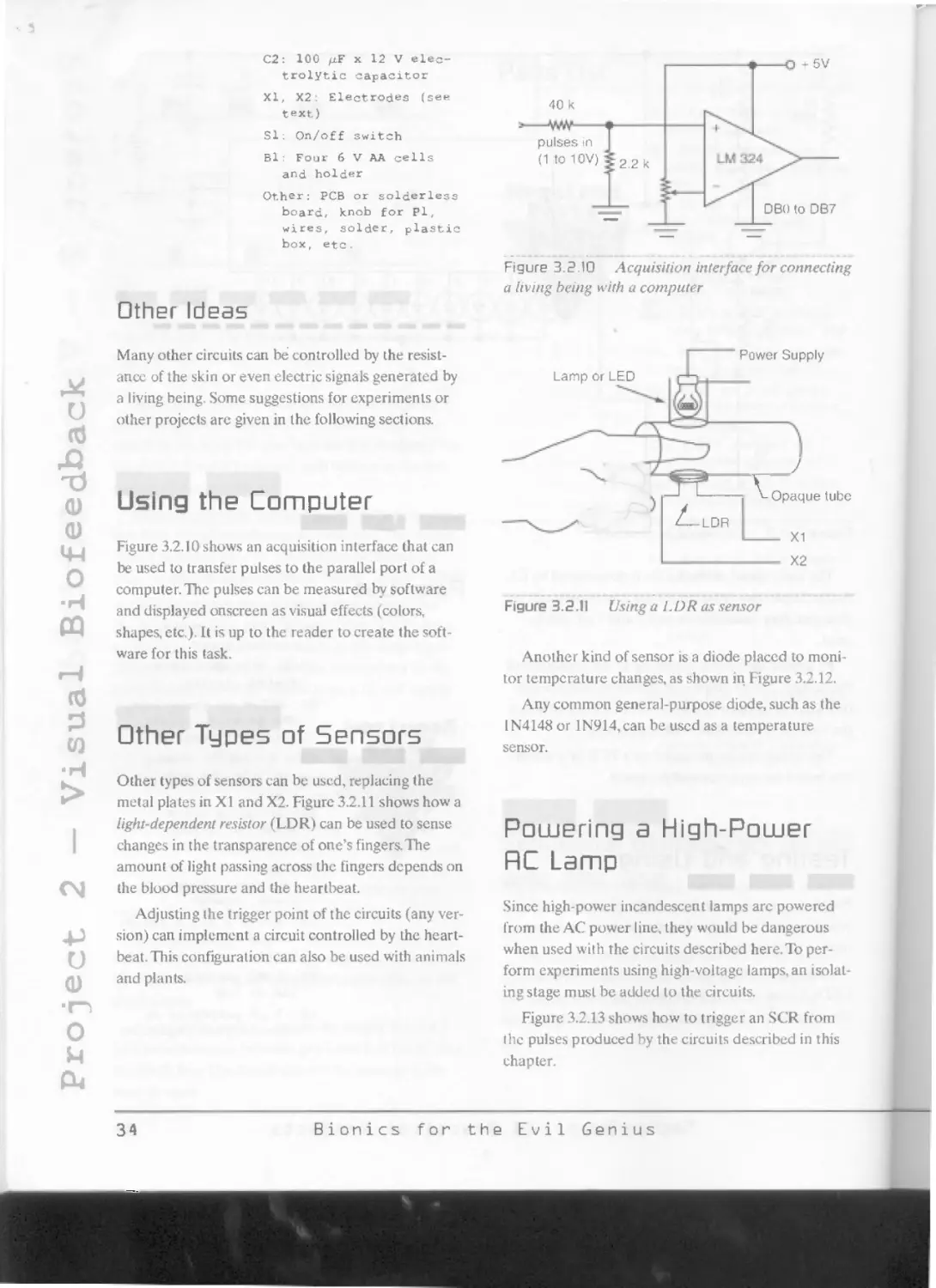
Project 3 — Audio Biofeedback 36 Project 20 — Ionizer 152
Project 4 — Nerves Stimulator 43 Project 21 — Tactile Hearing Aid 158
Projects — Stroboscopic Lamp 50 Project 22 — Using the Multimeter in Bionic Experiments
Project 6 — Bio-Amplifier 58 Project 23 — Bionic Vision 168
Project? — Panic Generator 66 Project 24 — Ecological Monitor 175
Project 8 — Magnetic Field Generator 77 Project 25 — Bat Ear 180
ProjE(T 9 — Hypnotic LEDs 86 Section Four Additional Information 187
Project 10 — Insect Repellent 92 Section Five Resources 189
Project 11 — Bionic Trap 99 Index 191
Contents
V
About the Author
Mr. Braga was born in Sao Paulo, Brazil, in 1946. His
activities in electronics began when he was only 13, at
which time he began to write articles for Brazilian
magazines. At 18. he had his own column in the
Brazilian edition of Popular Electronics, where he
introduced the concept of “electronics for
youngsters.”
In 1976, he became the technical director of the
most important electronics magazine in South
America. Revista Saber Eletronica (published at that
time in Brazil, Argentina, Colombia, and Mexico).
He also became technical director of other
magazines of Editora Saber, such as Eletronica
Total, and became the technical consultant for the
magazines Mecatronica Facil, Mecatronica Atual,
and PC & CIA,
During this time, Mr. Braga published more than
100 books about electronics, mechatronics,
computers, and electricity, as well as thousands of
articles and electronics/mechatronics projects in
magazines all over the world (United States, France,
Spain, Japan. Portugal. Mexico, and Argentina among
others). Many of his books have been recommended
at schools and universities around the world and
have been translated into other languages, with sales
of more than 3 million copies worldwide
The author currently teaches mechatronics at
Colegio Mater Amabilis, is a consultant for distance
learning organizations, and is engaged in education
projects in his home country of BraziLThese projects
include the introduction of electronics, bionics, and
mechatronics in middle schools as well as the
professional training of workers and teachers who
need enhanced knowledge in the field of electronics,
mechatronics. bionics, and technology. Mr. Braga lives
in Guarulhos (near Sao Paulo, Brazil) with his wife
and 16-year-old son.
This book has been written for anyone looking for
projects linking electronics with biology. It doesn’t
pretend to be a complete resource for the bionics evil
genius, but it certainly will offer a large assortment of
useful information and ideas for projects not found
anywhere else.
For more than 25 years, the author, as a
collaborator with American, European, and Latin
American electronics and mechatronics magazines,
has published a large assortment of practical circuits.
Many of those projects linked electronics to biology,
meaning that that they can be classified within a
science called bionics. Many of those projects and
ideas are included in this volume, most of which the
reader can huild using common tools and
components.
The projects range from experimental types
through practical types to amusement types. Of
course, other devices can be used to teach you
something about the fantastic science of bionics. So
the purpose of this book is not only to teach the evil
genius many tricks and techniques used to build
bionic devices, but also to provide ideas and complete
projects that can be built easily using low-cost and
easy-to-find parts.
The audience for Bionics for the Evil Genius
includes beginner, intermediate, and advanced
builders who want new ideas for projects, and
educators who want to introduce the use of
technology in their schools, helping students find a
vocation. Of course, the most important reader is the
evil genius, who can make incredible things using his
or her imagination, skills, and some parts gathered
from old equipment and appliances,“robbed” from a
younger sibling's toy, or bought in a local electronic
parts dealer.
If you think that it is impossible to build
interesting things using simple materials and
technology, you are wrong. Three types of technology
are used to build electronic and mechatronic projects.
The simplest or “traditional” technology depends
on the use of electric parts, such as motors, cells, and
passive components. This technology is simple
enough that even elementary’ school children can
understand it. Some interesting projects can be done
using this technology combined with your
imagination and skills.
Intermediate technology uses something more
advanced than the passive components of traditional
physics. The projects in this category include *
components such as semiconductors (diodes,
transistors, silicon-controlled rectifiers [SCRs], and
light-emitting diodes [LEDs]) and some integrated
circuits (ICs), but they aie not as advanced as the
ones using microprocessors, very large scale
integration (VLSI) chips and digital signal processors
(DSPs), which fall in the third category.
The great advantage of intermediate technology is
that it is accessible to all. Discrete components such
as transistors, resistors, and diodes can be easily
handled without the need for special tools. Using
these components can help reveal vocations and
talents, starting with a person’s natural aptitudes.
Since you will not need special tools to handle these
components, and they are strong enough to withstand
an inexperienced evil genius, it is very easy to build
any project described here.
The important point for our readers is that they
can build or create different devices that can only be
found in the movies, on TV, or in science fiction
magazines. Using low-cost parts and simple
technologies, the reader can explore nature to create
these bionics projects. He or she can build devices for
fish and plants or interact with his or her own body
or other living beings with the same approach you
see in TV series on the Discovery Channel.
You’ll be able to do all that, and we intend to give
you some of the necessary tools, ideas, and techniques
in this book. You’ll only have to complete these items
using your skills and the super-imagination only
found in a real evil genius.
The book is divided into five sections. In the first
two sections (Chapters 1 and 2), we will explain what
bionics is and introduce some basic concepts of this
science. We will convey what the reader will have to
know in order to handle electronic devices, especially
when used with living beings.The technology used in
the projects is also explained.
We will also dedicate some space to educators
who want to reveal the evil geniuses among their
pupils by building projects and making experiments
with them. The educators will see how easy it is to
link many of these projects with their middle or high
school science classes, using the projects as cross-
themes for their science curriculum.
Preface
VI X
(D
Q
Л)
We begin the projects in Section 3. Twenty-five of
them have been chosen from among the large
collection of the author's files, and many of them
have been specially created for the readers of this
book.
The projects are complete, with all the necessary
information for building a basic version that works
alone as a complete device. A brief description of the
projects will show what its primary outcome should
be. Following this part, the reader will find
information on the operation principles and how to
mount the parts, as well as a complete parts list.
Following the building process, many additional
circuits and ideas are provided for upgrading the
project, building variations, or creating new projects
based on the same principles. This is ideal for the
reader who wants to explore the creation of further
experiments and devices. The complete additional
circuits given actually increase the real number of
projects in this book to more than 1 (X). In some cases,
ideas for educators will be discussed that link the
projects as cross-themes for the science classes, and
additional information completes each project.This
approach makes the book easy to use as a large
reference for bionics projects, teaching the reader
much about the use of technology.
We hope that as a reader and potential evil genius
your face will light up and your eyes will be full of
mischief from the ideas provided in this book.
Newton C. Braga
RS. In the volume Mechaironies for the Evil Genius
by the same author, a detailed section explains how
to mount electronic devices (Sections 2.1 and 2.2). If
the reader is not experienced with these techniques,
we recommend taking a look al that publication.
Preface
flechatronics for the Evil Genius
Acknouuledgments
Q
О
£
I would like to thank all the people who helped make
this book possible:
Jeff Eckert, my book agent who helped me with
all the bureaucratic procedures involved in the
production of the book.
Carmen Regina Silvestre, teacher of biology at
Colegio Mater Amabilis, a great friend who helped
me with a lot of information in the bionics field, in
which she is a specialist.
Carlos Eduardo Portela Godoy and Marcelo
Portela Godoy, who gave me support when
working with my pupils at Colegio Mater Amabilis
in Guarulhos (Brazil), revealing among them
many an evil genius, and who let me use the
laboratory' for many experiments described in
this book.
Helio Fittipaldi, who allowed me to use many
illustrations and photos from articles I had
published in the magazines Mecatronica Facil
and Eletronica Total.
Edson de Santis, my great friend who supplied me
with many parts of the components I used in this
book’s projects.
My wife Neuza and my son Marcelo, who have
both been supportive of my efforts.
Newton C. Braga
edgments
Acknowledgments
ix
Section One
Introduction
The living world faces a wide range of biological
problems, yet within our world one can find a fantas-
tic source of high-performance solutions to these
problems.These solutions have been attained as a
result of natural selection, which has been taking
place over the last 3 billion years of life’s evolution
on Earth. The perfect operation and structural organ-
ization of Earth’s biological systems are the result of
specific principles and laws that guide and control the
functions of all living matter.
The most important of all the principles involved
in the evolutionary process, or acting upon living
matter, is the Optimal Design Principle or ODP. It
cannot be demonstrated by formulas or theories, but
it is considered valid because its existence can be ver-
ified in the organization of many living beings, from
the molecular level to the human being.
ODP is the methodological consequence of the
basic concepts within Darwin's evolution theory: the
struggle for survival and natural selection. According
to the Darwinian evolution theory, living beings are
changing their structure all the time in a way that
mutants are created at each generation. The mutants
replace the other individuals, and some of them are
superior according to some specific criteria. The crite-
ria include best performance, considering energetic
costs for maintenance, propagation (reproduction),
and operations. This means that the fantastic per-
formance of most living beings in our lime is the
result of billions of years of evolution. Scientists are
convinced of the optimization of all creatures’ abili-
ties in a world where a fight for survival is constant.
So why not use the characteristics found in nature
and observed in living beings to help us wilh our
technologies? This is exactly the aim of bionics and
another science considered to be a branch of bionics,
known as biomechatronics. Bionics can be defined
as a science that utilizes the results of biological
evolution.
Of course, not always, but very often, a natural
result can be the basis for the best solution to many
problems faced by a technology designer (and even
in other fields such as architecture or mechanics).
Starting from the previous concepts and from the
definition of bionics, we can show certain methods
that can be used by the bionics researcher, linking
solutions given by nature to solutions created by our
technology.
Technology can be linked to the solutions given by
nature in three ways, as shown in Figure 1,1. In the
first case, we have the direct application of the bion-
ics definition. We can use the results of biological
evolution to create artificial devices. Observing the
solutions given by nature, we can imitate those natu-
ral solutions using components and devices created
by our technology.
For example, the sonar abilities of bats and dol-
phins were the basis for the creation of devices
designed to delect objects underwater and even in
the air. Artificial legs and arms, as well as shape mem-
ory alloys (SMA),were developed after observing
how our muscles work.
The second way to work with bionics is also shown
in Figure 1.1. We can combine special functions cre-
ated by technology directly with nature, such as con-
necting a living being with an artificial device.
For example, an electric fish, generating a signal
that changes its frequency according to the pollution
level, can be used as a sensor directly connected to an
electronic circuit. It can also be used to monitor the
purity of water resources as an extremely sensitive
sensor. A plant, used as a sensor,can be connected to
an electronic circuit to monitor the level of oxygen in
the air, to monitor light, or to monitor for the possi-
bility of an earthquake. Even a person can be con-
nected directly to an electronic circuit to monitor his
or her degree of stress under determined conditions.
Section One — Introduction
Section One Introduction
1
3
Section One — Introduction
Integration
(c)
Figure 1-1 Bionics, linking living beings to technology
In these cases, a living structure is used as part of a
more complex device, performing tasks that artificial
parts can't do, all of which are considered bionics.
Finally, a living being can be used to send signals
to a circuit, acting as a sensor and at the same time
receiving signals to make him or her perform some
task. The living being is part of a more complex
device, acting at the same time as a sensor and an
actuator.
When we describe biofeedback, we are referring
to this type of bionic application, A signal is created
by the person connected to the electrodes, and a cir-
cuit processes the information sent by the person.
The circuit provides feedback, commanding some
kind of actuator that interacts with the person. Exam-
ples of this would be a lamp that changes its flashing
frequency or an oscillator that changes its tone, acting
on the eye or ear of the person and commanding
some kind of action. A stroboscopic lamp controlled
by the resistance of a plant leaf is another example of
this third application of bionics.
The practical projects described in this book can
be classified in one of the three categories described
earlier. The reader will find projects that can stand
alone as a complete device or circuit, or that can be
plugged into other applications or devices. Addition-
ally, many other circuits derived from the basic proj-
ects will be given to the reader who wants to go
beyond the frontiers of the primary.
This book is a rich resource of ideas and practical
applications for the bionic evil genius, and it has as its
limits only the imagination and the ability to work
with living beings and electronic parts.
2
Bionics for the Evil Genius
Section Two
Biology and Electronics
Electronics and biology have many points in com*
mon, as electronic circuits and living beings work
thanks to electric currents flowing through them. Liv-
ing beings work with weak currents of only a certain
number of millivolts that pass through cell mem-
branes, excite nerves and muscles, and perform other
tasks vital to their lives. Electronic circuits work with
a wide range of currents, starling from microamperes
in microprocessors or low-signal transistors, and
reaching many amperes in high-power semiconduc-
tors as Silicon-controlled rectifiers (SCRs), power
metal-oxide-semiconductor field effect transistors
(MOSFETs), insulated gate bipolar transistors
(IGBTs), and Triacs.
The point of all this is that it is possible to inter-
face living beings with electronic circuits in a way that
they can work together in harmony. Today we
observe around the world that researchers have
started to combine biology and electronics. The
results have led to new sciences such as bionics,
molecular electronics, artificial intelligence, bio-
physics, biomechatronics, and many others.The syn-
ergy of biology and electronics can be used to deliver
many real products, and this book provides some
practical examples.
Although we believe this fusing of biology and
electronics has great potential, we have learned to be
cautious. A convergence exists between electronic
circuits and biology, because both sides can work at
the same scale. Bionics is just a result of the combina-
tion of electronics and biology. As we saw in the
introduction, nature and technology can be combined
in three ways.
For the reader, it is important to consider that in
this book we will provide electronic solutions for the
bionic applications that are discussed. Since we are
not biologists, the science aspect will not be
approached as deeply as the reader may like, and
readers are encouraged to research more information
according to their interests. Resources such as the
Internet, books, magazines, and many other sources
can be used to discover necessary additional
information.
We also must consider the importance of safety
when working with electronic circuits and living
beings, especially if the living being is a human. You
might not expect that your experiments with bionic
devices would require some special protection, such
as Asimov’s “Laws of Robotics” in the case of robots
or any device interacting with people. Although most
of the projects in this book use common parts, the
relative inexperience of the builder will increase the
likelihood of an accident. Your simple bionic project
could cause harm to yourself or another. This means,
in simple terms, that you are not free from accidents,
such as receiving an electric shock when touching
a high-voltage circuit or cutting your hand when
trying to implant an electrode in a plant Or
another creature.
This book is not directed to professionals, and
since the bionics used in the projects don’t have a
professional aim, they are very simple and sometimes
experimental, but to avoid accidents it is important to
follow some basic simple rules of safety. You are
working with living beings, including humans and, of
course, yourself. If you lose control of your experi-
ments, they can do harm.
You must also consider that, even when you are
not working with dangerous devices, the plants, fish,
and other living beings used in these projects are very
fragile creatures. Even a current of few micro-
amperes flowing through their bodies can injure or
even kill them. So we believe that the inclusion of a
short chapter about safety is very important.
Section Two — Biology and Electronics
Section Tuuo Biology and Electronics
Safety Rules
Accidents caused by bionic projects, such as the ones
described in this book, tend to have three sources:
electronic, biological, and chemical.
Electronic
Low-power circuits, such as the ones used in our proj-
ects, are not particularly dangerous because they can
be placed inside boxes or operate from low-power
supplies. The following are some safety measures to
be considered:
• Protect all areas where high voltages are pres-
ent. Avoid the use of metallic parts or metallic
enclosures w'ith high-voltage circuits.
• Do not power the circuits from transformer-
less pow-er supplies, mainly the ones that will
be used w'ith humans (biofeedback, etc.).
• Include fuses or current-limiting circuits in
all sensitive circuits to avoid short-circuit
problems.
• Do not connect high-voltage circuits or cir-
cuits powered from the AC pow'er line to any
person.
• Experiments involving humans must be made
with the supervision of an adult.
Chemical
Chemical substances used in some experiments will
create additional hazards. The substances produced
by the specimens under experimentation used to pro-
duce special effects can cause accidents if used
improperly. To prevent accidents w'ith chemical sub-
stances, observe the following rules:
• Provide a secure exhaust if any gas is pro-
duced during the experiments.
• Be sure that any product used in the experi-
ments will not be injurious to humans or even
the specimen if exposure or contact occurs
with the eyes and skin.
• Avoid using chemical substances in closed or
unvcntilated rooms.
Following these recommendations, biology and
electronics can be used together with the best results.
The projects given in the next section are only a small
part of the wide universe of bionics today and in the
future.
Biological
Circuits used with living beings, such as humans, are
dangerous because they cause changes in the control
we have on our body. Biofeedback, for instance, can
cause a state of hypnotism or temporary’ confusion if
not correctly used. Some recommendations are given
here to avoid accidents:
♦ Do not cause any injury to the living being
used in the experiments. Be sure that all the
conditions it needs to be comfortable are
present.
• Observe if the experiment causes some dis-
comfort to the living being or human. Stop the
experiment if this occurs.
Нош to Mount
The projects described in this book are the result of
combining electronic technologies with biology. How-
to handle the living beings used in the projects and
perform the experiments will require some care, and
in order to mount the electronic parts of the projects,
the reader must be able to use some tools and know'
the basics of electronics.
Starting from the fact that the reader know’s some-
thing about electronics, let’s indicate the basic tech-
niques w»e intend to apply in the projects described in
this book as well as the tools the reader will need to
mount them. It is also important to take a look at the
components and devices recommended.
4
Bionics for the Evil Genius
The cost of a device built from parts acquired in
the specialized market is many times higher than the
same device bought ready for use, but the construc-
tion with carefully selected parts is still important if
one considers the fun, the opportunity to learn, and
the satisfaction that readers will have by “doing it
themselves.” As has been described in other books,
today we have many technologies that are used to
construct electronic projects and among them are
ones that can be used in the bionics field,
The manufacturers of consumer appliances use
tools, special methods, and even machines for attach-
ing small parts to the appliances, including an
approach called surface mount technology (SMT),
which employs very’ small parts (known as surface
mount devices or SMD). Without the use of these
special tools and machines, it is difficult to handle
these parts and certainly it is very difficult to mount
any project with them. This is different from the basic
technology that uses old parts, such as tubes, and
electric components, such as lamps, switches, fuses,
and other parts.
For most readers, the ideal is to start with the use
of an intermediate technology. In the case of bionics
the large components are too large to be handled
with special tools and therefore are ideal for mount-
ing by hand. The larger components do the same
tasks that the small SMDs do. They only need more
space in a board/ITie smaller devices, on the other
hand, require special tools and familiarity with those
tools. Beginners may not have these tools or skills in
handling very small parts.
So, the first thing you have to do before choosing
the projects to build alone, with your friends, or
pupils, or for your work in a science fair is to learn
something about the tools you have to use, the com-
ponents you are going to assemble, and the main
process: soldering.
The Tools
A bionic project requires two particular areas: a
workbench for mounting the electronic circuits and a
space for working with living beings or even humans.
Нош to Mount
Small ciectronic components need some support to
be kept in place and wired in a circuit. Several tech-
niques can be used to keep the components in work-
ing condition. The simplest way to place a component
in a circuit is to use a terminal strip, as shown in
Figure 2.1.
The components arc soldered to the terminals, and
the interconnecting wires are soldered to the corre-
sponding terminals. The way the components are
placed and wired determines what the circuit will do.
This is not the best way to mount a project these
days, but it has the advantage of being simple. It also
doesn’t need special tools or resources. Many projects
described in this book, mainly the ones with experi-
mental purposes, use this technique. They arc
intended for beginners who are not familiar with
more advanced techniques, such as the ones that use
printed circuit hoards (PCBs).
Another way to wire a circuit is to use a terminal
strip with screws, as shown in Figure 2.2. This method
of building circuits has the advantage that the compo-
nents don’t need to be soldered, but the disadvantage
is that you must take special care to place the connec-
tions firmly. Any bad contact can affect the circuit’s
performance or even cause no
performance at all. Another disadvantage is that this
mounting method can only be used with simple
circuits.
Figure 2.1 A terminal strip used as a chassis for a
simple project
Section Two — Biology and Electronics
Section Tujo Biology and Electronics
5
Q1
Section Two — Biology and Electronics
Figure 2.2 Wiring a circuit using a terminal strip
with screws
Finally, many experimental projects can be
mounted on soldcrless boards, such as the one shown
in Figure 2.3. The components’ terminals are placed
into holes where metallic terminal strips enable them
to be interconnected according to a predetermined
pattern. The advantage of this technique is that you
don't need to solder the components, and they can be
reused in other projects. It is also very easy to replace
components, making experiments achieve the best
values for the desired performance.
All the projects described in this book can be
mounted on soldcrless boards, because they are ideal
for experimental purposes. The projects can also be
easily altered and mounted in many versions.
Figure 2.3 Solderless board
The Printed Circuit Board
IPCBI
The small components used in electronic equipment
can’t stand alone without any physical support.They
need some kind of support to keep them firmly in
their operating positions and at the same time provide
the electric connection with the rest of the circuit.
Observing any electronic equipment, the reader
will find that the small parts or electronic compo-
nents are mounted in a special board of fiber or
another insulating material. This support or chassis
for the components is called a printed circuit board or
PCB. The board, as shown in Figure 2.4, is made of an
insulating material where copper strips are printed
on one or both sides.
The copper strips are the wires conducting the cur-
rents from one component to another, and the pat-
tern of the strips is determined by the function of the
circuit. All the strips are planned before the manufac-
turing process to provide the necessary connections
between the components and the desired function.
This means that a PCB produced to receive compo-
nents that form a radio can't be used to mount TV
circuits or any other equipment.
Tlie small components are placed on the board
with their terminals passing through holes in the
PCB. On the other side of the holes, the terminals are
soldered to the copper lines, as shown in Figure 2.5.
A mounting process found in consumer electron-
ics and professional equipment manufacturing uses
very small components.This process uses automatic
machines (for example,SMDs) controlled by com-
puters to place the components on a PCB according
Figure 2.4 Common PCB
6
Bionics for the Evil Genius
When heated to about 273 Celsius (523" Fahren-
heit), the solder melts and forms a little ball at the
terminal of the components that fixes it to the board
w’hile at the same lime providing electric contact with
the copper strips or other components. When work-
ing on mounting or replacing components, the reader
will need some solder and a soldering iron.The sol-
der can be bought in small quantities, as shown in
Figure 2.7. and a soldering iron is shown in Figure 2.8.
A 25- to 40-watt soldering iron with a shiny tip
is recommended w’hen w'orking with the small,
electronic components found in the circuits described
in this book. Of course, the builder could also use a
heavy-duty soldering iron to remove or place larger
components like those found in some electric and
electronic projects.
Figure 2.5 Soldering connects the components'
terminals to the PCB.
to a program that identifies what the circuit is being
created to do. They are programmed to be fixed by
automatic machines, as in SMDs.They are placed and
soldered to the board at the same side of the strips, as
shown in Figure 2.6.
Installing common components on a PCB is a deli-
cate operation that the reader who wants to work
w’ith electronic mounting circuits must know. Special
techniques are required for this work because the
components are small and fragile.
Tlte components are generally soldered to termi-
nal strips, and the copper lines of a PCB. The solder
used in an electronic assembly is an alloy formed by
60 percent tin and 40 percent lead with some rosin. It
is common to call this kind of solder a transistor sol-
der^ radio-TV solder, or a 60-40 solder.
Figure 2.7 Common solder
Figure 2.6 SMD components are soldered
directly to the copper lines.
Section Two — Biology and Electronics
Figure 2.8 A common soldering iron for the builder
who wants to build the projects described in this book
Section Tluo Biology and Electronics
7
Section Two — Biology and Electronics
Soldering is a simple operation, and anyone expe-
rienced with electronic mounting will be familiar with
this kind of work. Electronic devices are very delicate
and care must be taken not to damage them. Many
electronic devices are easily damaged by excess heat
or an incorrect soldering procedure.'lhe basic proce-
dures for soldering electronic components (removing
or installing on a PCB) are as follows:
1. Plug the soldering iron in and let it heat for at
least 5 minutes. This will be long enough to
bring the tip to the correct temperature for a
good soldering operation.
2. Touch the soldering iron to the component for
a very short time, allowing the component (or
the connection) to heat up, and then touch the
solder to the connection, not the iron, as
shown in Figure 2.9. You will notice that when
the solder melts it penetrates every part of the
solder joint.
3. Remove the iron and do not move the joint
until it has had time to cool. It is easy to see
when the joint has cooled. A peculiar haze will
pass over the metal, after which the joint is
cool enough and strong enough to withstand
movement.
Figure 2.10 shows a perfect solder joint and some
solder joints with problems. One of the principal
causes of problems in electronic equipment is the
“cool solder.”The solder seems to contact the com-
ponent, but no electric contact is made because the
joint was not heated enough to penetrate the metal,
creating an isolated layer of moisture or oxide to
form between them.
Other Tools
The soldering iron isn’t the only special tool needed
to work with the electronic circuits used in bionic
projects. When working with electronic parts, many of
the tools used in electric installations or automotive
electricity are suitable. Probably the reader has many
of these tools at home, but many electronic compo-
nents are very small and delicate and need special
tools and care.
The use of improper tools when working with
these components is often the cause of damage. If the
reader intends to work with electronic circuits, we
suggest having at least some of these tools:
• Cutting pliers, or diagonals (often called
dykes), from 4 to 6 inches long
• Chain-nose or needle-nosed pliers with very
narrow tips from 4 to 5 inches long
• Two or more screwdrivers between 2 and 8
inches long
Figure 2.9 Soldering a component to a terminal strip
8
Bionics for the Evil Genius
No penetration
Figure 2.10 A good soldered joint
• Crimping tools, a stripper and cutter, for 10 to
22 wire gauges
• Precision tool set (10 to 16 tools) with small
screwdrivers of hex, common, and Philips
types
• Soldering and dcsoldcring accessories,such as
a desoldering bulb and a soldering iron
holdcr/clcaner
• Extra hands to hold the work, such as a mini-
vise with a vacuum base or a project holder
• Mini-hand drill
Many other tools can be found in electronic and
tool catalogs.
Diagrams and Symbols
Schematic diagrams or simply schematics are used to
represent how the many parts of a piece of equip-
ment arc interconnected. The builder of bionics proj-
ects must be able to show the components and the
way they are interconnected via a schematic diagram.
In a schematic diagram, the components are not rep-
resented by their real shape or format; they are rep-
resented by symbols.
How to interpret a diagram is fundamental to the
reader who is unfamiliar with electronics but wants to
build something using this technology. Learning
the meanings of the symbols used to represent each
component and what they do in a circuit is an impor-
tant step toward becoming familiar with schematics.
-0
Let’s start with an example of how to read a
schematic diagram. Figure 2.11 shows a diagram of
simple electronic equipment, an audio oscillator used
in animal conditioning.
This schematic diagram represents all components
by their symbols, and in many cases, the identifica-
tion, values, and other important information are
given. At the side of each component’s symbol is the
identification number.This is important because it
can help the builder find the component on the PCB,
the terminal strip, or inside the equipment.
By a general convention, all the resistors are iden-
tified by the letter R, followed by the number of
the device in the project. This means that if many
Section Two — Biology and. Electronics
•O +
R1
47 k£2
Speaker
Figure 2.11 Representing a circuit by symbols
Section Tulid Biology and Electronics
9
Section Two — Biology and Electronics
resistors exist in a device, they will be identified by
Rl, R2, R3,and so on. Capacitors are usually noted
by the use of the letter CThe capacitors of a circuit
are numbered starting from Cl, C2,C3,and so on.
Transistors can be identified by Q,T,orTR.They can
be represented as QI. Tl, or TRI.
In many cases, a second number can identify the
“block11 or‘"stage'’ in which the component is placed,
'lhe resistors of the first stage can begin at R101 and
the resistors in the second stage start at R201. Near
the identification and the symbol, we can also find
the value or type of component.
Resistors have the value of resistance to the side,
such as Rl, 1,000 fl (ohms), or Ik. If it is a transistor,
you might find BC548, meaning that, when used, the
transistor must be replaced with a BC548 or, when
mounting, the transistor placed there must be a
BC548.Thc usual identification number for transis-
tors begins with a 2N, but many manufacturers have
started using groups of alphabetic characters signify-
ing their names, such as TIP (Texas Instruments) and
MPS or MM (Motorola). A European code uses BC
or BD as the identification of devices, and a Japanese
configuration uses 2SB.2SC, or 2SD to indicate
transistors.
In this book, the transistors for general-purpose,
low-power applications will generally be the BC548
and BC558. Medium-power transistors will beT!P31,
TIP32, Tl Pl 15, ВD135, or ВD136, and high-power
transistors will beTIP41.TIP42,or 2N3055.
Depending on the circuit, other important infor-
mation can be found in the schematic diagram, such
as the voltage at different points in the circuit. In the
example presented, it is indicated that, between A
and the ground (normally taken by reference or 0
volts), the measurement 6 volts is found when a mul-
timeter is used to take the voltage (see Figure 2.12).
Also found on a schematic are procedures for instal-
lation, diagnostic problems, equivalence, and so on.
To make things easier for the reader, besides the
schematic diagram we will also provide figures detail-
ing the building steps and offer a parts list. In lhe
parts list, we will describe the main characteristics of
the components used in the projects, including the
color codes for resistors, voltages, and current rates
for other components such as capacitors, transform-
ers, and diodes.
Figure 2.12 A diagram showing the voltages of
some points
LUorking uuith Living
Beings
Many projects described in this book will involve
direct contact with living beings. Although in many
cases they could be insects or plants, whom you cer-
tainly won’t cause any harm, when working with
humans you will have to double your efforts to be
careful.
Although the projects described in this book don’t
have any potential to cause great damage or pain to
anyone, you must be careful when using them. In case
of any doubt, consult an adult or make the experi-
ment under the supervision of an adult.
It is also important to have the appropriate place
to work with living heings. A biology lab offers spe-
cial workbenches for this task, and in your home find
a place where you can work with plants, insects, or
even fish.
Remember that life is fragile. If you don’t take the
necessary care, your specimens will die before you
have time to make the experiments. Keep in mind
that they are living creatures and we must respect
their lives, not cause any injury to them, or let them
die from neglect.
10 Bionics for the Evil Genius
4
Section Three
2Б Practical Projects
no
о
о
The purpose of this part is to describe projects, ideas,
and experiments involving bionics based on simple
circuits. The circuits and experiments described here
can be altered to change their performance or to be
used with other intentions.
The reader will find 25 basic projects, each stand-
ing alone as a complete device, and a large assort-
Project 1—Experiments ujith an Electric Fish
The Amazon Basin is a mysterious place where many
strange creatures have been known to live, even
today, although we’re not talking about prehistoric
monsters or man-eating plants.
ment of new circuits and ideas to be explored. Many
circuits are new versions of the basic projects using
different configurations to reach the same end, but
others are completely new devices, exploring only the
basic principles. This means that although the book
claims to contain only 25 projects, the reader will find
much more—in fact, over a hundred of them.
Although the author lives in Brazil, he is from the
southern part of the country, very far from the Ama-
zon (more than 2,000 miles!), and he can suggest
some interesting experiments and projects with small
Figure 3.1.1 The Itui Cavalo or Black Ghost
Experiments with Electric Fish
Section Three 25 Practical Projects
11
co
Й
Ф
e
м
ф
cu
X
Figure 3.1.2 A current field in the water or earth
can be used to detect minerals, caves, and large
objects.
(and docile) creatures from the Amazon easily found
even in the United States. In some pet shops (yes, pet
shops!), it is possible to find some of these strange
creatures that live in the Amazon and use them in
bionics projects like the ones described here.
One of those curious creatures is the electric fish
Black Ghost (or Itui Cavalo in Portuguese), known
by many who keep small aquarium fish (see Figure
3.1.1).The Black Ghost (Genus Apteronotus, and
families Electrophoridas, Gymnotoidae, Rham-
phichthidae, Hypopomidae, and Stcrnopygidae) and
some catfish have the ability to produce electric, low-
О
Current field
Figure 3.1.3 The current field around the Dark
Ghost
frequency fields around their bodies that are used to
detect other beings and objects.
The same principle of operation is used by equip-
ment that is used to detect mineral deposits and even
large objects in the sea. The idea is that a “current
field” is deformed by the presence of objects of dif-
ferent conductance, as shown by Figure 3.1.2.
Electrodes can map the currents and determine the
location of the objects that produce the deformation
of the field.
The fish uses this principle to detect objects and
other creatures in the dark water where he lives. The
Itui is nearly blind and must depend on his electric
sense to find food and escape from enemies. Figure
3.1.3 shows how the Itui produces an electric current
field in the water both to detect objects and commu-
nicate with other fish of the same species.
The most interesting points to consider are the
characteristics of the fish’s electric field and the sen-
sors developed by the fish’s nature. The Itui produces
a very stable, low-frequency field with frequencies
that depend on the size of the specimen and the
chemical conditions of the water around him or her.
For our experiments, we recommend the use of
the Itui Cavalo or Black Ghost (Apteronotus
Albifrons,the Gymnotoidae Family), which
produces very stable, low-frequency fields in a range
between 4(X) and 4,000 Hz. Figure 3.1.4 shows a typi-
cal wave shape of the current field generated by the
electric fish.
7WW\
ЛЛЛЛ/
1ms
Figure 3.1.4 The wave shape of the signal
generated by an electric fish
12
Bionics for the Evil Genius
Placing metal electrodes near the fish, it is possible
to pick up the signal produced by the fish and use it
to make interesting bionic experiments, as we will
describe in the this section. Of course, the reader can
go ahead and create his or her own experiments with
the electric signals produced by this strange creature.
Since the signal generated by the fish is very stable
in frequency, the reader can consider it as a living
“quartz crystal’' or “tuning fork,” which can be used
to drive computers, microprocessors,clocks, and even
a musical instrument, as suggested in the next section.
tsunami detector based on the fish’s reaction
—an interesting form of research to be made
these days.
• Dividing the signals by fractions of 8 (V«,%,
%, etc.), you can build a musical instrument
operating from the signals generated by the
fish.
• Knowing the frequency of your fish, you can
build an oscillator to produce the same signal
and make experiments to see how it can be
disturbed.
о
fl)
Q
The Bionic Experiments
The signals generated by the Black Ghost reach an
amplitude ranging from 3 to 4 volts, which is enough
to drive many external electronic circuits.
The simplest experiment, described here, is made
by picking up the signals and using them to drive a
small audio amplifier. When amplified, the low-
frequency signals can be heard as a pure audio tone
in a very interesting experiment involving animal
behavior. In a science fair or even in the lab, it is nice
to see how impressed people are when the pure tun-
ing-fork sound produced by the fish is heard. You can
also perform other projects such as the following:
• The stable signal can be used to drive a digital
or mechanic clock.
• A signaling system can be driven by the fish,
indicating to his or her owner that the fish is
alive. A light-emitting diode (LED) will blink,
controlled by the signal produced by the elec-
tric fish.
• It was shown that the frequency of the signal
produced by the fish changes slightly when
the pH or the CO2 concentration of the water
changes.This means that, monitoring the fre-
quency of a Black Ghost, you can develop a
bionic sensor of pollution for water sources.
The signal can be picked up and applied to a
computer to monitor the water of a source
using a living sensor.
♦ The frequency of the signals also changes
when the fish is disturbed by external influ-
ences. You can create an earthquake or
The Electronic Circuit
Our basic project consists of a simple, low-power
audio amplifier used to pick up the signals generated
by the fish. The signals are amplified and applied to a
loudspeaker, or reproduced by a loudspeaker as
shown in Figure 3.1.5.
Although you can use any audio amplifier for this
purpose, the experimenter can build his or her own
circuit and make experiments with the signals, placing
new blocks in the same solderless board.
The circuit is based on the integrated circuit (IC)
LM386, which can be powered from four A A cells,
producing a good audio signal to a small loud-
speaker/Die gain of the circuit is determined by the
capacitor placed between terminals 1 and 8. In our
case, because the signal picked up by the electrodes is
w
*6
n>
3
о
w
Figure 3.1.5 Picking up the signals generated by
the Dark Ghost
Section Three 25 Practical Projects
13
co
См
О
Ф
СО
а
ф
£
й
ф
и
из
Figure 3.1.Б Electrode placement in the aquarium
weak, we recommend working with high gain. So, a
10 /xF signal is used, resulting in a voltage gain of 200.
The electrodes are pieces of bare wire immersed
in the aquarium with the fish. It is recommended that
the wires be 20 to 30 cm long and that they are sepa-
rated by 20 to 50 cm, as shown in Figure 3.1.6.
It is not recommended that you power this circuit
from the AC power line, even using a good power
supply. The 60 Hz hum can disturb the operation of
lhe circuit, appearing in the loudspeaker.
Нош to Build
Figure 3.1.7 shows the schematic diagram of the
audio amplifier used in the basic experiment.The
components can be placed on a solderlcss board, as
shown in Figure 3.1.8.
This mounting process is particularly recom-
mended to beginners and for experiments made in a
lab, because the materials used to etch a PCB are not
Figure 3.1.7 Complete diagram for the audio amplifier
14
Bionics for the Evil Genius
Figure 3.1.8 The circuit is assembled on a
solderless board.
necessary. Of course, if the reader has the resources
to etch a PCB, he or she is free to choose this mount-
ing version for his or her amplifier. The PCB version
is shown in Figure 3.1.9.The pattern for this board is
shown in Figure 3.1.10.
Tlie positions of the polarized components, such as
the IC and the electrolytic capacitors, should be
observed. The loudspeaker can fit inside a small plas-
tic or wooden box, and an appropriate holder should
be used for the cells. In this mounting, as the circuit
works with low-power audio signals, it is very impor-
tant to keep all the connections and the components’
leads as short as possible to avoid instability or pick-
ing up undesirable hums.
Testing and Using
i • ii 0
Turn the unit on by using SI or by placing the cells in
the holder and plugging in an audio source, such as a
ceramic microphone. If you intend to use an electret
microphone, a 10,(XX)-ohm resistor should be added,
as shown in Figure 3.1.11.
To pick up the signals generated by the Black
Ghost, you must place the electrodes into the aquar-
ium and connect them to the input of the audio
amplifier using common wires (no shielded wires are
needed if the distance to be covered is short). If your
aquarium has a fluorescent light and/or a heater, it is
recommended that you unplug them from the power
line to not introduce noise to the circuit.
Figure 3 1.9 The same circuit mounted on a PCB
R1 C4
Figure 3.1.10 The PCB for the audio amplifier using the LM386
Experiments with Electric Fish
Section Three 25 Practical Projects
15
Figure 3.1.11 Testing with an electret microphone
о
о
0)
из
£
W
а
ф
S
й
ф
X
ид
Since the water is almost conductive, the aquarium
acts as a low-impedance signal source. This means
that if you haven’t any other powerful interference
source near the aquarium, such as electric devices, no
hum will appear in the loudspeaker.
Opening the volume control, you will hear a pure
tone, like an audio oscillator or tuning fork, which
will change in volume when the fish moves to
another place inside the aquarium. This tone is the
signal produced by the fish.
Unplug lhe electrodes to be sure that the picked-
up signals are really produced by the fish. If the noise
(hum) is reproduced by the speaker, see if any appli-
ance connected to the AC power line that is placed
near the aquarium is the cause.
Parts List: The Audio
Amplifier
Require^
Parts
IC-1: LM386, audio
amplifier, integrated
circuit
Cl: 100 x 12 V elec-
trolytic capacitor
C2: 10 mF x 12 V elec-
trolytic capacitor
C3: 220 mF x 12 V elec-
trolytic capacitor
C4: 0.05 or 0.047 mF
ceramic or polyester
capacitor
Pl: 10 kit log or lin
potentiometer
Rl: -10 x 1/8 W resis-
tor, brown, black,
black
SI: Single pole, single
throw (SPST) on/off
switch
Bl ; б V, 4 AA cells and
holder
SPKR: 4 or 8 Q x 5 to 10
cm small loudspeaker
Xl, X2: Metal electrodes
(see text)
Other; Solderless board
or PCB, wires, solder,
plastic box, knob for
Pl, etc.
Additional Circuits and
Ideas
Starting from the basic experiments, where we only
gave the reader the elements for picking up and hear-
ing lhe signals produced by the fish, we can suggest
many other experiments using the signals. In fact,
bionics means the integration of living beings with
electronic devices or using technology that adopts
solutions provided by nature after millions of years of
evolution, in the next section, we will give the reader
some ideas for new projects.
Observing the Signals in an
Oscilloscope
If you have an oscilloscope, you can directly observe
the signals generated by the Black Ghost. It only
requires plugging the electrodes to the input of the
instrument and adjusting the amplitude and fre-
quency to the appropriate value of the signals.
Figure 3.1.12 shows how to make the connections.
The signals can change in shape and frequency
according to the specimen. Figure 3.1.13 shows some
patterns observed in these fish. If your oscilloscope
has a frequency meter, you can determine the exact
frequency of the signal produced by your fish.
16
Bionics for the Evil Genius
Oscillosope
Figure 3.1.12 The waveforms observed in the
oscilloscope screen
Mic input
Figure 3.1.1U Observing the signals in the PC
о
(D
Q
жн
WWXAAAA v'v
Figure 3.1.13 Waveforms observed in the
oscilloscope
Using the Computer
If you have a program in your computer for observ-
ing audio signals, you can use it to monitor your elec-
tric fish. It is enough to run the program and plug the
electrodes into the microphone input, as shown in
Figure 3.1.14.
Il is important to keep the wires as short as possi-
ble and not have any electric device powered from
the AC power line near the aquarium, including the
fluorescent lamp. In some cases, if the amplifier used
to convert the signals from the mic input to the digi-
tal form is nut sensitive enough, the reader will have
to use a preamplifier or even the amplifier with the
LM386, picking up the signals from its output, as
shown in Figure 3.1.15.
The loudspeaker can be replaced by a 10-ohms
X V?-watt resistor to act as a load to the signals if you
don't want to hear them during the experiments.
Using a Common Audio
Amplifier
If you have an audio amplifier with a microphone
input, you can use it to pick up the signals. All you
have to do is plug the electrodes into the input using
wires that are as short as possible. It is again recom-
mended that no other device be plugged into the AC
power line near or in lhe aquarium.
□riving External Circuits:
An LED Blinker
A very interesting experiment is one that can result
in practical bionic devices using the Black Ghost.The
basic idea is to determine the frequency of the signal
generated by the fish and divide this frequency by the
some integer number, obtaining a 1 Hz signal (1 pulse
per second).This stable signal, generated by the fish,
can drive electronic devices such as clocks,
Figure 3.1.15 Using the LM386 to drive a
computer audio input
Experiments with Electric Fish
Section Three 25 Practical Projects
17
Figure 3.1.16 Driving an LED and a beeper with a 1 Hz signal
и
й
43
£
СО
С
Ф
е
й
ф
X
chronometers, and digital instruments. The simplest
application is shown in Figure 3.1.16.
The exact frequency of the signal generated by the
fish can be measured with a frequency meter or oscil-
loscope. For the frequency meter Jt may be necessary
to use an amplifier, as shown by Figure 3.1.17.
The basic amplifier using the LM386 is the ideal
circuit for driving a 4093 IC, which produces a square
wave from the waveshape of the signal produced by
the fish.To divide the frequency by any number, we
used a 4020 complementary metal oxide semiconduc-
tor (CMOS) IC and a 4048 CMOS IC.
As Figure 3.1.18 shows, the 4020 consists of a 14-
stage ripple carry binary counter having 12 outputs
that are a division of power-of-2 numbers of the input
frequency.This means that the circuit can be used to
divide the input frequency for numbers up to 16,384
(2й).
Figure 3.1.17 Measuring the fish frequency with a frequency meter
18
Bionics for the Evil Genius
4020
( 012 C □ Vdd
Q13 C a «5 □ 011 1
J Q14 C 3 14 JQ10 7 Outputs
Output \ at C 4
i 13 □ 08 1
os c 5
12 □ 09 j
07 C G
11 □ RST
Q4 C 7
10 □ CLK } Input
v$«. C ft
3 □ Q1 } Output
Figure 3.1.18 The 4020
Since the frequency range of the signals produced
by the Black Ghost is lower than the limit reached by
the 4020, it is easy to find lhe necessary number to
have a 1 Hz signa) or even other frequencies such as
0.5 Hz, 0.2 Hz, or even 0.1 Hz (one pulse at each 2,5,
and 10 seconds).
Let’s see how we can do that. Observing the 4020,
we can see that the outputs are Q1, Q3, Q4, Q6, and
so on. They correspond to the number represented by
a power of 2, by which the frequency of the input is
divided. For instance, Q4 is 16 (24),so the signal in
this output is the input frequency divided by 16.
The circuit doesn’t have outputs corresponding to
4(22) and 32 (25), but the remaining outputs are
enough to be combined and allow the designer to
find the necessary’ number to establish 1 Hz with sat-
isfactory accuracy.
Taking a numeric example, let’s imagine that our
fish generates a 1,556 Hz signal. Taking this number
and making the decomposition in powers of 2, we will
have lhe following table.
Because the 4020 does not have all the powers of 2
for outputs, the number obtained is the sum of the l’s
of lhe last column, or
1,024 + 512 + 16 + 2 = 1,554 Hz
This result has an accuracy better than 0.2 percent,
which is enough for experimental purposes. But to
get the 1 Hz signal, we must combine the correspon-
ding outputs in a logic circuit, which is the 4048 pro-
grammed as an AND gate, as shown by Figure 3.1.19.
Output Раше г of 2 Components of the decomposition for 1.556
Q14 '16,384 0
OI2 8,192 0
QU 4,096 0
Q10 2,048 0
09 1,024 1 (lasts 524)
OS 512 1 (lasts 12)
07 256 0
06 128 0
04 16 1 (lasts 8)
01 2 1 (lasts 2)
43
К
о
fl)
Q
The outputs QI, Q4, Q8, and Q9 must be con-
nected to the AND gate 4048. In this configuration,
by applying the signal of the outputs determined by
the decomposition table to each of the 1,546 pulses at
the input of the 4020, we will have one pulse at the
output of lhe 4048. An LED connected to this output
will blink at a 1 Hz frequency (one pulse per second),
as desired.
Of course, the number of outputs that will be con-
nected to the input of the 4048 will depend on the
value of the input frequency. If you are lucky enough,
your fish can produce a frequency corresponding to a
power of 2 (1,028 Hz, for instance), so you will not
need the 4048 and can plug lhe LED directly to Q8,
keeping the 1 к fl resistor in series, of course.
The complete circuit that makes the LED blink at
a frequency near 1 Hz is shown in Figure 3.1.20, using
only one output of the 4020.
Make sure one gate of the 4093 is used to drive a
piezoelectric transducer, producing beeps at twice the
rate at which the LED blinks.
I
W
X
43
fl)
h
fl)
w
tn
fl)
Q
Figure 3.1.19 Using lhe 4048
Section Three 25 Practical Projects 19
U)
Since the loudspeaker is not in use, it is replaced
by a 100-ohm resistor, acting as a load for the ampli-
fier. Of course, if another output is used, the beeps
can be produced at half the rate of the LED blinks.
Figure 3.1.21 shows the circuit mounted on a solder-
less board.
и
Parts List
Require^
Parts
co
a
ф
e
м
a
X
w
IC-1: LM386 integrated
circuit, audio ampli-
fier
IC-2: 4093 CMOS inte-
grated circuit
IC-3: 4020 CMOS inte-
grated circuit
LED: Common LED, any
color
Cl : 100 fiF x 12 V elec-
trolytic capacitor
C2: 10 mF x 12 V elec-
trolytic capacitor
C3: 220 ptF x 12 V elec-
trolytic capacitor
C4: 0.05 or 0.047
ceramic or polyester
capacitor
Pl: 10 kQ log or lin
potentiometer
R1 : Ю fl x 1/8 W resis-
tor, brown, black,
black
Figure 3.1.21
board
The circuit mounted on a solderless
R2: 100 П 1/8 W resis-
tor, brown, black,
brown
R3: 1 kfl x 1/8 W resis-
tor, brown, black, red
Si: SPST on/off switch
Bl: Four 6 V AA cells
and holder
Xl, X2: Metal electrodes
(see text)
Other: Solderless board
or PCB, wires, solder,
plastic box, knob for
Pl, etc.
(.) or 09/10 or 011/012
Figure 3.1.20 This circuit makes the LED flash once per second and produce beeps at a double rate.
20
Bionics for the Evil Genius
A Clock Driven by the Fish
A practical application for the signals generated by
the fish is a clock. You can mount a digital clock or,
if you prefer, use a cheap mechanical clock that is
powered by an internal crystal that the fish’s signal
will replace.This internal crystal generates 1 Hz to
power the small motor, and the clock’s indicator
advances 1 second at a time from each pulse pro-
duced by the circuit. All the reader has to do is dis-
able the crystal and apply the 1 Hz signal produced
by the fish to the motor.
Another possibility is to mount an experimental
clock using a gearbox with a small electric motor.
Figure 3.1.22 shows the circuit that will drive the
motor from 1 Hz pulses produced by the fish and the
circuit for an experimental clock.
All you have to do is determine how much the
indicator advances at each pulse and make a scale for
the clock. You can adjust the clock to a complete turn
at each minute. For instance, you can add a gear to
drive an hour indicator, as shown in Figure 3.1.23.
The ratio between the gears must be 1:24 or 1.12, so
the second indicator will show the hours.
The second alternative uses a digital clock.
Figure 3.1.24 shows a typical circuit of a common dig-
ital counter using the 4511 and 4518 CMOS IC driven
by the 1 Hz pulses generated by the fish.
See that this circuit counts up to 99. It must be
programmed to divide by 60. with another two-digit
block that must be programmed to divide by 60,
giving the minutes, and a final two-digit block divid-
ing by 12 to give the hours. Thus, you can receive the
1 Hz signal from the fish and have a 12-hour clock.
1 Hz
JTJT
4-3 to
12V
Ш
Figure 3.1.22 Using the 7 Hz to drive a
mechanical clock
The Fish as a UJireless
Sensor
Today the most advanced devices in computing, com-
munications, and even home appliances are wireless.
These devices communicate data and “talk” with one
another using high-frequency’ radio waves, as recom-
mended by the 802.11 standards.
Even in a variety of industries, sensors that are
plugged into machines with the aim of controlling
processes are now becoming wireless.The physical
aspects (temperature, pressure, force, and so on) are
converted to digital signals and sent to a remote
receiver where they are processed, as shown by
Figure 3.1.25.
But what can nature and the electric fish teach us
about communicating data without the need for
cables or other physical media? The Black Ghost is a
very sensitive creature. Small changes in the pH of
the water, the temperature, and the presence of
pollution alter the frequency of the signal generated
by the fish, who can be used as a remote sensor for
these changing factors.
Fish have been used to monitor water purity, for
example, and this process has been patented.
Figure 3.1.26 shows howr this monitoring process can
be done.
Going a little further, many creatures can detect
small changes in the stress of tectonic plates. Their
sense of danger can motivate them to leave a certain
о
u.
(D
Q
W
X
(D
3
Ф
3
и
Figure 3.1.23 The gearbox system to drive the
indicators
Section Three 25 Practical Projects
21
area before earthquakes or even tsunamis occur. It
would be an interesting discovery' if the Black Ghost
could be used to detect such events. A simple circuit
for detecting frequency changes in the fish's signal is
shown in Figure 3.1.27.
The circuit is adjusted by Pl to tune the central
frequency of the signal generated by the fish. When
tuned, the transistor QI will not conduct, and a relay
is then opened. P2 is used to adjust the sensitivity of
the circuit and then the bandpass.
If the frequency changes, the output of the NE567
goes to the HI logic level and the transistor QI starts
to conduct, closing the relay. An external circuit as an
alarm can be activated at this moment.
Other Fantastic
Experiments and Ideas
Of course, the strange way the Itui Cavalo or Black
Ghost “sees in the dark” using low-frequency current
fields can be used in many new bionic devices. What
can be done depends only on the imagination of the
reader. Some ideas are given here.
Figure 3.1.24 CMOS digital counter to implement a digital clock
22
Bionics for the Evil Genius
Transmitters
Sensor 2
Sensor 3
To
machine
Figure 3.1.2Б The world is becoming wireless.
Air Pollution Monitor
The presence of toxic or poisonous gases in an
ambient area is easily transferred to the water within
a large surface aquarium. If a Black Ghost is there,
the frequency changes can be used to detect those
substances.
As an example, in a semiconductor factory, a pet
fish was kept in an aquarium where people worked
with a very' poisonous gas derived from fluorine.
Since fish are much more sensitive than humans to
the presence of such a gas, the workers knew that if
the fish died, the gas had escaped and they would
need to evacuate the area as quickly as possible.
The advantage of the electric fish is that no one
would have to observe the fish to see if it is okay. The
Black Ghost could trigger the alarm by itself!
T3
о
(D
Q
Domestic Alarm
As already discussed, the Black Ghost is a very sensi-
tive creature.The presence of noise or light changes
the fish’s signal frequency. Placed in an aquarium
with sensors plugged into an alarm, the fish can trig-
ger it with the presence of intruders.
Radar for Blind
Based on the fish's system of “electric vision;’ the
reader can create a system based on magnetic fields
or sound fields to help blind people move around the
objects in a home.
signal
Figure 3.1.26 Remote sensing using the fish as a wireless transducer
Receiver
Experiments with Electric Fish
Section Three 25 Practical Projects
23
О +6v
Experiments with Electric Fish
LM386
Figure 3.1.37 Detecting changes in the frequency
External Influences Research
The extreme sensitivity of the Black Ghost as a sen-
sor can be used to detect how external influences can
affect its life. For instance, the use of light sources of
different colors can be used to see how the fish alters
its circadian rhythm.
Placing a coil in the aquarium and connecting it to
low- or high-frequency circuits, the reader can study
how magnetic fields alter the fish’s behavior. A circuit
for this task is shown in Figure 3.1.28.
I
More About the Black Ghost
U
G)
О
й
cu
The current field of the Black Ghost is produced by a
specialized organ called an electric organ discharge
(EOD). The electric organ is made up of modified
muscle or nerve cells placed in a series to gather the
voltage produced by each muscle or nerve. Figure
3.1.29 shows how they are placed. For most electric
fish, the EOD is located in the tail.
Strongly electric fish, such as the poraque (the
electric eel), have an EOD that is powerful enough to
stun their prey.The typical EOD amplitude for these
animals can reach 300 volts.
A weak electric fish EOD produces less than 10
volts. The discharges are too weak to stun prey but
are used to detect objects underwater in a process
called electrolocation.
Another use of the signals is to communicate with
other electric fish in a process called electro-
communication.
In different species of electric fish, the EOD wave-
form takes two genera) forms. In some species, the
signal is a continuous wave that is almost sinusoidal,
as in the Dark Ghost and other members of the same
family. In other species, the EOD waveform consists
of brief pulses separated by long gaps, as shown in
Figure 3.1.30. The fish with continuous wave opera-
tion are called wave species and the ones that pro-
duce pulses are known as pulse species.
24
Bionics for the Evil Genius
Р1 (*) m
6V 1N4002 50£J 15Q/2w
100 turns ot
22 AWG wire
around the
aquarium
Figure 3.I.29 Studying the influence of magnetic fields on the fish’s behavior
Keeping Your Black Ghost
Rlive
Tropical fish, such as the Black Ghost, are very deli-
cate creatures. If the appropriate ambient environ-
ment is not provided, they can die in few minutes. In
this final section, we will provide some idea of how to
keep your fish alive for many years while powering
your experiments and bionic devices.
Apteronotus
Carryout nerve
Figure 3.I.29 The EOD of an electric fish
Feeding
The Black Ghost must be fed a varied diet, which
includes live food, beefheart, shrimp pellets,snails,
small fish, and worms. Tubifex and bloodworms are
said to be a favorite.
They are big eaters, and if they are not properly
nourished they may hunt other creatures in the
aquarium. As always,live foods are beneficial, and
Black Ghosts arc very quick at detecting the smell
of food.
UUater Chemistry
The water should be slightly soft with a pH of around
6.5 to 7.0 and a temperature range from 72 to 80
degrees F.
Continuous signal
Pulsed signal
Figure 3.1.30 Waveforms for the signals generated
by electric fish
О
«J *
(0
Q
I
W
X
Ф
3
w
s
w
Ф
Q
Q
W
Section Three 25 Practical Projects
25
Project 2—Visual Biofeedback
Visual Biofeedback
U
Ф
О
й
cu
Many experiments in conditioning or animal behav-
ior can be performed using electronic devices. The
integration of animals and people with electronics is
an important branch of bionics, and this integration
can be made with devices using biofeedback.The
objective of this project is to provide lhe reader with
the resources for experimenting with biofeedback.
The aim of a biofeedback device is to use electron-
ics to form a loop involving a living being and an
electronic circuit in a manner that one can interact
with the other, as shown in Figure 3.2.1. So, by con-
trolling one’s emotions or reactions, the living being
can actuate the electronic circuit, which controls
external devices or gives a response that can be
observed by the researchers.
For this device, the term visual comes from the
fact that lhe indications of the control of the speci-
men on the circuit comes in a visual form. A light-
emitting diode (LED) pulse frequency depends on
the current flowing across the loop formed by lhe liv-
ing being and the electronic circuit. We also suggest
that the reader see the next project (audio biofeed-
back) and take a brief look at the “Ideas to Explore”
section suggested there.
This version is different from that audio project,
as it gives a visual response because the electrodes
are attached to the subject’s fingers or hands. The
subject presses on lhe electrodes to cause changes in
the resistance sensed by the circuit. The two LEDs
will flash in a rate determined by the operation fre-
quencies of the two oscillators. One of lhe oscilla-
tors is adjusted to a fixed frequency, and the other’s
frequency depends on the pressure of one’s fingers
on the electrodes. The subject should control the
pressure of his or her fingers or hands on the elec-
trodes in odcr to have a constant light pulse rate
produced by the LEDs. The electrodes can also be
placed on other parts such as the face, head, arms, or
legs, according to the experiment the reader wants
to conduct.
Many experiments can be performed using this
circuit:
• Test your capacity to control the circuit using
your mind. For example, changes in the mind
can cause changes in lhe electric resistance of
the skin in many parts of the body. This, in
fact, is the operating principle of the electro-
encefalograph.
• Test the changes in the subject’s ability to con-
trol the LED when the subject is under stress,
• Make collective experiments with many per-
sons controlling the same circuit at the same
time.
• Test if a living being can alter the flash rate
under conditions determined in an experi-
ment.
Нош It UUorks
Most of the biofeedback circuits use changes in skin
resistance to alter their operational characteristics.
The changes can alter the frequency of a signal,
change the intensity of a lamp, or trigger some kind
of alarm. This circuit uses the skin resistance to con-
trol the frequency of a low-frequency oscillator driv-
ing the LEDs.
When the resistance is low, the time constant of
the circuit is reduced and its frequency increases by
Figure 3.2.1 The operation principle of
biofeedback
26
Bionics for the Evil Genius
the same amount. This means that small changes in
the resistance will be translated into small changes of
the LEDs’ flash rate.
To show this, we use a 4093 complementary metal
oxide semiconductor (CMOS) integrated circuit (IC)
formed by four NAND Schmitt triggers as the start
point. Two of its gates are used as oscillators, and the
other two are used as digital buffers driving two
LEDs. One oscillator produces signals in a frequency
given by Cl and adjusted by PL The other oscillator
generates a signal with a frequency determined by C2
and the resistance between the electrodes.
Observe that one LED lights up when the output
of the buffer ICl-b (pins 5,6, and 7) goes high and
IC2-c (pins 8,9, and 10) goes low, and the other LED
lights up at the inverse condition. The following table
outlines these conditions:
Pin 4 Pin 10 LED1 LED2
Lo Lo Off Off
Lo Hi On Off
Hi Lo Off On
Hi Hi Off Off
Figure 3.2.2 shows the schematic diagram of the
visual biofeedback.The circuit is mounted on a
printed circuit board (PCB), as shown in Figure 3.2.3.
Cl and C3 are electrolytic capacitors rated to 12
working voltage DC (WVDC) or more, and their
position should be observed, as they are polarized
components, like the LEDs and the power supply.
The LEDs should be red and green.
The circuit can be powered from supplies ranging
from 6 to 9 volts, and R2 depends on the supply volt-
age. For a 6-volt supply, use a 1,000 fl resistor and for
a 9-volt supply use a 1,500 Q resistor.
The electrodes are small metal rods.The subject
must press the rods and observe the effect on the
LED frequency. Figure 3.2.4 shows how the elec-
trodes are built. Other types of electrodes can be cre-
ated by the reader according to the experiments to be
performed.
Figure 3.2.5 shows how to use two electrodes
inserted into a plant pot to observe the frequency of
the circuit when there are differences in light, stress,
noise, or other external influences.
I
hd
о
(D
Q
Figure 3.2.2 Schematic diagram for the visual feedback
Visual Biofeedback
' •’ ..л-. ‘ •
1
Project 2 — Visual Biofeedback
Figure 3.2.3 PCB for the visual feedback
Figure 3.2.4 Building the electrodes
Bare wire (20 to 30 cm)
Figure 3.2.5 Performing experiments with a plant
Testing and Using
Turn the power on using SI and adjust Pl to a flash
rate of about one or two flashes per second (1 or 2
Hz).This adjustment should be made with the elec-
trodes in your hands but without one touching the
other. After this, try to control the electrodes' flash
rate, one in each hand, by changing the pressure on
them.
Bionics for the Evil Genius
Parts List: Visual Biofeedback
Required
Parts
IC1: 4093 CMOS inte-
grated circuit
LED1 , LED: Common red
and green LEDs
Rl: 4.7 klL 1/4-watt, 5%
resistor, yellow, vio-
let, red
R2: 1 kfl, 1/4-watt, 5%
resistor, brown,
black, red
R3: 100 klL 1/4-watt, 5%
resistor, brown,
black, yellow
Pl: 100,000 Q poten-
tiometer
Cl : 1 to 10 /iF/12 WVDC
electrolytic capacitor
C2 : 4, 700 PF to 0 . 47 pT
ceramic or metal film
capacitor
C3: 100 pF/12 WVDC elec-
trolytic capacitor
SI: Single pole, single
throw (SPST) toggle or
slide switch
Bl: Four 6 to 9 V AA
cells or battery
XI, X2: Electrodes (see
text)
Other: PCB, cell holder,
plastic box, wires,
solder, etc.
Additional Circuits and
Ideas
A flashing lamp can be controlled from the skin
resistance monitored by sensors in many different
ways. Besides the one described in the basic version,
others are given here, using different techniques and
components.
High-Рошег Visual
Biofeedback Using the 5Б5
Figure 3.2.6 shows visual feedback (hat can drive a
small 6- to 12-voit lamp, much more powerful than
the LEDs of the basic version.
This circuit uses a 555 1C configured as an astable
multivibrator. The frequency is controlled by the
resistance between the positive rail of the power sup-
ply and pin 7.
Pl adjusts the basic frequency, and QI is used as a
variable resistor that changes the resistance accord-
ing to the amount of current flowing across the base.
Because the base current depends on the resist-
ance between the electrodes (XI and X2) and the
resistance is given by the skin of the subject, it is clear
that the frequency at which the lamp flashes depends
on the amount of feedback of the person connected
between the electrodes. The circuit is very sensitive
due to the presence of the transistor, and even resist-
ances of many megohms will cause the lamp to flash.
Of course, it is not just people that can be con-
nected to the electrodes. Animals, plants, and even
aquariums can be used.
To control the sensitivity, a 4.7 Mfl potentiometer
can be wired between the base of QI and the 0-volt
rail of the circuit. Cl determines the center frequency
of the oscillator and can be changed according to the
application.The reader is free to experiment with val-
ues between 0.1 and 10 ptF.
lhe circuit can be powered from cells or a power
supply with voltages between 6 and 12 volts. The volt-
age of the supply will determine the voltage of the
lamp. Lamps with currents between 50 and 3(X) milli-
amps can be used. If lamps with more than 100
milliamps are used, the transistor Q2 must be
mounted on a heatsink. For small lamps (up to 100
milli amps), A A cells can be used. For higher-power
lamps, if cells are used, they must be C or D types.
If a power supply is used, it must include a trans-
former. Do not use transformerless power supplies,
because they are not isolated from the AC power line
and the electrodes could cause severe shock hazards.
Section Three 25 Practical Projects
29
R1
Х1
Х2
100 к
В1
6/12V
Figure 3.2.6 Driving a lamp with а 555 IC for visual biofeedback
о
m
(б
и
The circuit can be mounted using a PCB or a sol-
derless board. The electrodes from the basic project
can be used, depending on the application.
A Darlington power transistor, such as the TIP120,
can be used, replacing 02. It is enough to increase R4
to 4,7 kfh This transistor can drive lamps up to 4
amps from a 12-volt supply.
Testing and Using
Power on the circuit and observe the lamp. If the
electrodes are separated, the lamp will not flash.
Placing your fingers on the two electrodes at the
same time and acting on Pl, the lamp will flash. You
will see that the flash rale will change when you press
on the electrodes.
и
ф
*
о
й
№
Parts List
Required
Parts
IC1: 555 integrated cir-
cuit
Ql: BC548 or the equiva-
lent NPN general-
purpose silicon tran-
sistor
Q2: BD135 or equivalent
NPN medium-power sili-
con transistor
XI, X2: Electrodes
Ll: Incandescent lamp, 6
or 12 V, up to 300 mA
Rl: 100 kQ x 1/8 W
resistor, brown,
black, yellow
R2, R3: 10 kQ x 1/8 W
resistor, brown,
black, orange
R4: 1 kl! x 1/8 W resis-
tor, brown, black, red
PI: 1 MQ potentiometer,
lin or log
Cl : 1 juF ele-trolytic or
polyester capacitor
(see text)
30
Bionics for the Evil Genius
С2: 100 )uF х 12 V elec-
trolytic capacitor
SI: On/off switch
Bl: 6 or 12 V power sup-
ply or cells (see
text)
Other; PCB or solderless
board/ cell holder
(optional)/ plastic
box, wires, solder,
etc.
Using a Fluorescent Lamp
The next version of visual biofeedback will light up a
small fluorescent lamp even when powered by com-
mon 6-volt cells (C or D).The effect obtained from
the circuit shown in Figure 3.2.7 is quite different
from the previous versions.
The lamp will flash in an intermittent mode with a
stroboscopic effect. The frequency of the intermit-
tence depends on what will be changed by the subject
when pressing the electrodes. Figure 3.2.8 shows the
waveshapes in different conditions for the circuit.
The circuit uses the 4093 IC as its base, as in the
original basic version. But in this configuration two
gates are used as oscillators.
One of them has its frequency dependent on the
amount of resistance between the electrodes XI and
X2, that is, the resistance of the skin of the subject, if
it is a person.This oscillator, running at a very low
frequency (between 0.1 and 5 Hz) controls a second
oscillator running also at a low frequency but a little
higher, between 5 and 10 Hz.
The result is an intermittent signal applied to the
base of a medium-power NPN transistor, as showm in
Figure 3.2.8. This transistor has as a load the low-
voltage coil of a transformer. The secondary is cou-
pled to a small, fluorescent lamp. Lamps in the range
from 4 to 20 watts can be used. Since the power gen-
erated by the circuit is only a few watts, the lamps will
not light up with all their power.
о
(D
Q
Figure 3.2.7 Biofeedback using a fluorescent lamp
Visual Biofeedback
Section Three 25 Practical Projects
31
__1ИЖ
_____Jnnii
LiUljl
lIWi
Parts List
IC1: 4093 CMOS inte-
grated circuit
Ql: BD135 NPN medium-
_ПЛЛ__ПЛЛ____
j____м___я___
Visual Biofeedback
Testing and Using
Sequential Binfeedback
О
32
Bionics for the Evil Genius
Figure 3.?.8 The waveshapes 0/ the voltage
applied to the fluorescent lamp
The second oscillator is important not only for
preventing a stroboscopic effect from the light pro-
duced by the lamp but also because it is necessary for
the pulsed current to induce high voltage in the sec-
ondary of the transformer.
As in the previous versions, do not power the cir-
cuit from transformerless power supplies.The circuit
can be mounted on a PCB or solderless board. Ql
must be mounted on a heatsink.
T1 is any power transformer with a primary for
the AC power line (117 VAC or 220/240 VAC) and a
secondary of 6 volts with currents in the range from
2(X) to 500 rnilliamps. If you want more power to the
lamp flashes, power the circuit from a 12-volt supply
and replace Ql by aTIP3i.
О
(У
Power the circuit on and place your fingers on the
electrodes.The electrodes must be separated, but you
must touch them at the same time. The flash rate of
the lamp will change as you press and release your
fingers, changing the pressure on the electrodes.
Cl and C2 can change the frequency of both the
stroboscopic effect and the intermittence.Try some
experiments with these components according to the
applications.
A sensitivity control can also be added. It is a 4.7
potentiometer between pin 1 and 2 of the IC and
the 0 volt line.The electrodes arc the same as in the
basic project.
power silicon transis-
tor
Rl : 10 kQ x 1/8 W resis-
tor, brown, black,
orange
R2: 100 kfl x 1/8 W
resistor, brown,
black, yellow
R3: 1 k!> x 1/8 W resis-
tor, brown, black, red
Pl, P2: 1 Mfl potentiome-
ters, lin or log
Cl : 0.47 or 1 juF poly-
ester or electrolytic
capacitor
C2 ; 0.047 ceramic or
polyester capacitor
C3: 100 /nF x 12 V elec-
trolytic capacitor
T1: Transformer (see
text)
LI: Any 4 to 20 W fluo-
rescent lamp
Si: On/off switch
Bl: 6 V power supply or
cells
Xl, X2: Electrodes (see
text)
Other: PCB or solder less
board, heatsink for
Ql, cell holder or
power supply, plastic
box, wires, solder,
etc.
A sophisticated biofeedback can be mounted using a
sequence of 10 LEDs, as shown by the circuit in Fig-
ure 3.2.9.
The LEDs will run in sequence at a speed deter-
mined by the resistance of the subject connected to
the electrodes. If the subject is a person, pressing
one’s fingers harder or becoming mentally stressed
can possibly control the speed of the LEDs.
Figure З.Э.9 Sequential biofeedback
The basic speed of the LEDs is determined by Cl.
According to the experiment, this component can be
changed. Any values between 0.1 and 1 pF can be
used.
Pl adjusts the speed according to the resistance of
the subject, but an additional sensitivity control can
be added. It consists of a 4.7 MQ connected between
the base of QI and the 0-volt supply line.
The circuit can be mounted on a PCB or a solder-
less board for experimental purposes.
Testing and Using
Power the circuit on and touch the electrodes with
your fingers.The electrodes are the same as those
used in the basic project.
Adjust Pl to the desired speed of the running
LEDs. Check to see that pressing the electrodes will
alter the speed. The device is now ready for use.
Parts List
Required
Parts
IC-1: 555 integrated
circuit timer
IC-2: 4017 CMOS inte-
grated circuit
QI: BC548 or equivalent
NPN general-purpose
silicon transistor
LED1 to LED10: Common
red LEDs (or other
color)
Rl: 100 kfl x 1/8 W
resistor, brown,
black, yellow
R2, R3: 10 kQ x 1/8 W
resistors, brown,
black, orange
R4: 470 fl x 1/8 W resis-
tor, yellow, violet,
brown
Pl: 1 Ml! potentiometer,
lin or log
Cl: 1 ptF polyester or
electrolytic capacitor
Visual Biofeedback
Section Three 2S Practical Projects
33
С2: 100 p.F х 12 V elec-
trolytic capacitor
XI, X2 . Electrodes (see
text)
Si; On/off switch
Bl: Four 6 V AA cells
and holder
Other: PCB or solderless
board/ knob for Pl,
wires, solder, plastic
box, etc.
Figure 3.2.10 Acquisition interface for connecting
a living being with a computer
Other Ideas
Many other circuits can be controlled by the resist-
ance of the skin or even electric signals generated by
a living being. Some suggestions for experiments or
other projects are given in lhe following sections.
Using the Computer
Figure 3.2.10 shows an acquisition interface that can
be used to transfer pulses to the parallel port of a
computer.The pulses can be measured by software
and displayed onscreen as visual effects (colors,
shapes, etc.). It is up to the reader to create the soft-
ware for this task.
Other Types of Sensors
Other types of sensors can be used, replacing the
metal plates in XI and X2. Figure 3.2.11 shows how a
light-dependent resistor (LDR) can be used to sense
changes in the transparence of one’s fingers.The
amount of light passing across the fingers depends on
the blood pressure and the heartbeat.
Adjusting the trigger point of the circuits (any ver-
sion) can implement a circuit controlled by the heart-
beat. This configuration can also be used with animals
and plants.
Figure 3.2.11 Using a LDR as sensor
Another kind of sensor is a diode placed to moni-
tor temperature changes, as shown in Figure 3.2.12.
Any common general-purpose diode, such as the
IN4148 or lN914,can be used as a temperature
sensor.
Рошеппд a High-Poiuer
AC Lamp
Since high-power incandescent lamps arc powered
from the AC power line, they would be dangerous
when used with the circuits described here.To per-
form experiments using high-voltage lamps, an isolat-
ing stage must be added to the circuits.
Figure 3.2.13 shows how to trigger an SCR from
the pulses produced by the circuits described in this
chapter.
34
Bionics for the Evil Genius
Any incandescent lamp up to 100 watts can be
used.The trigger point is adjusted by Pl.
The SCR must be mounted on a heatsink. Don't
touch any part of the circuit wired to the AC power
line.
Figure 3.2.1? Using a diode as a temperature
sensor
Figure 3.P.13 Controlling a high-power AC lamp
Section Three 25 Practical Projects
35
Project 3—Audio Biofeedback
Project 3 — Audio Biofeedback
Interaction between living beings and electronic
equipment can easily be performed with the aid of
devices that use the biofeedback principle. As we saw
in the previous project on visual biofeedback, experi-
ments in human or animal conditioning can also be
conducted using audio biofeedback.
In this project, the subject will touch the electrodes
with his or her fingers, controlling the pressure of
contact in order to make the circuit generate a tone
with a desired pitch or to cancel a tone produced by
the circuit.
Any change to the pressure exerted on the elec-
trodes will make the oscillator alter its frequency.
Thus, the subject can vary the tone pitch, controlling
the strength of the electrodes in this biofeedback
process.
Biofeedback means that the control of an elec-
tronic circuit is made by a loop that includes the sub-
ject's body, which could be a human being's body. It is
a biologic or bio loop, carrying the control signal back
to the input.
Нош It LLIorks
The circuit has the same configuration as in the previ-
ous project. It is formed by two audio oscillators, and
each one of them is made from one of the four gates
of a 4093 complementary metal oxide semiconductor
(CMOS) integrated circuit (IC). The 4093 consists of
four NAND two-input Schmitt gates that can be used
in their original function or as inverters or digital
buffers.
The first oscillator operates at a frequency deter-
mined by Cl and adjusted by Pl,and it drives a
piezoelectric transducer (BZ) via the digital buffer
formed by one of the four gates at the IC.The second
oscillator operates at a frequency determined by C2
and the body of the subject, which is pressing on the
electrodes. As the amount of pressure on the elec-
trodes changes, so does the resistance and the fre-
quency generated by the oscillator, as we have
explained previously. This second oscillator also
drives the same output transducer via a digital buffer
formed hy one of the four gates in the 4093 IC.
If the frequencies of the generated signals are the
same, no sound is produced by the transducer (beat
zero), because the signals are canceled.This is the
point of balance or zero point of the subject, and it
can be reached by controlling the amount of pressure
on the electrodes.
Нош to Build
In Figure 3.3.1, we have the schematic diagram of the
audio biofeedback. The experimental version can be
mounted on a solderless board, as shown in Figure
3.3.2.
The circuit is powered from four AA cells or a
9-voit battery. The electrodes are made with two
metal rods as in the previous project on visual
biofeedback. Do not use a transformerless power
supply.
The transducer BZ is any piezoelectric type or a
piezoelectric tweeter without the internal trans-
former that should be removed.
The circuit can easily be housed in a small plastic
box with two pieces of wire, 30 or more inches long,
that are connected to the electrodes via XI and X2.
XI and X2 arc optional as you can wire the elec-
trodes directly to the circuit or use terminals.
36
Bionics for the Evil Genius
Figure 3.3.1 Schematic diagram for lhe audio biofeedback
Figure 3.3.2 The circuit mounted on a solderless
board
Testing and Using
Apply pressure to both lhe eleclrodes at the same
time in one hand and adjust Pl to a low-frequency
tone using the other hand. Then grasp the electrodes,
one in each hand, and try to cancel the tone or keep
the pitch constant. When using the device, the experi-
menter should control the tone by pressing the elec-
trodes. Experiments with animals or plants can also
be made, connecting the electrodes to different sub-
jects.
Audio Biofeedback
Section Three PS Practical Projects
37
Parts List: Audio Biofeedback
Required
Parts
Audio Biofeedback
IC1: 4093 CMOS inte-
grated circuit, four
Schmitt NAND gates
Rl: Ю kQ x 1/8 W -
resistor, brown,
black, orange
R2: 100 kil x 1/8 W
resistor, brown,
black, yellow
Pl: 100 k(l potentiome-
ter, lin or log
Cl: 0.047 fJ.F ceramic or
metal film capacitor
C2: 2,200 to 4,700 pF
ceramic capacitor
C3: 100 ptF x 12 V elec-
trolytic capacitor
Si: Single pole, single
throw (SPST) toggle or
slide switch (on/off
switch)
Bl: 6 to 9 V AA cells or
battery
BZ : Piezoelectric trans-
ducer (see text)
Additional Circuits and
Ideas
Many different methods can be used to control the
tone produced from an oscillator detecting skin
resistance, from monitoring sensors, or from elec-
trodes used with animals and plants, Besides the one
described in the basic version, others are given in this
section, using different techniques and components.
и
о
cu
High-Роииег Audio
Biofeedback Using the 555
Figure 3.3.3 shows an audio feedback setup that can
drive a small loudspeaker, which is much more pow-
erful than the piezoelectric transducer used in the
basic version.
This circuit is formed by only one oscillator, so the
subject (the person or animal) must control the tone
generated by the circuit, not cancel it.This circuit uses
a 555 IC configured as an astable multivibrator.The
frequency is controlled by the resistance between the
positive rail of the power supply and pin 7.
Pl adjusts the basic frequency, and Ql is used as a
variable resistor that changes the resistance accord-
ing to the amount of base current. Because the base
current depends on the resistance between the elec-
trodes (XI and X2) and it is given by the skin of the
subject, it is clear that the frequency reproduced by
the loudspeaker depends on the amount of feedback
of the person connected between the electrodes.
The circuit is very sensitive due to the presence
of the transistor, and even resistances of many
megohms will cause the circuit to produce audible
sounds or clicks. Of course, not just people can be
connected to the electrodes. Animals, plants, and
even aquariums can be used.
To control the sensitivity, a 4.7 МП potentiometer
can be wired between the base of Ql and the 0-volt
rail of the circuit.
Cl determines the center frequency of the oscilla-
tor and can be changed according to the application.
The reader is free to experiment using values
between 0.470 and 100 /iF.
The circuit can be powered from cells or a power
supply with voltages between 6 and 12 volts. When
using power supplies above 9 volts, the transistor Q2
must be mounted on a heatsink. If a power supply is
used, it must have a transformer. Do not use trans-
formerless power supplies because they are not iso-
lated from the AC power line, and the electrodes
could cause severe shock hazards.
The circuit can be mounted using a printed circuit
board (PCB) or a solderless board. The electrodes
are the same as in the basic project, depending on the
application.
A Darlington power transistor, such as the TIP120,
can be used, replacing Q2. It is capable of handling a
high-powcr loudspeaker. For that reason, it is neces-
sary to increase R4 to 4.7 к ohms.
38
Bionics for the Evil Genius
Figure 3.3.3 Driving a loudspeaker with a 555ICfor visual biofeedback
Testing and Using
The first step in testing is to power on the circuit. If
the electrodes are separated, the loudspeaker will not
produce any sound. Maybe some random clicks will
be heard due to any current loss in the transistor.
If you place your fingers on the two electrodes at
the same time, the loudspeaker will produce a tone,
acting on Pl. You will see that lhe tone will change
when you apply pressure to the electrodes.
Parts List
Required
Parts
IC1: 555 integrated cir-
cuit
QI: BC548 or equivalent
NPN general-purpose
silicon transistor
Q2: BD135 or equivalent
NPN medium-power sili-
con transistor
XI, X2 : Electrodes
Audio Biofeedback
SPKR: 4 to 8 fl, 5 to 15
cm loudspeaker
Rl : 100 kli x 1/8 W
resistor, brown,
black, yellow
R2, R3: 10 k!l x 1/8 W
resistor, brown,
black, orange
R4: 1 kfl x 1/8 W resis-
tor, brown, black, red
Pl: 1 Mil potentiometer,
lin or log
Cl: 0.047 /iF ceramic or
polyester capacitor
(see text)
Section Three 25 Practical Projects
39
C2: 100 x 12 V elec-
trolytic capacitor
SI: On/off switch
Bl: 6 or 12 V power sup-
ply, battery or cells
(see text)
Other: PCB or solderless
board, cell holder
(optional), plastic
box, wires, solder,
etc .
Audio Biofeedback
Rn Intermittent Circuit
The next version of audio biofeedback produces an
intermittent sound like a siren, but it is controlled by
the electrodes. The effect obtained from the circuit
shown in Figure 3.3.4 is quite different from the pre-
vious versions.
The loudspeaker will produce bips at a rate that is
dependent on the pressure exerted on the electrodes.
Figure 3.3.5 shows the wave shapes in different con-
ditions of operation for the circuit.
The circuit uses the 4093 IC as its base, as in the
original basic version, but in this configuration two
gates are used as oscillators. One of them has its fre-
quency dependent on the amount of resistance
between the electrodes XI and X2, that is, the resist-
ance of the skin of the subject if it is a person. This
oscillator, running at a very low frequency (between
0.1 and 5 Hz), controls a second oscillator running
also at a low frequency but a little higher, between
500 and 1,000 Hz.
The result is an intermittent signal, applied lo the
base of a medium-power NPN transistor. This transis-
tor has the loudspeaker as its load.
The sound is loud depending on the power supply
voltage and loudspeaker. Power that ranges from 200
milliwatts (mW) to 1 watt will be produced from the
supply. As in the previous versions, do not power the
circuit from transformerless power supplies.
The circuit can be mounted on a PCB or soldcrless
board. QI must be mounted on a heatsink.
If you want to supply more power to the sound,
power the circuit from a 12-volt supply and replace
QI byaTIP31.
Figure 3.3.4 Biofeedback producing intermittent sounds
40
Bionics for the Evil Genius
_JUUUl_nJUUl—IUUU1—ЯЛЛЛ_________
Low resistance between X1. X2
-JUUUl___________HJUUWUUl_____
High resistance between X1, X2
Figure 3.3.5 The wave shapes of the voltage
applied to the transducer
SPKR: 4- or 8-ohm x 5 to
10 cm small loud-
speaker
Si: On/off switch
Bl: 6 V power supply or
cells
XI, X2: Electrodes (see
text)
Other: PCB or solderless
board, heatsink for
Ql, cell holder or
power supply, plastic
box, wires, solder,
etc.
nd
n
о
fl)
Q
Testing and Using
Power the circuit on and place your fingers on the
electrodes. The electrodes must be separated, but you
must touch them at the same time. The sound will
change as long you press and release your fingers,
changing the pressure on the electrodes.
The frequency of both the tone and the intermit-
tence can be changed by replacing Cl and C2. Try
experimenting with these components according to
the applications.
A sensitivity control can also be added. It is a 4.7
Mfl potentiometer between pin 1 and 2 of the IC and
the O-volt line.The electrodes are the same as those
described in the basic project.
Parts List
Required
Parts
ICl: 4093 CMOS inte-
grated circuit
Ql: BD13S NPN medium-
power silicon transis-
R1 : 10 ktl x 1/8 W resis-
tor, brown, black,
orange
R2: 22 k!2 x 1/8 W resis-
tor, red, red, orange
R3 : 1 kfl x 1/8 W resis-
tor, brown, black, red
Pl: 1 Mil potentiometer,
lin or log
Cl : 0.47 or 1 MF
polyester or elec-
trolytic capacitor
C2: 0.047 ^F x 12 V
polyester or elec-
trolytic capacitor
Other Ideas
The interaction between a living being (a human, for
instance) and an electronic circuit can be done in sev-
eral different ways. Additional suggestions for inter-
action are provided in this section.
Using the Computer
Figure 3.3.6 shows an acquisition interface that can
be used to transfer pulses to the parallel port of a
computer. The pulses can be measured by software
and displayed onscreen as visual effects (colors,
shapes, etc.). It is up to the reader to create the soft-
ware for this task.
Other Types of Sensors
Audio Biofeedback
Other types of sensors can also be used, replacing the
metal plates in XI and X2.
Figure 3.3.7 shows how a light-dependent resistor
(LDR) can be used to sense changes in the trans-
parence of your fingers. The amount of light passing
across one’s fingers depends on one’s blood pressure
and heartbeat.
Adjusting the trigger point of the circuits (any of
the versions) can allow the circuit to be controlled by
the heartbeat.This configuration can also be used
with animals and plants.
Section Three 25 Practical Projects
41
Audio Biofeedback
и
(D
О
й
Figure 3.3.Б Interface to get effects into a PC
Figure 3.3.7 Using an LDR as a sensor
Getting Better Performance
and Learning More About the
Circuit
Here are a few ideas for improving upon the circuit's
performance and for helping you get to know the cir-
cuit's characteristics more closely:
• Connect XI and X2 to electrodes to experi-
ment with living beings, such as plants, and
detect physiological changes in their behavior.
• Replace the electrodes with copper wires
without isolation and insert them into an
aquarium. Will the fish alter the frequency of
the sound? Perform an experiment involving
this subject.
• Explain why skin resistance changes with the
pressure on the electrodes.
• Program experiments in concentration, yoga,
and hypnosis using this circuit. Remember
that this kind of experiment must be made
with specialized assistance.
• Respiration and heart rates, along with blood
pressure, tend to increase after a stressful
activity. You can determine the influence of
stress on lhe skin's electric resistance from the
produced audio tone. Perform experiments
involving stress, and use a stressed subject to
produce the audio tone.
• The circuits discussed can also be used for
polygraphs or lie detectors. Any alteration of
the skin resistance due to stress caused by a
compromising question will change the tone
pitch of the circuit.
• Using two wires as electrodes, you can detect
modifications in the conductance of a liquid in
experiments involving chemistry.
42
Bionics for the Evil Genius
• Output to BZ can be connected to an oscillo-
scope to get visual feedback or allow a visual
analysis of the phenomena. Wire IC pin 4 to
the horizontal input (external sync) and pin 10
to the vertical input of the oscilloscope.
• Readers more experienced in electronics can
connect a circuit to a powerful audio amplifier
to perform experiments with loud tones.
о
(D
Q
Project 4—Nerves Stimulator
One of the pillars of bionics is that living matter can
conduct an electric current. This means that many
experiments can be done in which living beings are
stimulated with electric currents to monitor their
reactions.
The project described in this section focuses on
experiments with electrically stimulating living
beings, in particular those with a nervous system,
which means mammals (including humans), fish,
insects, and many others. Of course, the circuit can
also be used to stimulate other beings, such as plants,
microorganisms, and so on.The use of the circuit in
bionics is limited only by the reader’s imagination.
The nerves stimulator consists of a high-voltage
generator powered from simple cells. The circuit itself
is quite simple and has no critical parts or adjust-
ments. It is very important that the reader avoid the
danger of connecting the device directly to the AC
power line.This means that, although the circuit can
produce peaks of voltage reaching more than 2(K)
volts, in the case of shock, the reader will experience
a hard shock, but not a fatal one.
Of course, it is recommended that the reader
never use this device with others without the pres-
ence of an adult or a teacher who could limit the
effects of electric shocks. The circuit mustn’t be used
on persons with pacemakers or heart problems.
The Bionics Experiments
Many experimentscan be suggested using this project:
• You can use the circuit to show how the human
nervous system senses different voltages.
• Experiments with living beings, such as fish in
an aquarium, can be conducted to show how
an alternating electric field can alter their
behavior.
• Plants and other beings can be stimulated in
experiments at a lab to see how their circadian
rhythms and general behavior are altered.
• Experiments can be conducted to test if pain
can be controlled by nerve stimulation (under
the supervision of specialists, of course).
• A trap for insects can be created using this
circuit.
The Electronic Circuit
It is not possible to directly convert a low DC voltage
into a high DC or AC voltage without of the use of
special circuits.These circuits arc called inverters and
can be found in common applications, as in fluores-
cent lamps driven by common cells, or in car batteries.
To convert a low direct current (DC) voltage into a
high alternating current (AC) voltage, the recom-
mended configuration is to use a transformer. But to
drive a transformer, it is necessary to change the pure
DC current into a pulsed current or AC.Transform-
ers can’t operate with pure DC currents.
Consequently, an electronic circuit is necessary to
connect the transformer with the DC power supply,
as shown by Figure 3.4.1.
The oscillator produces current pulses, a square
signal that, when applied to the base of the power
transistor, is amplified and transferred to the low-
voltage coil of a small transformer.
Nerves Stiinulator
Section Three 25 Practical Projects
43
Low-voltage
power supply
l
Oscillator
Figure 3.4.1 Block diagram representing the
nerves stimulator
Nerves Stimulator
In lhe secondary coil of this transformer, a high
voltage appears, with peaks reaching more than 200
volts, enough to stimulate any living being, including
humans.To control the voltage applied to the speci-
men, a potentiometer is used. In parallel, a neon lamp
indicates that a high voltage is being produced.
Tlie frequency of the oscillator can be changed
both by a potentiometer and selecting the timing
capacitor (C2 or C3).This means that the bionics
researcher can select the type of signal to be applied
to the specimen under analysis.
When S2 connects the 0.047 /iF capacitor, the cir-
cuit operates with a high-frequency signal between
100Hz and 3 kHz approximately, adjusted by Pl.
When S2 uses the 1 pF capacitor, the circuit pro-
duces low-frequency pulses, ranging from 0.1 to 3
Hz. The neon lamp will blink when the pulses are
produced. The reader is free to change the capacitor
if different ranges of frequencies are needed for the
experiments.
The neon lamp is the best high-voltage indicator,
because it only glows when the voltage across its ter-
minals is more than 80 volts (typ, or typical). When
glowing, the neon lamp only consumes a low amount
of power, which does not affect the amount of high
voltage produced by the circuit.
Four cells make up the power supply, and for the
best autonomy it is recommended that C or D cells
be used. The circuit will drain between 100 and 300
milliamps, according to the characteristics of the
transformer used in the project.
u
Ф
T“1
О
й
cu
Нош to Build
/
• Figure 3.4.2 shows the basic version of the nerves
stimulator.
A printed circuit board (PCB) or a soldcrless
board can be used to implement the project. A sug-
gestion for a PCB pattern is shown in Figure 3.4.3.
Figure 3.4.4 shows the circuit mounted on a sol-
derless board. For experimental purposes, this is the
best way to build the circuit.
The transformer is the only critical part of the
project. Any small transformer having a primary
rated for the AC power line and a secondary rated
from 5 to 6 volts with currents ranging from l(M) to
500 milliamps can be used.The final results, or the
maximum output voltage, will depend on these com-
ponents, so we recommend that the reader experi-
ment with more than one transformer.
The probes depend on the experiment. Figure
3.4.5 shows some probes, which arc used according to
the experiment.
Testing and Using
Testing is very simple, especially if you are a coura-
geous reader.
First, place the cells in the cell holder and turn on
SI. Place S2 in position to connect C3, and after
adjusting Pl you will see the neon lamp glow and flash.
If the neon lamp shows that a high voltage is being
produced, you can pass to the next part of the test.
Put the potentiometer P2 in the minimum voltage
output position and then hold the two wires con-
nected to the output between your fingers, as shown
in Figure 3.4.6.
At first, the reader will feel a mild sensation, then
discomfort, and then a painful shock. Of course, this
is only a sample of what this circuit can do!
When using the circuit, start every time from the
minimum of P2. Do not turn the circuit on before
adjusting the output.
44
Bionics for the Evil Genius
Parts List
CAUTION
Required
Parts
IC-1: 555 - Integrated
circuit, timer
Ql: TIP31 (A, B, or C)
NPN silicon power
transistor
Rl: 22 кП x 1/8 W resis-
tor, red, red, orange
R2: 10 kil x 1/8 W resis-
tor, brown, black,
orange
R3: 1 kQ x 1/8 W
resistor, brown,
black, red
R4 : 220 kQ x 1/8 W
resistor, red, red,
yellow
Pl : 1 MI2, lin or log
potentiometer
P2: 10 kQ lin
potentiometer
Cl: 470 juF x 12 V elec-
trolytic capacitor
C2: 0.047 /.iF ceramic or
polyester capacitor
C3: 1 mF polyester or
electrolytic capacitor
SI: On/off switch
S2 : 1 pole x 2 positions
SPDT
Tl: Transformer (see
text)
Bl : A 6 V or four C or D
cells and holder
N£-l: NE-2H neon lamp
Jl, J2: Output jacks
Other: Plastic box, PCB
or solderless board,
knobs for Pl and P2,
probes, etc.
Figure 3.4.2 The complete schematic diagram for the nerves stimulator
Section Three 25 Practical Projects
45
Project 4 — Nerves Stimulator
P1
Figure 3.4.3 PCB for the nerves stimulator
Figure 3.4.4 The circuit mounted on a solderless
hoard
Additional Circuits and
Ideas
The circuit suggested here is not the only configura-
tion you can use to generate a high voltage for exper-
iments starting from cells or a low-voltage supply.
Other versions are given in the following sections.
46
Bionics for the Evil Genius
The Simplest High-Voltage
Generator
Using only four components, the circuit shbwn in Fig-
ure 3.4,7 can also be used to demonstrate the nerves
stimulation or to make some experiments with elec-
tric shocks.
о
(D
Q
Alligctor
clips
Fi gure 3.4. Б Some probes for the nerves
stimulator
A pulsed current is produced by scraping the wire
on a file, with the current flowing across the low volt-
age of the transformer.Thus, a high voltage is
induced in the secondary.
Of course, this is the only way to produce a big
voltage. If you keep the wire in contact with the file
after scraping, no high voltage will be induced
because no changes will occur in the current flowing
across the circuit. A potentiometer and a neon lamp,
as in the basic voltage, can be added to monitor and
control the output voltage.
Figure 3.4.6 Testing the high voltage
Parts List
Required
Parts
Tl: Transformer, the
same as in the basic
version
Bl: 1 to 4 C or D cells
XI: Flat file
X2 : Electrodes, as in
the basic version
Other: Wires, cell
holder (optional),
solder, etc.
Nerves Stimulator
Figure 3.4.7 The simplest nerves stimulator
High Voltage Using One
Transistor
Figure 3.4.8 shows another circuit that generates high
voltages from common cells. The circuit is a Hartley
oscillator built around the transistor Ql.The fre-
quency is determined by the LC-tuned circuit where
L is the secondary of Tl and C is C2.
Section Three 25 Practical Projects
47
Figure 3.4.8 Circuit using a transistor
Nerves Stimulator
Cl and Rl/Pl form the feedback network that
keeps the circuit in oscillation.This network also has
some influence on the frequency of the circuit.
Pl can be used to adjust the frequency in a narrow
range.This adjustment helps the reader find the point
of best performance for the circuit.
The transformer is the same one used in the basic
version. According to the transformer, it could be
necessary to find the best values for Cl and C2 that
provide the highest voltages in the output.
The transistor must be mounted on a heatsink
and, since the current drain is high, C and D cells are
recommended to serve as the power supply. Do not
use transformerless power supplies in this circuit or
in any other that has direct contact with living beings
(including humans).
The testing and using processes are the same as in
the basic project. A neon lamp can be added to indi-
cate the high-voltage generation.
CAUTION
Caution: Do not power this
circuit from transformerless
power supplies!
Parts List
QI: TIP31 (A, B. or C)
or BD13S NPN silicon
medium-power transis-
tor
T1: Transformer, as in
the basic version but
with a center tap
Pl, P2 : 10 kfl lin or log
potentiometers
R1 : 1 к!I x 1/8 W resis-
tor, brown, black, red
Cl: 0.047 pF ceramic or
polyester capacitor
C2 : 0.1 }1F ceramic or
polyester capacitor
SI: On/off switch
Bl: 6 V or four C or D
cells and holder
JI, J2: Output jacks
Other: PCB or solderless
board, heatsink for
the transistor, knobs
for Pl and P2, plastic
boxes, wires, solder,
etc.
48
Bionics for the Evil Genius
High Voltage
Figure 3.4.9 Powering a fluorescen t lamp
Рошеппд a Fluorescent Lamp
Tlie high-voltage generators used to make experi-
ments with nerves stimulation,can also be used as
experimental inverters. A small, common 4- to 8-watt
visible or ultraviolet (UV) fluorescent lamp can be
powered by the circuits shown here.
Remove the potentiometer from the output and
the neon lamp. Then plug the fluorescent lamp to the
output, as shown by Figure 3.4.9.
Powering on the circuit, in the versions where Pl is
present, and adjust this component to the best per-
formance (the highest power).
The UV version can be used to find fluorescence
in many different substances, including organic
materials, and it can be used to conduct experiments
with living beings. How plants, insects, and other
animals sense UV light is another interesting bionics
experiment.
Using a Darlington Transistor
or Рошег MOSFET
Darlington transistors and power metal-bxide-
semiconductor field effect transistors (MOSFETs) can
both be used in the basic version of the nerves stimu-
lator. Figure 3.4.10 shows how these transistors can
be wired to the circuit.
The Darlington transistor types that can be used
are the TIPI 10,111,112,120,121, and 122.
As for the Power MOSFETs, any type with a drain
current of 1 amp and up can be used. With some
types, it will be necessary to increase the power sup-
ply voltage to 9 volts for the best results.
о
(0
Q
A Collective Shock
An interesting experiment involving many people can
be performed using the nerves stimulator. A group of
people would be arranged in a circle with two individ-
uals on one side each holding onto an electrode.
When the group joined hands, they would experience
a collective shock, as shown in Figure 3.4,11.
When the circle is ready for the experiment, turn
on the SI switch, keeping P2 open.
Some interesting questions can be made after the
experiment (or before):
• Who experiences the strongest shock: the ones
at one side of the circle or everyone? Explain.
• Why are all the people affected?
• What is a closed circuit?
• Why are even those wearing shoes that pro-
vide isolation affected by the shock?
10 kQ
| :* High voltage
Darlington
transistor
Figure 3.4.10 Using Darlington and power
MOSFET transistors
Nerves Stimulator
Section Three 25 Practical Projects
49
К
Figure З.Ч.II A collective shock
Stroboscopic Lamp
Project Б—Stroboscopic Lamp
о
Common light sources, such as the sun, an incandes-
cent light, or a flame, produce a continuous flux of
radiation, which is received without any problem by
many living beings. The common means for detecting
a light source is through sight, but some creatures,
such as some species of snakes and insects, have the
ability to see infrared (IR) light. Also, plants and
many microorganisms use the light of the sun to store
energy through the use of chlorophyll.
Animals and humans use any source of light to see
objects. The light reflected in the ambient media
allows our eyes to form pictures of the objects we see.
Of course, any disturbance in the light that fills our
surroundings or the presence of a light source with
special properties can affect our behavior and the
behavior of many other living beings.
One form of light that can cause unexpected
behavior changes is stroboscopic light. The interac-
tion between living beings and a stroboscopic source
can result in interesting experiments and projects
involving bionics.
A stroboscopic light is a light source that flashes
from 1 lo 10 times by second. You can mount one
using an electronic circuit that will drive a common
light source such as an incandescent lamp, a fluores-
cent lamp, an LED, or a xenon lamp.
Xenon lamps are the best for this application
because they can produce very strong short-duration
light pulses, such as the ones seen on police cars and
ambulances.The advantage to the xenon lamp is that
when using them as stroboscopic light sources, the
flashes will be produced faster.
To help the reader conduct some experiments
using stroboscopic light, this section describes a basic
project using a common incandescent lamp. In the
section on additional projects and ideas, we are
going lo demonstrate other circuits of stroboscopic
light sources using light-emitting diodes (LEDs),
fluorescent lamps, and a powerful version using a
xenon lamp.
The Experiments in
Bionics
When you see a flashing stroboscopic lamp at a party
or a club, the interaction between you and that light
source is very simple to explain: You have the sensa-
tion of a moment in time being “frozen” from that
intermittent source of light. Why this phenomenon
happens will be discussed laler in this section, but the
50
Bionics for the Evil Genius
importance of a light source in bionics experiments is
that you can use it to discover many things about the
behavior of many different living beings.
The following are some experiments you can per-
form involving the interaction between an electronic
circuit that flashes a lamp and humans, animals,
and plants:
• What happens with a plant (even a tomato
plant) if it grows under the illumination of a
stroboscopic light source?
• What changes in the behavior of a small
aquarium fish if it is illuminated by a strobo-
scopic lamp? You can use this experiment to
see how the frequency of the electric fish
changes with a stroboscopic illumination. Illu-
minating the aquarium where the electric fish
is, the frequency can be changed after some
delay due to the induction of an uncomfort-
able situation.
• Can you induce panic or other discomfort in
others under the illumination of a stroboscopic
light source? Yes. Placing persons in a room
where the only light source is a stroboscopic
lamp, a panic situation can be produced.
• Can you use the modulation of a light source
to transmit information, serving as a visual
link between humans and a computer? For
instance, you can modulate pulses produced
by an LED to transmit sound from one place
to other, using a phototransistor as receiver.
• What is the limit of perception of frequency
changes or the frequency of the flashes from a
stroboscopic lamp sensed by a human being
or animal?
LUhat Is the Stroboscopic
Effect?
Wien a rotating electric fan is illuminated by a Hash-
ing light source so that a flash arrives as the fan
blades are running, the blades will seem to stand still
at a fixed position, as suggested by Figure 3.5.1.
This is a useful way of observing fast-moving
objects such as machinery or insect wings. If the
Observer
Rotating fan
Pulsed
lamp
о
Ф
Q
Figure 3.5.1 The stroboscopic effect can be
observed using a rotating fan.
flashes occur less frequently, the object will seem to
move more slowly than its actual movement. You can
observe this effect by rotating a small card fan in
front of your TV, as shown by Figure 3.5.2.
Another way to observe the stroboscopic effect is
to use a fluorescent lamp. This kind of lamp, operat-
ing on a 60 Hz alternating current, goes on and off
120 times per second. The light from the lamp would
go out completely, except that the phosphors have
some phosphorescent or "carry-over" action.That is,
they continue to glow for a short time after the exist-
ing radiation is cut off.
СЛ
о
tr
о
w
Q
о
TJ
Q
Stroboscopic
effect
Figure 3.5.2 Observing the stroboscopic effect in
front of a TV set
Section Three 25 Practical Projects
51
Stroboscopic Lamp
This variation in light output is known as flicker.
The flicker rate for a fluorescent lamp is 120 cycles per
second. At the ends of lhe lamp, each alternate flash
results in an effective rate of 60 flashes per second.
TTie 120-cycle flicker rate is too fast to be detected
by human sight. The 60-cycle flicker can be detected,
but only by the periphery of the retina. For this rea-
son, lamp flicker is seldom noticed except when
observing the ends of the lamps out of the corner of
one’s eye or when using related equipment.
The stroboscopic effect gives the illusion of
motion or nonmotion as the case may be. For exam-
ple, it was thought that the pulsating effect of an
alternating current operating at 60 Hz produced a
flicker, which when used on deteriorating machinery
would appear to indicate that the machinery was
stowing down or even stationary.
The danger of the stroboscopic effect is self-
evident, but with modern fluorescent tubes the prob-
lem has been minimized by reduced flicker effect and
should not cause problems. In some industrial situa-
tions, it is common for the ambient light source to be
in opposition of phase and therefore to not have the
presence of the stroboscopic effect.
The Circuit
U
Ф
О
й
cu
Common incandescent lamps are very slow when it
comes to producing stroboscopic flashes. Such lamps
cannot offer more than five flashes a second, because
the inertia of the filament does not allow it enough
time to return to the cold state, make small tempera-
ture changesand create another flash, as shown by
Figure 3.5.3.
If an incandescent lamp produces flashes at a rate
higher than four or five per second, the lamp will
begin to flicker. Crossing the 10-flashes barrier, the
flicker will not have enough amplitude to be detected
by our eyes.
So for our circuit, using incandescent lamps in the
range between 0 and 4 or 5 Hz will be useful The
basic circuit consists of a relaxation oscillator using a
neon lamp and a TRI AC circuit.
10 Flashes
each
second
Power
Figure 3.5.3 The inertia of the filament of an
incandescent lamp limits its ability to flush at a
higher frequency.
The load is an incandescent lamp with power
capabilities of up to 150 watts. When the circuit is
powered on, the capacitor Cl charges across DI. Rl,
and Pl. It charges until it reaches the trigger voltage
of the neon lamp, about 80 volts.
At this moment, the neon lamp conduces (or
begins to let the electric current pass across it), and
the capacitor Cl discharges through the gate of the
TRI AC. The TRI AC conduces for a moment, power-
ing the lamp used as a load.
The flash lasts until the charge of the capacitor
reduces the gate voltage to a value that is enough to
keep the TRI AC on. At this moment, the TRI AC
turns off and a new cycle of operation begins.
R2 controls the speed of Cl’s discharge and thus
the duration of the flash. The reader is free to find the
best value for this component. Values that range from
2.2 to 10 Ш must be tested if lhe flashes are not pow-
erful enough for the application.
The circuit can also be operated from the 220/240
AC power line. It is enough to replace DI by a
1N4007 and the TRI AC by a TIC226D.
52
Bionics for the Evil Genius
Нош to Build
Figure 3.5.4 shows the basic version of the schematic
diagram for the stroboscopic lamp.
Since few components are used, the circuit can be
mounted on a terminal strip, as shown in Figure 3.5.5,
Of course, (or readers with more resources for
mounting electric devices, a printed circuit board
(PCB) can be used.
The TRI AC must be mounted on a heatsink,
mainly if the lamp is powered at higher than 60 watts.
Remember that the circuit is not isolated from the
power supply line, so any exposed part can cause
severe shocks.
Place all the parts inside a plastic box. Only the
lamp will be placed externally, and a long pair of
wires can be used to wire the lamp to the circuit.
Lengths of up to 10 meters will not cause any prob-
lems for the circuit’s operation. You can use color
lamps or wire many lamps in parallel because the
sum of the power will not pass the maximum value
allowed by the circuit.
Testing and Using
First, plug the circuit into an AC power line. Adjust-
ing Pl, the lamp will flash at different rates, so find
the best effect.
If the power of the flash is not high enough,
change R2. Higher values will result in longer light
pulses, but the higher limit of the frequency range
will be reduced. ; c
Parts List
Required
Parts
TRIAC: TIC226B TRIAC for
117 VAC or equivalent
(TIC226D for 220/240
VAC)
Dl: 1N4004 silicon rec-
tifier diode (1N4007
for 220/240VAC)
NE-1: NE-2H or equiva-
lent neon lamp
XI: 10 to 150 W incan-
descent lamp according
to the AC power line
R1: 10 кй x 1/8 W resis-
tor, brown, black,
orange
R2: 2.2 kQ or 3.3 kQ x
1/8 W resistor, red,
red, red or orange,
orange, red
Pl: 100 kQ or 220 kQ lin
or log potentiometer
Cl ; 1.5 to 2.2 x 100
V or more polyester
capacitor
Other parts: PCB or ter-
minal strip, heatsink
for the TRIAC, power
cord, knob for Pl,
wires, solder, etc.
Figure 3.5.4 Schematics for the basic version
Additional Circuits and
Ideas
Short pulses of light can be produced using many
types of sources, such as LEDs, fluorescent lamps, or
xenon lamps. LEDs, for instance, can reach very high
frequencies for produced pulses and are suitable for
experiments and applications where other sources
don’t function.
The following sections cover some circuits using
these sources.The reader is free to change compo-
Section Three 55 Practical Projects
53
Stroboscopic Lamp
о
Ф
04
Figure 3.5.5 PCB for the stroboscopic lamp
ncnts to find the best performance according to the
experiment being conducted.
Using LEDs
The circuit in Figure 3.5.6 uses LEDs rather than
lamps and is powered from a DC power supply or
cells.The circuit uses a 1C-555 (timer) configured as
an astable multivibrator driving a power transistor.
The frequency is controlled by P1 in a range deter-
mined by CL and the pulse duration is determined by
R2. These components can be changed from 4.7 to
47 k. White bright LEDs are recommended, but
depending on the application, you can use common
LEDs of any color.
The power drain depends on the number of LEDs
used in the project and also on the values of R4 and
R5. These resistors can be increased if you don't need
high power or if you want to use common LEDs.
Parts List
Required
Part»
IC-1: 555 integrated
circuit and timer
Ql: TIP32 PNP silicon
power transistor
LED1 to LED4 : White LEDs
(see text)
Pl: 1 M<) lin or log
potentiometer
Rl, R2: -10 kfl x 1/8 W
resistors, brown,
black, orange
R3: 1 kl) x 1/8 W resis-
tor, brown, black, red
R4, R5: 47 x 1/8 W
resistors, yellow,
violet, black
Cl: 1 fiF polyester or
electrolytic capacitor
SI: On/off switch (SPST)
Bl: A 6 V or four AA, C,
or D cells with a
holder
Other parts:PCB or sol-
derless board/ knob
for Pl, wires, solder,
plastic box, etc.
54
Bionics for the Evil Genius
Figure 3.5.Б Stroboscopic LEDs
к
о
ф
Q
Fluorescent Stroboscopic
Light
Fluorescent lamps are faster than incandescent
lamps, so they are better for producing fast flashes in
a stroboscopic circuit.
The circuit shown in Figure 3.5.7 is not powerful,
but it can be used in some experiments involving
bionics such as animal conditioning, working with
stress, and others. The circuit consists of a relaxation
oscillator using a neon lamp to trigger a silicon-con-
trolled rectifier (SCR).
The capacitor Cl charges through Rl and DI until
the voltage across the lamp rises enough to trigger
the light. At this moment, the neon lamp lights up,
and the capacitor C2 is discharged through the gate
of the SCR. The result is that the SCR conducts the
discharge current of Cl, which flows across the low*
voltage winding of the transformer.
The high-voltage pulse produced at the secondary
is also applied to the lamp that flashes for a moment.
The pulse rale can be controlled by Pl, and the
power of the flash depends on the capacitor Cl.
The transformer can be any type used in power
supplies with a primary rated to 117 VAC and a sec-
ondary of 9 to 12 volts and currents ranging between
250 and 600 milliamps.
Additionally, any 5- to 20-watt fluorescent lamp
can be used. Even ones that do not function anymore
because they are weak will glow using this circuit. The
high-voltage pulses can easily be higher than 117
VAC, triggering the lamp on.
Depending on the components, to compensate tol-
erances C2 can be changed. Values that range from
0.1 to 0.47 /xF can be tested.
To operate from the 220/240 VAC power line,
change Rl to 1 kfl, replace DI with a lN4007,and
use lhe T1C106D for the SCR.
It is not necessary to mount the SCR on a heatsink
because it functions at short time intervals without
generating large amounts of heat.
Stroboscopic Lamp
Section Three 25 Practical Projects
55
£
(О
и
о
Л
О
й
О
Ф
• F""*
о
й
04
1N4OO4 (7)
Х1
5 to
20 W
(*) See text
Figure 3.5.7 Circuit using a fluorescent lamp
Parts List
CAUTION
Required
Parts
SCR: TIC106B (117 VAC
power line) or TIC106D
(220/240)
DI: 1N4004 (117 VAC) or
1N4007 (220/240 VAC)
silicon rectifier
diode
NE-1: NE-2H or equiva-
lent neon lamp
R1 : 470 D x 10 W (117
VAC) or 1 кП x 10 W
(220/240 VAC) wire-
wound resistor
R2: 10 kfl x 1/8 W resis-
tor, brown, black,
orange
R3: 47 k!l x 1/8 W resis-
tor, yellow, violet,
orange
Pl: 1 Ml) lin or log
potentiometer
Cl: 4.7 to 22 fiF x 200 V
(117 VAC) or 400 V
(220/240 V) elec-
trolytic capacitor
C2 : 0.1 jiF x 100 V or
more polyester capaci-
tor
Tl; Transformer (see
text)
XI: 5 to 20 W fluores-
cent lamp
Other: PCB or terminal
strip, power cord,
plastic box, wires,
etc.
Xenon Stroboscopic Light
The best way to generate high-power light pulses is to
use a xenon lamp. When a xenon lamp is active» the
gas resistance falls to a few ohms, allowing very high
currents to pass through it. The result is the genera-
tion of very high power light pulses. Common xenon
lamps are used in photographic cameras, beacons,
and in stroboscopic light sources such as the one
described here.
To trigger a xenon lamp, very high voltage pulses
are necessary, up to 4 kilovolts or more, and to pro-
duce the light pulses a large capacitor is needed to
provide the necessary energy.
In the circuit shown in Figure 3.5.8, a voltage dou-
bler is used to charge the capacitor C2 with a voltage
56
Bionics for the Evil Genius
C1 D2
(*) See text
Figure 3.5.8 Circuit with a doubler
о
near 300 volts when plugged into the 117 VAC power
line.The power will depend on the value of the
capacitors. Values between 10 and 22 jiF are recom-
mended.
The pulse rate is determined by Pl.This compo-
nent controls the speed of the C3’s charging process.
When C3 reaches about 80 volts, the neon lamp turns
on.Then C3 discharges acrossTl, generating a fast,
high-voltage pulse of about 4 kilovolts, enough to
trigger the xenon lamp.
When triggered, the gas inside the lamp becomes
conductive, allowing the capacitor C2 to discharge
across the lamp. The result is a powerful flash of light.
When the capacitor C2 discharges, the lamp turns off
and a new cycle of operation begins.
Any small xenon lamp powered by a few joules
can be used.The trigger transformer can be bought
with the lamp, but if you intend to use a lamp found
in a old-style flash attached to a camera, the trans-
former can be wound as shown in Figure 3.5.9.
According to the lamp, you can change the capacitors
Cl and C2 to get more power.
Ferrit
rod
5 cm —>|
30 or 32 AWG
wire
Figure 3.5.9 The triggering transformer Tl
Stroboscopic Lamp
Section Three 25 Practical Projects
Parts List
Required
Parts
SCR: TIC106B SCR
Dl, D2: 1N4004 (117 VAC)
or 1N4007 (220/240
VAC) silicon rectifier
diodes
NE : NE-2H or equivalent
neon lamp
Xl: Xenon lamp (see
text)
Rl: 220 П x 10 W wire-
wound resistor
R2: 100 kQ x 1/8 W
resistor, brown,
black/ yellow
Pl: 1 MQ lin or log
potentiometer
Cl, C2: 16 /zF.x 200 V
(117 VAC) or 400 V
(220/240 VAC) elec-
trolytic capacitors
(see text)
C3: 0.47 /zF x 100 V or
more polyester
capacitor
Tl: 4 kV trigger trans-
former (see text)
Fl: 1 A fuse and holder
Other: Power cord, PCB,
plastic box, wires,
knob for the poten-
tiometer, solder, etc.
Project 6—Bio-Amplifier
CAUTION
Caution: This circuit is not
isolated from the power sup-
ply line, so take care protect-
ing all the exposed parts.
Even the wires to the lamp
can cause a severe shock
due to the high-voltage
pulses.
Any biological process is accomplished by the gener-
ation of electric signals. Most of these signals are very
low, continuous, or alternating voltages, in the range
of few millivolts, meaning that only very sensitive
amplifiers can detect them.
Oscilloscopes are useful tools for viewing these
signals, but they are very expensive instruments, and
normally the common bionics evil genius doesn’t
have one at his or her lab.
Another tool for detecting signals produced by liv-
ing beings uses a high gain amplifier, such as the one
that will be described here. It is cheaper and can be
built using a few common parts, all of which can be
found at your nearest electronic component dealer.
Signals produced by the metabolism of plants,
insects, fish, and even humans can be amplified to
drive an indicator. In this project,the indicator is a
moving coil galvanometer in order to keep the cost of
the device low'.
The circuit is very safe because it is not plugged
into (he AC pow'er line. It can be powered from com-
mon cells or a battery, presenting a very low’ current
drain and a very low' input impedance. This is a very
important characteristic if you do not have much
electronics experience and intend to detect signals
generated by your own body.
The project consists of a high-gain operational
amplifier with an external gain control. The circuit
can be used to detect very weak signals ranging
between 10 microvolts and 1 volt. Remember that the
nerve cells (the neurons) of a human generate pulses
between 10 and 50 millivolts.
Because of the very high input impedance (many
teraohms, or thousands or billions of ohms), it is
important to not load the circuit w hen testing, and
keep in mind that living beings are normally high-
impedance sources of signals. A large number of proj-
ects and experiments in bionics can be performed
using this amplifier.
58
Bionics for the Evil Genius
Experiments in Bionics
The low voltage generated by living beings can be
used to drive many electronic circuits or be observed
to learn more about the way the voltages are pro-
duced. Experiments can be performed to see how
these voltages change when the specimens are placed
under special conditions (the influence of light, mag-
netic fields, chemical substances, etc.).
The following list of experiments and applications
is not a complete one, but the reader, using his or her
imagination, can add many others:
• Detect voltages generated by plants.The
Backster effect* can be studied using a
bio-amplifier.
• Detect changes in the resistance of skin, using
the amplifier as a lie detector or in experi-
ments to detect stress.
• Observe changes in the electric potential of
electrodes immersed in an aquarium due to
the presence of fish or other beings.
• Delect voltages produced in biological
processes such as fermentation or putrefac-
tion.
Cleve Backster has conducted hundreds of experi-
ments showing that plants respond to our emotions
and intents, as do severed or crushed leaves, eggs
(fertilized or not), yogurt, scrapings from the roof of a
person s mouth, sperm, and so on. Backster’s claims
were refuted, however, by Horowitz, Lewis, and
Gasteiger (1975) and Kmetz (1977). Kmetz denied
Backster’s ideas in an article for the Skeptical
Inquirer in 1978. He said that Backster had not used
proper controls in his experiments. When controls
were used, no detection of the plant’s reaction to
thoughts or threats could be found. They also said
that the cause of the polygraph contours could have
been due to a number of factors, such as static elec-
tricity, movement in the room, and changes in light
and humidity. For our readers who need to see to
*Clcvc Backster published some research in the International
Journal of Parapsychology (“Evidence of a Primary Perception in
Plant Life,” vol. 10. no. 4. Winter 1968, pp. 329-348). He tested his
plants using a polygraph machine and found that plants react Lo
ihoughis and ihreais.
believe, why not try the experiments? To learn more
about the subject, we recommend the book The
Secret Life of Plants by Peter Tompkins and Christo-
pher Bird.
Нош It LJLIorks
fl)
Q
The voltages generated by biologic processes are very
low, on the scale of few millivolts, and the impedance
of the source is very high.This means that the total
power involved in the processes is very low, needing
high gain amplifiers to be used in any application,
such as driving a meter.
The ideal device for the amplification of very low
voltage signals is an operational amplifier (see Figure
3.6.1). An operational amplifier has a very high input
impedance, a large voltage gain, and a low impedance
output.
The amplifier has two inputs, an inverting input
and a noninverting input.The output is a single line
and the gain is fixed by the feedback resistor R2.The
ratio between R2 and R1 determines the gain of the
amplifier.
A common operational amplifier can be pro-
grammed lo have gains between 1 and more than
100,000 times the signal, which necessitates replacing
R2 with a potentiometer, as we are going to adopt in
our project. Common operational amplifiers also
have an input impedance of some megohms, but a
special type of operational amplifier has very high
input impedance, in the range of many teraohms.
They use field-e ffect transistors (FETs) or junction
field-effect transistors (JFETs).
High input impedance is very important in applica-
tions involving biological systems because it doesn't
load the source. This means that the presence of the
external amplifier causes a minimum of influence in
fl)
Inverting
input
Noninverting
input
Output
Figure 3.6.1 The operational amplifier
Section Three 25 Practical Projects
59
— Output
High Z
between the inputs is zero is half the power supply
voltage. As the input 1 goes positive or negative when
compared to input 2, the output voltage oscillates to
more or less than Vcc/2 (half the power supply
voltage).
Special care must be taken when connecting the
inputs to a specimen. High impedance input also
means sensitivity to noisc/Ihe wires must be short
and shielded, and operation must be far from noise
sources such as fluorescent lamps, transformers, and
so on.
0)
Figure 3.6.2 High input impedance means less
influence by the circuit in the sample to be studied.
the system to be studied, as indicated by Figure 3.6.2.
Loading the source occurs if a something attached to
the circuit drains more current than is provided at the
output of the circuit. For instance, if a 100 mA load is
connected to the output of an amplifier with a maxi-
mum current of 50 mA, the amplifier will be loaded.
The basis of our circuit is the CA3140, a common
JFET operational amplifier with an input impedance
of many teraohms. The gain is programmed by a
feedback resistor and is selected by a switch. In the
high gain position, the circuit can present a gain of
100.000. The current drain is very low,so the cells can
have their life extended for several weeks or even
months.
The operation of the circuit is in the differential
mode, meaning that the circuit amplifies the differ-
ence of the voltages applied to the inputs.This means
that the output of the circuit when the voltage
Нош to Mount
Figure 3.6.3 shows the complete diagram of the basic
version for the bio-amplifier. The reader can mount it
using many common processes, but printed circuit
boards (PCBs) and solderless boards are the best.
Figure 3.6.4 shows how to mount the circuit using
a small PCB.
The components are housed inside a small plastic
box, having as external controls the gain switch and
the on/off switch, as shown in Figure 3.6.5.
Any galvanometer with full-scale currents
between 50 and 200 дА can be used. A multimeter
(analog or digital) can also be used, replacing the
analog galvanometer.
о
я
Ой
Figure 3.6.3 Schematic diagram for the bio-amplifier
60
Bionics for the Evil Genius
Figure 3.6.4 PCB for the bio-amplifier
Figure 3.6.5 The components are housed inside a
plastic box.
The electrodes depend on the application. To plug
the electrodes into the circuit, plastic terminals can be
used. Different colors are used to indicate the invert-
ing (-) and noninverting (+) inputs of lhe circuit.
When handling the operational amplifier, avoid
touching its terminals. The JFETs are very sensitive
to electrostatic discharges (ESD). If your body is
charged and you touch the component, you can
burn it.
Testing and Using
Place the power supply (cells or battery) in the circuit
and turn on SI. Keep S2 closed for initial tests and
open Pl, adjusting this potentiometer to the highest
resistance.
Touching the input terminals, adjust P2 to have
visible indications that do not pass the end of the
scale. Now open S2 and repeat the tests. The indicator
will move even when you place your hand close to
the input terminals without touching them.
The bio-amplifier can be used in two basic ways: as
a voltage monitor or as a resistance monitor. When
using the circuit as a voltage monitor, the signals gen-
erated by the specimen are amplified. The specimen
acts as a voltage source or a generator, producing a
direct current (DC) or an alternating signal (AC).
Figure 3.6.6 shows how to place electrodes on a plant
to observe the voltage generated by its biological
activities.
The electrodes can be made by small metal plates.
Use nonoxidable materials because the galvanic
Section Three 25 Practical Projects
Parts List
Figure 3.5.Б Placing the electrodes in a plant
Required
Parts
IC-1: CA3140 integrated
circuit and JFET oper-
ational amplifier
Pl: 4.7 Mil lin or log
potentiometer
P2: 47 kQ trimmer
potentiometer
Rl: 100 kfl x 1/8 W
resistor, brown,
black, yellow
R2, R3: 10 kfl x 1/8 W
resistors, brown,
black, orange
SI, S2: On/off switch
Figure З.Б.7 Using the bio-amplifier as a
resistance monitor
u
0)
о
cu
action of the plant fluids can attack the electrodes,
granting undesirable voltages and altering the indica-
tions. This galvanic effect can also kill the tissue
where the electrode is placed in a few hours after the
experiment has begun.
When using the bio-amplifier as a resistance moni-
tor, the circuit will detect changes in the resistance of
a specimen, as shown in Figure 3.6.7.
Pl and the resistance of a specimen act as bridge
or voltage divider. Adjust Pl to gel half the voltage of
the power supply and then any change in the resist-
ance will be amplified and shown by the instrument
plugged into the output of the circuit.
Bl: A 6 or 9 V source or
four AA cells and
holder
Ml : 0-50 /jA to 0-200 /1А
galvanometer
Other: PCB or solderless
board, cell holder
or battery connector,
wires, solder,
electrodes
Additional Circuits and
Ideas
The circuit presented here is the simplest configura-
tion you can mount using an operational amplifier.
More elaborate configurations can be made using
more than one operational amplifier or another type
of output. The following are some of those configura-
tions, and it is up to the reader to make experiments
with those circuits.
Audio Output (ADO
Instead of driving a galvanometer, the circuit can
drive an audio oscillator, as shown by the circuit in
Figure 3.6.8.
62
Bionics for the Evil Genius
Pin 6
САЗ140
Figure З.Б.8 Driving an audio oscillator
The basic tone with no input signal is adjusted by
P2 and determined by Cl. You can change the values
of C2 to alter the frequency of the oscillator; higher
output frequencies correspond to higher input volt-
ages. The circuit can also be used as a biofeedback
device
Parts List
Required
Parts
QI: -BC548 or equivalent
general-purpose NPN
transistor
Q2: BCS58 or equivalent
general-purpose PNP
transistor
Rl: 12 kQ x 1/8 W resis-
tor, brown, red,
orange
R2: 1 kflx 1/8 W resis-
tor, brown, black, red
Pl: 100 Ш x 1/8 W trim-
mer potentiometer
Cl: 0.47 /aF ceramic or
polyester capacitor
C2: 0.047 дГ ceramic or
polyester capacitor
SPKR: Small 4- or 8-ohms
loudspeaker
Other: PCB or solderless
board, wires, solder,
etc.
Section Three 25 Practical Projects
63
Using a 741 Operational
Amplifier
The 741 is the most famous operational amplifier and
due to its characteristics it can be used in a great
number of practical circuits, including a bio-amplifier.
A version using the 741 is shown in Figure 3.6.9.
This circuit uses a voltmeter or a multimeter with
a scale of 0 to 1 volts as an indicator. Digital or ana-
log multimeters can also be used.
The reader can also use a 50 to 200 рЛ gal-
vanometer in scries with a К) kfl resistor and a 100
kfl trimmer potentiometer. The trimmer potentiome-
ter can be adjusted to have 1 volt of the full scale.
Choosing the appropriated value for Rl, the circuit
can reach end scales of 1 millivolt. 10 millivolts. 100
millivolts, or I volt.
lhe reader can add a switch to select the values
for Rl according to the following table or simply use
lhe best value for the application he or she has in
mind.
Rl(O) Full Scale
1 к 1 mV
10 k 10 mV
100 k 100 mV - ’
IM IV
As the reader can see, the 741 acts as a x 1,000
amplifier due to the ratio between P2/R3 and Rl. P2
is used to adjust the correct gain of the circuit, com-
pensating for the tolerances of the used components,
lhe circuit is powered from two 9-volt batteries,
but because the current drain is very low. the life of
these sources will last for several weeks. We don't rec-
ommend the use of power supplies plugged into the
AC power line for safety considerations, as in other
projects that involve the interaction with people.
Pl is used to adjust the zero offset and the elec-
trodes, as in other versions of the bio-amplifier and in
biofeedback projects.
Figure 3.6.9 Bio-amplifier using the 741
64
Bionics for the Evil Genius
Parts List
Required
Parts
IC-1: 741 integrated
circuit operational
amplifier
Ml: IV voltmeter (see
text)
Rl: See table
R2: 100 kQ x 1/8 W
resistor, brown,
black, yellow
R3: 47 kQ x 1/8 W resis-
tor, yellow, violet,
orange
R4: 2.2 kQ x 1/8 К
resistor, red. red,
red
R5: 1 kQ x 1/8 W resis-
tor, brown, black, red
Pl: 10 kQ trimmer poten-
tiometer
Pl: 10 kQ potentiometer,
lin or log
SI: DPDT switch
Bl, B2 : 9 V batteries
and connectors
Other: PCB or solderless
board, wires, elec-
trodes, etc.
□riving the PC
The bio-amplifier, when powered from a 5-volt
source, can interface with a PC, as shown in Figure
3.6/10. This circuit uses an analog-to-digital converter
ADC0831 (National Semiconductor), but equivalent
configurations can be implemented using other ana-
log-to-digital converters.
This 8-bit circuit has a serial input/output system
that operates by a method called successive approxi-
mation, which produces an 8-bit digital representa-
tion of the analog input voltage. This means it has 256
possible digital levels for the selected input voltage
range.The device can operate in a range between
0.0195 and 5 volts, and the trimpot adjustment
depends on the scale to be measured.
More information about this device and how to
use it in a data acquisition system such as the one
suggested here can be found al the National Semi-
conductor Web site (www.national.com).
о
(D
О
Figure 3.6.10 Interfacing with the PC
Section Three 25 Practical Projects
65
Project 7—Panic Generator
Panic Generator
What kind of device can cause a penetrating sound to
resound inside your head? Of course, to know the
answer for the question, you don't need to implant a
loudspeaker inside someone's ear.
With the interesting circuit described here, you can
make exciting experiments involving some strange
acoustic phenomenon, such as interference, an ultra-
sound heat, and others that will be examined in this
section. The circuit discussed here can produce
sounds inside your ear without any physical connec-
tion or need for a device inside the head. But the
most interesting aspect is that the person can’t deter-
mine where the sounds are coming from, causing
strange and frightened reactions, one of them being
described in the name of the project: panic!
The panic generator was originally proposed by
the author in a project published in Electronica Total
(Brazil) in 1992. Since that time the circuit has been
modified and revised to achieve a better performance
using new devices that weren't available at the time
of the original writing. The new version is presented
here to the reader who wants to make some experi-
ments involving an acoustic phenomenon that is not
well known.
Bionic Applications for the
Project
Ihe interactions between living beings and the sound
source represented by the panic generator can be
used in many bionic applications, some of them with
unknown and imprcvisible results. Experiments in
this field can be considered very interesting.
u
О)
о
И
cu
Нош It Шогкз
The operation principle of the panic generator is a
phenomenon called beat. So, to understand its usage,
let’s begin by explaining what beat is.
You may have learned about tuning forks in
schoolbooks (see Figure 3.7.1). When they are struck,
they vibrate at their natural frequency, which is deter-
mined by their size, material, and format.
An interesting phenomenon occurs when two tun-
ing forks cut to different frequencies vibrate at the
same time and in the same place. If you listen care-
fully. you not only hear the two basic tones (for which
they are cut) emitted by the forks, but you may hear
both a much lower and a much higher tone.This phe-
nomenon occurs when the two tones are mixed inside
your ear, or specifically in the timphanon membrane.
The two additional frequencies heard have the
sum and the difference between the original frequen-
cies produced by the tuning forks. If one fork vibrates
at 800 Hz and the other at 300 Hz, it is very possible
that you could hear a lower-frequency 500 Hz tone
(800 - 300) and a higher-frequency 1,100 Hz tone
(800 + 300), as suggested in Figure 3.7.2. This phe-
nomenon, caused by the interference of the sound
waves, is called beat and is also used by electronic cir-
cuits with high-frequency signals.
If you examine how the two additional frequencies
are produced (1,100 and 500 Hz), you will find that
they occur because each point of the eardrum (tym-
panic membrane) receives, at the same time, vibra-
tions from the two sources. Each part has to vibrate
at the same time from the two frequencies.The
66
Bionics for the Evil Genius
Figure 3.7.2 The sum and difference of
frequencies produced by two tuning forks
movements caused by the two vibrations are com-
bined and, as result of this mixing, two new frequen-
cies are produced.
The important thing to notice in this phenomenon
is that the two new frequencies (sum and difference)
are not produced by the sound source but in lhe areas
where the vibrations occur. So the two new frequen-
cies take place inside your ear because the eardrum is
generating the new' vibrations.Thus, lhe 1,1 (X) and 500
Hz vibrations are produced inside your ear!
Let’s now go a step further and use the same
experiments with ultrasonic sources, one of them
operating at 19,000 Hz and the other at 20,000 Hz.
(Remember that humans can't hear sounds above
18,(XX) Hz.) Of course, nobody can hear the two ultra-
sounds produced by the sources because they are
operating above our hearing limit, but when the two
tones are mixed inside the ear, they produce two new
tones. One of them is the sum tone of 39,000 Hz,
which is above the upper limit of our audible fre-
quency range. But the other, the 1,000 Hz difference
tone, can be heard, as it is in our audible range.
The interesting fact about this phenomenon is that
(he different tone is produced inside the ear, or pre-
cisely in the eardrum (tympanic membrane), so we
have the strange sensation that the sound is gener-
ated inside our head or that it comes from nowhere,
as showm in Figure 3.7.3.
Of course, if the ultrasounds arc produced by high-
pow'er sources, the audible component generated
inside our ear will cause a certain discomfort, and if
the exposure to these effects takes place for a long
period of time, it can even cause a sensation of panic.
All of these factors are used in our project, w'hich
works as follows.
Нош the Circuit ULJorks
Two ultrasonic oscillators are mounted using two of
the four gates in a 4093 complementary metal oxide
semiconductor (CMOS) integrated circuit (1C), gener-
ating tones in the 20,000 Hz range. This frequency is
chosen because small, common tweeters, such as the
ones used in common audio equipment, can repro-
duce quality frequencies of up to 22,000 Hz.
The tw'o remaining gates of the 4093 are used as
low'-frcquency oscillators, modulating in frequency
the high-frequency signals produced by the other
oscillators. The tw'o ultrasonic oscillators’ frequencies
change slowly to values under and above 20,000 Hz
in a modulation process.
This process has an additional effect on the sub-
jects. The beat changes lhe frequency, becoming less
or more penetrating, like a siren. Because the modu-
lations are not synchronized, the ultrasonic oscilla-
tions change their frequencies such that a random
beat in the audible range is produced.
Panic Generator
Section Three 25 Practical Projects
67
The signals of the two modulated oscillators are
applied to powerful output stages using power metal-
oxide-semiconductor field effect transistors (MOS-
FETs). These transistors can source some watts from
ultrasounds to small, piezoelectric tweeters, as shown
by Figure 3.7.4.
This random beat is in the audible range and, as
we explained before, appears inside the ear, causing
the strange effect of a deep sound coming from
nowhere.
Figure 3.7.5 shows the waveshapes in different
areas of the electronic circuit and also in the tim-
phanon of a subject experiencing the vibrations pro-
duced by the circuit.
This electronic circuit can serve many practical
uses, such as functioning as an alarm or as part of
experiments involving human behavior, animal
behavior, plant growth, and sound pollution. Other
experiments related to music reproduction without
loudspeakers are also suggested.
Нош to Build
Figure 3.7.6 shows the schematic diagram of the
panic generator.
Panic Generator
Figure 3.7.4 Block diagram for the panic generator
Figure 3.7.5 Waveshapes in different areas of the circait
68
Bionics for the Evil Genius
4-5 to 12 V
IC-1
4093
Section Three 35 Practical Projects
JC1 b
IC1-C
D2
1N4148
R9
22 k
11---Wf/-
R7
330 к
"C5
0.22 MF
R8
41 kQ
R10
+ C6
10pF
C7
2,200 pF
Figure 3.7.5 Schematic diagram for the panic generator
O\
ю'Шаиэ-э otubj — £ lOaCojj
Figure 3.7.7 Panic generator mounted on a PCB
Panic Generator
The circuit can be mounted on a printed circuit
board (PCB). as shown in Figure 3.7.7.
In the figure, the transistors do not appear with
their heatsinks, but they are necessary. Any power
FET with a drain-source voltage rated to 200 volts or
more and a drain current up to 2 amps can be used.
The pattern for the PCB is suggested in Figure 3.7.8.
The tweeters arc miniature types rated to 80 watts
with a frequency response of up to 22,000 Hz or
more.The circuit must be powered from a 9- to 12-
О
Figure 3.7.8 The suggested PCB
volt X 3-amp source. A power supply for this circuit
is suggested in Figure 3.7.9.
1Ъе transformer has a primary according to the
power supply line voltage (117 VAC, for instance)
and a secondary for 7.5 or 12 volts with currents
ranging between 3 and 4 amps.
Testing and Using
Place the tweeters 12 to 20 feet from each other. Wire
one tweeter to the corresponding output, and turn on
the circuit. Next, adjust the corresponding trimpot to
cause the ultrasounds to occur (the sounds rise to the
treble and disappear).
Then disconnect the tweeter and wire the second
one, making the same adjustments. Disconnect the
pow’er supply and wire the two tweeters to their out-
puts. The effect should result in the sounds being pro-
duced inside your ear.
When conducting this experiment, take care not to
cause harm to anyone who might be exposed to the
sounds. Also, do not use the panic generator during
long intervals where people or animals are around.
70
Bionics for the Evil Genius
Parts List: Panic Generator
IC1: 4093 CMOS inte-
grated circuit
QI, Q2: IRF630, IRF620,
or equivalent power
FET (see text)
DI, D2: 1N4148 general-
purpose silicon diodes
Rl, R7: 330 Ш, 1/4-
watt, 5% resistors,
orange, orange, yellow
R2, R8: 47 kli, 1/4-watt,
5% resistors, yellow,
violet, orange
R3, R4 , R9, RIO: 22 kO,
1/4-watt, 5% resis-
tors, red, red, orange
R5, Rll : 4.7 kfl, 1/4-
watt, 5% resistors, -
yellow, violet, red
C2, C6: - 10 mF/12 work-
ing voltage DC (WVDC)
electrolytic film
capacitor
СЗ, C7: 2,200 pF ceramic
or metal film capaci-
tor
C4: 1,000 /zF/16 WVDC
electrolytic capacitor
TW1, TW2: 4 or 8 (1,
mini-piezoelectric
tweeters to 80 watts
or more
Other parts: PCB or sol-
derless board, wires,
power supply (see
text), heatsinks for
the transistors, plas-
tic box, etc.
R6, R12; -10 кП, 1/4-
watt, 5% resistors, -
brown, black, orange
Pl, P2: -100 kil -
trimmer potentiometers
or common potentiome-
ters
Cl . C5: -0.22 /iF
ceramic or metal film
capacitors
Additional Circuits and
Ideas
The basic version of the panic generator can stand
alone as a complete device, but the reader who wants
to make further experiments has many options to
explore. Some possibilities are given here.
12+12V
3A-CT
Panic Generator
1N5404
-Й-
1
-Й-
4,700 uF
TW2
Figure 3.7.9 Power supply for the circuit
Section Three 25 Practical Projects
71
IC-1b
Figure 3.7.10 Using an external amplifier
0
a
л
cu
Using External Amplifiers
If the reader has a good, high-power amplifier, he or
she can use it to power the tweeters, which must
accept all the power of the amplifier.
It is only necessary that the amplifier have a good
response to frequencies in the range between 15 and
25 kHz. Care must be taken not to overload the
amplifier’s output with these signals. Figure 3.7.10
shows how the external amplifier is connected to the
oscillators, canceling lhe output transistors.
UJorking Luith More Sources
Four 555 ICs are used as astable multivibrators in
this configuration. Two of them generate the high-
frequency tones, applying them to powerful output
transistors. Power MOSFETs are also mounted on
heatsinks, and the frequency of these oscillators are
adjusted by trimpots.
The other two 555s generate the modulation sig-
nals and are adjusted by the correspondent signals.
The performance is the same as the basic version.
P3 and P4 adjust the amplitude of the modulation.
Small changes in the components’ values could be
necessary to compensate for their tolerances and
achieve the best performance.
The effects of the beat can be increased if more than
two modulated ultrasound sources arc used. If three
sources arc used, for instance, we will have six combi-
nations of beats, with effects that even the author can
preview. Figure 3.7.11 shows how two circuits like the
ones described in the basic version can source four
ultrasonic signals to fill an ambient space.
A Circuit Using the БББ IC
Another circuit of a panic generator can be built
using the famous 555 IC, as shown in Figure 3.7.12.
TW 1 TW 3
TW 2 fW 4
Figure 3.7.11 Using four supersound sources
72
Bionics for the Evil Genius
+5 to 12V
Figure 3.7.12 A panic generator using 555 ICs
Panic Generator
Parts List
Required
IC-1 to IC-4: 555 inte-
grated circuits
Ql and Q2: IRF630 or any
equivalent-pOwer MOS-
FETs
Rl, R2, R3, R4 : 22 kQ x
1/8 W resistors, red,
red, orange
R5, R6: 2.2 kO x 1/8 W
resistor, red, red,
red
R7, R8. R9, RIO: Й.7 kQ
x 1/8 W resistors,
yellow, violet, red
Rll, R12: 1.2 Hi x 1/8 W
resistors, brown, red, red
Pl, P2, P3, P4, P5, P6.
100 kQ x 1/8 W trim-
pOtS
Cl, C2: 0.047 p.F ceramic
or polyester capaci-
tors
СЗ, C4: 2.200 pF ceramic
or polyester capacitors
C5: 470 MF x 16 V elec-
trolytic capacitor
TW1, TW2: 4 or 8 Q mini-
piezoelectric tweeters
to 80 watts or more
Other parts: PCB or sol-
derless board, wires,
power supply (see
text), heatsinks for
the transistors, plas-
tic box, etc.
Section Three 25 Practical Projects
73
Figure 3.7.13 Using Darlington transistors
Using Darlington Transistors
Panic Generate
Power NPN Darlington transistors can be used,
replacing the power MOSFETs. Figure 3.7.13 shows
how to make this replacement.
No change is necessary in the PC?B and in the
basic circuit. Types such as the TIP120,TIP121,and
TIP122 are suitable for this project. They also need to
be mounted on heatsinks.
Ideas to Explore
The effects of combining beat and ultrasounds are
not well known within the science field. Recently, a
program was shown on the Discovery Channel where
the effects of many types of sounds, including low fre-
quencies, were discussed. They didn‘1 report anything
especially dangerous or that any special effect
affected internal organs, but we recommend care
when working in this area.
и
(D
Experiments have shown that exposure to ultra-
sounds and infrasounds (sounds below the audible
limit or below 16 Hz) for long time intervals can
cause digestive problems such as nausea and dysen-
tery. We strongly recommend again to the reader to
take care during experiments involving this circuit for
long periods of time. Turn your device off if you fee!
something wrong with your stomach or intestines.
The author wrote some years ago an interesting
comic story involving a mad professor who devel-
oped a powerful ultrasonic generator modulated by
low frequencies (infrasounds) such as the one
described here. Professor Ventura used it to scare
birds from a particular square in his city. The birds
were perched in the trees and anyone who tried lo
walk under them felt a splash on the head.
The professor was able to use his device to scare
the birds away, but the side effect of the circuit was
not anticipated by Professor Ventura: dysentery.
After the mayor announced that the square was free
from the birds, the effect exploded like a bomb: Any
of the citizens who spent some time in the square left
in a panic with a terrible dysentery crisis.
This idea was explored on the Discovered Chan-
nel where some documentary filmmakers tried lo
reproduce these effects using low-frequency, power-
ful amplifiers. Although the story exaggerates the
supersound effects, we suggest that the reader try not
to repeat this experience.
However, we’d like to present some ideas for some
bionics experiments using your panic generator with
friends and other living beings:
• Alter C2 and C6 to have a different modula-
tion pattern.
• Use this circuit as part of an alarm, and con-
trol the power supply via a relay.
• Place the circuit in a location where you could
attract the attention of people or animals.
• Expose volunteers to this circuit during time
intervals between 10 and 15 minutes (but no
more to prevent causing a panic). After the
session, test the people’s skill in some activi-
ties. The reader could determine how
sonorous pollution can affect human reac-
tions, such as causing stress.
• You can also use this circuit as an alternating
method of pest control on farms. Investigate
how can birds or insects can be affected by the
vibrations produced by the panic generator.
Be sure to keep domestic animals away from
the device as exposure to the vibrations could
be harmful.
74
Bionics for the Evil Genius
41
о
Generator
Figure 3.7.14 A brontophonic* sound reproduction system, proposed by (he author
Experiments in growing plants and germina-
tion can also be conduced using the panic gen-
erator. Select two groups of fast-growing
plants, such as bean plants, and measure the
rate of growth of each group: lhe one exposed
to the panic circuit vibrations and the other
that isn’t.Then compare the growth.
Tn an experiment involving the effect of mag-
netic fields on plant growth or germination,
you can use coils instead of tweeters and
apply the signals to the plants. The coils can be
made by wiring 30 to 50 turns of common wire
around cardboard squares (15 X 15 cm).
• Another possibility for this circuit is deter-
mining how ultrasounds can affect organic
processes or interact with them. You can per-
form experiments with plant growth to see
how noise and sounds affect common plants
such as tomatoes and beans.
*Brontophonic conies from brontus a Latin word meaning
thunder.This describes a kind of sound that produces the low'
frequencies that cause other vibrations in a higher frequency to
occur, such as thunder vibrating a window.This can also occur
when a heavy truck passes by in the street
Section Three 25 Practical Projects
75
Panic Generator
An Idea tn Explore: A Nei_u
Sound-Reproducing
System
You can use a new form of sound reproduction using
the beat, as proposed by the author in 1992, where
the sounds are generated inside the listener’s ear
without the need for loudspeakers or earphones. Two
oscillators coupled to powerful ultrasonic transducers
will be used. One of them operates in a fixed fre-
quency and the other in the same frequency but mod-
ulated by a sound processor circuit, such as an audio
amplifier. The beat resulting from the two super-
sound signals inside the listener's ear will reproduce
the sound applied to the audio amplifier, such as the
sound from a CD player, microphone, or other
source, as suggested in Figure 3.7.14.
Make sure that the listener will hear the sounds
inside his or her head as the beat is produced in the
timphanon membrane, he or she will have the strange
sensation that the sound comes from.nowhere. An
American laboratory is now- working with a commer-
cial sound reproduction system using this effect,
which is not quite so new as they claim.
The difficulty in developing this circuit is that the
beat should correspond in frequency and intensity to
the original sound, and a simple direct modulation is
not enough for that. The signal to modulate the ultra-
sonic sound needs complex processing that would
require some research. It is a very interesting subject
to be explored by the reader who likes advanced
work in bionics, electronics, and acoustics.
76
Bionics for the Evil Genius
Project 8—Magnetic Field Generator
Circadian rhythms are the natural changes that take
place in living beings due to lhe day-night cycle.
Important organic changes can be observed in many
species of living beings, especially plants, due to this
cycle.
The interaction of living beings with electronic
devices that are controlled by circadian rhythms or
circuits that influence circadian rhythms are interest-
ing fields of bionics to explore. The reader can
observe what happens with plants or other living
beings, such as insects or even small mammals, when
exposed to external influences such as electric fields,
magnetic fields, or light of different wavelengths (col-
ors). Experiments can induce changes in the animal
or plant's behavior, and what is discovered can be
used to create new bionic devices.
What we are proposing here is to mount a mag-
netic field generator for this kind of experiment. The
circuit will generate high-current pulses that, flowing
across a coil, will create a pulsed magnetic field. Fig-
ure 3.8.1 shows how the coil can be placed around a
plant, applying the field to it.
The coil can be placed around cages of insects or
other animals according to the experiment to be per-
formed. The magnetic field can also be used to excite
plants to grow faster or to produce larger fruit. We
suggest experiments with tomato plants, which are
easy to cultivate and observe.
In the project described here, the field strength
can be controlled by a large range of values and also
by the frequency. In special experiments w'ith low-
frequency fields, caution must be taken.The fields
Figure 3.0.1 Applying a magnetic field to a plant
created by the low-frequency power lines afe 'danger-
ous, causing cancer and other problems, and studies
with plants and other living beings confirm this.
Bionic Experiments and
Projects
Many experiments and applications can be suggested
based on this circuit:
• Study how circadian rhythms change when
magnetic fields are applied to plants or
insects.
• Conduct research to see how fruit develops
under the influence of magnetic fields.
• Determine if magnetic fields can cause a
change in the behavior of insects such as ants
or bees.
• See how magnetic fields can influence the
behavior of small aquarium fish.
It is important to know that the low-frequency
fields produced by the device arc very weak and are
not harmful for humans, because they are concen-
trated only inside the coil where it is more intense, as
shown in Figure 3.8.2. Otherwise, the device's
strength is many times lower than the low-frequency
magnetic fields produced by domestic appliances
such as electric razors or appliances with motors that
arc much more dangerous.
н
о
CD
Q
Нош It UJorks
The basic project consists of a relaxation oscillator
plugged into the ЛС power line that has a Silicon-
controlled rectifier (SCR) as its main component. Fig-
ure 3.8.3 shows the block diagram for this circuit.
The AC power line voltage is rectified by DI,
charging the capacitor Cl through Rl, with the peak
value of this voltage at about 150 volts in the 117
Q
fl)
fl)
к
p)
О
Section Three 25 Practical Projects
77
Magnetic Field Generator
Figure 3.8.2 The field is concentrated inside the
coil.
Figure 3 8 3 Block diagram for this circuit
VAC power line.The SCR. Pl, R2, and C2 form a
relaxation oscillator with a neon lamp. A coil wired in
series with the anode of the SCR is the load.
0
<D
о
cu
This circuit works as follows: The capacitor C2
charges across the potentiometer Pl and R1 until the
trigger voltage of the neon tamp is reached. This volt-
age is about 80 volts for common neon lamps, as rec-
ommended by the NE-2H for this circuit.
When the neon lamp is triggered, the capacitor C2
discharges to the gate of the SCR, triggering this
component to the on state. In the on state, the SCR.
Cl, and the coil form a closed circuit,The capacitor
C2 then discharges through the SCR, producing a
powerful current pulse in the coil.Illis pulse pro-
duces the magnetic field for the experiment. As long
as the voltage in Cl falls below the holding value, the
SCR triggers off and a new charging cycle begins.
Triggering on and off, the relaxation oscillator pro-
duces high-power magnetic pulses in the coil. The
strength of the pulses and the frequency depend on
several factors, such as the following^
• The value of Cl determines the intensity of
magnetic pulses; capacitors with a range
between 1 and 32 p.F can be used. This com-
ponent also determines the frequency. Larger
capacitors will produce stronger pulses, but
the frequency is lower.
• The value of C2 and any adjustments to Pl
determine the frequency.
• The number of turns of the coil determines
how strong the magnetic field is.
Playing with these three parameters, the reader
can create a version customized to the experiments
or applications he or she has in mind.
Нош to Build
Figure 3.8.4 shows the schematic diagram for the
magnet field generator. The simplest way to mount
this circuit is to use a terminal strip to fit the compo-
nents, as shown in Figure 3.8.5. Of course, if the
reader has the resources, he or she can mount the
project using a printed circuit board (PCB).
The capacitor Cl is a high-voltage polyester or
electrolytic type. If an electrolytic capacitor is used,
the position must be observed because it is a polar-
ized component. The minimum voltage for this com-
ponent is given in the parts list. C2 is any polyester
capacitor rated to 100 volts or more. R1 is a wire-
wound resistor, and the values indicated between the
brackets are for the 220/240-volt AC power line.
The coil is formed by 50 to 5(X) turns of any wire in
a box that fits the assembly. You can use enameled
wire (AWG) from 22 to 32 or common plastic wire of
any gauge.
78
Bionics for the Evil Genius
(*) See text
Figure 3.8.4 Schematic for the magnetic field generator
Testing and Using
Plug the power cord into the AC power line. Adjust-
ing Pl, the neon lamp will flash.The flash rate
depends on the value of Cl and the adjustment of Pl.
The experiment is then conducted, placing the
specimens inside the coil. Decide what the time
frame will be and what you are intending to observe.
Use additional resources to measure the changes in
the specimen's behavior, such as a thermometer.
Parts List
Required
Parts
SCR: TIC106B(D) SCR
DI: 1N4OO4(7) silicon
rectifier diode
NE: Neon lamp, NE-2H or
equivalent
Rl : 1 kQ x 10 W (2.2 kQ)
wire-wound resistor
R2: 10 kQ x 1/8 W resis-
tor, brown, black,
orange
R3: 47 kQ x 1/8 W resis-
tor, yellow, violet,
orange
Pl: 1 Ml! lin or log
potentiometer
Cl: 1 to 32 mF * 200 V
(400 V) polyester or
electrolytic capacitor
(see text)
C2: -0.1 mF x 100 V
polyester capacitor
Xl: Coil (see text)
Other Parts: Terminal
strip or PCB, power
cord, wires, box, etc.
Magnetic Field Generator
Section Three 25 Practical Projects
79
Magnetic Field Generate
Figure 3.8.5 Using a terminal strip to mount the circuit
Additional Circuits and
Ideas
Whether they’ll be used in experiments with living
beings or for other means, producing low-frequency
magnetic fields can be done in many different ways.
Some circuits can also produce high-frequency fields,
which are covered in this section.
u
ft
Using the AC Рошег Line
A very simple way to generate an alternating mag-
netic field with the frequency of the power line is
shown by the circuit in Figure 3.8.6.
The advantage of this circuit is the reduced num-
ber of components. Otherwise, the main disadvantage
is that it has a fixed frequency: 60 Hz.
The strength of the field can be adjusted, selecting
the resistor in series with the coil. The resistor has an
important role in limiting the current to secure val-
ues. A current larger than that supported by the
transformer can burn this component.
The coil is the same used in the basic experiment.
This circuit has the advantage of not being plugged
directly to the AC power line. The transformer adds
isolation, meaning that anyone can touch live parts of
the circuit without the danger of shock hazards.
80
Bionics for the Evil Genius
Figure 3.9. Б Using the AC power line
Parts List
Required
Tl: 117 VAC (or 220/240
VAC) primary and 6 V x
300 mA to 500 mA sec-
ondary transformer
Rl: 27 ohms x 5 W wire-
wound resistor
Pl: 50 ohms wire-wound
potentiometer
XI: Coil (see text)
SI: SPST on/off switch
Fl: 500 mA fuse and
holder
Other: Power cord, ter-
minal strip or PCB,
box, solder, wires,
etc .
C1
(•)
—M—
D2
1N4002
C3
1,000 pF
F1
500 mA
(‘) See table and text
Figure 3.8.7 Another magnetic field generator suitable for experiments in bionics
Magnetic Field Generator
Section Three 25 Practical Projects
81
о
<D
Д
0)
О
О
й
A Hartley Oscillator
The circuit shown in Figure 3.8.7 can be used to gen-
erate low- and medium-frequency magnetic fields.
Depending on the components, the circuit can oper-
ate in the range from 1 to 10 kHz or from 1 to 5
MHz. The reader can conduct experiments using
several circuits like this, covering a wide range of
frequencies.
The frequency depends on the coil and can be
adjusted in a narrow band of values by the poten-
tiometer. The following table lists the number of
turns used to cover the main frequency ranges.
Frequency Range C1/C2 Coll
1 kHz to 10 kHz
10 kHz to 50 kHz
50 kHz to 250 kHz
250 kHz to 1 MHz
1 MHz to 5 MHz
0.022/0.47 mF
0.033/0.22 /zF
0.01/0 .1 mF
0-047/0 .047 mF
0.022/0 .001
200 + 200 turns
150 + 150 turns
100 + 100 turns
60 + 60 turns
20 + 30 turns
The coil can be wound around a piece of card-
board or plastic with its diameter, or its sides if a
square, being 10 to 40 cm.
The transistor must be attached to a heatsink.This
circuit is also isolated from the power supply line due
to the presence of the transformer. This adds safety to
the project.
Parts List
Required
Parts
Ql: BD135 medium-power
NPN silicon transistor
Dl, D2: 1N4002 silicon
rectifier diodes
Cl, C2: See table
C3: 1,000 mF x 12 V
electrolytic capacitor
Rl: 2.2 kQ x ДЛ W
resistor, red, red,
red
Pl: 10 kQ potentiometer,
lin or log
Xl: Coil (see table)
Tl: Transformer, with
the primary according
to the AC power line
and the secondary
rated at 6 to 7.5 V
with the current at
300 to 500 mA
Fl: 500 mA fuse and
holder
SI. On/off switch
Other: Power cord, ter-
minal strip or PCB,
wires, solder, etc.
S1
500 mA
Figure 3.8.8 High-voltage generator
82
Bionics for the Evil Genius
Experimenting uuith
Electric Fields
Electrostatic or electric fields, which are produced by
a high voltage, can also be used in studies of circadian
rhythms and external influences on living beings. The
circuit shown in Figure 3.8.8 can be used to produce a
voltage around 10,000 to 30,000 volts between two
plates, where the specimens under observation are
placed.
The strong electric field applied to the specimen
can cause changes in its behavior. The reader can per-
form experiments to see how some fruit or a plant's
flower is altered under the influence of this field, such
as if it grows faster.
The circuit consists of a Hartley oscillator, having a
high-voltage transformer as its load. This high-voltage
transformer is a fly-back one, like the ones used to
generate a high voltage in computer video monitors
and television sets. Figure 3.8.9 shows this component
and how the coil is wound in its core. This coil con-
sists of two sets of 15 turns of common #22 or #24
wire placed in the low part of the core, as shown by
the figure.
The high voltage in the secondary of the coil can
be used directly if the reader wants to perform exper-
Figure 3.8.9 The high-voltage transformer
iments with alternating electric fields, as shown in
Figure 3.8.10.
But if the reader wants to apply static (continu-
ous) fields to the plant, the rectifier and filter shqwn
in Figure 3.8.11 must be added.
The electrodes consist of two metallic plates meas-
uring from 10 X 10 cm to 50 X 50 cm. The reader
must be careful to not touch these plates when the
circuit is in operation due to the high voltage, which
could cause a severe but nonfatal shock.
The homemade capacitor C3 consists of two metal
plates, with a glass plate between them as a dielectric
that is 0.3 to 0.5 cm thick. The circuit can also be used
to perform electrostatics experiments in a physics lab.
Parts List
Required
Parts
QI: TIP31 silicon NPN
power transistor
DI, D2: 1N4002 silicon
rectifier diodes
Cl: 1,000 /zF x 25 V
electrolytic capacitor
C2 : 0.01 /zF ceramic or
polyester capacitor
C3: 0.1 /zF ceramic or
polyester capacitor
R1 : 1 kQ x 1/г W resis-
tor, brown, black, red
Tl: Transformer, with
the primary according
to the AC power line
and the secondary at 9
+ 9 V or 12 + 12 V x
500 mA
T2: Fly-back transformer
(sec text)
SI: On/off switch
Fl: 500 mA fuse and
holder
For the high-voltage
rectifier:
D3: High-voltage recti-
fier at 10 kV or
higher
C4: Homemade capacitor
Other: Power cord, plas-
tic box, solder,
wires, etc.
Project 8 — Magnetic Field. Generator
Section Three PS Practical Projects
83
Project 8 — Magnetic Field Generator
Figure 3.8 10 Performing experiments with alternating fields
High voltage
diode
(*) See text
Constant Current Source
Experiments with static magnetic fields, or fields like
the ones produced by magnets, can be made using the
circuit shown in Figure 3.8.12.The strength of the
produced magnetic field depends on the amount of
current flowing across the coil and the number of
turns of the coils.
Pl adjusts the amount of current, and values
between 100 milliamps and 1 amp are recommended.
Large values will lead to heat generation, mainly in
Figure 3.8.11 Add rectifiers and filters
F1
500 mA
D2
1N4002
Figure 3.8.12 A constant current source to produce static magnetic fields
R1
1.2Q
P1
5ОГ2
84
Bionics for the Evil Genius
200 to
1,000 turns of
28 AWG wire
Si: On/off switch
Fl: 500 mA fuse and
holder
Xl: Coil (see text)
Other: PCB or solderless
board, power cord,
heatsink for the IC,
wires, solder, etc.
nd
к
о
(D
Q
------ 6 to 8 cm —
Figure 3.8.13 Using an electromagnet to produce
concentrated magnetic fields
the coil, which is the same used in the previous exper-
iments, and the integrated circuit (IC) must be
mounted on a heatsink.
Experiments with concentrated magnetic fields
can be made using an electromagnet, such as the one
shown in Figure 3.8.13. The advantage of this electro-
magnet is that you can control the field strength,
which is not possible with common magnets. The
magnet is formed by 100 to 500 turns of 28 to 32
AWG wire in a plastic tube or an iron core (a screw
can be used for this task).
Parts List
Required
IC-1: LM350T integrated
circuit voltage
regulator
Dl, D2 : 1N4002 silicon
rectifier diodes
Cl: 2,200 x 25 V
electrolytic capacitor
Pl: 50 fl wire-wound
p otent iomete r
Rl: 1.2 tl x 1 W wire-
wound resistor
Tl: Transformer, with
the primary according
to the power supply
line and the secondary
at 12 4- 12 V x 1.5 A
Magnetic Fields and
Health
For many decades, research has been done to deter-
mine the influence of low-frequency magnetic fields
on human health. The main focus of this research has
been on the fields created by high-voltage power
lines, computer monitors, and TV sets. The result of
that research has revealed the dangers of such strong
fields, possibly causing cancer and leukemia.
What happens is that many cells in our body have
natural vibration frequencies (due to resonance) near
the frequency of the AC power line, which is 50 or 60
Hz. Under the influence of the low-frequency fields,
the atoms inside the cell tend to vibrate strongly,
destroying or altering the structure of the cell.
In many countries, law's have been established to
prevent homes from being built within 100 meters of
any high-voltage pow'er lines. Experiments with
insects, plants, and other living things can reveal more
about the influence of these fields.
Magnetic Field Generator
Section Three 25 Practical Projects
85
Project 9—Hypnotic LEDs
Hypnotic LEDs
One of the most curious interactions between an
external source of energy and a living being is one
that causes the living being to undergo a hypnotic
state. Not only humans, but many animals, can be
hypnotized. In this state, they lose control of their
movement and can even be subject to commands
that, in normal conditions, they would not respond to.
Many techniques exist for hypnotizing a living
thing, including humans. The simplest form, which is
used by many, utilizes the continuous movement of a
pendulum or repetitive sounds such as phrases,
instrumental music, or fixed-frequency sounds. If the
hypnosis uses an electronic device or interaction
between a living being and an electronic device
occurs, we can categorize this technique as a bionic
process.
Such a hypnotic process is just what we are going
to describe now: a project in which a living being
(including a human) is put in a relaxed, hypnotic
state. Such a frame of mind would be akin to the
intermediate state between being awake and asleep,
such as the “alpha” state used in transcendental med-
itation and other Eastern practices.
Of course, the device described here is not recom-
mended for use with people without specialized aid.
The slates experienced during the hypnotic processes
can be dangerous, but you can conduct some interest-
ing experiments using mammals, insects, fish, and
other creatures, without causing them any harm
or risk.
The following experiments are suggested:
♦ Study the influence of pulsed light on a plant’s
growth.
• Conduct research on the influence of inter-
mittent light on the behavior of insects.
Нош It LLJorks
The basic circuit proposed here consists of a low-
frequency oscillator that drives two high-power
LEDs. As shown in Figure 3.9.1, the LEDs will blink
at alternating times.
The core of this circuit is the 555 integrated circuit
(IC) wired as an astable multivibrator.The frequency
of the light pulses is determined by PL
The diodes are used to produce a signal with 50
percent of the duty cycle. Tins is necessary because
the LEDs of each channel must be on the same time
interval.
The signal at the output of the 555 is applied to
two complementary transistors that have as a load
high-power LEDs, or small incandescent lamps if the
reader prefers.
lhe negative positive negative (NPN) transistor
becomes active when the output of lhe 555 reaches
the high logic level, and the positive negative positive
(PNP) transistor begins when the output is at the low'
logic level.
As for the values used in the project, the LEDs
will blink at frequencies between 0.1 and 10 Hz
approximately. Of course, the reader can change Cl
to alter this range of frequency according to the
u
Ф
О
CU
Study the stress of hens and other birds under
the influence of blinking light-emitting diodes
(LEDs).
Study lhe influence of blinking LEDs on
people's ability to concentrate or their stress
levels.
Figure 3.9.1 Block diagram for the hypnotic
LEDs
86
Bionics for the Evil Genius
experiment in mind, and smaller values for Cl
increase the frequency.
The transistors recommended can drive LEDs or
lamps with currents up to 500 milliamps. Small 6-voll
incandescent lamps can replace the LEDs, depending
on the experiment.
Hie LEDs can be the same or different colors. It is
also possible to use only one LED, keeping the other
channel off. The circuit is powered from 4 A A cells or
a power supply using 6 v x 500 milliamps.
Нош to Build
Figure 3.9.2. shows the schematic diagram for the
hypnotic LEDs.
The circuit can be mounted using a small printed
circuit hoard (PCB), such as the one shown in
Figure 3.9.3.
When mounting, the reader must take care when
positioning the polarized components such as the IC,
the electrolytic capacitors, the LEDs, and the transis-
tors. If the circuit is used to control light sources
larger than 100 milliamps, a heatsink will be needed.
The circuit should fit inside a small plastic box, with
the only external controls being the switch SI and the
potentiometer.
The light sources can be used in different ways.
Figure 3.9.4 shows how lights can be placed ground a
plant specimen to study the effect of variable light. In
the same figure, we show how the effects of variable
light sources can alter the behavior of an ant colony.
Ants are creatures that are very easy to find and easy
to work with in many experiments. Many science
books show' how to construct an ant farm where you
can place these live creatures for your experiments..
An interesting exercise is to place the LEDs on a
pair of glasses, as shown in Figure 3.9.5, to perform
experiments in stress, meditation, and hypnotism.
Of course, when experimenting with people, be
sure to have an adult present since injuries can occur.
Also, people with certain health concerns, such as
epilepsy, should not take part in these experiments.
4
к
о
L-l.
(D
Q
Testing and Using
Testing is very simple. Place the batteries into the
holder and turn on the SI switch. The LEDs should
alternately blink. Act on Pl to change the frequency.
Hypnotic LEDs
Figure 3.9.2 Schematic diagram for the hypnotic LEDs
Section Three ES Practical Projects
87
P1
Figure 3.9.3 PCB for the hypnotic LEDs
Project 9 — Hypnotic LEDs
Circuit
LED 2
Figure 3.9.4 Experimenting with plants and
insects
Figure 3.9.5 Hypnotic glasses
When everything is ready, place the LEDs around
the plant at a distance specified by the experiment
and be sure to avoid external light sources. Figure
3.9.6 shows how to set up the experiment.
Dark chamber
Figure 3.9.5 An experiment with plant growth
and/or circadian rhythms
Parts List
Required
Parts
IC-1: 555 integrated
circuit timer
Ql: BD135 medium-power
NPN silicon transistor
Q2 : BD136 medium-power
PNP silicon transistor
Dl: 1N4148 general-
puipose silicon diodes
LED1, LED2 : Common high-
pOwer LEDs (see text)
Rl: 4,7 кН x 1/8 W
resistor, yellow, vio-
let, red
88
Bionics for the Evil Genius
R2: 2.2 kQ х 1/8 W
resistor, red, red,
red
R3, R4 : 1 kfl x 1/8 W
resistors, brown,
black, red
RS, R6: 220 Q x 1/8 W
resistors, red, red,
brown
Pl : 1 Mil linear or log
potentiometer
Cl: 1 /xF x 12 V elec-
trolytic capacitor
C2: 100 0 x 12 V
electrolytic capacitor
Bl: A 6 V source or four
AA cells and holder
Si On/off switch
Other: PCB, plastic box,
wires, solder, etc.
Additional Circuits and
Ideas
A light source can be made to blink or flash inde-
pendently in many different ways without consuming
its power. This section provides some ideas on using
some different circuit configurations.
Figure 3.9.8 Driving more powerful loads
I
Using the 4093 IC
Figure 3.9.7 shows a circuit that can be used to drive
two LEDs that will produce alternate flashes of light.
The frequency is controlled by Pl, and the circuit
can be powered from four A A cells or even a small
9-volt battery. This circuit directly drives the LEDs
without the need for a power stage because the
complementary metal oxide semiconductor (CMOS)
IC can sink, or source, the necessary current for
this task.
If the reader wants to drive more powerful loads,
such as small lamps with currents up to 500 milliamps
and voltages that range between 6 and 12 volts, a
driver stage such as the one shown in Figure 3.9.8 is
recommended.
Hypnotic LEDs
Figure 3.9.7 Using the 4093 IC
Section Three 2S Practical Projects
89
When powerful loads arc used and the circuit
operates for long intervals, it is recommended that
you use a power supply that replaces the cells.
Figure 3.9.9 shows a simple power supply recom-
mended for this circuit.
This circuit can also be used to provide energy for
the basic project using the 555 IC. The transformer
has a primary according to the AC power line and a
secondary rated to 6 v x 250 to 500 milliamps.
Parts List
Required
Parts
IC: 1 4093 CMOS inte-
grated circuit
LED1, LED2 : Common LEDs
(green and red)
Pl: 100 kQ potentiome-
ter, lin or log
Rl: 2.2 kfl x 1/8 W
resistor, red, red,
red
Hypnotic LEDs
R2 : 470 <1 x 1/8 W resis-
tor, yellow, violet,
brown
Cl: 1 /iF x 16 V elec-
trolytic capacitor
Bl: A 6 V source of four
AA cells and holder
SI: On/off switch
Other:
PCB, wires, solder, etc.
Figure 3.9.9 A power supply for the circuit
Changing the Duty Cycle
The circuits described until now have a duty cycle of
50 percent. This means that lhe lime the LEDs are on
is the same for each one.
If experiments with only one LED are made, the
duly cycle can be changed, and in this case the LED
will produce short light pulses or even long pulses
with short intervals between them. This can be made
using the circuit shown in Figure 3.9.10.
This circuit can be used to drive common LEDs,
high-power LEDs, or low-voltage lamps with currents
up to 500 milliamps.
The transistor must be mounted on a heatsink if
the driven current is 100 milliamps or higher. It is rec-
ommended that an external power supply is used if
lhe light sources drain more than 100 milliamps. For
low-power LEDs, a general-purpose PNP type could
replace the transistor, such as the BC558 or others.
R3 depends on the current across the LED. Table
3.9.1 gives the values for the resistor according to the
LED.
Table 3.9.1
Resistor values
LED or lamp
Common low-power LED
Medium-power LED
High-power LED. jumbo
R3
I к X Vs W
470 fl X '/2 W
47 Q to 220 fl x ’/? W
90
Bionics for the Evil Genius
5/12 V up to 500 Milliamps
Lamp No Resistor Needed
Parts List
Required
Parts
IC-1: 555 integrated
circuit timer
Ql: BD136 medium-power
NPN silicon transistor
LED: Common or high-
power LEDs or lamp
Dl, D2: 1N4148 - gen-
eral-purpose silicon
diodes
Pl, P2: 100 kQ poten-
tiometer lin or log
Rl, R2: 2.2 kQ x 1/8 W
resistors, red, red,
red
R3 . See text
Cl: 1 pF x 16 V elec-
trolytic capacitor
C2: Ю0 juF
trolytic
SI: On/off
Bl: 6 V to
supply
Other:
PCB, wires,
etc.
x 12 V elec-
capacitor
switch
12 V power
plastic box,
Experimenting uiith Infrared
Sources
Infrared LEDs are easy to find and cheap, so it would
not be a problem to try conducting some experiments
using an infrared light, which would replace the origi-
nal LEDs.
Figure 3.9.10 Changing the duty cycle
Project 9 — Hypnotic LEDs
Section Three 25 Practical Projects
91
Project 10—Insect Repellent
a
Ф
о
<D
0
a)
w
a
Some insects аге affected by audio tunes. In a certain
species, female insects can produce tones that will
repel other females, whereas in other cases certain
sounds will cause a disturbance for all the insects.
The basic idea explored in this project is to build
an audio oscillator that generates sounds capable of
repelling insects. Of course, experiments can be made
to see how the same sounds can affect other living
beings, such as fish in an aquarium.
Using an audio oscillator, it is possible lo scare
insects away from certain areas such as a bedroom or.
when camping, a tent. This project serves as an inter-
esting application of bionics where an electronic cir-
cuit imitates a living being interacting with the
insects. The circuit can also be used to study the
habits of insects and how external influences (such as
sounds) can alter them.
The basic version of the project consists of a sim-
ple audio oscillator driving a small piezoelectric
transducer. Other versions using high-power circuits
will be given too (such versions can be bought in
camping stores). The circuit can be used either in sci-
entific works or in practical applications.
Because the current drain will be very low, the cir-
cuit can be powered from AA cells, a 9-volt battery,
or even a power supply plugged into the AC power
line. The low current drain will allow the battery life
to last a number of weeks.
An adjusting potentiometer is also included that
acts on the frequency, which ranges from 200 to 2,000
Hz typically. However, depending on the application
frequency, the range can be altered by replacing Cl.
Values between 2,200 pF and 0.1 jjlF can be tested. Il
is also possible to replace the transducer, making the
circuit oscillate in the supersound range.
Bionics Experiments and
•t-i Applications
О
The tone produced is strong enough to allow this cir-
cuit to be used in experiments involving bionics and
even some practical applications such as those shown
in the following sections.
Fish Attractor
A circuit can be created to produce a sound that imi-
tates an insect in the water trying to escape, which
attracts fish. This effect is used in commercial fish
attractors, and it is only necessary to install the circuit
inside a bottle, as shown in Figure 3.10.1.The weighty
metal piece is necessary to make the bottle dive into
the water.
The reader must find the ideal frequency to attract
the desired fish, and experiments made in an aquar-
ium can be performed lo study the habits of the fish.
Repelling Other Insects
Experiments can be made to see if the circuit can be
used to scare insects such as ants and cockroaches.
The reader will have to change the capacitor and the
resistor in the frequency circuit to find the ideal tone
for the application.
Effects on Plants
Experiments to verify if the tones have an effect on
plant growth can be performed as well. Simply place
the circuit near the planl under observation, as shown
in Figure 3.10.2.
Because the current drain of the circuit is very low,
common AA cells can be used to power the circuit
over many weeks. Of course, for even longer experi-
ments or applications, the circuit can be powered
from a 3-volt AC/DC converter. Any type of power
supply with currents in the range of 50 to 250 mil-
liamps is suitable for this application.
When wiring the power supply to the circuit, be
sure to observe the polarity of the connector. Don’t
use transformerless power supplies for safety reasons.
92
Bionics for the Evil Genius
Figure 3.10.1 Using the circuit as a fish attractor
Rule
Plant under observation
Speaker
Figure 3.10.3 Place circuit near plant
Sound
generator
In the next section, we will see howr a power stage
can be added to increase the sound volume.
Наш the Circuit UJorks
The circuit is made from a 4093 complementary metal
oxide semiconductor (CMOS) integrated circuit (IC),
which consists of four Schmitt NAND gates. One of
the four gates is wired as an audio oscillator, driving
the three other gates that work as a digital buffer or
amplifier.
The frequency is determined by Cl and can be
adjusted to a large range of frequencies by Pl. Cl can
be changed if the frequency range covered by the cir-
cuit is not large enough for the application the reader
has in mind.
The signal from the output of the circuit is square
and can be used to directly drive a high-impedance
piezoelectric buzzer. Do not use loudspeakers or a
low-impedance transducer directly plugged into the
output of the circuit. Using this kind of transducer
will be discussed later.
Project 10 — Insect Repellent
Нош to Build
Figure 3.10.3 shows the schematic form of the insect
repellent.
This circuit is mounted on a small printed circuit
board (PCB), which is shown in Figure 3.10.4.
All the components can be housed into a small
plastic box. Holes should be drilled into lhe box to
allow the release of the sound produced by the trans-
ducer. The transducer is a piezoelectric type, such as
the ones used in buzzers, but you can also experiment
with transducers from ceramic mikes or phones.
Section Three 2S Practical Projects 93
Project 10 — Insect Repellent
Figure 3.10.3 Schematic diagram for the insect repellent
Figure 3.10.4 PCB for the insect repellent
94
Bionics for the Evil Genius
Testing and Using
Turn on the power switch and adjust Pl to the
desired audio tone. The ideal tone can he obtained by
experimenting,and in a general sense, the perfect
tone will be the one that is closest to the sound pro-
duced by the actual insect. Experiments shows that
certain female insects do not tolerate the presence of
other females, so reproducing their sound will proba-
bly lead to repelling them.
Additional Circuits and
Ideas
Using a CMOS IC is not the only way we have for
producing continuous audio tones in experiments
and bionics projects. Many other configurations can
be used for the same task, some of them driven by
powerful transducers such as loudspeakers or tweet-
ers. In the next section, we will discuss some of these
configurations.
О
(D
Q
Parts List: Insect Repellent
Required
Parts
IC1: 4093 CMOS inte-
grated circuit
BZ; Piezoelectric trans-
ducer (see text)
R1 : 10,000 П (10 k!l) ,
1/4-watt, 5 percent
resistor, brown,
black, orange
Pl; 100, 000 f) (100 кП)
potentiometer
Cl; 0.015 /j.F ceramic or
metal film capacitor
C2: 10 (UF/12 WVDC elec-
trolytic capacitor
Si; SPST toggle or slide
switch
Bl; A 6 or 9 V source or
four AA cells or 9 V
battery
Other parts: PCB, cell
holder or battery con-
nector, wires, plastic
box, solder, etc.
Using Transistors
Figure 3.10.5 shows a circuit that uses two transistors
to produce a tone in the range determined by Cl and
C2, and adjusted by Pl. It consists of an astable multi-
vibrator driving a piezoelectric transducer or a small
loudspeaker.
Another circuit using two complementary transis-
tors is shown in Figure 3.10.6. This circuit can drive a
loudspeaker from 5 to 10 cm (4 or 8 ohm) when pow-
ered from 3 to 12 volts.
For voltages up to 6 volts, Q2 must be replaced by
a BD136 (or aTIP32) mounted on a small heatsink.
In this case, the output power will be up for some
watts, ideal for experiments or applications involving
large ranges.
The frequency depends on Cl and can be adjusted
by P2. Replacing Cl by capacitors in the range of 0.47
to 2.2 /jiF, the circuit will produce very low-frequency
pulses, such as a metronome. Experiment to see the
effect of this kind of audio stimulation on insects and
animals.
3
w
(D
Q
Section Three 25 Practical Projects
S1
о
Figure 3.I0.6 Circuit using complementary transistors
u
(U
96
Bionics for the Evil Genius
Parts List
Required
Parts
QI: BC548 or equivalent
general-purpose NPN
silicon transistor
Q2: BC558 or BD136 gen-
eral-purpose or
medium-power PNP sili-
con transistor
Rl: 10 kU 1/8 W resis-
tor, brown, black,
orange
R2: 1 kD x 1/8 W resis-
tor, brown, black, red
Pl: 100 kli Un or log
potentiometer
Cl: 0.047 mF ceramic or
polyester capacitor
C2: 100 MF x 6 V elec-
trolytic capacitor
SPKR: 5 to 10 cm 4 or 8
(1 small loudspeaker
Bl: 3 to 12 V batteries
or cells
Figure 3.10.7 Circuit using the 555 IC
Other: PCB or terminal
strip, plastic box,
wires, solder, etc.
Another idea would be to use a transistor stage to
allow the circuit to operate with low impedance
loads. This circuit is shown in Figure 3.10.8. This cir-
cuit can be used with common loudspeakers if oper-
ating in the audible range or it can use piezoelectric
tweeters if operating in the supersound range.
3
w
(D
Q
Using the БББ IC
Parts List
Figure 3.10.7 shows a tone generator using the 555
IC.This version can drive a piezoelectric transducer
and. adding a transistor, a small loudspeaker.
The basic frequency is adjusted by the poten-
tiometer Pl and depends on Cl. With the compo-
nents shown in the circuit, the frequency can be
adjusted from 100 Hz to 1 kHz, representing the nor-
mal range of sounds that repel or affect most small
insects.
The reader is free to change the values of Cl, gen-
erating sounds of any frequency, including super-
sounds. Of course, when generating supersounds, an
adequate transducer must be used, because small
piezoelectric transducers have the reproduction
range limited to 10 kHz.
A suitable transducer can be found in piezoelec-
tric tweeters. In this case, the small transformer found
inside the loudspeaker must be removed and the
transducer directly coupled to the circuit.
IC-1: S55 integrated
circuit timer
Required
Parts
Pl: 100 kQ lin or log
potentiometer
Rl. R2: 2.2 k!l x 1/8 W
resistor, red, red,
red
Cl. 0.022 mF polyester
or ceramic capacitor
Si: On/off switch
Bl: 6 or 9 V cells or
battery
Xl : Piezoelectric
transducer
For the transistor out-
put stage;
QI: TIP31 silicon NPN
power transistor
Section Three 25 Practical Projects
97
R3
2k2
>---VA-
Figure 3.10.В
Using a transistor drive stage
Experiments Using the
Circuits
9 *
Try conducting some experiments involving living
beings to test the influence of continuous tones on
their behavior. Such experiments can be conduced
with insects, such as ants or flies to discover how a
tone can affect their behavior, or fish, as the trans-
ducer can be used under water. The potentiometer in
the basic version can be replaced by a light-dependent
resistor (LDR) or a negative temperature coefficient
(NTC) register to make the circuit sensitive to light
or heat.
Project 10 — Insect Repellent
R3: 2.2 kfl x 1/8 W
resistor, red, red,
red
SPKR: 4 or 8 ohms loud-
speaker or tweeter
Other parts: PCB or sol-
derless board, battery
connector or cell
holder, plastic box,
wires, solder,
heatsink for the tran-
sistor (if used), etc.
98
Bionics for the Evil Genius
Project 11—Bionic Trap
Many insects and other animals are attracted to the
light of certain wavelengths or colors. This explains
why many kinds of insects beat themselves against
fluorescent or even incandescent lamps at night. By
choosing the correct color of a lamp, it is possible to
attract a certain type of insect and make them fall
into a trap.
The bionic trap described here uses a fluorescent
lamp and an additional resource for capturing or
killing the insects. In the basic version, the insects are
collected in a bag, but we will also describe a high-
voltage killer later in Project 3.15. It is up to the bion-
ics evil genius to alter the circuit to capture the insect
or animals according to the kind of light or radiation
suitable for the species.
The Project
In the basic version, the circuit consists of a high-
voltage inverter used to drive a small fluorescent
lamp from cells or batteries. The fluorescent lamp is
chosen according to the type of insects the evil genius
intends to capture. Visible light lamps or ultraviolet
(UV) lamps with a power of up to 4 watts can be
used in this circuit, such as the ones shown in Figure
3.11.1.
The use of an inverter is important if the reader
intends to capture insects in the forest or other places
Figure 3.11.1 Small fluorescent lamps driven by the
circuit described here
where an AC power line outlet would not be accessi-
ble. The evil genius can use this device to collect spec-
imens during the night in many different places.
Of course, using cells, the life of the supply is not
very long, only 1 or 2 hours, so it is recommended
that rechargeable cells be used for this purpose. For a
larger autonomy, requiring many hours of supply for
the circuit, larger batteries should be used.
о
о
Q
Experiments in Bionics
Many types of insects can be used in bionic experi-
ments or other interesting applications, but the
reader must first capture them. This project explains
how to build a trap. This trap serves many uses, espe-
cially if the reader lives in an area where insects are a
problem.
The main applications for the bionic trap are as
follows:
• Capture insects for experiments or applica-
tions in bionics.
• Capture insects that are disturbing to people.
• Collect insects for studies in biology.
• Kill insects that are harmful to plants.
I
W
О
3
Q
• Power a fluorescent lamp, such as an emer-
gency lamp.
• Connect the high-voltage output to an electric
fence.
Нош It LJUorks
To convert a low DC voltage, such as the ones sup-
plied by cells and batteries, into a high AC voltage,
the recommended configuration uses a transformer.
But to drive a transformer it is necessary to change
the pure DC current into a pulsed or alternating cur-
rent because transformers can’t operate with pure
DC currents. Consequently, an electronic circuit is
Section Thfee 2S Practical Projects
99
necessary to allow the transformer to interface with
the DC power supply, as shown in Figure 3.11.2.
The circuit consists of a Hartley oscillator that pro-
duces an alternating signal that is applied to the low-
voltage coil of a small transformer.
In the secondary of this transformer, a high volt-
age appears, with peaks reaching more than 2CX) volts,
enough to drive any fluorescent lamp, even the ones
weak enough to no longer function anymore when
connected to the AC power line.
C2 and C3 determine the frequency of the oscilla-
tor. Depending on the transformer, the evil genius
must change the values of these components to find
Figure 3.11.2 Block diagram for the biologic (rap
the ones that result in the best performance. The
reader is also free to change the resistor Rl to find
the best performance matching with the characteris-
tics of the transformer.
, *
In the basic version, four cells form the power sup-
ply. For the best autonomy, it is recommended that C
or D cells or nickel cadmium (NiCd) rechargeable
cells be used.The circuit will drain between 100 and
300 milliamps, according to the characteristics of the
transformer used in the project and the lamp. For
larger autonomy, use a 6-volt battery.
Any small fluorescent lamp up to 7 watts can be
used. The reader can use white lamps or UV lamps,
according to the application. But if the reader con-
nects powerful lamps, even a 40-watt lamp, it will
glow but with reduced brightness because the circuit
can't source more than a few watts to lhe load.
Нош to Build
Figure 3.11,3 shows the complete diagram of the
bionic trap inverter.
Figure 3.11.3 Schematic diagram for the bionic trap
100
Bionics for the Evil Genius
The circuit is very simple, so it can be mounted
using a terminal strip as a chassis, as shown in Figure
3.11.4.
The transistor also needs a small heatsink.Take
care not to invert the connections for this component
when mounting the circuit.
All the components should fit into a small plastic
box, and to connect the lamp you can use a long wire,
as shown in Figure 3.11.5.
Any type of transformer having a secondary with
a center tap (CT) and voltages that range from 4.5
to 7.5 can be used. Currents range from 200 to 500
milliamps.
The primary wound can be rated to 110/117/
120/127 /220 volts or 240 volts.The higher the voltage,
the easier the lamp will be driven.
When connecting the lamp, take care with the iso-
lation of the wires. The high voltage present in this
part of the circuit is enough to cause a shock.
C2 and C3 are ceramic or polyester capacitors. The
transistor is a TIP31 (with any suffix: A, B, or C) and
equivalents such as the BD135 or even the TTP41 can
be used. Using aTIP41 or a 2N3O55, the circuit can
be powered from a 12-volt supply and larger lamps
can be driven.
о
Figure 3.11.5 The circuit fits into a small plastic
box.
Ihe trap can be made using several methods. One
of them is shown in Figure 3.11.6 and consists of a
bag placed under a lamp.
The insects attracted by the lamp beat against it
and eventually fall into the bag where they are col-
lected. A resource for preventing the insects’ escape
from the bag can be added, as shown in Figure 3.11.7.
If the evil genius wants to kill the insects, Project
3.15/Insect Killer,” will show you how to do that.
00
о
3
Q
0)
Figure 3.11 4 Circuit mounting using a terminal strip as a chassis
Section Three 25 Practical Projects
101
Figure 3.116 The trap using a plastic bag
Figure 3.11.7 Preventing the insects from escaping
from the (rap
u
Testing and Using
Power the circuit on, closing SI.The fluorescent lamp
will glow immediately. (See Figures 3.11.8 and 3.11.9.)
cu
If you lean down and place your ear near the
transformer, you should be able to hear the sound of
the oscillator. If no sound is heard and the lamp
doesn’t glow, turn off the circuit and take a good look
at your mounting. Something is wrong.
If the transistor heats and the lamp doesn’t glow,
turn the circuit off and check your mounting. Take
care with the positions of the polarized components,
because if they are inverted, the circuit won't
function.
Once the circuit is working, the reader can try
changes in Rl, Cl, and C2 to get a better perform-
ance. A practical idea is to place a 10 kilo-ohms trim-
pot in a series with RI, adjusting the output power.
When the circuit runs as expected, the evil genius
can install it in an area where insects will be col-
lected. Now is the time to experiment with white or
UV lamps.
102
Bionics for the Evil Genius
Parts List
Require^,
Parts
QI: TIP31 NPN silicon
power transistor
Rl : 1 k!> x 1/2 W resis-
tor, brown, black, red
Cl: 100 дГ x 12 V elec-
trolytic capacitor
C2 : 0.047 /zF ceramic or
polyester capacitor
C3: 0.1 fiF ceramic or
polyester capacitor
SI: On/off switch
Tl: Transformer (see
text)
6 + 6V
500 to
800 mA
1N4002
HX <
1N4002 -
1,000 12V
Figure 3.11.8 A power supply for the circuit
н
О
fl)
Q
Xl: Fluorescent lamp up
to 7 W (see text)
Bl: 6 V cells or battery
(see text)
Other: Terminal strip,
plastic box, heatsink
for the transistor,
connectors to the
lamp, wires, solder,
etc .
Additional Circuits and
Ideas
Illis circuit uses a small transformer to lower the
AC power line voltage to 6 volts and a rectifier to
send DC voltage to the inverter. Any transformer
producing voltages in the 4.5- to 6-volt range and cur-
rents between 500 and 800 milliamps can be used.
The other solution is to directly power the fluores-
cent lamp from the AC power line using the circuit
shown in Figure 3.11.9. It is suggested that you con-
sider buying a ballast rated to the power of the fluo-
rescent lamp. Also, the circuit is not isolated from the
power supply line, so be sure to not let any live part
of the circuit be exposed, which would cause a dan-
gerous shock.
w
о
Q
S
A simple inverter would be ideal for the evil genius
who is unfamiliar with assembly techniques. It is easy
to create and uses no printed circuit board (PCB).
But if the reader has more experience in building
electronic projects, many other versions can be sug-
gested, such as one that can be powered directly from
the AC power line. Let's take a look at those versions.
Poujering the Circuit from the
AL Рошег Line
The evil genius has two options for powering the
bionic trap from the AC power line. One of them is a
simple power supply, as shown in Figure 3.11.8.
Figure 3.11.9 Powering lhe lamp directly from the
AC power line
Section Three 25 Practical Projects
103
A Pouuerful Inverter
A powerful inverter powered from a 12-volt car bat-
tery is shown in Figure 3.11.10. This circuit can drive
lamps up to 20 watts and uses two transistors in a
push-pull configuration.
The transistor must be mounted on a heatsink
because the current drain for the circuit reaches more
than 1 amp in some cases. The output power will
depend on many factors.
One of the factors that determines the output
power is the transformer. Currents that range from
500 milliamps to 1 amp are recommended. As high is
the current is, more power can be obtained for the
lamp.
(fl
и
c:
о
CQ
You will want to experiment with the values of
many of the circuit’s components to find the best per-
formance, mainly to match the transformer’s charac-
teristics with the circuit. The values for resistors Rl
and R2, for instance, can range between 470 and 4.7
kilo-ohms, and C2 and C3 can range between 0.01
and 0.22 /хЕ C3 can also be replaced by units
between 0.047 and 0.22 /zE
Additionally, the power source is a 12-volt car or
motorcycle battery, and it is important to say that this
circuit will power lamps up to 40 watts, but they will
not glow at their total power.
Parts List
Required
Cl ; 1,000 p.F x
Qlf Q2: TIP42 PNP sili-
con power transistor
Tl: Transformer (see
text)
Rl, R2: 2.2 kll x 1/2 W
resistor, red, red,
red
electrolytic
16 V
capacitor
C2, C3: 0.01 /.lF ceramic
or polyester capacitor
C4 : 0.047 /xF ceramic or
polyester capacitor
Si: On/off switch
О
й
Рй
Bl: 12 V battery (see
text)
Xl: 5 to 20 W fluores-
cent lamp
Other: PCB, heatsinks
for the transistors,
wires, solder, etc.
Pulsed Light
Experiments with pulsed or stroboscopic lamps can
also be used to attract insects. The circuit shown in
the stroboscopic lamp section (Project 3.5) is sug-
gested for use in a fluorescent lamp.
Incandescent Lamps
Although incandescent lamps, due to their spectral
characteristics, are not that useful for attracting
insects, they can also be used. It is up to the evil
genius to discover if white or color lamps are more
efficient for this task. Black incandescent lamps are
also available, such as the one shown in Figure
3.11.11, but they are very poor UV sources, as sug-
gested by the spectral response.
'Ihe advantage of this source is that it can be
plugged directly into the AC power line without the
need for any other device (only the on/off switch, if
desired). Incandescent black light lamps from 60 to
100 watts can be used.
Other Experiments
The evil genius can probably imagine many other
applications linking a light source (visible or UV)
with a living being. For instance, it is well known that
many types of bees are blind to the color red, and
thus they cannot see any source of red light. If you
place bees in an area filled only with red light, for
them the room will be completely dark. Conse-
quently, they will crash against walls and objects
when flying.
An interesting experiment would be to see how
insects and many other living beings (fish and plants)
react under light sources of different wavelengths
(colors). Ihe evil genius could use not only white and
UV lamps, but different colored lamps.
104
Bionics for the Evil Genius
Figure 3.11.10 A powerful inverter
Project 11 — Bionic Trap
Figure 3.11.111 An incandescent UV Lamp (black
light lamp)
Section Three 2S Practical Projects
105
Project 12—Rnimal Conditioner
Project 12 — Animal Conditioner
Many animals, such as dogs, cats, and other mammals,
can be conditioned to respond to sounds. The inter-
esting point to consider is that many of these animals
can hear ultrasounds, which are beyond the hearing
range of humans. This means that it is possible to con-
dition a dog, for instance, to answer “inaudible”
sounds.
This project will focus on how to mount an audio
oscillator to be used in animal conditioning and even
an ultrasonic oscillator. The circuits can be powered
from cells, meaning that they are small and totally
portable.
The evil genius can use the information here to
surprise his friends with a remote control that calls
his dogs when a button is pressed. The interesting and
surprising fact is that no one except the dog will hear
anything when the button is pressed because the cir-
cuit produces ultrasounds.
Hens on a farm can also be conditioned to the call
produced by this circuit, but they are not so sensitive
to ultrasounds. The evil genius cart thus make inter-
esting experiments to see how the birds respond to
his or her “animal conditioner.” In a lab setting, the
evil genius can also try to discover how animals can
distinguish between two sounds with very close
frequencies.
The first experiments in animal conditioning were
made by the Russian researcher Ivan Pavlov. As
shown in Figure 3.12, he had shown that dogs, condi-
tioned by the sound of a bell at meal times, salivated
when they heard its sound.
Pavlov’s description of how animals (and humans)
can be trained to respond in a certain way to a partic-
ular stimulus has drawn a tremendous amount of
interest ever since he first presented his findings. His
work paved the way for a new and objective method
of studying animal and human behavior.
Figure 3.12.1 Pavlov's experiment in animal conditioning
106
Bionics for the Evil Genius
The Project
The basic project consists of two sound or ultrasound
oscillators. The first version uses a piezoelectric trans-
ducer and can produce sounds only in the audible
range. The second version uses a piezoelectric trans-
ducer that can produce frequencies of up to 25 kHz,
reaching the ultrasonic band. The frequency of the
sound can be easily adjusted by trimmer potentiome-
ters in both versions.
The power supply consists of four AA cells. Since
the circuit is powered for small time intervals, only
when a call is produced, the cell’s life will be long.
Experiments in Bionics
Many bionics experiments and activities can be per-
formed using the sonic and ultrasonic versions of the
conditioner:
• Conditioning your dog to come when the cir-
cuit is activated.
• Conditioning other animals using frequencies
according to the sensitivity of each specimen.
• Study the ability of different specimens to dis-
tinguish sounds of different frequencies or to
hear ultrasounds.
Нош the Circuit LLIorks
A 555 integrated circuit (IC) running in the astablc
configuration forms the two circuits in the basic ver-
sion. The frequency is determined by Cl, Rl, R2, and
the resistance adjusted by Pl.
The output of the 555 is enough to directly drive a
piezoelectric transducer. This type of transducer can
reproduce sounds up to 7 or 8 kHz. which will be
enough for the applications described in this project.
However, to drive a powerful transducer like a
piezoelectric tweeter reaching frequencies of up to 25
kHz, a driver stage is necessary. The version using this
stage is also shown in this project.
The current drain depends on the output power, so
the economic version is the one that uses the piezo-
electric transducer. The other version has a current
drain ranging from 80 to 300 milliamps, proportion-
ally reducing the battery life.
Нош to Build
As explained, the basic project is shown in two ver-
sions using piezoelectric transducers or loudspeakers
(tweeters).
Basic Project: Version 1
Figure 3.12.2 shows the schematic diagram for the
basic version using a piezoelectric transducer.
The circuit is very simple, and the evil genius can
mount it using a printed circuit board (PCB) or even
a solderless board. The pattern for a PCB is sug-
gested in Figure 3.12.3.
Take care when mounting the polarized compo-
nents. Any inversion can stop the circuit from
functioning.
The transducer is a piezoelectric type used in toys,
PCs, and many other applications where a warning
sound is produced. The circuit can be housed in a
plastic box, such as the one shown in Figure 3.12.4.
Remember to cut holes in the box to allow the sound
produced by the transducer to be heard.
Basic Project: Version 2
Figure 3.12.5 shows the schematic diagram for the
second version of the animal conditioner.
This version can also be mounted using a PCB or a
solderless board. A suggestion for a PCB is shown in
Figure 3.12,6.
If you intend to produce sounds only in the audi-
ble range, a small loudspeaker (5 to 10 cm) can be
used as a transducer. To reach higher frequencies in
the ultrasonic range, we recommend using a small
piezoelectric tweeter.The transistor must be
mounted on a heatsink.
Project 12 — Animal Conditioner
Section Three E5 Practical Projects
107
Project 12 — Animal Conditions
Figure 3.12.2 Schematic diagram for basic version 1
Testing and Using
Press SI to power on the circuit. Adjusting Pl, the
frequency of the produced sound will change. If no
sound is obtained, examine the circuit, looking for
mistakes or cold soldering.
Obtaining the sound, adjust Pl to the desired fre-
quency. The ultrasonic sounds arc produced when
you turn the trimmer potentiometer above the limit
of the audible range.This means above the highest
treble tone you can hear.
Animal conditioning requires some patience. Press
SI many times near the animal and each time give
the animal a reward. After several times, the animal
will associate the sound with the reward, running to
you each time you press SI.
108
Bionics for the Evil Genius
Figure 3.1Э.5 Schematics for basic version 2
Parts List: Basic Version 1
Parts List: Basic Version 2
Required
Parts
IC-1: 555 integrated
circuit timer
BZ: Piezoelectric
transducer
SI: Push button
Bl: A 6 to 9 V source or
four AA cells or
battery
Required
Pl: 100 kfl trimmer
potentiometer
Rl, R2: 2.2 kJ) x 1/8 W
resistor, red, red,
red
IC-1: 555 integrated
circuit timer
QI: BD135 silicon
NPN medium-power
transistor
TW1: 4 or 8 fl piezoelec-
tric tweeter or loud-
speaker
SI: Push button
Cl: A,700 pF ceramic or
polyester capacitor
C2 : 100 /iF x 12 V elec-
trolytic capacitor
Bl A 6 to 9 V source or
four AA cells or
battery
Pl: 100 kfl trimmer
potent rometer
Rl, R2, R3: 2.2 kQ x 1/8
W resistor, red, red,
red
Project 12 — Animal Conditioner
Other
PCB or solderless board,
battery connector or
cell holder, plastic
box, wires, solder, etc.
Cl: 4,700 pF ceramic or
polyester capacitor
C2 : 100 /zF x 12 V elec-
trolytic capacitor
Other; PCB or solderless
board, battery connec-
tor or cell holder,
small heatsink for the
transistor, plastic
box, wires, solder,
etc .
Section Three 25 Practical Projects
109
Animal Conditione
Figure 3.12.Б PCB for version 2
Additional Circuits and
Ideas
r •
The basic circuits produce continuous sounds or
ultrasounds, which are not the only ones the evil
genius can use in animal conditioning. Some circuits
that produce modulated sounds or two tones are
given in this section, and their usage depends only on
the imagination of the reader.
Modulated Sound Conditioner
The circuit shown in Figure 3.12.7 produces a modu-
lated sound like a siren, reproduced either in a piezo-
electric transducer or in a tweeter, as in the basic
versions.
Modulation is adjusted by Pl and the tone is
adjusted by P2/Ihe circuit can directly drive a piezo-
electric transducer or, if the evil genius prefers, a
loudspeaker or tweeter, using the same transistor
stage as in basic version 2.
Figure 3.12.7 Modulated animal conditioner
110
Bionics for the Evil Genius
Parts List
Тшо-Топе Conditioner
Required
Parts
IC-1, IC2: 555 inte-
grated circuit timers
Pl: 1 Ml) trimmer poten-
tiometer
P2: 100 kQ trimmer
potentiometer
Rl: 22 kQ x 1/8 W resis-
tor, red, red, orange
R2: 10 kQ x 1/8 W resis-
tor, brown, black,
orange
R3, R4: 2.2 kQ x 1/8 W
resistors, red, red,
red
Cl: 1 f±F polyester or
electrolytic capacitor
C2: 4,700 pF ceramic or
polyester capacitor
C3 : 100 /1F x 12 V elec-
trolytic capacitor
BZ: Piezoelectric
t ransducer
SI: Push button
Bl: 6 or 9 V cells or
battery
Another interesting circuit for animal conditioning is
shown in Figure 3.12.8. This circuit produces'alternat-
ing tones at a rate determined by R1. The reader can
experiment with the resistor in the range of 1 to 4.7
MQ.
The tones are determined by R2 and C2.The evil
genius is also free to experiment with values that
range from 10 to 100 kQ. Higher values result in
lower frequencies or bass tones.
The circuit can be mounted on a small PCB or on
a solderless board, and it fits into a plastic box, which
should have holes for the transducer. Figure 3.12.9
shows the PCB suggested for mounting this circuit.
When mounting, be careful with the positions of the
polarized components.
The circuit can also drive a loudspeaker using the
output stage shown in version 2 of the basic project.
In this case, remove Cl and C2 and replace them
with 1 kQ resistors.
Other: PCB, battery con-
nector or cell holder,
plastic box, wires,
solder, etc.
Figure 3.12.8 Circuit for a two-tone conditioner
Section Three 25 Practical Projects
111
Figure 3.1?. 9 PCB for this project
B2 (Transducer)
Figure 3.1?.10 Experimenting with fish in an
(црттип
Animal Conditioner
Parts List
Required
Parts
IC-1: 4093 complementary
metal oxide semicon-
ductor (CMOS) inte-
grated circuit
BZ: Piezoelectric
t ransducer
Rl : 2.2 Ml) x 1/8 W
resistor, red, red,
green
R2: 47 kfl x 1/8 W resis-
tor, yellow, violet,
orange
R3: 22 kfl x 1/8 W resis-
tor, red, red, orange
Cl: 0.47 ceramic or
polyester capacitor
C2, C3: 0.022 /iF ceramic
or polyester capacitor
C4: -100 fiF x 12 V elec-
trolytic capacitor
SI: Push button
Bl: 6 or 9 V cells or
battery
Other: PCB, battery con-
nector or cells
holder, wires, plastic
box, solder, etc.
О
(D
О
<N
Other Ideas for
Experiments
Many living beings can be conditioned by sounds, so
try some experiments with fish in an aquarium, as
suggested by Figure 3,12.10. The experiments can
reveal the sensitivity vf some species to sounds of
determined frequencies.
112
Bionics for the Evil Genius
Project 13—LUhite Noise Generator
о
Q
White noise is defined as a random sound within a
prescribed volume and tonal parameters. A more
sophisticated way lo define it is to say that white
noise is a signal with equal power per frequency unit
(hertz) over a specified frequency band. Another def-
inition would say that white noise is noise with an
autocorrelation function of 0 everywhere but at 0. It
is also called Johnson noise. White noise also has a
constant frequency spectrum.
What is important to the bionics evil genius is that
white noise affects people and animals in specific
ways, with the main effect on people being one of
relaxation and sleep.That is why natural sources of
white noise such as the sea, wind, or rain have a par-
ticular influence on humans, causing many to drop off
lo sleep or reach a state of relaxation.
The main sources of natural background noise are
the molecular-level agitation of matter via tempera-
ture changes and natural electric discharges in the
atmosphere. When we put a shell over our ear to hear
the “sea” noise, we are adding an acoustic amplifier
toour natural hearing organs.The shell increases the
white noise level produced by the thermal agitation
of the air molecules to a level above the audible
threshold. This is an audible white noise.
The idea in this project is to mount a white noise
generator to be used in many interesting applications
involving human reactions to this kind of sound. Pow-
ered from batteries and coupled to an amplifier, it
can be used to make you sleep in noisy places or help
you reach a slate of relaxation. You can also use it to
excite other living beings such as plants, insects, or
even fish in an aquarium to see how they react to
these sounds.
The basic circuit is very simple but needs an exter-
nal amplifier. Versions with an added amplifier will
be suggested too.
The Project
Electronics components such as resistors, diodes,
transistors, and so on can be used to produce white
noise, covering a large band of frequencies. In our
projects, we will use silicon transistors because they
are cheap and easy-to-find devices.
The basis of our project is a transistor used as a
white noise source coupled lo a preamplifier.The sig-
nals coming from the output of the preamplifier are
coupled to an external audio amplifier driving a
loudspeaker.
The amount of white noise obtained from the out-
put of the amplifier depends on its power. Amplifiers
that range from 0.5 to 50 watts are recommended for
most of the applications suggested here.
Coupled to the amplifier, the bionics evil genius
can use the white noise generator to help someone
sleep; cover the noise produced by cars, tools, and
other noisy places; and see how the noise affects liv-
ing beings such as mammals, insects, and plants.
I
5
о
2
о
w
Q
Experiments in Bionics
Why white noise has a special effect on people is not
well known. Maybe it is because the sound doesn’t
have a definite pattern on which the brain can con-
centrate its attention. The dispersive characteristic of
the noise makes the brain think about “nothing ”
helping it reach a sleepy or relaxed state.
Some suggested experiments and projects are as
follows:
• Build a “relaxation circuit” to interact with
humans.
0
(D
У
Ф
P
О
• Create a noise-eanceling circuit using white
noise.
• Determine how white noise affects plants and
other living beings at your home.
Section Three 25 Practical Projects
113
Project 13 — White Noise Generator
The Electronic Circuit
The thermal noise in a semiconductor junction (emit-
ter base junction in a transistor) is amplified by the
circuit and can be applied to the input of any audio
amplifier. A loudspeaker reproduces the signal at the
output of the amplifier, which is formed by a negative
positive negative (NPN) general-purpose transistor
with a gain determined basically by R1.
The circuit needs a voltage of up to 9 volts to pro-
duce noise at a level high enough to drive the ampli
fier, so the power supply must be a 9-volt battery or a
Amplitude
'(Hz)
Figure 3.13.1 White noise
12-volt source. Because current drain is very low, a 9-
volt battery will have an extended life in this applica-
tion, providing energy for many weeks.
Any general-purpose NPN transistor can be used
as a white noise source, and types such as the BC548.
2N2222, and BC547 can be used. Figure 3.13.1 shows
the representation of white noise.
An important point to consider is that the circuit is
sensitive to external noises, such as the sound pro-
duced by the AC power line. To avoid this noise, the
circuit must be connected to the input of the ampli-
fier using a shielded cable. It is not recommended
that you use an external power supply connected to
the AC power line because it can introduce noise in
the circuit.
Нош to Build
Ihe complete schematic diagram of the basic version
of a simple white noise generator is shown in
Figure 3.13.2.
The circuit can be mounted on a small printed cir-
cuit board (PCB) such as the one shown in Figure
3.13.3. Observe the position of the polarized compo-
nents, mainly the transistors.
Figure 3.13.3 Schematics for a white noise generator
114
Bionics for the Evil Genius
Figure 3.13.3 PCB for the white noise generator
Testing and Using
Plug the output of the circuit to the input of any
audio amplifier, as shown in Figure 3.13.4.Then turn
on the power supply and adjust the volume control of
the power amplifier to get a sound like the one pro-
duced by the sea or wind.
When using the circuit for relaxation purposes,
adjust the volume to a comfortable level. When using
White
Audio amplifier
Figure 3.13.4 Testing the white noise generator
it to cover ambient noise, adjust the volume to the
level necessary;
Parts List
Required
Parts
Ql, Q2: BCM8 general-
purpose NPN silicon
transistors
Rl : 470 k(i x 1/8 W
resistor, yellow, vio-
let, yellow
R2; 1 kll x 1/8 W resis-
tor, brown, black, red
R3: 330 kQ x 1/8 W
resistor, orange,
orange, yellow
R4: 10 kfl x 1/8 W resis-
tor, brown, black,
orange
Cl: 0.1 pF ceramic or
polyester capacitor
C2: 0.047 pF ceramic or
polyester capacitor
C3: 10 MF x 16 V elec-
trolytic capacitor
SI: On/off switch
Bl: 9 to 18 V battery
Other: PCB, battery con-
nector, shielded cable,
wires, solder, etc.
Proiect 13 — White Noise Generator
Section Three 25 Practical Projects
115
Additional Circuits and
Ideas
You can make experiments trying to record the
voices of the past or other dimensions using a white
noise generator as a source of stochastic noise.
Project 13 — White Noise Generator
Many experiments that involve humans interacting
with electronic circuits can be made using a white
noise generator. Some suggestions for a few exercises
are given in this section.
Stochastic Resonance
Stochastic resonance occurs when a modulated signal
that is too weak to be heard or otherwise detected
under normal conditions becomes detectable.This is
due to a resonance phenomenon that is produced
between the weak deterministic signal and a signal
with no definite frequency called stochastic noise. A
signal with no definite frequency is called noise and
can be produced by random phenomena such as ther-
mal movement of atoms in a material, or wind, or
rain.
This phenomenon explains why some people can
hear “voices” in the noise produced by the wind or
grass excited by the wind. The Native Americans say
that they can hear the voices of their ancestors in the
noise of the grass, as explained in the movie The
Grass Harp.
Adding an Amplifier
Figure 3.13.5 shows how to use the LM386 audio
amplifier, described in the electric fish experiment,
with the white noise generator. Make sure that the
white noise generator is powered from a 9- to 12-volt
source and the LM386 is powered from another sup-
ply producing 6 volts.
UUhite Noise Generator Using
an Operational Amplifier 741
Another source for white noise is the circuit shown in
Figure 3.13.6. The advantage of this circuit is that the
amplitude of the white noise can be controlled by Pl,
which sets the gain of the amplifier. This is important
for getting the necessary amount of signal to excite
the input of the external amplifier.
Another advantage is that the circuit has low-
impcdance output. This means that it is less sensitive
to noise, especially the noise produced by the AC
power line.
Figure 3.13.Б Using the LM386 to amplify the white noise
116
Bionics for the Evil Genius
Figure 3.13.Б Circuit using an operational amplifier
The circuit is powered from a 9- or 12-volt power
supply and the current drain is also very low, extend-
ing the battery life.
Any NPN general purpose can be used as a noise
source, and the operational amplifier 741 can be
replaced by equivalents.
Parts List
IC-1: 741 integrated
circuit operational
amp 1i f i e r
Required
Parts
Ql: BC548 or equivalent,
any general-purpose
NPN silicon transistor
Rl : 470 kll x 1/8 W
resistor, yellow, vio-
let, yellow
R2, R3: 22 kfl x 1/8 W
resistor, red, red,
orange
Pl: 2.2 Mil potentiome-
ter, lin or log
C4 : 100 /IF x 16 V elec-
trolytic capacitor
Si: On/off switch
Bl: 9 to 18 V battery
Other:
PCB, shielded cable,
wires, solder, etc.
Mounting a Noise-Canceling
Helmet
If you live in a noisy place, you can install earphones
in a helmet and plug them into the output of the
amplifier, as shown in Figure 3.13.7.
White Noise Generator
Cl, C3: 0.1 /zF ceramic
or polyester capacitor
C2: 10 /zF x 16 V elec-
trolytic capacitor
Section Three 25 Practical Projects
117
Other Applications
White Noise Generator
Earphones or small loudspeakers
Figure 3.13.7 A noise-canceling helmet using a
white noise generator
The influence of while noise on plants and animals is
not well known.The evil genius can make some
important discoveries using white noise to stimulate
plants or observe its effect on insects.
118
Bionics for the Evil Genius
Project 14 —Bionic Ear
What would a bionics evil genius think about being
able to hear very weak sounds from far away such as
light footsteps on a carpet or even conversations
through walls? Steve Austin, the six-million-dollar
bionic man, had those same abilities. He could hear
the weakest sounds, even ones produced from many
miles away Of course, the fantastic ears of the hionic
man can't he reproduced by simple electronic equip-
ment. Our natural ears are the most sensitive sensor
that nature can create, and no other sensor, even an
electronic one,could be superior to them.
The project described here imitates nature, creat-
ing a circuit that can receive weak sounds and repro-
duce them via headphones. The sensitivity of the
project can be upgraded to pick up sounds that even
creatures in nature cannot detect. Our project con-
sists of a very sensitive amplifier coupled to a micro-
phone with special resources to pick up weak sounds
from distant places or even through walls. For exam-
ple. one device can pick up a conversation that is far
away or on the other side of a wall, in the same way a
spy microphone picks up sounds.
Creatures like the rabbit depend
on good hearing to survive.
Figure 3.14.1 The ears act as antennas, picking up
weak sounds.
о
LJ.
fl)
Q
• You can use it to hear conversations through
walls or in distant places.
• The sensitivity of the ear can help you find
leakage in water plumbing.
• Noise sources can be easily located.
• You can explore the nature of hearing or
recording sounds produced by many living
beings.
I
О
П
о
w
Bionic Applications
The basic idea involved in this project is to create an
car. linking an electronic amplifier circuit to
resources, such as sound lenses and sensors, in order
lo pick up very weak sounds. The electronic circuit is
created by our technology, and the acoustic capabili-
ties for picking up the sounds are based on solutions
found in nature.
Such solutions would consist of the shape and
characteristics of the ears of many animals that
depend on their hearing for their survival. As Figure
3.14.1 showss the cars of a rabbit operate as acoustic
shells, picking up sounds coming from a determined
direction and concentrating them into the sensor, or
the car drum.
A bionic ear can be used for many interesting
applications such as the following:
Нош the Circuit LUorks
The audio amplifier has no secrets: It is the same one
used to amplify the signals generated by the electric
fish in Project 3.1.The difference is that the circuit
used here receives the signal picked up by a very sen-
sitive electret microphone.
An integrated amplifier, the LM386, has a gain of
200 programmed by an external capacitor plugged in
between pins 1 and 8. This circuit can source about
500 milliwatts to an earphone with an impedance of
about 8 ohms, which is enough to provide good
volume.
The electret microphone has an internal field
effect transistor, giving a preamplification to the
audio signal. The signal in the output of the micro-
phone passes across a volume (sensitivity) control
Section Three 25 Practical Projects
119
formed by a potentiometer and is then amplified to
the input of the amplifier.
The circuit is powered from four ЛА cells.
Because the current drain is not high, the cells’ life
will be extended to many hours of continuous use.
The electret microphone will be installed in
acoustic resources according to the application. Fig-
ure 3.14.2 shows some of the resources recom-
mended for this project.
The acoustic shell or the acoustic apparatus for
hearing through walls is very important for concen-
trating all the possible sound into the microphone.
These aspects will be described later in this section.
Figure В 14.2 Acoustic resources concentrate the
sound into the microphone.
Нош to Build
Figure 3.14.3 shows the complete diagram of the elec-
tronic circuit for the bionic ear.
The printed circuit board (PCB) is the same as that
recommended for the electric fish project, because
Rl and the microphone can be mounted externally,
as shown by Figure 3.14.4.
Of course, the other difference in the project is
that, instead of a loudspeaker, the output load is an
earphone. The same figure shows how to connect this
transducer.
The circuit fits into a small plastic box, and to
be easily used a handle is added, as shown in
Figure 3.14.5.
The microphone is connected to the circuit by a
long, shielded cable to avoid noise, mainly the hum
produced by the AC power supply lines.
When mounting, take care w ith the position of the
polarized components such as the integrated circuit
(IC), electret microphone, power supply, and elec-
trolytic capacitors. Any inversion will prevent the cir-
cuit from operating.
120
Bionics for the Evil Genius
Printed
circuit board
Figure 3.14.4 The circuit uses the same PCB as
Project 3.1.
If the evil genius wants, he or she can add an out-
put line to a small tape recorder to the circuit, as
shown in Figure-3.14.8.
Figure 3.1Ч.Б A directional microphone
Figure 3.1Ч.Б Caption
Figure 3.14.7 Using a parabolic shell
Bionic Ear
Acoustic Resources
The simplest acoustic aid is a small plastic shell with
lhe microphone placed at its center, as shown in Fig-
ure 3.14.6. Using this, it is possible to pick up sounds
from one particular direction.
An exactly parabolic shell is the ideal for picking
up weak remote sounds, such as the ones found in
nature.The reader can hear the song of birds or pick
up a conversation from a long distance, as suggested
by Figure 3.14.7.
The larger the parabolic shell is, the more sound
can he concentrated into the microphone. For practi-
cal purposes, shells with diameters between 40 and 80
centimeters are recommended.
Figure Э.1Ч.8 Adding a recorder output
Section Three 25 Practical Projects
121
Another acoustic resource would be a stethoscope
made with a heavy piece of metal and a plastic
sponge, as shown in Figure 3.14.9. Using this unit, the
evil genius can hear sounds through walls.
Parts List
Required
Parts
IC1 : LM386 (any Suffix)
integrated circuit
audio amplifier
Rl: 4.7 kQ x 1/8 W
resistor, yellow, vio-
let, red
R2: 10 П x 1/8 W resis-
tor, brown, black,
black
Testing and Using
Testing is very easy. Place the cells in the cell holder
and turn the device on. The amhient sounds will be
reproduced loud and clear in the headphones when
you open the sensitivity control. When using the
device, all you have to do is point the microphone or
stethoscope at the sound source.
Cl, C2: 10 pF x 12 V
electrolytic capacitor
C3 0.0 47 pF ceramic or
polyester capacitor
C4: 220 pF x 12 V elec-
trolytic capacitor
C5: 100 pF x 12 V elec-
trolytic capacitor
Pl: Ю kfl potentiometer
log
SI: On/off switch
MIC: Two terminals elec-
tret microphone
Bl: А б V source or four
AA cells and holder
EP: Earphone 8 to 32 fl
Other: PCB, earphone
jack, plastic box,
acoustic apparatus,
wires, solder, etc.
122
Bionics for the Evil Genius
Additional Circuits and
Ideas
In principle, any small audio amplifier powered from
cells or a battery can be used to amplify the signals of
an electret microphone.The evil genius can also use
other types of transducers to pick up signals from
nature, and two suggestions are provided here.
Using the TDA7052
An audio amplifier suitable for applications where
electret microphones are used is theTDA7052.Thc
basic circuit for this application is shown in Figure
3.14.1(1
The circuit is powered from four AA cells and can
produce about 170 milliwatts) to 8-ohms earphones
in the basic configuration.The input for the electret
microphone is the same, and the sensitivity or volume
control is also performed by a 10 kfl potentiometer.
Earphones with an impedance that ranges from 8 to
64 ohms can be plugged into the output of the circuit.
A small PCB for this circuit is shown in Figure
3,14.11. Another way to mount ibis circuit, for experi-
mental purposes, is to use a solderless board.
nd
о
(D
Q
Figure 3.14.10 Using the TDA7052 IC
Bionic Ear
Section Three 25 Practical Projects
123
5
Figure 3.14.H" PCB for the TDA 7052 amplifier
Parts List
Bionic Ear
Required
IC-1: TDA7052 integrated
circuit audio ampli-
fier
Rl: 4.7 kQ x 1/8 W
resistor, yellow, vio-
let, red
Pl: Ю kf 1 potentiometer
log
Cl: 10 juF x 12 V elec-
trolytic capacitor
C2: 100 x 12 V elec-
trolytic capacitor
SI: On/off switch
Bl: A 6 V source or four
AA cells and holder
JI: - Output jack for
the earphones
MIC: Two terminal elec-
tret microphone
Other:
PCB, plastic box, cell
holder, wires, knob
for the potentiometer,
solder, etc.
If the evil genius wants some adventure trying to
discover some “magnetic creature,*’ a magnetic sen-
sor can replace the microphone in our basic project.
The assembly process for this is shown in Figure
3.14.12.
This circuit is also useful for detecting sources of
magnetic noise such as power lines and electric appli-
ances.
During usage, all that is required is to place the
sensor in the suspected area and try to hear the
sound of magnetic fields, which will be heard as a
hum in lhe earphones.
The circuit is housed in a small, plastic box. XI, the
sensor, consists of 500 to 10,000 turns of enameled
wire 28 to 32 AWG in a plastic or cardboard form, as
shown in Figure 3.14.13.
The primary winding of any transformer can be
used as a sensor; simply remove the metal core. A fer-
rite rod inside the coil will increase its sensitivity. Just
place the sensor near the AC power lines, transform-
ers, or electric appliances, and hear lhe noise pro-
duced by lheir magnetic fields.
u
о
й
cu
Hearing Magnetic Fields
Although some living beings, such as pigeons, can
sense magnetic fields, no discovery has ever been
made of a creature that produces magnetic fields for
some special use.
124
Bionics for the Evil Genius
Figure 3.14.13 The sensor
П0
О
fl)
Q
Project 15 — Insect Killer
Project 3.11 described a biologic trap where visible
and ultraviolet (U V) light were used to attract insects.
In that project, the insects were collected in a bag
placed under the lamp. The idea suggested here is a
trap that kills insects and other very small creatures
by a high-voltage electric discharge.
Many pests such as cockroaches, slugs, and cater-
pillars can be killed by the discharge produced by the
high-voltage electrodes.The evil genius can add this
circuit to the biologic trap or use it alone, placing it
where insects arc present.
High-voltage
Figure 3.15.1 The circuit can be used as an electric
fence.
nsect Killer
The circuit is powered from the AC power line, but
it is safe because the high-voltage electrodes are iso-
lated. However, even though it is not dangerous, it
can cause severe shocks if touched, so the evil genius
must take care with its installation, placing it where
no one has access to the electrodes. The circuit can
also be used as an electric fence, keeping animals
confined, as suggested by Figure 3.15.1.The uncov-
ered wire must be isolated in this application.
Finally, we have to say that the power consump-
tion of the circuit is very' low. The evil genius can plug
the circuit into the supply line without the danger of
a large energy bill at the end of the month. The circuit
drains less than 5 watts from the power supply line
since it operates in a pulsed manner.
Bionics Applications
The great advantage of the electric killer is that it
uses no chemical substances and therefore is an “eco-
logical” solution for pest elimination. It can be used
in many applications:
♦ Killing pests without the use of chemical
substances.
• Capturing insects and killing them using the
biologic trap.
• Making experiments with insect conditioning.
• Creating an electric fence to confine animals.
Section Three 25 Practical Projects
125
Project 15 — Insect Killer
Нош the Circuit lUorks
The circuit consists of a relaxation oscillator using a
neon lamp to trigger a Silicon-controlled rectifier
(SCR).
The capacitor Cl charges through Ri and DI until
the voltage across the lamp rises enough to trigger it.
Al this moment, the neon lamp lights up and the
capacitor C2 is discharged through the gate of the
SCR. The result is that the SCR conducts the dis-
charge current of Cl that flows across the low-
voltage winding of the transformer.
Tlie high-voltage pulse produced at the secondary
is applied to the lamp that flashes for a moment. The
pulse rate can be controlled by Pl, and the power of
the flash depends on the capacitor Cl.
The transformer can be any type that is used in
power supplies, with a primary rated to 117 volts
alternating current (VAC), a secondary of 9 to 12
volts, and currents that range between 250 and 600
milliamps.
Although the primary of the transformer is rated
to 12 + 12 volts (24 volts), the pulses applied to this
component can reach 80 volts or more. This means
that voltage induced in the primary is not 117 volts
but higher with pulses rising to 400 volts or more.
In some cases, the transformer, which is not
designed to support this voltage, can present some
leakage, with sparks between the turns of the coil.
If this happens, find another transformer for the
application.
Depending on the components used, to compen-
sate tolerances C2 can be changed, and values that
range from 0.1 to 0.47 /zF can be tested.
To operate from the 220/240 VAC power line,
change Rl to 1 Ш, replace DI with a 1N4007, and
use theTlC106D for the SCR. It is not necessary to
mount the SCR on a heatsink because it only works
for short time intervals without generating large
amounts of heat.
f •
Нош to Build
Let's start with the complete schematic diagram for
the insect killer, shown in Figure 3.15.2.
Since the circuit is very simple and no integrated
circuit (IC) is used, it can be mounted using a termi-
nal strip as a chassis. Figure 3.15.3 shows the compo-
nent’s placement for this mounting.
This simple way to mount is ideal for beginners
who don’t have the resources to make a printed cir-
cuit board (PCB). When mounting, be careful with
the positions of the polarized components, such as
the diodes, capacitor, and SCR.
The Trap
The trap is made using a piece of wood and some
uncovered wires, as shown by Figure 3.15.4.
The distance between wires can vary from 0.4 to 1
centimeters depending on the size of the insects to be
killed. This distance is determined by the fact that the
insect must touch two wires at the same time to
receive the electric discharge. The wires to the circuit
must be isolated, and the maximum length is
3 meters.
126
Bionics for the Evil Genius
Х1
D1
Values between
brackets lor the 220/240 VAC
(D
Q
power line
Fl gure 3.15.2 Insect killer schematic diagram
Insect Killer
Figure Э. 15. 3 Component placement on a terminal strip
Section Three PS Practical Projects
127
Important
Uncovered
! wires
I <— 40 cm to 60 cm > I
Figure 3.15.4 The trap
The circuit doesn’t have problems with shorts. Even if
an insect dies making a bridge between wires, this
won’t cause any problems for the circuit.
Parts List
Ф
Required
Parts
Testing and Using
Testing is easy. Plug the circuit into the AC power line
and connect the output of the circuit to a fluorescent
lamp, as shown in Figure 3.15.5.
Adjusting Pl, the lamp will flash, indicating the
generation of high-voltage pulses. If you are a coura-
geous evil genius, plug the trap into the circuit and
verify the discharge, touching your fingers to the
wires. Make adjustments until you are able to pro-
duce the brightest flashes in the fluorescent lamp.
Now you can use the insect killer. Use some sub-
stance (sugar for cockroaches, for instance) and place
the killer in a place were you judge the insects to be.
SCR: TIC106B (117 VAC
power line) or TIC106D
(220/240)
Dl: 1N4004 (117 VAC) or
1N4007 (220/240 VAC)
silicon rectifier
diode
NE-1: NE-2H or equiva-
lent neon lamp
Rl : -470 Q x 10 W (117
VAC) or 1 kQ x 10 W
(220/240 VAC) wire-
wound resistor
R2: 10 kt) x 1/8 W resis-
tor, brown, black,
orange
R3: 47 kQ x 1/8 W resis-
tor, yellow, violet,
orange
Pl: 1 Mil lin or log
potentiometer
U
0)
Figure 3.15.5 Testing with a fluorescent lamp
128
Bionics for the Evil Genius
cl : 4.7 to 22 p.F x 200 V
(117 VAC) or 400 V
(220/240 V) elec-
trolytic capacitor
C2: 0.1 x 100 V or
more polyester
capacitor
T1: Transformer (see
text)
XI; Electrodes (see
text)
Other: PCB or terminal
strip, power cord,
plastic box, wires,
etc.
Additional Circuits and
Ideas
High voltages can he generated by many different
electronic configurations. Some of them are discussed
in the next section.
Very High-Voltage Killer
Very high voltages can be generated using a horizon-
tal transformer or a fly-back transformer, such as the.
one shown in Figure 3.15.6 in the basic circuit.
This transformer will replace T1 in the basic circuit
and can generate voltage pulses reaching up to 10,000
volts, certainly enough to kill any insect, regardless of
its size! For this purpose, the evil genius must make
the primary of the transformer, placing 20 to 30 turns
of common wire at the core of the transformer, as
shown in the figure.
Another change in the project is lo place the wires
with a certain amount of space between them. Dis-
tances between 0.5 and 1 centimeters will be neces-
sary to prevent sparks from being produced between
them. Figure 3.15.7 shows how to connect the flyback
output to the electrodes.
Fl g и re 3.15 6 Using a flyback transformer
High voltages can also be obtained from spark
coils, such as the ones used in cars or motorcycles. In
this case, however, the evil genius must take care
when mounting and using the circuit, because the pri-
mary and secondary are not isolated. This means that
the wires in the trap will not be isolated from the
power supply line, and any accidental touch can cause
a severe shock.
Using a Laser
A very interesting idea to be developed is shown in
Figure 3.15.8.The basic idea is a scanner that detects
the passing of a fly both by an image sensor or
another way.
When the fly is detected, a laser is triggered, strik-
ing the insect. Of course, simple LED lasers would
not be powerful enough to knock down a fly. so
helium-neon (HeNe) lasers or even more powerful
ones must be used (with much care, of course).
Insect Killer
Section Three 2S Practical Projects
129
5
Cathode of D1
+ Vcc
Flyback
X1
Laser
SCP
nsect Killer
Figure 3.I5.7 Connecting the circuit to the trap
Figure 3.158 Fly killer using a laser
и
0)
130
Bionics for the Evil Genius
Project 1Б—Bionic Tactile Organ
к
о
One of the objectives of bionics is the creation of
artificial human organs based on the performance of
natural organs. The five senses are included in this
case, and some of them are explored in this book with
simple projects that the evil genius, without a large
amount of experience in electronics, can undertake.
Now it is time to explore the tactile sense with a
simple project that would be ideal for a demonstra-
tion or that could be used as a starting point for a
more complex sensory project with wider applica-
tions. The idea is that the sense of touch is transmit-
ted from an artificial hand to transducers installed in
a glove or even on a flat surface where a person's
hand is placed, as shown in Figure 3.16.1.
Hie first question to be asked is. what kind of elec-
tric magnitude should we choose to transfer to a per-
son’s fingers as a tactile sensation: vibration, electric
shock, mechanical pressure, or temperature?
The idea explored in this project is vibration,
because it is an electric magnitude that’s easy to work
with using simple circuits. Thus, our project will trans-
mit the sensation of vibration using small transducers.
The idea of a remote, sensing tactile organ is very
interesting and can be used for a variety of different
purposes. For instance, a bionic tactile organ can be
installed in an artificial hand, as shown in Figure
116.2. The project is safe because it is powered by
cells and is easy to mount in the basic version.
Sensors
Figure 3.16.2 An artificial hand with an artificial
tactile organ—a bionics solution
The Applications in
Bionics
An artificial tactile organ can be used with an artifi-
cial hand or arm and in many other applications.The
evil genius can create a robot able to send tactile
information to the operator. For instance, this robot
will be able to handle objects with precision, sensing
the pressure necessary to pick up and place an egg
without breaking it.
• Create a bionic hand with tactile sense.
• Design a remote sensing device for general
use.
♦ Demonstrate how senses can be converted
into electric signals.
I
tr
Q
s?
(D*
Figure 3.16.1 The basic idea of an artificial tactile
organ
Нош the Circuit lUorks
The circuit is formed by many oscillators (one for
each finger) with a frequency determined by the
amount of pressure on an electrode. The simplest
electrode is made with conductive foam, which is also
used to protect integrated circuits (ICs) from an elec-
trostatic discharge (ESD). Figure 3.16.3 shows how
this foam is used.
When the foam is pressed, its ohmic resistance
falls, changing the frequency of the oscillator. The
basic frequency is determined by Cl, the resistance of
XI (the sensor), and R1 .The circuit is calculated to
Section Three 25 Practical Projects
131
Figure 3.15.3 Sponge used to protect ICs from
ESD
Project 16 — Bionic Tactile Organ
produce a central frequency in the audible range,
something around 1 kHz.
In this project, we will use a 555 IC for each oscil-
lator, but other ICs can be configured for the same
task, as we will suggest in the “Additional Circuits
and Ideas” section.
The output of this circuit is powerful enough to
drive a transducer, which will be the interface between
the sensors and the fingers of the operator. Small
piezoelectric transducers can be used for this task, and
they can be installed inside a glove or, if the reader
prefers, on a surface where the lingers can be placed,
The circuit is powered from common A A cells.
The current drain is very low and four cells can
power all five circuits necessary for each finger of a
hand. Details of the construction are given in the fol-
lowing section.
Нош to Build
Figure 3.16.4 shows the schematic diagram of one
oscillator. The evil genius will mount five circuits like
this to transmit the tactile sense to each finger.
The circuit can be mounted on a solderless board
or a printed circuit board (PCB), such as the one
shown in Figure 3.16.5.
Pl adjusts the frequency according to the charac-
teristics of the sensor. Cl can be tested using a large
range of values between 220 pF and 1 nF The ideal
value is one that matches the resistance of the sensor,
providing an audible tone.
ci ______
220 pF ”
to
1,000 pF______
Figure 3.15.4 Schematic diagram for one tactile oscillator
132
Bionics for the Evil Genius
Figure 3.16.5 PCB for the bionic tactile organ
P2 adjusts the level of excitation or sensitivity in
the sensor. Low levels are better because they fall in
a range where our tactile sensors are most sensitive.
The circuit can be housed in a small plastic box. If
many oscillators are used, cables should be used to
connect them to the remote hand. All the oscillators
can be powered from the same power supply.
Do not use power supplies from the AC line
because they are dangerous in an application where
hands or body parts have contact with devices in the
circuit.
Metal 1 x 2 cm
Conductive
foam
1 Metal 1 x 2 cm
Figure 3.16.6 Details of the sensors
The Sensors
Figure 3.16.6 shows how the sensors can be mounted
on an experimental bionic finger or hand. Small
pieces of conductive foam are cut and placed
between the electrodes, which are formed by flexible
metal plates or grids. Find a foam soft enough to be
easily compressed under pressure.
The transducer can be mounted inside a glove, as
shown in Figure 3.16.7.
Glove
Figure 3.16.7 Placing the transducer inside a
glove
Bionic Tactile Organ
Section Three 25 Practical Projects
133
Figure 3.1Б.В Another solution for the
transducer's mount inf’
Another solution is to mount the transducer on a
flat surface, such as a piece of wood, where the sub-
ject can place his or her hand, as shown in Figure
3.16.8. One must be able to touch the vibrating mem-
brane or even the piezoelectric crystal.
<u
Testing and Using
Power the circuit on and place your finger on the
transducer. Adjust Pl until you sense a light vibra-
tion. Then, pressing the sensor, the vibration will
change, giving more tactile sensation or vibration.
The amount of vibration is proportional to the pres-
sure in the transducer.
When using the glove device, you will touch the
objects with the sensors and try to determine shape
and consistency from the vibrations in your fingers.
Of course, how well you determine those characteris-
tics will depend on the number of sensors used in the
hand.
Parts List Material for One
Finger
Required
Parts
Bl: A 6 V source or four
AA cells
BZ: Piezoelectric trans-
ducer
IC-1: 555 integrated
circuit timer
SI: On/off switch
Xl: Pressure sensor (see
text)
Pl: 1 МП potentiometer
Rl. 10 к!I x 1/8 W resis-
tor brown, black,
orange
R2: 22 кП x 1/8 W resis-
tor red, red, orange
Cl: 220 pF to 1,000 pF
ceramic capacitor
C2: 100 x 12 V elec-
trolytic capacitor
Other:
PCB, cell holder, plas-
tic box, wires, sol-
der, etc.
Additional Circuits and
Ideas
A bionic tactile device has many functions and is lim-
ited only by the imagination of lhe evil genius. You
can work with different types of sensors and use
Figu re 3.1Б. 9 Using a loudspeaker as a transducer
134
Bionics for the Evil Genius
Figure 3.16 11 Using the 4093 IC
different techniques for transmitting the sensations to
a person’s fingers or a receiver. Some suggestions for
upgrading or creating new solutions are given in the
following section.
Using Other Transducers
The first idea to explore is the use of a small loud-
speaker as a transducer in the output stage. As shown
in Figure 3.16.9» a person touches the loudspeaker,
which will need drivers that use transistors.The loud-
speaker produces a mechanical vibration that can be
sensed by the fingers.
Small electromagnets with a metal diaphragm can
also be used, as shown in Figure 3.16.10. The electro-
magnets are formed by 100 to 500 turns of 30 to 32
AWG wire around a small screw.
Circuit Using the 4093
Figure 3.16.11 shows how a 4093 IC can be used as a
pressure-controlled oscillator suitable for this appli-
cation. The advantage of this configuration is that you
can use only one IC to drive four transducers from
the signals picked up by three sensors.
BD135
Figure 3.16.12 Using electric stimulation
shocks to one’s fingers from the stimulus picked up
by the sensors.
Pl is adjusted to put the circuit in the threshold of
stimulation; that is, where the vibrations begin to be
sensed.Then any change in pressure will lower the
frequency, increasing the voltage applied to the sen-
sor. The central frequency of the oscillator must be
found to provide the best sensation of pressure in the
receiver.
Bionic Tactile Organ
Dorking uuith Electric
Stimulation
Another interesting project using a tactile transducer
is shown in Figure 3.16.12. The circuit applies electric
Section Three 25 Practical Projects
135
Project 17—Lie Detector
Project 17 — Lie Detector
Under stress, the human body undergoes organic
transformations that include electrical changes or
electrical characteristics.These changes can be
detected by external devices such as a lie detector.
The basic idea of a lie detector is that, under stress,
the skin’s electric resistance changes, revealing if he
or she is lying.
Of course, detecting when someone is lying is not
so simple. Interpreting the changes in skin resistance
and preparing the subject for an interrogation
require special skills from a professional who works
with a lie detector.
Thus, the project described here is not infallible
and serves as an object of curiosity to demonstrate
how such a machine operates. The evil genius can use
it with his or her friends more for fun than as a seri-
ous device that can detect a lie under any condition.
The changes in skin resistance can also be used as a
feedback circuit. Real lie detectors are not easy to
use. The specialists are trained not only to observe
the signal indicators but to observe how the person
reacts and small details not seen by untrained per-
sons. These specialists study for years to become suc-
cessful operators of lie detectors.
Finally, the project can be used to detect changes
in the external resistance of other living beings, such
as plants or fish in an aquarium, or in areas where
changes are related to biological activities. Coupling
an electronic device with a living being is what bion-
ics is all about, as this book will convey.
Projects in Bionics
Mounting the lie detector, the reader can perform the
following experiments and applications:
• Show how an experimental lie detector
functions.
• Detect changes in a living being’s body resist-
ance under certain conditions, performing
experiments with stress, circadian rhythms,
and so on.
• Use the circuit for visual feedback*
• Detect changes in environments where living
beings are present.
• Detect biological activity in some experi-
ments (Any biological activity produces elec-
tric signals. Those signals can be observed
using this circuit as a biologic amplifier.)
Нош the Circuit LUorks
The basic circuit consists of a Wheatstone Bridge
where one of the arms measures the resistance of the
subject under interrogation. The null or zero indica-
tor. which appears when the bridge is balanced, is a
common analog galvanometer. Figure 3.17.1 shows
the basic circuit of a Wheatstone Bridge.
Simply place the electrodes in the hands or on any
point of the subject’s skin and then balance the
bridge, using a potentiometer for this task. Any
change in the resistance of the subject will be sensed
by the bridge, which goes out of balance, and is indi-
cated by the galvanometer.
The circuit is powered from four AA cells or a 9-
volt battery. Because the current drain is very low,
these supplies will have an extended life.
Figure 3.17.1 The Wheatstone Bridge
136
Bionics for the Evil Genius
It is also important to make sure that the current
flowing through the electrodes is extremely low and
does not cause any sensation for the subject or pose
any danger to cause a shock. The presence of the
transistor is just to act as an amplifier for the very low
currents that flow across the skin of the subject.
This basic circuit can be changed and many
upgrades can be added to improve its performance.
Making these changes will be covered in the ‘'Addi-
tional Circuits and Ideas" section.
Building the Lie Detector
Figure 3.17.2 shows the complete diagram of the lie
detector in its basic version using an analog gal-
vanometer as a null detector.
Since few components are used* the ideal for the
evil genius who is learning about electronics is to use
a terminal strip as a chassis, as shown in Figure 3.17.3.
Of course, lhe more experienced evil genius can use a
solderless board or a printed circuit board (PCB) to
mount the circuit.
The galvanometer is a unit with zero at the center
of the scale, as shown in Figure 3.17.4, with full-scale
currents ranging between 50 pA and 1 mA.
But if the reader doesn’t find this type of gal-
vanometer at a store or even after looking through
old, abandoned equipments common galvanometer
with zero in the extreme of the scale can be used. The
only difference will be the adjustments when operat-
ing the device.
The electrodes can be constructed in a couple of
different ways. One of them is to use two small metal-
lic plates upon which the subject can place his or her
fingers. The other consists of larger metallic elec-
trodes to be kept in the hands. Figure 3.17.5 shows
these two options.
The circuit can be housed in a small plastic box, as
shown by Figure 3.17.6. When mounting, be careful
with the position of the polarized components, such
as the transistor, galvanometer,and Bl.
о
(D
Q
Figure 3.17.2 The schematics for the lie detector
Section Three 25 Practical Projects
137
Figure 3.17.3 Components mounted on a terminal
When performing experiments with plants or
other living beings, the procedures arc the same: Start
from the point where the bridge is balanced. Any
change in the balance will be indicated by the
galvanometer.
Lie Detector
Testing and Using
To test the device, turn on the circuit, close SI, and
place your fingers on the electrodes, Keep constant
pressure on the electrodes.
о
0)
о
м
04
Then adjust Pl to have an indication of the middle
of the scale in M1 This is valid even you are using a
galvanometer with zero at one extreme. Observe that
the galvanometer will indicate any change in the
pressure of your fingers on the electrodes.
In an interrogation, the subject would need to
keep constant pressure on the electrodes and not let
the indicator move. If any movement occurs, it is
because the person is lying. During a test, you would
only have to ask the questions and keep an eye on
the indicator.
138
Bionics for the Evil Genius
Parts List
Figure 3.17.Б The electrodes
Figure 3.17.6 Housing the project
Ql : BC548 general-
purpose NPN silicon
transistor
Ml: Galvanometer (see
text)
Xl : Electrodes (see
text)
Rl: 100 kll x 1/8 W
resistor, brown,
black, yellow
R2, R3: 22 k!l x 1/8 W
resistors, red, red,
orange
R4 : 10 кН x 1/8 W resis-
tor, brown, black,
orange
Pl: -47 kil potentiome-
ter, lin or log
Si: On/off switch
Bl: 6 or 9 V AA cells or
battery
Other: Terminal strip or
PCB, plastic box, cell
holder or battery con-
nector, wires, solder,
etc.
Project 17 ~ Lie Detector
Section Three 25 Practical Projects
139
Lie Detector
Additional Circuits and
Ideas
Many improvements can be used to increase the per-
formance of this circuit or change it. Some of them
are described in this section.
Darlington Configuration
The transistor used in lhe basic project is a common
bipolar type with gains that range from 125 to 800.
The sensitivity of the circuit can be increased with the
use of two transistors wired in a Darlington configu-
ration, as shown in Figure 3.17.7.
When wired as a Darlington pair, the gain of the
stage will be lhe product of lhe individual transistors’
gains. For instance, if each iransislor has a gain of 400,
the total gain of the stage will be 160,000 (400 X 400).
This circuit can detect very small changes in skin
resistance due to the high gain of the Darlington
stage.
The parts list is the same, but the transistor is
replaced by two BC548s.
Three Electrodes
Figure 3.17.8 shows an interesting version of a lie
detector using three electrodes. Since constant
pressure must be exerted on three different points,
it is more difficult to maintain the balance of the
circuit and easier to delect any change during the
interrogation.
Figure 3.17.7 Using a Darlington pair to increase the gain
140
Bionics for the Evil Genius
R2
Figure 3.17.8 A three-electrode lie detector
Parts List
Required
Parts
QI: BCS58 general-
purpose PNP silicon
transistor
Q2: BC548 general-
purpose NPN silicon
transistor
Ml: Galvanometer (see
basic project)
Xl, X2, X3: Electrodes
(see basic project)
Rl: 100 kQ x 1/8 W
resistor, brown,
black, yellow
R2, R4: 10 kQ x 1/8 W
resistor, brown,
black, orange
R3 : 22 k(2 x 1/8 W resis-
tor, red, red, orange
Pl: 47 kti potentiometer,
lin or log
Ml: Galvanometer, as in
the basic project
SI: On/off switch
Bl: 6 or 9 V cells or
battery
Other: Terminal strip or
PCB, cell holder or
battery connector,
plastic box, wires,
etc.
Figure 3.17.9 Using a multimeter as a replacement
for .Ml
Using a Multimeter
Digital multimeters are not suitable for this applica-
tion because the numbers in the display change so
fast that we can’t see what they are saying. In this
project, what is important is not a fixed number but
the ability to detect changes. Thus, an analog multi-
meter is the best replacement for the galvanometer
and is wired as shown in Figure 3.17.9.
Section Three 25 Practical Projects
141
3
ie Detector
The scale of the multimeter is the lowest for cur-
rents (normally some microamps) and the measure-
ments for adjustments are the same as in the basic
project.
Any multimeter with sensitivity starting at 1,000
ohms/volt can be used. As we will see in the next
projects, the multimeter can be used in many experi-
ments involving the interface of living beings and
electronics.
Other Experiments
Ihe evil genius can also connect the lie detector to
plants and many other creatures not to detect lies, but
to detect changes in biologic activities. Figure 3.17.10
shows how to connect electrodes to a couple differ-
ent specimens.
The important point to observe in the connections is
that the circuit detects changes in the resistance the
same way that the bio-amplifier does (as in Project 3.6).
in conductivity
Figure 3.17.10 Using the lie detector with other
living systems
142
Bionics for the Evil Genius
Project 18—Bionic Smell Generator
о
Smell is one of the chemical senses. The other is taste.
They are so called because they sense chemicals.
Smells are chemicals because the senses are stimu-
lated by chemical substances present in the air.
Using these senses, we sample our environment
for information.These senses are very important in
nature because many living beings depend on them
to find food, for sexual purposes, and even defense.
Living beings are continuously testing the quality of
the air they breathe and they use this sense to be
informed of other information, such as the proximity
of food or another individual.
Our sensory systems can detect only chemicals
having certain properties. For instance, odor mole-
cules must be small enough to be volatile (or dis-
persed in the air) so that they can vaporize, reaching
the nose and then dissolving in the mucus. Since
volatile molecules can travel through the air, smell,
unlike taste, can signal long distances.
Our olfactory sense also serves a recognition func-
tion. All individuals have their own unique smell
(some more pleasant than others!) and can recognize
and be recognized by the smell. Some estimates sug-
gest that we can distinguish around 10,000 different
smells. Also, it has been proposed that smell can
influence mood, memory, emotions, mate choice,
the immune system, and the endocrine system
(hormones).
Experiments have been made in bionics to help
anosmics (people who have lost some or all of their
sense of smell) recover this sense. This process
entails connecting their olfactory nerves to bionic
sensors and has led to good results.
Although smells are complex, it was discovered
that they are formed by only three chemical
substances that are mixed in some proportion. The
combination, as in the case of basic colors, results in
all the smells we can sense.
Based on this fact, a company called TriSenx
(www.trisenx.com) launched a device that plugged
Figure 3.18.1 Sending smells by the Internet
into a computer and that could reproduce any smell
based on those basic substances, as suggested by
Figure 3.18.1.
What we are going to describe in this project is a
simple electronic device that can produce smells
based on chemicals. A circuit produces an artificial
smell to interact with the smell sense of living beings,
providing the bionic characteristic of the project.
Imitating nature, we can generate smells for our
comfort, to scare animals and or other humans, or to
add realism to a presentation. The smell chosen
depends on the application needed. We believe that
the evil genius will make a good choice, not as sug-
gested by Figure 3.18.2.
The circuit is timed and powered from the AC
power line. No dangerous substances are used,
although you can use them (see Figure 3.18.2), and
the application depends only on the imagination of
the evil genius. The main applications are provided in
the following section.
Bionic Smell Generator
Section Three 2S Practical Projects
143
Project 18 — Bionic Smell Generator
Figure 3.18.2 Take care with the chosen smell for your project. It can affect you too.
Bionic Applications for the
Project
Animals use smells to scare, attract, or even as a very
efficient defense weapon. A device that can generate
any smell can be used in many applications, such as
the following:
• Produce pleasant smells in places where natu-
rally bad smells are present (kitchens, rest-
rooms, places where people smoke, etc.).
♦ Show how smells can be produced by a bionic
device.
• Create fantastic smells by the combination of
basic smells.
• Function as part of other projects that create
effects in ambient (light, sounds, etc.).
Hom the Circuit Шогкв
I he smells are produced by a small bottle of essence
where a wick (like one from a candle) is heated by a
resistor. When the resistor is powered, the heat
vaporizes the essence, and smell is spread into the air,
thanks to the presence of a small fan, as shown in Fig-
ure 3.18.3.
To prevent the resistor from being constantly
heated, a timer circuit powers it at regular intervals.
This circuit is formed by a 555 integrated circuit (IC)
in the astable configuration with a frequency-
adjusting potentiometer. Using this potentiometer,
the evil genius can adjust the intervals between the
smell productions according to the application.
The circuit is powered from the AC power line,
and for small and medium areas power consumption
is very low'. The only concern the evil genius has is
filling the bottle of essence when it becomes empty.
Figure 3.18.3 Spreading the essence into the air
144
Bionics for the Evil Genius
Нош to Build
The electronic part of the project is very easy to mount
because no critical parts are used. Figure 3.18.4 shows
the complete diagram of the bionic smell generator.
The circuit mounts on a printed circuit board
(PCB), as shown by Figure 3.18.5.
R1 is the critical component of the project. It must
produce heat that is hot enough to vaporize the
essence in the wick.
For the 117 VAC power line, which must use a
wire-wound resistor between 5 and 10 watts, values
that range from 470 ohms to 2.2 kilo-ohms will be a
good starting point for an experiment. Depending on
the essence used, the vaporization can present differ-
ent degrees of difficulty.
The suggested fan is a small type found in a com-
puter’s power supply, powered by a 12-volt source.
This voltage is taken from the circuit that powers the
timer.
The transformer has a 12-volt secondary with cur-
rents that range from 500 to 800 milliampSs enough to
drive the relay and the fan.
The transducer resistor is powered directly from
the AC power line, so the relay must have double
contacts because the heater and fan are powered
from different sources.
Pl adjusts the interval between the resistor heatings,
and P2 adjusts the time in which the heater is on.
The values indicated in the parts list allow lime
intervals from some seconds to minutes. When
mounting, be careful with the isolation because the
heater (Rl) is not isolated from the AC power line.
We suggest that you install the device into a box, as
shown in Figure 3.18.6.
The device must be placed in an area where the
smells can easily be dispersed. Elevated places are
ideal.
о
CD
Q
The Smell Transducer
The transducer is formed by a small bottle where the
wick is installed as shown in Figure 3.18.7. The wick
involves the resistor so that the heat can vaporize the
essence. Cotton wicks are ideal because they can eas-
ily absorb the essence.
00
I
W
О
3
Q
Figure 3.18.4 Schematic diagram for the bionic smell generator
Smell Generator
Section Three 25 Practical Projects
145
5
Project 18 — Bionic Smell Generator
Figure 3.18.5 The circuit is mounted on a PCB,
Figure 3.18.6 The final mounting for the smell
generator
The Essence Choice
Choosing the smell you want to create is also an
important part of the experiment. Floral essences can
be found in supermarkets, along with essences of
smells of food. Depending on the application, you
can use bottles that contain different smells.
Of course, the evil genius will probably be thinking
about producing something that stinks. You can have
some bottles of these essences (argh?), but take care,
because if the experiment escapes your control, we
arc not responsible for the consequences.
Testing and Using
Fill the transducer with the essence and turn on the
circuit.Then adjust Pl and P2. The fan will turn on
and off in regular intervals. Adjust the desired inter-
vals to fill the area with the desired smell.
146
Bionics for the Evil Genius
Wire wound resistor
Fi g и re 3.1В. 7 The smell transducer
Pl : 1 Ml) potentiometer,
lin or log
P2: 470 k!) potentiome-
ter, lin or log.
Cl, C2: 1,000 MF x 25 V
electrolytic capaci-
tors
KI: 12 V x 50 mA DPDT
relay
Tl: 12 4- 12 V x 500 mA
to 800 mA transformer
SI: On/off switch
Ml: 12 V fan (see text)
Fl: 1 A fuse
Other: PCB, box, fuse
holder, material for
the transducer (bot-
tle, essence, wick,
etc.), power cord,
wires, solder, etc.
го
о
ct
If the resistor doesn’t heat up enough to vaporize
the essence, reduce its value. (Remember that reduc-
ing the resistance increases the current and therefore
the temperature.) Conduct experiments according to
the essence, and also be careful not to produce excess
heat, which will burn the resistor.Temperatures up to
1 (X) C are normal for wire-wound resistors, but they
can consume too much essence.
After the tests, the evil genius can install the smell
generator.
Parts List
IC-1: 555
circuit
integrated
timer
Ql: BC558 general-
purpose PNP transistor
Dl, D2, D3: 1N4002 sili-
con rectifier diodes
Rl, R2 : 22 kt) x 1/8 W
resistor, red, red,
orange
R3: 2.2 k(l x 1/8 W
resistor, red, red,
red
Additional Circuits and
Ideas
The device described in this project is only a basic
idea. Starting from here, the evil genius can easily
upgrade the project, adding many resources, and
some additional ideas are provided in this section.
Selecting Smells
A simple circuit that allows the manual selection of
smells is shown in Figure 3.18.8. You must mount the
resistor and fans with many bottles of essences, which
are selected by switches.
Another idea is to create an automatic selector
controlled by a computer, as shown by Figure 3.18.9.
This is a version that would be ideal for theaters,
where realism can be added to the experience of
watching a movie.
Bionic Smell Generator
R4: 470 Q x 2.2 k(l X 5 W
wire-wound resistor
(see text)
Section Three 25 Practical Projects
147
Fan
12V
E1 to E4 - Essences
Figure 3.18.8 Selecting smells
Project 18 — Bionic Smell Generator
Fl gиге 3.18.9 Computer-controlled smell
generator
Other Circuits
The circuit shown in Figure 3.18.10 is a simple dim-
mer that allows the evil genius to control the amount
of smell produced by a sensor. This circuit can stand
alone as a complete bionic generator or be added to
the basic project for a timed operation.
The resistor in the transducer is the same as in the
basic project, and you also must be careful with its
installation because its parts are not isolated from the
AC power line.
Figure 3.18.10 A dimmer for the smell control
148
Bionics for the Evil Genius
Project 19—Experimenting uuith Oscillators
Low- and high-frequency oscillators can be used in
many experiments involving bionics. Using an oscilla-
tor, the evil genius can lest how living beings react
under certain stressful vibrations, stimulate plants to
grow more quickly, or determine how Howers and
fruit react to certain tests. Since the influence of
many types of vibrations on living beings is not well
known, this project provides a good opportunity to
discover something new.
In previous projects, we worked with oscillators
that generated sounds, ultrasounds, and electric and
magnetic fields. Here we are going to give a circuit
more capabilities that can be used in experiments
and applications interacting with living beings.
Experiments and
Applications in Bionics
The curious evil genius can use (he oscillator
described here to see how many living beings react to
medium- and high-frequency fields. He or she can
also use it on insects or plants to see how they change
their habits or growth.
The Circuit
After having described other circuits in this book,
this additional configuration is dedicated to the gen-
eration of high frequencies that range from 100 kHz
Io20 MHz.The circuit is a Hartley oscillator,generat-
ing up to 5 watts of high-frequency signals that range
from 100 kHz to 20 MHz, depending on the coil (L1).
In a Hartley oscillator. LI and CV determine the
frequency of the signals generated by the circuit. C2
and Rl form the feedback network that keeps the
oscillator running.
The signal generated by the circuit is picked up
from a second coil in the same form of Ll.This coil
j i
acts as the secondary of a transformer where LI is
the primary.
The power supply comes from a battery or a sup-
ply with output voltages ranging from 6 to 12 volts.
Tine maximum drained current is around 800 mil-
liamps and depends on the tolerance of the compo-
nents and the transistor gain.
Q
Нош to Build
Figure 3.19.1 shows the diagram for the medium/
high-frequency oscillator. The circuit can be mounted
using a small printed circuit board (PCB), but the evil
genius without the resources to make a PCB can use
other techniques, such as a solderless board or even a
terminal strip.
Figure 3.19.2 shows a PCB for this project.
The coils (LI and L2) depend on the frequency.
Their characteristics are given in Tabic 3.19.1.
Table 3.19J
Coil characteristics
Frequency и LS
100 to 500 kHz 75 + 75 turns 50 turns
500 to 1,500 kHz 50 + 50 turns 30 turns
1.5 to 4 MHz 25 + 25 (urns 15 turns
4 to 10 MHz 15 + 15 turns 10 turns
10 lo 20 MHz 10 + 10 turns 8 turns
The coils are made with 26 to 30 AWG wire on a
ferrite rod 15 to 20 centimeters long and with a diam-
eter of 0.8 to 1 centimeters. Also, L2 is placed on LI.
CV is a common variable capacitor, such as ones
found in old AM radios.The maximum capacitance
must range between 200 and 4(M> pF. The transistor is
mounted on a heatsink and a power supply suitable
for this oscillator is given in Figure 3.19.3.
P
О
К
0)
Section Three 25 Practical Projects
149
Experimenting with Oscillators
Figure 3.19.1 The schematic diagram for the oscillator
Place the oscillator near the receiver and turn on
SI. Tuning CV, the signal produced by the oscillator
will be heard like a wind in the loudspeaker of the
receiver. The range will depend on the sensitivity of
the receiver but will not be more than some meters.
Since the circuit drains a high current do not use
AA cells. Use four C or D cells. For long-term experi-
ments, use the power supply suggested in Figure
3.19.3.
6 +6V D1
9 +9V 1N4002
Testing and Using
1N4002 х MF
16V
Testing is very easy. Simply place a radio receiver that
can tune the frequency of the oscillator near the cir-
cuit. Any short-wave receiver, tuning from the long
wave (LW) to the short wave (SW) bands, can be used
in Ihe test according to the coil used.
О
й
cu
Figure 3.19.3 Power supply for the oscillator
150
Bionics for the Evil Genius
Parts List
QI: BD13$ medium-pOwcr
NPN silicon transistor
L1/L2: Coils (see text)
R1 : 1 kll x V2 W resis-
tor, brown, black, red
Cl: 0.01 /nF ceramic
capacitor
C2 : 0.1 /nF ceramic
capacitor
CV: Variable capacitor
(see text)
Other: Power supply or
batteries, ferrite
rod, wires, solder,
etc.
Direct Application of the
Signals
Direct application of the signals can be made by con-
necting the electrodes wired to the output of the cir-
cuit, as shown by Figure 3.19,5.
This circuit includes an amplitude control that reg-
ulates the amount of power sent to the specimens.
The power in the circuit’s output can reach a certain
number of watts, which would be enough to kill small
creatures and plants. Be sure to not apply the signal
to humans.
(D
Q
Experiments and
Applications in Bionics
Some experiments using oscillators were suggested in
previous projects, but here are a few more.
Experiments u_iith Plants and
Insects
Figure 3.19.4 shows how to apply the signals gener-
ated by this oscillator to specimens via radiation.
Electrodes
Figure 3.19.5 Direct application of the signals
fl)
В
fl)
3
Figure 3.19.4 Irradiating signals for experiments
in bionics
Section Three 25 Practical Projects
151
Project 20—Ionizer
The effect of negative and positive ions in the air is
not well known. Some researchers say that negative
ions can help in cases of panic, allergies, and other
diseases associated with the respiratory system. In
some cases, a small degree of negative ionization in
the ambient air is recommended to add a sensation of
comfort and even eliminate the allergy crisis.
According to the Handy Science Reference Book
(Carnegie Library of Pittsburgh, 1994)/'A negative
ion generator is an electrostatic air cleaner that
sprays a continuous fountain of negatively charged
ions into the air. Some researchers claim that these
ions cause a feeling of well being, increased stamina
and relief from headaches, allergies and asthma.”
It is not difficult to build an ion generator for
experimental purposes and even make experiments
with living beings.The reader can make experiments
to see how the presence of ions in an area can affect
plant growth or the behavior of insects or other small
creatures.
Our basic project is a simple ion generator that,
although powered from the AC power line, is very
safe and can be used for medicinal purposes. The cir-
cuit will produce negative ions, but with a simple
inversion of the diodes it can be changed to produce
positive ones. The use of the device requires profes-
sional observation (a medical doctor, for instance,
because it is for medical purposes).
The production of negative and positive ions is
done by very high-voltage sources that range from
1,500 to 30,000 volts, but the current drain is very low,
which does not represent the additional demand on
your energy bill at the end of the month. The power
demand of the circuit is low, less than 2 watts.
Bionic Application of the
Circuit
Producing negative (or positive) ions in an area is not
a proper interaction between a living organism and
an electronic circuit. The purpose of the project is to
create conditions in order to investigate how electric
charges can alter the behavior of living beings.The
experiments can be made with
• Plants
• Insects
• Microorganisms
The device can also be used to investigate how
ions can affect people with allergic diseases. In this
case, with the supervision of a doctor, the device can
be used at home or in the car.
Ниш It UJorks
The circuit is a voltage multiplier with 13 stages,
which increase the peak of the AC power line voltage
up to 1,800 volts. This voltage is enough to generate a
constant flux of ions in the electrode. Of course, the
reader is free to increase the number of stages, pro-
ducing higher voltages.
When the circuit is powered on, each capacitor
charges with the peak voltage of the AC power line,
something near 150 volts. If the circuit is powered
from the 220/240 VAC power line, the output voltage
doubles. In this case, it is possible to use fewer stages
to generate enough voltage for a good flux of ions.
Since the capacitors arc wired in a scries, between
scmicycles, they are discharged through the output,
appearing as the sum of their voltages in the
electrode.
The resistors are important for limiting the current
in case of accidental contact with the electrodes,
because the circuit is powered directly from the AC
power line.
The capacitors arc not critical in this circuit. Values
between 0.1 and 0.47 /xF can be used, and they deter-
mine the amount of ions generated by the circuit.
The electrode is a needle or another metallic
object with a sharp point. The reader can add a fan,
such as one found in a computer, to spread the ions in
the area.
152
Bionics for the Evil Genius
Building the Ionizer
Figure 3.20.1 shows the complete schematic diagram
of the basic version.
The circuit can be mounted on a small printed cir-
cuit board (PCB), as shown in Figure 3.20.2. As
explained before, the number of stages can be altered
if the reader wants higher or lower voltages for the
application in mind.
The circuit fits in a plastic box, and the electrode
must be placed in a manner that won't cause any
accidents.The box should protect the ionizer and
contain a hole to Jet the ions escape if the ioniser is
placed somewhere out of reach. Figure 3.20.3 shows
how the electrode can be protected against accidental
contact.
It is also possible to add more electrodes to the
same circuit. A fan can be used to disperse the ions.
о
П)
Q
Figure 3.20.1 The schematic diagram for the ion detector
Figure 3.20.2 The circuit mounted on a PCB
Ф
К
Section Three 25 Practical Projects
153
Figure 3.20.3 Protecting the electrode XI
Testing and Using
First, plug the circuit to the AC power line.Then
place a small neon lamp near the electrode and. from
the influence of the high-voltage field, it should glow,
as shown in Figure 3.20.4.
At the same lime the ozone gas is produced, the
presence of the ions will also be indicated by a char-
acteristic smell being emitted.
Parts List
Required
Parts
Project 20 — Ionizer
DI to D13: 1N4007 sili-
con rectifier diodes
Cl to C13: 0.22 /.zF * 400
V polyester capacitors
R1: 100 D x 1 W resistor
R2. R3, R4 : Ю Mil x 1/8
W resistors, brown,
black, blue
XI: Electrode (see text)
Other: PCB, power cord,
wires, plastic box,
solder, etc.
Electrode
Figure 3.20.Ч Testing with a small neon lamp
Additional Circuits and
Ideas
f I
Some other configurations can be used to generate a
high voltage and therefore a flux of ions. Remember
that all the configurations given here are negative-ion
generators. Inverting the diodes is the procedure for
generating positive ions.
It is also important lo say that the amount of ions
produced by the circuit cannot be controlled, unless
you arc working on a medical experiment with spe-
cialized supervision. All the projects here should only
be used for experimental purposes.
High-Рошег Version Using an
SCR
The silicomcontrolled rectifier (SCR) circuit is ideal
for experiments in a lab or when producing ions at
home or in other places.
The circuit in Figure 3.20.5 is an ionizer powered
from the AC power line.The values between the
brackets in the parts list are for the 220/240 VAC
power line.
The circuit consists of a relaxation oscillator driving
a flyback transformer, such as one found in an old TV
set or video monitor. Find one with part of the ferrite
core exposed to make the primary winding, as shown
by Figure 3.20.6.
The primary is formed by 7 to 15 turns of common
covered wire 22 or 24 AWG.The circuit can be
mounted on a terminal strip or a PCB and is housed
in a plastic box. C3 is a glass capacitor mounted as
shown in Figure 3.20.7. Replace the 1N4004 with a
1N4007 and the TIC106B with a TIC106D when
plugging the device into a 220/240 AC power line.
The size of the glass piece is not critical. Alu-
minum foil or copper foil can be used as armatures
for this capacitor.
Cl determines the power of the circuit, and values
between 1 and 16 pF can be used. A high-voltage
capacitor can be salvaged from old TV sets, but
before using it, test it because this kind of component
154
Bionics for the Evil Genius
R! 1N4004(7) (.)
Values between brackets
for the 220/240 VAC (*) See text
power line
Figure 3,20,5 Circuit using SCR
О
N
(D
will suffer from loss capacitance if it hasn't been used
for a long lime interval.
The SCR doesn't need a heatsink, because it con-
ducts for short intervals of time without dissipating
large amounts of heat. The only component that
heats a little is Rl, so you should mount it leaving 1
or 2 millimeters of separation from the PCB.
D2 is any high-voltage rectifier, which can also be
found in old TV sets. It is usually connected to the
flyback. Also, when using this ionizer, take care to not
touch the electrode.
Figure З.Э0.Б The primary coil for Tl
Parts List
Required
Parts
SCR: TIC106B (D) SCR
Dl: 1N4004 (7) silicon
rectifier diode
02: High-voltage recti-
fier, 15 kV or more
NE-1: NE-2H or equiva-
lent neon lamp
Rl: 470 fl (1 k<2) x 10 W
wire-wound resistor
R2 : 10 kfl x 1/8 W resis-
tor, brown, black,
orange
R3: 47 k!l x 1/8 W resis-
tor, yellow, violet,
orange
R4: 1 x 1/8 W resis-
tor, brown, black,
green
Pl: 1 Mil 1 in or log
potentiometer
Cl : 1 to 16 MF x 200 V
(400 V) electrolytic
capacitor
C2: 0.1 x 100 V or
more ceramic or poly-
ester capacitor
Section Three 25 Practical Projects
155
Figure 3.20 .7 The glans capacitor
C3: Glass capacitor (see
text)
Si: On/off Switch
Tl; Flyback transformer
(see text)
XI: Electrode (as in the
basic project)
Other: Power cord, PCB
or terminal strip,
plastic box, knob for
Pl, wires, solder,
etc.
Lorn-Voltage Circuit for Home
and Car
The ion generator stage used in this project can oper-
ate with voltage sources as low as 12 volts. This means
that it can be powered from car batteries or a power
supply producing low DC voltages at home.
In the car, negative ions can be important for
reducing the effects of the positive charges accumu-
lated in the metallic structure, causing discomfort
mainly to those with allergies.The complete circuit is
shown in Figure 3.20.8.
Figure 3.20.9 shows a PCB suitable for this project.
If powered from a battery, the power supply sector
is not used.
T2 is any flyback obtained from an old nonfunc-
tioning TV set or another piece of equipment using a
TRI AC circuit. You must be sure to choose a flyback
with an exposed ferrite core where the primary is
wound. This primary coil is formed by 7 to 15 turns of
any wire between 22 and 18 AWG, You can also use a
car ignition coil of any type.
C3 is a glass capacitor, as in the previous project.
Figure 3.20.8 Low-voltage circuit with power supply
156
Bionics for the Evil Genius
F1 + 12v
R2
Figure 3.20.9 The PCB for this project
OV
Parts List
The parts list is divided into two sections, because the
second block is necessary only when powering the
circuit from the AC power line.
T2: Flyback transformer
or ignition coil (see
text)
Other: PCB, fuse holder,
heatsink for Ql,
wires, solder, plastic
box, etc.
Oscillator and Power Stage
IC-1: 555 integrated
circuit timer
Рошег Supply far the AC pouuer line
Required
Parts
D3: High-voltage recti-
fier (20 kV)
Ql: TIP31 silicon NPN
power transistor
Rl, R2: 10 kQ x 1/8 W
resistors, brown,
black, orange
R3: 1 kQ x 1/8 W resis-
tor, brown, black, red
Cl : 1,000 /xF x 25 V
electrolytic capacitor
C2 : 0.047 /xF polyester
or ceramic capacitor
C3: Glass capacitor (see
text)
Dl, D2, D3, D4: 1N4002
or equivalent silicon
rectifier diode
Required
Parts
Tl: Transformer, the
primary according to
the power supply line
and 12 V x 1A second-
ary
SI: On/off switch
Fl: 1A fuse
Other. Power cord, fuse
holder, wires, solder,
etc.
Xl; Electrode (as in the
basic project)
Fl: 1A fuse
Section Three
E5 Practical Projects
Project 21—Tactile Hearing Aid
A tactile hearing aid can be used to facilitate commu-
nication between the profoundly deaf and the hear-
ing. The basic idea is to convert sounds into mechanic
vibrations or an electric stimulus that can be sensed
by the skin or other sensory organs.
A common microphone picks up the sounds,
amplifies them, and applies them to a transducer. Of
course, other sound sources such as recorders, com-
puters, and so on, can be used.
Two kinds of transducers can be used. The first is a
vibrator that converts the sounds into mechanical
vibrations that can be sensed by the fingers or other
parts of the body. Research reveals that an interesting
part of the body on which to place the electrodes, due
to the sensitivity to vibrations, is the belly.
The other type of sensor is a high-voltage con-
verter that produces an electric stimulus sent to elec-
trodes that can be placed on any part of the body.
Figure 3.21.1 shows these possibilities.
The simplest way to make a tactile hearing aid is
to use a microphone, an amplifier, and a transducer,
which is just what we are going to describe here.
Of course, many improvements can be made to
facilitate communication between the hearing world
and the deaf. Research is being made using signal
processors and analog-to-digital converters to trans-
form a sound signal lo a form that can be easily rec-
Sound
Transducer
Amplifier
Amplifier
Figure 3.211 Hearing through electric and
mechanic v i brat ions
ognized by the tactile senses. This includes filtering,
the separation of the sound spectrum into bands, and
even making changes in the wave shapes. Th is is an
interesting bionics field to be investigated.
The evil genius, even if not deaf, can undertake
this bionic tactile hearing project to achieve other
purposes, as we will suggest in the next section.
The Projects in Bionics
The circuit described here is only a portion of a com-
plete application. The evil genius can change the
basic idea and work with other senses or even con-
vert sounds to other kinds of signals, such as light or
electric shock. Some ideas of applications are given in
the following lines.
• The evil genius can use this circuit to commu-
nicate with friends using an invisible language
of vibrations.
• Different sensations can be added to music
reproduction so that you can hear through the
belly (and other parts if you want).
• Help deaf people sense sounds and learn to
speak (Many deaf people are also mule. They
have not learned to speak because they can-
not hear the sounds).
Figure 3.21.2 shows an interesting possibility for
sound interfacing using vibrations, which is not rec-
ommended for practical purposes.
it is also possible to use the circuit in experiments
with other living beings such as plants, mammals, and
insects.
О
й
CM
158
Bionics for the Evil Genius
Figure 3.21.2 Interfacing people with sound
sources using mechanical vibrations
Нош the Circuit ULIorks
The electronic part of the project is very’ simple. All
we need is an electret microphone, an amplifier, and
a transducer.
The amplifier can be the same one used in our first
project and in the bionic ear, the unit using the
LM386 integrated circuit (IC). It is an easy-to-find
part and will have enough gain for the application wc
have in mind.
The transducer can be any electret microphone,
this type of microphone has a field effect transistor
(FET) inside, giving the device a high sensitivity.
Finally, the transducer is the only part that the evil
genius will have to mount with care.
To convert the sounds into mechanical vibrations,
even a small loudspeaker can be used. It is enough to
touch the diaphragm to sense the vibrations, as
shown by Figure 3.21.3, but details of another trans-
ducer will be given later.
The other transducer is a transformer that gener-
ates high voltage from the audio signals in the output
of the amplifier. Applied to electrodes, lhe high-
voltage signal can be sensed as a light shock in the
finger or other places. An amplitude adjuster is also
added to control the level of the stimulus, according
to the place where the electrodes are used.
Amplifier
Figure 3.21.3 A loudspeaker used as transducer
Нош to Build
Figure 3.21.4 shows the schematic diagram for the
tactile hearing aid.
The circuit can use the same printed circuit board
(PCB) described in the electric fish and bionic car
projects. Figure 3.21.5 shows how to connect the
microphone and the transducer.
The power supply consists of four A A cells
installed in a holder. When mounting, observe the
position of the polarized components, such as the
electrolytic capacitors, IC. and power supply.The
electret microphone is also a polarized component.
If the wire that connects this component to lhe cir-
cuit is long, a shielded cable must be used. The screen
must be connected to the 0-volt line or ground line of
the circuit.
The Transducers
The simplest transducer is a small plastic loudspeaker
placed on a base, and you must touch the cone to
sense the vibrations. Another transducer is shown in
Figure 3.21.6.
The coil is formed by 200 to 500 turns of 28 to 32
AWG wire on a small screw. The diaphragm is a plate
made of iron, steel, or another magnetic metal.
The distance between the plate and the magnet is
kept as low as possible to transfer the vibrations,
which can be sensed when the fingers arc placed on
the sensor.
Tactile Hearing Aid
Section Three E5 Practical Projects
159
1
Tactile Hearing Aid
This sensor and the loudspeaker can be used to
transfer the vibrations to other parts of the body; as
suggested at the beginning of this project.
The electric transducer is a transformer with a
117-volt or other high-voltage primary and a 6-voll
secondary with currents between 150 and 300
milliamps.
As shown in Figure 3.21.7, the subject must place
his or her fingers on the electrodes and adjust P2 to
the ideal electric stimulus from the sounds picked up
by the microphone.
160
Bionics for the Evil Genius
Figure 3.21.7 The electric transducer
Additional Circuits and
Ideas
! t
In principle, any common audio amplifier can be
used to transfer the vibrations sensed by a micro-
phone to a transducer. Two ideas are given in this
section.
к
о
ф
Q
Testing and Using
Place the cells in the holder and turn on the power
supply,closing SI.Then open Pl and P2. Place your
fingers on the sensor and, when speaking near the
microphone, the vibrations will be sensed.
Parts List
Required
Parts
IC-1: LM386 (any suffix)
integrated circuit
Pl, P2: 10 kQ log pot.en-
t i ometer
R1: 4.7 kQ x 1/8 W
resistor, yellow, vio-
let, red
R2 : 10 £1 x 1/8 W resis-
tor, brown, black,
black
Cl, C2: 10 /jlF x 12 V
electrolytic capacitor
C3: 0.04 7 /1F ceramic or
polyester capacitor
C4: 220 pF x 12 V elec-
trolytic capacitor
C5: 470 fiF x 12 V elec-
trolytic capacitor
XI: Transducer (see
text)
Si: On/off switch
Bl: Four 6 V AA cells
Other: PCB, material for
the transducer, cell
holder, plastic box,
wires, solder, etc.
ю
Circuit Using a Common
Audio Amplifier
Figure 3.21.8 shows bow to use a common audio
amplifier to convert sounds into vibrations or electric
signals. Audio amplifiers with power outputs from 1
to 50 watts can be used.
When using a high-voltage transformer, the evil
genius must be careful to not use all the power pro-
vided by the high-power amplifier (more than 10
watts).This can cause severe shocks or burn the
transformer. Slowly open the volume control to reach
the ideal point for the stimulus of the subject.
Common amplifier
Figure 3.21.8 Using a common audio amplifier
Tactile Hearing Aid
Section Three 25 Practical Projects
161
Other Circuits Using the
TDP7052
Figure 3.21.9 shows how to use another IC as an
audio amplifier in the experiments described here.
This amplifier can produce more than 100
megawatts to a small loudspeaker or even a trans-
former, providing vibrations or electric stimulus for a
subject.
Upgrading the Project
Deaf people, as well as the blind, can develop an
acute tactile sense because in most cas£s this sense
replaces the one that is missing. Experiments can
reveal the ideal stimulus for transferring the correct
sensation of sounds to a deaf person.
This experiment can include the use of filters or
tone controls, or even frequency converters. The curi-
ous evil genius can discover many interesting things
when developing a communication system using tac-
tile vibrations.
Project 21 — Tactile Hearing Aid
Figure 3.21.9 Using the TDA7052
162
Bionics for the Evil Genius
Project 22—Using the Multimeter in Bionic
Experiments
Low-cost analog or digital multimeters are sensitive
enough to detect changes in the skin resistance of liv-
ing beings, especially humans, and even changes in a
medium, or environment, where a living creature is
placed.
This chapter describes a scries of applications and
experiments where a common multimeter can be
used to detect the biologic activity of living beings.
The reader can use this multimeter to monitor
changes in the environment, using the creature as a
living sensor. Other applications include studies on
the behavior of many creatures, and even stress or
other states of mind in lhe lives of humans.
The important point to arise in this chapter is that
even a very low cost multimeter can be used in many
interesting applications without any need for hard-to-
find or expensive additional parts.
The Project
Many biologic activities include electric changes.
Resistance changes, the generation of electric poten-
tial, or even the production of electric signals or cur-
rent, such as in the case of electric fish, are examples
of these changes. Some of those changes are also
strong enough to be detected by even a common
multimeter,such as the ones found in supermarkets
for making general-purpose tests in your home or car
(see Figure 3.22.1).
Digital types are more expensive but can also be
used in the same experiments. Figure 3.22.2 shows a
digital multimeter that can be used with the same
purposes as the analog multimeter.
Using any of these multimeters, we can detect
small changes of resistance in living systems or the
generation of low voltages. Low voltages starting
from a fraction of a volt and resistances with a large
range of values can be measured using these
multimeters.
The sensitivity of low-cost multimeters can also be
increased with a few external components, such as
transistors that act as amplifiers.The other possibility,
explored here, is adding a sensor to the multimeter to
interface both of them with the biologic system being
studied. Light-dependent resistors (LDRs). transis-
tors, and pressure sensors can be connected to the
multimeter, acting as transducers.They can convert
other physical magnitudes such as light, color, tem-
perature, or pressure into electricity measured by the
multimeters.
Figure 3.22.1 Low-cost analog multimeter
suitable for the experiments described here
Figure 3.22 2 A low-cost general-purpose digital
multimeter
Multimeter in Bionic Experiments
Section Three E5 Practical Projects
163
Project 22 — Multimeter in Bionic Experiments
It is also possible to add some electronic circuits
for converting magnitudes and increasing the sensi-
tivity in order to detect other biological phenome-
non. Operational amplifiers and even transistors can
perform these tasks, as described in the next section.
Bionic Experiments
Using the multimeter and some accessories as the
electronic part of the project, the biologic part can be
any living being or biologic system.
♦ Bioactivity of microorganisms
Sensing the presence of life
• Heartbeat observation
• Breath detector
• Temperature sensor
The Multimeter and Its
Characteristics
Common analog multimeters can detect voltages of
up to 0.1 volts (100 millivolts) and resistances with a
large range of values. Multimeters with sensitivities of
5,(XX) or 10,000 ohms per volt are also available but
are more expensive.
The sensitivity in ohms per volt expresses the
amount of resistance introduced by the multimeter
when plugged into a specimen. For instance, when
using a multimeter with a sensitivity of I,(XX) ohms
per volt in the scale of 1 to 1.5 volts, this represents a
resistance of l,5(X) ohms in parallel with the meas-
ured circuit, as shown in Figure 3.22.3.
This resistance drains current from the circuit,
causing a voltage drop or change in the real voltage
to be measured. The less current that is drained, the
better the multimeter is because the less of a change
it causes in the voltage to be measured.
Since biologic currents are very low, representing
sources with high internal resistances, the presence of
Figure 3.22.3 The influence of the multimeter
a common multimeter normally will change the real
voltages being measured.This is because, as high as
the sensitivity of the multimeter is, it is better for bio-
logic experiments. However, these limitations don’t
prevent the use of low-cost multimeters in many dif-
ferent experiments. This chapter will explain how to
increase the sensitivity and how to use it in experi-
ments or applications where low sensitivity is not a
limitation.
Another point to observe is that, besides the volt-
age scales of the multimeter, we can also measure
resistances. The changes in the resistance of a speci-
men can reveal many things about it. To measure
resistances, the multimeter applies a voltage and
measures the current flow across it, as Figure 3.22.4
shows.
In this case, the sensitivity of the multimeter is
highest, and the current flowing across the specimen
is lowest. Low currents are highly desirable because
they don’t cause changes in the biological subject.
Figure 3.22 J4 Measuring resistances
164
Bionics for the Evil Genius
What happens is that when a current flows in a liv-
ing being, within the cells of a specimen, it causes gal-
vanic effects or chemical reactions that change the
specimen.The result is that, if the current is applied
for long time intervals, the specimen can die.
Also, digital multimeters are much more sensitive
than analog multimeters. Digital multimeters have a
very high input impedance (22 Mil), meaning that
they introduce a very low change or none in the
circuit being analyzed.
Analog multimeters also are unable to detect fast
changes in currents or voltages due to the fact that
the sample rate used to acquire data in the analog
form is not fast enough. This means that some experi-
ments described in this chapter can't be performed
with analog multimeters.
Generally speaking, digital meters have high
impedance and introduce low changes in the meas-
ured voltage: analog multimeters arc low-impedance
devices, and introduce changes in the voltage to be
measured.
The Projects
Most of the following projects use low-cost multime-
ters. In some cases (as indicated in the project), more
sensitive multimeters are recommended, as well as
digital multimeters.
The accuracy of the project or experiment
depends on several factors besides the multimeter.
such as the biological specimen, the skills of the
reader, and local and unpredictable conditions.
Although the author is careful to point out when
harmful materials and substances are used, be sure to
prevent contact with one's skin and eyes when using
these materials.
Bioactivity of Microorganisms
Changes in the transparency of a culture of microor-
ganisms can be detected easily using a multimeter
and an LDR, as shown by Figure 3.22.5.
This principle was used in one of the first Mars
expeditions. Food for microorganisms was placed in a
liquid. If life exists on Mars, the microorganisms
would eat and reproduce in the liquid, changing its
transparency. A sensor and a light source were used
to measure these changes and send the information
back to Earth.
The multimeter for this experiment will be
adjusted to a resistance scale according to the level
of light used. The evil genius must experiment to find
the best light scale to be used.
Other experiments involving changes in trans-
parency and color can be made using the same
configuration. Light filters and polarizers can also
be used to perform experiments involving organic
substances associated with biologic activity.
о
Ф
о
ю
м
Figure 3.22.5 Using the multimeter as biosensor
Multimeter in Bionic Experiments
Section Three 25 Practical Projects
165
Project 22 — Multimeter in Bionic Experiments
Heartbeat Observation
Breath Detector
The LDR and a light source placed as shown in Fig-
ure 3.22.6 can monitor a heartbeat.
The heart acts as a pump, forcing the blood to flow
across the circulatory system. Its action is made by a
process that produces waves of blood, propagating
through the vessels and changing the transparency of
the parts of the vessles where the pressure is high.
So by using a light source and a light sensor, as
shown in the figure, small changes in the trans-
parency due to the blood waves can be detected.
Small oscillations picked up by a multimeter will
indicate which waves are associated with the heart-
beat. The project is critical because no external light
can interfere with the sensor and the ideal scale must
be experimented with according to the light source.
When the air enters our lungs, it is cold, but when wc
expel this air it is warm. We can detect a person’s
breath by the difference of temperature between the
air that enters and the air expelled.
The sensor is a common diode that has an inverse
resistance that depends on the temperature. Since the
current is too weak to be measured by the multime-
ter, the sensor made by a diode must have a transis-
tor for amplification purposes.
The complete circuit for a hot air detector is
shown in Figure 3.22.7. The scale is the highest for the
multimeter (ohms x 1 к or ohms x 10 k).
Testing and using it is very easy; just breathe on
the sensor.The multimeter will indicate a fast fall in
the resistance. After waiting a few seconds, the resist-
ance will rise again because the sensor is now return-
ing to the original temperature.
As a temperature sensor, the device can be used to
detect bioactivity. Fermentation, the decomposition
of organic matter, and other phenomenon associated
Figure 3.22.Б Monitoring a heartbeat
166
Bionics for the Evil Genius
with biologic activities normally are accompanied by
changes in temperature.The multimeter with a tem-
perature sensor, such as the one described Ьеге; can
be used to monitor such changes.
An important fact to be considered when using
the multimeter is that the sensor can be placed far
from the indicator.The multimeter can be wired to
the sensor by cables up to 100 meters long.
However, digital multimeters are not suitable for
some of the experiments described here because they
do not use a power supply with enough current lo
power the sensors. Their impedance is very hi^h and
in some cases the changes in the measured magni-
tudes are not detected as fast as we need for the
application.
о
L-l.
(D
Q
Figure 3.22.7 The breath detector using a diode as a sensor
Multimeter in Bionic Experiments
Section Three 55 Practical Projects
167
1
Project 23—Bionic Vision
BH BIBI SMB BBB MB SBB SBB SBB MBS
a
о
co
>
о
a
о
CQ
The bionic man we mentioned earlier can see in the
dark and even through walls. Devices to sec in the
dark are common, but no X-ray system has been cre-
ated yet to allow humans to see through walls.
What we are proposing here is an interesting proj-
ect that allows blind people to sense their environ-
ment by using a device that converts light into sound.
Like an elementary eye (a very simple, one-pixel ver-
sion of an eye), the project creates complex sounds
because it uses four sensors, the same way insects
have eyes that arc multifaceted. Here we will be
using light sensors, each one acting as a single image
point or pixel sensor.
1Ъе number of points of image seen by an insect
depends on the number of facets in its eye, as shown
in Figure 3.23.1. The number of facets in common
insects varies between 50 and 5,000, but its eyesight
would be considered to suffer from poor definition
compared to humans or even a common charge-
couple device (CCD) photographic camera that has
some millions of pixels of definition.
The idea of bionic vision, replacing natural vision,
is to reproduce the image sensor (the eye), connect-
ing it to the optical nerve or sending the information
to the brain some other way. In this way, a damaged
Figure 3.23.1 Facets of an insect eye
Figure 3.23.2 The four-faced bionic eye
eye can be replaced by an electronic image* sensor
connected directly to the optical nerve.
Our project works with an interesting idea that
can be explored starting from its simplicity. The proj-
ect consists of a four-pixel sensor that converts the
amount of light picked up by each facet into a sound,
as shown by Figure 3.23.2.
Of course, the evil genius is free to increase the
number of facets and even create a high-definition
project using CCD image sensors or optical
resources, such as image-scanning systems.
The tones produced by each facet are combined to
produce an output signal in a small loudspeaker or
earphone.The eye of the device is placed in the per-
son’s hand so that it can explore the environment,
generating a sound image. With some experience, it
will be possible to know' w’hat each change in a tone
represents. The person will be able to recognize sim-
ple objects such as an open door or window or the
presence of moving things.
168
Bionics for the Evil Genius
Bionic Applications
The project is experimental and will appeal to the
curious.The evil genius can use it to create a game
where a blindfolded friend must find his or her way
to a group of people using only the signals given by
the bionic eye, as suggested by Figure 3.23.3.
Figure 3.23.3 Playing with the bionic eye
Other applications include the following:
• Experiments with artificial vision
• Create a simple vision system interfaced with
the computer
• Design an alarm that can recognize forms
Hold the Circuit LUorks
1Ъе sensors consist of light-dependent resistors
(LDR) that control the frequency of the oscillators. A
4093 integrated circuit (IC) formed by four NAND
gates is used for the four independent oscillators,
which are controlled by the four LDRs.
The basic frequency of each oscillator is deter-
mined by the correspondent capacitor. The signals in
the output of each oscillator are mixed and applied to
a high-impedance transducer.
Since the oscillator drains low currents and the
transducer doesn’t need much power to be activated,
power consumption for the circuit is very low. The
four AA cells that power the circuit can be used dur-
ing many weeks or even months without the need for
replacement.
The sensors (LDRs) are mounted together, form-
ing a multifaceted eye. A lens and small cardboard
tubes are used to add directivity and sensitivity to
the eye.
Нош to Build
Figure 3.23.4 shows the schematic diagram of the
bionic eye.
The basic circuit can be mounted on a printed cir-
cuit board (PCB) or a solderless board. Figure 3.23.5
shows a suggestion for a PCB for this mounting.
Die LDRs are common, round types with diame-
ters that range from 1 to 2.5 centimeters. Smaller
types are better because they can be easily mounted
inside thin cardboard tubes. When mounting, take
care with the positions of the polarized components,
such as the IC and power supply.
Section Three 25 Practical Projects
169
; X
Project 23 — Bionic Vision
Figure 3.23.4
Bionic eye schematic diagram
170
Bionics for the Evil Genius
Figure 3.23.5 The PCB for the bionic eye
Cardboard lube
LDR
| <— 6 to 8 m
Project 23 — Bionic Vision
Figure 3.23.6 The final mounting
The electronic part of the circuit fits inside a plas-
tic box, and the sensor is connected to the circuit by a
short cable, as shown in Figure 3.23.6.
The sensor consists of four cardboard tubes
mounted as shown in Figure 3.23.7.
To add sensitivity and directivity, a small plastic
lens can be placed in front of each sensor. The LDR
must be placed in the correct position near the focus
of each lens. The transducer is a small loudspeaker or,
if the reader prefers, an earphone.
The tubes must point
to different directions.
Figure 3.23.7 Details of the sensor
Section Three 55 Practical Projects
171
5
Testing and Using
Place the cells in the cell holder and (urn on the
power supply, closing SI /1Ъеп open the volume con-
trol. Sounds will be produced according to the light
picked up by the sensor. Moving the sensor to
explore the environment, the sound will change.
11 the evil genius wants, the sounds can be altered,
replacing the capacitors in each oscillator. Higher val-
ues will lower the frequency of the sounds.
Using is very simple: Explore the surrounding area
and try to associate the sounds with the image sensed
by the circuit. You could try blindfolding yourself
with a mask and explore the environment, identifying
open doors, windows, or people by the sounds pro-
duced by the device.
Parts List
Additional Circuits and
Ideas
The project described here is a very simple version of
a bionic eye. As suggested, many improvements can
be made, upgrading the original project. Some ideas
are provided in this section.
□riving a Phone or
Loudspeaker
The original project was created to drive high-
impedance piezoelectric transducers.To drive low-
impedance loads, the evil genius needs a transistor
stage like the one shown in Figure 3.23.8.
With a low-impedance load such as earphones or a
loudspeaker, power consumption increases, reducing
the battery life.
Required
Parts
w
IC-1 : 4093 CMOS inte-
grated circuit
BZi Piezoelectric
transducer
SI: On/off switch
Bl: A 6 V source of four
AA cells
LDR1 to LDR2: Any LDR
(see text)
Pl; 10 kt) potentiometer,
C6
C7
10 k
О
Cl to C4: 0.047 juF
ceramic or polyester
capacitor
C5: 10 jlzF x 12 V elec-
trolytic capacitor
C6 to C9: 0.01 pF
ceramic or polyester
capacitor
Other: PCB or solderless
board, plastic box,
material for the
transducer, cell
holder, wires, solder,
etc .
C8
C9
10 к
Figure 3.23.8
(D
“1------ -
| 4/8 О
] (SPKR
or phone)
135
Driving a low-impedance load
172
Bionics for the Evil Genius
Other Light-Dependent
Oscillators
Figure 3.23.9 shows another light-dependent oscilla-
tor using the 555 IC that is suitable for a bionic eye.
The main disadvantage when using this circuit is
that you will need one chip for each oscillator,
increasing the size and cost of the project.
Consumption can be reduced if the complemen-
tary metal oxide semiconductor (CMOS) version of
the 555 (7555) is used. The current drain of each
oscillator in this case will fall to less than 1 milliamp.
A Тшо-Sensor Oscillator
Another idea for a bionic eye project is to implement
two sensors controlling one oscillator, as shown in
Figure 3.23.10. fl)
The interesting characteristic of this circuit is that
when light increases on sensor 2, the frequency of the fT
oscillator also increases. Otherwise, when light
increases on sensor 1, the frequency falls to a point
where the oscillations arc cut.This means that the cir- j
cuit can be adjusted to sense a determined light
intensity range.
Figure 3.23 9 A light-dependent oscillator using the 555 IC
ttJ
о
3
Q
<
w
О
3
Section Three 25 Practical Projects
173
4093
Figure 3.23.10 Two LDRs are used to control one
oscillator.
Project 23 — Bionic Vision
Seeing in the Dark
Phototransistors and many LDRs can see infrared
(IR),or invisible, light.This means that, with the use
of appropriate filters at the front of the sensor, it is
possible to use the device in the dark. Figure 3.23.11
shows how to control the oscillators using phototran-
sistors instead of LDRs.
Figure 3.23.11 Using phototransistors and IR
fillers lo see in the dark with the bionic eye
Using the Computer
Powering the circuit with a 5-volt supply, the informa-
tion picked up by the sensor can be translated into a
digital form, as shown in Figure 3.23.12.
Using the input/output (I/O) port (parallel port)
configured to receive data, the evil genius can
develop a program to create an image, starting with
the information scanned from the bionic eye.
Figure 3.23.12 Converting images in bits
174
Bionics for the Evil Genius
Project 24—Ecological Monitor
Нош the Circuit ULIorks
Scientists researching the possibilities of life on other
planets define ecosphere as a region where tempera-
ture and other conditions can allow some kind of life
to develop. On Earth, we know that life can only exist
within a narrow range of temperatures. If too hot or
too cold, living beings cannot survive.
Nature has equipped all creatures with sensitive
temperature monitors that tell them when they reach
an uncomfortable state.The sensors can also trigger
defense mechanisms such as the ones that cause your
hair to stand up or that cause perspiration.
What we will describe in this chapter is a simple
project that monitors the environment's temperature,
like the sensors in our skin, and that triggers an alarm
if it rises to an uncomfortable value or falls below
another fixed value.The circuit can be installed any
place where sensitive creatures live, such as green-
houses, aquariums, or areas where insects and
microorganisms are common. In other words, the
device monitors the ecosystem, triggering an alarm if
the temperature is not appropriate for its existence.
By changing the sensor, the circuit can also be
used to monitor the amount of light in an environ-
ment, triggering an alarm if the place becomes too
dark or too bright. The alarm is a beeper driving a
piezoelectric transducer or a loudspeaker.
The Bionics
The device imitates the sensors found in many living
creatures and can be used in the following applications:
• Control the temperature of a greenhouse or
other monitored area.
• Sound an alarm in case of fire.
• Alert someone if heaters or refrigeration sys-
tems fail due to energy cuts or other causes.
о
Ф
Q
Voltage comparators are very high gain operation
amplifiers, having two inputs, as shown in
Figure 3.24.1.
Wiring a voltage divider at the inverting input
( IN) determines a reference voltage (REF) at this
point. If the input voltage is less than the reference
voltage, the output remains low (OV), But if the input
voltage is higher than the reference voltage, the out-
put goes high (Vcc).
We can connect the device so that it operates in
the opposite manner. If the reference voltage is
applied to lhe noninverting input ( + IN),the output
is high (Vcc) when the input is less than the reference
voltage, and the output is low when the input voltage
is higher than the reference.This performance is
show in Figure 3.24.2.
Noninverling
input
(+)
Inverting
input (-)
(ref)
Figure 3.24.1 A voltage comparator
Ecological Monitor
V out
V ref
V in
Figure 3.2M.2 Operating in the inverse mode
Section Three 25 Practical Projects
175
Two comparators operating in different modes can
he combined so that they become what is known as
a window comparator. This circuit is shown in Figure
3.24.3.
As we can see, two reference voltages are applied
to the comparators, VI and V2. If the input voltage is
lower than VI or higher than V2, the output is low.
The output is high only if the voltage is in the range
comprised by VI and V2.
If a temperature transducer provides the input, we
can convert voltage into temperatures.The output of
the circuit will be at the high level if the temperatures
are between the values adjusted by the references.
The output of the circuit passes to an inverter so that
a two-tone oscillator is triggered when the tempera-
tures are out of the adjusted range.
The evil genius can make some improvements to
this circuit, such as adding a relay to power a heater
or a cooler according to the application.
Нош to Mount
Figure 3,24.4 shows the complete circuit of the eco-
logical monitor.
Figure З.ЭМ.З The window comparator
Figure 3.2Ч.Ч Schematic diagram for the ecological monitor
о
и
W
176
Bionics for the Evil Genius
The circuit is mounted on a printed circuit board
(PCB) or a solderless board. A PCB pattern is shown
in Figure 3.24.5.
The sensor is a common negative coefficient resis-
tor (NTC), a device that changes the resistance as a
function of temperature. Essentially it is a tempera-
ture sensor.
P3 must have values that are twice the NTC resist-
ance or more at a normal temperature. For instance,
if the NTC is a 10 к type, use a 22 to 47 к potentiome-
ter. Types with resistances at normal temperatures
(ambient or 20 C) between 10 and 100 kilo-ohms can
be used.
The operational amplifier can be replaced by an
equivalent device. Even common types such as the
741 can be used.'Ihe only concern is choosing an
operational amplifier that operates with low-voltage
sources (6 volts).
Most of these devices have a linear characteristic
(that is, the resistance changes in direct ratio to the
temperature), making easier adjustments based on a
common thermometer.
The sensor can be placed far from the circuit, and
if exposed to waler or environmental conditions, it is
recommended that you protect it using glass, epoxy,
or another substances. Of course, when protected, the
device will take longer to respond to temperature
changes.
When mounting, the position of polarized compo-
nents such as integrated circuits (ICs) and the power
supply must be observed.The circuit has a very low
current consumption and this means that the c^lls
will have an extended life. If the evil genius wants, a
power supply can be used to provide energy to this
project.
о
0)
Q
Testing and Using
Close SI to power the circuit on. Adjust Pl and P2 to
stop the alarm if it is activated. P3 adjusts the sensi-
tivity of the circuit, so start from the point where P3
is in the maximum resistance.
First, place the sensor in a cold place (using some
ice, for instance) and adjust Pl to trigger the alarm.
Find a point where, breathing on the sensor, the
alarm stops.
Now place the sensor near a soldering iron, as
shown in Figure 3.24.6. Do not touch the sensor to
the iron. Adjust P2 to trigger the alarm.
This is a simple, basic adjustment. A more accurate
adjustment can be made, using a thermometer as a
reference. Once adjusted, the sensor can be installed
where the temperature must be monitored.
Figure 3.2Ч.Б PCB used for the mounting
Ecological Monitor
Section Three 25 Practical Projects
177
Figure 3,24.6 Adjusting the circuit
Other: PCB or solderless
board# wires, cell
holder, solder, etc.
Additional Circuits and
Ideas
The basic circuit can be altered to perform other
functions, and some suggestions are given in this
section.
Parts List
Ecological Monitor
Required
IC-1: LM324 integrated
circuit operational
amplifier
IC-2: 4093 CMOS
integrated circuit
Dl, D2: 1N4148 general-
purpose silicon diode
Pl, P2: 10 kQ trimmer
potentiometer
P3: 10 kQ to 1 MQ trim-
mer potentiometer (see
text)
R1: 10 kfl x 1/8 W resis-
tor, brown, black,
orange
R2: 4.7 kQ x 1/8 H
resistor, yellow, vio-
let, red
R3: 1 Mil x 1/8 W resis-
tor, brown, black,
green
R4: 47 kil x 1/8 W resis-
tor, yellow, violet,
orange
Cl. 0.47 (J.F ceramic or
polyester capacitor
C2 : 0.047 jJtF ceramic or
polyester capacitor
C3: 100 piF x 12 V elec-
trolytic capacitor
NTC: 10 kQ to 4 70 kQ NTC
BZ : Piezoelectric
transducer
Si: On/off switch
Bl: А б V source or four
AA cells
Driving a Relay
Figure 3,24.7 shows how to drive a relay when the
temperature falls below an adjusted value or rises
above the value.
Six- or 12-volt relays can be used. The only con-
cern in this case is to use the power supply voltage
according to the relay.Types with a 50-milliamps coil
are the best.
Figure 3.24.7 Driving a relay
178
Bionics for the Evil Genius
Using a Diode as Sensor
Common diodes can also be used as sensors, as
shown in Figure 3.24.8.
When using diodes, a transistor must be added to
increase the current in the circuit to a value that can
drive the operational amplifier. Any silicon diode can
be used as a sensor. Adjustments are made the same
way as in the basic version.
Figure 3.24.0 Using a diode as sensor
Monitoring Light
Figure 3.24.9 shows how to replace the NTC with a
light-dependent resistor (LDR) to monitor the light of
a particular environment.
Any common LDR can be used. P3 adjusts the
sensitivity of the circuit according to the light range
to be monitored. Other resistive sensors such as pres-
sure sensors or position sensors (potentiometers) can
be used in this project.
Figure 3.24.10 shows how to use a potentiometer
as a position sensor, monitoring the level of water in
a reservoir.
The evil genius can also find many other applica-
tions for this circuit in monitoring bioprocesses.
+ Vcc
100 к
3
Г t0
I— IC-1
13
Figure 3.24.9 Monitoring light
Section Three 25 Practical Projects
179
Figure 3.24.10 Monitoring position
Project 25—Bat Ear
Bats can hear ultrasounds reaching frequencies as
high as 100,000 Hz. Dogs and dolphins can also hear
sounds with frequencies above 18,000 Hz, the human
limit of hearing. Of course, the bionic man can hear
ultrasounds as well.
cd
CQ
CM
The project described here is a device that con-
verts ultrasounds into sounds, allowing the evil genius
to have a “bat ear.” Many sounds in one’s environ-
ment that cannot be heard by humans will be
revealed with this device.The circuit is only experi-
mental, so it is open to many improvements.
The circuit divides the frequency of the ultra-
sounds but does not maintain their original wave-
shape. This means that what the evil genius will hear
is not exactly the original sound, but something
near it.
The sensitivity of the device depends on the trans-
ducer used to pick up the sounds. For experimental
purposes, even a piezoelectric tweeter can be used for
this task, reaching frequencies of up to 25,000 Hz.
The circuit is powered from common cells, which
would allow portable use.The evil genius can use it to
explore nature, as suggested by Figure 3.25.1.The
sounds of bats and other animals can he heard using
this circuit.
Figure 3.25.1 Exploring nature with the bat ear
Applications in Bionics
Many applications exist for a circuit that converts
ultrasounds into sounds.The evil genius can explore
nature and sounds produced by mechanisms in his or
her house or in an industrial environment. Some
applications follow:
• Explore the sounds of nature.
• Hear curious sounds produced by mechanisms.
О
180
Bionics for the Evil Genius
Нош the Circuit UUorks
Figure 3.25.2 shows a block diagram representing the
stages of the bat ear.The input stage is formed by a
high-pass filter.The function of this filter is to block
the low* frequencies, letting only the high frequencies
corresponding to the ultrasounds pass through.
A small piezoelectric transducer is connected to
this stage. Common tweeters are not ultrasonic trans-
ducers, but they can perform well with sounds up to
25 kHz, which is enough for our purposes. If the
reader wants, he or she can look for piezoelectric
ultrasonic transducers that provide higher frequencies.
The output of lhe filter is applied to the input of
an audio amplifier. Again, the choice was the LM386,
which can operate with signals as high as 300 kHz.
With a 10 juF capacitor in the feedback circuit, the
gain will be 200 with frequencies of up to 30 kHz.The
output of this amplifier is also an ultrasound signal,
not heard by our ears.
[he frequency conversion is made, passing the sig-
nal across a 4093 integrated circuit (IC) to convert it
into square waves, and then a 4020 performs the divi-
sion by 16.
The result is shown in Figure 3.25.3, a square wave
that has ‘/i6 of the original frequency picked up by
the microphone. The output signal obtained in this
stage is applied to a transducer for reproduction.
In the simplest way. the transducer is a high-
impedance piezoelectric type, but the evil genius can
add a transistor stage, such as the one shown in
Figure 3.25..4, to drive a low-impedance earphone or
a small loudspeaker. Also, the circuit is powered from
AA cells.
о
(D
Q
I— Output
f/16
Figure 3.25.3 Waveshapes in the circuit
Bat Ear
Amplifier
High-pass
filter
Figure 3.25.2 Block diagram for the bat ear
---- 2k2
4020
— +6v
4 to 600 Q
OCJ earphone or
speaker
BC548
Figure 3.25Л1 Driving a low-impedance load
Нош to Build
Figure 3.25.5 shows the schematic diagram of the
bat ear.
The circuit can be mounted on a printed circuit
board (PCB), and the board suggested for this proj-
ect is shown in Figure 3.25.6.
When mounting, the position of the polarized
component must be observed. Any inversion of the
ICs, the electrolytic capacitors, and the power supply
can damage the components and prevent the circuit
from operating.
For the transducer, any piezoelectric tweeter can
be used. If a common low-impedance tweeter is used,
a transformer is necessary (T1). Any output trans-
former found in an old -time transistor radio is suit
able.The high-impcdance coil is plugged into the
circuit and the low-impedance coil to the tweeter.
Bat Ear
Figure 3.25.5 Schematics for the bat ear
182
Bionics for the Evil Genius
чз
н
о
Figure 3.25.Б PCB suggested for this project
Another solution is to lake off the small trans-
former found inside the tweeter and plug the trans-
ducer directly into Cl and GND without the need of
a transformer. According to the characteristics of the
transformer and the tweeter, the evil genius may
have to make experiments with Cl and C2, altering
the value and finding the best adjustment for Pl.
Testing and Using
Place the cells in the cell holder and close SI. Put Pl
in the position of maximum resistance and open the
gain control (P2).
Beating on the tweeter with one’s fingers, the
sound from BZ will be reproduced in the form of a
low’er-frequency signal. Sounds from one direction
can be concentrated in the sensor (tweeter) using a
parabolic reflector, as described in the bionic ear
project.
Bat Ear
Section Three 55 Practical Projects
183
3
Parts List
Required
Parts
Bat Ear
IC-1: LM386 integrated
circuit audio ampli-
fier
IC-2: 4093 CMOS
integrated circuit
IC-3: 4020 CMOS inte-
grated circuit
Tl: Transformer (see
text)
BZ: Piezoelectric trans-
ducer or earphone
TW: Tweeter (ultrasonic
microphone; see text)
Pl: 10 kJ I trimmer
potentiometer
P2: 10 kll log
potent iometer
Rl: 10 Q x 1/8 W
resistor, brown,
black, black
Cl, C2 : 0.01 pF ceramic
or polyester
capacitors
C3. 0.04? pF ceramic or
polyester capacitor
C4: 10 pF x 12 V
electrolytic capacitor
C5: 100 pF x 12 V
electrolytic capacitor
Si: On/off switch
Bl: A 6 V source or four
AA cells
Other: PCB or solderless
board, plastic box,
knob for P2, wires,
solder, etc.
A Loin-Impedance
Preamplifier
Figure 3.25.7 shows a preamplifier that allows the use
of a low-impedance microphone as the tweeter with-
out the need for a transformer. This circuit will work
well with transducers used as microphones in the
range of 4 to 600 ohms.
Driving a Loiju-Impedance
Phone
Driving a low-impedance source as a small loud-
speaker or a magnetic earphone needs a special drive
stage. This stage is shown in Figure 3.25.8.
Figure 3.25.7 Preamplifier for low-impedance
sources
u
<u
о
Additional Projects and
Ideas
Many improvements can be added to the original
version of the bat ear, and some of them arc sug-
gested in this section.
184
Bionics for the Evil Genius
Upgrading the Circuit
Other upgrades for the circuit include a low-pass fil-
ter to convert the square pulses in the output to a
smooth signal, which is better for hearing (he sounds.
Figure 3.25.9 shows how to add this filter.The best
values for Cl must be tested in the range 0.01 to
0.47 /nF.
Figure 3.25.9 Adding an output filter
О
го
Q
6v
4 to 64П
speaker or
'• earphone
4020 Z
2k2
□C548
BC135
Figure 3.25.Э Driving low-impedance sources
Bat Ear
Section Three 25 Practical Projects
185
Section Four
Additional Information
The evil genius who wants to mount bionic projects
must have some resources for finding components.
Many dealers can be located on the Internet and
send your parts by mail. You can pay using your
credit card and receive your shipment in a few days,
depending on where you are.
When buying parts for the projects described in
this book, the evil genius must take care to not buy
the wrong components. Make sure you’re aware of
the following points before purchasing some parts:
• Resistors have values given by a code color.
Take a good look at all the resistors before
using them in your project. It is not easy to
remove a resistor from a printed circuit board
(PCB) after you discover it is incorrect.
• Capacitors also have special codes to be iden-
tified, so be careful when conferring the val-
ues. In particular, take care with ceramic
capacitors, which are specified by a three-digit
code. 4k7 is not the same as 4K7!
• The voltages indicated in a parts list for the
electrolytic capacitors are the minimum
recommended for the application, but you
can use larger voltages for the same capaci-
tance. For instance, if you cannot find a 100
pF x 12 V for a project, you can use a 100
pF X 16 V, or even a 100 pF X 25 V, replac-
ing the original.
• Transistors have a suffix indicating its gain or
voltage. Be careful not to use one with charac-
teristics below the minimum required for the
project.
• Dissipation for a resistor follows the same
rule* If you don’t find a 1 kfl x '/« W resistor
for a project, you can use a 1 Ш x ‘A or even
а Ч2 W resistor.
• If you intend to use parts obtained from old.
nonfunctioning equipment, test them before-
hand. Electrolytic capacitors’ use will diminish
with time. These capacitors will not have a
capacitance or be able to function anymore.
Although transistors, diodes, and other semi-
conductors are not affected by time, it would
be better to test them before using.
Section Four — Additional Information
Section Four Additional Information
187
Section Five
Resources
Internet Resources
The Internet is a rich source of information about
bionics and electronic projects that can be applied to
bionics. This section provides some bionics-related
Web sites:
• Many links to sites containing information
about bionics are given at
www.alcph.se/Trans/lndividual/Body/
bion_page.htnil.
• The University of Berlin’s site provides basic
information about bionics at www.bionik.
tu-berlin.de/institut/xstart.htm.
• Many links to useful information on bionics
are located at http://mercury.sfsu.edu/
—swilson/emerging/artre332.bionics.html.
• Also,a site on bionics and the Six Million
Dollar Man can be found at
www.chiprowc.com/articles/bionics/
bionic3.html.
Bibliography
Barbarello, James. Handbook for Parallel Port
Design. Prompt Publications, 1999.
Braga, Newton C. CMOS Projectsand Experiments.
Boston: Newnes, 1999.
-----. CMOS Sourcebook. Boston: Prompt
Publications, 2001.
-----. Curso Bdsico de Electronica. Sao Paulo, Brazil:
Editora Saber, 1980.
-----. Eletronica Basica Para Mecatronica. Sao Paulo,
Brazil: Editora Saber, 2005.
-----. Electronics Projects from the Next Dimension.
Boston, MA: Newnes, 2001.
-----. Fun Projects for the Experimenter.
Indianapolis, IN: Prompt Publications, 1998.
Mechatronics for the Evil Genius. New York:
McGraw-Hill, 2005.
-----. Robotics, Mechatronics and Artificial
Intelligence. Boston: Newnes, 2001.
Chklovsky, I. Univers Vie et Raison. Moscow: Editions
de la Paix.
Iovine, John. Robots, Androids and Anima irons. New
York: McGraw-Hill, 1997.
McComb, Gordon. The Robot Builders Bonanza.
New York:Tab Books 1987,
Mironov, I. La Bionique. Moscow, Soviet Union: MIR
Publications, 1970 (in french).
Many articles published between 1980 and 2(X)5 in
Brazilian, European, and American magazines
such as Eletronica Total, Popular Electronics,
Revista Saber Eletronica, Eletronique Practique,
Mecatronica Facil.
Section Five — Resources
Section Five
Resources
189
Index
A
accidents, preventing, 3,4,153
acoustic interference, 66
acquisition interface, 34,41
agitation, molecular-level, 113
air pollution monitor, 23
alarm, 22,23,26,68,74,169,175,177
allergies, effects of negative ions on, 152,156
amplifiers, 15,17,18,58,59, ИЗ, 114,158,159
acoustic, 113
biologic, 136
external, 59,72,113,116
high gain, 58,59,175
high-power, 72,161
low-power audio, 13
operational, 58-62,64,65,116,117,164, 177-179
power, 115
response to frequencies, 72
TDA 7052,123,124,162
animal conditioner
modulated, 110
project, 106-112
animal conditioning, 9,36,55,106,108,110,111
aquarium, 13-17,23-25,29,38,42,43,51,59,92,112,113,
136,175
artificial human organs, 131
astable multivibrator, 29,38,54,72,86,95
audio
amplifier, 17,122,124,161,184
biofeedback, 26,36-42
oscillator, 9,16,36,62,63,92,93,106
В
bat ear project, 180-185
beat, 36,66,67,72,74,76
defined, 66
random, 67,68
ultra-sound, 66
behavior, changes induced by experiments, 24,25,42,43,50,
51,77,79,83.87,98,152,163
bio loop, 26,36
bio-amplifier project, 58-65
biofeedback, 40
audio biofccdback project, 36
high-power audio, 38
high-power visual, 29
sequential, 32,33
visual biofeedback project, 26-36,39
biologic activities, changes in, 142,163.165,167
biology, relations with electronics, 1,3-10
biomechatronics, 3
bionic
applications, 3,66,119,125,152,169
ear, 119-124,159,183
experiments, 13,77,99,163-167
eye, 168-174
tactile device, 134
trap, 99-105
trap inverter, 100
vision, 168-174
bionics, 3
introduction, 3-5
on the web, 189
Black Ghost, 11-13,15-17,19,21-25
body resistance, detecting changes in, 136
breath detector, 164,166,167
brontophonic sound, 75.76
c
capacitors
ceramic. 38,97,134,151,157,187
electrolytic, 15,16,20,31-34,40,41,89-91,111,112,122
glass, 154,156,157
high-voltage, 154
homemade, 83
identification of, 10
metal film, 29,38,71,95
polyester, 16,20,48,63,73, 78.79,83.103,104.109,
111,112
variable, 149,151
chemical substances, safety when using, 4,59,125,143
circadian rhythms, 24,43,77,83,88,136
circuits
basic. 52,74.86,110,113,123,129,136,137,169,178
high-frequency, 24
high-power, 92
high-voltage, 3,4,125
low-power, 4
low-voltage, 156
noise-canceling. 113
performance of, 5,6,11,42,66,72,102,137,140,175
stroboscopic, 55
clock driven by fish, 21,22
CMOS integrated circuit, 18,20.21,27,29,32,33,36,38,
41,67,71,89,90,93,95,172,173,184
coils
low-voltage,31,43,100
sensitivity of, 124
191
Index
spark,129
used for magnetic fields, 24,75,77-85,149-151,155-157,
159
comparators, 176
components
electronic, 6-8
polarized, 15,27,78,87,102,107, 111, 114,120,126,137,
159,169,177,182
soldering, 5-9
conversations, picking up, 119,121
□
damage, preventing, 8,10
dark chamber, 88
Dark Ghost, 13,24
Darlington
configuration, 140
transistors, 30,38
defense mechanisms, 175
diodes, 10,86,126,166,179,187
inverting, 152,154
producing white noise, 113
used as sensors, 34,35,167,179
discharges, 24,52,55,57,78,125,126,128
electric, 125,126
electric organ, 24
electrostatic, 61,131
natural electric, 113
diseases, effects of ions on, 152
dogs, conditioning, 106,180
domestic alarm, 23
DSPs (digital signal processors), 75
t E
ear, bionic project, 119
earphones, 76,119,120,122-124,168,171,172,182.184,185
earthquake detector, 13,22
ecological monitor project, 175-179
electric
eel, 24
fence, 99,125
fields, 12,43,77,83,84
fish, 11-25,51,119,159,163
fish experiment, 116,120
organ, 24,25
skin resistance, 26,42
transducer, 160,161
electrodes, 12-17
high-voltage, 125
pressure on, 32,36,37,39-42,131,138
electro-encefalograph, 26
electrolocation, 24
electromagnets. 85,135
electronic circuits, 3,5,8
electronics, synergy of biology and, 3
electrostatic air cleaner. 152
emotions
actuating circuits with, 26
influence of smell on, 143
plants responding to, 59
essences, 145-148
experimenting project, 149
F
facets, 168
fan, 145-148,152,153
feedback, visual, 27-29,43,136
field effect transistors, 59,119,159, see also FETs
fields
high-frequency, 80,149
low-frequency, 12,77,85
fingers
bionic, 133
transparence of, 34,41
fish
electric field of, 12,13
experiments using, 3,10,12-14,16-19,21-25,42,43,58,
59,86,92.98,104,112,113,136
frequency, 18
flash rate, 26-28,30,32,79
flicker, 52
fly detection, 129,130
flyback, 129,155,156
frequency
changes, 22,23,51
changes, detecting. 22
circuit, 92
conversion, 162,181
input, 18,19
meter, 16,18
natural, 66
pulse, 26
range, 19,53,82,93
range, audible, 67
spectrum, constant, 113
G
galvanic effects, 62,165
galvanometer, 60.62.136-139,141,164
moving coil. 58
generator, high-voltage, 43,47,49,82,84
glove, 131-133
glue transducer, 133
H
hands
artificial, 131
remote, 133
hearing, 16,119,120,158,180,185
heartbeat. 34,41,42, 166
observation, 164,166
heatsink. 29,32,70-74,103,104
helmet, noise-canceling, 117,118
hypnotic glasses, 88
hypnotic LEDs project, 86-91
192
Nechatronics for the Evil Genius
I
ICs (integrated circuits), 72,73,131,132,177,182
image sensor, electronic, 129,168
infrasounds. 74
input
frequency, 18,19
voltage, 63,65,175,176
insect
killer, 101,125-130
repellent project, 92-98
trap,43,99,101,102,125,126,128-130
insects
behavior of, 77,86,152
experiments with, 92,97-99,101,102,125,126,128,129
repelling, 92,95,97
integrated circuits, 13,16, see also ICs
intermittent sound, 31,32,40,41
inverter, 36,43,49,99,103-105,176
ionization, negative, 152
ionizer project, 152-157
ions, 152,156
positive, 152,154
irradiating signals, 151
Itui Cavalo, 11,12,22,лее also Black Ghost
JFET operational amplifier, 62
L
lamps, 29-32,51-55,99-104
black light, 104
fluorescent, 17,31,32,49-53,99,100,102-104
high-power, 29,34,35
incandescent, 30.35,50,52,53,55,86,99,104
neon, 44,47-49,52,53,55-58,78,79,126,128,154,155
stroboscopic, 31,32,50-57,104
UV, 100,102,104,105
xenon, 50,53,56-58
LDRs (light-dependent resistors), 34,41,42,98.163,165,
166,169-174,179
LEDs, high-power, 86,90,91
LEDs (light-emitting diodes), 26,27,29,32,33.50,53,54.
86-91
lie detector project, 136,137
light sources, 24,50.51,87,89,104,165,166
light-dependent oscillators, 173
light-emitting diodes, 13,26,50,see also LEDs
living system, 103,142,163
low-impedance preamplifier, 184
M
magnetic field generator project, 77-85
magnetic
fields, 23-25,59,75,77,78,80,82,84,85,124,149
fields, hearing, 124
fields, measuring using coils, 124-126
pulses, 78
mechatronics, 189
microphone, 76,119-122,124,158-161,181.184
electret. 15,16,119,120,123,159
modulation, 67
amplitude. 72
circuit, 75
frequency, 51,67
pattern, 74
molecular electronics, 3
monitoring, 13,17,43,47,163,166,167,175,179
bioprocesses, 179
temperature, 175
water purity, 21
MOSFETs, 3,49.68
motors, 21,77
multimeter, 64,141,163-165,167
musical instrument, operated by fish signals, 13
N
NAND two-input Schmitt gates, 36
natural vision, replacing, 168
negative coefficient resistor, 177, лее also NTC
negative positive negative transisitor, 45,86,114, see also
NPN transistor
negative-ion generators, 154
nerve
cells, 24,58
olfactory, 143
optical, 168
nerves stimulator project, 43-49
noise, 15,16,23.27,60,75,113,114,116,120,124
ambient, 115
external, 114
generator, 115
magnetic, 124
natural background, 113
sources. 60,117,119
sources, white, 113,114
stochastic. 116
thermal, 114
NPN (negative positive negative) transistor, 30.33,39,45,
48,82,86.88,91,103,109,114,117,151
null detector, 136,137
□
odor molecules, 143
oscillators, 26,27,36,131-133, 149-151,172-174
Hartley, 47,82,83,100.149
high-frequency, 149
independent, 169
light-dependent, 173
low-frequency, 26,67,86
modulated, 68
relaxation, 52,55,77.78,126,154
tactile, 132
two-sensor, 173
two-tone, 176
ultrasonic. 67,106.107
3
p-
(D
X
Index
193
Index
oscilloscope, 16-18,43,58
output, 17-20,43,44,59,60,113-115,175,176
power, 19,95,102,104,107
transducer, 36
transformer, 182
transistors, 72
voltages, 47,149
p
panic, 51,66.67.74,152
panic circuit vibrations, 75
panic generator project, 66-76
parabolic reflector, 121,183
Pavlov’s experiment, 106
PCBs (printed cicuit boards), 5-9,14-16,27-34
pest control, 74,125
phototransistors, 51,174
plants
experimenting with, 3,10,28,37,38,41-43,49-51,58,59,
77,83-86
growth, experiments with, 68,75,88,92,152
man-eating. 11
PNP (positive negative positive) transistors, 54,86,88,104
polygraph machines, 59
power
consumption. 125,169,172
drain, 54
FET, 70,71
lines. 15,55-57,78,80.124,126-128,145,152,154,155
lines, high-voltage, 85
lines, low-frequency. 77
metal-oxide-semiconductor field effect transistors, 3,68,
see also power MOSFETs
MOSFETs, 49,68,72,74
recommendations for powering circuits, 4,14
safety. 4
stage, 78,89,93,157
supply, 38,55,64,126,133
supply, low-voltage, 44
supply, transformerless, 4,29,32,36,38,40.48,92
transformer, 32,43,45.54,83,97,157
preamplifier, 17,113,119,184
printed circuit board, 5,6, see also PCBs
pulse species, 24
pulses. 17,19,21,24,34,41-44,58.78.126
high-voltage, 55,57,58,126, 128
low-frequency, 44,95
R
radar for blind, 23
radiation, 50,51,99.151
receiver, 21,23,51,135,150
rectifier, 83,103
high-voltage, 83,155,157
relaxation, 113,115
circuit, 113
oscillator, 52,55,77,78,126.154
relay, 22,74,145,176,178
remote sensing device, 131
resistance, 10.26,27,29,31-34,36,38,40,59,62,107,131,
132,136,163,164.166,177
changes, 136,163,177
measuring, 164
monitor, 61.62
resistors, 9,10
feedback, 59.60
identification of, 10
light-dependent, 34,41,98,163,169,179
stage, 10
transducer, 145
value of, 10
variable, 29,38
wire-wound, 56,58,78,79.81.85,128,145,147.155
s
safety, 3,4,64,82
Schmitt NAND gates, 38,93
SCRs (silicon-controHcd rectifiers), 3,34,35,55-58,77-80,
126-128,154,155
semiconductors, high-power, 3
sensation. 44,50.67,76,131,137,152.158
tactile. 131,134
senses, 21,95,131,134,143,158,159,162,168,173
chemical, 143
electric, 12
olfactory, 143
sensitivity, 174
of bat ear, 180
of bionic ear, 119
of bionic eye, 169,171
of a coil, 124
control, 32,33,41,119,122,123
of Darlington configuration, 140
of ecological monitor. 177,179
to frequency, 112
to frequency changes, 22,29,107
of hearing aid, 159
of multimeter, 142,163,164
to noise, 60
of receiver. 150
skin resistance,38
of tactile sensor. 133
to vibrations, 158
to weak sounds, 119
sensor, fish as wireless, 21
sensors, 12.21,23,24,29,34,41,42,119,124,125.130-135,
148,158-161,165 169,171-175, 177,179
bionic, 13.143
four-pixel, 168
living, 13,163
magnetic, 124
monitoring, 38
pixel, 168
position. 179
remote, 21
resistive, 179
tactile, 133
shocks, 43,44,49,53,58.83,101,125,129,135,137.161
collective, 49,50
194
Hechatronics for the Evil Genius
dangerous, 103
electric, 3,43,47,131,158
signals, 13,15-17.19.21,22
audio, 13,15,17,75,119,159
electric, 13,34,58,131,136,161,163
generated by electric fish, 12,13,16-19,21,22,24,25
high-frequency, 44,66,67,149
intermittent, 31,40
lo we r- freq uc псу, 183
modulated, 72,116
super-sound, 76
ultrasound. 72,181
silicon rectifier diodes, 53,56,58,79,82,83,85.128,147,
154,155,157
silicon-controlled rectifiers, 3,55,77.126,154,seeaZK> SCRs
single pole, single throw' switch, 16,29,38, see also SPST
skin resistance, 26,29,42,136,140,163
changes, 42
detecting, 38
sleep, 113
SMDs (surface mount devices), 5-7
smell, 143.145-148
control, 148
control, dimmer for, 148
generator project, 143,145-148
transducer, 145,147
smells
artificial, 143
characteristic, 154
of food, 25,146
unique, 143
soldering components, 5-9
solderless board, 6
sound
conditioner, modulated, 110
interfacing using vibration, 158
lenses, 119
pollution, 68
processor circuit, 76
random, 113,see also w'hite noise
reproduction using a beat, 75,76
sources. 66,67,122,158,159
spectrum. 158
sounds, 74-76, 106-108,158-162,180,181
ambient, 122
complex, 168
continuous, 110
hearing weak, 119
inaudible. 106
modulated. 110
from now'here, 66,67
ultrasonic, 76.108
species, wave. 24
specimens, 4,10
SPST (single pole, single throw'switch), 16,29,38,54
stethoscope, 120,122
stimulation
audio, 95
electric, 135
nerve, 43,47,49
stochastic resonance, 116
supersound effects, 72,74,97
surface mount device. 5, see also SMDs
T
tactile
hearing aid project, 158-162
organ, artificial, 131
organ project, 131-135
sense, 131,132,158,162
transducer, 135
TDA 7052 amplifier, 123,124,162
technology
surface mount, 5
types of, 5
temperature, 21,131,147,163,166,167,175-178
sensor, 34,35,164,166,167,177
transducer, 176
timer, 33,88,91,97,109,111,134,147,157
timphanon membrane, 66,76
tolerances, component, 55,64,72,126,149
tones, 92,95, ПО, 111.168
effects on insects, 92,98
effects on plant growth, 92
interference of, 66,67
transducer, fish as w ireless, 23
transducers, 92,93,131-135.158,159,180-184
piezoelectric, 19,36,38,92.93,95,97,107.109-112,132,
134,172,175,178.181.184
transformer, 10,29,43-45,47,48,55-58,99-104,126,
157-162
flyback,83,129,154,156,157
high-voltage, 83,161
horizontal, 129
transistors, 10,38-40,47-49.95-98,140
complementary, 86,95,96
identification of, 10
transmitters, 23
trap, bionic project, 99
TRI AC circuit, 3,52,53
trimmer potentiometer (trimpot). 62-65,70-72,107-109,
111,178,184
tsunami detector, 13
tuning forks, 13,16,66,67
tweeters, 67,70,72,75,95,98,107,110,181-184
piezoelectric, 36.68.71,73,97,107.109,180.182
tympanic membrane, 66,67
u
ultrasonic transducers, 76,181
piezoelectric, 181
ultrasound sources, modulated. 72
ultrasounds, 67,68,70.74.75,106,107.110,149,180
V
vibration frequencies, natural, 85
vibrations. 66-68,74,76,131,134,135,149,158-162
mechanic, 135,158,159
sensitivity to, 158
Index
195
stressful, 149
tactile, 162
vision project, 168
voltage, 10,24,27,29,40,41,43,44,55,56,58-62,77,78,
101,126,152,164,165,176,187
in biological processes, 58,59
circuit, 27,29,38
comparators, 175
DC-AC conversion, 43
divider, 62,175
doubler, 56
high, 44,46,47,49
monitor, 61
multiplier, 152
peaks, 43
produced by muscle or nerve, 24
reference, 175,176
in schematic diagram, 10
waveshapes of, 32,41
voltmeter, 64,65
HI
water, 16,25,92,98,177,179
current field in. 12
monitoring, 13,21,23
wave shapes, 17,25,31,32,40,41,68,158,181
white noise generator project, 113-118
wick,145,147
window comparator, 176
Index
196
fl ec h a t г о n i c s for the Evil Genius
BIONICS FOR THE EVIL GENIUS
85 BUILO-IT-YOURSELF PROJECTS
THE EVIL GENIUS
TACKLES BIONICS!
i*x> t<»4' In. II U i- • « U. V li I L/l. bl il.к Ivlk । .* Ь
Лк °5 'CtXL . O. xp niUk 'L ПС .strut in J he л ,;fe К П ’ e"*
i. 'on bin i,h. i. pula.i n* 'ne& i.'d л । •Mectronic an ! mec * ы »
.• a. ineAfcensi.e projt in infs» n. tion. ly enowned electron"s tt.
v wton BrayL prov h u, of L • and earning.
, • L . • I I. , I U , • J. hl
. i£i. i, , л . <S|. u i> к his' к »Пк к ♦
•u i u ir, к Uk.K'K’V. sth. ’atoi, pt ‘ege •
•4- x ’e. K 'n.vriamu i. nro^'ts;
BIONICS FOR THE EVIL GENIUS
ii.'t ces you to bionics step-by-si 'o—you don’t neec vo be a science vt
to get started, but you wilt he when you’re fini. bed
skills you need, including h w to solder, reco^ ie com»
and read schematics
♦ X, Wk
...... . -П» 4 . X
iiUPER-CUUL, INLxPLNSl.L PRUJLLTS IHAl
Tfe ACH BIONICS-—WHILE. PR О VILIING HOURS OF FUNI
Thp ЛЛс(зШ^’М1
I