/
Теги: weapons military affairs patent mortar
Год: 1925

Текст
jan-
Jan. 27, 1925.
1,524,273
H. NEWTON
TRENCH MORTAR AND THE LIKE
Filed Nov. 17, 1917
3 Sheets-Sheet 2
INVENTOR
Henry Menton
BY лЛ
ATTORNEY
Jan. 27, 1925.
1,524,273
H. NEWTON
TRENCH MORTAR AND THE LIKE
Patented Jan. 27, 1925.
1,524,273
UNITED STATES PATENT OFFICE.
HENBY NEWTON, OE DEBBY, ENGLAND.
TRENCH MOBTAB AND THE LIKE.
Application filed November 17, 1917. Serial No. 202,475..
(GRANTED UNDER THE PROVISIONS OF THE ACT OF MARCH S, 1921, 41 STAT. L„ ISIS.)
To all whom it may concern:
Be it known that I, Henry Newton, a
subject of the King of Great Britain and
Ireland, and residing at Market Place,
s Derby, in the county of Derby, England,
have invented certain new and useful Im-
provements in Trench Mortars and the like,
of which the following is a specification.
This invention relates to trench mortars
10 and the like.
In the conditions of trench warfare
weapons of this class have ordinarily had to
be carried by men to their positions of use,
these being inaccessible to vehicular trans-
15 port. The limitations of weight thus pre-
scribed make it necessary to construct the
weapon as low pressure gun. Further, in
service conditions a mortar of large bore and
relatively long range not only has greater
20 offensive power but is itself much less vul-
nerables than a short range weapon for
which the possible locations are narrowly re-
stricted. Hitherto, however, large bore low
pressure weapons have not given the ranges
26 desirable by reason of the fact that the com-
paratively low pressures and temperatures
to which such weapons are restricted have
made satisfactory ignition and combustion
of the propelling charge impossible of at-
80 tainment. It is important that the mortar
should be simple and cheap to construct so
that adequate supplies may be available;
and it must be simple to use so that the
personnel that may be called upon to use it
96 do not need long training.
The object of the invention is a large bore
trench mortal- of long and variable range in
which complete combustion of the charge
is attained by the creation of a proper
40 temperature and pressure environment.
More specifically the invention consists in a
trench mortar or like low pressure gun in
which the propellant charge is burnt in a
combustion chamber from which the gases
45 are emitted through ports or apertures
which may or may not be adjustable for the
purpose of varying the area of escape for
the gases.
A further object of the invention is a large
so bore trench mortar that can readily be trans-
ported in a few large parts, and assembled
without the aid of any loose small parts li-
able to be lost. The invention includes a
new means of supporting the barrel of a
mortar, consisting of tensional members 66
drawing the rounded end of the mortar
down upon a rounded seat.
Yet another object of the invention is a
trench mortar which has the characteristics
of a weapon of precision, inasmuch as means 60
are provided for varying the elevation and
deflection of the barrel by minute steps be-
tween wide limits and to a measured extent,
so that a particular setting of the mortar by
which an objective has once been reached 66
can be re-established with certainty when
required. In this aspect an embodiment of
the invention includes the combination of
adjustable tensional members connecting the
barrel of the mortar to the bed upon which 70
its end is supported, with a clinometer upon
the barrel of the mortar adapted to indicate
both elevation and deflection.
The invention further comprises other de-
tails and arrangements hereinafter more 76
particularly referred to.
The accompanying drawings illustrate
several modes of carrying out the inven-
tion :—
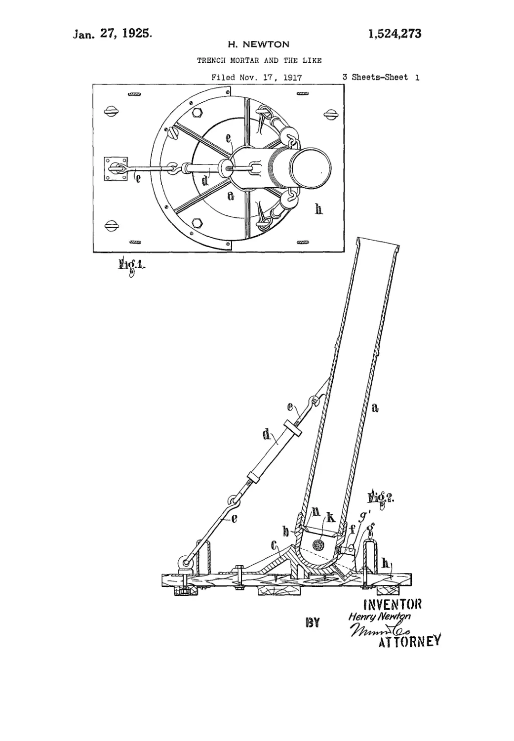
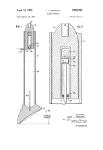
Figure 1 is a plan of one form of mortar 80
in accordance with the invention.
Figure 2 is a side sectional elevation.
Figure 3 is a front elevation, partly in
section;
Figures 4 and 5 are fragmentary views se
illustrating modifications.
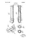
Fig. 6 is a detail view showing the cli-
nometer. In this view the gun barrel is dia-
gramatically shown.
Fig. 7 is a detail side view of the clinometer 90
showing the same attached to the gun bar-
rel.
Fig. 8 is a sectional view of a modified
form of combustion chamber showing a pis-
ton for regulating the chamber outlets. 95
Fig. 9 is similar view of another modifica-
tion of the combustion chamber in which
a cone is provided within the combustion
chamber for preventing clogging of the
chamber ports by the propellant. 100
Fig. 10 is a detail sectional view of a pro-
jectile carrying means for igniting the pro-
pellant
Fig. 11 is a side view of a portion of a
modified form of projectile. 106
Fig. 12 is a detail view partly in section
1,634,273
5
10
15
20
26
30
36
40
45
60
55
00
05
а
of a shell1 carrying a combustion chamber to
be used in lieu of the gun combustion cham-
ber.
Fig. 13 is a detail sectional view of <a
modified form of gun and projectile and
showing the projectile carrying the propel-
lant charge and the gun provided with a
striker for engaging the ignition cap of the
projectjle.
In carrying my invention into effect in one
convenient manner as illustrated in Figures
1 to 3, I form the mortar from a plain tube
a, preferably with a hemispherical end Ъ,
whereby the forces may be more evenly dis-
tributed as compared with those cases where
knuckle joints and pins are employed, so
that by this means even aluminium bases
such as c, or very light steel bases, may be
readily employed, this resulting in a con-
siderable saving of weight. Guy or stretch-
ing screws d with links or hooked ends e are
used to secure adjustment as to elevation and
direction, while a clinometer a', shown in
Figures 6 and 7 having a universal spirit
level bubble or the like which is adjustable
in two planes at right angles provides a
ready means for varying the range or direc-
tion with certainty, and I may also provide
a stud or pin f the axis of which contains or
is in alignment with the centre of the hemi-
spherical end portion and which is adapted
to move in a guide g on the mortar bed h in
order to ensure uniform movement of the
mortar, a suitable lock or projection g' being
provided upon the guide g for the purpose
of limiting the relative movement between
the pin and the guide.
The combustion chamber i for the propel-
lant charge к may be arranged within the
bore of the mortar, as shown, or outside the
same, and such combustion chamber may be
provided with a series of ports or outlets I
which may be adjustable or not as to size by
means of a piston i' as shown in Fig. 8 or
other suitable member or members for the
purpose of varying the area of escape for
the gases, the effect of such an arrangement
being that the pressure and temperature
within the combustion chamber will exceed
the normal temperature and pressure for
such low pressure guns as those under con-
sideration, and may be controlled so that a
uniform ignition and combustion of the pro-
pellant may be obtained and the disadvan-
tages hereinbefore noted in connection with
low pressure guns as hitherto constructed
completely obviated.
An ordinary rifle mechanism or other pri-
mary ignition may be arranged as shown
at m for the purpose of igniting the charge,
and when bombs of the tail type are em-
ployed a baffle plate n may be fitted to pre-
vent the streams of gas from impinging
upon the tail and producing distortion.
In place of the above arrangement the
combustion chamber may be provided with
an outlet aperture or mouth о (Figure 4) in
which case I arranged that the propellant
shall be ignited at the mouth by means of a
suitably placed nozzle p through which the
lighting agent may be conducted.
Priming charges to set up initial pres-
sures and temperatures may be employed in
connection with the propellant, and where
the combustion chamber is provided with
ports or apertures as above referred to I
may employ a cone i2 or other device or
means for preventing the clogging or cover-
ing of the ports by the propellant and in
this manner preventing the propellant from 80
becoming broken up and ejected in small
pieces into the bore of the mortar.
I may arrange so that a quick rate of fire
can be obtained by carrying the lightirig
charge i?’ on the projectile as shown in Fig. 85
10 in such a manner that it may be ignited
by the blow which obtains when the shell
comes to rest, firing the lighting cap and
igniting the propellant at its upper ex-
tremity, or as shown in Fig. 11, I may ar- 00
range a simple trigger action Is to effect the
firing when the shell has reached a predeter-
mined position in the bore of the gun.
In place of inserting the propellant into a
combustion chamber in the mortar, the pro- 05
pellant may be carried in a receptacle (as
shown in Fig. 12) fixed to or formed with
the shell base with lighting cap attached, the
receptacle being arranged in a manner simi-
lar to that above described so that a re- 100
stricted area for the escape of the gases will
be provided, with the result that increased
temperature and pressure are obtained.
In the example shown in Figure 5, the
charge carried on the base of the bomb q Ю5
consists of a primary charge r, such as bal-
listite or other suitable material, within the
cartridge container s and surrounded by a
secondary charge the latter being, if de-
sired, in two or more parts so that it may HO
be.varied as may be required for variation
in range, and being of any suitable form,
and instead of the secondary charge being
carried by the shell it may be located in the
base chamber of,the gun. H5
Where the bomb carries its own propel-
lant charge the mortar is provided with a
striker stud г7 (as shown in Fig. 13) fitted
at the bottom or the barrel, and such stud
may be telescopic or made to pass through 120
an aperture in the base of the gon or be
otherwise adjustable in such a manner as to
adjust the “working” stroke of the shell and
thus regulate the range. Again, as shown
in Fig. 11, the shell may carry a trip mecha- 125
nism to operate the igniting cartridges at a
predetermined point in their passage down
the bore.
Instead of providing for a fixed weight of
propellant and varying areas for escape of 130
1,524,273
5
10
16
20
25
30
35
40
45
50
55
60
65
the gases, I may. if desired, maintain the
ports or areas of escape constant and vary
the weights of the propellant charges em-
ployed. or I may vary both the weight of
the propellant and the areas of escape.
In a further modification the charge foi*
the mortar may comprise a slow burning
portion such as cordite wrapped round with
a quick burning charge such as gun-cotton
gum.
In any modification of the invention the
mortar maj’ be provided with the clinometer
a' adjustably mounted upon the barrel so
that in conjunction with a scale и (Figure
3) the clinometer may be adjusted to any
degree right or left for shooting right or
left.
The platform for the mortar or the like
may be of any suitable form, but I prefer
to construct the same of timbers united and
held together by interlocking portions and
by screws or other fastening devices, or so
arranged otherwise that a strong platform
is secured which will be easily dismountable
and readily transportable since it does not
comprise any heavy members in its con-
struction. It is to be understood that the
foregoing details are given by way of ex-
ample only of several methods of carrying
the invention into effect, as it will be clear
that I may vary the construction and ar-
rangement of mortar or howitzer or other
high pressure gun to which the invention
is to be applied, as also the size and loca-
tion of the combustion chamber, and the
manner of providing for the ignition of the
propellant, as may he found most satisfac-
tory in practice, depending upon any par-
ticular practical requirements that may have
to be fulfilled.
Having now described my invention, what
I claim as new and desire to secure by Let-
ters Patent is:—
1. A trench mortar or other low pressure
gun comprising in combination a hollow
barrel into which the projectile is intro-
duced, a combustion chamber for the pro-
pellant charge provided with a port or ports
communicating with said hollow barrel and
through which the whole of the propellant
gases pass and manually operated regulat-
able means for artificially raising the tem-
perature and pressure of combustion above
the normal substantially as descirbed.
2. A trench mortar or other low pressure
gun as claimed in claim 1 in which said
manually operated regulatable means com-
prises a device for controlling the size of
said port or ports connecting the combus-
tion chamber with the hollow barrel, sub-
stantially as described.
3. A trench mortar or other low pressure
gun as claimed in claim 1, in which said
manually operated regulatable means com-
prises a manually operated regulatable pis-
ton-like member provided for controlling the
s’ze of the port or ports connecting the com-
bustion chamber with tire hollow barrel.
4. In a trench mortar or other low pres-
sure gun the combination of a barrel having TO
a part spherical end, a bed carrying a part
spherical socket receiving and fitting said
end, and guys tensioned between said barrel
and said bed.
5. In a trench mortar or other low pres- TO
sure gun the combination of a barrel having
a part spherical end, a bed carrying a part
spherical socket receiving and fitting said
end. guys tensioned between said barrel and
said hed, and means fqr adjusting said guys 80
to vary the inclination of said barrel.
6. In a trench mortar or other low pres-
sure gun the combination of a barrel having
a part spherical end, a bed. a base thereon
having a part spherical socket receiving and 85
fitting said end, and having its axis inclined
forward, an adjustable tie in the vertical
plane containing said axis connecting said
barrel with a point on said bed in rear of
said socket, and other adjustable ties con- oo
nerting said barrel with points on said bed
to right and left of said socket respectively.
7. In a trench mortar or ether low pres-
sure gun the combination of a barrel having
a part spherical end, a base having a part 95
spherical socket receiving and fitting said
end, adjustable guys tensioned between
points on said barrel and points around
said socket, and means for indicating the
elevation and deflection of said barrel. TO®
8. In a trench mortar or other low pres-
sure gun the combination of a barrel having
a part spherical end, a base having a part
spherical socket receiving and fitting said
end, adjustable guys tensioned between 105
points on said barrel and points around
said socket, and a clinometer attached to
said barrel and adjustable in two directions
at right angles.
9. In a trench mortar or other low pres- 110
sure gun, the combination of a barrel having
a part spherical end, a bed carrying a part
spherical socket to receive and fit said end.
and guys permanently attached to one of
said members and adapted to be attached to 115
the other.
10. In a trench mortar or other low pres-
sure gun, the combination of a barrel having
a part spherical end. a base having a part
spherical socket receiving and fitting said 12°
end, a pin upon said end projecting radi-
ally from said end, a guide upon said base
confining said pin to movement in a plane
and adjustable tensional means supporting
said barrel and drawing its end into said 125
socket.
11. In a trench mortar or other low pres-
sure gun the combination of a barrel nav-
ing a part spherical end, a bed, a base hav-
ing a part spherical socket receiving and TOO
1,5ЭДО78
fitting Said end and having its axis in-
clined forward, a pin projecting radially
from said end in the vertical plane contain-
ing said axis, a guide on said base confining
s said pin to said plane, an adjustable tie in
the vertical plane containing said axis con-
necting said barrel with a point on said
bed in rear of said socket, and other ad-
justable ties connecting said barrel with
10 points on said bed to right and left of
said socket respectively.
12. In a trench mortar or other low pres-
sure -gun comprising in combination a, hol-
low barrel having a hemispherical lower
15 end, a hemispherical base within which said
end is free to work, a vertical guide upon
said hemispherical base', a pin in said hemi-
spherical end of the barrel, the axis of
which passes through the centre of said
20 hemispherical end and means for limiting
the relative movement between said pin and
said guide.
13. A trench mortar or other low pressure
gun as claimed in claim 12 having a cli-
25 nometer arranged on the barrel of the mortar
and combined with means for adjusting for
right and left shooting, substantially as
described.
14. A trench mortar or other low pressure
gun having a combustion chamber in which 30
the propelling charge is burnt, said chamber
being provided with ports commuBticating
between said combustion space and the
chamber containing the projectile, manually
regulated means for controlling the size of >5
said ports, and а г baffle between said ports
and the projectile.
15. A trench mortar or other low pressure
gun comprising a base provided with a
support having a semispherical cavity, a <®
hollow barrel provided with a hollow semi-
spherical lower end which is seated in said
cavity, tie members arranged between the
upper portion of the gun barrel and said
base for use in seating the barrel, a com- <5
bustion chamber arranged within the semi-
spherical space of the barrel, and means for
artificially raising the temperatures and
pressure of the combustion above the normal.
In testimony whereof I have signed my 50
name to this specification.
HENRY NEWTON.