/

Текст
BOX л a
NimBEfcr..
,Ы'С I п юад
CLASSH’
АЗДНт
ЖЕШШ
HANDBOOK
OF THE
9.45-INCH TRENCH MORTAR
MATERIEL
WITH
INSTRUCTIONS FOR ITS CARE AND USE
(Twenty-one Platea)
Compiled and Edited by the
Ordnance Department, U. S. A.
u
C
4
4
О
ARMY WAR COLLEGE
DECEMBER, 1917
t
О
ДО 4 WASHINGTON
^ь*^-*-* Ю GOVERNMENT printing OFFICB
1918
UNCIASSIFIEB
AVAR DEPARTMENT,
Washington, l)(cenibcr J, UH”.
The following manual, entitled “Handbook of the 9.45-Inch
Trench Mortar Materiel with Instructions for its Care and Use,’'
is published for the information and guidance of all concerned.
(710, A. G. O.)
JOHN BIDDLE.
Major General, Acting Chief of Staff.
Official :
H. P. McCAIN,
The Adjutant General.
3
AVAR DEPARTMENT,
The Adjutant General’s Office,
Washington, June 11), 7977.
To All Officers of the Army :
You are advised that this and alt subsequent documents of a
similar character, which may be furnished to you from this
office, are to be regarded as strictly confidential. They are to be
kept at all times in your personal possession, and are not to be
copied, nor are any parts of their contents to be communicated
either directly or indirectly to the press, nor to any persons
not in the military or naval service of the United States. In
Europe these documents are not to be carried into the front-line
trenches, nor farther to the front than the usual post of the
officers to whom issued.
Strict compliance with this injunction is enjoined upon every
officer into whose hands any of these confidential documents
may come.
By order of the Secretary of AV ar :
II. P. McCAIN,
The Adjutant General.
4
CONTENTS.
* rage,
List of equipment........................................... 7
The mortar.................................................. 9
General description..................................... 9
Weights, dimensions, etc............................... 10
Detailed description of parts of the materiel............. 1.1
Barrel, description of................................. 11
Breech mechanism, nomenclature and description of.... 11
Firing mechanism, nomenclature and description of... 13
Firing mechanism, action of............................ 14
Carriage, description of............................... 15
Racer, nomenclature and description of............. 15
Trunnion seats, nomenclature and description of. 18
Cheeks, nomenclature and description of............ 19
Racks, nomenclature and description of............. 19
Base....................................................... 20
Wooden platform, nomenclature and description of........... 23
Elevating mechanism, nomenclature and description of.... 26
Sight, nomenclature and description of..................... 28
Gunner’s quadrant.......................................... 31
Carts and carrying attachments............................. 32
Carts, nomenclature and description of................. 33
Carrying attachments, nomenclature and description of.. 37
Ammunition................................................. 43
Cartridge case......................................... 43
Care of............................................ 43
Primer................................................. 44
Projectile............................................. 44
Fuse................................................... 47
6
6
CONTENTS.
Page.
Installing and assembling the materiel....................... 47
Assembling the wooden platform........................... 47
Preparation of the ground............................ 47
Installation of the front and rear bracing beams... 47
Installation of the lower floor...................... 47
Assembly and installation of the framework......... 47
Installation of the jack screws...................... 48
Installation of the upper floor and cross beams.... ... 48
Mounting the base........................................ 48
Mounting the carriage.................................... 49
Mounting the mortar...................................... 49
Dismounting the materiel................................. 51
Dismounting the firing mechanism......................... 51
Care of the materiel..................................... 51
Inspection of the materiel............................... 52
Accidents during fire and precautions to be taken............ 52
Misfires................................................. 52
Defective functioning of the locking pin................. 53
Difficulty in introducing the projectile................. 53
Defective functioning of the platform.................... 53
Abnormal shots........................................... 53
Premature bursts......................................... 54
Misfires at the point of fall............................ 54
Precautions to be taken in order to avoid accidents.......... 55
Railroad transportation of the ammunition................ 55
Preservation of the ammunition........................... 55
Installation of the mortar............................... 55
Precautions during fire.................................. 56
Precautions in rainy weather............................. 56
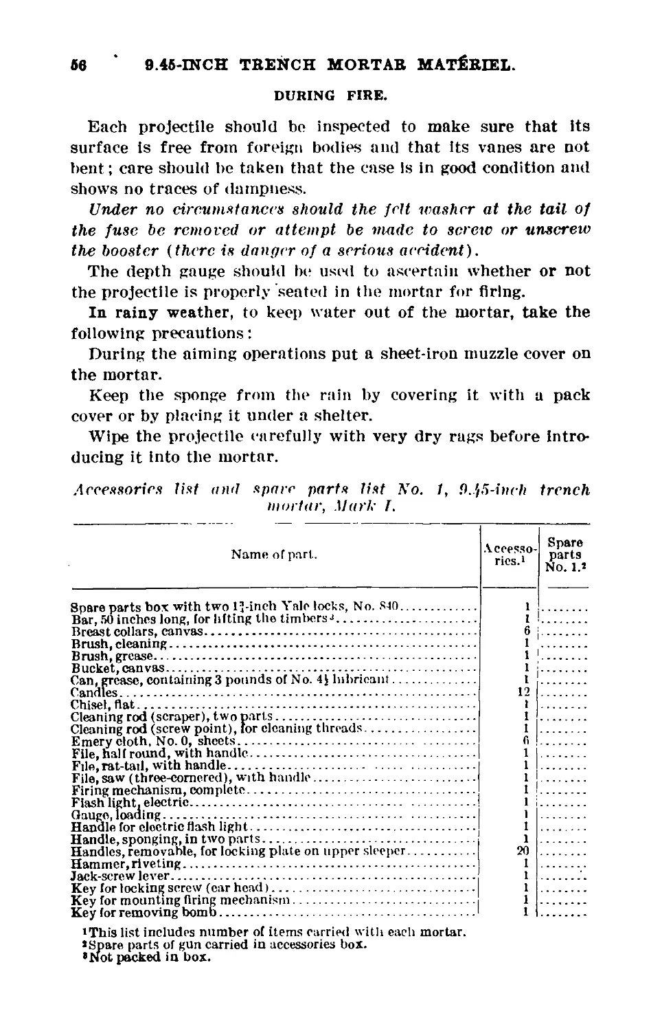
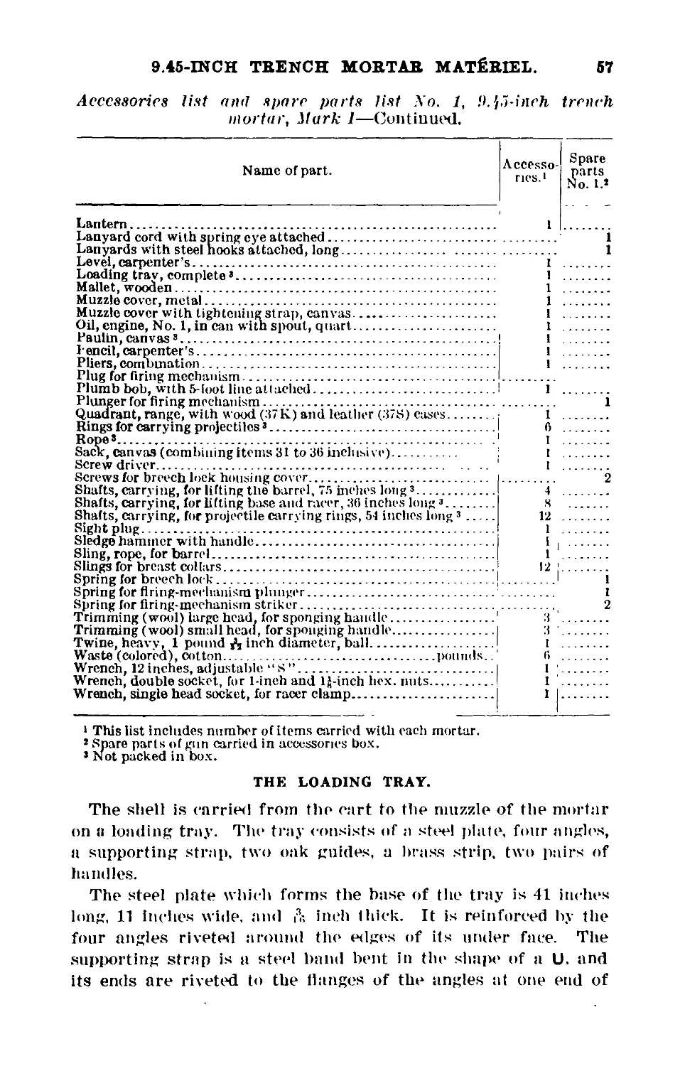
Accessories and spare parts list No. 1....................... 56
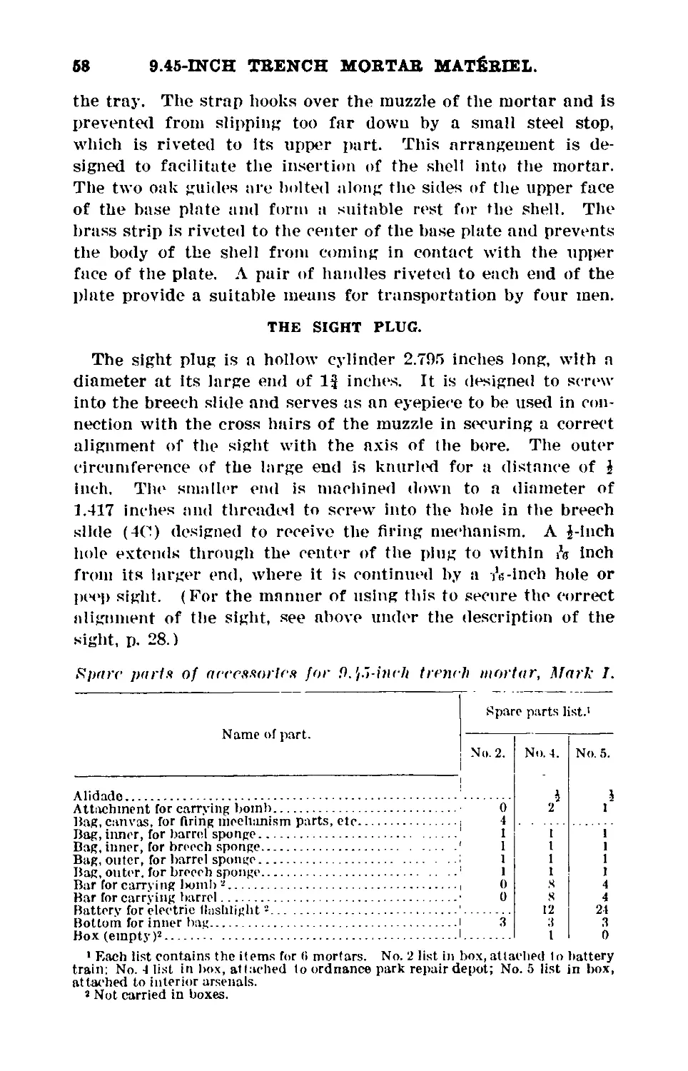
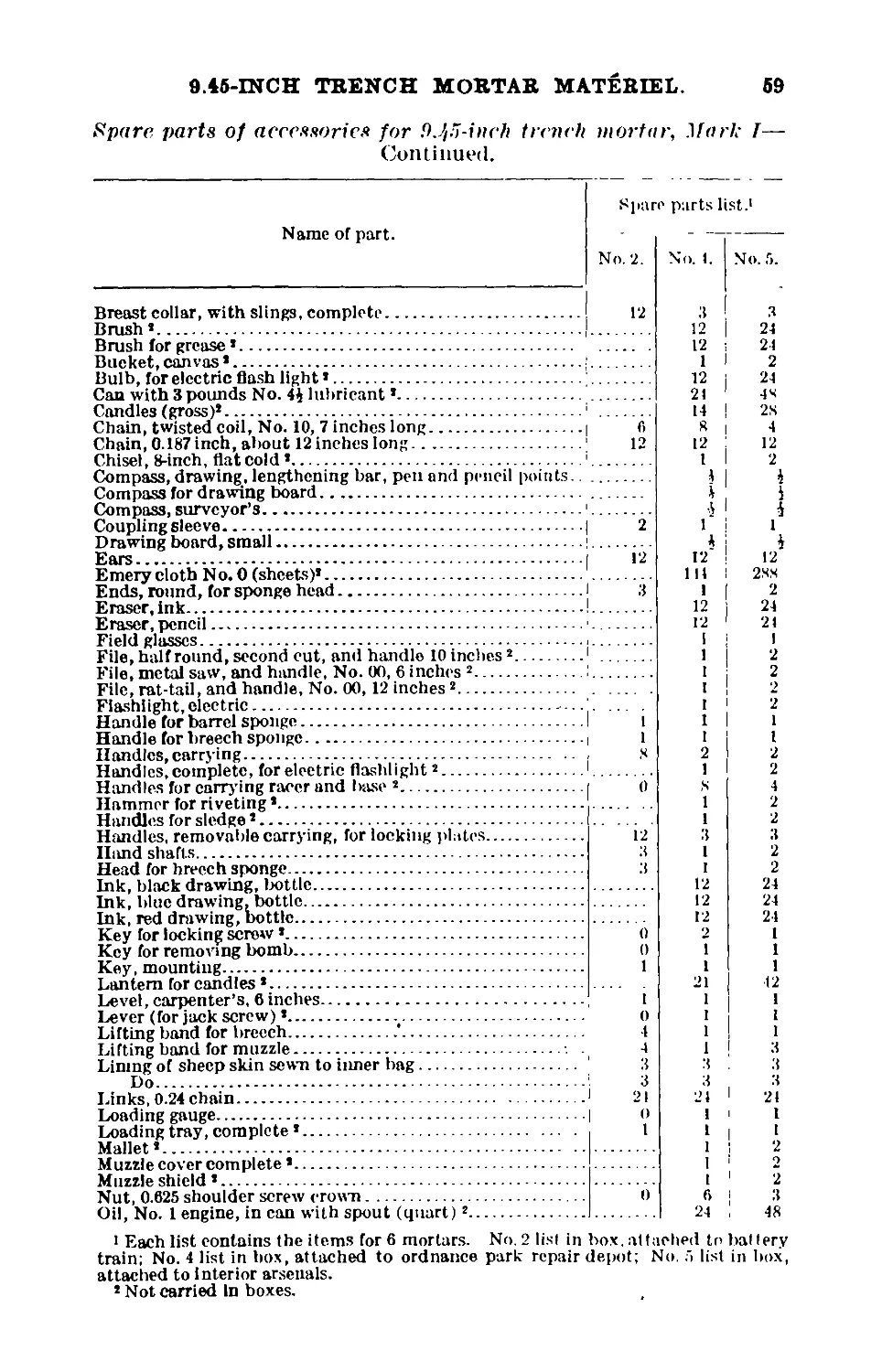
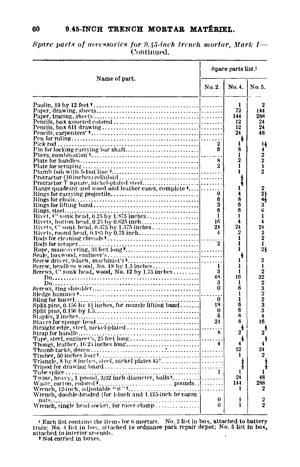
Spare parts of accessories................................... 58
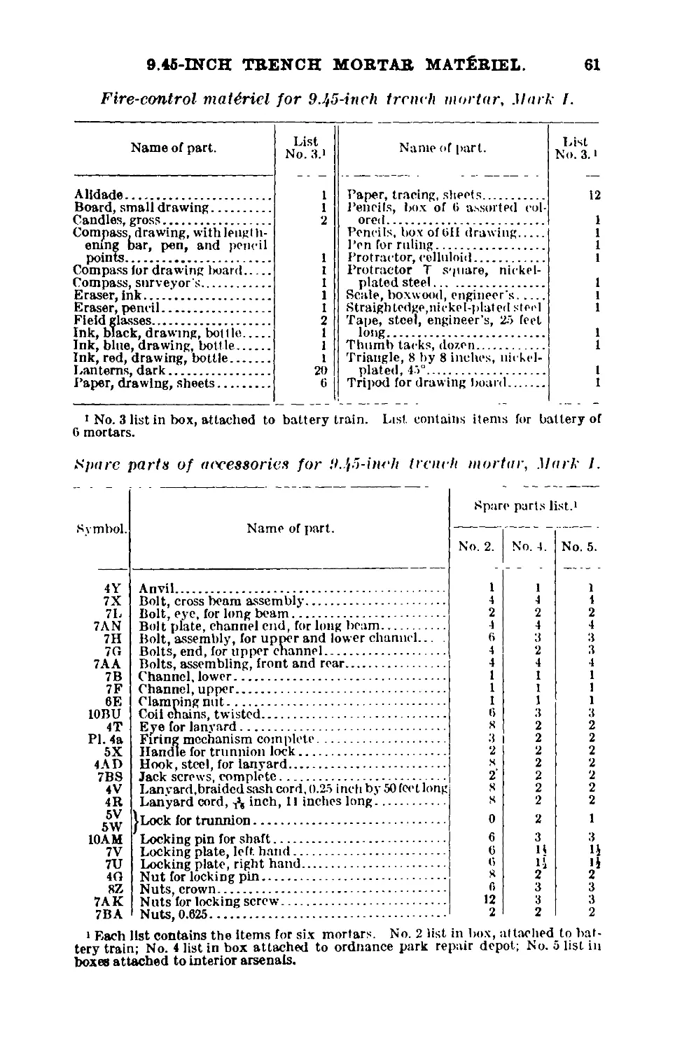
Fire-control materiel....................................... 61
Spare-parts list............................................. 61
Nomenclature of 9.45-inch trench mortar materiel............. 63
List of Equipment Furnished to One Trench-Mor-
tar Battery Equipped With 9.45-inch Trench-
Mortar Materiel.
No. Equipment.
6 9.45-inch trench mortars.
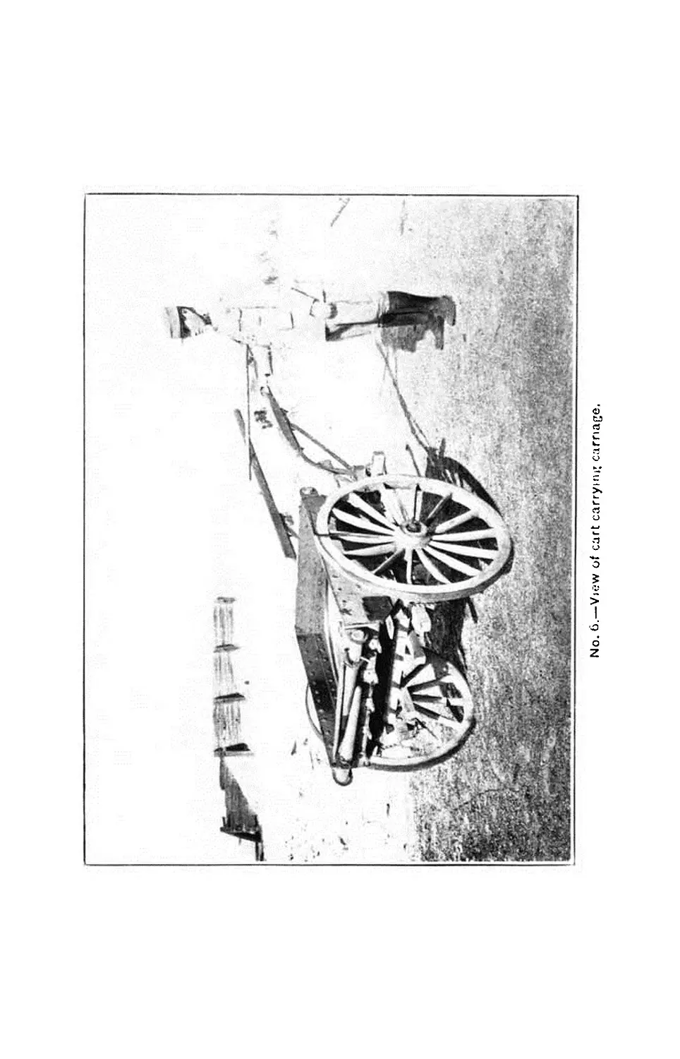
6 carriages on carriage carts.
G bases on carts.
12 park wagons for carrying wooden platform, the tools and tool
cases.
1 park wagon carrying spare-parts case and spare parts.
1 park wagon carrying the forge and its accessories.
1 forage wagon.
3 vans.
7
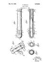
No. 1.—Sid-? view of assembled mortar with shells, cartridge cases, sponges, and carrying smarts
No. 2.—Front view of assembled mortar, showing general construction of f .o wooden nlatTorin
HANDBOOK
OF THE
9.45- INCH TRENCH MORTAR.
GENERAL DESCRIPTION.
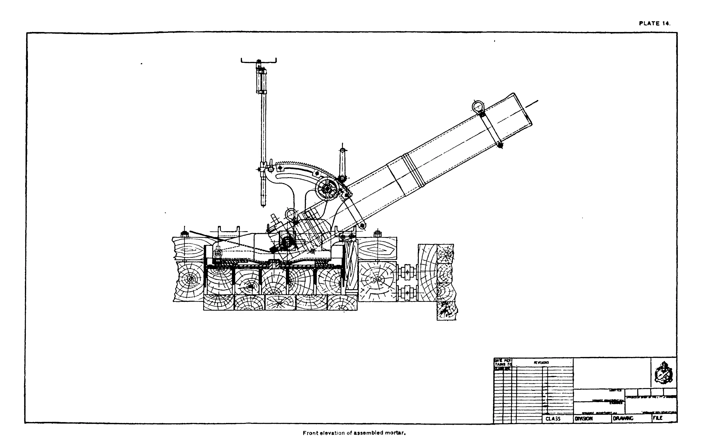
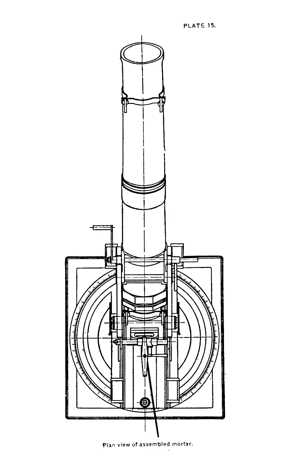
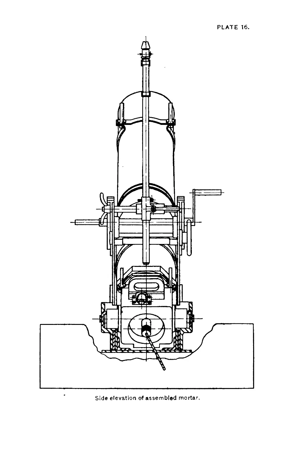
The 9.45-inch trench mortar is the heaviest of its type as yet
adopted for the United States Service. It throws a projectile
weighing when charged about 180 pounds and containing about
90 pounds of explosive to a range which may be made to vary
between 660 and 2,500 yards. It will hence readily appear from
the large caliber of the piece, the great weight of its projectile,
and its comparatively extended range that the use for which
it is primarily adapted is in the bombardment of strongly pro-
tected targets—dwellings, covered shelters, command posts,
entrances to galleries, etc.—or in the destruction of sectors of
trenches, salients, and the like. Under certain circumstances
the length of its range enables it to attain even the more ad-
vanced casements of the enemy batteries. Moreover, its enor-
mous demoralizing action on the personnel forms no inconsid-
erable part of the general effectiveness of this weapon (plates
14, 15, 16).
The mortar when mounted is composed of four major parts:
1. The barrel, or mortar proper, a hollow stixd forging, smooth
bored, 68.9 inches long, with an inside diameter of 9.45 inches,
which is joined to the breech by screw threads.
2. The carriage, consisting essentially of the racer, the trun-
nion seats supporting the trunnions of the breech, and the cheeks
and racks which carry the elevating mechanism of the piece.
All of these parts of the carriage are of steel and are riveted
together to form a solid whole.
3. The base, a complex arrangement of superimposed steel
plates and of angles, riveted together and forming a suitable
9
10 9.45-INCH TRENCH MOBTAB MATERIEL.
platform to support the weight of the carriage and barrel, as
well as to provide a surface, especially designed for traversing
the piece. The hub or axis feature of the traversing system is
a pintle riveted to the bottom plate and projecting through the
upper plate to receive the racer which may be pivoted around it.
4. A demountable wooden platform upon which the above
parts are invariably mounted. This is sunk into the ground and
Is composed roughly of two floors of timbers, the whole being
held solidly together by an appropriate arrangement of tie rods,
jack screws, and wedges.
The mortar is elevated by means of two handles and a crank
shaft which is keyed to two pinions meshing with the racks. Л
collar formed of three semicircular clamping bands bolted to-
gether encircles the barrel and is attached to the crank shaft.
A clamping handwheel working on a shaft which is supported
by the curved slots of the cheeks may be tightened against a
washer to hold the barrel at the desired angle of elevation.
The mortar is traversed by the rotation of the racer. When
the piece has been traversed to the desired direction it is held
in position by clamping the racer to the base.
Three one-horse carts are employed to transport, respectively,
the barrel and breech, the carriage, and the base. The timbers
of the wooden platform, together with the accessory equipment
of one mortar, are carried on two ordinary transport wagons.
Each of the one-horse carts may in turn be converted into a
shell carrier by the installation of a shell-carrying attachment.
WEIGHTS, DIMENSIONS, ETC.
Weight:
Barrel______________________(about) pounds__ 700
Carriage_____________________________ do--- 450
Base_________________________________ do___ 760
Wooden platform_______________________do____ 5,730 (cir.).
Total weight of mounted piece_________do____ 7,720 (cir.).
Weight of projectile filled and fused_do____ 180
Caliber_________________________________________ 9. 45 inches.
Length of barrel________________________________ 68. 9 inches.
Angles of elevation_____________________________ 45° to 75°
Horizontal field of fire________________________ 36°
Number of shots per minute______________________ 1/6
Maximum pressure (high charge) _ 3, 700 pounds per square inch.
Muzzle velocity (high charge)___... . ---- 475 feet per second.
Maximum range (high charge)---------------about 2,400 yards.
Minimum range (low charge)-------------------about660yards.
No. 3.—Rear view of assembled mortar with breech slide open, showing insertion of cartnd ;e
case and details of wooden platform.
9.45-ШСН TRENCH MOR TAB MATERIEL.
11
DETAILED DESCRIPTION OF THE VARIOUS PARTS OF
THE MATERIEL.
DESCRIPTION OF THE BARREL.
The barrel (4A) is a hollow forging of gun steel 68.9 inches in
length, with an external diameter at the breerh of 10.9 inches.
The bore is threaded at the breech end for a distance of 1J indies
for screwing onto the breech. This end is also shaped octagonally,
to allow for the application of a wrench. At about 27 inches
from the breech end the barrel is thickened by 0.08 of an inch
for a distance of 4.75 inches and is appropriately grooved to serve
as the seat for the gunner’s quadrant. A simitar thickness,
about 2 Inches in length, appears at the muzzle end. It is trav-
ersed by a sight cut.
A 2-inch groove situated about a foot from the breech end is
designed to receive the clamping bands (STI and 8I<) of the ele-
vating mechanism.
A register cut (4a) on the breech end serves for a correct
alignment of the barrel and breech.
Four sectional register cuts at intervals of 90° on the muzzle
end of the barrel are intended to receive the cross hairs used
together with the sight plug (see under accessories) in aligning
the sight (9M) with the axis of the bore. The barrel and breech
are locked together by means of я set screw (4N).
DESCRIPTION OF BREECH MECHANISM.
Nomenclature (plate J).
Symbol.
Quan-
tity.
Name of part.
Location.
4B
4D
4K
4F
4G
4E
4H
4C
4L
4M
4N
4Q
4P
1 Breech....................
1 Locking-pin housing.......
1 Locking-pin housing cover.
1 Locking pin...............
1 Locking-pin nut...........
1 Locking-pin spring........
1 Locking-pin ring.........
1 Breech slide.............
2 Breech-slide stops.......
4 Fillister head screws....
1 Headless set screw........
4 Countersunk head screws..
2 ......do..................
Breech end of barrel.
Fastened to top of breech.
Fastened to end of locking-pin hous-
ing (4I>).
Inside locking housing (4D).
On end of locking pin (4 F).
Inside locking-pin housing (411).
Attached to locking-pin nut (4G).
Inserted into vertical recess of breech
(4B).
Screwed to sides of breech slide (4C).
Fasten housing (ID) to breech.
For locking barrel to breech.
Fasten breech-slide stops (4L) to
breech slide (4C).
Fasten locking-pin housing cover
(4K) to locking-pin housing (ID).
12 9.45-INCH TRENCH MOBTAB MATERIEL.
The breech is provided with two trunnions (4d), which are
supported in the trunnion seats (5T and 5U) of the carriage.
Its front end is threaded to screw into the barrel. Immediately
to the rear of the threads the breech is octagonal in shape for
a distance of 1 inch to allow for the application of a wrench.
One face of the octagon is marked with a register cut (4b),
corresponding to the similar cut (4a) on the barrel. Between
the octagon and the vertical recess of the breech there is a
small hole (4c), | inch in diameter and of an inch deep,
which serves to receive the lifting band key (4AE). (Cf. de-
scription of breech-lifting attachments.)
The vertical recess, G.75 inches long and 2.34 inches wide,
extending through the bn*ech between the trunnions is de-
signed to receive the breech slide (4C). The breech is cham-
bered out to receive the cartridge case.
The locking-pin housing (4D) is securer! to the top of the
breech by means of four fillister head screws (4M). This hous-
ing contains the locking pin (4F) and the locking-pin spring
(4E). A hole extending lengthwise through the housing is
counterbored to provide a shoulder for the locking-pin collar.
The locking-pin housing cover (4K) is secured to the locking-
pin housing (4D) by means of the two screws (41*). The pur-
pose of the cover is to hold the locking pin and Its spring in
position within the housing.
Л nut (4G) is screwed and riveted to the outer end of the
locking pin. It serves merely as a seat for the locking-pin ring
(411) which is used as a handle for manipulating the locking
pin.
The locking pin (4F) is designed to hold the slide up during
the operation of loading or down during that of firing. The
locking-pin spring (4E) is designed to hold the locking pin in
position in the locking-pin recess of the breech slide.
The breech slide (4C) is inserted through the vertical recess
of the breech and is designed to close the breech chamber.
A hole is drilled and tapped in the breech slide to receive
the firing mechanism. It is provided with a handle (4f) at its
upper end for raising it during the operation of loading. Its
lower end is curved to facilitate the insertion of the cartridge.
Slightly below the handle on each side is a dovetail groove to
receive the dovetail tongue of the breech-slide stops (4L).
These stops are designed to prevent the slide from sinking too
far within the vertical recess. Between them on the rear face
9.45-INCH TRENCH MORTAR MATERIEL. 13
of the slide and slightly to the left of the center is a recess for
th£ locking pin, which prevents any upward movement of the
slide.
A recess directly corresponding to the locking-pin recess already
mentioned is drilled in the lower part of the breech slide to
receive the locking pin when the breech slide is raised.
DESCRIPTION OF FIRING MECHANISM.
Nomenclature (plate 2).
Symbol.
Quan-
tity.
Name of part.
Location.
4U
4Y
4W
4AA
4V
4Z
4S
4AB
4R
4T
4X
1 Housing..................
1 Anvil....................
1 Plunger..................
1 Striker..................
1 Plunger spring...........
1 Striker spring...........
1 Plug.....................
1 Vent bushing.............
1 Lanyard cord.............
1 Lanyard eye..............
1 Lanyard washer...........
Screws into breech slide (4C).
Insideof thehousing (41).
Inside of housing above the anvil.
Inserted in lowerend ofhousing.
Around lanyard cord (4R).
Around striker (4АЛ).
Screws into upper end ofhousing.
Screws into lower end ofhousing.
Extends through the plug and
plunger.
On the outer end of lanyard cord.
Tied to inner end of lanyard cord.
The flring-pin housing (4U) is threaded for a distance of 1
inch around the outside of the smaller end in such a manner
that it can be screwed into the breech slide after the insertion
of the projectile. This end is also tapped to receive the vent
bushing (4AB), which is tightened to the housing by means of
the mounting key. The outer end of the housing is tapped to
receive the plug (4S). Above the striker is situated the main
chamber of the housing, which contains the anvil (4Y), plunger
(4W), plunger spring (4AC) and plug (4S), the lanyard cord
(4R), and the lanyard washer (4X). The outer end of this
chamber is closed by the plug (4S), which projects a distance
of 1} Inches into the chamber. This projection is in the form
of a tube, which serves as a core for the plunger spring (4AC).
It is traversed by the lanyard cord (4R). Two small holes are
drilled through the plug (4S) to allow the application of a
mounting key. Around the inner end of this chamber are drilled
10 vent holes leading through the flutes (4e). The plunger (4W)
is a steel cylinder traversed through the center by a channel
whose diameter is slightly enlarged at one end to form a shoul-
der for the bearing surface of the lanyard washer (4X). The
lanyard washer is wrapped with twine and then spliced to the
14 9.45-INCH TRENCH MOBTAB MATERIEL.
eiul of the lanyard cord (4R) after the latter has been inserted
through the plunger hole. The lanyard washer (4X), which is
of steel, serves as a durable shoulder to prevent the detachment
of the lanyard cord from the plunger hole during the operation
of firing.
The lanyard cord (4R) is of sash cord about 6 inches In
length. Its outer end is spliced to the lanyard eye (4T), which
is of spring steel, and is split at its outer end to allow the pas-
sage of the lanyard hook (4AD) at the moment of firing.
The anvil (4Y) is tapped at the outer end to allow for screw-
ing to the plunger (4W) after the insertion of the lanyard
washer (4X) in the plunger. It is situated immediately above
the striker (4AA) and forms, when assembled, the lower part
of the plunger. It serves the twofold purpose of communicating
lhe pressure of the plunger spring to the striker and of holding
the lanyard washer in position.
The striker (4AA) is a steel cylinder slightly pointed at one
end. A collar situated at about I inch from its outer end serves
as a compressing surface for the striker spring (4Z). The
striker communicates the blow of the anvil (4Y) to the percus-
sion cap of the cartridge.
The rent bushing (4AB) is threaded to screw into the inner
end of the firing pin housing (4U) and forms a shoulder which
serves as the lower compressing surface for the striker spring.
A hole drilled through its center, having a diameter equal to that
of the striker (4AA), permits the functioning of the latter. Two
small holes in the inner face of the vent bushing allow for the
application of a mounting key.
ACTION OF THE FIRING MECHANISM.
1. The lanyard (4V) is drawn to the rear. This compresses
the plunger spring (4AC) and carries the plunger (4W) to the
rear of the chamber.
2. Upon the release of the hook (4AD) from the lanyard eye
(4T) the plunger spring is also released and carried forward,
the plunger and anvil against the striker (4AA).
3. The striker is driven against the percussion cap of the
cartridge, at the same time compressing the striker spring (4Z).
4. The striker spring returns the striker to its former posi-
tion.
9.45-ШСН TRENCH MOBTAB MATERIEL.
15
DESCRIPTION OF THE CARRIAGE.
The carriage consists of—
(«) The racer.
(M The trunnion
(C) The cheeks.
(d) The racks.
(a) THE RACER.
Nomenclature (plates ,1 and 4).
Name.
Location.
5 A В
01)
6(1
61Г
ОС
61)
5R
5S
5L
5M
5Q
5P
5N
5AQ
5Л R
6 К
6L
6M
6N
6R
6P
0Q
1 Lower horizontal plate....
1 Upper horizontal plate....
2 Angles....................
2 Inner plates...............
2 Outer plat es..............
2 Piller plates..............
1 Rear guide shoe............
1 Racer clamp shoe..........
1 Clamping nut...............
1 Stud.......................
1 Pin........................
1 Washer.....................
1 Chock plate................
1 Racer elamp shoe..........
1 Cover plate (right)........
1 Cover mate (left)..........
4 Shoulder pins..............
4 Keys.......................
8 Chain rings................
4 Twisted coil chains........
4 Eyebolts...................
1 Vernier bracket............
1 Vernier scale..............
1 Front socket (right).......
1 Front socket (left)........
1 Rear socket (right)........
1 Rear socket (left).........
1 Tie-plate.................
2 Reinforcing angles........
4 Screws.....................
Hase of racer.
Do.
Riveted to plate (5Л).
Riveted to angles (5B).
Riveted to plates (5D).
Riveted to plates (5E).
Riveted to plate (5Л).
Fastened to stud (6F).
Do.
Through holo in nlato (5Л).
Through stud (6F).
Over stud (6F).
Riveted to plate (5A).
Do.
Fastened to plate (5A).
Do.
Riveted to plate (5A).
Through shoulder pins (5L).
Through pins (5L) and bolts (5N).
Fastened to chain rings (5Q).
Fastened to plates (5E).
Riveted to racer wall.
Fastened to bracket (5AQ).
Riveted to racer wall.
Do.
Do.
Do.
Fastened to front sockets.
Fastened to rear sockets.
Fasten angles (OP) to sockets (6M
and 6N).
5 В
The racer consists of a series of steel plates and angles riveted
together to form a solid whole. It may be regarded as the foun-
dation of the carriage and it serves the double purpose of
adequately supporting the superstructure of the trunnion seats,
cheeks, and racks and of appropriately transmitting the shock
of recoil to the base.
The short lower horizontal plate (6A) 16| inches long, 8}
inches wide, and i inch thick, and the long upper horizontal
16 9.45-ШСН TRENCH MORTAR MATERIEL.
plate (5A) 34 inches long, 16$ inches wide, and § inch thick are
riveted together. These two plates are in turn riveted to the
horizontal flanges of the angles (5B). The two vertical walls
of the racer are composed of inner (5D) and outer (5E) plates
of an unequal length riveted to each other and to the vertical
flanges of the angles (5B). The space left between the longer
outer plates and the vertical flanges of the angles are filled by
the filler plates (5K) which serve as a reinforceinent to the
walls. A little to the front of the (enter both vertical walls are
cut away to form a rwess for the boxes of the trunnion seats
(5T and 51'). The dimensions of this recess are 4g inches deep
by 4£ inches wide.
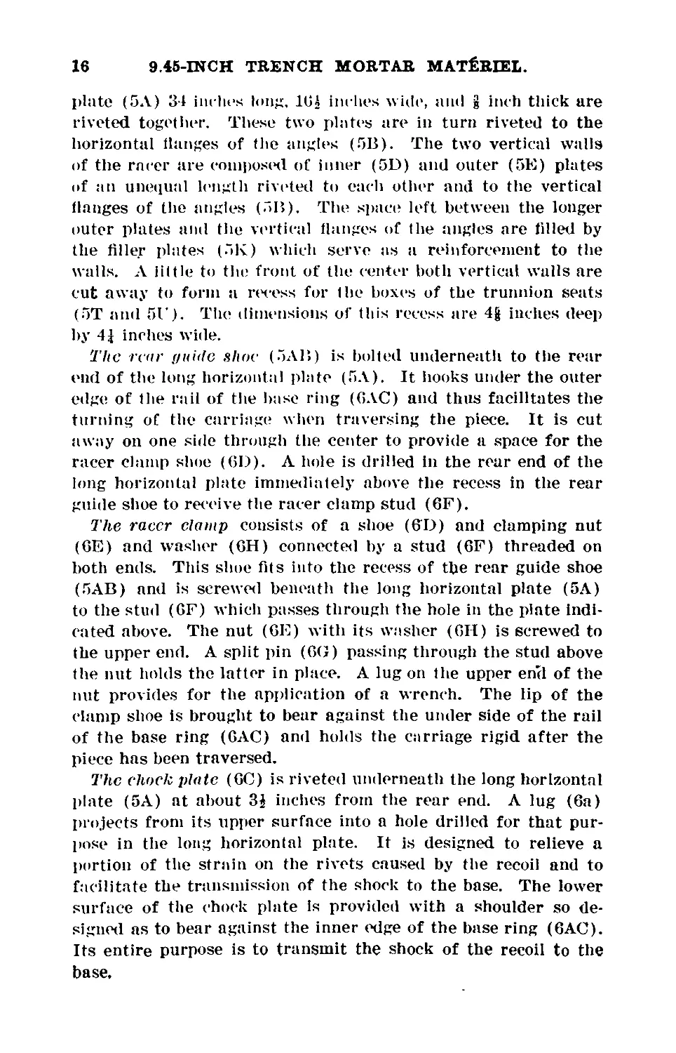
The rear (/uhlc shoe (5AB) is bolted underneath to the rear
end of the long horizontal plate (5A). It hooks under the outer
edge of the rail of the base ring (GAC) and thus facilitates the
turning of the carriage when traversing the piece. It is cut
away on one side through the center to provide a space for the
racer clamp shoe (6D). A hole is drilled in the rear end of the
long horizontal plate immediately above the recess in the rear
guide shoe to receive the racer clamp stud (6F).
The racer clamp consists of a shoe (6T>) and clamping nut
(GE) and washer (GH) connected by a stud (GF) threaded on
both ends. This shoe fits into the recess of the rear guide shoe
(5AB) and is screwed beneath the long horizontal plate (5A)
to the stud (GF) which passes through the hole in the plate indi-
cated above. The nut (GE) with its washer (GII) is screwed to
the upper end. A split pin (6G) passing through the stud above
the nut holds the latter in place. A lug on the upper erul of the
nut provides for the application of a wrench. The lip of the
clamp shoe is brought to bear against the under side of the rail
of the base ring (GAC) and holds the carriage rigid after the
piece has been traversed.
The chock plate (GC) is riveted underneath the long horizontal
plate (5A) at about 3$ inches from the rear end. A lug (6a)
projects from its upper surface into a hole drilled for that pur-
pose in the long horizontal plate. It is designed to relieve a
portion of the strain on the rivets caused by the recoil and to
facilitate the transmission of the shock to the base. The lower
surface of the chock plate is provided with a shoulder so de-
signed as to bear against the inner edge of the base ring (6AC).
Its entire purpose is to transmit the shock of the recoil to the
base.
9.45-ШСН TRENCH MORTAR MATERIEL. 17
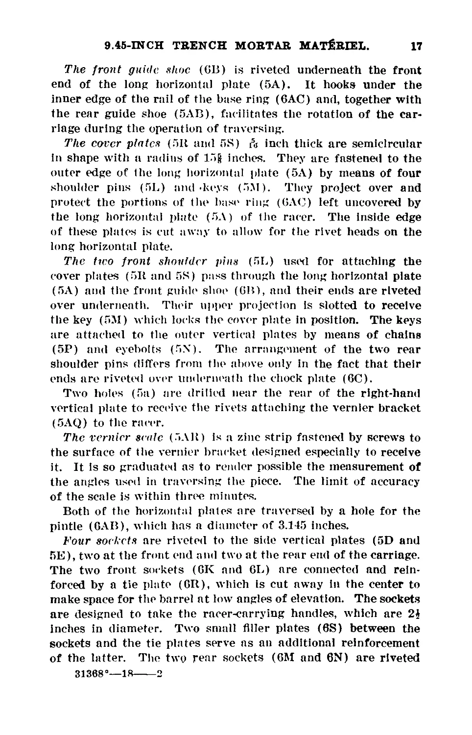
The front guide shoe (6B) is riveted underneath the front
end of the long horizontal plate (5A). It hooks under the
inner edge of the rail of the base ring (6AC) and, together with
the rear guide shoe (5AB), facilitates the rotation of the car-
riage during the operation of traversing.
The corer plates (511 and 5S) i5<j inch thick are semicircular
in shape with a radius of 15g inches. They are fastened to the
outer edge of the long horizontal plate (5A) by means of four
shoulder pins (5L) and -keys (5M). They project over and
protect the portions of the bast' ring (GAC) left uncovered by
the long horizontal plate (5A) of the racer. The inside edge
of these plates is cut away to allow for the rivet heads on the
long horizontal plate.
The two front shoulder j>ins (5L) used for attaching the
cover plates (511 and 5S) pass through the long horizontal plate
(5A) and the front guide shoe (6P>), and their ends are riveted
over underneath. Their upper projection is slotted to receive
the key (5M) which locks the cover plate in position. The keys
are attached to the outer vertical plates by means of chains
(5P) and eyebolts (5X). The arrangement of the two rear
shoulder pins differs from the above oidy in the fact that their
ends are riveted over underneath the chock plate (6C).
Two holes (5a) are drilled near the rear of the right-hand
vertical plate to receive the rivets attaching the vernier bracket
(5AQ) to the racer.
The vernier scale (5AR) is a zinc strip fastened by screws to
the surface of the vernier bracket designed especially to receive
it. It is so graduated as to render possible the measurement of
the angles used in traversing the piece. The limit of accuracy
of the scale is within three minutes.
Both of the horizontal plates are traversed by a hole for the
pintle (GAB), which has a diameter of 3.145 inches.
Four sockets are riveted to the side vertical plates (5D and
5E), two at the front end and two at the rear end of the carriage.
The two front sockets (GK and 6L) are connected and rein-
forced by a tie plate (GR), which is cut away in the center to
make space for the barrel at low angles of elevation. The sockets
are designed to take the racer-carrying handles, which are 2A
Inches in diameter. Two small filler plates (6S) between the
sockets and the tie plates serve as an additional reinforcement
of the latter. The two rear sockets (GM and 6N) are riveted
31368°—18---------2
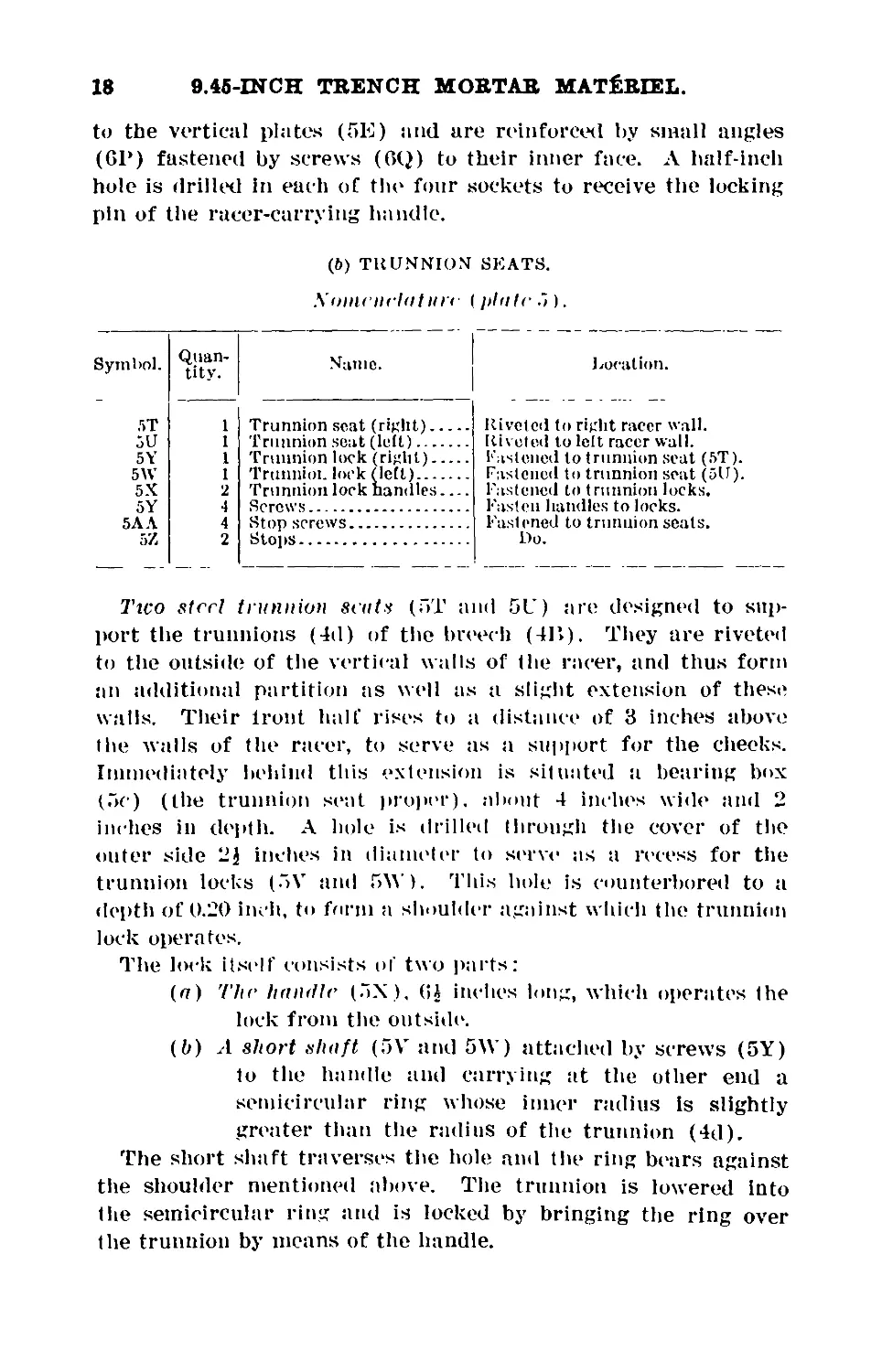
18 9.45-INCH TRENCH MOBTAB M AT Ё BIEL.
to the vertical plates (5E) and are reinforced by small angles
(СГ) fastened by screws (6Q) to their inner face. A half-inch
hole is drilled in each of the four sockets to receive the locking
pin of the racer-carrying handle.
(&) TRUNNION SEATS.
Xonuiiclatlire (plate .
Symbol.
Quan-
tity.
Name.
Location.
5T
5U
5Y
5W
5X
5Y
5АЛ
1 Trunnion seat (right)....
1 Trunnion seat (left).....
1 Trunnion lock (right)....
1 Trunnioi. lock (left)...
2 Trunnion lock handles....
4 Screws...................
4 Stop screws..............
2 Stops....................
Riveted to right racer wall.
Riveted to left racer wall,
fastened to trunnion seat (5T).
Fastened to trunnion scat (5U).
Fastened to trunnion locks.
Fasten handles to locks.
Fastened to trunnion seats.
Do.
Ttco steel trunnion seats (5T and 5L ) are designed to sup-
port the trunnions (4d) of the breech (4Г>). They are riveted
to the outside of the vertical walls of the racer, and thus form
an additional partition tis well as a slight extension of these
walls. Their trout half rises to a distance of 3 inches above
the walls of the racer, to serve as a support for the cheeks.
Immediately behind this extension is situated a bearing box
(5c) (the trunnion seat proper), about 4 inches wide and 2
inches in depth. A hole is drilled through the cover of the
outer side 2$ inches in diameter to serve as a recess for the
trunnion locks (5V and ГЛУ). This hole is counterbored to a
depth of 0.20 inch, to form a shoulder against which the trunnion
lock operates.
The lock itself consists of two parts:
(a) The handle (5N), (>Л inches long, which operates the
lock from the outside.
(b) A short shaft (5V and 5\V) attached by screws (5Y)
to the handle and carrying at the other end a
semicircular ring whose inner radius is slightly
greater than the radius of the trunnion (4d).
The short shaft traverses the hole and the ring bears against
the shoulder mentioned above. The trunnion is lowered into
the semicircular ring and is locked by bringing the ring over
the trunnion by means of the handle.
9.45-INCH TRENCH MORTAR MATERIEL. 19
Two stop screws (5AA) are screwed into the outside of the
box to act as stops for the handle and to maintain it either in
the locked or unlocked position.
Two stops (5Z) on each trunnion seat are attached by screws
to the outside of the box. Their purpose is to maintain the
carriage in position during possible transportation by a car-
riage cart of the model used in the French army.
(c) THE CHEEKS.
Nomenclature [plate }).
Symbol.
Quan-
tity.
Name.
location.
5AC
5AI>
Racer chock (right)
Racer cheek (left)..
Riveted to trunnion seat (5T).
Riveted to trunnion seat (5V).
The checks (5AC and 5AD) are irregularly shaped plates
riveted to the inside face of the extensions of the trunnion seats
(5T and 5U) indicated above and extending 22g inches above
them. Their purpose is to .support the elevating mechanism and
the clamping device which maintains the barrel at the desired
angle of elevation.
They are cut away through the center to minimize weight.
A slot (Gb) traversing nearly the entire length of their upper
part serves as a recess to receive the shaft (8C) of the clamping
mechanism. Their extreme upper edge is cut away, leaving
three lugs (6C), to which the racks (GAD) are bolted. Л slot
(Gd) is located immediately behind the rear lug, to receive the
cross-sight post shaft (9A). The slot of the right cheek is
counterbored to form a bearing surface for the collar of this
shaft. The slot of the left cheek is similarly counterbored to
act as a bearing surface for its shoulder.
(<7) THE RACKS.
Nomenclature (plate If).
Symbol. Quan- tity. Name. Location.
BAD 2 Racks Fastened to cheeks Г5ЛС and АЛП)
6AE 6 Bolts Fasten racks to cheeks.
20
9.45-INCH TRENCH MORTAR MATERIEL.
The racks (GAD) are curved strips with a tee-shaped cross
section. The web of the tee is cut away leaving lugs which cor-
respond, and are riveted to the lugs of the cheeks (5AC and
5AD). Teeth are cut in their upper and wider edge to mesh
with the teeth of the pinions (8A) of the elevating mechanism.
DESCRIPTION OF THE BASE.
Nomenclature (plates J and .}).
Symbol.
Quan-
tity.
Name.
I vocation.
6U
5AE
5AF
5AG
5AH
6AB
5C
6AA
6 AC
5AM
1 Base plate................
1 Angle.....................
2 Plates....................
2 .....do...................
2 Angles....................
1 Pintle....................
1 Pintle cover..............
1 Disk......................
1 Base ring.................
1 Azimuth circle............
5AN
6V
6W
6X
4 Packing plates...........
2 Anglos...................
4 ....do...................
2 Spades...................
6Y
5AK
5AL
2
4
10
4
Plates...................
____do...................
Locking lugs.............
Sockets..................
Main part of base.
Riveted to plate (6U).
Riveted to angle (5AE).
Riveted to plates (5AF).
Do.
Riveted to plate (6U).
Fits over pintle (GAB).
Riveted to plate (6U).
Riveted to disk (6AA).
Fastened to angle (5AE) and pack-
ing plates (5AN).
Fastened to plate (6U).
Riveted to plate (6U).
Do.
Riveted to plates (5AG) and angles
(6V).
Riveted to plate (fiV).
Do.
Riveted to plates (5AF).
Do.
The base is a complex arrangement of plates and angles riv-
eted together. Roughly it forms a steel box designed to act as
a support and a runner for the carriage and to transmit the
shock of recoil to the wooden platform.
The square base plate (GU), 39j inches long, 39| inches wide,
and i inch thick, is to be regarded as the foundation of the
rest of the base. It is surrounded on all four sides by an angle
(5AE), which is riveted to its upjier face, and whose vertical
flange rises 2J inches above the plate. This flange is sur-
mounted by two plates (5AF). Each plate is bent at right
angles and is riveted to two sides of the flange, thus forming
with the flange a vertical wall GJ inches in height around the
square base plate. An added reinforcement of the side walls is
obtained by two angles (5AH), 27} Inches long, which are riv-
No. 4.—Rear view of assembled mortar with breech slide closed, showing base, azimuth circle,
and detail-, of wooden platform.
9.45-INCH TRENCH MORTAR MATERIEL. 21
eted to the upper edges of these walls. Two additional plates
(5AG) are riveted to the front and rear walls. The upjier edge
of these is flush with the upper edge of the walls; their lower
edge projects 3 Inches below the square base plate and serves
as a riveting surface for the front and rear spades (GX).
The pintle (GAB) is a hollow steel cylinder, 2| inches long,
which is machined down to three diameters to provide for the
riveting collar and the successive projections of the pintle
through the square base plate (GU), the steel disk (GAA) of the
base, and the two horizontal plates (5A and GA) of the racer.
Its collar is riveted to the under face of the square base plate.
The pintle serves as the axis of the carriage for traversing the
piece.
The pintle is covered and protected by a steel pintle cover
(5C).
On the upper surface of the square base plate and concentric
with it is riveted a steel disk (GAA), J inch thick. Its diameter
is 33} inches.
Its outer edge is cut down to form a circular bearing surface
ft inch deep and 5g inches wide. It is designed to support the
base ring (6AC). The base ring is riveted to this surface and
Is surmounted by a T head rail which is of one piece with it.
The rail has a width of 1} inches. It serves as a runner for
the carriage and as a channel for the front (GB) and rear (5AB)
guide shoes of the racer. The head of the rail is cut away at
two opposite parts of its circumference to allow for disengag-
ing the guide shoes (5AB and GB) when dismounting the
carriage.
The azimuth circle (5AM) is made of zine and is composed of
four segments which, when screwed to the horizontal flange of
the angle (5AE) and to the packing plates (5AN) (see below)
form a ring 1g inches wide and | inch thick, with an outside
diameter of 37J inches. This circle is graduated in degrees,
each degree and half degree being represented by a cut and
every 10 degrees designated by a numeral. The azimuth circle
serves as a scale used in conjunction with the vernier scale
(5AR) when traversing the piece.
Four small packing plates (5AN), whose thickness, ft inch,
corresponds with the thickness of the horizontal flange of the
angle (5AE), are fastened by screws to the square base plate
22
9.45-INCH TRENCH MORTAR MATERIEL.
(GU). Both ends are cut to fit the angle (5AE) and their inter-
vening curve corresponds to the curve of the azimuth circle
(5AM). They serve to support those segments of the azimuth
circle which are left unsupported by the horizontal flange of the
angle.
To the lower face of the square base plate (GU) are riveted
six angles (6V and GW), whose horizontal flanges project be-
tween or over the sides of the timbers of the wooden platform,
and thus serve as spades in establishing the connection between
the latter and the superstructure of the mortar. The vertical
flanges of the four inner angles (GW) are 5 inches long; those
of the two outer angles (GV) 3 inches long. Each pair of hori-
zontal flanges of the inner angles face each other.
Two spades (GX) are inserted and riveted between the front
and rear angles (GV) and the additional plates (5AG) men-
tioned above as riveted to the vertical walls of the base. They
project 2g Inches below the vertical flanges of the angles and
serve as a reinforcement and extension of the outer spades.
Each is traversed by two holes for the locking pins (13C), which
secure it to the carrying attachment of the cart.
Six reinforcing plates, two (GY) between the two outer an-
gles and two (GZ) between the two center angles on either Bide
of the pintle shoulder, are riveted to the under face of the base
plate (6U). The dimensions of the two outer plates are, length
38} inches, width 5 inches, thickness tfc inch; those of the
central plates, length 1GJ inches, width 2g inches, thickness A
inch.
Five locking lugs (5AK), 2g inches long, 1A inches wide, and
i inch thick, are riveted to each vertical side wall of the base.
They are designed to fit into the locking plates (7BN) of the
wooden platform and serve to fix the base in position.
Four sockets (5AL) are riveted flush with the upper edge of
the side walls of the base, two at the front and two at the rear
end. They are designed to take the base-carrying handles, which
are 2} inches in diameter.
9.45-INCH TRENCH МОНТАН MATERIEL. 23
DESCRIPTION OF THE WOODEN PLATFORM.
Nomenclature (plate .5).
Syi
mbol. Quan- tity.
7A
7 В 2
7C 10
7I> 2
7Е 2
7F 2
7Cr 1
7П 10
7K s
7L 4
7M 5
7N 10
71’ 10
7Q 5
7R 10
7S 5
7T 10
71' 5
7 V tc
7W 2
7Y 4
7Z 4
7AA 6
7AB 4
7AE 3
7AC 4
7ЛР 4
7BX 10
7BP 10
Lower floor timbers..
Lower channels......
Assembling bolt pins
Ixmg beams..........
Struts....... .
Upper channels......
Bolts...............
..:..do..............
Tie rods...........
Eyebolts...........
Upper Door timbers
Reinforcing bands..
Spacers............
Tie plates........
Locking screws....
Tie plaies.........
Shoulder screws....
Locking plates.....
....do.............
Cross beams........
Front beams........
Rear beams.........
Bolts..............
Vortical blocks...
____do.............
Wedces............
Reinforcin': bands.
Lockim: plates....
Handles...........
Location.
Between long beams (7D).
Bo.
Tn flanges of channels (7B).
Outside of framework.
Connect beams (7D).
Across ends of beams (7D).
Fasten channels (7F) to beams (7D).
Fasten channels (7F) to channels
(7B).
Fasten ends of beams (7B) together.
Fastened to beams (7D).
Rest on timbers (7A).
Around ends of timbers (7M).
Fastened to timbers (7M).
Do.
Fastened to tie plates (7Q and 7S).
Fastened to timbers (7M).
Fastened to tie plates (7Q and 7Я).
Fastened to tieplates(7Q).
Fastened to tic plates (7S).
Fastened to beams (7D).
At front of excavation.
At rear of excavation.
Through front (7Y) and rear (7Z)
beams.
Between beams (7D) and (7Y).
Between beams (71)) and (7Z).
Between beams (7D) and (7M).
On large ends of wedges (7AC).
Fastened to timbers (»7AO).
Fastened to plates (7BX).
The wooden platform is composed of a rigid framework
formed by a suitable arrangement of timbers which arc held
together by a system of tie-rods, channel irons, and bolts. The
whole is stink into an excavation prepared for it in the ground
and Is clamped rigidly by means of jackscrews and wedges.
It is designed to serve as a level and firm-bearing surface for
the mortar, adapteil to sustain both the superimposed weight
of the piece and to adequately take up the shock of recoil
during firing.
The platform itself is composed of the following major parts:
(a) The lower floor.
(b) The framework.
(c) The upper floor.
(rf) The eight front and rear bracing beams.
24
9.45-INCH TRENCH MOBTAB MATERIEL.
(a) The lower floor is composed of five oak timbers (7A).
86} inches long, 8f inches wide, and 4$ inches thick, laid hori-
zontally side by side across the excavation. Plates (7BN) with
handles (7BP) are bolted to both ends of each timber to facili-
tate carrying them. The ends of the timbers rest on two lower
channels (7B), 43} inches long and G inches wide, the flanges
of which face downward. These flanges are pierced by holes at
suitable distances to receive the assembling bolt pins (7C).
(b) The framework consists of four beams: Two long beams
(7D) parallel with the timbers of the lower floor, 86} inches
long, 11} Inches wide, 11 inches thick; they rest on a slightly
higher level of the excavation than the lower floor timbers and
project 9} inches above the latter; two struts (7E), 49| inches
long, 5} inches wide, and 9} inches deep, which are supported
by the ends of the lower-floor timbers and fit between the two
long beams in recesses especially prepared in the latter to receive
them.
An upper channel iron (7F), 6 inches wide and 65} Inches long,
crosses the ends of the long beams of the framework and rests
on each strut. It is attached to the long beams by bolts (7G).
The bolts (7H) pass through this channel, the strut, the lower-
floor timbers and the lower channel iron where they are pre-
vented by the assembling bolt pins (7C) from turning while the
nuts are being tightened. The bolt heads are slotted to receive
these pins. This arrangement provides for the perfect solidity
of the lower floor with the framework.
Two pairs of tie-rods (7K) at each side, 68J inches long, one
above the other, connect the ends of the long beams of the frame-
work and contribute to its solidity. Ay eyebolt (7L) is at-
tached to each end of the long beams of the framework to facili-
tate carrying them.
(c) The upper floor is composed of five square oak timbers
(7M) 59 inches long, 7} inches wide, and 7J inches thick, which
are laid parallel across the top of the lower-floor timbers. They
rest between the two long beams of the framework. The ends
of each timber are provided with a steel reinforcing band (7N).
Between each pair of timbers and between the last timber and
the rear long beam of the framework, steel spacers (7P) are
located which are attached by screws to the timbers and serve
to provide proper intervals to receive the spades of the base.
9.45-INCH TRENCH MOBTAB MATERIEL. 25
About 10 inches from both ends of each timber there is a tie
plate (7Q and 7S) which serves as a seat for the locking lugs
(5ЛК) of the base. Attached to each tie-plate by a shoulder
screw (7T) there Is a locking plate (7V or 7U) designed to lock
tiie lugs of the base in position. The locking plate is held in
place by a locking screw (7R).
Two cross beams (7W), 54J inches long, inches wide, and
9 inches deep, rest on the ends of the upper floor timbers and
are secured by bolts (7X) to the long beams of the framework.
They are designed merely to hold down the timbers of the
upper floor.
(d) The eight bracing beams, four in front (7Y) and four in
rear (7Z), are oak timbers 9J Inches wide and 5J inches deep.
The front timbers (7Y) have a length of 137 inches, those of
the rear 15G inches. Each set of four is fastened together by
bolts (7AA), making a solid block. These blocks fit into the
appropriate portions of the excavation to the front and rear
of the platform.
The platform is clamped solidly together by means of the
following arrangement :
(a) Four vertical blocks (7AB), 22 inches long, are installed
so as to bear against the inner face of the four front-bracing
beams and in turn to furnish a bearing surface for four jack-
screws. The latter bear against the side of the front long beam
of the framework. Three vertical blocks (7ЛЕ) of like dimen-
sions fit between the rear long beam of the framework and the
four rear bracing beams. Their purpose is to transmit a more
even pressure to these last when the jack screws are tightened.
(b) A pair of oak wedges (7AC) 13? inches long is inserted
at each side between the long front beam (7D) of the frame-
work and the front vertical plate of the base. The larger end
of each wedge is provided with a reinforcing band (7AD) of
steel.
THE EXCAVATION.
The deptli of the excavation is about 20 inches and its shape
conforms closely to that of the platform. Its bottom must be
horizontal and the rear wall must be carefully dressed and
absolutely vertical, because it is against this surface that the
horizontal recoil of the mortar presses at the moment of fire.
26 9.45-ШСН TRENCH MOBTAB MATERIEL.
DESCRIPTION OF THE ELEVATING MECHANISM.
Nmnenclaturc (plate (>).
s>'"4 'Si?!’
Location.
8Л
811
8E
8Q
8N
8P
8C
8D
8F
8G
811
8K
8L
8Y
8V
8M
2 Pinions..................
I Elevating shaft..........
1 Crank (right)............
1 Crank (left).............
1 Crown nut................
1 Split pin................
1 Clamping shaft...........
1 Key......................
1 ....do...................
1 Handwheel................
1 U pper clamping band.....
2 Lower clamping bands...
2 Countersunk head screws..
4 ....do...................
4 Nuts......
1 Separator
Keyed to shaft (8B).
Through ends of upper clamping
band (811).
On end of shaft (8B).
Do.
Do.
Through end of shaft (8B).
Through ends of upper clamping
band (8П).
In left end of shaft (SB).
In right end of shaft (811).
On right end of shaft (8C).
Around barrel (4Л).
Do.
Through upper band (811).
Do.
On ends of screws (8Y).
Between ends of band (SI I).
The elevating mechanism is composed of the following major
parts:
(a) Two pinions (8A) operating on the racks (GAD).
(It) Two shafts—one upper or elevating shaft (SB) and
one lower or clamping shaft (SC).
(r) Two cranks (8E and 8Q) for manipulating the ele-
vating shaft (8B).
(d) One handwheel (8G) for clamping against washer.
(c) Three damping bands, one upper (811) and two
lower (8K), which connect the barrel (4A) with
the elevating mechanism.
(a) The pinions.—The cut-steel pinions (SA), 2A inches in
diameter, are drilled through the center to receive the crank
shaft (8B). These pinions mesh with the racks (GAD). They
are keyed to the elevating shaft (SB).
(b) The erank shaft.—The elevating or upper shaft (8B) is
of rolled steel. 18| inches long and 1 inch in diameter, which
holds and serves to rotate the pinions (8A) by means of two
cranks (8E and 8Q). The right end of this shaft has a diame-
ter of 1J inches for a distance of | inch, which forms a collar
designed to hold the right crank (8E) in position. The other
end is machined to J inch for a distance of inches and
threaded to receive the crown nut (8N). The same end is
drilled through the threaded part to receive the split pin (8P),
which holds the nut in position. Both ends are channeled to
9.45-INCH TRENCH MORTAR MATERIEL.
27
correspond with tlie feather-key ways of tin* pinions (SA) and
cranks (8E and 8Q).
The clamping or lower shaft (8C) of rolled steel is 15 inches
long and 1| inches in diameter. It is designed to maintain the
barrel at the desired angle of elevation. Its right end has a
diameter of 2g inches for a distance of J inch, which forms a
collar, bearing against the cheek (5AC) and thus maintaining
the shaft in position. At a distance of | inch from the collar
there Is a feather-key way parallel with the shaft for a distance
of 1 inch to receive a feather key (8D) designed to prevent the
rotation of the shaft. The other end is threaded for a distance
of 1} inches to receive the clamping handwheel. The clamping
shaft traverses and is operated in tin* long curved slot (Ga) indi-
cated above in the description of the racer cheeks (5ЛС) of the
carriage.
(c) The cranks (8E and 8Q) are merely forged-steel handles
used to rotate the elevating shaft. They are drilled at one
end to a depth of | inch to receive it. The interior of this
drilled surface is also channeled to correspond with the feather-
key way of the shaft and pinions. The cranks are held in posi-
tion by means of the feather keys (8D and 8F). The right
crank differs slightly from the left by reason of the fact that it
is counterbored to a distance of | inch to provide a shoulder,
which bears against the collar of the shaft and prevents its
detachment at that end.
(d) The clamping handwheel (8G) of cast iron, with a diame-
ter of G? inches, screws onto the right end of the clamping shaft.
Its outer circumference is g inch thick; its four spokes have a
thickness of J inch. It is bored through the center and tapped
to receive the end of the clamping shaft (SC). Л steel washer
(8R) is located between the wheel and the right racer cheek
(5AC) of the carriage. The hand wheel is designed when
tightened to maintain the clamping shaft (8A) in any desired
position; it must be loosened before operating the cranks (SE)
of the elevating mechanism.
(e) The clamping bands.—There are one upper (8H) and
two lower (8K) clamping bands of forged steel. When finally
bolted together they form a single band encircling the barrel
and fitting into the groove especially designs! to receive it.
(See above under the description of the barrel.) The under
ends of the two lower clamping bands (8I<) are bent at right
angles to allow them to be bolted together. With tin* exception
of this projection they form a semicircular arch with an inside
28
9.45-INCH TRENCH MOBTAB MATERIEL.
diameter of IO,1, inches, fitting snugly to the curve of the barrel.
Their two uj)j>er ends fit into the channels designed for them
in the two jiarallel sides of the upper clamping band (8H).
Their ends are fastened to the upper clamping band by means
of nuts (8V) and screws (8L).
Between the parallel sides of the upper clamping band (8H)
the curve of the band completes the circle around the barrel.
In addition to providing a suitable means for securing the upper
ends of the lower clamping bands, the parallel sides are designed
to receive both the elevating (8B) and clamping (8C) shafts
and thus serve as a connection between the barrel and the
elevating mechanism. For this purpose the upper arms of
these sides are drilled and slotted to receive the elevating shaft
and the feather keys which hold the shaft in position ; the lower
arms are drilled to receive the clamping shaft. Of these last
the left arm is slotted for the appropriate feather key.
Л steel separator (8M) 11g inches long, 1g inches \^lde, and g
inch thick is fastened to the lower arms of the sides of the
upper clamping band and serves to keep them parallel during
the operation of clamping.
DESCRIPTION OF THE SIGHT.
Nomenelature {plate 7).
Symbol. Quan- tity. Name. Location.
9M 1 Sight Fastened to stud (9R).
9R 1 Sight-post stud Inserted in bracket (9V).
9AN I Nut Screwed to stud (9R).
9V 1 Bracket Fastened to post (9X).
9N I Split pin Through hole in bracket (9V).
9Q 1 Chain Fastened to split pin (9N). Driven into stud (9R).
9S I Pin
9W 1 Bracket band Pinned to bracket (9V).
OAF 1 Cam pin Fastened to upper clamp (9AA).
9ЛК 1 Lock-nut rod Inserted in upper clamp" (9AA).
9 A P 1 Washer Over end of cam pin (9AF).
9 AC, 1 Cam lever Riveted to cam pin (9AF).
9AA 1 Sight-bracket clamp Fastened to top "of sight-post bracket (9 V).
9V 1 Sight-post bracket Against post (9X). Fastened to sight-post bracket (9V).
9Z 1 Sight-bracket clamp
9T 2 Straps Fastened to bracket (9V).
9ЛЕ 2 Strap locks Fastened to straps (9T).
9A 1 Cross sight-post shaft Between racer cheeks (5AC and 5 AD).
9E 1 Ilolder Slips over shaft (9A).
91. 1 Socket Around post (9F).
9F 1 Sight post Fits into holder (9E).
9K 1 Clamp lever Screwed onto post (9F).
9.45-INCH TRENCH MORTAR MATERIEL. 29
The major parts of the sighting device are as follows:
(a) The sight.
(b) The bracket.
(c) The cam and cam-locking mechanism.
(d) The sight post.
(e) The cross sight-post shaft.
(a) The sight (9M).—The front and rear sights are formed
by bending upward at both ends a plate of llange steel 9J
Inches long, 1ft Inches wide at the center, and tapering from the
center to a minimum width of I inch. The front and rear sights
are pointed and V-slotted, respectively. Through the center of
the sight plate a ft-inch fiat-sided hole is punched to receive, by
means of a forced fit, the upper threaded end of the sight-post
stud (9R). A nut (9AN) further insures the security of the
attachment.
(b) The bracket (9V) is a hollow steel cylinder 9 inches long.
Its upper end has an inside diameter of 1 inch for a distance of
2J inches to serve as a recess for the sight-post stud (9R). The
diameter of the remainder of the bracket is J inch. The bracket
is connected with the sight (9M) by means of the sight-post
stud (9R). The latter is a solid-steel cylinder 3ft inches long,
with a diameter of 1 inch machined down on the upper end to
a diameter of J inch and then threaded to a like distance. A
bearing shoulder for the sight plate is formed by a second reduc-
tion of the 1 inch diameter to $ inch for a distance of ft inch
below the threads. A hole 1J inches beneath the collar is tlriiletl
through the stud to receive the split pin (9N), which serves to
hold the stud within the bracket. In order to prevent its pos-
sible loss, the split pin (9N) is attached by means of a chain
(9Q) to the sight plate. To prevent the rotation of the stud,
and hence of the sight plate, as well as to avoid the contact of
the latter with the bracket, the stud (9R) is provided with a
pin (9S), which is driven into the stud about 1 inch below the
sight plate and rests in a slot designed to receive it on the upper
edge of the bracket. The bracket band (9\V) is pinned to the
bracket inches below the top of the bracket. Its outer side is
provided with an arm appropriately slotted to receive the cam
pin (9AF).
(c) The cam and cam-locking mechanism.—The cam (9AF)
is merely a device designed to correct the alignment of the
sights. The mechanism consists of—
30 9.45-ШСН TRENCH MORTAR MATERIEL.
(1) The cam pin (OAF) which traverses the upper clamp
and the lock-nut rod (OAK) and is riveted over a washer (9AP)
inside the clamp. The cam pin fits within the slot of the
bracket band (9\V) and serves to turn the bracket by means
of the cam lever (9AG).
(2) The <'<im lever (9AG) which passes through and is riveted
to the cam.
The cam-locking mechanism consists of a lock-nut rod (9AK)
passing through half the length of the damp (9AA) and
traversed by the cam pin (OAF). It may be tightened against
the latter or loosened as desired by means of the lock nut (9AH).
The brael.et (9V) is attached to the sight post (9X) by
means of two clamps, an upper clamp (9AA) carrying the cam
(OAF) and its locking device ami a lower ciamp (9Z). Each
clamp consists of two parts—the clamp proper fitting around
the sight post and the strap (9T) which encircles the bracket
(9V). In addition to the fact that the upper clamp is arranged
to carry the cam and its locking device, it differs also from the
lower clamp in that it merely tits over the end of the sight post
by means of a circular recess J inch deep bored in the clamp
to receive it. whereas the sight post passes completely through
the lower clamp. Each clamp is secured permanently to the sight
post by means of a pin (9AD). The strap, semicircular in shape,
is hooked and riveted at one end to hinge around a pin (9AB)
which passes through and secures it to the clamp. A suitable
recess in the clamp provides for the passage of the pin through
the looped end of the strap (9T) and also for sullicient play
for this end when the strap is opened. The strap is slotted at
the other end to receive tin' strap lock (9AE) which attaches it
to the clamp when finally closed around the sight post (9X).
The strap lock (9AE) is secured to the clamp by means of the
strap-lock bearing (9AG).
(d) The si<iht роя! (9X) is a steel tube 481 inches long with
an outside diameter of 1.307 inches closed at the lower end by
a bronze plug (9Y) which is soldered to it. It is connected by
a cross socket (9L), socket post (9F), and holder (9E), to the
cross sight-post shaft (9A) which supports it. Six holes ar-
ranged at equal distances along the lower half of the sight post
provide for raising or lowering it as desired. The post is se-
cured at the desired elevation by means of a holding pin (9AL).
The sight post (9X) passes through the cross socket (9L) which
in turn fits loosely over the socket post (9F). After the socket
9.45-INCH TRENCH MORTAR MATERIEL.
31
post (OF) has been inserted in the holder (9E), the latter is
passed over the cross sight-post shaft (9A) which traverses
likewise the inner end of the socket post. A pin (9G) driven into
the socket post and resting in the slot prepared for it in the
holder insures the alignment of the latter with the socket post.
'Die socket is slotted to form a rest for the holding pin. The
rear (‘nd of the socket post is threaded to receive the clamp lever
(9I<) which is designed to tighten the whole arrangement to the
cross sight shaft (9A). A split pin (9H) passing through this
end prevents the detachment of the lever (9K) from the socket
post (9F).
(c) The cross sight-post shaft (9A) is a steel rod about 14
inches long with a diameter of inches. It extends between
the cheeks (5AC and 5AD) and rests in the slots prepared for
them in the latter. (See above paragraph under description
of cheeks.) The left end of the shaft is machined down to
3 inch for a distance of 1? inches and is then threaded to receive
the wing nut (9C). The shoulder formed by this process bears
against the shoulder of the slot (6b) in the left cheek. The ex-
treme right end of the shaft has a diameter of 1g inches for a
distance of } inch forming a head which bears against the
shoulder of the slot in the right-racer cheek.
The cross sight-post shaft (9A) is tightened to the racer
cheeks by means of a wing nut (9C) on the threaded end of the
shaft. The wing nut is further secured to the shaft by means of
a split pin (9D). The shaft is prevented from rotating by
means of Л i-inch dowel pin (9G) driven into the shaft at the
collar. This pin fits into the small recess prepared for it at the
bottom of the slot in the right cheek.
To secure the correct alignment of the sights with the axis of
the bore of the barrel, the sight plug (see under accessories)
and the cross hairs, held in the register cuts in the muzzle, are
used. The intersection of the cross hairs is brought over the
center of a suitable trial target. If the center of the same
target appears immediately above the front sight the sights are
correctly aligned.
GUNNER’S QUADRANT.
The gunner’s quadrant is designed for measuring the angles
of elevation. It consists of a frame, a sliding spirit level with
Its spring, and two stop screws. The frame is a 3-cornered
bronze plate, 0.406 of an inch thick with two straight sides 5Л
32 9.45-ШСН TRENCH MORTAR MATERIEL.
inches long, which are perpendicular to each other. Its third
side is curved inward and represents the fourth of a circle with
a radius of 3.906 inches. The curved edge of this side is slotted
to receive the sliding level and spring. It is graduated from
0° to 90°, each degree being represented by a cut and every 10
degrees designated by a numeral. The frame is cut away
through the center to minimize weight. The spirit level is of
bronze. One side is curved to fit the curved side of the frame
and is secured to the latter by means of a T-shaped projection
designed to fit into the slot in the frames referred to above.
The upper face of the level is graduated with a vernier scale by
means of which the angles of elevation may be determined
within a limit of accuracy of 5 minutes. The spring which is
attached to the edge of this projection and bears against the
bottom of the slot maintains the level at any desired point on
the curved section of the frame. The stop screws at each end
of the curved side of the frame hold the level within the slot.
THE CARTS AND CARRYING ATTACHMENTS.
As was indicated in the general description of the mortar
(p. 9) the barrel, carriage, and base are transported on three
one-horse carts, which are provided with carrying attachments
adapted to these three parts of the materiel. Each cart may
also be used for the transportation of shells by the installation
of a suitable shell-carrying attachment.
DESCRIPTION OF THE CARTS.
Nomenclature (plate 8).
Symbol. Quan- tity. Name. Location.
10A 2 Long outside timbers On sides of carts.
10B 4 Packing blocks Bolted to timbers (ЮА).
IOC 2 Lower guides Do.
10D 4 Shaft sleeves Do.
10E 2 Shaft stops Do.
10F 2 1 fand-shaft brackets Bolted to right timbers (10A).
10G 2 Rear cross t im'>ers Bolted to timbers (10A).’
1011 2 Reinforcing Lands Fastened to timbers (ЮА).
ЮК 2 Long inside timlxrs Bolted to timbers (10O, 10L, and
10M).
10L 1 Front cross timl>er Bolted to timbers (ЮА and 10K).
ЮМ 2 Intermediate cross 1 ini I >ers Bolted to timbers (10K).
ION 1 Axle.. Fastened to timbers (10A and 10K).
10P 2 Handles Bolted to timbers (10L).
10Q 2 Hooks Do.
10R 1 Locking pin Through timlier (10L).
IOS 1 ('art poll1 Through cart-pole guide (10T).
ЮТ 1 Cart-'polc front guide Bolted to timber (lilL).
10U 2 Braces Bolted to axle (10N), and riveted to
T (10V).
10V 1 T Bolted to cross timber (10G) riveted
to braces (10U).
10X 4 Packing plates Bolted to timber (10G).
10Y 2 Angles Do.
10Z 4 Axle straps Bolted to timber (10A and (I0K).
10AA 1 Eyepiece Riveted to braces (10U) and T (10V).
10 A В 1 Singlet rec Hooked to eyepiece (10AA).
ЮАС 28 Hickory spokes In wheels.
10AD 14 Felloe segments Make up felloes of wheels.
10AE 2 Bronze hub boxes Fit over axle (10N).
10AF 2 Bronze flanges Fastened to hub boxes (10AE).
ЮАО 14 Bolts Bolt flanges to boxes (10AF).
10АИ 2 Tires Fitted over felloes.
10AK 14 Clips Between felloe segments (10AD).
10AL 2 Lirich pins Through axle.
128 2 Steel bars... Fastened to timbers (10A).
12T 2 Ash poles Fastened to bars (12A).
12U 2 Upper braces Do.
12V 2 Lower braces Do.
12W 12X 2 2 Shaft hooks Steel guides. Fastened to poles (12B). Fit over bands (1011).
10AM 2 Locking iiins Through timbers (10A).
IOAN 1 Prop boefy Fits into socket (ЮАР).
ЮАР 1 Socket Fastened to prop fixture (10AR).
10AQ 1 Ferrule Fits over lower end of bar (IOAN).
10AR 1 Prop fixture Bolted to timber (10L).
10 AS 1 Hand shaft Through hand-shaft shackle (108).
10 AU 1 1 land-shaft shackle Over end of cart pole (10S).
10 AV 2 Upper guides Riveted to angles.
The cart is composed essentially of—
(a) The body.
(b) The wheels.
(c) The shafts and singletree.
31368°—18---3
33
34 9.45-INCH TRENCH MORTAR MATERIEL.
(a) THE BODY.
The oaken body of the cart consists of (1) four long timbers,
(2) five cross timbers, (3) one axle (ION), (4) the rod and
two braces (10U). alt of which are suitably bolted or riveted to-
gether to form a rigid frame.
The two long outside timbers (10A) are 52 inches long and
2iJ inches square. Two packing blocks (10B) are bolted under-
neath the rear half of each of these timbers to serve as a sup-
port for the lower guides (lO(’) of the ammunition racks. Twn
steel shaft sleeves (101)) are bottl'd around the front end of
the timbers and a shaft stop (1OE) is bolted to the top of the'
same end to hold the shafts (12A) of the cart. Two hand-
shaft brackets (10F) are bolted to the right timber immedi-
ately in front of the cross timbers (10(1). The brackets are
designed to carry the hand shaft when not in use. A reinforc-
ing band (1011) of sheet iron protects the front end of the
timbers. It is grooved for the insertion of the shafts (12A).
The two long inside timbers (10K) are 481 inches long and
2 inches square. They are provided with the proper number of
bolt holes to receive the bolts which secure the cross timbers
(10A, 10(1, and 10M) and axle (ION) to it.
The front cross timber (10L) is 50 J inches long and 2$ inches
square. It is bolted to each of the long timbers (10A and 10K)
and projects 8g inches on each side. To each of these project-
ing ends there is attached a steel handle (ЮГ) to facilitate
maneuvering the cart by hand. The hooks (10Q) are bolted
to the cross timber between the outside and inside long timbers
on each side. A hole is bored through this section of the tim-
ber to receive a pin (10R), which secures the cart pole (10S)
when not in use. A steel cart-pole guide (10T), G inches long,
is bolted to the center of the cross timber to receive and sup-
port the cart pole. Secured by the same bolts to underside of
this timber, beneath the cart-pole guide, is located the prop
fixture (10AR), a steel plate with a ring of one piece with it,
which serves as an attachment for the upper end of the prop
(IOAN). A channel is cut immediately below the cart-pole
guide (10T) to receive the ends of the braces (10U) and the
T rod (10V).
The two rear cross timbers (10G), 38} inches long and 2
inches square, are bolted to each of the long timbers (10A and
10K). A steel socket (10BN) is bolted underneath the left end
of each timber to receive the cart pole (10S) when this is not
9.45-INCH TRENCH MOBTAB MATERIEL. 35
in use. Secured to the upper sides of the timbers by the same
bolts which secure them to the timbers there are steel plates
(10X) 2 inches square and $ inch thick surmounted by angles
(10Y) which are parallel to the long timbers. The vertical
flanges of these angles serve as one of the supports for the
ammunition racks (pl. 14).
The two inter med Mite cross timbers (10M), 23J inches long
and Ij inches square, are bolted to the long beams (10A and
10K) and serve merely as additional braces.
The axle (ION), a bar of forged steel, 56 inches long and 1|
inches square is secured to the long timbers by steel straps
(10Z). Both ends are turned down for a distance of 10§ inches
and are tapered to receive the hub boxes (10AE) of the wheels.
A rectangular slot is cut in each of these ends to take the linch-
pin (10AL), which secures the wheel to the axle. A vertical
bolt hole for attaching the flange of the T rod (10V) is drilled
at the center of the axle. Horizontal bolt holes for the bolts
of the braces (10U) are drilled about 14 inches from each end.
The T rod (10V) of steel 20f inches long, A inch thick, with a
flange 1| inches wide and a web 1J inches deep, is bolted to
the front face of the axle (ION), passes through the central
channel of the front cross timber (10L), and is riveted to the
ends of the braces (10V) and the eyepiece (10AA).
The braces (10U) are steel bars 32i inches long, J inch wide,
and J inch thick. Their rear ends are bent to allow for bolting
to the axle, as Indicated above. They pass through the central
channel of the front crossbeam and are riveted on each side of
the web of the T rod (10V).
A connection is established between the ends of the braces
(10U) and the T rod (10V) and the singletree (10AB) of the
pole by means of the eyepiece (10AA), which fits between the
ends of the braces and the web of the T rod and is riveted in
place.
(b) THE WHEELS.
The wheels are the same as those used on the 2.95-inch moun-
tain gun carriage. They are 36 inches in diameter. Each
wheel has 14 hickory spokes (10AC) and an ash felloe built up
of seven segments (10AD), a bronze hub box (10AE) which is
connected through the spokes to a bronze flange (10AF) on the
outside by seven bolts (10AG), and a steel tire (10AH). The
tire is 1J inches wide and J inch thick. The felloe segments are
Зв 9.45-INCH TRENCH MOBTAB MATERIEL.
joined by sheet-metal clips (10AK) bolted through the felloe to
the tire. The hub box has a taper fit on the axle (ION).1
(C) THE SHAFTS AND SINGLETREES.
Each of the two shafts is composed of (1) an ash-wood pole
(12T), (2) a steel bar (12S), (3) two braces (12U and 12V),
(4) a steel guide (12X).
The poles are 77 inches long, tapering toward the front end
to a diameter of 2| inches. From the rear end for a distance
of 24 inches they are rectangular in shape. At about the center
of each pole a shaft hook (12W) is bolted for a harness attach-
ment. Their rear ends are bolted to the steel bars.
The steel bar (12S) is a strip, 56 inches long, 1| inches wide,
and inch thick, designed as a convenient means of attaching
the pole (12T) to the cart. Its front end is bolted to the pole
as indicated above. Its middle part (about one-third of its
entire length) curves downwards from the pole and passes hori-
zontally through the shaft guide (12X) which is bolted to It.
A hole for the locking pin (10AM) which secures the shaft
to the outside long timber (10A) is drilled 4j inches from the
rear end of the bar.
Two steel braces (12U and 12V) are designed to reinforce the
bar.
The lower brace (12V) is 37 inches long, 1} inches wide, and
й inch thick. Its front end is bent to allow for bolting and
its rear end for riveting to the bar. The upper brace (12U) is
17} inches long and is riveted at both ends to the bar.
The steel guide (12X) is bolted to the end of the curved por-
tion of the bar as described above, and serves as an additional
support for the latter. It fits over the reinforcing band (10H)
on the end of the long outside timber.
Each shaft is attached to the long outside timber by a locking
pin (10AM) which is inserted through a hole prepared for it in
both.
The cart is held level after unhitching the horse by means of
the prop, which consists of an ash prop body (IOAN), 12} inches
long and 1} inches in diameter, tapering at the upper end, and
riveted into a socket (ЮАР) attached by means of an eye in
the prop fixture (10AR). The lower end is reinforced by a
ferrule (10AQ), which is riveted to it. The total length of the
prop is 17g inches.
1 The above description of the wheel is taken from Ordnance Pam-
phlet No. 1761; Handbook of the 2.95-Inch Mountain Gun Mat£riel
(p. 42).
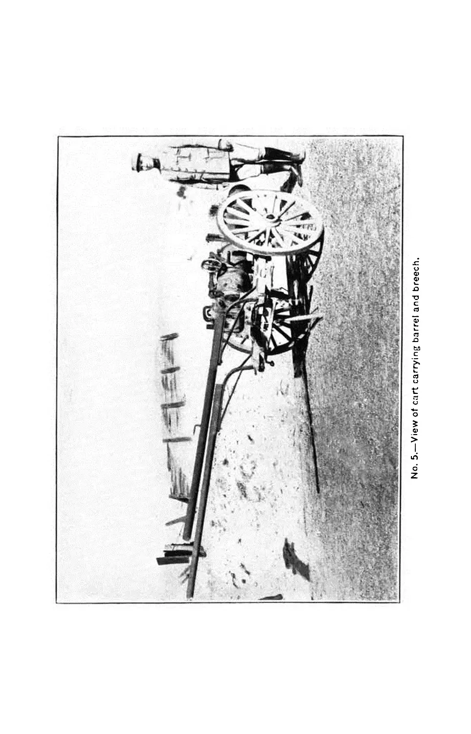
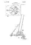
No. 5.—View of cart carrying barrel and breech.
9.45-INCH TRENCH MORTAR MATERIEL.
37
In addition to the shafts, a 27}-inch steel singletree (10AB)
completes the hitching equipment.
When it is necessary to maneuver the cart by hand, an at-
tachment consisting of a cart pole (IOS), hand shaft (10AS),
and hand-shaft shackle is used. The cart pole (IOS) is a cold-
drawn steel tube 47 inches long and 1ft inches in diameter. It
is made 1J inches square at one end for a distance of 2 inches.
A hole H inch in diameter is drilled through this end for the
locking pin (10AT). The other end is 1$ inches in diameter for
a distance of 1| inches. A steel hand-shaft shackle (10AU) is
provided with a hole to receive the cart pole, to which it is
welded. It Is pierced by a second hole at right angles to the
former to receive the hand shaft. The hand shaft is made of
ash, 29A inches long and 1J inches in diameter. It is pierced
by a hole, A of an inch in diameter, at a distance of 4$ inches
from one end for the pin (10AT), which locks it when not in
use.
DESCRIPTION OF THE CARRYING ATTACHMENTS.
As already suggested (p. 32), there are four different carrying
attachments—one for the barrel and breech, one for the carriage,
one for the base, and one for the shells.
BREECH AND BARREL CARRYING ATTACHMENTS.
Nomenclature (plate 9).
Sym- bol. Quan- tity. Name. Location.
11A 4 Angles Fastened to plates (11B).
11B 2 Plates (end) Riveted to angles (i 1Л)'.
11C 2 Plates (side) Fastened to side of chock (HD).
HD 1 Rear chock Secured above cross timbers (10O).
HE 2 Angles Bolted to timbers (10O)
HF 2 Plates Fastened to sides of front chock
(UH).
110 2 .... .do. Fastened to timbers (100).
11H 1 Front chock Across front end of cart.
IIP 7 Rivets Rivet, angles ('ll A), plates (11B), and
11V 1 Slotted half collar chock (HD) together. Hinged between the two left-end
HW 1 Eyebolt half collar angles (HA).
11Y 1 Eyebolt Winged to upper end of collar (11W).
HAA 2 Collar liners Riveted to half pollars HIV and
11W).
НАС 1 Wing nut Screwed onto eyebolt (11Y).
HAG 4 Hinge pieces Fastened to plates HIF^ and ehnrk
(UH).
HAK 2 Slotted half collars Hinged to front hinge pieces (11 AO).
HAH 2 E yebolt half collars....... Hinged to rear hinge pieces (HAG).
HAR 4 Collar liners Riveted to half collars illAH and
HAK).
11AV 2 Rear-chock locking pins... Secure attachment to cart.
HAW 2 Front-chock locking pins.. Do.
38 9.45-INCH TRENCH MORTAR MATERIEL.
The carrying attachment for the barrel and breech consists
essentially of two oak chocks secured firmly to the cart by
means of an appropriate arrangement of plates and angles, and
of a system of half collars, which may be bolted and tightened
above the respective parts, thus securing them to the cart.
The front chock is situated immediately above the front cross
timber, the rear chock above the rear cross timber. Their upper
surface is cut away to conform to the shape of the barrel and
breech.
The rear chock (HD) which supports the barrel is of oak,
12ti inches long, 6 inches wide, and 4 J inches deep. It is secured
to the cart by means of two side plates (11C), two end plates
(11B), and four vertical angles (11A), 10J inches high. All
are of steel and are riveted together. The plates are | of an inch
thick and correspond exactly to the lines of the chock except
that they project 113 inches below it. The angles project be-
neath to a level with the bottom of the long timbers (10K) of
the cart, and together with the side plates (11C) extend above
the chock for a distance of 1g inches. The plates are secured
to the chock by seven rivets (111’) ; four of these pass through
the plates, angles, and chock; three merely traverse the plates
and chock. The lower projections of the angles are slotted to
receive two locking pins (11AV), which pass through them and
under the rear cross timber (10G), thus fastening the carrying
attachment to the cart.
Two half collars (11V and 11W) are hinged to the upper
projections of the angles (HA) and during transportation are
brought together and tightened above the barrel by means of
a wing nut (11AC) and eyebolt (11Y). The barrel surface is
protected from contact with the collars by means of leather
liners (11AA), which are riveted to the latter.
The front chock (11H), which supports the breech, is rein-
forced and secured to the cart by means of two side plates (11F)
and two horizontal angles (HE). The form of the plate corre-
sponds with the lines of the chock. The horizontal flanges of
the angles are bolted to plates (HG) on the upper surface of
the inside long timbers (10K). Two steel plates (HG) 10?®
inches long, designed to protect the timbers (10K), extend be-
tween the carrying attachment and the timbers. Two locking
pins (HAW) passing through the angles (HE), plates (HF),
and chock (11H) fasten the plates and chock to the cart.
No. 6.—View of cart carrying carnage.
9.45-INCH TRENCH MORTAR MATERIEL. 39
The breech is secured to the cart by means of half collars
(HAH and 11AK), which are designed to encircle each trun-
nion in the following manner: Two hinge pieces (HAG) 5
inches long project above each end of the chock (11II). They
are attached to the plates by means of four tie bolts (UN),
which pass through the plates and chock, and in a similar
fashion the hinge pieces (HAG) serving for the half collars of
the trunnion on the opposite side of the breech. Two half col-
lars are hinged to them and during transportation are bolted
and tightened above the trunnion by means of an eyebolt
(11AM) and wing nut (HAN). As in the case of the rear at-
tachment, the trunnions are protected from contact with the
collars by means of leather liners (11AR).
CARRIAGE-CARRYING ATTACHMENT.
Nomenclature (plate 10).
Cl IJ .
Locution.
12A
12B
12C
12F
12L
1211
12G
12R
Plate............
Reinforcing angles
Angles...........
Shoulder-stud ....
Crown not.........
Fastening key....
Shoulder stud pin.
Leather thong.....
2
2
Bolted to rear cross t inibers (10G).
Riveted to plate (12Л).
Do.
Fastened to plate (12Л).
’Fastens stud (12F) to plate (12Л).
Fits into slot in stud (12L).
Fastens key (1211) tostud (12L).
Fastened to handle of pin (12G).
The carrying attachment for the mortar carriage consists of—
(a) One steel plate (12A).
(b) Four angles—two (12B) designed to reinforce this
plate and two (12C) to serve as a seat for the
horizontal plates of the carriage.
(c) One shoulder stud (12F) together with one pin
(12G) and fastening key (1211).
The whole is fastened together and to the cart by a suitable
arrangement of bolts and rivets.
• The plate (12A), 19} inches long, IGA inches wide, and } inch
thick is bolted to the rear cross timbers (10G) and the long in-
side timbers (10K) thus forming a base for the attachment.
A l}-inch hole is drilled through its center to receive the shoul-
der stud (12F).
40 9.45-INCH TRENCH MORTAR MATERIEL.
Two reinforcing angles (12B) 15g inches long, A inch thick,
with flanges 1| inches wide, are riveted to the underside of the
plate, at a distance of 5J inches from each side, in such a posi-
tion that they will fit between the rear cross timbers (10G).
The vertical flanges of two angles (12C) 8g inches long, j
inch thick, with flanges inches wide are also riveted to the
under face of the square plate (12A) at each side in such a
manner that the vertical flanges project above the plate for a
distance of 1| inches. As indicated above, these flanges form a
seat Jor the horizontal plates of the carriage.
The threaded end of the shoulder stud (12K) projects down
through the central hole in the square plate which is designed to
receive it. It is secured firmly to the underside of the plate by
a nut (12L). The projection of the shoulder stud above the
plate is 3?a inches high. A collar on the stud immediately above
the central hole is designed to fit into the pintle hole of the two
horizontal plates of the carriage. The upper end of the stud
above the collar is slotted to receive the fastening key (12H)
which is secured to the stud by the stud pin (12G). A hole
through one end of this pin is designed to receive a leather
thong (12R) which locks the fastening key (12H) in place; a
hole is provided at the other end for a split pin (12N) which
holds the stud pin in position. The steel fastening key (12H)
is 5| inches long, 1| inches wide, and A inch thick. A slot near
one end 2|* inches long and Ц inch wide is designed to
receive the stud pin (12G). By means of this slot the key
may be placed in either a horizontal or vertical position, when
In the former the key locks the carriage to the cart; its vertical
position, on the other hand, permits the removal of the carriage.
A smaller slot immediately above the former is provided for
one end of the leather thong (12R) which maintains the fasten-
ing key (12H) in the horizontal position.
THE BASE-CARRYING ATTACHMENT.
Nomenclature (plate 11).
Symbol. Quan- tity. Name. Location.
13A 3 Base supports Bolted to timbers (10K).
13B 1 Base support Do.
13C 4 Locking pins Through holes in supports (13A and 13B).
13D 4 Chains Fasten locking pins (13C) tocart.
No. 7,—View of cart carrying base.
No. 8.—View of cart carrying shells
9.45-INCH TRENCH MOBTAB MAT&BIEL. 41
The base-carrying attachment is a simple device which con-
sists of four supports (13A and 13B) bolted to the cart and
four locking pins (13C) which are attached to the cart by small
chains (13D).
The supports (13A and 13B) are steel plates i inch thick,
7Л inches lang, and 2 inches wide, with two prongs of one piece,
with them, which extend vertically 2} inches above the support
and 1A inches below it. The supports are holted to the ends of
the two rear cross timbers (10G), with the exception of the rear
right-hand support (13B), which is secured by means of a wood
screw (13F) in order to allow room for the hand shaft (IDAS).
The prongs are traversed by channels for the locking pins (13C)
which secure the base to the cart. The spades (OX) of the
base are inserted between the prongs of the supports and are
held in place by the locking pins (13C). which are introduced
through the holes in the prongs and the plates provided for that
purpose.
THE SHELL-CARRYING ATTACHMENT.
Nomenclature (plate J2).
Symbol. Quan- tity. Name. Location.
14B
14Л
14 M
14F
14K
14G
14H
14L
14S
14T
14U
4 Racks....................
2 Angles...................
8 Locking pins.............
2 U pper chocks............
4 Uppcr-chock collar bolts...
1 Lower front chock........
1 Lower rear chock.........
4 Lower-chock collar bolts...
4 Projectile supports......
4 Carriage bolts...........
4 Lag screws...............
Fit into guides (IOC).
Fastened to chocks (14F).
Fasten racks (14B) to carts and to
angles (14A).
Hold shells in place.
Fasten chocks (141’) to angles (14 A).
Fastened to angles (10Y).
Do.
Fasten lower chocks (14G and 1411) to
angles (10Y).
Fastened to chock (14G).
Fasten supports (14S) to chock (UH).
Do.
The shell-carrying attachment, designed for the transportation
of four shells, consists essentially of—
(a) Four forged steel racks (14B).
(b) Two angles (14A).
(c) Two lower chocks (14G and 14H), one for the front
and one for the rear.
(d) Two upper chocks (14F), one for the front and one
for the rear.
(c) Four steel projectile supports (14S).
42
9.45-INCH TRENCH MOBTAB MATERIEL.
The forged steel racks (14B) are 24? inches long, 2 inches
wide, and f inch thick. Near their center they are bent out
to allow for the curve of the shell. At their up]»er ends they
are thickened to 18 inch for a distance of 2? inches. This
portion of the racks is slotted to a depth of 2 inches to form
forks designed to receive the vertical flanges of the angles
(14A). The lower ends of the racks pass through t he chan-
nels provided for them in the upper and lower guides and are
fastened beneath to the carts by means of locking pins (14M).
An }(l;-inch stop pin (14D) is riveted to the inner face of each
rack 9} inches above the lower end. It projects £ inch from
the rack and fits into a slot provided for that purpose in the
angles, thus limiting the distance to which the rack may be
lowered into the guides (10AV).
The angles (14A) are 19? inches long and ? inch thick, with
flanges 2 lnch(*s wide. The horizontal flanges are cut away at
each end for a distance of 2J inches, which permits the inser-
tion of the vertical flanges in the forked ends of the racks.
The vertical flanges of the angles are secured to the racks by
locking pins (14M). Two holes are drilled in the horizontal
flanges at a distance of 5j inches from the ends of the angles
for the bolts (14K) which fasten the upper chocks (14F) to the
under faces of these flanges.
77/c lon:er front chock (14G) is an oak timber 34g inches long.
4? inches wide, and 4? inches thick. Its upper face is cut away
suitably to receive the curved surface of the front end of the
shells (plate 15). It is secured at each end to the horizontal
flanges of the angles by collar bolts (14L).
The lower rear chock (14И) has the same dimensions as the
preceding, with the exception that it has a thickness of ЗА
inches. Its upper face is likewise cut away to receive the rear
ends of the shells. It is also bolted at each end to the horizontal
flanges of the angles (10Y).
The projectile supports (14S) are steel strips 7 Inches long,
2 inches wide, and g inch thick. They are bent to fit against
the underside of the rear end of the shells and against the rear
face of the rear chock (14H). They are secured to the latter
by means of bolts (14T) and wood screws (14U).
9.45-ШСН TRENCH MORTAR MATERIEL. 43
AMMUNITION.
Separate loading ammunition is used in the 9.45-inch trench
mortar. Each projectile is issued filled but unfused. The com-
ponents of one round are the cartridge ease with primer, ixnvder
charge, projectile, adapter, booster, and fuse.
CARTRIDGE CASE.
The cartridge case is of solid drawn brass 9.776 inches long
and G.G7 inches in diameter. The head or base of the case has
a projecting flange or rim to facilitate» the removal of the case
from the breech. The center of the base is bored out to form
a seat, into which tiie primer is forced. The primer seat is
inandreled to near the finished-dimensions with a tapered steel
plug to toughen the metal of the case around the primer seat
and then reamed to finished size. This toughening is necessary
to prevent expansion of the seat under gas pressure, with a con-
sequent looseness of the primer in subsequent firings. The
primer is inserted in the case by means of a primer-inserting
press to avoid injury to the primer seat or cause the explosion
of the primer.
The base of the case is marked with the name of the mortar
and the lot number of the case.
CARE OF THE CARTRIDGE CASE.
As soon after firing as practicable the fired primers should
be removed from the cartridge case by means of the decapping
tool furnished with the reloading outfit. The case should be
thoroughly washed in a strong solution of lye or soft soap to
remove all powder residue. It should then be thoroughly dried.
If the cartridge cases are carefully cleaned and washed im-
mediately after firing, not only will less labor be required but
the life of the case will be greatly prolonged.
A good solution for washing cartridge cases may be prepared
by using ingredients in the following proportions:
1 gallon of water.
2| ounces of soft soap.
5} ounces of soda.
The mixture should be boiled and stirred until the ingredi-
ents are entirely dissolved.
44
9.45-ШСН TRENCH MOBTAB MATERIEL.
In washing cartridge cases this solution should be used hot
and in sufficient quantity to completely immerse the cases.
Primers that misfire should be turned in with the cases to
the ordnance establishment prescribed.
THE PRIMER.
The “ 110-grain percussion primer” consists of a brass case
resembling in shape a small-arms cartridge case. The head or
rear end of the primer case is countersunk, forming a cup-
shaped recess, in which is seated the cap or percussion primer
proper. The latter consists of the cup, the anvil, and the per-
cussion composition assembled. The percussion composition is
known as the “ H 42 ” mixture and contains the following in-
gredients: Flowers of sulphur, 21.97 per cent; sulphide of anti-
mony, 30.83 per cent; and chlorate of potash, 47.20 per cent.
The percussion-cap recess is connected with the interior of
the primer ease by a small axial vent. The body of the case
contains 95 grains of black powder, constituting the rear priming
or igniting charge for the propelling charge. This black powder
is inserted under a pressure of 2,400 pounds per square inch
and is pressed into the primer body around a central wire,
which is then withdrawn, leaving a longitudinal hole the full
length of the primer. Eight radial holes are drilled through
the primer and compressed powder, affording 16 vents for the
free exit of the black-powder flames. After filling the body
the front end is closed by two cardboard wads, waterproofed
with shellac. The radial perforations in the body are covered
by a tin-foil wrapper, shellacked on, to retain loose black powder
in the case as well as to exclude all moisture.
In action, the blow of the striker explodes the percussion cap,
which ignites the black powder; the flames of the latter shoot
out through the vents in the priming case and ignite the pro-
pelling charge.
PROJECTILE.
Merely one type of projectile is employed for the 9.45-inch
trench mortar—a steel shell which may consist of one, two, or
three pieces welded together. Its weight is 87 pounds, un-
loaded ; when loaded, 180 pounds.
9.45-INCH TRENCH MORTAR MATERIEL. 45
Nomenclature (plate 13).
Symbol.
Quan-
tity.
Name.
Location.
15A
15B
15C
15 D
15E
15F
15G
15H
15 К
15L
15N
15P
15Q
15R
15S
1 Body...................
2 Plates..................
4 Angles..................
1 Adapter.................
1 Booster casing..........
1 Fuse socket.............
1 Fuse-socket holder......
1 Washer (felt)...........
1 ....do..................
1 Washer (lead)...........
1 Link....................
1 Cover...................
1 Ring....................
1 Adapter-plug felt washer..
1 Adapter-plug copper wash-
er.
Main part of shell.
Welded to body (I5A).
Riveted to plate (15B).
Screwed into nose of body (15Л).
Screwed into adapter (151)).
Fit sin tofusc-socket holder (15G).
Fits into booster casing (15F.).
Fits around booster casing (15E).
Fits around fuse socket (15F).
Fits around adapter (151)).
Soldered to washer (15S).
Pinned to washer (15R).
Fastened to link (15N).
Between cover (15P) and washer
(15S).
Against felt washer (15R).
The shell consists of the following major parts:
(a) One body.
(b) Four vanes formed by the intersection of two plates.
(c) Four angles.
(d) One adapter.
(e) One adapter plug.
(a) The body (15A) is composed of one. two, or three sti^el
parts welded together to form a solid whole. It is 28} inches
long, including the vanes, and has diameter of 9.433 inches.
Its wall is 0.315 inch thick. A hole 3.2687 inches in diam-
eter is cut through the nose of the shell and is then threaded to
receive the adapter.
(b) The four vanes are formed by the intersection at right
angles of two plates (15B) 17.915 inches long, 9.173 inches wide,
and 0.203 inch thick, each of which is slotted to a distance of
approximately half its length for the purpose. The intersection
of the plates is reinforced and made rigid by the use of angles
(15C) to which they are riveted. The plates are cut away
suitably at one end to allow for the curved rear end of the body
to which they are welded.
(c) The angles (15C) are 11.22 inches long and | inch thick
with flanges 1} inches wide. They are fitted into the right
angles formed by the intersection of the plates and are riveted
to them as already indicated.
46 9.45-ШСН TRENCH MORTAR MATERIEL.
(rf) The adapter (15D) Is a steel bushing 3} inches in diam-
eter and 1.18 inches thick. It is especially designed to receive
the fuse, and when removed from the shell provides a larger
filling hole. It is machined at its inner end to a diameter of
3g inches to a distance of 0.775 inch. This end is also threaded
for a distance of 0.05 inch to screw into the nose of the shell.
The outer end of the adapter is notched on two sides to facilitate
the application of a wrench. The central channel of the adapter
has a diameter of 0.807 inch and is cut with metric threads to
receive the fuse. Its inner end is enlarged to a diameter of
l.?2 inches and is tapped with a left-hand thread for a depth of
0.39 inch to receive the booster casing (15E). Its outer end is
counterbored to a diameter of 1.84 inches for a depth of 0.16
inch to allow for the head of the fuse. Until the insertion of the
fuse, the core of the adapter is protected by the adapter plug.
Л lead washer (15L) placed over the threaded end of the
adapter tits between its shoulder and the nose of the shell. Л
felt washer (1511) is placed against the inner face of the
adapter between it and the bursting charge in the shell. The
booster easing (15E), a cylindrical steel pocket 3g inches long
and 1.16 inches in diameter, is threaded at its open end to screw
into the adapter.
The device employed to receive the fuse consists of a fuse
soeket holder (15(1) and a fuse soeket (15F). The former is a
hollow steel cylinder closed at the upper end. It has a diameter
of & inch and a length of 0.948 inch. Its upper end is flanged
to fit over the edges of the booster casing (15E) into which it
is inserted. Its lower end is traversed by a hole 0.575 Inch in
diameter, which provides a seat for the upper end of the fuse
soeket (15F). The fuse socket is a brass or gilding metal cup
1.171 inches long and 0.56 inch in diameter. Its upper end is
flanged to fit into it:; seat in the socket holder, where it is secured
by means of a pure tin solder. A felt washer (15K) designed to
hold the booster charge in place surrounds the fuse socket.
(c) The adapter plug is inserted in the adapter and is de-
signed to protect the seat of the fuse. It consists of a link (15N),
a cover (15P), a ring (15Q), a felt washer (15R), and a copper
washer (15S). The washers and cover are held together by
means of the link which is inserted through the holes in the
cover and is soldered to the lower face of the copper washer.
The plug is forced into the adapter under 100 pounds pressure.
The ring (15Q) attached to the link (15N) provides a convenient
means of removing the plug.
9.45-INCH TRENCH MOBTAB MATERIEL.
FUSE.
47
The fuse to be used with the 9.45 shell is similar to the French
ВТ fuse model 191G. as regards its external shape. It is to be
of the impact type, but is still in the experimental stage. Details
of the fuse will be published in a later bulletin.
INSTALLING AND ASSEMBLING THE MATERIEL.
ASSEMBLING THE WOODEN PLATFORM.
(a) Preparation of the ground.—The platform of the 9.45-
inch mortar is set into an excavation, the design of which ap-
pears on Plate 7.
The base of the excavation must be horizontal and the rear
wall carefully dressed and absolutely vertical, because it is
against this surface that the horizontal recoil of the mortar
presses at the moment of fire.
The depth of the excavation is 22 inches; its volume is 7.9
cubic yards.
(b) Installation of the front and rear bracing beams (Plate
5).—Put the lower front (7Y) and rear (7Z) beams with their
three assembling bolts (7АЛ) into the front and rear parts of
the excavation; the two intermediate beams are then placed on
each side and the upper beams brought into position. Then set
up the vertical blocks (7AE) in the rear, as is shown in the
design.
Spread sand on the bottom of the excavation to a depth of
about 4 inches; if sand is lacking, use tightly packed mold.
(c) Installation of the lower floor (Plate 5).—Place the two
channel irons (7B) at their prescribed distance on the bottom
of the excavation, each one being provided with its five vertical
bolts (711) held in place by the pins (7C) ; sink the irons into
the layer of sand with their plane surface up. The surface
formed by sand and the upper surface of the channel irons must
be even and perfectly horizontal.
Put the five timbers (7A) of the lower floor into position,
commencing with the front timber.
Spread a layer of sand 2 inches deep in front of the front
timber and behind the rear timber as a support during the
mounting of the long beams (7D) of the framework.
(d) Assembly and installation of the framework (Plate 5).—
The framework is assembled near the platform; if there is not
sufficient space available, it Is assembled over the excavation
itself, its lower surface being supported at the ground level.
48 9.45-INCH TRENCH MORTAR MATERIEL.
Place the two long beams (7D) at their prescribed distance;
each one is provided with its two channel end bolts (7G) and
its two cross-beam assembling bolts (7X), every bolt being held
in place by a nut; place the eight tie-rods (7K) in position and
fasten each one with a nut (7 AW).
Pass a bar through each of the eyebolts (7L) and let the
framework sink into position, the nuts (7AW) of the tie-rods
(7K) being placed toward the front in such a manner that they
may be tightened during firing; tighten the nuts of the tie-rods
slightly, so as to bring the long beams (7I>) into contact with
the outermost timbers of the lower floor (7A).
Remove the nuts (7AM) and (7AL) from the bolts (7G) and
(7H) ; put tlie struts (7E) in place, set the channel irons (7F)
and the faceplates (7AS) in position; then tighten the nuts and
the lock nuts of the assembling bolts (7G and 711) firmly, so as
to bring the long beams (7D) of the platform into their propel
place.
Tighten the nuts (7AW) of the eight tie rods (7K), screwing
them only little by little and each nut after the other, so that
the different parts may be perfectly in position. Tut the check
nuts (7ЛХ) in place and clamp them tightly.
Clamp the nuts (7AL and 7AQ) and the lock nuts (7AM and
7AR) of the bolts (7G and 7И).
(a) Installation of the jack screws.—Set up the four vertical
blocks (7AB) and the four jackscrews (7BS) in the manner
shown on plate 7 with the two outside jackscrews at the upper
part of the bearing surface (7a) and the two inside jackscrews
at its lower part. Screw them slowly one after the other until
the whole framework is firmly clamped together.
(/) Installation of the upper floor and cross beams.—Begin-
ning at the rear, place the upper timbers (7M) in the interior
of the framework.
The cross beams (7W) are not put into position until after
the mortar is entirely mounted.
MOUNTING THE BASE.
(a) To unload the base cart.—Unhitch the cart and take out
the shafts.
Remove the locking pins (13C) which secure the spades (GX)
to the framework of the cart; incline the cart to the rear and
let the platform slip to the ground.
9.45-INCH TRENCH MORTAR MATfiRlEL. 49
To load the base cart.—Put the platform on the ground with
the spades (GX) parallel to the side of the cart; bring up the
cart, raise the shafts, and place the platform on the cart, at
the same time fitting the spades into the framework of the cart;
insert the two front locking pins (13C) raise the cart and put in
the two other locking pins (13C).
(b) To place the base in position.—Open the locking plates
(7U) of the upper timbers (7M); introduce the carrying
shafts into the sockets (5AL) and raise tiie base, using as many
men at each shaft as is necessary ; put the base on the upper
floor and at the same time fit the spades into the intervals
between the timbers.
Close the locking plates and tighten them by hand without
forcing the locking screws.
MOUNTING THE CARRIAGE.
(a) To unload the carriage cart.—Unhitch the cart, take out
the shafts, introduce the carrying shafts into the sockets of the
carriage, bring the fastening key (1211) to the vertical position,
raise the carriage and pass it out over one of the wheels, using
four men at the carrying shafts.
To load the carriage cart.—liaise the carriage by means of the
four carrying shafts place it on the cart with the cheeks (5AD)
to the front, the racer over the stud (12E), insert the fastening
key (12H) and fasten the thong (12K).
(ft) To place the carriage in position.—Loosen the clamping
nut (6E) of the traversing mechanism; place the carriage on
the base, at the same time fitting the pintle (6AB) into its seat,
with the cheeks (5AC and 5AD) to the rear.
Turn the carriage so as to bring its register cut (5b) opposite
the zero mark on the azimuth circle.
As soon as the guide shoes (5AB and 6B) of the carriage are
caught under the rail of the base ring (GAC), turn the racer
one-eighth around in a clockwise direction in order to bring it
to the position for mounting the mortar.
Open the trunnion locks (5V and 5W) and tighten the clamp-
ing nut (6E) of the traversing mechanism.
MOUNTING THE MORTAR.
(o) To unload the mortar cart.—Unhitch the cart, take out
the shafts, and introduce the iron pole.
31368°—18----4
50
9.45-ШСН TRENCH MORTAR MATERIEL.
Unscrew the locking handwheel (8(1) and take out the clamp-
ing shaft (8C) ; remove the breech slide (4C).
Open the bands (11AH and 11AK) for the trunnions and the
bands (11V and 11 AV) for the barrel by unscrewing the wing
nuts; Introduce a carrying shaft into the rings of the carrying
band of the muzzle and another into the rings of the carrying
band of the breech.
Raise the mortar, using two men at tjie muzzle-carrying
shaft and four num at the breech-carrying shaft, while a fifth
holds the cart pole steady in order to keep the cart horizontal;
rest the breech on the framework of the cart so as to allow two
of the men at the breech-carrying shaft to gid over the pole;
piass the mortar out over one of the wheels of the cart and put
it on the ground; take away tin* cart.
To load the mortar cart.—Proceed in a manner inverse to the
above.
(/>) Mounting the mortar.—Raise the mortar, using four men
at the breech-carrying shaft, two men at the muzzle-carrying
shaft, and two men at a third shaft passed under the mortar
at the point of the clamping hands (SH and SK).
Bring the mortar to the front of the platform immediately
above the carriage; rest the breech-carrying shaft on the
cheeks of the carriage; raise the mortar gently, making it
pivot around this shaft; the trunnions (4d) will fit into their
seats (5T and oU) by themselves.
Engage the pinions (SA) of the elevating mechanism on the
racks and see to it that the teeth of the racks (6AD) in front
of the pinions are equal in number on both sides.
Take out the breech-carrying shaft; place the clamping shaft
(8C) in position by passing it into the left racer cheek (5AI>) ;
put on the washer (SR) and screw down the handwhiud (8G) ;
close the trunnion locks (5V and 5W) ; remove the muzzle-
carrying shaft.
Turn the carriage half around so as to bring the cheeks (5AC
and 5AD) to the front; then lower the mortar down until the
clamping shaft comes to the front end of the slots (Gb) of the
cheeks. The mortar is then in the position for loading.
Insert the breech slide (4C) and let it descend into the posi-
tion of “closed ” by pulling the locking pin (4F) to the rear.
The mortar being held in position, adjust the two upper cross-
beams (7W) and bolt them to the long beams (7D).
9.45-ШСН TBENCH MOBTAB МАТЁВЕЕЬ. 51
Tighten the upper-floor timbers against tlie rear of the wedges
(7AC) against each of the right and left ends of the front
timber.
DISMOUNTING THE MATERIEL.
For the platform and the different parts of the mortar, use
inversely the same method as In mounting.
DISMOUNTING THE FIRING MECHANISM.
Unscrew the vent bushing (4AB) and the plug (4S) with the
mounting key.
To replace tlie lanyard (4R), unscrew the anvil (4Y) from
the plunger (4\V).
CARE OF THE MATERIEL.
Battery commanders, with the aid of the personnel at their
disposition, may make slight repairs or replace worn parts from
the spare parts contained in the carts, but should take precau-
tions that this work does not include work with the lite, forging,
riveting, or tlie adjustment of the aiming instruments or of
their supports.
Any accident which can not be remedied by the means indi-
cated should be brought to the attention of the repairing crew
of the general depot.
Daily care.
After each period of Are, clean the mortar and the breech,
wash them plentifully with water, dry carefully with rags at-
tached to the bead of the cleaning rod, and then grease them
slightly with the sponges.
Take out the breech slide (4C), clean it, and grease it
slightly.
Remove with care all earth or foreign substances from the
base right (GAU) of the platform and grease it.
Dismount the firing mechanism and clean it. Never pul
thick grease into the interior; simply pass in an oily rag or
put several drops of oil on the outside of the plunger (4W) ;
tallow the part of the lanyard (4R) which rubs against the
plug (4S).
Finally put back the sponge into the mortar, replace the muz-
zle, breech, and platform covers.
52 9.45-INCH TRENCH MORTAR MATERIEL.
INSPECTION OF THE MATERIEL.
As frequently as circumstances permit, usually once a week,
or after a period of intensive fire, the battery commander should
make a detailed inspection of the inortars, the wooden platform,
the tools, and the carts.
For these inspections the materiel should l>e thoroughly cleaned
and the mortar and its platform taken down.
In each battery only a single piece Is taken down at a time.
Inspect the bore of the mortar, the breech slide (4C), and the
tiring mechanism, and make sure that the locking handwheel
(<SG) of the elevating mechanisni and the clamping nut (6E)
of the traversing system may be properly tightened; ascertain
that the base plate (5A) of the racer is not bent, that the base
ring (GAC) is in good condition, and that the spades (6X and
GW) are not bent.
Inspect carefully the various parts of the wooden platform
and repair them if necessary; take up the play by tightening the
nuts and the jackscrews.
Any deterioration which might possibly cause accidents while
firing must be reported without delay to the general deiwit.1
Advantage is taken of these inspections to replace imperfect
parts and to carefully grease the following:
Racks (5AC and 5AD) and pinions (8A) of the elevating
mechanism.
The threads of the locking handwheel (SG).
The joints of the carrying bands of the mortar.
The breech trunnions (4d).
The boxes of the trunnion seats (5T and 5U) and the trunnion
locks (5V and 5W).
The pintle (GAB) and the racer clamp.
The base ring (GAC) of the base.
The threads of the clamping nut (GE) of the racer clamp.
The screws of the jackscrews (7BS) of the wooden platform.
ACCIDENTS DURING FIRE AND PRECAUTIONS TO BE
TAKEN.
Misfires.
After the firing mechanism has failed three times to function,
verify the position of the breech slide (4C) ; the misfires may
1 Particularly deformations of the barrel which might be due to enemy
projectiles.
9.45-ШСН TRENCH MORTAR MATERIEL. 53
be due to the fact that the breech slide has not been brought
Into the position of “ closed ; ” make sure that the striker (4AA)
is not broken and that its point is not worn.
If the breech api>ears to have been properly closed and the
striker (4AA) seems to be in good condition, open the breech
gently, extract the case, lay it aside, and replace it by a new one.
Replace the striker if it is broken or worn or if other misfires
take place; if the trouble recurs when a new striker is used,
change the striker spring (4Z) or even the entire firing mecha-
nism.
DEFECTIVE FUNCTIONING OF THE LOCKING PIN.
If the locking pin (4F) closes badly or opens with difficulty,
take it out and examine it; if necessary, replace the pin or its
spring (4E).
DIFFICULTY IN INTRODUCING THE PROJECTILE.
It is absolutely forbidden to use force in introducing a projec-
tile into the mortar. A shell which can only be introduced
with difficulty must be withdrawn by means of the breech
wrench; it is then cleaned, the ridges are removed by means of
a file, and the vanes are straightened, if necessary.
DEFECTIVE FUNCTIONING OF THE PLATFORM.
When during fire the platform jumps or undergoes abnormal
displacement, put it back in position; verify carefully that the
jackscrews and the nuts are tight, and clamp them thoroughly.
ABNORMAL SHOTS.
A shot is regarded as abnormal in the matter of range when
it falls at a distance from the mortar which is less than two-
thirds of its average range.
Abnormal shots are generally due to the following causes:
(«) The charge has hung fire. Hangfires are due to a too
slow combustion of the powder, which develops an insufficient
pressure in the powder chamber; the projectile may then fall
near the mortar, sometimes even on the parapet of the trench.
This accident may he caused either by the use of a damp charge
or because the projectile has not been pushed deeply enough into
the mortar upon loading.
(b) The vanes are warped, a defect which gives the projectile
a bad position on its trajectory.
64 9.45-INCH TRENCH MOBTAB MATERIEL.
(c) The platform is badly put together or installed on ground
which is not homogenous or has little consistency. lu this case,
the slant of the platform causes, upon firing, abnormal reactions,
which may cause the projectile to “ tumble” on its trajectory.
(d) A wind which blows in squalls may cause abnormal shots,
particularly when firing at large angles.
Wind from the side has also a considerable influence on
the aim.
PREMATURE BURSTS.
These may be due to the following causes:
(a) Premature functioning of the fuse.—A fuse may func-
tion prematurely on account of a sudden diminution in the speed
of the projectile within the barrel.
A projectile which has been caked with earth, whose body is
seamed, or the vanes of which have deteriorated, may, after
starting, be wedged inside the bore by foreign bodies or by a
deformation of the tube; this wedging produces a sudden stop-
page. which may bring about the functioning of the fuse.
(b) The bomb strikes against the front wall of the trench,
either in the case of a hangfire or a grazing shot; this latter
accident may arise particularly if the clamping handwheel (8G)
of the elevating mechanism has been insufficiently tightened
and the mortar accordingly sinks from tin' desired angle.
(c) Rarely, the spontaneous detonation of the explosive.—
The defective transportation of the shells makes the explosive
sensitive to the shock sustained upon firing?
MISFIRES AT THE POINT OF FALL.
Misfires of this type are due generally to the fact that the
projectile does not fall upon its nose, either because it has
slanted in its trajectory or because the fire has been executed
on a terrain full of craters or upon a descending slope.
Abnormal shots are generally followed by misfires at the
point of fall.
1 In the filling shops the explosive is shaken down into the shell,
the latter being held vertically with tbc vanes down. When the
projectiles are transported In any other position the jarring may pro-
duce empty places near the walls and cause the tar with which they
are coated on the Inside to scale; premature bursts are then to be
feared on firing, due to the rubbing of the explosive against the rough-
ness of tbe exposed walls.
9.45-ШСН TRENCH MORTAR MATERIEL. 55
PRECAUTIONS TO BE TAKEN IN ORDER TO AVOID
ACCIDENTS.
RAILROAD TRANSPORTATION OF THE AMMUNITION.
The shells should be in their packing cases.
The cases should be so arranged in the cars that the vanes
of the shells are beneath. It is absolutely essential to comply
with this direction.
Avoid transporting cases of shells and cases of fuses or charges
in the same car. If it is necessary, however, to do this, pack
the cases of fuses or charges solidly on top of those containing
the shells, separating them by means of sacking or straw.
The shell bearers should be directed never to set the shells on
the ground on their vanes, a procedure which might bend them
or cause their deterioration.
THE PRESERVATION OF THE AMMUNITION.
(a) Shells.—As soon as they are brought to the mortars, the
shells should be piltxl up in the shelters, and the mortar chief
should ascertain personally that the projectiles are in good con-
dition, that the cylindrical bodies are without seams, and that
the vanes are not bent.
(5) Charges and fuses.—The boxes which contain the cases
and the boxes which contain the fuses should be sheltered from
rain and dampness; do not often them until the moment of fire,
close them as soon as the fire is ended ; open only one case at a
time.
INSTALLING THE MORTAR.
The construction of the platform should be carefully super-
intended.
During the course of firing the mortar chief should inspect
the position of the platform after each shot, have the wedges
driven in. and the jack st rows or the bolts tightened, if necessary.
As soon as the mortar is put in position the mortar chief
should see to it that the mortar does not graze at 45° and that
the fire is unhindered in any direction by a tree or by some other
obstacle.
56 9.45-ШСН TRENCH MORTAR MATERIEL.
DURING FIRE.
Each projectile should be inspected to make sure that its
surface is free from foreign bodies and that its vanes are not
bent; care should be taken that the case Is in good condition and
shows no traces of dampness.
Under no circumstances should the felt washer at the tail of
the fuse be removed or attempt be made to screw or unscrew
the booster (there is danger of a serious accident).
The depth gauge should be used to ascertain whether or not
the projectile is properly seated in the mortar for firing.
In rainy weather, to keep water out of the mortar, take the
following precautions:
During the aiming operations put a sheet-iron muzzle cover on
the mortar.
Keep the sponge from the rain by covering it with a pack
cover or by placing it under a shelter.
Wipe the projectile carefully with very dry rags before intro-
ducing it into the mortar.
Accessories list and spare parts list No. /, flJS-inch trench
mortar, Mark I.
Name of part.
Accesso-
ries.1
Spare
parts
No. 1.*
Spare parts box with two l]-inch Yale locks, No. 840............
Bar, 50 inches long, for lifting the timliersJ..................
Breast collars, canvas..........................................
Brush, cleaning.................................................
Brush, grease...................................................
Bucket, canvas..................................................
Can, grease, containing3 pounds of No. 4J lubricant.............
Canales.........................................................
Chisel, flat....................................................
Cleaning rod (scraper), two parts...............................
Cleaning rod (screw point), lor cleaning threads................
Emery cloth, No. 0, sheets......................................
File, naif round, with handle...................................
File, rat-tail, with handle.....................................
File,saw (three-cornered), with handle..........................
Firing mechanism, complete......................................
Flash light, electric.........................................I
Gauge, loading................................................I
Handle for electric flash light.................................
Handle, sponging, in two part s.................................
Handles, removable, for locking plate on upper sleeper..........
Hammer, riveting................................................
Jack-screw lever................................................
Key for locking screw (car head)................................
Key for mounting firing mechanism...............................
Key for removing bomb.........................................I
iThis list includes number of items carried with eacli mortar.
»Spare parts of gun carried in accessories box.
’Not packed in box.
9.45-ШСН TRENCH MORTAR MATERIEL. 57
Accessories list and spare parts list No. 1, !k'f,~)-inch trench
mortar, Hark 1—Continued.
Name of part.
Accesso-
ries.1
Spare
parts
No. I.1
Lantern..........................................................
Lanyard cord with spring eye attached............................
Lanyards with steel nooks attached, long.........................
Level, carpenter’s...............................................
Loading trav, complete ’.........................................
Mallet, wooden...................................................
Muzzle cover, metal..............................................
Muzzle cover with tightening strap, canvas.......................
Oil, engine, No. 1, in can with spout, quart.....................
Paulin, canvas ’............................................!
Pencil, carpenter’s..............................................
Pliers, combination..............................................
Plug for firing mechanism........................................I.
Plumb bob, with 5-Ioot line attached........................I
Plunger for firing mechanism.....................................
Quadrant, range, with wood (37 K) and leather (37S) cases........:
Rings for carrying projectiles ’............................I
Rope’.......................................................1
Sack, canvas (combining items 31 to 36 inclusive).......
Screw driver............................................... '
Screws for breech loek housing cover.............................
Shafts,carrying, for lifting the barrel, 75 inches long1 * 3.....
Shafts, carrying, for lifting base and racer, 36 inches long 3...
Shafts, carrying, for projectile carrying rings, 54 inches long3.
Sight plug.....................’.................................
Sledge hammer with handle........................................
Sling, rope, for barrel..........................................
Slings for breast collars........................................
Spring for breech lock...........................................|.
Spring for firing-mechanism plunger..............................
Spring for firing-mechanism striker..............................
Trimming (wool) large head, for sponging handle..................'
Trimming (wool) small head, for sponging handle..................।
Twine, heavy, 1 pound Л inch diameter, ball.................I
Waste (colored), cotton..............................pounds..
Wrench, 12 inches, adjustable “S”...........................i
Wrench, double socket, for 1-ineh and l}-inch hex. nuts.....I
Wrench, single head socket, for racer clamp.................I
1 This list includes number of items carried with each mortar.
* Snare parts of gun carried in accessories box.
3 Not packed in box.
THE LOADING TRAY.
The shell is carried from the eart to the muzzle of the mortar
on a loading tray. The tray consists of a steel plate, four angles,
a supporting strap, two oak guides, a brass strip, two pairs of
handles.
The steel plate which forms the base of the tray is 41 inches
long, 11 inches wide, and ft, inch thick. It is reinforced by the
four angles riveted around the edges of its under face. The
supporting strap is a steel band bent in the shape of a U. and
Its ends are riveted to the flanges of the angles at one end of
58
9.45-INCH TBENCH MOBTAB MAT1SBIEL.
the tray. The strap hooks over the muzzle of the mortar and is
prevented from slipping too far down by a small steel stop,
which is riveted to its upper part. This arrangement is de-
signed to facilitate the insertion of the shell into the mortar.
The two oak guides are bolted along the sides of the upper face
of the base plate and form a suitable rest for the shell. The
brass strip is riveted to the center of the base plate and prevents
the body of the shell from coming in contact with the upper
face of the plate. A pair of handles riveted to each end of the
plate provide a suitable means for transportation by four men.
THE SIGHT PLUG.
The sight plug is a hollow cylinder 2.795 inches long, with a
diameter at its large end of 1J inches. It is designed to screw
into the breech slide and serves as an eyepiece to be used in con-
nection with the cross hairs of the muzzle in securing a correct
alignment of the sight with the axis of the bore. The outer
circumference of the large end is knurled for a distance of i
inch. The smaller end is machined down to a diameter of
1.417 inches and threaded to screw into the hole in the breech
slide (4C) designed to receive the firing mechanism. A J-inch
hole extends through the center of the plug to within Лт inch
from its larger end, where it is continued by a /«-inch hole or
pi4‘p sight. (For the manner of using this to secure the correct
alignment of the sight, see above under the description of the
sight, p. 28.)
Spare parts of necessaries for fl.'i.l-ineh trench mortar, Mark I.
Spare parts list.1
Name of part.
No. 5.
Alidade................................................
Attachment for carrying bomb...........................
Bag, canvas, for firing mechanism parts, etc...........
Bag, inner, for barrel sponge..........................
Bag, inner, for breech sponge..........................
Bag, outer, for barrel sponge..........................
Bag, outer, for breech sponge..........................
Bar for carrying Iwmb -................................
Bar for carrying barrel................................
Battery for electric flashlight* * 2...................
Bottom for inner bag...................................
Box (empty)2...........................................
0
4
1
1
1
1
0
0
3 3
1 0
1 Each list contains the items for (i mortars. No. 2 list in box, attached to battery
train: No. 4 list in box, attached to ordnance park repair depot; No. 5 list in box,
attached to interior arsenals.
2 Not carried in boxes.
9.45-ШСН TRENCH MOBTAB MATERIEL.
59
Spare parts of accessories for turf-inch trench mortar, Mark I—
Continued.
Spare parts list.1
Name of part.
No. 2.
No. 5.
Breast collar, with slings, complete................
Brush *.............................................
Brush for grease *..................................................
Bucket, canvas*.............................................
Bulb, for electric flash light *............................ .......
Can with 3 pounds No. 44 lubricant *.................................
Candles (gross)*............................................; .......
Chain, twisted coil, No. 10, 7 inches long.................I f>
Chain, 0.187 inch, about 12 inches long........................ 12
Chisel, 8-inch, flat cold*.................................'.......
Compass, drawing, lengthening bar, peiiand pencil points.......
Compass for drawing board..............................
Compass, surveyor’s....................................1.......
Coupling sleeve........................................| 2
Drawing board, small...................................!.......
Ears...................................................I 12
Emery cloth No. 0 (sheets)*....................................
Ends, round, for sponge head...........................I 3
Eraser, ink...........................................!........
Eraser, pencil...........................................
Field glasses...........................................,
File, half round, second cut, and handle lOincbes*.......1
File, metal saw, and handle, No. 00, 6 inches 2..........
File, rat-tail, and handle, No. 00,12 inches2...........
Flashlight, electric.................................-...'
Handle for barrel sponge................................I
Handle for breech sponge................................।
Handles, carrying...................................... ,
Handles, complete, for electric flashlight*.............1
Handles for carrying racer and base *...................|
Hammer for riveting *....................................
Handles for sledge *.....................................
Handles, removable carrying, for locking plates..........
Hand shafts..............................................
Head for hrecch sponge.....
Ink, black drawing, bottle...
Ink, blue drawing, bottle....
Ink, red drawing, bottle....
Key for locking screw *....
Key for removing bomb......
Key, mounting......................................
Lantern for candles *..............................
Level, carpenter’s, 6 inches.............................
Lever (for jack screw) *...........(.....................
Lifting band for breech............’.....................
Lifting band for muzzle................................
Lining of sheep skin sewn to inner bag...................
Do....................................................
Links, 0.24 chain.....................................
Loading gauge.........................................
Loading tray, complete *.............................
Mallet*...............................................
0
0
1
1
0
1
1
3
21
0
1
Muzzle cover complete *...............................
Muzzle shield *.......................................
Nut, 0.625 shoulder screw crown.......................
Oil, No. 1 engine, in can with spout (quart)2.........
3
12
12
1
12
21
14
8
12
1
1
i
л
Г
A
12
1 11
1
12
12
1
1
1
I
I
1
1
2
1
S
1
1
3
1
I
12
12
12
1
1
21
1
I
1
1
3
3
21
1
1
1
I
1
6
24
I
I
i
i
i
I
I
3
24
24
2
24
44
28
4
12
2
h
4
4
1
4
12
288
1
2
2
2
1
1
2
2
4
2
2
3
2
2
24
24
24
1
1
1
12
1
1
1
3
3
3
21
1
1
2
2
3
48
1 Each list contains the items for 6 mortars. No. 2 list in box. attached to battery
train; No. 4 list in box, attached to ordnance park repair depot; No. 5 list in box,
attached to interior arsenals.
* Not carried In boxes.
во
9.45-INCH TRENCH MORT AB MATERIEL.
Spare parts of accessories for f)..'i5-ineJt trench mortar, Mark I—
Continued.
Name of part. Spare parts list.1
No. 2. No. 4. No. 5.
Paulin, 19 by 12 feet * 1 2
Paper, drawing, sheets 72 144
Paper, tracing, sheets 144 288
Pencils box assorted colored 12 24
Pencils, box 6И drawing 12 24
Pencils, carpenters’2 24 48
Pon for ruling i
Pick rod 2 1 H
Pin for locking carrying bar shaft 6 8 4
PIiers, combination 2 1 2
Plate for handles 8 2 2
Plate for scraping 2 1 1
Plumb bob with 5-foot lino 2 1 2
Protractor (10 inches) celluloid
Protractor T square, niekcl-plated st cel
Range quadrant anti wood and leather cases, complete 2.... 1’ 2
Rings for carrying projectile 0 4 2J 4J
Rings for chain 6 8
Rings for lifting band 3 6 3
Rings, steel 6 6 6 1
Rivet, (” sunk head, 0.25 by 1.875 inches 1 1
Rivets, button head, 0.25 by 0.625 inch 16 4 4
Rivets, C' sunk head, 0.375 by 1.375 inches 24 24 24
Rivets^ round head, 6.1S5 by 0.75 inch 4 2 2
Rods for cleaninc threads5... 1 2
Rods for scraper 2 1 1
Rope, maneuvering,33 feet long2 1 2J
Scale, boxwood, engineer's
Screwdriver, 9-inch, machinist’s2 1 2
Screw, headless wood, No. 18 by 1.5 inches 1 1 1
Screws, (.” sunk head, wood, No. 12 by 1.75 inches. 3 1 2
Do 48 16 32
Do 3 1 2
Screws, ring shoulder 0 6 3
Sledge hammer5 1 2
Sling for barrel. 0 1 2
Split pins 0.156 bv 11 inches, for muzzle lifting band 18 6 3
Split pins, 0.156 by 1.5 0 6 3
Staples, 2 inches 6 8 4
Staves for sponge head 21 8 16
Straight edge, steel, nickel-plated i 2
Strap for handle 8 2
Tape steel engineer's, 25 feet long i J
Thongs, leather, 1B.25 inches long 4 4 4
Thumb tacks, dozen * 12 24
Timber 50 inches long2.. 1 2
Triangle S by S inches, steel» nickel plates 45° i
Tripod for drawing board....
Tn Ire splice 1 1 1
Twine heavy 1 pound 3/32 inch diameter, balls2 24 48
Waste cotton colored2. . pounds . 144 288
Wrench 12-inch adjustable “S’’2.. 1 2
WrenchJ double-headed (for 1-inch and 1.125-inch hexagon nuts 0 1 2
Wrench single head socket for racer clamp.... ... 0 1 2
1 Each list contains the items for 6 mortars. No. 2 list in box, attached to battery
train; No. 4 list in box, attached to ordnance park repair depot; No. 5 list in box,
attached to interior arsenals.
2 Not carried in boxes.
9.45-INCH TRENCH MORTAR MATERIEL, 61
Fire-control materiel for 9Jf5-inch trench mortar, Mark I.
Name of part.
List
No. 3.1
Name of part.
List
No. 3. i
Alidade......................
Board, small drawing.........
Candles, gross...............
Compass, drawing, with length-
ening bar, pen, and pencil
points.......................
Compass for drawing Iward....
Compass, surveyor's..........
Eraser, ink.....’............
Eraser, pencil...............
Fieid glasses................
Ink, black, drawing, bottle..
Ink, bine, drawing, bottle...
Ink, red, drawing, bottle....
Lanterns, dark...............
Paper, drawing, sheets.......
1
I
1
1
1
2
1
1
1
20
6
Paper, tracing, sheets..........
Pencils, box of 6 assorted col-
ored............................
Pencils, box of 611 drawing.....
Pen for ruling..................
Protractor, celluloid...........
Protractor T s'piare, nickel-
plated steel....................
Scale, boxwood, engineer's......
Straightedge,nickel-plated steel
Tape, steel, engineer’s, 25 feet
long............................
Thumb tacks, dozen..............
Triangle, 8 by 8 inches, nickel-
plated, 45".....................
Tripod for drawing board........
12
1
1
1
1
1
1
1
1
1
1
1
1 No. 3 list in box, attached to battery train. List, contains items for battery of
6 mortars.
Sparc partu of accessories for Ikjo-inch trench mortar, Mark I.
Spare parts list.1
Symbol.
Name of part.
No. 5.
4Y
7X
7L
7AN
7H
7G
7AA
7B
7F
6E
10BU
4T
Pl. 4a
5X
4AD
7BS
4V
4R
5V
5W
10 AM
7V
7U
4G
8Z
7AK
7BA
Anvil........................................
Bolt, cross beam assembly....................
Colt, eye, for long beam.....................
Bolt plate, channel end, for long beam.......
Bolt, assembly, for upper and lower channel... .
Bolts, end, for tipper channel...............
Bolts, assembling, front and rear............
Channel, lower...............................
Channel, upper...............................
Clamping nut.................................
Coil chains, twisted.........................
Eye for lanyard..............................
Firing mechanism complete....................
Handle for trunnion lock.....................
Hook, steel, for lanyard.....................
Jack screws, complete........................
Lan yard,braided sash cord, 0.25 inch by 50 feet long
Lanyard cord, inch, 11 inches long...........
|Lock for trunnion...........................
Locking pin for shaft........................
Locking plate, left hand.....................
Locking plate, right hand....................
Nut for locking pin..........................
Nuts, crown..................................
Nuts for locking screw.......................
Nuts, 0.625..................................
1 1
4 4
2 2
4 4
fi 3
4 2
4 4
1 1
1 1
1 1
(i 3
X 2
3 2
2 2
X 2
2 2
X 2
X 2
0 2
6 3
6 H
0 LJ
X 2
6 3
12 3
2 2
1
1
2
4
3
3
4
1
1
I
3
2
2
2
2
2
2
2
1
i Each list contains the items for six mortars. No. 2 list in box, attached to bat-
tery train; No. 4 list in box attached to ordnance park repair depot; No. 5 list in
boxes attached to interior arsenals.
62
9.45-ШСН TRENCH MOBTAB МАТЁВГЕЬ
Sparc parts of accessories for 9..ff5-itich trench mortar, Mark I—
Continued.
Spare parts list.’
Symbol.
Name of part.
No. 2. No. 4. No. 5.
7 В E
7 AW
7BL
7BM
7('
4E
6( i
x.A
7BC
7 ВI >
7AS
7 b< ;
7BI1
7AY
4S
4W
GAD
4Q
5Y
6ЛЕ
1P
7BK
7AP
7AV
7AZ
7 BE.
7R
7T
6D
4(’
8AA
8P
Nuts, 1-inch..................................
Nuts, i-inch..................................
Nuts, 1.125 inches............................
Nuts, 1.125 inches, cheek.....................
Pin, assembling bolt, for lower channel.......
Pin for locking breech slide..................
Pin for clamping nut..........................
Pinions............4..........................
Plates, assembling bolt, with slot............
Plates, assembling bolt, without slot.........
Plates, bolt, for upper channel...............
Plates, cross beam assembly bolt with slot....
Plates, cross beam assembly' bolt, without slot...
Plates, eyebolt, for long beam................
Plug for firing mechanism.....................
Plunger.......................................
Racks.........................................
Rings for chain (ll)Bl’)......................
Screws, V sunk head. 0.312 by 1.25 inches.....
Screws, 0.375 by 0.75 inch, C' sunk head......
4L
A A
6E
Л E
7S
7Q
till
Sit
Screws, C' sunk head, for locking-pin housing.
Screws, flat head wood, No. 16 by 1.75 inches....
Screws, flat head wood, No. 16 by 1.75 inches....
Screws, flat head wood, No. 16 by 1.75 inches....
Screws, locking, for tie plate................
Screws, shoulder, for locking plate...........
Slice for racer clamp.........................
Slide for breech..............................
Split pins....................................
Split pins, 0.156 by 1.5 inches...............
Spring for locking pin........................
Spring, plunger, for firing mechanism.........
Spring, striker, for firing mechanism.........
Staples, 2 inches.............................
Stops for breech slide........................
Striker for firing mechanism..................
Stud..........................................
Thimble, 0.25 inch, for lanyard rope..........
Tie plates for upper floor timber, left hand..
Tie plates for upper floor timber, right hand.
Tie rods for long beam........................
Tie-rod plates, for long beam, with slot......
Tie-rod plates, for long beam, without slot...
Washer........................................
Washer, steel.................................
4
4
4
4
tk)
2
6
0
4
4
6
4
4
2
2
1
0
ti
0
4
6
2
8
200
96
12
12
1
0
168
3
8
8
2
6
0
8
1
8
6
6
4
1
1
1
3
4 4
2 3
4 4
4 4
15 15
2 2
2 4
2 2
2 2
2 2
3 3
4 4
4 4
2 2
2 2
2 2
3 3
2 5
4 4
3 3
8 8
50 50
96 96
3 3
3 3
1 J
84 81
1 2
2 2
2 2
2 2
3 3
2 J
2 2
2 2
H •J
Ц
2 1 2 1
1 3 1 3
1 Each list contains the items for six mortars. No. 2 list in box, attached to bat-
tery train; No. 4 list in box attached to ordnance park repair depot; No. 5 list in
boxes attached to i ntenor arsenals.
Nomenclature of 9.45-inch trench mortar materiel.
BARREL, BREECH, AND FIRING MECHANISM.
Symbol. Quan- tity. Nomenclature. Material. Location and purpose.
4 A 1 Barrel Gun steel Screwed onto breech (4B).
4B 1 Breech do Screwed into barrel (4A). Fits into trunnion seats.
4C 1 Breech slide Fits into recess in breech (4B). Holds cartridge in place. Fastened to breech (4ID. Contains locking pin (4F). Fitsoverpin (4F). Forcespin into hole in slide (4C).
4D 1 Locking-pin housing do
4E 1 Locking-pin spring Spring-steel wire
4F 1 Locking pin Forged steel Fastened to housing (4D). Holds breech slide (4C) open or closed. Screwed and riveted to end of pin (4F). Fastened to nut (4G). Provides handle to pull out pin (4F).
4G 1 Locking-pin nut
4H 1 Locking-pin ring Cold-rolled steel
4K 1 Locking-pin housing cover... Steel Fastened to locking-pin housing (4D), and holds pin (4F) and spring (4E) in place.
4L 2 Breech-slide stops Tool steel Fastened to breech slide (4C). Stop slide in proper position.
4M 4 Fillister-head screws Steel Fasten locking-pin housing (4D) to breech (4B).
4N 1 Headless set screw do Locks barrel (4A) and breech (4B) together.
4P 2 Countersunk-head screws do Fasten locking-pin housing cover (4K) to locking-pin housing (4D).
4Q 4 do Fasten breech-slide stops (4L) to breech slide (4C). Through plug (4S) and plunger (45V). Meansof pulling back plunger.
4R 1 Lanyard cord Braided sash cord
4S 1 I'lug--- Forged steel... Screws into end of housing (4U). Cover for flring mechanism.
4T 1 Lanyard eve. Spring-steel wire Forged steel... Attached to end of lanvard cord (4R).
4U 1 Housing Screws into ho e in breech slide (4C). Contains firing mechanism.
4V 1 Lanvard Braided sash cord..... Attached to lanyard hook (4AD). Operates firing mechanism. Fits inside housing (4C). Delivers blow to anvil (4Y).
4W 1 Plunger Forged steel
4X 1 Lanyard washer Steel Fits over end of lanyard cord (4R), preventing it from pulling through the plunger (4W).
4Y 1 Anvil Tool steel Fits inside housing (4LT). Drives striker (4AA).
4Z 1 Striker spring Spring-steel wire Fits inside housing (4U). Returns striker (4AA) to position.
4AA 1 Striker Tool steel Fits inside housing (4U). Strikes percussion cap of cartridge.
4 AB 1 Vent bushing Forged steel Screws into end ofhousing (4C).
4AC 1 Plunger spring Spring-steel wire Fits inside plunger (45V) and over plug (4S). Drives plunger. Catches in lanyard eye (4T) attaching lanvard (4V).
4AD 1 Lanyard hook Steel
4AE 1 Lifting band key do Locks lifting band in place.
4AF 1 Rope thimble Sight plug do Fits into lanvard hook (4AD). Protects lanvard (4V)-
4AG 1 do Fits into breech slide (4C) when aligning sight.
9.45-INCH TRENCH MORTAR MATERIEL.
£
CARRIAGE AND BASE.
Symbol. Quan- tity. Nomenclature. Material. Location and purpose.
5A 1 Upper horizontal plate Forged steel Main part of horizontal base of racer.
5B 2 Angles Steel Riveted to horizontal and vertical plates holding them together.
5C 1 Pintle cover Flange steel Protectspintie (GAB).
5D •2 Inner plates Steel Riveted to angles (5B) and plate (5E). Carries trunnion seat (5T) and (5U).
5E 2 Outer plates Riveted to angles (5B) and plate (50). Carries trunnion seat (5U) and (5U). Fasten rear guide show (5AB) to under side of plate (5A).
5F 2 Plow bolts do
5G 2 Crown nuts do Hold plow bolts (5F) in place.
5H. 2 Split pins do Prevent crown nuts (5G) from coming off.
5K 2 P i Iler plates Shoulder pins do Fill space between angles (5B ) and plates (;>E).
5L 4 do Riveted to chock plate (6C) and front giudeshoe (6B). Part of cover-
5M plate fastening devices.
4 Keys do Fit into slots in shoulder pins (5L). Lock cover-plate fasteners to racer. Riveted to plate (5E). Fasten one end of chains (5P) to racer.
5N 4 Eyebolts Forged steel
5P 4 Twisted coil chains Steel Connect eyebolts (5N) and rings (5Q). Prevent shoulder pins (5L) from being lost.
5Q 8 Chain rings do Fasten ends of shoulder pins (5L) to chains (5P).
5R 5S 1 1 Cover plate—right Cover plate—left jFlangesteel Fastened to racer. Protects rail of base ring (6AC).
5T 5U 1 1 Trunnion seat—right Trunnion seat—left tForged steel Riveted to racer. Carries trunnion (4d
5V 5W 1 1 Trunnion lock—right Trunnion lock—left }-.-do Fastened in holes in trunnion seats (5T and 5U). Lock the barrel (1A ) to the carriage.
5X 2 Handles Steel Fastened to trunnion locks (5V and 5W).
5Y 4 Countersunk-head screws. ... do Fasten handles (5X) to trunnion locks (5V and 5W).
5Z 2 Stops Forged steel Fastened to trunnion seats (5T and 5U) to aid in holding the carriage
to the cart in transportation.
5AA 4 Trunnion lock-stop screws... Steel Screw into trunnion seats (5T and 5U). Hold trunnion locks (5V
5AB Rear guide show and 5W) in open or locked position.
1 Forged steel Riveted to under side of plate (5A). Aids in guiding carriage.
SAC 5AD 1 1 Cheek—right Cheek—left |....do Riveted to trunnion seat (5T and 5L'). Carries rack (6AD).
9.45-INCH TRENCH MOBTAR MATERIEL.
31368'
1
2
2
2
10
5АЕ
5AF
5AG
5АН
5АК
5AL
5AM
5AN
5АР
5AQ
5AR
6А
6В
6С
6D
6Е
6F
6G
6Н
6К
6L
6М
6N
6Р
6Q
6R
63
6Т
6U
6V
6W
6Х
6Y
6Z
6АА
Annie.........................
Plates.....................
....do.....................
Angles.....................
Locking lugs...............
00
СП
I Steel...........
.....do...........
'....do...........
I.....do..........
I Forged steel....
4 Sockets....................... Steel............
4 Segments of azimuth circle... Zinc.................
4 Packing plates................. Steel..............
26
1
1
1
1
1
1
1
1
1
1
1
1
1
1
2
4
1
2
4
1
2
4
2
2
4
1
Round-head screws.........
Vernier bracket...........
Vernier scale.............
Lower horizontal plate....
Front guide shoe..........
Chock plate...............
Racer clamp shoe..........
Clamping nut..............
Stud......................
Brass............
Cast steel.......
Zinc.............
Steel............
Forged steel....
....do...........
....do...........
....do...........
....do...........
.do
.do
Pin
... .do.
Washer............
Front socket—right
Front socket—left..
Rear socket—right.
Rear socket—left......... ,
Reinforcing angles......... Steel........
Hexagonal-head cap screws........do......
Tie-plate...................... Flange steel.
Filler plates.............. Steel........
Hexagonal-head cap screws........do.........
Base plate........................do........
Angles............................do........
....do.............................•......................... do..
Spades................................... do.
Plates.....................1.....do.........
....do............................do.....
Disk............................. do.....
Riveted around four edges on the upper face of plate (6U).
Riveted to outer face of vertical flange of angle (5AE).
Riveted to outer face of plates (5AF).
Do.
Riveted to outer face of plates (5AF). Means by which base is
fastened to wooden platform.
Riveted to outer face of plates (5AF). Provide a convenient means of
। lifting base.
Fastened to the angle (5AE) or packing plates (5AN) for use in Are
control.
Fastened to plate (6U) by screws. Aid in supporting azimuth
circle (5AM).
Fasten segments (5AM) to angle (5AE) and packing plates (5AN).
Riveted to vertical wall of racer. Holds vernier scale (5AR).
Fastened to bracket (5AQ). Used in laying mortar.
Riveted to underside of plate (5A). Bears against metal base.
Belted to under side of plate (5A). Aids in guiding carriage.
Riveted to under side of plate (5A). Transmits shock to metal base.
Fits into recess in rear guide shoe (5AB) and on stud (6F).
Screws onto stud (6F). Provides means for locking carriage to base.
Riveted to racer clamp shoe (6D). Racer clamp parts are assembled
to it.
Through stud (6F). Prevents clamping nut (6E) from being un-
screwed t oo far.
Fits over stud (6F).
Riveted to racer. Provide means for lifting racer.
Fastened to sockets (6M and 6N) by screws. Reinforce socket.
Fastens reinforcing angles (6P) to sockets (6M and 6N).
Fastened to front sockets (6Kand 6L) bracing them.
Held between front sockets (6Kand 6L) ami tie-plate (6R) by screws.
Fasten tie-plate (6R) to sockets (6K and 6L).
Square plate to which most other plates and angles are riveted.
Riveted to the low'er face of plate (6U).
Do.
Riveted to plates (5AG) and angles (6V).
Riveted to the lower face of plate (6U).
Do.
Riveted to upper face of plate (6U).
cs
Ot
9.45-INCH TRENCH MOBTAB MATERIEL.
w
w
CARRIAGE AND BASE—Continued.
Symbol. Quan- tity. Nomenclature. Material. Location and purpose.
6AB 1 Pintle ... Steel Riveted to tinder face of plate (61 1. Axis for carriage.
6AC 1 Base ring do Riveted to tipper face of disk (6AA >. Provides a runner for carriage.
6AD 2 Racks . Forged steel Fastened to cheeks (5AC) and (5AD) bv screws. Engage with teeth
of pinions (SA).
6AE 6 Countersunk-head screws. .. Steel 1 Fasten racks (6AD) to cheeks (5AC and 5AD).
WOODEN PLATFORM.
7A. 5 Lower-floor timliers Oak Bolted to lower channels (7 B). Carrv upper-floor tirnlier (7M).
7B 2 Lower channels Steel Fastened to struts (7E) by bolts in lining through upper-floor timbers (7M) and upper channel.
7C 10 Assembling-bolt pins for lower channels. Forged steel Through holes in lower channels (7B) and slots in bolts (7H) pre- venting these from turning.
7D 2 Long beams Oak Fastened t о ends of unper channels (7F).
7E 2 Struts do Fastened to lower channels (7B) between long beams (7D).
7F 2 L'pper channels Steel Bolted to upper-floor timbers (.M ) and long lieams (7D).
7G 4 Upper-channel end bolts Forged steel Fasten upper channels (7F) tolongliearn- 71)).
7H 10 L'pper and lower channel assembling bolts. do Fasten upper (7F) and lower (713) channels, struts (7E) and upper- floor timbers (7M) together.
7K 8 Tie-rods for long beams do Fasten long beams (71)) and struts (7E) together, holding platform rigid. Fastened to long beam (7D). Provide means for lifting beam.
7L 4 Evebolts for long lx?ams do
7M 5 Upper-floor timliers Oak Rest on lower-floor timbers (7A ). Carry metal base.
7N 10 Reinforcing hands Forged steel Driven onto ends of upper-floor timliers (7M).
7P 10 Spacers Steel Fastened to rear faces of upper-floor timbers (7M) holding the tim- liers the desired distance apart.
7Q 5 Tie-plates for upper-floor timber. do Fastened to right end of upper-floor timbers (7M).
7R 10 Locking screws for tie-plates . Forged steel Fasten to tie-plates (7Q and 7S). Fasten locking plates in place. Fastened to left end of upper floor timliers (7M).
73 5 Tie plates for upper floor timbers. Steel
9.45-INCH TRENCH MORTAR MATERIEL.
7T 10
7U 5
7V 5
7W 2
7X 4
7Y 4
7Z 4
7AA 6
7AB 4
7AC 4
7AD 4
7AE 3
7AF 20
7AG 20
7AH 20
7AK 10
7AL 10
7AM 10
7AN 4
7AP 8
7AQ 4
7AR 4
7AS 14
7AT 2
7AU 2
7 AV7 16
7AW 8
7AX 8
7AY 4
"AZ 8
"BA 4
7BB 30
Shoulder screws for locking '....do......
plates.
Locking plates—right hand. .1 Forged steel.
Locking plates—left hand’........do......
Crossbeams.................I Oak.........
Cross-beam assembling bolts.! Forged steel.
Front beams................I Oak.........
Rear beams.................!.....do......
Front and rear assembling , Steel........
bolts.
Vertical blocks.
Wedges.........
Oak...
... .do.
Bands for wedges.....
Vertical blocks......
Tie-plate bolts......
Crown nuts...........
Split pins...........
Nuts for locking screw.
Nuts......................
Cheek nuts................
Channel and bolt plates for
long beams.
Wood screws...............
Cheek nuts.........
Channel bolt plates.
Forged steel.
Oak........
Steel......
....do.....
____do.....
____do.....
do.
do.
do.
do.
do.
do.
do.
Tie-rod plates for long beams |....do.
(with slots).
Tie-rod plates for long beams !....do.
(without slots). '
Wood screws.....
Check nuts................
Eyebolt plates for long beams
Wood screws...............
Nuts......................
Wood screws...............
do.
do.
do.
do.
do.
do.
• do.
Fasten locking plates (7U and 7V) to tie plates.
Fastened to tie plates (7Q). Lock base to platform.
Fastened to tie plates (7S). Lock base to platform.
Between long beams (7D). Hold upper floor timbers (7M) in place.
Fasten long beams (7D) and cross beams (7W) together.
Form front wall for platform.
Form rear wall for platform.
Hold front beams (7Y) together and rear beams (7Z) together.
Between beams (7Y) and long beams (7D).
Between long beams (7D) and upper floor timbers (7M) holding
latter rigid.
Reinforced heads of wedges (7AC).
Between beams (7Z) and long beams (7D).
Fasten tie plates (7T) to upper floor timbers (7M).
Fasten tie plates bolts (7AF) in place.
Hold crown nuts (7AG) in place.
Fastened to end of locking screws (7R), holding it to tie plates (7Q
and 7S).
Hold upper and lower channel assembling bolts (7П) in place.
Lock nuts (7AL) in place.
Fastened to underside of long beams (7D) to protect them.
Fasten plates (7AN) to long beams (7D).
Hold upper channel end bolts (7G) in place.
Lock nuts (7AQ) in place.
Bears against channels (7B and 7F) preventing bolt heads and nuts
from slipping through.
Fasten to rear long beam (7D).
Fastened to front long beam (7D).
Fasten tie-rod plates to long beams (7D).
Hold tie rods (7K) in place.
Hold nuts (7AW) in place.
Fastened to underside of long beam (7P).
Fastens eyebolt plate (7AY) to long beam (7D).
Hold eyebolt (7L) in place. *
Fasten spacers (71’) to upper floor timbers (7M).
9.45-ШСН TRENCH MORTAR MATERIEL.
WOODEN PLATFORM—Continued.
Symbol. Quan- tity. Nomenclature. Material. Location and purpose.
7BC 6 Assembling-bolt plates for Steel Fastened to lower front (7Y) and rear (7Z) beams.
front and rear beams (with
slot).
7BD 6 Assembling-bolt plates for do Fastened to upper front (7Y) and rear (7Z) beams.
front and rear beams (with-
out slot).
7BE 24 Wood screws do Fasten bolt plates (7BC and 7BD) to beams (7Y and 7Z).
7BF 6 N uts do Fasten bolts'(7AA) in place.
7BG 4 Cross-beam assembling-bolt do Fastened to underside of long beams (7D).
plates (with slot).
7BH 4 Cross-beam assembling-bolt do Fastened to upper face of cross beams (7W).
plates (without slot).
7BK 16 Flat-head wood screws do Fasten plates (7BG and 7BH) to beams (7D and 7W).
7BL 4 Nuts do Hold assembling bolts (7X) in place.
7BM 4 Check nuts do Lock nuts (7BL) in place.
7BN 10 Locking plates do Fastened to timbers "(7A). Carry handle (7BP).
7BP 10 Handies. Forged steel Fastened to locking plates (7BN). Part of lifting device for timbers
7BQ 20 Handle straps do (7A). Fasten handles (7BP) to plates (7BN).
7BR 50 Round-head wood screws. Steel Fasten plates (7BN) to beams (7A).
7BS 4 Jack screws do Hold wooden platform rigid.
ELEVATING MECHANISM.
8A 2 Pinions Forged steel
8B 1 Elevating shaft Cold-rolled steel
8C 1 Clamping shaft do
8D 1 Feather key Steel
8E 1 Crank—right Forged steel ।
8F 1 Feather key Steel :
I Keyed to elevating shaft (8B). Elevates or depresses the barrel.
Through upper clamping band (8H).
I Goes through upper clamping band (8H). Carries handwheel (8G).
Keys pinion ana crank (left) (8Q) to elevating shaft (8B).
। Keyed to elevating shaft (8B). Operates elevating shaft (8B).
J Keys pinion and crank (right) (8E) to elevating shaft (8B).
9.45-INCH TRENCH MORTAR MATERIEL.
8G 1 Handwheel Cast iron
8Н 1 Upper clamping band Forged steel.... do
8К 2 Lower clamping bands
8L 2 Countersunk-head screws Steel
8М 1 Separator Forged steel.
8N 1 Crown nut Steel
8Р 1 Split pin do
8Q 1 Crank—left Forged steel....
8R 1 Washer Steel
8S 1 Feather key do
8Т 1 Washer ". do
8U 1 Bolt do
8V 4 Crown nuts do
8W 4 Split pins do
8Х 2 Hexagonal-head cap screws... do
8Y 4 Countersink-head screws do
8Z 6 Crown nuts do
8АА 6 Split pins do
8ВВ 1 Crown nut do
8АС 1 Split pin do
9A 1 Cross sight-post shaft Steel
9B 1 Pin do
9C 1 Wingnut Forged steel...
9D 1 Split pin Steel
9E 1 Holder (sight post) Cast iron
9F 1 Sight post Steel
9G 1 Pin..". do
9H 1 Split pin do
9K 1 Clamp lever (sight post) Forged steel....
9L 1 Socket Cast iron
9M 1 Sight Flange steel.
9N 1 Split pin d'b
..... Screwed onto clamping shaft (8C). Locks elevating mechanism.
..... Around barrel. Attach elevating mechanism to barrel.
..... Do.
..... Fasten upper (8H) and lower clamping (8K) bands.
..... Between ends of upper clamping band (8H) reinforcing it.
..... Holds elevating shaft (8B) in place.
..... Holds crown nut (7N) in place.
..... Keyed to elevating shaft (8B). Operates elevating shaft.
..... Fits over end of elevating shaft (8B).
..... Keys clamping shaft (8C) to left side of clamp (8H).
..... Fits over end of elevating shaft (8B).
..... Fasten lower clamping bands (8K) together.
..... Hold screws (8Y) and oolt (8U) in place.
..... Hold crown nuts (8V) in place.
..... Fasten separator (8M) to upper clamping bands (8H).
..... Fasten upper (8H) and lower clamping bands (8K).
..... Hold screws (6AE) in place.
..... Hold crown nuts (8Z) in place.
..... Holds bolt (8C) in place.
..... Holds nut (8AB) in place.
SIGHT.
Slips into slots in cheeks (.iAC and 5AD). Supports sight.
Driven into shaft (9A). Prevent shaft from turning.
Clamps cross sight-post shaft (9A) in place.
Holds wing nut (9C) in place.
Slips over shaft (9Л) and holds post (9F).
Fits into holder (9E) and over shaft (9A). Carries socket (9L).
Driven into post (9F) and prevents it from turning.
Goes through end of post (9F). Prevents clamp lever (9K) from
coming off.
Screws onto post (9F). Clamps socket (9L), post (9F), and holder
(9E) so that they are rigid.
Around post (9F). Supports sight post (9X).
Fits over sight-post stud (9R). For use in fire control.
Tlirough sight-post bracket (9V). Prevents sight (9M) from being
lost.
9.45-INCH TRENCH MORTAR MATERIEL.
SIGHT—Continued.
Symbol. Quan- tity. Nomenclature. Material. Location and purpose.
9P 1 Ring Flange steel ... Through hole in sight (9M). Attaches sight to chain (9Q).
9Q 1 Chain 5 feet long Brass ... Fastens ring (9P) to split pin (9N).
9R 1 Sight-post stud Steel ... Slips into slot in sight-post bracket (9V). Carries sight (9M).
9S 1 Pin do ... Driven into stud (9R). Catches in slot in sight-post bracket (9V). ... Hohl sight post (9X) and sight-post bracket (9V) together.
9T 2 Sight-post straps Round-head rivets 1 Copper
9U 6 Iron ... Rivet sight-post straps (9T) around pins (9AB).
9V 1 Sight-post bracket Steel ... Link between sight post (9X) and sight-post stud (9R).
9W 1 Bracket do ... Fits over sight-post bracket (9V). Part of device to align sight with center of post.
9X 1 Sight post Steel tubing ... Through socket (9L) and straps (9T).
9Y 1 Plug Bronze ... Soldered into lower end of sight post (9X).
9Z 1 Sight-bracket clamp (bottom) ... .do ... Around post (9X) and against bracket (9V).
9AA 1 Sight-bracket clamp (top).... ... .do Do
9 AB 2 Pins Steel ... Fasten one end of straps (9T) to sight-bracket clamps (9Z and 9AA).
9AC 2 Strap-lock bearings do ... Driven into clamps (92 and 9AA). Provide catch for straps (9T).
9AD 2 Rivets do ...| Fasten sight-bracket clamps (9Z and 9AA) to sight post (9X).
9AE 2 Strap locks Bronze ...[ Riveted onto strap-lock bearings (9AC). Fasten end of straps (9T) 1 around sight-bracket clamps (9AA and 9Z).
9AF 1 Cam pin Steel ... Fits into hole in (top) sight-bracket clamp (9AA) and into bracke : (9W).
9AG 1 Cam-pin lever Bronze ... Over cam pin (9AF). With the cam tightens the sight (9M).
9AH 1 Bracket-lock nut do ... Fits into hole in sight-bracket clamp (9AA). Holds lock-nut rod (9AK).
9AK 1 Lock-nut rod <10 ... Fits into hole in sight-bracket clamp (9AA). Locks cam pin (9AF).
9AL 1 Holding pin Steel ... Through holes in sight post (9X) and catches in slot in socket (9L).
9AM 1 Spring <10 ... Fastened to holding pin (UAL), keeping it in place.
9 AX 1 Nut do ... Screws onto end of stud (9R) fastening sight (9M) in place.
9AP 1 Washer do ... Fits over ends of cam pin (9AF).
9.45-ШСН TRENCH MOBTAB MATERIEL.
CAR'
ЮА 2 1 Long outside timbers Oak
1IIB 4 Packing blocks do
ЮС 4 Lower guides Forged steel
10D 4 Shaft sleeves do
IDE 2 Shaft stops ; do
lol- 2 Hand-shaft brackets do
IOC 2 Rear cross timlx?rs Oak
1011 2 Reinforcing bands Sheet steel
loK 2 Long inside tiinlxus Oak
](>L 1 1 ront cross timber . .do
1I)M 2 Intermediate cross timbers... do
ION 1 Axle Forged Чсе1
loP 2 Handles <10
1OQ 2 Hocks do
10 R 1 Locking pin Steel
IOS 1 1 (art pole < old-drawn steel 11.1 —
1OT 1 1 Cart-pole front guide St ее?"
10U Braces do
10V 1 1 T do
1OX : -1 Packing plates do
1OY Angles do
1OZ 1 4 Axle straps 1- orged steel
A A 1 । >inglet ree eyepiece do
1OOA В 1 Singletree St eel ..
поле 2s .Spokes M bite oak or hickon .
юл I> 11 1- ( Hoe sections do
ЮЛЕ 2 Hub boxes Bronze
ЮА F 2 Hub flanges ... .do
10AG 11 Bolts Steel
ЮА 1Г 2 Fires Tire steel
ЮЛ к 10 i < hps Flange steel
1OAL 2 l.inch pins Forged steel
10ЛМ 2 1 Locking pins Steel
IOAN 1 1 Prop body АЛ
ЮАР £ 1 Socket 1 Malleable iron
Sides of body of cart.
Bolted to under face, of timbers (10A). Support lower guides (IOC).
Bolted to timbers (10A) and packing blocks (10B). Support racks
(14B).
Bolted to timbers (10A). Hold shafts (12A) in place.
Fastened to timl>ers (10A). Hold shafts (12A ) in proper place.
Bolted to right t initier (10A). Support hand shaft (10AS).
Boiled to timliers (10A and 10K). Part of body.
Fastened to timbers (10A ) protecting ends.
Bolted to timbers (10(1,10L, and lOAf). Part of body.
Bolted to timbers (1OA and loK). Part of body.
Bolted to timbers (10K). Strengthen the body.
Fastened to timbers (10A and 1()K).
Bolted to timber (10L). An aid in moving cart.
Riveted to timber (10L). For breast bands.
Locks cart pole (10S ) in pulling or carrying positions.
Fastened to cart for pulling it by hand.
Bolted to timber (101.). Supports cart pole (IOS).
Bolted t о axle (ION ) and riveted to T (10V ). Strengthens body.
Bolted to timber (10G) and riveted to braces (IOC). Strengthens
body.
Bolted to timbers (10G). Supports angles (10Y).
Bolted to timbers (10< J). Support carrying attachment.
Fastened to timbers (10A and ЮК). Fasten axle (ION ) to cart.
Riveted to ends of braces (lol'). Fastens singletree (10AB) to cart.
Hooked to eyepiece (10AA). Provides means for pulling cart.
Fit in hub boxes (10AE) and felloes (10AD).
Make up felloes of wheels.
Fit over axle (ION).
Bolted to boxes НОЛЕ).
Fasten flanges (10A F) to boxes (10AE).
Fitted ox er felloes (I0A J>).
Aid in fastening felloe sections HOAD) together.
Through hole in axle (ION i. Hold wheels on axle.
Lock bars 112Л) to tinil>crs (10A ;.
Fits into socket (ЮА P). Holds shafts off ground.
Hooks into prop fixture (10AR). Carries prop body (IOAN).
9.45-INCH TBENCH MOBTAB MATERIEL.
CART—Continued.
Symbol. Quan- tity. Nomenclature. Material. Location and purpose.
10 A Q 1 Ferrule Steel Protects end of prop body (IOAN).
WAR 1 Prop fixture Forged steel Bolted to timber (WL). Supports prop. Passes through hand-shaft shackle (WAU). Fastened to end of cart pole (WS). Riveted to angles (10Y). Support racks. Fit over end of axle (ION) after shells have been put on. Fasten angles (10Y), timbers (10A and WG), and packing blocks (WB) together.
10AS 1 Hand shaft Ash”.
10AU 1 Hand-shaft shackle Steel
10A V 4 Upper guides Forged steel
10 AW 2 Drag washers Steel
WAX 4 Countersunk-head carriage bolts. do
10AY 6 Crown nuts ... .do Hold bolts (WAX and 10BA) in place. Hold nuts (10AY) in place. Fasten timbers (10A and 10L) together.
10AZ 6 Split pins do
10BA 2 Countersunk-head carriage bolts. do
10BB 2 Countersunk-head rivets do Rivet braces (10U), T (10V), and eyepiece (10AA) together. Rivet upper guides (WAV) to angles (10Y). Fasten timbers (WK and 10G) together. Do.
10BC 8 do ....do
10 В D 2 Carriage bolts ... .do
10BE 2 do do
10BF 2 do do Fasten timbers (WG and 10L) together.
10BG 16 do do Fasten lower guides (IOC) to timbers (10A) and packing blocks (10B). Fasten T (10V) to axle (ION). Fasten braces (1OU) to axle (ION). Fasten reinforcing bands (10H) to timbers (10A).
10BH 1 Round-head bolt do
10BK 2 Bolts do
10BL 2 Countersunk-head wood screws. do
10BM 12 Carriage bolts do Fasten axle straps (10Z) to timbers (10A and WK). Bolted to left timber (10A). Supports cart pole (WS) in carrying position.
10BN 2 Cart-pole brackets Forged steel
10BP 1 Cart-pole rear guide do Bolted to T (10V). Holds cart pole (WS) In place. Fasten locking pins (WAM) to timber (WL), preventing its loss. Fasten handles (WP) to timlier (WL). Fasten guide (WT) and fixture (WAR) to timber (WL). Fasten bolts (ЮВХ) in place. Locks hand shaft (WAS) in carrying position.
10BU 2 Twisted coil chains Steel
10 В W 41 Carriage bolts do
10BX 2 do do
WBY 2 Hexagonal nuts do
WBZ 1 Hand-shaft bracket locking pin. Twisted coil chain do
I OCA 1 do Prevents pin (10BZ) from being lost by fastening it to timber (WG). Fastened to chain (WCC).
IOC В 1 Keeper pin Wrought iron
10CC 1 Twisted coil chain Steel Fastened to timber (10L). Holds up prop (IOAN).
9.45-INCH TRENCH MOBTAB MATERIEL.
CARRYING ATTACHMENT FOR BARREL AND BREECH.
11А 4 Angles Steel
UB 2 Plates fend) do
UC 2 Plates (side) do
UD 1 Rear chock Oak
HE 2 Angles Steel
UF 2 Plates do
11G 2 do do
11Н 1 Front chock Oak
UK 2 Chain eyebolts F orged steel
11L 4 Bolts Steel
11M 12 Crown nuts do
UN 4 Tie bolts do
IIP 7 Round hand rivets do
HQ 16 Countersunk-head rivets.. .. do
HR 6 Chain rings do
11S 4 Twisted coil chains do
11Т 12 Split pins.... do
11U 16 Countersunk oval head rivets do
11V 1 Slotted half collar Forged steel
11W 1 Eyebolt half collar. do
11Х 2 Half-collar hinge pins.. . Steel
UY 1 Eyebolt Forged steel
nz 1 Eyeboltcollar Steel
11AA 2 Collar liners Leather
ПАВ 1 E ye bolt hinge pm.. .. Steel
11АС 1 Wing nut Forged steel
HAD 1 Wing-nut washer.. Steel
ПАЕ 16 Rivets Copper
UAF 1 Eyebolt-collar pin Steel
HAG 4 Hinge pieces Forged steel
Riveted to plates (UB). Connects plates (HB) and plates (UC).
Riveted to angles (11A). Cover end ofchock (11D).
Riveted to angles (JIA). Cover sides of chock (HD).
Between plates (UB and UC) to receive barrel (4A).
Bolted to timbers (10K).
Fastened to sides of front chock (UH) for protection.
Lie between long timbers (ЮК) of cart ana angles (11E).
Fastened between plates (11F) to receive the breech (4B).
Fastened to front chock (UH) and rear cross Umber (10G) to secure
chains (US).
Secure angles (11E) and plates (11G) to long timbers (10K).
Secure tie bolts (UN) and plates (HF) in place.
Secure hinge pieces (11АС) and plates (UF) to chock (UH).
Rivet angles (11А), plates (11B), and chock (UD) together.
Rivet angles (11A) and plates (UB) together.
Connects chains (US) to chain eyebolts (UK) and locking pins (11 AV
and HAW).
Attached to chain eyebolts (UK) and locking pins (11AV and UAW).
Secure nuts (11М) in position.
Secure plates (UC) to angles (HA).
Hinged between two right end angles (HA). To receive eyebolt
Hinged between two left-end angles (HA). To hold eyebolt (UY).
Traverse end angles and half collars. To secure half collars.
Hinged to upperend of eyebolt half collar (UV). Connects both half
collars.
Pinned to end of eyebolt (UY). Prevents wing nut (НАС) from
becoming detached.
Riveted to inner surfaces of half collars (UV and 11W). Protects
barrel.
Traverses upper end of half collar (UV). Secures eyebolt (HY) in
position.
Screwed toend ofeyebolt (HY). Tightenshalfcollars(HVand 11W).
Between wing nut (11 AC) and slotted half collar (UW).
Rivet liners (11АА) to half collars (ИV and UW).
Pinseyebolt collar (HZ) to eyebolt (UY).
Fastened to plates (UF) and chock (11H). Receive half collars
(UAH and 11АК).
co
9.45-INCH TRENCH MOBTAB MATERIEL.
CARRYING ATTACHMENT FOR BARREL AND BREECH—Continued.
Symbol. Quan- tity. Nomenclature. > Material.
UAH 2 Eyebolt half collars .. Forged steel
HAK 2 Slotted half collars do
UAL 4 Half-collar hinge pins Steel 1
11AM 2 Evebolts ... Forged steel
UAN 2 Wing nuts do
UAP 2 Wing-nut washers 1 ..I Steel
HAQ 2 Eyebolt collars do
UAR 4 Collar liners ..; Leather
HAS 2 Eyebolt hinge pins .. Steel
HAT 2 Eyebolt collar pins do
HAU 16 Rivets .. Copper
11AV 2 Rear-chock locking pins... .. Steed
UAW 2 Front-chock locking’ pins.. do
Location and purpose.
Hinged to rear hinge pieces (11 AG).
Hinged to front hinge pieces (HAG).
Fastens upper end of hinge pieces (11AG) to half collars (ПАН and
11AK).
Hinged to eyebolt half collars (UAH). Secures half collars together.
Screwed to end of eyebolts (11AM). Tightens half collars around
trunnions (4d).
Between wing nuts (HAN) and slotted half collars (11АК).
Pinned to end of eyebolts (HAM). Prevent wing nuts (UAN) from
becoming detached.
Riveted to inner surfaces of half collars (UAH and 11AK). Protect
trunnions.
Hinge eyebolt (HAM) to eyebolt half collars (11AH).
Pin eyebolt collars (HAQ) to eyebolts (HAM).
Rivet liners (HAR) to half collars (HAH and HAK).
Secures barrel-carrying attachment to cart.
Secures breech-carrying attachment to cart.
CARRYING ATTACHMENT FOR THE CARRIAGE.
12A 1 Plate . ,j Steel Bolted to rear timbers (I0K). Makes seat for base of carriage.
12B 2 Reinforcing angles do Riveted to underside of plate (12A), reinforcing it.
12C 2 Angles .J do Riveted to underside of plate (12A) to aid seating of carriage.
12D 2 Countersunk-head bolts.... ..' do Fasten plate (12A) to rear cross timbers (10G).
12E 2 do do Do.
12F 1 Shoulder stud ..' do Bolted to plate (12A). Fits through pintle hole in carriage.
12G 1 Shoulder-stud pin ..! do Through stud (12F) holding fastening" key (12H) in place.
12H 1 Fastening key ..| do Fastened to stud (12F). Secures carriage to cart.
12K 1 Washer do Over end of pin (12G).
12L 1 Crown nut ..' do Fastens stud (12F) to place (12A).
12M 1 Split pin do Holds nut (12L) in place.
9.45-INCH TRENCH MORTAR MATERIEL.
12N 1 do do Holds pin (12G) in place.
12P 4 Nuts do Hold oolts (12D ana 12E) in place
12Q 4 Washers do Between nuts (12D) and place (12A)
12R 1 leather thong Leather Through handle of pin (12G).
12S 2 Bars Steel Fastened to poles (12S). Make up rear end of shafts
12T 2 Poles Ash Fastened to bars (12T), Make up main part of shafts
12U 2 TI pper braces Steel Fastened to bars (12T1 Brace shafts
12V 2 Lower braces do Do.
12W 2 Rhaft hooks do Fastened to poles fl2B) For harness attachment
12X 2 Shaft guides do Fit over bands (10H) helping to support shafts.
CARRYING ATTACHMENT FOR BASE.
13A 3 Base support Steel Bolted to cross timbers (10G). Carry spades (6X) of base
13B I1 do.".'. do Do
13C 4 Locking pins Forged steel Fasten base to cart.
13D 4 Chains Steel Fastened to locking pins (13C).
13E 4 Chain washers do Fastened to bolts. Chains (13D) are fastened to them
13F 1 Countersunk wood screw do Fasten support (13B) to timber (10G)
13G 3 Countersunk-head bolts do Fastens supports (13A) to timbers (10G)
13H 4 Bolts do Fastens supports (13A and 13B) to timbers (10G)
13 К 7 Hexagonal nuts do Holds bolts "(13G and 1311) in place.
13L 3 Washers do Fit over ends of bolts (13G).
CARRYING ATTACHMENT FOR BOMB.
14A 2 An gles Steel
14B 4 Racks Forged steel
14C 4 Eyebolts do ;
14D 4 Stop pins Steel
14 E 4 Upper-chock locking pins.... do
14F 2 Upper chocks Oak '
14G 1 Lower front chock do
14H 1 Lower rear chock do
14 К 4 Upper-chock collar bolts Steel
14L 4 Lower-chock collar bolts do |
Fastened to upper chocks (14F) and support them.
Fastened to guides (IOC). Support upper framework.
Fastened to racks (14B). Fastening for chains (141’).
Fastened to racks (14B), holding them in proper position.
Pass through racks (14B) and angles (14A), locking upper framework
to racks.
Between angles (14A). Hold shells in place.
Fastened to (10AS). Support shells.
Fastened to angles (IDAS). Support shells.
Fasten upper chocks (14F) to angles (14Л).
Fasten lower chocks (14G) and (14H) to angles (10Y).
9.45-INCH TRENCH MORTAR MATERIEL.
CARRYING ATTACHMENT FOR ВOMB—Continued.
Symbol. Quan- tity. Nomenclature. 1 | Material. Location and purpose.
14M 4 Rack locking pins .... I Steel Lock racks (14B) to carts.
14N 4 Chain rings Wrough t iron Fastening under cart for chains (14P).
14P 8 Twisted coil chain ...J Steel Prevent locking pins (14E and 14M) from being lost.
14Q 4 Split pins ....' do Hold nuts (14R)*in place.
14R 4 Crown nuts do Hold bolts (14K) in*place.
14S 4 Projectile supports ... 1 do Fastened to lower rear chock (14H).
14T 4 Carriage bolts*. । do Fasten supports (143) to chock (14H).
14U 4 Lag screws ....! do Do.
14V 4 Nuts ... .1 do Hold bolts (14T) in place.
SHELL.
15A 1 Body Steel
15B 2 Plates do
15C 4 Angles do
15D 1 Adapter do
15E 1 Booster casing do
15F 1 Fuse socket Brass or gilding metal-
15G 1 Fuse-socket holder Steel...?.
15H 1 Washer. Felt
15K 1 ... .do do
15L 1 . .do Lead
15M 28 Rivets Steel
15N 1 Link do
15P 1 Cover Tin plate
15Q 1 Ring Steel
15R 1 Adapter plug washer Felt
158 1 Ao.. /...“. Copper
Main part of shell.
Welded to body (15A). Steady shell in its flight.
Riveted to plates (15B) holding them rigidly at right angles.
Screwed into nose of bodv (15A). Carries booster casing (15E).
Screwed into adapter (15D). Carries booster charge.
Fitted into fuse socket holder (15G). Part of fuse container.
Fitted into booster casing (15E). Carries fuse socket (15F).
Fits around booster casing (15E). Holds bursting charge in place.
Fits around fuse socket (15F). Holds booster charge in place.
Fits between adapter (15D) and body (15A).
Fastens angles (15C) to plates (15B).
Fastens cover (15P), ring (15Q),and washers (15R and 15S) together.
Fastened to one side of felt washer (15R).
Fastened to end of link (15N). Provides means of withdrawing plug
from adapter (15D).
Forms main part of plug.
Fits against felt washer (15R) and is soldered to link (15N).
9.45-INCH TRENCH MOBTAB MATERIEL.
О
FLATE 1.
Sectional views of the breech and the firing mechanism.
PLATE 2.
Sectional views of the firing mechanism and the sight plug.
PLATE 3.
Sectional side view of the assembled carriage and base.
PLATE ♦.
Plar^vlew of assembled carriage and base.
PUATE 5.
Four views of the wooderi'platform.
PLATE 6.
8ДС 8ДВ 8K 8U
Two views of the assembled elevating mechanism.
PLATE 7.
Two views of the assembled sight.
PLATE 8.
Three views of the assembled cart.
PLATE 9.
Two views of the carrying attachment for the barret and breech.
PLATE 10.
Three views of the carrying attachment for the carriage.
PLATE 11.
Three views of the carrying attachment for the base.
PLATE 12.
Three views of the carrying attachment for the shell.
I
PLATE 13.
Sectional view of the assembled shell.
PLATE 14.
Front elevation of assembled mortar,
PLATE 15.
Plan view of assembled mortar.
PLATE 16.
Side elevation of assembled mortar.