/


Теги: radio military affairs military equipment radios radar innovative technologies groza radar
Год: 1971


Текст
RADAR "OROZA"
0 perating Instructions
PART 2
IN-FLIGHT MAINTENANCE
V/0 "AV,I:t\EXPORT"
USSR , MOSCOW
',
:. .. :\.'-
..(' .~.
••,·.~)-
\':i;(~-
r\_
..
.~?(,
T
I
•••
•l
'\.
.
11
·., ..
..
1
-..
'.
.J( ".•
I'·
('
'.
-
,
I
I
·'•
/.
.I
fI
/I
I
I
I
'
•
/
Page
Line
It has been printed
It should be read
5
Table l
?. 00
300
230
350
column s
130
200
160
250
2,3,4
100
80
13
3
140
110
.. . of the radar indicator
. . . of the radar indicator
picture when op e rating ... picture (on TU-144 air -
craft) when operating ...
2. The second (auxiliary) indicator (refe r to p a ge 12 Fig. 2) is used
in aicrafts of t ype IL-62, AN-24 .
3. Because of misprint in Fig. 2 on page 12 th e new one is rep r esented
below.
c::::,
m-HT/IE/1$ COO/TRRS?
H~RKS
$--
Fig. 2. Second (au x iliary ) indicator front pan el
;it
SU PPLEMENTARY SH EE T
for Operating Instru ctions of "G ROZA" radar. Part 2
A TT EN TION!
In "Groza" product No . .. . some change has been made in its AFC
ch a nnel circuit to assure an automatic capture that was not attained
with t h e aid of manual control "Frequency" knob avail able.
In this connexion, while the radar is switched on after turning its
function s w itch from "Standby" position to any one of " Ground' ', •
' ' Meteo" , " Contour", "Drift" the capture_ proceeds automatically ..
in 20 thru 30 s econds. But the "Frequency" knob stayed at its - place
providing interchangeabi lity with transceiver u ni ts where,: -thrs
correction was not performed. The "Frequency" knob rotation h a s ·no
influenc e on the ':F ~,cl ar operation.
1. Because of misp r int in Fig.
below .
on page 7 the new'one is represented - , ~::_.
4
8
2
5
1
3
F ig. la , Main indicator front panel
6
..
·-,~
... .:"\~ '
.-~-._
. ·:~_
,: ~'.:;.
r~
~ •,~~
:...: >
.A--: : -'J
Alteration
Item No.
2-
3
4
5
6
7
8
9
10
11
12
13
14
15
16
17
18
19
21.04.7 1
AL TERA TION RECORD LIST
I Date · of Alteration
Made
Basis for Alteration to Be 1v\ade
Signed
34-41 -000
,.. _
:
.:-:
.:
.,-. "'
:;:'.:
This m an ual intended for flying and navigating personnel of
civil aviation presents all data necessary and adequate for full and
proper in-flight operation and maintenance of the "Graza" radar.
When starting to bFome familiar with it, bear in mind that
the radar is an effective means for the increase of navigational ac-
curacy and flying safety. However, its potentialities are more vari-
ed than those described in these Instructions. To completely use
the radar potentialities, the crew should improve continuouslt;
their knowledge of the radar, gaining experience in operating the
equipment in various situations.
The designers and makers of the radar would highly appreciate
your opinion of these Instructions . Send your suggestions as to the
scope, contents and design of the manual to: "A via export", Smo-
lenskaja Square, Moscow , G-200, USSR .
LOTS OF LUCKY FLYING TO YOU!
34 -41-000
21.04.71
Chapter 1. PURPOSE AND BASIC SPECIFICATIONS
OF THE RADAR
The "Groza" meteo-navigation radar enables the aircraft
crew to:
-
scan parts of earth surface ahead of the aircraft for orien-
tation purposes using prominent landmarks. In this case the ra-
dar indicator picture approximates the representation of a parti-
cu l ar site on the terrain map made to sca le;
-
detect and fix active storm zones and turbulence clouds
with respect to the aircraft. In this case the radar indicator pic-
ture corresponds to the view of a horizontal air space layer ahead
of the aircraft at the flight altitude;
-
judge the relative hazard of the zone or cloud detected for
the flight;
-
measure the aircraft drift angle when flying over an y
stretches of land including those devoid of prominent landmarks;
-
correct the aircraft present position data determined by
the airborne navigational computer, should the radar be furnished
with a special unit, making use of prominent landmarks to -this
end.
The radar operating range is governed by the ,·ersion of its
delivery set and the nature of objects to be scanned (Table l).
TabIe
MAXIMUM SCANNING RANGE FOR VARIOUS OBJECTS
Objecls to be scanned
Very large cities and industrial
centres
Regional and medium industrial
centres
Vacant ground sites, large basins
and rivers when operating at "250"
sweep (data can be different at
o ther sweeps)
Medium intensity storm zones
Scanning range, low limit (km) for
radar with
760 mm dia
antenna
560 111111 dia
antenna on
located under
antenna on
IL -62, TU-l34A, fuselage of
YaK-40
TU-154 and
TU-124 ,
AN-24
TU-134
200
300
250
130
200
170
100
150
110
140
200
140
For aiir space or earth surface scanning at various scales of ra-
dar image, the "Groza" radar incorporates five range sweeps of
different duration, that is ,
21.04.71
34-41 -000
5
Ai
"30" sweep extending from O to 30 km, with range markers
a t 10 km intervals;
-
"50" sweep extending from O to 50 km, with range markers
at 10 km intervals;
-
" 125 " sweep extending from O to 125 km, with range mar-
kers at 25 km intervals;
-
"250" sweep extending from O to 250 km, with range mar-
kers at 50 km intervals;
-
"375" sweep extendipg from 200 to 350-400 km, with range
markers at 50 km intervals. The maximum range at which the ra-
d ar indicator picture sweep is accomplished in the latter case is
governed by the aircraft power supply frequency equal to 115 V,
t hat is,
350 km for 420 Hz power supply frequency;
375 km for 400 Hz power supply frequency;
400 km for 380 Hz power supply frequency
as well as all frequencies below.
The accuracy of intervals between any two adjacent range
m arkers is not less than:
+2 % of the interval at the crew cabin temperatures within
0to +35°C;
+5% of the interval at the crew cabin temperatures from -40
to +50° c.
The azimuth scanning sector of the "Groza" radar is not less
t han 100° on both sides of the aircraft structural axis. The indi-
c ator azimuth scale is spaced at 10° and numbered at 20° inter-
v als. The azimuth sector of +20° with respect to the zero mark
has additional calibration at 2° intervals for measuring the air-
craft drift angle .
. For higher stability of the ground surface radar picture and
m inimum distortion of the storm zone picture when manoeuvring,
t he "Groza" radar features gyroscopic stabilization of the antenna
beam operable up to the banking within 15°.
Several different versions of the "Groza" radar are made and
mounted on board , that is, those comprising:
one indicator and one transceiver,
two indicators and one transceiver,
-
one indicator' and two transceivers (high reliability),
-
two indicators and two transceivers (high reliability),
-
an additional unit for correction of navigational computers
using prominent radar check points.
The purpose, performance and operating principles of all ver-
sions are the same, minor differences in their design and additio-
nal control procedures being described in detail below.
34-41 -000
21.04.71
6
-
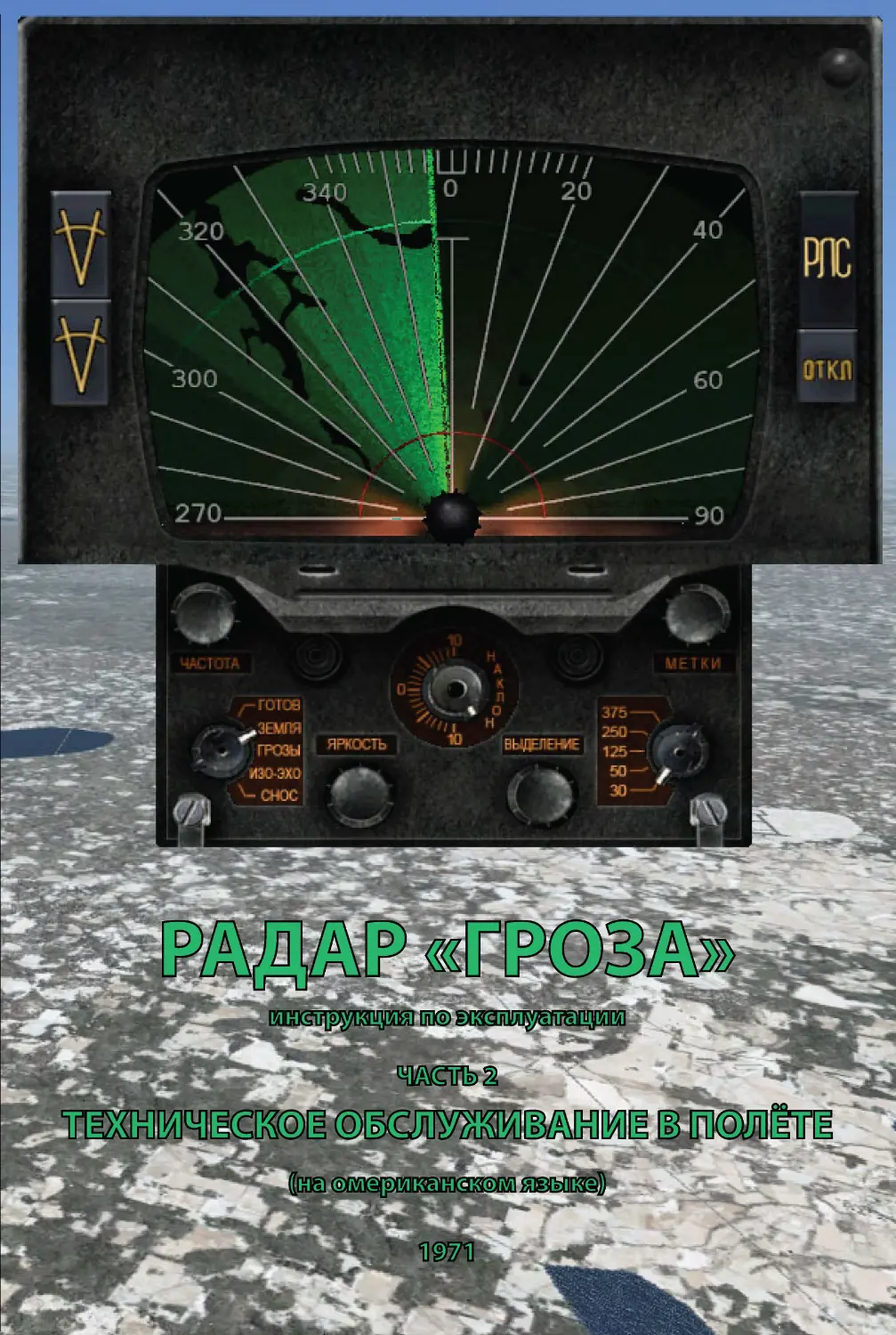
Chapter 2. RADAR CONTROLS
1. CONTROLS PROVIDED IN THE RADAR INCORPORATIN G
ONE INDICATOR AND ONE TRANSCEIVER
The "Graza" radar is so designed that most of its control s an d
operating knobs are located on the front panel of the indicator
(indicators), but one switch "Pe3epB. cTa6 ."
("Reserve stab.")
being built in one of the cabin instrument boards. This switch m a-
kes it possible to disconnect the radar antenna gyro stabilizati on
9
'I
280----- .::
~
'260--
--------100
fi
8
=
2
5
7
3
Fig. I. Main indicator front panel
system if the aircraft gyro vertical fails . In this case the antenn a
operates without gyro stabilization, the azimuth s,vinging plane of
its reflector coinciding with the aircraft lon gitudinal horizontal
plane.
The radar main indicator front panel with its controls 1-9 is
presented in Fig. 1.
21.04.7 1
34-41 -000
7
The purpose of each control
l - Radar On -Off Keys. Marking: "P.TTC" ( "RDR") , "Bb1KJ1."
("OFF").
To co nnect the radar to or disconnect it from the airborne po-
wer s upply, press the key required. In so doing, normal operation
of the radar starts in 3 or 5 minutes after it is cut in, when its
units and components are w armed up . This delay is s et up auto-
matically.
With the radar disconnected from the airborne el e ctric power
supply, even not for long, and switched on once more, the same
delay occ urs .
2 - Function Switch. Positions: 'ToTOB" ("Standby"), "3eMJrn"
("Ground" ) , "MeTeo" ("Meteo"), "KoHTyp" ("Contour" ), "C1-rnc"
("Drift") .
This i s the main switch governing the operating conditions of
the radar.
When the switch is put to the 'ToToB" position, radio waves
are not radiated, but the radar is ready for immediate operation
provided it has been connected to the aircraft power supply mains
thro ugh pressing the "P.TTC" key not le ss than 5 minutes in ad-
vance.
With the function switch put to the "3eMJrn" position, radiation
of ra dio \.vaves begins and scanning of earth surface located wi-
thin the radar azimuth scanning zone occurs. As this takes place ,
the "KoHTpaCT" 7 control located on the front panel becomes ope-
rative. This control makes it possible to increase image contrast
of the earth objects (such as cities, rivers and basins) of interest
for the operator against background echoes from vacant ground
sites. The radar is so designed that no readjustment is necessary
to reta in quality of th e radar indicator picture as the aircraft flight
altit ude or the nature of a ground site being scanned vary. These
variations are compensated for in the radar automatically.
In the "MeTeo" mode the radar radiates radio waves as a nar-
row beam and scans an air space layer limited in altitude, picking
up no earth s urface. This enables to observe radar indicator ima-
ges of thick cumu Ius clouds and storm zones without interference
from earth s urface at any flight altitudes above 1000 m .
When the switch is turned' over to the "KoHTyp" position, the
radar, as in th e preceding mode, detects meteo formations, but
special svvitc ing results in co mplet e s uppresion of detected
storm zo nes ;-1nd thic·k clouds (on the indicator) whose echo inten-
sity exceeds a predetermined v alue . This enables the crew to
judge indirectly on the turbule nce to be expected in the detected
zo ne (or c loud).
In th.e "C1-1oc" position the radar starts earth surface scanning
aga in , but automatic azimuth motion of its antenna is cut out. To
34 -41-000
21.04.71
8
match the beam projection onto the earth surface with the aircraft
true track line necessary for measuring the aircraft drift angle,
shift the antenna in azimuth manually, making use of the " ~ '
ke y. For adjustment of the antenna travel speed, use the '·1<_01-1-
TpaCT" control.
3 - Sweep Duration Switch. Positions: "30",
"50", "125",
" 250", "375".
This switch is intended to vary the duration of sweep and thus
o f the radar indicator picture scale. When turned over to the first
fo ur positions, the sweep begins with zero range and ends at the
instant echo radio waves come from the distances marked. In the
last (fifth) position the sweep begins from the 200 km range and
e nds at the instant signals from 350-400 km reach the radar.
With this sweep on, part of the space from zero range to distances
u p to 200 km is not scanned on the indicator, all signals from the
o bjects located at 200 km from the a ircraft being concentrated in
o ne point which is the sweep origin.
4 -Antenna Beam Tilt Control. Marking: "Ha1rno1/' ("Tilt").
This control makes it possible to tilt the radar antenna beam
up or down with respect to the horizon plane through any angle
up to 10°.
Calibration of the control scale corresponds to a space posi -
tion of a narrow beam in the "MeTeo" or
"Ko1nyp" modes.
When operating in the "3eM.nn" or "C1-wc" modes, the angle va lu e
read off from the scale does not correspond to the true va lue of
tilt, but the crew do not need to know the beam position in space
e xactly in such cases, because the criterion for its optimum shift
consists in a clear picture at a maximum range free from dead
spots. For approximate orientation of the beam in vertical plane
in these modes use is made of the same angle scale as in the
"J\11.eTeo" and "Koinyp" modes.
5 - Radar Picture Brightness Control. Marking: "5Ip1<0CTb"
( "Brightness").
Intensity of exterior light incident upon the aircraft radar indi-
cator screen may vary over wide limits which makes it necessary
to vary the brightness of the whole radar picture respectively. For
this purpose, the picture brightness control is provided. T_he
" Groza" radar circuit is so designed that, when adjusting the ra-
dar picture brightness, a simultaneous and proportional variation
in brightness of range markers and an optimum position of the
" Ko1npaCT" control selected by the operator occurs.
6 - Range Marker Brightness Control. Marking: "MeTKn"
{"Nl.arkers").
This control is intended for individual adjustment of bright-
ness of range markers with respect to the rest of the radar picture.
21.04.71
34 -41
- 000
9
7 - Contrast Control for Pictures of Surface Objects of In-
terest for the Op,erator. Marking: "KoHTpacr" ("Contrast").
With the radar operating in the "3eMJrn:" mode, this control
enables to increase contrast of such objects as large lo ca lities , ri-
vers and basins or individual groups of structures when flying
close by an airport against the general terrain background noise .
The radar picture of a vacant site usually consists of a numbe r
of small luminant spots varying in their brightness due to the di f-
ferent ability of various parts of the site (e. g. sand, arable land ,
meadow, forest, etc.) for reflection of radio waves. Specifically,
this fact results in the deterioration of radar pictures of water ob-
jects, making a picture blurred and partly masked . In addition t o
that, small localities, accidents of the ground and individual struc-
tures with good reflection power that the crew are not able t o
identify produce a lot of sufficiently bright flare spots distract-
ing attention and making it more difficult for the cre,v to read the
picture. The "KoHTpacr" control enables to e limin ate in the rada r
picture partiall y or completely the signals from such unid e ntifi-
able objects as well as equalize brightness of vacant site pictures .
With the control turned until rest, the indicator picture will com-
prise a uniformly bright background corresponding to reflections
from vacant ground sites against which only particularly large
localities are seen as flare spots differing abrup tl y in their bright-
ness and water reference points - in the form of sharply defined
dark spots or lines.
Besides, when operating in the "CHoc" mode, the "KoHTpacr"
control makes it possible to vary speed of the antenna motion in
azimuth, the possibility of contrast increase unacceptable for this
mode being ruled out.
8 - Heterodyne Frequency Control. M .arking: "Y:acTOTa" ("Fre-
quency").
This control enabling to adjust the radar local heterodyne
frequency is used to introduce frequency in to the holding zone
of the automatic control system after sw itching the radar on.
Further adjustment is effected b y the aforesaid system auto-
matically.
9 - Antenna Azimuth Shift Manual Control Key s. Marking· ;
These keys make it possibl e to start azimuth shifting of the an-
tenna in any direction required for drift angle measu rements as
well as stop it at any instant.
•
The controls and switches 2, 3, 4, 5, 7, 9 are opera tional , that
is, used most frequently during the flight. By contrast, controls 1,
6 and 8 are intended for additional adjustments and used once or
34-41 -000
21.04.71
10
..
I
I
f,
I
t wice during the whole flight. Location of the switches and cont-
rols on the main indicator front panel complies with the frequency
of their usage.
2. CONTROLS PROVIDED IN THE RADAR INCORPORATING
TWO INDICATORS
With the radar supplied complete with an additional (second)
ind icator unit, its operation comprising: connection of the radar
to the aircraft power supply mains; switching on the mode of ope-
ration required; switching on the sweep duration (radar picture
sca le) required; tilting the antenna beam at a predetermined (op-
timum) angle with respect to the horizon plane; controlling the
an tenna when measuring the aircraft drift angle is controlled
fro m the main indicator whose controls (their purpose and gro-
up ing) are described above in Section I of Chapter 2.
The seco nd indicator supp lied within this delivery set features
the contrnls enabling indi vidual adjustment of the radar picture
qual ity and its range markers, that is, the "5Ip1<0cTb", "KoH-
Tpa cT", "MeTJu1" controls.
The purpose, operating principle and marking of these controls
a re similar to those of the main indicator described above. To let
the pilot know on what sweep the radar operates at a given in-
stant of time, the decorative mask of the second indicator screen
fea tures an illuminated diagram indicating the intervals at which
the range rings visible on it are ,spaced.
An external view of the additional (second) indicator front
panel with its controls is shown in Fig. 2.
3. CONTIWLS PROVIDED IN THE RADAR INCORPORATING
TWO TRANSCEIVERS
When erecting on board plane the "Groza" radar equipment
co mprising t'-3/0 transceivers, the "Pe3epB. rrepe,n" ( "Reserve
t ranscr.") switch mounted on an instrument board in the cre-w
cab in is provided in addition to the above keys, switches and cont-
rols located on the main and additional (if any) indicators. This
switch is intended for cutting in the second (reserve) transceiver
instea d of the main one, should the latter become faulty. From the
insta nt the radar is connected to the aircraft power supply mains
the standby transceiver is kept hot and thus starts ope rating as
soo n as the switch is changed over.
There are no other differences betwee n th e sets compris ing
one and two transceiv ers.
21.04.7 1
34 -41-000
II
i
260--
Fig. 2. Second (auxiliary) indicator front panel
Chapter 3. OPERATING THE RADAR
For in-flight maintenance of the "Graza" radar equipment on
board any type aircraft, be sure to remember and comply with the
following general ,requirements, instructions. and practices.
When the radar is not in use, change the function switch ove r
to the 'ToToB " position, thus reducing a probability of the rada r
failure during the flight and extending its total service life.
With the plane in the air, do not operate the " OTKJI ." key of the
main indicator till the flight is completed, otherwise the radar will
be cut out for some 3 or 5 minutes at the very time it is required.
Having obtained a picture on the rada:r indicator using the
" 4acTorn" control, do not operate it any more. Should the pic-
ture disappear, restore it by means of the aforesaid control, com -
plying strictly with the requirements set forth in Section 7 an d
checking all other switches and controls of th e radar for their
proper settings beforehand.
34-41-000
21.04 .71
12
..
Bear in mind that when operating in any mode the "Graza"
radar does not detect any turbulence related to formation, exi-
stence or development of clouds in free atmosphere.
When operating at the "375" sweep, remember it begins with
the 200 km range, the whole zone from the aircraft up to this
range being not scanned by the radar.
Avoid operating at the "375" sweep, when flying· through
storm or active vertical cloud formation zones regardless of the
radar mode of operation. Should the radar incorporate two indi-
cators, be sure to warn the pilot on switching this sweep on .
If you suspect a decrease in the scanning ranges for earth
surface or other objects, as compared to those observed before,
switch on the 'ToToB" mode, return the "llacTOTa" control to its
extreme left position, then use the latter to restore the picture in
the "3eMJrn" mode.
Remember that the power supply ON signal lights up in the
'TOTOB" mode only and make sure there are range rings on the
radar indicator soreen in all other modes.
In case of + '27 V circuit temporarily cut off in any of the mo-
des specified for the "Graza" radar, the function switch should
be changed over to the 'ToToB" position with subs,equent return to
the position required to restore normal radar operation.
4. SAFETY PRECAUTIONS TO BE TAKEN WHEN OPERATING THE RADAR
The "Graza" radar is so designed that a radiation level safe
from the vi,ewpoint of biological standards is assured both in the
crew cabin and passenger compiartment on any type aiTcraft fur-
nished with this radar. High frequency radiation can affect only
those outside close by the aircraft nose. Because of this:
Never change the mode switch from the 'ToToB" position over
to any other position prior to taking off until the runway has been
approached.
After landing, change the function switch over to the 'ToTOB "
position until the runway has been left or cut out the radar comp-
letely.
No other safety precautions are required when operating the
radar both on the ground and in the air.
5. PURPOSE, MOUNTING AND STORAGE OF PROTECTING
TUBE AND POLAROID FILTER
A readily detachable protecting tube with a coated polaroid
filter fitted in it is intended to increase contrast of the radar in-
dicator picture when operating in daylight. This increase is effec-
ted owing to the fact that the light filter reduoes outside light
21.04.71
34-41 -000
13
reflected by the indicator screen to ,a much greater extent thap
the light emitted by the radar cathode ray tube screen picture. In
addition to that, the tube walls protect the indicator screeh
against straight light beams entering through the crew cabin glass.
For prolonged service life of the radar polaroid filter without
the deterioration of its properties, the rules for its maintenance
and storage should be complied with.
For protection of the light filter, check . up the tube for ci re-
liable connection to the indicator front panel each time before
switching the radar on and keep the light filt,er coating safe
against damage during the whole period of the radar operation.
To avoid clogging of the filter, do not touch its surfaoes with
hand and wipe them carefully with a piece of soft clean gauze
or flannel, should greasy spots appear. When badly clogged, wipe .
~ off the filt,er surfaces with a wad of gauze wetted in commercial
rectified alcohol. If dust or dirt is found on the light filter, remove
it carefully, making sure not to scratch the filter surfaces.
Never use acetone, hydrolysis alcohol or other substitutes for
cleaning the filter.
Since the polaroid light filter is a laminated structure made of
acetyl oellulose film, its moisture resistance is not sufficient for
areas with excessive air humidity. In this connection, when basing
or landing the plane on the fields with excessive air humidity, re-
move the P'rotecting tube from the radar indicator and stor,e it in
dry premises air conditioned, if possible. It is permissible to keep
the tube and the light filter in position, if the aircraft will not re-
main on the ground in a humid ar,ea for over four hours.
Transport and store the protecting tube in a packing box. Ad-
ditional precautions should be taken for protection of the box from
moisture by placing it in a navigator's case or making other ar-
rangements in case of precipitation.
6. SWITCHING ON.,. THE RADAR ON THE GROUND
Switching on the "Groza" radar consists of three stag,es as fol-
krws:
-
getting the radar ready for switching on (checking up the
settings of the radar controls);
-
cutting the electric power supply in;
-
turning on radiation of radio waves into space.
This may become necessary when taking off under poor meteo-
rological conditions and the crew must be sure in advance there
are no hazardous meteo formations on the take-off and ascending
path.
34-41 -000
21.04.71
14
,,,
"
For switching the radar on, proceed as follows:
~)
~ et all S'fit~hes anq ~o~tr~I ~ on the main and auxiliary (se-
cond) indicators to the following positions:
-
' the "4aCToTa" control of the main indicator to the extreme
counter-clockwise position (left);
-
the main indicator mode switch to the 'ToToB" position
(that is, extreme counter-clockwise position);
-
the "~p1mcTb" controls of both indicators to their mid-po si-
tions;
-
the "HaKJioH" control of the main indicator to its mid-po-
sition;
-
the "KoHTpaCT" controls of both indicators to their mid-po-
sitions;
-
the main indicator sweep duration s\vitch to the position
markep "125" (mid-position);
-
the "Merna" controls of both indicators to thei r mid-posi-
tions.
The "Pe3epB. cTa6." switch located on an instrument board in
the crew cabin should be set to its bottom position ( "Onw.") _
If the radar equipment incorporates the second (standby) trans-
ceiver, the "Pe3epB. nepe,ll, ." switch provided on an instrument
board should also be set to its bottom position ;
b) for cutting in the radar power supply, proceed in the follo-
wing way:
-
turn on the aircraft gyro vertical complying with its ope- -
rating instructions. Be sure to turn on the gyro vertical with which
the radar is connected; •
-
if the radar is interconnected with the airborne navigation
computer or a set of navigating and piloting equipment, switch
on the appropriate computer or set complying with their operating
instructions;
-
turn on the radar on-off switch or network protector locate d
on the navigating and piloting equipment panel (TU -14 4, TU-154
aircraft) or the airborne power supply board (YaK-40 , IL -62 air-
craft, etc.);
-
push H1e "PJIC" key of the main indicator as far as it goes.
Make sure that the key remains flushed · after release and a ligh t
signal indicative of normal switching on of the radar lights up on
the m~jn indicator front Rane! (in the screen bottom)_ However
faultless the co'rnpletion of all procedures may be, radiation of ra-
dio way,es into space cannot b~ turned on before its preheating
and preparatory procedure is completed, the duration of the proce-
~ ure varying from 3 to 5 minutes depending upon ambient tem-
p~rahire. This time delay is performed by the radar automatically;
c) for turning on ra~iation proceed as follows:
21.04.71
34-41 -000
15
-
fi\·e minutes after switching the radar on make sure that
there are no large reflecting objects such as hangars, large buil-
di ngs, etc. within the azimuth sector of 100° on both sides of the
longitudinal axis at distances less than 100 metres from the air-
craft, then change the main indicator mode switch over to the
"3eM.rrn:" position . If this is not achieved, the radar may fail. In
do ing so, luminant range rings should appear on the screen and
the power supply on signal switch off;
-
should there be no luminant rings on one or both indica-
to r s, rotate their "Menrn" controls till the rings appear. If this
me thod does not result in obtaining the range rings, operate the
" 5lpKOCTb" controls, having set the "MeTKI-1'' controls to thei,r ex-
treme right-hand positions. It would be sound practice to change
t he sweep duration switch in this case, prior to operating the
afo resaid controls, from position "125" to "375" and vice versa .
A schematic representation of the indicator screen with lumi-
nant range rings at various sweep durations is shown in Fig. 3 .
Both three and four range rings can be obserV1ed in this case on
t he "375" sweep, the fourth one being much wider and brighter
t han a ll others or consisting of two or more separate closely
sp aced rings in a number of cas,es . The range rings s hould ap-
prox imate circles in their form and distances between neighbour-
ing rings should be approximately the same.
Except for the " 375" sweep, the last •range ring at all sweeps
sho uld be located behind (above) the top horizontal line marked
on the screen across the zero azimuth line. As to the "375"
sweep, where the fourth ring may be lacking completely, the third
o ne s hould be located behind (above) the nearest horizonta l line.
There should be five range rings at the "50", "125" and "250"
sweeps within the azimuth sectors of 40 - 50° or 320-310°, three
r ings at the "30" sweep and three or four at the "375" sweep;
-
rotate the "4acroTa" control from its extreme (left) posi-
t ion in a clockwise direction until blips from ground features and
structu res within the azimuth sector scanned by the radar appear
o n the indicator(s) .
•
Rotate this control smoothly and slowly at a speed of not over
one revolution per JO seconds and stop the rotation right after
the blips are visible.
Thereupon, do not operate the "4acTora" control during the
who le period of the radar operation till cutting it out. Should the
ra dar picture disappear, restor,e it using the above control, having
checked beforehand all other switches and controls for their pro-
per se ttings;
-
if no blips are v isible on the indicator after turning the
" 4aCTora" control to the right as far as it goes, change the mode
switch over to the 'ToTOB" position , return the "4acTOTa" control
34 -41 -000
21.04.71
16
I
II
t o its extreme left position, then change over to the "3eMmr" mode
agai n . Repeat the procedure set forth in the preceding paragraph;
A
B
Maybe
l(ldin!f
Fig. 3. View of the indicator screen at various
sweep durations
-
change the mode switch over to the 'Tpo3br" position.
Raising the radar beam with the aid of the "HarrnoH" control,
proceed in this manner till no ground feature blips are visible.
Then return the contro l to its zero position.
2 1.04.71
34-41-000
2 3aKa3 1245
17
When th(; procedures set forth above are carried out, the radar
is ready for service in any of its operating modes.
Ffg. 4a shows the radar indicator screen with range rings and
ground clutter , when switching on the radar on the ground .
fig. 4 . Approximate shape of radar pictur es :
a - when switching on the radar on the ground: b -
when switching on tl1e radar in flight
7. SWITCHING ON THE AIRBORNE RADAR
When switching the airborne radar on, radiation of radio
waves is turned on by the crew with the aircraft in the air, but
all preceding stages of the switching-on procedure can be carried
out both in the air and on the ground.
For switching the airborn(; radar on, proceed as follows:
~ check up the settings of all switches and controls on the
main and auxiliary (second) indicators, making sure that they
comply with those given in Item 6a of th ese Instructions;
34-41-000
2l.04.7t
18
•
-
cut in the ,rad.ar power supply, comp lying with the rules set
for th in Item 6b of these Instructions;
-
t urn on the radar radiation, changing the main indicator
mode switch over to the "3eMm1" position. ln so doing, luminant
range rings s hould appear on the radar indicators;
-
if there are no luminant rings on one or both indicators,
rotate the "Menrn" controls till the rings ar,e v isible. lf this me-
thod does not result in obtaining the range ,rings, make use of
the "5t pKOCTb " controls, having s,et the "Menrn" controls to their
extreme right-hand positions. It wo uld be sound practice to
change the sweep duration switch in this case, prior to operating
the aforesa id co ntrols, from position "125" to "375" an d vice
versa;
-
w hen the luminant range rings are seen, use the "HairnoH"
control to tilt the radar beam down through 7°;
-
turn the sweep durati on switc h ove r to the following po-
sitions :
"30" at flight a ltitudes below 3000 metres,
"50" a t flight a ltitudes from 3000 to 5000 metres,
"125" a t flight altitudes from 5000 to 12 000 metres,
"250" at all flight altitudes above 12 000 metres ;
-
rotating the "Y:acTOTa" co ntrol in a clockwise directio n,
make s ure the radar picture of ground surface appears on the
radar sc reens.
Ro tate this control smoothly and slowly at a speed of not over
one revolution per 10 seconds and stop the rotation right after the
rad ar picture is visible.
The radar picture should be visible a t all az imuth angles
within + 100° wi thout dead spots and discontinuities;
-
if the picture obtained is much less brighter and shorter
than usual, change the mode swi tch over to the 'ToToB" position,
then return the "Y:acTOTa" control to its extreme left position . Re-
set it to the "3eMJrn" mode and repeat the procedure described in
the preceding paragraph.
When the procedures set forth above are ca rried out, the radar
is ready for service in any of its operating modes.
Fig. 4b shows the radar picture of ground surface, as obtai ned
when switch ing the airborne radar on.
8. SWITCHING THE RADAR OFF
To switch the "Graza" 'radar off, push the "BbIKJI . " key of the
main indicator and turn the radar on-off switch or network pro -
tector located on the navigating and piloting equipment panel
(TU-144, TU-154 aircraft) or the airborne power supply board
(YaK:-40, IL-62 and other types of aircraft) to the "OFF" position.
21.04.71
34 -41-000
2*
19
Particular attention in thi s case should be paid to the fact that,
no matter how short the period of disconnecting the radar powe r
supply is , three to five minutes delay is required when switching
it on again to let the equipment get ready for operation. No radar
picture can be obtained in any mode before this time lag is up.
The "Graza" radar is an intricate ,radio electronic device com-
prising many a hundred parts and components, each component
having a certain probability of failure. The transceiver compo-
nents operating when radio waves are radiated by the radar are
the least reliable. Therefore, if there is no need to use the radar
for a while, but it can become necessary at any instant, turn ra-
diation out by changing the mode switch over to the 'ToToB" po-
sition.
To turn radiation on in this case, no time lag is necessary be-
cause radiation starts right after the mode switch is turned over
to any other position. It goes without saying that one should ne-
ver push the "Onrn ." key, that is , cut out the radar, in such an
event.
9. OPERATING THE RADAR WHEN FLYING THROUGH STORM
ZONES AND CLOUDS
Radar Operating Procedure for the "MeTeo" Mode
When operating in this mode, the "Graza" radar enables the
aircraft crew to detect active storm zones, heap rainy and thick
heap clouds as well as makes it possible to fix the position of
these hydrameteoralogical obj,ects on an az imuth and ,range.
A typical radar picture for this mode is presented in Fig. 5
(A and B). As will be seen from the figures, restricted possibili-
ties of the radar indicators do not make it possible to ddermine
from the radar picture what areas of the zone or cloud detected
show the most turbulence and their hazard for the aircraft in ge-
neral. Therefore, in the "MeTeo" mode the radar informs the crew
on hydrometeoralogical objects on the flight path, indicating al-
.
ternate paths for bypassing these objects on an az imuth. When
in good working order, t h e "Graza" radar detects practically all
haza•rdous hydrometeoralogical objects. In certain ' cases it can
also detect non-hazardous objects which cause excessive bumping
when flying through them.
To change the radar over to the mode under consideration:
set the mode switch to the "MeTeo" position;
set the sweep duration switch to the position "250";
-
shift the "HaKJIOH" control to its zero position;
-
using the "5IpKOCTb" control , set a required brightness of
•
the range rings, avoiding, however, intensive continuous gating
34-41 -000
21.04.71
20
,.,
'
I
II
~
I
of the whole area of the indicator screen. When carrying out the
adjustment, set the· "MeT1<11" control to its mid-po s ition ;
-
having detected a hydrometeorological object, change over
the sweep duration switch as the object is approached, proceeding
from a specific situation;
Fig. 5. Typical screen pictures for the radar
operation in the "MeTeo" mode
-
should ther,e be no radar pictures of meteorological objects
for a long time, in an instrument flight (such as when flying in
clouds or at night) or in visual detection of suspensions clouds
with no picture of the latter on the radar screen, check up the ra-
dar for operable condition by tilting its beam down at 6-7° with
the aid of the "Hairno1-1" control. When ground echo appears on
'21.04.71
34-41-000
21
the screen in the form of a sufficiently wide luminant circular
z one (see Fig. 6), the radar is in good working order;
-
reset the "Ha1rnm1" control to zero.
The "KoHTpaCT" control
provided both on the main
and auxiliary (second) indi-
cators is disconnected when
operating the radar in the
"MeTeo" mode and may be
s et, therefore, to any posi-
tion.
F ig. 6 . Approx imate s hape of radar pic-
t ure w hen checking the radar for operabl e
cond ition in the "M .ereo " mode
Radar Operating Procedure
in the "KoHTyp" Mode
Since information alone
on a hydrometeorological
object within the scanning
z one is o.ften insufficient and the crew may want to know the
extent of danger it pre se nts , the "Groza" radar incorporates a
s pecial mode of operation enabling such an estimate to be made.
From the viewpoint currently held, the degree of turbulence in
clouds i s proportional to the precipitation rate from them. How-
ever, contemporary airborne radars incapable of measuring this
speed directly mea s ure turbulence in an indirect way from the
differences of precipitation intensities from adjacent parts of a
cloud (precipitation gradient).
When o perating in the "KoHTyp" mode, a radar picture enabl-
ing to draw a conclu s ion on the precipitation gradient and thus
make a rough estimate of the degree of turbulence is obtained.
Reflected in this mode from turbulent clouds and storms, the ra,
dio waves exceeding in their intensity a specific value result in
no picture on the indicator screen, the portions of the image of
a hydrometeorological object that correspond to them becoming
dark. The reflected wav es whose intensity is below the specific
value, but s ufficient to result in the radar image yet continue to
gate the screen.
A typical image of storm zones with the radar operating in
the mode mentioned above is presented in Fig. 7 .
Be sure to change over the "Groza" rada,r from the "MeTeo"
mode to the "KoHTyp" mode on having detected an image of a
hydrometeorological object on the radar indicator. The purpose
of this is to estimate turbulence and thus the extent of hazard
from the object detected or choose the least hazardous path for
passing through it. In so doing, the radar operating procedure is
as follows :
34-41 -000
21.04.71
22
-
change the mode switch over to the "Kotnyp" po sition ;
-
adjust the picture brightness, if nece ssary, using the "5Ip-
KOCT6" co ntrol.
When the procedure s set forth above are perfo rmed , th e images
of th e objects whose echo intensi tie s are over th e s pecific \·alue
appear on the screen in the form of light s pot s alternati ng with
dark ones which wi ll serve as a wa rning for the crew about an
appreciable probability of comi ng up again st heavy turbulence in
the objects detected. An esti-
mate of the precipitation gra-
dient in a given part of the
de t ected s torm zone or cloud is
yet po ssib le from the width of
luminant edging arou nd a dead
spot in th e picture. The hi gher
the gradient, i. e. the faster
the rise in precipi tat ion inten-
sity from the e dging inside the
zone ( or cloud), the narrowe r
is the edging in a given part Fig. 7 . T y pical pictures fo1· the radar
of th e radar picture. Thus,
operation in th e "Ko1nyp" mod e
narrow luminant s pots 111 the
radar picture are indicative of excess ive turbulence in the par-
ticular areas of the s torm z on e or cloud.
All h y drometeorological objects resulting in such "contour"
images should be bypassed at a di stance of not less than 10 km.
It is permissible to fly at clo se r di s tance s or directly through
these objects as a la s t resort only.
However, in the latter cases th e flight s h o uld be canied out
through or on the side of the widest portions of the edging
around dark s pots in the picture.
Do your best to avoid flying through or on the side of narrow
luminant edging.
In large cloud s o r s form zones, severa l dark spots according
to the number of ce ntres with s trong reflection can be observed
s imultaneously.
The "Groza" radar is so de s igned th a t the hydrometeornlogical
objects whose images appear on the indicator at di st an ces o\-er
100 km can be ju s t medium or large size shower-producing or
thunderstorm clouds. The radar detects less turbulent fo rm ations
at smaller ranges only. H owever, although detection of an object
at distance s below 100 km is indicative of probable h eavy tur-
bulence in it, dark spots in its radar picture will h a rdl y be ob -
tained at s uch considerable ranges . The refore, all hydrom eteoro-
logical objects detected by the •radar a t th e di s tan ces over 90 or
100 km should be considered ha za rdou s for flight s irrespective of
21.04.71
34 -41
-000
23
whether there are dark spots in their images or not, keeping a
watch over them. The dark spots in the images will appear gra-
dually as these hazardous objects are approached.
The circuitry of the "Groza" radar is so designed that if no
d ark spots made their appearance in the images at the distances
within 30 to 40 km, it is hardly probable that they will develop
later on. The latter is likely, if the object concerned builds up in
s ize intensively.
Radar Coverage for Meteorological Objects
The "Groza" radar scans space ahead of the aircraft within
a zimuth angles of about 100° on both sides from its longitudinal
axis . Vertical size of the zone being scanned and its position with
respect to the horizontal plane passing through the aircraft centre
of gravity depend upon the radar version and setting of its "Ha-
K.'I OH" control.
Most versions of the radar operated for scanning hydrometeo-
rological objects radiate radio waves in the form of a narrow
beam at a vertex angle from 3 to 4° depending upon . the type of
the aircraft. The beam is s ho wn schematically in Fig. 8 .
-----------===-~
=
~ ----
~
~
~~
=;
3:=-
~
.
~
....._
~
.,,._..._,.,.,,,__
_ ,, ,,,, _%!<&-~7'/C~<
Fig. 8. Beam sh ape with the antenna located in the nose dome
Thus, when operating in the "MeTeo" or "Ko1-nyp" modes, the
ra dar s cans an air space layer whose height depends upon dis-
t ance and the aircraft type.
For all aircraft where the antenna is located in the nose dome,
w ith the exception of small planes used by local air lines, this
height is approximately 52 metres per every kilometre of range.
For s mall aircraft of local air lines with t he antenna in the
nos e dome, this height is 70 metres per ki lom etre of range.
34-41-000
21.04.71
24
Total height of the air layer scanned at various ranges from
the radar is given in Table 2.
Table 2
APPROXIMATE HEIGHT OF AIR LAYER SCANNED BY THE RADAR
Distance from radar, km
10
30
50
100
200
Height of Zone to be Scanned, m
for large and medium
aircraft TU-144 , TU-154,
TU-134A , JL -62, JL-18, AN -24
520
I 600
2600
5200
10400
for aircraft usedlby local
air Jines YaK-40
710
2100
3 500
7000
14000
When the "Ha1rnOH" control is set to zero, the middle of this
zo ne roughly coincides with the horizontal plane passing through
the aircraft centre of gravity.
For the aircraft where the radar antenna is mounted under the
fuse lage (such as TU-104 , TU-124, TU-134, AN-10, etc.), the zone
Fig. 9 . Beam shape with the antenna located under the fuselage
of coverage differs considerably from that described above. Al-
t hough the radar beam in this case is 3° wide in the horizontal
plane, its width in the vertical plane is much greater. Fg. 9 shows
t he form of the beam in the vertical plane. Therefore, the "Groza"
ra dar with the a ntenna located under the aircraft fuselage scans,
when operating in any mode, the entire air space ranging from
roughly, the horizontal plane passing through the aircraft centre
o f gravity to the angles within 80 to 85° down including the earth
s urface.
.
21.04.71
34-41 -000
25
Using the Radar for Detection of Meteorological Formations
When the "Groza" radar operates, radio waves radiated by it
are reflected from clouds resulting in their radar images. Capa-
bility of a cloud to reflect radio waves depends upon the size of
water drops in it. The clouds containing just small drop s are not
haza·r dous for flights and do not give echoes sufficient for their
detection on the indicator, i. e . tho se falling into top , medium and
bottom cloud sheets.
Unlike them, vertical development clouds such as thick heap,
heap rainy and thunderstorm clouds which consist of rather large
drops result in fairly strong returning echoes making it possible
to observe the clouds on the indicator at considerable ranges de-
pending upon the size of each cloud and the stage of its develop-
ment. In most cases these cloud formations involving marked tur-
bulence are hazardous for flights.
If considerable areas ahead of the aircraft abound in precipi-
tation such as rain, the radar free space range for hazardous
clouds decreases and, what is more, interference glow from such
rain not hazardous for flights can appear on the indicator screen.
The atmospheric precipitation is composed of water drop s of dif-
ferent size depending upon the intensity falling from a cloud on
the earth. Any water drops on the way of radio Wc\Ves radiated
by the radar partially absorb radiation and partly result in re -
turning echoes. This is why the radar fre e space range for hazard-
ous clouds located inside low turbulence areas with precipitati on
decreases. By way of illustration we consider a heap rainy cloud
detectable in clear weather at 150 km. If there is rain falling out
at 4 mm/hr (moderate rain) and extending at 40 km between the
aircraft and the cloud, the l atter will be detected at 125 km.
Snow which is known to have lower liquid water content does
not generally result in echoes visible by the radar over th e whole
span of ranges, although appearance of a more active ly reflecting
layer is possible right under the zero isotherm. Snow flakes in
this layer do not melt and the rate of precipitation from it is
small which results in a heavier water content of the layer. How-
ever, because of its sma ll thicknes s (150---;-300 m), detection of
such a layer by the radar even at small ranges is hardly prob-
able.
Above the zero isotherm snow crystals give weak echoes not
visible by the radar, but below it they melt, forming small drops
whose rate of precipitation is relatively high and their concentra-
tion is thus insufficient for setting up a visible signal.
Hail particulary when it has melted a little can result in very
strong echoes. However, due to very high precipitation rates of
any kind of hail, the echoes set up by it are in most cases not ·de-
34-41 -000
21.04.71
26
tected by the radar. Hail precipitation is believed to occur, as a
rule, from the areas bordering with shower or thunderstorm zones,
but not from the zones proper. In this case, a projection whose
shape resembles a stretched or bent finger can develop on the
edge of the radar zone image. Therefore, in all cases when edges
of the radar image of a hydrometeorological object grow up sud-
1••
denly and rapidly, the crew would do better to bypass such an
i:
area because hail precipitation is likely to occur in it.
No matter how intensi ve whirlwind s and dust s t orms might
be, they are detected by the radar at ranges adequate to avoid
the dangerou s zones.
Discriminating· the Radar lmag·es of Meteorolog·ical Formations
and Ground Objects
In flight operation of the "Groza" radar with the antenna lo-
cated in the aircraft nose dome, consideration must be given to
the fact that at certain flight altitudes and tilt angles of the an -
tenna beam the latter will cross the earth surface, resulting in
echoes from ground objects and the earth surface proper. Th.ese
echoes can be mistaken by the crew for cloud or thunderstorm
echoes. To eliminate these interference echoes when flying over
even ground, it is enough to rai se the radar beam up to a \· alue
equal to that indicated in Fig. 10. Thunderstorm echoes do not
disappear at such tilt angles and thus di scrimination can be ac-
complished.
When flying over mountainou s areas, echoes from mountain
peaks can remain on the indicator at the aforesaid and even
greater angles of the beam tilt. This is generally the case at small
and medium ranges when the flight plane is below the level of
individual mountain peaks. In such cases discrimination of echoes
is not accomplished through the beam r a ising and the areas re-
sulting in such echoes should be bypassed, no analysis of their
nature being necessary.
At relatively large distances to mountains (80 km and more)
echoes from them can be eliminated using the method described
at the beginning of this paragraph. The angle of tilt required
can also be taken from Fig. 10 provided that the flight altitude is
regarded to be that above mountain peaks.
If the radar antenna is located under the aircraft fuselage,
echoes from ground surface can partly remain even at large
angles of the beam tilt. This occurs when flying at the altitudes
21.04.71
34-41 -000
27
,•
<
much less than those generally accepted for a particular type of
a ircraft. Nevertheless, at operational altitudes and with the an-
t enn a b eam raised, echoes from ground surface disappear, al-
t hou gh a t the angles slightly larger than those indicated in
Fig. 10.
~
~<:,
t;,
c:,
"'
,._
"'....
"'
,._
CS
15000
-:;- !ODDO
t
"
.,
_§
-
~
+-
+-
-
~
for medium cmd
l{lrg-e aircmft
~-
+-
for small llircraft
+-
of Lowl {lir lines
"~
~
j
I
~
J
,,
J
"'
I
I
)
I
,o
UP
II
IJ
I
I
I
/j
II
I'--
-. .J
j
II
II
'
I
J
I
---- a-JJOWN
Fi g. 10. Minimum a ngle of the antenna tilt for elimination of ground
e cho
34- 4 1-000
21.04.7 l
28
Should an attempt to eliminate echoes from ground surface by
,elevating the radar beam fail, discrimination of echoes can be
accomplished to some extent through an analysis sometimes
enabling to judge their nature with an assurance. Radar images
.of cloud formations can be discriminated from other images by
their larger size unusual even for those of major industrial cen-
tres, irregular shape, higher brightness over the whole area as
well as somewhat blurred edges (see "B", Fig. 5). However, there
c an be cases sometimes, when the screen areas taken by these
images a•re small, and the shape of markers is nearly oval or cir-
cular, the borders of the latter being defined rather sharply (see
" A", Fig. 5) . This generally occurs when observing particularly
heavy thunderstorms, showers or whirlwinds.
Right behind the echoes from hydrometeorological objects
specific "radar shadows" confirming their meteorological nature
c an be observed, if there is any assurance, of course, that within
~·
the sector under scanning there are no mountain masses which
give similar "shadows".
There are no other practicable methods for identifying radar
images of hydrometeorological objects, but on having gained suf-
ficient experience the radar operators identify them unmistakably.
10. OPERATING THE RADAR FOR EARTH SURFACE SCANNING
Radar Operating Procedure for the "3eMJisi" Mode
The "Groza" radar can scan the earth surf ace within the azi-
muth sector of 100° on both sides of the aircraft longitudinal axis .
In this mode the radar antenna beam for any type of aircraft
takes a shape making it possible to scan the earth surface at all
ranges from minimum to the maximum one.
The possibility of using the airborne radar to obtain a "•radar
map" of the terrain ahead of the aircraft is based on the fact that
v acant ground sites (forests, open spaces with grass lot or no
such lot and so on), localities and engineering structures give
r,eturning echoes of radio waves of different intensity sufficient
for gating the indicator screen. In so doing, towns (particularly
medium and large cities) result in fairly strong echoes received
by the radar at very large ranges within 150 to 400 km and ob-
served on the indicator as bright spots. Echoes from vacant
ground sites give continuous (but less intensive) gating of the
indicator up to 100-a -180 km .
In contrast, water surfaces reflect most radio waves incident
upon them in a regular way, that is, aside from the radar, and ,
21.04.71
34-41 -000
29
for practical purposes, produce no gating of the screen. Radar
detection of large and medium rivers and basins visible clearly
against general gating from vacan t ground sites in the form of
black spots is based on thi s principle.
Typical ,radar pictures of the earth surface are present e d in
Figs 11 and 12.
Fig. 11. Typi ca l radar pictur e of earth su rface
Fig_ 12. Typical rada r pictur e of ea rth surface
The radar operating procedure for eart h surface scanning
should be as fol lows:
turn the mode switch over t o the "3eMmr" position;
-
turn th e sweep duration sw itch over to the position "250";
-
using the "Ha1rno1-r'' control, tilt the radar beam down til l
an image of the earth surface is visible on the screen. When a
continuous picture of vacant ground sites free from dead spots,
34-41 -000
21.04.71
30
with sharp gating of the screen at maximum ranges is available
on the indicator, stop tilting at once.
With excessive tilting of the beam, the scanning range for
v acant ground sites as well as medium and large localities de-
creases, while with insufficient tilting large-size dark spots de-
ve lop in the images of vacant ground sites (Fig. 13) . Use a chart
Fig. 13. Approximate shape of radar pictures for
oper a tion in the "3eMJJ51" mode:
a - w ilh inadequate tilt of the antenna beam; b - with
excessive tilt of the antenna beam
(Fig. 14) for approximate orientation as to what angles of the
beam tilting ass ure optimum observation of the earth surf ace;
-
if necess a ry, set a required brightness of the picture and
range rings using the " 5IpKOCTb " and "MeTK11" controls, making
sure to avoid inten si ve gating w hich w ould make the whole screen
21.04.71
34-41-000
31
equally bright. Appearance of such gating would testify to the
fact that the possibility of further brightness control of radar has
come to an end.
~ for supersonic
rfircroft [I£
I
t\'1escent
1
'
I
For s11personic
I\
tlircr1.1/'t ot tiileoff
\II
ho..
15000
I\\
~
\
for subsonic
\
oircrtl ft
\
I
\I
'
\
\J
'
\\
\
\
\
10°
50
0
Fig. 14 . An approximate angle of the antenna tilt for earth surface
scanning
When operating in the "3eMJIH" mode the "KoHTpacT" control
can be set to any position, but it would be sound practice to turn
it over to its extreme left (counter-clockwise) position right after
changing the mode switch to the "3eMJIH" position;
34-41-000
21.04.71
32
-
set the sweep duration switch to a position optimum for
scanning the objects of interest for the crew (radar display
scale).
Having switched on the "375" sweep on TU-144 aircraft, tilt
the antenna beam throug·h 2 to 2.5° more from the position set be-
fore. Having· changed over to other sweeps, reset the "HaKnoH"
control to its former position.
It is not advisable to use the sweeps duration of which is less
than six times the altitude;
-
obtain optimum contrast of the objects of interest agains t
total background of the earth surface using the "KoHTpacT" con-
trol.
The possibility of the contrast increase in the "Groza" radar
is based on gradual elimination of echoes from larger and larger
man-made objects (such as towns, etc.) in the radar pidur€ and
equalizing simultaneously the gating brilliance from vacant
ground sites more and more intensively. Different parts of ground
/.'
(i. e. sand, arable land , forest, meadows and so on) vary in their
reflection of radio waves. Therefore, the radar picture of vacant
ground sites comprises a lot of portions featuring different brilli-
ance which reduces image contrast range for water objects against
the aforesaid background and results in blurred edges of the
images.
Fig. 15 . An example of the earth surface dis-
play picture with the "K:oHTpacT" control in
its extreme left position
Small localities, accidents of the ground, as well as individual
man-made structures and objects featuring good reflection most
of which are hard or impossible to identify also result in many
flare spots on the screen, distracting the operator's attention and
masking identifiable objects. All these disadvantages of the radar
21.04.71
34-41-000
3 3aKa3 1245
33
picture of ground s urface are eliminated to some extent with the
a id of the "Ko1-npaCT" control.
If the "KOJ-npaCT" control is in its extreme left (counter-clock-
wise) position, the radar picture incorporates echoes from all ob-
jects - both identifiable and unidentifiable.
Typica l radar pictures of th e ,e arth s urfaces with the "KoHT-
paCT" control fully out and in are presented in Figs 15 and 16.
Fig. 16. An exa mple of the earth surface picture
with the "Ko,npacT" co ntrol in a position
optimum for water sur f ace scan nin g
Deciphering the Earth Surface R.adar Picture.
Distortions Developed in Scanning
Even relatively inexp,erienced operators, as a rule, identify
ima ges of v arious water objects, when operating in the "3eMJ1H"
mode, w itho ut difficulty, because for all practical purposes, they
gi ve no 1r eturn ing echoe s of radio waves and are v isible clearly
a mong ground echoes in the form of dark spots. However, the na-
ture and configuration of the shore line in the radar images can
differ from those shown on a geographical map due to the dis-
tinctive characteri s tics of 1reflection of radio waves from various
parts of coasta l land . Thus, a marsh-ridden side can result in a
less distinct image with a lower brightness, dead spots and
depths not to be found on the map.
A mountainous shore line generally results in sharp and dark
dead s pots lo cated right behind brighter spots in the radar pic-
ture as well as in broken dark ships that run deep in the shore
line (Fig. 17) . These dead spots and breakdowns are "radar
shadows" formi::d behind mountains or vaTious accidents of the
ground.
34-41 -000
21.04.71
34
•
The size of radar images of water objects is ahvays slightly
reduced, small and m~dium rivers and lakes thus being not de-
tectabl~ on' the indicator. As the flight altitude and observation
rang~ incre9se, these non-detectable objects will grow in size be-
cause the radar beatn is sufficiently wide and only a small part
of it is crossed in the aforesaid cases by a river or a lake, •the
Fig. 17. Radar pictures:
a - mountainous and flat ground site's: /J - rnounLtinou s
sea shore line
rest of the beam radiating over the shores and result ing in almost
as strong returning ech.oes of radio ,..va ves as in the case of ab-
sence of a river O'r l<ike within the beam.
If there are no water objects within the scanning zone, de-
ciphering of radar images and identification of indi vidual objects
is more complicated and calls for a much greater experience from
21.04.71
34-41 -000
35
t he operator. Echoes from medium and large towns as well as
from mountain formations a·re relatively easy to identify, but iden-
t ification of other kinds of objects involves many difficulties and
t hus all possible experience should be gained continuously in ope-
rating the radar. The personnel should have a clear-cut under-
standing of bas ic principles underlying the formation and obtain-
ing of the radar picture of the earth surface.
In doing so, it should be kept in mind that, unlike water ob-
jects, all other objects give images extended in azimuth because
ev en a "point" reflecting object (such as a ship) produces re-
t urning echoes of radio waves during the whole period it remains
w ithin the radar beam travelling in azimuth. In this respect, its
image on the indicator takes the form of an arc, but is not dot-
s haped as could be expected.
As noted above, when flying over mountainous areas, "radar
s hadows" observed on radar pictures can be mistaken by the !fa-
d ar operator for images of water objects (Fig. 18) . To avoid this,
when approaching mountainous areas, compare the radar picture
wi th the map at regular intervals. This step is also very useful
w hen fl ying over any areas of the ea1rth surface because it faci -
lit ates id entification of images to a great extent and is beneficial
fo r gaining exp erience.
Fig. 18 . Formation oi radar "shadow" behind a mountain peak
Distances to various objects determined with the aid of the ra-
da r indicator ar e slant ranges, but not those over the earth sur-
fa ce used for charting geographical maps. As a result, the radar
picture is always slightly different from that of the same terrain
on a map, that is , certain distortions are inherent in radar images.
34-41 -000
21.04.71
36
•
The difference between slant and horizontal ranges is most ap-
preciable when scanning objects at short range. As to the dis -
tances that are more than six times over the flight altitude, this
difference, for practical purposes, can be disregarded. Specifically,
the objects located directly under the aircraft are observed on the
ra dar indicator at distances equal to the flight altitude. Image
distortions in the near-by zone increase with the flight altitude,
t he zone of marked distortion becoming wider.
The nature of the distortions described above is illustrated in
Fig. 19 where a conventional representation of a shore making
up a straight line is given for a sweep duration equal to 30 km
a nd the flight altitude of 8000 metres.
Actuul shore ltne
represent(! t ion
on the mop
/?(ldor i,m(l(T8
representation
oo tile tndtc{ltor
Fig. 19. Image distortion in the "3eMJJH" mode
As will be seen frnm Fig. 19, the shore line image is distorted .
However, all ranges measured with the aid of the range indicator
are true ones and it is only the shape of an object (i. e . a ground
site) which is distorted .
Approximate charts for conversion of slant range measured by
t he radar into that over the earth surface are presented in Fig. 20.
21.04.71
34-41 -000
37
Cl,
~~.. _
"'
t:::
~..__ ,
er,
30
10
8
6
J/-
2
A
lo, w
~~
10000m altitt1de
)~~
\,f1/j w
/~~
6OOOm qztitude
/~~
~ V~~
"
I">~~~ '
12ooom altd11de
1--V v/~ ~
--
l./Vj11/"
I__........
~~
_vV
V
/
0
10
20 hortzoot(Jl rqn, -e(,fm)
Fig. 20. Chart for conversion of slant range into earth
surface range at various flight altitudes
11. OPERATING THE RADAR TO MEASURE THE AIRCRAFT
DRIFT ANGLE
When operating in the "CHoc" mode , the "Graza" ,radar m ea-
sures the aircraft drift angle by the "stopped antenna" method
which does not involve any radar ground check points . Be sure
to change over the radar to this mode from the "3eMJ1H " rriode on
having obtained a ,radar ptcture of the earth surface on the indi -
cator screen in the latter 111od~ .
•
34-41-000
21.04.71
38
..
The radar operating procedure for measuring the drift angle
should be as follows:
-
set the mode switch to the "CHoc" position;
-
set the sweep duration switch to position "50,i when flying
at altitudes below 10 000 metres and to "125" -
at higher alti-
tu des.
Automatic azimuth travel of the scanning trace on the indica-
tor should cease several seconds after the "C1rnc" mode is switch-
ed on, the line stopping on the screen in an arbitrary position (in
the roll mode subsequent arbitrary azimuth travel of the scan-
ning trace is possible);
-
push the main indicator key marked " kf- "
to shift the
scanning trace over to that azimuth sector of the screen where
the aircraft true track line is expected to be. In so doing, the rate
of kavel of the scanning trace can be adjusted using the "KOI-IT -
paCT" control. If the direction of the scanning trace travel is op-
posite to the one required, when pressing one of the keys marked
" -"TI' ", release one and push the other.
The "KoinpacT" control enables in a number of cases to de-
crease the rate of the scanning trace travel to zero. Therefore, if
the line does not shift after pushing either key, turn this control
over before the travel begins.
If no assumptions can be made as to the position of the air-
craft true track line, shift the scanning trace up to the nearest
azimuth mark corresponding to an angle of 30° or 330°;
-
when approaching an assumed position of the true track
line or the above mark, decrease the scanning trace rate of travel,
using the "KoHTpacT" control, to a minimum. If so, stop the trace
travel by releasing the key;
-
rapidly pressing the keys " Aj-- " shift the scanning trace
first to one and then to the other side within the + 15° secto•r con-
•
tinuously watching variations in the glow of the scanning trace.
As the scanning trace approaches the actual position of the
aircraft true track line, the scanning trace or its individual sec-
tions begin flickering first at a very high, then at a constantly
decreasing frequency. The lowest frequency of flickering is ob-
served when the scanning trace matches the actual position of the
aircraf t true track line.
When the scanning trace passed through the true track line
position, the flickering frequency begins to increase and then
flickering disappears altogether. Inasmuch as flickering develops
21.04.71
34-41 -000
39
and varies within rather a small azimuth sector and does no t
occur on all other azimuths, shift the scanning traoe over not
more than 1 or 2° intervals or continuously at a low rate. If th e
scanning trace travels rapidly, the operator may fail to see the
flickering sweep trace sector.
For a higher precision in determining the actual position of
the aircraft true track line, it would be sound practice to obtain
the minimum flickering frequency within those (top) parts of th e
scanning trace that are most distant from the sweep origin.
The value and sign of the drift angle should be determined on
the indicator azimuth scale after the scanning trace stopped in a
position characterized by the lowest flickering frequency .
When measuring the drift angle, do not set the picture fo r
excessive brightness which makes the whole scanning trace uni -
formly bright, the drift angle measurement thus becoming im-
q
possible.
When flying over sea surface at a large distance from shore
line, the radar is generally not capable of measuring the drift
angle, but the measurement may become possible in heavy seas ;
-
having completed the measuring procedure, -reset the mode
switch to the "MeTeo" or "3eMJrn" positions as required by flight
conditions.
12. OPERATING THE RADAR FOR CORRECTION OF THE AIRBORNE
NAVIGATION COMPUTER
If a civil aircraft is furnished with a navigation computer,
the "Groza" radar makes it possible to correct present position
data of the aircraft r,eckoned by the computer. To this end, use is
made of a ground object which has known coordinates, is as small
in size as possible and is easy to observe and identify on the ra-
dar indicator.
With its coordinates introduced in the navigation computer
operating in a special mode, the computer determines the slant
range and course angle of the object expected at a given instant.
The computer transmits then the information obtained to the ra-
dar where it is plotted on the indicator screen in the form of a
luminous ring for the range to be expected and a radial line for
the course angle to be expected. The radar image of the ground
object chosen for correction should he located at a point where
the lines intersect, as reckoned by the airborne navigation com-
puter. Since the computer reckons the present position data with
an error, no such coincidence occurs in practice and, to have it
accomplished, the coordinates determined by the computer should
be altered.
34-41 -000
21.04.71
40
"
•
The aircraft present position data at which the coincidence
was accomplished can be regarded as true coordinates and used
in the computer (instead of those reckoned before) for all sub-
sequent calculations till the next correction is necessary, th e
procedure described above being the principle of the radar cor-
rection.
As is evident from the aforesaid, in the navigation compute r
correction the radar is but a coincidence indicator used to deter-
min e the instant when the cross lines are superimposed on the
image of the object concerned. In this case the cross lines are
controlled and the modes of operation of the airborne equipment
set from either panel of the computer (the set of the aircraft na-
vigating and piloting equipment), but no controls of the "Groza"
radar are operated.
In view of this as well as because of substantial differences in
the design of airborne computers, the correction procedure is set
forth in the airborne computer (set of navigating and piloting
equipment) operating instructions.
13. EMERGENCY SWITCHING OF RADAR
For disconnection of some components within the radar itself
or its con jugate parts that might fail as well as for connection of
standby components instead of faulty ones, the "Groza" radar in-
corporates a number of special switches, viz.:
-
the switch for disconnection of the aircraft gyro vertical
from the radar, if the former fails -
"Pe3epB . cra6."
("Reserve
stab .");
-
the switch for disconnection of the faulty radar transceiver
and connection of the standby one in the radar delivery sets
comprising two transceivers -
"Pe3epB. nepe,u. "
("Reserve
tr anscr.").
For emergency switching, proceed as follows .
Faulty Aircraft Gyro Vertical. If the crew have found out for
sure, when flying, that the aircraft gyro vertical to which the ra-
dar is connected had failed:
-
change the radar over to the earth surface scanning mode
as specified in para 10 of these Instructions;
-
change the "Pe3epB. cra6." switch from "OrKJI." to its top
position;
-
set the "HaKJIOH" control for an optimum picture of the
earth surface in a horizontal flight free from banking.
21.04.71
34-41 -000
41
If the gyro s t ab ilization sys tem s upposedly failed, but it is not
known with assurance whether the aircraft gyro vertical or the
radar stabilization unit got faulty, it is necessary to:
-
change the radar over to the earth surface scanning duty
as set fo rth in para 10 of these Instructions;
-
make certain that the system is inoperative by watching
the radar indicator image and using the criteria specified in Chap-
ter 4 of these Ins tructions. If there are no indications of a faulty
condition, roll the system to the left and right in turn through an
angle of 10°;
-
change the "Pe3epB. CTa6." switch over from "Onrn." to its
top position, if the radar image confirms the inoperable condition
of the gyro stabilization system;
-
set the "Ha1rno1-1" co ntrol for an optimum image of the
earth s urface at zero az imuth with no banking. Make sure that
there are no large dead spots in the radar picture at other azi-
muth angles.
If there are dead s pots in the picture at so me azimuths ·after
c hange-over of the "Pe3epB. cTa6." switch, the radar stabilization
system is faulty.
In thi s case the eme rgency switching described above is inef-
fective and the radar s hould be cut out, if the indicator picture
quality is very poor.
Faulty Transceiver. If the radar picture disappears during the
flight and the "HaKJIOH" and " 4acToTa" controls do not enable to
restore it or when no picture is obtained in the check-up for
operable condition in the "MeTeo" mode, the following procedure
should be carried out in the reserve set:
-
change the mode switch over to the "foToB" position;
-
change the "4acToTa" control to its extreme l eft;
-
turn the sweep duration switch to positions:
" 30" at flight altitudes below 3000 metres,
"50" at flight altitudes from 3000 to 5000 metres ,
"125" at flight altitudes from 5000 to 12 000 metres,
"250" at flight altitudes over 12 000 metres;
~ change the "Ha1rno1-1" c ontrol over to a position of the ra-
da-r beam tilted down through 7°;
-
change the "Pe3epB. nep e,u." sw itch over from "OTKJI ." to
its top position;
-
turn the mode switch over to the "3eMm1" position;
-
rotate the " 4 acTOTa" contro l clockwise so as to obtain a
picture on the radar indicator.
When adjusting with the a id of the "4acToTa" contro l, be sure
to comply w ith the requirements set forth above in para 7.
34-41 -000
21.04.71
42
I..
I
fI,
I
..
Chapter 4. KEEPING THE RECORD OF THE RADAR
FAULTS AND TROUBLES
Should a trouble or fault occur in the radar during the flight ,
a detailed description of fault indications and a record of operat-
ing and control procedures carried out by the crew after trouble
shooti ng are indispensable for ground maintenance service. This
information enables to detect the cause of fault (trouble) quickly
and repair the equipment in a brief space of time ·which is parti-
cularly important because of a high rate of flying.
By contrast to this, such entries in th e flight log book as
"faulty radar", "no radar picture", "no sweep", etc. unfortunately
most frequently met with are practically useless in trouble shoot-
ing and repairs .
The "Groza" radar is a complex radio electronic device and
thus no single procedure for inspecting it by the crew can be re-
commended, should a trouble or fault occur. Howe,-er , presented
below is a list of questions drawn up by the radar makers. If full
answers to these questions are available, they might be very use-
ful for the ground repairmen:
1) When and how long after s,vitching on the trouble (fault)
occurred (was detected)?
2) What was observed by the crew when detecting the fault
(trouble)?
3) In what mode did the radar operate when the trouble
(fault) occurred (was detected)? How did the radar operate be-
fore the fault (trouble) occurred?
4) Does the radar operate in other modes after the fault
(trouble) detection? How, if it does?
5) If luminous range rings di sa ppear, jitter or vary in quant-
ity during the radar operation at some sweep, do similar pheno-
mena occur at all other sweeps?
6) If, with the radar set comprising two transceivers. the
fault (trouble) occurs in one indicator , does in occur in the
other?
7) If there is a dead spot in the earth surface radar picture .
in what part (parts) of the screen is it located and what is it
shaped like? In what flight modes does it occur?
8) What are the arrangements made by the crew to clear
a fault (trouble) and what are the results of these arrange-
ments?
There is no fixed form for an entry on a fault (trouble). Pre-
sented below are several examples of prop erly worded descriptions
of faults.
21.04.71
34-4l-OOO
43
Example t. At 10.30, twenty minutes after switching on, heavv
jittering of range r ings occurs at sweep "250", operation at all
other sweeps being normal. Before and at the moment the trouble
was detected, the ra dar operated in th e "3eMmr" mode. After the
trouble occu rred , operation in other mod es a t swee p "250" is nei -
ther possible. The tro uble is noted in both indicators.
The radar was not cut out in flight and not used at other
sweeps . The crew made no a rrangeme nt s for clearing the trouble
in f light.
Example 2. A t 12.45, five minutes after switching the radar on,
no picture both in left and right parts of the screen, when chang-
ing the radar over from 'ToTOB" to "3eM Jrn" modes, while in the
medium secto r the picture is normal. No maneuvering was made
wh ile flying. The trouble was observed in both indicators, at al l
sweeps and in a ll modes of operation. Disconnection of the air-
craft gyro ve rti cal was ineffective. Radar then vvas cut out a nd
not used in fl ight any longer.
34-41 -000
2 1.04.71
44
f'
,.,.
en
t-v
,-...
0,.p.
--i
0-)
,.p.
'
, .p.
,-...
0
0
0
't,
...-
..
Table3
ELEMENTARY TROUBLES LIKELY TO OCCUR lN THE RADAR OPERATION
AND THEIR IN-FLIGHT REMEDIES
Trouble
With the radar changed over from
'Torna" to some other mode, range
rings on th e indicator cannot be ob-
tained using radar cont rol s
The radar picture ca nnot be obtain-
ed using th e "HaKJloH" and "L!acToTa"
co ntrol s
Cause
Power is not supp li ed to the r adar
at all or in part
Transceiver sa fet y fuse failed
Indicator (either one) failed
Tran sceive r failed
Remedy
Make sure that switches and network pro-
tectors on the aircraft power supply sw itch-
board and the navigating and piloting
equipment p an el (if any) are cut in. If the
suppl y indicati ng lamp in the main indica-
tor unit lights up the radar power suppl y
i s on. Cut in off duty or disconnected
switches or network pro tectors
See that the r ed and white disc in the
transceiver operating time meter di al bottom
rot ates . If it does not, r eplace the left-hand
fuse in the transceiver front panel. Should
th e disc rotate w ith no range rings observed,
replace the right-hand fuse
Make sure that there are no rings at all
sweeps . If th e radar set incorporates the
second ( addition::il) indic1tor and it is pos -
sible l o ob t ain 1·cmge rings on eithe r of
lhern, use the second one fo r obse rvation.
Replace the faulty indic ator after l anding
Us ing the seco nd (additional) transceiver,
cut it in through the "Pe3epa. nepen." switch,
comply ing with the requirements set forth
in para 13
~
a,
vJ
>+'>-
>+'>-
'
0
0
0
l~
0
~
-.)
Trouble
The radar picture available before
disappeared and cannot be res tored
using "HaK,1m1" and "l(oll'rpaCT" con-
trols
The shape of range rings differs
from circular one or the scanning
trace length is substantially reduced
over a 11 or some parts of the screen
Continuous and uniforml y bright
gating over the whole area of the in-
dicator screen, against which the r a-
dar pictu re is poorly visible
With the indicator screen and range
rings very bright, the display is heav-
ily defocussed (blurred) and there a1·e
haloes around the brightest areas
Cause
With the aircraft flying over a con-
tinuous stretch of water, no ground
areas are within th e radar sc,rnning
zone c1I distances above 200 km
The mJin indicator fililcrl
Excessive brightness of the picture
Wrong setting of the "YcT. apKocn1"
control of the indicator (indicators).
In this case the sweep flyback should
be seen on the screen in the form of
a triangle located more often opposite
the sweep origin
Excessive pic!ure brilliance
!~~~-
Remedy
Proceeding from the orientation carried out
before , make sure that there is a continuous
stretch of water ahead of the aircraft. No
picture in this case is normal and thus is
not indicative of the radar failure
Operate the radar, if possible, till the air-
craft landing. Replace the main indicator
after landing
Rotating the "5-IpKOCTb" control to the left,
1·educe brightness to an acceptable level or
eliminate continuous gating, making sure
that brightness of objects of interest for the
operator is not below the level permissible
Switch the radar over lo the "CHoc" duty.
Turn the "5-IpirncTb" control to the left until
rest. If gating does not disappear co mplet e-
ly in doing so, rotate the "YcT. np1rncrn "
control slowly until it does, engaging a
screw driver in a slit provided in a special
hole in the indicator top cover. Stop the ro-
tation as soon as gating disappears
Rotating the "5-lp1rncn," control to the left,
decrease brightness to ;111 acceptable level
·.- .-
--
--
, I>,
-.J
tv
-
0
~
:..--i
w
~
~
0
0
0
•
Trouble
Observation range for the radar
picture of vacant ground sites as well
as large and medium localities is ge-
nerally less than that to be obtained
(as specified in Table I of these In-
structions)
When flying at night and setting a
low level of the screen brightness,
images of vacant lots and towns can-
not be obtained simultaneously on
either indicator
,.
Cause
Transceiver failed
Indicator failed
Wrong setting of the "YacrnTa" con-
trol due to considerable variations of
some parameters of the radar
Wro11g adjustment of lhe imlicator
"Yn. Hp1rncn1" control
<l
Remed y
If the "5IpKOCTb '' control fails to reduce
excessive brightness observed on both indi-
cators, switch on the second (duplicating)
transceiver (if any), proceeding as specified
in para 13
With the radar set incorporating the se-
cond (additional) indicator and but one
screen glowing bright, continue operating
the rndar in case of emergency. Replace the
abnormally bright indicator after the air-
craft landing
Switching the radar· over to the 'TornB"
mode and returning the "LfaCToTa" control
to its extreme left position, use this control
to obtain the radar picture of ground sur-
face again. If this results in reduced obser-
vation ranges once n10_i:e, replace the trans-
ceiver after the aircraft landing. Should ano-
ther (duplicating) transceiver be available
on board the aircraft, switch it on, proceed-
ing as specified in para 13
Change the radar over to tl1e "C11oc" duly.
Setting the "51p1rncrb" control to its extreme
left position, rotate the "YcT. HpKocrH" con-
trol so as to obtain the scanning trace on
the screen. Then, rotate the latter in the op-
posite direction till lhe scanning trace disap-
pears and stop rotating at once. Rotate the
"YcT. HpKOCTH" control, er:gaging a screw
driver in a slit provided in a special hole
in the indicator top cover
"'"00
vJ
..,.
.. ,.
-
00
0
N)
-
0.., .
~
Trouble
Cnusc
With the mode sv.iitcl,. changed over\ The radar co ntrol and slabilizalion
to the "C1wc" position, the scanning unit f,Ji\ed
trace keeps moving 011 the indi ca tor
Remedy
Replace the unit after the aircraft landing.
Do not operate under the "Crroc" condit i ons
in flight, measuring the drift angle in the
" 3eMJrn" mode by motion of check points
W·ti tl ,, \_/,, 1
d . (I I W_rong._
setting of the m,1i11 indi c;ilor I Rotating the main incl.icalor "KorrTpaCT"
1 1 ie AA <ey \Hesse 111 ic "Kornp ,1CT" control
control, set the req11ircd 1·3tc of lhe sornrJing
" CHoc" duty, the scanning trace does
not run over the indicator screen
With the scanning trace moved ma-
nually over the whole range of azi-
muth angles from 330° to 30° and the
rada r operating in the "CHoc" mode,
no flickering of t11e scanning trace is
obse r ved
---- :I
The r,1dar cont rol a11d stabilization
unit fai:cd
No ground ec hoes
<;'
----'
trace (ravel
Replace the unit after the aircraft landing.
Do not operate under the "Cr-roc" · c onditions
in flight, mea suri ng the drift angle i9;/ 1the
" 3cMJrn" mode by motion of check - pointsr) •
~
Proceeding from position finding carr ied
out before, make sure that there is (dry)
ground \ ,ithin the radar coverage, zone over
the range .corresponding to that set on the
sweep duration switch. When flying over a
continuous stretch of water, no measuremcni
of the drift angle is generally done . •
Change over to the "C rroc" duty from "3e1r-
mr" conditions only, with a clear picture of
the ground surface available in the latter
mode
---- --- --- --
---
-
~-4
, I>-
w.,
:,:
.,
"'
;::,
...
c.n
"""
<D
t-v
-
0.i:,..
:.-.:i
-
c,:,
.i:,..
.i:,..
-
'
0
0
0
Trouble
With the radar operating in the
"3eMJrn" mode, there is no picture at
all or it disappears at r egular inter-
vals over the screen edges (on the
left and right) or within the centre of
th e screen (Fig. 21)
Jittering or vari ations in number of
the indicator range rings
Cause
Excessive brightness of the ground
surface rad ar picture
The aircraft gyro vertical failed
The rada r control and stabilization
unit failed
Norma l operation of the main indi-
cator is upset
..
Remedy
Change the radar over to the "3e~vrn"
duty again and reduce brightness so as to
enable observing the brightest elements of
the ground surface picture. Then sh ift the
radar to the "C1rnc" mod e
Using other aircraft instruments, make
sure that the gyro vertical failed. If it did,
disconne,c:t it by means of the "Pe3epa.
crn6.' \ )'witch, as set forth in para 13
Using the "Pe3epa. cTa6." switch, discon-
nect the aircraft gyro vertical, as set forth
in para 13. If the indicator picture quality
did not change in so doing, report on the
failure to the ground repair men after land-
ing. Use the radar in flight prior to landing,
if necessary, bearing in mind that this will
not result in a failure of 0ther 11nils of l he
radar·
Change the sweep duration sw itch to posi-
tion "375",
then reset it back : If jittering
docs not disappear or the number of range
ri11gs still differs from that reqL1i red, check
for trouble-free operation wilh other sweers.
If the radar is operable al other sweeps, be
s11re lo operate the equip ment al these
sweeps before l and in g
._, ,
For Notes
I
--
I
j
i
I
I
I
~-1-J I
I
j.
J
J
34-41-000
21.04.71
For Notes
21.04.71
34.41 .000
CONTENTS
Chapter 1. Purpose and Basic Specifications of the Radar . . . . . .
Chapter2.RadarControls.................
I. Controls Provided in the Rad a r Incorporating One Indi c ator and
OneTransceiver...................
2. Controls Provided in the Rad a r Incorpor a ting Two Indicators
3. Controls Provided in the Radar Incorporating Two Transceivers
Chapter3.OperatingtheRadar...............
4 Safety Precautions to Be Taken when O p e rating the Radar
5. Purpose, Mounting and Storage of Protecting Tub e and Pola-
roidFilter.......
. -ijji;-
6. Switching On the Radar on the Ground
7. Switching On the Airborne Radar . .
8. Switching th e Radar Off .
9. Operating the R a dar when Flying throu g h Sto rm Zones and
Clouds........•.
.
.
.
.
.
10. Operating the Radar for Earth Surface S c anning .
11. Operating the Radar to Measure the Aircraft Drift Ang le
12. Operating the Radar for Correction of th e Ai rborne Navigation
Computer...................
13. Emergency Switching of Radar . .
.
.
.
.
.
Chapter 4. Keeping the Record of the Radar Faults and Troubles
·., i
-f.
Jl 0 -4462/1245
Pag e
5
7
7
11
11
12
13
13
14
18
19
20
29
38
40
41
43
34-41 -000
21.04.71
{<'
(,_ i_,.,
l)
i" i.
-~-.!. ,1
~~T~---1
:
,
l
~~'; ,......
•
I{I
/;
l
·I
....- ·
··\)' ·.
.,
.
"
,,...
,. ,t
,..
,_. /·
- :;_:, r
·,
'
-; ' _____..-....J.___...,,.__,,,,,_.,.,,,,.... _
i'
/
l
/
'I