/


Текст
ELECTRONICS
for HOBBYISTS
DIGITAL COMPUTERS
703 54
Unit 6
DIGITAL COMPUTERS
6-21 UNIT SIX
CONTENTS
Introduction........................................... 6-3
Unit Objectives........................................ 6-4
Unit Activity Guide.................................... 6-5
What is a Digital Computer?............................ 6-6
Digital Computer Organization & Operation ............ 6-13
Computer Programming.................................. 6-36
Software.............................................. 6-55
Microprocessors....................................... 6-62
Unit Examination...................................... 6-81
Examination Answers................................... 6-89
Digital Computers
INTRODUCTION
Digital circuits were originally developed to provide a means of imple-
menting digital computers. As new circuits and techniques were de-
veloped, computer performance was improved. But the greatest impact
on digital computers has been the development of integrated circuits, or
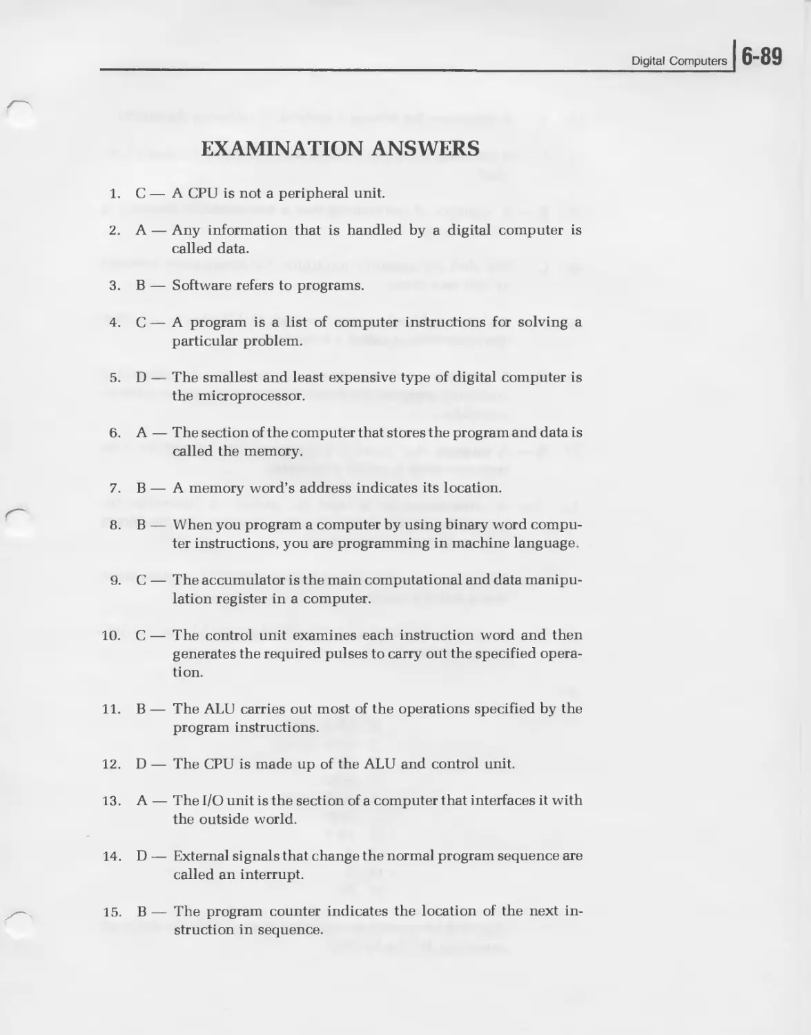
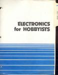
“IC’s,” which made them more powerful and greatly reduced their size
and cost. Over the years, digital computers have continued to decrease in
price. Their size and power consumption have also decreased signifi-
cantly. At the same time, their performance and sophistication have
increased, making them practical for a wider range of applications.
Recent technological advances in semiconductor techniques have
created a unique digital product. Large scale integration of digital cir-
cuits have permitted the semiconductor manufacturers to put an entire
digital computer on a single chip of silicon. These computers are known
as microprocessors. We normally think of digital integrated circuits as
being the gates and flip-flops used to implement a computer. Now, the
computer itself is a single, low-cost integrated circuit. But the power of
this device is significant, and for many applications it can replace hun-
dreds of small scale and medium scale integrated circuits. This signific-
ant development will further broaden the applications for digital com-
puters. Best of all, it will increase the sophistication and capabilities of
the electronic equipment that uses them.
While it is impossible to cover all aspects of this exciting field in this unit,
it will introduce you to the digital computer and its related techniques.
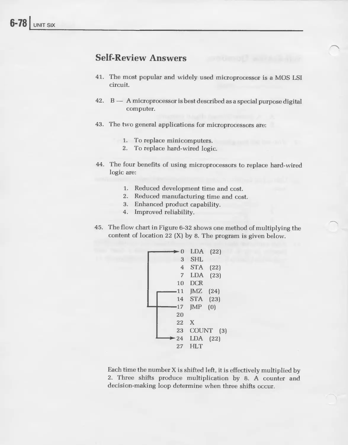
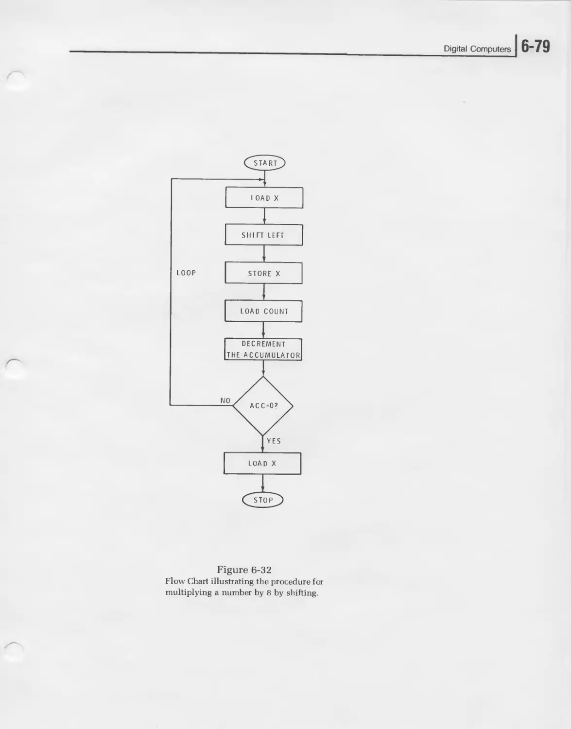
The primary emphasis will be on the microprocessor and its ability to
replace standard hard-wired digital logic systems.
The “Unit Objectives” are listed next. They state exactly what you are
expected to learn in this unit. Review this list now and refer to it as you
are completing this unit to be sure you meet each objective. The “Unit
Activity Guide” follows. Be sure to complete each item.
6“4 I UNIT SIX
UNIT OBJECTIVES
When you have completed this unit you will be able to:
1. Define digital computer, data, instructions, program, software, and
peripheral unit.
2. Name the four types of small computers.
3. List the four major sections of a digital computer and define each.
4. Define computer instruction, address, central processing unit, ac-
cumulator, and interrupt.
5. List the seven steps of computer programming.
6. Define machine language programming, algorithm, flow chart,
coding, and loop.
7. Analyze a simple program, when given the computer instruction
set.
8. Define subroutine, assembler, compiler, cross-assembler, cross-
compiler, and utility program.
9. State the primary use and applications of the microprocessor.
10. List the benefits of using a microprocessor over a hard-wired logic
system.
11. Write a simple microprocessor program when given the problem
and computer instruction set.
Digital Computers
UNIT ACTIVITY GUIDE
Completion
Time
I | Read “What is a Digital Computer?”
| | Answer Self-Review Questions 1-7.
I | Read “Digital Computer Organization and Opera-
tion.” _________
I | Answer Self-Review Questions 8-20.
I | Read “Computer Programming.”
I | Answer Self-Review Questions 21-34.
I | Read “Software.”
I | Answer Self-Review Questions 35-40
I | Read “Microprocessors.”
I | Answer Self-Review Questions 41-45
I | Complete the “Unit Examination.”
I | Check the “Examination Answers.”
6-61 UNIT SIX
WHAT IS A DIGITAL COMPUTER?
A digital computer is an electronic machine that automatically processes
data by the use of digital techniques. Data refers to any information such
as numbers, letters, words, or even complete sentences and paragraphs.
Processing is a general term referring to a variety of ways in which the
data can be manipulated. The computer processes the data by performing
arithmetic operations on it, editing and sorting it, or evaluating its
characteristics and making decisions based upon it. In addition to being
able to manipulate data in a variety of ways, the computer contains an
extensive memory where data is stored. The key characteristic of a digital
computer is its ability to process data automatically without operator
intervention.
The manner in which the data is manipulated is determined by a set of
instructions, or “instruction set,” contained within the machine. These
instructions form a program that tells the computer exactly how to
handle the data. The instructions are executed sequentially to carry out
the desired manipulations. Most computers are general purpose, in that
the instructions can be assembled into an almost infinite variety of
application programs.
Each computer has a specific instruction set. These instructions are put
into the proper sequence so they will perform the required calculation or
operation. The process of writing the desired sequence of instructions is
called programming.
How Computers are Classified
There are many different types of digital computers and a variety of ways
in which they can be classified. One method of classifying computers is
by size and computing power. At one end of the spectrum are large-scale
computers with extensive memory and high-speed calculating
capabilities. These machines can process huge volumes of data in a short
period of time and in any desired manner. At the other end of the
spectrum are the small-scale, low-cost digital computers, such as the
microprocessor — whose application and computing power is more lim-
ited.
Digital Computers
Computers are also classified by function or application. The most com-
monly known digital computer is the electronic data processor that is
used by most business industry, and government organizations to main-
tain records, perform accounting functions, maintain an inventory, and
provide a wide variety of other data processing functions. Then there are
the scientific and engineering computers that are used primarily as
mathematical problem solvers. They greatly speed up and simplify the
calculations of complex and difficult scientific and engineering prob-
lems.
Another way to classify digital computers is general purpose or special
purpose. General purpose machines are designed to be as flexible as
possible. This means that they can be programmed for virtually any
application. Special purpose computers, on the other hand, are generally
dedicated to a specific application. They are designed to carry out only a
single function. General purpose computers with a fixed program be-
come special purpose computers.
Most digital computers are of the general purpose type, and most have
versatile instruction sets so they can be programmed to perform almost
any operation. With the proper program, a general purpose computer can
perform business data processing functions, scientific and mathematical
calculations, or industrial control functions.
The most widely used computers are the small-scale machines. These
include the minicomputer, the microcomputer, the programmable cal-
culator, and the microprocessor. While all of these small-scale machines
together account for less than 10% of the total computer dollar invest-
ment, they represent more than 95% of the unit volume of computers.
Small-scale computer systems are very low priced. Today, you can
purchase a complete computer system for less than the price of a new
automobile. Microprocessors and programmable calculators are even
less expensive. There are many thousands of small computers in use
today. Your own personal contact with a digital computer will no doubt
be through some type of small-scale computer.
”8 UNIT SIX
MINICOMPUTERS
The minicomputer is the largest of the four types of small computers.
This is a general purpose digital computer, usually constructed of bipolar
logic circuits, and supported with software and peripheral units.
Software refers to the programs supplied with the computer that make it
easy to use. Peripheral units are the input-output devices that allow an
operator to communicate with the computer. Typical peripheral units are
typewriters, card readers and printers. Minicomputers are similar to the
larger digital computers, but their memory capacity, speed, and applica-
tions are more limited.
You can purchase a complete but minimum minicomputer for less than
$1,000. This does not include peripheral equipment. However, such
machines are often purchased to be built into a larger piece of equipment
or a system for use as a controller. The users of such computers are
referred to as original equipment manufacturers (OEM). A complete
stand-alone minicomputer with sufficient memory, peripheral devices,
and software to be used for general purpose computing may cost less than
$5,000.
MICROCOMPUTERS
A microcomputer is similar in many respects to a minicomputer in that it
is a general purpose machine that can be programmed to perform a wide
variety of functions. However, the microcomputer is normally smaller
and more restricted in its application. Its speed and memory capacity is
less than a minicomputer. As a result, microcomputers are substantially
less expensive than minicomputers. Microcomputers are more often used
in dedicated, single function applications. Software and peripheral sup-
port is minimum. Most microcomputers are implemented with MOS LSI
circuitry.
PROGRAMMABLE CALCULATOR
A programmable calculator can be classified as a special purpose mi-
crocomputer. These machines are similar in many respects to hand-held
and desk-top electronic calculators. The programmable calculator has an
input keyboard for entering data and a decimal display for reading out the
results of calculations.
Digital Computers
In a standard calculator, an operator enters the numbers to be manipu-
lated and the functions to be performed by depressing keys on the
keyboard in the proper sequence. The solution to the problems then
appear on the display. A programmable calculator can also be used in this
way, but it contains a memory and control unit that is used to automate
the problem solving process. The data to be operated upon and the
functions to be performed are entered via the keyboard and stored in the
memory in the proper sequence. When it is enabled, the programmable
calculator will then automatically solve the problem stored in its memory
without operator control.
Programmable calculators offer the advantage of improved speed and
convenience over standard calculators when the same problem must be
computed several times with different data. Long problems requiring
complex data and many mathematical operations are also best solved by a
programmable calculator, as they relieve the operator from the tedious
work and greatly minimize errors. Another advantage of the programma-
ble calculator over other types of digital computers is its ability to com-
municate directly with the operator through the keyboard and decimal
readout display.
MICROPROCESSORS
A microprocessor is the smallest and least expensive type of digital
computer that still retains all of the basic features and characteristics of a
computer. It can be implemented with standard digital integrated cir-
cuits or it is available as a single large scale integrated (LSI) circuit. While
the capabilities of a microprocessor are limited when compared with a
microcomputer or minicomputer, this device is still a very powerful unit.
It extends the applications of computer techniques to many areas where
minicomputers and microcomputers are not economically feasible.
6-101 UNIT SIX
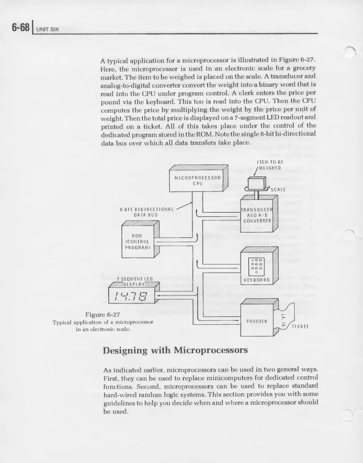
Microprocessors are generally designed to perform a dedicated function.
These devices are built into electronic equipment that will be used for
some specific application. Some typical dedicated applications include
traffic light controllers, electronic scales and cash registers, and elec-
tronic games. In addition, engineers are finding that low cost microp-
rocessors can be used to replace standard hard-wired digital logic. Design
time and cost can be significantly reduced in the design of a digital
system when microprocessors are used.
A microprocessor can be used economically if the design is equivalent to
thirty or more standard integrated circuit packages. Such hard wired
logic designs are replaced by a microprocessor with a stored program.
The program stored in a read only memory permits the microprocessor to
carry out the same functions as a hard-wired logic controller. Micro-
processors can also be used as the main component of a minicomputer or
microcomputer.
Digital Computers
6-11
Self Review Questions
1. What is a digital computer? ______________________________
2. What is data? ____________________________________________
3. The way the computer manipulates data is determined by a set of
4. A list of computer instructions for solving a particular problem is
called a____________________________
5. What is software? ________________________________________
6. List several types of computer peripheral units.
7. Name the four types of small computers.
6-121 UNIT SIX
Self-Review Answers
1. A digital computer is an electronic machine that uses digital
techniques to automatically process data.
2. Data is any information such as numbers, letters, words, or even
complete sentences and paragraphs.
3. The way the computer manipulates data is determined by a set of
instructions.
4. A list of computer instructions for solving a particular problem is
called a program.
5. Software refers to the programs supplied with a computer.
6. Peripheral units are typewriters, card readers, printers, and other
input-output devices.
7. The four types of small computers are:
minicomputers
microcomputers
programmable calculators
microprocessors
Digital Computers
] 6-13
DIGITAL COMPUTER ORGANIZATION
AND OPERATION
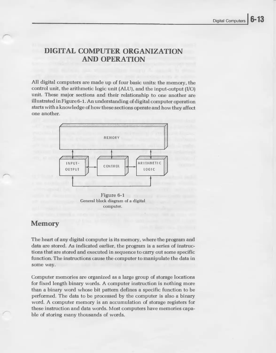
All digital computers are made up of four basic units: the memory, the
control unit, the arithmetic logic unit (ALU), and the input-output (I/O)
unit. These major sections and their relationship to one another are
illustrated in Figure 6-1. An understanding of digital computer operation
starts with a knowledge of how these sections operate and how they affect
one another.
Figure 6-1
General block diagram of a digital
computer.
Memory
The heart of any digital computer is its memory, where the program and
data are stored. As indicated earlier, the program is a series of instruc-
tions that are stored and executed in sequence to carry out some specific
function. The instructions cause the computer to manipulate the data in
some way.
Computer memories are organized as a large group of storage locations
for fixed length binary words. A computer instruction is nothing more
than a binary word whose bit pattern defines a specific function to be
performed. The data to be processed by the computer is also a binary
word. A computer memory is an accumulation of storage registers for
these instruction and data words. Most computers have memories capa-
ble of storing many thousands of words.
6-14 UNIT SIX
Digital computers typically have a fixed word size. A 32-bit word is
common for many large computers. Minicomputers usually have a 16-bit
word. Microprocessors widely use an 8-bit word. Memory sizes range
from approximately several hundred words to several hundred thousand
words of storage. A typical minicomputer may provide 4096 16-bit
words. A microprocessor may use 1024 words of 8-bit memory. The
number of words in memory is generally some power of two.
Each memory location appears to be like a storage register. Data can be
loaded into the register and retained. The word can also be read out of
memory for use in performing some operation.
Each memory word is given a numbered location called an address. The
address is a binary word used to locate a particular word in memory. The
normal procedure is to store the instruction words in sequential memory
locations. The instruction word generally contains an address which
refers to the location of some data word to be used in carrying out the
operation specified. The instructions stored in the sequential memory
locations are executed one at a time until the desired function is per-
formed.
Most modern digital computers use semiconductor memory, MOS LSI
circuits where data is stored in latch flip-flops or as the charge on a
capacitor. Semiconductor memories are small, fast, and inexpensive.
Many computers, however, still use magnetic core memories. In these
memories, binary data is stored in tiny donut-shaped magnetic cores. By
magnetizing the core in one direction a binary zero is stored. Magnetizing
the core in the opposite direction causes it to store a binary one. Elec-
tronic circuitry associated with the cores is used to store data into the
memory and read it out.
The advantage of core memories over semiconductor memories is their
non-volatility. When power is removed from a semiconductor memory,
all of the data is lost. Removing the power from a magnetic core memory
has no effect on the data contents. Because the cores are permanently
magnetized in one direction or the other, all data is retained.
Digital Computers
] 6-15
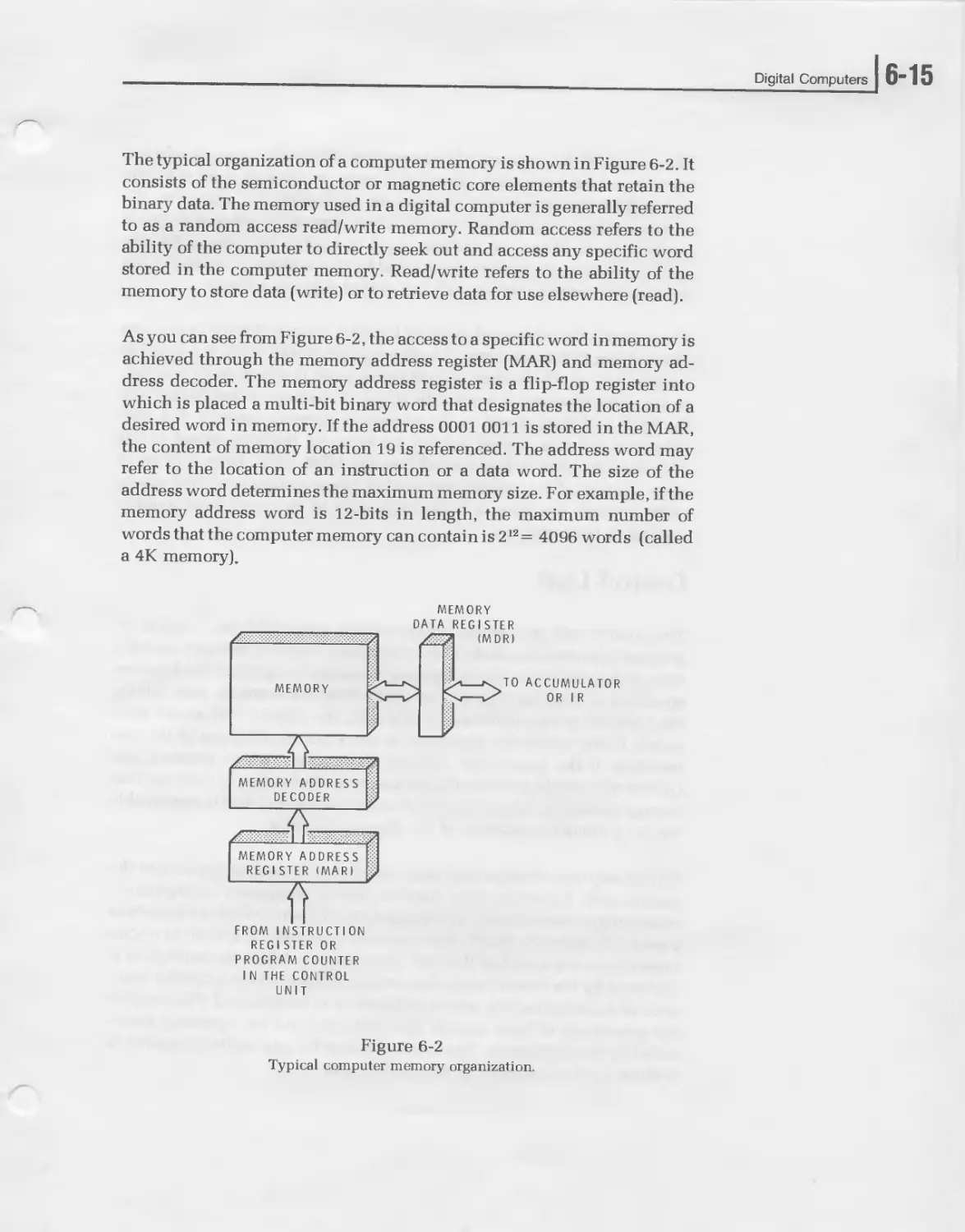
The typical organization of a computer memory is shown in Figure 6-2. It
consists of the semiconductor or magnetic core elements that retain the
binary data. The memory used in a digital computer is generally referred
to as a random access read/write memory. Random access refers to the
ability of the computer to directly seek out and access any specific word
stored in the computer memory. Read/write refers to the ability of the
memory to store data (write) or to retrieve data for use elsewhere (read).
As you can see from Figure 6-2, the access to a specific word in memory is
achieved through the memory address register (MAR) and memory ad-
dress decoder. The memory address register is a flip-flop register into
which is placed a multi-bit binary word that designates the location of a
desired word in memory. If the address 0001 0011 is stored in the MAR,
the content of memory location 19 is referenced. The address word may
refer to the location of an instruction or a data word. The size of the
address word determines the maximum memory size. For example, if the
memory address word is 12-bits in length, the maximum number of
words that the computer memory can contain is 212 = 4096 words (called
a 4K memory).
MEMORY
DATA REGISTER
FROM INSTRUCTION
REGISTER OR
PROGRAM COUNTER
I N THE CONTROL
UNIT
Figure 6-2
Typical computer memory organization.
6-161 UNIT SIX
The output of the memory address register drives the memory address
decoder, which recognizes one unique memory address word at a time
and enables the appropriate location. In semiconductor memories, the
memory address decoder is generally a fixed part of the integrated circuit
memory itself. When an address word is loaded into the MAR, the
specific location in memory designated by that address is enabled. Data
can then be written into or read out of that memory location.
The access to the addressed memory location is made through a memory
data register (MDR) or memory buffer register (MBR). This is a flip-flop
register into which the data or instruction word is stored on its way into
or out of the memory. A word to be stored in memory is first loaded into
the MDR and then stored in the addressed memory location. If a read
operation is being carried out by the memory, the data stored in the
addressed location is first loaded into the MDR. From there it is set to
other portions of the computer as needed. Many computers do not use an
MDR. Instead, the data or instruction goes to or comes from another
register in the computer.
Control Unit
The control unit in a digital computer is a sequential logic circuit. Its
purpose is to examine each of the instruction words in memory, one at a
time, and generate the control pulses necessary to carry out the function
specified by that instruction. The instruction, for example, may call for
the addition of two numbers. In this case, the control unit would send
pulses to the arithmetic logic unit to carry out the addition of the two
numbers. If the instruction calls for the storage data in memory, the
control unit would generate the necessary control pulses to carry out that
storage operation. As you can see, it is the control unit that is responsible
for the automatic operation of the digital computer.
Almost any type of sequential logic circuit can be used to implement the
control unit. However, most modern digital computers incorporate a
microprogrammed control unit using a preprogrammed circuit known as
a read only memory (ROM). Here, special binary words known as micro-
instructions are stored in the read only memory. When an instruction is
analyzed by the control unit, that instruction will cause a certain sequ-
ence of microinstruction words in the ROM to be executed. The result is
the generation of logic signals that will carry out the operation desig-
nated by the instruction. The instruction set for any digital computer is
defined by the operation of the control unit.
Digital Computers
J 6-17
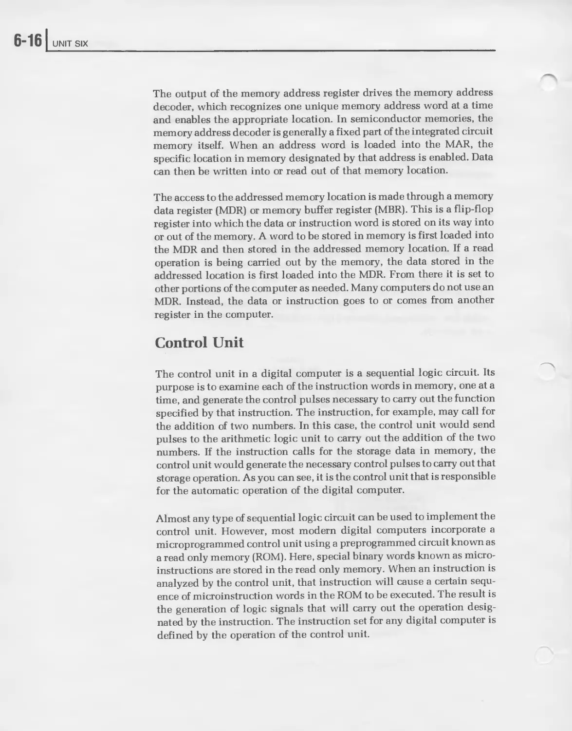
The exact logic circuitry used in the control unit varies widely from one
machine to another. However, the basic elements are shown in Figure
6-3. The control unit consists of an instruction register, a program
counter, an instruction decoder, a clock oscillator, and some type of
sequential logic circuit used for generating the control pulses.
FROM MDR
Figure 6-3
Typical control unit organization.
The instruction register is a multi-bit flip-flop register used for storing the
instruction word. When an instruction is taken from memory, it passes
through the MDR and then into the instruction register. From here, the
instruction is decoded by the instruction decoder. This logic circuitry
recognizes which instruction is to be performed. It then sends the ap-
propriate logic signals to the control pulse generator. Under the control of
the clock oscillator, the control pulse generator then produces the logic
signals that will enable the other circuitry in the machine to carry out the
specified instruction.
6-18 UNIT SIX
The program counter is simply a binary up counter that keeps track of the
sequence of instructions to be executed. The program consists of instruc-
tions that are stored in sequential memory locations. To begin a program,
the program counter is loaded with the starting address. The starting
address is the location of the first instruction in the program to be
executed. The first instruction is then read out of memory, interpreted,
and carried out. The control circuitry then increments the program
counter. The contents of the program counter is then fed to the memory
address register that then permits the next instruction in sequence to be
addressed. Each time an instruction is executed the program counter is
incremented so that the next instruction in sequence is fetched and
executed. This process continues until the program is complete.
In Figure 6-3, you will notice a connection between the instruction
register and the program counter. There are times when the instruction
itself will modify the contents of the program counter. Some instructions
specify a jump or branch operation that causes the program to deviate
from its normal sequential execution of instructions. The instruction
register will contain an address that will be loaded into the program
counter to determine the location to which the program jumps.
Arithmetic Logic Unit
The arithmetic logic unit (ALU) is that portion of the digital computer
that carries out most of the operations specified by the instructions. It
performs mathematical operations, logical operations, and decision-
making functions. Most arithmetic logic units can perform addition and
subtraction. Multiplication and division operations are generally prog-
rammed. The ALU can also perform logic operations such as inversion,
AND, OR, and exclusive OR. In addition, the ALU can make decisions. It
can compare numbers or test for specific quantities such as zero or
negative numbers.
The arithmetic logic unit and control unit are very closely related, so
much so that it is sometimes difficult to separate them. Because of this,
the ALU and control unit together are often referred to as the central
processing unit (CPU). Most microprocessors are single chip LSI CPUs.
Digital Computers
]б-19
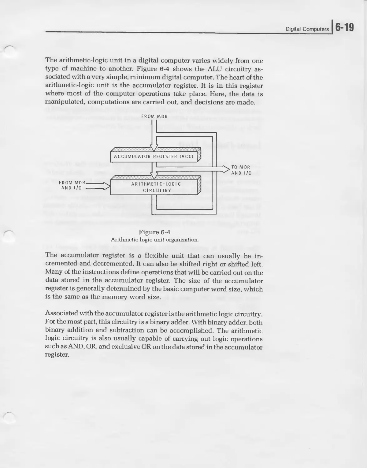
The arithmetic-logic unit in a digital computer varies widely from one
type of machine to another. Figure 6-4 shows the ALU circuitry as-
sociated with a very simple, minimum digital computer. The heart of the
arithmetic-logic unit is the accumulator register. It is in this register
where most of the computer operations take place. Here, the data is
manipulated, computations are carried out, and decisions are made.
FROM MDR
Figure 6-4
Arithmetic logic unit organization.
The accumulator register is a flexible unit that can usually be in-
cremented and decremented. It can also be shifted right or shifted left.
Many of the instructions define operations that will be carried out on the
data stored in the accumulator register. The size of the accumulator
register is generally determined by the basic computer word size, which
is the same as the memory word size.
Associated with the accumulator register is the arithmetic logic circuitry.
For the most part, this circuitry is a binary adder. With binary adder, both
binary addition and subtraction can be accomplished. The arithmetic
logic circuitry is also usually capable of carrying out logic operations
such as AND, OR, and exclusive OR on the data stored in the accumulator
register.
6-201 UNIT SIX
The arithmetic-logic circuitry is capable of adding two binary words. One
of the binary words is stored in the accumulator. The other binary word is
stored in the memory data register. The sum of these two numbers
appears at the output of the arithmetic-logic circuitry and is stored in the
accumulator register, replacing the number originally contained there.
Most of the other operations with the arithmetic logic circuitry are carried
out in this manner. The two words to be manipulated are initally stored in
the accumulator and the MDR, with the results of the operation appearing
back in the accumulator replacing the original contents.
Input-Output Unit
The input-output (I/O) unit of a computer is that section that interfaces
the computer circuitry with the outside world. The term “outside world”
refers to everything outside the computer. In order for the computer to
communicate with an operator or with peripheral equipment, some
means must be provided for entering data into the computer and reading
it out. Data and programs to be stored in the memory are usually entered
through the input-output unit. The solutions to calculations and control
output signals are usually passed to the external equipment through the
I/O unit.
The I/O unit is generally under the control of the CPU. Special I/O
instructions are used to transfer data into and out of the computer. More
sophisticated I/O units can recognize signals from extra peripheral de-
vices called interrupts that can change the operating sequence of the
program. Some I/O units permit direct communications between the
computer memory and an external peripheral device without interfer-
ence from the CPU. Such a function is called direct memory access
(DMA).
Digital Computers
] 6-21
The input/output section of a digital computer is the least clearly defined
of all digital computer sections; it can vary from practically no circuitry at
all to very complex logic circuitry approaching the magnitude of the
remainder of the computer itself. For our explanation of digital computer
operation here, we will assume the simplest form of input/output cir-
cuitry.
Data transfers between the computer and external peripheral devices take
place via the accumulator register. Data to be inputted and stored in
memory will be transferred a word at a time into the accumulator and
then into the memory through the MDR. Data to be outputted is first
transferred from the memory into the MDR, then into the accumulator,
and finally to the external peripheral device. These data transfers into
and out of the accumulator register take place under the control of the
CPU and are referred to as programmed I/O operations. Special in-
put/output instructions cause the proper sequence of operations to take
place.
Most digital computers can also perform I/O operations at the request of
an interrupt, a signal from an external device requesting service. The
external device may have data to transmit to the computer or may require
the computer to send it data. When an interrupt occurs, the computer
completes the execution of its current instruction, and then jumps to
another program in memory that services the interrupt. Once the inter-
rupt request has been handled, the computer resumes execution of the
main program. Data transfers occurring in the interrupt mode can also
take place through the accumulator.
6-221 UNIT SIX
Digital Computer Operation
Now that you are familiar with the basic architecture of a digital compu-
ter, you are ready to see how the various sections operate together to
execute a program. The units we described previously, when used to-
gether, actually form a simple hypothetical digital computer. In this
section, it is used to demonstrate how a computer operates. A program for
solving a problem is already stored in memory. The computer will exe-
cute each instruction until the problem is solved. The complete operation
is described and the contents of each register shown as the program is
carried out.
Assume that the problem to be solved is a simple mathematical operation
that tells us to add two numbers, subtract a third number, store the result,
print the answer, and then stop. The numbers that we will work with are
36, 19, and 22. The program calls for adding 36 and 19, subtracting 22,
and then storing and printing the answer.
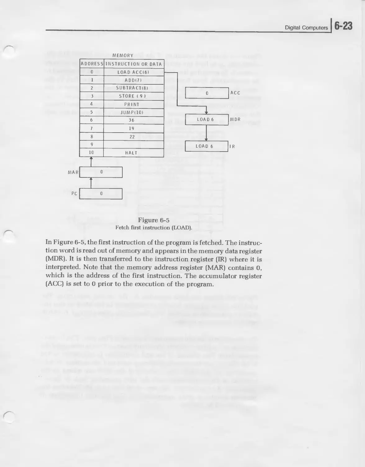
The solution to this simple problem as it is solved step-by-step by the
computer is illustrated in Figure 6-5. Here, we show a simplified block
diagram of the digital computer, emphasizing the memory and the major
registers. The program is stored in memory. The contents of each memory
location, either instruction or data, is shown adjacent to the memory
address. To solve this problem, the computer sequentially executes the
instructions. This is done in a two-step operation. First, the instruction is
fetched or read out of memory. Second, the instruction is executed. This
fetch-execute cycle is repeated until all of the instructions in the program
have been executed.
Digital Computers
Figure 6-5
Fetch first instruction (LOAD).
In Figure 6-5, the first instruction of the program is fetched. The instruc-
tion word is read out of memory and appears in the memory data register
(MDR). It is then transferred to the instruction register (IR) where it is
interpreted. Note that the memory address register (MAR) contains 0,
which is the address of the first instruction. The accumulator register
(ACC) is set to 0 prior to the execution of the program.
6-24 UNIT SIX
Figure 6-6 shows the execution of the first instruction, LOAD ACC (6),
which tells us to load the accumulator with the data stored in memory
location 6. In executing this instruction, the number 36 is transferred to
the accumulator. Note how this is done. The address specified by the
instruction word (6) is transferred from the instruction register to the
memory address register (MAR). This causes the number 36 stored in that
location to be transferred to the MDR and then to the accumulator. During
this step, the program counter (PC) is incremented by one so the next
instruction in sequence will be fetched.
MEMORY
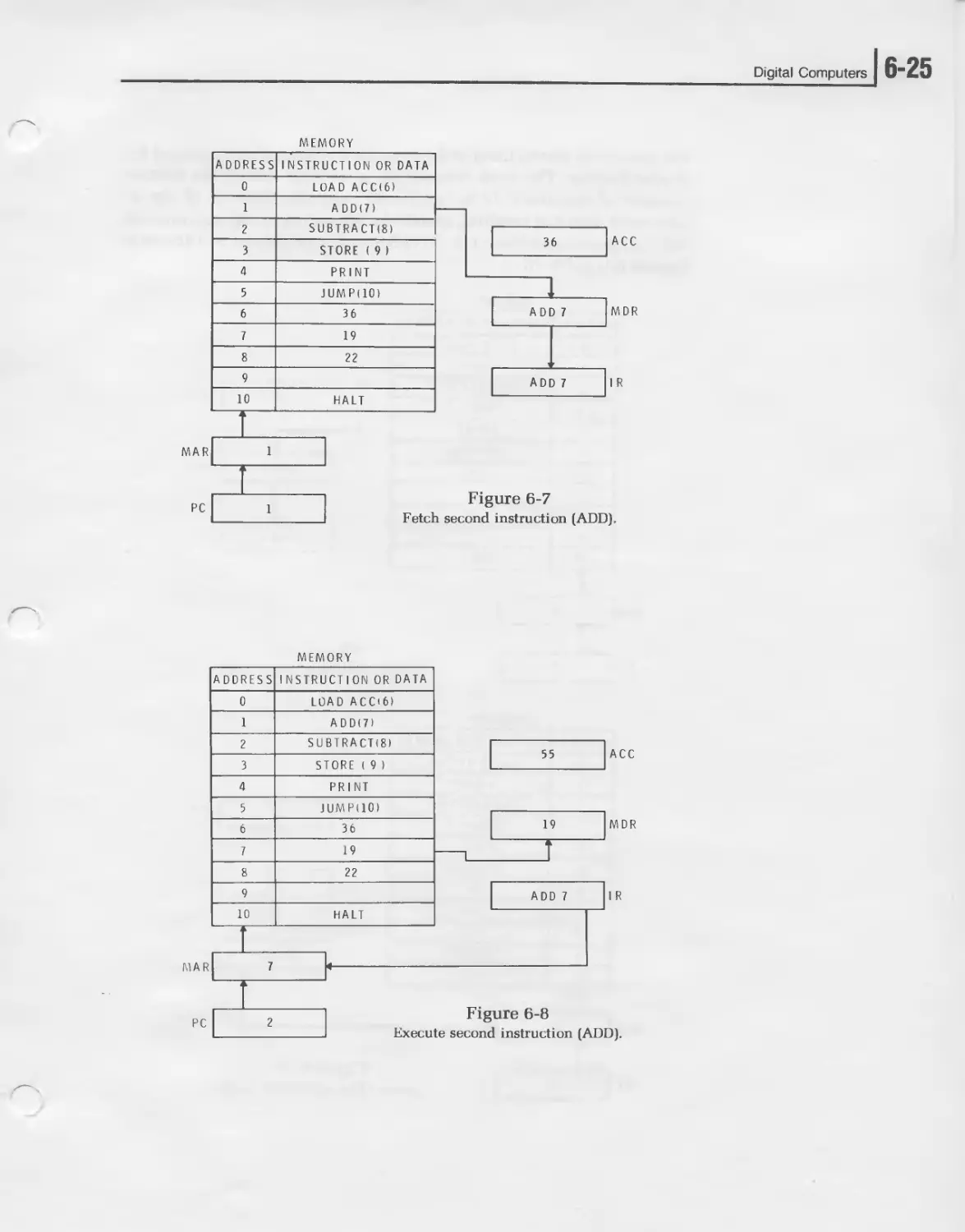
Figure 6-7 shows the fetch operation for the second instruction. The
contents of the program counter is transferred to the MAR so that the
ADD(7) instruction is fetched. This instruction passes though the MDR
into the instruction register.
The execution of the add instruction is shown in Figure 6-8. This instruc-
tion tells us to add the contents of memory location 7 to the contents of the
accumulator. The address of the add instruction is transferred to the
MAR. This causes the contents of memory location 7, the number 19, to be
transferred to the MDR. The contents of the MDR are added to the
contents of the accumulator with the sum appearing back in the ac-
cumulator. As you can see, the sum of 36 and 19 is 55. Note that the
program counter is again incremented so that the next instruction in
sequence will be fetched.
Digital Computers
] 6-25
Figure 6-7
Fetch second instruction (ADD).
6-261 UNIT SIX
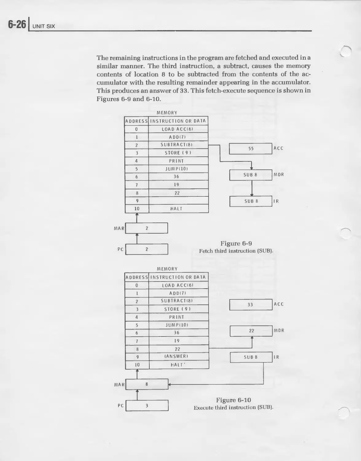
The remaining instructions in the program are fetched and executed in a
similar manner. The third instruction, a subtract, causes the memory
contents of location 8 to be subtracted from the contents of the ac-
cumulator with the resulting remainder appearing in the accumulator.
This produces an answer of 33. This fetch-execute sequence is shown in
Figures 6-9 and 6-10.
MEMORY
MEMORY
Digital Computers
] 6-27
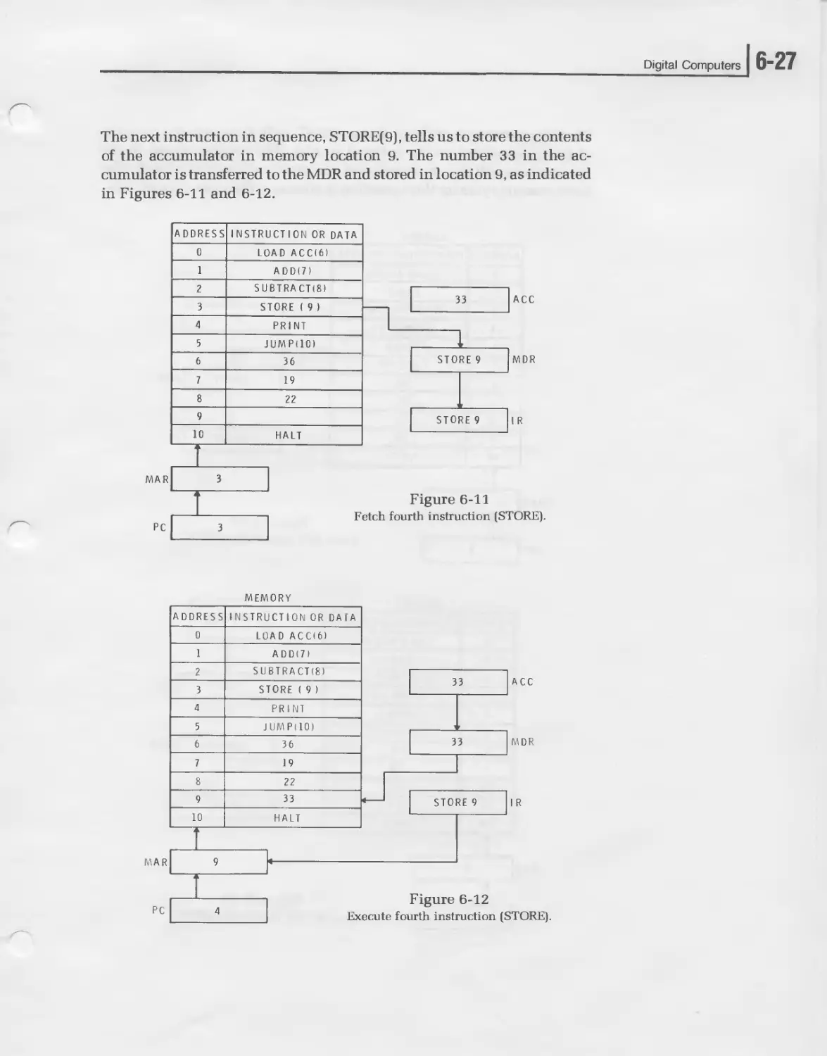
The next instruction in sequence, STORE(9), tells us to store the contents
of the accumulator in memory location 9. The number 33 in the ac-
cumulator is transferred to the MDR and stored in location 9, as indicated
in Figures 6-11 and 6-12.
MAR
PC
MEMORY
6"28 I UNIT SIX
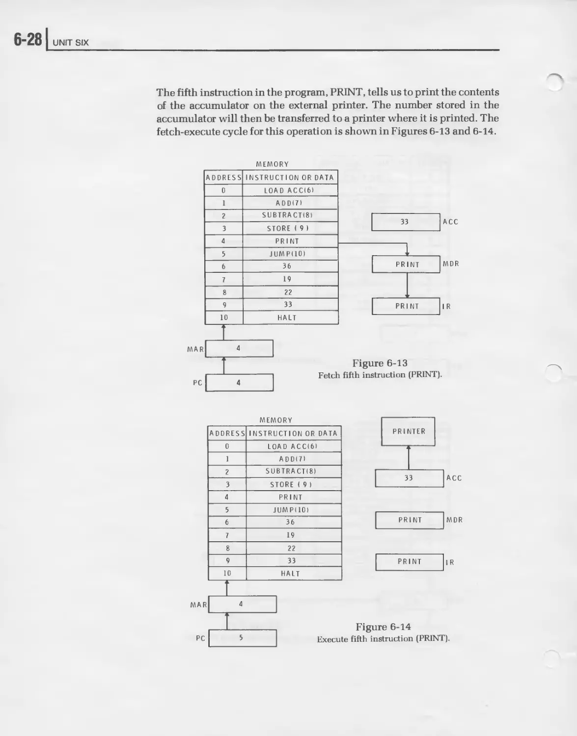
The fifth instruction in the program, PRINT, tells us to print the contents
of the accumulator on the external printer. The number stored in the
accumulator will then be transferred to a printer where it is printed. The
fetch-execute cycle for this operation is shown in Figures 6-13 and 6-14.
MEMORY
ADDRESS INSTRUCTION OR DATA
0 LOAD ACCI6I
1 ADDI7I
2 SUBTRACTS)
3 STORE ( 9 I
4 PRINT
5 JUMP(IO)
6 36
7 19
8 22
9 33
10 HALT
ACC
MEMORY
ADDRESS INSTRUCTION OR DATA
0 LOAD ACCI6I
1 ADDI7I
2 SUBTRACTS)
3 STORE ( 9)
4 PRINT
5 JUMP(IO)
6 36
7 19
8 22
9 33
10 HALT
Figure 6-13
Fetch fifth instruction (PRINT).
Figure 6-14
Execute fifth instruction (PRINT).
Digital Computers
]б-29
The sixth instruction in sequence is a JUMP(IO) instruction that causes
the normal sequence of program executions to change. The jump instruc-
tion tells us not to execute the contents of the next memory location in
sequence. Instead, it tells us to take the next instruction from memory
location 10. You can see by referring to Figure 6-15 that the contents of
the next memory location in sequence (address 6) contains a data word.
MEMORY
Figure 6-15
Fetch sixth instruction (JUMP).
6-301 UNIT SIX
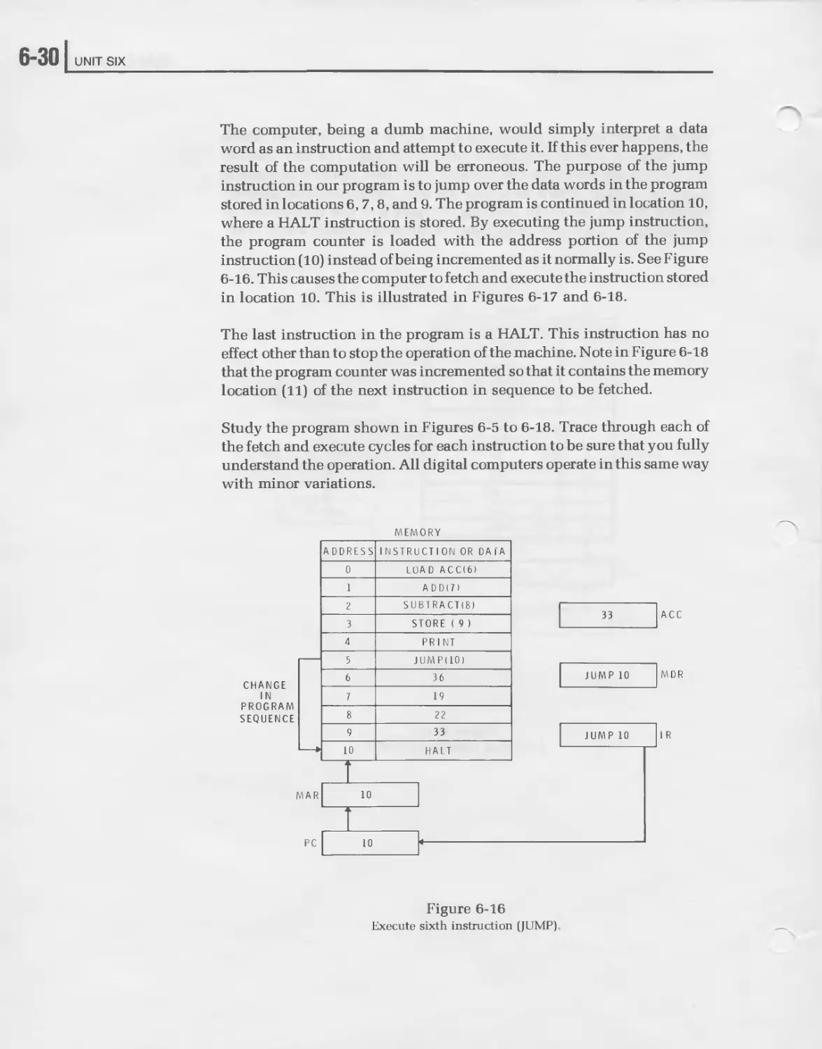
The computer, being a dumb machine, would simply interpret a data
word as an instruction and attempt to execute it. If this ever happens, the
result of the computation will be erroneous. The purpose of the jump
instruction in our program is to jump over the data words in the program
stored in locations 6,7,8, and 9. The program is continued in location 10,
where a HALT instruction is stored. By executing the jump instruction,
the program counter is loaded with the address portion of the jump
instruction (10) instead of being incremented as it normally is. See Figure
6-16. This causes the computer to fetch and execute the instruction stored
in location 10. This is illustrated in Figures 6-17 and 6-18.
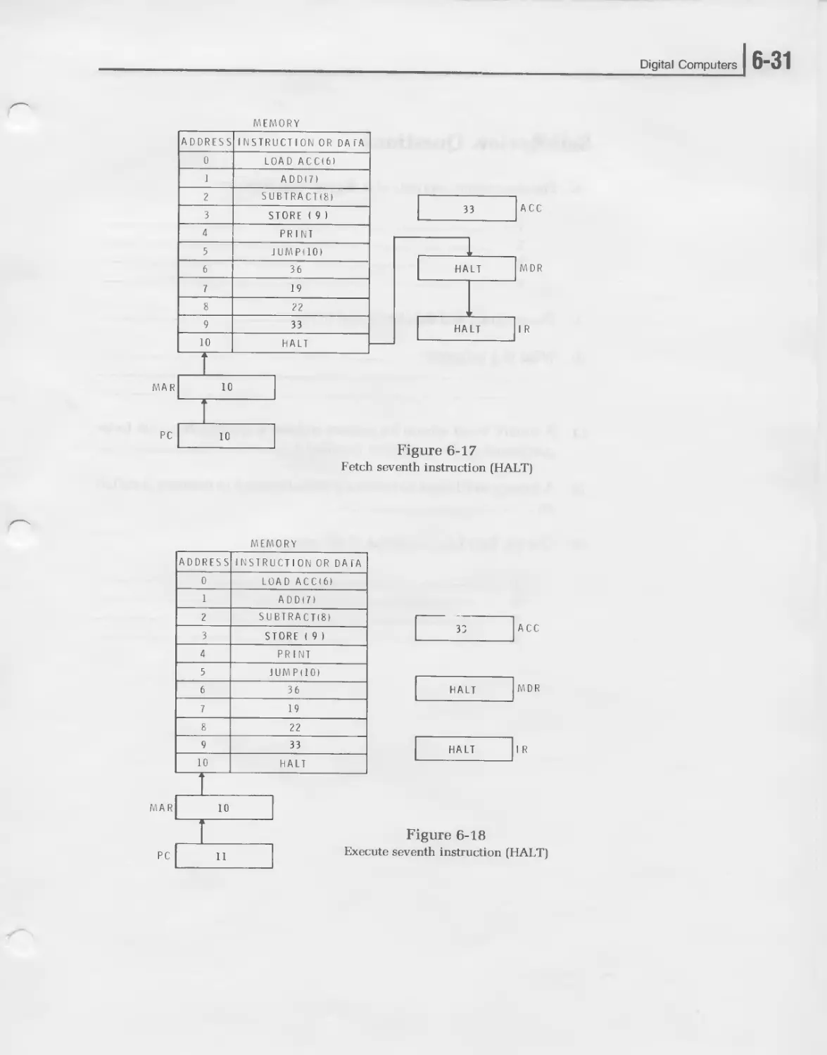
The last instruction in the program is a HALT. This instruction has no
effect other than to stop the operation of the machine. Note in Figure 6-18
that the program counter was incremented so that it contains the memory
location (11) of the next instruction in sequence to be fetched.
Study the program shown in Figures 6-5 to 6-18. Trace through each of
the fetch and execute cycles for each instruction to be sure that you fully
understand the operation. All digital computers operate in this same way
with minor variations.
MEMORY
CHANGE
IN
PROGRAM
SEQUENCE
Figure 6-16
Execute sixth instruction (JUMP)
Digital Computers
] 6-31
Fetch seventh instruction (HALT)
MEMORY
ADDRESS INSTRUCTION OR DAlA
0 LOAD ACCI6)
1 ADDI7)
2 SUBTRACTS)
3 STORE ( 9 I
4 PRINT
5 J UM P (10>
6 36
7 19
8 22
9 33
10 HALT
MAR 10
Figure 6-18
p c > > Execute seventh instruction (HALT)
6-321 UNIT SIX
Self-Review Questions
8. The four major sections of a digital computer are:
1.
2. _________________________________________________-—
3.
4.
9. The program and data are stored in the-----------------------
10. What is a program?-------------------------------------------
11. A binary word whose bit pattern defines a specific function to be
performed by the computer is called a----------------------------
12. A binary word used to locate a particular word in memory is called
an-------------------------------
13. List the four basic sections of the memory.
1.
2. _____________________________________________________
3. ___________________________________________________—
4. ___________________________________________________
Digital Computers
16-33
14. What is the control unit of a computer and what is its purpose?
15. What is the arithmetic logic unit?
16. The main computational and data manipulation register in a compu-
ter is the______________________________
17. The arithmetic logic unit and control unit combined are referred to
as the_____________________________________
18. What is the input-output unit of a computer?
19. What is an interrupt? _____________________________________________
20. In carrying out a program, the computer repeats a series of
and operations on the instructions in
memory.
6-341 UNIT SIX
Self-Review Answers
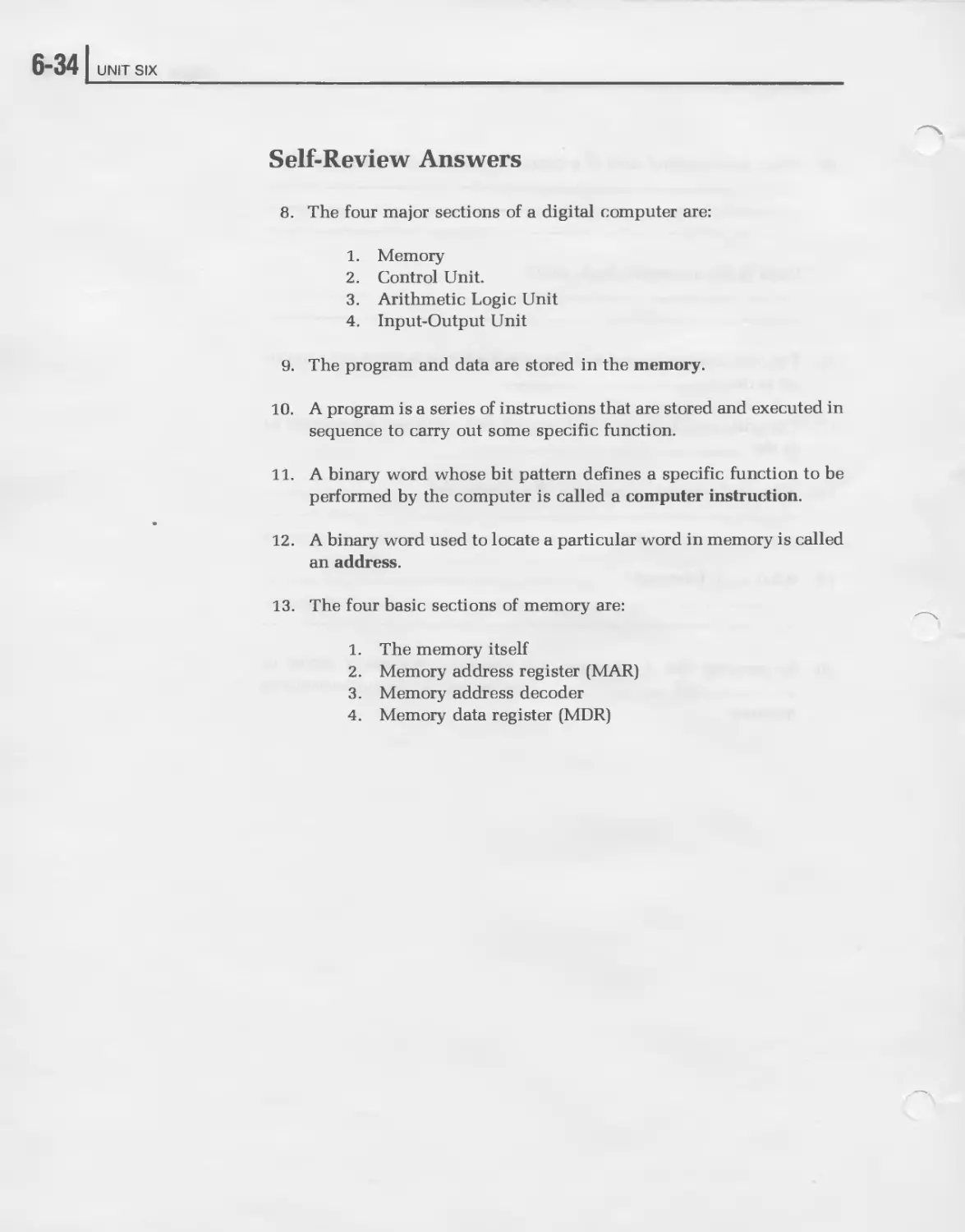
8. The four major sections of a digital computer are:
1. Memory
2. Control Unit.
3. Arithmetic Logic Unit
4. Input-Output Unit
9. The program and data are stored in the memory.
10. A program is a series of instructions that are stored and executed in
sequence to carry out some specific function.
11. A binary word whose bit pattern defines a specific function to be
performed by the computer is called a computer instruction.
12. A binary word used to locate a particular word in memory is called
an address.
13. The four basic sections of memory are:
1.
2.
3.
4.
The memory itself
Memory address register (MAR)
Memory address decoder
Memory data register (MDR)
Digital Computers
]б-35
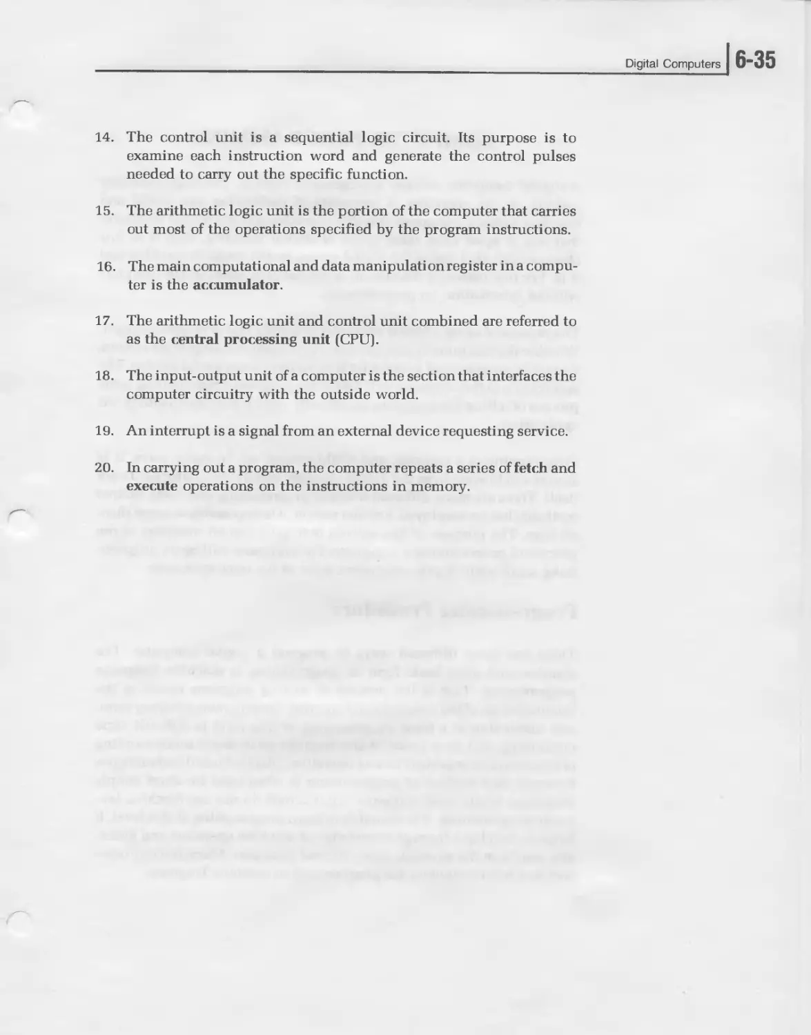
14. The control unit is a sequential logic circuit. Its purpose is to
examine each instruction word and generate the control pulses
needed to carry out the specific function.
15. The arithmetic logic unit is the portion of the computer that carries
out most of the operations specified by the program instructions.
16. The main computational and data manipulation register in a compu-
ter is the accumulator.
17. The arithmetic logic unit and control unit combined are referred to
as the central processing unit (CPU).
18. The input-output unit of a computer is the section that interfaces the
computer circuitry with the outside world.
19. An interrupt is a signal from an external device requesting service.
20. In carrying out a program, the computer repeats a series of fetch and
execute operations on the instructions in memory.
6-361 UNIT SIX
COMPUTER PROGRAMMING
A digital computer without a program is useless. The logic circuitry
making up the computer is incapable of performing any useful end
function without a program. It is this characteristic of a digital computer
that sets it apart form other types of digital circuitry. And it is this
characteristic that makes the digital computer the versatile machine that
it is. For this reason, a discussion of digital computers is not complete
without information on programming.
The process of using a digital computer is mainly that of programming it.
Whether the computer is a simple microprocessor or a large scale system,
it must be programmed in order for it to perform some useful service. The
application of the computer will define the program. Programming is the
process of telling the computer specifically what it must do to satisfy our
application.
Programming is a complex and sophisticated art. In many ways, it is
almost a field apart from the digital circuitry and the computer hardware
itself. There are many different levels of programming and many unique
methods that are employed. For that reason, it is impossible to cover them
all here. The purpose of this section is to give you an overview of the
process of programming a computer. The emphasis will be on program-
ming small scale digital computers such as the microprocessor.
Programming Procedure
There are many different ways to program a digital computer. The
simplest and most basic form of programming is machine language
programming. This is the process of writing programs by using the
instruction set of the computer and entering the programs in binary form,
one instruction at a time. Programming at this level is difficult, time
consuming, and error prone. It also requires an in-depth understanding
of the computer organization and operation. Dispite these disadvantages,
however, this method of programming is often used for short simple
programs. While most computer applications do not use machine lan-
guage programming, it is desirable to learn programming at this level. It
helps to develop a through knowledge of machine operation and gener-
ally results in the shortest, most efficient programs. Many microproces-
sors and minicomputers are programmed in machine language.
Digital Computers
j 6-37
To illustrate the concepts of programming in this unit, we will use
machine language programming. Other more sophisticated methods of
programming will be discussed later.
Programming a digital computer is basically a seven step process. These
seven steps are: (1) define the problem; (2) develop a workable solution;
(3) flow chart the problem; (4) code the program; (5) enter the program
into the computer; (6) debug the program; (7) run the program. We will
discuss each of these steps in detail.
The first and perhaps the most important step in programming a digital
computer is defining the problem to be solved. The success of the pro-
gram is directly related to how well you define the operation to be
performed. There is no set standard for the problem defining procedure,
and you can use any suitable method. The definition can be a written
statement of the function to be carried out, or it may take the form of a
mathematical equation. In some cases, the problem may be more easily
defined by graphical means. For control applications, the problem may
be expressed with a truth table. The form in which you place the defini-
tion is strictly a function of the application.
Once the problem is analyzed and defined, you canbegin thinking of how
the computer may solve the problem. Remember that a computer prog-
ram is a step-by-step sequence of instructions that will lead to the correct
results. You should think in terms of solving your problem in some
step-by-step sequential manner. What you will be doing in this phase of
the programming procedure is developing a algorithm. An algorithm is a
method or procedure for solving a problem.
An important point to remember is that there is usually more than one
way to solve a given problem. In other words, there is more than one
algorithm suitable for achieving the goal that you have set. Much of the
job of programming is in determining the alternatives and weighing them
to select the best suitable approach. The simplest and most direct al-
gorithms are usually the best.
6-381 UNIT SIX
Figure 6-19
Basic flowcharting symbols.
The next step is to flowchart the problem. A flow chart is a graphical
description of the problem solution. Various symbols are used to desig-
nate key steps in the solution of the problem. Figure 6-19 shows the basic
flowcharting symbols. An oval defines the starting and finishing points.
A rectangular box defines each individual computational step leading to
the solution. Each rectangle contains some basic operation or calculation
that is to take place. The diamond shaped symbol represents a decision
point. It is often necessary to observe the intermediate results in a prob-
lem solution and make a decision regarding the next step to be taken.
There are generally two exits to the diamond-shaped, decision-making
symbol. These represent a yes or no type of decision.
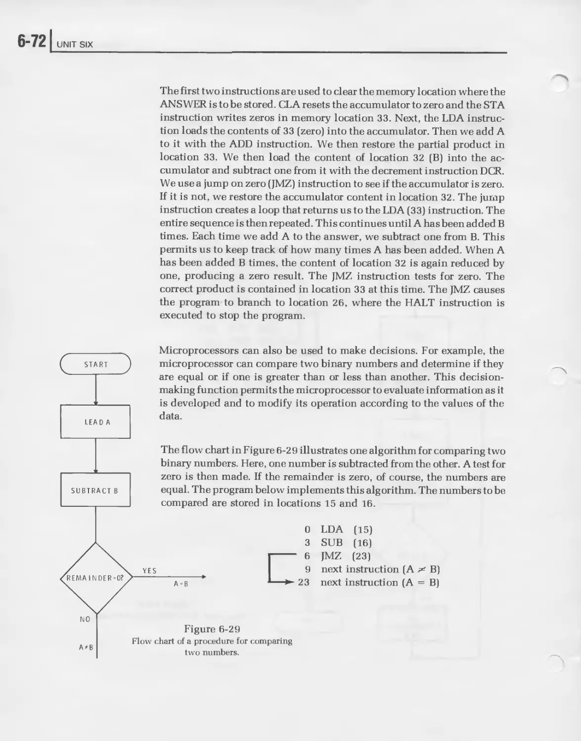
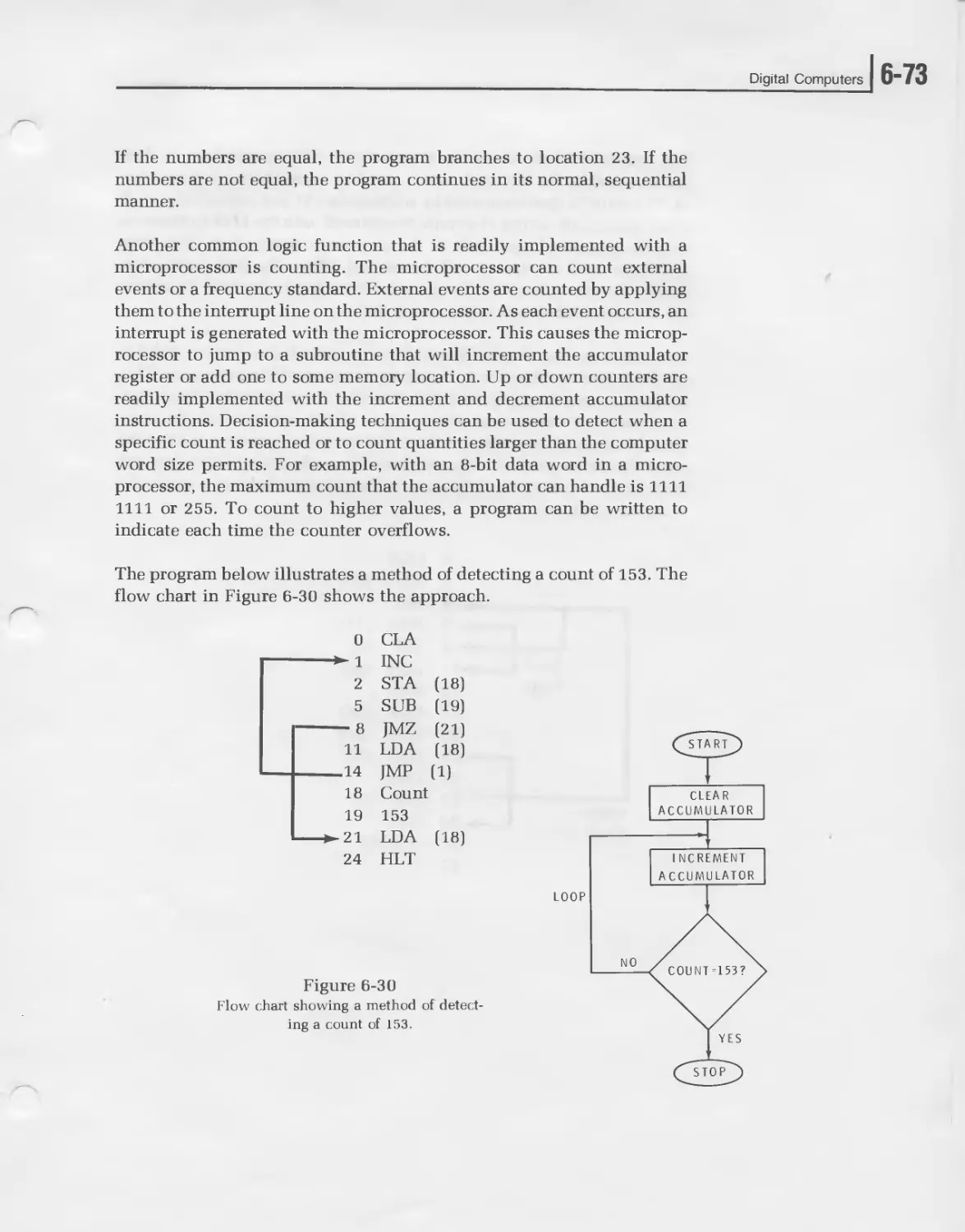
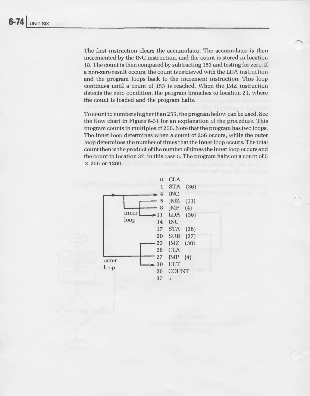
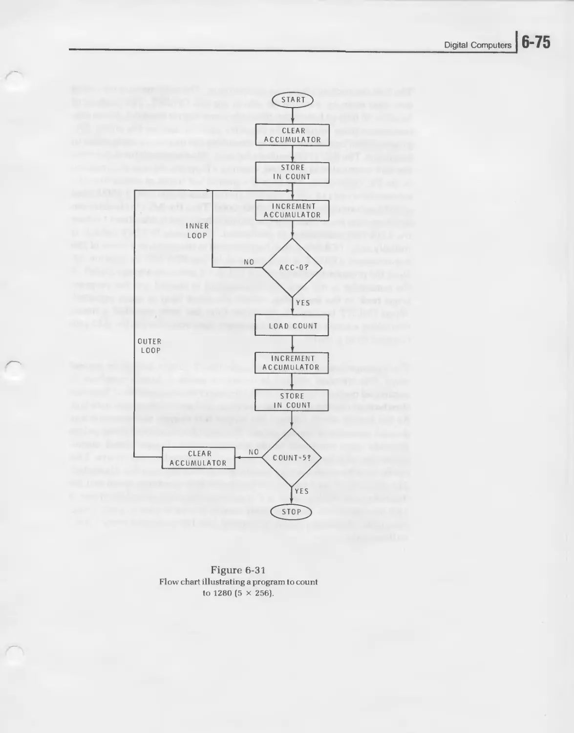
Figure 6-20 shows a simple flow chart for the problem solved earlier. No
decision was made in this program.
As you can see, the flow chart is a graphical representation of the basic
method used to solve the problem. The flow chart permits you to vis-
ualize the algorithm you developed. In many cases, the flowcharting of a
problem helps to determine the best approach to solve a problem since it
forces you to think in a logical sequence and express the solution in a
step-by-step form.
At this point in the programming procedure, your problem is quite well
defined and a basic method of solving the problem has been determined.
You are now ready to convert your flow chart and algorithm into a
machine language program. This process is called coding. Coding is the
procedure of listing the specific computer instruction sequentially to
carry out the algorithm defined by the flow chart. This requires a familiar-
ity with the instruction set of the computer you plan to use.
The next step in the programming procedure is to load the program into
the computer memory. Once you have written the program with the
computer instructions, you have all of the information necessary to enter
that program into the computer memory. If you are dealing with machine
language programming, you will convert the instruction words into their
binary equivalents and then load them into the computer. If the program
is a simple one, it can be loaded by using the binary switches on the front
panel of the computer. However, for long, complex programs, this man-
ual loading procedure is difficult and time consuming.
Figure 6-20
Flow chart for the problem 36 + 19 = 33
and print.
Digital Computers
] 6-39
Most computers make it easy for the programmer to enter his program.
Because of the availability and use of support programs residing within
the machine, the program can usually be entered automatically. One of
the most common ways of entering data into a comupter is with a
keypunch machine. This is a typewriter-like machine that punches a
standard computer card with the instructions to be entered. Teletype
input/output machines using perforated paper tape are also commonly
used for program entry. The instruction designations are typed on the
machine and as they are typed, a paper tape is punched.
Once the cards or paper tape are punched, they are then fed into a tape
reader or card reader and loaded into the computer memory. A special
program residing within the computer memory, called a loader, causes
the program to be loaded automatically.
With the program now in the computer memory, you can begin to run it.
However, before you use it to obtain your final answer, it is often neces-
sary to run through the program slowly a step at a time to look for
programming errors and other problems. This process is called debug-
ging. Y ou test the program to see that it produces the desired results. If the
program produces the correct result, it is ready to use. Often, program-
ming mistakes are encountered and it is necessary to modify the program
by changing the instruction steps. Often the entire program may be
discarded and a new one written, using a different algorithm.
Once the program has been debugged, it is ready for use. With the
program stored in memory, your problem can be solved. The computer is
started and the desired results are produced.
6-401 UNIT SIX
Writing Programs
Before you can begin coding programs, you must be familiar with the
instruction set of the computer you are using. Most digital computer
instruction sets are basically alike in that they all perform certain basic
functions such as addition, branching, input/output and the like. But
each instruction set is different because the logic circuits unique to each
computer carry out these operations in different ways. To code the prog-
ram properly, you must know exactly what each instruction does. You
can get this information by studying the instruction set as it is listed and
explained in the computer’s operation and programming manuals. By
studying the instructions set, you will learn how the computer is or-
ganized and how it operates. The insight you gain from this will be
valuable to you not only in coding the program but also in developing the
best solution to a problem with a given machine.
Computer Instructions
A computer instruction is a binary word that is stored in the computer
memory and defines a specific operation that the computer is to perform.
The instruction word bits indicate the function to be performed and the
data which is to be used in that operation.
There are two basic types of computer instructions: memory reference
and non-memory reference. A memory reference instruction specifies the
location in memory of the data word to be used in the operation indicated
by the instruction. A non-memory reference instruction simply desig-
nates an operation to be performed. Non-memory reference instructions
generally refer to internal housekeeping operation to be performed by the
computer and manipulations on data stored in the various registers in the
computer.
Digital Computers
] 6-41
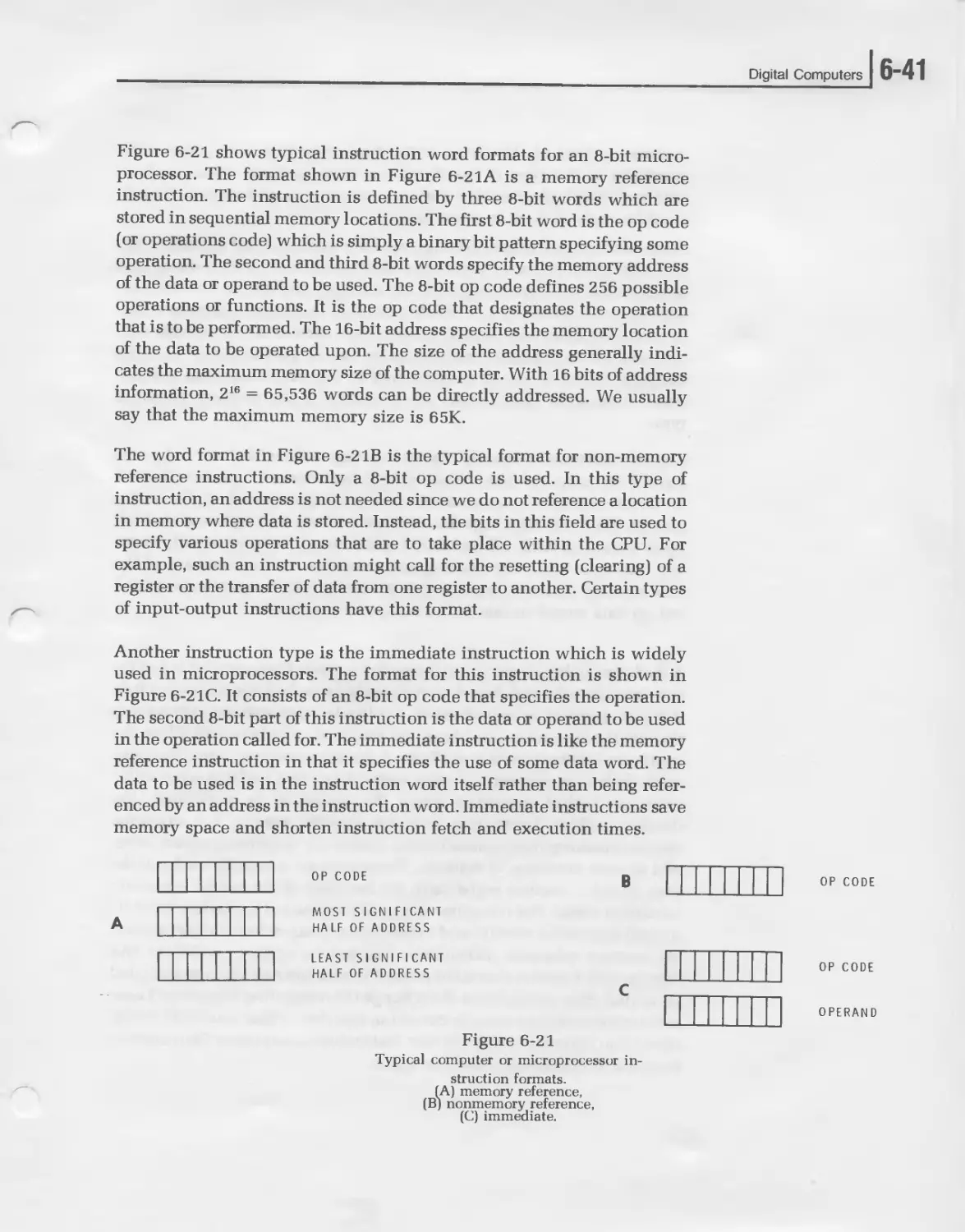
Figure 6-21 shows typical instruction word formats for an 8-bit micro-
processor. The format shown in Figure 6-21A is a memory reference
instruction. The instruction is defined by three 8-bit words which are
stored in sequential memory locations. The first 8-bit word is the op code
(or operations code) which is simply a binary bit pattern specifying some
operation. The second and third 8-bit words specify the memory address
of the data or operand to be used. The 8-bit op code defines 256 possible
operations or functions. It is the op code that designates the operation
that is to be performed. The 16-bit address specifies the memory location
of the data to be operated upon. The size of the address generally indi-
cates the maximum memory size of the computer. With 16 bits of address
information, 216 = 65,536 words can be directly addressed. We usually
say that the maximum memory size is 65K.
The word format in Figure 6-21B is the typical format for non-memory
reference instructions. Only a 8-bit op code is used. In this type of
instruction, an address is not needed since we do not reference a location
in memory where data is stored. Instead, the bits in this field are used to
specify various operations that are to take place within the CPU. For
example, such an instruction might call for the resetting (clearing) of a
register or the transfer of data from one register to another. Certain types
of input-output instructions have this format.
Another instruction type is the immediate instruction which is widely
used in microprocessors. The format for this instruction is shown in
Figure 6-21C. It consists of an 8-bit op code that specifies the operation.
The second 8-bit part of this instruction is the data or operand to be used
in the operation called for. The immediate instruction is like the memory
reference instruction in that it specifies the use of some data word. The
data to be used is in the instruction word itself rather than being refer-
enced by an address in the instruction word. Immediate instructions save
memory space and shorten instruction fetch and execution times.
OP CODE
MOST SIGNIFICANT
HALF OF ADDRESS
LEAST SIGNIFICANT
HALF OF ADDRESS
OP CODE
OP CODE
OPERAND
В
c
Figure 6-21
Typical compuier or microprocessor in-
struction formats
(A) memory reference,
(B) nonmemory reference,
(C) immediate.
6-421 UNIT SIX
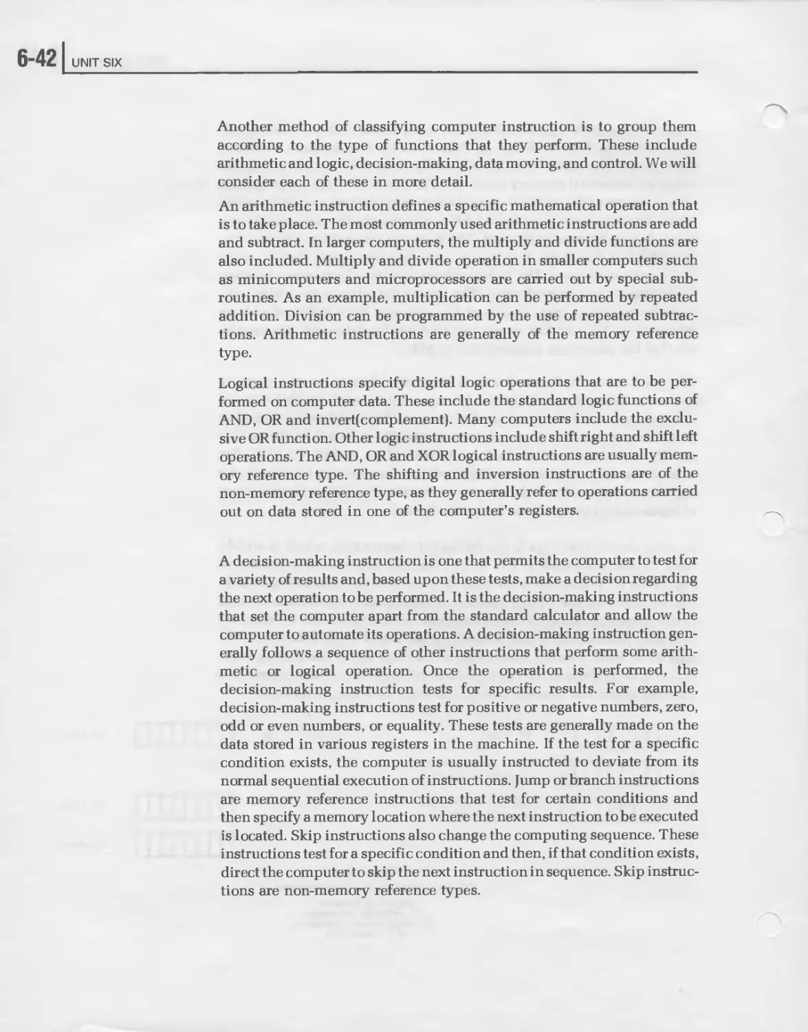
Another method of classifying computer instruction is to group them
according to the type of functions that they perform. These include
arithmetic and logic, decision-making, data moving, and control. We will
consider each of these in more detail.
An arithmetic instruction defines a specific mathematical operation that
is to take place. The most commonly used arithmetic instructions are add
and subtract. In larger computers, the multiply and divide functions are
also included. Multiply and divide operation in smaller computers such
as minicomputers and microprocessors are carried out by special sub-
routines. As an example, multiplication can be performed by repeated
addition. Division can be programmed by the use of repeated subtrac-
tions. Arithmetic instructions are generally of the memory reference
type.
Logical instructions specify digital logic operations that are to be per-
formed on computer data. These include the standard logic functions of
AND, OR and invert(complement). Many computers include the exclu-
sive OR function. Other logic instructions include shift right and shift left
operations. The AND, OR and XOR logical instructions are usually mem-
ory reference type. The shifting and inversion instructions are of the
non-memory reference type, as they generally refer to operations carried
out on data stored in one of the computer’s registers.
A decision-making instruction is one that permits the computer to test for
a variety of results and, based upon these tests, make a decision regarding
the next operation to be performed. It is the decision-making instructions
that set the computer apart from the standard calculator and allow the
computer to automate its operations. A decision-making instruction gen-
erally follows a sequence of other instructions that perform some arith-
metic or logical operation. Once the operation is performed, the
decision-making instruction tests for specific results. For example,
decision-making instructions test for positive or negative numbers, zero,
odd or even numbers, or equality. These tests are generally made on the
data stored in various registers in the machine. If the test for a specific
condition exists, the computer is usually instructed to deviate from its
normal sequential execution of instructions. Jump orbranch instructions
are memory reference instructions that test for certain conditions and
then specify a memory location where the next instruction to be executed
is located. Skip instructions also change the computing sequence. These
instructions test for a specific condition and then, if that condition exists,
direct the computer to skip the next instruction in sequence. Skip instruc-
tions are non-memory reference types.
Digital Computers
6-43
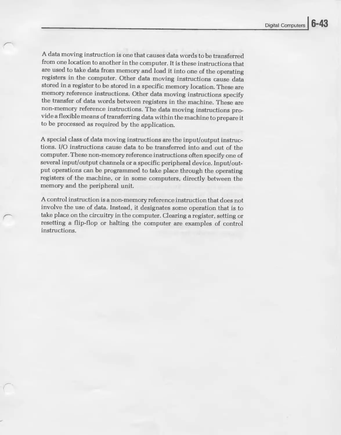
A data moving instruction is one that causes data words to be transferred
from one location to another in the computer. It is these instructions that
are used to take data from memory and load it into one of the operating
registers in the computer. Other data moving instructions cause data
stored in a register to be stored in a specific memory location. These are
memory reference instructions. Other data moving instructions specify
the transfer of data words between registers in the machine. These are
non-memory reference instructions. The data moving instructions pro-
vide a flexible means of transferring data within the machine to prepare it
to be processed as required by the application.
A special class of data moving instructions are the input/output instruc-
tions. I/O instructions cause data to be transferred into and out of the
computer. These non-memory reference instructions often specify one of
several input/output channels or a specific peripheral device. Input/out-
put operations can be programmed to take place through the operating
registers of the machine, or in some computers, directly between the
memory and the peripheral unit.
A control instruction is a non-memory reference instruction that does not
involve the use of data. Instead, it designates some operation that is to
take place on the circuitry in the computer. Clearing a register, setting or
resetting a flip-flop or halting the computer are examples of control
instructions.
6-441 UNIT SIX
A Hypothetical Instruction Set
A typical but hypothetical instruction set for a minicomputer or microp-
rocessor is shown in Table I. Only a few of the most commonly used
instructions are listed so that you can become acquainted with them
quickly. Real instruction sets are far more extensive. Nevertheless, the
instruction set in Table I is representative. We will use it to demonstrate
the writing and coding of programs.
The instruction set in Table I can apply to the hypothetical computer
described earlier or a typical microprocessor. For the instructions listed
here, we assume that the computer has an 8-bit word length and 65K of
memory. The accumulator and memory data registers are 8 bits in length.
The program counter and MAR are 16 bits in length. I/O transfers take
place though the accumulator. A single instruction may occupy one, two
or three consecutive memory locations depending upon its format as
shown in Figure 6-21. Study the instructions in Table I so that you will be
familiar with the operation each performs. Note that each instruction is
designated by a three-letter mnemonic. The type of instruction is desig-
nated by the letters R (memory reference), N (non-memory reference), A
(arithmetic-logic), T (data moving or transfer), D (decision) and C (con-
trol). Despite the simplicity of this instruction set, it can be used to
program virtually any function.
Digital Computers
] 6-45
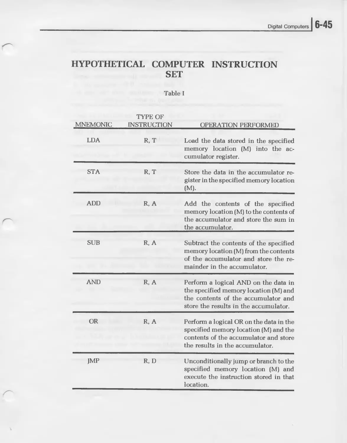
HYPOTHETICAL COMPUTER INSTRUCTION
SET
Table I
MNEMONIC TYPE OF INSTRUCTION OPERATION PERFORMED
LDA R, T Load the data stored in the specified memory location (M) into the ac- cumulator register.
STA R, T Store the data in the accumulator re- gister in the specified memory location (M).
ADD R, A Add the contents of the specified memory location (M) to the contents of the accumulator and store the sum in the accumulator.
SUB R, A Subtract the contents of the specified memory location (M) from the contents of the accumulator and store the re- mainder in the accumulator.
AND R, A Perform a logical AND on the data in the specified memory location (M) and the contents of the accumulator and store the results in the accumulator.
OR R, A Perform a logical OR on the data in the specified memory location (M) and the contents of the accumulator and store the results in the accumulator.
JMP R, D Unconditionally jump or branch to the specified memory location (M) and execute the instruction stored in that location.
6-461 UNIT SIX
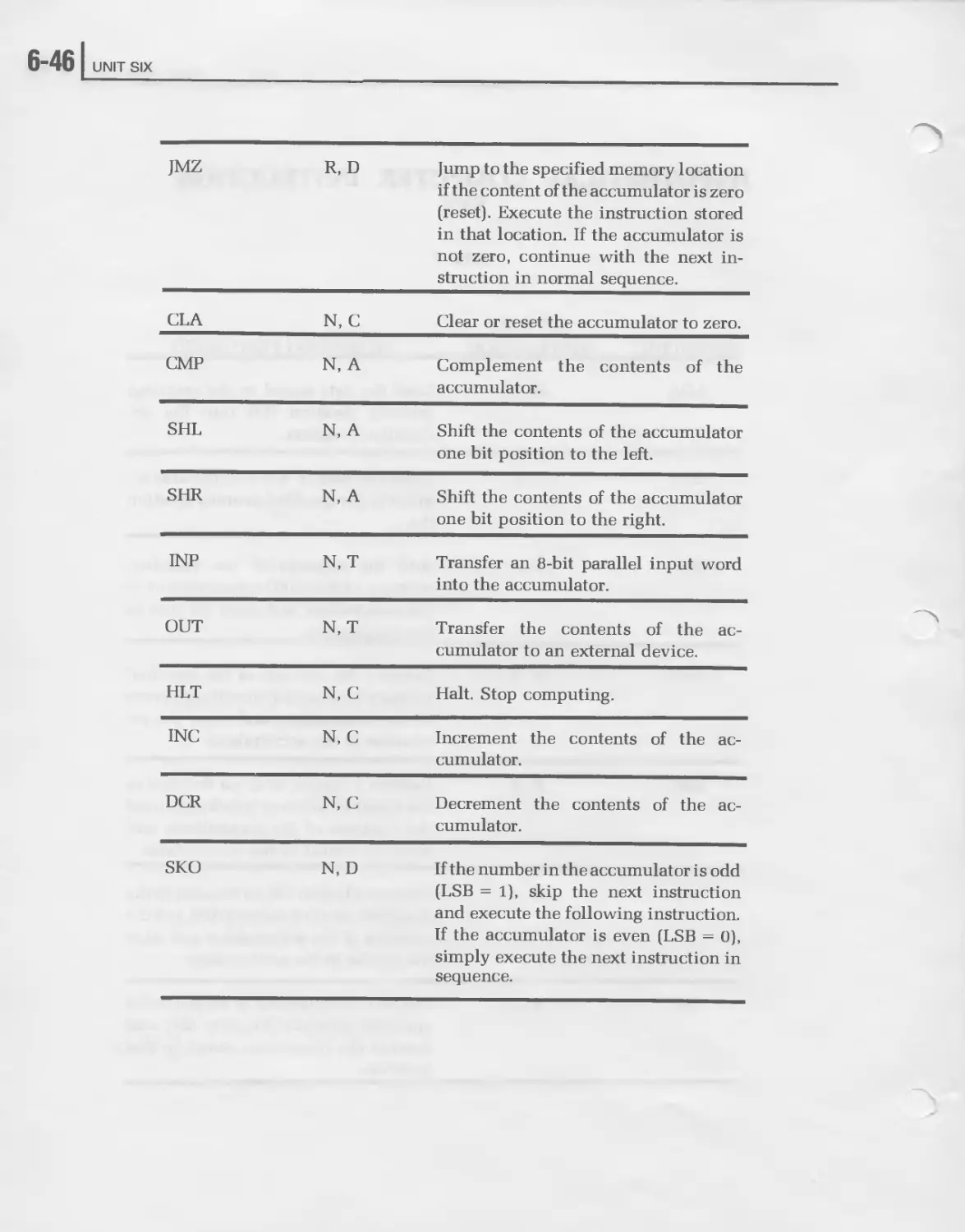
JMZ R, D Jump to the specified memory location if the content of the accumulator is zero (reset). Execute the instruction stored in that location. If the accumulator is not zero, continue with the next in- struction in normal sequence.
CLA N, C Clear or reset the accumulator to zero.
CMP N, A Complement the contents of the accumulator.
SHL N, A Shift the contents of the accumulator one bit position to the left.
SHR N, A Shift the contents of the accumulator one bit position to the right.
INP N, T Transfer an 8-bit parallel input word into the accumulator.
OUT N, T Transfer the contents of the ac- cumulator to an external device.
HLT N, C Halt. Stop computing.
INC N, C Increment the contents of the ac- cumulator.
DCR N, C Decrement the contents of the ac- cumulator.
SKO N, D If the number in the accumulator is odd (LSB = 1), skip the next instruction and execute the following instruction. If the accumulator is even (LSB = 0), simply execute the next instruction in sequence.
Digital Computers
] 6-47
Example Programs
The following examples illustrate the use of the instruction set in writing
programs. The program description, flowchart and instruction code are
given in each example. Study each program, mentally executing the
instructions and imagining the outcome. The format of the instruction
coding is shown below.
3 ADD (7)
The number on the left is the memory address. The mnemonic specifies
the instruction. The number in parenthesis is the address of the operand
called for by a memory reference instruction. This line of instruction
coding says that memory location 3 contains an add instruction that tells
us to add the content of location 7 to the content of the accumulator.
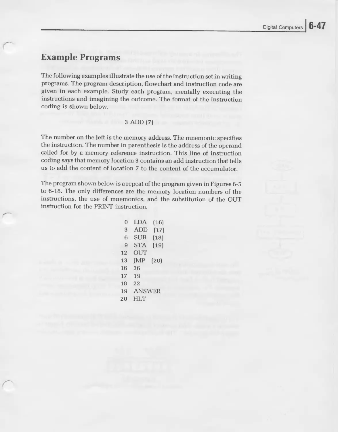
The program shown below is a repeat of the program given in Figures 6-5
to 6-18. The only differences are the memory location numbers of the
instructions, the use of mnemonics, and the substitution of the OUT
instruction for the PRINT instruction.
0 LDA (16)
3 ADD (17)
6 SUB (18)
9 STA (19)
12 OUT
13 JMP (20)
16 36
17 19
18 22
19 ANSWER
20 HLT
6-481 UNIT SIX
The difference in memory addresses is the result of the assumption that
our computer uses an 8-bit word and that memory reference instructions
occupy three sequential memory locations. In the program of Figures 6-5
to 6-18, we assumed that one memory address contained one instruction.
In the program above, theLDA (16) occupies memory locations 0,1 and 2.
The op code is in 0, the most significant part of the^ddress (0000 0000) is
in location 1, and the least significant part of the address (0001 0000) is in
location 2. The ADD, SUB, STA and JMP memory reference instructions
each occupy three sequential locations. The OUT and HLT instructions
do not reference memory so they occupy only a single location.
LOAD A
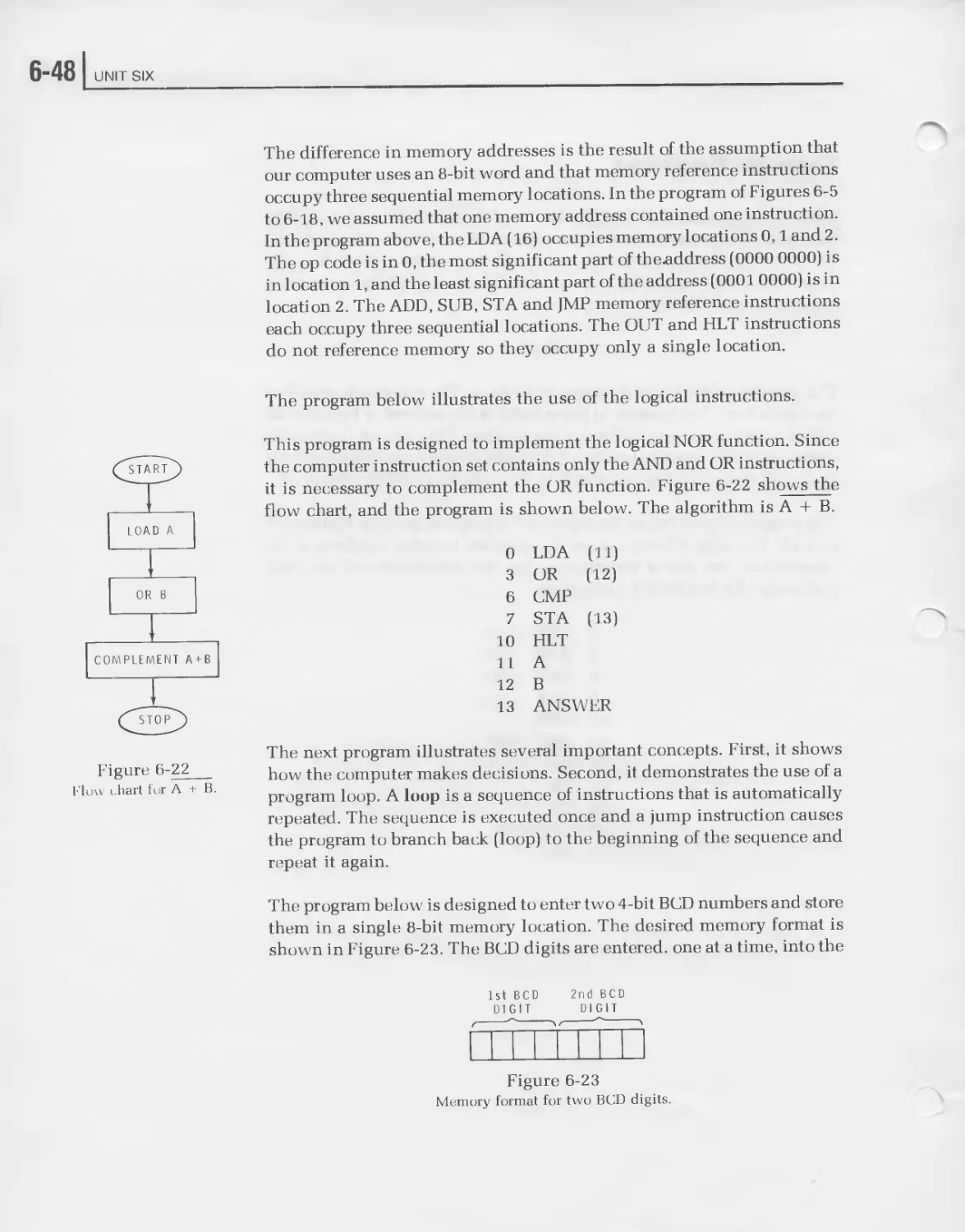
The program below illustrates the use of the logical instructions.
This program is designed to implement the logical NOR function. Since
the computer instruction set contains only the AND and OR instructions,
it is necessary to complement the OR function. Figure 6-22 shows the
flow chart, and the program is shown below. The algorithm is A + B.
OR В
COMPLEMENT A + B
Figure 6-22
Но» chart for A + B.
0 LDA (1 1)
3 OR (12)
6 CMP
7 STA (13)
10 HLT
11 A
12 В
13 ANSWER
The next program illustrates several important concepts. First, it shows
how the computer makes decisions. Second, it demonstrates the use of a
program loop. A loop is a sequence of instructions that is automatically
repeated. The sequence is executed once and a jump instruction causes
the program to branch back (loop) to the beginning of the sequence and
repeat it again.
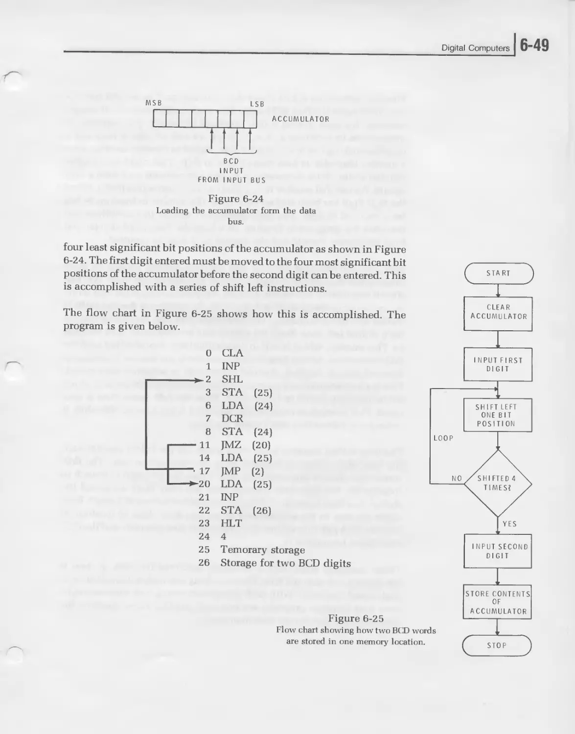
The program below is designed to enter two 4-bit BCD numbers and store
them in a single 8-bit memory location. The desired memory format is
shown in Figure 6-23. The BCD digits are entered, one at a time, into the
1st BCD 2nd BCD
DIGIT DIGIT
Figure 6-23
Memory format for two BCD digits.
Digital Computers
J 6-49
ACCUMULATOR
INPUT
FROM INPUT BUS
Figure 6-24
Loading the accumulator form the data
bus.
four least significant bit positions of the accumulator as shown in Figure
6-24. The first digit entered must be moved to the four most significant bit
positions of the accumulator before the second digit can be entered. This
is accomplished with a series of shift left instructions.
The flow chart in Figure 6-25 shows how this is accomplished. The
program is given below.
0
1
*~2
3
6
7
8
- 11
14
• 17
►20
21
22
23
24
25
26
CLA
INP
SHL
STA (25)
LDA (24)
DCR
STA (24)
JMZ (20)
LDA (25)
JMP (2)
LDA (25)
INP
STA (26)
HLT
SHIFT LEFT
ONE BIT
POSITION
4
Temorary storage
Storage for two BCD digits
INPUT SECOND
DIGIT
Figure 6-25
Flow chart showing how two BCD words
are stored in one memory location.
STORE CONTENTS
OF
ACCUMULATOR
6-501 UNIT SIX
The first instruction (CLA) clears the accumulator. The second instruc-
tion (INP) loads the first BCD digit. This digit is then shifted left one bit
position. We need to shift it four positions to the left. The sequence of
instructions in locations 2, 3, 6, 7, 8, 11, 14 and 17 form a loop and a
decision-making test to accomplish this. Stored in memory location 24 is
a number that tells us how many times to shift. That number is loaded
into the accumulator decremented by one and restored each time a shift
occurs. We test that number with a jump on zero instruction (JMZ). When
the BCD digit has been shifted four times, the number in location 24 has
been reduced to zero. The JMZ instruction detects this condition and
branches the program to location 20 where the data word is retrieved
from temporary storage and the second BCD digit is inputted.
Now, we will consider the loop and decision-making process in more
detail. After the first input digit is loaded, it is shifted left once. We then
store it temporarily in location 25. This is to prevent loss of the data while
we are in our decision-making loop. Next, the number of desired shifts is
loaded into the accumulator. We decrement it by one, indicating that we
have shifted left once. Next, we restore this number (now 3) in location
24. This number, which is still in the accumulator, is now tested with the
JMZ instruction. At this time the accumulator is not zero so the program
does not branch. Instead, the next instruction in sequence is executed.
This is a load accumulator instruction that retrieves the data words which
we temporarily stored in location 25. Then the JMP instruction is exe-
cuted. This instruction returns us to location 2 to produce another shift. It
is the jump instruction that creates the loop.
The loop is then repeated three more times. On the fourth pass through
the loop, the number in location 24 is decremented to zero. The JMZ
instruction detects this condition and causes the program to branch to
location 20. We have now escaped from the loop. Next we reload the
shifted data from location 2 5.Finally, we load the second BCD digit. Both
digits are now in the accumulator so we can store them in location 26
with the STA (26) instruction. The program is now complete and the HLT
instruction terminates it.
These examples show how a computer performs its work. It does it
laboriously, one step at a time. The only thing that makes it practical is its
high speed operation. With each instruction taking only microseconds,
even long complex programs are executed quickly. To an operator, the
execution appears almost instantaneous.
Digital Computers
Self-Review Questions
21. What is machine language programming?
22. List the seven steps of programming.
1.
2. ___________________________________________________________________________
3. ___________________________________________________________________________
4. ___________________________________________________________________________
5.
6.
7.
23. A procedure for solving a problem is an
24. A graphical description of the problem solution is known as a
25. What is coding? ______________________________________________
26. Name the two types of computer instructions and describe each
one. _______________________________________________________________
27. Name the computer instruction groups according to function.
1.
2.
3. ___________________________________________________________________________
4. ___________________________________________________________________________
5. ___________________________________________________________________________
6-52 UNIT SIX
28. What is a loop? _______________________________________________
29. The content of the accumulator is 10111010. The CMP instruction is
executed. The new accumulator content is
30. Which instruction would you use to down-count the ac-
cumulator?
(Use the Hypothetical Computer Instruction Set.)
31. The content of the accumulator is 45. A JMZ (34) instruction in
location 25 is then executed. The next instruction executed is in
location____________________
32. Program loops are implemented with the and
_________________instructions.
33. The number 0110 0101 is stored in the accumulator. The number in
memory location 18 is 1111 0000. The AND (18) instruction is
executed. The content of the accumulator becomes
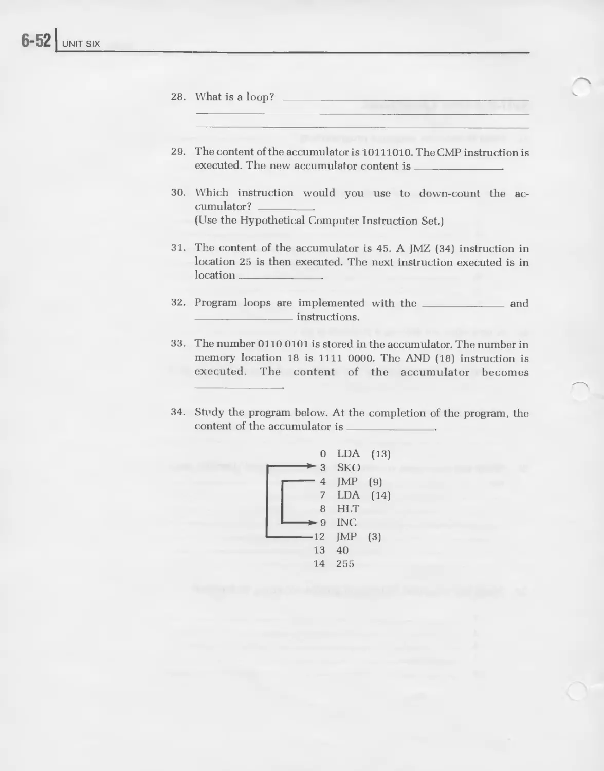
34. Study the program below. At the completion of the program, the
content of the accumulator is
0 LDA (13)
3 SKO
4 JMP (9)
7 LDA (14)
8 HLT
►9 INC
12 JMP (3)
13 40
14 255
Digital Computers
]б-53
Self-Review Answers
21. Machine language programming is the process of writing programs
by using the instruction set of the computer and entering the prog-
rams in binary form, one instruction at a time.
22. The seven steps of programming are:
1. Define the program.
2. Develop a solution.
3. Flow chart the problem.
4. Code the program.
5. Enter the program into the computer.
6. Debug the program.
7. Run the program.
23. A procedure for solving a problem is an algorithm.
24. A graphical description of the problem solution is known as a flow
chart.
25. Coding is the procedure of listing the specific computer instructions
sequentially to carry out the algorithm defined by the flow chart.
26. The two types of computer instructions are memory reference and
nonmemory reference. A memory reference instruction specifies the
location in memory of the data word to be used in the operation
indicated by the instruction. A nonmemory reference instruction
simply designates an operation to be performed.
27. The computer instruction groups according to function are:
1. Arithmetic
2. Logic
3. Decision making
4. Data moving
5. Control
6-541 UNIT SIX
28. A loop is a sequence of instructions that is automatically repeated.
29. The complemented accumulator content is 01000101.
30. To down-count the accumulator, you should use DCR (decrement).
31. The next instruction executed is in location 28.
The JMZ(34) instruction tests for a zero accumulator. The ac-
cumulator content is 45; therefore, the program does not branch to
location 34. Instead, it executes the next instruction in sequence,
which begins in location 28. Remember that the JMZ(34) instruction
and its reference address occupies locations 25, 26 and 27.
32. Program loops are implemented with the JMP and JMZ instructions.
33. The content of the accumulator becomes 0110 0000. Consider the
two words to be ANDed as inputs to an AND gate as they would
appear in a truth table. Then AND each corresponding pair of bits to
get the result.
34. The content of the accumulator is 255.
This program uses the “skip on odd” accumulator instruction (SKO)
to test the content of the accumulator. It first loads the content of
location 13 into the accumulator. This is the number 40. The SKO
then tests for an odd condition by monitoring the LSB. Since 40 is
even, the program does not skip. The next instruction in sequence is
executed. This is a JMP (9) instruction which causes the program to
branch to location 9. Here the INC instruction is executed. The
accumulator then becomes 41. The next instruction JMP (3) loops
the program back to location 3, where the SKO instruction again
tests the accumulator. This time, the content is odd. The instruction
in location 4 is now skipped and the next in sequence is executed.
This is an LDA (14) which loads 255 into the accumulator. The
program then halts.
Digital Computers
] 6-55
SOFTWARE
The steps that we have just described make up the procedure typically
used in developing application programs for the digital computer. The
program may be solving a mathematical equation, sorting and editing a
large volume of data, or providing some type of automatic control to an
external machine.
These application programs fall into a larger category of computer prog-
rams called software. Software is a general term used to describe all of the
programs used in a digital computer. Besides the specific applications
programs, there are many special programs supplied by the computer
manufacturer which are used to simplify and speed up the use of the
computer. These support programs eliminate much of the drudgery from
programming and using a computer. It was determined early in the
development of the digital computer that the computer itself with special
internal control programs could assume much of the responsibility for
the detailed translation of a problem into the binary language of the
computer.
Subroutines
Many digital computer manufacturers supply what are called software
libraries of subroutines and utility programs. A subroutine is a short
machine language program that solves a specific problem or carries out
some often-used operation. For example, typical subroutines in many
minicomputers and microprocessors are the multiply and divide prog-
rams. Instead of using the multiply subroutine each time it is required in a
problem, the subroutine is stored in the computer memory only once.
This saves a substantial amount of memory space. Each time the multiply
subroutine is required, a jump instruction in the program causes the
program to branch to the multiply subroutine. Once the multiplication
has been performed, the computer jumps back to the normal program
sequence.
6-561 UNIT SIX
There are many different types of commonly used subroutines. Multipli-
cation and division are two of the most commonly used. Other sub-
routines include binary to BCD and BCD to binary code conversions. To
communicate with external peripheral devices which use the decimal
number system and the alphabet, a code such as ASCII is used. Data is
entered into the computer in the ASCII code. In order for the computer to
process this data, it must first be converted into pure binary numbers.
Solutions to computer programs are in the pure binary form. A sub-
routine is used to convert the binary numbers into the ASCII format and
then they are sent to an external peripheral device such as the printer.
Utility Programs
Utility programs refer to the short routines used to run the computer.
Input/output programs for specific types of peripheral devices fall into
this category. A loader is another utility program. This is a short sequence
of instructions that allows data to be loaded into the computer. In order to
operate, a computer must be programmed. But to load a program into the
computer automatically requires that the loader program exist in the
memory to begin with. Such loader programs are often entered manually
from the computer front panel. The short loader program in memory then
permits longer, more complicated programs to be loaded automatically.
Digital Computers
J 6-57
Assembler
The most sophisticated software supplied with most computers are large
complex conversion programs called assemblers and compilers. These
programs allow the computer to be programmed in a simpler language.
Machine language programming is completely impractical for many
modern applications. To simplify computer programming and eliminate
the need for a knowledge of binary numbers and the computer architec-
ture, computer manufacturers have developed easier methods of prog-
ramming the computer. These methods involve higher level languages,
which are special systems for speeding up the programming process. The
higher level language permits someone with no computer expertise
whatsoever to use the computer. The higher level language permits the
programmer to express his problem as a mathematical equation or in
some cases as an English language statement. These equations and state-
ments are then fed to the computer, which then automatically converts
them into the binary instructions used to solve the problem.
The simplest form of higher level programming language is called as-
sembly language. This is a method of programming the computer an
instruction at a time as you do in machine language programming.
However, instead of binary designations for each instruction, short mul-
tiletter names called mnemonics are given to each of the computer in-
structions. These are then written sequentially to form the program.
Mnemonics are also given to memory addresses to avoid the use of
specific memory locations.
Once the computer program is written inthe assembly language, it is then
entered into the machine along with an assembler program. The assem-
bler program resides in the computer memory and is used to convert the
mnemonics into the binary instruction words that the computer can
interpret. As you can see, the assembler is a program that eliminates the
necessity of dealing with binary numbers in the digital computer. How-
ever, since the machine is still programmed an instruction at a time, it
provides wide flexibility in solving a given problem.
6-581 UNIT SIX
Compiler
The compiler, like the assembler, is a complex conversion program that
resides in the computer memory. Its purpose is to convert a simplified
statement of the program into the binary machine code that the computer
can understand. The difference between the compiler and the assembler
is that the compiler is capable of recognizing even simpler problem
statements.
In one type of compiler programming language know as Fortran, the
program can be written as an algebraic equation. The algebraic equation
is then entered into the computer through a teletypewriter or via punched
cards. The compiler program then analyzes the formula and proceeds to
construct a binary program to solve this equation at some location in
memory.
Another higher level programming language know as Cobol uses English
language statements to describe the problem. These English language
statements are punched into cards and then read into the computer
memory. The compiler interprets them and converts them into the binary
program. Unlike an assembly language program which has a one-to-one
correspondence of instruction steps with machine language, a single
compiler language program statement often causes many binary instruc-
tions to be generated.
There are many different types of higher level programming language
used with computers. All of them have the prime function of simplifying
the programming procedure. They greatly speed up and expedite the
communications with the computer. They allow anyone who is capable
of defining his problem to use the computer.
Digital Computers
] 6-59
Cross Assemblers and Compilers
There are several special types of higher level programming language
that have been developed to aid in programming microprocessors. For
simple applications, microprocessors are programmed at the machine
language level. However, when longer or more complex programs are
required, it is desirable to use an assembler or compiler if it is available.
For minicomputers and larger scale computers, compilers and as-
semblers that reside within the computer memory itself are available to
aid in the programming process. However, most microprocessors do not
have sufficient memory to accomodate such large complex programs. In
addition, the microprocessor is generally to be dedicated to a specific
application and, therefore, its memory will only be large enough to hold
the application program required. In order to simplify the development
of programs for use in a microprocessor, special programs called cross-
assemblers and cross-compilers have been developed. These are special
programs that reside in the memory of a larger, general purpose digital
computer. The application programs are written in these higher level
languages and the larger machine then converts the application program
into the binary machine language required by the microprocessor. The
output of the larger scale computer is generally a paper tape containing
the binary program, which is later loaded into the microprocessor mem-
ory.
Some of the larger more sophisticated microprocessors have been used as
the primary component in a microcomputer that can be used as a software
development system for that microprocessor. A large random access
memory is added to the microprocessor along with appropriate
peripheral devices. Resident assembler programs have been developed
for these machines. In this way, the microcomputer based on the microp-
rocessor can be used to develop application programs that will be used
later in another system employing the same microprocessor.
6-601 UNIT SIX
Self Review Questions
35. What is software? _________________________________________
36. What is a subroutine? _____________________________________
37. Input/output and loader programs are called.
programs.
38. The program used to convert an instruction by instruction
mnemonic program into binary machine language is called an
39. What is a compiler? _______________________________________
40. What are cross assemblers and compilers?
Digital Computers
Self-Review Answers
35. Software is a broad term used to describe all of the programs used in
a digital computer.
36. A subroutine is a short, machine language program that solves a
specific problem or carries out some often used operation.
37. Input/output and loader programs are called utility programs.
38. The program used to convert an instruction-by-instruction
mnemonic program into binary machine language: is called an as-
sembler.
39. A compiler, like an assembler, converts a statement of the program
into a binary machine language program. However, a compiler is
more complex in that it may convert a single statement into several
machine language steps. Whereas, the assembler can only convert
each mnemonic instruction into a single machine language step.
40. Cross assemblers and compilers are used with large scale, general
purpose computers to develop machine language programs for mic-
roprocessors.
6-621 UNIT SIX
MICROPROCESSORS
As indicated earlier, a microprocessor is the simplest and least expensive
form of digital computer available. However, this section is more
specific. It discusses exactly what a microprocessor is, the types that are
available, and how they are used.
Types of Microprocessors
Most microprocessors are the central processing unit (CPU) of a digital
computer. That is, microprocessors usually contain the arithmetic-logic
and control sections of a small scale digital computer. Most of these
microprocessors also contain a limited form of input-output circuitry
which permits them to communicate with external equipment. To make
the microprocessor a complete computer, external memory and input-
output devices must be added. An external read only memory (ROM) is
normally used to store the program to be executed. Some read/write,
random access memory (RAM) may also be used. The external input-
output circuitry generally consists of registers and control gating that
buffer the flow of data into and out of the CPU.
Microprocessors come in a wide variety of forms. However, the most
popular and widely used microprocessor is a MOS LSI circuit. These
circuits are made with both P-channel or N-channel enhancement mode
MOS devices. The entire CPU is contained on a single chip of silicon and
mounted in either a 16, 24 or 40-pin dual in-line package. Such micro-
processors are available with standard word lengths of 4, 8 or 16 bits.
Other more sophisticated types of microprocessors are contained within
two or more integrated circuit packages. When combined, they form a
complete, small scale digital computer.
While most microprocessors are of the single chip MOS variety, there are
numerous bipolar microprocessors available. These are inherently faster
than the MOS devices but occupy more chip space and consume more
power. Where high speed is required, these bipolar devices can be used.
A recently developed integrated circuit technology, referred to as integ-
rated injection logic (I2L), combines both the speed of bipolar devices and
the high density characteristics of MOS devices. These new I2L LSI
circuits offer many benefits, and their potential for microprocessor appli-
cations is great.
Digital Computers
] 6-63
Microprocessors can also be constructed with standard TTL integrated
circuits. Standard MSI packages can be combined to construct a small
CPU. Figure 6-26 shows a computer of this type. While this kind of
microprocessor takes more circuitry and consumes more power, it gener-
ally offers several advantages. First, the microprocessor can be con-
structed to execute a special instruction set designed specifically for the
application. With a standard off-the-shelf CPU, the instruction set is
fixed. Special instruction sets are often necessary for some applications
and they can be readily optimized with a special TTL microprocessor
design. Another advantage of an MSI TTL microprocessor is high speed.
A standard MOS microprocessor may be too slow for the application. The
fastest available MOS microprocessor can execute a single instruction in
approximately 2 microseconds. The simpler and less sophisticated MOS
microprocessors have instruction execution speeds in the 10 to 50 mi-
crosecond region. With a special TTL MSI microprocessor, execution
speeds in the nanosecond region are easily obtained.
Figure 6-26
A microprocessor made with TTL MSI
and SSI integrated circuits. This machine
is more powerful than the typical LSI
microprocessor but less powerful than a
full minicomputer. (Photo courtesy Com-
puter Automation Inc.)
In order to use a standard single chip microprocessor, some form of
external memory must be used. The program to be executed by the
microprocessor is generally stored in a ROM. Data is stored in RAM.
Other external components needed to support a microprocessor are an
external clock circuit, input-output registers, and peripheral devices.
6-641 UNIT SIX
All single chip microprocessors incorporate a data bus through which all
external data transfers take place. This may be a 4 or 8-bit bi-directional
bus over which all data transfers between the memory and input-output
devices communicate with the CPU. A bus design of this type greatly
minimizes the number of interconnections required to connect the mic-
roprocessor to the external devices. The limiting factor of such intercon-
nections is the number of pins on the integrated circuit package. The bus
organizations keeps the pin count to a minimum, but at the same time
requires time sharing of the bus. Since all data transfers between the
memory and CPU and between the CPU and the peripheral devices must
use the same input-output lines, each operation must take place at a
different time.
The input-output devices used with most microprocessors are quite
different from those used with larger digital computers. Most larger
computers are connected to input-output devices like CRT terminals,
teletypewriters, paper tape readers and punches, card readers and line
printers. On the other hand, microprocessors are interfaced to devices
such as keyboards, 7-segment LED displays, thumbwheel switches, re-
lays, analog-to-digital and digital-to-analog converters, temperature sen-
sors, and other such components.
Applications of Microprocessors
Microprocessors are used primarily for dedicated functions. Rarely are
microprocessors used to implement a general purpose digital computer.
The program of a microprocessor is usually stored in the read only
memory. This means that the program is fixed and dedicated to the
specific application.
There are two general applications for modern LSI microprocessors.
They can be used as replacements for minicomputers or as replacements
for random hard-wired logic. The development of the minicomputer
enabled many engineers to design digital computers into special control
systems. The minicomputer was dedicated to the control application and
its programmable flexibility offered many benefits. But its cost was very
high. Some microprocessors have nearly as much computing power and
capability as or minicomputer and can replace the minicomputer in
many systems. A microprocessor has the advantage of smaller size, lower
cost, and lower power consumption.
Digital Computers
] 6-65
Another common use for the microprocessor is as an alternative to stan-
dard hard-wired digital logic circuits. Equipment customarily con-
structed with logic gates, flip-flops, counters, and other SSI and MSI
circuits can often be implemented with a single microprocessor. All of
the standard logic functions such as logic operations, counting and
shifting can be readily carried out by the microprocessor through prog-
ramming. The microprocessor will execute instructions and sort sub-
routines that perform the same logic functions.
Many benefits result from using the microprocessor in replacing hard-
wired random logic systems. Some of these advantages are: (1) reduced
development time and cost; (2) reduced manufacturing time and cost; (3)
enhanced product capability; (4) improved reliability.
Development time and cost can be significantly reduced when a microp-
rocessor is used. The design procedures used with standard logic circuits
are completely eliminated. Much of the breadboarding, cut-and-try and
prototype construction is completely eliminated. Design changes can be
readily incorporated and new functions implemented by simply chang-
ing the program. With a microprocessor, the logic and control functions
are implemented with programs. The program can be written and entered
into memory and then tested. System changes are easy to make by simply
rewriting the program. Unique functions can be readily added by increas-
ing the size of the program. In many cases, the system can be made
self-checking by programming special diagnostic routines.
Development time is further reduced because a single integrated circuit
microprocessor usually replaces many other integrated circuits. This
reduces wiring and interconnections and simplifies printed circuit board
layout. Often the printed circuit board will be significantly smaller with a
microprocessor system. Power consumption and cooling are also usually
simplified. The benefit of reduced development time and cost, of course,
is that the product can come to market or be applied sooner.
Manufacturing costs are also reduced as a result of replacing random
logic with a microprocessor. Fewer integrated circuits and smaller
printed circuit boards are required to construct the system. Therefore,
less time and materials are required to assemble the equipment. The
programmed nature of the microprocessor system also makes it easier to
test and debug than an equivalent hard-wired system.
6-661 UNIT SIX
Enhanced product capability is another benefit of using the microproces-
sor to replace hard-wired logic. The power of a digital system im-
plemented with a microprocessor is limited strictly by the imagination of
the designer. Many unique features and capabilities can be incorporated
into the design by simply adding to the program. The incremental cost for
adding such features to a microprocessor system is small compared to
that of a hard-wired logic system. The ROM used to store the program
usually contains extra room for program additions. Therefore, it is very
easy to add special features. Many of these special or unique features
would be difficult to incorporate in a random hard-wired logic design
because of the extra design time, the complexity, and the additional cost.
When a microprocessor is used, no additional parts or significant amount
of design time are required to add them. The more unique and special
features that a product can incorporate the better it performs and the more
competitive it will be in the marketplace.
Another benefit of using the microprocessor to implement digital sys-
tems is increased reliability. Whenever the number of integrated circuits
and wiring interconnections are reduced in a system, reliability increases
significantly. Most system failures result from the failure of an integrated
circuit or from an interconnection. The number of integrated circuits and
interconnections are greatly reduced in going from a standard hard-
wired logic system to a microprocessor system. Increased reliability
means fewer failures and leads to a corresponding reduction in both
warranty and service costs.
The benefits of using a microprocessor are so significant that they will
soon replace most random hard-wired logic designs. But the biggest
present disadvantage of using a microprocessor is the designer’s lack of
programming knowledge. Very little circuit or logic design is required to
implement a system with a microprocessor. Instead, the primary skill
required is digital computer programming. Most engineers and digital
Digital Computers
]6-67
designers were not trained in this subject, and therefore, initial design
attempts with microprocessors may be slow and frustrating. However, as
microprocessors are more widely used and their benefits recognized,
engineers and designers will learn programming and begin to implement
their systems with these devices.
Where are Microprocessors Used?
There are so many applications for microprocessors that it is difficult to
classify and list them. However, to give you a glimpse at the many diverse
uses for these devices, consider some of the applications where they are
now being used.
1. Electronic Cash Registers
2. Electronic Scales
3. Electrical Appliance Controls
4. Automotive Controls
5. Traffic Signal Controllers
6. Machine Tool Controls
7. Programmable Calculators
8. Automatic Test Equipment
9. Data Communications Terminals
10. Process Controllers
11. Electronic Games
12. Data Collection
These are only a few of the many applications presently implemented
with microprocessors. Just keep in mind that the microprocessor can be
used in any other application where hard-wired standard logic systems
are now used. In addition, microprocessors can also be used as the CPU in
a small general purpose microcomputer or minicomputer.
6-681 UNIT SIX
A typical application for a microprocessor is illustrated in Figure 6-27.
Here, the microprocessor is used in an electronic scale for a grocery
market. The item to be weighed is placed on the scale. A transducer and
analog-to-digital converter convert the weight into a binary word that is
read into the CPU under program control. A clerk enters the price per
pound via the keyboard. This too is read into the CPU. Then the CPU
computes the price by multiplying the weight by the price per unit of
weight. Then the total price is displayed on a 7-segment LED readout and
printed on a ticket. All of this takes place under the control of the
dedicated program stored in the ROM. Note the single 8-bit bi-directional
data bus over which all data transfers take place.
Designing with Microprocessors
As indicated earlier, microprocessors can be used in two general ways.
First, they can be used to replace minicomputers for dedicated control
functions. Second, microprocessors can be used to replace standard
hard-wired random logic systems. This section provides you with some
guidelines to help you decide when and where a microprocessor should
be used.
Digital Computers
] 6-69
Microprocessors are generally much slower and less sophisticated than
the typical minicomputer. But despite these limitations, microprocessors
can often be used to replace minicomputers in some systems. The reason
for this is that most minicomputers used in control systems are not used
to their full capability. In a sense, they are a case of overkill. Many control
systems used the minicomputer simply because of the ease with which
the control can be changed by modifying the program. The significantly
higher cost has been traded off for the convenience of system modifica-
tion. In these applications, the microprocessor can usually handle the
control functions as well as the minicomputer. A careful study must be
made in such designs to see when a microprocessor can replace a
minicomputer. There are many trade-offs to consider (speed, cost, etc.).
Keep in mind that microprocessor development is in its infancy. Many
technological improvements will be made over the years, causing the
microprocessor to further approach the capabilities of today’s minicom-
puter.
The microprocessor is a design alternative which should be considered
in the early design stages of any digital system. The benefits of a micro-
processor over standard hard-wired designs is significant in the larger,
more sophisticated digital systems. As a general guideline, a micro-
processor can be used beneficially if it will replace from thirty to fifty
standard MSI and SSI TTL integrated circuits. If a preliminary design
indicates that this many TTL integrated circuits must be used, a micro-
processor should be considered. Unless the speed limitaton of the micro-
processor is a factor, all of the benefits mentioned earlier will result by
using the microprocessor.
Another way to equate a microprocessor design with the more conven-
tional hard-wired logic design, is to compare the number of gates in a
hard-wired design with the number of bits of memory required by a
microprocessor system. It takes approximately 8 to 16 bits of memory in a
microprocessor system to replace a single gate. Since most read only
memories used to store the program for a microprocessor can contain as
many as 16,384 bits, such a memory can replace from 1000 to 2000 gates.
Depending upon the number of gates per SSI or MSI package, this can
represent a replacement of hundreds of integrated circuit packages. A
16,384 (16K) bit ROM in a single 40-pin IC package, for example, can
replace one hundred to four hundred 14, 16, or 24-pin SSI and MSI
packages. This is a significant saving.
6-701 UNIT SIX
/Л this point, you may still have some doubts about the ability of a
microprocessor to replace standard hard-wired logic functions. It may be
difficult for you to imagine how a microprocessor can perform the func-
tions you are so used to implementing with SSI and MSI packages.
Therefore, we will consider all of the standard logic functions and illus-
trate how a microprocessor can perform them.
The microprocessor can readily perform all of the standard logical func-
tions such as AND, OR, and Exclusive OR. It usually does this by execut-
ing the instructions designed for this purpose. Logical operations are
generally performed on data stored in memory and in the accumulator
register, with the result appearing in the accumulator. Suppose that you
wanted to perform the NAND function on two 8-bit words. Using the
instruction set in Table I, we could write the following program. Assume
that the two words to be NANDed are stored in locations 8 and 9.
0 LDA (8)
3 AND (9)
6 CMP
7 HLT
The first instruction loads the first word into the accumulator. The
second instruction performs the AND function with the word in the
accumulator and the word in location 9. The result appears in the ac-
cumulator. Finally, this result is complemented to form the NAND func-
tion. This simple example illustrates the procedure you use to implement
any Boolean function.
Arithmetic operations are also readily performed by a microprocessor.
Special adders, subtractors and other arithmetic circuits are not required
because all microprocessors can perform arithmetic operations through
programming. Multiplication and division operations are carried out by
subroutines. Even the higher math functions such as square root,
trigonometric functions, and logarithms can be computed with sub-
routines. Many special algorithms have been developed for solving these
higher mathematical functions with digital computers. To handle very
large or very small numbers or to improve the accuracy of computation,
multiple precision arithmetic subroutines are also available. Number size
is limited by the number of bits in the basic computer data word. How-
ever, several computer words can be used to represent a quantity as large
or as small as needed. Special programs can then be written to manipu-
late this data just as if it were represented by a single smaller word.
Digital Computers
] 6-71
An example of a programmed arithmetic operation is shown in Figure
6-28. This flow chart illustrates the procedure for multiplying two posi-
tive numbers, A and B, by repeated addition. A is added В times to
produce the product. The program to implement this algorithm is given
below. The numbers to be multiplied are stored in locations 31 and 32.
The product or answer is stored in locations 33.
CLA
STA (33)
LDA (33)
ADD (31)
STA (33)
LDA (32)
DCR
JMZ (26)
STA (32)
JMP (4)
HLT
A
В
ANSWER
Figure 6-28
Flow chart of multiplication subroutine.
6-72 UNIT SIX
The first two instructions are used to clear the memory location where the
ANSWER is to be stored. CLA resets the accumulator to zero and the STA
instruction writes zeros in memory location 33. Next, the LDA instruc-
tion loads the contents of 33 (zero) into the accumulator. Then we add A
to it with the ADD instruction. We then restore the partial product in
location 33. We then load the content of location 32 (B) into the ac-
cumulator and subtract one from it with the decrement instruction DCR.
We use a jump on zero (JMZ) instruction to see if the accumulator is zero.
If it is not, we restore the accumulator content in location 32. The jump
instruction creates a loop that returns us to the LDA (33) instruction. The
entire sequence is then repeated. This continues until A has been added В
times. Each time we add A to the answer, we subtract one from B. This
permits us to keep track of how many times A has been added. When A
has been added В times, the content of location 32 is again reduced by
one, producing a zero result. The JMZ instruction tests for zero. The
correct product is contained in location 33 at this time. The JMZ causes
the program to branch to location 26, where the HALT instruction is
executed to stop the program.
Microprocessors can also be used to make decisions. For example, the
microprocessor can compare two binary numbers and determine if they
are equal or if one is greater than or less than another. This decision-
making function permits the microprocessor to evaluate information as it
is developed and to modify its operation according to the values of the
data.
The flow chart in Figure 6-29 illustrates one algorithm for comparing two
binary numbers. Here, one number is subtracted from the other. A test for
zero is then made. If the remainder is zero, of course, the numbers are
equal. The program below implements this algorithm. The numbers to be
compared are stored in locations 15 and 16.
LDA (15)
SUB (16)
JMZ (23)
next instruction (A x B)
next instruction (A = B)
Digital Computers
J 6-73
If the numbers are equal, the program branches to location 23. If the
numbers are not equal, the program continues in its normal, sequential
manner.
Another common logic function that is readily implemented with a
microprocessor is counting. The microprocessor can count external
events or a frequency standard. External events are counted by applying
them to the interrupt line on the microprocessor. As each event occurs, an
interrupt is generated with the microprocessor. This causes the microp-
rocessor to jump to a subroutine that will increment the accumulator
register or add one to some memory location. Up or down counters are
readily implemented with the increment and decrement accumulator
instructions. Decision-making techniques can be used to detect when a
specific count is reached or to count quantities larger than the computer
word size permits. For example, with an 8-bit data word in a micro-
processor, the maximum count that the accumulator can handle is 1111
1111 or 255. To count to higher values, a program can be written to
indicate each time the counter overflows.
The program below illustrates a method of detecting a count of 153. The
flow chart in Figure 6-30 shows the approach.
0
-----1
2
5
------8
11
______14
18
19
---*~21
24
CEA
INC
ST A (18)
SUB (19)
JMZ (21)
LDA (18)
JMP (1)
Count
153
EDA (18)
HLT
CLEAR
ACCUMULATOR
Figure 6-30
Flow chart showing a method of detect-
ing a count of 153.
LOOP
INCREMENT
ACCUMULATOR
6-74 UNIT SIX
The first instruction clears the accumulator. The accumulator is then
incremented by the INC instruction, and the count is stored in location
18. The count is then compared by subtracting 153 and testing for zero. If
a non-zero result occurs, the count is retrieved with the LDA instruction
and the program loops back to the increment instruction. This loop
continues until a count of 153 is reached. When the JMZ instruction
detects the zero condition, the program branches to location 21, where
the count is loaded and the program halts.
To count to numbers higher than 255, the program below can be used. See
the flow chart in Figure 6-31 for an explanation of the procedure. This
program counts in multiples of 256. Note that the program has two loops.
The inner loop determines when a count of 256 occurs, while the outer
loop determines the number of times that the inner loop occurs. The total
count then is the product of the number of times the inner loop occurs and
the count in location 37, in this case 5. The program halts on a count of 5
X 256 or 1280.
0 CLA
STA (36)
INC
JMZ (11)
JMP (4)
LDA (36)
INC
STA (36)
SUB (37)
JMZ (30)
CLA
JMP (4)
HLT
COUNT
37 5
Digital Computers
] 6-75
Figure 6-31
Flow chart illustrating a program to count
to 1280 (5 x 256).
6-761 UNIT SIX
The first instruction clears the accumulator. The next instruction writes
zero into memory location 36 which we call COUNT. The content of
location 36 tells us how many times the inner loop is repeated. These first
two instructions initialize the circuitry prior to starting the count. The
program then begins the count by executing the increment instruction in
location 4. The JMZ (11) then tests for zero. If the accumulator is not zero,
the JMP instruction is executed, creating a loop that returns the program
to the INC instruction. The loop is repeated 255 times, at which time the
accumulator is 1111 1111. The INC instruction is executed a 256th time
and the accumulator recycles to 0000 0000. Then the JMZ (11) instruction
again tests for zero. This time the program branches to location 11 where
the LDA (36) instruction is performed. This loads COUNT (which is
initially zero). COUNT is then incremented to indicate that a count of 256
has occurred. COUNT is then restored by the STA (36) in location 17.
Next, the program tests to see if COUNT is 5. It subtracts 5 from COUNT. If
the remainder is not zero, the accumulator is cleared and the program
loops back to the beginning, where the inner loop is again repeated.
When COUNT becomes 5, the inner loop has been repeated 5 times,
indicating a count of 1280. The program then branches via the JMZ (30)
instruction to a HLT.
The microprocessor can also generate timed output pulses, in several
ways. The simplest method is to store a series of binary numbers in
sequential memory locations with the proper bit designations. These can
then be read out of memory, one at a time, and sent to the output data bus.
As the binary words change, the output bits change and generate any
desired sequence of timing pulses. The rate of occurence of these pulses
depends upon the speed of the microprocessor. Longer timed output
pulses can also be generated by producing internal timing delays. This
can be done by programming counting loops like the ones just illustrated.
The time delays are a product of the instruction execution speed and the
desired count. With a count of 153 and an instruction execution speed of
12.5 microseconds, the total delay would be 153 x 12.5 = 1912.5 mic-
roseconds. The binary words in memory could be outputted every 1.9125
milliseconds.
Digital Computers
] 6-77
Self-Review Questions
41. The most popular and widely used microprocessor is a
circuit.
42. Which of the following best describes a microprocessor?
A. A general purpose digital computer.
B. A special purpose digital computer.
43. What are the two general applications for microprocessors?
1. ________________________________________________
2. _____________________________________________________
44. List the four benefits ofusing microprocessors to replace hard-wired
logic.
1. ________________________________________________
2. _____________________________________________________
3. _____________________________________________________
4. _____________________________________________________
45. Write a program showing how you would multiply a number (X) in
location 22 by 8. Use the instruction set in Table I. Start your
program in location 0. (Hint: A shift-left operation multiplies by 2.)
6-78 UNIT SIX
Self-Review Answers
41. The most popular and widely used microprocessor is a MOS LSI
circuit.
42. В — A microprocessor is best described as a special purpose digital
computer.
43. The two general applications for microprocessors are:
1. To replace minicomputers.
2. To replace hard-wired logic.
44. The four benefits of using microprocessors to replace hard-wired
logic are:
1. Reduced development time and cost.
2. Reduced manufacturing time and cost.
3. Enhanced product capability.
4. Improved reliability.
45. The flow chart in Figure 6-32 shows one method of multiplying the
content of location 22 (X) by 8. The program is given below.
►O LDA (22) 3 SHL 4 STA (22) 7 LDA (23) 10 DCR 11 JMZ (24) 14 STA (23)
20 22 X 23 COUNT (3) *-24 LDA (22) 27 HLT
Each time the number X is shifted left, it is effectively multiplied by
2. Three shifts produce multiplication by 8. A counter and
decision-making loop determine when three shifts occur
Digital Computers
] 6-79
Figure 6-32
Flow Chart illustrating the procedure for
multiplying a number by 8 by shifting.
6-801 UNIT SIX
Digital Computers
J 6-81
UNIT EXAMINATION
The purpose of this exam is to help you review the key facts in this unit.
The problems are designed to test your retention and understanding by
making you apply what you have learned. This exam is not so much a test
as it is another learning method. Be fair to yourself and work every
problem first before you check the answers.
1. Which one of the following items is not a peripheral unit.
A. Card reader.
B. Teletypewriter.
C. CPU.
D. Keyboard.
2. Any information, such as numbers, letters, words, or even complete
sentences and paragraphs that is handled by a digital computer is
called:
A. Data.
B. A program.
C. An instruction.
D. Software.
3. Software refers to:
A. Data.
B. Programs.
C. The computer itself.
D. The CPU.
4. A program is:
A. The data upon which the computer instructions will be
carried out.
B. The accumulator contents.
C. A list of computer instructions for solving a particular
problem.
D. All of the above are correct.
6-82 UNIT SIX
5. The smallest and least expensive type of digital computer is the:
A.
B.
C.
D.
Minicomputer.
Microcomputer.
Programmable calculator.
Microprocessor.
6. The section of the computer that stores the program and data is
called the:
A. Memory.
B. Control Unit.
C. ALU.
D. Input/Output.
7. A memory word’s address indicates its:
A. Contents.
B. Location.
C. Size.
D. Configuration.
8. When you program a computer by using binary word computer
instructions, you are programming in:
A. Assembly language.
B. Machine language.
C. Fortran.
D. Cobol.
9. Which one of the following is the main computational and data
manipulation register in a computer?
A.
B.
C.
D.
MAR.
MDR.
Accumulator.
PC.
Digital Computers
] 6-83
10. What section of the computer examines each instruction word and
then generates the required pulses to carry out the specified opera-
tion?
A. Memory.
B. ALU.
C. Control Unit.
D. I/O.
11. What portion of the computer carries out most of the operation
specified by the program instructions?
A. Memory.
B. ALU.
C. Control Unit.
D. I/O.
12. The CPU is made up of the:
A. Memory and ALU.
B. I/O and control unit.
C. ALU and I/O.
D. ALU and Control Unit.
13. What section of a computer interfaces it with the outside world?
A.
B.
C.
D.
I/O
CPU
ALU
MAR
14. External signals that change the normal program sequence are cal-
led a/an:
A.
B.
C.
D.
Bus.
Branch or jump.
F etch.
Interrupt.
6-841 UNIT SIX
15. What register indicates the location of the next instruction in sequ-
ence in a program?
A. Accumulator.
B. Program counter.
C. Instruction register.
D. Memory data register.
16. A procedure for solving a problem is called a/an:
A.
B.
C.
D.
Algorithm.
Assembler.
Loop.
Subroutine.
17. A graphical description of a problem solution is called a:
A.
B.
C.
D.
Loop.
Subroutine.
Map.
Flow chart.
18. A sequence of instructions that is automatically repeated is called
a/an:
A.
B.
C.
D.
Loop.
Subroutine.
Interrrupt.
Jump.
Digital Computers
19. Analyze the program below and determine which algebraic expres-
sion is being solved.
0 LDA (15)
3 ADD (16)
6 ADD (17)
9 SUB (18)
12 SHL
13 SHL
14 HLT
15 W
16 X
17 Y
18 Z
A. W + X + Y- Z
B. W + X- Y + Z
C. 4 (W + Y + Y - Z)
D. (W + X + Y - Z) /4
20. A short machine language program that carries out an often used
operation is called a/an:
A. Subroutine.
B. Compiler.
C. Cross-compiler.
D. Assembler.
21. A program used to convert an instruction-by-instruction mnemonic
program into binary machine language is called a/an:
A. Assembler.
B. Compiler.
C. Utility program.
D. Subroutine.
6-86 UNIT SIX
22. A program that converts a statement into several machine language
steps is called a/an:
A. Assembler.
B. Compiler.
C. Utility program.
D. Subroutine.
23. The program stored in a large scale digital computer that is used to
convert an instruction-by-instruction higher level language prog-
ram into the binary code used in a microprocessor is called a/an:
A. Compiler.
B. Assembler.
C. Subroutine.
D. Cross assembler.
24. The program used to enter a program into the computer memory is
called a/an:
A. Subroutine.
B. Loader.
C. Compiler.
D. Assembler.
25. Which of the following is used primarily as a special purpose digital
computer?
A. Minicomputer.
B. Microcomputer.
C. Programmable calculator.
D. Microprocessor.
Digital Computers
]б-87
26. Write a program, using the instruction set of Table I, that performs
the following algebraic expression.
4 (X - Y) + Z
2
6-88 UNIT SIX
Digital Computers
16-89
EXAMINATION ANSWERS
1. C — A CPU is not a peripheral unit.
2. A — Any information that is handled by a digital computer is
called data.
3. В — Software refers to programs.
4. C — A program is a list of computer instructions for solving a
particular problem.
5. D — The smallest and least expensive type of digital computer is
the microprocessor.
6. A — The section of the computer that stores the program and data is
called the memory.
7. В — A memory word’s address indicates its location.
8. В — When you program a computer by using binary word compu-
ter instructions, you are programming in machine language.
9. C — The accumulator is the main computational and data manipu-
lation register in a computer.
10. C — The control unit examines each instruction word and then
generates the required pulses to carry out the specified opera-
tion.
11. В — The ALU carries out most of the operations specified by the
program instructions.
12. D — The CPU is made up of the ALU and control unit.
13. A — The I/O unit is the section of a computer that interfaces it with
the outside world.
14. D — External signals that change the normal program sequence are
called an interrupt.
15. В — The program counter indicates the location of the next in-
struction in sequence.
6-901 UNIT SIX
16. A — A procedure for solving a problem is called an algorithm.
17. D — A graphical description of a problem solution is called a flow
chart.
18. A — A sequence of instructions that is automatically repeated is
called a loop.
19. C — The shift left operation multiplies the accumulator contents
by two each time.
20. A — A short machine language program that carries out an often
used operation is called a subroutine.
21. A — A program used to convert an instruction-by-instruction
mnemonic program into binary machine language is called an
assembler.
22. В — A program that converts a statement into several machine
language steps is called a compiler.
23. D — A cross-assembler is used to convert an instruction-by-
instruction higher level language program into the binary
code used in a microprocessor.
24. В — The program used to enter a program into the computer mem-
ory is called a loader.
25. D — A microprocessor is used primarily as a special purpose digi-
tal computer.
26.
0 LDA (13)
3 SUB (14)
6 SHL
7 SHL
8 ADD (15)
11 SHR
12 HLT
13 X
14 Y
15 Z
The shift left operation multiplies by two, while the shift right
operation divides by two.