/


Автор: Johnsen M.A.
Теги: physics chemistry reference book aerosols aerosol industry
ISBN: 0960-3250-3-4
Год: 1982


Текст
THE AEROSOL
HANDBOOK
2
nd EDITION
MONTFORT A. JOHNSEN
DANVILLE, ILLINOIS
WAYNE DORLAND COMPANY
Publisher: Eleonore K. Dorland
Editor: Gabrielle J. Dorland
MENDHAM, NEW JERSEY
IV
The Aerosol Handbook
Copyright 1982 by Wayne Dorland Company. All rights reserved.
Printed in the United States of America. No part of this publication
may be reproduced, stored in a retrieval system, or transmitted, in any
form or by any means, electronic, mechanical, photocopying,
recording, or otherwise, without the prior written permission of the
publisher.
82: Library of Congress Catalog Card Number 72712
ISBN 0960 3250 3-4
Typesetting: Benway, Maxwell & Smith, Inc., Chatham, N.J.
Printing: Compton Press, Inc., Morristown, N.J.
V
This second edition of
THE AEROSOL HANDBOOK
is dedicated to
WAYNEE. DORLAND. . .
Always a strong supporter of the aerosol industry, he gave it more status and
identity when he began the publication of AEROSOL AGE in May, 1956
— a magazine devoted to aerosols: their technology, production and marketing.
Wayne is also recognized as an organizer and charter member of the Aerosol
Golf Invitational, as well as for many other contributions to the industry. It
was his inspiration in 1970, followed by many hours of work, that led to his
publication of the First Edition of THE AEROSOL HANDBOOK in
1972. In 1980 he again inspired the author, Montfort A. Johnsen, that a
committment of time and effort be made to produce a Second Edition of the book.
The work was started and Wayne devoted much of the last year of his life to
compiling and organizing data for the book. His health failed and he died May
11, 1981. His work was continued and has now been completed by his wife,
daughter and close friend. Wayne's last fond wish for the industry he loved has
now been brought to reality.
EKD.
GJ.D.
\
M.A.J.
VI
The Aerosol Handbook
Sponsors
Aeropres Corporation
Continental Can Company, U.S.A.
Crown Cork & Seal Company, Inc.
Diversified Chemicals & Prapeliants Company
E.I. du Pont de Nemours & Co. (Inc.)
Industrial Hydrocarbons, Inc.
Peterson/Puritan, Inc.
Precision Valve Corporation
Summit Packaging Systems Inc.
X
The Aerosol Handbook
List of Tables
TABLE PAGE
1. U.S.A. Production of Consumer Retail Packages 6
2. U.S.A. Production of Toiletries Retail Packages 6
3. Aerosol Shaving Cream — Summary of Customer
Complaints 12
4. Unit Market Shares of the Aerosol Hair Spray 16
5. Unit Hair Spray Market in England; 1972-1980 16
6. Unit Hair Spray Market injapan; 1972-1980 16
7. TotalUnit Hair Spray Market in the U.S. A 17
8. U.S.A. Hair Spray Market Profile; 1980 17
9. Unit Shares of Major Hair Spray Brands in the U.S.A. ..18
10. Hair Spray Formulations Using Dimethyl Ether 19
11. Unit Market Shares of Antiperspirants and Deodorants ..21
12. LevelofAntiperspirant Salt in Various Product Forms ..22
13. Antiperspirant/Deodorant Market in England 22
14. Antiperspirant/Deodorant Aerosol Market in Japan ....23
15. Dollar Volume Brand Share of Major Antiperspirant/
Deodorant Aerosol Products; 1977-1978 24
16. Unit Volume of Aerosol Perfumes and Colognes in the
U.S.A. andjapan; 1970-1979 25
MARKETING
TABLE PAGE
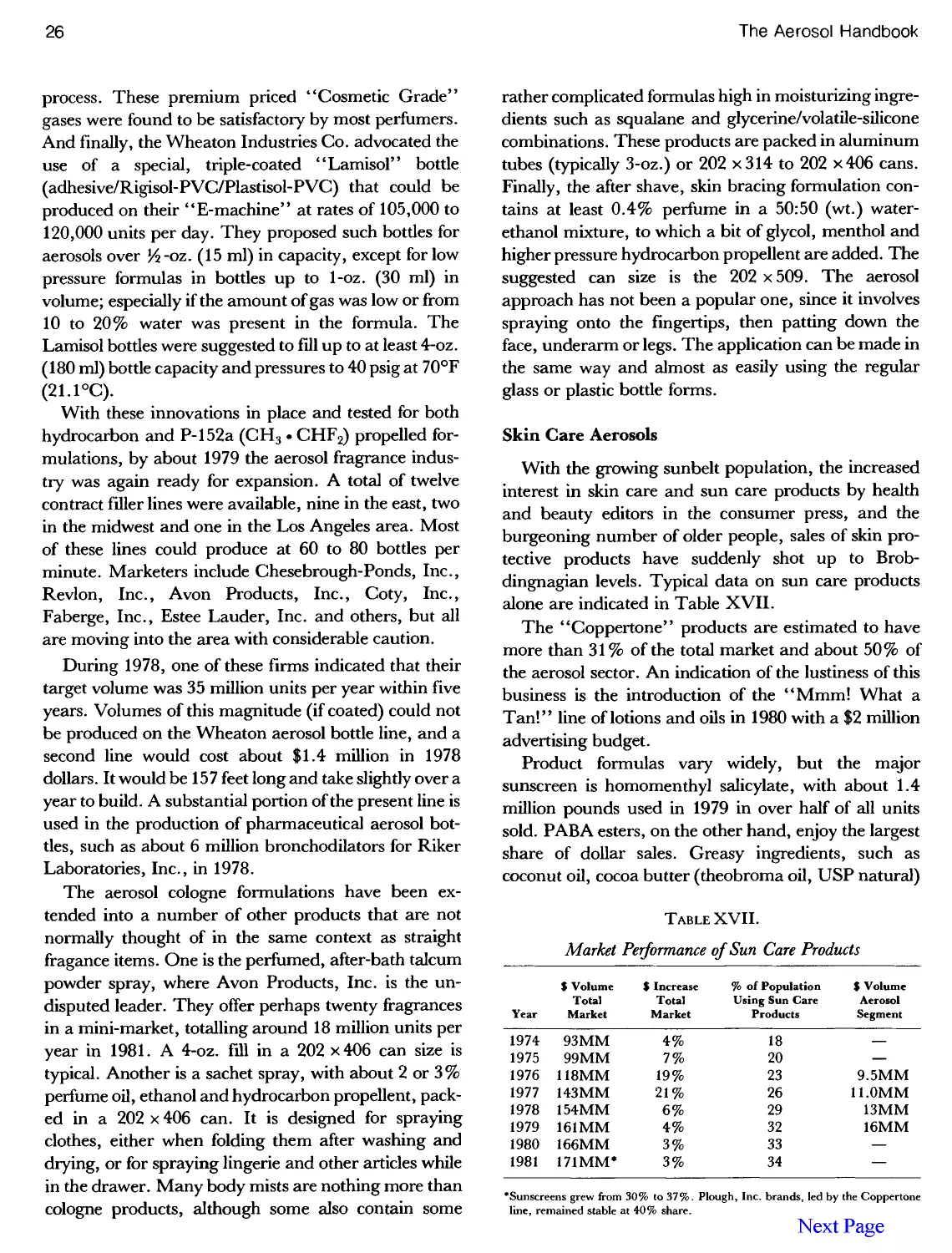
17. Market Performance of Sun Care Products 26
18. Unit Sales of Aerosol Insecticides; 1970-1980 27
19. Aerosol Product Sales; 1979-1980 27
20. Unit Sales of Aerosol Paints; 1974-1980 30
21. Unit Sales of Air Fresheners; 1970-1980 30
22. Unit Sales of Food Aerosols Including Whipped Cream
Products; 1972-1980 (U.S.A.) 33
23. Worldwide Consumption of Aerosols; 1979 35
24. Production and Uses of Chlorofluorocarbons P-ll and
P-12; 1958-1980 35
25. Propellent Selection for Aerosols Filled in 1979 (%) 36
26. Aerosol Productions During 1979 36
27. Market Share of Selected Aerosol Products 37
28. Aerosol Production of Larger Volume Countries 38
29. World Production of Aerosols; 1970-1980 39
30. Ten Year Variations in U.S.A. Aerosol Categories 40
31. Advantages of the Aerosol Dispensing System 45
32. Disadvantages of the Aerosol Dispensing System 46
1. Market Share of Aerosol Containers 48
2. Major Aerosol Can Suppliers in the U.S. A 48
3. Factors Influencing the Structural Strength of Aerosol
Cans 51
4. Thickness of Tinplate Used in Aerosol Cans 51
5. Variation of Tinplate Thickness 51
6. Variation of Baseweight Thickness at Different
Locations 52
7. D.O.T. Requirements for Metal Aerosol Containers .... 52
METAL CONTAINERS
8. Buckle Resistance of Typical 211-Diameter Can
Bottoms 53
9. Temper Specifications for Steel Plate 54
10. Dome Labeling Recommendations for Three-Piece
Aerosol Containers 57
11. Standard Sizes for Three-Piece Aerosols 59
12. Preferred Can Sizes and Volume Fills in Europe
Federation of European Aerosol Associations; 1979 62
13. Body Plate Preferences for Various Can Diameters 63
List of Tables
XI
TABLE PAGE
14. Accuracy of Electrochemical Prediction of Test Pack
Results 67
15. Solder Codes for Aerosol Containers 70
16. Modifications of the Process for Welding Cans 71
17. U.S.A. Tinplate and CCI-Steel Aerosol Can Sizes 73
18. Aluminum Aerosol Can Suppliers to the U.S. A 75
19. Aluminum Aerosol Container Profiles -1982 76
20. Aluminum Aerosol Cans Available in the U.S. A 78-79
21. Alusuisse Straight-Shouldered Aluminum Cans 80-81
22. Total Height of Monobloc Aluminum Aerosol Cans 81
1. Relative Propellent Energy, as a Guide to Bottle
Selection 119
2. Ignition Consequences Upon Instant Release of C-17
(N-Butane) From a Ruptured Plain Glass Aerosol 121
3. Various Aerosol Colognes, Based on Use of
Dimethylether 122
TABLE PAGE
23. EEC Directive (Annex III) Giving the Range of Volumes
for Products Sold in Aerosol Form 82
24. Approximate Compositions of Aluminum Alloys Used in
Aerosol Can Manufacturing 86
25. Label Dimensions and Print Areas for Aluminum Cans
Made by Metal Box Limited 90
26. Specifications for Paper Labels Used for Steel and
TinplateCans 94
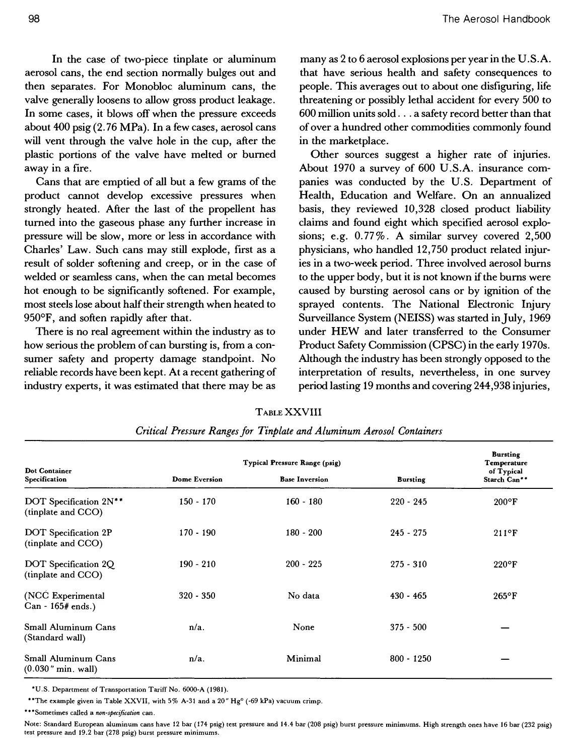
27. Pressure of Various Aerosols at Elevated Temperatures . . 97
28. Critical Pressure Ranges for Tinplate and Aluminum
Aerosol Containers 98
GLASS AEROSOLS
4. Wheaton "SAF" Process Uncoated Aerosols and
Plastic Coated Aerosols 123
5. Drop Testing Results for Various Uncoated Glass
Aerosols 126
6. Parameters Involved in Drop Testing Glass Aerosols ... 128
PLASTIC AEROSOLS
1. Permeation Rates Through 4-oz. Zytel 101 Bottles of
0.050"Average Wall Thickness 146
2. Permeation Factors at Different Temperatures 146
1. Properties and Recommendations for D&A Cup
Latexes 155
2. Weight Loss Data for a Non-Flammable Aerosol
Insecticide Product 159
3. Typical Gasket Swell Levels After Immersion in
Common Aerosol Solvents 160
4. Comparisons of Weight Loss Between High Methylene
Chloride and High 1,1,1-Trichloroethane Aerosol
Insecticides 161
3. Computer Cost Analysis for 2-oz. Celcon Bottle 147
4. Plastic Identification Table 148
VALVES
5. Nomenclature and Structure of Elastomers Used for
Valve Gaskets 162
6. Dip Tube Swelling When in Contact with Solvents 168
7. Compilation of Seaquist Valve Company Valve Series
and Basic Assemblies 172
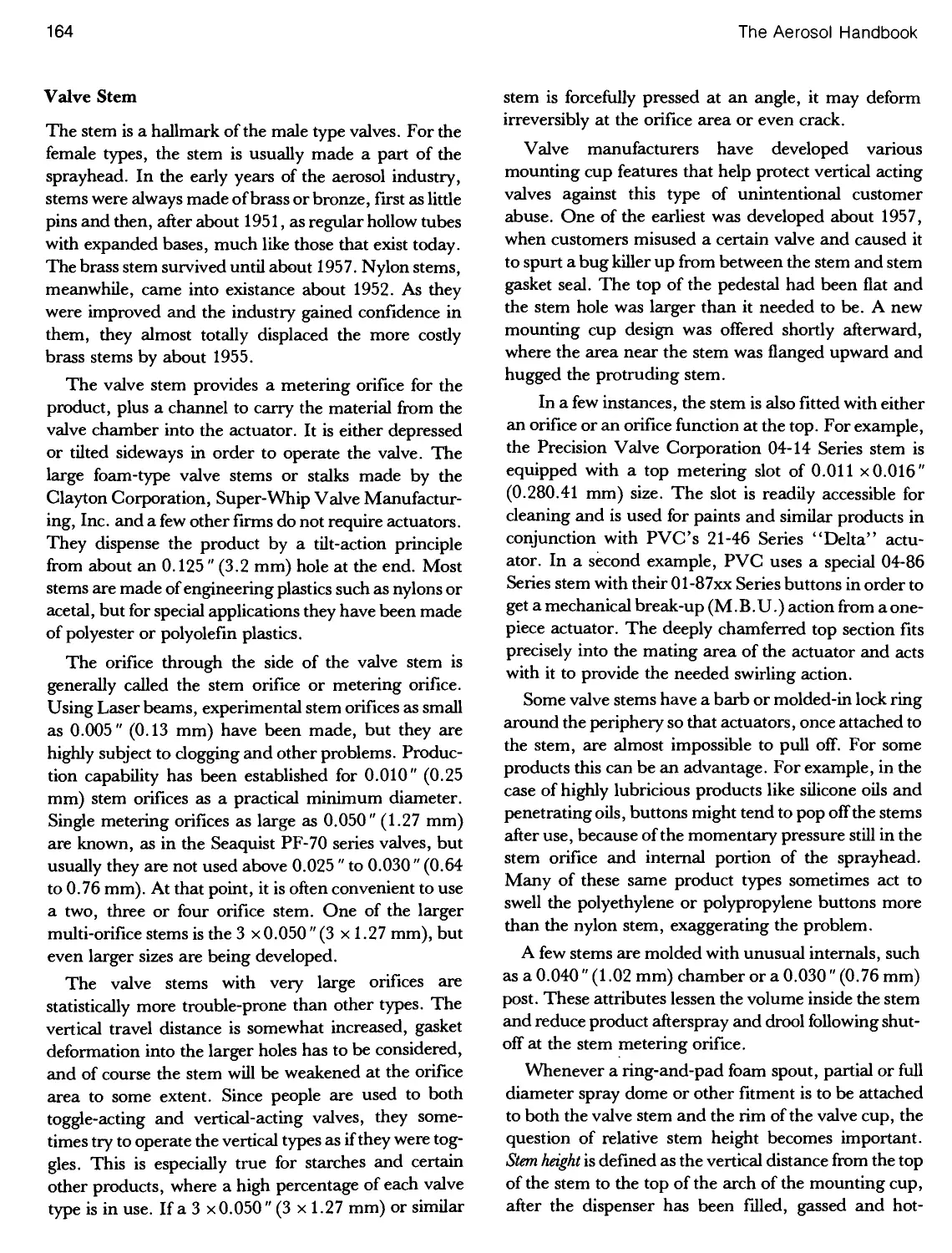
8. CSMA "A-D Dimension" Chart for Suggested Dip
Tube Lengths 182
COVER CAPS
1. Aerosol Plastic Cover Cap Identification Chart .... 187-189
2. Variation of Cap Wall Thickness with Diameter 190
3. Dimensional Comparison of 21 Typical Aerosol Cover
Caps 190
XII
The Aerosol Handbook
TABLE PAGE
1. Flammable Aerosol Classifications and Precautionary
Labeling in Japan 204
2. Flammable Contents of Aerosols Produced in the U.S.A.
andtheU.K 206
3. Typical Flammability Test Results 208
4. Required Aerosol Labeling as a Result of Flame
Projection Test 210
5. Aerosol Flammability Test Results 213-15
6. Flammability of Selected Hair Sprays by the Flame
Projection Test 217
7. Flame Projection Test Results for an Insecticide 218
8. Flash Points of Common Aerosol Ingredients 223
FLAMMABILITY
TABLE PAGE
9. Aerosol Flammability Worksheet 227
10. Triboelectric Table of Common Substances 228
11. Electrostatic Charge, Voltage and Sparking Energy
for 202 x 406 Cans of Several Aerosol Products 230
12. Variation of Electromotive Force (Voltage) When an
Aerosol Is Sprayed and/or Punctured 230
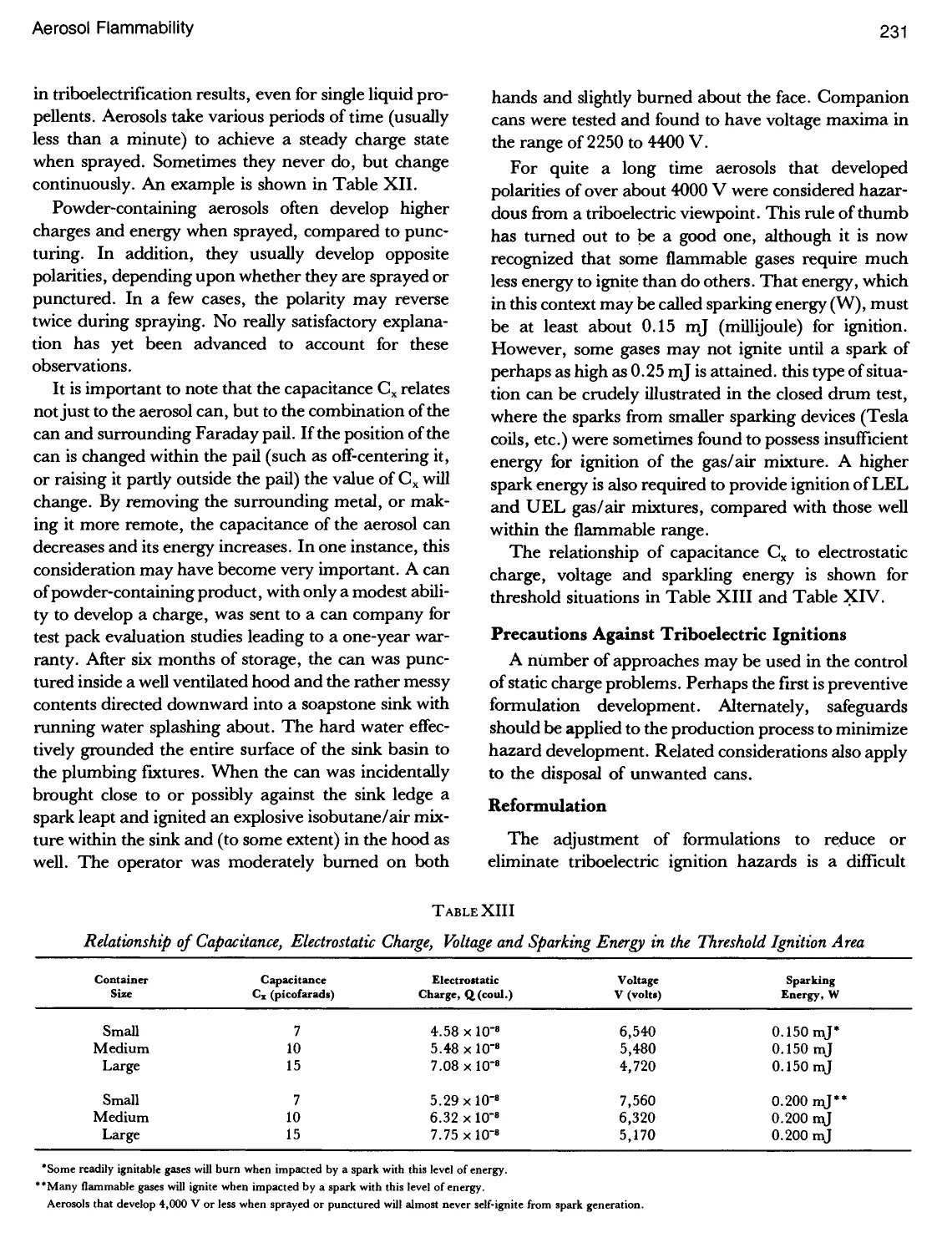
13. Relationship of Capacitance, Electrostatic Charge,
Voltage and Sparking Energy in the Threshold Ignition
Area 231
14. Minimum Ignition Energy of Various Substances 232
15. Summary of FM Test Results of 1979/80 on Aerosol
Prototypes 244
1. Major Categories of Acute Poisoning; 1971 & 1979 255
2. Consumer Attitudes: Problems with Aerosol Hair
Sprays 256
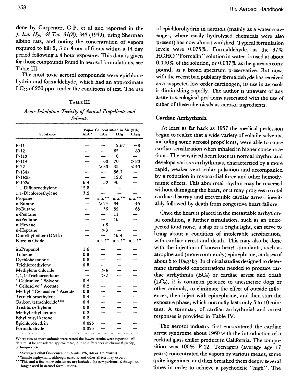
3. Acute Inhalation Toxicity of Aerosol Propellents and
Solvents 258
4. Incidence of Cardiac Arrhythmia due to Propellent
Inhalation 259
5. Threshold Limit Values (TLV) for Various Aerosol
Propellents and Solvents 262
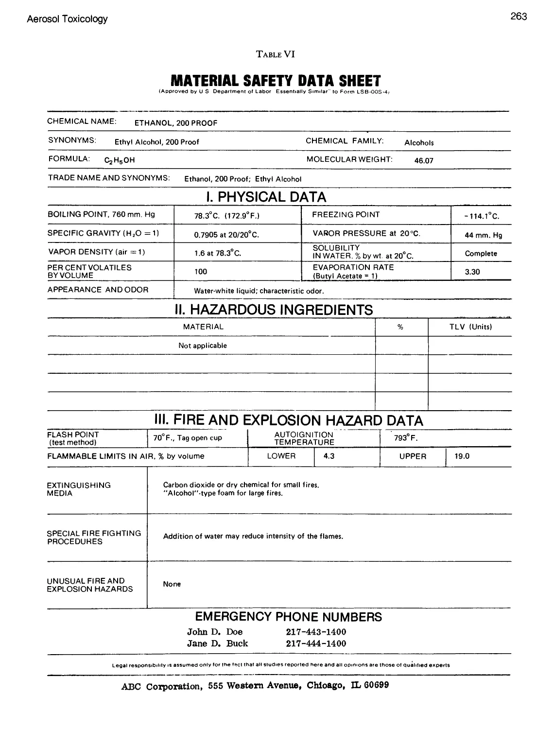
6. Material Safety Data Sheet 263, 264
TOXICOLOGY
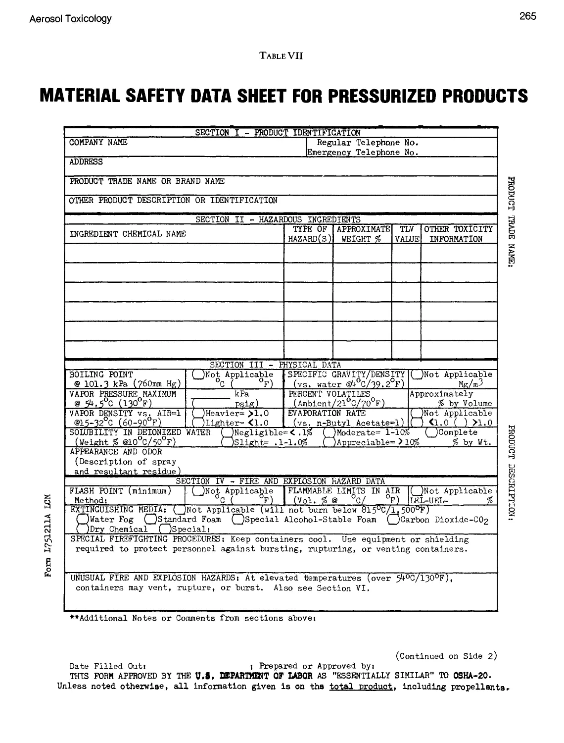
7. Material Safety Data Sheet for Pressurized
Products 265, 266
8. Fee Schedule for Acute Toxicology Studies 267
9. Particle Size Distribution of Hair Sprays 271
10. Falling Rate, as a Function of Droplet Size 272
11. Modified Ames Test Results Using Aerosol Grade
Hydrocarbon Propellents 275
12. Results of the Ames Screening Test for Mutagenicity,
with Added Carcinogenicity Assays 276
13. Mutation Activity of Various Compounds on Fruit
Flies 271
1. Propellent Loss 282
2. Variation of Crimp Depth with Crimp Diameter 288
3. Variation of Crimp Depth with Gasket Material
Thickness 288
4. Variation of Crimp Depth with Collet Radius 288
5. Variation of Crimp Depth with Thickness of Valve
Cup 288
6. Variation of Crimp Depth with Can Curl Thickness .... 288
7. Variation of Crimp Depth with Bead Contact Height. . . 289
8. Variation of Crimp Depth with Diameter of the Can
Opening 289
CRIMPING
9. Variation of Crimp Depth as a Function of Dimensions
of Six Factors 290
10. Contact Height Specifications for Various Cans and
Valve Cups 293
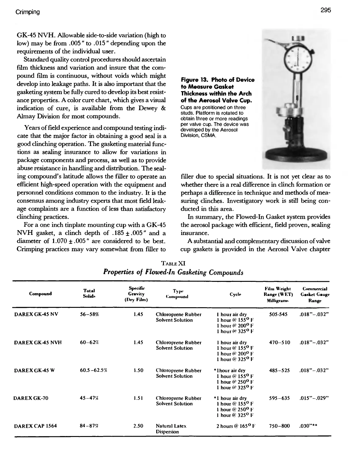
11. Properties of Flowed-In Gasketing Compounds 295
12. Influence of Crimp Cap Height on Valve Cup Gasket
Leakage Rate 296
13. Weight Loss Through Precision Valves, for a Hair
Sprayina202 x509Can 301
14. Crimping Dimensions for "Sepro-Cans" and Effects
Thereof 304
List of Tables
XIII
TABLE PAGE
1. Stratospheric Removal of Ozone (Estimated) 312
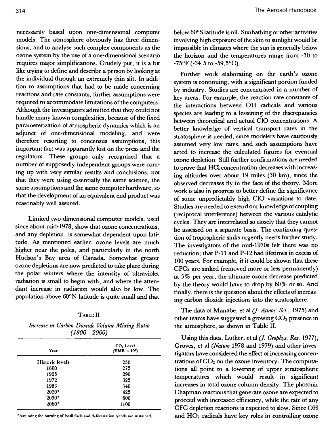
2. Increase in Carbon Dioxide Volume Mixing Ratio
(1800-2020) 314
3. Production and Uses of P-ll and P-12 318
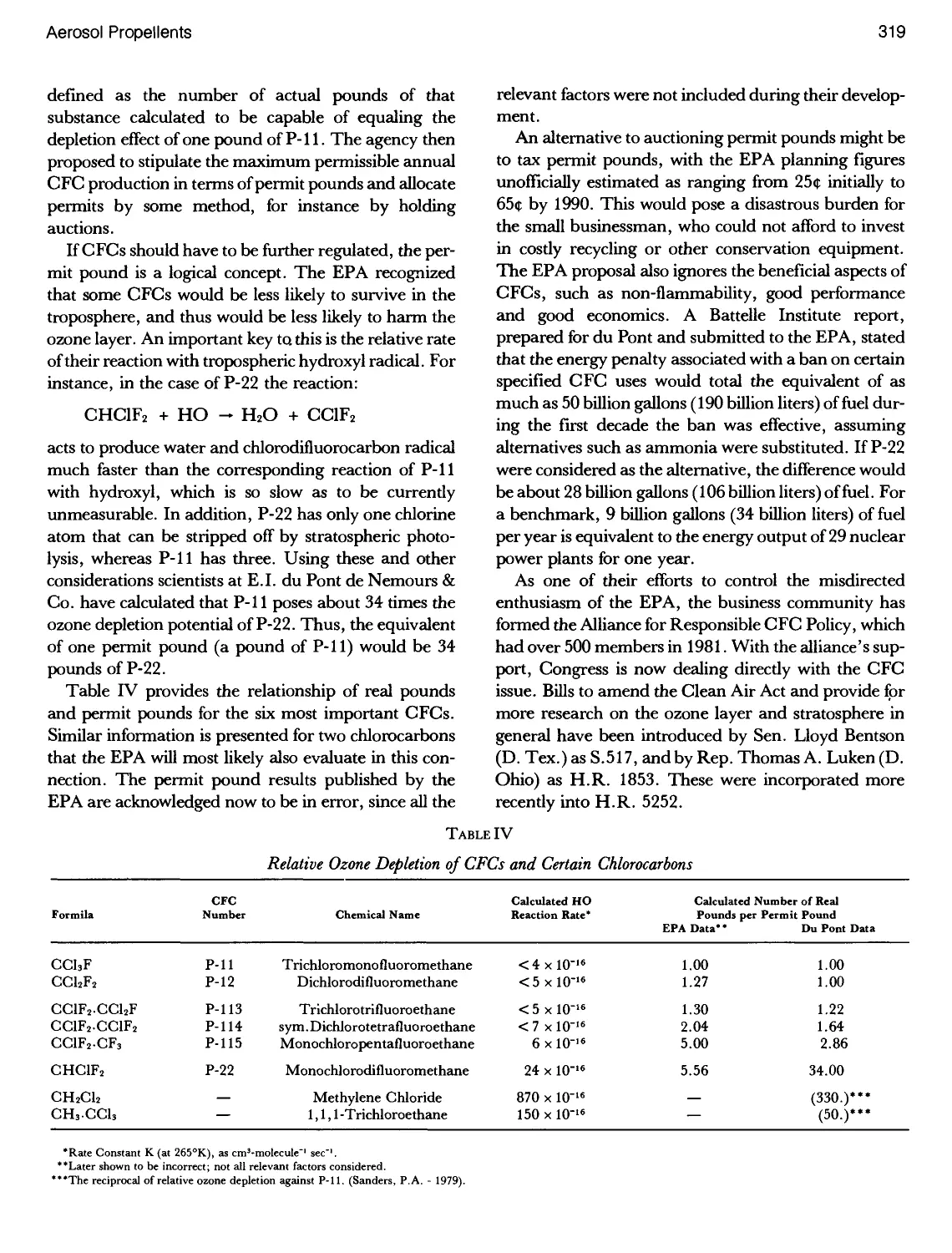
4. Relative Ozone Depletion of CFCs and Certain
Chlorofluorocarbons 319
5. U.S.A. Exemptions from the Bans on Chlorofluorocarbon
Propellents 320
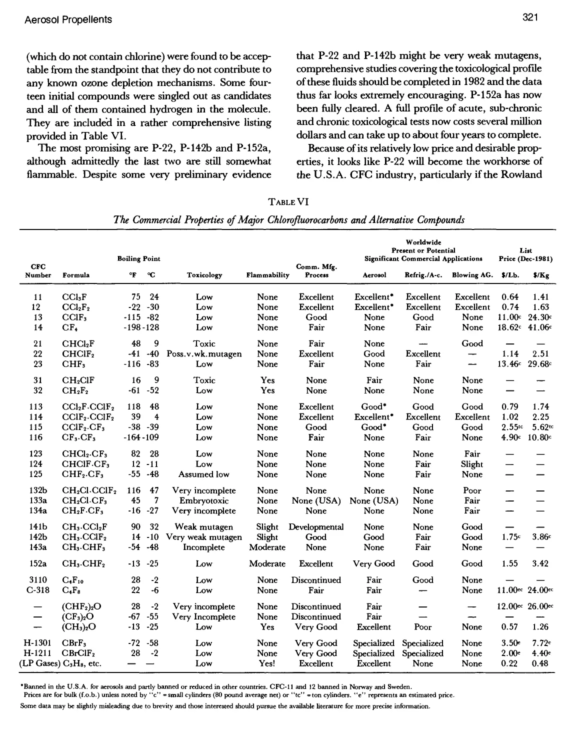
6. The Commercial Properties of Major Chlorofluorocarbons
and Alternate Compounds 321
7. Physical Properties of Fluorinated Hydrocarbon
Propellents (Common Types) 324
8. Amounts of Phosgene (mg) Formed by the Pyrolysis
of One Gram of Propellents 326
9. Pressure of Pure Fluorocarbon Propellents at Various
Temperatures 326
10. Pressure of P-12/P-11 Blends at Various Temperatures . 326
11. Pressure of P-12/P-114 Blends at Various
Temperatures 327
12. Glass Cologne and Perfume Aerosol Formulations 328
13. Physical Properties of the Fluorinated Hydrocarbon
Propellents (Uncommon Types) 329
14. Borderline Solubility Compositions of P-152a, Ethanol
and Water 330
15. Aerosol Propellent Use Profile in Switzerland
(1977-1978) 336
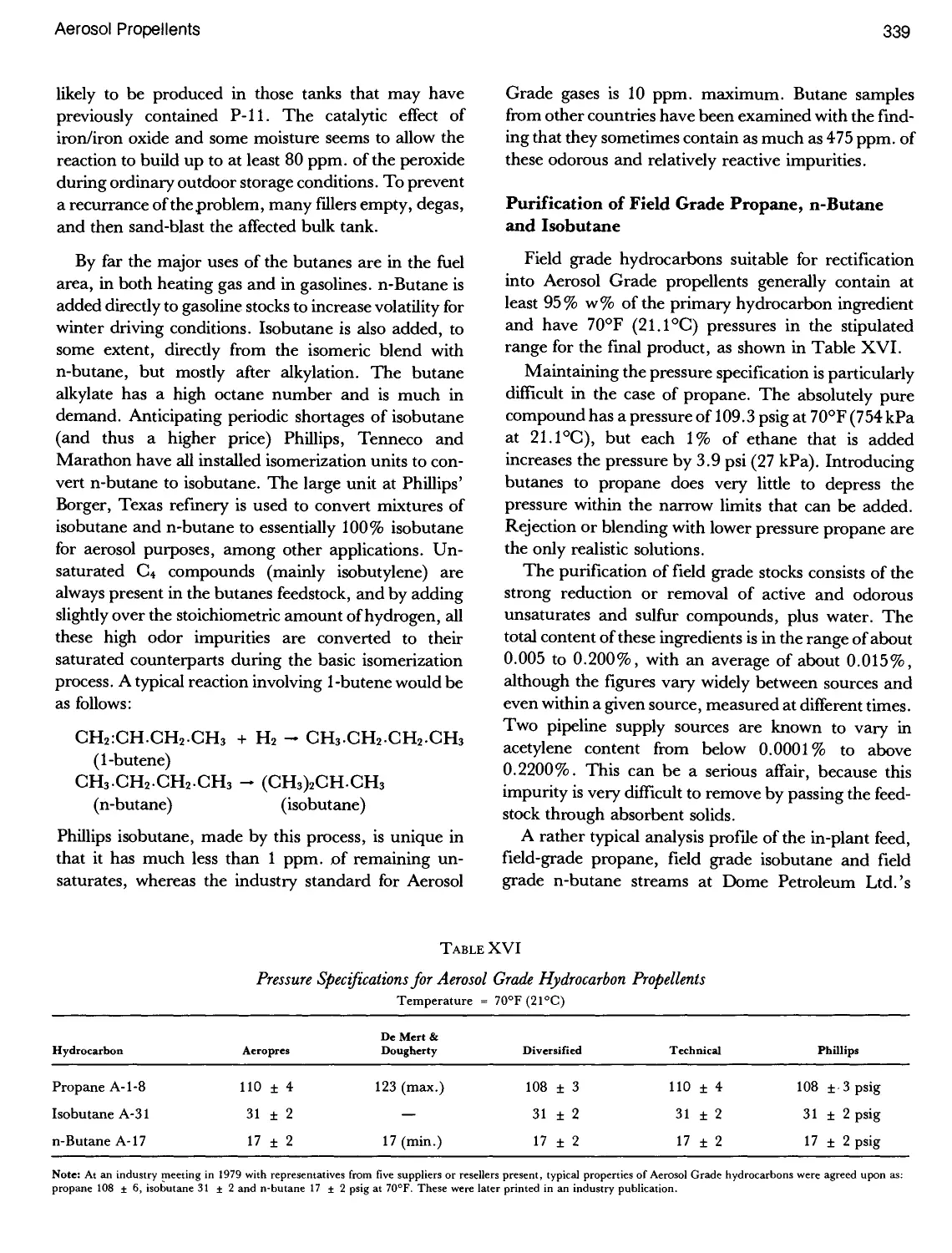
16. Pressure Specifications for Aerosol Grade Hydrocarbon
Propellents 339
17. Plant Feed and '' Field Grade'' Hydrocarbon Analyses . 340
18. Hydrocarbon Propellent Specifications 342
19. Typical Composition of Aerosol Grade Propellents 343
20. Laboratory Test Results Accompanying Isobutane
Shipments 343
PROPELLENTS
TABLE PAGE
21. Physical Properties of Purified Hydrocarbon
Propellents 344
22. Heat of Combustion for Various Aerosol Ingredients . . . 345
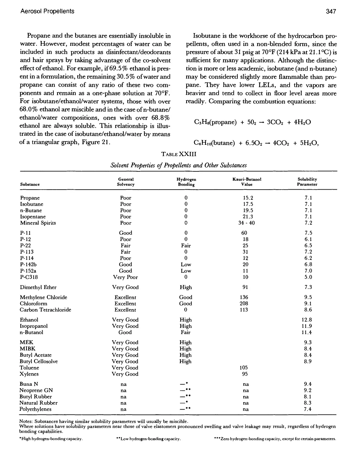
23. Solvent Properties of Propellents and Other
Substances 347
24. Conversions Between Mol, Volume and Weight Per Cent
for Blends of Propane and Isobutane 349
25. Composition and Physical Properties of N-Butane/
Propane 351
26. Decrease in Pressure as Aerosol Hair Spray is
Discharged 351
27. Typical Compositions for Hydrocarbon Propellent Blends
Having a Gauge Pressure of 46 psig 352
28. Typical Compositions of the Aeropin Propellents 352
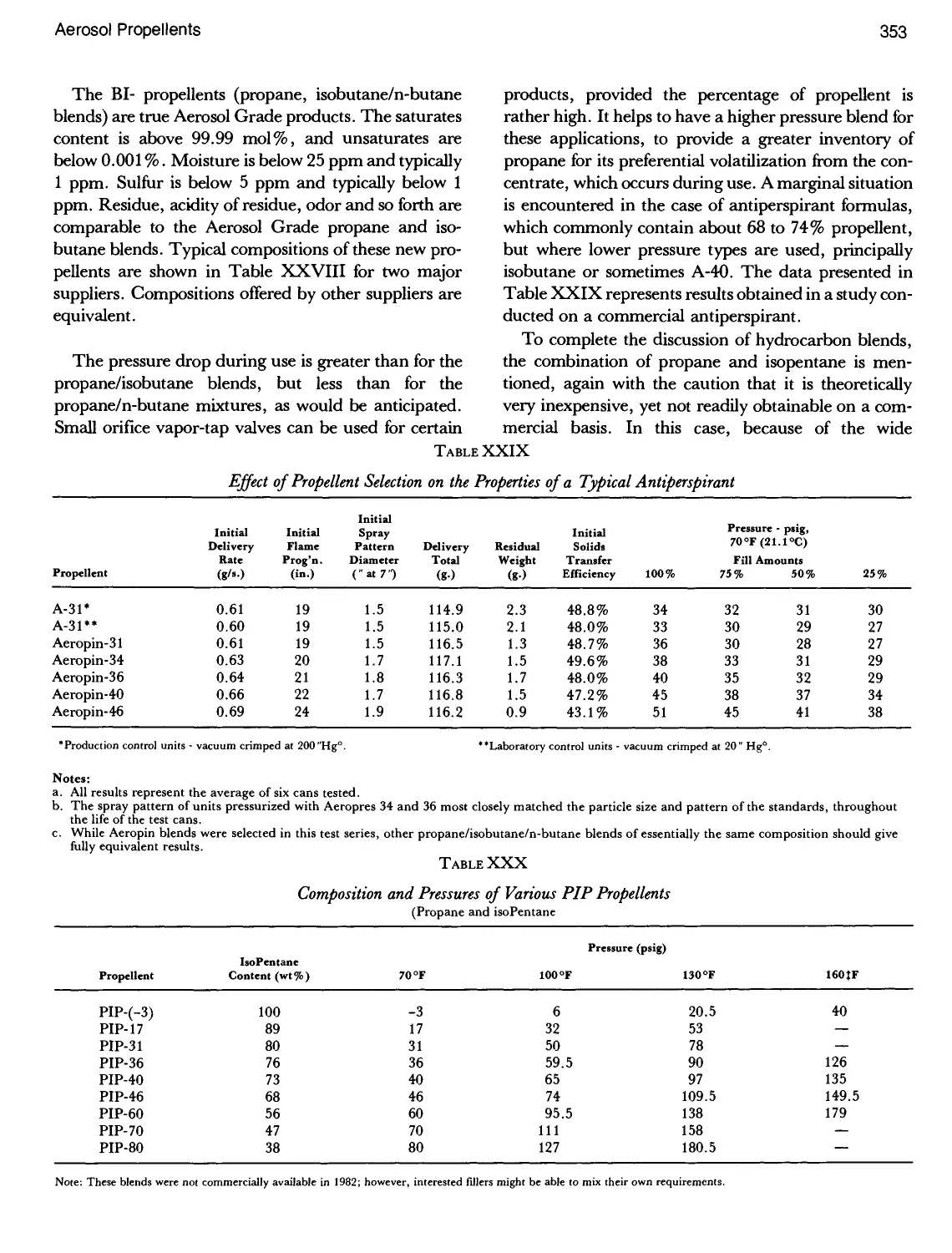
29. Effect of Propellent Selection on the Properties of a
Typical Antiperspirant 353
30. Composition and Pressures of Various PIP Propellents .353
31. Particle Size Distribution of an Anhydrous Insecticide
Spray 354
32. Specifications for Dimethyl Ether(DME) 355
33. Physical Properties of Dimethyl Ether (DME) 356
34. Solubility and Pressure Development for DME and
25%P-152a/75% DME Mixtures 357
35. Pressure and Density of DME Solutions in Water 358
36. Solubility of C02 and N20 in Selected Solvents 359
37. Flame Projection Results with Dimethyl Ether (DME)
Formulas 359
38. Properties of Sym-tetrafluorodimethyl Ether and
Perfluorodimethyl Ether 361
39. Physical Properties of Certain Compressed Gas
Propellents 362
40. Solubility of CO2 and N2O in Certain Aerosol Liquids
and Propellents 364
41. Effect of Methylene Chloride as a Cloud Point
Suppressant in Hydrocarbon Type Hair Sprays 370
1. Crimping Efficiency as a Function of Air Withdrawal. . . 423
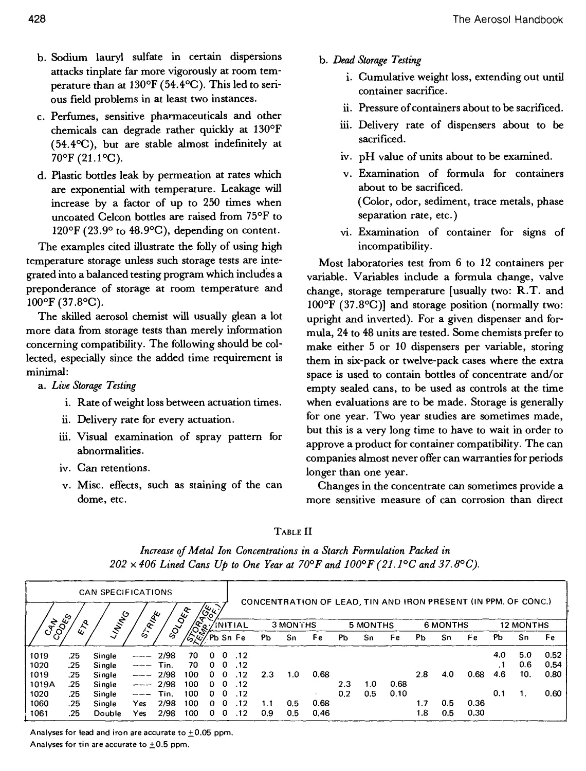
2. Increase of Metal Ion Concentrations in a Starch
Formulation Packed in 202 x 406 Lined Cans Up to One
Year 428
AEROSOL LABORATORY
3. Flying Insect Killer, Weight Loss After Actuation -
Buna-N Gasket 430
4. Flying Insect Killer, Weight Loss After Actuation -
Neoprene Gasket 430
5. Weight Loss Storage Tests 431
The Aerosol Handbook
TABLE PAGE
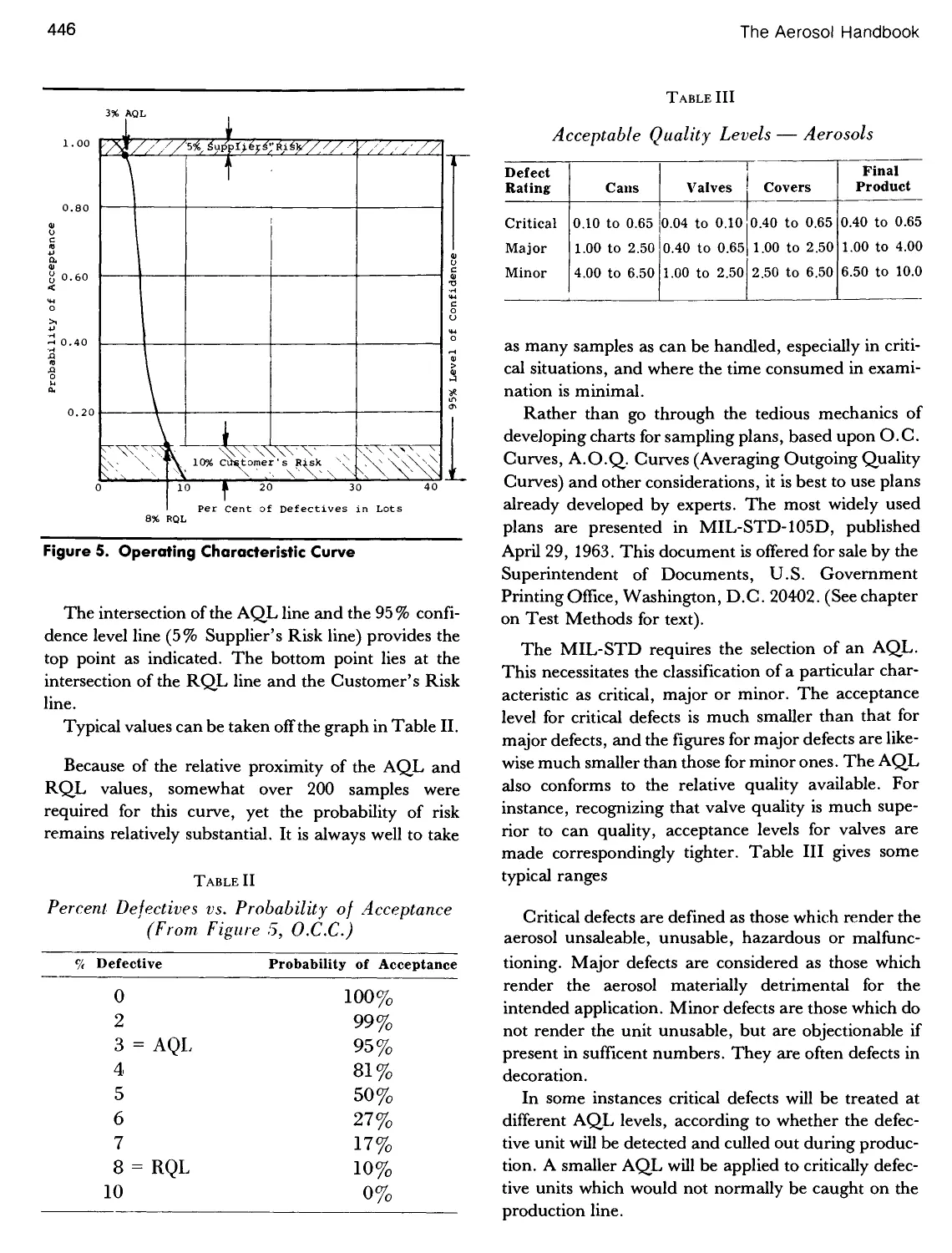
1. Percent Defectives vs. Probability of Acceptance 445
2. Percent Defectives vs. Probability of Acceptance 446
3. Acceptable Quality Levels - Aerosols 446
4. Incoming Inspection Program - Cans 447
5. MIL-STD (Table 11-A) Single Sampling Plan for
Normal Inspection 448
6. Incoming Inspection Program - Bottles 451
7. Incoming Inspection Program - Valves 454
8. Incoming Inspection Program - Labels 456
QUALITY ASSURANCE
TABLE PAGE
9. Incoming Inspection Program - Caps 457
10. Incoming Inspection Program - Cases 457
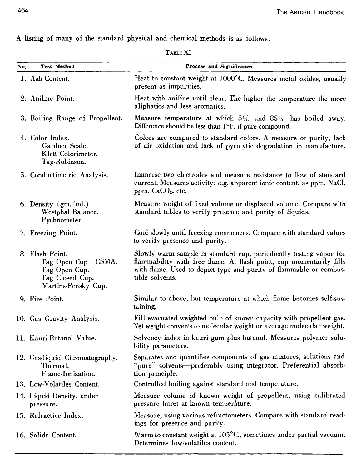
11. Physical Methods of Analysis 464-465
12. Chemical Methods of Analysis 465-466
13. X-r Data Tabulation 471
14. Standard Deviation by the Frequency Distribution
Method 473
15. Finished Aerosol Analyses 476
1. EPA Product Toxicity Categories for Labeling
Purposes 513
2. Type Size of Warning and Precautionary Statements
forthe Labeling of EPA Products 513
3. Typical EPA Precautionary Statements by Toxicity
Category
4. Application for New Pesticide Product Registration .. . 514
5. Confidential Statement of Formula 516
GOVERNMENT REGULATIONS
6. Label Technical Data 517
7. Certification Statement 518
8. FIFRA S 3(C) (B) Summary Sheet 519
9. Generic Data Exemption Statement 520
10. Labeling Requirements of the FIFRA, as Amended .. . 522
11. Neiss Results on Aerosol Injuries; 1974-1978 with
Estimated U.S.A. Totals 534
XV
List of Illustrations
FIGURE PAGE
1. Aerosol Container Sales in 1980 vs. 1979 12
2. Aerosol Shaving Cream Market Volume 13
3. Aerosol Hair Spray Market Volume 16
4. Aerosol Antiperspirant/Deodorant Market 20
5. Aerosol Perfume Cologne Market Volume 25
6. Aerosol Insecticide Market Volume 28
7. Various Aerosol Fry-Pan Release Products 33
8. A Grouping of Aerosol Food Items 34
MARKETING
FIGURE PAGE
9. Difference Between Demand in the Absence of CFC
Regulation and Demand with Regulation 35
10. Aluminum Tubes for Personal Protection Products 37
11. Japanese Anti-Static Products for Garments 37
12. World and U.S.A. Aerosol Production 39
13. U.S.A. Aerosol Production 1972-1981 40
14. Packaging of Gillette Products in England 41
15. Translucent 6-Pack Trays Made in England 43
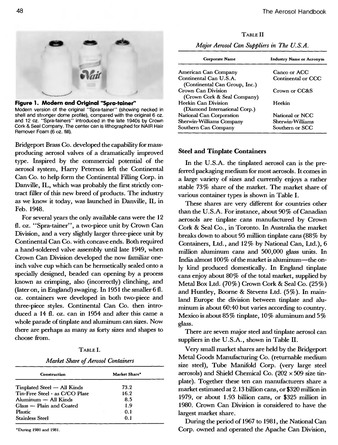
1. Modern and Original "Spra-tainer" 48
2. Cross-Section of #100 ETP, Showing Layers of Tin
and Intermetallic Compound 50
3. Dimensions of a Cross-Section of 85# Base Plate with
#100/25 Differential Tinplate 50
4. ASTM (Sub. XX) Plate Thickness Survey 52
5. Typical Bottom Double Seam Profile 55
6. Cross-Section of "Snap-lock 202-Dome Top 56
7. Cross-Section of "Snap-lock" 211-DomeTop 56
8. Various Can Bead Profiles 57
9. Configuration of Open and Closed Can Curls 57
10. Proposal for Top End Dimensions for Necked-In
Tinplate Aerosol Cans 59
11. The Dual-Radius Can Bottom Profile 59
12. Dual and Single Radius Can Bottoms 59
13. Various Necked-In Varieties of U.S.A. Cans 60
14. Three-Piece Tinplate Welded Side Seam Cams 60
15. AerosolCanof "Flit" and "Aerosect" 62
16. Worksheet Recording Can Evaluation 67
17. Examples of Seamless Can Bodies 71
METAL CONTAINERS
18. Soudronic Wireweld Manufacturing Process 72
19. The Continental 'Conoweld I' Process 72
20. A Personal Product Line, Packaged in Three-Piece
Tinplate Aerosol Cans 74
21. Aerosol Products Are Packaged in Standard Cans
Varying in Height and Diameter 74
22. Aerosol Can of DOT Specification 2Q. 74
23. One-Piece Drawn Aluminum Aerosol Cans 75
24. Monobloc Aluminum Container 76
25. Monobloc Shaped Aluminum Aerosol Cans 76
26. Shaped Aluminum Aerosol Cans 77
27. Award Winning Aluminum Container 77
28. Aluminum Tube Used For Foam Product 82
29. A Pair of Aluminum Aerosol Cans Produced in France . . 82
30. Aluminum Can Custom Shaped by Alusuisse 83
31. Typical European Designs for Aluminum Aerosol
Cans 83
32. Typical Control of a 13 mm Aluminum Tube 83
33. Finish Designs for 20 mm Aluminum Tubes 84
34. Finish Designs: 25.4 mm Tubes, Cans 84
XVI
The Aerosol Handbook
FIGURE PAGE
35. Typical European 1 " (25.4 mm) Bead for Aluminum
Can Showing Machined Section 85
36. Typical Cliff Impact Division 1 " (25.4 mm) Bead for
Aluminum Can, Showing Groove 85
37. Progressive Collapse of Aluminum 1 " (25.4 mm) Bead
as Pressure Load Increases 85
38. Relationship of Curl Deformation to Pressure Load for
1 "(25.4 mm) Aluminum Cans 86
39. Slugs Used in Making Drawn Cans 87
40. Selection of 15 Monobloc Aluminum Decorated Aerosol
Cans 88
41. Unique Aluminum Tube-in-Can Development 89
42. Printing Aera and Other Dimension for Typical
Peerasol Cans 89
43. Corrosion Pattern of Water/Ethanol Solutions in
Aluminum Aerosol Cans 90
44. Some Tall Commercial Aerosol Cans 93
45. Plain and Lithographed Aerosol Cans 95
46. Exploded Aerosol Can Due to Fire/Heat 97
FIGURE PAGE
47. Cut Away of Three-Piece Soldered Can 97
48. Original Version of RVR Aerosol Can 100
49. Base Section of Aluminum Monobloc Container 101
50. Polyethylene Piston Used in Mira-Flo Aerosol Can .... 102
51. ATypical Early "Sepro-Can" 103
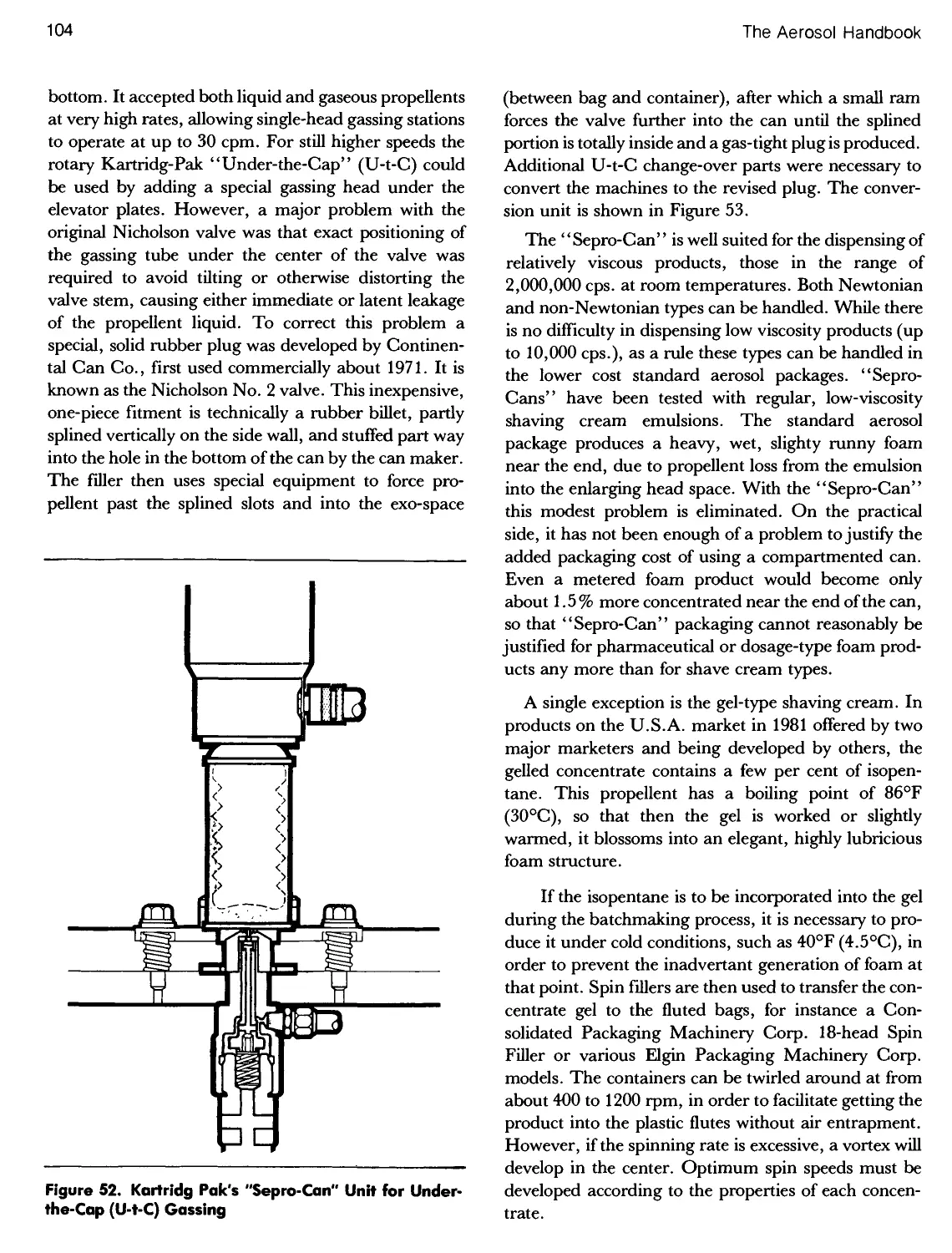
52. Kartridg Pak's "Sepro-Can" Unit for Under-The-Cap
Gassing 104
53. Bag-in-Can System Offered in Europe 106
54. Polyethylene Bag for Alupress-Pack 106
55. The Alu-Compack Composite Aerosol System 107
56. Bag-in-Can Development from Switzerland 107
57. Alucompack System for Toothpaste Product 107
58. Cross Section of Alucompack Dispenser 108
59. Coating, Filling and Use of "Flip" Barrier Pack Cans . . 108
60. Piston Used in the "Pepo" Ecological Aerosol
Container, Belgium 109
61. The "Preval" Spraymaker 110
GLASS AEROSOLS
1. Glass Colognes 112
2. Dimensions; Finish of 20 mm Glass Aerosols 114
3. Coated Glass Cylinder Rounds by Wheaton Aerosols
Company 115
4. Glass Bottles by Risdon Corp 124
1. Plastic and Glass Aerosol Containers 138
2. Cologne in Celcon Bottles 139
5. Original Stock Design Aerosol Bottles by Carr-
Lowrey Glass Co 125
6. Bottles Described in Table V, in Relation to Breakage
Resistance 127
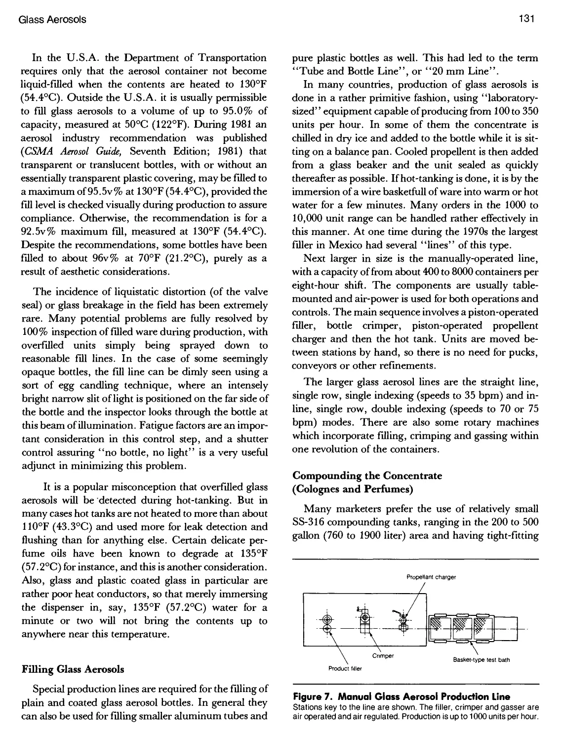
7. Manual Glass Aerosol Production Line 131
8. Clear Glass Bottle Prior to Fall Labeling 135
PLASTIC AEROSOLS
3. Sketch of OPET 140
4. 1982 Prototype of OPET Bottle 141
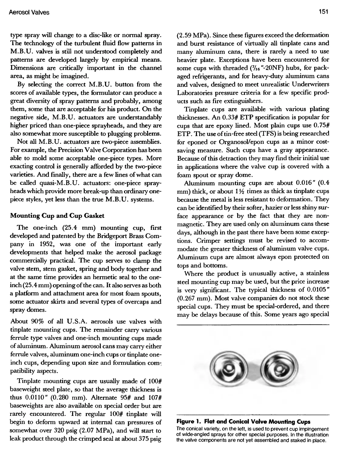
1. Flat and Conical Valve Mounting Cups 151
2. Cross Section ofa Flat Cup and Conical Cup Valve ....152
3. Cross Sectional View, Showing Aerosol Valve with
Stem Gasket and Cup Gasket Eudiometers 158
4. Model CL Valve 166
VALVES
5. Seaquist NS-31 Aerosol Valve Assembly 170
6. Seaquist PF-71 Toggle Valve Assembly 170
7. S-63 Tilt Valve by Summit Packaging Systems 170
8. Diagrams Showing Valve Action in Open and Closed
Positions 171
List of Illustrations
XVII
FIGURE PAGE
9. Exploded View of CA-78 Female Aerosol Valve 173
10. Seaquist SF-91 Female Valve Assembly 174
11. Standard and Metering Ferrule Type Aerosol Valves
by the Emson Research, Inc 176
12. Schematic Drawing of CLF Valve 177
FIGURE PAGE
13. Variable Aerosol Actuator Operation 177
14. Aquasol Dispenser Stem and Sprayhead 178
15. Two-Piece Specialty Actuators 179
16. CliXon Dispensing Cycle. Also a Spray vs. Time
Profile 179
COVER CAPS
1. Slotted Cover Cap with Extension Tube 184
2. Drawing of Old Style One-Inch Cap 185
3. Drawing of Double Shell Cap 185
4. Drawing of Rim Snap Cap 185
5. Drawing of Snap Lock Cap 185
6. "Lift-Up" Cap 186
7. European Cap 191
8. Aerosol Cover Cap Fitment Gauge 191
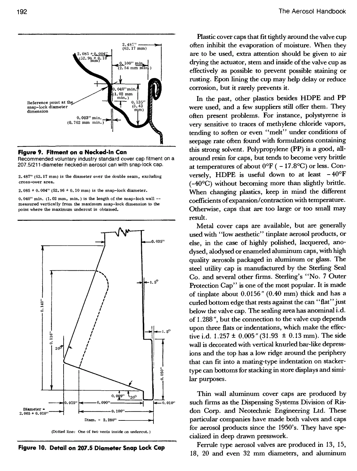
9. Fitment on a Necked-In Can 192
10. Detail on 207.5 Diameter Snap Lock Cap 192
11. 114-Diameter Can Necked-In to a 112 Can 193
12. Selection of Anodysed Aluminum Caps 194
13. Mark Series Caps by Metal Box Ltd 194
1. Flame Consequences of Spraying 207
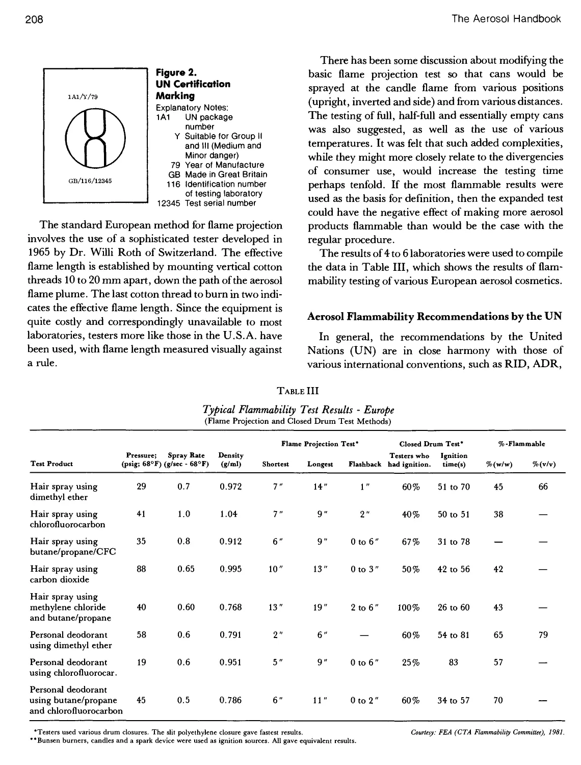
2. UN Certification Marking 208
3. Australian Flame Projection Test Unit 209
4. Canadian Flame Projection Tester 209
5. U.S.A. Flame Projection Testing Device 211
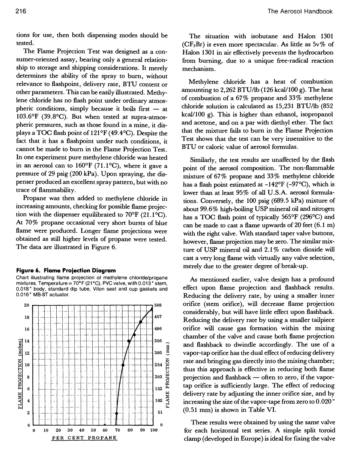
6. Flame Projection Diagram 216
14. Full Diameter Cover Cap 195
15. KinderGuardTM 196
16. Overcaps by Knight Engineering & Molding Co 196
17. Modified Summit S-63 Valve and Heavy Duty
Actuator/Overcap Used for Tire Inflation 197
18. Precision Valve Actuator Caps 197
19. Hemishperical Cover Cap Design 197
20. Customized Cover Caps and Actuator Cap on
Aluminum Cans — European Market 198
21. Ordinary Tinplate Can and Cap, Compared with
Brushed Aluminum Can and Cap 198
22. Blendax Aerosol Toothpaste in Composite Aluminum
Tube, Custom Cap, Spout and Base in Shadow-Box,
Sold in West Germany 198
FLAMMABILITY
7. Closed Drum Test Apparatus 220
8. Modified Tagliabue Open Cup Flash Point Tester 221
9. Flammability of Surface Residues Tester 224
10. Apparatus for Measuring Static Charge 229
11. Warehouse Fire Involving Aerosols 242
12. Graph Charting Flammable Storage Hazard 247
1. Biotransformation of Methylene Chloride 260
2. Biotransformation of N-Hexane 260
3. Chart of Exposure to Methylene Chloride 261
4. Time-Related Divisions of Toxicological Testing 267
5. Cross-Section View of the Human Respiratory System . 268
TOXICOLOGY
6. Deposition of Airborne Particles in the Respiratory
Tract, Shown as a Function of Aerodynamic
Dynameter 269
7. Retention of Aluminum Chlorohydrate in the Lungs . . . 269
8. Particle Size Distribution of Anhydrous Insecticide ....273
XVIII
The Aerosol Handbook
FIGURE PAGE
1. Split Ring and Nut, for Temporarily Sealing Aerosol
Valves 283
2. Closed and Open Curl Configurations 284
3. Open and Closed Curl Configuration 10X
Magnification 284
4. Open and Closed Curl Configurations 20X
Magnification 284
5. Dimensions Surrounding Crimped Can Curl 286
6. Device to Determine the Throat Radius of the Can
Dome 289
7. Can Dome and Upper Body Section of 211 Can 290
8. Valve, Dome and Upper Portion of Aerosol Can 290
9. Device to Determine the "Point of Hard Contact" 290
10. Sketch Illustrating Point of Hard Contact 291
11. Gauge to Measure Contact Height 292
12. Gauge for 1 Inch Valve Cup Flowed-In Gasket 294
CRIMPING
FIGURE PAGE
13. Device for Determining the Gasket Thickness 295
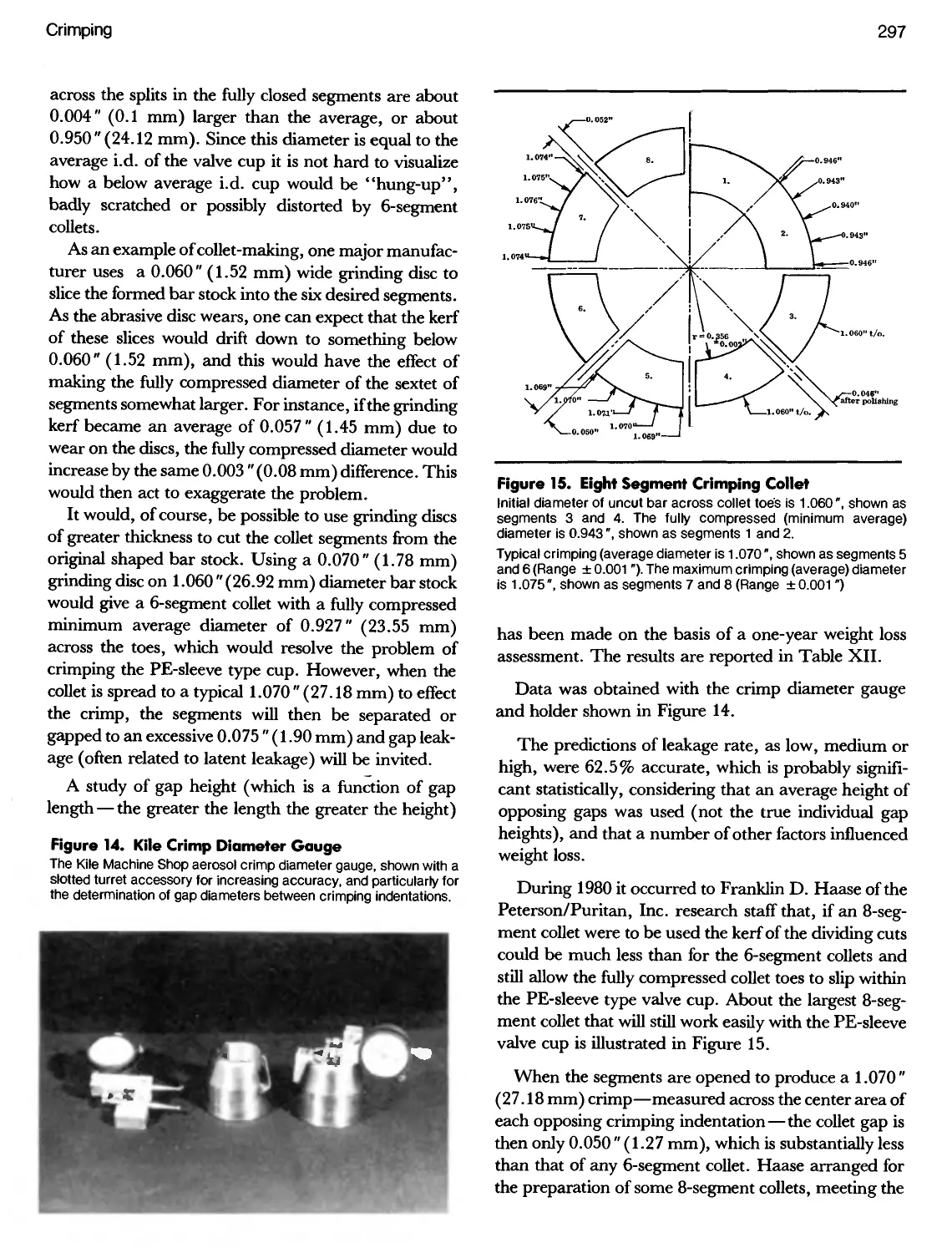
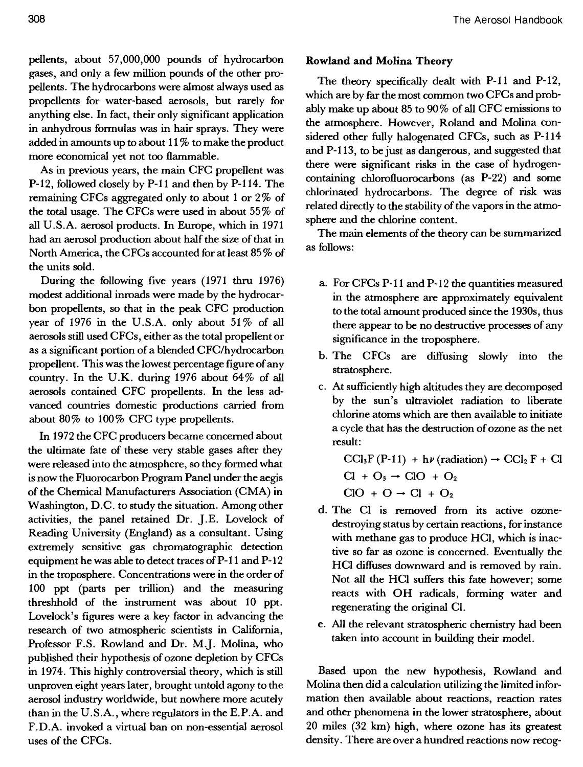
14. Kile Crimp Diameter Gauge with Slotted Turret 297
15. Eight Segment Crimping Collet 297
16. Device for Measuring Valve Cup Inside Diameter 298
17. Shoulder Profile of Aluminum Can 299
18. Glass Aerosol Valve Correctly Crimped 300
19. Incorrectly Crimped, Too Loose - Latent Leaker 300
20. Incorrectly Crimped, Too Tight and High 300
21. Kile Gauge for Measuring Crimp Diameter 302
22. Kile Aerosol Crimp Depth Gauge 302
23. Kile Aerosol Can Throat Contour Gauge 303
24. Graph On Throat Profile 303
25. Inner Throat Profile for 202-Diameter Can Before and
After Crimping 303
PROPELLENTS
1. Concentration Profile of Atmospheric Ozone 311
2. Percent Distribution of Stratospheric Ozone 313
3. Total Ozone Over the Northern Hemisphere 316
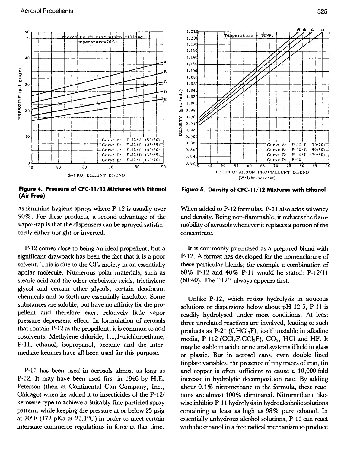
4. Pressure of CFC-11/12 Mixtures with Ethanol 325
5. Density of CFC-11/12 Mixtures with Ethanol 325
6. Pressure ofP-12/Ethanol and P-114 Ethanol Mixtures . .328
7. Vapor Pressure vs. Temperature for Fluorocarbons
P-113,P-114andP-115 329
8. Pressure and Phase Diagram for Blends of Ethanol,
Water and P-152a 331
9. Pressure for Blends of P-152a/Isobutane and P-152a/
P-133a 332
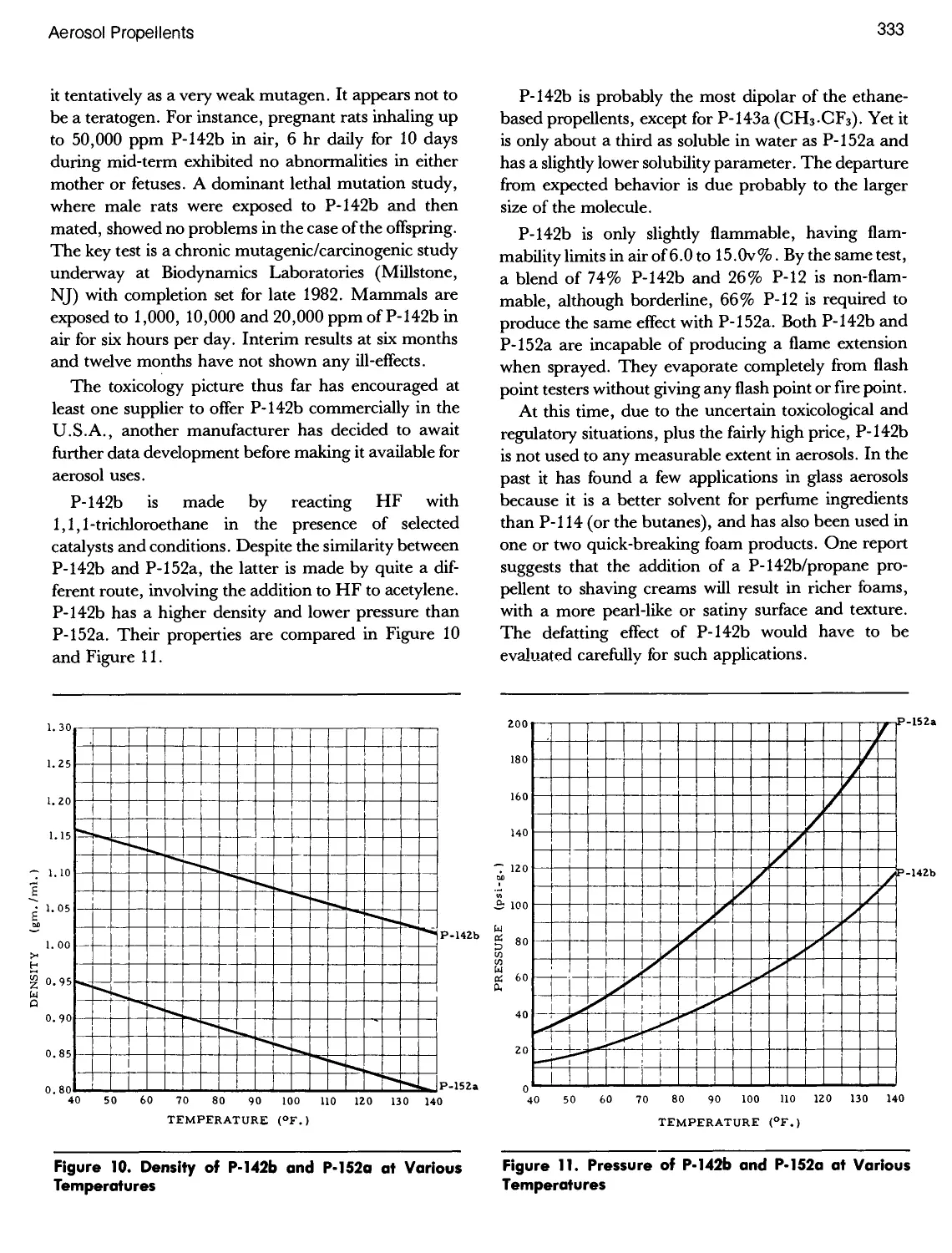
10. DensityofP-142band 152aat Various Temperatures ..333
11. Pressure of P-142b and P-152a at Various
Temperatures 333
12. Pressure of Common Halons and Blends 334
13. Density of Common Halons and Blends 334
14. Anti-Perspirant Transfer Efficiency 335
15. Refiners and Resellers of Aerosol Hydrocarbon
Propellents 337
16. Field Grade and Aerosol Grade Prices of the Common
Aerosol Hydrocarbon Propellents 338
17. Butane Purification Facility 341
18. G/L Chromatographic Analysis of Aerosol Grade
Isobutane 343
19. Pressure of Hydrocarbon Propellents at Various
Temperatures 346
20. Density of Hydrocarbon Propellents at Various
Temperatures 346
21. Solubility of the Ethanol, Water & Isobutane System
at 70°F 346
22. Pressure of Propane/Isobutane Propellents at Various
Temperatures 350
23. Density of Propane/Isobutane Propellents at Various
Temperatures 350
24. Pressure of CO2 and N20 Propellents at Various
Temperatures 362
25. Density of CO2 Propellent at Various Temperatures ...362
26. Pre-Saturation Equipment for the Addition of CO2 or
N20 to Aerosols 368
27. Effect of Methylene Chloride on the Cloud Point of
Aerosol Hair Sprays 369
List of Illustrations
XIX
FIGURE PAGE
1. Floor Plan for a Typical European-Style Filling Plant
with Two Lines and Provision for a Third 376
2. Propellent Blending System 378
3. Plastic Container Carrier Pucks 380
4. A Manual Type Production Filling Operation 381
5. Single and Double Row, Double-Indexing Lines 382
6. Rotary Line with Filler/Crimper/Gasser Machine 382
7. Double-Indexing Aerosol Loading Line 382
8. High-Speed In-Line "Core Assembly" Machine - the
Heart of an Aerosol Line 383
9. StarPakM20by Aerofill, Ltd 383
10. Rotary Filling Machine with Water Bath 383
11. Layout for Lehn & Fink Hi Speed Line for Packaging
Lysol 384
12. Product Acceptability vs. Weight of Propellent A-46 for
a 2 Av. Oz. Shave Cream 385
13. Lay-Out of an Aerosol Production Line Designed to
Run One Product, at About 100 CPM 386
14. High Flexibility Production Line 387
15. A Simple Rotary Line, Rated at 120 CPM 387
16. Economical Tray-and Disc Can In-Feeder Unit 388
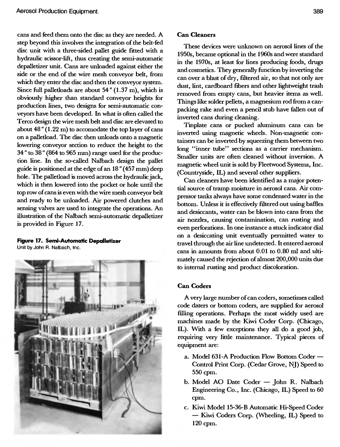
17. Nalbach Semi-Automatic Can Depalletizer 389
18. Nalbach Model 16-RS Food Aerosol Machine 392
MACHINERY
FIGURE PAGE
19. Terco Inc. Indexing Rotary Filling Machine 393
20. Terco Inc. Rotary Aerosol Filling Machine
(40 CPM) 393
21. Nalbach Tube and Glass Aerosol Filler and Crimper . . . 394
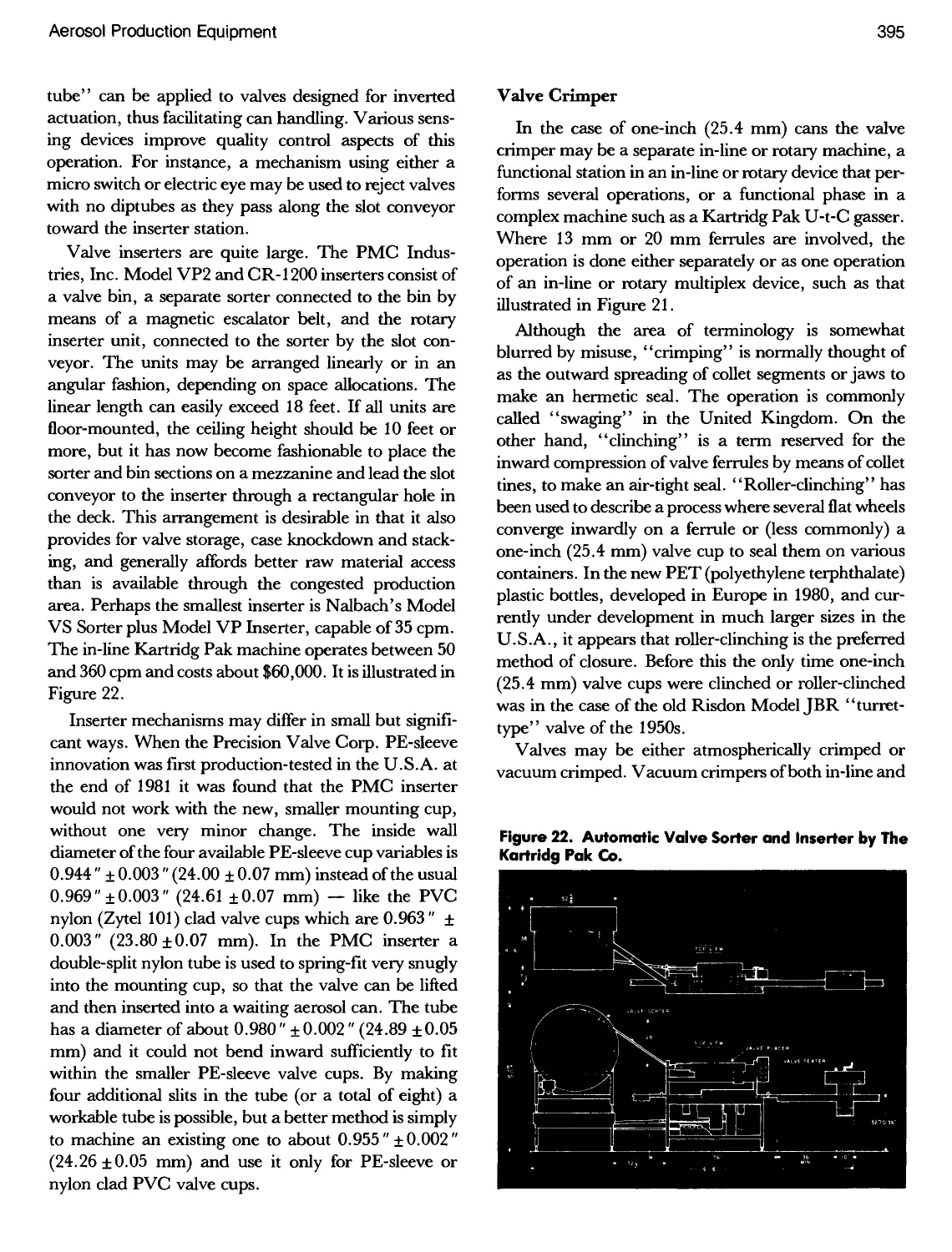
22. Kartridg-Pak Automatic Valve Sorter and Inserter ....395
23. Comparison of Theoretical and Typical Can
Evacuations 396
24. Terco Inc. Hand-Operated Filling Machine with
Production Heads 397
25. Elaborate Chlorofluorocarbon and Hydrocarbon
Propellent Tank Farm 398
26. Floor Plan of Gas House 398
27. Nalbach Model HPC Aerosol Propellent Charger 399
28. Can Evacuation, Filling and Crimping Sequential
Operations of a Kartridg Pak U-t-C Gasser with Nine-
Head Frame 400
29. A Typical Kartridg Pak U-t-C and Saturator Layout . . . 401
30. Propellent Supply System to Kartridg Pak U-t-C
Gasser 402
31. The Nalbach Sepro-Charger Accessory to Their
Various Rotaries 403
32. Nalbach Double-Row Hot Tank and Can Blower 405
33. Nalbach Model 1-L1 Hot Tank, Showing Water
Heater and Pump 406
34. Nalbach Rotary Cap Placer Machine with Cap Sorter . . 407
AEROSOL LABORATORY
1. Statistics of New Product Development 411
2. Comparison of 0.10#ETPand0.25#ETP Steel Plate. . .412
3. Peterson/Puritan Laboratory, Main Floor 419
4. Peterson/Puritan Laboratory, Second Floor 420
5. Peterson/Puritan Food Pilot Line 420
6. Flame Propagation Tester. FEA X-601 421
7. Flame Extension Measurement Apparatus 421
8. Valve Delivery Rate Tester 422
1. Hold Release Report 441
2. Rejection Report 442
9. Graph of Air in Liquid and Vapor Phases 424
10. and 10 A. Pressure Burettes 434
11. Aerosol One-Inch (25.4 mm) Valve De-Crimper 435
12. Precisionaire Valve Tester 436
13. Aerosol Spray Testing Apparatus 436
14. Spring Force Tester 436
15. Can Curl Meter 437
QUALITY ASSURANCE
3. Supplier's Downtime Report 443
4. Operating Characteristic Curve 445
XX
The Aerosol Handbook
FIGURE PAGE
5. Operating Characteristic Curve 446
6. Micrometer for "G" Dimension 450
7. Gauge for Baseweight of Metal 450
8. Gauge for Height of Valve Cup 450
9. Custom Made Valve Stem Height Tester with Dial
Micrometer Readout 451
10. Measuring Crimp Diameter 451
11. Gauges for Crimp Measurements 451
12. Quicktest Crimp Micrometer 452
13. Gauge for Double Seam Height 453
14. "Go/No-Go" Stem HeightGauges 453
15. CSMA Gauge for "A-D" Dimension 453
16. Oditest Gauge for Can Bead 453
17. Incoming Inspection Report 458
18. Reject Inventory Adjustment 459
19. Typical Label for Batch Samples 460
20. Raw Materials Analysis Form 461
21. Compounding Instruction Sheet 462
22. Batch Record Sheet 463
FIGURE PAGE
23. Certificate of Analysis 463
24. Production Data 467
25. Filling, Gassing Reports 468
26. Quality Control Chart 468
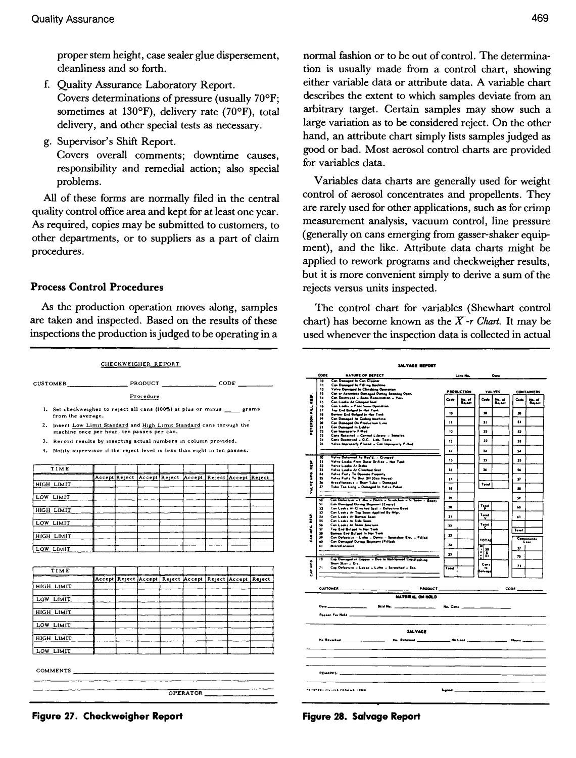
27. Checkweigher Report 469
28. Salvage Report 469
29. Inspector's Daily Report 470
30. Supervisor's Shift Report 470
31. Roving Inspector's Check Sheet 470
32. Statistical Treatment of Data 471
33. X-r Chart for Weight Control 471
34. Chart of Assignable Causes 472
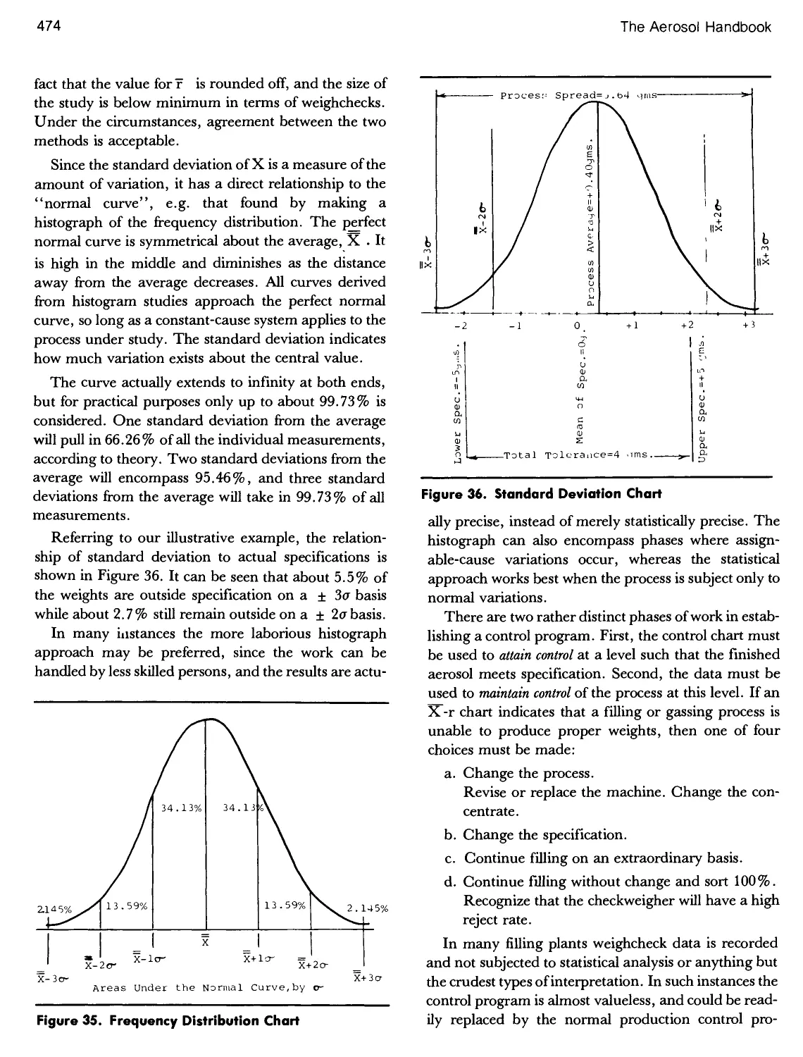
35. Frequency Distribution Chart 474
36. Standard Deviation Chart 474
37. End of the Line Report 475
38. Flowed-In Gasket Analysis 477
39. Batch and Finished Product Analysis Report 479
40. Label for Retainer Samples 484
TEST METHODS
Apparatus for Tower Method 487
Apparatus for Trough Method 488
Tag Open Cup Tester 489
Glass Test Cup 489
Leveling Device for Adjusting Liquid Level in Test Cup 490
Layout for Sample Labels 524
Disinfectant Sample Label 527
A-D Valve Dimension 492
A-D Measuring Gauge 492
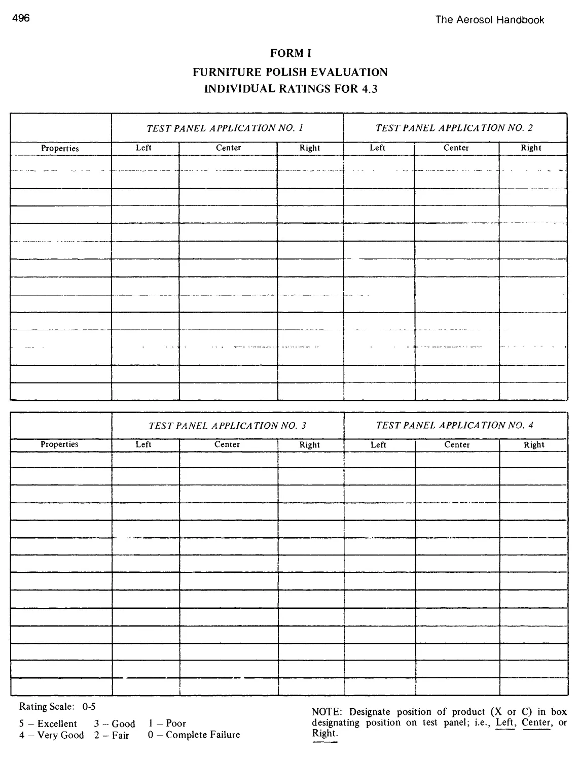
Furniture Polish Evaluation Form 496
Identification of Can Dimensions 501
GOVERNMENT REGULATIONS
Insecticide Sample Label 528
Danger Symbols 544
Contents
List of Tables x
List of Illustrations xv
Introduction 1
1. Aerosol Marketing Considerations 5
Scheduling a Product Introduction 7
Consumer Profiles 11
Consumer Attitudes 11
Marketing Strategies 13
Shaving Creams 13
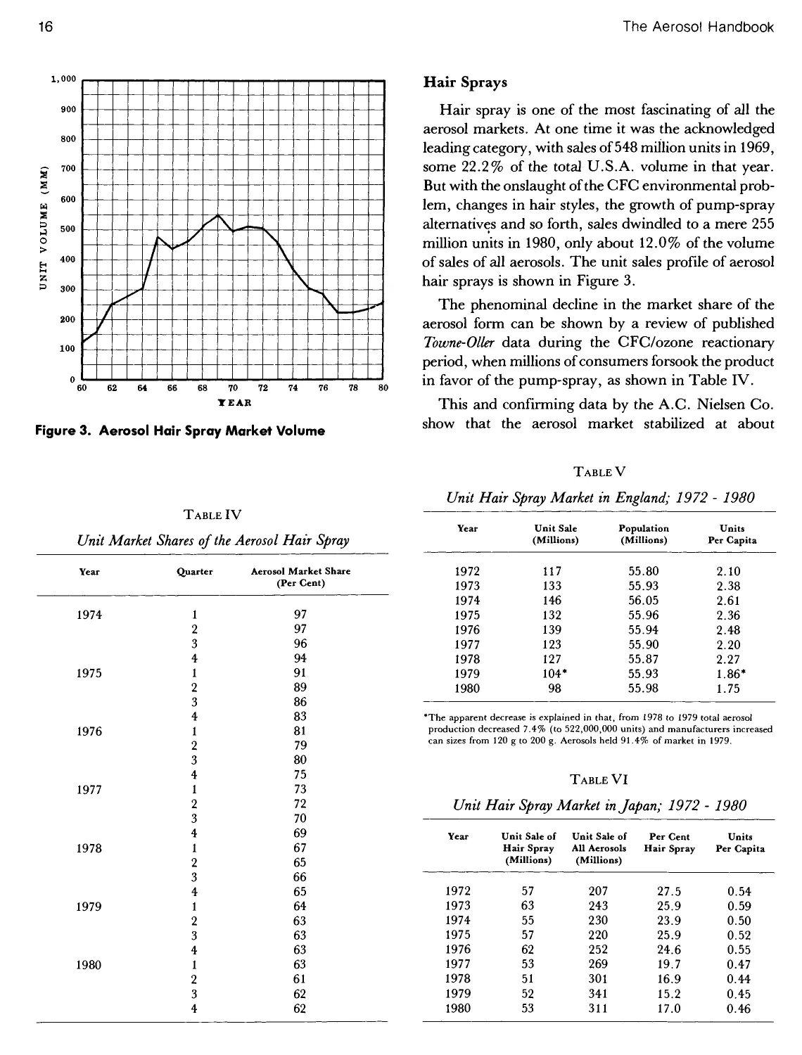
Hair Sprays 16
Antiperspirant Sprays 20
Perfumes and Colognes 24
Skin Care Aerosols 26
Insecticides 27
Cigarette Lighters 29
Insect Repellents 29
Furniture Polishes 29
Paints, Coatings and Finishes 29
Laundry Aids 30
Air Fresheners 30
Home Insulation Aerosols 31
Food Products 32
Aerosol Production 35
The Marketplace 41
Packaging Considerations 42
Marketer's Packaging Check List 42
[This page has been leformatted by Knovel to provide easiei navigation. yjj
viii Contents
Cost Considerations in Aerosol Production 44
The Aerosol Advantage 46
2. Metal Aerosol Containers 47
Steel and Tinplate Containers 48
Temper 54
End Unit Construction 55
Body Fabrication Techniques 63
Can Linings 63
Side Seam Construction 69
U.S.A. Two- and Three-Piece Tinplate or Steel Cans 74
Aluminum Containers 75
Production of Aluminum Aerosols Cans 86
Linings 87
Decoration 87
Label Dimensions and Print Areas 89
Corrosion Aspects of Aluminum Cans 89
Production of Aluminum Aerosols 91
Commercial Aspects of Aluminum Cans 92
Stainless Steel and Other Aerosol Containers 92
The Paper Labeling of Aerosol Containers 93
Lithographic Decoration 94
Container Shaping 96
Aerosol Can Safety Devices 97
Compartmented Aerosols Cans 101
The Sepro-Can 102
The Presspack System 105
The Alupresspack System 106
The Microcompack and Alucompack Systems 106
The FLIP System 108
The Enviro-Spray System 109
Other Barrier Packs 109
[This page has been leformatted by Knovel to provide easiei navigation.
Contents ix
3. Glass Aerosols 111
Manufacture of Glass Aerosol Bottles 112
Decoration of Glass Containers 116
Pressure Considerations 116
Glass Aerosol Bottle Designs 122
Uncoated Glass Aerosol Designs 122
Plastic Coated Glass Aerosol Designs 123
Glass Aerosol Testing Procedures 124
Total Visual Inspection 125
Internal Pressure Testing 125
Drop Testing 127
Comprehensive Load Testing 129
Thermal Shock Testing 129
Impact Testing 129
Characteristics Interfering with Coatings 130
Glass Distribution Testing 130
Capacity Testing 130
Filling Glass Aerosols 131
Compounding the Concentrate 131
Filling, Air Removal and Crimping 132
Gassing 134
Hot Tanking 134
Labeling 135
Marketing Summary 136
4. Plastic Containers 137
TheOPET Plastic Container 139
Other Modern Plastics 142
Properties of Plastic Aerosols 142
Fabrication 142
Decoration 142
Size and Weight 143
[This page has been leformatted by Knovel to provide easiei navigation.
x Contents
Design 143
Staining 144
Impact Resistance 144
Safety 145
Organoleptic Compatibility 145
Permeation 145
Chemical Compatibility 147
Marketing Aspects 148
Future 148
5. Aerosol Valves 149
The Vertical Action Aerosol Valve 150
Actuator 150
Mounting Cup and Cup Gasket 151
Gasket Leakage Considerations 157
Stem Gasket 163
Valve Stem 164
Valve Body 165
Spring 166
Dip Tube 167
Vertical Valve Assemblies 169
The Toggle Action Aerosol Valve 170
The Female Aerosol Valve 172
Ferrule Type Aerosol Valves 174
Special Components or Accessories 176
One-Shot Valves 176
The VariSeal Aerosol Actuator 177
The Aquasol and Aquamist Systems 177
Special Applicators 178
Suggested Valves for Various Products 181
Future 181
[This page has been leformatted by Knovel to provide easiei navigation.
Contents xi
6. Cover Caps 183
Cover Cap Dimensions 187
Custom Caps 193
Actuator Caps 194
Child Resistant Caps 195
Specialty Caps 196
Decoration Techniques 197
7. Flammability 199
Aerosol Flammability Regulations in Japan 203
Aerosol Flammability Regulations in Europe 204
Aerosol Flammability Recommendations by the UN 208
Aerosol Flammability Regulations in Australia 209
Aerosol Flammability Regulations in Canada 210
Aerosol Flammability Regulations in Argentina 211
U.S.A. Flame Projection Test 211
U.S.A. Closed Drum Test 220
Modified Tagliabue Open Cup Flash Point Test 221
Surface Flammability Tests 223
Foam Flammability Tests 225
Composite Flammability Tests 226
Electrostatic Flammability Hazards 227
Precautions Against Triboelectric Ignitions 231
Reformulation 231
Production Precautions 232
Aerosol Flammability in Plants and Warehouses 234
Safe Handling of Aerosol Concentrates 234
Safe Handling and Gassing of Hydrocarbons 236
Unloading, Storage and Handling System 236
TheGassingRoom 237
Warehouse Storage of Aerosols 239
The Factory Mutual Initiative 240
Product Reformulation 246
[This page has been leformatted by Knovel to provide easiei navigation.
xii Contents
Warehouse Storage of Aerosols - International 248
Safe Disposal of Aerosol Containers 249
8. Toxicology 253
Acute Toxicity 254
Cardiac Arrhythmia 258
Biotransformation 259
Acceptable Limits of Exposure 261
Material Safety Data Sheets 262
Sub-Acute Toxicity 267
Sub-Acute Inhalation 268
Aerosol Vasodilators or Antiasthmatics 270
Biological Consequences of Inhalation 270
Sub-Acute Dermal Toxicity 274
Chronic Toxicology 274
Sub-Acute Oral Toxicity 274
Teratogenic Studies 274
Mutagenic Studies 275
Carcinogenic Studies 277
Retrospective Epidemiological Toxicology Surveys 279
9. Crimping 281
General Considerations 282
Crimping Specifications for Metal Cans 286
Gasket Material Thickness 288
Collet Foot Thickness 288
Thickness of Tinplate Valve Cup 288
Can Curl Thickness 289
Diameter of the Can Opening 289
Calculation of Crimp Depth 291
Contact Height of Can Bead 291
Flowed-in Gaskets 293
Causes of Container Leakage at the Crimp 298
[This page has been leformatted by Knovel to provide easiei navigation.
Contents xiii
Measuring Finished Crimp 301
10. Propellents 305
The Chlorofluorocarbons Propellents 307
Rowland and Molina Theory 308
Preliminary Atmospheric Chemistry 310
Empirical Ozone Measurements 315
Regulatory Activities 317
Costs of Conversion to Alternate Propellents 320
Properties of the CFC and FC Propellents 323
The Alternate CFC and FC Propellents 330
The Bromochlorofluorocarbons and Bromofluorocarbons 334
The Hydrocarbons Propellents 335
Purification of Field Grade Propane, n-Butane and Isobutane 339
Inspection of Purified Propane, n-Butane and Isobutane 342
Properties of the Aerosol Grade Hydrocarbons 344
Blends of Hydrocarbon Propellents 349
Ether Type Aerosol Propellents 354
Purity and Physical Properties of DME 355
Solubility Aspects of DME 357
Flammability of DME Formulations 359
Methylethyl Ether and Diethyl Ether 360
Bis(Difluoromethyl) Ether and Bis(Trifluoromethyl) Ether 361
Compressed Gases 361
Toxicological Considerations of C02 and N20 366
Production Aspects of C02, N20 and N2Gases 366
Methylene Chloride 368
Specialty Gases that Function as Propellents 371
11. Production Equipment 373
The Aerosol Production Line 379
Individual Production Equipment Items 388
Can Depalletizers and Other in-Feed Equipment 388
[This page has been reformatted by Knovel to provide easier navigation.
xiv Contents
Can Cleaners 389
Can Coders 389
Can Counters 390
Powder Filler 390
Liquid Concentrate Fillers 391
Checkweighers 394
Valve Inserters 394
Valve Crimper 395
Propellent Gassers 397
Hot Tank 405
Tipping Machines 406
Capping Operations 407
Aerosol Can Packaging 407
Future Aerosol Filling and Packaging Equipment 407
12. The Aerosol Laboratory 411
Formulation 414
Lay-Out of an Aerosol Laboratory 419
Equipment Requirements 420
Laboratory Techniques 422
Product Use Tests 431
Product Economics 433
Specialized Equipment for Aerosol Testing 434
Reed Valve Torque Tester 434
Pressure Burettes 434
Hydrostatic Bursting Unit for Aerosol Cans 435
Can Puncturing Device 435
Va Ive Th ickness Ga uge 435
Aerosol Decrimper 435
Valve Delivery Rate Tester 436
Aerosol Spray Test Apparatus 436
Spring Force Tester for Aerosol Valves 436
Device for Measuring Crimping Force 436
Meter for Checking Mechanical Stability of Aerosol Can Curl 437
[This page has been leformatted by Knovel to provide easiei navigation.
Contents xv
13. Quality Assurance 439
Organizational Relationships 440
Scope of Quality Control Operations 441
Establishment of a Quality Assurance Program 443
Scientific (Statistical) Sampling 444
Incoming Inspection of Cans 447
Incoming Inspection of Plain and Plastic-Jacketed Glass Bottles 451
Incoming Inspection of One-Inch Cup Valves 453
Incoming Paper or Paper-Backed Foil Labels 455
Incoming Inspection of Overcaps 456
Incoming Inspection of Corrugated Shipping Containers 456
Incoming Inspection - Final Comments 458
Inspection of Chemicals 459
Quality Assurance During Compounding 462
Manufacturing Procedures 463
Process Control Procedures 469
Inspection of Finished Aerosols 475
Special Projects 478
Current Good Manufacturing Practices 478
Summary 479
Regulations in South America 484
14. Test Methods 485
Revised Flammability Test Methods for Aerosol Products 485
Tentative Method for Determining the Relative Flammability of Aerosol Foam Products 486
Flash Point Determination 488
Tentative Method for Measuring "A-D" Dimension of Aerosol Can Valves 492
Procedure for Evaluation of Combing Characteristics of Hair Spray Formulations 493
Determination of the High Humidity Curl Retention of Aerosol Hair Sprays 494
Determination of the Pressure (or Vacuum) in an Aerosol Container 495
Tentative Method for Furniture Polish Evaluation 497
Military Standard Sampling Procedures MIL-STD-105D 498
[This page has been reformatted by Knovel to provide easier navigation.
xvi Contents
Tin Plate Fabricated Aerosol Cans 501
Method for Determining Delivery Rate of Aerosol Products 501
15. Government Regulations 503
The Food, Drug and Cosmetic Act 505
Fair Packaging and Labeling Act of 1966 510
The Environmental Protection Agency 511
The Federal Insecticide, Fungicide and Rodenticide Act of 1947 511
Federal Environmental Pest Control Act of 1971 529
The Toxic Substances Control Act 530
The Resource Conservation and Recovery Act Consumer Product Safety Act 531
Clean Air Act 531
Consumer Product Safety Act of 1972 532
The Federal Hazardous Substances Act of 1960 532
The Poison Prevention Packaging Act of 1970 533
The CPSC National Electronic Injury Surveillance System 533
CPSC Aerosol Ingredient Labeling Program 534
Other CPSC Activities 535
The Occupational Safety and Health Act of 1970 535
Department of Transportation (DOT) 537
The U.S. Department of Agriculture (USDA) 539
State Regulations 539
Regulations Concerning Weights and Measures 540
European Regulations 541
Net Contents 541
Transportation 542
Regulations Outside the U.S.A. and Europe 543
16. Buyer-Seller Relationships 545
Product Safety Warranty 545
Container Warranty Agreement 550
Confidentiality Agreement 551
[This page has been reformatted by Knovel to provide easier navigation.
Contents xvii
17. Aerosol Contract Fillers 553
18. Aerosol Marketers 569
AAPRI Cosmetics INC ... Jean Patou INC 569
Jericho Laboratories ... Zynolyte Products CO 592
Trademarks 617
Appendix 633
Industry Trade Terms and Abbreviations 633
Company Listings 638
Index 642
This page has been reformatted by Knovel to provide easier navigation.
AEROSOL
MARKETING CONSIDERATIONS
5
1
Marketing has been defined as the management
process responsible for identifying, anticipating and
satisfying customer requirements profitably. To do well at
marketing, a company must evaluate constantly its
resources and match them to the environment in which
it operates. Marketing is by no means restricted to those
firms whose products are presented to the consumer on
the store shelf, by mail order or by the door-to-door
salesperson; it is a ubiquitous force, being applied by
every successful company as its marketing experts
assess the realities and potentials of their customer mix.
The marketing operation may begin with the flash of
inspiration that heralds the development of a new or
improved product. It acts to regulate and systemize that
development through the myriad of steps required to
bring the product to the point where the consumer
purchases it. Marketing is a very big business. During the
last decade, the number of new consumer products
increased from 26,000 to 37,000 per year, at research and
development costs of over $17.5 billion. As imposing as
this dollar figure may seem, it is still only a small part of
the capital that U.S.A. companies must lay out during
the evolution of new products and packages. The
advertising and promotional budget for a full-scale
national program normally starts at $10 to $14 million.
New products form an increasingly demanding
aspect of corporate decision-making. The high impact
and complexities of technical and marketing
developments have brought about a virtual condition of sink or
swim in the marketplace, and there is less financial
room for errors than ever before. The whole world loves
a gambler—when he is successful. For a company not
to introduce new products, better products, new
services or new economies is to be unloved, particularly on
Wall Street, and unwanted by talented creative people
as the corporate entity withers. New marketing thrusts,
then, are essential, even though the cost of failure can
be disastrous. (In 1981 the failure of a feminine protec-
6
The Aerosol Handbook
Table I
U.S.A. Production of Consumer Retail Packages
Plastic Bottles
Glass Bottles
Collapsible Tubes
Metal
Plastic
Metal Cans
General Line
Sanitary
Beer & Beverage
Aerosol
Paper, Foil & Composites
Units Produced
1971
6.0
41.0
1.44
0.06
10.0
31.0
37.0
2.8
177.0
(Billions)*
1980
9.7
47.1
1.2
0.13
4.9
30.0
54.4
2.4
286.0
"Estimates from various sources. Packaging cost $47 billion at the manufacturing level
in 1980.
tion product cost $90 million.) In the whole complex
maze of product introduction and maintenance no one
is more important than the marketing director.
In the larger companies, new product marketing
activities are aided by inputs from research,
engineering, manufacturing development, packaging and cost
accounting. Outside agencies are increasing
contributions in such areas as advertising, package design,
clinical testing and brandname selection. Smaller roles
are played by quality assurance, sales and legal
departments. In the smaller company, the marketing
executive is often forced to go outside for nearly everything.
Historically such firms have often turned to contract
fillers, taking advantage of their years of experience in
formulation and packaging areas.
For a large, nationally oriented product introduction
program, the time for completion will take from one to
four years, up significantly from the time frames of a
decade ago in the 1970s when things were simpler and
less regulated. The longer programs may come about
through the need for exhaustive clinical testing, the
satisfaction of EPA or FDA requirements,
unanticipated complications, or even new developments that
may make it necessary to restructure the schedule. In
one interesting case, an aerosol pancake batter product
was developed during a three year period. During this
time, however, the priorities of the marketing
department changed. It was realized that a $900,000 batter
processing system would have to be installed, and a
study of breakfast eating habits showed a steady decline
in the consumption of pancakes. The project was killed.
There is nothing small about the consumer
packaging market. Packaging costs are now about $49 billion
for 1981 at the supplier level, up from $22 billion in
1971. The 1981 figure translates to a retail level close to
$85 billion. About 4,600 manufacturers make the
containers and employ roughly a million workers in the
process. The final package is put together in some
300,000 filling and packaging plants, with a gross
output of around 370 billion units per year. A breakdown
of the various container types is given in Table I.
Sir Francis Bacon once said, "Figures can be likened
to streetlamps: they can serve both to illuminate the
written word and provide support for the weary
writer." (Market statistics included.) Our purpose in
reporting these numbers is to show the truly massive
dimensions of the U.S. packaged commodity market,
with aerosols showing up as somewhat less than 1 %.
An interesting contrast can be shown by examining
the toiletries packaging market, which is only about 2 %
of the total, but where aerosol containers make up the
largest category. A comparison of the various container
types is given in Table II.
The future advances will be derived from the
technical developments now underway. Programs designed
Table II
U.S.A. Production of Toiletries Retail Packages*
Plastic Blow-Molded
Bottles
Glass Bottles
Collapsible Tubes
Metal
Plastic
Aerosol Cans
Boxes
Folding
Set-Up
Closures
Total
Annual Rate Of
Increase (Per Cent)
Units
5
0
2
5
4
4.5
(2)
—
—
Dollars
17
11
12
17
14
14.5
8
15
7.5
Dollar Shipments to
Mfgrs. (Millions)
1980
212
54
27
23
302
151
5
119
893
1985
465
91
48
50
581
294
4
240
1773
"Estimates from Frost & Sullivan, Inc.
Aerosol Marketing Considerations
7
to reduce energy consumption, improve recyclability,
produce higher quality and lower cost decoration,
improve tube laminations, provide easier opening and
dispensing closures, improve gas barrier resins for
plastic bottles and so forth will all help determine the
upward pace of the market. Many improvements for
aerosol cans and valves are in progress and are
described in later chapters.
Scheduling A Product Introduction
These days the introduction of a new product
involves thousands of individual steps taken by
hundreds of people. A central master plan must be evolved
to schedule and control this myriad of steps and
operations, so that they can be completed in a minimum of
time and at the least expense. The PERT (Project
Evaluation and Review Technique) is used by many
firms to achieve these objectives.
Although PERT was designed originally as a
computer system and used by the Navy to develop the
Polaris missile, the method can be described in such
simplified terms that it can be understood and
administered without the need for either a computer or
extra personnel.
In the simplified PERT system, a series of circles,
squares or rectangles is used to designate a specific
operation which is a part of the overall program. The
job description is written inside. The diagram normally
flows from left to right, using a backbone of key
operations to build upon. A series of such key points would
be, for example:
a. Marketing motivation (The beginning of it all.)
b. Marketing plan
c. Creation of the package
d. Development of final formula and specifications.
e. Test market approval
f. National program approval
g. Full production
h. Consumer purchase
The accentuated key operation points are connected
up by means of a large number of secondary
operations. For instance, test market approval starts a
sequential chain of events involving:
a. Elaborate test market planning.
b. Placement of advertising in various local media.
c. Personal contact with test stores.
d. Ordering chemicals and packaging.
e. Production and shipment to test stores.
f. Package performance evaluation.
g. Evaluation of test market results.
h. Possible revision of product according to
marketing analysis.
i. Final production costs established.
The objective of this program: that a national
marketing program can be established. In some
diagrams, the above chain will not necessarily be
sequential. If a delay is anticipated with the production
operation, supplies can be purchased for the run even
before test market plans are finalized. In some cases this
may lead to back-up production, or an excess of
merchandise, but the time saved will often be worth the
risk.
Arrows are used to link up sequential operations, and
proposed time to complete each step is posted above the
arrows. It is convenient to indicate time in weeks and
decimal fractions of weeks, but some PERT networks
are timed in days. A few PERT diagrams are drawn
with strict attention to time as the X-axis, or abscissa;
thus keeping time coordination between operations on
an easily viewed basis. The various circles or squares
are often circled in red as they are completed. Auxiliary
PERT diagrams, which can be looked upon as insets on
the primary one, are made usually where more detailed
development is needed for a particular situation, such
as the purchase of all the chemicals and packaging
components for the test market product. An outstanding
example of a marketing type PERT diagram is given in
Modern Packaging Encyclopedia, 1971 issue; page 47.
Network planning is rapidly becoming popular with
marketing directors and package development
executives, since it tells them exactly where the project
stands. The chart indicates the time schedule, shows
what may have gone wrong (if anything), and provides
the necessary interrelationships — who has to do what
before something else can be done. The primary
benefits are avoidance of unnecessary delays and
expenses. Another benefit is that minor contributory
points will not be overlooked. Two pitfalls, both minor,
have come to light: if the timing on the chart is too
generous, no one will finish ahead of schedule, and if
the network is all nicely drawn and organized, few
people will risk antagonism by proposing meaningful
improvements. Both can be minimized by an alert
marketing executive.
8
The Aerosol Handbook
Any good product introduction program will benefit
from the creation of a Packaging Committee as the
central organizational feature. The committee should be
composed of experts on construction, graphics,
scheduling and so forth, and should have the power to
make approvals in the absence of top managers.
Committee activities also help cut snags in communications
and lessen the need for lengthy report writing. The key
people, working with the project day by day, attend
these meetings. They will surely note things of interest.
The interplay between these packaging experts often
results in significant improvement of the final product.
Marketing people must keep in mind the thought
that every new product must start and finish with the
consumer. Here, regardless of all else, it must be able to
stand on its merits. The finest marketing program, the
best package, the most effective formula, will all go
down in ruin if the soverign consumer remains
unimpressed. New product ideas must be encouraged
constantly from all sources, particularly suppliers. Speed is
vital in product introduction. Be first if at all possible.
Nielsen has made a 15 year study of the sales record of
"pioneer brand" versus that of followers. The first
follower gained only 51 % of the sales volume of the first
brand after three years, while the second follower
managed only 25%. It is also essential to work within
clearly defined corporate objectives and business
realities. The new product must have the hearty
sanction of top management. There are too many cases
where middle executives have worked many months on
a new product, only to have it killed during a Board of
Directors meeting.
Many new products are carried to the market on
three waves of activity, each more costly than the last.
In the first stage, sometimes called the initial
assessment, the idea is submitted to a generalized scanning
process, aimed mainly at deciding whether the project
should be subjected to further and more intensive
study. A PERT diagram or a simple listing of
requirements will suffice at this stage. Some typical check
points are:
a. Is the product consistent with consumer needs or
desires?
b. What precisely is the new product concept and
how does it perform?
c. What type of customer would likely purchase?
d. What is the marketing platform in relation to:
i. Population of probable consumers.
ii. Market statistics.
iii. Market experience of other firms with
similar products.
iv. Competitive position.
v. Price policy.
vi. Cost of advertising.
vii. Rate of product obsolescence.
e. Do distributional channels pose any problems to
the company?
f. Can the sales force effectively sell the product?
g. Is the formula available?
i. Is the formula free of patents, royalties or
other encumbrances?
ii. Is the formula well tested for compatibility
and safety?
iii. Is the formula exclusive in any way?
h. Do production requirements pose any problems?
i. Are there any legal or registrational difficulties?
j. Is the development program capital intensive?
k. Does the development and marketing of the
product conform to broad corporate objectives?
If the proposed new product passes muster at this
level, then it is generally qualified for second stage
assessment — a much more searching scrutiny over a
broader field. At this stage, the inquiry must become
strongly consumer oriented. Sequential check points
can be listed as:
a. Organize the facts by preparing a brief covering:
i. Rationale for introduction.
ii. Proposed brandname(s).
iii. Description of quality requirements,
iv. Estimated cost structure.
v. Anticipated problems, if any.
b. Examine advertising concepts, aided by small-
scale panel testing.
c. Survey all existing information concerning the
desired market area, consumer buying habits and
important product attributes. Conduct market
surveys to fill in any missing data.
d. From the above, determine the approximate
consumer rating of the proposed product versus
competition.
Aerosol Marketing Considerations
9
e. Define as accurately as possible the estimated
market size and value.
f. Estimate competitive brand shares.
g. Estimate competitive expenditures (both present
and future) compared with those of the new
product.
h. Determine marketing position.
i. Is the brand aimed at becoming a leader?
ii. Is the pricing to be highly competitive?
iii. Is the product designed to fill an unfilled
marketing need?
iv. At what level should the sales estimate and
advertising budget be set?
v. What is the laboratory's assessment of the
advantages of the product over competition.
Can they be dramatized?
vi. What is the consumer's assessment, based
on small panel tests?
vii. What is the pull of the proposed brand-
name?
viii. What have been the results of any similar
introductions either in the U.S.A. or abroad?
ix. What is the strength of competition? What
are the weaknesses?
x. Are distributional networks available?
xi. Are trade margins favorable?
i. Check availability of packaging components and
chemicals.
j. Outline a complete quality assurance program.
k. Check production methods; possible problems.
1. Ascertain preliminary direct costs, delivered to
warehouses.
The final stage involves the decision to launch, with
all the attendant complexities.
A PERT network becomes essential from this point
on. Nearly always, a test market will precede initiation
of a full national program. A test market is justifiable if:
a. More than a "slight risk" is attached to the
introduction.
b. The test will assist in finalizing certain details of
label, advertising, container size, pricing,
distribution and so forth.
c. By selecting certain test areas, a true indication of
the national market can be obtained.
d. There are many uncertainties about the product,
advertising, distribution, etc. that should be
finalized.
Presuming that a test market strategy is integrated
into the program, typical check points are about as
follows:
a. Prepare the PERT diagram, or launch timetable.
b. Finalize the product formulation.
i. Are the color, odor, viscosity and other
physical attributes acceptable to consumer
panels?
ii. Has the product demonstrated compatibility
with the least expensive practical container?
(At least nine months.)
iii. Have all clinical safety tests been completed?
iv. Can all label claims be justified to the FTC if
necessary?
v. Does the product do a highly acceptable job
for the intended use?
vi. Are all registrations, new drug applications
and similar tasks well along or completed?
c. Finalize the packaging components.
i. Has the package been tested with the
formulation?
ii. Does the package conform to applicable
regulations; such as use of FDA approved
materials for foods and drugs, use of child-
resistant closures, etc.?
iii. Have suitable packaging suppliers been
selected?
d. Describe the initial brand marketing strategy
which will serve as a guide to all future agency
actions.
e. Write the copy strategy.
f. Prepare the label, using "b(iv.)" generalities as a
guide.
i. Is copy acceptable to the laboratory?
ii. Is copy acceptable to legal department?
iii. Produce final package art work.
g. Prepare the creative material. Test it in panel
groups.
h. Finalize all market, sales and advertising
estimates.
10
The Aerosol Handbook
i. Send revised advertising figures to agency for final
media budgets.
j. Supply accounting, planning, buying, and
production with final figures and develop a final
overall cost.
k. Prepare the final profit statement and make
budgetary revisions as needed.
1. Plan for the test market.
m. Prepare final media strategy and submit to
agency.
n. Order all components and chemicals for test
market.
o. Produce and ship product to designated
warehouses.
p. Establish final production costs based on
experience generated in "o".
q. Analyze test market results.
r. Revise art, designs, package specifications,
formula, etc. as dictated by test market results.
s. Establish full national program,
t. Plan production on national scale.
i. Obtain bids from contract fillers in different
locations.
ii. Make sure components and chemicals can
be produced at needed rates.
iii. Consider alternate packaging sources and
supplies.
iv. Design and produce introductory special
displays, etc.
u. Consider danger of competition.
i. May get into full distribution before you do.
ii. May establish deals, price incentives and so
forth to eat up available shelf space.
iii. May revise copy, advertising methods, even
formula to "improved" type.
v. Set ad promotional budget.
w. Hold national sales meetings and notify trade.
i. Distribute salesmen's samples and other
selling materials.
ii. Inform salesmen about product and
strategy.
x. Produce and ship product to distribution points.
y. Ship to outlets.
z. Check consumer purchases in selected stores.
It is very important to evaluate continuously the
product itself at various stages of development,
including systematic consumer testing. Consumer
evaluation is necessary to determine what they want
from a product, and the value they place on specific
attributes. Laboratory evaluations must be meshed into
this program, in order to determine how these
objectives can best be accomplished. Consumer and
laboratory tests can be considered equally important in
any development program, since one will rarely
provide meaningful answers without the other.
Although there is certainly a greater degree of control
built into laboratory testing, the procedures are set up
usually to test only one attribute at a time. Research
people should not be expected to estimate the relative
importance of these attributes to the marketing success
of the product. In contrast, consumer testing provides a
rough estimate of all the factors considered at one time.
It is concerned with overall satisfaction or rejection
based on subjective factors.
Unfortunately, people are often conditioned to
expect certain characteristics in a product. One of the
pitfalls of consumer testing is that they will fault a
product if it does not provide the expected characteristics,
even though the attribute may have little or no
beneficial effect. (A furniture polish without a lemon odor
will probably not sell very well these days, although the
citrus fragrance contributes nothing to the polishing
effect whatever.) Sometimes the laboratory methods
can suffer from over-expertise, since the technical
people are well aware of the product and container
parameters. In consumer use testing it must be remembered
that people do not read "use directions" and do not
always use products as intended by the manufacturer.
As an example, when a new aerosol valve was
introduced, about 1958, a large production of bug killer
spray was produced and thoroughly checked by many
experts before being released to the market. A week or
two later complaints started coming in by the hundreds.
The cause? Customers were sometimes tilting the valve
during actuation, instead of pressing the button straight
down as did the experts. Under this new and
unplanned for stress, the gasket allowed secondary sprays
of product to spurt out from the base of the stem. Most
of the production was recalled, at great expense, and
the valve housing fitted with a special press-fitted cap
which prevented sideways movements of the stem and
button. The design was incorporated into the valve cup
a short while later and remains there to this date.
Aerosol Marketing Considerations
11
Other well known limitations of consumer testing
are: over-response (people are all too willing to
criticize), too short a trial period, as reaction may vary
with extended use, lack of specificity, since people tend
to generalize, and the possibility that dislike of one
product characteristic will be carried over by the
consumer to the product's other characteristics.
Consumer Profiles
A sound marketing program should recognize
always the changing market demands for products and
services. Demographic surveys show that, while the
largest U.S.A. markets are still in the East and
Midwest, the greatest percentage gains during the
1980s will be in the sunbelt areas. This will affect
package sales of many products, and influence design in
favor of stronger colors and more vibrant graphics — a
change already noted for outdoor products and those
aimed at the large "60-plus" and retiree market.
With the huge youth market of the late 1960s and
1970s now blossoming into a booming young adult
market of the 1980s some of the current emphasis on
teenage needs will subside. During the 1980s there will
be a 42 % growth in the number of people aged 35 to 44;
both this market and the rapidly increasing market for
financially secure older people should cause profound
changes in the orientation of many products.
In 1960, women accounted for 32.3% of the U.S.A.
labor force. This rose to 36.8% in 1970 and to almost
42 % in 1980. This is a significant statistic for marketers
since working women have very different buying needs
and patterns than the homemaker, particularly in the
amount of available discretionary money. They can
indulge themselves in items of higher quality if they
elect to do so. In 1980, over 55% of all U.S.A.
households contained two or fewer people, compared with
46% in 1960; this trend is expected to continue. Also in
1980, single persons made up 30% of the total
population, compared with half that level in 1960. With the
obvious increase in households, the sale of household
products has been advancing at a very fast pace.
During the 1980s, an increasing amount of attention
will be given to minority needs. In 1980, there were an
estimated 25 million Blacks (11 %) in the U.S.A. with a
buying power of $96 billion. About 1.0% of this is spent
on health and beauty aids. The average Black is 21, in
contrast to the White median of 29, and they will
account for one-fifth of the population gain during the
1980s.
The formal complaints received by marketers
represented about one in every fifty significant
problems during 1978-79, and was perhaps as high as one in
twenty-five in 1980-1981. Other complaint routes
involved reports by retail stores regarding returned
merchandise and contacts by attorneys seeking
restitution for furniture damage and other losses suffered by
their clients.
Another increasingly important racial group is the
Hispanics, with a market of 21 million consumers in
1980. They have a purchasing clout of some $32 billion.
Government estimates indicate that by 1985 they will
have the largest population of any minority. The
median age for the Hispanic consumer is 21.5 years old.
With an average household income of $15,000 per year
in 1980, they tend to be conservative and family
oriented.
All these statistics have an important place in any
quantitative market analysis. Distribution of income
affects the market for many products, and particularly
aerosol products. With the "income pyramid" turning
upside down during the last 25 years or so, it is essential
to recognize family expenditure patterns and predict
them into the future.
Consumer Attitudes
The aerosol package has been extolled as convenient,
profitable, clean and soft, easily controlled by the
consumer, dependable, easy to use, efficient, having good
identity and so forth. These attributes are probably
more useful as a palliative to the anxious marketer than
as anything highly visible to the consumer. To the
buyer, aerosols have been around "forever," always in
essentially the same packaging style, and they have little
or no novelty. Their advantages are taken for granted;
but their presumed or actual disadvantages are treated
with less tolerance than ever before.
Starting in the 1978-79 period, consumers began to
indicate their displeasure with aerosols by means of a
significant escalation of written complaints to the
marketer. A typical summary of complaints for a
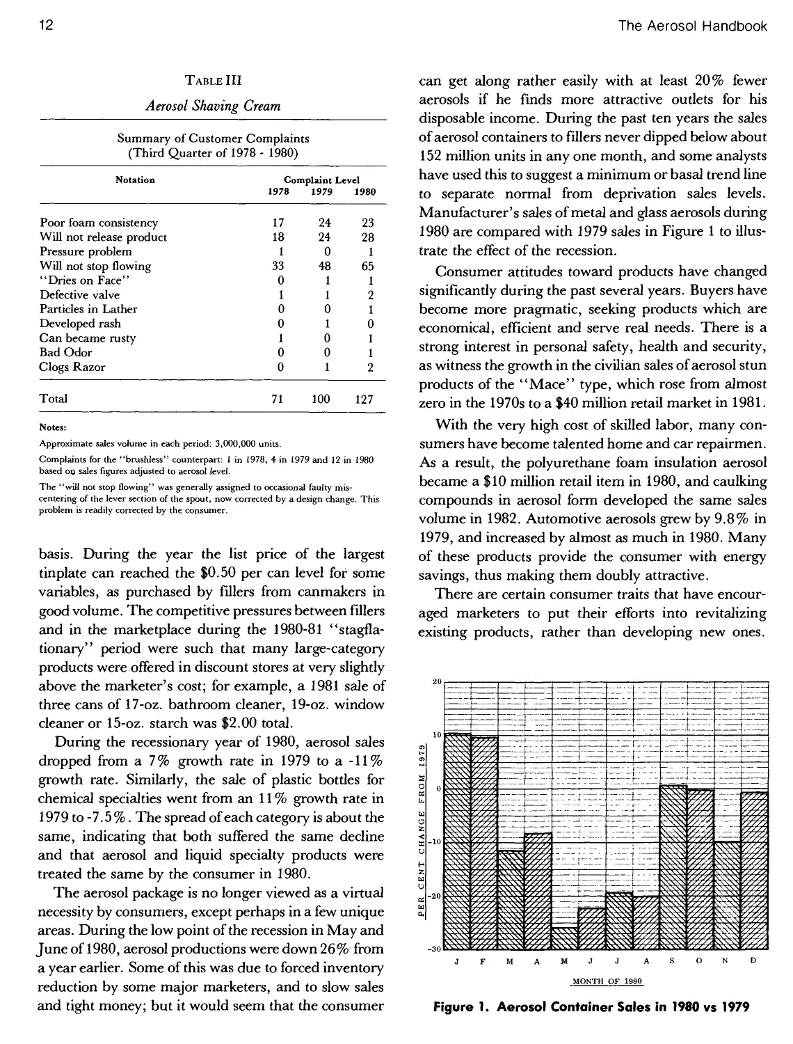
shaving cream is shown in Table III.
The aerosol package has been increasingly regarded
by consumers as a relatively high priced commodity.
This is especially the case where the high costs of
essentially anhydrous formulations have forced marketers
into smaller packages or higher price levels. In 1981,
virtually all anhydrous solvent/propellent compositions
cost fillers at least $0.30 per pound on a bulk purchase
12
The Aerosol Handbook
Table III
Aerosol Shaving Cream
Summary
of Customer
Complaints
(Third Quarter of 1978
Notation
Poor foam consistency
Will not release product
Pressure problem
Will not stop flowing
"Dries on Face"
Defective valve
Particles in Lather
Developed rash
Can became rusty
Bad Odor
Clogs Razor
Total
1980)
Complaint Level
1978
17
18
1
33
0
1
0
0
1
0
0
71
1979
24
24
0
48
1
1
0
1
0
0
1
100
1980
23
28
1
65
1
2
1
0
1
1
2
127
Notes:
Approximate sales volume in each period: 3,000,000 units.
Complaints for the "brushless" counterpart: 1 in 1978, 4 in 1979 and 12 in 1980
based on sales figures adjusted to aerosol level.
The "will not stop flowing" was generally assigned to occasional faulty mis-
centering of the lever section of the spout, now corrected by a design change. This
problem is readily corrected by the consumer.
basis. During the year the list price of the largest
tinplate can reached the $0.50 per can level for some
variables, as purchased by fillers from canmakers in
good volume. The competitive pressures between fillers
and in the marketplace during the 1980-81 "stagfla-
tionary" period were such that many large-category
products were offered in discount stores at very slightly
above the marketer's cost; for example, a 1981 sale of
three cans of 17-oz. bathroom cleaner, 19-oz. window
cleaner or 15-oz. starch was $2.00 total.
During the recessionary year of 1980, aerosol sales
dropped from a 7% growth rate in 1979 to a -11%
growth rate. Similarly, the sale of plastic bottles for
chemical specialties went from an 11 % growth rate in
1979 to -7.5%. The spread of each category is about the
same, indicating that both suffered the same decline
and that aerosol and liquid specialty products were
treated the same by the consumer in 1980.
The aerosol package is no longer viewed as a virtual
necessity by consumers, except perhaps in a few unique
areas. During the low point of the recession in May and
June of 1980, aerosol productions were down 26% from
a year earlier. Some of this was due to forced inventory
reduction by some major marketers, and to slow sales
and tight money; but it would seem that the consumer
can get along rather easily with at least 20% fewer
aerosols if he finds more attractive outlets for his
disposable income. During the past ten years the sales
of aerosol containers to fillers never dipped below about
152 million units in any one month, and some analysts
have used this to suggest a minimum or basal trend line
to separate normal from deprivation sales levels.
Manufacturer's sales of metal and glass aerosols during
1980 are compared with 1979 sales in Figure 1 to
illustrate the effect of the recession.
Consumer attitudes toward products have changed
significantly during the past several years. Buyers have
become more pragmatic, seeking products which are
economical, efficient and serve real needs. There is a
strong interest in personal safety, health and security,
as witness the growth in the civilian sales of aerosol stun
products of the "Mace" type, which rose from almost
zero in the 1970s to a $40 million retail market in 1981.
With the very high cost of skilled labor, many
consumers have become talented home and car repairmen.
As a result, the polyurethane foam insulation aerosol
became a $10 million retail item in 1980, and caulking
compounds in aerosol form developed the same sales
volume in 1982. Automotive aerosols grew by 9.8% in
1979, and increased by almost as much in 1980. Many
of these products provide the consumer with energy
savings, thus making them doubly attractive.
There are certain consumer traits that have
encouraged marketers to put their efforts into revitalizing
existing products, rather than developing new ones.
Figure 1. Aerosol Container Sales in 1980 vs 1979
Aerosol Marketing Considerations
13
Time constraints now often limit shopping time,
causing people to buy familiar brands. There is an
increasing tendency toward avoidance of risk, perhaps in part
due to lurid television and newspaper stories that have
made "chemicals", "aerosols" and even "new" bad
words; this steers people away from new or untried
brands. The public is less attentive, less keyed to new
things. Finally, there is continued interest in the
genuine original, the authentic tried-and-true, which they
may never leave unless some dramatic or emotional
issue arises, such as a disappointment or a compelling
sale of a competitive product.
In general, marketers are far happier to count on
continued support of existing products. It is a less
expensive, surer way to conduct business. Relatively
minor improvements: a new valve, or a revised
propellent composition, can be incorporated for as little as
$50,000 in research, consumer tests and other routines.
The success rate is better than 98%, compared with a
recent Benton & Bowles' figure of only 67% for new
products unveiled during the 1975-1980 period. Even if
the revision fails, the marketer has the obvious option of
returning to the original.
Many marketers simply feel it is too expensive to
launch new products. They keep their customers loyal
by extending existing lines or making stronger efforts to
lift established brands into new product categories.
Special incentives are fast becoming a vital ingredient
when a marketer considers a new product possibility.
There must be a patent, a uniquely effective
formulation, a magic ingredient or some other factor — and
even then, many marketers will not stray very far away
from fields in which they have strength and expertise.
Marketing Strategies
Every marketer approaches product introductions or
improvements from a different standpoint. There are a
few who are interested only in high volume routine
products: 5 to 10 million units per year or more.
Obviously these are restricted to well recognized and popular
items. Others aim for the specialties market, where
relatively small sales can still generate interesting
profits because of the higher prices that can be charged per
unit. Many firms are quite satisfied to capture a very
small share of one or more major markets. For instance,
it is estimated that there are now about 4800 brands and
formulas of aerosol hair sprays. In 1977, and again in
1980, only 19 firms shipped over $100,000 at wholesale
prices, but well over 4000 hair sprays had sales volume
of a mere several thousand units per year. Many were
sold to more than 200,000 beauty salons in the U.S.A.
A review of a number of specific aerosol market areas
should be of interest in providing information on
volume sales, market profile and opportunities that
may be available.
Shaving Cream
This important aerosol category accounted for
93.8% of the $205,000,000 retail market for shaving
preparations in 1980. Product use is 94% male oriented
and this segment represented 17% of the $970,000,000
retail men's toiletries market for that year. According to
Packaged Facts, Inc., the dollar growth of the aerosol
shaving cream market went from $181,000,000 in 1979
to $192,000,000 in 1980; from this they predict about a
5% continuing growth to 1986.
This is a difficult growth figure to handle, since
shaving creams advanced in price from $1.24 (retail
supermarket) to $1.38 during 1980, for a gain of 11.4%.
Thus a 5 % dollar growth would reflect a sales decline of
about 6.4% per year. As a matter of record, unit sale of
shaving cream has been increasing at an average rate of
3.8% per year for the 1976-1980 period, and this hardly
seems likely to reverse. Explanations could lie in the
selection of can size or intensity of price-cutting, but
these are hardy sufficient to cover the proposed
difference.
The market profile in terms of unit volume is given
for shaving cream aerosols as follows:
s
s
w
S
P
J
O
>
H
Z
P
200
180
160
140
120
100
HO
60
40
20
60 62 64 66 68 70 72 74 76 78
YEAR
Figure 2. Aerosol Shaving Cream Market Volume
14
The Aerosol Handbook
In 1971, a Gillette R&D report stated that 71 % of all
U.S. shavers were "wet" shavers and 73% of this
group were users of aerosol shaving creams. The
average user consumed 26 ounces of aerosol shaving
cream per year at an average cost of $0.11 per ounce,
thus accounting for a market of $111,000,000 per year.
During 1981, a decade later, one can suggest that about
94% of "wet" shavers use aerosol shaving cream;
another 5% of sales volume should accrue to increasing
use of shaving cream by women. Thus the market
should have increased by about 36%. Instead, unit
volume was down by 5.0%. This might suggest that
circumstances are ripe for a significant regrowth in this
product category, and indeed there are many
encouraging signs of marketer interest and good sales reports.
Rather surprisingly, shaving cream sales are
somewhat seasonal: the highest sales develop during
August, September and October, when they trend
about 10% above average. The lowest sales volume
occurs in January, at 12% below average.
There are three major formulation types:
a. Standard ambient temperature foam.
i. Standard formula for men. (Menthol,
regular and lemon-lime.)
ii. Gentle formula for women. (No sodium or
potassium salts present.)
iii. Special formula for blacks. (Urea and
sodium sulfite usually present.)
b. Hot foam.
i. Thermogenic or self-heating. (Co-
dispensing package with peroxide.)
ii. Appliance for external heating. (Electrical or
hot-water type.)
c. Gelated, post-foaming.
i. S.C. Johnson & Son, Inc. "Edge" type.
(Patented.)
ii. Other varieties, as Carter-Wallace, Inc.
type.
At least 97 % of the volume is marketed in three-piece
tinplate (or C/CO plate) cans. Some high-margin
specialty items are sold in two-piece "Spra-tainers"
and "Peerasol" aluminum cans in the nominal 6-oz.
size. A growing market area has developed recently in
the 1 to 1 V% -oz. travel-size package, using an aluminum
container.
The usual formulation contains about 8% sodium
and potassium stearates (80%)/cocoates(20%), 10%
triethanolamine stearate(80%)/cocoate(20%) or some
mixture of the two. Foam stabilizers such as sodium
lauryl sulfate, diglycol stearate, polysorbate 80 and
certain amphoterics are then added, along with propylene
glycol or glycerin humectants, fragrances and
sometimes some special items. In the early 1970s it seemed
fashionable to market formulas with as many as 22
ingredients, but later on as many as half were discarded
as probably worthless or because they were possible
skin sensitizers, or because of the need to report all of
them on the label in accordance with a new FDA
requirement.
The usual propellent selection is a blend of isobutane/
propane or mixed-butanes/propane having a pressure
of between 40 to 52 psig at 70°F (276 to 359 kPa-gage at
21.1°C), and being used at about 3.2 to 3.6% of the
total formulation. Nitrous oxide, at about 0.9%, has
been looked at because it provides dense foams of
exceptional surface luster or pearliness. There are some
disadvantages of a technical nature, however, such as a
growing' 'soupiness'' as the can is emptied, and a more
difficult gas injection procedure.
Shaving creams typically contain 76 to 79% water
and are considered non-flammable under both
warehouse storage and consumer use conditions. The
freshly dispensed foam can be lit momentarily with a
match, but this academic fact has no real significance.
The few serious consumer complaints against shaving
creams have generally related to the use of steaming hot
tap water, poured onto the can for an extended period,
with the individual hoping to get a hot shave. In some of
these thermal insults the pressure build-up has been so
intense as to cause eversion and rupture of the
dispenser.
While most women use standard men's shaving
creams, a number of products are available formulated
especially for feminine use. They do not contain the
harsh sodium stearate soaps, but tend toward
combinations of potassium and triethanolamine soaps, and
ideally to the pure triethanolamine (diethanolamine-
free) stearate/cocoates, if the expense can be tolerated.
This is unimportant for shaving the legs, but mildness is
of primary concern when shaving the underarm areas.
The hot lathers of the early 1970s are now largely a
thing of the past, due to packaging deficiencies and
expense. The thermogenic types used combinations of
hydrogen peroxide and either sulfite, thiosulfate,
thioureas or pyrimidines to react and produce heat.
Aerosol Marketing Considerations
15
The temperature rise could be adjusted by the amounts
of thermal ingredients used, and the rate of heating by
the use of sodium molybdate or other catalysts. The
peroxide was contained in a plastic or laminated bag
attached to the valve body, so that upon actuation both
it and the product were co-dispensed, mixing and
warming up in the process. Problems involved the
maintenance of a reasonably close ratio of the two liquid
phases during the life of the package. For several
products the peroxide concentration exceeded 10% and it
was thus capable of permanently opacifying the eye
lens, if it were to be "spritzed out" as the last bit in the
can and somehow contacted the eye. Nearly all the co-
dispensing valves were sensitive to throttling actions by
the cautious consumer, losing their ability to maintain
the correct ratio of phases when this happened. Other
difficulties involved production of slightly malodorous
reaction by-products, plus the production expense of
having to fill separately polyethylene tubes in a special
filler, join them to the valve, and then hand-insert the
special valve into the aerosol can.
During the 1967-1973 period a significant number of
thermal products were marketed. "The Hot One",
"Rise-Hot" and "Hot Lather" captured an estimated
6.5% of the total shaving cream business, with retail
sales of about $6.7 million. Other products included hot
windshield de-icers, hot beauty oils, hot facial cleaner
foam and an experimental hot pre-surgical scrub.
These products have nearly vanished today, and the
business climate does not seem propitious for their
return.
Shaving cream cans may be fitted with an appliance
for achieving a hot foam. The earliest one (circa. 1963)
consisted of a vaned metal chamber, preheated by
passing hot water over the exterior, after which the shaving
cream was forced through the device so that it emerged
in a moderately warm condition. Since then, a large
number of hot water heaters have come and gone, with
an indifferent response in the marketplace. One
shortcoming is that most of them are limited to use with just
one aerosol valve design.
A more effective but vastly more expensive appliance
is the electrical type. The can is often fitted inside this
heater, and used routinely until it is empty. The unit is
plugged in and activated, with an amber light coming
on when the heating step is complete. The formulas for
these units are best made with thickeners, such as gels
and cetyl alcohol, so that they will not be too loose when
heated to 180°F (82°C) or higher. Also, the ingredients
must be thermally stable at such temperatures, without
changing color, texture or fragrance. Although heating
to such high temperatures may seem excessive, actually
it is not; the foam structure has such a low thermal
transfer rate that it can be placed on the skin at literally
212°F (100°C) without discomfort — provided it
remains a stable foam, without weeping. The "Hot
Lather Machine'' is the most popular of the electrical
types, although sales are slowly declining. The device
will accept only the 6-oz "Schick Hot Lather" "Spra-
tainer" can, fitted with a long-stemmed aerosol valve.
About 1966, S.C. Johnson & Son, Inc. brought out
their "Edge" shaving cream, and with it a new
dimension to the aerosol shaving lather business. Packaged as
a light green gel in a "Sepro" can, the product
contained a dispersed P-114/pentane propellent (now
isopentane) which became gaseous when the gel was
rubbed across warm skin, causing the appearance of a
foam structure. The novelty and heavy advertising
brought the product up to an 8.4% market share in
1970, after which something of a sales slump took place.
An improved formula with superior lubricity was then
developed and promoted in the media as "To cut
yourself you almost have to try!'' The lubricity resulted from
the use of certain diethanolamides and other special
ingredients. By 1977, the product had slowly captured a
13.5% market share, and by 1981 this reached about
16%. At this time it was emulated by products in
"Sepro" cans marketed by Carter-Wallace, Inc.,
makers of "Rise" shaving cream, the overall brand
leader for many years. It is hard to predict the future of
these unusual shaving creams, but it seems likely they
will carve out even larger market shares in the
forthcoming years.
Other innovations in the shaving cream market have
included a formula with "all natural" ingredients, one
designed to actively inhibit the corrosion of razor blades
and one based entirely upon non-ionic detergents.
During 1981, Jasco Products, Inc. introduced "Brush-On",
an actuator fitment ending in a large brush of imported
boar's bristles. The first shaving creams to use designer
perfumes were test marketed in 1980, with "Burley"
and "Aramis" fragrances, breaking away from the
traditional, nondescript, menthol and lemon-lime
types. Still further marketing ploys include the use of
shaving cream as one of a number of men's toiletries in
lines with highly similar labels, such as the "Yardley of
London Spice'' grouping. All in all, the aerosol shaving
cream market looks healthy and certainly capable of
significant additional growth.
16
The Aerosol Handbook
'
900
800
— 700
s
s
~~ 600
u
2
o
>
400
H
Z
P 300
200
60 62 64
68 70 72 74 76 78 80
TEAR
Figure 3. Aerosol Hair Spray Market Volume
Hair Sprays
Hair spray is one of the most fascinating of all the
aerosol markets. At one time it was the acknowledged
leading category, with sales of 548 million units in 1969,
some 22.2% of the total U.S.A. volume in that year.
But with the onslaught of the CFC environmental
problem, changes in hair styles, the growth of pump-spray
alternatives and so forth, sales dwindled to a mere 255
million units in 1980, only about 12.0% of the volume
of sales of all aerosols. The unit sales profile of aerosol
hair sprays is shown in Figure 3.
The phenominal decline in the market share of the
aerosol form can be shown by a review of published
Towne-Oller data during the CFC/ozone reactionary
period, when millions of consumers forsook the product
in favor of the pump-spray, as shown in Table IV.
This and confirming data by the A.C. Nielsen Co.
show that the aerosol market stabilized at about
Table IV
Unit Market Shares of the Aerosol Hair Spray
Year
1974
1975
1976
1977
1978
1979
1980
Quarter
Aerosol Market Share
(Per Cent)
1
2
3
4
1
2
3
4
1
2
3
4
1
2
3
4
1
2
3
4
1
2
3
4
1
2
3
4
97
97
96
94
91
89
86
83
81
79
80
75
73
72
70
69
67
65
66
65
64
63
63
63
63
61
62
62
Table V
Unit Hair Spray Market in England; 1972 - 1980
Year
Unit Sale
(Millions)
Population
(Millions)
Units
Per Capita
1972
1973
1974
1975
1976
1977
1978
1979
1980
117
133
146
132
139
123
127
104*
98
55.80
55.93
56.05
55.96
55.94
55.90
55.87
55.93
55.98
2.10
2.38
2.61
2.36
2.48
2.20
2.27
1.86'
1.75
'The apparent decrease is explained in that, from 1978 to 1979 total aerosol
production decreased 7.4% (to 522,000,000 units) and manufacturers increased
can sizes from 120gto200g. Aerosols held 91.4% of market in 1979.
Table VI
Unit Hair Spray Market in Japan; 1972 - 1980
Year
1972
1973
1974
1975
1976
1977
1978
1979
1980
Unit Sale of
Hair Spray
(Millions)
57
63
55
57
62
53
51
52
53
Unit Sale of
All Aerosols
(Millions)
207
243
230
220
252
269
301
341
311
Per Cent
Hair Spray
27.5
25.9
23.9
25.9
24.6
19.7
16.9
15.2
17.0
Units
Per Capita
0.54
0.59
0.50
0.52
0.55
0.47
0.44
0.45
0.46
Aerosol Marketing Considerations
17
Table VII
Total Unit Hair Spray Market in The U.S.A.
(Expressed as number of aerosol hair spray can equivalents; 1973
1980.)
Year
1973
1974
1975
1976
1977
1978
1979
1980
Aerosols
97
96
87
79
71
66
63
62
Market Share (Per Cent)
Pump
Sprays
3
4
13
19
28
33
36
37
Other
(as dips)
0
0
0
0
1
1
1
1
Actual Units
Aerosols
453
376
308
285
223
224
238
252
(MM)
Pumps
(etc.)
14
16
44
76
89
115
140
154
Equivalent Units
Aerosol
Aerosols Equiv. *
453
376
308
285
223
224
238
252
+
+
+
+
+
+
+
+
25
29
79
137
160
207
252
277
;(MM)
Total
= 478
= 405
= 387
= 422
= 383
= 431
= 490
= 529
'Expressed as the actual number of pump-sprays, dips and other non-aerosols, multiplied by a factor of 1.8.
63 ± 1 % during 1979 and 1980, after losing some 34%
to the pump-spray packaging form. During this period
the pump-sprays were advertised at greater than ten
times the expenditure for the aerosol form, and virtually
every marketer promoted the aerosol merely as an
"also ran", if at all.
An interesting comparison can be made in the case of
the aerosol hair spray market in England, where the
chlorofluorocarbon/ozone theory never achieved much
publicity until about 1979 (Table V).
A second comparison can be made with the aerosol
hair spray market in Japan, a case in which the total
aerosol consumption rose rapidly during the 1972-1980
period (Table VI).
Data in the U.S.A. and England show that women
use aerosol hair sprays at 7.5 ±2.5 g per application
and men use them at 4.0+0.9 g. In the case of
domestic pump-sprays, the use rate by women is
3.2 +0.7 g per application. The ranges represent the
difference between light and heavy users. The
comparison between female users of both product types is
not surprising, since the pump-sprays contain an
average of about 1.9 times as much film-forming resin
as the aerosol hair spray, the usual ranges are about 3.4
to 7.0% vs. 1.2 to 2.8%, respectively.
These data can be adjusted to consider relative
dispenser size and used to develop a tabulation of total
hair spray usage, based upon "aerosol hair spray can
equivalents", as shown in Table VII.
The total column in Table VII shows the number
of aerosol hair sprays that would be used in the absence
of other packaging forms. The production dip in the
1974-1978 period is probably due mainly to an overall
consumer reaction against all forms of hair spray, due
to the ozone controversy. The increases following 1978
may be attributed to the increased numbers of women
entering the work force, different hair styles and a
dulling of consumer recollections regarding the
controversy. Nearly one-third of all young girls (about
4,000,000 in the age 12 to 18 category) used hair spray
in 1979, twice as frequently as in 1976.
During 1979 and 1980 there was an increasing trend
toward the extra-soft, soft, and gentle hold hair sprays,
as well as an increase in the hard-to-hold and extra firm
types, all at the expense of the regular category. The
soft holding sprays were positioned toward the fast-
growing teen-age market, while the growing market of
older people increasingly preferred the firm holding
formulas to prevent fly-away hair. The overall market
profile in 1980 is shown in Table VIII.
Use of hair sprays exhibits very little seasonality;
sales in the months of March and April are about 5 %
above average, with the other ten months not varying
Table VIII
U.S.A. Hair Spray Market Profile - 1980
Product Type
Pump Spray
Regular
Hard-to-Hold
Super Hard-to-Hold
Aerosol Spray
Extra Soft
Soft
Regular
Hard-to-Hold
Super Hard-to-Hold
All Others (as dips)
Share of Category
(Per Cent)
25.5
4.6
7.0
0.8
3.1
23.1
15.3
19.7
0.9
Resin*
(Per Cent)
3.8
7.0
8.2
1.2
1.6
2.0
2.3
2.6
(Diverse.)
"Will vary somewhat according to type of resin used.
18
The Aerosol Handbook
more than about ±3% from the average. "Final Net"
is the leading non-aerosol hair spray, and in fact leads
the entire category in dollars. The leading aerosol
product is "AquaNet" followed closely by "VO-5", "Miss
Breck" and the five Toni Division-Gillette products,
such as "Adorn" and "White Rain". "Rave",
introduced in 1979 to cater to the teen-age soft-hold market,
has made surprising gains and was followed in 1980 by
"Adorn Soft Hold" and others. The current problem
with soft-hold sprays is that while they promise hold,
over 33 to 63% of the users (depending on the product)
find that the level is unsatisfactory. In 1980, a typical
10-oz. hair spray could be purchased at discount center
sales for as low as $0.79, and this price advanced 8.5%
during the following year. For comparison, the cost of a
typical 10-oz. non-aerosol hair spray on the same basis
was $1.09 in 1980 and $1.18 in 1981. The Marketing
Focus newsletter reported the total hair spray market as
$352,000,000 for 1980. Despite the fluorocarbon/ozone
controversy, the recession, and other factors, the dollar
volume of hair sprays has advanced each year for at
least the last ten years.
Formulation of aerosol hair sprays is an interesting
subject. During the early 1970s, nearly all U.S.A.
products contained about 45 to 50% of a propellent
blend averaging about 55% P-ll, 35% P-12 and 10%
A-31 (isobutane). The rest was anhydrous ethanol plus
resins, neutralizer and perfume, except that sometimes
up to about 10% methylene chloride was added to
reduce cost, enhance resin solubility, and lower relative
flammability. After the fluorocarbon/ozone
controversy, products were pressurized with hydrocarbon
propellents, typically A-31, A-40, and A-46, all used in
the 20 to 25% range. (Carbon dioxide was tried, at 5%
or so, but the product was always delivered with too
much force due to the 100 psig initial pressure at 70° F
and the inability of the limited amount of propellent to
adequately break up the spray. These formulas were
abandoned after about two years; e.g., 1979.)
Because the apolar hydrocarbons limited the
solubility of most resins in the ethanol/propellent system,
many marketers added modest levels of methylene
chloride to prevent the resins from separating at storage
temperatures below about 55°F. The usual levels were
8 to 21 % of the total formula. The addition of water was
found to accomplish the same purpose, and more
cheaply, although not more than about 10% could be
added without incurring phase separation. Other
problems involved can corrosion and changes in the drying
ratio. In general, can corrosion could be controlled by
using an amine based resin neutralizer in conjunction
with extremely pure water and a double lined can,
preferably one with an' 'Organosol'' dome lining. The
drying ratio problem, a measure of the distortion of the set-
Table IX
Unit Shares of Major Hair Spray Brands in the U.S.A.
Marketer
Brand Name
Unit Share of Category (%)
1971 1981 1981
All Outlets All Outlets Food Stores
Clairol Division
Shulton Division
Chesebrough-Ponds
Alberto-Culver
Gillette (Toni Div.)
Rayette- Faberge
Whitehall Lab's.
Others
Final-Net*
Miss Breck, etc.
Rave
VO-5, etc.
White Rain"
Mink Difference***
Adorn
Aqua-Net**
Caryl Richards
Sudden Beauty
2
10
0
5
7
0
7
19
6
6
38
15
10
9
7
7.8
2
6.5
5
1
1
36
12
12
19
•"Introduced Sept. 1981
* Pump-action spray. (Introduced as aerosol spray in 1982.)
* * Lower cost entries.
Aerosol Marketing Considerations
19
fixed coiffure upon application the spray, assumed
minor importance at the 5% water level, and was still
quite modest at 8 to 10%.
Around 1976, La Maur, Inc. introduced a
hydrocarbon version of their "Style" and other professional use
hair sprays. A211 x 713 can was used, labeled 20 fl. oz.
(16 av.oz. or 1 lb.). In order to fit both label
declarations, and also into the can, the company used
methylene chloride at about 18% of the total formula to gain
the needed increase in product density. Other
marketers of institutional hair sprays, such as Faberge, Inc.
and Bonat, Inc., were quick to follow, setting a labeling
trend for these hair sprays that remained strong in 1981.
In the quest for reduced flammability, several
marketers are now experimenting with hair sprays
based on the use of dimethylether (DME). This
propellent was produced only in Japan and Europe, but it
is now also made by E.I. Du Pont de Nemours & Co.,
Inc. (for non-captive uses) in 1982, and by Conn Chem
Div. Canada in 1983. A major impediment is the
current U.S.A. price of about $0.57/lb. (1982), which is
only slightly less than the imported cost of bulk "tank-
tainers'' of DME from Germany. This is about three
times the price of most hydrocarbon blends and well
above the European price of about $0.25/lb.
Data are given in Table X showing proposed
formulations in both the U.S.A. and Europe, where DME
functions as the primary propellent.
The use of so much water in the proposed U.S.A.
formula does not contribute as much toward the
relaxation of waved hair as might be imagined. Droop is
minimized by the azeotropic removal of much of the
water by the dissolved DME. There still remains a
problem with product cost, but this is partly compensated by
the much reduced flammability level of the product.
The selection of film-forming resin is critical for hair
sprays and sets. Some require plasticizers and others do
not. The original aerosol hair spray was '' Liquinet'', in
1948, which used shellac. In 1950 PVP
(polyvinylpyrrolidone) was found to be a better choice, but it had
low curl resistance to high humidity droop. During the
early 1950s, copolymers such as P(VP/VA) 70:30 were
introduced by GAF Corp., in which the vinyl acetate
part acted to reduce sensitivity to humidity and
improved holding power. Further improvements came
in the 1960s, when National Starch & Chemical Corp.
developed "Resyn 28-1310," a vinyl acetate/crotonic
resin, to be followed by GAF Corp.'s "Gantrez
ES-225", monoethyl ester of polyvinylmaleate/maleic
anhydride copolymer, and "Gantrez ES-425", the
slightly less polar monobutyl ester. Still later National
Starch & Chemical Corp. brought out the first public
offering of a terpolymer, with their "Resyn 28-2930"
(vinyl acetate/crotonic acid/vinyl neodecanoate
polymer) and "Amphomer" (an octyl acrylamide/arcyl-
ates/butylaminothylmethacrylate polymer). The state
of the art rested at this point until 1980, when Stepan
Chemical Co. introduced its "Stepanhold R-l"
terpolymer resin, and 1981, when the Amerchol Corp.
began offering "Amphoset" terpolymer, equivalent to
the leading hair spray resin of Japan.
The resins must give adequate hold, even in high
humidity conditions, but they must also provide high
lustre, easy comb-out, minimum stiffening or boardi-
ness, no flaking, no yellowing or darkening, and be
removed readily by shampooing in warm water. Add-
Table X
Hair Spray Formulations Using Dimethyl Ether
Ingredients
Fixative Resin*
Neutralizer
Perfume, etc.
Ethanol (anhydrous)
Isopropanol**
Methylene Chloride
De-ionized Water
P-ll (CCUF)
P-113(CC12F.CC1F2)
Dimethylether
U.S.A.
3.0
0.1
0.1
31.8
—
—
30.0
—
—
35.0
England
3.0
—
0.1
15.0
—
15.0
—
36.8
—
30.0
France
3.0
—
0.1
5.0
—
—
—
66.9
—
25.0
France
3.0
—
0.1
5.0
—
—
—
51.9
40.0
Germany
3.0
0.1
0.1
3.0
7.0
35.0
—
26.9
—
25.0
Germany
3.0
—
0.1
3.0
7.0
35.0
—
16.8
35.0
Italy
3.0
—
0.1
5.0
—
35.0
—
31.9
—
25.0
'Indicated on a 100% solids basis, although some are marketed as the 50% solution in ethanol and in similar forms.
**Used because of government taxes on ethanol.
20
The Aerosol Handbook
ing plasticizers will partly neutralize and soften most
resins, rendering them more water dispersible and
more polar in their solubility relationships. Excess use
of plasticizers will cause tackiness (reduction of coherent
bonding) and flakiness (reduction of adherent
bonding). The hair will also pick up dirt faster. Certain
plasticizers may migrate to the surface of the film and
cause changes in "tackifier" properties. This can be an
important factor when the plasticizer ratio is high, as in
certain "soft-feel/good-hold" formulas using "Gan-
trez" resins, where the plasticizer is increased from the
usual 12% (of the resin level) to 18 to 20%. One major
formula avoids higher plasticizer problems by using a
Resyn neutralized with AMP at 7.5%; another uses
"Stepanhold R-l", which does not require an external
plasticizer.
There are a number of aerosol hair products. The
hair set is a strong-hold formula, designed for
application after shampooing and conditioning. Various hair
sheens are available which seem to be particularly
popular with Blacks, based upon myristyl lactate lauryl
laurate and similar hair substantive ingredients that
adhere to the hair and give it shine and substance. Hair
sprays with built-in conditioning action have been
developed recently, using the GAF Corp.'s "Gafquat
755N" polymer. In fact, the combination of "Gafquat
755N" and copolymer "8-45" is useful for soft-hold,
conditioning type hair sprays.
1,000
900
800
60 62 64 66 68 70 72 74 76 78
YEAR
Figure 4. Aerosol Antiperspirant/Deodorant Market
Antiperspirant Sprays
Of all the major aerosol categories, the antiperspirant
spray was the one affected most severely by the impact
of the fluorocarbon/ozone controversy on marketer
activities and consumer buying practices. (The
colognes/perfumes and frypan lubricant sprays were
stricken even more, but were not major product lines.)
There are two distinctly different types of underarm
sprays: the antiperspirant, which controls both wetness
and odor, and the personal deodorant, which
minimizes odor by germicidal action. The antiperspirant
always contains aluminum chlorhydroxide powder,
suspended temporarily by shaking in a solution of
predominantly hydrocarbon propellent. It must reduce
underarm sweat levels by at least 20%, averaged across
a one day period, in order to be legally called an
antiperspirant. If the product is declared to be an extra-
strength antiperspirant, then it must produce at least a
30% reduction. The aluminum chlorhydrate complex
first acts to reduce perspiration by dissolving in the
ever-present film of underarm moisture, forming an
astringent, mildly acidic salt solution that closes the
axillary sweat pores to varying degress. Meanwhile, the
acidic solution (pH = 4.0 ± 0.5 as a rule) causes
bacteriostasis, so that the resident skin bacteria which
catabolically produce the characteristic underarm odors
are unable to function. In the past, a few marketers
added germicides to antiperspirants, but this approach
has been found superfluous and is no longer done.
As a general rule, the aerosol underarm products run
about 80% antiperspirants and 20% personal
deodorants in unit volume. The deodorant came first, being
developed about 1957, and it represented a new
application for a simple ethanol/fluorocarbon type
formulation. When the more complex antiperspirant came
along two years later ("Princess Val", developed by
Don Virzi at Chase Products Co.) it caught hold rather
quickly, pushed past the deodorant and ran ahead to
achieve a unit volume estimated at some 480,000,000
units in 1974. This same situation is now being
experienced in the young and fast-growing stick market,
where personal deodorants held 60% in 1980 but less
than 50% in 1981, as antiperspirants took the lead.
Underarm aerosol products are often lumped
together as deodorants, or as antiperspirants in
marketing reports and other non-technical literature.
The SAMI (Selling Areas Marketing, Inc.), Nielsen
(A.C. Nielsen Co.), CSA1A and other market surveys
all consider these two products as one category, and no
Aerosol Marketing Considerations
21
further breakdowns are given. On the other hand, some
published Towne-Oller reports do quantify the
component product sales figures.
The unit sales profile of the aerosol antiperspirant
and personal deodorant products is shown in Figure 4.
The dramatic decline in the market share of the
aerosol antiperspirant/deodorant spray can be
illustrated by Table XI.
These and other data show that the aerosol form has
lost a 52% market share during the seven year period of
1974-1981. The burgeoning sales of the antiperspirant
stick, scheduled to increase strongly during 1981, with
three large marketers set to launch these products,
shows that the slide of the aerosol forms is still
continuing. Aerosols will be surpassed by roll-ons during 1981,
and both of these will be overtaken by the stick form by
1983-1985.
Marketers have several concerns with antiperspirant
aerosols. In order to get the benefit of about a quarter
ounce of aluminum chlorhydrate the consumer must
purchase a relatively expensive can, as well as a large
amount of hydrocarbon propellent. The propellent
averages about 70% of the formula. The can may
contain a half ounce of alluminum salt, but only about 55%
is actually transferred to the underarm area; the rest is
lost to the air during spraying and the potential long-
term toxicological effects of breathing this dust is the
subject of intensive study by both the FDA and several
marketers. In the old fluorocarbon antiperspirants the
transference efficiency averaged about 86%. Although
Table XI
Unit Market Shares of Antiperspirants and Deodorants - All Types
Year
1974 1
2
3
4
1975 1
2
3
4
1976 1
2
3
4
1977 1
2
3
4
1978 1
2
3
4
1979 1
2
3
4
1980 1
2
3
4
A.P.
60
55
54
54
51
48
45
41
40
38
36
32
33
34
33
33
33
31
31
29
29
28
27
25
24
24
Aerosol Products
P.Deod.
15
16
16
16
16
18
18
18
18
16
14
12
13
13
13
12
13
12
12
12
12
11
11
11
11
10
Powder
A.P.
13
12
12
11
9
8
7
6
6
6
6
5
5
5
5
5
4
4
4
4
4
4
4
4
4
4
Total
Aerosol
90
89
88
83
82
81
76
74
70
65
62
60
56
49
51
52
51
50
50
47
47
45
45
43
42
40
39
38
A.P.
Roll-On
4
5
6
10
12
11
16
16
18
19
20
22
26
30
27
27
28
29
29
32
32
34
34
34
35
35
AP&PD
Sticks
1
1
2
2
2
3
3
4
5
7
7
8
9
10
10
10
10
12
12
13
13
14
14
16
18
20*
Non-Aerosol Products
A.P.
Creams
4
4
4
4
4
4
4
4
4
4
3
4
4
4
3
4
4
4
4
4
4
4
4
4
3
3
A.P.
Pumps
0
0
0
0
0
0
0
1
2
4
5
5
4
7
8
7
7
5
5
4
4
3
3
3
3
2
Pads&
Sq. Bottles
0
0
0
0
0
0
0
0
0
0
0
0
*Gillette claims the total stick solid segment increased from a 19.1% unit share in 1980 to a 23.5% unit share in 1981. Of the total segment, antiperspirant stick solids
went from a 6.9% unit share in 1980 to a 10.5% unit share in 1981.
22
The Aerosol Handbook
the technology for doing almost this well with
hydrocarbon formulas is available, it has yet to be applied
commercially. The alternative packaging forms generally
contain more active ingredients than the aerosol, as
shown in Table XII.
Table XII
Level of Antiperspirant Salt in Various Product Forms
Percentage of Aluminum Chlorhydrate
Product Type Average Range
Aerosol
Standard Formulas
Water-Based Formulas
Light Powder Formulas
Roll-On
Stick
Cream or Lotion
Pump
Pad
Squeeze Bottle
11
17
5
20
21
15
16
25
9
5 to 14
15 to 21
4 to 7
18 to 23
18 to 25
12 to 16
12 to 20
25
6 to 12
Except for the pad (which has a negligible market
share) they deliver practically all of their astringent salt
to the underarm area during normal use. In some
instances they use antiperspirants that are more
biologically active than those permitted for use in aerosols,
e.g. aluminum zirconium tetrachlorohydrex-glycine.
Despite the concerns about economics, toxicology
and relative efficacy, the aerosol antiperspirant remains
an exceptionally easy, quick, clean and decisive way to
treat the underarm area. There is no stickiness; no
sensation of "something" having been laid down on the
skin. The aerosol is also versatile to the extent that more
can readily be sprayed on, perhaps to compensate for a
hot day, exercise or other activities. One aerosol can
may be used hygienically by the whole family. To
compensate for this, the roll-ons and sticks have now been
positioned as personal (not family) products.
An interesting comparison can be made between the
antiperspirant market in the U.S.A. and in England,
where the chlorofluorocarbon/ozone issue did not
receive much publicity until about 1979, and where
nearly all antiperspirants are still formulated with
chlorofluorocarbon propellents. In mid-1980, the
aerosol sector of the total English market accounted for
64%, compared with 40% in the U.S.A. The roll-on is
the major alternate. In England, stick antiperspirants
suffered from severe dry-out and weight-loss problems,
which were solved in 1979. But this factor acted to
depress the category strongly until then.
The antiperspirant aerosol market was about
$92,000,000 in England during 1980, and in that year
the brand leader, Elida Gibbs (Sure), with about a 19%
share, spent about $1,900,000 in heavily TV-weighted
advertising. Such advertising commitments are totally
missing from the U.S.A. market.
The antiperspirant aerosol market in England is
shown in Table XIII:
In mainland Europe, the popularity of the underarm
aerosol products has been maintained all through the
1970s, but with a distinct shift toward the deodorant-
cologne side of the market. Rather interestingly, this
perfume-enhanced deodorant was not available in the
U. S. A., until 1982, but it comprises by far the strongest
sales in West Germany and to a lesser extent in
Switzerland. The popularity of this item may explain
why the 1979 per capita use of underarm aerosols was
2.09 in West Germany, but only 1.25 in the U.S.A.
The second largest per capita use of underarm aerosols
in Europe was in Switzerland, at 1.80.
A final comparison can be made with the aerosol
antiperspirant/deodorant market in Japan, where total
aerosol consumption increased rapidly during the
1970-1979 period. This is given in Table XIV.
Unit sales increased every year of the decade. They
advanced from a factor equal to 4.0% of hair spray sales
in 1970 to 33.5% in 1979, and still increasing in 1981.
Data developed in the U.S.A. and England show
that hydrocarbon-based antiperspirants and
deodorants are used at about 1.9 g per application, whereas the
Table XIII
Unit Antiperspirant/Deodorant Aerosol Market in England;
1972 - 1980
Year
1972
1973
1974
1975
1976
1977
1978
1979
1980
Unit Sale*
(Millions)
48
62
70
51
59
61
45**
53**
61***
Population
(Millions)
55.80
55.93
56.05
55.96
55.94
55.90
55.87
55.93
55.98
Units
Per Capita
0.86
1.10
1.25
0.91
1.05
1.09
0.81
0.94
1.08
'Figures do not include feminine hygiene sprays and food deodorants, two
categories often lumped into European surveys of antiperspirants and
deodorants.
**The decrease is due mainly to competition from roll-ons on economic
grounds.
**'Unexplained sales surge in all forms of antiperspirants and deodorants.
Aerosol Marketing Considerations
23
Table XIV
Unit Antiperspirant/Deodorant Aerosol Market in Japan;
1970 - 1980
Year
1970
1971
1972
1973
1974
1975
1976
1977
1978
1979
1980
A.P. Deod
(MM)
2.1
2.6
4.4
4.4
8.7
9.0
11.5
12.6
17.9
19.1
22.0
All Aerosols
(MM)
174
191
207
243
230
220
252
269
301
342
311
A.P./Deod.
1.21
1.36
2.13
1.81
3.78
4.10
4.56
4.68
5.95
5.58
7.07
Per Capil
0.020
0.025
0.042
0.041
0.079
0.082
0.102
0.111
0.156
0.164
0.190
fluorocarbon counterparts are used at 3.6 g. Some of
these products contain mixtures, such as those with
about 25% isobutane as the true propellent, and 60%
P-ll as the solvent/carrier component. (These are also
popular in Australia and in Canada, where they are
sometimes referred to as "the Gillette formula".)
Figures on amount per application vary, but about 3.0
g is probably a good average. In sharp contrast, the
average application rate for roll-ons runs about 0.63 g
while sticks are about 0.58 g. These low usage levels
explain the rather small package size of these alternate
formulations. Using the 1979 retail prices, a cost
effectiveness study shows that aerosols average about 1.8
times the application cost of the other two types,
although formula types, product sizes and other factors
have led to the development of a surprisingly large cost
of application range for all three packaging forms. This
economic disadvantage does not bode well for the
aerosol, despite its many advantages as a delivery
system.
Formulation of antiperspirants is a complex subject.
Almost without exception they contain about 12%
aluminum chlorhydrate complex (shortened to
aluminum chlorhydrex for labeling purposes), having
the formula [Al2Clx(OH)6.x]n, where x = about 1.0 to
1.6 and n is a very large number. As the amount of CI
(chloride) increases, efficacy rises, but problems of
dermal and nasal irritation may also increase, especially in
the case of sensitive people, typically the older,
overweight woman who shaves the underarm area.
About 0.06 g of aluminum salt (for women) is
required per underarm to produce sweat reductions
comfortably above the 20% minimum FDA
requirement. For men, this escalates to about 0.08 g, simply
due to scale up. A two-second spray time under each
arm is stipulated in the FDA test protocol; using this it
follows that the spray can must deliver 0.03 g/s (for
women) or 0.04 g/s (for men) to the underarm surface.
Considering the more rigorous case which applies to
men, and assuming the transfer efficiency of the
hydrocarbon-based aerosol spray is only 60%, then
0.067 g/s at 70°F (21.1°C) of aluminum salt must be
sprayed to achieve the desired result. Valve delivery
rates will vary depending upon selection, and the
delivery rate will also fall off somewhat near the end of
the can, since a vapor-tap valve is required for a
relatively slow spray rate, while still using large enough
valve orifices so that they will not become plugged by
the powdered product. A spray rate of about 0.55 g/s at
70°F (21.1°C) is considered a practical minimum.
From this the percentage of aluminum salt can be
calculated from the expression:
In practice, a 12.2% aerosol antiperspirant will give
about a 28% average level of sweat reduction for a
panel of equal numbers of men and women. For men,
as a sub-group, the estimate would be 24.5%, and for
women about 32.2%. Around the half-full area, the
level of antiperspirancy will rise a few points, due to the
progressive depletion of propellent and increase in
transference index, counterbalanced only slightly by a
decrease in delivery rate. And at the point of near
emptiness, antiperspirancy will dwindle a few points, due
principally to the decrease in delivery rate.
Lest these figures appear to give an overly precise
picture of the relationship of sweat reduction to
aluminum salt level, it is appropriate to say that this is
far from the case. Variations of 20% or more are not
uncommon. In fact, experimental formulations have
sometimes been found to include antiperspirant
blocking ingredients that cause surprising reductions below
anticipated efficacy.
The particle size of the aluminum chlorhydrate is
extremely important from both a toxicological and
valve operation standpoint. As a general rule, particles
Spray rate of aluminum salt (g/s at 70 °F) (21.1 °C) n nc-
-^-J! __ - vs t\ > = 0.067 x ioo% = 12.2% Aluminum Salt
Spray rate of aerosol can (g/s at 70 °r) (21.1 ^J) n ,-,-
24
The Aerosol Handbook
with a mean diameter of about 0.5 to 6.0 microns stand
a good chance of being retained in the deep, sub-cilial
alveolae of the lung if inhaled. Those above about 6
microns will impact in the cilial region and be removed
from the lungs by automatic body functions. Because of
this, the makers of aluminum clorhydrate have made
the product available in a "macrospherical" form,
where about 99.7% of the material is present in the
form of roundels having a mean diameter of at least 6
microns. The upper particle size range of a typical
product: "Macrospherical 95F" is about 55 microns
(0.002 "), and this has been shown to still be compatible
with valve systems of the powder-tolerant type —
although not by a particularly large margin. A more
detailed discussion of the toxicological aspects is given
in the chapter on toxicology.
Personal deodorants are relatively simple
formulations. Typically they consist of about 30% hydrocarbon
propellent, such as A-70, about 68% anhydrous
ethanol, and small amounts of benzthionium chloride
or other germicidal agents. One firm uses three related
parabens. Perfume is included at up to about 1 %, and a
bit of glycol, isopropyl myristate/palmitate or other oily
vehicle is put in to help cause the germicide to adhere to
the skin while providing a lubricious film.
Nearly all antiperspirants and deodorants are sold in
202-diameter cans, up to the 509 height. The outlet
breakdown was 51.2% in food stores, 31.0% in drug
stores, and 17.8% mass merchandising stores during
1980. The heaviest advertiser was Procter & Gamble
Co., with about a 16% share; they were probably also
the market leader for that year.
The brand share of major products within the three
aerosol spray sub-categories is shown for the years 1977
and 1978 in Table XV.
During these years the leading marketer was Procter
& Gamble Co., with a 32-35% market share, and the
leading single product was "Right Guard", available
in roughly 65 items. The greatest loser in the period was
"Arm & Hammer", with a -92% change.
Perfumes and Colognes
This dual category is interesting in that it was the
hardest hit of all aerosol areas by the CFC/ozone
problem, decreasing from 169 million to a mere 11 million
units in the U.S.A. in four years. In contrast, sales in
other countries were virtually unaffected. The unit sales
profile of perfumes and colognes is shown in Figure 5.
The U.S.A. is the largest consumer of fragrance
products in the world, yet the rate of use of aerosol
perfumes and colognes is less than that of England, West
Germany, Saudi Arabia and several other countries.
Also in the U.S.A. the men's fragrance market is well
developed and grew 1.9 times the rate of the women's
component during 1980 and 1981. Despite this, aerosol
fragrances for men are virtually unknown. A
comparison between the U.S.A., English and Japanese
aerosol markets is given in Table XVI.
Table XV
Dollar Volume Brand Share of Major Antiperspirant/Deodorant Aerosol Products; 1977 - 1978
Brand Name
Sure
Secret
Right Guard
Soft 'n Dri
Arrid
Dial'*
Ultraban
Dry Ban
Brut
Old Spice
Mennen
Arm & Hammer
Others
Total:
Deod.
0
5.16
12.80
0
0.04
Negl.
0
0
1.80
0.86
0.78
2.61
1.05
25.10
1978 (Per Cent)
A.P.
20.12
6.62
7.32
5.76
12.00
5.70
4.62
Negl.
2.16
0.2
Negl.
0
0.99
65.21
A.P.P.*
0
0
2.50
0.97
5.29
Negl.
0.04
0
0.45
0
0
0
0.41
9.66
Total
20.1
11.8
22.6
6.7
17.3
5.7
4.7
Negl.
4.4
0.9
0.8
2.6
1.5
100.0
Deod.
0
5.90
14.63
0
0.02
Negl.
0
0
2.25
1.12
0.90
0.20
0.47
25.39
1978 (Per Cent)
A.P.
21.34
7.86
5.95
6.41
12.48
5.37
3.24
Negl.
2.36
Negl.
Negl.
0
0.76
65.39
A.P.P.
0
0
2.40
1.17
4.74
Negl.
0.02
0
0.33
0
0
0
0.15
8.81
Total
21.3
13.8
23.0
7.6
17.2
5.4
3.3
Negl.
4.9
1.1
0.9
0.2
1.3
100.0
*Antiperspirant powder sprays. These products typically contain 2.0% talcum powder.
**Includes Dial Very Dry.
Aerosol Marketing Considerations
25
Table XVI
Unit Volume of Aerosol Perfumes and Colognes in
the U.S.A. and Japan, 1970 - 1979
Millions of Units
Year
1970
1971
1972
1973
1974
1975
1976
1977
1978
1979
1980
U.S.A.
90
96
158
169
134
80
63
11
24
29
30***
England
46.3
51.0*
57.3
64.6
59.8
64.5**
51.0
Japan
2.6
2.5
2.1
3.3
1.6
1.2
0.7
1.7
1.3
1.2
0.5
*48% of the total $84 million market.
**40% of the total $88 million market.
***With 43% in aluminum tubes, up from 29.3
i 1978.
In the U.S.A., as aerosols rapidly lost market share
starting about Oct. 1973, marketers began to realize the
implications of the CFC/ozone controversy. Eventually
they might have to use flammable hydrocarbon
propellents, where odor was somewhat variable and where
certain low-level impurities (as isobutylene,
1,3-budatiene and acetylene) could damage sensitive
fragrance components. Other problems soon surfaced.
The usual fluorocarbon type perfumes and colognes
were formulated completely by the filler, including
propellent, and allowed to remain in a loosely closed tank
at about 20°F (-7°C) until the incompatible resins and
substantives finally precipitated and could be filtered
out. The resulting clear product was cold-filled into
tubes or bottles, which were then sealed by clinching the
valve in place. Because of the problem of flammability,
this method could not be used when a switch to
hydrocarbon propellents was forced by the government ban
on use of fluorocarbons. Fillers would have to add a
filtered concentrate to the container, attach the valve
and pressure fill the propellent. Under such conditions,
the apolar hydrocarbons were found to cause
precipitation of portions of the essential oil in the aerosol unit
itself. This was unsightly in a clear bottle, and could
also cause staining when unshaken bottles were
sprayed. A final problem was the possibility of bottle
breakage. During 1977, there were at least four product
liability cases in which persons were struck with shards
of flying glass. The most costly of these was settled for
about $200,000. With the addition of hydrocarbon
propellent, a breakage situation could result in a significant
flammability hazard as well. Actually, a typical 1-oz.
glass aerosol with 13% hydrocarbon will instantly
release about 3.1 g of vapor upon breakage. This will
produce about 17 gallons of (LEL-basis) flammable
gas/air mixture, capable of forming about 25 gallons of
flame if ignited by a bathroom hot water heater flame
or other source. The possibility of product liability suits
was thus seen as significantly increased by the use of
hydrocarbon propellents.
Faced with all these uncertainties, marketers ceased
their promotion of glass aerosol and aluminum tube
aerosol fragrance products after about 1974, and
directed their research people to concentrate on
developing pump-spray alternates. New non-throttling
pumps were perfected that eliminated the effects of
varying finger speed and gave finer sprays. The
outstanding success of firms such as Jovan, Inc. (100%
pumps), versus the static performance of firms such as
Revlon, Inc. (mixture of pumps and aerosols), gave
further impetus to the move toward pump-sprays in the
late 1970s.
To help salvage the aerosol fragrance market, some
marketers developed concentrates that were more
compatible with the hydrocarbon propellents, sometimes
adding up to 18% water to help separate components
that were likewise insoluble in the butanes. The
propellent firms developed hydrocarbons that were
extremely low in unsaturates content, either by hydro-
genation or by employing a special molecular sieving
200
ISO
S
w loo
S
p
►J
o
>
50
7v 4
J T_
1 \
-E ■ " t-
' ^ / i
f t - -
"4-X 14 - -
- -t zh ^^ - -it- —
' \f \
/ \
ys, t I -
^ rf ._. t _
^ -++ t ,S
~L id-ib^
K_r
60 62 64 66 68 70 72 74 76 78 80
YEAR
Figure 5. Aerosol Perfume & Cologne Market Volume
26
The Aerosol Handbook
process. These premium priced "Cosmetic Grade"
gases were found to be satisfactory by most perfumers.
And finally, the Wheaton Industries Co. advocated the
use of a special, triple-coated "Lamisol" bottle
(adhesive/Rigisol-PVC/Plastisol-PVC) that could be
produced on their "E-machine" at rates of 105,000 to
120,000 units per day. They proposed such bottles for
aerosols over J4-oz. (15 ml) in capacity, except for low
pressure formulas in bottles up to 1-oz. (30 ml) in
volume; especially if the amount of gas was low or from
10 to 20% water was present in the formula. The
Lamisol bottles were suggested to fill up to at least 4-oz.
(180 ml) bottle capacity and pressures to 40 psig at 70°F
(21.1°C).
With these innovations in place and tested for bodi
hydrocarbon and P-152a (CH3 • CHF2) propelled
formulations, by about 1979 the aerosol fragrance
industry was again ready for expansion. A total of twelve
contract filler lines were available, nine in the east, two
in the midwest and one in the Los Angeles area. Most
of these lines could produce at 60 to 80 bottles per
minute. Marketers include Chesebrough-Ponds, Inc.,
Revlon, Inc., Avon Products, Inc., Coty, Inc.,
Faberge, Inc., Estee Lauder, Inc. and others, but all
are moving into the area with considerable caution.
During 1978, one of these firms indicated that their
target volume was 35 million units per year widiin five
years. Volumes of this magnitude (if coated) could not
be produced on the Wheaton aerosol bottle line, and a
second line would cost about $1.4 million in 1978
dollars. It would be 157 feet long and take slightly over a
year to build. A substantial portion of the present line is
used in die production of pharmaceutical aerosol
bottles, such as about 6 million bronchodilators for Riker
Laboratories, Inc., in 1978.
The aerosol cologne formulations have been
extended into a number of other products that are not
normally thought of in the same context as straight
fragance items. One is the perfumed, after-badi talcum
powder spray, where Avon Products, Inc. is the
undisputed leader. They offer perhaps twenty fragrances
in a mini-market, totalling around 18 million units per
year in 1981. A 4-oz. fill in a 202 x406 can size is
typical. Another is a sachet spray, with about 2 or 3%
perfume oil, edianol and hydrocarbon propellent,
packed in a 202 x 406 can. It is designed for spraying
clothes, either when folding them after washing and
drying, or for spraying lingerie and other articles while
in die drawer. Many body mists are nothing more than
cologne products, although some also contain some
rather complicated formulas high in moisturizing
ingredients such as squalane and glycerine/volatile-silicone
combinations. These products are packed in aluminum
tubes (typically 3-oz.) or 202 x 314 to 202 x406 cans.
Finally, die after shave, skin bracing formulation
contains at least 0.4% perfume in a 50:50 (wt.) water-
ethanol mixture, to which a bit of glycol, menthol and
higher pressure hydrocarbon propellent are added. The
suggested can size is the 202 x 509. The aerosol
approach has not been a popular one, since it involves
spraying onto the fingertips, then patting down die
face, underarm or legs. The application can be made in
die same way and almost as easily using die regular
glass or plastic bottle forms.
Skin Care Aerosols
Widi the growing sunbelt population, the increased
interest in skin care and sun care products by healdi
and beauty editors in die consumer press, and die
burgeoning number of older people, sales of skin
protective products have suddenly shot up to Brob-
dingnagian levels. Typical data on sun care products
alone are indicated in Table XVII.
The "Coppertone" products are estimated to have
more than 31% of the total market and about 50% of
the aerosol sector. An indication of the lustiness of this
business is the introduction of the "Mmm! What a
Tan!" line of lotions and oils in 1980 with a $2 million
advertising budget.
Product formulas vary widely, but the major
sunscreen is homomendiyl salicylate, with about 1.4
million pounds used in 1979 in over half of all units
sold. PABA esters, on the other hand, enjoy die largest
share of dollar sales. Greasy ingredients, such as
coconut oil, cocoa butter (dieobroma oil, USP natural)
Table XVII.
Market Performance of Sun Care Products
Year
1974
1975
1976
1977
1978
1979
1980
1981
$ Volume
Total
Market
93MM
99MM
118MM
143MM
154MM
161MM
166MM
171MM*
$ Increase
Total
Market
4%
7%
19%
21%
6%
4%
3%
3%
% of Population
Using Sun Care
Products
18
20
23
26
29
32
33
34
$ Volume
Aerosol
Segment
—
—
9.5MM
11.0MM
13MM
16MM
—
—
'Sunscreens grew from 30% to 37%. Plough, Inc. brands, led by the Coppertone
line, remained stable at 40% share.
Next Page
26 Previous Page
The Aerosol Handbook
process. These premium priced "Cosmetic Grade"
gases were found to be satisfactory by most perfumers.
And finally, the Wheaton Industries Co. advocated the
use of a special, triple-coated "Lamisol" bottle
(adhesive/Rigisol-PVC/Plastisol-PVC) that could be
produced on their "E-machine" at rates of 105,000 to
120,000 units per day. They proposed such bottles for
aerosols over J4-oz. (15 ml) in capacity, except for low
pressure formulas in bottles up to 1-oz. (30 ml) in
volume; especially if the amount of gas was low or from
10 to 20% water was present in the formula. The
Lamisol bottles were suggested to fill up to at least 4-oz.
(180 ml) bottle capacity and pressures to 40 psig at 70°F
(21.1°C).
With these innovations in place and tested for both
hydrocarbon and P-152a (CH3 • CHF2) propelled
formulations, by about 1979 the aerosol fragrance
industry was again ready for expansion. A total of twelve
contract filler lines were available, nine in the east, two
in the midwest and one in the Los Angeles area. Most
of these lines could produce at 60 to 80 bottles per
minute. Marketers include Chesebrough-Ponds, Inc.,
Revlon, Inc., Avon Products, Inc., Coty, Inc.,
Faberge, Inc., Estee Lauder, Inc. and others, but all
are moving into the area with considerable caution.
During 1978, one of these firms indicated that their
target volume was 35 million units per year within five
years. Volumes of this magnitude (if coated) could not
be produced on the Wheaton aerosol bottle line, and a
second line would cost about $1.4 million in 1978
dollars. It would be 157 feet long and take slightly over a
year to build. A substantial portion of the present line is
used in the production of pharmaceutical aerosol
bottles, such as about 6 million bronchodilators for Riker
Laboratories, Inc., in 1978.
The aerosol cologne formulations have been
extended into a number of other products that are not
normally thought of in the same context as straight
fragance items. One is the perfumed, after-bath talcum
powder spray, where Avon Products, Inc. is the
undisputed leader. They offer perhaps twenty fragrances
in a mini-market, totalling around 18 million units per
year in 1981. A 4-oz. fill in a 202 x406 can size is
typical. Another is a sachet spray, with about 2 or 3%
perfume oil, ethanol and hydrocarbon propellent,
packed in a 202 x406 can. It is designed for spraying
clothes, either when folding them after washing and
drying, or for spraying lingerie and other articles while
in the drawer. Many body mists are nothing more than
cologne products, although some also contain some
rather complicated formulas high in moisturizing
ingredients such as squalane and glycerine/volatile-silicone
combinations. These products are packed in aluminum
tubes (typically 3-oz.) or 202 x 314 to 202 x406 cans.
Finally, the after shave, skin bracing formulation
contains at least 0.4% perfume in a 50:50 (wt.) water-
ethanol mixture, to which a bit of glycol, menthol and
higher pressure hydrocarbon propellent are added. The
suggested can size is the 202 x 509. The aerosol
approach has not been a popular one, since it involves
spraying onto the fingertips, then patting down the
face, underarm or legs. The application can be made in
the same way and almost as easily using the regular
glass or plastic bottle forms.
Skin Care Aerosols
With the growing sunbelt population, the increased
interest in skin care and sun care products by health
and beauty editors in the consumer press, and the
burgeoning number of older people, sales of skin
protective products have suddenly shot up to Brob-
dingnagian levels. Typical data on sun care products
alone are indicated in Table XVII.
The "Coppertone" products are estimated to have
more than 31% of the total market and about 50% of
the aerosol sector. An indication of the lustiness of this
business is the introduction of the "Mmm! What a
Tan!" line of lotions and oils in 1980 with a $2 million
advertising budget.
Product formulas vary widely, but the major
sunscreen is homomenthyl salicylate, with about 1.4
million pounds used in 1979 in over half of all units
sold. PABA esters, on the other hand, enjoy the largest
share of dollar sales. Greasy ingredients, such as
coconut oil, cocoa butter (theobroma oil, USP natural)
Table XVII.
Market Performance of Sun Care Products
Year
1974
1975
1976
1977
1978
1979
1980
1981
$ Volume
Total
Market
93MM
99MM
118MM
143MM
154MM
161MM
166MM
171MM*
$ Increase
Total
Market
4%
7%
19%
21%
6%
4%
3%
3%
% of Population
Using Sun Care
Products
18
20
23
26
29
32
33
34
$ Volume
Aerosol
Segment
—
—
9.5MM
11.0MM
13MM
16MM
—
—
'Sunscreens grew from 30% to 37%. Plough, Inc. brands, led by the Coppertone
line, remained stable at 40% share.
Aerosol Marketing Considerations
27
and parafin wax were replaced in the early 80s with
non-greasy items like "UCON Fluid LB-625", C12-C15
alcohol benzoates and polyethylene emulsions, such as
'' A-C 627", all of which act to resist water and hold the
sunscreen in place for a longer length of time. The
aerosol products are usually anhydrous and contain
from 35 to 40% of hydrocarbon "A-40" to "A-46"
propellent blend.
In early 1980, sun screening agents were added to
skin care creams, lotions and aerosols. If screening
claims are made, the FDA classifies the product as an
O-T-C drug, according to proposed rules. But in
addition a warning may be used, such as, "Over-exposure
to the sun may lead to premature aging of the skin and
skin cancer. The liberal and regular use of this product
may reduce the chance of premature aging of the skin
and skin cancer." Such language is considered very
helpful to product promotion. As little as 1 to 2% sun
screening agent will give a minimum SPF (Skin
Protection Factor) of 2, and this is considered sufficient for
products not marketed primarily as sun protection
types. For instance, Lanvin-Charles of the Ritz, Inc.
recently introduced sun screens to its "Revenescence
Moist Environment Body Treatment" and "Optimum
Balance" skin care products, and several firms are
marketing an aerosolized lotion that incorporates an
insect repellent, poison plant urushiol absorbent, sun
screen and mild germicide, pressurized with nitrous
oxide.
The skin care market (considered separately from the
sun care segment) increased to about $220 million in
1980. In 1981, aerosols had almost no stake in this
business. The current 1980 leader is "Vaseline
Intensive Care" (23%), followed by "Wondra" (10%),
"Jergen's Lotion" (9%), "Keri Lotion" (8%) and
"Rose Milk" (4%, down from a high of 14%).
Products by Gillette, "Silkience", and Clairol, Inc.,
"Condition", are expected to be introduced in 1981, adding
to the overall market volume. With proper positioning,
many experts feel the aerosol form has a place in the
skin care area: perhaps as an elegant aluminum or
necked-in 202-diameter can, with a suitable spout and
nitrous oxide formula capable of producing a very
heavy foam.
Insecticides
Insecticides represent the original aerosol market,
starting in about 1943 with the World War II
"Bombs", and graduating to the non-returnable can in
1947. They have had an interesting, if unspectacular
Table XVIII.
Unit Sales of Aerosol Insecticides; 1970 - 1980
Year
1970
1971
1972
1973
1974
1975
1976
1977
1978
1979
1980
U.S.A.*
105
109
127
135
125
102
114
120
132
138***
150
(Millions
England
20
24
26
27
36
42
47
68**
85**
61
62
of Cans)
Japan
46.6
51.0
53.4
60.4
68.5
49.0
50.7
59.8
68.9
90.8
68.1
Western Europe
—
—
179
184
212
203
243
262**
234**
—
—
'Includes insect repellents but excludes pet sprays, such as flea and tick
insectidides. Both categories were about 12 million in 1979.
**Many of these were exported, especially by England and Holland.
***The CSMA figure of 199 million units is strongly disputed by industry.
growth. Representative production figures during the
1970's are shown in Table XVIII.
Several European countries reported sharply
decreased consumption of insecticides during the
1970s. For example, France dropped from 30 to 14
million, and Italy dwindled from 53 to 31 million
during the 1974-1978 period. The Netherlands showed a
level production between 1972-1978, but after 1976
about half of this was exported to Nigeria, the Middle
East and other locations.
There are four major subdivisions of the insecticide
category. They are shown in Table XIX, compared in
volume sales with the two main liquid categories.
Table XIX.
Aerosol Product Sales During 1979 - 1980
Type and Class
Per Cent of Combined Liquid & Aerosol Sales
Aerosol Residual Spray
Aerosol House & Garden
Aerosol Flying Insect Killer
Aerosol Fogger (Indoor and
Outdoor types)
Liquid Residual Sprayer
Liquid Flying Insect Killer
All Others - Aerosol & Liquid
(As Hornet & Wasp Sprays,
Mothproofer Sprays, etc.)
1979
35
10
16
13
23
2
1980
36
9
14
13
25
2
Solid types, such as mosquito strips, powders, roach traps and pastes are not
included.
28
The Aerosol Handbook
Insecticides are highly seasonal. Sales during the first
three months of the year are at levels in the range of 7 to
20% of sales during early May, depending on class.
The residual aerosol is the largest single class, with 1979
sales of 48 million units and 1980 sales of over 54 million
units.
The residual insect spray is composed of about 1 or
2% of active materials, dissolved either in low-odor
petroleum distillate, or blends of that solvent with
n-butyl Cellosolve and other liquids in order to dissolve
certain solid toxicants, such as the carbamate types.
The propellent is almost always C02, although two
intermediate size marketers use hydrocarbon blends.
The active ingredients are toxic substances at this time,
but technology has been developed on the use of "bio-
rational pesticide" materials, such as biochemical pest
control agents isolated or derived from natural sources
(pheromones, insect growth regulators, enzymes, etc.),
microbial agents and other ingredients whose pesticide
efficacy is not based on inherent toxicity. The EPA,
which acts to pre-register and control all insecticides,
has looked favorably upon these new agents and may
reduce significantly the development data requirement
in order to get them onto the market in greater
62 64 66 68 70 72 74 76 78 80
YEAR
Figure 6. Aerosol Insecticide Market Volume
Includes insect sprays for animals; excludes insect repellents.
For 1979, the 199 million unit CSMA figure is discounted in favor of
figures from other marketing reports.
numbers. Only one or two types appeared
commercially in 1981.
The largest insecticide class for flying insects is the
oil-out emulsion formula, where the active ingredients
amount to only a few percent, the balance of the
formulation being about 65 % deionized water (with
detergent, inhibitors) and possibly a perfume), and 30 to
32% hydrocarbon propellent in the A-40 to A-46 range.
Pyrethrins have been used classically for such products,
but their use is dwindling, due to the present price of
about $200/lb. (100% basis) and the long term
uncertainty of supply. The use of various forms of allethrin,
resmethrin, sumethrin and neo-pynamin is increasing;
the last of these was priced at about $57/lb. in 1981.
Some insecticides have been developed in France and
Japan that are rated at 10 to 50 times as bio-toxic as
pyrethins, but they have not been used in the U.S.A. to
any extent, as of 1981.
The major insecticide marketers include S.C.
Johnson & Son, Boyle-Midway Division, Chevron
Chemical Co. and the d-Con Co., Inc. Each has a
substantial line of individual products. Special insecticides
have been developed for use in food kitchens, dairy
barns, for aircraft disinfection and for flea and tick
control on pets. One unique formula uses dry, finely
divided silica as a toxicant. This inside fogger, with
17% of the market, is designed to lock open and spray
to emptiness, ridding an entire house of insects.
The aerosol pet spray market has remained fairly
static at about 19 million units per year. Nevertheless,
with Americans owning some 48 million dogs, 27
million cats, 25 million birds, 250 million fish and 125
million assorted other fauna, (44.6 million American
households included a pet in 1980), the potential for
increased sales is certainly a real one. About two-thirds
of the aerosol market is held by insecticides, mainly dog
flea and tick sprays. Insecticidal cat sprays and pet
shampoos with insecticidal properties are less
important. Other products include miticidal products for
birds and birdcages, grooming aids, litter-box
deodorants and training sprays. Indoor and outdoor dog
repellents are generally placed in a separate category.
They include formulas based upon methyl nonyl
ketone, to prevent the phytotoxic and/or staining effects
of urination. More recently an off-shoot of the
$44,000,000 "Mace" market has developed to afford
protection against wild or rabid small animals. The
combined category unit sales volumes are shown in
Figure 6.
Aerosol Marketing Considerations
29
Cigarette Lighters
Disposable cigarette lighter packs are not considered
an aerosol category in the U.S.A., but are in a number
of other countries. Of the 275 million produced in 1980,
about 150 million were made by the Bic Pen Corp., 75
million by Gillette Co., and about 50 million by Colibri
Corp. of America and other marketers. Worldwide
disposable cigarette lighter sales increased from 45 million
units in 1971 to about 800 million in 1980. The lighters
sold for as little as $0.29 each in the U.S.A. during
1981.
Insect Repellents
In 1979 the overall market for insect repellents was
about $22 million, down from the $35 million level in
1971, but growing to a probable $27 million pace in
1980. About 80% of the business is held by S.C.
Johnson & Son, Inc. with their various "Off brand
products, and aerosols accounted for about 70% of the
total. Other important marketers include Cutter
Laboratories Inc. and the d-Con Co. Inc. division of
Sterling Drugs Inc. As of 1981, the growth of non-
aerosol types exceeded the aerosol segment. For
example, Cutter Laboratories Inc.'s Consumer Division has
reported that their "Cutter Stick" repellent showed a
sales growth of 129% in 1978.
"DEET" (N,N-diethyl-m-toluamide) is the
principle active ingredient and is commonly used at 20% in
the aerosol products. The spray aerosols used ethanol as
the diluent and small amounts of either hydrocarbons
or CO2 as the propellent. Aerosolized lotions are also
available here and there, often using N2O to produce a
very dense, easily spreadable foam.
"DEET'' gives very effective protection against most
mosquitos (which the other important repellent:
"6/12", 2-ethyl-l,3-hexandiol does not), but neither
are effective against several important biting insects,
such as the Bodega Black Gnat (Leptoconops kerteszt).
"R-ll" and "R-326", offered by the MGK Co. are
also used to a slight extent.
Furniture Polishes
This category first became important in about 1963
and grew to about 100 million units in 1970 and 109
million in 1972, when the older oil-in-water emulsion
polishes slowly gave way to the new water-in-oil types,
as exemplified by brand leaders "Pledge", offered by
S.C. Johnson & Son, Inc. and "Behold", marketed by
The Drackett Products Co. The market in 1980 is
estimated at about 130 million units. This is the household
product category and does not include the automotive
polishes which amount to about 5 million units. Other
significant marketers are Colgate Palmolive Co., with
their product "Woodcrafter", Alberto-Culver Co.
offering'' Kleen Guard'' and Scott, marketing'' Liquid
Gold".
Except for "Liquid Gold" and several very small
volume paneling and cabinet sprays, the usual
furniture polish contains about 5% silicones, waxes,
perfume and emulsifier, 20% odorless petroleum distillate
of the naptha, ligroin, petroleum ether, benzine or
heptane type (typical TCC flashpoint = 40°F or 5°C),
63% water and 12% hydrocarbon propellent blend.
About 85% of all U.S.A. furniture polishes contain
silicones, representing about a $15 million market in
1980. The addition of silicone products provides easy
care and a higher gloss but evaporation may eventually
dull the finish. When the silicone gets into the varnish
or lacquer, refinishing becomes more complex. A long
term problem with the water-based polishes is that they
have the ability to lift and crack thinly applied finishes.
The furniture polish market is more advanced in the
U.S.A. and Canada than elsewhere. For instance, in
1979 only 6.9 million units were sold in Japan. It is also
interesting to note that retail prices have not increased
in the United States during the last ten years or so. For
example, a 14-oz. (400 g) can of "Kleen Guard" sold
for as little as $0.84 during 1981.
Paints, Coatings and Finishes
This market is one of the largest in the industry. At
its high point in 1977 it accounted for 15.4% of all
aerosol products, but this will decrease to about 13.5%
in 1981 for a variety of reasons. The modest decline is
mainly due to a relative lack of advertising, with
marketers saying there is no longer enough profit to
justify investing in media activities. In a related move, a
disproportionate amount of SKUs (shelf space rating)
are pushed toward high end-cost specialty paints, since
so little money can be made at the low end. The low end
is thus offered less, and consumers are balking at the
apparent price increases. Some low end quality
problems are becoming more noticeable, such as lack of
''one-coat hiding power'' ''washability'', "durability''
and so forth. Some consumer groups are now pressing
hard for a rating system, to avoid disappointments after
getting the can home and using it.
30
The Aerosol Handbook
Table XX.
Unit Sales of Aerosol Paints; 1974 - 1980
(Millions of Units)
Year
1974
1975
1976
1977
1978
1979
1980
U.S.A.
257
278
306
331
309
301
286
England
13.0
15.0
16.5
21.5
28.0
28.5
24.0
Japan
16.9
18.4
23.4
27.9
35.7
38.2
36.3
Western I
45
45
50
64
88
—
—
Recent sales figures show that aerosol paints are
growing rather well in Europe, but only slightly in
Japan, while U.S.A. sales have been slighdy negative
since 1977, see Table XX. The increases abroad are
said to be due largely to the continuous introduction of
new and improved items, along with more trade show
and media promotional activity.
The market is very highly segmented. Scores of
marketers fill their own products and often fill for others
as well. The number of paint shades is legion, and
therefore the size of any one production run is apt to be
quite small, with cans generally paper labeled. Possibly
the largest single run of any paint product took place in
1980 when New York Bronze Powder Co. ran slighdy
over 500,000 lithographed cans of a specialty spray
enamel, called the "Nearest Thing to Chrome''. Many
paint fillers sell directly to retail accounts. Some have
between 500 and 1000 accounts, which means that
business procedures often get quite complex.
The five-year outlook for the U.S.A. aerosol paint
business seems to indicate a slow decline to a plateau in
the 250 million units per year area, since the industry is
not generating any more new users except in the
younger (replacement) bracket. The inexpensive $0.99
paints are devastating the good $1.49 types, turning the
profit picture downward with resulting cuts in quality
control, formulation options (acetone is now replacing
methylene chloride, and solids content is being
reduced), the use of fewer directional and more cheaper
sprayheads and so forth. In 1980 a DME type water-
based paint formula was developed by Conn Chem
Div. in Toronto, followed by other water-based paints
patented by Seymore of Sycamore, Inc., Sycamore, IL.
Perhaps these innovations will act to free up some
advertising funds to help ward off the general slow
dwindling of the overall market. In England, 1979
paint sales were up 2%, to 28.5 million.
Laundry Aids
About 30% of all households used starches and siz-
ings during 1980 and 1981, generating a business of
about $45 million. The leading starch is "Niagara
Spray" starch with "Easy On" starch running an
important second place. In the related sizing field, the
acknowledged leader is "Magic Sizing" with a 70%
share. All non-aerosol alternates amount to less than
10% of the starch and sizing category.
Laundry prespotters in all forms make up a $130
million business, being used by 46% of all households.
But here the heaviest sales are in the liquid product
area. They do not have the size limitation and higher
per ounce cost of the anhydrous aerosol counterparts,
and may impart less residual "kerosene type" odor to
fabrics because they are water-based. The leading
aerosols are "Spray 'n Wash" and "Shout", but both
are slowly declining in sales volume.
Air Fresheners (Including Disinfectant/Deodorants)
This rather large market is divided into two distinct
product types: the air freshener and the alcohol-based
disinfectant/deodorant sprays. Nearly all air fresheners
consist of 0.4 to 1.0% perfume, about 68% water,
small amounts of emulsifier and inhibitors, and about
30 to 32% of hydrocarbon propellent blend in the A-40
to A-46 range. A few have actual deodorant materials,
such as 3,5,5-trimethylhexanal. Still fewer are ethanol
or isopropanol based, with these solvents replacing the
water in order to give a more elegant, drier spray. The
other variety is characterized as a surface disinfectant
and space deodorizing product. It contains typically
Table XXI.
Unit Sales of Air Fresheners (Including Disinfectant/
Deodorant Aerosols) in 1970 - 1980
Year
1970
1971
1972
1973
1974
1975
1976
1977
1978
1979
1980
U.S.A.
162
164
176
188
202
153
125
136
132
122
120
England
13.0
—
—
—
25.0
23.0
28.5
25.0
35.0
30.0
37.0
Japan
2.1
2.4
4.3
9.5
7.7
11.2
11.1
8.2
8.9
8.5
7.8
Aerosol Marketing Considerations
31
either about 0.1% of o-phenylphenol (or similar) or
mixtures of quaternary ammonium chlorides, with
about 15% water, a large amount of ethanol, traces of
corrosion inhibitors, perfume and other substances,
and either 20% hydrocarbons or 5% carbon dioxide.
The unit volumes sold in the U.S.A., England and
Japan are shown in Table XXI.
During 1981, mass merchandiser retail prices for
aerosol air fresheners were as low as $0.88 per 7-oz.
water-based type and $1.14 per 7-oz.
disinfectant/deodorant type. Marketer advertising strongly
favored the various alternates, such as the odor
absorbent canister products, indicating that the aerosol forms
may suffer further sales reductions.
Home Insulation Aerosols
A new aerosol market has been generated in the early
80's as a result of the increasingly high cost of home
heating and air conditioning. It is based upon two
product types: polyurethane foam and caulking compounds.
The rigid polyurethane foam had its beginnings in the
U.S.A. about 1960, when Allied Chemical Corp.
showed sample cans of a two-component system to the
industry as a sales promotional tool. A can of toluene
isocyanate and one of a polyol/catalyst/propellent were
combined by pressing the (special) valves together so
that the high pressure mixture flowed into the non-
pressurized unit. The final can was shaken, whereupon
it became very warm, fluid and ready to use. This
cumbersome process, also somewhat dangerous due to
the toxicity of the isocyanate, was not a marketing
success, and the industry awaited the development of a
single component system.
Several years later, single packs were developed in
West Germany, and still later the ICI formulas started
to appear in Europe. They were unreliable, often
becoming very thick or solid in the can after five to ten
months storage. The foam also formed a hard, adherent
core in the valve nozzle between uses. In 1977, the first
of these products appeared in the U.S.A., under the
tradename of "Great Stuff', marketed by Insta-Foam
Products, Inc. firm under a license from Rubicon
Chemicals, Inc. For a long while it had the drawbacks
of the early European formulas, but it appears that
these are now resolved. Other U.S. follower products
include "Poly Cell", made by the Poly Cell Division,
W.R. Grace & Co.; "Foam-O-Fill" (filled in Ohio,
using German technology); "Easy Insulator", by
Scott-Page, Inc., and "Touch-n-Foam", by the
Convenience Products Division of Clayton Corp.
During 1981, this market was estimated as about 5
million cans per year in the U.S.A. with a value of
about $15 million wholesale. Retail prices varied
between $4.99 and $6.99 per standard 14 av. oz. (400 g)
can, except for the "Touch-n-Foam" product, where
the marketing approach is one of lower prices; e.g.
about $2.79 per unit. The growth rate is about 30% per
year, based primarily upon "Great Stuff' figures.
Since probably less than 1 % of potential buyers are
even aware of the product, the sales potential is very
large. "Great Stuff' now holds about 65% of the
U.S.A. market.
Some growth retardation came about as a result of
product instability in the can, now corrected, at least in
one or two formulations. One marketer sought to
convince buyers that the problem was corrected by
encasing the can in a polyethelene bag containing "Drierite''
granules. In the case of "Easy Insulator", the marketer
claims a minimum shelf life of 14 months, according to
tests still in progress. Mass merchandising techniques
were still largely untapped in 1981, although Insta-
Foam Products, Inc. made a beginning by using point
of purchase type materials, such as display cases tied
into a fall presentation by a home center, placing the
display next to fiberglass insulation and similar energy-
saving commodities.
There are two distinct use patterns. The
builder/contractor now purchases about 20% of the U.S.A.
volume (80% in Europe) for foam insulation, especially
around window bucks and door jambs. This is an
especially large market for the "Poly Cell" product.
The rest of the purchases are made by the home
handyman, who uses the foam to fill large crevices between
the masonry foundation and the wood sills of the house,
around electrical oudets where an air draft is indicated,
around ducts or pipes where they go through sheetrock
or other walls and so forth. In many cases a number of
cans are required. Fortunately the government allows a
substantial tax credit on such energy-saving purchases.
The can is in the 211 x 612 range, and generally in a
"DOT Specification 2Q" strength to withstand the
pressure increase that accompanies the exothermic
reaction of the isocyanate and polyol ingredients, when
they are added (separately) to the can, and then mixed
quickly together with a shaking operation. A
temperature rise of 55 °F (30 °C) is sometimes seen, although
the usual increase is about 45 °F (25 °C). A Clayton
Corp. valve is used, normally with a nylon stem,
32
The Aerosol Handbook
although the "Poly Cell" product uses a special
Swedish valve. Polyethylene adapters and Vi " (7mm)
diameter straws are often used to inject the product into
deep cracks and crevices. After use, the product forms a
solid plug in the last inch or so (about 25 mm) of the
straw, and this much is then snipped off before the next
use. The standard 14 av. oz. (400 g) fill is sufficient to
produce as much as 175 feet (53 m) of Yi inch (12 mm)
diameter bead, or the equivalent of around 15 standard
11 av. oz. (312 g) tubes of caulking compound.
The primary ingredient is an isocyanate, either
toluene isocyanate (as in "Great Stuff') or the less
volatile and thus lower toxicity methylene diisocyanate
(MDI), which is used in "Easy Insulator". The
isocyanate is mixed in the can with about 0.8 part of a
special polyol. A bit of reaction catalyst is also needed.
This can be added as a separate ingredient, such as an
aliphatic amine, or internally, as a part of the structure
of the polyol. The isocyanates are available from
Mobay Chemical Corp., Upjohn Co., Rubicon
Chemicals, Inc., and Union Carbide Corp. The polyols can
be obtained from Dow Chemical co., Mobay Chemical
Corp., Union Carbide Corp., Wyandotte Corp. or
other suppliers. All have relatively low equivalent
weights and a moisture content of 0.15% maximum, or
0.08% typical. If water is present above about 0.20%,
the aerosol product will undergo a degree of thickening
that will render it unusable in many cases.
The Environmental Protection Administration
allows the use of chlorofluorocarbon propellents in these
products, and indeed they are often found to be the
propellents of choice. "Great Stuff' uses a blend of P-ll
and N2, while Foam-O-Fill contains P-ll and P-12.
"Touch-n-Foam" uses 20% hydrocarbon A-70 blend.
About 30% of a 90:10 mixture of P-12 and dimethyl-
ether (DME) has been found ideal for certain formulas.
The product is extruded from the aerosol as a very
rough-surfaced foam. Upon standing, it rapidly
undergoes a secondary expansion, with an evening out of the
surface, forming a fairly hard, glossy crust. It is strongly
adherent to most surfaces. Flexible polyurethane foams
can be made by reducing the cross-linking density of the
polyol, so that a preponderance of linear polymer is
formed.
The caulking market is now about $250 million in the
U.S.A. and acrylic emulsion products like "Easy
Caulker'' have brought the aerosol into this new arena.
At least 2 million units of the product should have been
sold in 1981, for a retail sales volume of $10 million.
"Easy Caulker" is delivered as an exceptionally dense
foam and is most useful in filling gaps or crevices of V2 "
(14mm) or smaller, leaving the larger ones to the poly-
urethanes. The 11 av. oz. fill is the equivalent of 4
caulking cartridges, and sufficient to lay down as much
as 140 feet (43 m) of V* inch (7 mm) bead, smooth on
top and conforming to the surface. Growth of this
market is estimated as 30 to 100% per year, since
market reception has been phenomenal.
Food Products
Food aerosols have long been an enigma to
marketers. They have become important only in the
U.S.A.; other countries have only a few million units
per year at best and many have none. Regulations in
the U.S.A. have limited propellent choices to n-butane,
isobutane, propane, CO2, N2O, N2 and Freon Food
Propellent C-318 (perfluorocyclobutane), although
some of these are not permitted to be used in other
countries — most notably N2O. Rather interestingly,
N2O is generally denied because of its anesthetic
qualities (laughing gas), yet this effect can only be
obtained upon breathing large amounts of the virtually
pure propellent gas, something that is impossible to do
with an aerosol can. Outside the U.S.A., the use of
P-ll and P-12 is sometimes permitted in the
formulation of cookware sprays. In Canada, P-ll is still
allowed, on the basis that it is a solvent, not a
propellent.
The largest food category is the whipped cream
product, dating back to the late 1940s as one of the earliest of
all aerosols. The concentrate is a synthetic dairy cream,
compounded and pasteurized immediately before
filling. It is cold filled into cans of about 18 fl. oz. (typically
564 ml) capacity, filling them about 60% by volume
with product. The units are sealed with a suitable valve
and either CO2 or N2O propellent is introduced by a
gasser-shaker process until the pressure reaches the
equivalent of about 110 psig at 70°F (21.1 °C). In a few
cases, a particular blend of CO2 and N2O is used,
where the tartness of the first is counterbalanced by the
sweet taste of the second.
The Avoset Co. has long been a leading captive and
contract filler in the filling of sterile whipped cream
aerosols. The finished concentrates are flash sterilized
by heating to about 280°F for such a brief period that
there is essentially no cooking or browning of the
ingredients. From this point on they are handled in a closed
sterile transfer system, going into a special Hope filler,
Aerosol Marketing Considerations
33
and then into aerosol cans that have been sterilized by
very brief heating to about 450°F. Chemically sterilized
aerosol valves are applied and crimped in place, after
which the units are gassed with CO2 (generally) that has
been passed through a 0.2 micron filter to strain out any
trapped microorganisms. The finished units do not
exhibit any spoilage, but at room temperatures there is
a slow degradation, probably the result of enzyme
related chemical changes. Because of this, the units are
stored at about 34° to 38°F (1° to 3°C), remaining
stable for well over a year.
The whipped cream products are filled by specialty
firms that have the necessary heat exchange units,
refrigeration rooms and other production
requirements. The major contract fillers do not participate in
this business. Since the non-sterile types undergo a slow
degradation, even when stored below 40°F,
arrangements are usually made to provide for the swift delivery
of finished stocks to retail outlets (using refrigerated
trucks), where they are then sold in store coolers.
The U.S.A. consumption of aerosol food products is
described in Table XXII.
The second largest category of food aerosols is the
cookware spray, sometimes called the frypan lubricant.
This product was pioneered by Gibraltar Industries,
Inc. under the name "Pam", originally a dispersion of
3% selected lecithin derivative in 97% P-ll/P-12
chlorofluorocarbons. A small amount of isobutane was
later introduced as a cost-cutting measure. The formula
was so elegant and effective that it remained unchanged
until the FDA mandate to curtail use of
chlorofluorocarbons barred it from further sale in 1978. In the
interim Gibraltar Industries Inc. had been purchased
by the Boyle-Midway Division and was operated as the
Pam Products Unit of that firm. Contingency refor-
Table XXII.
Unit Sales of Food Aerosols Including Whipped
Cream Products; 1972 - 1980 (U.S.A.)
(Millions of Units)
Year
1972
1973
1974
1975
1976
1977
1978
1979
1980
All Food Aerosols
90
112
122
150
151
125
143
141
130
Whipped 1
46
57
48
70
73
64
67
71
60
.1
Figure 7. Various Aerosol Fry-Pan Release Products
Lecithin is used to prevent the sticking of food residues to cookware.
GOLDEN TOUCH, LEAN FRY and PAM are products of Boyle-
Midway Division. MAZOLA NO-STICK is a product of the Best Foods
Division of CPC International, Inc. All are low calorie, except for
GOLDEN TOUCH and COOKING EASE, which contain considerable
amounts of vegetable oil and may be used for basting, "buttering"
popcorn, potatoes and so forth.
mulation work started about 1975, carrying through
ethanol compositions and so forth until the present line
of products was developed. Similar activities were
carried out for the second-place brand, "Mazola
No-Stick", a product of the Best Foods Division, CPC
International Inc. Now in 1981 at least 25 frypan
lubricant sprays are available (some strictly institutional),
and nearly all of the water-based type. Their combined
unit volume was estimated at about 40 million (in 1979
and 1980).
The water-based versions use the lecithin and
sometimes an auxiliary non-ionic food-approved
surfactant to achieve a reasonable stable emulsion, which
is then pressurized with about 20% hydrocarbon
propellent. Traces of color, flavor, citric acid and other
items are often added. The water is present only to
make the overall product essentially non-flammable. In
contrast to the clear films laid down by the anhydrous
predecessor products, water-based sprays produce an
opaque, yellow-white foam layer which has
undoubtedly made millions of customers wonder if they received
the correct product. The thin foam coating dries out
quickly when the frypan is heated, leaving a translucent
or transparent film behind. If the coating is sprayed
directly into the pre-heated frypan (ignoring label
directions to avoid such action) the result is vigorous boiling,
steaming and popping of water globules that can sting
the hands if one gets too close.
An interesting offshoot of the frypan lubricant is the
vegetable oil spray. It is possible to disperse up to about
34
The Aerosol Handbook
ft-
fM*4W*
I* RILtf
Figure 8. A Grouping of Aerosol Food Items
The Butter Flavoring Spray and Imitation Grape-Ade Spray Mix (plus
other items) were sold by the Jewel Home Shopping Service
Division. The can of TOPPEROO Ice Cream and Desert Topping
(Marshmallow and three others) were test marketed by the Best
Foods Division of CPC International, Inc. The aluminum piston-
operated can of SNACK MATE American Pasteurized Process
Cheese Spread (plus other cheeses) is marketed by Nabisco, Inc.
2.5 to 3% lecithin derivative in corn oil (or the less
expensive soy bean oil) then add butter flavor and a
carotene colorant. This gives a "butter oil" which also
has pan release properties. To aerosolize, about 4.4%
N2O or 4.2% CO2 is added by a gasser-shaker
operation. The resultant product is dispensed as a fairly
coarse spray, suitable for "buttering" popcorn,
spraying upon vegetables, lubricating frypans and giving a
pleasant butter flavor to eggs or other items to be fried,
even for the very rapid "buttering" of sliced bread or
toast in institutional kitchens. Specific popcorn sprays
do not require the lecithin ingredient. They can be
applied to popped popcorn, but even better, they can be
used to spray unpopped kernels (salted) in a hot air or
other popper, so that when the kernels pop they will
become coated with butter flavored oil which can then
act additionally to hold the desired salt onto the surface.
The sales volume of this innovative product was only
about a million units per year in 1981, but it seems
destined for growth.
Two food products are somewhat unique in that they
are packaged in "Mira-flo" (piston-type) 202 x405
aluminum cans. Their combined volume, as reported
by The Can-Maker's Institute, was 30 million units in
1979. The larger, estimated at about 25 million units, is
a sizable line of 4-oz. cheese spreads, marketed by
Nabisco, Inc. The other product is a cake decoration
icing, sold by Pillsbury Co. It can be used to lay down
various inscriptions or designs on iced cakes, and
several colors are available.
A large number of food aerosols have come and
gone, and of course many potential products never
quite made it to the store shelf in the first place. Some
interesting ones can be mentioned. One is a soft drink
concentrate, capable of producing from 17 to 50 non-
carbonated beverages per can. Problems involved can
corrosion (eventually), since several were acidic citrus
types, pressurized with CO2, which itself forms
carbonic acid in water, plus consumer problems with
putting in the proper amount into the ice water base. A
chocolate syrup additive for milk drinks often resulted
in a doubling of the amount of milk consumed, so that
secondary economic considerations argued against
repurchase. A puffed mayonnaise product was offered
on the basis that it had fewer calories per teaspoonful,
but consumers perceived it as a new item, with no
connection with ordinary mayonnaise, and were confused
as to what to do with it, other than decorate jello-type
preparations. Ice cream toppings are feasible, in such
flavors as marshmallow, cherry and chocolate, but only
can be prepared using a typical 9 av. oz. (255 g) can.
After a lengthy research program, an aerosol pancake
batter was developed about 1972, but the cost per
pancake was considered excessive: one four-inch (100 mm)
diameter pancake per ounce (28 g) cost $0.14 (1982
dollars). There were heavy costs in the batter processing
system required, and the ever present faint possibility of
a marketing and product liability fiasco in the event
something should go wrong and allow microorganisms
to proliferate in the aerosol can; this despite thousands
of microbiological tests that gave the product a clean bill
of health, if made correctly.
The "Sepro" can, marketed by the Continental Can
Co. since the early 1960's, has received some attention
in terms of food aerosol developments. Products such as
peanut butter, butter, margerine, jellies, honey,
toothpaste have all been looked at, and the last two are
commercially available, almough in very low volume. The
high package cost has been a significant deterrent. Also,
there is a certain imagery that food aerosols have
insecticide cousins and should not be placed on the table,
along with condiments and other food items. Given all
these constraints it is reasonable to suggest that there
will probably not be any particular flare of activity in
the food aerosol segment during the next few years.
Aerosol Marketing Considerations
35
Aerosol Production
A majority of marketing analysts believe that the
aerosol industry has reached the point of saturation in
the U.S.A., Canada, many Western European
countries, and so forth, and will not continue to grow beyond
the increments related to population growth unless
significant new products are developed. Perhaps the
highest aerosol sales density ever recorded took place
between about mid-1973 and mid-1974 in the U.S.A.,
when a volume of significantly over 3 billion units per
year drove per capita consumption to 14.1 units per
year. In contrast to this, the per capita use during 1979
in various major markets is shown in Table XXIII.
The 28% decrease in per capital usage between the
peak year and 1979 in the U.S.A. is due largely to the
exceedingly bad publicity and government regulations
that followed in the wake of the CFC/ozone controversy
that surfaced in 1974. (The added effect of the 1980
recession widened this to a 35% decrease, since per
capita usage was only 9.15 units.)
~ 2.
w
J
o
>
o
s
8
£
0
0
-■
._
—
—
'■"
PERIOD
Overheated
economy
cession —|—
Onset of CFC
controversy
—
—
—
--
—\-
\ *
-t-
— t-
h.t 4_.
-4 4--i
....
--
■
h —
1970 TO
-4 -
cession
1990
..-;44-|+i-
i i i i
sion
K IS
iHk '*
j 4^
! "T TTi^
y±
dP^"'"H"^ h
- { - - • : -1-1 -1- -
-i j +-4--<- • - ' T-t -+ 1 -
\-\-\ I l -* l '< \ ' ' ; i :
W//////////////////, nnhHritv and regulations i
—
—i
-■h-
h-H -
-n-
r i T 1
—-
...-4-4 .-. ; -, , -, , - i ■
.— | -4 -J \ +- - <- + { 4-
; i '
i
I
I I
1970 72
74
76
78 80 82
YEAR
Figure 9. Difference between Demand in the Absence
of CFC Regulation and Demand with Regulation
Table XXIII.
Worldwide Consumptior
Market
U.S.A.
England
The Netherlands
Australia
France
West Germany
Switzerland
Canada
Austria
New Zealand
Italy
Greece
Norway
Finland
Argentina
Republic of South Africa
Japan
Mexico
Sweden
Brazil
of Aerosols in 1979
Million
Units Sold
2,398
498
175
135
429
462
47
134
39
13
252
28
10
18
94
72
311
71
11
101
Other Latin Amer.Countries 145
Other African Countries
136
Units
Per Capita
10.20
8.90
9.97
8.98
7.73
7.34
6.94
5.74
4.92
4.18
3.65
3.21
2.96
2.94
2.89
2.88
2.62
2.19
1.45
0.96
0.07
Year
1958
1959
1960
1961
1962
1963
1964
1965
1966
1967
1968
1969
1970
1971
1972
1973**
Table XXIV.
Production and Uses of Chlorofluorocarbons
World
Production
(Billion Pounds)
0.23
0.28
0.33
0.36
0.44
0.52
0.61
0.68
0.79
0.87
0.99
1.13
1.23
1.34
1.52
1.73
1974*** 1.86
1975
1976
1977
1978
1979
1980
1.58
1.70
1.62
1.53
1.48
*Estimated.
During 1958 to 1980
Western Nation
Production
(Billion Pounds)
0.22
0.27
0.32
0.35
0.43
0.50
0.58
0.64
0.74
0.81
0.93
1.07
1.16
1.27
1.44
1.65
1.791
1.65
1.64
1.54
1.45
1.40
U.S.A.
Production
(Billion Pounds)
0.90
0.80
0.86
0.90
0.93*
* * Base year for many calculations.
P-11 and P-12;
U.S.A.
Sales
(Billions of $)
0.40
0.37
0.41
0.44
0.50*
U.S.A. CFC
Aerosol
(Billion Units)
0.11
0.32
1.36
1.30
1.47
1.67
1.41
1.13
0.92
0.55
0.21
0.03
0.02
***Peakyear.
36
The Aerosol Handbook
Table XXV.
Propellent Selection for Aerosols Filled in 1979 (%)
Country
U.S.A.
England
France
West Germany
Italy
Denmark
Belgium
The Netherlands
Canada
Mexico
Fluorocarbon
1
68
70
67
60
55
50
20
11
47
Hydrocarbon
90
30
25
23
30
40
28
62
82
51
D.M.E.
0
0
0
0
0
0
18
15
0
0
C02/N20/N2*
9
2
5
10
10
5
4
3
7
2
"In the approximate ratio of 85:14:1.
The graph suggests a loss of about 4.33 billion units
up to 1990, after which it is assumed the controversy
should have no further impact on aerosol usage, even it
it has not been resolved scientifically by that time.
Using the CSMA figure of 2.165 billion units for 1980,
this loss of business adds up to two full years of
production. Actually the analysis shown in Figure 9 is
extremely conservative; other econometric studies point
to losses of two to five times this amount.
The U.S.A. position against chlorofluorocarbon
gases has been the subject of endless debate. Aerosols
were the first target of the EPA and FDA. The effect of
their regulations, plus the international activities of the
EPA in trying to achieve wider bans on chlorofluorocar-
bons, is shown in the following Table XXIV, from
which it is apparent that sales diminished after 1974 on
a worldwide basis.
Despite the increasingly obvious defects and
shortcomings of the Rowland-Molina theory, where these
researchers tried to explain three-dimensional
atmospheric phenomena using a one-dimensional computer
study, the EPA strove vigorously to export the U.S.A.
position on banning CFC aerosols to a variety of other
nations. They received mixed reactions, more generally
on the negative side. About 1979 Canada agreed to a
partial ban on fluorocarbon propellents, where they
were used as true propellents for hair sprays, personal
Table XXVI.
Aerosol Productions During 1979
Product
Insecticides (Non-pet)
Air Freshener (& D/D)
Waxes & Polishes
Oven Cleaners
Laundry Aids, as starch
Other Household Products
Hair Sprays
Cologne/Perfumes
Antiperspirants & Pers Deod.
Shaving Creams
Other Personal Products
Medicinals
Foods
Paints and Coatings
Automotives
Industrials (Other than Paints)
Animal Products
Other Miscellaneous Products
Total Household Products*
Total Personal Products
Total Miscellaneous Products*
Total Aerosols (Excluding the
butane cigarette lighters)
Butane Cigarette Lighters
U.S.A.
131
122
140
38
117
235
238
32
268
137
97
26
141
271
166
134
16
88
784
772
842
2,398
275
Canada
10.5
8.0
10.5
2.6
3.5
11.0
13.0
7.5
20.5
8.0
3.5
6.6
3.5
17.0
5.5
1.5
1.0
0.3
46.1
52.5
35.4
134.0
N.A.
England
60.5
30.0
43.5
5.0
13.0
10.0
103.5
64.5
52.5
18.5
8.0
34.0
2.0
28.5
31.5
13.0
2.0
2.0
162.0
247.0
113.0
522.0
26.3
Japan
89.1
8.4
6.9
3.3
20.5
26.9
57.2
1.2
19.1
5.6
7.4
9.1
1.2
38.2
14.3
27.1
1.6
3.1
156.7
90.5
94.6
341.8
23.0
Switzerland
0.6
1.5
0.4
0.9
0.9
6.4
11.9
5.2
7.2
1.6
4.6
1.1
0.1
3.1
1.8
0.9
0.2
1.6
10.7
30.5
8.8
50.0
N.A.
"These categories are patterned from the English (BAMA) figures, not the U.S.A. (CSMA).
Aerosol Marketing Considerations
37
deodorants, antiperspirants and colognes. In 1980
Sweden effected a ban, followed by one in Norway, and
Western Europe generally agreed to try to limit
utilization of CFCs to 70 % of their former levels, over a three-
year period, the cumulative effect of bans, planned
reductions, recessions, marketer indecision, adverse
consumer reaction, consumerist positions and other
factors has been that the 1980 sales of P-l 1 and P-12 are
now about 36% below the level which would have been
predicted in the absence of the Rowland-Molina
theory, the bad press and all the socio-economic
problems which followed. The loss is estimated as about 880
million pounds (400 Kilotonnes or 400 Gg). During the
1973-1977 five year period, U.S.A. consumption of
CFC dropped about 67%, and U.S.A. aerosol
production fell from about 50% of world aerosol production to
about 33%. The 1979 situation for aerosols filled in
various countries is shown in Table XXV:
In 1977 worldwide manufacture of aerosols
accounted for 48% of all P-l 1 and P-12 production. By
1978 this had dwindled to 43%, with refrigeration and
air conditioning uses remaining in second place with
31 % .Japan appears to be the fastest growing CFC
producer, manufacturing 141 million pounds (64 Kilo-
tonnes, or 64 Gg) during 1980.
Approximate figures for aerosol production in
several countries during 1979 are given in Table
XXVI.
Figure 10.
vr — Aluminum
-j j Tubes for
5 - j Personal
3 ) Protection
a <*■ ' Products.
The containers are % " (22mm) diameter tubes. Both have 20 mm
ferrule-type valves and special actuating heads.
Figure 11. Japanese Anti-Static Products for Garments
The Japanese dispenser is smaller and the product is more distinctly
perfumed than U.S.A. counterparts. A special actuator covers the
valve cup.
The use of data on aerosol productions can be very
misleading. For example, the production of insecticides
in England rose from 42 million in 1975 to 85 million in
1978. What might seem to be a dynamic market was
actually one where domestic consumption was at the
saturation point of about 19 million units, with all the
rest being exported. Another statistical tool that is badly
overrated is aerosol market share, as shown in Table
XXVII.
Table XXVII.
Market Share of Selected Aerosol Products
U.S.A. 1980
Product
Insecticides
Insect Repellents
Spray Disinfectant/Deodorants
Bathroom Cleaners
Starch Sprays
Sizing Sprays
Oven Cleaner Sprays
Upholstery Cleaner Sprays
Window Cleaner Sprays
Shave Creams
Hair Sprays
Antiperspirant/Deodorants
Colognes/Perfumes
Sun Care (Sun Screen) Aerosols
Refrigerated Toppings
Caulking Compound
Market S
74*
70
71
11**
68**
18**
86
98.4
9
94
62
39
5
7.7
11
1
*Of the aerosol plus pump-spray market.
**Of the all-purpose cleaners category.
***Of the dry, liquid and aerosol starch, plus sizings market.
38
The Aerosol Handbook
Aerosols with small market shares in their category
might appear destined for growth, but this is not usually
the case. Conversely, aerosols with a lion's share of
their overall category can experience growth, simply by
expansion of the category itself, as in upholstery
cleaners, during 1980 and 1981 to date.
Marketers customarily evaluate the sales
performance (both volume and pricing) of products during
immediately preceding years before deciding to make
Table XXVIII.
Aerosol Production of Larger Volume Countries
Country
U.S.A.
England
West Germany
France
Japan
Italy
U.S.S.R.
Netherlands
Canada
Spain
Australia
Brazil
Poland
Argentina
Venezuela
Belgium/Lux.
Switzerland
Mexico
Czechoslavakia
Country
Austria
Yugoslavia
East Germany
South Africa
Greece
Formosa (Taiwan)
Hungary
Rumania
Nigeria
Portugal
Finland
Iran
Israel
New Zealand
Norway
China
Sweden
India
Indonesia
Egypt
Denmark
1975
2355
440
457
480
245
176
139
65
137
109
115
85
61
105
32
45
48
45
33
Production (Millior
1978
2231
563
450
412
301
207
198
139
135
130
128
111
97
71
72
51
44
50
47
1979
2398
522
467
419
342
230
235
159
131
156
125
125
105
92
80
61
50
56
50
Production (Million
1978
37
30
28
61
30
21
23
25
22
24
14
14
15
13
15
12
12
9
8
13
9
1979
36
33
33
58
29*
25
25
25
26
30
18
20
16
13
12
12
12
10
10
15
10*
l Units)
1980 1981
2163 2198
498 490
462
429
311
252
292
175
130 134*
151
135
101
112
94
84
72
47
71 93
55
i Units)
1980
39
28*
27
18
13
9
14
11
12
13*
•Estimated
Note: Imports and exports change consumption figures significantly from
production figures.
introductions. In many cases products in the U.S.A.
were first launched in Europe, such as the feminine
hygiene spray, and the reverse is also true. On the other
hand some aerosol products doing quite well in Europe
do not seem to have interested U.S.A. marketers.
Examples are foam shampoos and anti-dandruff
sprays. Frypan lubricants are very successful in the
U.S.A. and Australia, but are rarely seen anywhere
else.
A listing of countries producing more than ten
million aerosols per year is given in Table XXVIII.
In most of these countries the rate of aerosol
productions has been essentially static over the past several
years, indicating saturation. In several, the chloro-
fluorocarbon/ozone controversy has caused sharp
reductions in volume, such as 26% in Canada, 30% in
the U.S.A. and 38% in Scandinavia, measured from
the onset of the problem to the non-recession base year
of 1979. The greatest increases in volume are now
taking place in the developing countries. Mexico increased
its aerosol production by 30% from 1978 to 1979. This
trend continues into 1980 and 1981, and should be
sustained by an economy made more robust by increasing
petroleum exports. In Africa, virtually every nation
except the Republic of South Africa (which is saturated)
is growing fast in aerosol consumption. Omitting South
Africa, the continent showed a production increase
from 46.4 million in 1978 to 80.5 million in 1979, an
advance of 73%. During 1980 this increase continued,
although figures are not available at this writing, and
large numbers of aerosols were imported from the
Netherlands, England and other countries against the
time when additional local filling facilities could be
constructed. In 1980, Nigeria imported more aerosols than
were filled locally, and several smaller African
economies did the same.
Other important growth areas include the whole of
Central and South America, where production rose
22.8% in 1979, and Asia, where aerosols increased by
14.9% in 1979. (Nothing is known of Siberian aerosol
production; it may be included in the U.S.S.R.
contribution of 210 million units to the European total.)
When the growth, static and declining areas are
considered, recent worldwide production is suggested as
5.89 billion for 1978, 6.40 billion for 1979 and about
6.52 billion for the recession year of 1980.
Production figures for key countries are given for the
period 1970 through 1979 in Table XXIX. Those for
1961 through 1970 are provided in the first edition of
The Aerosol Handbook and are not repeated here.
Aerosol Marketing Considerations
39
During the period 1970 to 1980 U.S.A. aerosol
production dwindled from 55 to 35 % of world figures. This
has been laid to the chlorofluorocarbon/ozone issue,
with resultant marketer confusion, bad press, lack of
aerosol advertising and consumerist activities, as well as
the ban on CFCs starting in 1978, but there were other
factors as well. Even before the ozone controversy, by
1973, the zenith of U.S.A. production years, the
industry produced only 50% of the world total. This was due
to saturation. Later on such things as
inflation/recession (stagflation) and relatively high prices for aerosols
began taking their toll. Marketers turned increasingly
to less costly alternates. A comparison of U.S.A. and
world aerosol production figures is shown in Figure 12.
S 6
•a
§
■s
o
g
a
3 *
8
o
H
P 2
a
1
——.
-__-_
i
^
<^
•
--=-
--: — --"—
SU'l'SS' 1--
S^
"^
'
1
H
U~^
| " " " "
si:s.\ss. -
_.._
-——3=^^-1
1-
^^^u.s.aT1
rssriz
ZSZZZ.
-— WORLt
as=^
S
«•*■=■-
1
Figure 12. World and U.S.A. Aerosol Production
Table XXIX
World Production of Aerosols - J 970 - 1980
Country
West Germany
England (U.K.)
France
Italy
Switzerland
The Netherlands
Sweden
Spain
Belgium
Austria
Finland
Denmark
Norway
Ireland (Eire)
Portugal
Greece
Turkey
Iceland/Malta/Cypress
U.S.S.R. & Satellites
Total Europe
U.S.A.
Canada
Japan
Australia
New Zealand
Brazil
Argentina
Other Latin Amer.
Mexico
Africa
World Total
1970
401
304
254
136
51
90
23
34
39
20
20
13
13
6
4
7
2
1
137
1555
2623
140
194
72
13
33
43
15
19
40
4775
1971
401
349
304
158
57
119
27
48
45
28
21
13
16
12
6
14
2
1
134
1766
2554
152
217
83
17
35
53
17
23
50
5013
1972
412
361
359
173
60
120
20
68
45
29
27
14
18
13
7
17
(3)
0)
(175)
(1899)
2823
163
237
88
18
39
61
17
32
55
5465
(Millions of Units)
1973
389
438
394
194
58
136
24
99
49
31
29
14
17
22
8
20
(3)
(1)
(225)
(2159)
2902
168
264
105
22
58
64
18
36
73
5910
1974
418
478
450
203
59
155
24
112
46
31
29
14
15
15
9
23
(*)
(1)
(270)
(2353)
2722
182
252
126
26
67
101
20
44
91
6009
1975
425
441
383
173
47
147
19
109
46
33
22
14
13
5
12
22
(5)
(2)
(320)
(2237)
2354
148
220
115
15
85
105
50
65
80
5477
1976
457
495
454
253
50
145
i8
120
51
35
21
13
14
5
20
26
(5)
(2)
(385)
(2566)
2295
149
272
124
13
108
92
71
54
84
5804
1977
454
532
466
192
53
143
13
146
54
38
15
11
13
5
30
28
6
2
429
2633
2150
144
269
121
14
100
70
93
48
132
5773
1978
450
563
412
207
44
139
12
130
52
37
14
9
15
5
32
30
7
2
408
2557
2231
135
301
128
13
111
71
104
50
147
6027
1979
467
522
419
227
50
159
12
156
61
38
18
10
12
6
30
29
7
3
489
2709
2398
135
342
120
13
130
92
132
65
191
6551
1980
462
498
429
252
47
175
11
151
72
39
18
13
9
3
27
28
7
3
528
2771
2165
130
311
135
13
101
94
145
71
208
6144
Note: Figures in parentheses represent best available estimates.
40
The Aerosol Handbook
Table XXX
Ten Year Variations in U.S.A. Aerosol Categories
Category
Insect Sprays
Coatings and Finishes
Household Products
Personal Products
Animal Products
Industrial Products
Food Products
Automotive Products
Miscellaneous
Per Cent of the Total Market
1970
4.0
8.8
23.8
52.6
0.4
1.7
3.4
2.2
3.0
1975
4.3
11.8
24.1
45.6
0.6
3.2
6.4
3.3
0.6
1979
5.8
12.8
28.0
33.1
0.8
5.7
6.0
7.1
0.6
1980
6.9
14.3
26.8
29.4
0.7
7.9
6.5
6.0
1.4
During 1980, worldwide use of aerosols was about
1.4 units per capita. If we assume conservatively a
population growth of 2 % per year and an increase in
usage rate to 1.6 by 1990, world consumption then
becomes 8.8 billions, up 42% from the 1980 figure. By
referring to Figure 6, where the U.S.A. production is
projected to 3.25 billion by 1990, it follows that the
domestic contribution will remain about the same, at
some 37% of the total.
The U.S.A. market has often been considered a
trendsetter for markets in other countries. This is only a
qualitative thing at best, since production of various
products in other lands will inevitably be a composite of
climate, regulations, timeliness, public perceptions,
backgrounds and other factors. But in general, many
countries begin with heavy emphasis on insecticides,
then air fresheners and shaving creams, then other
personal products plus paints, and finally a strong growth
in the automotive and industrial products. It is
interesting to look at the U.S.A. aerosol market to see how the
aerosol categories have changed during the 1970s, as
shown in Table XXX.
Strong expansion in the automotive and industrial
product categories might suggest these areas for new
product introductions. Insecticides are also believed to
be a late bloomer. According to Packaged Facts, Inc. 1980
retail sales will be about $324 million and should rise to
$660 million retail by 1985. This is due to an alarming
rise in insect population, strong advertising, heavy
trade promotion and new product introductions. If this
is true, insecticides could account for more than 10% of
the total U.S.A. aerosol market; something they have
not done for over twenty years.
The Can Maker's Institute provides their members
with monthly survey figures on the number of cans
Figure 13. U.S.A. Aerosol Production 1972-1981
a
<
n
^
i*
«£>
r.
■■»
<a
*r
.-r.
n
>
X
p.
m
m
?
t-<
>■
1
c,
m
m
V,
*?.
n
2£
P-j
n
w
s
»">
'H
<t.
ST.
<^
sa
ir-
'Z.
<
•w
<
X
a.
IS)
Ul
an
rf
n
rf
w
0.
M
01
S5
<:£
.-,
X
s
Bt
W
w
< <$
Aerosol Marketing Considerations
41
made and shipped by participating companies.
Unfortunately, some of the firms that make aluminum
containers exclusively have not contributed their figures, as
a result the CMI surveys are consistently about 7.2%
lower than actual. When this non-reported quantity is
figured in, and the total adjusted to include die small
percentage of the industry volume marketed in glass
and plastic aerosols, a rather accurate assessment of
total U.S.A. aerosol volume emerges. The monthly
survey data becomes available about 75 days after the
reported month. Allowing a month for shipment to die
filler, warehousing of empties by the filler, actual
filling, further warehousing and shipment to the marketer
or distribution center, it is reasonable to suggest a 45
day time lag in relation to either production of the
aerosol or its availability to the marketplace for sale.
For a number of years the aerosol business has
displayed an interesting cyclical pattern. The peak can-
making period is in March, followed by one in October.
Very slow months include July and December,
probably due to vacation spending and Christimas gift
spending as alternates to the purchase of aerosols. The
effects of recessions can be clearly seen when these
monthly data are graphed. Then in mid-1974 the
devastating effects of the chlorofluorocarbon/ozone
controversy can be observed, widi production tumbling
about 35% to a bottoming point in "black February"
of 1976. These data are shown in Figure 13.
The Marketplace
Most aerosols are sold in supermarkets and mass
merchandiser oudets. The rest are sold in drugstores,
grocery stores, hardware stores and a variety of otiier
retail establishments. The larger stores constandy
monitor sales per linear foot of shelf space as well as
profitability. It takes an average 27% markup just to
operate a supermarket, and tiiese stores will tolerate
lower markups only for nationally advertised brands
where the customer expects to find them available. The
loss leaders are national brand laundry detergents,
where me markup is only 10%. Because of the low
profit, supermarkets have pushed private label
counterparts from less than 1% in 1970 to about an 11%
market share in 1981.
Supermarkets characterize their products about as
follows:
a. National brands.
b. Private label (PL) products.
i. Store name products — such as "Stop &
Shop".
ii. Franchise brands — such as A&P's "Sail",
promoted and advertised by me chains
much like a national brand.
iii. Buying Co-Ops which joindy buy PL
products — such as "Topco", now offered by
over twenty chains.
iv. Generics
c. Regional or local brands.
In contrast to most nationally branded products, PL
products can generate significant profits for the store.
They usually sell for 20 to 30% below the nationals,
with generics an additional 10% below that. Store
name brands are more or less on a par with the quality
of the national brands. They can thus generate
consumer loyalty which can grow to overall store loyalty.
Private label fillers include Chase Products Co.,
Georgia-Pacific, Inc., and several others. It is a capital
and space intensive business due to inventory
requirements. Also, these manufacturers are expected to show
supermarkets how to improve meir PL sales. The
products need a highly visible position, an adequate price
spread and regular advertising support and
promotions, such as couponing. The package must have a
strong selling message.
The generic products were initiated in France, where
they now hold over 30% of the big laundry detergent
market and several otiiers. They were introduced into
die U.S.A. by Jewel Home Shopping Service, Inc.,
Figure 14. Packaging of Gillette Products in England.
Cans are placed in trays then shrink-wrapped in polyethylene. Much of
the European aerosol production is shipped in this form. The material
for two 211 x 413 can six-packs weighs 20 grams, while an empty
12-pack corrugate (175# burst) case weighs 220 grams, — eleven
times as much.
42
The Aerosol Handbook
and now hold a 22% share of certain categories. They
are increasing fast. Aside from a large 24 Av. oz.
aerosol shaving cream product we have not seen any
aerosol generics during 1981; however, the aerosol
market is not immune from this type of merchandising.
Packaging Considerations
Good formulations rarely sell themselves. They
require expert packaging with careful attention to
marketing (and legal) requirements. Fewer than 10%
of new products, packages, sizes and so forth are
accepted by supermarkets these days. When a buyer or
retailer looks at an aerosol, he sees merely another
consumer packaged goods item to be evaluated. He wants
to hear selling facts. Specifically he wants to see:
a. Proof of potential sales volume.
b. Profitability.
c. Evidence of consumer demand.
d. A new and uncomplicated item, free of problems.
Proof of potential sales and valid evidence of
consumer demand are generally provided to him in terms
of test market results. Market studies often show that
aerosols have superior sales and profit power, but not
always. In terms of such aspects as:
a. Total dollar sales.
b. Dollar margin.
c. Total unit sales.
d. Dollar sales per item stocked.
e. Average profit per item stocked.
f. Unit sales per item stocked.
g. Dollar sales per linear foot of shelf space.
h. Dollar margin per linear foot of shelf space.
Aerosols often outsell non-aerosols, and for this
reason have a much improved chance of securing the
retailer's valuable shelf space and inventory investment
dollar.
In matters of package design the average or smaller
marketer will work in conjunction with a large
advertising agency or specialty house. In a few cases the
contract filler will make a major contribution to container
and label development. Package design and display are
considered the major purchasing inducement for over
25% of customers, and it follows that elaborate plans
are developed to show off the package in its best possible
form. A check list is often compiled and used to
rationalize and organize efforts toward this goal.
Marketer's Packaging Check List
Product Review
a. Is the product new or demonstrably better than
others?
b. Has an analysis been made of its relative qualities
competitively?
c. Are the advantages identified over competition?
d. Does the packaging choice consider—
i. Which package will reach desired markets
most effectively?
ii. Improved properties that permit shelf life;
better distribution?
iii. Are additional forms possible to enhance
sales?
Market Review
a. Has the ultimate consumer been determined?
(Age — income — sex — race — life habits —
interests)
b. Has the distribution plan been determined? What
channels?
(Independents — chains — self-service — mail
order — house-to-house)
Display Program
a. Have retailer buying habits been checked for —
i. Unit of purchase?
ii. Storage prior to sale?
iii. Display on shelf, counter, window, etc.?
Mass display?
iv. Will package be viewed at, above or below
eye level?
v. Which panel of display box, shadow box,
etc. will be visible?
vi. Will there be a point-of-sale display?
Size Considerations
a. Is size of package adapted to distribution
methods, consumer habits and needs?
b. Would a change in size affect consumer
convenience of quality of purchase?
Competition
a. Has product been compared to competition, if
any?
b. Has packaging been compared, as to materials,
size, shape, colors and designs?
Aerosol Marketing Considerations
43
c. Is packaging to be distinctive, or should it
resemble that of brand leaders?
Graphics Review
a. Is identity clearly established by —
i. Necessary features, properly positioned and
emphasized?
ii. Printing brand name in unmistakable
position, clarity and style?
Hi. Is product name featured for instant
identification by consumer?
iv. Is name of manufacturer presented with
adequate prominence?
v. Possible link-up with family name, if any?
b. Does die packaging indicate—
i. Any outstanding qualities of the product?
ii. The manufacturer's integrity, sense of
responsibility or warranty?
iii. Tie-in with advertising programs or
slogans?
iv. Possibility of useful television promotion?
c. Is information presented on—
i. Instructions for use?
ii. Instructions for secondary uses?
iii. Precautionary statements?
iv. Formula of product; for economic poisons,
drugs, foods, some cosmetics, paints, etc.?
v. Illustration panels?
vi. Suggested retail pricing?
vii. Code marking?
viii. All items covered under Federal and local
Acts and Regulations?
d. Is overall impression good at point of sale?
i. Are colors and designs in good taste and
appropriate for product?
ii. Does package look good from a distance,
from close up, on the shelf, in the home,
next to competition?
iii. Does it carry a self-selling story?
iv. Is it adequately visible and appetizing?
v. Is recall value high?
Distribution Review
a. Is package size and shape convenient for
wholesaler and retailer?
b. Is packaging convenient for storage, stacking,
display, sales handling, price marking, checkout
and delivery to home?
c. Is package designed to expedite self-selection, self-
service, quick turnover?
d. Does package help solve pilferage problems,
soilage, breakage, seasonal and holiday loads and
dealer problems with regard to tie-ins and
promotions?
e. Are contents damaged by freezing or
overheating?
Use Factors
a. Is the size unit the best possible?
b. Is pre-sale inspection desired or possible?
c. Can package be easily opened and reclosed; cap,
actuator dome, child-resistant closure?
d. Is label resistant to water damage?
e. Can consumer measure out desired amount with
reasonable assurance?
f. Will package perform under all reasonably
forseeable use conditions?
g. Is size convenient for consumer storage units?
To illustrate the importance of advertising, package
design and displays, it has been shown that these
attributes were instrumental in influencing 67% of all
brand switchers to buy a product that they would
normally not have purchased.
Figure 15. Translucent 6-Pack Trays Made in England
Six-pack 211-diameter and 202-diameter translucent, thin plastic
trays used to hold aerosol cans made in Europe and shrink-wrapped
with polyethylene film. This cost-saving packaging mode has not yet
been approved by the U.S. Department of Transportation.
«l
«---
44
The Aerosol Handbook
It must be remembered that the most effective
packages are functional, they get attention at a distance and
close by, they excel in recognition power and they must
have lasting power beyond the duration of the
advertising campaign. Package designers strive to achieve
these goals by increasing the apparent size of the unit,
giving it high visibility (many shoppers forget their
glasses), distinctive design, message organization, color
dominance and mass impact, where one plus one
should equal more than two.
Even such seemingly trivial things as package gloss
must be considered. High gloss finishes are preferred by
25 to 1. Gloss conveys such impressions as "the cared-
for look" (like a fine car), a safer product (smoothness
connotes safety; less suspicion of contamination), the
wet look (perceived as recently cleaned and still wet),
good complexion (attractive), strength (strong and
durable), easy visibility. A glossy surface is also
sometimes interpreted as flashy, cheap and utilitarian,
so the more expensive products indulge in gloss only on
a limited scale; usually for lettering, metallic designs
and so forth. Where softness is desired, such as in
certain boudoir products, gloss is totally avoided.
Colors are immensely important to product success.
The most dominant color is puce (color of dried blood),
but this has unpleasant overtones, so yellow is more
often selected. Generally, yellow is used in moderation
because of its brilliance. It is used for "cents-off' bursts
and other special applications. Yellow is also applied to
specific products, such as sun badiing products. Yellow
suggests the sun, blue symbolizes the sea, and bronzes
indicate a healthy suntan. Subliminal psychological
motivations are a major selling force in this and other
markets.
Yellows, green-yellows and orange colors are being
used often, as aerosol marketers strive for high
visibility. These colors are associated with the trend toward
lemons, limes, citrus fragrances and so forth, which
appear to connote the ultimate in cleanliness. Products
designed for the teen-age market often include red,
purple on yellow, royal blue on orange, and so forth,
because of the younger set's proven affinity for hot
colors. White has a clinical appeal, but gold and white
combines efficacy with elegance and this combination is
used for several high priced, perfumed, after-bath
talcum powder sprays. Men's colors include glossy
blacks, browns and tans, often embellished with
touches of vivid orange and red for style. It should be
remembered, however, that women still do much of the
buying for men, and are the dominant buyers of men's
toiletries.
In countries other than the U.S.A., the response to
colors may be quite different. For instance, in Japan red
is perceived as a brave and manly color, while white
signifies craftiness and cunning.
Once the finished label design is arrived at, it must be
scrutinized carefully by a number of experts, such as the
Technical Director (for verification of claims, formulas
and use directions), the VP-Sales, Group Product
Director and Product Manager (for appeal, position,
visibility and so forth) the Packaging Development
Director (for technical reproduction, etc.) and the Legal
Department (for compliance widi myriad Federal
Regulations). After this, the design is submitted to the
can company, the glassmaker or the paper label
manufacturer for conversion into final form. Preliminary
copy, such as canmaker's "black-and-white" proofs, is
nearly always sent to the marketer for final review
before the production process commences.
Cost Considerations in Aerosol Production
At the production level the cost of a finished aerosol is
made up of three components:
a. Concentrate and propellent
b. Packaging elements
c. Services.
Each of these must be developed separately. For the
first two categories the net supplier costs are used for the
quantity levels required. Reasonable overages are
added to compensate for anticipated factory losses.
Freight costs must also be figured in where applicable.
In the services category are included the cost of direct
labor, manufacturing burden, SG&A (Selling, General
& Administrative Expenses) and profit. In unusual
situations, additional costs may be incurred, such as the
need to purchase special equipment, or to inventory
finished stock against established minimums. On the
other hand, discounts are often provided for cash-with-
order or immediate payment of invoices for produced or
shipped merchandise.
An example can be provided in the case of a 1 lb. hair
spray formulation, filled in lots of 100,000 cans per
order.
a. Cost of concentrate and propellent.
Fill weight target is 464.9 g per can (1.025 lb./can)
Aerosol Marketing Considerations
45
Alcohol (anhydrous)
AMP
Amphomer 28-4910
Isopropyl myristate
Methlyene chloride
Perfume oil
Propellent A-70
$195.19/M. cans
(with 3 % loss factor)
5.29/M. cans
(with 5% loss factor)
79.89/M. cans
(with 5 % loss factor)
1.51/M. cans
(with 5 % loss factor)
46.01/M. cans
(with 6% loss factor)
11.69/M.cans
(with 5% loss factor)
85.35/M. cans
(with 12% loss factor)
S424.93/M. cans.
b. Cost of packaging elements.
Can (211x713) lithographed $319.65/M. cans
(with 1.5% loss factor)
Valve with actuator 44.83M. cans
(with 1.5% loss factor)
Cap - one-inch - white 8.74M. cans
(with 1.0% loss factor)
Case-12pack 14.17/M. cans
(with 1.0% loss factor)
Glue & miscellaneous 1.03/M. cans
c. Services.
Direct labor
Manufacturing burden
SG&A
Desired profit
S388.42/M. cans.
$16.00/M.cans
32.00/M. cans
4.00/M. cans
variable
S52.00/M. cans,
plus desired profit
The Factory Cost is thus: $861.35/M. cans, and
The Sales Price is thus: $865.35/M. cans, plus
desired profit.
This cost development system is fairly standard for
the U.S.A. In Europe and certain other areas the
method of calculation is quite different, and more
complicated.
In the above example, if the marketer purchases the
100,000 hair spray units for $930.00/M. including
freight to his distribution centers, he will then charge his
distributors from about $1000.00/M. (lots of 1000
Table XXXI.
Advantages of the Aerosol Dispensing System
1. Product cannot evaporate.
2. Product cannot become contaminated with bacteria,
dust and so forth.
3. Product cannot spill if package is overturned.
4. Highly colored, alkaline or chemically active
products can be delivered without contacting the
body.
5. Product is ready for instant use at any time. No
heating or thawing, no screw-caps to undo, no
mixing, blending or measuring.
6. Product can be applied to surfaces cleanly and
evenly.
7. No extra items are needed, such as a paintbrush,
bucket, rags, cleaner and so forth in the case of
paint products.
8. Products have very long shelf lives — 3 to 30 years.
9. Dispensers are portable, easily stored.
10. Metering spray valves give automatic portioning or
dosages if desired.
11. Very small amounts can be dispensed — down to
about 50 mg.
12. Extremely fine mists can be produced, for instance,
to make insecticides much more active.
13. Product characteristics will not change under
extended storage.
14. Sprays can be used to penetrate cracks and crevices
— to lubricate, undercoat, kill insects hiding
between walls, and so forth.
15. Provides a unique and desired dispensing method,
as in hair sprays or foams.
16. Can safely contain and dispense noxious chemicals,
such as "Mace".
17. Can dispense powders, liquids, gases, gels, foams,
dispersions, pastes and other product forms with
equal facility.
18. Sealed system prevents oxidation of delicate
chemicals, such as some perfumes.
19. No skills or tools are required to operate.
20. Dispenser will not break or shatter if dropped.
21. Can perform unusual feats — such as killing wasps
and hornets in their nests at distances of fifteen feet
(5 m) or more.
22. Automatically stops dispensing when valve is
released.
23. Are eminently safe when used as directed and have
a good safety record.
24. Are often less expensive than competitive products.
46
The Aerosol Handbook
Table XXXII.
Disadvantages of the Aerosol Dispensing System
1. Users may inhale aerosol mists, sometimes irritating, as in
the case of antiperspirants.
2. Package may overpressurize and rupture if heated to
about 155° to 220°F (60°C to 105°C), depending upon
formula and dispenser.
3. Some aerosols are flammable — could cause hazards if
used contrary to label directions.
4. Some persons object to insecticidal odors, as dispensed by
some aerosol insecticides.
5. Directionality of the spray may be a problem for some
actuators.
6. Clogging or sustained streaming may occur for paints,
coatings, starch sprays and so forth, especially if label
directions are not followed.
7. In rare instances (less than one can per thousand) aerosols
may depressurize as a result of slow propellent leakage
and become inoperative.
8. Relatively high expense as a packaging system.
9. The term "aerosol" is limiting, reminding users of bad
press on the chloroflurocarbon/ozone controversy and
consumerist issues.
10. Disposal of aerosols is perceived as a possible problem.
11. Higher than average energy consumption is needed to
produce the can — especially aluminum cans — and
hydrocarbon propellents represent an energy source that
could be used for heating or other applications.
12. With minor exceptions all containers are cylindrical in
shape.
13. Aerosols may dispense gaseous and/or liquid hydrocarbon
products into the air (estimated at 15,000 pounds, or 7,000
kg, per day in the Greater Los Angeles Metropolitan area,
for example) and thus come under strong criticism from the
"Clean Air" advocates in areas sensitive to smog problems.
14. Can be used to produce psychodelic highs and to generate
graffiti, as is the case with a number of other products as
well.
cases) to $1300.00/M. (lots of 11 cases or less). The
distributor will then establish a salon or wholesale store
cost of about $1.80/can, and after that the markup to
retail will normally* be at least 30%, or $2.34/can.
The Aerosol Advantage
Despite the relatively high cost in some instances, the
aerosol dispensing form has a large number of
advantages, and no marketing survey would be complete
without considering them. A listing is given as Table
XXXI. It is not represented as complete, and the
advantages do not apply to every aerosol. Nevertheless,
it remains as a useful guideline.
On balance, it is only fair to comment that there are
several disadvantages to the aerosol dispensing system,
and a number of these are described in Table XXXII.
It is interesting to note that the industry has long
considered explosions and flammability to be the major
hazards of the aerosol system. However, the consumer
discounts these and worries mostly about inhalation
and possible toxicological sequellae. His rationale? He
can control and eliminate flammability and bursting
with reasonable care, but he cannot escape inhaling,
eventually, those aerosols sprayed in the house.
In this chapter we have provided many of the
essential considerations of the marketing process; an
immensely complex route from product concept to the
emergence of the finished aerosol in over 100,000 retail
outlets throughout the country. Corporate profits, in
some cases even corporate existence, often hang on
marketing decisions made with never enough data, but
with gaps filled in by experts using educated guesswork
born of experience.
47
THE TECHNOLOGY OF
METAL AEROSOL CONTAINERS
2
The first true aerosols were developed by the
inventor Eric Rotheim of Oslo, Norway in about 1922.
He used heavy-walled brass shells, brazed together at
the center, as the container. He added the aerosol
concentrate to the "bomb" through a small hole in the top,
screwed a primitive aerosol valve into the hole and
added propellent to the formula by forcing it
backwards, through the valve and into the can. Isobutane,
vinyl chloride and carbon dioxide were used as
propellents. The chlorofluorocarbon gases had not yet been
discovered by the I.E. duPont de Nemours & Co. Inc.
About 1972, one of Rotheim's original cans was spray-
tested in Oslo by Dr. Hroar Hafel of the Norwegian
Aerosol Association. It worked perfectly, after over fifty
years.
Although Rotheim patented his developments,
practically nothing was done with the aerosol concept until
1943 when two USDA researchers, Lyle Goodhue and
William Sullivan, were asked to develop an insecticide
"bomb" to assist U.S.A. troops in coping with severe
mosquito problems in various South Pacific islands.
They eventually produced very effective insecticide
formulas consisting of about 10% oil-based pyrethrums
concentrate, plus 90% P-12 (dichlorodifluoromethane)
as the propellent. They tested this mixture in containers
made of 0.0444 "(1.1 mm) sheet steel by Westinghouse,
of a size sufficient to hold one pound of product.
Between the years 1943 and 1947 over 30 million of
these dispensers were produced and during this time
they found acceptance in the civilian marketplace. The
high cost of these returnable steel cans prompted both
the Continental Can Co. and the Crown Can Division
to see if they could produce a lightweight disposable
container, patterned after their existing beer cans but of
heavier construction. Teams led by Harry E. Peterson
and Earl Graham, completed these projects in 1946. In
the following year both the Continental Can Co. and
48
The Aerosol Handbook
Table II
Major Aerosol Can Suppliers in The U.S.A.
Xtir
Figure 1. Modern and Original "Spra-tainer"
Modern version of the original "Spra-tainer" (showing necked in
shell and stronger dome profile), compared with the original 6 oz.
and 12 oz. "Spra-tainers" introduced in the late 1940s by Crown
Cork & Seal Company. The center can is lithographed for NAIR Hair
Remover Foam (6 oz. fill).
Bridgeport Brass Co. developed the capability for mass-
producing aerosol valves of a dramatically improved
type. Inspired by the commercial potential of the
aerosol system, Harry Peterson left the Continental
Can Co. to help form the Continental Filling Corp. in
Danville, IL, which was probably the first strictly
contract filler of this new breed of products. The industry
as we know it today, was launched in Danville, IL in
Feb. 1948.
For several years the only available cans were the 12
fi. oz. "Spra-tainer", a two-piece unit by Crown Can
Division, and a very slightly larger three-piece unit by
Continental Can Co. with concave ends. Both required
a hand-soldered valve assembly until late 1949, when
Crown Can Division developed the now familiar one-
inch valve cup which can be hermetically sealed onto a
specially designed, beaded can opening by a process
known as crimping, also (incorrectly) clinching, and
(later on, in England) swaging. In 1951 the smaller 6 fi.
oz. containers wre developed in both two-piece and
three-piece styles. Continental Can Co. then
introduced a 14 fi. oz. can in 1954 and after this came a
whole parade of tinplate and aluminum can sizes. Now
there are perhaps as many as forty sizes and shapes to
choose from.
Table I.
Market Share of Aerosol Containers
Construction
Tinplated Steel — All Kinds
Tin-Free Steel - as C/CO Plate
Aluminum — All Kinds
Glass — Plain and Coated
Plastic
Stainless Steel
Market Share*
73.2
16.2
8.5
1.9
0.1
0.1
Corporate Name
Industry Name or Acronym
American Can Company
Continental Can U.S.A.
(Continental Can Group, Inc.)
Crown Can Division
(Crown Cork & Seal Company)
Heekin Can Division
(Diamond International Corp.)
National Can Corporation
Sherwin-Williams Company
Southern Can Company
Canco or ACC
Continental or CCC
Crown or CC&S
Heekin
National or NCC
Sherwin-Williams
Southern or SCC
•During 1980 and 1981.
Steel and Tinplate Containers
In the U.S.A. the tinplated aerosol can is the
preferred packaging medium for most aerosols. It comes in
a large variety of sizes and currently enjoys a rather
stable 73% share of the market. The market share of
various container types is shown in Table I.
These shares are very different for countries other
than the U.S.A. For instance, about 90% of Canadian
aerosols are tinplate cans manufactured by Crown
Cork & Seal Co., in Toronto. In Australia the market
breaks down to about 95 million tinplate cans (88% by
Containers, Ltd., and 12% by National Can, Ltd.), 6
million aluminum cans and 500,000 glass units. In
India almost 100% of the market is aluminum—the
only kind produced domestically. In England tinplate
cans enjoy about 80% of the total market, supplied by
Metal Box Ltd. (70%) Crown Cork & Seal Co. (25%)
and Huntley, Boorne & Stevens Ltd. (5%). In
mainland Europe the division between tinplate and
aluminum is about 60:40 but varies according to country.
Mexico is about 85% tinplate, 10% aluminum and 5%
glass.
There are seven major steel and tinplate aerosol can
suppliers in the U.S.A., shown in Table II.
Very small market shares are held by the Bridgeport
Metal Goods Manufacturing Co. (returnable medium
size steel), Tube Manifold Corp. (very large steel
aerosols) and Shield Chemical Co. (202 x 509 size tin-
plate). Together these ten can manufacturers share a
market estimated at 2.13 billion cans, or $320 million in
1979, or about 1.93 billion cans, or $325 million in
1980. Crown Can Division is considered to have the
largest market share.
During the period of 1967 to 1981, the National Can
Corp. owned and operated the Apache Can Division,
The Technology of Metal Aerosol Containers
49
first making both tinplate and aluminum drawn-and-
ironed aerosol cans in several sizes, but later restricting
themselves to a few tinplate sizes. Competitive pressure
from a 202-diameter double necked-in welded can
drove the Apache Can Division out of business. These
sophisticated containers are now lost to the industry. In
one instance a special 211x713 can with 165#
207.5-diameter dome was shown to be capable of
withstanding 460 psig (3.17 MPa) before bursting,
which is 50 to 100% higher than the industry averages
for tinplate aerosol cans.
The primary aim of all can suppliers is to make high
performance cans at minimum cost. In this case, they
start with a low carbon steel plate that has been rolled to
a specific thickness ranging from 0.006" to 0.016 " (0.15
to 0.41 mm), except for the still heavier plate used for
the drawn "Spra-tainers". Usually, the chemistry of
the steel can be described as Type MR, (Minimum
Residuals), meaning low in carbon, sulfur and
phosphorus. Other steel compositions are sometimes used,
such as Type D, which always contains aluminum, and
Type L, which is uniquely low in both metalloids and
copper, but these types have restricted applications and
are not nearly as popular as Type MR, the industry
standard. Type D aluminum-killed plate is used by
some can companies for deep-drawn can domes, since
it is more ductile and fabricates better than other types
of steel.
As the finished steel emerges from the open hearth
furnace or the Basic Oxygen Furnace (B.O.F.) it is
most commonly poured into ingots about 24 " x 24" x
72" (610 x 610 x 1,830 mm) which are then hot rolled
into slabs and finally into plate. A newer and more
sophisticated method is now gaining popularity: the
continuous casting process, where the molten steel
leaves the open hearth or B.O.F. mold as a liquid slab
about 12" (305 mm) thick by 36 "(915 mm) wide. As it
drops, it is cooled and solidifies as a long, curving slab
which is cut to desired lengths. The slab is then rolled to
a prescribed plate thickness. Plate made by the
continuous cast process has a more uniform grain structure
and is more homogeneous in its properties. The method
used in the preparation of steel plate contributes to the
final properties of the aerosol can, and the canmakers
make their material selections accordingly.
Two basic kinds of plate are produced: single
reduced and double reduced. To make the first, the
steel slab is rolled to the desired final thickness, then
annealed, cleaned and either tin or chrome-chrome
oxide electroplated. To make the increasingly popular
double reduced plate, the steel is rolled to a thickness of
10 to 100% greater than the final desired dimension.
The plate is annealed and then given a final cold
reduction: rolling it to the desired thickness. After this step it
is cleaned and electroplated in the same fashion as
single reduced plate. Double reduced, or 2CR plate
(twice cold rolled) as it is called, is often used for can
bodies. The work hardening that is produced by the
second rolling makes for a relatively britde plate with
very distinct directional properties. Can companies
take advantage of each type of plate for specific can
making operations. Single reduced plate is a
requirement for aerosol can ends. Double reduced plate is
required for Continental Can Co.'s Conoweld (electro-
forge welded) side seam cans, because the process
works best with this variety.
Annealing is performed using either a box (or batch)
process or a continuous one. In the box mediod, coils of
plate are stacked in a large oven and thermally treated
in a controlled atmosphere for about three to five days.
In continuous annealing, the coil of plate is unrolled
into a very long vertical oven in which heating and
cooling is performed in various zones at pass-through rates
of about 2500 to 4000 feet per minute (760 to 1200
m/min.). Continuous annealing provides closer and
more exacting control of time and temperature,
resulting in a plate of more uniform properties. The
annealing step can be used to produce plate with a variety of
tempers, depending on operating conditions.
After cleaning, the annealed plate is electroplated,
with tin. Until the mid-1970s at least some plate was
tinned by the hot-dip process, but this was abandoned
due to cost factors and the relative non-uniformity of the
tin thickness from one location to another.
Pure tin is the most common material plated onto the
base steel. The product is then called electrolytic tin-
plate, or ETP. A second process is to electroplate a very
thin coating of chromium and chrome oxide on the base
steel. This plate is known as electrolytic chrome coated
steel, or ECCS. It is more commonly referred to as
C/CO plate or TFS (tin free steel).
In the tin plating mill the plate is unrolled from the
coil, cleaned of oxidation products and then given an
inorganic phosphate chemical treatment designed to
improve the bonding of the plating material to the base
steel surface. The strip is then submerged in a long
electroplating bath, where tin metal is transferred from
pure tin anodes to the steel in a strictly controlled
operation. Conditions are used which tend to maximize the
production of a highly resistant intermediate layer of
50
The Aerosol Handbook
(mainly) FeSn2 alloy between the steel base and surface
tin coating, such as free flame melting of the tinplated
surface deposition after the plate is removed from the
bath, washed and dried. Flaming also produces a
smoother and brighter tin surface, with greater
resistance to corrosion because of the reduced surface area.
As a final step, the tinplate is passed through a warm
sodium dichromate solution in a process known as
"cathodic dichromate treatment". An electric current
acts to deposit an exceedingly thin film of chromium
and chrome oxide (about 4 to 5 micrograms per square
inch, e.g. 0.7 fig/cm2) onto the plate. This produces a
change in surface properties which promotes adhesion
of can enamels and also inhibits the oxidative yellowing
of the tin, if left bare.
A stylized cross-section of #100 ETP is shown as
Figure 2, indicating the alloy layers.
Typical #25 ETP (also called quarter-pound or .25#
plate) has a quarter of a pound (114 g) of tin coated onto
both sides of the standard base box area of steel plate. A
base box is a historical term that is still a U.S.A.
standard reference area. It consists of the area of 112 sheets
measuring 14" x 20" (356x508 mm), or in other words,
31,360 square inches, 217.78 square feet or 20.25 m2.
The equivalent thickness of the tin coating is thus about
0.000022" (560 nm) total, or about 0.00001" (280 nm)
on each side.
Figure 2. Cross-Section of #100 ETP, Showing Layers of
Tin and Intermetallic Compound
Figure 3. Dimensions of a Cross-Section of 85# Base
Plate with #100/25 Differential Tinplate
Tinplate thicknesses are expressed as theoretical thickness, not
considering FeSn2 alloy formation. The diagram is not to scale.
Most aerosol cans are made from #25 EPT, but
where product compatibility problems require heavier
tin coatings they can be made available on reasonable
notice. A #50 ETP can be used, as well as the #50/25
and #100/25 differentially coated plates. On these last
two there is a different weight or thickness of tin on each
side. The heavier tinplate is normally turned toward the
product, to provide increased mechanical and
electrochemical protection. Figure 2 depicts a cross-section of
a typical 85# base weight plate with a dual or differential
#100/25 tinplated surface.
During 1982 two new, extra-thin tinplates were
introduced, #10 ETP and #10/20 ETP, for cost-saving
purposes. The #10 ETP surface is actually so thin that
the dark grey steel and alloy layer can be seen through
it. On the differential #10/20 ETP plate the suppliers
often recommend turning the thin side toward the
product, to keep the end-sections from looking dull grey.
Depending on can size and plate selection the savings
can be as much as about $2.00/M.
The usual #25 ETP, now used on well over 90% of
all tinplated aerosol cans, is produced by modern
techniques which control tin thickness, the alloy layer, grain
structure and other factors to a remarkable degree.
Because of this it will offer virtually the same degree of
electrochemical protection to the steel as will any of the
much more expensive tinplates, except where tin may
be required as a sacrificial metal in the corrosion
process.
The final product of the steel mill is coils of tinplate or
ECCS having a thickness of from 0.006" to 0.016"
(0.15 to 0.41 mm) and a range of widths from 24" to 40 "
(610 to 1020 mm). The coils run some five to six feet
(1.5 to 1.8 m) in diameter and weigh between 30,000
and 40,000 lbs. (13.6 and 18.1 Mg). A 12 " (305 mm)
core is provided for handling and unreeling purposes.
The steel company may ship coils to the can company,
or occasionally first cut the coiled stock into sheets,
which are then stacked and wrapped for shipment.
The performance aspects of aerosol cans relate to
structural strength, corrosion resistance, lithographic
quality and several other parameters. Considering
structural strength, at least five factors" apply, and the
canmakers must engineer and design their production
equipment accordingly. See Table III.
There are also several other less important factors.
For instance, the application of the valve cup
(considered as a secondary end by the canmaker) may
deform the dome sufficiently to reduce pressure
resistance. Dents and nicks on can ends may also reduce
The Technology of Metal Aerosol Containers
51
Table III
Factors Influencing The Structural Strength of Aerosol Cans
Factor
Degree of Canmaker Control
Unit profile. (Specific shape
or configuration)
Plate thickness.
Temper.
Steel chemistry.
Processing temperature
(Hot-tank)
Complete.
The canmaker has total control over the thickness specification selected, but no control over the
variability of this plate as received from the mill.
The canmaker has total control over the temper specification selected, but no control over variability
from the steel mill.
Canmaker has total control over selection from those alloys available, but no control over variability
from the steel mill.
None. The can filler has total control over hot tank temperature and residence time, within equipment
limitations. Temperature has a minor effect on strength of domes. Cans may lose 7 to 10 psi. (48 to 68
kPa) of buckle resistance when the temperature is raised from 70° to 130°F (21° to 54°C).
strength, depending on exactly where they occur. As a
rough approximation, those close to the center panel
may reduce resistance from 270 psig. to 235 psig.
(0.020" dent) or even to 140 psig. (0.100" dent). A dent
on the can body does not change the pressure capability
of the can, but it may reduce vacuum resistance at the
time of vacuum crimping, possibly leading to can
collapse. This is an important factor in the case of the
new extra-thin double-reduced bodies.
A major consideration affecting structural strength is
the actual thickness of the plate used to fabricate the
container. The nominal thickness is indicated by the
Table IV
Thickness of Tinplate Used In Aerosol Cans
Weight per
Base Box
Pounds
65*
70*
71
75
80
81
85*
90*
95*
100*
107
112
118
123
128
135
Thickness
(Minimum)
Inches
0.0065
0.0069
0.0070
0.0074
0.0079
0.0080
0.0085
0.0089
0.0094
0.0099
0.0106
0.0111
0.0117
0.0122
0.0127
0.0134
Thickness
(Average)
Inches
0.0072
0.0077
0.0078
0.0083
0.0088
0.0089
0.0094
0.0099
0.0105
0.0110
0.0118
0.0123
0.0130
0.0135
0.0141
0.0149
Thickness
(Maximum)
Inches
0.0079
0.0085
0.0086
0.0091
0.0097
0.0098
0.0103
0.0109
0.0115
0.0121
0.0129
0.0136
0.0143
0.0149
0.0155
0.0163
"basis weight" or base weight, the weight in pounds of
a standard plate area called the base box. As mentioned
earlier, this is the area of 112 sheets measuring
14"x20" (356x508 mm), or 31,360 square inches,
217.78 square feet or 20.25 m2. In the U.S.A., at least
16 base weights are used in making aerosol cans. Their
dimensions are shown in Table IV.
Plate as light as 55 lb. (made only in double reduced
form) and as heavy as 165 lb. (for domes) has been used
in the preparation of sample runs of aerosol cans, but
not yet on any commercial applications. Cans with very
light weight bodies cannot be effectively vacuum
crimped.
As the steel strip passes through the rolling mill
stands the individual rollers bend in the center ever so
slightly. The displacement is measured in 0.0001" units
(2.8/tm units), but this causes the strip to be slightly
thicker in the center area than along the edges. During
rolling, electronic measurements are taken
continuously and entered into servo-feedback equipment for
automatic correction of out-of-specification episodes.
But even so, the standard tolerance for U.S.A. plate is
Table V
Variation of Tinplate Thickness (14 Baseweights)
Locus of Measurement
Tinplate Thickness (9200 Readings)
Below -10% Above + 10%
Minimum Maximum
Centerline of tinplate coil 1 (0.01%) 14 (0.15%)
One inch in from edge 10 (0.11%) 5 (0.05%)
*PIate available as either single reduced or double reduced.
The data were adjusted for apparent wild readings.
52
The Aerosol Handbook
1
M ■
-ONE INCH FROM
EDGE LOCATION
— 1/4 INCH FROM
= EDGE LOCATIO
/
s*
\
/
/
,
s\
i t i
\ •
\ \\ i
v I) i
\!
/ J 1
CENTER LOCATIC
\ i V *
\ \
1'
\ 1
V 1 >VJ
|
I
PLATE VARIATION FROM TARGET THICKNESS (")
Figure 4. ASTM (Sub. XX) Plate Thickness Survey
Single reduced, 100# to 135# base weight.
±10% of the thickness, figured at the three sigma
(99.69%) confidence level. In England the standard
tolerance is ±8%, also at three sigma.
Figure 4 illustrates the variability of thickness at three
points on the strip: the center, one inch (25 mm) from
the edge, and 0.25 inch (6 mm) from the edge. See
Table V.
As a rule, the thinner the plate the narrower the
spread of thicknesses; E.g., the difference between
minimum and maximum thickness. From a practical
standpoint, the percentage spread is more uniform,
generally ranging 2 to 5% from the nominal base
weight and not greatly affected by plate thickness. This
is shown in Table VI.
Table VI
Variation of Baseweight Thickness at Different Locations
(14,000 Readings.)
Baseweight Thickness (Pound)
Nominal % -Variance
Baseweight Y* " From Edge 1" From Edge At Center % " To Center
S.R.
60 1b.
65
70
75
80
85
90
95
100
107
112
118
128
135
D.R.
55 1b.
60
85
90
95
100
58.6
64.0
67.8
71.8
76.6
81.9
87.0
91.2
96.8
101.9
107.6
113.0
123.6
128.1
54.0
59.3
82.5
89.7
93.1
98.6
59.9
65.5
69.7
73.8
78.9
83.9
89.2
93.9
99.1
104.7
110.5
115.2
127.5
130.6
55.1
60.4
83.6
91.9
95.0
100.3
60.9
66.5
71.4
75.5
80.4
85.4
91.0
95.5
101.0
107.0
112.7
117.0
129.4
131.9
55.1
61.4
85.2
93.5
97.1
102.5
3.8
3.8
5.1
4.9
4.8
4.1
4.4
4.5
4.2
4.6
4.6
3.4
4.5
2.8
2.0
3.5
3.2
4.2
4.2
3.9
S.R. stands for Single Reduced plate and D.R. stands for Double Reduced or
"2CR" plate.
The minimum thickness for a given base weight has
considerable significance. Minimum thickness plate
generally has the lowest strength for a given base
weight. Can ends and bodies must be designed to
perform satisfactorily at the minimum thickness or
strength level.
Aerosol cans are produced to three levels of pressure
resistance in the U.S.A., in order to conform to the
Table VII
D. 0. T. Requirements For Metal Aerosol Containers
DOT
Specification
Non-Spec" (2N)
2P
2Q
Minimum
Metal Thickness
(Inches)
(None)
0.007
0.008
(Mm)
(None)
178
203
Minimum
Pressure Resistance
Without Burst (psig)
210
240
270
Maximum
Product Pressure
(psig at 130°F.)
140*
160
180
"Equivalent to 965 kPa at 54.5°C in the SI system.
The Technology of Metal Aerosol Containers
53
Department of Transportation (DOT) requirements.
They are identified as "non-specification" (technically
DOT Specification 2N), DOT Specification 2P and
DOT Specification 2Q_ containers. The
"non-specification" can must simply meet the minimum burst
requirement of 210 psig (1.45 MPa) and aerosol
products put into it must not have pressures greater than 140
psig at 130°F (965 kPa at 54.5 °C). DOT Specifications
2P and 2Q_ impose minimum metal thicknesses as well
as minimum bursting strength and maximum product
pressure limitations. These are summarized in Table
VII.
It should be noted that 70# base weight usually used
for' 'non-specification'' cans fails to meet the minimum
plate thickness requirement of DOT Specification 2P
perhaps 0.1 % of the time. Because of this, when DOT
Specification 2P cans are made, the can manufacturer
must either use a base weight heavier than 70# (some
use 71# for the body plate) or else cull out the lower end
of 70# plate to insure that plate thinner than 0.007 "(178
/an) is never used. A similar situation is in effect for
DOT Specifications 2Q_ cans, where 80# base weight
stock does not quite fulfill the requirement of an 0.008"
(203 fim) minimum thickness.
Aerosol containers exported to certain foreign
countries must often meet certain size and design standards
for those countries. For instance, in Japan containers
must have a minimum 0.008" (203 /an) metal thickness
and also meet certain pressure requirements without
permanent distortion. Exporters should check carefully
regulations to insure against possible rejection of filled
stock at the customs inspection area.
Regardless of the final equilibrium
pressure-temperature profile of the aerosol formulation, certain filling
operations may cause a momentary to temporary rise in
the internal pressure to levels where all but the strongest
can bottoms may evert or buckle. The injection of
warm propane and the "impact gassing" of carbon
dioxide or nitrogen are examples of operations causing
a momentary pressure peak. The gassing and shaking
of either chlorofluorocarbon or hydrocarbon propelled
polyurethane foam products causes a dimerization that
will raise the temperature by about 55°F (30°C)
maximum — depending on formula — and thus provide a
concurrent pressure surge, lasting until the reaction
ceases and the dispenser cools. Cans used in such
operations must have the equivalent of 2P or 2Q_
constructions, although they need not be tested statistically
to destruction by the canmaker, as is the case for cans
having official 2P and 2Q_ specifications, where one can
per 25,000 must be tested.
The end base weight of both unofficial and official 2P
and 2Q_ containers often will be heavier than that of
standard cans. As one exception, if a special temper or
special highly resistant profile is used, then some
reduction of base weight may be possible. The data in Table
VIII illustrate the buckle resistance of a specially
contoured can bottom.
The concept of minimum baseweight is also
important during hot-tanking, a production step
mandated by the DOT for most aerosol products. The
finished units are passed through a stainless steel trough
up to 35 feet long, containing water heated to about
135° to 165°F (57° to 74°C), with the object of causing
the temperature of the contents to rise until the pressure
becomes at least equal to the equilibrium pressure in the
can when the contents are at 130°F (54.5°C), without
permanent distortion. Ancillary benefits of hot-tanking
include leak detection (as gas bubbles), cleaning off
most product residues and dirt, and even providing a
warmed metal surface to facilitate more efficient paper
label application.
The DOT testing regulation is satisfied if the
pressure of the contents reaches the equilibrium 130°F
Table VIII
Buckle Resistance of Typical 211-Diameter Can Bottoms
Criteria
128# T5
Baseweight and Temper
118#T5
118#T4(Dual*)
Baseweight Range Tested
Buckle (Minimum) (psig)
Buckle (Average) (psig)
Buckle (Maximum) (psig)
115 to 141#
190
245
285
106 to 130#
160
200
250
106 to 130#
250
310
360
*A special, dual-radius*profile bottom, developed by several can companies during the 1975 to 1978 period.
54
The Aerosol Handbook
(54.5°C) pressure, even if only for a moment, without
can distortion. This will occasionally happen prior to
hot-tanking, as in "impact gassing", gasser-shaking or
the injection of warm, higher pressure propellents, such
as propane A-108, the propane/P-152a azeotrope, or
Aeropin 85 and other propane-rich hydrocarbon
blends. Or it may happen as the result of an exothermic
physical or chemical reaction in the can, as with the
polyurethane foam formula mentioned earlier. Hot-
tanking is not a legal requirement in such cases. In fact,
when high-pressure propellents are added to
concentrates that cannot assimilate them readily, due to
viscosity, an oil-in-water (o/w) emulsion system or
other factors, then it is appropriate to cool-tank or
warm-tank the product, since the heating of a can
already under high pressure might cause permanent
distortion or even rupture. An alternate method is to
either hand shake or mechanically shake these cans, so
that the propellent dissolves or disperses into the
product, causing a suppression of the pressure so that hot-
tanking may be feasible. The use of more pressure-
resistant ends can act to provide more latitude and an
inherently safer production operation in those instances
where higher pressure propellents are used.
Finally, baseweight thickness is important as a
determinant of what will happen when a can is dropped. The
most critical drop is when a can lands vertically upon a
hard surface. The momenta! effect of the instantaneous
transition of the liquid from vj to vf = 0 (plus other
effects) serves to add a force equivalent to a considerable
downward pressure factor against the can bottom, often
inverting it. For example, cans under 100 psig (690
kPa) pressure and greater than 202-diameter will often
invert when dropped perpendicularly onto a hard floor
from a height of three feet (914 mm) or more, unless the
bottom plate is extra strong. A drop from this distance
with the can at a 45° angle is far less discriminating.
Under DOT Exemption No. 7951, certain whipped
cream aerosols are now being gassed at 40°F (4.5°C)
and a charging pressure of 150 psig (1.034 MPa) of
CO2 and/or N20 propellent. The cans are DOT
Specification 2P and the dome has a venting device. If these
cans are dropped off the conveyer after charging and
land squarely, there is always base eversion and also
about a 1 % chance of a dangerous can rupture
situation. The cans are both 211- and 300-diameter with a
123# TU base. The can manufacturer is now
investigating at a 128# TU base (normally used with
211-diameter DOT Specification 2Q_cans) as a partial
remedy — at least for the bursting problem.
Significantly, this bursting phenomenon will not occur under
consumer use conditions, since the pressure slowly
subsides to about 95 psig. (655 kPa) when the can is stored
at 40°F (4.5°C) for a day or two. At this lower pressure
a severe drop may cause bottom eversion of the larger
filled cans, but not ruptures.
Temper
The temper (or stiffness) of steel plate is another
extremely important consideration. In fact, it is
impossible to do more than roughly describe tinplate or
C/CO plate without designating this intrinsic property.
Table IX
Temper Specifications For Steel Plate
Temper
Designation
Rockwell
30-T Hardness
46-52
50-60
54-60
57 - 60*
58-64
62-68
67-73
Rolling Treatment
Single (hot) reduced
Single (hot) reduced
Single (hot) reduced
Single (hot) reduced
Single (hot) reduced
Single (hot) reduced
Single (hot) reduced
Annealing
Treatment
Box
Box
Box
Continuous
Box
Box
Box
Tl
T2
T3
TU
T4
T5
T6
DR7, DR8&DR9**
>75*
Double (cold) reduced**
(None)
•Metal grain and other differences make TU plate readings inconsistant with those of Tl through T6 steels. Also, the tester cannot be meaningfully used for DR plate; it
perforates the material instead of indenting it.
*DR9 (and DR9 Special) are still experimental for aerosol applications. Strength is measured as minimum yield; typically 90,000 psi (621 MPa) with a 0.2% offset in the
longitudinal direction.
*2CR plate. Reduced to one-half the original hot rolled thickness by cold rolling.
The Technology of Metal Aerosol Containers
55
At least ten levels of temper have been described for
steel plate alone, as shown in Table IX.
The softest plate used in canmaking is Type D steel,
available in DTI and DT2 tempers. Such steels are
described as aluminum-killed, from the technique of
adding granular aluminum metal to the molten ingot to
provide quick chilling and the development of small
crystal size and correspondingly high ductility. U.S.
Steel makes an equivalent product; their "Riband
Steel," quenched with a special silicon material. When
these drawing steels are made by continuous casting,
the initial slab is quick chilled by physical means
enroute to the hot rolling state. These steels are
particularly well suited for deep draw and draw-plus-redraw
operations, such as the fabrication of can domes,
without the fracturing problems which might occur with
harder plate. They allow the production of high contour
domes (as in the 207.5-diameter cans) with deep
countersinks and smooth buckle resistant surfaces. The
deep draw "Spra-tainer" shells are made from DTI
plate with an initial thickness of about 0.0172" (0.437
mm). During drawing, the thickness is reduced to
about half and the plate is work-hardened to a temper
equivalent of about T5.
Because there is essentially no work-hardening of
soldered or welded can bodies, higher temper steels are
preferred for their construction. Temper hardness is
only limited by the increasing possibility of double seam
flange splits and by tear-dropping or fluting: the
problem of producing an essentially smooth cylindrical
profile for side seaming operations.
By using DR8 plate instead of TU plate, body wall
thickness can be reduced by about one base weight. On
the same theme, 75# MRT3, 75# MRT4 and 65# DR8
are all about equal from a paneling resistance
standpoint. Actually, the pressure resistance of the body does
not involve the ability of the broad area of the can body
to withstand internal pressure excesses; the body plate
is extremely strong in this respect. Body-ripping is seen
occasionally in burst cans, but rarely in those where the
body has not previously been softened by contact with
fire. Body pressure resistance relates specifically to the
stiffness of the body hook, and particularly the ability of
this area to help prevent physical separation of everted
domes or bottoms during a pressure overload. Because
of work-hardening the effective temper in the bent
(180° return) hook area can be considered as probably
T6 or higher. A final but very important attribute of
stiff body plate is that it is less prone to denting as a
result of normal can handling operations. This provides
a higher quality aerosol can to the customer. Figure 4
shows a cross-section of a typical bottom double seam,
with a few of the more critical dimensions.
End Unit Construction
A wide variety of base weights and tempers are used
for the end units of aerosol cans. End base weights are
selected according to can diameter, desired pressure
resistance, profile or geometry reinforcement effects,
metal chemistry and other factors. Despite the fact that
they are about 40 to 80% heavier than the body plates,
the end units are always the first to deform under
excessive internal pressure. One can maker produces top
ends that are always weaker than the can bottoms.
Pressure curves (against time) taken with transducers
show that the pressure in the can will drop momentarily
about 5 to 7 psi (35 to 48 kPa) upon dome eversion, then
go back up again. This is merely due to the increase in
can volume when the end inverts. All the can
companies have the ability to make bottoms a great deal
stronger than the domes, but there is no reason, design,
performance or economic, for doing so.
Can domes are made from plate in the 112 to 135#
range, with tempers from DT2 to T5. The 202-dia-
meter cans use 112# plate as a rule, while the 300-dia-
meter can is fitted with nothing less than 135# domes.
Probably the strongest of the 300-diameter cans is the
one with a 135# T4 dome for DOT Specification 2P
0.0«7" - typical
Figure 5. Typical Bottom Double Seam Profile
Double seam compound is not illustrated
56
The Aerosol Handbook
uses. It usually has a special profile, including a deeper
countersink (chime) depth, giving it a 170 psig (1.17
MPa) minimum buckle. (Actually in the 185 to 195 psig
range for production units measured at room
temperatures.)
Plate used for can domes is usually in the T3 or T4
area, but during the die forming of the end, work-
hardening occurs and it is difficult if not impossible to
relate temper measurement on the formed ends back to
the initial temper of the raw plate. The can curl or bead
area probably has the highest temper of all, simply
because it has been work-hardened the most. In fact,
the use of plate that has too high a temper rating to start
with will probably result in a cracking phenomenon
known as split curls or split beads. This is the area
where the aerosol valve cup is sealed onto the can's one-
inch (25.4 mm) opening, so that a crack here most likely
will cause either an immediate or latent leaker.
Can domes are formed by cutting circles of metal out
of the plate and forming these discs on what is called a
"hat press". This machine produces an intermediate
end profile which is similar to the shape of a monk's hat
with a wide brim, hence the name. The machine, or
slide press, is operated at about 300 units per minute.
The "hats" are fed into either a five or seven slide
sequential press, operating at about 125 pieces per
minute, where reforming dies produce what is
essentially the final shape, including the one-inch (25.4 mm)
hole surrounded by the curl or bead. Finally, a curling
wheel, with a groove on the outside and a correspond-
-1.221 ±.010
1334.001
Enlarged
View of "Snaplock
006±. 002
Figure 6. Cross-Section of "Snap-Lock" 202-Dome Top
Courtesy of the Continental Can Company, Inc.
Figure 7. Cross-Section of "Snap-Lock" 211-Dome Top
Courtesy of the Continental Can Company, Inc.
ing groove on an outer segment, provides the rim or
curl geometry, consisting of a peripheral channel
around the end which is filled with a double seam
compound, such as Continental Can Co.'s No. 318, made
by the Dewey & Almy Division of W.R. Grace & Co.
This compound, when cured, provides the seal between
the end and body sections of the double seam when
fabricated into the final can.
The ' 'flat'' section just outward from the can curl is a
weakening factor in dome design from an axial load
standpoint. Yet it is needed to provide a surface to
support the one-inch (25.4 mm) overcap or a double shell
overcap. During warehouse storage of completed
aerosol products, without a flat area for the overcap to
rest upon, fatigue factors affecting the plastic might
cause the cap to spread and then split, perhaps allowing
actuation of the valve. Can companies design their
domes and select their plate specifications in order to
provide sufficient axial strengths to withstand virtually
all warehouse storage conditions.
Many design features are built into can domes in the
interest of strength and aesthetics. One canmaker will
not permit domes to elongate more than 0.025" (640
/on) at 140°F (60 °C) product pressures that may occur
during hot-tanking; even then a 50% return is required
of the design when the dispenser is cooled down to 70 °F
(21 °C). The curl portion is available in either open or
closed profiles, and some canmakers have more or less
The Technology of Metal Aerosol Containers
57
OPEN CURL
CLOSED CURL
CLOSED BEAD
BARKLEY BEAD
Figure 8. Various Can Bead Profiles
Figure 9. Configuration of Open and Closed Can Curls
standardized on a modified profile that reportedly
contains the advantages of both extremes. Where Under-
the-Cap (U-t-C) gassing is employed, open curl and
modified open curl configurations provide clearance for
liquid propellent, trapped within the curl, to escape
instantly. In the case of tightly closed curls the liquid
propellent sometimes took many minutes to seep away,
causing these cans to resemble crimp leakers in the hot-
tank. They were called "phantom leakers".
Three representative can curls are shown in Figure 8.
The modified open curl (not shown) is roughly halfway
between the open and closed curl designs.
The Barclay curl is a change in configuration
initiated about 1975 by Continental Can Co. on their
202-diameter cans and subsequently extended to the
other sizes. It has a straighter inside profile than
standard curls, offering a better angle to crimp the valve
against, thus giving a better, more positive crimp. Like
every other curl it can be distorted greatly by marginal
crimping. In fact, after crimping there is only about a
1 % chance of telling whether the bead was a Barkley
type or one of the others.
The use of open curl designs seems to be decreasing,
since the other types provide a stronger design and are
less apt to roll up more tightly under heavy crimping
pressures, especially those exerted by the U-t-C gasser.
Severely distorted can curls often lead to either
immediate or latent (after several weeks or months)
leakage problems. Curl designs as a parameter of crimp
integrity are discussed more fully in the chapter on
Crimping.
In some cases it is desirable to determine the base
weight of plate used for an aerosol can. This is
especially important if the strength is questioned, either
as the result of hot-tank eversions or ruptures, or
because of a consumer liability action. The body base
weight can be determined by flattening out this section
and determining the thickness with a conical anvil
micrometer. Weighing is also accurate; it is done by
taking the exact weight of a3" x 3 "(76.2 x 76.2 mm)
sheet. For 100# plate the theoretical weight would be
0.0287 lb. (13.01 g). In the case of end sections, the
micrometer readings will be slightly lower than those of
the original plate, due to the drawing action, especially
on the dome. Domes can best be checked by weight,
against standards of known base weight and equivalent
profile. In the case of Continental Can Co. regular can
bottoms the 118# 123 # and 128# base weights averaged
14.74, 15.36 and 15.97 g, resp. in a test involving 96
cans. Despite this apparent accuracy, end section
weights from one or even a small group of cans may not
be sufficient to tell with certainty what the original base
Table X
Dome Labeling Recommendations For Three-Piece
Aerosol Containers*
Can Diameter Type Size
Statement
202 11 point SHAKE WELL BEFORE USING
(Red** and black type)
207.5 14 point SHAKE WELL BEFORE USING
(Red** and black type)
211 14 point SHAKE WELL BEFORE USING
(Red** and black type)
211 14 point SHAKE WELL - KEEP
REFRIGERATED
(Red** and black type)
211 14 point SHAKE WELL - POINT
ARROW AT DOT
(Red** and black type)
300 14 point SHAKE WELL BEFORE USING
(Red** and black type)
*Developed by the Aerosol Committee, Can Manufacturers Instiute,
1625 Massachusetts Avenue, N.W., Washington, D.C. 20036,
•Pantone Matching Number — PMS 179C.
o
o
n
■o
c
CO
X
"o
CO
o
<
H
jo
1
Area
(Vhere Used
A. & Europ<
A. & Europ<
A. & Europ<
U.S.A.
Surope**
U.S.A.
Surope**
cfl cfl cfl
w
j
CO
3
S-s .2
S.S a
ill
™ U Q
g-o "s
IS .8
ill
00
10
*-H(0©CMCMr~r~CMCMCM(0(OCMCM©~*r~r~r~~Hr~©
cm r- r^ cm cm
i-~ co © cm in
n n ^ in to
CMO>l-~CM00CMr^-HCM
enoooiooiNCN'^io
COI-~*CMCMI-~OCMCMI-~©(OCMCMCM (O -*
rvaio^NioiooiOinNCftONO a> 00
t-~a>-Hina>©©oocMCM(OcocMCMoqcM'*'*'*^>oocM
^inr^n + iotdtDNNi^co'cftoicjid^r^cjpieoio
CM ■* CO l-~ -*
a> *-* co r~ cm
co_ CM r-. CO CO 1
*h en n in id
a> ■* —
1-^ CO CM
io*NOtoM5i*"[onaiMiftai
CM CO CO (O I—
< ft, g.< < g.
3 3 _• „• 3
V V
V V
ix< •< ex <x< < ex a
0..00..00
»-i C/3 C/3 l-< l-iC/3C/3 l-< l-<
1) 1) 1) 1) 1)
o, o, o, o, o,
o o o o p
t-l t-l t-l t-l &
3 3 3 3 3
W W W W W
<<
e"
Europ
Europi
§•08 08
s.
Euro
<<
s.
U.S.
U.S.
Euro
§•
§•
u 3 . 3
2 08 ai 08 ai
W <j D <j D
£>£>£>
cfl
cfl
(X &,<! < < <X< (X
OO * • * O ' O
u t-. C/3 (/J (/J u C/3 »-■
3 3 * 3 • 3
cfl
a
G C -0 C
mm CMCMCMCMCMCMCMCMCMCMCMCMCMCMCMCMCMCMCM
^^ mmmmmmmmmmmmmmmmmmm
©© ©©©©©©©©©©©©©©©©©©©
c c c c c
r~ r~ r~ r-- r~
m m m m m
© © © © ©
©©©©©©©©©
©©©©©©©©©
a
-a
mmmmmmmmmmmmmm©
(0(0(0(0(0(0(0(0(0(0(0(0(0(0©
©©©©©©©©©©©©©©©
©m©©©mm©©©mm©©©©mmm©m©
■*r^^H©'*'^r^cTi-^-^CM'*r^r^ai©cncn(oai©m
©mm©©
r^ en © cm m
cm co ■* m (o
©©in©©©m©©
noioiftONN+in
eoen'*'*mmmm(o
mmm©©m©©©m©m©©©
r~a>©r~CM(0(0©mmcMa>©r^©
coco-*-*ininin(0(0(or~r~coco©
in ©
o> 00
13
0 C -0 C
o> © ma>—<cmcm(0-ho>—<mi-~©ma>
N"^ONCCOD0500^WeOeO**(0(ONCftOlO
xxxxxxxxxxxxxxxxxxxxxx
c c a a a
r^ © ■* r~ r~
*-* ^ (o © m
-h -h -h CM CM
x x x x x
r~ r~ r~ r~ r~
m m m m m
CM«(O©O(O©00CM
M + + (OM»5>5in
xxxxxxxxx
©©©©©©©©©
(0(0(0(0(0(0(0(0(0
a
-a
cococMCMi-~-H-H-Hincoinoo©(0©
HrHN^ifti^NcooiCft^cn^ioo
«„«««««„««CMCMCMCMcO
xxxxxxxxxxxxxxx
mmmmmmmmmmmmmmm
(0(0(0(0(0(0(0(0(0(0(0(0(0(0(0
x x
(O (O
m
■n a
in a
a
-a m
co -* a>
-H -H ©
co ■* m
xxx
CO CO CO
©co-*r~'*cMin(Ococo(00>'*inco©oo*-H'*
0«-H©-H©©©-H©©©«©©©©-H©
CMCMCMcoco-*'*'*'*inininin(0(or~r~r^co
xxxxxxxxxxxxxxxxxxx
CMCMCMCMCMCMCMCMCMCMCMCMCMCMI^CMCMCMCM
©©©©©©©©©©©©©©CO©©©©
CMCMCMCMCMCMCMCMCMCMCMCMCMCMCOCMCMCMCM
a
m
409
X
205
"3
508
X
205
a
m
607
X
205
a
m
802
X
205
1020 ni
X
205
m
coo>CMin*-*incoeoeo
-H©«©©©©-H O
■*mm(or^r^r^r^cri
xxxxxxxxx
mmmmmmmmm
r-' r-^ r-^ r*.' r^ r*.* r-^ r-^ r-^
a
"^ "^ ~° eo ■*
i^dno+NMwrHBiffltosiO"
0-H-H-«©-H-H©-H-H©©©©-H
***ift(O(O(OMsr^0DCJiCJi«^
xxxxxxxxxxxxxxx
CMCMCMCMCMCMCMCMCMCMCMCMCMCMCM
© ©
© ©
o ©
CO CO
The Technology of Metal Aerosol Containers
59
NOMINAL DIA-
METER OF CAN
DIMENSIONS SHOWN IN DRAWING
BCD
45
52
57
65
Common Tolerance
(mm)
43.6
(1.717")
50.7
(1.996")
55.5
(2.185")
63.2
(2.488")
±0.3
5.6
(0.220")
8.0
(0.315")
9.5
(0.374")
13.5
(0.531")
±0.6
2.9
(0.114")
3.2
(0.126")
3.3
(0.130")
3.3
(0.130")
±0.15
5.3
(0.209")
5.6
(0.220")
6.0
(0.236")
6.3
(0.248")
+0.5
-0.0
45.2
(1.780")
52.7
(2.075")
57.8
(2.268")
65.9
(2.596")
±0.3
Figure 10. Proposal for Top End Dimensions for Necked-
In Tin-Plate Aerosol Cans
*For cans with a common test pressure of 12 bars (174 psi-g. or
120 MPa). For higher pressure cans (15.18 bars) plate thickness
will increase and the dimensions will change accordingly.
weight had been. This is because of the considerable
variations of weight and thickness within each base
weight, leading to overlap areas with adjacent standard
base weights. Because of this, can companies have
asked that the weights of can sections not be used in
incoming inspection routines.
In a similar vein, the original temper cannot be
determined by the examination of can bases that have
everted, since the original value would have been
increased by the metal-working process of inverting.
For domes, the temper can be read, but only by taking
measurements on the breast area, where no profile
changes would have taken place during eversion.
There have been numerous attempts to standardize
the dimensions of aerosol cans, even internationally.
In the case of dome sections, during 1981 SEFEL made
a proposal to the Federation of European Aerosol
Associations (FEA) that certain dimensions for the
popular necked-in tops be made standard, to
harmonize with previous standards for the regular domes.
Their recommendations are shown in Figure 10.
Can bottoms are made from 100 to 135# plate, with
tempers in the TU to T5 range. As a rule they are about
one base weight lighter than domes, and about two
temper levels higher since they are worked to a lesser
degree in forming. Bottoms are rather simple to make,
requiring only one forming operation, and more types
of steel can be used than is the case for domes. One can-
maker has already started to use double reduced tin-
plate for bottoms, although rim cracking remains a
potential problem.
As mentioned earlier, the American Can Company,
Continental Can Company and Heekin Can Division
have developed and partially adopted the so-called
dual-radius profile, as depicted in Figure 11.
BREAK-POINT
•LARGER CHUCK,WALL RADIUS
Figure 11. The Dual-Radius Can Bottom Profile
Data for Table XI on page 58:
•Dimensions suggested by the Metric Working Group of the Can Maker's
Institute, based on I.S.O. (International Organization for
Standardization) diameters to the nearest whole mm, and can heights over
the double seams (CSMA Dimension D) converted to the nearest whole
**IGA (West Germany) and COLIPA. (Comite de Liason des Syndicats
Europeens de lTndustrie de la Perfumerie et des Cosmetiques)
ni = necked in (at the top only) and dni = double necked in (at both
double seam areas). The current protocol for dimensions has been used in
columns one and two, although this is being modernized in both Europe
(I.S.O.) and the U.S.A. (C.M.I, and A.C.M.I.).
Figure 12. Dual and Single Radius Can Bottoms
The Continental Can Company dual-radius concave can base,
shown at left, compared with a single radius can bottom. Several
firms offer the dual-radius type, which is a stronger design.
60
The Aerosol Handbook
Figure 13. Various Necked-ln Varieties of U.S.A. Cans
The center can is a 211/300 x 709 by the Southern Can Company,
necked-in at the top double seam area only. The other units are
made by the Continental Can Company and are necked-in at both top
and bottom. The can at the left is a 200-201/202 x 514 size Conoweld
type. The others are 207.5/211 x 612 Conoweld units.
During the forming of can bottoms the temper of the
metal increases as the result of work hardening, but
much less than for domes. For this reason higher
temper plate can be used.
In the U.S.A., by industry convention, can sizes are
given as the diameter across the double seam times the
can height (the base to the top of the top double seam,
thus excluding the dome, such as 211 x 713). The first
digit in each number is the number of inches and the
last two are the number of sixteenth inches in addition.
For example, a211 x713can has a maximum diameter
of 2 11/16" (68.26 mm) and a total wall height (CSMA
Dimension D) of 7 13/16" (198.44 mm).
Figure 14. Three-Piece Tinplate Welded Side Seam Cans
The 202 x 509 can at the left shows the modern necked-in feature at
top and bottom. It may be compared with the regular 202 x 509 can
at the right. The center unit is a 211 x 604 size, showing the
Soudronic "Wima-weld" line of the side seam.
Strictly speaking, this convention of "Sales Code
Diameter" and "Sales Code Height" applies only to
three-piece cans made in the U.S.A. It has been
extended informally to two-piece "Spra-tainers" made
by Crown Cork & Seal Co. and in the past to the now-
obsolete "Pressure Master" and "Apache" cans. In
the case of aluminum cans, only those made by
American Can Company are identified by the supplier,
using this system. For these two piece cans, since there
is only one double seam, the "Sales Code Height" is
taken as the total vertical wall height. All other suppliers
of aluminum cans identify their containers by means of
diameter times the overall height, measured in inches
and using either a fractional or decimal system.
The Canadian system of aerosol can nomenclature is
identical to that used in the U.S.A., while Mexico
follows the European metric system. In England, the
U.S.A. Sales Code system was abandoned about 1975
in favor of a Commercial Description combining the
nominal brimful capacity (a volume measurement to
the nearest 5 ml over 100 ml) widi the overseam can
diameter. Thus, a 211 x 702 can becomes a 600.065
container. This system is becoming a European
standard, for both tinplate and aluminum containers.
Table XI provides nomenclature and availability
data for three-piece aerosol cans in both die U.S.A. and
Europe.
With the advent of the Soudronic welding process in
1966, it became possible to neck in the can body to allow
the application of smaller diameter end units. Each
individual necking in operation acts to reduce the body
diameter by about 1/16" (1.6 mm) for die smaller cans
or up to 1/8" (3.2 mm) for the larger ones. Thus a
202-diameter can could be reduced to a 201-diameter, a
211 to a 209 and a 300 to 214. In practice, this single
reduction was not favored, especially for top ends
designed to be fitted with a full-diameter plastic cap or
spraydome. For one thing, a series of new diameter
domes and overcaps would have to be prepared and
inventoried; for another, applied overcaps would
exceed the body wall diameter of the can, and tiiis
would detract from the aesthetic appeal of die perfect
cylindrical profile of finished units. Because of this, the
upper area of die top single necked in bodies was
reworked and necked in further, giving the larger
diameter cans a "double waterfall" contour. The
202-diameter can is thus reduced to a 200-diameter, the
211 to a 207.5, and the 300 to a 211. The last two
reduced diameters fit standard can domes.
The Technology of Metal Aerosol Containers
61
Starting about 1976, when necking-in seemed about
to assume importance in both the U.S.A. and Europe,
various aerosol standards groups wrestled with the
development of a suitable system of nomenclature.
Until 1979, the European (informal) convention was to
identify these cans in accordance with the following two
examples:
a. Single necked in can:
Top/Body/Bottom x Nominal Height;
e.g. 52/57/57 x 207
b. Double necked in can:
Top/Body/Botton x Nominal Height;
e.g. 52/57/54 x 207.
This plan was rejected by the F.E. A. Tinplate
Standardization Subcommittee in 1979, in favor of a plan
exemplarized as:
a. Single necked in can:
Body/Bottom/Top x Nominal Height;
e.g. 57/57/52 x 207
b. Double necked in can:
Body/Bottom/Top x Nominal Height;
E.g. 57/54/52 x 207,
which was in harmony with I.S.O./SEFEL
(International Standards Organization/Society for European
Container Standards).
Later in 1979 all this information was reviewed by
the CSMA Aerosol Division Commercial Standards
Committee (Sub-group D), after which still another
system was recommended:
a. Single necked in can:
Top/Bottom/Body x Nominal Height;
e.g. 52/57/57 x 207
b. Double necked in can:
Top/Bottom/Body x Nominal Height;
e.g. 52/54/57 x 207.
This proposal was submitted to the Can Maker's
Institute (CMI), which they then shared with the
American Can Manufactures Institute (ACMI). In
mid-1979 both these organizations had indicated a
preference for listing the body as the last of the diameter
notations, and the proposal was in accord with that
presentment.
Those working in the area of converting U.S.A. and
Canadian Sales Code Diameters and Sales Code
Heights to their metric equivalents under the voluntary
metric standards programs now in effect should note
carefully that the Sales Code Diameter dimension is
established as being 0.010" (254 fim) greater than the
actual diameter across the double seams. Thus, a 202
diameter can has a maximum diameter of typically
2.115" (53.72 mm). In contrast, the European
convention is to use the ideal design inside can body plug
diameter rounded to the nearest whole millimeter. The
202 diameter can thus converts to one with a nominal
metric diameter of 52 mm. In calculating nominal
heights in the metric system, the starting point is
CSMA Dimension D (CSMA Aerosol Guide). For
every aerosol can this dimension is 0.020" (508 fim)
less than the Sales Code Height distance. Thus for a
202 x 700 can, the Sales Code would indicate a
nominal height of 7.000" (17.78 mm), whereas CSMA
Dimension D gives the height as 6.980 ± 0.032"(177.3
± 0.79 mm). The nominal metric can height is taken
over the top and bottom double seams, the same as
CSMA Dimension D, but with the result rounded off to
the nearest whole millimeter. In the example, the
nominal metric height would be 177 mm.
Can capacity measurements can also pose problems,
because there are at least three methods in use. The
brimful capacity, as used in England and increasingly
in Europe, involves filling the can right to the top with
water and whisking any convexity away with a straight
edge. By using water at 39°F (4°C) the density becomes
unitary, and the can volume in ml will be the same as
the weight difference between the empty and filled can
in g, less any experimental errors, such as air bubbles in
the chimes. The second measurement is that of net
capacity: the internal volume of the can with the valve
in place. This is again determined by filling the can with
water, then pressing the valve in place to squeeze out
any excess, and wiping carefully the dome dry before
reweighing. A built in slight error of about 0.5 ml
involves the draw-up factor, where the floor of the valve
cup is slightly raised during crimping. Also, valves tend
to have different cup and diptube displacements. This is
probably the most realistic can capacity determination
in relation to overfill considerations. The final method
is now being studied by the CMI, and simply involves
filling aerosol cans to the base of the curl with water at
68°F (20°C). It is an extension of studies begun on
metric size F-style cans during 1979.
The determination of can volume is important so
that one can be assured of not adding an excessively
large fill of product to an aerosol dispenser, thereby
62
The Aerosol Handbook
HI
'■■•K.I
'«Si<T
fEROSECT
•i- . •*—•„''
Figure 15. Aerosol Cans of "Flit" and "Aerosect"
A Continental Can Company "double concave" aerosol can of FLIT
Insect Spray (EssoOil Company, now Exxon) made in 1951 and still
functional in 1981. Also illustrated is an AEROSECT "bomb", an
insecticide filled for Pennsylvania Engineering Company in 1946.
inviting end bulging and possible rupture if the unit is
heated. The DOT regulations merely state that the can
shall not become liquid filled when the contents are
heated to 130°F (54.5°C). In a more sophisticated
document, the CSMA Aerosol Guide recommends filling
to a volume of not greater than 95.5% of can capacity,
measured at 130°F (54.5°C), provided that either the
dome or bottom end can evert at significantly below
burst pressures. Otherwise, fills of no more than 92.5%
of can capacity at 130°F (54.5°C) are recommended.
In Europe the maximum volume fill is described as
95% at 122°F (50°C). Japanese regulations are now
being revised, so no figures can be given.
In the U.S.A. there are no regulations governing
minimum volume fills for aerosls. Although the
National Bureau of Standards (NBS) brought up this
issue under the heading of "non-functional slack fill"
about 1968, nothing was ever done. In Europe the
concept has been taken much more seriously by the EEC
and led, in 1979, to an F.E.A. proposal for ten
preferred can capacities and minimum volume fills, as shown
in Table XII.
Table XII
Preferred Can Sizes and Volume Fills in Europe
Federation of European Aerosol Associations; 1979
Minimum Fill
Volume (20°C)
Minimum Can
Capacity (ml)
Minimum
Percentage Fill
European I.S.O. Can
Dimensions
100 ml
125 ml
150 ml
200 ml
250 ml
300 ml
400 ml
500 ml
600 ml
750 ml
140
175
210
270
335
405
520
650
800
1000
71.4
71.4
71.4
74.1
74.6
74.1
76.9
76.9
75.0
75.0
52x72
52x88
52 x 105 and 52 x 109 ni.
52 x 132, 52 x 136 ni and
57xll7ni.
52 xl61, 52 xl65 ni and
57 x 140 ni.
52 x 195, 52 x 199 ni,
57 x 164 ni, 60 x 146 and
65x122.
57 x207 ni, 60 x 186 and
65x157.
57 x 257 ni, 60 x 232 and
65 x 195.
65 x 240.
65x300.
Notes:
a. Only tinplate cans are considered in this tabulation, ni = necked in.
b. The 52 x 72 and 52 x 88 cans are recommended by IGA (West Germany) and Coilpa
c. All necked in cans except 57 x207 are recommended by CFA (France).
d. For U.S.A. Nominal Dimension equivalents, see Table XII.
e. Additional cans were considered earlier and may be brought up again as this work progresses. They include the 45 x96, 45 x 118 and 45 x 140 units, where the
equivalent in the U.S.A. would be the non-existant 113-diameter. One proposal would restrict preferred can sizes to those made in at least three countries and in at
least a volume of 5 million units per year.
f. The volume per cent minimum fills are given for aerosols using liquified gases. For CO2 and N2O products the minimums are relaxed to about 55 v.% because of
operational problems that might otherwise occur.
The Technology of Metal Aerosol Containers
63
Body Fabrication Techniques
Can body plate is received as coiled or sheeted stock
by the can manufacturer. For various diameter cans it
is ordered about as shown in Table XIII, each can
maker having certain preferences. The body plate, in
typically 34" x 34 "(964 x 864 mm) squares, is
subjected to some or all of the following manufacturing
steps:
a. First coating of liner enamel applied and
baked on. Optional
b. Second coating of liner enamel applied and
baked on. Optional
c. Base coat for lithography system applied and
baked on. Optional
d. Lithographed design applied and
baked on. Optional
e. Varnish top coat for lithography system
applied and baked. Optional
f. Sheets passed through slitter to produce
body blanks.
g. Blanks passed through body-maker side seaming.
i. Soldered side seam, or
ii. Soudronic welded side seam
a) Regular weld, or
b. Wima weld, or
c. Super-Wima weld, or
Conoweld I electroforged side seam, or
Conoweld II wireweld side seam.
Can cylinders passed through side seam striper.
i. Internal liquid or powder sintered stripe,
and/or Optional
ii. External powder sintered stripe. Optional
in.
IV.
i. Cylinders passed through flanger.
j. Finished bodies passed through double seamer.
i. Bottoms are seamed on.
ii. Then tops are seamed on.
k. Finished cans are tested in a drum pressure tester
for leaks.*
1. Cans are arranged in palletized loads for
shipping.
*A low pressure device capable of detecting only gross leakers.
Can Linings
The vast number of formulations marketed
successfully in steel and tinplated aerosol cans attests to the
versatility of this packaging system. A truly anhydrous
product, one with less than about 80 ppm of water
present, has never been found to cause corrosion problems
with these cans. But, where water is present, the
possibility of interactions between dispenser and formulation
must be evaluated carefully. In many instances, it is
desirable to apply phenolic, epoxy or vinyl coatings to
the inner surface of the container, including the valve
cup, in order to minimize the effect of such incompata-
bilities. The use of some corrosion inhibitors such as
sodium nitrate, and sodium benzoate, also ammonium
m-nitrobenzoate, morpholine, 2-methyl butynol,
Expoxol 9-5 and sodium n-lauroylsarcosinate has also
been found to be beneficial. Conversely, there are
substances that function as corrosion promoters and
they should be avoided. Examples are copper ion,
chloride ion (also bromide and iodide), thiocyanate ion,
sodium lauryl sulfate and carbonic acid. Rust, which is
a form of hydrous iron (III) oxide, is a promoter, which
explains why many corrosion reactions that form this
Table XIII
Body Plate Preferences For Various Can Diameters
Sales Code
Diameter
202
207.5
211
300
Non- Specification
65#DR8 to 75#T3
75#T3 or TU to
80#TU or T4
70#DR8 to 85#T4
85#TU to 90#TU
Body Base Weights
DOT Spec. 2P
70#DR8 to 80#T3
70#DR8 to 80# TU
or T4
70#DR8 to 80#DR8
or 85#TU or T4
90#TU to 95#TU
of ETP and CCO Plate
DOT Spec. 2Q
80#DR8 to 80#T3
80#DR8 to 85#TU
or T4
80#DR8 to 90#TU
orT4
(Not made.)
The 70# plate for DOT Spec. 2P and 80# plate for DOT Spec. 2Q. is selected from coils where over 99.7% of the area (three sigma) measures over 0.0070 " (178 itm) and
0.0080" (203 fan), respectively.
64
The Aerosol Handbook
substance are self-accelerating. One of the reasons for
using de-ionized water in many formulations is to
prevent or control corrosion rates to acceptable levels.
There are numerous aerosol products on the market
which use de-ionized water and which would perforate
the can rather quickly if ordinary hard water were to
have been used erroneously in their formulation. In
general, softened water, with its relatively high chloride
ion content, is quite hard on aerosol cans.
The simplest can lining is the epoxy-phenolic single
coating, cured onto the tinplate or C/CO plate by
baking, prior to fabricating the body. A further refinement
is the application of an enamel stripe over the exposed
side seam area. Different stripe compositions are used
for pre-solder, post-solder and post-welding
applications. Pre-welded stripes are impossible because of the
very high temperatures involved. The golden epoxy-
phenolic post-weld stripes are the most popular. They
are applied as a liquid and cured in place by either
electrical induction heating or flame heating the can body.
Chemical resistance is very good, but there is often
some shattering or flaking at the ends, when the metal is
bent in the flanter and then hooked in the double
seamer. This is due to the brittleness imparted by the
phenolic component. To help resolve this problem
American Can Company and others have developed
urea-formaldehyde/epoxies. While they do not have the
resistance of the phenolic hybrids, they give much
improved protection at the ends of the welded seam.
They are normally colorless when baked on, and the
can companies are now in the process of adding
colorants so that incoming component inspectors at filling
plants will not think the side seam stripe is absent,
merely because it is almost invisible.
In the case of soldered cans, side seam striping was
not as important as in welded types. The heavy coating
of tin or lead/tin gave both physical and electrochemical
protection to the underlying steel. In
disinfectant/deodorants and several other products, the anodic or
sacrificial action of lead was very beneficial to product
compatability. But between 1979 and 1982, at least in
the U.S.A. and much of Europe and Japan, a massive
conversion to welded aerosol cans has taken place. The
solder-type body-maker machines have sometimes
been shipped to less technologically advanced
countries. By the end of 1982, most U.S.A. can makers will
no longer offer soldered can options, and those that
retain solder-type lines will still do the bulk of their
business in welded units, using the solder-type
equipment only for special products that are incompatible
with welded side seam containers, since they apparently
need the anodic protection of lead. Certain
disinfectant/deodorants, window cleaners and rug shampoos
are in this category. The change to welded cans has
acted to make side seam striping an extremely common
step in the body-making process.
The welding process is fraught with a number of
idiosyncrasies which make the seam more susceptible to
corrosion processes. Without a side seam stripe the cut
edge of the body plate will expose the steel directly to the
formulation. Since the Soudronic welding process is still
an atmospheric one, much of the surface will contain
traces of FesCX, FeO, FesC (cementite), possibly ferrite
and remnants of the original FeSn2 alloy. These
structures act to darken and roughen the steel surface; they
protect it from corrosion in some cases and hasten
product attack in others. Organic coatings do not adhere as
well on this oxide oriented surface as they do on tin-
plate, or particularly C/CO plate, thus they are less
effective as barriers. The copper (oval) wire electrode
used in the wireweld process to scavenge particles of
molten tin, may leave traces of copper behind as a
bronze alloy, and this can function as a corrosion
promoter in some systems. Finally, even with the newer
versions of the Soudronic process, there are still vestiges
of the sharp edges and unbonded wings of the steel body
plate. Sharp surfaces are often catalytic and will
promote certain types of corrosion. Crevices under the
wings readily spawn corrosion, perhaps due to the
potential between oxygen-rich and oxygen-poor cells,
but more commonly because of build-ups in
detrimental ion species or the localized depletion of the inhibitor.
With all these potential problems, it is easy to see why
nearly all welded cans are also side seam striped.
Although it is important only from an aesthetic
standpoint, many welded cans are externally side seam
striped. This is especially critical with the Conoweld I
can, which uses C/CO plate, since this plate is much
less resistant to corrosion than ordinary plain tinplate.
The Conoweld I can is always single coated externally
as a minumum, plus being given a side seam stripe.
The stripe is applied after a very brief cooling of the
weld area, using either a liquid or powdered organic
material. The residual heat dries the liquid partially
and acts to sinter on the polypropylene or other type of
powder coating, after which further heating promotes a
smoother surface and chemical curing of the stripe pre-
polymers. For the Conoweld I can, the presence of
inside and outside coatings aids in the lubricity of the
plate in can making equipment.
The Technology of Metal Aerosol Containers
65
To this point, only single coatings have been
described. Certain cans are double coated and at least
one is even triple coated: some "Spra-tainer" base
sections. A second coat coating is applied to further reduce
statistical levels of metal exposure to the product, either
by covering scratches, eyeholes, bruises or voids, or by
minimizing the possibility of penetration that would
lead to underfilm corrosion. The top coat is almost
always composed of a different polymer mix than the
initial coating. This means that in order to get through
both coatings, the product must be able to affect
adversely polymers with significantly different
solubility parameters and other properties.
Perhaps the ultimate in protection is a double-coated
can plus stripe, where the top coat is a spray applied
special vinyl or "Organosol" material. The usual
double coat systems are flat applied to both body and
end sections. The sprayed coatings are put on after the
can segments have been formed completely, except for
assembly. The cylindrical bodies are placed in a rotary
holder within a special, Teflon-lined drum, then
sprayed from a spray head moving lengthwise through
them as they are spun about. The finished bodies are
then baked at about 400 °F. These spray-clad coatings
are about three times as heavy as ordinary vinyl
topcoats. This is about as much as can be achieved
reasonably without draping and other problems. They are
only offered by some companies and sometimes only in
specific sizes, or specific parts, such as end units only.
Since the reduction of metal exposure to certain
minimums is the major object of double coat can
linings, the can companies use various pieces of electrical
equipment to determine coating efficacy. The thickness
of the coating can be measured in various areas by
means of portable gauges, such as models F102 and
F1002 (for steel substrates) and N52 (for stainless steel
and aluminum cans), made by Surfatest, Inc., 5700
Thurston Avenue, No. 224, Virginia Beach, VA
23455. The overall imperviousness of the coating
system is measured with portage gauges, such as the
Model No. 10780 or 10781 Waco Enamel Rater and
similar devices. In a typical test, the finished aerosol can
is filled essentially to the brim with a sodium chloride
(conductive) solution in water. An electrode is inserted
in the brine and another is clipped onto an area of the
can that has been scraped previously down to the bare
metal. Conductivity is read by connecting these leads to
the machine. If the conductivity is above a certain low
level the coating system is considered defective.
There is a body of opinion that coatings can literally
be "too good". It is thought that they may expose an
exceedingly tiny area of the can to the product, either
initially or latently, so that the whole corrosive force of
the composition gets concentrated into this minute
locale, causing some severe effects, such as perforation.
This may be true in a few instances, but is thought to be
exceptional at best.
Can linings are applied to tinplate, passivated (oxide-
film) tinplate, C/CO plate, aluminum, naked steel and
various solder compositions, during the manufacture of
aerosol cans. They are usually baked on at up to 480°F
(250 °C), either by the use of heated air, or better by
induction heating. Induction curing works from the
inside, causing thermosetting and solvent evaporation
before gas entrapment can occur. It is very fast and
provides a much improved junction between the coating
and the underlying metal.
Enamel lining specifications are determined best
through a general consideration of the product,
followed by test packing. For example, American Can
Company's E-5 single coat epoxy is a highly successful
lining, but it contains a colorant that is not certified for
use with foods under the Code of Federal Regulations
(21 CFR 175.300). For whipped creams, water-based
frypan lubricant sprays and other food aerosols, their
colorless E-9 version of E-5 can be used, but E-39 is
preferred. It is essentially identical to E-5 but has a
food-grade colorant.
For double coat protection American Can Company
may suggest their K-5 system, consisting of an E-5 or
E-39 base coat plus a vinyl top coat. If the product
contains a vinyl top coat solvent, such as methylene
chloride, then either X-28 (E-5 or E-39 plus a phenolic
top coat) or X-55 (a double coat of E-5 or E-39) may be
used. Still further protection is afforded to end sections
through the use of X-42, which is a system comprising
either E-5 or E-39 as the base coat plus a gray'
'Organosol" top coat. This is not used generally on bodies.
American Can Company offers several stripes. Their
S-19 is an air-dried type, relatively low in resistance to
ethanol and certain other solvents, still used on soldered
cans but no longer specified on Soudronic types, where
it has been replaced by another food approved stripe:
S-41, whch is an epon-phenolic. Although the S-41
provides extraordinary protection so long as it is intact, it is
relatively brittle due to the phenolic content, and this
has caused loss of adhesion near the ends, when the
body plate is bent to form the double seam hook. A
newer stripe, S-79, consisting of a urea-formaldehyde-
66
The Aerosol Handbook
epoxy hybrid, gives slightly less protection compared to
intact S-41, but is more ductile and will not flake or
crack near the seam ends during seaming. S-41 and
S-79 are heat cured and gold in color.
Continental Can Co. has a similar selection of
linings. Their 83-GLD is used most commonly for single
linings, usually in combination with a 392-GLD side
seam stripe. Double coated systems commonly use
86-GLD/99-CLS, phenolic modified epoxy under
vinyl, for the body (always with a stripe) and either
155-GLD/142-CLS or 155-GLD/159-GRY for the end
sections. 155-GLD is the same as 83-GLD, but without
the anti-eyeing additive, 142-CLS is a modified vinyl
and 159-GRY is a grey-colored "Organosol" that can
be applied flat and is not harmed significantly during
the end-forming operations.
In the case of Crown Cork & Seal Co. cans the
terminology of Style 62, 64 and 65 is used to describe
plain, single epon lined and double epon/vinyl lined
three-piece cans, resp. For their "Spra-tainer" line,
Style 7.3.2 signifies a single-coat epon-sprayed body
and Style 7.4.4 designates the corresponding single-
coat epon roller-coated bottom. Further descriptions of
available can linings could be provided for all the can
companies. For any product development program, it
is best to consult directly with the can company
technical service representative to get their up-to-date
appraisal of what can lining systems should be
specifically studied. They will then supply samples and
possibly participate in the testing program. With the
difficult economic picture that has characterized 1982
certain can companies have seriously considered
assessing a charge for "casual" can samples.
To illustrate the parlance of the can companies in
describing finished aerosol units we can give the
following example:
CCC211 x 604 Conoweld I
Top: 128# - #25 ETP-83GLD i/s-white o/s-318
compound
Body: 70# - TFS 83GLD i/s-white o/s
Bottom: 128#- #25 ETP-83GLD i/s-87CLS o/s-318
compound
I/S stripe: 392GLD
O/S stripe: 398GLD
This can has a complete single epoxy enamel lining.
The 318 compound refers to the flowed-in sealant used
to make the double seams pressure tight. The entire
outside surface is also coated; clear-colorless on the
bottom and white otherwise. The body is suitable for either
silk-screening (rare) or paper labeling.
Linings can add as much as about 10% to the net
cost of the aerosol can, so they should be used only
when needed. The U.S.A. industry has a reputation for
over-specifying; for using can linings where they are not
really necessary. In many instances new products are
the worst offenders, with can linings and other
attributes over-specified to compensate for test pack
limitations; and as an insurance policy for the risk of capital in
a new introduction. They often fall back to more
reasonable specifications as production line test packs
mature, field experience is evaluated and more
favorable can warranty positions are established with
the can suppliers.
Several can companies have elaborate
electrochemical set-ups with which to evaluate
container/product compatability, thus enabling them to
give short term predictions on long term effects. In one
technique, the "Driven Can Test" is used to accelerate
strongly possible corrosion reactions. It is normally a 24
to 72 hour test, where a potential of about 1.5 V is
applied. The can is then cut open and examined. In
another, the galvanic current is determined as an
indication of the intensity of the corrosion potential. The
electrode potentials across various can metals are also
determined to see what materials will be anodic; E.g.
tend to corrode or dissolve. In a typical example, an
experimental rug shampoo (pH = 8.62) was tested in a
double lined and striped 2/98 soldered can, giving three
results:
Galvanic current: 1.64 jta/cm2
Electrode potentials; open circuit values:
Coupled: 571 /tV
Steel: 377 /tV Heavy oxide, crevice
corrosion.
Tin: 640 /tV
2/98 Solder: 672 /tV Slight corrosion.
Driven test; 1.5 V for 24 hours:
Shallow pit at bottom crossover of body and end in
pressure ridge under silicate film (from product).
The galvanic current showed that both low-tin solder
and tin are anodic to steel with solder the most active
anode. The overall opinion was that the product might
cause an occasional perforation, but should have a
reasonable shelf life in the test can variable.
The accuracy of the preliminary electrochemical
evaluation varies with the time under test and with the
type container, but runs approximately as shown in
Table XIV.
The Technology of Metal Aerosol Containers
67
-?Qf s-S**TTy xofAS.
■j-/*rry X0 / AS-
J>XowcT /7 #Alf yf*4o*
SS £*£*#.
Vary SllgKc
siiehc
Moderate
Farforation
Thin Film
Siiehc Buildup
M»daraca Buildup
Savara Buildup
Dollar fi la
EjWffiii...
_2S£
s*»rry Mo f A-Jt.
swryl
DECREE
t ' Slight
Q Hod«rac.
COWPITIOH
1 Plnbliaearlng
2 BiiaCating
1 Blush
4 OlccoLoratloa
5 Softening
• Lifting
Product is moderately darker Yellow in color in comparison to that
stored at 70° F
Figure 16. Worksheet Recording Can Evaluation
DATA
Product: Hydroalcoholic, phenolic-type disinfectant/deodorant
spray.
Propellent: Hydrocarbon
Test Pack: #79-C 369
Container: 202 x 509, #25, single epon lines, with epon-phenolic side
seam stripe and Soudronic welded body.
Miscellaneous: Vacuum crimp of 17" Hg° (42kPa-absolute)
The greatest problem involves intermediate or long
term reversal of polarity, and this is important
especially in welded cans for such products as window
cleaners, water-base hair sprays and
disinfectant/deodorant sprays. Incompatible products which
become compatible also show slow changes in electrode
potentials. For instance, either most or all water-based
lecithin-type frypan lubricating sprays rise in pH value
from typically 4.0 to 5.5 during storage as the lecithin
Table XIV
Accuracy of Electrochemical Prediction of Test Pack
Results
Incompatible Compatible
Where Where
Actually Actually
Container Accurate Compatible Compatible
Tinplate or CCO plate with
soldered side seam 85% 10% 5%
Tinplate or CCO plate with
Soudronic or Conoweld side
seam, resp. 85% 8% 7%
Aluminum 82% 10% 8%
macromolecules take up hydrogen ion via various
mechanisms. This causes a stabilization of the
container/product system.
These considerations point to the absolute need for
test packs. Working with the can companies, and
perhaps on the basis of electrochemical
prognostications, two or three dispenser variables are selected for
study. A minimum of 36 cans of each product or valve
variable is prepared, with 24 often going to the can
maker and the rest being retained by the marketer or
contract filler. One can maker stores a few cans at
130°F (54.5°C) for a month, before cutting and
evaluating them, but the majority store half the cans at
70°F (21.1 °C) and the rest at either 98 °F (36.7 °C) or
100°F (37.8°C). They are generally stored upright,
since this position is by far the most common for field
storage. In the past examinations were normally made
at 1, 3, 6 and 12 month anniversaries, with reports
issued to the marketer or filler. But by 1982 major
cutbacks in Customer Services or Technical Service
departments have caused a marked attrition of these
free services from the can companies. Sometimes only
one or two cuttings will now be made on a given test
pack. It is uncommon for 70 °F (21.1 °C) cans to be cut
for the one month evaluation. Figure 16 shows a typical
worksheet for a disinfectant/deodorant at six months.
This particular formulation is one which shows an
apparent increase in corrosive intensity with time,
perhaps as a result of the increased breaching of the
lining and the catalytic effect of rust. Despite the finding
of scattered very light to moderate pitting in the 98°F
(36.7°C) variable at six months, the formula has now
been shown to perforate plain #25 ETP cans in five
months, single lined and s.s.s. cans at ten months and
double-lined s.s.s. containers after twelve months at
this temperature. The perforations always occured at
the body wall next to the bottom double seam.
"Organosol' ' variables were not tested, but would probably last
at least fifteen months at 98°F (36.7°C). This is still too
short a period for commercial acceptability.
Test pack results are always reported on the basis of
the worst can seen per variable, and shelf lives are
estimated in the same fashion. Thus, an aerosol that
has a shelf life estimation of ten months in the field
would have had at least one can perforate in about
eleven months at 98°F (36.7°C) out of the twelve cans
tested at that temperature. The rest of the cans might
reasonably be expected to perforate during the next six
months or so, but this time frame is very uncertain.
There are many test pack and field examples where one
68
The Aerosol Handbook
or more cans perforate and the others never do. In the
case of starch products, most commercial formulations
are beset with a very occasional field perforator, yet
99.9 + % of the cans are essentially perfect in internal
appearance after a year or two.
Test packs are often used as a means of securing a
special container warranty by the can supplier. By
means of this legal document the canmaker agrees
formally to extend his customary good workmanship and
materials warranty to include:
a. That the can has the proper specifications to fit the
intended purpose.
b. That the containers will provide a one year service
life (normally) after filling, for the stipulated
formulation, provided:
i. The marketer complies with all government
rules and regulations
ii. No changes are made in formula, filling
technique, or vacuum level.
c. The marketer provides some stipulated number
(24 to 48) of cans to the canmaker from the first
production run.
Special container warranties are almost always
provided for a twelve month term. In one rare case a few
two-year warranties were reluctantly given by two can
companies to a large insecticide marketer. In some
cases, six and nine month warranties have been offered;
especially where the storage time for test packs has been
limited to a few months and the results looked
promising.
The can makers have different philosophies with
respect to warranties. One has made the informal
statement that the document is protection only against
container perforation. Such other aspects as double seam
failure (rare), weight loss, internal corrosion or detin-
ning, organoleptic effects, as changes in product color,
odor or enzymic activity, secondary damages due to
shelf leakage, and so forth are all outside the purview of
coverage. Another can maker has limited the tenure of
their warranties to the year of issue, leaving it up to the
marketer to press for timely re-issuance for each
following year. One purchasing practice, that has has an
extremely negative effect upon warranty programs, has
been to show the warranty of one can maker to another,
so that the second firm can offer a "sales-initiated
warranty" of duplicate coverage, thereby qualifying for
some or all of the available business without having
invested in the sizable storage and testing program that
led to the initial warranty. This has led one or more can
makers to strongly deemphasize their interest in
warranty development and maintenance.
The advent of the welded side seam can has brought
further problems into the troubled area of product
warranties. The welded can is more capricious than
soldered tinplate variables, although less so than
aluminum. The anodic protective influence of tin and
lead is missing. The weld area has an extraordinarily
complex chemistry, containing various oxides,
carbides, carbon, perhaps copper and tin, and sometimes
other trace heavy metals. The physical surface
properties are likewise very complicated, involving an intricate
panoply of crystal layers, micro-pinnacles (usually cata-
lytically active toward corrosion reactions) and
labyrinthine crevices. The pandurate non-metallic scales have
low enamel adhesion, posing an additional problem. It
has been estimated that up to 5% of the products that
have been successfully packaged in soldered cans
cannot be commercially packaged in the welded types.
Faced with electrochemical assessments that are less
reliable than before, and with test packs that may not
agree with commercial production results in terms of
corrosion development, the can companies are
naturally more reluctant to offer warranties for welded can
variables.
There are, of course, exceptions, where welded cans
are preferred for certain products — aside from their
economic advantages. One strange but interesting
circumstance involves oven cleaners and all-purpose
cleaners, sometimes called "double seam detinning
seepers". These high-pH products apparently have the
ability to slowly perforate through the bottom double
seam and build up tiny deposits against the outer body
wall. In relatively low humidity weather the alkali
content gradually turns to carbonate/bicarbonate, but at
higher humidities the deposit becomes semi-liquified
and absorbs oxygen. It then exerts a strong corrosive
effect upon the can, sometimes leading to perforations
from the outside in. At higher temperature storage, the
can base is forced downward from the increased
pressure of the contents, thus tightening the double seal and
reducing percolation. As a consequence the problem is
greater at lower temperatures of storage. Similarly, at
the junction of soldered side seam and the bottom
double seam there is a "fat spot", seven tinplate layers
thick. This area literally invites percolation, whereas
the equivalent area of a welded can (with the equivalent
of only about 5.4 layers) does not. Welded cans are the
preferred variable for these products.
The Technology of Metal Aerosol Containers
69
In some cases the electrochemical differences
between soldered and welded cans can be
accommodated by a change in corrosion inhibitors in the
product. For example, a de-icer formula, containing
methanol, ethylene glycol, water and carbon dioxide
slowly attacked both plain and lined soldered cans until
0.15% morpholine was added as an inhibitor. But
when the formula was tested with welding cans,
corrosion again became a problem. The morpholine (in the
form of morpholinium bicarbonate in the solution) was
ineffective. Other inhibitors were then tested, and it
was found that either ammonia or ammonium
carbonate gave good results.
Hair sprays have shown interesting experimental
results. Essentially anhydrous formulas containing the
Resyn type film formers (typically, a methylvinyl-
ether/maleic anhydride copolymer) could not be packed
in cans soldered with "2/98" or other lead-containing
alloys, because lead was anodic and gradually went into
sodium solution up to levels recorded at 520 ppm. and
perhaps higher. Pure tin solders were satisfactory, but
such cans were more expensive. Now, in the welded
cans, Resyn formulas are stable even without the usual
side seam striping, whereas the BASF, Gantrez and
other tackifiers are almost always packaged with striped
cans due to their higher pitting potentials and selective
attack of grain boundaries.
Side Seam Constructions
The concept of using solders to bond metal surfaces is
undoubtedly thousands of years old. It first was applied
to tinplated cans about 1740 in England, and to aerosol
cans by 1946. By 1966 the first welded side seam cans
were made in Belgium, using the process developed by
Soudronic, S.A. in Switzerland, and by the end of the
1960's both Soudronic S.A. and Conoweld cans were
being made in the U.S.A. As welding techniques
gradually improved, it became obvious that they had
many economic and design advantages over the
soldered varieties.
Some are listed as:
a. Reduced container weight.
b. Elimination of the economic burden of using lead
and/or tin metals. Tin was priced at over
$8.00/lb. ($17.60/kg) in 1981.
c. Reduction of unsightly side seam surface from
% " to 7/s" (19-22 mm) down to about 7/s2" (5.5
mm); e.g. a reduction of about 73%.
d. An expansion of the area available for
lithographic decoration.
e. Adaptability to necking-in operations.
i. Production of stronger, lighter containers.
ii. Use of straight cylinder designs, with full-
diameter caps.
iii. Reduction of maximum can diameter, with
reduction of up to 8 v.% in case sizes.
f. Utilization of more reliable RVR, PRM and
other dome designs for the safe and automatic
discharge of overpressurized cans.
g. Ability to shape or contour the body wall for
design individuality.
h. Elimination of the "solder creep'' problem, where
the side seam slowly spread apart under higher
pressure stress, ultimately causing leakage.
i. Elimination of tinplate, as an available option, in
favor of C/CO plate.
A number of solder constructions and compositions
have been used in the U.S.A. as shown in Table XV.
By mid-1982 the transition from soldered to welded
cans was over 97% completed. A total of 110 welded
lines were available to produce welded aerosol cans,
food cans and other types. The obsolete solder-type
bodymakers are being shipped abroad as they are
replaced with weld-type machines. By the end of 1982
American Can Company, Continental Can Co. and
Crown Cork & Seal Co. may have eliminated their
solder-type facilities altogether, and the industry will
depend upon lines maintained by National Can Co.
and Heekin Can Co. for soldered side seam
constructions. Many of the cans run on these lines will be for
products still incompatible with welded can variables,
often despite extensive research on inhibited formulas
and related approaches.
Because of the unrushing obsolescence of soldered
cans for most products, the technology of these side
seams is not further discussed. Instead, the reader is
referred to an extensive treatment in the first edition of
The Aerosol Handbook, or to other trade books and
journals.
As is often the case with change, the main force
behind the move to welded side seam cans is economics.
The various canmaker's solders, normally about 98%
lead, came under heavy pressure from the FDA, the
CPSC and other agencies dedicated to reducing the
amount of lead pick-up in consumer products, most
notably foods, hair sprays and paint sprays. Except for
paints, where lead can originate as an impurity in the
Next Page
The Technology of Metal Aerosol Containers
Previous Page
In some cases the electrochemical differences
between soldered and welded cans can be
accommodated by a change in corrosion inhibitors in the
product. For example, a de-icer formula, containing
methanol, ethylene glycol, water and carbon dioxide
slowly attacked both plain and lined soldered cans until
0.15% morpholine was added as an inhibitor. But
when the formula was tested with welding cans,
corrosion again became a problem. The morpholine (in the
form of morpholinium bicarbonate in the solution) was
ineffective. Other inhibitors were then tested, and it
was found that either ammonia or ammonium
carbonate gave good results.
Hair sprays have shown interesting experimental
results. Essentially anhydrous formulas containing the
Resyn type film formers (typically, a methylvinyl-
ether/maleic anhydride copolymer) could not be packed
in cans soldered with "2/98" or other lead-containing
alloys, because lead was anodic and gradually went into
sodium solution up to levels recorded at 520 ppm. and
perhaps higher. Pure tin solders were satisfactory, but
such cans were more expensive. Now, in the welded
cans, Resyn formulas are stable even without the usual
side seam striping, whereas the BASF, Gantrez and
other tackifiers are almost always packaged with striped
cans due to their higher pitting potentials and selective
attack of grain boundaries.
Side Seam Constructions
The concept of using solders to bond metal surfaces is
undoubtedly thousands of years old. It first was applied
to tinplated cans about 1740 in England, and to aerosol
cans by 1946. By 1966 the first welded side seam cans
were made in Belgium, using the process developed by
Soudronic, S.A. in Switzerland, and by the end of the
1960's both Soudronic S.A. and Conoweld cans were
being made in the U.S.A. As welding techniques
gradually improved, it became obvious that they had
many economic and design advantages over the
soldered varieties.
Some are listed as:
a. Reduced container weight.
b. Elimination of the economic burden of using lead
and/or tin metals. Tin was priced at over
$8.00/lb. ($17.60/kg) in 1981.
c. Reduction of unsightly side seam surface from
% " to 7/8" (19-22 mm) down to about 7/s2" (5.5
mm); e.g. a reduction of about 73%.
d. An expansion of the area available for
69
lithographic decoration.
e. Adaptability to necking-in operations.
i. Production of stronger, lighter containers.
ii. Use of straight cylinder designs, with full-
diameter caps.
iii. Reduction of maximum can diameter, with
reduction of up to 8 v.% in case sizes.
f. Utilization of more reliable RVR, PRM and
other dome designs for the safe and automatic
discharge of overpressurized cans.
g. Ability to shape or contour the body wall for
design individuality.
h. Elimination of the "solder creep'' problem, where
the side seam slowly spread apart under higher
pressure stress, ultimately causing leakage.
i. Elimination of tinplate, as an available option, in
favor of C/CO plate.
A number of solder constructions and compositions
have been used in the U.S.A. as shown in Table XV.
By mid-1982 the transition from soldered to welded
cans was over 97% completed. A total of 110 welded
lines were available to produce welded aerosol cans,
food cans and other types. The obsolete solder-type
bodymakers are being shipped abroad as they are
replaced with weld-type machines. By the end of 1982
American Can Company, Continental Can Co. and
Crown Cork & Seal Co. may have eliminated their
solder-type facilities altogether, and the industry will
depend upon lines maintained by National Can Co.
and Heekin Can Co. for soldered side seam
constructions. Many of the cans run on these lines will be for
products still incompatible with welded can variables,
often despite extensive research on inhibited formulas
and related approaches.
Because of the unrushing obsolescence of soldered
cans for most products, the technology of these side
seams is not further discussed. Instead, the reader is
referred to an extensive treatment in the first edition of
The Aerosol Handbook, or to other trade books and
journals.
As is often the case with change, the main force
behind the move to welded side seam cans is economics.
The various canmaker's solders, normally about 98%
lead, came under heavy pressure from the FDA, the
CPSC and other agencies dedicated to reducing the
amount of lead pick-up in consumer products, most
notably foods, hair sprays and paint sprays. Except for
paints, where lead can originate as an impurity in the
70
The Aerosol Handbook
formula, the government would like to see lead levels at
about 0.2 ppm or less. In the U.S.A. there has been a
reduction from an average of .32 ppm in 1974 to 0.22
ppm in 1980 and this trend is continuing, especially in
the food and pharmaceutical area. The need for lead-
free can constructions left the industry with three
options: tin solder, welded side seams or seamless cans.
If one considers a tin soldered can carrying 4.54 g (0.01
lb.) of tin in the side seam, at the 1981 price of tin, an
imported, cartel-controlled material, the cost of solder
becomes about $0.08/can. No matter how this burden
is distributed it is an almost unbearable add-on to the
cost of making large aerosol cans. Turning now to the
seamless can, such as the Crown Cork & Seal "Spra-
tainer", the obsolete American Can Company
"Pressure-master" and the obsolete National Can Co.
"Apachecan", the deep-draw or drawn-and-ironed
methods used to make these units are not competitive
with those used for three-piece containers. Depending
upon can size and other factors, at least 12% had to be
added, above the three-piece prices, in order to make
these containers profitably. As a result, only the "Spra-
tainer" survives, and even here the manufacturer has
informally suggested that marketers should give
preference to three-piece cans (and not use the "Spra-
tainers") whenever practical. This leaves only the
welded container as the ultimate choice for tinplate or
C/CO aerosol cans. (See Figure 17).
In the Soudronic welding process, sometimes called
"The Wireweld Process", a continuous band of
tinplate from 6.7 " (170 mm) to 9.2 " (234 mm) wide is
shived into a long cylinder with the edges overlapped by
about 0.100" (2.5 mm). Welding is performed on the
lapped area, using twin electrodes of eliptical cross-
section tinplated copper wire. The heavy tin coating of
the electrode wire is used up during the process, and
this has led to the term "Lost Wire Process" for this
operation. On a typical 80# MRTU plate under 90
pounds (41 kg) of welding pressure, a 10 ampere, 60
cycle sine-wave current will produce a welded joint of
Table XV
Solder Codes for Aerosol Containers
Company
Continental Can
American Can
Crown Can Div.
Heekin Can Div.
National Can
Southern Can Co.
Solder Code
2/98
Tricom
Pure Tin
Duocom
Q,-ll (inside tabs)
0,-12 (inside tabs)
0,-13 (inside tabs)
0,-14 (inside tabs)
Q.-18 (inside tabs)'
Q.-21 (outside tabs)
Q.-22 (outside tabs)
Q.-23 (outside tabs)
0,-24 (outside tabs)
1.1 Lead
1.2 Hr-str. Lead
7.1 Pure Tin
7.2 Hi-Str. Tin
7.3 Tin
P.C. 5
High Tin
High strength lead
High strength tin
(Only welded)
Tin
2
1.4
100
98
2
100
2
99.85
95
2
100
2
99.85
2
1.5
100
95
99.5
1.5
95
1.5
95
—
Chemical
Lead
98
98.1
0
0
98
0
97.5
0
0
98
0
97.5
0
98
98
0
0
0
98
0
98
0
—
Composition (%)
Antimony
0
0
0
2
0
0
0
0
5
0
0
0
0
0
0
0
5
0
0
5
0
5
—
Silver
0
0.5
0
0
0
0
0.5
0.15
0
0
0
0.5
0.15
0
0.5
0
0
0.5
0.5
0
0.5
0
—
'Obsolete. Available only temporarily on special large orders.
Note; It is estimated that virtually all soldered cans will be obsolete in the U.S.A. after 1982.
The Technology of Metal Aerosol Containers
71
IMN
•i '
1' '_ i
*T*Ne we
Figure 17. Examples of Seamless Can Bodies
The can at left is a 12-oz. Crown Cork & Seal Company "Spra-tainer"
in DOT Specification 2Q construction. The other two are excellent
but now obsolete cans made by the Apache Division of National Can
Corporation in 211- and 202-diameters.
some 2.62 times the original plate thickness. Part of this
thickness is due to the non-parallel juxtaposition of the
plate in the lapped area. The initial Soudronic
machines operated at about 25 feet (7.5 m) per minute,
but in 1971 larger machines were introduced that could
handle speeds of about 100 feet (30 m) per minute.
Two weld points are obtained for each electrical
cycle; thus 7,200 weld modules per minute at 60 cycles
per second (60 Hz). At a plate travel of 30 feet (9.1 m)
per minute, this means that a weld would be produced
every 0.050 " (1.27 mm) of plate length. It is necessary
to use tinplate and a tin coated electrode for the process,
so that the tin can be melted and drawn into the micro-
structure or interstice between plate layers, thus filling
up all the tiny crevices that would otherwise exist. The
higher speed model has a more complex welding
system, but the number of weld points per inch remains
about the same. A typical Model HSP machine,
operating at 109 feet (33 m) per minute, will produce can
bodies of the 211 x 604 size at the rate of 206 units per
minute.
This weld was technically acceptable, but the large
"step'' at the cut edge was aesthetically offensive. Some
people even cut their fingers slighdy on the sharp edge.
This ultimately led to the Soudronic "Wima-weld"
process (after WIre-MAsh, indicating the procedure) in
which me basic technoloy remained the same, but the
overlap area was reduced to about 0.026 " to 0.30 " (665
/im to 760/im) and the thickness at the plate lapover
area reduced to about 1.37 times the original single
plate thickness by mechanical compression of the hot
metal. As before, tin was used to fill in the micro-
crevices, although there was still not enough to cover
die cut steel edge. Tests have shown that even 0.05#
ETP (at 0.000002 " or 56 nm on each side) has sufficient
tin for crevice filling. Except for the 114-diameter (45
mm) cans, which run rather slowly, the welding process
runs at linear speeds of about 220 to 230 feet (67 to 70
m) per minute, which equates, for example, to a
production rate of about 425 211 x 604 cans per minute. In
1981 about 70% of all U.S.A. three-piece aerosol cans
were made by this process.
The latest development in Soudronic welding came
with the advent of the "Super Wima- Weld" process. In
this case the lap width has been reduced at least another
0.008 " (203 /im) to about 0.016 " (405 /im) making the
weld almost a butt-weld in design. Thickness at the
overlap has been reduced still further, to about 1.2
times that of the original plate. This feature is thought
to enable Super Wima-Weld cans to function
acceptably as piston cans.
While this modification has been used by at least one
U.S.A. aerosol canmaker, it shortly was discontinued,
since even a slightly out of register condition may lead
Table XVI
Modifications of the Process For Welding Cans
Tradename
Developer
Plate Used
Status
Soudronic (Original)
Soudronic Wima-weld
Soudronic Super Wima-weld
Conoweld I (C/CO)
Conoweld I (ETP)
Conoweld II (C/CO)
Conoweld II (ETP)
Soudronic Corp.
Soudronic Corp.
Soudronic Corp.
Continental Can Co.
Continental Can Co.
Continental Can Co.
Continental Can Co.
Tinplate Obsolete (1968 - 1977) in U.S.A.
Tinplate 1973 to present. Most popular.
Tinplate 1975 to present. Unpopular in 1981 in U.S.A.
Very popular in Europe, due to technology and
controls on process.
C/CO Plate 1971 to present. 202 & 211 cans only.
Tinplate Introduced 1980 for 211. (202 in 1982).
C/CO Plate Under development in 1981.
Tinplate Introduced 1980 for 207.5 cans but to be extended
to all diameters by 1983.
72
The Aerosol Handbook
—O
Seam
Uotw Surface
Lowe' Surtac*
Romng Electrode
W»tdM
SoMSwm
Ro«>ng Electrode
Ftxce
Figure 18. Soudronic Wireweld Manufacturing Process Figure 19. The Continental 'Conoweld T Process
to loss of overlap or even an open crack. There is less
metal to generate heat as the electric current goes
through. In some cases tin fills in where the steel does
not quite come together, and this may lead to numbers
of cans ' 'unzipping'' or opening up during hot tanking,
or even gassing, as the tin fractures. In England, faced
with the same problems, the Metal Box Ltd. people
developed an engineering control system that "reads"
the quality of each weld as it is made, with a feedback
feature to guide the operation toward making optimum
side seams. Virtually all the Metal Box three-piece cans
are made in this fashion and they have made their
technology available to other companies interested in
saving a bit of metal and getting a cleaner, highly
reliable weld. The Super Wima Weld is now used in the
U.S.A. for baby food cans and other items as well.
Further improvements in the Soudronic process will
probably relate to shielded welding, as an improvement
over the atmospheric welding now performed. The
technology is in place, but the added cost is an economic
problem. By eliminating the air, production of surface
oxides will cease, although some carboniferous alloys
will still be present on the weld surface. Other current
efforts are directed at designing bead structures to
achieve optimum strength, especially when using
lightweight base weight stocks, such as 65# DR8 plate.
The can companies are still expanding their
Soudronic welding capabDities. For example,
American Can Company installed a 300 x 709
Soudronic line at their Regency, NJ plant in late 1981 and
another in their Englewood, IL facility in early 1982.
This gave them fifteen can sizes. Metal Box Ltd. in
England also has fifteen can sizes. Crown Cork & Seal
Co. is perhaps unique in having 202 x 200 and
202x214 cans available with welded side seam
constructions.
The Conoweld system was introduced by
Continental Can Co. about 1971, and with it the first use of
C/CO tin-free, double reduced steel plate. Despite very
early statements to the contrary, the original Conoweld
process (now called "Conoweld I") cannot be used for
tinplate, although it does have potential for use with
nickel plated steels and other types. It is a rolling
electrode system, especially designed for production of an
electro-forged side seam at high production speeds.
In the welding procedure, body blanks of C/CO
DR8 steel are edge-cleaned and then passed into a
special Conowelding bodymaker. Here the blanks are
rolled into cylinders, flexed to minimize panelling, and
then lapped slightly so that the edges can be tacked
together accurately by spot welding to fix the exact can
diameter. About four tacks are used ona211 x413 can
and six on a 211 x604 size. The cylinders are then
passed through the seam electro weld station, where the
continuous weld is produced. A special 500 cycle per
second (500 Hz) square wave current provides a nearly
continuous heating effect. The welded section is about
0.040" (1.0 mm) wide and about 83% as thick as the
original double thickness of the overlapped sheets.
The Conoweld I process is used to produce cans of all
diameters, from 202 to 300, but it is somewhat oriented
toward high volume productions in the major standard
sizes. For those customers wishing to have tinplate
variables, and perhaps shorter runs of less common size
cans, Continental Can Co. developed the Conoweld II
process, which is essentially a Soudronic type lap and
wireweld method. The company installed such lines in
their plants in the early 1980s.
Welded side seams vary greatly in quality. There are
excessively hot welds, "cold" welds, welds with
blowholes, interplate crevices, rust occlusions, even
welds with gaps so large that the can contents can
escape within a second or two after gassing. The more
bizarre types can sometimes be detected during incom-
The Technology of Metal Aerosol Containers
73
ing inspection by the filler, but most are encountered
during hot tanking. In some productions, over 98% of
all hot tank rejects have been weld leakers. They
sometimes come in surges, where one operator can scarcely
remove bubbling cans from the tank quickly enough to
keep up. It is at hectic times like these that relatively
slow weld leakers can pass through undetected. For
these cans, if the leak is located below the liquid level in
the can, it may stain the final shipping case and be
detected a few days later, particularly if the case is
located on the outside layer of the pallet, or if it is
handled individually in a drop-shipping operation.
Whenever an unusually high incidence of welded
side seam leakers is encountered during hot tanking,
the operator should be on the lookout for cans that leak
only at the rate of one gas bubble every ten or twenty
feet. These are the insidious "hypoleakers". They are
very hard to detect, but are still sufficient to ruin a can
within a month or two. In some cases they may
mysteriously stop leaking, only to start up again after a few
months. If hypoleakers are seen, another person or two
should be stationed at the hot tank, and any can
showing a gas bubble clinging to the cut edge of the welded
seam should be scrutinized to see if it is slowly growing.
In one instance a rug shampoo markerter experienced a
rather steady complaint level of about 40 defective cans
for every million sold. Of those that were returned, two
out of three were found to be hypoleakers. The supplier
evaluated the cans and admitted that the weld was
imperfect in every instance where leakage was
involved; no can corrosion was detected, as sometimes
happens with this type product.
Table XVII
U.S.A. Tinplate and CCI-Steel Aerosol Can Sizes
(Availability from various can makers)
Can Size
Can
Capacity* *
American Continental
Crown
C&S
Heekin National
Ring
Sexton
Sherwin-
Williams Southern
200
202
202
202
202
202
202
202
202
202
207.5
207.5
207.5
207.5
207.5
211
211
211
211
211
211
211
211
211
211
x200
x214
x314
x406
x411**
x412
x509
x700
x708
x808
x509
ix605
'X701
x708
ix713
x214
x315
x412***
x413
x503***
x604
x612
x713
x908
xl008
211/214x411**
300
x709
100 ml
144 ml
198 ml
223 ml
216 ml
240 ml
287 ml
364 ml
388 ml
436 ml
386 ml
446 ml
497 ml
521 ml
538 ml
238 ml
324 ml
396 ml
401 ml
433 ml
523 ml
564 ml
649 ml
792 ml
876 ml
370 ml
793 ml
X
X
X
X
X
X
X
X
X
X
X*
X
X
X*
X
X
X
X
X
X
X
X
X
X
X
X
X*
X*
X
X*
X*
X
X
X*
X*
X
X*
X
X
X*
X*
X*
X*
X*
X
X*
X*
X*
X*
X
X
X
X
X
X
X
X
X
X
X
X
X
X
X
x'
x'
X
X
*These containers are also produced on the West Coast, for fillers in that area.
"'Measured as minimum volume can, with valve crimped in place.
***Two-piece (seamless) tinplate containers.
74
The Aerosol Handbook
'•ttW! NE*
WWI
SCtHTEO
"WYSPflAT
"EOOORAWT
"ftukiiijj soda
tf All/Of
Figure 20. A Personal Product Line, Packaged in Three-
Piece Tinplate Aerosol Cans
The two-three piece tinplate cans illustrated are a 202 x 509 (with 8
Av. oz. fill) and 207.5 x 605 (with 12 Av. oz. fill). Both "Scented" and
"Unscented" versions of the product are listed in both can sizes.
The products are by Johnson & Johnson, Inc.
Figure 21. Aerosol Products Are Packaged in Standard
Cans Varying in Height and Diameter
A size comparison of one of the shorter cans (202 x 214) with one of
the taller varieties (211 X713) in common use. KZR, a product of
Texize Chemical Co., is used to remove fabric stains by dry silica
absorption. SHIMMER is an all-purpose institutional cleaner/polish
marketed by Drackett Industrial Products Division in a can that
makes use of the brilliant, clear-varnished tinplate surface to
promote cleanliness and elegance.
M R
( <
DUST REMCfl
*" out*
"<tiii«k
''Hllli
'IFMfNT
si in»\r
° >.
Figure 22. Aerosol Can of DOT Specification 2Q
A two-piece drawn tinplate 211 x 412 lithographed can used for an
institutional DUST REMOVER product. The can is made by Sexton
Can Company in a DOT Specification 2Q style, since the content is
pure dichlorodif luoromethane (P-12) with 130°F(54.4CC) pressure of
181 psig (1,241 Pa).
U.S.A. Two- and Three-piece Tinplate or Steel Cans
It is important for research, purchasing and
marketing people to know about can availability: what
sizes are available, and from what suppliers and
locations. Some cans are made by only one supplier. Using
them will automatically invite such possible problems
as unavailability during strikes, higher freight costs,
monopolistic pricing policies and even the
discontinuance of the line. Examples of such one-supplier cans
include the soldered variables, which will probably be
made only by the National Can Corp. after 1982, in
four 202- and four 211-diameter sizes, and only with
95% tin/5% antimony high-strength solder. In
addition, the Cono-weld and Sepro-cans are made only by
the Continental Can Co., U.S.A., and the two-piece
cans are now made only by Crown Cork & Seal Co.;
e.g. their six and twelve ounce "Spra-tainers".
The regular can sizes produced in the U.S.A. are
shown in Table XVIII. Special cans are not shown. For
instance, Continental Can Co. makes three tops for
their 202-diameter cans: the regular top, the
200-diameter necked-in dome and the unique "Sepro"
The Technology of Metal Aerosol Containers
75
can top, which has a special curl dimension to
accommodate the thickness of the plastic alloy bag. Variations
in plate thickness have essentially no effect upon can
capacity figures shown in the table. A 211-diameter
regular strength American Can Company can has a
capacity of less than one ml greater than their DOT
Specification 2Q(RVR) can, with 135#top, 80#body
and 128# bottom. The choice of valve cap will
sometimes cause a change in dispenser capacity, up to
about one ml. The conical cup displaces the least
volume; the Precision Valve Corp. cups with nylon
liner and other deep wall profile cups displace the
greatest volume. Can linings do not measurably affect
container capacity. Where the can contains an inner
container, such as the "Sepro" can bag or the
PressPack Corp. bag, now supplied by the Southern
Can Co., the container capacity must relate to bag
volume, not can volume.
Aluminum Containers
Aluminum cans are considered to comprise about
8.5% of the U.S.A. aerosol market, for a sales volume
of about 184 million units in 1980. The percentage is
only slightly higher in Mexico and the U.K. However,
in Europe, overall, aluminum cans probably enjoy
about 30% of the market. Despite their obvious
aesthetic appeal, aluminum aerosols suffer from
problems of higher cost, product compatibility limitations
and (in the U.S.A. and Canada) a general lack of
availability in sizes larger than about 13 fl. oz. (325 ml)
overflow capacity. Production js also somewhat more
fe '»
il
I
Figure 23. One-piece Drawn Aluminum Aerosol Cans
A variety of one-piece drawn aluminum aerosol cans made in the
U.S.A. The cans are made by the Peerless Tube Company and are
trade-named "Peerasols". Products are (left to right) COLIBRI
Butane Fuel Refill (2.40 Av. oz.), POLO Antiperspirant (4.00 Av. oz.),
MEDI-QUICK First Aid Spray (3.00 Av. oz.), SANTA CLARA
Antiperspirant Spray (2.50 Av. oz.), ENZACTIN Athletes Foot Spray (3.00
Av. oz.) NORFORM Feminine Hygiene Spray (9/16 Av. oz.), BINACA
Concentrated Golden Breath Spray (1/3 Av. oz.) and FRESH LIPS
Moisturizing Spray (1/4 Av. oz.).
difficult; aluminum containers must usually be inserted
into pucks with steel incorporated into the bottom in
some fashion, to enable fast handling on magnetic
conveyor equipment.
There are several aluminum aerosol can suppliers
in the U.S.A., plus a number of others who serve the
U.S.A. market, often maintaining domestic sales
offices to improve their services. These firms are shown
in Table XVIII.
These suppliers make a very wide diversity of tubes
and cans by the process of impact extrusion. Sizes from
about V3 fl. oz. (10 ml) to 100 fl. oz. (2.96 liters) are
available. A few cans in the smallest sizes are available
Table XVIII
Aluminum Aerosol Can Suppliers To The U.S.A.
Corporate Name
Advanced Extrusions, Ltd.
Alusuisse of America, Inc. & Alusuisse Metals, Inc.
Swiss Aluminum Ltd.
American Can Company
Cebal Division
Pechiney Ugine Kuhlmann Devel. Inc.
J.L. Clark Manufacturing Co.
Cliff Impact Division
Parker Hannifen Corp.
Emson Research, Inc.
Impact Container Corp.
Metal Box Limited
Peerless Tube Co.
Victor Industries Corporation of California
Virjune Manufacturing Co.
White Metal Manufacturing Co.
Division of Wheeling Stamping Co.
Brandname
—
Boxal
Mira-spra and Mira-flo
Cebal
Monobloc
E-10-19
One-piece
—
Peerasol
Victor
—
—
Home
Office
Canada
Switzerland
U.S.A.
France
U.S.A.
U.S.A.
U.S.A.
England
U.S.A.
U.S.A.
U.S.A.
U.S.A.
U.S.A. Sales
Office
—
Fairlawn, NJ
Greenwich, CT
New York, NY
Eastlake, OH
Bridgeport, CT
Rochester, NY
—
Bloomfield, NJ
Chico, CA
Waterbury, CT
Hawthorne, NJ
76
The Aerosol Handbook
Figure 24.
Monobloc Aluminum
Container
A large (2.88" x 11.0")
container made by Cliff
Impact Division of
Parker Hannifin
Corporation. This size is
often used for dairy barn
insecticides and other
institutional products.
Tare is 131 g and
capacity is 1.060 kg.
with a 13 mm beaded opening. Small, intermediate,
and a few large sizes (to 11 fl. oz. or 322 ml) are made
with a 20 mm curled opening. And lastly, the
intermediate and larger containers are offered with the
standard one-inch (25.4 mm) finish. A number of
standard and custom can profiles are produced, as
indicated in Table XIX.
The shaped cans, made by Alusuisse Metals, Inc.,
are produced in twenty standard patterns plus various
custom designs that are proprietary to specific
Figure 25. Monobloc Shaped Aluminum Aerosol Cans
Four examples of Alusuisse (Boxal Division) monobloc shaped
aluminum aerosol cans now available from stock in Europe. See
Figure 26 for other examples and design limitations.
customers. The top 3.15" (80 mm), as measured
downward from the base of the bead, is available for
shaping. Three basic shapes are offered: faceted (ovals,
lozenges and polygons), multi-rings (wide, narrow,
"fir cone" and composite) and curved ("bullet",
necked in, spindle and composite). The shaped
containers are supplied in 35, 45, 50, 55, 59 and 66 mm
diameters and in heights from 70 to 259 mm.
Aluminum aerosol can suppliers vary considerably
in the diversity of sizes offered; one firm makes only two
standard sizes, whereas Boxal produces over 120 and
Cliff Impact Div. is prepared to extrude 2.5", 3",
3.13", 4" and 4.5" diameter units into any desired
height within the capacity range of 15 to 100 fl. oz. (444
to 2,960 ml). A substantial sampling of available can
Table XIX
Aluminum Aerosol Container Profiles - 1982
Canmakers
Monobloc Monobloc Monobloc (With 1 " (25.4 mm) Finish) Two-Piece
13 mm Round 20 mm Round 2-Step Straight 1" Straight
Shoulder Round Shoulder Shoulder Round Shoulder Shoulder
Regular Regular Shaped Regular Shaped Regular Regular Shaped Regular
Adv. Extrusions
Boxal Division
American Can Co.
Cebal Division
J.L. Clark Mfg. Co.
Cliff Impact
Emson Research
Impact Container
Metal Box Limited
Peerless Tube Co.
Victor Industries
Virjune Mfg. Co.
White Metal Mfg.
The Technology of Metal Aerosol Containers
77
sizes is given in Table XXI. For sizes other than these,
the marketer should contact the various suppliers. For
example, the unique Cebal 40 and 50 mm diameter
cans (both 20 mm and one-inch beads) are not shown.
There may also be discontinued sizes and new sizes.
Most extruders can provide special container heights
(and wall thicknesses), provided the customer pays the
tooling charge, or if the proposed manufacturing order
is large enough.
There are literally hundreds of aluminum aerosol
can sizes in Europe. In 1974 the EEC recognized the
great proliferation of both tinplate and aluminum
aerosol can sizes and began considering ways to limit
the number as an aid to the customer. Starting with
Article 8 (l)(c) of Council Directive 75/324 on
May 20, 1975, the EEC began working in conjunction
with aerosol industry associations to limit can sizes and
make them relate to a set of specific, "neat", round
number (of ml) minimum fill volumes, more readily
identifiable by the consumer. In Sept-1979 the FEA,
representing industry in Europe, was able to
recommend a pattern of ten minimum fill volumes and ten
Figure 27. Award
Winning Aluminum
Container
Aluminum container by
Alusuisse (Boxal) is sold
only in Europe. VIVELLE
Hair Spray is marketed by
Cadonett.
VheBe
corresponding minimum can capacities for tinplate
cans, (see Table XIII) and a similar set of sixteen
minimum fill volumes and sixteen corresponding
minimum can capacities for aluminum cans, see Table
XXII.
Figure 26. Shaped Aluminum Aerosol Cans
<
x
o
I c/>
>- CD
° E
/J=S I
Faceted
Multirings
*-, P^N
{
\L=!
Curved
Drawings—Courtesy of Alusuisse Metals, Inc.
78
The Aerosol Handbook
Table XX
Aluminum Aerosol Cans Available in the U.S.A.
Round-shouldered Monobloc
Size Designations
(Inches)
(Sales
code)
(mm)
Overflow
Finish Capacity
(mm) (ml) Peerless
Emson
Manufacturer or Distributor
Victor Virjune Metal Box Cebal Alusuisse
% x 215/16
5/a x 2'5/16
%x4
7/a x 2%2
% x Vk
7a x 3
15/16 x 2Va
15/i6 x 2%
%x3
1 x 27/a
1 x 3'3/16
1V32X25/16
l'/32X3%
l'/32X33/4
1'/32X4'/16
lVax2'/2
l'/ax35/8
l'Ax43A
1% X 2'/2
1% x 2%6
1% x 2%
1% x 3
1% x 37/16
1% x 3'3/16
I%x4%
1%x5'/2
1%X5'V.6
1'/2X43/16
l'/2X4"/16
1V2X5
IV2 x 55/16
l'/2x57/8
1V2X6V2
13Ax33A
1% x 4'/8
1%x4'/2
I%x49/16
1% x 4%
1% x 4%
l3Ax4'5/16
1% x 5'/16
1% x 5%
13A x 5'A
l3Ax55A6
l3Ax53/8
010x215
010x215
010 x 400
014x205
014x208
014 x 300
015 x 202
015x206
015 x300
100x214
100x313
101 x 205
101 x306
101 x312
101 x401
102 x 208
102 x310
106 x 208
106 x 209
106x212
106x300
106 x 307
106x313
106x412
106 x 508
106x511
108x311
108 x 403
108x411
108 x 500
108 x 505
108x514
108 x 608
112x312
112 x402
112 x408
112x409
112 x410
112 x412
112 x415
112 x501
112 x502
112x504
112 x505
112 x506
16x75
16x75
16 x 102
22 x58
22 x64
22 x76
24x55
24x60
24x76
25x74
25x97
26x59
26x85
26x95
26 x 103
29x64
29x79
104x412 32x121
35x63
35x66
25x70
35x76
35x88
35x97
35 x 120
35 x 140
35 x 145
38x94
38 x 106
38x119
38x127
38 x 135
38 x 149
38 x 165
45x95
45 x 105
45x114
45x115
45x117
45 x 120
45x125
45 xl28
45 x 130
45 x 133
45 x 135
45 x 136
13
20
20
20
20
20
20
20
20
20
20
20
20
20
20
20
20
25.4
25.4
25
25
25
25
25
25
25
25
25
25
25
25
25
25
25
25.4
25.4
25.4
25.4
25.4
25.4
25.4
25.4
25.4
25.4
25.4
25.4
10
10
14
21
23
27
21
23
30
35
46
29
42
47
51
38
55
88
57
54
59
68
75
86
105
125
130
96
111
127
133
142
156
172
130
145
162
163
166
171
177
181
184
188
191
192
*20 mm finish
K)|sJ|sJ|sJ|sJ|sJ|sJ|sJ|sJ|sJNJ|sJK3lsJK)|sJK) K3|sJ|sJ|sJNJ|sJ|sJ|sJ|sJ|sJ|sJ|sJK3lsJ|sJ K3ND|sJK3K)|sJ|sJK3lsJ|sJ|sJ|sJ|sJ
oaoaoaoaoaoaoaoaoaoaoaoaoaoaoaoaoa
oawwoawwwoaoawoaoaoaoaoaoaoa
xxxxxxxxxxxxxxxxx xxxxxxx
h-MMMMiriincococococosjciijioioi
00 *-J *^l *^l ^J *^l -J
xxxxxxxx
ooooooooooooo
00000000000000000000000000
to Co Co to Co Co Co Co Co Co Co *^o to
xxxxxxxxxxxxx
xxxxxxxxxx
O^O^O^O^OiOiOiUiUiUi
oooooooooooooooooooooooooooooooo
oaoaoaoaoawoaoaoaoaoaoaoaoaoaoaoaoaoaoaoaoaoaoaoaoaoaoaoaoaoaoa
xxxxxxxxxxxxxxxxx xxxxxxxxxxxxxxx
MMMMh-l£ll£lCOCOCOCOCOv)aia)CnOiaivJvIslv]s)sI(ji(jia)Oia)yiCnCn
4" **J Ol isj **
ooooooooooooo ^*-.*-.*-.*-.h-*-.*-.*-..
XXXXXXXXXXXXX XXXXXXXXXX
O^-O^-^-OOOOO^-^-O k-OOO^-^-^-^-OO
OiO«OiOiUiOiOiOiOiOiO«OiO«0«0«OiOiOiUiUiOiOiOiO«OiOiUiUiOiOiUiOi
OiOiOiOiOiOiOiOiOiOiOiOiOiOiUiOiOiOiUiOiOiOiOiUiOiOiO«UiOiOiOiOi
xxxxxxxxxxxxxxxxx xxxxxxxxxxxxxxx
ODOlOlU'OiOSWNDMh-OOCOviaiyi.f.
^Oi£>inCOODvisjaiCiCiCn^WW
WOOi'-'^OtOOO^I'OOOiOiOiND
CnCnyitnCnyitnyiyiv
xxxxxxxxxxxxx xxxxxxxxxx
yiOOuirouifON300ioco4»
OiOiOOiOOOOiOaisJO
OiOiUiOiOiOiO«OiOiOiOiOiO«OiOiUiUiOiUiOiUiOiUiOiOiOiOiOiOiOiOiUi
4"K3lsJ4>'4>'4>'4>'4>'4>'4>'4>'4>'4>'4>'4>'4>'4>' 4*4>'4>'4>'4>'4>'4>'4>'4>'4>'4>'4>'4>'4>'4>' 4*4»-4»-4»-4»-4»-4»-4»-4»-4»-4»-4»-4»- ^4»-4»-4»-4»-4»-4»-4»-4»-4»-
OUi*-N)N)aivlwWKlOl£lW^OUiWCnls300l£lMvIUi^WW^O'Nl^
OiOUiWOJMOCOsIUilsDMK ^OONJi— i— "--OOOtO
yi^^MCnyiOOUiNSMUiCO 004*CT>tOK>tOOiK>K-.00
XXX XX XXXXXXXXXX XXXXXXXXXXXXXXX XXXXXX X ^XXXXXXXXXXXXX
oooooooooooo
oooooooooooooooooooooooo
X X
00 00
xxxxxxxxx
xxxxxxxxxxxxxxxxxxxxx
i"-- ~~ flO"- i^ M"- 0^~ — ^ »~ ■*** -«W M-"1 —"~ —"~ »~~ -^V" ->^W i""" i""" m"- O*
xxxxxxxxxxxxxxxxxxxx
OOOOOOOOOOOO
xxxxxxxxxxxx
K-O^-i— ^-^-O^-OOh-O
OCooi*"^^wyico^OOi
OOOOOOOOOOOOOOOOOOOOO
ooooooooooooooooooooo
xxxxxxxxxxxxxxxxxxxxx
OO^-^-OOOOO^-^-OOOO^-^-^-^-^-h-
4>-eo4>'ivoooo^eoisjoeneoooeneoisjeneoisjisJ4».eo
xxxxxxxxxxxxxxxxxxxx
o^o^o^enenenenenenen4»4»4»-4»-4»-4»-4»eoeoeo
ooo^-^-^-oooo^-^-^-^-ooo^-^-^-
XXXXXXXXXXXX
fO NJ NJ NJ *-■ **
K> ^- O O ^1 ^1
o y n) o *-o
enenenenenenenenenenenenenenenenenenenenen
OOOOOOOOOOOOOOOOOOOOO
xxxxxxxxxxxxxxxxxxxxx
oaiyii-ooifcvjuiisDO^ooiMOuiwi-o
enenenenenenmenenenenenenenenenenenenen
xxxxxxxxxxxxxxxxxxxx
o^wociui'CoiwoaiwOMwrooo
4>.4>.4>.4>.4>>-4>>-4>>-4>>-4>>-4>>-4>>-4>>-
4^4^4^4^4^4^4^4^4^4^4^4^4^4^4^4^4^4^4^4s.fcf*.
4^4^4^4^4^4^4^4^4^4^4^4^4^4^4^4^4^4^.hf*.hf».
(O^-enOO^en^^ONJ^lO
eoeoeoeoisJ|sJ|sJlvOlsJ|sJNDIsJ|sJ|sJ|sJ|sJ|sJ|sJ|sJ«-'«-'
OCnOCOM^CO^O^^yDyiWOiCOOJO^OiOi
WIsjMMMOO^^COvJslslOiOiOigi^WM
MO)COOlOCOOWOOiy3tnOM<CCOIJiOJl<C
The Technology of Metal Aerosol Containers
81
Table XXI — (Continued)
Alusuisse Straight-Shouldered Aluminum Cans
(Made in Europe - readily imported)
(Inches)
2.165 x5'5/16
2.165x7%
2.165 x8'/,6
2.165 x9%
2.323 x515/16
2.323x6%
2.323 x 713/,6
2.323x8
2.323x8%
2.323 x85/16
2.323x87/16
2.323 x93/16
2.323 x 10%
2.323 x 10%
2.323 x 10%
2.323x11%
2.598 x6"/,6
2.598x7%
2.598 x8V,6
2.598x8%
2.598x8%
2.598x8%
2.598 x813/16
2.598x9%
2.598 x 10%
2.598 x 10³/,6
2.598x11%
2.598x12%
Sales Code
203x515
203 x714
203 x 801
203 x 904
205 x515
205x610
205 x713
205 x 800
205 x 804
205 x 806
205 x 807
205 x 903
205 x1002
205 x1004
205 x1008
205 x 1102
209x611
209 x 708
209 x 801
209 x 802
209 x 804
209 x 808
209x813
209x912
209 x1002
209 x1003
209 x1004
209 x1206
(mm)
55 x 150
55 x 200
55 x 205
55 x 235
59 x 150
59 x 168
59 x 198
59 x 203
59 x 209
59x211
59x215
59 x 234
59 x 257
59 x 260
59 x 267
59 x 282
66 x 173
66 x 190
66 x 205
66 x 207
66x210
66x215
66 x 224
66 x 248
66 x 257
66 x 259
66 x 285
66x314
Finish
(mm)
25.4
25.4
25.4
25.4
25.4
25.4
25.4
25.4
25.4
25.4
25.4
25.4
25.4
25.4
25.4
25.4
25.4
25.4
25.4
25.4
25.4
25.4
25.4
25.4
25.4
25.4
25.4
25.4
Overflow Capacity
(ml)
315
430
443
510
364
405
486
499
514
520
534
582
643
650
655
708
520
586
607
613
623
639
668
745
800
805
888
993
Table XXII
Total Height of Monobloc Aluminum Aerosol Cans
(Round Shoulder)
Capacity to
Overflow (ml)
40
47
75
89
110
130
140
175
210
270
335
405
520
650
800
1000
35
51
59
88
102
125
146
156
38
77
90
110
128
138
40
83
100
118
125
156
45
81
94
102
125
150
191
50
106
125
155
190
226
53
114
142
172
205
Container Diameter
55
132
160
191
58
148
176
222
59
141
169
214
267
(mm)
60
140
167
209
64
185
230
65
146
183
224
66
143
178
218
263
74
210
258
77
169
202
246
80
228
82
The Aerosol Handbook
The fill volumes were based on liquid fills to from
about 71 to 77% of the can overflow capacity, in the
case of products with liquified propellents, such as the
hydrocarbons, chlorofluorocarbons and dimethylether.
In the case of compressed gas aerosols, special fill
volumes in the area of 55 % of the can volume were
anticipated, due to the need for more headspace for
these products.
On Feb. 25, 1980 the EEC published their Annex III,
listing standard can capacities and fill volumes, and
stating that aerosol products complying with this
Directive need not be marked with the nominal weight of their
contents. This listing is shown in Table XXIII.
The Directive also states that aerosol containers with
the volumes as shown in Annex III cannot be refused in
trade between EEC member countries. As of mid-1981
no tinplate or aluminum aerosol can made in the
U.S.A. would fit the EEC Directive or have "neat"
round number metric fill volumes. This could have
serious consequences for marketers involved in long-
term international trade activities, particularly trade
with EEC countries.
On June 9, 1980 the TC52 committee of ISO
(International Standards Organization) met and decided to
establish a new sub-committee: ISO TC52 SC3, to
study the terminology and metrology of aerosol cans,
giving special attention to nominal diameters and
nominal fill volumes. This determination came as a
direct result of the EEC Directive and Annex III. The
hope to establish the type and direction of aerosol can
standards by about May, 1982. Their conclusions will
have global impact, and would thus have profound
effects upon future tinplate and aluminum can sizes in
the U.S.A. As one aspect, GATT (The 1979 General
=S-J? Figure 28. Aluminum
Tube Used For
Foam Product
VESPHENE FOAM, a cutaneous antiseptic based on an alcoholic
solution of 2,4,4' trichloro-2'hydroxyphenol ether. Manufactured in
France. Fine print on the container is smaller than 4-point type.
Table XXIII
EEC Directive (Annex III) Giving the Range of Volumes
For Products Sold in Aerosol Form (Metal containers)
Container Capacity (ml)
Volume of Liquid
Phase (ml)
25
50
75
100
125
150
200
250
300
400
500
600
750
Products Propelled
by Liquefied Gas
40
75
110
140
175
210
270
335
405
520
650
800
1000
Products Propelled
by Compressed Gas
47
89
140
175
210
270
335
405
520
650
800
1000
—
Notes
a. Compressed gas products must not also contain liquified gases and the
Bunsen coefficient must be 1.2 or less.
b. Products sold in glass or plastic aerosol containers are covered in a different
category. The liquid phase must have a volume of 25, 50, 75, 100, 125 or
150 ml.
c. Medicinals and certain other products are excluded.
Agreement on Tariffs and Trade Section, entitled
"Agreement on Technical Barriers to Trade") states
that the regulatory bodies of signatory countries shall
use relevant international standards when writing
regulations to control import trade. As a result, these
countries will not be able to ignore those standards that
will eventually be developed by the ISO TC 52 SC3
group.
There are many other commercial aspects
surrounding aluminum aerosol cans. The 184 million
\uru
Figure 29. Ring "*• *
at Can Shoulder lAl1
Hts Plastic
Overcap p-wi.*
A pair of 202-diameter (52 mm) aluminum aerosol cans produced in
France, featuring a small indented ring at the shoulder to fit "sTiap-
on" plastic full-diameter caps.
The Technology of Metal Aerosol Containers
83
*BE-
ftSEHGt
Figure 30. 1980
de Emballage
Award for
Brut 33
\
ra
OXAL
This 5.92 fl. oz. (175 ml) aluminum can was custom shaped by
Alusuisse (Boxal) for Faberge's famous BRUT 33 cologne. In 1980 it
was awarded the coveted French Oscar de Emballage award for
excellent and innovative design.
The straight tube of 11%6" (49.2 mm) diameter is extruded and
trimmed to a height of 5%" (149 mm). After inside lining, oven curing
and litho printing, the tube is necked in and reduced to the 20 mm
opening during 24 progressive die stages. The excellent flexibility
and adhesive properties of the can lining allow it to survive
unharmed.
aluminum aerosol cans produced in the U.S.A. during
1980 is a very tiny percentage of the aluminum
container market as a whole, actually less than 0.1%. By
comparison, the Alusuisse Castor II Process plant in
Europe produces 300 million pounds of aluminum
coiled strip per year, and the Pearl Container Co. plant
in San Antonio, TX can make over 700 million beer
cans per year using typical 48" (1.22 m) wide
aluminum sheet. Those companies that provide
aluminum aerosol cans are invariably in the business of
making other items as well, such as tubes, bottles and
structural forms. The Peerless Tube Co. provides the
starting billets of aluminum to all the other aluminum
aerosol canmakers in the U.S.A., except the American
Can Company.
Most aluminum aerosol cans are produced from
99.5% pure aluminum. Such alloys as 1170 and H19
have been used for high strength requirements in the
larger size cans, but the more common approach is
simply to increase wall thickness. For example,
standard 1V2 " (38 mm) diameter cans with 0.012 to 0.014"
(305 to 356 fim) walls will resist pressures of 600 psig
(4.14 MPa), and increasing the thickness to 0.030"
increases pressure resistance to well over 1000 psig
(6.89 MPa). In practice, extra strength is needed only
in extremely rare circumstances, such as in gaining UL
(Underwriter's Laboratories) approval for certain
Figure 31. European Designs for Aluminum Cans
Typical cans are shown in this photo. The Boxal unit is decorated
with a combination of metallic red and brilliant gold, to indicate the
lithographic capabilities.
products. The standard cans made or imported into the
U.S.A. will all readily meet or (in most cases beat) the
DOT Specification 2Q pressure requirements. Metal
thickness increases as size increases. One major
supplier, making can sizes from 60 to 1000 ml, suggests
that his containers will withstand from 180 to 340 psig
(1.24 to 2.34 MPa) in the standard thicknesses — the
exact resistance depending upon size, contour and
other factors.
The geometry of the sealing area of aluminum
containers is of utmost importance since it is most
susceptible to seepage or leakage of the product. The containers
with a 13 mm opening have various contours at die top,
of which die one in Figure 32 is typical.
I
-15.2 ±0.2n
13.0* 0.2 n
*©.5*0.2n
mi »
H
>
1
1.5 mi
t
*A|
(D
t
2.0 mi
T
- 4.5 * 0.3 mm
Figure 32. Typical Contour of a 13 mm Aluminum Tube
A=Approximate point where the crimping indentation of ferrule and
necked-in can wall is made. The top contour of the can then
assumes the "S" contour.
The tops of Virjune Manufacturing Co. cans and other 13 mm cans
are bent inward to a lesser degree than the example shown here.
84
The Aerosol Handbook
For the aluminum cans with a 20 mm opening, the
"S" contour, inside bead and outside bead are all in
current use. For instance, the "S" contour is preferred
by the Virjune Manufacturing Co. While it is relatively
simple to form this neck finish (the seal is made by
forcing the cut edge about a third of the way through the
ferrule sealing gasket), some laboratories have been
unable to prevent excessive weight losses in the case of
formulations containing strong solvents, such as
Propellent 152a or methylene chloride.
The Peerless Tube Co. uses the inside bead
construction for their 20 mm finish cans, and, in fact, for their
entire line of 21 standard size Peerasol containers,
which include 13 mm and 1 " (25.4 mm) neck sizes,
except the 2.089 " (53 mm) diameter cans.
There are at least two general designs for 20 mm cans
with outside bead construction: the "round bead" and
' 'rounded rectangular bead''. The first is typically used
by such European firms as R. Lechner, S.A. (West
Germany) and Tubettificio Ligure Sp.A. (Italy). The
second is used by Cebal (France), Boxal (France) and
others. Four 20 mm designs are sketched in Figure 33.
31.3 * 0.2 mm
31.3 * 0.2 mm
ROUND BEAD FINISH -
OUTSIDE TYPE
31.3 ±0.2 mm
22.2*0.2
20.0* 0.2 mm
"S" CONTOUR TUBE FINISH
20.0* 0.2 mm, ,
ROUND BEAD FINISH - INSIDE TYPE
20.0*0.2
14.0* 0.2 mm
mm
I
«
©
•¥
©
'
ROUND BEAD FINISH - OUTSIDE
TYPE
ROUNDED RECTANGULAR BEAD FINISH
Figure 33. Finish Designs for 20 mm Aluminum Tubes
Figure 34. Finish Designs: 25.4 mm Tubes, Cans
The standard 1" (25.4 mm) aluminum can is the
most common type. It utilizes at least three basic
designs of the round bead construction. The inside bead
and outside bead are widely used, and then there are
also some cans that are necked to form a solid bead.
Most suppliers provide only the outside bead, such as
Cebal and Boxal Sales Division — and the American
Can Company which produces a somewhat modified
form. The Peerasol cans generally use an inside bead.
The three basic designs are depicted in Figure 34.
Such factors as bead dimensions, bead strength,
bead eccentricity and parallelism are very important to
the quality of the clinched or crimped seal. In some
cases there are legislative or regulatory restrictions. For
instance, the Japanese Ministerial Ordinance No. 53 of
MITI (Enforced Regulation for High Pressure Gas),
Article 12 (d)(i & ii) limits the largest size diameter of
aerosol cans to 3.15" (80 mm) and the thickness to a
minimum of 0.0085" (0.215 mm). Considered
worldwide, some aluminum cans are wider than this
diameter limit, and nearly all tinplate cans are thinner
than the thickness minimum. Some of the smaller
aluminum tubes are also thinner, particularly in the
bead area.
The Technology of Metal Aerosol Containers
85
31.3 ± 0.2 mm
Machined area
31.1 * 0.2 mm
0.76 * 0.13 mm
0.25 ± 0.06 mm
malnum 1100-F.
* Illustrated as 27.2 mm in this example.
Figure 35. Typical European 1" (25.4 mm) Bead for
Aluminum Can Showing Machined Section
The sketches in Figures 32, 33, and 34 do not include
the machined area at the top of the bead which is
standard for European cans, but which is rarely used in the
U.S.A. The machining step is used to provide either a
smooth, flat surface, a flat surface with very small
circular grooves or (in the unique case of the Cliff Impact
Division cans) a single, circular groove. As the
aluminum can bead is formed through progressive die
stages in the necking machine it may have small radial
compression furrows that make it much more difficult
for the cup gasket to effect a hermetic seal during
crimping or clinching. Other factors such as non-planarity,
eccentricities due to warp, spring-back and so forth may
also be present and they also act to debilitate the gasket
seal, so that latent leakers may eventually result. All
these negative factors can be largely overcome by
machining the top of the can bead. According to several
canmakers, machining is especially important for beads
of cans over 2.09 " (53 mm) since they are more subject
to abnormalities. Where beads are not machined, the
manufacturer normally takes very special pains to
produce an extra high quality bead during necking.
Figure 36. Typical Cliff Impact Division 1" (25.4 mm)
Bead for Aluminum Can, Showing Groove*
'Aluminum containers with and without groove are available.
The FEA specification for the minimum inside
diameter of the machined area is 26.9 mm, but this is
currently under review, with the possibility of enlarging
it to 27.6 mm. Certain rather corrosive formulations,
normally packed in double-lined aluminum cans, are
said to be able to etch and pit the more accessible inner
locus of the present 26.9 mm minimum diameter ring of
bare metal. A typical 26.9 mm machined bead is shown
in Figure 35.
Another advantage of the machining step is that the
tiny grooves (or single large one in the case of Cliff
Impact Division) assist in holding the cut gasket in
position and may provide a unifacial effective compression
of the gasket that adds to the sealing effect of the flat
compression factor. The "Cliff' grooved bead is shown
in Figure 36.
In order to make a good seal the gasket must be
sufficiently compressed between valve and can, and minor
(partly elastic) deformation of the hollow bead must also
occur. The loading force applied by production
crimpers on 1" (25.4 mm) beads is between about 285
Figure 37. Progressive Collapse
of Aluminum 1" (25.4 mm) Bead
as Pressure Load Increases
35° = Clinching forces influence the
bead in a direction which is at an angle
of about 35° to the vertical centerline
of the bead
He = Initial Contact height
He'= Final Contact height
CD = Curl Deformation (Vertical)
86
The Aerosol Handbook
1.1
'
2
f
1 °
9 a *
w
Q
B
■
■
—
n
_
n
a
n
a
n
■
_
■
r
■
—
s
*~"
s
r
B»
r
-
S
~~
-
s
~T"
1
1
!*iS
I
"I™
Z1
r
sg
~'
h—
s\
J
~*
—
•
*-
_j
r
—
—■
/
/
j-
1
"^l
,-
~
/
/
'
-
s
-
*'
■~*
~~
/
f
—
'
-
n
>
'
"~
''
y
->
r
/
7*
/
-
/
/
~
_
_
~
/
/
7
-'
—
"~
-"
1
t
/
Hj
-
-
—
"~
»1
,
/
/
'
•'i
-s
n
^.
i.
n
n
0 50 100 ISO 200 250 300
COMPRESSIVE FORCE (Kg)
Figure 38. Relationship of Curl Deformation to Pressure
Load for 1" (25.4 mm) Aluminum Cans
1. Can with weak closed curl. May not leak if deformed, depending
on crimping pressure and amount of deformation.
2. Can with strong open curl. May not deform enough to increase
possibility of leakage.
3. Can with strong closed curl. A non-leaker from the standpoint of
curl deformation.
A. Machined curl cans with deformation curves lying to the right of
this dotted line should not leak. Others are bad or uncertain.
B. Non-machined curl cans with deformation curves lying to the right
of this dotted line should not leak. Others are bad or uncertain.
to 460 pounds (130 to 210 kg) and major deformation of
the bead must not take place under these conditions.
The difference between minor and major deformation
of the aluminum can bead is illustrated in Figure 37.
In order to prevent collapse of the rolled can bead
under crimping pressures the metal should be of
adequate thickness and temper and fully curled. An
open or partly curled bead will tend to resist crimping
pressures up to about the 300 pound (136 kg) level. It
will then collapse slightly—to allow the bead to become
fully curled, with the cut edge biting against the metal at
the throat of the can. After a plateau of resistance
against still higher pressures, the bead will then finally
collapse, as shown in Figure 37. In the case of can beads
weakened by over-machining (or polishing), this area of
the structure will collapse, followed by the same type of
plateau; and then a secondary, more complete collapse,
again as shown in Figure 37. FEA Standard X-404 E
describes a procedure for taking such measurements.
Typical results are shown in graphic form, Figure 38.
These same general considerations will also apply to
tinplate and C/CO plate beads, except that much less
work has been done in this area, and none has been
published to date.
Production of Aluminum Aerosol Cans
The manufacture of single-piece aluminum aerosol
containers starts with the melting of an 1100 series
aluminum ingot; e.g. 1100-F. The purity has been
described as 99.0 to 99.8%.
The liquid aluminum at about 1290°F (700°C) is
poured from a gas-fired or electric melting furnace
through a special trough and onto a chilled casting
wheel in order to produce a thick, continuous strip of
metal. The slab is then rolled to the desired thickness.
Aluminum cans that are tall in comparison to diameter
require thicker strips. For instance, a standard \XA"
(38mm) x 55/]6 " (135 mm) can requires a typical strip
thickness of 0.410" (10.4 mm).
The final rolled slab is lubricated, usually with a
bacterially inhibited emulsion of about 3 % cutting oil in
water, and then passes into a blanking machine, where
anywhere from six to twelve dies punch out round
aluminum slugs. The slugs are of the regular bowl-
shaped design and generally have a preformed button
of metal in the center to facilitate smooth extrusion later
on. They are about 0.015 to 0.020" (381 to 508 fan)
smaller in diameter than the proposed container so that
they will fit readily into the press. After first passing
them through an annealing furnace to soften them for
can extrusion, they are tumbled in a cylinder to smooth
any rough edges and are then re-lubricated and loaded
into an automatic hopper leading to a 200-ton (181
metric ton) flat-bed or vertical impact extrusion press.
Table XXIV
Approximate Compositions of Aluminum Alloys Used
In Aerosol Can Manufacturing
Element
Aluminum
Iron
Magnesium
Manganese
Copper
Titanium**
Lead
Silicon
Boron**
Other metals
99.5% Grade
99.50 min.
0.30
0.01
0.01
0.02
0.02 max.
0.02 max.
0.10
0.01 max.
0.01
99.7% Grade*
99.70 min.
0.18 max.
0.01 max.
0.01 max.
0.01 max.
0.02 max.
0.01 max.
0.05***
0.01 max..
0.00
'Preferred for pharmaceutical and certain toiletry uses.
*'Titanium and boron are added if necessary, to give TiB2 (titanium IV boride)
for grain development in the alloy.
"*"The maximum value is 0.10%.
The Technology of Metal Aerosol Containers
87
The press shank or piston slides through die die and
strikes die aluminum slug widi tremendous force,
causing the metal to flow up the side wall between shank and
die. A mechanical stripper removes the hot extruded
tube, after which the side wall is accurately trimmed to
the desired length. The tubes or tall cups then pass to
the necking machine, where a series of dies
progressively form the top contour, including the bead. The
cans are then led through a three-stage solvent bath for
complete degreasing.
In some instances the tubes or tall cups are further
formed by a drawing operation, and in addition some
aluminum alloy blanks are stamped and then drawn.
The classical drawing-and-ironing process (as used in
the manufacture of the former Apachecans of
aluminum and also tinplate) led to the most accurate
control of wall thickness and thus the greatest economy
of metal. However, the overall economy was poor and
the method was discontinued for aerosols in 1981.
Linings
The aluminum metal must be protected from the
product (or vice versa) in some cases, and for this
reason many cans are internally sprayed with either an
epoxy phenolic or Organosol enamel. The epoxy type is
much more common. The Organosol is thicker, more
expensive and somewhat more protective.
After spraying, the cans pass through a long pre-
heater oven to cure the lining. The epoxy is applied as a
clear liquid, but this cures to a golden or even yellow-
brown hard film. Most Organosol linings are dark gray
when cured. The integrity of spray-coated enamels in
monobloc aluminum cans is far superior to that in most
tinplate containers since there is no subsequent bending
or welding operation. The manufacturers routinely
check for possible voids by filling the lined can with a
mildly acidified 10% copper (II) sulfate solution. In
case of bare aluminum exposure, the solution will plate
copper quickly on the metal, which shows up as a
reddish-brown stain.
Decoration
Normally, aluminum containers receive an exterior
coating of epoxy enamel, whether they eventually are
lithographed or paper labeled. Some manufacturers
include the base of the can in this operation, but others
lack the equipment to apply a 100% base-coating.
Without the coating, the bare aluminum metal will turn
Figure 39. Slugs Used in Making Aluminum Drawn Cans
The slug with the hole in it is used for the American Can Company
202x406 two-piece "Mira-spra" and "Mira-flo" cans.
slowly a dull or dingy gray, due to the protective oxide
coating that forms as a surface layer.
The base-coat is applied either with automatic spray
equipment or by roller coating the metal. After thermal
curing the base-coated cans are brought to an offset
lithographic printing press for final decoration. The
Rutherford machine is a common type in the U.S. A. It
can print up to four colors at once. The machine has
four "color stations". At each location, several rollers
are used to pick up and smooth out the various inks,
after which they are transferred to zinc lithographic
plates etched from the customer's art work. In a
complex process, the inks are applied to four printing
cylinders and then to a single printing blanket. The
blanket is made of thin rubber. The four inks are
perfectly registered onto it, so that there is no overlapping,
mixing or layering. Finally, the blanket is used to
simultaneously kiss print all the colors onto the base-
coated aerosol can that is rolled across it on a turning
spindle. The printed matter is then oven-dried. To
complete the process, the delicate printing is sprayed
with a coating of clear epoxy lacquer, which is then heat
cured.
In addition to offset printing, or instead of it, some
manufacturers are able to provide brushed and
textured effects, pearly, glossy, matte and transparent
lacquer finishes, gold and silver blocking and special
coatings for iridescent effects. Halftones are common
in Europe and Japan.
One alternate is silk screening, where a special nylon
fine-mesh screen is photographically cut to the desired
format in a process not unlike that used for
photoengraving. An inking station spreads the liquid colorant
on the back of the screen, so that it oozes through the
88
The Aerosol Handbook
open areas. The can is rolled against the front of the
screen and picks up the design. Further steps involve
the optional registered addition of a second color, heat
curing, application of the top enamel and final curing.
Silk-screening has limitations in terms of number of
colors and design complexity. It is also rather expensive.
But it is useful where relatively small production runs
are involved.
Another alternate to offset printing is Thermiage
transfer. The design is applied to release coated paper
placed on a carrier device. The container is decorated
by pressing the hot carrier against it, using a heated
roller. This interesting procedure can be used to apply
up to five-color rotogravure printing. Half tones and
other process art can be added likewise. A clear coating
of top enamel protects the delicate printing from
abrasions or other damage.
Texturing or texturizing is a popular process,
although not a particularly common one in the U.S.A.
In Europe many hair spray products are sold in large
textured aluminum cans with gold or silver metallic
finishes. In the most simple texturing process, the raw
metal is wire-brushed or otherwise abraded and then
clear epoxy coated for protection.
The more elegant aluminum tubes may contain a
so-called wedding band neck with a matching full-
diameter cap so that the package has a full cylindrical
appearance. These components are produced by the
progressive drawing of thin aluminum sheet using an
eyelet process. They are decorated by enamelling,
texturizing, gold or silver dye lacquering or buffing. The
relatively high cost of making and applying these
fitments has held down their acceptance. Plastic caps in
a huge variety of shapes, thicknesses and decorations
are used more commonly, especially for large cans.
Relatively similar techniques are employed in the
manufacture, lining and decoration of two-piece
aluminum cans, such as the American Can Company's
"Mira-Spra" and "Mira-Flo" containers and the 46,
52 and 65 mm diameter containers by Metal Box Co.
Some two-piece cans, such as those by Metal Box Co.,
are only made with tinplate ends. This gives them a
substantial manufacturing economy, and also allows
the filler to use standard magnetic handling equipment
instead of engaging in a puck handling operation.
However, the electrochemical dissimilarity between
steel and aluminum may cause local bridge cell
formation where the solution is capable of conducting a
current. The more active aluminum may then be
corroded.
For the typical 52 mm (2.047 ") diameter Metal Box
Co. can, the aluminum shell is 0.460 mm (0.018 ") thick
through the wall and 0.016 mm (0.040") thick at the
I.
insect
fepefe I
Spray |
' ©
- u —J
r ^ _
zz
;-2
no
no
:^ E=
i /' ™
r ^
1 £
■ //
Figure 40. A selection of 15
monobloc aluminum
decorated aerosol cans by
Metallemballasje, A.S.,
Norway, packed in a
14"X18"(350mmX450
mm) corrugate display case
as samples. Can sizes
range from 58 X195 mm
(365 ml) to 22X68 mm (21
ml).
The Technology of Metal Aerosol Containers
89
Additional information regarding paper or foil
labeling of aerosol cans is provided later in this chapter,
where such things as preferred grain direction,
wrapping and paper weight are discussed.
Figure 41. Unique Aluminum Tube-in-Can Delopment
Photo shows a tube-in-can development marketed by Aerosol
Service, A.G. of Mbhlen, Switzerland, in which a flanged, very thin
aluminum tube is filled with product and dropped into the one-inch
(25.4 mm) or 20 mm opening of a drawn aluminum container (Both
openings shown here). A thin rubber gasket separates flange and
bead. The unit is then gassed and clinched or crimped (in the case of
the ferrule type valve). The unit may be used for liquids, lotions,
coarse sprays and pastes.
shoulder. The tinplate base has a thickness of 0.28 mm
(0.011").
Label Dimensions and Print Areas
Unlike tinplate cans, which can be lithographed
throughout the entire body wall height, aluminum
aerosol containers are necked in and otherwise
contoured at the top by processing them in Guzzi or similar
machines. These curved areas can be base-coated and
varnished, but they cannot be printed or paper labeled.
The manufacturers provide literature giving the size of
the printing area for their various cans. Typical
specifications are shown for Metal Box Co. one-piece
and two-piece cans in Table XXV, and for two
monobloc Peerasol cans in Figure 42.
In the case of wrap around paper or foil labels the flat
vertical length of the can body is determined using a
ruler. This dimension, less about lhe" (1.59 mm) for
drift, can be used for the vertical label size. The
horizontal dimension can be determined by wrapping a
thin strip of paper around the can to get the
circumference. An overlap dimension of about Vi " (12.7
mm) is then added, to give the overall length of the
label.
Corrosion Aspects of Aluminum Cans
Aluminum can be rather unpredictable in terms of
corrosion. With one limited exception, aluminum can-
makers will warranty only good workmanship. Unlike
tinplate manufacturers, they will not provide typical
one-year warranties against corrosion or other forms of
incompatibility. Aluminum is a very active metal,
readily taking on a tenacious film of inert aluminum
oxide when exposed to air. This gives rise to a rather
unique and complex set of corrosion properties.
For example, aluminum cans are corroded by both
pure water and pure anhydrous ethanol, but not by
many mixtures of these solvents. Figure 43 indicates the
general corrosion activity of water/ethanol solutions,
but must be regarded as semi-quantitative at best, since
J0.500'l
— *1min. f~
PRINTING AREA AND OTHER DIMENSIONS FOR
TYPICAL PEERASOL CANS
PRINTING AREA
FOR LITHOGRAPHED CAN
7/8" x 3" PEERASOL TUBE
wrrH
20 mm FINISH
(STYLE 10-2)
DIE SHEET
O.S97-
1. 004 ^
AT
1*1.500 ±0.005"-»J f
,
.
\
.
=
.
i*
^f
.
"0"
PRINTING AREA
FOR LITHOGRAPHED CAN
1 1/2" x 4 3/16" PEERASOL TUBE
WITH
1" (25.4 mm) FINISH
(STYLE 50-2)
^5
DIE SHEET
Figure 42. Printing Area and Other Dimensions For
Typical Peerasol Cans
90
The Aerosol Handbook
0 20 40 60 80 100
PER CENT BY VOLUME OF ETHANOL IN WATER
Figure 43. Corrosion pattern of water/ethanol
solutions in aluminum aerosol cans (semi-quantitative only)
so many factors are involved, such as air, temperature,
pH value and other ingredients. Water or ethanol can
be prevented from attacking aluminum by the addition
of acidic substances, such as carbon dioxide or acetic
acid. Aluminum is remarkably resistant to acids in
general, often due to passivity. It is resistant to acetic
acid at all concentrations, and even to strong nitric acid,
although no more than traces of these substances should
ever be used in aerosol formulas. While the metal is not
attacked by ammonia or other weak bases, the addition
of stronger alkalis could be disasterous. For example, if
an aluminum can, lined or otherwise, were to be used
to prepare a typical oven cleaner (which contains a few
per cent of sodium hydroxide) the reaction:
Al° + 6NaOH - 2Na3A103 + 3H2 (gas)
would be anticipated, and the can would either leak at
the crimp or simply rupture as the ultimate result of
hydrogen gas overpressurization.
Table XXV
Label Dimensions and Print Areas For Aluminum Cans Made by Metal Box Limited
Commercial
Description
One-Piece Cans
067.035
084.035
105.035
125.035
130.045
145.045
200.045
235.045
Two-Piece Cans
140.046
135.052
215.052
295.052
360.065
475.065
595.065
Nominal
Dimensions l.S.O.
Diameter x Overall
Height (mm)
35x75
35x95
35 x 120
35 x 140
45x95
45 x 105
45 x 150
45 x 165
Diameter x Height
(to shoulder, mm)
46x95
52x67
52 x 103
52 x 140
65x110
65 x 145
65 x 180
Overall
Height (mm)
Tolerance
±0.5 mm
76.2
96.0
120.1
139.7
95.0
105.0
140.0
165.0
102.0
76.2
111.9
148.8
122.4
157.9
192.8
Design Area
Length (mm)
Excluding
Overcap
108
108
108
108
140
140
140
140
142
166
166
166
207.5
207.5
207.5
Maximum
Height (mm)
65
85
110
129
70
83
118
140
91.5
63
95
136
106
141
176
Courtesy of Metal Box Limited
Notes:
Essential details should be at least 2 mm (0.079") inside the maximum design area. Where background color or horozintal bands overlap at the junction, the design area
should be increased by 2 mm (0.079").
The label height, including tolerances, should not exceed the recommended maximum design area height.
The Technology of Metal Aerosol Containers
91
Many chlorinated solvents should never be
formulated in aluminum cans. Propellent-11 (CCI3F) can
decompose to produce hydrogen gas in certain
anhydrous compositions. If ethanol is present also, it
becomes particularly active, forming hydrogen, acetyl
chloride, aluminum chloride, hexachloroethane, Pro-
pellent-21 (CHCI2F) and other products as the result of
a free radical reaction. The addition of water and a bit
of acid may eliminate this reaction, but in any case,
extreme caution is advised. The Dow Chemical Co. has
advised particularly against the incorporation of their
Aerothene TT solvent (inhibited 1,1,1-trichloroethane)
in formulas designed to be marketed in aluminum
containers, or even in those that contain aluminum
powder, such as certain aerosol paint products.
A large number of substances act as corrosion
promoters for aluminum containers. As a rule, they are
least effective for highly purified (99.8 + %) aluminum,
more so for various aluminum alloys used in canmak-
ing. Chloride ion is a strong promoter, especially in
acidic media. Even trace quantities exert a major effect,
and this applies to bromide and iodide ions as well.
Oxidizing agents should be avoided, such as copper ion,
peroxides and traces of hypochlorite ion. Rather
surprisingly, certain reducing agents, such as sulfurous
acid, formic acid, esters and aldehydes can bring
about corrosion, but this may involve reactions by
which the aluminum reduces the reducing agent; e.g.
transforms an aldehyde to the alcohol. Fluoride ion is
said to be an inhibitor, and many of the usual inhibitors
used for tinplate cans have been found to be useful in
aluminum containers as well.
Because of die complexities surrounding die
compatibility of aluminum and various aerosol formulas,
each formulation should be tested specifically for many
months in die suggested lined or unlined aluminum can
before being produced in commercial quantities.
Aluminum and tinplate can be used together with
greater freedom from corrosion than might be
anticipated, when considered from the dissimilar metal
electrochemical standpoint. Tinplate bottoms are used
often to lessen costs and facilitate can handling by
avoiding die necessity of pucks on die production line.
Tinplate valve cups also are used commonly widi
aluminum containers. In some cases, tinplate cans are
fitted widi aluminum valve cups to increase dieir
resistance to attack by aggressive formulas, such as
distincdy acidic products.
Production of Aluminum Aerosols
Most captive and contract fillers can handle
aluminum cans that use a 1 "(25.4 mm) closure. The 13
mm and 20 mm types are filled normally on' 'Tube and
Bottle Lines", since a special clinching machine is
required to pinch in die ferrule of die valve so mat the
junction widi die container becomes air-tight. To
produce die clinch, a radier large and cosdy collet, about
6" (15.2 mm) long and carrying 16 to 24 tines, is
brought down over die valve ferrule and die tines are
dien strongly pinched inward, using a sliding mandrel
sleeve. The ferrule wall is dius deformed, somewhat
like die cap of a soft drink botde, in order to create die
hermetic seal widi die can.
For most production lines larger than laboratory
scale models, aluminum (and glass) containers must be
inserted into puck carriers — simply called "pucks".
Odierwise the cans would tip over, fail to clear junction
areas, float in all but specially designed hot tanks, and
create odier serious problems. A typical 200 foot (61 m)
production line, operating at 100 cpm, will require
about 650 pucks, and another 10% should be on hand
to allow for contingencies.
Pucks are available normally widi eidier a
magnetically susceptible stainless steel baseplate, or one or two
small bar magnets attached to die bottom area of a
polyethylene or polypropylene retaining cup. A
phosphor-bronze spring clip is used often to hold the
inserted container firmly in place. Each can diameter
(and botde shape) normally will require a different set
of pucks. Upon request, die puck supplier can provide
pucks widi differently colored plastic shells to designate
die container diat it is designed to accommodate. Two
representative puck suppliers are State Manufacturing
Co., Chicago, and Terco, Inc., Schaumburg, IL (See
Company Listings).
Aside from puck handling, a production line for 1"
(25.4 mm) aluminum cans will have to have a special
bottom coding device, sometimes special U-t-C gasser
centering bells (as in die case of 2.089" (53.0 mm)
diameter "Peerasol" cans), and perhaps special
machines to apply such fitments as polished metal
"wedding bands" when required. Extra large
aluminum cans may pose problems for die standard
aerosol line, simply due to dieir dimensions. Also, if
they are over 26.8 fl. oz. (793 ml) capacity, a special
DOT permit will be required for interstate shipments
widiin the U.S.A.
Next Page
The Technology of Metal Aerosol Containers
Previous Page
Many chlorinated solvents should never be
formulated in aluminum cans. Propellent-11 (CCI3F) can
decompose to produce hydrogen gas in certain
anhydrous compositions. If ethanol is present also, it
becomes particularly active, forming hydrogen, acetyl
chloride, aluminum chloride, hexachloroethane, Pro-
pellent-21 (CHCI2F) and other products as the result of
a free radical reaction. The addition of water and a bit
of acid may eliminate this reaction, but in any case,
extreme caution is advised. The Dow Chemical Co. has
advised particularly against the incorporation of their
Aerothene TT solvent (inhibited 1,1,1-trichloroethane)
in formulas designed to be marketed in aluminum
containers, or even in those that contain aluminum
powder, such as certain aerosol paint products.
A large number of substances act as corrosion
promoters for aluminum containers. As a rule, they are
least effective for highly purified (99.8 + %) aluminum,
more so for various aluminum alloys used in canmak-
ing. Chloride ion is a strong promoter, especially in
acidic media. Even trace quantities exert a major effect,
and this applies to bromide and iodide ions as well.
Oxidizing agents should be avoided, such as copper ion,
peroxides and traces of hypochlorite ion. Rather
surprisingly, certain reducing agents, such as sulfurous
acid, formic acid, esters and aldehydes can bring
about corrosion, but this may involve reactions by
which the aluminum reduces the reducing agent; e.g.
transforms an aldehyde to the alcohol. Fluoride ion is
said to be an inhibitor, and many of the usual inhibitors
used for tinplate cans have been found to be useful in
aluminum containers as well.
Because of the complexities surrounding the
compatibility of aluminum and various aerosol formulas,
each formulation should be tested specifically for many
months in the suggested lined or unlined aluminum can
before being produced in commercial quantities.
Aluminum and tinplate can be used together with
greater freedom from corrosion than might be
anticipated, when considered from the dissimilar metal
electrochemical standpoint. Tinplate bottoms are used
often to lessen costs and facilitate can handling by
avoiding the necessity of pucks on the production line.
Tinplate valve cups also are used commonly with
aluminum containers. In some cases, tinplate cans are
fitted with aluminum valve cups to increase their
resistance to attack by aggressive formulas, such as
distinctly acidic products.
91
Production of Aluminum Aerosols
Most captive and contract fillers can handle
aluminum cans that use a 1 "(25.4 mm) closure. The 13
mm and 20 mm types are filled normally on' 'Tube and
Bottle Lines", since a special clinching machine is
required to pinch in the ferrule of the valve so that the
junction with the container becomes air-tight. To
produce the clinch, a rather large and costly collet, about
6" (15.2 mm) long and carrying 16 to 24 tines, is
brought down over the valve ferrule and the tines are
then strongly pinched inward, using a sliding mandrel
sleeve. The ferrule wall is thus deformed, somewhat
like the cap of a soft drink botde, in order to create the
hermetic seal with the can.
For most production lines larger than laboratory
scale models, aluminum (and glass) containers must be
inserted into puck carriers — simply called "pucks".
Otherwise the cans would tip over, fail to clear junction
areas, float in all but specially designed hot tanks, and
create other serious problems. A typical 200 foot (61 m)
production line, operating at 100 cpm, will require
about 650 pucks, and another 10% should be on hand
to allow for contingencies.
Pucks are available normally with either a
magnetically susceptible stainless steel baseplate, or one or two
small bar magnets attached to the bottom area of a
polyethylene or polypropylene retaining cup. A
phosphor-bronze spring clip is used often to hold the
inserted container firmly in place. Each can diameter
(and botde shape) normally will require a different set
of pucks. Upon request, die puck supplier can provide
pucks widi differently colored plastic shells to designate
die container that it is designed to accommodate. Two
representative puck suppliers are State Manufacturing
Co., Chicago, and Terco, Inc., Schaumburg, IL (See
Company Listings).
Aside from puck handling, a production line for 1"
(25.4 mm) aluminum cans will have to have a special
bottom coding device, sometimes special U-t-C gasser
centering bells (as in die case of 2.089" (53.0 mm)
diameter "Peerasol" cans), and perhaps special
machines to apply such fitments as polished metal
"wedding bands" when required. Extra large
aluminum cans may pose problems for die standard
aerosol line, simply due to dieir dimensions. Also, if
they are over 26.8 fl. oz. (793 ml) capacity, a special
DOT permit will be required for interstate shipments
widiin the U.S.A.
92
The Aerosol Handbook
Commercial Aspects of Aluminum Cans
Aluminum cans are generally more costly than
corresponding tinplate cans, even though they are only
about 50 to 60% as heavy. This is due to the much
higher cost of aluminum, which reflects the great
amount of energy needed to produce the metal. A
recent statement by Alusuisse suggests that 28% of all
aluminum is now recycled, at an energy cost of 5% that
needed to produce the virgin metal, so this may help the
cost situation somewhat in the long range. In India,
aluminum cans are extruded or drawn using metal
produced in that country from their extensive bauxite
deposits. To protect the industry, an importation tariff
of about 250% is levied against tinplate cans. As a
result of this artificial economic situation India's small
aerosol industry now uses a great preponderance of
aluminum containers.
With rare exceptions, such as the Tube Manifold
cans, the tinplate and steel containers lie within a
capacity range of 3.4 to 26.8 fl. oz. (100.5 to 793 ml).
Aluminum cans are not subject to these limitations, and
can extend from 0.3 to at least 45 fl. oz. (8.9 to 1,520
ml). The smaller sizes compete with glass, coated glass
and plastic for such products as perfumes, breath
fresheners and medicinals, while the larger sizes are
used for industrial and institutional products, such as
dairy barn insecticides.
The seamless aluminum containers often can be
decorated with strikng impact. The use of silver and
gold blocked decors, burnished finishes, brushed
textured effects, iridescent metallic dye painting, wedding
band and matching cap closures all contribute to
suggest that aluminum cans may, at a price, be
embellished with today's most sophisticated and beautiful
decorative techniques. Such firms as the Risdon
Manufacturing Co., and AndBro, Inc. specialize in
high quality custom decoration. Their capabilities often
may extend significantly beyond those of the aluminum
can manufacturer. Despite the extra expense and
delay, they should be considered when a particularly
elegant container is needed.
Aluminum is often able to hold products quite
corrosive to tinplate. This may relate to the unique
properties of the metal, or the ability to line the can completely
with up to four or more coatings of enamel without any
seams or bridging problems to contend with, as would
be the case with tinplate. Also, since it is incapable of
rusting in die standard sense, aluminum cans will not
leave rings of corrosion product as stains in a wet or
humid environment.
Aluminum cans can be developed into packages of a
simple cylindrical design, but tinplate welded and
double necked-in cans can come very close to this ideal.
Aluminum cans may be produced widi a certain degree
of contouring. So may tinplate cans, but normally at a
much higher cost, unless the sales volume is enormous.
Both aluminum and tinplate cans can be used for inner-
container barrier-pack systems. At uiis time, only the
seamless aluminum can is fully adaptable to piston
packaging, akhough welded tinplate cans may be
developed with uiis capability within a year or two.
These special container types are described later in this
chapter.
Stainless Steel and Other Aerosol Containers
A very small market exists for stainless steel aerosol
cans, particularly in the half to one fl. oz. (15 to 30 ml)
range. They have die "S-type" 20 mm finish, because
the alloy would tend to crack if worked into a bead
finish design. These units obviously are expensive and
can be justified for use only with costly products that are
sensitive to aluminum metal, for example, a few
delicate pharmaceutical items. These cans are available
from die Virjune Manufacturing Co., Emson
Research, Inc. and perhaps other firms.
Large stainless steel aerosol cans of the returnable
type are still available. They cost in the area of $7.00
each, in the 14 to 19 fl. oz. (414 to 562 ml) range. They
are one piece units made by electrowelding top and
bottom sections, followed by grinding and polishing. A
typical application is for whipped cream dispensing,
since they can be charged with up to 400 psig (2.76 Pa)
and will then deliver a superior, fluffy product when
dispensed.
Most of Eric Rotheim's early aerosol cans (1922)
were made of heavy-walled brass shells, brazed
together at the center. Some twenty years later, some
experimental cans were made of brass and bronze by
Westinghouse. But the properties and relatively high
cost of these copper alloys was never conducive to
commercialization, and with one possible exception occur-
ing in Eastern Europe, such aerosol cans have never
been made in quantity.
At present (1982) aerosol cans, except those of pure
99.8% aluminum, contain up to four metals. For
example, a high lead, high strength, soldered tinplate
can will contain iron, tin, lead and either silver or
The Technology of Metal Aerosol Containers
93
antimony. CHher metals are present in die steel alloy;
e.g. Type MR steel contains a maximum of 0.20%
copper. As a logical extension of tin and CCO plated
steels the can companies have experimented with clad
plate: LCDD and ether steel alloys coated widi nickel,
monel metal or even aluminum. These metals are fused
to the steel using special techniques, after which die
plate is rolled to the final diickness. One of these metal
companies, after rolling to a 100 lb. baseweight, might
consist of 0.001" (25.4 m) of monel, 0.008 " (203 m) of
steel and 0.002 " (50.8 m) of monel. The heavier monel
coating would be designed to go against aggressive
products. In practice, however, die high cost of clad
plate effectively prevented its use for aerosol cans. Some
clad valve cups were used about 1972, but in very
limited quantities. They cost about as much as stainless
steel valve cups and very few products could afford such
exotic packaging luxuries.
Figure 44. Some Tall Commercial Aerosol Cans
Illustrated are some of the tallest commercial cans of their
respective diameters. The unit at left is a 207.5x1113 "bazooka-type"
made in France for hair sprays and other products. The large dark
can is made by Hi-Pac Co.. for industrial applications and is
returnable. It has been used for mineral oil based egg coating sprays. The
other two are a 211 x 908 FIK insecticide by The d-Con Company,
and a 300 x 709 spray foam rug shampoo by Carbona Corporaiton.
The Paper Labeling of Aerosol Containers
Aerosol cans may be decorated directly upon die
basecoated metal, using a number of techniques
mentioned earlier, or by using paper labels. Paper or foil
labeling is used for about one tinplate container in five;
more rarely in die case of aluminum cans, except in die
larger sizes. It provides diese unique advantages:
a. Warm, elegant feel.
b. Ideally suitable for short runs, especially under
25,000 units.
c. Can be decorated in every imaginable
combination of colors, metallics, half-tones and shades.
Foil laminates provide an extra measure of gloss
and other effects.
d. Labels may be embossed or debossed for special
effects.
e. They cover die welded side seam slag line and
soldered area of three piece cans.
f. They can be overprinted to provide distributor
information, even in the case of very small
productions. Similarly, such diings as
pharmaceutical expire dates, slot codes, coupon deals
and so forth can be applied to existing label stocks.
g. They can be used to mask obsolete or defective
liuiography, so uiat die value of die aerosol can
(up to $0.49 each for tinplate 300 x 709s in 1981)
can be salvaged.
h. They help minimize inventory costs — important
for firms widi cash flow and warehouse
limitations.
®
Uimen
4*t
. I
V
II.1
When ordering paper labels it is vital to specify
correct dimensions of paper and printing, as well as other
criteria. In the case of tinplate cans made in die U.S.A.,
suggested dimensions are shown in Table XXVI. For
aluminum cans, diese same concepts may be used,
referring also to die manufacturer's recommendations
for label height, as indicated in Table XXV and Figure
42. Reduced heights can be used for aluminum cans if
desired, but for three-piece regular cans, labels should
fit radier snugly between die double seams.
Paper labels should be made of reasonably good
stock running about 60 ± 10# in thickness. Individual
preferences may differ, but it is generally considered
uiat die grain should run the long (horizontal) way of
die label for minimum labeler losses. When die grain
runs die long way, wetting die back of die label widi
water will cause it to curl into die longest possible tube.
94
The Aerosol Handbook
The glue lap position should be specified to the
supplier. Most often it is located at the left hand margin.
Slight champfers are used occasionally at the corners
opposite the lap area. They act to reduce the unsight-
liness of sharp edges visible on slightly spiraled labels.
Most labels are packaged in bundles of 1000
(sometimes 500), and preferably with heavy cardboard at top
and bottom, using moisture resistant paper. They
should be shipped packed tightly in sturdy corrugate, or
even wooden cases, to minimize "dog ears" and odier
problems. Any labels remaining in opened packages
should be resealed to prevent curling due to humidity.
Depending upon dimensions, composition (foil-
faced, etc.), packaging, size of the production run,
condition of the paper labeler, expertise of the operator,
glue selection and other factors, label losses will run
between 2 to 5%. In rare cases they may get to 15% or
even cause shut-down of the production line.
Paper labels have a series of disadvantages,
summarized as follows:
a. Labeling operations may reduce line speeds by 3
to 10%, dius increasing filling costs.
b. They have rather limited water resistance,
although foil-faced labels are better, and should
not be used where they can become wet and
wrinkled.
c. Considering die overall AQL (Acceptable Quality
Level) of the finished aerosol unit, the use of paper
labels often has a mildly depressing effect on
quality.
d. Embossed and foil-coated labels are very
expensive when purchased in relatively low volumes.
e. During use, paper labels may absorb grease,
grime and dirt, making the label unsightly.
In addition to regular paper labeling, paper labels
may also be attached to cans (and bottles) as window
panels, metallized medallions, bottom discs (often
giving the name and address of die manufacturer, net
weight, code or other vital data) and (rarely) as a cover
for special plugs or valves fitted into die base section of
compartmented or piston aerosol cans. In some cases,
they may be wrapped around the top inch (25.4 mm) or
two of the can, or around the side wall of the cover cap
to provide the purchaser with a coupon, a contest ticket,
or some special information. Spot labels are sometimes
affixed to the top of covercaps using contact adhesives,
in order to give the retail store a place to print the price
or to embellish die otherwise plain upper portion of the
dispenser.
Lithographic Decoration
Lithography is used on about 80% of tinplate cans
made today, and may be expected to become even more
popular if the fledgling trend toward necked-in cans
continues. Many aluminum cans are also lithographed,
especially the smaller sizes. The procedure for
developing a final lithographed can is outlined as follows:
a. The crude label is developed and checked for
compliance with existing government regulations.
b. The sketch is provided to commercial artists for
Table XXVI
Specifications for Paper Labels Used for Steel and Tinplate Cans
Dimensions
Capacity (ml)
Length
Height, av.
Height, max.
Total length
of printing*
Length of
live matter
Length of
Gloss Coat
* Includes V8 " bleed
24 oz.
300 x
709
793
9"/l6"
Vki"
7%"
9%6"
9'/16"
9Vi6"
area under 5/b '
20 oz.
211 x
713
649
8%"
715/16"
Vk"
8%"
8%"
8%"
'lap.
18 oz.
211 x
612
564
8%"
6'%2 "
67,6"
8V«"
8%"
8'/e "
16 oz.
211 x
604
523
8%"
52%2"
5'5/l6"
8V4"
8%"
8% "
16 oz.
207.5 x
701
493
8% "
62%2"
6%"
Vk"
Vk"
Vk"
14 oz.
211 x
510
472
8 V
5%2 "
55/16"
8'/4"
8%"
8'/8"
*'Two
14 oz.
207.5 x
605
443
8Vs"
531/32 "
6"
Vk"
Vk"
Vk"
■piece drawn car
12 oz.
211 x
413
403
8%"
5'%2 "
5'/2 "
8%"
8%"
8%"
1.
12 oz.
207.5 x
509
386
8Ve "
57/32"
5V«"
Vk"
Vk"
Vk"
12 oz.
214 x
411*
368
97.6"
5"/,2"
5%"
8'%6"
8"/16"
8"/16"
12 oz.
202 x
708
398
7%2"
7%2 "
73/16"
621/,2 "
6'732"
6'7,2"
The Technology of Metal Aerosol Containers
95
final designing, which leads to a product called
"artwork" in the trade.
c. After approval by the marketer, the artwork is
processed by the canmaker into "black and white
proofs" (actually blue and white, today).
d. The proofs and color swatch samples are then
approved by the marketer and the can supplier
then prepares "press plates", using contact
negative photoengraving techniques.
e. Unless they happen to be made at the same
location, the press plates are then forwarded to the
lithographing can plants, where the cans will be
manufactured.
Marketers often ask the can companies to supply
"Color Tolerance Booklets" for their cans. Each
booklet contains a set of three can bodies in the flat,
showing the lightest, the average and the darkest color
combination the canmaker proposes to supply. These
booklets are sometimes used by the quality assurance
department of the marketer or contract filler in order to
maintain reasonable color uniformity of the finished
lithographed plate.
In addition to standard lithography, done in the flat,
dry offset lithography and other processes may be used
to decorate containers that have already been formed;
e.g. aluminum cans. Silk screening is an option, where
short runs are planned and only one or two colors are
acceptable.
%'
JfAlR
^■WOVER
> 1
Figure 45. Plain and Lithographed Aerosol Cans
A plain, white enameled Crown Cork & Seal Company 6 oz. "Spra-
tainer" ready for either silk-screening (rare) or paper labeling,
compared with a comparable lithographed can of GONE, a hair remover
foam, with an obsolete 5.3 fl. oz. fill declaration.
During the latter 1960s tinplate bodies were
sometimes embossed about 0.004 " (100 /im) so that the metal
could be used to highlight and accentuate printing
designs. This practice has now been discontinued.
Various textured designs have appeared, where extra
thick areas of the print coat are used to create a
marginal three-dimensional effect. In some cases the
Table XXVIB
Nominal size
Dimensions
Capacity (ml)
Length
Height, max.
Height, aver.
Total length
of printing**
Length of
live matter
Length of
gloss coat
12 oz.
211 x
411*
387
87e"
47.6"
4'%2"
8%"
8'/6"
8'/e"
10 oz.
207.5 x
413
336
8%"
4376«"
43'/6«"
7Ve"
7'/2"
7'/2"
11 oz.
202 x
700
372
7732"
6"/,6"
62l/32"
62'/32"
6'%2"
6'%2"
9oz.
202 x
509
287
7732"
5'/4"
5%2"
62I/32"
6'%2"
6'%2"
7 OZ.
202 X
406
223
75/32"
4V,6"
4'/32"
62,/32"
617/32"
6'732"
6 oz.
202 x
411*
216
7732"
37.6"
3'%2"
62,/32"
6'%2"
6"/32"
6 oz.
202 x
314
197
7732"
3l7,2"
3V2"
62'/32"
6"/32"
6'%2"
5 OZ.
113 X
411
176
6 V
47,6 "
4-732"
574"
57e"
57e"
4 oz.
202 x
214
144
7752"
27.6"
2"/32"
62l/32"
6'732"
6'732"
3 oz.
202 x
200
98
7732"
l"/.6"
l2'/32"
62,/32"
6"/32"
6'732"
* Two-piece drawn cans.
* 'Includes Vs " bleed area under % " lap
96
The Aerosol Handbook
appearance of texturizing can be achieved by the use of
color combinations, as in some matte and leatherette
finishes.
The durability of modern lithographic decorations
allows the can maker to utilize several types of metal-
working techniques on the body, such as double seam
bending, necking-in, and can forming operations. The
decoration survives these procedures remarkably well.
On the dome, such decorative finishes as, clear lacquer,
base coat and varnish, and base coat, print and varnish
may be applied before the progressive die-forming
operations that turn the flat disc into the finished
contour. Dome printing should be applied in terms of short
and simple words, such as "Shake Before Use" (never
"Shake The Can Before Using"), so that the user can
read the precaution without turning the can around
totally. Also, the words may drift somewhat, since the
metal stretches unevenly when going through the die
press. The words should never be underlined, since this
merely highlights the waviness problem.
Container Shaping
The now defunct Hunter-Douglas Co. in California
was perhaps the first aerosol manufacturer to produce
shaped cans. About 1957 they produced 202-diameter
aluminum units in a variety of contours. Some failed,
such as accordion-shaped cans, which "grew" during
hot tanking as a result of the high internal pressures that
were developed. Most were well designed and were
offered to an industry that was simply not ready to
accept them.
During the mid-1960s the Boxal Sales Division of
Alsuisse provided conies, Gibson Girl (narrow-waisted)
and other cans, but they were rarely seen in the
European markets. More recently, the firm has introduced
well over twenty contoured aluminum cans, some
customized and others available from stock, all with the
upper portion especially shaped to provide a high
degree of individuality, as shown in Figure 26 and the
Brut 33 cans, Figure 30.
The first contoured tinplate aerosol cans were
produced by the Continental Can Co., using their elec-
troforged Cono-weld side seam units. By the year 1969
the technology had been developed at Continental Can
Co. 's R&E Center in Chicago for what was termed the
"Electro-hydraulic Can Forming Process", in which
the lithographed can body was placed in a shaping mold
and filled with a sturdy rubber cylinder, containing a
pair of electrodes and some electrolyte solution.
Sufficient current is passed through the electrodes to
produce a known amount of hydrogen gas, sufficient to
expand the sealed rubber diaphragm very hard against
the can body, forcing the metal outward to assume the
contour of the shaping mold. The gas is then released
and the mold opened to remove the expanded can
body. This method is suitable only for expanding the
body several per cent beyond the nominal double seam
diameter. It was never used to any extent in the aerosol
industry as things turned out, mainly due to extra costs
involved. Several molds had to be prepared, and the
cans were made more costly due to this added
production step. However, the process was used to make a
popular beer-barrel shaped 12 fl. oz. beer can during
the early 1970s.
Continental Can Co. has since used several other can
shaping methods, in one notable instance providing
inwardly shaped cans for a large antiperspirant
marketer. The economics of aerosol marketing
programs later caused a reversion back to the standard
cylindrical container.
Shaping may be applied to the low-temper bodies of
tinplate and CCO welded cans, but not to drawn or
drawn-and-ironed tinplate cans, unless the high temper
is first relieved by annealing. This added treatment
would be too costly to consider seriously. Many designs
give rise to contoured cans that have a special panel for
the product trade name. Whenever the contouring is of
this type (not homogeneous around the can body), the
lithographed can will have to be registered accurately in
the mold before shaping. Also, during shaping, the can
wall is often pulled toward the shaped area, generally
more in one place than another. This means that
shaped can bodies must then be trimmed to length,
necked-in (as a rule) and flanged, before assembling the
end units.
Other options have been used occasionally to try to
convey contouring to aerosol cans, even to the extent of
fitting the aerosol entirely within a plastic outer
container, as in some products marketed during the 1970s
in Italy. Various shapes can be suggested for plastic
overcaps, particularly those which fit over the top
double seam of necked-in cans. A line of antiperspirants
sold in England was distinguished by a cover having a
ball-like shape, giving the product a rather perspicuous
phallic silhouette. In rare instances, the impression of
contouring has been achieved by using plastic snap-on
fitments that go over the bottom double seam.
However, they are a direct extra cost item, tend to com-
The Technology of Metal Aerosol Containers
• I
97
\
ii
4ITOX
"J ??££.
Figure 46. Exploded Aerosol Can Due to Fire/Heat
The cleaned body and base sections of an aerosol dispenser that
had been placed in a fire and heated until the pressure of the
contents everted and then blew off the dome.
Figure 47. Cut Away of Three-Piece Soldered Can
A three-piece soldered side seam can opened for inspection of the
interior surfaces to check for possible corrosion. Shown with a can
of NU-TOX insecticide (made in 1960s) bulged to an unusual degree
before the body split, when thrown accidentally into a fire.
plicate packaging, and add to shelf space requirements
if they flare outward. In one unique instance, a
decorator base of metallized plastic was used to snap
onto a necked-in bottom double seam and extend
upward to cover the bottom 25% or so of the can with a
delicate filigree design.
As the aerosol industry moves into the 1980s, many
of these cosdy decorations are being set aside in favor of
the simple, straight cylindrical approach. Aerosols
already suffer somewhat from an over-packaging
image, and products that deliberately add obvious
luxury tend to be passed over by an increasingly economy
minded public.
Aerosol Can Safety Devices
Even though empty cans and bottles are non-
combustible, all too often aerosol dispensers have been
disposed of by incineration. Despite precautionary
instructions there are reports of aerosols tossed into the
backyard burn-barrel, an apartment house incinerator,
or large city refuse treatment centers. They may be
overheated by exposure to furnaces, stoves, sunlight or
other forms of thermal energy. One large car maker
measured 265°F (130°C) in the glove compartment of a
black automobile, in a set of "worst case" conditions.
Another measured a still higher temperature in the
heated air emitted by under-seat car heater pipes. Any
or all of these conditions are sufficient to cause ordinary
aerosol cans to evert and then burst. Table XXVII
provides an indication of the pressure rise in aerosol units
when exposed to high temperatures.
In ordinary three-piece tinplate aerosol cans, when
overheating occurs dome eversion will result, then base
inversion and finally rupture, as the top or bottom seam
unwraps and one of the ends blows off. In some cases,
the base will evert first, or the dome will evert and
separate before the base inverts. Quite rarely, the body
metal will bulge and then tear apart before the ends
separate. If a soldered side seam is involved, it will fre-
quendy soften in a fire, causing rupture to occur at that
location before anything else happens. Many exploded
aerosol cans will be found to have bodies with
significant bulging. The two photographs illustrate aerosol
cans where significant body bulging took place, prior to
rupture.
Table XXVII
Pressure of Various Aerosols At Elevated Temperatures
Aerosol Pressure (psig)
Spray Starch Spray Starch Air Freshener
Temperature (5% A-31) (5% A-31) (31% A-46)
°F °C Air-Free (20 "Hg° Vac. Cr.)* Air-Free*
100
120
140
160
180
200
38
49
60
71
82
93
59
84
111
153
181
223
65
91
119
162
191
235
80
110
147
191
243
305
"As percent head space decreases the incremental pressure of air rises, due to
greater reduction of the head space when adding the propellent.
*Example considers a minimum head space, thus minimizing preferential
evaporation of propane as the dispenser is heated, yet without liquid filling the
dispenser, even at 200°F (93°C).
98
The Aerosol Handbook
In the case of two-piece tinplate or aluminum
aerosol cans, the end section normally bulges out and
then separates. For Monobloc aluminum cans, the
valve generally loosens to allow gross product leakage.
In some cases, it blows off when the pressure exceeds
about 400 psig (2.76 MPa). In a few cases, aerosol cans
will vent through the valve hole in the cup, after the
plastic portions of the valve have melted or burned
away in a fire.
Cans that are emptied of all but a few grams of the
product cannot develop excessive pressures when
strongly heated. After the last of the propellent has
turned into the gaseous phase any further increase in
pressure will be slow, more or less in accordance with
Charles' Law. Such cans may still explode, first as a
result of solder softening and creep, or in the case of
welded or seamless cans, when the can metal becomes
hot enough to be significantly softened. For example,
most steels lose about half their strength when heated to
950°F, and soften rapidly after that.
There is no real agreement within the industry as to
how serious the problem of can bursting is, from a
consumer safety and property damage standpoint. No
reliable records have been kept. At a recent gathering of
industry experts, it was estimated that there may be as
many as 2 to 6 aerosol explosions per year in the U.S.A.
that have serious health and safety consequences to
people. This averages out to about one disfiguring, life
threatening or possibly lethal accident for every 500 to
600 million units sold... a safety record better than that
of over a hundred other commodities commonly found
in the marketplace.
Other sources suggest a higher rate of injuries.
About 1970 a survey of 600 U.S.A. insurance
companies was conducted by the U.S. Department of
Health, Education and Welfare. On an annualized
basis, they reviewed 10,328 closed product liability
claims and found eight which specified aerosol
explosions; e.g. 0.77%. A similar survey covered 2,500
physicians, who handled 12,750 product related
injuries in a two-week period. Three involved aerosol burns
to the upper body, but it is not known if the burns were
caused by bursting aerosol cans or by ignition of the
sprayed contents. The National Electronic Injury
Surveillance System (NEISS) was started in July, 1969
under HEW and later transferred to the Consumer
Product Safety Commission (CPSC) in the early 1970s.
Although the industry has been strongly opposed to the
interpretation of results, nevertheless, in one survey
period lasting 19 months and covering 244,938 injuries,
Table XXVIII
Critical Pressure Ranges for Tinplate and Aluminum Aerosol Containers
Dot Container
Specification
DOT Specification 2N**
(tinplate and CCO)
DOT Specification 2P
(tinplate and CCO)
DOT Specification 2Q
(tinplate and CCO)
(NCC Experimental
Can - 165# ends.)
Small Aluminum Cans
(Standard wall)
Small Aluminum Cans
(0.030 "min. wall)
Dome Eversion
150 - 170
170 - 190
190-210
320 - 350
n/a.
n/a.
Typical Pressure Range (psig)
Base Inversion
160 - 180
180 - 200
200 - 225
No data
None
Minimal
Bursting
220 - 245
245 - 275
275-310
430 - 465
375 - 500
800 - 1250
Bursting
Temperature
of Typical
Starch Can**
200°F
211°F
220°F
265°F
—
—
•U.S. Department of Transportation Tariff No. 6000-A (1981).
"The example given in Table XXVII, with 5% A-31 and a 20" Hg° (-69 kPa) vacuum crimp.
"'Sometimes called a non-specification can.
Note: Standard European aluminum cans have 12 bar (174 psig) test pressure and 14.4 bar (208 psig) burst pressure minimums. High strength ones have 16 bar (232 psig)
test pressure and 19.2 bar (278 psig) burst pressure minimums.
The Technology of Metal Aerosol Containers
99
only five cases were related to aerosol explosions.
Most can explosions result from throwing aerosols
into fires. The backyard incinerator or burn barrel, the
inside fireplace, a pile of burning leaves or refuse fires
can all quickly overheat aerosols and cause them to
rupture. Representative pressure ranges for dome ever-
sion, bottom inversion and can rupture are given in
Table XXVIII, along with typical contents
temperature at the time of rupture, using an aerosol
starch with A-31 (isobutane) propellent as an example.
Pressure relief devices to protect aerosols from
thermal rupture have been the subject of well over 200
U.S.A. Patents over the past 30 years, and studies in
this complex area are still in progress. Most of the work
has been done by the can manufacturers, but aerosol
valves have also been an active area. Out of all this
effort, only three devices were ever commercialized;
two of them in such miniscule quantities, they can
almost be discounted. The only device of importance is
the Rim Vent Relief (RVR) can dome modification
developed about 1969 by the American Can Co. and
later licensed to other can manufacturers, including the
Continental Can Co., where it is called a Pressure
Relief Mechanism (PRM).
The very limited number of available pressure relief
devices available presently is due largely to the
combination of economic, aesthetic and performance
requirements that have had to be met. Some of these
are summarized as follows:
a. The cost of the safety feature must be absolutely
minimal, since the consumer will not normally
recognize it and will have essentially no interest in
the commodity if the price is out of line with that of
comparable products. Most consumers feel they
are able to handle aerosols safely and will pay
nothing extra for a safety device, since they
consider it unnecessary in their case.
b. The device must be essentially foolproof in its
operation. If the dispenser can still explode, the
marketer may have to suffer the legal
consequences of having lulled the consumer into a sense
of complacency by installing the safety
mechanism. If, on the other hand, the dispenser may
sometimes be caused to spew out its contents
prematurely (for instance, at too low a
temperature), then the marketer may have to face torts
where injured parties attempt to recover damages
to property. This is especially worrisome now that
about 90% of all aerosols contain hydrocarbon
gases fully capable of causing detonations, if they
escape and ignite in closed areas.
c. The safety device must not look unsightly or
otherwise interfere with the saleability of the
product.
d. The device must not interfere with the assembly
or operation of the aerosol package.
e. As a part of the economic consideration, the
device must not force the canmaker to use extra-
heavy plate, conduct many extra quality
assurance tests, slow down the speed of his
production lines or do anything else that would
increase the price of the empty can. If integrated
with an aerosol valve, the same concepts apply.
f. The mechanism must not act to reduce the quality
or performance standard of the finished unit.
g. The safety device should work (ideally) on all
types of aerosol dispensers.
h. The unit should shut off (again ideally) the
discharge of product when the pressure is reduced
to safe levels.
As it turns out, the device that is the most promising
by far is the RVR type construction. This unit meets an
average of five of the eight criteria. The pragmatic
overall rating is about 75%, or perhaps 80%, if only
tinplate three-piece cans are considered. Because of
these aspects, the safety feature is now used on only 4 or
5% of all aerosols made in the U.S.A.
The earliest safety feature was a fusible plug of
Lipowitz' Alloy, melting point 160°F (71°C), or some
other solder composition set into the.floor of the valve
cup. Due to unreliability, inadequate discharge rates,
cost and other factors this attribute has been almost
totally discarded.
Perhaps the next important innovation was the
hardened steel spike, developed in the mid-1960s by
Cornell Aeronautical Institute at government
suggestions. The final system involved poising a sharp spike
directly above the countersink trench of the dome on
three-piece cans so that, when excessive pressure
caused dome eversion, the spike would puncture the
metal and release the overheated product. In practice,
the spike was very unsightly. In operation, it filled up
most of the hole it punctured in the dome, allowing
rather slow release of the can contents; so slow in fact,
that many cans could be exploded by continued
heating, even though the pressure relief mechanism
was operating.
100
The Aerosol Handbook
The "Beard Clip", which is really a modified spike,
was developed by Walter C. Beard in the late 1960s.
This hardened steel, U-shaped litde accoutrement
could be literally clipped onto the top double seam and
could be expected to gouge a big hole in the dome when
mat section everted under excessive product pressure.
It was somewhat unsightly and a bit costly as well.
Modified clips were designed for use along the bottom
double seam, but in this case at least three were needed
or the can would be off-balance. The various "Beard
Clips" saw almost no use in production of aerosols.
About 1970 the now defunct Sterigard Corp. (in
California) developed a rather expensive "Safti-Pac"
valve spout, designed to vent cans when the pressure
increased high enough to overcome the tension on a
sealing spring. It never moved into production. Even
now, in 1981, work is progressing in at least two
locations with the aim of creating a double-acting, pressure
relief aerosol valve at a minimum upcharge.
During 1968 and 1969 the American Can Company
performed the major portion of their development work
at Barrington, IL on what is still the only viable method
for preventing the bursting of overheated three-piece
aerosol cans. It involves the incorporation of a pressure
activated safety feature, the Rim Vent Release (RVR),
into the top portion of the top double seam. In the
original design, a typical 211-diameter can dome is
made with twelve radial scorelines, about lA " (6.4 mm)
long and evenly spaced around the periphery. Those
scorings are made in a press, where a die squeezes the
dome metal down to a prescribed thickness in each of
the indentations. The seaming elastometer is then
flowed in and cured, after which the completed dome is
Figure 48. Original
- Version of RVR
O Aerosol Can
r\ American Can Company
F~: introduced the Rim Vent
: Release (RVR) aerosol can
P in the 1960s. The single
!Z indentations are now
| replaced with triplet inden-
w , tations for better control.
'„ rlESHIt
• Kim
seamed to the can body under carefully regulated
conditions.
After a period of a few years American Can
Company determined that the pressing of slighdy smaller,
shorter and shallower indentations on either side of the
single previous one acted to control the temper due to
metal working and made the mechanism more reliable.
Safety device cans produced by American Can
Company and their licensees still display this triple
indentation design.
When the RVR-type aerosol can is overpressurized
the dome everts. Metal movement at the top double
seam area allows the scorelines to crack open to form
narrow, lense-like apertures, through which the
product can exit rapidly. Leakage may occur even before
total eversion takes place, usually at one or two
locations, but if the pressure can still rise another 5 psi (35
kPa) or so, then total eversion will occur and all the
central indentations can be expected to open and release
either gas or product.
The RVR-type containers appear to offer safe
venting of three-piece aerosol cans under all situations,
except those that involve direct misuse in violation of
precautionary labeling instructions. During the 1970s a
frequent complaint was that commercially empty cans,
thrown into a fire, might undergo soldered side seam
softening and rupture at that area before the internal
pressure became high enough to cause dome eversion
and RVR release of the product still in the can. In a
very hot fire, some relatively full cans might build up
pressure faster than could be discharged through the
dome apertures, in which case the dispenser might
explode. With the swing from solder to welded cans, the
first problem is eliminated. The second one was
investigated in 1980 and 1981 and found to be extremely rare.
Problems that still exist are as follows:
a. Cans will spew out their entire contents at the time
of dome eversion, which will happen in the field
with far greater frequency than rupture due to the
much lower pressure (or temperature) required.
Such things as pigments, strong solvents and
flammable hydrocarbon propellents can then
bring about secondary damage.
b. The score lines on the dome are very visible and
may show rusting if the can is stored in a moist
environment. The newer, triple-scored domes
have been viewed as an attractive embelleshment
by some persons. The scorings are more visible in
The Technology of Metal Aerosol Containers
101
the case of white enamelled domes, least for dark
gold lacquered domes.
c. The safety feature may dilute the intent of
precautionary labeling. The can companies have
developed suitable alternate formats.
d. The development is limited to three-piece
containers.
e. Can costs are increased about 1 %.
f. RVR-type cans are significandy more hazardous
in a warehouse fire than placebo cans. Cans do
not fly around, but anhydrous escaping product
from a multitude of cans produces a large,
extremely hot fire, capable of producing structural
damage to roof areas within a short time period.
g. In a situation where some aerosols are the RVR-
type and others are not, the consumer may not be
able to differentiate between the two and think he
has an "explosion-proof can, when in fact he
does not. He might then take certain liberties in
terms of storage or disposal that could cause the
can to explode.
h. Wide acceptance of the RVR-type can could
impose very heavy costs on the canmakers, by
forcing them to add a complex operation to each
of their dome-forming lines.
i. Wide use of the RVR-type system would put
aluminum cans and glass aerosols at a marketing
and product liability disadvantage, since it works
only for three-piece units.
j. RVR-type cans undergo dome eversion and
product discharge within the 175 to 205 psig (1.21
to 1.41 MPa) range, whereas no aerosol can will
normally burst below 220 psig (1.52 MPa). To
compensate for this and reduce the statistical
chance of product release under very warm
storage conditions, the marketer must often
choose between the use of a lower pressure
formulation and a higher strength container—such
as the DOT Specification 2P type.
At least one government has recognized officially the
safety aspect of RVR-type aerosols. In regulations
effective during 1972, Canada required that a bursting
symbol be prominendy displayed on the front panel of
aerosols to warn the user of its potential hazard.
However, if the dispenser has an approved safety device
designed to prevent bursting, they agreed that the
onerous symbol could be omitted.
Marketer acceptance of the RVR-type container has
been indifferent. Probably no more man about 100
million have been made in any year since they were
introduced about 1970, and the number seems to be
decreasing at the start of the 1980s. Rationales by
marketers for using the special cans vary: dedication to
safety, concerns about product liability actions,
promotional campaign (for a direct selling or "wagon trade"
concern), want the best possible product in every way,
and so forth. The precautionary statement "Do not
incinerate." should be retained on RVR-type cans,
since long jets of fire can be produced when the dome
section everts, at least for some formulations. These jets
can injure persons standing close to backyard burn
baskets, burn barrels and fireplace type incinerators. In
fact, with the increasing numbers of refugees, the so-
called "functional illiterates" and others with a below-
average comprehension of the English language, some
marketers are talking about revising the statement to
' 'Do not incinerate or burn.'' (Even though the English
word "incinerate" is closely related to the Spanish
" incineradar ".)
Compartmented Aerosol Cans
A number of compartmented aerosol containers are
available. They are considered under two headings:
those where the can is prefitted with a piston, inner
cylinder or bag, and those where the compartment is
introduced as an extension of the valve. Only the first
variety is considered here.
Perhaps the earliest piston can is the American Can
Company's "Mira-flo" aluminum 6-oz. container,
introduced in the early 1960s. The container itself is
their "Mira-spra" 202 x 406 can, containing a plastic
piston and a base section pierced with a small hole. The
piston is made usually from a particular polyethylene
alloy. The skirt is about 1.5" (38 mm) long and is
designed that way to minimize "blow-by" of lower
viscosity products, to prevent possible tilting and to
Figure 49. Base section of aluminum monobloc can
flared inner portion of the rubber plug showing
102
The Aerosol Handbook
negate the effects of small body wall dents, which might
otherwise allow the gas to slip past the piston and form
bubbles in the product itself. See Figure 51.
During the early years the sales of "Mira-flo" cans
were inhibited because of the difficulty of gassing the
can through the bottom % " (3.2 mm) hole and then
plugging it under sealed-system conditions with the end
of a reel of rubber rod about %4 " (3.6 mm) in diameter.
Complex laboratory scale devices were produced by the
canmaker, and finally some production size gasser-
pluggers were developed. After that, sales began to rise.
During the early 1970s, a modification of the European
Varnley Valve was developed in order to simplify the
gassing process, but nearly all "Mira-flo" cans are still
gasser-plugged.
The combined sales volume of the "Mira-spra" and
"Mira-flo" cans totals about 30 million units per year
from American Can Company's plant at Regency, PA.
However, since there are only two major marketers
using the "Mira-flo" can, information on the sales
volume of this particular unit would be too revealing of
the marketer's sales.
The "Mira-flo" dispenser is useful only with
products within a certain viscosity range, generally about
10,000 to 500,000 cps., as measured at room
temperature, using a Brookfield Model RVT Viscosimeter
with Spindle No. 7 at 10 rpm. Since nearly all the
possible products are non-Newtonian fluids, the conditions
of measurement have to be delineated for reproduce-
ability. A variety of cheese spreads and cake toppings
are currendy marketed in the "Mira-flo" unit. Many
other products are possible as well, such as hand
lotions, petrolatums, mayonnaise and toothpastes. On
the other hand, certain likely candidates have failed,
such as peanut butters, where most compositions
undergo syneresis under pressure, with the vegetable
oil separating slowly at the top and leaving an
exceptionally high viscosity peanut grind as the lower
stratum.
Figure 50. Polyethylene
piston used in "Mira-flo"
aerosol can. The
diameter is about 2.00"
(51 mm).
Historically, the only other piston can has been
American Can Company's "Flo-Master" container, a
drawn 211 x 413 tinplate can that was introduced about
1969 and discontinued after several years because of
disappointing sales, plus the Pepo unit, described later
in this chapter.
The Sepro-Can
The Continental Can Co. introduced their "Sepro-
Can" development about 1967, with the thought that it
would expand significantiy the aerosol industry by
adapting the aerosol principle to permit the dispensing
of higher viscosity products; e.g. those in the 10,000 to
2,000,000 cps. range, measured with a Brookfield
RVT at S.#7 and 10 rpm. under ambient conditions.
The first units consisted of a 202 x 406 can with an
interior plastic bag of either modified polyethylene or
"Conoloy", a special plastic alloy of relatively low
permeation rate. The side walls were pleated, like an
accordion, so the bag could collapse upward as the
container was emptied. The top of the bag curled
outwards, fitting neady over the can bead. The can itself
was radier routine, except that the plug diameter of the
usual one-inch (25.4 mm) opening was expanded to
about 1.025 " (26.0 mm) in order to make room for the
plastic bag. Also, a V8" (3.2 mm) hole was punched
through the center of the bottom to allow for gassing
and plugging. "Sepro-Cans" sold for a premium of
about 55 % over the cost of the non-compartmented can
of the same size. A typical "Sepro-Can" of 1970 is
shown in Figure 52.
During the first few years several changes were made
in the bag contour, giving it a more wavey or "sine-
curved" profile, since the original sharp pleats often
caused gas voids when die concentrates were added.
When the gas bubbles emerged during actuation, uiey
expanded with sharp splats, sometimes spattering the
product in the process. The company also added a
202 x 509 can size and a 202 x 200 sample can. They
also produced samples of "Sepro-Cans" in die
211 x604 container, but no market ever developed.
The 202 x 509 dispenser eventually became die most
common size by far. In this case, the bag capacity is
about 7.02 fl. oz. (207.6 ml) with the valve in place. An
additional 1 or 2 % of product can be filled if the
concentrate is added at temperatures of about 40°F (4.4°C),
depending upon die thermal expansion coefficient of
the product.
At room temperatures, die capacity of the bag for die
202 x 509 can is about 74% as large as the overall can
The Technology of Metal Aerosol Containers
103
capacity of 9.71 fl. oz. (287 ml). This compares rather
favorably with the average aerosol fill of about 85% of
can capacity, especially when the liquid hydrocarbon
propellent outside the bag is also included. In terms of
volume fill, the penalties for using "Sepro-Cans" is a
small reduction in fill size, and the fact that the net
weight will have to relate to one bag-full of the product.
It is impossible to overfill a bag without spilling the
excess, and underfilled bags have the spattering effect
mentioned earlier. The net weight of "Sepro-Cans"
must now relate to the weight of concentrate that can be
dispensed from the bag, about 96 to 98% of the weight
in the lowest net weight bag in twenty representative
samples. According to NBS Handbook No. 113,
published in 1981, there is no longer a weight allowance of
about % oz. (3.5 g) to compensate for the difference in
results of the fast discharge test method and the slow
discharge process used by the average consumer. The
allowance has been retained only for foam aerosols. As
such, it probably cannot be considered to apply to the
gelled (post-emergent foaming) shave creams that now
form the bulk of the "Sepro-Can" filling business.
A major potential problem with "Sepro-Cans"
and, in fact, with all plastic bag-in-can dispensers is the
phenomenon of permeation. Permeation takes place
when significant numbers of molecules pass through a
barrier during a fixed time period. Larger molecules
permeate more slowly than small ones. More
permeation takes place at higher propellent pressures, simply
because there are more molecules in contact with the
barrier. Molecules with higher solvency ratings tend to
pass through more effectively than inert types. The
gross effect of permeation is that "Sepro-Can"
concentrates tend to become slighdy aerated upon aging.
Ingredients in the concentrate may also pass through
the bag into the propellent phase. For example, acetic
acid in a packed mayonaisse product seeped uirough
the bag and severely attacked the unlined can, causing
perforations.
P-l 14 (sym-dichlorotetrafluoroethane) is perhaps the
ideal propellent for slow permeation performance. It is
a large molecule, with very slow solvent powers. The
fluorocarbons P-l 15 (monochloropentafluoroethane)
and Freon C-318 (perfluorocyclobutane) offer
comparable peformance but are very high priced. The
smaller P-l2 molecule permeates bag walls somewhat
more rapidly, and the regular hydrocarbon gases
(propane, isobutane and n-butane) more rapidly yet. In
most cases, strong solvents permeate too fast to be used.
As a result, P-ll (trichloromonofluoromethane),
Figure 51. A typical early "Sepro-Can" made by the
Continental Can Company in 19/0.
The inner bag of the "Sepro-Can" is a one-ply structure. Shown at right
is a cross-section of the system. Compatibility of product with the
plastic bag must be considered when developing product formula.
methylene chloride, dimethyl ether and certain
perfume aldehydes should be tested thoroughly before
approval. Carbon dioxide, nitrous oxide and even
compressed air have been suggested for "Sepro-Can"
systems, but they have the distinct shortcoming of
having no liquid reserve to draw upon. Thus, the
propellent pressure decreases markedly during use. As an
ancillary consideration, there is also no reserve against
slow or latent seepage, either through the bag or
through the can itself.
Even after some 14 years, the "Sepro-Can" inner
bag is still a one-ply or non-laminate structure. Efforts
have been made to coat the bag with films of Mylar or
other plastics having very low permeation, but the
engineering problems have been too intense for a
practical solution.
Gassing has always been a general problem with
"Sepro-Cans". Special equipment is needed. The
earliest versions required a gasser-plugger, which
tended to restrict filling to only a few contract fillers who
had the needed engineering skills to develop such a
production device. Then, in the early 1970s, the cans were
introduced with the Nicholson Model 55-18 valve
(fashioned rather like a football or basketball valve) that
fitted through a somewhat enlarged hole in the can
104
The Aerosol Handbook
bottom. It accepted both liquid and gaseous propellents
at very high rates, allowing single-head gassing stations
to operate at up to 30 cpm. For still higher speeds the
rotary Kartridg-Pak "Under-the-Cap" (U-t-C) could
be used by adding a special gassing head under the
elevator plates. However, a major problem with the
original Nicholson valve was that exact positioning of
the gassing tube under the center of the valve was
required to avoid tilting or otherwise distorting the
valve stem, causing either immediate or latent leakage
of the propellent liquid. To correct this problem a
special, solid rubber plug was developed by
Continental Can Co., first used commercially about 1971. It is
known as the Nicholson No. 2 valve. This inexpensive,
one-piece fitment is technically a rubber billet, partly
splined vertically on the side wall, and stuffed part way
into the hole in the bottom of the can by the can maker.
The filler then uses special equipment to force
propellent past the splined slots and into the exo-space
Figure 52. Kortridg Pak's "Sepro-Can" Unit for Under-
the-Cap (U-t-C) Gassing
(between bag and container), after which a small ram
forces the valve further into the can until the splined
portion is totally inside and a gas-tight plug is produced.
Additional U-t-C change-over parts were necessary to
convert the machines to the revised plug. The
conversion unit is shown in Figure 53.
The '' Sepro-Can'' is well suited for the dispensing of
relatively viscous products, those in the range of
2,000,000 cps. at room temperatures. Both Newtonian
and non-Newtonian types can be handled. While there
is no difficulty in dispensing low viscosity products (up
to 10,000 cps.), as a rule these types can be handled in
the lower cost standard aerosol packages. "Sepro-
Cans" have been tested with regular, low-viscosity
shaving cream emulsions. The standard aerosol
package produces a heavy, wet, slighty runny foam
near the end, due to propellent loss from the emulsion
into the enlarging head space. With the "Sepro-Can"
this modest problem is eliminated. On the practical
side, it has not been enough of a problem to justify the
added packaging cost of using a compartmented can.
Even a metered foam product would become only
about 1.5% more concentrated near the end of the can,
so that "Sepro-Can" packaging cannot reasonably be
justified for pharmaceutical or dosage-type foam
products any more than for shave cream types.
A single exception is the gel-type shaving cream. In
products on the U.S.A. market in 1981 offered by two
major marketers and being developed by others, the
gelled concentrate contains a few per cent of isopen-
tane. This propellent has a boiling point of 86°F
(30°C), so that then the gel is worked or slightly
warmed, it blossoms into an elegant, highly lubricious
foam structure.
If the isopentane is to be incorporated into the gel
during the batchmaking process, it is necessary to
produce it under cold conditions, such as 40°F (4.5°C), in
order to prevent the inadvertant generation of foam at
that point. Spin fillers are then used to transfer the
concentrate gel to the fluted bags, for instance a
Consolidated Packaging Machinery Corp. 18-head Spin
Filler or various Elgin Packaging Machinery Corp.
models. The containers can be twirled around at from
about 400 to 1200 rpm, in order to facilitate getting the
product into the plastic flutes without air entrapment.
However, if the spinning rate is excessive, a vortex will
develop in the center. Optimum spin speeds must be
developed according to the properties of each
concentrate.
The Technology of Metal Aerosol Containers
105
During 1981, some 30 million "Sepro-Cans" were
produced in the U.S.A. Nearly all of this volume was
dedicated to the latent foam gel shave cream products,
but other items of a cosmetic nature were filled as well.
The cans were gassed using two Kartridg-Pak Co. 9
head U-t-C fillers (modified), three Terco, Inc. Sepro
Chargers (40 cpm capacity), and at least three custom-
built machines of limited throughput. As an indication
of cost, the Terco device runs about $14,000 complete,
for the 202-diameter cans.
Products that have been commercially packed in the
"Sepro-Can" include a moisturizing cream, depilatory
cream, shaving gels (for both men and women),
caulking compounds, a tomato catsup, natural honey,
toothpastes and an interesting ablative gel designed to
thermally protect precious ringstones during resizing of
the band. A number of products have also been
considered, for instance, such food type items as chocolate
syrup, ice cream toppings, soft drink
super-concentrates (good for up to 100 8-oz. drinks), maple syrups,
jellies, and mayonnaise. But the concept of an
expensive container that did nothing but dispense the
standard produce proved uninspiring to consumer test
panels, and the projects were dropped in every
instance.
The Presspack System
During 1978, the Presspack Corp. of Bronxville, NY
combined forces with the Southern Can Co. to
introduce their new Presspack System to the aerosol
industry. An interesting "Doubleheader" package was
offered. It consisted of a double necked-in 202 x 509
"Slim-Look" can with Southern's "Aeroweld Super
Seam" construction. Each end was fitted with a can
dome, measuring a 1.998 ± 0.004" (50.75 ± 0.10
mm) across the double seams. Two specially shaped
translucent polyethylene bags had been inserted into
the can body before end seaming, and after the ends
were attached, the flared lip of each bag was pulled
through the one-inch (24.5 mm) opening. The cut edge
at the top had an average diameter of about 1.160"
(29.5 mm), allowing it to hug the can bead at least as far
out as the crown area. The bags had a neck finish
thickness of about 0.012 " (0.53 mm) and this required the
can domes to have a plug inside diameter of about
1.048" (26.6 mm) and an outside bead diameter of
about 1.242 " (31.5 mm). The bags varied in thickness
from about 0.028 " (0.71 mm) at the throat to as thin as
0.009 " (0.23 mm) at the body wall bulges. They had a
capacity of about 4 fl. oz. (118 ml) and each was filled
with a different cosmetic product.
To insure a gas tight seal between the can and the
0.14 " (0.35 mm) thick lined aluminum cups, a
standard 0.040 " (1.00 mm) thick rubber cut gasket is placed
over the can bead before crimping. Crimp dimensions
of 1.070 " (27.18 mm) diameter and 0.190 " (4.83 mm)
depth were recommended. The use of valves with
GK-45 or similar flowed-in gaskets was specifically not
recommended, since the typical 0.22" (0.56 mm)
elastometer thickness is insufficient to bridge the 0.015"
(0.38 mm) step between gasket and can bead at the
outer rim of the polyethylene bag flange in order to
create an effective secondary seal.
The "Doubleheader" unit was principally designed
as a sales give-away product, and had little or no
commercial significance. The regular unit looks much like a
regular 202 x 509 can, and normally has a single shell,
full diameter Risdon Corp. cover cap to complete the
cylindrical appearance.
In cooperation with Kartridg-Pak, the Presspack
Corp. has developed recommended gasser adjustments
to convert for the U-t-C gassing of their "Presspack"
barrier units. Either a compressed gas at the desired
pressure of 115 psig (793 kPa) or so, or about 2.5 to 3.0
g of a hydrocarbon propellent may be used as the
propellent. For example, for the addition of a liquified
propellent by either the in-line or rotary U-t-C
equipment, the following steps must be undertaken:
a. Relax collet pre-set adjustment
b. Replace pressure pad spring with solid washers or
stops to give negative inner bell lift.
c. Set head in fill posiiton with a }4 " (8.3 mm)
spacer under can to be filled. (No valve in can.)
d. Set for propellent charge of about 2.5 g and
propellent pressure of about 400 psig (2.76 MPa).
e. To allow for dwell time in filling cycle, reset
vacuum timer to operate during the fill cycle.
(Inline machines only.)
f. Set for crimp diameter of 1.070 " (27.18 mm) and
crimp depth of 0.190" (4.83 mm). Use standard
molded cap seal. Prefer undimpled valves.
The "Presspack" dispenser is said to be thoroughly
researched and proved out in terms of millions of cans
produced commercially with at least 25 product types.
Nitrogen or compressed air propellents are preferred.
Such forms as pure liquids, pastes, gels, foams and
106
The Aerosol Handbook
>
Deli
tody
■/
/
Figure 53. Bag-in-Can
System Offered in
Europe
A "Compak" depilatory
container, illustrating the
bag-in-can system offered
by Aerosol Service AG,
Switzerland. The design is
contrived to give the
cylindrical container the
appearance of being
contoured.
creams can be dispensed with the container held in any
position. Emptying efficiency is up to 99% of the bag
contents. There is a slow permeation of the bag material
by various propellents, and this may cause some
aeration of the dispensed products.
The Alupresspack System
Starting about 1978 a European development took
place, with the creation of a barrier pack startingly
similar to the U.S.A. "Presspack" development. The
) 1.30" (33.0 mmLa—
j0.97"(25mm)f|>—
Bag capacity 463 ml. with valve
inserted.
Aluminum can diameter: 65 mm.
*2.11" (53.6mm)-
Dimensions are typical. They are not
to be used for specification development.
Figure 54. Polyethylene Bag for Alupress-Pack Can
European system provides for the exclusive use of an
aluminum Monobloc aerosol can in the 1.575" (40
mm) to 2.559 " (60 mm) diameter range and the
provision for adding the propellent through a hole in the can
base, which is then sealed with a rubber plug. The
invention is being successfully marketed by Aerosol
Services, S.A. of Mohlen, Switzerland.
The range of product sizes is from about 100 to 500
ml. In a typical product, a disinfectant spray is
marketed with the formulation:
350 ml in a polyethylene bag:
80.00% Ethanol96v.%
0.40% Formalin (37% HCHO in water -
inhibited; DAB 7)
0.01 % Alkyldimethylbenzylammonium
chloride 90%
0.03% Glyoxal (40% C3H4O2 in water -
inhibited)
0.01 % Oligo-di(iminoimidocarbonyl) imino-
hexamethylene 20%
0.05% Perfume
19.50% De-ionized Water
In the surrounding 65 x 212 (628 ml) aluminum
can:
12.0% ± 2.0 g propellent.
The spray is soundless and the dispenser can be
operated from any position. There is no significant
change in delivery rate during the life of the package. A
sketch of the polyethylene bag is provided in Figure 51.
The Microcompack and Alucompack Systems
Both of these recent developments took place in
Europe and are being marketed in the early 1980s by
Aerosol Services, S.A., Switzerland. The
"Microcompack" system utilizes an aluminum tube in the 5 to 15
ml range, fitted with a heat-softened, thin aluminum
inner tube (cylindrical, with a flat base) that slides into
the can rather snugly through the 20 mm opening. The
diameter of the inner container is thus about 14.0 mm.
It is flat-flanged at the top and seals against the beaded
can opening with the aid of a cut rubber gasket that is
only about 0.012 " (0.3 mm) thick.
In the production operation, the inner container is
filled with the product to within a short distance of the
flanged top. The 20 mm aerosol valve, with a large-
diameter plastic body, is fitted into the top of the tube,
where the body acts as a sealing plug. Meanwhile, the
empty can is filled with a few grams of extremely cold,
The Technology of Metal Aerosol Containers
107
u
/>
Figure 55. The Alu-Compack Composite Aerosol System
This system is marketed by Aerosol Service, A.G. The illustration
shows aluminum cans with and without base plugs, and how the
aluminum inner tube collapses rather completely as the unit is
dispensed. Both spray and foam type actuators are shown.
Figure 56. Bag-in-Can Development from Switzerland
A unique bag-in-can development, where the special polyethylene
alloy container is inserted into an aluminum can, filled with product
and attached to the special valve assembly. Hydrocarbon propellent
is injected and the valve crimped into place. (Aerosol Service, A.G.)
liquid propellent. The inner container is slipped quickly
in place and the 20 mm valve ferrule clinched to the
can, making a hermetic seal.
This dispenser has been commercialized in Europe
during 1980, using both hydrocarbon and chlorofluoro-
carbon propellents — and possibly dimethyl ether. But
in the U.S.A. a major stumbling block is the addition of
highly flammable hydrocarbon liquid to an open
container. A closed system gassing method is now available
in Europe because of this problem. They gas the outer
tube with the inner one about half-way inserted and
then make the crimped or clinched seal under closed
system conditions.
The larger "Alucompack" system is designed along
the same lines as the "Microcompack" version, but
uses aluminum cans in the 30 to 35 mm diameter
range, with standard one-inch (25.4 mm) opening. The
inner tube or "Alu-bag" of heat-killed aluminum may
now be about 0.992 ± 0.003" (25.2 ± 0.08 mm) in
outer diameter, and again, may be only about Vi "(12.7
mm) shorter than the outer container. After filling with
product, the inner tube is plugged with the mounting
cup of the valve. An exploded view of the overall
assembly is shown in Figure 59, in this case relating to a
very unusual application. Most of these units are fitted
with regular spray, paste or foam valves and are used
for various pharmaceuticals and toiletry products. In
the early 1980s a large toothpaste marketer has
introduced one of his products in an "Alucompack"
dispenser measuring about 1.2 " x 6.0 " long (30 x 152 mm),
packaging it in an attractive shadow box. The unit is
designed to stand upright, and obviously avoids the
various problems inherent in the conventional tube,
such as unsightliness and the need to roll it up during
use. Marketers in the U.S.A. are studying this
important innovation. They were unsuccessful in the case of
the "nitrosol" Crown 202 x411 cans of the 1960s, and
have seemingly been disenchanted in the "Sepro-Can"
toothpastes marketed in small volumes during the
1970s. Aside from cost considerations, the toothpaste
Figure 57. Alucompack System for Toothpaste Product
A sophisticated dispenser of toothpaste, marketed in West Germany
by Blendax. A vertical slit in the plastic actuator opens to dispense
the paste when pushed sideways, then closes to prevent hardening
or other exposure effects.
Anfr
UmpMU
An«i
108
The Aerosol Handbook
"of the 1980s" in "Alucompack" form may capture
their interest. One highly intriguing aspect of the
German product is the use of a dispensing tube that is
rounded at the end, rather like a bullet-shape, and then
slit longitudinally for a short ways. Upon actuation, the
slit opens to provide the product, but when the toggle-
action valve is released the slit closes tightly, keeping the
toothpaste clean, soft and ready for the next use.
The FLIP System
The FLIP (Formed Liner In Place) aerosol system
was developed by Dr. Tor Petterson, a professional
inventor at Rancho Palos Verdes, CA, with patents
issued and/or pending in several countries. The aerosol
can is first sprayed or dipped to coat the interior with
controlled release coating, such as a polyethylene/
acrylonitrile laminate, vinyl acetate/polyethylene/
polyimide laminate or acrylate/polyvinyl chloride
composition. For three piece cans this operation is best
performed before attaching the dome section. A base is
used that is fitted with a gassing aperture, preferably
using a gassing plug of the type now used for "Sepro-
cans".
As shown in Figure 60, the container is filled with
product, sealed with a suitable valve and then gassed
through the base. At least 30 ml of head space should be
left in the can when filling the concentrate to allow for
the later addition of propellent and also leave some
Figure 59. Coating, Filling and Use of "Flip" Borrier Pack Cans Courtesy of Tor Petterson, I.D.S.A.
COAT FILL CHARGE USE EMPTY
W?
Concentrate
fc
Valve assembly
Thin lathe-cut rubber gasket
Inner "Alu-bag"
Propellent
Aluminum Monobloc tube, 1.25"
(32 mm) in diameter and 6.50"
(165 mm) long.
Thickness of valve cup and
aluminum outer tube are
exaggerated to emphasize
thin "Alu-bag" component.
Figure 58. Cross-Section of Alucompack Dispenser
(Exploded view, showing typical valve.)
The Technology of Metal Aerosol Containers
109
space to take up any thermal expansions of product and
gas that might occur prior to consumer use.
When the dispenser is first used, the head space air is
emitted quickly with a sharp crackling sound. After this
the product emerges. As it does, the lower section of the
can liner separates from die can wall and folds upward.
Since it is only about 0.002" to 0.008" (0.05 to 0.20
mm) thick, progressive upward folding is not a
problem. When the dispenser is commercially empty the
lining will have folded to about mid-point of the can wall,
as shown.
The dispenser has been tested using propellent
pressures of from 25 to 90 psig (172 to 620 kPa) with
chlorofluorocarbon, hydrocarbon and compressed gas
(CO2 and N20) propellents. Products such as pre-
foamed shaving cream, toothpaste, skin cream, cough
medicine and a caulking compound have all been tested
satisfactorily for over two years. The dispenser will
discharge at least 95% of viscous materials and a
minimum of 97% of low viscosity liquids. Only about 4
to 10% of the inner coating is exposed to the propellent
prior to consumer use. In addition, most coatings are
laminates, so that permeation of propellent into die
product is negligible. The system is being
commercialized in Germany under a European license.
The Enviro- Spray System
The final barrier pack to be discussed in some detail
is die. "Enviro-Spray", developed by inventor Ellis
Reyner during the 1960s and taken over by Grow
Group, Inc., Montgomeryville, PA, about 1977. After
a long and costly refinement program, Grow Group
introduced their first consumer product, "Like Magic''
Plant Spray during 1981 and also offered samples to
interested marketers.
The product is prepared using a special barrier pack
that is dropped into the empty aerosol can before filling
with concentrate and sealing with the valve. A
combination of citric acid and sodium bicarbonate (or
similar chemicals) is used to generate slowly gaseous
carbon dioxide in the can, raising it to a pressure
sufficient for efficient dispensing action. The gas remains
widiin die expanded bag and does not mix with the
product. As the product is dispensed, the bag becomes
still larger, rupturing an inner wall and releasing more
■ chemical to form additional gas. This may occur several
times during the life of the can, so that the gas pressure
widiin the unit can remain reasonably uniform during
use. The plastic pouch and its contents may weigh to 1
oz. (28 g) for a 16 oz. (454 g) fill. The dispenser is
claimed to deliver 98% of its contents. For further
information, refer to U.S. Patent No. 3,718,236 or
Enviro-Spray Systems, Inc. at Montgomeryville, PA.
Other Barrier Packs
Around 1980 Boxal/Alusuisse introduced their
"Compack" unit, representing a new type of barrier
system where the gassing operation can be performed
by forcing the propellent into the container between can
neck and valve cup. This eliminates the need for a
punctured can base and special gasser-plugger type
operation. The plastic inner bag is secured to the valve
tailpiece via a special polyethylene adapter. Either
bubble or ridged sidewall plastic bags can be used and
the unit can be adapted to all standard containers with a
standard one inch (25.4 mm) opening. The bag must be
the correct length for the can, since a preliminary inter-
fit with die adapter is required before U-t-C gassing. At
the time of gassing the pneumatic pressure forces the
top section of the bag fully into the circular slot in the
adapter producing a barbed, hermetic seal between
valve and bag.
During the late 1970s inventors Th. & H.
Schumacker developed the "Pepo" ecological aerosol
and formed S.A. Kervil, N.V. to promote the
dispenser. The firm is located in Brussels, Belgium.
The unit is a piston type, similar to American Can
Company's "Mira-flo" container. The piston is
somewhat unique in diat it has five fins diat wipe
against the can wall. Fins two and three (from the
bottom) have a diameter of typically 2.065 "(52.45 mm)
and are very diin, so they can bend against the body
wall. The bottom fin is typically 2.051 "(52.10 mm) and
the two uppermost fins are each typically 2,039 " (51.80
mm). They are there to keep the 1.940 " (49.28 mm) tall
piston aligned vertically so diat die two wider, sweeping
Figure 60. Piston used in
the "Pepo" ecological
aerosol container
promoted by S.A. Kervil
NV, Brussels, Belgium
110
The Aerosol Handbook
Figure 61. The "Preval" Spraymaker
fins can act to separate gas and product portions. The
second thin fin is also insurance against the co-mingling
of phases, if the can wall has a slight dent that would
distort one of the fins but not the other concurrently.
The piston has a well in the top to accommodate the
valve body. Samples are shown with a Boxal can and
Valois valve. The propellent is compressed air,
although liquified propellents should work even better,
since they would maintain a constant pressure
throughout package life. The propellent is injected via a gasser-
plugger operation. Concentrates of the water-base and
hydroalcoholic base have been tested successfully and
other, non-warping types would seem reasonable
candidates.
The original "Preval" unit was introduced by the
Precision Valve Corp. in 1965. The propellent in a
power unit, typically a lithographed 1% " x 6 "(35 152
mm) aluminum tube, is used to aspirate product out of
a separate container. After some disappointing initial
results with filled products, which were able to leak out
of the dip tube connecting them to the "Preval" valve,
Precision Valve Corp. decided to sell only the dispenser
with the product container empty. In the present form,
a nominal 4 fl. oz. (118 ml) glass wide-mouth jar is used
to contain the product. The black plastic screw cap is
fitted with the'' Preval'' power unit, so that pressing the
valve button creates a 99% vacuum in the valve,
causing the product to flow up the common dip tube, be
mixed with the emitted gaseous propellent and be
discharged as a spray. The original dispensers
contained P-12, but in the U.S.A. these have had to be
revised to a hydrocarbon propellent with a consequent
drastic reduction of filling weight to about 3 oz. (85 g)
and some loss of capacity. At a typical dispensing ratio
of about ten parts product to one part propellent, some
30 oz. (850 g) of paint, lubricating oil, cutting oil,
sealants and other products can be handled during the
life of the unit. The manufacturer sells a fair number of
"Prevals" each year, mainly in retail outlets such as
hardware and automotive supply stores.
The final "barrier pack" is not really a composite
aerosol but is included for completeness. In the early
1970s, Plant Industries, Inc. introduced their Selvac
Division's "Selvac" dispenser, consisting of a posted
heavy rubberized bag mounted within a formed can,
plastic bottle or other rigid container. The bag was
closed at the top with an aerosol valve, after which
product was injected to fill the unit. In the unfilled
form, the bag had an internal volume of only a few ml
and when distended with (for instance) a pint (473 ml)
of product, the resiliency factor caused it to exert a
considerable pressure on the contents. This pressure was
utilized to dispense the material. Some hand lotions and
related products have been packed commercially using
the "Selvac" system.
During late 1980, three "Selvac" experts departed
from Plant Industries, Inc. and formed Container
Industries, Inc., Londonderry, NH. In the following
year they introduced their "Exxel" elastomer package
counterpart, claiming added design simplicity and
other advantages. Several personal care and household
products were test marketed in 1981, and such products
as greases, creams, lotions, foams, gels are
recommended for trials. The bag is non-porous polymer and
can be manufactured from selection of several
materials.
Considering barrier packs in general, although they
have been available for perhaps 25 years or so, the
present interest seems to be on the increase. In 1981 it
reached a sales volume of about 1.5% of the total
aerosol productions of both the U.S.A. and Europe.
This should continue to grow in the decade of the 1980s.
GLASS AEROSOLS
We wish to thank Mr. Edmund
Budzilek, consultant for Wheaton
Aerosol Company, for his invaluable
help in reviewing the manuscript on
this chapter.
111
3
The earliest use of glass for a self-pressurized
dispenser probably dates back to "Gebauer's Topical
Anesdietic Spray," where a heavy glass tube contained
ethyl chloride and the product was emitted as a thin
stream when a spring-loaded rubber seal was removed
from a pinhole orifice. By 1950, the Zonite Corporation
introduced the first formulated product in glass
aerosols: a mothproofing spray, based on the use of an
aqueous solution of sodium silicofluoride, plus an
insoluble chlorofluorocarbon propellent. The solution was
far too corrosive to be packed in a metal can. The 16-oz.
glass bottle was shielded from breakage by gluing it
widiin a sturdy cardboard cannister.
Aerosol fragrance products had been marketed by
Lucein LeLong and others since 1949, but the cans
were relatively unattractive, so in 1952 the Wheaton
Glass Company (now Wheaton Aerosols Company)
brought out several glass aerosols in presssure-resistant
designs. Two-ounce (59 ml) and four-ounce (118 ml)
sizes were most common, and the new containers were
recommended for colognes, perfumes and medicinals.
Unlike the previous products in 2-oz. (59 ml)
aluminum cans and G^oz. (170 ml) "Spra-tainer" tin-
plate cans, the glass packages were an instant success in
die marketplace. A large number of special glass aerosol
lines were installed by marketers and fillers alike, and
soon these products made an important contribution to
the hefty overall growth rate of the aerosol industry.
The first Wheaton aerosol bottles were of plain soda-
lime glass, sometimes with a follow-up surface
treatment, such as acid-etching or sand-blasting for special
decorative effects. The pristine glass units could
withstand pressures in the 600 -1200 psig (4.14 - 8.28 MPa)
range under static conditions, but were susceptible to
damage by impacting forces. Although small plain glass
aerosols and small to medium size plastic-coated glass
aerosols are now recognized as eminently safe, in those
112
The Aerosol Handbook
early days, with only plain glass bottles available,
marketers were concerned that diey might burst
through some mishap in the field, perhaps causing
injuries to some of dieir customers. So they went to the
glass suppliers and insisted that some kind of a
protective coating be developed, one that would not diminish
the aesthetic properties of the bottle, but would safely
contain all die glass fragments in the event that
breakage should occur. Wheaton developed such a composite
container in late 1953. The sheath was composed of
polyvinylchloride. The first plastic coated bottle was
marketed by die Allen B. Wrisley Company in 1954.
During the 1953 and 1954 formative period, glass
bottles were produced by several firms: die Wheaton
Glass Company, Maryland Glass Company, Foster-
Forbes, Inc. and others. Wheaton remained the only
producer of plastic-coated bottles for a number of years,
until Owens-Illinois developed a modest line of twelve
stock bottles during die 1960s.
According to Commerce Department figures, die
U.S. cologne and perfume aerosol market reached a
unit sales volume of about 169 million units in 1973.
Over half of diis was in glass and coated glass. The rest
was in aluminum tubes. Pharmaceuticals, such as
bronchodilators for inhalation dierapy, topical
germicides and so forth were packaged in glass aerosols at die
rate of about 11 million units per year. From diis, one
may suppose that die market for glass aerosols
approached 100 million units per year in die peak year
of 1973, widi fragrance products comprising some 85%
or so of diis volume.
In 1974 die CFC/ozone controversy struck, and die
market for glass aerosols fell away very rapidly,
probably down to die bottom level of 20 million units in
1977, a decline of 75% or more. Very nearly all die lost
fragrance product volume had been replaced by pump
Figure 1.
Glass Colognes
The larger unit is "Cristal"
eau de toilette 96% vol. by
(Lesord of Paris. 4 Av. oz fill
(Density is 0.96 g/ml) in a
diamond-faceted aerosol
bottle. Decoration is silk
screened white on blue.
Metallized PE cap has three
vanes that compress against
a 20mm ferrule. The bottle on
~ left looks like an aerosol but
is a pump-spray. Jovan Musk
Oil; 7/8 fl. oz. by Jovan, Inc.
sprays, akhough a small fraction was transferred to
aluminum cans.
Following 1977, the glass aerosol industry started to
grow slowly, on die basis of reluctant marketer
acceptance of of hydrocarbon propellents for colognes and
perfumes. It reached about 38 million units in 1980
(composed of about 17 million fragrance products and
21 million pharmaceutical products) and this increased
to around 42 million in 1981. About 25% of aerosol
fragrance products are now in coated glass bottles, but
die figure is much higher for pharmaceuticals. About
13 million fragrance products were packaged in
aluminum tubes in 1980. Considering pump-spray and true
aerosol fragrance products in 1980, die pump-spray
variety held about 87% of die unit volume. In most
cases, diey look almost exactly like the plain glass
aerosol version, akhough die lack of internal pressure
permits die use of larger bottle sizes and more complex
shapes.
Container suppliers in 1982 were limited to die
Wheaton Aerosols Company, Carr-Lowry Glass
Company, and Brockway Glass Company. Wheaton is die
acknowledged leader in volume sales and die only
source for die plastic-coated glass aerosol units. The
Wheaton botdes are produced by a Wheaton Industries
plant some 20 miles to die east of the plastic-coating
plant at Mays Landing, N.J. They are plastic coated on
lines such as die big "E Line", capable of producing
105,000 to 120,000 units per workday.
Manufacture of Glass Aerosol Bottles
The general technology of glassmaking can be
obtained from other sources. Once a blow-molding
operation is ready, molten glass is led from the furnace
to die bottlemaker as a yellow-white hot, radier viscous
mass of metallic silicates, borates and oxides, and
shaped into the form of the finished unit witiiin about
five seconds. The mass immediately begins to cool. As
it does, stresses build up as die congealed outer layer
tries to compress die still molten mass within. These
stresses must be quickly relieved if the bottle is to be
usable. The newly formed botde is thus placed in an
annealing lehr and reheated, to allow a satisfactory
redistribution of force vectors. Then it is cooled slowly
so there will be a minimum of stress concentrations
present in die cool bottle.
If die bottle is to be left uncoated, or if it is one of
marginally acceptable geometry that could be marketed
only in a coated form, it is subjected to a surface
Glass Aerosols
113
toughening process known to the trade as a "Hot and
Cold End" treatment. At Wheaton this is called the
SAF Process. The very hot, newly formed bottle is
treated with an organic titanium complex or tin
chloride in the vapor phase. Because of the residual heat
of the bottle, the metal ion present in the vapor is
reduced to the metal at or near the bottle surface. It
then plates out upon the highly reactive glass matrix
and is rapidly oxidized to the dioxide form, utilizing
oxygen present on the surface. The resulting skin of
metallic dioxide — or metallic silicate complex,
depending upon preference — is substantially harder
and tougher than the underlying glass. It may be as thin
as 1 m/t. (4.0 x 10"8 inch), so that it is completely
colorless and transparent, or as thick as 6 m/t. (1.5 x 10"7
inch), so that it can cause an optical interference effect
resulting in a brilliant display of iridescent colors.
To achieve the very best results, the oxide film is
finally sprayed with a lubricant as the ware emerges at
the cold end of the annealing lehr. Typical lubricants
are polyethylenes, silicones and various stearate esters.
The system of oxide and lubricant not only helps
prevent accidental scratching but also minimizes adverse
environmental changes of the glass surface. Sometimes,
however, the system may bring about certain problems,
such as loss of adhesion between paper labels and
siliconized glass bottles.
Three USP Types of glass are used for the
manufacture of aerosol bottles:
a. USP Type I.
A borosilicate type glass, normally used for
parenteral drugs — injectables. It is considered acid
resistant and is very low in alkalinity.
b. USP Type II.
A soda-lime glass that has been treated with sulfur
dioxide inside the bottle, to remove active sodium
from the surface, resulting in a glass that is less
alkaline than Type III but more so than Type I.
c. USP Type III.
The conventional soda-lime glass used most
commonly for aerosol packaging and for glass
packaging in general. Aerosols are made normally
from Type III glass unless the product requires
one of the other two USP types.
Most uncoated glass bottles are made of clear,
colorless glass. This material is a very poor ultraviolet light
absorber. If the proposed formulation would be harmed
by contact with ultraviolet light, the bottle must be
made of amber glass, or it must be coated. Amber glass
has been used for many years to afford ultraviolet
protection to sensitive products, but even this glass
transmits some of the wavelengths between 300 to 385 mu.
The color also carries medicinal overtones and is
therefore not particularly appealing to marketers of cosmetic
products. The best approach is to use a coated bottle.
By incorporating an organic ultraviolet screening
agent, such as a substituted benzophenone, into a clear
plastic jacket, it is possible to achieve 100% cut-off at
wavelengths of 385 mu. and below (the high energy
portion of the ultraviolet spectrum) and from 95 % to
97% cut-off at wavelengths from 385 mu. to 400 mu. in
the visible violet range.
After the bottle emerges from the annealing lehr, it
is inspected for a number of visible detectible defects,
such as:
a. Seeds. Bubbles of gas in the glass.
b. Stones. Undissolved inclusions.
c. Marks. Imperfections on the glass surface.
d. Checks. Tiny cracks in or on the glass.
e. Misshapen Bottles.
f. Leaners.
g. Incompletely Blown Bottle.
Anything which is not contributory to a perfect
bottle may be considered to be a defect.
In addition to the 100% visual inspection program,
aerosol bottles undergo at least three special tests,
conducted at specified intervals throughout the shift:
a. Pressure Testing
b. Compression Testing.
c. Thermal Shock Testing.
Ware produced prior to the production testing
operations is quarantined until tested. Upon completion of a
successful testing series the ware to that point is released
and the next lot of quarantined ware is examined.
Systems such as this help insure that a minimum of
substandard ware will reach the field.
Despite the care exercised by the glass manufacturer
to maintain surface perfection, some marketers insist
upon secondary decorating operations, such as ceramic
or metallic decoration, acid frosting, or sand-blast
surfacing. Metallic or ceramic decoration requires that the
glass be heated back up to the strain point or beyond, in
order to insure that a good bond is formed between the
114
The Aerosol Handbook
15,5'—
-1^-
Sr I
JE-
Figure 2. Dimensions; Finish of 20 mm Glass Aerosols
glass and the decorative material. This requires another
trip through an annealing lehr, plus considerably more
handling, so that the possibility of damaging the glass
surface is greatly enhanced.
In die U.S.A. diere is essentially only one standard
neck finish, or contour for the neck and top, whether
die glass bottle is to be offered plain or with a bonded
plastic coating. A typical finish is shown in Figure 2, for
the 20 mm size.
The finish is not standard. There is only tacit
agreement among glass manufacturers to maintain the more
critical dimensions. Outside the U.S.A. die non-
bonded plastic coated bottle is still available and this
requires an indented ring at the neck. During botde
manufacture, blow molds are used which provide the
glass with a circular groove directly under die lip of die
unit. When the botde is plastic coated this groove fills
with plastic, forming a thickened ring. When the metal
valve ferrule is clinched down over this ring of plastic,
the coating is effectively prevented from blowing off the
ruptured bottle, even if the fracture involves severe
damage to the neck area itself.
About 60% or more of all glass aerosols in the
U.S.A. is now plastic coated. Only die very small
bottles for fragrance products are a notable exception.
The interest in coatings is twofold: prevent injury from
flying glass fragments by effectively containing diese
shards should bottle rupture occur, and to prevent
injury from the possible ignition of die hydrocarbon
propellent and product by effectively containing the
contents should bottle rupture take place. A number of
ancillary advantages are conferred also by the coatings
and these include:
a. Coatings preserve the glass surface from
weathering effects.
b. Coatings provide ultra-violet protection if needed.
c. They protect die glass surface from rough
handling by die manufacturing plant and also die
customer, which often acts to weaken the glass
structure.
d. They act to increase impact resistance. Impacting
forces on die order of four to five times greater are
required to shatter a plastic sheathed bottle.
e. Special surface effects can be obtained. For
instance:
i. High gloss or low gloss,
ii. Texturized or smoodi.
iii. Transparent, translucent or opaque,
iv. Essentially water white or colored.
a. Single colors.
b. Metallic colors.
c. Variegated colors.
d. Iridescent colors.
e. Nacreous colors. (Pearlescent)
f. They allow the safe utilization of pressures over
about 20psigat 70°F, (138kPaat 21.1°C), as well
as larger sizes up to 4 oz. (118.3 ml) nominal
capacity for flammable compressed gases.
g. They improve the filling aesthetics, especially for
long, narrow-necked bottles, where piston fillers
can cause a wide spread of fill levels. The use of
translucent or opaque coatings obscures the men-
iscal lines.
h. They may improve product aesdietics. An
essentially opaque coating can effectively hide
traces of precipitated components of the essential
oil. Also, such coatings eliminate the need to color
the product by adding D&C and/or FD&C dyes
to the concentrate.
The limitations of plastic coated bottles include the
increase in unit cost. Also, small surface designs on the
glass, such as flutes, diamonds, designers initials,
scrolls and so forth, are so filled in by the plastic that
these enchancing effects are best eliminated from the
botde design in the first place. Finally, a few people
may object to the feel of the plastic surface as "non-
cosmetic", when compared with the smooth, solid feel
of glass.
In order to apply the bonded type coatings now
standard in the U.S.A. for plastic sheathed bottles, the
pristine glassware is suspended from soft metal or
plastic spring holders diat fit widiin die opening and
Glass Aerosols
115
spread out. The bottles are mildly preheated and are
then run through a dip machine, where they are
immersed almost completely in a warm bath of clear
adhesive. The excess adhesive is then drained
electrostatically off and the remaining film heated electrically
to bring about a partial curing effect. In a similar
fashion the bottles are passed through a fairly viscous
bath of plastisol: a concentrated collodial dispersion of
high molecular weight polyvinyl chloride in a liquid
plasticizer blend. The fluid plastisol clings to the bottle
as a gel structure which has little physical integrity.
After the excess is drained off electrostatically it forms a
layer about 0.5 mm in average thickness, conforming
essentially to the geometry of the bottle. The unit then
passes dirough a heating stage which fuses the solid
resin, bonds it to the adhesive layer, and develops such
properties as good tensile strength, tear resistance and
impact absorbing properties. The coated unit now
passes through a final dip machine containing a
dispersion of high molecular weight polyvinyl chloride with a
different molecular orientation. Upon curing, the top
layer bonds to the "rigisol" lamination and forms a
relatively soft covering that is still high in tensile
strength and provides good impact absorbing
properties. The bottles are then trimmed around the top of
the neck and decorated to suit.
Both the dipping and fusing cycles must be controlled
carefully to produce coatings of optimum thickness and
physical properties. The use of an excess of primary
plasticizer, for instance, will produce a soft, tacky
coating of low tensile strength. If a secondary plasticizer
is used in the coating compound there is die possibility
that it will weep out of the coating structure and
solubilize lacquered or varnished furniture finishes.
Back in the 1960s some plastic coated bottles left rings
on vanity tops and dressing tables, but mis problem has
long since been eliminated.
Coating thicknesses on the order of 0.01" to 0.10 "
(0.25 to 2.5 mm) are applied easily from bath dipping
systems, but normally the coating on an aerosol bottle
will run from 0.035" to 0.055" (0.9 to 1.4 mm),
depending upon the size of the bottle and the surface
area to be covered. On bottles of three ounces (90 ml) or
larger, the average thickness of the surface coating
works out to be about 1.4 times the square inch area equals
the thickness in mils (0.00J "). This relationship applies to
all types of coatings.
There are two major coating systems in use at
present. Both systems use polyvinyl chloride resins in a
plastisol system as the film former. They differ only in
the end product being manufactured. These coating
systems are:
a. Non-bonded, vented coatings.
At one time this was the only coating for glass
aerosols. It is still used widely in Europe. A bottle
finish with a circular grove is required. When the
bottle is broken, the plastic coating swells up like a
small misshapen balloon, retaining the glass and
allowing a controlled emission of the contents
through venting holes pierced through the plastic
sheath during the manufacturing process. It is not
considered satisfactory for glass aerosols that use
hydrocarbon propellents due to flammabililty
considerations.
b. Bonded coatings.
There are two types: the simple plastisol and die
laminated or Lamisol type. In each the bottle
should have a conventional (non-grooved) finish,
almough grooved ware can certainly be used. An
adhesive primer is applied to the glass as described
above, after which either one or two coatings of
polyvinyl chloride are applied and cured in place.
If such a bottle should break, the energies con-
Figure 3. Coated Glass Cylinder Rounds by Wheaton
Aerosols Company
116
The Aerosol Handbook
tained within the package are not released
immediately. The coating remains intact for an
indefinite period of time, even though the bottle is
obviously broken inside. No significant expansion
takes place. This metastable condition continues
to exist until plastic fatigue allows a small splinter
of glass to penetrate the jacket. Then the energies
will dissipate slowly through the tiny hole thus
formed. The effect can be compared to the
breaking of a piece of safety glass. Vent holes are useless
for bonded systems and are never incorporated
into such coatings.
Glassware to be used with non-bonded coatings
must be blow-molded with plastic key lock grooves
under the lip. The coating must also be vented, either
by means of pinpoint slits or with positive 0.090" (2.3
mm) diameter holes, to allow for the controlled released
of the contents without stress rupture of the coating.
This type of coating is no longer used in the U.S.A.
because of concern over the flammability of released
hydrocarbon/alcohol formulations.
Decoration of Glass Containers
Plain glass aerosol ware may be given an interesting
variety of finishes. The Wheaton Aerosols Company
provides three surface treatments'.
a. Crystal Clear. An ultra-thin clear titania coating
b. Moonsheen. A silvery transparent titania coating.
c. Rainbow Iridescent. A coating providing a
kaleidoscope of shimmering transparent color.
Bottles may be silk-screened by conventional
methods, just prior to the lubricating step. Two-color
silk-screening is available also for special effects.
Many interesting innovations are available for the
decoration of plastic coated bottles. Pearlescent and
other special colors may be used for unique effects.
Colors may be sprayed directly onto the bottle, after
which transparent or translucent coatings are applied.
These include golds, silvers and bronzes, as well as
shaded or blended two-color combinations. For the
exotic taste, the plastic coating may be enhanced by the
addition of a tiny jewel to embellish the label or silk-
screened design. Bottles are available with bands of
gold or silver filigree, a preformed metal ring or
shoulder sleeve, or a metal or molded plastic foot or
base. Silk-screening in one or two colors is
recommended for a quality appearance and superior
durability. During the custom filling operation, paper or
foil labels can be applied to either unprinted or silk-
screened bottles.
Pressure Considerations
The ideal glass aerosol, from a pressure resistance
and strength standpoint, would be a very small sphere.
The perfect sphere would also be the least expensive to
produce. Being practical, however, it is necessary to
design glass bottles into more distinctive, attractive and
utilitarian shapes, with the design and sizes limited only
by pressure resistance and strength considerations.
Many variables enter into the design of such containers.
Of prime importance is the utilization of shapes which
permit good distribution of glass and elimination of
strain through proper annealing. Whenever possible,
sharp corners and large flat areas must be avoided. For
optimum designs, all horizontal flat areas should have a
minimum 30° taper, and all radii should be not less
than 3/16" (4.8 mm).
As bottle sizes increase, the use of plastic coatings
becomes more imperative from a safety standpoint.
Glass thickness and plastic thickness must be increased
to maintain proper strength and protection against
impaction. Plain glass aerosols are not normally made
in sizes over two ounces, and the SAF Process bottles
are not produced in models larger than three ounce
capacity. Even here, certain cylindrical or other less
sturdy designs are made available for use only in
conjunction with metal or plastic cases for the final
product. The largest size for plastic coated bottles is the ten
ounce Boston Round design, although still larger sizes
are currently being produced in Europe.
Glass derives a great deal of its strength from an
unblemished surface, and since the surface of glass
aerosols is normally under some compression in
relation to the underlying material, anything which
disturbs the surface produces a region where tensional
stresses accumulate. Glass is extremely strong in
compression, but relatively weak in tension. Any
bruises, abrasions, scratches or other impaction related
surface aberrations will serve as stress concentraters for
forces applied to the bottle, often reducing the strength
of the bottles to less than half the original strength. Even
the physio-chemical effects of fingermarks can be
shown to reduce the strength of pristine glass surfaces.
It is for these reasons that glass manufacturers handle
glass with great delicacy and strive to protect and
preserve the original surface properties by the use of special
oxide films and lubrication techniques.
Glass Aerosols
117
Glass is actually such a strong material that the
internal pressure of the aerosol contents has almost
nothing to do with bringing about breakage. Bottles can
often withstand pressures in excess of 1000 psig (6.89
MPa). Glass fragmentation is almost always impact
related. However, in the case of defective bottles, such
as those that have severe strains or cracks, the exertion
of substantial pressure will cause bursting, and this has
caused both the glass manufacturer and the filler to use
pressure as a quality assurance tool. Some fillers
undertake a 100% pneumatic pressure test on bottles just
prior to the filling step, although this is not now
recommended, since pressure retention properties may be
reduced. Nitrogen or dry, filtered compressed air is
used at pressures in the 120 - 150 psig (0.83 to 1.03
MPa) range. A heavy plastic or metal shroud covers the
bottle at this stage to prevent possible injuries to
personnel. In practice, defective bottles are effectively weeded
out during hot-tanking.
During the period ending about 1973 products in
plain glass aerosols bottles were usually formulated to
give pressures not over about 15 psig at 70°F (103 kPa
at 21.1°C) under normal conditions where die amount
of entrapped air was nil. This suggestion related to the
use of anhydrous combinations of ethanol and P-114
(sym. dichlorotetrafluoroethane), where the viable air-
free formulations exerted pressures in the 10 to 13 psig
at 70°F (6.9 to 9.0 kPa at 21.1°C) range. During that
period a few marketers added very modest amounts of
n-butane, into the sealed bottle, backwards through the
valve, in order to achieve the double economy of a low-
cost propellent and an increasd volume of total product.
This propellent could be added without disturbing the
15 psig (103 kPa) maximum, since the hydrocarbon
exerts only a pressure of 16.7 psig at 70°F (115 kPa at
21.1 °C). In those days, depending upon the air content
of the ethanol and propellent, the temperatures used for
the refrigeration filling operation and other minor
factors, a 1 to 3 psi (7 to 21 kPa) partial pressure of
entrapped air might be included in the total pressure. It was
much less common to add the propellent through the
valve by a pressure loading technique. If this method
was used, without removing air by purging with a con-
densible gas, partial air pressures up as high as 21 psi
(145 kPa) might result, leading to total pressures up to
about 36 psig at 70°F (248 kPa at 21.1°C). This might
appear like a dangerous way to go, but actually,
virtually all the energy in the product is that developed by
the liquefied propellent, so that these units were
probably about 99% as safe as the essentially air-free
counterparts. (The ballistic energy is admittedly higher
for air-containing dispensers, but not total energy.)
The use of chlorofluorocarbon propellents has
persisted in Europe, Japan and other countries after 1974,
but in the U.S.A. this year marked the beginning of a
steep decline in the use of such gases for essentially all
aerosol uses. By about 1977, there were very few
chlorofluorocarbon type glass aerosols in the U.S.A.
and substantial research programs were underway to
develop suitable hydrocarbon-based formulas for this
packaging form.
By 1982, the use of hydrocarbon propellents had
increased to cover 100% of U.S.A. glass aerosols
(except certain medicinals) and a substantial
percentage of those produced in Europe. Due to a
regulation that prohibited the use of hydrocarbons for any
cosmetic products, the glass aerosol industry in Japan
was still 100% committed to the use of
chlorofluorocarbon gases. The preferred hydrocarbon
propellents consisted of Cosmetic Grade n-butane, Cosmetic
Grade blends of n-butane and isobutane (such as C-24,
55w% isobutane and45w% n-butane), and Cosmetic
Grade combinations of n-butane and propane (as C-41,
22w% propane and 78w% n-butane) all used in the
range of 12 to 20% of the total product.
The question of maximum pressure (and maximum
energy) for glass aerosols continued, having been at
least partly resolved (unsatisfactorily) in Europe by
regulatory fiat. For uncoated glass bottles in Europe the
pressure limit is 1.50 bar (21.75 psig or 150 kPa) at
20°C (68°F), provided the amount of liquefied gas is no
more than 50w% of the total formula. If the propellent
level exceeds 50w%, the pressure ceiling is reduced,
although unsupportable by dynamic theories.
According to standards of spray pattern and temperature
performance now standard in Europe, this restriction has
been considered a matter of concern.
In the U.S.A. a general exemption from the D.O.T.
(Department of Transportation) regulations applies to
containers of not more than 4.00 fl. oz. (118.7 ml) in
overflow capacity. Bottles larger than this may be
shipped interstate provided the pressure does not
exceed 40 psia at 70°F (276 kPa-absolute at 21.1°C) or,
regardless of the pressure at 70°F (21.1°C), a pressure
of 104 psia at 130°F (717 kPa-absolute at 54.4°C), or
any flammable product having a pressure not to exceed
40 psia at 100°F (276 kPa-absolute at 37.8°C) as
determined by ASTM Test D 323. The U.S.A. regulation
118
The Aerosol Handbook
makes no distinction between uncoated and coated
bottles. Since flammable aerosol products having the
above 100°F (37.8°C) pressure in the ASTM D 323
Reid Tester can be expected to have a pressure of no
more than about 1 psig at 70° (69 kPa at 21.1°C) it is
apparent that this aspect of the regulation is an effective
barrier to the interstate shipment of any hydrocarbon-
type glass aerosol where the bottle has a capacity of over
4.00 fl. oz. (118.7 ml). At least two firms have applied
to the D.O.T. for special exemptions to permit the
export of relatively large coated bottles of various cologne
products to the Arab countries and other destinations.
Also in the U. S. A., the CSMA Aerosol Guide (page 42
of the Seventh Edition) recommends that uncoated
glass aerosols not be pressurized to a level greater than
18 psig at 70°F (124 kPa at 21.1°C), including the
partial pressure of occluded air. In the case of simple
plastisol coated glass aerosols the recommended
pressure maximum is about 25 psig at 70°F (172 kPa at
21.1°C) including air, and where a bonded type
composite coating is used, such higher pressures as may be
needed to achieve the desired spray or foam are
approved. These are industry recommendations
approved in 1976. They carry no regulatory authority.
In rare instances carbon dioxide, nitrous oxide or
nitrogen may be used as the propellent gas. In such
cases the CSMA Aerosol Guide recommends a maximum
pressure of 90 psig at 70°F (621 kPa at 21.1 °C), and the
container should not be filled to over 70v% of capacity.
The advice is based upon a recognition that only from
about 0.3 to 5.2% of the total content weight will be
made up of the dissolved propellent gas, depending
upon the propellent selection and the solvent
composition of the concentrate. This little propellent will keep
the release energy sufficiently low in the event of a
bursting incident.
The bursting energy released by the terminal
impaction of a given plain glass aerosol with 80% P-l 14 will
be essentially the same as if the formulation contained
only 40% P-l 14. Similarly, a glass aerosol containing
100 g of a 30% P-l 14 formula will explode with the
same kinetic energy as one containing 50 g of a 60%
P-l 14 composition. Although P-l 14 has almost exactly
three times the molecular weight of n-butane (and they
have about the same pressure) a composition
containing 20% n-butane will have the same release energy as
the same weight of a formula containing about 60%
P-l 14. And finally, since pure P-l2 has about 5.5 times
the pressure and 70% the molecular weight of P-l 14, a
given glass aerosol with, say, 50% P-l2 should display
about 7.6 times the energy of a 50% P-l 14 counterpart
upon rupture. Bursting energy is concentrated in the
vapor space, with volume and pressure being the
dominant factors.
These considerations actually relate to behavior in a
vacuum at some fixed temperature in the ambient
range, but can be applied to a room temperature
atmospheric burst with reasonable accuracy.
Edmund Budzilek, formerly the Technical Director
of the Wheaton Aerosols Company and long regarded
as the premier authority on glass aerosols, suggests that
gas expansion values are isothermal, but ballistic
energy is adiabatic, and can be derived from the work
equation:
Work(orB.E.) = PV' |"l ( ?*)"'*]
in inch-pounds, at constant entropy.
Pi is the pressure of the aerosol (psi-abs.), P2 is the
atmospheric pressure (psi-abs.), Vi is the volume of the
vapor space (cu. in.) and K is the ratio of specific heats
(Cp/Cv). During the 1960s he derived a large group of
product energy values for various propellents and their
percentages in ethanol by equating the expansion
volumes of the mol fraction of propellent with the rate of
expansion, for any fixed product weight and head space
volume to be referenced. The data are presented in
Table I, where we have included equivalent values for
some hydrocarbon propellents, thus making the data
more relevant to the present (non-CFC) situation in the
U.S.A. The table is not thermodynamically accurate,
but will nevertheless serve as a good relative guide.
Potential propellent energy translates to ballistic
energy (work) upon terminal impaction of a plain glass
aerosol, and this can be related to ballistic fragment
spread, or ballistic hazard. As a consequence, the
approximate numbers in Table I can be considered as a
frangible container hazard index. An arbitrary value of
3.40 has been used to divide acceptable propellent
compositions and levels from unacceptable ones in the case
of a plain glass bottle of typical two-ounce (60 ml)
nominal capacity. For bottles of one-ounce (30 ml)
nominal capacity this divider would move upward, to
about 6.80. The greater compositional latitude is
compensated by the increased resistance of the smaller
bottle to breakage, the statistically reduced size of the glass
fragments and the reduction of propellent weight in
keeping with the smaller volume of the container.
Glass Aerosols
119
For glass aerosols, particularly uncoated glass
aerosols utilizing hydrocarbon propellents, there are
two distinct hazards which must be taken into
consideration when establishing a total hazard potential:
ballistic fragment spread and flammability. According
to Budzilek (priv. comm.) the most logical measure of
relative flammability is the critical distance from the
burst point, beyond which the released contents would
not be expected to ignite. Although theoretically a
hemisphere of flammable mist would be expected upon
bursting, the vertical vector appears to be somewhat
depressed by the momentarily overlying mass of the
container, plus the density of the released material —
compared to air. By discounting spurt or flare effects
and considering only the average diameter of the
flammable field (the area at or above the lower explosive
limit) this dimension then becomes a direct function of
the square root of the flammable content weight of the
aerosol. The entire contents are used in the case of
ethanol/hydrocarbon compositions. The exact
percentage and composition of the hydrocarbon propellent,
and the minor amount of water that may be present in
some formulas, all seem to play only a minor role in
controlling the relative diameter of the flammable
field, at least within formula parameters now in
common usage.
Two general expressions can now be described. For
non-flammable plain glass aerosols:
Total Potential Hazard = Ballistic Energy = ki x w
where ki is a constant, relating to the potential energy
for various propellents and propellent percentages in a
two fluid ounce (59 ml product volume) aerosol bottle,
and where w is the content weight. On this basis the
maximum, still acceptable Total Potential Hazard for a
non-flammable aerosol with a typical formula density of
1.00 g/ml at 70°F (21°C) becomes:
Total Potential Hazard = 3.40 x (59 x 1.00) = 200
Table I
Relative Propellent Energy, As A Guide To Bottle Selection
Propellent
P-12
P-12/11
P-12/11
P-12/11
P-12/11
P-12/114
P-12/114
P-12/114
P-12/114
P-12/114
P-12/114
P-12/114
P-114
C-17*
C-24"
C-31"**
C-41***'
P-152a
(100%)
(50/50)
(40/60)
(35/65)
(30/70)
(40/60)
(35/65)
(30/70)
(25/75)
(20/80)
(15/85)
(10/90)
(100%)
(100%)
(100%)
(100%)
75
10.0
5.95
5.14
4.67
4.23
6.08
5.65
5.23
4.70
4.41
3.80
3.34
2.30
60
8.13
4.75
4.10
3.74
3.38
4.85
4.52
4.17
3.82
3.45
3.08
2.68
1.85
1
50
6.71
3.99
3.78
3.12
2.83
4.05
3.77
3.49
3.19
2.87
2.57
2.24
1.54
Per Cent Propellent By Weight
40 30 20
5.37
3.19
2.73
2.49
2.25
3.40
3.01
2.78
2.54
2.30
2.05
1.77
1.23
4.02
2.36
2.04
1.87
1.69
2.42
2.23
2.09
1.91
1.72
1.54
1.34
0.92
3.04
4.30
5.54
7.21
2.68
1.07
1.61
0.51
2.01
2.84
3.66
4.83
4.89
15
2.00
0.78
1.20
0.36
1.50
2.12
2.75
3.63
3.67
10
1.34
—
—
0.49
0.08
0.75
0.69
0.63
0.57
0.50
0.29
0.20
0.98
1.38
1.79
2.35
2.30
isobutane and 45w% n-butane.
'Cosmetic Grade n-butane.
"Cosmetic Grade blend of 55w*?
* "Cosmetic Grade isobutane.
"Cosmetic Grade blend of 78w% n-butane and 22w?
i propane.
Compositions to the right of the solid lines are generally considered acceptable for plain glass aerosol units up to a nominal two-ounce (59 ml) capacity, e.g. below 3.40.
120
The Aerosol Handbook
For flammable plain glass aerosols having a typical density of 0.73 g/ml at 70°F (21.1°C):
Total Potential Hazard = Ballistic Energy + Flammable Field Diameter
= k2 (w + Vw~)
No coefficient has been developed to modify the
relative size of the two component hazards since the
question of which is more dangerous: flying glass or fire,
is subject to a thousand interpretations and is therefore
moot. In this treatment the relationship is merely left at
1:1.
Considering flammable products in plain glass
aerosols, which are limited in bottle size to a nominal
capacity of one fluid ounce (29.5 ml product volume) for
hydrocarbon formulas by informal industry agreement,
the value of the maximum still acceptable k factor can
be derived to make it consistant with the above k2 figure
of 200 for Total Potential Hazard, e.g.
ki = 200 = k2 [(29.5 xO.73) + V29.5x0.73 ]
k = 7.64
One of the most popular aerosol colognes on the
market in 1982 comes in a totally silkscreened plain
glass cylindrical bottle containing 0.26 ounces (7.37 g)
of product. The propellent is C-41 at 20w% of the total
contents. Solving for the Total Potential Hazard we get:
Total Potential Hazard = k2 (7.37 + -JTM)
= 77.0
which is much less than the arbitrary TPHmax of 200.
On this basis the package may be considered safe, even
though the Relative Propellent Energy is 4.83, as
shown in Table I. The small product fill is quite
important in this case. Had the bottle contained one ounce
(28.4 g) of the product the TPH would have been 257.7
(unacceptably high). The low density would have made
it necessary to use a bottle with a nominal capacity of at
least 1.5 fl. oz. (44.3 ml), and this would have been a
strong signal that a potentially dangerous combination
existed, since the industry informal maximum of one
fluid ounce (29.5 ml of product volume) would be
exceeded.
In developing this type data Budzilek (priv. comm.)
prefers the expression:
Total Potential Hazard
: Ballistic Energy
+ Flammable Field Diameter
= Ballistic Energy
+ Propellent Weight3'2
to provide a non-dimensional figure that appears to be a
usable index.
Using for an example a nominal two-ounce
container, with an average volume of 67 to 71 ml and an
occupied volume of 62 ml (maximum), we can consider
both a CFC formula and a n.butane A-17 formula,
with the latter containing 9.5 g of propellent. In the case
of the non-flammable CFC propellent type, where the
Flammable Field Diameter aspect is omitted from the
equation, we have:
Total Potential Hazard =
(34.7)(0
•3) T / 14.7\109-1/1091*
Ty-Knj) J +0
1.09
= 7.8 (non-dimensional)
For the flammable n.butane A-17 propellent type,
which also has 0.3 cu.in. vapor space in this example,
we have:
Total Potential Hazard =
(34
t.7Xo.30)[- /^yn-v^y
1.11- 1 L V 34.7 /J
= 7.6 + 29.3
= 36.9 (non-dimensional)
Finally, if we compare the n.butane A-17 two-ounce
package (above) to the same formula in a lA -ounce
container, where the average volume is 22 to 24 ml and the
occupied volume is 21 ml maximum, we have:
Total Potential Hazard =
(34.7)(0.061)
1.11 - 1
'Inch-pounds
[.-(if) ""J-"".
= 1.5 + 5.7
= 7.2 (non-dimensional)
Glass Aerosols
121
A possible weakness in the Budzilek approach is that
the Total Potential Hazard appears to rise very fast as
the aerosol bottle is emptied. Taking the last example,
at a liquid volume of 95.5 % TPH = 7.2, but at a liquid
volume of 0.1% (in other words, when the bottle is
empty) TPH = 38.7. More work is clearly needed to
better define these relationships.
The Flammable Field Diameter has been
determined in at least one series of tests, using pure A-17
(n-butane). Plain glass aerosol bottles were dropped 6 ft
(1.83 m) onto a heavy steel plate. Three candles, each
having a height of between 3 and 6 in (76 to 152 mm),
were placed at various distances from the point of
impaction. The candles were lit and bottles containing
fixed amounts of A-17 were terminally impacted on the
plate, releasing a cloud of propellent vapor. If the cloud
did not ignite, the three candles were moved inward
and the test repeated. If it did, they were moved
outward. Finally, a diameter was reached where the three
candles ignited about 50% of the time. The size of this
circle is called the Flammable Field Diameter, or
sometimes the Critical Radius. The resulting fireball
has only about one-third this diameter or radius.
The use of a "non-flammable" formulation in glass
aerosols would seem to serve two main purposes: it
would improve safety from a usage and rupture
standpoint, and in the U.S.A. it would permit the sale of
bottles with overflow capacities greater than 4 fluid ounces
(118.3 ml). Such bottles are banned from interstate
commerce by the D.O.T. if the contents are tested as
"flammable". Two tests are employed. In the Flame
Projection Test the contents are "not flammable" if,
when sprayed from 6 " (152 mm) through the top third
of a candle flame, a flame projection of less than 18 "
(457 mm) is obtained at full valve opening, and also, a
flashback to the dispenser is not obtained at any degree
of valve opening. In the Closed Drum Test, the product
is considered "not flammable" if it can be sprayed onto
a 55 gallon (200 liter) drum for up to one minute
without a large gout of flame being formed. The drum
is closed, is laid on the side and has a candle burning at
the center of the bottom. A search has been made for
reasonable "not flammable" glass aerosol
compositions and valve combinations, but with no real success.
Some products pass the tests by default, such as
foams, meterspray items and liquid steamers, but they
are unimportant commercially, especially in the larger
bottle sizes. Products with large amounts of chloro-
fluorocarbon (CFC) propellents can easily be made
"non-flammable", as defined. In the U.S.A.,
however, they are limited by law to certain essential
pharmaceuticals. These are presented in bottles of
relatively small capacity. The various hydrocarbon
propellents give ' 'flammable'' results, even with near
maximum levels of dissolved water in the formula. The
compressed gases such as CO2 and N2O give coarse
spray patterns of low interest. Finally we come to the
only two gases that work: P-152a (1,1-difluoroethane)
and DME (dimethylether), which pass the tests if large
amounts of dissolved water are present in the formula.
Although testing did not get underway until about
1980 due mainly to a supply problem, DME now looks
like the preferred propellent. On a weight basis it is less
than half as costly as P-152a. Reports have also
circulated that it is preferred over both the CFCs and the
hydrocarbon propellents for odorous fidelity. It gives
Table II
Ignition Consequences Upon Instant Release of C-17 (N-Butane) From A Ruptured Plain Glass Aerosol
Weight
Released
(g)
0.1
0.5
1.0
2.0
3.0
4.0
5.0
6.0
10.0
Volume of Lower Explosive
Concentration of Vapor
(cu. ft.) (liters)
0.079
0.395
0.790
1.568
2.35
3.16
3.96
4.74
7.90
2.24
11.18
22.4
44.4
66.5
89.3
112.1
134.1
223.6
(ft.)
0.9
1.7
2.16
2.7
3.1
3.4
3.7
3.9
4.6
Critical Radius
For Ignition
(m)
0.27
0.52
0.66
0.82
0.94
1.04
1.13
1.19
1.40
(ft.)
0.3
0.57
0.72
0.91
1.05
1.15
1.24
1.31
1.56
Approximate
Fireball Radius
Upon Ignition
(m)
0.09
0.17
0.22
0.28
0.32
0.35
0.33
0.40
0.48
Courtesy of Wheaton Aerosols Company
122
The Aerosol Handbook
the truest performance odor compared to ethanolic
standards. And lastly, DME forms a useful azeotrope
with water (like its isomer, ethanol). This aids in the
rapid evaporation of water from sprayed surfaces such
as the skin. In turn, this allows the use of more water in
some formulas, without inviting a sensation of excessive
wetness.
The properties of DME are described more fully in
the propellent chapter, but it is sufficient to state here
that it is capable of dissolving large amounts of water,
thus making it quite unique as an aerosol propellent. In
fact, if at least 7% of ethanol is present, any proportion
of DME and water will form a single phase liquid
system. Typical formulations have now been proposed
for hydroalcoholic/DME colognes by Dr. Leonardus
Bohnenn of Holland, a world renowned expert on
DME technology (unpublished speech; 1981), and
some are shown as follows:
At least two of these formulas were are on the
European market during 1981.
The ability of a formula and valve combination to
pass the Flame Projection Test and Closed Drum Test,
and thus legally be called "not flammable", can be
misleading in terms of drop test results. Dispensers
containing P-152a and DME type "not flammable"
products have been dropped and ruptured near open flames
and the fireball effect was nearly as pronounced as for
the equivalent hydrocarbon type formulas. This is not
surprising if we consider the third formula of Table III,
since the caloric content per unit of weight is about 73 %
as high as it would be for the theoretical anhydrous
ethanol counterpart, containing 25% hydrocarbon
propellent.
Table
Glass Aerosol Bottle Designs
Every glass aerosol bottle starts with a design
concept. The idea is brought to the glass house, where
skilled engineers and draftsmen create a final design
that conforms to geometries proven historically to be
highly impact resistant and pressure tolerant. The final
shape must also permit good distribution of glass and
allow for the virtual elimination of strain by proper
annealing. Swirls, ribs, fluting or other surface features
may be added, especially for uncoated bottles, since
they appear to increase the resistance of the glass to
accidental breakage. The capacity of the bottle must be
considered in order to allow for an adequate outage
space, so that the bottle will never become liquistatically
filled under reasonable forseeable filling conditions. If
this should occur, tremendous pressures will be
generated in the dispenser. Most often the result is a lifting of
the clinched valve ferrule, with gross leakage as a
consequence. But in the case of bottles with flat wall surfaces,
thin glass or other weakening features, rupture will
probably occur first.
Uncoated Glass Aerosol Designs
Uncoated glass aerosol bottles are available from the
three U.S.A. manufacturers, as well as Saint-Gobain
Des Jonqueres, France and several other firms in
Europe. The range of sizes extends from about 5 to 100
ml, but those in excess of 30 ml are strongly discouraged
in the U.S.A. for flammable compositions under
product stewardship programs exercised by the glass-
makers. Both stock molds and private molds are
III
Various Aerosol Colognes, Based On Use of Dimethylether
Ingredients
Aluminum Can
Container Type
Aluminum Can Glass Bottle
Glass Bottle*
Essential Oil (Perfume)
Ethanol (Andydrous Basis)
De-ionized Water
Inhibitor* *
DME (Dimethylether)
2.5
25
22.3
0.2
50
2.5
45
17.3
0.2
35
2.5
55
17.5
25
5
70
15
10
Pressure (psig at 70°F)
Pressure (kPa at 21.1 °C)
Flame Projection Test***
40
276
Non-F.
30
207
Non-F.
20
138
Non-F.
1
7
n/a.
*Actually a toilet water with pump-spray valve, although a true aerosol. The DME is added as a fragrance intensifier and (in Europe) to reduce the amount of heavily taxed
ethanol that is included.
••Quaternary ammonium phosphates or other effective systems.
"••When tested with a suitable valve, (n/a = not applicable)
Glass Aerosols
123
available. Most of the stock items consist of straight wall
"Cylinder Round" or "Boston Round" designs.
Important design aspects are even glass distribution,
prevention of concentrated stress areas, avoidance of
sharp angles, and making sure there will be no rapid
inflections in shape. Oblong shapes are difficult to
execute. The thinnest wall section, or the point of
greatest stress, should not coincide with the outer
periphery of the bottle, since this surface is the one most
likely to be bruised when bottles impact each other or
some other hard surface during handling. For instance,
the area where the side walls join the base (sometimes
referred to as the Murgatroyd Belt) is normally an area of
major stress concentration. If the lower side walls are
tapered inward, so that there is less danger of the bottle
being scratched in this area, then the chance of
subsequent container failure is minimized. Most bottles have
this design attribute, especially the larger sizes.
To improve the safety and appearance of uncoated
glass aerosols some manufacturers have developed
special types of glass, as well as surface coatings that
improve resistance to breakage, scratches and abrasion.
For example, a thin film of metal oxide deposited on the
outer surface of the container helps to protect it by
making the surface substantially tougher than that of the
original untreated glass. The Wheaton "SAF Process"
uncoated bottles provide an example of one highly
effective surface treatment of this type. A large listing of
the Wheaton plain bottles is given in Table IV.
Plain glass aerosol bottles offered by other suppliers
are listed in Figure 4 and Figure 5.
Plastic Coated Glass Aerosol Designs
The simplest designs for plastic sheathed bottles are
the cylinders. There are two main varieties: the
"Cylinder Rounds" and the "Boston Rounds".
Sometimes they are referred to as the "Aerosol
Rounds". The Bostons are characterized by a more
rounded top contour and the availability of larger sizes.
Table IV
Wheaton "SAF" Process Uncoated Aerosols and Plastic Coated Aerosols
Mold No.
S-775C
S-633
S-329
S-111B
S-12A
S-7A
S-791C
S-275
S-2053F1
S-1744F1
S-2320FX
S-1844F1
SS-1141F
S-1409F1
S-2605F
S-1744F1*
S-1844F1
S-1527F1
S-3083F
S-1743F1
S-2320F"
S-204F6
S-1409F1
M-937F
Exterior Finish
Plain
Plain
Plain
Plain
Plain
Plain
Plain
Plain
Plain
Plain
Plain
Plain
Plain
Plain
Plain
Coated
Coated
Coated
Coated
Coated
Coated
Coated
Coated
Coated
Finish (mm)
13
13
13
13
13
13
13
13
15
20
20
20
20
20
20
20
20
20
20
20
20
20
20
20
Practical Fill (ml)
1.0
1.5
2.0
3.5
5.0
10.0
12.0
15.0
7.0
8.0
10.0
10.0
11.9
20.0
29.6
7.0
10.0
30.
59.
89.
10.0
15.0
20.0
118.
Overflow
Capacity (ml)
1.8
1.9
2.6
5.0
8.5
12.7
17.0
20.0
8.3
10.5
13.0
13.0
15.8
26.0
33.2
10.0
13.0
36.
68.
106.
12.0
23.0
26.0
128.
Height
(mm)
33
36
40
45
53
60
59
65
65
59
54
64
73
70
93
60
64
100
108
129
55
60
70
116
Diameter
(mm)
15
14
15
18
19
23
26
27
17
21
24
21
19
30
32
22
23
31
37
43
25
33
32
52
All plain (uncoated) bottles are available only as rounds.
*Bottles in this grouping are available as cylinder rounds.
**Bottles in this grouping are available as Boston rounds.
Next Page
Glass Aerosols
Previous Page
available. Most of the stock items consist of straight wall
"Cylinder Round" or "Boston Round" designs.
Important design aspects are even glass distribution,
prevention of concentrated stress areas, avoidance of
sharp angles, and making sure there will be no rapid
inflections in shape. Oblong shapes are difficult to
execute. The thinnest wall section, or the point of
greatest stress, should not coincide with the outer
periphery of the bottle, since this surface is the one most
likely to be bruised when bottles impact each other or
some other hard surface during handling. For instance,
the area where the side walls join the base (sometimes
referred to as the Murgatroyd Belt) is normally an area of
major stress concentration. If the lower side walls are
tapered inward, so that there is less danger of the bottle
being scratched in this area, then the chance of
subsequent container failure is minimized. Most bottles have
this design attribute, especially the larger sizes.
To improve the safety and appearance of uncoated
glass aerosols some manufacturers have developed
123
special types of glass, as well as surface coatings that
improve resistance to breakage, scratches and abrasion.
For example, a thin film of metal oxide deposited on the
outer surface of the container helps to protect it by
making the surface substantially tougher than that of the
original untreated glass. The Wheaton "SAF Process"
uncoated bottles provide an example of one highly
effective surface treatment of this type. A large listing of
the Wheaton plain bottles is given in Table IV.
Plain glass aerosol bottles offered by other suppliers
are listed in Figure 4 and Figure 5.
Plastic Coated Glass Aerosol Designs
The simplest designs for plastic sheathed bottles are
the cylinders. There are two main varieties: the
"Cylinder Rounds" and the "Boston Rounds".
Sometimes they are referred to as the "Aerosol
Rounds". The Bostons are characterized by a more
rounded top contour and the availability of larger sizes.
Table IV
Wheaton "SAF" Process Uncoated Aerosols and Plastic Coated Aerosols
Mold No.
S-775C
S-633
S-329
S-111B
S-12A
S-7A
S-791C
S-275
S-2053F1
S-1744F1
S-2320FX
S-1844F1
SS-1141F
S-1409F1
S-2605F
S-1744F1*
S-1844F1
S-1527F1
S-3083F
S-1743F1
S-2320F"
S-204F6
S-1409F1
M-937F
Exterior Finish
Plain
Plain
Plain
Plain
Plain
Plain
Plain
Plain
Plain
Plain
Plain
Plain
Plain
Plain
Plain
Coated
Coated
Coated
Coated
Coated
Coated
Coated
Coated
Coated
Finish (mm)
13
13
13
13
13
13
13
13
15
20
20
20
20
20
20
20
20
20
20
20
20
20
20
20
Practical Fill (ml)
1.0
1.5
2.0
3.5
5.0
10.0
12.0
15.0
7.0
8.0
10.0
10.0
11.9
20.0
29.6
7.0
10.0
30.
59.
89.
10.0
15.0
20.0
118.
Overflow
Capacity (ml)
1.8
1.9
2.6
5.0
8.5
12.7
17.0
20.0
8.3
10.5
13.0
13.0
15.8
26.0
33.2
10.0
13.0
36.
68.
106.
12.0
23.0
26.0
128.
Height
(mm)
33
36
40
45
53
60
59
65
65
59
54
64
73
70
93
60
64
100
108
129
55
60
70
116
Diameter
(mm)
15
14
15
18
19
23
26
27
17
21
24
21
19
30
32
22
23
31
37
43
25
33
32
52
All plain (uncoated) bottles are available only as rounds.
*Bottles in this grouping are available as cylinder rounds.
**Bottles in this grouping are available as Boston rounds.
124
The Aerosol Handbook
In fact, Wheaton has made this design in the nominal
10 ounce size, with an overflow capacity of 12.0 fluid
ounces (355 ml) and a diameter of nearly three inches
(75 mm).
A third major design is the "Ascot" bottle, with
upward taper. These bottles look more stylish than the
rounds. They are preferred for cosmetic uses while the
round forms are almost selected for pharmaceutical
products.
The final category is the so-called "Fancy Aerosol"
bottle, reserved for designs other than the rounds and
ascots. They include ware with narrow waists, oval
shapes, con vexed walls and footed bases.
All the major fragrance houses purchase their own
private molds from the glass manufacturer, sometimes
as many as twenty at a time. The same bottle may be
used for a specific line of fragrances, differentiated only
by labeling and perhaps die basic coloration of the
plastic coating.
Figure 4. Glass Bottles by Risdon Corporation
Item
A
8
C
0
E
F
G
Description'
'.'*o*. Swirl, clear
2.3 oz. Swirl, clear
2.3 cz. Teardrop, clear
2.3 oz Cordial, clear
2.3 ox. Cordial, clear
2.3 02. Embark, clear
2.3 <«. Embark, clear
Ht. {in.}
2.281
4.500
4.S10
4.640
■3.281
i.em
4.281
Finish
20-FF-10S
20-FF-105
20-FF1O5
1-500-18
20-KK-105
1-400-18
20-FF-105
Dia (ii
.890
1.640
1.550
1531
1.531
1.531
1.531
— I
Wheaton Aerosols Company is die only present
domestic source for plastic coated bottles, as mentioned
earlier. However, at least two or three European firms
also produce this packaging variety. (Many buyer's
guides may be misleading here, since tiSey also list
resellers.)
Glass Aerosol Testing Procedures
Glass, as an aerosol container, has enjoyed a history
of at least 28 years tiSus far with a remarkably good
safety record. Actually better than that of the beverage
bottle; even better than that of metal aerosol containers.
Pressure resistance is generally extremely high,
sometimes exceeding 1000 psig (6.895 MPa). Glass
containers, upon incineration, crack due to thermal shock
long before product pressures build up to an intolerable
level. Much of the safe history of glass is due to design
sophistication and an unremitting program of quality
control at the point of manufacture.
Although there are only generalized, informal
guidelines for some phases of the manufacture of glass
aerosols, such as those set forth in three documents
contained in the CSMA Aerosol Guide (Seventh Edition;
1981), there is a remarkable similarity between the
testing programs of the various manufacturers, as well
as in the internal design specifications for these
containers. The design limitations are entirely self-imposed
by the glass manufacturers. Conservative designs may
be less intriguing in some instances, but will result in
the production of ware which will pose a minimum of
potential hazard to the ultimate consumer.
Aerosol glass differs from non-pressurized glass
primarily in that the designs are limited to those
geometries which are most effective in enhancing
pressure resistance and impact resistance. These are the
only two characteristics that provide for consumer
safety, and so the glass manufacturers attach more
importance to tests aimed at the assurance of quality in
these areas than to all other tests combined.
An average quality assurance program will normally
include the following procedures:
a. Total Inspection (Visual)
b. Statistical Inspection
i. Internal pressure resistance.
ii. Comprehensive load resistance,
iii. Thermal shock resistance,
iv. Wettability of the glass surface—
Glass Aerosols
125
v. Inspection for characteristics that would
interfere widi coatings.
c. Attribute Inspection
i. Impact testing.
ii. Glass distribution — by sectioning.
iii. Drop testing.
iv. Capacity determination.
Total Visual Inspection
This inspection is performed as bottles emerge from
die annealing lehr at die glass plant. Anything
appearing abnormal is culled out and returned to die melt as
cullet. This includes bottles widi such defects as seeds,
stones, marks, checks, odd shapes and so forth. When
incoming ware is received at die coating facility, visual
inspection is repeated, but diis time on a statistical
basis. If such defects as cracks, chips or bruises have
been picked up during handling in die glass plant, diey
will usually be detected and die lot dien subjected to
100% inspection before coating or decorating
operations takes place.
Internal Pressure Testing
This is a routine test applied periodically to samples
from all mold cavities during any production run. It is
used also at die coating plant, where incoming ware is
inspected under Mil.Std.l05-D (Single Sampling),
using an AQL of 0.65 for functional defects.
Two procedures are used for pressure testing:
a. Pneumatic Testing. The minimum pressure
specification is checked by applying air pressure at
150 psig to die bottle for a dwell time of 17
seconds.
b. Hydrostatic Testing. This is a considerably more
sophisticated test, using a complex device capable
Figure 5. Original Stock Design Aerosol Bottles by Carr-Lowrey Glass Company
L33
'/SOI
5210
CATACITY
MOULO MO
Ii
I&J1S OZ
3S99 A
1 3 OZ
MM*
Cvl ncttr
I OZ
4sat
»1B
Foootl
4BM
RIBBED
AEROSOL BOTTLES
\
! I
ft
f
b34B ..
_ VSOZ' J/805E*
w 20MM
*¥aU A 4961 -A
13/4 02
30MM
485? -A
3 1 1OZ
10MM
IS
Fodtail
Fluwd
Fiund
1
1 I
«
CAFACtTV
MOULD NO
7fjZ
nti
jo?
on
1 DZ
4301
a oz
4304
> OZ
4303
2 OZ.
3*13
AEHOBOL MAOE WITH »HM CRIMT OH FINIEM
126
The Aerosol Handbook
of imposing 29 progressively higher test pressures
for a dwell time of three seconds on an automatic
sequential basis. This device can test bottles to
destruction, but the test is usually stopped at the
150 psig level.
The pneumatic test is used with much greater
frequency. At some plants it is applied on a 100% basis,
using special equipment. Special precautions must be
used to prevent flying glass problems, should bottles
burst in the tester.
Table V
Drop Testing Results For Various Uncoated Glass Aerosols
(100 Filled aerosol units per test.)
Test
No.
Bottle Form
Bottle
Cap'y
(ml)
Content and
Weight (g)
Critical
Dropping Heights*
Him
1. Boston Round - SI. Mod.**
2. Boston Round - SI. Mod.**
3. Boston Round - SI. Mod.
4. Boston Round - SI. Mod.
5. Boston Round - Girdled
6. Boston Round - Girdled
7. Boston Round - Girdled
8. Boston Round - Girdled
9. Boston Round - SI. Mod.
10. Boston Round - SI. Mod.
11. Boston Round - SI. Mod. Slim
12. Boston Round - SI. Mod. Slim
13. Boston Round - Mod. Beaded**
14. Boston Round - Mod. Beaded**
15. Rounded Rectangular, with Ribs
16. Rounded Rectangular, with Ribs
17. Rounded Rectangular, with Ribs
18. Rounded Rectangular, with Ribs
19. Straignt-wall Oval (Rounded)
20. Straight-wall Oval (Rounded)
21. Straight-wall Oval (Octagon)* *
22. Straight-wall Oval (Octagon)**
23. Lightly Ribbed Round Tapered Downward
24. Lightly Ribbed Round Tapered Downward
25. Lightly Ribbed Round Tapered Downward
26. Lightly Ribbed Round Tapered Downward
27. Lightly Ribbed Round Tapered Downward
28. Lightly Ribbed Round Tapered Downward
29. Tapered Octagonal
30. Tapered Octagonal
63
63
110
110
57
57
112
112
35
35
55
55
33
33
54
54
104
104
35
35
43
43
61
61
120
120
90
90
60
60
Water
Aerosol***
Water
Aerosol
Water
Aerosol
Water
Aerosol
Water
Aerosol
Water
Aerosol
Water
Aerosol
Water
Aerosol
Water
Aerosol
Water
Aerosol
Water
Aerosol
Water
Aerosol
Water
Aerosol
Water
Aerosol
Water
Aerosol
55
55
94
94
50
50
95
95
32
32
48
48
30
30
50
50
88
88
31
31
35
35
52
52
97
97
74
74
54
54
3.00
4.00
3.00
3.00
3.00
2.50
3.00
3.00
3.00
3.00
3.00
2.50
1.50
1.50
2.50
2.50
2.50
2.00
3.50
3.50
0.50
1.00
2.00
2.00
2.50
2.50
2.50
2.50
3.00
3.50
4.90
5.01
4.23
4.29
4.53
4.43
4.26
4.21
4.59
4.69
4.23
4.23
3.11
3.23
4.33
4.41
4.10
4.01
4.62
4.80
1.84
2.42
3.82
3.43
4.22
4.42
4.09
4.39
4.77
4.74
5.50
5.50
5.50
5.50
5.50
5.50
5.00
5.00
5.50
5.50
5.00
5.00
4.00
4.50
5.50
5.50
5.00
5.00
5.50
5.50
4.00
4.00
5.00
5.00
5.50
5.50
5.50
5.50
5.50
5.50
*Ho is the dropping height maximum where no bottles will break.
H50 is the dropping height which causes 50% breakage.
Hioo is the dropping height minimum where all bottles will break.
H50 is actually the arithmetric mean height, calculated from the data obtained by dropping 50 bottles sideways, then 50 bottles vertically The derivation is given in the
CSMA Aerosol Guide pg. 48 (1981).
All heights are shown in meters. To convert to feet, multiply by 3.28.
**These bottle shapes are illustrated. Those in Test 1/2 were the most fracture resistant, those in Tests 21/22 were the least resistant, and those in Tests 13/14 were the next
worst.
***The aerosol formulation used in these tests was: 16.5% Perfume, etc.
57.0% Ethanol - Anhydrous
26.5% Propellents 12/114(10:90)
which had a density of about 1.0 at 68°F (20°C) and a pressure of 22 psig. (152 kPa) at this temperature. Actually, the nature of the contents had almost no effect upon the
frangibility results.
Glass Aerosols
127
Drop Testing
This is an important, highly controversial and
publicized test, which has been written up as a standard
test method in the CSMA Aerosol Guide (Seventh Edition;
1981). Put as succinctly as possible, filled plain or
coated glass aerosol bottles are dropped from varying
heights onto a heavy steel plate by the release of a
vacuum-operated suction cup. Using 75 drops for each
highly vulnerable position of the bottle under test, and
centering in on the height at which about half the
dropped bottles break, a record of drop data is generated
which permits the statistical calculation of the
arithmetic mean height at which 50% of the ware will
fracture. Bottles are compared for drop resistance using
this as a standard.
It is also useful to determine the height below which
no bottles will be expected to break. The consumer
normally drops bottles through a distance from 40 to 70
inches (1.02 to 1.78 m). The higher figure applies
mostly to bottles being taken down from a high storage
shelf. Any bottles that shatter at test distances of less
than about 6 feet (1.83 m) should be a matter of
potential concern to the marketer.
The data presented in Table V was developed by an
aerosol bottle manufacturer in a southern European
country. Details on the precise aspects of the dropping
mechanism are not available, but the plain bottles were
dropped upon a large, heavy steel plate. The method
for calculating H5o (the arithmetic mean height, called
Figure 6. Bottles Described in Table
"X" in the CSMA Aerosol Guide), is comparable to that
for deriving the value of "X". The profiles of the best,
next-to-worst and worst of the thirty bottles tested are
shown in Figure 6.
Variations of the method in the CSMA Aerosol Guide
may be used at the discretion of the glass maker or
marketer. In one, 50 bottles are dropped 40" (1.02 m)
onto the heel surface and a second group of 50 are
dropped pre-oriented to land on the side and shoulder,
from the same distance. The per cent of those which
break is noted in each instance. Some laboratories
prefer to drop unbroken bottles a second time, stating
that their data matches results obtained where each
bottle is dropped only once. If the formulation for the
product to be packaged in the bottle is known it is best to use
it in the testing program, at the target fill weight
(U.S.A.), or volume (Europe, etc.). If nothing else, this
precaution minimizes any possible critique of the
methodology, which may be scrutinized in the case of
undesirable test results or a product liability tort.
The actual pressure of the formulation does not seem
to be important, although there are a few people who
suggest that internal pressure on the bottle tends to
decrease the incidence of breakage, particularly in the
case of relatively weak designs. One can theorize that
the localized compressive force upon terminal impact is
thousands of times greater than the counter-vector of
product force against the impacted area. Glass breaks
because the microflexing at any point, due to the
V, in Relation to Breakage Resistance
LEAST RESISTANT NEXT TO LEAST RESISTANT
MOST RESISTANT
128
The Aerosol Handbook
pressure of impact, causes the area immediately
adjacent to go into tension. Glass is not very strong in
tension, and it takes relatively little to exceed the flexural
limit and cause failure. Any internal pressure which will
resist such flexing will therefore aid non-breakage, at
least within narrow limits which require statistical
treatment to acquire validity. The kinetic force can be
readily calculated by assuming a drop height of 40 inches
(1.02 m). Over this short distance the effect of air
friction on terminal velocity can be ignored safely. Thus,
the bottle recovers essentially 100% of the energy
required to raise it to the dropping height. This
potential energy can be calculated from the formula:
Potential Energy = mgh,
where:
m = mass (Newtons) (A force of about 9.8 kg of
weight equals one Newton)
g = acceleration due to gravity (9.76 m/s2)
h. = height (meters)
So that in the present situation:
Potential Energy = m(9.76 m/s2)(1.02 m)
1 = (9.96 m2/s2)
The formula for kinetic energy is:
Kinetic Energy = ¥i (mv2)
where:
m = mass (Newtons)
v = velocity (m/s)
Since the kinetic energy at impact is essentially
equivalent to the potential energy in the present
example, it follows that:
i/2 (mv2) = m (9.96m2/s2)
v2 = 19.92 m2/s2
v =4.46 m/s at impact.
Table VI provides terminal velocity figures for
bottles dropped at a variety of heights.
The table also shows the striking force (as a multiple
of the weight of the dropped unit), and by using the
example of a bottle and contents weighing 100 g we can
calculate that the vertical force vector upon impaction
will be 1900 g for a bottle dropped 40 inches (1.02 m). If
we consider a typical impact area of 1.0 mm2, then the
momentary compressive pressure exerted at that area
upon striking will be 190 kg/cm2 (or 2,710 psi or 18.7
MPa). This is about a hundred times the magnitude of
the content pressure, and explains why the pressure, or
non-pressure of the content has essentially no effect
upon bursting results.
If the bottle is dropped onto a softer surface, such as a
rubber or plastic tile floor, the area actually impacted
can be expected to increase perhaps a hundredfold,
compared with steel (as in the drop tester) or ceramic
tile floors. The compressive pressure is then greatly
reduced and the dispenser has a much better chance for
survival.
No attempt is generally made to assess the degree of
hazard arising from flying glass shards. The tester is
contained within a large cabinet, having a floor space of
about four feet square (1.22 m square) so there is no op-
Table VI
Parameters Involved in Drop Testing Glass Aerosols
Distances
(ft)
0.063
0.125
0.250
0.500
0.750
1.000
2.000
3.333"
4.000
5.000
(m)
0.019
0.038
0.076
0.152
0.229
0.305
0.610
1.02
1.22
1.52
Terminal
(ft/s)
2.0
2.9
4.0
5.6
6.9
8.0
11.5
14.7
16.0
17.0
Velocity
(m/s)
0.61
0.88
1.22
1.71
2.10
2.4
3.5
4.5
4.9
5.2
Travel
Time
(»)
0.063
0.090
0.125
0.175
0.215
0.25
0.36
0.47
0.50
0.53
Impact
Momentum
(Nm/S)'
0.0062
0.0090
0.0125
0.0175
0.0214
0.025
0.036
0.047
0.050
0.053
Striking Force
(x weight)
0.8
1.5
2.4
4.0
6.0
7.5
13
19
22
26
"Momentum = Mass (Newtons) x Velocity (m/s)
The mass is taken as that of a typical 100 g unit; e.g. about 0.0102 N
'Equal to 40 inches, the minimum dropping distance.
Glass Aerosols
129
portunity to determine the lateral or vertical spread of
the fragments. There is little difference in lateral spread
between bottles filled with water and those filled with
pressurized products at TPH values of 200 or less. The
energy of the propellent is less than the kinetic forces
developed during the drop. There is, however, a
significant difference in the height to which the fragments will
rise upon breakage. A non-pressurized bottle will
seldom have fragments which rise more than about six
inches (150 mm) when it shatters, whereas a properly
formulated aerosol will show a fragment height of up to
about 20 inches (508 mm) upon breakage at room
temperatures. At higher pressures the propellent
becomes a greater determinant in developing the lateral
spread. The size, contour and initial attitude of the glass
fragments at the instant of impact will determine how
far each will travel. A fairly small piece, cupped toward
the explosive epicenter, and with its major axis of about
45°, may be expected to fly outward to the greatest
extent.
Many experts feel the drop test is seriously overrated.
However, the apparent relationship to consumer
mishaps has so much appeal to non-technical people that it
will probably be around for some time to come. The
concern, not only of injuries due to breakage, but of
flammable consequences as well, has now gotten the
U.S.A. marketers to adopt overwhelmingly the glass-
maker's recommendations regarding pressures and the
idea that bottles over one fluid ounce (nominal) (30 ml -
nominal) should be plastic coated. This stance has acted
to reduce consumer problems to the extent that no
publicized lawsuits are known during 1979, 1980 and
1981, with only one in 1978 and three in 1977.
In the case of plastic coated bottles, the drop test
helps to evaluate the protective properties of the
coating. The test will provide empirical data on the
composite of:
a. Bottle design.
b. Coating thickness.
c. Degree of Plastisol fusion and adhesion.
d. Impact absorption.
e. Fracture patterns.
f. Hydrodynamics.
g. Performance of venting systems - non U.S.A.
h. Performance of bonding systems; e.g. rate of
propellent release.
All these parameters are so interrelated that it is
usually extremely difficult, even for the expert, to
determine the specific causes of failure in coated bottles
without also resorting to extensive testing by methods
other than the drop test. An exception is where some
aspect is grossly out of line and can thus be pinpointed
as the principal cause of failure.
Many laboratories prefer to develop results that
relate to the most severe, reasonably expected
consumer drop circumstance, for example, a drop onto a
steel plate from a distance of six feet (1.83 m) with the
dispenser at 100° to 105°F (37.8° to 40.6°C). The steel
plate simulates a ceramic tile floor. For plastic coated
ware, temperature is important in two ways: the heat
acts to elevate internal pressure, and it also renders the
plastic softer and thus statistically more apt to develop
pressure and glass containment problems.
Comprehensive Load Testing
In this test the bottle is subjected to a vertical load of
about 500 to 1000 pounds. A certain percentage of the
bottles are tested to destruction. The test is applied on a
routine basis to samples from every mold cavity, often
using the minimum acceptance level of 500 pounds of
force. When bottles are subjected to incoming
inspection at the decorating and coating plant, they are tested
using the Mil.Std. 105D (Single Sampling) with 0.65%
acceptance level for critical defects.
Thermal Shock Testing
Glass manufacturers apply this test principally to
insure that their ware will stand up under routine 100 %
hot-tanking, which is done by most aerosol fillers as
part of their production process. Thermal shock testing
is a routine quality assurance procedure, using a
minimum temperature differential of 90°F. from cold
to hot. During the development stage of a new
container, thermal shocks are undertaken at much higher
temperature ranges, in order to determine the mean
failure level. But this destructive testing is not
performed routinely.
Impact Testing
This is an attribute test, performed on a spot check or
sporadic basis due to its time consuming nature. It is
used principally to check new container designs during
bottle development. Routine production ware are
subjected to impact testing perhaps once per shift, to fill out
the job history.
130
The Aerosol Handbook
The impact tester itself is a weighted pendulum
device, available from the American Glass Research
Institute, and it is calibrated in terms of velocity (ips =
inches per second, or mps = millimeters per second)
rather than force units. The procedure supplied by the
manufacturer is generally the one used. It is generally
reproducible between laboratories. However, the
evaluation of data resulting from impact tests should
only be done in conjunction with that of other test work,
and related to observations made during the particular
run from which the test samples were collected. A
typical specification for aerosol glass is 35 ips (889
mmps) minimum.
Characteristics Interfering with Coatings
Bottles are inspected routinely for such things as
dropped bottoms, choked necks, excessive pushup and
other factors which would interfere with, or detract
from, the quality of the unit in its final coated form.
Glass Distribution Testing
During every production period, samples are
collected from individual molds and are cut into four
vertical sections with a silicon carbide saw or diamond
studded cutting wheel. The sections are then studied to
determine glass distribution. Minimum glass thickness
must be retained at several critical areas, such as small
radii loci. If the wall thickness falls below a minimum
value at these critical points the mold is removed and all
ware produced subsequent to the last acceptable test
acceptable test is rejected.
Minimum wall thickness will vary according to bottle
shape and size, and whether it is to be plastic coated or
not. Figures for any specific bottle are developed
experimentally. Bottle weight provides an interim
checking method for thickness, assuming distribution is
within reasonable limits.
Capacity Testing
Prior to coating, glass bottles are inspected
statistically for capacity and glass weight. Small variations
below minimum glass weight are usually not serous,
provided drop testing survival is still acceptable.
However, significant increases in glass weight may
suggest a short capacity situation.
Capacity is an important consideration. Bottles are
normally engineered to give headspaces up to 15% or
so over nominal volume capacity designations. In fact,
with coated ware, the 15% figure is often a minimum.
This is particularly desirable for bottles that are going to
be given opaque or translucent/opaque coatings, or
opaque silk screening treatments, since these can act to
obscure the product fill line during production.
Marketers of uncoated bottles and transparent
plastic coated ware are becoming increasingly
interested in fill line aesthetics. The consumer appears to
prefer aerosol bottles filled nearly to the brim, as is often
the case with non-pressurized glass containers. As a
result, glassmakers are being asked to provide ware
with increasingly smaller outage space, and thus higher
fill lines, in order to create the illusion of full measure.
Other marketers act to cover the meniscal area with
decoration of opaque plastic coatings. The label content
declaration: net weight in ounces of deliverable product
in the U.S.A. and net contents in ml in Europe and
Japan, for instance, is not an important consideration
to the consumer, compared with the visible evidence of
fill line. Volume percentage fill thus becomes a very
important consideration for certain bottle types.
Where the customer does not regulate overflow
capacity, as in stock bottle designs, the glass
manufacturer often will size his container to provide a mean of
about 12% outage space over the fluid ounce nominal
fill volume. In practice this suggests a range of about 9
to 14% during any production run. If the custom bottle
customer desires a tighter specification, then certain
data should be supplied to the glassmaker; e.g.
a. Stated label weight (g) =A
b. Specific gravity of formulation, at a specified = B
temperature.
c. Expected maximum overfill factor (g) =C
d. Valve displacement within bottle (ml) =D
e. Minimum acceptable outage space, at the = E
specified temperature.
From these parameters the glassmaker can then
calculate the overflow capacity of the "min bottle", e.g.
the smallest capacity bottle to be produced during his
production run, as:
A +C +D
B 1 nn _ Overflow Capacity
<nA p x 1UU _ of "Min Bottle".
100 - E
The custom glass can then be produced to a capacity
specification so that the range will bottom out on the
calculated overflow capacity of the "min bottle".
Glass Aerosols
131
In the U.S.A. the Department of Transportation
requires only that the aerosol container not become
liquid-filled when the contents are heated to 130°F
(54.4°C). Outside the U.S.A. it is usually permissible
to fill glass aerosols to a volume of up to 95.0% of
capacity, measured at 50°C (122°F). During 1981 an
aerosol industry recommendation was published
(CSMA Aerosol Guide, Seventh Edition; 1981) that
transparent or translucent bottles, with or without an
essentially transparent plastic covering, may be filled to
a maximum of 95.5v% at 130°F(54.4°C), provided the
fill level is checked visually during production to assure
compliance. Otherwise, the recommendation is for a
92.5v% maximum fill, measured at 130°F (54.4°C).
Despite the recommendations, some bottles have been
filled to about 96v% at 70°F (21.2°C), purely as a
result of aesthetic considerations.
The incidence of liquistatic distortion (of the valve
seal) or glass breakage in the field has been extremely
rare. Many potential problems are fully resolved by
100% inspection of filled ware during production, with
overfilled units simply being sprayed down to
reasonable fill lines. In the case of some seemingly
opaque bottles, the fill line can be dimly seen using a
sort of egg candling technique, where an intensely
bright narrow slit of light is positioned on the far side of
the bottle and the inspector looks through the bottle at
this beam of illumination. Fatigue factors are an
important consideration in this control step, and a shutter
control assuring "no bottle, no light" is a very useful
adjunct in minimizing this problem.
It is a popular misconception that overfilled glass
aerosols will be detected during hot-tanking. But in
many cases hot tanks are not heated to more than about
110°F (43.3°C) and used more for leak detection and
flushing than for anything else. Certain delicate
perfume oils have been known to degrade at 135°F
(57.2°C) for instance, and this is another consideration.
Also, glass and plastic coated glass in particular are
rather poor heat conductors, so that merely immersing
the dispenser in, say, 135°F (57.2°C) water for a
minute or two will not bring the contents up to
anywhere near this temperature.
Filling Glass Aerosols
Special production lines are required for the filling of
plain and coated glass aerosol bottles. In general they
can also be used for filling smaller aluminum tubes and
pure plastic bottles as well. This had led to the term
"Tube and Bottle Line", or "20 mm Line".
In many countries, production of glass aerosols is
done in a rather primitive fashion, using "laboratory-
sized' ' equipment capable of producing from 100 to 350
units per hour. In some of them the concentrate is
chilled in dry ice and added to the bottle while it is
sitting on a balance pan. Cooled propellent is then added
from a glass beaker and the unit sealed as quickly
thereafter as possible. If hot-tanking is done, it is by the
immersion of a wire basketfull of ware into warm or hot
water for a few minutes. Many orders in the 1000 to
10,000 unit range can be handled rather effectively in
this manner. At one time during the 1970s the largest
filler in Mexico had several "lines" of this type.
Next larger in size is the manually-operated line,
with a capacity of from about 400 to 8000 containers per
eight-hour shift. The components are usually table-
mounted and air-power is used for both operations and
controls. The main sequence involves a piston-operated
filler, bottle crimper, piston-operated propellent
charger and then the hot tank. Units are moved
between stations by hand, so there is no need for pucks,
conveyors or other refinements.
The larger glass aerosol lines are the straight line,
single row, single indexing (speeds to 35 bpm) and
inline, single row, double indexing (speeds to 70 or 75
bpm) modes. There are also some rotary machines
which incorporate filling, crimping and gassing within
one revolution of the containers.
Compounding the Concentrate
(Colognes and Perfumes)
Many marketers prefer the use of relatively small
SS-316 compounding tanks, ranging in the 200 to 500
gallon (760 to 1900 liter) area and having tight-fitting
Propellant charger
Crimper
Basket-type test bath
Figure 7. Manual Glass Aerosol Production Line
Stations key to the line are shown. The filler, crimper and gasser are
air operated and air regulated. Production is up to 1000 units per hour.
132
The Aerosol Handbook
covers. Type SS-304 is often satisfactory, but a contract
filler putting in new equipment should install the
SS-316 in order to handle all requirements. Relatively
slow, top-entering agitation is also needed.
Most batches contain ethanol, water, perfume and
possibly some colorants and extenders such as
polyglycols or Purcellin Oil. The water is sometimes
incorporated by using 190° ethanol, where it is a
5.00v% (7.22wt%) component of this essentially
azeotropic commercial mixture. Although water was
almost never included in the old P-12/P-114 colognes of
the 1970s, it is now added with some frequency. The
incorporation of water conveys both benefits and
possible problems; for example:
a. Advantages:
i. Water usually imparts a green, lifting and
fresh note to the fragrance.
ii. Water reduces formulation cost by up to
about S2.50/M one-ounce (30 ml) bottles,
used at the 20% level.
iii. It reduces flammability, at least statistically.
iv. It is more difficult to break up into particles
than ethanol, thus requires more propellent.
Since hydrocarbon gases are less costly than
ethanol this has advantageous aspects.
b. Disadvantages:
i. Water may force certain essential oil fonds,
resins and other substantives out of solution
and this may alter the fragrance balance. It
may also reduce lasting time.
ii. Water over 9% may limit the perfume oil
level to about 8% or less, due to general
incompatibility, leading to precipitation.
Water is limited to 5 to 7 % when perfume
oils increase to 12% of the concentrate.
iii. It limits the ability of ethanol to function as a
pressure suppressent, thus higher dispenser
pressures may occur.
iv. By increasing density slightly, more
essential oil and other expensive items may be
needed for a unit having a fixed volume of
product.
The concentrate batch is compounded at room
temperature, with the water and then the colorants
being the last ingredients to be added. After quality
assurance approval, the batch is allowed to maturate;
that is, to sit for one, three or seven days at room
temperature in order to develop a fine precipitate of the
incompatible elements of the essential oil. As a rule,
increasing the level of essential oil acts to increase the
time of maturation. After the aging step the batch is
chilled and then filtered down to 10 m/i or less. It is then
ready to be filled into bottles.
Filling, Air Removal and Crimping
(Colognes and Perfumes)
Air removal is an important step, inasmuch as air
causes a significant elevation in the pressure of the
completed product. In rare instances it may also react with
delicate perfumes, perhaps causing aldehydes to change
to the corresponding carboxylic acids, and so forth. As a
rule, as much air is removed as possible.
In the pressure testing step, either air, nitrogen or
carbon dioxide may be used to pressurize the bottle to
as high as 150 psig (1.035 MPa), but carbon dioxide has
the advantage of being a reasonably soluble compressed
gas, and thus any residual traces in the bottle will not
act to elevate the pressure to any measurable degree. By
testing using carbon dioxide, only about 9% of the
original air will remain in the bottle when the
pressurizing head releases and the excess gases rush out. But
even this small amount can be reduced. A few fillers use
very warm bottles containing about 1 ml of ethanol,
and subject these to the pressure test. The carbon
dioxide carbon forms about a 7.5% solution in the ethanol
and then, when the pressure is released the ethanol
solution atomizes, so that the additional carbon dioxide
and ethanol vapors can displace even more of the initial
air content. A final sophistication is to pre-purge some
of the air from the bottle using carbon dioxide, just prior
to the pressure testing step. By using the combination of
these three modes, an estimated 96 + % of the air can
be removed. Such bottles should be filled with the
concentrate as quickly as possible and then sealed, in order
to minimize reentry of air through the open top of the
container. In 1980 one of the more popular cologne
sprays in the U.S.A. had the formulation:
12% Essential Oil
68% S.D. Alcohol 39c (190 proof)
92.78% Ethanol (and n-butyl
phthalate denaturant)
7.22% Water
20.00% Propellent C-41
25.00% Propane
75.00% n. Butane
Glass Aerosols
133
It was revised during the following year by replacing the
S.D. Alcohol 39c (190 proof) with S.D. Alcohol 40 (200
proof) and making other minor alterations. If we
assume the target fill to be 0.23 oz. (6.52 g) of
concentrate having a density of 0.811 g/ml at 70°F (21.1°C),
then one gallon (3.79 liters) of concentrate will produce
about 471 bottles, discounting manufacturing losses.
From this it follows that a 55 gallon (200 liter) drum of
finished concentrate would provide sufficient material
for 25,900 bottles, or a day's production on a
highspeed bottle line. As a corollary, the drum of
concentrate might well have a valuation exceeding $2,000,
largely dependent upon the cost of the essential oil.
The finished concentrate is added to the bottle using
a Filamatic or other high-accuracy piston filler with
metal parts of SS-316 and elastomers preferably of
Teflon. Where rubber' 'O' '-rings or other rubber parts
must be used, either Buna-N or Buna-P are usually
better than Neoprenes.
The filled, purged bottle is then fitted with an
appropriate valve by hand, after which the valve is crimped
onto the neck to create a hermatic seal. The latter
operation, also called clinching in the U.S.A. and
swaging in the U.K., is commonly performed using a
rather large collet with from 16 to 24 tines, joined to a
solid hub. The collet is brought down over the
aluminum or steel valve ferrule and the tines are then
projected inward by means of a down-sliding plunger or
mandrel sleeve. The ferrule wall is deformed inward,
somewhat like the cap of a beverage bottle. This draws
the outer sealing gasket down hard on the bottle finish
and effects the seal.
In is necessary to exert at least some flat
compression on the valve sealing gasket. This is the primary
sealing area for both plain and coated bottles. For plain
bottles the crimping height specification can be given
as:
C.H. = + 0.40b + c + 2.00d ± 0.15b
where:
a = thickness of bottle lip—excluding sealing bead.
b = thickness of valve sealing gasket.
c = thickness of valve body flange—excluding
sealing bead.
d = thickness of valve ferrule.
The mean, bottle should be used for determination of
the "a" dimension. The other dimensions relate to the
valve and are sufficiently reproducible so they need to
be determined only once for any valve model. By using
this equation to determine the height from the lowest
extent of the skirt to the outer flat portion, flat
compression on the valve sealing gasket will vary from about
22% for the maximum bottle to about 4% on the
minimum bottle. The actual figures will be somewhat
different for every lot of bottles. It should be noted that
the sealing beads cut into the valve sealing gasket about
30% each way, so that the effective compression will be
60%, even if the "flat compression" is 0%. In practice
the 60% figure must be regarded as a rough average,
since there should always be some flat compression to
enlarge it and some bead deterioration or imperfections
(especially in the glass bead) to detract from it.
For plastic coated bottles the formula becomes:
C.H. = a + 0.40b + c + 2.00d + 0.015" ± 0.15b,
where the dimensions are the same as before, except
that the figure of 0.015 " must be added to compensate
for the nominal amount of plastic expected to be present
under the lip of the bottle finish. The figures for flat
compression and effective compression of the valve
sealing gasket remain as before, provided the nominal
0.015" vertical vector remains essentially constant. The
experimental value for the crimp height on plastic
bottles is a little more difficult to determine, since the
ferrule skirt continues downward, past the crimp, necked
in snugly against the container wall. It is most readily
obtained by direct caliper measurements, as the vertical
distance from the "hang up" line at the top of the
crimped skirt area, where the contour changes rapidly,
to the flat outermost ring at the top of the ferrule.
a. 13 mm. valves: CD. = 0.757 + 0.005"
(Reduction of 0.030" in diameter.)
b. 15 mm. valves: CD. = 0.752 ± 0.006"
(Reduction of 0.035" in diameter.)
c. 20 mm. valves: CD. = 0.720 ± 0.008"
(Reduction of 0.067 " in diameter.)
However, because of the variation in coating
thickness and bottle neck diameter it would be wise to
determine the optimum crimp diameter for each lot of
ware.
When the crimp height is larger than usual,
compression on the valve sealing gasket is reduced or
eliminated to the point where sealing integrity is lost.
Leakage will then take place in the case of uncoated
bottles. However, for plastic coated bottles a secondary
134
The Aerosol Handbook
seal exists where the crimp tightens the ferrule against
the Plastisol sheath. This is not an effective way to seal,
and the condition will usually result in latent leakers;
that is, containers which leak only after several weeks or
months of storage.
If the crimp height is smaller than usual, the
aluminum ferrule will be crushed hard against the
glass, often becoming thinned or fractured. The
anodized surface may be rubbed through. For plastic
coated ware the plastic may cold flow downward and
puff out the extreme bottom of the ferrule skirt.
Sometimes it will "bubble" out, just below the skirt.
In the event the crimp diameter is too shallow, the
unit may leak as a consequence of insufficient
compression at the valve sealing gasket. Sometimes leakage may
commence only at higher pressures and temperatures.
This is especially true for plastic coated units, where the
plastic softens considerably with increasing
temperature, allowing upward movement of the ferrule. With
a proper diameter, pressures of over 400 psig (2.76
MPa) are required to unseat a 20 mm valve from a
plastic coated bottle.
If the crimp diameter is too deep, the collet tines may
actually strike and even score the glass, in the case of
plain bottles. For plastic coated ware, metal abrasions
on the ferrule may be noted and plastic may be oozed
out, forming a ring-like protuberance just below the
skirt. In severe cases actual cutting of the plastic may
occur, jeopardizing the safety of the bottle during its
service life.
Gassing
Where chlorofluorocarbon propellents are used the
filler has the option of adding them to the open bottle,
on top of the chilled concentrate, or with the chilled
concentrate. In fact, since these propellents often
contributed to the slow precipitation of essential oil
components, it was considered preferable to maturate the
entire aerosol formulation in a tank chilled to about
20°F (-6.7°C) for about three days or so. Very little
propellent loss was encounteed if the tank lid was taped
tightly or otherwise sealed to the main section.
This procedure is impractical with hydrocarbon
propellents, due to their extreme flammability. They must
be gassed into the bottle, backward through the opened
valve, at pressures in the 400 to 850 psig (2.76 to 5.86
MPa) range, to insure a fast flow. Many glass bottle
valves have a stem orifice of only 0.013" (33^m) and the
specified weight of propellent must be forced past this
restriction and into the bottle in one to two seconds. An
accurate, small-scale piston filler is required. A number
of suppliers have such equipment available.
Hot Tanking
In the U.S.A., the Department of Transportation
requirements do not actually specify hot tanking for
glass and coated glass aerosols. Nevertheless, hot
tanking is still an excellent means of detecting leakers and
cleaning the exterior surfaces of the dispenser, so this
important production step should not be omitted.
As a rule, warming the contents to about 100°F
(37.8°C) will suffice to detect leakers and will still allow
fairly rapid evaporation of residual moisture for the
container after it passes through the air jet driers at the
end of the hot tank unit. Both glass and (particularly)
plastic coated glass are poor heat conductors, so, if a
contents temperature of 100°F (37.8°) is desired the
best way to get it is to pass ambient units through the
hot tank several times, with the water set at
progressively increasing temperatures, until the pressure of the
unshaken units becomes equal to the equilibrium
pressure of those contents at 100°F (37.8°C). The hot
tank water temperature may have to be set much higher
than this in order to attain the 100°F (37.8°C) heat
condition. For a given bottle, content and hot tank, this
determination need be made only once.
Water temperatures in excess of 115°F (46.1°C) will
normally be required to heat plain glass to the 100°F
(37.8°C) level. Much higher hot tank temperatures will
be needed in the case of plastic coated bottles.
However, the tank water should never be set at
temperatures over 135°F (57.2°C) if the article is
immersed for over 3.5 minutes, or 140°F (60°C) for 1.5
minutes. Such heating is very hard on both the
chemical and structural stability of Plastisol coatings.
At these temperatures the plastic offers relatively little
protection, should the unit break.
It is preferable to have the hot tank conveyor belt run
independently of any other drives. Then, should a
breakdown take place elsewhere on the line, the hot
tank can be kept going until the bottles are deposited
out of the water, at the far end. It is also recognized that
lengthy exposures to temperatures in the 140°F (60°C)
area can have debilitating effects upon the stability of
delicate perfumes and certain pharmaceutical
ingredients.
Thermal shock is sometimes a factor in hot tanking
operations. Plastic coated bottles do not pose a prob-
Glass Aerosols
135
lem, since the warming rate of the glass is buffered. But
where plain bottles, especially larger ones, are
refrigeration filled and then hot tanked, substantial strains
may be generated and some units may burst. A'
'waterfall" intermediate step is sometimes used, where room
temperature water is poured over the bottle briefly, just
before hot tanking. Because of thermal shock, increased
pressures, decreased resistance of the plastic coatings
and other factors, the hot tank should be well screened
on top and the operator should wear protective clothing
and a face mask.
By the use of de-ionized recycle water, or tap water
modified by the addition of about 0.2% Calgon
(sodium hexametaphosphate) the emerging bottles can
be dried by air blasts and normal evaporation without
leaving water spots. Sometimes a small amount of
detergent is added to hot tank water to promote
cleaning. Many glass lines are not set up to provide sufficient
time for the bottles to air dry. This means that the ware
must be hand dried with cloths. The bottles are still
quite warm at this point, so it is desirable to place
rubber runner mats on the floor, and rubber mats on the
table itself. This also holds true for the packing table
area, where the bottles are put into display cartons,
shadowpacks and final corrugate outer shippers.
Labeling
Most glass and plastic coated glass bottles are silk
screened at the glass works. Others may be decorated
by hot stamping, color-dec heat transfer labeling (to six
colors), U-V offset and multi-color Tampo, by such
firms as AndBro, Inc. of Pitman, NJ.
Paper labeling plastic coated bottles has always been
somewhat of a problem. Acrylic based adhesives have
become available, and these are the type that work best
with a polyvinyl chloride coating. Normal label
adhesives are usually made with vinyl compounds which will
extract the plasticizer from the coating, become soft and
lose adhesion. Acrylics, on the other hand, block the
plasticizer extraction and allow the initial adhesion to
remain undisturbed. The Avery Label Company can
supply paper and foil paper-backed labels utilizing their
P-8 acrylic based adhesives, and other firms are also
entering this area.
A variety of automatic and semi-automatic labelers
may be used for labeling glass aerosols. In some cases
both silk-screening and spot labeling may be employed
on the same bottle. An advantage of labeling over silk
screening is that the manufacturing code may be affixed
to the individual unit. This is of special importance for
aeroceutical containers. Difficult label jobs are quite
often done by hand, such as where precise location of a
small, irregular label is required. The labels, backed
with pressure-sensitive adhesive, are machine fed to the
operator. Application speeds range from about 12 to 20
per minute, per person. Bottles having strong double
curvatures cannot be labeled unless the labels are small,
or are applied to the bottom of the unit.
In many instances the bottle is left undecorated, with
the product name applied to a gold lacquered collar and
the "legal information" (manufacturer, address, code,
net weight, and so forth) placed on a foil circle label
attached to the base. Plain sand-blasted bottles are often
labeled in this fashion.
Composite containers are often used for cosmetic
applications. Perhaps the simplest is where the plain
glass bottle is press-fitted into a gold anodized filigree
sheath. In others, a plain bottle is inserted into an
aluminum tube, where it rests upon a shock absorbent
foam pad at the bottom and is fitted with a 1% " or 1 Vi "
diameter collar at the top, connecting it to the tube at
this point. The collar is shouldered to accommodate the
cover. Metal Fabrications, Inc. markets complete units
of this type, where the valve is already crimped to the
bottle, requiring only pressure loading and labeling.
Figure 8. Clear Glass Bottle Prior to Foil Labeling
A 3.5 oz clear glass bottle of cologne, prior to foil labeling. Uncoated
glass units over 1.0 oz are uncommon in the U.S.A., due to the
possibility of fracture and the dual hazards of flying glass and flam-
mability of the hydrocarbon propellent formulation.
L J
' JJ u
136
The Aerosol Handbook
Marketing Summary
The marketer interested in glass aerosols has the
option of producing his own products or having them
made by a contract filler. Considering a full-scale line
as one capable of doing about 60 to 80 units per minute,
there are now eight such lines along the east coast, two
in the midwest (Indiana) and the equivalent of 1.5 in
the west (California). In 1981 the average filling charge
was about $180/M units. Several of the largest cologne
and pharmaceutical marketers have preferred to do
their filling in-house. For these firms seasonality may
be a problem, since (depending upon product) from 30
to 65% of colognes and perfumes are sold during the
pre-Christmas period.
Some of the interest in aerosol colognes has been
generated from the fact that women are now spending
more on fragrance products than at any time in the
past. Also, the aerosol is demonstrably better than the
pump spray in terms of fragrance retention and shelf
life, at least in most instances. And finally, use up is
faster, causing an increase in sales volume. The pump-
spray units can be expected to retain their
predominance in the case of larger, more intricate bottle shapes,
but aerosols should gain market share in the years to
come.
137
PLASTIC AEROSOL CONTAINERS
4
Over the past twenty years or so quite a large
number of plastics have been examined for use in the
manufacture of aerosol containers. Polystyrenes, phenolic
resins, melamine resins, nylon polyamides, acetal
copolymers and acrylic copolymers have all been
studied. Until 1981 none of these materials showed more
than minimum promise. The ideal engineering plastic
had to demonstrate a large number of properties, such
as:
a. High mechanical strength without brittleness.
b. Excellent chemical, creep and permeation
resistance.
c. Adaptability to production technology.
i. Injection molding,
ii. Injection blow molding,
iii. Ultrasonic or spin welding,
iv. Decoration methods.
d. Design flexibility.
e. Moderate to low cost.
No single plastic appeared to possess this panorama
of characteristics. In some instances the problems could
be moderated by imposing limitations on container
size, wall thickness and design features. Or they could
be reduced by modifications in chemical composition.
The use of internal spray linings also helped. Newer
bottle-making methods made it possible to produce
containers from a wider range of plastic materials. And
finally, compatibility problems could be minimized by
imposing certain requirements on the aerosol
formulation. Even with all these sophistications there are only a
few plastics which are viable for use as aerosol
containers.
At the beginning of 1972, plastic containers still
remained almost entirely in the development stage.
138
The Aerosol Handbook
r
Figure 1. Plastic and Glass Aerosol Containers
All units are molded from Ceicon plastic, except the glass bottle,
second from right. Plastic containers with one-inch openings were
produced by Union Carbide Corporation during the mid-1970s, but
never went beyond test market. The other containers are fitted with
a 20mm valve ferrule, but with the alternate of omitting the ferrule
segment and either spin-welding or sonic welding the plastic valve
body directly to the flared bottle neck finish.
Only three or four plastics were being investigated to a
significant extent:
a. Specific grades of Ceicon resin, Celanese Plastics
Company. A highly crystalline, thermoplastic
acetal copolymer of trioxane, produced by
advanced polymerization techniques.
b. Lopac. The Monsanto Company. A rather brittle
copolymer of acrylonitrile and styrene.
c. Barex. Vistron Corporation. About 80% of a
copolymer of acrylonitrile and methyl acrylate,
plus about 20% of a butyl rubber matrix
component.
d. (Name withheld). A copolymer which softens in
contact with humidity or water; used as the core
material for lined and coated bottles.
Perhaps the greatest effort toward the development
of plastic aerosol bottles was at that time put forth by the
Celanese Plastics Company, at their Newark, N.J.
facilities.
A variety of bottle sizes and shapes have been made
by Celanese since 1971 or so. The earlier types were
barrel-shapes, finished to accommodate a standard
one-inch valve cup. Sizes were three to six ounces
overflow. The appearance of the unsightly valve cup largely
destroyed the aesthetic appeal of the finished unit, so
that efforts were then directed more toward bottles with
the 20 mm ferrule type closure. A three-ounce bullet-
shape (round), four-ounce flat oval (oval) and six-
ounce tapered oval (oval) are examples of Celanese
bottles using the 20 mm closure. About 1972 the company
produce bottles with a finish designed for valve
attachment by ultrasonic welding — the neatest seal of all.
Those bottles included a five-ounce pistol-grip (oval),
three-ounce bullet (round) and a three-ounce hourglass
(round). Other designs were also prepared to show the
considerable molding capabilities of Ceicon plastic.
Four other firms have produced Ceicon bottles.
Perhaps the most well known was the Minisol Division of
the Pelorex Corporation. These bottles, so far produced
only as the half-ounce (15 ml) one-ounce (30 ml) mini-
barrel, were successfully market tested by Faberge, Inc.
as the container for their line of "Purse-Pouf" hair
sprays. Near the end of 1971 the Pelorex Corporation
entered into an agreement with the Seaquist Valve
Company, whereby Seaquist would assemble and
decorate the Minisol containers at their plant near Cary,
Illinois.
During 1972 the first high-speed filling line designed
exclusively for filling plastic bottles came into existence
at the Rayette-Faberge, Inc. plant in St. Paul, MN.
This line, reportedly built and installed jointly by
Pelorex and Seaquist at a cost of about $300,000, was sold to
Faberge and initially used for the production of'' Purse-
Pouf" hair spray. Some 10MM "Purse-Poufs" were
run at St. Paul, and marketed in July, 1972.
Three-ounce Ceicon bottles of an elongated barrel
(round) design were developed by the then Wheaton
Plasti-Cote, Inc. They were designed to take a standard
20 mm ferrule valve. As a unique feature, the rim of the
bottle finish was molded with a deep horizontal slot.
When the ferrule is crimped onto the split finish area,
the two vanes of plastic distort together slightly at the
outermost edge. Afterward, the plastic exerts a
permanent tensile effect upon the ferrule, tightening it against
the rubber gasket to produce a seal of high integrity.
Wheaton then developed manufacturing technology for
a five-ounce elongated barrel (round) for introduction
in late 1972.
A one-ounce Ceicon bottle was later made in several
designs by Cypro, Inc. (Hempstead, MD). Some
designs were quite unique. Finally, the Citation Plastics
Division of Jomar Industries, Inc. (Pleasantville, NJ)
introduced a two-ounce Ceicon bottle using a unicavity
mold.
Work toward the development of aerosol bottles
using plastics other than Ceicon was also quite active,
both in the United States and in Europe. The
Continental Can Company produced an experimental round,
Plastic Aerosol Containers
139
opaque plastic bottle from a thermosetting resin, which
they called their "19 ml" container. It was tapered
slightly, with the top somewhat larger than the base.
The finish accommodated a special 26 mm valve
ferrule. It has now been discontinued.
Union Carbide Corporation and several other firms
have produced plastic aerosols in either research or pilot
plant quantities. Much of this work was of a
confidential nature, but one of these new plastic bottles was
unveiled during a commercial production run at the
Peterson/Puritan, Inc. filling plant in Berkeley, RI in
April, 1972.
Aerosol historians may consider 1972 as the year
plastic bottles became a market factor. Certainly there
was every indication that the reception and growth of
these new containers would position them as viable
competition to other aerosol packaging forms.
But unfortunately, as time passed along, they failed
to achieve this initial promise. They were considered
too lightweight and "cheap" for the cologne and
perfume aerosol market, expecially when compared to
heaviness and transparency — and even the cool feel
and elegance — of glass. Only very small sizes could be
made within reasonable economic boundaries, and as a
result, with rare exceptions, only bottles with capacities
of one-ounce (30ml) or less became commercial. The
Celcon bottle is still available, and is being sold in 1982.
One example is a % Av. oz. (22 g) Celcon container of
Candlelight cologne, marketed by Take-Along, Inc. of
Buffalo, NY. The bottle is natural Celcon, with black
silk-screened decoration. The valve is integrated in the
dome and body shell and covered by a full diameter
silvered polyethylene friction cap. The base is spin-
welded on. An illustration is provided as Figure 2.
Basically, during the period of 1972 to 1980 the
plastic aerosol business stagnated at a very low level and a
number of the manufacturers and marketers simply
turned their attention to other areas of involvement.
But in 1981, some new developments came to the
attention of the industry, which promise to have a profound
effect upon it during the decade of the 1980s. The most
important of these is the "OPET" type container.
The OPET Plastic Container
The acronym OPET stands for oriented polyethylene
terephthalate. This basic and essentially 100% pure
plastic composition has been known for many years under
such trade names as "Mylar" and "Dacron". In
Europe, during mid-1981, it was injection molded sue-
If
I ! f
Figure 2. Cologne in Celcon Bottle
"Candlelight" aerosol cologne, packaged in a Celcon 1-fluid ounce
(30 ml) bottle with integral valve assembly and plastic
silver-metallized cap. Marketed by Take-Along, Inc., Buffalo, NY.
cessfully to make aerosol tubes about 1.15" (29 mm) in
outside diameter, 1.00 " (25.4 mm) in inside diameter.
The bottom end was sealed, using a spin-welded or
sonic-welded disc, and the top contoured to mate with a
standard one-inch (25.4 mm) valve cup, where the
outer edge of the cup was rolled inward, into a groove in
the tube, to effect the hermetic seal. The first samples of
this revolutionary package appear to have been
distributed by Aerosol Services, A.G., of Mohlen,
Switzerland — a firm long recognized for their innovative
expertise.
The Aerosol Services dispenser was a hand cream,
where the thick lotion was contained in a very thin
aluminum tube, almost equal to the inner diameter of the
plastic tube and only slightly shorter. It had a top flange
with a rubber flat-ring gasket. To produce the package,
the plastic tube was cooled and then about 2 ml of iso-
butane propellent added by simply pouring it in. The
filled inner aluminum tube was then inserted into the
plastic one, after which the aerosol valve was pressed
into place and the cup attached to the plastic tube by a
roller-clinching operation. The plastic tube is thought
to be PET, the non-oriented form of OPET, in its clear
microcrystalline form.
In 1981, at least two programs were started in the
U.S.A., designed to modify the recently introduced
OPET two-liter carbonated beverage bottle into a
suitable aerosol container. By early 1982, a one-pint (473
ml) prototype container had been injection/blow
molded by the Sewell Plastic Company. A sketch of this
interesting development is shown in Figure 3.
140
The Aerosol Handbook
Injection molded neck
- Top-carrying ring
Biaxially oriented
polyethylene terephthalate blow-
molded bottle protion
High density polyethylene snap-on
base section
Figure 3. Sketch of OPET Plastic Aerosol
Prototype model of plastic aerosol container, OPET, offered by The
Sewell Plastics Company, Atlanta, GA. Decoration of OPET bottles
can be handled by hot stamping, dry offset, silk-screening, heat
transfer labeling.
The manufacture of this bottle is a complex process.
The best approach is to injection mold the neck section,
leaving a base of plastic to be formed later into the bottle
section. The injected structure is taken out of the mold
and cooled. It has about 30% crystallinity and 0%
orientation. It is then placed in an oven while protecting
the neck section from heating, but allowing the base
core to reach a predetermined temperature. The
temperature is selected with great care to get formability,
but only by the application of considerable force. In
other words, the plastic is not melted, but heated only to
a softened condition. The structure is then placed in a
special blow molding machine, where a stretch rod first
forces the base core downward to the bottom of the
bottle mold. The rod is withdrawn and a pneumatic
pressure of about 50 to 80 psig (344 to 552 kPa) is applied to
stretch the plastic horizontally into the shape of the
mold. In this fashion the plastic is biaxially oriented,
first by stretching it vertically and then by stretching it
laterally, which acts to strain harden it.
If the mold is not a rounded type, so the plastic can
blow out smoothly and evenly, much higher pressures
must be applied. The petalloid base shapes often
molded by the Continental Can Company, where the
bottle rests upon several large bumps around the
periphery, have to be made using up to 600 psig (4.14
MPa). Bottle shapes are also restricted to within certain
limits of axial stretch and radial stretch if the plastic is to
orient evenly and well.
The PET material is highly crystalline. It is necessary
to keep the crystals small so the bottles retain
transparency and have good strength. If the plastic is overheated
the little crystals will coalesce to form much larger ones
called spherulites, separated by amorphous areas.
Molding temperatures and times are controlled
carefully to minimize any spherulytic crystallization, as well
as to increase the degree of crystallinity by heat setting.
OPET botdes achieve their best properties in the
evenly biaxially oriented form. The non-oriented bot-
de, such as the small sizes made by Wheaton Aerosols
Co. and other firms, develop only about 60% of the
barrier ability of the oriented bottles and are relatively
brittle. They can be made by straight injection blow
molding. The degree of orientation of OPET bottles
can be measured by optical birefringence techniques.
An alternate method for OPET bottle manufacture
involves die use of die Neissi Company's four-station
injection blow molding machines, which have a
capacity of 5 to 6 million units per year per machine. Ware
made by this continuous four-stage process is said to be
slightly inferior to that made by the two step method
just described, since any temperature deviations or
inhomogenieties developed in die injection phase
cannot be gotten rid of before the blow molding phase takes
place. The initial tool cost of the Neissi operation is
lower per machine, but when it is considered that from
2 to 4 of these machines are required to match the 11 to
20 million unit per year capacity of the two step
equipment, the costs appear to be comparable.
Spin welding has been suggested as a process for the
attachment of valves to OPET bottles. It can be done,
but not as well as in the case of polystyrene and a
number of other plastics. Such a technique, if it can be
developed, would allow the industry to eliminate tiie
present valve cup and valve cup gasket costs. But that is
for the future.
The base area of OPET bottles must be made in
rounded form. Either the regular or petallized profile
will work for aerosols, but the regular rounded form is
preferred. If the bottom were to be made like that of
ordinary glass or plastic bottles, the pressure of the
aerosol (or beverage) product would slowly overcome
the creep resistance and cause the area to become
slightly convex, giving the bottle a wobble. To handle
the problem a small, annular indentation is made
around the lower wall area of the bottle and a high
density polyethylene base is attached by a very tight snap-
fit. This can be seen in the familiar two-liter carbonated
Plastic Aerosol Containers
141
beverage bottle, and the same process has been used in
one of the prototype aerosol containers.
Creep resistance is a possible problem with the neck
area as well. In the beverage bottle it can have the effect
of elongating the plastic screw threads, causing the
metal cap to bind to some degree. However, these units
normally have such short (usually refrigerated) shelf
lives that the problem never becomes serious. For the
aerosol container, creep resistance can be improved by
introducing different crystallization modes and, of
course, by making the walls thicker. The pint (473 ml)
Sewell bottle has a neck thickness of from Vb " to 3Ae "(3.2
to 4.8 mm).
The large ledge of plastic near the top of the Sewell
bottle is for top-carrying purposes, and is comparable to
that used in the carbonated beverage bottle. It probably
is not really needed for the pint size (473 ml) bottle.
Either a much smaller collar or nothing at all would do.
But, it would be somewhat more useful on the nominal
24 oz. (793 ml) container when this size is developed.
Valve attachment has not been fully resolved. There
is no way to injection mold an annular groove into the
inside neck area of the bottle so that the aerosol valve
can be crimped in place, more or less like it is in metal
containers. This groove would have to be made in a
separate machining operation, which would add to the
cost. In addition, the outward pressure vector from the
crimp might eventually lead to stress cracking, unless
outward creep would occur rapidly enough. The best
method is to mold an annular groove into the outside
neck section and clinch the valve mounting cup inward,
into this area, using either a multi-tine clinching collet
or a three-wheel rotary clincher. The clinching
operations could probably be done by the U-t-C gassing
equipment now a part of many aerosol lines.
The pressure resistance of OPET two-liter
carbonated beverage bottles, which have wall thicknesses of
about 0.015 "(0.4 mm), is at least 150psig(1.03 MPa)
at ambient temperatures. In fact, this is a critical test,
which must be passed by these containers. In the case of
aerosols, a wall thickness of about 0.030" (0.8 mm)
appears optimum, since pressures can get at least 50%
higher than the highest carbonated beverage pressure
levels, and in addition, higher temperatures are
statistically more likely to be encountered.
The two-liter carbonated beverage bottle, if well
made, can be dropped from 15 to 18 feet (4.6 to 5.5 m)
onto a hard floor without breakage; above this the
bottles will split slightly and sometimes tear to some
degree. They normally cannot be smashed by hurling
them at a hard surface. These same properties should
be easily accommodated for aerosol OPET containers.
Product permeability is a function of OPET
crystallization level, orientation level, thickness and the
formulation. Permeability increases with temperature, as
would be expected. There is substantial absorbtion of
both CO2 and O2 into the plastic, even from the air.
Such firms as Continental Can Company,
Owens-Illinois, Hoover, Sewell Plastics, Amoco and Monsanto
can provide permeability data for particular solvents.
Extensive programs are underway to reduce
permeability. For example, a large wine manufacturer has
been working with one OPET supplier with the aim of
applying a Saran barrier to the outside of these plastic
bottles. In general, permeation is not a significant
problem.
Decoration of OPET bottles can be handled by hot
stamping, dry offset, silk-screening, heat transfer
labeling, the B&H type wrap-around labeling process and so
forth. In the last, labels are applied at speeds as high as
300 to 400 per minute to bottle areas totally coated with
a special hot melt adhesive.
I
Figure 4. 1982 Prototype of OPET Bottle
An early aerosol bottle of about 16 fl oz capacity, made of biaxially
oriented polyethylene terephthalate (OPET) by a Chicago firm.
Undergoes excessive creep with higher pressure formulations, and at
temperatures about 120°F (49°C) with most aerosol formulations.
142
The Aerosol Handbook
OPET botdes are essentially 100% polyethylene ter-
ephthalate in composition. There are no fillers or other
additives. As the material is processed, the macromole-
cules tend to spallate off various moieties from the ends,
most notably acetaldehyde (CH3CHO). Thus the
material has a slight acetaldehyde content. The trace
amount of this simple aldehyde has not prevented the
use of OPET for various food products. Bottles are not
made from reprocessed OPET.
The present cost of bulk OPET plastic is about $0.60
to $0.62/lb ($1.35/kg) in 1982, with the industry at
about 60% of capacity. If the industry gets to 90% of
capacity, die price will rise to about $0.75/lb
($1.65/kg). Aside from capacity influences, the price is
expected to rise at about 6% per year due to inflation
and related factors. The cost of a pint size (473 ml)
aerosol bottle is estimated at $0.20 to $0.25 per unit in
1982.
Other Modern Plastics
There are at least three other plastics that are being
looked at for aerosol applications. Their identities are
proprietary at mis time. But improvements are being
made every year in die area of engineering resins, and
new products are coming out with some frequency. An
engineering resin is roughly defined as one having a
tensile strengui greater than 5000 psi (34.5 MPa), a
modulus (stiffness) in excess of 100,000 psi (690 MPa)
and a heat-deflection temperature of at least 130°C
(266°F). For example, General Electric's Ultem 1000
unreinforced natural polyetherimide resin, at $4.25/lb,
still has potential in smaller size containers. It is one of
die finest plastics available and also flame retardant
without being halogenated.
Improved nylons, PET/PBT (polyemylene tereph-
thalate/polybutylene terephmalate alloy),
polycarbonates, polyphenylene oxide, polyacetals and other resins
all show promise as possible aerosol container
materials. Improved blends and molding techniques promise
to extend the applications of many plastic materials into
new fields, such as aerosol containers. In many cases
there is leverage toward larger containers from a price
standpoint. As plastic containers move into the aerosol
market during the decade of die 1980's, diey will
probably begin witli large bottles for water-based type
products. DOT regulations forbid the use of non-metallic
containers for flammable aerosol products in capacities
of greater man 4 fl. oz. (118 ml), except by special
exemption. An exemption has been granted to a plastic
coated glass bottle in the 5 fl. oz. (148 ml) range, and
work is now underway to secure exemptions for plastic
containers. It is difficult to say how long or successful
this activity will be, with such relatively large dispensers
involved.
There are mose who predict that 25% of all U.S.A.
aerosols may be packaged in OPET and perhaps other
plastics by 1986, and a majority of aerosols by 1990.
This is certainly a possible scenario, but will depend
largely upon the comparative economics of metal versus
plastic containers in future years.
Properties of Plastic Aerosols
To be useful as aerosol container materials, plastics
must exhibit a wide variety of desirable properties.
These are often taken for granted in the case of steel,
aluminum and glass. In some instances, plastics can
provide these prerequisites and then go further,
conferring such things as freedom of shape and a warm
feeling, which metals and glass cannot convey.
Fabrication
Ideally, the plastic should be adaptable to extrusion
blow molding, injection blow molding or injection
molding. Celcon and OPET can be molded by any of
these procedures. They allow the preparation of
containers in a multitude of shapes and colors; and with
special surface effects, such as slightly embossed or
debossed designs.
Plastics that can be injection molded are sometimes
fabricated into finished containers by the attachment of
two separate pieces. The Celcon bottles made by die
Pelorex Corporation have the base ultrasonically
welded to the body. The hermetic weld has the tensile
strength of virgin plastic and the container will
withstand up to 700 psig in the case of the one ounce (30 ml)
size. In the past, nylon and Zytel (duPont) botdes were
joined around the middle by spin welding. This
particular treatment had the disadvantage of always leaving
a definite weld ring uirough the center of die printed
wall area. Also, spin welding can be used only on round
containers. Other bonding techniques are available,
including the use of special adhesives. But in general,
strengths and chemical resistance obtained with
adhesives leave something to be desired.
Decoration
Colors can be molded into the bottles in most cases,
and sometimes striations and variegations, which add
to die beauty of the finished unit. Celcon botdes have
Plastic Aerosol Containers
143
been made with molded-in textures, designs, colors and
letters — features not obtainable in metal or glass
containers except for a modest degree of expensive
embossing and other texturizing in tin-plate three-piece cans.
These molded-in features are more permanent than
any present decoration on metal or glass. In addition,
plastics can be decorated by printing (offset or silk
screening) hot stamping, paper or foil labeling, or with
transfer labels. The Faberge "Purse Pouf' Celcon
bottles have been printed followed by flame treating to
obtain maximum adherence to the normally very
chemically resistant plastic surface. Silk-screen printing
is effective on nearly all plastics, but is generally limited
to one or two colors because of cost. Hot stamping,
painting and vacuum metallizing can be done on most
plastics by conventional methods. Paper labels can be
used where the surface is flat or has only one element of
curvature. Paper or paper-backed foil labels are
attached by means of special vinyl or acrylic adhesives.
The spot label technique, where essential data is
inscribed on a circular label about 0.75" in diameter,
attached to the bottom of the container, should also be
useful for plastic aerosols. Finally, transfer labels of the
"Therimage" type can be used.
Size and Weight
The plastics mentioned thus far exhibit densities
extending from about 0.905 gm/cc (polypropylene) to
about 1.410 gm/cc (acetal copolymer). Wall
thicknesses vary according to type of plastic, bottle size, design
parameter and other considerations, but are generally
in the range of 0.030" to 0.075". The smaller plastic
bottles may therefore be expected to be about equal to
the weight of comparable sizes of aluminum aerosol
cans and, of course, much less than the weight of glass
or plastic-coated glass bottles. Plastic thickness
increases as bottle size goes up. In the case of Celcon,
which costs about $1.20 per pound ($2.50/kg) the raw
material cost for a typical 30 gram flat oval bottle of four
ounce overflow capacity is about $0,083, which is not
inconsiderable. Similar considerations apply to all
plastics.
Design
From a purely design standpoint the most efficient
plastic bottle would be a perfect sphere. This shape
requires the least weight of plastic per unit volume. As
departures from the spherical shape become more and
more pronounced, extra plastic must be used. In
general, smooth curves and generous radii are
recommended for maximum economy. Radical departures in
shape, such as flat walls, should have the increased cost
balanced by the possible marketing advantage of using
such a shape. Certain guide lines are available for
design considerations:
a. Recommended attributes.
i. Cylindrical shapes
ii. Curved side walls,
iii. Embossed effects, less than 0.010" deep.
b. Attributes not recommended.
i. Extreme ovals
ii. Flat sides
iii. Deep ridges, over 0.010" deep,
iv. Small radius areas, especially for OPET.
As container size increases, more and more attention
must be paid to design attributes. Straight side walls
which would be acceptable for a small container
sometimes are difficult to use for a larger one without going
to the expense of adding an extra plastic to compensate
for the increase in hoop forces and other factors. As
capacity increases, the side of a straight walled plastic
bottle may have to become oval and then extremely
oval. OPET is an exception, due to its extremely strong
characteristics. Indirectly, this means that the ratio of
the maximum to minimum diameters may have to
move toward an eventual 1:1 or circular relationship.
Bottles with highly curved side walls usually have small
bases and shoulders, and this adds strength to the unit.
Deformation may result as the effect of internal
pressure on poorly designed bottles.
Distortion may also be linked to permeability, but
only for those resins which are swollen or plasticized by
aerosol formulations. Increasing wall thickness adds a
large measure of plastic strength and rigidity and is one
method of reducing the effect of permeability. Poly-
amide aerosol bottles displayed base inversion when
holding certain formulations at 110°F for several weeks.
By using a thicker base section, a less active formula, or
a lower internal pressure, the problem of' 'rockers'' was
avoided.
Containers of Celcon and certain other plastics have
the inherent flexibility of being readily formed with any
type of neck opening configuration. Any of the
standard one inch, 20 mm, 15 mm or 13 mm openings can
be molded or post-machined on the containers. A
144
The Aerosol Handbook
straight finish with countersunk opening may be used
to match up with valves which are to be attached by
ultrasonic welding. The valve body fits into the beveled
opening like a highly tapered cork. This method of
attachment provides an aerosol container in which no
metal or rubber parts are in contact with the product.
Base design of Celcon and other plastic containers
must be given careful attention since this is the most
impact-vulnerable area of the dispenser. The following
base design criteria will help guard against impact
fracture or base inversions:
a. Recommended attributes.
i. A radiused blend of wall to bottom.
ii. Wall tapered into base, resulting in a smaller
base area.
iii. Inverted truncated and conical shaped base.
iv. Programmed base — use of extra plastic
where most needed.
b. Attributes not recommended.
i. Sharp base corners.
ii. Flared out wall at base,
iii. Flat bottom base,
iv. Non-programmed base.
The smooth transition of side wall into base provides
more surface for impact than does a sharp corner. This
is desirable because it diffuses the shock energy at
impact. Sharp corners provide concentrating locations
for molded-in stresses, making them doubly inimical to
good container design and strength.
The tapered-in base is remarkably stronger than the
flared-out base, as can be shown from botde drop
impact performance data. At impact the energy is
concentrated on the corner of flared-out botdes and
transferred sharply up the wall. Additionally, flared-out base
designs preclude placement of sufficient plastic to the
base corner. In the case of a particular Celcon bottle,
only 0.025 " of plastic could be delivered to the flared-
out corner, even with a maximum programming
stroke. The reason for this is that the parison tube must
be stretched a great distance, which decreases wall
diickness. An equivalent container with tapered-in base
received up to 0.070" of plastic, giving it very
satisfactory impact performance.
The strongest base, of course, would be a perfect
hemisphere, but such a botde would not be self-
supporting. The practical next choice is men an
inverted cone. In order that sharp radii can be avoided
and a minimum of material used, a wide angled
truncated structure is recommended.
In Celcon blow molding, a parison tube may be
extruded into the mold and plastics subsequently blown
into the configuration of the mold. Certain parts of the
bottle become highly stretched because of the distance
they must travel upon being blown outward against die
mold wall. One of these critical parts is the base. Extra
heavy material distribution in the base can readily be
achieved wim only a minimum increase in botde weight
as a consequence of efficient programming. For well
designed bottles, programming can be used to at least
double the base thickness. For bottles in the three to six-
ounce range, minimum base thickness will vary from
about 0.060 " to 0.080 ". Oval base designs require 10%
to 20% additional plastic thickness, compared with the
corresponding circular base configuration.
Staining
Aerosol formulas which contain darkly colored
perfume oils as well as certain other materials are known to
stain nylon and Delrin containers. These effects are also
encountered with aerosol valve stems and bodies made
from such plastics. Celcon and OPET are not affected.
Interior coatings with Saran (vinylidene chloride —
vinyl chloride copolymer) and other relatively
impervious plastics greatly reduce both staining and
permeation effects. Plastic staining is generally a slow process,
becoming noticeable in a mondi or two, and reaching a
maximum intensity after about six to twelve months.
Nylon bottles filled with a cologne containing 5% per-
fumeoil,45% ethanoland50% P-12/114(10:90)were
found to be stained twice as fast and three times as
deeply at 105°F as at 70°F. The staining occurs
principally in areas of liquid contact. The two best cures for
staining have been to use internal linings, or to use
colored or opaque bottles.
Impact Resistance
By impact resistance is meant the ability of a filled
bottle to resist failure when dropped. (A better term
would be impact performance.) In the Celanese
Laboratory a standard procedure and performance
requirement has been developed for screening new bottle
shapes. Filled bottles are dropped onto a steel plate
from a collapsible six foot platform. No more than
5.0% of the containers must break when they are
dropped on their most vulnerable position. Bottles
Plastic Aerosol Containers
145
which fail may be corrected by the use of additional
plastic. Anodier consideration involves die minimizing
of molded in stresses, such as by optimizing melt and
mold temperatures and output cycle during the
molding process for that particular bottle. Typically, Celcon
containers exceed ten foot drops with no breakage.
The three-ounce Celcon dispensers once offered by
Wheaton Plasti-Cote, Inc. were said to provide 100%
survival when dropped from distances of up to about
8.5 feet. This is far in excess of the performance of glass
aerosols and most plastic-coated glass aerosols. As
noted before, large OPET bottles can be dropped over
15 ft (5 m) without fracturing.
Safety
Plastic bottles generally provide a very good level of
safety. Three considerations are paramount: what
happens if the bottle is dropped in normal use, what
happens if the bottle is dropped with sufficient force to
cause breakage, and what is the result of excessive
heating?
We have mentioned that Celcon and OPET bottles
will not break under normal drop conditions. If a plastic
container is broken under unusual circumstances it will
not shatter as does glass. Rather, in the case with
Celcon, it will break into two or three parts, or for
OPET it will develop a split, the Celcon parts will fly
outward as the container pressure releases, but they are
not massive or sharply pointed. They are not
considered dangerous.
When plastic bottles are dirown into a fire or placed
in a very hot environment, their relatively low melt
point enables the heat from die blaze to melt a section of
the bottle locally and allow the pressurized product to
be released. The low thermal conductivity of plastics
inhibits heating of the contents to an intolerable extent
before sufficient softening can take place. Escape of the
contents through a relatively small hole may cause a
minor rocket effect, but this is not highly dangerous, at
least for non-flammable formulas. Most plastics will
soften to content release levels at 225°F or below.
Celcon softens at a still higher termperature.
Organoleptic Compatibility
Aside from the effects of solvent permeation, storage
of many scented products in unlined plastic containers
presents an odor stability problem. Tests were
conducted in nylon bottles held six mondis at room
temperature, with the finding that die fragrance of colognes
containing oriental, aldehydic and floral perfumes was
definitely downgraded, compared with standards in
glass. A citrus fragrance was good, but less intense. A
similar test was made in Delrin. Here only slight
differences were noted against the controls, but there was a
general weakening of the top note or' 'dry-out" note for
about half the products tested. Plastics used for aerosol
bottles must never contain plasticizers, since these can
be leached out to various extents, creating odor
problems, as well as problems for the container itself. In
some instances, ingredients are present in the aerosol
formula which act as plasticizers. Water is a plasticizer
for polyamides, while hydrocarbons and aromatic
substances are plasticizers for polypropylene. Celcon
cannot be plasticized, nor can OPET. Plasticizing is one of
two effects which cause container distortion. The other
is lack of creep resistance. (To be accurate, pressure
may also cause minor distortion, as a function of design
and wall thickness. For instance a flat, diin side will
bulge more than a curved, thicker side wall.)
Celcon bottles have been tested for compatibility
widi a number of fragrances. In a typical test, six
perfumes were formulated as 4% Perfume Oil, 46% SD.
Alcohol 39c (190 proof) Premixed, and 50% P-12/114
(10:90) and held under the following test conditions for
about 20 weeks:
a. Room temperature.
b. 104°F(30°C)
c. 122°F(40°C)
d. Exposure to sun at room temperatures.
e. Exposure to ultraviolet for five hours per day at
room temperatures.
f. 44°F(6.7°C)
g. Freeze diaw, 23°F ( - 5°C) to room temperature
weekly. (Six week test period.)
Uncoated Celcon containers gave no evidence of
major apparent adverse stability effects. Very slight
organoleptic changes were noted, but controls in glass
exhibited parallel effects.
Permeation
Personal deodorants, colognes and odier products
have now been tested by a number of perfume houses,
using bodi coated and uncoated Celcon bottles. In no
case have any adverse fragrance changes been noted.
Celcon appears comparable to glass.
146
The Aerosol Handbook
Table I
Permeation Rates Through 4-oz. Zytel 101
Bottles oj 0.050" Average Wall Thickness
Composition
100% P-11
50%P-12& 50% P-l 1
100% P-12
100% P-l 14
40%P-12&60%P-114
100% P-l42b
100% P-l52a
100%P-226
99% Water & 1% P-12
Pressure at 75° F.
99% 95v% Ethanol & 1% P-12
99%Ethanol& 1% P-12
(psi-a.)
15
55
93
30
58
50
85
-
93
2
2
Weight Loss
Per Year
-0.38 gram
-0.23
-0.27
-0.20
-0.03
-0.30
-0.25
-0.11
-10.30
-5.6
+ 1.0
+ = A gain in weight.
- = A loss in weight.
Table II
Permeation Factors at Different Temperatures
For Celcon Aerosol Containers
(Grams/mil/day/100 in.2)
Ingredient
P-l 1
50% P-12 & 50% P-l 1
P-12
P-l 14
30% P-12 & 70% P-l 14
P-l 42b
Ethanol (180 proof)
95% Isopropanol & 50% Water
Propylene Glycol
Dip ropy lene Glycol
Acetone
Methyl Ethyl Ketone
Methylene Chloride
1,1,1 -Trichloroethane
Trichloroethylene
Kerosene (12% Aromatics)
Ethyl Acetate
Dimethyl Phthalate
Tween20(HLB= 16.7)
Water
75°F.
+0.2
0.0
0.0
+0.1
+0.2
+0.5
-1.1
-0.5
+0.8
+0.4
-12.4
-3.3
-
-0.5
-13.8
+0.1
-9.4
+0.7
-0.1
-3.6
100°F.
+0.8
+0.2
-
+0.5
+0.6
-0.5
-5.5
-2.8
+0.8
+0.6
-
-10.1
-
-0.8
-28.5
+0.1
-21.1
+0.2
-0.8
-11.9
120"F.
+ 1.9
+ 1.1
-
+ 1.3
+ 1.0
-0.5
-15.5
-7.3
+0.9
+ 1.1
-
-25.8
-
-2.7
-56.6
+0.3
-40.1
+0.1
-3.3
-27.3
: A gain in weight.
A loss in weight.
All plastics can be permeated. Widi a plastic aerosol,
permeation is a function of die material, the wall
thickness, the surface area of die container and the
temperature. Pressure (within the range of aerosol pressures)
has little effect compared widi unpressurized systems.
In some cases permeation can be very severe, as
illustrated by the case of a four-ounce shaving cream, held
one year at 100°F in a Zytel 101 bottle with 0.030 "
average wall thickness. The containers lost an average of 24
grams during die year. The material which got tlirough
die botde wall consisted almost entirely of water.
Plastics differ gready in their permeability. Polyetli-
ylene and polypropylene show a very high permeation
rate for propane, isobutane and similar hydrocarbon
gases, due to the chemical similarity and low molecular
weight of tliese aerosol propellents. In contrast,
remarkably low values are shown for certain fluorocarbon
gases, such as P-114, P-115 and Freon FP-C318
(perfluorocyclobutane).
The permeation rate can be expressed in terms of the
weight loss from a given plastic bottle held at a fixed
temperature, as in Table I, or it can be given as a
nominal figure which can then be used to calculate the
permeation to be expected for any size botde of any wall
thickness. At the Celanese Laboratory the equation:
p _ L x M x 100 in.2
d xA
where:
P = Permeation Rate; (gm/mil/day/100 in 2)
L = Loss of Product; (gm)
M = Average Wall Thickness; (mil)
d = Time of Container Exposure; (days)
A = Surface Area of Container, (in2)
has proved to be quite useful. Since die permeation rate
varies dramatically with temperature, and increases in
a specific non-linear fashion widi temperature for every
substance, all permeation rates must be qualified by the
test temperature reading.
For room temperature studies it is generally safe to
predict that an ingredient permeating at less than 5.0
gm/mil/day/100 in.2 can be packaged safely in the
plastic tested. This is equivalent to a weight loss of about
6% per year in a three ounce bullet (round container.)
Specific ingredients which permeate at rates higher
than this can still be packaged in plastic if they are used
at low percentages and if a litde extra can be added to
the formula to compensate for the higher loss. The most
Plastic Aerosol Containers
147
valid determinations are those made using the proposed
formulation and bottle. Seepage through the valve and
around the cup or ferrule must be added to permeation
rate to provide a figure for total weight loss. As a rule
the loss across a three or four month testing period can
be directly proportioned to provide an extrapolated
figure for annual weight loss.
The Celanese Plastics Company has developed
nominal permeation rate figures for some sixty possible
aerosol ingredients, based on storage in diree ounce
unpressurized Celcon containers for 24 months at 75°F
(24°C), 6 months at 100°F (38°C), and 3 months at
120°F (49°C). Twenty of the more important
ingredients are described in Table II.
In many instances die permeation rate can be
reduced considerably by the application of internal
barrier coatings. A particular Celcon bottle which showed
Computer Cost A
Cost Factors ($/M Uni
Input
Table III
nalysis for 2-oz. Celcon Bottle
(1972 Basis)
ts)
Annual Volume (MM Units)
Celcon Cost
Spray Cost
Labor and Salary
Tooling Cost
Rent
Capital
Variable Costs
Celcon
Spraying
Printing
Packaging
Total Variable Cost
Fixed Costs
Labor
Depreciation
Tooling
Supplies
Maintenance
Utilities
Rent
Other
Total Fixed Cost
**TOTALCOST
Anticipated Production
20bpm.
9.125
29.21
0.00
23.60
1.64
4.37
13.77
29.21
0.00
5.00
1.38
35.59
23.60
1.38
1.64
1.18
0.55
2.39
4.37
1.38
42.12
77.71
Rate
40 bpm.
17.549
29.21
0.00
12.31
0.85
2.28
7.18
29.21
0.00
5.00
1.38
35.59
12.31
0.72
0.85
0.62
0.29
1.34
2.28
0.72
22.08
57.67
50 bpm.
21.936
29.21
0.00
9.85
0.68
1.82
5.74
29.21
0.00
5.00
1.38
35.59
9.85
0.57
0.68
0.49
0.23
1.11
1.82
0.57
17.71
53.30
a 6.0% annual loss of water without a coating gave
results between 1.5% and 3.0% with a coating. This is
a reduction of 50% to 75%>. Coated No. 501 Baby
Barrels (5 fl. oz.) filled widi 60 ml of water and 10 ml of
P-12/P-114 (40/60) were examined after ten months at
75°F (23°C) and showed a weight loss of 3.1 gm/yr, or
4.2% of the contents. Some of the propellent
undoubtedly escaped through die one inch valve. The rest was
water loss by permeation. (Losses due to propellent
permeation are negligible in this instance.)
The tables show diat some plastic aerosols gain
weight during storage. This is explained by the pick-up
of moisture from the storage environment. When more
water penetrates into the container dian there is
permeation of the product to die outside, a weight gain will
occur. One explanation is advanced that diis occurs for
hygroscopic products, and that the intake will continue
until the product is fully saturated with water. This
might explain the observed weight increase of nylon
and Zytel bottles containing anhydrous ethanol,
although the rate of weight gain slows considerably after
only a few per cent of water builds up in die edianol.
But it does not explain die phenomenon of weight gains
when various propellents are stored in Celcon at about
70°F (21 °C) or above. Weight gains increase widi
rising storage temperatures, at least up to 120°F (49°C).
The solubility of water in these propellents is very low
indeed. In the case of P-l 14 it is only about 0.005% at
room temperatures.
Chemical Compatibility
Since plastics are organic materials, they are quite
often adversely affected by organic solvents. A
significant number of plastics are either weakened or
dissolved by long contact with mediylene chloride at room
temperatures. Fortunately, methylene chloride, forma-
mide, acetone and other strong solvents are not used to
any extent in those aerosol products which offer the
most promise for plastic packaging.
Plastics may also be affected by strong acids or bases.
Nylon is affected adversely by long contact with
strongly basic solutions, such as aerosol oven cleaners
and certain specialy cleaners. Eventually the nylon may
disintegrate into small shards, but this takes two or
more years at room temperature. Nylons can withstand
acidic solutions down to at least pH = 1.0 at room
temperatures.
Celcon plastic exhibits a good tolerance for all but
moderately acidic products. Trouble may begin at
pH =3.0 for some product types.
148
The Aerosol Handbook
Marketing Aspects
Because of the unique situation with plastics it will be
necessary to conduct special compatibility tests on
proposed formulas, but these studies should not take any
more time than similar studies performed to audienti-
cate other container types for new formulas.
For the smaller marketer, the idea of utilizing plastic
aerosols may be intriguing, but implementation may
require fair amounts of both courage and money.
Consumer purchasing factors are not yet well defined in die
area of plastic aerosols. They are lighter than plastic-
coated glass aerosols, but the larger OPET bottles are
comparable to tin plate cans in weight. The light weight
plastic might insert an impression of cheapness into the
thoughts of the consumer (quite inconsistent with the
normal retail price of die dispenser), and so impede
purchasing.
Colognes and perfumes packaged in glass will
probably resist incursions by plastic aerosols, simply because
they look quite elegant and feel cooler, heavier and
more "solid".
Plastic bottles in the one-ounce size will probably
have to invade and capture the "traveler's market" to
ever be really successful. These items have been
designed for out-of-die-home uses, whedier for die
weary salesman, die city-hopping executive, or the
housewife out playing bridge or having dinner in a
restaurant. The Faberge package consists of about V2 oz
Table
hair spray, designed to be carried in die purse as
insurance against windblown or odierwise disarranged hair.
The carry-around advantage of the small unit will have
to compete widi die greater economies of much larger
hair spray dispensers selling at about the same price.
Disposal of empty products is safe in that there need
be no fear of explosion due to incineration. It is also
interesting diat the major products of Celcon and
OPET combustions are simply water and carbon
dioxide. This advantage can be promoted from an ecology
standpoint.
Plastic aerosols can be a serious potential problem in
a warehouse fire if diey contain flammable
formulations. They would be expected to react like RVR (or
PRM) self-venting metal cans in this respect.
Future
Plastic aerosol containers have a definite place in the
future of die aerosol business. Every refinement in
polymerization technology and plastic bottlemaking
expertise will widen the possibilities for marketing diese
novel packaging forms. Since a number of large firms
are now working on exactly these improvements, it is
reasonable to anticipate that a significant market will
eventually be captured by plastic aerosols. Sizes up to
die U.S.A. limit of 793 ml should become available
widiin two years. The containers should handle all the
pressures now in use and many of the present aerosol
formulations.
IV
Plastic Identification Table
Plastic
Trade Names
Acetal
Acrylic
Acrylonitrile-butadiene-styrene (ABS)
Cellulose acetate
Cellulose nitrate
Nylon
Polycarbonate
Polyethylene
Polypropylene
Polystyrene
Polyvinyl chloride
Polyetherimide
Tetrafluoroethylene
Diallylphthalate
Melamine
Phenolic
Polyester
Polyethylene terephthalate
Polyurethane
Urea
Delrin, Dielux, Celcon
Acrilan, Acrylite, Cadco, Crystalex, Cyrstolex, Lucite, Plexiglas, Zerlon
Blendex, Cycolac, Lustran I, Abson
Celacloud, Cellon, Fibestos, Hercocel, Kodapak, Lumarith
Amerith, Cellophan, Fiberlac, Herculoid, Hycoloid, Pyralin
Capran, Caplene, Chemstrand, Filon, Zytel
Lexan, Merlon
Agiline, Olathon, Ameripal, Durethen, Dylan, Poly-T
Escon, Olefane, Poly-Pro, Olefil
Amphenol, Dylene, Exon, Evenglo, Lustrex, Plio Tuf
Boltaflex, Chemclad, Corvic, Diamond PVC, Duran, Durasol, Duratex, Flamenol,
Naugahyde, Nygen-Tolex, Opalon, Pliovic, Tolex, Velon, Veloflex, Vinylite,
Ultem
Armalon, Dorlon, Fluran, Genetron, Teflon, Halon
Dapon, Diall
Cymel, Melantine, Permelite, Melmac
Aqualite, Aquapearl, Arcolite, Bakelite, Beckopol, Durite, Beckacite, Tego
Amaster, Apex, Aqua-glass, Amorex, Aropol, Duolite, Dypol, Glykon, Marco,
Paraplex, Stypol, Vibrin, Laminae
Mylar, Dacron, OPET, PETPAC, PET
Arothane, Carthane, Daycollan, Vibrathane, Vulkollan
Arodures, Avisco, Beetle, Daka-Ware, Rhonite, Urac
149
AEROSOL VALVES
An essential element in every aerosol dispenser is
the valve, which, when actuated, releases the product
from confinement and allows it to go to work. Valves
can be varied within surprisingly wide limits. They can
deliver a very fine mist, a coarse spray, a very long
stream, a foam, or even a viscous gel or paste. While
most of them deliver the product at the convenient rate
of about 1.0 g/s under ambient conditions, there are
some that deliver as little as 0.2 g/s and odiers that run
up to as fast as 80 g/s.
In 1970 there were at least 15 valve producers active
in the U.S.A. and an estimated 40 to 60 additional
valve makers in the rest of the world. These numbers
have now shrunk considerably. In the U.S.A. die
following firms produce virtually all the aerosol valve
requirements:
Precision Valve Corporation
Seaquist Valve Company
Summit Packaging Systems Inc.
ARC Division of Ethyl Corporation
Dispensing Systems Division of Risdon Corporation
Newman-Green, Inc.
Emson Research, Inc.
Clayton Corporation
Sprayon Products, Inc.
Avoset Corporation
Leading foreign manufacturers include many firms
owned, licensed or otherwise affiliated with various
U.S.A. valve makers. A partial listing of larger
operations would include:
Metal Box Limited (Affiliated with Precision Valve
Corporation)
Valois, S.A. (French affiliate of Seaquist Valve
Company)
Aerosol Research Ltd. (English affiliate of Cope-
Allman, Ltd.)
5
150
The Aerosol Handbook
Reboul Sofra, S.A. (French affiliate of Cope-Allman,
Ltd.)
Coster Technologie Speciali (Italy)
Solfrene S.p.A. (Italy)
Deutzsche Prazisions Ventil Gmbh. (West Germany
affiliate of Precision Valve Corporation)
Newman-Green (U.K.) Ltd. (Wales, U.K.)
Aervalv, S.A. (Mexico)
Maruka Machinery Co., Ltd. (Japanese affiliate
of Newman-Green, Inc.)
The Vertical Action Aerosol Valve
By far the most popular type is the vertical-acting,
piston-type or push-down valve; usually just called die
vertical valve. Probably 90% of all aerosol valves are
made in diis basic design. The operating principle is
very simple. The valve opens when the stem is
depressed into the body and shuts off when it is released
and springs back into place. When in the normal or
closed position the stem is pressed upward by a metal
spring. But when a sufficient downward pressure is
applied the spring tension is overcome and die stem is
forced downward. This serves to slide one or more
horizontal stem orifices past the seat gasket and into the
top of the valve chamber, which is under pressure from
the product. The pressure dien forces die product
through die stem orifice(s) into the vertical center hole
of the stem and out through the valve button or spout.
A typical vertical-action valve has seven basic parts:
the actuator, mounting cup, stem, stem gasket, spring,
valve body and dip tube. Only three move in relation to
die odier parts: the stem, stem gasket and spring.
Actuator
The actuator may be a simple spray button, or it may
be an integral part of various spouts or spray domes. As
a rule, it not only allows the user to operate the valve,
but it may also fulfill a major role in determining spray
rate, spray pattern, particle size distribution and so
forth. A very large array of actuators is available for
dispensing sprays, foams and other product varieties.
The actuators are almost always injection molded
from polyethylene or polypropylene, using plasticizers
and other components diat virtually eliminate any
chance of cracking from stem tension. A number of
design features are used. One, of course, is the size of
the terminal orifice — where the product emerges from
the dispenser. For sprayheads, die normal range is
0.013" to 0.030" (0.33 to 0.76 mm). The diameter is
generally selected in a size diat is slighdy larger than
that of the metering orifice in the valve stem to develop
a spray of better and more uniform particle size
distribution.
The terminal orifice may be straight or tapered, and
if tapered it may be either a forward or reverse type. In
addition to the standard straight or tubular orifice,
modified straight orifices are made by stepping the bore
outward at a shouldering point, so that the end of die
bore is larger than the beginning. Many of the "flat
face" and powder spray buttons have bores that are
widened near the end. If the widening takes place near
the mid-point, and especially if the shoulder area is
angled instead of square, the actuator will take on the
properties of a "regular" or outward tapered type.
Some actuators have a tubular orifice designed to
accommodate a 0.090 " (2.3 mm) plastic extension tube
of various lengdis. A tapered orifice will give a slighdy
better break-up dian a tubular one, and the reverse
tapered type will generally provide a slightly better
break-up and somewhat wider pattern than either the
standard or regular tapered profiles.
Actuators may be specially formed and equipped
with plastic inserts to aid in the development of
particularly desirable spray patterns. In general, diey are
called M.B.U. or mechanical break-up systems. A few
are designed to produce jets and other unique patterns,
but most M.B.U. actuators are used to eidier provide a
spray with odierwise non-sprayable compositions, or to
enhance the break-up provided by the propellent by
adding a mechanical factor. In die case of starches or
window cleaners, for instance, the products are about
90% water and they could not be marketed in aerosol
form were it not for the ability of the M.B.U. actuator
to break up the solid stream of liquid into an acceptable
coarse spray.
The insert component is forced into die enlarged
orifice area of the actuator, where it often fits over a post
that is channeled on the flat end. The product enters a
peripheral channel, and dien goes into at least two and
nearly always four offset radial channels that end at the
insert orifice. The configuration acts to give die product
a strong swirling action as it leaves die actuator. Taken
by itself, this would result in a hollow cone type spray,
able to produce a doughnut pattern on a surface. But if
the offset radials are arranged correcdy and if a mixing
or interaction area is provided, just below die terminal
insert orifice, then product from the violent mixing area
will tend to fill in die hollow area, and die doughnut
Aerosol Valves
151
type spray will change to a disc-like or normal spray.
The technology of the turbulent fluid flow patterns in
M.B.U. valves is still not understood completely and
patterns are developed largely by empirical means.
Dimensions are critically important in the channel
area, as might be imagined.
By selecting the correct M.B.U. button from the
scores of available types, the formulator can produce a
great diversity of spray patterns and probably, among
them, some that are acceptable for his product. On the
negative side, M.B.U. actuators are understandably
higher priced than one-piece sprayheads, and they are
also somewhat more susceptible to plugging problems.
Not all M.B.U. actuators are two-piece assemblies.
For example, the Precision Valve Corporation has been
able to mold some acceptable one-piece types. More
exacting control is generally afforded by the two-piece
varieties. And finally, there are a few lines of what can
be called quasi-M.B.U. actuators: one-piece spray-
heads which provide more break-up than ordinary one-
piece styles, yet less than the true M.B.U. systems.
Mounting Cup and Cup Gasket
The one-inch (25.4 mm) mounting cup, first
developed and patented by the Bridgeport Brass
Company in 1952, was one of the important early
developments that helped make the aerosol package
commercially practical. The cup serves to clamp the
valve stem, stem gasket, spring and body together and
at the same time provides an hermetic seal to the one-
inch (25.4 mm) opening of the can. It also serves as both
a platform and attachment area for most foam spouts,
some actuator skirts and several types of overcaps and
spray domes.
About 90% of all U.S.A. aerosols use valves with
tinplate mounting cups. The remainder carry various
ferrule type valves and one-inch mounting cups made
of aluminum. Aluminum aerosol cans may carry either
ferrule valves, aluminum one-inch cups or tinplate one-
inch cups, depending upon size and formulation
compatibility aspects.
Tinplate mounting cups are usually made of 100#
base weight steel plate, so that the average thickness is
thus 0.0110" (0.280 mm). Alternate 95# and 107#
baseweights are also available on special order but are
rarely encountered. The regular 100# tinplate will
begin to deform upward at internal can pressures of
somewhat over 320 psig (2.07 MPa), and will start to
leak product through the crimped seal at about 375 psig
(2.59 MPa). Since these figures exceed the deformation
and burst resistance of virtually all tinplate cans and
many aluminum cans, there is rarely a need to use
heavier plate. Exceptions have been encountered for
some cups with threaded (Vie "-20NF) hubs, for
packaged refrigerants, and for heavy-duty aluminum cans
and valves, designed to meet unrealistic Underwriters
Laboratories pressure criteria for a few specific
products such as fire extinguishers.
Tinplate cups are available with various plating
thicknesses. An 0.33# ETP specification is popular for
cups that are epoxy lined. Most plain cups use 0.75#
ETP. The use of tin-free steel (TFS) is being researched
for eponed or Organosol/epon cups as a minor cost-
saving measure. Such cups have a gray appearance.
Because of this detraction they may find their initial use
in applications where the valve cup is covered with a
foam spout or spray dome.
Aluminum mounting cups are about 0.016" (0.4
mm) thick, or about 1XA times as thick as tinplate cups
because the metal is less resistant to deformation. They
can be identified by their softer, hazier or less shiny
surface appearance or by the fact that they are
nonmagnetic. They are used only on aluminum cans these
days, although in the past there have been some
exceptions. Crimper settings must be revised to
accommodate the greater thickness of aluminum valve cups.
Aluminum cups are almost always epon protected on
tops and bottoms.
Where the product is unusually active, a stainless
steel mounting cup may be used, but the price increase
is very significant. The typical thickness of 0.0105"
(0.267 mm). Most valve companies do not stock these
special cups. They must be special-ordered, and there
may be delays because of this. Some years ago special
Figure 1. Flat and Conical Valve Mounting Cups
The conical variety, on the left, is used to prevent cup impingement
of wide-angled sprays for other special purposes. In the illustration
the valve components are not yet assembled and staked in place.
152
The Aerosol Handbook
laminated cups were made by at least two firms, die
steel core being overlaid with thin films of Monel,
stainless steel, aluminum or odier metals. A typical
metal "sandwich" consisted of 0.002" Monel/0.008 "
steel/0.001" Monel, with the heavier 0.002 " (0.05 mm)
Monel layer facing the product. Plate of this type is still
available but is of no current interest to die aerosol
industry.
A number of specific shapes have been used for
mounting cup designs. The so-called "flat cup" and
"conical cup" designs are illustrated in Figure 2.
The conical profiles are often used where die actuator
must be elevated somewhat in order to allow a wide-
angled spray to clear die edge of the mounting cup
without impingement and dripping.
The portion of die valve cup that holds the valve
assembly is called the pedestal. The cup pedestal is
clamped securely over the valve body wall by means of
a stake or clinch. The dimensions of this indentation
must be controlled closely. If they are too loose, die
valve may leak or show excessive seepage. If they are
too tight or high, the stem gasket may be over-
compressed, causing it to squeeze inward, toward the
stem and make die valve hard to operate or to spray
poorly. Most valves have different size bodies, and thus
the pedestals have a variety of diameters. This becomes
important for Through-the-Valve (T-t-V) gassing
operations where die adapter makes a seal around the
top wall of the pedestal. Many adapters will not handle
more dian one, two or three valves because of this
variation.
The diameter of die one-inch (25.4 mm) hole in the
can dome is specified as 1.000 ±0.004" (25.40 ±0.10
mm). In order to fit smoodily into the minimum
diameter can plug, the diameter of the outer valve cup wall
is specified as 0.991 ±0.003" (25.17 ±0.07 mm). This
leaves a ring of at least 0.001 " (0.025 mm) to
accommodate out-of-round conditions, die bottom feather-
edge of Flo wed-In® cup gasket materials and so forth.
In some instances, valve cups are produced with
smaller outside wall diameters. For example die
Precision Valve Corporation's nylon-liner cup has an o.d. of
about 0.956 " (24.28 mm) since it is held within a lower
sheath or lining of nylon about 0.20 ±0.002"
(0.51 ±0.05 mm) thick, to protect it from discoloration
by thioglycollates contained in depilatories, for exam-
®Registered trademark of the W.R. Grace & Company.
Figure 2. Cross Section of a Typical Flat Cup and Conical Cup Valve
CONICAL CUP
STEM
STEM OKIFICE
MOUNTING CUP
CUP CASKET
DIMPLE
STEM GASKET
BODY
VAPOR TAP HOLE
BODY OK1FICE
DIP TUBE
u:
-POWDER STEM
FEATURE
-STEM
-STEM ORIFICE
..MOUNTINC CUP
-CUP GASKET
-DIMPLE
-STEM CASKET
-BODY
-VAPOR TAP HOLE
•BODY OKIFICI-:
-DIP TUBE
Aerosol Valves
153
pie. The cup o.d. has to be made smaller to
accommodate the liner and still fit within the can orifice.
In a potentially much more important example, the
mounting cup used widi the Precision Valve
Corporation's polyethylene sleeve development must have an
o.d. of 0.965 ±0.003" (24.51 ±0.07 mm) to make
allowance for the PE-sleeve, which runs about 0.0125 to
0.0140 " (0.32 to 0.36 mm) in thickness. The PE-sleeve
is designed to replace the more conventional GK-45-
NV and NVH type Flowed-In® gaskets as well as the
buna, neoprene, Viton and other cut gaskets, but it
differs from diem in that up to 0.014" (0.36 mm) of
polyethylene is designated to hug the outer body wall.
The Flowed-In® gaskets have only about 0.001 to
0.002 "(0.025 to 0.050 mm) of thickness in this area and
the cut types have none at all.
The PE-sleeve offers much promise as the future
gasket of choice for the aerosol industry. It can be
gassed widi both T-t-V and U-t-C (pre-set) machines
and has the following set of advantages:
a. Lower cost and low anticipated future costs.
b. No possibility of EPA actions under the Clean Air
Act, as may be the case for other gasket
compositions.
c. Can be made to significantly closer dimensional
tolerances than other gaskets.
d. Shows very low clinch leakage, even with very
high solvent systems.
e. It produces a cork-like vertical seal, plus the
regular seal in the arch of the cup.
f. Gasket flaking (which may cause valve clogging)
does not occur.
g. Latent leakers are avoided.
The gasket is specially compounded from low density
FDA grade polyethylene, nominally 0.014 " (0.36 mm)
thick. Because of the tension at the upper cut edge area
when in place it has had to be formulated in such a way
as to be highly resistant to environmental stress
cracking. The gaskets are made in Precision Valve
Corporation's Aeroclo Division plant in New Jersey, using the
following six-step process:
a. The polyethylene, in prilled form, is melted and
extruded into tubes.
b. The tubing enters a six-station machine, where it
is first cut to length and placed onto die valve cup
by controlling and feeding arbors.
c. It is driven home, into the cup arch.
d. It is conditioned for the final forming operation—
tucking into die curl.
e. The height of the sleeve and other dimensions are
checked with mechanical fingers.
f. Finished valve cups are bulk packaged for storage
prior to assembly of finished valves.
Actually, dimpling (three unusually large outward
dents just below the bottom edge of the sleeve) is now
performed on die valve assembly line, but will later be
done immediately after die checking operation (step e.).
The dimples are extra large since they must protrude
out past the sleeve and make a distortion fit past the can
curl diameter to enter the can slighdy and effectively
hold die loose valve in place until die time it is crimped
to die container. The equivalent diameter
circumscribing die three dimples is about 1.013" (25.73 mm).
As of mid-1982 Precision had the PE-sleeve gasket
available in at least four cup variables and were
working on additional ones, including an aluminum cup.
The cup system has patent applied status at this time.
The company has offered the development to other
interested valve manufacturers.
In addition to the change in cup wall diameter,
other alterations are necessary to achieve final, after-
crimping, stem heights. For example, die conical cup
for PE-sleeve gaskets must be made deeper (0.228 "
going to 0.238 ") to get the optimum stem height of about
0.304" (7.72 mm) after crimping, so that plastic full-
diameter actuating components can be seated correctly
for die best operational results. The stock used for these
cups is normally 0.25# ETP 100# baseweight plate.
Crimping dimensions of 1.070" (27.18 mm) diameter
and about 0.181 to 0.185" (4.60 to 4.70 mm) depth
seem to be optimum. The cup dimples have to be about
0.020 " (0.51 mm) lower dian normal in order to obtain
a good vacuum in the U-t-C gasser.
In 1982 (and for about thirty years previous), the
GK-45 type Flowed-In® gasket was the standard, used
in nearly all U.S.A. aerosol valve cups. The usual
method of application involves pouring about a 50%
dispersion of the neoprene-based material into the
hollow of the inverted mounting cup, using a special
nozzle, while die cup is rotating slowly. The pour
period equates to 360° of rotation, although a 720° cycle
has sometimes been used. After the pour, the cups are
heated in three stages to drive off the solvents and
chemically cure the elastomer. The thickness specifica-
154
The Aerosol Handbook
tion is usually described as 0.022 ± 0.007 " (0.56 ±0.18
mm) on an Acceptable Quality Level (AQL) of = 0.25,
but it is very hard to maintain this specification widiout
constant surveilance. In addition, the gasket should
extend downward along the cup wall to a distance of
0.175 ±0.015" (4.45 ±0.38 mm) below the crown or
highest part of the mounting cup (K-dimension) widi
an AQL of = 1.5. The wet or pour weight of the gasket
is generally controlled to between 475 - 500 mg per cup.
The GK-45 NVH dispersion is 60% solids.
Several modifications of these dimensions and
weights have been used, but always to a very
insignificant extent. During the 1970s at least two valve
suppliers offered cups with a so-called "double gasket". In
this case die thickness was increased to 0.040 = 0.010"
(1.02 ±0.25 mm) (AQL = 0.25) with a maximum
thickness variation of 0.017 " (0.43 mm) per can (AQL
= 0.25), and the gasket height was established as
0.195 ± 0.015 " (4.95 ± 0.38 mm) at an AQL of 0.25.
Of more interest today is die "half-diick" gasket,
widi a wet or pour weight of 225 to 250 mg per cup. It
often holds swelling-type formulations, such as
methylene chloride types, more effectively dian the
standard gasket, and also generally costs about
$0.50/M. less.
Another variation is the "low-lined" gasket,
available from Summit Packaging Systems, Inc. in
both regular (445 to 475 mg) and "half-thick" varieties
(225 to 250 mg - tentatively). The low-lined profile
requires a change in pour nozzles and is designed to
provide extra gasket compound at die vertical wall of
the valve cup. It is also very effective for holding a
number of products to a very low annual weight loss
range.
Until about 1973 die GK-45 composition, by die
Dewey & Almy Division of W.R. Grace Co., contained
NA-22, a 2-mercaptoimidazoline curing agent made by
E.I. du Pont de Nemours & Co. But about that time,
evidence came to die FDA diat the additive might be a
chemical carcinogen. Aldiough die calculated amount
of unreacted imidazoline that could enter die product
was only about 1 x 10"8 %, the FDA (in a housekeeping
measure) asked that it be removed from bodi the stem
and cup neoprene-type gaskets. This was done. Very
high boiling, non-volatile esters were used to replace die
imidazoline derivative. Depending upon the selection
of additives, the GK-45 material was dien revised to
GK-45 NV and GK-45 NVH. The properties of these
two substitute elastomers were highly comparable, so
that diey were often used interchangeably. The GK-45
NVH is currently by far the most popular.
In the case of the cup gaskets only a small sacrifice of
sealing properties had to be made in the transition, but
die quality downgrade was somewhat more serious in
die case of neoprene stem gaskets, since here a flexing
action was involved also.
Several odier poured-in cup gaskets have been
advocated by the Dewey & Almy Division in recent years. A
general problem with die GK-45 types is tfiat they
either swell or shrink excessively with some aerosol
products, they require rather high and long curing oven
temperatures, and they contain toluene and other
solvents that are driven off during curing, to die
consternation of the EPA (Clean Air Act) and OSHA
(from possible worker exposure). D&A's GK-70 was of
interest for a time in diat it did not shrink with such
compositions as ether or ethanol/P-12 personal
deodorants and disinfectant/deodorants, but when
P-12 was removed from the U.S.A. aerosol market the
materia' went into a decline and is now an almost
extinct special order item.
Water-based latexes have been under intense
development for several years because of the environmental
and possible healdi concerns relating to toluene cook-
offs during curing of the solvent-based types. They are
also less costly, and presently run about $1.15/lb.
($2.54/kg). D&A's Cap 5520 and W-1809 waterbase
mounting cup compounds have the properties listed in
Table I.
The D&A Cap 5520 latex emulsion was developed
by the company's overseas division in Great Britain
and has been run commercially by Metal Box Limited
and odier European valve makers for many years.
About 1979 an effort was made to introduce this
product into the U.S.A. by importation from England. A
major valve cup supplier in the Chicago area attempted
to pour mounting cups with it but experienced a series
of production problems. Marginally acceptable cups
were finally produced, but still showed a certain
amount of leakage, due to fish-eyes, voids, poor cup
adhesion, pin-holding, rippling and in general a non-
homogeneous lay-down of die elastomer. However,
cups hand selected for good quality pours gave better
performance than GK-45 NVH cups, in the case of
formulations high in methylene chloride.
The reason for die U.S.A. production problems
have never been explained. They may relate to pot-life,
to cooling of the drums during trans:Adantic air ship-
Aerosol Valves
155
ment, or to other factors. At any rate, the final result is
that this emulsion is no longer offered in the U.S.A.
The D&A Darex W-1809 latex emulsion, made at
the Dewey & Almy Woodbury, NJ facility, represented
an attempt to produce a product essentially equivalent
to the European Cap 5520 material. It became
available commercially about 1978. Testing revealed that
cup adhesion and solvent resistance were inferior to
GK-45 NVH, and that some exudation occurred with
CO2 packs and other higher pressure formulas. In the
case of formulas containing 20 to 70% of methylene
chloride, weight losses were less than those found for
GK-45 NVH. A lower shoulder placement was
required, up to 0.016 " (0.040 mm) above the valve skirt
height, in order to prevent the compound from oozing
into the container during the heavy compression stage
immediately prior to U-t-C crimping.
Table I
Properties and Recommendations for D&A Cup Latexes
Attributes
Cap 5520
W-1809
Physical Properties
Color (Liquid)
Color (Dried, cured solid)
Viscosity (cps at 77°F or 25°C)*
Total Solids (%w/w)
Specific Gravity (wet)
Specific Gravity (dried film)
Durometer (Shore A)
Diluent
Lining Conditions
Nozzle Size
Air pressure (psig)
Film Weight (wet) (mg)
Film Volume (dry) (gauge) (inch)
Shoulder placement
Lining speeds
Curing Cycle
Red
Red
2900 to 4000
83.5 to 84.5
1.96
2.42
—
Water
54 drill
10 to 20
650 to 675
0.028
0 to 0.016"
above curl
Slow
Red
Red
2300 to 2800
82.5 to 83.5
1.94
2.34
74
Water
56 drill
10 to 20
600
0.025
Even with curl
Slow
15
15
Air Dry (max.) (minutes)
Time per Zone, and Temperature °F)
Zone 1 30 at 135 30 at 130/135
Zone 2 30 at 155 30 at 150/155
Zone 3 30 at 195 30 at 190/195
Price (S/lb in 80 lb pails - 1980) 85 88.5
FDA Status 1980 Applied for Approved
'Brookfield Viscometer, Model LVF, Spindle #3 at 60 rpm.
In 1979, D&A learned that certain ingredients,
including a critical emulsifier, were being discontinued
in this country. In response, they abandoned plans to
improve upon W-1809 and began researching new
compositions that might equal GK-45 NVH's
performance profile. During 1980, supplies of the discontinued
ingredients became exhausted. It was not considered
economically feasible to import European equivalents,
so the W-1809 program was suspended.
A third water-based cup gasket material is identified
as the Wiederhold latex emulsion, or (more simply)
WDH Compound or CAP 85-64. It is a red, viscous
liquid made in West Germany and used in many
European countries. In the U.S.A. it is available from at
least two valve manufacturers on special order.
Cured WDH gaskets are very sensitive to humidity
and are able to absorb up to about 8% water. The
material is relatively soft under any conditions, but with
absorbed water it becomes even softer and more
flowable under pressure. In many cases, WDH type
valves, stored at 50% R.H., have shown a significant
degree of ooze, or extrusion, when gassed and crimped
by a U-t-C machine. The same valves, pre-heated in
incubators at 160°F (71°C) to drive off the
preponderance of any absorbed water, did not show
any oozing. But even where enough gasket material
squeezes out to give a severe draping effect the crimp
seal integrity always seems to remain intact, with very
low weight losses. The gasket material appears to
adhere better to epon lined cups than to plain ones, but
even on plain types it is better than D&A's Cap 5520. It
is especially good for products high in chlorinated
solvents, such as methylene chloride. There is a report
that the material caused corrosion of bright, machine-
finished aluminum can beads.
The future of WDH latex in the U.S.A. is
uncertain at best. There are concerns about pot life, and
about the possibility of freezing the emulsion if it is
airfreighted across the North Atlantic during the winter
months, and perhaps even during the summer. A
number of domestic productions have been made
successfully, but if the PE-sleeve gasket lives up to present
expectations it will do everything the WDH will do, and
more cheaply as well.
A number of firms apply poured-in gasketing
compounds to valve cups. The largest is Handy Button
Machine Co., with plants in Melrose Park, IL and
New York, NY. They are said to produce about 1.2
billion units per year. Probably the next largest is the
156
The Aerosol Handbook
Aeroclo Division of Precision Valve Corporation.
Others include Bristol Flowed Gasket Co., Thomas
Industries, Inc., and Sterling Seal Division. A few valve
manufacturers also do some of their own pourings.
The other major valve mounting cup gasket is the
"cut gasket", which in Europe is called the "laid-in
gasket". It generally consists of a buna, neoprene or
Viton hollow disc. Dimensions vary somewhat, but the
i.d. is about 0.985 " (25.0 mm) and the o.d. is roughly
1.142" (29.0 mm). The thickness was standardized in
Europe about 1975, at 1.00 mm, or 0.039". In the
U.S.A. a popular thickness has been 0.050 "(1.27 mm).
Gaskets down to 0.025 " (0.64 mm) have been
investigated, but below about 0.028 " (0.71 mm) they become
too flimsy for easy handling. Aluminum cans with
"eyelashed curls" have seemed to require a gasket
thickness of at least 0.036" (0.91 mm) to be quite free
from radial micro-groove seepage.
An estimated 94% of the valves used in the U.S.A.
and Canada use flowed-in gaskets, with cut gaskets
being used only in particular product areas, such as
some fumigants, many P-12 and P-114 refrigeration
unit recharge cans, many of the larger diameter
aluminum cans and a few other areas. Most valves in
Japan and Australia used flowed-in gaskets. But in the
rest of the world the most popular outer gasket is the
laid-in type. An outstanding example is West
Germany, where the ratio is 85% cut gaskets to 15%
flowed-in gaskets, with valves being gassed by both T-t-
V and U-t-C methods. In Europe, as a whole, it is
estimated that about 60% of all valves carry the laid-in
gasket, and that the percentage is steadily increasing.
Originally the reason for using cut gaskets was the
necessity to employ this type of seal to prevent the
possibility of leakage in aluminum cans. Then it started
to be used increasingly in the growing tinplate can
market, because of its good performance and the
problem of double inventories of both flowed-in and laid-in
gaskets were to be maintained.
The cut gaskets are produced from smooth-surfaced,
flat ground rubber sheeting by means of a cutting lathe
or by punch presses. In at least one instance, this
general type of outer gasket has been molded, more or
less in the shape of the top third of a laterally sliced
doughnut, with a crescent top and flat bottom cross-
section. Producers include American Gasket &
Rubber, Inc., Bentley Manufacturing Company, J.B.L.
Corporation, Vernay Laboratories, Inc. and (in
France) Le Joint Francais, S.A.
In the U.S.A. the most available laid-in gaskets
include buna rubbers with Durometers of from 35 to
50, neoprenes with Durometers of about 65 to 85 and
Viton fluoroalkane types. At least two Viton
compositions are available. The most common is the brown
type, generally 0.042 " (1.07 mm) thick, but there is also
a little-known black variety with a thickness of 0.035 "
(0.90 mm). The lower Durometer gaskets are much
harder to handle on automatic placing machines,
especially if they are relatively thin. In fact, one major
valve manufacturer has standardized on an 80
Durometer buna in Europe, because of machine difficulties
with lower Durometers and also with neoprenes. While
laminated gaskets are very uncommon, sandwiches
with low Durometer faces and high Durometer cores
appear to have good machine handling properties, and
the soft buna surfaces probably flow somewhat to make
a still better hermetic seal with the valve cup arch and
the can bead. At least a few million of these have been
run with very good results. No blow-outs were
encountered in U-t-C gassing tests.
Like the flowed-in gaskets, cut gaskets have rather
complex compositions. They contain the basic poly-
chloroprene, buna-N (polybutadieneacrylonitrile), or
buna-S ingredients that characterize the gasket type,
but in addition there are softening agents, age
protectors, ozone protectants, lampblack, organic and
inorganic fillers, curing and vulcanizing ingredients and so
forth, according to the chemical and physical properties
that are required. Factors such as tensile deformation
resistance, low temperature set and module of elasticity
can be adjusted according to the additives used. For
example, a West German qualitative formulation for a
black, oil-resistant gasket with a Shore A hardness of 75
is as follows:
Perbunan N (Buna N)
Zinc oxide - activated
PAN aging protector
Paraffin
Lampblack (soot) - Durex
Lampblack (soot) - CK
Plasticizer
Sulfur
Vulcanizer CZ
In the optimum proportions, this composition gives a
buna rubber with a typical tensile strength of 110
kg/cm2, a breaking elongation of 360%, an impact
elasticity of 43% and a density of 1.25. In these com-
Aerosol Valves
157
positions it is important to minimize the free sulfur
content, or bright machine finished aluminum can curls
can be corroded, with the formulation of aluminum
sulfide, AI2S3.
In contrast to Europe, there is a significant lack of
incentive to use cut gaskets in the U.S.A. The gaskets
are not supplied already fitted to the valve cup and this
process requires a hand labor operation. Then, in the
hopper and sorter assembly of automatic valve inserter
equipment up to about 1 % of the assembled cut gaskets
may fall out. If they are undetected, obviously a gross
leaker will result when the unit is gassed. And finally, it
is difficult to use U-t-C gassing equipment with these
gaskets without blowing some of them into the can,
again resulting in a gross leaker.
In the U.S.A..valves using cut gaskets are almost
always gassed by T-t-V methods, since there has been
little or no incentive to expand the technology. In
Europe, T-t-V gassing was the standard method only
until about the mid-1970s, but then, as the result of a
special process said to have been developed by Precision
Valve Europe, U-t-C gassing also came into
widespread use. The basic technology is available from
Precision, anywhere in the world, and it simply
involves adjustments to the U-t-C gasser to establish a
particular flow path for the propellent during charging.
This optimum flow pattern results from strongly
reducing the initial turbulent surge of gas-liquid into the
container at the outset of the gassing phase. It is done by the
use of needle valve flow controls, the use of relatively
low propellent pressures, in the 400 to 600 psig (2.76 to
4.14 MPa) area, and by the use of sequential springs in
the head.
Gasket Leakage Considerations
Valve leakage, through the crimped seal area, or
through the seat or stem gasket area, has been the target
of endless investigations. All aerosol dispensers leak to
some extent, but those that leak excessively can bring
about some serious commercial consequences. Ideally,
leakage should not exceed about 0.1 Av.oz. (3 g) across
a year of ambient temperature storage. Most aerosols
fit into this category. Those that contain strong
solvents, or sometimes those that have much higher
pressures (such as C02 or N2O packs), may leak at up
to about 0.25 Av.oz. (7 g) per year. Any dispensers that
exhibit leakage rates higher than this should be
monitored very carefully. Perhaps the crimping dimensions
were incorrect, or possibly the formulation could be
turned out just as well with lower percentages of strong
solvents. A different elastomer might be required.
These higher-leakage dispensers sometimes have the
ability to hold the product well enough for several
months, but after that period the seal may breach,
allowing the can to depressurize in a day or two. These
units are often called latent leakers and are unwittingly
produced at the level of many millions each year.
The conditions of storage often have a considerable
effect upon weight loss rates. Dispensers showing low
weight loss rates in the upright position do not generally
change materially if they are laid sideways or inverted.
But if the formula contains a strong solvent, such as
acetone, methylene chloride or toluene, or if it displays
a moderately high weight loss rate in the upright
position, then inversion can easily cause the rate to increase
anywhere from about 20 to 100%.
Seepage rates almost always increase with
increasing storage temperatures. As a very rough rule, when
the storage temperature increases by 25°F (14°C), the
rate of weight loss will increase by 50 to 100%. This
generalization applies between 40° to 125°F (4 to
52°C). Many formulas with relatively large
percentages of high solvent ingredients will function in a
satisfactory fashion up to 100° or 110°F (38° to 43°C),
above which they may eventually turn into latent
leakers. The favored storage temperature for testing
aerosol weight loss and compatibility is 100°F (38°C).
This temperature will cover most field conditions and
will promote a 50 to 100% acceleration of weight loss
(over ambient temperatures found in the home). It will
also act to speed up any corrosion or organoleptic
problems, also by 50 to 100%, while still providing a valid
qualitative relationship to room temperature effects.
On the other hand, above 100°F )38°C), and
particularly above 125°F (52°C), results may be obtained
which would never occur at ordinary field
temperatures. In one case, a water-based insecticide perforated
a tinplate aerosol can in a week at 160°F (71°C),
whereas packs stored at up to 100°F (38°C) showed
almost no incompatibility, even after two years.
Table II (pages 158, 159) shows the effect of
temperature, gasket selection and other factors on
weight loss, using a very high solvency formulation
based on 62% methylene chloride. When latent leakage
took place, it generally occurred within four to eight
months.
As a reference to the various crimp depths used in the
table, it can be suggested that optimum dimensions
would be those listed as follows on page 158.
158
The Aerosol Handbook
GK-45 NVH gasket
Water-based gaskets, as WDH
0.042 "Viton gaskets
0.050 " Buna and Neoprene gaskets
0.014 "PE-sleeve gasket
0.178 ±0.005"
0.185 ±0.005"
0.197 ±0.005"
0.205 ±0.005"
0.182 ±0.005"
Data for Table II on Facing Page
In this example depths were made on the low side of
the specification or below it, recognizing the high
solvent properties of the formulation.
A considerable body of knowledge has been
assembled which suggests that the leakage rate through the
mounting cup gasket seal is only 10 to 20% of the
permeation loss through the stem gasket. One way to
determine the leakage route(s) through an aerosol
dispenser is to carefully gas a du Pont Dytel-12 solution
into the formulation via the valve stem. This solution
consists of a brilliant red dye in P-12. Any
concentration can be added to the can, within headspace
limitations. The can is then inverted and allowed to remain
for a while until a red stain shows on the exposed area of
the stem gasket or on the skirt of the valve cup. This will
serve to pinpoint the site of leakage.
To determine the differential leakage rates between
stem and cup gaskets a double eudiometer tube is used.
This simple apparatus is shown in Figure 3.
Pack
r-l
2
3
4
5
6
7
8
9
10
11
12
13
14
15
16
17
18
19
20
21
22
23
24
25
26
27
28
29
30
31
32
33
34
35
36
37
38
39
40
41
42
43
No.
Cans
3
3
3
3
3
3
3
3
3
3
3
3
3
3
3
3
3
3
3
3
3
3
3
3
3
3
3
3
3
3
24
24
24
24
24
24
36
24
12
12
48
36
36
Valve
Seaq.
Seaq.
Seaq.
Seaq.
Grace
Grace
Summit
Summit
Summit
PVC
PVC
PVC
PVC
Seaq.
Summit
Summit
Summit
Summit
PVC
Coster
Grace
Grace
Summit
Summit
Summit
Summit
Summit
Summit
Summit
Summit
PVC
PVC
PVC
PVC
PVC
Summit
PVC
Summit
Summit
Summit
Summit
Summit
Summit
Cup
Gasket
Cut buna
Cut buna
Cut buna
Cut buna
GK-45
GK-45
GK-45
GK-45
GK-45
PE Sl've
PE Sl've
PE Sl've
PE Sl've
Cut Viton
Cut Viton
Cut Viton
Cut Viton
Latex 1809
Latex WDH
Stem
Gasket
(Blind)
.050"buna
.050"neop.
. 042"Viton
(Blind)
(Blind)
.050"buna
.050"neop.
. 042" Viton
Buna 72 A
Buna 72A
Neoprene
Neoprene
(Blind)
.050"buna
050"neop.
042" Viton
.050" buna
.050"neop.
(Flowed In) Neoprene
GK-45
GK-45
Cut Viton
Cut Viton
Cut Viton
Cut buna
Cut buna
Cut buna
1/2 GK-45
GK-45
Latex WDH
Latex WDH
Cut buna
Cut buna
PE Sleeve
Cut buna
Latex WDH
Cut Viton
GK-45
GK-45
GK-45
GK-45
(Blind)
(Blind)
.050"buna
.050"neop.
Crimp
Depth
0.190"
0.190"
0.190"
0.190"
0.175"
0.185"
0.175"
0.175"
0.175"
0.175"
0.185"
0.175"
0.185"
0.190"
0.190"
0.190"
0.190"
0.175"
0.175"
0.180"
0.185"
0.1G5"
0.185"
0.185"
.042" Viton 0.185"
.050"buna
.050"neop.
0.185"
0.185"
.042" Viton 0.185"
050"buna
0.165"
042" Viton 0.165"
Viton
Viton
Viton
Viton
Viton
Viton
Viton
Viton
Viton
Viton
Viton
Viton
GK-45, low (Blind)
lined on cud
0.165"
0.175"
0.190"
0.185"
0.175"
0.180"
0.167"
0.190"
0.175"
0.165"
0.170"
0.170"
0.170"
Figure 3. Cross Sectional View, Showing Aerosol Valve
with Stem Gasket and Cup Gasket Eudiometers
Aerosol Valves
159
Table II
Weight Loss Data for a Non-Flammable Aerosol Insecticide Product (g/yr)
(3% Oils, 3% Isopropanol, 62% Methylene Chloride and 30% Propellent Blend A46)
Pack
1
2
3
4
5
6
7
8
9
10
11
12
13
14
15
16
17
18
19
20
21
22
23
24
25
26
27
28
29
30
31
32
33
34
35
36
37
38
39
40
41
42
43
Crimp
Diam.
1.090"
1.090"
1.090"
1.090"
1.080"
1.070"
1.080"
1.080"
1.080"
1.080"
1.070"
1.080"
1.070"
1.090"
1.090"
1.090"
1.090"
1.080"
1.080"
1.070"
1.070"
1.080"
1.070"
1.070"
1.070"
1.070"
1.070"
1.070"
1.080"
1.080"
1.080"
1.080"
1.090"
1.080"
1.080"
1.080"
1.080"
1.090"
1.080"
1.080"
1.080"
1.080"
1.080"
Weight
Upright
aver.
3.42
4.07
5.31
0.86
max.
4.
4,
11.
1.
,39
.62
14
53
Loss (77 °F/yr)
Inverted
aver.
3.62
6.51
6.66
1.64
max.
5.
12.
14.
2.
09
82
,79
,40
i
4,
4
4.
5.
4.
4.
5.
2.
5.
9.
5.
Upi
iver.
.66
.39
10
05
14
00
86
,81
,13
,64
,15
10.38
1,
.24
Weight Loss (100°F/yr)
right
max.
6.
6.
4.
9.
6.
6.
8.
3.
7.
32.
10.
44
06
59
04
54
,28
73
03
,28
,24
,94
33.80
1,
.92
Inverted
aver.
25.78
18.66
empty
empty
30.68
21.92
26.98
34.38
18.65
29.99
2.30
21.25
15.67
6.50
23.84
16.00
0.91
empty
37.40
25.49
31.49
23.42
28.49
5.17
4.87
5.86
6.49
5.44
4.62
7.42
3.30
6.26
7.45
7.63
6.67
2.00
max.
26.35
19.34
empty
empty
31.46
22.57
33.91
37.24
20.68
31.74
2.97
21.94
16.29
7.90
24.25
17.52
1.24
empty
39.00
26.93
32.35
23.96
30.25
6.85
7.22
6.82
8.65
6.30
4.86
17.27
3.82
10.34
8.00
20.01
10.37
4.00
Weight Loss (120°F/yr)
Upright
aver.
max.
empty empty
8.
10.
7.
7.
74.
1.
,76
,41
.09
.91
28
93
10.
12.
9.
9.
,28
52
,27
.48
empty
2.
,38
Inverted
aver. max.
5.51 5.92
6.90 7.40
7.40 8.01
16.73 27.08
6.12 6.42
10.80 12.14
empty empty
empty empty
9.59 14.39
13.49 15.59
8.95 10.60
8.45 8.81
16.77 46.87
2.75 5.05
No.
0
0
0
0
3
3
3
2
0
3
3
2
2
0
3
0
0
1
0
1
0
3
3
1
0
3
0
0
3
3
0
-
0
0
0
0
0
0
1
0
5
0
Gross
Leakers
%
0
0
0
0
100
100
100
67
0
100
100
67
67
0
100
0
0
33
0
33
0
100
100
33
0
100
0
0
100
100
0
-
0
0
0
0
0
0
8
0
18
0
160
The Aerosol Handbook
Table III
Typical Gasket Swell Levels After Immersion in Common Aerosol Solvents
(Three days at 7T>F-25"C)
Solvent
n-Hexane
Ethanol - Anhydrous
Acetone
Methylene Chloride
Perchloroethylene
Buna-N
1±2
1±4
32 ±14
57 ±22
9±8
Neoprene
4±2
0±2
7±4
35 ±5
32 ±4
Chlorobutyl
40
-1
2
23
47
Viton A
0
1±1
56 ±12
5±3
1±1
EPDM
26
-2
-3 ±3
9
32 ±5
Polysulfide
0
i
8±3
53
7
Polyurethane
4±2
13 ±8
35 ±7
40
10
Courtesy of the FEA (Draft X-641)
Note: In five instances, out of 42, the figure or range denotes shrinkage. See interpretative limitations, as noted in text.
A more complete explanation of eudiometry is
provided in the current Seventh Edition of the CSAiA
Aerosol Guide. In this instance, the twin tubes are pre-
filled with water and are then placed over the valve
pedestal and valve cup, respectively by holding the
entire affair under water. After placement, the test unit
is stored upright at ambient temperatures for two or
three days, at which time the volumes of trapped
propellent gas are noted. They may be calculated back into
weight loss per year figures. Alternately, the weight loss
of the dispenser can be determined over the testing
period. If the can is assumed not to leak, or if it is a one-
piece aluminum can, then the collected gas volume can
be related to the weight loss, after which the stem gasket
loss and the cup gasket loss can be determined readily.
Using combinations of methods such as these it has
been found that the majority of valve leakage occurs
through the seal between the top of the stem gasket and
the opposing part of the pedestal. The usual causes are
gasket variations, along with varying degrees of gasket
compression when the stake is made to lock the valve
components within the pedestal. The valve shown in
Figure 2 is the Model SV-73 Vertical Action Valve by
Summit Packaging Systems, Inc. and it has castella-
tions on the upper part of the valve body that come up
against the top of the pedestal. This mating of plastic
against metal leaves a rather fixed vertical dimension
for the stem gasket, so that compression will then relate
almost solely to variations in gasket thickness. This
design is viewed as superior to that of some other valve
configurations. It should be noted that stem gaskets are
typically 0.042 ±0.005" (1.07 ±0.13 mm), which still
leaves a lot of latitude for compressive variation, despite
the fixed height of the gasket recess.
The compatibility between gasket and product has a
profound effect upon weight loss. Products affect
gaskets in a variety of ways. One of the most obvious is
swelling or (occasionally) shrinkage. There may also be
leaching of certain additives, a breakdown of the
polymeric structure and other degradative effects.
Table III illustrates the short-term effect of five
common solvents on seven elastomers, all of which have
been used for either stem or cup gaskets at one time of
another.
A number of limiting comments must be made in
relation to Table III. They are as follows:
a. Variations in swell for a given gasket type may
relate to toughness, additives, Shore A or
Durometer hardness and batch variations.
Table IV (Part 1 below, Part 2 on facing page)
All cans were 211 x413 size; plain ETP inside.
All Viton stem gaskets were 0.042 " (1.07 mm) thick.
Packs 4-Ca and 4-Cb were designed to check weight losses at the upper
and lower edge of the crimp depth specification of 0.170 ±0.005"
(4.32 ±0.13 mm) of Pack 4-C.
M packs contain methylene chloride; C packs contain
1,1,1 -trichloroethane.
Pack
1-M
1-C
2-M
2-C
3-M
3-C
4-M
4-C
4-Cn
4-Cb
No.
Cans
60
36
24
3S
24
36
36
84
12
12
Valve
PVC
PVC
PVC
PVC
PVC
PVC
Summit
Summit
Summit
Summit
Cup
Gasket
Latex WDH
Latex WDH
Cut buna
Cut buna
Cut Viton
Cut Viton
GK-45
GK-45
GK-45
GK-45
Stem
Gasket
Viton
Viton
Viton
Viton
Viton
Viton
Viton
Viton
Viton
Viton
Crimp
Depth
0.165"
0.165"
0.190"
0.190"
0.190"
0.190"
0.170"
0.170"
0.1G5"
0.175"
Aerosol Valves
161
b. Swelling results will be different for other
temperatures and time periods. If swelling is
continuous with time, the gasket will eventually
disintegrate. Some gaskets will swell for a few days
and then shrink to well below the original size
before reaching equilibrium.
c. Gasket swelling in a mixture of two solvents
cannot be predicted from a knowledge of the degree of
swelling in each one, although it is generally
within the range of values. Exceptions are found
for mixtures containing the lower alcohols or
water, where swelling may exceed the values for
any single component.
d. In about 90% of the tests the swell values at three
days represented equilibrium states, but in some
instances up to 21 to 28 days were required to
reach equilibrium. In the case of neoprene stem
gaskets used with a Choke and Carburetor
Cleaner, the product was satisfactory at 28 days,
but at between 36 to 48 days it started protruding
out of the pedestal and causing gross leakage.
e. Buna (nitron) sometimes shows a delayed frothing
effect between gasket and stem due to very slow
seepage. Although this may be unsightly, weight
losses are small.
The inclusion of very small amounts of methylene
chloride has sometimes been made to correct
formulations showing either shrinkage or no effect on gaskets.
In general, it is desirable to have from about 2 to 9% of
swell, but swells over 10% should be viewed with some
concern. On the other hand, cup gaskets seem to be
more "insulated" from swelling problems than are
stem gaskets, simply because of the crimp, and the fact
that the elastomer just above the crimp is inhibited from
swelling because there is no room for expansion without
dislodging the seal, all the way around the valve cup. A
good, extra-tight crimp is vital for susceptible gaskets to
perform well in high solvency systems.
An example of this type of performance is given in
Table IV, where several cup gaskets are compared with
formulas that contain either 62% methylene chloride or
62% 1,1,1-trichloroethane but are otherwise identical.
Viton stem gaskets were used since this material is
known to give very low weight losses with chlorinated
solvent formulations; see Figure 2, pack No. 25, and
Figure 3, pack No. 3M and 3C. Although Viton gave
the best results it is very expensive, commanding an up-
charge of $5.00/M or more for stem gaskets and about
$50.00/M for cut cup gaskets. It is not normally used if
there are any alternates. (Butyl rubbers command
similar premiums.)
Table IV
Comparisons of Weight Loss Between High Methylene Chloride and High 1,1,1-Trichloroethane Aerosol Insecticides
(3% Oils, 5% Isopropanol, 62% Methylene Chloride or 1,1,1-Trichloroethane and 30% A46
Crimp
Diam.
1.080"
1.080"
1.090"
1.090"
1.090"
1.090"
1.080"
1.080"
1,080"
1.080"
Solvent
CII2C12
CH3- CC13
CH2C12
C H3 * CCI3
CII2C12
CH3-CC13
CII2C12
CH3CCI3
CII3CCI3
CH3CCI3
Weight Loss
Upright
aver. max.
3.42 4.39
1.33 1.80
0.67 0.78
0.29 0.49
12.25 45.41
1.11 2.07
(77°F (g/y)
Inverted
aver. max.
3.62
1.35
0.77
0.33
4.18
0.99
5.09
2.38
0.92
0.45
4.98
2.49
Weight Loss
Upright
aver. max.
5.30
1.54
4.09
1.67
2.80
0.53
8.72
3.07
4.59
2.48
3.03
0.90
31.79 119.80
2.20
2.01
1.32
31.88
2.75
3.44
; (100°F g/y)
Inverted
aver. max.
6.34
2.05
5.86
1.90
3.30
0.51
9.52
1.55
2.56
2.74
17.25
2.79
6.82
3.16
3.82
0.92
18.10
4.35
4.20
3.50
Weight Loss
Upright
aver. max.
8.76 10.28
2.91 3.55
83.31 empty
1.89 2.43
(120°Fg/y)
Inverted
aver. max.
9.59 14.40
13.23 64.77
47.69 63.55
1.85 2.53
162
The Aerosol Handbook
Valve manufacturers recognize the importance of
high quality gaskets to assure sealing integrity. One
major supplier inspects 800 cups in every lot of 175,000
for gasket voids. This is a slug type defect, tending to
begin suddenly and then die away rather quickly. At
cup gasket thicknesses of below about 0.012 " (0.3 mm)
they are unavoidable. Finding one defect is cause for
rejection and reinspection of the lot. The GK-45 NVH
thickness of 0.022 ±0.007" (0.56 ±0.18 mm) with an
AQL of 1.5 has now been both altered and tightened up
considerably by several large marketers and valve
makers. The most recent thinking suggests 0.025 ±
0.007" (0.64 ±0.18 mm) with an AQL of 0.10. The
maximum single part variation is now 0.010" (0.25
mm). The so-called sidewall gasket (section) is either
the usual 0.175 ±0.015" (4.45 ±0.38 mm), AQL =
Table V
Nomenclature and Structure of Elastomers Used For Valve Gaskets
Tradename
Chemical Name
Polymeric Structure
Polyethylene, LDPE
or PE-Sleeve
(Various)
Buna, Buna N,
Perbunan-N, Nitrile
or KP-6 Buna
BunaS
EPDM
Buna CB or Isoprene
Butyl rubber
Neoprene, Perbunan-C
or 759 Neoprene
(Various)
Chloro-butyl
Viton
Thiokol
Vulkollen
BunaP
Polyethylene
Polybutadiene
Acrylonitrile-butadiene
Styrene-butadiene
Ethylene-propylene-butadiene
(-Cri2~Cri2""Cri2""Cri2"")n
(-CH2-CH =CH-CH2-)n
[(-CH2-CH =CH-CH2)m-CH2-CH-]„
I
CH2
[(-CH2-CH =CH-CH2)m-CH2-CH-]n
I
C6H5
[-CH2-CH2-(CH2-CH = CH-CH2-)m-CH2-CH-]n
I
CH3
Polyisoprene
Isobutylene-isoprene
Polychloroprene
Acrylonitrile-chloroprene
Isobutylene-chloroprene
Difluoroethylene-Hexa-
fluoropropylene
Alkyl-polysulfide
Ethylenglycol-apidic
acid-napthalinediisocyanate
polyester
(Proprietary)
(-CH2-C=CH-CH2-)n
1
CH3
[(-CH2-C=CH-CH2-)m
1
CH3
(-CH2-C=CH-CH2-)n
1
CI
[(-CH2-C=CH-CH2-)m
|
1
CI
[(-CH2-C=CH-CH2-)m
1
1
CI
[(-CF2-CH2-)m-CF-CF2
1
CF3
(-CH2-CH2-S-S-)n
1 1
s s
(Variable)
(Unknown)
CH3
|
-C-CH2-]n
1
CH3
-CH2-]„
|
CN
CH3
1
1
-C-CH2-]„
1
1
CH3
"]n
Aerosol Valves
163
0.25 below the cup curl, or now sometimes 0.171 ±
0.015" (4.34 ± 0.38 mm) on the same basis.
Stem Gasket
The gasket surrounding the stem is possibly the most
critical part of the valve assembly. It has to maintain a
reasonable gas-tight seal even when flexed during
operation of the dispenser. It also comes into contact with
the product on all its surfaces, with the lower flat surface
being in direct contact with the formula at all times. In
the U.S.A. nearly all stem gaskets are made from either
buna or neoprene. One major valve maker offers
elastomers such as buna P, (slightly harder than regular
buna N) according to the results of swell tests and other
examinations. The composition of these gaskets is
unknown. Viton stem gaskets are used to a vanishingly
small extent because of price.
Neoprene stem gaskets are almost always supplied as
low durometer stock, with a Shore A Durometer
specification of 70 ±5. This same material is used for
neoprene type seat gaskets for female valves. The
specification is also standard in Europe. For instance,
Metal Box Limited supplies neoprene only as
"Neoprene 70" for their Metal Box Precision valves
and Metal Box CL and CLF valves.
Buna N stem gaskets are available with Shore A
Durometer specifications of 55 ±4, 65 ± 4, 68 ± 4,
70 ±5 and 75+5, and perhaps others as well.
However, most valve manufacturers have standardized
on only one, two or at the most three, for their valves.
The higher durometer specifications are sometimes
preferred for high pressure (CO2 type) formulations, as
well as for high solvency compositions where their
inherent toughness tends to inhibit swelling to some
degree. Powder-containing products also work well
with the higher range bunas. For example, a popular
antiperspirant utilizes both 68 and 75 durometer
material. Buna N stem gaskets are a popular item in
Europe, where they are often called nitrile gaskets.
They are available in the same durometer range.
The selection of stem gasket durometer is often
dictated by the design features of the aerosol valve. For
example, one popular valve in the U.S.A. and Europe
can handle stem gasket durometers of from 55 to 70 and
can be ordered with any gasket specification in the
range. Others may not have this latitude. Spring
compression, valve body design and other factors influence
gasket selection.
Stem gaskets are made from other buna rubbers,
from Viton, and sometimes from other elastomers. A
greater diversity appears to be available outside the
U.S.A. Table V provides a listing of some of the valve
gasket materials that have been used, along with their
polymeric structures.
Again, it must be recognized that each elastomer
category contains specific compositions that very widely
in terms of additives, copolymer ratios, molecular
weight distributions, degree of cross-linking and so
forth. As an example of an obvious variation, both
buna N and neoprene are available in white as well as
black.
The white modifications are used mostly in the case
of glass colognes and perfumes, where the container is
transparent. A number of years ago, it was discovered
that traces of lampblack carbon from black buna ferrule
mounting gaskets were getting into alcoholic products
and discoloring them rather significantly. The problem
was eliminated by replacing the carbon with titanium
dioxide or zinc oxide, although with a minor loss of
engineering properties.
Stem gaskets are usually die cut from sheets or strips
of material having a very smooth surface finish. The
thickness is generally in the range of 0.040 to 0.050"
(1.0 to 1.3 mm), with tolerances of from ± 6 to ±12%,
depending upon the supplier. The inside diameter
relates to the geometry of the valve stem and is
generally in the 0.096 to 0.148" (2.44 to 3.76 mm) range,
with tolerances of from about ± 3 to ± 4 %. The outside
diameter also varies considerably with valve design but
is often in the 0.375 " (9.5 mm) area.
Not all gaskets are round. The Precision Valve Cor-
opration has developed a unique "hex-gasket" with a
hexagonal periphery for use with their spined cup & hex
gasket very high speed T-t-V gassing valves. The
mounting cup hole is ringed with six 0.040" (1.0 mm)
round cut-outs, giving it a star-like appearance and
facilitating extra-fast transfer of liquid propellent past
the pedestal "barrier". Once inside the pedestal, the
propellent can go past the depressed area of the stem
gasket, between it and the valve stem, but also through
six more-or-less chord-like apertures between the hex-
gasket and the pedestal wall. The company
recommends this valve for instantaneous T-t-V impact
gassing and other applications, where extra-fast propellent
injection can be beneficial. The valve can be either
impact or liquistatically gassed at rates of from 0.5 to
1.5 seconds per unit, as a general rule.
164
The Aerosol Handbook
Valve Stem
The stem is a hallmark of the male type valves. For the
female types, the stem is usually made a part of the
sprayhead. In the early years of the aerosol industry,
stems were always made of brass or bronze, first as little
pins and then, after about 1951, as regular hollow tubes
with expanded bases, much like those that exist today.
The brass stem survived until about 1957. Nylon stems,
meanwhile, came into existance about 1952. As they
were improved and the industry gained confidence in
them, they almost totally displaced the more costly
brass stems by about 1955.
The valve stem provides a metering orifice for the
product, plus a channel to carry the material from the
valve chamber into the actuator. It is either depressed
or tilted sideways in order to operate the valve. The
large foam-type valve stems or stalks made by the
Clayton Corporation, Super-Whip Valve
Manufacturing, Inc. and a few other firms do not require actuators.
They dispense the product by a tilt-action principle
from about an 0.125 " (3.2 mm) hole at the end. Most
stems are made of engineering plastics such as nylons or
acetal, but for special applications they have been made
of polyester or polyolefin plastics.
The orifice through the side of the valve stem is
generally called the stem orifice or metering orifice.
Using Laser beams, experimental stem orifices as small
as 0.005 " (0.13 mm) have been made, but they are
highly subject to clogging and other problems.
Production capability has been established for 0.010" (0.25
mm) stem orifices as a practical minimum diameter.
Single metering orifices as large as 0.050" (1.27 mm)
are known, as in the Seaquist PF-70 series valves, but
usually they are not used above 0.025 " to 0.030 " (0.64
to 0.76 mm). At that point, it is often convenient to use
a two, three or four orifice stem. One of the larger
multi-orifice stems is the 3 x 0.050 " (3 x 1.27 mm), but
even larger sizes are being developed.
The valve stems with very large orifices are
statistically more trouble-prone than other types. The
vertical travel distance is somewhat increased, gasket
deformation into the larger holes has to be considered,
and of course the stem will be weakened at the orifice
area to some extent. Since people are used to both
toggle-acting and vertical-acting valves, they
sometimes try to operate the vertical types as if they were
toggles. This is especially true for starches and certain
other products, where a high percentage of each valve
type is in use. If a 3 x 0.050" (3 x 1.27 mm) or similar
stem is forcefully pressed at an angle, it may deform
irreversibly at the orifice area or even crack.
Valve manufacturers have developed various
mounting cup features that help protect vertical acting
valves against this type of unintentional customer
abuse. One of the earliest was developed about 1957,
when customers misused a certain valve and caused it
to spurt a bug killer up from between the stem and stem
gasket seal. The top of the pedestal had been flat and
the stem hole was larger than it needed to be. A new
mounting cup design was offered shortly afterward,
where the area near the stem was flanged upward and
hugged the protruding stem.
In a few instances, the stem is also fitted with either
an orifice or an orifice function at the top. For example,
the Precision Valve Corporation 04-14 Series stem is
equipped with a top metering slot of 0.011 xO.016"
(0.280.41 mm) size. The slot is readily accessible for
cleaning and is used for paints and similar products in
conjunction with PVC's 21-46 Series "Delta"
actuator. In a second example, PVC uses a special 04-86
Series stem with their 01-87xx Series buttons in order to
get a mechanical break-up (M.B.U.) action from a one-
piece actuator. The deeply chamferred top section fits
precisely into the mating area of the actuator and acts
with it to provide the needed swirling action.
Some valve stems have a barb or molded-in lock ring
around the periphery so that actuators, once attached to
the stem, are almost impossible to pull off. For some
products this can be an advantage. For example, in the
case of highly lubricious products like silicone oils and
penetrating oils, buttons might tend to pop off the stems
after use, because of the momentary pressure still in the
stem orifice and internal portion of the sprayhead.
Many of these same product types sometimes act to
swell the polyethylene or polypropylene buttons more
than the nylon stem, exaggerating the problem.
A few stems are molded with unusual internals, such
as a 0.040 " (1.02 mm) chamber or a 0.030" (0.76 mm)
post. These attributes lessen the volume inside the stem
and reduce product afterspray and drool following shut-
off at the stem metering orifice.
Whenever a ring-and-pad foam spout, partial or full
diameter spray dome or other fitment is to be attached
to both the valve stem and the rim of the valve cup, the
question of relative stem height becomes important.
Stem height is defined as the vertical distance from the top
of the stem to the top of the arch of the mounting cup,
after the dispenser has been filled, gassed and hot-
Aerosol Valves
165
tanked. It is a function of the protruding length of the
stem, known as stem extension, and the pedestal height
relative to the top arch of the mounting cup.
Stem heights are influenced by the cup contour (flat
or conical), the stem extension and the method of
production. When a valve is crimped under ordinary
conditions the stem height rises approximately 0.040 " (1.0
mm). Adding pressure to the can causes a trace of
upward pedestal distortion and stem gasket
compression, totalling around 0.007" (0.18 mm); another
0.008" (0.20 mm) or so is added during hot-tanking.
When the can cools back to ambient conditions, a
relaxation of about 0.005 " (0.13 mm) takes place. The result
of all these increments is an overall stem height increase
of about 0.050" (1.3 mm) during production.
Many valve suppliers offer valve stems in three or
four lengths, plus the option of using either a flat or
conical cup as a means of roughly matching the stem
heights required by these special actuator fitments. The
vertical difference between flat and conical cups is
approximately 0.100" (2.54 mm), although this will
vary with particular designs. In addition, the filler has
the option of using "keepers" on his gassing equipment
which act to limit the height of the pedestal and
therefore the valve stem. With all these options, the
filler can usually produce the desired stem height within
about ±0.020" (0.5 mm). This is considered
satisfactory.
Stem height is checked during production using
either a "go/no-go" stepped gauge block or a special
dial micrometer. Keeper adjustments may have to be
made occasionally, if the range starts to drift
significantly. The suppliers of foam spouts, actuator domes
and other fitments should always be asked to stipulate
the required stem height specification in writing, so that
appropriate valve cups and stems can be selected for the
development program.
Valve Body
For a male, vertical-acting valve, the basic function
of the valve body (sometimes called the housing or the
spring cup) is to provide an enclosure for the spring to
force the base of the stem up against the valve stem
gasket. It may also be provided with a tailpiece orifice
and perhaps a vapor-tap orifice, and serves to make a
connection with the dip tube. Valve bodies are
generally molded of the same plastics as stems, using large,
multi-cavity injection machines.
The tailpiece or main housing orifice extends from
about 0.010 to 0.260 "(0.25 to 6.60 mm) in diameter. In
special cases there is no orifice as such, but large slots or
channels, as in the Seaquist Valve Company NS-29
aerosol valve assembly, designed for bag or piston type
dispensers. The larger orifices are designed for viscous
products. In many cases, the dip tube is inserted into
the tailpiece entryway and may or may not preempt the
need for a tailpiece orifice. In the Seaquist NS-24
capillary valve assembly, any of six different capillary dip
tubes may be inserted. The entry is chamferred for
highly reliable machine insertion, and a circular barb or
molded-in locking ring makes it almost impossible for
the dip tubes to be separated. The capillary tubes have
i.d.s of from 0.018 to 0.060 " (0.46 to 1.52 mm) and can
thus function as a lower or "tailpiece" orifice, if one is
needed.
Vapor-tap orifices are used commonly to add a small
amount of vapor phase propellent to the liquid stream,
which acts to give a finer break-up, a lower delivery rate
and a warmer spray. As an example, many antiperspir-
ants use vapor-taps in order to reduce spray rates
without reducing the other orifice sizes and taking the risk of
clogging the valve with the aluminum salt. Vapor-taps
are bored through either the body wall or the shoulder
area near the base. They are either molded in or drilled
by Laser to sizes which range from 0.010 to 0.030"
(0.25 to 0.76 mm). Holes down to 0.005" (0.13 mm)
have been made by Laser equipment but clog easily
and in tests with whipped creams and certain other
products did not seem to provide any significant
benefit. Vapor-tap holes of 0.008 " (0.20 mm) are probably
available on a special order basis from some suppliers.
On some occasions, a vapor tap orifice is used in the
reverse sense to provide a suitable spray with the
dispenser in the inverted position. In this case, the body
orifice becomes the vapor tap orifice. Feminine hygiene
sprays often apply this principle. It is desirable to have
both the tailpiece and vapor tap orifices about the same
size, or the spray upon inversion of the container will be
either faster or slower than that in the upright position.
Valve bodies have often been described as "regular"
and "pressure-filling". In the past this meant that the
regular valve was able to be gassed only at the rate
propellent could pass through the valve stem and stem ori-
fice(s), then through the body orifice(s) and into the
can. If the valve stem orifice happened to be an 0.013 "
(0.33 mm) size, even at extremely high propellent
pressures approaching 1200 psig (8.27 MPa), it would still
Next Page
Aerosol Valves
Previous Page
tanked. It is a function of the protruding length of the
stem, known as stem extension, and the pedestal height
relative to the top arch of the mounting cup.
Stem heights are influenced by the cup contour (flat
or conical), the stem extension and the method of
production. When a valve is crimped under ordinary
conditions the stem height rises approximately 0.040 " (1.0
mm). Adding pressure to the can causes a trace of
upward pedestal distortion and stem gasket
compression, totalling around 0.007" (0.18 mm); another
0.008" (0.20 mm) or so is added during hot-tanking.
When the can cools back to ambient conditions, a
relaxation of about 0.005 " (0.13 mm) takes place. The result
of all these increments is an overall stem height increase
of about 0.050" (1.3 mm) during production.
Many valve suppliers offer valve stems in three or
four lengths, plus the option of using either a flat or
conical cup as a means of roughly matching the stem
heights required by these special actuator fitments. The
vertical difference between flat and conical cups is
approximately 0.100" (2.54 mm), although this will
vary with particular designs. In addition, the filler has
the option of using "keepers" on his gassing equipment
which act to limit the height of the pedestal and
therefore the valve stem. With all these options, the
filler can usually produce the desired stem height within
about ±0.020" (0.5 mm). This is considered
satisfactory.
Stem height is checked during production using
either a "go/no-go" stepped gauge block or a special
dial micrometer. Keeper adjustments may have to be
made occasionally, if the range starts to drift
significantly. The suppliers of foam spouts, actuator domes
and other fitments should always be asked to stipulate
the required stem height specification in writing, so that
appropriate valve cups and stems can be selected for the
development program.
Valve Body
For a male, vertical-acting valve, the basic function
of the valve body (sometimes called the housing or the
spring cup) is to provide an enclosure for the spring to
force the base of the stem up against the valve stem
gasket. It may also be provided with a tailpiece orifice
and perhaps a vapor-tap orifice, and serves to make a
connection with the dip tube. Valve bodies are
generally molded of the same plastics as stems, using large,
multi-cavity injection machines.
165
The tailpiece or main housing orifice extends from
about 0.010 to 0.260 "(0.25 to 6.60 mm) in diameter. In
special cases there is no orifice as such, but large slots or
channels, as in the Seaquist Valve Company NS-29
aerosol valve assembly, designed for bag or piston type
dispensers. The larger orifices are designed for viscous
products. In many cases, the dip tube is inserted into
the tailpiece entryway and may or may not preempt the
need for a tailpiece orifice. In the Seaquist NS-24
capillary valve assembly, any of six different capillary dip
tubes may be inserted. The entry is chamferred for
highly reliable machine insertion, and a circular barb or
molded-in locking ring makes it almost impossible for
the dip tubes to be separated. The capillary tubes have
i.d.s of from 0.018 to 0.060 " (0.46 to 1.52 mm) and can
thus function as a lower or "tailpiece" orifice, if one is
needed.
Vapor-tap orifices are used commonly to add a small
amount of vapor phase propellent to the liquid stream,
which acts to give a finer break-up, a lower delivery rate
and a warmer spray. As an example, many antiperspir-
ants use vapor-taps in order to reduce spray rates
without reducing the other orifice sizes and taking the risk of
clogging the valve with the aluminum salt. Vapor-taps
are bored through either the body wall or the shoulder
area near the base. They are either molded in or drilled
by Laser to sizes which range from 0.010 to 0.030"
(0.25 to 0.76 mm). Holes down to 0.005" (0.13 mm)
have been made by Laser equipment but clog easily
and in tests with whipped creams and certain other
products did not seem to provide any significant
benefit. Vapor-tap holes of 0.008 " (0.20 mm) are probably
available on a special order basis from some suppliers.
On some occasions, a vapor tap orifice is used in the
reverse sense to provide a suitable spray with the
dispenser in the inverted position. In this case, the body
orifice becomes the vapor tap orifice. Feminine hygiene
sprays often apply this principle. It is desirable to have
both the tailpiece and vapor tap orifices about the same
size, or the spray upon inversion of the container will be
either faster or slower than that in the upright position.
Valve bodies have often been described as "regular"
and "pressure-filling". In the past this meant that the
regular valve was able to be gassed only at the rate
propellent could pass through the valve stem and stem ori-
fice(s), then through the body orifice(s) and into the
can. If the valve stem orifice happened to be an 0.013 "
(0.33 mm) size, even at extremely high propellent
pressures approaching 1200 psig (8.27 MPa), it would still
166
The Aerosol Handbook
require many seconds to inject reasonable amounts of
gas into cans. By a redesign of the valve body, the first
pressure-filling valves were made (in the late 1950s)
and these allowed the liquid propellent to flow into the
valve body not only through the stem but around it as
well, due to a rather profound displacement of the
center portion of the stem gasket. Special buttons were
developed for these valves. Some had tiny legs on the
underside, so that they could not press hard up against
the top of the pedestal and cut off die flow of propellent
around the stem; others had one or two vertical holes to
carry propellent into a cavity at the bottom of the
button, and then down along the stem, while the skirt of the
button (around the cavity) pressed against the pedestal.
These pressure-filling valves worked very well unless
there happened to be a tailpiece restriction. Depending
upon valve design, the tailpiece is almost always an
"orifice" of sorts, leading into the dip tube. The
unrestricted tailpiece bores are usually 0.062 to 0.080 " (1.57
to 2.03 mm), and pressure-filling valves with such
tailpieces can generally be gassed in less than one second.
Difficulties arise, however, when the tailpiece contains
a restricting orifice. Compared with an 0.080" (2.03
mm) tailpiece pressure-filling valve, one with a 0.025 "
(0.63 mm) tailpiece will take 5.10 times as long to gas,
and for a 0.013 " (0.33 mm) tailpiece the gassing period
Figure 4. Model CL Valve
Illustrated is the Model CL Valve by Metal Box Limited, England.
Arrows indicate the propellent pathway through the CL Valve. A faster
model CLF became commercial in 1981. An essentially identical valve
is offered by the Precision Valve Corporation. The Seaquist Valve
Company offers similar models in both vertical and toggle-acting
variations.
will be 22.9 times as long. Such problems can be solved
by eliminating the tailpiece restriction, if practical, by
gassing with a U-t-C machine, or by using a valve
which can be gassed not only through the valve body
but around it, as shown in Figure 4.
As mentioned earlier, die splined cup and hex-gasket
variety of valve pressure-fills by the usual routes
through the body, but propellent also passes over the
top of the stem gasket and then downward past the
eight-tine stake via special body slits or castellations and
into the head space. Gassing time is usually less than
one second, regardless of body orifices. The new Metal
Box CLF valve is said to be even 33% faster than their
CL type.
These valves probably will have somewhat less
popularity in the U.S.A. and Canada because of the large
numbers of U-t-C machines in use for moderate and
high-speed production lines. However, the innovation
should be well received in other parts of the world where
T-t-V type gassing is very common.
Spring
The valve spring is one of the most reliable
components of the aerosol package. It is made by winding the
desired shape from wire of 0.016 to 0.035 " (0.41 to 0.89
mm) diameter on high speed springmaking equipment.
The spring is then generally heat treated to regain
strength. The individual springs are coiled in a close,
then wider, then close lengthwise fashion to prevent
interlocking during high speed valve manufacture. In
the U.S.A., practically all springs are now made from
Grade 302 stainless steel, typically passivated at 160°F
(71°C) in a 30% solution of nitric acid, HN03, and
then washed and dried. Probably the 0.020 " (0.51 mm)
wire diameter is most common.
In a few instances other stainless steel alloys have
been required, such as Grade 316, containing 2%
molybdenum, and which resists attack by mildly acidic
sulfate solutions and several other media. This type is
sometimes called for in pharmaceutical products for
added insurance against possible incompatibility with
the formulation.
A few segments of the U.S.A. aerosol industry use
hard drawn steel springs, and there is some interest in
expanding this base, since the Grade 302 stainless
springs are undoubtedly an overspecification for many
anhydrous products. The savings would amount to
about $0.50/M in 1982. Putting this into perspective,
Aerosol Valves
167
for a marketer with a sales volume of 100,000 aerosols
per year, the cost reduction would amount to $50. This
small benefit would have to be weighed against the cost
of any confirming laboratory work, paperwork and the
infinitesimally small risk involved in the change.
Dip Tube
While the primary function of the dip tube is to
transfer the liquid product to the valve body, it may
sometimes also serve as a metering station and as a
repository of product for inverted spraying. There are three
general classifications according to diameter. The
smallest are called capillary tubes and have bores of
from 0.013 to 0.060 " (0.33 to 1.52 mm), generally with
an o.d. of 0.090 " (2.29 mm). Then there are the
standard size tubes, generally having an i.d. of about 0.125
to 0.150 " (3.18 to 3.81 mm), which are probably used
for over 75% of all U.S.A. aerosols. Finally, there are
the macro-dip tubes, — sometimes sub-divided into
large and jumbo sizes. The large size might include
standard tubing of 0.165 and 0.194" (4.19 and 4.93
mm) i.d., whereas the jumbo tubes have i.d.s of
typically 0.260 and 0.285 " (6.60 and 7.24 mm). Most
generally, the macro-dip tubes are used to hold a
significant amount of product so that the aerosol can be
inverted and still spray for many seconds. For example,
a jumbo dip tube with an i.d. of 0.285 " (7.24 mm) and
an effective length of 8 " (203 mm) can hold about 8.4
ml of product.
The standard dip tube is polyethylene, but high
density polyethylene (HDPE) and polypropylene are used
as well. Nylon has been used on rare occasions,
sometimes for its clarity in clear glass aerosol products, and
sometimes for its product resistance at unusually high
temperatures. As an example, solutions containing
corn oil (hot), turpentine and several other specific
solvents cause polyethylenes to "melt" into a mush, but
nylon is unaffected. At one time, polyethylenes were
prone to stress-cracking after having been slipped over
the tailpiece section of the valve body. This had the
effect of creating a huge vapor-tap and rendered the
finished aerosols almost useless. This problem has now
been practically eliminated widi the development of
suitable plasticizing agents, used at about 20% of the
total plastic composition.
Most suppliers cut the end of each dip tube with
either a shallow notch or a slant configuration to
prevent the remote possibility that it might jam directly
against die bottom of the can and either partly or fully
shut itself off. During gassing on a T-t-V basis, die dip
tube tends to whip around and even one that will be cut
on the short side can still form a shallow figure "S" and
bind against the concave can bottom. Notched or
slanted ends are good insurance in the case of
aluminum monobloc cans or glass bottles.
In the extrusion operation, the tubing is wound
directly onto large drums, causing it to take a
permanent curvature. The suppliers take advantage of this by
orienting the curvature to the direction of the button or
to a directional dot placed on the rim of the valve cup for
the purpose of having die consumer line up the button
widi the dot after purchase. This ensures diat the
bottom of the dip tube is within the liquid product even
though the can may be tilted during use. This feature is
quite important for starch and sizing products as well as
paints. In the case of personal deodorants and a few
other products, the tube may be curved 180° away from
the direction of the button or dot. This is because the
can is often tilted backwards during actuation.
About 1972, the U.S.A. aerosol industry agreed to
designate the length of dip tubes according to the
CSMA "A-D Dimension", which is the length from
the top of the valve cup to the bottom of the dip tube,
when it is held straight. Several valve suppliers provide
customers with little plastic rulers designed to facilitate
this measurement. Although the original proposal for
standardizing dip tube length measurements originated
with the F.E.A. in Europe, it is believed that die
U.S.A. and Canada are the only countries diat have
adopted it across the board.
Like all plastics, dip tubes are affected by solvents.
One of the most obvious effects is dimensional change.
In almost every case, various degrees of swelling will
result, aldiough with polypropylene and anhydrous
ethanol uiere is a small amount of shrinkage. There
may be odier examples of shrinkage, but they are rare.
Like die elastomers, plastic dip tubes may reach an
equilibrium state rather quickly, or may take months to
do so. We have not been able to verify the widespread
suggestion that about 90% of the swelling takes place in
the first 24 hours of ambient storage. Table VI on page
168 shows the effect of 19 important aerosol solvents
upon two different compositions of low-density poly-
ediylene (LDPE) and polypropylene.
The two polyethylenes behave quite differendy with
certain solvents. The linear and diameter swelling
levels bear only a general relationship to each other and
168
The Aerosol Handbook
Table VI Dip Tube Swelling When in Contact with Solvents
SOLVENT
TUBING
MATERIAL
(Temperature - 75°For24°C)
LINEAR SWELL (%)
1 Month 3 Months
OUTSIDE DIAMETER SWELL (%)
1 Month 3 Months
Acetone
Methyl Ethyl Ketone
Methyl Iso. butyl Ket.
Methanol
Ethanol (Anhydrous)
Isopropanol
Iso. butane
LDPE
LDPE
PP
LDPE
LDPE
PP
LDPE
LDPE
PP
LDPE
LDPE
PP
LDPE
LDPE
PP
LDPE
LDPE
PP
LDPE
LDPE
PP
Isopar H (Exxon) LDPE
LDPE
PP
VM&P Naptha LDPE
LDPE
PP
Kerosene (20% Arom.) LDPE
LDPE
PP
H.A.N. (80% Arom.) LDPE
LDPE
PP
LDPE
LDPE
PP
LDPE
LDPE
PP
P-ll (CCI3F) LDPE
LDPE
PP
P-12 (CC12F2) LDPE
LDPE
PP
Methylene Chloride LDPE
LDPE
PP
1,1,1-Trichloroethane LDPE •
LDPE ■
PP
Perchloroethylene LDPE ■
LDPE •
PP
Toluene
Xylenes
0.0
1.8
1.8
0.9
1.8
0.9
0.9
3.6
1.8
0
0
0
0
0
9
0
0
9
2.7
3.6
5.4
3.6
5.3
0.0
5.4
8.9
6.3
2.7
5.4
0.9
4.5
7.1
3.6
5.4
7.1
4.5
5.4
7.1
6.3
P-114 (CC1F2* CC1F2) LDPE - 1
LDPE - 2
PP
1.8
5.4
4.6
4.5
7.1
5.4
8.0
8.0
6.3
0.9
1.8
1.8
0.0
1.8
1.8
1.8
1.8
0.9
0.9
3.6
1.8
0.0
0.9
0.0
0.0
0.9
-0.9
0.0
0.0
0.0
3.6
7.1
5.4
8.9
6.3
3.7
5.4
3.6
5.4
8.0
5
4
0
4
3
9
3
7,
2
3
3,
2,
5,
3,
4.
7,
5.4
8.0
8.0
7.1
0.9
1.8
3.6
0.0
0.0
0.0
0.0
0.0
0.0
0.0
0.7
0.0
3.4
2.9
3.0
3.9
1.6
0.7
6.2
3.9
5.2
3.9
1.9
1.5
4.5
2.9
3.7
6.2
3.6
3.7
6.2
3.6
3.7
2.3
2.9
6.0
2.3
0.6
2.2
2.8
1.9
3.0
5.1
3.6
5.2
8.5
5.8
5.9
1.1
0.7
1.5
1.1
0.3
0.7
1.1
0.3
1.5
2.3
0.6
1.5
0.0
0.0
0.0
0.0
5.7
2.6
6.7
3.9
5.2
3.9
3.2
3.7
0.6
3.6
6.0
2.8
3
0
4
9
0
1
6
2
8.5
6.1
5.9
1.1
0.7
1.5
Aerosol Valves
169
often not even that. The one month and three month
results are often significantly different.
In specific tests with a typical spray starch
formulation, it was found that the swelling level seemed to be
related to the 4% isobutane content, and not to the
water and other ingredients, which had almost no
effect. In one test, the maximum swelling appeared to
occur after three days at 80°F (26.7°C) with a linear
expansion of HDPE to 4.10%. After 31 days, the
expansion was measured as 4.15 %. However, the same
product showed a range of 3.50 to 4.24% (3.72%
average) when stored at 80°F (26.7°C) for 7 days. When
stored at 120°F (48.9°C) for 7 days the range was 3.62
to 6.01%, with an average swelling of 4.85%. These
findings point out a few of the pitfalls involved in dip
tube swell tests.
Swelling of the dip tube may cause end-jamming
(rare) and distortion, plus loosening of the connection
to the valve body, if it fits over the tailpiece. In some
cases, vapor may get into the liquid stream by
aspiration, causing a slight vapor-tap effect. The usual
procedure for avoiding these often minor consequences of
swelling is to predetermine the amount of swell
experimentally and allow for it in ordering the dip tube
length.
Precision, Seaquist and perhaps other valve
companies are able to mold a peripheral barb on the outside of
the tailpiece (Seaquist can also provide this on the
inside), which is of great help in maintaining the
connection between the dip tube and the valve body. Major
marketers variously specify that both regular and
capillary dip tubes must have a removal force in the 6 to 7
pound (2.72 to 3.18 kg) range. This measurement is
most commonly made with a spring-loaded dial-type
force gauge. Another method involves slipping the
valve cup, upside down, into an inverted "T" slot of a
standard weight, and then pulling up very slowly on the
dip tube to see if it separates. Most non-barbed
connections can pass the test, but barbed junctions pass it with
great ease. In fact, the dip tube usually elongates and
breaks before the connection is broken.
Vertical Valve Assemblies
Valves can be assembled at 800 to 1000 units per
minute on some lines, but most of them are much
slower than that. One manufacturer is now installing a
ten-head machine capable of applying gaskets to valve
cups at the rate of about 780,000 units per day. The
larger valve makers have single plants that often
produce in excess of 2 million valves per day and have
nameplate ratings much higher than that. Many valve-
making facilities produce their own injection molded
bodies, stems, actuators, cups and other items,
bringing them together for assembly in one section of the
plant.
In the U.S.A. the three largest manufacturers of
vertical action valves are Precision Valve Corporation,
Seaquist Valve Company and Summit Packaging
Systems, Inc. The Precision Model 1-NN valve is said to
come in over 10 million variations. It adapts to
capillary, regular, macro and "no" dip tubes, simply by
selecting the appropriate valve body. Their 32 standard
stems divide into six series, each having a particular
attribute, such as diameter, stepped profile, top
metering slot, special sealing ring for suspension formulas
and so forth. Within each series are stems having
different height and/or orifice selections. Because of this
design diversity, Precision valves can be used for almost
every vertical action valve application.
The Seaquist Valve Company has conveniently
divided their very extensive line into eight series of basic
assembly types: four series of vertical-acting valves, two
of the toggle-action valves and two of their female-type
valves. In addition, with their recent purchase of certain
assets from the Ethyl Corporation (ARC Division) to
manufacture various series of aerosol can valves, the
above product line will be expanded to include the AR
series female-type valve, as well as various overcaps and
accessories. A listing of the eight series and their
individual valve assemblies is given in Table VII on
Page 172.
The Summit Packaging Systems, Inc. firm also has a
very extensive line of valve variables. They have elected
to divide it into three basic constructions: their S-63 tilt-
action valve, their S-73 vertical-acting unit and their
CA-78 female-type valve. Each has its own retinue of
components; for example, the S-73 has 11 stems
covering two stem orifice height designs, and 36 bodies in
two designs: the Series 23 for standard dip tubes and the
Series 43 for capillary dip tubes.
While these three major suppliers have selected very
different ways to organize and present their elaborate
lines of aerosol valves and accessories, their catalogs are
superb sources of information for the aerosol
development man and should be kept readily available. In
addition to product listings, these books also include a
lot of very useful technical information: newsletters,
reprints of magazine articles and specific valve
recommendations for various aerosol formulation types, to
name a few.
170
The Aerosol Handbook
MOLDED IN LOCK RING
FLOWED-IN GASKET
MOUNTING CUP
Figure 5. Seaquist NS-31 Aerosol Valve Assembly
Some valve makers illustrate specific valves with
pictorial cross-sectional views, as shown for the popular
Seaquist NS-31 valve in Figure 5.
All valve makers provide easy-to-understand
drawings of how their valves operate, as illustrated for the
Precision Model 1-NN valve in Figure 8.
In some instances, information is presented on
various means of gassing the valve, showing the propellent
pathways through and/or around specific models
during production injection operations. For the
specifications writer, the quality assurance person, engineers
and others, all the valve manufacturers are able to
supply detailed engineering drawings of their various
components and finished assemblies upon request, as well
as to provide answers to nearly all inquiries.
FLOWED IN GASKET
MOUNTING CUP
Figure 6. Seaquist PF-71 Toggle Valve Assembly
cm
Figure 7. S-63 Tilt Valve by Summit Packaging Systems
The Toggle Action Aerosol Valve
At least two U.S.A. manufacturers make what is
commonly termed a toggle action or tilt action valve as
differentiated from die vertical action or reciprocating
varieties. These are the Seaquist Valve Company and
Summit Packaging Systems, Inc. In addition, the long-
stem valves made by the Clayton Corporation and the
Super-Whip Valve Manufacturing Company for foam
products technically fit into this general category.
As a rough estimate, toggle action valves of the
sprayhead type probably account for 10 to 15% of the
U.S.A. aerosol volume. They have excellent direction-
ally characteristics, a factor which appears to be quite
important to consumers. In addition, they have a very
light and comfortable actuating force that is not
available with the reciprocating or vertical action valves. In
the vertical types, die consumer must press down with
from 3 to 6 pounds (1.4 to 2.7 kg) of direct downward
force to counteract the spring pressure plus the
propellent pressure in the dispenser. In fact, for CO2 packs
and other higher pressure packs, the actuating force
may reach over 8 pounds (3.6 kg). In the toggle action
valves, the consumer employs a sideways force to
depress the seat and spring at one side until the seal
between seat and stem gasket is opened and product
flow can occur. The theoretical mechanical advantage
is in the order of five to ten, offset by gasket
compression and some other factors, but this means that the
valve is very easy to operate, even for long periods of
time. A typical toggle valve is illustrated as the Seaquist
Valve Company's PF-71 Aerosol Valve Assembly;
Figure 6. This may be compared with the Summit
Aerosol Valves
171
Packaging Systems, Inc. S-63 tilt valve, shown in
Figure 7.
Both the Seaquist PF-70 series valves and the
Summit S-63 valvess are designed for very fast pressure
filling, regardless of any body restrictions. The high rate of
fill is possible because the propellent passes around the
body and into the head space, with only an incidental
amount traveling through the body. This feature helps
to minimize "dip tube whip", which sometimes acts to
bind the dip tube against the concave can bottom at a
point inconsistant with the button orientation. By
gassing with the button on, tipping and possible hand
orientation operations by the filler are avoided.
In order to gas with buttons on, the actuator should
be made smaller in diameter than the valve pedestal.
This prevents "hang up" of the button in the case of
adapters designed to seal around the periphery of the
pedestal by the mechanical compression of an
"0"-ring. Where a slightly wider diameter button is
required for some reason, the valve can still be gassed
with the buttons on, but in this case the adapter will
require a rubber boot that is designed to seal against the
floor of the mounting cup. Much more gas loss will
occur in this arrangement when the gassing head lifts
off the container. For gassing purposes, the button and
valve stem can be depressed vertically by the liquistatic
pressure of the propellent, but better weight control and
less gas loss will occur if the adapter is designed to make
the seal, mechanically depress the button (allowing the
valve to gas), release the button and then break the seal.
Proper design of adapters is a major factor in good
gassing operations, and many of those now available are
known to have design features that can be improved
significantly.
Toggle action valves are useful with a wide range of
products, and are particularly desirable where
misdirection of the spray is a problem to be particularly
avoided. In the case of an underarm product,
misdirection could cause a consumer to spray the face or eyes. In
the special case of high-solvency products, such as those
Figure 8. Diagrams Showing Valve Action in Open and Closed Positions
or toweefi/re/ire 4hb
4* /*t/rroM /i P£rg£**£ff
4^4/ivtr trf/Hir r<v</w,
&->fX£r rt.£xe*, £-xpo*i*/ar
*r£M &*/*/£.£ ro /vree/v4L
Pg£**i/g£, T*£4/0r 4LJ.0IVIN4
coxaeH re* r£ 4vp {./gi/ie rtgptu-
4mt mis rs *e r?e6£B rMieu
0r/r/<?£- //V Mi.y£ *r£M 4MB
f/H4Lty^7yfW9srrc>H
— !4lLI/£ CLOtsc —
-fat-ye &P£H££> -
Courtesy Precision Valve Corporation
172
The Aerosol Handbook
Table VII
Compilation of Seaquist Valve Company Valve Series
and Basic Assemblies
NS-20 Series
NS-21
NS-24
NS-26
NS-28
NS-29
NS-30 Series
NS-31
NS-34
NS-36
NS-38
NS-39
NS-40 Series
NS-41
NS-44
NS-46
NS-48
NS-49
ST-70 Series
ST-71
ST-74
ST-78
St-79
PF-30 Series
PF-31
PF-34
PF-40 Series
PF-41
PF-44
PF-70 Series
PF-71
PF-74
PF-78
PF-79
SF-80 Series
SF-81
SF-84
AR Series
AR-71
AR-74
0.158 " stem diameter, for interchangeability
with overcaps and spouts.
Standard dip tube
Capillary dip tube
Spray Anyway (Sprays upright or inverted)
Jumbo dip tube
Double slot body (Tubeless, for bag-in-can
or piston can uses)
0.125" stem diameter, most popular, widest
diversity of stems & actuators.
Standard dip tube
Capillary dip tube
Spray Anyway
Jumbo dip tube
Double slot body
0.125" stem diameter, self-cleaning seal,
especially good for powders.
Standard dip tube
Capillary dip tube
Spray Anyway
Jumbo dip tube
Double slot body
Toggle action, good directionality, positive
shut-off & high sealing force.
Standard dip tube
Capillary dip tube
Jumbo dip tube
0.107" (Tubeless) (For bag-in-can or piston
can uses)
Like the NS-30, but body moves to allow very
rapid pressure filling, both through and around
the assembly.
Standard dip tube
Capillary dip tube
Like the NS-40, but body moves to allow very
rapid pressure filling, both through and around
assembly. Self cleaning seal for powders.
Standard dip tube
Capillary dip tube
Toggle action, like the ST-70, but body moves
to allow very rapid pressure filling both
through and around assembly.
Standard dip tube
Capillary dip tube
Jumbo dip tube
0.107 " (Tubeless) (For bag-in-can or piston
can uses)
Female valve assembly. Accepts only the
0.125" nominal stem. Fast gassing.
Standard dip tube
Capillary dip tube
Female valve assembly. Accepts the 0.135 "
nominal stem. Fast gassing.
Standard dip tube
Capillary dip tube
Note: The KN series vertical-acting valve and PARC powder valve, acquired from
Ethyl Corporation in 1981 are no longer available.
with large percentages of methylene chloride or
toluene, toggle action valves may give problems of weight
loss or actuation due to stem gasket swelling and other
effects. If toggle action valves are considered for such
formulations, they should be checked most carefully for
compatibility, and the valve manufacturer consulted
for technical advice and assistance.
The Clayton and Super-Whip valves are used almost
exclusively on whipped cream products. Some years
ago they were also used on shaving creams. However,
foam spouts were developed that covered the entire
mounting cup, and did not require can inversion to
operate. These spouts provided a total valve system that
was less expensive than the "stalk-type" valves, which
were gradually displaced. In fact, two manufacturers of
this type valve have closed and another has added a line
of tilt-action valves.
Avoset Food Corporation (Oakland, CA) provides
an interesting, stemless type valve for whipped cream
products—many of which they fill, for themselves and
others—which is particularly adaptable to sterile filling
applications. Their Model 201SS valve has a lever
actuator as one option, a stainless steel body and a
mounting cup with a proprietary flowed-in gasket. The
stem sealing gasket is held tightly against the stem hole
in the cup by means of a stainless steel leaf spring fitted
into the cup at both ends, because of a special folded
contour at the periphery of the cup base. The various
actuators carry a dispensing pin designed to depress the
leaf spring to allow the seal to part and the product to
emerge. The valve does not use a dip tube and is
operated with the container inverted.
The technology of the mounting cups, elastomers,
dip tube, spring and certain other parts of the toggle
action valves was discussed under the heading of
vertical acting valves.
The Female Aerosol Valve
The female valve design has been an important
factor in the aerosol industry for over 30 years. It is made
in the U.S.A. by at least three major valve suppliers:
Newman-Green, Inc., Seaquist Valve Company and
Summit Packaging Systems, Inc. It is characterized by
having the valve stem contiguous with and an integral
part of the actuator. The mounting cup thus has a hole
in the center, leading down into a gasket-lined cavity
with the valve seat at the bottom. The stem is inserted
into this hole and then depressed vertically to actuate
the valve. An expanded view of the components used
Aerosol Valves
173
for such valves is illustrated for the Summit CA-78
Female Valve, shown in Figure 9.
The female valve is a well-designed efficient valve,
eminently suitable for a number of specific applications
such as dispensing paints and coatings. It is normally
gassed by T-t-V methods with the buttons off, or by
U-t-C with the buttons on. T-t-V gassing is extremely
high speed, due to the absence of a stem orifice
restriction and the usual absence of any tailpiece orifice. Most
tailpieces are from 0.060 to 0.093 " (1.52 to 2.36 mm) in
internal diameter, although this might be reduced by an
inserted dip tube in the case of the Newman-Green
Model R, R-34 and V-8 series. A significant exception
is found in some bodies manufactured by Summit,
which include ten Series 65 models with tailpiece
restrictions in the 0.013 to 0.030" (0.33 to 0.76 mm)
range, some of them also having vapor tap features.
Summit also features six bodies with the full 0.060"
(1.52 mm) tailpiece, with vapor taps ranging from none
to 0.032 " (0.81 mm) diameters.
The mounting cup of most female valves has what is
known as a roll-over feature at the orifice to reduce or
eliminate possible problems during die tipping
operation. The metal around the cup orifice is simply rolled
upward and then laid back, so that if the delicate end of
the actuator stem is not perfectly centered over the hole,
it will have a better chance of sliding sideways a bit and
then entering normally. In the past, fracture of the stem
has been a problem with tipped actuators. In some
cases, the fracture was buried in the valve assembly and
could not be detected on the production line, letting a
defective product get out on the market. In others, an
unusual slant to the actuator or some other feature
would alert production control people to the problem.
With modern refinements in tipping and valve cup
design, plus the fact that a large number of female
valves are U-t-C gassed, this problem has largely gone
away.
Female valve makers offer from two to four stem
gasket i.d.s to accommodate the valve to products having
different elastomeric swell properties. For example, the
Newman-Green Model R Series valves have gasket
i.d.sof0.118,0.123, 0.128and0.132"(0.30, 0.31, 0.33
and 0.34 mm). Most products can use the two smaller
i.d. gaskets. Their gaskets are available in either neo-
prene or buna-N, each in 70 Durometer. When filling
formulas capable of elastomeric swelling into containers
then sealed with female valves, care should be taken to
<gS\
ACTUATOR
Available in 4 styles
with 3 GROOVE
dimensions
Flow Rate controlled
by groove dimension
MOUNTING CUP
With ROLLOVER FEATURE
FOR EASE IN TIPPING
CASKET (INTERNAL')
BUNA N OR NEOPRENE
-SEAT
-SPRING
Stainless Steel
-BODY
Available in STANDARD
or CAPILLARY with
VARIOUS V.T. DIAMETERS
-DIP TUBE
STANDARD OR CAPILLARY
Figure 9. Exploded View of CA-78 Female Aerosol
Valve Offered by Summit Packaging Systems, Inc.
174
The Aerosol Handbook
insert the sprayhead without delay. In one example, for
instance, a carburetor and choke cleaner with a high
level of xylene caused such a gross expansion of the
gasket, that after a short while the sprayheads could no
longer be reliably inserted.
Since the terminal orifice system and the metering
slots are both incorporated into the same component,
fillers can often inventory just one basic valve and
expect to use it for a wide range of applications. For
example, Newman-Green provides about 104 spray-
heads for their various valves and most are perfectly
interchangeable from one basic type to another.
Female valves are particularly desirable for paints,
coatings and other products that may tend to dry out in
the valve between uses. For other valve styles this might
result in clogging, and this can, of course, occur also
with the female types. But here the sprayhead can be
removed from the rest of the valve and cleaned
(sometimes by a brief immersion in lacquer thinner or some
other strong solvent), then replaced in order to restore
the valve to full operating status. Clogging problems
may be reduced by actuator designs, and by means of
repeated instructions to the user of paint and coatings
products to briefly actuate the dispenser inverted, at the
end of spraying, to allow the propellent to help clean
concentrate out of the stem and orifices.
A typical female valve assembly is illustrated in
Figure 10, showing the Seaquist SF-91 unit. This valve
accepts virtually any sprayhead having a 0.135 " (3.43
mm) stem diameter.
A companion valve, the Seaquist SF-81, will accept
0.125 " (3.18 mm) stem diameters. This allows the
Seaquist line of female valves and related actuators to be
DIP TUBE
Figure 10. Seaquist SF-91 Female Valve Assembly
used interchangeably with conjugate components from
other suppliers and also provides for the reverse
situation.
Sprayheads for female aerosol valves include both
one-piece and two piece models. Some spray out
horizontally and others spray upward at 10° or other
angles, mainly to avoid the possibility of some slight
spray impingement on the rim of the valve cup. The
single-piece types have both forward and reversed
internal tapers, as well as straight bore orifices, both for
spraying and for use with extension tubes. The two-
piece sprayheads may be of the mechanical break-up
(M.B.U.) type or the non-mechanical break-up type.
The Newman-Green Model 166 Series sprayheads are
designed to be used with their V-8 Series valve
assemblies to produce variable sprays, according to how the
button is turned on the seat. Wafer collars of white
plastic are available to be oriented and then pressed in place
snugly on the valve just below the attached button.
They are inscribed with lettering such as, "L—H -
Adjust Spray", "L—M—H - Adjust Spray" and
"Stream — Spray", and are used for specific mating
variable sprayheads and assemblies. For example, one
combination will give sprays having a low, medium or
high delivery rate, by turning the button to the
indicating point on the plastic wafer insert.
A fan type spray is sometimes desired for paints and
coatings. Newman-Green has these available in regular
size sprayheads with slightly protruding inserts, as well
as in a large button size where the o.d. is about 0.92 "
(23 mm). The large size button, skirted to fill the one-
inch (25.4 mm) valve cup, is also available in two-piece
Model 181 and 186 Series in at least 38 spray variables.
Ferrule Type Aerosol Valves
During 1982 approximately 40 million glass and
plastic-coated glass aerosol units were produced in the
U.S.A., and all of them required a ferrule type valve.
In addition, at least an equal number of 13 mm and 20
mm aluminum tubes were sold. These also required a
ferrule type valve. A much more limited number of
straight plastic aerosols were marketed, perhaps a few
million, and the valves for these units were often
integrated into the plastic top-and-body section. Otherwise,
they required a ferrule type valve. Out of this
background, the current domestic market for ferrule valves
would appear to be in the area of 80 to 100 million units
per year, or about a 4% share of the total aerosol
business.
Aerosol Valves
175
These valves are made by the Risdon Manufacturing
Company, Emson Research, Inc. and possibly one
other U.S.A. firm on a special order basis. Thus the
number of manufacturers is strongly down from the
seven or so of about ten years ago, as a reflection mainly
of the sales decrease in the glass toiletries area.
Ferrule type aerosol valves are made for container
finishes of 13, 15, 18, 20 and 32 mm sizes. The ferrule is
almost always formed of aluminum and is usually
supplied with a gold anodized finish. It replaces the
mounting cup of the usual valve, and is attached to the
container by a clinching operation, whereby the skirt is
tucked under the finish using (generally) a direct
inward squeezing operation or (uncommonly) an
inward rolling operation. In the first process, a collet
with about 16 to 20 tines is placed over the ferrule skirt
at a predetermined height. A plunger or mandrel then
descends, pinching the ends of the individual tines
toward each other, so that they force the skirt of the
ferrule inward. If the dimensions are correct, the ferrule,
while being pressed inward, will pull downward with
considerable force; the top becoming somewhat
rounded in the process, but compressing the buna valve
gasket very tightly between the top of the container and
the flat rim of the ferrule, thus effecting an hermetic
seal. The process can be likened to the attachment of
caps on beer and beverage bottles.
Because of their diminutive size product uses, valves
for bottles and tubes usually have stem orifices in the
order of 0.013" (0.33 mm), so that delivery rates will
tend to be less than 0.5 g/s at ambient temperatures.
The dip tube is normally an inside fitting capillary type;
an i.d. of 0.045 "(1.14 mm) is the most common one in
current use. Other i.d.s are available, down to 0.013"
(0.33 mm) in polyethylene. Polypropylene is the most
widely used capillary dip tube material, but
polyethylene and even nylon may be obtained on special order.
In addition to the standard valves there are also
metered valves—sometimes called a meter-spray type.
They are designed to dispense a fixed volume of
product at each actuation. The dosages available from stock
include 40, 50, 67, 80, 100, 150 and 250 mcl
(microliters); others may be available on special order,
depending upon sales volume. Most metered valves are
pressure fillable.
The majority of metered valves operate in the
following fashion: when the actuator is depressed, a seal is
produced between the metering chamber and the
contents of the container. Further depression then opens
the metering chamber to the atmosphere via the stem
orifice and button. When the actuator is released, the
connection of the chamber to the atmosphere is first
broken, after which the chamber is connected to the
contents via the dip tube. The pressure of the contents is
always a combination of propellent and air partial
pressures, whereas any liquid entering the metering
chamber will only have the pressure of the propellent, plus
that of a fraction of the total air, which is dissolved. The
pressure differential between all of the air and part of
the air is sufficient to cause the product to flow into the
chamber and refill it completely. Then also, the
warmth of the hand upon the aerosol unit will also cause
a bit of extra pressure.
The vast majority of metered valves deliver
extremely small dosages, suitable for perfumes, certain
pharmaceuticals and drug products. From time to time,
valves such as the Risdon Magna-metering type and
the Swallowfield macro-metering attachment have
appeared and are capable of providing dosages of
several grams. In one instance, valves were produced
where the plastic metering chamber was about 0.95 " in
diameter by 3 " long (24 x 76 mm), and it delivered
just about 1.00 fl. oz. (29.57 ml) of product per shot.
Such valves are rarely called for but might be available
from existing molds and parts on a special order basis.
The earlier metered valves could only be cold-filled,
but all the present versions can be pressure loaded by
passing propellent into the metering chamber and then
out of it into the main content area by means of the
liquistatic force of the material, which temporarily
opens up an annular rubber seal around the housing,
allowing the incoming propellent to by-pass the closed
dip tube.
Actuators for ferrule type valves take a number of
forms, but most are simple polyolefin cylinders or
truncated cones, with a plastic or metallic disc-type insert
forming the terminal orifice. Upon occasion the plastic
button may be friction fitted into a deep drawn
anodized aluminum cup, to give the actuator the elegence
of a metallic lustre or shine. Standard and metered
valves available from Emson Research, Inc. are
illustrated in Figure 11 on Page 176.
These valves are available from Emson Research,
Inc. in Bridgeport, CT, or from their facilities at
Bredon, Tewkesbury, Glos. in England.
Metered valves for bronchodilator uses are often
marketed in conjunction with a large tunnel-like
accessory that fits over the spray unit at one end. By depress-
176
The Aerosol Handbook
ing a pad at one end of this 2 or 3 " (51 to 76 mm) long
device, the correct amount of medication is caused to
float into the tunnel, from which it can be inhaled by the
user.
Many years ago in Europe a meterspray inhalation
product was introduced, which consisted of a dilute
solution of acetylsalicylic acid (Aspirin active
ingredient) and was said to work by rapid absorption into the
bloodstream. Extremely low amounts were enough to
cure headaches and even migraine attacks, because it
could go directly to the seat of the problem with a
minimum of dilution and loss. Relief was obtained in a few
minutes or less. The product was withdrawn from the
market for unknown reasons, but it does point to one
more interesting and novel application of the aerosol
principle.
Special Components or Accessories
The ingenuity of valve manufacturers and other
people in the industry has acted to produce a large number
of special purpose components and valve accessories
that have increased the scope of aerosol systems. A few
are now discussed.
One-Shot Valves
Possibly as much as 1% of the U.S.A. industry
relates to products that utilize the entire contents of the
can at one time. Individual cans ranging from 2.5 to 7.5
Av. oz. (71 to 213 g) of product are used, for instance,
in the indoor insecticide fogger to thoroughly treat a
room, or even a small house, ridding it of both crawling
and flying insect infestations. A means of latching or
locking the valve in an open position had to be found.
At first a toggle action valve was used, with a special
actuator that operated by pulling the stem sideways to
the extent that the other end of the fitment could be
latched around the cut edge of the valve cup. The valve
was then able to spray the entire can almost vertically
into the air and the particle size of the dispensed product
allowed it to remain airborne for a considerable time.
This device, while generally serviceable, has now been
replaced with at least two other actuators.
In one case, a special fitment was produced by the
Precision Valve Corporation which locks into the
crimping indentations and contains a hinged central
pad with a short tube extending over the stem. A small
orifice points directly up, over the stem connection.
The unit can be sprayed as an ordinary flying insect
killer (FIK) by lightly depressing the hinged actuator
pad. But if the pad is depressed more fully, it has a lug
that can be latched under the surrounding ring, causing
the valve to spray continuously. If necessary, the pad
can be disengaged by pulling it strongly upward.
A second, quite different approach has been
conceived by the Seaquist Valve Company. In this case a
202-diameter (52 mm) overcap is used, with a special
depression molded into the center of the top surface.
Figure 11. Standard and Metering Ferrule Type Aerosol Valves By the Emson Research, Inc.
S13,15,18,20,
or 32 mm valve
NO. PART MATERIAL
1
2
3
4
5
6
7
Mounting
Ferrule
Body
Stem
Stem Gasket
Spring
Dip Tube
Aluminum
(anodized)*
High Density
Polyethylene
Delrin/Celcon
Buna*
Stainless Steel
(SS302)*
Polypropylene
capillary .045" I.D.*
Valve Gasket Buna*
*Others available on request
MP 13, 15, 18,20,
or 32 mm valve***
NO. PART MATERIAL
1 Mounting
Ferrule
2 Body*
3 Stem
4 Stem Gasket
5 Spring
6 Dip Tube
7 Valve Gasket
Aluminum
(anodized)*
High Density
Polyethylene
Delrin/Celcon
Buna*
Stainless Steel
(SS302)*
polypropylene
capillary
.045" I.D.*
Buna*
♦Others available on request
**Dosage available: 40, 50, 67, 80,
100, 150,250mcl.
***Pressure tillable
Aerosol Valves
177
When the overcap is removed and inverted over the
valve stem, the depression area fits exactly over the
valve cup rim and snaps onto it with peripheral lugs.
When this is done, the valve stem is caused to slip into a
shallow tube ending in a vertical orifice, and the stem is
at the same time depressed so that it actuates.
Admittedly the arrangement looks a bit unusual, but it
functions very well indeed. It also saves the price of the
special actuator by combining it into the overcap.
This single product provides almost the entire
market for the one-shot valve. Others may come along,
such as fumigants and perhaps certain fire
extinguishers, but that is where we are at this time in 1982.
The VariSeal Aerosol Actuator
The Essex Chemical Corporation (Mahwah, NJ)
has established a VariSeal Group responsible for the
marketing of a rather unique variable spray actuator.
This device consists of a sprayhead designed to fit on
either 0.125 or 0.158" (3.18 or 4.01 mm) diameter
valve stems. It uses a dial to control the spray pattern.
The dial fits on a lock nut and extends horiontally from
the side of the actuator, just behind the spray orifice. By
rotating the dial to the left and thus backing an internal
sealing pin out from behind the orifice, the operation is
converted from an off position to a fine spray, a
medium spray, a coarse spray and finally a stream, during
one revolution. The orifice sizes are 0.010, 0.013 and
0.015" (0.25, 0.33 and 0.38 mm). The invention is
patented. Samples can be obtained by writing to the
company. The device is illustrated in Figure 13.
part section through the
valve In the Closed Position.
' Showing "Spline" above the
. mounting cup aperture
' Showing gasket nesting into
the stem waist
PROPELIXNT
Pert section through the
valve in its fully open pro- .
pellent charging position. 1.
Spline ndw located within [Jl >V
the.mounting cup aperture, t, 1 \ \
the gasket is folded down \? V^-J V
and the propellent is \ \ !'■
forced over the gasket \^-
Figure 12. CLF Valve by Metal Box Ltd
Detailed section of the CLF Valve by Metal Box Ltd, England,
showing both the closed and open positions of the valve.
OFF
SPRAY
The Aquasol and Aquamist Systems
The "Aquasol" dispensing system was introduced
by the Precision Valve Corporation in 1974, and a
similar system known as the ' 'Aquamist" was developed by
the Seaquist Valve Company the following year.
It has been recognized that the total dispersive effect
of propellents is never truly used in the aerosol systems.
The poorest efficiency is developed with the regular
solution system using a straight bore valve orifice. This
same solution will provide a finer spray if the sprayhead
is converted to a mechanical break-up (M.B.U.) type,
and the spray will be finer yet if a vapor-tap valve orifice
is added. These sophistications cause the propellent to
work harder to produce a spray of greater and greater
break-up. The Aquasol and Aquamist valves carry this
one step further. They provide maximum break-up
with minimum propellent. As the names imply, they
STREAM Nf^,
f=33==*
s* -*■>
Full
Turn Left
-iT
(
420
\u
fj
)
R> 505 MAX
-.
Figure 13. Variable Aerosol Actuator Operation
The illustrations are for the Variseal "Dial-A-Spray" series
178
The Aerosol Handbook
allow the use of water containing formulas, which are
always hard to break-up into a finely divided spray
pattern. A typical suggestion has involved hydroalcoholic
deodorants with 6% active solution, 32% water, 32%
ethanol and 30% hydrocarbon propellent. Hair sprays
of equivalent composition have been suggested. All
these products must be shaken before use, since they
exist as two liquid phases. In the meanwhile, aerosol
chemists have found that these valve innovations are
often successful in producing fine, non-aqueous
product sprays with less propellent than before.
The valve of the Aquasol system is a significantly
modified vapor-tap, vertical-acting type, where a
product stream and a gas stream are caused to enter a valve
stem with two vertical passageways leading into a
special sprayhead. Separations prevent the gas and
product from mixing until they reach a swirl chamber just
behind the button insert. At this point they come
together at high speeds and mix into what is probably a
low density fluid containing millions of tiny gas bubbles
•(^-ACTUATOR
CHANNEL
AQUASOL ACTION
COMPONENT
PROPELLANT INLET
(VAPOR)
PRODUCT ORIFICE
DIP TUBE
PRODUCT
Figure 14. Aquasol Dispenser Stem and Sprayhead
Aquasol is a Tradename of Precision Valve Corporation.
of propellent per ml. The degree of mixing is far more
efficient than that produced by ordinary vapor-tap
designs. An illustration of the upper portion of the stem
and of the valve sprayhead is provided in Figure 14.
The Aquamist system is similar. Both provide a fine,
dry spray with many existing water or solvent-based
formulations. By modifying the orifices spray, rates can
be adjusted to various levels within a range of 0.2 to 1.2
g/s. Millions of both valve systems have been sold, and
the price is now roughly comparable with the cost of
regular vapor-tap valves with M.B.U. sprayheads.
Special Applicators
A large variety of special applicators are available for
specific uses. Oral applicators for inhalation therapy
have been mentioned. Contraceptive foam applicators
are also a small but important area. Dental applicators
of stainless steel are used to administer anesthetics to
gums to deaden the dermal tissues prior to injections.
Simple plastic extension tubes are used for lubricants,
anhydrous cleaning sprays and silicones — even for
woodworms, in the case of one aerosol product.
A product called "Prist'' is marketed by PPG
Industries, Inc. to provide for the addition of methyl cello-
solve to the fuel tanks of certain jet aircraft, at the same
time they are being refilled. The material cosolves any
small amounts of water that could separate at the
bottom of the tank and sometimes provide a breeding
ground for certain types of bacteria. If unchecked, these
microorganisms could get into the engine and cause jet
burn out. To operate the product a 24" (610 mm)
lengfii of 0.080" (2 mm) i.d. PVC tubing is fitted with a
0.090 " (2.3 mm) tubulature at one end and a metal clip
at the other. The tube is connected to the valve button
and the clip is attached to the rim of the inlet pipe of the
fuel tank. A complete mixing action results when the
aerosol and jet fuel hose are actuated simultaneously
into the tank.
A similar delivery tube is sold by Chemtronics Inc.
(Hauppauge, NY) as their "Vibra-Jet" Aerosol
Pulsating Device. It consists of a polypropylene 0.090 " (2.3
mm) connector to the valve button, attached to a 26 "
(660 mm) section of 0.080 "(2 mm) i.d. polyurethane
tubing, which in turn is attached to a 5.50" (140 mm)
section of 3.5 mm i.d. polyurethane tubing on the
outside and a 17 mm stub of 0.090 " (2.3 mm) PP tube on
the inside, making a three-ply joint. At the end of the
large tube there is a similar junction to accommodate a
7 " (178 mm) length of the 0.090 "(2.3 mm) PP tubing.
Aerosol Valves
179
Figure 15. Two-Piece Specialty Actuators
Three actuator slots are available for the S-64 Tilt Valve by Summit
Packaging Systems, Inc.
When used in conjunction with a Solvent TF
(CC12F.CF2C1) or 1,1,1- trichloroethane (CH3.CCI3)
type aerosol cleaner and degreaser spray the device
provides a pulsing or vibrating "solvent impact" action
that dislodges hard-to-remove contaminants,
penetrates surface pores and improves overall cleaning,
lubrication, moisture displacement and other desired
effects.
Unusual actuators are sold by several valve
companies. For rug shampoos, certain garden sprays and other
products which are applied with the dispenser inverted,
Precision provides their 01-06 Series "Satellite"
version and Summit has a similar #72304 Series in three
slotted fan-spray models for their S-63 tilt-valve. These
actuators are about 1.5 "(38 mm) in diameter and have
a press pad. The Summit design is illustrated in Figure
15 on this page.
Other inverted-use actuators include the Summit
#70039 open tire actuator, #72500 nylon open foam
spout and #70059 PP vertical spray head with
0.020"(0.51 mm) M.B.U. insert.
Both Seaquist and Precision offer aerosol valve filters
that are integral with the tailpiece section of the valve
body. The Seaquist filter is provided only for their
popular NS-31 valves. These filters can hold back
foreign particles down to 0.002 " (0.05 mm) in mean
diameter, such as cardboard fibres, lint and certain insoluble
materials which occasionally form in the container as
the concentrate ages or as tolerable amounts of
corrosion products develop. The Seaquist 262 mesh nylon
filter is sonically welded to the bottom of the valve body.
The use of filters may be contraindicated for
moderately viscous products if they impede the flow into the
body to an undesirable degree.
An interesting valve accessory has been developed by
Tor Petterson Associates (Rancho Palos Verdes, CA)
called the CliXon system. It is designed to replace
electrically operated timed aerosol dispensers which
produce a brief spray every so often until the container
becomes empty. The invention centers around a
cuplike affair containing a permeable barrier. Product
enters the lower area through the stem of an actuated
valve and passes slowly through the membrane to
pressurize the upper area. When a sufficient pressure has
been attained a concave disc everts, thereby opening an
aperture to release the pressure. Once the pressure has
dissipated, the disc reverts to its original shape and
closes the orifice. The operation is illustrated in Figure
16 below.
The company states that models developed thus far
have been able to dispense the contents of a typical 16
oz. (454 g) container in time periods ranging from
several minutes to several months. Discharge intervals
extend from one second to six hours. The amount of
product dispensed ranges from a few mg to about one g.
To our knowledge, products incorporating this
invention are not yet on the market. Modifications include
the Pulsair (for high precision) and the Pulsmatic (for
industrial uses).
1^ * •*• -*J..*-..:*,..tr
**»**• *tlpllllt
<H#; K-„
■r
SPRAY PROFILE
40
30
20
10
Discharge Zones
. Accumulating Zone
Time in Minutes
Figure 16. CliXon Dispensing Cycle, Also A Spray vs.
Time Profile
180
The Aerosol Handbook
Valves for Antiperspirants, Body Powders and Powder Type Spot Removers
PRECISION VALVE CORPORATION
Actuator
Stem
Body
Stem Gasket
Mounting Cup
Dip Tube
Spring
01-6280 0.020"
04-0562 0.024" ringed
07-3468 0.062" x 0.025 "VT
05-0320 Low durometer
12-8700 Conical, lipped & eponed
09-3520 0.050" capillary
06-6044 0.020" stainless steel
SEAQUIST VALVE COMPANY (author's suggestion)
Model No.
Actuator
Stem
Body
Stem Gasket
Mounting Cup
Dip Tube
Spring
NS-31
0.020" two-piece
2 x 0.018" Acetal-pink
0.025 "VTacetal-yellow
Buna, Shore A Durometer of 75
Flat, dimpled. 0.75# ETP epoxy-coated t/b.
0.050 "capillary
0.020 " stainless steel
SUMMIT PACKAGING SYSTEMS, INC.
Model No.
Actuator
Stem
Body
Stem Gasket
Mounting Cup
Dip Tube
Spring
SV-73 (Vertical)
01-6380 0.020"
04-0801 2 x 0.020"
07-3478 0.062" x 0.030"VT
05-0301 Low durometer
12-8600 Conical, lipped & eponed
09-3520 0.050 "capillary
06-0101 0.023 "stainless steel
0.019" RT 824000 or 0.020 "ST 821000 or 0.020" STD 807000
0.020" 101007
0.062" RE x 0.025" VT 439001
0.050" Buna B50000
0.063 " Flat Epoxy Bottom 025011
0.042 " i.d. Capillary 65061-0208
0.034" stainless steel 634000
Valves for Hair Sprays and Personal Deodorants
PRECISION VALVE CORPORATION
Actuator
Stem
Body
Stem Gasket
Mounting Cup
Dip Tube
Spring
01-1406 0.018 "FT
04-1215 0.016"
07-0020 0.025" x 0.013"VT
05-0310 BunaN
12-8700 Conical, lipped & eponed
09-2010
06-6010 Stainless Steel
SUMMIT PACKAGING SYSTEMS, INC.
Model No.
Actuator
Stem
Body
Stem Gasket
Mounting Cup
Dip Tube
Spring
SV-73 (Vertical)
0.016 "STD 854000
0.016" 101005
0.020"RE x 0.013 "VT 239016
0.050" Buna B50002
0.102"Flat, plain 033010
Standard 200000
0.033 " stainless steel 633000
21-8541 0.013 " MB concave BOF*
04-1220 0.018"
07-0093 0.020" x 0.016"VT
05-0330 Neoprene
12-8700 Conical, lipped & eponed
09-2010
06-6010 Stainless steel
♦Alternately, 01-5008 0.016 "MBST
S-63 (Tilt)
0.016" MB Disc 70001-0020
0.013 "63009-0004
0.016" RE x 0.016 "VT 63001-0066
0.058" Neoprene 63000-0580
0.063 " Flat, epoxy bottom 63000-0410
Standard 200000
0.023 " stainless steel 65003-0005
Note: For both Precision and Seaquist the second column selections are preferred for personal deodorants or rather
dry hair sprays.
Aerosol Valves
181
Valves for Cleaners, Starches and Polishes
PRECISION VALVE CORPORATION
Actuator
Stem
Body
Stem Gasket
Mounting Cup
Dip Tube
Spring
01-8708 0.016 " MBST (light spray)
01-8718 0.020 " MBST (heavy spray)
04-8673 2 x 0.020 "(recessed taper)
07-1901 0.080"
05-0310 Buna N
12-8700 Conical, lipped & eponed
09-2010
06-6010 Stainless steel
SUMMIT PACKAGING SYSTEMS, INC.
Model No.
Actuator
Stem
Body
Stem Gasket
Mounting Cup
Dip Tube
Spring
SV-73 (Vertical)
0.016" MB 900101
0.025 " 105001
0.062" RE 239000
0.050" Buna B50002
0.130" Flat, epoxy t/b 040013
Standard 200000
0.033 " Stainless Steel 633000
01-5008
01-5018
04-1270
07-1901
05-0310
12-8700
09-2010
06-6010
0.016" MBST (light spray)
0.020" MBST (heavy spray)
2 x 0.020"
0.080"
Buna N
Conical, lipped & eponed
Stainless steel
S-63 (Tilt)
0.016" MB 70055-0003 or -0014
0.030" 63011-0004
0.062" RE 63000-0066
0.058" Buna 64000-0019
0.063 " Flat, epoxy t/b 63000-0412
Standard 200000
0.023 " Stainless Steel 65003-0005
Suggested Valves for Various Products
Some valve manufacturers list suggested specific
valve combinations for various standard aerosol
products. They should be regarded as starting points, since
each marketer may have his own unique ideas about
what constitutes an acceptable spray pattern. A large
degree of supplier interchangeability can be managed
by maintaining the same orifices, gaskets and other
attributes during the development of alternate or
second-source valve specification.
It would be too space consuming to list valve
possibilities for large numbers of aerosol products, but three
have been selected for examples. They include (a) the
antiperspirant, body powder and spot remover type,
(b) the hair spray and personal deodorant type, and (c)
the cleaner, starch and polish type.
The dip tube lengths for the valve suggestions on
these pages can be determined roughly by reference to
Table VIII on page 174. In all cases the dip tube length
should be confirmed by making tests in the proposed
formula.
The bottom of the can may be perforated and then
removed to check the dip tube for any length
adjustments due to swelling or possibly shrinking in the
product. When ordering dip tubes any notched or bias cut
ends should be specified, if these are desired.
It is suggested that technical service personnel at the
valve companies be consulted to determine optimum
product assembly.
Future
The wealth of innovations that have characterized
the valve making industry in the past may logically be
expected to continue into the future. For example, the
Precision Valve Corporation has recently developed a
stem orifice system that permits a faster delivery rate
valve than they had previously. The company has also
started using their "Density Pack" technique of
vibrating an extra 50% or so valves into standard cases. Thus
a typical 2000-pack box can be made to hold 3000
valves. Boxes currently cost just about $1.00 each, so
the cost savings from this aspect alone would amount to
$0.17/M in the example mentioned. Consideration is
being given to bulk-pack collapsible containers, sized to
fit on standard pallets. These could be returnable.
New button styles are under development, including
some radically different types which are still in the
confidential stage, while patent positions are being
pursued. Many of the newer sprayheads can be expected to
be slightly larger at the top than at the base, to facilitate
rapid removal from multi-cavity molds. Even the
spring is under study. A process for rough chromium
plating of steel springs is being considered as an alter-
182
The Aerosol Handbook
nate to the use of SS-302 , SS-316 or Nitronic-50 steels.
In fact, at least two valve manufacturers have active
programs underway to eliminate the coil spring entirely
for some product types. The new designs would allow
the base of the stem to expand a funnel-like split hollow
cone of a specific plastic, spreading it reversibly. The
resiliency of the thin plastic chives would cause the stem
to return upward after use.
There are many other programs underway. Some
relate to the inward clinching or rolling attachment of
special valve cups to the top finish of OPET and other
plastic type aerosol bottles up to 50 cu. in. (793 ml) in
size. Others are still confidential and cannot be
described at this time. In summary, the industry can
anticipate the continuation of a high level of innovation
from the valve makers in the future.
Table VIII CSMA "A-D Dimension" Chart for Suggested Dip Tube Lengths
Can
Size
202x200
202x214
202x314
202x406
202x509
202x700
202x708
Spratainer
Spratainer
207.5x509
207.5x605
207.5x701
207.5x708
211x413
211x604
211x612
211x713
300x709
Nominal
Fill
2oz.
3 oz.
4 oz.
6oz.
8 oz.
9 oz.
10 oz.
6oz.
12 oz.
12 oz.
14 oz.
16 oz.
16 oz.
12 oz.
16 oz.
18 oz.
20 oz.
24 oz.
CSMA.
Standard
2'%j"
3'%,-
4%,"
4l%,"
5*%,"
7'%,"
7"/3,"
4*%2"
4"/»"
6%2"
7%,"
7*%,"
8%,"
5'%2"
6^%,"
7'%,*
8'%j"
8%,"
Standard
(mm!)
60.
84.
106.
122.
149.
186.
197.
118.
121.
156.
179.
198.
210.
140.
176.
191.
213.
208.
C.S.M.A.
Jumbo
(in.)
3%,"
4%,"
4*>/»"
5"/»"
7«/»-
7'%,"
4"/»"
4l%,"
6
6"/3,"
7»%,"
8%,"
5'%,-
6»/»"
7'%2"
8'%,-
8%,-
Jumbo
(mm)
81.
103.
117.
146.
184.
194.
114.
117.
152.
176.
195.
206.
138.
175.
189.
211.
206.
Aluminum
Tube Size
Iy4x4y4"
I%x2'/r
1 %x3-
1%x3'tf«"
1ttx3"/i«"
1ttx4vi«"
1'/<>x4"/i«"
1ttx5"
1ttx5*i»"
1'/ix5%-
lVix6!6-
ly4X4'/i"
ly4x5Vi"
1J/4X6V<!*
2.089x4"/i«-
2.089x5'/i-
2.089x6"
2.089x6'/i"
Nominal
Fill
2.5 oz.
1.75 oz.
2oz.
2.5 oz.
2.8 oz.
3.3 oz.
3.8 oz.
4oz.
4.3 oz.
4.5 oz.
5oz.
4.9 oz.
5.9 oz.
7.0 oz.
6.8 oz.
8.2 oz.
9oz.
9.7 oz.
c.s:m.a.
Standard
(in.)
4»%,"
2'%,-
3"
3l%2"
3»%,"
4%,"
4^%,"
4"/»"
5'%,'
5^%,-
6'«A2-
4'%j-
5'%j"
6'%j-
4"A2-
5'%j*
6%j-
6'%j-
Standard
(mm)
122.
62.
76.
95.
92.
105.
117.
124.
137.
151.
165.
113.
140.
165.
121.
140.
154.
165.
C.S.M.A.
Jumbo
(in.)
4l%2-
2'%2"
2^%,"
3»%,"
3'%,"
4%2"
4'%,"
4l«/i,"
5'%,'
5l%,"
6'%,'
4'%,"
5'%,"
6'%,"
4»%,"
5'%,"
6"
6'%2"
Jumbo
(mm)
121.
60.
75.
94.
90.
103.
116.
122.
135.
149.
164.
111.
140.
164.
119.
138.
152.
164.
Courtesy of Precision Valve Corporation.
183
AEROSOL COVER CAPS
6
Aerosol cover caps came into existence about
1951, as a necessary adjunct to the new one-inch (25.4
mm) valve. The protective covers used before this, such
as the flat 211-diameter (65 mm) dust lids, "Derby
Domes" and small metal clips or shrink-set plastic
valve wraps, are not usually thought of as cover caps.
Aerosol cover caps have a number of functions, such
as:
a. They physically protect the spray head from
possible damage if the dispenser is dropped.
b. They prevent the actuator from discharging the
contents during storage, due to the pressure of
overlying cases.
c. They prevent cases from becoming bulged or split
during storage, due to the pressure of overlying
cases.
d. They avoid the accumulation of dust or dirt on the
valve and (often) on the dome of the can.
e. They provide tamper-proof or child-resistant
attributes, if desired or needed.
f. They enhance the general appearence of the
container, sometimes adding height and volume,
covering double seam constructions, or assisting in
the development of color and decoration schemes.
g. They can be imprinted with short but important
messages, such as "Shake Before Use."
h. Full-diameter plastic cover caps are thought to
provide a degree of thermal insulation to the dome
area of cans if they become involved in a
warehouse fire, thus reducing the hazard slightly by
delaying rupture and release of possible
flammable materials.
In some instances cover caps have added a
substantial degree of novelty or utility to the package. Some
184
The Aerosol Handbook
Figure 1. Slotted Cover Cap with Extension Tube
Top-slotted cover cap with friction-fitted extension tube (patent
pending). Saves labor cost of applying side wall of dispenser using
either a rubber band or Scotch Tape.
aerosol fire extinguishers use caps in the shape of a
fireman's helmet. One used with an absorbant silica
product is molded with plastic bristles on the top surface for
removing the spent powder. The now obsolete "Sun-
brella" suntan lotion product used a yellow cap in the
shape of an umbrella for quick identification and
interest at the point of purchase. A similar sunscreening
product of Japanese origin carried a yellow cap in the
shape of a delicate parasol. Finally, an interesting cap is
sometimes used for products requiring valve button
extension tubes, such as lubricants, car lock de-icers,
adhesives and similar specialty items. The top of the cap
is slotted to hold the tube on a friction fit basis. If the
units are hand-packed, extension tubes having lengths
of up to twice the can diameter can be accommodated
readily in regular shippers. A typical slotted cap and
extension tube is shown in Figure 1.
A special form of the cover cap is the actuator cap,
where the actuating pad is recessed in the plastic cap to
prevent accidental operation. At the same time it
provides a convenient way of discharging the contents
without the need for first removing the protective cover.
The actuator itself may be a large or small button, or a
lever hinged to the cap. These special caps have an
advantage of being highly directional, so that customer
mishaps caused by misdirecting the spray are rarely
encountered. These dual-purpose fitments have
become very popular in recent years. They do increase
packaging costs in most cases and cannot be used for
certain aerosol products, such as paints and coatings.
The first aerosol cover caps were rather small,
designed to snap over the outer edge of the one-inch
(25.4 mm) valve mounting cup. They quickly became
known as one-inch caps. Actually, the term is a
misnomer, since these caps have outside diameters of about
1.45" (36.8 mm). They were made in enameled tin-
plate, polyethylene, polypropylene, polystyrene and
other materials. One fancy cologne product even had a
cap made of polished wood.
The one-inch caps are now rather uncommon,
although they do represent the practical ultimate of
packaging economy. They have been replaced largely
by plastic full-diameter caps and actuator caps, since
marketers discovered that these larger versions had
advantages of aesdietics, functionality and apparent
package size enhancement that far outweighed the
modest price increase. The one-inch cap is compared
widi several full-diameter cover cap designs in Figures
2, 3, 4 and 5.
Aerosol cover caps and their spray-cap counterparts
represent a business volume of about 2.2 billion units
per year and a dollar volume of about $4 million (1981
and 1982 basis).
Today, nearly all the caps are of plastic, due to
economics. They are made by a relatively small group of
plastics molding companies, but also by a few
marketer-fillers and contract fillers.
Considering aerosol cans with one-inch valves, there
are technically four areas where the cap can be locked
into position on the dispenser.
a. The outermost cut edge of the valve mounting
cap.
This applies to all one-inch metal and plastic
cover caps, to full-diameter double shell
plastic cover caps and to two-piece
fabricated metal caps of a similar shape.
b. A "snap-lok" ring around the can dome, just
inside die countersink area.
This applies to single shell plastic cover caps
of a particular set of designs, where the base
is thickened so that lugs can hold the fitment
onto the dome contour, while still allowing
the cap to sit upon the top double seam for
bodi stability and appearence.
A ring of four dome dimples has been used
in the past for the same purpose, but the
dome became rather ugly as a result and the
design was discontinued about 1971.
Aerosol Cover Caps
185
c. The top double seam of the can.
Two cap designs are available in this case,
but both snap over the double seam and are
held firmly in place with lugs.
The first of these caps was produced about
1958 with the design shown in Figure 4.
When attached, it produced a final
dispenser shape consisting of a cylinder with an
annular ring around it. The necked-in can
became available in a limited way about
1967, and for these units a full-diameter,
straight wall, internally ribbed cover cap
was made to fit over a double necked-in top
seam construction to give the package a
perfectly cylindrical profile.
d. The crimping indentations in the valve cap.
(Obsolete)
This full diameter cover cap style had a
double shell construction. The inner shell was
either straight or vee split, for flexibility, and
had lugs to fit within the crimping
indentations. It was phased out because the valve
button was often pushed to one side rather
severely when the cap was removed in the
normal way. Several full diameter valve
actuators still use this method of attachment.
In the foreseeable future the necked-in can will
undoubtedly become more important, due to simple
economics, and with it the straight wall, single shell,
over-the-rim plastic cover cap. In North America, as of
1982, this can design had not yet become a production
item of major significance. As a consequence, the cover
cap is thought to be produced by only one U.S.A.
supplier: Risdon Corporation's Dispensing Systems
Division, as their Models #82-02-1 (202- or 52 mm
diameter) and #82-11-1 (211- or 65 mm diameter),
although Southern Can Company may elect to act as a
distributor of these caps for cans of all diameters. In
Europe, where necked-in cans were pioneered by the
Metal Box Limited firm and are now fairly
commonplace, Metal Box and several other firms now produce a
range of these caps for use with tinplate cans from 114-
(45 mm) diameter to the 211- (65 mm) diameter.
One of the more critical appraisals for a cover cap is
the firmness of its attachment to the rest of the package.
The fit must be snug and tight, but not so tight that it
cannot be taken off except by the application of brute
force. Many persons seem to have a preference for
picking aerosols up by the cover cap or spray cap. In this
SI
SMOOTH TOP ■ EASILY PRICE MARKED
Figure 2. Drawing of Old Style One-Inch Cap
The old style one-inch caps are gripped by the outer edge ot the
valve mounting cup.
s over valve cup
FLUSH KVITH BEAD OF CAN
Figure 3. Drawing of Double Shell Cap
It is the inner shell of the double shell cap that grips the container,
fitting around the outer edge of the mounting cup.
FITS OVER OUTER HEAD
Figure 4. Drawing of Rim Snap Cap
Rim snap caps are of single shell construction. The outer rim of the
cap snaps over the chime to hold the cap in place.
LOCKS INSIDE SPECIAL RECESS
IN DOME OF SNAP LOCK CAN
COMPACT AND EFFICIENT
Figure 5. Drawing of Snap Lock Cap
The snap lock cap locks into position by being pressed into a ringlike
depression in the countersink area of the dome.
186
The Aerosol Handbook
Figure 6. "Lift-Up" Cap
Unique "lift-up" cap used on
some food products on a
Mira-flo aerosol can. The
lever provides easy removal.
case a relatively loose cover cap may come free of the
can, causing it to fall. At least a few lawsuits have
resulted from foot injuries sustained in retail outlets
because of loose-fitting caps.
During the mid-1960s a CSMA Committee took a
hard look at the problem of loose cover caps and
eventually suggested the use of a simple "go/no-go" testing
device developed by Gilbert Plastics, Inc., as a standard
for measuring the gripping force between the one-inch
cap and the valve cup. The Aerosol Cover Cap Fitment
Gauge or Cap Gauge, as it came to be called, consists of
a solid mass of hardened steel, weighing 1 lb. 7 oz. (652
g) and having the dimensions shown in Figure 8.
The A, B, C and D dimensions are critical and
should be machined accurately. The A dimension is the
most critical of the set. In the event metal caps are
tested, this diameter should be checked periodically for
possible wear, using a micrometer.
To perform a fitment test, the cap is assembled over
the rim of the simulated valve cup portion of the gauge
block. The unit is then lifted carefully by the cap and
slowly tilted to an angle of 30° with the vertical. The cap
should remain in place.
This method, while certainly useful, applies only to
separating loose caps from others. It does not detect
extra tight-fitting caps, nor can it be used with any caps
that attach at the snap-lok or around the top double
seam. Since the preponderance of cover caps are of
these last two varieties, some additional method had to
be found.
During the late 1970s, at least one marketer
developed a rather interesting method for assessing the
holding quality of these full diameter cover caps. In this
case, a small hole is bored through the top of the cap,
exactly one inch (25.4 mm) from the axis. A thin string
is knotted and inserted through the hole, after which the
cap is snapped onto the test can. The test can should
previously have been measured with a micrometer, so
that it is known to have a representative average
diameter for that dimension needed for a good cover cap
fit. The can is fixed in a testing jig and the string led
upward at an angle of 30° with the vertical, then
through an eyelet (to maintain the angle), after which it
is attached to a spring gauge. By slowly pulling upward
on the spring gauge the tension (actually torque)
needed to dislodge the cap can be determined readily.
The acceptable force range can be derived from
panel or consumer tests. If the cap manufacturer
concurs and agrees to the test and applied benchmark as a
valid measurement of the fit quality, then the method
can be applied as part of the incoming inspection
process.
Without an unwieldy degree of sophistication and
inspection time, the methods cannot be applied to
"worst case" cover cap retentions. These would occur
at the maximum can diameter and minimum cap
diameter, for the tightest fit, and the reverse for the loosest
fit. By using a test can from the lot to be actually mated
with the cover caps during production, a satisfactory
test result and prognosis can almost always be obtained.
Overly loose and tight cover caps are still an
occasional problem, and have resulted in both in-plant
rejections and field problems. Although cover caps are
produced in steel molds of precise dimensions, the
shrinkage of the molded article can vary according to
(1) plastic composition (including plasticizer type and
amount) (2) the type and loading level of pigments, and
(3) the molding temperature. In one memorable case, a
marketer changed his full-diameter cap color from a
pastel blue to a dark blue and had to reject the lot
because the new caps were almost impossible to apply
and remove from the cans.
Cover cap manufacturers use a still more
sophisticated method for measuring cap retention. The cap is
attached, either to a standard aerosol can or to a
machined and hardened steel dummy, with ideal dome
and valve cup dimensions. The assembly is then fixed
in a horizontal position and a dial-reading force gauge is
positioned on a vertical column so that the force bar is
directly over the top end of the cap, where the side wall
joins the top. Using a hand lever, pressure is applied
increasingly until the cap is dislodged. In the case of
child-resistant caps, grip retention is monitored by
physically pulling caps off the cans.
In the case of actuator caps, the very strong
attachment of cap to can is deliberate. They are not meant to
be removed. The shape and size of the hold-down lugs
Aerosol Cover Caps
187
are adjusted so that these caps require such drastic
removal methods that they are often stripped of their
lugs, deformed or destroyed in the process.
A similar very strong attachment is used for tamper-
proof caps. This type of cover cap is used for paints,
coatings and other products to prevent capricious or
malicious actuation. A tamperproof cap is also child
resistant. It must be pried open by inserting a
screwdriver through a slot and using it as either a torsion bar
or as a lever, depending upon cap design. The smaller
versions are shaped to fit inside the valve cup, and the
attachment is made by means of a lower skirt shaped to
snap into the crimp indentations. A typical version is
the Snap-Lox Model 910 by Newman-Green, Inc.
Other models include full-diameter varieties, where the
connection is made around the outer cut edge of the
valve cup, using a rather heavy flange. The double shell
Gilbert Model No. 306-SD is typical of these designs.
These caps are generally made from high-density
polyethylene (HDPE).
Cover Cap Dimensions
Plastic cover caps are available for the 114-, 202-,
207.5-, 211- and 300-diameter tinplate cans, plus 20
mm valve containers, various aluminum tubes and
special collared fittings. They come in various heights.
One of the tallest is the Gilbert Model 301-EH, with a
height of 2.641 " (67.1 mm), designed to fit over the
Clayton and Super Whip type valves characterized by
their tall dispensing stems. Conversely, cover caps can
be quite small indeed; one of the smallest fits over the
actuator pad of foam valves. A typical protective cover
of this variety measures about 1.19"x0.31" high (30.2
x 0.79 mm) and may be ordered optionally already
fitted onto the foam spout by the supplier, so that the filler
has only one assembly step on the production line
instead of two.
A listing of 70 cover caps is provided in Table I,
showing most of the sizes provided by six major cap
suppliers.
Table I
Aerosol Plastic Cover Cap Identification Chart
Container
Diameter
General Description
Total
Height
Gilbert
Aerosol Cover Cap Manufacturer's Stock Number
Imperial Sunbeam Atco Pharmaplastics
Paragon
Plastics
5/8"
(20 mm)
(20 mm)
(20 mm)
(20 mm)
(20 mm)
(20 mm)
(20 mm)
Straight wall - to fit over
5/8 " diameter tube
Straight wall - to fit over
20 mm valve ferrule
Serrated, curved wall - to
fit over 20 mm valve ferr.
Serrated, curved wall - to"
fit over 20 mm valve ferr.
Serrated, curved wall - to
fit over 20 mm valve ferr.
Inside ribbed, curved wall,
1.250" o.d. - fits on ferrule
Plain reverse taper - to fit
over 20 mm valve ferrule
Plain reverse taper - to fit
1010 collar for use with the
Wheaton bottle No. RS-1668
1.125"
1.250"
1.250"
1.375"
1.875"
1.469"
1.656"
1.656"
901
902
(20 mm) Plain reverse taper - to fit
1500 collar for use with the
Carr-Lowry bottle No. 4303
1.469"
0.625
90-A
90-T
Series 160
Series 110
Series 100
Series 150
188
The Aerosol Handbook
Table I (Continued)
Aerosol Plastic Cover Cap Identification Chart
Container
Diameter
General Description
Total
Height
Gilbert
Aerosol Cover Cap Manufacturer's Stock Number
Imperial Sunbeam Atco Pharmaplastics
Paragon
Plastics
(20 mm) Fine ribbed, dome-top, band- 1.906"
ed cap with short internal ribs
(20 mm) Fine ribbed, dome-top, band- 1.906"
ed cap with short internal ribs
Series 200
Series 210
(20 mm) Ribbed, flat top, banded cap 1.906"
with short internal ribs
(20 mm) Ribbed, flat top, banded cap 1.906"
with long internal ribs
(20 mm or
one-inch)
(One-inch)
(1.5" tube)
114-diam.-
necked-in
202-diam.
Spra-tainer
202-diam.
(52 mm)
2.089 "diam.
(52 mm)
202-diam.
necked-in
202-diam.
(52 mm)
202-diam.
(52 mm)
Double ribbed overcap to
bottles or one-inch valve i
Double ribbed "Stacker"
Cap for 1.50" aluminum
Single shell rim-snap, by
Box Ltd. and Southern C
Co. (only)
Smooth, straight wall.
Double-shell.
,»
Double-shell for Peerless
fit
cups
cap
tube
Metal
an
Tube aluminum monobloc
Single-shell, rim snap.
By Metal Box Ltd. & Risdon
Single-shell, rim snap
> >
Single shell, snap-lock
,
1.625"
1.000"
1.500"
1.750"
1.516"
1.219"
1.313"
1.375"
1.969"
1.719"
1.500"
1.313"
1.375"
1.391"
1.437"
1.516"
1.969"
2.020"
1.250"
1.346"
1.469"
1.485"
405
1100
100
209
209T
201
201T
201 XT
1202
202-diam. Spra Guide (Directional 1.375"
(52 mm) Spray)
202-diam. Tamperproof Cap. Double 1.375"
(52 mm) shell.
202-diam. Spra Mate (Directional 1.625"
(52 mm) Spray)
202-diam. Single shell, rim snap with 2.000"
(52 mm) polyethylene brush on top
100SC
Series 220
Series 230
Series 400
40B Series 450
1.5F Series 550-560
10D Series 950-951
202-DD 202-DS 20D
202-RS 202-RS 20A
202-S
202-SG
202-CR TP-202-DS
202-SM
202-RB 2260-RB
Series 940
Series 960
Series 930
Series 800
2020R
XT2020R
202 IR
T202IR
Aerosol Cover Caps
189
Table I
Aerosol Plastic Cover Cap Identification Chart (Continued)
Container
Diameter
207.5-diam.
(60 mm)
207.5-diam.
(60 mm)
207.5-diam.
(60 mm)
207.5-diam.
(60 mm)
207.5-diam.
(60 mm)
211-diam.
211-diam.
(65 mm)
211-diam.
(65 mm)
211-diam.
(65 mm)
211-diam.
(65 mm)
211-diam.
(65 mm)
211-diam.
211-diam.
necked-in
300-diam.
(76 mm)
300-diam.
(76 mm)
300-diam.
(76 mm)
300-diam.
(76 mm)
General Description
Double-shell
Single-shell, rim snap
Single-shell, snap-lock
Spra Guide (Directional
Spray)
Spra Mate (Directional
Spray)
Double-shell dome-top
Double-shell
Single-shell, rim snap
Single-shell, snap-lock
Spra Guide (Directional
Spray
Tamperproof Cap
Tamperproof Cap - Flat finish
Single-shell, rim snap. Made
by Metal Box Ltd. & Risdon.
Double-shell
Single-shell, rim snap
Single-shell, snap-lock
(Not made; weakens dome.)
Spra Guide (Directional
Spray)
Total
Height
1.656"
1.688"
1.719"
1.844"
1.825"
1.750"
1.875"
1.688"
1.688"
1.625"
1.625"
1.688"
1.969"
1.688"
1.844"
1.859"
2.031"
2.641"
1.688"
1.813"
1.930"
1.750"
1.656"
2.000"
1.656"
2.088"
1.656"
1.672"
1.688"
1.766"
2.125"
1.875"
Gilbert
809
801
1801
309
305
309T
301T
301 XT
301 EH
1301
306
509
501T
Aerosol Cover Cap Manufacturer's Stock Number
Imperial Sunbeam Atco Pharmaplastics
207-DS
2 HDD
211DS
211-RS
211-CR
211-CRF
300-DS
207.5-DS
207.5-RS
207.5-SG
207.5-SM
211-DS
211-RS
211-ST
211-SG
TP-211
300-DS
80D
Series 970
30D
Series 910
30T
50D
300-SG
Paragon
Plastics
T207.5IR
211DW
T2HOR
XT2HOR
XT211IR
Notes:
a. All height dimensions are approximate ( ±0.031 "). Manufacturers tolerance for height is usually ±0.015".
b. Cover caps are often available in polypropylene as well as polyethylene.
c. The tabulation is not represented as complete. Current data should always be obtained from the suppliers.
d#. A single-shell, rim snap cover cap for 300-diameter necked-in cans is experimental at this time and available from the Southern Can Company.
e. Lines of plastic cover caps are available from most valve companies and from several other firms. They are not included here only because of lack of space.
f. As an example of the terminology used by cap suppliers, Imperial caps are designated DS for double shell and flat top, DD for double shell with domed top (center
area), RS for single shell and flat (matte finish) top and CR for child-resist ant (with domed top- center area).
190
The Aerosol Handbook
Table II
Variation of Cap Wall Thickness With Diameter
Can Diamete:
(in.)
114
202
207.5
211
300
r
(mm)
45
52
60
65
76
Typical Cap Wall Thickness
(in)
0.032
0.033
0.035
0.042
0.048
(mm)
0.813
0.838
0.889
1.067
1.219
Thicker constructions provide more deformation resistance, greater load-bearing
ability and more crush resistance if the aerosol is dropped.
There are two general groupings in terms of cap
diameter, the various "full-diameter" caps and those
which are much smaller and fit direcdy over 13 mm, 20
mm and one-inch (25.4 mm) valves. The full-diameter
types are slightly less than the maximum can diameter
if they fit on snap-lock can domes, and slightly larger if
they fit over the top double seam, as in the rim snap
varieties. Where the can is double necked-in at the top,
then caps that fit over the double seam are truly the
same diameter as the can; but this is the only case.
For 20 mm closures full-diameter cover caps are
often vaned inside, so that three or possibly four radially
situated vanes fit snugly against the outer wall of the
valve ferrule and allow the cap to be made in any
desired diameter, up to the diameter of the bottle or
aluminum tube as a practical limit. A problem sometimes
experienced with these caps is that die consumer may
attempt to remove them by pulling them upward at an
angle. If one of the vanes then forces the valve button to
one side there probably will not be any damage, but the
actuator will take on an unsightly appearence, unless it
is straightened.
Most plastic cover caps are engineered to provide a
wall angle of about 1° to 1.5° with the vertical. This is to
facilitate removal from the mold after injection. Wall
thicknesses vary with can diameter, and typical values
are about as shown in Table II.
Although the steel molds used commonly to make 8,
16 or even more caps in each operation are machined to
very precise dimensions, the finished cap dimensions
are less exact because of shrinkage. Plastic shrinkage
Table III
Dimensional Comparison of 21 Typical Aerosol Cover Caps
General Type
Over valve cup
Over valve cup
Over valve cup
Over rim
Over rim
Over rim
Over can chime
Double shell
Double shell
Double shell
Over rim
Double shell
Over rim
Over rim
Over rim
Double shell
Double shell
Double shell
Double shell
Over rim
Double shell
Can Size
(All)
(All)
(All)
202
202
202
202
202-Sp*
202
202
207.5
207.5
211
211
211
211
211
211
211
300
300
Model No.
401
405
411
201
202-T
202-XT
201-CC
100
209
209-T
801
809
301-T
301-XT
301-EH
309
305
309-T
306-SD**
501-T
509
Overall Height
(in.)
1.438
1.438
1.438
1.391
1.516
1.969
1.391
1.516
1.219
1.469
1.844
1.656
1.859
2.031
2.641
1.656
2.688
1.969
1.688
2.125
1.656
(mm)
36.52
36.52
36.52
35.33
38.51
50.01
35.33
38.51
30.96
37.31
46.84
42.06
47.22
51.59
67.08
42.06
42.88
50.01
42.88
53.98
42.06
Overall Diameter
(in.)
0.969
0.969
1.078
2.066
2.066
2.066
2.250
2.066
2.000
2.000
2.555
2.266
2.766
2.766
2.766
2.469
2.469
2.469
2.469
3.101
2.750
(mm)
24.61
24.61
27.38
52.48
52.48
52.48
57.15
52.48
50.80
50.80
64.90
57.56
70.26
70.26
70.26
62.71
62.71
62.71
62.71
78.77
69.85
I.D. at Contact Surface
(in.)
1.265 ±0.012
1.265 ±0.012
1.265 ±0.012
2.185 ±0.008
2.185 ±0.008
2.185 ±0.008
2.175 ±0.015
1.269+0.006
1.269 ±0.006
1.269 ±0.006
2.485 ±0.015
1.269 ±0.006
2.701 ±0.006
2.701 ±0.006
2.701 ±0.006
1.268 ±0.006
1.268 ±0.006
1.268 ±0.006
1.216 ±0.006
3.005 ±0.015
1.269 ±0.006
(mm)
32.13 ±0.30
32.13 ±0.30
32.13 ±0.30
55.50 ±0.20
55.50 ±0.20
55.50+0.20
55.24 ±0.38
32.23 ±0.15
32.23 ±0.15
32.23 ±0.15
63.12 ±0.38
32.23 ±0.15
68.61 ±0.15
68.61 ±0.15
68.61 +0.15
32.21 ±0.15
32.21 ±0.15
32.21 ±0.15
30.89 ±0.15***
76.33 ±0.38
32.23 ±0.15
Number of
Tangs
4
4
4
4
4
4
3
3
3
4
3
4
4
4
3
3
3
—
4
3
*For 6-ounce Spra-tainer can.
"Tamper-proof - Screwdriver release - slotted cover cap.
'"Measured to inner edge of continuous hold-down flange.
Models and dimensions are those of Gilbert Plastics, Inc.
Aerosol Cover Caps
191
after separation from the mold will vary according to
the cycle speed composition, temperature and other
factors. For polyethylenes, it will average about
0.012 "/inch (0.012 mm/mm) or 1.2%. If the mold
temperature increases, shrinkage will increase.
Non-critical dimensions for cover caps generally
have tolerances in the range of ±0.31" (±0.38 to
± 0.79 mm) and are often noted as inches plus fractions
on drawings. As a rule, the only really critical
dimension is the inside diameter at the contact surface, where
the snap-on to the aerosol container is made.
Tolerances of about ± 0.006 "( ±0.15 mm) are applied to this
dimension. Wall thickness is important from an
economic standpoint, since a reduction of as little as 0.001"
(0.025 mm) can save 2 to 3% of the plastic weight,
depending on cap diameter. Decreased wall thickness
invites warping in the cases, crushing if the can is
dropped on the cover, a reduction of load-bearing
strength in warehouse storage (especially important
during hot, moist summer days, when corrugate is
weakened considerably) and some reduction of holding
power in the connection to the can. Wall thicknesses are
generally held to a tolerance of less than ± 0.002"
(0.051 mm).
Table III provides the overall height, overall
diameter and the critical i.d. at the contact area for a group of
21 cover caps made by Gilbert Plastics, Inc., stipulating
that the selection of this firm does not imply any
recommendation as to dimensions, quality or other attribute.
Dimensional development can be more complex
than is generally recognized. Cover caps are often
engineered rather intricately to provide optimum strength,
fit and aesthetics. A case in point is the snap-lock cover
cap. As shown in Figure 9, the undertuck dimension on
the snap-lock can dome is only 0.003 " (0.076 mm) as a
minimum, and the cap must fit snugly to this tiny
protrusive ring of metal.
The detail of a typical snap-lock cap in this area is
provided in Figure 10, in the case of a 207.5-diameter
(60 mm) size. The design is further complicated by the
inclusion of about two air vents. In some cases, up to
twelve or sixteen lugs are used instead of a regular
undercut band. Either high density polyethylene
(HDPE) or polypropylene (PP) are the preferred
plastics for snap-lock cover caps.
Air vents are included in nearly all full-diameter
caps. This is because residual moisture from the hot
tank water may be trapped below the valve cup or on
other top areas of the dispenser. If the cover cap acts to
Figure 7. European Cap
A unique European
polyethylene cap, designed to
fit around the one-inch valve
cup.
seal it in, then eventual rusting may result. In the
U.S.A., the air vents are simple channels cut inside the
cover cap, where it contacts the dispenser. In Europe, a
very small breather hole is pin molded through the top
surface, near the edge. Both work equally well. A
European cap by Metal Box Limited is shown in Figure 9 on
the next page.
Figure 8. Aerosol Cover Cap Fitment Gauge
-1.470'' ■>
°-Tl I
&*
0.074'
ZI
ffr
3.500"
K=-
s:
-2.062".
0.125"
192
The Aerosol Handbook
2.487"
Reference point at the,
snap-lock diameter
dimension
0.003" min. _
(0.762 mm min.ji
Figure 9. Fitment on a Necked-ln Can
Recommended voluntary industry standard cover cap fitment on a
207.5/211-diameter hecked-in aerosol can with snap-lock cap.
2.487" (63.17 mm) is the diameter over the double seam, excluding
cross-over area.
2.085 ± 0.004" (52.96 ± 0.10 mm) is the snap-lock diameter.
0.040" min. (1.02 mm, min.) is the length of the snap-lock wall —
measured vertically from the maximum snap-lock dimension to the
point where the maximum undercut is obtained.
Diameter »
2.065 ± 0. 010
1.5°
Diam. = 2.280'
(Dotted line: One of two vents inside on undercut.)
Figure 10. Detail on 207.5 Diameter Snap Lock Cap
Plastic cover caps that fit tightly around the valve cup
often inhibit the evaporation of moisture. When they
are to be used, extra attention should be given to air
drying the actuator, stem and inside of the valve cup as
effectively as possible to prevent possible staining or
rusting. Epon lining the cup may help delay or reduce
corrosion, but it rarely prevents it.
In the past, other plastics besides HDPE and PP
were used, and a few suppliers still offer them. They
often present problems. For instance, polystyrene is
very sensitive to traces of methylene chloride vapors,
tending to soften or even "melt" under conditions of
seepage rate often found with formulations containing
this strong solvent. Polypropylene (PP) is a good, all-
around resin for caps, but tends to become very brittle
at temperatures of about 0°F ( - 17.8°C) or less.
Conversely, HDPE is useful down to at least -40°F
(-40°C) without becoming more than slightly brittle.
When changing plastics, keep in mind the different
coefficients of expansion/contraction with temperature.
Otherwise, caps that are too large or too small may
result.
Metal cover caps are available, but are generally
used with "low aesthetic" tinplate aerosol products, or
else, in the case of highly polished, lacquered, ano-
dysed, alodysed or enameled aluminum caps, with high
quality aerosols packaged in aluminum or glass. The
steel utility cap is manufactured by the Sterling Seal
Co. and several other firms. Sterling's "No. 7 Outer
Protection Cap" is one of the most popular. It is made
of tinplate about 0.0156" (0.40 mm) thick and has a
curled bottom edge that rests against the can "flat" just
below the valve cap. The sealing area has anominal i.d.
of 1.288 ", but the connection to the valve cup depends
upon three flats or indentations, which make the
effective i.d. 1.257 ± 0.005" (31.93 ± 0.13 mm). The side
wall is decorated with vertical knurled bar-like
depressions and the top has a low ridge around the periphery
that can fit into a mating-type indentation on stacker-
type can bottoms for stacking in store displays and
similar purposes.
Thin wall aluminum cover caps are produced by
such firms as the Dispensing Systems Division of Ris-
don Corp. and Neotechnic Engineering Ltd. These
particular companies have made both valves and caps
for aerosol products since the 1950's. They have
specialized in deep drawn presswork.
Ferrule type aerosol valves are produced in 13, 15,
18, 20 and even 32 mm diameters, and aluminum
Aerosol Cover Caps
193
cover caps are available for all of these sizes. In
addition, pressed-fitted aluminum collars are made for both
glass and aluminum aerosol packs, and these too can be
outfitted with aluminum caps. A typical composite can
be cited as the Risdon No. 73-20-4 (inverted teardrop)
or No. 72-20-4 (swirl design) two-ounce glass bottles,
which can be sealed with a 20 mm ferrule valve and
then press-fitted with a No. 61-20-3 polished and dye
lacquered aluminum collar. The No. 51-20-3 polished
and dye lacquered aluminum cap is then fitted over the
collar and held snugly in place by means of several
small vertical ribs. As an alternate, plastic collars are
also available.
Aluminum cover caps are usually straight walled and
flat-topped; however, they can be obtained with slightly
domed tops, ballooned tops, flared bases (Europe only),
and flared tops. It is not unusual for major toiletry
marketers to have thier corporate name or logo embossed or
debossed on the top of these caps for an added touch of
elegance.
These caps fit onto the appropriate valve ferrule
because of a forming process known as cap triangula-
tion. They are made out-of-round in the lower wall
area, actually pressed into the shape of a very rounded
triangle form. The degree of out-of-roundness is almost
unnoticeable, actually, but when the cap is slipped over
the ferrule, the inner walls provide a friction fit against
it in three equidistant points around the circumference.
A second option is to provide ribbing for the cap, but
generally the aesthetics have caused marketers to shy
away from this alternate. Ferrule ribs have been used,
but nearly always for the long-skirt ferrules found so
commonly with pump-action sprayers.
U.S.A., Europe and Japan have developed uniquely
styled cover caps that have undoubtedly assisted them
in getting on-the-shelf recognition and in expanding
their sales.
Each marketer must decide if the added cost of a
custom closure is worthwhile for his particular product,
weighing at the same time the limitations placed on the
flexibility of his operations by the adoption of custom
rather than stock parts. For example, if he does his own
filling at a single location and has his custom caps made
internally or nearby, then his transportation problems
are minimized. On the other hand, if he has his product
filled at widely separated points for national
distribution, then there will be an added cost for shipping his
custom closures to the remote filling locations. This is
not a large factor, since large cover caps and actuator
caps can be packed 500 to 1000 per box and from about
275,000 to 600,000 per truckload. Then too, only about
15% of U.S.A. aerosol production is done west of the
Mississippi River, where distances are greatest.
The marketer who decides to work with stock
closures is not particularly inconvenienced. Special colors
and printing offer a considerable degree of brand identi-
Custom Caps
Customized cover caps are available in any size, in
both metal and plastic. For example, a major marketer
in the U.S.A. currently makes most of his plastic caps
and actuator caps. The cost of multi-cavity molds of 16
or more units can easily run into the $60,000 to
$100,000 area, so decisions to make special cover caps
cannot be made lightly, or for products with sales of less
than about 5 to 10 million units per year. Single unit
soft or hard molds can be made in a few weeks at a cost
of about $10,000 or less, and can be used to turn out
perhaps as many as 100,000 special caps for test
marketing and other purposes. From this point on the
stakes get considerably higher in terms of both capital
and waiting time. Nevertheless, marketers in the
'4
Figure 11. 114-Diameter Can Necked-ln to a 112 Can
A 114-diameter (45mm) aerosol can, necked-in to a 112-diameter
(42mm) and fitted with a single shell overcap. The can and cap are
made by Metal Box Limited. Like most European caps, this one has a
small air vent hole in the top to release possible moisture from the
hot tanking operation. The hole is near the decorative recessed ring.
194
The Aerosol Handbook
fication. Cap colors can be matched to dominant colors
on the can label or lithography. Cap printing can be
handled in up to three colors, although this is rarely
called for. In some cases, heavy paper hoops are fitted
over full-diameter caps to provide the consumer with
special information, redemption coupons and other
offers. In a few cases the plastic cap is printed with
various offers, with directions that the cap be cut with
scissors to isolate the coupon, after the can is used up.
Actuator Caps
The actuator cap was introduced at least as early as
1954, in conjunction with the first productions of RAID
insecticide, in Danville, IL. The Schrader Valve
Division was responsible for some very early actuator caps,
and National Laboratories used them on three of their
disinfectant/deodorant sprays back in the fifties.
Several difficulties slowed the growth of this packaging
adjunct, such as splitting, warping and fitting
difficulties, as well as the relatively high costs.
About 1961 both "Raid" and "Glade" products (by
S.C. Johnson & Son, Inc.) were converted to water-
based forms, and presented in very attractive
dispensers with well-designed VCA actuator caps. Their
many competitors responded, and among other things,
this put the actuator cap into the aerosol business in a
very big way. Now, some twenty years later, most of
the cap makers and valve companies offer one or more
designs, some of them quite unique, and the actuator
cap is used on a large percentage of all aerosol products.
The actuator cap cannot be used on a number of
products. For instance, it is contraindicated for paints
and coatings, for extension tube items and for viscous
products. In some cases, the added cost may not be
supportable. But in general it has had a very good recep-
Figure 12. Selection of Anodysed Aluminum Caps
These caps are for 13 and 20 mm ferrules. Shown also is an
aluminum cap of breath freshener under the OSPRAY brand, sold in
Europe by Beecham Markenartikel AG (Switzerland) with the label
printed in English and German. The bottle cap is a 20 mm
polyethylene type.
tion. A number of distinct advantages have led to this
degree of success:
a. The package is easier to hold and operate.
b. The rather unsightly can dome is not exposed—in
the case of full-diameter caps.
c. Directionality, and thus consumer safety, is
markedly enhanced for spray products.
d. No overcap need be removed and replaced.
e. Considerably more aesthetic appeal is possible.
f. A sense of larger proportions is achieved.
g. Special actuating features can be obtained, such
as a brush top used for certain upholstery
cleaners, where the product is actuated into the brush
area.
h. Replaces the standard actuator and overcap, so
that the cost of these components can rightfully be
subtracted from that of the actuator cap.
Figure 13. Mark Series
Caps by Metal Box Ltd.
The first three styles (I to r)
are full diameter, for
regular and necked-in 114
(45 mm), 202 (52 mm),
207.5 (60 mm) and 211 (65
mm) ETP cans. The last
two styles fit over the valve
mounting cup.
The middle cap style is
also made by Plasticum,
bv (Tilburg, Holland) for the
112/114 and other necked-
in cans.
Aerosol Cover Caps
195
i. The dispenser can be dropped to the floor in any
position, probably with no damage.
j. Diptube orientation is more reliable.
k. The large actuator pad reduces finger fatigue
during extended spray periods.
1. The unit is instantly available for use.
m.Certain designs qualify as "Child Resistant" and
"Tamper-proof". A "Pressure-release" version
is under development in California.
Child Resistant Caps
Under the Poison Prevention Act of Dec. 30, 1970,
the Consumer Product Safety Commission (CPSC) has
the authority to develop and enforce regulations
governing the child-resistant packaging of dangerous
consumer products. Since their purvue is confined mainly
to household products (although the Consumer Product
Safety Act appears to give them much broader
authority in the field of safe packaging), the
Environmental Protection Agency (EPA) moved to require
child-resistant packaging in the case of economic
poisons as well.
Under these almost identical regulations, "special
packaging" is designed to protect children from serious
injury or illness that might otherwise result from the
handling, using or ingestion of harmful substances.
Acceptable packages must be sufficiently difficult for
children under the age of five to open, or to obtain a
toxic or harmful amount of the substance from the
package, but not difficult for the normal adult to use
properly.
The test protocol for evaluating the child-resistant
properties of a closure requires that 200 children be
used. They must be about equally divided as to sex, and
distributed in age between 42 and 51. months, inclusive.
They are dispersed into groups of two each, and placed
in comfortable surroundings. A "specially packaged"
commodity, which has already been opened and closed
ten times or more, is given to each of the paired children
with a request for them to open it. For those children
unable to open the package after five minutes, a silent,
visual demonstration is given for opening the closure.
The reclosed package is then given to each child for an
additional five minutes.
In the second phase of the testing protocol, a panel of
100 adults, aged 18 to 45 years inclusive, 70% of whom
are female, is then tested, individually. Each person is
given five minutes to open the package. Standard
opening instructions, if any, are to be read prior to testing.
The percentage effectiveness of all three testing cycles is
recorded and compared against specific standards
stated in the regulations; e.g.
a. Child-resistant effectiveness without
demonstration: 85% minimum
b. Child-resistant effectiveness with demonstration:
80% minimum.
c. Adult-use effectiveness: 90% minimum.
The cost of these elaborate testing programs runs
between $6,000 and $12,500, depending upon the firm
selected.
The regulations still permit marketers of hazardous
products to sell one can size in ordinary packaging
forms, designed for those homes where children are not
present, and where the adults may have an infirmity of
arthritis, poor eyesight or other problem that limits
their ability to remove the child-resistant closure.
Aerosol caustic-type oven cleaners, furniture polishes,
engine cleaners high in petroleum distillate content and
other somewhat hazardous products are often sold in a
single package size, thus avoiding the need for onerous
special packaging closures.
The first aerosol child-resistant closure was
introduced by Stem Industries, Inc. in 1969. It was a two-
piece assembly of polypropylene. The top segment has
an internal thread that was placed over a mate collar
held in place by lugs that extended under the rim of the
valve cup and allowed it to rotate freely. To open, the
collar must be held firmly to keep it from rotating, while
the top portion is turned counterclockwise. Like most of
its successors, the key to success was that two separate
manual operations had to be done, simultaneously, to
open the unit. The Stem Industries product looked
rather cumbersome, the lower section sometimes
impinged the spray, and it was fairly expensive. It was
never used to any extent and may now be obsolete.
Figure 14.
Full Diameter
Cover Cap
Unique polyethylene full-
diameter cover for
202-diameter (42 mm)
tinplate cans containing
various underarm spray
products—marketed in
England.
196
The Aerosol Handbook
Figure 15.
KinderGuard™
Child-resistant actuator.
Kinder-Guard is a
registered trademark of
the Seaquist Valve
Company, Cary. IL
A unique design for a child-resistant cap was
developed by Seaquist Valve Co. about 1972 and is known as
the Kinder-Guard™ system. The unit consists of a full-
diameter actuator cap, where the actuator has a more-
or-less rectangular pad on top. At each side of the
actuator are small mounds, or rounded "ears" of
plastic which must be spread outward in order to allow the
actuator to be depressed. A child's finger is sufficiently
narrow that pressing down on the actuator pad will not
serve to spread both "ears", although this can be done
rather easily by an adult. The closure is the only child
resistant system that provides automatic
re-engagement of the child resistant position after each use. By
doing so, it avoids perhaps the greatest problem with
child-resistant hardware: failure of the adult to replace
the cap or otherwise reseal the unit after using it. See
Figure 15.
About 1-976, a major marketer launched an ill-fated
product line characterized by a rather unique
full-diameter, dome-like, child-resistant actuator cap with a
vertical protuberance along one side. To operate, a
person inserted the index finger all the way into the tubular
cavity formed by the protuberance. At the end was the
hidden actuator, which could then be depressed and
operated. The child-resistant attribute was satisfied on
the basis that a child's finger was simply not long
enough to extend up through the hole and reach the
sprayhead. In the marketplace the huge plastic dome
was said to have had a negative effect upon sales from
both an appearence and functional standpoint.
Apparently a few people were injured when they had their
finger up into the hole at a moment when someone else
spontaneously grabbed the unit to take a better look at
it. Fingers were sometimes broken in this fashion. The
actuator now seems to have disappeared from the
market.
Excellent child-resistant caps are now supplied by
several firms. The 26 active cap models sold by Gilbert
Plastics now include 3 child-resistant versions. Imperial
Plastics offers 10 active models of cover caps, including
two child-resistant sizes. The Knight Engineering and
Molding Co. produces 11 caps, of which three are child
resistant. The child resistant type locks to the valve cup
when attached, and can be removed only by squeezing
the sides at designated (serrated) areas while twisting
and pulling off. Removal instructions are normally
embossed on the top surface of all child resistant caps.
Figure 16 is an illustration of the Knight Engineering
child resistant cover caps.
Specialty Caps
In addition to tamperproof and child resistant cover
caps, several other specially designed caps are available
to help the marketer dispense or use his product more
effectively. Powder brush and foam brush caps have
Figure 16. Overcaps by Knight Engineering & Molding
Company, Arlington Heights, IL (Photo at right)
Figure 16 A. Shown below is a line detail of the Knight child resistant
overcaps.
Aerosol Cover Caps
197
Figure 17. Modified Summit S-63 Valve and Heavy Duty
Actuator/Overcap Used for Tire Inflation
been mentioned. A rather unique reversible
202-diameter spray cap is made by the Seaquist Valve
Co. for indoor foggers. By removing the cap, turning it
upside down and then snapping it down on the valve
cup the valve stem is jammed into a centerline hole that
ends in a spray orifice. The geometry is such that the
stem is depressed far enough to actuate the valve.
Other ideas that have been used include the custom
gluing of a plastic scrubber pad onto the top of full-
diameter caps for hard surface cleaners and paint
stripper products. In a similar approach, an emery cloth was
attached to the top of caps for paint touch-up products,
but the cost was apparently excessive compared with
the benefit, and the idea was never marketed. The
modified S-63 transfer valve by Summit Packaging
Systems Inc. is fitted with a special heavy duty actua-
tor/overcap that can be used for tire inflation or for
refrigerant transfers. It is illustrated in Figure 17.
Precision Valve Corp. (U.S.A.) makes two distinct
series of spray domes: the 03-0560/03-0750 Series, and
Saturn 03-42 Series. The first of these, developed in the
early 1960s, is designed specifically to spray water-
based insecticides and air fresheners upward at a 45°
angle. Otherwise these products would have to be
sprayed by holding the can at an awkward angle to treat
the air in the upper third of a room. Because nearly all
water-based products must be shaken prior to use to
assure a reasonably uniform composition of the spray,
the five spray domes are embossed on the top with the
words "Shake Before Using." Examples of each series
are shown as Figure 18.
Figure 18. Precision Valve Actuator Caps
(Left: 03-560 Series Right: 03-42 Saturn Series)
Decoration Techniques
Cover caps can be made in any desired color. As a
rule, if the customer desires a particular color he will
submit a swatch or coupon to the cap maker, where it is
compared against standard color chips in a light box.
Plastic prills are provided and molded to that color,
with sample caps compared with each other and to the
master chip for statistical color control during
production.
Cap printing is usually done on fully automatic silk-
screening equipment, using the customer's camera-
ready art. Inks must be formulated to match color
specifications. They must resist ultraviolet induced fading
and also adhere firmly to the plastic. Copolymer,
polypropylene, polyallomer, polyethylenes, K-resin, SAN,
ABS and other plastics have all been silkscreened with
excellent results. Polyolefins are surface treated to alter
the surface and make it more receptive to inks, paints
and lacquers. These treatments may include chemical,
flame or electronic methods.
Hot stamping is sometimes used for special effects. It
is a dry process where a flexible foil or other coating is
Figure 19. Hemispherical
Cover Cap Design
The hemispherical plastic
cover cap is used on some
202-diameter cans of anti-
perspirants and a few other
products. The cap is
sometimes anodyzed in gold
or silver for extra elegance
198
The Aerosol Handbook
Murefe
tli it'll
**!« .
pour
ii
i -1...,
fbatfea
■■
•a i
hc#
;isa in
r \
Figure 20. Customized Cover Caps and Actuator Cap on
Aluminum Cans — European Market
Figure 21. Ordinary Tinplate Can and Cap, Compared
with Brushed Aluminum Can and Cap
transferred to the plastic surface by pressure and heat.
The impression is made by a metal or silicone die. In
the similar heat transfer process preprinted images on
the foil are applied to the plastic. This multicolor
decoration is a one-step process. Vacuum metalizing and
other techniques are available if needed.
Figure 22. Blendax Aerosol Toothpaste in Composite
Aluminum Tube. Custom Cap, Spout and Base in
Shadow-Box, Sold in West Germany
Anfr
Anth
Plaque
Zahnpnta
DflntifnC€
Metal cover caps may be decorated in a variety of
ways. An anodized finish is commonly used for
aluminum caps to give a brilliant gold or silvered surface. The
process involves an anodic treatment to form an oxide
film of controlled properties. The brushed surface often
seen on aluminum caps results from a so-called Butler
finishing technique, where the metal is micro-scored
with a myriad of more-or-less parallel lines, using
rotating wire brushes or cloth wheels with applied abrasives.
(This technique is also used for the finishing of
aluminum aerosol cans in Europe, but is not yet done in the
U.S.A.)
Aluminum caps are also treated by matte dipping,
electroplating and vacuum metalizing. In the last
process a very thin film of metal (generally aluminum) is
deposited on the substrate by means of evaporation
under high vacuum. After metalizing, a top coat of
clear or colored lacquer is applied to protect the delicate
metal film. The process can be applied to most plastics
and to glass.
Aluminum and enameled steel caps may be
decorated by silkscreen printing. Steel discs are silkscreened
or enameled prior to deep drawing into cover caps. The
printed matter may become slightly wavy due to the
uneven stretching of the metal as it is worked, but this is
almost never a cause for concern.
AEROSOL FLAMMABILITY
199
7
The flammability of aerosol products has always
been an issue of primary importance to the industry. In
the U.S.A., starting about 1977, it assumed even
greater dimensions as the non-flammable chlorofluoro-
carbdns (CFCs) had to be virtually abandoned due to
federal regulations, and were largely replaced with
intensely flammable hydrocarbon gas liquids. Finally,
in 1980, the Factory Mutual Research & Engineering
Corp., owned and operated by four major insurance
companies, conducted a series of large-scale fire tests
using palletloads of aerosols and concluded that most
warehouses did not have sufficient sprinkler-system
protection to safely store a majority of aerosol products.
An overview assessment suggests that the flammability
of aerosols is one of the most pressing and important
issues that the industry must address during the 1980s.
In the U.S.A., the earliest aerosols were the
insecticide "bombs", developed in 1943 by Lyle Goodhue
and William Sullivan of the U.S. Department of
Agriculture. They were formulated with 85 to 90% P-12 in
order to obtain a very fine particle size for maximum
killing power. Because of the very high CFC content
they were non-flammable under any reasonable
condition of use. When the first disposable-can aerosols came
along, about 1947, pressure limitations imposed by the
Interstate Commerce Commission (ICC) required die
use of at least 80% CFC propellents to produce a space-
type spray. As a result these insecticides and room
deodorants were also considered non-flammable.
But, by the end of the 1940s, several other products
had entered the market. They included hair sprays and
paints, products designed to produce a somewhat
heavier, coating-type spray. They used only 60 to 65 %
CFC propellents. In early 1950, a fire chief in Buffalo,
NY demonstrated the flammability of a hair spray by
lighting the spray plume with a match during a lecture
on product safety. The experiment got out of hand
200
The Aerosol Handbook
when a curtain behind the podium ignited, to the
supreme embarrassment of the speaker and to the
delight of several reporters in the audience. The
resulting publicity brought the aerosol industry face to
face with the the flammability issue.
Within a few months a Flammability Committee was
formed within the new Aerosol Division of CSMA. Its
purpose was to develop test methods and guidelines for
aerosol flammability. They worked closely with Dr.
John McKenna of the Bureau of Explosives, of the
American Association of Railroads, and with Dr.
"Bus" Fulton of the USDA, finally developing three
mutually complementary test methods, specific for
aerosols. In their capacity as an advisory technical body
to the Interstate Commerce Commission, the Bureau of
Explosives recommended that test methods and
definitions be added to the Commission's official tariff, which
described regulations for the interstate transportation of
dangerous goods. This was done in 1952.
As succinctly as possible, the three methods may be
described as follows:
a. The Flame Propagation Test
An aerosol is "Flammable" if it produces a flame
elongation of 18" (457 mm) or greater when
sprayed through the top third of a candle flame
from a distance of 6 "(152 mm).
b. The Closed Drum Test
An aerosol is "Flammable" if, when sprayed
through a 1" (25 mm) port into a closed,
horizontal 55 gallon (200 liter) metal drum with a lighted
candle at the bottom, a "whoof' or large, rapid
burning of the vapor/air mixture occurs within 60
seconds.
c. The Open Drum Test
An aerosol is "Flammable" if, when sprayed at a
candle flame within a horizontal, open-end 55
gallon (200 liter) metal drum from a distance of
about 36 " (914 mm), a gross enlargement of the
flame occurs.
At first the "Flammable" aerosols were not
permitted in interstate shipment, but as more and more viable
products of this type were developed in various
laboratories, the need to ship them became more acute,
and chemists started to use low delivery rate and vapor-
tap valves in order to control the sprays so that they
could pass the tests.
In 1954 the bug killer (75% petroleum distillate and
toxicants,plus 25% P-12) was developed, but even with
the most propitious valve adjustments it easily failed all
three tests. Following a special industry meeting in
Chicago, a group approached the ICC about mid-1954
and was able to persuade them to allow such products in
interstate commerce, provided the flash point, by a low-
temperature modification of the standard Tagliabue
Open Cup method, was 20°F ( - 6.7°C) or higher. The
outer shipping cases also had to carry a red, diamond-
shaped "Flammable" product label.
With this relaxation in the regulations, large
numbers of red-labeled aerosols began to flow through
channels of trade. The 20°F (-6.7°C) temperature selection
was actually designed to permit the use of acetone and
solvents of higher flash point, but to prohibit the
interstate transportation of diethyl ether engine starting
fluids. Hydrocarbon propellents were virtually
unknown in 1954, so the flash point proviso had almost
no limiting effect on the industry at that time.
But, in 1955 isobutane entered the aerosol scene,
being first used in "Bon Ami" window cleaner at a
level of 3.0%, and in conjunction with the mechanical
break-up valve, first developed by Walter C. Beard, Jr.
of Risdon Manufacturing Co. during the preceding
year. The flash point test could not be meaningfully
conducted on this product, because the large amount of
water in the concentrate froze when the aerosol was
equilibrated to -20°F (-28.8°C) prior to opening the
unit. In any event, running this test was unnecessary,
since the standard triad of flammability tests were all
passed by the product. This development set the stage
for the introduction of similar products: aerosol starch
in 1955, aerosol multi-purpose cleaners in 1956, aerosol
oven cleaners in 1957, and so forth, all with about 2 to
5.5% of hydrocarbon propellent and large amounts of
water.
Blends of hydrocarbons and CFCs were then
used,not only for hair sprays, but for penetrating oils,
personal deodorants and a number of other products.
They could be purchased directly from the CFC
producers. Two of the more common were identified as
Propellent A (45% P-12, 45% P-ll and 10%
isobutane) and Varisol IV Propellent (52.4% P-12,
37.0% P-ll and 10.6% isobutane — to which various
amounts of methylene chloride were sometimes added
as the fourth component during the filling process).
During 1961 S.C.Johnson & Son, Inc., introduced
their lines of "Raid" insecticides and "Glade" air
fresheners in a water-based form. A number of similar
formulations were launched by other marketers during
Aerosol Flammability
201
1962 to 1964 as a response, since the economic
advantage was so overwhelming. Typically, these
formulations had 28 to 34% hydrocarbon (A-31 to A-46), less
than 10% of oil-based concentrate and the balance of
water, plus traces of emulsifier and corrosion
inhibitors). They were still non-flammable, although
just barely so in many cases.
They owed this accomplishment to the use of low
delivery rate valves having vapor-tap features. The
success of these new formulations sensitized the rest of the
industry to the fact that valve modifications represented
an important way to get around the three flammability
tests and market products as "not flammable", which
actually contained a rather high level of flammable
ingredients.
The Federal Hazardous Substances Act of 1960 was
passed by Congress about this time, and the FDA was
charged with the administration requirements. On
Aug. 14, 1961 they published their Final Order (26
Federal Register 191) covering definitions and procedural
and interpretative regulations. Part 191.1(1)(1 & 2)
promulgated the first federal definitions ever
established specifically for "Flammable" and "Extremely
Flammable" aerosols:
Flammable Contents. Contents of self-pressurized
containers are "flammable" if when tested by the
method described in pph. 191.15 a flame
projection exceeding 18 inches is obtained at full valve
opening or a flashback (a flame extending back to
the dispenser) is obtained at any degree of valve
opening.
Extremely Flammable Contents. Contents of self-
pressurized containers are "extremely
flammable" if when tested by the method described in
pph. 191.15, flashback (a flame extending back to
the dispenser) is obtained at any degree of valve
opening and the flashpoint, when tested by the
method described in pph. 191.16, is less than
20°F.
The scope of the Act was limited to household
products. It did not cover economic poisons, foods, drugs,
cosmetics or fuels. On the other hand, the industry
quickly used the results of these tests as a guide for the
precautionary labeling of all aerosol products. While
the safety of the consumer was the central concern,
another factor was that marketers could protect
themselves more adequately in product liability suits if they
could state that their products were labeled in
accordance with government requirements for similar
products, in the absence of any regulations specifically for
the product in question. This concept is still being used
in the defense of suits brought against personal
products, since the FDA has yet to establish any labeling
regulations relating to the flammability of aerosol foods,
drugs or cosmetics.
If an aerosol product falling under the FHSA is
classified as "Flammable", the regulations require the
statement "WARNING — Flammable" (or
"CAUTION — Flammable", optionally) to appear on the
principal panel. The signal word must be in 18 point
type, while the statement of hazard must be in 12 point
type. An exception, down to 6 point type, may be made
for small containers. Supplemental statements are also
required. The minimum would be: "Keep away from
heat, sparks or open flame. Use with adequate
ventilation." These words may be on the front, back or side
panels, in type size of normally 10 point. If they do not
appear along with the signal word and statement of
hazard on the principal panel, then some statement
such as ''See back panel for additional cautions.'' must
appear below these words.
Similarly, if a product is classed as "Extremely
Flammable", the regulations require the statement
"DANGER — Extremely Flammable" to appear on
the principal display panel. All the other provisos given
in the preceding paragraph then apply also.
When the Consumer Product Safety Commission
(CPSC) was formed in 1972, the Congress declared
that they should assume the administration of the
regulations under the FHSA. Accordingly, in 1973 the
regulations were revised and transferred [CPSC Ch. 2,
C, 1500(c)(6)(v & vi)]. The revisions were minor and
did not affect aerosol flammability sections.
During the mid-1960s the ICC, now a segment of the
newly created Department of Transportation,
established that the excellent safety record in the
shipping of aerosols warranted a benevolent relaxation in
their regulations. Three separate things were dope:
a. The red, diamond-shaped "Flammable —
Danger" label could be removed from the outer
shipping cases of all metal aerosol units, up to can
sizes of 35 cu. in. (573.5 ml) overflow capacity.
b Flammable aerosols in metal container were
permitted for shipment even if the contents had a
TOC flash point below 20°F (-6.7°C).
c. The Open Drum Test was abandoned, since it
had little or no practical significance.
202
The Aerosol Handbook
The concessions had a stimulating effect upon the
industry. After a time it became obvious that the safe
shipping record was still being maintained, and in 1976
the DOT acted to substantially revise the entire fabric
of their shipping regulations. Over 99.8% of all aerosols
were presumed to fall under the new ' 'Consumer
Commodity ORM-D" classification, which applied to all
aerosol packages weighing under 29.5 kg (65 lbs) and
where the product was either a consumer commodity or
an industrial/institutional item for which there was a
practical consumer counterpart sold domestically. The
other 0.2% or less were I/I items for which there was no
consumer equivalent, such as metal lay-out dyes and
refrigeration system leak detectors. Under ORM-D,
aerosols could be shipped without restraint as to flam-
mability status or metal container size, up to the 50 cu.
in. (819 ml) limit. Strictly I/I type aerosols still had to be
marked with red "Flammable" labels if the dispenser
size was over 35 cu. in. (573.5 ml).
The ORM-D term meant "Otherwise Regulated
Material — Class D" and was applied only to ground
transportation. For air transport the related term
"Consumer Commodity ORM-D-AIR" was used,
and a few additional regulations also came into play.
On a practical basis, despite the permissive DOT
position, those wishing to transport flammable aerosols by
air will find that commercial airlines have very strict
corporate or union-originated rules which often make it
impossible, impractical or extremely expensive to make
such shipments. The shipment of a few pounds of
flammable aerosols between the U.S.A. and Europe by a
freight-carrying (non-passenger) airplane could easily
cost over $100 in 1982.
In the special situation of glass, plastic-coated glass
and plastic aerosol containers, the DOT have elected
not to relax their original regulations, since they were
rather concerned about the possible hazardous effects of
product breakage, during an accident or as the result of
rough handling. In general, these aerosols are not
permitted in interstate shipment if their contents are
"Flammable'' and have a modified TOC flash point of
20°F (-6.7°C) or less, provided the dispenser has a
capacity of over 4 fl. oz. (118.2 ml). Aerosols of less than
4fl.oz.(118.2 ml) capacity are exempted from pressure
limits, flammability considerations and all other DOT
regulations, provided the contents are non-poisonous.
With the virtual demise of CFC propellents in the
U.S.A. after 1977, the glass aerosol segment of the
industry suffered a particular problem in that many of
their standard size bottles were over the 4 fl. oz. (118.2
ml) limit. They could not be shipped interstate or
abroad if they contained formulations utilizing a
hydrocarbon propellent and were classed as "Flammable".
A few products, such as foams, quick-breaking foams
and other high water content formulas, could be
propelled with hydrocarbons and still remain
non-flammable, but probably 98% of all large size glass, plastic-
coated glass and plastic aerosols were banned from
interstate shipment on the basis of flammability.
About 1980 the Wheaton Aerosols Company (the
sole U.S.A. producer of plastic-coated glass aerosols)
decided to meet this restriction head on. After
exhaustive testing they were able to prove that their
popular nominal 4 fl. oz. Boston Round aerosol bottle,
with Lamisol plastic tri-layer coating, was extremely
resistant to breakage, and that even if it did break, the
rate of product release was either nil or negligible for a
long time thereafter. This bottle has a capacity of 4.67
fl. oz. (138.0 ml). After a review of the data the DOT
authorized a special exemption for this particular
coated botde. Any customer using the bottle is
automatically covered by the exemption.
During the 1970s the U.S. Environmental Protection
Agency (EPA) also developed flammability regulations.
The first phase came about as a public notice, under the
aegis of the Federal Insecticide, Fungicide and Roden-
ticide Act (FIFRA). It was little more than a jumble of
words, ambiguous and impossible to interpret with
confidence. But then, about mid-1975, revised
definitions and labeling provisions were promulgated in the
form of revisions to the Federal Environmental Pest
Control Act regulations (FEPCA).
Under FEPCA, if an aerosol concentrate has a
modified TOC flash point of 20°F (-6.7°C) or less and
the finished aerosol has a flashback (a flame extending
back to the dispenser) at any degree of valve opening,
then a label statement is required which reads,
"Extremely Flammable. Contents under pressure.
Keep away from fire, sparks and heated surfaces. Do
not puncture or incinerate container. Exposure to
temperatures above 130°F may cause bursting."
(130°F equals 54.4°C). The precautions may be placed
on the side or back label panel if desired.
Similarly, if the aerosol concentrate has a modified
TOC flash point above 20°F (-6.7°C) but not greater
than 80°F (26.7°C), or if the flame extension is greater
than 18" (457 mm) when the finished product is
Aerosol Flammability
203
sprayed through the top third of a flame from a distance
of 6" (152 mm), then a label warning statement is
required which reads, "Flammable. Contents under
pressure. Keep away from heat, sparks and open flame.
Do not puncture or incinerate container. Exposure to
temperatures above 130°F may cause bursting."
(130°F equals 54.4°C.)
In contrast, for all other pesticides a warning label
statement is required which reads, "Contents under
pressure. Do not use or store near heat or open flame.
Do not puncture or incinerate container. Exposure to
temperatures above 130°F may cause bursting."
(130°F equals 54.4°C.)
These required pesticide precautionary statements
normally appear on the side or back panels, and type
size is determined by that of the other printed matter,
available space and other factors.
But in no event shall the type size be smaller or less
distinct or less contrasted with the background than that
of the other printed material. In at least one instance, a
pesticide was seized by the EPA because the
precautionary language was uniquely inscribed in dark blue
over a metallic blue background, making it excessively
hard to read. The marketer agreed to paper label the
unsold dispensers, changing the disputed area of the
metallic blue color to white.
Aerosol Flammability Regulations in Japan
In Japan all aerosols are produced, labeled and sold
under the jurisdiction of the High Pressure Gas Control
Law of 1951 but broad exemptions are provided when
the products conform to later Ordinances and
Notifications of the Minister of International Trade and
Industry (MITI). Typical general requirements for both
flammable and non-flammable products are as follows:
a. The amount of propellent is limited to 500 g per
container.
b. The product volume is limited to 90v % of the
container at 95°F (35°C).
c. Containers with a capacity over 100 ml must be
cylindrical, with an inner diameter not over 3.15"
(80 mm) and made of steel or light metals. An
exception is containers for P-12, which are limited
to a bore of 3.00 " (76 mm).
•While these requirements are current in 1982, the AIAJ advises they are under
extensive review and may be completely revised. Firms wishing to determine
current regulations after 1982 should contact the AIJA or the Japanese Embassy for
information.
d. Metal containers shall not have a thickness below
0.008465 " (9.215 mm). Note: this corresponds to
the minimum thickness of 81-lb baseweight plate,
as made in the U.S.A.
e. The maximum pressure for liquefied propellents
or blends is 114 psig at 95°F (8 kg/cm2 or 786 kPa
at 35°C), and that for compressed gases (as CO2)
is 143 psig at 95°F (10 kg/cm2 or 986 kPa at
35°C).
f. Metal containers shall not deform irreversibly at
pressures less than 186 psig (13 kg/cm2 or 1.282
MPa).
g. Metal containers shall not burst at pressures less
than 214 psig (15 kg/cm2 or 1.476 MPa).
h. Metal containers shall not exhibit gross leakage
below 118.4°F(48°C).
i. Insecticides are limited to 250 g of contents and
may contain up to 56% of methylene chloride.
j. Formulations must be non-toxic and non-
corrosive to the dispenser.
k. Glass aerosols are limited to 100 ml capacity and
must be plastic coated.
1. The name or symbol of the manufacturer, the
production lot number, and the precautions of use
must be listed on the label of aerosols having a
capacity of over 1.00 fl. oz. (30 ml).
m.All aerosols must be hot-tanked so that the
contents temperature is raised to within the range of
115 to 122°F (46 to 50°C), but no higher.
Aerosol cosmetic products specified in the
Pharmaceutical Law are permitted to contain up to 10%
flammable propellents, but only if the water content is over
40% and the product is dispensed as a foam or paste.
Activities are now being carried out under the aegis of
the Aerosol Industry Association of Japan (AIAJ) to
have this rule (Notification No. 291 of MITI, 1974)
relaxed in order to permit hydrocarbons and dimethyl
ether to be used more adequately for such products.
The precautionary labeling of aerosol products
according to five levels of relative flammability is
regulated under Notification No. 557 of MITI, 1968.
Flammability is assessed on the basis of two tests: the
Flame Projection Test (similar to the U.S.A. method,
except that a gas burner must be used) and a modified
Closed Drum Test. The Japanese "explosion chamber"
is a horizontal cylinder of 11.9 to 14.5 gallon (45 to 55
liter) capacity, equipped with a fan and a sparking or
204
The Aerosol Handbook
ignition plug. A loose-fitting lid closes off one end of the
chamber and the other end carries a small port for
spraying the aerosol into the drum. Spraying is done for
one second at a time, with two seconds in between.
When a "poof or mild explosion occurs, the weight
loss from the aerosol can is measured and the Explosive
Concentration (Ec) is measured as the weight loss in
grams divided by the volume of the chamber in liters.
The required precautionary labeling consistant with the
results of the two tests is shown in Table I.
Experiments in the U.S.A have shown that the
results of the Japanese Closed Drum Test can be
duplicated with the U.S.A. 55 gallon (200 liter) regular
Closed Drum device, provided a spark plug is used
instead of the conventional candle flame, since the
flame actually burns up a portion of the flammable
vapor during the test, making the results apparently less
critical.
Table I
Flammable Aerosol Classifications and Precautionary
Labeling in Japan
Test Result Classification Precautions
Do not keep at temperatures over
40°C
Do not throw into fire after use.
As above.
Ec =over 3 g/1 and
F.P. =0"max.
Non-flammable
Ec =Over 1 g/1 and
F.P. =2"(50mm) max.
Not easily
flammable
Ec =Over 0.25 g/1 Do not direct toward a flame.
F.P. = 10" (250 mm) max. Do not use large amounts near a
Slightly fire,
flammable Do not keep at temperatures over
40°C
Do not throw into fire after use.
Ec = Over 0.13 g/1 and Do not apply toward the human
F.P. = 17.7" (450mm) max. body.
Moderately Do not use near fire,
flammable Do not use large amounts where a
flame is also present in the room.
Do not keep at temperatures over
40°C
Do not throw into fire after use.
Ec = Below 0.13 g/1 or Do not apply toward the human
F.P. =over 17.7" (450mm) body.
Highly Do not use near fire or in houses
flammable where flames are also present.
Do not store at temperatures over
40°C
Do not throw into fire after use.
Aerosol Flammability Regulations in Europe
In Europe, aerosols are produced and sold under the
laws of individual countries, but may be transported or
exported under various international regulations.
Typical general regulations which apply to both
flammable and non-flammable aerosols are as follows:
a. European Economic Community (EEC)
regulations apply to metal cans from 50 to 1000 ml
capacity, to plastic coated or otherwise
permanently protected glass containers from 50 to
220 ml capacity and to frangible glass or plastic
containers from 50 to 150 ml capacity. Dispensers
larger than these sizes are not permitted.
b. The product volume is limited to 95v% of the
container at 122°F (50°C) if the can has a deformable
concave base; otherwise it is 90v%. For aerosols
normally stored in cars this may decrease to 85v%
in some countries. The dispenser should not
become liquid filled at temperatures less than
158°F (70°C).
c. Containers of metal having an outside diameter of
1.575" (40 mm) or greater must have a concave
base. (U.K.)
d. For containers having products where the
pressure is less than 97.2 psig at 122°F (670 kPa at
50°C) the test pressure resistance must be at least
145 psig (1.000 MPa). For containers holding
products with pressures higher than that, the test
pressure resistance must be at least 50% higher
than the pressure at 122°F (50°C) for liquefied
propellents and 33.3% higher than the pressure at
122°F (50°C) for compressed gases. (EEC —
1975)
e. The maximum pressure for liquefied propellent
formulas is 116 psig, and for compressed gas
formulas is 130.5 psig at 122°F (800 and 900 kPa
resp. at 50°C). (EEC - 1975)
f. Aerosols must be hot-tanked so that the contents
temperature rises to at least 122°F (50°C), or the
pressure becomes equivalent to the equilibrium
pressure of the contents at that temperature.
g. Contents are declared as average volume,
expressed only in metric units. An exception is
made for U.K. cosmetics, which presently may be
labeled in both metric and imperial units of weight
and/or volume. This will probably change soon.
Aerosol Flammability
205
Around 1966 the Federation of European Aerosol
Associations (FEA) settled upon a definition of
flammability based upon the weight and percentage of
combustible components in the aerosol formulation.
Specifically, they recommended that aerosols
containing more than 45% by weight, or more than 250 g of
flammable contents should be labeled ' 'Flammable. Do
not use near fire or flame.'' The flammable ingredients
(interchangeably called both inflammable and
combustible in Europe) were those having a flash point of
less than 212°F (100°C), using the Tagliabue, Abel,
Abel-Pensky or Luchaire-Finances closed cup testers.
Shortly afterward the Reglement International Con-
cernant le Transport de Merchandise Dangereuses par
Chemin de Fer (RID) adopted the definition for
purposes of railroad transportation in Europe. They
allowed both types of aerosols without restraint, even
for railroad express shipments.
About 1969 the Accord Europeen Relatif le
Transport International Dangereuses par Route
(ADR) also adopted the definition for purposes of truck
transportation in Europe. Aerosols were grouped into
the danger category, Class 2, Part E, and differentiated
as follows:
a. Non-flammable aerosols.
b. Flammable aerosols.
i. Those with less than 45% by weight of
flammable material.
ii. Those with more than 45% by weight of
flammable material.
Their regulations (No. 2208, 2209 and 2210) specify
the conditions required for transport, such as container
markings, fill amount and so forth. They are in harmony
with the latest revisions of the Technical Regulations for
Pressurized Gases (TRG 300 — West Germany) and
other national and international regulations.
At about the same time the International Maritime
Consultative Organization (IMCO), developed
regulations for shipping purposes, now known as the
International Maritime Dangerous Goods Code (IMDG),
which is more complicated than the RID or ADR
regulations, but where the percentage of flammable
ingredients is still used for the classification of aerosols.
Four classes are used, according to relative
flammability:
a. Class 2: (Gases) Aerosols containing more than
10% flammable gases.
b. Class 3: (Flammable Liquids) Aerosols
containing either more than 45% flammable liquids and
no flammable gases, or those containing more
than 35% flammable liquid in the presence of
flammable gases,
c. Class 9: (Various Dangerous Materials) Aerosols
containing no flammable gases but more than
10% of flammable liquids.
The International Air Transport Association (LATA)
publishes air transport regulations. So far they have
adhered to the U.S.A. and Canadian methods of
defining flammability on the basis of the properties of the
aerosol, rather than the composition. However, if
aerosols contain flammable gases or liquids, a
prescribed red flame-symbol label must be affixed to the
outer case. Conversely, aerosols containing
nonflammable gases must carry a green label on the
shipper.
Around 1968 a concerted effort was made, led by Dr.
Werner Lessenich in Europe and the author in the
U.S.A., to harmonize the divergent approaches to
aerosol flammability in these two areas, which at that
time accounted for about 86% of the world's aerosol
production. Some 350 cans were tested for both
flammable content and flammability in Europe and about
250 cans were evaluated in the same way in the U.S.A.
Using the European 45% flammables dividing point,
there was a 74% agreement (non-flammable by test =
below 45% flammables, and flammable by test =
above 45% flammables), with an additional 23%
classed as non-flammable by test but flammable in
Europe, and 3% flammable by test, although having
less than 45% flammable ingredients. By moving the
dividing point to 55 % flammables the results per 85 %,
10% and 5%, resp. and by adjusting to 56.5%
flammables the results became 87%, 8% and 5%, resp.
This last result was the one that showed the greatest
agreement possible between approaches.
A number of U.S.A. aerosols were non-flammable
according to the flammability tests, yet they contained
well over 45% flammable ingredients. This was due to
the use of low-delivery rate valves, based upon either
small orifice or vapor-tap features, or sometimes the
addition of methylene chloride as a flame suppressant
in the flame projection test. Neither of these
expediencies were much used in Europe at the time. Now they
are. In fact, the heavy usage of methylene chloride as a
vapor pressure depressant, flame depressant and
solvent has engendered numerous regulations there. For
example, in solvents, paints, varnishes and glues, if
more than 10% is used, the label must have a St.
206
The Aerosol Handbook
Andrews (diagonal) cross, plus the phrases "Harmful
vapor. Avoid contact with the skin, eyes and clothing.
In pesticides, if more than 20% is used the label must
state "Contains % methylene chloride"; but in
cosmetics up to 35% is permitted and no warning
phrases or symbols are required.
A provisional decision was made by the FEA that
they would try to persuade the RID and ADR
organizations to accept as "Flammable" those aerosols
which either contained 55% or more of flammable
substances or were flammable according to the test
methods used by the ICC in the U.S.A. But, it was
predicated on approval of the same criteria by the ICC.
The proposal was presented to the Flammability
Committee, Aerosol Division, CSMA where it met with
strong minority resistance. Subsequently, it was
discussed informally with Mr. Roberts, the Secretary to
the ICC commissioners, who turned it down, since he
did not like any "either/or" regulations. As a result,
the proposal failed and the two leading producers,
Europe and North America, are now unalterably
committed to their different approaches toward the defini-
Table II
tion of aerosol flammability. At least to date, the
dichotomy has not had any significant ill-effects on the
industry.
During the past several years, European aerosols
have inexorably moved toward compositions
containing higher levels of flammable ingredients. This has
been due not only to bans, threats of bans, 30%
voluntary reductions and other sanctions placed upon the use
of CFCs due to the CFC/ozone controversy, but also
because alternate propellents such as the hydrocarbons
and dimethyl ether (DME) are much more economical.
The transition can be seen in Table II which shows
large increases in the flammable content of aerosols in
both the U.S.A. and the U.K. during the period 1976
through 1981.
It is anticipated that, during the 1980s, the
flammable content of virtually all anhydrous or low-water
content European aerosols will rise well above the 45 %
mark, causing about 75% of the overall production to
be considered "Flammable".
The British have recognized that the U.S.A., IMDG
and other entities have established two or more levels of
Flammable Contents of Aerosols Produced in the U.S.A. and the U.K. (1976 and 1981)
Country
Year
Product
Category
Production
(Millions)
0-20
Per Cent Flammable Content
20-40 40-60 60-80
80-100
U.S.A.
1976 Antiperspirant
Personal Deod.
Hair Sprays
Other Personal Products
Household Products
Industrial Products
Food Products
Lighter Fluids
298
107
289
287
1,069
94
151
252
98
0
0
55
26
30
95
0
2
5
3
1
21
10
4
0
0
70
96
27
3
50
1
0
0
25
1
17
5
5
0
0
0
0
0
0
44
10
0
100
U.K.
1976 Personal Products
Household Products
Industrial Products
Lighter Refills
242
243
13
22
22
21
58
0
42
78
7
0
35
1
20
0
1 0
0 0
15 0
0 100
U.S.A.
1981 Antiperspirant
Personal Deod.
Hair Sprays
Other Personal Products
Household Products
Industrial Products
Food Products
Lighter Fluids
180
55
252
260
1,090
177
147
280
0
0
0
74
23
10
71
0
0
0
0
1
20
2
0
0
98
100
96
23
52
85
23
100
U.K.
(Est.)
1981 Personal Products
Household Products
Industrial Products
Lighter Refills
207
232
19
27
10
23
49
0
30
59
6
0
40
10
21
0
7 13
4 4
14 10
0 100
Aerosol Flammability
207
flammable hazard, and now they have done this as
well. Aerosols have "Flammable Contents" (as before)
if they contain 45% by weight or more than 250 g of
substances having a closed cup flashpoint of 212°F
(100°C) or less. In a later regulation (the Highly
Flammable Liquids and Liquefied Petroleum Gases
Regulations of 1972, S.I. 1972/917 aerosols with a total
content of 500 ml or more and with a highly flammable
content of more than 45 % by weight or more than 250 g
are regarded as having "Highly Flammable
Contents". Highly flammable ingredients are here
defined as either liquefied flammable gases or liquids
having a flash point of less than 90°F (32°C).
During about 1978 Flammability Committees were
formed within the FEA, BAMA and other associations
for the purpose of developing various test methods,
including counterparts of the Flame Projection Test
and Closed Drum Test as used in the U.S.A.
Modifications of these tests were considered also. One involved a
determination of maximum ignition distance, by
bringing a lighted candle progressively closer to the dispenser
and actuating the valve until ignition occurred. Figure
1 provides the results of testing a variety of ethanol/pro-
pellent hair spray prototypes by this method. The
delivery rate is assumed to be about 0.4 g/sec at 77°
(25°C). The coarser sprays were the most flammable,
according to the test results.
Other approaches involved a calculation of the
weighted average heat of combustion in BTU/kcal/g)
for the contents of filled cans, and a method for
determining the relative flammability of a sprayed surface.
Combinations of flammability methods have also been
suggested. Perhaps the most notable in Europe was that
presented by Vitat, Viel and Pichard of Rhone Poulenc
Industries — France — at the FEA meeting in Brussels,
March 26, 1980. It involved the use of four tests
(%flammables content, flame extension, lower
flammability limit and flashpoint/firepoint) to develop
twenty numerical results per product. By complex
statistical methods, involving principal components
factor analysis, discriminant factor analysis and
multivariate regression, products can be assigned a
flammability index number from 0 to 100. The high
flammability range extends from 71 to over 100. The
FEA committees have not acted on the proposal during
the two years since it was first presented, perhaps due to
the complexity of the statistical treatment.
Figure 1. Flame Consequences of Spraying
Diagram illustrating flame consequences of spraying hair sprays
various distances to a candle ignition source. Chart through the
courtesy of the Aerosol Industry Association of Japan.
700 r
VOLUME %
hano
60
50
40
60
50
60
50
99+
1 Propellent
40 A-51
50 A-51
60 A-51
40 A-73
50 A-73
40 P-12/11 30:70
50 P-12/11 30:70
1- Nitrogen
DISTANCE TO CANDLE FLAME (mm)
(Flame position - axis to fepray cone.)
208
The Aerosol Handbook
lAl/y/79
fXT\
Co)
GB/116/12345
Figure 2.
UN Certification
Marking
Explanatory Notes:
1A1 UN package
number
Y Suitable for Group II
and III (Medium and
Minor danger)
79 Year of Manufacture
GB Made in Great Britain
116 Identification number
of testing laboratory
12345 Test serial number
The standard European method for flame projection
involves the use of a sophisticated tester developed in
1965 by Dr. Willi Roth of Switzerland. The effective
flame length is established by mounting vertical cotton
threads 10 to 20 mm apart, down the path of the aerosol
flame plume. The last cotton thread to burn in two
indicates the effective flame length. Since the equipment is
quite costly and correspondingly unavailable to most
laboratories, testers more like those in the U.S.A. have
been used, with flame length measured visually against
a rule.
There has been some discussion about modifying the
basic flame projection test so that cans would be
sprayed at the candle flame from various positions
(upright, inverted and side) and from various distances.
The testing of full, half-full and essentially empty cans
was also suggested, as well as the use of various
temperatures. It was felt that such added complexities,
while they might more closely relate to the divergencies
of consumer use, would increase the testing time
perhaps tenfold. If the most flammable results were
used as the basis for definition, then the expanded test
could have the negative effect of making more aerosol
products flammable than would be the case with the
regular procedure.
The results of 4 to 6 laboratories were used to compile
the data in Table III, which shows the results of flam-
inability testing of various European aerosol cosmetics.
Aerosol Flammability Recommendations by the UN
In general, the recommendations by the United
Nations (UN) are in close harmony with those of
various international conventions, such as RID, ADR,
Table III
Typical Flammability Test Results - Europe
(Flame Projection and Closed Drum Test Methods)
Test Product
Flame Projection Test* Closed Drum Test* %-Flammable
Pressure; Spray Rate Density Testers who Ignition
(psig; 68°F) (g/sec - 68°F) (g/ml) Shortest Longest Flashback had ignition. time(s) %(w/w) %(v/v)
Hair spray using 29 0.7 0.972
dimethyl ether
Hair spray using 41 1.0 1.04
chlorofluorocarbon
Hair spray using 35 0.8 0.912
butane/propane/CFC
Hair spray using 88 0.65 0.995
carbon dioxide
Hair spray using
methylene chloride 40 0.60 0.768
and butane/propane
Personal deodorant 58 0.6 0.791
using dimethyl ether
Personal deodorant 19 0.6 0.951
using chlorofluorocar.
Personal deodorant
using butane/propane 45 0.5 0.786
and chlorofluorocarbon
10'
13'
14"
9"
9"
13"
19"
6"
9"
11"
1"
2"
0 to 6"
0 to 3"
2 to 6"
0 to 6"
0 to 2"
60% 51 to 70 45
40% 50 to 51 38
67% 31 to 78 —
50% 42 to 56 42
100% 26 to 60 43
60% 54 to 81 65
66
25% 83
57
79
60% 34 to 57 70
•Testers used various drum closures. The slit polyethylene closure gave fastest results.
**Bunsen burners, candles and a spark device were used as ignition sources. All gave equivalent results.
Courtesy: FEA (CTA Flammability Committee), 1981.
Aerosol Flammability
209
IMCO and IATA. Flammable aerosols are in Classes
2, 3 and 9, as in the IMDG code. They must carry the
now familiar 100 mm x 100 mm red, diamond-shaped
"flame" label on the outer shipper and meet package
performance tests, such as drop, stacking and leakage
tests. "Permitted packages" may carry the UN
certification mark shown in Figure 2 along with required
specific data.
Aerosol Flammability Regulations in Australia
Voluntary standards for aerosols are provided in
Australian Standard AS 2278-1979 and are the same
for non-flammable, flammable and highly flammable
formulations:
a. Containers must have at least 10v% head space at
131°F (55°C) and must not become liquid filled at
less than 185°F (85°C).
b. Maximum allowable pressures are as follows:
i. Low pressure container: 140.7 psig at 131°F
(970 kPa at 55°C).
ii. Intermediate presssure container: 159.5 psig
at 131°F (1.100 MPaat 55°C).
High pressure container: 179.8 psig at
131°F(1.240MPaat55°C).
Soldered side seam container: 100.0 psig at
100.4°F (690 kPa at 38°C).
v. Tire inflator products at 185°F (85°) must
not exceed the bursting pressure of the
container.
c. All containers must be hot-tanked unless the
contents are adversely affected.
The sole measure of flammability is the Flame
Extension Test; AS 2278-1979 Section 2.4.3(a & b).
Using an apparatus similar to that in Figure 3, aerosols
are defined as "Flammable'' if the average length of the
flame is between 7.87-17.72" (200-450 mm) and
"Highly Flammable" if the average length of the flame
is over 17.72" (450 mm), or if it burns back to the
actuator, or if it continues to burn when the test flame is
extinguished.
Aside from relevant statutory requirements, where
appropriate, each aerosol container must be
prominently marked "Flammable" or "Highly
Flammable" and must carry the appropriate symbol as
specified in AS 1216 Part 1.
While the Australian Standard is not mandatory, the
State of New South Wales has passed legislation where
in.
IV.
Adjustable test flnme
Figure 3. Australian Flame Projection Test Unit
the Flame Extension Test is used to determine
flammability, which in turn legislates specific labeling. The
commercial importance of the State has thus, in effect,
created a regulation for almost all products made in
Australia.
With the dramatic increase in the use of hydrocarbon
propellents in recent years, the industry has been
talking with the authorities about potential problems in the
storage and transport areas, and the use of definitions
in the International Maritime Dangerous Goods
(IMDG) code are being considered for outer shipper
designations and handling procedures.
Figure 4. Canadian Flame Projection Tester
A. Recommended remote can actuating device
B. n-Butane gas flame: 150 mm from actuator button
C. First frame for cheesecloth: 150 mm from flame
D. Second frame for cheesecloth: 450 mm from flame
210
The Aerosol Handbook
Aerosol Flammability Regulations in Canada
In general, the aerosol regulations and industry
accords in Canada are quite similar to those in the
U.S.A., but this does not extend to flammability.
During early 1979 a new modification of the Flame
Projection Test was agreed upon between government
officials and an industry committee containing
representatives of the Canadian Cosmetic, Toiletry and
Fragrance Association (CCTFA), Canadian
Manufacturers of Chemical Specialities Association (CMCSA)
and the Canadian Paint Manufacturers Association
(CPMA). The apparatus is illustrated in Figure 4.
The device carries a holder to fix the aerosol can and
spray, plus a recommended remote actuator, such as a
caliper type, side pull bicycle hand brake. A burner
tube with 0.050" (1.2 mm) gas orifice is positioned to
terminate 2 " (50 mm) below the aerosol orifice and is
then adjusted to give a 2 " (50 mm) flame height. If
ignition fails to occur, the position is changed to 4" (100
mm) below the dispenser orifice and the flame adjusted
to give a 4.7 " (120 mm) height.
The burner is located 6 " (150 mm) from the orifice of
the dispenser. It is attached to a supply of n-butane via a
regulator which governs the flame height.
Two vertically adjustable support frames are
positioned 6 " (150 mm) and 18 " (450 mm) from the burner.
They each have an open space 13.78 " (350 mm) wide
by 17.71" (450 mm) high. During the test they are used
to support cheesecloth fabric, which is clipped on and
Table IV
Required Aerosol Labeling as a Result
of Flame Projection Test
Flame Projection/
Longueur de la flamme
Less than 15 cm/
mollis de 15 cm
15 cm or more but
less than 45 cm/
15 cm et plus nwis
oolns de 45 cm
45 cm or more/
45 cm et plus
Flashback to the
container/
Ret our de flamme
jusqu'au contenant
Symbol/
Symbole
W
<§>
®
@
Signal Word/
Mot-indicateur
Caution/
Attention
Warning/
Avertlssement
Danger/
Danger
Danger/
Danger
Nature of Primary Hazard/
Nature de risque primal re
Flammable/
Inflammable
Flammable/
Inflammable
Extremely flammable/
Ext rSmement inf lamina ble
Extremely flammable/
Ext Tenement Inflammable
drawn tightly across the open spaces.
The test is conducted by equilibrating three identical
dispensers to 71.6 ± 3.8°F (22 ± 2°C). They are
shaken and given a 5 second discharge to clear the dip
tube of possible propellent. After fixing the first can in
the stand, the flame is lit and a trial flame projection is
made to see if the second flame position and height are
to be required for combustion. Assuming a flame
projection is achieved with at least one of the flame settings,
the nearest open frame is fitted with cheesecloth and the
aerosol is then sprayed at it, through the flame, for 5
seconds. If the cloth burns the test is repeated using the
second frame. Any flashback to the container is noted,
as well as any lack of flame projection. The remaining
two units are then tested. The longest flame projection
that causes burning of the cheesecloth is the one
considered for labeling purposes.
The labeling consequences of the flame projection
test are shown in Table IV. The text is bilingual
(English and French) since this is a general labeling
requirement for all Canadian products.
The industry is not particulary pleased with the
labeling regulation, which went into effect in 1982.
They accepted the test and definitions because the
Federal Department for Consumer and Corporate
Affairs was considering the use of a combination of the
Flame Projection Test, Closed Drum Test, Modified
Tagliabue Open Cup Flash Point Test and 45%
Flammables Assessment as an alternate approach. The
concept of calling an aerosol "Flammable" (triangle
symbol) if there is any flame elongation whatever seems
unduly harsh. With the continuing decline of CFCs in
Canada, the test will have the effect of pronouncing as
"Flammable" virtually all products that do not contain
very large quantities of water, methylene chloride or
1,1,1 -trichloroethane.
Tests using large numbers of cans have shown about
a ± 6% variation in actual flame length for the same
can, about ± 12% for different cans of the same
product, and ± 20% for different cans (with vapor-tap
valves) of the same product. These findings are
matched by results obtained in BAMA (England) and
CSMA testing programs. Considering this, there is an
industry feeling in Canada that about 10% should be
added to the average flame length of the three test cans.
Thus, an average result of 16 " (406 mm) would
probably be adjusted to a maximum result of 17.6" (447
mm), which would cause burning of the cheesecloth
positioned at the 17.7 " (450 mm) distance. The product
would then be considered "Extremely Flammable".
Aerosol Flammability
211
Aerosol Flammability Regulations in Argentina
Argentina and several other Latin American
countries have adopted the CSMA Flame Projection Test
method as their criterion for the determination of
aerosol flammability. Under Resolution No. 710 of
Law No. 19,982, the Secretary of State, Commerce and
International Economic Negotiations published IRAM
Regulation No. 3793 (Oct. 3, 1978) to establish
flammability labeling of aerosol products in Argentina. The
testing device is essentially identical to that in use in the
U.S.A., described in detail later in this chapter. The
regulation covers all aerosols of capacity greater than
100 ml, except that for unprotected glass containers the
pressure may not exceed 14.3 psig (1.00 kg/cm2 or 98.6
kPa).
According to the results of the Flame Projection Test,
aerosols are classified as follows:
a. Class A. If the flame extension is greater than
17.7" (450 mm) or shows a flashback
to the dispenser, the label must state,
"Inflammable, do not spray over
flame."
b. Class B. If the flame extension is from 7.9 " to
17.7 " (200 to 450 mm), the label must
Figure 5. U.S.A. Flame Projection Testing Device
Components:
Heavy-duty poly-ethylene support base, about 8"x36"x2"
(200x915x51 mm)
Three '%,* (12 mm) aluminum support rods for rule, preferably
covered with Vz" (12,7 mm) i.d. Teflon tubing to prevent corrosion
Clear epoxy-coated heavy aluminum stick-ruler, marked to 24" in
1" increments
Metal centering ring for candle or gas burner
Adjustable-arm candle clamp, mounted on 6" (150 mm) support
rod
Container support base and positioner, adjustable in height
state, "Combustible, do not spray
over flame."
c. Class C. If the flame extension is 7.9" (200
mm), the label must state, "Do not
spray over flame."
Odier labeling, required for both flammable and
non-flammable aerosols, includes the phrases: "Do not
expose to temperatures greater than 50°C. Do not
throw into fire or incinerator. Do not puncture.
Refilling is prohibited." Labels must also indicate the brand
and name of the merchandiser. Products are to be
marked with the net contents in terms of grams and/or
volume in cubic centimeters.
In the special case of cosmetic products, they may be
pressurized with either carbon dioxide or CFC
propellents, or CFCs mixed with hydrocarbons provided
the flame projection is not over 7.9 " (200 mm). They
are not permitted to use hydrocarbon propellents,
exclusively. Because of economics, there has been a
strong tendency to use propellents that are rich in
butane (or even exclusively butane), and the Ministry
of Public Health has had to monitor filling plants very
closely to enforce this difficult law.
U.S.A. Flame Projection Test
The test apparatus in use today is still the same as
that approved originally by the CSMA in 1951 and
inserted into the Interstate Commerce Commission
tariff in 1952. A rather elegant model, developed by the
author, is shown in Figure 5, as well as the CSMA
Aerosol Guide (Seventh Edition; April 1981) and other
publications.
Tester designs vary widely. Every laboratory will
normally build their own equipment. Since the hot
flame plume curves upward, the horizontal ruler should
be placed at least 6" (150 mm) above the dispenser
actuator. (See Page 485 for exact method.)
Testing should be done in a draft free area that can
be ventilated and cleared of fumes after.each test. Large
amounts of product should not be sprayed in. small,
confined areas. If the formulation contains chlorinated
hydrocarbons or CFCs, any burning of the spray will
act to form toxic materials, such as formic acid,
hydrochloric acid, hydrofluoric acid and traces of phosgene.
Operators should then vacate the testing area
immediately after completing each test, allowing it to be
ventilated. Nasal irritation, along with possible headache,
nausea and diarrhea, may result from excessive
exposure.
212
The Aerosol Handbook
The flame projection test is conducted as follows:
a. Equilibrate the dispenser to 70 ±1°F (21 +0.5°C)
in a water bath.
b. Shake the dispenser and spray briefly to clear any
layered phases from the dip tube. Hold upright in
the tester unless the labeled directions anticipate
inverted use.
c. The dispenser is actuated by hand (or with a rod)
so that the spray passes through the top third of
the flame, located 6 " (150 mm) away. The button
is fully depressed for 4 seconds, during which a
second operator notes any extension of the flame
and any flashback.
d. The test is repeated twice more with the same
dispenser.
e. The flame projection and/or flashback figures are
averaged for reporting purposes.
This procedure is equivalent to the one in the CSMA
Aerosol Guide and ASTM Standards. It represents the best
thinking of the aerosol industry. It is extremely
unfortunate that the Federal Hazardous Substances
Act regulations, developed by the FDA in 1960, contain
an elaboration of this procedure to add the concept of
' 'flashback (a flame extending back to the dispenser) at
any degree of valve opening''. The regulations were
transferred to the CPSC in 1973 and the flashback
definition was copied by the EPA about 1975 in the
interest of regulatory harmony. To fully comply with
the current regulations for CPSC and EPA products,
the industry procedure must be extended by either
spraying the product into the top third of the flame
while slowly releasing the button to choke off the spray,
or by aiming the product at the top third of the flame
while slowly depressing the button to cause a gradual
increase in spray rate. This aspect of the test has no
pragmatic significance whatever. It was added by two
FDA technicians who knew very little about aerosols,
and who wanted to prevent persons having the end of
their index finger burned if the spray accidentally
caught fire. In reality, it is extremely hard to operate an
aerosol valve in anything other than a wide-open
position. If the spray did indeed catch fire, only in the rarest
of instances would the flashback reach fully back to and
touch the button at full actuation. One low-pressure
cologne was shown to do this in some instances. The
development of a flashback is a relatively slow process;
it takes a second or two for the flame to fight its way
back against the forward velocity of the spray. This
would give the user plenty of time to release the
actuator, causing a complete and immediate extinction of
the spray and flame.
The gross effects of throttling off the spray are to
increase particle size, lower the delivery rate and (most
importantly) reduce the forward velocity of the spray.
Depending upon the valve system, most aerosol sprays
emerge from the actuator at forward speeds ranging
from 10 to 32 ft/sec (3.05 to 9.75 m/sec). After the first
1" (25 mm) of travel, the velocity is reduced by about
25%, due to break-up and air friction. The break-up
introduces a widening range of velocities, since the
explosion of a large initial particle into a host of smaller
ones has vectors in all directions, including both
forward and backward motions. The burning velocity of
propane gas in air is 10.6 ft/sec (3.23 m/sec) and that of
the butanes is about 9.3 ft/sec (2.83 m/sec) at ambient
temperatures. The degree to which flashback extends
toward the dispenser depends upon where the forward
average velocity of the spray equals the backward
burning (flame front) velocity of the flammable gases. (Note:
only gases burn; not liquids or solids, which ignite only
to the extent that they can form vapors.) At full
actuation of a very flammable product the flashback will
extend from 3.0 to 4.5 " (76 to 114 mm) toward the
dispenser — almost always missing the actuator by at least
1.5 "(38 mm).
When the aerosol spray is deliberately throttled, the
situation becomes quite different. The forward motion
of the spray is reduced dramatically, and this quite
often allows the flame to return to (and touch) the
actuator if the spray is ignited. Again though, the return is
slow enough that the user has ample time to release the
button or even drop the aerosol, thus positively shutting
off both spray and flame within a split second. Should
the operator deliberately keep operating the dispenser
in this unique, partly throttled fashion, then the flame
may reach the sprayhead. For many products,
particularly ethanol types, the button will have become
wetted with product around the terminal orifice, so that
when the flashback flame touches it the concentrate will
ignite to produce a small candle-like flame perhaps 1.3 "
(33 mm) high. This secondary flame will only last a
second or two, but it will cause a heat blister on the
finger of the operator.
The profoundly critical effect of the "flashback...at
any degree of valve opening" has been illustrated by
specific tests with 23 non-CFC and 3 CFC type aerosols
representing commercial type formulations (see Table
V).
Aerosol Flammability
213
Table V
Aerosol Flammability Test Results at Full Percentages of Full Delivery Rate
Product Type
General Formula
Valve Description
Flame Projection/Flashback
100% D.R. 50% D.R. 25% D.R. Test Result*
Personal Deodorant
Personal Deodorant
Disinfectant/
Deodorant
Hair Spray
Hair Spray
Hair Spray
Hair Spray
Hair Spray
(Fluorocarbon)
Hair Spray
(Fluorocarbon)
Hair Spray
(Fluorocarbon)
Actives
Alcohol
n-Butane
co2
Actives
Alcohol
Prop. A70
Actives
Alcohol
DX Water
Prop. A46
Actives
Alcohol
OH2CI2
Prop. A70
Actives
Alcohol
GH2CI2
Prop. A31
Actives
Alcohol
Prop. A46
Actives
Alcohol
CH2CI2
Prop. A46
Actives
Alcohol
CH2CI2
P-ll/12
Prop. A31
Actives
Alcohol
CH2CI2
P-ll/12
Prop. A31
Actives
Alcohol
Prop. A
0.93%
76.07%
18.00%
5.00%
1.77%
61.23%
37.00%
0.88%
53.09%
26.03%
20.00%
1.94%
66.07%
12.00%
20.00%
2.50%
55.00%
12.50%
30.00%
3.30%
60.70%
36.00%
3.30%
59.70%
12.00%
25.00%
2.00%
58.00%
8.00%
32.00%
1.60%
34.00%
9.00%
50.00%
5.40%
1.16%
43.84%
55.00%
Precision
0.013 "stem
0.060 "body
0.017" capillary
0.016" Delta Concave
Summit S-63
0.030 "stem
0.088" body
0.016" Vapor-tap
0.009 70.011 "MB
Summit S-63
0.016" stem
0.022" body
0.016" MB button
Precision
0.013 "stem
0.061 "body
0.017" capillary
0.016" RT button
Summit S-63
0.016" stem
0.016 "body
0.020 "MB button
Precision
0.016 "stem
0.025" body
0.013" Vapor-tap
0.013 "RT button
Precision
0.013 "stem
0.080 "body
0.013" RT button
Precision
0.018" stem
0.013 "body
0.018" Reverse taper
Precision
0.018" stem
0.013 "body
0.018" Reverse taper
Seaquist NS-31
0.016" stem
0.013 "body
16 74" 1075" 576" Extremely
Flammable
10 70" 8 70" 6 70" Not Flammable
13 70'
12 "4"
672"
10 76"
15 73'
15 70'
12 76"
12 70"
0.020 " Reverse taper
274"
670"
8 70"
470"
Extremely
Flammable* *
Extremely
Flammable
Extremely
Flammable
Not Flammable
20 75" 16 75" 1270" Flammable
17 74" 1470" 970" Not Flammable
16 72" 1470" 870" Not Flammable
19 70 " 18 70 " 10 '70 " Not Flammable
•As per the Federal H.S.A., used by the E.P.A. and C.P.S.C. (Not FDA.)
**6" flashback achieved at less than 1/4 delivery rates.
214
The Aerosol Handbook
Table V - Continued
Product Type
General Formula
Valve Description
Flame Projection/Flashback
100% D.R. 50% D.R. 25% D.R. Test Result*
Leaf Polish
Actives
IPA
CH2CI2
iso-Pentane
co2
2.30%
27.70%
30.00%
37.00%
3.00%
Seaquist NS-31
0.010" stem
0.011 "body
0.015 "button
20 70" 1170" 3 76" Extremely
Flammable
S.S. Cleaner
Shoe Shine
Insecticide
Roach & Ant Sp.
Surfactant 2.50% Seaquist NS-31
Solvent 2.00 % 0.016" stem
Distillates 26.00% 0.018 "body
Perf./Pres. 1.30% 0.016" Dynamist but.
DX Water 51.20%
Prop. A60 15.00%
Actives 10.2% Seaquist NS-31
IPA 20.0% 0.011 "stem
CH3CC13 46.8% 0.010" body
Prop. A108 23.0% 0.015" Reverse taper
Actives 0.9% Precision
Pet. Dist. 79.1% 0.018" stem
Prop. A55 20.0% 0.018" body
0.018" Reverse taper
Actives 1.0% Seaquist NS-31
Solvent 7.5% 0.013" stem
Pet. Dist. 88.9% 0.013 "body
C02 2.6% 0.018" actuator
12 72" 1270"
6 70 " Not Flammable
1170" 670" 370" Not Flammable
20 73" 13 70" 676" Extremely
Flammable
2470" 20 76" 12 76" Extremely
Flammable
Hair Spray
Actives 1.6% Precision
Alcohol 58.4% 2x0.020" stem
Prop. A46 40.0% 0.080" body
0.020" vapor-tap
0.020 " actuator
2470"
1470" 770" Flammable
Hair Spray
Developer
Actives 4.2% Ethyl Corp. PARC-39 2470" 1270" 676"
Alcohol 53.8% 0.016" stem
CH2CI2 15.0% 0.018 "body
Prop. A46 27.0% 0.020" MBU RKN-62
Actives 2.5% Ethyl Corp. AR-74 17 70" 1270" 1070"
Pet. Dist. 37.5% 0.016" Vapor-tap
Prop. A46 60.0% 0.040" Capillary
0.018" RAR-90 button
Extremely
Flammable
Not Flammable
Suntan Oil
Concentratet 53.0%
Prop. A31 47.0%
Seaquist NS-31
0.018 "stem
0.018" body
0.013" Vapor-tap
0.018" actuator
20 70" 15 70" 376" Extremely
Flammable
Hair Dressing Actives 7.00% Summit S-63
IPM 6.60% 0.016 "stem
Alcohol 52.35% 0.016 "body
Prop. A70 34.00% 0.016" Vapor-tap
0.013"MB button
8 70"
6 70" 0 70" Not Flammable
TLargely mineral oil, plus cocoa butter, lanolin, screening agent, scent, etc.
Aerosol Flammability
215
Table V - Continued
Product Type
General Formula
Valve Description
Flame Projection/Flashback
100% D.R. 50% D.R. 25% D.R.
Test Result*
Silicone Lubricant
Antistatic Spray
Burn Spray
Butter Spray
Athlete's Foot
Suntan Oil Spray
Actives 3.75%
Pet. Dist. 30.00%
CHs-CCU 62.45%
C02 3.80%
Actives 1.70%
Mineral Sp. 35.00%
CH2C12 58.30%
C02 5.00%
Concent.* 75.00%
CHs-CCb 5.00%
Prop. A31 20.00%
Actives 3.00%
Soy Bean Oil 94.00%
C02 3.00%
Actives 3.00%
Ucon Fluid 5.00%
Alcohol 20.00%
Prop. A31 72.00%
Actives 1.00%
Mineral Oil 12.12%
Veg. Oils 50.00%
Prop. A40 36.88%
Seaquist NS-31
0.011 "stem
0.010 "body
0.016"Excel Dy.M.
Precision
0.013 "stem
0.062" body
0.020 "capillary
0.018" MB Concave
Precision
0.020" stem
0.080 "body
0.016 "MB-ST button
Newman-Green
R-70-118
160-20-73 Sprayhead
Ethyl Corp. T-56
0.016 "stem
0.016 "body
0.016" Vapor-tap
RK-23 button
Seaquist NS-31
0.018" stem
0.018 "body
0.018" button
1470"
0 70"
16 "3"
1170"
2470" 6 72'
22 70" 12 70"
070"
13 70" 1270"
8 70'
2 70'
6 70"
0 70'
8 76'
1474"
6 76'
Not Flammable
Flammable
Flammable
Not Flammable
Extremely
Flammable
Extremely
Flammable
*Mainly vegetable oil; plus 4% benzyl alcohol, 2% benzocaine, oxyquinoline and other items.
Hydrocarbon-propelled products found to be
extremely flammable included hair sprays without
vapor-tap valves, personal deodorants without vapor-
tap valves, athlete's foot spray, disinfectant/deodorant
spray, sun tan spray and a leaf polishing spray.
Hydrocarbon based antiperspirants (typically
containing 72% isobutane) and colognes have not been
included in Table V, but are recognized from other
studies to be generally in the extremely flammable
category, depending upon formula and (more importantly)
valve selection.
It is important to reiterate that two tests must be
failed if an aerosol formula is to be considered extremely
flammable: the flashback portion of the Flame
Projection Test, and the Modified Tagliabue Open Cup
(TOC) test. For EPA products the concentrate must
have a TOC flash point of 20°F (-6.7°C) or less; for
CPSC products the entire aerosol formulation must
have a TOC flashpoint of 20°F (-6.7°C) or less. FDA
type products are not covered.
The Flame Projection Test is applicable to about
86% of all U.S.A. aerosol products. The principal
exception is foam products, particularly shave creams
and whipped creams, but other formulations such as
pastes, lotions, pour-products, meter-sprays and so
forth may also be impossible to test because they do not
produce a sustained spray upon actuation. Products
with a variable flow rate, such as the Newman-Green
V-8 Series with Model 166 Series sprayhead, should be
tested at the high/low or high/medium/low delivery rate
choices, and the product should be labeled according to
the most critical results encountered. Where extension
tubes are used, the end of the tube should be positioned
horizontally, 6" (152 mm) from the ignition flame.
Tube lengths range from about 1" to 6 " (25 to 152 mm)
in the case of silicones, cleaning fluids and penetrating
oil lubricants, on up to 30" (762 mm) in the case of a
99.2% methyl Cellosolve nitrosol pack used as a fuel
additive for jet airplanes. If the product can be used
with or without the extension tube, according to direc-
216
The Aerosol Handbook
tions for use, then both dispensing modes should be
tested.
The Flame Projection Test was designed as a
consumer-oriented assay, bearing only a general
relationship to storage and shipping considerations. It merely
determines the ability of the spray to burn, without
relevance to flashpoint, delivery rate, BTU content or
other parameters. This can be easily illustrated.
Methylene chloride has no flash point under ordinary
atmospheric conditions, simply because it boils first — at
103.6°F (39.8°C). But when tested at
supra-atmospheric pressures, such as those found in a mine, it
displays a TOC flash point of 121°F (49.4°C). Despite the
fact that it has a flashpoint under such conditions, it
cannot be made to burn in the Flame Projection Test.
In one experiment pure methylene chloride was heated
in an aerosol can to 160°F (71.1°C), where it gave a
pressure of 29 psig (200 kPa). Upon spraying, the
dispenser produced an excellent spray pattern, but with no
trace of flammability.
Propane was then added to methylene chloride in
increasing amounts, checking for possible flame
projection with the dispenser equilibrated to 70°F (21.1°C).
At 70% propane occasional very short bursts of blue
flame were produced. Longer flame projections were
obtained as still higher levels of propane were tested.
The data are illustrated in Figure 6.
Figure 6. Flame Projection Diagram
Chart illustrating flame projection of methylene chloride/propane
mixtures. Temperature = 70°F (21 °C). PVC valve, with 0.013" stem,
0.018" body, standard dip tube, Viton seat and cup gaskets and
0.016" MB-ST actuator.
20
18
16
14
12
10
2 -
III
It flTrrrr- Tt:fi_-_
508
457
406
356 _
305 5
s
254 2
H
O
W
ft
203
152
102
51
10 20 30 40 50 60 70
PER CENT PROPANE
80 90 100
The situation with isobutane and Halon 1301
(CF3Br) is even more spectacular. As little as 5v% of
Halon 1301 in air effectively prevents the hydrocarbon
from burning, due to a unique free-radical reaction
mechanism.
Methylene chloride has a heat of combustion
amounting to 2,262 BTU/lb (126 kcal/100 g). The heat
of combustion of a 67% propane and 33% methylene
chloride solution is calculated as 15,231 BTU/lb (852
kcal/100 g). This is higher than ethanol, isopropanol
and acetone, and on a par with diethyl ether. The fact
that the mixture fails to burn in the Flame Projection
Test shows that the test can be very insensitive to the
BTU or caloric value of aerosol formulas.
Similarly, the test results are unaffected by the flash
point of the aerosol composition. The non-flammable
mixture of 67% propane and 33% methylene chloride
has a flash point estimated at -142°F (-97°C), which is
lower than at least 95% of all U.S.A. aerosol
formulations. Conversely, the 100 psig (689.5 kPa) mixture of
about 99.6% high-boiling USP mineral oil and nitrogen
has a TOC flash point of typically 565°F (296°C) and
can be made to cast a flame upwards of 20 feet (6.1 m)
with the right valve. With standard taper valve buttons,
however, flame projection may be zero. The similar
mixture of USP mineral oil and 2.1% carbon dioxide will
cast a very long flame with virtually any valve selection,
merely due to the greater degree of break-up.
As mentioned earlier, valve design has a profound
effect upon flame projection and flashback results.
Reducing the delivery rate, by using a smaller inner
orifice (stem orifice), will decrease flame projection
considerably, but will have little effect upon flashback.
Reducing the delivery rate by using a smaller tailpiece
orifice will cause gas formation within the mixing
chamber of the valve and cause both flame projection
and flashback to dwindle accordingly. The use of a
vapor-tap orifice has the dual effect of reducing delivery
rate and bringing gas directly into the mixing chamber;
thus this approach is effective in reducing both flame
projection and flashback — often to zero, if the vapor-
tap orifice is sufficiently large. The effect of reducing
delivery rate by adjusting the inner orifice size, and by
increasing the size of the vapor-tape from zero to 0.020 "
(0.51 mm) is shown in Table VI.
These results were obtained by using the same valve
for each horizontal test series. A simple split toroid
clamp (developed in Europe) is ideal for fixing the valve
Aerosol Flammability
217
tightly down on the can bead without the necessity of
crimping. At the end of a particular test the dispenser is
emptied and the clamp loosened. Both valve and clamp
are transferred to a new can containing the desired
concentrate mixture. After tightening the clamp, T-t-V
gassing is used to pressurize the dispenser with the
correct amount of propellent. (See Figure 1, Page 283.)
By the use of the same valve, the inevitable delivery
rate differences between valves can be avoided. These
variations can often get to ± 15% and cause
considerable pertubations in the results unless determinations
on several individual cans are averaged. Large
variations in product density, viscosity and pressure will
affect delivery rate uniformity from a given specific
valve. In some cases the effect of methylene chloride or
other strong solvents will act to reduce delivery rate.
The data in Table VI show that vapor-tap valves can
reduce flame projection of ethanol/hydrocarbon
formulas down to less than 6 " (150 mm) and eliminate
flashback entirely. In associated tests with a 0.023 " vapor-
tap valve, both flame projection and flashback were
eliminated. An extreme example is given in the literature,
where 100% propane (as gas, at 70°F - or 21.1°C)
exhibited a delivery rate of 1.08 g/s and failed to ignite
in the flame projection tester. In the same sequence,
100% isobutane delivered at 0.34 g/s and also failed to
ignite. The spravs could be used to extinguish the
candle flame, as could that of P- 152a gas.
Table VI
Flammability of Selected Hair Sprays by the Flame Projection Test
Formulas and Test Results
Ethanol (100%)
Methylene Chloride
Propellent A-46
75%
—
25%
27.5
700
6.0
150
23.0
585
6.0
150
17.0
432
6.0
150
60%
15%
25%
23.5
597
6.0
150
22.0
559
6.0
150
15.5
394
6.0
150
45%
30%
25%
21.5
546
6.0
150
20.0
508
6.0
150
14.0
356
6.0
150
40%
35%
25%
20.5
521
6.0
150
17.0
432
5.0
127
12.5
318
6.0
150
30%
45%
25%
19.0
483
3.0
75
15.0
381
4.0
102
10.0
254
5.0
127
15%
60%
25%
—
—
—
7.0
178
0.0
0
—
—
—
60%
—
40%
—
—
—
22.5
572
6.0
150
—
—
—
25%
35%
40%
—
—
—
20.0
508
6.0
150
—
—
—
At D.R. = 0.70 g/s
Flame Projection (")
(mm)
Flashback* (")
(mm)
At D.R. = 0.45 g/s
Flame Projection (")
(mm)
Flashback* (")
(mm)
At D.R. = 0.20 g/s
Flame Projection (")
(mm)
Flashback* (")
(mm).
At D.R. =0.45 g/s
0.013 "Vapor-tap
Flame Projection (")
(mm)
Flashback* (")
(mm)
0.016" Vapor-tap
Flame Projection (")
(mm)
Flashback* (")
(mm)
0.020" Vapor-tap
Flame Projection (")
(mm)
Flashback* (")
(mm)
20.5
521
6.0
150
18.5
470
6.0
150
5.5
140
0.0
0
16.0
406
6.0
150
5.5
140
0.0
0
2.5
64
0.0
0
*With valve in a fully opened position.
218
The Aerosol Handbook
Particle size is another important parameter in the
flame projection test. Fortunately, in the U.S.A. the
test procedure anticipates the use of full cans. In other
countries this is not always the case. For example, in the
Swiss Official Methods aerosol dispensers having
contents in excess of 50 g must be tested when full, 50%
empty and 90% empty. Where the content is less than
50 g the test is conducted only at the 50% full level.
As a rule, the flame projection test results are made
more critical by partially emptying the dispenser, since
the spray normally becomes coarser and carries the
flame further. The difference is particularly noticeable
in the case of vapor-tap gradually becomes less effective
due to the partial loss of propellent. Many vapor-tap
systems use formulations that are typically 5%
concentrate, 65% water and 30% hydrocarbon propellent.
Table VII
Flame Projection Test Results for an Insecticide
Formula: 67.5 to 77.5% (10 parts Isopropanol and Toxicants, plus 90 parts 1,1,1-Trichloroethane)
22.5 to 32.5% Hydrocarbon.
Valve: Summit Model SV-78, with stem, body and actuators as noted.
Temperature - 70°F (21°C).
Propellent
Blend
A-46
NP-52
NP-52
NP-52
NP-65
NP-65
NP-65
NP-65
NP-65
NP-65
NP-65
NP-65
NP-65
NP-65
NP-65
NP-65
NP-65
NP-80
NP-80
NP-80
NP-80
NP-80
NP-80
NP-80
NP-80
NP-80
A-108
A-108
A-108*
A-108
A-108
A-108
A-108
A-108
A-108"
A-108
%
30.0
30.0
32.5
32.5
22.5
22.5
22.5
25.0
25.0
25.0
25.0
25.0
25.0
25.0
25.0
25.0
27.5
22.5
22.5
22.5
22.5
22.5
22.5
22.5
22.5
22.5
22.5
22.5
25.0
25.0
22.5
22.5
22.5
25.0
25.0
25.0
Valve
Stem
0.020"
0.020"
0.020"
0.020"
0.020"
0.020"
0.020"
0.020"
0.020"
0.020"
0.024"
0.024"
0.024"
0.016"
0.016"
0.016"
0.020"
0.020"
0.020"
0.020"
0.020"
0.016"
0.016"
0.020"
0.020"
0.020"
0.016"
0.016"
0.016"
0.016"
0.020"
0.020"
0.020"
0.020"
0.020"
0.020"
Valve
Body
0.080"
0.080"
0.080"
0.080"
0.080"
0.080"
0.080"
0.080"
0.080"
0.080"
0.062"
0.062"
0.062"
0.062"
0.062"
0.062 "
0.080"
0.080"
0.080"
0.080"
0.080"
0.062 "
0.062"
0.080"
0.080"
0.080"
0.062"
0.062"
0.062"
0.062 "
0.080"
0.080"
0.080"
0.080"
0.080"
0.080"
Valve
Button
AX-8359
AX-8359
AX-8359
0.040 "Ext.
AX-8359
0.025" Ext.
0.023 " Str.
AX-8359
AX-8359
AX-8359
AX-8359
0.025" Ext.
0.023 " Ext.
AX-8359
0.025 " Ext.
0.023" Ext.
AX-8359
AX-8359
0.025" Ext.
0.023" Ext.
0.023 " Ext.
AX-8359
0.025 " Ext.
0.025 " Ext.
0.025 " Ext.
0.023" Ext.
AX-8359
0.025 " Ext.
AX-8359
0.025 " Ext.
AX-8359
0.025 " Ext.
0.023" Ext.
AX-8359
0.025" Ext.
0.023 "Ext.
Pressure
P"g
30.0
33.0
35.0
35.0
38.0
38.5
38.0
39.0
43.0
43.0
44.0
44.0
44.0
42.0
42.0
41.5
41.0
45.0
45.5
45.0
44.0
47.5
45.0
44.0
44.0
44.0
61.5
61.5
66.5
66.0
61.5
61.0
62.0
65.0
64.5
65.5
kPa
207
228
241
241
262
265
262
269
296
296
303
303
303
290
290
287
283
310
313
310
303
328
310
303
303
303
424
424
459
456
424
421
428
448
445
451
Del. Rate
(g/»)
2.60
2.46
2.50
2.67
2.52
2.43
2.47
2.66
2.89
2.74
2.80
2.75
2.58
1.75
1.79
1.68
2.65
3.01
2.90
3.11
3.14
3.36
1.82
—
2.78
2.59
2.60
2.00
2.48
2.00
3.40
2.68
2.58
3.48
2.70
2.60
>24
>24
>24
>24
32
32
24
0
0
>24
32
32
32
24
0
0
>24
26
27
0
24
22
0
24
0
0
0
0
0
0
0
0
0
0
0
0
Flam Proj.
(in)
>24
>24
>24
>24
30
32
32
0
>24
0
32
29
33
23
24
0
>24
29
25
24
22
26
0
24
0
24
0
0
0
0
0
0
0
0
0
0
>24
>24
>24
>24
35
34
26
>24
>24
>24
30
28
30
24
24
0
>24
24
28
0
24
24
0
0
0
24
0
0
0
24
0
0
0
0
0
0
*Best of group in terms of 0" flame projection and good economics.
"Second best of group, same basis.
Aerosol Flammability
219
The initial fine mist of water serves to quench the
potential flammability of the hydrocarbon — normally
A-31, A-40 or A-46. But as propellent is progressively
lost during operation of the dispenser, the water
droplets become larger and less effective. At this point long
bursts or gusts of blue flame will start to appear in the
test, slowly changing to a steady flame as the unit is
emptied still further.
The phenomenon of sporadic long spates of flame is
not uncommon. It occurs where large percentages of
flame suppressant substances are present in the
formulation, such as water, methylene chloride or 1,1,1-tri-
chloroethane. Outside the U.S.A. it is sometimes
encountered with CFC formulations. Outstanding
examples of sporadic, long-reach flaming can be found
with the hydrocarbon/1,1,1-trichloroethane system,
where the hydrocarbon is a high pressure type, used at
about 25% of the total composition. Examples are
shown in Table VII.
Flame projection is suppressed by lowering the
delivery rate, but only to a slight degree. Reducing the
concentration of the hydrocarbon propellent obviously
is useful. But the best way to prevent occasional flaming
is to decrease particle size by using (in this case) straight
propane. Propane has significantly more break-up
ability than the various blends of n-butane/propane
shown in the table. In some of these tests there was no
flaming for the full 4 second spray period, to be followed
by a momentary 30" (762 mm) burst as the valve was
released.
In conducting the test, flame bending should not be
recorded so as to indicate a slight degree of
flammability. Dispensers containing two separate liquid phases
should be shaken just before each test. Otherwise,
hydrocarbon type formulas will give falsely optimistic
results. The dip tube should always be cleared before
testing, or momentary long-reach flames might result
from trapped or phase-separated hydrocarbon
propellents in the tube. It is very important to keep test
cans at the 70°F (21°C) temperature. If a constant
temperature bath is not available in the testing area, the
cans should be kept in an insulated bucket of 70°F
(21°C) water before or between uses. The delivery rate
should be recorded, for those cans tested. If the delivery
rate of other cans of the same product is significantly
higher, due to valve variation, air entrapment or other
causes, the test should be repeated using the highest
delivery rate can available. Some marketers use a test
variation allowance of 1 to 2 inches (25 to 50 mm),
which is added to the flame projection result found
during product development. Others feel that 90 to 95.5%
of the cans should fall within a flame projection range
equal or less than the flame projection "maximum"
value, recorded in product specifications.
Much criticism has been devoted to the shortcomings
of the flame projection test. Despite the spectacular and
simplistic nature, it has little pragmatic significance in
terms of consumer hazard. Well over 90% of consumer
fires are caused by product misuse, such as overheating
the dispenser in or on a stove, in a backyard incinerator
(sometimes called a ' 'burn barrel") or in a place heated
excessively by the sun. In other cases, dropping the
container may act to cause valve leakage (frequency below
1%) if the cover is not in place. If the dispenser is
already severely overpressurized, due to heating,
dropping may cause it to burst.
Nearly all fires that are caused by actually spraying
the aerosol are surface coating fires, where the
application of the spray causes a hard or absorbant surface to
become flammable. During pre-aerosol days,
numerous fires were started by pump-sprayers (the old-
fashioned "Flit gun") used to treat the tops of cast iron
plate stoves with kerosone-based stove polishes or
insecticides. The gas or coal fires often burning below the
heavy ironplates might then cause the hot kerosone to
flare up and severely burn the person doing the
spraying. In a more modern setting, during the early 1970s a
number of oven fires and "whoosh" types explosions
were encountered in England after the introduction of
aerosol oven cleaners, containing about 20% of a
combustible organic solvent in addition to the 5% or so of
isobutane propellent. After the foam layer broke and
much of the water evaporated, the solvent vapors
exceded the lower explosive limit (LEL) concentration
in air, and when this mixture came into contact with the
oven pilot light very rapid burning resulted. The British
Aerosol Manufacturers Association (BAMA) reacted
quickly. Their Code of Practice (Fourth Edition - 1980)
now states that "Flammability hazard under in-use
conditions shall be minimized by restricting the
percentage of flammable contents to 6%w/w." The label
also warns that the oven door should be kept open after
spraying. Similar problems existed about 1972 in the
U.S.A. and were recited by a consumerist group during
the first formal hearing held by the newly created
CPSC during that year, which happened to be on the
subject of aerosol safety.
The glow from burning cigarettes or cigars is not
sufficiently hot to ignite a potentially flammable aerosol
220
The Aerosol Handbook
spray — despite unsubstantiated reports that are
received every five years or so, suggesting mat the
momentary, tiny fire on certain charring cigarette
papers can cause sprays to ignite. As a result, the
applicability of the flame projection test results in the real
world would seem to be limited to the spraying of oven
gas stove or hot water heater pilot lights. In one case, an
insecticide containing 50% hydrocarbon propellent was
claimed to have ignited the area under a gas-fired
refrigerator when the spray contacted the pilot light. No
reports have been seen regarding combustion from gas-
fired floor furnaces or electrical resistance wire heaters.
The flame projection test remains as the most
popular assay for aerosol flammability, despite its many
shortcomings of bom a technical and pragmatic nature.
It is certainly to be preferred over other individual
flammability tests, and also offers the development chemist
the flexibility of adjusting products to pass the test by
various alterations of formultion and valve design.
U.S.A. Closed Drum Test
This test is of little importance today, so coverage is
correspondingly brief. It was developed concurrendy
with the Flame Projection Test in 1951 and made a part
of the I.C.C. regulations during the following year. It is
still in the latest interstate shipping tariff, but is applied
only to those institutional or industrial products
between 35 to 50 cu. in. (573.6 to 819.4 ml) for which
mere is no consumer counterpart product. Such
products are extremely uncommon. A few other countries
use the test; for instance, it is called the "barrel test" in
the Swiss Official Methods manual and is used to assess
Figure 7. Closed Drum Test Apparatus
55 gallon or 200 liter size drum
the flammability of aerosols larger than 50 g of contents
weight. An illustration of the Closed Drum Tester is
given in Figure 17. (See Page 486 for exact test
memod.) A complete description of the tester is
provided in the CSMA Aerosol Guide (Sevenm Edition, April
1981), but briefly, it consists of a 55 (U.S.) gallon or 200
liter steel drum, laid on its side, with two 6"x6"
(150x150mm) windows and eimer one (CSMA) or
diree (I.C.C, Switzerland, etc.) 1.00" (25.4mm)
diameter ports in the solid end, as shown in the
drawing. The single port used in the CSMA and ASTM
procedures is located at the top of the solid end.
The other end is hinged to the drum body, or better,
a sheet of eimer 0.0022 " (0.05 mm) polyethylene or
0.0005" (0.013 mm) nylon film is stretched over the
drum body and held in place wim a very large rubber
band or circular tension spring. A 1" (25 mm) diameter
candle set in the center of me bottom is lit — with a long
taper, dirough a port, if the end is plastic covered.
Immediately start spraying the 70°F (21°C) test can
dirough the top port. Record spray time at full
actuation until the LEL is reached and a large scale burning
and pressure "whoosh" take place. In the U.S.A.
procedure, the test may be terminated at 60 s if no result is
obtained. In the Swiss method at least 20 g must be
sprayed into the drum wimout effect, if the dispenser is
to be considered non-flammable. The interpretive
parameters for the smaller Japanese Closed Drum test
have already been mentioned.
Even mough the test has practically no regulatory
significance any more, aerosol chemists still use it to
assess the flammability of certain products, particularly
those where large amounts of the formulation are
released at any one time. Examples include the indoor
fogger, where the can is latched open and sprayed to
emptiness, undercoating products and so forth. Some
laboratories prefer to measure flammable potential of
mese products in terms of the number of cubic feet (or
liters) that can be brought to a LEL by dispensing the
entire can. In such cases, the cans will be sprayed until
the drum flames and develops a pressure "whoosh",
and the weight loss will then be determined. A simple
calculation will then give the desired result.
A candle flame is probably the best ignition source,
but it has the disadvantage of removing some of the
oxygen in the drum and also pre-burning a portion of
the aerosol contents. In some cases, the candle flame
will increase to a height of 18 " (457 mm) and touch the
top surface of me drum, and still it may be a number of
Next Page
220
Previous Page
spray — despite unsubstantiated reports that are
received every five years or so, suggesting mat the
momentary, tiny fire on certain charring cigarette
papers can cause sprays to ignite. As a result, the
applicability of the flame projection test results in the real
world would seem to be limited to the spraying of oven
gas stove or hot water heater pilot lights. In one case, an
insecticide containing 50% hydrocarbon propellent was
claimed to have ignited the area under a gas-fired
refrigerator when the spray contacted the pilot light. No
reports have been seen regarding combustion from gas-
fired floor furnaces or electrical resistance wire heaters.
The flame projection test remains as the most
popular assay for aerosol flammability, despite its many
shortcomings of bom a technical and pragmatic nature.
It is certainly to be preferred over other individual
flammability tests, and also offers the development chemist
the flexibility of adjusting products to pass the test by
various alterations of formultion and valve design.
U.S.A. Closed Drum Test
This test is of little importance today, so coverage is
correspondingly brief. It was developed concurrendy
with the Flame Projection Test in 1951 and made a part
of the I.C.C. regulations during the following year. It is
still in the latest interstate shipping tariff, but is applied
only to those institutional or industrial products
between 35 to 50 cu. in. (573.6 to 819.4 ml) for which
mere is no consumer counterpart product. Such
products are extremely uncommon. A few other countries
use the test; for instance, it is called the "barrel test" in
the Swiss Official Methods manual and is used to assess
Figure 7. Closed Drum Test Apparatus
55 gallon or 200 liter size drum
The Aerosol Handbook
the flammability of aerosols larger than 50 g of contents
weight. An illustration of the Closed Drum Tester is
given in Figure 17. (See Page 486 for exact test
memod.) A complete description of the tester is
provided in the CSMA Aerosol Guide (Sevenm Edition, April
1981), but briefly, it consists of a 55 (U.S.) gallon or 200
liter steel drum, laid on its side, with two 6"x6"
(150x150mm) windows and eimer one (CSMA) or
diree (I.C.C, Switzerland, etc.) 1.00" (25.4mm)
diameter ports in the solid end, as shown in the
drawing. The single port used in the CSMA and ASTM
procedures is located at the top of the solid end.
The other end is hinged to the drum body, or better,
a sheet of eimer 0.0022 " (0.05 mm) polyethylene or
0.0005" (0.013 mm) nylon film is stretched over the
drum body and held in place wim a very large rubber
band or circular tension spring. A 1" (25 mm) diameter
candle set in the center of me bottom is lit — with a long
taper, dirough a port, if the end is plastic covered.
Immediately start spraying the 70°F (21°C) test can
dirough the top port. Record spray time at full
actuation until the LEL is reached and a large scale burning
and pressure "whoosh" take place. In the U.S.A.
procedure, the test may be terminated at 60 s if no result is
obtained. In the Swiss method at least 20 g must be
sprayed into the drum wimout effect, if the dispenser is
to be considered non-flammable. The interpretive
parameters for the smaller Japanese Closed Drum test
have already been mentioned.
Even mough the test has practically no regulatory
significance any more, aerosol chemists still use it to
assess the flammability of certain products, particularly
those where large amounts of the formulation are
released at any one time. Examples include the indoor
fogger, where the can is latched open and sprayed to
emptiness, undercoating products and so forth. Some
laboratories prefer to measure flammable potential of
mese products in terms of the number of cubic feet (or
liters) that can be brought to a LEL by dispensing the
entire can. In such cases, the cans will be sprayed until
the drum flames and develops a pressure "whoosh",
and the weight loss will then be determined. A simple
calculation will then give the desired result.
A candle flame is probably the best ignition source,
but it has the disadvantage of removing some of the
oxygen in the drum and also pre-burning a portion of
the aerosol contents. In some cases, the candle flame
will increase to a height of 18 " (457 mm) and touch the
top surface of me drum, and still it may be a number of
Aerosol Flammability
221
additional seconds before total burning takes place.
These activities tend to prolong the spray time and give
a result that is both optimistic and unreliable. If a large
pre-ignition flame develops it is best to repeat the test.
Other ignition sources have been tested. A micro-
burner is equivalent to a candle flame. A spark plug
works, but only if it has sufficient energy to ignite the
LEL mixture. A fairly large (typically 20,000 v) neon
light transformer is required. In one memorable test,
conducted in Yonkers, NY during 1961 or so, and in
front of the City of New York Fire Department, a
flammable aerosol was sprayed into the drum until the LEL
concentration was exceeded by a good margin. The
spark plug was then activated, and an explosion ensued
which resounded throughout the warehouse, tossed the
drum several feet in the air, and released a huge gobbet
of flame that extended clear to the 30' (9.1 m) ceiling
structure. Similar experiments can be made on a much
smaller scale using an aerosol can fitted with a spark
plug and a loose cap or valve cup.
Hot wires have also been tested. Nichrome (or
chromel) wires are not hot enough. Like cigarettes and
cigars, they have insufficent energy to reach the
reaction threshold. A platinum wire, when electrically
heated to an estimated 3000°F (1649°C), will cause
ignition, but relatively thin wires will then melt quickly
(3217°F or 1769°C) due to the combustion reaction on
the white hot surface. In one test made with a 0.5 m
diameter rhodium wire, which melts at 3560°F
(1960°C), the wire survived. This general method of
ignition cannot be recommended.
The test is applicable to most continuous spray
products, as is the flame projection test. Additionally, it will
not work effectively on streaming sprays and a few
other products types. It has been used with pump-
action air sprays to show that, on a weight basis these
products are just about as flammable as the hydro-
carbon/ethanol aerosol hair sprays. This result would
not have been predicted on the basis of LEL theory.
Modified Tagliabue Open Cup Flash Point Test
This test is based upon an archetype patented by
Charles J. Tagliabue in 1862. The original version
modified for aerosols, was first used by the I.C.C. in
1956 to distinguish levels of relative hazard in
"flammable" aerosol products. It was later adopted by the
FDA for use in the Federal Hazardous Substances Act
(FHSA), about 1960, and then by the EPA as part of
the testing routine to define both "Extremely
Flammable" and "Flammable" aerosols. A complete text
for the method appears in 38 CFR No. 187, page 27015
(Sept. 27, 1973), in the CSMA Aerosol Guide (Seventh
Edition, April 1981) and other publications. Sketches of
the tester and glass testing cup are shown in Figure 8.
(See Page 485 for exact test method.)
It is unfortunate that the official method is very
cumbersome and lengthy, requiring triplicate
standardization tests on two solvents, one initial test (to
determine the approximate flash point) and then
triplicate tests of the product under study. All this
activity would probably take over a day, to get just one
averaged result. It is almost never attempted, for that
reason. As a rule, only one flash point test is run.
There are a large number of devices for the
determination of flash point, including the Pensy-Martens
and Cleveland testers. Some are particularly useful
within certain temperature ranges. The Tagliabue
Open Cup (TOC) tester, for example, should not be
used for liquids boiling at over about 175°F (80°C), and
is much less reliable for liquids that are viscous, or tend
to skin over. Testers are used in Europe and Japan that
are relatively unknown in the U.S.A. During 1981, the
Figure 8. Official CPSC Modified Tagliabue Open Cup
Flash Point Tester
222
The Aerosol Handbook
relatively new Setaflash Tester came into vogue in the
U.S.A. For aerosol concentrates, it gives about the
same results as the Tagliabue Closed Cup (TCC)
device. In time, it may be used by the CPSC instead of
the TOC or TCC, for some ranges.
The open cup testers characteristically give
somewhat higher results and are less sensitive to traces of
volatile, flammable ingredients than the closed testers.
The temperature difference can often be 10°F (5.5°C).
the closed cup types are generally regarded as more
sophisticated and more reliable. For instance, the
CPSC is using the closed cup for pump-spray product
evaluations.
The ASTM Coordinating Committee on Flash Point
(CCFP) developed a revised flash point definition in
1980 which reads, "the 'flash point' is the lowest
temperature, corrected to a pressure of 760 mm Hg
(101.3 kPa, 1013 bar) at which application of an
ignition source causes the vapor of a specimen to ignite
under specified conditions of test." In contrast, the
term "fire point" can be defined as the lowest
temperature, corrected to a pressure of 760 mm Hg
(101.3 kPa, 1013 bar) at which application of an
ignition source causes the vapor of a specimen to ignite and
sustain such ignition, under specified conditons of test.
The aerosol test container, flash cup and bath
solution of the tester are all chilled to about -25°F (31.7°C).
The aerosol unit is then punctured to release any
propellent, such as CO2, which may still have some
pressure at this temperature. The chilled formulation is
then transferred to the flash cup, filling it to a level of
exactly Vs" (3.2 mm) below the rim, after which the test
is started.
If the aerosol formulation freezes, becomes
excessively viscous, forms crystals or becomes otherwise
impossible to test as such, most industry experts feel the
test should be aborted and flammability determined
solely on the basis of the flame projection test. In the
case of aerosol products that separate into two liquid
layers, somehow the correct ratio of each layer should
be transferred to the flash cup. This is rarely
encountered, except for a few glycol type air fresheners and
other relative oddities.
The test interpretation is silent on the matter of how
much material can volatilize off before the procedure is
terminated. This was of considerable importance with
the non-flammable CFC type propellents, suggesting
for instance that a 80% CFC and 20% ethanol
composition should be considered as less hazardous than
one of 20% CFC and 80% ethanol. It is of no
importance today, at least in the U.S.A. (Some of the TOC
test procedures include terminating the test if the liquid
level falls lA " (6.4 mm) in the brass flash cup.)
The substitution of one flash point tester for another
is never recommended. Flash point differences of up to
100°F (55.6°C) can be obtained when comparing
closed cup methods, and differences of over 200°F
(111.1 °C) can be measured when comparing open cup
with closed cup methods. For aerosol flash points, the
exact apparatus indicated in Figure 8.
To a degree, flash points can be roughly predicted.
For example, it would be a waste of laboratory time to
run a TOC flashpoint on an isobutane/ethanol hair
spray. The result is always far lower than the initial
-25°F (-31.7°C) testing temperature. The addition of
up to 10% water or 20% methylene chloride to these
formulations does not act to change the flash point
significantly.
The CFCs can be used to quench the flash points of
hydrocarbon propellents. Up to about 11.6% of
isobutane can be rendered non flammable by the
addition of 88.4% of P-12/11 (50:50). During the 1950s Dr.
Winston Reed developed Propellent A, containing
10% isobutane with 90% P-12/11 (50:50) and patented
it as non flammable under all reasonable conditions of
testing and consumer use.
Similar blends, such as Propellent P (for paints) were
later used to some extent as nonflammable blends of
CFCs and various hydrocarbons, dimethyl ether or
vinyl chloride. Propellent 152a (CH3CHF2) has a flash
point of below -58°F (-50°C), but despite this, it is so
weakly flammable that it is rather easily formulated into
non flammable blends by the addition of (ideally) a
mixture of about P-12/11 (90:10) which has about the
same vapor pressure.
The flash point of an aerosol mixture bears little
relation to flammable hazard. Aerosol formulations with
flash points of -150° to 250°F (-101 to 121°C) can be
easily made to produce virtually identical large or small
flame projections. At one time a low-cost window
cleaner aerosol was formulated with about 2%
n-butane and 98% of a concentrate consisting almost
entirely of water. It could not be tested for TOC flash
point because the water froze during the chilling phase,
but if this were not the case, the flash point would have
been -101°F (-73.9°C), the same as an aerosol lighter
fluid containing 100% n-butane. The two products can
hardly be compared in terms of flammable hazard.
Aerosol Flammability
223
Table VIII provides TOC and TCC flash points for
36 common aerosol ingredients and a few mixtures.
Additional values may be gleaned from
manufacturers's Material Safety Data Sheets (MSDS) of the
OSHA-20 format, as well as other literature. Because of
the high predictability of a "flammable" vs.
"nonflammable" result from this test, even large aerosol
laboratories may run it only once every year or two, and
then in an abbreviated format.
Surface Flammability Tests
It was not until about 1975 that a large group of
industry experts sat down and compared the causes of
consumer accidents involving flammability, with the
finding that most of them related to the flammability of
a sprayed surface. Data from press clippings, lawsuits,
CPSC National Electronic Injury Surveillance System
(NEISS) results and other inputs were all surveyed.
Accidents resulting from ignition of an aerosol spray
were considered to be less than 10% of the total. They
occurred only when the spray impinged upon a flame,
such as that of a match, gas stove or pilot light. Some
resulted from overheating and bursting of aerosols, and
these might be considered as some combination of
vapor and surface deposits. But the preponderance
involved the ignition of vapors arising from a sprayed
surface, either during the time of spraying or shortly
afterward.
In some cases, people have been severely burned
from both aerosol sprays and pump-action alcohol
sprays as a consequence of gross negligence and misuse.
In one instance, a young short order cook attempted to
cool himself off by liberally spraying the front of his tee-
shirt, using portions of an ethanol/CFC personal
deodorant from two cans he found in his boss's
shopping bag. He then returned to his gas-fired hot plate,
whereupon the ethanol saturated tee-shirt caught fire.
In a second case, three young women jumped hurriedly
into the back seat of a car which was to take them to a
Halloween masquerade party across town. They
wanted to stiffen the taffeta on their costumes, so one of
them had brought a large can of hair spray for that
purpose. After they had applied most of the can to their
apparel, one of them lit a cigarette. In a final example,
we can recite a typical "hair aflame" situation, where a
woman with a rather fluffy page-boy hair style applied
many times the ususal amount of hair spray because of
the windy conditions outside, and then lit a cigarette.
Either a tiny flare from the match ignition caught the
alcohol drenched hair on fire, or possibly a spray strand
of hair acted as the link. These brief recitations indicate
the potential danger of creating highly flammable
surfaces.
Methods for testing surface flammability have been
developed in various countries. In the U.S.A. the
preferred procedure was to spray the product for three
seconds onto a Formica disc, 8 " (203 mm) in diameter,
attempting to uniformly coat the surface. After five
seconds, a lit taper or long-handled match is manually
moved sideways toward the disc, starting at a point 8 "
Table VIII
Flash Points of Common Aerosol Ingredients and Mixtures
Substance
Propane
P-12/Propane(91:9)
isoButane
n-Butane
n-Pentane
n-Hexane
n-Heptane
n-Octane (Gasoline area)
n-Nonane
n-Decane
Gasoline
Mineral Spirits
Odorless Mineral Spirits
Mineral Seal Oil - Typical
Cocoanut Oil
Corn Oil
Methanol
Ethanol
Ethanol/Water (90:10)
isoPropanol
Ethylene Glycol
Propylene Glycol
Glycerin
Acetone
Methyl Ethyl Ketone (MEK)
Methyl isoButyl Ketone (MIBK)
n-Butyl Acetate
isoUndecane (As Isopar H - Exxon)
isoUndecane/Nonionic Emulsifiers
(80:20) = UNE
UNE/Water (50:50 Emulsion)
UNE/Water (40:60 Emulsion)
UNE/Water (20:80 Emulsion)
UNE/Water (10:90 Emulsion)
UNE/Water ( 5:95 Emulsion)
Toluene
Xylenes
Flash Point (°F)
Tagliabue
Open Cup
-156
-70
-117
-101
-45
-1
—
—
—
—
102
128
255
510
590
60
62
—
60
240
225
350
15
—
62
90
—
—
—
—
—
—
—
45
75
Tagliabue
Closed Cup
-163
—
-126
—
<-44
-6
31
56
88
115
-50*
97
119
170
420
490
54
55
157
53
232
210
320
0
30
75
72
133
126
120
119
124
130
134
40
63
*Due to very small butane content.
224
The Aerosol Handbook
Figure 9. Flammability of Surface Residues Tester
Legend:
A Duraluminum (duralumin or aluminum) sheet, 610 x 405 x 3 mm
B Leg, 130 mm high (Six required)
C Circle of metal, 200 mm diameter, preferably cut out and flanged
below for support
D Slot, about 260 mm long and 4 mm wide, cut along middle axis
E Micro-burner
F Worm-drive
G yt HP or comparable electric motor
H Reduction gear and pulley drive
J Forward operating switch for motor
J, Reverse operating switch for motor
K Switch gear
L Microswitches (two) overriding the operating switches, to
prevent damage
M Bearings to support worm-drive at each end
N Bearings supports of 25 mm angle iron
P Spacers to secu re micro-bu rner nozzle at same plane as su rface
of sheet
R Flange for supporting circle, if made removable as
recommended
X Upward view from arrow X, showing internals of instrument
Y Detail view, showing method of affixing micro-jet burner to worm-
gear
(203 mm) distant and closing at about 1" (25 mm) per
second. The distance to the disc was determined in the
event a flash or sustained flame occurred. If the flame
could be moved inward to touch the edge of the disc
without causing an ignition of the sprayed product,
then the result was considered non-flammable.
The method was approved by the CSMA Aerosol
Division Flammability Committee, but no agreement
could be reached on how to classify the results, should
ignition of the disc occur.
Some members felt that this was the business of
regulators, not scientists. Others felt the regulators
might take the method, perhaps establish an
interpretation of the results that would be overly restrictive, and
add it to their current battery of test methods. In the end
nothing was done, and the U.S.A. has no test for this
very important aspect of flammability.
In England, the British Aerosol Manufacturers
Association (BAMA) developed their own version of
this method during the late 1970s. They felt the need to
utilize a relatively elaborate mechanized testing device
(estimated cost $1500 in 1982), which is shown in
Figure 9.
The apparatus consists of a duraluminum (or
duralumin) sheet, 28" long by 16" wide and %" thick
(710 x 405 x 3 mm) mounted horizontally upon six legs
5 % " (130 mm) high. A circle 8 " (200 mm) in diameter
is marked with its center 6" (150 mm) from the
midpoint of one end. It is useful to actually cut the circle
from the sheet, making it removable for cleaning
purposes, and supporting it with a flange or similar
arrangement. A slot about 10 54 " (260 mm) long and
0.16 " (4 mm) wide is cut along the middle axis of the
sheet and is marked in inches or 10 mm divisions,
beginning at the periphery of the circle. A micro-burner
is positioned within the slot. By means of a motor and
reduction gear drive the burner is caused to move
within the slot at 1" (25 mm) per minute. The V8 H.P.
motor is operated by both forward and reverse switches.
The nozzle of the burner is maintained even with the
surface of the sheet.
Preferably three cans of the test product are
equilibrated to 77°F (25°C). The first can is sprayed
evenly upon the disc for three seconds and from a
distance of about 10 " (250 mm). After five seconds, the
micro-burner is set in motion toward the disc. If
ignition occurs, which may be either a flash or sustained
burning, the test is terminated. If not, the flame is
brought to the edge of the disc and kept there for ten
Aerosol Flammability
225
seconds. If ignition still does not occur, record the result
as negative. The can is then discharged to the 10% full
level and retested. The remaining two test units are
similary tested. The BAMA report does not suggest
how the results might best be interpreted in terms of
"Extremely Flammable" or "Flammable" criteria.
The British aerosol community may have had concerns
about the possible regulatory impact of any suggestions
in this area.
Foam Flammability Test
Foam products are considered to comprise about
10% of the U.S.A. aerosol market, and as such should
be candidates for flammability studies. They cannot be
meaningfully assessed by the methods described thus
far. In fact, the Sepro Can shave creams and similar
products cannot even extrude the bulk of their
hydrocarbon propellent, since it is contained in the so-called
"exo-space", between the can and the inner plastic or
aluminium container that holds the product.
No particular furor has been raised by these methods
shortcomings, and the most important reason is that no
one consders shave creams, whipped creams and puffed
lotion-type products to be flammable. When these
products, which have 0 to 3.5% hydrocarbon propellent,
are subtracted from the overall foam product category,
there is really very litde mat is left.
Flammable foams would include a few of the
nonaqueous types developed by Kennedi Klausner during
die early 1960s. A typical formulation would be:
Non-Aqueous Aerosol Sunscreen Foam
1% Sun Screen Agent (As homomendiyl
salicylate)
60% SD Alcohol 40-2 (Anhydrous)
30% Polyethylene Glycol 200 or 400
1% Non-ionic Fatty Acid Ester (Or polyox-
yediylated fatty alcohol)
8% Propellent A46
Low-Aqueous Foam For Charcoal Ignition
75% Low-odor petroleum distillate; e.g. No. 1
Kerosene.
1% Selected non-ionic or anionic detergent
system.
9% De-ionized Water
15% Propellent A46
A small number of minimum-water foams were also
developed during die 1960s, such as those for igniting
charcoal briquets in a grill or wood in a fireplace. One
of diese is listed below at left.
Other so-called flammable foams include die hydro-
alcoholic, quick-breaking types such as suntan lotions,
insect repellent lotions, body colognes and poison plant
protectant creams (urushiol absorbants). The fully
anhydrous types are further illustrated by such diverse
products as baby oil foams, brilliantines, cleansing
creams, frypan lubricants and spot-marking foams for
farm or surveying operations. In die last instances,
foams were produced from glycols and an edioxylated
stearyl alcohol mixtures. They had the extraordinary
ability to last many days, even under hot sunny
conditions.
During die 1960s researchers at Precision Valve
Corporation developed die combination Tower and
Through Test to define foam flammability. These
procedures are described fully on Page 486 of diis
handbook. The tower is used to define die relative amount of
flammable vapors released by a foam during a certain
period of time, while die trough is used to establish die
degree of flammability of the foam surface. The trough
mediod was adopted by die British Aerosol
Manufacturers Association (BAMA) several years later, and
appears in die latest edition of dieir Code of Practice
(Fourth Edition, pg. 36, 1980).
Nearly every hydrocarbon propelled foam product
will produce a very transient, or fleeting, flame when
die puff of foam is actually touched with a free flame.
During 1960 die writer indulged in a bit of histrionics to
convince die Commissioners of die City of New York
Fire Department diat such foams were still eminendy
safe. The demonstration consisted of spreading such a
foam upon a relatively large portion of die face (to
simulate a shaving routine) and dien touching die foam
layer with a lighted match. No harm was done, but one
of die clearest recollections of diis radier unusual
experiment was how difficult it was to actually bring die
lit match to the face, even with die psychological
assistance afforded by a hand mirror.
As in die case of die mediods developed to assess die
flammability of surface sprays, no actual interpretive
definitions for die distinction of extremely flammable,
flammable or non-flammable foams were ever
promulgated. Viable interpretations of the data in bodi die
tower and trough procedures were developed by the
CSMA Aerosol Division Flammability Committee, but
226
The Aerosol Handbook
a legal opinion was obtained that the association should
not publish such information. Any recommendations
might be taken by regulators and possibly tightened,
should they feel that official methods and definitions
would be useful in this area. The BAMA trough
method is also devoid of any interpretations of the data.
Because of this development, plus the relative rarity of
flammable foams, the test methods are almost never
applied.
In one rather interesting development, a low-
aqueous charcoal lighter formulation initially gave a
very tight, stable white foam. Despite the high (20%)
hydrocarbon propellent content, it had to be actually
contacted with a match or lighter flame for ignition. It
burned rather controllably, "melting" into the
charcoal briquets from the surface heat, and setting them
afire in time. The product was shown to a particular
marketer who wished to sell it, but strongly preferred
that the foam be colored a canary yellow. A trace of tar-
trazine dye was added for the desired effect. Test packs
were initiated, but before they could age for more than
a few months a substantial production was ordered,
made and shipped. About six months later the firm
began to be beseiged with an array of consumer
complaints. The foam was marginally stable now, and
produced gallons of flammable vapors. A typical report
came from a customer who foamed a goodly quantity
onto wet wood in a fireplace. When he tried to light the
foam, the surrounding vapor/air mixture ignited with a
"whoomp" type pressure wave, burning the hair from
his forearm and blowing ashes from the previous fire
onto the hearth apron and nearby floor area. An
examination of the can confirmed information already
demonstrated by the pre-production test pack units at
this time: that the trace of dye caused the formula to
become more active and dissolve enough polyvalent tin
and iron from the dispenser that these ions could then
significandy impair emulsion stability, changing an
innocuous product into a relatively dangerous one. In this
case, running foam flammability tests on new
production units would not have served to indicate the hazard
that developed later.
Composite Flammability Tests
For this approach the theory is that no individual test
can satisfactorily elucidate the possible flammable
hazard of an aerosol product. A combination of tests are
needed. The first U.S.A. activity in this area suggested
the use of three tests (and sometimes a fourth) to assess
aerosol flammability hazards. As mentioned earlier,
they were the Flame Projection Test, the Closed Drum
Test and the Open Drum Test. The Lower Explosive
Limit test was also used in the case of 100% propellent
type products. The oudine of one version of this last test
is given in the Propellent Chapter, in the discussion of
dimethyl ether.
The classical European definition of flammability:
"45% or more of flammable ingredients, or over 250 g
per can of these ingredients", is now being actively
reconsidered since, without the CFCs, practically all
anhydrous or near-anhydrous aerosol products will
have to be classed as "Flammable". The rule has
already been supplemented in Switzerland by the
Flame Projection Test and Closed Drum Test. Both the
FEA and individual European national aerosol
associations have Flammability Committees now actively
working on test methods. BAMA recendy finalized a
flame extension, closed drum and surface residue
method and submitted them to other aerosol
associations worldwide, eliciting comments for possible
improvement.
A composite of flammability tests might include:
a. Elaborations based upon one standard method.
b. Independent use of two or more test methods.
c. Colligative use of two or more test methods.
In the first case, the method can be expanded by
merely increasing the testing parameters. For example,
the British feel that the flame projection test should be
widened to consider if the aerosol spray will sustain the
flame orice the ignition source is removed, and if a unit
90% emptied will have different properties than one
90% full.
The second case is rather common. It has achieved
prominence by virtue of official sanctions. The tests are
run independendy and the results noted. The product is
then considered flammable if either, both, or all
methods give flammable results, depending upon how
the regulation is written. In the U.S.A. if eitherthe flame
projection or the flashback test is failed, the product is
classified as "Flammable", but for definition as
"Extremely Flammable" both the flashback and
modified TOC flash point tests must be failed.
The final approach involves the intermingling of two
or more test methods to produce a final, more rational
result than any of them would provide, taken
individually. The essentials of the Rhone Poulenc Industries
(France) four-test method have already been described.
Aerosol Flammability
227
A similar approach, but without the need for a
statistical treatment, was promoted to the CSMA
Aerosol Division Flammability Committee about 1976.
It uses either a four or five component approach,
depending upon the flammability level of the product,
as shown by the worksheet in Table IX.
At this time the committee was reasonably pleased
with the regulatory situation, even though they
deplored the shortcomings of the individual methods.
They saw no reason for possibly upsetting the status quo.
For those countries where the aerosol industry has
matured, so have the flammability regulations. They
have grown like a web, from agency to agency, to
standard-setting institutions, state and local regula-
Table IX
Aerosol Flammability Results and
Product Classification
DORK SHEET
M1VI DESCRIPTIONl
•ACOUH CKIMP! _
nana, pressure (optional):
initial delivery rate:
J2B^.
t»i-rt. at 70°F.
gni./aac. at 70°r.
Hark an "X" through tha dot ra-
praaanting raeult in each test.
TESTS t CALCULATIONS
FLAME PROPAGATION at 70°F
TEST 1: "
TEST 2!
TEST 3.
FLASHBACK at 70°F.
CLOSED DRUM TEST at 70°F.
CALCULATION:
a. x «/«.
PERCENT PLAHMABLES
(BY CALCULATION)
IF OVER «>.X. FLASH-
pomror flammables,
(Hod. IOC)
RESULTS
aTaragt
».*
°r.
TEST CRITERIA
0"
0»ar 0" to 18"
0»«p 18" to 2V'
Oaer JV.
0"
Ow 0" to 3"
Oaer J" to 5"
Ovar 5" to 6"
Total diapenaer
Ow 120 g.
Ow 60 to 120 g.
Ow 30 to 60 g.
Omr 0 to 30 g.
0 to l».5v.X
Ow 4.5 to *5 V.X
Over 43 to 100 V.X
Orap 212°F.
Ow 100 to 212°F.
Orar 20° to 100°F.
20°F. or laaa
SPRAY CLASSIFICATIONS
Non-FJ None
a
a
•
a
.
a
•
•
Comb.
•
•
•
,
• •
Slain.
•
•
—
•
_...
•
E,.r.
•
•
•
..
•
DO ROT FILL OUT fOLLCMIHO SECTION IF SPRAY IS MOK-FLAKHABLE OB EXTREMELY FLAMMABLE.
TESTS
SURFACE FLAMMABILITY
FORMICA
Ho flaa* (-) _
Hoaantary flaao(+) t_
Sustained flam
<♦+)
COTTCK CLOTH
Ho flaM (-) _
Mtmaatary fla»a(+)
Stutainad flaaa
<♦♦) "~
RESULTS
Total
nuabar
of U)
■arka.
TEST CRITERIA
No (+) Mrice.
On« O) Bark.
Two or nor* (+)
■arka.
RESIDUE CLASSIFICATIONS
Kone
•
Comb.
•
Fla».
•
8pr«7 ia claaalflad according to hlghant laval of flaaaabilit; In any ona taat, axcept
that "Extpeaaly Flaianabla" raqulraa two auch taat ratlnga. Raaldua ia elassiflad ae
highaat laval of flaaaiabillty in any ona taat.
SPRAI CLASSIFICATION RESIDUE CLASSIFICATION
tions, importation rules, international transport
interpretations and so forth, until by now they are virtually
immutable and permanently fixed adornments of what
may be called "the system". Modest additions or
refinements might be contemplated, but deletions
would be incredibly hard to implement. Some will
recall that the ICC deleted their Open Drum Test about
twenty years ago, and despite this, the method still
shows up in the protocols of testing laboratories, state
regulations and briefs filed by certain consumer groups.
For those firms interested in exporting or importing
aerosols, it is important to recognize that the
methodology and interpretation of results for the
various flammability tests will differ from country to
country. For instance, the closed drum tester varies
from 11 gallons (50 liters) in Japan to 40 gallons (150
liters) in England to 55 gallons (200 liters) in the U.S.A.
The first uses a spark plug, the second a candle near the
roof of the drum, and the third a candle at the floor of
the drum. Aerosols are equilibrated to 77°F (25°C)
before testing in Europe and to only 70°F (21.1°C)
prior to testing in the U.S.A. The drum test is recorded
in terms of g/1 in Japan, g in England and s in the
U.S.A. Exports to other countries should be tested in
accordance with their test methods, and the products
labeled as per their interpretations and required
precautionary language, type size, placement and so
forth. To fail in this area can be extremely expensive,
since products may simply be impounded at dockside.
Complete documentation for any foreign country can
generally be secured by writing to their embassy or to
the appropriate aerosol association.
Electrostatic Flammability Hazards
Static electricity is a phenonmenon of nature that
affects every moving substance. The effects of static
discharge can vary from huge lightning bolts to such
subtle changes that they can be detected only by the
most sensitive instruments. In the aerosol industry, (as
in the electronics industry and others) the greatest
problem with static is caused by the development of tribo-
electric charges. These charges are generated whenever
two materials in direct contact are separated. One of the
materials, called the host substance, tends to strip
electrons from the other, called the donor substance. For
example, a person can generate 25 to 50 volts (V)
merely by waving his or her hand in dry air. The simple
act of taking off a sweater or cotton tee-shirt can create
localized charges of up to 10,000 V in dry air. If the
228
The Aerosol Handbook
room is darkened at the time, blue flashes of static
electricity will be quite visible within the garment.
Materials differ widely in their ability to become
positively or negatively charged. Table X provides such a
comparison for a modest number of common materials.
Conductivity is a key factor in static electricity
considerations, since conductive materials are able to
dissipate more quickly a charge and also to release electrons
more easily to a less conductive host substance. The
relative humidity, and the ability of materials to absorb
moisture are both important aspects of conductivity.
In the aerosol field, triboeletric charge became
important about 1977, when it was discovered that
certain products, formulated from either CFC or
hydrocarbon propellents, were able to generate a profound
electrical charge if the dispenser was leaking rapidly at a
time when they were electrically insulated. But with the
hydrocarbon propellents, the situation was potentially
more serious. If the accrued energy was sufficient, the
Table X
Triboelectric Table of Common Substances
Air
Human hands
Asbestos
Animal fur
Glass
Mica
Human Hair
Nylon
Wool
Lead
Silk
Aluminum
Paper
COTTON
Iron and steel
Wood
Amber
Stainless steels
Sealing wax
Hard rubber
Nickel, copper and brass
|
Easily becomes
positively charged.
Can become
positively charged.
Reference
Can become
negatively charged.
Silver, gold and platinum metals
Sulfur
Acetate (as rayon)
Polyester
Celluloid
Orion
Saran
Polyurethane
Polyethylene
Polypropylene
Polyvinyl Chloride (PVC)
Kel-F
Silicon
Teflon
Easily becomes
negatively charged.
hot spark that resulted when the container discharged
onto a conducting surface could cause the ignition of
any flammable contents remaining in the can. Such
cans sometimes turned into erratic flame-throwers.
Somewhat lower voltages (ranging from about
75,000 to 200,000 V) have been recorded in the case of
perfumed after-bath talcum powder sprays, dry powder
antiperspirants and regular antiperspirants of both the
70% hydrocarbon and 90% CFC varieties. Liquids
were generally in the 0 to 4,000 V range, although
exceptions have been noted. For example, P-12 was
tested at 920 V and P-152a gave a 25,800 V reading.
For any of these voltages to accrue, the cans had to be
electrically isolated. In normal consumer spraying, the
charge is distributed over the human body, which
eliminates any build-up and thus any possible hazard.
For some of the absorbent powder cleaning products,
depending upon humidity and use conditions, a slight
electrical tingling of the hand might result from
extended spraying, but this was of no marketing
significance.
When an aerosol can is sprayed or punctured, the
product cloud emerges with a total charge Q_ (which
may be either positive or negative) and the can,
assuming it is electrically isolated, is left with an equal charge
of opposite sign. The charge on the dispenser itself may
not be a uniform one; for instance, the plastic actuator
and the metal can may be quite different. In some
cases, the dispenser will build up a charge of a
particular sign and then, anywhere from perhaps 2 to 30
seconds afterward, the charge will diminish, pass
through the zero point and grow into a sizable one of the
opposite sign. The cause appears to be a spatial
redistribution of charge in the product remaining in the
can, as powders setde and as the charge percolates with
difficulty into essentially non-conducting formulas.
Electrical charge Q_ is measured in coulombs (given
as C in the new International System of Units, ISO
Standard 1000) and is a quantity of electricity. It may
be measured with a Keithley Model 610C electrometer,
operating as a high (1014 ohn) input impedance unit
gain amplifier. For best results, the output is read from
an attached Keithley Model 173 4-J4 digit digital
multimeter. These are expensive instruments, and their
cost has limited the determination of electrical charge to
a small number of firms, such as the Phillips Chemical
Company and E.I. duPont de Nemours & Co., Inc.
The charge Qwas determined originally by
positioning the aerosol can within a so-called '' Faraday pail'': a
metal container about 8 " (200 mm) in diameter and 12 "
Aerosol Flammability
229
SCHEMATIC DIAGRAM ELECTRICAL DIAGRAM
Q = CHAJiGL
C = CAPACITOR (CONDJJNSUR)
V = VOLTAGL
Figure 10. Apparatus for Measuring Static Charge
on Aerosols
(300 mm) high. The can is insulated from the pail, by
setting it on a styrofoam base, and the pail is likewise
isolated electrically by positioning it on a block of
styrofoam. The physical and electrical schematics are
shown in Figure 10.
The can and pail constitute a capacitor: a device for
accumulating and holding a charge of electricity, since
they form two equally charged conducting surfaces
separated by a dielectric of plastic. The capacitance is
identified as Cx. The pail, in turn, is connected to a
ground via a capacitor of certified known capacitance,
Cm. Capacitance is measured in microfarads, or /iF,
and a typical value for Cm would be about 0.05/tF.
To determine Cx, which varies from can to can, two
or three special dry cell batteries, used in photography,
are purchased which have voltages in the 225-250 V
range. They are series connected to the aerosol can.
The Keithley is then used to determine Q, which is
equal to CmVm. From this, Cx is determined from:
cx = cmvm
vb
If Cm = 0.05/tF and the charge Vb is 720 V from
three batteries, a Keithley reading of Vm = 100 mV
would relate to a Cx value of:
C = 0.05mF x O.lOOv
720 v
Cx = 0.0694/tF x 10 -* = 6.94pF (Picofarads)
The reading of about 7 pF is typical for a 202 x 406
can containing 4 Av.oz. (113.4 g) of product, but the
range for this example varies widely: from about 4 to 11
pF. Conversions to 202-diameter cans of other heights
are made according to the height ratio. For example, a
202 x 509 can is 25% taller than the 202 x 406 unit, so
the typical capacitance should be about 7 x 1.25, or
8.75 pF. The much larger 211 x604 can with a 10
Av.oz. (283.4 g) fill will show an average capacitance of
about 15 pF. with a range of about 11 to 22 pF. For
comparison, the human body has an average
capacitance of about 75 to 300 pF.
Now that the capacitance Cx is known (or estimated),
the can may be tested for charge development when
sprayed or punctured. The can is positioned on an
electrically isolated support and connected to the positive
lead of the Keithley. It is also connected to the Keithley
negative lead via a capacitance of known value,
generally in the range of 1,000 to 100,000 pF. The
negative lead is also grounded, and the ground wire
connected to the support base that will receive the
released aerosol product. The maximum coulombs
developed by the aerosol is read from the electrometer.
This value is then used to determine both voltage and
charge.
To determine voltage V the equation:
y _ Q (charge in coulombs)
C^capacitance in farads)
is used. If we assume the measured value of Qis 8 x 10⁻⁷
coulombs and the capacitance of the aerosol can is 7 pF,
solving for V gives:
v =8x10-% . 114,000
7 x 10-12
To determine energy W, the equation:
\y = Q2 = coulombs2
2CX 2 x farads
is used. If we use the mentioned values again for Qand
Cx, solving for W gives:
W _ (8 x 10⁻⁷)2 = 0.046 joules
2 x 7 x 10-12
W = 46 millijoules (mj)
Using the Cx value of 7pF, the values for voltage,
electrostatic charge (Q) and sparking energy (W) can be
linked together for a number of chemicals or aerosol
compositions. Table XI (Page 230) lists typical data.
230
The Aerosol Handbook
Although the "Faraday Pail Method" of static
charge measurement is useful for indicating the
electrical relationships involved, it must be considered only
as an interim procedure, replaced with much superior
methods as the investigations continued. It probably
will not be used any further by the aerosol industry.
The currently (1982) preferred method is the "Direct
Charge Method", such as the one developed recently
by a CSMA Aerosol Division task force and proposed
for inclusion in the CSMA Aerosol Guide.
The method involves the direct connection of the test
can, puncturing device and insulating stand to the
Keithley electrometer. After a standardization step
using a capacitor of known value and a flashlight battery,
'Punctured can became empty at about 16 seconds.
The Simco Electrostatic Locator appeared to have a lag time of about five seconds.
where the measured charge should equal the calculated
one, the equipment is set to determine the aerosol
charge upon puncturing. The can is punctured and the
maximum coulombic charge is recorded. This value
can then be used to calculate both voltage and energy.
Further information cannot be given since the test
method is unpublished proprietary information in the
care of CSMA at this time. It should be published in the
CSMA Aerosol Guide by 1983.
Other devices, such as the Simco Electrostatic
Locator, may be used, and also other experimental
techniques, such as the Screen Test Apparatus, jointly
developed by Calspan Corp. and a major U.S.A.
marketer. As Table XI shows, there are wide variations
The product contained about 10% powder (mainly talc), 15% ethanol and
75% A-31.
Table XI
Electrostatic Charge, Voltage and Sparking Energy for 202 x 406 Cans of Several Aerosol Products
(Assume dispenser capacitance Cx = 7 picofarads.)
Aerosol Product
P-12
P-114
P-12/11(50:50)
P-142b
P-152a
Isobutane A-31
Perfumed Talc No. 1
Perfumed Talc No. 2
Antiperspirant P-12/11
Absorbant Silica Spray
(50:50)
Voltage
(kV)
0.375 - 2.00
0.080 - 2.80
8.0 (typical)
4.60 - 10.00
3.15-9.950
0.12-0.300
123.0 (typical)
110.0 (typical)
95.0 (typical)
285. (typical)
Electrostatic Charge
(Q, in + or - coulombs x 10"7)
0.0263 to 0.140
0.0056 to 0.196
0.560
0.322 to 0.700
0.221 to 0.697
0.0084 to 0.021
8.60
7.71
6.65
20.0
Sparking
Energy (W, in mj)
0.0005 to 0.014
0.00002 to 0.027
0.224
0.0741 to 0.350
0.0349 to 0.348
0.00005 to 0.00032
52.8
42.4
31.6
286.
Flammable products developing over 4 kV or 0.15 mj may be dangerous in production, unless precautions are taken.
Table XII
Variation of Electromotive Force (Voltage) When an Aerosol is Sprayed and/or Punctured
Elapsed
Time
(seconds)
0
5
10
15
20
25
30
35
40
45
50
55
60
65
70
Can A
100% Full
Sprayed
0
100
800
1600
2000
2300
2400
2450
2450
2450
2450
2450
2450
2450
2400
Can A
50% Full
Sprayed
0
100
600
1400
2100
2700
2800
2700
2200
1600
800
-200
-800
-1450
-1500
Can A
15 % Full
Sprayed
0
100
950
1750
2000
1600
800
50
-600
-900
-1050
-1150
-1200
-1300
-1400
Can B
100% Full
Sprayed
0
100
600
1250
1650
1950
2300
2650
2950
3300
3500
3450
3500
3450
3400
Can B
50% Full
Sprayed
0
100
750
1500
1750
1950
2100
2200
2250
2150
1700
1000
200
-800
-1200
CanC
100% Full
Punctured
0
250
1750
3400
3250*
3300
3300
3300
3300
3300
3300
3250
3250
3250
3250
Aerosol Flammability
231
in triboelectrification results, even for single liquid
propellents. Aerosols take various periods of time (usually
less than a minute) to achieve a steady charge state
when sprayed. Sometimes they never do, but change
continuously. An example is shown in Table XII.
Powder-containing aerosols often develop higher
charges and energy when sprayed, compared to
puncturing. In addition, they usually develop opposite
polarities, depending upon whether they are sprayed or
punctured. In a few cases, the polarity may reverse
twice during spraying. No really satisfactory
explanation has yet been advanced to account for these
observations.
It is important to note that the capacitance Cx relates
not just to the aerosol can, but to the combination of the
can and surrounding Faraday pail. If the position of the
can is changed within the pail (such as off-centering it,
or raising it partly outside the pail) the value of Cx will
change. By removing the surrounding metal, or
making it more remote, the capacitance of the aerosol can
decreases and its energy increases. In one instance, this
consideration may have become very important. A can
of powder-containing product, with only a modest
ability to develop a charge, was sent to a can company for
test pack evaluation studies leading to a one-year
warranty. After six months of storage, the can was
punctured inside a well ventilated hood and the rather messy
contents directed downward into a soapstone sink with
running water splashing about. The hard water
effectively grounded the entire surface of the sink basin to
the plumbing fixtures. When the can was incidentally
brought close to or possibly against the sink ledge a
spark leapt and ignited an explosive isobutane/air
mixture within the sink and (to some extent) in the hood as
well. The operator was moderately burned on both
hands and slightly burned about the face. Companion
cans were tested and found to have voltage maxima in
the range of 2250 to 4400 V.
For quite a long time aerosols that developed
polarities of over about 4000 V were considered
hazardous from a triboelectric viewpoint. This rule of thumb
has turned out to be a good one, although it is now
recognized that some flammable gases require much
less energy to ignite than do others. That energy, which
in this context may be called sparking energy (W), must
be at least about 0.15 mj (millijoule) for ignition.
However, some gases may not ignite until a spark of
perhaps as high as 0.25 mj is attained, this type of
situation can be crudely illustrated in the closed drum test,
where the sparks from smaller sparking devices (Tesla
coils, etc.) were sometimes found to possess insufficient
energy for ignition of the gas/air mixture. A higher
spark energy is also required to provide ignition of LEL
and UEL gas/air mixtures, compared with those well
within the flammable range.
The relationship of capacitance Cx to electrostatic
charge, voltage and sparkling energy is shown for
threshold situations in Table XIII and Table XIV.
Precautions Against Triboelectric Ignitions
A number of approaches may be used in the control
of static charge problems. Perhaps the first is preventive
formulation development. Alternately, safeguards
should be applied to the production process to minimize
hazard development. Related considerations also apply
to the disposal of unwanted cans.
Reformulation
The adjustment of formulations to reduce or
eliminate triboelectric ignition hazards is a difficult
Table XIII
Relationship of Capacitance, Electrostatic Charge, Voltage and Sparking Energy in the Threshold Ignition Area
Container
Size
Capacitance
Cz (picofarads)
Electrostatic
Charge, Q(coul.)
Voltage
V (volts)
Sparking
Energy, W
Small
Medium
Large
Small
Medium
Large
7
10
15
7
10
15
4.58 x 10"8
5.48 x lO"8
7.08 x 1CT8
5.29 x 10"8
6.32 x 10"8
7.75 xlO'8
6,540
5,480
4,720
7,560
6,320
5,170
0.150 mj
0.150 mj
0.150 mj
0.200 mj
0.200 mj
0.200 mj
*Some readily ignitable gases will burn when impacted by a spark with this level of energy.
'Many flammable gases will ignite when impacted by a spark with this level of energy.
Aerosols that develop 4,000 V or less when sprayed or punctured will almost never self-ignite from spark generation.
232
The Aerosol Handbook
business. The additives needed to reduce charge are
often incompatible, or may represent a significant cost
increase. Also, they may be unreliable, so that one can
is non-hazardous but a second one is.
If a product develops a potential of 4 kV in less than
four seconds after spraying or puncturing it should be
considered possibly hazardous. The same can be said of
dispensers developing sparking energies of over about
0.15 mj in four seconds or less. As these ratings
increase, so does the probability of hazard, should
appropriate conditions arise. Where ratings are very
high, the chance of reducing potential and energy
values to essentially safe ranges becomes a virtually
impossible task.
The addition of water generally decreases triboelec-
tric hazard, but 2 to 3 % must often be added to be
effective. The addition of solids can reduce charge in the
presence of polar liquids, such as ethanol and water,
but will increase it greatly in the case of non-polar
solutions. Surface active materials, such as non-ionic and
cationic detergents, will often reduce hazard. Propylene
Table XIV
Minimum Ignition Energy of Various Substances
Material
Lead (II) Azide
Hydrogen
Carbon Disulfide
Mercury (II) Fulminate
Cyclopropane
isoButane
n-Pentane
Benzene
n-Hexane
n-Heptane
Gasoline
Ethane
Propane
Methanol
n-Butane
Methane
Acetone
Aluminum Powder
Ethanol
Nitrocellulose (13.4%N)
Trinitrotoluene (TNT)
Ammonium Perchlorate
Minimum Ignition
Energy (millijoules)
0.01 (min.)
0.02
0.02
0.03 (min.)
0.18
0.20
0.20
0.21
0.23
0.24
0.25
0.25
0.25
0.25
0.26
0.29
0.60
0.60 (min.)
0.65
62.0
62.5
6150.
Courtesy of Julie Associates, Inc. (Billercia - Pinehurst - MA 01866)
A larger listing involving 56 flammable gases and vapors is provided in
Electrostatic Hazards by Heinz Haase (translated by Michael Wald), Verlag
Chemie, Weinheim and New York (1977). Data are taken in air mixtures at 1
bar absolute and 20°C.
glycol and sometimes glycerin are effective in non-polar
environments. Metallic stearates and similar
compounds sometimes help.
Rough measurements of charge development can be
made with equipment costing less than $1,000, but
when a final product is developed and thought to be
acceptable, it is a good idea to have it tested by an
industry supplier or a consulting firm with the proper
equipment to obtain a fairly reliable answer. The
Calspan Corporation and Hercules Powder Company
can do this work. Consultant services are freely
supplied by The Simco Company (Lansdale, PA 19446),
Electro-Tech Systems, Inc. (Glenside, PA) and the
Static Control Systems group, 3 M Company.
Production Precautions
When a potentially hazardous product is to be run,
the gassing equipment should be checked carefully,
more than usual, striving to eliminate the chance of
star-wheel jamming. Dead plates between live
conveyor sections should be flat and smooth. Top cylinder
seals should be checked for hydrocarbon leakage. And
the synchronism of head release and out-feed
mechanisms should be looked at to prevent tilting and
jamming at the gasser. The exit of valve button tippers
is another sensitive area that should be checked.
If no production or rate difficulties are anticipated,
the T-t-V (through-the-valve) gasser is preferred over
the U-t-C (under-the-cap) variety. It is more problem-
free. The cans should be grounded at all times, unless
they happen to be flipped from the line as a result of a
jam-up.
Can grounding starts with the grounding of all the
associated production equipment. One or two deep-
earth grounding pipes, driven at least 10 ft (3.05 m) into
the soil, are required. They are connected to some spot
on the line, such as a conveyor section. Each piece of
equipment is then grounded by a double, heavy copper
wire connection to the piece on either side, so that the
entire line is then grounded. The cans should be in
contact with the metal of the production line at all times
where jamming or puncturing could occur, even if this
means the replacement of Delrin fixed can handling
parts with conductive materials, using stainless steel
conveyor rails instead of nylon, and changing plastic
conveyor belts to metal linkages. Kartridg Pak
Company and other machine suppliers now offer these
alternates. As an available option, the starwheel (notched
wheel) and guides at the exit of the gasser may be made
Aerosol Flammability
233
of conductive plastic, such as Velostat Series 3000, by
the 3M Company, this material is also made as an
adhesive-backed 8 mil (0.2 mm) film — Velostat No.
1758. Some firms have used bronze "whiskers" along
critical parts of the conveyor system to dissipate the
charge from any punctured cans caught between plastic
rails.
Additional precautionary measures have been
proposed, but they are considered to be of value only if
there are doubts that the aerosol can will always be in
contact with a conductive surface. They can be
conveniently listed as:
a. Apply a steam jet to the gasser heads and exit star-
wheel area to "wet lubricate" moving parts and
improve conductivity. Note: High humidity does
not stop the generation of static or ignition of
flammable mixtures from a hot spark, but it can
prevent the accumulation of static charge.
b. Direct a stream of ionized air at problem areas
after the gasser, using a #907 Ionized Air Source
from the 3M Company, or comparable
equipment, in conjunction with a low-pressure air
supply.
c. Monitor sensitive areas with static detection
equipment. Note: Typical equipment is the Sim-
co Electrostatic Locator, Types SS-1 (The Simco
Company, Inc.) Operation is difficult and
requires special knowledge — see Simco
instructions. Accessories are needed for full scanning,
such as determination of charge on cordlike belts
used on some weighcheckers. Where plastic
moves on some other surface, potentials up to 20
kV have been measured and sparking can be seen
in a darkened room.
d. The use of beryllium copper will reduce
mechanical sparking by about 98%. However,
these sparks are never sufficiently energetic to
ignite gas/air mixtures. The purchase of very
expensive, relatively soft beryllium copper tools for
gas houses must be questioned.
e. Use conductive materials to ground employees in
sensitive areas. Floors can be made of concrete
containing a grounded copper surface grid, or of
ceramic tiles containing enough iron (III) oxide to
provide a low conductivity. Such tiles are made by
the Winburn Tile Manufacturing Company
(Little Rock, AR) and other firms. Rubber floor mats
should not be used. Wetted floors are more
conductive.
f. Discontinue the use of synthetic clothing for
employees, such as polyesters. Use cottons,
woolens and leather soled shoes.
g. Direct a mist or small stream of tap water at
critical surface areas to wet them down and
improve conductivity.
h. After one punctured can produced a 7 ft (2.13 m)
horizontal lance of flame that narrowly missed a
nearby operator, the firm erected a clear plastic
barrier in that area of the line.
i. Another firm identified a substantial charge
development on a 30 gallon (114 liter) metal
drum, used in the gas house to hold leaking or
otherwise defective aerosol cans. The drum was
on an oak pallet for easy transport, and thus
electrically isolated. They now clip a grounding wire
onto such refuse drums before using them.
j. One company had a threesome of punctured cans
cause a brief but very hot fire surrounding the
U-t-C gasser The propellent hoses were damaged
and had to be replaced. The original hoses were of
standard nylon core, polyester braid and
polyurethane jacketed, with a working pressure of
2250 psi (15.5 MPa). The firm now uses Synflex
hoses with an additional outer jacket made from
an asbestos-ceramic compound. Working
pressure remains the same.
k. Another concern had a can puncture initiate a fire
in the U-t-C gasser area and the machine
developed large secondary fires from leaking
seals. After extinguishment, all worn or damaged
seals were replaced and the maintenance program
was intensified.
1. High tribophoric aerosol products may not only
cause spark-initiated fires when the can is
punctured, but also when defective crimps are
produced (bady cocked cans, non-centered, dimpleless
valve cups, etc.) and where valve area leakage is
caused by such things as a missing spring and a
stress cracked mounting cup. These causes can be
reduced by machine maintenance and heightened
inspection levels.
Potentially dangerous aerosol products should
always be grounded when deliberately punctured dur-
234
The Aerosol Handbook
ing both mechanical and manual disposal operations.
For example, a serious fire in an outside area injured a
laboratory technician when she attempted to puncture a
small number of antiperspirant aerosol units without
grounding them first.
Due to space limitations, coverage of this interesing
subject has been brief. Additional data can be gleaned
from the National Protection Association (NFPA) Fire
To this point we have discussed only the
flammability aspects of single aerosol units, but the scope of
aerosol flammability extends also to considerations of
safe manufacture and storage. These aspects have
become particularly important during the period from
about 1977 on, when the industry was forced to rely
upon hydrocarbons as the predominant propellent
type. The first major testing of aerosol flammability
under simulated warehouse conditions was begun by
the Factory Mutual Engineering Corporation (FM) in
1979 and led to results, conclusions and
recommendations of concern to the industry. As. a result, a
cooperative program with FM has been funded by
industry for further testing, and this may not be
concluded until about 1983. These larger-scale
flammability aspects are covered here in detail.
Safe Handling of Aerosol Concentrates
The transition from CFC to hydrocarbon propellents
has not had a significant effect upon the composition of
aerosol concentrates, but the growing industry
commitment to overall plant safety, brought on by the
increased use of hydrocarbon gas liquids, has acted to
improve the manufacturing conditions under which the
concentrates are produced. Stated more direcuy, there
was little point in investing up to millions of dollars for
the safe utilization of hydrocarbons, if a serious fire in a
relatively unsafe liquid compounding operation could
burn down the plant.
Of the plant and warehouse fires that have directly
affected the aerosol industry during the past ten years or
so, hydrocarbon gas liquid types are by far the most
Code, 1977 issue, Volume 4, Chapter 56A, as well as
Part IV, Sec 46. Also, the BAMA Electrostatics Panel
produced a manual titled General Guidelines for the Safe
Handling and Disposal of Powder Containing Aerosols"
(1980); and finally, special reports such as the Aerosol
Age (March 1979) article titled "Measuring In-plant
Electrostatic Charge" by Reusser, R.E., et al of
Phillips Petroleum Company should be of interest.
common, being perhaps 60% of the total. Aerosol
concentrate fires and warehouse storage fires account
about equally for the remainder.
The usual cause of a concentrate fire is the ignition of
a flammable vapor/air mixture by an electric spark.
Two classes of sparks may be involved: those from the
commutator area of an electric motor or from an electric
switch, and those generated by static electricity. The
ignition of flammable powder/air mixtures is very rare
(only one small instance known), and ignition from free
flames is also very uncommon.
The two substances most commonly involved in
aerosol concentrate fires are ethanol and relatively
volatile petroleum distillates. Ethanol has a Tagliabue
Closed Cup (TCC) flash point of 55°F (12.8°C). A
typical, fairly volatile petroleum distillate used in many
furniture polishes and other products, consists of a
blend of mainly isoheptane and isooctane and has a
typical TCC flash point of 39°F (3.9°C). Since these
flash point temperatures are usually below ambient, the
mere act of striking a match near the top of a tank
containing either solvent could result in a disastrous fire. In
fact, the situation is made even more critical in that the
stirring and possible vortexing of these liquids acts to
wet the walls of the tank and create a miasma of vapor
and tiny liquid droplets in the head space, making the
tank more susceptible to content ignition than might be
anticipated from the temperature of the liquid.
Heating ethanol is not recommended except in a
completely closed, pressure-tight vessel. The same
comment applies to petroleum distillates all the way up
to the kerosenes and even mineral seal oils. As a rule,
Next Page
AEROSOL FLAMMABILITY IN PLANTS AND WAREHOUSES
234
Previous Page
ing both mechanical and manual disposal operations.
For example, a serious fire in an outside area injured a
laboratory technician when she attempted to puncture a
small number of antiperspirant aerosol units without
grounding them first.
Due to space limitations, coverage of this interesing
subject has been brief. Additional data can be gleaned
from die National Protection Association (NFPA) Fire
The Aerosol Handbook
Code, 1977 issue, Volume 4, Chapter 56A, as well as
Part IV, Sec 46. Also, die BAMA Electrostatics Panel
produced a manual tided General Guidelines for the Safe
Handling and Disposal of Powder Containing Aerosols"
(1980); and finally, special reports such as die Aerosol
Age (March 1979) article tided "Measuring In-plant
Electrostatic Charge" by Reusser, R.E., et al of
Phillips Petroleum Company should be of interest.
AEROSOL FLAMMABILITY IN PLANTS AND WAREHOUSES
To diis point we have discussed only die flammabil-
ity aspects of single aerosol units, but die scope of
aerosol flammability extends also to considerations of
safe manufacture and storage. These aspects have
become particularly important during die period from
about 1977 on, when die industry was forced to rely
upon hydrocarbons as die predominant propellent
type. The first major testing of aerosol flammability
under simulated warehouse conditions was begun by
die Factory Mutual Engineering Corporation (FM) in
1979 and led to results, conclusions and
recommendations of concern to die industry. As, a result, a
cooperative program with FM has been funded by
industry for further testing, and this may not be
concluded until about 1983. These larger-scale
flammability aspects are covered here in detail.
Safe Handling of Aerosol Concentrates
The transition from CFC to hydrocarbon propellents
has not had a significant effect upon the composition of
aerosol concentrates, but the growing industry
commitment to overall plant safety, brought on by the
increased use of hydrocarbon gas liquids, has acted to
improve the manufacturing conditions under which the
concentrates are produced. Stated more direcdy, there
was little point in investing up to millions of dollars for
the safe utilization of hydrocarbons, if a serious fire in a
relatively unsafe liquid compounding operation could
burn down the plant.
Of the plant and warehouse fires that have directly
affected the aerosol industry during the past ten years or
so, hydrocarbon gas liquid types are by far the most
common, being perhaps 60% of the total. Aerosol
concentrate fires and warehouse storage fires account
about equally for the remainder.
The usual cause of a concentrate fire is the ignition of
a flammable vapor/air mixture by an electric spark.
Two classes of sparks may be involved: those from the
commutator area of an electric motor or from an electric
switch, and those generated by static electricity. The
ignition of flammable powder/air mixtures is very rare
(only one small instance known), and ignition from free
flames is also very uncommon.
The two substances most commonly involved in
aerosol concentrate fires are ethanol and relatively
volatile petroleum distillates. Ethanol has a Tagliabue
Closed Cup (TCC) flash point of 55°F (12.8°C). A
typical, fairly volatile petroleum distillate used in many
furniture polishes and other products, consists of a
blend of mainly isoheptane and isooctane and has a
typical TCC flash point of 39°F (3.9°C). Since these
flash point temperatures are usually below ambient, the
mere act of striking a match near the top of a tank
containing either solvent could result in a disastrous fire. In
fact, the situation is made even more critical in that the
stirring and possible vortexing of these liquids acts to
wet the walls of the tank and create a miasma of vapor
and tiny liquid droplets in the head space, making the
tank more susceptible to content ignition than might be
anticipated from the temperature of the liquid.
Heating ethanol is not recommended except in a
completely closed, pressure-tight vessel. The same
comment applies to petroleum distillates all the way up
to the kerosenes and even mineral seal oils. As a rule.
Aerosol Flammability
235
heating ethanol is useful only in speeding up the
dissolution of solid hair spray resins and similar additives,
which will go into solution at room temperature if given
a little more time. But in the case of the isoparaffinic
and similar petroleum distillates, it is often necessary to
heat the oil-phase to about 170°F (77°C) before
combining it with a water-phase to make various emulsion
type concentrates. Ideally, this potentially dangerous
step should be conducted in a closed tank with two or
three intakes of an efficient exhaust system located
below the side wall area, and with no electrical
equipment within at least 30 feet (9.1 m) unless it is
explosion-proof. The tank should not be opened until
the completed emulsion has been jacket-cooled to 100°F
(37.8°C) and preferably below.
The relatively volatile isoparaffinic solvents, VM&P
napthas and similar petroleum distillates are considered
more dangerous than ethanol. They have lower flash
points as a rule, form flammable vapor/air mixtures
with less than 1 % vapor (ethanol has an LEL
concentration of 3.28%), and have vapor densities of typically
3.5 to 4.0 compared with air. Ethanol is only 1.6 times
as heavy as air. A heavy vapor has the capability of
traveling a good distance along a floor, drainage
channel or other surface — possibly to a remotely located
ignition source. A travel distance of over 250 feet (76 m)
has been authenticated in the case of a hydrocarbon
vapor. When ignited, hydrocarbon vapors produce
relatively smoky fires. Burning hydrocarbon liquids are
also far more difficult to extinguish than ethanol fires,
because they are insoluble in water. They may even
form burning layers on the surface of the water, which
act to carry the problem into other areas of the facility.
Other flammable chemicals have been implicated in
aerosol fires, either in the compounding area or filling
area. They include diethyl ether, acetone, methyl ethyl
ketone (MEK), methyl isobutyl ketone (MIBK),
methanol and isopropanol (IPA). all these liquids are
volatile and have TCC flash points of about 60°F
(15.6°C) or below. Several contract fillers have turned
down potential business involving these solvents
(especially diethyl ether) on the basis that they felt the
level of flammablility risk was unacceptable for their
production facilities. In one instance, after settling a
major claim, an insurance company advised a filler that
they would no longer insure his plant if he continued
using any volatile liquid petroleum distillates.
The primary defense against concentrate fires is
ventilation. Exhaust registers should be located near tanks
used for compounding flammable concentrates,
preferably below the rim, to suck up any vapors escaping
from the top. Larger plants may have very large
exhaust systems, with main trunks of sheet metal
construction measuring as much as 4 x 4 feet (1.22 x 1.22
m) in cross-section. They remove air to the outside so
rapidly that adequate heating of the compounding
areas can be very difficult during the cold winter
months.
Direct ventilation by the use of explosion-proof fans
can be used to diffuse relatively concentrated and
possibly flammable vapor/air mixtures so that they
become harmless through dilution with more air. This
approach is suitable if the mass of generated vapor is
relatively small in comparison with the size and air
transfer rating of the enclosure. Some fillers leave large
doorways open during the summer, to provide cross-
ventilation. This may be useful as a back-up
precaution, if a good breeze is blowing in the right direction,
but only to that extent.
The escape of flammable vapors can be minimized
by closing over the tops of compounding and holding
tanks, keeping hatches shut when not in use for
additions or observations, and monitoring the introduction
of chemicals to tanks so that dangerous spill-overs will
not happen. In one case, a hair spray concentrate
overflowed a 4,000 gallon vertical holding tank, and the
alcoholic mixture festooned downward onto a plywood
enclosure literally covered with switches on both the
inside and outside walls. Fortunately, nothing
happened — except that the plywood cubicle was
dismantled and the banks of switches mounted in a more
remote location. Flammable liquids and gases are
unforgiving: if a flammable vapor contacts an ignition
source, it will catch fire.
Fortunately for the aerosol industry, very few
formulations are prepared by adding finely divided
potentially flammable powders to liquids. Many chemical
manufacturers deliberately produce flammable or
combustible solids in macro forms: prilled, pelleted or
coarse granules, for the safety of both their own
employees and those of their various customers. Starch
powders are often added to hot water to produce starch
concentrates, but the humidity helps to moisten the
paper bag and drain away any possible charges. An
example with far more potential for static-induced
flammability would be the addition of powdered
pharmaceutical compounds to ethanol, especially if
they are contained in polyethylene bags. Plastic bags
236
The Aerosol Handbook
are notoriously difficult to ground, since they are so
non-conductive. For this kind of work, employees
should be grounded by means of wrist straps, shoe
straps or conductive floor mats. Further protection is
afforded by the use of the 3M Company's "907" Ionized
Air Source or a similar device. In the "907" (which is
really only a nozzle) a circular strip of Polonium 210
ionizes up to 75 CFM (35.4 liters/s) of air. This is
sufficient to reduce a static charge of 25 kV to zero in less
than one second at a distance of two feet (0.61 m). The
polonium is an alpha emitter, but these particles cannot
even penetrate the epidermous layer of skin and are
thus regarded as harmless. The isotope has an effective
life of one year, and the equipment is leased for that
period of time. The ' '907" nozzle must be connected to
a suitable air blower system.
Ethanolic concentrates have caused a large number
of so-called filler fires over the years, possibly caused by
sparking micro-switches, static charge or other ignition
sources. Remembering that only vapors burn, many
fillers position air-circulating fans near the filling
machine to remove flammable vapors and,
incidentally, hasten the evaporation of any spilled liquid
product.
Safe Handling and Gassing of Hydrocarbons
A great deal of specific information has been
amassed by experts into such books as the "CSMA
Recommendations for the Safe Handling and Filling of
Hydrocarbons in the Plant and Laboratory" and such
equivalent volumes as those by the British Aerosol
Manufacturers Association (BAMA) and Aerofill, Ltd.
In addition, such circumspect firms as Gillette and
Unilever have developed safe practice guides,
guidelines and checklists for audit and inspection, to
make sure their aerosol products are produced in
conformance with recognized safety standards in the use of
hydrocarbon propellents. Finally, a number of
seminars have been held in both die U.S.A. and
Europe, under the auspices of trade associations
interested in providing aerosol people with information
regarding die safe use of these gases. Because of diis,
our treatment here is limited.
There are two key segments of any installation using
hydrocarbon propellents: the unloading, storage,
pumping and piping system, and the gassing room.
Fires have occurred in both areas, aldiough the ones
within die gassing enclosure are almost always die more
serious.
Unloading, Storage and Handling System
Since hydrocarbons are delivered in tanktrucks of up
to 8,000 gallon (30,280 liter) capacity and in tankcars of
up to about 30,000 gallon (113,600 liter) capacity, the
minimum tankage for any filling plant will be about
10,000 gallons (37,850 liters). Permanent storage tanks
in the 10,000 to 30,000 gallon range must be located not
less than 50 feet (15.24 m) from property lines and
important buildings. Tank truck and/or tankcar
unloading stations should be at least 10 feet (3.05 m)
from the tank. Both storage tanks and associated
equipment should be maintained in a fenced area with two
emergency exits. The land should be kept free of grass
and weeds and should have no low spots. Air should
move freely across it to disperse any possible vapors.
Shut-off valves at the tank should be accessed
readily, even in the unlikely event of a fire at die
propellent pump. Safety relief devices on the tank should
have the required capacity and venting extensions. The
vessel itself should have approved steel or concrete
supports. It should meet the 250 psi (1.72 MPa) working
pressure and ASME code requirements and must be
well grounded.
The storage tank should have a pressure gauge, dier-
mometer and liquid level gauge. Appropriate shut-off
valves, emergency shut-off valves, back-flow check
valves and excess flow valves should be used in
conjunction with die liquid inlet, liquid oudet and vapor line.
The tank should be painted in a white or pastel color
and marked or placarded as to die contents.
Pipelines should be laid out to allow for expansion
and contraction of die metal and for expansion of liquid
contents to prevent rupture between shut-off points.
The latter is handled by hydrostatic relief valves in each
section. All pipes should be painted and placarded as to
contents and direction of flow.
Unloading compressors or pumps should be
mounted on a concrete base and kept fairly remote from
tanks or other pumps, since seals have been known to
leak, dien fail and cause ignition, producing fire plumes
up to an estimated 60 feet (18.3 m) high. In large
installations, these pumps have been collected into a pump
house fitted widi gas detection equipment. All electrical
equipment must comply with the National Electrical
Code, Class I, Group D and be grounded. The
unloading of grounded tanktrucks and tankcars is
described in die National Fire Protection Association
(NFPA) Pamphlet No. 58 and in odier literature.
Startup and shut-down procedures for die entire system
should be followed closely, preferably by check-list.
Aerosol Flammability
237
An uncontrolled fire in a tank farm, leading to the
overheating of propellent tanks beyond the capability of
pressure relief valves to drain off the excess pressure
development, will cause eventual tank rupture and a
truly awesome burning liquid expanding vapor
explosion sometimes called a BLEVE. A large propellent
tank might produce a blast-associated fireball up to 500
feet (150 m) in diameter, with upward drafts of up to
400 mph (590 ft/s, or 180 m/s). Steel and aluminum
metals within the fireball are known to melt, be carried
aloft, and then come down as a red hot rain. Buildings
within a quarter mile (402 m) may be set afire from the
radiation. Exposed persons some distance away may
get mild "sunburns", severe "sunburns", burns, or
worse, depending upon proximity.
Tests carried out in England (at the School of
Artillery, Larkhill, by Expamet Blevex Ltd.) in April 1979
proved that heavily insulated propellent tanks could
survive a one hour heating from a kerosene fire as long
and wide as the tank above it. The insulation was
composed of about a 2 " (50 mm) air space, then 4 " (100
mm) of coated, expanded aluminum foil (15 layers,
supported on Hi-Rib struts off the tank), a second 2 "
(50 mm) of coated, expanded aluminum foil (15 layers,
supported on Hi-Rib struts off the tank), a second 2 "
(55 mm) air space, and then the whole encased in sheet
metal.
At least one major U.S.A. filler reviewed this option
for tank protection and decided against it, due to cost
and other reasons. Instead, the firm protected their
many propellent tanks with a monitor gun (or "water
cannon'') fire suppression system. Several cannons are
mounted at widely separated points, such as roof edges
or towers, near the tank farm. They are activated by
temperature rate-of-rise detectors located throughout
the tank installation. Supplied by either city water or
private reservoirs, each water cannon can spray more
than 600 g/m (2,300 liters/m) into the tank farm.
The Gassing Room
Installations for the gassing of hydrocarbon
propellents into aerosol containers come in a diversity of
designs, sizes, levels of relative safety and costs. A
preferred system includes a gashouse physically
separated from the main plant buildings by at least five feet
(1.5 m). A number of fires and explosions have been
caused by placement of gassing enclosures within plant
buildings; however, in some cases this alternate is
unavoidable.
The gas house should be constructed with three
rather substantial walls, preferably of concrete, plus a
fourth wall that contains large "blow-out" panels.
Since a hydrocarbon gas/air explosion can theoretically
generate up to about 120 psig (827 kPa) — except that
any gashouse would rupture first — it is necessary to
protect operators from dangerous pressure build-ups by
providing light-weight panels, sheer-bolted to wall
frames so that they can blow outward at internal
pressures of about 0.08 to 0.13 psig (0.55 to 0.86 kPa).
The panels also serve to protect the gashouse from
serious structual damage.
Ventilation is the key to explosion prevention under
normal operating circumstances, but its limitations
must be clearly understood. For a typical gashouse with
an air volume of 2,000 cu. ft. (56,600 liters) as little as
1.25 gallons (2.7 kg) of isobutane can bring the entire
area to the lower explosive limit (LEL). Much less is
needed to reach the LEL or beyond in specific areas,
such as near the gassing machines. Considering that
high-speed gassing operations often require as much as
15 g/m (56.8 liters/m) of liquefied propellent gas, it is
easy to show that a serious rupture in an unprotected
gas inlet line could bring the gashouse to a potentially
explosive condition in a matter of a few seconds.
The usual ventilation system changes the air in a
gashouse once every minute, which would not have any
significant ameliorating effect on the consequences of a
serious rupture in an unprotected gas line. If the
hydrocarbon sensing device detects a rise to 20% of the
LEL value (about 0.4v% gas) an alarm is normally
triggered and an interlock system causes the ventilation
rate to be tripled — to an air change every 20 seconds.
Finally, when the hydrocarbon detector system
senses a rise to 40% of the LEL value, or about 0.8v%
gas, a different alarm is sounded, the gasser is shut
down automatically and the hydrocarbon inlet line is
automatically closed by a solenoid-operated valve. In
any event an inlet line would be protected by one or two
excess flow valves, so that, even if a serious rupture
occurred, the flow increase would act to shut off the gas
supply.
In the course of operations, various propellent leaks
take place at the U-t-C or T-t-V gassers. The propellent
liquestatic pressure in these machines and the inlet lines
ranges from 550 to 800 psig (3.80 to 5.52 MPa). If
certain metal components in the heads fracture, or if a
pulsing flexible hose ruptures, the leakage rate can be
intense. For safety purposes the closest excess flow valve
should be located quite near the machine, without any
accumulators, large diameter pipes or other high
238
The Aerosol Handbook
capacity line components in between. This will act to
minimize gas entry into the room as a result of the
sudden leak.
Various sensing devices are available to detect the
build up of propellent vapors in the gassing enclosure.
The most foolproof type draws the vapor/air mixture
from 3/i6" (4.7 mm) copper tubing terminals placed in
two or three strategic locations, passing the mixture
across a continuous infra-red sensor that determines
absorption at a specific waveband where the
hydrocarbon gases are relatively opaque. The degree of
absorption indicates the concentration of propellent in the
mixture. If concentrations beyond the 20% LEL level
are encountered, an interlock system acts to increase
ventilation, sound an alarm and perhaps light up
warning annunciator signals elsewhere in the plant. At 40%
LEL levels the equipment is shut down and the gas
supply closes automatically, as mentioned earlier. Some
set-ups perform these functions at 25% LEL and 50%
LEL, respectively. The equipment can be pre-set as
desired.
The system is made fail-safe so that in the event one
or more of the ' 'sniffer'' intakes becomes inoperative —
kinked tubing, vacuum pump failure, belt failure, etc.
— the equipment will be shut down and the gas line
shut off until the problem is remedied. One
shortcoming of the equipment is that it takes a number of seconds
for the gas/air mixture to travel through the copper or
aluminum tube and finally reach the remotely located
sensing unit.
Infra-red systems are supplied by the Mine Safety
Appliances Company (Pittsburgh, PA), Davis
Instruments Division (North Charlottesvile, VA), Scott
Aviation Company (Lancaster, NY) and the Bacharach
Instrument Company (Pittsburgh, PA).
A far less costly system is also available, which uses a
thermal conductivity sensor at the site to pick up the
presence of hydrocarbon vapors. Response time is thus
almost instantaneous. The sensors can be inactivated
by vapors or mists that can form a coating on the metal
detection surfaces. Methylene chloride, silicones,
varnishes and several other substances can act to breech
the integrity or poison the sensors in this way. A few
installations use only this type of system; some use both
the infra-red and thermal systems together. Firms such
as Bacharach and Mine Safety Appliances produce the
thermal conductivity system.
A lot of controversy still exists concerning other
equipment that may be placed in the gashouses. It is not
uncommon for them to also contain hi-pressure
propellent booster pumps, check-weighers, button tippers,
vacuum equipment and so forth. In one case, a gassing
room contains a hot tank. Industry engineers appear to
be about evenly divided on whether gashouses should
only contain gassers, or also several pieces of other
production-related equipment. In any event, all gas
house electrical gear must be Class 1, Group D,
Division 1 (explosion proof), and electrical equipment
outside the gashouse, but within 30 feet (9.15 m) should be
Division 2.
It is very desirable to maintain the gassing room
humidity at 70% RH or higher, generally by the use of
steam jets. These jets can also be used to de-ice the
gasser heads, provided a strictly anhydrous product is
not being produced. The humidity acts to reduce the
possibility of static sparking. A number of fires have
occurred in gassing rooms. Most had an unexplained
origin, but were probably initiated by triboelectric
sparking at energy levels of 0.2 mj or above.
Very costly copper-beryllium wrenches, hammers
and other tools are often found in gas houses. The metal
is soft, compared with hardened steel, so wear and
damage can be a problem. The theory is that this alloy
is only about 2 % as spark-prone as steel, when it strikes
a steel surface, thus it is safer to use. Two arguments
with this theory are that the LEL or flammable level
should never be reached in the first place, and even if it
were, mechanical sparks are not sufficiently energetic to
ignite a hydrocarbon/air mixture.
Nearly all gashouses have a system for extinguishing
fires. They depend upon pressure, heat, or ultra-violet
detection devices positioned on the ceiling or upper wall
areas and react to fires by activating water deluge
equipment (typically delivering 350 to 400 g/m (1,325
to 1,514 liters/m) or a ceiling-mounted cylinder or
"egg" of Halon 1301 (CBrF3). The Halon type
equipment is available from Walter Kidde & Company
(Belleville, NJ), Fenwal, Inc. (Ashland, MA) and other
firms.
For the usual Halon 1301 fire suppression system, a
pair of ultra-violet wide-range detectors are installed on
the ceiling and a pair of back-up pressure-increase
detectors are mounted on upper wall areas opposite
each other. The UV system will pick up fire radiation in
the 170 to 260 nanometer (nm) range, with peak
sensitivity at 2150 nm. Detection and reaction time is
about 5 milliseconds (ms). The detector unit sends an
electrical signal to the solenoid striker between the
Halon 1301 egg and spreader assembly, rupturing the
Aerosol Flammability
239
prescored bursting disc and letting the Halon fly out at
injection speeds averaging about 200 ft/s (61 m/s). At
the same time, the ventilation system is shut off, so that
no Halon is wasted to the outside.
The hydrocarbon/air flame front has a velocity of
about 1.44 ft/s (0.44 m/s) at LEL. If a fireball of about
1 ft (305 mm) in diameter has been produced by the
time detection is accomplished in the 6 ms before the
Halon 1301 strikes it and total suppression is effected,
the fireball will have grown to about 2.73 ft (0.83 m) in
diameter. This scenario assumes a 15 ft (4.5 m)
travel distance from spreader assembly to the core of the
fire, and zero growth from the instant of contact. Actual
results are more serious. In one example, the fireball
was described as one quarter as large as the gassing
room and momentarily engulfing the lone operator. In
another case no dimension was given, but three persons
in the room were engulfed. In both, the internal
pressure rose by about 2.5 psi (17 kPa) and the people
were somewhat dazed and had mild burns on exposed
skin surfaces. Their cotton clothing did not burn.
About 5 v% of Halon 1301 is necessary for explosion
suppression.
Halons have been discussed in the propellent
chapter. In the case of Halon 1301 there are no human
effects up to the 7 v% level in air, after 4 minutes of
exposure. Above this, people were subject to
lightheadedness and had a problem with mental
concentration. It was non-lethal, even at very high levels. No
cardiac arrhythmias were detected. The thermal
decomposition products included hydrogen fluoride (HF) at
200 to 300 ppm, hydrogen bromide (HBr) at 40 to 50
ppm, plus bromine (Br2), carbonyl fluoride (COF2),
carbonyl bromofluoride (COBrF) and carbonyl
bromide (COBr2) at concentrations too low to measure
and probably less than a few ppm.
The major problem with Halon 1301 installations is
economics. For example, a system in the Chicago area
was set off by a person welding about 60 ft (18 m) away.
About $5,000 of extinguishant was released into the gas
house and the production line was down for the rest of
the day, while arrangements were made to have the egg
recharged and the system reset. These situations are
now quite rare, since firms with this equipment have
learned how to accommodate to its ideosyncrasies.
Suppression systems are used principally to prevent or
mimimize employee injuries. With blow-out panels and
shut off systems, the protection of the gashouse and its
equipment is a secondary function.
Warehouse Storage of Aerosols
Industry interest in the possible flammable hazard of
stored aerosol products extends back to at least 1955,
when large amounts of flammable or combustible
substances were first introduced into formulations.
Several isolated experiments were made where one to
five 12-pack cases were placed in a bonfire. Two series
of experiments were conducted in this manner near
Jones' Beach, Long Island, NY, where photographs of
rupturing cans were taken to help determine the
optimum ethanol concentration in a hair spray. In one
informal study, about 25,000 cans of a predominantly
kerosene product were ignited, producing a fire
averaging 50 ft (15 m) across, plus large amounts of dense
black smoke. In one photograph, a flying can was
clearly outlined at a height of about 170 ft (52 m).
During the early 1960s a palletload of aerosol varnish
was set afire by the Factory Mutual Engineering
Corporation in their testing center at West Glocester, RI. A
vigorous fire resulted which could not be controlled by
the standard sprinkler system and had to be
extinguished using fire hose. A film of the fire was taken,
and the research results informally reported to the
National Fire Protection Association (NFPA) and other
organizations.
The NFPA, which often sets recommended
standards that are later enacted into national or local
regulations, is an organization composed primarily of fire
marshalls, insurance company engineers and industry
in general. Among their diverse interests is the safe
storage of flammable and combustible liquids,
including aerosols. They have defined these liquids as follows:
Class 1A Liquids having TCC flashpoints below
73°F (22.8°C) and having a boiling point
below 100°F (37.8°C). Examples:
isopentane, diethyl ether and aerosols
defined as "Flammable" (or "Extremely
Flammable") by the Federal Hazardous
Substances Act of 1960.
Class IB Liquids having TCC flashpoints below
73°F (22.8°C) and having a boiling point
at or above 100°F (37.8°C). Examples:
acetone, hexanes and ethanol.
Class IC Liquids having TCC flashpoints at or
above 73°F (22.8°C) and below 100°F
(37.8°C). Examples: turpentine,
n-butanol and n-nonane.
240
The Aerosol Handbook
Class II Liquids having TCC flashpoints at or
above 100°F (37.8°C) and below 140°F
(60°C). Examples: many kerosenes,
butylene glycol and Cellosolve Solvent.
Class III Liquids with TCC flashpoints at or
above 140°F (60°C) and below 200°F
(93.3°C). Examples: less volatile
kerosenes and pine oil.
Class IIIA Liquids with TCC flashpoints at or
above 200°F (93.3°C). Examples:
propylene glycol, corn oil and mineral oil.
Note: Class I liquids are considered as
"Flammable" liquids and the others are
considered "Combustible".
The NFPA 30 recommendations stipulated storage
restrictions for these liquids, which were most stringent
for Class IA, and thus "Flammable" aerosols, as
defined by the FHSA. Sanctions included maximum
pile size in terms of gallonage and height, aisle
placement and widths and the prohibition of basement
storage for Class I liquids. At one time, Class IA liquids
were recommended only for storage at heights up to 3 ft
(0.91 m), but this was later raised to 5 ft (1.52 m). Even
this was considered extremely oppressive and
unwarranted for "Flammable" aerosols and the industry was
greatly troubled by the recommendation, and often
unable to comply with it for economic reasons.
When the Occupational Safety and Health
Administration (OSHA) was formed in 1970 they planned to
engage in widespread standard-setting activities, and
began adopting many voluntary consensus standards as
regulations. The NFPA definitions were encoded into
Chapter XVII, Sec. 1910.106 (13, 18 and 19) of the
Code of Federal Regulations, and the recommended
restrictions for storage were likewise adapted with no
changes. The restrictions remained as OSHA
regulations from about 1972 to 1978, at which time the
agency, reacting to public and Congressional opinion,
deleted about 1100 individual regulations, including all
those that related to aerosols, with the exception of one
that stipulated maximum gallonage per pile.
Unfortunately though, during the 1970s several
states and numerous local authorities adopted the
NFPA/OSHA concepts into their own regulations.
There is a great deal of inertia at these levels, and even
now at least two states have regulations banning the
stacking of "Flammable" aerosols over 3 ft (0.91 m)
high. Fortunately, they are not enforcing them. In 1979
an attempt was made to get the NFPA to delete their
definition of a "Flammable" aerosol as a Class IA
liquid, or, failing in that, at least have such aerosols
equated with Class IB liquids, so that stacking could be
10 ft (3.04 m) high in harmony with their
recommendations. The attempt was initially unsuccessful and was
not pursued in 1980 because of developments within the
Factory Mutual Insurance group that impacted on this
area. *
The Factory Mutual Initiative* *
The Factory Mutual Research and Engineering
Corporation (Norwood, MA) is part of the Factory
Mutual Insurance Group, which is jointly owned and
operated by four major insurance firms: Allendale,
Arkwright-Boston, Philadelphia Manufacturers and
Protection Mutual. The company engages in loss
analysis, risk analysis, training and other activities,
making periodic recommendations to their associated
commercial carriers regarding risk reduction and loss
prevention. Factory Mutual (FM) has about 740 loss
protection engineers who frequently accompany sales
personnel on field trips, assessing the safety of
warehouses and plants, and make recommendations for the
reduction of risk to what may be termed an acceptable
level. In some instances, retrofitment is necessary as
continuing research uncovers new problems, or if the
establishment is used for the storage of new, more
hazardous goods than before. Once compliance with
engineering standards is reached, the carriers will
insure it or provide re-insurance, as the case may be. As
a rule, the carriers provide their insureds with sufficient
time to upgrade their warehouses, continuing their
insurance coverage for periods up to two years or more
if the firm promises to make the needed improvements.
In most cases, the semi-annual or annual FM
engineering "spec" of warehouses results in anywhere from one
to ten recommendations for improvement. In many
cases, the owners can respond in writing, stating that
they feel they are applying safe storage conditions and
*One interesting legal analysis suggests that the NFPA definition of a
"Flammable" aerosol is tied to the FHSA definition in laws now administered by the
CPSC. As such, it only relates to household products — not to pesticidal, food,
drug or cosmetic aerosols. Consequently, at least 40% of all aerosol products
would not be subject to the NFPA Class IA liquid definition, or regulations by
various authorities based upon the NFPA liquid classifications. In any event, the
NFPA Code 30 is scheduled for a total review in the near future, and it is hoped
that the industry can insert some beneficial changes into the wording on aerosols
at that time based on test data still being collected.
**This section is written with some reluctance, since the complex situation is still
developing and the end results may be quite different than what is viusalized at
this time. No standards or recommendations are proposed or implied.
Aerosol Flammability
241
no actions are contemplated. This often ends the
matter, unless serious deficiencies are involved.
The carriers associated with FM are known as HPR
(Highly Protected Risk) insurers. Their rates are very
low, since the risk has been reduced to a practical
minimum in the establishments they insure. IRI
(Industrial Risk Insurers), Kemper, IRM (Improved
Risk Mutual) and other carriers offer the same type of
coverage, and there are also many other insurers that
adjust their premiums on the basis of perceived risk
level. These latter companies, however, usually have
rates which are significantly more than that of HPR
insurance.
The FM carriers may form the largest property
insurance unit in the world. Through Factory Mutual
International they operate in a number of countries and
are said to insure over 20,000 business establishments
worldwide. Most are plants and warehouses, but some
are large retail outlets as well. The FM research
facilities are the most sophisticated available for large-
scale warehouse fire testing. As a result, their technical
recommendations are treated with respect. They are
looked at both by recommending bodies (Underwriters
Laboratories and NFPA) and standard-setting
organizations (BOCA and UBC) as the acknowledged
technical leader in the field of fire control. For example,
the UBC is the United Building Code Organization,
which operates in the thirteen western states. Within
the UBC a committee of fire chiefs and persons with
similar interests are now developing what is called the
United Fire Code (UFC); a document that will affect
the construction and fire protection requirements of
commercial buildings for years to come. They are using
the published FM loss prevention data in their
decisionmaking activities. Regulatory bodies and other
insurance carriers often accept or are at least influenced by
the various FM recommendations. Consequently,
although there may be a lag time of (say) six months to
six years for these large organizations to develop or
change their codes, the pronouncements made by FM
have a very large long-term effect, influencing many
other aspects of fire control, safety and risk assessment
outside the company.
FM's interest in aerosols was sharpened during 1978
and early 1979 when three warehouses had fires which
caused over $250 million in damage. They were
insured in part by the FM carrier companies. The
investigations that followed showed that both
warehouse structures and the goods they contained had
changed greatly during the 1970s, to the extent that the
standard protection systems could no longer effectively
cope with the new hazards. Many warehouses had
grown taller; some were now over 100 ft (30.5 m) in
height, with racks from floor to ceiling and often
supporting the roof. Pallets were moved in and out by
computer-controlled stacker cranes or automatic track
and lift operations. Any fires that started in these high-
rise structures could readily grow to heights of 60 to 80 ft
(18.3 to 24.4 m) within several minutes, prior to
activating the ceiling sprinkler system. By that time control
might be extremely difficult or impossible.
Very large warehouses had also come into vogue.
One section of the huge Ford warehouse that burned
during 1978 in Merkenich, West Germany had an area
of over 18 acres (7.2 ha or 7.6 million ft2). Numerous
warehouses in excess of a million ft2 (0.95 ha) are now
operated in the U.S.A. One of these burned in the
Edison, NJ area during 1978 and aerosols are alleged to
have been involved in spreading the initial fire.
The other factor was that the nature of the stored
goods had changed. The most significant change was
the greatly increased use of plastics, replacing metal,
wood, paper and other traditional materials in both
products and packaging. Probably the most flammable
form of plastic is polystyrene foam and similar foam
structures, used for paper cups, meat trays, mattresses,
cushion-packaging and so forth. Finally, it was
recognized that some aerosol products now had higher
contents of flammable ingredients and might be more
hazardous.
In 1979 FM engineers designed a series of fire tests to
reevaluate their guidelines for protecting warehouses.
The program was divided into two sections; one was
related to rack storage of ordinary and mixed
combustibles and plastics. The other involved aerosols.
The aerosol program, funded at about $200,000,
consisted primarily of the evaluation of FM's three
classes of products: water-based, alcohol-based and
liquid petroleum based. Large numbers of aerosol cans
were purchased from a local filler. They were of the
211 x 604 (65 x 158 mm) size and had either 9 or 10 Av.
oz (255 or 284 g) fills. The water-based prototype
product consisted of 65% water and 35% of hydrocarbon
propellent A-70, the alcohol-based type contained 65%
isopropanol and 35% hydrocarbon, and the liquid
petroleum based formula was composed of 65%
toluene and 35% hydrocarbon. These formulations were
supposed to represent the full range of aerosol
formulations and packaging variations.
242
The Aerosol Handbook
The results of the FM tests have been published in
Fire Record, (pg 10, Sept/Oct-1980) and other journals.
The water-based formula was tested first. A single
palletload, consisting of 72 12-pack cases of aerosols,
was ignited at the bottom using a cotton ball saturated
with 4 oz (113.4 g) of n-heptane. As the corrugate fire
grew, some cans ruptured, but the 0.3 gpm (12.3
liter/m) sprinkler system controlled it easily. Other
storage arrays were tested with the same results. The
test team concluded that these products could be
protected effectively by sprinkler systems recommended for
ordinary combustibles. The fires were related to the
Class A types, generated by paper and cardboard
commodities.
These tests were conducted at the FM Research
Center at West Glocester, RI, where two test pads are
available and can be set up to duplicate most warehouse
configurations. The sprinkler system has nearly 1000
sprinkler positions. Various horizontal spacings,
sprinkler head sizes, water pressures and other
variables can be handled. The ceiling system in the
Figure 11. Warehouse Fire Involving Aerosols
Photo of early stage of warehouse fire, involving aerosols
formulated with 65% isopropanol and 35% A-70. Ceiling sprinklers
rated at 0.3 gpm (12.3 liter/m/m2) with 286°F (141°C) linkages were
inadequate for control.
A partly dispersed fireball accounts for the enlargement of the upper
reaches of the fire. Only a small amount of smoke has been formed.
• *
main test area is 30 ft (9.14 m) above the floor, but
platforms can be erected to reduce this distance if desired.
The usual sprinkler system for a general purpose
warehouse consists of a "Christmas tree" or more
modern grid type piping arrangement, starting with 6
to 8 " (152 to 203 mm) mains that connect to the water
tower, reservoir or city water supply. As the system
spreads across the warehouse ceiling area, the pipe size
gets progressively smaller, down to a 1" (25 mm) end-
pipe size (as a rule) to accommodate the usual J4 " (13
mm) threaded connection to the 30 gpm (114 liter/m)
individual sprinkler heads. The heads may be fitted
with fusible lead-alloy activators that melt at 286° or
160°F (141° or 71°C). Fusible linkages are available at
other temperature ratings, but are much less popular.
The 286°F (141°C) heads are used most commonly for
ceiling sprinkler systems, since for most fires they were
found to provide an optimum response: actuating fairly
promptly, and yet not melting the linkage so readily
that the system is compromised by the operation of an
excessive number of heads, some of them not over the
actual fire.
The 160°F (71°C) heads have been preferred for in-
rack storage protection, where they are often back-
mounted on each storage tier at 8 ft (2.44 m) intervals,
as an extension of the basic ceiling system. Recent data
suggests that for use over aerosol products, these low-
melting heads may be better than the 286°F (141°C)
type for ceiling sprinklers. The ceiling systems generally
contain sprinkler heads at 10 ft (3.05 m) intervals, so
that every head controls an area of 100 ft2 (9.29mz).
Thus, if the head is rated to spray 30 gpm (114 liter/m)
at standard water pressure (generally 25 to 30 psig or
172 to 207 kPa), the sprinkler density is rated as 0.3
g/m/ftz (12.3 liter/m/m2). In abbreviated form, the
density is simply mentioned as a number, or as a
number identified as "gpm" to indicate that the
English system is being used.
The FM test team then began the evaluation of
alcohol-based aerosols, thought to represent a medium-
range hazard. They set up a 20 ft (6.1 m) high row of
racks, two pallets deep, four pallets high and six pallets
wide. In the center they placed eight pallets of actual
aerosols (four high and two wide). The rest of the pallets
contained corrugate boxes with metal liners. Also, on
the other side of an 8 ft (2.44 m) aisle they placed a
target rack filled with more dummy cases. The only fire
control in this test was a 0.3 gpm (12.3 liter/m/mz)
ceiling sprinkler system.
Aerosol Flammability
243
The FM engineers ignited the aerosols at floor level,
using the standard cotton/n-heptane wad. In about
1:50 minutes the fire had reached a height of about 2Q ft
(6.1 m) and cans started to rupture. Some rocket
propulsion also took place. When the individual cans
exploded under a pressure of about 225 psig (1.55
MPa) and equivalent equilibrium temperature of about
160°F (71.1°C), the 35% of hydrocarbon A-70 blend
propelled the flaming contents outward in all
directions, resulting in a fireball of approximately 9 ft (2.74
m) in diameter, lasting for about a second.
The characteristics of the fire in its early stages is
shown in Figure 11. The fire got out of control very
quickly and had to be extinguished by using a
combination of greatly increased water pressure in the sprinkler
system (about 90 psig or 621 kPa) and manually
operated fire hoses.
The next test was a repetition of the previous one,
except that in-rack sprinklers were used in addition to
the ceiling system. In this case the fire was controlled,
although some cans did rupture. The flames did not
spread across the 8 ft (2.44 m) aisle. When a fire is listed
as "controlled", this does not mean that it has been
extinguished; only that it has been reduced to
proportions that are not expected to enlarge as long as
sprinkling continues. For example, fires deep within the
framework of oak pallets cannot be reached by sprinkler
water and will continue to burn until extinguished by
fire hoses operated manually.
The third test was similar to the second, but with the
number of palletloads of product escalated from 8
(1 x 2 x 4 high) to 24 (2 x 3 x 4 high). The fire was more
intense than before, but was eventually controlled by
the combination of ceiling and in-rack sprinklers.
The fourth test was the only one involving floor
storage. Twelve pallets were assembled into a 3 x 4 x 1
high array, about 12 " (305 mm) apart. A 0.3 gpm (12.3
liter/m/m2) ceiling system was used. After ignition
between the palletloads, many cans ruptured and the
fire was intense, but the sprinklers were able to control
the fire, with less than half the cans becoming involved.
The results left open the question of what would happen
in the event of storage of two and three palletloads high,
if ignition occurred.
The final test for the alcohol-based product series
involved a small in-rack storage array of pallets,
2x2x2 high. Only ceiling sprinklers were provided.
An ignition at the center caused a rapid fire
development which grew out of control. The test had to be
aborted.
The conclusions reached by the FM engineers at the
end of this test series were that aerosols with alcohol-
based contents can be protected with ceiling sprinklers
if they are stored in solid piles about one palletload high,
but if stored in racks, both ceiling and in-rack sprinkling
must be used if the fire is to be controlled.
The last product to be tested was the
toluene/hydrocarbon prototype. This was expected to give the
sprinkling system its most severe test, since the BTU
(kcal/g) content was about 20% higher than the
isopropanol/hydrocarbon blend. Furthermore, the
toluene is also water-insoluble and tends to create
floating, burning layers upon water. Smoke generation
was also expected to be a problem.
In the first sequence, the FM engineers set up a rack
storage of eight pallets with a 2 x 2 x 2 high
configuration. A target row of dummy cases was set up across an
8 ft (2.44 m) aisle. Both ceiling and in-rack sprinkler
systems were used, with the heads rated at 0.3 gpm
(12.3 liters/m/m2). The fire spread quickly, generating
fireballs and spread across the aisle quite easily. It was
soon aborted because the sprinklers could not effect
control.
The second test was limited-height solid floor pile
study, involving an array 3x4x1 high. Ceiling
sprinklers rated at 0.3 gpm (12.3 liters/m/m2). Shortly
after ignition, flames engulfed the entire pile and the
test had to be aborted. In a subsequent study only a
single palletload was ignited. Within four or five
minutes, even this small amount of storage got
completely out of control and the test had to be aborted.
Nearly every can had ruptured and all flammable
contents had been consumed when the fire was finally
extinguished. These three tests convinced the FM
engineers that standard 0.3 gpm (12.3 liters/m/m2)
sprinkler systems were inadequate for this type of
aerosol formulation.
In the next three tests with the toluene/A-70
prototype product, the FM engineers used special sprinkler
heads with larger orifices rated at 0.6 gpm (24.6
liter/m/m2). These heads had orifices of 17/32" (13.5
mm) diameter instead of the V2 " (12.7 mm) diameter
used previously on the 0.3 gpm (12.3 liter/m/m2)
heads. Despite the cross-sectional enlargement of only
13%, these new heads could deliver twice as much
water to the fire with the same water pressure (30 psig
or 207 KPa).
In the first test a rack storage was set up using a
2x2x2 high pallet configuration, along with a target
row of palletloads across an 8 ft (2.44 m) aisle. Cans
244
The Aerosol Handbook
began to rupture about 2 Vi minutes after ignition, but
the combination of high-density ceiling sprinkler heads
and standard density in-rack sprinklers controlled the
fire.
A floor-standing array 3x4x1 high was then set up
and ignited. Although there were fireballs and heavy
smoke, the 0.6 gpm (24.6 liter/m/m2) sprinklers
controlled the conflagration.
In a final, larger test an array of 24 palletloads
(2x3x4 high) was placed in racks, with a target row of
1 x 2 x high aerosol palletloads directly across an 8 ft
(2.44 m) aisle. Fireballs and dense black smoke were
produced a little over two minutes after ignition, and
about a minute later the fourth (top) tier of the target
row caught fire. Despite the intensity of the fire, the
high-density ceiling sprinklers and regular 0.3 gpm
(12.3 liters/m/m2) in-rack sprinklers controlled the
blaze.
The results of the many FM tests are summarized in
Table XV. They showed that aerosol products can be
stored safely in warehouses, provided sufficient
sprinkler water is provided. For water-based items the
standard 0.3 gpm (12.3 liter/m/m2) ceiling sprinklers
were found sufficient under all storage conditions. For
alcohol-based formulas, the standard ceiling sprinkler
system was found to control one-high floor storages,
and in rack storage, standard in-rack sprinklers must
also be used. Finally, for liquid petroleum distillate
types, the FM tests indicated a need for high-density,
0.6 gpm (24.6 liter/m/m2) ceiling sprinklers to control
Table
one-high floor storages, while for in-rack storage, both
these and standard 0.3 gpm (12.3 liter/m/m2) rack
sprinklers were needed. There were also concerns
about smoke generation and flying, flaming cans in the
case of the liquid petroleum distillate formulas. It was
thought that the flying cans might ignite satellite fires,
possibly putting an intolerable strain upon the overall
sprinkling system.
The aerosol industry was made aware of the FM test
results at about the beginning of 1980. CSMA
immediately assumed a lead role for response, forming an
Aerosol Storage Task Force and later a Protocol
Development Task Group to design and execute
further tests. The industry disagreed with the FM position
that their aerosol testing was about 95% complete.
Several experts considered that it was more like 35%
complete and that more testing was necessary to
provide sufficient cost effective alternatives, especially for
bulk pallet storage, as opposed to in-rack storage. It
would be premature to try to get thousands of
warehouses — plants, distribution centers, supermarket
storage areas and so forth — to upgrade their fire
protection facilities for the storage of flammable aerosols.
Typical questions that circulated throughout the
industry at the time can be illustrated as follows:
a. Which of the three FM categories (water-based,
alcohol-based or liquid petroleum based) fits my
products? For example, antiperspirants, hydroal-
coholic products, emulsion types and products
XV
Summary of FM\ Test Results of 1979/80 on Aerosol Prototypes
Class
Aerosol
Concentrate
Pallet
Array
Stacking
Floor
Rack
Sprinkler Size
Ceiling Rack
Result
Water-based
Water-based
Water-based
Alcohol-based
Alcohol-based
Alcohol-based
Alcohol-based
Alcohol-based
Liq. P.D.-based
Liq. P.D.-based
Liq. P.D.-based
Liq. P.D.-based
Liq. P.D.-based
Liq. P.D.-based
65% Water
65% Water
65% Water
65% Isopropanol
65% Isopropanol
65% Isopropanol
65% Isopropanol
65% Isopropanol
65% Toluene
65% Toluene
65% Toluene
65% Toluene
65% Toluene.
65% Toluene
lxlxl
2 x2 x2
2 x2 x2
1 x2 x4
1 x2 x4
2x3x4
3x4x1
2x2x2
1 x2x4
3x4x1
1 xl xl
1 x2x4
3x4x1
2 x3 x4
X
X
X
X
X
X
X
X
X
X
X
X
X
X
0.3*
0.3
0.3
0.3
0.3
0.3
0.3
0.3
0.3
0.3
0.3
0.6**
0.6
0.6
0.3
—
0.3
0.3
0.3 •
0.3
0.3
Controlled
Controlled
Controlled
Not Controlled
Controlled
Controlled
Controlled
Not Controlled
Not Controlled
Not Controlled
Not Controlled
Controlled
Controlled
Controlled
*0.3 gpm (12.3 liter/m/m2) standard (General Purpose Warehouse) sprinkler heads, with Vi " (12.7 mm) orifice and 286°F (141°C) linkage.
**0.6 gpm (24.6 liter/m/m2) high-challenge sprinkler heads, with 1kt" (13.5 mm) orifice and 286°F (141°C) linkage.
fFM = Factory Mutual Research & Engineering Corp.
Aerosol Flammability
245
with very high levels of non-flammable chlorocar-
bons were impossible to categorize.
b. Are all liquid petroleum based products
equivalently dangerous? For example, it was
recognized that the 65% toluene prototype caused
the activation of 36 0.3 gpm (12.3 liter/m/m2)
sprinkler heads when a single pallet was ignited,
but other tests, involving paint products with 70 %
of a toluene-based concentrate, only opened 4
sprinkler heads of identical design and capacity.
c. Why was so little emphasis given to floor standing
palletloads in the FM program (only five tests)
and why was no testing done in the case of floor
standing aerosols over one pallet (5 ft or 1.52 m)
high? For example, possibly 90% of warehoused
aerosols are stored on the floor in multi-pallet
heights not tested by FM.
d. Could improvements in storage design reduce
flammability hazard? For example, the floor
standing FM tests were conducted with sprinkler
heads about 25 ft (7.62 m) above the stock, which
gave the fires a chance to develop more fully
before the system was actuated. Tests at
Southwestern Research Institute, Texas have indicated
an optimum distance of from 3 to 8 ft (0.91 to 2.44
m).
e. Could improvements in package design reduce
flammability hazard? For example, the use of
flame retardant cases and/or dividers, highly
water absorbant cases and/or liners, or specially
designed cases to enhance content wettability.
f. If the four insurance carriers associated with FM
insist upon cost-intensive retrofitment of
warehouses containing flammable aerosols as a
condition for continuing HPR coverage, is there any
merit in transferring to non-HPR forms of
insurance coverage?
Additional testing was necessary in order to answer
these and a myriad of other serious questions. About
$250,000 was subsequently raised by the CSMA, in
terms of collections and pledges from firms in both the
U.S.A. and abroad, to fund a program of further
testing. Protocols were developed by the industry and
then technically reviewed with FM engineers before
each phase of the testing was done at the FM Research
Center at West Glocester, RI. At the time of this
writing (June 1, 1982) CSMA is beginning to seek
further funds to continue the program.
During July, 1981, after a year or so of review and
approvals, FM published their "Loss Prevention Data
7-29S" titled "Storage of Aerosol Products". This ten-
page document had been developed prior to the
initiation of the first CSMA tests (Nov. 24, 1980), and thus
took no cognizance of CSMA's test results. Many of the
statements surprised the industry, particularly since the
conclusions and recommendations were all based upon
prototype products quite different than the real ones
they were designed to represent. The aerosol industry
would have preferred that FM refrain from issuing any
datasheet until the results of CSMA's program could be
developed and evaluated.
In their datasheet, FM stated that 10 to 80% of the
contents of an aerosol is the propellent, such as
isobutane and propane. They felt that their testing
suggested that the propellent adds little to the overall
hazard (at least up to 35%), so that the flammability of
the base product is the major consideration. If the
product (concentrate) contains more than 80% water it
should be classified as a water-based product and
treated the same as ordinary combustible goods for
warehousing purposes; e.g. Class III commodities.
Alcohol-base products were not otherwise identified.
The FM recommendation was that they be stored
without restraints anywhere in the warehouse, but floor
storage should be limited to one palletload or 5 ft (1.5
m) high. Ceiling sprinklers should be designed to
provide 0.30 gpm (12 liters/m/m2) over 2,500 ft2 (230 m2)
using 286°F (141°C) heads. Pile sizes should be limited
to a total of 25 palletloads and separated by a minimum
of 5 ft (1.5 m) from other storage piles. For in-rack
storage, in addition to the ceiling system just
mentioned, rack sprinklers should be installed every 8 ft
(2.44 m) using 165°F (73.9°C) heads. One line for
every tier except the top tier. Hose stream demand was
suggested as 750 gpm (2.8 m2/m), if cut-off rooms are
not used.
From these recommendations the total water
requirement can be calculated. In the case of a floor
storage area of 2,500 ft2 (230 m2) the maximum ceiling
sprinkler demand would be 750 gpm. Adding this to the
750 gpm demand (for three 2.50 " (64 mm) fire hoses)
the total becomes 1,500 gpm (5.6 m2/m). this amount
of water can usually be supplied by a reliable city water
main system. If not, either a water tower or reservoir
would be required. The capacity of these water storages
would have to be at least 180,000 gallons (672 m2) —
enough to supply the maximum for at least two hours.
246
The Aerosol Handbook
It should be emphasized that this "maximum
scenario" assumes that every sprinkler in the 2,500 ft2
(230 m2) minimum controlled area will be activated.
This would amount to 25 sprinklers. To put this in
perspective, a fire that is well controlled may actuate 4
sprinklers or less. Those that set off over about 12
sprinklers are regarded as serious.
The FM datasheet then gave recommendations for
petroleum-liquid based aerosols, where their concerns
were greatest. Because of rocketing cans and potential
exposure of other commodities, they recommended that
these aerosols be stored in a one hour fire-resistant
cutoff area. (A wall with this level of fire resistance can be
constructed with a surface of Yi" (12.3 mm) thick
plaster-board or sheetrock.) Floor storage should be
limited to one palletload or 5 ft (1.5 m) high. Ceiling
sprinklers should provide a density of 0.60 gpm (24
liters/m/m2) over 2,500 ft2 (230 m2) with 17/32" (14
mm) orifice 286°F (141°C) rated heads. For in-rack
storage, in addition to the ceiling sprinkler system, rack
sprinklers should be installed every 8 ft (2.44 m) using
165°F (73.9°C) heads rated at 0.30 gpm (12
liters/m/m2). One sprinkler line should be used for
each tier except the top tier. For this overall method of
protection, storage heights are limited to 20 ft (6.1 m),
but another sprinkler configuration, not listed here, is
available for still taller constructions. Finally, if the
distance between the top of the storage and ceiling
sprinklers exceeds 15 ft (4.57 m) a barrier should be
installed, over the top tier of storage and in-rack
sprinklers provided beneath.
Considering the suggested hose stream demand of
750 gpm (2.8 m2/m) and the maximum ceiling
sprinkler demand over the minimum 2,500 ft2 (230 m2)
floor storage area, the total water requirment for floor
storage can be calculated as 2,250 gpm (8.4 m2/m).
This is beyond the average capacity of many city water
main systems. The alternate would be to use either a
water tower or reservoir. The capacity of these storage
systems would have to be at least 270,000 gallons (1009
m2), or enough to supply the maximum requirement
for at least two hours. With cut-off rooms of less than
6,000 ft2 (560 m2), reductions of the fire hose demand
are permitted.
In the case of rack storage areas used for petroleum-
liquid based aerosols, the total water requirement
would be still higher, depending upon the extra
demand for the rack sprinkler heads, with the exact
amount subject to in-rack storage provided.
If a reservoir is contemplated, a suitable pumping
system will have to be provided. The capacity will
depend on the type and quantity of aerosols in storage
under maximum foreseeable conditions. Some city
water systems get down to pressures as low as about 5
psig (34 kPa) at times of peak demand: those below 30
psig (207 kPa) will need pressure upgrading by means
of a pumping station. The average water tower will
provide the 30 psig (207 kPa) minimum pressure
requirement listed in the FM datasheet, assuming the vertical
head or distance between the bottom of the tank and the
6 to 8 highest (and most remote) sprinkler heads is
sufficient. Considering a modern grid system, where the
pressure is essentially flat, a head of 69.2 ft (21.1 m) is
then needed.
Literature available for some newer sprinkler heads
suggest that density, water pressure and head design
are all important for fire control. Pressures in the area
of 50 psig (345 kPa) appear to be minimum for some of
these sprinklers, giving a combination of small water
drops for evaporative cooling near the ceiling (to avoid
setting off more heads than really needed), and larger
water drops to go into the fire plume and into the seat of
the fire to fight it directly. Any need for these higher
pressures must be considered against the backdrop of
limitations that apply to existing water supply and
sprinkler systems.
The industry hoped to achieve a reduction of the
stated FM 2,500 ft2 (230 m2) minimum control area,
based upon the good results of recent tests. (Note: in
1982 the Viking head was informally rated for 1,500 ft2
(138 m2) minimum. City water mains will then
probably be able to continue to supply the anticipated
needs of most warehouses and distribution centers.
Any firms contemplating adjustments to their fire
control systems should consider what has been reported
here only as a general guide, necessarily incomplete in
the interest of brevity and confidentiality, and subject to
revisions as the art of aerosol fire-fighting develops
further. Competent fire engineers should always be
consulted, as well as local fire codes.
Product Reformulation
A great deal of confusion exists as to how to fit
existing aerosol formulations into the three categories
(water-based, alcohol-based and liquid-petroleum
based) in the FM recommendations. It is probable,
however, that about one-third of U.S.A. aerosol
formulas can be fitted into each class as they apparently
Aerosol Flammability
247
were meant to be defined. Many products must be
considered borderline. For example, many furniture
polishes contain about 20% petroleum distillate in the
overall formula, and this would mean that the
concentrate portion would have to contain less than 80%
water. They would then be classified as petroleum-
liquid based products and made subject to the fire
control requirements just mentioned, according to the FM
datasheet. On the other hand, actual test results have
demonstrated that these formulas are no more
hazardous than products containing more water, and should
be included in the water-based category.
Reformulation might be considered as an option, but it is hard to
justify the derogation of a fine product in order to force
it into an artificial storage category.
On the other hand, many aerosol products can be
reformulated with the addition of water, or more water,
as a goal. In some cases this may result in a change of
category. Paint products can now be prepared with
about 35 % water, and some of these commercial
formulations use dimethyl ether instead of the usual
hydrocarbon A-70 blend. (Dimethyl ether has 69% of
the BTU value of the hydrocarbons.) In any event, it is
very doubtful if paints can ever be formulated with
sufficient water to fit into the FM water-based category.
Ultimately, it may be practical to have certain
formulations specifically tested by FM to determine if they are
sufficiently safe to be exempted from their liquid
petroleum based class and placed in a less hazardous one.
On a more positive note, such products as anhydrous
bug killers, mothproofers and engine cleaners can be
reformulated using sufficient water (80% in the
concentrate) to be fitted into the FM water-based
category. The addition of water to ethanol-based products
has been looked at. For example, hair sprays are on the
market with up to 9% water and the technology exists
to raise this amount to at least 30%, while still
maintaining a single-phase liquid. For some formulas,
however, there are questions of wetness and (in general)
consumer acceptance. In the 1960s hair sprays with 30
to 35% water were marketed, but they were two-phase
liquids and never did well. Such brandnamed hair
sprays as Cindy and French Touch were discontinued
by about 1965. Personal deodorant sprays can be
formulated with 5 to 8% of water before phase separation
occurs, but they are then perceived as wetter than
before, so this approach is generally contraindicated.
Disinfectant/deodorant sprays usually contain modest
amounts of water, which has been shown to make them
more effective against many microorganisms. In no
case has it been possible to reformulate a so-called
alcohol-base product into a product fitting the FM
definition of a water-based formula.
As merely one way of looking at the way flammable
hazard increases with flammable content, we can
suggest the approach illustrated in Figure 12.
About 70% of all warehouse fires are caused by
human error. Some 14% are caused by incendiarism.
The arsonist quite often sets two or three separate fires,
putting a severe and often intolerable strain on the
sprinkler system. Equipment failure, lightning bolts
and other random causes account for a minority of
warehouse fires.
Static sparking of damaged aerosol cans was the
probable cause of a $515,000 loss in California. A spark
from the electric motor of a fork lift truck ignited an area
containing reject and often leaking butane lighter fuel
containers in a warehouse in Stoke-on-Trent,
Staffordshire, England. The building contained 2.5 million
aerosols, including air fresheners, furniture polish and
other items. The loss was about $3.5 million and
occured in Feb., 1980. A third fire was caused by
stacking paint cans too close to a radiator, so that the exces-
s w
«s
rim
Bo
HE
Kg
«*
©
s
fa
•d y
> S
^ y^
Petroleum-liquid /
base formulation*
/ /Alcohol-based
/ / formulations
25 50 75
PETROLEUM-LIQUID BASE OR ALCOHOL-BASE (%>
25
METAL SALT OR OTHER TOTALLY
NONFLAMMABLE COMPONENTS (%)
Figure 12. Graph Charting Flammable Storage Hazard
Increase of flammable storage hazard with flammable content of
aerosol concentrates (As estimated by the author). Assumptions:
that the hydrocarbon propellent, if used, is 35% or less; and that
chlorocarbon ingredients are absent.
248
The Aerosol Handbook
sive heat ruptured them, after which they ignited. And
a fourth was started by flames or sparks from the
exhaust of a lift truck, parked near palletloads of hair
spray, so that the corrugate ignited. Warehouses
associated with manufacturing facilities are probably
more susceptible to fire than buildings used solely for
storage purposes. In England, two plants burned as a
result of the release of hydrocarbon gas in one case and
the spillage of a drum of flammable solvent in another.
Details on these and other major fires have been
published in the Fire Prevention Journal, Dec, 1980, in a
U.K. Insurance Technical Bureau publication titled
"Aerosols — the hazards of manufacture, storage and
use in the United Kingdom, (1980)" and in other
periodicals.
A key to success in controlling aerosol fires is quick
sprinkler response. The initial test series conducted by
FM indicated response times of not less than about 2
minutes after ignition, and often shortly following
rupture of the first aerosol cans of alcohol-based and liquid
petroleum based products. Depending upon the aerosol
contents, distance to the sprinklers and similar aspects,
10 minutes may elapse between ignition and sprinkler
actuation. Modest reductions in these latency periods
may be effected by the use of 160°F (71°C) bismuth-
alloy linkage heads, by differently designed heads and
so forth.
An improvement in response time may be provided
by specific detection units. They can range from highly
simplistic smoke or heat sensor units with audible
alarm, to a highly sophisticated system of electrically
connected combinations of smoke, fixed temperature
and rate-of-rise (in temperature) detector units. In the
ideal system, these sentinel stations will cause an
audible alarm to sound at one or more fire alarm control
panels, where quick reference to the specifically
illuminated zone of annunciation on the panel will show
the plant or warehouse area in trouble. As a guard
against malfunction of a particular sensor, many
systems require the actuation of two units for a full-alert
response mode, often including the automatic
operation of an alarm in a nearby fire station. The best heat
detectors are the combination rate-of-rise and fixed
temperature type. The best smoke detectors are of the
solid-state photoelectric type, operating on the light-
scattering photodiode principle. These detectors are
typically factory set to detect smoke at a nominal 15%
light obscuration per foot, regardless of the rate of
combustion, the distance between the detector and the fire
source, the combustible material, the temperature or
velocity of the smoke and whether the fire is in a
confined or open area. They are designed also to ignore
invisible airborne particles or smoke densities below the
factory set point.
Combinations of these detector units are normally
ceiling mounted on a 15 x 15 ft (4.57 x 4.57 m) grid.
Individual zones comprise anywhere from 3 to 40
detectors and are usually identifiable areas within the plant
or warehouse, such as the staging area, or the north
warehouse addition. In one example, a 345,000 ft2
(32,100 m2) plant required 18 zones. Smoke detectors
are generally preferred for areas where storage density
is high and people density is low; temperature detection
units are usually suggested for the reverse, such as
laboratories, maintenance shops and cafeterias. If desired,
the automatic actuation of sprinklers can be effected in
hazardous areas, using sprinkler supervisory devices.
In 1982 the installation of a complete smoke/tempera-
ture/rate-of-rise detection system with 120V-AC con-
duited power, control units and so forth cost about
$14,000 for 100,000 ft2 (27,870 m2) filled stock
warehouse.
Such systems are installed to greatly reduce detection
time in case of fire. Detection is often accomplished in
less than a minute after a reasonably large-scale
ignition. Although automatically calling the local fire
department is sometimes the only response, most plants
and warehouses place some reliance upon their own
people to converge upon the fire and try to either
contain it or extinguish it while it is still quite small — and
has not yet had time to start rupturing aerosol cans.
Many states have regulations concerning the
organization, training and other aspects of a fire brigade. If such
a formal response activity is contemplated, state and
local regulations should be reviewed.
Suppliers of these fire control systems include the
Autocall Division of the Federal Signal Corporation
(Shelby, OH), the B&A Division of George E. Miller,
Inc. (Terre Haute, IN) and other firms. They will assist
in designing custom engineered systems to match the
individual needs of warehouses and filling plants.
Warehouse Storage of Aerosols - International
Concerns relating to the safe storage of flammable
aerosols are not limited to fire prevention organizations
in the U.S.A. Conflagrations involving multi-million
unit aerosol storages have occurred recently in
England, West Germany, Nigeria and South Africa. In
Aerosol Flammability
249
fact, the disaster in South Africa, which destroyed the
facilities of Alupac (Pty.) Ltd., is reported to be the
most serious aerosol plant fire in history, with several
deaths and over a hundred persons hospitalized. The
firm was South Africa's largest contract filler. The fire
took place in Feb., 1982.
For purposes of brevity, the warehouse storage
situation in only one other country is reviewed here. In the
U.K., there are several overlapping regulations, plus
others in progress, that deal with aerosol storage. The
general "Petroleum Regulations" define volatile
petroleum mixtures as those containing ingredients
directly derived from petroleum with a flash point
below 73°F (22.8°C). To store more than 3.6 (U.S.A.)
gallons (13.6 liters) of such materials requires that the
premises carry a petroleum license. CFC aerosols do
not pose a problem, but for kerosene-based products
that are hydrocarbon propelled this restriction can be
very real.
Such products fall under the definition of "Highly
Flammable'' in the Highly Flammable Liquids and
Liquified Petroleum Gases regulations, which control the
storage and labeling of aerosols containing more than
500 ml of product, where the contents include over 45 %
or over 250 g of flammables — substances with a flash
point equal or less than 212°F (100°C).
In addition, the Health and Safety Executive
(Committee) (HSE), under the Health and Safety at Work
Act and the Sixth Amendment of the Substances
Directive, is drawing up three sets of regulations covering the
storage of hazardous commodities (including aerosols)
at all places of work. The first is directed at flammable
gas storage. The general proposals have been approved
by the Advisory Committee on Dangerous Substances
and a draft of the regulations could well be published for
public comment during 1982. But, as yet, the contents
are not known with any accuracy. There is some
likelihood of a modest quantity exemption for aerosols, but
not for enough to cover a typical supermarket situation.
The second covers flammable liquids. Fortunately, it
contains an exemption for most aerosol products. The
third is more general, and would appear to divide
aerosols into two or three classes of flammability, which
would affect how they must be stored in a warehouse. If
only good housekeeping principles are required, then
there will be few problems; but if segregated storage,
fire resistant structures or other restrictions are
involved, then the regulations will be extremely serious
for business at both the wholesale and retail levels and
could badly damage the marketing of aerosols. At this
point, it looks like segregated storage and similar
sanctions may be proposed.
The European industry has followed the FM activity
as closely as possible. Their sprinkler heads and other
aspects of the control system are different than the
American standards and this has been of some concern.
Because of the role of a fork lift truck in the reported
initiation of the very large Permaflex warehouse fire, the
British Aerosol Manufacturers Association (BAMA) is
planning some studies of such factors as the crushing of
a single can of highly flammable product in a
warehouse under a variety of conditions.
Across the world there seems to be a growing
awareness of the flammability of hydrocarbon based
and CO2 based anhydrous aerosol products. What it
portends in terms of warehouse requirements is difficult
to assess at this time, but it seems logical that
improvements in fire control systems and structures will be
required, first by several insurance firms and later by
various authorities.
Safe Disposal of Aerosol Containers
During the late 1970s, and particularly starting
about 1980 both safety and regulatory concerns caused
the industry to focus on methods available for the safe
disposal of their defective aerosol units. Although there
are wide variations from filler to filler, about 0.5% of
filled aerosol cans are now considered as
non-salvageable rejects. The percentage is higher for drug and
cosmetic products because of FDA Current Good
Manufacturing Practices (CGMP) and tigher quality
assurance requirements; and lower for household
products which are less stringently controlled. For example,
in past years millions upon millions of aerosols,
inadvertantly filled to slightly less than the prescribed net
weight range, were simply "short-shotted' with a few
grams of additional propellent to bring them up to the
specification weight. Many marketers no longer permit
this latitude. In fact, certain marketers no longer allow
the dispensing of a few grams from aerosol products
filled with a net weight slightly over the specified range.
During production, reject cans collect at various
points along the filling line: at the hot tank, the gassers,
inspection stations near the end of the line, and so forth.
Some of these cans will be recognized as leakers, others
will be misfills, defective lithos, units with crushed
valves and cans with pressure-induced deformations
such as buckling. Where a rash of leaking cans is en-
250
The Aerosol Handbook
countered, the potential for serious risk increases.
Productions have been made where well over a thousand
welded side seam leakers have been detected in the hot
tank during one eight-hour shift. The rate of rejection
(hour to hour) can vary widely in such instances, and
the rate of leakage can vary from cans that produce a
gas bubble every ten or twenty seconds to those best
described as "gushers". Where rapid leakers are
encountered, every effort should be made to remove
them promptly to an outside area in order to prevent
fires. Ventilation of the filling area (and obviously the
gassing area) is also a vital attribute.
Cans discarded after the gasser sometimes include
leakers. In many cases, cans with misplaced valves will
leak to emptiness in a few seconds. Some gassing rooms
also house checkweighers, button tippers and other
equipment.
Rejects from these operations are generally non-
leakers. Normally they are tossed into the reject barrel
along with the gasser rejects. The use of a regular 30 to
55 gallon (110 to 200 liter) steel drum is commonplace,
but ideally these receptacles should be pierced near the
bottom with a number of 1 " to 2 " (25 to 51 mm)
diameter holes in order to get any escaping hydrocarbon or
dimethyl ether vapors out of the drum and into the
ventilation system where they can be swept out of the area
on a continuous basis. If powder-type or other
electrostatically sensitive aerosols are being produced, it is a
good idea to ground the drum with alligator clips.
Once these drums of reject cans are taken to the
outside for disposal, the question of the best disposal
method must be addressed. In the past, such cans were
often simply loaded into a parked dumpster and
periodically hauled away to the nearest dumping site.
For smaller operations, cans were often pierced by
hand, using a hammer-like tool having a hardened steel
pointed cone. Both of these options are now considered
obsolete in today's more highly regulated society.
Considerably more expensive methods must be employed.
In the U.S.A. disposal procedures for aerosols must
follow the EPA regulations under the Resource
Conservation and Recovery Act of 1976 (RCRA), which were
issued May 19, 1980. State and possibly local
regulations must also be considered. The language of the
federal regulations supports a legal opinion that fillers
may puncture, crush, incinerate or otherwise "unseal"
an aerosol container in a pre-disposal activity without
the need to register with the EPA as a treater of
hazardous waste.
Aerosols are not listed by the EPA as hazardous
wastes. Therefore, they may be considered as such only
if they meet the characteristics of hazardous wastes
identified in 40 CFR Part 161 (45 Fed. Reg. 33084).
Four such general characteristics are listed. In addition,
if the waste contains any of approximately 400
chemicals regarded as toxic, reactive or otherwise dangerous,
then the waste will qualify as hazardous and persons
who dispose of such materials must comply with the
applicable hazardous waste management and
permitting regulations or be subject to EPA enforcement
action.
The subject of reactivity of an aerosol dispenser has
been studied. While aerosols do rupture if heated under
confinement (as do cans of various beverages, packed
vegetables and so forth), it has been determined that the
apparent intent of Congress and the exact wording of
the reactivity definition makes it impractical and
unreasonable to interpret the reactivity characteristic to cover
aerosol cans and other sealed containers. During late
1980, persons at the EPA concurred informally with
this interpretation.
While aerosol cans, in and of themselves, are
considered as not subject to regulation as hazardous solid
wastes, the contents of such cans must now be
addressed. If they exhibit any of the characteristics of
hazardous waste or are specifically listed as hazardous
wastes, then those contents are subject to regulation.
The flammability or explosivity of the contents must be
considered, as well as the toxicity and acidity/alkalinity.
As a general rule, it is thought that aerosols considered
as non-flammable under the Federal Hazardous
Substances Act of 1960 (FHSA) are not candidates for
hazardous waste under the flammability or explosivity
category. Aerosol oven cleaners that contain sodium
hydroxide or potassium hydroxide are probably
hazardous wastes from an alkalinity and corrosivity
standpoint.
If aerosol cans containing materials identified as
hazardous waste are punctured or otherwise
"unsealed" and the contents collected and subsequently
shipped off-site for treatment or disposal, the facility
' 'unsealing'' the cans would be a generator of
hazardous waste and subject to the requirements of 40 CFR
Part 262 (45 Fed. Reg. 33140). On the other hand, if,
after the cans are "unsealed" the contents are treated
or disposed of on-site, the facility "unsealing" the cans
would be a "treater" of hazardous waste (the contents)
and be subject to the requirements of 40 CFR Parts 264
and 265 (45 Fed. Reg. 33154). While these statements
Aerosol Flammability
251
are based upon legal opinions current at the time of
writing, firms having questions in this area should
consult expert counsel for additional advice.
A number of equipment options are available for the
disposal of reject aerosol containers. They include can
shredding (high and low speed), can piercing, can
crushing, catalytic burning, incineration and so forth.
A sophisticated can shredder called a Pulvermatic
System is available from the Metal Box Engineering
Division (Cheshire WA14 1TA, England) in the form
of a turnkey operation. Cans are fed into the shredder
via a special conveyor belt. The shredded solids then
pass into a container below, while the liquid materials
go into a companion drum. Any explosive gas is greatly
diluted with ambient air using a ventilation system,
after which it is discharged to the atmosphere. A second
version of the device, which is quite a bit larger, handles
54 gallon (200 liter) drums which can be loaded with
aerosol cans, boxes of tablets, or other items. The
drums are tipped into the machine and the operation is
then as just described. Both versions have been installed
and are operating successfully.
Similar devices are offered by the Hoveringham,
Ltd. firm also of England. One is now in New Jersey
and another in the Chicago area, in addition to devices
in use within the U.K. The firm has arranged to pick up
filled 54 gallon (200 liter) drums of aerosol waste,
remove them to the disposal site, process them and
invoice the filler on the basis of the number of drums
submitted each time. A disposal unit under development
by Kartidg Pak, Inc. (Davenport, IO) is reported to
function on similar principles.
At least one major U.S.A. filler/marketer uses a can
crushing device, consisting of a heavy stone millwheel
rolling against a track. The unit crushes areosol cans
easily and the liquid portion of the product is then
directed into a holding vessel nearby. Since the tank
contents are saturated with hydrocarbon gases and
have a boiling point of essentially the ambient
temperature, there have been concerns regarding safe disposal.
The device stands in a relatively remote outdoor
location and should ignition occur in the crusher no damage
would result.
Can piercing is a fairly common disposal method.
For example in the Cloud Manufacturing Company
device, which is quite inexpensive, cans are fed down a
metal tube, where they encounter a starwheel with
sharp, penetrating points. The gases and liquids are
drawn further downward and diluted with air. The
ventilating system then emits the gas/air mixture to the
atmosphere, while the liquid passes through a coarse
screen and into a drum. The perforated cans are
deflected by the screen and are collected into a second
drum or bin. A can flattening device may be used to
eliminate much of the bulkiness of the emptied units,
after which they can often be sold as scrap for about $60
per ton ($66 per metric ton).
In some piercing models cans enter a slot and are
positioned for piercing. A ground bar swings into
position on the row of cans. The piercing mechanism is
hollow and contains inlet holes to enable the can
contents to be withdrawn while the device is in the can up to
the circular seal. The contents pass through the piercer
under their own pressure and enter a vacuum
exhausting chamber which is also heated to prevent chilling of
the liquid, so that the propellent portion can be
vaporized more completely and ventilated away. Sometimes
nitrogen is introduced into the baffled chamber until the
released propellent gases exceed the upper explosive
limit (UEL), as monitored by a detection device. As
before, the trapped liquids will contain some
hydrocarbon gases and be extremely flammable.
Two types of devices seem to be preferred for paints
and coatings, which of course can be very messy when
the can is breeched. The first is incineration. A heavy-
duty furnace is available, where cans may explode from
the heat without damaging the equipment. Conveyors
are used to bring filled cans to the furnace and to
periodically withdraw ruptured cans from the firebox.
Depending upon air availability, these furnaces may
produce heavy smoke from the combustion of solvents
such as toluene and xylenes. Since heavy smoke can
pose problems from the standpoint of the Clean Air Act
and other regulations at both the federal and state
levels, a few firms have considered the addition of
catalytic converters to furnance exhaust systems.
Catalytic converters are now used by one or two
firms in New Jersey (a state with unusually severe
environmental regulations) to convert exhausting
hydrocarbon vapors into heat. The heat is then used for
energy recovery. This type of system can be used for gas
house vents as well as for the stack vents of can
shredders, piercers and crushers.
The second system considered for paint type
products involves a pressure type crusher to be located in a
safety disposal room similar to a gassing room. High
forces and velocities are used at the crushing level to
fully flatten the dispenser while jetting the contents
252
The Aerosol Handbook
downward into a collection vessel. This device has been
designed by a major paint filler/marketer and may be in
operation shortly.
The Can Disposal Committee within the Aerosol
Division of CSMA has collected a large amount of
specific data on methods for aerosol can disposal. They
will be written and published by CSMA as an adjunct
to their book tided'' Recommendations for die Safe Use
of Hydrocarbon Propellents in the Plant and
Laboratory".
AEROSOL TOXICOLOGY
253
8
Toxicology has been defined recendy as die
science dealing widi die effects, antidotes, detection and
odier aspects of die interaction of chemicals with
various forms of life; or, more succindy, a study of die
chemical facts of life. The chemicals we are talking
about may be quite natural and normal in their origin,
or they may be man-made substances that enter die
body by ingestion, inhalation or even dirough the
permeable barrier of die skin. In a great many instances
chemicals are produced in situ, when the body is
exposed to initiating substances or to radiation.
Toxicity and toxicology should not be confused as to
their meaning. The word ' 'toxicity'' is derived from die
Greek word for poison and can be defined as the
inherent capacity of a substance to produce injury. A related
term, "hazard", indicates the probability that
substantial injury will result from reasonably foreseeable uses.
Hazard is thus the antidiesis of safety. All diese terms
are relative. Nothing is completely non-toxic or non-
hazardous. Pure water can be toxic to a drowning
person, or irritating to die skin after long exposure. Pure
air can be toxic to an individual with a severe case of the
bends, or suffering from drastic hypothermia due to
overexposure to cold air. Toxicity is a matter of dosage.
Many trace elements, such as chromium and selenium,
are vital to continued health, but are violent poisons if
taken in large quantities. Some become carcinogens at
higher dosage levels.
Exposure to possible toxicity is sometimes a matter of
choice, as in the smoking of cigarettes compared with
non-smoking. The choice may be made by
governments. For example, Canada has approved the use of
cyclamates but banned saccharin in food products,
whereas die reverse holds true in the U.S.A. Choices
may often be made between product forms. Aerosol
antiperspirants, for example, are often perceived as
being more irritating to die respiratory tract than per-
254
The Aerosol Handbook
sonal deodorants, and such problems can be avoided
completely by the use of stick and roll-on alternates. In
some instances there simply is no choice; one breathes
the available air and drinks the available water, since
corrections are either long term or unacceptable for
various reasons.
The toxicology of a substance must be examined
from a large number of aspects in order to assure
relative safety in use. For example, mineral oils and
paraffins are used widely in topically applied products and
sometimes in foods, but will produce lipid pneumonia
when finely aerosolized and inhaled. Petroleum
distillates also produce lipid pneumonia, while vegetable oils
may bring about eosinophil pneumonia when atomized
and breathed. Silicon dioxide (sea sand), when finely
pulverized, is safe orally and topically, but prolonged
exposure to even small amounts of the dust by
inhalation causes silicosis (progressive pneumoconiosis).
Aerosols are unique in that they may atomize rather
safe materials that would never otherwise be inhaled.
As a result, inhalation toxicology is an extremely
important aspect of the toxicology of aerosols.
Most toxicity experiments are divided into two main
types: acute or short-term studies and chronic or long-
term tests. Recendy the time differences between die
two have blurred. New terms, such as sub-chronic
testing, have been introduced to cover programs that take
from about two-weeks to six months to complete in the
laboratory. The longest chronic studies may require up
to about 42 mondis: to 6 months for protocol
development and other preparations; 24 mondis for exposure to
rodents and/or other animals; and 12 mondis for
padiological and histiopadiological examination of
organs, report writing and so forth. Since diese massive
undertakings involve perhaps 2,000 mice, rats,
hamsters, dogs or combinations of mammals and take three
Or four years to complete, they are done only in die case
of important industrial chemicals. Methylene chloride
was tested in diis manner during die years 1977-1981,
because of early concerns expressed by die FDA.
Dimethyl edier is now being tested similarly. Since these
programs cost from $3 to $5 million each (1982 dollars)
it is becoming quite common that companies widi a
stake in the outcome will divide up die costs.
Acute Toxicity
In toxicology, die term ' 'acute'' means that exposure
to a substance is limited to one day or less. In fact die
dosage may be given all at one brief period. The results
of acute studies are often given as LD5o (a lethal dose for
50% of die test animals) or as LC5o (a lethal
concentration of gas or vapor in air, for 50% of die exposed
animals). Related terms are ED50 and EC5o, the effective
dose or concentration needed to bring about dizziness,
irritation or some biological response odier dian
mortality. Large numbers of animals are normally used to
establish all these 50% levels with some statistical
accuracy. If a small test program is planned, perhaps as
a pilot study, the term ALD (average lethal dose) may
be obtained on the basis of only six animals.
These results, obtained, as they say, "at the drop of a
rat", are useful to aerosol people only in a rough
screening sense. An acute toxicity rating does not
describe fully die safety or hazard of a substance. It fails
to take into account die inhalation of essentially
nonvolatile liquids and finely divided solids. It does not
consider long-term effects, such as cumulative depositions.
Or that old, weak or diseased persons may have much
less resistance dian a group of young, healthy rabbits.
And finally, that the toxicology of a complete aerosol
formula may be quite at variance widi die weighted
average toxicity of its component chemicals.
Slightly over 60% of all U.S.A. aerosol products are
regulated by die Consumer Product Safety
Commission (CPSC), under its administration of the Federal
Hazardous Substances Act (FHSA) and odier laws.
The CPSC requires diat household products exhibiting
special toxicity hazards must have these hazards
identified on the label. Precautionary statements are
normally included, telling die consumer how to avoid the
hazard, and what to do if a toxicity problem arises as a
result of misuse. In die formulation of such products
certain relatively hazardous ingredients may be
needed. If over 10% petroleum distillates, or 4%
medianol, or 2% of sodium or potassium hydroxides
are included, die product label must identify the
presence of these items and list hazards diat may occur.
Turpentine, certain acids and a few odier ingredients
are handled similarly. In addition, household products
should be tested clinically, using the protocols in the
regulation as minimums. The clinical studies are:
Toxicity (Oral, inhalation
and dermal) CPSC 1500.3(b)(5, 6)
Irritation (Skin and eyes-
primary) CPSC 1500.3(b)(8)
Corrosivity (To living tissue) CPSC 1500.3(b)(7)
Strong Sensitizer (To living
tissue) CPSC 1500.3(b)(9).
Aerosol Toxicology
255
The regulations do not actually specify that the
studies be conducted, but any improperly labeled products
are made subject to official actions, such as seizure and
penalties. The rather cosdy skin sensitization test is not
performed commonly unless there is reason to believe a
problem may exist based upon background
information. In 1982 me minimum cost of having die toxicity,
irritation and corrosivity tests performed by a
recognized clinical laboratory was about $1,500. Detailed
1981 prices are given in Table VIII.
Anodier commanding reason for having such tests
performed is the growing incidence of consumer
complaints relating to clinical, flammable or other safety
aspects of specialty products. One major marketer in
the U.S.A. reported a growdi of from 5,000 consumer
complaints in 1970 to almost 15,000 in 1980.
In 1981, the British Medical Journal reported the major
categories of acute poisoning in die U.K. for the years
1971 and 1979, showing a 117% apparent increase.
This data is given in Table I.
The apparent growth rate of consumer complaints in
the U.S.A. and Canada has been even faster, aldiough
here, as in the U.K., products have been made even
safer over die past decade.
The root causes of die problem are complex, but
much of it can be related to die increasingly bad image
of the chemical industry, as the result of poor coverage
by the media. Press reports that are incorrect,
scientifically unsound and often biased negatively may be good
for the fourth estate, but diey gradually act to erode
public confidence in industry. Nowhere is diis more
evident dian in the chemical industry, which is now
ranked lowest of all in public esteem.
In 1981, only 29% of the general public and 43% of
die diought leaders were favorably inclined to die
Table I
Major Categories of Acute Poisoning, 1971 & 1979
As reported to National Poisons Information Services,
covering the United Kingdom and Republic of Ireland
Product Category
Drugs
Household
Agricultural
Industrial
Plant and Animal
Miscellaneous
Total
1971
Number
8,799
5,392
1,110
578
1,277
578
17,734
Reported Episodes
%
49.6
30.4
6.3
3.3
7.2
3.3
1979
Number
19,486
11,124
2,275
2,192
2,179
1,170
38,426
%
50.7
29.0
5.9
5.7
5.6
3.1
chemical industry. Only 6% of the public and 4% of
die diought leaders recognized diat it makes die biggest
contribution to the national economy, and a mere 12%
of die public felt that it makes die largest contribution to
die "quality of life". Over 61% of the public and a
clear majority of thought leaders condemned the
chemical industry as having the biggest problems in die
healdi, safety and environmental areas. Despite public
opinion, the facts are given in a recent report by the
U.S. National Safety Council: that die chemical
industry has die nation's second best record of safety and
health, just behind die aircraft industry.
The aerosol industry, which is really a micro-
segment of die vast chemical industry, has suffered a
similar erosion of public confidence. As people become
convinced diat products are hazardous or unreliable,
diey look upon them more critically and increasingly
report what diey feel may be problems. Particularly
during the period of about 1978 to the present time
(1982), complaint statistics maintained by a number of
marketers have shown a doubling or more of the
frequency. The rise in complaint level does not seem to be
product or package oriented. (See Table III of the
Aerosol Marketing chapter.)
A 1981 U.K. survey showed that 29% of hair spray
users and 33% of air freshener users made spontaneous
criticisms of aerosols when asked of their general
feelings about die products. For die hair spray users 7%
felt aerosols were harmful to health, as an unsolicited
comment. When asked if aerosols were harmful to
healdi, 14% said yes and 12% said no. For the air
freshener customers, 3% felt aerosols were health
hazards, unsolicited. When directly asked if they thought
aerosols were harmful to health 5% said diey were and
26% replied that diey were not. In bodi groups,
adverse environmental effects ranked about equally
widi health concerns (die U.K. still uses CFC
propellents), but die greatest disadvantage mentioned (by
23% of bodi groups) was that the dispensers would not
spray; e.g. nozzle blockage or odier problem.
In die U.S.A. a published consumer attitudinal
survey was recendy conducted among users of various
aerosol products. Considering only the hair spray
category, die results of interviews with about 2000 users,
recent users and non-users are shown in Table II on die
next page.
Several industry observers have looked at data such
as diis and have suggested that, while flam-
mability/explosivity of aerosols may have constituted
256
The Aerosol Handbook
the great challenge of the 1970s, toxicological
considerations may be the most controversial issue of the
1980s. Considering only the current hair spray users,
Table II suggests that 29% identified aerosols as having
specific types of toxicity, against only 12% who were
concerned about flammability/explosivity. Within the
specified toxicity grouping, both users and non-users of
aerosol hair sprays felt that inhalation toxicity was by
far the most serious problem with these products.
Starting about 1977 the U.S. Environmental
Protection Agency (EPA), which regulates about 12% of all
domestic aerosol products, followed the lead of the
CPSC regarding the labeling of insecticides, disinfect-
Table II
Consumer Attitudes
Problems with Aerosol Hair Sprays
Respondant Base
Have seen or heard of
problems with aerosols
Problems:
Harmful/pollute environment/
bad for ecology
Destroys/uses up ozone/
damages ozone layer
Hydrocarbons/fluorocarbons
pollute air
Hydrocarbons/fluorocarbons
endanger or destroy ozone
Other (unduplicated) ecological
dangers
Current
Hair Spray
Users
912
_%_
64
15
18
2
4
39
Use an
Aerosol
Hair Spray
636
_%_
64
18
14
1
1
34
Use a
Non-Aerosol
Hair Spray
464
%_
71
17
16
3
3
39
Dangerous or harmful to health 2 2 3
Aerosols are linked to cancer 4 4 4
Fumes are dangerous if inhaled 5 6 6
Bad for lungs/irritate/cause
lung damage 14 11 14
Irritate the eyes 4 3 3
Dangerous in home/may
explode/flammable 12 13 15
Other (unduplicated) health
hazards 35 34 39
Won't work/won't spray/get
stuck
Nozzle clogs
Wasteful/lose propellent/can
won't empty
Other (unduplicated) problems
with can
7
5
7
18
9
6
7
20
8
6
8
24
Source: Hair Spray Usage and Attitude Study, privately funded, April 1979.
ants, insect repellents, herbicides and like products
according to toxicological hazard. They established
Toxicity Category I, II, III and IV, according to the
results of five clinical tests, as outlined in the Code of
Federal Regulations, Title 40, Ch. 1, 162.10(h)(l & 2):
Oral LD50
Inhalation LC5n
Dermal LD5o
Eye Effects — such as irritation or corrosion
Skin Effects — such as irritation or corrosion
Toxicity Category I, where the minimum front panel
precautionary language must read: "POISON. Keep
out of reach of children. Read carefully cautions on
back (or side) panel.", is defined on the basis of oral,
inhalation or dermal toxicity (as distinct from skin or
local eye effects) and will almost never be encountered
in the form of aerosol pesticides. Front panel labeling
for Toxicity Category II substances must begin with the
word "DANGER"; while the other categories use the
words "WARNING" or "CAUTION".
The EPA also requires label warnings where certain
active chemicals are used, such as specific organophos-
phates; plus the stipulation of particular inert
ingredients, such as nitrites, which may react with diethanola-
mine and certain other nitrogen compounds to form
traces of N-nitrosamines, a few of which have now been
identified as animal carcinogens. Formulas containing
both nitrite and morpholine have been denied product
registration on the basis that toxic N-nitrosomorpholine
would probably form in the dispenser over a period of
several months. Vitamin C and some other substances
are said to inhibit the formation of N-nitroso
compounds but it is doubtful if any aerosols have utilized
this technology.
Under the provisions of the Poison Prevention
Packaging Act of 1970 (PPPA), the CPSC has required the
use of child-resistant closures for both specific
compositions and in general those that are unusually toxic. The
criteria for such packages are that they must be resistant
to being opened by at least 85% of a group of not less
than 200 children, aged 42 to 51 months, who are given
five minutes to open the product. For those unable to do
so, a visual demonstration without verbal explanation is
given. After this, 80% must still be unable to open it.
Conversely, at least 90% of adults must be able to open
the package and resecure it within five minutes.
Aerosol Toxicology
257
Specific formula types mentioned in the PPPA
include products with 2% or more of sodium hydroxide
or potassium hydroxide (as in most aerosol oven
cleaners), and those with more than 10% ethylene glycol,
Where two or more sizes are offered, any one size
product may be sold in a non child-resistant packaging form.
The rule was designed to allow for the special needs of
persons with eyesight problems, arthritis and so forth in
childless households. Some marketers have used this
part of the regulation too liberally, by providing their
most popular package size in the standard, easy-to-
open form.
Between 1970 and 1980 the number of accidental
poisonings of children under the age of five dropped
from 7.0 million to 2.6 million, a decrease of 63%, and
fatalities dwindled to 151 in 1980. Some of these 1980
statistics related to certain pesticides, and this prompted
the EPA to establish their "special packaging" rules,
effective March 9, 1981. In regard to child-resistant
packaging, a pesticide's toxicity places it in one of three
categories: (1) those products which clearly match or
exceed the toxicity criteria in the Federal Register, Tide
40, 162.16(c)(2) and which must use child-resistant
closures unless exempted, (2) products for which existing
toxicity data are not precise enough to determine if
child-resistant packaging is needed, and where such
packaging is required until vindicating data might be
developed, and (3) those products which clearly do not
meet die toxicity criteria.
In practice, nearly all aerosol pesticides designed for
consumer use are sufficiendy innocuous mat special
packaging is not required. The status can be
determined readily by reviewing the results of the clinical
studies now required as a part of the documentation
that must accompany every Application for Product
Registration. In die case of diose pesticides registered
before such studies were mandated, die marketer may
have die tests performed, or alternately follow die
advice of qualified firms (such as toxicant suppliers),
consultants or odier knowledgeable persons regarding
packaging. Should the marketer elect to use a child-
resistant closure, it must conform to die established
testing standards, regardless of the relative toxicity of the
product.
Definitions of a " toxic substance " can be expected to
vary, especially between countries; but in the U.S.A.
the federal agencies and dieir state counterparts have
agreed on two levels of toxicity, and their definitions are
essentially identical, although often worded radier
differently. The most recent definitions are shown here,
taken from die Toxic Substances Control Act (TSCA):
a. A "Highly Toxic Material"means:
i. A chemical substance or mixture that has a
median ledial dose (LD5o) of 50 mg or less
per kg of body weight when administered
orally to young adult laboratory rats; or
ii. A chemical substance or mixture diat has a
median ledial dose (LD5o) of 200 mg or less
per kg of body weight, when administered
by continuous contact for at least 24 hours
on die bare skin of one mammalian species,
preferably young adult albino rabbits; or
iii. A chemical substance or mixture that has a
median lethal concentration (LC5o) in air of
200 ppm by volume or less of gas or vapor,
or 2 mg per liter of mist, fume, or dust when
administered by continuous inhalation for at
least one hour to young, adult laboratory
rats.
b. A "Toxic Material" means:
i. A chemical substance or mixture diat has a
median lethal dose (LD5o) of more dian 50
mg/kg but less than 500 mg/kg of body
weight when administered orally to young
adult laboratory rats; or
ii. A chemical substance or mixture that has a
median ledial dose (LD5o) of more dian 200
mg/kg, but not more than 1,000 mg/kg of
body weight when administered by
continuous contact for at least 24 hours on die bare
skin of one mammalian species, preferably
young, adult albino rabbits; or
iii. A chemical substance or mixture that has a
median ledial concentration (LC5o) in air of
more than 200 ppm but not more than 2,000
ppm by volume of gas or vapor, or more
dian 2 mg per liter but not more than 20 mg
per liter of mist, dust, fume, or dust when
administered by continuous inhalation for at
least one hour to young, adult laboratory
rats.
For aerosols, die only significant route into die body
is via inhalation. Respiration of aerosol mists appears to
be connected with about 99%. of all toxicological
problems widi aerosols—real or imagined. Some early work
on inhalation toxicity of individual compounds was
258
The Aerosol Handbook
done by Carpenter, C.P. et al and reported in die
J. Ind. Hyg. & Tox. 31(8), 343 (1949), using Sherman
albino rats, and noting die concentration of vapors
required to kill 2, 3 or 4 out of 6 rats widiin a 14 day
period following a 4 hour exposure. This data is given
for diose compounds found in aerosol formulations; see
Table III.
The most toxic aerosol compounds were
epichlorohydrin and formaldehyde, which had an approximate
LC5o of 250 ppm under die conditions of test. The use
Table III
Acute Inhalation Toxicity of Aerosol Propellents and
Solvents
Substance
P-ll
P-12
P-113
P-114
P-22
P-134a
P-142b
P-152a
1,1 -Difluoroethylene
1,1 -Dichloroethylene
Propane
n-Butane
isoButane
n-Pentane
isoPentane
n-Hexane
n-Heptane
Dimethyl ether (DME)
Nitrous Oxide
isoPropanol
Toluene
Cychlohexanone
Trichloroethylene
Methylene chloride
1,1,1 -Trichloroethane
"Cellosolve" Solvent
"Cellosolve" Acetate
Methyl "Cellosolve" Acetate
Tetrachloroethylene
Carbon tetrachloride***
Trichloroethylene
Methyl ethyl ketone
Ethyl butyl ketone
Epichlorohydrin
Formaldehyde
Vapor Concentration in Air (v%)
AL.C* LCo LC30 CL100
—
—
—
—
—
—
6.4
12.8
3.2
—
—
—
—
—
I
1.6
0.8
0.8
0.8
0.4
0.2
0.8
0.4
0.4
0.8
0.2
0.2
0.025
0.025
—
—
60
>30
—
—
32
s.a.**
>24
36
—
—
>6
>3
s.a.**
—
>4
>2
—
—
—
—
—
2.62
62
6
70
35
56.7
12.8
40
s.a.**
34
52
11
16
—
—
16.4
s.a.**
z
—
—
—
—
—
~8
80
—
>80
<40
—
—
—
s.a.**
45
65
—
—
—
—
s.a.**
—
—
—
—
—
—
Where two or more animals were tested the lowest results were reported. All
data must be considered approximate, due to differences in chemical purity,
techniques, etc.
•Average Lethal Concentration (6 rats; 2/6, 3/6 or 4/6 deaths).
"Simple asphyxiant, although narcotic and other effects may occur.
***This and a few other substances are included for comparisons, although no
longer used in aerosol formulations.
of epichlorohydrin in aerosols (mainly as a water
scavenger, where easily hydrolysed chemicals were also
present) has now almost vanished. Typical formulation
levels were 0.075%. Formaldehyde, as die 37%
HCHO "Formalin" solution in water, is used at about
0.100% of the solution, or 0.037 % as die gaseous
compound, as a broad spectrum preservative. But now,
widi die recent bad publicity formaldehyde has received
as a suspected low-order carcinogen, its use in aerosols
is diminishing rapidly. The audior is unaware of any
acute toxicological problems associated with the use of
either of these chemicals as aerosol ingredients.
Cardiac Arrhythmia
At least as far back as 1957 the medical profession
began to realize that a wide variety of volatile solvents,
including some aerosol propellents, were able to cause
cardiac sensitization when inhaled in higher
concentrations. The sensitized heart loses its normal rhythm and
develops various arrhyuimias, characterized by a more
rapid, weaker ventricular pulsation and accompanied
by a reduction in myocardial force and other
hemodynamic effects. This abnormal rhyuim may be reversed
without damaging the heart, or it may progress to total
cardiac disarray and irreversible cardiac arrest,
inevitably followed by death from congestive heart failure.
Once the heart is placed in the metastable arrhyuim-
ial condition, a further stimulation, such as an
unexpected loud noise, a slap or a bright light, can serve to
bring about a condition of intolerable sensitization,
with cardiac arrest and death. This may also be done
with the injection of known heart stimulants, such as
atropine and (more commonly) epinephrine, at doses of
about 6 to lOfig/kg. In clinical studies designed to
determine threshold concentrations needed to produce
cardiac arrhythmia (ECo) or cardiac arrest and death
(LC0), it is common practice to anesthetize dogs or
other animals, to eliminate the effect of outside
influences, then inject with epinephrine, and then start the
exposure phase, which normally lasts only 5 to 10
minutes. A summary of cardiac arrhythmial and arrest
responses is provided in Table IV.
The aerosol industry first encountered the cardiac
arrest syndrome about 1960 with the introduction of a
cocktail glass chiller product in California. The
composition was 100% P-12. Teenagers (average age 17
years) concentrated the vapors by various means, some
quite ingenious, and then breathed them deeply several
times in order to achieve a psychodelic. "high". The
Aerosol Toxicology
259
euphoric period lasted from about 60 to 480 seconds,
depending upon dose, often followed by a trough or
rather depressed period. The glass chiller was quickly
withdrawn, but this merely caused the youths to
evaluate other products. Those high in CFC content and
relatively free from messy or irritating concentrates were
the primary targets. Although at least twenty different
aerosol products have been reported in these episodes,
the frypan lubricant (then 97% CFCs) and antiperspir-
ant (then 90% CFCs) were used the most widely. But
Table IV
Incidence of Cardiac Arrhythmia due to Propellent Inhalation
(Using dogs, anesthetized and injected with about 6(tg/kg of epinephrine
as a cardiac stimulant to stimulate conditions of stress response.)
Concentration of Propellent (v%)
Threshold to Threshold to
Propellent Produce Cardiac Produce Cardiac
Tradename Formula Arrhythmia, EC0 Arrest, LCo
•Hamsters and rabbits gave threshold (ECo) values of about 4%.
**Non-sensitized dogs gave ECo values of 5% and exercized dogs had ECo
values of 10%.
•••Test run on anesthetized monkeys, anesthetized and sensitized mice, dogs,
etc.
••"Tests run using 99.7% He and 0.3% Oi at 122 atmos. (12.3 MPa) showed
no ill-effects.
n.a. = non-applicable.
even such unlikely formulations as black paint aerosols
(then about 55% CFCs) were implicated.
The industry reacted in a variety of ways, many of
them public relations oriented, and including the
education of specific thought leaders: police chiefs, high-
school principals and teachers, team coaches, and
public service workers, on the serious implications of
"sniffing" or "huffing" aerosol products. Despite these
efforts the problem continued, becoming quite
notorious in the late 1960s. It was made a topic of the first
formal hearing by the newly formed Consumer Product
Safety Commission, held in 1973. During the early
1970s, teenagers discovered that sniffing the toluene in
aerosol paints would provide a longer and more
satisfying ' 'high.'' By this time nearly all paints had changed
from CFC to hydrocarbon propellents, so the transition
to these products acted to curtail the number of deaths
resulting from gross product misuse. During the 1976
to 1978 period, when aerosols were reformulated to
CFC-free systems because of pending government
regulations related to the CFC/ozone controversy, the
problem finally went away. The "sniffing" of paints
still continues and may even be increasing in the
southwestern U.S.A., but few if any deaths result from this
form of abuse. Similarly, medical students, hospital
orderlies and other persons having access to nitrous
oxide have turned to deliberately sniffing this gas for its
euphoric effect. After one deep draught of the gas, plus
an imbibition period of 15 to 30 seconds, users
experience an exhilarating "high" lasting about 120 to 200
seconds. The state is prolonged with rebreathing.
Aerosol cans containing whipped creams have been used for
similar purposes. In one celebrated case, an elderly
couple used up as many as 100 cans in one session, and
averaged about three or four episodes per week. A
number of serious side effects usually accompany this
type of physical and mental abuse.
Biotransformation (metabolism)
Once they have entered the body, many chemicals
are eliminated unchanged. The process is most rapid
with gases or highly volatile solvents, where most of the
elimination takes place via the lungs. Less volatile
compounds are voided through the urine, feces and even
through the skin in some cases. In a few cases bio-
accumulation will occur, such as with lead compounds,
which concentrate in the skeletal structure and bone
marrow with serious long-term consequences. The
drastic limitation of lead-containing compounds in
aerosol paints relates to concerns of this type.
P-11
P-12
P-21
P-22
P-31
P-32
P-113
P-114
P-115
P-123
P-124
P-132b
P-134a
P-142b
P-152a
P-C318
Carbon
Tetrachloride
Methylene
chloride
Propane
isoButane
n-Butane
isoPentane
Dimethyl Ether
Nitrous Oxide
Nitrogen
Helium
CC13F
CC12F2
CHC12F
CHC1F2
CH2C1F
CH2F2
CC12F.CC1F2
CC1F2.CC1F2
CC1F2.CF3
CHC12CF3
CHCIFCF3
CC1F2.CH2C1
CH2FCF3
CH3CC1F2
Co3'CHF2
cyc.C,FB
CC1,
OH2Cl2
C3H8
C«Hio
C«Hio
CsHi2
CH3OCH3
N20
N2
He
0.5 to 1.0*
2.5 to 5.0"
0.5 to 1.0
2.5 to 5.0
2.5 to 5.0
20 to 25
0.5 to 1.0
2.5
15.0
1.0 to 2.0
1.0 to 2.0
0.25 to 0.50
7.5
2.5 to 5.0
13.0 to 15.0
25.0
0.5
0.5
>20.0*"
10 to 20***
10 to 20***
5 to 10***
20
>80***
>80***
>80****
0.5
2.5
0.5
to 1.0*
to 5.0"
—
—
—
—
to 1.0
5.0
—
1.0 to 2.0
1.0 to 2.0
—
—
—
—
—
—
—
—
<15
n.a.
n.a.
n.a.
260
The Aerosol Handbook
I O2 insertion, via I
H-C-Cl Cytochrome P-450^ h-C-CI
Methylene
chloride**
H-C-Cl Rearran«es % H-C-
I I
Formyl
chloride
intermediate
H-C-OH RearrmHes *">
H-C-H
Formaldehyde
H-C-Cl
I
Figure 1. Biotransformation of Methylene Chloride
*Up to about 1.5% of this and other uncharacterized reactions may
occur. No formic acid (HC02H) is formed.
"Commercial product; 97.8v% methylene chloride and 2.2v%
inhibitors, not considered.
Other chemicals may be susceptible to reaction with
enzymes and odier biological factors, so drat various
percentages are metabolized into new compounds. The
process is usually one of progressive oxidation, so that
energy can be produced for the body. Catabolism, die
formation of simpler compounds, will sometimes occur.
It is a form of destructive metabolism. Conversely, ana-
bolism (constructive metabolism) may take place, widi
the generation of more complex substances. Many of
these processes take place in die liver in die presence of
die microsomal monoxygenase system or NADPH.
Cytochrome P-450 dependent reactions are involved
also; for instance in die oxidation of secondary alcohols
drat do not undergo ordinary /3-oxidation.
In die case of saturated CFCs, biotransformation is
eidier insignificant or absent. They are excreted mainly
via die lungs, more or less in relation to dieir volatility.
The hydrogenated CFCs or FCs (such as P-152a) may
be metabolized to a small extent, based upon such
evidence as increased urinary fluoride. Methylene
chloride, once inhaled, is 78 to 93% eliminated in the
breath during the following two hours, and 98% is
excreted by various routes during the first 24 hours after
exposure. Approximately 94% is unchanged; the other
6% is metabolized, as shown in Figure 1.
Except for their obvious ability to oxidize by
combustion, the saturated hydrocarbons are characterized by
their chemical inertness; nevertheless, they can be
metabolized by die body. Propane is probably biotrans-
formed to some minute extent in animals, but no
specific studies have been performed. The butanes are
metabolized by rodents, but no tests have been made in
man. Similarly, the pentanes, hexane and heptane are
metabolized, leading to a variety of alcohols, ketones,
and odier compounds, as shown in Figure 2.
Figure 2. Biotransformation of n-Hexane
Note: n-Heptane displays similar metabolic pathways, although more complex due to greater chain length and asymmetry.
CH3-CH2-CH2-CH2-CH2-CH3
n. Hexane
Monoxygenase system in animal liver microsomes.
CH3-CH2-CH2-CH2-CH2-CH2
OH
1-Hexanol
CH3-CH2-CH2-CH2-CH2-C*
1-Hexanal
CH3-CH-CH2-CH2-CH2-CH3 =5=
OH
2-Hexanol
(Main reaction product.)
I
CH3-CH-CH2-CH2-CH-CH3 "5=
OH OH
2,5-Hexanediol
CH3-C-CH2-CH2-CH2-CH3
O
Methyl n. butyl ketone
CH3-C-CH2_CH2—CH-CHo
O OH
5-Hydroxy-2-hexanone
CH3-CH2-CH-CH2-CH2-CH3
OH
3-Hexanol
CH3-CH2-CH2-CH2-CH2-C
Hexanoic Acid
sOH
(5-oxidation of fatty acids via
cytochrome P-450 dependent
reactions.
CH3-C-CH2-CH2-C-CH3
O O
2,5 -Hexanedione
n. Heptane displays similar metabolic pathways, although more complex
due to greater chain length and asymetry.
Aerosol Toxicology
Biotransformations are of extreme interest to the
toxicologist, since in some cases mutagenic or
carcinogenic chemicals may be formed. In other instances,
chemical reactions may occur which have nothing to do
with metabolic processes, but may be significant to
health. For example, as mentioned previously, nitro-
samines form with extreme ease by the reaction of sec.
amines and certain tert. amines with either nitrous acid
(HONO) or its various salts. The most important salt is
sodium nitrite (NaN02). However, sodium nitrate
(NaN03) is present in the body to various extents and
may be changed to the nitrite form by the action of
nitrogen-reducing bacteria. Nitrosamine formation can
be catalysed by formaldehyde (HCHO) and thiocya-
nate ion (SCN~) and inhibited by ascorbic acid
(Vitamin C) and sometimes by dl. tocopherols (Vitamin E).
Many nitrosamines are bodi mutagenic and
carcinogenic agents. It is prudent to avoid die use of sec. and
tert. amines in aerosol sprays which could be inhaled,
since this would act to eliminate any in vivo production
of possibly dangerous nitrosamines.
During the 1970s, certain groups attempted to place
labeling or other sanctions on products containing
methylene chloride, stating that the catabolically
produced carbon monoxide (CO) reacted quickly with
hemoglobin (He) in the blood to produce carboxy-
hemoglobin (COHe) in dangerous amounts.
Investigations showed that levels as high as 20% COHe acted to
induce headache and nausea, and could be potentially
dangerous for persons with coronary heart disease But
such level would never be approached except under die
most flagrant conditions of product misuse. Normal
levels of COHe range between about 0.5 to 2.0%, but
can be increased by smoking or exposure to carbon
monoxide from other sources. In a particular test, an
aerosol was sprayed into a small, unventilated area to
establish a concentration range of 65 to 200 ppm in air,
except for a 500 ppm peak, lasting less than 30 seconds.
People with pre-test COHe values of 1.1 to 2.1 % were
exposed to this treated air space, after which dieir
COHe levels changed to a rather uniform 2.1%,
indicating an insignificant increase. A study of beauty salon
operators working all day in a Time Weighted Average
(TWA) of 6.1 ppm methylene chloride showed a 1.4%
elevation of COHe over baseline levels.
A consumer aerosol paint remover was used to
emptiness in a room widi extremely poor ventilation,
resulting in a methylene chloride concentration of 80 to
90 ppm in air at the breathing zone and localized peak
concentrations of 534 ppm (after 3 minutes) and 698
i i \ \—i—, i i \ \ \ \ i—,—i—.—,—,—\ > i > ,—j 1 1
0 2 4 6 8 10 12 14 W 18 20 22 24 26 28 30
TIME SINCE BEGINNING OF EXPOSURE (HR)
Figure 3. Chart of Exposure to Methylene Chloride
Per cent COHe in the blood as a function of exposure to a continuous
net level of 180 to 200 ppm of methylene chloride during 8-hour
workdays. Tests based on an average of seven men (non-smokers).
ppm (after 5 minutes) from the end of the spray period.
For safety purposes this type of scenario should be
avoided when using such products.
In one other test, the consecutive use of three hair
spray aerosols in a 4'x6'x8' (2.23 m2) bathroom
resulted in the production of an average of 102 ppm of
methylene chloride vapors in air across the 15.5 minute
period following the last spraying episode. While this
situation could be hazardous to some persons, it is
strongly magnified from reasonably foreseeable
circumstances, where only one can would be sprayed, a
larger bathroom would be used, the door would be
open, and the person would normally leave the area
after spraying the hair. In a recent decision die CPSC
determined that no sanctions should be placed on
aerosols containing methylene chloride as a result of possible
COHe formation in die body.
A final example shows that men exposed to about
190 ppm of mediylene chloride vapors continuously in
me workplace developed peaks of about 8.35% COHe
in the blood, provided they did not smoke. There was
about a 74% return to the pre-exposure baseline
overnight. These data are elaborated in Figure 3.
Acceptable Limits of Exposure
In the U.S.A. the first formal approach to die control
of chemical vapor inhalation in die workplace was taken
by the American Conference of Governmental
Industrial Hygienists (ACGIH) about 1939. They
established me concept of the Threshold Limit Value (TLV)
as the maximum to which it was believed workers could
be exposed, day after day, without adverse effects. In
262
The Aerosol Handbook
1968, these values became legal limits under the Walsh -
Healey Act. They were picked up in 1971 by the newly
formed Occupational Safety and Health
Administration (OSHA), when they adapted a host of industrial
consensus standards in writing their regulations.
A term of almost synonymous significance is the
Time Weighted Average (TWA) airborne
concentration of mists, vapors or gases in the workplace. They are
usually numerically identical. They are generally
expressed in both ppm or mg/m3 of contaminant, with
a maximum level established as 1,000 ppm, except for
the special case of carbon dioxide which is higher. TLV
or TWA values in one system of measurement can be
converted to the other by an easy calculation; for
instance a figure of 500 ppm for n-heptane is equivalent
Table V
Threshold Limit Values (TL V)for Various Aerosol
Propellents and Solvents
Vapor in Workplace Air
p-n
P-12
P-22
P-113
P-114
P-115
Propane
n-Butane
isoButane
n-Pentane
isoPentane
n-Hexane
n-Heptane
Dimethyl ether (DME)
Carbon Dioxide
Methylene Chloride - Inhibited
Ethanol
Isopropanol
1,1,1-Trichloroethane -
Methyl isoButyl Ketone
Diethyl Ether (DEE)
Monoethanolamine
Inhibited
(MIBK)
Odorless or Low-odor Kerosene
Toluene
Xylenes
TLV* (ppm in air)
lo000**
1,000
1,000
1,000
1,000
1,000
1,000
600
800***
500
500
500
500
1,000
1,000
500
1,000
400
500
100
400
3
500
200
100
(100)
(100)
(75)
*OSHA values, usually the same as Time Weighted Average (TWA) values.
** Except for the special case of carbon dioxide, the highest TLV or TWA
recommendations are 1,000 ppm. or 0. lv%.
***isoButane is listed but no value is specified. 800 ppm is an estimate.
Values in parentheses are those of the National Institute of Safety and
Health, indicated when different from the TLVs. Other values, such
as those by the EEC for MAC, and those currently proposed by the
ACGIH, may be even lower.
to 1,800 mg/m3. TLV figures for various common
propellents and solvents are shown in Table V.
The National Institute of Safety and Health
(NIOSH) functions in an advisory capacity to such
agencies as OSHA and the EPA, and they frequently
propose revisions in the TLV/TWA values in
accordance with current clinical findings and consensus
opinions.
For instance, they have now asked for a reduction to
50 ppm in the case of n-hexane (consistant with the
European MAC value) which recognizes such recent
findings as (1) 100 ppm can cause neuropathy in
chickens after 4 to 5 weeks of continuous exposure, (2) 250
ppm causes mild neuropathy in the mouse after 6 d/wk
for one year and (3) workers exposed to 500-1000 ppm
8 hr/d showed impaired sensory perception, loss of
strengdi, muscular atrophy and other factors that
continued for up to one year after exposure was removed.
The proposed level of 50 ppm would provide a safety
factor of approximately ten-fold.
Many TLV/TWA listing include an extra allowance
for short term exposures. Although both n-hexane and
n-heptane are listed as 500 ppm for 8 hour exposure
averages, concentrations of 1,800 ppm are allowed for
periods to 15 minutes. In the case of ethylene glycol
monomethyl ether (EGMME), CH3O.CH2.CH2OH,
the OSHA TWA is 25 ppm, while the ACGIH has a
Permissible Exposure Limit (PEL) of 25 ppm 8-hr
TWA and a Short Term Exposure Limit (STEL) of 35
ppm for any 15 minute excursion. Those wishing to
determine the TWA value for particular chemicals may
consult the U.S. Federal Register 29 Sec. 1910.1000 in the
OSHA regulations.
Material Safety Data Sheets
An easier way to determine TWAs plus a great deal
of other toxicological information is to refer to a
Material Safety Data Sheet, OSHA Form 20, or forms
essentially similar, which have been approved by the U.S.
Department of Labor. An example of a properly filled
out form is shown as Table VI (Pages 263, 264), except
for the deletion of the manufacturer and relevant data.
Around 1974 the aerosol industry recognized a need
for such a form for aerosol products. A special task force
under the aegis of the CSMA Aerosol Division
developed a "Material Safety Data Sheet for Pressurized
Products" during the following year and had it
approved by the government as one essentially similar
to the OSHA-20 form. This two-page form is shown as
Table VII (Pages 265, 266).
(continued on page 267)
Aerosol Toxicology
263
Table VI
MATERIAL SAFETY DATA SHEET
(Approved by U S Department of Labor Essentially Similar" to Form LSB-00S-4,
CHEMICAL NAME: ETHANOL, 200 PROOF
SYNONYMS: Ethyl Alcohol, 200 Proof CHEMICAL FAMILY: Alcohols
FORMULA: CjHsOH MOLECULAR WEIGHT: 46.07
TRADE NAME AND SYNONYMS: Ethanol, 200 Proof; Ethyl Alcohol
I. PHYSICAL DATA
BOILING POINT, 760 mm. Hg
SPECIFIC GRAVITY (H20=1)
VAPOR DENSITY (air =1)
PER CENT VOLATILES
BYVOLUME
APPEARANCE AND ODOR
78.3°C. (172.9°F.)
0.7905 at 20/20°C.
1.6 at 78.3°C.
100
FREEZING POINT
VABOR PRESSURE at 20°C.
SOLUBILITY
IN WATER. % by wt. at 20°C.
EVAPORATION RATE
(Butyl Acetate = 1)
-114.1°C.
44 mm. Hg
Complete
3.30
Water-white liquid; characteristic odor.
II. HAZARDOUS INGREDIENTS
MATERIAL
Not applicable
%
TLV (Units)
III. FIRE AND EXPLOSION HAZARD DATA
FLASH POINT
(test method)
70°F., Tag open cup
FLAMMABLE LIMITS IN AIR, % by volume
EXTINGUISHING
MEDIA
SPECIAL FIRE FIGHTING
PROCEDURES
UNUSUAL FIRE AND
EXPLOSION HAZARDS
AUTOIGNITION
TEMPERATURE
LOWER
4.3
793° F.
UPPER
19.0
Carbon dioxide or dry chemical for small fires.
"Alcohol"-type foam for large fires.
Addition of water may reduce intensity of the flames.
None
EMERGENCY PHONE NUMBERS
JohnD. Doe 217-443-1400
Jane D. Buck 217-444-1400
Legal responsibility is assumed only for the f=»ct that all studies reported here and all opinions are those of qualified experts
ABC Corporation, 555 Western Avenue, Chloago, IL 60699
The Aerosol
Table VI - Continued
Side 2 of Material Safety Data Form
IV. HEALTH HAZARD DATA
THRESHOLD LIMIT VALUE
EFFECTS OF OVEREXPOSURE
EMERGENCY AND FIRST
AID PROCEDURES
1,000 ppm.
Swallowing liquid causes inebriation, headache, nausea, and vomiting. Liquid
causes eye irritation. Breathing of vapors may cause drowsiness.
Flush skin and eye contact with plenty of water. If inhaled, remove
to fresh air; give artificial respiration if breathing has stopped.
Call a physician. If swallowed, induce vomiting.
V. REACTIVITY DATA
STABILITY
UNSTABLE
—
STABLE
V
INCOMPATIBILITY
(materials to avoid)
HAZARDOUS
DECOMPOSITION PRODUCTS
HAZARDOUS POLYMERIZATION
May Occur
Will not Occur
V
CONDITIONS
TO AVOID
Avoid heat, sparks, and fire.
None
Thermal decomposition may produce carbon monoxide and/or carbon dioxide.
CONDITIONS
TO AVOID
None
VI. SPILL OR LEAK PROCEDURES
STEPS TO BE TAKEN
IF MATERIAL IS RELEASED OR
SPILLED
WASTE DISPOSAL METHOD
Flush heavily with water.
Incinerate in a furnace.
VII. SPECIAL PROTECTION INFORMATION
RESPIRATORY PROTECTION
(specify type)
VENTILATION
LOCAL EXHAUST
MECHANICAL
(general)
PROTECTIVE GLOVES
OTHER PROTECTIVE
EQUIPMENT
None required
Preferable
Acceptable
SPECIAL
OTHER
None required PROTECTION
Goggles
Eye bath and safety shower
VIII. SPECIAL PRECAUTIONS
PRECAUTIONARY LABELING
OTHER HANDLING AND
STORAGE CONDITIONS
ETHANOL, 200 PROOF
On the basis of the toxicological, physical, and chemical
properties of ETHANOL, 200 Proof, precautionary labeling
used on the containers is as follows:
FOR INDUSTRY USE ONLY
—
Printed in U.S.A.
Aerosol Toxicology
265
Table VII
MATERIAL SAFETY DATA SHEET FOR PRESSURIZED PRODUCTS
s
1-3
o
fa
SECTION I - PRODUCT IDENTIFICATION
COMPANY NAME
ADDRESS
Regular Telephone No.
Emergency Telephone No.
PRODUCT TRADE NAME OR BRAND NAME
OTHER PRODUCT DESCRIPTION OR IDENTIFICATION
SECTION II - HAZARDOUS INGREDIENTS
INGREDIENT CHEMICAL NAME
TYPE OF
HAZARD(S)
APPROXIMATE
WEIGHT %
SECTION III - PHYSICAL DATA
TLV
VALUE
OTHER TOXICITY
INFORMATION
BOILING POINT
©101.3 kPa (760mm Hg)
VAPOR PRESSURE MAXIMUM
@ fy.'fc (130°F)
VAPOR DENSITY vs. AIR«=1
®15-32°C (60-90°F)
( )Not Applicable
"C (
kPa
Psig)
°F)
Heavier= >1.0
Lighter^ <1.0
SOLUBILITY IN DEIONIZED WATER
(Weight % @10°C/50°F)
SPECIFIC GRAVITY/DENSITY
(vs. water (a^°C/39.2°F)
PERCENT VOLATILES
(Ambient/21°C/70°F)
APPEARANCE AND ODOR
(Description of spray
and resultant residue)
BNegligible=< ,\fo
Slights
EVAPORATION RATE
(vs. n-Butyl Acetate=l)
.1-1.(
B
( }Not Applicable
Mg/m3
Approximately
by Volume
Moderate= 1-1C$
Appreciable^
B
Not Applicable
<1.0 ( ) >1.0
( )Complete
% by Wt.
FLASH POINT (minimum)
Method-.
SECTION IV - FIRE AND EXPLOSION HAZARD DATA
( )Not Applicable
FLAMMABLE LIMITS IN AIR
Vol. % @ °C? °F)
( )Not Applicable
LEL-UEL= %_
EXTINGUISHING MEDIA":"(_JNot Applicable (will not burn below S,\S°Q/\,s6o°T)
8Water Fog Qstandard Foam Qspecial Alcohol-Stable Foam QCarbon Dioxide-C02
Dry Chemical ( )Speciali
SPECIAL FIREFIGHTING PROCEDURES: Keep containers cool. Use equipment or shielding
required to protect personnel against bursting, rupturing, or venting containers.
UNUSUAL FIRE AND EXPLOSION HAZARDS: At elevated temperatures (over 5*+oC/l30°F),
containers may vent, rupture, or burst. Also see Section VI.
**Additional Notes or Comments from sections above:
a
o
>-3
as
3
o
o
c
o
i-3
o
w
o
as
(Continued on Side Z)
Date Filled Out: ; Prepared or Approved by:
THIS FORM APPROVED BY THE U.S. DEPARTMENT OF LABOR AS "ESSENTIALLY SIMILAR" TO OSHA-20.
Unless noted otherwise, all information given is on ths total product, including propellsntsr
266
The Aerosol Handbook
Table VII* - Continued
MATERIAL SAFETY DATA SHEET FOR PRESSURIZED PRODUCTS (Continued)
PRODUCT TRADE NAME:
Side 2
SECTION V - HEALTH HAZARD DATA
THRESHOLD LIMIT VALUE (TLV)t ( )Not Applicable (T
n
ppm
EFFECTS OF OVEREXPOSURE:
EMERGENCY AND FIRST AID PROCEDURES: If unconscious, remove victim to fresh air and call
a physician. If gotten in eyes, flush immediately with large amounts of water.
(^Contains cardial sensitizer - if unconscious from inhalation, do not give adrenalin-
type drugs, n
SECTION VI - REACTIVITY DATA
CHEMICAL STABILITY: ( )STABLE ( )UNSTABLE - CONDITIONS TO AVOID
INCOMPATABILITY (Materials to avoid): ( )None with common materials ( )
HAZARDOUS DECOMPOSITION PRODUCTS (From burning, welding, oxidation, high temperatures):
None ()Carbon Monoxide ( )Phosgene (^Hydrofluoric Acid ()Hydrochloric Acid
£
HAZARDOUS POLYMERIZATION: (_JWill not occur (_)May Occur - Conditions to avoid:
SECTION VII - LEAK AND DISPOSAL PROCEDURES
STEPS TO BE TAKEN IF CONTAINERS ARE LEAKING OR LARGE AMOUNTS ARE RELEASED: (^JAvoid
breathing vapors. ( )Remove ignition sources. (_~}Avoid skin contact with liquid.
WASTE DISPOSAL METHOD: Do not puncture or incinerate containers. Give empty, leaking,
or full containers to a disposal service equipped to safely handle and dispose of
pressurized containers.
SECTION VIII - SPECIAL PROTECTION INFORMATION
RESPIRATORY PROTECTION (Specify type): (_)Not Applicable. (_J
LOCAL EXHAUST (Hoods, Fans, etc.)»(_)Not Applicable.
ID-
VENTILATION
MECHANICAL (General Area Ventilation): (_)Not Required
( )Should be on while spraying, to remove solvent vapor
SPECIAL:
QNot Applicable
EYE PROTECTION: (_jNot Applicable
()Wear Goggles while spraying.
PROTECTIVE GLOVES: ( )Not Applicable
Wear:( )Rubber ( )Vinyl ()Polyethylene
_Q
gloves while spraying
eg. P^B E»IF»Ti U»ot «MU»Me U» «t .»» ^^ ^ by w
SECTION IX - SPECIAL PRECAUTIONS
1-3
PRECAUTIONS TO BE TAKEN IN HANDLING AND STORAGE: Do not store where temperatures could
exceed D^°G (l30°F) Q °C ( °F). Q
OTHER PRECAUTIONS:
SPECIAL PRECAUTIONARY STATEMENTS: Please read and follow the directions on the product
label| thsy are your best guide to using this product In the most sffeotlve way, and
give the necessary safety precautions to protect your health.
**Additional Notes or Comments from sections above:
"late Filled Out: j Prepared or Approved by:
The accuracy of data and information given on this form is not guaranteed, but it has been
filled out to the best of our knowledge and belief. If you find any errors or have any
suggestions to improve the presentation, please contact us at the address on the first sheet.
•Table VII appearing on pages 265, 266 is a reproduction of the two sides of Form L751211A LCM, the Material Data Sheet for Pressurized Products
Aerosol Toxicology
267
Marketers are increasingly requiring the submission
of OSHA-20 type forms from chemical suppliers, for
individual components, and fillers, for total
formulations. In addition, it is prudent to have a file of these
forms available in case of chemically related plant
accident, so that proper measures can be taken, even by
relatively untrained personnel.
The toxicological properties of a formulation are not
normally the same as those predicted by taking a
weighted average of the properties of the ingredients.
For assurance they must be determined by testing the
total formulation. The tests described under
CPSC/FHSA and EPA/FIFRA have been mentioned.
Similar tests are used under FDA and TSCA
programs. In some cases, these procedures are over twenty
years old and outdated. During 1980/1981 the
Cosmetic, Toiletries and Fragrance Association (CTFA)
Pharmacology and Toxicology Committee developed a
series of nine safety testing guidelines for evaluation of
various types of toxicity and irritation/sensitization. It
is hoped that the regulatory procedures will be
reevaluated and modified accordingly. These guidelines have
now been published by the CTFA.
Considering the acute tests described in the
regulatory literature and mentioned earlier, the 1981 costs for
having them performed at a typical outside laboratory
are indicated in Table VIII.
Other acute tests may be performed under special
circumstances, such as a photosensitization study,
vaginal irritancy test and teratology assay. They are not
always relatively inexpensive; the teratology assay cost
from $17,500 to $22,000 in 1981.
Sub-acute Toxicity
In toxicology the term "sub-acute" (or, sometimes,
"sub-chronic") suggests a study of intermediate
duration, where exposure lasts for a period of several days to
a few months. A typical sub-acute inhalation or
subacute feeding study would be conducted for 90 days.
The objectives are to gain more specific information
about the biological response to repeated exposures or
multiple doses of a substance. These tests are used
frequently to determine optimum protocols for chronic
tests of still longer duration and greater expense.
Although sub-acute tests almost never last more than
six months, such a study would cover 25% of the
average life span of the rat. Or it would be the equivalent of
202 months (17'years) in man. So, when done with
certain animals, there are very definite chronic implica-
/
(
w
=
i
-
--
-
-
^
/
<-
/
/
/
/
1—
H
~5~
<
0
-H
,
_
_ 1
1
'
z
9
V
B
r\
£
o
S>
n
}
w
~£
w
«
H
<
?
D
s
B
W
n
■i
^
*4
>
3
-" N
(
-
-
-
1 da. 1 no. 1 yr.
DURATION OF ADMINISTRATIVE PHASE OF TEST
Figure 4. Toxicological Test Program Chart
Arbitrary time-related divisions of toxicological testing program
(approximate).
dons. Despite the time-related standards developed by
the World Health Organization (WHO) in 1966 where
the acute, sub-acute or chronic definition was
established with respect to duration administration, many
toxicologists feel that the percentage of the life span of
the test animal should be the controlling factor. The
WHO standards are now very controversial, because of
this and some other considerations.
The term sub-chronic is used increasingly to describe
tests where the administrative phase is from about 3 to
12 months duration. The WHO standard limits
subacute studies to three months, and on the other hand,
true chronic studies usually take from two years to the
lifetime of the test animals. A comparison of the five
time-related divisions of toxicological testing is given in
Figure 4.
Table VIII
Fee Schedule (1981) for Acute Toxicology Studies
(Average pricing)
Acute Oral Toxicity
Acute Inhalation Toxicity
Acute Dermal Toxicity
Primary Skin Irritancy*
Primary Eye Irritancy*
Dermal Sensitization Assay**
Dose Range Finding
Landsteiner Method
10 rats
10 rats
10 rabbits
6 rabbits
6 rabbits
4 guinea pigs
10 guinea pigs
»190
600
600
260
260
250
1,200
*Draize Method.
*Not normally performed unless a known strong sensitizer is present.
Reference: Federal Register, CPSC 1500.3
Next Page
268
Previous Page
Sub-acute Inhalation
Unlike acute inhalation studies, which are aimed at
establishing LC50 levels, and where post-exposure
pathology is usually absent, sub-acute testing is designed to
learn the effects of much longer exposures to specific,
non-lethal concentrations of the substance in air.
Typical exposure times are 10, 30 and 90 days, and 30
weeks. Observations made on live animals during the
tests include body weight, electrocardiogram, x-ray,
blood and urine chemistry and ophthalmologic
examinations. Animals are sacrificed interimly during the
longer tests, and also at the end of testing. Pathological
and histiopathological routines are followed, skeletal
measurements are made, and organ weights are taken.
Out of this, a clinical picture is developed to show the
resistance of the animal to the various concentrations
tested.
In one case of interest, studies at E.I. duPont de
Nemours indicated that dimethyl ether (DME) had no
effect upon rodents, except for a decrease in liver weight
Figure 5. Human Respiratory System
Cross section view of the human respiratory system.
The Aerosol Handbook
on exposure to 20,000 ppm for over 90 days but less
than 210 days. All other acute and sub-acute tests
showed excellent results. The company, under their
product stewardship program, decided to sell the
product but restrict its use to those applications where
persons would not repeatedly inhale significant
concentrations of the vapor. To implement this decision, they are
now marketing DME for aerosol products, other than
air fresheners and cosmetics. If the results of a two-year
chronic inhalation program come in as anticipated, the
restrictions will be removed.
When an aerosol is sprayed into the air and some
portion of the output is then inhaled, the lungs will
come into contact with the gaseous component, as well
as the portion of the spray particles having a diameter of
between about 0.5 and 16.0 micrometers (f*m). Those
particles that are below 0.5^m have properties much
like cigarette smoke: they tend to "airflow" around
much larger objects. When they are inhaled they
remain airborne and are exhaled a second or two later.
Particles with a mean diameter of 16.0^m or greater
generally do not get much beyond the nose and nasal
cavity immediately behind it. When they impact and
penetrate to a lipid layer of the mucous lining in the
nasal cavern, certain osmophoric ingredients may be
picked up by the odor receptor nodes and transmitted to
the brain as a particular smell.
The 0.5 to 16.0^m range of particle diameters that
can impact the lung must be regarded as an
approximate one. The fact that we can physically smell true
gases and also particles known to be smaller than
16.0fim proves that at least some of these components
are impacted in the nasal vault. A number of colligative
factors affect these approximate limits. Many aerosol
particles are not roughly globular in form. They may
contain solids or even be nearly 100% solid, with
shapes ranging from approximately round, to platelike
or even splintery. Some have little spiney solid
accumulations on the surface, resulting from solvent
evaporation. Others will have developed an intense electrical
charge, either positive or negative. And a few, like
fumed silicas, will have an exploded structure with a
vast surface area but practically no density. All these
factors tend to blur the limits of particle size for those
aerosol droplets that can get into the lung and deposit
there.
Particles generally in the range of about 6.0 to
16.0^m can enter the lung, but have a high probability
of deposition in the posterior nares (conchae) and
vestibules that constitute the upper respiratory area. The
Aerosol Toxicology
very uneven walls are covered with tiny hairlike ciliated
columnar cells, generally protruding slightly from a
mucous blanket. The cilia act like beating flaggella,
causing the entire mucous layer to move upward at
about 1cm/sec. Any deposited substances are thus
carried slowly out of the upper lung area and into the
throat, where they are swallowed or otherwise
eliminated. A cross-sectional diagram of the lung is shown in
Figure 5.
Inhaled particles first enter the tracheal tube, which
splits into two bronchii, one servicing the right lung and
the other the left lung. The bronchii then divide into
branches that carry any remaining particles into the five
separate lobes of the lung system. At this point the cilial
system becomes less dense and effective. Within the
lobes the terminal bronchioles subdivide into
respiratory bronchioles, a network of tiny tubulatures lined
with alveoli or air exchange sacs. There are actually
about 10,000,000 of these infinitesimal pouchlike
structures, formed of reticular and elastic fibers that form a
continuous network of supporting capillaries. It is
within the alveoli that oxygen and carbon dioxide are
exchanged.
The total area of the human respiratory system may
be compared with that of a football field. Less than a
thousandth of this area is lined with ciliary cells. Once
particles get past this ciliary area they may either be
deposited in the deep lung recesses or else (if they are
small enough) simply airflow back out again. Particles
within the range of about 0.5 to 8.0/tm display the
greatest ability to reach the respiratory bronchiole and
alveoliar region and deposit there. Figure 6 shows the
overall relationship of deposition fate to particle size.
In general, the formulator should try to avoid the
development of products that contain a very significant
portion of the sprayed particles in the 0.5 to 10.0/tm
area, on a weight basis. About 1975 this consideration
became an important issue in the case of certain anti-
perspirants that utilized zirconium/aluminum chloro-
hydrate glycine complex as a superior astringent
ingredient. Studies with the rhesus monkey showed that the
inhalation of such products might cause irritation or
lesions of the deeper lung tissues. The supplier of the so-
called ZAGS complex modified his manufacturing
method so that a new ' 'macrospherical-95 powder
contained about 99.7% by weight of particles that were
more or less round (roundels) and at least 6 /an mean
diameter. The log/log stylized graph shown in Figure 7
269
0 1 2 3 4 5 6 7 8 9 10 11 12 13 14 15
AERODYNAMIC DIAMETER (microns)
Figure 7. Aluminum Chlorhydrate Retention in the Lungs
shows that only perhaps 0.04% by weight of typical
Macrospherical-95F aluminum chlorohydrate complex
will be retained in the deeper recesses of the lungs.
Historically, this development did not prevent the
FDA from acting "on the side of caution", and with
essentially no persuasive data, to ban the further use of
the ZAGS product in aerosols, regardless of particle size
or even product use. (In fact, the ban extends to any
and all zirconium compounds, and this has affected
such diverse products as aerosol foams and lotions that
contain zirconium hydrous oxide to help ameliorate the
effects of poison ivy and poison oak exposures.)
The controversy with respect to the use of ZAGS
sensitized the FDA to the possibility that some respiratory
hazard might be connected with the use of ACH in
aerosol antiperspirants. Later they placed ACH in their
over-the-counter (OTC) drug Category III, indicating
PARTICLE SIZE (microns)
Figure 6. Particles in the Respiratory Tract
Deposition of airborne particles in the respiratory tract, shown as a
function of aerodynamic dynameter. Data based on 15
respirations/minute and 750 ml tidal volume.
270
The Aerosol Handbook
that further studies would be required in order to
establish clinical safety. During January, 1982 the
Cosmetics, Toiletries and Fragrances Association (CTFA)
submitted a protocol for a two-year inhalation study on
rats. Funding will be attempted if the FDA approves
the design.
Aerosol Vasodilators or Antiasthmatics
Certain aerosol products are designed for delivery
into the bronchiole/alveolar recesses of the lungs. While
there are many different types and causes of the
asthmatic state, the most common condition is that the
terminal bronchioles (smooth muscle region) become
constricted so that air can no longer pass freely down these
passages to the alveoli. A frequent specific cause is a
thickening of the mucous sheet. At any rate, the
narrowing of the terminal bronchiole interferes with
oxygen/carbon dioxide exchange in the alveoli sacs and
results in labored breathing or even gasping for breath.
Aerosol inhalants can relieve the muscle tone in the
bronchioles and restore the normal exchange cycle.
Aerosol inhalants are a very small part of the $11
billion pharmaceutical industry in the U.S.A.;
nevertheless, they are important to aerosol people as the largest
glass aerosol product and the largest product category
still permitted to use CFC propellents. To the severe
asthmatic, such products may be considered life-saving
devices.
In formulating this type of aerosol, the formula/valve
combination should be selected as one that provides a
maximum of particle weight in the useful 0.5 to 16.0/t
diameter range. This maximizes bioavailability; in this
case, that portion that reaches the smooth muscle area
of the lung. It also minimizes impaction in the mouth or
throat, which might bring on side effects such as the
atrophy of certain enzymes that prevent Candida
overgrowth.
The ideal situation suggests that 95 to 98% of the
particle weight should be below 10/«n with a peak
particle size range of about 2 to 5/tm in mean diameter, with
enough propellent still in the particle to give it a
reasonably globular shape. Other considerations are that the
toxicology of the adjuvants must be well established
and the method of delivery of the drug must be such
that the substance is delivered to the target area with
high reliability and precision.
Aerosol particles are deposited by several
mechanisms:
a. Impaction (Inertial
Deposition)
b. Sedimentation (Stokes'
Law)
c. Diffusion (Brownian
Motion)
d. Diffusiophoresis
e. Thermophoresis
f. Electric Mobility
Important
Minor
Very minor over 0.5/tm
Negligible over 0.5/tm
Negligible over 0.5/tm
Negligible over 1.0/tm
The basic equation dealing with impaction is
I = Ut U sin 0/gR,
where Ut is the terminal settling velocity of the
entrained particle, U is the velocity of the airstream, R
is the radius of the airway and g is the gravity factor. For
a non-turbulant system, the science of deposition by
impaction is so exact that devices such as the Cascade
Impactor utilize this technology to establish size
brackets for aerosol sprays within the 1.0 to 50.0/tm
range.
Only modest advances have been made in the aerosol
inhalant field during the past twenty years or so, but it is
hoped that the future will bring some dramatic new
items into the market. Insulin inhalant sprays are a
possibility. Aspirin-type sprays have been seen in
Europe, and their effect is very rapid. Mass
immunizations by inhalation methods are a longer term
possibility.
Biological Consequences of Inhalation
For the great preponderance of aerosols, the particle
size distribution is such that either very little or
practically none of the material will enter the deeper lung
cavities. Even where this may occur, there are several
removal mechanisms that generally serve to prevent
accretion. They include enzymatic and absorbtion
activities, plus several others. These relief mechanisms
do not operate for some substances, however. For
example, silica dusts that get into the alveolar sacs do
not absorb significantly, cannot be dissolved, and
cannot be digested by the phagocytes. Consequently, they
accumulate, and over the years may eventually plug the
sacs or otherwise act to decrease their transpirational
efficacy.
A number of substances are removed at a very slow
rate. If mineral oils are inhaled, they can produce
lymphoid pneumonia. Liquid paraffins of C12H26 and
higher react similarly. Microdroplets of mineral oils
produce an intense inflammation, and the small
granulomas that develop contain fibroblasts and collo-
Aerosol Toxicology
271
gen as well as oil droplets. Thus recovery is slow and is
often incomplete.
In some cases, the shape of individual particles affects
biological response. For example, the "soft" structure
of highly porous exploded or fumed silica dusts invokes
no profound changes, but if finely ground quartz (a
micro-splintery form of silica) were to be used we would
have a situation where a highly toxic reaction would
occur. This material kills macrophages when ingested
by them. Granulomas may develop at first but the
material is released as the cells die and is taken up by
more cells which die also; other toxic substances are
released when the cells die and these may promote
inflammation. The alveoli fill with masses of dead or
immobilized macrophages and these stimulate the
production of fibrous tissue by fibroblasts. The lesions due
to extreme tissue reaction in simple silicosis may
produce no early symptoms, even though the nodules are
clearly demonstrated by X-ray.
Severe respiratory disease may be caused by a
chronic immunological reaction to inhaled particles.
Allergic alveolitis is an acute inflammation of the lungs
coupled with the development of chronic
hypersensitivity granulomas. Such granulomas contain epithelioid
cells (modified microphages) and inflammatory cells
and tend to develop more rapidly than foreign body
granulomas. The majority of materials causing allergic
alveolitis are of vegetable and occasionally animal
origin. A very high concentration of fungal spores must be
present.
The vast majority of people have no problem with
inhalation associated with the normal use of aerosol
products. Those with histories of asthma, hay fever or
other respiratory difficulties have a statistically greater
chance of developing adverse reactions. If coughing,
difficulty in expelling air or other symptoms follow the
use of aerosol sprays, doctors have suggested
minimizing intake by holding the breath while spraying and
then leaving the area, limiting the time exposure and
spraying only in a well ventilated area. Heavy smokers
should also minimize exposure as general rule.
Hair sprays have seemed to be the major target
category, where adverse inhalation responses are
concerned. Over twenty years ago doctors coined the term
"thesaurosis" to describe the nodules reportedly found
in the lungs of a few people. Extensive tests were done
by industry, using animals up to their maximum
inhalation tolerance level (without contracting
pneumonia), and also human volunteers subjected to
extravagant dosages. The results were negative and the
controversy subsided but never went away. It is
rejuvenated from time to time as various medical reports
come to the attention of the press. Several physicians
specializing in pulmonary services suggest that strong
adverse reactions to perfumes used in hair sprays can
lead to serious consequences in highly susceptible
people. However, the issue remains medically unproven.
Hair sprays are among the most diversely formulated
aerosol products known. For instance, the ethanol
content varies from 15 to 80%, depending upon the cost of
this ingredient, which varies widely from country to
country as a result of both availability and taxation.
Some countries effectively prohibit ethanol for this type
of use, and isopropanol is used instead. Propellants
Table IX
Particle Size Distribution of Hair Sprays in Six Countries*
Per Cent
10 pro
25
23
24
16
11
10
0.44
0.43
0.23
0.05
8.8
8.5
8.2
5.4
4.7
4.5
3.2
2.2
2.1
2.0
1.8
1.2
8.8
5.0
4.9
by Volume Under Size
20 /an
100
46
100
34
43
43
2.3
2.6
8.1
0.31
39
30
31
19
20
18
10
8.1
9.3
9.7
5.9
6.2
22
17
19
50 fim
100
84
100
73
99
99
19
25
100
3.2
99
89
92
71
80
77
42
39
51
59
27
44
73
60
55
"Belgium, U.S.A., France, Germany, U.K., Italy and the Netherlands, not
presented in that order.
Aerosols were equilibrated to about 75-7 7°F (24-25°C) prior to
testing. The laser of a Malvern ST 1800 analyzer was positoned
perpendicular to the axis of the spray cone at a distance of 16 " (40
cm). Duplicate results were averaged, except for F, where triplicate
results were averaged.
272
The Aerosol Handbook
have included CFCs, hydrocarbons, CO2 and various
blends. All these factors have tended to bring about a
wide range of particle size distributions, especially
between countries. Some particle size data is provided
in Table IX (Page 271).
In the U.S.A., with the ban on CFCs that occurred
in 1978, the propellent content of hair sprays dropped
from an average of about 48% CFC/hydrocarbon
blend to an average of 20% of hydrocarbons in the
pressure range of 31 to 40 psig at 70°F (214 to 276 kPa at
21.1 °C), although one product now on the market uses
a surprising 37.5% of hydrocarbons. It should have a
much higher percentage of particles in the pulmonary
deposition range of about 0.5 to 10.0/un diameter.
Since about 1954 regulations under the Federal
Insecticide, Fungicide and Rodenticide Act (FIFRA),
first administered by the U.S. Department of
Agriculture (USDA) and later the U.S. Environmental
Protection Agency (EPA) have divided pesticide sprays into
three categories with respect to particle size
distribution. The finest of these is the "aerosol space spray",
where 80% or more of the individual spray particles
have a mean diameter of 30/tm or less, and where none
may have a mean diameter of more than 50/tm. Of
intermediate size is the "pressurized spray", where
(informally) 80% or more of the individual particles must
be 50/tm or less. And finally, there is the "residual
spray'', where none of the sprayed particles may be less
than 50/im in mean diameter.
Particle size measurements were made by the now-
obsolete and very difficult Yeomans Method, which
Table X
Falling Rate, As a Function of Droplet Size
(Stoke's Law)
Time Required to Fall 1.00 Meter
(3.281 feet)
Diameter Qua)
0.1
0.5
1.0
5.0
10.0
20.0
40.0
50.0
100.0
200.0
Density - 0.8g/ml
48.0 da
1.9 da
11.5 hr
27.5 min
7.2 min
3.6 min
26.0 sec
16.5 sec
4.2 sec
1.1 sec
Density - 1.2 g/ml
32.4 da
1.3 da
7.8 hr
18.3 min
4.7 min
2.3 min
17.5 sec
11.0 sec
2.8 sec
0.7 sec
Note: A particle 0.1/tm in diameter has a volume of 5.2 x 10 16 ml and a particle
of 10.0/im in diameter has a volume of 5.2 x 10"13 ml.
Because of lateral wind currents the falling rate of particles below about 5/im in
mean diameter may have little pragmatic meaning.
involved spraying the aerosol towards a wax-coated
glass microscope slide for a very brief period, then
measuring the diameter of the micro-craters produced by
the impact of individual particles containing solvent
and P-l 1 components. After one or two hundred such
measurements were taken, using a microscope with a
reticulated scale, the diameter of the depressions was
converted to the original diameter of the particle by a
complex equation. The bottom of the range was at a
depression diameter of about 0.0002 " (5/tm),
corresponding to a particle diameter of approximately 2/tm.
With the advent of modern laser-based aerosol
particle size counters, such as the Malvern ST-1200
Analyser and the even more recent LAC 326, 16-channel
Hiac/Royco Instruments Division analyser (Menlo
Park, CA), which could now record vast numbers of
particles in the submicron area (range 0.1 to 300/tm),
the categorical definitions for pesticides have become
antiquated and have fallen into disuse; that is, all except
the generalization that "residual spray" products must
have a particle size distribution lying above about
50/tm.
Particle size categories are quite different in other
countries. For example, in the Republic of South Africa
the Department of Agriculture is now (1982)
considering a proposal by the Aerosol Association that a
pesticide "space spray" have at least 50w% of the particles
under 50/tm and at least 95w% less than 100/tm,
measured with a Malvern instrument at 20 " (50 cm).
Similarly, a "surface spray" must have no more than
7.5w% of the particles smaller than 50/tm and no more
than 20w% of the particles larger than 250/tm,
measured at 12 "(30 cm).
There are several reasons for this concern with
particle size distribution. Certain relatively toxic insecticidal
actives are permitted in "residual sprays", simply
because the large particle sizes preempt them from
entering into the pulmonary system of the body. The
heavy particles fall to the floor quite rapidly, see Table
X, and this effectively keeps them out of the nasal and
tracheobronchial cavities. Several of these toxicants
have recently been criticized (The Lancet, August 8,
1981, etc.), such as organophosphates, including mala-
thion and dichlorvos (DDVP), and carbamates, such
as propoxur ('Baygon'). Laboratory studies reportedly
show that these insecticides and their derivatives can be
mutagenic, hematoxic and leukemogenic when
inhaled. Dichlorvos is permitted in "space sprays" in
many countries, but generally with restrictions limiting
Aerosol Toxicology
273
use to 0.5 to 1.0% of the total formula. It is being
increasingly scrutinized in relation to its biological
effects.
In the U.S.A. certain valve manufacturers have
installed Malvern ST 1800 Analysers for the
determination of particle size distributions and will provide this
data to fillers or marketers who submit aerosols for such
analyses. Particle size information may be presented in
tabular form (see Table XXX - Propellent chapter) or
in graphic layouts. The graph shown in Figure 8 relates
to 100% full cans 1, 2 and 3 in Table XXX of the
Propellent chapter. They each contain the same
formulation:
15.0 % Toxicants in Odorless Mineral Spirits
17.0 % 1,1,1-Trichloroethane-inhibited
40.0 % Methylene Chloride - inhibited
28.0 % Propellent A70 Blend (Propane/isoButane)
packed under identical conditions and with the same
valve specification. The differences in particle size
distribution are not detectable visually, yet Can No. 3
contains only 4.8% of total particle weight in the 0.5/on to
6.0/im pulmonary impaction range, where Can No. 1
contains 8.3% and Can No. 2 contains 8.9%. The
difference is most probably due to very minor variations in
valve geometry, which affect turbulent vaporization in
the chamber, stem and actuator, and "flash-off
efficiency": propellent separation just outside the terminal
orifice of the button.
The per cent by volume of aerosol particles under
10/ttn, and thus likely to impact in the pulmonary
system, varies widely between products and even within
product categories. For example, CFC/hydrocarbon
type antiperspirants had from 0.85v% to 63v% in this
range, according to a 1981 survey covering six countries
in Europe. Similarly, a survey of 18 fly sprays showed
that from 0.6v% to 58v% of the particles were in this
range. Water-based air fresheners showed from 1. lv%
to 10v%, and polishes showed 0.33v% to 2.7v%.
Classical residual sprays such as starches, ironing aids,
window cleaners and oven cleaners generally had no
more than 0.2v% below 10/tm.
Another survey showed that average
single-application amounts of water-based air freshener, water-based
flying insect killer (FIK), hair spray and antiperspirant
Figure 8. Particle Size Distribution of Anhydrous Insecticide
unit 1 full
ION DM. • 22.31
unit 2 full
MEAN DM.- 2133
unit 3<jli
ML>H Di/.- 31.?1
PARTICLE SIZE ( m)
274
The Aerosol Handbook
produced between 1.4 to 3.0 million particles in the
0.3-5.0/im range per square foot of floor area (0.093 m),
and that the particles had a half-life ranging from 2.3 to
28.4 min. These levels compared with the smoke output
from one cigarette in a large room: 6.9 million particles
per square foot (0.093 in) and with a half-life of 30 sec,
although here the particle size ranged from about
0.012/tm to 0.35/tm.
Sub-acute Dermal (and Transcutaneous) Toxicity
This is another area of rare involvement for the
aerosol formulator. Where skin lotions or other dermally
applied aerosol products are under development, the
ingredients should be checked for compatibility by
contacting the supplier. A typical test of this type would
involve daily applications of the test substance to the
pre-shaved dorsal skin area of the rat, with exposures
lasting from 1 to 6 months. Dosages of about 500 mg
per 20 cm of skin are about average. The skin is
examined each day for edema, erythema and possible slough
formation. If the time period extends to six months and
the histologic appearance testing is elaborated by more
sophisticated pharmacodynamic, mutagenic,
teratogenic, reproductive, hematologic and other studies,
then the program will have taken on chronic testing
overtones. The results of these tests on raw materials
should be reviewed carefully by the aerosol formulator,
especially where any unusual substances are being
considered.
Chronic Toxicology.
As indicated in Figure 4, chronic toxicological studies
involve an exposure time of from about 3 months to the
lifetime of the test animal, but most commonly, these
durations are between 6 months to 24 months, with
emphasis on the latter time period. They are designed
to determine the effects of repeated or continuous
exposure to a chemical. They are also used to determine if a
compound is potentially carcinogenic (causes cancer),
as well as to define a no-effect level. The objective is to
actually find toxicity; to determine the harmful effects of
a given substance. If such effects are not produced, the
study will not have succeeded in a major objective, and
it will not mean that the substance under test is
nontoxic. As a consequence, some very high dosages may
be administered, simply to produce the toxic effect
within the time frame of the study. Only by this means
can a safe dosage level be assessed with a reasonable
margin of safety. There are special exceptions to this
general rule in the areas of carcinogenic and teratogenic
testing protocols.
Standards of comparison are used often, where a new
drug or other substance is screened against a reference
standard that has been in the field for many years and is
considered acceptably safe.
Sub-acute Oral Toxicity
This area is of relatively little interest to the aerosol
industry, although such tests have been conducted with
specific solvents and a few food aerosol formulations. A
common technique is to administer about 1 to 2 g/kg/
day for about 15 weeks, using gavage or an intragastric
tube. Animals are checked for food consumption,
variations of body weight, activity and so forth.
Pharmacodynamic studies may be made, such as determining
effects upon metabolism and learning how rapidly the
material may be excreted. At the end of the test about
half the animals are sacrificed for pathological data; the
rest are observed for any delayed changes, toxic effects
or disturbances in progeny.
Teratogenic Studies
A teratogen is a compound that interferes with the
normal development of the fetus (or baby).
Technically, this is a one-time change and will not continue
into the following generation. In the case of a mutagen,
the change will appear in all the offspring produced
thereafter. Although it has been recognized since 1945
that certain drugs and other substances may be
teratogenic, still, the science did not really get underway until
the thalidomide disaster, when an estimated 8,000
children were born deformed.
There are at least eight known human teratogenic
groups of agents. They include thalidomide, excessive
Vitamin D, radiation, androgens, cytotoxic agents,
rubella, cytomeglic virus and toxoplasmosis. Studies
involve the use of chick embryos, the rat, mouse, rabbit
and other animals. In a typical routine, the product is
administered to the pregnant test animal by inhalation
or oral dosing, during the critical mid-trimester period.
For the rat this is from the 4th- 16th day of gestation; for
the rabbit, from the 5th-20th day. The fetus is often
delivered by Caesarean section, sacrificed and autop-
sied, looking especially for abnormalities in the brain,
eyes and gonads. The abnormalities are often very
difficult to diagnose, especially tumors of the liver in rats
Aerosol Toxicology
275
and subcutaneous sarcoma (skin cancer) in the mouse
and rat.
A very large number of commercial and potential
CFCs have been evaluated for possible teratogenic
activity. P-113 showed partial or complete eye closure at
2%, during exposure only. P-21 showed no direct
teratogenicity, but such effects may be implied from the fact
that 60% of rats exposed to 1% of the vapor in air
showed resorbtion of the early stage fetus by the body.
P-22 may be weakly teratogenic in that there was
evidence of a non dose-related 0.45% incidence of
offspring with microphthalmia or anophthalmia in tests
with 1,996 rats. P-133a caused resorbtion of about 60%
of the fetuses at 0.2% and this was essentially 100% at
over 0.5% levels. The hydrocarbon propellents have
shown no indication of teratogenic behaviour.
Methylene chloride was tested at 1,250 ppm with no indication
of teratogenic, maternal, embryonal or fetal problems.
Certain in vitro clinical tests may yield information
that has teratogenic overtone significance. For instance,
the in vitro cell transformation test, using rat embryo
cells, showed that methylene chloride caused a 100%
incidence of fibrosarcomas. Thus it was more potent
than 1,1,1-trichloroethane - inhibited, or trichloro-
ethylene. Such tests have screening merit only, and if
positive results are encountered, more persuasive
studies should then be conducted.
Mutagenic Studies
A mutagen is a substance which can cause a
biological change to appear in the offspring and also in
subsequent offspring. Many mutagens are also carcinogens
and the two areas are closely related.
A number of in vitro screening tests have been
developed during the 1970s to provide a quick assessment of
the mutagenicity/carcinogenicity of various substances.
By far the most celebrated is the Ames test using
bacteria. These assays provide results that range from
about 40 to 80% of actual; in other words, they often
indict compounds that have either no or an acceptably
low mutagenic or carcinogenic potential when later
tested against higher life forms.
The Ames test, devised by Dr. Bruce Ames about
1972, uses Salmonella typhimurium, strains TA1535,
Table XI
Modified Ames Test Results Using Aerosol Grade Hydrocarbon Propellents
Compound
(Negative Control)
(Positive Control)
Methylene Chloride
Propane
n-Butane
isoButane
n-Pentane
isoPentane
Metabolic
Activation*
+
+
+
+
+
+
+
III
2
2
50
50
50
50
50
50
10
10
10
10
Strain
TA1538
10
30
16
52
14
16
18
37
7
16
8
22
14
16
Average Histidine Revertants
Per Plate of S. Typhimurtium
Strain
TA98
29
38
234
237
18
21
22
48
26
26
22
18
15
22
Strain
TA100
138
155
900
1066
144
88
122
134
108
98
138
116
124
124
*(-) Indicates that the metabolic activation system was not present.
( +) Indicates that the metabolic activation system was present.
Only the highest dosage groups are shown in the interest of brevity.
Only three strains of five tested are shown.
The positive control (methylene chloride) was mutagenic in strains TA98 and TA100.
None of the hydrocarbon propellents were mutagenic under the conditions of test; e.g. six hour exposure, followed by incubation for 42 additional
hours before scoring.
Reference: Kirwin, C.J. and Thomas, W.C.J.Soc.Cosmet.Chem. 31, 367-370 (1980)
276
The Aerosol Handbook
TA1537, TA1538, TA98 and TA100, which are all
histidine auxomorphs by virtue of mutations in the
histidine operon. When these histidine-dependent cells
are grown on a minimal media Petri dish containing a
trace of histidine, only those cells that revert to histidine
independence (his + ) are able to form colonies. The
small amount of histidine allows all the plated bacteria
to undergo a few subdivisions. In fact, this growth is
generally essential in order for mutagenesis to occur.
The his + revertants are determined readily as
substantial colonies against the slight background growth of the
histidine-dependent original forms. Within each of the
Table XII
Results of the Ames Screening Test For Mutagenicity, With
Added Carcinogenicity Assays
Substance
Carbon Tetrachloride
Vinyl Chloride
Vinylidene Chloride
Methylene Chloride
P-11
P-12
Propane
Butanes
Pentanes
Nitrous Oxide
Folpet (Phaltan insecticide)
Dieldrin (Insecticide)
Chrysene (Polynuclear aromatic)
Anthracene (Polynuclear aromatic)
Mutagenicity
0
w +
w +
+ *
0
0
0
0
0
0
+
0
+
0
Malathion (Dithiophosphate insecticide) -
Thiourea
Ethyl Carbamate (Urethane)
Cyclohex'ane
Acetone
Acetic Acid
Ethanol
Isopropanol
n-Butanol
0
0
0
0
0
0
0
0
EDTA (Ethylenediamine tetraacetic acid)0
DM SO (Dimethyl sulfoxide)
Dimethylnitrosamine
N-nitrosomorpholine
N-nitrosopyrrolidone
Guanidine
Hydrazine Sulfate
Hydroxylamine Hydrochloride
Sodium Nitrite
0
w +
w +
w +
+
w +
0
w +
Carcinogenicity
+
+
+ ?
-
0
0
0
0
0
0
0
+
w +
cO
0
w +
+
+ ?
0
0
0
0
0?
0
0
+
+
+
+
+
0
0
+ =A positive result.
0 - A negative result,
w + = A weakly positive result.
0? = Probably negative; more work needed.
'Positive with three mutant strains of Salmonella typhimurium, but shown to be
negative via results of more elaborate tests and retrospective surveys.
Most data from McCann, Choi, Yamasaki and Ames,
Proc.Nat.Acad.Sci.USA 72 5135 (1975).
strains the mutational frequency is relatively constant,
but if a mutagen is added to the agar the frequency may
be enhanced greatly.
Another aspect of the test is the addition of a rat liver
enzyme fraction to the agar in some plates, in order to
simulate the ability of such enzymes in the liver, lung
and kidney to metabolize various clinically inert
chemicals to others, which may be carcinogens. If the
mutation rate is enhanced on only those plates that contain
the chemical plus the added enzyme (S-9 mix), then the
chemical may be regarded as a co-mutagen, rather than
as a direct-acting mutagen.
During 1980 the hydrocarbon propellents were
tested for mutagenic potential using the Ames test, with
and without the metabolic activation system, and by
exposing the Petri dishes to the highest concentration of
vapors the bacteria could tolerate for six hours without
lethal consequences. Methylene chloride, which
normally gives a mutagenic result with two and sometimes
three of the bacterial strains, was used as a positive
control. The negative control was ordinary air. The
abbreviated results of the test are shown in Table XI (Page
275).
The Ames test, while it does yield indicative
information has the defect that bacterial changes cannot be
equated scientifically with the DNA changes in
mammals that lead to mutations and cancer. Specific
shortcomings are as follows:
a. Bacterial cells have no nucleus; mammalian cells
do. Bacterial DNA is in the general protoplasm.
b. Bacterial DNA is bare, lacking the extensive
protein coatings that envelop mammalian DNA.
c. Bacterial DNA is a circular molecule;
mammalian DNA is a long chain type.
d. Mammalian DNA has many sites for the same
gene, acting as a safety feature or spare parts
mechanism. Bacterial DNA has almost none.
e. DNA repair mechanisms differ between bacteria
and mammals.
f. Disturbances in bacterial membranes can
seriously affect integrity and replication of their
DNA, but in mammalian cells DNA is protected
by protein coats.
Methylene chloride is definitely mutagenic to the
TA100 stran of Salmonella typhimurium on a linear dose
response basis. It is about eight times as potent as
1,1,1-trichloroethane and trichloroethylene in this test.
Yet is has been cleared of any mutagenicity or carcino-
Aerosol Toxicology
277
genicity on the basis of two-year studies using rats and
hamsters. It does not bioaccumulate to any significant
extent.
A very large number of substances and mixtures
have been subjected to the Ames screening test. The
results obtained with some 32 substances which might
be included in aerosol formulations are set forth in
Table XII.
Although the Ames test remains by far the most
popular screening test for mutagenicity and
carcinogenicity, due to cost factors, relative reliability of the
results and so forth, at least six alternate studies are also
fairly popular, and no less than 33 have been developed
to date. The "second place" assay involves the ability
of compounds to cause mutations in Drosophila melano-
gaster, a species of the fruit fly, by a recessive lethal test
technique. In the case of methylene chloride, some
14,600 insects were tested in this manner, with
exposure for three days to a 0.1 % concentration of the
solvent in their drinking water. No mutagenic activity was
observed.
One of the problems that has plagued methylene
chloride is the mutagenicity/carcinogenicity of highly
similar compounds. The retrospective human study
that condemned vinyl chloride as a relatively potent
carcinogen, causing a special type of liver cancer known
as hemangiosarcoma, responsible for about 0.001% of
all cancer deaths, also acted to indict other simple
chlorinated hydrocarbons, merely on the basis of structural
similarity. The theory was strengthened by the finding
that 1,2-dihaloethanes have considerable mutagenic
activity, as do X-CH2-Y geminal dihalocarbon
compounds; see Table XIII.
Perchloroethylene (CUCiCC^) was found to act as a
carcinogen in rats and mice when administered by gav-
age in the dosage range of 386 to 1072 mg/kg/day for 78
weeks. Dose unrelated hepatocellular carcinomas were
observed in 40 to 60% of the mice, compared with a
control level of about 10%. Results were inadequate to
prove carcinogenicity in the rats on a conclusive basis,
since many died during the study from dose-related
toxic nephropathy and lung lesions indicative of
pneumonia.
Several studies involving the administration of
chloroform (CHC13) have shown that this compound
has significant carcinogenic activity.
Vinyl chloride was used to some extent in aerosol
hair sprays and a few other products until about 1965
when it was banned from such applications by the joint
action of the EPA and FDA. Chloroform has been used
in certain residual insecticides as a solvent, and
perchloroethylene has been a component of a few pre-laun-
dry cleaners and industrial products, again as a solvent.
These uses have practically disappeared, at least in the
U.S.A. and Canada.
Carcinogenic Studies
Carcinogenicity is so closely linked with
mutagenicity that some aspects have already been covered above.
In 1982 probably 1 to 4% of all cancer deaths may be
due to past exposure to occupational chemicals, down
from about 1 to 5% in 1978. The reason is that more
safety measures were installed into workplaces about
1960 and later, as the science of cancer control
developed. Cancer resulting from exposure in the U.S.A.
workplace in 1982 is estimated as less than 0.5% of all
cancer cases.
This would indicate that the vast preponderance of
cancers are caused by lifestyle factors. Many clinical
scientists suggest that the present figure of some
370,000 cancers per year in the U.S.A. could be
reduced by 50% by forsaking alcohol, cigarettes and
meat products. (Meats contain dietary fat and
sometimes nitrosamines.) There are several supporting
pieces of evidence for such statements, such as
epidemiological surveys of certain religious groups in the
U.S.A. and various ethnic cultures abroad.
Chemicals associated with cancer can be divided into
three categories: direct carcinogens, procarcinogens,
and promoters/inhibitors. Those in the first group will,
by themselves, cause the malignant transformation of
cells. They are nearly all highly electrophilic species and
Table XIII
Mutation Activity of Various Compounds on
Drosophila Melanogaster
(Fruit Flies)
Compounds
Control
Methylene Chloride; CH2C12
Methylene Bromochloride;
CH2BrCl
Methylene Dibromide;
CH2Br2
Dosage
(mg/24 hrs)
0
5 to 10
100
5 to 10
100
5 to 10
100
Mutations (%)'
0.27 ±0.08
0.12±0.10
0.24 ±0.16
0.38 ±0.18
1.78 ±0.55
0.33 ±0.16
0.48 ±0.22
•Filipova, et al, Genetika 8 134-7 (1967).
278
The Aerosol Handbook
include epoxides, certain solvents and even some
anticancer drugs. The procarcinogens constitute the
preponderance of important carcinogenic compounds. In
their natural form they are not potent neoplastic agents,
but can be metabolized and transformed by enzymes in
cells to generate one or more strong carcinogens. The
promoters/inhibitors constitute a large and ill-defined
class. They do not cause neoplasms. But ethanol,
various hormones, phorbol esters and other chemicals do
act to promote and amplify the cancer-producing
abilities of other compounds. Conversely, certain
antioxidants, cellular molecules and vitamins are able to
inhibit cancer by blocking the attack of carcinogens on
sensitive DNA sites.
Carcinogens create cancer by either directly
damaging the DNA or by promoting or facilitating the
manifestation of some inherent tendency toward malignant
transformation. In 1982 at least, the theory of mutation
by genetic damage is in favor. Regardless of the
mechanism, the change results in a cell that has lost control of
its growth cycle. It proliferates rapidly. The induced
alteration is not lethal to the cell, but rather is
perpetuated by its progeny. This is a neoplasm.
The length of time between exposure and the
appearance of a neoplasm can be surprisingly long. For vinyl
chloride the period was between 14 to 29 years.
Cigarette smokers may have 30 to 40 years of exposure before
a tumor is manifest. And in the case of pregnant
mothers who took diethylstibesterol, the cancers finally
developed in their daughters. The evolution of a cancer
is a slow, multistep process that requires decades to
complete. The process is affected by age, hormonal
status, competence of the immune and repair systems,
rapidity of tissue growth and presence of promoters.
The likelihood of tumor development following
exposure to a carcinogen seems dependent upon total dose.
These doses are additive; one big exposure or several
small ones lead to the same end.
If aerosols are implicated in the complex processes
that may lead to cancers, the central concern must be
the route of entry. Inhalation is the only one of
importance. Solids, liquid particles and gases can all be
inhaled. Solid particles that are about 8/im or less can
be carried to the alveoli and absorbed in some cases.
For filamentous particles, sizes up to 30-60/tm can
reach the alveoli, as is evidenced in such conditions as
asbestosis and talcosis. Mesothelioma is a cancer of the
lung that is commonly equated with exposure to small-
fiber materials, such as asbestos. Talc is a material used
in certain aerosol products: some powder-type antiper-
spirants and most after-bath perfumed body sprays, for
instance. Because of the possibility of mesothelioma,
only asbestos-free talcs should be used. Two such talcs
are Whittaker, Clark and Daniels No. 1621 Italian talc
and Alpine 123 talc, but there are others. (Incidentally,
talcs that are chlorinated to kill bacteria and reduce iron
content are sometimes capable of hanging on to residual
chlorine that can harm the odor of aldehydic perfumes
when formulated into aerosols. Simple heat-treated
talcs are preferred.)
Several marketers have elected not to use nitrite
containing aerosol formulations, because nitrites may react
with secondary amines to form N-nitrosamine
carcinogens. Sodium nitrite is the main target, but
n-propylammonium nitrite and other organic nitrites
are also involved. West Germany is considering a ban
on sodium nitrite, nitromethane and 1-nitropropane in
aerosols, provided sufficient supportive data can be
assembled by petitioners.
Liquid materials that are used in aerosols and are
suspected as being carcinogens include a number of
important solvents. In 1982 the CPSC were still looking
at methylene chloride and 1, 1, 1-trichloroethane,
despite firm assurances from industry that exhaustive
testing supported their continued use in aerosols. They
were also concerned about xylene as a possible
teratogen and carcinogen, perchloroethylene and
formaldehyde. Cellosolve Solvent and dimethylformamide
(DMF) are on their study list for review processing, but
no action is planned in the near future. They have
cleared hydrocarbon propellents of any possible chronic
toxicity and probably will not take any action on chloro-
carbons, even on a long term outlook basis. The
Japanese report that triethanolamine (TEA) is a primary
irritant and possible carcinogen checked routinely.
During 1981 a report released by the National
Academy of Science on "indoor pollutants" suggested that
exposure to airborne chemicals is much greater in
newer, more tightly constructed houses than in older
houses or outdoors. The report centered upon carbon
monoxide, radon gas, nitrosyl halides, formaldehyde
and so forth, but chemicals originating from aerosol
spray applications were also mentioned. Chronic
studies are now underway at the National Laboratories at
Oak Ridge, TN. Whatever these studies may show, the
CPSC is just about through with responses that would
result in bans. Their thrust would now be to reduce
exposures to acceptable risk levels.
Aerosol Toxicology
279
Aerosol propellents available for general purpose
uses in the U.S.A. have all been cleared of any possible
carcinogenicity by means of a variety of testing
programs. Newer propellent possibilities, not yet fully
cleared as to carcinogenic potential, include P-22,
P-142b and dimethylether(DME). P-22 gave a weakly
positive Ames test, but a lifetime study on mice and rats
showed no problems except for a minor incidence of
salivary malignant tumors at 50,000 ppm exposures in
the case of the oldest male rats. Final reports should
become available in 1982, but the present conclusion is
that P-22 is safe under TWA = 1000 ppm and
reasonably anticipated consumer use conditions.
P-142b has been subjected to a two-year chronic
toxicity/carcinogenicity study at Bio-Dynamics, Inc. (East
Millstone, NJ) with no adverse compound-related
effects. Dominant lethal and cytogenic studies
conducted during the first year of the overall study showed
that P-142b was not mutagenic under the conditions of
test. Complete results will be available about mid-1982
and should serve to permit unlimited applications of
this propellent.
In the case of dimethylether (DME), as reported
earlier, a two-year study is in progress, and until the
results are obtained and assessed (about 1983) du Pont
has limited its uses to those involving minimal
inhalation. It is not permitted for sale to those who might wish
to use it in cosmetics or air fresheners, for example,
under the company's product stewardship program.
However, in Europe it is sold without restraint.
The activities of government agencies have been
mentioned throughout this chapter. They often arrange
for long-term testing of chemicals by such groups as the
National Cancer Institute (NCI), Battelle Memorial
Research Institute \Columbus, OH), the National
Institute of Safety and Health (NIOSH), and in the
U.S. Department of Health and Human Services
(DHHS). NIOSH periodically issues Current Intelligence
Bulletins on various compounds covering their general
toxicology or else their specific clinical behaviour in one
or more areas. About six of their 38 bulletins (to early
1982) have dealt with chemicals important to aerosol
formulators, such as formaldehyde. They are revised as
new data is assessed.
The EPA is active in controlling chemicals of possible
toxicity t under FIFRA, TSCA, CAA and other Public
Laws. Chemicals with both high exposure and high risk
will be given priority consideration. An Interagency
Testing Committee, composed of members from 21
government agencies and commissions, routinely
makes recommendations to the EPA, and the EPA
must then respond within one year as to whether it will
require industry to conduct further tests. Late in 1981
the EPA proposed that industry test methylene
chloride, 1, 1, 1-trichloroethane and nitrobenzene for
health and environmental effects. All are being used in
aerosols, although nitrobenzene uses are extremely
limited.
The TSCA mandate that a better system be
developed for collection and retrieval of chemical
information has resulted in the establishment of the Chemical
Substances Information Network (CSIN). Planning is
being done by about 25 government agencies with EPA
playing a pivotal role. CSIN is designed to gather and
sort many kinds of data, which includes the biological
properties of substances, exposure data and any
regulations that may apply.
Government policies and regulations in the complex
carcinogen area may be expected to become fully
developed during the 1980s, as a result of unrelenting
pressure from consumerist groups, plus an increasing
reliance on improved short-term testing methods.
Retrospective Epidemiological Toxicology Surveys
The final step in the assessment of toxicity involves
detailed studies of persons who have been exposed to a
chemical under study, preferably for long periods of
time. Many toxicologists consider this the ultimate and
best test for toxicity. Animal tests have many
shortcomings. An animal species, even primates, may not
respond to a given chemical in the same way as
humans. For instance, rodents develop more tumors
when fed polyunsaturated fats as opposed to saturated
fats. Humans have the opposite response. Many
common substances, such as table salt, Vitamins A & D2,
penicillin, estrogens, phenobarbitol, calcium
compounds and saccharin are found to be either definite or
suspected carcinogens in animal studies, although most
are beneficial for humans, taken at realistic dosage
levels.
One large study has been helpful in establishing the
safety of methylene chloride. It was carried out at the
Eastman Kodak Company (Rochester, NY) about
1974. In some rooms used for film manufacture, the
methylene chloride levels ranged from 30 to 125 ppm
and peaked at 350 ppm. Some 750 white males worked
in these rooms; about half for over 20 years, some for as
high as 37 years. This was an important consideration
280
The Aerosol Handbook
since some cancers have a latency period of 20 years, or
even longer.
For those persons still living, examinations showed
no increase in cardiovascular, gastrointestinal
(including liver), genitourinary, or central nervous system
disease, compard with zero-exposure employees
manufacturing film in the plant. Companion studies on people
who had died, statistically showed that the causes of
death for these people (comparing the figures with the
expected number of deaths in various categories of
disease for control persons) were actually less than the
control group, and even less than that for the general
population of the State of New York. The observed deaths
from both malignant neoplasms (as cancer) and
circulatory diseases were less than expected, based upon
New York rates. Finally, the survivorship of the 20 +
year employees was checked for some 13 additional
years and was found to be better than that for Kodak
Park, New York State and the United States as a whole.
More scientific research is badly needed to better
define how society can safely interact with the myriad of
chemicals that are all about us and in our bodies.
Essentially 100% of them are toxic and probably 10% are
carcinogenic, in sufficient dosages. Like our skin, which
constantly renews and repairs itself, our bodies can
adapt to reasonable environmental conditions, using
tolerance abilities that relate to gene redundancies,
enzyme repair mechanisms, metabolic and physical
elimination, cellular systems for resiliency and repair,
and a host of other natural defense mechanisms —
provided exposure levels are limited to reasonable amounts
of toxic substances.
The aerosol formulator must keep such concepts in
mind, taking care not to expose people to relatively
untested substances of unknown toxic potential, or
conversely, only using those chemicals known to be safe
under the gamut of reasonably forseeable conditions of
use.
281
CRIMPING
crimping is certainly one of the most critically
important steps in the production of an aerosol package. A
tight, dependable crimp effectively locks the
formulation within the package, guaranteeing that it will not
seep away at an excessive rate, thus creating a defective
unit.
Factual, definitive data on crimping is rather hard to
come by. Perhaps the first such information was
provided by the Crown Cork & Seal Company for their
"Spra-tainer" cans about 1950. They listed two
measurements, that of crimp diameter, suggesting
1.065 ±0.005" (27.05 ±0.13 mm); and crimp depth,
recommending a specification of 0.242 "±0.005"
(6.15 ±0.13 mm). This latter distance was measured
from the top plane of the valve cup curl to the bottom of
the 3/64" (0.047" or 1.19 mm radius) crimping collet.
Because of the many controversies and complaints
which arose as a result of these published specifications,
Crown has probably wished, in retrospect, that they
had been promulgated by some other source.
Nevertheless, they have served a useful purpose and are still in
use today, restricted to'' Spra-tainer'' applications, and
with the crimp depth specifications revised to
0.195 ± 0.005 " (4.95 ± 0.13 mm) to reflect a
measurement which can be used to check cans directly, rather
than crimper settings. The distance now extends
vertically from the plane of the valve cup curl to the center-
line of the %4 " collet radius. As such, it differs by exactly
one %4" collet radius, or 0.047" (1.19 mm), from the
previous specification.
The Crown "Spra-tainer'' figures remained the only
published crimping data until about 1960 and 1961,
when several articles appeared which provided similar
data for three-piece tinplate cans. Compensations for
the use of aluminum valve cups and unique can bead
dimensions were also provided. During those days
there were very significant differences between the
9
282
The Aerosol Handbook
dimensions of three-piece can beads. Some canmakers
supplied very tightly curled beads; others supplied
relatively large ones. Different throat contours were used.
Measuring methods for the thickness of the curl around
the one-inch opening (G-Dimension) differed in both
choice of contact point and angle of measurement.
These and other factors delayed the establishment of
firm crimping diameter and depth specifications for the
most common of all aerosol containers.
Meanwhile, similar difficulties were being
encountered in the case of glass and plastic-coated glass
aerosols. Variations in the finish dimensions of the glass,
thickness of plastic coating, and thickness of valve
gasket and housing flange all accrued to obstruct the
determination of a useful crimping specification. Indeed,
this complex matter was resolved by about 1968, after
industry agreement on a formula approach, where the
dimensions of the crimp were determined against those
of the aerosol unit being considered.
Aluminum cans and tubes present special problems,
due to the large variation in bead contours (the smallest
units do not even have a bead, as such), and the radial
drawing grooves (eye lashes) which often cause leakage
to occur. Even the bead dimensions of an individual can
may sometimes show surprising latitudes.
Much progress has been made on all these crimp-
related problems during the past decade, and much
more should logically be made in the near future as
large committees of aerosol experts from both the
CSMA and (in Europe) the FEA tackle the complex
relationships involved in crimping valves to aerosol
containers.
Because of the diversity of special-situation crimping
problems, and since the state of the art is such that
many important questions still remain unresolved, no
crimping specifications given in this book are to be
construed as necessarily having official significance, or
even the benefit of general industry agreement. They
should not be used in the litigation of product liability
cases. Valve manufacturers sometimes feel that the
publication of crimping specifications might place them
in an unfavorable position in such actions—particularly
in the case of crimping maximums for the diameter
measurement.
General Considerations
Recognizing the importance of the crimping
operation (sometimes called clinching, hermetic sealing or
swaging) most fillers pay special attention to this step.
Dimensional attributes of the can bead, valve cup and
gasketing compound are generally checked rather
thoroughly. Crimp diameters, crimp depths, and
sometimes torque resistances are taken at frequent intervals
during the production run. The practice of hot-tanking
is followed at nearly all aerosol plants. It is required by
law for most metal containers, e.g. as certain heat-
sensitive products may be exempted. However, it is not
a requirement for glass and plastic aerosol units.
Hot-tanking is a simple process, yet one which
sometimes conveys a sense of false security. Only very high-
rate leakers will be detected in the hot tank, as shown in
Table I.
The three minute time is that during which the
container is completely submerged in a slow moving, full
length hot-tank. Ten seconds is average checking time
(waiting for an additional gas bubble or two) with the
operator standing in one position, such as behind a
vertical Plexiglas shield near the end of the tank. The 48
Table I
Propellent Loss
(Gas volume compared to weight loss of dispenser)
Propellent
Nitrogen
Methylene Chloride*
Propellent-12
Propellent-11
Propellent-114
Iso-butane
Propane
Carbon Dioxide**
Weight Loss
Per Year
at70°F(21°C)
2.84
2.84
2.84
2.84
2.84
2.84
2.84
2.84
48 hours
13.6
4.6
3.3
2.9
2.3
6.55
8.94
8.94
Seepage Rate (ml at 70 °F (21 °C)
3 minutes
0.0142
0.0048
0.0034
0.0030
0.0024
0.0067
0.0091
0.0091
10 seconds
0.00079
0.00027
0.00018
0.00016
0.00013
0.00037
0.00051
0.00051
•Slightly soluble in 140°F hot-tank water.
*'Significantly soluble in 140°F hot-tank water.
Crimping
283
hour readings refer to results in the CSMA Standard
Seepage Rate Test. In the case of soluble gases, such as
carbon dioxide, Propellent-152a, and so forth, a 25%
brine solution could be used instead of water, but this is
quite impractical except in a laboratory setting.
Assuming that an alert operator could detect seepage
at the rate of 0.02 ml per ten seconds in the hot tank,
this still relates to extremely high annual weight losses;
e.g. 150 g/yr. for isobutane and 300 g/yr. for Propel-
lent-12. The solubility of carbon dioxide in heated
water is such that hot tanking is almost valueless as a
means of detecting low rate seepage losses of propellent.
Finally, hot tanking cannot be used effectively to
detect latent leakage problems, caused by changes in
the shape, size or porosity of the flowed-in gasket, due
to long-term actions of the product upon the elastomer.
Particularly insidious are products which contain large
amounts of gasket shrinking ingredients, such as etha-
nol, with no compensating solvents which might exert a
corrective swelling action.
In spite of certain limitations, the hot tank remains a
vital part of the aerosol filling operation. It detects
extravagant leakers, defective cans and improperly
made valves. It also provides an effective water flush to
rinse product from the exterior of the can. Where a
labeling job is required, warm cans will be found much
more convenient to work with during the pick-up
gluing operation.
Three machines are utilized in can crimping
operations, depending upon availability and the overall
filling requirements:
a. Standard Crimper
i. Air-operated (noisy).
ii. Electric motor operated via flexible shaft.
(Rare.)
iii. In-line type. Rated up to 70 cans per minute
per head.
iv. Rotary type. Normally three to six stations.
b. Vacuum Crimper
i. Requires high capacity vacuum pump as
auxiliary equipment.
ii. Rotary type. Normally three to six stations.
c. "Under-the-Cap" Gasser by Kartridg Pak
Company.
i. Vacuum or atmospheric.
ii. Rotary type; nine or eighteen head frames.
d. Composite Filler/Crimper/Gasser Rotaries.
Regardless of the machine used to make the crimp, it
is necessary to feed the cans and adjust the device in
such a way that the units will be essentially vertical at
the time of crimping. Otherwise, depending upon the
spring pressure, either a slanted crimp, or a "flat"
crimp in a slanted can bead and valve will result. In the
second instance, the downward spring pressure may be
sufficient to drive the high part of the valve and can
bead downward slighdy into the breast portion of the
can dome. "TJnder-the-Cap" machines are normally
supplied with 175-pound springs (more rarely,
310-pound springs for use with higher pressure
propellents) and this is usually enough to depress the valve
and can bead. Some distortion of the can bead itself
may take place if the can is non-vertical during
crimping, regardless of spring pressure. Gasket redistribution
problems may result as a result of both uniform and
non-uniform pressure applied during can crimping.
This may or may not be beneficial, depending upon
extent.
A certain amount of controversy has arisen on the
matter of spring pressures during crimping. Many
experts feel that compressing the valve cup downward
on the can bead immediately prior to crimping is
undoubtedly helpful, but not vital in most instances.
This is done on an exclusive basis in some laboratory
crimpers. Aerosols containing only the concentrate can
be crimped very effectively with no mechanical
downward pressure. The crimping action itself generates
Figure 1. Split Ring and Nut for Temporary Seal
Assembly unit for temporarily sealing aerosol valves to one-inch
(25mm) can bead. Assembly consists of a 3" (76mm) diameter knurled
ring, split and hinged, with an inward flange at the base of the 1.238"
(31.45 mm) hole to fit below the can bead, plus a knurled cap ring,
threaded inside to fit the split ring. The split ring is positioned on the
can dome and closed under the bead. A valve is placed in the ring.
Then the cap ring is screwed down, sealing the valve to the can. This
assembly allows valves and cans to be used repeatedly, and product
changes to be compared, using the exact same valve each time.
284
The Aerosol Handbook
Figure 2. Closed and Open Curl Configurations
both a horizontal and downward force vector, with the
latter being quite effective in snugging the valve down
upon the can bead. For "problem" products, such as
formulas which tend to shrink flowed-in gasketing
compounds, and for "Sepro-can" products of all types, the
downward spring pressure approach would be
particularly recommended, plus the use of crimp depth
dimensions that will help insure a tighter seal.
The amount of spring pressure which should be used
seems to be largely a matter of opinion and experience.
Some years ago it was suggested that the range was
normally between 55 lbs (25 kg) and 88 lbs (40 kg), with
some manufacturers of crimpers setting about 74 lbs
(33.6 kg) as an upper limit. The Alusuisse Metals, Inc.
firm, which markets Boxal aluminum cans in the
U.S.A. has recommended the use of a maximum down-
Figures 3 and 4. lOx and 20x Magnifications of Open and Closed Curl Configurations
Crimping
285
ward pressure of 176 to 198 lbs (80 to 90 kg) for
aluminum cans that contain only concentrate.
In the case of Under-the-Cap (U-t-C) gassers, we
have a special situation because the propellent is
normally added to the cans just prior to the crimping stage.
As a result, the head must be forced down upon the can
valve with extra pressure to prevent a possible ' 'blow-
by" event. A spring pressure pad with four "brown"
springs is provided by Kartridg Pak as standard
equipment. The springs are rated individually at
compressions of 175 lbs/inch (3.13 kg/mm) and considering the
various deflections used, are sufficient for all
propellents except the highest pressure types, such as propane
A-108 and CO2. For these gases a combination of
diagonal "brown" and "blue" springs is recommended. A
more complete discussion of this topic is found in the
Aerosol Filling and Packaging Equipment chapter,
under Kartridg Pak and Mace U-t-C machines.
A practical approach to the determination of
optimum spring pressure is that the can curl must not be
deformed significantly during crimping and the
Flowed-In® * gasket (if used) should be compressed by
at least 0.005" (0.13 mm). Cut gaskets and the PE-
sleeve gaskets are more uniform in thickness and are
probably not compressed more than about 0.002 " (0.05
mm) as a result of normal crimping operations.
Another area in which there has been substantial
industry disagreement is the contour of the can bead, as
it may affect the sealing integrity of the crimp. Since
1953 aerosol three-piece cans had been made with a so-
called "closed curl"; that is, where the cut end of the
can curl was tucked all the way underneath so that it
contacted the can metal at the throat area, generally at
about a 90° angle. But about 1965, when "Under-the-
Cap" gassers came into widespread use, complaints
about "phantom leakers" began to reach serious
proportions. Actually, a fraction of a gram of propellent
had been forced within the can curl during the gassing
cycle, under about 600 psig (4.14 MPa) of liquistatic
pressure, from which it afterwards escaped, either
rapidly or slowly. The rate was dependent upon tightness
of the metal-to-metal seal and other factors. Some of the
"slower" cans entered the hot tank and gave signs of
apparent leakage through the crimped seal. These were
the' 'phantom leakers'', which were, in some instances,
hard to distinguish from the true crimp leakers.
Reacting to these complaints, the canmakers
enlarged the plug diameter for domes going through the
•® A registered trademark of the W.R. Grace Corporation.
punch press, causing the formation of so-called "open
curl" tops, where the cut end was perhaps 0.02 " from
the metal at the throat section. With this alteration,
' 'phantom leakers'' ceased to be a problem. For
crimping purposes, however, it seemed that this new bead
contour was less satisfactory since it could be deformed
more easily.
When the crimp is effected, the metal of the valve cup
wall is pressed tighdy against the metal at the can
throat. This is essential if the valve is to be wrapped
sufficiendy under the can curl so that the crimp is tight.
In most cases mere is a very slight outward movement
of the throat section, due to the crimping force. With a
"closed curl", where an essentially 90° angle exists at
the cut edge and mroat junction, the can bead itself is
also pushed upward and out slightly during crimping.
This exerts an extra compressive action upon the
flowed-in gasket, resulting in a tighter fit without undue
metallic distortion. This advantage does not apply to
the "open curl", which is not normally contacted
during crimping.
At this point, it should be noted that if a "closed
curl'' can is made wimout the approximately 90°
angulation, so that the cut edge of the can bead can slip
upward along the throat metal during crimping, or if
the crimping operation is sufficiendy out of control so
that excessive mroat distortion will cause such cut edge
slippage even with good angulation, then a much
greater potential problem may ensue. By slipping
upwards, the can bead is rendered smaller in diameter,
sometimes by as much as 20% in the "G" dimension,
and the compressive seal of the flowed-in compound is
abrogated. Unless the formula exerts a swelling action
on the compound, such units are very likely to become
latent leakers. This type of leaker appears to have a
satisfactory seal for several weeks or months, after
which a relatively high level of seepage commences. For
curl comparisons see Figures 2,3, and 4.
In practice, conversion to the "open curl" appeared
to bring about a serious leakage problem at several
plants which specialized in filling hair sprays. Three
factors seemed to be involved whenever such crimp
leakage was noted:
a. Use of "open curl" cans.
b. Storage of finished units in the inverted position.
c. Use of an U-t-C Propellent Reclaim unit during
production.
Inverted storage had been used as a cure for
problems caused by concentrate entrapment in the dip tubes
286
The Aerosol Handbook
Figure 5. Dimensions Surrounding Crimped Can Curl
Used in the Calculation of Crimp Settings
as a result of container evacuation prior to gassing in the
U-t-C.
It is now thought that the "open curl" is able to
deform downward to a certain extent under the
combination of the downward force vector resulting from
crimping, plus the downward pressure applied by the
four springs in the U-t-C. When the spring
compression force is removed after crimping, the valve cup can
then recover and spring back slightly, more so than the
shorter radius arm can bead. This has a loosening effect
upon the flowed-in gasket. The absence of any
reinforcing from the cut edge part of the bead would have a
similar slight loosening effect upon the throat wall.
These two effects would then act in concert to make the
gasket more accessible to the product, particularly in
cases where the can was stored inverted. It is known
that, after several weeks of such inverted storage, some
hair spray formulations (principally the P-l 1 or
methylene chloride ingredients) can extract enough material
from GK-45 gasketing compound so that it will become
relatively porous, causing leakers to appear.
Sub-committee "C" of the Aerosol Division
Commercial Standards Committee, CSMA, was formed
around 1969 to investigate this and related problems
and continues to be very active. Thus far, the hair spray
situation has not been completely explained,
particularly the involvement of the reclaim units, unless this
was fortuitous, as some now think. By changing to
GK-70 as the gasketing material, it appears that the
problem can be avoided completely, since this elas-
tomeric blend is more resistant to extractions than
GK-45. However, it is somewhat more expensive, said
to cost about $1.50/M more, as a part of finished
valves. In 1977, when CFC propellents were replaced
with hydrocarbon types, the problem vanished
altogether.
The aerosol filler exercises control of the crimp
during the crimping operation by adjustments in crimp
diameter and crimp depth. Various changes in the
dimensions of other critical factors can often be
compensated by altering the crimp settings.
Correspondingly, crimp specifications which can be used to cover a
particular production run can be calculated from a
knowledge of the dimensions of the other critical
factors. It is necessary to measure each of the component
dimensions, checking a sufficient number of parts for
each one so that the actual dimensions and tolerances
can be established with reasonable precision. A
knowledge of the relationship of these factors is also useful as a
means of determining the cause of crimping problems.
The interrelationship between crimp diameter and
crimp depth can be scaled out geometrically or
calculated trigonometrically from Figure No. 2, devised by
Roy Rousseau of the Kartridg Pak Company.
As a crimp diameter decreases, so must the crimp
depth (on a lesser scale) in order to maintain the same
degree of crimp tightness. This is found to be a change
of 0.002 " in crimp depth for a change of 0.005 " in crimp
diameter. The variation is direct, over a reasonable
range of typical values.
Crimping Specifications for Metal Cans
The CSMA Crimp Committee (Subcommittee C)
has not yet developed any recommendations on what
specifications should be adopted for crimping.
Actually, the committee takes the view that it would be
unwise and perhaps impossible to recommend a
standard crimping practice until basic standards are first
developed on how crimp should be measured. Sample
lots of containers have been shipped to laboratories of
about ten companies participating in the crimp study to
see if reproducible results can be obtained by these
laboratories in measuring crimp, and to determine how
closely the results obtained by any one laboratory will
match those obtained by others. Different gauges, such
as the Federal Tool Company and Kile Machine Shop
crimp diameter and crimp depth gauges are currently
Crimping
287
being compared for reproduceability and accuracy by
Sub-committee C. The variations have been
considerably larger than anticipated.
Participating laboratories have also been asked to
report on what procedures they follow in measuring
crimp. Some companies take a gauge reading on every
segment of the crimp—others measure at a single point.
A few measure between segments, but most firms
measure from the middle of each segment. The committee
plans to urge all in the industry to follow a standard
procedure in measuring crimp, taking a reading for depth
and diameter in the middle of each segment. Only after
they have standardized procedure in measuring crimp,
and been able to demonstrate that different laboratories
can obtain reproducible results, will they be in position
to approach the eventual goal of developing basic
standards for crimping.
Some years ago the committee devised and approved
a listing of sixteen critical mechanical considerations
which affect the crimp. Roy Rousseau has assigned
specifications and other conditions to these dimensions,
based upon geometrical and mathematical analysis.
The individual dimensions are taken from accepted
manufacturing standards.
The data presented in Table II (Page 286) illustrate
this relationship.
Similar relationships can be established to show the
way in which a number of other critical dimensions
affect optimal crimp depth. The following five
dimensions are now considered:
a. Gasket material thickness.
b. Collet foot thickness.
c. Tinplate thickness of valve cup.
d. Can curl thickness, (G-Dimension).
e. Diameter of the can opening.
When the crimp diameter is fixed at 1.070 ", a crimp
depth setting of 0.185 " is used when these five
dimensions are all at their midpoints or targets. The
individual effect of each of these critical dimensions upon
These dimensions are provided in the CSMA "Aerosol
Guide' Seventh Eauion, (1981) as "Industry Specifications for Tin Plate Fabricated Aerosol Cans".
Critical Dimensions of the Can
1. Diameter of can opening 1.000 ±0.004"
2. Can Curl Thickness: 0.130 ± 0.007 "
Critical Dimensions of the Valve Cup
These dimensions may be considered as ' 'Proposed
Tentative Standard Dimensions" provided through the
CSMA. They apply only to tinplate valve cups.
3. Outside Cup Diameter: Bv
4. Inside Skirt Radius: Ry-Tv
5. Tinplate Thickness: Tv 0.011 ±0.001"
6. Flowed-In Gasket Thickness (Dry) Dv
0.023 ±0.010"
7. Flowed-In Gasket Length: Ev
Critical Dimensions of the Crimping Collet
Applies only to 6-segment, 3/W radius collets
designed for standard one-inch valves.
8. Collet Foot Radius: 0.047 ±0.002"
9. Check Diametral Integrity of Collet in
Expanded Positon. (Ring Gauge)
10. Check Corner Radius at Each Edge of all
Segments. (Radius Gauge)
Critical Dimensions of Crimped Valve Cup
These dimensions apply only to one-inch tinplate
valve cups, crimped onto tinplate cans.
11. Measure Crimp Diameters Across All
Segment Impressions: 1.070 ± 0.005 "
12. Measure Crimp Diameters Across all Segment
Gaps:*
13. Measure Gap Width Between Sections of
Crimped Impressions:*
14. Check for Contact Between Can Curl and
Valve Cup at Segment Impression:*
Check for Contact Between Can Curl and
Valve Cup at Gaps Between Segment
Impressions: *
15. Measure Crimp Depth at Each Collet:
0.185 ± (Variable)
16. Measure Mounting Cup Gasket Compression
at Top of Can Curl, after Crimping:*
a. Measure gasket thickness before crimping.
b. Measure distance between top of can curl
and inside surface of metal valve cup.
*Industry specifications not developed as of 1982.
288
The Aerosol Handbook
Table II
Crimp Depth vs. Crimp Diameter Settings
Crimp Diameter
1.065"
1.068"
1.070"
1.072"
1.075"
Crimp Depth
0.183"
0.184"
0.185"
0.186"
0.187"
Table III
Crimp Depth vs. Gasket Material Thickness
Gasket
Thickness
(I n-crimped.)
Gasket
Thickness
(Crimped)
Crimp Depth
Value
Ah
Valu<
0.013"
T9"
..j23"
0.027"
0.033"
0.007"
0.010"
0.012"
0.014"
0.017"
0.180"
0.183"
0.185"
0.187"
0.190"
—0.005
—0.002
0.000
0.002
0.005
Table IV
Crimp Depth vs. Collet Radius
Collet Radius
0.045"
0.047"
0.049"
Crimp Depth
Thickness of Valve Cup
0.010"
0.011"
0.012"
Crimp Depth
0.183"
0.185"
0.187"
Table V
vs. Valve Cup
Crimp Depth
0.1844"
0.185"
0.1856"
Ah
—0.002"
0.000"
0.002"
Thickness
Ah
—0.0006"
0.000"
0.0006"
Table VI
Crimp Depth vs. Can Curl Thickness
Can Curl Thickness
Crimp Depth
Ah
0.123"
0.127"
0.130"
0.133"
0.137"
0.178"
0.182"
0.185"
0.188"
0.192"
-0.007'
-0.003'
0.000'
0.003'
0.007'
adjustment of the crimp depth can be elucidated from
the "Delta h" values in the five tables which follow.
The total adjustment of crimp depth thus becomes
0.185 " ± the sum of these five "Delta h'' values.
Gasket Material Thickness
The thickness of the flowed-in gasket material had
earlier been specified as 0.022 ± 0.007 ". The origin of
this specification appears uncertain, but it is now
regarded as too tight for gaskets made under ordinary
methods of production and control. A more reasonable
specification is 0.023 ±0.010".
In the preparation of a crimp of proper tightness, the
gasket is ideally compressed to about 50% of the initial
thickness, or to a final specification of 0.012 ±0.005".
A change in the final thickness of the gasket will require
a correspondingly large change in the crimp depth
setting. A variation in the thickness of an uncrimped
gasket will necessitate a half-sized change in the crimp
depth. These ideas are illustrated in Table III.
Collet Foot Thickness
Both V32" (0.031" or 0.79 mm radius) and %<"
(0.047 "or 1.19 mm radius) crimping collets are
available, but the V32" size is less reliable and is being phased
out in favor of the %4 " collet. These discussions consider
only the 764 " collet size, which has a foot radius
specification of 0.047 " ± 0.002" (1.19 ± 0.05 mm). A change
in this radius affects crimp tightness by a direct
relationship, as shown in Table IV.
Thickness of Tinplate Valve Cup
Tinplate valve cups are nearly always produced from
100# plate, which has an average thickness of about
0.011" (0.28 mm). Variations are usually within ± 4%
for a given lot of valve cups, but may extend to as high
as ±10% for different lots.
A change in metal thickness of the valve cup requires
a corresponding change of about 0.6 the amount in
crimp depth, to maintain the same crimp tightness.
This relationship is shown in Table V.
An increase of 0.001" (0.025 mm) increase in crimp
depth, due to the vertical vector introduced at the crown
of the cup, plus a decrease of 0.0004 " (0.01 mm) due to
the vertical vector of the thickness at the point of hard
contact. The net result is an increase of 0.0006 " (0.015
mm). For all practical purposes the effect of plate
thickness on crimp depth can be neglected, unless the cup is
Crimping
289
made from aluminum alloy, in which case the effect is
significant because the cup is much thicker.
Can Curl Thickness (or "G" Dimension—CSMA)
Can curl thickness is a measurement taken at an
arbitrary angle of 20° from the horizontal, using a
special micrometer. The barrel type micrometer was
developed by the Commercial Standards Committee of the
Aerosol Division of CSMA, and has since been slightly
modified by the manufacturer.
The can curl thickness measurement carries a
specification of 0.130 ±0.007"(3.30 ±0.18mm), as applied
to cans made in the U.S.A. and Canada. The
dimension relates, in a generalized way, to the effect of the can
bead in the establishment of correct crimp depth. A
change in curl thickness requires an equal change in
crimp depth, as seen in Table VI.
Since the can curl thickness may be determined
accurately and rapidly, and since it exerts a greater
effect upon the establishment of proper crimp depth
than any of the other critical factors, the measurement
should be taken from at least three points around the
can curl, and the results averaged.
The can curl thickness measurement should not be
confused with a similar measurement: that of contact
height, which is used widely in Europe. The normal
range of contact heights for U.S.A. tinplate cans can be
given as 0.163 ±0.007", (4.15 ±0.19 mm), as
determined by the BAMA or Kroplin (S-2002) "ball-and-
anvil" gauges, or the Boxal gauge, which is of die
"drum-and-anvil" type. If one of these gauges is
available (the BAMA and Boxal cost about $600 each, but
the unofficial Kroplin gauge costs only about $180), it
may be used to determine the height of the can bead as
it directly affects the crimp depth; e.g. Table VII.
Diameter of the Can Opening
A variation in the diameter of the can opening affects
the tightness of the crimp in an inverse fashion. If the
assumption is made that an increase in the minimum
diameter of the opening, normally 1.000 ± 0.004"
(25.4 ±0.1 mm), will relate to an equal increase in the
diameter at the point of hard contact, usually about
1.028 ± 0.004 "(26.1 ±0.1 mm), then, if the contour of
the can throat at the point of contact is at an angle of
about 36° to 54°, increasing the radius of the can
opening by 0.001" (0.025 mm) will require a decrease in the
crimp depth of 0.001" (0.025 mm) in order to maintain
tightness. The relation to the can opening diameter,
then, is an inverse 1:2 ratio, as shown in Table VIII:
Table VII
Crimp Depth vs. Bead Contact Height
Can Bead Contact
Height
Crimp Depth
Ah
0.155"
0.159"
0.162"
0.165"
0.169"
0.178"
0.182"
0.185"
0.188"
0.192"
—0.007"
—0.003"
0.000"
0.003"
0.007"
Table VIII
Crimp Depth vs. Can Opening Diameter
Diameter of the Can
Opening
Crimp Depth
Ah
0.996"
0.998"
1.000"
1.002"
1.004"
0.187"
0.186"
0.185"
0.184"
0.183"
0.002"
0.001"
0.000"
—0.001"
—0.002"
Figure 6. Device to
Measure Throat
Radius of
the Can Dome
[II
o
Assembled and separated views of a device engineered by the
American Can Company and produced by the Paramount Machine &
Tool Corp., Fairfield, NJ, to determine the throat radius of the can
dome. The three small circles at right in the picture below are gauge
standards.
290
The Aerosol Handbook
Figure 7. Upper Portion of 211-Diameter Can
Where the can contour at the point of hard contact is
between about 30° to 36° with the horizontal plane, the
ratio between crimp depth and can opening diameter
becomes about an inverse 2:5 relation. A more precise
ratio can be derived trigonometrically for any particular
contour, but such refinements are rarely necessary.
Figure 9.
BAMA Gauge
Figure 8. Can Dome and Upper Body of Aerosol
Upper portion of aerosol can is encapsulated in clear amber plastic
and cross-sectioned. After polishing the cut surface, exact
measurements can be taken at critical areas. The technique is used
to measure key dimensions without allowing can areas to warp or
deform due to cutting. Sealing efficiency, potential strength can be
studied.
Device developed by the British Aerosol Manufacturers Association
to determine "point of hard contact" for various can domes. Gauge
setting standard ring is illustrated at side.
Table IX
Variation of Crimp Depth as a Function of Dimensions of Six Factors
Critical Factor
DeKchption of Crimp
Ideal Crimp
1.070"
0.000"
0.012"
0.000"
0.047"
0.000"
0.011"
0.000"
0.130"
0.000"
1.000"
0.000"
0.185"
0.000"
Typical Crimp
1.068"
-0.001"
0.015"
t 0.003"
0.047"
0.000"
0.011"
0.000"
0.127"
—0.003"
1.002"
—0.001"
0.183
—0.002"
Abnormal Situation
1.075"
+ 0.002"
0.017"
+ 0.005"
0.049"
+ 0.002"
0.012"
+ 0.0006"
0.137"
+ 0.007"
0.996"
+ 0.002"
0.2036"
+0.0186""
Crimp Diameter
Measurement
Difference from Ideal (Ah)*
Casket Material Thickness
Measurement
Difference from Ideal (Ah)
Collet Foot Thickness
Measurement
Difference from Ideal (Ah)
Tinplate Thickness of Cup
Measurement
Difference from Ideal (Ah)
Can Curl Thickness
Measurement
Difference from Ideal (Ah)
Diameter of Can Opening
Measurement
Difference from Ideal (Ah)
Crimp Depth
Measurement
Difference from Ideal Depth
•Represents amount of crimp depth adjustment necessary for compensation *Sum of maximum positive crimp depth adjustments, as given in Tables II, HI, IV, V, VI, and VIII
Crimping
Calculation of Crimp Depth
Having described the six critical factors which
influence crimp depm, it is now possible to illustrate meir
quantitative effects by citing three examples: an ideal
situation, a typical situation and a highly unlikely
situation, where each factor acts to increase the required
depth. This is shown in Table IX.
From this development it might appear that the
crimp depth should be specified as 0.185 ±0.019"
(4.70+0.48 mm), in the event that the six critical
dimensions which affect the depth dimension are all at
the positive limits (or the negative limits) of their
individual specifications. However, these
circumstances have an occurrence probability of less than a
million to one.
Note: For practical purposes the crimp depth may be specified as
0.185 ±0.005" (4.70 ±0.13 mm), unless some particular deviation in the
other critical dimensions is noted, making it desirable to change the midpoint
of the crimp depth specification accordingly.
Note 2:
Assuming the tolerances represent normal 2-sigma values (95.46%
confidence levels), the chance for all six to be at their maxima or minima at the
same time is calculated as one in 1.142 x 10e.
If no preliminary study of the six critical dimensions which affect crimp depth
is undertaken, then the tolerance for the crimp depth must be derived from
the theorem that the standard deviation of the sum of any number of
independent variables is the square root of the sum of the squares of the standard
deviations of the independent variables. In the present instance:
Independent Variable
Crimp Diameter
Gasket Material Thickness
Collet Foot Thickness
Tinplate Cup Thickness
Can Curl Thickness
Diameter of Can Opening
X'
1.070
0.012
0.047
0.011
0.130
1.000
2rr*
0.002
0.005
0.002
0.0006
0.007
0.002
o~'
0.001
0.0025
0.001
0.0003
0.0035
0.001
So that:
't/c'cDi*2 * K""GMT>2 ♦ <°"CFT>2 * <°"TCT>2 * <°"cCT>2 + <°" DCO>2
=~\/<0.001)2 + (0.002S)2 + (0.001)2 + <0.0003)2 + (0.003S)2 + (0.00I)2
»",
CD
21.59 x 10-"
3
Valve Cup
1.2 mm Radius
(0.047")
Figure 10.
Point of Hard Contact
mm (1.067") Diameter
* 'CD = 4-646 " 10'
2o- 'CD = 0.0093
Contact Height of the Can Bead
As mentioned previously, the concept of contact
height was developed in Europe, where it has been
widely used since about 1969. Contact height may be
defined as the vertical distance from the top plane of me
can bead to the centerline of a measuring ball (of radius
equal to the thickness of the proposed valve cup, plus
the radius of the proposed clinching collet toe) when the
ball is positioned so as to touch the can throat profile at
the "Point of Hard Contact". See Figure 10. The
"Point of Hard Contact" in turn, is an exact position,
horizontally around the can throat, which represents
the uppermost point of contact between can and valve
cup, during normal clinching. It is also the highest
point at which the valve cup is still under direct control
of the clinching collet.
To measure this point, a hardened steel ball of about
0.059 "(1.50 mm) radius is positioned within the can so
that it touches the wall lightly at this exact location, and
the measurement is taken in terms of contact height, as
described above. The vertical centerline through the
ball will be found (trigonometrically or mathematically)
to be about 0.0135" (0.34 mm) inward from the radius
of the can curl—or about 0.4865 "(12.36 mm) from the
centerline of the can. This offset distance is dependent
upon the can having a normal mroat profile, the valve
cup having a normal diameter of 0.992 ±0.004"
(25.20 ±0.10 mm), and on other factors as shown by
the formula:
From this treatment it can be seen that the 2-sigma specification for crimp
depth, as an average figure plus deviations for the six critical dimensional
factors, will be 0.185 ±0.009 "(4.70 ±0.23 mm). This specification can be
narrowed to the more usual one of 0.185 ±0.005 "(4.70 ±0.13 mm) only if it is
first ascertained that high-influence factors such as compressed gasket
thickness and can curl thickness are pre-checked and found to be within tighter
limits than their normal specifications would indicate. This is often the case
on individual lots.
R + t-
(S + 2t —D)
(FEA Standard
401 E; indicating
derivation) ;
or alternately, by the simplified formula:
292
The Aerosol Handbook
Contact Height
Variable
Measured by Means
of Dial Gauge
Measuring Anvil
1.5 ran (0.059 '
Radius
.55 mm (.014") Constant Built
— into instrument
Figure 11. Gauge to Measure Contact Height
in which:
R =
t =
S =
D =
Radius of the clinching tool — normally
0.047 " (1.2 mm) in the U.S.A. and Europe.
Plate thickness of the valve cup — normally
0.010" (0.25 mm) in the U.S.A. and 0.012 "
(0.30 mm) in Europe; allowing a 0.001"
(0.025 mm) reduction during drawing.
Diameter across expanded clinching collet —
normally 1.070" (27.18 mm) in the U.S.A.
and 1.067" (27.10 mm) in Europe.
Internal diameter of the can opening —
normally 1.000" (25.4 mm) in the U.S.A. and
Europe.
The value for "X", (0.0135 " or 0.014" in Europe),
can be calculated for U.S.A. cans and clinching
specifications as:
X =0,Q47"- (1-070-1.000")
2
X =0.012" (or 0.305 mm)
The value for the diameter of the hardened ball
"RB ", (0.059" in Europe), can also be calculated for
U.S.A. cans as:
RB =R+t
RB =0.047"+0.010"
RB =0.057" (or 1.45 mm)
These deviations from the European situation are
small, but even then, since the U.S.A. ball (0.002"
smaller in radius) is brought 0.0015 " (0.033 mm) closer
to the can wall, the original situation is restored almost
exactly.
Typical specifications for contact height are provided
in Table X.
At least for U. S. A. tinplate cans, a direct relationship
appears to exist between crimp depth and contact
height:
Crimp Depth = Contact Height ± t + Gc, in which
t = Plate thickness of the valve cup —
normally 0.010" (0.25 mm) for tinplate and
0.015 " (0.38 mm) for aluminum,
allowing for a reduction of 0.001" (0.025 mm)
during drawing.
Gc = Flowed-in gasket thickness after crimping
— normally 0.012 " (0.30 mm).
Thus, for tinplate:
Crimp Depth =0.163" +0.010" +0.012"
Crimp Depth =0.185" (or 4.70 mm)
For aluminum:
Crimp Depth =0.171" +0.015" +0.012"
Crimp Depth =0.198" (or 5.03 mm)
These results match generally accepted figures for
crimp depths in the United States, provided the crimp
diameter is targeted at 1.070" (27.18 mm).
Since curl thickness (CSMA "G" Dimension) is
taken at an arbitrary 20° angle, there is no direct
relationship between it and contact height. The contact
height circle appears to be about 0.014" (0.36 mm)
higher on the can throat than the curl thickness circle, in
the case of tinplate cans. A similar relation exists with
aluminum cans, except for J.L. Clark Manufacturing
Company tubes where the throat profile will not permit
a 20° measurement, so the company proposes one
made at about 10°.
The BAMA (British Aerosol Manufacturers
Association) gauge is the most favored one for
measurements of contact height. It is available from British
Indicators, Ltd., Acrewood Way, Hatfield Road, St.
Albans, Hertfordshire, England, at a cost of about
$600. The Boxal gauge is fairly popular in France and
may be purchased from Boxal France, S. A., 38 Beaure-
paire, France. The principle is similar to that of the
BAMA gauge. The main difference in construction is
that a ' 'barrel'' or' 'drum'' with a vertical axis replaces
the ball. The Kroplin S-2002 gauge is best known,
although unofficial. It operates on the ball principle.
Crimping
293
Flowed-In Gaskets
A highly es.sential element in the job of sealing the
valve into the container is the mounting cup gasket. Its
major function is to serve as an effective sealant for the
valve into the clinched seam. This is accomplished in
two ways. The primary seal is provided by the shoulder
portion of the film of gasketing material. The thicker,
channel portion of the film provides a necessary
secondary seal, thereby insuring sealing latitude to the filler. It
also serves as a cushioning device during the crimping
operation. This is of particular importance when
containers are being gassed and crimped on automatic
machines such as Under-the-Cap fillers.
The material from which the flowed-in gasket is
compounded must have physical properties so that initial
sealing will be provided against gas leakage, and the
gasket must also resist product attack and gas
transmission during the shelf life of the product. Because of the
wide range of products packaged as aerosols, and the
variety of propellents used, the development of
satisfactory gasketing materials has presented quite a problem.
Early in the development of aerosol containers, the
need for a valve mounting cup gasket which would seal
effectively yet would remain in the cup through valve
assembly and filling operations was met by the Flowed-
In® Gasket. In 1952, the Dewey and Almy Chemical
Division of W.R. Grace & Co. introduced a peptized,
vulcanizable dispersion of chloroprene rubbers (neo-
prene) which could be applied in a "flowed-in"
operation. The compound, properly cured, provides a
rubbery, highly resistant gasketing material. Now, thirty
years later, the aerosol industry still uses a modification
of that original compound, as Darex® GK-45 NVH.
Other early attempts to provide a sealing system
considered alternate approaches such as a natural latex
gasketing system, Darex Cap 48, some of which is still
used, but only on a special order basis. A modification
of that formulation, called Darex Cap Compound 1564
was developed in England for the European market,
since raw materials for the GK-45 formulations were
not available in Europe. The 1564 Compound provided
a thicker, somewhat softer film, which proved suitable
for the sealing conditions encountered in the European
market. Today it is an important compound used to
seal aerosol valve mounting caps in Europe.
In a given country, compound selection involves a
combination of factors, not the least of which is the
gasket's ability to perform under a specific set of
conditions. Which material is used depends on the domestic
availability of raw materials for manufacture, the
sealing requirements of the local aerosol industry, the types
of cans used, and the methods for filling them. For
example, GK-45 NVH is used in many of the major
Table X
Contact Height Specifications for Various Cans and Valve Cups
Continent
No. America
No. America
No. America
Europe
Europe
Europe
Can ,
Material
E.T.P.
E.T.P.
Aluminum
E.T.P.
E.T.P.
Aluminum
Valve
Material
E.T.P.
Aluminum
Aluminum
E.T.P.
Aluminum
Aluminum
Valve
Wall
Thickness
0.009" to
0.011"
0.015" to
0.017"
0.015" to
0.017"
0.012" to
0.016"
0.020" to
0.024"
0.020" to
0.024"
Contact Height
Knglish I'nits
0.1634 i 0.006'"'
0.1634 i 0.008""
0.1712 t 0.008""
(No data)
0.1575 ± 0.006"*
0.1653 ± 0.006"*
0.1673 ± 0.006"*
Specifications
Metric Units
4.15 ± 0.15*
4.15 ± 0.20"
4.35 ± 0.20"
(No data)
4.00 ± 0.15*
4.20 ±0.15*
4.25 ± 0.15*
'Figures supplied by F.E.A. (Italians, suggest 4.25 ± 0.15mm)
""Figures supplied by Editor from tests.
294
The Aerosol Handbook
GAGING COMPONENT SPECIFICATIONS
A
B
C
0
E
F
BASE
INDICATOR BALL DIA
WEIGHT
VALVE CUP PLATFORM
DIAL INDICATOR
TOTAL WEIGHT OF
BALL AND MECHANISM
FEDERAL PRODUCTS
OR EQUIVALENT
093 DIA
GRAMS
3 POINT SUPPORT
EQUALLY SPACED
001 - 1.000 RANGE
WITHOUT SPRING
55-60 GRAMS
Figure 12. Gasket Thickness Gauge
Diagram of Thickness Gauge for 1-inch valve cup flowed-in gasket.
SET-UP:
1. Check that ball indicator point is screwed tightly into indicator stem.
2. Ball point must rest on one of the three valve cup platform supports.
3. Remove gasket from one of the lot of valve cups to be measured.
4. Place the stripped valve cup on the platform, and with ball indicator
resting in gasket groove rotate the dial to point zero.
5. Remove valve cup from platform and proceed to measure valve
cups.
PROCEDURE:
1. Raise indicator stem and place valve cup on platform, release
indicator gently and record thickness shown on dial indicator. (This will
be thickness of the gasket only).
2. Raise indicator stem, rojate valve cup approximately 90 degrees,
release indicator down gently, and record second reading.
3. Rotate cup 90 degrees two additional times, proceeding as in step 2;
record readings #3 and #4.
4. Record average of the four readings, plus the high and low reading of
each cup measured.
Available from Alpha Gage & Machine Tool Co., Downers Grove, IL.
aerosol markets, but only to a vanishing small extent in
Europe. It seals effectively the entire range of aerosol
products packaged, and performs extremely well in
Under-the-Cap filling.
In the European market, there is still a great deal of
curl dimension and profile variation among countries
and among different types of containers. The natural
rubber latex compounds, Darex Cap 1564 and 1586,
used in Europe, provide a thick, soft gasket which will
seal over this wide range of curl configurations. While
1564 Compound is used successfully in many Under-
the-Cap filling operations, it does not typically exhibit
the wide latitude that GK-45 NVH demonstrates in
these applications. Improvements are being made to
the 1564 type of compound to improve its performance
in Under-the-Cap filling.
The relative cost of these compounds will vary from
country to country. For example, the Darex GK-45
NVH series compounds would probably be more
expensive than Darex Cap 1564 in Europe.
Conversely, in the U.S.A. the reverse is true. Cost is
primarily a function of the availability of raw materials
and the manufacturing equipment located in that
country, but may also be affected by tariffs and trade
agreements, if the material is not manufactured in that
country.
To review the chronology of the currently-used
sealants in the U.S.A., the original GK-45 compound was
introduced in 1946. It consisted of a solvent solution of
peptized, vulcanizable special neoprene rubbers which
upon drying and curing formed the final gasket. The
first major improvement in this type of compound was
Darex-45 NV which eliminated the necessity for
vacuum stirring before application and greatly reduced
the incidence of gasket pinholes. A higher total solids
version offering certain application advantages, Darex
GK-45 NVH, was developed subsequent to the GK-45
NV version and is now the standard Flowed-In®
gasket type in the U.S.A.
In response to an industry need for a sealing material
with more latitude for ethanol-containing products
which tend to shrink GK-45 series compounds, Darex
GK-70 was developed. This material, which swells in
the presence of alcohol or pure propellents, increases
the margin of sealing latitude available to the filler. It is
now only rarely needed, and available only on special
order. Most commonly used gasket thickness
specifications call for a .025" ±.007", or .022"±.010" for
® Registered trademarks of the W.R. Grace & Company.
Crimping
295
GK-45 NVH. Allowable side-to-side variation (high to
low) may be from .005 " to .015 " depending upon the
requirements of the individual user.
Standard quality control procedures should ascertain
film thickness and variation and insure that the
compound film is continuous, without voids which might
develop into leakage paths. It is also important that the
gasketing system be fully cured to develop its best
resistance properties. A color cure chart, which gives a visual
indication of cure, is available from the Dewey &
Almay Division for most compounds.
Years of field experience and compound testing
indicate that the major factor in obtaining a good seal is a
good clinching operation. The gasketing material
functions as sealing insurance to allow for variations in
package components and process, as well as to provide
abuse resistance in handling and distribution. The
sealing compound's latitude allows the filler to operate an
efficient high-speed operation with the equipment and
personnel conditions common to the industry. It is the
consensus among industry experts that most field
leakage complaints are a function of less than satisfactory
clinching practices.
For a one inch tinplate mounting cup with a GK-45
NVH gasket, a clinch depth of .185 ±.005" and a
diameter of 1.070 ±.005" are considered to be best.
Crimping practices may vary somewhat from filler to
Figure 13. Photo of Device
to Measure Gasket
Thickness within the Arch
of the Aerosol Valve Cup.
Cups are positioned on three
studs. Platform is rotated to
obtain three or more readings
per valve cup. The device was
developed by the Aerosol
Division, CSMA.
filler due to special situations. It is not yet clear as to
whether there is a real difference in clinch formation or
perhaps a difference in technique and methods of
measuring clinches. Investigatory work is still being
conducted in this area.
In summary, the Flowed-In Gasket system provides
the aerosol package with efficient, field proven, sealing
insurance.
A substantial and complementary discussion of valve
cup gaskets is provided in the Aerosol Valve chapter
Table XI
Properties of Flowed-In Gasketing Compounds
Compound
Total
Solids
Specific
Gravity
(Dry Film)
T>|M-
Com pound
Film Weight Commercial
Cycle Range (WET) Casket Gauge
Milligrams Range
DAREX GK-45 NV
56-58%
1.45 Chloroprene Rubber
Solvent Solution
I hour air dry
1 hour @ 155° F
1 hour <» 200° F
1 hour C"> 325° F
505-545
.018 "-.03 2"
DAREX GK-45 NVH
60-62%
1.45 Chloroprene Rubber
Solvent Solution
1 hour air dry
lhour<S 155° F
1 hour <» 200° F
1 hour @ 325° F
470-510 .018"-.032"
DAREX GK-45 W
DAREX GK-70
DAREX CAP 1564
60.5-62.5%
45-47%
84-87%
1.50 Chloroprene Rubber
Solvent Solution
1.51 Chloroprene Rubber
Solvent Solution
2.50 Natural Latex
Dispersion
"lhour air dry
1 hour @155° F
1 hour <? 250° F
1 hour <? 325° F
* 1 hour air dry
1 hour @ 155° F
1 hour @ 250° F
1 hour @ 325° F
2 hours @ 165° F
485-525 .018"-.032"
595-635 .015"-.029"
750-800 .030"**
296
The Aerosol Handbook
and should also be consulted. This material also
includes in-depth descriptions of cut gaskets, which are
the most widely used form in Europe and enjoy
significant use in the U.S.A. [especially for aluminum cans
with one-inch (25.4 mm) openings], as well as the
Precision Valve Corporation PE-sleeve gasket, first used
commercially in 1981. The PE-sleeve gasket is probably
the most important single development in the valve
gasket area in thirty years and should capture a large share
of the worldwide aerosol market during the 1980s.
In order to accommodate the 0.012 to 0.014 "(0.31 to
0.36 mm) thick sleeve on the side wall of the valve
mounting cup and still have it fit within the
1.000 ±0.004" (25.4 ±0.1 mm) can or plastic bottle
openings, the cup has been modified to have a side wall
i.d. of 0.944 ±0.003" (23.97 ±0.07 mm), and o.d. of
0.964 ± 0.003 " (24.49 ± 0.07 mm). Production
experience has shown that new or fairly new 6-segment
crimping collets often have difficulty in entering these
smaller diameter valve cups. They may not come back
out, once forced in for the crimping operation, and this
causes "hang-ups" in the crimper or U-t-C gasser.
Depending upon the degree of wear, the 6-segment
collet will cause various degrees of vertical scoring or
scratching on the inside wall of the valve cup — often
right down to the steel itself. A new 6-segment collet will
have a fully compressed minimum average diameter of
0.946 " (24.03 mm) and is generally slightly larger. The
six segments do not come together in a true circle, but
as a sextet of arcs representing the original diameter of
the bar stock used to make the collet, which is variously
1.060 " to 1.070 "(26.92 to 27.18 mm), depending upon
the manufacturer. As a consequence, the diameters
Table XII
Influence of Crimp Cap Height Upon Valve Cup Gasket Leakage Rate
Formula: 5% Isopropanol, 65% Methylene Chloride and 30% Hydrocarbons A-46
Valve: PVC, with 0.020" stem, 0.080" body, 75A Durometer Viton stem gasket, dimpled cup, Latex WDH cup gasket
Crimp Diameters: 1.076 to 1.080" as noted Crimp Depths: 0.173 to 0.177" Temperature: Ambient
Can
No.
1
2
3
4
5
6
7
8
9
10
11
12
13
14
15
16
17
18
19
20
21
22
23
24
Crimp Diameter
Range
1.077- 1.078"
1.077- 1.078"
1.077- 1.079"
1.076- 1.078"
1.077 - 1.079"
1.077- 1.078"
1.077- 1.078"
1.077- 1.078"
1.076- 1.079"
1.077- 1.078"
1.077- 1.078"
1.077- 1.078"
1.077- 1.079"
1.078- 1.079"
1.078- 1.079"
1.078- 1.080"
1.077- 1.079"
1.078- 1.080"
1.077- 1.080"
1.078- 1.080"
1.078- 1.080"
1.078- 1.080"
1.078- 1.079"
1.078- 1.080"
Sum of
1 to 4
0.011"
0.012"
0.014"
0.014"
0.012"
0.015"
0.012"
0.014"
0.012"
0.012"
0.013"
0.012"
0.014"
0.013"
0.013"
0.012"
0.013"
0.012"
0.013"
0.012"
0.012"
0.012"
0.011"
0.012"
Opposing Crimp Gap Heights*
2 to 5
0.013"
0.013"
0.012"
0.012"
0.012"
0.013"
0.014"
0.012"
0.014"
0.017"
0.012"
0.013"
0.012"
0.012"
0.012"
0.016"
0.013"
0.014"
0.013"
0.011"
0.014"
0.018"
0.013"
0.018"
3 to 6
0.011"
0.014"
0.013"
0.014"
0.014"
0.013"
0.011"
0.014"
0.017"
0.013"
0.012"
0.014"
0.012"
0.012"
0.012"
0.017"
0.014"
0.012"
0.012"
0.015"
0.012"
0.012"
0.013"
0.012"
One
Low
Prediction
2.75
4.05
3.63
3.95
3.34
2.53
210.50x
266.81x
11.82x
61.33x
Year Weight Loss at 100°F
Medium
Prediction
5.95
6.07
6.29
5.99
3.79x
7.24
10.18
13.18
254.72x
312.78x
310.73x
High
Prediction
9.68x
32.58
311.70
'Average of adjacent crimp diameters less gap diameter. Note: individual opposing gap heights may be considerably different; e.g. they are not necessarily one half
the sum of opposing gap heights.
xPrediction was incorrect, based on gap height sums (9/24 or 37.5% wrong.)
Cans 12, 14, 18, 20 and 22 showed partial gasket outward extrusion.
Crimping
297
across the splits in the fully closed segments are about
0.004" (0.1 mm) larger than the average, or about
0.950 " (24.12 mm). Since this diameter is equal to the
average i.d. of the valve cup it is not hard to visualize
how a below average i.d. cup would be "hung-up",
badly scratched or possibly distorted by 6-segment
collets.
As an example of collet-making, one major
manufacturer uses a 0.060" (1.52 mm) wide grinding disc to
slice the formed bar stock into the six desired segments.
As the abrasive disc wears, one can expect that the kerf
of these slices would drift down to something below
0.060" (1.52 mm), and this would have the effect of
making the fully compressed diameter of the sextet of
segments somewhat larger. For instance, if the grinding
kerf became an average of 0.057 " (1.45 mm) due to
wear on the discs, the fully compressed diameter would
increase by the same 0.003 " (0.08 mm) difference. This
would then act to exaggerate the problem.
It would, of course, be possible to use grinding discs
of greater thickness to cut the collet segments from the
original shaped bar stock. Using a 0.070" (1.78 mm)
grinding disc on 1.060 " (26.92 mm) diameter bar stock
would give a 6-segment collet with a fully compressed
minimum average diameter of 0.927" (23.55 mm)
across the toes, which would resolve the problem of
crimping the PE-sleeve type cup. However, when the
collet is spread to a typical 1.070 " (27.18 mm) to effect
the crimp, the segments will then be separated or
gapped to an excessive 0.075 " (1.90 mm) and gap
leakage (often related to latent leakage) will be invited.
A study of gap height (which is a function of gap
length — the greater the length the greater the height)
Figure 14. Kile Crimp Diameter Gauge
The Kile Machine Shop aerosol crimp diameter gauge, shown with a
slotted turret accessory for increasing accuracy, and particularly for
the determination of gap diameters between crimping indentations.
Figure 15. Eight Segment Crimping Collet
Initial diameter of uncut bar across collet toe's is 1.060", shown as
segments 3 and 4. The fully compressed (minimum average)
diameter is 0.943", shown as segments 1 and 2.
Typical crimping (average diameter is 1.070", shown as segments 5
and 6 (Range ± 0.001"). The maximum crimping (average) diameter
is 1.075", shown as segments 7 and 8 (Range ± 0.001")
has been made on the basis of a one-year weight loss
assessment. The results are reported in Table XII.
Data was obtained with the crimp diameter gauge
and holder shown in Figure 14.
The predictions of leakage rate, as low, medium or
high, were 62.5% accurate, which is probably
significant statistically, considering that an average height of
opposing gaps was used (not the true individual gap
heights), and that a number of other factors influenced
weight loss.
During 1980 it occurred to Franklin D. Haase of the
Peterson/Puritan, Inc. research staff that, if an 8-seg-
ment collet were to be used the kerf of the dividing cuts
could be much less than for the 6-segment collets and
still allow the fully compressed collet toes to slip within
the PE-sleeve type valve cup. About the largest 8-seg-
ment collet that will still work easily with the PE-sleeve
valve cup is illustrated in Figure 15.
When the segments are opened to produce a 1.070 "
(27.18 mm) crimp—measured across the center area of
each opposing crimping indentation—the collet gap is
then only 0.050 " (1.27 mm), which is substantially less
than that of any 6-segment collet. Haase arranged for
the preparation of some 8-segment collets, meeting the
298
The Aerosol Handbook
dimensions indicated in Figure 15, and found that they
were able to apply an excellent, scratch-free crimp on
PE-sleeve valve cups. In addition, weight loss studies
using both high-alcohol and high methylene chloride
formulations showed conclusively that average weight
losses were reduced, probably because of the
significantly reduced gap length and gap height.
Production tests later showed that this particular
design had an average life-span of only about 200,000
Figure 16. Device to Measure Valve Cup Inside
Diameter and Fully Closed Diameter of Crimping Collets
The tool is machined to initially include the dotted portion at the
bottom. This area is turned to an i.d. of 0.960 * for a vertical distance
of 0.100 * in order to establish a base point for the 1:50 taper. Taper
dimensions are:
A = 0.900"
B = 0.959*
C = 0.960"
The bottom 0.147" portion is cut off after the taper is produced in
order to facilitate closed diameter measurements for 3/64" radius
crimping collets.
To measure the closed diameter, insert the collet firmly into gauge.
Measure protruding length. Subtract from total length to obtain the
inserted length "Y". Calculate closed diameter from the expression:
CD. = 0.960" -0.020Y
Closed collets should have maximum diameters of 0.942" for PE-
sleeve type mounting cups and 0.965" for regular Flowed-ln or cut-
gasket mounting cups.
The 0.941" "go/no-go" gauge at the top is designed for incoming
inspection of PE-sleeve type valve mounting cups, which should
have an inside diameter of 0.944 ±0.003". If the gauge end goes
into the cup quite easily the cup is satisfactory. If it enters with any
difficulty or friction, then the cup i.d. is too small or out of round.
crimps, whereas the average 6-segment collet averages
about 550,000 crimps, when used for a variety of
products. (Some products, such as starches, shorten the life
of a collet considerably, whereas non-aqueous solution
type products enhance collet life. Collet cleanliness is
also important.) In response to the short life-span
problem, Haase then set about designing a greatly improved
segment profile. By switching to a different alloy he was
able to both harden and case harden the new collets to
about the Brinnell 64 level, making them substantially
more wear resistant than the average collet. The new
Mark V 8-segment collets are currently (1982) passing
the 850,000 crimp level in a production setting, with a
variety of products, and none has broken or shown any
appreciable sign of wear.
A series of Mark IV 10-segment crimping collets
have also been prepared and these are performing
satisfactorily as well, on production lines running a variety
of products. In this case, the gap length and gap height
are reduced still further. The evaluation of any benefits
from additional weight loss reduction will have to await
the results of tests now in progress.
As a part of the research program relating to the
crimping of PE-sleeve valve cups and the development
of 8 and 10 segment collets of a superior design, Frank
Haase also devised a testing device (a) to check PE-
sleeve type cups for acceptably large inside diameters
on a go/no-go basis and (b) to determine the maximum
circumscribing diameter of the fully closed collet across
the collet toe area. The device is illustrated in Figure 16.
Not all well-worn 6-segment collets will work with
the PE-sleeve for crimping purposes; many still scratch
the inner cup wall and leave the exposed steel free to
discolor or corrode. Not all 8-segment collets work
either, for that matter. Collets of this type have been
sold by the Mace Engineering Company (California)
and at least two other firms for a number of years, and
none of these particular designs appear to work in
production with the PE-sleeve cups. By using the gauge in
Figure 16 one can predict whether a particular lot of
PE-sleeve valve cups will work in production with a
specific group of crimping collets.
Causes of Container Leakage at the Crimp
The largest single cause for defective crimped seals is
the use of an incorrect setting for crimp depth. It is
necessary to consider this dimension rather carefully,
and in context with the six critical factors which
influence it. Special circumstances, such as the use of alumi-
Crimping
299
num valve cups, aluminum cans, pre-formed gaskets,
PE sleeves, unusual aerosol compositions and so forth
may also have to be considered. The CSMA, FEA, and
some can suppliers are against the publication of any
specific figure for crimp depth, since so many factors
significantly influence this dimension. The usual
aluminum can with inward or outward curl will seal at a
typical 1.069 " (27.15 mm) diameter and 0.193 " (4.90
mm) depth (Boxal specification for flowed-in gaskets).
Aluminum cans with solid beads (certain two-piece
varieties) are rarely encountered in the U.S.A., but
they require a depth of about 0.202 ±0.006"
(5.13 ±0.15 mm) for a good seal. The use of extra-thick
or double-thick flowed-in gaskets can pose substantial
problems unless the crimp depth is let out by some
0.006 " to 0.012 " in compensation. The relative novice
may use the normal crimp depth figure of 0.185 " with
little or no appreciation of the many related factors.
Generally the figure will give a good crimp, but there
are enough instances where it will not, so that industry
associations and suppliers naturally hesitate to propose
what may be looked upon as a hard figure; one mat will
always provide a good crimp.
Crimp diameter is usually specified as
1.070 ± 0.005 "(27.18 ±0.13 mm) in the United States.
In Europe crimp diameter is specified by die FEA as
1.067 ( +0.008/-0.004") of 27.1 the metric equivalent
27.1 +0.2/-0.1) mm. The range of 1.063" to 1.075"
matches very closely the most recent U.S.A. range of
1.065" to 1.075". These specifications apply only to
three-piece tinplate aerosol cans, fitted with tinplate
valve cups.
Since an aluminum valve cup is about 0.005 " (0.13
mm) thicker than a tinplate cup, at least in the U. S. A.,
compensation must be made for this fact in the settings
of both crimp depth and crimp diameter. The depth
should be deepened, as previously described. The
diameter could be specified as 1.060 ±0.005", but is
usually set for a litde more than this to compensate for
spring-back effect.
Aluminum valve cup alloys are more subject to
cracking than tinplate, and hot tank leakers are
sometimes seen where the gas bubbles emerge from metal
splits at the end of one or more crimp indentations.
Procter & Gamble and other firms have made an
intensive study of this problem, and as a result, specifications
are now available for suitably rounding the edges of the
crimping collet toe so that split leakage is minimized,
while still retaining a good hermetic seal.
Aluminum tubes and cans are more difficult to crimp
satisfactorily than are those of tinplate construction.
The can curl is almost always more variable in terms of
contact height, planarity and metal smoothness. Some
containers have radial grooves resulting from the
forming operations running across the crown of the curl
area. This condition can be detected better by running
the fingernail very lighdy along the crown than by
direct visual scrutiny or other methods. Crown grooves
will sponsor crimp leakage with flowed-in gaskets
unless the seal is made very tightly. The use of cut
gaskets improves seal reliability. Extra thick flowed-in
gaskets can be supplied by some cup manufacturers, which
also improve crimping integrity.
A study on die optimum crimping of 1.375" and
1.500" diameter aluminum tubes has shown that
U.S.A. aluminum valve cups are best sealed using a
crimp diameter of about 1.091" and a crimp depth of
about 0.164 ". The work was performed on "Peerasol''
tubes, and is not necessarily relatable to tubes made by
other manufacturers.
Glass aerosols are generally more difficult to crimp
than metal cans, one reason being that there is more
variation in the shape of glass containers than mere is in
metal cans; thus it has not been possible to set up as
tight specifications for glass botdes as for cans.
Crimping has been a particularly severe problem on plastic
coated glass aerosols.
1.231 « 0. 008"
Figure 17. Shoulder Profile of Aluminum Can
300
The Aerosol Handbook
One of the reasons why crimping of glass aerosols has
continued to be a problem is because testing glass
aerosols for crimp has itself been a problem. Grip test,
torque test, study of crimp profile — none of these test
methods has been satisfactory for glass. Thus Ed
Budzilek of Wheaton Aerosols Company has suggested
(Aerosol Age, Apr. 1967, pg. 40) that the same method
used in checking crimp on metal cans be applied, with
modifications, to glass aerosols — using a crimp height
and crimp diameter measurement. But, instead of
establishing a single specification for heights and
diameters, he suggests establishing separate measurements
for each combination of valve and container from
different suppliers. His suggested system, and a formula
to be used in its application, are described in the article
in Aerosol Age referred to above.
Modern crimping machinery can usually apply
crimps at depth and diameter tolerances of ± 0.005 "
( ±0.13 mm). With close attention, diameters can be
held to ± 0.002 " ( ± 0.05 mm) for the three diameters
(1-4, 2-5 and 3-6) on an individual can, and to about
± 0.0035 " ( ± 0.09 mm) for cans and valves out of
single lots. Crimp depths can rarely be held much better
than ±0.003" (±0.08 mm) for the six indentation
depths on a single can (or the eight indentation depths
on single cans clinched with eight segment collets). For
cans and valves within the same lot, ±0.005" ( ±0.13
mm) is a minimum tolerance. The "Under-the-Cap"
gassers made by Kartridg-Pak, Inc. may be fitted with
either molded seals or simple "O" ring seals. With the
molded seals, crimp depth tolerances of ±0.005"
( ± 0.13 mm) can be held, but problems leading to
production line slow-downs may occasionally develop. The
"O" ring seals give better overall machine
performance, but the depth tolerances must normally be
increased to ± 0.008" or so.
A broken piece of a segmented collet can be replaced
with a new one. However, this practice may produce an
unbalanced collet, where the new tooth may indent the
valve cup somewhat more deeply than before, or
produce a groove a few thousandths higher or lower than
before. It is often better, whenever possible, to replace a
broken segment with a used one from another collet. In
any event, the repaired segmented collet should be
checked carefully by crimping a few cans and
measuring the diameter and depth of the six indentations.
Alterations in the new segment can sometimes be made
by careful grinding.
A particularly good crimp must be made whenever
the aerosol formulation may be expected to exert a
strong solvent effect on the flowed-in compound gasket,
or whenever the formulation will cause gasket
shrinkage. Some formulas, such as diethyl ether types, will
often do both. The ideal aerosol composition, from a
gasket standpoint, is one which will cause a mild
swelling effect, in the area of 4% to 15%, without bringing
about plasticizer extraction or other solvent related
problems. Weight loss data, taken in part from
unpublished results obtained by the Specialty Chemical
Corporation, show that most of the seepage from an aerosol
takes place through the valve itself. See Table XIII.
The seepage weight loss from this aerosol
composition is probably about 0.2 g/yr through the crimped
seal, and about 0.2 g/yr through the container double
SCALING MAM
VALVE FEMULE
RUMER CASKETS
SEALING MADS
VAIVE FERRULE
RUMER GASKETS
SEALING *£AC«
VAIVE FERRULE
Figure 18. Glass Valve Figure 19. Latent Leaker Figure 20. Plastic Bulged
Correctly Crimped Incorrectly Crimped Too Loose Crimped Too Tight and Too High
Crimping
301
Table XIII
Weight Loss Through Precision Valves, for a Hair Spray in a 202x509 Can
Time in
Storage
(mo.)
1
3
6
9
12
75"
0.2
0.5
0.9
1.6
2.0-
Bu
na Gaskets
100
0.3
1.2
2.1
3.3
4.5
130
0.4
2.6
—
—
—
Wei
75
0.1
0.4
0.6
0.9
1.2
ight
Loss During
Neoprene Gasket
100
0.3
0.8
1.4
2.0
2.8
Upright
130°
0.5
1.5
—
—
—
Storage of H
75
0.0
0.2
0.3
0.4
0.6
Vi
air Spray
ton Gask
100
0.1
0.2
0.6
0.9
1.2
(Grains)
ets
130
0.1
0.3
—
—
—
Blar
75"
0.0
0.0
0.2
0.3
—
ik Valve Cup
100
0.0
0.1
0.1
0.3
—
130
0.1
0.2
0.3
0.7
—
Simulated Hair Spray Formula:
(Fill - 200 grams)
Propellent-12 25%
1,1,1-Trichloroethane 10%
Ethanol - Anhydrous 50%
Methylene Chloride 15%
seams, at a temperature range of from about 70°F to
105°F. These figures are quite low, considering that the
average aerosol container shows a weight loss of about
3.0 g/yr.
Methylene chloride, acetone, xylenes and Propel-
lent-21 are ingredients which cause strong solvent and
leaching effects upon the flowed-in gasket compound.
They are profound gasket swellers, often causing the
gasket to expand and push partially out of the normal
position, provided they can contact it sufficiently well.
Weight losses of products high in these solvents will
often be in the range of 6 to 12 g/yr.
Ethanol, isopropanol, diethyl ether, propylene
glycol, polyethylene glycols, Propellent-12 and Propel-
lent-114 exert either a negligible swelling effect, or a
shrinking effect upon ordinary Dewey & Almy GK-45
NVH neoprene-based gaskets. The shrinking effect of
ethanol is about 7 v%. In the case of products
containing these solvents without die presence of substantial
amounts of swelling type solvents, such as personal
deodorants, feminine hygiene sprays and engine starter
fluids, the gasket must be drawn up very tighdy during the
clinching operation, or leakage may result. This type of
leakage is often described as "latent leakage" since it
does not commence until a certain degree of gasket
shrinkage has taken place: a matter of a few weeks or
months. For example feminine hygiene sprays have
been crimped most successfully into tinplate cans, less
successfully into beaded aluminum cans with one-inch
openings, still less successfully into beaded aluminum
cans with openings for 20 mm ferrule closures, and with
least success into aluminum tubes with "corrugated"
finishes, also designed to accommodate die 20 mm
ferrule-type closure.
In any closed aerosol system die gasket compound
tends to build up an equilibrium relationship with the
formulation after about two weeks. At this time, die
rate of weight loss stabilizes, and several other
parameters also cease to fluctuate. The effect of the solution
upon the gasket is direcdy proportional to die
availability of contact between the two. A tight crimp will
strongly reduce diis contact, but maintaining the
dispenser in an upright condition will also be quite
beneficial. The use of lower temperature storage reduces die
concentration of vapors in die outage space and also
minimizes the solvent activity of diese vapors. These
considerations show die wisdom of storing aerosols cool
and upright, wherever possible.
Certain gasket materials are more resistant to aerosol
solutions dian others. For instance, Dewey & Almy
GK-70 material is less affected by edianol and diethyl
ether than is GK-45, and is therefore a preferred
composition for use widi diese solvents. More on diis is
presented in die section dealing specifically widi flowed-in
valve gaskets.
Measuring the Finished Crimp
Crimped aerosol cans are measured for crimp
diameter and depth widi good frequency in any well
organized operation. See Figures 21 and 22. In a few
instances, especially where the product is hard to hold,
302
The Aerosol Handbook
me can is measured for diameter between crimp
indentations. This figure varies, but is often about 1.040".
When it becomes less, there is a possibility of leakage
between indentations. Double crimping, which
statistically will remove over 90% of diese higher areas, has
been shown to reduce the seepage rate of personal
deodorant formulas (mostly edianol and P-12) to less man
half me former averages. It is not feasible for production
purposes.
Finished aerosols are sometimes checked by means of
a torque tester. The tester developed by Dr. Winston
Reed is by far the most popular in die U.S., and is
available as a set of specific tools widi accessories
designed to clamp onto die housings of various aerosol
valves. Under no circumstances should any torque
tester clamp outward against die crimped seal, or
inward against die maximum diameter of die valve
cup, since this will distort die very area under
measurement. Widi die tester attached, die can is held rigidly in
place and die torque arm is slowly rotated, noting die
dial gauge, until die valve cup begins to turn in its seat.
The maximum dial reading is recorded. As a rule, a
value of between 30 and 60 inch-pounds indicates a
satisfactory crimp.
This test, which has die disadvantage of destroying
die aerosol unit, is a poor measure of comparative
sealing efficiency. The torque reading is a rough
summation of such conditions as:
a. Out-of-roundness of die crimp sealing area, as
ellipticity.
Figure 21. Kile Gauge for Crimp Diameter
A dial read-out crimp diameter measuring gauge, made by the Kile
Machine Shop, Danville, IL. Considered by many to be the most
accurate and reproducible device available for such measurements.
Operation is simple and direct.
J
*<>
b. Smoodi versus rough finish on die gasket
compound.
c. Burrs or odier interruptions of die smoodi metal
surface.
d. Lubricity of product spills on die can-to-valve
interface.
e. Formulation of plastic jacket of aerosol botdes in
relation to frictional effects.
One cannot determine what portion of all these
extraneous conditions is present to affect die final
reading of crimp tightness. The test will definitely not
determine gasket diickness variations, gasket channels,
grooves or odier imperfections, or slight-to-moderate
can bead distortions.
The Reed instrument, complete widi various
accessories, costs about $420. Torque testers are in use in die
United States, Canada, and Italy, but do not seem to be
widely used elsewhere in the world.
Perhaps die best method of full laboratory crimp
evaluation, but used to a limited extent, is die
determination of crimp profile. A gauge for tiiis purpose is
shown as Figure 23.
It has been used to determine tiiroat profiles of a
given can bodi before and after crimping, as illustrated
in Figure 24.
W.E. Hensen and J.W. Thomas of S.C. Johnson,
Inc., described such a mediod, which diey developed,
at die May, 1970, meeting of die CSMA Commercial
Standards Committee in Chicago. They pointed out
Figure 22. Kile Crimp Depth Dial Gauge
Unlike some gauges, the depth is read as the distance below a knife
edge laid on the crown of the valve cup, directly over the crimping
indentation to be measured. Thus, any non-planarity or molded cap
seal impressions are not able to influence the determination.
c
/
Crimping
303
©
^.
Figure 23. Kile Gauge for Throat Profile
A compound gauge for the determination of throat profile in the
depth range of 0.06 to 0.25 * (1.52 to 6.35 mm) below the top plane of
the can bead. A dial gauge radius may be read for each depth setting
of the needle connected to the barrel micrometer. Readings are then
plotted to show contour. Made by Kile Machine Shop, Danville, IL.
Figure 24. Throat Profile Graph
.500
y
NSQ
-si
-^ THROKX PH0f.lLE.
^-—■ —s-^. *N AMERICAN CAN COMPANY
".. j:
,£O2'S09 CAN ' ! j 1 !
""NA $Q 30-LI91 NO. 90798 -CHICAGO \\\\
\ . ptr^ENptqN&
h TOTAL CAN HEIGHT
j\ PUJ& X.D.
» j COAL. O.O
l ! CURL. DIAMETER. IM0*U-)
,'* / CUflL *fi" rHMBNSION
aerobe,-'' -' e.A ma. point op hard
,„-' y' CONTACT (A)
^,^'APTER CRIMP OlAMBTeP.
"■^f--^. CRIMP OEPTH
^"^Ov GAP f.9ADPL£> DIAMETER
\\ COLLET SEGMENTS
A--^\ NOTE DOTTED t-MEB A
N/N^ THROAT PfiQFtL.E ',
\ ^^£J£fORE CRlMPfN*
THROAT PPOFILd . ' —
AFTER CRIMPING- .
.530 .Gil .TOO .«2f, .1150 .(J?5 .TOO
BEFORE
J.33S".
C.9M"
l.£ffc"
O. HZ'
O.tZI*
O. lk$S"
-
-
-
-
AFTER . .
.CfUMPjfita !
s.aat* , ,
OM3'
*. 333"*.
a./|i". !
O IIS" .
. o. /xsefi
I.07& *O.OJOO*
<5.«Z5* 0.0005
j.otr^o.ooi"
6
HE ESTIMATES-
.725
ZI-JM-I98L
.750 .775
XNNER THROAT F*RQFtLE FOR JtOZ-tMAMErER
AtfEtA/CAN CAN COMPANY CAN -CHICAOOFU.ANT.
BMPORC AND AFTB.R CffWftW-
XN THIS CASS CRIMP/H0 DBPRMMMO rop OP GVA*.
mr o.oie" aho CAvsmo fiattenm* ©f both cv*l
ah0 ovsr covet apma op vomm.
A ■ POINT OP HARD CONTACT (SANA OAVtG.
RA1IILS (Moas
il from vertical ccnlcrllne ol container.) (inches)
Figure 25. Inner Throat Profile Graph
that, when an investigator measures crimp diameter
and depth, he sees and studies only the external
configuration of the crimped valve. It was their purpose to see
what actually happens inside the can after the valve is
crimped, and thus be able to observe the cause of the
crimping problem.
They observed mat the method of examining the
cross section of a crimped valve by exposing a cross
section by cutting would provide some insight into crimp
integrity. However, this mediod would not allow them
to observe the actual state of the crimped valve, because
me very act of cutting dirough the can dome with a saw
would release pressure on the dome, permitting it to
spring from the crimped position and resulting in
deformation of me crimp seal. What diey determined to do to
avoid this problem was to cast die can dome and
crimped valve in plastic before cutting through dome
and valve widi a saw. They would dien examine the
exposed cross section under magnification. The
stepwise procedure is as follows:
a. Puncture can base and expel die contents.
b. Remove dome at top chime widi EKCO can
opener or similar instrument. Wipe dome and
valve section clean and dry of product. Remove
diptube.
c Pour liquid resin into casserole for casting. The
resin (Castolite Company, Woodstock, Illinois) is
mixed widi one part catalyst to 99 parts resin.
Immerse can section in resin, using care to
minimize trapped air.
d. Place sample in vacuum chamber at about 20"
Hg° for 15 minutes to further remove entrapped
air.
304
The Aerosol Handbook
e. Allow resin to harden slowly over 24 hours at
40°F. Tacky resin is then conditioned at about
110°F for 2 to 4 hours until hard.
f. Make a vertical cut dirough die center of die
valve, using a fine toodi band saw.
g. Rough polish sample on a drum sander to remove
saw toodi marks.
h. Do final polishing widi waterproof abrasive paper
in a sink with water runing continuously over
sample. Polish widi #320 paper and men #600
paper.
i. Dry and polish widi Johnson's "Favor".
j. Project sample image widi Model 814 Ex-cell-o
contour projector set for 10 x magnification.
Tracings of die image can then be prepared.
k. Relate tracing to standards in effort to determine
cause of crimp failure.
Preparation time for a sample is approximately 30
minutes, and it takes an elapsed time of approximately
24 hours from start of die test until die sample can be
inspected. Thus this mediod will, die developers
believe, be limited to crimp study projects or production
troubleshooting studies, and is not adapted to routine
production application.
Most crimp failures are the result, not of a single out-
of-specification dimension, but of two or tfiree which
reinforce each odier — acting in concert. Thus, a
slighdy low crimp depdi of 0.192 " (4.88 mm), will not
ordinarily cause any problems—unless die crimp
diameter is less than about 1.060 ", or die can curl diickness is
less dian about 0.123 ", and so forth. Many crimp
problems seemingly solve diemselves when a new lot of cans
or valves is brought in. But actually, die new
component may simply have dimensional attributes that act to
correct die deviation of some odier factor.
Table XIV
Crimping Dimensions for "Sepro-Cans" and Effects Thereof
Crimp
Can No. Diameter Crimp Depth Can Condition
1. 1.075 " 0.150 " Depth too shallow so bag is almost
severed. Can curl is deformed. No
immediate leakage.
1. 1.070" 1.175" Good crimp. No tendency to cut the
bag or deform curl. No immediate
leakage.
3. 1.060" 0.190" Depth too deep. Giving very loose
crimp which immediately leaked.
Crimp failures widi glass and plastic-coated botdes
often give rise to latent leakers through die rubber-glass
interface. In one major instance of such leakage, 0%
showed leakage up to ten days, 17% showed leakage
between ten and fourteen days, and about 2% showed
leakage between fourteen days and diree months. Non-
leaking samples of diis lot were easily forced to leak by
cycling from -20°F to 130°F to -20°F in as litde as diree
cycles.
By means of a new mediod for crimp evaluation,
originated by Edmund Budzilek* and now an official
CSMA mediod written into the Aerosol Guide, it has
become possible to define a good crimp depth in terms
of the dimensions of die valve components and botde
finish. Latent leakers may be eliminated if diis
procedure is followed. It is described more fully in die chapter
on Glass Aerosols.
The crimp depdi on ferrule type valves can be
determined by means of an optical comparator, by vernier
calipers, or by means of a "ball-and-anvil" gauge
similar to diat described for die determination of contact
height. These dial gauges have so far been made to
order by two or more large marketers who specialize in
glass and plastic coated glass aerosols. They are not a
commercial item. The Kroplin S-2002 "ball-and-
anvil" gauge for contact height can be used for die
determination, widi only slight modifications and
insertion of a correction factor.
Ferrule crimps made on small aluminum tubes must
be considered using the same parameters as for glass
botdes. The tube end will be either curled or waved.
Trigonometry can be used to derive clincher settings,
based upon die metal of die tube protruding at least
35% into die large rubber sealing gasket of die valve.
It is necessary to press down radier forcibly upon
valve ferrules to help get die penetration into die rubber
needed to create a hermetic seal between die valve and
die glass or aluminum container. The use of proper
hold-down devices or "nests'' is valuable in minimizing
valve distortion. The nest should be contoured for each
valve used.
The "Sepro-can" carries a dome widi slighdy
enlarged plug diameter and smaller curl size. Based
upon known variations occurring widi "Sepro-can"
dimensions because of die extra variable due to die
"Conoloy" or polyediylene bag, these specifications
should be used only as a general guide for set-up
purposes.
*E. Budzilek is a world authority on glass aerosol technology and is currently a
consultant for the Wheaton Aerosol Company.
305
AEROSOL PROPELLENTS
10
An aerosol propellent is defined as an essentially
non-toxic aeroform fluid capable of exerting pressure
when held in a sealed container at room temperatures.
A more specific industry definition enlarges the scope to
those fluids which boil at or below 105°F (40.6°C) at
normal atmospheric conditions. This has the effect of
including methylene chloride as a propellent. Anomer
definition considers what is termed die "true
propellent' ': a material capable of expelling the contents of
an aerosol container. Such commodities as trichloro-
monofluoromediane (P-ll), isopentane and methylene
chloride would men be excluded. According to
regulations issued by the Department of Transportation
(DOT) in the U.S.A., all true propellents are identified
as compressed gasses. Within industry circles, this term
is more or less reserved for the high pressure
propellents, such as emane, carbon dioxide, nitrous oxide
and nitrogen. Almost all the aerosol propellents exist as
liquids at room temperatures. Exceptions are gases like
nitrogen and helium. Emane is borderline, wim a
critical temperature at 90°F (32.3°C) above which the
liquid phase cannot exist.
Propellents can be classified broadly as:
a. Fluorocarbons
i. True fluorocarbons CwHxFy.
ii. Chlorofluorocarbons CwHxClyFz
iii. Bromochlorofluorocarbons C^BRxCl^
b. Hydrocarbons CWHX
c. Ediers
i. Dimediyl edier and homologues CwHxO
ii. Terra- and perfluorodimemyl CwHxFyO
ediers (Discontinued)
d. Compressed Gases CO2, N20
N2, A, etc.
e. Memylene Chloride CH2C12
306
The Aerosol Handbook
f. Miscellaneous
i. Methyl bromide (fumigant) CH3Br
ii. Ethylene Oxide (sterilant) C2H40
The earliest aerosol propellent was undoubtedly
carbon dioxide, recorded as early as the 1860s in U.S.
Patent 8,834 and odier documents as a means of
expelling milk products and odier beverages in aerated form.
Fifty years later Gebauer and other firms sold cans and
glass tubes of ediyl chloride (B.P. = 54°F or 12.3°C) to
chill and partly anesdietize the skin prior to minor
surgery. The most popular was Kelene, by Gebauer. In
Rotheim's early patents, starting about 1931, die
Norwegian "fadier of aerosols" recognized the
advantages of using liquefied gases to expel products out of
cans. He used various hydrocarbons, mediyl chloride
and dimediyl ether. Some of his samples survive today,
in working order.
During the 1930s Thomas Midgley of E.I. duPont
deNemours Co. developed a number of fluorinated
refrigerants, of which Freon 12 was the most important.
U.S.D.A. scientists Lyle Goodhue and William
Sullivan used Freon 12 in 1943 to develop their famous
' 'World War II Bug Bombs'', which usually contained
about 90% of the propellent. Beginning about 1947
odier firms started joining DuPont in the manufacture
of chlorofluorocarbons for bodi aerosols and
refrigeration purposes.
The hydrocarbon gases, which became the dominant
propellent type worldwide in 1979, did not actually
attain any importance until 1954 because of a general
lack of low-odor material, plus a strong feeling that they
were too flammable to be used safely in aerosols. Three
diings happened in 1954: the first reliable mechanical
break-up valve was developed (at Risdon
Manufacturing Co.), Phillips Chemical Co. started to offer bulk
quantities of essentially odorless "Pure Grade"
propane and butanes, and a famous court batde started
that upheld a U.S. Patent on the use of
chlorofluorocarbons propellents for shave creams. This had the effect of
precipitating the industry into water-based
hydrocarbon products, such as window cleaners and shaving
creams.
Technically, three ethers qualify as aerosol
propellents, using the expanded 105°F (40.6°C) definition:
dimethyl ether (B.P. = -12.1°F or -24.5°C), methyl
emyl ether (B.P. = 51.4°For 10.8°C) and diediyl ether
(B.P. = 94.1°F or 34.5°C). Dimethyl ether has unique
solvent properties and is fast gaining in importance.
The memyl ediyl ether will probably not ever be used.
The pressure is too low and toxicological clearance costs
would be very high. In the case of diediyl ether we really
have a product, rather than a propellent. It is used
uniquely in engine starter aerosols, where a typical
formula would contain 90.5%, plus about 0.5% of
lubricating oil and 9% carbon dioxide. The carbon
dioxide provides a good pressure which survives rather
well even at -25°F (-31.7°C), which is a requirement for
this particular product.
The fluorinated ether propellents, typified by
1,1,2,2-tetrafluorodimethyl ether (CHF2 • O • CHF2)
and perfluorodimediyl edier (CF3 • O • CF3) have been
offered first by W.R. Grace & Co. and later by Phillips
Chemical Co., but are now discontinued, probably due
to cost and die expense of completing the toxicological
studies. They would have been ideal propellents from a
number of important aspects.
Those fluids which are handled as liquid propellents
extend from ethane/propane blends (B.P. = -50°F or
-45.6°C) to the chlorofluorocarbon known as P-114
(B.P. = 38.4°F or 3.6°C). These pure or blended
liquids are contained in sealed pressure tanks and
normally gassed into aerosols either through die valve (T-t-
V) or around the valve cup (U-t-C). In rare instances,
the non-flammable, chlorofluoromethanes may be
filled by refrigeration methods, which (incidentally)
was once die dominant method for adding propellent to
aerosol containers. On die world scene at least two
firms are adding hydrocarbon propellents to containers
by a cold fill mediod, but diis is considered extremely
dangerous from a flammability standpoint.
The higher pressure aeroform liquids, such as carbon
dioxide, are stored in "receptacles," where the internal
pressure is maintained at about 300 psig (2.07 MPa) by
a combination refrigeration and heating system. A gas
stream is withdrawn from the outage space and piped to
the gassers or gasser-shakers, as die case may be, for
injection into aerosol units. Even though the liquid
temperature in die heavily insulated "receptacle" tank
approximates 0°F (-17.8°C) at equilibrium, significant
withdrawals from the gaseous phase results in cooling of
the liquid, so that a heating unit must be used to restore
the original temperature.
Of the non-liquefiable propellents only nitrogen gas
is of commercial importance. The gas is purchased
normally in die form of unitized banks of five-foot (1.52 m)
cylinders, all piped to a common outlet. The cylinder
pressures, which start about 3000 psi (20.7 MPa), are
Aerosol Propellents
307
reduced to about 250 psig (1.72 MPa) using a pressure
regulator and the medium-pressure gas stream is then
piped to the U-t-C gasser or gasser-shaker machine
used to inject the propellent into aerosol cans. Larger
installations are very rare, but in such cases cylinders of
liquid nitrogen are used. The gas may be employed also
in aerosol plants for dry blanketing of tanks containing
moisture sensitive materials, and for the purging of
moist air from aerosol containers to be filled with these
same materials.
The non-liquefiable propellents could also include
argon, air and methane, all of which have been looked
at, although probably none have been used to any
significant commercial extent. They are sometimes
called "fixed" or "permanent" gases. Nitrogen and
the related gases probably are not used to pressurize
more than about 0.1 % of all aerosol cans.
Many aerosol formulations are pressurized using a
single propellent, and this has certain advantages in
terms of pressure uniformity during use of the product,
but limits the formulator in terms of pressure selection,
delivery rate and other parameters. As a result, many
aerosols use blends of two and sometimes three
propellents. In addition to improvements in the product,
these blends sometimes provide economic advantages.
Perhaps the most common of all propellent mixtures
are those of propane and isobutane. They offer the
formulator a pressure range of from 31 to 109 psig at 70°F
(214to751kPaat21.1°C).
Although very few blends are technically contra-
indicated, there are many that provide no particular
formulation or economic advantage. Examples of
useful blends include the addition of modest amounts of
propane to isobutane to get Propellent A46, which is the
standard blend for shaving creams. Widi isobutane
alone, a puff of shave cream foam would undergo some
residual expansion, but with Propellent A46 this does
not occur. Going higher in pressure than Propellent
A46 serves no purpose and could even require an extra-
strength container. Another example is the addition of
P-l 1 to isobutane to reduce the production of irritating,
air-borne dust in the case of hydrocarbon-propelled
antiperspirants. The P-l 1 helps to carry the aluminum
chlorhydrate particles to the underarm area, after
which it evaporates quickly. This particular application
of P-l 1 is now prohibited by regulation in the U.S.A.
but a very similar effect can be achieved by replacing
the isobutane with a mixture of about equal parts of
propane and isopentane. In diis case, the isopentane
acts as the carrier fluid. As a last example, a rather old
patent covers the addition of 15% carbon dioxide to
nitrous oxide, to give a blend that has neither die tart
taste of CO2 or the sweetish taste of N20. The blend,
sometimes called "White's Propellent", has been used
in pressurizing whipped creams.
Production considerations are important whenever
propellent blends are specified. For the filler without
propellent blending equipment, die stipulation of a new
blend may require the allocation or purchase of a bulk
storage tank and associated foundation, pump, filter,
piping system and so forth. In 1979, such a storage
system cost $45,000 installed; by 1981 this had risen to
$56,500. Many of the larger aerosol fillers have either
manual or digital (automatic) blending equipment. In
1979 a typical Foxboro Corp. two-stream manual
system cost about $11,500 exclusive of tankage
requirements. The cost rose to $14,000 during 1981.
Automatic installations are more convenient, but
breakdowns require repairs by the supplier's service
personnel as a rule, with more lengdiy downtime of the
equipment. For a two-stream automatic system the
1981 price was $46,500 and for a three-stream system
$57,500, again excluding tankage needs. One thing to
keep in mind with such systems is that the quantity of
blended propellent should not exceed the production
requirement. If it does, the heel quantity in die line tank
will have to be adjusted specially to revise it to the
subsequent blend.
A final approach to die production of aerosols widi
two propellents is to fill the propellents separately. The
chlorofluorocarbon antiperspirants provide a classic
example of this technique. The concentrate, consisting
mainly of aluminum chlorhydrate and isopropyl myri-
state, is slurried with cooled P-l 1 in a sealed vessel. The
mixture is then transferred to a filler by means of a
recirculating piping system. After filling into cans die
P-l2 is added. In a more complex fashion, blends of
carbon dioxide and hydrocarbon are added separately
to aerosol cans, first by injecting die CO2 via the
Kartridg-Pak "Under-the-Cap" (U-t-C) gasser by an
impact gassing technique, after which the sealed units
move downstream to a "Through-the-Valve" (T-t-V)
gasser where the hydrocarbon is added. Careful
attention must be paid to die relationship of pressure and
container strength in this type of gassing operation.
The Chlorofluorocarbon Propellents
During 1971 the U.S.A. aerosol industry used about
420,000,000 pounds of chlorofluorocarbon (CFC) pro-
308
The Aerosol Handbook
pellents, about 57,000,000 pounds of hydrocarbon
gases, and only a few million pounds of the other
propellents. The hydrocarbons were almost always used as
propellents for water-based aerosols, but rarely for
anything else. In fact, their only significant application
in anhydrous formulas was in hair sprays. They were
added in amounts up to about 11 % to make the product
more economical yet not too flammable.
As in previous years, the main CFC propellent was
P-12, followed closely by P-l 1 and then by P-l 14. The
remaining CFCs aggregated only to about 1 or 2% of
the total usage. The CFCs were used in about 55% of
all U.S.A. aerosol products. In Europe, which in 1971
had an aerosol production about half the size of that in
North America, the CFCs accounted for at least 85 % of
the units sold.
During the following five years (1971 thru 1976)
modest additional inroads were made by the
hydrocarbon propellents, so that in the peak CFC production
year of 1976 in the U.S.A. only about 51% of all
aerosols still used CFCs, either as the total propellent or
as a significant portion of a blended CFC/hydrocarbon
propellent. This was the lowest percentage figure of any
country. In the U.K. during 1976 about 64% of all
aerosols contained CFC propellents. In the less
advanced countries domestic productions carried from
about 80% to 100% CFC type propellents.
In 1972 the CFC producers became concerned about
the ultimate fate of these very stable gases after they
were released into the atmosphere, so they formed what
is now the Fluorocarbon Program Panel under the aegis
of the Chemical Manufacturers Association (CMA) in
Washington, D.C. to study the situation. Among other
activities, the panel retained Dr. J.E. Lovelock of
Reading University (England) as a consultant. Using
extremely sensitive gas chromatographic detection
equipment he was able to detect traces of P-l 1 and P-12
in the troposphere. Concentrations were in the order of
100 ppt (parts per trillion) and the measuring
threshhold of the instrument was about 10 ppt.
Lovelock's figures were a key factor in advancing the
research of two atmospheric scientists in California,
Professor F.S. Rowland and Dr. M.J. Molina, who
published their hypothesis of ozone depletion by CFCs
in 1974. This highly controversial theory, which is still
unproven eight years later, brought untold agony to the
aerosol industry worldwide, but nowhere more acutely
than in the U.S.A., where regulators in the E.P.A. and
F.D.A. invoked a virtual ban on non-essential aerosol
uses of the CFCs.
Rowland and Molina Theory
The theory specifically dealt with P-ll and P-12,
which are by far the most common two CFCs and
probably make up about 85 to 90% of all CFC emissions to
the atmosphere. However, Roland and Molina
considered other fully halogenated CFCs, such as P-l 14
and P-l 13, to be just as dangerous, and suggested that
there were significant risks in the case of hydrogen-
containing chlorofluorocarbons (as P-22) and some
chlorinated hydrocarbons. The degree of risk was
related directly to the stability of the vapors in the
atmosphere and the chlorine content.
The main elements of the theory can be summarized
as follows:
a. For CFCs P-ll and P-12 the quantities measured
in the atmosphere are approximately equivalent
to the total amount produced since the 1930s, thus
there appear to be no destructive processes of any
significance in the troposphere.
b. The CFCs are diffusing slowly into the
stratosphere.
c. At sufficiently high altitudes they are decomposed
by the sun's ultraviolet radiation to liberate
chlorine atoms which are then available to initiate
a cycle that has the destruction of ozone as the net
result:
CC13F (P-ll) + hv (radiation) - CC12 F + CI
CI + O3 - CIO + O2
CIO + O - CI + O2
d. The CI is removed from its active ozone-
destroying status by certain reactions, for instance
with methane gas to produce HC1, which is
inactive so far as ozone is concerned. Eventually the
HC1 diffuses downward and is removed by rain.
Not all the HC1 suffers this fate however; some
reacts with OH radicals, forming water and
regenerating the original CI.
e. All the relevant stratospheric chemistry had been
taken into account in building their model.
Based upon the new hypothesis, Rowland and
Molina then did a calculation utilizing the limited
information then available about reactions, reaction rates
and other phenomena in the lower stratosphere, about
20 miles (32 km) high, where ozone has its greatest
density. There are over a hundred reactions now recog-
Aerosol Propellents
309
nized as important within the ozone layer. The
significance of many was not recognized in 1974.
Where rates were not available, they were estimated,
sometimes arbitrarily. Thus, having reduced the
complexity of atmospheric physics into mathematical
equations, the scientists cranked diem into a computer
capable of doing a time-dependent one-dimensional
analysis (die single spatial dimension was vertical) and
came up with results that indicated that the continued
release of CFCs at the 1972 rate would result in an
eventual reduction of stratospheric ozone of about 7 to
13% — and diat diis would take about 100 years to
develop, owing to the slow transport of CFCs to die
ozone layer and the mechanisms involved.
Even diough most CFC vapors are four or five
times as dense as air, when diey are released at die
earth's surface, wind currents disperse them
throughout die troposphere within just a few mondis.
The troposphere is the turbulent atmospheric layer
nearest the earth, extending up between 6 to 12 miles
(10 to 20 km), where winds blow, rain falls and
temperatures decrease with altitude. At die top of die
troposphere is the tropopause, die transition layer
separating die troposphere and stratosphere. The
temperature at die tropopause averages -67°F (-55°C).
Above die tropopause lies the huge stratospheric layer,
extending up anodier 20 miles (32 km) or so to die
stratopause and, above die stratopause, die meso-
sphere. The stratosphere is characterized by lateral
wind currents (the lowest of diese are the familiar "jet
streams"), relatively litde vertical air motion, an
absence of particulate moisture except for very tall
diunderheads, and a gradual warming with increasing
altitude, up to about 28°F (-2°C).
Once the CFC molecules pass through the
tropopause and into die stratosphere they take an average of
ten years to travel upward anodier 15 miles (24 km) or
so into die upper reaches of the broad ozone layer,
where they can be bombarded effectively by the shorter
wavelengths of die sun's ultraviolet light, as yet not
filtered out by resident oxygen and ozone molecules.
The bombardment slowly generates CI which, it is
theorized, then attacks die ozone. This extended time-
scale, or lag effect, prompted Rowland and Molina to
state mat we could not afford to wait for empirical proof
diat die ozone layer was being depleted, thus proving
the hypothesis, before deciding whether or not to take
action. In addition, diey said diat the accumulating
burden of CFCs in die troposphere provided die system
wim so much inertia diat even widi a total immediate
ban on further production die depletion of ozone would
increase for about 15 years. Anodier 50 years would be
needed for die depletion to fall to half die maximum
value.
In 1974, the year the hypothesis was first publicized,
worldwide CFM (the saturated chlorofluoromemanes;
e.g. predominandy P-ll and P-12) was 2,028 million
pounds or 920 metric tons. This figure includes an
estimated 10.8% contribution from die communist
countries, in addition to die reported data. About
93.9% of me annual production figure, or some 1,904
million pounds (865 metric tons) in 1974 was emitted to
the atmosphere in eidier that year or shortly mereafter.
CFCs packed into aerosols, or used for sterilant gas
mixtures, flexible foams or solvents were 100%
emitted. Those used in refrigerators, air conditioners and
rigid foams were emitted slowly. Aerosols accounted for
75.6% of me total emissions, and just two categories,
antiperspirant/deodorants and hair sprays, made up
over 77% of die aerosol total. Rowland and Molina
recognized these relationships, at least to some extent,
and diey responded by calling for an immediate total
ban on the use of CFCs in aerosols, which diey deemed
"non-essential" in any event. The news media were
quick to single out aerosols as destroyers of the earth's
protective ozone layer, and concentrated dieir attack on
underarm and hair care products, calling them the
worst offenders of all.
The scientific community reacted quickly to the
Rowland and Molina Theory, and to their strident
warning diat die situation was critical. Despite the fact
diat die supporting evidence was very limited, and mat
experimental verification of the dieory was largely
lacking, many atmospheric scientists regarded die hypodie-
sis as sufficiendy plausible to be taken seriously. The
prestigious National Academy of Science studied the
dieory and its portents in 1975 and concurred that there
might indeed be a looming problem of major
proportions. One committee chairman suggested strong
federal action to limit CFC emissions, at least until
more scientific investigations could be conducted to
prove or disprove the theory.
Investigations were started radier quickly, and
produced isolated results of limited merit, especially when
die audiors concluded diat diey either proved or
disproved the hypomesis. A very large number of more
detailed and difficult experiments are now in progress
and sound results have begun to emerge.
310
The Aerosol Handbook
Preliminary Atmospheric Chemistry
Without any doubt the presence of stratospheric
ozone is beneficial to life on earth by absorbing harmful
ultraviolet radiation. Non-melanoma skin cancers have
been ascribed to many years of human exposure to
sunlight high in ultraviolet content. While non-melanoma
skin cancers are the most common skin cancer for
Caucasians, they are also the most treatable form of
skin cancer. Malignant melanoma, a much less
common but life-threatening skin cancer, on the other
hand, does not appear to be linked directly to exposure
to sunlight. Some scientists feel that Caucasians may
suffer about a 2% increase in the incidence of non-
melanoma skin cancer for every 1 % reduction in the
amount of stratospheric ozone. During the mid-1970s a
German team even went so far as to develop a tenuous
hypothesis that the precipitate demise of the dinosaurs
was coincident with a supernova some 90 million years
ago, which depleted the ozone layer by at least 50%.
Not having the protection of a furry, hairy or scaley
coat, they succumbed to skin malignancies. Fanciful
stories such as these were very much in the news during
1975 and 1976.
A second concern was the effect that increased
ultraviolet radiation might have on the food chain.
Animals should be relatively immune, but marine life
forms might be affected, since ultraviolet light can
penetrate several meters into clear water. Bacteria,
algae and plant life also might be affected. The major
question of all this is the matter of degree. Life forms
can adapt to environmental changes up to certain
limits. Thus, a 5% depletion of the ozone layer might
pose no significant problems, while a 50% reduction
could be disastrous. Although much of the science has
yet to be developed, there are many known examples of
beneficial effects in insect, plant, marine and crop life,
but they have received scant mention outside of trade
and technical journals.
The third and last concern is that of the so-called
greenhouse or temperature elevating effect that might
result from an attenuated stratospheric ozone layer. In
1980 the EPA claimed that climatological effects of a
projected eventual 16.5% ozone depletion would
include an increase in the mean, global temperature of
perhaps 0.6°F (0.3°C) and that this would be
significant, causing an expansion of desert areas, reductions
in crops and melting of polar icecaps. Yet, in other
reports prepared for the agency in that same year, it was
concluded that modest warmings of up to about 1.5°F
(0.9°C) might be beneficial, whereas larger ones like
that projected for C02 effects — 5.5°F (3.0°C) from
1982 to 2035 — would be adverse. Actually, the
warming trend predicted from many sources indicates that
CO2 will be ten times as important as CFCs as the
causative agent. CO2 levels have risen from an assumed
pre-industrial level of about 250 ppm (more
scientifically expressed as 250 x 10"6 VMR, or Volume Mixing
Ratio) to 340 ppm in 1983 and might increase to 680
ppm by the year 2035. Aside from the noted average
global increase, such warmings are calculated to reach
as high as 13 to 18°F (7 to 10°C) during the winter over
the North Pole area and could lead to a 20 foot (6 m)
higher ocean level by the end of the next century. All of
these effects are based on projections widi large
uncertainties.
The carbon dioxide greenhouse effect is based on the
concept diat increased carbon dioxide would alter die
way the earth loses heat. Incoming radiation warms the
earth's surface, which loses heat by radiating infrared
radiation into space. Observed temperatures thus result
from the dynamic balance between incoming solar
radiation and outgoing infrared radiation. Certain gases,
including carbon dioxide, ozone and CFCs, absorb and
emit infrared radiation. Increased concentrations of
carbon dioxide, for instance, would absorb more of the
outgoing infrared radiation, but the net process causes a
"high-C02 planet" to emit radiation less efficiently
than a "I0W-CO2 planet." Since incoming and
outgoing energy must balance, the high-CC*2 planet warms
up slightly to reestablish the dynamic balance.
The process, which incidentally has virtually nothing
to do wim greenhouses, is extremely complex because
many other factors, including ice and snow cover,
clouds, etc. would also be affected by temperature
changes and can themselves affect radiation equilibria.
These other factors can potentially enhance (positive
feedback processes) or counteract (negative feedback
processes) the highly simplified concept described.
These feedback processes are, therefore, major sources
of the large uncertainties associated with these
calculations of long-term temperature changes.
Solar radiation that includes wavelengths throughout
the entire ultraviolet range strikes the upper
atmosphere, but wavelengths shorter than about 180 nm do
not penetrate as far as the stratosphere. Those in the
range of 180 to 260 nm reach into the upper
stratosphere and are absorbed by molecular oxygen, which
ruptures into oxygen atoms. The energetic oxygen
Aerosol Propellents
311
^8S?
.""Sgj
^-J
TT.r.r
"—V-
„.___
j—
z='rrrr~
I"--
l-
::t_4 _~ll
zz_:h^:-_
+ :.-_-_■:-
,
777=t77
—7-"-
=T^-.
^
^
^^
"Zl-^
L-" - -
, _..
1 -
----K-
^+_
—
— r
:"_... l"^_i.i"
r "
S^_|
^^1*9*
-"-"- r^^
:■_: .:"..
—' i -:'"
■■- .
..--! '
_.--h
- *
.77t;^
7rrlF7j
^pj
__""_!
-r-::L:--:
■ ]
_": [ ' '
^fesd :
!*^^W
r^
! ■
_ I - -
jjfggjS&i
gggaggp
111
:-..r -..
--::|--:-
"i -
I
^SL
^^fc^
^^§k
^8
^
;^^
-ggg^iP
§ftj|j|i
L- :
': -
---<---
--_: f -:j -
- -- ■ :
. 1."—:
: !:
.. i
^
yIISl
!§§§»
ifiHI
l§f§^
wr ■
*
■
OZONE CONCENTRATION (molecules per cm-1)
Figure 1. Concentration Profile of Atmospheric Ozone
atoms combine with oxygen molecules to produce
ozone. All the ozone in the stratosphere is formed in this
fashion.
The ozone inventory of the atmosphere stretches
continuously from the earth's surface to at least 50 miles
(80 km) in the mesosphere, by which time it has thinned
out to an estimated 5 x 10⁶ molecules per cm3, too
attenuated to be measured. Figure 1 shows the
concentration profile of ozone with altitude.
The concentration is expressed in absolute terms: as
molecules per cm3. If it had been given in relative
terms, such as ppm or ppb, a very different shape would
have resulted, since the air thins so profoundly at upper
altitudes. For example, at 12.5 miles (20 km) the air
pressure is only about 13 mm (0.25 psi or 1.7 kPa),
which is 1.7% of normal pressure at sea level.
Considering the maximum of the measured ozone range, an
easy calculation suggests a relative ozone concentration
of 2.4 ppb at sea level and one of 1.8 ppm at 12.5 miles
(20 km), about 750 times higher. The ozone layer
provides its greatest absorption of ultraviolet radiation at
an altitude of about 13 miles (21 km). It is not truly a
"layer" at all, although if one were to be fantasized it
would lie conveniently in the range of 8 to 20 miles (13
to 31 km), since this band should generally contain at
least 3 x 10¹² molecules per cm3.
The concentration of ozone is quite variable at
different points on the earth. It ranges from a low of about
225 milliatmosphere-cm (Dobson Units) at the equator
to almost 400 D.U. at the northern tip of Quebec. The
NYC area has about 320 D.U. of coverage while
southern Florida has only 275 D.U. and this 14%
difference in ozone overlay accounts, in part, for the faster
tanning or burning of skin in southern Florida. The
comparison invites the suggestion that a 14% reduction
of ozone in the stratosphere, ignoring other factors such
as latitude, would cause the equivalent of Florida
sunshine in NYC, and one notes that the flora and fauna of
Florida are doing well.
The amount of ozone at any one location also
undergoes a substantial change. Ozone decreases slightly
during the night and increases slightly by day. In the
spring, ozone may be 30% more plentiful then in the
autumn. Strong weather fronts may change the
concentration by as much as 34%, although equilibrium is
restored quickly. And finally there are the so-called
eleven year sun spot cycles which change ozone by
about 5%.
Once formed, ozone itself can absorb the sun's
ultraviolet radiation, breaking down into an oxygen
atom and oxygen gas in the process. It absorbs most
strongly at about 250 nm, and absorption is also
important between about 200 to 310 nm. (A modest
absorption range also exists from about 460 to 750 nm in the
visible spectrum, which is why concentrated ozone
looks blue.) In addition, atomic oxygen is capable of
attacking ozone to form oxygen gas. Much of the early
work on these reactions was done by Chapman, and
they have become known as the Chapman reactions.
More recently they have been described as "odd-
oxygen processes" since an atomic oxygen unit or
ozone itself has been involved in each. The term also
has a relationship to other processes that deplete ozone.
Odd-oxygen processes (Chapman Reactions):
03 + hi> (at 210 to 300 nm or so) — O + 02
03 + O - 202
Three additional processes act to deplete ozone. Each
of these is a cyclic type; that is, the original initiating
compound is regenerated in a catalytic fashion and
continues to react until it is removed from the site by
diffusion or by reacting with other compounds to form
temporary or permanent sinks. The odd-nitrogen process is
the most important:
Odd-nitrogen process:
NO + O3 - N02 + O2
NO2 + O - NO + O2
312
The Aerosol Handbook
The odd-hydrogen process is very similar:
HO + O3 - HO2 + O2
HO2 + O - HO + O2
By summing up eidier of these cyclic reactions die
overall process is seen as one where a molecule of ozone
and an oxygen atom (itself a precursor of ozone) is
transformed to two molecules of oxygen gas, dius
depleting ozone.
The last significant reaction cycle for die possible
depletion of ozone was that discovered in 1973 or so and
termed die chlorine oxide cycle. Chlorinated organic
compounds injected into the stratosphere from such
diverse sources as volcanoes, biospheric reactions, die
space shuttle, industrial emissions and aerosols could be
stripped of their chlorine content by ultraviolet
radiation, and the chlorine atoms might dien attack ozone.
Chlorine oxide cycle:
CI + O3 - CIO + O2
CIO + O - CI + O2
As before, ozone and oxygen atoms are transformed to
oxygen molecules as die net result.
Finally, diere are a host of minor reactions diat can,
at least theoretically, act to deplete ozone. For example,
bromine can be stripped by radiation from bromine
compounds, and can dien react in a bromine oxide
cycle, perhaps even synergizing die chlorine oxide cycle
in die process, making it about 10% more potent,
according to some researchers. Also, some ozone is
undoubtedly lost from die stratosphere as a result of
downward travel to die troposphere, even diough diis is
partially offset by ozone in die troposphere formed as a
result of electrical storms, combustions and other
reactions, which diffuses to the stratosphere.
An extremely important aspect of the three cyclic
reactions is how long diey can be sustained. On a
statistical basis, does an NO, HO or CI particle react
with ozone a hundred times or a hundred thousand
times before something happens to break die chain?
The NO2 and OH entities are required for die
perpetuation of their respective cycles, yet they can also react
with each other to form nitric acid in die presence of a
third body. Nitric acid is reasonably stable, but can be
attacked eidier chemically or photolytically to some
extent so that the initial oxides are reintroduced. In diis
sense it functions as a temporary sink, eliminating reac-
tants only for a limited time. However, if it diffuses
down and is removed by rain, then it can be regarded as
a permanent sink.
During 1976 an important new sink was
discovered, involving die reaction between CIO and NO2
to form CINO3, chlorine nitrate. As a sink, CINO3 has
bodi temporary and permanent properties. It can be
degraded more readily dian nitric acid, but it is also
able to rapidly hydrolyse to HC1, HCIO and HNO3
widi moisture and be rained out. The introduction of
CINO3 in die calculations caused many dieoreticians to
reduce dieir ozone depletion figures downward to about
half die earlier values.
The relative importance of die known major sinks
involve many factors, including die concentration of the
reactants and die reaction rates. Both of diese vary widi
altitude and temperature. In a crude sense, the ozone
inventory can be likened to die amount of water in a
baditub, with the faucet adding more and die drain
partially open to take some away. The rate of
"addition" is as constant as die quantity of the sun's
ultraviolet radiation. The rate of "drainage" can be
affected by die level of bodi natural and andiropogenic
injections of ozone-depleting chemicals into die
stratosphere and by die amount of ozone present.
Using die data available in 1978, estimates are made of
the relative importance of the major depletion
reactions. This is illustrated in Table I.
An indication of die sensitivity of die data to
concentration and reaction rate factors can be obtained from
die Cress Report No. 131, prepared by SRI
International for the EPA in mid-1980. In contrast to die
Sanders* data die report claims diat nitrogen oxides
(NOx) are less effective in reducing ozone dian CFCs.
Also, odier halogenated species are less important
depleters than CFCs. During the 1970s several
potential ozone direats, including die SST and nitrogen
based fertilizer episodes, have waxed and waned as new
information has caused changes in die results from die
computer calculations.
*Dr. Paul Sanders of E.I. du Pont de Nemours & Co.
Table I
Stratospheric Removal of Ozone (Estimated)
1. Odd-oxygen processes (Chapman) 15 to 20%
2. Odd-nitrogen cycle 50 to 70%
3. Odd-hydrogen cycle 10 to 15%
4. Chlorine oxide cycle 20 to 0%
5. Other processes 1 to 2%
Bromine oxide cycle
Transport to troposphere
Others - known and unknown
Aerosol Propellents
313
Another factor of extreme importance is die
continuing search for sinks: mechanisms that remove
effectively potential ozone-depleting compounds and thus
act to decrease ozone depletion rates. One type of sink
would act to prevent or delay potential ozone depleters
from forming in die first place. For instance, very dry
sand particles, in the presence of strong sunlight,
absorb P-ll and perhaps P-12 from die troposphere and
possibly change diem to P-21 (CHCbF) and perhaps
P-22 (CHCIF2), respectively. The presence of
unexplained higher levels of P-21 downwind from die
Sahara Desert has been suggested as empirical evidence
of such a sink. However, researchers have not yet been
able to quantify this effect. Anotiier possible sink
involves die entrapment of P-l 1 in the upper layers of
die Antarctic ice mantle. Some CFC emissions find
tropospheric sinks in die seas, but die concentrations
are quite low and fall off rapidly witii increasing deptii.
Again, die significance of tiiis effect is not known. The
intriguing point of all tiiis is tiiat die model calculations
are very sensitive to such CFC sinks. Even slow
tropospheric removal processes could reduce substantially
ozone depletion calculations.
Other processes witii die potential to alter present
calculations are possibly to be found in die stratosphere.
The products from die reaction between hypochlorite
(CIO) radical and hydroperoxyl (HO2) radical are of
current interest because they might help explain the
high 2 and 8 ppb CIO levels found by James G.
Anderson in mid-1977 and later. The theory calculates about
1.0 to 1.5 ppb. If confirmed, they could alter the ozone
depletion calculations. One research team has
considered the two most probable reactions:
CIO + H02 - HOC1 + 02,
CIO + HO2 - HC1 + O3
and
commenting that, if the second reaction accounts for as
much as 10% of the total mechanism, current
predictions for eventual ozone depletion would drop by a
factor of about three.
In measuring reaction rates, frequendy only die
disappearance of reactants is measured, not die rate of
reaction product formation, and sometimes the nature
of the products is only assumed. Yet they are quite
important. If there is a significant reaction between the
CIO and HO2 radicals, any HC1 formed would provide
the CI moiety with an enhanced downward path to the
troposphere where it could be rained out. In the same
fashion, any HOC1 formed would be decomposed by
ultraviolet radiation. If CI + O were formed, the ozone
should increase; if OH + CI were formed, it should
have almost no effect, and if H + CIO were to be
formed, tiiere should be a decrease in ozone.
The values given for die degree of ozone depletion
have generally been based upon die model suggesting a
continuous emission of CFCs at die 1976 levels, until a
steady state is reached, sometime after about 2100.
Steady state is approached asymptotically, so tiiat the
selection of an actual date becomes somewhat arbitrary
after about 2060. The values start with a 1974 range of
13 to 18% ozone depletion, as proposed by Rowland
and Molina. As the science progressed they fluctuated,
both up and down, and the present values are mostly
between 5 to 7 %. The theoretical variations are shown
in Figure 2.
In addition, it is appropriate to recognize that
uncertainties remain with the latest and much lower
calculations, and that further revisions are likely.
A limitation in the theories set forth by Stolarski and
Cicerone, Rowland and Molina and other atmospheric
scientists during the mid-1970s is tiiat they were
% DEPLETION' OF STRATOSPHERIC OZONE
Figure 2. Per Cent Distribution of Stratospheric Ozone
314
The Aerosol Handbook
necessarily based upon one-dimensional computer
models. The atmosphere obviously has three
dimensions, and to analyse such complex components as the
ozone system by the use of a one-dimensional scenario
requires major simplifications. Crudely put, it is a bit
like trying to define and describe a person by looking at
the individual through an extremely thin slit. In
addition to assumptions that had to be made concerning
reactions and rate constants, further assumptions were
required to accommodate limitations of the computers.
Although the investigators admitted that they could not
handle many known complexities, because of die fixed
parameterization of atmospheric dynamics which is an
adjunct of one-dimensional modeling, and were
therefore resorting to concensus assumptions, this
important fact was apparantly lost on the press and the
regulators. These groups only recognized that a
number of supposedly independent groups were
coming up with very similar results and conclusions, not
that they were using essentially die same science, the
same assumptions and the same computer hardware, so
diat the development of an equivalent end product was
reasonably well assured.
Limited two-dimensional computer models, used
since about mid-1978, show diat ozone concentrations,
and any depletion, is somewhat dependent upon
latitude. As mentioned earlier, ozone levels are much
higher near the poles, and particularly in die north
Hudson's Bay area of Canada. Somewhat greater
ozone depletions are now predicted to take place during
die polar winters where the intensity of ultraviolet
radiation is small to begin widi, and where the
attendant increase in radiation would also be low. The
population above 60°N latitude is quite small and diat
Table II
Increase in Carbon Dioxide Volume Mixing Ratio
(1800 - 2060)
CO* Level
Year (VMR x 10«)
Historic level) 250
1800 275
1925 290
1972 325
1983 340
2020* 425
2030* 600
2060* 1100
•Assuming the burning of fossil fuels and deforestation trends are sustained.
below 60°S latitude is nil. Sunbathing or odier activities
involving high exposure of die skin to sunlight would be
impossible in climates where the sun is generally below
die horizon and die temperatures range from -30 to
-75°F (-34.5 to -59.5°C).
Further work elaborating on the earth's ozone
system is continuing, with a significant portion funded
by industry. Studies are concentrated in a number of
key areas. For example, the reaction rate constants of
the interactions between OH radicals and various
species are leading to a lessening of the discrepancies
between dieoretical and actual CIO concentrations. A
better knowledge of vertical transport rates in die
stratosphere is needed, since modelers have cautiously
assumed very low rates, and such assumptions have
acted to increase die calculated figures for eventual
ozone depletion. Still further confirmations are needed
to prove that HC1 concentration decreases with
increasing altitudes over about 19 miles (30 km), since the
observed decreases fly in the face of die theory. More
work is also in progress to better define the significance
of some unpredictably high CIO variations to date.
Studies are needed to extend our knowledge of coupling
(reciprocal interference) between the various catalytic
cycles. They are interrelated so closely that they cannot
be assessed on a separate basis. The continuing
question of tropospheric sinks urgently needs further study.
The investigators of the mid-1970s felt uiere was no
reduction; that P-11 and P-12 had lifetimes in excess of
100 years. For example, if it could be shown that these
CFCs are sinked (removed more or less permanently)
at 5% per year, the ultimate ozone decrease predicted
by the theory would have to drop by 60% or so. And
finally, diere is the question about die effects of
increasing carbon dioxide injections into die stratosphere.
The data of Manabe, et al (J. Atmos. Sci., 1975) and
other teams have suggested a growing CO2 presence in
die atmosphere, as shown in Table II.
Using uiis data, Luther, etal(/. Geophys. Res. 1977),
Groves, et al (Nature 1978 and 1979) and odier
investigators have considered die effect of increasing
concentrations of CO2 on die ozone inventory. The
computations all point to a lowering of upper stratospheric
temperatures which would result in significant
increases in total ozone column density. The photonic
Chapman reactions that generate ozone are expected to
proceed with increased efficiency, while the rate of any
CFC depletion reactions is expected to slow. Since OH
and HO2 radicals have key roles in controlling ozone
Aerosol Propellents
315
above 25 miles (40 km), any increase in tropospheric
temperature resulting from CO2 increases would affect
ozone by increasing the supply of water vapor to the
stratosphere through the equatorial "cold trap".
Although computers available to date have not been
able to handle such attendent complexities as the
sensitivity of atmospheric circulation to changes in
radiative field in the lower stratosphere, the dynamics
of transferring ozone downward, where it is better
conserved, and the effect of concentrations of CO2 in excess
of two times the current atmospheric levels, still the
overall effect from these parameters can be analysed to
show that increased CO2 significantly increases ozone.
The latest paper by Groves, et al (1979) considers the
effect of raising the CO2 concentration from 275 to 600
ppm (volume) in an atmosphere also containing 0.75
ppb methyl chloride (CH3Cl), 0.13 ppb carbon
tetrachloride (CCU), 0.8 ppb P-ll and 2.3 ppb P-12, with
the latter two molecules relating to steady state 1975
rates. This so-called chlorine chemistry model showed
that the effect of increasing the CO2 level would result
in an overall increase in ozone of 2.3%.
A recent development of substantial interest is the
ability to perform model calculations in which several
emissions calculated to affect stratospheric ozone are
considered simultaneously. Previously, calculations
varied one emission, for instance CFCs, while the other
atmospheric inputs were kept constant. This was
clearly an unrealistic scenario. When CFCs, carbon
dioxide and nitrogen oxides from aircraft operations
and denitrification of synthetic nitrogenous fertilizers
are considered simultaneously, important offsets and
interactions are found to occur. To date, only
calculations for the period 1960-1965 have been published
(National Aeronautical & Space Agency and World
Meteorological Organization [NASA/WMO]: The
Stratosphere 1981 - Theory and Measurement), but
these show that the overall effect upon ozone is
negligible — less than a 0.2% increase or decrease for the
period. It is important to emphasize that this does not
eliminate the concern, since major uncertainties in the
calculations remain and further scientific research is
essential. However, what it does mean is that, as far as
the urgency for further regulation is concerned, (1) we
are clearly not faced with a crisis, (2) there is ample time
to obtain a clearer scientific picture without significant
risk to human health and the environment, and (3) to
date there is no proof that CFCs or any of these other
activities are having any real impact on ozone.
Empirical Ozone Measurements
The high variability of the earth's ozone inventory
according to diurnal, seasonal and sunspot cycles has
been mentioned. It also changes with latitude in a
complex fashion. Even vulcanism is a factor. During the
1976 eruptions of Mount St. Augustine in Alaska some
400 million pounds (180 million kg) of chlorine (as
various vaporized compounds) were injected straight
into the stratosphere. This amounted to about 36% of
the chlorine going into CFCs in that year. These
disturbances have made actual measurements difficult
and the construction of hemispheric or total world
inventory figures even more difficult.
The classical instrument for measuring atmospheric
ozone is the Dobson spectrophotometer.
Measurements are made in Dobson Units (D.U.), layer
thickness expressed in milliatmosphere-cm. For example,
the ozone column isopleth (concentration contour line)
that cuts through the New York City area is 320 D.U.,
which means that if all the ozone were concentrated into
a layer of pure gas at sea-level conditions it would be
0.126" (0.32 cm) in thickness. Ozone monitoring
stations at Oxford, England and Arosa, Switzerland have
been in operation since 1925. During the 47 year period
ending in 1972 they measured an irregular total gain of
about 6% in the ozone layer. However, the earlier
measurements are subject to some questions of
accuracy. A more reliable survey has come from a
range of up to 39 Dobson station results between 1958
and 1975, showing a 4% gain in the Northern
Hemisphere. The data in Figure 3 (Page 316) uses the results
of several recent measuring sequences to suggest a 5%
increase between 1954 and 1978. The significance of
these increases is not known.
Fewer measurements have been made in the
Southern Hemisphere, perhaps because less than 10%
of the chlorofluorocarbon industry is located there.
CFC emissions in the Soudiern Hemisphere are also
probably less tiian 10% of those in the Northern
Hemisphere. With this background it is interesting to
note that the increase of ozone below the equator has
occured at only about 25% of the rate in the Northern
Hemisphere. Again, the significance of this estimate is
not known. Although the exchange rate between
hemispheres is very slow, due to trade wind influences,
nevertheless, there is speculation that some of the excess
ozone in the north may have drifted south. This would
suggest that long-term measurements of ozone over die
316
The Aerosol Handbook
Northern Hemisphere have given increase figures that
would have been larger, had it not been for the drain-off
effect.
Until about 1980 all diat could be suggested was
that die sum total of natural and anthropogenic (man-
made) injections of various chemicals into die
stratosphere, plus other ozone-affecting factors, seemed to
have caused a net increase in ozone averaging about
2 % per decade and possibly increasing in rate. It was
also recognized diat about 4.7 billion pounds (2.13
million metric tons) of P-ll and 7.35 billion pounds
(3.33 million metric tons) of P-12 had been produced by
the Free World by die end of die 1960s, and that about
80 to 90% of diis total amount had been released to die
atmosphere. Given a ten year period for die slow
vertical transport dirough die stratosphere and into die
upper ozone layer area, one could point to an infusion
of about 10 billion pounds (4.5 million metric tons) into
the ozone layer by die end of the 1970s, and yet die only
empirical result seemed to be a possible increase in
ozone.
During die year 1980, satellite data was used to
confirm that die results of die many ground-based ozone
monitoring stations were globally representative, diat
no geographical bias was caused by the distribution of
the stations throughout die world. But perhaps even
more important, the complex technique of "ozone
trend analysis" was developed. The technique involves
die mathematical removal of all known natural
variations in ozone concentrations using computers. After
diis, if the remaining ozone averages were changing
from year to year, this would be due to man's activities,
such as die production and emission of CFCs, or to
hidierto unrecognized natural variations. The results of
Reisel and Tiao at die University of Wisconsin, for
instance, have shown diat during die 1970s die most
likely trend in ozone was an 0.8% increase globally.
The calculated 95% confidence limit of diis result is
±1.3% for the decade. In other words, it was very
likely diat die ozone inventory in die 1970s changed
from die initial value to a range of from 2.1% upward
to 0.5% downward.
When compared widi die 1979 computer model
results showing a range of from 0.6 to 3.6% downward
(widi a reduction of 2.1 % being considered most
probable), it is clear diat die best empirical results obtainable
are inconsistant widi those obtained by the theoretical
models in 1979. However, widi the much-reduced 1981
calculations, one can only conclude that models and
actual observations are not necessarily inconsistant and
that further work to refine calculations and ozone trend
analysis techniques is necessary.
In 1981 the technique of ozone trend analysis had
developed to the point where a change of about ±1.3%
in ozone averages could be detected. In subsequent
years, with additional ozone measurements, die
sensitivity and confidence of ozone trend analysis is
expected to increase. During die 1970s the cumulative
Figure 3. Total Ozone Over the Northern Hemisphere
Aerosol Propellents
317
Free World production of P-ll grew to 7.7 billion
pounds (3.5 million metric tons) and P-12 increased to
11.2 billion pounds (5.0 million metric tons). These
figures show an overall CFC inventory increase of
57%, discounting sinks.
Regulatory Activities
Almost immediately after the Rowland and Molina
theory was promulgated in Nature and various other
periodicals in 1974, the press and consumer groups
applied pressure on Washington, D.C. to eliminate any
further production of chlorofluorocarbons, especially
for aerosol uses. Within several months a preliminary
assessment was reported by the President's Council on
Environmental Quality, which became known as the
IMOS document. It cited the issue as a legitimate cause
for concern, and that if the National Academy of
Science confirmed the theory and predictions, then uses
of P-ll and P-12 should probably be restricted to the
recharging of existing refrigeration and air conditioning
equipment. New fluids would have to be developed for
essentially all other then current uses of CFCs.
The National Academy of Science first assessment
was issued in September 1976 and acted to condemn
the CFCs, based upon what was then known and
conjectured. The report by their Panel on Atmospheric
Chemistry suggested that ozone would be depleted
slowly at about 0.07% per year, to a calculated 7%
steady state reduced level in 100 to 200 years. However,
the data was so uncertain that the probable range of
final depletion could only be established within a range
of from 2 to 20%. The second NAS report was provided
by their Committee on Impacts of Stratospheric
Change, sometimes called the Tukey Report. It
suggested a moratorium of not more than two years be set
up for the establishment of further test data, after
which, in the absence of evidence to show that ozone
levels would be reduced by no more than a few percent,
various forms of restrictions on CFC uses should follow.
While noting that such sanctions were a political
matter, the report stated that aerosols were a major source
of CFC release and that ozone depletion was a global
concern requiring international attention. Other areas
covered environmental concerns, such as skin cancers,
climatological effects and so forth.
Under the Federal Clean Air Act Ammendments,
the Toxic Substances Control Act and other legislation
it became apparent that three Executive federal
agencies: EPA, CPSC and FDA had ultimate jurisdiction in
regulating the CFC problem. Of these, the EPA had
very broad authority over not only aerosols but all other
uses of CFCs. It therefore became the lead agency.
During 1977 the CPSC indicated they would leave
most future CFC decisions to the EPA and FDA. After
assessing the NAS reports and hearing other testimony,
the EPA and FDA proposed a phase-out schedule for
CFCs in aerosols, except for a few special medical items
and other justifiable products. Under the regulations
no CFC aerosols could be shipped interstate after April
15, 1979, unless exempted. (See Table IV page 320.)
The EPA officials then attempted to export their
policies to the rest of the Free World. In 1978, for
instance, only 39% of the world production of CFCs
was made in the U.S.A., with practically all of it going
into non-aerosol applications, such as refrigeration, air-
conditioning, solvents, flexible polyurethane foam,
rigid foams, sterilization mixtures, fire extinguishers
and fast-freezing. Canada rapidly passed regulations
eliminating CFC propellents from certain toiletries,
such as underarm products and hair spray aerosols.
Since about 82 % of CFC aerosol usage in both the
U.S.A. and Canada had gone into cosmetic and toiletry
products, the Canadian decision was very effective in
limiting the further use of CFCs in aerosols. (Solvent-
based applications of P-ll are still permitted in
Canada, for all aerosol products.)
Meanwhile in Europe the nine-country bloc
eventually reacted by asking for a voluntary 30% reduction
in aerosol CFC uses (based on 1976 levels) by the end of
1981. This was accomplished with only moderate pain,
and the Ministers are now recommending a voluntary
"freeze" for the future at the end of 1981 level. But in
the interim, a number of specific countries have become
concerned over the highly publicized dire predictions of
the EPA and consumer groups. They have now either
enacted or are considering legislation which would
restrict aerosol uses of CFCs on a unilateral basis.
Norway and Sweden adopted virtual bans in 1980 and
1981, respectively. Denmark may ban propellent uses
of CFCs during about 1983, or else slowly snuff them
out by about 1986 to 1988. Switzerland is seeking
regulatory authority to propose a propellent ban, if
further reassuring data is not developed by about the
beginning of 1983. In Portugal an investigation into the
CFC/aerosol situation is in progress, with the industry
hoping to avoid a ban. And in Austria, a CFC aerosol
ban may be enacted if feasible alternatives become
available locally. Japan and Latin American countries
318
The Aerosol Handbook
have not taken positions, altiiough Japan may well go
the way of Europe if CFC aerosol bans on that
continent become widespread. One of me current Japanese
problems involves a long-standing law tiiat forbids die
use of any flammable propellents in cosmetic aerosol
products. This law is now being challenged by firms
wishing to sell dimetiiyl etiier (DME) and other
propellents in this important marketing area.
The effect of die U.S.A. regulations was to reduce
die use of CFCs in aerosols from a peak of
approximately 500 million pounds (230,000 metric tons) in
1973 to about 14 million pounds (6,300 metric tons) in
1981. Furthermore, die size of die aerosol industry itself
was reduced by over 35 % in die process. While diis half
billion pound (225,000 metric ton) reduction was
significant, representing about a quarter of die world
production figures for each of die years 1973 tiirough 1976,
the EPA noted that tiiey would be unable to meet their
goal of 5% maximum ozone reduction, based upon die
National Academy of Science (NAS) figures. They also
noted a slow domestic growth in die use of CFCs for
non-aerosol applications: from about 370 million
pounds (180,000 metric tons) in 1973 to some 550
Table
million pounds (250,000 metric tons) in 1979. Faced
witii only slight success in Europe, and total frustration
in Latin America, Africa and Asia, die EPA again
turned tiieir attack on American industry, tiiis time to
die non-aerosol CFC applications. See Table III.
On October 7, 1980, the EPA issued an Advance
Notice of Proposed Rulemaking (ANPR) on CFCs.
They started witii the premise that the 1979 NAS figure
of a 16.5% ozone depletion at sustained 1977
production levels was still valid. Also, that the world
production of CFCs would grow at 9% (and the U.S.A.
production by 7%) during the decade of the 1980s
unless somehow stifled by regulations, thus,
theoretically increasing ozone depletion into die 35 to 60%
range. The agency then proposed placing a cap on
domestic CFC productions, for instance at the 1979
level. Then, as one scenario, choke off even this much
by instituting 25% reductions in both 1983 and 1988.
To handle the relationship to ozone depletion,
instead of pounds of CFCs they introduced the concept
of the "permit pound". The greatest potential ozone
depleter on a weight basis was correctly identified as
P-ll, and a permit pound of any other CFC was
III
Production and Uses of P-ll and P-12
Year
World Production*
(Kilotonnes**)
P-ll P-12
World Production*
(Pounds X 10s)
P-ll & P-12
U.S.A. Production
(Pounds x 106)
Total
Aerosol
1935
1940
1945
1950
1960
1965
1970
1971
1972
1973
1974
1975
1976
1977
1978
1979
1980
0
0
1
52
123
235
256
303
342
377
310
330
315
296
0
1
7
98
190
324
340
385
440
452
410
428
412
359
0
2
17
331
690
1230
1314
1516
1724
1827
1587
1671
1602
1444***
0
2
16
720
755
797
822
861
782
647
615
560
551
0
0
10
38
420
398
440
446
408
326
142
68
18
15
14
'Excludes the small increment from the Communist Bloc States, e.g. 11%.
**One kilotonne (metric ton) is 1000 kg or 2,204,000 pounds.
•"About 50% of the 1978, 1979 and 1980 totals consisted of aerosols.
In 1979 U.S.A. CFC sales were valued at $375 million; with world sales at $1.00 billion.
In 1981 U.S.A. CFC sales were valued at $505 million, due mostly to price increases.
In 1980 and 1981 the EPA forecasted a 9% worldwide annual increase in CFC production, also quoting a worldwide production figure of 1,927
million pounds in 1977, which undoubtedly included the contribution of the Communist Bloc States.
Aerosol Propellents
319
defined as the number of actual pounds of that
substance calculated to be capable of equaling the
depletion effect of one pound of P-11. The agency then
proposed to stipulate the maximum permissible annual
CFC production in terms of permit pounds and allocate
permits by some method, for instance by holding
auctions.
If CFCs should have to be further regulated, the
permit pound is a logical concept. The EPA recognized
that some CFCs would be less likely to survive in the
troposphere, and thus would be less likely to harm the
ozone layer. An important key to this is the relative rate
of their reaction widi tropospheric hydroxyl radical. For
instance, in the case of P-22 the reaction:
CHC1F2 + HO - H20 + CC1F2
acts to produce water and chlorodifluorocarbon radical
much faster than the corresponding reaction of P-ll
with hydroxyl, which is so slow as to be currently
unmeasurable. In addition, P-22 has only one chlorine
atom that can be stripped off by stratospheric
photolysis, whereas P-ll has diree. Using diese and odier
considerations scientists at E.I. du Pont de Nemours &
Co. have calculated that P-ll poses about 34 times the
ozone depletion potential of P-22. Thus, die equivalent
of one permit pound (a pound of P-ll) would be 34
pounds of P-22.
Table IV provides the relationship of real pounds
and permit pounds for the six most important CFCs.
Similar information is presented for two chlorocarbons
that the EPA will most likely also evaluate in this
connection. The permit pound results published by die
EPA are acknowledged now to be in error, since all the
CCI3F
CC12F2
CC1F2.CC12F
CC1F2.CC1F2
CC1F2.CF3
CHC1F2
CH2CI2
v-»l"l3.v-'V-'l3
*Rate Constant K (at 265°K), as cm3-molecule~' sec"1.
**Later shown to be incorrect; not all relevant factors considered.
***The reciprocal of relative ozone depletion against P-ll. (Sanders, P.A. - 1979).
relevant factors were not included during their
development.
An alternative to auctioning permit pounds might be
to tax permit pounds, with the EPA planning figures
unofficially estimated as ranging from 25<t initially to
65c by 1990. This would pose a disastrous burden for
die small businessman, who could not afford to invest
in costly recycling or other conservation equipment.
The EPA proposal also ignores the beneficial aspects of
CFCs, such as non-flammability, good performance
and good economics. A Battelle Institute report,
prepared for du Pont and submitted to the EPA, stated
mat die energy penalty associated with a ban on certain
specified CFC uses would total die equivalent of as
much as 50 billion gallons (190 billion liters) of fuel
during the first decade the ban was effective, assuming
alternatives such as ammonia were substituted. If P-22
were considered as the alternative, the difference would
be about 28 billion gallons (106 billion liters) of fuel. For
a benchmark, 9 billion gallons (34 billion liters) of fuel
per year is equivalent to die energy output of 29 nuclear
power plants for one year.
As one of dieir efforts to control the misdirected
enthusiasm of the EPA, the business community has
formed die Alliance for Responsible CFC Policy, which
had over 500 members in 1981. With the alliance's
support, Congress is now dealing directly with the CFC
issue. Bills to amend die Clean Air Act and provide for
more research on the ozone layer and stratosphere in
general have been introduced by Sen. Lloyd Bentson
(D. Tex.) as S.517, and by Rep. Thomas A. Luken (D.
Ohio) as H.R. 1853. These were incorporated more
recently into H.R. 5252.
Table IV
Relative Ozone Depletion of CFCs and Certain Chlorocarbons
CFC Calculated HO Calculated Number of Real
Number Chemical Name Reaction Rate* Pounds per Permit Pound
EPA Data* * Du Pont Data
P-ll
P-12
P-113
P-114
P-115
P-22
—
Trichloromonofluoromethane
Dichlorodifluoromethane
Trichlorotrifluoroethane
sym.Dichlorotetrafluoroethane
Monochloropentafluoroethane
Monochlorodifluoromethane
Methylene Chloride
1,1,1 -Trichloroethane
<4xl0-'«
<5xl0-'«
<5xl0"16
< 7 x 10"16
6 x lO"16
24 x 10-16
870 x 10"16
150 x 10"16
1.00
1.27
1.30
2.04
5.00
5.56
—
1.00
1.00
1.22
1.64
2.86
34.00
(330.)
(50.)
Formila
320
The Aerosol Handbook
It is hoped that the results of this work, when added
to research already done (du Pont alone has spent over
$30 million to date) will ensure that the EPA considers
only the most recent scientific developments and seeks a
rational international concensus. To its credit, the EPA
in 1981 has repeatedly emphasized diat die agency has
made no decision on whether further regulation of
Table V
U.S.A. Exemptions From the Bans on
Chlorqfluorocarbon Propellents
1. Aerosol propellents, when not used to expel liquid or solid
materials different from the propellent; e.g. CFC
refrigeration or aid conditioning system refills, boat horns,
fire extinguishers and so forth.
2. Mercaptan (thiol) stench warning devices for use in
mines.
3. Release agents for molds used in the production of plastic
and elastomeric materials.
4. Flying insect pesticides for use in non-residential food-
handling areas and for space-spraying of aircraft.
5. Diamond-grit spray.
6. Non-consumer articles used as cleaner-solvents, lubricants
or coatings for electrical or electronic equipment.
7. Articles necessary for the safe maintenance and operation
of aircraft.
8. Uses essential to the military preparedness of the U.S.A.
as determined by the EPA Administrator and the
Secretary of Defense.
9. Metered-dose steroid human drugs for nasal or oral
inhalation,
10. Metered-dose adrenergic bronchodilator human drugs for
oral inhalation.
11. Contraceptive vaginal foams for human use.
12. Metered-dose ergotamine tartrate drug products
administered by oral inhalation for human use.
13. Use of P-115 (chloropentafluoroethane) alone or with
carbon dioxide, nitrous oxide, propane, and
octafluorocyclobutane as an aerating agent for sprayed or
foamed food products, with any propellent effect being
incidental to and no more than is minimally necessary to
achieve the aerating function, except that use is not
permitted for those standardized foods that do not provide
for such use.
14. Other temporary or permanent exemptions as may be
approved from time to time, such as a blowing agent for
polyurethane foams and a unique insect spray for tobacco
barns.
Note: In a Final Rule (40 FR 55241, Nov. 27, 1978) aerosol propellents were
clarified to positively include those substances such as P-ll and P-l 13, which
have no gauge pressure at 75°F (23.9°C) or less.
CFCs is warranted, will submit future technical
reports, for instance, from NAS, to careful peer review,
will evaluate competent cost/benefit studies, and seek
an international concensus on what further steps, if
any, are needed.
During the opening months of 1982, as diis is being
written, the EPA has continued their 1981 stance. They
are evaluating the huge industry response to dieir
ANPR of October, 1980 and consulting with industry,
scientific institutions and Congress in an effort to
develop long-term and more rational strategies for die
regulation of CFCs.
Only slight and often temporary relaxations have
been made by eidier the EPA or FDA in permitting die
utilization of saturated CFCs in aerosol products. As of
1982 the listing shown in Table V represents just about
all the sanctioned aerosol uses for these propellents.
Costs of Conversion to Alternate Propellents
In 1975, almost 50% of die 2.7 billion aerosols
produced in die U.S.A. contained a saturated CFC
propellent or solvent, and die production of diese fluids (for
both aerosols and odier uses) amounted to almost 800
million pounds (360,000 metric tons). Six domestic
firms synthesized CFCs, and dieir shares of die aerosol
propellent market in diat year were about 39% du Pont
(Freon), 39% Allied Chemical (Genetron), 11 % Penn-
walt (Isotron), 6% Union Carbide (Ucon), 4% Kaiser
Chemical (Kaiser) and 1 % Racon (Racon). About 326
million pounds (150,000 metric tons) of CFCs were
used in aerosols, contrasted with about 180 million
pounds (82,000 metric tons) of hydrocarbons and much
smaller amounts of CO2 and other propellents.
By 1981 diis picture had changed radically. CFC
production for aerosol uses had dwindled to almost
nothing. Some firms, such as Union Carbide, dropped
out. Hydrocarbon gases were now the major aerosol
propellents, with about 300 million pounds (136,000
metric tons) of Aerosol Grade and Commercial Grade
n-butane, isobutane and propane (and their blends)
being used during the year. Over 90% of all U.S.A.
aerosols now used hydrocarbon propellents.
During die late 1970s du Pont and other producers
looked for CFCs that would be marginally less stable in
the troposphere than P-ll and kindred compounds, yet
not so unstable that they would contribute to smog
formation, as does trichloroethylene. Many hydrogen-
containing CFCs were found to have this desired
intermediate stability. In addition, the true fluorocarbons
Aerosol Propellents
321
(which do not contain chlorine) were found to be
acceptable from the standpoint that they do not contribute to
any known ozone depletion mechanisms. Some
fourteen initial compounds were singled out as candidates
and all of them contained hydrogen in the molecule.
They are included in a rather comprehensive listing
provided in Table VI.
The most promising are P-22, P-142b and P-152a,
although admittedly die last two are still somewhat
flammable. Despite some very preliminary evidence
diat P-22 and P-142b might be very weak mutagens,
comprehensive studies covering die toxicological profile
of diese fluids should be completed in 1982 and die data
dius far looks extremely encouraging. P-152a has now
been fully cleared. A full profile of acute, sub-chronic
and chronic toxicological tests now costs several million
dollars and can take up to about four years to complete.
Because of its relatively low price and desirable
properties, it looks like P-22 will become the workhorse of
the U.S.A. CFC industry, particularly if die Rowland
Table VI
The Commercial Properties of Major Chlorqflnorocarbons and Alternative Compounds
CFC
Number
11
12
13
14
21
22
23
31
32
113
114
115
116
123
124
125
132b
133a
134a
141b
142b
143a
152a
3110
C-318
—
Formula
CC13F
CC12F2
CCIF3
CF,
CHCbF
CHC1F2
CHF3
CH2C1F
CH2F2
CC12F.CC1F2
CC1F2-CCIF2
CC1F2.CF3
CF3CF3
CHC12.CF3
CHCIF.CF3
CHF2.CF3
CH2C1-CC1F2
CH2C1CF3
CH2F.CF3
CH3CC12F
CH3CC1F2
CrT3'CrlF3
CH3-CHF2
C4F10
C4F8
(CHF2)20
(CF3)20
(CH3)2Q
H-1301 CBrF3
H-1211 CBrClF2
(LP Gases) C3H8) etc.
Boiling ]
°F
75
-22
-115
-198-
48
-41
-116
16
-61
118
39
-38
-164-
82
12
-55
116
45
-16
90
14
-54
-13
28
22
28
-67
-13
-72
28
Point
°C
24
-30
-82
128
9
-40
-83
9
-52
48
4
-39
109
28
-11
-48
47
7
-27
32
-10
-48
-25
-2
-6
-2
-55
-25
-58
-2
Toxicology
Low
Low
Low
Low
Toxic
Poss.v.wk.mutagen
Low
Toxic
Low
Low
Low
Low
Low
Low
Low
Assumed low
Very incomplete
Embryotoxic
Very incomplete
Weak mutagen
Very weak mutagen
Incomplete
Low
Low
Low
Very incomplete
Very Incomplete
Low
Low
Low
Low
Comm. Mfg.
Flammability Process
None
None
None
None
None
None
None
Yes
Yes
None
None
None
None
None
None
None
None
None
None
Slight
Slight
Moderate
Moderate
None
None
None
None
Yes
None
None
Yes!
Excellent
Excellent
Good
Fair
Fair
Excellent
Fair
None
None
Excellent
Excellent
Good
Fair
None
None
None
None
None (USA)
None
Developmental
Good
None
Excellent
Discontinued
Fair
Discontinued
Discontinued
Very Good
Very Good
Very Good
Excellent
Worldwide
Present or Potential
Significant Commercial Applications
Aerosol Refrig./A-c. Blowing AG.
Excellent*
Excellent*
None
None
None
Good
None
Fair
None
Good*
Excellent*
Good*
None
None
None
None
None
None (USA)
None
None
Good
None
Very Good
Fair
Fair
Fair
Fair
Excellent
Specialized
Specialized
Excellent
Excellent
Excellent
Good
Fair
Excellent
Fair
None
None
Good
Excellent
Good
Fair
None
Fair
Fair
None
None
None
None
Fair
Fair
Good
Good
Poor
Specialized
Specialized
None
Excellent
Excellent
None
None
Good
None
None
Good
Excellent
Good
None
Fair
Slight
None
Poor
Fair
Fair
Good
Good
None
Good
None
None
None
None
None
None
List
Price (Dec-1981)
*/Lb. */Kg
0.64
0.74
11.00c
18.62c
1.14
13.46c
0.79
1.02
2.55-c
4.90c
—
—
1.75c
1.55
11.00"
12.00"
0.57
3.50=
2.00c
0.22
1.41
1.63
24.30c
41.06c
2.51
29.68c
—
1.74
2.25
5.62'c
10.80c
—
3.86c
3.42
24.00cc
26.00"
1.26
7.72c
4.40c
0.48
•Banned in the U.S.A. for aerosols and partly banned or reduced in other countries. CFC-11 and 12 banned in Norway and Sweden.
Prices are for bulk (f.o.b.) unless noted by "c" = small cylinders (80 pound average net) or "tc" =ton cylinders, "e" represents an estimated price.
Some data may be slightly misleading due to brevity and those interested should pursue the available literature for more precise information.
322
The Aerosol Handbook
and Molina theory continues to be sustained by the
EPA for a number of additional years. Plant expansions
have to be made to handle increased requirements. For
instance, Allied Chemical added 25% capacity in 1980,
and began a $50 million HF expansion at Geismar, LA
in that same year.
As of the beginning of 1982, P-22 had not been used
in any aerosol productions. The use of P-142b (Penn-
walt) was vanishingly small, due to the unresolved tox-
icological situation and other things, and the utilization
of P-152a was significant but very small. It may have
been included in up to 1 % of U.S.A. aerosols. Outside
the U.S.A. it probably was unobtainable.
A very major consideration in formulating aerosols is
(of course) the cost of ingredients. Since the alternate
fluorocarbon propellents cost between 5 to 8 times as
much as the hydrocarbons, they must provide some
special attribute to the product besides the simple
propellent function in order to be used. The non-
flammability factor, which applies only to P-22, is
normally unimportant, since the other major ingredients of
the formula, such as alcohols, petroleum distillates and
the like, are flammable, thus making the total
composition flammable. Borderline exceptions to this
generalization can be made in the case of 1,1,1-trichloro-
ethane, or for blends of methylene chloride and
1,1,1-trichloroethane, when they are used in large
percentages. The alternate fluorocarbons do show far
better solvency than the hydrocarbon propellents,
which accounts for some of their uses. As dimethyl ether
becomes more thoroughly tested, it may act to replace
propellents such as P-152a, since it is a superb solvent
and much less costly.
Aside from research and manufacturing costs to
develop alternate propellents, the industry had to
develop and test literally thousands of new' 'non-CFC''
aerosol products. Of the approximately 65,000 aerosol
formulas on the market in 1975, about 30,000 had to be
reformulated due to the regulatory ban in the U.S.A.
An additional 10,000 have been reformulated in
Canada and Europe, and this process is continuing.
Much of this work can be classed as duplicative, with
one new formula generalization specifically being
applied to a number of products. When it is considered
that the costs are not merely those of reformulation, but
include toxicological testing, efficacy testing, field
testing and possible EPA re-registrations, the cost can
be viewed as extremely high. The cost of the laboratory
work alone has been estimated at about $340 million.
The work occupied the full time resources of virtually
every aerosol laboratory in the U.S.A. for almost three
years. During this time research in all other directions
was terminated, and the industry suffered many
opportunities foregone, due to the EPA and FDA bans. It is
impossible to measure the ultimate cost of this
backslide.
Production costs increased, mainly due to the need to
more safely handle hydrocarbons since these
propellents were the principal heirs to the CFCs and were
almost doubling in rate of use. There are an estimated
550 filling lines in the U.S.A., ranging in production
speeds from about 10 to 380 cpm. In 1973 about 25% of
these lines were "more or less" equipped to produce
hydrocarbon-type aerosols. Depending upon the funds
available to the filler and his commitment to safety,
amounts of between $10,000 to $700,000 (in 1978
dollars) were spent for each line upgraded. The larger
marketers and fillers, with larger production facilities,
generally spent the higher amounts, from $175,000 to
$700,000 per line. A rough calculation suggests that the
purchase and installation of both improved and new
safety equipment cost the aerosol industry about $55
million (in 1978 dollars). The figure is about one-third
of the "state of the art" cost and reflects the limited
capital most fillers had after the aerosol business
dwindled by about 35 % in the U. S. A., in the aftermath
of the Rowland and Molina theory and the bad press
that came with it. The "missing" two-thirds of a full
commitment to safety is possibly evidenced by the
procession of fires and explosions that has occured in filling
plants during the last several years.
When the costs of reformulation, toxicological
testing, consumer testing, new formula market
introduction, safety engineering, new equipment, public
relations programs, ozone studies, fires and so forth are
fully considered, the penalty of the CFC ban in the
U.S.A. amounts to an estimated $1.0 to $1.2 billion in
1982 dollars. The impact of industry shrinkage (plant
closings, consolidations, etc.) has not been included,
nor has the upstream effect upon suppliers of precursor
chemicals and component parts. This huge cost has, as
always, been passed along to the ultimate consumer.
Considering the production during the period of 1975
through 1981, it would amount to an increment of
about 7.5c per average can.
Outside the U.S.A. industry costs for conversion
have been substantially less. In Canada, where CFCs
are imported and many formulations now use alternate
Aerosol Propellents
323
propellent technology developed in die U.S.A. under
die regulatory sword, die cost of dieir partial ban on
CFCs has been estimated at about 1% of die U.S.A.
total. In Europe, die EEC countries are typified by die
U.K. which went from 95 million pounds (43,000
metric tons) of CFCs in 1977 to an estimated 66 million
pounds (30,000 metric tons) in 1982. Production
volumes in bodi years were about equal. The loss was
compensated by an increase in hydrocarbon usage:
from 28 million pounds (12,900 metric tons) to an
estimated 38 million pounds (17,000 metric tons).
Relatively little pain was caused by diis voluntary
transition, since die time frame was generous, diere was
little bad press, and die bulk of die change was handled
by the top 20 or so of die 126 contract and marketer
fillers. Nearly all of diem already had hydrocarbon
facilities, at least to some degree. In Norway and
Sweden, which now have CFC bans, die process of
change was very costly, forcing many smaller firms to
go out of business and inviting a huge increase in
imports from nearby Denmark and Germany. At diis
time, no large aerosol-producing country appears in
danger of a ban, and diere is hope diat die CFC/ozone
dieories may be so strongly modified by new data
during die next two or diree years diat no further political
interdictions or bans will take place.
Properties of the CFC and FC Propellents
Because of the current ban on saturated CFC
propellents in die U.S.A. only minor coverage will be
accorded to P-ll, P-12, P-113, P-114 and P-115. The
first four are still very important outside die U.S.A.,
where they were estimated to account for about 480
million pounds (218,000 metric tons) of CFC
production in 1980. The forerunner of die line is P-12,
followed by P-ll and dien (far behind) P-114. Only
P-12 and P-l 14 can be considerred as true propellents.
P-ll and P-113 are incapable of forming a spray at
room temperatures and are commonly thought of as
volatile non-flammable solvents.
P-12 is used most commonly at levels between 20 to
50% of die total formula. At 20% the spray is fairly
coarse, and light-bodied volatile concentrates are
required to get a satisfactory spray down to die end of
die can. Such solvents include 1,1,1-trichloroediane,
edianol and isopropanol. If a less volatile concentrate is
required, dien the minimum level of P-12 will have to
be raised to about 25%. Where the concentration of
P-12 is relatively small die distillation effect must be
considered. As die dispenser is sprayed, die outage
space expands and P-12 vaporizes out of die liquid
phase to maintain die equilibrium pressure. The result
is a gradual reduction of the per cent P-12 in die liquid
phase, becoming more serious near die end of the can
since diere is less of a reservoir to draw upon. The
pressure and delivery rate can be expected to decrease
at least slightly as any aerosol is used up, but die effect is
more pronounced for products containing low
percentages of propellent.
The properties of P-12 are shown in Table VII (Page
324) along widi diose of odier common CFCs.
Succinctly stated, it has a vapor pressure diat can be tolerated at
any concentration (aldiough a "DOT Specification
2P" or' 'DOT Specification 2Q_'' can may be needed at
levels of over about 70%), it is non-flammable, non-
hydrolysable and a radier poor solvent.
On die basis of economics, and perhaps bans or odier
sanctions, products which used to have 20 to 25% P-12
as die propellent have now been reformulated to
contain 3 to 5% CO2. The spray may be a little coarser,
particularly as die package is sprayed down, and
perhaps somewhat more sensitive to propellent leakage
rates, but odierwise diere are very few problems widi
die transition. Products such as
disinfectant/deodorants, wasp and hornet sprays, modiproofers, engine
degreasers, carburetor and choke cleaners, bug killers
and so forth may be sprayed widi eidier propellent.
The early hair spray formulations typically contained
35% edianol-based concentrate, plus 65% of a
propellent blend consisting of about 20 parts P-12 and 45
parts P-ll. The large percentage of CFCs were used to
give elegant sprays (with die valves then available) and
only a slight degree of flammability, such as an 8 inch
(200 mm) flame in die Flame Projection Tester.
However, in die U.S.A. at least, edianol was only about half
as costly as the CFCs, and this economic fact forced
CFC levels inexorably downward, until by about 1968
hair spray formulas averaged about 50% concentrate,
26% P-12, 14% P-ll and 10% isobutane A31. The
flame projection was now in the 16 to 18 inch (400 to
457 mm) range. During diese transitions to less costly,
more flammable products, die industry closely
monitored die market to see if diere were any hazardous
consequences. Essentially none were reported. In 1975
through 1977, when the CFCs had to be removed from
most U.S.A. aerosols, diese data encouraged most
marketers to go directly to edianol/hydrocarbon
formulations. A few more cautious ones tried to use CO2,
Next Page
Aerosol Propellents
Previous Page
propellent technology developed in die U.S.A. under
die regulatory sword, the cost of dieir partial ban on
CFCs has been estimated at about 1% of the U.S.A.
total. In Europe, die EEC countries are typified by die
U.K. which went from 95 million pounds (43,000
metric tons) of CFCs in 1977 to an estimated 66 million
pounds (30,000 metric tons) in 1982. Production
volumes in bodi years were about equal. The loss was
compensated by an increase in hydrocarbon usage:
from 28 million pounds (12,900 metric tons) to an
estimated 38 million pounds (17,000 metric tons).
Relatively little pain was caused by uiis voluntary
transition, since die time frame was generous, uiere was
little bad press, and die bulk of die change was handled
by the top 20 or so of the 126 contract and marketer
fillers. Nearly all of diem already had hydrocarbon
facilities, at least to some degree. In Norway and
Sweden, which now have CFC bans, die process of
change was very costly, forcing many smaller firms to
go out of business and inviting a huge increase in
imports from nearby Denmark and Germany. At uiis
time, no large aerosol-producing country appears in
danger of a ban, and uiere is hope mat die CFC/ozone
dieories may be so strongly modified by new data
during die next two or diree years mat no further political
interdictions or bans will take place.
Properties of the CFC and FC Propellents
Because of the current ban on saturated CFC
propellents in die U.S.A. only minor coverage will be
accorded to P-ll, P-12, P-113, P-114 and P-115. The
first four are still very important outside die U.S.A.,
where they were estimated to account for about 480
million pounds (218,000 metric tons) of CFC
production in 1980. The forerunner of die line is P-12,
followed by P-ll and dien (far behind) P-114. Only
P-12 and P-l 14 can be considerred as true propellents.
P-ll and P-113 are incapable of forming a spray at
room temperatures and are commonly thought of as
volatile non-flammable solvents.
P-12 is used most commonly at levels between 20 to
50% of die total formula. At 20% the spray is fairly
coarse, and light-bodied volatile concentrates are
required to get a satisfactory spray down to die end of
die can. Such solvents include 1,1,1-trichloroeuiane,
euianol and isopropanol. If a less volatile concentrate is
required, dien the minimum level of P-12 will have to
be raised to about 25%. Where the concentration of
P-12 is relatively small die distillation effect must be
323
considered. As die dispenser is sprayed, the outage
space expands and P-12 vaporizes out of the liquid
phase to maintain die equilibrium pressure. The result
is a gradual reduction of the per cent P-12 in die liquid
phase, becoming more serious near die end of the can
since uiere is less of a reservoir to draw upon. The
pressure and delivery rate can be expected to decrease
at least slightly as any aerosol is used up, but die effect is
more pronounced for products containing low
percentages of propellent.
The properties of P-12 are shown in Table VII (Page
324) along widi uiose of ouier common CFCs.
Succinctly stated, it has a vapor pressure diat can be tolerated at
any concentration (aluiough a "DOT Specification
2P" or' 'DOT Specification 2Q_'' can may be needed at
levels of over about 70%), it is non-flammable, non-
hydrolysable and a rauier poor solvent.
On die basis of economics, and perhaps bans or ouier
sanctions, products which used to have 20 to 25% P-12
as die propellent have now been reformulated to
contain 3 to 5% CO2. The spray may be a little coarser,
particularly as die package is sprayed down, and
perhaps somewhat more sensitive to propellent leakage
rates, but ouierwise uiere are very few problems widi
die transition. Products such as
disinfectant/deodorants, wasp and hornet sprays, mouiproofers, engine
degreasers, carburetor and choke cleaners, bug killers
and so forth may be sprayed widi eiuier propellent.
The early hair spray formulations typically contained
35% euianol-based concentrate, plus 65% of a
propellent blend consisting of about 20 parts P-12 and 45
parts P-ll. The large percentage of CFCs were used to
give elegant sprays (with die valves then available) and
only a slight degree of flammability, such as an 8 inch
(200 mm) flame in die Flame Projection Tester.
However, in die U.S.A. at least, euianol was only about half
as costly as die CFCs, and this economic fact forced
CFC levels inexorably downward, until by about 1968
hair spray formulas averaged about 50% concentrate,
26% P-12, 14% P-ll and 10% isobutane A31. The
flame projection was now in the 16 to 18 inch (400 to
457 mm) range. During diese transitions to less costly,
more flammable products, die industry closely
monitored die market to see if diere were any hazardous
consequences. Essentially none were reported. In 1975
through 1977, when the CFCs had to be removed from
most U.S.A. aerosols, diese data encouraged most
marketers to go directly to edianol/hydrocarbon
formulations. A few more cautious ones tried to use CO2,
324
The Aerosol Handbook
but even when up to 20% methylene chloride was
included the sprays were still considered too coarse.
One very promising formula, using 60% concentrate,
15% methylene chloride, 14% isopentane and 6%
CO2 was abandoned after about 500,000 cans had been
made, due to manufacturing hazards involving the
isopentane, plus the unreliable supply situation for that
ingredient.
The U.S.A. is rather unique in having unlimited
supplies of specially denatured ethanol (95v% and
anhydrous) at prices of about $0.30/lb. ($0.66/kg) on a
1981 and 1982 basis. In the past this has acted to
depress the per cent of the relatively expensive CFCs in
hair sprays, personal deodorants and other ethanol-
based products. But now, since it is 50% more
expensive than the Aerosol Grade hydrocarbons, there is at
least some incentive to increase the amount of
propellent. The cost of ethanol in virtually all other
countries is much more than either the CFCs or
hydrocarbon gases. Thus, hair sprays and other ethanol
formulas are designed with a minimum of this alcohol.
In Mexico, hair sprays have been sold with as little as
12% ethanol and the balance mainly CFCs. In various
European countries, a heavy tax is applied to ethanol
(also sometimes to isopropanol), with extreme
conservation as the end result.
The pressure and densities of various P-12/P-11
blends with anhydrous ethanol are given as Figure 4
and Figure 5 respectively.
The pressure data was developed using a
refrigeration filling technique (now obsolete for production
purposes in nearly all countries), simply as a means of
excluding the partial pressure of air that always enters
into the total pressure of pressure-filled aerosol
products.
When the percentage of P-12 reaches about 40% to
96%, the products give a finely particled spray pattern,
progressing to the area of a 3/*m average particle size at
the 90% level. For particularly good break-up and soft,
slow delivery rate sprays, valves with vapor-tap orifices
are often used. The chilling or cooling effect is also
reduced, and this has been important in such products
Table VII
Physical Properties of Chlorofluorinated and Fluorinated Hydrocarbon Propellents (Common Types)
p-11
p-12
p-21
p-22
P-113
P-114
P-115
P-152a P-142b
Formula
Molecular Weight
CCI3F CCI2F2 CHCI2F CHC1F2 CC12FCC1F2 CC1F2CC1F2
137.4 120.9 102.9
86.5
187.4
170.9
CC1F2CF3 CH3CHF2CH3CC1F2
154.4 66.1 100.5
Boiling Point °F)
Freezing Point (°F)
Pressure (psi-g. at 70°F)
Pressure (psi-g. at 130°F)
Density (gm./ml. at 70°F)
Density (gm./ml. at 130°F)
Vapor Density at B.P. (gm./l.
Water Solubility (ml./lOO gr.)*
Kauri-Butanol Number
Solubility Parameter
Hydrolysis in Water
(gm./yr.)"
Hydrolysis in 1 % Na2C03
(gm./yr.)"
Hydrolysis in Water with Steel
Strips Present (gm./yr.)**
Flammability Limits in Air v%
74.8
-168.
-1.3
24.3
1.485
1.403
5.861
20.
60.
7.5
0.005
01.20
19.
none
21.6
-252.
70.2
181.0
1.325
1.191
6.258
5.7
18.
6.5
0.005
0.040
0.82
none
48.1
-211.
8.4
50.5
1.323
1.193
4.570
226.
102.
8.0
0.010
330
5.2
none
-41.4
-256.
122.5
300.
1.209
1.064
4.827
85.
25.
6.5
0.010
220
0.14
none
117.6
-31.
-9.2
3.4
1.574
1.493
7.330
31.
7.2
0.005
none
38.4
-137.
12.9
58.8
1.468
1.360
7.83
12.
6.2
0.005
0.010
1.4
none
-37.7
-159.
104.9
252.1
1.309
1.149
8.781
7.4
7.
5.7
0.005
0.005
0.08
none
11.2
-179.
61.7
176.
0.911
0.813
3.38
116.
11.
7.0
0.005
0.005
0.010
5.1/19.1
15.1
-204.
29.1
92.0
1.119
1.028
4.84
33.
20.
6.8
0.010
0.20
9.0/14.8
*At one atmosphere and 77°F.
**VaIues expressed as grams HCl/liter of propellent/year, at 68°F when solutions of approximately 25% Propellent, 25% Water and 50% Isopropanol are stored in ampules.
Aerosol Propellents
325
50
1 30
^
-
-
1
^
p
T
—i ~^b^
^~
-rf—
-
1 '
1
4
|
i
bi
emi >er ati
re
' 1
1
j
i
1
hrrr
k(l°F
1
rz
i
1
i
"
Curve A:
Curve B:
— Curve C:
Curve D:
C
*ur
ve
E:
XiLJjJifl
\-
! ]__
^
—
—
—
—
P-12/11 (50:50)
P-12/11 (45:55)
P-12/11 (40:60)-
P-12/11 (35:65)
P
-12/11
(30:70)
40
50 60 70
%-PROPELLENT BLEND
80
90
Figure 4. Pressure of CFC-11/12 Mixtures with Ethanol
(Air Free)
as feminine hygiene sprays where P-12 is usually over
90%. For these products, a second advantage of the
vapor-tap is that the dispensers can be sprayed
satisfactorily either upright or inverted.
P-12 comes close to being an ideal propellent, but a
significant drawback has been the fact that it is a poor
solvent. This is due to the CF2 moiety in an essentially
apolar molecule. Numerous polar materials, such as
stearic acid and the other carbolyxic acids, methylene
glycol and certain other glycols, certain deodorant
chemicals and so forth are essentially insoluble. Some
substances are soluble, but have no affinity for the
propellent and therefore exert relatively little vapor
pressure depressent effect. In formulation of aerosols
that contain P-12 as the propellent, it is common to add
cosolvents. Methylene chloride, 1,1,1-trichloroethane,
P-ll, ethanol, isopropanol, acetone and the
intermediate ketones have all been used for this purpose.
P-ll has been used in aerosols almost as long as
P-12. It may have been used first in 1946 by H.E.
Peterson (then at Continental Can Company, Inc.,
Chicago) when he added it to insecticides of the P-12/
kerosene type to achieve a suitably fine particled spray
pattern, while keeping the pressure at or below 25 psig
at 70°F (172 pKa at 21.1°C) in order to meet certain
interstate commerce regulations in force at that time.
28t
160
1?(1
04(
02(
prv
98(
961
94C
92C
90C
86C
8 4C
y^^
Tei ipe ra:ur
,
L
e f 7lo0i'.
' 1
| y
s\/
c
c
c
1
A
t
7\7
r
/
i
I
_+_i
!
urve A:
urve B:
urve C:
urve D:
1 i I
1 1
C
O
1 1
P-12/11 (30:70)
P-12/11 (50:50)-
P-12/11 (70:30)
P
-12
1.
1.
1.
1.
1.
1.
1.
1.
1.
- 1.
£ 1.
d u
2 0.
>. 0.
is °-
\ 0.
a 0.
0.
0.
0.
°" ""46 45 50 55 6"0 65 70 75 80 85 90
FLUOROCARBON PROPELLENT BLEND
(Weight-percent)
Figure 5. Density of CFC-11/12 Mixtures with Ethanol
When added to P-12 formulas, P-ll also adds solvency
and density. Being non-flammable, it reduces the flam-
inability of aerosols whenever it replaces a portion of the
concentrate.
It is commonly purchased as a prepared blend with
P-12. A format has developed for the nomenclature of
these particular blends; for example a combination of
60% P-12 and 40% P-ll would be stated: P-12/11
(60:40). The "12" always appears first.
Unlike P-12, which resists hydrolysis in aqueous
solutions or dispersions below about pH 12.5, P-ll is
readily hydrolysed under most conditions. At least
three unrelated reactions are involved, leading to such
products as P-21 (CHCUF), itself unstable in alkaline
media, P-112 (CC12F.CC12F), COz, HC1 and HF. It
may be stable in acidic or neutral systems if held in glass
or plastic. But in aerosol cans, even double lined
tinplate variables, the presence of tiny traces of iron, tin
and copper is often sufficient to cause a 10,000-fold
increase in hydrolytic decomposition rate. By adding
about 0.1% nitromethane to the formula, these
reactions are almost 100% eliminated. Nitromethane
likewise inhibits P-ll hydrolysis in hydroalcoholicsolutions
containing at least as high as 98% pure ethanol. In
essentially anhydrous alcohol solutions, P-ll can react
with the ethanol in a free radical mechanism to produce
326
The Aerosol Handbook
Table VIII
Amounts of Phosgene (mg) Formed by the Pyrolysis of One Gram of Propellents
Temperature
°F °C
392 200
572 300
752 400
932 500
1112 600
1292 700
1472 800
1652 900
1832 1000
p-ll
Steel
0
0
0
0
0
0.002
0.013
0.21
19.
Against
Quartz
0
0
0
0
0
0
0
0.07
7.04
P-12
Steel
0
0
0
0
0
0
0.001
0.009
0.13
Against
Quartz
0
0
0
0
0
0
0
0
0.002
Methylene
Steel
0.007
0.06
1.3
10.4
—
—
—
—
—
Chloride
Against
Quartz
0.0005
0.0025
0.0035
0.0440
1.60
9.3
22.0
18.
18.
Propellent/air mixtures held about four hours in steel or quartz tubes.
Phosgene is a product of only one of several known reactions.
Ta'ble IX
Pressure of Pure Fluorocarbon Propellents at Various Temperatures
Temperature
40°F
50°F
60°F
70°F
80°F
90°F
100°F
110°F
120°F
130°F
140°F
150°F
160°F
170°F
4°C
10°C
16°C
21°C
27°C
32°C
38°C
43 °C
49°C
54°C
60°C
66°C
71°C
77°C
P-ll
-7.8
-5.9
-3.9
-1.3
1.6
5.0
8.9
13.4
18.5
24.3
30.8
38.2
46.3
55.2
P-12
37.0
46.7
57.7
70.2
84.2
99.8
117.1
136
158
181
207
235
265
297
P-21
-2.2
0.7
4.3
8.6
13.3
19.4
25.7
41.0
61.2
85.0
P-22
68.3
85.4
104.4
123.3
145
168
193
255
340
343
P-113
-12.1
-11.2
-10.4
-9.3
-8.0
-6.1
-4.4
-2.0
0.7
3.7
7.2
11.0
16.1
21.6
P-114
0.5
4.0
8.1
12.9
18.3
24.6
31.7
39.7
48.7
58.8
70.1
82.0
95.3
110.0
P-115
58.3
72.1
88.2
104.9
123.7
143
166
189
216
252
291
335
376
422
Table X
Pressure ofP-12/P-ll Blends at Various Temperatures
Composition
P-12
100%
90%
80%
70%
60%
50%
40%
30%
20%
10%
0%
p-ll
0%
10%
20%
30%
40%
50%
60%
70%
80%
90%
100%
40°F 4°C
37.0
33.0
29.0
25.0
21.0
16.9
12.6
8.0
2.9
-2.7
-8.7
70°F 21°C
70.2
63.9
57.3
50.8
44.2
37.5
30.5
23.0
15.3
7.1
-1.3
Temperature
100°F 38°C
117
107
97.3
87.3
77.2
67.1
56.8
45.9
34.2
21.9
8.9
130°F 54°C
181
167
151
136
121
107
91.9
76.3
60.1
42.8
24.3
160°F 71°C
265
244
223
202
180
158
137
117
94.6
71.3
46.3
Pressures in Table IX and X are noted in psig. To convert to kPa multiply by 6.895.
Aerosol Propellents
327
P-21 (CHCUF), acetaldehyde (CH3CHO) and HC1.
Nitromethane can again function as an effective
inhibitor. In commercial products such as hair sprays,
alcololysis rarely occurs, but when it does the results are
disasterous. The rarity is due to the presence of other
ingredients, which either act to destroy traces of
peroxide free radical reaction initiators or else exert direct
chain-breaking effects of their own. Recognizing the
beneficial effects of nitromethane, several CFC
manufacturers have offered a blend known as P-11S to
interested customers. It consists of a mixture of 99.7%
ethanol and 0.3% nitromethane, and is designed to
give a 0.1 % level of the inhibitor in the average ethanol-
type aerosol product. The "S" stands for stabilized.
P-ll should never be used in conjunction with
anhydrous ethanol formulations in aluminum cans,
since here a curious reaction may occur, producing
P-21 (CHCI2F), acetyl chloride (CH3COCI) and H2.
The acetyl chloride will promptly ruin the formulation
and the nascent hydrogen will rupture the dispenser
unless it can penetrate the seal rapidly enough to
dissipate before creating intolerable pressures.
From time to time the CFCs have been blamed for
excessive rusting of steel furnace surfaces. Tests have
shown that P-12 does not react with steel or iron below
about 1450°F (790°C) and P-ll fails to react below
about 1220°F (660°C). These temperatures are readily
attained in the combustion area, but not outside this
zone. Thus, some rusting of the steel may take place,
where it is in contact with the flames, and this rate of
oxidation may increase if traces of P-ll or P-12 are
present in the furnace air intake, provided it is not
supplied from outside the house. A more important
consideration is meuiylene chloride, which can attack steel
at temperatures at least as low as about 360°F (182°C).
Several reactions occur, and products include phosgene
(COCb), HC1, HF and C02. The acid fumes attack
the steel, forming divalent halides, which are then
hydrolytically oxidized to iron (III) oxide, or rust. Rust
accumulations on the heated exterior surfaces of the
furnace are highly visible and have caused the bulk of
field complaints and bad press. The generation of
phosgene (COCl2) by pyrolysis of P-ll, P-12 and
methylene chloride is shown in Table VIII.
When P-ll, P-12 and particularly methylene
chloride or 1,1,1 -trichloroethane are burned, such as by
the ignition of an aerosol spray, significant quantities of
phosgene (COCI2) carbon oxychlorofluoride (COC1F)
and related compounds are formed. The phosgene
(MAC = 50 ppb) has never proved fatal, but can cause
nasal irritation, a burning numbness in the lungs and
various stages of diarrhea. The accompanying fumes of
HC1 and (particularly) HF cause similar irritations and
also attack metal surfaces. For these reasons, flame pro-
TableXI
Pressure of P-.12/P-114 Blends at Various Temperatures
Composition
P-12
100%
90%
80%
70%
60%
50%
40%
30%
20%
10%
0%
P-114
0%
10%
20%
30%
40%
50%
60%
70%
80%
90%
100%
40°F 4°C
37.0
34.2
31.3
28.1
25.1
21.5
17.8
14.1
9.9
5.2
0.5
70°F 21°C
70.2
65.7
61.1
56.1
51.0
45.6
39.9
33.6
27.2
20.2
12.9
Temperature
100°F 38°C
117
110
104
96.3
88.6
80.3
71.8
62.5
52.5
42.2
31.7
130°F 54°C
181
172
162
150
139
127
115
102
87.8
73.6
58.8
160°F 71°C
265
250
236
221
205
187
172
155
136
116
95.3
Pressures are noted in psig. To convert to kPa multiply by 6.895.
328
The Aerosol Handbook
90
80
70
_ 60
u
PS 40
D
30
20
10
260
T
fifl
7(1
'F
1
..,J
P-12
P-114
10 20 30 40 50 60 70 80 90 100
PERCENT PROPELLENT-1Z
Figure 6. Pressure of P-12/Ethanol and P-114 Ethanol
Mixtures
jection tests, the closed drum test and other combustion
type studies should always be conducted in a well
ventilated hood.
P-114 is the third most commonly used propellent;
also one of the more highly fluorinated ones, since it
contains 44.4% fluorine. Because of this it exhibits
outstanding chemical, hydrolytic and thermal stability,
as well as a very low odor level. Its low pressure has
made it especially interesting as a propellent for glass
aerosols, either straight or blended with P-12.
The pressure of various CFC propellents is
compared with temperature in Table IX.
In addition, since P-12/11 and P-12/114 are blended
very commonly to achieve special properties, the
pressures of respective blends are shown at various
temperatures in Table X and XI, respectively.
P-114 is a very poor solvent. About 78.7% P-114
even 95v% ethanol becomes immiscible at 70°F
(21.1°C). The corresponding value for P-12 is 91.1%,
and for P-l 1 it is 100.0%. The more highly fluorinated
CFCs and CFs are even poorer solvents in general.
Propellents such as P-l 15 and P-C318 are among the
poorest solvents known.
P-114 is actually a commercial mixture of about
92% sym, dichlorotetrafluoroethane (CC1F2.CCIF2)
and 8 % 1,1 -dichloro-1,2,2,2-tetrafluoroethane
(CCI2F.CF3). The second isomer, technically known as
P-l 14a, boils only 0.6°F (0.3°C) away from the first
and has virtually identical properties.
Throughout the world more P-114 is used for cologne
and perfume sprays than any other application. A
comparison of old and new formulations is shown in Table
XII.
The hydrocarbon version is used only in the U.S.A.,
as a result of the CFC ban. When fragrance products
are packaged in aluminum tubes instead of glass or
coated glass there is no further need to limit pressures,
and so formulas much higher in P-12 content are used.
The pressure of various P-12, P-114 and anhydrous
ethanol compositions is shown in Figure 6.
The higher and lower fluorine analogs of P-l 14 are
identified as P-l 15 and P-l 13, respectively. Both have
been used in aerosol formulations to some extent. P-l 15
is a rather high pressure fluid having poor solubility in
both water and alcohol, as well as many oils. It
disperses well, and this, coupled with its certification as
a food-approved propellent, has led to its major use, as
an adjuvant propellent for whipped toppings. By
adding it to nitrous oxide or carbon dioxide, using a
special system, the mixture can be used as a food
propellent for puffed products, giving them more stability
in the foamed stage and also allowing the last portion of
the dispenser to dispense product that is not overly
dense or runny, as would be the case for the compressed
gas propellents alone. One interesting application has
been for a chocolate ice cream topping. Without P-l 15,
at about 1 % of the total formula, the puff of product
slowly lost its micelle structure at the surface, becoming
progressively darker. This was very noticable when the
puff was touched with a spoon, exposing the much
Table XII
Glass Cologne and Perfume Aerosol Formulations
Ingredients
Perfume Oil
Ethanol (Anhydrous)
Ethanol (95v%)
Ethanol (90v%)
P-114
P-12
Propane A108
n-Butane A17
U.S.A.:
Europe:
1952-1960
—
3**
37
—
—
60
—
—
—
1091-1977
1961-1981
3**
—
57
—
36
4
—
—
1978-1981
Future*
3*'
—
—
77
—
—
5
15
*DimethyI ether may also be used.
**This ingredient varies widely, and may go up to 12% or more in the case of
perfume sprays.
Aerosol Propellents
329
lighter interior area. The stabilizing effect of the P-l 15
corrected the problem. It also allowed more product to
be filled into a given can size, while still preventing any
serious runniness or dense foam problems at the end of
the can.
P-l 13 is not a true propellent, but rather a
nonflammable, volatile solvent. It has been used as a
specialty cleaner for electronic and television
equipment, as a super-pure solvent for medical adhesives and
as a component of colloidal Teflon dispersion-based
aerosol dry lubricant sprays. Its density of nearly
1.6g/ml has helped keep the Teflon in suspension. The
pressures of P-l 13, P-l 14 and P-l 15 at various
temperatures are shown in Figure 7.
During the 1960s E.I. du Pont de Nemours & Co.
developed Freon Food Propellent C-318 (perfluoro-
cyclobutane, C+Fa) specifically for use in food aerosol
products. That was a time when there was a gread deal
of optimism about the possibility of expanding aerosols
into the food specialties area, which unfortunately did
not occur. Like P-l 15, P-C-318 helped produce more
100
90
80
70
P-115
W
OS
D
to
to
W
OS
a.
Po : I lu jrc ca :bc ns
P-
P-
P-
L14
LI'
LI!
P-114
P-113
40 50 60 70 80 90 100 110 120 130 140
TEMPERATURE (°F.)
Figure 7. Vapor Pressure vs Temperature for Fluorocar-
bons P-113, P-114 and P-115
Table XIII
Physical Properties of Fluorinated Hydrocarbon Propellents (Uncommon Types)
Formula
Molecular Weight
Boiling Point (°F)
Freezing Point (°F)
Pressure (psi-g. at 70°F)
Pressure (psi-g. at 130°F)
Density (gm./ml. at 70°F)
Density (gm./ml. at 130°F)
Vapor Density at B.P. (gm./l.)
Water Solubility (ml./lOO gm.)*
Kauri-Butanol Number
Solubility Parameter
Hydrolysis in Water (gm./yr.)**
Hydrolysis in 1% Na2C03 (g/yr)**
Hydrolysis in Water with Steel
Strips Present (gm./yr.)**
Flammability Limits in Air v%
P-13
CCIF3
104.4
-114.6
-294.
456.
—
7.01
2.20
0.005
none
P-23
CHF3
70.0
-115.7
-247.7
603.
—
35.1
0.005
none
P-l 16
C2F6
137.9
-108.8
430.
—
1.5
0.005
0.010
0.05
none
P-132a
CHCI2CHF2
146.9
-136.1
-149.1
- 11.4
-1.8
1.492
4.66
751.
none
P-133
CH2C1CF3
118.5
41.8
-158.
11.3
56.1
1.344
91.
0.010
0.06
none
P-227a
C3HF7
170.1
-15.5
-258.
65.3
178.
1.0
0.005
P-218
C3F8
188.1
-38.0
297.
1.29
0.5
0.001
0.005
0.04
none
none
P-3110
C4F10
238.1
28.4
-121.
1.30
0.5
0.001
0.002
0.005
none
C-318
C4F8
200.0
21.5
-42.5
25.4
92.0
1.515
9.30
0.5
5.1
5.64
0.0003
0.002
0.040
none
*At one atmosphere and 77°F.
**Values expressed as grams HCl/liter of propellent/year, at 68°F when solutions of approximately 25% Propellent, 25% Water and !
> Isopropanol are stored in ampules.
330
The Aerosol Handbook
stable foam structures and inhibited runniness and
other problems when cans were nearly empty. One of
the major incentives was to allow the marketing of
whipped cream topping cans that were 70v% to 80v%
full of product, instead of the 50v% standard that was
developed out of concern for the runniness problem.
However, when these new, more completely filled
dispensers appeared on the market they were shunned
by the consumer because of the higher price being
charged for cans that seemed to be the same size as
before. Eventually, sales of both food-grade propellents
dwindled and have been almost discontinued. This is a
sad commentary, considering the many millions of
dollars spent in attaining their food-approved status.
The properties of FP-C318 (as it is often identified)
are given in Table XIII (Page 329), along with those of
eight other CFCs and FCs that are too uncommon in
aerosols to mention here.
The Alternate CFC and FC Propellents
In the U.S.A. the virtual unavailability of the
saturated (fully halogenated) CFC propellents, due to
the regulatory ban of 1978, has led to a concerted search
for other propellents. The hydrocarbons have major
flammability and minor solvency problems, and the
compressed gases, such as CO2 and N2O, have excess
pressure, which limits their use to coarse spray products
containing 6% or less of propellent. These deficiencies
spurred research on propellents that seemed to offer
either no or moderate flammability, better solvency,
reasonable pressures, low toxicity and (of course)
relativly low prices. One early combination seemed to
be mixtures of P-21 and P-22, covering a pressure range
of 8 to 123 psig at 70°F (55 to 845 kPa at 21.1°C), but
toxicity studies initiated about 1976 quickly showed
problems. The P-21 was considered toxic. Inhalation of
0.1% in air (6 hr daily, 5 days/week x 13 weeks) caused
liver damage and excess mortality in the rat, although
not in dogs. In addition, inhalation of 1 % in air by
pregnant rats (6 hr daily x 10 exposures—days 6-15 of
21-day gestation) was embryotoxic in 15 of 25 rats. The
P-22 was considered possibly very slightly mutagenic
and teratogenic. The Bruce Ames test for mutagenicity
in Salmonella typhimurium bacteria was positive, and a
standard teratogenicity test involving inhalation of
various concentrations (100 to 50,000 ppm) by
pregnant rats (6 hr daily x 10 exposures) showed an 0.45%
incidence of microophthalmia (smaller than normal
eyes) or anophthalmia (no eyes) in the fetuses. The
statistical significance of this finding, particularly below
the highest level of 50,000 ppm or 5%, remains
questionable. Comparably exposed rabbits were not
affected. During 1979, results from du Pont's Haskell
Laboratory and from a large scale European teratology
study have suggested that no teratogenic hazard for
women exists at the OSHA workplace standard of 1000
ppm (v/v). A chronic two-year inhalation study has
been conducted on mammals in England. As of
January 1, 1982 only the summary results have been
made available. They are very encouraging, showing
that P-22 is not a teratogen or mutagen at any
reasonable exposure level. In fact, there are no effects until
long-term exposures at 10,000 ppm or higher are
involved. Tumors of the salivary gland were found at
50,000 ppm, long-term, but not at 10,000 ppm.
Once the results of the two-year (lifetime) study can
be assessed fully it is highly likely that P-22 will be
approved and offered for sale as an aerosol propellent in
the U.S.A. and Europe. Aside from being
non-flammable it has other interesting properties. For example,
below 34% P-22, its mixtures with ethanol have lower
pressures than corresponding P-12/ethanol blends. A
blend of 30% P-22 and 70% ethanol has been
suggested for glass aerosols; the pressure is 24 psig at 70°F
(164kPaat21.1°C).
As of early 1982 the only alternate fluorocarbon
propellent in commercial use for aerosol applications was
P-152a (CH3CHF2). The physical properties are
described in Table VIII. It is chemically very stable,
and since it contains no chlorine or bromine it is not
involved in the CFC/ozone controversy and is free from
any regulatory restrictions. It is a rather ideal
propellent, except that it is flammable and some seven
times as costly as the competing hydrocarbons. The
molecular configuration makes P-152a dipolar and a
Table XIV
Borderline Solubility Compositions of P-152a, Ethanol
and Water
Ingredients
Ethanol (100%)
Water
P-152a
A
30
10
60
Composi
B
45
20
35
tions
C
47.7
27.3
25.0
D
45
40
15
The addition of a tiny amount of either water or P-152a to any of these formulas
will cause phase separation. In every case the air-free pressure is 62 psig at 70°F
(427kPaat 21.1°C).
Aerosol Propellents
331
P-152* WATER
Figure 8. Pressure and Phase Diagram for Blends of
Ethanol, Water and P-152a
Pressure isobars are on an air free basis. Temperature is 70°F
(21.1°C)
good solvent for both apolar and other dipolar liquids.
It is soluble in water to the extent of 0.28% at
atmospheric pressure and 77°F (25°C), and to a level of
several times that (1.66%) under its own vapor
pressure at die same temperature. It is soluble in all
proportions in a solution of 47.7% ethanol in water, at
77°F(25°C). Several borderline solubility compositions
for the Ethanol/water/P-152a system are shown in
Table XIV and the overall picture in Figure 8.
Although P-152a is technically flammable, the pure
propellent spray cannot be ignited in the flame
projection test, and the lower explosion limit (LEL) is 3.9v%
minimum in air, compared with 1.6v% minimum in
air for isobutane. Actually, P-152a/air mixtures are
about a hundred times more difficult to ignite than
hydrocarbon/air blends, but this fact has practical
importance only when spark sources are used for
mixtures that are fairly close to the LEL or UEL
compositions. Approximately 32% of either P-12 or P-114
would have to be added to P-152a to make the overall
composition non-flammable.
Perhaps the single largest product application of
P-152a in the U.S.A. is the indoor fogger, due
principally to the development of such formulations by a
single filling firm. This product is designed to be placed
in the center of a room or area to be cleared of both
crawling and flying insects, actuated using a latch-
down valve design, and sprayed until the can is empty.
After three or four hours, during which the toxicants
will presumably have penetrated into just about every
nook and cranny and have killed the insect population,
the area is reentered and aired out. This type of product
poses a set of new constraints on the flammability of the
aerosol. Instead of spraying just a few grams, as in die
case of most insecticides and other aerosol products, the
indoor fogger sprays from about 150 to 200 grams into a
closed area at one fell swoop. This new and different
dispensing mode caused marketers to worry about
flammability from a total use standpoint. If the can
were to be actuated near a floor furnace, or in a
confined area containing a stove or hot water pilot light,
could the spray cause an explosion and fire? To
minimize that possibility, formulations were developed
according to two schools of diought:
Ingredients
Petroleum Distillate
and Toxicants
1,1,1 -Trichloroethane
Mediylene Chloride
P-152a
Propane A108
P-152a
Type
8%
48%
20%
24%
—
Propane
Type
8%
60%
20%
—
12%
The propane type is much less expensive, but is it
more flammable? Considering the
1,1,1-trichloroethane as neutral in terms of relative flammability, one
must decide if 24% of a somewhat flammable
propellent is more or less hazardous than 12% of a very
flammable one. Closed drum tests indicate the two
formulas are extremely comparable, but there may be
other criteria, such as vapor density and diffusion rate,
that must be considered for a total answer.
The same exercise has been applied to a choice
between P-152a and hydrocarbon propellents in the
case of plain glass aerosols, which could discharge die
entire content upon breakage. The hydrocarbons seem
to be preferred strongly in this case, perhaps because
the package size is so small (normally 20 g or less), and
there would be someone diere to cope with a small fire if
it should get started.
The final use of P-152a is where its solvent properties
are required. In one instance, a medical concentrate
high in non-ionic surfactant content could not dissolve
332
The Aerosol Handbook
enough isobutane to produce a satisfactory spray.
Taking 50 g of concentrate, phase separation took place
when over 21 g of isobutane was added. The final
formulation consisted of 50 g of concentrate, 25 g of
isobutane and 25 g of P-152a. It produced the desired
spray pattern. In this case, the P-152a acted as a co-
solvent, propellent and pressure booster. Pressure
enhancement occurred as a result of its azeotropic
properties.
In the second case, a surfactant solution designed to
provide a fairly unstable sprayed foam was pressurized
with a combination of 1 g of isobutane and 4 g of nitrous
oxide. The hydrocarbon enhanced foam stability, while
the nitrous oxide increased the breaking rate. The
combination gave the degree of instability that was desired.
As it turned out, these propellents were sufficiently
hard to add accurately to the dispenser, that production
rates were very poor. In addition, the last portions of
the product were delivered with poor foamability, due
to the depletion of propellent in the concentrate as the
head space increased in volume. All these problems
were solved when about 2.5% P-152a and 0.5%
hydrocarbon A63 (isobutane/propane) were premixed
and added as the 3.0% total propellent. However, the
cost did increase to some extent.
As a final example, P-152a (along with a small
percentage of ethanol) has been used in the formulation
of quick-breaking foam products. In the case of the
100
80
e to
#60
ft
H
M 50
40
30
20
10
BO. BUTANE A31
P-133a (CHoCl'CFal
—
0 10 20 30 40 50 60 70 80 90 100
PER CENT P-152a
Figure 9. Pressure for Blends of P-152a/lsobutane and
P-152a/P-133a. Temperature: 70°F
saturated CFCs and hydrocarbon propellents, much
higher levels of ethanol would be needed; perhaps more
than would be wanted to develop the optimum
formulation.
Rather interestingly, preliminary studies have
shown that dimethylether (DME) can probably replace
P-152a in each of these examples, although its much
greater solubility would necessitate using less of it in the
case of quicker breaking and less stable foam structures.
It is currently priced at about a third that of P-l 52a, and
this merely adds another incentive.
P-l52a exhibits a fairly rare property for an aerosol
propellent: it forms azeotropic blends with essentially
non-polar propellents. Thus, its mixture with 21 %
propane exhibits a pressure of 122 psig at 70°F (841 kPa at
21.1°C) and the mixture with 29% isobutane has a
pressure of 71 psig at 70°F (490 kPa at 21.1°C). These
are the azeotropic maxima, substantially higher than
the pressure of any of the pure propellents. On the other
hand, with a polar substance such as P-l33a
(CH2CI.CF3) a perfectly normal pressure-composition
curve is formed. The isobutane and P-133a curves with
P-l52a are illustrated in Figure 9.
The last commercially significant propellent in this
category is P-142b. Like 152a, this fluid was offered to
the aerosol industry over thirty years ago. P-152a was
known as P-l00 and P-l42b was identified as P-l01 in
those early days. Neither enjoyed any significant
aerosol applications, perhaps because of their flam-
mability and somewhat higher cost.
P-142b (CH3.CC1F2) is a CFC and thus must be
considered in terms of the ozone question. No
regulatory sanctions have been imposed yet, but they
are anticipated from a reading of the EPA's ANPR of
October 7, 1980, discussed earlier in this chapter. The
calculated tropospheric lifetime is 24 years (compared
with P-ll at about 91 years) and the ozone depletion
relative to P-ll is about 0.09. As a result,
approximately 20 pounds of P-l42b would have the same
predicted effect upon ozone as one pound of P-l 1. (The
figure for P-22 is 34 pounds.)
Several observers feel that the regulatory situation
being considered by the EPA against all uses of CFCs,
including the permit-pound concept, probably will not
materialize due to business and political opposition.
Firms considering the use of P-l42b should regard the
CFC status as only a mild deterrent.
P-l42b appears to have a satisfactory toxicological
profile, despite an early Ames test result that classified
Aerosol Propellents
333
it tentatively as a very weak mutagen. It appears not to
be a teratogen. For instance, pregnant rats inhaling up
to 50,000 ppm P-142b in air, 6 hr daily for 10 days
during mid-term exhibited no abnormalities in either
mother or fetuses. A dominant lethal mutation study,
where male rats were exposed to P-142b and then
mated, showed no problems in the case of the offspring.
The key test is a chronic mutagenic/carcinogenic study
underway at Biodynamics Laboratories (Millstone,
NJ) with completion set for late 1982. Mammals are
exposed to 1,000, 10,000 and 20,000 ppm of P-142b in
air for six hours per day. Interim results at six months
and twelve months have not shown any ill-effects.
The toxicology picture thus far has encouraged at
least one supplier to offer P-142b commercially in the
U.S.A., another manufacturer has decided to await
further data development before making it available for
aerosol uses.
P-142b is made by reacting HF with
1,1,1-trichloroethane in the presence of selected
catalysts and conditions. Despite the similarity between
P-142b and P-152a, the latter is made by quite a
different route, involving the addition to HF to acetylene.
P-142b has a higher density and lower pressure than
P-152a. Their properties are compared in Figure 10
and Figure 11.
P-142b is probably the most dipolar of the ethane-
based propellents, except for P-143a (CH3CF3). Yet it
is only about a third as soluble in water as P-152a and
has a slightly lower solubility parameter. The departure
from expected behavior is due probably to the larger
size of the molecule.
P-142b is only slightly flammable, having flam-
mability limits in air of 6.0 to 15.0v%. By the same test,
a blend of 74% P-142b and 26% P-12 is
non-flammable, although borderline, 66% P-12 is required to
produce the same effect with P-152a. Both P-142b and
P-152a are incapable of producing a flame extension
when sprayed. They evaporate completely from flash
point testers without giving any flash point or fire point.
At this time, due to the uncertain toxicological and
regulatory situations, plus the fairly high price, P-142b
is not used to any measurable extent in aerosols. In the
past it has found a few applications in glass aerosols
because it is a better solvent for perfume ingredients
than P-l 14 (or the butanes), and has also been used in
one or two quick-breaking foam products. One report
suggests that the addition of a P-142b/propane
propellent to shaving creams will result in richer foams,
with a more pearl-like or satiny surface and texture.
The defatting effect of P-l42b would have to be
evaluated carefully for such applications.
1.25
1.20
1.15
1.10
0.90
-^H4^ I I—1 P|
1 ^*V^ : 1 1 *
P-152a
40 50 60
70 80 90 100
TEMPERATURE (°F.)
110 120 130 140
180
140
£ 100
P-142b £
S
en
W
tt 60
a.
1—
,P-152a
■142b
40 50 60 70 80 90 100 110 120 130 140
TEMPERATURE (°F.)
Figure 10. Density of P-l42b and P-l52a at Various Figure 11. Pressure of P-l42b and P-l52a at Various
Temperatures Temperatures
334
The Aerosol Handbook
The Bromochlorofluorocarbons and
Bromofluorocarbons
These aeroform fluids can function as aerosol
propellents but are not normally used as such, so their
discussion is brief. There are about six or seven
commercially available compounds, all under the
tradename of Halon, but only Halon 1301 (CF3Br) by
duPont and Halon 1211 (CF2ClBr) by I.C.I. United
States Inc. are of any real importance. They are used
almost exclusively as fire extinguishing agents,
breaking the combustion reaction chain and cooling the fire.
Two major reaction chains are involved: free-radical
and ionic. The major decomposition products are CO2,
HBr, HC1 (if CI is present) and HF, but minor
amounts of Br2 (bromine), COBr2 (carbonyl dibro-
mide), COCh (phosgene — if CI is present), COF2
(carbonyl difluoride) and carbonyl mixed halides are
formed.
Although the Halons have not been implicated
directly in the regulations relating to the CFC/ozone
0 ■—*—i—J—1—1—1—'—'—'—'—'—'—'—'—'—' ' '——*
40 50 60 70 80 90 100 110 120 130 140
TEMPERATURE (°F)
controversy, the omission probably arises from their
disassociation with aerosols in general. They are
manufactured in more limited quantities than the
major CFCs. Certain Halons are very susceptible to
tropospheric reactions. For example, Halon 1211 in the
presence of 400 ppm of moisture will hydrolyse and
produce sufficient acid to perforate a tinplate aerosol can
within 24 hours. It would not be expected to survive
hydrolysis in the troposphere to any extent, and may
therefore be considered as non-threatening to
stratospheric ozone.
The Halons have a wide pressure range, and blends
have been used often. Combinations with P-12 and also
CO2 have been employed, mainly to increase die
pressure of Halon 1211. The pressures and densities of
selected Halons and blends are shown in Figure 12 and
Figure 13.
The 20% P-12 and 80% Halon 1211 mixture is now
used widely for smaller fire extinguishers outside the
U.S.A. They may be found in cars, boats, garages,
workshops, laboratories and in some houses. Some con-
l i i 1 1 '
0.9 —!—!—|.—j—1— A = Halon 1211
__! I_J l_ l_ B = Halon 1301/1211 (30:70)
j J ! I ' | C = 209c P-12 + 80% Halon 1211
0.8 ——|—i—!—p- D = jjajon 130i
I I i ' . , , , , .
40 50 60 70 80 90 100 110 120 130 140
TEMPERATURE (°F)
Figure 12. Pressure of Common Halons and Blends
Figure 13. Density of Common Halons and Blends
Aerosol Propellents
335
tingency studies are being performed using a 16% P-22
and 84% Halon 1211 composition, in case sanctions
against P-12 are increased.
On a practical basis, to sell a fire extinguisher in the
U.S.A. one must obtain Underwriters Laboratories
(UL) approval. This is an extremely complex, long and
costly affair; so much so that no ordinary aerosol
dispenser has yet been approved. One of the numerous
test requirements involves the extinguishment of an
n-heptane fire having a fuel surface of 1.0 sq. ft. (305 x
305 mm) at -40°F (-40°C). The relatively large, heavy-
duty fire extinguishers, typically holding from 4 to 7 lbs.
(1.8 to 3.2 kg), are formulated by adding sufficient CO2
to Halon 1211 to generate a 70 psig minimum pressure
at 70°F (483 kPa at 21.1°C) in order for the product to
put out fires with an operating range of -40° to 120°F
(-40°C to 49°C) minimum. Such products have a Class
B fire rating and Class C electrical rating. They must
have a small (patented) pressure gauge integral with the
dispenser to assure that no CO2 leakage has occured,
dius preventing proper operation at very low
temperatures. The British Standards Institute, which is the
equivalent of the UL in the United Kingdom, is not as
strict, and for this reason aerosol fire extinguishers of
the non-returnable type represent a significant portion
of the aerosol busines in that area. Similar situations
apply over much of the rest of the world.
The toxicology of the Halons has been rather well
defined. Once these substances are used to put out a
fire, the noxious nature of the reaction products
(typically at the 10 to 50 ppm level) will be sufficient to
limit human exposure to both the unreacted Halon and
its decomposition residues. One of the less common
Halons is unique in that it has one of the most intense
cardiac sensitization and arrhythmia profiles ever
recorded. This is not a significant problem with the
common Halon materials.
The Hydrocarbon Propellents
The hydrocarbon propellents became the dominant
type worldwide during 1979. During that year and
through at least 1982 these gases will have accounted for
about 90% of all U.S.A. aerosol units, and for a
requirement of about 300 million pounds per year (136
million kg/yr). In Canada about 82 % of all aerosols
contain hydrocarbon propellents, although sometimes
in combination with CFC types. The figure is the result
of a selective ban, directed at hair sprays, colognes and
underarm products, since these accounted for the great
bulk of CFC sales in that country. Rather interestingly,
the ban results only to "true propellent" uses; not to
solvent or carrier uses. This tends to exempt P-11 and
P-113 from consideration. As one result of this
situation, the leading antiperspirant spray now uses a
formulation consisting of about 10% concentrate, 65%
P-11 and 25% hydrocarbons. It is considered superior
to the straight hydrocarbon types since it does not inject
so much acidic dust into the air during use. The liquid
droplets of P-11 carry over 88% of the astringent
aluminum chlorhydrate to the underarm area and then
quickly evaporate. In contrast, the isobutane in straight
hydrocarbon propellent types evaporates almost
immediately upon release, leaving nothing but a bit of
oily material (isopropyl myristate and/or volatile
silicone) to carry the aluminum compound to the skin.
As a result, only about 55% is actually transferred; the
rest floats about as a dusty, irritating cloud in the air, to
the aggravation of the user. This situation is further
elucidated in Figure 14.
In Europe the use of CFCs also decreased
substantially during the post Rowland-Molina period, and
particularly during 1978-1982. After a review of the
UNDERARM;
ICFC FORMULATION
4% Aluminum Chlorhydrate
FORMULA TYPE
HAP FORMULATION
14% Aluminum Chlorhydrate
TRANSFER
EFFICIENCY ("o)
1I/P-I2 (CFC) (Old U.S., present Japan, etc.) 88-91
P-11/25%Isobutane (CFC/HAP) (Canada, Australia, etc.) 83 - 86
■Isobutane (HAP) (Present U.S., some Canada, etc.) 48-59
Propane/Iso.pentane (HAP) 78 - 81
Propane/n. Butane/1,1,1-Trichloroethane 72
Fatty Acid/Silicone Gum (U.K. #1,589,229 & 1,589,230) 75 - 82
Iso.butane/Water (Sea-Chem, experimental) 75 - 80
Optimum Package/Formula (U.K. #1,591,312 & 1,591,365) No data.
CFC = Chlorofluorocarbon propellent
HAP = Hydrocarbon aerosol propellent
Figure 14. Anti-Perspirant Transfer Efficiency
336
The Aerosol Handbook
CFC/ozone theories the EEC asked for a voluntary
reduction of 30% in CFC aerosol uses by January,
1982, compared with the 1976 level, and promised a
mandatory reduction if this was not accomplished. The
reduction was in fact realized, although much more so
in some countries than others, and the EEC has now
recommended a continuing voluntary freeze at a level
not to exceed 102% of the Jan. 1, 1982 figure. The
results of a Metra, Ltd. survey of the 1979 propellent
selections for various European countries are
incorporated into Table XXV of the Aerosol Marketing
chapter.
The 1982 usage level varies widely from country to
country in Europe. For example, it extends from a level
of about 70% of all aerosol units in France, where about
25% of their production is in 100% CFC type fragrance
products, to only 2% in Norway and Sweden, where
virtual bans on CFCs are in place. The usage level also
varies widely from filler to filler, partly depending upon
the filling facilities that are available. The data in Table
XV illustrate the differences between the four largest
filling installations in Switzerland, as well as the
breakdown of uses between product categories.
From 1982 on, the European consumption of
hydrocarbon propellents will increase further, as marketers
Table XV
Aerosol Propellent Use Profile in Switzerland
(1977-1978)
Filler
1.
2.
3.
4.
Product Mix
All kinds of aerosol products
Principally cosmetic items
All kinds of aerosol products
Only cosmetics
Propellent Usage
CFCs HAPs
73%
82%
82%
100%
27%
12%
18%
0%
Per Cent of Use (By Weight)
Product Group CFC Only CFC/HAP HAP Only
Cosmetics
Hair Sprays
Underarm Products
Perfumes/Colognes
Others
House and Garden
Chemical/Technical
Paints and Lacquers
Pharmaceuticals and
Veterinarian Items
Overall
64.7
90.4
100.0
12.6
7.9
85.2
10.5
88.5
47.2
35.3
3.2
0.0
10.1
36.4
0.0
0.0
7.6
16.0
0.0
6.4
0.0
79.3
55.7
14.8
89.5
3.9
36.8
Courtesy of Dr. Willi Roth - ASA
become more confident of the new formulas, and as
fillers develop more sophisticated gassing facilities to
handle these more economical gases.
In the U.S.A., isobutane is by far the most popular
hydrocarbon propellent, accounting for about 70 to
75% of the total aerosol use of hydrocarbons. This is
despite the fact that this gas accounts for only 4% of the
composition of well-head LP-gas mixtures and is the
most expensive of the common hydrocarbons. Propane
occupies about a 15 to 20% market share, while
n-butane has around a 10 to 15% share.
In other countries the use of hydrocarbon often
depends upon what is available locally. For example,
the natural gas fields in southern Australia yield a
combination of approximately 60% propane and 40%
butane that is refined and sold as is for most aerosol
uses. If a higher or lower pressure propellent is needed,
it is produced from the basic blend by distillation and
sold at a modest premium.
About 20% of all the n-butane that goes into aerosols
enters as a co-propellent, as a recognized ingredient in
isobutane and (to a much lesser extent) in propane. In a
similar fashion, co-propellents include up to about 3 %
ethane in propane and 3 % isopentane in blends high in
n-butane. The purified, Aerosol Grade propellents are
specified to have a minimum purity of 95.0 w%, and
this leaves ample room for the co-propellents as
mentioned. For some aerosol products, such as paints,
lacquers and certain industrial types, the use of purified
(low-odor) Aerosol Grade hydrocarbons has been
deemed unnecessary by many marketers. The
Commercial Grade LP-gases are used instead. On the
average, these compositions have a higher odor level
and a broader pressure range than the Aerosol Grade
gases, but they are also significantly less costly. As a
general rule the Commercial Grade materials can be
considered to have purities above about 90.0 w% for
the individual gases, but specifications are tied more
closely to pressure range than actual composition. Most
of the Commercial Grade aerosol propellents are either
propane or blends containing a substantial amount of
propane. In early 1982 propane was selling at $0.39 per
gallon ($0.10 per liter) and ethane at only $0.21 per
gallon ($0,055 per liter). This price difference indicates
the incentive for refineries to inject as much ethane into
their Commercial Grade propane as possible, within
the pressure limit of 224 psig at 100°F (1.54 MPa at
37.8°C) laid down by the American Petroleum Institute
(API) and other groups. Whereas the pressure of Aero-
Aerosol Propellents
337
sol Grade propane is 114 psig at 70°F (786 kPa at
21.1°C) as a maximum, the pressure of the
Commercial Grade material may get to 128 psig at 70°F (883
kPa at 21.1°C), as a result of an ethane content
approaching 4.0%. Steps are underway to allow the
introduction of even higher amounts of ethane. The
presence of ethane is not a problem, except that it may
act to elevate the pressure of the finished aerosol
product. Ethane will provide a finer break-up of the spray
than propane, but this is rarely a disadvantage within
the limits involved in this case.
The LP-gases have natural origins, being extracted
from both crude oil and natural gas supplies. U.S.A.
natural gas contains an average of 25.9% ethane (1981
figure; dropping about 0.8% per year), 12% propane,
7% n-butane and 3.7% isobutane. The largest
component of natural gas is methane, generally at over 50%.
Smaller constituents include n-pentane, isopentane and
the isomeric hexanes. Carbon dioxide is usually
present. Finally, there are a large number of other
compounds in die raw gas streams which are considered
undesirable for aerosol applications, due to odor,
reactivity or other factors. They include the unsaturated
hydrocarbons, such as ethylene CH2:CH2, propylene
CH3 • CH: CH2, 1-butene CH2: CH . CH2 . CH3,
2-butene CH3 • CH: CH • CH3, isobutylene
(CH3)2C:CH2, the pentenes, acetylene CH:CH,
methyl acetylene CH3.C:CH, allene CH2:C:CH2 and
butadiene CH2:CHCH:CH2, as well as sulfur
compounds; e.g. hydrogen sulfide H2S, akylthiols (formerly
mercaptans) CH3SH, etc. and dialkyldisulfides
RSSR'. Moisture may also be present.
In any given well these individual components may
vary quite widely. Some wells have had to be capped
because the gas stream contained over 50% hydrogen
sulfide and mere was no practical way of using the
product. Others are unusually rich in acetylene, which
is an impurity difficult to remove. These particular wells
are shunned by the firms who purify LP-gas into aerosol
propellents. Finally, the ratio of n-butane to isobutane
varies from about 80:20 to about 60:40, depending on
the well. Wells with the higher stream contents of
isobutane are preferred for aerosol purposes.
Despite the fact that only 0.1 percent of the U.S.A.
propanes and butanes are directed to aerosol propellent
applications, this segment amounts to sales of about $70
million per year. About 58,000,000 gallons of raw
feedstock are purified to Aerosol Grade materials, and an
*
*
AEROPRES
CORPORATION
PHILLIPS
CHEMICAL CO.
|
U.S.
CONSOLIDATED GAS CO.
CITY SERVICE
COMPANY
TECHNICAL
PETROLEUM CO.
DEMERT AND
DOUGHERTY INC.
INDUSTRIAL
HYDROCARBONS
DIVERSIFn-D
C&P CO.
.*
[
SKELLY OIL
CO. (ETC.)
"UTURE
-
'
>-
$
1
§
K
W
i
i
IVE
PAINT
&
COATINGS
Figure 15. Refiners and Resellers of Aerosol
Hydrocarbon Propellents
Two of the largest resellers of Aerosol Grade hydrocarbons in the
U.S.A. and Canada are Diversified Chemicals and Industrial
Hydrocarbons.
additional 11,000,000 gallons or so are sold directly to
aerosol fillers as the Commercial Grade product. Six
firms are currendy engaged in the purification of one or
more of the gases in the group consisting of propane,
n-butane and isobutane. They are listed in Figure 15.
The Aeropres Division of Aeropres Corp., the
Phillips Chemical Co. subsidiary of the Phillips
Petroleum Co., the City Service Co. and the Technical
Petroleum Co. are basic suppliers of Aerosol Grade
hydrocarbons. They can provide tiiis grade of propane,
n-butane and isobutane, or virtually any mixture of
these gas liquids. On the other Hand, U.S.G.L., Inc. of
the U.S. Consolidated Gas Co> can supply only
isobutane. DeMert & Dougherty, Inc. is a Chicago area
aerosol filler who installed a purification unit during
1980 and is willing to sell excess propane and n-butane.
There are several resellers of Aerosol Grade
hydrocarbons in the U.S.A. and Canada. Two of the
largest are Diversified Chemicals and Propellents Co.
(Chicago area) and Industrial Hydrocarbons, Inc. (Los
Angeles area). Diversified Chemicals and Propellents
Co. provides their Aeron® gas liquids via seven
distribution terminals across the U.S.A. and also does
business in Canada. They are now installing their own
propellent purification facilities. On the other hand,
Industrial Hydrocarbons, Inc., sells Phillips 66's
A-17® (n-butane), A-31® (isobutane), A-108®
(propane) and blends primarily in the Western States. Both
firms sell purified hydrocarbons for other purposes, and
have business interests that include CFC applications,
resale of methylene chloride, and so forth.
338
The Aerosol Handbook
1.40
1.30
1.20
. 1.10
1.00
0.90
0.80
0.70
0.60
OrSO
0.40
0.30
0.20
0.10
ISO. EUTANE AND N.BUTANE
LIST
"JFMAMJJASONb^FMAMJjASbNDJfMAMJJASOND
-^ 19 7 9 T-r< -19 8 0- :*-.- - 19 8 1- *-
Y E A R a
Figure 16. Field Grade and Aerosol Grade Prices of the
Common Aerosol Hydrocarbon Propellents
Spot prices for Field Grade hydrocarbons are updated weekly.
Prices for Conway, KS hydrocarbons are illustrated. Prices for Mt.
Belvieu and Sarnia (Canada) gases are generally within ± 10% of
the Conway KS figures. They are for tankcars, f.o.b. source. List
prices for Aerosol Grade materials are for tankcars, f.o.b. source.
For those aerosol paint fillers and others who may
wish to purchase a Commercial Grade hydrocarbon
propellent, there are sellers such as Phillips Petroleum
Co. (out of the U.S. Industrial Chemical Co.'s plant in
Tuscola, IL, for example), and Dome Petroleum Ltd.
(Sarnia, Ontario, Canada) Terminals also exist at
Conway, KA, Mont Belvieu, TX and other locations. This
grade of propellent is also known as feedstock quality,
fuel grade, and field grade. The prices are revised on a
weekly basis. They are compared with the Aerosol
Grade prices for propane, n-butane and isobutane in
Figure 16.
The price of propane, n-butane and isobutane is
affected by massive factors outside the realm of the
aerosol industry. Natural gas is the major source for
these gas liquids, and the extent to which it is needed for
a myriad of other uses controls the cost. After the
natural gas undergoes CCvstripping, deethanization
and other operations, the gas-processing plant uses a
depropanizer unit to separate the propane, after which
the isomeric butanes are separated in their turn. The
remaining feed stock is distilled into relatively pure
n-pentane, isopentane, hexanes and other light
fractions according to need, but these are of limited interest
to the aerosol formulator.
The mixed butanes may or may not be separated.
They are very often used directly as components of
liquefied petroleum gas (LPG) and synthetic natural
gas (SNG). Starting in 1980 the mixed butanes
(especially about 60% n-butane and 40% isobutane)
began to be used along with propane in the formulation
of certain purified, lower cost aerosol propellents. The
blends had pressures in the range of about 24 to 70 psig
at 70°F (165 to 483 kPa at 21.1°C) and were sold under
such tradenames as Aeropin® (Aeropres) and Aerosol
BIP® (Phillips). Their lower cost could be justified on
the basis that the approximate $0.10 to $0.14 per gallon
cost (depending on freight increment) of separating the
butanes was saved; also, n-butane was less costly than
isobutane, and this dictated a savings when compared
with the usual isobutane/propane combinations.
The domestic market for propane, n-butane and
isobutane divides into three categories: fuel use,
chemical use and net refinery use. The Aerosol Grade
propellents were effectively taken out of the fuel
classification through an action of the U.S. District
Court for the Western District of Louisiana (June 15,
1981) which disallowed any Department of Energy
regulation of these gas liquids as fuels. Thus they were,
in effect, placed in the "chemical uses" category.
Regardless of how they are classified, the aerosol
gases compete with fuel and other applications that
require propane, n-butane and isobutane. These gas
liquids in 1981 accounted for 67.3 % of all ethylene
production, leading to polyethylenes. About 3.6 billion
pounds per year (1.6 million metric tons per year) of
n-butane finds its way into chemicals: ethylene, acetic
acid, maleic anhydride and butadiene, for example.
Almost 1.0 billion pounds per year (0.44 million metric
tons per year) of isobutane is used, mainly for tertiary
butyl alcohol, but also for making propylene oxide via
the Oxirane process, now owned by Arco. Propane will
be the cheapest feedstock for steam crackers over the
next decade.
The Oxirane process is of special interest to aerosol
people. It involves a two-stage reaction mechanism,
with isobutane, oxygen and propylene reacting to
produce tertiary butyl hydroperoxide (CHj)3C.O.OH as
an intermediate, which then produces propylene oxide
and also tertiary butyl alcohol as a co-product. The
peroxide is characterized by having a strong,
chlorinelike odor even at very low levels. It has been a sporadic
site-generated contaminant in bulk tanks that hold
isobutane or blends containing isobutane. It is particularly
Aerosol Propellents
339
likely to be produced in those tanks that may have
previously contained P-ll. The catalytic effect of
iron/iron oxide and some moisture seems to allow the
reaction to build up to at least 80 ppm. of the peroxide
during ordinary outdoor storage conditions. To prevent
a recurrance of the problem, many fillers empty, degas,
and then sand-blast the affected bulk tank.
By far the major uses of the butanes are in the fuel
area, in both heating gas and in gasolines. n-Butane is
added directly to gasoline stocks to increase volatility for
winter driving conditions. Isobutane is also added, to
some extent, directly from the isomeric blend with
n-butane, but mostly after alkylation. The butane
alkylate has a high octane number and is much in
demand. Anticipating periodic shortages of isobutane
(and thus a higher price) Phillips, Tenneco and
Marathon have all installed isomerization units to
convert n-butane to isobutane. The large unit at Phillips'
Borger, Texas refinery is used to convert mixtures of
isobutane and n-butane to essentially 100% isobutane
for aerosol purposes, among other applications.
Unsaturated C4 compounds (mainly isobutylene) are
always present in the butanes feedstock, and by adding
slightly over the stoichiometric amount of hydrogen, all
these high odor impurities are converted to their
saturated counterparts during the basic isomerization
process. A typical reaction involving 1-butene would be
as follows:
Cri2:Cri.Cri2'CH3 + H2 -* Cri3.Cri2'Cri2-dri3
(1-butene)
Cri3.Cri2-Cri2-Cri3 —* (Gri3)2CrI.Gri3
(n-butane) (isobutane)
Phillips isobutane, made by this process, is unique in
that it has much less than 1 ppm. of remaining
unsaturates, whereas the industry standard for Aerosol
Table XVI
Pressure Specifications for Aerosol Grade Hydrocarbon Propellents
Temperature = 70°F(21°C)
Hydrocarbon
Propane A-1-8
Isobutane A-31
n-Butane A-17
Aeropres
110 ± 4
31 ± 2
17 ± 2
De Mert &
Dougherty
123 (max.)
—
17(min.)
Diversified
108 ± 3
31 ± 2
17 ± 2
Technical
110 ± 4
31 ± 2
17 ± 2
Phillips
108 ±3 psig
31 ± 2 psig
17 ± 2 psig
Note: At an industry meeting in 1979 with representatives from five suppliers or resellers present, typical properties of Aerosol Grade hydrocarbons were agreed upon as:
propane 108 ± 6, isobutane 31 ±2 and n-butane 17 ±2 psig at 70°F. These were later printed in an industry publication.
Grade gases is 10 ppm. maximum. Butane samples
from other countries have been examined with the
finding that they sometimes contain as much as 475 ppm. of
these odorous and relatively reactive impurities.
Purification of Field Grade Propane, n-Butane
and Isobutane
Field grade hydrocarbons suitable for rectification
into Aerosol Grade propellents generally contain at
least 95% w% of the primary hydrocarbon ingredient
and have 70°F (21.1°C) pressures in the stipulated
range for the final product, as shown in Table XVI.
Maintaining the pressure specification is particularly
difficult in the case of propane. The absolutely pure
compound has a pressure of 109.3 psig at 70°F (754 kPa
at 21.1°C), but each 1% of ethane that is added
increases the pressure by 3.9 psi (27 kPa). Introducing
butanes to propane does very little to depress the
pressure within the narrow limits that can be added.
Rejection or blending with lower pressure propane are
the only realistic solutions.
The purification of field grade stocks consists of the
strong reduction or removal of active and odorous
unsaturates and sulfur compounds, plus water. The
total content of these ingredients is in the range of about
0.005 to 0.200%, with an average of about 0.015%,
although the figures vary widely between sources and
even within a given source, measured at different times.
Two pipeline supply sources are known to vary in
acetylene content from below 0.0001% to above
0.2200%. This can be a serious affair, because this
impurity is very difficult to remove by passing the
feedstock through absorbent solids.
A rather typical analysis profile of the in-plant feed,
field-grade propane, field grade isobutane and field
grade n-butane streams at Dome Petroleum Ltd.'s
340
The Aerosol Handbook
"National Gasoline Plant" at Sarnia, Canada is given
in Table XVII.
Not shown is the condensate stream, composed of
about 25% n-pentane, 25% isopentane, 50% hexanes
and higher, and about two-thirds of the C4 unsaturate
content of the in-plant feedstock.
Several methods are available for the removal of
unsaturates, sulfur compounds and water. One
procedure, used little in the U.S.A. but known in other parts
of the world, involves the ambient temperature reaction
of these impurities with 99% sulfuric acid. Propylene
absorbs to give a series of polymers, plus some propyl
hydrogen sulfate that yields isopropanol when hydrol-
ized. Isobutane absorbs even more easily, to give
2,4,4-trimethylpentene-l and many other polymers,
plus some tertiary butyl hydrogen sulfate that produces
tertiary butyl alcohol on the addition of water. This
alcohol has a strong camphor type odor and may
contaminate the hydrocarbon with this odor unless washed
thoroughly with water. Butene-1 and butene-2 are
polymerized to some extent and also yield secondary butyl
alcohol on the addition of water. Acetylene is not
polymerized by sulfuric acid, but yields acetaldehyde
CH3CHO and crotonaldehyde CH3CH:CHCHO
instead. Hydrogen sulfide, alkythiols and alkydisulfides
are oxidized by sulfuric acid, giving sulfur dioxide,
monosulfoxides and monosulfones as illustrative of the
large variety of possibilities. After the acid treatment the
cleaned gas liquids are scrubbed through a Raschig ring
column of 10% sodium hydroxide, followed by a column
containing clean water. At a typical operating
temperature of 60°F (15.6°C) propane dissolves 129 ppm. of
water and the butanes dissolve only about 54 ppm. This
means that the usual reduction to the specification of 25
ppm. water (maximum) can be accomplished readily
with solid drying agents. If the butanes are below 40°F
(4.4°C) no desiccation is necessary; only entrapment of
water droplets with aluminum turnings or some similar
hydrophilic maze-like material. Optionally, the finished
gas stream can be further "polished" by passing it
through a granular type of activated carbon, such as
Darco S-51, then through a very fine filtration unit and
into a storage tank.
In the U.S.A. the sulfuric acid purification process is
used generally only if unsaturate levels are about 0.25
to 1.00%, which is fairly rare, or if sulfur compound
levels are excessive. Even then, it is only a preliminary
purification step, with the final process involving
absorption of contaminants by means of activated
carbon and zeolyte (molecular sieve) mixtures. A basic
sketch of such a system is shown in Figure 17, for the
purification of field grade isobutane.
This system can be used for other propellent gas
liquids, or expanded to simultaneously run other
hydrocarbons by adding storage tanks, piping and
purification towers.
A suggested procedure involves the fairly rapid
(high-stream) passage of the gas liquid through a
preliminary tower containing trays of activated carbon
granules and Zeolytes 4A and 13X, then a slower
passage through a (low-stream) tower filled with the
Table XVII
Plant Feed and "Field Grade" Hydrocarbon Analyses
(Typical month, at Dome Petroleum Ltd. Sarnia, Canada.)
Ingredients
Methane
Ethane
Propane
Isobutane
n-Butane
Isopentane
n-Pentane
Hexanes, etc
Unsaturated
Hydrocarbons
Sulfur Compounds
Water
Plant Feed
0.05
1.7
50.3
9.8
17.3
5.0
4.6
11.3
0.03
trace
trace
F.G. Propane
0.1
2.9
94.9
2.0
0.1
0
0
0
0
trace
trace
Per Cent By Weight
F.G. Isobutane
0.01
0.03
2.4
96.2
1.3
0.05
0.03
0
0
trace
trace
F.G. n-Butane
0.01
0.02
0.4
1.9
96.0
1.9
0.2
0
0
trace
trace
The in-plant feed is distilled to the "Field Grade" gases, plus condensate, consisting of about 18% of the in-feed and composed of C5, Ce and some C7 hydrocarbons.
For propane and n-butane, unsaturates are generally below 42 ppm. sulfur compounds are almost always below 0.6 ppm, according to one user.
Aerosol Propellents
341
180 FOOT ENCIjOSURE
Figure 17. Butane Purification Facility
C.H. = Control House(14'x28') P.U. = Purification Unit
R.U. = Regeneration Unit F.G.I. = Fuel Grade Isobutane
(Waste)
Cost: $1,800,000 (1982)
Capacity: 3 million gallons per year
Available consultants: George A. Brock & Associates, Inc., and
Linde Division, Union Carbide Corporation
same absorbents. Molecular sieve absorbents are
supplied by W.R. Grace & Co. and the Linde Division.
Each of the three absorbent materials has a well-defined
spectrum of utility, and ratios should be selected in
keeping with the type and amounts of impurities to be
captured. For example, Zeolyte 4A is particularly
useful as an absorbent for water.
For larger units (those above 1 or 2 million gallons of
pass-through per year) it is generally recommended
that absorbent reactivation equipment be installed.
Eventually even a large tower will reach impurity
saturation widi respect to some specific ingredient.
Then, if elution continues, some other impurity may be
absorbed preferentially, displacing the saturated first
ingredient as a line slug. For example, acetylene is
weakly absorbed by the zeolytes, and once saturation
occurs, it can be supplanted easily by such large-scale
impurities as isobutylene. Pure acetylene has only a
very slight odor, and without constant gas chromoto-
graphic surveillance, could easily be displaced totally
into the Aerosol Grade propellent storage tank.
Depending upon the make-up of the field grade gas
liquids and the size of the purification tower, anywhere
from about 200,000 to 1,000,000 gallons can be passed
through before impurities start to percolate into the
finished product line and it becomes obvious that
regeneration is necessary. Zeolytes in particular are
expensive commodities, so that replacement is not
feasible. They must be regenerated, either in site or at a
remote service location.
There are two major types of regeneration
equipment, both in the $500,000 range: salt bath heaters and
burning bed heaters. Both operate at about 700°F
(370°C). The salt bath heater of about 2.5 million BTU
seems to be preferred. The tower is pumped free of any
gas liquids and the absorbents are then heated for a four
hour period, using hydrocarbon gas that has been
heated by passage over a hot salt bath. After
temperature is reached, the hot gas is pumped off to a cooling
unit, carrying with it all the impurities, which may total
as much as 2,000 to 4,000 pounds (907 to 1814 kg)
depending on elutants and tower size. This takes about
four hours and is followed by a final hour period for cool
down of the unit.
A typical, well-conducted regeneration will only
deplete absorptive efficiency by about 1 or 2%, due to
powdering and unsaturated gas polymerizations on the
zeolytes. However, if periods much longer than four
hours are used for the two heat-utilizing stages, bed life
can be shortened considerably.
At the cooling tower the heavily contaminated gas
liquid will form a layer over the condensed water,
allowing the water to be decanted and sewered. The
remaining 1,000 to 2,000 gallons (3,790 to 7,570 liters)
of malodorous liquid gas can be eliminated in various
ways, perhaps by being vended to a local fuel dealer as
No. 5 Grade heating gas.
A typical 12,000 pound (5,440 kg) tower can hold up
to about 110 pounds (50 kg) of acetylene, 1,050 pounds
(476 kg) of unsaturates such as propylene, isobutylene,
butadiene and so forth, and up to 3,000 pounds (1,360
kg) of any combination of water and sulfur compounds.
Tower capacities are generally in the 8,000 to 16,000
pound (3,630 to 7,260 kg) range and nearly all
installations have regenerative capacity built into the system.
At least two large marketer-fillers (captives) of
aerosol products have purification towers to "polish"
Aerosol Grade gas liquids for use in cosmetic products.
Up to about 1979 some suppliers provided Aerosol
Grade stocks relatively high in unsaturates, giving the
products a rather stale, undesirable odor. As an
example, the Aeropres Division used to offer two grades of
propellent: Aerosol and Cosmetic grades. They were
specified as having maximum unsaturate content of
1,000 ppm. and 100 ppm., respectively. But later on,
manufacturing improvements allowed Aeropres to
produce all their propellents with a maximum unsaturate
content of only 10 ppm. This included me
"Aeropres"® propellents (Aerosol Grade propane,
n-butane and isobutane, plus propane/isobutane
blends) and after June 1, 1980 the new "Aeropin"®
blends made from propane and mixed butane
feedstocks.
342
The Aerosol Handbook
In other parts of the world many aerosol fillers have
their own absorption equipment, although some has
fallen into disuse as local gas suppliers have improved
their quality. In England and France, where
hydrocarbon odors are taken very seriously, many fillers still
operate ' 'polishing'' columns. In Latin America at least
one filler has installed an activated carbon ' 'polishing''
tower to remove occasional high levels of acetylene that
contaminate the local Aerosol Grade gas liquids. The
tower can be regenerated easily by heating to 150°F
(65.6°C) and can also remove sulfur compounds rather
effectively, if they are present.
As in the case of molecular sieve columns they should
be used only for the intended purpose of purifying
hydrocarbon propellents. For example, the
introduction of CFCs, methylene chloride or other chlorocar-
bons into the hydrocarbon stream, such as might arise
from bulk tank transfers, will act to blind the sieve
components and greatly impede their efficiency.
Inspection of Purified Propane, n-Butane and
Isobutane
The several suppliers of aerosol hydrocarbon gas
liquids have developed various specifications over the
years, and the differences between them are rather
remarkable. Typical product specifications are
illustrated, in Table XVIII.
When typical 30,000 gallon (114,000 liter) tankcars
or 8,300 gallons (31,440 liter) tanktrucks of product
arrive at filling plants they are sampled prior to
unloading and the sample is then checked for pressure,
odor level and composition. No further tests are
performed. Smaller fillers, who may lack a recording
gas/liquid chromatograph, will not be able to check the
composition.
To test odor, a favorite method is to pour the liquid
propellent down the side of a glass beaker (contained in
a well ventilated hood) until about 5 ml have been col-
Table XVIII
Hydrocarbon Propellent Specifications
Aeropres
Property
Purity-Wt. % (minimum)
Purity-Mol.% (minimum)
Pressure (psig)
70°F(21.1°C)
100°F (38°C)
130°F (54°C)
Initial Boiling Point (°F)
Dry Point (°F)
Flash Point (°F)
Specific Gravity of Liquid
(60°F)
Moisture (ppm)
(maximum)
Sulfur (ppm)
(maximum)
Unsaturates (ppm)
(maximum)
Residue (g/100 ml)
(maximum)
Total Saturated
Compounds (w%)
Acidity of Residue
Odor (Panel)
Prop.
95
110 ± 4
25
5
10
0.0005
Neut.
Pass
isoBut.
95
31 ± 2
25
5
10
0.0005
Neut.
Pass
n-But.
95
17 ± 2
25
5
10
0.0005
Neut.
Pass
Diversified
Prop.
95
108 ± 3
172 ± 3
257 ± 3
-46
-42
-156
0.508
<5
<1
0
>99.9
Pass
isoBut.
95
31 ± 2
59 ± 2
97 ± 2
9
15
-117
0.563
<5
<1
0
>99.9
Pass
n-But.
95
17 ± 2
37.5 ± 2
67 ± 2
28
33
-101
0.584
<5
<1
0
>99.9
Pass
Phillips
Prop.
98
108 ± 4
5
0.0005
>99.9
Neut.
Pass
isoBut.
95
31 ± 2
5
0.0005
>99.9
Neut.
Pass
n-But.
97
17 ± 2
5
0.0005
>99.9
Neut.
Pass
Aerosol Propellents
343
Table XIX
Typical Composition of Aerosol Grade Propellents
Composition (mol%)
Ethane
Propane
isoButane
n-Butane
Pentanes
Propane
0.5 max.
95.0 min.
5.0 max.
0.5 max.
—
Isobutane
3.0 max.
95.0 min.
5.0 max.
0.1 max.
n-Butane
1.0 max.
3.0 max.
97.0 min.
2.0 max.
lected. The beaker is swirled to facilitate evaporation.
At the point where the last amount is about to volatilize
the contents are sniffed for possible off-odor. In some
cases odors are compared with those of standards.
More propellent is rejected for off-odor than for any
other reason, by far.
The gas/liquid chromatographic (GLC) analyses is
aimed at determining the composition of the major
components, those over 0.05 to 0.10%, rather than
scanning for contaminants. A typical GLC trace is
shown in Figure 18, for Aerosol Grade isobutane, using
an instrument with integrator and recorder.
A recent CSMA publication contains a consensus of
the hydrocarbon suppliers regarding die typical
compositions for the three common propellents. They are
shown in Table XIX.
To reduce this to a practical basis the figures may be
compared with those listed on laboratory test reports
covering tankcars of isobutane received from four
major suppliers, as shown in Table XX. All four lots
were approved as excellent, during 1980.
If a GLC assay yields good results, pressure testing
may be superfluous, unless the partial pressure of air is
in question. Unlike the CFCs, air is absent in
hydrocarbon receipts, for all practical purposes. Pressure tests
are normally made at 70°F (21.1°C), so diat a direct
comparison with the specification pressure range at that
temperature can be made. For blends, the 70°F
(21.1°C) pressures should be that stipulated in the
blend designation + 2 psi (14 kPa).
Both suppliers and fillers often prefer to check
pressures at temperatures between 60°to 80°F (15.6° to
26.7°C) instead of equilibrating die sample to 70°F
(21.1 °C). They then convert the result to 70°F (21.1 °C)
standard temperature by means of a chart. For
example, an isobutane pressure of 36.00 psig at 75°F would
convert to 31.75 psig at 70°F using a factor of 0.85
psig/°F. (In the ISO system, isobutane pressure
3.95
7.38
12.40
1155403
15SS6
1.423
97.24
1.337
(Propane)
(lso.Butane)
(n.Butane)
Figure 18. G/L Chromatographic Analysis of Aerosol
Grade Isobutane
Supplier's analysis: 0.01% ethane, 1.91% propane, 96.08%
isobutane and 2.00% n-butane (June 30,1980).
Note: The arrow indicates a possible peak for ethane, not integrated
in the illustrated analysis.
Table XX
Laboratory Results Accompanying Isobutane Shipments
(From four major Aerosol Grade suppliers)
Attribute
C2 Ethane**
C3 Propane
IC« Isobutane
NC4 N-butane
C5 + (Isopentane, etc.)
Unsaturates
Sulfur
Moisture
Residue (g/100 ml)
Acidity of Residue
Pressure (psig at 70°F)
Odor
A
0.01
1.91
96.08
2.00
0.00
< 0.0003
0.0001
< 0.00012
0.0001
Neutral
31.95
Pass
Compan;
B
1.29
97.13
1.58
31.5
7
c
0.33
96.30
3.37
Trace
30.9
Pass
D.*
0.01
99.97
0.02
31.0
Pass
'Supplier does not provide analyses. Tests performed by filler.
**GLC results supplied as mol.% and liquid volume %. Converted to mol.%
throughout, for uniformity.
Note: All four lots approved by the filler as excellent quality.
In a survey of 100 lots of Aerosol Grade isobutane, the highest level of
propane was 2.26% and the highest level of n-butane was 3.75%. The
two lowest isobutane assays were 94.37% and 95.43%.
344
The Aerosol Handbook
measured as 248.2 kPa at 23.9°C would change to a
pressure of 218.5 kPa at 21.1 °C, using a conversion
factor of 10.6 kPa/°C.)
A similar technique is used for measuring the specific
gravity of bulk shipments. Prices are based upon U.S.
Gallons at 60°F (15.6°C). For example, a standard
tanktruck with a water capacity of 10,450 gallons is
79v% loaded with 8,255 gallons of iosbutane at a
temperature of 75°F (23.9°C). Using a temperature
conversion factor of 0.981 the volume is changed to
8,098 gallons at 60°F (15.6°C). If the truck is weighed
before and after unloading payment is made according
to weight loss, converted to U.S. Gallons at 60°F
(15.6°C) by dividing the weight loss in pounds by
4.6937 pounds of isobutane per gallon at that
temperature.
Chemical tests are rarely performed during
inspections of hydrocarbon propellents. If a chlorine or
hypochlorite bleach type odor is detected, it may be due
to tertiary butyl hydroperoxide (CH3)3COOH,
produced in situ by Grignard RMgCl or other types of
reactions. A sophisticated laboratory can detect this
contaminant by GLC procedures, but wet-method
testing for peroxide moieties is often sufficient in assigning
cause. If acetylene is suspected for any reason, the same
philosphy applies. It can be determined by GLC
instrumentation, but also by the simpler procedure of
bubbling the gas liquid through ammoniacal copper (I) or
silver (I) solutions to precipitate the sparingly soluble
metallic acetylides. (Caution! These are explosive when
dry and should be destroyed with acid.)
Properties of the Aerosol Grade Hydrocarbons
Over half of the total consumption of aerosol
hydrocarbons is in the form of the individual gas liquids. For
example, neariy all antiperspirants and many hair
sprays use isobutane. On the other hand, n-butane is
almost never used any more as a single propellent, due
to the sensitivity of such products to variations in
temperature. At one time the two largest volume
window cleaners were pressurized with n-butane, since
somewhat less was needed than with isobutane. But at
temperatures below about 55°F (12.8°C) the air-free
Table XXI
Physical Properties of Purified Hydrocarbon Propellents
Property
Ethane*
Propane
Isobutane
N-butane
Isopentane*
Formula
Molecular Weight
Vapor Pressure (psig at 70°F)
Freezing Point (°F) (1 atm.)
Boiling Point (°F) (1 atm.)
Specific Gravity (liquid) (60°F)
Specific Gravity (gas) (60°F) (Air = 1)
Critical Temperature (°F)
Critical Pressure (psig)
Critical Density (g/ml)
Flash Point (°F)
Lower Explosive Limit (v% in air)
Upper Explosive Limit (v% in air)
Heat of Combustion (BTU/lb.)
Dispersion (Gas at 1 atm and 70°F)
From 1 g (ml)
From 1 ml (ml)
Solubility of Water in Propellent (70°F)
Solubility of Propellent in Water (70°F)
(w% at 1 atm)
C2H6
30.06
543
-297.8
-127.5
0.35
1.02
90.1
707.1
0.203
<-200
3.12
15.0
22,190
793
276 est.
0.0'31
0.008
VJ3-H-8
44.09
109.3
-305.9
-43.7
0.508
1.55
206.2
616.1
0.220
-156
2.20
9.51
21,620
540.2
272.3
0.0168
0.0079
C4H10
58.12
31.1
-255.3
10.9
0.563
2.01
274.8
528.1
0.221
-117
1.78
8.40
21,298
414.0
229.3
0.0088
0.0080
CiHio
58.12
16.92
-216.9
31.1
0.584
2.08
305.6
550.1
0.228
-101
1.84
8.48
21,318
400.6
233.9
0.0075
0.0080
C5H12
72.15
-3.5
-255.8
82,2
0.620
2.61
370.0
482.6
0.234
<-60
1.39
7.97
21,102
na
na
0.0063
0.0084
•Usually considered as co-propellents — present in commercial propellents.
Next Page
344
Previous Page
The Aerosol Handbook
measured as 248.2 kPa at 23.9°C would change to a
pressure of 218.5 kPa at 21.1 °C, using a conversion
factor of 10.6 kPa/°C.)
A similar technique is used for measuring the specific
gravity of bulk shipments. Prices are based upon U.S.
Gallons at 60°F (15.6°C). For example, a standard
tanktruck with a water capacity of 10,450 gallons is
79v% loaded with 8,255 gallons of iosbutane at a
temperature of 75°F (23.9°C). Using a temperature
conversion factor of 0.981 the volume is changed to
8,098 gallons at 60°F (15.6°C). If the truck is weighed
before and after unloading payment is made according
to weight loss, converted to U.S. Gallons at 60°F
(15.6°C) by dividing the weight loss in pounds by
4.6937 pounds of isobutane per gallon at that
temperature.
Chemical tests are rarely performed during
inspections of hydrocarbon propellents. If a chlorine or
hypochlorite bleach type odor is detected, it may be due
to tertiary butyl hydroperoxide (CH3)3COOH,
produced in situ by Grignard RMgCl or other types of
reactions. A sophisticated laboratory can detect this
contaminant by GLC procedures, but wet-method
testing for peroxide moieties is often sufficient in assigning
cause. If acetylene is suspected for any reason, the same
philosphy applies. It can be determined by GLC
instrumentation, but also by the simpler procedure of
bubbling the gas liquid through ammoniacal copper (I) or
silver (I) solutions to precipitate the sparingly soluble
metallic acetylides. (Caution! These are explosive when
dry and should be destroyed with acid.)
Properties of the Aerosol Grade Hydrocarbons
Over half of the total consumption of aerosol
hydrocarbons is in the form of the individual gas liquids. For
example, nearly all antiperspirants and many hair
sprays use isobutane. On the other hand, n-butane is
almost never used any more as a single propellent, due
to the sensitivity of such products to variations in
temperature. At one time the two largest volume
window cleaners were pressurized with n-butane, since
somewhat less was needed than with isobutane. But at
temperatures below about 55°F (12.8°C) the air-free
Table XXI
Physical Properties of Purified Hydrocarbon Propellents
Property
Ethane*
Propane
Isobutane
N-butane
Isopentane*
Formula
Molecular Weight
Vapor Pressure (psig at 70°F)
Freezing Point (°F) (1 atm.)
Boiling Point (°F) (1 atm.)
Specific Gravity (liquid) (60°F)
Specific Gravity (gas) (60°F) (Air = 1)
Critical Temperature (°F)
Critical Pressure (psig)
Critical Density (g/ml)
Flash Point (°F)
Lower Explosive Limit (v% in air)
Upper Explosive Limit (v% in air)
Heat of Combustion (BTU/lb.)
Dispersion (Gas at 1 atm and 70°F)
From 1 g (ml)
From 1 ml (ml)
Solubility of Water in Propellent (70°F)
Solubility of Propellent in Water (70°F)
(w% at 1 atm)
C2H6
30.06
543
-297.8
-127.5
0.35
1.02
90.1
707.1
0.203
<-200
3.12
15.0
22,190
793
276 est.
0.0'31
0.008
VJ3-H-8
44.09
109.3
-305.9
-43.7
0.508
1.55
206.2
616.1
0.220
-156
2.20
9.51
21,620
540.2
272.3
0.0168
0.0079
C4H10
58.12
31.1
-255.3
10.9
0.563
2.01
274.8
528.1
0.221
-117
1.78
8.40
21,298
414.0
229.3
0.0088
0.0080
CiHio
58.12
16.92
-216.9
31.1
0.584
2.08
305.6
550.1
0.228
-101
1.84
8.48
21,318
400.6
233.9
0.0075
0.0080
C5H12
72.15
-3.5
-255.8
82,2
0.620
2.61
370.0
482.6
0.234
<-60
1.39
7.97
21,102
na
na
0.0063
0.0084
•Usually considered as co-propellents — present in commercial propellents.
Aerosol Propellents
345
pressure sank below 9 psig (62 kPa) and the spray
deteriorated to one with a streaming center.
The physical properties of the purified hydrocarbon
propellents are given in Table XXI.
The only ones of real importance to the formulator
are the pressures, densities and flammability. As a
consequence, supplementary information on pressures is
provided in Figure 19., and data on the variation of
density with temperature is shown in Figure 20. The
degree of flammability can be measured in terms of
BTU/lb. (as one of several criteria). The BTU values of
the hydrocarbons are very high, and they are compared
with those of the lower alcohols and other important
aerosol ingredients in Table XXII.
Ethane is a relatively high pressure gas, now used
only because it is a co-propellent almost always found in
propane. It has no odor and is completely inert
physiologically. It is available in states of high purity, since the
only practical contaminants, methane and ethylene,
are considerably more volatile. It may be purchased in
five-foot cylinders, but the propellent suppliers
continue to state that they have no plans to sell ethane in
larger vessels. One intriguing idea has been to "beef
up" Aerosol Grade propane by the addition of up to
about 7.6w% ethane. This would act to elevate the
pressure to 156.0 psig at 70°F (1.076 MPa at 21.1°C)
which is the same as Polymerization Grade propylene.
Table
Thus, such a blend could be transported in tankcars like
propylene, but higher pressure compositions could not.
Theoretically, such a blend should be about 3.5% less
costly than propane. It should also possess about 16 to
20% more dispersive power, depending upon the
properties of the aerosol concentrate.
Ethane has been used in the formulation of a number
of experimental aerosol products, often with
satisfactory results, but these have come to nothing because of
both the supply problem and the fact that it could
usually be replaced with either carbon dioxide or nitrous
oxide, which have pressures about 44% higher than
ethane and solubilities about 25 to 30% lower. Ethane
would have to be introduced into aerosol units using
instantaneous impact gassing techniques on either T-t-
V or U-t-C gassing equipment, unless an explosion-
proof gasser-shaker was available in a suitable
enclosure.
Propane is a fairly high pressure propellent and is
used either pure or in blends whenever a propellent
pressure of greater than 31 psig at 70°F (214 kPa at
21.1°C) is needed. Outside the U.S.A. it is sometimes
used at concentrations of about 8 to 9%, with a
preponderance of P-11 and concentrate levels of 10 to
20%, in order to give non-flammable sprays of
excellent break-up. At least 30 to 35% P-12 would be
required for the same dispersibility. Propane is also
XXII
Heat of Combustion for Various Aerosol Ingredients
Molecular
Kg-cal.
Kg-cal.
Ingredient
Weight
30.05
44.06
58.08
72.15
86.21
100.22
114.24
128.26
142.29
156.31
32.03
46.05
60.10
46.05
58.08
84.93
BTU/lb.
22,190
21,620
21,298
21,152
20,887
20,741
20,601
20,471
20,376
20,304
10,238
13,309
14,390
13,586
13,226
2,262
100 g
1226
1195
1183
1163
1150
1144
1140
1137
1132
1128
533.5
711.4
799.5
754.8
734.8
125.7
BTU/gMW
1463
22089
2728
3328
3930
4552
5171
5789
6392
6999
679
1300
1908
1380
1694
424
gMW
368.4
526.3
687.2
838.3
989.9
1146.5
1302.7
1458.3
1610.2
1763.1
170.9
327.6
480.5
347.6
426.8
106.8
Ethane
Propane
iso-Butane
Pentane
Hexane
Heptane
Octane
Nonane
Decane*
Undecane**
Methanol
Ethanol
isoPropanol
Dimethyl Ether
Acetone
Methylene Chloride
Heats relate to combustions initiated at 20°C and one atmosphere, resulting in gaseous CO2, liquid H2O and heat. Hydrocarbons through pentane, as well as dimethyl ether
are burned in the gas state.
'Corresponds to mineral spirits or light kerosenes.
•'Corresponds to standard kerosenes.
346
The Aerosol Handbook
used in conjunction with combinations of about one-
part methylene chloride and three-parts 1,1, 1-trichloro-
ethane (and up to 10% active materials) to produce
heavy, residual sprays (at about 10%) or typical space
sprays (at about 16%). A number of automotive
products use propane as the propellent, because it is able to
disperse heavy oils, greases, undercoatings and similar
concentrates when used at 12 to 20% levels.
Propane, along with the butanes and pentanes, is
characterized by non-polarity, a total lack of hydrogen
bonding, and very poor solubility in conjunction with
polar substances, such as water, glycols, certain hair
spray fixatives and many perfume ingredients. One
measure of solvency is Kauri-Butanol value: a measure
of incompatibility with a solution of Kauri resin in
n-butyl alcohol. This is an old test and the results are
somewhat artificial, but still used widely. A more
fundamental measure of solvency is the solubility
parameter concept, developed in 1916. It is a measure
of Keesom (hydrogen bonding) forces and other forms
of molecular attraction. When substances have similar
solubility parameter values, they are usually miscible.
Where a solution has a solubility parameter value close
to that of an aerosol sealing gasket, there will most likely
IMMISCIBLE
REGION
ko.butane 10 20 30 40 50 60 70 80 90-*-ethanol
compositions are in weight percent
Figure 21. Solubility of the EtHanoi, Water and
Isobutane System at 70°F (21.1°C)
be severe valve leakage and elastomer swelling,
regardless of hydrogen bonding capacities. The K-B and S-P
values for propane and other hydrocarbons are
included in Table XXIII.
40 50 60 70 80 90 100 110 120 130 140 150 160 170 180
TEMPERATURE (<>F)
0.590
0.580
0.560
0.550
0.540
0.530
0.520
0.510
-0.500
a
\
* 0.480
CO
Z 0.470
Q 0.460
0.450
0.420
kli ": i ; ii i | i i i i !
. i>m ! : i i
! 1 j 1 !
Ml!
1 . Sv^ i ! ! j 1
\! ' Nv, N. BUTANE
. >\ ' ■■ : |S|.. j 1 ;
' N
-
-
1 I i !
1
! ; 1 '
Xi ! , . | |
i ■■ ■ i ' >Sj
• ! i ,
, ! i
i . "V^
^Nv—
1 1
1 1
1
i
L ' '
1 :
! ;
' . '
N^
1 1
1 •
\ 1
ISO. BUTANE ^v
' N.
! 1 . 1 . , . Xl
V ' 1
X. <
1 i 'II!' :Xpropane
1 ' ■ i ■ "N.
1 !
1
i i
j
1 1 j
i ; 1
[ ■ !
! |
1 : !
!
i i ; ' X
>V 1 I '
\l 1
1 l ■
i i i ; ; : Mi
_i. ! 1 ; ! i : .lV , ■■ : i ■ .. .; Li i .
11 ! ; I , . i\ ' : ' • ' ■ 1 ■ j !
i '■ . ' 1 i ' ' i\ ■ i ■ ' ■ I i ! i i
i i II ' 1 ' i i : \ ■ : ' l
i
III: ' M I ! ■ 1 III
1 1 ! I
"- ; "m ; ■
' ■ IV ■ ' ;
II I \l ! 1 i 1 1
1 ; \ 1 ' : i ' I
40 50 60 70 80 90 100 110 120 130 140 150 160 170 180
TEMPERATURE (°F)
Figure 19. Pressure of Hydrocarbon Propellents at
Various Temperatures
Figure 20. Density of Hydrocarbon Propellents at
Various Temperatures
Aerosol Propellents
347
Propane and the butanes are essentially insoluble in
water. However, modest percentages of water can be
included in such products as disinfectant/deodorants
and hair sprays by taking advantage of the co-solvent
effect of ethanol. For example, if 69.5% ethanol is
present in a formulation, the remaining 30.5% of water and
propane can consist of any ratio of these two
components and remain as a one-phase solution at 70°F.
For isobutane/ethanol/water systems, those with over
68.0% ethanol are miscible and in the case of n-butane/
ethanol/water compositions, ones with over 68.8%
ethanol are always soluble. This relationship is
illustrated in the case of isobutane/ethanol/water by means
of a triangular graph, Figure 21.
Isobutane is the workhorse of the hydrocarbon
propellents, often used in a non-blended form, since the
pressure of about 31 psig at 70°F (214 kPa at 21.1 °C) is
sufficient for many applications. Although the
distinction is more or less academic, isobutane (and n-butane)
may be considered slightly more flammable than
propane. They have lower LELs, and the vapors are
heavier and tend to collect in floor level areas more
readily. Comparing the combustion equations:
C3H8(propane) + 502 - 3C02 + 4H20
C4HI0(butane) + 6.502 - 4C02 + 5H20,
Table XXIII
Solvent Properties of Propellents and Other Substances
Substance
Propane
Isobutane
n-Butane
Isopentane
Mineral Spirits
P-ll
P-12
P-22
P-113
P-114
P-142b
P-152a
P-C318
Dimethyl Ether
Methylene Chloride
Chloroform
Carbon Tetrachloride
Ethanol
Isopropanol
n-Butanol
MEK
MIBK
Butyl Acetate
Butyl Cellosolve
Toluene
Xylenes
BunaN
Neoprene GN
Butyl Rubber
Natural Rubber
Polyethylenes
General
Solvency
Poor
Poor
Poor
Poor
Poor
Good
Poor
Fair
Fair
Poor
Good
Good
Very Poor
Very Good
Excellent
Excellent
Excellent
Very Good
Very Good
Good
Very Good
Very Good
Very Good
Very Good
Very Good
Very Good
na
na
na
na
na
Hydrogen
Bonding
0
0
0
0
0
0
0
Fair
0
0
Low
Low
0
High
Good
Good
0
High
High
Fair
High
High
High
High
*
**
**
*
**
Kauri-Butanol
Value
15.2
17.5
19.5
21.3
34-40
60
18
25
31
12
20
11
10
91
136
208
113
105
95
na
na
na
na
na
Solubility
Parameter
7.1
7.1
7.1
7.1
7.2
7.5
6.1
6.5
7.2
6.2
6.8
7.0
5.0
7.3
9.5
9.1
8.6
12.8
11.9
11.4
9.3
8.4
8.4
8.9
9.4
9.2
8.1
8.3
7.4
Notes: Substances having similar solubility parameters will usually be miscible.
Where solutions have solubility parameters near those of valve elastomers pronounced swelling and valve leakage may result, regardless of hydrogen
bonding capabilities.
*High hydrogen-bonding capacity. * "Low hydrogen-bonding capacity. ""Zero hydrogen-bonding capacity, except for certain parameters.
348
The Aerosol Handbook
The isodiermal increases in gas volume are 17% and
20%, respectively. In a closed space, this would give
only a slight increase in pressure. The large pressure
increase noted during fires or explosions is due mainly
to die temperature effect. At die LEL, for instance,
1.8v% of isobutane will combine widi 11.5v% of
oxygen in a chemical reaction generating intense heat. This
heat instantly dissipates through the 86.7v% of non-
reacting molecules (mainly nitrogen) in die mixture
and causes an immediate expansion to several times die
original gas volume in accordance with Charles' Law.
If there is an impediment to diis expansion, then the
pressure will increase and die impediment (such as a
room or building) may or may not give way.
When the isobutane concentration increases beyond
3.0% it is then capable of reacting widi all the oxygen in
die gas mixture and must then reach beyond the
immediate reaction locale to find additional oxygen.
Reactions at supra-LEL levels are substantially more
violent dian diose at die LEL, with bodi flame travel
rate and fireball size being magnified. When die
pressure increase gets to more than 0.04 psi (0.28 kPa)
windows may blow out, roofs may bulge and odier
things may happen in the resulting "whoosh". At less
than this level die pressure increase may be felt only in
the ears. The key to all this is the relationship of the
amount of flammable gas mixture to die size of the
enclosure, and, to some extent, the sturdiness of the
construction.
Isobutane is the most common propellent for anti-
perspirants, window cleaners, starches, hair sprays and
a host of other aerosol products. Many aerosol fillers
use it also in die production of lighter fluids and refill
tubes. For paints, shaving creams and other
applications where higher pressure propellents are needed,
isobutane is commonly blended with propane, by eidier
the supplier or the filler, using explosion-proof
proportioning blending equipment.
n-Butane is rarely used in die pure form, but it does
find a minor place in the production of some colognes
and perfumes, being used at about 16% to 20% of such
formulations. Its low pressure of 17 psig at 70°F (117
kPa at 21.1°C) makes die spray pattern susceptible to
deterioration at temperatures below 55° to 60°F (13 to
16°C). Nearly all die n-butane diat finds its way into
aerosols does so in the form of blends: up to about 4%
in compositions high in isobutane, and up to 60% in
blends of propane with the unseparated butanes, as is
discussed later.
Isopentane is the last hydrocarbon propellent of any
significance. Since it has a boiling point of 82.2°F
(27.9°C) it is a very volatile liquid and not a true
propellent. It occurs as a co-propellent in certain
commercial and Aerosol Grade blends, particularly those of
propane and die natural butane mixtures, where it may
get as high as 3.0%. In die pure form it is used as a
latent puffing or foaming agent in certain Sepro-can
type shaving creams.
There are two major roadblocks that must be
overcome before isopentane can be a higher volume aerosol
ingredient: odor, and its unique flammability hazards.
The highly purified material can be purchased in
tankcar or (at least formerly) tanktruck quantities, but
not as an Aerosol Grade material. One supplier will
(somewhat reluctandy) spot-check die odor level of
available tankcars and ship the lowest ones to interested
aerosol customers, who may or may not have dieir own
purification towers. The odor level of hand-picked,
good quality lots of Commercial Grade (gasoline grade)
isopentane is generally very close or even equal to diat
of the purified material. The odor of the hydrocarbon
itself is slightly higher uian diat of isobutane, but
comparable with diat of n-butane. Except under rather
unusual circumstances the odor of isopentane is not a
formulating problem.
Because isopentane is such a volatile and flammable
liquid it has been treated as a true propellent in filling
plants. Using sealed systems, the material is pressure
loaded into containers using T-t-V or U-t-C
techniques. But, even here it is felt that isopentane may
pose an extra or even unacceptable level of hazard, due
to the fact that it is essentially a liquid substance. For
instance, a rupture of a 600 to 800 psig (4.14 to 5.52
mPa) isopentane hose in the gas house could act to
release a radier large amount of liquid before a
sufficient quantity of gas is produced, so diat the detection
system would sense it and react by electrically
activating the interlock circuitry. If a fire was initiated die
fuel pool on die floor could sustain it, in spite of some of
the sprinkling systems now in use. Such a situation
would not occur with propane or the butanes, since they
would not form liquid pools unless very cold (and non-
warmed) propellent supplies were being used.
Isopentane has been used in at least a million cans of
hair spray, widi typical formulations consisting of about
5.5% C02, 15% isopentane, 12% methylene chloride
and 67.5% emanolic concentrate. They provided
extraordinarily good spray patterns at all stages of use,
Aerosol Propellents
349
but were discontinued in favor of formulas that were
safer for the plants to produce.
The "fuel pool" disadvantage of isopentane is
eliminated if the material is brought into the gas house as a
blend with propane. Since isopentane is only slightly
higher in price than propane, such blends are
economically attractive. Some filling has been done with
such blends. The so-called distillation effect, where
propane would preferentially escape from the liquid phase,
is not a problem, provided the propane content of the
total formulation is over 10 to 12 % and a non vapor-tap
valve is used. Certain higher pressure propane/isopen-
tane blends can be used with vapor-tap systems. In any
case, since the propellent suppliers do not blend
isopentane with Aerosol Grade propellents, such mixtures
have to be produced by the fillers themselves.
Blends of Hydrocarbon Propellents
Almost half of the hydrocarbon aerosol market is
held by blended gas liquids. The oldest and still the
most common mixtures are combinations of propane
and isobutane, giving pressures which range from 31 to
109 psig at 70°F (214 to 752 kPa at 21.1°C). The lower
pressure blends of this series are the most popular.
The propane isobutane mixtures are most commonly
identified in the U.S.A. by designations such as A-36,
A-40, C-70, C-85 and so forth. The "A" stands for
Aerosol Grade and the "C" stands for Commercial
Grade. The number which follows signifies the
pressure at 70°F (21.1 °C), with a pressure specification
generally ± 2 psi (14 kPa) from that figure.
The various "A" type designations, such as A-36,
were copyrighted with the U.S. Patent Office by
Phillips Petroleum Co. during the 1950's, when they
pioneered the Aerosol Grade products and blends. The
terms became very popular and are used generically by
almost everyone in the aerosol industry. That liberty is
taken here, for simplicity, but recognizing that they are
Phillips Petroleum Co. trademarks and that the
industry owes this company much for their foresighted
investment into specially purified aerosol propellents
that are so important to us today.
Outside of the U.S.A. and Canada, these blends are
identified by stating the ingredients and the pressure in
bars at 20°C (68°F); for example: propane/isobutane,
2.7 bars. This mixture is the equivalent of A-41.7 in the
Phillips Petroleum Co. designation, assuming the
hydrocarbons are in a purified state.
Propane/isobutane blends are also identified in terms
of mol%, volume % and weight % by the suppliers, and
this has led to a great deal of confusion in the filling
segment of the industry. Since weight is the basis on which
virtually all aerosols are formulated and filled, various
supplier data expressed in mol% and volume % must
be laboriously converted to weight % in order to be
meaningful. Charts and graphs are available to help
make the conversion, and a short summary of the
interrelationship is provided here as Table XXIV.
The table is idealized, as if only mixtures of ultra-
pure propane and isobutane were involved, when
actually up to 5% of other hydrocarbons can be present
within the scope of the Aerosol Grade specification.
Thus, a typical composition for A-46 might be 0.08%
ethane, 19.59% propane, 78.34% isobutane, 1.97%
n-butane and traces of other components.
The pressure of several standard blends is given at
various temperatures in Figure 22 and the density
versus temperature relationships of the same mixtures are
shown in Figure 23 (Page 350).
Blends have been made commercially using
isobutane and n-butane. Of these, only A-24 is significant,
but others include A-20, A-28 and A-29. They are of
some interest in the formulation of glass aerosol
products.
Table XXIV
Conversions Between Mol, Volume and Weight
Per Cent for Blends of Propane & Isobutane
Pressure Pressure Propane Content
(psig 70 °F)
31.1*
34.0
40.0
46.0
52.0
59.0
62.0
67.0
70.0
76.0
80.0
85.0
92.0
96.0
109.1**
(kPa21°C)
214
234
276
317
359
407
427
462
483
524
552
586
634
662
754
Mol%
0
3.8
11.4
19.0
26.8
35.6
39.5
45.9
49.8
57.3
62.5
68.9
77.9
83.0
100.0
Volume %
0
3.2
9.8
16.5
23.5
31.7
35.5
41.7
45.5
53.1
58.4
65.1
74.8
80.4
100.0
Weight %
0
2.9
8.9
15.1
21.7
29.6
33.1
39.2
41.9
50.6
55.8
62.7
72.8
78.7
100.0
'Aerosol Grade isobutane; known as A-31.
"Aerosol Grade propane; known as A-108.
AH other compositions are standard industry blends now in commercial use, e.g.
A-34, A-40, A-46, etc.
350
The Aerosol Handbook
About 1979 the n-butane/propane series of
propellent blends became commercially important. They
had always been available, but in 1979 they were
starting to be priced lower than comparable pressure
isobutane/propane mixtures. This was a reflection of
the considerably lower price tag for field grade
n-butane, compared with field grade isobutane. It was
inappropriate to call these blends by the A-17 to A-108
type designations, since this would invite confusion
with the standard isobutane/propane compositions. As
a result, a series of other terms were developed. For
example, the 46 psig at 70°F (317 kPa at 21°C) blend
became known as Aeropres B-46, Aeron NP-46
(Diversified), Propellent BP-46 (Phillips), and so forth.
At least nine of these n-butane/propane blends have
been sold commercially. A listing of stylized
compositions (as if they contained only ultra-pure n-butane and
propane) is provided in Table XXV, along with
pressure and density figures for 70°F and 130°F
(21.1°Cand54.4°C).
An examination of these mixtures as possible
replacements for isobutane or isobutane/propane
blends shows that they do not have quite as much
dispersant ability. This minor shortcoming can be
corrected by using about 1.08 times as much propellent in
350
300
250
a.
w200
w
« 180
D
S 160
W
? 140
120
100
80
60
40
20
40 50 60 70 80 90 100 110 120 130 140 150 160 170 180
TEMPERATURE <°F)
Figure 22. Pressure of Propane/lsobutane Propellents
at Various Temperatures
[/■
y
s
A-
A
A
1(
-4
-.<
8,
U
/
/
/
f
the formula, or by revising the composition to the next
higher pressure level. (Intermediate blends can be
supplied as easily as the standard ones, if needed.) The
higher pressure approach is generally the easiest for the
formulator. Any slight increases in delivery rate can be
removed by selecting a valve with a slightly smaller
rate-limiting orifice size. As the amount of propane in
the n-butane/propane blends increases, there is less and
less need for such adjustments, since the n-butane,
which causes the differences, is diluted into relative
insignificance.
During the spray-down of any aerosol composition,
except an air-free ultra-pure single propellent, the
pressure moves downward, rather fast at first as head
space air is diluted, and then more slowly, due mainly
to evaporation of propellent out of the liquid phase into
the expanding head space. If the propellent consists of a
blend, the pressure decreases during use at a rate
somewhat greater than is the case for a single
propellent. Where the formulation contains a relatively
high percentage of propellent, the distillation effect is
reduced, since the liquid composition is changed less by
evaporation of the most volatile components into the
enlarging head space.
40 50 60 70 80 90 100 110 120 130 140 150 160 170 180
TEMPERATURE (°F)
Figure 23. Density of Propane/lsobutane Propellents at
Various Temperatures
Aerosol Propellents
351
This is illustrated by taking a standard anhydrous
hair spray as an example, where the commercial
formulation consists of a concentrate, plus 20% A-31. By
substituting a blend of n-butane/propane (31 psig 70 °F
for 214 kPa at 21 °C) for the isobutane, the pressure will
decrease during use as shown in Table XXVI.
The delivery rate drops significantly and the quality
of the spray deteriorates during the second half of the
can spray out. By using a higher pressure blend of
n-butane/propane the quality of the spray pattern is
improved, but changes in delivery rate. Relative
fineness of the particles still change as a result of the
selective evaporation of the rather small propane
inventory.
The n-butane/propane blends in the range of B-70 to
B-90 work much more satisfactorily, and are virtually
indistinguishable from the regular A-70 to A-90 blends.
They are used to a significant extent in paint and
coatings, and in several automotive products.
The use of vapor-tap valves places an additional
strain on the n-butane/propane blends, since propane is
lost not only to the expanding headspace, but to the
atmosphere as well, through the valve vapor-tap orifice.
Such valves should be used with n-butane/propane
blends only when the relative amount of propane is
reasonably high, and when the percentage of propellent
blend is rather high as well.
Before leaving these blends, a small economic aspect
should be noted. Considering A-31 and B-31 as an
example, the density of A-31 is 0.564 at 60°/60°F
(15.6°/15.6°C), while that of B-31 is 0.5736 at the same
references. The difference in density is 1.7%. Since
hydrocarbons are purchased by the gallon and sold by
the pound, there is an additional economic incentive of
1.7% (roughly $0.02/gallon) to purchase B-31 instead
of A-31. However, as greater amounts of propane are
included in the "B-" blends, the incentive becomes
less.
In June, 1980, after about two years of research and
preparation, Aeropres Corp. introduced their Aeropin
blends. They are prepared from combinations of
propane with naturally occurring n-butane/isobutane
Table XXV
Composition and Physical Properties of n-Butane/Propane Propellent Blends
Propellent
Blend
B-24*
B-31
B-40
B-46
B-59
B-70
B-80
B-85
B-90
Mol%
8.0
16.0
25.0
31.7
44.7
57.5
68.3
73.7
79.0
Propane Level
Wt.%
6.2
12.6
20.2
26.1
38.0
50.7
62.1
68.0
74.1
70 °F
24
31
40
46
59
70
80
85
90
Pressure (psig)
130 °F
81.4
96.1
114.4
126.4
153.0
176.3
198.0
207.2
219.0
Density (g/ml)
70 °F
0.570
0.565
0.558
0.553
0.543
0.535
0.527
0.522
0.517
130 °F
0.530
0.523
0.513
0.506
0.494
0.485
0.474
0.467
0.459
*Aeropres B-24, Aeron NP-24 (Diversified), Propellent BP-24 (Phillips), or like blend from other propellent suppliers. The same for other propellent designations.
Table XXVI
Decrease in Pressure as Aerosol Hair Spray is Discharged
(For hair spray, with 20.0% propellent.)
Propellent
25
Pressure (psig at 70°F or 6.89 kPa at 21°C)
Per Cent of Product Dispensed
50
75
A-31
B-31*
BI-31"
BI-34
BI-36
30
30
30
33
35
23
19
20
22
23.5
22
16
17
20
22
20
14
16
18
20
17.5
12.5
14.5
16.0
17.0
•Aeropres B-31, Aeron NP-31 (Diversified), Propellent BP-31 (Phillips), etc.
**Aeropin 31 (Aeropres), Aeron NIP-31 (Diversified), Propellent IBP-31 (Phillips), etc. Approximately 8w% propane, 37w% isobutane and 55w^
n-butane.
352
The Aerosol Handbook
stocks. These stocks may contain up to about 3 mol%
isopentane, so this co-propellent must be considered
also. The economic attraction is that the distillation step
used normally to separate the isomeric butanes need
not be conducted. The Aeropin butanes are drawn
from east Texas gas wells where the concentration of
isobutane is unusually high, approximately 40.0 w% of
the total butanes content. The Aeropin propellents start
Table
with Aeropin-24 and then, by adding increasing
amounts of propane, they extend upward to
Aeropin-70. By 1981 other hydrocarbon suppliers also
offered equivalent series of propellent blends. The
Phillips products were called Propellents A-(number)
IBP and the Diversified blends were designated Aeron
NlP-(number), for example. A comparison of the
compositions of A-46, B-46 and BI-46 propellents is
provided in Table XXVII.
XXVII
Typical Compositions for Hydrocarbon Propellent Blends Having a Gauge Pressure of 46 psig (3.22 kg/cm2 or 317.1 kPa)
At21.1°C(70°F)
Ingredients
Propellent A-46*
Aeropres 46**
Aeron A-46***
Per Cent by Weight
Propellent A-46*BP
Aeropres B46**
Aeron NP-46***
Propellent A-46'IBP
Aeropin 46**
Aeron NIP-46***
Ethane
Propane
Isobutane
n-Butane
Pentanes
Hexanes
Unsaturated Hydrocarbons
Sulfur Compounds
Water
0.08
19.59
78.34
1.975
0.010
0.001
0.001 (max
0.0005 (max
0.0025 (max
•)
■)
•)
0.25
26.00
2.00
69.236
2.500
0.010
0.001 (max
0.0005 (max
0.0025 (max
•)
•)
•)
0.29
21.67
30.09
45.236
2.700
0.010
0.001 (max.)
0.0005 (max.)
0.0025 (max.)
*Trademark of the Phillips Petroleum Company.
"Trademarks of the Aeropres Corporation.
"Trademark of the Diversified Chemicals and Propellents Co.
Table XXVIII
Typical Compositions of the Aeropin Propellents
(Considering only propane, isobutane and n-butane)
Propellent
Aeropin-24*
Aeropin-29
Aeropin-31
Aeropin-46
Aeropin-52
Aeropin-70
Density (60 °F)
0.5742
0.5708
0.5696
0.5591
0.5547
0.5411
Composition
1.65
6.19
8.03
22.27
28.34
47.93
Propane - Isobutane -
■ N. Butane
(Weight Percent)
39.29
37.53
36.78
31.09
28.67
20.83
Typical
58.96
56.28
55.19
46.64
42.99
31.24
•Registered trademark of the Aeropres Corp.
Typical Compositions of the Phillips BIP Propellents
Propellent
A-31* BIP
A-46* BIP
A-70* BIP
A-80* BIP
A-85* BIP
Ethane
0.0
0.0
0.0
0.0
0.0
Propane
9.0
22.2
47.7
60.6
66.9
Composition
i (Weight Per Cent) Typical**
Isobutane
36.1
30.9
20.7
15.7
13.1
n-Butane
54.2
46.4
31.3
23.5
16.8
Pentanes
0.7
0.5
0.3
0.2
0.2
"Registered trademarks of the Phillips Petroleum Co.
* "Specification maximums for ethane = 1 mol%, and for pentanes = 1.5 mol%.
Aerosol Propellents
353
The BI- propellents (propane, isobutane/n-butane
blends) are true Aerosol Grade products. The saturates
content is above 99.99 mol%, and unsaturates are
below 0.001 %. Moisture is below 25 ppm and typically
1 ppm. Sulfur is below 5 ppm and typically below 1
ppm. Residue, acidity of residue, odor and so forth are
comparable to the Aerosol Grade propane and iso-
butane blends. Typical compositions of these new
propellents are shown in Table XXVIII for two major
suppliers. Compositions offered by other suppliers are
equivalent.
The pressure drop during use is greater than for the
propane/isobutane blends, but less than for the
propane/n-butane mixtures, as would be anticipated.
Small orifice vapor-tap valves can be used for certain
Table
products, provided the percentage of propellent is
rather high. It helps to have a higher pressure blend for
these applications, to provide a greater inventory of
propane for its preferential volatilization from the
concentrate, which occurs during use. A marginal situation
is encountered in the case of antiperspirant formulas,
which commonly contain about 68 to 74% propellent,
but where lower pressure types are used, principally
isobutane or sometimes A-40. The data presented in
Table XXIX represents results obtained in a study
conducted on a commercial antiperspirant.
To complete the discussion of hydrocarbon blends,
the combination of propane and isopentane is
mentioned, again with the caution that it is theoretically
very inexpensive, yet not readily obtainable on a
commercial basis. In this case, because of the wide
XXIX
Effect of Propellent Selection on the Properties of a Typical Antiperspirant
Propellent
A-31*
A-31**
Aeropin-31
Aeropin-34
Aeropin-36
Aeropin-40
Aeropin-46
Initial
Delivery
Rate
(g/»0
0.61
0.60
0.61
0.63
0.64
0.66
0.69
Initial
Flame
Prog'n.
(in.)
19
19
19
20
21
22
24
Initial
Spray
Pattern
Diameter
("at 7")
1.5
1.5
1.5
1.7
1.8
1.7
1.9
Delivery
Total
(g-)
114.9
115.0
116.5
117.1
116.3
116.8
116.2
Residual
Weight
(g0
2.3
2.1
1.3
1.5
1.7
1.5
0.9
Initial
Solids
Transfer
Efficiency
48.8%
48.0%
48.7%
49.6%
48.0%
47.2%
43.1%
100%
34
33
36
38
40
45
51
Pressure -
70 °F
(ai.
P"g.
l°C)
Fill Amounts
75%
32
30
30
33
35
38
45
50%
31
29
28
31
32
37
41
25%
30
27
27
29
29
34
38
"Production control units - vacuum crimped at 200 "Hg°.
'Laboratory control units - vacuum crimped at 20" Hg°
Notes:
a. All results represent the average of six cans tested.
b. The spray pattern of units pressurized with Aeropres 34 and 36 most closely matched the particle size and pattern of the standards, throughout
the life of the test cans.
c. While Aeropin blends were selected in this test series, other propane/isobutane/n-butane blends of essentially the same composition should give
fully equivalent results.
Table XXX
Composition and Pressures of Various PIP Propellents
(Propane and isoPentane
Propellent
PIP-(-3)
PIP-17
PIP-31
PIP-36
PIP-40
PIP-46
PIP-60
PIP-70
PIP-80
IsoPentane
Content (wt%)
100
89
80
76
73
68
56
47
38
70 °F
-3
17
31
36
40
46
60
70
80
Pressure (psig)
100 °F
6
32
50
59.5
65
74
95.5
111
127
130 °F
20.5
53
78
90
97
109.5
138
158
180.5
160IF
40
—
—
126
135
149.5
179
—
—
Note: These blends were not commercially available in 1982; however, interested fillers might be able to mix their own requirements.
354
The Aerosol Handbook
discrepancy in vapor pressure between the two
component hydrocarbons, distillation effects can be expected
to be at a maximum. The most useful of these blends
are the higher pressure ones, used preferably at
reasonably high concentrations in the total product.
Table XXX provides composition and pressure data on
these so-called PIP compositions.
In a second study, this time involving an anhydrous
insecticide high in 1,1,1-trichloroethane and carrying
30% of hydrocarbon propellent blend, particle size
measurements were taken at the 100% full, 50% full
and 25% full levels, to compare the break-up of the
A-70 standard propellent with both a propane/iso-
butane/n-butane (PIN-70) blend and the propane/iso-
pentane (PIP-70) blend as the dispensers were emptied
isothermally at about 70°F (21.1°C). The results of this
Malvern type analysis are shown in Table XXXI and
also in a particle size profile in the Aerosol Toxicology
chapter, Figure 8.
The data show that both the A-70 and PIN-70
propellents give comparable results, whereas the PIP-70
particulation is a bit coarser, but probably acceptable
commercially, and undoubtedly correctable by
changing to a higher pressure blend, such as PIP-80.
Ether Type Aerosol Propellents
These propellents are not yet commercialy
significant in the U.S.A. or other countries in the Western
Hemisphere, but one (dimethyl ether, or DME) has
achieved fairly large scale use in certain European
countries and in Japan. DME is said to account for
20% of the aerosol unit production in Belgium (1980),
17% of that in The Netherlands (1980) and 18% of the
total in Japan (1979). About 22 million pounds (10,000
metric tons) were produced in Europe in 1980, account-
Propellent
Can
Fill
Mean Diameter (/un)
A-70
A-70
A-70
Aeropin-70
Aeropin-70
Aeropin-70
PIP-70
PIP-70
PIP-70
1, 2&3
1, 2&3
1, 2 & 3
4, 5&6
4, 5&6
4&5
7
7
7
100%
50%
25%
100%
50%
25%
100%
50%
25%
25.63
29.25
36.25
22.18
30.88
30.62*
20.03
33.72
41.07
*Can 6 (25%) input deleted from average — appears to have developed vapor-tap
characteristics.
Table XXXI
Particle Size Distribution of an Anhydrous Insecticide Spray
(Malvern Analyser) (36% Hydrocarbon Propellent)
Fill
Propellent
0.5
1.0
6.0
Cumulative Weight of Particles Below: (/un)
10 20 30 40
50
60
70
1
1
1
2
2
2
3
3
3
4
4
4
5
5
5
6
6
6
7
7
7
100
50
25
100
50
25
100
50
25
100
50
25
100
50
25
100
50
25
100
50
25
A-70
A-70
A-70
A-70
A-70
A-70
A-70
A-70
A-70
Aeropin-70
Aeropin-70
Aeropin-70
Aeropin-70
Aeropin-70
Aeropin-70
Aeropin-70
Aeropin-70
Aeropin-70
PIP-70
PIP-70
PIP-70
.13
.04
.09
.18
.10
.21
.07
.14
.04
.30
.26
.16
.20
.25
.05
.18
.20
.41
.40
.33
.14
.42
.15
.27
.54
.35
.55
.24
.39
.13
.85
.69
.49
.61
.66
.19
.54
.58
.95
.93
.97
.50
8.4
4.6
4.7
9.1
7.0
6.6
4.9
5.6
3.2
11.7
8.1
6.5
10.3
7.8
4.5
9.1
8.2
7.9
13.2
9.4
6.3
19.0
11.7
10.3
19.5
15.9
12.9
11.2
11.7
7.9
23.6
15.9
12.5
21.8
15.3
11.0
19.5
16.7
14.1
25.3
18.0
14.1
49.6
37.1
28.1
48.2
43.1
30.6
32.0
29.8
25.0
53.2
36.7
30.0
53.0
35.5
33.4
48.2
40.4
29.5
61.1
35.2
35.4
74.4
63.2
46.8
71.6
67.5
47.5
53.7
47.8
44.9
75.3
55.3
45.9
76.0
53.9
56.9
71.6
61.4
43.4
82.3
52.9
54.1
91.1
82.2
63.2
88.4
84.0
61.9
71.5
63.2
63.2
88.4
70.0
60.1
89.6
68.6
75.7
86.4
76.9
55.2
89.1
67.0
67.6
96.1
92.9
76.0
94.2
93.1
73.3
84.0
75.3
77.6
95.0
80.7
72.0
96.0
79.5
87.9
94.2
87.1
65.0
96.3
79.8
81.3
98.8
97.6
85.2
97.8
97.4
81.8
91.8
84.1
87.4
98.0
88.1
80.2
98.7
87.0
94.7
97.8
93.2
72.9
97.9
90.1
87.3
99.7
99.3
91.4
99.2
99.1
87.9
96.1
90.1
93.5
99.3
92.9
86.4
99.6
92.1
97.9
99.2
96.6
79.2
99.2
91.6
89.0
Aerosol Propellents
355
ing for about 4.6% of all European aerosols. During
1979 the Japanese production amounted to about 13
million pounds (6,500 metric tons), going into about 60
million cans.
DME was used by inventor Eric Rotheim of Norway
as early as 1922 in preparing aerosol compositions. It
was unavailable in the U.S.A. from several firms
during the period 1950-1968, but then discontinued as a
commercial item, although cylinder supplies could be
ordered from specialty houses. In 1981 E.I. du Pont de
Nemours & Co., Inc. entered the U.S.A. market with a
highly purified material, made from a less purified form
which they used internally as a reaction intermediate in
the production of dimethylimide for making textile
polymers. The price of DME during 1982 was $0.57/lb.
($1.26/kg) in bulk lots, f.o.b. plant.
In Europe, the West German firm of Union Kraft-
stoff, Gmbh. decided to purify their DME for aerosol
uses at the request of a Dutch filler, Aerofako bv
(AKZO), and this resulted in the 1966 introduction of
the first DME aerosols: hair sprays, on the French
market. With the recent expansion of the aerosol
market for DME, Union Kraftstoff has increased the
yield of their manufacturing process to provide a
production capacity of up to 100 million pounds (45,400
metric tons) per year. The price of DME in Europe was
said, to be in the order of $0.27/lb. ($0.59/kg) in
mid-1982.
DME is produced in Japan by four companies as a
by-product of high pressure methanol synthesis. The
market was said to have grown by 22% between 1979
and 1980, but supply is not viewed as a potential
problem there. In Canada, production interest has been
expressed by both CCL Industries Ltd. (Toronto) and
Alberta Gas Chemicals Ltd. (Montreal). The latter cur-
rendy is a producer of 99.85% methanol by high
pressure synthesis in the province of Alberta. About
60% of the anticipated CCL Industries Ltd. production
would be available for purchase.*
Purity and Physical Properties of DME.
The most effective manufacturing processes for
DME begin with the reaction of bituminous or lignitic
coals with steam to give water gas (CO, H2, CH4, etc.),
which is then passed over finely divided nickel or an
alternate catalyst at 660°F (350°C) and 450 psig (3.00
'The firm prefers to use the terms dimethyl oxide or DMO for this
product, feeling that the word ether has an unpleasant connotation of flamma-
bility, anesthesia and odor.
MPa) conditions to form formaldehyde, which is then
reduced to methanol and a small amount of DME.
Depending upon conditions, these last two products
can be reduced by the hydrogen to form methane and
water, but this is not allowed to occur to any significant
extent. Where the reaction is adjusted to give methanol
as the final product, only about 1.5 to 4.0% of DME is
formed as a by-product. But by minimizing the steam
content and changing other process conditions the
output of DME can be increased, to as high as 40% of the
total. The propellent can be considered to be formed by
the dehydration of methanol.
The specifications for DME will vary depending to
some extent upon the synthesis procedure, but more
particularly upon the purification process.
Specifications for European and U.S.A. products are given in
Table XXXII.
In the presence of oxygen (or air) and ultraviolet
light, DME will slowly form a rather unique peroxide:
H2C(OOH)OCH3. Since peroxides can be thermally
or mechanically unstable, and have led to explosions in
the case of diethyl ether and di-isopropyl ether, the
significance of this reaction was studied in the case of
DME. It has not been found to present a problem in
either glass or metal containers, with DME alone or in
formulated products. Conjecturally, this may be
because ultraviolet radiation of a sufficiently short
wavelength to cause peroxidation cannot penetrate the
glass or metal dispenser.
Another potential concern was the generation of
bichloromethyl ether (BCME), which is considered to
Table XXXII
Specifications for Dimethyl Ether (DME)
Specification
Organic Purity
Water
Methanol
Methane, ethane, propane
& butanes
Sulfur compounds
Mineral oil
Formaldehyde
•Private communication:
**Private communication.
0.2
ppm
Du Pont
99.8%) min.
99.9% typ.
0.05%) max.
0.02% max.
is typical.
Union Kraftstoff
99.6% min.
99.8% typ.
0.05%) max.
0.001% max.
0.4%) max.
0.2% typ.
0.0001% max.*
0.003% max.
trace**
Although not stated in specifications, traces of acetone, ammonia and acetic acid
may be present in the 0.001% range.
356
The Aerosol Handbook
be a powerful carcinogenic compound. Some early data
indicated 10 ppb of BCME in several aerosol formulas
containing both DME and chlorinated compounds.
However, later tests on formulas up to four months old
showed no BCME, using special instrumentation with
a threshhold sensitivity of 1 ppb. In fact, inoculated
BCME formulas showed anywhere from slow to rapid
decomposition of the added compound, due to reaction
with water, ethanol or other polar ingredients. No
BCME was formed upon spraying DME/chlorocarbon
formulas into ultraviolet irradiated air, even after an
hour of aging time and under humidities ranging from
0 to 57%. In this study the instrument had a sensitivity
of 100 ppt (100 pg/g). The suggested BCME
carcinogen problem can thus be dismissed as fiction.
The physical properties of DME are provided in
Table XXXIII. The propellent is a clear, water-white,
virtually odorless liquid having a low viscosity and
surface tension. It is unique among propellents in that it
has a high solubility in water and functions as an
excellent solvent for many other polar substances. See U.S.
Patent 3,207,386 (Sept. 21, 1965).
Table XXXIII
Physical Properties of Dimethyl Ether (DME)
Formula
Molecular Weight
Vapor Pressure at 70°F (21.1°C) psig
Vapor Pressure at 130°F (54.4°C) psig
Freezing Point
Boiling Point
Specific Gravity (liquid) at 68°F (20°C)
Specific Gravity (gas) at 68°F (20°C)
Air = 1
Critical Temperature
Critical Pressure
Critical Density (g/ml)
Flash Point
Lower Explosive Limit (v% in air)
Upper Explosive Limit (v% in air)
Heat of Combustion (BTU/lb)
Auto-ignition Temperature
Solubility of Water in DME at 68°F
(20°C) and 63 psig (w%)
Solubility of DME in Water at 68°F
(20°C) and 63 psig (w%)
Solubility of DME in Water at 68°F
(20°C) and 1 atm. (ml gas/ml)
CH3.OCH3
46.07
63.03
174.
-217.3°F(-138.5°C)
-12.7°F(-23.7°C)
0.66
1.617
231.6°F(126.9°C)
777.5 psig
(5.361 MPa)
0.242
-42°F(-41°C)
3.4
18.2
13.586
660°F (350°C)*
5.84
34.17
36.5 ml/ml
•West German sources report 455°F (235°C). The difference may relate to the
tester or testing conditions used.
Because DME is such a strong solvent, special
precautions must be used in the selection of valve gaskets
and crimping specifications. The formulator can have a
lot of nasty surprises in these areas. Crimping
specifications are suggested as 1.070 ±0.005" (27.18 ±0.13
mm) for diameter and 0.182 " (4.62 mm) maximum for
crimp depth, except in the case of the Precision PE-
sleeve cup gasket, where the differences in geometry
suggest a crimp depth specification of 0.185 ±0.005"
(4.70 ±0.13 mm).
In the case of stem gaskets, neoprene (with its low
degree of hydrogen bonding capacity) is good unless the
methylene chloride content of the formula exceeds
about 25%. Buna is possibly the best from a weight loss
standpoint, but even small additions of methylene
chloride can be disastrous. The modified bunas used in
Europe and to a small extent in the U.S.A. are very
good and have less sensitivity to methylene chloride.
Butyl rubbers are generally excellent, but are subject to
a $5.00/M upcharge in the U.S.A. Rather surprisingly,
the Viton fluorinated polymers are extremely poor,
often turning into a mush with significant
concentrations of DME.
Cup gaskets also present a complex picture. GK-45
neoprene has fair resistance in the absence of methylene
chloride, but weight losses increase to three or more times
the normal rate when 20% of this solvent is included in
formulations. The Precision PE-sleeve gasket is rated as
excellent. A bit of weight loss may take place for a day
or two, but then the PE seems to cold-flow and seal off
any crevices or imperfections, so that further losses
become quite low indeed. (This also occurs with other
high-solvent formulations.)
Cup gaskets of the cut or pre-formed type show
varied performance. Neoprenes are acceptable in
general, but buna is good only where methylene
chloride is absent. European studies have shown that
the three common water-based cut gaskets are
acceptable, as are some of the new laminated cut gaskets using
buna/neoprene at different Durometers for optimum
sealing. Viton cut gaskets are totally unacceptable.
Weight losses as low as 0.3g/yr have been reported
for the combination of butyl stem gaskets and PE-sleeve
gaskets under ambient storage using a 50% ethanol and
50% DME formulation. Replacing the PE-sleeve with
a GK-45 gasket increased the loss to 0.5 g/yr. In the
case of a higher solvent formulation: 10% petroleum
distillate, 40% 1,1,1-trichloroethane, 20% methylene
chloride and 30% DME, valves with butyl stem gaskets
Aerosol Propellents
357
and eidier PE sleeve, water-based flowed-in or various
cut type gaskets gave ambient losses of 2 to 4 g/yr. With
GK-45 this increased to 7 g/yr. In fact, die GK-45
gasket will give an unusually wide spread of individual
container leakage rates widi many DME formulas. In
one sequence of 72 cans rates ranged from 0.4 to 73.4
g/yr.
In any event, the above information should be
regarded as indicative only. Extensive weight loss
studies should always be run, preferably using stem and
cup gasket combinations suggested by die valve
companies for the formulation type under consideration.
The toxicological profile of DME is very good. It has
a low order of acute, subacute and subchronic
inhalation toxicology. Chronic studies funded by du Pont are
now in progress. In one key study, rats were exposed to
as high as 20,000 ppm of DME for seven mondis.
There was no gross, clinical or histiopadiologic
evidence of toxicity, odier dian a 2% decrease in liver
weight for rodents exposed at die highest DME level
tested. There are no mutagenic or teratogenic effects, at
least up to die tested limit of 28,000 ppm. The
propellent is metabolized rapidly in die body.
It is a very weak cardiac sensitizer. In studies at two
laboratories an effect level (EC5o) of about 200,000 ppm
(20v%) in air was established.
After a review of die toxicological data to date, the
Dutch government adopted a provisional no-effect
exposure level of up to 10,000 ppm (lv%) for DME.
The E.I. duPont de Nemours Co. has established an
acceptable exposure limit (AEL) of 1,000 ppm for
workers. Until die long-term, two-year inhalation
studies are complete die company requires diat dieir
DME be used only where inhaled concentrations will
Table
be very low. They will not offer die propellent for
cosmetic and air freshener applications, for example. In
Japan, where flammable propellents cannot be used for
cosmetics or personal products by order of die Ministry
of Healdi, a petition has been filed to allow die use of
such propellents, provided die flame extention of die
final aerosol product does not exceed 8 " (20 cm).
DME is not of concern as a possible depletion agent
for stratospheric ozone. The material is attacked rapidly
by tropospheric hydroxyl radicals and nitrogen oxides
under die influence of ultraviolet radiation. This
accounts for about 99.9 + % of DME and an additional
0.02% or so is rained out into die aquatic environment.
Somewhere between about 0.10 to 0.01% of die gas is
diought to penetrate into die ozone layer some 10 miles
(16 km) high, given a sufficient span of years, but even
dien no depletion-related reactions are expected to
occur from diis off-sourced contaminant.
Solubility Aspects of DME
The water solubility properties of dimediyl edier are
quite unique. They have paved die way for die
commercial introduction of certain water-based paints and
are being studied for numerous odier applications. In
die formulation of polyurediane aerosols, die
introduction of very minor amounts of DME acts to tie up traces
of moisture that would odierwise affect adversely the
long-term stability of die urediane pre-polymer. For
example, widiout 2 or 3% DME many formulas will
turn very viscous or even harden widiin about 6 to 12
mondis at ambient storage. Widi it, diese same
formulations have exhibited up to 30 mondis of good
storage in tests conducted to date. (These data relate to
aerosol units that have never been actuated. After an
XXXIV
Solubility and Pressure Development for DME and 25%P-152a/75%DME Mixtures With Water, Ethanol and
50/50 w% Solutions of Ethanol and Water
Pressure
64
63
60
50
40
30
20
10
0
DME
Water*
0
63
72
79
85
90
94
100
Propellent
Ethanol
0
13
41
57
71
82
91
100
50/50 (W:E)
_
0
21
48
63
75
85
93
100
Water* *
0
93 +
93
96
89
98 +
99
99 +
100
25% P-152a/75% DME
Ethanol
0
3
10
35
53
66
78
89
100
Propellent
50/50 (W:E)
0
3
10
44
74
84
93
99
100
'Insolubility range: 6 to 34% water. (Blends over 6w% ethanol are miscible.)
**Insolubility range: 3 to 92% water. (All compositions over 27w% ethanol are miscible.)
Next Page
Aerosol Propellents
Previous Page
and eidier PE sleeve, water-based flowed-in or various
cut type gaskets gave ambient losses of 2 to 4 g/yr. With
GK-45 this increased to 7 g/yr. In fact, die GK-45
gasket will give an unusually wide spread of individual
container leakage rates widi many DME formulas. In
one sequence of 72 cans rates ranged from 0.4 to 73.4
g/yr.
In any event, the above information should be
regarded as indicative only. Extensive weight loss
studies should always be run, preferably using stem and
cup gasket combinations suggested by die valve
companies for the formulation type under consideration.
The toxicological profile of DME is very good. It has
a low order of acute, subacute and subchronic
inhalation toxicology. Chronic studies funded by du Pont are
now in progress. In one key study, rats were exposed to
as high as 20,000 ppm of DME for seven mondis.
There was no gross, clinical or histiopadiologic
evidence of toxicity, odier dian a 2% decrease in liver
weight for rodents exposed at die highest DME level
tested. There are no mutagenic or teratogenic effects, at
least up to die tested limit of 28,000 ppm. The
propellent is metabolized rapidly in die body.
It is a very weak cardiac sensitizer. In studies at two
laboratories an effect level (EC5o) of about 200,000 ppm
(20v%) in air was established.
After a review of die toxicological data to date, the
Dutch government adopted a provisional no-effect
exposure level of up to 10,000 ppm (lv%) for DME.
The E.I. duPont de Nemours Co. has established an
acceptable exposure limit (AEL) of 1,000 ppm for
workers. Until die long-term, two-year inhalation
studies are complete die company requires that uieir
DME be used only where inhaled concentrations will
Table
357
be very low. They will not offer die propellent for
cosmetic and air freshener applications, for example. In
Japan, where flammable propellents cannot be used for
cosmetics or personal products by order of die Ministry
of Healui, a petition has been filed to allow die use of
such propellents, provided die flame extention of die
final aerosol product does not exceed 8 " (20 cm).
DME is not of concern as a possible depletion agent
for stratospheric ozone. The material is attacked rapidly
by tropospheric hydroxyl radicals and nitrogen oxides
under die influence of ultraviolet radiation. This
accounts for about 99.9 + % of DME and an additional
0.02% or so is rained out into die aquatic environment.
Somewhere between about 0.10 to 0.01% of die gas is
diought to penetrate into die ozone layer some 10 miles
(16 km) high, given a sufficient span of years, but even
dien no depletion-related reactions are expected to
occur from diis off-sourced contaminant.
Solubility Aspects of DME
The water solubility properties of dimediyl edier are
quite unique. They have paved die way for die
commercial introduction of certain water-based paints and
are being studied for numerous odier applications. In
die formulation of polyuremane aerosols, die
introduction of very minor amounts of DME acts to tie up traces
of moisture that would odierwise affect adversely the
long-term stability of die urediane pre-polymer. For
example, widiout 2 or 3% DME many formulas will
turn very viscous or even harden within about 6 to 12
mondis at ambient storage. Widi it, diese same
formulations have exhibited up to 30 mondis of good
storage in tests conducted to date. (These data relate to
aerosol units that have never been actuated. After an
XXXIV
Solubility and Pressure Development for DME and 25%P-152a/75%DME Mixtures With Water, Ethanol and
50/50 w% Solutions of Ethanol and Water
Pressure
64
63
60
50
40
30
20
10
0
DME
Water*
0
63
72
79
85
90
94
100
Propellent
Ethanol
0
13
41
57
71
82
91
100
50/50 (W:E)
_
0
21
48
63
75
85
93
100
Water* *
0
93 +
93
96
89
98 +
99
99 +
100
25% P-152a/75% DME
Ethanol
0
3
10
35
53
66
78
89
100
Propellent
50/50 (W:E)
0
3
10
44
74
84
93
99
100
'Insolubility range: 6 to 34% water. (Blends over 6w% ethanol are miscible.)
**Insolubility range: 3 to 92% water. (All compositions over 27w% ethanol are miscible.)
358
The Aerosol Handbook
actuation, effects induced by the non-metallic valve
components may cause strong increases in viscosity
after 30 to 60 days.)
The water-ethanol-DME system is of particular
interest. DME is soluble up to 35% in water. If 6%
ethanol is added to any ratio of water and DME,
complete solubility will occur. DME dissolves in water with
the evolution of a fair amount of heat, indicating that
strong bonding forces are involved. The physical
affinity between the two is so intense that pressure builds up
slowly as DME is added. Also, because of this same
intra-molecular attraction, the particle size of the spray
tends to be coarser than anticipated. By adding ethanol,
these properties are diluted and the spray pattern
improves.
Du Pont has recommended the use of P-152a
(CH3CHF2) in conjunction with DME. P-152a
contributes the pressure requirement while DME provides
solvency and adds to the total percentage of propellent
present. Both have about the same pressure and flam-
inability levels (similar LELs) and this is a further
benefit. The pressure properties of DME in ethanol,
water, and ethanol/water (50:50 w%) solutions are
compared with those of 25% P-152a/75% DME in the
same solvents in Table XXXIV (Page 357).
DME is similar to ethanol in that its affinity for water
is sufficient to cause a relative contraction in the density
of its water solutions, compared with the theoretical
densities. This is illustrated in Table XXXV.
The strong solvent powers of DME are beneficial in
the formulation of cologne and perfume aerosols.
Table XXXV
Pressure and Density of DME Solutions in Water
Temperature = 70°F(21°C)
Density
DME Content
0%
5%
10%
15%
20%
25%
30%
35%'
40%*
60%*
80%*
100%
Ps'g
0
10
19
29
38
48
57
63
63
63
63
63
Pressure
kPa
0
67
135
197
264
331
393
434
434
434
434
434
Theoretical
g/ml
0.999
0.975
0.953
0.929
0.907
0.889
0.871
0.852
0.833
0.769
0.724
0.668
Actual
g/ml
0.999
0.994
0.986
0.976
0.966
0.952
0.935
0.905
0.894
0.820
0.746
0.668
*An immiscible, two-phase solution is formed.
Essential oils contain heavy notes or fonds: resinous
substantive ingredients that are easily precipitated upon
the addition of apolar substances to the concentrate.
This has posed problems in the case of hydrocarbon
propellents, mostly resolved by using carefully screened
perfume bases and a minimum level of propellent.
With DME, even at rather high concentrations, the
perfume ingredients remain soluble, providing a clean
solution and a more balanced fragrance. The DME
also helps lift or exalt the perfume notes. It allows the
introduction of more water to the formula, if desired. It
is also less flammable than the hydrocarbons and
provides a lower flame extension plus greater relative
safety, if a bottle is ruptured near a flame source. And
finally, since it smells rather like ethanol (with which it
is isomeric), DME fragrance products are said to have
truer odors than those that use other propellents.
During 1981 a well known multi-national marketer in
Europe successfully launched a line of hydroalcoholic
perfume and deo-cologne sprays, all based on DME.
Hydroalcoholic and water-based bathroom air
freshener sprays containing DME have been sold
successfully in several European countries for a decade.
The cans are set in a frame attached to a wall surface
and are activated with a pull cord or chain.
Hydroalcoholic hair sprays containing up to about 15% water,
along with 35 % ethanol and 50 % DME, have been
developed and show fast drying times, essentially no curl
retention problems, and flame projection test results of
only 12 " (300 mm), compared with 16" to 20" (400 to
500 mm) for the anhydrous hydrocarbon types. These
products are now commercial in Europe.
Underlying all these product developments is the
element of cost. Both ethanol and isopropanol are taxed
and are thus very expensive in Europe. By using a
larger amount of propellent (facilitated by DME) costs
can be reduced since less alcohol is required. A similar
rationale can be made for using more water, which
(again) is facilitated by DME formulations. Typical
prices in Holland at the beginning of 1981 were as
follows:
DME: 0.66 Guilder/liter = $1.293/U.S. gallon
= $0.232/lb.
Ethanol: 8.00 Guilder/liter = $15.50/U.S. gallon
= $2.370/lb.
Isobutane: 0.50 Guilder/liter = $1.00/U.S. gallon
= $0.265/lb.
Aerosol Propellents
359
Table XXXVI
Solubility of CO2 and N2O in Selected Solvents
Solvent
Solubility (w/w% at 100 psig and 70 °F)
COj N20
Ethanol(100%)
Water
Dimethyl Ether (DME)
5.37
1.23
10.38
5.53
0.39
11.39
Bohnen (Aerofako bv) reports the NaO solubility in DME as 19.1 g per 100 ml
at 145.5 psig and 68°F(1.00 MPa at 20°C.) Solubility is thus 28.9 g per 100 g of
DME.
Similarly, he reports the COi solubility in DME as 17.4 g per 100 ml at 145.5
psig and 68°F (1.00 MPa at 20°C.) Solubility is thus 26.4 g per 100 g of DME.
Using the tabulated data the N2O and CO2 values in the following formulas can
be calculated:
Ethanol(100%)
Water
Dimethyl ether
N,0
25.0%
45.6%
25.0%
4.4%
Ethanol(100%)
Water
Dimethyl ether
co2
25.0%
45.5%
25.0%
4.5%
for 100 psig at 70°F (689 kPa at 21°C) conditions. Actually, the gas
concentrations are about 10% lower than shown, probably because some of the
binding capacity of the DME is used in attracting the water.
at a time when the Guilder was $0,518. One year later
the exchange rate had slipped further, to $0,393,
presumably making the chemical costs even less
expensive in terms of U.S. dollars.
The fiscal situation in the U.S.A. is remarkably
different. Our ethanol is tax-free and sells for about 10%
of the Dutch price, while DME is marketed at $0.57/lb.
by the sole U.S. supplier, which is around over two
times the estimated current price in Europe. As a result,
marketers wishing to use DME must first be prepared
to pay more for their product, even if more water is
used. This key factor is expected to strongly depress
U.S. sales of DME except in those specific
circumstances where the use of this unique propellent provides
a benefit that outweighs the financial disincentive.
One interesting approach for reducing the level of
expensive DME (in the U.S.A.) is to add C02 or N20
propellents. Aside from dimethyl sulfoxide (DMSO),
DME probably has a higher solvency for these gases
than any other liquid or gas liquid. Solubility data are
supplied in Table XXXVI.
In the examples illustrated, about 4% of either CO2
or N20 can be injected into 25% DMW formulas.
Such amounts are capable of significantly reducing
particle size, or of allowing the use of more water and less
DME while preserving the original particle size.
Addition of small, solubilized or floating amounts of propane
have been considered for the same purposes.
Flammability of DME Formulations
DME may be considered as a partly burned form of
ethane. Experimentally, it has 63.8% of the caloric
content of propane. In the flame projection test pure DME
typically produces a 12" (300 mm) flame, whereas pure
hydrocarbons typically generate flames of 24" (600 mm).
The flame is generally light blue, small and transparent,
unless significant amounts of liquid or gas liquid
hydrocarbons are included in DME formulations. Some
typical results are provided in Table XXXVII.
Another aspect of flammability is the volume of
flammable vapor-in-air mixture produced by the spray. The
volume may be measured in a time frame, or in terms
of the weight of product. Since aerosol valves can vary
widely in delivery rate, the volume of LEL gas/air mix-
Table XXXVII
Flame Projection Results with Dimethyl Ether (DME) Formulas
(At valve delivery rates of 0.8 g/sec. and a temperature of 70°F (21°C)
Composition
9 10 11 12 13 14
Ethanol (100%)
Petroleum Distillate
Methylene Chloride
P-113(CCl2F.CClF2)
Water
Dimethyl Ether (DME)
50 45 40 35 30 25
35
0
50
5
50
10
50
15
50
20
50
25
50
14
80
— 10 15 20 20 25 —
— 15 — — — — 55
— 50 — — — 55 —
35 — 65 55 60 — —
30 25 20 25 20 20 45
Flame Projection
(inches)
(mm)
12 12 10 8 4 0 0 11 0
300 300 250 200 100 0 0 325 0
0 10 8 14 6
0 250 200 350 150
Flashback (inches) 4300000 0000 000
360
The Aerosol Handbook
ture per gram of product has often been taken as a
standard of flammability. Experimentally this is
measured most often in a closed drum tester of 55 gallon
(200 liter) capacity. For gas mixtures with no liquid
components it has also been measured using a 4 "i.d. x
32" high (100 mm i.d. x 813 mm high) Lucite tube
fitted with a spark plug next to the head of a wooden
match. The tube is partly evacuated (typically to 200
mm pressure) and then refilled with the desired partial
pressure of test material, plus air back to atmospheric
pressure. The tube is inverted several times, allowing
three or four loose rubber stoppers to fall through the
gas space to facilitate gas mixing, and the ignition
source is then actuated to see if the gas mixture is
flammable. This device, developed by du Pont, is useful in
determining LEL and UEL values.
The LEL for DME is 3.4v% in air (86 g/m3), while
that of a comparable pressure propane/isobutane blend
is about 1.95v% in air (53.6 g/m3). In the closed drum
test the comparison is 14.7 g to LEL for DME to only
8.3 g for hydrocarbon A-63.
These relationships have significance in
circumstances where aerosol products are totally discharged at
one time, either during normal use (such as an indoor
insect fogger) or by dispenser leakage or rupture. If
substantially more product is needed to cause a possible
fire, then that product is inherently safer.
A final flammability consideration is BTU content.
Because DME has only 13,310 BTU/lb (755 K.cal/100
g) compared with a typical figure of 21,350 BTU/lb
(1204 K.cal/100 g) for the hydrocarbon propellents,
and because DME formulas often contain more water,
they are generally much lower in BTU/lb or fuel
content value. As an example of this, two typical hair spray
formulations can be compared:
67% Ethanol Concentrate
8% Water
25% Propane/isobutane A-36
14,250 BTU/lb (808 K.cal/100 g)
35% Ethanol Concentrate
15% Water
50% Dimethyl Ether (DME)
11,450 BTU/lb (650 K.cal/200 g)
The formulations have essentially the same spray
characteristics, wetness and other properties, yet the
DME type has only 80.3% of the BTU/lb of the
hydrocarbon version. This is of interest to warehousemen and
fire fighters, since the lower fuel content formula
presents less of a potential fire hazard.
In summary, dimethyl ether is a highly interesting
propellent, capable of doing many things better than
the conventional propellents. It is destined for a greater
role in European and Japanese aerosol products. If the
price decreases in the U.S.A. and Canada, its
utilization in those two countries should increase remarkably
in the coming years.
Methylethyl Ether and Diethyl Ether
Methylethyl ether (CH3OC2H5) has a boilingpoint of
45.7°F (7.6°C), a density of 0.697 g/ml at 70°F
(21.1°C) and a pressure of 9.8 psig at 70°F (67.6 at
21.1 °C). It is thus far a laboratory curiosity, commonly
made by the method of Williamson, from ethyl iodide
(C2H5I) and sodium methoxide (CHsONa) in yields of
about 81 %. If needed commercially it can be made by
the dehydration of methanol and ethanol, although in
much lower yield, since dimethyl ether and diethyl
ether are large by-products. About 18w% of water can
be dissolved in MEE under its own vapor pressure at
70°F (21.1°C). It has a pronounced ethereal odor. If
MEE is ever commercialized other propellents will have
to be added, since it does not have a vapor pressure
sufficient for aerosol uses.
Diethyl ether (C2H5OC2H5) has a boiling point of
94.3°F (34.6°C), a density of 0.708 g/ml at 700°F
(21.1°C) and an ability to dissolve 7.4w% water at
70°F (21.1°C). It is not a true propellent. DEE is
available as a by-product of the preparation of ethanol
by hydrating ethylene with sulfuric acid and water. It is
also obtained in good yield by the reaction of
Senderens: heating ethanol over alumina inoculated
with iron (III) chloride, at about 500°F (260°C). The
material possesses a very strong typically ether-type
odor, recognizable by some people at concentrations
below 1 ppm in air.
The only commercial aerosol use of DEE is in the
preparation of engine starting fluids. A typical
formulation might contain 0.5% lubricating oil, 90.0% DEE
and 9.5% of carbon dioxide. Since DEE has the fairly
unique ability to shrink valve elastomers, making crimp
dimensions very critical if leakage is to be avoided, one
or two marketers have elected to include very small
amounts of methylene chloride in their products to help
counteract the shrinkage problem. The odor of DEE
can be smelled at the valve of any engine starting fluid
aerosol by simply removing the protective metal cap.
Aerosol Propellents
361
Bis(diiluoromethyl) Ether
and Bis(trifluoromethyl) Ether
During 1977 W.R. Grace began promoting two
compounds: the first is variously called bis(difluoro-
methyl) ether, sym-tetrafluorodimethyl ether, per-
fluorodimethyl ether and finally 6-FDME. They were
proposed as non-flammable propellents having good
solubility and free from any implication with the
stratospheric ozone layer. They are made, rather
expensively, by the electrolytic fluorination of dimethyl
ether and the company holds several U.S. Patents
covering this art. For the price to get under about
$2.00/lb. (1982 basis) the fluorination process would
have to be done by means of reactions of a regular
chemical nature, involving hydrogen fluoride.
Preliminary toxicology yielded good results, such as
acute toxicity and erythmial tests on the monkey, five
and ten day ingestion and irritation studies and a 90 day
inhalation test. Results of the Ames mutagenicity test
were negative.
4-FDME and 6-FDME exhibit physical properties as
shown in Table XXXVII.
By adding 10% 6-FDME to 4-FDME the vapor
pressure is elevated from 20 psig to 36 psig at 70°F (138
to248kPaat21.1°C), and by adding 25 % of 6-FDME
a pressure of 50 psig at 70°F (348 kPa at 21.1 °C) is
attained. 4-FDME has a strong affinity for such polar
solvents as water and ethanol; a 50% 4-FDME and
50% ethanol (95v%) solution has a pressure of only 5
psig at 70°F (35 kPa at 21.1°C). These propellents
dissolve significant amounts of such items as propylene
glycol, dibutyl phthalate and sorbitan trioleate. They
do not swell diptubes, but may extract the black
colorants from exposed buna rubbers r as in glass aerosol
valves. In summary, there are no commercial plans for
these potentialy useful propellents as yet, largely due to
the cost of completing the toxicological profile and the
cost of the materials themselves.
The Compressed Gases
The compressed gas propellents are generally
considered to consist of carbon dioxide (CO2), nitrous
oxide (N20) and nitrogen (N2). Theoretically the field
is much larger and also includes ethane (C2H6), which
was described earlier, argon (A), helium (He) and
difiuoromethane (CH2F2). However, these latter gases
do not have any commercial aerosol applications in the
pure form and are therefore not usually discussed.
The term ' 'compressed gas'' is denoted by the
industry to mean a high pressure propellent that must be
injected into containers in the gaseous form instead of as
a liquid under pressure. This is in marked contrast to
the regulatory definition, as set forth by the
Department of Transportation (DOT) and various agencies,
and which is supported by the Compressed Gas
Association (CGA) and other standard-setting groups.
According to the DOT, a compressed gas is, "Any
material or mixture of materials having in the container
either an absolute pressure exceeding 40 psi at 70°F or
an absolute pressure exceeding 104 psi at 130°F, or
both, or any liquid flammable material having a Reid
(ASME Test D-323) vapor pressure exceeding 40 psi-
absolute at 100°F.'' From all this it is possible to have a
substance defined as a compressed gas, even if it exerts
a pressure as low as about 4 psig at 70°F (27 kPa at
21.1°C), provided it is flammable.
The aerosol technologist presently considers that the
"liquefied propellents" are those which can be shipped
by ordinary tankcar and tanktruck, and thus have
pressures equal or less than that of Polymerization Grade
propylene; e.g. 156 psig at 70°F (1.076 MPa at
21.1°C). These gas liquids can be added to aerosol
dispensers by standard T-t-V or U-t-C gassing
techniques. Probably the highest pressure example of such
propellents that has been filled to date is a blend of
4w% ethane and 96w% propane with a pressure of 128
psig at 70°F (883 kPa at 21.1°C). At pressures above
Table XXXVIII
Properties ofSym. Tetrafluorodimethyl Ether and
Perfluorodimethyl Ether
Property
Formula
Molecular Weight
Vapor Pressure (psig at 70°F)
Vapor Pressure (psig at 100°F)
Freezing Point - approx. (°F)
Boiling Point (°F) (1 atm)
Vapor Density at Boiling Point
(g/ml)
Density of Liquid (70°F) (g/ml)
Flammability
Sym-Tetrafluoro-
Dimethyl Ether
(CHF2)20
118
20
54
-240
28.4
0.005304
1.3
None
Hydrolysis in 1 % NaOH Solution None
(80°F)
Perfluoro-
Dimethyl Ether
(CF3)20
154
217
345
-240
-67
0.011733
1.4
None
None
362
The Aerosol Handbook
1200
1100
1000
f
3 900
w
p 800
w
to
W
* 700
P.
600
500
400
200
100
I
-_.
1
1
i
1
!
! .
1
i \
I
i
i
i
i
—
--
—
—
<
:1tl
iOp
--
i
bal
—
lm
nts
1
N?(
)
—
—
0 10 20 30 40 50 60 70 80 90 100
TEMPERATURE (°F)
Figure 24. Pressure of C02 and N20 Propellents at
Various Temperatures
1.06
1.00
0.95
n
--
i
i
—
N
K
1 !
i
i
1
i
1
—
Xk
1 N
!
i
1
I
;~1
■ -
! i
—
...
—
V
^
--*
'~i~"
1
! N
i
-
~t
1
—
....
-
1
i
!
Ctl
—
tlcal Point '
1 1
^_
—
i
1
1
1
I
0.75
S5
W 0.70
a
0.65
0.60
0.55
0.50
0 10 20 30 40 50 60 70 80 90 100
TEMPERATURE (°F)
Figure 25. Density of C02 Propellent at Various
Temperatures
this, end-buckling of tinplate cans could occur,
especially under warm gassing conditions.
From all this we can suggest that the "aerosol
compressed gas" category embraces gases with pressures
higher than about 135 to 155 psig at 70°F (930 to 1068
kPa at 21.1°C), and which must be gassed into
containers by gasser-shaker, pre-saturation gassing, T-t-V
instantaneous impact gassing (with an appropriate
valve design) or U-t-C instantaneous impact gassing
methods. The term "fixed gas" or "permanent gas"
relates to those gases such as nitrogen, helium and
argon that are always gaseous (never liquid) at ambient
temperatures. These are older terms, now rarely
encountered.
The physical properties of several aerosol
compressed gases are indicated in Table XXXIX.
The compressed gases were the first aerosol
propellents, CO2 having been used as early as about 1840
in the pressurization of certain milk products. Since
then CO2 and N2O have been used in a number of food
products, such as whipped creams, ice cream toppings,
fruit flavored concentrates for addition to water or milk,
chocolate milk concentrates, salad dressings, meat
sauces, simulated butter sprays, popcorn sprays, garlic
sprays, squirt-type drink mixes (such as in the home bar
compounding of Manhattans of Daiquiris) and even an
experimental pancake batter. Outside the food field,
CO2 is used often in such diverse products as starting
fluids, bug killers, stain repellents for upholstery,
disinfectant/deodorants, engine cleaners and
windshield de-icers.
Since both CO2 and N2O have significant solubility
in water, they can be added to foam products to
destabilize the foam to various degrees. For instance, if
nitrous oxide is added to a standard shave cream, the
foam structure at the surface of the puff will "melt" to
give an enhanced, pearly appearance. When the gases
are added to various hydrocarbon-propelled cleaning
products, the stability of the foam layer decreases and it
is more readily absorbed into the cleaning cloth, rather
than just being pushed around without significantly
wetting either the cloth or the surface. The addition of
about 50 psi (345 kPa) of nitrous oxide is usually
sufficient. Conversely, a chocolate flavored ice cream
topping propelled with nitrous oxide displayed surface
darkening of the foam structure after a minute or so,
and this was quite obvious by contrast when the topping
layer was spooned, exposing the lighter product below.
By the addition of a water insoluble propellent, such as
Aerosol Propellents
363
Freon FP-C-318 or Freon FP-115, at about 1%, the
foam was stabilized and the problem resolved.
The foam destabilizing properties displayed by CO2
and N2O can be duplicated and even exceeded by other
propellents showing water solubility, as well as by the
addition of ethanol, isopropanol, glycol monomethyl
ether (methyl cellosolve), silicone antifoams and other
specific chemicals according to need. To get to the so-
called quick-breaking foam stage a significant amount
of co-solubilizing material is usually needed. About
25% of either dimethyl ether or ethanol may be
sufficient, especially if a water soluble propellent such as
CO2, N2O or P-152a can be included also.
The compressed gases have high pressures, actually
far beyond the strength of ordinary aerosol cans. The
pressure-temperature curves for both CO2 and N20 are
shown in Figure 24.
The related density-temperature curve for CO2 is
shown in Figure 25, and the curve for N20 (not shown)
is almost identical to it at ambient temperatures.
Because of the high pressure characteristic,
solubilities of these gases must be expressed as a function of
both pressure and temperature. As the gases are added,
the pressure increases linearly with concentration,
starting with that of the original contents as a baseline.
This concept is quite accurate to about 200 psig (1.380
MPa), and thus covers all aerosol applications. Up to
200 psig (1.380 MPa) of CO2 and N2O have been
added to a number of pure substances and several
solutions without causing phase separations. The miscible
status of barely miscible solutions might be altered by
additions of these gases, but this has not been tested. In
some cases considerable heating accompanies the
introduction of CO2 (and to a lesser extent N2O) into certain
solvents, such as ethanol and acetone. At least some
heating (the Joules Effect) occurs for almost every
solvent tested. Except in the case of water, where CO2
reacts to form carbonic acid, the usual compressed
gases do not combine chemically with aerosol
ingredients.
The solubility relationships of CO2, N2O, N2 and
other gases have been described classically using such
concepts as the Ostwalt Solubility Coefficient, mol%
solubility per atmosphere of partial pressure and so
forth. In order to convert between the OSC (X) and the
weight of gas filled into an aerosol container under a set
Table XXXIX
Physical Properties of Certain Compressed Gas Propellents
Property
Formula
Molecular Weight
Vapor Pressure (psig 70°F)
Freezing Point (°F)
Boiling Point (°F)
Specific Gravity (liq.) (70°F)
Specific Gravity (gas) (70°F)
Air = 1
Density (gas) g/1 32°F 760 mm
Density (solid) (-109.2°F)
Critical Temperature (°F)
Critical Pressure (psig)
Critical Density (g/ml)
Flash Point (°F)
Explosive Limits in Air
Solubility in Water (ml/100 ml
water at 32°F)
Solubility in Water (ml/100 ml
water at 70°F
Carbon
Dioxide
CO2
44.0
830.
-69.9*
-109.2"
0.721
1.530
1.9768
1.561
87.80
1056.
0.468
none
none
179.7
85.4
Nitrous
Oxide
N2O
44.0
745.
-131.5
-127.26
0.720
1.530
1.977
97.7
1052.
0.457
none
none
130.52
69.62
Nitrogen
N2
28.0
na
-345.93
-320.44
na
0.971
1.258
-232.6
491.5
0.311
none
none
2.35
1.51
Helium
He
4.0
na
-456.1
-452.0
na
0.138
1.176
-450.2
33.2
0.0693
none
none
0.97
1.02
Argon
A
39.9
na
-326.6
-302.6
na
1.383
1.793
-187.6
704.2
0.531
none
none
5.60
3.0
♦At 76.3 psig (526 kPa).
**Sublimes.
364
The Aerosol Handbook
of experimental conditions we can use the equation of
Hsu:
XX = (WRT/VCMP) + (X-l), where:
X = Ostwald solubility coefficient (OSC)
X = Volume of liquid divided by volume of the
container
W = Weight of compressed gas added (g)
R = Gas constant (82.06 ml-atm/mole-°K)
T = Temperature (°F)
Vc = Volume of container (ml)
M = Molecular weight of compressed gas
P = Total pressure (atmospheres, absolute)
Such concepts seem bulky and academic to the
aerosol chemist, and they pose some rather lengthy
translational difficulties for those who must consider
solubilities in the more pragmatic framework of grams
per can. In formulation work, a result based on theory
would be checked experimentally in any event, to avoid
possible errors or inaccuracies.
A more practical guide has been developed, using
air-free 202 x509 aerosol cans (287 ml) filled to 80v%
of capacity (230 ml) with various pure solvents or
propellents. The weight of CO2 or N20 required to
produce a pressure of 100 psig at 70°F (690 kPa at 21.1°C)
was then determined. It was recognized that the 20v%
head space would contain a portion of the gas; actually
0.0139 g/ml, or 0.792 g/can, and that this could be a
very important percentage of the total gas weight if the
solvent or propellent could dissolve only a small
percentage. The data provided in Table XL shows the
results of this study.
To be more exact, as gas is added the liquid volume
swells, by about 1.3 ml per gram of CO2 or N2O, and
Table XL
Solubility of CO2 and N20 in Certain Aerosol Liquids and Propellents
Solvent
Isobutane
n-Butane
Odorless Min. Spirits
Water
Ethanol (100%)
Isopropanol (99.5%)
Acetone
Dimethyl Ether
Methylene Chloride
1,1,1 -Trichloroethane
P-ll (CChF)
Gas
N2O
co2
N20
co2
N20
cc-2
N20
C02
N20
C02
N20
C02
N20
C02
N2o
C02
N20
C02
N20
C02
N20
C02
Solvent
Weight
Per Can
(g)
128.1
129.3
133.5
133.5
170.5
170.5
229.2
229.7
177.7
177.6
176.4
177.2
180.1
179.1
151.9
151.7
301.0
300.5
296.4
296.5
357.4
355.8
Gas Wt.
To Reach
100 psig at
70 °F (g)
10.17
7.25
11.26
7.81
9.76
6.27
1.68
3.50
10.80
10.48
9.46
7.95
20.31
24.06
19.65
17.75
20.25
16.92
16.90
13.35
18.50
13.00
Gas Wt. Required to
Reach 100 psig at 70 °F
(w/w%) (g/100ml)* (g/100ml)'*
7.33
5.31
7.78
5.52
5.41
3.46
0.729
1.500
5.73
5.57
5.10
4.30
10.13
12.08
11.48
10.46
6.31
5.34
5.40
4.32
4.92
3.53
4.42
3.16
4.90
3.40
4.25
2.73
0.733
1.524
4.70
4.56
4.11
3.46
8.83
10.45
8.54
7.72
8.80
7.37
7.35
5.80
8.05
5.65
3.98
2.82
4.44
3.04
3.71
2.36
0.392
1.224
4.32
4.18
3.59
3.19
7.91
9.22
7.65
7.03
7.87
6.73
6.71
5.40
7.21
5.26
70 °F
100
100
100
100
100
100
100
100
100
100
100
100
100
100
100
100
100
100
100
100
100
100
Pressure (psig)
100 °F
143.5
141.0
141.0
134.5
125.5
122.0
135.0
140.0
136.0
136.0
124.5
122.0
133
143
136
135
131.0
132.5
136.0
135.5
130°F
I
—
151.5
142.0
174.0
182.0
175.0
172.5
152.0
146.0
179.5
176.0
*Of solvent; e.g. gas weight divided by 2.30. (Discounts head space gas.)
"Of solution. Excludes head space gas, figured at 0.000139 g/ml/psig of N20 or COa paitial pressure, at 70°F.
Aerosol Propellents
365
this makes the head space smaller. In the case of avid
solvents, such as acetone and dimethyl ether, there is a
contractive effect due to intermolecular forces and the
volume growth then diminishes to only about 1.0 to 1.1
ml per gram of dissolved gas.
A quick survey of Table XL would suggest that
acetone is the strongest solvent listed. But it must be
remembered that in the case of dimethyl ether, the gas
pressure is built upon a base of 63 psig at 70°F (434 kPa
at 21.1°C), and that by the time sufficient CO2 or N20
is added to reach 100 psig (689 kPa) the amount
dissolved is already 76 to 97 % as great as in acetone, resp.
The spray pattern reflects the level of CO2 or N2O in
the formula. A volatile solvent also contributes to a
finely particled spray. For instance, a 12% solution of
CO2 in acetone sprays like a dry gas, and a solution of
6.0% CO2 in equal parts of acetone, methylene
chloride and odorless mineral spirits (OMS) gives a
very fine spray, like an anhydrous air freshener.
A 5% solution of CO2 in anhydrous ethanol gives a
spray considererd marginally too wet for hair spray use.
However, 6.4% solutions are considered satisfactory,
although pressures are too high for tinplate cans. The
addition of volatile solvents, such as methylene chloride
(up to 20 %) or isopentane (to 15 %) act to bring the
particle size of 5% CO2 hair sprays into a good range.
A 4.0% solution of either N20 or CO2 in vegetable
oil (usually with traces of carotene dye and butter
flavoring) makes a very coarse spray suitable for
spraying popcorn and even bread slices in institutional
kitchens. A similarly coarse spray is obtained with
3.0% CO2 and various odorless or low-odor petroleum
distillates, for such products as bug killers and engine
degreasers. Finally, there are sprays so low in gas that
the only break-up is afforded by using a mechanical
break-up valve. They include a commercial line of pet
sprays, where the concentrate is about 95% water and
where only 0.39% of dissolved N20 is the sole
propellent. These sprays are soundless, or almost so, and
as such they do not startle pets when actuated.
A major concern with CO2 and N20 products
involves the inevitable pressure drop during use, as
propellent escapes from the liquid phase to enter the
enlarging head space. For example, a product very high
in ethanol and containing 5% CO2 starts out at a
typical pressure of about 90 psig at 70°F (621 kPa at
21.1°C), and during use this pressure dwindles to about
49 psig (338 kPa). due to frictional factors, the delivery
rate only drops by about 25 to 30% during this time,
and this goes unnoticed by the consumer. In general,
the pressure drop aspect has been over-emphasized,
along with the concomitant factors of slower delivery
rate and a coarsening of the spray. In development,
aerosols made at the low end of the pressure
specification should be tested for spray acceptability by spraying
down to emptiness. Also, vapor valves should never be
used, and special care should be taken to assure crimp
reliability. Crimp leakage has been more of a problem
with CO2 and N20 formulas than others (especially
ethanol types). This is due to the high pressures in the
can and the fact that these gases are very small
molecules, and thus are better able to wriggle through
elastomeric seals than the much larger hydrocarbons
and fluorocarbons. Only a few grams of propellent loss
can have a significant effect upon the product quality.
Cans containing both methylene chloride and CO2 and
held in upright storage have been checked for both
pressure and weight loss after a year, with the finding
that over half the weight loss consisted of methylene
chloride. Similar results were obtained with
1,1,1-trichloroethane, although loss rates were only 10
to 20% of the methylene chloride packs.
Nitrogen gas has been used to pressurize
concentrates to be delivered as streams or as very coarse sprays
produced by a mechanical break-up valve. One
interesting use is the wasp and hornet spray. The
concentrate is predominantly a C10H22 type deodorized
kerosene, pressurized with about 0.3% N2 to 100 psig
at 70°F (689 kPa at 21.1°C). With the proper valve a
stream can be projected up to about 16 to 20 ft (4.9 to
6.1 m), which provides a better range and enhances
operator safety, although attacking wasps sometimes fly
back along the stream to sting the user. When such
products are formulated using CO2, sufficient break-up
occurs that they are virtually unusable beyond about 6
or 7 ft (2 m).
Nitrogen has been used to pressurize toothpaste in
non-compartmented aerosol units, probably now
obsolete, although on the market for up to about ten years.
When used to pressurize food items such as honey or
pancake syrups, the product can be dispensed looking
like it usually does, but after a second or two it
undergoes a metamorphosis, turning translucent, then
milky as the nitrogen forms ever larger gas bubbles in
the liquid matrix. Eventually, in perhaps ten or twenty
seconds, the gas rises to the surface and escapes, leaving
a normal product. This would probably be "too much
magic" for the consumer, and such products have
never entered the market except in very small numbers.
366
The Aerosol Handbook
Toxicological Considerations; C02 and N20.
The toxicology of CO2 is well defined. It is present in
normal air at about 300 ppm, so it is obviously
compatible with life forms. CO2 functions as a regulator of the
breathing function, and an increase will accelerate the
rate of breathing. At 0.1 to 1.0% levels there is a slight
but unnoticable increase, while at 2% there is a 50%
increase, and at 3% a 100% increase. At 5% the
increase rises to 300% and breathing becomes
laborious. A level of 10% CO2 can be endured for only a few
minutes. From 12 to 15% soon causes unconsciousness
and 25% will cause death in several hours. The thresh-
hold limit has been established at 5000 ppm (0.5%).
The gas has a pungent odor, sharp and acidic, but not
unpleasant. The solid form (dry ice) can cause severe
frostbite.
The toxicology of nitrous oxide has been studied
exhaustively. It is well recognized as a medical and
dental anesthetic, the so-called "laughing gas" being a
mixture of about 80% N20 and 20% O2. Various
studies suggest that chronic exposure can cause a
number of effects, particularly on frequently dividing
cells. They are time and dose dependent. They impair
vitamin B12 metabolism and the production of tetra-
hydrofolate, which can affect DNA synthesis.
Symptoms of sub-chronic exposure include early sensory
complaints, loss of balance, leg weakness, gait ataxia,
impotence and sphincter disturbances. Changes have
been seen in lysosomal lung cells in mice, and damage
has been found in the cortical cells of rats.
Epidemiologic work has uncovered higher risks of
spontaneous miscarriage, liver disease and other serious
health problems. A number of deaths have resulted
from deliberate deep inhalation, a drug abuse form
designed to provide a psychedelic experience but also
leading to intoxication, autolethal acts and often simple
asphyxiation. Exposure of pregnant rats to N20
showed it to be fetotoxic and a teratogen. The
mechanism was not related to the intrinsic mechanism
for anesthesia. Xenon gas, a very similar anesthetic,
was without effect on the rats.
While these toxicological findings may seem a bit
grim, and might be sufficient to cause the cancellation
of development work on some new propellent, the
controlling factor is that about 600,000 clinical and hospital
personnel and over 100,000 dental personnel work with
the gas during many days each year and yet have
suffered no ill-effects. N20 exposures at aerosol filling
plants should be far less, and the consuming public
would have virtually no exposure at all. It is fortunate
that the epidemiological 100 year history of safe use far
outweighs the concerns relating to the effects of high-
level repeated exposures.
Nitrogen (and helium and argon) propellents are
probably used in fewer than 1 to 2 million aerosol units
per year in the U.S.A., and they are formulated at very
low levels, generally in the range of 0.1 to 0.5% of the
product. There are no toxicological constraints other
than the obvious but remote possibility of asphyxiation
in a grossly misengineered and mismanaged
production setting.
Production Aspects of C02, N20 and N2 Gases
CO2 is available as the liquefied gas in either 60 lb (27.2
kg) net cylinders or in tankwagons of varying
capacities. The Commercial Grade product contains
99.5%min. CO2, plus 0.342%max. N2, 0.086%max.
O2 and 0.072%max. H2O. Although "bone dry"
grades and even purities of up to 99.995 % CO2 are also
available at a price, virtually all fillers use the
Commercial Grade product.
Banks of interconnected cylinders can be purchased
for smaller operations, but otherwise the so-called
"CO2" receptacle" is recommended. It consists of an
insulated horizontal bulk tank bolted to a frame that
also carries a refrigeration and heating system. Between
the two, the propellent is maintained at 2 ± 4°F
(-16,7 ±7.2°C) and this keeps the CO2 pressure at
300 ±20 psig (2.069 ±0.140 MPa). Between
productions the refrigeration unit operates periodically to keep
the liquid sufficiently chilled. During productions, as
gas is withdrawn from the top area of the tank a cooling
of the liquid phase takes place due to evaporative
replacement. When the pressure drops to the base of
the established range, a relay turns the heating system
on to restore the mid-point temperature.
For cylinder banks evaporative cooling can be more
of a problem. If nothing is done to rewarm them the
liquid CO2 will drop to about -40°F (-40°C) and there
will then be insufficient pressure generation to continue
the production function. Also, the cylinders will quickly
develop a thick coating of ice. To prevent all this, a
person should frequently spray the banks with warm water
from a hose.
Nitrous oxide can be purchased in up to a 99.99%
ultra high purity grade, and also in a 99.93% medical
grade, but the Chemically Pure Grade at 99.0%min.
Aerosol Propellents
367
N20 is almost always sufficient. The main impurity is
nitrogen. N2O is normally made by the thermal
decomposition of ammonium nitrate (NH4NO3). Any
entrained powder and traces of reactive nitrogen oxides
are removed by dissolution in water, after which the
purified gas is dried and stored.
N2O may be used out of the same type cylinders (60
lbs net, or 27.2 kg) and the same receptacles as were
described above for CO2. All conditions and comments
apply equally to N2O operations.
Unlike CO2, nitrous oxide is a strongly endothermic
gas. Heat is absorbed when it is theoretically formed
from the elements. The standard heat of formation
(AHf°) is 19.49 kg-cal/mol. Although it is essentially
unreactive at ambient temperatures, it becomes
increasingly active when heated. At above about 450°F
(232°C) it functions as a strong oxidant. Recognizing
this, any frictional or other heating should be
stringently avoided if there is any chance that combustible
material may be present, such as lubricating oils or
greases.
In one memorable occasion a 3/4-inch (19 mm) i.d.
steel pipe, carrying 300 psig (2.07 MPa) N20 from a
receptacle to a gasser-shaker machine suddenly became
red hot at the midsection, just below the ceiling of the
gas house. Within another 15 seconds or so it became
white hot and then melted, with the released gas jet
blowing molten globules of steel in all directions. In
another instance, a solution of N2O in methanol
(CH3OH) at about 200 psig (1.38 MPa) pressure
caused a relatively small pre-saturation tank to detonate
in the premises of a Chicago area filler, causing severe
consequences. And finally, N2O managed to slowly
decompose to N2 and O2 when packed in aerosols with
a relatively acidic food condiment, causing cans to
explode several months after filling. The product,
called "Sizzle Spray", was abruptly discontinued.
These three episodes, along with many others, have
never been satisfactorily explained. It is known that
N2O decompositions are very sensitive to catalysis, and
that once initiated on a micro scale they might produce
a hot spot that might rapidly enlarge. Catalytic actions
might be the key to these mysterious ocurrences.
During the early days of the aerosol industry CO2,
N2O and their mixtures were injected into sealed cans
backwards through the valve, using in-line gasser-
shaker equipment, such as the LeMay Machine Co. 's 8
to 11 station machines. The rate of gas addition was a
function of the smallest orifice size in the valve, the
pressure differential between inlet line and can, the
viscosity of the product, the fill volume and the selection
of gas. For instance, N2O usually dissolves more slowly
than CO2, and with less heat of solution. The shaking
efficiency depended, in part, upon the relative size of
the head space. If the head space was less than about
16v% (or even 20v% for less fluid products) the gassing
time was lengthened because the liquid could no longer
be agitated so violently. As of this writing, gasser-
shakers are still used widely. They extend from the
small, semi-automatic types such as that made by L'Air
Liquide, S.A. of France, rated at 8 to 16 cpm, to the
advanced 6, 12 and even 18-head rotary types, such as
those offered by Andora Automation, Inc., which are
capable of speeds up to 160 cpm, depending upon
conditions.
During the late 1950s in the U.S.A. Kartridg Pak,
Inc. developed a pre-saturation method for adding
these gases. Considering a typical bug killer for
example, consisting of 2 % toxicants, 95% petroleum
distillate and 3% CO2, a pre-mix of about 47 parts
petroleum distillate and 3 parts CO2 was prepared in a
pressure-resistant, baffled, mixing vessel of about 20 to
60 gallon (75 to 227 liter) capacity. The petroleum
distillate was maintained at a volume level, and the
CO2 was added using a supply line fitted with a
pressure regulator which, in this case would be set at
about 185 psig (1.276 MPa). After filling the can with 2
parts toxicants and 48 parts petroleum distillate, an
equal weight of the pre-mix would be added, using T-t-
V or U-t-C propellent gassing techniques. The final
can pressure would be about 88 to 90 psig (607 to 621
kPa). The small apparent loss of pressure would
actually relate to the fact that the pre-mix was only
about 98% saturated, and would also provide gas for
the head space of the aerosol can. A schematic diagram
is shown in Figure 26 (Page 368).
The final injection method, known as instantaneous
impact gassing, is undoubtedly the best procedure
available, provided the concentrate is reasonably fluid;
e.g. about twice as fluid as corn oil. The gas is brought
to either the T-t-V or U-t-V gasser under a pressure of
typically 625 psig (4.31 MPa) and a fixed volume is
rammed into the can at great speed. Before the pressure
in the can is able to rise to critical values, the liquid is
blasted into a fine mist so that it can absorb the injected
gas almost completely. If the process is conducted
correctly, the excess pressure (that amount over the
equilibrium pressure) will only be about 10 psi (69
368
The Aerosol Handbook
kPa), and it will subside completely in a day or two. A
term called Impact Gassing Efficiency relates to this
pressure difference:
% IGE = Equilibrium Pressure x iQ0%
Actual Pressure
The contents temperature must be the same when
measuring both pressures. As a part of the procedure
for Actual Pressure determination the can temperature
should be measured using a thermistor probe of the
"skin temperature" profile. Because of the Joules
Effect, measuring the concentrate temperature prior to
gas injection will give low temperature results.
If the %IGE is below about 80%, the system should
be examined. The head space may be too small for
adequate agitation. The valve cup wall (in U-t-C
operations) may overly concentrate the ram-jet effect of the
entering gas, causing different degrees of concentrate
break-up. The material may be too viscous, the valve
(in T-t-V operations) may not allow ultra-quick entry of
the gas into the can, the pressure may be too low, or
various settings on the U-t-C may be incorrect. When
7K
5> '&9
<J
r-Q*
^
©
1. Product to be packaged in aerosol form. (In this scheme
100% is pre-pressurized.)
2. Transfer pump.
3. Saturator.
4. Compressed gas supply.
5. Pressure regulator.
6. Pressure gauge.
7. Excess pressure pump.
8. Metering pump, or gasser.
9. Aerosol container.
Figure 26. Pre-Saturation Equipment for the Addition of
C02 and N20 to Aerosols
everything is functioning smoothly, rates as high as 288
cpm have been obtained using a re-engineered Kar-
tridg Pak 9-head U-t-C gasser with cans as large as the
211 x 713 size.
Methylene Chloride
With a boiling point of 103.55°F (39.75°C)
methylene chloride is not a true propellent, but
functions more as a propellent adjuvant or extender. The
1981 production of 545 million pounds (247,000 metric
tons) in the U.S.A. was expected to drop to 530 million
pounds (240,000 metric tons) in 1982. The major end
uses consist of paint removers (30%), aerosol
propellents (20%) and degreasers (10%), and this 106
million pound (48,000 metric ton) aerosol propellent
market is expected to remain about flat to very slightly
upward in the next few years.
The price of methylene chloride (inhibited) was listed
at $0.305/lb ($0.673kg) at the beginning of 1982, but
with a domestic capacity of up to about 825 million
pounds (375,000 metric tons) there is great downward
pressure on pricing. Imports were 60 million pounds
(27,000 metric tons) in 1981, causing still further price
problems.
Other properties of methylene chloride include,
M.W. = 84.94, Freezing Point = -139°F (-95°C),
density = 1.3255 g/ml at 20/4°C and water solubility
= 2.0% at 70°F(21.1°C).
Because of early concerns expressed by the Food and
Drug Administration (FDA), the toxicology of
methylene chloride has been examined exhaustively.
To repeat the total of this work, using 1982 prices,
would cost in excess of $20,000,000. The industry
position is that methylene chloride should pose no
significant hazard to health or the environment when used
within established guidelines, according to all animal
and human toxicology data now available. Perhaps the
key element in the entire battery of about two dozen
programs is the massive study, cosponsored by
Diamond Shamrock, Dow Chemical Co., Imperial
Chemical Industry (U.K.), Stauffer Chemical Co., and
Vulcan Materials. The study, conducted by Dow
Chemical Co., involves a two-year inhalation of
methylene chloride vapors at concentrations of 500, 1500
and 3500 ppm in air by hamsters and rats of both sexes.
The test results are based on examination of 90,000
tissue samples taken from 1,896 animals. The final
compilation of results shows no increase in malignant tumors
in the hamsters and female rats, and only a slight in-
Aerosol Propellents
369
crease in the male rats at the highest solvent level tested.
This last finding does not indicate significant risk of
cancer or ouier known adverse heakh effects when
memylene chloride is used according to accepted
exposure guidelines. The LD15 orally in rats is 1.6 ml per
kg. It is a narcotic to humans in high concentrations.
Methylene chloride is used in aerosol formulations,
generally at levels of below about 25%, although levels
to 35 % are known in some coating products. An
insecticide made in Holland is known to contain about 72%.
At above 20% or so, some rather difficult containment
problems may occur, simply because methylene
chloride is such a strong solvent and can easily cause
swelling and penetration of elastomeric seals. Buna
gaskets have the lowest resistance, and neoprene types
should be used at over about 20%. Considering the
aspects of solubility parameter (See Table XXIII) and
so forth, neoprene should be affected almost as
drastically as buna gaskets. But neoprene is such a
dense, tough material that it resists deformation and
consequent permeation.
Neoprene stem and mounting cup gaskets should be
used for products having more than about 20 to 25%
methylene chloride. Although weight losses are often
five to ten times higher than for non methylene chloride
formulas they successfully hold compositions
containing as high as 80% of the solvent, provided storage
temperatures do not exceed about 104°F (40°C) and a
good, tight crimp is applied. Dimensions of about
1.075" crimp diameter and 0.175" crimp depth are
recommended.
The best valve seal for methylene chloride is Viton,
but me very high expense tends to limit its use. Valves
with Viton stem gaskets and neoprene-based flowed-in
gaskets have been successful with insecticide and paint
stripper formulas containing as high as 70 to 80%
methylene chloride, even at temperatures to 120°F
(49°C), although occasional gross leakers may be
encountered, even under ideal crimping conditions.
Even better performance can be obtained where bom
me stem and cup gasket are composed of Viton.
However, Viton cut gaskets for valve cups are so costly that
mis ultimate approach is almost never used in practice.
Weight loss data for a high methylene chloride
insecticide formula are given in die chapter on Crimping.
The use of methylene chloride in cosmetic products
has been banned in some countries, and limited to 35%
or other percentages in odiers. In die U.S.A. and
Canada there are no limitations, nor are any being
considered. Hair sprays constitute the largest cosmetic
product containing methylene chloride, with the
solvent incorporated into quite a large number of
formulas, generally in the range of 12 to 24%. Consumers
start to pick up the solvent odor and skin tingling effects
at over about 16%, but they do not develop any
purchasing resistance until solvent levels over 20% are
used. Many hypo-allergenic persons cannot use
memylene chloride hair sprays without developing
edema, rash or ouier irritations of the scalp and
adjacent skin surfaces.
For the manufacturer, memylene chloride facilitates
the production of hair sprays by speeding the
dissolution of several important film-forming resins mat are
sold in solid form. However, it does cost somewhat
more than the formula block of about nine parts ethanol
and one part A-31 to A-40 which it replaces. It also has
a higher evaporative loss rate. Production losses of
between 6 to 9% are commonplace, and they get even
higher if the methylene chloride is purchased in 600 lb
(275 kg) steel drums.
Figure 27. Effect of Methylene Chloride on the Cloud
Point of Aerosol Hair Sprays
(2.00% Resin 80% neutralized with AMP*, in ethanol and with 20. 00% A-4C)
«
P
Jh 20
<
s
W
H 0
—
1
—
|S
--
t
—
—
i
iS
i
■^
i
s!
~1 ^\7
_S
j
-
—
—
i i
"
i
Js
n!
!
—
--
! I
! 1 1
TLj "
L iSi
—
-
—
-
_.._
"t"
T"
! r\ i >J i
. i i 1
11
-j 1
>v
^slNl
-
x. ' 'Sl
\ I !^L
—
.._
—
- . 1..
rSJ I T\|
Sj_±j__llj>
!
>< : ; !
-(1.7 H
<
■12.2
W
P.
3
w
-17.8 H
-23.4
5 10 15 20
METHYLENE CHLORIDE (',; )
(National S&C Corp.)
(National S&C Corp.)
(National S&C Corp.)
(National S&C Corp.)
(GAF Corporation)
* This polyiner requires less neutralization; it is 9% neutralized
with AMP.
Note: Clear points are about 11°F (6°C) higher than cloud points.
A = Resyn 28-1310
B = Luviskol VA-28
C - Luviskol VA-37
D ■= Resyn 28-2930
E = Gantrez ES-225*
370
The Aerosol Handbook
During product development, methylene chloride
provides the formulator with additional latitudes. An
important consideration in hair spray formulations is
the cloud point: that temperature below which the resin
falls out of solution as a white cloud. Usually it goes
back to solution when the temperature is raised to about
10°F (6°C) above the cloud point, but the process may
be a slow one. Cloud points below 30°F (-1°C) are
generally considered acceptable, those between 30 to
40°F (-1 to 4°C) are somewhat worrisome, and those
over 40°F (4°C) are definitely unacceptable, since they
will result in consumers encountering clogged valves,
erratic sprays and white flecks on their hair in some
cases, with practically no holding power. Methylene
chloride (and also water) acts to depress substantially
the cloud point of resins in ethanol/hydrocarbon and
ethanol/C02 solutions. Because of this they permit the
use of higher percentages of hydrocarbon propellent (a
cost saving measure), the use of less compatible resins
(such as Resyn* 28-1310 and Luviskol* VA-28), a
greater variety of neutralizing agents and (if desired)
larger degrees of neutralization than would be
otherwise possible. Figure 27 serves to illustrate the effect of
methylene chloride as a cloud point suppressant in the
case of several hair spray resins.
In a similar fashion Table XLI shows the
percentages of methylene chloride, and also water, needed to
bring several hair spray formulations down to a cloud
point of 0°F(-18°C).
Salon tests have shown that the addition of up to at
least 8 % water or 16 % methylene chloride to hair spray
formulas has no negative effect so far as consumers are
concerned. This is true even in the so-called
"unscented" formulas, where the chemical odor of
methylene chloride shows through the very light,
nondescript perfumes that are used routinely. On the
negative side, the solvent action is sometimes strong
enough to loosen hair dyes, dull the plastic frames of
eyeglasses, cause skin irritations, and bring about long
term degradation of the stem gasket in the aerosol
valve, so that the button may tend to stick in the down
or actuating position. The solvent has both failed and
passed the Ames Mutageniety (screening) Test, and
because of the failure, some salesmen selling brands
that are free of methylene chloride will rather
unscrupulously show buyers copies of various documents,
including one in the Federal Register, which cite the Ames test
failure and the subsequent concerns of the FDA at that
time. This has been a marketing problem to some
Table XLI
Effect of Methylene Chloride as a Cloud Point Suppressant in Hydrocarbon Type Hair Sprays
Formulations with cloud points of 0°F (-18°C).
2.0% Resyn* 28-1310 and 0.18% AMP neutralizer:
Propellent A-40
Ethanol Concentrate
Methylene Chloride
7.5
92.5
0.0
10.0
84.0
6.0
15.0
71.0
13.5
20.0
61.5
18.5
25.0
51.0
24.0
30.0
41.0
29.0
35.0
30.0
35.0
2.0% Resyn* 28-2930 and 0.18% AMP neutralizer:
Propellent A-40
Ethanol Concentrate
Methylene Chloride
18.0
82.0
0.0
20.0
78.5
1.5
25.0
70.7
4.3
30.0
62.0
8.0
35.0
52.5
12.5
2.0% Gantrez** ES-225, 9% stoichiometrically neutralized with AMP:
Propellent A-40
Ethanol Concentrate
Methylene Chloride
20.0
80.0
0.0
25.0
72.0
3.0
30.0
64.0
6.0
35.0
54.5
10.5
2.0% Resyn* 28-1310 and 0.18% AMP neutralizer:
Propellent A-40
Ethanol Concentrate
Water
7.5
92.5
0.0
For Comparison
10.0
88.7
1.3
15.0
81.2
3.8
20.0
74.6
5.4
25.0
67.7
7.3
30.0
insol.
insol.
35.0
insol.
insol.
'Registered trademark of the National Starch and Chemical Corp.
•Registered trademark of the GAF Corp. 2% solids, or 4% as supplied in 50% ethanol solution form.
Aerosol Propellents
371
extent, for those firms selling hair sprays that contain
methylene chloride.
Space does not permit any further in-depth product
descriptions of formulas that include methylene
chloride, but in summary, this solvent is very important
to the industry, its safety has been fully established
when it is used under reasonable conditions. It is
valuable as a strong solvent, flammability suppressant,
pressure depressant and viscosity thinner. The outlook
for future growth in aerosol applications suggests a
marginally upward trend.
Specialty Gases that Function as Propellents
There are a number of products that contain
propellent-type substances where the fact that they are
the pressurizing agent is incidental to the central use.
Rather common examples include the use of P-12
(CCI2F2) in 100% form as refrigerant refills, boat horn
energizers, and for fire extinguishers, personal hazard
alarm whistles, cocktail glass chillers (now obsolete) and
as a dry, inert purging gas in laboratory settings.
Similarly, butanes are used as lighter fluids and
propane is used as a fuel source for home and industrial
paint stripping and welding.
Less routine applications include the use of 100%
methyl bromide as a fumigant, particularly for flour
and grain products. It is useful for the disinfection and
disinsection of commodities on a smaller scale as well.
The gas liquid is highly irritating and toxic. It must be
handled and filled using extravagent precautions to
protect plant personnel. Since it has a boiling point of
38.3°F (3.5°C) and a pressure of 12.9 psig at 70°F (89
kPa at 21.1°C) it is easily handled. The density is 1.732
g/ml at 32 °F (0°C). The usual procedure is to strongly
refrigerate the material, then pour it into two-piece
aerosol cans of a nominal 12-ounce size (actual 368 ml
capacity) and crimp the unit with a threaded valve cup.
The density allows the can to easily accommodate 1 lb
(453.6 g) fills. In order to use the container, a special
valve is screwed onto the cap. It carries a needle-like
piercing pin that can puncture the cap, and then, upon
withdrawal, allow the gas (or liquid, if the can is
inverted) to flow out of the can and through a flexible hose
connection to the point of use. Since the gas is toxic and
also weakly flammable, precautions must be observed
during use, similar to those for filling. In the U.S.A.
pre-marketing requirements include product
registration with the EPA.
The filling of sulfur dioxide [sulfur (IV) oxide; SO2]
into aerosol type cans has taken place in the past but
may now be obsolete, at least in the U.S.A. The gas
liquid has been used as both a refrigerant and fumigant.
It has a boiling point of 14.0°F (-10°C) and a vapor
pressure of about 60 psig (250 kPa) at 70°F (21.1°C). It
is pungent, poisonous and non-flammable. The usual
packaging process is the same as described above for
methyl bromide.
The final example of an aerosol dispensed specialty
gas is ethylene oxide (C2H4O). In the pure form it is a
very low pressure gas, with a boiling point of 51.3°F
(10.7°C). It is extremely irritating and toxic, as well as
flammable. The density is 0.887 g/ml at 45.0°F (7°C).
Ethylene oxide is used principally as a gas sterilant,
but the sterilizer equipment must be explosion-proof
and maintained in special rooms with ventilation,
blowout sections and other precautionary features. A more
acceptable procedure is to use a non-flammable
mixture of either 12% EtO and 88% P-12, or 10% EtO
and 90% CO2. The first of these compositions is
conveniently blended and packaged into aerosol cans by
Ben venue Laboratories (Ohio) and a few other fillers.
The usual product consists of a 1 lb (453.6 g) fill in a
two-piece aerosol can of 357 ml capacity. The pressure
is about 66 psig (455 kPa). These containers may be
connected to non explosion-proof sterilizing cabinets in
ordinary treatment rooms. In practice, a moderate to
deep vacuum draw is made on the cabinet enclosure,
after which the ethylene oxide mixture is introduced to
a pre-set sub-atmospheric pressure. Steam may be
pulsed into the chamber during or after the evacuation
stage in order to get the relative humidity up to at least
30 % and preferably 50 % to produce spore hydration so
that the EtO cidal activity is accelerated. It also helps
warm the chamber to the final sterilizing temperature,
which is usually somewhat higher than ambient in
order to speed up the first-order sterilizing action. The
effects of vacuuming, repressurization and temperature
must be carefully evaluated if packaged products are
being sterilized, for they could be distorted, lose their
sealing integrity and fail in their end-use performance.
The FDA has been concerned about the local and
systemic toxic effects of EtO and its reaction products,
ethylene chlorohydrin (ETCH) and ethylene glycol
(ETG), as well as reports of the mutagenic effects of
EtO and ETCH. As a result, in 1978 they established a
"Daily Dose Limit" on drugs amounting to 30 g/kg/-
372
The Aerosol Handbook
day for 30 days in the case of EtO, as well as an identical
level for ETCH and a limit of 1 mg/kg/day for 30 days
for ETC In addition, they will generally defend no
EtO sterilization use on foods or cosmetics. On the
other hand, cans and bottles can be sterilized, and one
firm reliably supplying such a service (for aerosolized
drugs and other products) is the Microbiotrol Division
of Griffith Laboratories, Inc. in Alsip, IL.
The aerosol filling of EtO/P-12 products represents
only a micro-segment of the aerosol industry, with a
volume of only several million units per year.
Nevertheless, it stands as an interesting innovation enlarging
the scope of beneficial aerosol products into new areas.
AEROSOL
PRODUCTION EQUIPMENT
373
11
The establishment of a major aerosol filling and
packaging facility can be an enormously complicated
enterprise, and one that is quite costly as well. In the
U.S.A. high-speed aerosol lines rated at 160 to 280 cpm
will cost about $1.0 to $1.5 million each, depending
upon the degree of automation. Added to this will be
the value of hydrocarbon gas-house facilities, propellent
bulk tanks, compounding equipment, piping and so
forth, plus any extra machines added to the production
line to enable it to handle a greater diversity of
products. The total cost can then rise to over $2.0 million for
a first-rate facility.
The initial consideration in designing a line is to
consider what product(s) will be run and how much
production is needed per year. A comfortable production
cushion is generally built in to allow for peak periods,
where seasonal sales, special promotions, introductions
or other factors may double the average requirement.
Many captive lines and a few lines operated by contract
fillers are set up to run only one product type, such as
shave creams, antiperspirants or hair sprays. These
lines are relatively simple and can be run very
efficiently. In one line that ran a disinfectant/deodorant almost
exclusively, shift production figures ranged only about
1.5% from the average and percentage yield figures for
both components and chemicals were extremely high,
usually within 1% of theoretical.
A few lines in the U.S.A. and many lines throughout
the world are designed to run only CFC propelled
aerosol products. They are not outfitted with the
sophisticated gas-houses that are needed for
hydrocarbon propellents. At least one line was designed
specifically to run only a carbon dioxide spray product at high
speeds. Over ten years later the marketer decided to
add a hydrocarbon type product and was forced to
purchase and install a complete new production line. Most
contract fillers are preempted from filling whipped
374
The Aerosol Handbook
creams, because of the need for high-speed gasser-
shaker equipment, food-grade compounding and
handling equipment, a suitable area for conducting food-
compounding and food-filling operations and finally,
the need for a large cooler in which to store finished
merchandise. On the same basis, only a few specialty
houses can effectively fill very small drug and cosmetic
aerosols, since special fillers, clinchers and other
machines are required. In the U.S.A. there are only 20
to 22 aerosol lines capable of clinching 20 mm or other
size ferrule-type valves onto bottles and aluminum
tubes. The filling of paints and coatings is generally
regarded as a specialty business. With perhaps two
exceptions, the 300 million per year U.S.A. production
of these products is handled by a large group of small to
moderate size establishments.
The larger fillers usually have several lines, with
each one made as versatile as is reasonable, and with
each line complementary to the others, in order to
insure a maximum level of product adaptability, consis-
tant with equipment costs and other factors. Yet even
for these fillers many relatively unusual products must
be turned down because they cannot be adapted to the
lines that are available. A listing of the different kinds of
aerosol products follows, as looked at by plant engineers
and other production people:
a. Aerosol glass and tube lines — for 13 mm ferrule-
type valves.
b. Aerosol pharmaceuticals — with "white room"
capability and CGMP compliance.
c. Food aerosol lines — for whipped creams,
requiring coolers and so forth.
d. Food aerosol lines — for spray products.
e. Food aerosol lines — for piston-can products,
requiring gasser-plugger machines.
f. Paint and lacquer lines — with clean-up
versatility
g. Aerosol co-dispensing product lines —
"Y-shaped", rare in the 1980s.
h. Miniature plastic aerosol lines — purse size spin
welded base type; now rare.
i. Compartmented can lines — for Sepro Cans,
Alucompack Cans and others.
j. Large plastic aerosol lines — for OPET bottles,
with undertucked valve cup sealing.
k. Lines for DME (DMO) propellent aerosols —
with Class C electrical system in gas houses.
1. Lines for highly viscous products — caulkers, gel
cosmetics, toothpastes, etc. (In some cases only
the concentrate is viscous.)
These twelve representative product types illustrate
the diversity of aerosol formulations and packaging
forms now on the market.
Every new product makes its own particular set of
demands upon compounding equipment, production
facilities, or the establishment in general. For example,
in the case of a 100,000 unit run of an antiperspirant,
the relatively small amount of concentrate had to be
made in a rather large mixing tank, relatively far away
from the production line. Despite attempts to minimize
losses, the dished tank bottom, handling system, filler
bowl and other components held back so much product
that the loss was almost 20%. Had the run been
200,000 units the loss would have been only 10%, and
so forth, showing one attribute of volume on costs.
Production facilities can often be modified slighdy
to accommodate new product requirements. The
addition of some 600 to 1000 pucks can transform a regular
(tinplate) can line into one capable of handling
aluminum cans. For very large concentrate fills a
double-bank Cozzoli Machine Co. filler may be
modified to fill half the concentrate amount through each
8-nozzle bank. However, by doing this the filling speed
of the machine drops to 50% of normal. To fill a
powder spray, a Diehl-Mateer or similar auger-type
powder filler must be added to the line. Filamatic fillers
(National Instrument Co.) are sometimes added to
lines if some small ingredient must be added accurately.
For a gel-type cosmetic, a case-shaker was inserted at
the end of the line to mix the gel and propellent phases
together.
In many instances these "minor modifications"
severely downgrade the production capacity of the line.
If a filler expects a line to generate a certain gross
income during a shift, an action that reduces overall
line speed to 50% of average will also cause the services
charge to double. Sometimes these speed reductions are
not fully anticipated. A Chicago filler was asked to drop
a mixing-ball into a rather unusual product. Not having
done this before the filler merely charged for the cost of
two or three additional people. But when the time came
for production it was found that this operation was the
limiting one. People couldn't drop balls into cans
quickly enough. After a few unprofitable shifts, the firm
purchased an automatic ball dropper and the problem
was resolved.
Aerosol Production Equipment
375
With U.S.A. aerosol production at 70% of the peak
1974 level (prior to the CFC/ozone controversy) filler
undercapacity is not normally a problem. It may
become so in the future, since in the past two years a
capacity of over 200 million cans per year has been lost,
due to fires, plant closings, Chapter 11 bankruptcies
and other causes. If a marketer needs more product
than his captive facilities can produce, he has the option
of employing a contract filler to provide the extra
temporary volume needed. These marketer situations are
brought about by peak load requirements, and also by
strikes, large constructions, fire, serious equipment
failures and other problems. Peak loads can usually be
anticipated and can sometimes be handled by
stockpiling or overtime work, both of which are increasingly
expensive these days. On the other hand, smaller
marketers sometimes carry "contingency thinking" too far
and invest large amounts of capital in an oversized
production line. Here we can only suggest, "If you have a
bag of peanuts, don't buy an elephant — it may become
a white elephant!"
Basic plant layout must be considered carefully.
Usually it is a matter of positioning an aerosol line
within an existing building, or readjusting equipment
to accommodate an addition to the building. There is
nothing quite like an ample warehouse for raw
materials and filled stock, yet this panacea is very
elusive. Boards of Directors and stockholders always
consider capital requests from the standpoint of Return
on Investment (ROI), and warehouses are not
moneymakers — at least not directly. Because of this, many
marketers and fillers find themselves leasing or renting
available space around town, and paying premiums for
local transportation, travel time and shipping wear.
Uncrowded warehouses allow better segregation of raw
and filled stock, approved and rejected stock (in
accordance with CGMP concepts) and filled stocks of similar
appearance. Warehouse transport becomes more
efficient and damage to goods decreases. At this time,
experimental facts are emerging to suggest uiat
flammable aerosol products require extra sprinkler
protection beyond die 0.3 gpm/ft2 (12 liters/m/m2) in use for
General Purpose Warehouses. Where floor-standing
piles of two or diree palletloads high are involved,
alcohol-based products seem to require about twice this
sprinkler density, liquid petroleum liquid based
products appear to require about three times this much, and
antiperspirants apparently require about four times this
flow rate. In addition, special Viking' 'high challenge''
160°F (71°C) thin band sprinkler heads must be used
for quick response and maximum effect. In time it is
thought uiat many warehouses will install heavy duty
sprinkler equipment under roof, according to needs and
insurance company demands. If uiis takes place in
time, then a further segregation of filled stock will be
necessary for most warehouses. Whenever segregation
is required the warehouse becomes less space-efficient.
The U.S.A. warehouse approach is toward one large
room for smaller structures and a few large rooms for
larger ones. Individual areas amounting to 30,000 to
80,000 ft2 (2,790 to 7,435 m2) are not uncommon. On
the other hand, die European approach is to divide
warehouses into much smaller units with areas ranging
from 1,000 to 10,000 ft2 (93 to 930 m2) and use not more
than 60% of the floor space for actual product storage.
Walls between the areas are usually of one-hour fire
resistance and often are fitted with self-closing fire
doors.
The floor plan for a typical European type aerosol
filling plant is illustrated in Figure 1 (Page 376).
The main building is rectangular and has an area of
about 36,500 ft2 (3,400 m2). The space allocated for the
two production lines is only about 4,700 ft2 (435 m2), or
about 13% of the total plant area. This particular plant
was designed to produce only one product; as a result,
die production lines are identical and the size of the
compounding area is quite small. There is no space
allocation for drums of "drain out" concentrates —
product left over from previous production runs — as
there would be in a plant producing a number of aerosol
products. The free area to the left of die production lines
is normally used for staging those components brought
out of the warehouse to be used in die filling operation
for that day. Any rework would normally be done in
that area as well.
One measure of plant efficiency is the in-plant
distance that an average component or chemical must
be transported before it leaves in the form of finished
merchandise. In Figure 1 the average distance is 340 ft
(104 m), or 84% of the length-plus-width of the
structure, which is considered good. A figure of 100%
length-plus-width is considered average, and many
plants calculate out to 125% or more, which means
extra man-hours for lift-truck drivers, and more wear
and tear on both lift-trucks and stock.
The lay-out in Figure 1 could probably be improved
by enlarging the quality assurance and plant offices,
combining them with engineering and odier plant-
related offices and situating the lot above the
maintenance workshop and rooms to the right. A stair-
376
The Aerosol Handbook
way could provide access to the plant or the outside.
The plant general manager could then overlook the
production area to monitor the progress of the
operation.
In larger aerosol plants a more or less square
construction is probably best. The production block should
have the compounding area located about midway
between banks of production lines, such as three aerosol
lines, compounding, two aerosol lines and a liquid line.
A departure must be made if the plant fills foods and/or
drug products, since in these cases separate
compounding facilities for each such line will be required to
prevent cross contamination. If widely divergent products,
such as insecticides and hair sprays are to be run in a
plant, it will be highly desirable to physically separate
the lines with a wall or partition.
The chemical compounding area should be laid out
for maximum flexibility, especially where the filler
expects to encounter new formulations in the course of
time. Bulk tanks of solvent should be located inside or
outside, depending upon freezing point. Outside tanks
should be surrounded by a low wall of reinforced
concrete, an embankment or berm, able to contain the
contents of the largest single tank in case of rupture,
fracture or overfilling. Inside tanks should likewise be
within a low concrete barrier and have the floor fitted
with a drain.
As a rule, solvents can be stored in plain or lined
steel tanks and piped into the compounding area with
ordinary steel 154 " to 2 " (38 to 51 mm i.d.) pipe. Brass
or bronze valves can be used except for ammonia
solutions or amines. Where food or drug products are
involved these metals are no longer acceptable.
Commodities like corn oil (for frypan release sprays) and
isopropyl myristate/palmitate (for antiperspirants)
require stainless steel #304 or #316 tanks and piping.
If the filling plant produces only anhydrous
household products, such as insecticides or paints, then
the use of plain steel tanks and steel piping may be
marginally acceptable, but otherwise, stainless steel is
strongly recommended. A minimum of # 304 stainless
steel should be used for all tanks, piping, pumps, filters,
OFFICES
•Carton
Store
83 m (272'-4")-
Finished Goods
OUT
Carton
Store
Valve Store
Finished Goods warehouse'
jHrehdi
I to Warehs
cu
Ol 01
C (0
M
CapStore -•
'i q c m
Self
door
of fi
A-Butane
B-Propane
C-LPG Propellent
D-Propellent
Scrubber
Raw Materials
IN
Raw Materials
IN
Propellent Supply
over Road on
Overhead Gantry
st=Solvent Tank
28 m (92'-0")
Figure 1. Floor Plan for a Typical European-Style Filling Plant with Two Aerosol Filling Lines and Provision for a Third Line
Aerosol Production Equipment
377
homogenizers and other equipment. Hoses of
reinforced neoprene rubber or Tygon (PVC) with Dracon
braiding may be used for temporary connections,
provided they are compatible with the product being
transferred.
Equipment made of #316 stainless steel has become
increasingly popular for food and drug products. It is an
alloy much like that of #304 but also contains 2%
molybdenum, and thus has greater chemical resistance
to moderately acidic sulfates, phosphates, citrates or
certain other anions. It commands a premium of 10%
to 25% over #304 in price and delivery times are often
longer. For food products, tanks should be provided
with a No. 4 (Food Grade) finish for better durability,
drainage and cleaning. In the case of food items special
quick-disconnect #316 piping is also required. It maybe
noted that #316 is not immune to food products. For
instance, saline vinegar solutions such as Worchester-
shire Sauce will cause perforation of Schedule 10 (thin
wall) #316 tubing after two or three months of use.
The medium to large fillers routinely install 2500 to
4500 gallon (9460 to 17,000 liter) compounding tanks
— although one filler (now defunct) had a giant 25,000
gallon tank used especially for the preparation of a
window cleaner concentrate. When full, this tank had a
gross weight of 215,000 lbs (94,000 kg). Ideally, tanks
should be set upon balance platforms with the tops
protruding a few feet above a mezzanine operations area.
The weight is then shown on a 24" (610 mm) dial, also
protruding through the mezzanine deck, close to the
point where additions to the tank are made. For
example, the dial may have a "face range" of 2,000 lbs (907
kg), but an additional 18,000 lbs (8,165 kg) may be
cranked in, using counter-poise weights, and this
additional weight shows in a small box on the dial face and
must be added to the amount showing on the dial itself.
The scale capacity of 20,000 lbs (9,070 kg) is the
equivalent of 2,400 gallons (9,070 liters) of water or
3,040 gallons (11,500 liters) of anhydrous alcohol at
ambient temperatures.
In some operations, water and certain solvents are
added to compounding tanks by means of ordinary or
temperature-correcting gallon-metering equipment. In
others, batches are made up to various heavy scratch
marks on the inside of the tank. This last approach is
more accurate than one might guess. Where the
accuracy of a 20,000 lb (9,070 kg) scale is about ± 20 lbs (9.1
kg), the accuracy of gallonmeter and "to the scratch"
additions is in the order of +60 lbs (27.3 kg) for
equivalent amounts of product.
In weighing materials into tanks the contents of full
bottles, buckets and bags are often recorded using the
net weight listed on these containers. Partial container
amounts are weighed separately on a small scale and
then added to the tank batch. The contents of 55 gallon
(200 liter) drums are added most efficiently by raising
the drum on a special hoist and pouring them into the
batch tank.
Food and drug products (in the U.S.A.) must be
compounded using Current Good Manufacturing
Practice (GMP) techniques. Everything must be
weighed or measured in accordance with a Master
Formula Card and reported on an Individual Batch
Production Record, which is signed by the batchmaker and
countersigned by a second person who was present and
verified the weights or measures. This practice is a good
one and is being increasingly applied in the preparation
of cosmetic products.
Tanks should be equipped with heating and cooling
jackets, preferably of the dimple-jacket types, which are
now fairly standard. The least expensive dimple-jacket
designs are those with the jacket girdling the lower side-
wall of the tank. The more desirable types provide
jacket coverage of most of the side wall and also the
bottom shell or cone. According to requirements, the
dimple-jacket connections are made to cold water, hot
water (as from a steam-heated tube-and-cylinder heat
exchanger) or straight boiler steam. Many water based
concentrates require both heating and cooling. The
heating step may be done as a preliminary to forming
an emulsion. The emulsion must then be cooled down
to 110°F (43.3°C) or so to facilitate the addition of
perfume, formalin and any other volatile or sensitive
ingredients.
Almost all compounding tanks are vertical and are
agitated by variable speed, top-entering stirrers.
Ideally, motors should be at least 5-HP, since a viscous
product may come along that may require the full
capacity of such a motor to stir it properly. Side-
entering stirrers are certainly used, but they have
several disadvantages. When the tank is 30 to 40% full
they tend to throw the liquid about and unduly aerate
the product. Aeration is not a problem for most
products, but for gels and oxygen sensitive compositions it is
certainly contraindicated on a tramp ingredient basis.
Side entering agitators commonly leave quiet areas
near the bottom of the tank on the far side.
378
The Aerosol Handbook
In larger operations, compounding tanks should be
available in different sizes, and agitation systems should
utilize stirrers ranging from small propellers to wide
sweeping or even wall scraping blades. The larger
blades are useful in the preparation of more viscous
items. Some propeller shafts carry two or three
propellers at different heights. They may extend down to
the bottom of the tank and may even be socketed into a
female fitment there. Rotational speeds of from about
40 to 240 rpm will cover most requirements.
The compounding area should be well lighted and
well ventilated. Many aerosol chemicals are noted for
their toxicity (a better phrase might be "physiological
response factor") or for their flammability, making
vapor build-ups rather dangerous. If practical,
explosion-proof motors should be used throughout.
Someday this may be a requirement under developing
OSHA regulations for plant safety. Floor drainage
should be provided, either by round drains or via
narrow channels covered by gratings. In many instances,
an extensive wastewater purification program must be
carried out. This may involve the conversion of many
acres of ground into settling lagoons, aeration ponds
and other water collection areas to facilitate bacterio-
chemical clean-up and thermal equilibration programs.
Analyses for BOD, COD, pH, trace elements and
other factors are made frequently to control the
operation of the system.
One factor that truly characterizes an aerosol filling
plant is the presence of large quantities of propellent —
sometimes 300,000 gallons or more at a time. The
largest inventories are normally carried by the leading
contract fillers, as they struggle with the task of pro-
Figure 2. Propellent Blending System
Schematic diagram for batch and in-line propellent blending
systems. In-line blending eliminates tanks and complicated piping
for mixing chemical products.
IN-LIKE BLENDING ELIMINATES TANKS AND COMPLICATED PIPING.
viding an ever-increasing diversity of pure and mixed
propellents to their customers. The aerosol industry in
the United States has been slow to change over to
inline propellent blending, preferring to do their own
batch blending or else have their suppliers undertake
this for them. However, in-line blending, despite the
expense and other problems, must come. The
advantages can no longer be denied or discounted.
Economic justifications for in-line blending are
many. Foxboro, which has installed many propellent
blending systems, claims a 25 % reduction in tankage is
typical. In addition, blending time is reduced over
50%.
There is a wide range in the cost of blending
equipment, depending on the quality of the equipment and
the number of optional devices included. Mechanical,
electronic or pneumatic controls are used to maintain
the proper ratios between the individual components of
the product. Keene Corporation (Greenville, Tenn.)
supplies a basic mechanical system which costs about
$9,800 per stream and which has a blending rate of 0.1
to 250 gpm. Digital Blending Systems, Inc.
(Providence, RI) offers a moderate size electronic blender for
two components for about $25,000 or so. Foxboro
Corporation (Foxboro, MA) and the Fischer & Porter
Company (Warminster, PA) also supply electronic
systems. Blending accuracies normally range between
±0.25 to ±1.0%, although minimum expense
installations can go to ±1.5%
Other economic advantages result from reduced
propellent inventories, less labor, lower propellent loss,
fewer chances for human error, reduced analytical
requirements, more accurate blending and simplified
piping arrangements. Aerosol plants which do no
blending usually have losses of 7.5 to 8.0% propellent
per year. Those with bulk tank blending facilities
usually lose more than 9.0% per year. There is always the
odd blend left over from a packaging run, which may
not be used again for several months. In a high quality
operation this would either be saved or blown to the
atmosphere in order to free up the tank. In a low quality
operation the blend is sometimes added to much greater
volumes of similar propellents or blends on the basis
that the difference will not be apparent.
The magnitude of propellent losses may seem
surprising to some, but it is factual, having been reported
in plant after plant. Most of the loss occurs at the
gassing machines. Depending upon the gassing adapter,
the amount of propellent lost to the atmosphere when
separation of the head from the can takes place will
Aerosol Production Equipment
379
amount from 0.07 to 2.8 ml. Adapters that make a
direct connection to the valve stem cause the least loss,
but all the liquefied propellent, under a liquistatic
pressure of 800 to 1000 psig (5.52 to 6.90 MPa), must
pass through the stem orifice and tailpiece orifice. This
may have a severely limiting effect upon production
rates. In addition the valve button will have to be tipped
onto the stem later on, and possibly oriented to the dip
tube curvature.
One of the least efficient gassing adapters is a
standard design with a large rubber boot that makes a seal at
the bottom of the valve mounting cup and depresses the
valve stem liquistatically. In the case of a typical
pedestal opening of 0.130" (3.3 mm) the actuating
pressure exerted by an 800 psig (5.52 MPa) liquistatic
propellent pressure calculates to 10.6 lbs (4.82 kg),
which is more than enough to open both vertical and
toggle-action valves. A substantially improved adapter
design for through-the-valve (T-t-V) gassers is one that
effects a seal near the top of the side wall of the valve cup
pedestal by the inward compression of a small neoprene
"0"-ring. An instant later the "X"-slotted top of the
adapter cavity actuates the valve button or valve stem
mechanically, to allow gassing to occur. At the end of
the injection phase the stem is allowed to move upward
to reseal the valve, after which the connection with the
cup is broken. By working in this fashion much less
propellent loss results when the gassing head lifts off the
container. In addition, valve shut-off is more positive
and this results in more accurate propellent weights.
These two adapter designs can be compared with
respect to loss difference by filling the respective cavities
with water and measuring the increase in weight. The
difference amounts to about 1.2 ml. While this may not
seem too significant, for isobutane A31 it amounts to
0.66 g/can at about 70°F (21.1°C) and if 100,000 cans
are run during the shift the loss from this cause alone
will be 66 kg or 31.7 gallons of propellent at a current
(1982) cost of $34.50.
Other losses of propellent arise from leaking molded
cap seals in the gassers, the venting of pipeline contents
to the air before changing propellents in the gas house,
leaks at pump seals and so forth. In the U.S.A. at least,
no heel credit is given for the small portion of propellent
returned to the supplier in commercially emptied tank
trucks and tankcars. Because of this most fillers attach a
compressor to the exit line of the emptied vehicle and
suck out the remaining material, down to a 23 " Hg°
(-77.7 kPa) vacuum or so. In a typical tank truck of
9200 gallon (35,000 liter) capacity, isobutane A-31 gas
at 70°F (21.2°C) will weigh 576 lbs (261 kg). If 76.8%
of these vapors can be drawn out by the filler, the net
gain is 95.4 gallons (361 liters) of liquid, for a current
(1982) value of $104. This analysis assumes an absence
of residual liquid, but in fact there always is a certain
amount of this also, which would be vaporized and the
vapors partially withdrawn, adding to the savings.
The Aerosol Production Line
The average aerosol production line is composed of
ten to twenty pieces of equipment linked together by
conveyors. Perhaps the simplest operation would be to
stretch everything out into a straight line, but this might
run into several hundred feet and make it difficult for
supervisors and maintenance men to get from one end
of the line to the other. The more practical approach is
to use a layout with a minimum of corners and to
provide these corners with small rotary discs to carry the
cans around and eliminate dead-plate problems.
Aerosol lines are usually categorized according to
speed rating in terms of number of units per minute.
Four classifications are considered, as illustrated in
Table I.
There are many circumstances under which a high
speed aerosol line will be able to operate only at a
fraction of its nameplate capacity. This is more commonly
encountered by contract fillers than marketers, since
fillers must try to handle many kinds of products and
packaging requirements on a limited number of lines,
some of which do not "fit" as well as others.
In one instance, a 160 cpm rated line was slowed to
78 cpm because nitrous oxide (N2O) had to be injected
by means of an Autoproducts, Inc. (formerly Andora
Automation, Inc.) gasser-shaker. In another, it was
slowed to 105 cpm because the gel-type concentrate had
to be shaken mechanically into the propellent phase and
four Red Devil (single case) shaker machines were all
that were available. In a final example, the same line
Table I
Production Line Ratings According to Speed In cpm
Type of Container
Tinplate cans
Aluminum cans
Glass bottles
Plastic coated glass
Plastic
Slow
0-50
0-30
0-25
0-25
0-25
Production Speeds (cpm)
Moderate
50 - 125
30-80
25- 75
25-70
25-75
High Very High
125 - 200 200 - 500
80 - 125 125 - 175
75-110 —
70 - 100 —
75-110 —
380
The Aerosol Handbook
was reduced to a speed of 120 cpm because there was
not sufficient length on the packaging line for people to
perform a complex assembly operation any faster than
this rate.
Viscous concentrates, large filling weights,
excessive quality assurance requirements, paper labeling
and other factors also reduce line speeds. Paper labeling
will lower rated speeds by 6 to 10% as a rule, but
"problem" labels, such as those which are a little too
tall, will force larger reductions. Some years ago, the
through-the-valve (T-t-V) filling of valves occasionally
caused slow-downs due to reduced gassing rates. This
was particularly true for certain valves with a restricted
tailpiece orifice. By now there is such a diversity of
pressure-filling valves, with gassing rates of faster than
300 ml per second, that the limitation has just about
vanished.
In one unique situation the removal of perchloro-
ethylene from a cleaning product, and replacement
with additional odorless petroleum distillate, caused the
concentrate volume to be so large that the head space in
Figure 3. Plastic Container Carrier Pucks
the can was reduced to below the critical level of 15v%
that must be available for efficient "instantaneous
impact gassing" of CO2. During the summer months,
the product could not be run in this manner without
first cooling the concentrate to enlarge the headspace in
the can. The production rate became a function of how
rapidly the available refrigeration unit could draw the
concentrate from ambient to about 40°F (4.4°C).
Tinplate cans can be run at very high speeds, partly
due to the fact that they are ferromagnetic. They can be
held down and guided by magnetic can handling
equipment when necessary, as for instance in most hot tanks.
In addition, they are cylindrical, which greatly aids can
handling.
There are a number of aerosol production lines in the
U.S.A. which operate at about 280 cps, plus a few
which use the Kartridg Pak 18-head Under-the-Cap
(U-t-C) gasser to reach speeds of about 360 cpm.
Reportedly the fastest aerosol line in the world is a
captive line in Holland, with speeds variously reported as
450 to 550 cpm.
Aluminum cans and tubes often require insertion in
polyethylene or nylon pucks for both stability and
magnetic hold-down. Two puck suppliers are
mentioned in the chapter on metal aerosol containers.
Figure 3 shows several pucks distributed by Terco, Inc.
(Schaumburg, IL).
Some aluminum tubes are so tall
(height/diameter = 8) that pucking is mandatory to prevent fall
over. But in other cases, lines that are designed
especially to handle more reasonably proportioned
tubes can do so without the need for pucks. D.H.
Industries Ltd. (England) conveyor systems, for
example, are engineered to very close tolerances for
aluminum tubes, to prevent bouncing and moving
about. Delrin starwheels are used for in-feeds, as well as
converging and diverging operations with a typical
clearance of only 0.008 " (0.2 mm), and deadplates are
very small and adjusted for the smoothest possible
transfer. The feed worms are kept as close as possible
against the backup plates. Variable speed drives and
photoelectric controls are also useful in such lines.
In the case of plain glass aerosols, it is important to
maintain the pristine exterior surface of the glass. For
this reason pucks are strongly preferred, although they
are not always used, especially in the case of round
bottles on manually-operated or low speed lines. Plastic
coated glass can be handled about like aluminum;
without pucks if a sufficiently sophisticated transfer
system is used.
Aerosol Production Equipment
381
Aerosol production lines can be categorized
according to design, as summarized in the following listing.
Speeds in terms of units per shift are also included.
a. Laboratory units. 800 to 2,500 ups.
b. Manually operated lines. 7,500 ups.
c. Single indexing, in-line assemblies. 14,000 ups, or
35 upm
d. Double-indexing, in-line assemblies. 28,000 ups,
or 70 upm.
e. Rotary operations. 14,000 ups and higher.
(Single and double indexing)
The so-called laboratory units can be used with
surprising effectiveness for simple operations. It is thought-
provoking to see certain plant operations in Mexico,
South America and Africa, where one or more
moderately sized rooms are set aside for the filling of glass or
aluminum tubes by one or two people. To make a
typical cologne, the concentrate is added volumetrically
to the empty unit with a buret, filled every few minutes
from a copper tube extending out through the wall of a
refrigerator. Very cold CFC propellent is then added to
a preset gross weight. The container is then crimped,
allowed to warm up and bulk-packed for shipment to
the marketer. One person can do as many as 1250 units
per shift on crude lines of this type, making direct labor
costs roughly comparable with those of much larger
aerosol lines.
The manually operated lines consist typically of a
lever-operated filler, a crimper and a gasser, mounted
separately on a work table, sometimes followed by a
three-basket hot tank. The lines are unusually air-
operated. One is illustrated in Figure 4.
If the program is simple, two people can often
produce between 6,000 to 8,000 units per shift. On the
other hand, if paper labeling or other auxiliary
operations are required, either more people will be needed or
the operation will have to proceed more slowly.
The individual operating units can be of many makes
and descriptions. One good way to combine the
crimping and gassing operations and gain a large measure of
packaging latitude is to use a single-head Kartridg Pak
U-t-C gasser. It is not inexpensive. With the vacuum
pump, Grayco high-pressure propellent supply pump,
and sometimes other accessories, it can cost about
$16,000.
Single-indexed lines are available in both in-line
and rotary styles. Sometimes the two forms are mixed,
so that an in-line filler will be used with a rotary gasser.
Straight line indexing lines require more space than
rotary equipment. But maintenance is generally easier,
since there are fewer filling, crimping and gassing
heads, especially when comparing larger lines.
The best drives use the so-called Geneva design,
which provides accurate container positioning with a
smooth, fast, non-jerky transfer motion. It is much
better than the air-cylinder crank operated drives.
Electric operated drives are always preferred over air-
operated types, regardless of the actuating mechanism.
Most indexing machines have an electrical inter-lock
control circuit, that prevents recycling until the slowest
component has completed its operation. This system
results in automatic adjustment to the maximum
production rate of the machine, without regard for
container volume, concentrate viscosity or several other
factors. It also insures against slack-filled units by
making adequate time available for each operation. To
eliminate production problems the fillers and gassers
should be provided with container-sensing valves that
provide a no-container, no-fill operation.
A single-indexing, single-line, in-line system will
produce up to about 35 units per minute. A double-
indexing, single-line, in-line set-up will produce twice
that rate, by conducting operations on two units at once
for each operating step. The fastest in-line assembly is
the double-indexing, double-line, with operating units
on both sides of a common frame or machine table.
These lines have nameplate ratings of about 120 units
per minute, but can often be coaxed to go about 20%
faster than that by means of various drive adjustments.
However, they may wear out more rapidly on that
Figure 4. Manual Production Filling Line
Product is transferred manually to each step of the operation.
Pcopellant charger
Product filler
382
The Aerosol Handbook
MODEL DSLD
DlU^rnmK CRIMPERS (4) PROPEILANT REJECTORS (4
OPTIONAL IN-FEED | 1 °Ml F'llERS «5SSg?!«
TRANSFER DISCOR CONVEYOR DOALPURGERS CHARGERS<4)
FEEDER DRIVE OR CLEANERS (2)
MODEL SLD
3' 1
r
2-4"
"-—ft
;
M$mmtiT~a3Z.
Ji S i'
PH
»!!<9l:T
"~"i
INFEEO TIMING SCREW DUAL FILLERS PURGER
Figure 5. Nalbach Design of Single and Double Row,
Double-Indexing Lines
Figure 6. Rotary Line Including Filler/Crimper/Gasser
With single-indexing, this line achieves speeds of 35 to 40cpm; with
double-indexing, speeds move up to about 70 cpm. Design by John
R. Nalbach Engineering Co.
N Explosion proof hydrocarbon charging room
Automatic aerosol
valve sorter and inserter
Packaging room wall
Can de-palletizer
Figure 7. Double-Indexing Loading Line
John L. N«lb»ch Engineering Company, Inc.
basis. Examples of single-row and double-row double-
indexing lines are illustrated in Figure 5.
Perhaps the simplest rotary line is one where the
filling, crimping and gassing operations are all
consolidated into one machine. In U.S.A. operations the
machine is normally placed in an explosion-proof
hydrocarbon charging room, or gas house, preferably
outside the main production building. These lines
normally operate at from 35 to 70 units per minute and are
readily available to containers of different sizes and
constructions, as well as to the requirements of a wide
variety of different products. A schematic of such a line
is shown in Figure 6. The higher speeds require double-
indexing at the rotary filler/crimper/gasser.
As an alternate, the key steps can be handled by a
combined filler/crimper rotary, followed by a rotary
propellent charger. Again, bom single and double-
indexing variables can be obtained from several
suppliers. A double-indexing line of this kind is illustrated
in Figure 7.
This line has a rating of 40 to 50 units per minute. A
similar, single-indexing line is rated at 25 to 30 units per
minute. It has only a single-track hot tank, no disc
accumulator and a simple 36" (914 mm) disc-type
container feeder.
The largest aerosol lines are almost always rotary in
design, since in-line equipment seems to have a
practical limit of about 140 to 160 units per minute at best.
Rotaries may go to three times that rate and are much
more space efficient.
In die U.S.A. large rotary lines seem to center
around high-speed rotary gassers made by The Kar-
tridg Pak Co. (Davenport, IA). There are two types:
Under-the-Cap (U-t-C) and Through-the-Valve
(T-t-V), in both 9-head and larger models. They are
discussed later on.
A number of machinery suppliers offer "core
assemblies": an integrated single piece of equipment
for doing several operations at the heart of the aerosol
production operation. Figure 6 illustrates this machine
in layout form, if the in-feed transfer disc is omitted.
Five operations are performed by this composite unit. A
similar in-line unit by the J.G. Machine Works, Inc. is
shown in Figure 9.
In the case of rotary equipment an outstanding
example of the "core assembly" principle is the Star
Pak M-20 Filling Machine by Aerofill Ltd. (England).
The base unit accommodates six metering heads and
seven omer heads and will produce at rates of 20 to 45
Aerosol Production Equipment
383
cpm, handling either cans or bottles. A twin unit has
double this range. Typical of the operating heads that
can be integrated with this machine are concentrate
fillers, a can cleaner, ball dispenser, valve inserter,
valve sensor, crimper or vacuum crimper, propellent
fillers, valve rim stamp coder, checkweigher and liquid
purger. With optional extras the machine fills slurries,
powders or compressed gases. Odd shaped bottles can
also be accomodated. The machine is illustrated in
Figure 10.
In some instances the' 'core assembly'' is extended to
include machines normally before it and behind it on
the production line; e.g. an "extended core assembly".
All three devices are bolted directly together. In the
Terco, Inc. unit shown in Figure 9 only the hot tank is
conveyorized.
Individual' 'core assemblies" will only handle up to
45 or 60 cpm, which limits them to moderate speed
operations. For faster lines the concept must be
abandoned in favor of individual machines. Here again, a
number of suppliers, such as Aerofill, Ltd. (England),
The Kartridg Pak Co. and Coster Aerosol Filling
Equipment Division (Italy) can produce high-speed
machines.
Higher speed lines are often assembled by selecting
the best filler, gasser, case packer and other
components, setting them out in a certain arrangement,
Figure 8. Rotary Filler by Terco, Inc.
Rotary filling machine with water bath will process up to 40 cpm. It is
air operated. All stations interlocked so slowest operation controls
overall output speed. Machine consists of 4'x6' table, coder, 2
product fillers, vacuum crimper and 2 propellent chargers.
Figure 9. Core-Assembly Machine
High-speed line by J.G. Machine Works, Inc. The core-assembly
machine is the heart of an aerosol filling line.
1 ••»•
\i
1 I
»■
1
Figure 10. Star Pak M20 by Aerofill, Ltd.
Lower photo shows the Star Pak filling machine with automatic valve
inserter/sorter. Photo above shows the working heads in more detail.
The machine can accomodate six metering heads and seven other
heads. It is the core assembly unit of any associated aerosol line.
IW1A«*f* ALVft M*i'Hltt'lll|»n
I!
f
i^kll-
384
The Aerosol Handbook
and then linking them together with conveyers. Some
lines are far more mechanized than others, and the
extent to which mechanization is introduced depends
largely upon the attitude of the company management
and the amound of funds available. A minimally
mechanized 200 cpm production line can be installed
for approximately $500,000 whereas costs for the highly
mechanized equivalent can total up to $850,000 or so.
As more machines are added, the average production
rate drops somewhat, more warehouse space is
consumed and maintenance costs are increased, but the
tremendous savings in labor more than justify these
shortcomings. Individual machines are often purchased
on the basis of pay-off time evaluations. If a rotary valve
inserter costs $65,000 and saves the expense of six extra
people on the production line, using a two-shift
analysis, it is possible to calculate how quickly the
$65,000 can be saved in labor in order to justify
purchase. If the six workers were each paid $150 per week,
Figure 11. Lehn & Fink Hi-Speed Aerosol Line
© ® ©
List of Production Equipment
1.
2.
3.
4.
5.
6.
7.
8.
9.
10.
II.
Depalletizer.
Unscrambler.
Can Cleaner.
Can Bottom Coder.
Concentrate Filler
Sorter Station of
Valve Inserter.
Hopper of Valve
Inserter.
Varidyne Motor.
Electrical Control
Panel.
Valve Inserter.
Repair Benches.
12.
13.
14.
15.
16.
17.
18.
19.
20.
21.
22.
23.
24.
Undercap Filler.
Propellent Pump.
Heat Exchanger.
Checkweigher.
Water Bath.
Capper.
Cap Sorter Station.
Accumulator Table.
Case Packer.
Box Former.
Case Sealer.
Compression Unit and
Case Coder Station.
Palletizer.
to which a 50% benefits and overhead figure could be
added, the total cost per week for these people would be
$1,350. The pay-back or Return On Investment (ROI)
period would then be about 48 weeks. This is normally
sufficient justification for purchase, even in times of
fairly tight money. But if the same plant were only
running on a one shift basis, with no outlook toward two
shifts, the ROI period would become about 96 weeks,
which might be considered too long. Other important
factors involve the financial condition of the company
and its access to the required capital.
The design features of an aerosol line can be greatly
simplified if only one or two produts are to be run on it.
A classic example of a captive line of this kind is the high
speed facility installed by 1966 by the Lehn & Fink
Products Corp. at their plant in Lincoln, IL. It runs
almost exclusively, even today, on a single hydroalco-
holic product that is marketed in three can sizes. The
line is rated at about 160 to 210 cpm, depending upon
package size. Changeovers are in the area of thirty per
year and require about 70 operator-hours each. The
line is located in an area of about 60 x 90 ft (18 x 27 m).
The original design, illustrated in Package Engineering
many years ago, was so well conceived that relatively
few changes have been necessary. One involved a
necessary propellent change. Another was to add some
sophisticated new equipment, such as a Currie
Machinery Co. pallet loader. The basic "U"-shaped
layout provides the best communications and control
capability of any design, and this general shape was
used by Lehn & Fink engineers, as shown in Figure 11.
Because of its limited product range, the Lehn &
Fink line does not include such items as a paper labeler,
auxiliary concentrate filler, hydrocarbon gassing
capability (to date) and can shakers. However, the
contract filler nearly always has to build these extra
facilities into his aerosol lines to gain added flexibility.
In many instances, a new line may be installed with
spaces left for future additions of packaging machinery.
In a typical example, room was left near the end of one
aerosol line for a future box former, case packer and
palletizer.
It is important to consider space requirements for
accumulating tables, mechanized, manual or
automatic weigh stations, record desks, repair benches, heat
exchangers, vacuum pumps, control panels and one or
two satellite production control stations when laying out
a new line. Ample room should be provided for special
packaging operations, such as unit boxing, addition of
Aerosol Production Equipment
folders, hand cleaning, hand application of special
actuators, domes or stickers, and unique display case
packaging programs. These "extra allowances" may
add significantly to the total space requirement, but
they nearly always pay off handsomely in the long run.
Aerosol lines are frequently tailored or modified to
perform specific operations. A line used only for
aluminum or glass containers will have no provision for
a depalletizer, since a puck-type carrier is normally
used. Lines used for the production of whipped creams
will not have a gasser in the usual sense, but either a
rotary gasser-shaker for moderate or slow speed
operations, or a U-t-C gasser with either an ' 'instantaneous
impact gassing" modification or "saturation"
accessory for higher-speed productions. A can cleaner would
have no real value on a tube and bottle line unless it is
designed specifically for these containers. A U.S.
Bottler's cleaner is available which grips these particular
units, inverts, blows and then vacuum cleans each one
individually. This is now done in place of the integrity
check for glass, where the bottles were pressurized to
120 to 150 psig (827 to 1034 kPa) with compressed air or
nitrogen, and it was assumed that any lint, corrugate
dust or other light materials would be blown out when
the pressure was suddenly released.
Special requirements are often handled by the
addition of mobile equipment to the production line. The
line is modified to readily accept insertion of such items
as a paper labeler, auxiliary concentrate filler, ball
dropper and accumulator. If the equipment is not
needed elsewhere in the plant, the mobile units may be
left in the line as non-functional fillers. An individual
line may be required to handle concentrate fills of from
about 6 to 600 g, as well as propellent fills over a similar
range. This is usually accomplished by the use of special
orifices and different sized charging cylinders, so that
greater absolute fill weight accuracies can be obtained
for the smaller fill requirements. Very small aerosols
are sometimes filled to tolerances of as little as ± 0.05 g
for both concentrate and propellent portions. In a
marginal situation a 2 Av. oz, (56.7 g) shave cream had
a two-sigma propellent fill weight specification of
1.93 ±0.6 g. The contract filler could not meet this
requirement with high speed T-t-V equipment. The
best that could be managed was a two-sigma tolerance
of +0.85 g. Figure 12 shows that too little propellent
would result in an overly dense or soupy foam, while
too much would cause the foam to be dry and hard to
apply to the face or body. Rather than have the product
filled with extreme accuracy, but on a slower line and
1.0 1.5 2.0
PROPELLENT WEIGHT (g)
Figure 12. Product Acceptability vs. Weight of
Propellent A-46 for a 2 Av. oz. Shave Cream
therefore at an increased cost, the marketer decided to
move the target fill upwards by 0.20 g. The histogram
for a specification of 2.13 ±0.85 g is not shown but is
still almost entirely within the "relative acceptability"
curve.
This situation would be totally unacceptable for
aerosols with ±0.05 g tolerances. In such cases fillers
and gassers with unusual accuracy are needed.
Pamasol and a few other firms supply this equipment,
often for Class 100 clean room pharmaceutical
productions and less frequently for meter-spray perfumes and
a few other products.
The larger equipment suppliers will often provide
prospective customers with a lay-out of a proposed
aerosol line as part of their bidding and business
solicitation programs. Figure 13 (Page 386) illustrates a
production line designed by Aerofill Ltd. (England) for
a marketer who wished to make only one aerosol
product at rates of 120 cpm minimum. Rotary equipment is
used for filling, crimping and gassing.
In contrast, a highly versatile high speed line consists
of a relatively large number of individual items of
production equipment. Auxiliary equipment, such as
pumps, filters, electrical control boards and hot tank
heat exchangers are often located nearby. Figure 14
shows such a line. A summary of the production
equipment is given in the accompanying list (Page 387).
A fully versatile aerosol can production line should
include the following machines or operations:
a. Semi-automatic depalletizer.
b. Can cleaner.
386
The Aerosol Handbook
c. Can coder.
d. Empty can counter.
e. Ball dropper Optional.
f. Powder filler. Optional.
g. First concentrate filler - volume to 250 ml.
h. Second concentrate filler - volume to 750 ml.
i. Line speed indicator. Optional.
j. Automatic concentrate
checkweigher. Optional.
k. Valve inserter.
1. Valve cup depresser - or cup seater.
m. Accumulating table.
n. Under-the-cap (U-t-C) 9 or 18 head gasser.
o. Through-the-valve (T-t-V) 12 head gasser.
p. Rotary 12 or 18 head gasser-shaker.
Optional.
Figure 13. Lay-out of an Aerosol Production Line
Description:
1 ■ Rotary Unscrambler-Extended loading
3-6/12 Head Rotary Product Filler with Guard
7-6/12 Head Rotary Vacuum Crimper
14 - 6/12 Head Rotary Propellent Filler with Guard
21 -Checkweigher
23 - Six Lane Test Bath
25 - Rim Coder
27 - Tamperproof Seal Applicator
Aerosol line by Aerofill, Ltd. of England is designed to run one product
at 100 cpm.
q. Automatic product checkweigher.
r. Valve button tipper.
s. Can washer. Optional.
t. Hot tank and blow drier - 4 to 6 lane.
u. Accumulating table.
v. Wrap-around paper labeler, on conveyor
shunt.
w. Capper.
x. Overhead compression unit - to seat caps.
y. Assembly, cleaning, inspection and packing
table.
z. Cartoner- 2, 3, 4, 6 and 8 pack. Optional
aa. Case packer.
bb. Case sealer and compression unit,
cc. Case coder,
dd. Case counter,
ee. Case shaker. Optional.
ff. Case palletizer frame - manual packing.
Notes:
Additional accumulators may be added if desired, such as just
before the can washer.
Box formers, sorter stations and other units not in the main
sequence have been omitted.
Conveyors and smaller quality assurance devices have been
omitted, such as a no-button reject station prior to the capper.
Items designated as "optional" are often omitted, depending on
product mix or preference.
AEROFILL LTD.
Y«»/ol/
Aerosol Production Equipment 387
A smaller size rotary line, with far fewer stations, is
shown in Figure 15. It has a working capacity of about
120 cpm, with six filling heads mounted on a nine-
station U-t-C.
The line is designed for straightforward, easy-to-
handle aerosol products. It has almost no accumulating
(surge table) space. There is no provision for manual
operations except for on-loading empty cans, packing,
sealing and pallet-building. About seven people are
needed to operate this line, as a minimum.
Aluminum cans with one-inch (25.4 mm) openings
can be produced on versatile can lines of the types
shown, such as the one in Figure 14, using puck
containers, but for 13 mm, 20 mm and similar small size
tubes and bottles a special line is required. The
Schering-Plough Corp. (Pharmaceutical Division) tube
line in St. Louis, MO is an outstanding example of
what is required. The product run on this line is
Figure 14. High Flexibility Production Line
List of Production Equipment
1.
2.
3.
4.
5.
6.
7.
8.
9.
:'0.
1 1.
12.
13.
14.
15.
16.
17.
Busse Depalletizer
Overhead Conveyor.
Unibelt Conveyor
Unibelt Conveyor
Fleetwood Can Cleaner and Blower Unit
Conveyor and Worktable
Kiwi Coder
Conveyor and Worktable
Cozzoli I6-Head Concentrate Filler
Conveyor and Six-Foot Manual Weigh-Table
By-Pass Conveyor
PMC Valve Inserter—Rotary Applicator
PMC Valve Inserter—Disc Sorter
PMC Valve Inserter—Valve Supply Bin
Outside Conveyor—Covered
Head
Outside Conveyor—Covered. Inside Worktable
Double-Width Conveyor
18.
19.
20.
21.
22.
23.
24.
25.
26.
27.
28.
29.
30.
KP "Undercap" Gasser and Propellent Reclaim
Conveyor
"Metramatic" Checkweigher
Conveyor and Worktable; Two Track Split at End
Double-width Outside Conveyor—Covered
Four Track Splitter, Terco Hot Tank and Blowers
Can Accumulator—Six Tracks, Eight Feet Long
By-Pass Conveyor and Blowers. Labeler Insertion.
Conveyor, Blowers, Electric-Eye Button Detector
and Discard Table
"Pneumacap" Capper
Conveyor With Compression Wheel and Worktable
Box Former
SKC Automatic Gluer, Compression Unit and
Case Coder
NOTE: Work Tables Are Not Shown on Drawing
Optional pack-off table
■ Cap seater
Single line unscrambler
Can cleaner
, Product filler
Hydraulic pump
/ri,Vacuum
Q \J pump
Undercap
Conveyor dnver
Overcapper Can drVer
Cap sorter 20-foot waterbath
Figure 15. Simple Rotary Line, Rated 120 CPM
The Kartridg Pak U-t-C gasser in this line is outfitted with six filling
heads in the 1,2,4,5,7 and 8 positions on a standard nine-head frame.
388
The Aerosol Handbook
"Vanceril", a 54 Av.oz. cannister of inhalant, where
the drug is suspended in a mixture of P-l 1 and P-12 and
dispensed via a metering valve. The line components
are listed as follows:
a. Unscrambler. Rondo
b. Accumulating turntable.
c. Tube cleaner. U.S. Bottlers
d. Filler. Pamasol
i. Product filler turret.
ii. Valve seating transfer disc,
iii. Crimping turret,
iv. Gassing turret.
e. Checkweighers - two required. Anritsu
f. Printer. A.B. Dick
g. Heat tunnel leak detector,
h. Bulk packaging station.
Standco
The line normally runs at 110 to 120 tubes per minute
and is crewed by five people. The bulk containers of
finished aerosols are transported to another area of the
plant for final pressure checking, assembly to the
inhaler nozzle and final packaging. The Pamasol filler
operates within an enclosed area that is the practical
equivalent of a Class 100 clean room. In addition, it has
its own enclosure and a laminar flow of air under
positive pressure. D.H. Industries Ltd. (England) was
the primary contractor for the equipment.
Individual Production Equipment Items
General descriptions and sources of the more important
pieces of production equipment are of interest to
persons wishing to purchase or improve aerosol
installations. Although a number of suppliers are cited, listing
such names should not be construed as any particular
recommendation by the author, expressed or implied.
Can Depalletizers and Other In-Feed Equipment
Most tinplate cans are now shipped to fillers in
palletized form. In large-scale operations these
standard units are mounted on the in-feed conveyor of an
automatic depalletizer and then hand stripped of their
bandings, polyethylene wraps and top sheet of
chipboard. The hoist unit then moves the palletload upward
until the top layer of empty cans is level with an
accumulating table about 48 " (1.22 m) wide. By pushing a
button on the control board an operator causes a rake to
move over the cans and draw them forward, onto the
metal belt conveyor that feeds a rotary disc which then
supplies cans to a single track conveyor leading to the
production line. After the layer of cans has been
transferred, the second layer of chipboard is removed from
the palledoad, it is raised another tier, and die rake
again sweeps them onto the broad metal mesh belt. In
some installations mirror imaged units are placed about
three feet (0.92 m) apart so that one operator can
handle both machines at once. In one case such a
duplex installation handled over 400,000 cans in a 21
hour period.
A popular automatic depalletizer is one made by
Busse Bros., Inc. and known as the Busse Hydraulic
Empty Can Depalletizer, Model WD-300. Another is
made by Coster Aerosols Ltd. (England), known as
their FIMS 1200, rated at 400 cpm.
Container in-feeding on a less costly scale is done by
rotary discs, multiple conveyors, conveyorized rotary
discs, unscramblers and semi-automatic depalletizers.
The rotary discs consist of XA " (6.4 mm) thick sawed
circles of steel or stainless steel from 36 " to 48 " (0.92 to
1.22 m) in diameter, let into the countertop of a
stationary tray, as shown in Figure 16. Cans are unloaded
onto the tray by hand and pushed onto the disc, which
then feeds either one or two single lane conveyors. The
smaller disc will handle at least 40 cpm and the larger
one will do about 60 cpm. These can feeders are the
least expensive ones available.
The next more sophisticated can feeder is a device
like the above, but where the short stationary tray is
replaced by a wire mesh belt that can hold 500 to 1000
Figure 16. Economical Tray-and-Disc Can In-Feeder Unit
Aerosol Production Equipment.
389
cans and feed them onto the disc as they are needed. A
step beyond this involves the integration of the belt-fed
disc unit with a three-sided pallet guide fitted with a
hydraulic scissor-lift, thus creating the semi-automatic
depalletizer unit. Cans are unloaded against either the
side or the end of the wire mesh conveyor belt, from
which they enter the disc and then the conveyor system.
Since full palletloads are about 54" (1.37 m), which is
obviously higher than standard conveyor heights for
production lines, two designs for semi-automatic
conveyors have been developed. In what is often called the
Terco design the wire mesh belt and disc are elevated to
about 48 " (1.22 m) to accomodate the top layer of cans
on a palletload. The disc then unloads onto a magnetic
lowering conveyor section to reduce the height to the
34 " to 38 " (864 to 965 mm) range used for the
production line. In the so-called Nalbach design the pallet
guide is positioned at the edge of an 18 " (457 mm) deep
hole. The palletload is moved across the hydraulic jack,
which is then lowered into the pocket or hole until the
top row of cans is even with the wire mesh conveyor belt
and ready to be unloaded. Air powered clutches and
sensing valves are used to integrate the operations. An
illustration of the Nalbach semi-automatic depalletizer
is provided in Figure 17.
Figure 17. Semi-Automatic Depalletizer
Unit by John R. Nalbach, Inc.
Can Cleaners
These devices were unknown on aerosol lines of the
1950s, became optional in the 1960s and were standard
in the 1970s, at least for lines producing foods, drugs
and cosmetics. They generally function by inverting the
can over a blast of dry, filtered air, so that not only are
dust, lint, cardboard fibers and other lightweight trash
removed from empty cans, but heavier items as well.
Things like solder pellets, a magnesium rod from a can-
packing rake and even a pencil stub have fallen out of
inverted cans during cleaning.
Tinplate cans or pucked aluminum cans can be
inverted using magnetic wheels. Non-magnetic
containers can be inverted by squeezing them between two
long "inner tube" sections as a carrier mechanism.
Smaller units are often cleaned without inversion. A
magnetic wheel unit is sold by Fleetwood Systems, Inc.
(Countryside, IL) and several other suppliers.
Can cleaners have been identified as a major
potential source of tramp moisture in aerosol cans. Air
compressor tanks always have some condensed water in the
bottom. Unless it is effectively filtered out using baffles
and desiccants, water can be blown into cans from the
air nozzles, causing contamination, can rusting and
even perforations. In one instance a stuck indicator dial
on a desiccating unit eventually permitted water to
travel dirough the air line undetected. It entered aerosol
cans in amounts from about 0.01 to 0.80 ml and
ultimately caused the rejection of almost 200,000 units due
to internal rusting and product discoloration.
I
,?l I JJliJi ' '
t f
■'J '
i;'.Til
i » ' i |
\
Can Coders
A very large number of can coders, sometimes called
code daters or bottom coders, are supplied for aerosol
filling operations. Perhaps the most widely used are
machines made by the Kiwi Coder Corp. (Chicago,
IL). With a few exceptions they all do a good job,
requiring very little maintenance. Typical pieces of
equipment are:
a. Model 631-A Production Flow Bottom Coder —
Control Print Corp. (Cedar Grove, NJ) Speed to
550 cpm.
b. Model AO Date Coder — John R. Nalbach
Engineering Co., Inc. (Chicago, IL) Speed to 60
cpm.
c. Kiwi Model 15-36-B Automatic Hi-Speed Coder
— Kiwi Coders Corp. (Wheeling, IL) Speed to
120 cpm.
390
The Aerosol Handbook
d. Kiwi Model 15-72-B Automatic Hi-Speed Coder
— Kiwi Coders Corp. (Wheeling, IL) Speed to
400 cpm.
e. Ertel Bottom Coder — Ertel Bottom Coder —
Ertel Engineering Co. (Kingston, NY) Speed to
120 cpm.
f. Markocoder Model BD-1 Bottom Coder —
Adolph Gottscho, Inc. (Union, NJ) Speed to 250
cpm.
g. Markocoder Model SWB Bottom Coder —
Adolph Gottscho, Inc. (Union, NJ) Speed to 550
cpm.
h. Code-A-Top — M.E. Cunningham Company
(Ingomar, PA) Speed over 100 cpm.
i. Code-A-Can; Mark II — M.E. Cunningham
Company (Ingomar, PA) Speed to 136 cpm.
j. Code-A-Can; Model 66 — M.E. Cunningham
Company (Ingomar, PA) Speed to 500 cpm. on
single line of cans.
k. Top Bead Code-A-Can — M.E. Cunningham
Company (Ingomar, PA) Speed over 100 cpm.
Machines "a" through "g" function by rotating sets
of pre-inked rubber type against the bottom of aerosol
cans. Either Baselock or Kiwi channel type is used in
various heights. The machine in "h" cuts the code into
the side wall of ferrule-type valves and thus provides a
way for indelibly coding glass bottles. The
Cunningham machines, "i" and "j" operate by forcing a
marking head hard against the vertical wall of the bottom
double seam, so that a series of letters and numerals are
impressed horizontally into the can metal. The machine
in ' 'k'' is similar, but inscribes the top head.
In the U.S.A. there has been a strong preference for
inked-on codes. At first there were some groundless
concerns about the continuing hermetic integrity of
coded bottom seams, but now the greatest fear is that a
customer will reject aerosols with an indelible and
incorrect punched-in code. With open code dating and
rigorous government requirements the need for correct
coding is now more critical than ever before. At least
with inked-in codes any incorrectly marked containers
can be corrected in the rework area, with solvent and
hand restamping.
Recent developments in this area include the so-
called microscopic coding, using extremely small
numbers and letters, and also laser beam coding.
Compact laser coding systems are available from Laser
Applications Ltd. and Laserprint Hull Ltd. in
England, as well as "Laser Mark" equipment from
Lumonics, Inc. (Ottowa, Canada)
Codes with smudged or missing numbers or letters
usually constitute a major defect and sometimes a
critical defect, depending upon product category and
marketer attitude. For this reason the operation of a
coder should be checked frequently. If a problem is
encountered all cans produced with a defective code will
probably have to be segregated for rework. All coders
have practical limits in terms of the number of lines
(usually two) and characters per line. The limits must
be considered during product development or in the
quoting process.
Can Counters
Starwheel actuated devices are available at very low
prices for counting cans passing any point on the
aerosol line. Differences between two or more of these
counters provide information relating to can losses
during production.
Powder Filler
This type of filler is needed for the addition of talc,
silicas, bentonite clays, dry starch derivatives and other
finely divided solid materials to aerosol cans. In some
instances limited amounts of these materials may be
added alternately as a slurry, provided sufficient carrier
is used that the slurry is not too stiff. Up to 16%
aluminum chlorhydrate is added to antiperspirant cans
in the form of a slurry, but in most cases the amount of
powder that can be added is less than 6%. Direct
addition of powders provides an alternate approach, and is
frequently the only way to add relatively large amounts
of powder, particularly if the amount of solvent carrier
is very limited. Thus the addition of individual or
blended powders to aerosol cans provides better
formulation flexibility and may solve other handling and
mixing problems as well.
The Diehl-Mateer line of powder fillers by the
Mateer-Burt Co. are quite popular, especially for lower
speed lines. They are available in both in-line and
rotary models. Up to four in-line units have been
mounted on aerosol lines, depending upon indexing
and trackage. The Model 10A powder filler design is of
interest in that it incorporates an electronic volume
control feature. A solid state digital counter scans the auger
shaft revolutions to provide improved accuracy. The
system is available as a kit to improve fillers made
before about 1968.
Aerosol Production Equipment
391
A second line of powder fillers is the CMR series: a
series of higher speed rotary machines capable of
virtually dust-free operation at up to 450 cpm. Most of
these fillers incorporate the Perry Accofil system for
greater filling accuracy. The machines are produced by
Perry Industries, Inc.
In a few instances powders must be filled into non-
metallic containers, and here static charges can be a
serious impediment to obtaining a clean, accurate fill.
Herbert Products, Inc., the 3M Company and other
firms have deionizing equipment that can effectively
eliminate this difficulty.
Liquid Concentrate Fillers
The selection of the concentrate filler may involve
one of die most difficult and cost-intensive decisions a
packager must make during equipment selection. A
series of compromises must be made in relation to price,
job requirements, maintenance and other factors.
Some of the general types are:
a. Vacuum or vacuum-gravity — constant level —
liquid.
b. Piston — volumetric — liquid, semi-viscous.
c. Pressure-time — liquid, semi-viscous.
d. Pocket filler — volumetric gravity — liquid.
e. Time-gravity — liquid.
The first consideration is die type of concentrates
which must be handled. For the contract filler this will
normally mean a wide variety of liquids, ranging from
low viscosity to barely pourable types. Filling weights
may vary between 6 and 600 grams, and diis particular
variation is generally best handled by the use of change-
parts; e.g. different orifices or different cylinder sizes.
The captive filler may use his machine for die filling of
only one or two products, in which case the buying
decision is much easier.
Other considerations may be summarized as follows:
a. Time required for mechanical changeover from
one can diameter to another or from one height to
anodier.
b. Cleanability of the machine. Time required to
break down and dioroughly clean all contact parts
such as filler bowl, filling nozzles, pistons,
cylinders, valves and so forth.
c. Maintenance accessibility. Access to die motor,
gear reducer and drive train is very important in
case of breakdown as well as for regular
maintenance.
d. Maintenance level. Consider die degree of
protection given to the motor, power train and other
moving parts so diat concentrate spills and flush
liquids will not come into contact widi diem and
reduce their operational life. Maintenance often
increases as die number of elastomeric seals
increases. The seals must be made of materials
compatible with die concentrates.
e. Ability of the machine to function reliably without
the need for a machine operator. This saves on
labor but may increase maintenance
requirements.
f. Cost. A good high speed filler will cost from
$20,000 to $80,000 if purchased new. A used filler
has a much lower initial cost, but maintenance
costs will be much higher, and production losses
due to breakdowns more frequent. Older
machines tend to leak and have less accuracy.
A very large number of equipment manufacturers
offer concentrate fillers. Each has unique advantages
and disadvantages. It has been said that die
experienced maintenance man or filler operator can detect a
"personality" in every filler, and that even supposedly
identical fillers will respond quite differendy to various
production situations. By developing a rapport with
filler idiosyncrasies die maintenance man can predict
problems, lay in stores of change parts known to have
short service livfes, and make adjustments that will
enable the machine to give maximum performance.
Typical fillers are listed as follows:
a. The "JG Volumetric Product Filler" (also
designated as the "Model VOF-A Automatic
Volumetric Filler" when mounted with conveyor
system) is available from die JG Machine Works,
Inc. (Patterson, NJ) The Model VOF-A has a
reported accuracy of ±0.25% which makes it
very interesting. Interchangeable product fill
cylinders are available in 30 to 550 cc. capacities.
The Model VOF-A provides speeds up to 65 cpm.
depending on fill and viscosity.
b. "Cozzoli Filler", by the Cozzoli Machine
Company (Plainfield, NJ) The 8-head model does
about 50,000 units per shift under average fill
conditions and the 16-head can do almost 100,000
units per shift on a similar basis. Highly versatile,
Next Page
Aerosol Production Equipment
Previous Page
A second line of powder fillers is the CMR series: a
series of higher speed rotary machines capable of
virtually dust-free operation at up to 450 cpm. Most of
these fillers incorporate the Perry Accofil system for
greater filling accuracy. The machines are produced by
Perry Industries, Inc.
In a few instances powders must be filled into non-
metallic containers, and here static charges can be a
serious impediment to obtaining a clean, accurate fill.
Herbert Products, Inc., the 3M Company and other
firms have deionizing equipment that can effectively
eliminate this difficulty.
Liquid Concentrate Fillers
The selection of the concentrate filler may involve
one of the most difficult and cost-intensive decisions a
packager must make during equipment selection. A
series of compromises must be made in relation to price,
job requirements, maintenance and other factors.
Some of the general types are:
a. Vacuum or vacuum-gravity — constant level —
liquid.
b. Piston — volumetric — liquid, semi-viscous.
c. Pressure-time — liquid, semi-viscous.
d. Pocket filler — volumetric gravity — liquid.
e. Time-gravity — liquid.
The first consideration is die type of concentrates
which must be handled. For the contract filler this will
normally mean a wide variety of liquids, ranging from
low viscosity to barely pourable types. Filling weights
may vary between 6 and 600 grams, and this particular
variation is generally best handled by the use of change-
parts; e.g. different orifices or different cylinder sizes.
The captive filler may use his machine for die filling of
only one or two products, in which case the buying
decision is much easier.
Other considerations may be summarized as follows:
a. Time required for mechanical changeover from
one can diameter to another or from one height to
anodier.
b. Cleanability of the machine. Time required to
break down and dioroughly clean all contact parts
such as filler bowl, filling nozzles, pistons,
cylinders, valves and so forth.
c. Maintenance accessibility. Access to die motor,
gear reducer and drive train is very important in
391
case of breakdown as well as for regular
maintenance.
d. Maintenance level. Consider die degree of
protection given to the motor, power train and other
moving parts so diat concentrate spills and flush
liquids will not come into contact widi diem and
reduce their operational life. Maintenance often
increases as die number of elastomeric seals
increases. The seals must be made of materials
compatible with die concentrates.
e. Ability of the machine to function reliably without
the need for a machine operator. This saves on
labor but may increase maintenance
requirements.
f. Cost. A good high speed filler will cost from
$20,000 to $80,000 if purchased new. A used filler
has a much lower initial cost, but maintenance
costs will be much higher, and production losses
due to breakdowns more frequent. Older
machines tend to leak and have less accuracy.
A very large number of equipment manufacturers
offer concentrate fillers. Each has unique advantages
and disadvantages. It has been said that die
experienced maintenance man or filler operator can detect a
"personality" in every filler, and that even supposedly
identical fillers will respond quite differendy to various
production situations. By developing a rapport with
filler idiosyncrasies die maintenance man can predict
problems, lay in stores of change parts known to have
short service livfes, and make adjustments that will
enable the machine to give maximum performance.
Typical fillers are listed as follows:
a. The "JG Volumetric Product Filler" (also
designated as the "Model VOF-A Automatic
Volumetric Filler" when mounted with conveyor
system) is available from die JG Machine Works,
Inc. (Patterson, NJ) The Model VOF-A has a
reported accuracy of ±0.25% which makes it
very interesting. Interchangeable product fill
cylinders are available in 30 to 550 cc. capacities.
The Model VOF-A provides speeds up to 65 cpm.
depending on fill and viscosity.
b. "Cozzoli Filler", by the Cozzoli Machine
Company (Plainfield, NJ) The 8-head model does
about 50,000 units per shift under average fill
conditions and the 16-head can do almost 100,000
units per shift on a similar basis. Highly versatile,
392
The Aerosol Handbook
with product cylinders from 20 cc. to 600 cc. The
20 cc. size provides tolerances of better than ±0.1
gram, even with slurries.
The 16-head can also fill two concentrates, one in
each 8-head in-line section, or the same
concentrate twice, if an especially large volume fill is
needed. Filler speeds are decreased to about 50%
under these conditions.
c. The Filler Machine Co. (Philadelphia, PA)
supplies versatile piston fillers in rotary, multi-in-line
and single in-line models. Their 8-head rotary
operates from 120 to 200 cpm, depending upon fill
conditions.
d. The National Instrument Company (Baltimore,
MD) manufactures alarge line of "Filamatic"
inline and rotary piston fillers which are versatile,
very accurate and fairly inexpensive. While many
Figure 18. Food Aerosol Machine
Nalbach Model 16-RS
r
I I
1J
I1
I"'../
*»'X
I.
M
t I
!
■«
<A
models have limited speeds, the larger in-lines
and their Model 400R 16-station rotary can
handle the needs of any high speed aerosol filling
operation.
A wide variety of accessories are available, such as
pumping units to push high viscosity products
fully into the piston filling cylinders, final filters that
locate between the discharge valve and filling
nozzle to "polish" concentrates immediately prior to
filling, and heaters for handling gel-type and
similar products that must be filled in the
150°-200°F (66°-93°C) range.
e. The U.S. Bottlers Machinery Co. produces a line
of rotary vacuum fillers which are excellent for
water-based aerosol concentrates. The 36 head
unit will handle the largest aerosol fills at speeds of
280 cpm.
f. '' Levelmatic Filler'', by the New Jersey Machine
Co. High speed, uses a unique fluidic sensor to
control liquid level in the can, eliminating need
for an overflow system and speeding up cleanup
and changeovers.
g. The New Way Packaging Machinery Inc. firm
(Hanover, PA) produces an extensive line of
product fillers and accessories. Their Model 700
Automatic Rotary Liquid Filler can be used for
filling medium to larger size aerosols, and actually
other containers up to about one-gallon (3.785
liters) in size for "duplex" (aerosol and non-
aerosol) production line requirements. The
24-head filler can run to 200 cpm in the case of
foaming or non-foaming products and will fill
fairly viscous items, but more slowly.
A smaller product filler, the 12-head Model A31,
will do up to 72 cpm with fills ranging from 10 g to
several liters.
h. In England a number of advanced-design fillers
are available from such firms as the Neumo
Division, P&L Industries Ltd. (England); C.E. King,
their "Technfill" machines with a dial-a-dose
volumetric control to below ± 0.5%, starting at 1
ml fills; DH Industries Ltd., where mini-fillers
are available to handle inhaler aerosol slurries, for
instance, and use a recirculating system with an
air-operated filling nozzle on the end of a slave
cylinder; and Adelphi Manufacturing Ltd.,
whose new Mark V Accramatic electronic filler
will handle from 1 to 700 ml fills at low to
Aerosol Production Equipment
393
moderate speeds. A single length of tubing acts to
both draw and dispense liquids.
Additional firms that supply product fillers include:
a. The Kartridg Pak Co. (Model 124 rotary, 24
head, ±0.5 ml.)
b. Cherry-Burrell Corp.
c. MRM/Elgin Packaging Machinery Corp.
d. Terco Inc.
e. Pneumatic Scale Corp., Ltd.
f. Pacific Packaging Machinery Co.
g. John R. Nalbach Engineering Co., Inc.
h. Hercules Inc.
Several of these firms provide integrated fillers and
crimpers, or filler/crimpers/gassers. The Nalbach
Model 16-RS Food Aerosol Machine, illustrated in
Figure 18, includes twin sanitary product fillers,
automatic valve sorting, a valve crimper and coder in
one compact unit. It will handle about 30 cpm, or
25,000 units per day on a two shift basis.
In the Terco Indexing Rotary Filling Machine, rated
at 100 cpm and illustrated in Figure 19, the product
fillers are only one small component of the overall
integrated assembly. Such lines often contain propellent
charging equipment. In this case close-coupling of the
gassers may fail to consider the need for separate gas
houses for hydrocarbon injection. The Terco Inc. 40
cpm rotary equipment shown in Figure 20 is completely
air operated and, for hydrocarbon gassing operations,
is designed to be located in a gas house. All stations are
interlocked, so that the slowest controls the line speed.
It also has a no-container no fill-feature. Situated
around the three foot (914 mm) plastic disc are a can
cleaner, coder, twin fillers, a purger, crimper and two
propellent chargers.
Various accessories are often added to concentrate
fillers, some more necessary than others. For example,
one company has developed various types of
continuous sonic defoaming systems for reducing problems
often encountered with rug cleaner concentrates,
bathroom cleaner concentrates and other high-foaming
liquids. The Herman H. Sticht Co. (New York) has
their Standco Model 450 and other dial gauges for
continuously monitoring the production rate of fillers as a
function of die revolutionary speed and number of
heads. Some fillers have built-in screens or filtration
systems, but in most cases a final filter is placed on die
ho* mwj hoi*** *hi in** haihwi
•ar*
Figure 19. Rotary Filling Machine 100 CPM
Indexing rotary filling machine by Terco, Inc.
incoming product line, just before the filler.
The larger fillers are very complex machines, with
over a thousand individual parts, and it is necessary to
maintain a suitable supply of replacement items:
springs, gaskets, adapters, sealing rings and so forth. It
is a good idea to permanendy number the individual
filling heads of both in-line and rotary fillers, using
solvent-resistant colored tape made for such purposes.
The filling of glass aerosols requires specialized
equipment, as illustrated in Figure 21. Here a Nalbach
Figure 20. Rotary Filling Machine 40 CPM
Unit with cleaner, coder, fillers, purger, crimper and gassers. Made
by Terco, Inc.
-i Tl
J >t
. V
Jl
K
r
i
»$
V 4
K
394
The Aerosol Handbook
Glass Aerosol Filler and Crimper is used for the slow-
speed rotary filling of various glass, plastic-coated glass
and 20 mm type aluminum tubes (in pucks, if they are
very slim), with either hand or.conveyorized container
entry.
Checkweighers
These small machines became important during the
early 1960s as a permanent quality control feature of
larger aerosol lines. A typical unit is the "Metramatic"
Model 121806, by the Metramatic Corp. Most
highspeed lines have one of these checkers, usually situated
right after the gassers and often in the gassing house.
But some also have a checker located after the filler as
well. It basically comes down to a matter of dedication
to quality and available funds.
Because the checkweighers can only determine the
gross weight, and since the weight of the empty metal
cans will often vary up to about ±8% (generally within
±5 g, however) die checkweigher readings will not
replace production control and quality control weight
Figure 21. Tube and Glass Aerosol Filler and Crimper
by John R. Nalbach Engineering Company
[
\ .
u
%
validation routines. The checkweigher may be set to
reject units weighing outside ± 6 g of the target weight,
since on the basis of taking the square root of die sum of
the square of can variation and the square of fill
variation, mis would allow for a can variance of ± 5 g and a
fill variation of ± 3.3 g. Cans rejected by the air blast or
air-operated ram at the end of die checkweigher move
into a small collection area and are normally rechecked
by hand on a small balance. Overweight cans are often
sprayed down to the desired range. Underweight cans
may be "short-shotted" with a few grams of additional
propellent. Both practices are being increasingly
frowned upon by highly quality conscious marketers,
however, and may be used to a lesser extent in the
future than now. The prevailing opinion is that an off-
weight can is out of specification because of under- or
over-filling of eidier the concentrate or the propellent;
not bodi. The balance between the two is dierefore
upset and die can does not contain die stipulated
percentages of each. The "whitewashing" type corrections
just mentioned do nodiing to rectify the underlying
problem, except fortuitously in the case of short-
shotting.
Checkweighers are readily available that are rated
for 200 to 300 cpm. When one is used at speeds faster
than the nameplate rating it will tend to kick out more
correct weight cans than die normal 0.1% or so.
Checkweighers for very small aerosols often have lower
speed ratings of 40 to 80 cpm. Microprocessor controls
automatically compute various statistics.
Valve Inserters
Both in-line and rotary models of these large
machines are available from a number of suppliers.
When purchasing one of diem certain considerations
should be given to attributes such as:
a. Changeover time, for the range of cans to be run
on that line.
b. Change parts which will be needed.
c. Delivery schedules — sometimes very long.
d. Maintenance accessibility
e. Can handling capabilities.
The sorting abilities of most valve inserters are about
the same. Special problems may arise when attempting
to sort aluminum valves, stainless steel valves, valves
without diptubes or valves with extra-large diameter
diptubes. In some instances, a so-called "dummy dip-
Aerosol Production Equipment
395
tube" can be applied to valves designed for inverted
actuation, thus facilitating can handling. Various
sensing devices improve quality control aspects of this
operation. For instance, a mechanism using either a
micro switch or electric eye may be used to reject valves
with no diptubes as they pass along the slot conveyor
toward the inserter station.
Valve inserters are quite large. The PMC
Industries, Inc. Model VP2 and CR-1200 inserters consist of
a valve bin, a separate sorter connected to the bin by
means of a magnetic escalator belt, and the rotary
inserter unit, connected to the sorter by the slot
conveyor. The units may be arranged linearly or in an
angular fashion, depending on space allocations. The
linear length can easily exceed 18 feet. If all units are
floor-mounted, the ceiling height should be 10 feet or
more, but it has now become fashionable to place the
sorter and bin sections on a mezzanine and lead the slot
conveyor to the inserter through a rectangular hole in
the deck. This arrangement is desirable in that it also
provides for valve storage, case knockdown and
stacking, and generally affords better raw material access
than is available through the congested production
area. Perhaps the smallest inserter is Nalbach's Model
VS Sorter plus Model VP Inserter, capable of 35 cpm.
The in-line Kartridg Pak machine operates between 50
and 360 cpm and costs about $60,000. It is illustrated in
Figure 22.
Inserter mechanisms may differ in small but
significant ways. When the Precision Valve Corp. PE-sleeve
innovation was first production-tested in the U.S.A. at
the end of 1981 it was found that the PMC inserter
would not work with the new, smaller mounting cup,
without one very minor change. The inside wall
diameter of the four available PE-sleeve cup variables is
0.944" ± 0.003 " (24.00 ± 0.07 mm) instead of the usual
0.969 "±0.003" (24.61 ±0.07 mm) — like the PVC
nylon (Zytel 101) clad valve cups which are 0.963 " ±
0.003" (23.80 ±0.07 mm). In the PMC inserter a
double-split nylon tube is used to spring-fit very snugly
into the mounting cup, so that the valve can be lifted
and then inserted into a waiting aerosol can. The tube
has a diameter of about 0.980" +0.002 " (24.89 ±0.05
mm) and it could not bend inward sufficiently to fit
within the smaller PE-sleeve valve cups. By making
four additional slits in the tube (or a total of eight) a
workable tube is possible, but a better method is simply
to machine an existing one to about 0.955 " ± 0.002 "
(24.26 ±0.05 mm) and use it only for PE-sleeve or
nylon clad PVC valve cups.
Valve Crimper
In the case of one-inch (25.4 mm) cans the valve
crimper may be a separate in-line or rotary machine, a
functional station in an in-line or rotary device that
performs several operations, or a functional phase in a
complex machine such as a Kartridg Pak U-t-C gasser.
Where 13 mm or 20 mm ferrules are involved, die
operation is done either separately or as one operation
of an in-line or rotary multiplex device, such as that
illustrated in Figure 21.
Although die area of terminology is somewhat
blurred by misuse, "crimping" is normally thought of
as die outward spreading of collet segments or jaws to
make an hermetic seal. The operation is commonly
called "swaging" in the United Kingdom. On die
odier hand, "clinching" is a term reserved for die
inward compression of valve ferrules by means of collet
tines, to make an air-tight seal. "Roller-clinching" has
been used to describe a process where several flat wheels
converge inwardly on a ferrule or (less commonly) a
one-inch (25.4 mm) valve cup to seal them on various
containers. In die new PET (polyemylene terphdialate)
plastic botdes, developed in Europe in 1980, and cur-
rendy under development in much larger sizes in die
U.S.A., it appears that roller-clinching is the preferred
method of closure. Before diis die only time one-inch
(25.4 mm) valve cups were clinched or roller-clinched
was in the case of die old Risdon Model JBR "turret-
type" valve of the 1950s.
Valves may be either atmospherically crimped or
vacuum crimped. Vacuum crimpers of both in-line and
Figure 22. Automatic Valve Sorter and Inserter by The
Kartridg Pak Co.
396
The Aerosol Handbook
rotary formats were introduced about 1957, but they
did not become popular until the 1960s. At that time
many CFC type products were cold-filled and
propellent vaporization very effectively removed the tramp
air from the head space. For pressure loaded products
air could be removed by means of CFC gas jets and
drips, or by means of CO2 gas streams. (CO2 was then
priced at only about $0.03/lb. ($0.066/kg) in bulk, at
least in many parts of the country.)
The early rotary vacuum crimpers were able to draw
up to a 25" Hg° (-84.7 kPa) vacuum in cans having
head spaces of about 150 ml or less, which is about
83.6% of a full vacuum and rather phenominal by
today's standards that normally range from about 16 to
21" (-54.2 to -70.9 kPa) for K-P Under-the-Cap
machines and other composite equipment. Drawing
partial vacuums on cans is somewhat useful in
minimizing full-can pressures and in slowing the effects of
some forms of corrosion, but in general the advantages
of vacuum crimping are overstated.
A single-head one-inch (25.4 mm) valve crimper is
nominally rated at about 60 cpm, but they have been
driven to 75 or 80 cpm on some lines by the application
of modest engineering changes. When these same
heads are used for vacuum crimping, the rate often falls
as the evacuation level increases. An indication of the
amount of air withdrawal necessary to achieve certain
vacuum levels is shown in Figure 23.
VOLUMES OF AIR WITHDRAWN
(Each volume is equal to the size of one headspace.)
Figure 23. Theoretical and Typical Can Evacuations
The single-head units made by Nalbach, such as
Models 1-HVC and 1-HCRP, can use either the
outward crimping collet for one-inch (25.4 mm) valves or
the inward clinching collet for ferrule type closures.
Large machines are available from this supplier. Their
Model 4-HVC consists of four heads in a rotary frame
and can handle from 50 to 150 cpm, depending upon
head space size and the degree of can evacuation
reqired. A still larger unit with eight heads runs at rates
of 80 to 240 cpm on the same basis.
The J.G. Machine Works, Inc. produces a line of
quality standard, vacuum and ferrule type crimpers of
the one-head design, rated at up to 60 cpm. Crimpers
are also sold by The Kartridg-Pak Co., Terco Inc. and
other suppliers.
Ferrule crimping is done by changing over standard
crimpers with standard change parts, or by using
regular ferrule clinchers. Clinching is often considered
to be a more demanding operation than crimping, since
there are several bottle finish diameters (and thus
ferrule diameters) and several depths according to the
container profiles. Different settings are required for plain
glass, plastic coated glass, various types of aluminum
tubes and straight plastic aerosol containers. At least
five top finish designs are used for aluminum tubes.
As an added complexity, the Rudy Lechner barrier
pressure packs (distributed by On-Line Equipment
subsidiary of John Lelliot Ltd. in the U.K., Ireland and
the Middle East, and by Aerosol Services, A.G.,
Switzerland, in the rest of the free world) use an internal
aluminum tube or pouch with a flange and thin cut
gasket that fits between the monobloc aluminum can
curl and the valve. The ferrule clinching height must be
adjusted downward to allow for the inserted flange and
gasket. The Lechner system is also available for one-
inch (25.4 mm) cans, and the same considerations
apply.
A bottle crimping collet is much larger than the collet
for cans having a one-inch (25.4 mm) plug, and several
times more expensive. The adjustment of clinching
depth is made by adding or removing shims from under
the valve sealer. The shims are generally from 0.005 " to
0.010" (0.127 to 0.254 mm) thick and are made of
hardened steel. The distance between the valve sealer
and collet jaws governs the tightness of the clinch. For a
plain glass bottle with a typical 0.209 " ferrule skirt, the
distance from the bottom of the valve sealer to the
bottom of the collet is about 0.235 " (5.97 mm). The same
setting is used for plastic coated glass containers, where
the skirt length may extend to 0.335" (8.51 mm) in
Aerosol Production Equipment
397
order to bind the plastic to the glass more effectively.
The Kartridg Pak Co. supply their Model 919 for
slower speed operations, plus a variety of machines for
speeds running to 120 cpm, and even higher. Similar
equipment is available from several other suppliers.
Propellent Gassers
Pressure chargers can be classified into two main
categories: those that fill through die crimped or
clinched on valve and those that fill around crimped on
valves. The first is sometimes called a T-t-V (Through-
the-Valve) type and includes bodi the liquid injection
machines and die gasser-shaker for gaseous gases. The
second is generally called the U-t-C (Under-die-Cap),
from terminology suggested by the supplier: The
Kartridg Pak Co., who like to call a cup a cap.
T-t-V liquid injection chargers act to force liquefied
propellents dirough the valve under pressures that are
typically in die range of 650 to 1,100 psig (4.48 to 7.58
MPa) but most often in die middle half of that pressure
span. The injection pressures are derived eidier from an
air-powered booster cylinder assembly or liquistatically
operated booster pumps, such as Union or Wheadey
types. A very large number of valves are designed
specially to accept propellent at rates of 300 ml/sec.
They are called pressure filling or PF valves. One very
effective design by Precision Valve Corp. is known as
die "splined cup and hex-gasket" valve. The
availability of all these valves has rather effectively reduced the
gassing speed barrier that used to be a fair-sized
problem for die T-t-V fillers.
A very low speed, very simplistic filling, crimping
and gassing operation is shown in Figure 24. Even on
diis small scale it would be considered inappropriate to
gas products widiin anything odier than a separated
explosion-proof structure with high ventilation,
propellent sensing and all the odier features that make up
what is commonly called a gas house.
For any installation much larger dian diis, die
propellent must logically be transported to the filling
location in eidier tank cars or tank trucks and be stored in
above-ground bulk tanks. Many of the larger fillers
have one or two dozen such tanks, ranging in size from
1000 to 30,000 gallons (3785 to 113,600 liters) in
nominal capacity. (Actual overflow capacities are about
8% larger.) Figure 25 is a panoramic view of a very
sophisticated propellent storage system for chloro-
fluorocarbon and hydrocarbon propellents now in use
by the Samuel Taylor (Pty.) Ltd. Division near
Sydney, Australia.
A full description of the engineering and safety
requirements for propellent storage installations can be
obtained from any of die propellent suppliers (see
Aerosol Propellents chapter) and would be too lengdiy
to discuss here. In brief, the propellent is withdrawn
from die bulk tank or blending facility and pumped
through a welded piping system containing excess flow
check valves, excess pressure relief valves, screen
filtering equipment, an accumulator and odier devices,
finally entering the gas house. This structure should
consist of a small room, preferably set completely
outside the main building and outfitted with explosion-
proof equipment (Group 1, Class D for hydrocarbons
or Group 1, Class C for dimediyl ether). A typical gas
house is shown in Figure 26.
Cans are brought in dirough die 8 "(203 mm) wide
aperture at the left, using a hooded conveyor to protect
them from rain if they are not already crimped. They
are T-t-V or U-t-C gassed in the upper right-hand
quadrant of the gas house and then returned through
die 8" (203 mm) opening at die right. Experts are
strongly divided about die wisdom of including odier
devices in the gas houses, but in diis sketch, space is
allocated at die left for die installation of a high-pressure
propellent pump and vacuum pump needed for U-t-C
operations. The building itself is ideally constructed
from reinforced 6 " to 8 " (152 to 203 mm) concrete (or
from concrete block as an alternate), except for one wall
Figure 24. Terco Inc. Hand Operated Filling Machine
with Production Heads
Shown at left, front: explosion proof vacuum pump; left rear,
mechanical charging valve; center, vacuum sensing valve and
propellent handling system; right, product nozzle, product tank.
398
The Aerosol Handbook
fitted with blow-out panels held in place with shear-pin
fittings. The 2 '0 " (610 mm) opening provides the fresh
air inlet for the ventilation system. Ideally, air is swept
across the floor and drawn up into registers just under
the blow-out sections. From there it rises through a duct
terminating about 10 -0 " (3.05 m) above the gas house
roof. The gas house should also be outfitted with
hydrocarbon gas detection systems (which will also detect
dimethyl ether, if that propellent is to be used). This
equipment typically uses infrared spectroscopy and
microcomputer-controlled components to detect
propellent gases and provides read-outs and response
modes in terms of percentage LEL (lower explosive
limit).
Instrument capabilities range from portable, single
purpose analyzers, such as the Sierra Monitor Model
2000 Portable Combustible Gas Leak Detector by the
Sierra Monitor Corp., (Sunnyvale, CA), which is
sensitive to 25 ppm, but not recommended except for small
installations and back-up purposes) to the large,
permanently installed equipment by such firms as the
Mine Safety Appliances Co., the Foxboro Analytical
Division (Norwalk, CT) and the Fenwal Corp.
(Chicago). These instruments provide audible, visual
and/or electrical interlock alarm operational modes,
including complete shut-down of the propellent supply
and production facility if the gas concentration becomes
too high, typically 50v% of the LEL concentration.
A large number of small, single head aerosol pro-
m
— U'-4"
i i
Blow-^ut panels
■rei
T
Smooth concrete floor pitches
toward drain, 1" per lO'-O".
-*- 2'-0" -*4*- 2'-0" -*-j 64*-*|l'-Oj
■« "IS
V A"* I *CANS door I 2 &'
i i j i » ij *cfNs
I fcANS
' ' R" '
_x
Figure 26. Floor Plan of Gashouse
pellent chargers are available, such as the Nalbach
Model HPC pneumatic type illustrated in Figure 27.
Figure 25. Propellent Tank Farm
Chlorof luorocarbon and hydrocarbon tank farm. Samuel Taylor
Division, (Pty.) Ltd. Sydney, Australia. Illustration shows 22-bulk tanks Imperfections in the photograph are due to compositing three views,
and protective sprinkler system with heat deflectors over most indicated by the thin separation lines in the picture.
sprinkler heads. New 30,000 gallon (114,000 liter) storage system is
in construction at right.
(i * *
jr i
it
'1
i
. *
"—mv
■ 1'
• r ,K-
/.r
\
_ >
j
"^ 4
7
Aerosol Production Equipment
399
This particular unit can be supplied with measuring
and charging cylinders from the 5 to 50 ml range to the
30 to 300 ml range. Unless the valve is impeded, these
hand-operated gassers will easily do 25 to 30 cpm.
For in-line gassing operations, speeds are generally
limited to 100 to 140 cpm, on the basis of a double-
indexing, double row production facility using four
chargers. But for speeds of over about 75 cpm the
option of going to a rotary gassing system should be
considered very seriously. Some rotary systems, such as
those by Terco, Nalbach, Aerofill and Coster are of the
"core assembly" type mentioned previously, and as
illustrated in Figure 10. But for high-speed production
lines, it is best to consider the gasser as a separate
functional unit.
Several rotary gassers are available. Through-the-
Valve (T-t-V) types are made by Kartridg Pak, Coster,
Pamasol and other firms. They appear to be more
popular in die U.S.A. than in eitiier Europe or Japan at
this time. The Coster Technologie Speciali s.p.a. (Italy)
RTV-128 rotary is a high speed machine sold and
serviced by AyPak Machinery, Inc. (Closter, NJ).
By far the most popular T-t-V type rotary gasser in
the U.S.A. is the Kartridg Pak "small base" line of
machines. They are rated at 25 cpm/head (max.) for
Model 70 fixed can handling and at 18 cpm/head (max)
for Dial-O-Matic can handling, and are available in
models carrying 3, 6, 12 and 15 heads. The production
rate is determined from the expression:
For example, for a 240 ml propellent fill and a valve
diat gases at a rate of 80 ml/sec, a 12-head machine will
provide 156 cpm. (This figure is validated by noting
that it is under the maxima of either 300 or 216 cpm,
depending on die method of can handling used.)
These machines are outfitted widi propellent
cylinder liners diat provide for fills between 4 and 550
ml with a maximum accuracy of ± 0.8 ml, but optional
liners can be obtained to provide filling ranges of 2 to
100 ml and 4 to 1000 ml with the same accuracy. (The
earlier 1 to 35 ml liner has been discontinued.)
Propellent is normally supplied to die machine pre-
warmed to about 100°F (37.8°C) and at a pressure of
from 400 to 1000 psig (2.76 to 6.90 MPa). The
warming step is useful as a means of reducing die liquid
density by 5 to 10% and thus reducing die weight of
propellent lost to the gas house atmosphere each time
the machine releases a can at die end of the cycle. But it
is also important in keeping the various Disogrin, Buna
N, Neoprene and Viton gaskets warm and supple, and
at their ideal dimensions. (Here it is again noted that
Viton and other standard gaskets may be incompatible
with dimethyl edier, DME, and they should be checked
carefully in diis high-solvency propellent, prior to any
productions.)
The propellent pressure can be regulated by turning
the square-headed screw on top of die line regulator.
Below 400 psig (2.76 MPa) there is not sufficient
pressure to motivate rapidly key components in the
machine. At over 1000 psig (6.90 MPa) machine wear
is increased. As a general rule the machines should be
run at about die lowest pressure diat will satisfy
production rate requirements. Many fillers make die mistake
of operating in the 1000 to 1200 psig (6.90 to 8.27 MPa)
range, using only a small portion of the machine's
filling cycle. This is a poindess exercise and increases wear
on the moving parts. Measured with a meter or special
balloon at any one time, these gassers will almost
always show a certain amount of normal propellent
leakage. The leakage rate is a lot less at 600 psig (4.14
MPa) than it would be at 1200 psig (8.27 MPa).
The Kartridg Pak "large base" T-t-V gasser is an
18-head machine required only for the very highest
speed operations. Under ideal conditions it can easily
achieve speeds in excess of 400 cpm. It is a massive
s
t
Figure 27. Nalbach Propellent Charger
Production Rate - Valve Filling Rate (ml/sec) x fi0 >w.yTT1,n y Number of Heads
1.54 Propellent Volume (ml/can)
400
The Aerosol Handbook
device, costing over $100,000 and having many
constructional and operational differences when compared
to the "small base" gassers. Only a limited number
have been sold to date.
Perhaps the most commercially successful of all
gassers is die Kartridg Pak U-t-C 9-head unit. This
machine actually performs three individual functions:
air evacuation, propellent filling (around die slightly
lifted valve cup) and crimping,, as the can revolves
within it at speeds of from 3.3 to 27.0 rpm. Figure 28
illustrates the planetary sequences.
In terms of accuracy and reliability it is not a highly
effective machine. For instance, the accuracy is listed as
± 2.0 ml maximum, and a number of firms have a
program for "beefing up" new U-t-C's when diey come
in. On die odier hand, the high-speed capabilities,
flexibility and tripartite operational mode have won wide
acclaim, especially in the U.S.A.
From a minimum fill of 4 ml, diree charging cylinder
liners provide maximum fills of 100 ml (optional), 550
ml (standard) or 1000 ml (optional). The last size, for
instance, would be used only for aerosols of a quart (946
ml) or more in size, and where a major proportion of
the fill was propellent.
Many aerosol people feel that the 9-head U-t-C will
operate at up to 20 cpm per head, but this is only an
estimate. The method of can handling, fill size and
degree of evacuation versus container head space
volume are all important factors. With fixed can
handling (Model 70) the 9-head machine will fill up to 180
ml per can at rates up to 25 cpm per head, provided
evacuation is not a speed deterrant. This size fill
equates to about 100 g for the hydrocarbons and to over
240 g for the chlorofluorocarbons, which is more than
most filling specifications. But where fills larger than
180 ml are needed, the maximum rate can be calculated
as 4500/fill in ml/head. For example, a 300 ml fill can
be delivered at up to 135 cpm for a 9-head machine.
Considering die range up to 180 ml of fill volume, it
follows that a 9-head machine should operate up to 225
cpm, if there is fixed can handling and no can
evacuation drawback. In practice, many machines have been
re-engineered (different sprockets, etc.) to provide
maximum rates in die 285 cpm area. Additional wear has to
be accommodated by maintenance programming, but
this is a modest price to pay for increasing production
from 94,500 to 120,000 units in a typical eight-hour
(actually 420 min) shift.
For Dial-O-Matic in-feeds the 9-head U-t-C will
produce up to 18 cpm/head at fill volumes up to 250 ml.
Above this the equation 4500/fill in ml will give the rate.
The U-t-C will draw 20 " Hg° (68 kPa) of vacuum in
an empty 500 ml can at 18 cpm/head rates, using a 5HP
vacuum pump capable of about a 29 " Hg° (98 kPa)
tank vacuum under no-load conditions. For higher
vacuums the speed of die machine must be reduced. It
is important to note mat the actual vacuum drawn upon
the can is not the amount shown by the vacuum gauge
on the machine. There is always some loss, in the area
of 10 to 15% if good maintenance is observed. To check
actual can evacuation levels, the machine must be run
under normal "on the fly" equilibrium conditions, but
with die propellent flow cut off from one or more heads
by merely moving die lever arm of die Jamesbury or
odier valve at the head. Because of the cost in
underfilled cans mis quality assurance check is made no more
frequently than necessary.
If the associated pumps and drive are considered, die
power requirement for a 9-head U-t-C will be 15 HP for
a supply of 15 gpm (56.8 liters/min) using a Triplex
pump, or 13 gpm (49.2 liters/min) using a Duplex
propellent pump, under maximum operational conditions.
The machine is used occasionally with 3 or 6 heads on
die 9-head frame; and in these cases the power
requirement is substantially less although the rating is
generally the same.
The U-t-C is an extremely complex instrument.
Many options are possible. There are pre-set and pre-
FRONT OF MACHINE
Figure 28. Can Evacuation, Filling, Crimping Sequential
Operations of a Kartridg Pak U-t-C Gasser with Nine-
Head Frame
Aerosol Production Equipment
401
open types, molded cap seal and "0"-ring cap seal
types, and at least a dozen other variations to handle
various propellent types, regular and bottom-filling
cans, and so forth.
There are certain hazards connected with the U-t-C,
as there are with most complex machines. In one case, a
typical machine was operated under conditions where
the valve cup was able to be sucked up against the cap
seal, thus shutting off most of the vacuum, so far as the
aerosol can was concerned. Had the condition been
noticed, the maintenance response would have been to
turn down the collet pre-set adjustment (to expand the
collet in its relaxed state) to the point where a slight drag
is felt against the cup. The cup could not then be sucked
up to shut off the vacuum. If the lower vacuum seal or
the cap seal leaks, the result will be the same: a blow-by
will occur and propellent will be drawn into the vacuum
hose, where it will evaporate instantly and soon cause
hose frosting. In an extreme situation, a large amount
of propellent entered the vacuum hose, being drawn
into the vacuum pump tank and then compressed out of
that tank and into the plant area a good distance from
the gassing enclosure. Eventually, the consequences
were disastrous.
The machine may be operated in either a right
hand or left hand direction, but cannot be converted
from one to the other without great difficulty. Can
handling is from conveyor to a cast worm screw, and
then into either a "fixed can handling" center in-feed
and fixed starwheel or a "Dial-O-Matic" center guide
and "Dial-O-Matic" starwheel. The "Dial-O-Matic"
feature allows for the almost instant conversion of the
&■
I
f
r
i
■<&
■JZJ — T
©Ob
. fi A
* ©
•• •
°0
oO •
»
SOLUBLE IAS SUPPLY
PRODUCT
UNOEKCAP PROPELLENT SOLUBLE IA3-PMOUCT
FILUM* STATION PUMP IMPftESNATOR
Figure 29. U-t-C and Saturation Unit Layout
Typical Kartridg Pak design
U-t-C from one can diameter to another, but the speed
of the machine suffers somewhat as a consequence.
Exiting is by starwheel, which places finished cans on a
single-track conveyor. It is at this point that cans are
occasionally gouged and perforated, so that powder-
containing aerosols sometimes are able to develop a
sufficient static charge that the contents can be ignited
when a spark leaps to a grounded surface. This is
discussed in detail in the flammability chapter.
Kartridg Pak also produces a one-head U-t-C,
designed mainly for laboratory and small production
facilities. It can be hand or conveyor fed and can do 15
to 20 cpm. Larger laboratories often use them to
simulate large-scale production equipment. The
technique of U-t-C "instantaneous impact gassing"
was developed by Paul D. Hughett about 1970, using
such a machine at the Peterson/Puritan, Inc. research
center in Danville, IL.
Before this development, carbon dioxide (CO2) and
nitrous oxide (N2O) were introduced into aerosol cans
either with a LeMay, Andora, Nalbach or other type of
gasser-shaker; or at faster speeds by means of a
Kartridg Pak U-t-C system equipped with a "saturator
tower". This tower, sometimes called a "soluble gas
product impregnator", was used to pre-agitate
approximately 40 to 60% of the product with a fixed pressure
of propellent gas. Ungassed product entered in one part
of the tank and was sent through a baffle system and
mixing area, so that it dissolved 88 to 94% of the
equilibrium amount of propellent for that pressure and
temperature. The gassed product then left the saturator
and was fed to the U-t-C as if it were a regular
propellent. By using a pressure in the 220 psig (1.52 MPa)
area, the final equilibrium pressure of the aerosol would
be 90 to 105 psig at 70°F (620 to 724 kPa at 21°C). This
system was fairly good for very low production runs,
but had a number of problems, such as the loss of all the
material in the tower after each run. See the schematic
drawing in Figure 29.
The principle of "instantaneous impact gassing" is
thought to have been first considered in West
Germany, about 1968, for cans fitted with extremely high
gassing rate Precision valves. It suggests that the act of
blasting high pressure soluble gas into an aerosol can
containing a concentrate will disrupt the liquid into
something akin to a super thick mist with an enormous
surface area; thus facilitating absorption of the gas
before the pressure can rise to can-bursting levels of 220
to 280 psig (1.52 to 1.93 MPa), at least in the case of
tinplate cans. Experimentally, it was found that when
402
The Aerosol Handbook
super-fast injection pressures reached about 575 psig
(3.96 MPa) the break-up action overcame the
pressurizing action and the process was successful, at least
where there was at least about 19v% headspace for
expansion and mixing, and where the concentrate was
not too viscous. The optimum pressure range is 625 to
650 psig (4.31 to 4.48 MPa). Above 650 psig (4.48
MPa) the system still works well enough, but this range
may not be attainable with cool CO2, due to
condensation.
To our knowledge, N2O has never been gassed into
cans by instantaneous impact gassing techniques,
except under laboratory conditions, where it works out
as well as CO2. The reason for this lies in its strongly
endothermic character, and the worry about
decomposition with heat generation and other sequelae. More
recently, it has been shown that nitrogen (N2) can be
impact gassed, which was rather a surprise because
very few grams of nitrogen can be absorbed by solvents
— in the area of 10% that of C02 and N20. But with
very special modifications to the U-t-C this can be
done, and has proven very useful for a number of nitro-
sol products. The engineering particulars used in
adapting U-t-C (and T-t-V) gassers to this general type
of gassing operation are only partly disclosed in the two
existing U.S.A. patents, and there is no reason to delve
into this complex matter in these pages.
The Kartridg Pak Company produces an 18-head
U-t-C gasser (Model 1967-18), which could be the most
complex machine an aerosol filler would ever purchase,
and perhaps the most expensive. We would estimate
Figure 30. Propellent Supply System to Kartridg Pak
U-f-C Gasser
the cost at about $140,000 depending upon choice of
accessories and other factors. Few fillers require higher
speeds than the 225 to 285 cpm generally afforded by
the 9-head U-t-C machines. Even if they do, there is the
option of dividing the production line into a'' Y'' design
just ahead of the gas house and using two 9-head
machines. We would estimate that only one of the
massive 18-head U-t-C gassers is sold for every 40
regular 9-head U-t-C gassers. They should provide
speeds of up to 450 to 560 cpm, provided the other line
equipment can be up-sized accordingly.
The propellent supply system to any of the Kartridg
Pak T-t-V or U-t-C gassers is a fairly complex one. A
typical lay-out is illustrated in Figure 30.
Liquid propellent is withdrawn from the bulk tank
through a double valve, strainer and then a low
pressure transfer pump, where the pressure is increased
to at least 15 psi (103 kPa) and preferably at least 60 psi
(414 kPa) over the regular vapor pressure. The
propellent then travels to the vicinity of the gasser and goes
through a second strainer, then a Wheatley or other
high pressure booster pump, capable of developing
1000 to 1200 psig (6.89 to 8.27 MPa) and rated at from
about 10 to 25 gpm (38 to 95 liters/min) depending on
gasser size. A high pressure line then passes a safety
relief valve set at about 1300 psig (8.96 MPa) and splits
to form a return line to the tank via a by-pass valve and
a line going toward the gasser. The gasser line goes
through an accumulator and filter, then a pressure
gauge (0 to 1500 psig; or 0 to 10.34 MPa) and into a
short length of high pressure flexible hose that leads to a
Deublin right-hand or left-hand upper rotary union on
top of the gasser. The vacuum line also connects into
ALTERNATE
.^ACCUMULATOR
-* TANK
" 1
Aerosol Production Equipment
403
this union. Check valves have not been mentioned, but
are included. Pressure relief valves should be placed
everywhere in the system where propellent could be
locked in between two valves or other shut-off points, to
prevent liquistatic rupturing. And finally, it is very
important to place an excess flow valve as near to the
gasser as possible, to minimize loss of dangerous
propellent in the case of blown or split hoses, fracture of
poppets or sudden seal failure. If the excess flow valve is
within the gas house the valve relief opening should be
piped to an outside location.
The U-t-C gassers make their initial hermetic seal to
the can at the flat dust-cover area, or the comparable
area, in the case of aluminum containers. A pressure
pad above the inner bell is assembled with four
"brown" springs (each rated at 175 lbs per inch of
compression). The springs are given an 0.065" pre-load
compression, so that the set of four creates a force of 45
lbs (20.4 kg). During the initial can evacuation stage,
since they do not deflect any more than this, a 45 lb
(20.4 kg) force is maintained downwards on the can
dome. During propellent filling they are moved another
0.190" (4.8 mm), which allows the inner bell and cap
seal to compress hermetically onto the can dome with a
force of 133 lbs (60.3 kg). And then finally, for the
crimping operation they are deflected an additional 0.440 "
(11.2 mm) to provide a downward force vector on the
valve cup of 308 lbs (140 kg) while still maintaining the
133 lbs (60.3 kg) force on the can dome. The combined
downward force on the can is thus 441 lbs (200 kg).
^
la.
~\
Pt^Ot^LLAuT
CVLIWOCR.
J/4 6TK.PKg
1-OP-STtttfM.fc
r^^ft
o- of- &T<co<.enTrLru^
vA L V* ' *■ ■■■■*
£=I
1
Figure 31. Nalbach Sepro-Charger Accessory for Their
Various Rotary Units
In addition to the standard "brown" springs, Kar-
tridg Pak can provide Danley "blue" springs having a
310 lb rating per one inch compression, or even "red"
springs with a 790 lb rating. For straight propane A108
or some of the higher pressure butane/propane blends
(like A90) the' 'brown" springs may not provide a
sufficiently strong seal at the can dome, and some blow-by
may occur, with consequent light fill weights. This can
be corrected by using a diagonal combination of two
"brown" and two "blue" springs, for a 185 lb (84 kg)
full dome compression, or four "blue" springs, for a
236 lb (107 kg) force. Aerosol cans are made with a
minimum 285 lb (129 kg) dust shelf crush, so these
forces can be tolerated. Theoretically, a force of 133 lbs
(60.3 kg) will handle propellent pressures to 64 psig
(441 kPa), but in practice they will tolerate somewhat
more than that because of differential displacement
compression of the seal.
The large downward force exerted in the can during
crimping, 441 lbs (200 kg) in the case of "brown"
springs, would seem to be sufficient to crush the can.
However, the countereffect of the propellent pressure
must be taken into account. Nevertheless, many
aerosol cans show a clear imprint of the molded cap seal
on the arch of the valve mounting cup, indicating the
considerable pressures that are exerted at this stage.
In some cases, the U-t-C may be used only as a
vacuum crimper, with the gassing being done by a
downstream T-t-V or gasser-shaker. Kartridg Pak then
recommends the use of four very weak springs (e.g.
Associated Products No. CO-720-055-1000) which
deflect to a force of only 11.5 lbs (5.2 kg) on the
container. No valve cup distortion will then occur from the
seal. In using a U-t-C gasser as a vacuum crimper, care
must be taken not to bottom out on the third cam
operation (springs fully compressed) since the container will
then crush from the hydraulic pressure.
The gassing of Sepro cans, from the bottom, can be
handled by the U-t-C gassers, provided they are
adjusted to perform this function. The necessary
accessories can be installed during manufacture, or a field
conversion kit can be provided and installed into
existing machines. In 1981, the conversion cost for an
existing 9-head machine was $33,000, with exchange of the
dial housing.
Terco Inc. also produces Sepro can gassers. Their
single-head unit will produce 40 cpm at a cost of about
$20,000 and a four-head, in-line Sepro-charger (which
is still on the drawing board) should run at 140 to 160
404
The Aerosol Handbook
cpm and would cost $52,000 in 1981. The propellent
weight tolerance is said to be ±0.5g.
The John R. Nalbach Engineering Co., Inc. also
provides an air-operated, automatic Sepro-charger that
can be used with their Model 16-RS, Model VB-16 and
Model VB-32 rotary indexing machines, Figure 31.
In the "at rest" position the crimping head is up,
the Sepro-charger head and the pistons in its two
supporting cylinders are down and the propellent charging
cylinder piston is retracted and ready to charge. When
the indexing starwheel moves the Sepro can into
contact with the can sensing valve, the four-way valve on
the crimper is shifted and air flows into the top port of
the crimping head to perform the crimping operation.
At the same time, air flows into the bottom port of the
head, raising the cylinder and causing the piston to
move up 0.75" (19 mm), which raises the Sepro
charging head to seal it against the bottom of the can and
open the Sepro valve. Simultaneously, the air flows
through the charging cylinder four-way valve and
causes the propellent charging cylinder piston to move
forward, discharging a pre-set volume of liquefied
propellent and forcing it through the Sepro can valve at
high pressure.
After charging, the "end-of-stroke" sensing valve is
depressed which causes the four-way valve on the
propellent charging cylinder to shift. This causes the piston
to return to its normal "at rest" position. At the same
time, it allows air flow into the bottom part of the
seating cylinder. The 0.31 " (7.9 mm) motion of the
piston in this cylinder seats the Sepro valve. At the end
of its stroke, the seating cylinder piston actuates the
"end-of-stroke" sensor valve, which then shifts the
crimper four-way valve, returning the crimping head
and Sepro charging head pistons to their normal "at
rest" positions, ready for the next cycle.
In smaller and moderate size operations compressed
gases (CO2, N2O and N2) are injected into sealed
aerosol cans by means of either in-line or rotary gasser-
shakers. The rotary devices made by Autoproducts Inc.
(formerly Andora Automation, Inc.) are now
considered the standard machines for this type operation
and in-line machines have almost vanished. The
Autoproducts Inc. rotaries are made in 6-head, 12-head
and special 18-head models at a 1982 cost of about
$3,600 per head. Typical applications include the
insertion of CO2 or N2O into windshield de-icers or ether
starting fluids, or the injection of these gases into
various whipped cream products.
The operating rate is dependent upon valve design.
A valve with a restrictive tailpiece or small stem orifice
can take a very long time to fully pressurize the can.
The machines are rated at about 10 cpm/head, but this
rate is for wide-open valves, such as the Clayton and
Super-Whip valves. In practice, rates are from 50 to
75% this high for most other valves. The ±10% to
±15% variation of valve orifice diameters (depending
upon size) also affects gassing rate. If these valves were
to be gasser-shakered for a very long time, such as
several minutes, all the containers would come to the
same equilibrium pressure. But in actual practice, the
dwell time (the time gas is actually injected) is around
six seconds, and under these conditions the valves with
the larger orifices receive more gas and those cans come
to higher pressures.
The gasser-shaker unit is often the speed-limiting
device in an aerosol production line, and for that reason
various methods are used to try and maximize its
output. Increasing the pressure at the inlet is an obvious
approach. With the generation of from 90 to 115 psig at
70°F (621 to 793 kPa at 21°C) pressures in the can as
the usual goal, inlet pressures of up to about 200 psig
(1.38 MPa) have been used to force the gas in more
quickly, particularly near the end of the cycle, when
back-pressures in the can become significant.
However, the higher the inlet pressure the larger the
variation in final equilibrium can pressures will be.
Factors like exact time of shaking, valve orifice,
fortuitous mixing efficiency, line pressure drops and so
forth all become more important under high inlet
pressure conditions.
Cooling the concentrate generally assists in reducing
gasser-shaker time. Whipped cream concentrates are
usually filled at about 38°F (3.3°C) to keep the product
as fresh as possible; but in some instances, other
concentrates are also cooled prior to gassing, to improve
rates. For some there will be some optimum
temperature between ambient and the practical cooling
maximum where gassing is most efficient. Above this
temperature, back pressures inhibit gassing rates more,
and below it viscosity inhibits gas absorption to a
greater degree.
When cans emerge from the gasser-shaker, they are
not under equilibrium pressure. There is always a
significant surplus of compressed gas in the head space,
which will largely dissolve in the product after about
two minutes of simple mechanical shaking (as with a
Red Devil paint shaker), or about five minutes of fairly
Aerosol Production Equipment
405
vigorous hand shaking, or upon overnight standing. In
a production operation the equilibrium 70°F (21°C)
pressure can be best determined by noting the
equilibrium pressure that results after mechanical
shaking, then determining the contents temperature using a
"skin type" thermocouple and thermistor, and finally
converting to the 70°F (21°C) standard by using a
temperature correction factor obtained from a chart.
Hot Tank
The hot tank has always been a vital part of nearly all
aerosol production lines, and is actually required for
most self-pressurized products under the Department
of Transportation (DOT) regulations. With the aim of
bringing the can pressure up to at least the equilibrium
level for 130°F (54.4°C), the water in hot tanks is
maintained at from about 140° to 165°F (60° to 74°C),
depending upon product formula, can size and
container strength. For instance, the large 300 x 709
(76 x 192 mm) can will sometimes invert at 152°F
(67°C) in the case of water-based formulas pressurized
with isobutane A-31, and so under these conditions the
water bath is best reset at about 145°F (62.8°C).
The hot tank serves to detect leaking dispensers, plus
those that are lower than normal in pressure resistance.
It tends to clean or rinse off unwanted chemical residues
on the can, if any are present. Warm cans are almost
always easier to paper label. And from time to time, hot
tanking will show up unsatisfactory lithographic work,
where for instance the top varnish coat is either missing
or too thin, causing tackiness or even running of the
print coat.
An alert operator is a necessity for proper hot tanking
of aerosols. Many cans leak at very low rates. For
example, if an operator notes a gas bubble attached to
the welded side seam of a can, it should be watched
carefully for a few feet (a meter or so) for possible
growth, thus indicating a slow seam leaker. If a group of
these insidious leakers is spotted, a second operator
should be added for still more careful scrutiny. In some
cases, the second person merely turns the incoming
cans about to make sure the welded side seams are
directly visible to die regular inspector. Slow CO2 leaks
are especially hard to detect because die gas is soluble in
water. In diis case, suspected leakers can be immersed
individually in a 20% brine solution, in which the gas is
essentially insoluble.
The smallest commercial hot tanks are the three
basket and five basket models. They work best where
small non-magnetic containers are being produced, but
have been used for all odier kinds of aerosols as well.
The basket consists of a heavy steel mesh square
container with a lid of similar construction that can be
latched in place. Usually, the basket is dipped in PVC
to prevent rusting and any scratching of the aerosol
units. It is immersed in the hot water tank and then
checked to see if any bubbles are produced by the
containers.
The larger hot tanks have from one to six single-
width tracks, or else one or more double-width tracks,
each split by means of a stainless steel center rail. Squat
"horseshoe" magnets are positioned under die metal
tracks every few inches (150 mm) or so for hold-down
purposes. Otherwise, cans might slide down the end
inclines, become floaters or have odier problems. The
total immersion time varies from 30 to 90 seconds,
according to length and belt velocity. Figure 32
illustrates a typical double-row Nalbach hot tank with a
capacity of about 100 cpm. The unit is preceded by a
Kiwi coder and followed by a Nalbach automatic
capper. Protective steel mesh covers are shown at die far
end of the trough.
Hot tanks can be rather dangerous appliances if not
used and maintained properly. During die 1970s a filler
in New Jersey had a chain reaction of exploding shave
cream cans mat literally almost tore die hot tank in two.
Had diese cans contained a formula high in
hydrocarbon content die consequences could have been even
more serious. Many large hot tanks have ventilated
Figure 32. Nalbach Double Row Hot Tank and Can
Blower
i€
406
The Aerosol Handbook
hoods for the quick exhaustion of any hydrocarbon
gases released from fast leakers or rupturing cans. The
enclosures usually have plexiglass observation ports
that can be opened easily to wididraw defective cans
and are lighted widi explosion-proof fixtures. This type
of lighting is available from the Holophane Division of
Johns-Manville, Inc. (Denver), and other suppliers.
Most baths are die straight-run type, but a few are of
die wide bed variety, where cans move back and forth
several times on different conveyor belts before
emerging. Some of these tanks are eight or more tracks wide.
One problem with such models is diat the cans often
travel too rapidly, making eddy currents diat interfere
widi inspection. Another is diat diey are often too far
away for good vision and ready removal of defectives.
Some baths are equipped with small pincers diat grip
individual cans and carry diem along. This is a good
innovation for non-magnetic containers, but is not
recommended for over 150 cpm rates.
Most baths are heated widi low pressure steam (up to
15 psig or 103 kPa), using steam heat exchangers, or
else heat exchangers widi electric elements. Odiers are
heated widi commercial gas-fired or electric hot water
heaters, or with electric elements or steam coils
submerged in die tank itself. The cost of heating hot
bath water is often neglected or underestimated. It
varies with the aerosol load and with the rate of
drainage. Not much can be done about the former, but
die cycling rate can generally be reduced to a mere
trickle if the dispensers are of good quality and are
relatively clean going in. In 1981 the cost of steam
averaged $4.00 per million BTU in Canada and $5.10
Figure 33. Hot Tank Showing Water Heater and Pump
Nalbach Model 1-L1
I
per million BTU in die U.S.A. Aerosol cans require
from 10 to about 85 BTU (with a 30 BTU average) for a
temperature elevation of 60°F (33.3°C). Considering
other losses, from radiant heating, conversion
inefficiency, drainage and so forth, a hot tank that uses steam
should have a power cost of $300 per million cans. If it
uses electric heat, die figure will move up to about
$2,000 per million average cans.
Blow-off hoods are located at die end of virtually all
conveyorized hot tanks. Low pressure air jets blow
water out of valve cups and dome countersink areas
widi varying degrees of efficiency. Many fillers
supplement the blower system widi high-pressure air jets
directed at specific hard-to-dry areas, such as under die
rim of die valve cup. These jets are often constructed of
1/8" or 1/4" (3.2 to 6.4 mm) copper tubing, pinched
partially off at the end.
It is important to get die can dome and valve cup as
dry as possible, and to delay attaching the overcap for as
long as practical, to minimize die possibility of rusting.
In critical cases, the cans may be heated a little hotter to
expedite evaporation of trapped moisture. Most hot
tank water is treated with sodium nitrite (NaNC^) to
form a solution of about 0.05% concentration, which
acts to inhibit can corrosion to some extent. Detergents
may also be added to hot tank water for die purpose of
promoting drainage and solubilizing any oily residues
that may be on the cans. The choice of detergent is
broad. Quite often obsolete chemicals are used, if diey
are available. Figure 33 shows die "back side" of a
relatively small Nalbach Model 1-L1 hot tank and
serves to illustrate the water heating and circulating
system.
Tipping Machines
In some cases, the valve button must be applied by
the filler, and this operation is performed either before
or after hot tanking. Large size buttons must always be
tipped, because the crimping collet cannot ride over
them to make the crimp. The acknowledged leader
among equipment suppliers in diis small area is the
Haumiller Engineering U.S.A., Inc. firm. They
provide the Liberty and Super Liberty Automatic Spray
Tip Applicator, and in 1981 introduced an air-operated
tipping machine at a relatively low cost, rated at 90
cpm. The Haumiller machines are compact, feeding
buttons onto valve stems from a revolving, vibrating
bowl, then hammering them down lighdy to seat them
properly. Any button orientation must be done by
hand.
Aerosol Production Equipment
Capping Operations
Most lines that operate over about 70 cpm are now
outfitted with automatic capping equipment. One of
the more popular is the "CaPeM" unit, by
Consolidated Packaging Machinery Corp. Their Model
TG-8-15 provides rates, of up to 300 units per minute.
Resina cappers and the Pneumatic Scale Corporation's
"Pneumacap" machines are also quite popular. Other
makes are also available.
One of these is the specialty capper made by Nalbach
for "stalk-type" (Clayton and Super-Whip) valves.
The caps are applied from a sorting helix, where they
are positioned upright and dropped over the valve, they
are then centered and pressed down forcefully, enabling
the plastic lugs to grip under the rim of the valve cup.
The cap placing unit has a Geneva Drive to facilitate a
smooth, fast operation. Similar units are made by
Aerofill Ltd. and other suppliers. The Nalbach
machine is illustrated in Figure 34.
Aerosol Can Packaging
A number of operations take place at the end of the
aerosol production line, and many of them are
performed mechanically on the larger installations. The
aerosol case loader machines replace one line operator
for about every 40 cpm of line speed. Cases are set up
either by hand or with the aid of a box-maker and are
fed to the case packer via a skate wheel or roller
conveyor. In the packer, collected cans are dumped into the
waiting carton through thin shives. Once filled it is
given a sideways shove onto a second conveyor, where
it travels to the case sealer.
Roller conveyors used in this area may be energized
using a padded chain drive, such as those available
from the Rapistan Division (Grand Rapids, MI), their
Model 1276, or filled cases may be raised using a
rubber-belt conveyor and deposited on a simple skate-
wheel or roller type, pitched downward slightly, so that
a row of cases can be fed to the case sealer.
In the sealer, normally both top and bottom outside
carton flaps are glued, and then closed and compressed
against the inner flaps for 30 seconds or so to make the
seal. Other sealing options are used less commonly. For
instance, the case bottom can be stapled shut with a
device such as the Bostitch Division's FC95-B
motorized carton bottomer, using wide crown copper-toned
staples. Some marketers prefer to use tape to seal carton
tops.
During the compression cycle, while the glue seizes,
407
case codes are able to print identifying information on
the side or end wall of the box. A few are able to code
simultaneously both side and end sections.
Case sealing systems are made by Standard Knapp
Corp., the Elliott Manufacturing Co. (Model 68-12),
and in England by Paklocker, Ltd. (Andover, Hants).
Some of the Standard Knapp equipment is over 40 ft
(12.2 m) long.
Completed cases are usually stacked on pallet boards
by hand, often using a two-sided steel frame to bump
the cases against. However, a few firms offer automatic
case palletizers, such as the Currie Machinery Co.
They are large machines and often become still larger
when conveyor in-feeds are considered.
During recent years, pallet wrapping has become
fairly popular. Pallet wrapping turntables with a spiral
elevator design provide for the ascent and descent of the
polyethylene wrapping film. Economical "Victory"
and "Commander" machines are available from
Stevenson Industries (Chatsworth, CA), and in Europe
from Ballinger-Rawlings Ltd (Watford, Herts,
England) and Lantau BV in Holland; e.g. their "FLM
Savr System".
Future Aerosol Filling and Packaging Equipment
Current indications suggest a trend toward moderate
speed, no frills equipment, at least in the U.S.A. Lines
are available in the 60 to 120 cpm range, where only 7
or 8 operators are necessary. They can often be
purchased for less than $200,000 in 1982 dollars. When
they are inevitably compared with high-speed
production lines, able to go about twice as fast, using twice as
Figure 34. Rotary Cap Placer Machine and Sorter
408
The Aerosol Handbook
many operators, and costing several times as much, it
can be persuasively argued that two moderate speed
lines may very well offer better overall economics than
one large, sophisticated, high-speed line. The smaller
lines also provide quicker changeovers and can
therefore handle smaller production volumes more
efficiently than the high-speed types. Many contract fillers, who
use only moderate speed equipment, do not consider
the contract fillers with only high-speed facilities as true
competitors. They aim for business in the area of 5,000
to 50,000 units per order, knowing that the larger fillers
generally "bottom out" between 25,000 to 50,000 units
per order, due to the need to flush large tanks, complex
handling equipment and fillers, plus the fact that their
change-overs may require many hours of work. If a
production line must be changed over to a new product
during normal production time, then there will be a
lengthy period where all the investment in equipment,
"brick-and-mortar" and labor produces no income.
Considering a high-speed operation running on a two-
shift basis, it can be suggested that individual
productions of less than 160,000 to 200,000 units will force a
changeover during the normal work period. In fact,
even with runs of this many units, if the production is
started during the work period, a changeover will be
required during work on the following day. High-speed
lines often produce far less than the theoretical numbers
of units, and return on investment (ROI) is often much
less than anticipated, simply because of the very high
cost of changeovers. As the present high cost of money
continues into the 1980s, it is likely that one result will
be an increasing interest in the moderate speed
production lines.
' During the 1980s increasing attention will be given to
the six basic criteria that affect the productivity growth
of a plant:
a. Manpower — planning, training, control,
reduction of absenteeism.
b. Capital budget control.
c. Quality control/assurance.
d. Purchasing control.
e. Maintenance control.
f. Cost control.
In the manpower area, more attention will be given
to management planning, the annual budget cycle,
departmental objectives and management
performance. Formal training will increase as business becomes
ever more complex. Probably 1 to 2% of the total work
force will be doing nothing but training for higher
positions. Plants will perform productivity objective
analyses. They will include lost time due to accidents as
a per cent of total hours worked, the absenteeism rate
— which is expected to cost the U.S.A. $115 billion and
Canada about $9 billion in 1982, or about eleven times
as much as strikes — and "idle time" on the job. Most
labor utilization figures are calculated only when a line
is running and are therefore not a total picture. "Idle
time" data should be dollarized. Periodic capacity
planning should be undertaken to forecast labor and
other needs and thus avoid expensive catch-ups.
In the typical well run aerosol production plant,
capital funds are spent about as follows:
a. 16% for existing products — to maintain current
capacity.
b. 27% for existing products — to increase current
capacity.
c. 44% for cost reduction.
d. 3% for new product requirements.
e. 10% for "necessities" — safety needs, security
programs, employee comfort, etc.
During the next few years, other plants may move
closer to this balance of interests. For many of them,
there will be a decreasing desire to increase current
capacity, but to aim selectively more for cost reduction.
This will eventually mean the maximizing of profits
from operations(PFO) as a primary goal and
maximizing return on investment (ROI) as a secondary one.
Quality control/assurance will be increasingly looked
upon as a productivity improvement tool, and
eventually this will also be applied to a major portion of the
research and development effort. In 1982, probably
fewer than 5% of U.S.A. aerosol firms maintain any
quality control cost analyses. Typical costs in a well run
plant now run about 30% for "failure", 60% for
"appraisal" and 10% for "prevention" — such as
planning, maintenance and improvements. Great
stress will be placed toward the reduction of "failure",
since mistakes are becoming more and more expensive,
and the public is less tolerant of business errors.
The quality control/assurance program should cost
about 5% of the direct costs for the average aerosol
plant. It will obviously be higher for plants involved in
pharmaceutical or food activities, probably
approaching 8% or so as a limit. If the cost is greater than these
figures, an analysis of the quality oriented activities
should be made with reduction of "busy work", scrap
Aerosol Production Equipment
409
analyses, rework activities and so forth in mind. Many
plants currently discard over 2% of their incoming
components and chemicals as scrap. In one notable
instance, a well organized program to reduce scrap from
1.7% to a lower figure was initiated in 1978. Plant
personnel were advised of the cost of materials and the cost
of plant scrap each month. A second checkweigher was
installed on each line, after the concentrate filler. There
was more surveillance and more questioning of the
reason for scraping cans. By mid-1980 the scrap rate
was reduced to 0.66%. The increasingly high cost of
materials will make such programs more commonplace
during the 1980s.
Under purchasing control, increasing attention will
be given to maximizing trade discounts, allowances,
rebates and similar benefits. The practice of' 'ordering
well ahead" (to ensure production schedules) will be
optimized in view of the high cost of money. Purchasers
will increasingly ask suppliers to have their anticipated
needs produced and set aside, for shipment no earlier
than it is actually required. For example, some
propellent suppliers now park tankcars on sidings a few
miles from the final destination, so that delivery can be
made more expeditiously upon the customer's release.
Services of this type will increase.
Maintenance control will be upgraded and many
haphazard activities done today will be formalized in
the future, such as check-off lists for lubrication
schedules and analysis of parts replacement needs to
predict minimum future needs and highlight possible
problems. Maintenance people will be better trained
and organized in their activities, with more attention
given to preventive actions than to ' 'putting out fires.''
Finally, under cost control there will be increasing
use of computer technology to expedite data collection
and analysis. Microprocessors will be Used more often
to smooth and sophisticate production operations. For
instance, MPs could speed up lines to achieve optimum
conditions or slow down certain sections to allow for
possible breakdowns. They can also sense impending
motor or drive failures on the basis of variant amperage
draws.
A micro-processor-based quality control system will
provide a way to reduce errors and labor requirements
in weight checking procedures. A typical system, such
as that recently afforded by the Syscon Corporation's
QCT-1000, will automatically record weight
deviations, signal out-of-tolerance conditions for every head
of both filler and gasser, and totally eliminate the
present need for manual data recording of tare and filled
weights.
By 1982, the only chemicals not costing at least $0.30
per lb. ($0.66 per kg) in bulk were water, CO2, the
hydrocarbon propellents and some of the lower-grade
hydrocarbon liquids. Because of this, there will be
added pressures on suppliers of filling machines to
increase accuracy as a means of reducing the average
concentrate filling weight per can. A few super high
accuracy fillers are available, and we can recite as an
example the Oden Corporation's (Suffern, NY)
Pro/Fill 2000 solid state filler, with digital computer
logic controlled process circuitry. This interesting
machine exhibits up to ±0.1% accuracy at speeds up
to 75 cpm. The filling range is from 0.1 ml on up, and it
can handle rather viscous lquids and gels, strong acids
and bases, high-foamers and low-foamers, hot fluids
and cold fluids, and thixotropic or rheopectic
emulsions. It also has an electronically controlled anti-drip
system. Expansion modules are available for multiple
fill station capability, within the 4.0 gpm (15.1 liter per
minute) maximum flow rate per port. Machines of this
sophisticated nature will probably replace the
"nonelectronic "types in time.
During the decade of the 1980s we forsee the
commercial develoment of various all-plastic aerosol
containers, and their production utilization starting about
1983 or 1984. By the end of the decade, they will
probably account for more than 50% of all aerosol
containers, mainly because of economics. Eventually even
valve cups will be replaced with plastic fitments that
hold the valve components and seal onto both the inside
and outside of the bottle finish using a thin polyethylene
gasketed multiple set of barbs on each surface. The
development of these components will have a profound
future effect upon aerosol production. The bottom of
the PET or other plastic bottle may be shock-jacketed
with a magnetic plastic snap-on fitment to facilitate can
handling. Special design features at the top of the bottle
may allow the survival of U-t-C gassing techniques, but
at the expense of extra plastic there. Otherwise gassing
will have to be done on a T-t-V basis.
In summary, great challenges lie ahead in the filling
and packaging of aerosols, and the industry will survive
and prosper by using them to their advantage, as they
have done with so many innovations in the past.
411
THE AEROSOL LABORATORY
12
Figure 1. Statistics of New Product Development
ONE SUCCESSFUL
20% 30% 40% S0% 60% 70S »N 90S
B«u>ulta 1 H«Mlto* in
ftttuiOi MWrtnHM
Research and Development activities have done
much to create the present aerosol industry. Indeed,
many of the more renowned figures in the industry
started out in research, developing new cans, valves,
formulations and so forth. During 1982 it is estimated
that some $48 million will be spent for aerosol research
by marketers and contract fillers alone. In terms of real
dollars diis represents a figure about on a par with that
of $27 million in 1972. Before 1972 research growth
ranged between 7 to 11% per year. Afterward there
was a severe slump from 1973 to 1976, followed by a
catch-up period of growth as research teams strove to
convert thousands of aerosol products from the
condemned chlorofluorocarbon propellents generally into
hydrocarbon types. We are now on a plateau.
Probably the greatest slump in true research and
development has taken place within the contract filler
area. In 1982 contract filler research will probably not
exceed about $4 million. Only a small fraction of that
will be spent in new product development, since there
are very few new product possibilities left these days
and such programs are very costly. A recent analysis by
Booz • Allen & Hamilton Inc. suggests that there are
about 58 new product ideas for every actual
development of a new commercial product. If the idea is
generated by a marketer and is screened before sharing it
with a contract filler with a request to develop it the
odds drop to about 13 to 1. The statistics are more fully
laid out in Figure 1.
There has historically been an unwarranted level of
optimism that new product ideas brought to contract
fillers (or to research departments in general) will
culminate in new products. Actually, only about 10%
become commercial, depending on how much
screening and business analysis has been conducted
beforehand.
412
The Aerosol Handbook
When an idea for a possible new product is brought
to a contract filler for development, a number of factors
should be considered before a commitment is made.
Some of these are now listed and explained.
a. Is the product possible?
i. Is aerosol hardware available?
ii. Are the anticipated chemicals compatible
with the dispenser?
Are there any regulatory barriers?
Can the desired claims be achieved?
Are the economics reasonable for the
intended use?
m.
IV.
v.
vi. Is the assembly within reasonable
production limitations?
b. Will the program have reasonable proportions?
i. Will the usual interminable time periods be
needed to obtain Underwriter's Laboratory
(UL), Factory Mutual (FM) or Good
Housekeeping (GH) approval?
ii. Will special approvals be required by the
EPA, FDA, DOT or other agencies?
Will special hardware have to be developed
by others?
Is success related to a New Drug Application
(NDA) or other long-term activity?
Is the quality of the inquiry sufficient?
in.
IV.
O- OOOOOOS " METAL
THICKNESSES AKE
MlflLr TRANSPARENT
OMOOCJ' METAL
THICKNESSES ARE
TRANSLUCENT
O 10 E"
W
J
s
Figure 2. Pictorial Comparison of 0.1 OW ETP and 0.25#
ETP Steel Plate
i. Is the inquiring firm actually a marketer, a
distributor, or a person with an idea?
ii. Is the firm currently selling aerosol
products? In what volume?
iii. Is the proposed compatible with the product
mix of the firm?
iv. Does the product idea have top level support
. . . or is it simply an idea by one or two
people who would like outside assistance?
v. Is the firm currently a customer?
vi. Is the firm financially sound?
vii. Has screening and some degree of business
analysis been done on the idea?
viii. Is reasonably sustained business likely to
result?
d. Miscellaneous aspects.
i. Would the product seem to have a
reasonable chance of success in the market?
ii. Are there any patent or trademark
impediments?
iii. Are significant capital commitments needed
for production? And will these be picked up
or shared by the inquiring firm?
iv. Does the filler have people and talent
available for the requested project?
v. Is the anticipation of developmental success
reasonably high?
vi. Has the inquiring firm been offered a
preliminary quotation and found it to be
acceptable? [Relates to a.(v.)]
Inquiries which should generally be turned down
politely might include requests for a barrage of ten or
more product types, requests for co-dispensing
aerosols, and a suggestion from a person with a few wealthy
friends for a few "new and different" products for
evaluation. On the other hand, requests for reasonably
standard, off-the-shelf aerosol products can be handled
easily.
Much research is now directed toward reducing
costs, a's it always has been; but now there seems to be
an added urgency or impetus. For example, tinplate
cans are now available (in 1982) with 0.10/0.10# ETP
and 0.10/0.20# differential ETP systems. The
difference between a 0.10# ETP finish and the minimum
0.25# ETP finish of previous years is illustrated in
Figure 2.
The Aerosol Laboratory
413
The canmakers feel that the electrochemical
protection afforded by 0.10# ETP is the equivalent of that
provided by conventional 0.25# and even 0.50# ETP
finishes. Cans with the thinner tinplates cost from about
$1.00 to $3.00/M less because less weight of expensive
tin metal is used, and this has given marketers an
incentive to use them if possible. The task then falls to the
research laboratory to see if these new cans can truly
contain various aerosol products as well as the older
ones, or at least well enough for commercial uses.
In the case of certain stripping-type detergent
solutions, it was found that iron could be dissolved more
rapidly in the case of 0.10# ETP cans, turning the
product from essentially water-white to a light straw, then
amber and finally to dark amber (due to colloidal iron
oxide hydrates), over a number of months of ambient
storage. By the application of a relatively high vacuum:
about 20 "Hg° ( - 68 kPa), this development was
significantly slowed, since dissolved oxygen was a key factor
in the solubilization of iron.
But, this finding brought researchers into conflict
with yet another cost-reducing innovation by the can
companies: the use of DR-8 (double reduced - effective
temper of about 8) body plate which could be used at
thicknesses as low as 70# for 211-diameter (65 mm) and
75# for 300-diameter (76 mm) cans. While these extra
tough plates were quite satisfactory in holding
pressures, they were slightly deficient in holding vacuums
without crumpling. Under dynamic production
conditions vacuum crimps higher than 16 " to 17 "Hg° ( - 54
to - 58 kPa) might cause crumpling, sometimes also
called "paneling". Without the ability to draw the
higher vacuum levels, the aerosol cans would still be
subject to slow product discoloration.
In 1982 still another can making innovation
occurred. It was found that completed welded can
bodies (unflanged) could be compressed carefully into thin
ovals, about 5 to 6 times as wide as they were high, con-
veniendy shipped to satellite plants where they would
be rolled round again and flanged, and then have the
end sections attached. In the rounding process there is
the possibility that extremely small "micro-cracks"
may form as the tin metal is stretched at both ends of the
oval. This would cause a general breeching of the
protective coating and a lesser breeching of the
electrochemical protection. These cans would have to be
examined for continuing compatibility with existing
aerosol products.
These three examples of innovations in the can
making field point up the defensive need for research on
present aerosol formulations. When valve innovations,
filling changes and other attributes are included, this
type of activity can represent a significant portion of the
workload of an aerosol laboratory. The new all-plastic
aerosol containers, scheduled for introduction in about
1983 or 1984 in the U.S.A. (and perhaps earlier in
Europe), will cause an enormous amount of research of
this type, aimed at determining compatibility,
strengm, solvent effects, permeation rates and so forth.
In many aerosol plants the research department is
increasingly called upon to resolve difficult production
problems. These may involve can leakage, can
corrosion, valve pluggage, phase inversion of emulsion
systems and so forth. In some cases, research groups may
work on the development of improved crimping collet
designs, better and simpler adapter designs, and on
ways to reduce chemical losses during the
compounding, handling and production operations. These
activities either make or save considerable sums of money for
the company and are thus strongly encouraged.
Many aerosol laboratories are add-ons to existing
research facilities. There are almost no "pure" aerosol
laboratories, since few if any firms are engaged only in
the business of making or selling aerosol products.
Nearly all contract fillers also have liquid facilities and
some also fill powders, tubes and other product forms.
In many research facilities operated by major
marketers, the aerosol laboratory and possible pilot plant are
merely one section or division in the overall research
center. In this setting many of their technical
requirements are supplied by other units in the center. Some of
these inputs may include:
a. Literature and patent searches.
b. Analysis of competitive products.
c. Use of instrumentation as an aid in formulation.
d. Clinical studies to assure product safety.
e. Microbiological studies to insure product safety
and stability.
f. Small "focus group" workshops to provide
consumer evaluation data.
g. Government registration for economic poisons
and certain other products.
h. Pilot plant studies to determine the production
limitations or adaptation.
414
The Aerosol Handbook
i. Development of analytical methods manuals for
proposed products.
j. Consultation.
The independent aerosol laboratory must respond to
the challenge by adjusting to handle those special areas
which can still be brought within the scope of their bud-
getry limits, or by arranging to have at least some of
them handled by outside consulting laboratories or by
suppliers. Consulting laboratories are used by small
and large research laboratories alike. Typical
requirements best handled by the consulting firm are:
a. Special microbiological assays.
i. Studies on M. tuberculosis, for "Tuberculoci-
dal" label claims.
ii. Studies on Influenza A2 virus, for
"Virucidal" label claims.
iii. Studies on CI. botulinum, for specific
bactericidal information.
b. Trace metal determinations; e.g. iron, tin, lead
and copper.
c. Clinical studies, to assure safety.
d. Clinical studies, to assure efficacy.
e. Entomological studies, such as Peet-Grady fly-
chamber tests.
The essential responsibilities of the aerosol
laboratory include research, development, scientific liaison
and quality control. The chemically oriented activities
of quality control are often taken care of in the general
laboratory, but as companies get larger and inevitably
become'more departmentalized, these functions are
frequently separated into an indendent operating unit.
In the aerosol industry, true research is generally
linked to the creation of new and improved products.
Thus it becomes equatable with formulation, plus
container selection. After research has brought the aerosol
package into existence, the development phase then
takes over. Further tests are conducted to assure the
company that the package is a potentially marketable
commodity. Quite often the research man will handle
many phases of the development program.
Formulation
An aerosol formulation can usually be considered as
a composite of three segments:
a. Active Ingredients — those chemicals which
characterize the product.
b. Solvent/Diluent System.
c. Propellent.
The determination of optimum percentages is
usually most difficult in the case of active ingredients. The
formulator can usually rely on many sources for
assistance in arriving at approximate levels. Some of these
are:
a. Previous work done in the laboratory.
b. Supplier literature or comments.
c. Library sources, including aerosol oriented
periodicals.
d. Analysis of competitive products.
e. Label declarations on competitive products;
especially economic poisons and medicinal items.
f. General knowledge.
g. Testing of prototype formulations,
h. Government restrictions.
A typical situation of this type can be illustrated in
the case of the development of an aerosol first aid spray
for cuts and abrasions. Some elements of the formula-
tive thought processes might be:
a. What bacteriostat(s)? Hexachlorophene would be
ideal at about 0.025 % in a formula high in volatile
ingredients, but the FDA has, for all practical
purposes, placed a ban on its further use. A good
replacement is Ciba-Geigy's "Irgasan DP-300"
(or "Triclosan") since it has had the benefit of a
great deal of testing on the skin, with very good
results. "Irgasan" is reportedly 20% to 40%
stronger than hexachlorophene, so use about
0.020%.
Since "Irgasan DP-300" is weakly effective
against Pseudomonas and certain other
microorganisms, a back-up bacteriostat is desirable.
Most dermal flora are Gram-negative, and these
are best controlled by means of quaternary
ammonium salts. Use BTC-50, which is
specifically approved for skin applications and is one of
the more efficacious of the old reliable types.
According to literature, and considering
evaporation, 0.015% should be adequate as a minimum.
Since blood, serum and certain proteins partially
deactivate quaternaries, perhaps 0.020% would
be a more realistic figure.
b. Topical pain killers? Choices are benzocaine,
n-butyl-p-aminobenzoate, Lidocaine (Xylocaine)
The Aerosol Laboratory
415
and others. Benzocaine is probably best because
of an elaborate history of safe use. It is compatible
and relatively low in cost. About 0.30% should
do. This will concentrate to 10% on the skin.
c. Perfume? Possibly a trace of lemon . . . Perfumes
are not normally used and might even irritate.
Use chlorothymol if an odor is needed.
d. Carrier? Some extremely bland solvent is needed,
mainly to hold the active ingredients onto the
skin. Isopropyl myristate and isopropyl palmitate
are poor solvents for the quaternary. Oxo-process
hexadecanol is too oily. About 3 % of Polyglycol
600 is liquid, non-oily and will keep the scab
relatively soft.
e. Co-solvent? Polyglycol 600 sometimes needs
assistance to dissolve in propellents. The addition
of about 3% of either ethanol or isopropanol will
maintain phase stability down to about 50°F.
Isopropanol is preferred since this eliminates AT&F
ethanol regulations and problem of adding denat-
urants. Odor difference is of no consequence at
proposed use level. Very slight sting will be
considered as a sign of effectiveness by many users.
f. Other ingredients? Subjective area. Use of allan-
toin might promote more rapid healing, but FTC
requires direct proof of such claims, which would
escalate costs of clinical program. So forget it. Use
of dyes is contra-indicated because of scattering
effect of spray and possible misuse.
g. Principal solvent and diluent. Propellent-11 is
best, since it is bland, non-inflammable and
evaporates readily. Is a fair solvent for ingredients.
However, while this would be acceptable in
Canada, Europe (except for Norway and Sweden)
and the rest of the world, the use of P-ll for this
purpose is banned in the U.S.A., so a substitute
solvent and diluent has to be found. The two most
logical candidates are ethanol and water. Ethanol
has the disadvantages of flammability, sting and
cost. An aqueous product will require shaking
before use and must also include one or two emul-
sifiers. The corrosion potential of the product
would have to be determined in whatever can is
desired: tinplate or aluminum.
h. True propellent. From 24 to 28% P-12 will give
an ideal spray, where its use is permitted (see
above). Higher levels will cause "fines" to get
into the nasal passages, where some irrit&tion
might result from the quaternary compounds.
The addition of about 7.5% propane A108 or
25% isobutane A31 could be considered as a
replacement for the P-12 to save money.
If ethanol is used instead of P-l 1, then 35%
isobutane would be a reasonable propellent choice. In
the case of water-based formulas one could
consider 32% A46 or about 40% dimethyl ether
(DME).
These considerations would then result in the
establishment of a prototype formula. In the case of the P-ll
and P-12 option it might be the following:
Formula 1
First Aid Spray for Cuts and Abrasions
0.02% Irgasan DP-300* (Ciba-Geigy, Inc.)
0.02% BTC-50** (OnyxChemical Co.)
0.30% Benzocaine, USP
2.66% Polyglycol 600*** (Dow Chemical Co.)
3.00% Isopropanol — anhydrous
70.00% Propellent-11
24.00% Propellent-12
* 2-Hydroxy-2',4,4,-trichlorodiphenyl oxide.
** Alkyl dimethyl benzyl ammonium chloride — 50%.
**• PoJyoxyethylene glycol.
The formulation of this product is relatively simple,
yet even here it is seen that a number of ingredient
interrelationships apply. The BTC-50 broadens the
antimicrobial spectrum of the Irgasan DP-300, for
instance. The effect of one or more ingredients on
another must be kept in mind during most formulation
activities. Typical examples are:
a. Co-solvent Effect. Semi-polar ingredients such as
ethanol, isopropanol, acetone and methylene
chloride can bring immiscible liquid phases
together.
b. Combination emulsifiers of different HLB
(Hydrophilic/Lipophilic Balance) values usually
act more effectively than either one alone.
c. Water scavengers, such as 1,2-propylene glycol or
epichlorohydrin, act to remove traces of moisture
from oil-based formulas containing DDVP
(2,2-dichlorovinyl dimethyl phosphate — Vapona)
or carbon dioxide. Otherwide items such as
dimethylphosphoric acid and carbonic acid would
form and cause product deterioration, can
corrosion or both.
416
The Aerosol Handbook
d. Toxicant synergism is nearly always used in the
case of pyrethrins and allethrins insect sprays.
Typical synergists are piperonyl butoxide and
MGK-264 (N-octyl bicycloheptene dicarboxi-
mide). Some toxicants, such as SBP-1382, do not
require synergism.
e. Preservatives are often used to protect sensitive
ingredients against bacterial attack. Most
cosmetic emulsions, all starches and some food
products are susceptible to degradation unless
preservatives are included.
f. The addition of non-ionic detergents and certain
other ingredients has the effect of inactivating
phenolic bacteriostats and must be generally
avoided in such formulas. But in a few instances
such materials act as enhancers.
g. The addition of anionic detergents to formulas
containing cationic detergents, bacteriostats,
softeners, rinses and so forth will result in
deactivation, and even precipitation.
A more complex formulation is an aerosol shaving
cream. Here it often helps to set forth a product profile
that can be used as an aid in devising prototypes.
Profile factors that should be considered are:
a. Firm, stable foam.
i. Dense foam.
ii. Good texture.
iii. Good handle.
iv. Smooth consistency.
Use palmitate/stearate soaps, modified with
coconut soap. Potassium stearate up to 0.5% often
gives more body and a denser foam.
b. Emulsion Stability.
Include glyceryl monostearate, generally as the
self-emulsifying, acid-stable mixture with poly-
oxyethylene stearate. Also include up to 10%
Tween-20/Tween-80, or up to 4% Arlacel 165.
c. Rich, copious foam.
Use 7% to 9% total fatty acid, including myris-
tate (preferably) or stripped coconut fatty acids up
to 12% to 24% of this total. Triethanolamine
gives an aura of richness to foams, especially at
over 20% coconut acids.
d. Non-irritating foam.
Avoid ordinary coconut fatty acids, which contain
up to 4% capric acid, C9Hi2- C02H.
Include about 0.15% of PVP K-30, which
functions as an anti-irritant.
Select perfumes with care. If desired, add 0.05%
maximum of DL-Menthol; undetectable by odor,
but capable of exerting a mild cooling effect on
skin.
e. Good foam appearance.
Add up to 0.5% cetyl alcohol to get velvety
texture. Also helps add body.
Enhance shape retention by including 0.10%
PVP K-30, or up to 0.80% Veegum. These
polymers also give good sheen and more consistency.
f. Whisker wettability.
Increased by adding sodium lauryl sulfate at up to
about 1.50% A.I. Also by use of other auxiliary
emulsifiers, such as polyols, self-emulsifying
glyceryl monostearate, lauric diethanolamide and
specific Arlacels.
g. Close shave lubricity.
Retain 1 % to 3 % unreacted fatty acid. This
provides superfatting action, plus more lubricity and
emolliency than soap itself. Over 3% may give
formulas a pearly sheen. Diethanolamides also
provide superfatting action and lubricity.
h. Razor glide.
Silicone fluids are of some benefit if properly
selected. Coconut oil is better, and lauric
diethanolamide types are best.
i. Long drying time.
To keep lather wet longer, add 3.5% to 10.0% of
polyols, Sorbo (sugar alcohol), glycerin or similar
humectants. Use of auxiliary emulsifiers has some
effect, so that only 3.5 to 5.0% of humectants are
needed.
j. Corrosion inhibition.
Not normally a problem. For tinplate, use 0.04%
borax 10 mol, and for aluminum use about
0.25% of sodium silicate 35°Be. solution.
k. Water dispersibility.
Good rinsability of remaining foam on face and
razor crevices is obtained by including hydrophilic
emulsifiers, such as Tween-20.
1. Dispensing properties.
Dictated by propellent selection. Use 2.9% to
3.5% A-46 blend for the best results. (Fluorocar-
The Aerosol Laboratory
417
bons will usually give finer textured foams at
6.5% to 9.0%, but are too expensive, even
though the Spitzer Patent has expired.)
m. Freeze-thaw stability.
Not normally a problem if over 3 % glycerin or
similar humectant is present and
significant amounts of oils are absent.
n. Product preservation.
Not usually needed. One formula containing
sodium lauryl sulfate required routine
preservation.
Where coconut oils, oleates or ricinoleates are
used, add an anti-oxidant such as 0.012% BHT,
in order to avoid possible rancidity.
o. Dermal antisepsis.
Use of 0.05% ofIrgasanDP-300, 0.05% Vancide
BN or alternate bacteriostats is sufficient to
inactivate most skin-resident bacteria. Helps reduce
possible infections from acne or razor cuts.
p. Can retention.
Use of excessive amounts of thickeners, gellents or
pituitous ingredients will cause retention of an
excessive amount of product in the "emptied"
can. This must be corrected by reformulation or
overfilling.
q. Emolliency.
Conferred best by hydrophilic lanolin derivatives,
such as Lanol, Lanogel 21, Atlas G-1441 and so
forth. Also a property of free stearic acid.
r. Good application.
The ability of the foam to be applied as a smooth,
even layer upon the face depends upon fineness of
bubble structure, presence of thickeners, humec-
tants and other special ingredients.
s. Perfume selection.
Floral, citrus and light non-descript perfumes are
used most often. Lemon-lime is a favorite. Levels
range from 0.15% to 0.65% depending upon
potency, positioning of product, and other factors.
t. Color selection.
Obtained through use of D&C or FD&C dyes.
Pastel yellows are most popular for men's shave
creams.
Nacreous or pearlescent ingredients can be
included for special effects.
u. Unique ingredients.
Allantoin TGA (200 mesh) may be added at
about 0.05% to promote more rapid healing of
cuts. (Should not be so labeled, since this amounts
to a drug claim.)
Special wetting-type formulas, when used with an
excess of propellent, will enable the claim of
"Twice as much foam per can" to be made.
Use of Purcellin oil, Mink Oil and similar
specialty oils gives special spreading and skin
softening properties. Adjust formula to leave oil on skin
by maintaining pH below 8.9 and so forth.
Use of special organic compounds can sponsor the
claim of "Protects blades. Makes them last up to
30% to 50% longer."
Elimination of sodium and potassium ions in
favor of triethanolamine, while not giving a
superior product, can result in the claim of "Contains
no metallic compounds." (This might be
considered as an unfair practice, making the most of the
present ecological turmoil.)
Further considerations are necessary when
formulating self-heating or externally heated shave creams. In
the latter case, the dispenser must operate satisfactorily
without preliminary shaking, and the ingredients must
be heat stable to at least 200°F. Triethanolamine,
which is not particularly heat stable in a shaving cream
environment, turns the product tan or light brown.
Perfumes may also give problems.
Application of the concepts developed in the shave
cream product profile lead to the following typical
formulation:
Formula 2
Aerosol Shaving Cream
4.85% Double-pressed Stearic Acid
1.60% Stripped Coconut Fatty Acids
4.30% Triethanolamine — 99%
0.35% Triethanolamine Lauryl Sulfate
8.00% Glycerine — 99%
0.75% Veegum
0.03% IrgasanDP-300
0.32% Perfume
0.06% DL-Menthol, USP
76.89% De-ionized Water
2.85% Propellent A46
16w% Propane A108
84w% Isobutane A31
(R.T. Vanderbilt)
(Ciba-Geigy, Inc.)
418
The Aerosol Handbook
Quite often, the cost of a formulation must be limited
to some predetermined figure per thousand cans. Even
though cost cutting can be an agonizing finale to the
development of a superior formulation, it is,
nevertheless, a fact of business life. Typical approaches to cost
reduction can be given for the shaving cream formula:
a. Eliminate the expensive DL-Menthol, USP.
b. Replace the 8.00% glycerin, with a mixture
of 5.00% glycerin -and 3.00% propylene
glycol.
c. Use a less costly perfume.
d. Use 85% grade of triethanolamine.
e. Use a slightly higher ratio of stearic acid to
coconut fatty acids.
f. Use a reduced net weight per can.
g. Eliminate the Irgasan DP-300.
In the case of shaving creams and most other water-
based aerosol products the so-called solvent-diluent and
propellent portion cannot be further reduced in price.
But in anhydrous systems the large-percentage
ingredients offer prime targets for savings. An insecticide
marketer with sales of about 2 million bug killer cans per
year changed to a low-odor petroleum distillate which
cost about $0.01 per gallon less than the previous one
and saved over $2,500.
Most anhydrous formulas contain a balance of
hydrocarbon propellent and solvent and perhaps
either methylene chloride and/or 1,1,1-trichloroethane;
so that, with the proper choice of valve, the spray will
often not be classed as "Extremely Flammable" or
"Flammable" under the conditions of the Flame
Projection Test, Closed Drum Test and Modified Tag
Open Cup Flash Point Test. These tests are fully
described in the Flammability Chapter.
A great deal of balancing, or "fine-tuning'' is usually
done in order to achieve the best product with a low
cost and as little flammability hazard as possible, when
used correcdy.
Once the aerosol laboratory has formulated a new
product, it must be tested to establish not only
conformance with regulations, but good performance in the
hands of the consumer. The product can be evaluated
in accordance with standard laboratory check lists, such
as the following:
a. Formulation
i. Is formula compatible over temperature
range anticipated during use?
ii. Can formula be filled using available
production equipment?
iii. Is the propellent blend consistent widi
production and storage limitations?
iv. Is the pressure sufficient, yet not excessive?
v. Can formula be compounded and filled
without special hazards of toxicity,
irritation, flammability and so forth?
vi. Can desired weight be placed in container
while still maintaining head space
requirements?
vii. Is product non-flammable, as dispensed?
viii. Is pH value consistent with application?
ix. Has lack of toxicity been established?
x. Is formula as inexpensive as possible?
xi. Does the product perform as indicated on
the container label?
xii. Is can retention minimal?
xiii. Is formula highly effective for intended use?
xiv. Is product delivered in acceptable form
throughout life of container?
xv. Does product conform to all applicable
regulations?
b. Dispenser Compatibility
i. Does product affect container adversely?
Check for:
Can perforations.
Pressure increase — aluminum cans only.
Plastic botde permeation or distortion.
Can lining effects — blistering, stripping or
dissolution.
Rust formation.
Detinning effects.
Valve deterioration — gasket swelling,
"blow-by", nylon/alkali problems, diptube
distortion or button fall-off.
Valve plugging.
ii. Does container affect product adversely?
Check for:
Product discoloration.
Changes in product odor — tinny odor or
gasket plasticizer odors.
Emulsion breakdowns — often due to
polyvalent ion generation.
The Aerosol Laboratory
419
Formation of complexes or clathrate
compounds.
Formation of sludge products.
Changes in taste, for food products.
Other organoleptic effects.
iii. Has adequate storage experience been
obtained?
Ideally, a twelve month canmaker's
warranty should be available. In-house 70° and
100°F (21° and 38°C) storage should
provide good results for at least six months.
Data for weight loss should indicate ability of
dispenser to hold formula without excessive
seepage. Spray rate and spray pattern
should remain good after several months of
70° and 100°F (21° and 38°C) storage.
iv. Have simulated use studies been made?
Check for:
Changes in pressure as can is emptied.
Changes in spray rate and spray pattern as
can is emptied.
Effect on valve of intermittent spraying —
plugging, hard to operate or "vapor-tap"
effects.
For emulsions: effect of shaking can versus
not shaking.
Effect of product on overcaps, dome
enamels or button attachment.
Effect of predictable consumer misuse.
Changes in seepage rate as container is
used.
In-home problems associated with use of
dispenser — rust rings, paint stripping,
furniture spotting, sticky deposits on can.
c. Quality Assurance
i. Are individual ingredients susceptible to
physical and chemical analysis?
ii. Can concentrate be analyzed for presence of
all ingredients?
iii. Can concentrate and finished aerosol be
analyzed quantitatively for key ingredients,
such as toxicants?
iv. Can product be produced under acceptable
control conditions?
v. Can product be performance tested quickly,
during production?
vi. Has a "Quality Assurance Manual" been
prepared?
vii. Is product sensitive to moisture, carbon
dioxide, certain metals or certain types of
mixing?
viii. Can product be frozen during transit?
Where the formulated product is presented in a com-
partmented can, with a co-dispensing valve or with
some other unique feature, special attributes must be
considered also. These can be added to the check list.
Lay-Out of An Aerosol Laboratory
The floor plan of an aerosol laboratory can take an
almost endless variety of forms, depending upon size,
functions required and space availability. When the
aerosol facility is located within a larger, more general
laboratory, one or more rooms should be given over to
the aerosol operation. For purely aerosol laboratories,
the number of work areas reflects the size of the facility.
Three typical lay-outs are listed:
a. Small Aerosol Laboratory
i. Product Formulation, Quality Control and
Storage Area.
ii. Adjoining Office Area.
b. Medium Aerosol Laboratory
i. Product Formulation Area.
ii. Quality Control Area,
iii. Storage Area,
iv. Conference Room.
v. Office Space.
1 J2 Li
§
c
™£Siw
IBM] ■ H
i u y.ui
18) II El ^
Figure 3. Peterson/Puritan Laboratory, Main Floor
420
The Aerosol Handbook
c. Large Aerosol Laboratory
i. Product Formulation Room No. 1.
ii. Product Formulation Room No. 2.
iii. Quality Control Room.
iv. Analytical Equipment Room.
v. Can Storage Area.
vi. Valve Storage Area.
vii. Room Temperature Test Storage Area for
Finished Aerosols.
viii. 100°F Test Storage Room for Finished
Aerosols.
ix. Chemicals and Propellent Storage Area.
x. Pilot Line Room.
xi. Office Area.
xii. Technical Director's Office.
xiii. Conference Room & Library.
xiv. Special Services Area; e.g. Microbiology or
Focus Panel Testing Room.
The Research Center for Peterson/Puritan, Inc., at
Danville, IL, is perhaps typical of a large aerosol
laboratory. The floor plan is shown in Figures 3, 4 and 5.
Within the various rooms and work areas, the
layout of laboratory benches, desks, storage shelves, hoods
and other furnishings is about the same as for any
standard laboratory. Formica-topped benches are usually
quite sufficient, and certainly cost less and look better
than soapstone or synthetic stoneware tops. Stainless
steel sinks can be used instead of corrosion resistant
types. The gassing area should be made explosion proof
if possible and, in any event, provided with good
ventilation to reduce the hazard from hydrocarbon
propellent vapors. Since a great deal of spray testing is usually
done, it is a good idea to provide one or two hoods for
vapor removal. Fluorocarbon vapors can be harmful or
at least irritating if released in large quantities in rooms
where open flames are present, such as under a hot
water heater.
Equipment Requirements
In addition to the standard glassware, pH meters,
electroviscosimeters, stirrers and other routine
hardware, the aerosol laboratory requires a large number of
relatively special items. There are now several suppliers
catering to the unique needs of aerosol research people.
Among these are:
a. Aerosol Laboratory Equipment Corp.
R.D. #1 Route 10 Box 75
Walton, NY 13856
Crimpers, crimp gauges, pressure testers, burette pressure
fillers, burst tester, freezers, hoses, connectors,
compatibility tubes, etc.
b. Aerosol Service A.G.
Comes Maschinenbau
21 Steinligasse
CH-4313 Mohlin, Switzerland
Spray testing device, spring force tester, can curl meter,
pressure gauge, flame extension measurement apparatus,
COMES FLM
PILOT LINE
COMPOUNDING AREA
1
1
jo™.
ta
la
Pn
fa
STORAGE
AREA
23'9"*23'4"
/
\ <c.
23'9" k 34'6"
Itnutr, kettlea, pump*.
EMPTY
ALUMINUM CAN
AND TUBE STORAGE
AREA
Jlllf
WORKBENCH
RESERVE AREA
(For «pannon..l
23"?" x 28'2"
/
AEROSOL
VALVE
STORAGE
AREA
AEROSOL
VALVE
STORAGE
AREA
4'9" x 17'2"
EMPTY CAN STORAGE
RESERVE
STORAGE
AREA
onf.)
EMPTY GLASS t, PLASTIC AEROSOL STORAGE AREA
to
Figure 4. Peterson/Puritan Laboratory, Second Floor
Figure 5. Peterson/Puritan Food Pilot Line
The Aerosol Laboratory
c. Field Emission Company
Melrose & Linke Streets
McMinnville, OR 97128
Faxitron Model #805 X-ray Machine.
d. The Kartridg Pak Company
807 West Kimberly Road
Davenport, IA 52808
Crimpers, "Under-theCap" crimpers, pumps, leak test
tank, fillers, etc.
e. EJ. McKernan Company
P.O. Box CA
Garden Grove, CA 92642
Various new and used equipment.
f. Mine Safety Appliances Company
600 Penn Center
Pittsburgh, PA 15235
M.S.A. Portable Oxygen Indicator
M.S.A. Explosimeter Model #2.
g. National Instrument Company, Inc.
4119-27 Fordleigh Road
Baltimore, MD 21215
Filamatic fillers, net weighing machines, filters, filling
stands, etc.
h. Scientific and Process Instruments Division
Beckman Instruments, Inc.
Fullerton, CA
"Aerosol Head Space Sampler and Oxygen Analyzer,",
pH Meters, Gas Chromatographs and Spectrophoto-
metric equipment.
Many devices used in aerosol formulation and
testing procedures must be custom built; generally in a
machine shop. In some instances prints may be
available from the CSMA "Aerosol Guide", supplier
literature or other sources. In others the device must be
developed from scratch. Typical examples of research
and control equipment which must be custom built are
as follows:
a. Aerosol Flammability Testing Devices.
i. Flame Propagation Tester,
ii. Closed Drum Tester.
iii. Tower Tester.
iv. Trough Tester.
v. Flame Propagation Tester — Mechanical
(Roth) Method: FEA X-601E. (Figure 6).
b. Aerosol Viscosity Testing Devices.
i. Delivery rate from container under constant
nitrogen pressure.
ii. Falling ball, released magnetically in glass
aerosol. Piezoelectric detection of strike.
Standard or solid state electronics.
Figure 6. Flame Propagation Tester. FEA X-601
a.
b.
c.
d.
e.
f.
R-
h.
i.
k.
1.
m.
n.
Guide rails.
Main switch
Frame.
Rolls
Cotton thread.
Micro-switch I.
Clamp.
Belt.
Synchronous motor.
Pointer.
Scale.
Micro-burner.
Aerosol container.
o.
P
q-
r.
s.
t.
u.
v.
w.
X.
z.
Support.
Lever.
Micro-switch II.
Sight diaphragm.
Pointer for flame flash back
Counterweight.
Rolls.
Control lamp.
Fixation screws.
Hold down screws for the
motor
Fixing rolls for the threads.
Figure 7. Flame Extension Measurement Apparatus
Unit developed for COMES, Aerosol Service AG, Switzerland.
Ignition is by an electric arc generated between two electrodes. In this
way the inflammability of the spray stream alone is measured. The
flame extension is measured visually against a graduated scale.
422
The Aerosol Handbook
c. Aerosol Spray Pattern Testing Devices.
i. DuPont apparatus with rotating cut-out
sector over pick-up surface.
Surface modifications include:
(a) Glass plate coated with magnesium
oxide; photographed. (Dixon)
(b) Paper disc coated with talc-plus-dye;
photographed. (Root)
(c) Absorbent paper, with dye added to
test can. (Gunn-Smith & Piatt)
(d) Paper treated with phenolphthalein or
thymolphthalein; photographed.
(Johnsen).
ii. Calibrated glass plate held flat. Sprayed
from a fixed distance, such as seven inches.
For starch dispersions and detergent sprays.
d. Particle Size Testing Devices.
i. Battelle Institute "Cascade Impactor".
ii. Malvern ST-1200 Analyser; Malvern
Instrument Company.
iii. BAMA Method. Draft finalized in 1969.
iv. World Health Organization Method;
"WHO Research Series No. 125, 1957, 28.
e. Delivery Rate Determinatin.
i. CSMA Method. (No special equipment).
See "Aerosol Guide". Seventh Edition.
1981.
ii. Sun Tube Method. Drawing & Part No.
B-1261.
iii. General Kinetics Apparatus GK-66-DR.
5245.00.
Figure 8. Valve Delivery Rate Tester
Apparatus custom built for Peterson/Puritan, Inc., accurate to four
significant figures. It consists of a solenoid-operated can holder/
actuator, stop clock measuring to ± 0.001 second, solid state relay
and operating push button switch.
iv. Peterson/Puritan, Inc. Apparatus.
Precision ±0.0006 gram/second. See Figure 8.
f. Density Determination.
i. CSMA Hydrometer Method. See "Aerosol
Guide". Seventh Edition. 1981.
ii. CSMA Pychnometer Method. See
"Aerosol Guide". Seventh Edition. 1981,
53.
iii. Graduated Pressure Tube Method.
g. Device for Determining the "A-D" Dimension
for Valve Dip Tube Depth. See' 'Aerosol Guide''
Seventh Edition, 1981.
h. Device for Charging "Sepro Cans" and "Mira-
flo" cans.
i. Device for Determining Air Content in Aerosol
Cans.
i. Zahm-Nagel Apparatus. For carbon dioxide
packs, only.
ii. Perchlorethylene Absorbtion Tube
apparatus. For fluorocarbons and hydrocarbons
only.
iii. Gas Chromatograph, with special pressure
valve.
j. Adaptors for Connecting Pressure Gauges and
Charging Devices to Valves.
Some testing devices are highly specific and are used
on only one or two aerosol products. Such an apparatus
is the Drag Tester, used to determine the slickness of
textiles treated with starch or fabric finish sprays. A
motorized pulley arrangement is used to pull a heated
iron at 44 inches (1.12 m) per minute over freshly
treated cloth. A coil spring attached to the iron gives the
force necessary to overcome the frictional resistance of
the cloth/iron interface. By adding certain silicones or
other lubricants to the starch, readings as low as 14g can
be obtained.
\
Laboratory Techniques
An experienced aerosol formulator always makes test
units and samples in ways that reflect the production
situation. One of the more important production
limitations, for instance, is air removal from the filled
container. Although refrigeration filling provides 90 to
95% air removal, this production method is cosdy,
cumbersome and fast disappearing. Other ways to
remove air involve vacuum crimping, sparging and
Next Page
422
Previous Page
c. Aerosol Spray Pattern Testing Devices.
i. DuPont apparatus with rotating cut-out
sector over pick-up surface.
Surface modifications include:
(a) Glass plate coated with magnesium
oxide; photographed. (Dixon)
(b) Paper disc coated with talc-plus-dye;
photographed. (Root)
(c) Absorbent paper, with dye added to
test can. (Gunn-Smith & Piatt)
(d) Paper treated with phenolphthalein or
thymolphthalein; photographed.
(Johnsen).
ii. Calibrated glass plate held flat. Sprayed
from a fixed distance, such as seven inches.
For starch dispersions and detergent sprays.
d. Particle Size Testing Devices.
i. Battelle Institute "Cascade Impactor".
ii. Malvern ST-1200 Analyser; Malvern
Instrument Company.
iii. BAMA Method. Draft finalized in 1969.
iv. World Health Organization Method;
"WHO Research Series No. 125, 1957, 28.
e. Delivery Rate Determinatin.
i. CSMA Method. (No special equipment).
See "Aerosol Guide". Seventh Edition.
1981.
ii. Sun Tube Method. Drawing & Part No.
B-1261.
iii. General Kinetics Apparatus GK-66-DR.
5245.00.
Figure 8. Valve Delivery Rate Tester
Apparatus custom built for Peterson/Puritan, Inc., accurate to four
significant figures. It consists of a solenoid-operated can holder/
actuator, stop clock measuring to ± 0.001 second, solid state relay
and operating push button switch.
The Aerosol Handbook
iv. Peterson/Puritan, Inc. Apparatus.
Precision ±0.0006 gram/second. See Figure 8.
f. Density Determination.
i. CSMA Hydrometer Method. See "Aerosol
Guide". Seventh Edition. 1981.
ii. CSMA Pychnometer Method. See
"Aerosol Guide". Seventh Edition. 1981,
53.
iii. Graduated Pressure Tube Method.
g. Device for Determining the "A-D" Dimension
for Valve Dip Tube Depth. See' 'Aerosol Guide''
Seventh Edition, 1981.
h. Device for Charging "Sepro Cans" and "Mira-
flo" cans.
i. Device for Determining Air Content in Aerosol
Cans.
i. Zahm-Nagel Apparatus. For carbon dioxide
packs, only.
ii. Perchlorethylene Absorbtion Tube
apparatus. For fluorocarbons and hydrocarbons
only.
iii. Gas Chromatograph, with special pressure
valve.
j. Adaptors for Connecting Pressure Gauges and
Charging Devices to Valves.
Some testing devices are highly specific and are used
on only one or two aerosol products. Such an apparatus
is the Drag Tester, used to determine the slickness of
textiles treated with starch or fabric finish sprays. A
motorized pulley arrangement is used to pull a heated
iron at 44 inches (1.12 m) per minute over freshly
treated cloth. A coil spring attached to the iron gives the
force necessary to overcome the frictional resistance of
the cloth/iron interface. By adding certain silicones or
other lubricants to the starch, readings as low as 14g can
be obtained.
\
Laboratory Techniques
An experienced aerosol formulator always makes test
units and samples in ways that reflect the production
situation. One of the more important production
limitations, for instance, is air removal from the filled
container. Although refrigeration filling provides 90 to
95% air removal, this production method is cosdy,
cumbersome and fast disappearing. Other ways to
remove air involve vacuum crimping, sparging and
The Aerosol Laboratory
423
purging, none of which is particularly effective. An
average vacuum crimper — either an independent
unit, or a segment of an "under-the-cap" gasser — will
pull only about a 16 " Hg° vacuum under all head space
conditions. This amounts to about 54% air removal.
With volatile products, even as little as a 10" Hg°
vacuum may cause boiling, making it necessary to fall back
to a lower figure. For water-based products with head
space volumes not exceeding about 200 ml, vacuums
up to 20 " Hg° (67% air removal) can be attained.
Vacuum crimping equipment is not generally
available for aluminum tubes, glass bottles or plastic bottles.
In this case, air removal is done by means of purging. A
condensable gas, such as P-12, is poured into the
opening of containers just before the valve is attached. The
gas stream may be measured or continuous, and in
some cases liquid propellent is dripped into the
container, where it volatilizes on contact with the
concentrate. Purging ranges from 15% to 65% in
effectiveness, under the usual production conditions. Liquid
purging is more effective than gas purging. Sparging,
where nitrogen or a similar inert gas is forced into the
liquid under pressure, separating as it is filled into
aerosol cans, is another form of purging. It is rarely better
than 5 to 10% effective in removing air, and therefore is
always used in conjunction with vacuum crimping or
purging. Sparging serves to replace a minor portion of
oxygen in the head space with nitrogen, in addition to
displacing most dissolved oxygen from the concentrate,
and has no effect upon the final can pressure.
Perhaps the maximum amount of air removal on a
production basis was accomplished during the filling of
an acidic fruit juice concentrate where the presence of
oxygen exerted a dramatic can corrosion effect. Testing
showed that Organosol lined cans of good quality were
stable up to one year if oxygen removal was better than
85%. A combination of 23" Hg° vacuum crimping,
carbon dioxide purging and nitrogen sparging was
used. As a result 87 to 92% of the original air was
removed, judging from remaining oxygen. Zahm-
Nagel results showed 15 to 20% non-condensables
(oxygen plus nitrogen). Calculations showed the
mixture was about 12% oxygen.
The reason for production difficulties in achieving
high performance vacuum crimps lies in the fact that
the process of air removal becomes less efficient as more
and more air is removed. More dwell time is required to
provide a 23" Hg° vacuum crimp than an 18 " Hg° one,
for instance. This is shown in Table I.
The 29.92 " Hg° vacuum listed in the table is
theoretical, since this would require a 100% efficient pump
of infinite size. The 25.00 " Hg° vacuum is a practical
upper limit for most industrial pumps. The figures for
degree of evacuation would decrease if any sealing leaks
were present near the container.
In the laboratory, vacuum crimps of up to 25 " Hg°
can be obtained readily, and in certain instances, all the
way to 29 " Hg°. Purging can be done with air removals
of 95 to 99%. Under these conditions, cans made in the
laboratory will have lower pressures, lower delivery
rates, a slightly coarser particle size and generally less
corrosion than corresponding production units. As a
secondary effect, they will give better results in any
Flame Propagation or Closed Drum flammability tests.
Since laboratory samples must represent production
units, care must be taken to leave the proper amount of
air. For vacuum crimping, this can be done by use of a
throttling valve on the vacuum pump system. An
accurate can pressure, compared against pressures of
99% purged and atmospherically crimped cans, should
give a measure of air removal to within about ± 10%.
The pressure increase due to air is generally between 13
and 21 psi. The higher figure is obtained when sizeable
propellent volumes are pressure loaded into aerosol
cans.
Oml.
50 ml.
100 ml.
200 ml.
300 ml.
400 ml.
500 ml.
Table 1
Crimping Efficiency as a Function of Air Withdrawal
Volume of Air
Removed From
Can with 100 ml.
Head Space
Percentage
of Original
Air Remaining
in Can
At 29.92'
% of Air
Removed
' Hg° Vacuum
Degree of
Evacuation
At 25.00"
% of Air
Removed
' Hg° Vacuum
Degree of
Evacuation
100
60.5
36.7
13.4
4.9
1.8
0.65
0
39.5
63.3
86.6
95.1
98.2
99.35
0" Hg°
12" Hg°
19" Hg°
25" Hg°
28.5" Hg°
29.4" Hg°
29.7" Hg°
0
32.9
52.7
72.3
79.4
82.0
83.0
0" Hg°
10"Hg°
16"Hg°
22" Hg°
23.7" Hg°
24.5" Hg°
24.8" Hg
424
The Aerosol Handbook
Most laboratories maintain two sets of gauges for
taking the pressure of aerosols. The so-called
"Inspector's Gauge", costing about $56.00, is accurate to
about ±0.5 psi. Most laboratories maintain a small
stock of these gauges in the popular 60 psi and 160 psi
dials, using them only where the work at hand requires
such accuracy. They are used as "Master Gauges", for
checking the accuracy of the less expensive, routine
gauges which cost from about $5.00 to $20.00. These
gauges are accurate to about ± 3 % of the dial face
range. Careful handling and use of pressure gauges is a
requirement for good laboratory practice.
The pressure of an aerosol can be determined via a
number of procedures, depending upon the accuracy
desired. The usual method is to bring the container to a
fixed reference temperature (70°F or 130°F in the
United States, and 77°F or 131°F in Europe) and
attach a pressure gauge to the valve. By actuating the
valve the pressure is obtained. The units of
measurement are pounds per square inch — gauge (psig) in the
United States, and kilograms per square centimeter
(kg/cm2) or kPa in Europe. A convenient cross
reference is that 100 psig is almost exactly 7.00 kg/cm2 or
689.5 kPa.
Every so often pressure data is given in terms of
pounds per square inch — absolute (psia). These
figures are obtained by adding the atmospheric pressure to
the pressure gauge reading, in order to obtain the
container pressure in reference to absolute vacuum condi-
(Teimperature » 70°F.)
PERCENT BY VOLUME OF LIQUID
Figure 9. Graph of Air in Liquid and Vapor Phases
Distribution of air between P-12/11 (50:50) liquid and vapor phases
as a function of percentage by volume of liquid.
tions. The average atmospheric pressure at sea level is
14.7 psi (103 kPa) whereas, within about 200 miles of
Chicago it averages 14.3 psi (98.6 kPa) due to the
prevailing altitude of about 750 feet. An aerosol can with
an absolute pressure of 50 psia would provide a reading
of 35.3 psig (243 kPa) in New York City and 35.7 psig
(246 kPa) in Danville, Illinois, provided barometric
readings were at their average levels. During stormy
weather both gauge readings could drop as much as 0.5
psi (3.45 kPa). These considerations show the
advantages of the psia scale where accurate results must be
presented.
It is almost impossible to prepare aerosols where the
increase in pressure due to air is insignificant. CFC
propellents carry dissolved air in amounts sufficient to
elevate their pressure by 0.5 to 5.0 psi (3.45 to 34.5
kPa). In those rare instances when extremely accurate
work is necessary, much of the dissolved air can be
removed by allowing the pure propellent liquids to boil
gently in a glass separatory funnel with a four foot (1.22
m) long piece of glass tubing corked into the top. After
about a third of the liquid has boiled off, the propellent
can be poured into aerosol cans through the bottom
outlet of the funnel.
Depending largely upon the method of preparation,
the partial pressure of air in aerosol dispensers will vary
between about 0.5 to 22.5 psig (3.45 to 155 kPa). The
higher pressures are produced when the container is
crimped atmospherically and then pressure loaded with
a considerable volume of propellent. This is particularly
important for low-pressure formulas in plain glass
aerosols, where the pressure due to air may even exceed the
gauge pressure of the propellent.
When air is present in an aerosol container part of it
remains in the head space and the rest dissolves in the
liquid phase. The distribution ratio between the liquid
and vapor phases is constant at equilibrium and is
independent of the amount of air present. The ratio is
determined by the volume fill in the container, the
solubility of air in the liquid phase and the temperature of
the dispenser. The distribution of air between liquid
P-12/11 (50:50) and the head space above it can be seen
in Figure 9.
From the graph it is evident that the available air is
divided evenly between the liquid and vapor phases
when the container is 65 volume per cent filled. If an
empty can is crimped atmospherically and then
pressure loaded to a 65 volume per cent fill with P-12/11
(50:50), then one half of the original air will remain in
The Aerosol Laboratory
425
the 35 volume per cent head space, under 70°F conditions. From the formula:
£± x Original Air Pressure (psia) = Final Air Pressure (psia)
F2
Fi = Fraction of original air in head space
F2 = Fraction of original head space
the air pressure can be determined as:
^- x 14.7 psia =21.0 psia (145 kPa-abs.)
35%
If, in the same example, the propellent is filled to 75
volume per cent, then 62% of the air will dissolve in the
liquid phase and the air pressure in the head space
works out to be 22.4 psia (154 kPa-abs.). If the air were
to be insoluble in the liquid phase, as would be the case
for mercury and a few other substances, the pressure of
air in the 25 volume per cent head space would become
58.8 psia (405 kPa-abs.).
Taking the pressure of an essentially air-free aerosol
package is a simple matter, and almost any kind of a
gauge system can be used. A non-prepressurized gauge
will give the same result as a prepressurized one. But
when the aerosol contains a fair amount of air, accurate
pressures can be achieved only with prepressurized
gauges. In this case a gauge is used which is fitted with a
toggle valve and aerosol can valve adapter. The adapter
is connected to an aerosol can of P-12 or other suitable
propellent and the toggle valve opened to allow pressure
to enter the Bourdon tube of the gauge. The valve is
closed and the unit disconnected. Generally, the
pressure of the sample aerosol container is known within
reasonable limits. The toggle valve is cracked to allow
slow escape of propellent vapor from the gauge until the
upper limit of the probable pressure range of the sample
unit is reached. The gauge system is then connected to
the sample unit and the toggle valve opened. A more
perfect pressure equilibrium is sometimes reached if the
sample unit is shaken or jolted with the gauge open to it.
This simple method is the one used most commonly in
nearly all aerosol laboratories. Significant errors do not
arise unless the maximum sample pressure is badly
misjudged, or unless a large gauge system is used to
check the pressure of a small sample unit with high air
content.
An alternate method, which has achieved some
prominence is one in which three consecutive readings
are taken on the same aerosol can, using non-prepres-
surrized equipment. The true pressure of the sample is
referred to as the "0th" pressure reading, obtained by
backward extrapolation of the results. For instance, if
the readings are 28, 27 and 26 psig, the original sample
pressure is considered to be 29 psig. This method is
more cumbersome than the prepressurized gauge
method just described.
One of the surest ways to harm a pressure gauge
(short of dropping it) is to allow various aerosol residues
to collect in the Bourdon tube so that its motion is
distorted. Prepressurizing helps, but it is good practice to
flush out gauge sysems using special aerosols containing
either water or methylene chloride under pressure.
Flushing should be done after every test or test series in
order to prevent drying or corrosion. A seldom used
alternate approach is to outfit the gauge with a
protective diaphragm. These devices are fairly costly, running
about $30.00, and are also bulky, with typical
dimensions of 2 " x 2 " x 2 ". Diaphragm distortion can make
gauge zero points tend to drift. Like the gauge, the
protector unit must be flushed clean, or residues may build
up around the diaphragm which will cause distortion of
the pressure readings.
Another primary measurement taken on aerosol
cans is the valve delivery rate. In prescribed limits, it
provides assurance that the product has about the right
pressure, viscosity and density; and that the orifices of
the valve are about the right size. Since delivery rates
are affected by so many variables, the largest being the
tolerance of valve orifice diameters, it is quite common
for them to vary within a range of ± 15% from the
target value. Since entrapped air increases the pressure,
aerosols with significant amounts of air start out with
higher delivery rates than normal. The delivery rate
decreases moderately as the can is used up, unless the
valve is of the vapor-tap variety. In this case, the
delivery rate decreases rapidly, since the air is discharged
direcdy from the head space, and more air boils slowly
out of the solution to replace it.
The delivery rate of air-free aerosols will also
decrease as the container is used up, but very slowly,
perhaps unnoticeably in many instances. This is due to
propellent fractionation, which takes place when any
426
The Aerosol Handbook
propellent is dissolved in a concentrate or in additional
propellent. The more volatile propellent goes into the
expanding head space preferentially, causing a pressure
decrease. The delivery rate of an essentially full can of
P-12/11 (50:50) will decrease about 8% from
beginning to end. Air-free cans of pure, single propellents, or
of such propellents over a concentrate in which they are
immiscible, will give constant pressure readings and
delivery rates throughout the life of the container.
Most delivery rates are taken very informally. The
container is temperature equilibrated to 70°F (80°F for
insecticides) weighed, sprayed for exactly ten seconds
and reweighed. The rate is usually expressed as grams
per second, but some firms prefer grams per minute.
Because of the large variations in delivery rate, it is
generally poindess to determine individual readings wiui
any better than the accuracy of ± 1 % or so, which this
method provides. Various mechanical devices are
available, but they are rarely used. They depress die
valve button magnetically and measure seconds with an
electrical timer connected to the solenoid. In at least one
instance, such a device demonstrated a precision
of ± 0.0006 gram per second. It served as a research tool
for determination of high kinematic viscosities, extent
of product/valve interactions and effect of varying force
direction on valve button.
Delivery rates can be a problem where three-phase
systems, dispersions of solids and certain emulsion
systems are involved. The first two tend to settle out,
generally causing the delivery rate to increase from second
to second. Some emulsions tend to hold gas bubbles in
solution if shaken, causing a reduction in apparent
delivery rate.
The ten second delivery time is preferred over others.
For one thing, it corresponds more closely to the
average time of a consumer use. Also, at less than ten
seconds, the accuracy of the time check is impaired. At
longer than ten seconds, such things as product setding,
cooling of the formula (especially with vapor tap units)
and warming of the formula (from warm air, or from
grasping the container) all act to create aberrations
which affect accuracy adversely.
Prior to taking pressures, delivery rates, flamma-
bility studies or other measurements, the container
must be equilibrated to a fixed temperature, usually
70°F (21.1°C). An error of 1°F (0.55°C) can easily
cause errors of from 0.6 to 5.0% in pressure and
delivery rate determinations. The larger errors are found
with lower pressure formulations. The time required to
bring the aerosol dispenser to the desired temperature is
a function of a large number of factors:
a. Magnitude of temperature change required.
Longer times are needed for larger adjustments.
b. Specific heat of the formula. Compositions with
high specific heats, such as water-based types,
change temperature more slowly.
c. Viscosity of the formula. Compositions with
higher viscosities resist heating or cooling, due to
poor convection.
d. Shape of the container. Compositions in squat
cans change temperature more slowly than those
in slim cans.
e. Size of the container. Larger cans change
temperature more sluggishly than smaller ones.
f. Type of container:
i. Metal cans conduct heat better than glass.
Glass conducts better than plastic-coated
glass.
ii. Compartmented cans conduct heat very
slowly, due to the insulating effect of the
plastic bag and (especially) the exo-space
between can and bag. "Sepro" cans change
temperature more slowly than "Powr-flo"
dispensers, since the bag is uiicker, has less
contact with the can wall and surrounds the
product completely, except for the valve
cup.
iii. Co-dispensing dispensers take longer to heat
or cool, since the plastic bag or botde serves
to insulate the Phase II inner solution.
g. Fill in the container. A half-empty can will
equilibrate faster than a full one.
h. Agitation. An agitated can will equilibrate much
more rapidly than a still can. Cans in agitated
water baths equilibrate somewhat faster than cans
held under quiet conditions.
Aerosols are temperature equilibrated in several
ways. Reference temperatures of 70°F (21.1°C) and
130°F (54.4°C) are those used most commonly for
taking pressures, but the 70°F (21.1°C) figure is used for
nearly all other standard tests. Two levels of accuracy
have been established informally: routine and research.
The routine procedures are used where only
moderately accurate pressures or other test results are
required. All methods use water as the heat transfer
The Aerosol Laboratory
427
medium, and in every case the final temperature of the
water should be used as the reference temperature. The
following procedures apply to low viscosity aerosols in
standard metal cans:
a. Routine procedures.
i. Swirl cans in at least twenty times their
weight of water for 5 to 10 minutes.
ii. Immerse cans in at least twenty times their
weight of water for 15 to 30 minutes.
b. Research procedures.
i. Immerse cans in a circulating or agitated
constant temperature bath for 30 to 60
minutes.
ii. Immerse cans in at least forty times their
weight of water in an insulated tank for 60 to
90 minutes.
For glass aerosols, use twice the suggested time
periods. For plastic-coated glass aerosols, use three
times the proposed times. For "Sepro" cans, use at
least twelve hour immersion times. For formulas which
contain carbon dioxide or nitrous oxide, cool the can to
at least 25 °F ( - 14°C) below the reference temperature
before immersion. Shake occasionally during
equilibration to help excess gas escape from the liquid phase.
Where pressures, delivery rates and certain other
determinations are involved, test results can be converted to
70°F (21.1°C) conditions by applying experimentally
derived correction factors.
Storage tests represent an important phase of nearly
all product evaluation programs. If an established
product is revised in some minor fashion, such as a change in
the percentages of inert ingredients or the substitution
of a new perfume oil, storage testing can be abbreviated
or even eliminated. However, on occasion, revisions
which appeared to be minor have brought about
disastrous consequences. Typical examples are:
a. The addition of 10 ppm of tartrazine dye to an
emulsion of kerosene and water caused so much
corrosion, that the product was withdrawn.
b. The replacement of 4% isobutane with P-12
caused can perforations in an aerosol oven cleaner
within three months.
c. The use of 96v% ethanol in place of anhydrous
ethanol reduced the shelf life of a line of hair
sprays from several years to nine months.
d. The replacement of a neoprene gasket with a
buna gasket in a "female" valve caused a routine
window cleaner to exhibit "blow-by" in two
weeks.
e. The addition of sodium omadine to an aqueous
dispersion at a level as low as 0.01 % caused severe
lead solder reactions and formation of precipitated
crystals that plugged valves.
From this it follows that, if there is any doubt whatever
about the effect of a change in the formula or dispenser,
adequate storage testing should be undertaken.
Over 99% of all aerosol storage tests are conducted at
either room temperature or 100°F (37.8°C). (Room
temperature is generally considered to fall within 68°F
to 77°F or 20° to 25°C.) There is now general
agreement that finished aerosols will be stored at
temperatures between about 68°F to 100°F (20 to 38°C),
during most of their inventory and service life. Short
exposures down to 32°F (0°C) and up to 130°F (54.4°C)
seem to have no effect upon most products. Feezing
affects most starches and a few other aerosol water-
based products, and the effects of such exposures should
be looked at in the case of such items. A few marketers
like to use 110°F (43.3°C) storage, and one can
company checks test cans for a month at 130°F (54.4°C).
The value of testing at temperatures over 100°F
(37.8°C) is certainly questionable; quite often test
results are obtained which are very misleading. Cyclic
testing has been used, but it is time consuming to
transfer cans from 130°F to 40°F (54.4° to 4.4°C) and back
again every two days or so. This procedure is rarely
used except under special circumstances, such as
accelerated testing of crimped seals thought to be defective.
Storage results obtained at temperatures between
120°F and 130°F (48.9° to 54.4°C) can often be subject
to gross misinterpretation when attempts are made to
relate such data to more reasonable storage conditions.
Consider these four examples:
a. A bug killer containing about 99% petroleum
distillate, pressurized with carbon dioxide gave
excellent storage results at 130°F (54.4°C) but
caused rapid can perforation at room
temperature. Analysis showed a moisture content of about
160 ppm of water. At lower temperatures, the
water came out of solution and formed a few small
droplets which were saturated with carbon
dioxide and were therefore relatively acidic. In the
absence of inhibitor or can linings, the droplets
bored holes through the can. At 130°F (54.4°C)
the corrosive action was so diffuse as to become
negligible.
428
The Aerosol Handbook
b. Sodium lauryl sulfate in certain dispersions
attacks tinplate far more vigorously at room
temperature than at 130°F (54.4°C). This led to
serious field problems in at least two instances.
c. Perfumes, sensitive pharmaceuticals and other
chemicals can degrade rather quickly at 130°F
(54.4°C), but are stable almost indefinitely at
70°F(21.1°C).
d. Plastic bottles leak by permeation at rates which
are exponential with temperature. Leakage will
increase by a factor of up to 250 times when
uncoated Celcon bottles are raised from 75°F to
120°F (23.9° to 48.9°C), depending on content.
The examples cited illustrate the folly of using high
temperature storage unless such storage tests are
integrated into a balanced testing program which includes a
preponderance of storage at room temperature and
100°F (37.8°C).
The skilled aerosol chemist will usually glean a lot
more data from storage tests than merely information
concerning compatibility. The following should be
collected, especially since the added time requirement is
minimal:
a. Live Storage Testing
i. Rate of weight loss between actuation times.
ii. Delivery rate for every actuation.
iii. Visual examination of spray pattern for
abnormalities.
iv. Can retentions.
v. Misc. effects, such as staining of the can
dome, etc.
b. Dead Storage Testing
i. Cumulative weight loss, extending out until
container sacrifice.
ii. Pressure of containers about to be sacrificed.
iii. Delivery rate of dispensers about to be
sacrificed.
iv.
VI.
pH value of units about to be examined.
Examination of formula for containers
about to be sacrificed.
(Color, odor, sediment, trace metals, phase
separation rate, etc.)
Examination of container for signs of
incompatibility.
Most laboratories test from 6 to 12 containers per
variable. Variables include a formula change, valve
change, storage temperature [usually two: R.T. and
100°F (37.8°C)] and storage position (normally two:
upright and inverted). For a given dispenser and
formula, 24 to 48 units are tested. Some chemists prefer to
make either 5 or 10 dispensers per variable, storing
them in six-pack or twelve-pack cases where the extra
space is used to contain bottles of concentrate and/or
empty sealed cans, to be used as controls at the time
when evaluations are to be made. Storage is generally
for one year. Two year studies are sometimes made,
but this is a very long time to have to wait in order to
approve a product for container compatibility. The can
companies almost never offer can warranties for periods
longer than one year.
Changes in the concentrate can sometimes provide a
more sensitive measure of can corrosion than direct
Table II
Increase of Metal Ion Concentrations in a Starch Formulation Packed in
202 x 406 Lined Cans Up to One Year at 70°F and 100°F (21.1°C and 37.8°C).
CAN SPECIFICATIONS
/ CV /
1019 .25
1020 .25
1019 .25
1019A .25
1020 .25
1060 .25
1061 .25
/I
Single
Single
Single
Single
Single
Single
Double
°0 / Co
Yes
Yes
2/98
Tin.
2/98
2/98
Tin.
2/98
2/98
Nl
/4^PbS
70 0
70 0
100 0
100 0
100 0
100 0
100 0
0
0
0
0
0
0
0
CONCENTRATION OF LEAD
TIAL
n Fe
.12
.12
.12
.12
.12
.12
.12
3MON"
Pb
2.3
1.1
0.9
Sn
1.0
0.5
0.5
"HS
Fe
0.68
0.68
0.46
TIN AND IRON PRESENT (IN PPM.
5 MONTHS
Pb
2.3
0.2
Sn
1.0
0.5
Fe
0.68
0.10
6 MONTHS
Pb
2.8
1.7
1.8
Sn
4.0
0.5
0.5
Fe
0.68
0.36
0.30
OF CONC.)
12 MONTHS
Pb
4.0
.1
4.6
0.1
Sn
5.0
0.6
10.
1.
Fe
0.52
0.54
0.80
0.60
Analyses for lead and iron are accurate to ±0.05 ppm.
Analyses for tin are accurate to ±0.5 ppm.
The Aerosol Laboratory
429
examination of the container itself. Development of
buff colors indicates solution of iron. Increases in pH
may signify that metal is going into solution, with metal
ions replacing hydrogen ions. Differences in emulsion
stability, odor, solid residues and so forth also give clues
to indicate corrosion. Direct determinations of iron, tin
and lead are sometimes made. The data in Table II
show metal ion build ups for a typical aerosol starch
when tested in four can variables:
The results of this analytical study show:
a. A single lining is adequate; double linings
affording no further protection.
b. Use of a side seam stripe reduces lead and tin
corrosion by about 50%.
c. Iron concentration grows to about 0.6 to 0.8 ppm
and levels off.
d. The rate of tin corrosion is about ten times as fast
with 2/98 solder as with pure tin solder.
e. The metal corrosion rate is roughly 50% faster at
100°F (37.8°C) than at 70°F (21.1°C).
f. The amount of tin which goes into solution does so
at an increasing rate for non-striped cans,
reaching 5 to 10 ppm at one year. This may cause
organoleptic problems.
The product was commercialized as Code 1060,
which uses a single lined 0.25# ETP can, striped and
2/98 soldered. After about 15 months of field
experience there have been almost no problems. (It has now
been revised to a welded side seam can.)
The weight loss figures determined during storage
can be used to determine the extent to which the aerosol
container should be overfilled; that is, the amount of fill
over the labeled net weight. This figure is derived from
a consideration of at least four factors:
a. Can Retention (Average Experimental Figure,
less Test Allowance if any)
b. Filling Machine Tolerlance (Two-Sigma Basis)
c. Weight Loss in Dead Storage (Two-sigma Basis)
d. Contingency Overfill Average (To Account for
Exceptionally Long or Hot Storage, etc.)
Can retention is usually only a few grams, and if a
test allowance is subtracted the factor gets down to only
a gram or two. Viscous products would be an
exception. The two-sigma filling machine tolerance should
be determined on the basis of the machines destined to
fill and gas the product, with figures based upon their
known performance with similar products. The
tolerance is determined by taking the square root of the sum
of the squares of the individual machine tolerances. For
instance, if the two-sigma tolerances for filler and gasser
are established as ± 3.0 g each, the total two-sigma
tolerance will be ±4.2 g. (Not ±6.0 g.)
Dead storage weight loss figures are usually
presented in terms of g per year, or ounces per year. They
can be applied in this form if the marketer considers
that better than 90% of the product will move off the
retail shelf within one year. If the product is a fast seller,
slow seller or seasonal seller, different dead storage
times will have to be considered. An insecticide
produced during February will be sold within eight months
if it moves well in the market; otherwise it may take up
to twenty months (two selling seasons) before being
sold. A greater overage must be added to slow moving
products to make sure the State Inspectors will not find
lightweight cans and institute seizure proceedings.
In many cases, a marketer may establish a minimum
overage in order to provide a small cushion of safety to
further insure against field problems. This is sometimes
referred to as a contingency overfill, and helps to
compensate for such things as:
a. Time filler or gasser may be out of control before
detection and correction.
b. Bicyclic control pattern of most fillers and gassers.
(Cycle over drift.)
c. Imperfection of statistical treatment of variable
factors.
d. Effect of unforseeable storage conditions upon
weight loss.
i. Unusually long storage.
ii. Unusually hot storage.
e. Difference in rate of average weight loss between
laboratory results and various production lots.
As an example, consider the rather unusual
insecticide formula for a flying insect killer on page 430.
Suitable test packs were prepared for upright and
inverted storage at 75°F and 100°F, using ARCo. valve
variables identical except for choice of gasket material.
In addition, 24 cans of each valve were prepared and
tested for live storage performance on a two-day cycle
basis. The results of the 75°F (23.9°C) weight loss
storage tests are recorded in Tables III, IV and V.
430 The Aerosol Handbook
Table HI
Flying Insect Killer. Weight Loss After Actuation —Buna-N Gasket
(Losses shown in grams)
Can No.
1
2
3
4
5
6
7
8
9
10
11
12
13
14
15
16
17
18
19
20
21
22
23
24
Average
Two days
.2083
.2184
.2154
.2149
.2285
.2566
.2443
.2217
.1924
.3141
.1952
.1924
.1852
.2198
.1705
.1607
.1769
.2155
.1945
.2028
.2347
.2221
.2049
.1847
.2114
Two days
.1871
.1804
.2380
.2459
.2138
.2487
.2381
.2276
.2093
.3053
.1959
.1937
.1880
.2107
.1805
.1689
.1597
.2155
.1916
.2038
.2330
.2370
.2069
.2119
.2121
Two days
.2072
.1547
.2155
.2093
.2023
.2258
.2030
.2020
.1919
.3007
.1755
.1856
.1822
.1843
.1807
.1596
.1725
.2015
.1769
.1801
.2195
.2173
.1915
.1862
.1969
Total 6 days
.6026
.5535
.6689
.6701
.6446
.7311
.6854
.6513
.5936
.9200
.5666
.5717
.5554
.6148
.5317
.4892
.5091
.6325
.5630
.5867
.6872
.6764
.6033
.5828
.6205
Loss/Ye
36.6
33.6
40.6
40.7
39.1
44.4
41.6
39.5
36.0
55.9
34.4
34.7
33.7
37.3
32.3
29.7
30.9
38.4
34.2
35.6
41.7
41.1
36.6
35.4
37.7
Table IV
Flying Insect Killer. Weight Loss After Actuation — Neoprene Gasket
(Losses shown in grams.)
Can
No.
1
2
3
4
5
6
7
8
9
10
11
12
13
14
15
16
17
18
19
20
21
22
23
24
Average
Two
Days
.1745
.2076
.1946
.1769
.2065
.1674
.2112
.1605
.2248
.2200
.1950
.2412
.1969
.2289
.1582
.1968
.2042
.2877
.2091
.1898
.1915
.2196
.2261
.1868
.2036
Two
Days
.1691
.2105
.1740
.1795
.1858
.2254
.2217
.1460
.2330
.1844
.1243
.2385
.1848
.2268
.1615
.2178
.1930
.2007
.2059
.1729
.1709
.2227
.2417
.1802
.1905
Two
Days
.1712
.2033
.0751
.1552
.2028
.2220
.2063
.1358
.2195
.1633
.1981
.2087
.1705
.2279
.1517
.1872
.1823
.2083
.1969
.1784
.1450
.2065
.2318
.1644
.1841
Two
Days
.1698
.2267
.1670
.1703
.1858
.2365
.2203
.1386
.2264
.1784
.2279
.2121
.1607
.2371
.1517
.2114
.1786
.2213
.1912
.1668
.1444
.2129
.2345
.1593
.1929
Two
Days
.1176
.1835
.1260
.0934
.2143
.2129
.2113
.0924
.2159
.1147
.2050
.2126
.0918
.2260
.0853
.1836
.1258
.2051
.1190
.0932
.1225
.1420
.2115
.1145
.1550
Two
Days
.1710
.1875
.1825
.1868
.1954
.1832
.2310
.1471
.2356
.1808
.2215
.2215
.1619
.2306
.2535
.1785
.1829
.2347
.2036
.1617
.1397
.2159
.2321
.1885
.1970
Total
12
Days
.9732
1.2191
.9191
.9621
1.1906
1.2474
1.3018
.9204
1.3552
1.0466
1.1718
1.3345
.9666
1.3773
.9619
1.1753
1.0668
1.3578
1.1257
.9628
.9140
1.2196
1.3777
.9337
1.1267
Loss/
Year*
29.5
37.0
27.9
29.2
36.1
37.9
39.5
24.9
41.1
31.8
35.6
40.5
29.3
41.8
29.2
35.7
32.4
41.2
34.2
29.2
27.7
37.0
41.8
30.2
34.25
'Highly extrapolated values. Used to show magnetude in more familiar frame of reference; e.g. gms./yr.
The Aerosol Laboratory
431
Formula 3
Flying Insect Killer
0.51% Vapona Insecticide; 99% Tech.
0.24% SBP-1382 Insecticide; 85% Tech.
0.05% Epichlorohydrin
0.15% Perfume
15.80% 1,1,1-Trichloroethane
63.25 % Methylene Chloride
20.00% Propellent Blend A70
50v% Isobutane A31
50v% Propane A108
Tables III and IV are informational only. They do
not relate to the factors used to determine product
overage. However, examination of the Buna-N valve
gaskets following live storage showed that they had swelled
and become softened to such an extent that the sharp
corner of the stem orifice cut into many of them, tearing
bits of rubber from the inner surface. This did not occur
in the case of neoprene due to the toughness of the
swelled elastomer. As a result of this finding, the Buna-
N gaskets were eliminated from further consideration.
Can retention was found to vary between 3.2 and 4.6
g, on four cans tested. The average was taken as 3.9g.
The tolerance in the concentrate filler was considered
to be ± 3.1 g on a two-sigma basis, from results with a
related product. The tolerance for the "Under-the-
Cap" gasser is stipulated as ± 2.0 ml by the
manufacturer, when 550 ml cylinders are used. This converts
to ± 1.1 g of A70 propellent.
Table V
Weight Loss Storage Tests
Can
Number
1.
2.
3.
4.
5.
6.
7.
8.
9.
10.
Average:
Range:
Deviation (2
Weight Loss (Grams/year)
Buna-N Valve Gasket
Upright
Storage
11.8
9.8
12.8
13.2
9.0
12.4
14.1
12.7
10.0
13.6
11.5
5.1
cr^) +
Inverted
Storage
16.3
14.1
14.4
15.8
13.0
10.9
15.5
13.8
14.7
15.1
14.4
5.4
3.4
Neoprene Valve Gasket
Upright
Storage
13.7
14.0
15.2
11.7
9.7
15.1
13.2
9.6
12.8
11.1
12.7
5.6
Inverted
Storage
14.1
17.7
13.1
15.5
11.8
14.3
18.0
15.2
11.3
16.1
14.7
6.7
+ 4.1
The contingency overfill was set at 2.0 g by the
marketer. It was also decided that the product would have a
maximum life of 20 months in channels of trade. The
total overage is derived from the sum of the individual
overages, plus the combined two-sigma tolerances:
Ot = R-net + Sav. + C + V Ftol.2 + Gtol.2 + Stol.2
The terms may then be filled in from the Flying
Insect Killer example, using a twenty month
maximum dead storage plan. The individual
factors become:
Rnet
Rnet
R-NET
R-NET
Ftol.
Ftol.
Gjol.
Gtol.
Sav.
Sav.
Sav.
C
= Net Can Retention
= Average Retention — Test Allowance
= 3.9-3.5
= 0.4 g.
= Concentrate Filler Tolerance
= ±3.1 grams.
= Propellent Gasser Tolerance
- ±1-1 g-
= Dead Storage Weight Loss for the
stipulated time period.
= 13.7 ±4.1 g per year x 1.67
= 22.8 ±6.8 g.
= 2.0 g.
so that the total overage is given by:
Ot =0.4+22.8+2.0+ V3.12 + l.l2+6.82
0T=25.2+ V5T2"
0T = 32.8g.
Using the same contingency, similar calculations can
be used to show that an overfill of only 15.8 g is needed
for an eight month dead storage time. Conversely, a
20.0 g overfill equates to a storage time of 11.1 months.
An average of about 5% of the cans will be found
slightly underweight if tested by the standard wet tare
method at the end of the respective time periods. This is
not sufficient cause for seizure by regulatory
authorities.
Product Use Tests
It is not enough to design an aerosol that has good
economics and the proper physical attributes of
pressure, delivery rate, spray pattern, storage stability and
so forth. It must also perform well. A window cleaner
must clean without streaking and a room deodorant
must provide a pleasing fragrance without nasal
irritation. In many cases product testing can be a
complicated business, requiring a good deal of special
equipment.
432
The Aerosol Handbook
For hair spray product testing, the following methods
are suggested:
a. Film Hardness (Sward Rocker Method).
Films cast on a glass plate at 50 % RH and 70°F to
80°F (21.1° to 26.7°C) are examined for hardness
at 1, 2, 3 and 4 hours. Satisfactory values are those
in the 18 to 28 range.
b. Drying Time.
Product is sprayed five seconds on standard glass
plate. Drying time is rated as the time when the
film becomes dry to the touch. Most products are
between 3.5 to 5.0 minutes. Shorter times are
better.
c. Film Clarity.
Product is sprayed to make an even film on glass.
After ten minutes for complete drying, examine
for clarity. Repeat at one hour.
d. High Humidity Curl Retention.
Two gram swatches of 12 " (305 mm) Remi, Blue
String, European brown hair, (De Meo Bros., 39
West 28th St., NYC.) are washed, well sprayed,
curled and held at 140°F (60°C) for 30 minutes
and then overnight at 50% RH and room
temperature. Remove holding clip, so curl spirals
downward. Attach to retention board and
measure increase in length every 30 minutes at 90%
RH and 70°F (21.1°C) for a period of three
hours. Mean Per Cent Curl Retention should be
about 30.0% over the test period, as determined
by:
b. Wet Cloth Drag Test.
Subjective evaluation of ease of wet ironing phase.
Iron should not stick, stretch or bind on cloth.
c. Scorch Test.
Pass iron, preheated to 300°F (150°C), across
cloth ten times. Compare cloth to standards rated
0 to 10 for degree of yellowing or tanning.
d. Ironing Odor.
Rate odors arising during ironing, as, "Formalin
Type", "Burnt", "Overly Sweet", "Pleasant",
etc.
e. Handle Test.
Subjective evaluation of cloth feel after ironing.
Consider scratchiness, abrasive character,
smooth, full, slick, stiff, limber, wrinkle ease, etc.
f. Brightener Test.
Place square of ironed cloth in ultraviolet view-
box. Examine for presence and evenness of
brightener under long wavelength ultraviolet
light.
g. Sole Plate Test.
Iron a 24" x 24 " (610 x 610 mm) section of cloth
previously dipped into the starch concentrate and
wrung out until an equal weight of concentrate
remains. Examine the sole plate for presence of
starch adhesion.
h. Flaking Test.
Proceed as in the sole plate test, but examine the
Curl Retention (%) = L(fully extended)-L(after exposure) vino
L(fully extended)-L(before exposure)
e. Combing Test.
A subjective evaluation of adhesion, flaking,
snarling, gloss and general effect on combing
characteristics of aerosol hair sprays on hair.
For specific testing of spray starch and fabric finishes
we suggest these methods:
a. Dry Cloth Drag Test.
Attach spring scale of about 100 gram capacity to
standard iron. Spray and iron test fabric until dry.
Attach string to scale and draw iron across fabric
mechanically at about 44 inches (1.12 m) per
minute, noting tension. Reading should be 15 to
20 gon 100% cotton.
ironed cloth for detachable flakes of dried starch,
as well as glossy spots. Use dark colored cotton,
i. Soak-In Test.
Spray test fabric until fully covered. Iron. Watch
for rate of foam die-away. Iron should not push
foam across to any extent.
Furniture polishes are tested by comparison with
controls, since this method gives the best results. The
test substrate is cleaned with mineral spirits, divided,
and the two or more sections polished, using one or two
applications depending on the surface. Evaluation is
begun five minutes after the last application. The
following properties are rated on a scale of 0 to 5, with 5
considered excellent:
The Aerosol Laboratory
433
a. Ease of Rub-up to Maximum Gloss. (Made
during applications.)
b. Gloss. (Evaluated as depth of gloss.)
c. Uniformity. (Examine for streaks, dry spots and
general uniformity.)
d. Film Clarity. (Look for clearness and sharpness of
reflections.)
e. Smear and Mar Resistance. (Check for smear or
oiliness by making an "S" widi finger. Check for
mar by hitting surface a glancing blow with the
knuckles. Note degree of film damage.)
f. Film Healing. (Observe length of time for smear
and mar to disappear.)
g. Rebuffability. (Observe ease and completeness of
repairability when smears and mars are buffed
with polishing cloth.)
h. Cleaning. (Check removal of old polish and
common soils, as beverage stains.)
i. Water Spotting. (Wait two hours after
application. Allow penny-sized water drops to remain on
surface 5, 15, 30 and 60 minutes. Blot off. Check
for presence and degree of film damage.)
j. Gloss Retention. (Compare degree of gloss of new
and old wax films.)
k. Dust attraction. (Compare dust accumulation
against control up to one week.)
Personal deodorants, after-bath body sprays and
similar products are tested as follows:
a. Antibacterial Efficacy. (Several standard
microbiological tests may be used.)
b. Feel of Skin After Spraying. (Not wet or
excessively oily.)
c. Chill Factor. (Use Chilling Effects Machine,
developed by Allied Chemical Corporation, to measure
relative drop in surface temperature on spraying.)
d. Odor. (Fragrance, level and duration. Possible
nasal irritation.)
For new aerosol items, special methods must be
worked out. Whenever possible, the test method should
bear a relation to consumer use conditions.
Product Economics
The aerosol formulator fights a constant battle to
minimize the cost of his product, or to reduce the cost of
an existing product. This is a potent tool for die contract
filler in obtaining new business. To the marketer it
means more profits, and often an expansion in sales
volume.
More money can be saved by revisions of formulas
than by manipulations on cans and valves. Typical
areas for study include:
a. Replacement of high-priced perfume oils with less
expensive ones.
b. Replacement of high-priced solvents, oils,
extenders or diluents with less costly counterparts.
c. Addition of water to edianol or isopropanol
formulas as a partial replacement for the alcohol
while still retaining compatibility.
d. Substitution of hydrocarbon propellents for
fluorocarbon types whenever possible, and within
limits dictated by flammability considerations.
e. Use of lowest cost hydrocarbons, instead of
isobutane.
f. Replacement of costly active ingredients with less
expensive ones.
Most aerosol products now on the market can be
rendered less expensive through the effects of a concerted
research program. Quite often a single-lined can may
be used instead of a double-lined container, or the
lining on a valve cup may be eliminated by the addition of
a trace of vapor-phase inhibitor to die formula.
Sometimes the use of good vacuum crimping can reduce the
corrosion potential of the formula to the point where
less expensive packaging can be used.
Every aerosol product category can be considered to
have an optimum perfume cost, based on the price of
the fragrance and the amount used. For
disinfectant/deodorant sprays a $6.00 fragrance, used at about
0.10%, is best for fluorocarbon types, while a $5.00 oil,
used at about 0.16%, appears best for hydrocarbon
varieties. Up to about 0.25% of $5.00 to $7.00 perfume
seems preferred for shaving creams, unless some special
odor significance appears in die product advertising.
An aerosol cologne will carry about 3 to 5% of a $12.00
fragrance. There are no hard and fast rules, of course,
but if excessive perfume costs make a product less
competitive, a lower priced perfume should be considered.
The increasing scarcity of isopropyl myristate has
now escalated die cost of diis lipophilic carrier to well
over $1.00 per pound. Isopropyl palmitate, and odier
esters have been recommended as replacements.
Water may be added to various colognes,
disinfectant/deodorants and odier products to reduce costs. In
434
The Aerosol Handbook
some cases increases in product acceptability have
resulted. The extra water is often needed to stay safely
inside flammability limits. Perhaps the greatest
potential for cost reduction is in the area of substituting
hydrocarbon propellents for fluorocarbons. Nearly all
U.S.A. antiperspirants used about 90% of
approximately P-12/11 (35:65) until about 1977. By replacing
this with hydrocarbon A31 at 75 to 80% a huge
reduction in propellent cost was effected. Similarly, hair
sprays are on die world market with 30 to 50% fiuoro-
carbon propellent. The average U.S.A. hair spray now
contains 20 to 25% hydrocarbon propellent — about
A36.
The effects of die increasing differences in price are
being felt during 1982, and so it would be wise to start
programs to determine the effect of replacing isobutane
witih blends such as 16 v% propane and 84 v%
n-butane. Similarly, A46 might be replaced with a
mixture of about 34% propane and 66 v% n-butane.
Extensive work on pressure, delivery rate, particle size,
spray patterns and vapor-tape partitionment will have
to be done in order to authenticate the new blends.
Finally, die replacement of cosdy active materials
provides an interesting area for cost reduction.
Recendy a fabric finish was reformulated to use
"Technical Grade" CMC materials instead of die more
expensive "Standard Grade". The only significant
difference was in salt content. In anodier instance, a series
of insecticides was reformulated to use die syndietic
pyrediroid SBP-1382 at 0.20% as a replacement for
0.20% pyredirins plus 1.00% piperonyl butoxide. The
syndietic product was less cosdy dian die pyredirins,
and required no synergist. The final factor in achieving
maximum product economics is one often neglected
during product development. The aerosol must be
designed for production under high speed conditions.
Any deviation adds cost. Special attributes, such as
oversized valve buttons, aluminum cans, or multi-stage
filling requirements, will always increase production
costs by making die line run more slowly or by
requiring additional people to accommodate die increased
packaging requirements.
By keeping all diese factors in mind, die aerosol
chemist should be able to develop aerosols widi good
consumer acceptance and good economics. Such
products, will have die maximum chance for survival in
today's competitive markets.
Specialized Equipment for Aerosol Testing
tr
* •>
*u
Figure 10. Reed
Pressure Burette
Figure 10A. Burette by
Aerosol Lab. Equip. Corp.
Reed Valve Torque Tester
This device, which measures die amount of force
required to twist or rotate a valve cup on die bead of die
can to which it has been crimped, consists of a hand-
wheel diat holds a collet, a tee-bar wrench to lock die
collet on die hub, and an adaptor connecting die hand-
wheel to a torque wrench. The equipment is supplied
packed in a box, widi a set of collets. It is used to detect
poor crimps which might not be apparent on die basis of
depth and diameter measurements. The device can be
used on glass bottles as well as on metal cans. Available
from W.H. Reed Co., Punta Gorda, FL at a price
ranging from $459 to $629 depending on number and
type of collets included.
Pressure Burettes
These devices are useful for a number of types of
studies around die aerosol research and developmental
laboratory: experimental filling of aerosol packs; exam-
The Aerosol Laboratory
435
ination of pressurized liquid systems; measurement of
density, vapor pressure, etc.; determination of
viscosity, surface tension, miscibility boundaries, etc. The
burette handles a wide range of container sizes from 5
ml glass botdes to 20 oz (590 ml) 9 " (229 mm) tall cans.
It accommodates two sizes of tubes: the 240 ml tube
graduated in ml, or a 60 ml tube with 0.2 ml divisions.
Available from W.H. Reed Co., Punta Gorda, FL at a
price of $829 for die basic unit. The Reed burette is
shown as Figure 10 on page 434. A burette by Aerosol
Laboratory Equipment Corp., Walton, N.Y. is shown
in Figure 10A page 434. The pressure filling burette is
equipped with gas handling system and aerosol valve
adapter, mounted on a stand. The 50 ml glass burette
(within a Lucite protective cylinder) is charged with
liquid propellent. The natural pressure is sometimes
augmented by' 'topping off' with nitrogen, to facilitate
flow. Alternately, the aerosol can and contents may be
cooled. The adapter is connected to the can. The
increase in gross weight is noted, since this is more precise
man volumetric measurements off the burette scale.
Several gassings and weighings may be needed to come
to the exact desired propellent weight addition.
Hydrostatic Bursting Unit for Aerosol Cans
Specialized equipment for applying hydrostatic
pressure to aerosol cans to determine susceptibility of the
container to bursting or distortion is available. The unit
is equipped widi a pressure gauge measuring up to
1,000 psi, and has a needle type can piercing coupler.
Universal fitting valve caps are supplied. The device
should be useful in testing the new anti-bursting,
pressure-relief containers such as American Can
Company's RVR container. All of them could be
tested by the device as it is supplied, but the valve types
would require the addition of a side-piercing ring.
Available from Aerosol Laboratory Equipment Corp.,
Walton, NY.
Can Puncturing Device
A simple, inexpensive can puncturing device has
been developed by the Freon Products Division of E.I.
duPont de Nemours & Co. Inc., Wilmington, DE. It is
small, easy to assemble, and the can to be punctured
can be positioned in the equipment in the most
convenient way. Cost is between $5.50 and $8.50 to make.
In assembling the device, a piece of 1" x 2 " x J4 "
steel is drilled and tapped for J4 " NPT straight thread
in the center of a 1" x 2 " face. Two Aero-Seal M44 hose
clamps hold the steel plate to the side of die can. The
can is punctured by threading a "Fitzall" Can-O-Gas
puncturing valve through the plate and into the can.
The gasket on the valve provides the necessary seal.
An alternate device, which is not quite as strong, can
be made by bending the prongs on die clamps furnished
with me Fitzall valve to a horizontal plane. The two
opposed prongs are dien pressed into contact with the
can by two Aero-Seal M22 hose clamps. The can is
punctured by threading die puncturing valve dirough
the can clamps in die normal manner.
Valve Thickness Gauge (CS-100-70)
A gauge for measuring the combined tiiickness of die
valve cup and die flowed-in compound in an aerosol
valve is available through the Chemical Specialties
Mfrs. Assn., 1001 Connecticut Ave. NW,
Washington, DC 20036.
Aerosol Decrimper
A Decrimper unit is offerd which makes it possible to
readily remove die valve from an aerosol container and
recover die contents for re-use. The container can dien
be refilled and resealed if desired. The unit is capable of
pulling die valves from 800-900 cans per hour, or
inserting new valves in 400-500 cans or botdes per
hour. Supplied by Aerosol Laboratory Equipment
Corp., Walton, NY.
1
I
i
'i
I
Figure 11. Aerosol One-Inch (25.4 mm) Valve De-
Crimper, Showing a Second Adapter and Collet
436
The Aerosol Handbook
Figure 12.
Precisionaire
Valve Tester
Apparatus made by Sheffield
Division of Bendix
Corporation. Model B60103063.
Measures air flow through a
valve under fixed pressures
by means of an air-float ball
in a calibrated one foot (305
mm) glass tube.
Valve Delivery Rate Tester
This device measures air flow through a valve under
fixed air pressure conditions. The valve is attached to
the device for testing. Made by The Sheffield Corp. (A
Division of Bendix Corp.) Dayton, Ohio, this piece of
testing equipment is called The Sheffield "Compact"
Precisionaire.
Aerosol Spray Test Apparatus
Equipment for determining the spray characteristics
and other properties of aerosol products has been
developed by Haarmann & Reimer GmbH, Holzmin-
den, Germany. It is also useful in checking valve
performance. The device measures such characteristics as
spray pattern, spray rate, angle of spray cone, droplet
size, quality of dose, functional control, and degree of
evacuation. It can be pre-set to spray the contents of a
container at selected time intervals, with spraying and
pause periods being set on two relays. The standard
unit is fitted with an actuating plunger for vertically
actuated valves, and special plungers can be installed to
actuate tilt-type valves. Where it is desired to carry out
tests on a number of aerosol packs at one time, it is
possible to connect several of the spray devices so they can
be actuated by a single control unit. The unit is sold by
Aerosol Service AG, Switzerland.
Figure 14. Spring
Force Tester
Figure 13. Aerosol Spray Testing Apparatus
Spring Force Tester for Aerosol Valves
An instrument is offered for measuring the force
and/or travel required to actuate an aerosol valve. It is
useful in checking incoming valves received by the
filling plant. It measures, not only the strength of the valve
itself, but also the force required to actuate it, including
spring pressure and the sealing effect of the gasket. It
also measures the travel required to open the valve.
Excessively low measurements will warn of the
possibility of leakage, while valves that require a great deal of
effort to actuate may cause difficulty in use. Supplied by
Aerosol Service, Switzerland, at a price of about $652.
Device for Measuring Crimping Force
A dynamometer is offered for measuring the force
exerted on the top an aerosol container when the valve
is crimped on. The device is useful for checking when
leakers of undetermined origin occur. By its use it is
possible to determine if the cause of leaking may be
insufficient force applied during crimping. The device
measures the actual load applied to the gasket during
crimping. A standard spring is held in a stationary
The Aerosol Laboratory
437
base, with a movable pan above the spring. A gauge
measures the length of the spring, reading the amount
by which this length is diminished during crimping of
the valve. The value is read on the gauge in millimeters,
which can be translated into kilograms of pressure
applied to the can by referring to a conversion table.
This equipment was developed in Italy by F.D.G.
Aerosol Filling Equipment Co., Bologna, Italy.
Available in the U.S.A. from Aerosol Laboratory
Equipment Corp., Walton, NY.
Meter for Checking Mechanical
Stability of Aerosol Can Curl
Because the stability of the curl of an aerosol
container is an important factor in obtaining a tight seal of
the package, a device has been developed for measuring
mechanical stability of the curl. The sawed-off upper
portion of an aero can is placed in the stand, with the
opening downward. A punch is then lowered onto the
inside of the curled neck and pressure applied similar to
that which would be applied during crimping, causing
the curl to deform. After the strain has become stabil-
I
Figure 15. Can
Curl Meter
I
r
ized, the impingement distance is measured by a meter.
The unit is sold by Aerosol Service AG, Switzerland.
438
The Aerosol Handbook
STANDARD AEROSOL CAN VALVE NOMENCLATURE
C.S.M.A..
CAN VALVE COMPONENT NOMENCLATURE
A.
B
STAUQARO
(RECOMMENDED)
ALTERNATE.
ACTUATOR
SPRAY HEAD
BUTTON
-|MOUNT^Q CUP
MOUNTING COVER
WOUUTKGv CUP GASKETl IFLOWED-1N GvASKEVi
STEM BASKET
5EAL\MG\ O^ASKETT
VALVE. SEAT
STEM
SF»R\KiQ
BODV
HOUSNQ
SPRING, CUP
SHELL
C»f=> TUBE.
OTHER TERMS SUGGESTED FOR STAMP AR.DVZ.AT\ON.
A. ~ ACTUATOR ORIFVCE: ID~QODV ORlF\CE.
IB~ STEM ORIFICE
C~ VAPOR TAR OR\FlCE
QUALITY ASSURANCE
439
13
Quality Assurance is defined as "all those planned
or systematic actions necessary to provide adequate
confidence that a product or a service will satisfy given
needs." It involves making sure that the quality is as it
should be. This includes a continuing evaluation of
adequacy and effectiveness with a view to having timely
corrective measures and feedback initiated where
necessary. In contrast, Quality Control is defined as
"all those operational techniques and the activities
which sustain a quality of product or service that will
satisfy given needs; also the use of such techniques and
activities." Further elaborations can be obtained from
the ANSI/ASQC Standard A-3-1978.
The most essential function of any quality assurance
group is to conserve money for the company. This is
done in several ways; for instance:
a. By minimizing losses due to the production or sale
of sub-standard merchandise.
b. By minimizing losses due to production
downtime.
c. By minimizing over-filling losses of materials.
d. By suggesting optimum filling procedures and
techniques for specific products so that smooth
production of high quality merchandise will
result.
A less obvious benefit is that a good quality assurance
and control program enhances the corporate image,
both internally and externally, so that better employees
and additional customers will be attracted to the firm.
For example, many marketers now sell "drug"
products, such as aerosol antiperspirants, athlete's foot
sprays, sun screens and other items, all of which must
be filled under the FDA's Current Good
Manufacturing Practices (CGMP) program. A well trained
and staffed quality assurance group is essential in
bringing a firm up to the many standards now required. A
440
The Aerosol Handbook
number of contract fillers are unable to meet these
criteria for record-keeping, plant cleanliness and
sanitation, procedure development and so forth and are
thus denied access to certain types of aerosol business.
Increasingly, cosmetics and toiletries are being
produced under what amounts to CGMP conditions, and
the Cosmetics, Toiletries and Fragrances Association
(CTFA) has recently petitioned the FDA to extend their
formal CGMP requirements to these products as well.
This could well happen during the next few years.
Suppliers quickly learn that it is far better to provide
a good quality grade of merchandise to quality
conscious customers than to face a possible rejection.
Starting about 1980 a number of contract fillers and
marketers began to us the "Report Card" system for
evaluating their suppliers. The report covered many
aspects, such as pricing, meeting delivery schedules,
customers service support, new innovations, frequency
of sales contacts, and also (very importantly) the quality
of the products provided. A supplier with a good report
card might be able to look forward to enlarging his
share of the customer's business, or to other benefits.
In a general sense, the size and caliber of the quality
effort will depend upon management's assessment of
the importance of selling a quality product and the
financial justification of maintaining the required
degree of control.
Organizational Relationships
The quality control group can be integrated into the
overall organization in a number of ways, some better
than others. One common scheme is to make it one of
the essential divisions of the technical department.
Thus, a typical chain of command would be:
Executive Management
Technical Director
Quality Assurance Director
Quality Assurance Managers
Quality Assurance Technicians
The approach has the distinct advantage of
maintaining the integrity of the technical department,
so that technical people report to those who understand
their problems, except perhaps at the highest level.
A less favored approach is where the quality control
department reports directly to executive management.
This plan may have a divisive effect upon the technical
and laboratory operations, partly resolved in some
instances by the creation of two technical centers; one
for research and the other for control. Where the
expense of duplicate laboratories cannot be justified,
various compensatory factors may be introduced. The
Technical Director may be given "dotted-line
authority" over certain technical aspects of the control
program. Or he may be made responsible for those
laboratory operations involving chemical analyses,
recordkeeping, customer contacts and so forth, advising the
Quality Control Manager of any results which might
affect his sphere of operations.
There is a growing tendency to place quality control
under the direction of the General Manager. Since
quality and quantity do not always go hand in hand,
this sort of relationship sometimes generates internal
problems. In any event, the special needs of the General
Manager must be considered carefully. A quality
control program made too stringent can turn in upon itself,
resulting in excessive plant downtime, large quantities
of rejected stock, and friction between employee
factions. In most operations the General Manager will
provide a special group of relatively lower-skill people
who conduct production control operations under line
supervisors. Ideally, every person in the company
should consider himself quality oriented, acting
constructively to improve control whenever possible. In
practice, of course, this is rarely the case.
Every organizational plan must take many factors
into account, such as the size and orientation of the
company, the absolute and relative capabilities of key
individuals, and the location of these various people.
The can companies usually have their management
locations and research centers so completely separated
from their plants that quality control operations fall
under the Plant Managers with less difficulty than is
usually the case. In certain small marketing concerns,
particularly those that make outside purchases of
finished products, quality control may come under the
Marketing Director or the Director of Purchases. Many
larger firms add special positions, such as Corporate
Director of Quality Assurance, in order to strengthen
certain control areas or to gain uniformity among their
various manufacturing locations.
Regardless of the organizational structure, it remains
the exclusive responsibility of executive management to
insure that the quality control program is always
uniformly superimposed over the activities of the
purchasing, manufacturing and marketing departments. They
must also make it clear that quality activities are a
serious consideration of the organization, otherwise
Quality Assurance
441
they will be quickly relegated to a subordinate position.
Consistently satisfactory product quality will occur only
when all levels of the organization are held equally
responsible for the consequences of quality decisions, as
well as for the consequences of technological and
production decisions.
One important aspect of organizational
responsibility lies in the matter of the "quality control over-ride".
Most concerns have had to develop routines for
handling situations where a rejection (or, more rarely, an
acceptance) of material is stipulated by the Quality
Control Manager, in conflict with the views of others in the
company. Many smaller concerns have plans that
provide for an over-ride by specific individuals, such as the
Technical Director, Plant Manager or Senior
Marketing Executive. The President may ultimately be
determinative. Some larger organizations divide the
responsibility for an over-ride among the Division
Heads of various sections of the company which might
be affected by the release of sub-standard stock.
As a rule, all Division Heads must agree to release;
otherwise the merchandise remains rejected. Final
disposition is then made by reinspection, rework or
destruction.
Scope of Quality Control Operations
The quality control program should be applied to all
raw materials as they enter the manufacturing plant,
and should remain in effect until the finished goods are
shipped out. More recent government regulations have
made it highly desirable to generate a "trial of
paperwork", by which all approvals, routings, dispositions
and other data relating to lots of incoming merchandise
can be traced through the various operations until
release as finished stock. These are, admittedly, ideal
circumstances. They are rarely attained. They can be
carried out only if the quality control department has
sufficient and qualified personnel, and receives the
complete cooperation of other departments within the
manufacturing and warehousing areas.
When control operations fall short of the ideal, they
begin to reflect outside influences to the extent that
certain products will be controlled more effectively than
other. Household products are less controlled than
cosmetics; and aerosol foods are less stringently looked
after than pressurized pharmaceuticals. Products that
are more difficult to manufacture are better controlled;
also those more susceptible to storage problems. In a
sense this is risk insurance. Contract fillers find they
can exercise better control over larger productions than
small ones. They may be expected to assign extra
control measures to the products of customers who
themselves are more quality oriented; or who say they are.
Certain marketers may have specifc areas within the
control program which they regard as being far more
important than the others. Quality control departments
have had to develop an uncanny ability to detect these
idiosyncrasies, adjusting their activities accordingly.
Whenever sub-standard material is detected, the
department must act immediately to promulgate
pertinent information. They must notify all other
departments, first by telephone and then by confirming
memoranda. If a supplier is at fault he should be
notified at once, preferably by telephone, followed by
confirming letter and illustrative samples. Records
should be maintained to cover losses such as production
downtime, extra labor and amount of defective
merchandise. These are especially valuable if financial
restitution appears appropriate. The modern aerosol
manufacturing plant is so complex and integrated that
failure to report quality problems immediately can have
serious consequences.
Another major quality assurance area involves
preventative activities. The department is expected to
HOLD RELEASE REQUEST
No. Date_
DESCRIPTION OF PRODUCT OR MATERIAL
Quantity
REASON FOR HOLD __^___^
REASON FOR RELEASE REQUEST^
REQUESTED BY ^^_ Date_
APPP0yAL_TO_RELEASE_0N_EXTRA0RLINARY_QUALITY_BASIS
ACCEPTED DENIED SIGNED DATE
R&D
MANUFACTURING
MARKETING
COMMENTS
DISPOSITION
Note: All approvals are on a one-time basis only.
Figure 1. Hold Release Report
442
The Aerosol Handbook
detect and correct any problems which might lessen the
probability of producing good finished merchandise.
Ideally, they should participate in a program for "first
in, first out" rotation of warehouse stocks. They should
require segregation of like materials to minimize
confusion and extra handling, and to help insure that
improper stocks will not be inadvertently brought to the
production lines for filling. Compounding facilities should
be inspected to see that proper procedures and
precautions are being observed.
The department should have frequent supplier
contacts, in order to review mutual problems and agree
on corrective procedures. Certain more sophisticated
control groups maintain a point system analysis of
supplier quality, reporting cumulative data and any special
remarks to each supplier monthly or every quarter. In
this manner the supplier is made aware of how he
measures up against his competition, and what
elements of his manufacturing operation most urgently
Your Company {fame
QUALITY CONTROL" REJECTION REPORT
Date Line 12 3 4 Shift A B C_
Product Size_
Cu s t ome r
Empty Cans - Dented or Bad Litho:
Supplier
Filler
]
Filled Cans - Before Gasser
Crimps
Filled Cans - After Gasser
(Includes Rejects Separated by Packers)
Gasser
Bath
Pa ck i ng
E.
Other Rejected Components
(List part and quantity)
Quality Control Inspector_
Figure 2. Rejection Report
require correction. Even though the supplier's product
may never have been actually rejected, poor
performance on the point rating system may result in loss of
business until his quality is brought up to parity.
By far the most complex task of the quality control
department is that of monitoring production line
operations. They must collect, tabulate, analyze and
interpret data that will ultimately lead to reduced losses and
higher product uniformity. They are required to correct
these operations when they are unsatisfactory, allowing
them to run without interference when they are
satisfactory. Most important, they must know the difference
between these two conditions; and this can only be
determined by statistical means unless gross deviations
are involved. Development of filling machine control
charts, for instance, challenges each machine operator
to improve his work and gives him the assurance that
his workmanship is being observed and recorded
because of its importance. The data can also be used to
determine the capability of the machine to meet certain
requirements. This prevents time being wasted in an
attempt to coax greater precision from the machine
than it can deliver.
The quality control department is expected to do a
great deal of record keeping. This is especially the case
where CGMP programs are maintained. Reports of
nearly all their activities are kept on file in case of field
problems, court litigation, government inquiries,
customer requirements and so forth.
Statistical data must be available from previous
production operations in order to know if process quality is
the same from one time to the next and to establish a
consistent economic balance between production
quality capabilities and market quality requirements. In
addition to records, samples of key raw materials,
batches and finshed aerosols are maintained for
re-evaluation in the event of field problems. Storage should be
within a temperature-controlled, limited-access area.
Records should be held for a minimum of three years,
and samples for a minimum of one year.
It is vitally important that the quality assurance
activity be extended beyond the routine acceptance or
rejection of incoming component lots and the control of
in-process activities. The information gained through
these operations becomes of much greater value when
calculated, recorded and fed back to those responsible
for initiating and improving package design, function,
testing and evaluation. Only then can a proper quality
assurance interlock be established through all parts of
the organization.
Quality Assurance
443
Establishment of a Quality Assurance Program
At the core of any quality assurance program there
are three considerations:
a. What tests should be conducted?
b. At what frequency?
c. At what acceptance or rejection level?
The approach to these questions varies widely,
depending upon the size and capabilities of the
department, and on the specific product to be controlled.
Programs are often enlarged to conform to special
situations, such as:
a. Specific customer requirements that extend
beyond normal control levels.
b. Production where one or more components are
only marginally acceptable.
c. Production where experience shows the need for
extra control.
d. Production of new products — or on new filling
lines.
The size, diversity and acceptance levels of any
control program are generally worked out by a Quality
Control Engineer or similarly oriented person, utilizing
general information and also specific data relating to
the product being manufacturd. Quite frequently a
conference is then held so that the program can be
reviewed with production, research, marketing, process
control and other departments in order to gain
agreement in principle. Further inputs and refinements are
nearly always applied to the program during these
meetings. Many customers request conferences with
their contract filler in order to review their proposed
control programs, prior to productions. In some
instances, where extra personnel must be added by the
filler to handle requirements of an above-normal
nature, the cost of these people must be added to the
filler's service charge.
Any quality control test must be meaningful. It must
define or measure an attribute necessary to the
functionality or appearance of the final package. Ideally it
should be rapid and lead to a positive result. For this
reason physical tests are run in preference to chemical
tests, whenever possible.
The size of the acceptance sampling program for
incoming materials, batched material and final aerosol
products may vary from 0% to 100%. It may fall into
any of these five categories:
a. No testing whatever.
b. Spot-checking.
c. Scientific sampling.
d. Constant-percentage sampling.
e. 100% testing.
Occasionally components or chemicals are received
which are not inspected but are sent directly to storage,
processing or assembly. Such treatment is often
reserved for situations where:
a. The material is used for production almost
immediately upon receipt.
b. The commodity has a history of high quality.
c. Reasonable deviations in quality will not
adversely affect the final aerosol.
d. A certified analysis sheet, or a certified control
chart concerning the process is provided by the
vendor.
FtfPAM IN TWLlCAIf
COKPAKY WWE
SUPPLIERS RESPONSIBILITY D0«NTI«E
•»•» TIM* C«»M*I L>H Tia* .
0*i#» •! Iw fli ill.
PRODUCTION DEPARTMENT
t
QUALITY ASSURANCE OR LABORATORY
IDENTIFICATION OP DEFECTIVE PART
' t if"
M. .i»Ui_
-■■lltll-
SHIPPING
t.
OFFICE USE
r»iMf
Figure 3. Supplier's Downtime Report
444
The Aerosol Handbook
e. The material is not readily subject to meaningful
testing.
f. The control program cannot be extended to
include the commodity without adversely
affecting other, more vital, control areas.
If the material turns out to be defective, this fact may
not be known until batching or production is begun.
Costs related to chemical losses, defective aerosols,
production downtime and so forth can then work out to
many times the cost of the defective material itself.
Under these conditions, the supplier may willingly
replace the defective material, but will often balk at
picking up the other, much larger charges, feeling that
the customer should have exercised a reasonable degree
of inspection. These situations easily result in strained
vendor-consumer relationships.
Spot-checking of random shipments is a compromise
measure which will theoretically stop some defective
material from entering production, but not the rest. It
gives an element of flexibility to the control program,
inasmuch as this type checking is often done only when
there is the time or talent to do so.
Scientific sampling plans provide the best
compromise between 100% sampling and no check. They have
the virtue of distinguishing between critical and less
critical characteristics, the risk level of making a wrong
decision is known, and all material of the same
classification is subjected to testing of similar discriminatory
power. (The large lots are not discriminated against,
nor are the small lots under-inspected.)
Constant percentage sampling is used often,
although its popularity is dwindling in favor of scientific
sampling. The most notorious of these plans is the 10%
sample from each lot of material. The risk of accepting
defective material under this plan is less than under the
no-check and spot-check plans, but greater than that
under the scientific sampling program at the same
overall workload. The greatest fault is that large lots are
over-inspected, while small ones are under-inspected.
The 100% sampling program is rarely undertaken
because of the exorbitant cost. It is encountered where
a component is known to exhibit low or marginal
quality, where it is expensive, or where perfect functionality
is essential. Metered spray valves are a good example.
They are often subjected to an extra-charge 100%
inspection by both the supplier and the customer.
Unfortunately, the efficiency of any checking technique
decreases as the number of checks is increased, so that
100% inspections are sufficiently conducive to sloppy
inspection practices and the true inspection level rarely
gets beyond 85 to 90%.
The acceptance levels will vary according to the
general concept of the plan and the nature of the defect.
The tighter the plan is, the more costly it will be to
implement, and these costs must be reconciled against
the added benefits to be derived. Defects vary in their
ability to create economic losses. A minor container
defect affects only one package, but not to the extent of
making it unsaleable. A major container defect that can
be detected during production is not as critical as one
that would pass through production and later cause
trouble in the field, such as a latent leaker or loose
solder defect. A defect in a particular chemical might be
enough to ruin an entire batch, or, if not detected,
might jeopardize thousands of finished aerosols. The
more serious defects are naturally subject to reduced
acceptance levels during sampling.
Scientific (Statistical) Sampling
Statistical sampling is necessary to get the most
reliable data for the least expenditure of time and money.
Data inputs must be accurate. The sampling must be
truly random and the results from the testing program
must be honest and accurate. The use of a statistically
sound sampling program in no way enhances the value
of sloppy or erroneous data.
The first consideration in establishing the sampling
plan is to determine the desired degree of
discrimination between acceptable and reject materials. The most
valuable tool for doing this is the "Operating
Characteristic Curve", commonly called the O.C.Curve.
This curve permits the evaluation of the efficiency of the
sampling plan under varying conditions of incoming
material and is an excellent way of illustrating the risks
that are inherent in all sampling plans.
Consider the O.C.Curve for a sampling plan which
provides for a sample of ten pieces taken from a lot of
one hundred pieces. If the sample contains zero or one
defectives, the lot is accepted. If the sample contains
two or more defectives, the lot is rejected. In symbol
form this is written:
Lot size: N = 100
Sample size n = 10
Acceptance number: c = 1
The O.C.Curve shows the probability of accepting a
lot if it contains a certain percent of defectives. For
instance, if the material was actually 10% defective, the
Quality Assurance
445
sampling plan would accept about 74% of the lots and
reject the other 26%.
For other levels of defective material the curve gives
*hese results:
Table I
Percent Defectives vs. Probability of Acceptance
(From Figure 4, O.C.C.)
OPERATING CHARACTERISTIC CURVE
% Defective
0
5
10
15
20
25
Probability of Acceptance
100%
93%
74%
54%
36%
23%
This level of discrimination is not very satisfactory,
so that the example points to the need for a more
elaborate sampling program. For a sampling program to
operate satisfactorily it must accept nearly all lots
considered to be of "good quality" and reject nearly all lots
which are worse than this. The use of the world neatly
provides recognition of the risks involved in sampling.
Sampling fluctuations will occasionally cause erroneous
results, and consequently result in an erroneous
decision. The usual sampling plan is set up arbitarily to
accept at least 95% of the lots which are as good as, or
better than, the standard for "good quality".
Conversely, up to 5% of the lots may be sent back to the
supplier as reject goods when they really do meet the
"good quality" standard. This is sometimes known as
"Supplier's Risk". The figure can be reduced if the
supplier provides material of better quality than the
standard for acceptance.
The quantification of what is meant by "good
quality" is an essential consideration, whenever acceptance
sampling is applied. What percentage of defectives can
be tolerated? There is no simple set of rules. Most
decisions are based upon past experience and general
guidelines. Many fillers are provided with manuals by
their more quality conscious customers stipulating what
acceptable quality levels (AQL) to use for particular
situations. The marketer often regards the filler's plant
as a simple extension of his own manufacturing
facilities, and thus provides for the uniform control of
his products without regard to location.
The AQL may be defined as the percentage of
defectives that will be tolerated before rejection of the lot.
•8 0.20
0 10 20 30 40
Percentage of Defectives in Incoming Lots
Figure 4. Operating Characteristic Curve
Sometimes, for special purposes, AQL is regarded as
the maximum permissible number of defectives per
hundred units sampled.
A converse term, RQL, or rejectable quality level,
specifies a measure of rejectable quality. This is where
the quality is so bad that acceptance would invite
substantial difficulties, either in the production process or
in the quality of the finished aerosols. RQL is usually
two or three times as large as AQL. As the value for
RQL approaches that of AQL, the sampling plan
becomes more discriminatory and larger sample sizes
are required.
Because of the risks inherent in any sampling plan,
sample fluctuations will sometimes result in
acceptance of sub-standard material. This risk cannot
be eliminated except by 100% inspection, but it can be
limited to some specified percentage. It is often called
"Customer's Risk", and is usually set at 10% of the
lots examined.
These four quality considerations:
a. Acceptable Quality Level—AQL
b. Rejectable Quality Level — RQL
c. Supplier's Risk—normally 5%
d. Customer's Risk—normally 10%
can be integrated into an O.C. Curve to show the
degree of discrimination of the sampling plan.
Assuming AQL is 3% and RQL is 8%, a curve can be
constructed.
446
The Aerosol Handbook
3% AQL
0 10I2030 40
Per cent of Defectives in Lots
8% RQL
Figure 5. Operating Characteristic Curve
The intersection of the AQL line and the 95%
confidence level line (5% Supplier's Risk line) provides the
top point as indicated. The bottom point lies at the
intersection of the RQL line and the Customer's Risk
line.
Typical values can be taken off the graph in Table II.
Because of the relative proximity of the AQL and
RQL values, somewhat over 200 samples were
required for this curve, yet the probability of risk
remains relatively substantial. It is always well to take
Table II
Percent Defectives vs. Probability of Acceptance
(From Figure 5, O.C.C.)
c/< Defective
0
2
3 = AQL
4
5
6
7
8 = RQL
10
Probability of Ac
100%
99%
95%
81%
50%
27%
17%
10%
0%
Table III
Acceptable Quality Levels — Aerosols
Defect
Rating
Critical
Major
Minor
Cans
0.10 to 0.65
1.00 to 2.50
4.00 to 6.50
Valves
0.04 to 0.10
0.40 to 0.65
1.00 to 2.50
Covers
0.40 to 0.65
1.00 to 2.50
2.50 to 6.50
Final
Product
0.40 to 0.65
1.00 to 4.00
6.50 to 10.0
as many samples as can be handled, especially in
critical situations, and where the time consumed in
examination is minimal.
Rather than go through the tedious mechanics of
developing charts for sampling plans, based upon O.C.
Curves, A.O.Q. Curves (Averaging Outgoing Quality
Curves) and other considerations, it is best to use plans
already developed by experts. The most widely used
plans are presented in MIL-STD-105D, published
April 29, 1963. This document is offered for sale by the
Superintendent of Documents, U.S. Government
Printing Office, Washington, D.C. 20402. (See chapter
on Test Methods for text).
The MIL-STD requires the selection of an AQL.
This necessitates the classification of a particular
characteristic as critical, major or minor. The acceptance
level for critical defects is much smaller than that for
major defects, and the figures for major defects are
likewise much smaller than those for minor ones. The AQL
also conforms to the relative quality available. For
instance, recognizing that valve quality is much
superior to can quality, acceptance levels for valves are
made correspondingly tighter. Table III gives some
typical ranges
Critical defects are defined as those which render the
aerosol unsaleable, unusable, hazardous or
malfunctioning. Major defects are considered as those which
render the aerosol materially detrimental for the
intended application. Minor defects are those which do
not render the unit unusable, but are objectionable if
present in sufficent numbers. They are often defects in
decoration.
In some instances critical defects will be treated at
different AQL levels, according to whether the
defective unit will be detected and culled out during
production. A smaller AQL will be applied to critically
defective units which would not normally be caught on the
production line.
Quality Assurance
447
Most industry standards for acceptance sampling
follow the general concepts of MIL-STD-105D. Most
programs are not particularly elaborate, and utilize the
single sampling plan, at normal inspection levels, as
shown in Table V.
As an example, if a lot of 1500 pieces is received, to
be inspected at an AQL of 1.5, the table dictates a
sample size of 125 units, with an acceptance level of 5
defects and a rejection level of 6 defects.
When a lot is rejected by a small margin, the usual
procedure is to resample at either the same or an
expanded level. This is done in the hope that an
erroneous result was obtained through the statistical process
and that further examination will prove the lot to be
acceptable. For a proper treatment all the data should
be collected together; e.g. an acceptance upon second
sampling should not negate a rejection on the first.
More formal techniques are available for double
sampling and multiple sampling, and charts for these
approaches are provided in the MIL-STD. The MIL-
STD also takes note of past performance as a guide to
the degree of discrimination to be used in the present.
Provisions are made for tightened or reduced
inspection, including continuance and switching criteria.
Incoming Inspection of Cans
Aerosol cans are usually delivered in palletized loads,
held in by means of bands, corrugate sleeves or shrink-
pack plastics. Any cans on outside rows which are
dented or scuffed during shipment are usually
discarded and exempted from sampling. Less frequently, cans
may arrive in bulk-pack cases, master shippers or
standard reshippers. When cans are found spilled in the
truck or railroad boxcar it is customary to take Polaroid
photographs of the situation, and then institute
cleanup on a 100% visual inspection basis. Cases which are
badly scraped or gouged may be expected to contain
defective cans. Shrink-packed palletized loads are
favored, due to visibility factors and the fact that the
cans are delivered free of dust and dirt.
Table IV
Incoming Inspection Program — Cans
Class
Crit. A
Crit. B.
Crit. C.
AQL
0.1%
0.25%
0.65%
Sample
500
500
500
Ac.
1
3
7
Re.
2
4
8
Table IV, for the three critical categories, the tables
for the major and minor categories and the descriptions
which follow can be used to illustrate the features of a
multi-classification inspection program for an incoming
lot of 35,000 to 150,000 aerosol cans.
Description:
Can interior contains solder flash or pellets
over 0.009 " across that are loose in the can.
Any defect which makes the can inoperative or
hazardous.
Paneling resistance below vacuum specification.
Can not within CSMA dimensional
specifications on visual basis.
Presence of significant corrosion, flux or dirt;
inside or out.
Absent or incomplete varnish top coat over
litho.
Presence of visual construction defects that
might cause leakage of over 10 grams per year:
a. Double seam cross-over or similar defect.
b. Overly tight double seam, so that metal is
fractured or weakened. (Evidenced by
protruding d.s. compound, thin metal, or
sharp edges.)
c. Side seam must be properly bumped flat.
d. One-inch opening should appear round
and with specified (open or closed) bead,
Class
Major
AQL
2.50%
Sample
500
Ac.
21
Re.
22
Description:
Any deviation from can specifications issued for
purchase:
a. Can has improper tinplate thickness.
b. Can has incorrect decoration on dome or
base.
c. Can has wrong solder.
d. Lot contains cans with alien lithography.
Any visual defect that makes the can unfit for sale.
a. Dome defects:
Scuffs or scratches through to the metal.
Dents longer than M> inch.
Significant under-varnish marks or stains.
oo
Table V
MIL-STD-105D (Table 11-A) Single Sampling
Plan for Normal Inspection
Sample
aize
code
letter
Sample
aize
Acceptable Quality Levela (normal inspection)
0.010
Ac Re
0.015
Ac Re
0.025
Ac Re
0.040
Ac He
0 065
Ac Re
0.10
Ac Re
0.15
Ac Re
0.25
Ac Re
0*0
Ac Re
065
Ac Re
1.0
Ac Re
15
Ac Re
2.5
Ac Re
4.0 65 10 15
Ac Re
Ac Re
Ac Re
Ac R<
25
Ac Re
40 65 100 150 250 400 450 1000
Ac Re
Ac Re
Ac Re
Ac Re
Ac Re
Ac Re
Ac Re
Ac Re
13
20
32
50
80
125
200
315
500
800
1250
41
0 1
o
0 I
o
o
£
I
1 2
2 3
1 2
2 3
3 4
2 3
3 4
5 6
3 4
5 6
7 8
5 6
7 8
10 II
7 8
10 11
14 15
10 11
14 15
21 22
14 15
21 22
30 31
21 22
30 31
44 45
30 31
44 45
«o4
0 I
O
O
1 2
1 2
2 3
1 2
2 3
3 4
2 3
3 4
5 6
3 4
5 6
7 8
5 6
7 8
10 11
7 8
10 11
14 15
10 II
14 15
21 22
14 15
21 22
0 I
0 1
o
o
o
1 2
-3-
1 2
2 3
1 2
2 3
3 4
2 3
3, 4
5 6
3 4
5 6
7 8
5 6
7 8
10 11
7 8
10 11
14 15
o-
o
0
o
o
o
1 2
1 2
2 3
1 2
2 3
3 4
2 3
3 4
5 6
3 4
5 6
7 8
5 6
7 8
10 11
7 8
10 11
14 15
10 11
14 15
21 22
14 15
21 22
21 22
o
0 1
0 1
2000
0 1
o
O
o
o
1 2
1 2
2 3
1 2
2 3
3 4
2 3
3 4
5 6
3 4
5 6
7
5 6
7 8
10 11
7 8
10 II
14 15
10 11
14 15
21 22
14 15
21 22
21 22
<V
1 2
2 3
3 4
5 6
7 8
10 11
14 15
21 22
10 11
14 15
21 22
14 15
21 22
21 22
o
<-%
21 22
30 31
30 31
44 45
44 45
^r>
T^i»" m Uae firat sampling pi as below arrow. II aanple aire equnla, or exceeds, lot or batch aize, do 100 percent inspection
■^t**^* a* Uae first sampling plnn nbove arrow.
Ac *> Acceptance number.
Re at Rejection number.
3"
CD
>
CD
—%
O
cn
O
X
01
13
Q.
O"
O
O
Quality Assurance
449
b. Body Defects:
Scuffs or scratches through to the metal,
and exceeding Vm " x 1" on principal panel
or Vm " x 2 " on back or side panels.
Dents longer than % inch.
Under-varnish blush, marks or stains over
1 % of lithography area.
Significant lithography defects. Too dark,
too light (per acceptance standards), mis-
registered, hazy or illegible printing,
upside-down, smeared or with missing
letters.
Solder not properly wiped free of excess.
Side seam unduly flattened and bowed
inward.
c. Base defects:
Scuffs and scratches through to the metal.
Dents causing double seam to be
significantly out of round or to cause can to
wobble on flat surface. (Such dents may also
cause hot tank eversion.)
Any spots of grease, oil, dirt or grime over J4 " x Vi " in
cumulative size.
Any can interior containing solder nodules lightly
attached but 0.010" in diamater or greater. (If they can be
abraded off the can wall with a rubber policeman,
rubber eraser or toothbrush, they are considered to be
lightly attached.)
Class
AQL
Sample
Ac.
Re.
Minor
6.50%
500
1
Description:
Dome Defects:
a. Scuffs and scratches not to cumulatively
exceed Vs" x % ".
b. Dents between J4 " and V% " long.
c. Under varnish stains over % " x %" in
cumulative area, but not over %" x % " in
cumulative area.
Body defects:
a. Scuffs and scratches through to the metal,
not exceeding %t" x 1 " on the principal
panel or %t" x 2 " on the side or back panel,
yet greater than one half these dimensions.
b. Dents or distortions over J4 " long but less
than Vi " long.
c. Under varnish marking or staining greater
than Vs" x )4 " in cumulative area.
Base Defects:
a. Seam scuffs or scratches Vm " to V32" wide
and longer than 2".
b. Minor dents in the double seam,
insufficient to cause the can to wobble on a flat
surface.
c. Knock out punch marks or other
indentations which might interfere slightly with
coding.
Any spots of grease, oil, dirt or grime over Vs" x % " in
cumulative size, but under J4 " x J4 ".
Any interior which contains firmly attached solder
pellets which are 0.010 " in diameter or greater.
Class
AQL
Sample
Ac.
Re.
50
1
Special (— )
Description:
Diameter of one-inch opening is outside the
CSMA range of 0.996" to 1.004 " as measured
with B&S Intrimik or comparable instrument.
1
0
1
Special (— )
Description:
Upon side seam tear-down, solder is found to
be crystalline, to contain worm-holes, voids, or
flux pockets which could lead to leakage. Tabs
are found to be unlocked, mis-formed, mis-
centered or show draw-back. Lapped areas are
less than 90% soldered, indicating loss of
strength.
Special
(-)
10
(Function
of degree)
Description:
Upon one minute immersion in a solution of
20% copper (II) sulfate in 2% sulfuric acid,
enameled segments show significant deposition
of copper metal, indicating absence of lining.
10
0
1
Special (—)
Description:
Measurement of total height and total diameter
give results outside CSMA prescribed ranges.
450
The Aerosol Handbook
- is
The ' 'Special Test'' category was developed because
of the need to do at least some testing where the nature
of the test was time consuming to the degree that the
precepts of MIL-STD-105D could not be reasonably
followed. Other special tests may be undertaken
according to special circumstances. Typical examples are:
Figure 6. Micrometer for "G" Dimension
A key dimension for the control of can curl geometry is the "G"
dimension, measured at an inclination of 20° with the horizontal
plane of the can bead with a barrel-type micrometer. This instrument
is made by the LS. Starrett Co., Athol. MA as a special order item.
\ /
0 »
/^
«D
I
'3 ■** *
it
Figure 7. Gauge for Baseweight of Metal
Made by Precision Material Company (Spring Valley, NY), this gauge
reads to ± 0.0001", with a range of 0 to 0.0500 * and may be used for
measuring cut sections of tinplate, aluminum or other materials.
Various anvils are available to accommodate soft or curved items.
**^ *
Figure 8. Gauge for Height of Valve Cup
The gauge positions the thin foot-like projection at the floor of the
valve mounting cup so that the micrometer anvil is centered over the
stem or stem hole, depending on valve type. If a stem is
encountered, it slips conveniently into a verticle hole in the anvil. The
gauge reads pedestal height to about ±0.0005" with a range to
0.500" and is made by Mitutoyo of Japan. It is available from the
Bruwiler Precise Sales Company, Los Angeles, CA.
a. Weight studies. Done to rapidly establish plate
thickness. (Check with can supplier.)
b. Solder analysis. Done to assure use of high-
strength solders for high-pressure or critical
packaging operations.
c. Conductivity testing. Done to assure adequate
metal coverage for spray-lined cans. Use Wilkens-
Anderson (WACO Enamel Rater or equivalent.)
d. Microscopic analysis. Done to detect enamel
coverage at fillet area.
e. Metal thickness studies. Done with ball and anvil
dial micrometers or similar instruments to
determine baseweights.
f. Alcoholic fast flush and filtration. Done to
determine degree of lint, corrugate fibers, loose flux,
metal and other trash in aerosol cans.
g. Determination of can bead 20° crimping
diameter. Done with CSMA barrel type
micrometer or comparable European instruments
suitably corrected. To determine suitability of
bead to seal onto valve with proper crimp. Low
readings indicate need for shallower crimp depth.
Variable readings indicate possible seepage.
h. Pneumatic pressure test. Rare. Done to
determine resistance to distortion or burst; normally by
connecting carbon dioxide into can which is sealed
with ARC Model LA-10 or comparable valve.
Pressure is increased using a pressure regulation
valve, holding can in a safety enclosure. Used for
"Specification 2P" and "Specification 2Q_" can
studies. The alternate liquistatic test is now
officially suggested by the CSMA because of greater
simplicity and safety,
i. Leakage Test. Done for suspicious cans, to
determine if product seepage might occur in storage.
Attach valve and gas with a few grams of A-31,
then hold unit under warm water and observe for
bubbles.
j. Can Lining Tests. Done to distinguish between
single and double rollercoat systems, for presence
of side seam stripe, and so forth. Vinyl topcoats
Quality Assurance
451
are detected by spotting with methylene chloride,
where they dissolve to give a sticky solution. Rub-
off exposes base coat, if present. Certain products
cause the side seam stripe to slough off and cause
valve clogging. In such instances, presence of the
stripe constitutes a critical defect with an AQL of
0.1%.
k. Exterior Lacquer Test. Done to establish presence
of clear lacquer on ends. Check using acid copper
sulfate solution, antimony chloride solution, or by
making a % " scratch and observing for presence of
lacquer curlecue with 7X to 20X magnification.
Although the classification, description and
interpretation of this ensemble of standard and special tests may
appear rather rigorous, the program is currently being
carried out for a number of larger marketers. Certain
aspects of the test series may be of more interest to
certain marketers than others, depending upon the
particular product and other circumstances.
Incoming Inspection of Plain and
Plastic-Jacketed Glass Bottles
Aerosol bottles are usually delivered in master cases
holding from about 48 to several hundred units. Inner
dividers and layer cards are provided to minimize
abrasions during transport. Cases must be marked with
complete information, such as lot number, content
identity, customer's part number and so forth.
Table VI and the accompanying descriptions can be
used to illustrate the features of a multi-classification
program for an incoming lot of 10,000 to 35,000 aerosol
bottles.
Table VI
Incoming Inspection Program—Bottles
Class
AQJ.
Sample
Ac.
Re.
Crit.A 0.15%
315
1
Description:
Bottle finish is for other than stipulated valve.
Clear coated bottles are deficient in ultra-violet
cut-off.
315
16
Crit.B 0.65%
Description:
Botde not within dimensional specifications,
on visual basis.
Presence of significant grease, dirt or grime;
inside or out.
W
"tiurreM
HI
n
^ O
n
M
* M
M
40
Figure 9. Custom Made Valve Stem Height Tester with
Dial Micrometer Readout
Figure 10. Measuring Crimp Diameter
German-made dial micrometer that can be used to determine crimp
diameter or other inside measurements up to 2.000 " (50.7 mm). It is
sold in the USA by the National Gage and Tool Co., Glendale, CA.
Figure 11. Gauges for Crimp Measurements
Federal Products Corporation Crimp Diameter Gauge Model
149P-611 and Crimp Depth Gauge Model 444P-161-R4, with related
gauge blocks, used for the determination of one-inch valve crimping
dimensions. The firm is located in Providence, Rl.
452
The Aerosol Handbook
>«
(V>
Figure 12. Quicktest Crimp Micrometer
The gauge on the left is the Kroplin "Quicktest" dial micrometer,
Model S-1538 for measuring crimp depth. Extra 1/16 "or 2/32 "steel
balls are available to provide for wear of this part. The larger device
is their Model S-1180 for measuring crimp diameter. The toe
sections can be screwed outward to allow for wear. Both gauges are
very delicate and cannot be mishandled. Available from various
sources in the USA, including Alpha Gage & Machine Tool Co.,
Downers Grove, IL.
Absence of vent holes in PVP or Lamisol
jackets.
Roughness, chipping or other defects in finish
area that could lead to leakage of over 10 grams
per year.
Presence of rockers or leaners.
Lot contains bottles with alien silk-screening,
where design is sufficiently close to standard as
to require 100% inspection.
Major
1.50%
315
10 11
Any deviation from specifications issued for
purchase.
Significant defects in glass—air bubbles,
aberrations, strain refractions, cracks or stars.
Significant defects in jacket—uneven coating,
roughened areas, incorrect texture, surface
flaws such as unfused resin, air holes, stars,
bubbles, ripples, sags, barberpoling, wash-
boarding or occlusions of foreign material.
Significant defects in jacket color, color
uniformity and decoration. Incomplete silk
screening, fuzzy areas, lack of definition, missing or
broken letters and smears.
Insufficient jacket weight.
Lack of adhesion on bonded jackets.
Insufficient tensile strength — standard tester.
Improper registration.
Drop testing program shows defects.
Improper registration.
Drop testing program shows defects.
Scratches on plain or enameled plain glass
surface.
One or more slits absent, or one or more holes,
incompletely punched through the jacket, so
that, upon dropping and bottle fragmentation,
the release of gas may be so slow that the
coefficient of elasticity (4.5 to 5.5) of the plastic will
be exceeded and the inflated jacket will burst.
High or low necks.
Finish flat not horizontal, so that crimping
integrity is reduced.
Class
AQL
Sample
Ac. Re.
315
21 22
Minor 4.00%
Description:
Insignificant defects in glass and/or jacket, of
the varieties listed above.
Broken bottles.
Minor dirt on exterior only.
Class
AQL
Sample
Ac.
Re.
16
1
Special —
Description:
Botde bursts under application of 150 psig
pneumatic pressure for 15 second dwell time.
— 1 0 1
Description:
Heaviest bottle out of 24 checked for weight,
fails to safely contain maximum (two-sigma)
fill of product at 130°F.
1
0
1
Description:
Gross discoloration of plastic occurs when
jacket is exposed to proposed product, where
exposure time is one hour and recovery period
is 24 hours.
— 16 12
Description:
Silk screening can be dislodged from glass with
fingernail, or from jacket by hard rubbing.
Quality Assurance
453
Under the "Special Test" category are others which
are relatively time consuming and are therefore
undertaken only when circumstances appear to warrant the
added work. Some other special tests are:
a. Adhesive Studies. Done to establish suitability of
P5, P8 and other label adhesives upon the plastic
surface, or of other vinyl adhesives for label
attachment to the glass surface. Use of silicones
and other surface treatment agents sometimes
causes interference.
b. Alcoholic fast flush and filtration. Done to
establish presence and degree of lint, fibres and
other contaminants.
c. Glass Analysis. To differentiate between types.
To verify use of Type 1 borosilicate for injectables.
This program of tests may be varied according to
specific requirements and constraints. In some
instances, since the routine is simpler for plain glass, a
larger sample size is withdrawn from the lot under
study, thus improving the level of discrimination.
Examination of all-plastic bottles; e.g. Celcon types;
will follow the general concepts advanced for glass bot-
des. Only one marketer is deeply into this field at this
time, so a special treatment is not justifiable.
Incoming Inspection of One-Inch Cup Valves
Aerosol can valves are nearly always delivered in
heavy corrugate cases containing from 1500 to 3000
pieces each. One panel carries printed data relating to
the lot number, case number, quantity, general
specifications, customer's part number, date of
manufacture and so forth. It is desirable to pack the
valves in an inner polyethylene bag, to protect them
from adverse conditions of humidity, dust, lint, fiber
pick-up and other contaminants.
The valve is by far the most intricate part of any
aerosol. The valve makes the aerosol a device, rather
than (simply) a product in a container. The valve has
seven or eight parts, all of which must be fitted together
with accuracies of from ± 0.0002" to ± 0.0050" in
order for the finished unit to function properly. It is a
tribute to the valve manufacturers that they have made
their product so reliable, at least partly due to the
rigorous programs of quality assurance which they have
developed and use religiously.
Because the valve is such a vital part of the total
aerosol package, where almost any "little" thing that
goes wrong can lead to disaster, AQL levels are quite
Figure 13. Gauge for Double Seam Height
L.S. Starrett Company micrometer for measuring total double seam
height and also body hook height, modified by Continental Can
Company, Inc. Design No. G-37-1C. Range: 0 to 0.500" in 0.001"
divisions on the barrel.
i^«"'
Figure 14. "Go/No-Go" Stem Height Gauges
Plastic gauges supplied by the Seaquist Valve Company as used to
control the height of the valve stem over the top plane of the
mounting cup to facilitate correct adaptation to foam spouts and spray-
dome fitments.
Figure 15. CSAAA Gauge for "A-D" Dimension
An aluminum gauge block is fitted with an accurately positioned
1 steel rule, measuring from 0 to 8 3/4". To determine the A-D Dimen-
1 sion, insert the valve cup into the left end of the device and read the
position of the end of the dip tube on the ruler.
Figure 16. Oditest Gauge for Can Bead
This gauge is used to determine the contact height of Form Z
(tinplate) and Form Y (aluminum) can curls, according to FEA
(Specification DIN-55-500. It is made by H.C. Kroplin, Gmbh.,
Schluchtern, West Germany. Shown with standard 4.25 mm gauge
block.
454
The Aerosol Handbook
often tightened during incoming inspections. In some
cases the AQL levels are left about the same as for cans,
but the acceptance level is reduced by changing from
MIL-STD-105D Normal Inspection to MIL-STD-
105D Tightened Inspection (Table IIB). While this is
not in harmony with the concepts of tightened
inspection, the modification serves the intended purpose by
making the program 20% more critical.
Table VII can be used to define the essentials of a
multiple classification incoming inspection program
designed to check a lot of 35,000 to 150,000 valves.
Table VII
Incoming Inspection Program — Valves
Class
AQL
Class
AQL Sample
Ac. Re.
500
1
Critical 0.1 %
Description:
Any defect that will make the valve inoperative
or cause the finished product to be unsaleable.
Any valve which leaks — flowrater tester.
Any valve which will not shut off—flowrater
tester.
Any valve which will not spray — flowrater
tester.
Missing component.
Incorrect component.
Missing or broken insert in actuator.
Kinked, jammed or short spring.
Gasket of improper composition, improper size
or double gasket.
Cracked, split or broken valve body.
Loose diptube — 2.0 lb minimum pull force.
Diptube split, stress cracked, overly brittle,
kinked (if polypropylene or nylon), or attached
in any fashion which allows undesired vapor
access into valve system from headspace.
Lack of specified vapor-tap orifice, if any.
Improper weight, thickness range or coverage
of D&D Flowed-In gasket compound. Dip tube
more than Vi " shorter than specification.
Split button or spout.
Valve badly cocked or distorted in cup.
Components produced from incorrect
materials.
Sample
Ac.
Re.
500
8
Major 0.65
Description:
Substantial grime, oil, dirt or grease within cup
or an assembly. Any rusting on cup.
Contamination, mold, dirt or flash inside
valve.
Incorrect assembly; e.g. dip tube not fully
slipped into or over tailpiece.
Hard kinks in polyethylene dip tubes that
might give trouble in automatic valve inserter
unit.
Dip tube more than Vt " too long; or between
V\ " and Vi " too short.
Spray rate significantly different from spec-
ficiation; usually over 20% from average.
Flowrater tester, with suspicious valves tested
with actual formula and then torn down for
further inspection.
Button is incorrect color.
Damaged mounting cup.
Mounting cup not epon lined, or not epon
coated outside, if specified.
Directional dot missing, or 180° misoriented.
(May not apply if button is attached, as
received.)
Loose actuators— 1.0 lb. minimum pull force.
Class
AQL
Sample
Ac.
Re.
500
14
15
Minor 1.50
Description:
Excessive, non-critical flashing on plastic
pieces.
Minor amounts of dirt, grime and grease on
valve.
Directional dot missing, or 180° misoriented,
where button is attached. Excess marking ink
on cup.
Directional dot misoriented over 30°, where
button is not received attached.
Dip tube is outside specification range by more
than V32 ", but less then %2". Determined using
CSMA Dip Tube Depth Tester.
Lack of mounting cup dimples, where
specified, and vice versa.
Quality Assurance
455
Dip tube partly folded inward against tailpiece
so that stress cracking might ultimately
develop.
Excessive scratching of open or Organosol
lined mounting cups.
Mounting cup has improper skirt length,
where such defect interferes with reliability of
attachment of specified cover or spray dome.
Class AQL Sample Ac. Re.
Special — 10 12
Description:
Gasket i.d. Where a multiplicity of gasket
inside diameters is available, as for "female-
type" valves, examine gaskets against low
power microscope reticule to determine hole
size. Compare with chart of standard ranges.
— 10 0 1
Description:
Insert cups into 0.996" i.d. "go/no-go" gauge
block. All cups must fit with moderate
pressure.
— 10 0 1
Description:
For aluminum mounting cups only, prepare
aerosols, using standard crimp with rounded
collet tines. Gas with a few grams of P-12 and
check under warm water for fracture leakage at
crimp indentations.
— 20 12
Description:
Dip tube Curvature. Insert valves into testing
jig to determine distance from end of diptube to
extension of major axis of valve. Should be at
least one inch per six inches for all capillary and
standard dip tube diameters.
— 10 0 1
Description:
Using finger pressure, try to twist housing to
test stake tightness. Compare results to
standards, since some valves can be twisted or
popped out of cup with only moderate force.
Other special tests may be conducted as background or
circumstances warrent. Examples of such tests are:
a. Blow-by Study. Done principally for "female-
type" valves. Prepare desired aerosol. Spray.
Allow 24 hours for dimensional equilibration and
respray. If product oozes or sprays up from
gasket-to-button stem interface, valve is defective.
b. Properly Plasticized Dip tubes. Immerse dip
tubes overnite in p-nonylphenoxy-(EtO)9 -ethanol
or comparable non-ionic surfactant. Withdraw,
flush and check for splits.
Other special tests are required for hermetically
sealed valves, metering valves, valves with large
diameter dip tubes, double dip tubes, "SA"
attachments, codispensing designs and so forth. Glass bottle
type valves are checked routinely, except that the
mounting cup is now an aluminum or steel ferrule with
various finishes. Ferrule skirt length varies according to
whether the finished pack involves an aluminum or
stainless steel tube, a plain glass bottle, an all-plastic
bottle or a glass bottle with plastic jacket. Special tests
are often applied to the larger sealing gasket to assure
organoleptic compatibility with the product. Such
gaskets are often made of special grades of buna rubber,
are hot-washed with methanol, may be offered as low-
carbon whites, using a titanium dioxide filler, or may
contain special plasticizers.
Incoming Paper or Paper-Backed Foil Labels
Labels should be delivered in bundles of 500 to 1000
pieces, preferably wrapped in foil or moisture-resistant
heavy paper. Each bundle should be identified as to
contents, either by a specimen label or marking.
Bundles should be packed in heavy corrugate or wood
cases, so that dog-ears are avoided on label corners.
Many labels have a strong tendency to react to
humidity upon opening the bundle, curling along the grain.
After sampling, bundles should be reclosed and taped
shut. Data relating to lot number, supplier identity,
number of labels, date of manufacture, customer's part
number and so forth should appear on each case.
Table VIII may be used to define a program for the
incoming inspection of a lot of 10,000 to 35,000 labels.
In some instances a new, critical or dubious batch of
labels will be tested by attachment to warm cans under
production conditions. Although the use of defective
labels does not ruin the final product, rework,
production downtime and excess label losses can be quite
expensive. Certain conditions, such as edge wrinkling,
cannot be corrected except by ordering a new lot of
labels with improved sizing.
456
The Aerosol Handbook
Table VIII
Incoming Inspection Program — Labels
Class AQL Sample Ac. Re.
Critical 0.65% 315 5 6
Description
Printing significantly misregistered.
Lap margin along incorrect edge.
Printing blurry, indistinct or significantly
incorrect.
Printing is of improper color or shade,
compared with standards for acceptance.
Key printing is missing; such as E.P.A. REG.
No.
The label is taller than the average can height
between double seams, less V32". (CSMA
Dimension F.)
More than Vi6" of lap area is revealed upon
simulated attachment to specified can.
Major 1.50% 315 10 11
Description:
When label edge is wetted with lap paste gross
horizontal wrinkling occurs.
Carry through designs fail to come together
within Vie".
Colors smear when rubbed with moist fingers,
indicating absence of varnish top coat.
Label stock exceeds 70# in thickness.
Label stock is sufficiently translucent to show
pick-up glue stains.
Double printing or ghost printing is present.
Label is shorter than average can height
between double seams, less % ".
Top and bottom edge chamfers are missing,
where specified.
Special — 1 0 1
Description:
New label designs which do not conform to
government regulations for printing,
placement, precautions, spacing, type size and so
forth.
Minor 6.5% 315% 21 22
Description:
Excessive blocking between labels, which could
give trouble in labeling operation.
Embossing or debossing does not match
printing.
Labels are excessively dog-eared, bruised,
water-marked or wrinkled.
— 10 12
Description:
Grain of paper does not run as per
specification. Wet tube test. Wet label back and it will
form a tube running in the direction of the
grain.
Incoming Inspection of Overcaps
In these days of increasing packaging sophistication,
overcaps may be made of steel, brass, aluminum or
various plastics. They come in sizes from those that fit
over 13 mm ferrules to those that cover 300-diameter
cans. Overcaps come in cases which contain from
several hundred to several thousand pieces, depending
upon size. In some instances the fitment serves not only
as an overcap protective device, but as a "Child-
resistant" closure, a spray-dome, a spray guide, or
highly decorative cover.
Table IX may be used to illustrate a program for the
incoming inspection of 150,000 to 500,000 protective
covers.
Other special inspections include the checking of
"Child-resistant" closure operation, orifice and insert
system of spray domes, and so forth.
Incoming Inspection of
Corrugated Shipping Containers
Corrugated shippers are formed by gluing a Kraft
paperboard corrugating medium between two Kraft
paperboard facings. They are generally used for six-
packs, twelve-packs, and twenty-four-packs of finished
aerosol containers, in which case they are ordered in
175 and 200 psi. Mullen test bursting strengths. The
facings are then 42#/M sq ft with 26#/M sq ft medium;
e.g. 42-26-42, for the 200 psi boxes and usually a
combination such as 42-33-33, 42-30-33 or 42-26-33 for the
175 psi cases. They are preferably received as 50-pack
Quality Assurance
457
Table IX
Incoming Inspection Program — Caps
Class
AQL Sample
Ac. Re.
800
10
11
Critical 0.65%
Description:
Cap not proper color or surface texture.
Cap is sufficiently loose on can that it will not
support weight of filled unit. In the case of full
diameter caps, cap should support weight of
filled unit held at 45° angle.
Printing is illegible.
Flash is sufficiently excessive as to interfere
with operation of unit or cause production
problems.
800
21
22
Major 1.50%
Description:
Cap is overly tight. (Check corresponding can
or valve cup diameter before condemning cap.)
Portions of plastic are missing, due to cold
molding.
Cap is dented, distorted, cut, squashed,
cracked or badly blemished.
Cap is outside of purchasing specifications.
Where caps contain sliding segments slides fail
to move freely, resulting in sustained sprays or
other defects.
Antistatic property is missing, when specified.
Printing is significantly misregistered or partly
missing.
Embossments or debossments, special surface
textures or other features are substandard or
missing.
800
21
22
Minor 4.00%
Description:
Caps have dust, lint, dirt, grime, soil or oil.
10
0
0
Special —
Description:
Caps do not match up with specified valve set
to proper stem height. Applies to spray domes
where actuator is integrated with cover.
Special —
Description:
10
Caps become extremely loose after being
applied and removed several times, indicating
severe depredation of hold-down lugs.
bundles, combined onto pallets and strapped down
with a minimum of five bands. Folded corrugate or
scrap cases should be placed at corners under the bands
to prevent serious denting or tearing of the top cases.
The average filler is not equipped to study and verify
Mullen test strength or Compression Strength, even
though he is the one responsible for conforming to the
Freight Classification Rule 41, which relates Mullen
test results to the weight of the packed case; e.g. a 175#
case may weigh 20 to 40 pounds when packed. Instead,
the filler or aerosol manufacturer generally selects other
routes to ascertain proper case strengdi.
Table X may be applied to the incoming inspection
of 3200 to 10,000 corrugate cases.
Table X
Incoming Inspection Program -
-Cases
Class
AQl
Sample
Ac. Re.
20
0
1
Critical 0.65%
Description:
Size is incorrect, by inside dimensions.
a. Width and Depth must be equal to the sum
of can diameters and divider thicknesses
plus from yi6" to 3/i6".
b. Height must equal can height, plus 0" to
y8".
Boxmaker's specification seal is missing.
Printing is grossly misoriented or of incorrect color
or shade.
0
1
Major 2.50% 5
Description:
Case is so dry or brittle that fold score lines
crack upon set up.
Glued or taped seal is in poor condition.
Box is water-stained, excessively dirty, grimy
or oil stained.
Box is seriously parallelogrammed upon set up.
458
The Aerosol Handbook
Distance between top flaps exceeds !4 " and
distance between bottom flaps exceeds %"•
(Ideally, flaps should touch about V2 " above
made up case.
Box has incorrect flute.
Minor
6.50%
0
1
Description:
Box is severly cut by straps or bands.
DOT Precautionary symbol is omitted, where
specified.
Special tests are sometimes applied in order to cope
with special requirements. One major marketer applies
a compression test where the top to bottom strength
must be 15# per perimeter inch. Those who fill aerosols
for this firm are well advised to obtain suitable testing
equipment and put it to work.
INCOMING INSPECTION REPORT
PRODUCTION DESCRIPTION AND SIZE
PART NAME PART NO._
PURCHASE ORDER NO. ^___
LOT SIZE SAMPLE SIZE
_SUPPLIER'S LOT NO..
DATE RECEIVED
REFERENCE: MIL-STD-I05D TABLE II
DESCRIPTION OR
SPECIPICATICK
UKDER TEST
Major
Functional Defect;
AQL- %
Minor
Functional Defect;
AQL= %
Major
Appearance Defect;
AQL= %
Minor
Appearance Defect;
AQL= %
INSPECTION DISPOSITION
SALVAGE DISPOSITION
INSPECTED BY_
APPROVED BY
_DATE_
DATE
Figure 17. Incoming Inspection Report
Incoming Inspection — Final Comments
In an aerosol system, where all interlocking
components must function jointly, it is common to find that
a critical defect is caused by the concerted action of two
or three minor defects. Where such instances may arise,
past experience may dictate elevation of particular
minor defects to the major defect category, or particular
major defects to the critical category.
Since it is common to use the acceptance number or
rejection number to apply to the total of all defects
within a given classification, adding description
categories to the classification has the effect of making the
inspection level somewhat tighter. Many incoming
inspection programs are set to contain more or fewer
descriptive categories than are presented in the
examples given. In many plans one or two reserve
categories are provided, to cover the unanticipated type of
defect. In others, these are described in a "Remarks"
section.
In some incoming inspection programs, different
language or categories may be used than the critical,
major and minor defect groupings used here. An
alternate plan is as follows:
Major Functional Defect
Minor Functional Defect
Major Appearance Defect
Minor Appearance Defect
AQL =0.10%
AQL =2.50%
AQL =0.25%
AQL =6.50%
Forms are usually provided for making a permanent
record of each inspection, and in many cases customers
may ask their filler to routinely submit copies of these
for review. The forms contain sections for component
description, data presentation, and component
disposition. The data presentation section carries a blank
column for defect description, usually not longer than a
dozen defect possibilities. For each defect type there is a
wide space for each classification that might apply.
These spaces accommodate "laundry lists" of the
"111" variety that may be accrued for each defect as
inspection progresses. These lists are never longer than
22, since the attainment of this number signifies
rejection, regardless of classification, if MIL-STD-105D
Table II is being followed.
If rejection is signified under the component
disposition section, it is desirable to indicate what means of
salvage, if any, may be applied. Sometimes this is not
possible, if a delayed final determination is necessary.
Causes for the variance from specification are
determined, to see if they are justifiable or anticipated.
Quality Assurance
459
Meanwhile, the quality control department sees that a
"HOLD" tag is placed on each pallet-load of defective
merchandise. If the cause for rejection is marginal, a
management decision may be made to override the
rejection, in which case an "ACCEPTED" tag is
placed over the "HOLD" tags. Such goods are
considered to have been approved on an extraordinary
basis, due to the nature of the defect, the need for the
component in production and so forth. In other
instances it may be determined that 100% inspection
can be justified to cull out faulty stock. In this case the
"HOLD" tag is covered by a "REWORK" tag.
When the rework is done and reinspection shows that
the stock has attained the proper quality, these earlier
tags are covered by an "ACCEPTED" sticker.
Finally, where there is no recourse but to destroy the goods or
return them to the supplier for credit, a
"REJECTED" tag is applied. All these tags are ideally
about 1 Yi " by 5" long, come in appropriate colors, are
annotated for a brief descriptionof lot and defect, and
are produced with gummed backs. Some plants are so
arranged that any pallet not bearing an
"ACCEPTED" tag will be refused by production.
Whenever components are reworked or rejected, an
inventory adjustment must be made. To be
meaningful, the inventory should consider only accepted goods.
A "Reject Inventory Adjustment" form is provided
so that correct amounts of rejected components can be
removed from good-stock inventories and listed under a
separate classification.
Care should be taken when transferring from a
previously accepted quality control level to a more
stringent one without giving due notice to the suppliers.
Similarly, a recent Federal Court decision has protected
the interest of suppliers by stating, "Acceptance of out-
of-specification materials over a prolonged period of
time nullifies the right to reject materials within the
range previously accepted." Accepted components do
not always maintain the level of quality displayed at the
time of inspection. If the goods are exposed to:
a. Storage for long periods of time,
b. Bleaching effects of sunlight,
c. Staining effects of rain water—broken windows,
leaking roofs,
d. Softening effects of humidity and temperature,
e. Scrapes, bruises, or scars, caused by inplant
translocations,
f. Accidents — break in an ammonia line or water
pipe — oil spray,
g. Depredations of rodents, insects, birds or
bacteria,
then the quality level will decrease. Such effects can
often be minimized by First-In/First-Out (FIFO)
warehouse rotations, but it is still a good plan for the quality
control group to cursorily reinspect components as they
are brought to the manufacturing area. At the same
time they can verify age and part number. It is common
for certain components to be manufactured under an
AQL of 0.10%, for example, and then be found to
exhibit an AQL of 0.25% when examined at the
customer's plant. The differences involve bruising,
dust, abrasions, weather effects and so forth.
Incoming Inspection of Chemicals
Incoming chemicals should be subjected to a
reasonable degree of incoming inspection, at the
YOUR COMPANY NAME
YOUR ADDRESS • CITY. STATE. ZIP CODE • TELEPHONE NUMBER
I REJECT INVENTORY ADJUSTMENT )
Dote
Product
Customer . „_———
Port Nome & Number
Port Description
Reason for Rejection
No. of Cartons No. of Units.
Shift Inspector
QC4
Figure 18. Reject Inventory Adjustment
460
The Aerosol Handbook
minimum level of one sample per lot, and generally at
the level of the square root plus one of the containers in
each lot. All containers should be tagged with yellow
"HOLD" stickers until released, when a green
"PASSED" or similar sticker is placed over the yellow
one. This is a mandatory part of any CGMP progam.
Depending upon the testing requirement, liquid
samples will be withdrawn at the rate of 12-ounces to
32-ounces. Solids will be sampled at the rate of about
8-ounces to 16-ounces. Data relating to lot number,
name of commodity, weight involved, date received
and so forth should be attached to each sample.
Chemicals arrive in various types of containers:
tankcars, tanktrucks, compartmented tankwagons,
flexible bulk-packs (pillow-packs), drums, bags, fibre
drums, carboys, plastic kegs, tins, pails, bottles,
wooden cases and so forth. Each packaging mode has
its own unique set of subdivisions. For instance, drums
may be made of stainless steel, aluminum, extra-heavy
gauge steel, plain steel, lined steel, galvanized steel,
tinplated steel and other compositions. In some
instances either thin, two-piece polyethylene liners or
thick, one-piece polyethylene inner drums are used in
conjunction with steel outer drums. Unit sizes may
vary from 150,000 pounds, all the way down to
1-pound. A lot may consist of one bulk shipment, or
from one to about 60 smaller containers. It normally
represents the manufacturer's batch, but it may also
relate to a composite of two or more batches collected in
a storage tank and analyzed as a unit. All chemical
YOUR COMPANY NAME
YOUR ADDRESS
CITY. STATE. ZIP CODE
PRODUCT
AMOUNT
MADE BY
DATE
CHECKED BY
TESTS MADE .
REMARKS
Figure 19. Typical Label for Batch Samples
sampling should be done on the basis of lot number.
The sampled drum or other container should be
identified by a sticker tying it to the sample bottle
identification. (This is required in a CGMP program.)
During sampling, the condition of the container
should be noted. Abnormalities must be recorded.
Repairs should be instituted where possible, such as
taping up torn bags and turning punctured drums in
such a position that leakage will cease. Any containers
without seals, showing rust or foreign materials, found
to be punctured, leaking, soaked or lightweight should
be "HOLD" tagged and set aside for special
disposition. Inventory adjustments and claims may be
necessary where substantial leakage has occurred. Certain
chemicals are harmed by exposure to air. Sodium
hydroxide will liquefy, hydrous zirconium oxide will
dry out irreversibly, sodium nitrite will oxidize slowly,
and volatile solvents will evaporate. These factors
reduce the chance for eventual acceptance of punctured
containers.
All drums and smaller containers should be
adequately labeled or stencilled with content identity, lot
number, date, customer's part number, and net
weight. Further information is sometimes given, such
as gross weight, drum number and purity range.
Containers are suspect, where this key information is
incomplete or missing. Other problems arise when
color-coding is incorrect, or where units are of improper
size. The use of wrong construction materials can cause
problems.
Contract fillers may sometimes have to inventory
containers of the same chemical consigned to more than
one customer on a specific basis. In this case, special
tags must be applied to indicate the customer for whose
product the container must be used. Warehouse
segregation is suggested for such materials. In fact, certain
marketers feel much more confortable if their raw
materials are segregated together.
When the time permits, propellent tankcars should
be checked for valve and flange leakage by applying a
detergent solution across the joint, using a common oil
can. Any leakage of gas will be translated into foam
bubbles for easy detection. Tankcars of petroleum
distillates often contain tramp water on the bottom, so it is
a good policy to drain some of the liquid through the
bottom valve and check for presence of water and rust,
prior to bottom sampling. In some cases ten or twenty
gallons will have to be poured onto the ground to
minimize the amount of water pumped into storage
Quality Assurance
461
tanks. This may necessitate an inventory adjustment
and claim.
During die sampling of drums it is good practice to
peer through die liquid, using a flashlight, to check for
off-color, lack of clarity, possible sediment, torn plastic
linings and odier problems. Sodium lauryl sulfate
solutions and similar detergent liquids will rapidly attack
steel and become discolored if die plastic drum lining is
breached.
Once die sample is brought into die Analytical
Services Laboratory or comparable area, it is divided into
eidier two or three smaller sample botdes as follows:
a. Working Sample of 4 to 16 ounces. This is for
immediate analysis.
b. Reserve or Reference Sample of 4 to 8 ounces.
This is placed in storage for at least one year.
c. (Optional) Standard or Pre-shipment Sample to
Customer, of 4 to 8 ounces.
These fresh botdes are prompdy labeled widi
chemical identity, lot number, date of sampling, part
number and so forth. Specially prepared labels are
often used for diis purpose. If diey are of die
"Stik-Tite" variety it is sometimes necessary to add
transparent tape to prevent eventual peeling. Where
die chemical is expensive, such as perfume, alledirin,
SBP-1382 and so forth, it is customary to use smaller
botdes for sample purposes.
Many marketers require submission of samples for
each raw material and batch. In some cases diey will
authorize shipment of die chemical or finished aerosols
only after diey complete dieir own analyses of
submitted samples. In others, die filler must await customer
approval of raw materials before making his batch;
odierwise he makes die batch and fills on his own
recognizance. These procedures are bodi expensive and
time-consuming, involving airmail transport of
samples, telephones approvals, and still a delay of a
week or two during which die filler must inventory
large quantities of raw materials and components
before filling. In some instances diis approach can be
justified by die fact diat many fillers do not possess die
expensive devices for instrumental analysis which are
needed in order to correctly identify certain chemicals.
Raw materials may be analyzed by means of a huge
array of mediods. There are diree levels of analysis, in
terms of time required: visual, physical and chemical.
Far more materials are rejected on die basis of visual
analysis; e.g. color, clarity, texture, odor, rough
viscosity and foreign matter, dian by die physical and
chemical procedures combined.
The raw material supplier is often requested to
submit a "Certificate of Analysis" widi die shipment. In
many cases the certificate will contain information that
would be very difficult for the filler to confirm precisely.
In such instances a relatively cursory examination will
usually suffice. The results of incoming chemical
inspections are recorded in bound notebooks, widi die
notations dated, signed and counter-signed, and
sometimes also on "Raw Material Analysis Form" sheets
which may be forwarded on to die marketer.
When incoming inspection is passed, a "Raw
Material Release" sticker or "PASSED" sticker is
affixed to all drums or odier units of die approved lot.
The Compounding Department is dien free to use this
stock in batchmaking operations. In instances where a
material has a limited storage life, such as shellac
solutions, sodium hypochlorite solutions and polymer
emulsions, a note calling for re-examination before use
may be attached to die container.
RAW MATERIAL ANALYSIS REPORT
MATERIAL ANALYSED DATE
GENERAL INFORMATION
SUPPLIER DATE RECEIVED
SUPPLIER'S LOT NO. OUR LOT NO.
QUANTITY CONTAINER CONDITION
ROUTINE ANALYSES
TEST
Color, Odor fe Clarity
Specific Gravity @ °C.
REFRACTIVE INDEX @ Z5°C.
Viscosity, Brookfield @ UC.
Spindle No. RPM =
pH VALUE @ °C.
Solids Content - Pan Dry (Atm. )
Solids Content - Pan Dry ( "Vac
ACID NUMBER
Acid Titration to pH "
Base Titration to pH *
IODINE NUMBER
Moisture Content (KFM)
Hexachlorophene Content
RESULTS
1
SPECIFICATION
INTER PRET'N
SPECIAL ANALYSES
Spectrophotometry Trangmittance
Spectrophotometry Absorbtion
Spectrophotometry Extinction Coefficienj
G/L Chromatographic Analysis
(Tape chart to back side)
Melting Point Analysis
Mixed Melting Point Analysis
FINAL RESULT
ANALYST
Figure 20. Raw Material Analysis Form
Next Page
462
Previous Page
Quality Assurance During Compounding
The quality control department is ultimately
responsible for certain aspects of the compounding operations.
They must assure that a clean set of tanks, hoses, filters,
pumps and so forth are available. Debris on top of
drums, tank covers and scale heads indicates
substandard housekeeping. Tools, food and other personal
items should be stored in approved locations. Weigh-
scales should be checked regularly for precision. Any
non-functioning equipment should be clearly identified
as such. Where customers require segregation of their
raw materials, such practices must be set up and man-
tained. All chemicals brought to the compounding area
must be within a proper temperature range. In many
instances drums of alcohol, glycols and other solvents
must be warmed in order to dissolve solid ingredients at
DATE: lg-PtC-lTO
SUPERSEDES: 31-OCT-1969
COMPOUNDING INSTRUCTIONS
PRODUCT: COMPLETE QERHICIOE SPRAT CUSTOMER: HPKSEKEB LABORATORHS. IMC.
PART NO.
117269
117679
117706
11708J
117983
117001
122002
11769li
INGREDIENTS
Dowlcide Mo. 1
Dowlcide Mo. *
Surfactant 0-13
Inhibltrex 0-17
Perfuse #*6-578
De-loniied water (Spec. <i)
S.D.Alcobol 40-2 (Anhyd.)
Propellent-12
CONCENTRATE TOTAL FORMULA
0.1768*
0.0370*
0.1392*
0.1250*
0.1500*
9.50*5*
89-6675*
0.1*1**
0.0296*
0.111**
0.1000*
0.1200*
7-6036*
71.89*0*
20.0000*
NET WEIGHT SPECIFICATION: *08.* « 7-0 grass.
METHOD OF FILLING: n.T-C or Tww.f... B.fri,.r.Hn.■
If 0-T-C, use 21" Hg° Tacuua criap.
BATCHING INSTRUCTIONS
INGREDIENTS
Dowicide No. 1
Dowicide No. *
Surfactant G-13
Inhibitrex Cj-17
Perfuac #*6-578
Deionized Water
(Spec. *)
SD.Alcohol <io-2 (Anhyd.)
Propellent-12 (
REPORT 0NL1
1000 lba.
l.*l*
0.296
1.11*
1.000
1.200
76.036
718.9*0
K200.000)
10.000 lba.
l*.l*
2.96
11.1*
10.00
12.00
76O.36
7l89.*0
(2000.00)
50.000 lba.
70.70
1*.80
55.70
50.00
60.00
J801.80
359*7.00
(10000.00)
PROCEDURE: Add saall ingredients to alcohol asd than add deionized water.
Use etainleae ateel equipaent only. Filter at five Microns.
1000 Cane will require 903 lbs. of total foraula - theory (no losses).
1000 lbs. of total foraula will produce 1107 units -theory (no losses).
SUBMITTED:
CHECKED:
Figure 21. Compounding Instruction Sheet
The Aerosol Handbook
a reasonable rate. Relatively low melting lanolin
derivatives, waxes, amides and other chemicals are
preferably pre-warmed in a "hot room" until they
become liquefied. It is a good policy to warm for at least
48 hours, and then "stick" the drum to ensure
complete liquidity. The drum is then rolled around for a few
yards in order to make sure the contents are
homogeneous, especially if only part of the contents are to be
used.
It is desirable to have an approved procedure in
making every batch. This becomes critically important for
aqueous w/o or o/w emulsions; non-aqueous emulsions
and solid dispersions; since phase and particle size may
be affected adversely by the use of incorrect
compounding methods. Research personnel should be on hand
for the first preparation of any new batch. If there are
delicate or critical aspects, research control should
extend across the first several batches.
A "Batch Record" or "Chemical Report" should be
filled out for every batch made. Whenever possible,
batch sizes should be standard, rather than calculated
to meet the inventory of packages to be filled. Details
for formulas and batchmaking should be written out on
a permanent "Compounding Instruction" sheet. It is
common for such sheets to list the complete formula,
weights of ingredients for one or two batch sizes,
theoretical units filled for each batch size, and a
procedure for compounding.
When a batch is to be prepared, a blank "Batch
Record" sheet is filled out with various details,
including the theoretical weight figures for the proposed
operation. Whenever these figures are not direcdy
available from the "Compounding Instruction" sheet,
they are worked out factorially and checked by either
the quality control or research department for accuracy.
As the batch is produced, each ingredient is recorded on
the sheet at the time of addition. Flushing material
usages are also recorded. Ideally, the records should
indicate the tank number used for compounding and
holding the batch. The tanks themselves should also be
annotated, in order to avoid the chance of using the
incorrect batch in a filling operation. The completed
"Batch Record" sheet is submitted for inventory
control, and copies are made available to the customer if
desired.
Samples are withdrawn at the end of each batch,
after making certain the batch is well mixed and
homogeneous. In some instances interim samples may
be taken. For instance, it is a good plan to check the pH
Quality Assurance
463
of hair spray concentrates after only the resin and
AMPD are added, simply to make sure the proper
degree of neutralization has been achieved.
Batch samples are analyzed by visual, physical and
chemical methods, such as those oudined in Table XI
and XII. Some marketers demand proof of presence for
each ingredient. This can bring on some difficult
analytical procedures because of masking influences
impressed upon the system by other ingredients. Batch
analysis forms are always filled out and copies made
available to customers on request. Alternately, the
customer may ask for a "Certificate of Analysis" to
cover research type tests on both the batch and
completed aerosol package.
During their inspection of compounding facilities,
the quality assurance people should check for use of
proper pumping equipment, proper filters and special
devices, such as shear-pumps or homogenizers,
adjusted to proper settings. The use of copper, brass or
bronze fittings cannot be tolerated where ammoniacal
or sodium lauryl sulfate type solutions are involved.
Copper will go into solution and cause can corrosion
problems of the most serious types. Periodic samples of
deionized water should be taken and rechecked for
conductivity. With all these safeguards the total
compounding operation—often one of the more troublesome and
wasteful steps in the manufacturing process—should be
brought into proper control.
Manufacturing Procedures
Every manufacturing sequence is unique, according
to production line and product characterization. On a
glass line, for instance, it is customary to pressure check
all empty ware by applying a momentary pressure of
150 psig. This is not considered necessary on can and
tube lines. The ideal production line will have two
Turn to page 467
YOUR COMPANY NAME
BATCH RECORD SHEET
YOUR COMPANY NAMF
CERTIFICATE OF ANALYSIS No.
ISSUED TO
0«-«
Sn-»
CHEr/'CA.S USED [
1 Pd't l\o 1 OC--MI
1 1 | "^
H 1
j - '
«l
5-i
6 j
''
8 I
9 ,
iC .
"
12
13
771
TOTAL WEIGHTS
We.qKt ana Batch Nl
Flujh.no, Material el s
HoWinq tanl nun-.ber
New Mm Drum Out
Art ni%
M.. V.«n Ar-,ln^l
Lot
BATCH WEIGHTS
Theoret.cal
Act^i
1
i
1
Mrtkw tank number
Production Code
The following data were determined for aerosol productions identified as:
PRODUCT NAME _^____ ____
BATCH NUMBER(S)
FILLING DATE(S)
PRODUCTION CODE(S)
TEST
1.
2.
3.
4.
5.
6.
7.
e.
ANALYSIS
ANALYSIS
ANALYSIS
COMMENTS
Figure 22. Batch Record Sheet
Figure 23. Certificate of Analysis
464
The Aerosol Handbook
A listing of many of the standard physical and chemical methods is as follows:
Table XI
No.
Test Method
Process and Significance
1. Ash Content.
2. Aniline Point.
3. Boiling Range of Propellent.
4. Color Index.
Gardner Scale.
Klett Colorimeter.
Tag-Robinson.
5. Conductimetric Analysis.
6. Density (gm./ml.)
Westphal Balance.
Pychnometer.
7. Freezing Point.
8. Flash Point.
Tag Open Cup—CSMA.
Tag Open Cup.
Tag Closed Cup.
Martins-Pensky Cup.
9. Fire Point.
10. Gas Gravity Analysis.
11. Kauri-Butanol Value.
12. Gas-liquid Chromatography.
Thermal.
Flame-Ionization.
13. Low-Volatiles Content.
14. Liquid Density, under
pressure.
15. Refractive Index.
16. Solids Content.
Heat to constant weight at 1000°C. Measures metal oxides, usually
present as impurities.
Heat with aniline until clear. The higher the temperature the more
aliphatics and less aromatics.
Measure temperature at which 5% and 85% has boiled away.
Difference should be less than 1°F. if pure compound.
Colors are compared to standard colors. A measure of purity, lack
of air oxidation and lack of pyrolytic degradation in manufacture.
Immerse two electrodes and measure resistance to flow of standard
current. Measures activity; e.g. apparent ionic content, as ppm. NaCl,
ppm. CaC03, etc.
Measure weight of fixed volume or displaced volume. Compare with
standard tables to verify presence and purity of liquids.
Cool slowly until freezing commences. Compare with standard values
to verify presence and purity.
Slowly warm sample in standard cup, periodically testing vapor for
flammability with free flame. At flash point, cup momentarily fills
with flame. Used to depict type and purity of flammable or
combustible solvents.
Similar to above, but temperature at which flame becomes
self-sustaining.
Fill evacuated weighted bulb of known capacity with propellent gas.
Net weight converts to molecular weight or average molecular weight.
Solvency index in kauri gum plus butanol. Measures polymer
solubility parameters.
Separates and quantifies components of gas mixtures, solutions and
"pure" solvents—preferably using integrator. Preferential absorb-
tion principle.
Controlled boiling against standard and temperature.
Measure volume of known weight of propellent, using calibrated
pressure buret at known temperature.
Measure, using various refractometers. Compare with standard
readings for presence and purity.
Warm to constant weight at 105°C, sometimes under partial vacuum.
Determines low-volatiles content.
Quality Assurance
465
Table XI — Continued
No.
Test Method
Process and Significance
17. Spectrophotometry
Infra-red
Visible
Ultra-violet
18. Melting Point.
19. Mixed Melting Point.
20. Sieve Test.
21. Solubility.
22. Viscosity.
Brookfield
Ostwald
Prepare sample or derivatized sample in cuvette or on plate.
Determine transmission or absorbtion at critical wavelengths or over
prescribed wavelengths. Peaks give compositional data. Height gives
concentration data.
Melt capillary tube of solid against thermometer held under glycerin
in a Thiele tube. Compare melting point to standards. Sharp melting
point indicates good purity.
Intimately mix equal parts of sample and the pure material it is
thought to be. Sharp proper melting point signifies pure sample of
correct composition. Low, slushy melting indicates different material.
Determine percent of sample passing through one or more standard
sieves. Compare to specification.
Determine ability of sample to dissolve in specified solvents,
examining solution for solid impurities.
Measure, using viscosimeters, at one or more temperatures. Compare
to standards.
23. Specific Gravity.
Hydrometer
Baume Hydrometer
Alcohol Proof Hydrometer
24. Polarimetry.
25. Specialized Tests.
Slowly immerse float-ball hydrometer into temperature equilibrated
liquid. Read at meniscus. May be done in P-12 bath at -20°F. for
most propellents and blends. Then called "Densimetric Analysis".
Compare to tables.
Determine percentage of optically active compounds by twisting of
polarized light slit. Compare to tables.
As submitted by various customers.
Table XII
No. Test Method
Process and Significance
1. Ammonia Determination.
2. Acid Value.
3. Aldehyde Content.
4. Copper Content.
5. Chloride Content.
Heat sample in strong lye solution to distil ammonia as gas. Catch
in water and titrate with standard acid.
Use direct titration with standard 0.1 N. NaOH to get neutralization
equivalent.
Acidometric method where hydroxylamine hydrochloride reacts in
ethanol/pyridine to give an oxime and HC1.
Extract copper with chloroform after chelating with Neocuproine
(2,9-Dimethyl-l,10-phenanthroline). Color.
Buchler-Cotlove Chloridometer. Orion potentiometry. Methods of
Fajan, Mohr, Volhard or Caldwell.
466
The Aerosol Handbook
Table XII
No. Test Method
Process and Significance
6. Ethanol Content.
7. Ethanol Purity.
8. Hexachlorophene.
9. Aldehyde.
10. Aldehydes & Methyl Ketones.
11. Alcohols or Phenols.
12. Aliphatic Amines.
13. Aryl Amines.
14. Carboxylic Acids.
15. Acetic, benzoic, and
dicarboxylic acids.
16. Saponification Equivalent
for esters.
17. Unsaturation Equivalent
for olefins.
18. Iodine Number, for Fats
and Oils.
19. Nitrite Ion.
20. Substituted Phenols.
21. Sulfate ion.
22. Phosphate ion.
23. Lead ion.
24. Air in C02 Aerosol Packs.
25. Specialized Tests.
Standard method as approved by Alcohol, Firearms and Tobacco
Division; Department of the Treasury.
Add potassium permanganate solution. Color fade should be zero to
very slight during half hour test.
USP Method. 1 Gram of sample in 100 ml. of SDA-3A is titrated
potentiometrically with 0.1N. NaOH solution.
Heat 30 minutes in 0.8N. sodium hydroxide plus hydrogen peroxide.
Titrate for amount of carboxylic acid formed against a blank.
React with excess 10% sodium sulfite solution at 32°F. and titrate
the alkalinity developed with 0.5N. HC1.
Add 2.000 ml. of 15% acetic anhydride in pyridine to 50 mg. of
sample. Boil, cool, add 25 ml. water and titrate against blank for
loss of acetic acid in formation of alkyl or aryl esters.
Use direct titration to pH = 5.5 with 0.1N. HC1 to get neutralization
equivalent.
Use direct titration to pH = 2.8 with 0.1N. HCI to get neutralization
equivalent.
Use direct titration to pH = 9.0 with 0.05N. NaOH, preferably
against blank, to get neutralization equiv.
Dissolve 0.3 g. in 20 ml. water. Add 1 g. KI, 5 ml. of 3% KI03
and 25 ml. 0.1N. Na2S203. After 20 minutes back titrate with
standard I2 solution to get neutralization equivalent.
Reflux ester with excess NaOH in ethanol standard.
Titrate remaining excess with 0.25N. HCI.
Wijs Method. Add an excess of standard I2 solution in glacial acetic
acid to chloroform solution of sample. After 30 minutes in the dark
titrate with standard 0.1N. Na2S20:i solution against blank.
Analysis 17, where answer is determined as grams of I2 consumed
by 100 grams of sample.
On a spot plate add a 10% solution of 3,7-thiaxanthenediamine-5,5-
dioxide in 48% HBr to a few drops of sample. Blue color indicates
nitrite.
Determine U.V. absorbence against standards.
To 200 ml. of solution, add 35 ml. cone. HCI, boil, dilute to 400 ml.
and add 10% BaCl2 to slight excess. Filter and ignite precipitate.
Weigh as BaS04.
Acidify solution with HN03. Boil, filter, and add excess ammonium
molybdate. Stir and hold overnight. Filter, dry and weigh as
ammonium phosphomolybdate.
Evaporate sample with an excess of cone. H2S04. Add water, filter,
wash with ethanol, and ignite at 550°C. Weigh as lead sulfate.
Zahm-Nagel. Pierce can and lead gases through 50% KOH solution
in eudiometer. C02 dissolves, leaving air to be measured at known
temperature and pressure. Multiply by 0.19 to determine ml. oxygen
per can.
As submitted by various customers.
Quality Assurance
467
checkweighers; one after the concentrate filler and
another after the gasser. Unfortunately, this is rarely
met with in actual practice.
Minimum quality control coverage is one operator
per line. Principal duties will be weight checking,
trouble shooting and taking various measurements. This is
an undesirable situation unless the line is slow or
moderate speed. Many higher speed lines are set up
with one permanent controller, operating out of a
satellite control station next to the filler, plus central
back-up service for longer routines, plus the sporadic
coverage of a roving inspector and the supervisor. The
degree of control may be varied according to product
and customer requirements. Key line personnel are
expected to render production control services, such as
frequent checking of weights, vacuum, crimp
dimensions and so forth. However, any changes in these
various parameters must be made with the authority of
the quality control operator.
PRODUCTION DATA
PRODUCT
LINE:
1. CONTAINERS;
glen bottle
aluminum con
plastic bottle
one piece
three piece
CAN CODE-
P. M. NO.
label (
litho {
Mocking feature {
map lock (
concave j
2. VALVE
TYPE.
pressure (ill ( )
valve cup ( )
d.p tube ( )
3 ACTUATOR,
orifice
4. OVERCAP:
5 PROPELLENT:
cold (ill ( )
6. WEIGHTS
TARGET
rnnr*nlrnlt>
prnpnllsnt
7 PRESSURE
TC-. F
9. TEMPERATURE
PSIG
P. M. NO.
body orifice:
item orifice:
vapor top:
P. M. NO.
reverse to par:
index: w/dip tube
P. M. NO.
metol
stocking feoture
pressure fill
MIN.
8. VACUUM
prrtp»ll»nt
leak test bath-
colort
arrow-.
1 )
TOLERANCE MAX.
GMS
GMS
GMS
IN. OF HG
F
F
OTHFP INST&I IfTlON
A typical production line sequence is described as
follows, showing integration of the quality control
program:
a. Depalletizer.
b. Unscrambler.
c. Can Cleaner.
Inspect for use of filtered and oil-free air under
good flow conditions.
d. Can Coder.
Inspect every 20 minutes for complete, non-
blurred code. Change code as needed to reflect
new batch or new shift.
e. Can Counter.
f. Concentrate Filler.*
Check at least once per hour at all heads for
proper fill weights, proper shut off and appearance of
product.
g. Valve Inserter.*
Check at least once per hour for proper working
ability. Check any add-on control systems, that
contribute to quality by not accepting valves with
faulty components or missing button or diptube.
h. Gasser (KPUndercap).*
Check once per hour for proper gassing weights,
proper degree of can evacuation and correct crimp
depth and diameter settings.
i. Checkweigher. *
Check hourly for accuracy and proper operation.
j. Water Bath.*
Check hourly to ensure proper water temperature
and cleanliness. Air driers should have proper air
supply.
k. Wiping Table. *
Automatic or manual can wiping should be
checked once per hour. Should be used as a minor
quality upgrade and not as a vitally necessary
operation due to hot tank malfunction. Wipers
must be clean.
1. Missing Button Detector
Check every twenty minutes using control
can with button off.
m. Capper.
n. Auto-Packer (or manual packing station).
o. Master case packer.
Figure 24. Production Data
*These functions require production control and frequent checking to
assure proper operation.
468
The Aerosol Handbook
Production Sequence Cont.
p. Case Sealer and Coder.
Check every thirty minutes,
changing code as required.
q. Palletizer.
Check stack and place pallet
identification tags on
finished loads.
QUALITY CONTBOL CHART. ■ rLANT .
_ TMf CWt "EIGHT _
SPCCINCATION Llum <fll
ONTTCL Ltutli (AOJIAT
wrtn vcancATtoM u
m E
* r~
B I
eject
LMTJ
MIT ON
IttHGE
CHART
AmIcm Mo*
UPPER C
iOM
T—(l*(*>vM 1 1 I 1 I 1
II I | |
Bm+H4 1 1 1 1 1 1
Gk» 1 I 1 1 I 1
1 1 | [ |
1 1 1 1 1 ]
T*Hl 1 1 I 1 1
I 1 I 1 1 1
ww«.^ 1 1 1 1 | |
»-•■ 1 1 1 1 1 1
'-— •'! 1 1 1 1 1
■a
1
IWT ON RANGE CHART
=
=
I
E
1
i
-
B
£
f
1
d
l**M> U*« Dun.
_ TEMPERATURE AT THE FILLM
UNJTOFHEASUREHEHT
i
1
T
g
s
r
1
B
i
y
--£
i
i
CM
H
AD
1
|
m
i
- 1-
1
1
!
M
1
i
1—1
i
1
'f
^=
J
]
1
1
1
1
1
1
1 1
Prior to any production, a "Production Data" sheet
is filled out and issued to the production line supervisor
and quality control operator. It is the responsibility of
the operator to make sure that the proper materials are
brought in for production, that proper weights,
temperatures, crimping dimensions and vacuum settings are
supplied, and that all the equipment has been properly
cleaned and serviced. In some instances the operator
may be required to obtain "on-line" samples of
propellent and concentrate for final laboratory approval.
Duality Control Sheet Bo.101 * 112
riMfl1" H*<»IWg RBfOW CASS I MO mCHin RMOBT
1,-
1
1
1
*
"W,ii(t>—)
I
A
7
t
»
10
1|
13
F.IIWGm* R«>cX
C>.**
VHM
C>4>
Oik*
Figure 25. Filling, Gassing Reports
Figure 26. Quality Control Report
Once the production commences, certain control
forms must be worked up for key operations. Among
these are:
a. Filling Report.
Covers the weight checks for product added to the
can by the concentrate filler, super-concentrate
filler, powder filler, various gassers, gasser-shaker
and so forth. Average, range and total weight per
can are calculated. Temperatures, vacuum,
crimp dimensions and related data may be
reported, according to design of the form.
b. Checkweigher Report.
Covers number of cans lightweight and
overweight cast aside by automatic checkweigher.
Such cans may or may not be amenable to salvage
techniques, depending on circumstances.
c. Hot Tank Report. (Salvage Report)
Cans found defective in the hot tanking operation
are to be reported on the reject report form and
then discarded.
Additional data may be collected in three or four further
report forms:
d. Inspector's Shift Report.
Covers line inspections such as can quality, code
legibility, vacuum in cans, crimp readings, case
coding and so forth.
e. Roving Inspector's Shift Report.
Covers use of correct components, correct codes,
Quality Assurance
469
proper stem height, case sealer glue dispersement,
cleanliness and so forth.
f. Quality Assurance Laboratory Report.
Covers determinations of pressure (usually 70°F;
sometimes at 130°F), delivery rate (70°F), total
delivery, and other special tests as necessary.
g. Supervisor's Shift Report.
Covers overall comments; downtime causes,
responsibility and remedial action; also special
problems.
All of these forms are normally filed in the central
quality control office area and kept for at least one year.
As required, copies may be submitted to customers, to
other departments, or to suppliers as a part of claim
procedures.
Process Control Procedures
As the production operation moves along, samples
are taken and inspected. Based on the results of these
inspections the production is judged to be operating in a
normal fashion or to be out of control. The
determination is usually made from a control chart, showing
either variable data or attribute data. A variable chart
describes the extent to which samples deviate from an
arbitrary target. Certain samples may show such a
large variation as to be considered reject. On the other
hand, an attribute chart simply lists samples judged as
good or bad. Most aerosol control charts are provided
for variables data.
Variables data charts are generally used for weight
control of aerosol concentrates and propellents. They
are rarely used for other applications, such as for crimp
measurement analysis, vacuum control, line pressure
(generally on cans emerging from gasser-shaker
equipment), and the like. Attribute data charts might be
applied to rework programs and checkweigher results,
but it is more convenient simply to derive a sum of the
rejects versus units inspected.
The control chart for variables (Shewhart control
chart) has become known as the X -r Chart. It may be
used whenever the inspection data is collected in actual
CUSTOMER
CHECKWEIGHER REPORT
PRODUCT
Procedure
1. Set checkweigher to reject all cans (100%) at plus or minus grai
from the average.
2. Insert Low Limit Standard and High Limit Standard cans through the
machine once per hour, ten passes per can.
3. Record results by inserting actual numbers in column provided.
4. Notify supervisor if the reject level is less than eight in ten passes.
MLVACt MPWT
TIME |
RAccept
HIGH LIMIT
LOW LIMIT
HIGH LIMIT
LOW LIMIT
HIGH LIMIT
LOW LIMIT
Reject
Accept
Re]ect
Accept
Reiect
Accept
Reiect
TIME I
lAccept
HIGH LIMIT
LOW LIMIT
HIGH LIMIT
LOW LIMIT |)
HIGH LIMIT
LOW LIMIT
Reject
Accept
Reject
Accept
Reject
Accept
Reject
COMMENTS
OPERATOR
HATUWE or OCFKT
4 U Can cU
*> Pni|is In 'lll-aa IkKIm
il«. 0—mn< In CltocMaa. OanaHaa
» a. tflMWi Dtont. Owl*, kwMt Oaa..
m D**Hv<r*J - S*aa> E*aa>i •••»•*•> - Vac.
«. laafc* . Pw Saan> Ota""**
• En* Solaa** In Hm Tank
iMM> En*1 •ulaaa' In MM Tank
» DwH *' Caa".na Machtna
« t>—.«—■ 0» *>aair«.an L.«
&
i
t
i
«
n
»
Can -natM-ly Flllari
Cant Ratasftaa - Carnal L-•**•>' - Saatalat
Can. Daawaraa - Q.C L+- Tad*
Val.a ImatanatlT *lacari . Can kaaraaarly ■ill**'
X
ii
n
n
3*
IS
M
37
Val-a Mnoaj A* HW*. - Cf.maaa
VaU. Laafct t—m Om> Onfica - Hat Tank
V*l.a Laafct A> Stat*
V.ln Laak* At Cl.«ha* Seal
Val.a Fail, Ta Oaaraw •raaarl.
V.lv. Fall. T. Sh„i Off (Ga( Mwm)
«ii«H»«.> . than Tint* - Oaawaa*
Tufc* Ta* Lana - Da-aaaa" In Vat.. *akar
M
SI
Can Dafac1.«a - L.nSa . Dan** - Scranha* - V Warn . Etna)*
Can Oamaaaa Ow.aa Sh.ainan' IEma.T)
Tn» fn4 SJaW In Hat Tana
Im* Eaa> •ulaaa' In Hat Tana
Can tWs.n..* - Lttha . Oan*« - leratd
Ca* Oamaaa< Dm.na ».»•»•■» ("illaal
- 0— f »WM«»** Cajn.Haat.wt
•DM
C-.
1...I
UCTION
fc*S
VALVES
Caaa
»
■
3
3
.
i
3a
T...I
Na.al
T...I
Tat.l
T...I
TOTAl
M
Cant
••■<
COMTArNC**
Caaa
»
SI
u
SJ
s*
ss
M
V
St
St
«0
.1
T.tal
Na.a<
Lati
n
n
„
Cut TOME K
•stomirT
MAXIMAL 0M HOLD
(-oof
1ALVA6I
Figure 27. Checkweigher Report
Figure 28. Salvage Report
470
The Aerosol Handbook
RETURN TO QUALITY DAILY
QUALITY CONTROL
INSPECTORS DAILY REPORT
STOC
DATE
CANS&LlTHO
OR LABEL
C0D;ng OF
CANS
PRESS
TEMP
VACUUM
CRIMP
DIAMETER
OfPTM
WATER
BATH TEMP
PRESSURE
AFTER BATH
VALVES
DIP TUBE
LENGTH
ACTUATORS
CAPS
COOING
OF BOXES
GLUING &
PRINTING
Numb*' of Unit*
Cpn Label Cod*
Comment t On F
«■ un
U.H..
IttdH..
3.0. Hr 1 4th H>
1
!
0 C ln*p«elo
size _
5th H..
6th H>
1 ™ <>„..•<* (T,m.l . L.™ F
7th H.
n.thed (Tinw)
tth H>.
Figure 29. Inspector's Doily Report
SUPERVISOR'S SHIFT REPORT
PROOUCT CANS PER M>N PEOPLE USED
Why? Mar* poopl* uwd Man Kh**»M.
DOWN TIME
VK^rfaipw
n,vl,s„
Ebctriul
•utton Ttppar
IN MINUTES
_h
ExpUin:
C^mrflU*«<h.WtMi*iMWI E*Uk
— DO NOT FILL >N IELOW .
measurements. Certain parameters must be
predetermined, as:
a. What characteristics should be studied?
b. How often should checks be made?
c. How should we select the samples to be checked?
How many?
The characteristics are generally the concentrate weight,
followed by the total weight, so that the weight of
propellent can be determined by difference. The checks are
generally made at the beginning of the production, and
as often thereafter as the operator can complete the
activity cycle. This should come out to at least 30
individual weight determinations per hour. The samples
should be selected with maximum randomness, except
that, for filling machines, it is good to get samples from
different heads. In some cases, one sample is
withdrawn from each head. Most X-r Charts are based
upon a sample size of 5, with the operator then
adjusting frequency of checks to obtain desired control.
COMPANY
SIZE CAN
ROVING INSPECTOR'S CHECK SHEET
(In-process Inspections.)
PRODUCT
LINE
INSPECTOR
SUPERVISOR
_ DATE _
SHIFT
Starting Time (or Listings
Correct Can and
Condition
Correct Valve and
Actuator
Can Code Condition
Concentrate Weights
Crimp Diameter (")
Crimp Depth (»)
Vacuum in Can ("Hg°>*
Propellent Weights
Checkweigher or
Balance Scale
Water Bath Temp.(°F.)
Can Pressure After Bath
Blow-off of Water Within
Valve Cup
Spray Test Result
Purge or Sparge Status'
Actuator Orientation*
Stem Height*
Lithography or Label
Condition
Overcap Condition and Fit
Final Pack Condition'
Shipper Code Condition
Case Sealer Glue Dis-.
persement
Over-all Line Cleanliness
Dver-all Pack Cleanliness
Dented or Scratched Units
Spray Rate*
Container Evacuation *
Torque (inch-pounds) *
l"
Hour
1
2"d
Hour
3rd
Hour
4*h
Hour
5th
Hour
6*h
Hour
7«~
Hour
8th
Hour
* When applicable.
Place any comments on reverse side.
Figure 30. Supervisor's Shift Report
Figure 31. Roving Inspector's Check Sheet
Quality Assurance
471
STATISTICAL TREATMEHT OF AEROSOL PRESSURE DATA
Table XIII
X -r Data Tabulation
Specification =69.5gm.
PRODUCT XYZ Air Deodorant SIZE 9-ounce 202x706
CODE B171PX & B171PY DATE PRODUCED August 19. 1982
Container Pressures at 70°F
B171PY
B171PX
Pressure
45
46
frequency
1
2
5
Pressure
44
45
48
50
52
53
Upper a Liml-t—ry-
prequency
6
6
2
48
50
N - 28
X - 47.6 psig
Sigma = 2.23 psi
R « 44-53
71.4% above specification
0.0% below specification
N - 26
X - 46.0 psig
Sigma » 1.62 psi
R = 44-50
46.2% above specification
0.0% below specification
DISPOSITION Accept on exceptional quality basis.
COHMENTS Sales has urgent need for stock in St. Louis Area
-J***
fi <*&>«_
DATE
^
T JO,/?,**
Figure 32. Statistical Treatment of Data
<
-2
X-r Chart
AZ^ZL
/ ''
6 J—
°r-
i
/
i
\
irj
I
s
1
'!
•-_,_
h
i
'r
1
i
r—'
H]
sample Number
Figure 33. X-r Chart for Weight Control
The control chart utilizes several sumbols:
X =an individual mesurement or observation.
Xi =the first of a series of individual measurements
or observations.
X2 = the second of a series.
X =(bar-X or X-bar); the average of Xi, X2, etc.
r =the range, or variation of Xi, X2, etc.
The typical work-up of raw weight data into an X -r
data sheet can be shown as follows:
Can
Check No. 1
Gross Tare Net
Check No. 2
Gross Tare Net
1.
2.
3.
4.
5.
Aver.
Range
144.0
146.5
145.1
144.1
144.0
75.6
75.3
75.3
75.7
74.9
68.4
71.2
69.8
68.4
69.1
69.3
2.8
149.2
145.4
146.7
145.7
145.9
76.0
76.5
76.1
75.6
76.8
73.2
68.9
70.6
70.1
69.1
70.3
4.3
Check No. 3
Gross Tare Net
Check No. 4
Gross Tare Net
144.4
145.6
143.3
146.2
146.0
Aver.
Range
74.8
76.3
75.1
76.4
75.8
Check No
Can Gross
1. 145.6
2. 145.3
♦1 3. 145.4
0 4. 145.9
_! 5. 145.7
Aver.
Range
Tare
75.8
75.1
75.0
75.9
76.8
69.6
69.3
68.2
69.8
70.2
69.4
2.0
.5
Net
69.8
70.2
70.4
70.0
68.9
69.8
1.3
147.0
147.5
145.8
146.3
145.8
76.5
76.2
75.1
75.0
76.8
Check No
Gross
147.8
146.8
145.1
144.6
146.2
Tare
77.3
75.6
76.2
75.3
76.4
70.5
71.3
70.7
71.3
69.0
70.5
2.3
6
Net
70.5
71.2
68.9
69.3
69.8
69.9
2.3
Check No. 7
Gross Tare Net
Check No. 8
Gross Tare Net
145.6
146.5
147.2
147.7
145.2
Ave.
Range
75.2
76.9
77.1
77.8
77.0
70.4
69.6
70.1
69.9
68.2
69.6
2.2
147.0
147.7
144.8
148.1
145.3
75.8
76.9
74.3
77.1
75.4
71.2
70.8
70.5
71.0
69.9
70.6
1.3
The Grand Average,
The Average Range,
X = 69.9 grams,
r = 2.2 grams
This "average and range" data can then be presented
in the form of a filling machine control chart, Figure 33.
472
The Aerosol Handbook
Many quality control departments do not take the
trouble to construct X-r control charts. This may be
due to the multiplicity of products and conditions of
filling or perhaps because the supervisor is not sufficiently
aware of the advantages of statistical analysis. In some
cases the control chart is plotted and a copy is
maintained near the filler or gasser, so that the operator may
have an exact feel for the level of quality he is putting
out. Whenever analyses are made later on, generally in
the central quality control offices, the line operator
must record any changes in settings, so the statistical
results can be annotated to reflect whether the machine
was operating under a steady state or under a condition
of progressive adjustment.
Statistical analysis of the X -r chart should not be
attempted until at least 20 (and preferably 25) plottings
have been made. For best results the operator should
use an adding machine. This saves times and reduces
the chance for error. The_ first calculation generally
involves determination of X , the grand average. If the
value of the grand average is significantly above the
specification average, then chemicals have been
I. PLOTTINGS OUTSIOE CONTROL LIMITS
UCL-
CENTER LINE
•LCL
2. SHIFTS
UCL-
CENTER LINE
-LCL-
3. TRENDS
-UCL-
CENTER LINE
-LCL-
Figure 34. Chart of Assignable Causes
wasted. For instance, on a one shift production of
100,000 units, if X exceeds the target by three grams,
about 660 pounds of material will have been used in
excess of theory. A heavy dashed line is oftenplaced on
the control chart to indicate the position of X .
The Upper Control Limit for Averages, UCLx ,
and the Lower Control Limit for Averages, LCLx, are
then determined by calculation. The average range, F ,
is first calculated from the individual r values. For the
X-r control table in the example, the limits would be:
Upper Control Limit for Averages,
UCLx =X + A2F =69.9+0.577x2.2
= 69.9 + 1.27
= 71.17
Lower Control Limit for Averages,
LCLx = X - A2r = 68.6 grams.
The value for A2 is obtained from tables and is
dependent upon sample size. For a sample size of four it
is 0.729, and for a sample size of six it is 0.483.
The Upper Control Limit for Ranges, UCLr, and
the Lower Control Limit for Ranges, LCLr, are
determined similarly:
Upper Control Limit for Ranges,
UCLr = D4? =2.115 x 2.2 =4.6
Lower Control Limit for Ranges,
LCLr=D3F =0x2.2=0
Again, the values for D4 and D3 are obtained from
tables and are dependent upon sample size. For a
sample size of four they are 2.282 and 0, and for a sample
size of six they are 2.004 and 0, respectively.
After the four limits have been calculated, they
should be placed on the chart as light broken or dashed
lines. Many companies use color codes to distinguish
the center lines and control limits, since they serve to
make the charts more readily subject to interpretation.
One use of the control limits is that variations of an
uncommon nature can be rapidly detected. Variation
may be caused by changes in the operating adjustment
and condition of the machine, the manner in which the
operator looks after it, and the uniformity of the
concentrate or propellent. So long as all these factors of
machine, man and material are constant, the process
will exhibit a certain predictable degree of variation and
give filling weights close to the average measurement.
This pattern will continue until some disturbing
influence is brought to bear on the system. When a change
Quality Assurance
473
takes place that causes either a change in the average or
a change in the amount of variation, then it follows that
an assignable cause is involved. For instance, die first
concentrate batch is used up and the compounding
department changes over to one which is warmer.
It is then good practice to state that die machine is out
of control limits, and diat an assignable cause has been
superimposed upon the normal constant-cause system
of variations.
The nature of me disturbing influence should be
investigated and the machine readjusted as necessary to
restore the original balance. About three times in a
thousand incidents a plotting subject only to inherent
variation will fall outside die limits. Here a search for
assignable cause will be fruitless.
Although me protrusion of a plot outside the control
limits nearly always signifies presence of an assignable
cause disturbance, certain shifts and trends which are
still wimin the control limits may also indicate a
disturbance.
A shift may be indicated when there is a sudden
transition in the values of X or r. When this transition is
more gradual, a trend is indicated, such as a series of
consecutive plottings which move either upward or
downward. These changes, if significant enough, form
an adequate indication of assignable cause.
Any process which is said to be "in control" is not
affected by assignable causes. If assignable causes of
variation are present, the process is said to be out of
control. Not all assignable causes are detrimental, some
may be beneficial.
It is convenient to think of all matters related to filling
accuracy in terms of three functions: specification,
production and inspection. First, as described above, the
filling machine must be tested to find the probable
limits of its capability, and men compared with the
specification limits. If the result is satisfactory, as
determined by checking the natural variation in filling
weight under given conditons of operation, then the
filling operation can proceed indefinitely. The final step in
weight control is to determine whether the filled
quantity is what was intended. This is done by determining
me standard deviation, represented by die symbol a' or
sigma prime.
When a significant collection of weights or other data
has been made, the standard deviation from X" can be
determined by either the control chart method or the
frequency distribution method. Using die control chart
memod, we can represent:
a'w = -J— =2.2/2.326=0.94
d2
for me earlier example. The value for d2 was obtained
from a table and is dependent upon sample size. In this
case me sample size was five. For four, the value would
be 2.059 and for six the value becomes 2.534.
The frequency distribution memod is more complex,
but avoids the need to construct a tabulation or control
chart and select a synthetic number for the value of d2.
It is illustrated by the example presented in Table XIV.
If the 0.94 and 0.51 readings for standard deviation
are compared, the apparent discrepancy arises from the
Table XIV
X
69.3
69.4
69.5
69.6
69.7
69.8
69.9
70.0
70.1
70.2
70.3
70.4
75.5
70.6
f
1
1
0
1
0
1
1
0
0
0
1
0
1
1
8
fX
69.3
69.4
0
69.6
0
69.8
69.9
0
0
0
70.3
0
70.5
70.6
559.4
X2
4802
4816
4830
4844
4858
4872
4886
4900
4914
4928
4942
4956
4970
4984
68402
fX2
4802.42
4816.36
0.00
4844.24
0.00
4872.12
4886.06
0.00
0.00
0.00
4942.18
0.00
4970.30
4984.36
39118.04
fX = 559.4 g &9925
n o
= yiHl8.04 _(69,927
= V4889-76 - 4889.50
= ^0.26
0.51
474
The Aerosol Handbook
fact that the value for r is rounded off, and the size of
the study is below minimum in terms of weighchecks.
Under the circumstances, agreement between the two
methods is acceptable.
Since the standard deviation of X is a measure of the
amount of variation, it has a direct relationship to the
"normal curve", e.g. that found by making a
histograph of the frequency distribution. The perfect
normal curve is symmetrical about the average, X . It
is high in the middle and diminishes as the distance
away from the average decreases. All curves derived
from histogram studies approach the perfect normal
curve, so long as a constant-cause system applies to the
process under study. The standard deviation indicates
how much variation exists about the central value.
The curve actually extends to infinity at both ends,
but for practical purposes only up to about 99.73% is
considered. One standard deviation from the average
will pull in 66.26% of all the individual measurements,
according to theory. Two standard deviations from the
average will encompass 95.46%, and three standard
deviations from the average will take in 99.73% of all
measurements.
Referring to our illustrative example, the
relationship of standard deviation to actual specifications is
shown in Figure 36. It can be seen that about 5.5% of
the weights are outside specification on a ± 3a basis
while about 2.7% still remain outside on a ± 2a basis.
In many instances the more laborious histograph
approach may be preferred, since the work can be
handled by less skilled persons, and the results are actu-
Areas Under the Normal Curve, by cr-
Figure 35. Frequency Distribution Chart
i a +
u o
o L Total Tolorance=4 .ims.
Figure 36. Standard Deviation Chart
ally precise, instead of merely statistically precise. The
histograph can also encompass phases where
assignable-cause variations occur, whereas die statistical
approach works best when the process is subject only to
normal variations.
There are two rather distinct phases of work in
establishing a control program. First, the control chart must
be used to attain control at a level such that the finished
aerosol meets specification. Second, the data must be
used to maintain control of the process at this level. If an
X -r chart indicates that a filling or gassing process is
unable to produce proper weights, then one of four
choices must be made:
a. Change the process.
Revise or replace the machine. Change die
concentrate.
b. Change die specification.
c. Continue filling on an extraordinary basis.
d. Continue filling without change and sort 100%.
Recognize that the checkweigher will have a high
reject rate.
In many filling plants weighcheck data is recorded
and not subjected to statistical analysis or anything but
die crudest types of interpretation. In such instances the
control program is almost valueless, and could be
readily replaced by the normal production control pro-
Quality Assurance
475
cedures of gross weighing substantial numbers of units
at the various filling and gassing machines. The
approach gives fairly good results provided the weight
of the empty container is automatically tared off using
one of average weight for the lot. If the empty container
exhibits a standard deviation much greater than that of
the fill, as is the case with glass and plastic-coated glass
aerosol ware, then this type of weight control becomes
more complex. Generally, the stress is placed on the
bottles falling below the low limit of the control, and
slight overfills are overlooked unless conditions are such
that headspace requirements are placed in jeopardy.
In a circumstance where the standard deviation of
container weight is 2.2 g and the standard deviation of
the filler capability is 1.0 g, the estimated standard
deviation of the total is formulated as:
o' total = yj(a'container)2 + (a' filler)2
= V2.22 + 1.02
= V4.84 + 1.0
= V5l$4~
= 2.41 g.
After this, a convenient point in the vicinity of -2a is
selected, such as -5.0 grams (-2.08a). On a + 3 tr basis,
the weights of 98% of the bottles will then fall between
-5.0 and + 7.2 grams from the specification target.
Inspection of Finished Aersols
The sum of all manufacturing shortcomings is
collected in the final product. Bad codes, spiraled labels,
short fills, cracked buttons, improper height valve
stems and so forth all act to make the final aerosol
package less than good in quality. So it is here that a
significant portion of the inspection program must be
expended.
One common practice is to simply remove a random
case or two from the production line at regular intervals
and proceed to examine each can on a close visual
scrutiny basis. Sometimes a surprising number of
defects can be noted. Many visiting inspectors examine
stock this way. Incoming inspections, when marketers
receive stocks from contract loaders, are performed in
this manner. Where certain circumstances prevail,
special measures may be taken. Sometimes cases may
be held until a sampling has been checked 48 hours later
by a second pass through the hot tank— as in
productions of personal deodorants, diethyl ether starting
fluids and other formulas that act to shrink the common
Dewey & Almy GK-45 NVH neoprene flowed-in
gaskets.
Even with very adequate incoming and in-process
inspection programs, the finished aerosol package may
exhibit some appalling defects. In such cases it will often
be found that two or more minor defect conditions have
acted in concert to bring about a problem of major
proportions. Typical examples are:
a. The outside diameter of a common aerosol valve
cup is 1.276 ± 0.003 ". Using a closed can bead of
the Barclay closed curl configuration, and
standard crimping dimensions, this diameter
increases by 0.002", to 1.278 ±0.003". Now, the
"A" dimension, the inside diameter locus of the
QUALITY CONTROL REPORT
LINE I PALLETI
DATE INSPECTOR .
CUSTOMER
PRODUCT NAME LOT SIZE __
PRODUCT SIZE SAMPLE SIZE
A.O.L. t AC.I RE.I
CODE
SAMPLE CARTON
CHECK
COOE
LABELS
LITHO
CLEANLINESS
DENTS
SCRATCHES
WATER IN
VALVE CUP
SPRAY TEST
OTHER:
TOTALS
1
3
3
4
5
6
7
8
9
10
11
12
total*
AM
RELEASED REJECTED HELD
Figure 37. End of the Line Report
476
The Aerosol Handbook
A listing of some typical finished aerosol analyses is as follows:
Table XV
No.
Test Method
Process and Significance
1. Product Odor
2. Product Clarity
3. Product Color
4. Foam Stability
(or instability)
5. Pressure, at 70°F.
6. Pressure, at 130°F.
7. Delivery Rate (g s) at 70°F.-
8. Total Delivery (grams)
9. Total Delivery at Angle.
(Can Retention)
10. Spray Pattern:
a. Diameter at 7".
b. Uniformity.
c. Particle Size.
d. Cast. (Distance)
11. Blow-by During Actuation.
12. Filtration or Sieve Test.
13. Moisture Content
14. Densimetric Analysis
15. pH Value.
16. Undissolved Solids.
17. Flammability Tests.
a. Flame Propagation.
b. Flashback.
c. Closed Drum Test.
d. Modified Tag Open Cup.
e. Trough & Tower Test.
18. Dissolved or Dispersed Solids.
19. Microbibological Analyses
a. Germicidal ability.
b. Bacteriostatic activity.
20. Chemical Analyses.
21. Instrumental Analyses.
23. Specific Gravity.
24. Refractive Index.
25. Zahm-Nagel Air Analyses.
In beaker or on sniff-blotter, against control.
In beaker, against control.
In beaker, against control.
On plate, against control or stopwatch. Record time for hydroalco-
holic emulsions to liquify.
Simple prepressurized gauge. A check on proper propellent blend
and level; also on vacuum crimp.
Assures compliance with ICC (DOT) limitations.
Assures proper valve and clear orifices.
Assures non-clogging situation. Proper tube length.
For starches, paints, etc. Assures dip tube length and proper
orientation. Compliance with Model Laws.
Proper button and dispersion. Good valve.
Proper button and dispersion. Good valve.
Proper button and propellent level. Good valve.
Proper button and pressure. Good valve.
Mildly abuse valve during actuation, checking for faults.
Puncture and depressurize can. Pour through filter, checking for
retained solder, lint, etc.
Karl Fischer Method.
Cool to -20°F. in P-12 bath. Open and determine density at -20°F.
by CSMA Method.
Open can and depressurize. Dilute alcoholic solutions 1 to 1 with
deionized water. Check. Shows presence of acid/ base items, proper
hair spray resin neutralization, etc.
For items containing aluminum chlorohydroxide, talc, silicas, etc.
Filter, wash and oven dry.
Assures compliance with ICC (DOT) and FHSLA Regs.
Pan-dry Solids. For starch levels, etc.
For disinfectant sprays or cleaners.
For emulsions, subject to microbial degradation.
As necessary to prove presence or amount.
As necessary to prove presence or amount.
Generalized Check.
Generalized Check.
Determines ml. of air or oxygen in headspace.
Quality Assurance
477
three undercuts or lugs on the inner tube of a
typical double-shell cover cap, is 1.267
( +0.007 7-0.005 "). Using the smallest
specification valve cup diameter and die largest "A"
dimension specification cover cap diameter, the
fit interference amounts to only 0.001". This is
hardly sufficient to hold die cover cap securely to
the dispenser. The use of a vented can bead would
help slightly by making the valve cup diameter
about 1.281 ±0.003" after crimping. The use of
caps with smaller "A" specifications or four lugs
is also helpful.
b. If the pull-off resistance of a dip tube is less than
about four pounds, pressure loading widi P-12 or
propane may cause it to separate from die valve.
The problem is intensified if the tube extends
clear to the bottom of die can, so that
backpressures can be created. The problem is also
made more critical if the aerosol formula contains
sufficient methylene chloride or similar solvent so
that sifnificant swelling and loosening of the dip
tube can occur.
c. The combination of a minimum crimp diameter
(c.a. 1.065") and maximum crimp depth (c.a.
0.192") will generally still give a hermetic seal.
But a number of secondary factors may add to diis
situation to bring about a certain incidence of
crimp leakage. The chance for leakage is
increased if shrinkage of die DAREX GK-45NVH
flowed-in gasket takes place, due to the effect of
the aerosol formula. The use of gaskets on die
minimum side of the usual 0.025 ±0.010"
specification, on the low side of the usual 283 mg
weight average, on the high side of the 0.005"
allowable thickness variation per valve, or on the
high side of the average Durometer, all contribute
toward crimp leakage.
d. "Blow-by" is a condition which may occur with
female-type valves unless the sealing gasket is
swelled more than about 0.002" as a result of
contact with the product. The swelling action actually
tightens the gasket hole by 0.002" or more,
making it fit more snugly about the actuator stem.
This potential problem is often brought into
reality by the use of Buna gaskets in conjunction widi
aqueous formulations. The compositions often act
to deplasticize the Buna, rendering it hard and
non-resilient. The problem may also be brought
on by the use of gaskets with overly large bores,
rough-cut bores or out-of-round bores. The use of
valves with loose stakes (pedestal crimps) will also
have an adverse effect.
In many instances diese defects can be detected by
examination of die finished aerosol. Some latent
problems may surface in a day or two, but diey more often
require a more lengdiy time period to mature.
In order to cope widi the longer term problem, nearly
all quality assurance departments maintain a library of
filled aerosol cans. A common procedure is to sample
one empty can and valve, plus three filled cans, at the
beginning of the run, and then pull one additional can
after each hour of production. In this way every
complete shift is represented by one 12-pack case containing
eleven filled cans and an empty unit as a control. The
program is adjusted so that one case will also be
collected for runs shorter than one shift. The cans are
usually weighed to die nearest ±0.1 gram. The library
is maintained from six months to one year, after which
it is the usual policy to either destroy the cans or make
some non-commercial use of them.
In some operations, where the filling codes are
related to batch code, it may be more convenient to
wididraw library samples on die basis of one or two
batch codes per case.
Gasket No.
Product:
Date:
Valve Lot No.:
Wt. = mg. Ml'*^*^ ^^^f-'Wk Wt' = m9'
Th. = 0.0 in. M^A BvSli Th- = 00 in-
Wt. = mg. ^SrtjL ^fc&y Wt- = mg-
Th. = 0.0 in. ^$£M$^%TfZ$jix£r Th. = 0.0 in.
Total Weight Applied
Total Weight Removed
Variation in Thickness
Average Thickness
Color
Figure 38. Flowed-ln Gasket Anolysis
478
The Aerosol Handbook
The central quality assurance laboratory is expected
to perform a series of visual, physical and chemical tests
upon the completed aerosol unit. The results may be
entered in bound notebooks, on forms covering analysis
of the finished product, or on other forms which
combine the results of batch and finished product analyses.
Contract fillers are often required to submit samples
of finished aerosols, batches, and sometimes incoming
chemicals to their customers. The frequency of
sampling, method of transportation and other factors must
be considered for such programs. Special labels are
usually placed on sample boxes in order to avoid
confusion and possible mishandling.
Shipping papers are usually prepared on such
shipments, since it is customary for the customer to pay
a fixed price for these samples, plus transportation
costs.
Special Projects
In addition to their routine duties, the quality
assurance department may be called on to perform
special operations, usually of a one time nature.
Unusual controls must be brought to bear during the
production authentication of new valves or other
components. Recommendations on the improvement of
certain machine functions, such as labeling, may be
requested. Added sophistications often originate as
special projects, where the department must set up
added control procedures. Compliance with the FDA's
CGMP regulations often requires extension of the
control program, such as defining by record the code
numbers of products shipped to specific destinations.
As a rule, special projects are highly individual in
nature and represent activities within the company
directed toward better control, maintenance,
recordkeeping, inventories, claim actions and so forth.
Current Good Manufacturing Practices
One of the largest regulatory activities to impact the
quality assurance area for some time has been the
FDA's Current Good Manufacturing Practices
(CGMP) program. The thrust has thus far been
confined to drug products and devices, but there is every
expectation that there will be an extension into
cosmetics and toiletry products within a few years. In fact,
the CTFA (Cosmetics, Toiletries and Fragrances
Association) has formally petitioned the FDA to
provide just such an extension. The agency has actually
drafted GMP for cosmetic products. They have not
been introduced as new regulations and implemented
because the FDAs Division of Cosmetic Technology
has insufficient funds and staff.
The FDA is currently sending inspectors out into the
field to evaluate the compliance of drug manufacturers
with the regulations relating to CGMP. A number of
aerosol products are involved, such as antiperspirants,
sunscreens, certain types of moisturizing lotions, first
aid sprays, athlete's foot preparations and so forth.
Persons engaged in the filling and/or packaging of these
products must comply with the CGMP regulations or
face various forms of censure—even including the
padlocking of their facilities in the case of flagrant and
knowing violations.
The FDA inspectors look about for any evidence of
cross-contamination, contamination, dirtyness, lack of
sanitation, or loosely controlled plant practices that
could have the final effect of allowing sub-standard
products to enter channels of trade. Record-keeping is of
very high importance, and this includes procedure
documentation, training records, double-signed and
dated analytical records, batch records and so forth.
When the FDA investigator presents himself (or
herself) at the plant, the receptionist should contact the
Director of Quality Assurance or some similar senior
person appointed previously by management to be the
primary escort. The escort should be knowledgeable,
reasonable, articulate and always polite. There is never
any pre-notification of an inspector's visit, so none
should be anticipated. The investigator should present
credentials, which should include name, photograph,
and I.D. number, and these should be examined by the
escort.
Next, the reason for the visit should be determined.
That is, whether a specific problem is involved (possibly
an employee complaint, a field complaint involving
quality, or a re-check of a previous inspection complaint
to see if the facility is now back into compliance), or if a
general inspection is planned. The inspector will
normally profer Form No. 482, which should contain the
purpose of the visit.
The investigator may have a camera with plans to
use it taking photographs of the plant. While this is not
specifically permitted at this time, many companies
allow picture-taking as a matter of avoiding possible
antagonism and a possibly more severe inspection. The
issue will undoubtedly be resolved in the courts one
Quality Assurance
479
day. In the meantime, companies should develop a
formal policy on this matter.
After the formalities, the inspector will start asking
various questions about the plant. The visit will
normally take 6 to 8 hours as a minimum and about 3 days
as a practical maximum, although some have taken
weeks or even months. About 75% of the average
inspection will normally take place in the escort's office
or a convenient conference room, with people and
written records being brought in as needed. To develop
evidence that written procedures are being followed,
the inspector may ask to see incoming inspection
records, batching records, analytical reports, bills of
lading and so forth. In addition, about 25% of the visit
may be taken up by a slow walk through all areas of the
plant and immediate environs. The inspector may wish
to question some plant employees and they should be
BATCH AND FINISHED PRODUCT ANALYSIS REPORT
MATERIAL^ANALYZED _
GENERAL INFORMATION
Supplier
Botch Number
Quantity Under Anolyiis
TEST
Color, Odor 4 Clor.ty
Speof.cGrov.ty ■ 20°C.
Retroct.ve lr.de* ' 25"C.
Moisture Conteni (K.F.M.)
pH Value • 253C.
Infrared Spe e t roph orome 1 er
AIW,mly
' RESULT
1
SPECIFICATION
i INTERPRETATION J
j 1
! !
i
!
1
_A£ld,lt
_Ac._d Volue
__So.ubrl.ry
.Solids
Mellmg Point
Case Wo
55
no
"265
550
780
1100"
1365"
Pressor
j Del Rote
_
1
CAN ANALYSIS
Solids C<>sf \o.
| 1650
! 1915
| 2200
' 2750
; 3300
j 3850
Pressure
Oe-.Rote
S.l,d.
r-
GAS CHROMATOGRAPHIC RESULTS
AREA | t
con IDENTITY '
' 1
i i
!
[TOTAL RESULT
Figure 39. Batch and Finished Product Report
allowed to answer, although volunteered information
should be discouraged by the escort. Samples of
products may be requested and signed for, using Form
484. During the entire interview, the escort should take
notes on any comments made by the inspector. The
inspector must be allowed to peruse all documents,
training manuals, instructions, shipping papers and
other records having to do with adherence to CGMP
requirements. Two types of records the inspector is not
required to see are pricing information and sales
figures.
At the end of the inspection, the company will be
given a copy of Form 483 which lists observations of
alleged CGMP deficiencies. This should be presented
and reviewed at a final meeting attended by as many
senior company officials as possible. A formal reply
from the company should be sent to the District Office
of the FDA indicating corrective actions. Any serious
violations are listed in a "regulatory letter" sent to the
company with a prompt response required. Criminal
actions are possible for very serious violations.
The forms on pages 480-484 have been used by a
major contract filler in performing his own internal
CGMP audits, to make sure the various plant locations
were in full compliance. This practice can be highly
recommended. A full set of specific inspection listings
has not been included in the interest of space, but the
requirements can be determined easily from a review of
the regulatory information in the Federal Register or
Code of Federal Regulations.
Summary
We have presented a fairly technical, definitive
picture of the quality control program which should be
undertaken by contract fillers and marketers of aerosol
products. Every company will have its own idea of the
degree to which control programs should be
undertaken, although for custom fillers the extent is often
dictated by their major customers. The AQL levels,
nature of tests, interpretation of results and other
factors are often highly individualized, so it must be
recognized that we have presented procedures and
other data simply as a general guide to those who may
wish to form, expand or modify their own quality
control programs.
The literature on aerosol quality control is rather
scarce, with most articles being rather short and of
limited scope. It is therefore hoped that this more
definitive discussion may serve as a general and in-
depth guide over the entire area.
480
The Aerosol Handbook
PETERSON/PURITAN, Inc.
P/P
OVERALL FACILITY CONTROL
GENERAL PROCEDURE FOR QUARTERLY OR ANNUAI
INTERNAL CGMP AUDIT
[METHOD NO. 1 I PAGE 1 OF 3
A. Ask for organization chart indicating education and experience of the management
group and showing the responsibilities of the quality group.
B. Ask to see written procedures for the following:
1. Employee training on the job and in CGMP areas.
2. Management training on the job and in CGMP areas.
3. Records that show the above are being done on a regular basis.
4. Control of packing materials, from receipt through usage using lot
identification in packed batches.
5. Control of raw materials from receipt through usage using lot identification
in packed batches.
6. Control of finished product from production through shipment including an
adequate recall procedure.
7. Product protection insect, bird and rodent control, and other protection
from product contamination. (Hairnets, clean clothes, etc.)
8. Washout and sterilization of equipment.
C. Choose one or two packed and released batches at random and ask to see all the
related paperwork (or batch packets). Verify that:
1. The batch was formulated properly from an authorized Formula Card or
Master Batch Sheet.
2. All required information is available and legible and properly authorized.
(If full names are not used, an official initial, signature list should be
available. )
3. All quality limits were met and yield calculations were made.
4. Anything out of the ordinary should be fully explained in writing.
5. Raw materials and packing material lots used in the batch must be identified
and analytical records must be readily available and indicate they were in
limits and authorized for use. These records must be signed and verified,
6. The batch packet must clearly indicate that the batch was released for
shipment.
PETERSON/PURITAN, Inc.
P/P
OVERALL FACILITY CONTROL
GENERAL PROCEDURE FOR QUARTERLY OR ANNUAL
INTERNAL CGMP AUDIT
METHOD ND. 1 I PAGE 2 OF 3
D. Observe the making and packing of a batch for proper operating procedures and
physical conditions.
1. Are written procedures followed?
2. Are proper dispensing and weighing procedures being followed — accuracy,
double weighing, sanitation, etc. ?
E. Inspect the entire CGMP area — warehouseing, shipping, packing, processing
and laboratory — etc. — looking for evidence of CGMP awareness and compliance.
Include the following observations:
1. Is the product sream covered? (Including any empty product containers and
rework.)
2. Are containers used only as intended?
3. Is the chance of glass breakage minimized near the product stream? (Locate
and/or cover lights and gauges so that accidental breakage will not allow glass
to enter the product stream.)
4. Are all containers properly marked for the intended use? (Scrap, rework, etc.)
5. Does a high level of general cleanliness minimize the possibility of product
contamination? (Check for dirt, insects, birds and rodents.)
6. Is personnel cleanliness high when contacting the product stream? (Clean
gloves for container handlers, etc.)
7. Are adequate heir (and beard) coverings used and worn properly?
8. Are obviously ill employees or those with open cuts or sores able to
contaminate the product stream?
9. Does the mop water contain adequate disinfectant to prevent bacterial growth?
(Two samples should be plated weekly.)
10. Are food items stored and consumed only in designated areas?
11. Are receipts and inventory clean and free of infestation? Are bags and other
material containers properly sealed and covered?
12. Are trucks and rail cars clean and free of pests, foreign matter, odors and
other possible contaminants?
PETERSON/PURITAN, Inc.
OVERALL FACILITY CONTROL
P/P
HGENERAL PROCEDURE FOF QUARTERLY OR ANNUAL
INTERNAL CGMP AUDIT
METHOD NO. 1 PAGE 3 OF 3
13. Is the building tight to prevent pests from entering? Are doors closed and
screens in place ?
14. Are units and partials of raw materials, packing materials and finished
product properly identified (hold, quarantine, released, etc^ at all stages of flow?
15. Do bait boxes and traps show any evidence of rodent activity? (Inspect weekly
and record inspection date,)
16. Are specific types of materials confined to prescribed storage areas? (Raw
materials, finished product, misc. items.)
17. Are released and held materials stored in the same warehouse raw?
18. Are scales used for raw material and finished product weights properly tagged?
Applies to both laboratory and packing lines. Tags should show date of
inspection, due date and inspector's initials.
19. Does each bag or container of raw material have a release sticker, and have
they been properly voided after use?
20. Are errors and corrections on permanent records correctly changed and
initialed?
21. Are raw material dispensing spouts, valves and actuators covered to prevent
contamination ?
22. Are hoses and adapters properly covered and stored to prevent contamination?
23. Is tobacco usage confined to approved areas ?
24. Foreign material in any product container is to be considered unacceptable
when four particles are visible at 30" or ten are visible at 15". Insects,
hairs and other gross foreign material will always be unacceptable.
PETERSON/PURITAN, Inc.
P/P
1. Is Raw Material identification
receipt against purchase orde
RAW MATERIAL CONTROL
SPECfFIC PROCEDURE FOR QUARTERLY OR ANNUAL
INTERNAL CGMP AUDIT
DATE 198 2 | METHOD NO. 2 | PAGE 1 OF 3
YES
checked upon
r voucher?
2. Are Raw Material code numbers on the
material?
3. Are incoming Raw Materials physically
quarantined pending release?
4. Are Raw Materials separated by supplier lot
number and code number?
5. Is there a written procedure for acceptance of
Raw Materials?
6. Are containers of Raw Material visually
examined for proper markings, contamination and
damage, and by whom?
7. Are procedures available to the Receiving
Department and to Quality Assurance personnel
on the disposition of questionable Raw Material?
8. Is there a separate area for holding rejected,
obsolete or deteriorated material?
9. Are records maintained of the disposition of all
obsolete, rejected or deteriorated Raw Material?
10. Who does the actual sampling and inspection of
Raw Materials?
11. Is Raw Material samDling under the supervision
of responsible Quality Assurance personnel?
12. Is Raw Material samolins and inSDection done
in a clean, well lighted area, and under
conditions designed to prevent errors or other prob-
NO
COMMENTS
Quality Assurance
481
PETERSON/PURITAN, Inc.
P/P
RAW MATERIAL CONTROL
SPECIFIC PROCEDURE FOR QUARTERLY OR ANNUAI
INTERNAL CGMP AUDIT
13. Are containers of Raw Material from which
samples are taken resealed and identified?
14. Are written instructions available to the
inspector for sampling Raw Materials?
15. Are there instructions available to the
inspector for handling hazardous chemical Raw
Materials?
16. Does the inspector follow the sampling and
inspection procedures?
17. Are the samples taken representative of the
lot of Raw Material?
18. Is a separate laboratory sample and a separate
retained sample taken from the same composite
sample of Raw Material?
19. Is there a procedure for Raw Material sample
retention ?
20. Is twice the quantity of Raw Materials
necessary for all required tests retained?
21. Does the Quality Assurance Supervisor check
all Raw Material inspection reports?
22. Are Raw Material storage areas clean, well
lighted and adequately ventilated?
23. Do any Raw Materials require storage under
special temperature or humidity conditions,
and is this done? (Hot room storage, etc.)
24. Do the proper temperature and humidity
conditions exist in Raw Material storage areas to
maintain acceptable quality?
PETERSON/PURITAN, Inc.
P/p
RAW MATERIAL CONTROL
SPECIFIC PROCEDURE FOR QUARTERLY OR ANNUAL
INTERNAL CGMP CONTROL
DATE 1982 [ METHOD NO. 2 [ PAGE 3 OF 3~
YES
25. Are Raw Materials on "HOLD" status cominglec
with approved lots of Raw Materials?
26. Are Raw Materials indentified upon release ■>
27, How? Each lot by assay numher? Each drum
o"r otber container. Each palletload?
28. Are Raw Material rejections identified?
29. Are Raw Material rejections isolated in special
areas ?
30. Are Raw Materials reconciled by receiver
number and quantity?
31. Are approved Raw Materials rotated in such a
fashion that the oldest stock is used first?
(e.g. FIFO).
32. Are chemicals reassayed if not used in one
year from receipt?
33. Are those Raw Materials that are received
with a certification from the vendor tested for
identity as a minimum procedure?
34. Does the Manufacturing Department ever use
some material before Quality Assurance accept
ance. If so, explain.
35. Are special storage areas available and
adequate for controlled substances; e.g. alcohols?
Auditor Date
NO
COMMENTS
PETERSON/PURITAN, Inc.
P/P
COMPOUNDING CONTROL
SPECIFIC PROCEDURE FOR QUARTERLY OR ANNUAL
INTERNAL CGMP AUDIT
flpATE 1982 1 METHOD NO. 4 ] PAGE 1 OF 4
1. Is each of the reproduction of the batch records
checked for accuracy, dated and signed?
2. Are batch records checked by two responsible
individuals and dated.
3. Do batch records provide information £jch as
processing materials, components, equipment,
packaging, process codes, sterilization methods,
date of start of production, date ot sterilization,
date of Q.A. release and so forth">
4. Is each significant step documented immediately
upon performance ?
5. Is each process specification requirement in the
process checked and double checked and initialed
by those present?
6. Are all containers and equipment labeled during
7. Do records for machines and equipment used in
the process reveal the sequence of products
m anufac ture d ?
8. How are automatic and continuous systems
controlled and maintained to consistantly produce
material in compliance with designated standards
(Such as de-ionized water, or propellent blends.)
9. In the de-ionized water process, how often are
records, charts, gauges and such instruments
examined by ket processing and/or quality
assurance personnel ? Is there a formal approval
procedure for any change in the manufacture?
10. Are records and charts filed by product or
production date — or not filed.
PETERSON/PURITAN, Inc.
p/p
COMPOUNDING CONTROL
SPECIFIC PROCEDURE FCR QUARTERLY OR ANNUAL
INTERNAL GMP AUDIT
PAGE 2 OF 4
11. Are records and charts filed by batch number?
12. Have all previous batch indentifications been
removed from tanks, etc. between batches or
at appropriate intervals in a continuous product
ion episode ?
13. Who records that the equipment is checked?
14. Are machine and equipment clean-up
procedures in writing?
15. Are processing steps adequately separated
from each other?
16. Are atmospheric conditions in the processing
area adequately temp2rature and humidity
controlled ?
17. Are any metering pumps used ruid if so, who
checks them for accuracy? (e.g. propellents.)
18. How frequently are chemical and water transfer
lines cleaned?
19. Are different products isolated from each other
during processing? Rooms? Space only?
20. Is there a dirt collection system available and
adequate in the processing areas ?
21. Is the manufacturing program operated in such
a manner as to minimize cross-contamination
or product intermixing, where more than one
product is being prepared or exposed in the sam
area?
22. Is the intake of air of drying areas free from
odors, fumes, dusts or vapor contaminants ?
NO COMMENTS
Generally not applicable.
Generally not applicable.
482
The Aerosol Handbook
PETERSON/PURITAN, Inc.
P/P
COMPOUNDING CONTROL
SPECIFIC PROCEDURE FOR QUARTERLY OR ANNUAL
INTERNAL CGMP AUDIT
198 2 METHOD ND. 4 PAGE 3 OF 4
26. Are product sampling and testing pians
documented?
27. Who performs the testing inspections — Q. A.
or manufacturing ?
28. Are in-process checks conducted to assure
uniformity of product? (No fish-eyes, etc.)
29. Are all product yields checked by two
responsible and trained individuals ?
30. who investigates discrepancies?
31. Are count discrepancies recorded and
accounted for ?
32. Who can forward or release a hatch with yield
discrepancy — P/PI or customer ? Both ?
33. Is rejected material tagged and quarantined?
By room, space only... ?
34. Are reusable containers inspected and cleaned
prior to use ?
35. Are all finished batch records verified for
completeness and forwarded to customers in
a timely and orderly fashion?
36. How are lot numbers assigned and who issues
lot numbers? (P/PI, customer, both,.. ?)
37. What is the system for lot number designation?
38. Are adequate precautionary steps taken to
prevent cross-contamination or mix-ups?
39. Are workers suitably attired or garbed,
including hair coverings ?
PETERSON/PURITAN, Inc.
P/P
COMPOUNDING CONTROL
SPECIFIC PROCEDURE FOR QUARTERLY OR ANNUAL
INTERNAL CGMP AUDIT
METHOD NO. 4 PAGE 4 OF 4
40. Prepare a simple "Process Flow Chart" and
indicate key process steps and all control
points.
41. Is material to be reworked stored separately?
42. Are there reprocessing procedures established
implemented and controlled to assure that the
reprocessed product or component meets the or
iginal or subsequently modified and approved
specifications ?
43. Are all products rejected during finished
product inspection and later reprocessed subject
to another complete final inspection for any
characteristic of the product which may be ad-
verely affected by such reprocsessing.
PETERSON/PURITAN, Inc.
f>/R
PRODUCTION CONTROL
SPECIFIC PROCEDURE FOR QUARTERLY OR ANNUAL
INTERNAL CGMP AUDIT
METHOD NO. 5 PAGE 1 OF 3
1. Is there a person responsible for label control?
2. Is there separate storage of labels to avoid mix-
ups?
3. Is anyone responsible for label review?
4. Is the printer count of labels accepted or are
labels weighed or otherwise counted on receipt?
5. Is there adequate control of labels issued for
use?
6. Are the production facilities inspected prior to
labeling?
7. Is there a written control procedure to follow if
a significant unexplained discreptancy is found
between the quantity of finished goods and the
quantity of labels issued to production?
8. Are there segregated facilities for labeling one
batch at a time ?
9. Are the following requirements for the labeling
area and packaging area met prior to the
implementation of these operations:
a. Is there an inspection of the labeling
and packaging area to assure that the
product and labeling materials from
prior operations are gone ?
b. Is this area inspection carried out by
a qualified individual?
c. Are product and/or labeling materials
found during this inspection removed
prior to the onset of a new or different
labeling and packaging operation?
PETERSON/PURITAN, Inc.
P/P
10.
11.
12.
13.
14.
15.
16.
17.
18.
19.
20.
21.
22.
23.
24.
Are labels stored and mainta
that provides proper identific
PRODUCTION CONTROL
SPECIFIC PROCEDURE FOR QUARTERLY OR ANNUAL
INTERNAL CGMP AUDIT
DATE 19 82 | METHOD NO. 5 ■ | PAGE 2 OF
YE5
med in a manner
ation ?
Are labeled materials examined for identity?
Is there a record of label examinations?
Does this record include the date and name of
the person performing the examination?
Are finished goods properly identified?
Is there a finished goods inspection plan?
Is it documented?
Wbo performs it?
Are the results documented?
Who has release authority?
What is the release procedure?
Are internal audits conducted to assure that
only released products are shipped to
customers?
Are the storage areas suitable to maintain
product integrity?
How are warehouse storage conditions
monitored? (Plant warehouse... leased warehouses.)
Does the finished product require a code,
batch number and expiration date?
NO
COMMENTS
3
Quality Assurance
483
PETERSON/PURITAN, Inc.
P/P
PRODUCTION CONTROL
SPECIFIC PROCEDURE FOR QUARTERLY OR ANNUAL
INTERNAL CGMP AUDIT
I METHOD NO. 5 PAGE 3 OF 3
25. Is this being properly done?
26. Is shift code issuance control documented to
assure non-duplication?
COMMENTS
PETERSON/PURITAN, Inc.
P/P
QUALITY ASSURANCE CONTROL
SPECIFIC PROCEDURE FOR QUARTERLY OR ANNUAL
INTERNAL CGMP AUDIT
METHOD NO. 7 PAGE 1 OF 3
1. Is the facility edequate in size, lighting, work
space and ventilation (or air-conditioning) to
perform its function?
2. Is it kept orderly and clean?
3. Is food, drink, smoking, etc. allowed?
4. Are drawers, cabinets, etc. labeled to identify
their contents?
5. Are all solvents, standard solutions, chemicals
and sample containers identified as to contents?
6. Are expiration dates required on any of these?
Are such containers labeled and monitored?
7. Are applicable documents available and
accessible, such as test method specifications, U.S.P.
references and so forth?
8. Are records and results kept by some logical
system to allow ease of filing and retrieval?
9. Are reference standards available, such as I. R.
spectra, conversion charts, color standards and
so forth?
10. Are laboratory notebooks kept?
11. Does each notebook entry indicate the sample
identification, lot number, control number, the
applicable specifications and test method, with
limits — and are all computations and dates
recorded?
12. Is each entry signed by the analyt and dated?
COMMENTS
PETERSON/PURITAN, Inc.
P/P
13.
14.
15.
SAJ
16.
17.
18.
19.
20.
21.
22.
23.
24.
Does a supervisor or person
ersign and date each entry?
QUALITY ASSURANCE CONTROL
SPECIFIC PROCEDURE FOR QUARTERLY OR ANNUAL
INTERNAL CGMP AUDIT
DATE 1982 [ METHOD NO. 7 | PAGE 2 OF 3
YES
in charge count-
Is there a statement of compliance with the
entry?
Are completed notebooks safely stored?
SPECIFIC CONTROL PROCEDURES
1PLES
Are samples adequately identified to prevent
loss or error?
Is the sample size (such as 8 Av.oz. or 100 g)
specified on the applicable specification?
Is there any tracking procedure to make sure
samples and test requests are properly
handled and dispositioned?
How is the sample disposed?
Are test requests made via a standard form or
verbally?
How is work assigned? By technician specialty
general distribution, randomly?
How are the results communicated to the
requester? Verbal, written, standard format,
control tickets....
Are there special procedures to handle
rejections and/or retests?
What data is communicated in a release? Lot
number, dates, notebook pages, actual
numerical results?
NO COMMENTS
XXX
Receipt of sample constitutes a
specific testing request.
PETERSON/PURITAN, Inc.
P/P
CALIBRATION
QUALITY ASSURANCE CONTROL
SPECIFIC PROCEDURE FOR QUARTERLY OR ANNUAL
INTERNAL CGMP AUDIT
DATE 1982 j METHOD NO. 7 | PAGE 3 OF 3
YES
25. Does the Q. A. Department have a calibration
program ?
26. Are the Calibration Standards traceable to the
NBS when applicable?
27. Is equipment labeled with the last date of
Calibration and the next projected date. (Logbook?)
28. Who performs the calibrations?
29. Is there a routine or preventative maintenance
program for laboratory equipment''
PERSONNEL — TRAINING — OUTSIDE TESTING
30. Is the Supervisor or Manager in charge
qualified by degree, training and/or experience?
31. Are laboratory technicians formally trained,
cross-trained and formally qualified to perform
specific analyses? Is there documentation of
such training?
32. Are outside test facilities used?
33. How are they selected?
34. How are they monitored?
35. How are their results communicated? Standard
format, verbally, letter form (multiple), etc. ?
Auditor Date
NO COMMENTS
XXX
XXX
484
The Aerosol Handbook
PETERSON/PURITAN, Inc.
P/P
OWNED WAREHOUSE CONTROL
SPECIFIC PROCEDURE FOR QUARTERLY OR ANNUAL
INTERNAL GMP AUDIT
METHOD NO 8 PAGE 1 of 2
1. Are products quarantined prior to
release by the Quality Assurance Dept.?
2. Are written procedures established
and followed for First-In/First Out?
3. Are written procedures established for
a system where distribution data on
each lot of product is recorded?
4. Are the drug processing and
manufacturing areas of sufficient size to permit:
a. Orderling positioning of equipment
b. Good and effective cleaning?
c. Avoidance of component mix-ups?
d. Avoidance of contamination?
e. Separate storage of quarantined
stocks?
5. Is lighting adequate?
6. Is there a defined single area for
rejected materials?
7. is storage of released and un-released
material separate?
8. Has a sewer back-up ever occurred? Is
there an air-break to prevent this—or
other device to prevent back-siphonage?
{Traps are unsatisfactory.)
9. Is sewage, trash and other refuse
removed from the building and immediate
premises in a safe and sanitary way?
Regulations in South America
The following discussion concludes the review of
government regulations on Page 544.
Some brief comments can now be provided for other
countries. In South America, aerosol products are often
regarded as dangerous commodities to be closely
controlled. Brazil, for instance, requires both the product
and the manufacturing facility to be registered under
the Brazilian Sanitary Vigilance Law of 1976 (and
degree of 1977). All products must be harmless to the
skin, include only ingredients on positive lists and bear
prescribed labeling.
Product registration is also featured in Venezuela,
where the requirements include providing the
authorities with a technical description and justification for the
product, as well as a statement of ingredients and copies
of any planned advertising. As in all Latin American
countries, the Venezuelan government merely
recommends that chlorofluorocarbon (CFC) propellents not
be used. But there are no restrictions on their uses, as
there are in the U.S.A., Canada and the EEC group of
countries in Europe.
It is inappropriate to discuss the aerosol regulations
in Japan, since they are presently (1982) being recon-
PETERSON/PURITAN, Inc.
P/P
OWNED WAREHOUSE CONTROL
SPECIFIC PROCEDURE FOR QUARTERLY OR ANNUAL
INTERNAL GMP AUDIT
METHOD NO. 8 I PAGE 2 of 2
10. Do rest rooms have hot and cold
water, soap or detergent, air driers
or single-service towels and clean
toilet facilities? Are they easily
accessible?
11. Are outside warehouses and auxiliary
buildings checked for clean and
sanitary conditions?
12. Are there written procedures
assigning responsibility for sanitation and
describing cleaning schedules, methods
and equipment—and are they available
and followed?
13. Is the building in a good state of
repair? No porous floors or peeling
paint. No roof leakages?
14. Are there sanitation procedures for
controlling microorganisms?
15. Are drains periodically cleaned and
is there a procedure and assignment
of responsibility for this activity?
16. Are there procedures to control
insects? {Screen doors, lack of exterior
wall openings for pipes, etc.)
The forms reproduced on pages 480-484 are useful
in keeping internal records.
RETAINER SAMPLES
Product: Size:
Run No:
Code No:
Date:
Filler:
YOUR COMPANY NAME
kYOUR ADDRESS
CITY. STATE. ZIP CODE
II
Figure 40. Label for Retainer Samples
sidered and some very major and sweeping changes will
probably be made by the end of 1983. A recitation of
several of their key present regulations is presented in
the Aerosol Toxicity chapter, but many of these may be
revised shortly.
485
TEST METHODS
REVISED FLAMMABILITY TEST METHODS
FOR AEROSOL PRODUCTS
Recommendations of Subcommittee on
Consumer Hazards and Safety Aerosol Division of CSMA
1. Abandon the Open Drum Test as a meaningful guide
in establishing flammability hazards.
2. The following changes and modifications in the
Flame Projection Test, Tagliabue Open-Cup Flash Point
Test, and Closed Drum Test:
Flame Projection Test
1. Equipment required. The test equipment consists of a
base 8 inches wide, 2 feet long, marked in 6 inch intervals.
A rule 2 feet long and marked in inches is supported
horizontally on the side of the base and about 6 inches
above it. A paraffin candle approximately 1 inch in
diameter and of such height that the top third of the flame
is at the height of the horizontal rule, is placed at the zero
point in the base.
2. Procedure. The test is conducted in a draft-free area
that can be ventilated and cleared after each test. Condition
the dispenser to 70° ± 1° F. Shake the dispenser before
test. Hold the dispenser upright unless label states
otherwise. Place the dispenser at a distance of 6 inches from
the flame source. Spray for 4 seconds (one observer noting
the extension of the flame and the other operating the
dispenser) through the top third of the flame and
essentially parallel to the rule. The height of the flame
should be approximately 2 inches. The normal bending of
the flame is part of the recorded distance. Take 3 readings
for each test and average. As a precaution do not spray
large quantities in a small, confined space. Free space of
previously discharged material.
Tagliabue Open-Cup Flash Point Test
1. Equipment. ASTM Designation: D 1310-55T. Issued
1954; Revised 1955. "Flash Point of Volatile Flammable
Materials by Tag Open-Cup Apparatus". The apparatus
proposed for use is the new Tag Fischer open-cup flash
point apparatus, with the addition of some means,
preferably an open type of vessel to contain dry ice, to chill
the aerosol unit.
2. Procedure. The aerosol unit, filled as for use, is
chilled to a temperature of about 25° F. below zero and
14
486
also the flash cup and the bath solution (brine or glycol).
The chilled formulation is transferred to the test apparatus
and the cup filled to the conventional level using the
mechanical leveling device furnished with the apparatus.
The test liquid is allowed or caused to increase in
temperature at a rate of about 2° F. per minute and the
test flame taper passed across the cup at intervals of 2° F.
until the sample reaches +20° F. or until the test sample
has evaporated completely.
This procedure is not applicable to products in which
the presence of a solid portion prevents the transfer of a
uniform sample to the cup at —25° F.
Closed Drum Test
1. Equipment required. The apparatus consists of a
55-gallon open head drum which has been modified as
follows:
(1) a closure is fitted over the open head (see note No.
i);
(2) a circular opening 1 inch in diameter is bored
through the base, about 2 inches from the edge, in such a
position that when the drum is on its side the hole will be
at the top.
(3) a metal base 9 inches long, 2 inches wide and at least
1/16 inch thick is used as a candle support (see drawing
above);
(4) a paraffin candle approximately 1 inch in diameter
and at least 3 inches in height;
(5) optionally a 6-inch square opening is cut through the
center of the base of the drum and securely covered with a
piece of safety glass.
2. Procedure. Lay the modified drum on its side under
conditions where the temperature is between 60° and 80°
F., but preferentially as close to 70° F. as possible. Stand a
paraffin candle in the drum on a special metal base half-way
from each end of the drum. (See drawing above) Condition
the dispenser to 70° ± 1° F.
Light the candle on the base and secure closure. (When
the film closure is used the candle should be ignited by
means of a taper through the 1 inch circular opening).
Shake the dispenser and hold upright or, if necessary, in
such a position that the liquid contents can be sprayed
directly into the drum. As quickly as possible place the
dispenser at the one-inch opening and spray into the drum,
directing the spray toward the center of the opposite end
until an explosion takes place, or for a period up to 60
seconds, whichever occurs first. After each test, open the
drum to clear the atmosphere. Clean the drum of any
residues which might affect future tests. Repeat the test
twice as before using the same dispenser if possible. If size
limitations make it necessary to use more than one
dispenser, then not more than one dispenser shall be used in
the performance of any one test.
The results of three tests are averaged.
Note 1. A hinged lid or a 16. mil thickness polyamide
film can be used as the closure.
Polyamide Film: The film is stretched over the open end
of the drum and held in place by a strong rubber band, that
CANDLE BASE HINGED LID
will stretch one inch when a one pound weight is hung from
its lowest point, when around the drum. A one-inch slit is
cut vertically in the film beginning at a point 2 inches from
the top of the drum.
The polyamide film must be drawn taut over the
opening
TENTATIVE METHOD FOR DETERMINING
THE RELATIVE FLAMMABILITY OF
AEROSOL FOAM PRODUCTS
Introduction
Flammability is one of the more important criteria of an
aerosol product. The Flame Propagation and Closed Drum
Test procedures, which work so well with most aerosols,
cannot be made to reliably assess the flammability of those
products which are dispensed as stable foams. The present
method is designed to fill this void.
Foam products may be sprayed or extruded. They may
be of the stable type, semi-stable variety or quick-breaking
compositions. Flammability may be brought about through
the use of sufficient quantities of flammable or combustible
liquids, flammable propellents, or both at once. It is
because of these variations that no single method has
appeared to be suitable for all foam products. Rather, a
dualistic method, based upon two complementary
procedures, is required.
The first of these procedures, known as the "Tower
Test," is used to assess the rate at which a fixed volume of
foam, with a specified surface area, can generate gas; and
whether this gas is capable of forming a flammable mixture
with air. In the second procedure, the "Trough Test," a
flame is touched to the foam surface to determine if the
composition is capable of flashing or sustaining a fire.
Apparatus
1. Apparatus for the Tower Method: The dimensions
and other specifications are provided in FIGURE ONE. The
equipment consists of a base section, designed to hold a
measured amount of product, over which is fitted a
cylindrical chimney pierced with a vertical row of small
Test Methods
holes. The suggested material is aluminum, although brass
and stainless steel have also been used.
2. Apparatus for the Trough Method: The dimensions
and other specifications are provided in FIGURE TWO. The
equipment consists of a simple flat trough, preferably
formed from stainless steel sheet, of about No. 16 Gage
(0.062") thickness.
Procedure for the Tower Method
1. The aerosol can is brought to equilibrium
temperature by holding for at least 45 minutes in a water
bath at 70° F. Tests are run for each of two "use
conditions." The first test is conducted on a new can, and
the second test on the same can after it has been discharged
to 20% of the stated net weight of the contents of the can
plus the weight of one test cupful of product. If there is
insufficient material in one can for both tests, two different
cans for each test may be used. In order to more nearly
reproduce "use conditions," tests are not conducted on the
partially used cans until one hour after the cans have been
discharged. Cans should be kept at room temperature (70°
F.).
2. The sample can is shaken briefly and then discharged
in the normal use position into the test cup. Care should be
exercised when charging the test cup so that the air pockets
are not occluded by the foam, thereby reducing the
apparent volume of test material used. An adapter can be
used to facilitate charging the test cup with foam.
3. When the foam sample is in the test cup, allow five to
ten seconds, counted from the time the cup has been filled,
for the foam to expand fully before proceeding to the next
step.
4. Level the foam by drawing a spatula across the top of
the test cup.
5. The tower unit, with a single length of strippable tape
adjusted to seal its apertures, is set in place over the foam
filled cup.
6. The apparatus is left undisturbed in a draft-free area
for a five-minute holding time before proceeding to the test
measurement.
7. After the five-minute holding time, and again without
moving the apparatus, the protective tape is stripped from
the touchholes at a uniform rate so that each hole is
exposed at two-second intervals.
8. As each touchhole is exposed, starting from the top
^15 hole, the flame of a small lighted gas jet is brought to
the aperture. The flame should just touch the metal at the
lower edge of the hole. Do not insert the flame into the
hole.
Figure 1. Apparatus for Tower Method
Procedure for the Trough Method
1. The test samples used for this procedure are the same
samples that are used for the Tower Test. The flame
propagation tests are run in between the two sets of tower
tests; i.e. after the intial tests, but before the cans have been
discharged to 20% of the stated net weight of the contents
of the can plus the weight of one cupful of product.
2. The aerosol can is brought to equilibrium in a water
bath at 70° F.
3. The sample foam is shaken briefly and then
discharged into the test trough. Care should be taken when
charging the test trough, so that air pockets are not
occluded by the foam, thereby reducing the apparent
volume of the test material used.
4. When the trough has been filled, allow the foam to
expand for five seconds before proceeding to the next step.
5. Quickly draw the edge of a large spatula across the
top of the trough to level the foam.
9. A positive result is indicated when a flash occurs in
the tube, and the hole number from where the flash occurs
is recorded. Reported results should be the average of three
tests for each sample.
6. Three tests are conducted for each foam sample. The
first test, immediately after the foam has been leveled in
the trough; the second test, after a two-minute holding
488
The Aerosol Handbook
Figure 2. Apparatus for Trough Method
time; and the third, after a five-minute holding time. The
trough is left undisturbed and in a draft-free area for the
designated holding times between tests.
7. At the end of the holding time, a small lighted gas
flame is brought to the surface of the foam in the area to
one-half inch from the end of the trough.
8. A positive test is indicated when the flame is
sustained or propagated by the propellent gas or foam
material after withdrawal of the flame.
Presentation of test results
A positive result for the Tower Test is reported as the
average of three tests for each product. For example:
Test No. 1 Positive; at hole number 7.
Test No. 2 Positive; at hole number 9.
Test No. 3 Positive; at hole number 6
Average: Positive. Hole number 7.
A positive result for the Trough Test should be reported
in terms of these observations:
P Indicates propagation of flame.
12 Depicts distance of travel in inches.
SM Indicates flame is sustained on surface.
RT Shows flame is not sustained, but travels to
end of trough and returns toward the
starting point. Numbers may be added to
indicate number of inches on return.
Typical positive results might then be recorded as:
P-3 Showing that the flame traveled three inches
toward the far end of the trough and then
went out.
P-14/RT-7 Indicating that the flame traveled to the far
end of the trough and then returned about
halfway back before extinguishing itself.
P-l 4/SM Flame travels across trough and continues to
burn.
These typical results of each test can be compared as
follows:
Tower Test: Touchhole No. 9 indicates a product more
flammable than Touchhole No. 6
Trough Test: P-14/SM is worse than P-14/RT-7 which, in
turn, is more flammable than P-3
Discussion
Because of the difficulty in relating the results of these
tests to the degree of hazard involved in the transportation,
warehousing or end uses of these foam type products, the
two procedures are not to be used in order to determine if a
product is to be called "Flammable" as distinguished from
"Non-flammable." They are presented simply as the means
by which the relative flammability of foam products may
be assessed.
The procedures have been most thoroughly evaluated on
simple shaving cream aerosols, and are certified only for
application to this particular product type. In addition, the
methods have been applied to a variety of stable foam
items, such as upholstery cleaner, charcoal lighter, metal
polish and hair shampoo, with good results. The procedures
have not been evaluated with thermal foams, foaming gels,
quick-breaking foams, anhydrous foams and reticulated
gels; so that any conclusions made concerning the relative
flammability of these products must be made according to
the investigator's own recognizance.
FLASH POINT DETERMINATION
Excerpts from Regulations Issued For
The Federal Hazardous Substances Act
(1) Extremely flammable and flammable contents of
self-pressurized containers — (1) Extremely flammable
contents. Contents of self-pressurized containers are
"extremely flammable" if when tested by the method
prescribed in f 191.15, flashback (a flame extending back to
the dispenser) is obtained at any degree of valve opening
and the flashpoint, when tested by the method described in
1191.16, is less than 20° F.
(2) Flammable contents. Contents of self-pressurized
containers are "flammable" if when tested by the method
described in f 191.15 a flame projection exceeding 18
inches is obtained at full valve opening or a flashback (a
flame extending back to the dispenser) is obtained at any
degree of valve opening.
(m) Substances that generate pressure. A substance is
hazardous because it "generates pressure through
decomposition, heat, or other means" if:
(1) It explodes when subjected to an electrical spark, or
to percussion, or to the flame of a burning paraffin candle
for 5 seconds or less; or
Test Methods
489
(2) It expels the closure of its container, or bursts its
container, when held at or below 130° F. for 2 days or less;
or
(3) It erupts from its opened container at a temperature
of 130°F. or less, after having been held in the closed
container at 130°F. for 2 days.
(4) If it comprises the contents of a self-pressurized
container
fl91.13 Tentative method of test for flashpoint of
volatile flammable materials by Tagliabue
open-cup apparatus1 >2
Scope
1. (a) This method describes a test procedure for the
determination of open-cup flashpoints of volatile
flammable materials having flashpoints below 175° F.
(b) This method, when applied to paints and resin
solutions which tend to skin over or which are very viscous,
gives less reproducible results than when applied to
solvents.
Outline of Method
2. The sample is placed in the cup of a Tag Open Tester,
and heated at a slow but constant rate. A small test flame is
passed at a uniform rate across the cup at specified
intervals. The flashpoint is taken as the lowest temperature
at which application of the test flame causes the vapor at
the surface of the liquid to flash, that is, ignite but not
continue to burn.
Apparatus
3. The Tag open-cup tester is illustrated in Fig. 1. It
consists of the following parts, which must conform to the
dimensions shown, and have the additional characteristics
as noted:
(a) Copper bath, preferably equipped with a constant
level overflow so placed as to maintain the bath liquid level
1/8 inch below the rim of the glass cup.
(b) Thermometer holder. Support firmly with ringstand
and clamp.
(c) Thermometer. For flashpoints above 40° F., use the
ASTM Tag Closed Tester Thermometer, range of +20 to
+230° F., in 1° F. divisions, and conforming to
thermometer 9F. of ASTM Standard E 1. For flashpoints
below 20° F., use ASTM Thermometer 33F. The original
Tag Open-Cut (Paper Scale) Thermometer will be a
permissible alternate unit January 1, 1962. It is calibrated
to -20° F.
The Food and Drug Administration has obtained permission
from the American Society for Testing Materials, Philadelphia, Pa.,
to reprint this method in these regulations. The text has been
slightly modified, for practical reasons.
2ASTM Designation: D 1310-59T, issued 1954; revised
1955,1956,1959.This tentative method has been approved by the
sponsoring committee and accepted by the American Society for
Testing Materials in accordance with established procedures, for use
pending adoption as standard. Suggestions for revisions should be
addressed to the Society at 1916 Race St., Philadelphia, Pa.
~V=CD
Figure 1
(d) Glass test cup. Glass test cup (Fig. 2), of molded
clear glass, annealed, heat-resistant, and free from surface
defects.
(e) Leveling device. Leveling device or guide, for proper
adjustment of the liquid level in the cup (Fig. 3). This shall
be made of No. 18-gage polished aluminum, with a
projection for adjusting the liquid level when the sample is
Figure 2
The Aerosol Handbook
-to
__L
3~T
FIGURE 3 — Leveling device for adjusting liquid level in test cup.
added to exactly 1/8 inch below the level of the edge or rim
of the cup.
(0 "Micro," or small gas burner of suitable dimensions
for heating the bath. A screw clamp may be used to help
regulate the gas. A small electric heater may be used.
(g) Ignition taper, which is a small straight, blow-pipe
type gas burner. The test flame torch prescribed in the
method of test for flash and fire points by Cleveland Open
Cup (ASTM designation: D 92) is satisfactory.
(h) Alternative methods for maintaining the ignition
taper in a fixed horizontal plane above the liquid may be
used, as follows:
(1) Guide wire, 3/32-inch in diameter and 3 1/2 inches
in length, with a right-angle bend 1/2-inch from each end.
This wire is placed snugly in holes drilled in the rim of the
bath, so that the guide wire is 5/8-inch from the center of
the cup and resting on the rim of the cup.
(2) Swivel-type taper holder, such as is used in ASTM
METHOD D92. The height and position of the taper are
fixed by adjusting the holder on a suitable ringstand
support adjacent to the flash cup.
(i) Draft shield, consisting of two rectangular sheets of
noncombustible material, 24 inches x 28 inches, are
fastened together along the 28-inch side, preferably by
hinges. A triangular sheet, 24 inches x 24 inches x 34 inches
is fastened by hinges to one of the lateral sheets (to form a
top when shield is open). The interior of the draft shield
shall be painted a flat black.
Procedure
4. (a) Place the tester on a solid table free of vibration,
in a location free of perceptible draft, and in a dim light.
(b) Run water, brine, or water-glycol solution into the
bath to a predetermined level, which will fill the bath to
1/8-inch below the top when the cup is in place. An
overflow is permissible for water-level control.
Standardization
8. (a) Make determinations in triplicate on the flashpoint
of standard paraxylene and of standard isopropyl alcohol
which meet the following specifications:
(i) Specifications for p-xylene, flashpoint check grade.
p-Xylene shall conform to the following requirements:
Specify gravity: 15.56° C./15.56° C, 0.860 minimum,
0.866 maximum.
Boiling range: 2° C. maximum from start to dry point
when tested in accordance with the method of test for
distillation of industrial aromatic hydrocarbons (ASTM
designation: D 850), or the method of test for distillation
range of lacquer solvents and diluents (ASTM designation:
D 1078). The range shall include the boiling point of pure
p-xylene, which is 138.35° C. (281.03° F.).
Purity: 95 percent minimum, calculated in accordance
with the method of test for determination of purity from
freezing points of high-purity compounds (ASTM
designation: D 1016), from the experimentally determined
freezing point, measured by the method of test for
measurement of freezing points of high-purity compounds
for evaluation of purity (ASTM designation: D 1015).
(ii) Specifications for isopropanol, flashpoint check
grade. Isopropanol shall conform to the following
requirements:
Specific gravity: 0.8175 to 0.8185 at 20° C./20° C. as
determined by means of a calibrated pycnometer.
Distillation range: Shall entirely distill within a 1.0° C.
range which shall include the temperature 80.4° C. as
determined by ASTM method D 1078.
Average these values for each compound. If the
difference between the values for these two compounds is
less than 15° F. (8.5° C.) or more than 27° F. (16° C),
repeat the determination or obtain fresh standards.
(b) Calculate a correction factor as follows:
X = 92-A
Y=71 -B
Correction =
2
Where:
A = Observed flash of p-xylene, and
B = Observed flash of isopropyl alcohol.
Apply this correction of all determinations. Half units in
correction shall be discarded.
Precision
9. (a) For hydrocarbon solvents having flashpoints
between 60° F. and 110° F., repeatability is ±2° F. and the
reproducibility is 5° F.
(b) If results from two tests differ by more than 10° F.,
they shall be considered uncertain and should be checked.
The calibration procedure provided in this method will
cancel out the effect of barometric pressure if calibration
and tests are run at the same pressure. Data supporting the
precision are given in Appendix III of the 1956 Report of
Committee D-l on Paint, Varnish, Lacquers and Related
Products, Proceedings, Am. Soc. Testing Mats., Vol. 56
(1956).
fl91.14 Method for determining extremely
flammable and flammable solids.
(a) Preparation of sample —(1) Granules, powders, and
pastes. Pack the sample into a fiat, rectangular metal boat
with inner dimensions 6 inches long x 1 inch wide x
one-fourth inch deep.
Test Methods
491
(2) Rigid and pliable solids. Measure the dimensions of
the sample and support it by means of metal ringstands,
clamps, rings, or other suitable devices as needed, so that
the major axis is oriented horizontally and the maximum
surface is freely exposed to the atmosphere.
(b) Procedure. Place the prepared sample in a draft-free
area that can be ventilated and cleared after each test. The
temperature of the sample at the time of testing shall be
between 68° F. and 86° F. Hold a burning paraffin candle
whose diameter is at least 1 inch, so that the flame is in
contact with the surface of the sample at the end of the
major axis for 5 seconds or until the sample ignites,
whichever is less. Remove the candle. By means of a
stopwatch, determine the time of combustion with
self-sustained flame. Do not exceed 60 seconds. Extinguish
flame with a CO2 or similar non-destructive type
extinguisher. Measure the dimensions of the burnt area and
calculate the rate of burning along the major axis of the
sample.
(c) Firmly support the thermometer vertically halfway
between the center and edge of the cup on a diameter at
right angles to the guide wire, or on a diameter passing
through the center of the cup and the pivot of the taper.
Place so that the bottom of the bulb is 1/4-inch from the
inner bottom surface of the cup. If the old Tagliabue
thermometer is used, immerse to well cover the mercury
bulb, but not the wide body of the thermometer.
(d) Fill the glass cup with the sample liquid to a depth
just 1/8-inch below the edge, as determined by the leveling
device.
(e) Place the guide wire or swivel device in position, and
set the draft shield around the tester so that the sides form
right angles with each other and the tester is well toward
the back of the shield.
(0 If a guide wire is used, the taper, when passed, should
rest lightly on the wire, with the end of the jet burner just
clear of the edge of the guide wire. If the swivel-type holder
is used, the horizontal and vertical positions of the jet are
so adjusted that the jet passes on the circumference of a
circle, having a radius of at least 6 inches, across the center
of the cup, at right angles to the diameter passing through
the thermometer, and in a plane 1/8-inch above the upper
edge of the cup. The taper should be kept in the "off
position, at one end or the other of the swing, except when
the flame is applied.
(g) Light the ignition flame and adjust it to form a flame
of spherical form matching in size the 5 32-inch sphere on
the apparatus.
(h) Adjust heater source under bath so that the
temperature of the sample increases at a rate of 2 ±0.5° F.
per minute. With viscous materials this rate of heating
cannot always be obtained.
Initial Test
5. Determine an approximate flashpoint by passing the
taper flame across the sample at intervals of 2° F. Each pass
must be in one direction only. The time required to pass
the ignition flame across the surface of the sample should
be 1 second. Remove bubbles from the surface of the
sample liquid before starting a determination. Meticulous
attention to all details relating to the taper, size of taper
flame, and rate of passing the taper is necessary for good
results. When determining the flashpoint of viscous liquids
and those liquids that tend to form a film of polymer, etc.,
on the surface, the surface film should be disturbed
mechanically each time before the taper flame is passed.
Recorded Tests
6. Repeat the procedure by cooling a fresh portion of
the sample, the glass cup, the bath solution, and the
thermometer at least 20° F. below the approximate
flashpoint. Resume heating, and pass the taper flame across
the sample at two intervals of 5° F. and then at intervals of
2° F. until the flashpoint occurs.
Reporting Data
7. The average of not less than three recorded tests,
other than the initial test, shall be used in determining the
flashpoint and flammability of the substance.
fl91.15 Method for determining extremely
flammable and flammable contents of
self-pressurized containers
(a) Equipment required. The test equipment consists of
a base 8 inches wide, 2 feet long, marked in 6-inch intervals.
A rule 2 feet long and marked in inches is supported
horizontally on the side of the base and about 6 inches
above it. A paraffin candle 1 inch or more in diameter, and
of such height that the top third of the flame is at the
height of the horizontal rule, is placed at the zero point in
the base.
(b) Procedure. The test is conducted in a draft-free area
that can be ventilated and cleared after each test. Place the
self-pressurized container at a distance of 6 inches from the
flame source. Spray for periods of 15 seconds to 20 seconds
(one observer noting the extension of the flame and the
other operating the container) through the top third of the
flame and at a right angle to the flame. The height of the
flame should be approximately 2 inches. Take three
readings for each test, and average. As a precaution do not
spray large quantities in a small, confined space'. Free space
of previously discharged material.
fl91.16 Method for determining flashpoint of
extremely flammable contents of
self-pressurized containers
The apparatus used is the Tagliabue Open-Cup
Flashpoint Apparatus as described in f 191.13. Some means
such as dry ice in an open container is used to chill the
pressurized container. The container, the flash cup, and the
bath solution of the apparatus (brine or glycol may be
used) are chilled to a temperature of about 25° F. below
zero. The chilled container is punctured to exhaust the
propellant. The chilled formulation is transferred to the test
apparatus and tested in accordance with the method
described in 1191.13.
CSMA NOTE: This test is taken from ASTM Designation
D-1310-SST Issued 1954; revised 1955. "Flash Point
Volatile Flammable Materials by Tag Open-cup Apparatus".
The test is considered to terminate when the sample flashes,
reaches +20° F. or evaporates completely.
492
The Aerosol Handbook
"A-D" VALVE DIMENSION
TENTATIVE METHOD FOR MEASURING
" A I-»"
A-D" DIMENSION OF AEROSOL CAN VALVES
INTRODUCTION
A simple device is presented for the routine
measurement of the "A-D" valve dimension. This distance
is defined as the standard for stipulating dip tube depth. It
is the centerline dimension from the top plane of the
mounting cup curl to the far end of the diptube; (Figure 1).
For quality control purposes it is desirable to have a
method available for the rapid measurement of dip tube
depth. This is especially important where large numbers of
measurements must be taken. The present device eliminates
cumbersome hand manipulations, parallax errors and
similar difficulties. It provides a means for measuring dip
tube depths with excellent accuracy at speeds of from
about 10 to 14 per minute.
METHOD
The measuring guage is produced from an aluminum
cylinder machined to a length of 8.717' and an outside
diameter of 1.216". A complete description is given in the
accompanying drawing; (Figure II). This is for a left-handed
guage. A right-handed one may be produced by machining a
mirror-image of the gauge bar itself and locating the ruler
on the opposite quadrant flat.
For individual accurate "A-D" measurements the valve is
inserted so that the dip tube slides down the centerbore of
the gauge. With the mounting cup held snugly in place
against the gauge end, the exact dip tube depth is read off
the steel rule.
For repetitive or quality control measurements the valve
is inserted as before, using a gauge where the steel rule has
been temporarily marked in pencil to show the tolerance or
range of acceptance. Each valve may then be rapidly
checked to show compliance with the "A-D" specification.
The pencil marks may then be removed by hand rubbing.
Do not use ball point pens or other marking devices where
the lines will have to be removed with solvent or abrasive.
This can also remove the black lettering and line fillers of
the ruler itself, rendering it much harder to read. With only
a slight loss in accuracy the tolerance marks may be made
upon the opposite quadrant flat. For some operations
permanent marks may be scribed on this flat with a suitable
tool.
DISCUSSION
The true measure of dip tube depth is a function of the
depth of protrusion into the aerosol can. This will be
Figure 1. "A—D" Valve Dimension
affected by relativt dip iuoo ;nrvatures and by variations in
the ratio of can diameter to total height — factors which
cannot be anticipated by any simple gauging device. The
present measurement compensates for variations in cup
depth, cup contour, body length and upper reference
position of the dip tube. Operations such as crimping the
valve and pressurizing the aerosol container will shorten the
"A-D" dimension slightly, but these effects are fairly
reproduceable and compensations could be made if
necessary.
If the steel ruler is attached to the gauge bar with a high
degree of precision, the device may be expected to function
with an accuracy of about ±0.012". Where the ruler is
attached with a metal adhesive, the inset end of the gauge
bar should end at 0.033" by extension of the cut offend of
the ruler. If it is too long the end should be machined
down. Where the ruler is attached by means of several
screws, it is desirable to use roundhead machine screws, set
through holes in the ruler large enough to allow for precise
positioning of the scale before final tightening.
Only one assumption is made in the construction of the
gauge: that the vertical distance through the curl of the
mounting cup, including the thickness of the cup gasket,
totals 0.0333". Studies made with an Ames No. S-4469 dial
micrometer or comparable equipment will show that this
crown dimension usually holds true to within about
±0.004" on a 2-sigma or 95% confidence level. The
variation is due mainly to differences in cup gasket
thickness. It is not possible for the average operator to read
the ruler this accurately; normal reproduceability being
about ±0.0065" with a perfectly sheared dip tube. The
variation may be neglected for all practical purposes.
rr
11
t
"""i
.._.
fi*
fmmm/MMMMM£MMWMW/M
i
i
~j
Figure 2. Measuring Gauge
Test Methods
The average dip tube is not cut off at precisely a right
angle, nor is the cut end smooth and free from
imperfections. Often the center-line distance from the short
sector to the long sector is as much as 0.006". The slight
residual curvature of the dip tube, as it reposes within the
gauge bar, may require the averaging of high and low
readings on the oblique surface. Polyethylenes stretch easily
and should never be straightened with any method which
involves tension. Polypropylenes and nylon dip tubes are
less easily stretched.
The distortional effects of valve crimping and can
pressurization have been mentioned. Hot tanking also
produces an irreversible distortion of about 0.0025". To
these vectors are added the swelling effect of the aerosol
formula and the consideration that the cut end of the dip
tube is never horizontal, but slanted towards a point on the
bottom chime of the container. From all this it is apparent
that dip tube measurements with accuracies better than
+0.016" serve no real purpose in quality control operations.
The usual specification for dip tube depth is supplied by
valve manufacturers at L+0.063".
A gauge bar has several applicational limitations. It
cannot be used to provide an accurate "A-D" measurement
for ferrule type valves*, co-dispensing valves, extra-large
dosage metering valves, or those with unusual mounting cup
designs, such as the turret-top styles. Double dip-tube valves
and those with dip tubes having an outside diameter greater
than about 0.242" cannot be handled. The "A-D"
dimension itself is often found to be inapplicable to these
unique valves.
CREDITS
The Modern Machine Shop, Inc., at 123 North Hazel
Street, Danville, Illinois 61832, has had experience in the
manufacture of a number of these gauge bars and may,
therefore, be considered as a reliable source.
We are indebted to the British Aerosol Manufacturers
Association (BAMA) and the Federation of European
Aerosol Associations (FEA) for providing the original idea
for the construction of this instrument.
ALTERNATE DEVICE FOR MEASURING THE
DIP TUBE DEPTH OF AEROSOL VALVES
This device consists basically of 3 machined parts made
of plexiglas. In addition, there is a scale glued to the "scale
block"; a foam bottom pad may be added for non-slip
characteristics.
The valve to be measured is inserted into the device,
placing the actuator/stem end to the higher end of the
device. The slide bar is then pushed firmly to the left to
"seat" the mounting cup against base end. The reading may
then be taken off the scale at the end of the dip tube, giving
the "A-D dimension" from top of mounting cup to dip
tube end.
Note that this measuring device can be used to measure
valves of various types, including ferrule-type valves. It
would not be applicable to co-dispensing or large-tank
metered valves; undue distortion would occur with double
dip tube valves or large O.D. dip tubes.
*Reference is made to an attached alternative device for measuring
dip tube depths. It may be used for "A-D" measurements of ferrule
type valves as well as for aerosol can valves.
493
PROCEDURE FOR EVALUATION
OF COMBING CHARACTERISTICS OF
HAIR SPRAY FORMULATIONS
(Editor's Method)
SCOPE
This test evaluates, subjectively, the adhesion, flaking
and general effect on combing characteristics of aerosol
formulations on hair.
Two undesirable effects seen in some formulations on
hair:
1. Flaking
This condition manifests itself in the appearance of
small polymer particles distributed throughout the
hair.
2. Snarling
This appears to be due to general tackiness or,
conversely, extreme brittleness. In the case of brittle
polymers, the resin ruptures during combing and
produces small barbs of polymer protruding from the
hair shafts. Both the tacky and brittle polymers resist
combing and increase the possibility of entanglement
of individual hair shafts.
PROCEDURE
1. Ten inch hair swatches are prepared according to the
description given in the "Curl Retention Procedure".
2. All testing; i.e., spraying, drying and combing is
performed at 72°F./50RH and run on three swatches
for each formulation.
3. The test formulation is applied to a rotating (20
RPM) hair swatch by a 5-second aerosol discharge at a
distance of 7 inches.
4. The swatch is allowed to dry, undisturbed, for 30
minutes.
5. Comb the length of the hair piece 5 times (at a rate of
3"/second) with the fine teeth of a comb (13-7/8"
teeth/inch): Record evaluations.
6. Repeat steps 3 to 5 until the formulations under test
show severe flaking or are difficult to comb.
7. Perform test on 3 swatches for each formulation
variable.
EVALUATION
A. Combing Rating
None to slight resistance to combing — 1
Moderate resistance distributed at different points
along length of hair —2
Moderate to severe resistance throughout length of
of hair —3
494
The Aerosol Handbook
Definite snarling of hair, resisting combing at
different points along length of hair
Definite snarling of hair throughout length of
hair, completely resisting combing
-4
-5
B. Microscopic Examination Rating
Good adhesion —1
Small amount of resin particles —2
Appearance of polymer fragments protruding from
resin film - increased flaking (moderate) —3
A more general loss of adhesion from hair shafts —4
Severe Flaking —5
Note - With microscope ratings of 3-5 the flaking is usually
apparent upon visual examination of the hair swatch
without magnification.
C. Flaking Rating - Visual Inspection
None - very slight visible
Slight
Moderate
Moderate - severe
Severe
-1
-2
-3
-4
-5
Note - Also report differences in gloss among the
formulations under test.
DETERMINATION OF THE
HIGH HUMIDITY CURL RETENTION
OF AEROSOL HAIR SPRAYS
(Editor's Method)
The curl retention properties of polymeric hair spray
resins are measured at 90% RH over a period of three hours.
The change in percentage retention versus time may be
plotted to illustrate differences among formulations. The
procedure lends itself to statistical analysis of formulation
variables.
EQUIPMENT
12" Remi, Blue String, European, brown hair
Barber shears
7 1/2" nylon combs
Alligator and paper clips
White cotton thread, size # 8
Identification tags
"Klippees" hair clips
3"x 1/2" Teflon mandrel
140° oven - Forced air
Swingline binder clips
Plexiglass retention board
Humidity Cabinet (precision to± 2% RH at 70°F.)
Motor and rheostat
Shampoo (J. H. Breck)
Interval timer
PROCEDURE
A. Preparation of Curl Swatches
1. Separate hair into small swatches of approximately 2
grams in weight.
2. Secure hair sample 1 inch from root end by winding
with cotton thread.
3. Fold over at root end and secure the hair into a small
loop with thread (Figure 1). Leave approximately 6
inches of loose thread to secure identification tag.
4. Wash hair swatch in a 10% solution of shampoo. Then
rinse thoroughly with distilled water.
5. Comb to untangle the hair shafts.
6. Cut the hair swatch to measure 10 inches in length
from the looped root end. Dry 1/2 hour at 140°F.
7. In order to prevent loss of individual hair shafts
during subsequent combing, glue the root end at the
thread windings with Duco cement
B. Preparation and exposure of Test Samples
1. Hang a hair swatch from a motor chuck. Secure the
end of the tress with a Swingline binder clip to
prevent motion of the hair during spraying. The
motor should be adjusted with a rheostat so that the
shaft rotates at 20 RPM.
2. With the hair swatch rotating, hold the aerosol
container at a distance of 7 inches and spray for 10
seconds. Direct the spray uniformly throughout the
length of the tress.
3. Remove the binder clip and bring fingers gently down
the full length of the hair, squeezing off any excess
resin solution.
4. Comb hair twice, using the wide teeth (9-7/8"
teeth/inch) of a 7 1/2" nylon comb. Roll curl on a
1/2" diameter Teflon mandrel. Remove curl from
mandrel and secure with a "Klippee".
5. Dry in a 140°F oven for 30 minutes and then allow
curl to condition at 72°F at 50% RH overnight.
6. Remove "Klippee" and gently bring the curl down by
unwinding into a spiral with a glass rod.
7. Place the unwound curls at random on Plexiglass
retention boards (Figure 2). Take initial reading.
8. Set retention boards into humidity chamber and
record length of curl every 30 minutes over a period
of three hours (Figure 3).
C. Calculations
Calculate percentage curl retention by:
L-Lt
Curl Retention (%) =
L-Lr
x 100
Where L = Length of hair fully extended
Where L0 = Length of hair before exposure
Where Lt = Length of hair after exposure
Note - Determine retention of 10 replicates of each
variable.
Test Methods
495
DETERMINATION OF THE PRESSURE (OR VACUUM) IN AN AEROSOL CONTAINER
(Editor's Method)
SCOPE
The method is satisfactory for all aerosols having a
pressure of 180 psi-g. or less, provided they have a valve to
which the gauge assembly can be connected.
APPARATUS
Apparatus requirements will vary according to the
pressure (or vacuum) in the container, the design of the
aerosol valve, and the accuracy desired. Gauge assemblies
should be selected in accordance with the following table:
For the accurate readings the U. S. Inspector's Gauge is
threaded to a coupling, then a toggle valve and finally to an
adapter made to match the valve of the test unit. For less
accurate readings the Inspector's Gauge may be used
without the pre-pressurization assembly.
For the less accurate readings a General Purpose Gauge
may also be used, either with or without the
pre-pressurization assembly. If pre-pressurization is not
desired, connect the gauge directly to the valve adapter. In
this case the gauge should be either two-inch or three-inch
diameter, to minimize the size of the Bourdon tube.
Individual gauges or complete assemblies may be
purchased from several sources, including Builder's Sheet
Metal Works, Inc., 108 Wooster Street, New York, N. Y.
10012; or General Kinetics Division, 451 Stephens Street,
SW, Atlanta, Ga. 30302. The Inspector's Gauge with
pre-pressurizing assembly cost about $69.29 in 1972. The
General Purpose Gauge with adapter cost about $9.70
during 1972.
Pressure gauges should be checked against standards on a
daily basis, using pure propellent as the pressure source.
A water bath, normally maintained at 70° ± 0.5°F., is
required for accurate work. For less accurate studies the
water bath may have a tolerance of + 1.0°F.
PROCEDURE
1. Condition test container by upright immersion in water
bath for 30 minutes.
2. For pre-pressurized gauges, pressurize to 2 or 3 psi.
greater than anticipated test container pressure.
3. Remove container from water bath, actuate briefly,
remove button or foam spout, shake for five seconds,
and apply the gauge assembly firmly to the valve to get a
good seal.
4. Actuate the valve by moving the gauge assembly against
it. Open toggle valve and agitate assembly to bring gauge
pointer to maximum reading. Tap gauge face lightly.
Re-actuate several times and take the average of the
readings.
For best readings at elevated temperatures, leave test
container in water bath while taking readings.
5. Clean out any product forced into valve system by
applying gauge to a can containing a P-12/ethanol
mixture.
REPORTING
Accurate gauge readings should be reported to the
nearest ± 0.5 psi. Less accurate readings may be reported to
the nearest + 1.0 psi.
Test methods in this chapter supplement discussions
elsewhere in this text. The reader is referred also to the
CSMA Aerosol Guide, Seventh Edition, 1981.
Type of Gauge
Inspector's
General Purpose ♦
Inspector's
General Purpose
Inspector's
General Purpose
Inspector's
General Purpose
Gauge Pressure
Range; psi-g
0" to 30" Hg°
0" to 30" Hg°
0 to 60
0to60
Oto 160
0 to 160
0 to 300
0 to 300
Pressure Range Required
Accurate
Determination; psi-g.
0" to 30" Hg°
Oto 40
30 to 100
80 to 180
Less Accurate
Determination; psi-g.
0" to 30" Hg0**
0" to 30" Hg°
Oto 40**
30 to 60
30 to 100**
30 to 160
60 to 180**
60 to 300
♦General Purpose Gauges may be used with or without the pre-pressurization assembly.
•"♦Inspector's Gauge is used without the pre-pressurization assembly.
496
The Aerosol Handbook
FORM I
FURNITURE POLISH EVALUATION
INDIVIDUAL RATINGS FOR 4.3
Properties
- — -
TEST PANEL APPLICA TION NO. 1
Left
Center
— -
- •
Right
TEST PANEL APPLICA TION NO. 2
Left
—-
Center
- - -
-
Right
- -
_
----- - - - .
Properties
TEST PANEL APPLICATION NO. 3
Left
Center
Right
TEST PANEL APPLICA TION NO. 4
Left
Center
Right
idling ouue. u-j N0TE. Designate position of product (X or C) in box
5 -Excellent 3 - Good 1 -Poor designating position on test panel; i.e., Left, Center, or
4 - Very Good 2 - Fair 0 - Complete Failure Right.
Test Methods
497
TENTATIVE METHOD FOR
FURNITURE POLISH EVALUATION
Subcommittee B (R. J. Thimineur, Chairman) of the
Scientific Committee of the Waxes, Polishes and Floor
Finishes Division, (C.S.M.A.) approved the following
method in New York City, December, 1970.
1. Functional Definition
1.1 A furniture polish aids in cleaning, improving the
appearance, and protecting the furniture finish from such
common damaging effects as finger marking, food stains
and other surface deposits that are commonly encountered
with furniture.
2. Scope
2.1 This test method is intended to define the
properties to be tested, the apparatus to use and the
comparisons of product performance. It is recognized that
considerable discretion exists among formulators and
marketers of furniture polish on what properties or
performance characteristics are best for their products. This
test method will be flexible to honor this fact within the
confines of the furniture polish definition above.
2.2 The methods of testing are subjective and
empirical in order to conform to the basic characteristics of
the industry and to allow flexibility in testing.
3. Apparatus and Materials
3.1 Sample of polish to be tested
3.2 Sample of control polish. The control polish is
selected subjectively for comparison to the test polish. It
may be a competitive product, a modified formulation of
the test polish, etc. The one stipulation is that the control
polish be of the same or similar type as the test polish. For
example, if the test polish is an aerosol emulsion polish, the
control should be an aerosol emulsion polish. It would not
be meaningful to select a paste or liquid product as a
control for comparison with an aerosol emulsion test
polish.
3.3 Test Substrates. The test substrate should be one
for which the test polish is intended. The test surface
should be in good physical condition, not badly cracked,
scratched, or otherwise damaged so as to interfere with
evaluation of polish properties. The minimum test surface
area for each sample should be 200 sq. in.
3.4 Polishing cloth. The same type of polishing cloth
should be used with each sample tested. Separate cloths are
to be used for each sample. Materials such as washed cheese
cloth, rumple cloth, flannel, cotton diaper cloth, and
non-woven fabrics are suitable for this purpose. Felt or
paper should not be used.
3.5 Cleaning solvent. Aliphatic solvents with KB
values less than 38.
3.6 Eye droppers and tap water.
4. Procedure
4.1 Cleaning of Test Substrates. An aliphatic solvent
having a KB value less than 38 should be used to clean the
test substrate thoroughly. Paper towels may be used to
apply the solvent to the surface and to wipe it clean. New
towels should be used each time.
4.2 Application of Polish. Assuming the control
polish or the test polish is a commercially available product,
follow the directions on the container so far as is possible.
When in doubt on the method of use, the directions for
similar products may be used. Equal volumes of control and
test polish should be used to avoid excessively thin or heavy
coats of polish. One or two applications may be used
depending on the substrate and the discretion of the tester.
The same number of coats must be used for both the test
polish and the control polish.
4.3 Placement of Polishes. A controlled randomized
method of laying out the test (x) and control (c) polishes is
represented as follows:
Left
C
C
X
X
Center
X
C
C
X
Right
C
X
X
c
These four positionings should be written on tags and
drawn randomly by each of the four who apply the polishes
Four persons are involved with the application and
evaluation of the polishes. Each of the four persons take
turns applying the polishes while the other three rate all
properties except application properties. The persons
applying the polishes rate ease of use and other application
properties. This means there will be only four readings on
application properties. The three rating the polishes do not
observe the application because they rate properties of each
polish "blind."
5. Evaluation
Five minutes following the application of the polishes
evaluation is begun. In each case comparison is made
between the test polish and the control. All or any number
of the following properties are evaluated:
5.1 Ease of Rub-Up to Maximum Gloss. During
application of the polishes note the time and ease with
which each product develops maximum gloss.
5.2 Gloss. Evaluated as depth of gloss.
5.3 Uniformity. Observe the surface for streaks,
unpolished dry spots and general uniformity.
5.4 Film Clarity. Observe the clearnessor sharpnessof
an object's image in the polished surface. Overhead lights,
498
The Aerosol Handbook
face, hand, or other objects may be used for reflection. 1'his
test may be eliminated for low luster surfaces that do not
possess mirror-like finishes.
5.5 Smear and Mar Resistance. Smear is the degree of
oiliness or greasiness after the polish is rubbed-up to the
desired polish appearance. Mar is the degree of film damage
resulting from a glancing blow to the polish substrate.
Check smear by making a design such as an "S" with one's
finger. A glancing blow with one's knuckles or soft object
such as a book or magazine may be used for determining
the degree of mar.
5.6 Film Healing. Observe the length of time required
for the smear or mar in 5.5 to disappear from the polish
film.
5.7 Rebuffability. Observe the ease and completeness
of repairability when the smears and mars are buffed with a
polishing cloth. The amount of physical effort and length
of time required is noted.
5.8 Cleaning. Observe the ease of removal of old
polish films as well as common soiling materials such as
dust, grease, oils, finger marks, beverage stains, etc. This
may be done either in the lab or observed during actual use
trials of the products. In the lab, removal of old polish may
be determined by applying multiple coats (10-20
applications) and determining polish build-up. A polish
showing little build-up would be rated a good cleaner for
old polish. Other materials, such as greases, oils, sugar
solutions, etc., should be tested on an individual basis.
5.9 Water Spotting. At least two hours after
application of the polishes, place at random to the polished
surfaces several spots of water about the size of a penny.
Allow the water to remain on the surface for 5-minutes,
15-minutes, 30-minutes, and 1-hour. At precise intervals,
blot the water with a paper towel or other absorbent
material. DO NOT WIPE! Observe the presence and degree
of film damage. Other materials such as milk, coffee, juice,
alcoholic beverages, etc., may be used to supplement the
water test.
5.10 Gloss Retention. Observe the degree of gloss of a
freshly applied polish film compared to that of an aged
polish film.
5.11 Dust Attraction is measured by carefully wiping
the test surface to remove all dirt and dust. Place the test
substrate in the place of your choice to accumulate dust.
Check dust build-up on the panel after 24, 48, and 72
hours, and after one week.
6. Report
6.1 All properties should be rated 0-5. A value of 5
equals excellent and 0 equals complete failure. Values in
between are various degrees between these extremes.
6.2 Form 1 should be used to record the raw data.
Form II should be used to summarize and compare the raw
data. The following calculation provides a rating factor for
each property tested:
F = Rating factor for test polish
Fq = Rating factor for control polish
^property = Sum of all readings of a specific property
for the test polish.
^property = Sum of all readings of a specific property
for the control polish.
n = Number of observations.
X property p _ C property
MILITARY STANDARD SAMPLING
PROCEDURES MIL-STD-105D
Many excellent sampling tables exist for acceptance
inspection by attributes. Each of the tables differs
from all others in various ways. Some emphasize
selecting the plans by Acceptable Quality Level, AQL, the
maximum percent defective that can be considered
satisfactory as a process average; others by Average
Outgoing Quality Limit, AOQL, the maximum Average
Outgoing Quality, AOQ, which can be accepted.
Sampling tables provide different inspection levels; single,
double, and multiple types of sampling plans; and normal,
tightened, and reduced degrees of inspection. Regardless
of their characteristics, each set of tables possesses plans
for which the Operating Characteristic, or OC, Curves
and AOQ Curves have been plotted, or for which these
curves may be determined. If a person keeps these
curves in mind and recognizes their value, any of the
tables may be used efficiently and satisfactorily.
In this chapter we shall discuss the Military Standard
Sampling Procedures and Tables for Inspection by
Attributes, or MIL-STD-105D, the international designation
of which is ABC-STD-105. These tables will be discussed,
not because they are necessarily the --best" tables, but,
rather, because they are gaining the widest acceptance
at the present time and are representative of most all
sampling plans.
These standards have undergone several revisions since
they were first adopted by the Department of Defense
in September 1950. The present revision, MIL-STD-
105D, 29 April 1963, has been approved by the
Department of Defense and is mandatory for use by the Depart-
Test Methods
499
ments of the Army, the Navy, the Air Force and the
Defense Supply Agency. The large number of defense
contracts awarded since the original adoption may,
in large part, account for the wide acceptance of the
standards by industry as well as the Government.
A. Preliminary Considerations
As with any sampling plan, one of the first considerations
is to select the characteristic to be checked, and to provide
an adequate test procedure.
B. Selection of an AQL Value
After the characteristic has been defined, MIL-STD
105D requires the selection of an AQL. This necessitates
a classification of particular characteristic as critical,
major, or minor. The usage of the particular
characteristic must be known and considered with respect to the
possibility and consequences of failure in assembly and
use. If the characteristic is of a critical nature, a low
AQL must be selected. If it is of a non-critical nature,
a higher AQL would be indicated. Where a classification
of characteristics has been made by specifying them
as critical, major, minor, the selection of an AQL value
can be greatly simplified.
C. Normal, Tightened, and Reduced Inspection
MIL-STD-105D provides a specific set of rules as to
the use of nermal, tightened, and reduced inspection,
including continuing one and switching from one to
another.
The following instructions are taken from MIL-STD-
105D.
INITIATION OF INSPECTION. Normal inspection
will be used at the start of inspection unless otherwise
directed by the responsible authority.
CONTINUATION OF INSPECTION. Normal,
tightened or reduced inspection shall continue unchanged for
each class of defects or defectives on successive lots or
batches except where the switching procedures given
below require a change. The switching procedures shall
be applied to each class of defects or defectives
independently.
SWITCHING PROCEDURES
NORMAL TO TIGHTENED. When normal inspec-
t on is in effect, tightened inspection shall be instituted
when 2 out of 5 consecutive lots or batches have been
rejected on original inspection (i.e., ignoring resubmitted
lots or batches for this procedure).
TIGHTENED TO NORMAL. When tightened
inspection is in effect, normal inspection shall be instituted
when 5 consecutive lots or batches have been considered
acceptable on original inspection.
NORMAL TO REDUCED. When normal inspection
is in effect, reduced inspection shall be instituted
providing that all of the following conditions are satisfied:
a. The preceding 10 lots or batches (or more, as indicated
by the note to Table VIII) have been on normal
inspection and none has been rejected on original
inspection; and
6. The total number of defectives (or defects) in the
samples from the preceding 10 lots or batches (or such
other number as was used for condition ••a'" above)
is equal to or less than the applicable number given
in Table VIII. If double or multiple sampling is
in use, all samples inspected should be included,
not "•first"' samples only; and
c. Production is at a steady rate; and
d. Reduced inspection is considered desirable by the
responsible authority.
REDUCED TO NORMAL. When reduced inspection
is in effect, normal inspection shall be instituted if any
of the following occur on original inspection:
a. A lot or batch is rejected: or
6. A lot or batch is considered acceptable under certain
conditions of reduced inspection when the sampling
procedure may terminate without either acceptance
or rejection criteria having been met. In these
circumstances, the lot or batch will be considered
acceptable, but normal inspection will be reinstated
starting with the next lot or batch.
c. Production becomes irregular or delayed; or
d. Other conditions warrant that normal inspection
shall be instituted.
DISCONTINUATION OF INSPECTION. In the event
that 10 consecutive lots or batches remain on tightened
inspection (or'such other number as may be designated
by the responsible authority), inspection under the
provisions of this document should be discontinued pending
action to improve the quality of submitted material.
It should be noted here that many of the rules
established for the use of MIL-STD-105D by the Government
have been modified for use in industry. The foregoing
rules have often been modified or changed, but the
prospective user of these plans should benefit by restating
the above conditions with his own modifications to insure
a definite plan for changing from one type of plan to
another.
D. Selection of an Inspection Level
The MIL-STD-105D tables provide for varying the
discriminatory power of the sampling plan bv selecting
one of four special inspection levels, S-l, S-2, S-3, S-4,
500
The Aerosol Handbook
or one of three general inspection levels, I, II, III. In
each case the higher the number the more discriminatory
the plan. The more discriminatory the plan the larger
the sample size. The OC Curves and certain tabulated
values for them are given.
Inspection level II is usually selected.
E. Single, Double, and Multiple Sampling
For most AQL values and inspection levels, the user
has the opportunity to select single, double, or multiple
sampling. The selection of the type of sampling plan
will depend upon:
1. Psychological likes and dislikes,
2. Difficulty of administering and using the various
kinds of sampling,
3. Average amount of inspection required by using
the various kinds of sampling, and
4. Difficulty in selecting samples.
However, for any given AQL and inspection level, the OC
curves will be nearly the same regardless of the kind of
sampling.
F. Selecting a Sampling Plan
After the preceding decisions have been made, a
sampling plan can be selected for any given lot when the lot
size is known. A sample size code letter, dependent
upon the lot size and the inspection level, is obtained
from Table I. (See page 342.)
The appropriate sampling plan, sample size(s) with
acceptance and rejection number(s), can then be obtained
from Tables II-IV.
In a single sampling plan,
prescribed size is drawn at
characteristic checked, and
determined. If the number
sample is equal to or less th
the lot should be accepted,
found in the sample is equal to
number, the lot should be rej
Table II, a sample of the
random from the lot, the
the number of defectives
of defectives found in the
an the acceptance number,
If the number of defectives
or greater than the rejection
ected.
In a double or multiple sampling plan, Table III or
Table IV, a first sample of the prescribed size is drawn
at random from the lot, the characteristic checked, and
the number of defectives determined. If the number
of defectives found in the first sample is equal to or less
than the first acceptance number, the lot should be
accepted. If the number of defectives found in the first
sample is equal to or greater than the first rejection
number, the lot should be rejected. If the number of
defectives found in the first sample is greater than the
first acceptance number and less than the first rejection
number, a second sample of the prescribed size is drawn
from the lot. The characteristic is checked, and the
number of defectives found in the first and second samples
are accumulated. If the accumulated number of
defectives is equal to or less than the second acceptance number,
the lot should be accepted. If the accumulated number
of defectives is equal to or greater than the second rejection
number, the lot should be rejected. In multiple sampling
this process is repeated until a decision is reached.
It is observed that a decision is reached with one sample
in single sampling, with two or less samples in double
sampling, and with seven or less samples in multiple
sampling. However, the size of each sample decreases
as one goes from single to multiple sampling, so that,
in general, a smaller average amount of inspection is
necessary for multiple than for single sampling.
The disposition of any defectives found in the samples
will depend upon the nature and magnitude of the defect
and upon the agreement made between the producer
and consumer.
G. An Illustrative Example
Suppose we have agreed on an AQL of 1.5 °0 for a
certain characteristic, a shipment of 1500 pieces is received,
and we are to determine appropriate sampling plans
based on general inspection level II, normal inspection.
From Table I, we obtain the sample size code letter K.
From Tables II, III, and IV, we obtain:
Single
Sampling
Sample
Size Ac
125 5
Re
6
Sample
Number
First
Second
Multiple
Sampling
Double
Sampling
Sample
Size
80
80
Ac
2
6
R«
5
7
Sample Sample
Number Size
Ac Re
First
Second
Third
Fourth
Fifth
Sixth
Seventh
32
32
32
32
32
32
32
4
5
6
7
8
9
10
H. Additional Features of MIL-STD-IQ5D
Although the AQL is commonly thought of as a percent
defective, it can also be interpreted as the number of
defects per 100 units. The single sampling plans are
particularly adaptable and have AQL values ranging
from 0.010 to 1000 defects per 100 units. This permits
the use of these tables where the number of defects is
a better measure of quality than is the percent defective.
Test Methods
501
TIN PLATE FABRICATED AEROSOL CANS
202 Diameter
202 x 200
202x214
202x314
207.5 Diameter
207.5x413
207.5 x 509
211 Diameter
211 x 407.5
211 x413
300 Diameter
202 x 406
202 x 509
202 x 608
207.5 x 605
207.5x701
211 x510
211 x604
202 x 700
202 x 708
207.5 x 708
207.5 x713
211 x612
211 x 713
300 x 709
Dimensions included in Industry Specifications to Date:
A. Inside Diameter of 1" Cup Opening.
B. Outside Diameter of 1" Cup Opening.
C. Height of Curl Opening above Double Seam.
D. Height over Double Seam.
E. Overall Height of Container.
F. Height Between Double Seams.
G. Thickness of Curl Around the One Inch Opening.
METHOD FOR DETERMINING DELIVERY RATE
OF AEROSOL PRODUCTS
Introduction
The delivery rate of an aerosol dispenser is determinable
by measuring the quantity of material expelled through the
valve in a given time. The exact duration of discharge and
the temperature of the dispenser must be carefully
controlled for good reproduceability.
Delivery rate tests assist in evaluating one aspect of valve
performance and are considered a prerequisite to both
biological and storage testing. Biological and clinical tests
are often made with one or two dispensers selected from a
group similiar in all respects except for delivery rate. When
it is desirable to select dispensers with equal delivery rates,
two or three tests should be performed on each dispenser.
In the case of storage tests a single delivery rate test is
normally performed at each examination period to conserve
the contents and extend the life of the dispenser.
Equipment
Water-bath, maintained at 70° ±0.5°F. (80° ±0.5° F.
for insecticides, to match Peet-Grady test requirements),
with a screen or perforated metal shelf one inch above the
bottom of the bath.
Stirrer — air or electric.
Balance, one-tenth gram scale.
Stop watch or electric timer.
Procedure
Remove the protective cover, paper label and other
detachable materials from the dispenser, except the button.
If a foam spout is used, remove, cut away all non-essential
plastic, and replace.
Activate the valve for a few seconds, remove any valve
cup impingements, and weigh the dispenser to the nearest
0.05 gram. Place the dispenser on the shelf in the water
bath, which is at the test temperature of 70° ± 0.1° F.
Keep the dispensers in an upright position, spaced one
inch apart and covered with one inch of water. Circulate
the water with the mechanical stirrer. Hold for 15 minutes
in the case of essentially anhydrous products and for 25 to
30 minutes for viscous or water-based formulations.
Remove the dispenser. Actuate the valve for a given time
(preferably 10 seconds), preferably into an exhaust hood.
Dry the dispenser with a cloth or towel and use a blast of
compressed air to remove moisture from the mounting cup
and can seams, in the case of metal containers. Reweigh the
dispenser and compute the difference in weight.
502
The Aerosol Handbook
The results of each test are reported as delivery rate in
grams per second and calculated as follows:
Weight loss in grams
Delivery Rate =
10 Seconds
Repeat the above procedure if duplicate tests are made
on dispensers.
Discussion
The reproduceability of results by this method is
considered to be about +1%. Precision is about ±2%.
Any air, trapped in the product and outage space, may
be expected to have an elevating effect upon delivery rates.
The effect decreases as the can is emptied. The rate of
decrease is much more rapid for dispensers with vapor-tap
valves. Even without air, minor distillation effects will
occur within the dispenser as it is used up, and these will
have a small depressing effect upon delivery rates.
The variation in valve orifice diameters may be as high as
±10%. Because of this, delivery rates may vary as much as
±15% from can to can.
Generally, the product should be shaken before any
actuation. Reference should be made to label instructions.
In the case of thixotropic, rheopectic and certain other
emulsion types the degree of agitation will have a
considerable effect upon delivery rates.
The delivery rate of freshly prepared aerosols will not
usually be the same as that after aging. This is due to gasket
swelling, changes in elastomer hardness and other factors.
NOTE: About 0.03% of sodium nitrite may be added to
the water bath to prevent the minor rusting of
some tinplate containers.
GOVERNMENT REGULATIONS
503
15
Man dreams: man creates. He changes his
environment in search of a better life. In the beginning he
became man when he began to create options beyond
those provided by nature. His hopes for a better
tomorrow challenge him to extend his knowledge.
In the more advanced countries of the free world,
where he has been oriented to the future and open to
change, man has extended his basic freedoms via
technology and the free enterprise system. But he continues
to hope for a still better society, for his children and for
their children, and this can only be brought about by
constantly redirecting and refocusing technology so that
the risks remain subordinate to the benefits.
Technology and society work a complex weave of
effects upon each other. Our society recognizes certain
obvious hazards in unbridled technological progress.
Yet, many of us are unaware that excessive intolerance
to risk will condemn us to a retreat from technology and
then to the lustreless and uncertain future of second-
rate nations. The engines of consumerism, the press,
special interest groups and a somewhat over-responsive
government are leading us away from innovation.
They are stifling technology by legislative fiat and
regulation. The odds for turning aspirations into
achievements grow slimmer every year, as more and
more effort is required for less and less return.
Risk is becoming excessively expensive as
intolerance continues to escalate. The costs of product
development, health and safety in the workplace,
quality assurance, product liability and similar risk-related
attributes of marketing are now growing at an overall
rate of some 14% per year. Like all other business costs,
those for risk-management are passed along to the
unsuspecting consumer. Like the government, we are
now spending his money for him, in the name of
protection, reducing his purchasing power through inflation,
and therefore his standard of living. Higher retail costs
504
The Aerosol Handbook
then inevitably lead to further attacks on the business
community. Until people realize the dangers of an
over-benevolent society and the risk of risk avoidance,
technological apathy will remain one of our most
pressing national problems.
An example of added cost without comparable added
value can be cited in the case where a major
pharmaceutical marketer developed a line of topical products,
including an aerosol dispenser, all based upon a new
European drug. The aerosol product alone required a
pre-marketing program lasting three years, during
which over 38,000 sample units were prepared in the
laboratory for testing purposes. This work was required
to satisfy FDA requirements. The contract filler had to
apply strict Current Good Manufacturing Practices
(CGMP—or, simply, GMP) as stipulated by the FDA,
and this added considerably to his costs. When the
product finally reached the market it sold for over three
times the retail cost of a very similar cosmetic
formulation.
The cost of governmental regulations designed to
reduce perceived or imagined risks is truly awesome:
slightly over $200 billion per year, or about $3,900 per
year during 1980 for an average family of four. In 1979,
these added costs helped give the U.S.A. a 13%
inflation rate, a 0% productivity increase and a Real GNP
of-3%, after inflation. In 1980 and 1981 the figures
were quite similar.
Another example of regulatory costs was developed
in a survey on the impact of the EPA's Toxic Substance
Control Act (TSCA) on innovation in the chemical
specialties industry, which includes aerosol products.
The study was conducted in 1981 and predicted a 36 to
67% decline in product and formulation innovation.
The testing rules under Section 4 of TSCA are now in
effect, and the EPA suggests that it will now cost about
$ 1 million per chemical to get their approval to market a
new product. A major marketer has disagreed, stating
that the mandated carcinogenic and other tests will take
over three years and boost the overall cost to $2 million.
Small chemical manufacturers simply cannot afford to
develop new products on this basis. Those that depend
heavily on such projects will either have to realign their
activities or go out of business.
The impact of government upon the aerosol industry
has been touched upon throughout this book. The
reaction of the EPA/FDA to the chlorofluorocarbon-ozone
question in 1975 was a major factor leading to a
business reduction of over 30%. The associated bad
press and virtual elimination of television advertising
has kept the industry flat ever since. Conversions to
hydrocarbon propellents cost the industry an estimated
$40 million at a time when severe over-capacity was
acting to drive down contract filler prices to the point
where profit margins nearly vanished. About 1979 the
cost of money began to escalate rapidly, moving up to a
prime rate of 21 % in 1981. When a contract filler
purchases components and/or chemicals for a customer, his
funds may be tied up for 2.4 months before payment is
received. If he is fortunate enough to have access to
"20% money", his cost of money wll then be 4%. By
way of example, if he purchases $0.95 of materials per
can and pays $0.05 per can in wages and other
immediate expenses, then his cost for money will be $0.04 per
can. This would be about 25 to 50% as much as his
unadjusted service income. The net effect has been to
cause fillers to ask marketers to order all materials
except the propellent, and sometimes to offer discounts
to those who can pay at the time of purchase, with
minor deviations then credited or debited, according to
the number of units actually produced, material gains
or losses and so forth.
All of these effects have caused a drastic weakening
of the industry. During 1981, a capacity reduction of
about 170 million units per year occurred, through the
closing of two major plants and the elimination of others
as a result of economics or fire. By early 1982, an
additional 100 million units of capacity was eliminated.
Two or more firms avoided bankruptcy by selling out to
competitors. The attrition is expected to continue at
least through the end of 1983. The strong recessionary
characteristics of 1981 and 1982 have led to heavy
borrowing from suppliers and to delayed payment of
invoices (90 to 150 days) on the part of some fillers. The
future viability of these firms must be regarded as
uncertain.
During the decade of the 1970s, the Congress of the
U.S.A. turned out from 180 to 375 anti-packaging bills
per year. At the start of the 80s this was down
considerably. Under "Reaganomics", regulatory
activities were picked up by the states at an unprecedented
rate. During 1981 a total of some 55,000 state bills were
introduced, of which 57% were passed into law. (The
Federal government passed only 9% of their bills.) The
high percentage of enactments at the state level is one of
concern because many are not well considered, good
quality legislation. They are then subject to regulation
developments never anticipated by the law-makers. In
one instance, the California State Air Resources Board
Government Regulations
505
threatened to force the replacement of hydrocarbon
propellents by chlorofluorocarbon propellents on the
basis that the hydrocarbons might react photochem-
ically to produce smog in the Los Angeles basin. The
plan was later withdrawn when industry met with the
California Board late in 1981 and advised them that
their basic premise was subject to several technical
errors.
A number of Federal agencies administer regulations
that affect the aerosol industry directly. They include
the following, as perhaps the most important:
a. The Food and Drug Administration (FDA)
i. The Food, Drug and Cosmetic Act (FDCA)
ii. The Fair Packaging and Labeling Act of
1966 (FPLA)
b. The Environmental Protection Agency (EPA)
i. The Federal Insecticide, Fungicide and
Rodenticide Act of 1947 (FIFRA)
ii. The Clean Air Act of 1977 (CAA)
iii. The Solid Waste Disposal Act of 1978
(SWDA)
iv. The Toxic Substances Control Act of 1972
(TSCA)
v. The Federal Environmental Pest Control
Act (FEPCA)
vi. The Resource Conservation and Recovery
Act (RCRA)
vii. The Clean Water Act
c. The Federal Trade Commission
i. The Fair Packaging and Labeling Act of
1966 (FPLA) for non-FDA products
d. The Consumer Products Safety Commission
(CPSC)
i. The Consumer Products Safety Act of 1972
(CPSA)
The Federal Hazardous Substances Act
of 1961 (FHSA)
The Poison Prevention Packaging Act of
1970 (PPPA)
e. The Occupational Safety and Health Agency
(OSHA)
i. The Occupational Safety and Health Act of
1970 (OSHA)
f. The Department of Transportation (DOT)
g. The U.S. Department of Agriculture (USDA)
h. The National Bureau of Standards — Office of
Weights and Measures (Advisory)
Actually, a total of 55 major regulatory agencies
operate in Washington, D.C. In 1980, they produced
over 77,000 pages of regulations, as promulgated in the
Federal Register. Very few will ever be rescinded or
nullified. A survey taken in 1981 showed that,
considering all levels of government, there are about 79,000
administrative agencies, entities or functionalities,
employing about 15,500,000 people, or about 14% of
the nation's work force. These regulatory units often
work closely with the court system, which also employs
millions of people, even up to the U.S. Supreme Court,
the final earthly arbiter of all legal matters. Unlike the
unfettered competitive free enterprise system
envisioned by Adam Smith, these figures show that
Americans actually live in a very highly regulated and
controlled society.
The Food, Drug and Cosmetic Act
The basic FDA Act has been in existence since 1906,
with major amendments provided in 1938, 1962 and
1976 that have acted to increase its scope. About 25%
of all consumer dollars are spent on products regulated
by the agency. Aside from foods, drugs and cosmetics,
the revised act provides coverage for medical devices,
for room deodorizers and disinfectant sprays used in
hospital settings and for aerosol products, where
deliberate consumer mis-use allows them to function as
drugs. An example of this last aspect is found in a recent
FDA investigation of aerosol paints and coatings, used
to achieve psychodelic highs by deliberate deep
inhalation of the toluene and/or other solvents.
The most successful aerosol food products are
whipped creams and cookware release sprays. Syrups,
honey, mayonnaise and other products have been test
marketed in Sepro cans and are now being looked at in
the new Enviro can, which uses pouch-packed citric
acid solution and sodium bicarbonate to generate CO2
propellent pressure, as needed. Facilities that produce
these aerosols must be registered with the FDA as food
plants and are subject to GMP inspections to assure the
agency that good, safe, sanitary and correct production
practices are followed.
The ingredients used in food type aerosols must be
FDA-approved. Additives must appear on the agency's
506
The Aerosol Handbook
GRAS (Generally Recognized As Safe) list. Everything
that comes into contact with the food product must also
be acceptable to the FDA, and may include the
elements of the storage, compounding, handling and
filling system, any lubricants used in that system, the
aerosol dispenser components and so forth. For
example, an FDA investigation developed when a new
plastic, used in an aerosol valve, changed color in
contact with the food product. In another case, the FDA
disallowed the continued use of neoprene valve gaskets
containing a trace of a thiazole derivative as a curing
agent after it was identified as a possible carcinogen.
Even though the supplier provided data to show that the
amount of unreacted material that could be gleaned off
the surface of the seat gasket and GK-45 type gasket by
the products was in the order of 10 pp(quad), or a
millionth of a ppm, the agency steadfastly called for its
elimination. This was finally accomplished, but with
considerable difficulty.
Drugs, medicinals and pharmaceutical aerosols are
all controlled by the FDA, against differing standards
and with variable strictness. These products include
vascodilators, vaporizers, dermal fungicides, burn
treatments, antiseptics, oral anesthetics, contraceptive
foams, antiperspirants, sunscreens, and probably such
products as depilatories, breath fresheners, skin
dewrinkling preparations and skin moisturizers. They
amounted to about 12% of the total aerosol volume in
1981. Plants filling these products must have at least a
"Type I" Drug Master File. The FDA will send
interested firms a copy of their Guidelines for Drug Master Files
upon request, describing the regulatory requirements
in terms of paperwork to obtain a DMF Number, the
plant facilities, personnel, product types to be made,
operating procedures and so forth. The time required to
receive a DMF Number is 3 to 6 weeks.
Drugs have been officially defined (in 1938) as
articles intended for use in the diagnosis, cure, mitigation,
treatment or prevention of disease in man or other
animals, and articles (other than food) intended to
affect the structure or any function of the body of man
or other animals. In contrast, a cosmetic is an article,
other than soap, that is applied to the human body for
cleansing, beautification, promoting attractiveness or
altering appearance. These two definitions are not
mutually exclusive. For instance, a fluorinated
toothpaste is both a cosmetic, because it whitens teeth, and a
drug because it prevents tooth decay. A personal
deodorant is simply a cosmetic, but an antiperspirant,
which affects a body function (perspiration) is subject to
regulation by the FDA as an over-the-counter (OTC)
drug. Actually, a personal deodorant and an
antiperspirant may have the same formulation, with the only
difference being in the label claims.
In the sunscreen area, products labeled for use only
as sunscreens unquestionably fall into the OTC drug
category. As such, they must contain the minimum
recommended amount of sunscreening ingredient (2
mg/ml for a lotion) and claim at least the minimum
recommended sun protection factor (SPF) of two —
indicating a blockage of 50% of the sun's ultraviolet
radiation. Such screening agents must be placed in the
FDA's Category I (safe) by the OTC Panel of FDA on
the basis of tests such as photo-toxicity, the Ames
mutagenicity procedure and so forth. For example, a
popular sunscreen, 2-ethylhexyl p-dimethylaminoben-
zoate, has been placed in Category I for concentrations
between 1.4 to 8.0% in the final product.
As of the beginning of 1982 the FDA had yet to issue
a tentative final monograph as the next step in their
review process of such quasi-drug items as moisturizing
lotions and creams (with or without incidental sun-
screening agents present), lip balms and skin softeners.
The question probably will not be settled for at least five
years as to whether or not they are drugs.
Other issues of coverage are equally provocative.
Soap products have been omitted from FDA control,
but does this also apply to the new liquid soaps that
captured over 7 % of the bar soap market between 1979 and
1982? Or to medicated soaps? About 1972 the agency
strongly limited the use of hexachlorophene, based
upon evidence that it might cause brain damage if high
doses were ingested. Skin cleansing products were
limited to 0.75% unless designed for hospital or
prescription uses. Not more than 0.1% could be used in
cosmetics and then only as a preservative. The
germicide was banned for feminine hygiene sprays. The
immediate result of these sanctions was to cause
industry to drop this valuable and inexpensive product in
favor of other ingredients. One manufacturer stated
that a 3 % hexachlorophene skin cleanser had a multi-
million unit per year business for over 22 years without
any report of a neurotoxic reaction. But in the panic to
abandon hexachlorophene his words fell upon deaf ears
at both the FDA and industry.
A few skin treatment products fall outside the
jurisdiction of the FDA, such as insect repellent sprays and
lotions. In one of these products, claims for the preven-
Government Regulations
507
tion and control of poison plant (urushiol) effects are
made, on the basis of absorption of the active ingredient
by hydrous zirconium (IV) oxide/carbonate, thus
giving it drug overtones. In addition, the FDA banned the
use of zirconium compounds in aerosols about 1972,
after satisfying themselves (but not the industry) that
the use of certain zirconium/aluminum chlorhydrate
glycine complexes in antiperspirants might cause
pulmonary problems. While privately agreeing that the
ban should not relate to zirconium oxide compositions
in an aerosol foam type lotion (which could hardly be
inhaled) the FDA made no move to modify the ban. So
in this product we have the unique situation that, if the
insect repellent were to be removed, thus taking the
product out of the "protective'' jurisdiction of the EPA,
it would become a banned drug product under the
FDA.
There are about 355,000 OTC products on the
U.S.A. market, and the FDA began reviewing them in
1972 to assure their safety, efficacy and proper labeling.
Drug review panels, consisting of government and
industry scientists and consumer representatives, have
been doing this work. Panel recommendations are then
analysed by the FDA's Product Evaluation Division
with certain ones accepted for inclusion in the final
monographs. This huge task has been ongoing since the
1970s and will probably never really come to an end.
For one thing, monographs are not monolithic; they
must be changed as more technology develops. Several
have been delayed until further testing can be
completed.
Aerosol antiperspirants are by far the largest aerosol
OTC drug item. Their future is uncertain, at least to a
slight extent, from both a marketing standpoint and the
position taken by the FDA's OTC Drug Review Panel.
During 1980, OTC Review Chief William Gilbertson
advised the industry that the FDA did not agree with
the industry's assessment that two rather new federal
studies on aluminum clorhydrate aerosol
antiperspirants sufficiently established the safety of such products
that they should be given Category I (safe) status.
These studies involved Syrian hamsters, Fisher rats and
Hartley guinea pigs, and indicated that when a lung
burden 100 times that expected in an aerosol antiper-
spirant user is produced in these animals the only
response in the lung is an increase in the number of
alveolar macrophages — precisely the same response
that occurs due to the inhalation of common dust. The
OTC Scientific Advisory Committee on Aerosols
recommended to the FDA that aerosol antiperspirants
be placed in the Review's Category III (more testing
needed). Mr. Gilbertson's panel felt that a two-year
primate inhalation study was needed to determine the
safety of these aerosols. They claimed that monkeys are
a better species as a predictor of toxicity in man.
With monkeys from India and Bengladesh costing
about $1,600 each in late 1980, a 50-plus monkey
study, with special housing and feeding costs, could
easily run into millions of dollars. Industry was
naturally reluctant to fund such a study, if there was any
other way to satisfy the agency. While an intense study
program was being conducted by the CTFA, the FDA
placed aerosol antiperspirants in their Category III
(more data needed) classification. As a result of recent
clarifications by the courts, FDA has the power to limit
this period to a year, which in this instance would have
the effect of a delayed ban.
After further meetings with industry, in August,
1981, the FDA withdrew the recommendation for a
primate study, finding that the data submitted already
"provide enough information to satisfy the previous
request for subhuman primate data." Instead, they
told the cosmetics industry that an aerosolized
aluminum chlorhydrate two-year inhalation
carcinogenicity study in rats is necessary before it can
determine the safety of the antiperspirant ingredient. The
industry has agreed tentatively and protocols are under
development. Implicit in all of this is that the FDA will
maintain aerosol antiperspirant in what amounts to a
Category III status, provided the industry moves
expeditiously to have the additional testing conducted.
Regardless of the results of the study (unless interim
results are astonishingly disappointing) the industry
will have until about mid-1984 to market aerosol
antiperspirants on the present basis.
The larger significance of the FDA's actions are not
lost on the industry.
The agency could be laying the groundwork for
more exhaustive testing of other food, drug and
cosmetic products that are subject to inhalation by
humans, such as hair sprays and after-bath perfumed
talc sprays. A hazard in the latter instance is that the
present market volume for the talc sprays is in the order
of 18 million units per year, hardly sufficient to justify
the funding level needed for a multi-million dollar
chronic inhalation program. Despite occasional quips
that the FDA would prefer to test only heavy-smoking,
asthmatic monkeys suffering from pulmonary disfunc-
508
The Aerosol Handbook
tion, the whole issue of inhalation testing is one of
serious proportions and should not be discounted. It
will be with the industry for a long time. Further
information on chronic inhalation studies is given in the
Toxicology Chapter.
Current Good Manufacturing Practice (CGMP), or
GMP) regulations are provided in the Code of Federal
Regulations, Title 21, Food and Drugs, Parts 200 to 299,
U.S. Government Printing Office, Washington, D.C.
4-1-79, pp 61-80. They describe the minimum
requirements that a food and drug must satisfy. Increasingly,
industry is extending these concepts to the production
of cosmetics. In fact, about mid-1977 the industry
launched a "Citizen Petition" to have the FDA take
action to develop CGMP in the manufacture,
processing, packing and holding of cosmetic items, advocating
that this language be inserted into the Code of Federal
Regulations, Title 21, Cosmetics, Part 750. In 1982, a
spokesman for the FDA suggested that the agency
might publish cosmetic CGMP as guidelines, and then
see if regulations were in fact needed. During 1980,
there were about 375 FDA inspections of cosmetic
production establishments, and about 89% were found to
be deficient in one or more major respects. Raw
material and product control practices had the highest
deficiency rates: from 46 to 68% deficient. Major
problems during the past few years have included recalls of
cosmetics with illegal colorants and with
microbiological contaminants, including Pseudomonas. Nitro-
samine contamination is another area of investigation.
Recent studies have shown that the average person
absorbs 0.41/ig/day of nitrosamines from cosmetics that
pass through the skin and enter the bloodstream,
compared with 17.00 /ig/day from one pack of cigarettes.
Cured meats are rated below 0.25 ng per serving. The
nitrosamine problem with cosmetics may, therefore, be
much less critical than it was once thought to be.
In the future, contract fillers able to demonstrate a
high level of compliance with CGMP will be awarded
more business by increasingly quality conscious
marketers. After the initial investment is made in
bringing the facility into compliance, the tight control of yield
accounting, virtual elimination of compounding errors,
customer rejections and field recalls, plus a group of
other advantages will make the operation more
competitive than before. One fairly large cosmetic marketer
rates fillers as to plant quality, quality control, quality
assurance, warehouse management, production
flexibility, predicted relationships and reputation. Many of
these attributes have strong CGMP overtones. Plant
cleanliness is extremely important, extending even to
the immediate grounds. Good lighting, ventilation and
screening are required. All reasonable measures must
be taken to prevent contamination of chemicals,
components and finished product by microorganisms,
insects, filth or other extraneous material. Partitions,
roped-off areas, separate enclosures or other divisions
must be used to prevent cross-contamination, the use of
incorrect materials (as from the previous product on a
line), or the erroneous shipment of on-hold or
quarantined stock into the distribution system. Each chemical
and component should be traceable by a trail of
paperwork from the time it enters the plant until it leaves,
either as finished stock or as rejected material. Yield
accounting is important as a means of proving lack of
contamination. Every chemical should be analysed
upon receipt. Upon approval the initial hold-tag is
replaced with one that signifies "Approved For Use"
(or a comparable statement) and the lot is transferred to
the "Approved Chemicals" area. Batches and finished
product are handled similarly. It is impractical to try
and provide any more comprehensive treatment of
CGMP requirements in these pages, except to restate
that a very complete set of records must be kept
covering all aspects of the operation. These must include the
signed and countersigned results of all analytical and
microbiological tests, batch preparations, filling
machine operations and other manufacturing records.
When an FDA inspector (or a customer's inspection
team) audits the facility, from one to three days is
required. About 70% or more of that period is spent in
answering questions with frequent references to written
records.
The label of food, drug and cosmetic products must
carry the ingredients, listed in descending order of
concentration by weight, except that the items present
under 1 % may be scrambled if desired. For foods, in
many instances standards of identity must be met. For
example, if the product is described as honey, that
ingredient cannot be legally diluted with water. A
limited number of propellents are available for foods,
but they include n-butane, isobutane, propane, carbon
dioxide, nitrous oxide, nitrogen and Freon FP C318
(perfluorocyclobutane). In the case of drug products,
the declaration of ingredients must start with the
statement ' 'Active Ingredient'', followed by the one or more
items, such as aluminum chlorhydrate, that fit that
Government Regulations
509
description. This is then followed by the statement
"Inert Ingredients" or "Inerts", after which the
remaining cosmetic type chemicals are listed. In the case
of cosmetics, a simple listing is all that is needed. The
terminology to be used can be obtained from a book
published by the Cosmetics, Toiletries and Fragrances
Association (CTFA), which is frequently updated by
means of supplements and new editions. The names of
chemicals used in the product should conform to the
sometimes strange designations in the book, since this
provides uniformity and ready reference by poison
control centers and other interested persons, (including
competitors.) No more material should be used in this
declaration than mandated. For example, if SD Alcohol
40 is sufficient, one should not set down SD Alcohol 40-2,
since this is both slightly confusing and may limit a
firm's options for changing denaturants.
New cosmetic ingredients are usually evaluated by
the Expert Panel of the Cosmetic Ingredient Review
Committee (CIR), with their results published as
supplements to the Journal of Environmental Pathology and
Toxicology, starting in May, 1980. The panel examines
existing cosmetic materials as well, particularly those
where scientific reports have indicated a clinical
problem area. For example, work in 1980 implicated
hydroxyanisole as a potential skin depigmenting agent
and this could lead the panel to the conclusion that it is
unsafe as a cosmetic ingredient. In another case, the
clinical data for cetearyl octanoate was insufficient for
the panel to draw any conclusions. In such instances,
industry generally has 90 days to inform the panel that
such studies will be undertaken and completed within
one year. Otherwise delisting follows.
Drug and cosmetic items must be labeled in
accordance with FDA regulations. The principal display panel
must be large enough to accommodate all the
mandatory label information without crowding or affecting
clarity. The identification of the product must appear,
in terms of the common or usual name of the product,
as an appropriately descriptive name or as an
appropriate illustration, illustrating the intended use. The
statement of the identity of the product must be in bold
type, of a size reasonably related to the most prominent
other printed matter on the panel. The name and place
of business of the manufacturer, packer or distributor
must also appear on the principal display panel.
The net contents declaration must appear on the
principal panel, within the bottom 30%, and
reasonably separated and distinct from other live
matter. However, if the package has a label where the
principal display panel is 5 square inches (32.26 cm2),
the 30% requirement no longer applies. If the cosmetic
or drug is marketed using an outer and inner container,
the net weight need not appear on the inner pack.
(Most marketers place a net weight declaration on
both.) The statement of ingredients also need not
appear on the inner pack.
For cosmetics packaged in "boudoir type"
containers, such as decorative cartridges, pencil shapes and
highly stylized glass aerosols, the requirements for the
main display panel are modified to permit this data to
be inscribed on a removable tag or tape, affixed to the
dispenser. In some cases, a small round label is
attached to the base of the container, giving the product
name, manufacturer's name and address, and
generally the net weight. In addition, the manufacturing
code is imprinted on this label, or on the container base
next to it, if there is room.
Aerosol foods, drugs and cosmetics must be labeled
according to their deliverable net weight, in accordance
with regulations under the Fair Packaging and
Labeling Act (FPLA). If the net weight is less than one
pound, labeling shall be in terms of ounces, such as
"Net Wt 3 oz.". But if the aerosol weight is over one
pound (but less than four pounds), the declaration must
be given in ounces, but followed in parentheses by a
declaration in whole pounds, with any remainder in
terms of either ounces or decimal fractions of the
pound; for instance, "Net Wt 18!/2 oz. (1 lb 2</2 oz.)"
or "Net Wt 20 oz. (1.25 lb)". Supplementary
statements may include a declaration in terms of fluid
ounces, or one in metric units such as grams, but not on
the principal panel and not in any way that might
hinder the consumer from making proper value
comparisons.
For over a decade several products in the institutional
hair spray category, packaged in large 211x713
(65 x 198 mm) cans, used the declaration of "Net
Contents 20 fl. oz. (1 pint 4 fl. oz.)" as the principal
indication of quantity. The "Net Wt 16 oz. (1 lb)" statement
was subsidiary. The unspoken rationale for using the
volumetric declaration was simply that it provided a
larger number, due to the rather low density of the
product. At one time during the mid to late 1970s the
FDA supported this declaration, based upon a rather
old ruling in the area. But after listening to informal
petitions for uniformity by the National Bureau of
Standards (NBS) and the Interagency Regulatory
Liaison Group (IRLG), FDA attorneys finally decided
510
The Aerosol Handbook
to support the net weight concept. A still further delay
period ensued, since the states are the ones with
authority to stipulate fill quantities and provide enforcement
actions. Several states, such as Illinois, have suggested
no great preference for one mode or the other. In 1982
these particular products have persisted with the
volumetric declaration.
The size of the net weight declaration is consistant
with FPL A standards. The principal label is defined as
representing the front 40% of the total labeling area of a
container. Where this area is less than 5 sq. in. (32.26
cm2) the label size may be as small as 1/16 " (1.59 mm)
in height. Such containers include glass and aluminum
aerosols up to about a 2 Av. oz. filling weight. For
dispensers with principal panels having an area of
between 5 and 25 sq. in. (32.26 to 161.30 cm2) the label
size must be at least 1/8" (3.18 mm) in height. This
range includes every U.S.A. common aerosol can,
except the 300 x 709 (76 x 192 mm) size, which is
almost never used for FDA products.
According to the FDA, there are about 85,000
establishments in the U.S.A. that are under its
regulatory veil. For the 1980-81 fiscal year, FDA was
granted a budget of $362.5 million, and in 1978 (the
year for which the latest statistics are available) the
agency conducted 34,493 establishment inspections,
conducted 829 product recalls, 385 surveys, 50
inspection actions and 35 criminal prosecutions. Only about
1.1% of these inspections involved cosmetics plants.
Drug-producing plants were visited frequently, and
food establishments (including markets, restaurants
and grain barges) were visited most of all. The FDA can
be expected to become significantly more important to
the aerosol industry in the future, as a result of CGMP
requirements and their many other activities.
Fair Packaging and Labeling Act of 1966
This is a very narrow and specific act, based on the
premise that informed consumers are essential to the
fair and efficient functioning of a free market economy.
Package labeling labels should enable customers to
obtain accurate information as to the quantity of the
contents and should facilitate value comparisons. The
Federal Trade Commission (FTC) has primary
jurisdiction over this act, and through issued regulations
and interpretations, has established labeling guidelines
for consumer products with the exception of foods,
drugs, devices and cosmetics. The FDA has concurrent
jurisdiction to enforce this act with respect to foods,
drugs, devices and cosmetics. The act is
straightforward and specific on such factors as type sizes, as
indicated in the previous few paragraphs.
The act requires the conspicuous statement of the
name and place of business of the manufacturer,
packager or distributor. Where the product is not
manufactured by the company whose name appears on
the label, the name must then be qualified by a phrase
that reveals the connection such company has to the
product. Such phrases as "Manufactured for...",
"Distributed by..." or "Sold by..." are used to
report the existing relationship. The most appropriate
of these is "Distributed by.. .".
Various label claims, such as "Cents Off' and
"Economy Size" statements, are controlled by the
FPLA. Deceptive phrases like "Jumbo", "Giant" and
so forth are prohibited. Non-functional oversize
packaging, which may give an aerosol product more
shelf space and make it look larger to the customer, may
be prohibited under the FPLA for cause. Shadow-
boxes, for instance, are permitted, since the actual
container can be seen. The box provides space for various
information of consumer value and makes smaller
aerosols less likely to be stolen by shoplifters. Under the act,
questionable, suggestive, improprietous or misleading
names are prohibited.
One of the later provisions of the FPLA is designed to
control savings representation abuses, such as certain
"cents off' and related promotions. The act requires
the retailer to maintain selling price records for a
minimum of one year on any item which has been the
subject of price or other promotions. Inspectors from
the FTC or FDA can then determine if the consumer
has, in fact, been given the savings claimed by the store.
Packages described as "Economy Size" must show a
significant reduction in price per unit of weight; usually
at least 5%. A newly developed commodity, or one
which has changed in some functionally significant
respect, or one that has been newly introduced into a
geographic trade area, may be the subject of an
"Introductory Offer" type promotion. Such packages may be
sold at reduced prices for up to six months, provided
they are labeled as "Introductory Offer" merchandise,
with the post-promotional price included on the label.
The act also concerns itself with several aspects of
overpackaging, operating on the concept that excessive
or blatantly superior packaging may limit the consumer
in making accurate value comparisons. For example,
Government Regulations
511
internal fillers diat are non-functional but serve only to
aggrandise package size are prohibited. Any such fillers
must be shown to be necessary to protect die fragile
inner product. Glass aerosols are sometimes sold in
pasteboard boxes lined widi a light corrugate filler, and
diis is acceptable to die FDA.
One of die more pertinent aspects of die act widi
respect to aerosols is die consideration of non-functional
slack fill. The most common fill for aerosols is about
85v%, measured at about 70°F (21.1°C). But some
packs are below diis level, usually for specific reasons.
Many whipped cream products are packed at about 45
v% of can capacity, because diey can carry only a very
low percentage of CO2 or N2O before pressures in die
can become excessive. The larger head space provides a
larger reserve of propellent gas and prevents die foam
from becoming soupy near die end of die can.
Widi die change-over to hydrocarbon gases as
replacements for die chlorofluorocarbon propellents,
most problems of non-functional slack fill have been
eliminated. Marketers have been concerned about die
low densities of hydrocarbon-based products and want
to fill cans to die highest practical level to prevent
consumer resistance to buying products diat seem to be
only half-full or so, on die basis of gross weight.
However, there are still infractions of die spirit of die
FPLA. One major product used to be formulated widi
over 90% chlorofluorocarbon propellent and was
packed at die level of 12 Av. oz. (340 g) per 211 x413
(65 x 122 mm) can. Great difficulty was experienced in
die transition away from CFCs, about 1978, and die
product is now sold as a 4 Av. oz. (113.4 g) fill in die
same can size. The can is about 33% full, by volume, at
70°F (21.1°C). Because of die unavoidable
concentration of die active ingredient, die product still lasts about
as long as die earlier CFC type dispenser. The
formulation is more costiy, on a per ounce (or per gram) basis.
Because of diese mitigating factors, die company feels
its commitment to business ethics has been preserved.
In die U.S.A. (unlike Europe) diere has been almost no
interest or activity in die fill volume of aerosol products.
This includes die non-functional slack-fill area.
The Environmental Protection Agency (EPA)
The EPA is structurally an independent
administrative agency which has charge of several acts and statutes
and has a staff which is often augmented by state
government parallel agencies such as for die
enforcement of clean air standards. During die Carter
administration, while die budgets of most regulatory agencies
were reduced, die budget for EPA alone was increased
by 40% and some 1,300 staff positions were added. In a
recent CSMA survey, it was found diat die EPA had by
far die greatest effect upon die aerosol industry of any
government agency or commission.
Now, under die Reagan administration, diere is a
hue and cry diat die EPA is about to be destroyed as an
effective agency, due to proposed budget reductions.
The budgets for fiscal years, including construction
grants, amounted to $4.7 billion in 1981 and $5.1
billion in 1982 under Reagan, but were changed to $3.7
billion for 1981 and eidier $3.4 or $3.75 billion for 1982
(not yet setded) under Carter. The request by current
EPA Administrator Anne Gorsuch for fiscal 1983 is
$3.5 billion. According to Gorsuch, much of die
reduction can be justified in terms of eliminating
unproductive managers and refocusing enforcement and research
toward more productive areas. Persons such as past
administrator Russell Train (1973 - 1977) point to die
difference of up to $1.7 billion in die 1982 budgets and
suggest diat diis represents a 45% cut when inflation is
considered, and diat attrition of personnel is currendy
running at 32 % per year. It is too early to determine die
effect upon industry of diese sweeping changes.
However, we do recognize diat even under die halcyon days
of Carterism, die EPA inefficiencies, lack of
decisionmaking, delays and odier problems were well known to
industry. For example, die registration of a routine
aerosol pesticide could easily take over two years.
The Federal Insecticide, Fungicide and Rodenticide
Act of 1947
This act, labeled widi die acronym of FIFRA, was
created for purposes of regulating die marketing of
economic poisons and devices for using diem. Up to
1970, die act was administered by die U.S.
Department of Agriculture (USDA), but dien it was
transferred to die newly created Environmental Protection
Agency (EPA), where it remains today (1982). Widi
regard to aerosol products, die act covers all
insecticides, insect repellents, disinfectants, disinfectant
cleaners, fungicidal sprays and weed killers. It does not
include germicides or fungicides designed to be sprayed
on humans or animals. These fall to die FDA. Among
die strange products to be included under FIFRA we
have a tree-banding spray, which places a barrier of
perpetually sticky polybutene/castor wax around a tree
so diat various insects cannot crawl up die trunk and eat
die leaves or do odier damage. The product was recog-
Next Page
Government Regulations
Previous Page
511
internal fillers diat are non-functional but serve only to
aggrandise package size are prohibited. Any such fillers
must be shown to be necessary to protect die fragile
inner product. Glass aerosols are sometimes sold in
pasteboard boxes lined widi a light corrugate filler, and
diis is acceptable to die FDA.
One of die more pertinent aspects of die act widi
respect to aerosols is die consideration of non-functional
slack fill. The most common fill for aerosols is about
85v%, measured at about 70°F (21.1°C). But some
packs are below diis level, usually for specific reasons.
Many whipped cream products are packed at about 45
v% of can capacity, because diey can carry only a very
low percentage of CO2 or N2O before pressures in die
can become excessive. The larger head space provides a
larger reserve of propellent gas and prevents die foam
from becoming soupy near die end of die can.
Widi die change-over to hydrocarbon gases as
replacements for die chlorofluorocarbon propellents,
most problems of non-functional slack fill have been
eliminated. Marketers have been concerned about die
low densities of hydrocarbon-based products and want
to fill cans to die highest practical level to prevent
consumer resistance to buying products diat seem to be
only half-full or so, on die basis of gross weight.
However, there are still infractions of die spirit of die
FPLA. One major product used to be formulated widi
over 90% chlorofluorocarbon propellent and was
packed at die level of 12 Av. oz. (340 g) per 211 x 413
(65 x 122 mm) can. Great difficulty was experienced in
die transition away from CFCs, about 1978, and die
product is now sold as a 4 Av. oz. (113.4 g) fill in die
same can size. The can is about 33% full, by volume, at
70°F (21.1°C). Because of die unavoidable
concentration of die active ingredient, die product still lasts about
as long as die earlier CFC type dispenser. The
formulation is more costiy, on a per ounce (or per gram) basis.
Because of diese mitigating factors, die company feels
its commitment to business ethics has been preserved.
In die U.S.A. (unlike Europe) diere has been almost no
interest or activity in die fill volume of aerosol products.
This includes die non-functional slack-fill area.
The Environmental Protection Agency (EPA)
The EPA is structurally an independent
administrative agency which has charge of several acts and statutes
and has a staff which is often augmented by state
government parallel agencies such as for die
enforcement of clean air standards. During die Carter
administration, while die budgets of most regulatory agencies
were reduced, die budget for EPA alone was increased
by 40% and some 1,300 staff positions were added. In a
recent CSMA survey, it was found diat die EPA had by
far die greatest effect upon die aerosol industry of any
government agency or commission.
Now, under die Reagan administration, diere is a
hue and cry diat die EPA is about to be destroyed as an
effective agency, due to proposed budget reductions.
The budgets for fiscal years, including construction
grants, amounted to $4.7 billion in 1981 and $5.1
billion in 1982 under Reagan, but were changed to $3.7
billion for 1981 and eidier $3.4 or $3.75 billion for 1982
(not yet setded) under Carter. The request by current
EPA Administrator Anne Gorsuch for fiscal 1983 is
$3.5 billion. According to Gorsuch, much of die
reduction can be justified in terms of eliminating
unproductive managers and refocusing enforcement and research
toward more productive areas. Persons such as past
administrator Russell Train (1973 - 1977) point to die
difference of up to $1.7 billion in die 1982 budgets and
suggest diat diis represents a 45% cut when inflation is
considered, and diat attrition of personnel is currendy
running at 32 % per year. It is too early to determine die
effect upon industry of diese sweeping changes.
However, we do recognize diat even under die halcyon days
of Carterism, die EPA inefficiencies, lack of
decisionmaking, delays and odier problems were well known to
industry. For example, die registration of a routine
aerosol pesticide could easily take over two years.
The Federal Insecticide, Fungicide and Rodenticide
Act of 1947
This act, labeled widi die acronym of FIFRA, was
created for purposes of regulating die marketing of
economic poisons and devices for using diem. Up to
1970, die act was administered by die U.S.
Department of Agriculture (USDA), but dien it was
transferred to die newly created Environmental Protection
Agency (EPA), where it remains today (1982). Widi
regard to aerosol products, die act covers all
insecticides, insect repellents, disinfectants, disinfectant
cleaners, fungicidal sprays and weed killers. It does not
include germicides or fungicides designed to be sprayed
on humans or animals. These fall to die FDA. Among
die strange products to be included under FIFRA we
have a tree-banding spray, which places a barrier of
perpetually sticky polybutene/castor wax around a tree
so diat various insects cannot crawl up die trunk and eat
die leaves or do odier damage. The product was recog-
512
The Aerosol Handbook
nized by the EPA as an insect repellent after it had been
on the market almost twenty years. In a similar case, a
product consisting of methyl Cellosolve, propelled with
nitrogen gas, was used as an additive to jet fuel. In the
fuel tank it acted to dissolve possible small pools of
condensed water, which (rather surprisingly) could support
several species of microorganisms. If a sufficient
amount of these bacteria entered the delicate jet engine
of certain private aircraft, a burn-out might occur. By
solubilizing the water, the bacteria could no longer
grow. The EPA determined that the product should be
considered as a bactericide, based upon label claims.
Approximately 12% of all aerosol products "belong"
to the EPA.
All economic poisons must be EPA-registered before
interstate shipment can occur. Sales in most states are
prohibited without federal registration. States that
require in-state registration rarely impose any further
testing or informational requirements on
EPA-registered products. A notable exception is California,
which is discussed later in this chapter.
Like a New Drug Application (NDA), the
registration of a new toxicant substance under FIFRA can
easily cost in excess of a million dollars and take several
years of intense effort. Only the largest raw material
firms can afford such programs. Some of the more
recent pesticides include hormones that arrest the
developmental stages of an insect, pheromone sex
attractants and bio-rational organisms.
Economic poisons can be added to aerosol
formulations without restraint, provided the product label does
not make pesticidal claims or indicate the inclusion of
these substances, which the EPA considers an
implication to the customer that the product is an economic
poison. Disinfectant chemicals are often included in air
deodorizers, and in various products for their
preservative action. These products need not be
EPA-registered. In a broad sense, label claims (not composition)
are what constitute classification of products as an
economic poison, a drug, a germicide or even a food.
However, in some instances labeling must relate to
composition, especially for products controlled by the
Consumer Product Safety Commission (CPSC) which
contain certain hazardous substances.
The labeling requirements for pesticides are
complex, and are covered in the Code of Federal Regulations
Title 40, Part 162.10. The name, brand or trademark
of the pesticide must appear on the front panel. It must
have been approved during registration and not be false
or misleading. The name of the producer, registrant or
person for whom produced must appear on the label,
along with the appropriate address. If the product was
produced by one firm and marketed by another whose
name then appears on the label, qualifying words must
be added, as "Distributed by. . . " or "Sold by. . . ".
An unqualified name and address on the label shall be
considered by EPA to be the name and address of the
producer.
For aerosol pesticides the measure of the contents
shall be in terms of weight, expressed as Avoirdupois
pounds and ounces. In all cases the largest suitable
units shall be used: i.e., "Net Wt 1 lb. 1 oz." instead of
"17 Av. oz.". In addition to the net weight in the
Avoirdupois system, it may be expressed in metric units
(grams). The variation above a minimum content or
around an average is permissible only to the extent that
it represents an unavoidable deviation still consistant
with good manufacturing practice. In no case shall the
average content of the packages in a shipment fall below
the stated average content.
The product registration number must appear on the
label in formats such as "EPA Registration Number
11525-89" or "EPA Reg. No. 11525-90" in a type size
not less than 6 points high (2.12 mm) and in any case
not smaller than nearby type sizes. The producing
establishments registration number must also appear,
using a format such as EPA Est. 11525-IL-2", either on
the label or on the immediate container—sometimes as
a bottom code, together with any manufacturing codes.
In the example, 11525 is the establishment
identification number, the IL stands for Illinois, and the 2
signifies that the producing plant was the second one in
Illinois to be registered and used by the producer. Label
type size must be at least 6 point (2.12 mm)
The ingredient statement must appear on the front
panel of the label in easily read type of not less than 6
point (2.12 mm) size. After the phrase "Active
Ingredients):" name and the total percentage by weight of
each active ingredient must be listed. If there are inert
ingredients, then the phrase "Inert Ingredient(s):"
must be placed directly below the phrase ' 'Active
Ingredients):" and followed by the total percentage of all
such ingredients. The EPA may require the listing of
any particular inert ingredient (such as sodium nitrite),
if they consider that it may pose a hazard to man or the
environment.
Required warnings and precautionary statements
concerning general areas of toxicological hazard fall
Government Regulations
513
Table I
EPA Product Toxicity Categories For Labeling Purposes
Hazard indicators .
Toxicity Categories
I
II
III
IV
Oral LD50 Up to and including
50 mg/kg
Inhalation LC50 Up to and including
.2 mg/liter.
Dermal LD50 Up to and including
200 mg/kg.
Eye effects Corrosive; corneal
opacity not reversibli
within 7 days.
Skin effects Corrosive
From 50 thru 500
mg/kg
From .2 thru 2 mg/
liter.
From 200 thru 2000
Corneal opacity re-
: versible with 7
days; irritation
persisting for 7 days.
Severe irritation at
72 hours.
From 500 thru 5000
mg/kg
From 2. thru 20 mg/
liter.
From 2,000 thru
20,000.
No corneal opacity;
irritation reversible
within 7 days.
Moderate irritation
at 72 hours.
Greater than 5000
mg/kg
Greater than 20 mg/
liter.
Greater than 20,000.
No irritation.
Mild or slight
irritation at 72 hours.
into two groupings: those required on the front panel,
and those which may be placed anywhere. As indicated
in the chapter on Aerosol Toxicology, there are four
toxicity categories in use by the EPA, labeled I, II, III
and IV. The category assigned to an economic poison is
the highest of the results of any of the five clinical tests:
oral LD50, inhalation LC50, dermal LD50, eye effects
and skin effects. These limits are explained in Table I.
According to the toxicity category of the product, the
following signal words must appear on the front panel:
Category I "POISON", Category II "WARNING",
Category III "CAUTION" and Category IV
"CAUTION". For Category I, in some cases, and for the
other categories in all instances, the signal word may be
followed by a statement such as "See practical
Table II
Type Size of Warning and Precautionary Statements for
the Label of EPA Products
Size of Product Label (in2)
Total Front Panel
Required Keep Out Precau-
Signal of Reach of tionary
Word* Children Statement
Points Points Points
Up to 12.5
Above 12.5-25
Above 25-37.5
Above 37.5-75
Above 75
Up to 5
Above 5-10
Above 10-15
Above 15-30
Above 30
6
10
12
14
18
6
6
8
10
12
*A11 capitals.
For metric conversion, 1 point is 0.353 mm.
The 300 x 709 (76 x 192 mm) can has a total label size of about 69 in2 (444 cm2).
Table III
Typical EPA Precautionary Statements by Toxicity Category
Toxicity
Category
Oral, Inhalation, or Dermal Toxicity
Skin and Eye Local Effects.
II
III
IV
Fatal (poisonous) if swallowed [inhaled or absorbed
through skin]. Do not breathe vapor [dust or spray
mist]. Do not get in eyes, on skin, or on clothing.
[Front panel statement of practical treatment required.]
May be fatal ifswallowed [inhaled or absorbed through the
skin]. Do not breathe vapors [dust or spray mist]. Do
not get in eyes, on skin, or on clothing. [Appropriate
first aid statement required.]
Harmful if swallowed [inhaled or absorbed through the
skin]. Avoid breathing vapors [dust or spray mist].
Avoid contact with skin [eyes or clothing]. [Appropriate
first aid statement required.]
[No precautionary statements required.]
Corrosive, causes eye and skin damage [or skin irritation].
Do not get in eyes, on skin, or on clothing. Wear goggles
or face shield and rubber gloves when handling.
Harmful or fatal in swallowed. [Appropriate first aid
statement required.]
Causes eye [and skin] irritation. Do not get in eyes, on
skin, or on clothing. Harmful if swallowed.
[Appropriate first aid statement required.]
Avoid contact with skin, eyes or clothing. In case of contact
immediately flush eyes or skin with plenty of water.
Get medical attention if irritation persists.
[No precautionary statements required.)
The Aerosol Handbook
Table IV
Form Approved
OMB No. 158-R0066
U.S. ENVIRONMENTAL PROTECTION
OFFICE OF PESTICIDES PROGRAM (WH-567)
WASHINGTON. D.C. 20460
APPLICATION FOR NEW PESTICIDE
PRODUCT REGISTRATION
(Please read instructions on reverse before completing)
A
1. REFERENCE CODE
3. COMPANY/PRODUCT NO.
5. NAME AND ADDRESS OF APPLICANT (Include ZIP Code)
r -i
L- _l
I | CHECK IF THIS IS A NEW ADDRESS
8. PRODUCT NAME
10. LOCATION OF LABEL DIRECTIONS
I 1 ON LABEL
Q3 ON MATERIAL ACCOMPANYING PRODUCT
2. ...;.. .::MP*:m£'OHt^<'r(mA
'&&>}4&X?-.^3ikl
4. PROPOSED CLASSIFICATION
I | GENERAL
I | RESTRICTED
8. TYPE OF CONTAINER
I |METAL
1 1 PLASTIC
1 1 GLASS
1 1 PAP ER
1 1 OTH ER (Specify)
7. WILL CHILD RESISTANT
PACKAGING BE USED?
□ YES 1 1 NO
9. EXPERIMENTAL PERMIT
NO.
11. MANNER IN WHICH LABEL IS AFFIXED TO PRODUCT
□ LITHOGRAPH 1 | OTHER (Specily)
I | P APER GLUED
f_ ] STEN CIL ED
12. TYPES OF DATA SUBMITTED
01. NONE
02. PRODUCT CHEMISTRY
03. RESIDUE CHEMISTRY
04. ENVIRONMENTAL CHEMISTRY
0 5. EFFICACY
06. PH Y TO TO XI CI TY
07. HUMAN SAFETY
08. DOMESTIC ANIMAL SAFETY
09. FISH AND WILDLIFE SAFETY
10. BENEFICIAL INSECT SAFETY
11. ACCIDENT EXPOSURE EXPERIENCE
12. OTHER (Speciiy)
13. OTHER (Specify)
13. METHOD OF SUPPORT (See instructions)
1 1 Required Supporting Data Attached. (2 A)
1 1 Required Supporting Data is Submitted
' ' by Reference. (2B)
1 . Proceed on the Basis of Established Use
1—! Patterns. (2C)
OFFER TO PAY STATEMENT
1 hereby offer to pay reasonable
compensation to the extent provided under Section 3
(c)(1)(D) of the Federal Insecticide,
Fungicide, and Rodenticide Act, as amended, and
in accordance with the Regulations and
Guidelines published thereunder for use of
any test data which has been submitted to the
U.S. Environmental Protection Agency in
connection with an application for the
registration of a pesticide for the first time on or
after October 21, 1972 and which maybe used
in support of the registration application for
the subject pesticide.
1201
1202
1203
1204
1205
1206
1207
1208
1209
1210
121 1
1212
1213
14. CONTACT POINT
Complele items directly below for
identification of individual to be contacted, if
necessary, to process this application.
NAME
TITLE
TELEPHONE NO. (Include Area Code)
16. SIGNATURE
18. TYPED NAME
17. TITLE
19. DATE SIGNED
FOR EPA USE ONLY
-':''.'::-:.:;:
: ■ ;
15. DATE APPLICATION
RECEIVED (Stamped)
EPA Form 8570-1 (Rev. 11-74) previous editions are obsolete.
Government Regulations
515
treatments on back panel" or " See back panel.'' But in
all cases, the words "Keep out of reach of children"
must appear on the front panel. All the precautionary
information provided on front and back panels must be
kept together and reasonably segregated from other
printing matter. The front panel is 40% of the total
label size. Type sizes are stipulated for the
precautionary statements and must conform to the
information in Table II. Typical precautionary statements are
illustrated in Table III.
In the special case of aerosol products where they are
found to be "Flammable" or "Extremely
Flammable", the test results and required statements are
given in the Aerosol Flammability chapter.
The actual process of obtaining an EPA registration
is rather painstaking and certainly quite time
consuming, as viewed by contract fillers and marketers. It can
become frustrating and expensive if unforseen delays
come up. As a rule, the process begins with the
utilization of a prototype formulation suggested by and
registered to one of several large pesticide compounders
and resellers. The McLaughlin Gormley King Co., the
S.B. Penick Unit (CPC International Inc.) and the
Fairfield American Corp. are three such firms. Full
supporting data will have been filed with the EPA in the
process of registering these formulations, and this must
be referenced in filings by fillers and marketers.
Alternately, a "me-too" conditional registration may be
sought where the proposed product is identical to or
substantially similar to a product already registered.
New users need an incremental risk assessment before a
decision can be made to provide conditional
registration.
In the case of disinfectant/deodorants and
disinfectant cleaners, the filler or marketer can develop
reasonable formulations based upon disinfectant
chemicals or mixtures already registered with the
agency. These are then tested for efficacy against one or
more bacteria by the Official AOAC Germicidal Spray
Test and, depending upon desired product claims, on
specific organisms, such as Pseudomonas aerogenes,
Mycobacterium tuberculosis, Influenza A (virus),
Trichophyton mentagrophytes (fungus) and so forth. A
routine industrial microbiological laboratory can
handle all the tests except the virus and tuberculosis
organisms. For these, a more elaborate laboratory
facility is needed, since the procedures are more
complex and the safety of the operator is more at risk.
Special testing is required for special products. For
instance, indoor foggers are designed to control large
areas and even small houses with one total-can
discharge. Except for the "me-too" conditionals, testing
for these formulas cannot be fully satisfied by Peet-
Grady tests and others of small scale proportions. In
one case, an entire house was constructed near
Baltimore, MD and deliberately infested within walls
and in all areas. It was then treated. Afterward the
house was literally taken partially apart to determine
the effectiveness of the product. Insect repellent
formulations likewise require special testing.
The proposed product must also be tested for
possible flammability, and for clinical toxicity (see Table I).
According to the results of the toxicity data (for
insecticides) or efficacy data (for disinfectants), plus the
flammability and toxicological data, a label is then
developed. The label should contain all the claims for
the finished product, but these should not exceed those
established experimentally during the testing program.
The applicant is then ready to file an application for the
registration of an economic poison. The minimum
requirements for a submission to the EPA are listed as
follows:
a. Application for New Pesticide Product
Registration (EPA Form 8570-1 (Rev. 11-74)). Note 1.
b. Confidential Statement of Formula (EPA Form
8570-4 (Rev. 12-74)). Note 2.
c. Proposed labeling, including all printed or
graphic matter which may accompany the sale of
the product. Note 3.
d. Biological efficacy data. Note 4.
e. Mammalian toxicological data. Note 5.
f. Cite all certification. Note 6.
g. Generic Data Summary Sheet (FIFRA pph.
3(C)(2)(B)). Note 7.
h. Child-resistant closure data. Note 8.
Note 1. A copy of this form is shown as Table IV.
Note 2. A copy of this form is shown as Table V.
If the formula or any of its ingredients are unknown
to the applicant, then the "basic supplier" must
supply this information, often by giving the EPA
written permission to utilize certain confidential
records maintained at the Pesticides Office for that
purpose. An example of unknown ingredients are
the inhibitors and emulsifiers used for water-based
insecticides.
516
The Aerosol Handbook
Table V
Form Approved
OMBNo. 158 • R0066
U.S. ENVIRONMENTAL PROTECTION AGENCY
OFFICE OF PESTICIDE PROGRAMS (WH-S67)
WASHINGTON. D.C. 20480
CONFIDENTIAL STATEMENT OF FORMULA
(See instructions on back of last page) C
3. NAME AND ADDRESS OF APPLICANT/REGISTRANT (Include Zip Code)
7. NAME AND ADDRESS OF PRODUCER (Include Zip Code)
U. PRODUCT NAME
"F1
t
*
IH
lis?-:
m
|-i||:--!
;;;i
*
p
l"». COMMERCIAL COMPONENT (List each as actually introduced into this
formulation. Give 1' rade Name (if any). Name o/ Supplier, and EPA
Registration Number ii applicable)
f liquid measure, give specific gravity or
ounds per gallon.
21. SIGNATURE AND TITLE
1.
PAGE OF
2. REGISTRATION/FILE
SYMBOL
4. CONTAINER SIZEISI
6. COUNTRY WHERE FORMULATED
8. WEIGHT/GALLON
DENSITY
11. pH
9. WEIGHT/UNIT
TABLET
12. PERCENT FREE
ALKALI
15. FLASH POINT/FLAME
EXT
,8- AMOUNT
OF EACH
COMPONENT'
TOTAL WEIGHT OF BATCH
19.
PERCENT
BY WEIGHT
100.00%
22. NAME OF FIRM
5» LOCATION OF
NET CONTENTS
1 1 CONTAINER
□LABEL
10. SOLUBILITY
RATE
13. DRUM TEST
16. DIELECTRICAL
BREAKDOWN VOLTAGE
20.
PURPOSE IN FORMULATION
23. DATE SIGNED
EPA Form 8570-4 (R*v. 12-74)
PREVIOUS EDITIONS ARE OBSOLETE.
Government Regulations
Table VI
517
It- U.S. Government Printing Office: 1975-627-714
Form Approved
OMB No. 1S8-R0066
U.S. ENVIRONMENTAL PROTECTION AGENCY
OFFICE OF PESTICIDE PROGRAMS (WH-567)
WASHINGTON. O.C. 20460
LABEL TECHNICAL DATA
(Sea INSTRUCTIONS on back of last part)
4. APPLICATION SITES
(Check all that apply)
01 CROPS (Fruit)
02 CROPS (Vegetable)
03 CROPS (Field)
04 CROPS (Spice)
05 CROPS (Nut)
09 CROPS (Other)
10 SOI LTREA TMEN T (No crop specified)
20 FOREST
30 ORNAMENTALS
40 TURF
50 STOREO PRODUCTS TREATMENT
01 ANIMALS (Livestock)
62 ANIMALS (Dairy)
63 ANIMALS (Pet)
64 animals (Laboratory)
69 ANIMALS (Other)
71 OUTDOOR (Nocrop Agricultural)
72 OUTDOOR (Rasident/Commercial)
73 OUTDOOR (Non agricultural)
61 BUILDINGS (Agricultural)
82 BUILDINGS fCommerc/a/J
S3 BUILDINGS (Food Processing)
84 BUILDINGS (Medical)
85 BUILDINGS (Residential)
91 EQUIPMENT (Commercial)
92 EQUIPMENT (Food)
93 EQUIPMENT (Agricultural)
94 EQUIPMENT (Medical)
95 EQUIPMENT (Transporta//onJ
96 LAUNDRY AND DRY CLEANING
97 INDUSTRIAL PRESERVATIVES
96 PESTICIDE (Manufacturing only)
99 OTHER (Speclly)
1. COMPANY/REGISTRATION NO.
2. EPA USE 0NLT
3. PRODUCT NAME
5. PEST TYPE
(Check ail that apply)
01 ALGAE
02 AMPHIBIAN/REPTILE
03 BACTERIA
04 BIRDS
05 FISH
06 FOULING ORGANISMS
07 FUNGI
08 INSECTS AND MITES
09 MAMMALS
in NEMATODES
11 PLANTS
12 RODENTS
13 SLIME
14 SLUGS ANO SNAILS
15 VIRUS
16 OTHER (Specily)
6. MODE OF ACTION
(Check all that apply)
01 ATTRACTANT
02 BIOLOGICAL CONTROL
03 CHEMOSTERILANT
04 DEFOLIANT
OS DESICCANT
05 FEEDING DEPRESSANT
07 GROWTH INHIBITOR
06 GROWTH REGULATOR
09 POISON (Single dose)
10 POISON (Multiple Dose)
1 f PRESERVATIVE
12 REPELLENT
1 3 OTHER (Specify)
7. USER TYPE
(Check alt that apply)
01 UNSPECIFIED GENERAL USE
02 UNSPECIFIED RESTRICTED USE
03 HOMEOWNEft USE
04 JANITORIAL USE
05 PEST CONTROL OPERATOR USE
06 COMMERCIAL APPLICATOR USE
07 FARMER USE
08 MEDICAL USE
09 VETERINARY USE
10 GOVERNMENT AGENCY USE
11 MANUFACTURING USE
8. FORMULATION
(Check one only)
01 TECHNICAL CHEMICAL
02 FORMULATION INTERMEDIATE
03 OUST
04 GRANULAR
05 PELLETED/TABLETTED
06 WETTABLE POWDER
07 WETTABLE POWDER/OUST
08 CRYSTALLINE
09 MICROENCAPSULATED
10 IMPREGNATED MATERIALS
11 SELF-GENERATING SMOKE
12 EMULSIFIABLE CONCENTRATE
13 INVERT EMULSION
14 FLOWABLE CONCENTRATE
15 SOLUBLE CONCENTRATE
16 SOLUTION (Ready to Use)
17 OILS (No added pesticide)
18 PRESSURIZED (Gas)
19 PRESSURIZED (Liquid)
20 PRESSURIZED (Dust)
21 OTHER (Speclly)
REMARKS
EPA Form 8570-10 (11-74)
518
The Aerosol Handbook
Table VII
REVISED 8/10/79
CERTIFICATION STATEMENT
EPA File Symbol/ Reg. No. Date of application to which
this statement applies
Product Name
Applicant's Name and Address
I certify that I have notified in writing the companies (except those with whom
I have reached written agreement) who have submitted data upon which I have relied
to support my application and offered to:
1. Pay compensation for those data in accordance with Sections
3(c)(1)(D) and 3(c)(2)(D) of the Federal Insecticide,
Fungicide and Rodenticide Act, as amended; and
2. Commence negotiations to determine which data are subject
to the compensation requirements of FIFRA, and the amount
and terms of compensation, if any, due.
The companies I have notified are:
f~f All companies listed on the Pesticide Data Submitters List for all
active ingredients contained in my product (see 40 CFR 162.9-5).
(Check this box only if you are using the "cite-all" method of support.)
n All companies listed on the Pesticide Data Submitters List for all
active ingredients contained in my product which are not derived
from registered and purchased products (see 40 CFR 162.9-8(f)).
(Check this box only if you are using the "combined" method of support.)
n Those companies who have conducted the studies which I have submitted
(or cited if conducted with an identical product)(see 40 CFR 162.9-8(e)).
(Check this box if you are using either the "alternate" method of
support or the "combined" method of support.)
Signature and Title
Typed name Date signed
Government Regulations
519
Table VIII
FIFRA S 3(C)(2)(B) SUMMARY SHEET
Appendix III-2
EPA Registration No.
Product Name:
Applicant's Name:
Registration Standard for Products Containing;
Date Registration Standard Issued:
Date Guidance Package Issued:
With respect to the requirement to submit "generic" data imposed by the FIFRA
section 3(c)(2)(B) notice contained in the referenced Guidance Package, I am
responding in the following manner:
1.
2.
5.
6.
Attached is a completed "Generic Data Exemption Statement.'
I will submit data in a timely manner to satisfy the following
requirements. If the test procedures I will use deviate from
(or are not specified in) the Registration Guidelines or the
Protocols contained in the Reports of Expert Groups to the
Chemicals Group, OECO Chemicals Testing Programme, I enclose the
protocols that I will use:
I have entered into an agreement with one o- more other
registrants under FIFRA S 3(C)(2)(B)(ii) to satisfy the
following data requirements. The tests, and any required
protocols, will be submitted to EPA by (name of other
registrant).
I enclose a completed "Statement of Willingness To Enter
Into An Agreement With Other Registrants For Development Of
Data" with respect to the following data requirements:
I request that you amend my registration by deleting the
following uses:
I request voluntary cancellation of the registration of this
product.
Dated:
Registrant's Authorized
Representative:
(signature)
(typed)
520
The Aerosol Handbook
Table IX
GENERIC DATA EXEMPTION STATEMENT
Appendix III-l
EPA Product Registration Number:,
Registrant's Name: _________
As an authorized representative of the registrant of the proauct identified
above, I hereby certify that:
(1) I have read and am familiar with the terms of a Notice in a Guidance
Package from EPA dated concerning a requirement for submission
of generic data on the active ingredient _____________________________
under FIFRA Section 3(c)(2)(B).
(2) My firm requests that EPA not suspend the registration of our product,
despite our lack of intent to submit the data in question, on the grounds
that the product is an end-use product and it contains the active
ingredient solely as the result of the incorporation into the product
{during formulation or packaging) of a manufacturing-use product which
contains that active ingredient, which is registered under FIFRA Section
3, and which is purchased by us from another producer.
(3) An accurate confidential formula statement for the above-identified
product, is attached to this statement. That formula statement indicates,
by company name, registration number, and product name, the source of the
active ingredient in my firms's product. My firm will apply for an
amendment to the registration prior to changing the source of the active
ingredient in our product.
(4) I understand, and agree on behalf of my firm, that if at any time any
portion of this Statement is no longer true, or if my firm fails to comply
with the undertaking made in this statement, my firm's product's
registration may be suspended in accordance with FIFRA Section 3(c) (2)(B).
Dated:
Registrant's Authorized
Representative:
(Signature)
(Typed)
Government Regulations
521
Note 3. Requirements include submission of Label
Technical Data (EPA Form 8570-10 (Rev. 11-74)),
as shown in Table VI.
Copies of the container label, any hang-tags, any
outer-pack or shadow-box labeling and so forth must
also be submitted. A typewriter may be used to
prepare the copy at this stage.
Note 4. Such data include:
i. Knockdown and kill data for insecticides
ii. Microbiological efficacy for disinfectant/
deodorants
iii. Microbiological efficacy, removal of 5% blood
serum stains, efficacy in hard water. Refer to
the EPA's Label Requirement listings
DIS/TSS-1 (April 24, '81), DIS-TSS-2 (Jan. 25,
'79 and DIS/TSS-15 (March 24, '81)
iv. Insect repellency data for insect repellents.
Note 5. Minimum tests include oral LD5o, inhalation LC5o,
dermal LD5o, eye effects and skin effects, as
described in Table I.
Note 6. A copy of the cite-all Certification Statement is
shown in Table VII.
Note 7. A copy of the FIFRA pph. 3(CX2XB) Summary
Sheet pertaining to the requirement to submit
"generic" data is illustrated in Table VIII.
Most applicants elect to check box number one of
this form, in which case a "Generic Data Exemption
Statement" must be completed. This statement is
illustrated in Table IX.
Note 8. Certain pesticides may require child-resistant
closures, as defined in Title 40 Code of Federal
Regulations, Chapter 1, Sub-chapter E, pph.
162.16(c)(2). An example is a disinfectant toilet
bowl cleaner. If this is the case, the EPA requires an
exact description of the proposed child-resistant
closure so they can refer to test data, filed with the
agency by the closure supplier, for review purposes.
If such data is not filed, the applicant must have the
closure tested or arrange with the "basic supplier"
to get this work done and have it submitted.
According to circumstances, additional information
may be required. For example, a disinfectant cleaner
using detergents unknown to the EPA may be subject to
testing for possible chronic skin sensitization, which
costs somewhat over $2,000 and requires several
months for test results to become available, since
studies involve first hamsters and then (if there are no
problems) human subjects. Unknown chemicals are
approved without difficulty if they are classed as
perfume ingredients.
When filing an application, great care should be
exercised in developing a correct label. A good label can
reduce the waiting time considerably. The EPA has
tabulated labeling requirements into a handy reference
guide, shown here as Table X.
In a typical instance, an application may be made on
Jan. 1, 1982; by Feb. 15, 1982 the firm may receive an
acknowledgement from the EPA saying that it has been
received and is being processed. On May 1, 1982 a
"First Action" will be received. The EPA will write the
applicant a letter, usually listing from 3 to 40 specific
points of objection, often concerning the label. As the
skill of the applicant increases in drawing up proposed
labels and applications in general, the number of
objections will decrease markedly. The objections may be
classified as:
a. Label changes must be made, as stipulated.
b. Further descriptive or clarification data is needed,
needed.
c. Additional test data is required. (Sometimes this
can be handled by changing or deleting label
claims.)
The applicant is now given six months in which to
respond. Otherwise the application is simply discarded.
In many cases, the'' First Action" results in a finding
that the product is acceptable for registration "as-is",
or with the stipulation that certain minor label changes
must be made. An EPA Registration Number is
provided, since it will have to appear on the finished label.
The firm now finalizes the format of their label and
arranges for printing, making sure that type sizes,
proximity limits and other requirements are met. A print-
shop is then engaged to prepare a small number of final
labels, five of which are submitted to the EPA with a
covering letter. Typically, this takes a month, and
brings the data forward to June 1, 1982.
After another ten weeks or so, the agency provides
the applicant with an official "Notice of Registration"
and a stamped and initialed approved copy of their
label, for reference purposes. This brings the
registration process to August 15, 1982, or to a total elapsed
time of 7J4 months. During 1981 and 1982, this
minimum time was virtually unimprovable. A more
average time was 9 months, partly because of the time
needed to prepare the final label, which might also take
the form of "black-and-white" lithographic proofs,
screen printed papers made by taping a piece of paper
to the container as it goes through the printing process,
photo-reduced copies of accompanying advertising
matter. In several instances, where a novice registrant
522
The Aerosol Handbook
Table X
Labeling Requirements of the FIFRA, As Amended
(Refer to the sample labels on page 524 following Part II of this table)
Item
1
2
3
4
5
6a
6b
7
7a
7b
7c
Label Element
Product Name
Company Name and
Address
Net Contents
EPA Reg. No.
EPA Est. No.
Ingredients Statement
Pounds/Gallon
Statement
FRONT PANEL
PRECAUTIONARY
STATEMENTS
Keep Out of Reach of
Children (Child Hazard
Warning)
Signal Word
Applicability
of Requirement
All Products
All Products
All Products
All Products
All Products
All Products
Liquid products where
dosage given as lbs
ai/unit area
All Products
All Products
All Products
Skull & Cross Bones and All products which are
word "POISON" (in Category I based on
red) oral, dermal or
inhalation toxicity
Placement on Label
Required Preferred
Front Panel
None
None
None
None
Front Panel
Front Panel
Front Panel
Front Panel
Front Panel
Front Panel
Center front panel
Bottom front panel or
end of label text
Bottom front panel or
end of label text
Front Panel
Front panel,
immediately before or
following Reg. No.
Immediately following
product name
Directly below the main
ingredients statement
Above signal word
Immediately below
Child Hazard Warning
Both in close proximity
to signal word
Comments
If registrant is not the
producer, must be qualified by
"Packed for**" "Distributed
by***", etc.
May be in metric units in
addition to U.S. units
Must be in similar type size
and run parallel to other type
May appear on the container
instead of the label
Text must run parallel with
other text on the panel
All front panel precautionary
statements must be grouped
together; preferably blocked
Note type size requirements
Note type size requirements
All products in Category I: Front Front panel for all
Categories I, II, and III panel unless
referral statement is
used.
Others: Grouped
with side panel
precautionary
statements
7e
8
8a
Referral Statement
SIDE/BACK PANEL
PRECAUTIONARY
STATEMENTS
Hazards to Humans
and Domestic Animals
All products where
precautionary labeling
appears on other than
front panel
All Products
All Products in
Categories I, II, and III
Front Panel
None
None
Top or side of back
panel preceding
Directions for Use
Same as above
Must be grouped under the
headings given in 8a, 8b, and
8c; Preferably blocked
Must be preceded by
appropriate signal word
8b Environmental Hazards All Products None Same as above Environmental hazards
include the bee caution where
applicable
7d Statement of Practical
Treatment
Government Regulations
523
is involved, or when a relatively complex or' 'different''
product is to be registered, the process can take two
years and longer.
In 1971, a typical registration was less complicated,
but still took an average of a year. At times during the
1970s, when the agency had special problems, such as
the five-year review of registrations and the suit
involving the agency's use of supposedly confidential supplier
data in the registration of other people's products,
product registrations took an average of three years.
Currently, the time is about 9 months, but it could well
lengthen if planned budgetary cuts limit the staff in the
Pesticides Regulation Division of EPA.
Long registrations have their problems. Overly long
waiting times, not anticipated in PERT diagrams, have
often held up these complex timetables for product
introductions, "deals", improvements, advertising
campaigns and the like, at great expense to the
marketer. Occasionally the laws or regulations will
change interimly, so that materials initially found to be
acceptable may have to be revised. There are numerous
products now on the market which the EPA would not
register today, without new information, different
labels or other caveats. In some instances, tests have
been required that were so costly as to be beyond the
reach of the marketer or filler, and the project was
dropped. As an example of this, a complex organic
chemical was found to have the property of
dramatically slowing down the growth rate of lawn grass (and
other grasses). Depending upon dosages, lawns could
be mowed only once a month, or even less frequently.
When registration was sought, the EPA's response
indicated an expense level about on a par with the net
worth of the would-be marketer, and the project was
dropped.
Once a "Notice of Registration" is secured, the
applicant may proceed with production and interstate
sale of the product. No change in formula, labeling, or
even the size of the product can be made without EPA
review and approval. This is handled by submitting an
"Application for Amended Registration of Economic
Poisons''; PR Form 9-198. No person other than
applicant may distribute the product under a different name
unless an "Application for Supplemental Registration
for Distributors"; Form 9-1, is submitted. Intrastate
distribution and sales are not covered by the EPA
unless interstate commerce is "affected", but all the
States have their own apparatus for dealing with
economic poisons, usually still under their Department
of Agriculture, so that it is fair to say that all shipments
of economic poisons are covered under existing law.
During 1970 the USDA stipulated that all economic
poison labels must be resubmitted every five years.
They would then be evaluated for continued
compliance with newer laws, regulatory interpretations and
testing procedures. This requirement covered over
65,000 labels at the time, and presented the EPA with
an essentially impossible task. In attempts to comply
with the wish of Congress many other programs were
unattended. The situation was finally resolved, and it is
reasonably safe to suggest that such massive reviews
will not be conducted (or attempted) in future years.
In the enforcement of the law (FIFRA), samples
collected from interstate shipments by official inspectors
are tested analytically and microbiologically. The
analytical methods are generally reserved for
insecticides and herbicides. The label is checked for
compliance with that shown for the product registration. If a
disparity is detected, the EPA's Pesticides Enforcement
Branch sends a certified letter to the manufacturer (not
the distributor, necessarily) and demands an
explanation and statement of intentions. The manufacturer has
twenty days in which to respond, showing cause and the
steps that will be taken to regain compliance. Mild
infractions are usually permitted to remain in sales
channels, but severe violations can result in seizures, court
actions <and heavy fines. Contract fillers have become
aware that they are liable, under the law, for
compliance of products they produce for marketing firms.
In many instances, contract fillers are unaware of the
formula, nor do they have the analytical or
microbiological facilities to check compliance.
In their review of economic poison labels, the EPA
takes special notice of those words and phrases which
describe the product or its potency. They disallow any
claims which state or imply efficacy beyond the proven
capabilities of the product. Some typical descriptive
words are defined as follows:
a. Insecticide.
Any substance or mixture of substances intended for
preventing, destroying, repelling, or mitigating any
insects which may be present in any environment.
b. Fungicide.
Any substance or mixture of substances intended for
preventing, destroying, repelling or mitigating any
fungi.
c. Rodenticide.
Any substance or mixture of substances intended for
preventing, destroying, repelling, or mitigating
524
The Aerosol Handbook
Table X - Continued
Item
Label Element
Applicability
of Requirement
Placement on Label
Required Preferred
Comments
8c Physical or Chemical
Hazards
All pressurized
products; others with flash
points under 150°F
None
Same as above
9a Restricted Block
All RESTRICTED
products
Top center of
Preferably blocked front
panel
Includes a statement of the
terms of restriction. The
words "RESTRICTED USE
PESTICIDE" must be the
same type size as signal word.
9b Statement of Classifica- All products classified
tion GENERAL
Immediately
following heading
of Directions for
Use
9c Misuse Statement
All products
Immediately
following
Statement of
Classification or head of
Directions for Use
10a Re-entry Statement All cholinesterase In the Directions
inhibitors for Use
Immediately after
Misuse Statement
10b Category of Applicator All RESTRICTED In the Directions
products for Use
Immediately after
Reentry Statement (when
used)
10c Storage and Disposal All products
Block
In the Directions
for Use
Immediately before
specific directions for
use or at the end of
directions for use
Must be grouped together,
and preferably blocked.
Heading must be same type
size as Child Hazard Warning
lOd Directions for Use All products
None
None
May be in metric units as well
as U.S. units.
©
®
©
■^r
SIOltAGC ANO
OtSI'OSAL
<SL> '-? ======
PRODUCT
NAME
©
■©
<©
KEEP OU! OF flEACH OF CHILDREN
CAUTION
©►•;■
a 'Mi 'on unfix* nt(tuiOHi>*> utimitii \ (\^\
•.'-.r-z-ri^
©i
©
©>
mcujtuuAi ■■*■<•*•■■•
®y~~?--~
*■ tHIHI tt*ltu«Hl
STOnAQE ANO
INSPOSAL
RESTRICTED USE
PESTICIDE
PRODUCT
NAME
■ ©
®
© .....
KEEP OUl Of REACH OF CHIlOnEN
©♦ DANGER-POISON
—, IOHH •)«« =
<©
♦©
♦©
«©
■ i)
W* MMHUIKM
Government Regulations
525
rodents or any other vertebrate animals which the EPA
shall declare to be a pest.
d. Herbicide.
Any substance or mixture of substances intended for
preventing, destroying, repelling or mitigating any
weed.
e. Nematocide.
Any substance or mixture of substances intended for
preventing, destroying, repelling or mitigating
nematodes.
f. Miticide.
Any substance of mixture of substances intended for
preventing, destroying, repelling or mitigating mites.
g. Sterilant.
Any substance or mixture of substances intended to
destroy all forms of life, including micro-organisms,
bacterial and fungal spores, and viruses.
h. Disinfectant.
Any substance or mixture of substances intended for
destroying 100% of most vegetative bacteria—but not
bacterial endospores.
i. Sanitizer.
Any substance or mixture of substances intended to
mitigate the number of vegetative bacteria to a
relatively safe level, normally about 5% or less of the
original number. Inapplicable to aerosols as an
indicator for minimal antimicrobial activity, if registered
as economic poisons.
j. Antiseptic.
Any substance or mixture of substances intended for
preventing, destroying, repelling or mitigating
bacteria found on living tissue. The term is not applied
to economic poisons, but only to bacterial suppressants
regulated under the F.D.A.
k. Germicide.
Any substance or mixture of substances intended for
preventing, destroying, repelling or mitigating all
micro-organisms other than spores. In practice,
generally considered as capable of destroying
pathogenic bacteria.
1. Virucide.
Any substance or mixture of substances intended for
preventing, destroying, repelling, inactivating or
mitigating viruses. This term must be modified for
labeling purposes, as: "Virucidal against many
viruses, such as Type 2 adenovirus, Influenza Aj,
Vaccinia. Type 1 polio and Herpes simplex." The product
must be shown effective against each virus listed.
Auxiliary claim.
m. Tuberculocidal.
Any substance or mixture of substances intended for
destroying 100% of Myobacterium tuberculosis — a
species of Gram-positive bacteria which causes over
90% of tuberculosis infections in man. Auxiliary
claim.
n. Streptocidal.
Any substance or mixture of substances intended for
preventing, destroying or repelling 100% of most
Streptococci, a genus of Gram-positive bacteria.
Auxiliary claim.
o. Staphylocidal.
Any substance or mixture of substances intended for
preventing, destroying or repelling 100% of most
Staphylococci, a genus of Gram-positive bacteria.
Auxiliary claim.
p. Sporicidal.
Any substance or mixture of substances intended for
destroying bacterial endospores. Routine economic
poisons are never sporicidal.
q. Pseudomonacidal.
Any substance of mixture of substances intended for
preventing, destroying or repelling 100% of most
Pseudomonas bacteria; a genus of Gram-negative rods
often resistant to bactericides. Auxiliary claim.
r. Mildewcide
Any substance or mixture of substances intended for
preventing, destroying, or repelling 100% of most
fungi. Auxiliary claim.
s. Plant Regulator.
Any substance or mixture of substances intended
through physiological action, to accelerate or retard the
rate of plant growth or rate of plant maturation. (Not to
include plant nutrients, trace elements, and the like.)
The EPA refuse to accept extravagant, misleading
or all-encompassing claims. Use of such words as
"perfect" or "ideal" is disallowed. Specific directions
must be provided for the product use, under which it
will satisfy the label claims, up to a 95% confidence
level. Impractical claims are rejected, such as
"disinfects whitewall tires, awnings..." Hard-to-
interpret statements are revised, often by adding words
to obtain needed clarification. Claims such as "kills
most bacteria" are revised to "kills most bacteria on
environmental surfaces"; reflecting the fact that the
authority of FIFRA Act does not extend to living
things, specifically the skin and hair of animals,
including humans, with the relatively unique exception of
insect repellent compositions of all types.
Insecticides are tested for efficacy using the Peet-
Grady Chamber Method, and observing the behavioral
characteristics of houseflies in this box at certain time
intervals following introduction of a fixed amount of
526
The Aerosol Handbook
spray. Results, at 5 min., 10 min., 15 min., and 24
hours, are compared with knock-downs obtained with
an "Official Test Aerosol" standard. Other specific
tests are also available, such as the "Cockroach Test".
Insecticides containing new toxicants are required to
undergo far more extensive testing for efficacy, safety
and environmental compatibility. Several field tests are
included in this program. As a result of such testing,
first the toxicant, and then various formulas containing
it, are registered with the EPA. Others who may desire
to use the toxicant or the suggested formulations, must
then arrange with the registrant to make the
confidential EPA file available for review by the agency in
processing further registrations. Minor changes, such as
perfume or petroleum distillate level, will not
jeopardize the registration. Propellent changes may be
challenged by the EPA, if they feel that the effect on
particle size will reduce the effectiveness of the formula
to less than "O.T.A." levels.
The USD A worked out various methods for
determining the efficacy of disinfectants, during the 1960s,
and handed them over to the EPA in 1970, when the
FIFRA was transferred. The relative unreliability of
any one is such that large numbers of replicates,
sometimes hundreds, must be used to prove label
claims to the satisfaction of the agency. Disinfectants
have been divided into three classes, according to
efficacy and intended use. In the terminology of the early
1970s these were "Class A" (with minimal claims),
"Class B" (for general disinfection), and "Class C"
(for superior disinfection in hospitals, clinics,
veterinarian's offices, etc.). These general classes have
survived into the 1980s, but the names have changed to
more descriptive phrases.
"Class A" hard surface disinfectants are known as
those with "limited efficacy claims". The label must
specify the major group of microorganisms against
which it is effective, such as Gram-positive or Gram-
negative bacteria. The test requirement involves the
AOAC Germicidal Spray Products Test. Sixty carriers
must be tested with each of three samples, representing
three different batches, one of which is at least sixty
days old. For Gram-negative claims they must be tested
against Salmonella choleraesuis ATCC 10708, and for
Gram-positive claims they must be assayed against
Staphylococcus aureus ATCC 6538. The samples must kill
59 out of each set of 60 carriers in order to provide
effectiveness at the 95% confidence level.
"Class B" hard surface disinfectants are now known
as those with "general or broad spectrum efficacy
claims". Label claims of effectiveness as a "general"
disinfectant, or representations that the product is
effective against a broad spectrum of micro-organisms
are acceptable if the product is proved effective against
both Gram-positive and Gram-negative organisms.
Using the AOAC Germicidal Spray Products Test, as
above, sixty carriers must be tested with each of three
samples, representing three different batches, one of
which is at least sixty days old. As before, the samples
must kill 59 or more out of each set of 60 carriers in
order to be rated as effective at a 95% confidence level.
' 'Class C'' hard surface disinfectants are now known
as those with ' 'hospital or medical environment efficacy
claims". Such label claims will be accepted by EPA
only for those products that have been demonstrated to
be effective for general or broad-spectrum disinfection
and additionally against the nosocomial bacterial
pathogen Pseudomonas aeruginosa. Using the AOAC
Germicidal Spray Products Test, as above, sixty carriers
must be tested with each of three samples, representing
three different batches, one of which is to be at least 60
days old, against each of the following: S. choleraesuis, S.
aureus, and Ps. aeruginosa ATCC 15442.
For any of these products substantiated label claims
of effectiveness of the disinfectant against specific
microorganisms other than the designated test
microorganisms are permitted by EPA but not required,
provided the targeted pest is likely to be present in or on the
recommended use areas and surfaces and thus may
present a potential problem.
The effectiveness of disinfectants against specific
microorganisms other than those named in the AOAC
Germicidal Spray Test, AOAC Fungicidal Test,
AOAC Tuberculocidal Activity Method, but not
including viruses, must be determined by the AOAC
Germicidal Spray Test, using ten carriers with each of
two samples, representing two different batches,
against each specific microorganism. Killing the test
organism in all carriers is required. Plate count data, on
appropriate culture media, must be submitted on each
test organism to show that a concentration of at least
10,000 microorganisms survive the carrier-drying step,
in order to provide meaningful results.
In some cases, disinfectants and disinfectant cleaners
may be designed to include uses on other than hard,
non-porous surfaces, or applied for exposure periods
longer or shorter than those specified in the standard
methods. Labeling and testing may have to be revised
to fit these other criteria. For a product tested with a
Government Regulations
527
residence time of ten minutes on a surface, the label
must not state "instantly active", or "spray on surface
and immediately wipe off with clean cloth". Instead,
the necessary exposure time must be featured
prominently on the label. For porous surface claims, the
product must be tested using unglazed ceramic tile
carriers, or if specific surfaces, such as wood or leather are
listed, then testing must be done using these materials
as carriers. If hard water is involved in the intended
uses, as in cleaners, toilet cleaners or like products, then
all claimed organisms must be retested using hard
water to make sure they are still adequately controlled.
Any disinfectant cleaner or cleaner-sanitizer
designed to remove organic soil must be tested for
efficacy by appropriate methods which have been
modified to include a representative organic soil such as
5% blood serum. If the surface is heavily soiled, the
label should include directions for cleaning it prior to
the application of the pesticide-cleaner. In some
instances, application of the disinfectant product will
control the proliferation of microorganisms for a more-
or-less specific time period, depending upon many
conditions, such as type and porosity of the surface, type of
bactericide, fungicide or other active ingredient(s),
humidity and so forth. Where re-growth is possible
within one month, the product label should state, "for
continuing control re-spray every x-days''. Where
control is obtained for over a month, the label may simply
state "for continuing control respray as necesary", or
words to that effect.
If virucidal claims are desired, they must be
supported by clinical data on at least one preparation
against each of the viruses named on the label, run
according to accepted virulogical techniques. Such tests
are always performed at the larger microbiological
■laboratories and the cost can run to $600 or more per
determination.
Major changes often have to be made in label claims
before submitted labels will be accepted for registration
by the EPA. The following examples are typical of
labels submitted by firms relatively inexperienced in
label development. First we show the front and back
label copy for a proposed disinfectant cleaner,
theoretically submitted for approval under FIFRA.
LABEL ONE
Tomorrow's cleaner . . .
For your bathroom.
PP DISINFECTANT CLEANER HO. I
SPRAY CLEANER
WITH AMMONIA
Cleans and disinfects most environmental
surfaces on contact!
NET WT. 20 OZ.
(I lb. 4 oz.)
WARNING: Contents under pressure, eye irritant.
Keep from children's reach. Read carefully other
cautions on back panel.
Made by
PETERSON/PURITAN, INC.
Hegeler Lane, Danville III. 61832
EPA Reg. No
Stock No
P/P Disinfectant Cleaner No. 1 with Ammonia
CLEANS. DISINFECTS AND DEODORIZES BATHROOMS
DIRECTIONS: Shake well before ond during use. Point arrow on
sproy button to red mork on rim. Sproy evenly, holding con 6 to
8 inches from surfoce to be cleaned.
For control of mold and mildew, sproy all woshable surfoces
thoroughly. Reopply as new growth appears.
Allow foam to penetrote ond dissolve dirt, scums and stoins.
Rinse clean with moist cloth, sponge or paper towel. No need
to wipe dry. For chrome, simply rinse with water.
* * *
Cleaner is fine for ony household cleaning job, big or small. Its
heovy-duty power formula lifts owoy most types of dirt and
stoins; oil you hove to do is wipe. Never o fuss— never a
muss. As it cleans it also disinfects. Kills most dangerous
household germs, such as Staph, and Strep. Kills othletes foot
fungus on household surfoces. Prevents mold ond mildew
growth on hord, non-porous surfaces.
Use it for bothtubs, wosh basins, bothroom tile, toilet surfoces,
shower stolls, chrome fixtures, plostic counter tops, baked
enamel surfaces, porceloin ond ceromic surfoces.
ACTIVE INGREDIENTS:
Sodium salt of 5-chloro-2-(2,4-dichlolophenoxy)
phenol 0.05%
Isoproponol 4.95%
Diethanolomine-louric ocid omide 0.20%
EssentiolOil 0.08%
INERT INGREDIENTS* 94.72%
'Includes detergents and other cleoning ogents.
WARNING: Contents under pressure, eye irritant. Contains
strong detergents. Do not puncture or incinerate. Do not expose
to heat or store above 120°F. In cose of contoct with eyes flood
with woter, call physicion. Keep from children's reoch.
Front Panel of Label as Submitted
Back Panel of Disinfectant Label
528
The Aerosol Handbook
EPA asked for the following changes:
1. Change "toilet surfaces" to "toilet seats". If the
product is intended for use in the toilet bowl,
directions must be expanded to include expelling
the residual water over the trap prior to
application of the product.
2. Additional data must be submitted to support
the claim that the product kills athlete's foot
fungus and Strep.
3. Perfumes or essential oils in quantity less than
0.2% are considered to be Inert Ingredients and
must be included under "Inert Ingredients."
4. Tetrasodium ethylene diamine tetraacetate is
considered to be an Active Ingredient and must
be so listed.
5. The effectiveness of products against mold and
mildew organisms depends to a significant
extent on the nature of the surfaces or articles to be
treated. The product must be tested, using the
appropriate method, if claims of this nature are
made. Test requirements can be minimized by
selectively naming surfaces or articles which it is
claimed can be treated by the product.
NET WT. 12 OZ.
P/P INSECTICIDE NO. I
Based on SBP 1382; a new synthetic pyrethroid for controlling
the following household flying and crawling insects: house-
flies, mosquitoes, gnats, wasps, roaches, ants, earwigs, spiders,
grain mites, sowbugs and centipedes.
ACTIVE INGREDIENTS:
*t(5-Benzyl-3-furyl),methyl 2, 2-dimethyl-3-(2-methyl
propenyljcyclopropanecarboxylate —- 0.250%
Related compounds 0.034%
Aromatic petroleum hydrocarbons 0.332%
Petroleum Distillate - 19.374%
IN ERT INGR ED IENTS: 80.010%
*Cis/trans isomers ratio: max 30% (=*=) cis and min.
70% (=■=) trans.
'U.S. Patent No. 3,465,007
(Safe when used as directed on the label)
CAUTION: KEEP OUT OF THE REACH OF CHILDREN.
Avoid contamination of feed and foodstuffs. Cover or remove
all fishbowls. Contents under pressure. Do not expose container
to temperatures above I20°F. Never throw container into fire
or incinerator.
Non-Flammable
Made by
PETERSON/PURITAN, INC.
Hegeler Lane, Danville III. 61832
6. If claims are made for control of mold or mildew,
label should read "spray all hard, non-porous
surfaces" not "spray all washable surfaces".
7. The results of a flame extension test on the
product are required to evaluate its fire hazard.
8. Laurie diethanolamide must be declared.
9. Objection is raised to the statement. . ."with
ammonia". . . which is considered misleading in
that undue attention is focused on one ingredient
when in fact that ingredient may be present in
such a small amount as to be of no practical
value in the product.
10. The front panel cautionary statement should be
changed to read "Keep Out of Reach of
Children".
11. The following statements should be added to the
precautionary section: (After the statement
"Eye Irritant".)
(a) If in contact, flush thoroughly with water.
Get medical attention if irritation persists.
(b) The statement "Contains Nitrite" in close
proximity to the ingredient statement.
DIRECTIONS FOR USE
Remove protective cap. Aim spray opening away from
person. Push button to spray.
FOR HOUSEFLIES, MOSQUITOES AND GNATS:
Close all doors and windows. Point nozzle upward, direct the
spray mist to all parts of the room, especially windows and
other light sources which attract insects. Fill the room with
mist, then leave the treated area. Keep the room dosed for
at least fifteen minutes. Ventilate the room when treatment
is completed.
WASPS: Application should be made in the late evening
when insects are at rest. Spray liberally into hiding and
breeding places, contacting as many insects as possible.
Repeat as necessary.
FOR CRAWLING INSECTS: Roaches, earwigs, grain mites,
sowbugs, spiders and centipedes: Spray thoroughly into
hiding places, such as cracks, crevices, moist areas, openings
around pipes and sinks, under refrigerators, baseboards, and
storage areas. Spray directly on insects where possible.
Repeat as necessary.
ANTS: Spray trails, nests and points of entry. Spray on ants
where possible. Repeat as necessary.
EPA Reg. No. I 1525-1 Part No
Insecticide Label as Submitted
Back Panel of Label as Submitted
Government Regulations
529
12. The child hazard warning should immediately
precede the signal world and other statements of
hazard.
13. The contents declaration should be moved into
the bottom 30% of the front label panel.
14. The ingredients statement must be placed on the
front label panel immediately following the
product name.
Similarly, a proposed label for a typical insecticide
was submitted to the EPA with front and back panels as
shown in Label II on page 528.
The EPA asked for the following changes before the
label could be accepted for registration:
1. The claim that the product is "non-flammable"
would have to be either proved or omitted. The
flame projection test result of 7 " indicates that
flammable components and characteristics are
present.
2. Deletion of the claim "Safe when used as
directed''. The EPA considers that the use of the
word "safe" or similar claims detracts from the
statement of hazard.
3. The signal word "WARNING" must follow the
child hazard warning.
4. Underlining must be removed from "Active
Ingredients". In the final label the words
"Active Ingredients" and "Inert Ingredients" must
be of equal type size, placement, margin, color
and readability.
5. The ingredients statement should appear
directly below the product name.
6. The contents declaration must appear in the
bottom 30% of the front label panel.
7. Permission should be obtained from the
suppliers) to authorize use of their confidential
formula^) in support of the product's registration.
Alternatively, the suppliers) should be asked to
submit to EPA their complete formula(s) giving
names and percentages of both active and inert
ingredients.
8. Under the claim for control of houseflies,
mosquitoes and gnats, directions should be revised to
read "direct the mist to all parts of the room
especially windows and other light sources which
attract these insects.''
Federal Environmental Pest Control Act of 1971
(FEPCA)
About 1970 it was recognized that FIFRA
regulations were designed to provide firm registrational and
labeling control of pesticide products, but that they
tended to leave broad environmental and public
protection issues alone to a great extent. These omissions were
addressed by HR 10729 with the aim of expanding
FIFRA coverage. New legislation has now acted to:
a. Create two classes of pesticides: those for general
use and mose for restricted use. "Restricted use"
products can be applied only by licensed pesticide
treaters and applicators.
b. Require factory (establishment) registration and
permit factory inspections.
c. Require consideration of environmental factors
during the process of registration.
d. Permit a hearing and review in the event the EPA
turns down a request for the registration of a new
product. In addition, the applicant may ask the
National Academy of Science to pass judgment on
relevant scientific issues.
e. Provide specific federal pre-emption of state and
local laws regarding the labeling and packaging of
pesticides. However, the states would be
permitted to ban the shipment of any restricted pesticide
within their borders for cause.
f. States would be permitted to adopt local
regulations governing pesticides, which might be more
stringent than the federal controls.
The concept that the states may be permitted to
develop pesticide regulations different from mose in use
by the federal government is one that is particularly
onerous to the pesticide industry. Manufacturers,
marketers and users feel quite strongly that regulations,
standards and registration procedures should be
uniform throughout the U.S.A. to facilitate the
manufacture, formulation, packaging and distribution
of pesticide chemicals—in fact, all chemicals and
commodities. The industry, therefore, strongly suppports
the concept of federal preemption in this area.
While the industry accepts the idea that the states
may have different local needs and should have
something to say about uses and applications, it is felt that
they should not participate in such areas as registration,
labeling, standard-making and regulations different
than those at the federal level. Industry feels that labels
Next Page
Government Regulations
Previous Page
12. The child hazard warning should immediately
precede the signal world and other statements of
hazard.
13. The contents declaration should be moved into
the bottom 30% of the front label panel.
14. The ingredients statement must be placed on the
front label panel immediately following the
product name.
Similarly, a proposed label for a typical insecticide
was submitted to the EPA with front and back panels as
shown in Label II on page 528.
The EPA asked for the following changes before the
label could be accepted for registration:
1. The claim that the product is "non-flammable"
would have to be either proved or omitted. The
flame projection test result of 7 " indicates that
flammable components and characteristics are
present.
2. Deletion of the claim "Safe when used as
directed''. The EPA considers that the use of the
word "safe" or similar claims detracts from the
statement of hazard.
3. The signal word "WARNING" must follow the
child hazard warning.
4. Underlining must be removed from "Active
Ingredients". In the final label the words
"Active Ingredients" and "Inert Ingredients" must
be of equal type size, placement, margin, color
and readability.
5. The ingredients statement should appear
directly below the product name.
6. The contents declaration must appear in the
bottom 30% of the front label panel.
7. Permission should be obtained from the
suppliers) to authorize use of their confidential
formula^) in support of the product's registration.
Alternatively, the suppliers) should be asked to
submit to EPA their complete formula(s) giving
names and percentages of both active and inert
ingredients.
8. Under the claim for control of houseflies,
mosquitoes and gnats, directions should be revised to
read "direct the mist to all parts of the room
especially windows and other light sources which
attract these insects.''
529
Federal Environmental Pest Control Act of 1971
(FEPCA)
About 1970 it was recognized that FIFRA
regulations were designed to provide firm registrational and
labeling control of pesticide products, but that they
tended to leave broad environmental and public
protection issues alone to a great extent. These omissions were
addressed by HR 10729 with the aim of expanding
FIFRA coverage. New legislation has now acted to:
a. Create two classes of pesticides: those for general
use and those for restricted use. "Restricted use"
products can be applied only by licensed pesticide
treaters and applicators.
b. Require factory (establishment) registration and
permit factory inspections.
c. Require consideration of environmental factors
during the process of registration.
d. Permit a hearing and review in the event the EPA
turns down a request for the registration of a new
product. In addition, the applicant may ask the
National Academy of Science to pass judgment on
relevant scientific issues.
e. Provide specific federal pre-emption of state and
local laws regarding the labeling and packaging of
pesticides. However, the states would be
permitted to ban the shipment of any restricted pesticide
within their borders for cause.
f. States would be permitted to adopt local
regulations governing pesticides, which might be more
stringent than the federal controls.
The concept that the states may be permitted to
develop pesticide regulations different from those in use
by the federal government is one that is particularly
onerous to the pesticide industry. Manufacturers,
marketers and users feel quite strongly that regulations,
standards and registration procedures should be
uniform throughout the U.S.A. to facilitate the
manufacture, formulation, packaging and distribution
of pesticide chemicals—in fact, all chemicals and
commodities. The industry, therefore, strongly suppports
the concept of federal preemption in this area.
While the industry accepts the idea that the states
may have different local needs and should have
something to say about uses and applications, it is felt that
they should not participate in such areas as registration,
labeling, standard-making and regulations different
than those at the federal level. Industry feels that labels
530
The Aerosol Handbook
registered by the EPA should either be accepted for
state registrations, or else made exempt from state
registration requirements.
Starting about 1979 there have been several
problems with the FIFRA implementation at both the
federal and state level. Congress is attempting to deal with
these situations via HR 5203 and other bills. By 1982 at
least six states have attempted to expand their pesticide
programs to exceed the federal requirements.
California, in particular, has imposed unnecessary and
burdensome regulations upon the industry, requiring a
second registration (by CDFA) before marketing can
begin. One insect spray registered by the EPA in 1976
required 594 days for the CDFA to register it. Lengthy
registration delays may result from the slightest label
changes, and it has taken from 15 to 24 months to add a
new use or a new pest to the California label, even after
approval by the EPA. California has sometimes
changed test data requirements in mid-stream,
resulting in delays and increased data requirements by the
registrant. Attempts are now being made to amend
FIFRA's Section 24(a) which covers the authority of the
states. Two key provisions can be cited. A state's
request for data, which does not come within the realm
of special local concern data, is to be reviewable by
EPA, and products in this category are to be granted
registrations pending further review. Also, an
obligation is imposed upon the states to act on most
registration applications within 60 days of receipt or the
product is deemed registered. It can finally be noted that
California now exacts a registration maintenance fee on
an annual basis, plus another, based upon the number
of units sold within the state and the retail price of each.
The annual fees are paid by the registrant and the per-
unit fees are handled by the marketer. They reportedly
go into the financial support of the state program for
registration, plus safety educational activities in the
pesticides area.
Where pesticides are to be used in or around food
handling establishments, a USDA registration is
required in addition to the EPA registration. This is
normally done by coordinating the activities of these
two authorities at the same time, advising each of the
progress of the other. The USDA Registration No. may
then appear on the label of the finished product.
Various federal and state agencies, as well as
universities, may analyze the active ingredient levels of
insecticides and disinfectants and report their findings to the
marketer. Because of the high cost of some insecticide
ingredients (over $200/lb, or $440/kg) most of the
activity centers on insect sprays. Companies are then often
obliged to respond in a fixed time period, to show that
the assay is correct. In some cases, the insecticidal
activity may be questioned, aside from any percentage
considerations, and here the response is normally the
submission of the results of the Aerosol and Pressurized
Spray Insecticide Test (Large Group Method), where
the product is assayed in comparison to the Official Test
Aerosol (OTA-II).
The Toxic Substances Control Act
Added powers have been provided to the EPA under
this complex legislation. Some are:
a. Restriction of prohibition of the use of hazardous
chemicals in industry or commerce if they
threaten the health of the environment.
b. Premarket clearance of all new chemicals and
certain existing products.
c. Power to summarily seize chemical substances
deemed to be imminent hazards.
The EPA enjoyed these powers with respect to
pesticides, but the TSCA greatly expands these
prerogatives. The activities of the agency in controlling
2,4-D and 2,4,5-T type herbicides is well known and
has been linked to almost unimaginable costs to both
government and industry.
The CSMA has now completed a massive study of
the effects of TSCA and Premanufacture Notification
(PMN) on innovation in the chemical specialties
industry. The so-called Kirschner Report of 1981 showed
that ingredient suppliers produced 26% fewer new
substances since 1979, that 72% of these surveyed firms
planned to reduce such new substance developments,
and the cost of filing a PMN averaged $16,000 plus at
least $5,000 in toxicity tests. The CSMA has used this
documentation to suggest changes under Sections 4 and
5 of TSCA, which would either limit the amount of
information required for a PMN (facilitated by using a
simpler form), or that flexibility could be achieved by
using model protocols rather than set guidelines for tox-
icological testing. The agency should also establish
exemptions for substances with small risks and those
chemicals not worth the expense of a full
premanufacture review.
During mid-1981 the EPA proposed further testing
of methylene chloride, 1,1,1-trichloroethane and
nitrobenzene under TSCA Section 4 test rules, for a
total cost of up to $2 million. In the case of methylene
chloride, such tests as acute toxicity to birds and
Government Regulations
531
bioconcentration in plants seem to have little practical
merit. By this time, methylene chloride may well be the
most thoroughly toxicologically tested of all known
chemicals. It has had an exceptionally good record in
these tests. The value of the proposed tests under TSCA
may be questioned both in general and from the
standpoint of the very minimal exposure levels of the target
life forms.
The Resource Conservation and Recovery Act
(RCRA)
This act was signed into law in 1976, and concerns
the disposal of hazardous waste materials. Sub-title C of
the act contains the famous "cradle-to-grave"
approach of tracking and regulating hazardous waste
from the generator to the transporter and to the
ultimate disposal site.
Hazardous waste regulations were proposed in
1978 by EPA. They contain a definition of "hazardous
waste" based on criteria covering ignitability, corro-
sivity, reactivity, and toxicity. Specific chemical wastes
are also cited as hazardous. Standards covering storage
facilities and disposal sites are included in the proposed
regulations. Any person generating, transporting,
treating, storing or disposing of a hazardous waste must
file a preliminary notification with EPA. Wastes that
are not "hazardous" are still regulated under RCRA.
Strangely enough, aerosols are regulated under the
broad category of "solid waste", which includes solid,
liquid, semi-solids or contained gaseous materials. As
mentioned in the chapter on Aerosol Flammability, the
aerosol dispenser as such is not considered hazardous,
but the contents may be if they are "Flammable" or
"Extremely Flammable", caustic (as in some oven
cleaners) or relatively poisonous. Because of the
burdensome requirements, there has been a marked
decrease in the number of disposal sites handling
hazardous wastes, resulting in higher disposal prices and
more paperwork. Operators of disposal sites assume
certain risks. For example, in 1981 a site near Wilson-
ville, IL was closed down by an action of law as a'
'common nuisance", after five years of operations. The site
was operated by SCA Services, Inc., the nation's third
largest waste management firm, with 1980 revenues of
$230 million. Nevertheless, the business of waste
disposal is increasingly lucrative under TSCA. The
Chemical Waste Management Division of Waste
Management, Inc.—the largest firm in this business—has
30% of the chemical waste disposal business (in 1981
and 1982) and is expected to grow by 30-35% during
each of the next five years. A key to their success was the
foresight to acquire large, hazardous waste landfill
capacity ahead of time.
In September 1980 Congress passed the Superfund
Hazardous Waste Clean-Up bill to assist RCRA in its
waste management activities. As an example, iso-
butane is considered a hazardous waste item (within a
specific listing of about 40 chemicals), and the
producers must forward a fee to go into the superfund
according to the amount sold each quarter. The fee is
less than 1 % of the selling price, so the impact upon the
aerosol industry is negligible in this case.
Clean Air Act
This act was initiated in 1977, to protect and enhance
the quality of the nation's air resources so as to protect
the public health and welfare and the productive
capacity of its population. This act was the one invoked
during the CFC/ozone controversy. In time, it may be used
to control the emission of hydrocarbon gases at filling
establishments.
The average filler loses 7 to 10% of his hydrocarbon
propellent purchases into the atmosphere, from a
variety of leakage points and operations. Where products
such as shave creams are filled, because they have so
little propellent in the formula, the loss rate for the filling
operation may get as high as 25% or so. The
entrapment or burning-off of hydrocarbon vapors is
impractical, except that a catalytic combustion system might
be placed in the venting system of gas houses, at
considerable expense, to change this portion of the loss into
innocuous CO2 and water vapor.
Another long-term problem attaches to the
production of GK-45 and similar Flowed-In™ valve mounting
cup gaskets under the CAA, since toluene is lost into the
air during the heat-curing operations. This is one of the
rationales used by Precision Valve Corp. in pioneering
their polyethylene sleeve gasket, since here no curing
stage is involved. PVC's Aeroco Division, where these
operations are done, is located in New Jersey, which
has been an extremely difficult state to deal with on
clean air and environmental issues.
Under Section 112 of the act, there is a listing of
specific hazardous air pollutants. As of 1982 it included
asbestos, beryllium and its compounds, mercury and its
compounds, vinyl chloride monomer, radionucleides,
benzene and inorganic arsenic compounds. The listing
will undoubtedly be lengthened in the future.
532
The Aerosol Handbook
CONSUMER PRODUCT SAFETY ACT OF 1972
This act was created to "protect the public against
unreasonable risk of injury associated with consumer
products . . . and ... to assist consumers in evaluating
the comparative safety of consumer products." The act
is designed to control the safety aspects ofthe dispenser
and contents of "household products", but it has been
applied in a broader sense to cover packages for all
classes of consumer products. The "household
products" area specifically excludes products that fall under
the FDA, the EPA, and the Treasury Department
(under the Alcohol, Tobacco and Firearms Act -
AT&FA), as well as those that are produced only for
institutional and/or industrial uses and will never get
into domestic areas.
The Federal Hazardous Substances Act of 1960
Originally designated as a labeling act, the FHSA
has taken on larger regulatory parameters. It has, as its
principal thrust, the protection of the consumer by
means of regulating the precautionary labeling on the
container. Specific definitions and test methods are
described for hazards such as toxicity, corrosivity,
irritancy, sensitization, flammability, pressure generation
and radioactivity. Aerosol formulas may become
involved with all of these hazards except the last.
Specific hazards are defined in a cursory fashion as
follows, but for a more precise rendering one must refer
to the official interpretations ofthe act:
a. Toxicity
Products which are classified as highly toxic are required
to carry warnings of a strong character and those classed
as toxic must carry modified warnings. Divisions are
made based upon LD50 or LC50. The LD50 is the weight
ofthe substance in mg related to the kg weight ofthe test
animal, which results in the death of 50% ofthe animals.
The LC50 indicates the concentration of a gas or mist of
the product in air which results in the death of 50% of
the test animals.
b. Irritant
Irritants are classified on the basis of a numerical score
determined by conducting prescribed patch tests on the
skin or albino rabbits. A score of higher than 5 classifies
the product as a primary irritant. Eye irritation ratings
reflect the irritational effect of the substance in the eyes
of these rabbits.
c. Corrosivity
A product is corrosive if it causes visible destruction or
irreversible alteration of the skin tissues at the point of
contact.
d. Strong Sensitizer
A product that produces an allergenic sensitization in a
substantial number of persons who come into contact
with it. (Also covered in FDA regulations, Sec. 191.6)
e. Flammability
"Extremely Flammable" aerosols are those where, in
the flame projection test, a flashback (a flame extending
back to the dispenser) is obtained at any degree of valve
opening, and the flashpoint, by the Modified Tag Open
Cup Flashpoint Test, is less than 20°F (-6.7°C).
'' Flammable'' aerosols are those where, in the flame
projection test, a flame projection exceeding 18" (457 mm)
is obtained at full valve opening or a flashback (a flame
extending back to the dispenser) is obtained at any
degree of valve opening.
f. Pressure Generation
The particular definition applicable to aerosols is that a
product is hazardous if it comprises the contents of a self-
pressurized container. (All aerosols are hazardous from a
pressure generation standpoint and require
precautionary labeling accordingly. However, the pressure
generating substance need not be identified on the label.)
In addition to these classes of hazardous materials,
there are a number of specific hazardous materials
identified in the regulations which, above certain
percentages, must be identified on the label. They include
petroleum distillates and turpentine, in amounts of
10% or more, methanol over 4%, sodium hydroxide or
potassium over 2%, ethylene glycol and so forth.
Labeling provisions are set forth, stating that the
immediate package label must contain the name and
place of business of that manufacturer, packer,
distributor or seller, the common name of each
component that contributes to the hazard (aerosol propellents
exempted), precautionary measures to be taken, first
aid instructions when necessary and appropriate, and
the statement, "Keep out ofthe reach of children" or
the practical equivalent. For products designed for use
by children this last caution would be revised to "Keep
out ofthe reach of children except under adult
supervision."
Where the only hazard is that the contents are under
pressure, under the regulations in Chapter II,
Subchapter C, Part 1500.130(b), the label must state:
"WARNING - CONTENTS UNDER PRESSURE
Do not puncture or incinerate container. Do not expose
to heat or store at temperatures above 120°F. Keep out
ofthe reach of children." (Note: 120°F = 48.9°C). If
desired, the word "CAUTION" may be substituted
for the word "WARNING".
Government Regulations
533
If a particular hazard has been identified by clinical
tests, then additional information must be presented on
the label. If the aerosol is "highly toxic", such as
certain tear gas products used for personal defense, the
label must contain the words "POISON" and
"DANGER" on the principal display panel, followed
by such phrases as, "Keep out of the reach of children.
Contains (name of toxic chemical). See cautions on
back panel." The back panel must then contain a
section titled "Precautions", where first aid and safety
information is provided. In many cases the phrase
"Cannot be made non-toxic," is included.
The minimum labeling for an "Extremely
Flammable" areosol will involve statments such as:
"DANGER - EXTREMELY FLAMMABLE"
(principal display panel - 18 point type), "Keep out of
the reach of children" (principal display panel - 10
point type) and "See precautions on back panel"
(principal display panel - 10 point type). On the back
panel, in not less than 10 point type, "Keep away from
heat, sparks or open flame. Use with adequate
ventilation. Do not puncture or incinerate container. Do not
store at temperatures above 120°F" (Note: 120°F =
48.9°C) If desired, all the precautions may be placed on
the principal display panel.
The signal word and statement of the principal
hazard(s) must appear on the front panel of the label,
along with the words "Keep out of the reach of
children." and the reference "See other cautions on
back panel.", or the equivalent. The signal word must
be in capital letters and in not less than 18 point type
(6.35 mm high), while the statement of hazard must be
in a minimum of 12 point type size (4.23 mm high) and
the other statements must be in not less than 10 point
type size (3.52 mm high). Other precautions, usually
found on the back or side label panel, must be at least 10
points (3.52 mm high). An exception is made in the case
of small labels, but in no event may the type size be
smaller than 6 point (2.12 mm high).
The Poison Prevention Packaging Act of 1970
This is one of the least known acts administered by
the CPSC, but an important one for the aerosol
industry. It establishes regulatory standards for special
packaging of any household substance dangerous to
children. Sometimes it is erroneously called the Child
Resistant Closure Act, since these closures are its most
visible attribute. The act is specific and detailed, and
one which requires close analysis during product
development.
Household product aerosols are subject to "special
packaging" if they are corrosive to the eye or skin, have
an acute dermal LD5o of 2000 mg/kg or less, have an
inhalation LC50 of 2 mg/liter or less or have an acute
oral LD50 of 1.5 g/kg or less. The Commission may find
that products other than household products may
qualify for "special packaging", wherever they present
a serious hazard of accidental injury which such
packaging might act to reduce. Finally, should a product be
so dangerous that "special packaging" is deemed
insufficiently effective in removing or reducing the hazard,
the Commission may ban them. For example, this was
done in the case of a water repellent based upon an
organo-titanium (IV) compound dissolved in a highly
flammable solvent/propellent system, and designed to
be sprayed on very large areas of concrete or concrete
blocks. After several explosions, caused by vapor
ignitions from nearby pilot lights or furnaces, the product
was banned. Later it returned to the market in a
modified formula.
The testing protocols for child-resistant closures
have already been described. They involve 200 children
and 100 adults of specific age and sex distributions. The
full protocol test currently costs about $5,000 (1982),
and a "half-size" partial protocol screening test runs
about $3,600 (1982). Firms such as the California
Consultants Testing Division (Woodbridge, CA 95258) are
able to perform these studies. Rather interestingly, a
machine has been developed by the National Bureau of
Standards (NBS) and the CPSC to test child-resistant
closures. This tester can be used in screening tests, but
the full human testing program is still required. The
CPSC plans to use the device for testing child-resistant
closures on the market, to make sure they are
performing as stipulated. Blueprints are available from CPSC.
Most aerosol formulations are outside the realm of
child-resistant packaging requirements. Some that are
affected, however, include caustic oven cleaners, a few
heavy duty or high-alkaline cleaners (such as some
toilet bowl cleaners), personal protection aerosols and
some paint strippers (such as those that contain both
methylene chloride and a gelling agent). Both EPA and
CPSC product categories are subject to "special
packaging"; other aerosols are not.
The CPSC National Electronic Injury Surveillance
System (NEISS)
Early in the 1970s the CPSC set up a "NEISS
Study" system, where 119 hospitals and selected
doctor's emergency rooms reported a variety of accidents
534
The Aerosol Handbook
Table XI
NEISS* Results on Aerosol Injuries; 1974 - 1978
With Estimated U.S.A. Totals
Year
1974
1975
1976
1977
1978
Actual Number of
Statistical
Accidents Reported Adjustment Factor
162
250
229
233
165
27.5
22.6
25.3
26.0
25.4
Estimated
U.S.A. Total
4,457
5,656
5,798
6,059
4,191
'National Electronic Injury Surveillance System.
caused by various products. With reference to accidents
involving aerosols, data is summarized in Table XI.
About 25% of the injuries treated in emergency
rooms are due to minor dermatitis and conjunctivitis.
Minor chemical burns (caustic, etc.) formed the second
largest category. Taking the 1978 inventory as an
example, reported deaths due to aerosols were listed by
the CPSC as 9, due to intentional inhalation abuses,
one, due to an explosion, and one, due to inhalation
where there was no intentional abuse.
The industry has always been concerned about these
particular inputs of the NEISS reports. Much of the
data is vague and much is improperly categorized. For
example, a laceration could result from a thrown
aerosol can. A baby's broken finger resulted from
dropping an aerosol can on it. The inclusion of these
accidents in the overall statistics make aerosols seem more
hazardous than they really are. The statistical
treatment of the data has been the subject of much criticism,
and finally, these data do not give any hint of the
severity ratings, simply numbers of visits. It is easily shown
that aerosol-related accidents are, on the average, far
less severe than many other types, such as those caused
by power mowers. Products that pose greater risks to
consumers than aerosols include cleaning compounds,
household products in general, fuels, paints, solvents,
waxes and polishes, pesticides, cosmetics and even
prescription drugs. In this sense the NEISS report is
positive in that it shows that aerosols are usually the
safest way to present a product to consumers. Finally,
according to the NEISS data, even when an aerosol is
misused, the chances for a person suffering an injury
are less than one per 300,000.
According to present CPSC Chairman Nancy
Steorts, the recent decision to cut the agency's budget
by 30% in fiscal 1982 will have its effect in reducing the
NEISS program. The number of reporting hospitals
will be diminished. This and other modifications in the
system will save the agency over $500,000 and 100 staff-
months of time. Some of the savings will be redirected
to allow for added special hazard identification studies.
CPSC Aerosol Ingredient Labeling Program
Since 1976 the CPSC has made use of a product
ingredient data base called the CCHI (Chemical
Consumer Hazard Information) file, which is referred to
more commonly as the Auerbach file, from the
contractor who developed it. Formulation data on some 8200
household products is listed and available, including
well over 100 aerosols. Since the half-life of formulary
data is about ten years, and the file was compiled in
1973 and 1974, the data are rapidly becoming obsolete.
In 1981, the CPSC announced plans for a new survey
(sometimes called CHIP II) to update their file at a cost
of about $100,000. As before, the collected data would
be used by those trying to establish what chemicals were
being used in household products, various formula
trends and so forth.
Industry has always objected to this overall activity,
partly from a finding that numbers of confidential
formulations were made public as a result of the Auerbach
survey. Obviously, another route toward the unveiling
of formulations is for the CPSC to require formula
labeling, much as the FDA now requires it for foods,
drugs and cosmetics, and as the EPA requires it for
pesticides. In 1980, the CPSC launched a formal
investigation of such labeling. Their options were to require
only propellent labeling, full ingredient labeling, the
labeling only of hazardous ingredients, or no labeling.
Full ingredient labeling, patterned after the
semiquantitative "descending order of percentage by
weight'' method used by the FDA, seemed to be their
choice. The staff estimated that the proposed regulation
would affect 5,500 different type products with a sales
volume of 800 billion units annually and would cost
industry only about $2.8 million (1980 dollars). There
was also a suggestion that the CPSC might want to
demand pre-clearance for such labels, which,
technically, they have no authority to implement. Pre-
introduction testing and certification would be a
halfway measure.
The implementation of such a labeling program
would first require a multi-year cooperative project,
where industry and CPSC personnel would develop a
huge list of standard names for household product
Government Regulations
535
ingredients, much like the CTFA did in developing
their CTFA Cosmetic Ingredient Dictionary, in cooperation
with the FDA during the early 1970s. (This big book of
thousands of ingredients sold for $160 including
shipping in 1982).
Possibly because of a delayed realization of the true
costs and time involved in such an undertaking, the
CPSC has not done anything substantive during 1981
and 1982 in this area. However, this hiatus period may
only be due to recent budgetary constraints, and
perhaps the recognition of higher priority items by the
agency within that framework.
Other CPSC Activities
During the beginning of the 1980s a great deal of
attention has been focused on chronic hazards. Under
new legislation, the CPSC has to set up a Chronic
Hazards Advisory Panel (CHAP) to review proposed
rulemaking relating to chronic hazards defined as
consisting of cancer, birth defects or gene mutations. The
panel of seven persons will be drawn by the President of
the National Academy of Sciences from state
employees, academia and other non-federal and non-industry
experts. The panels are ad hoc, designed to handle an
existing investigation and then dissolve.
The questions of chronic hazard are also addressed
under the EPA's TSCA program and under OSHA
mandates, with OSHA undoubtedly having assumed a
lead role in cancer policies.
During late 1981, the CPSC became involved in a
new issue: indoor air pollution. During periods in
winter when houses and offices are tightly shut, it was
found that build-ups of formaldehyde, carbon
monoxide, hydrocarbon carcinogens such benzopyrene,
nitrogen (IV) oxides (NO2/N2O4) and even traces of
radioactive radon gas, could take place to the extent
where physiological or medical problems would result.
The well-sealed house of the 1980s was perhaps 4 to 10
times as tight as the average house of the 1970s, so that
the rate of air flow was reduced to only about 2 to 5
turnovers in a day. Under these conditions, a number
of chemicals produced or released in situ were said to
cause such nagging symptoms as "perpetual cold",
headaches, respiratory problems, colds, skin rashes,
eye irritation, lethargy, dizziness, memory lapses and
cancer.
Formaldehyde was the most worrisome air pollutant,
seeping into the confined air space from
urea-formaldehyde insulating foam, particle board, rugs and
carpets, clothing and specialty chemicals. The CPSC
acted to ban all new uses of urea-formaldehyde
insulation. Some aerosol formulators have replaced
formaldehyde with other broad spectrum microbicides in such
products as fabric finishes, starch, various lotions and
creams. Some marketers have considered replacing the
usual weekly formaldehyde bactericidal treatment of
de-ionizer beds with weekly treatments using some
other broad-spectrum bactericide. . . .not because the
formaldehyde will enter formulated products (it is all
flushed down the drain) but from a sense of
responsibility to personnel in the compounding area.
Various articles on indoor air pollution also recite
aerosols as culprits, causing various chemicals to enter
the air, so that they are breathed by everyone in the
building before they finally circulate to the outside.
Actually, after normal spraying and distribution,
aerosol ingredients generally drop into a concentration
range of about 100 ppt to 100 ppb in the confined
airspace, where most of them cannot even be measured
with present-day instrumentation. There does not seem
to be any ready or realistic solution to the "aerosol
problem", if indeed there is one.
The Occupational Safety and Health Act of 1970
This act was passed in order to better ensure the
safety and health of workers. It is administered by the
Occupational Safety and Health Agency, within the
Department of Labor. They are authorized to require
labeling of industrial products, to set standards for
chemical exposure levels, to investigate worker
grievances relating to health and/or safety, to perform
inspections of suspect plants and to cause employers to
provide workers with detailed information regarding
the products they are asked to work with. During 1979,
OSHA conducted 58,000 inspections, wrote out
132,000 violations and assessed fines of over $25
million. One of their inspections almost invariably
results in substantial expenses to the business involved,
for the correction of some purported violation (written
or verbalized), or for the preparation of formal
responses to prove innocence. In one plant, a group of
vengeful employees showered the local OSHA office
with so many grievances that almost 200 inspections
were initiated in one year alone, causing such heavy
distraction of management that profits sagged seriously
and were a major factor in the closing of that operation
in 1982.
In 1980, OSHA published their second cancer
policy, a 100 page document in 45 Federal Register Part
536
The Aerosol Handbook
5001 titled "Identification, Classification and
Regulation of Potential Occupational Carcinogens". An
amendment was published in 1981 (46 FR 4889), and
further rulemaking was under study (47 FR 187) in
1982. Thus far over 250,000 pages of hearing testimony
and an awesome volume of written submissions have
resulted, but the legal battle will probably not be as
difficult as was the one over OSHA's first carcinogen
policy, where over two years of hearings resulted and
paperwork was generated by the truckload.
Some of the industry points are that OSHA should
not attempt to define scientific criteria, but rather,
should define guidelines. Similarly, mandating
techniques for defining carcinogens is poor science, since this
is a fast changing and developing field. The OSHA goal
appears to be to establish the nation's first overall
cancer policy. If this is the case, the White House Office
of Science and Technology, National Academy of
Sciences (NAS), Interagency Regulatory Liaison
Group (IRLG) and several other bodies should be
consulted for the best overall approach.
Under the Carcinogen Policy (as it is usually called),
OSHA moves through three stages in the screening of
potential carcinogens for regulatory action. First, they
briefly review certain available data and publish a
Candidate List. Then they conduct a more thorough search
and assemble two Priority Lists often substances each.
And finally, OSHA selects high priority substances for
rulemaking.
As of mid-1982, OSHA has published a Candidate
List, but has not issued a Priority List. Industry's
concern with these compilations is that they could readily
develop into blacklists that are unsupported by an
adequate review of the data. (The EPA also publishes so-
called candidate lists for interim review.) In all
probability, OSHA may abandon these potentially
damaging lists as they reconsider taking a generic approach to
carcinogeniety.
The OSHA Carcinogen Policy's provision that
exposure limits for Category I carcinogens must be set at
zero if a substitute is available for one or more uses is a
"zero-risk" idea. This is inconsistant with Executive
Order 12291 and its cost/benefit considerations, also
with the Supreme Court's ruling in the celebrated
benzene case in 1980. Any publication of Category I or
Category II lists will probably be contested by industry.
A problem in this area is that the EPA's TSCA policy
covers much of the same responsibilities in its aim of
preventing unreasonable risks of injury or health from
exposure to toxic substances. TSCA personnel,
working with OSHA people, are assembling Category I and
II listings which will probably total some 3,500
chemicals—from 6 to 9% of all chemicals in commercial
use, according to definition. If either agency eventually
require the labeling of industrial containers of these
substances as "DANGER" — Contains (Chemical
Name) — Cancer Hazard", there will be an
unprecedented level of resistance by the business community.
Behind all this there are some deep-seated
dichotomies. For example, OSHA has suggested that from 60
to 90% of all cancers in the U.S.A. are associated with
environmental factors caused by industrial substances
and pollution. Industry feels the figure is more properly
less than 5% and receding; that personal habits —
smoking, drinking alcoholic beverages, eating charred
meat or caramelized glazed doughnuts—are more
important by far. Also, both OSHA and TSCA consider
that if a substance produces cancer in a test animal,
regardless of dosage level or time of administration, that
it should be sanctioned. Industry feels otherwise,
recognizing that there are broad response differences
between animals and that humans appear to be less
susceptable to carcinogens in general. These points are
more fully described in the chapter on Aerosol
Toxicology.
OSHA is highly interested in having industry
provide employees with data and training that may act to
help them avoid health and safety problems. The
Materials Safety Data Sheet (OSHA Form 20) was
designed to supply toxicological data and precautions
against undue exposure to specific chemicals. Copies of
these forms (for individual chemicals and also for
aerosol formulations) are shown in the Aerosol
Toxicology chapter. In practice, firms that consistantly deal
with 1000 to 3000 chemicals, such as aerosol fillers, find
it difficult to produce these forms for all their chemicals
and finished formulations. When they do, the forms
seem to go into the back of a cabinet and be largely
forgotten by the employees they were designed to help.
The OSHA health standards, such as the benzene
standard 1910.1028, the coke oven emissions standard
1910.1029, and so forth have quite specific and detailed
requirements for the instruction and training of
employees exposed to these hazards. Broader safety
standards, such as the respiratory protection standard
1910.134, also contain references to instruction and
training. OSHA's Employment Safety and Health
Guide, Chapter VIII, Part 4360.1 Section 5(a)(1) is
being used increasingly by OSHA Compliance Officers
as the basis for violations for employers who fail to train
Government Regulations
537
and properly instruct the employee in the hazards
associated with his/her work. For example, under the
General Duty Clause, an aerosol filler must advise an
employee about the possible hazards of hot tank
operations, the flammability of various solvents used in
compounding, the danger of hand-puncturing
power-aerosol units and even, in one case, the danger of
deliberately inhaling nitrous oxide (N2O) gas to achieve a
psychodelic high.
During 1981 OSHA proposed either mandatory
standards or guidelines to protect laboratory workers
against exposure to toxic chemicals. Part of the
background was a recognition that many laboratory and
research chemicals are more toxic than those used in
industry in general, and that the greater professional
training of chemists and technicians may not be a
sufficient offset. Industry has objected, stating that the
agency should work through professional groups who
routinely publish such guidelines. As of mid-1982 the
matter was still unresolved.
The OSHA position on a worker's "right to know"
is the object of much controversy at this time. A
Hazardous Materials Identification System (HMIS) labeling
proposal in being implemented to promote worker
safety when using chemical raw materials. The use of
Material Safety Data Sheets (MSDS) is still voluntary,
except for the U.S. Coast Guard and a few other small
areas, but it will probably be mandated ultimately by
either OSHA or EPA (TSCA). Under Section 6(b)(7)
OSHA is now attempting to provide workers with vast
files of data relative to the identification of chemical
ingredients in industrial mixtures, even though they
might constitute confidential information of extreme
importance to the business interests of the suppliers
involved. The agency feels that confidentialities, trade
secrets, patient/doctor communications and records are
all subsidiary to the basic health and safety of the
worker and should be accessible. In the near future they
may follow up this presumed role more closely and
agree with the EPA to leave chemical hazard warnings
up to TSCA.
Provisions of the "right to know" issue that are
contested by industry include the right of workers to walk
off the job if they feel that hazard information is not
provided or is inadequate, responsibility of the employer to
provide lists of hazardous substances that are being
used, requirements for the employer to maintain safety
records over long periods of time, and the publication of
trade secret information. There is some concern that
tanks and filling machines will perhaps have to be
placarded with hazardous product data on contained
products, although pipelines, pumps and so forth
would be exempted. Under their proposed new Hazard
Communication Rule, OSHA plans to phase in these
standards by 1985. A hazardous mixture is also defined
as any combination of chemicals containing at least 1 %
of a hazardous chemical. On this basis, even a shaving
cream could be cited as hazardous. The "right to
know" proposed standard could pose an initial cost of
$590 million, with annual costs of $230 million
thereafter, in 1982 dollars. It is regarded as the most
important regulatory action to affect the aerosol industry in
1982 and 1983.
Department of Transportation (DOT)
This relatively new federal unit operates under Title
49 of the Code of Federal Regulations, having replaced the
older Interstate Commerce Commission (ICC) as the
regulatory body dealing with interstate transportation.
In the regulations, virtually all aerosols are covered
under Section 173.500(a)(4) of the Official Tariff.
They are considered as ORM-D commodities:
materials that present a limited hazard during
transportation, due to their form, quantity or packaging. These
materials must be subject to the exemptions recited in
Section 172.101. A specific shipping description is
required, as provided in Section 172.101.
Those regulations specific to aerosols are listed in
Sections 173.300(a) definitions of compressed gas,
173.300(b) definitions of flammable compressed gas,
173.306(a) requirements for limited quantities of
(nonflammable and flammable) compressed gases and
173.1200(8) requirements for (non-flammable and
flammable) compressed gases. Definitions are
presented in the Aerosol Flammability chapter. Most
aerosol shipments are covered under 173.306(a), and these
requirements are given as follows:
Limited quantities of compressed gases,
(a) Limited quantities of compressed gases for which
exceptions are permitted as noted by reference to this section in
$172,101 of this subchapter are exception, specification
packaging requirements of this subchapter when packed in
accordance with the following paragraphs. In addition,
shipments are not subject to Subpart F of Part 172 of this
subchapter, to Part 174 of this subchapter except $174.24
and to Part 177 of this subchapter except $177,817. (1)
When in containers of not more than 4 fluid ounces capacity
(7.22 cubic inches or less) except cigarette lighters. Special
exceptions for shipment of certain compressed gases in the
ORM-D class are provided in Subpart N of this part. (2)
When in metal containers filled with a material that is not
classed as a hazardous material to not more than 90 per cent
538
The Aerosol Handbook
of capacity at 70°F then charged with nonflammable, non-
liquefied gas. Each container must be tested to three times
the pressure at 70°F and when refilled, be retested to three
times the pressure of the gas at 70°F. Also, one of the
following conditions must be met:
(i) Container is not over 1 quart capacity and charged to
not more than 170 psig at 70°F and must be packed in
strong outside packaging, or
(ii) Container is not over 30 gallons capacity and charged
to not more than 75 psig at 70°F
(3) When in metal container charged with a solution of
materials and compressed gas or gases which is non-
poisonous, provided all of the following conditions are met.
Special exceptions for shipment of aerosols in the ORM-D
class are provided in Subpart N of this part.
(i) Capacity must not exceed 50 cubic inches (27.7 fluid
ounces).
(ii) Pressure in the container must not exceed 180 psig at
130°F. If the pressure exceeds 140 psig at 140°F but does
not exceed 160 psig at 130°F, a specification DOT 2P
($178.33 of this subchapter) inside metal container must
be used; if the pressure exceeds 160 psig at 130°F, a
specification DOT 2Q, ($178.33a of this subchapter)
inside metal container must be used. In any event, the
metal container must be capable of withstanding without
bursting a pressure of one and one-half times the
equilibrium pressure of the content at 130°F.
(iii) Liquid content of the material and gas must not
completely fill the container at 130°F.
(iv) The container mnst be packed in strong outside
packagings.
(v) Each completed container filled for shipment must
have been heated until the pressure in the container is
equivalent to the equilibrium pressure of the content at
130°F. (55°C.) without evidence of leakage, distortion,
or other defect.
(vi) Each outside packaging must be marked INSIDE
CONTAINERS COMPLY WITH PRESCRIBED
REGULATIONS.
The Section 173.1200 requirements are provided in
the introductory statements and then specifically in
173.1200(8). These are provided as follows:
If the material meets the definition of an ORM-D then the
material may be transported using the proper shipping
name: Consumer Commodity. The material may be hazard
classed as an ORM-D material provided that an ORM-D
exception is authorized in the Hazardous Materials Table of
Section 172.101, and that it is prepared in accordance with
the following: (The gross weight of each package must not
exceed 65 pounds and each package offered for
transportation aboard aircraft must meet the requirements of
Section 173.6)
(Paragraphs 1 through 7 are omitted as inapplicable.)
(8) Compressed gases must be:
(i) In inside containers, each having a water capacity of
4-fluid ounces or less (7.22 cubic inches or less), packed
in strong outside packagings.
(ii) In inside metal container charged with a solution of
materials and compressed gas or gases which is non-
poisonous, meeting all of the following:
(A) Capacity may not exceed 50 cubic inches (27.7 fluid
ounces).
(B) Pressure in the container may not exceed 180 psig at
130°F (55°C) but does not exceed 160 psig at 130°F (55°C) a
specification DOT 2P ($178.33 of this subchapter) inside
metal container must be used; if the pressure exceeds 160
psig at 130°F (55°C), a specification DOT 2Q (5178.33a of
this subchapter) inside metal container must be used. In any
event the metal container must be capable of withstanding,
without bursting, a pressure of one and one-half times the
equilibrium pressure of the contents at 130°F (55°C);
(C) Liquid content of the material and gas not completely
fill the container at 130°F (55°C);
(D) The containers must be packed in strong outside
packagings; and
(E) Each completed container filled for shipment must have
been heated until the pressure in the container is equivalent
to the equilibrium pressure of the content at 130°F (55°C)
without evidence of leakage, distortion, or other defect.
(iii) In a non-refillable inside metal container of 50
cubic-inch capacity or less (27.7 fluid ounces), with
foodstuffs or soaps and with soluble or emulsified
compressed gas, provided the pressure in the container does
not exceed 140 psig at 130°F (55°C). The metal container
must be capable of withstanding, without bursting, a
pressure of one and one-half times the equilibrium
pressure of the contents at 130°F (55°C) and must
comply with the following provisions:
(A) Containers must be packed in strong outside
packagings, and
(B) Liquid content of the material and gas may not
completely fill the container at 130°F (55°C).
(iv) In refillable inside metal containers with cream and
soluble or emulsified compressed gas packed in strong
outside packagings. Containers must be of such design
that they will hold pressure without permanent
deformation up to 375 psig and must be equipped with a device
so as to release pressure without bursting of the container
or dangerous projection of the parts at higher pressures,
(v) In non-refillable inside metal containers charged
with a solution, containing biological products or a
medical preparation which could be deteriorated by
heat, and compressed gas or gasses which is non-
poisonous and non-flammable. The capacity of each
container may not exceed 35 cubic inches (19.3 fluid
ounces). The pressure of the container may not exceed
140 psig at 130°F (55°C) and the liquid content of the
product and gas may not completely fill the container at
130°F (55°C). One completed container out of each lot of
500 or less, filled for shipment, must be heated, until the
pressure in the container is equivalent to the equilibrium
pressure of the content at 130°F (55°C). There may not
be any evidence of leakage, distortion, or other defect.
Container must be packed in strong outside packagings.
(vi) In electronic tubes, each having a volume of not
Government Regulations
539
more than 30 cubic inches and charged with gas to a
pressure of not more than 35 psig and packed in strong
outside packagings.
(vii) In an inside metal container as a component of an
audible fire alarm system powered by a compressed gas
meeting the following provisions:
(A) Each inside container must have contents which are not
flammable, poisonous or corrosive and defined under this
Part;
(B) Each inside container may not have a capacity
exceeding 35 cubic inches (19.3 fluid ounces);
(C) Each inside container may not have a pressure
exceeding 70 psig at 70°F (21°C) and the liquid portion of the
gas may not completely fill the inside container at 130°F
(55°C);
(D) Each inside container must be designed and fabricated
with a burst pressure of not less than five times its charged
pressure or more than the pressure of the content at 130°F
(55°C); and
(E) Each fire alarm system must be packed in a strong
outside packaging.
At the present time (1982), the only DOT-approved
'' strong outside packaging'' for aerosol units is 175 lb or
heavier weight corrugate, depending upon package
weight, unless one considers wood or nietal containers.
In Europe it is now commonplace to find aerosols six-
packed in light plastic trays and PE shrink-wrapped. In
the U.S.A. this substantially less expensive wrap is not
permitted, and several well-documented petitions
based upon extensive tests have been rejected. One
minor consolation is that, in a warehouse fire,
corrugate cases were found to be highly beneficial as heat
insulators, acting to slow down dramatically the
bursting and possible fire-balling of aerosol cans.
Shrink-wrapped palletloads did not demonstrate this
effect. Despite the much lower BTU (cal/g) rating of the
shrink-wrap, fires involving it were much more intense
and harder to control.
In summary, the industry has very few problems
with the DOT at the present time. A good, reasonable
relationship has been established, and is likely to
continue for a number of years to come.
The U.S. Department of Agriculture (USDA)
Until about 1970 the USDA administered the FIFRA
and other acts important to the aerosol industry, but at
that time they were transferred to the newly created
EPA and the Department took a subsidiary role.
However, marketers have found that USDA must authorize
the use of various products within "official
establishment' ' operating under the Federal meat, poultry, shell
egg grading and egg products inspection programs.
Depending upon their composition, products may be
approved by the USDA for use in non-edible product
processing areas, non-processing areas and/or exterior
areas of these establishments, or actually within such
areas, provided they do not come into direct contact
with food products. A number of restrictions apply. For
pesticides, in addition to EPA registrational
requirements, the product must have precautionary labeling
and use directions relating to such processing plants. In
general, no product may be used which masks odors
resulting from insanitary conditions, or which emits an
odor that can penetrate into an edible product area. A
stainless steel cleaner, for example, should be
formulated with an absolute minimum of fragrance if
USDA "exterior" approval is desired.
In pesticides areas the USDA wait for EPA approval,
after which they will then provide separate approval. It
is best to work simultaneously with both regulating
bodies when attempting to obtain both EPA and USDA
registrations for a given product, showing each the
correspondence received from the other.
After registration by the USDA, any distributor
proposing to sell the product to official establishments must
submit a completed MP Form 28 to the USDA for that
specific item. A letter of authorization is then issued. If
the registrant is not the distributor, a copy of the letter is
issued to the registrant as well, but no formal
authorization is issued to a non-distributor. Correspondence with
the USDA on these matters should be directed to:
Chemist-In-Charge
Compounds Evaluation Unit, CPS
Product Safety Branch
Food Ingredient Assessment Division
Food Safety and Quality Service
Science Division
U.S. Department of Agriculture
Building 306, Bare. East
Beltsville, MD 20705
An estimated 5 to 12 million aerosols per year are
registered with the USDA. Many are industrial
products designed for use in restaurants, food kitchens,
meat processing plants and poultry house. A significant
number are packaged in large monobloc aluminum
cans with paper labels.
State Regulations
Under the constitutional scheme, in the U.S.A.
those powers not specifically ceded to the Federal
Government by the states are retained by the states and
540
The Aerosol Handbook
may be exercised through the use of'' police powers'' or
local state authority on all matters which concern the
health and welfare of the citizens of the state, or the state
itself. During the 1970s and especially during the
opening years of the 1980s (under Reagan) the states have
greatly increased their activity—especially in areas of
consumer protection and environmental matters. Both
have a profound effect upon the aerosol industry.
Usually, state regulations are designed to dove-tail
with and further support federal regulations in the same
area. But often some states will attempt to do more,
citing special problems of their cities, such as clean air
control in the Los Angeles basin, or storage in congested
New York City warehouses. In such cases, industry
must adapt to new "local" regulations that further
complicate the business process.
Some U.S.A. communities have large new
settlements of immigrants, who cannot read English labels
and who may therefore use pesticides or other products
they purchase incorrectly. More than one marketer has
been penalized for selling an English-labeled product in
communities with a high percentage of non-English
speaking people.
The deliberate inhalation of toluene-containing
aerosols (such as paints and coatings) has become a
major regional social problem in the southwest. An
example of local legislation to counter this situation is
the California Legislature amendment to Section 380 of
the Penal Code passed as Assembly Bill 797 in March
1980. This amendment prohibits retailers from selling
products containing toluene or any other item or
combination of hydrocarbons capable of inducing toxication
to minors. Penalties extended from $2500 fines to six-
month jail terms and even loss of license. In the
background of this legislature was a fast growing problem of
substantive inhalent abuse, with no easy solutions. In
one city, aerosol drug abuse increased 40 times from
1974 to 1979.
In addition to the obvious commercial and legal
problems resulting from aerosol drug abuse, the
personal and community injury is substantial. Irreversible
damage to the central nervous system of the abuser may
occur after the first or second year of "sniffing". Brain
and liver damage may also result. These symptoms
would indicate that toluene and the xylenes are more
insidious than heroin when misused in this manner
(heroin does not attack the nervous system.) Any such
abuse is a strain on the community. An increase in
violent crime seems to occur along with such drug
abuse problems. The physical care of the "victims"
adds further to strains on their families and the
community.
The original version of California AB-797 would
simply have banned the sale of any toluene type
product in California, except gasoline. Similar legislation
was considered in Texas, as a consequence of serious
abuse cases in Houston, Austin and Corpus Christi,
but was reduced to a ban on sale to persons under 18
years of age. Most aerosols used for "sniffing" are said
to have been stolen, so such partial bans are of doubtful
utility. To help in this situation industry has
contributed funds for model educational programs and
other worthwhile activities, but the problem still
remains a serious one for the paints and coatings segment
of the aerosol industry.
Regulations Concerning Weights and Measures.
Regulatory powers over weights and measures of
commodities are enjoyed by both the Federal
Government and the several states. Federal activities are
handled by the Bureau of Weights and Measures, National
Bureau of Standards, Office of Productivity,
Technology and Innovation of the U.S. Department of
Commerce in Washingtion, D.C. One of the main
objectives of the Bureau is to coordinate and
standardize state regulations covering weights and measures in
the interest of uniformity and improved interstate
commerce. Many of these activities are finalized each year
at the National Conference on Weights and Measures.
Attendees at these gatherings are mostly state officials
with direct responsibilities in this area. After
agreements are reached, sometimes by conference approval
of suggested model laws, these officials return and
generally take actions necessary to bring their states
into compliance.
The NBS became interested in aerosols about 1963,
at a time when they were actively promoting the
concept that certain packages, such as aerosols and fire
extinguishers, were basically "devices" and as such,
must deliver the declared contents, rather than just
contain a stated quantity. Until then, the aerosol industry
had always operated on a "contained" or dry-tare
quantity basis. Shortly afterward, they changed to a
"delivered" or wet-tare basis.
The method to determine quickly the delivered
weight became rather important. The ideal method was
to dispense as much as the consumer did over a period
of weeks or even months. Originally, and up to about
1981 there were four methods, one for foods, one for
high-viscosity products, one for non-food foam pro-
Government Regulations
541
ducts and finally one for low-viscosity products.
Various test allowances were stipulated, since it was
thought that the quick test method left slighdy more in
the can than a consumer would. In the case of low-
viscosity products the allowance was set at Vi6-oz (1.8 g)
for packages containing \Vz oz to 3 oz (42.5 to 85.0 g)
and at Va oz. (3.5 g) for all larger sizes.
About 1967, industry discovered that test allowances
were not really needed, and they were rarely used after
that. This information and data was presented to the
NBS, but they failed to act on it until about 13 years
later, when some Pennsylvania weights and measures
officials examined a huge number of aerosol products
and discovered the same facts, with the possible
exception of a small variation for foams. Consequently the
Model Law and methods of test were changed.
The procedure involves selecting the lightest gross
weight dispenser from at least ten like containers,
without overcaps. The unit is shaken as specified on the
label. Holding the container, as per label instruction, it
is then actuated until commercially empty of liquid and
gas, with the operator recording the weight of the
emptied unit and determining the wet tare net weight
accordingly. If the net weight equals or exceeds the
declared weight, then the NBS suggest "it may be
reasonable to assume that the lot is satisfactory." If the
net weight is less than the declared weight, it is
necessary to treat the ten packages as a sample of the
lot. They may all be tested as was done for the lightest
can, but a more rapid and approved procedure is to go
through the test only for the heaviest gross weight
package. The wet tare weights of the lightest and
heaviest units are averaged to obtain the average wet
tare. This weight can then be subtracted from the gross
weights of all ten cans to determine the wet tare net
weight of each to the nearest Vi6 oz (1.8 g). (Note:
Actually, most balances available to officials are accurate to
at least 0.1 g.)
Errors that are "unreasonably" large are circled.
For aerosol packages in the range of 2 to 8 oz (56.7 to
226.8 g) an unreasonble error is outside the range of-3/i6
to +% oz (-5.3 to + 10.6 g) from the declared weight.
For aerosols containing 8 to 32 oz (226.8 to 907.0 g) an
unreasonable error is outside the range of- lA to + Yz oz
(-7.1 to + 14.2 g) from the declared weight. (Reference:
NBS Handbook No. 67 & 130, Section 5.1.3 Step 3.) If
one unit in the ten has an unreasonably large negative
error, the inspector may elect to examine more units,
order the lot repackaged or relabeled, or hold it in
violation of the statute and taken in evidence, at his
discretion. If two units in ten have an unreasonably large
negative error the entire lot must be held in violation,
without looking at any further packages. Large plus
errors are merely reported to the store operator by
inspectors.
Several viscous aerosol products may leave as much
as 1 Vz oz (42.5 g) in the can when commercially
emptied. They are commonly filled by at least this much
extra in order to meet wet tare declared weight
requirements. Most non-viscous products will only leave 1 to 2 g
in the cans when commercially emptied, even in the case
of large package sizes.
European Regulations
This area can be approached best from a
consideration of the European Economic Community Directives,
plus those of various other multi-national
organizations.
Net Contents
The EEC Directives require that aerosols must be
marked with a statement of quantity, declared in
volume terms using the metric system. The declared
volume is corrected to a reference temperature of 68°F
(20°C). Minimum type sizes are stipulated. For
volumes to 50 ml the declaration must be 2 mm high,
for 50 to 200 ml it must be 3 mm high and for 200 to the
maximum fill of 750 ml it must be 4 mm high.
In the EEC Prescribed Quantities Directive, thirteen
volume fills are stipulated for metal containers, ranging
from 25 to 750 ml. Six volumetric fills are prescribed for
glass and plastic containers, and these range from 25 to
150 ml. Fills below 25 ml are not subject to the
Directive. In every instance the capacity of die container itself
must also be shown on the label, but in such a way that
consumers will not confuse it with the quantity
declaration. The metal containers normally have capacities
about 20 to 25% greater than the volume of their
contents. Additional information in this complex area can
be obtained in the chapter on Metal Aerosol
Containers, in the Code of Practice of the British Aerosol
Manufacturer's Association (BAMA), Fourth Edition,
1980, available at 9 pounds-sterling by applying to
them at the Alembic House, 93 Albert Embankment,
London SE1.7TU, or from the EEC Directive itself.
In order to indicate compliance with the EEC
Prepackaging Directive and other EEC rules, an epsilon or
"e" must be shown in the same field of vision as the
quantity declaration, with a height of at least 3 mm.
542
The Aerosol Handbook
The form of the "e" is specifically defined (see Aerosol
Flammability chapter). In the absence of this qualifying
sign the finished product will be immediately subject to
the labeling requirements of the country where it is
offered for sale. If these are different from those of the
EEC, it is likely that product seizure or other sanctions
will be applied.
EEC Directive No. 75/324 restricts aerosol container
sizes to 1000 ml for metal, 220 ml for protected glass
and 150 ml for plain glass. Plastic containers are classed
with either protected glass or plain glass, depending on
whether they shatter or not when impacted.
The degree of filling is defined as a minimum of
75v% at 68°F (20°C) and a maximum of 90v% at
122°F (50°C), for all products with container capacities
greater than 50 ml. The EEC directives do not discuss
limit temperatures for the liquid-filling of aerosols, but
the West German Technical Regulations for
Pressurized Gases (TRG - New Version) specifies that this
shall not occur below 158°F (70°C) and other national
regulations cover this aspect as well.
Transportation
In Europe, both national and international
organizations legislate the transportation by road, railroad, sea
and air. There is a high degree of regulatory harmony
between these rule-making bodies, as might be
anticipated. EEC regulations and UN recommendations are
consistant with these transport regulations.
The Accord Europeen Relatif le Transport
International Dangereuses par Route (ADR) controls
international road transportation in Europe. Aerosols
(officially called pressurized packages) are grouped into the
"Danger Class 2", and further differentiations are
made according to (a) non-flammability, (b)
flammability, with less than 45% flammable materials, and (c)
flammability, with more than 45% flammable
materials. Note that a "flammable material" for these
purposes is a substance with a Tag Closed Cup
Flashpoint of 212°F (100°C), although different flashpoint
testers are usually used.
Units with over 45% flammable content must be
marked with the word "Aerosol" plus a symbol
showing a black flame on a red background. Other aerosols
must be simply identified with the word "Aerosol" on
the outer packings.
All transport papers muist be filled out carefully. The
propellent used must be entered specifically with a red
underline, together with the class, number and letter of
the ADR specification. For example, if an aerosol
contains more than 45 % flammables and propane/butane
is the propellent, the identification needs to be,
"Pressurized packages with propane/butane, Class 2,
Number 10b, 2".
The Reglement International Concernant le
Transport de Merchandise Dangereuses par Chemin de Fer
(RID) controls the international railroad transportation
in Europe. The grouping of dangerous goods categories
is very similar to that described for the ADR. The
definition and classification of aerosols is identical, as is
the numbering system, but RID uses only the last three
digits of the ADR numbers. All types of aerosols can be
transported by express.
The International Maritime Dangerous Goods Code
(IMDG), formerly IMCO covers the shipment by sea
of aerosols of more than 50 ml content. The grouping of
aerosols according to the regulations in Annex "A",
also called the IMCO code, is much more complicated
than in the ADR or RID regulations. Depending upon
the container content, aerosols can be grouped very
differently:
Not dangereous: Aerosols containing no flammable
gases and not more than 10% of
flammable liquids.
Class 9: Aerosols containing no flammable
gases but more than 10%
flammable liquids.
Class 2: Aerosols containing more than 10 %
of flammable gases.
Class 3: Aerosols containing either more
than 45 % of flammable liquids and
no flammable gases — or — more
than 35% flammable liquid in the
presence of flammable gases.
The class grouping, with UN-number and page
number of the IMCO Code defines the necessary kind
of packaging, declaration and marking, weight of
transport unit and the location on board the freight-carrying
ship.
The prescribed warning signs are similar to those in
use by the ADR and RID, but the flame symbol carries
the wording "Inflammable Gas" and also the number
of the Danger Class.
The International Air Transportation Association
(IATA) control worldwide shipments of aerosols by air,
subject to many additional restrictions by the individual
carriers themselves. Aerosols are listed in the
alphabetical article compilation under numbers 2164-2166. The
Government Regulations
543
compilation describes the official transport description
of the goods, the classification, the prescribed danger
symbol and the permission for transport by passenger
or freight planes. The I ATA warning specifications are
different than those discussed under ADR, RID, and
IMDG.
If aerosols contain flammable gases or liquids the
transport unit must carry a prescribed red flame symbol
(red label) with a specific warning statement on it.
Otherwise a green label is required, with the imprint,
"Non-flammable compressed gas. Keep cool."
German national regulation TRG-300 is very
complete and has served as an unofficial European standard
for countries not having developed their own internal
regulations. The EEC may adapt parts of it in time.
The regulation differentiates between warehouse
rooms, storage rooms and sales rooms. Warehouse
rooms are divided up into Size I (up to 646 ft2 or 60 m2),
Size II (to 5,380 ft2 or 500 m2) and Size III (above 5,380
ft2 or 500 m2). Only 60% of these spaces must be used
for actual storage. Each room must be equipped with
adequate fire extinguishing pipelines and devices, and
the fire protection system has to be coordinated with the
local fire department.
No warehouse room may be located in a building
used also for residential purposes. Rooms of Size II
must not be below any other rooms continuously
occupied by people. Rooms of Size III must only be in
buildings used exclusively for warehousing. Each room
must have fire resistant walls, ceilings and floor
material, and be equipped with two separate exits with
fire-retardant doors. The rooms must not have any
heating devices with open fire and no chimney closures
for cleaning.
Storage rooms are rooms not larger than 215 ft2 (20
m2) where aerosol packages may be kept before they are
moved to the sales rooms, and sales rooms must not be
used to store more product than is presumably required
for one day. Filled aerosols must not be permitted in
store windows, and aerosol sales stands are not
permitted near store exists. They must not be stored in
passages, stairway rooms, hallways or directly under
roofs. All warehouses must be adequately ventilated
and provide for easy escape in case of danger. Smoking
or open fire is not permitted in any storage room
containing aerosols, and such rooms must not contain
wastes or other flammable materials that are easily
ignited. The rooms must show the required warning signs.
The European regulations are sometimes rather
mind-boggling in their complexity. For example, in
Germany the transport of dangerous goods is covered
by two international recommendations, five
international regulations and three national regulations,
totalling over 4000 pages of printed text. The portions
valid for aerosols are sprinkled throughout these
compendia and must be ferreted out for any real
understanding of their portent.
Regulations Outside the U.S.A. and Europe
In Canada, new multi-model regulations are under
development covering all kinds of transport.
Previously the "Red Book" regulations for rail were
seen as highly effective and had been in use for many
years. National sea and air regulations were similar. No
federal regulations were applied to highway
transportation, since this was classed as a provincial
responsibility. These are now all replaced with the new
Transportation of Dangerous Goods Act of 1980 and equivalent
provincial acts developed in 1981 and 1982.
Regulations under the basic act are still in development
(mid-1982) and are being published piecemeal in The
Canada Gazette as Transportation Canada's Dangerous
Goods Branch Codes 1,2,3,4 and so forth, still in draft
form. Industry sees these as giving them an
unconscionable economic burden. Infractions carry penalties
of up to $100,000 or two years in prison. Specific
problems are that there will be an unnecessary degree of
container obsolescence due to mandated discard of low
lifespan tankcars, drums and so forth. The laws will
demand Canadian labeling, even in aerosols sent down to
Canada's largest customer: the U.S.A. The proposed
regulations would discard proven IATA regulations in
favor of unproven UN ideas. Added definitions are
needed. A total of nine classes are being developed for
dangerous goods.
During 1969, a tough Canadian Hazardous
Products Act was enacted and went into effect on February
28, 1972 because of the difficulties experienced by
industry in complying with some of the more onerous
provisions. The act is fairly complex. It mandates a
series of twelve bold danger, warning and caution
symbols for product labeling, in accordance with the degree
of hazard and also requires bilingual (English and
French) label warnings for many household products.
Consumer commodities covered under the regulation
include bleaches, polishes, sanitizers, glues, aerosols
and cleaners. Every type of aerosol is required to carry
an explosive warning symbol, unless it can be rendered
544
The Aerosol Handbook
non-explosive by means of RVR or PRM can dome, a
special pressure-relieving valve or some other
authorized fitment. At the time the law went into effect,
Minister Ronald Bashford, head of Canada's
Consumer and Corporate Affairs, indicated that the
octagon around an exploding bomb signifies "DANGER
—Explosive—it can kill you." A diamond around the
bomb would mean "WARNING—Explosive—it can
severely injure you." And a triangle shape would mean
"CAUTION — Explosive — it can injure you." A
typical aerosol furniture polish, sold in Canada, would
carry three symbols:
"DANGER—Poison—WARNING — Flammable — CAUTION — Explosive.
The twelve symbols and their significance are
illustrated in Figure 1.
They are required for all regulated products and are
placed on the principal display panel below the
common name or brand name of the product. The area of a
circle circumscribing the symbol may not be less than
4% of the area of the principal disply panel and, in no
event, can it be less than V8 " in diameter. Despite their
approximate size equivalency, the danger symbol is
most prominent, followed by the warning sign and then
the caution symbol.
The signal word, at least V32" in height, is inscribed
just below the symbol. The statement of primary
hazard is inscribed just below the signal word, and in a
height of 716" for smaller cans and '/a" for the larger
sizes. Statements of the nature of a secondary hazard,
statements of precaution, first-aid treatment and so
forth are presented anywhere on the label in type not
Figure 1.
DANGER/POISON DANGER, FLAMMABLE DANGER/EXPLOSIVE DANGER/CORROSIVE
WARNING/POISON WARNING/FLAMMABLE WARNING/EXPLOSIVE WARNINGCORROSIVE
CAUTION/POISON CAUTION/FLAMMABLE CAUTION/EXPLOSIVE CAUTION/CORROSIVE
less than Vi6 " high for all aerosol can sizes, except the
300 x 709 cans, where they are Va" high.
Flammable products are judged as to relative hazard
by means of flashpoint, but it now appears, because of
industry protests, the aerosols will be assessed
according to the general concepts for "Extremely
Flammable", "Flammable" and "Combustible"
classification as used in the United States FHSL Act. The
government may also cause the manufacturer of any
product to disclose the complete formulation in order to
ensure adequate regulations.
The appearance of one, two or three prominent
symbols in the middle of the front panel of Canadian
aerosols and other regulated products is quite disastrous
from an aesthetic standpoint. It will undoubtedly result
in more expensive and often less effective products as
marketers attempt to avoid this stigma.
The Canadian Consumer Packaging and Labeling
Act of 1972 became effective in 1973 and was patterned
after the U.S. Fair Packaging and Labeling Act
(FPLA). However, it has a considerably tougher make
up. Like the CHPA, it is administered by the Canadian
Department of Corporate and Consumer Affairs. It has
a number of important features. Some are recited as
follows:
a. Covers all household products and is intended to
facilitate rational choice of products by consumers
at the point of purchase.
b. The net weight must appear in both the
appropriate English units (pounds, etc.) and in the
equivalent metric units. (This continues
Canada's move toward total metrication.)
c. Bilingual labeling is specified for all but a few
exempted products.
d. A provision encourages voluntary package-size
standardization by industry, but empowers the
government to seize products if it determines that
there are too many sizes and shapes.
e. Gives the government the power to issue ' 'on the
spot" regulations, justifying them on the grounds
that they are beneficial to consumer.
The net effect of these and other legislated
restrictions have led industry observers to suggest that the
Canadian aerosol industry will have a significantly
tougher time coping with the regulatory burden than
will be the case for the industry in the U.S.A., at least
for the foreseeable future.
(Brief comments for registration in other countries
are listed on Page 484)
545
BUYER-SELLER RELATIONSHIPS
16
Many Marketers purchase from contract fillers
finished aerosol products which are developed in the
laboratory of the filler. These are normally tested for
effectiveness and safety, but to varying extents. The
larger contract packagers, with more extensive facilities
and more money available for outside clinical testing
can often provide a product superior to that of the
smaller filler. An exception to this is encountered where
the smaller firm has developed a high level of expertise
in one or more specific product categories.
The marketer will often conduct his own efficacy and
safety tests upon products received from contract fillers.
But in some cases such testing may be very cursory
indeed. One document that is now becoming of
increasing importance is the'' Product Safety Warranty''. The
supplier must then set forth specific information, as illu-
strated in this example:
PRODUCT SAFETY WARRANTY
Date
Return to Mr. John A. Doe, Buyer
True Blue Corporation.
Name of Aerosol Product:
General Chemical Composition:
Any Required Health and Safety
Recommendations:
Remarks:
Answer the following:
Is this aerosol toxic to persons who use it
incorrectly? Yes No
If "Yes Explain
546
The Aerosol Handbook
Is this aerosol an irritant to the eyes?
Yes No Skin? Yes No
The respiratory system? Yes No If
'Yes"explain
Does the product contain materials in any of these
categories:
Metallic compounds of aluminum arsenic,
lithium, lead, mercury, copper, phosphorus or
silver? Yes (Which ) No
Aromatic carbon compounds, as benzene,
toluene, xylenes, tetralin, methylated
naphthalenes, aniline, phenol or kerosenes?
Yes No
Aliphatic carbon compounds, as
formaldehyde, methanol, ethylene glycol, chloroform,
carbon tetrachloride, diethyl ether or acetone?
Yes No
Inorganic compounds, such as free sodium
hydroxide, free potassium hydroxide,
fluorides, chromate, cyanide or meta-silicates?
Yes No
List materials, except metallic compounds, (if
any, and state the approximate quantity present.
Flammability situation:
Flame Propagation at 70°F (full valve
opening): inches.
Flame Flashback at 70°F (any valve
opening): inches.
Closed Drum Test at 70°F seconds.
Modified Open Cup Test °F
Percent '' Flammables'' wt % (Those
which have flashpoints below 212°F)
Pressure at 70°F: psig. At 130°F: psig.
(Using production crimp.) Delivery Rate at
70°F: gm/sec Level of vacuum crimp
(if any) " Hg°.
Certified by:
Title:
Company:
Some of these Product Safety Warranties call for
attachment of any container compatibility warranties,
reports of clinical testing and other documents that may
be available to further indicate the safety of the product.
When the buyer is ready to place an order for
aerosols, he normally protects his interest under the
provisions of the Fair Labor Standards Act by setting forth
a statement of terms and conditions on his purchase
orders. A typical format would be as follows:
Front Side
Seller agrees he has full knowledge of the
conditions printed on the reverse side hereof; and the
same are part of the agreement between Buyer
and Seller and shall be binding notwithstanding
any terms or conditions which may be contained
in any acknowledgement, invoices or other form
seller may submit.
Reverse Side
1. COMPLETE AGREEMENT. This order is
the complete agreement between Buyer and
Seller. It supercedes all agreements,
understandings, and writings made prior to the date of
this order. Subsequent changes to this order must
be in written form, signed by the Buyer's
authorized representative, and delivered to the Seller.
2. CHANGES TO THIS ORDER. Seller agrees
to perform any changes to the work or services
being furnished under this order when requested
by the Buyer in writing. If the changes made by
the Buyer results in a variance from the Seller's
cost performance or deliveries, an equitable
adjustment of the order will be negotiated and
incorporated into the order. Seller must notify
Buyer in writing if an adjustment is required.
Pending such adjustment, Seller will proceed to
perform under this order as revised.
3. DISCOUNTS. Discounts will be computed
from the date of receipt of invoice or the date of
receipt of the goods or services ordered, whichever
is later. If original invoice or shipment is
incorrect, discount will be computed from date of
correction.
4. DELIVERY. Each package shall be
numbered and labeled with the Buyer's order number,
Buyer-Seller Relationships
547
stock number, contents and weight, shall contain
an itemized packing slip and shall be properly
packed for shipment. No charges will be allowed
for packing, crating, freight, express or cartage
unless specified on the face hereof. Time is of the
essence hereof and if any goods are not delivered
within the time specified on this purchase order,
or within a reasonable time if no time is specified,
Buyer may refuse to accept such goods and may
cancel this agreement.
5. PRICE. In case the price specified herein
includes the payment or allowance of any trans-
portion charges by Seller, Buyer shall be charged
with any increase or credited with any decrease in
such transportation in effect at the date hereof.
When no unit price is stated on the face of this
purchase order, this order must not be filled at
higher prices than last quoted to the Buyer.
6. QUANTITY. Goods delivered in excess of
order may be returned at Seller's expense.
7. TAXES. The prices on this order include all
applicable state, local, and federal taxes in effect
on the date of this order. Seller will comply with
all applicable tax laws and will indemnify Buyer
against loss due to non-compliance on Seller's
part.
8. WARRANTIES. The Seller unconditionally
warrants that the items furnished under this order
conform to the specifications, drawings, samples,
or other wirtten or physical descriptions or guides
referenced in this order, and that the items
furnished under this order:
a. Will be in accordance with the terms of this
order.
b. Are free of liens and other encumbrances.
c. Are free from defects in labor, materials and
workmanship.
d. Seller has good and marketable title to the
items furnished.
Buyer reserves the right to cancel unfilled portion
of order, without liability, for breach of warranty,
and return for full credit, at Seller's expense, any
materials not conforming thereto.
9. INSPECTION. Final inspection and
acceptance of the items furnished will be accomplished
by the Buyer within ninety (90) days after
delivery. Such inspection will be conclusive except,
for latent defects or fraud. The Seller agrees to
allow Buyer, on request, free access to his plant
and operations for the purpose of inspection.
Payment for material prior to inspection does not
constitute an acceptance.
10. PATENT INDEMNITY. Seller will
indemnify Buyer (and all persons claiming under Buyer)
all claims or liabilities for actual or alleged
infringements of any patent, trademark,
copyright or other similar rights in connection with the
materials or articles furnished under this order,
except where such claims and liabilities result
from the Seller's strict compliance with Buyer's
drawings, designs, specifications or written
instructions.
11. DRAWINGS, ETC. All drawings, blue
prints, dies, patterns, tools, printing plates, etc.
prepared or constructed by the Seller and paid for
by the Buyer shall be the property of the Buyer,
and upon completion of deliveries hereunder, or
upon termination of this agreement, shall be
delivered to Buyer.
12. DEFAULTS. Buyer may, by written notice
to Seller, cancel for default this order in whole or,
from time to time, in part, if:
a. The Seller fails to deliver the material or
perform the services ordered with the time
specified.
b. The Seller fails to deliver materials which
conform to the requirements of this order or
to perform any of the provisions of this order
or so fails to make progress as to endanger
performance of this order in accordance with
its terms.
c. The Seller becomes insolvent or commits an
act of bankruptcy.
Delays, defaults or stoppages due to acts of God or
other causes beyond the control of Buyer or Seller
will not result in liability to either party. In the
event that Buyer elects to cancel this order in the
whole or in part solely for the convenience of the
Buyer, an equitable adjustment in the price of this
order will be negotiated.
548
The Aerosol Handbook
13. ASSIGNMENTS. Seller may not assign any
monies due or to become due under this order
without the written consent of the Buyer. Any
such assignment as may be authorized by Buyer
will be subject to setoff, recoupment or other
lawful means of enforcing any present or future
claims which Buyer may have against Seller.
Seller may not assign his obligation to perform
under this order.
14. COMPLIANCE WITH STATUTES AND
REGULATIONS. All work performed under
this order will be in accordance with all applicable
state, local, and federal statutes and regulations.
Seller assumes full responsibility for
noncompliance on his part with any such laws and
regulations. Such statutes shall include, but not be
limited to, the Fair Labor Standards Act of 1938,
as amended and the regulations and orders of the
U.S. of Labor issued under Sect. 14 thereof.
15. CONFIDENTIAL RELATIONSHIP. Seller
agrees to treat as strictly secret and confidential all
specifications, drawings, blueprints, nonmen-
clature, samples and models and other information
supplied by Buyer. Unless writt'en consent of
Buyer is first obtained, Seller shall not in any
manner advertise, publish, or release for publication,
any statement mentioning Buyer or the fact that
Seller furnished or contracted to furnish Buyer
items required by this contract. Seller shall not
disclose any information relating to this contract to
any person not entitled to receive it. Buyer's
blueprints, instructions and facilities, tools and
materials (as defined in pph. 8 and 11) shall be
used exclusively in the production of items required
by this contract for Buyer, and shall not be used for
production, manufacture or design of any item for
any other firm, person, or corporation, without
Buyers's written consent.
16. CONFLICT OF INTERESTS. If any of the
provisions of Seller's proposal or Seller's other
writing are in conflict with the terms of this
purchase order, the terms of this purchase order shall
govern.
17. RIGHTS AND REMEDIES. The Buyer, in
addition to any rights and remedies it may have at
law or in equity or under any other provision
herein, shall also have the right to any one or more
of the following cumulative remedies.
a. In the event Seller fails to provide the
supplies in accordance with the requirements
hereof, Seller, upon request by Buyer agrees
to promptly at his own expense, correct,
replace or repair, in any manner satisfactory
to the Buyer, any supplies found
nonconforming or defective and rejected by the
Buyer.
b. In the event Seller fails to correct, replace or
repair any non-conforming, defective or
rejected supplies in a manner satisfactory to
the Buyer, Buyer may do so at Seller's
expense.
18. WAIVER. No waiver of a breach of any
provision of this order shall constitute a waiver of any
other breach or provision.
19. LAW GOVERNING. This order is to be
governed by and construed in accordance with the
laws of the state from which this order is issued.
The seller will generally respond in kind, in order to
protect his interests when submitting invoices and
similar documents relating to work planned or
accomplished. A typical format would be as follows:
Front Side
Buyer agrees he has full knowledge of the
conditions printed on the reverse side hereof; and the
same are part of the agreement between Buyer
and Seller and shall be binding notwithstanding
any terms or conditions which shall be contained
in any acknowledgement, invoices or other form
Buyer may submit.
Reverse Side
1. COMPLIANCE WITH STATUTES AND
REGULATIONS. The Seller warrants that all
merchandise delivered pursuant to this invoice
has been manufactured in accordance with the
provisions of the Fair Labor Standards Act of
1938, as amended.
2. WARRANTIES. Seller warrants that the
product sold hereunder is in conformity with its
current specifications therefor. THERE IS NO
Buyer-Seller Relationships
549
WARRANTY THAT PRODUCT SOLD
HEREUNDER SHALL BE FIT FOR ANY
PARTICULAR PURPOSE, NOR IS THERE
ANY WARRANTY OF
MERCHANTABILITY OR ANY OTHER WARRANTY,
EXPRESS OR IMPLIED, EXCEPT AS
EXPRESSLY HEREIN SET FORTH. Buyer
expressly agrees that Seller's liability and Buyer's
exclusive remedy for breach of any warranty shall
be limited to the return of the purchase price of the
products sold hereunder. Seller shall in no case be
liable for consequential damages. Any
recommendations for the use of the product, or
equipment, materials or apparatus in conjuction
therewith, are based on Seller's best judgment,
but there is no warranty of results to be obtained,
and no liability in connection therewith. Any
claims against Seller for defects in product must
be presented in writing with thirty (30) days after
discovery of such defect, provided that Buyer
must, in any case, commence any action for
breach of contract not later than one (1) year from
the date of sale.
3. PRICE. In addition to the purchase price,
Buyer shall be responsible for all sales, use, excise,
property or similar taxes which Seller is required
to collect or pay in connection with the sale of the
goods to the Buyer.
4. PATENT INDEMNITY. Seller shall not be
liable for infringement of any patent, domestic or
foreign, arising out of the use of the material
covered by this order.
5. OTHER INDEMNITY. If Buyer has
submitted any formulas or specifications and directed
Seller to comply therewith, Buyer agrees to
indemnify and hold Seller harmless against any
and all damages, costs, expenses and other
liabilities arising out of such compliance,
including but not limited to any liability based on
claims of infringement by third parties.
6. TRANSFER OF TITLE. Title to the goods
shall be in Seller until it passes the f.o.b. point
indicated on the reverse side hereof,
notwithstanding the fact that Buyer may have furnished
raw materials.
7. COMPLETE AGREEMENT. This
instrument contains all the terms and conditions with
respect to the sale and purchase of the
merchandise named herein. No modification of these
terms and conditions shall be of any force, or
effect, unless in writing and signed by the party
claimed to be bound thereby. Further, no
modification shall be effected by the acknowledgement
or acceptance of purchase order forms containing
different conditions.
The capitalized material set forth in Section 2 must
be printed in solid caps on the final form, since the
Uniform Commercial Code invalidates such an
exclusion, if it is not displayed prominently.
In many instances, it has become advisable to
stipulate carefully the specifications of finished aerosols
and/or their components, in the event substandard
materials are received and rejection by the buyer is
contested by the supplier. A typical specification for a
standard aerosol overcap, for instance, would include:
Supplier Sunbeam Plastics, Inc.
Construction #211 double shell linear
polyethylene
Color Yellow 1-0962
Print 11-2-65
The print should include specifications for all size
relationships. Similar specifications can be obtained for
containers, valves, shippers, chemicals and other raw
materials. Finished aerosol specifications are usually
generated by the buyer (or by the seller with buyer's
approval). Quite often all these product specifications
are gathered into a manual which is used for
compliance with the terms set forth in the buyer's purchase
order.
In most cases the seller is given purchasing latitude,
so that he may direct orders to one or more of several
approved raw material suppliers. The manual will
usually stipulate those suppliers whose products have been
evaluated and found satisfactory. In the example
above, other aerosol cap suppliers might be listed as:
Gilbert Plastics, Inc.
Armirotto Tool Co.
Landis Plastics, Inc.
Imperial Plastics, Inc.
#309; Yellow P-71794
#30D; Yellow No. 1
W211 D.S.; Yellow P-121
#2500-D; Yellow TM
In many instances, for a container supplier to
become an approved supplier, a "Container Warranty
Agreement" must be supplied to the buyer:
The Aerosol Handbook
Container Warranty Agreement
Seller: True Blue Can Company, Inc., 225 W.
Harmony Avenue, Park Forest, IL. 60072.
Buyer: John A. Doe Aerosol Company, Inc. 16
Third Avenue, Danville, IL., 61832.
The True Blue Can Company, Inc. ("Seller")
and Buyer agree for the years 1982, 1983 and
1984 as follows:
1. Anything in any Contract or
Acknowledgement of Seller for sale to Buyer of
containers for the end-use designated
herein to the contrary notwithstanding,
Seller extends, to Buyer only, its special
warranty that the containers subject to this
agreement will:
i. be merchantable and fit for designated
end-use,
ii. have the shelf-life specified below, and
iii. be equal to specifications
THIS WARRANTY, HOWEVER, IS GRANTED
SUBJECT TO THE FOLLOWING
LIMITATIONS:
(a) Shelf-life shall be computed from container
filling date, which must be clearly shown
by coding on containers, on cartons, or,
subject to seller's prior written approval, at
another place.
(b) Seller shall not be liable under any
circumstances to Buyer or any other person for
container failure where the containers are
not assembled, filled, closed, handled,
used, warehoused, or distributed in
accordance with the customary good
commercial practices of the trade, or when any
or all applicable DOT regulations have not
been fully complied with.
(c) Containers are to be filled with Buyer's
product identified in Section (f) of this
agreement, samples of which have been
made available to Seller for such tests as
Seller may require.
(d) Buyer shall provide Seller with samples of
the product and containers involved when
presenting a claim for container failure.
(e) Seller may withdraw this warranty
forthwith in its sole discretion, in whole or in
part, upon written notice to Buyer, but the
withdrawal shall not affect the warranty
with respect to containers delivered prior to
the notice of withdrawal.
(f) The shelf life applicable to the Buyer's
products is as follows:
Container Size-Style
Specifications
211 x604
aerosol
Body 0.25#ETP,
2/98 solder.
Btm. 0.25#ETP,
999-compound.
Top 0.50#ETP,
999-compound
End-Use of Product Room Spray
Buyer's Product 9999-11
Identification Packed under at
least 15 "Hg° of
vacuum
Container Shelf Life 12 months.
The above container specifications pertain only
when the propellent equilibrium pressure in the
product at 70°F is 60 psig or less at 70°F and 140
psig or less at 130°F.
If this warranty is withdrawn, in whole or in
part, for any reason, SELLER MAKES
NO WARRANTY, EXPRESS,
IMPLIED OR STATUTORY, AND SELLS
THE AFFECTED CONTAINERS AS IS,
except that Seller will be responsible for
faulty workmanship and use of imperfect
materials.
Accepted:
TRUE BLUE CAN COMPANY, INC.
By:
Tide
Date:
Buyer: JOHN A. DOE AEROSOL CO., INC.
By:
Tide:
Date:
Whenever a marketer, a contract filler or a third
party wishes to divulge proprietary information for any
purpose, a formal "Secrecy Agreement" may be
presented for die signature of the firm designated to receive
Buyer-Seller Relationships
551
such information. Sometimes this data is released for
purposes of evaluation and determination of the
feasibility of putting it to commercial use. In other case the
information is made available to permit a contract filler
to operate adequately under filling contracts. A typical
agreement is worded as follows:
CONFIDENTIALITY AGREEMENT
This instrument shall constitute an agreement on
the transfer and handling of confidential
information regarding Product X, from the True Blue
Company to the John A. Doe Aerosol Company,
Inc.
1. It is agreed that the John A. Doe Aerosol
Company, Inc. (JADAC) shall maintain as
secret and confidential any and all data,
specifications and information obtained
from the True Blue Company (TBC) with
respect to Product X. JADAC will also limit
access of TBC's information to such of
JADAC's employees as may reasonably
require same for accomplishment of the
purpose for which the transfer of such
information is being made.
2. JADAC also agrees not to itself
independently use, practice or exploit any portion or
all of such information and/or details with
respect to Product X insofar as it is to be
held in strict confidence by JADAC
pursuant to this letter of agreement.
3. Under no circumstances will JADAC
divulge any portion or all of such
information and/or detail with respect to
Product X to the ABC Company, or to any
employees or representatives of the ABC
Company, of which JADAC is a wholly-
owned subsidiary.
4. The above three paragraphs shall be limited
in time to the duration of any contractual
relations between TBC and JADAC, plus
an additional five years, and shall not, by
their terms or implications, apply to public
information, apply to information which
JADAC can establish by competent proof
was in its possession prior to the time of
disclosure by TBC, or apply to information
which JADAC receives on a
non-confidential basis from a third party, provided
that JADAC has no reason to believe that
such information was obtained on a
confidential basis directly or indirectly from
TBC.
5. JADAC shall return all segregated papers
pertaining to the secret and confidential
information concerning the product covered
by this agreement upon termination of
contractual relations between TBC and
JADAC, relating to Product X.
If this agreement meets with your approval,
please execute the enclosed duplicate copy and
return to the TBC company for recording.
Signed:
For the True Blue Company, Inc.
Date:
Approved
for the John A. Doe Company, Inc.
Signed:
Title:
Date:
While "Confidentiality Agreements" are quite
popular, they do have shortcomings. By signing such a
document a filler may find that his research becomes
stifled in the area covered. On the other hand, fillers
cannot totally divorce themselves of their knowledge of
topics covered under secrecy agreements, when
considering innovations, and are at times tempted to modify
their secret information sufficiently to put it to the use of
others. Recognizing this possibility, some companies
insist on secrecy agreements, but still deliver certain key
ingredients to the filler under a code designation.
553
AEROSOL FILLERS
17
Data reported in this listing of aerosol fillers and their filling
capabilities was obtained from information supplied by the
various companies. Proofs of the listings were sent to the
companies in April, 1982—and corrections made as late as August,
1982. This information is given to identify the most recent date
when the addresses, phone numbers and personnel were
checked. Obviously, this information will change with time —
and must be kept up to date to be of real use. We shall
appreciate being advised of any errors or omissions so they may be
corrected in future editions.
ACCRA PAC, INC.
2730 Middlebury St.
Elkhart, IN 46516
219/295-0000
President — Satish Shah
Materials Management — Praful Palan
Sales — SherwinJ. Klein
Technical Services — Robert M. Smith
Manufacturing—Dan Blankenship
Chemist — Stewart Butters
Finance — Richard D. Russell
Director of Mfg. — Dennis J. Brosh
4 filling lines: capacity 50 MM units per year
Fill for others and also fill and market some products of
own
Filling capability: T-t-V and U-t-C pressure filling,
compressed gas, glass bottles, and non-aerosol filling
Fill: household aerosols, automotive, pesticides,
industrial, pharmaceuticals, powder aerosols, cosmetics,
colognes and perfumes, glass aerosols and C02 products
Offer blow molding and silk screening services
Trade names: "Cyclo" "Kem Krest" "T.F.X." and
"Performer" for automotive chemicals, household
products and general purpose chemicals/cleaners
ADVANCE AEROSOL & CHEMICAL CO.
172 S. Carter St.
Genoa City, WI 53128
414/279-5151
President — Thomas K. Gabbo
Director Research — Thomas K. Gabbo
2 filling lines.
Fill for others and also fill and market some products of
own
Filling capability: T-t-V pressure filling and non-aerosol
filling
Fill: household aerosols, automotive, paints, industrial
and CO, products.
Trade Names: "Advance" (household, industrial and
automotive aerosols and spray paints.)
AERKO INTERNATIONAL CORP.
516 N.E. 34th St.
Ft. Lauderdale, FL 33334
305/565-8475
President — Dr. R.E. Robinson
Director Purchasing—Dr. R.E. Robinson
Director Sales —Michael F. Dallett IV
Director Research — Dr. R.E. Robinson
Director Quality Assurance — Michael F. Dallett Iv
554
The Aerosol Handbook
2 filling lines: capacity 5 MM units per year
Fill for trade and also fill and market some aerosol
products of own.
Filling capability: pressure filling, glass bottle filling,
compressed gas filling, and Septro cans as well as non-
aerosol products
Fill: household aerosols, automotive, paints, industrial,
colognes and perfumes, C02 products.
AEROFILL, INC.
7 Turner Place
Piscataway, NJ 08854
201/752-1010
President — Ronald Pontolilo
AERO-KING, INC.
1530 Stillwell Ave.
Bronx, NY 10461
212/823-8300
President — H. Edwards
one filling line
Fill for others and also fill and market some products of
own.
Filling capability: T-t-V pressure filling, powder and
non-aerosol filling
Fill: household aerosols, pesticides, industrial and CO,
products.
AEROPAK DIVISION
(See DeMert & Dougherty)
AEROSOL FILLERS, INC.
5485 Ramsay Road
St. Hubert, Quebec, Canada J3Y 5S8
514/58-4040
President — A. S. Clarke
director Purchasing—F. Schimmel
Director Sales — R. York
Director Research — W. Schlichtig
Dirctor Quality Assurance — W. Schlichtig
5 filling lines: capacity 8 MM units per year
Fill for others and also fill and market some aerosol
products of own.
Filling capability: pressure fill T-t-V and U-t-C, powder
fill, compressed gases, glass bottles, partitioned
dispensers and non-aerosols.
Fill: household aerosols, automotive, pesticides,
industrial, pharmaceuticals, powders, cosmetics,
colognes and perfumes, glass aerosols and C02
products.
Trade names: "Biolan" (hair spray, air freshener,
disinfectant deodorizer, furniture polish, window
cleaner).
AEROSOL PAINT PACKAGING, INC.
4730 Astoria Circle
Anaheim, CA 92807
714/998-4676
President — Harvey McKay
Director of Purchasing— Linda McKay
Director of Research — Than Myint
Fill for trade only
Fill: aerosol paints
AEROSOL RESEARCH LABORATORIES, INC.
606 South St.
Holbrook, MA 02343
617/767-2593
President — Alan R. Levine
Director Purchasing—Melvin Levine
Director Quality Assurance—Judy O'Bryant
2 filling lines: capacity 10 MM units per year
Fill exclusively for the trade
Filling capability: T-t-V pressure fill, powder fill,
compressed gas, glass bottles and non-aerosols
Fill: household aerosols, automotive, pesticides,
industrial, powder aerosols, cosmetics, glass aerosols and
C02 products.
AEROSOL SERVICES COMPANY, INC.
425 S. Ninth Ave.
Industry, CA 91746
213/968-8531
President — Walter K. Lim
Vice-President—Howard C. Lim
6 filling lines: capacity 51 MM units per year
Fill exclusively for the trade
Filling capability: T-t-V and U-t-C pressure filling,
compressed gas, glass bottles, partitioned dispensers,
collapsible tubes and non-aerosol filling.
Fill: household aerosols, automotive, industrial,
pharmaceuticals, cosmetics, colognes and perfumes,
glass aerosols and C02 products.
AEROSOL SYSTEMS, INC.
9150 Valley View Road
Macedonia, OH 44056
216/467-4195
President — Larry Albright
Vice Presicent Manufacturing — William Bonham
Executive Vice President—Jerry West
Vice President Research and Development—Lloyd Planner
Manager National Accounts — Hal Brady
5 filling lines: capacity 50 MM units per year
Fill exclusively for the trade
Filling capability: T-t-V pressure fill, U-t-C pressure
fill, compressed gas.
Fill: household aerosols, automotive, paints, pesticides,
industrial and C02 products.
AEROSOL WEST
2595 Katherine Ave.
Ventura, CA 93003
805/644-1193
Director Purchasing—Robert Hamming
3 filling lines: capacity 12 MM units per year
Fill exclusively for the trade
Filling capability: T-t-V and U-t-C pressure filling,
compressed gas, glass bottles, partitioned dispensers and
non-aerosol filling.
Fill: household aerosols, automotive, paints, pesticides,
industrial, pharmaceuticals, cosmetics, colognes and
perfumes, glass aerosols and C02 products.
AERVOE-PACIFIC COMPANY, INC.
2424 Merced St.
San Leandro, CA 94577
415/351-4860
President — David A. Williams
Director Sales — Sandra Arthur
Technical Director —Paul J. O'Neill
Aerosol Fillers
555
3 filling lines: capacity 10 MM units per year
Fill for others and also fill and market some aerosol
products of own
Filling capability: T-t-V pressure fill, compressed gas
and non-aerosol products
Fill: household aerosols, automotive, paints, pesticides,
industrial and C02 products.
Trade names: "Aer-Voe" (industrial lubricants,
cleaners and paints); "Athena" (art and craft paints);
"Cor-On" (decorator paints and automotive chemicals)
AIROSOL COMPANY, INC.
525 North 11th St.
Neodesha, KS 66757
316/325-2667
President—John Matthews
Director Purchasing — Carl Stratemeier
4 filling lines: capacity 20 MM units per year
Fill for others and also fill and market some products of
own
Filling capability: T-t-V and U-t-C pressure filling, non-
aerosol filling.
Fill: automotive aerosols, pesticides, C02 products.
AMERICAN AEROSOLS, INC.
6600 N. Ogallah St.
Chicago, IL 60631
President — RoberJ. Ken-
Fill mainly paints
AMERICAN AEROSOLS, INC.
636 E. 40th St.
Holland, MI 49423
1-616/372-7811
President —Joe Knoll
Director Purchasing—Dale Knoll
Executive V.P. — Ronald Rhea
V.P. Sales — Roger Scholten
Technical Director — Paul Boesenecker
Director Quality Assurance — Kevin Armstrong
10 filling lines: capacity 100 MM units per year
Fill exclusively for the trade
Filling capability: T-t-V and U-t-C pressure filling,
comp. gas, non-aerosol filling and plastics
Fill: household aerosols, automotive, paints, pesticides,
industrial, cosmetics and C02 products.
AMERICAN JETWAY CORP.
34136 Myrtle St.
Wayne, MI 48184
313/721-5930
President — Frank Acitelli
Director Purchasing—Janice Germann
Director Sales — Frank Acitelli
Director Research —John Roach
Director Quality Assurance — Chuck Quint
Fill exclusively for the trade
Filling capability: T-t-V pressure filling, powder filling,
compressed gas, and non-aerosol
Fill: industrial aerosols, paints, pesticides, powder
aerosols and C02 products.
AMREP INC.
(formerly Aero Mist, Inc.)
990 Industrial Park Drive
Marietta, GA 30062
404/422-2071
President—John R. Doyle
Director Purchasing—Jerry Satherfield
Director Sales — Daniel E. Ritter
Director Research — Toney Jackson
Director Quality Assurance — Debbie Gifford
2 filling lines: capacity 15 MM units per year
Fill for others and also fill and market some products of
own
Filling capability: T-t-V and U-t-C pressure filling,
compressed gas
Fill: household aerosols, automotive, pesticides,
industrial and C02 products.
APOLLO INDUSTRIES, INC.
1850 S. Cobb Industrial Blvd.
Smyrna, GA 30080
404/433-0210
President — Steve P. Theofilos
Director Purchasing—Maria S. Theo
General Manager—John Hennecy
2 filling lines: capacity 5 MM units per year
Fill for others and also fill and market some products of
own.
Filling capability: U-t-C pressure pressure filling,
compressed gas.
Fill: household aerosols, automotive, paints, pesticides,
industrial, C02 products.
ARMSTRONG LABORATORIES, INC.
Division ATI, Inc.
423 LaGrange St.
West Roxbury, MA 02132
General Manager — Harvey Mintzer
Sales — Donald Lakin
Purchasing—Wilfred Roberge
Technical Director—Arthur Melvin
Specialize in pharmaceuticals, breath fresheners, glass
and aluminum tube filling
ARMSTRONG-LANG
A Division of CCL Industries Inc.
26 Waterman Ave.
Toronto, Ontario M4B 1Y5
Canada
416/755-9271
Executive V.P. — E.G. Johnston
General Manager — Helve Hamley
Plant Manager — Barry Nickason
Technical Manager — Andrew Halasz
Divisional Controller—Maurice Smith
Sales Manager—Jacques Cote
Filling capability: T-t-V pressure filling, powder filling,
compressed gas, glass bottles, non-aerosol filling and
cosmetic-drug powder products.
Fill: pharmaceuticals, powder aerosols, cosmetics,
colognes and perfumes, glass aerosols and C02
products.
CHEM SPRAY DIVISION
ATI, Inc.
5 Taft Road
Totowa, NJ 07512
201/785-0333
General Manager—John D. Shepherd
Sales — Roger Gabriel
Purchasing—Barbara Semeraro
Technical Director—Vincent Biondi
2 aerosol lines
556
ATI, INC.
5 Taft Road
Totowa, NJ 07512
201-785-0333
President —H.R. Shepherd
Director Corporate Purchasing—R.C. Patane
Vice President, Sales — Fred Presant
Director Quality Assurance — Fred Presant
Divisions:
Armstrong Laboratories
Chem Spray Division
Fill exclusively for the trade.
Filling capability: T-t-V and U-t-C pressure fill, powder
fill, compressed gas, glass bottles, partitioned dispensers
and non-aerosol filling.
Fill: household aerosols, automotive, pesticides,
industrial, foods, pharmaceuticals, powder aerosols,
cosmetics, colognes and perfumes, glass aerosols, C02
products and solid sticks.
BARR COMPANY
Division of Pittway Corp.
6100 West Howard St.
Niles, IL 60648
312/775-7700
"Chief Executive Officer—George Barr
President — Howard Isenberg
Director Sales — David N. Parker
Technical Director — Mark Jagusiak
Director Quality Assurance — Stanley Stavropolous
Purchasing Director—Judy Adamoski
16 filling lines
Fill exclusively for the trade
Filling capability: T-t-V and U-t-C Pressure filling,
powder filling, partitioned dispensers and non-aerosol
filling.
Fill: household aerosols, automotive, industrial, foods,
pharmaceuticals, powder aerosols, and cosmetics.
BARRETT CHEMICAL CO.
H & Luzerne Sts.
Philadelphia, PA 19124
215/425-6880
President—J.G. Garson
Director Purchasing—A Nuneviller
Director Sales—J. Pare
Director Quality Assurance — F. Pilko
3 filling lines
Fill for others and also fill and market some products of
own.
Filling capability: T-t-V pressure filling, powder filling,
compressed gas, glass bottles and non-aerosol filling.
Fill: automotive and industrial aerosols, C02 products,
prints, powder aerosols.
Trade names: "Multifix" (aerosol cleaner), "Pressure
Kleen" (aerosol cleaner)
CARE LABORATORIES, INC.
P.O. Box "F" 3474 Germantown Pike
Collegeville, PA 19426
215/279-3777
President — A. Frank Strouse
Director Sales — Richard J. Roetling
Director Quality Assurance — Mary Ann Stanley
One filling line: capacity 4MM units per year
Fill for others and also fill and market some products of
own
The Aerosol Handbook
Filling capability: compressed gas
Fill: automotive and industrial aerosols, paints, C02
products.
CASE-MASON FILLING, INC.
816 Pulaski Highway
Joppa, MD 21085
301/679-8900
President — Alfred P. Mason
V.P. Director Sales — Allen Case
Plant Manager — Wayne Grube
4 filling lines
Fill exclusively for the trade
Filling capability: T-t-V pressure filling, powder filling,
compressed gas, glass bottles and non-aerosol filling.
Fill: pharmaceuticals, powder aerosols, cosmetics,
colognes and perfumes, glass aerosols and C02
products.
CHASE PRODUCTS COMPANY
19th & Gardner Rd.
Broadview, IL 6u0153
312/865-1000
Chairman — R.W. Svendsen
President — D.R. Virzi
Director Purchasing—J. Pucci
Director Sales—L. Meldorf
Director Research—J.W. Langer
Director Quality Assurance — W. Gaston
5 filling lines: capacity 100 MM units per year
Fill for others and also fill and market some products of
own
Filling capability: T-t-V and U-t-C pressure filling,
powder filling, compressed gas and non-aerosol filling.
Fill: household aerosols, automotive, paints, pesticides,
industrial, pharmaceuticals, powder aerosols, cosmetics,
colognes and perfumes, and C02 products.
Trade names: "Chasemm" (insecticide); "Champion
Sprayon" (spray paint); "Color Spray" (spray paint);
"Does Wonders" (household spray); "Santa" (aerosol
snow); "Valu Plus" (household and personal product
aerosols).
CHEMAID
100 Mayhill St.
Saddle Brook, NJ 07662
201/843-3300
Owner—Roy H. Reiner
Manager of Operations — Dana Graham
Director of Research — H. Akrongold
Director Quality Control—J. Gulino
Director of Marketing— S. Jankowitz
Aerosol products: Cosmetics
CHEMICAL PRODUCTS CO.
10 Beach St.
North Warren, PA 16365
814/723-2161
President —T.C. Atwell
Diector Purchasing—T.C. Atwell, Jr.
Director Sales — T.C. Atwell, Jr.
Director Research—T.C. Atwell
Director Quality Assurance — T.C. Atwell, Jr.
One filling line
Fill for others and also fill and market own products.
Filling capability: U-t-C pressure filling, compressed gas
and non-aerosol filling
Fill: industrial aerosol products
Aerosol Fillers
557
CHEM-PAK, INC.
13 Oates Ave., P.O. Box 685
Winchester, VA 22601
703/667-1395 or 667-1341
President — G.P. Duane, Jr.
Director Research — S.A. Resan
Controller—H. Dalby
2 filling lines: capacity 3MM units per year
Fill for others and also fill and market some products of
own.
Filling capability: T-t-V pressure filling and compressed
gas.
Fill: automotive aerosols, paints, industrial, and C02
products.
Trade names: "Chempakut" (metal cutting oil);
"Electro-Sound" (electric guitar pick-up cleaner);
"Finger-Ease" (guitar spring lubricant); "Gun Sav'r"
(gun lubricant); "Lightning" (penetrant, lubricant);
"Metal-Tap" (metal tapping fluid); "Mold Ease"
(mold release); "Solve Clean" (solvent cleaner); "Stop
Lock" (anti seize compound); "Triple Tool" (lubricant,
penetrant, rust preventive); "True Blue" (spotting and
fitting blue); "True Scribe" (layout ink); "Water
Gard" (rust preventive); "Ways Ease" (machine ways
lubricant); "Zero" (contact point cleaner).
CHEMSCOPE CORP.
3200 E. Randol Mill Rd.
Arlington, TX 76011
817/261-2287
President —Clifton R. Duke
Director Purchasing—Hal Applegate
Director Sales—Jim Lackey
Director Research — Frank Wood
Director Quality Assurance — Frank Wood
2 filling lines: capacity 70 MM units per year
Fill exclusively for the trade
Filling capability: T-t-V and U-t-C pressure filling, non-
aerosol filling.
Fill: household aerosols, automotive, pesticides,
industrial.
CHEMSICO, INC.
8494 Chapin Industrial Drive
St. Louis, MO 63114
314/427-4886
President —David C. Pratt
Director Purchasing—Timothy J. Kuhn
Director Sales — Craig E. Roeper
Director Research—James J. Albanese, Jr.
Director Quality Assurance — Debbie Hertsel
Plant Manager — Glen Dorow
3 filling lines: capacity 35 MM units per year
Fill exclusively for the trade
Filling capability: T-t-V pressure filling, powder fill,
compressed gas, aluminum tubes and non-aerosol filling
Fill: household aerosols, automotive, pesticides,
industrial and C02 products.
CHEM-TECH, INC.
6725 Gov. Printz Blvd.
Wilmington, DE 19899
302/798-9675
President — C. Ross Donovan, Jr.
Vice President — Nicholas Kypraios
2 filling lines
Fill for others and also fill and market some products of
own.
Filling capability: compressed gas and non-aerosol filling
Fill: automotive and industrial aerosols.
Brand names: LRP/100 (penetrating lube); Slip-It
(clear lube)
CLAIRE MANUFACTURING CO.
500 Vista Ave.
Addison, IL 60101
312/543-7600
President — Thomas H. Ehler
V.P. Operations — V.R. Kaspar
Director Purchasing—V.R. Kaspar
Sales Manager—James Murray
3 filling lines
Fill for others and also fill and market some products of
own.
Filling capability: T-t-V pressure filling and compressed
gas.
Fill: household aerosols, automotive, pesticides,
industrial and C02 products.
Trade names: "Fast Kill" (insecticide); "Fly Jinx"
(insecticide); "Gleme" (glass cleaner); "Golden Jet"
(bee, wasp and hornet killer); "Mister Jinx" (cleaner);
"Spray Nox" (insecticide).
CLAPP INDUSTRIES CORP.
(Subsidiary of Creative Products Corp.)
318 West State St.
Potomac, IL 01865
217/982-6468
President — C.H. Clapp, Jr.
2 filling lines: capacity 15 MM units per year
COLORADO AEROSOL, INC.
1395 Zuni St.
Denver, CO 80204
303/629-7814
Owner —Clifford Pettee
Product Manager, Director of Quality Control —
David Stickney
Director of Research — Clifford Pettee
2 filling lines; capacity 5MM per year
Fill: paints, industrial and automotive
Fill exclusively for the trade.
CONN CHEM
A Division of CCL Industries
26 Waterman Ave.
Toronto, Ontario M4B 1Y5
Canada
416/755-9271
President — Ted Johnston
General Manager — Keith Wilson
Technical Director — Bruce Dawson
VP Operations — P. Mulder
Fill exclusively for the trade.
Filling capability: T-t-V and U-t-C pressure filling,
powder filling, compressed gas, glass bottles, partitioned
dispensers and non-aerosol filling.
Fill: household aerosols, automotive, paints, pesticides,
industrial, pharmaceuticals, powder aerosols, cosmetics,
colognes and perfumes, glass aerosols, and C02
products.
Other aerosol contract packaging divisions include:
KG Packaging—James Wega, General Manager
Armstrong-Lang—Helve Hamley, General Manager
558
The Aerosol Handbook
CONNECTICUT AEROSOLS, INC.
Division of Accra Pac, Inc.
85 Furniture Row
Milford, CT 06460
203/877-3211
President—John Franchini
Director Sales — Don Pontolilo
Director Research & Quality Assurance —John Frangos
Vice President — Alan Gererd
7 filling lines: capacity 50 MM units per year
Fill exclusively for the trade
Filling capability: T-t-V and U-t-C pressure filling,
compressed gas, glass bottles and non-aerosol filling.
Fill: household aerosols, automotive, paints, pesticides,
industrial, pharmaceuticals, cosmetics, colognes and
perfumes, glass aerosols and C02 products.
CONTACT INDUSTRIES, INC.
(Subsidiary of Safeguard Chemical Corp.)
641 Dowd Ave.
Elizabeth, NJ 07201
201/351-5900
800/526-6832
President — Poozant Piranian
Director Purchasing — Peter Piranian, Jr.
Director Sales — Mourad S. Nersesian
Director Research — Romesh Goel
Director Quality Assurance — Willie Danon
5 filling lines: capacity 60 MM units per year
Fill for others and also fill and market some products of
own
Filling capability: T-t-V and U-t-C pressure filling,
powder filling, compressed gas and non-aerosol filling
Fill: household aerosols, automotive, paints, pesticides,
industrial, powder aerosols, toilet preparations and C02
products.
Trade names: "Blackjack" (insecticides, cleaning
compounds); "Contact" (sanitary specialties);
"Permoseal" (coating for electrical wires); "Safeguard"
(chemical specialties); "Slip-A-Lume (aluminum
lubricants); "Vandal-X" (graffiti remover); "X-Term"
(insecticide).
CONTINENTAL LABORATORIES INC.
912 S. State
Madrid, IA 50156
515/795-2000
President — Gary E. Loest
Manager of Operations — David A. Bequeaith
Buyer—Jo Hampton
Product Manager — Gary Loest
Director of Research — Paul Romitti
Director of Marketing—Tom Mahoney
2 filling lines: capacity 2.75 MM units per year
Fill: cosmetics, pharmaceuticals, insecticides, animal
grooming products, lubricants
CREATIVE PRODUCTS CORP.
315 Peck St.
New Haven, CT 06513
203/562-5118
President —C.P. Clapp
Director Operations — W.G. Clapp
Director Sales — S.A. Drab
Director Research — C.P. Clapp
Director Quality Assurance — H.F. Bogen
3 filling lines: capacity 15 MM units per year.
Fill for others and also fill and market some products of
own.
Filling capability: T-t-V and U-t-C pressure filling,
compressed gas, glass bottles, small containers and non-
aerosol filling.
Fill: household and automotive aerosols, pesticides,
industrial, foods, pharmaceuticals, cosmetics, colognes
and perfumes, glass aerosols and CO, products.
Trade names: "Griddle Mate"T (cooking spray);
"Micro-Care"T (microwave oven cleaner).
CROWN INDUSTRIAL PRODUCTS CO.
100 State Line Road
Hebron, IL 60034
815/648-2424
President — Amos E. Buettell
Director Purchasing—Ed Ehring
Director Sales — F.G. Scheufler
Director Research—Joseph D. Szumlas
Director Quality Assurance — Philip T. Miller
3 filling lines: capacity 20 MM units per year
Fill for others and also fill and market some products of
own.
Filling capability: T-t-V pressure filling, compressed gas
and non-aerosol filling
Fill: household aerosols, automotive, paints, pesticides,
industrial, powder aerosols, aviation paints and
lubricants and CO, products.
Trade names: "All Four" (lubricant); "Fault Finder"
(spray for non-destructive testing); "Freeze-It"
(electrical spray); "Plastic Mastic" (spray adhesive);
"Slix-It" (lubricant); "Spra-Line" (spray paint);
"Spra-Tool" (spray device); "Tap-Tool" (spray
device).
CSA LIMITED, INC.
P.O. Box 73308
Houston, TX 77090
713/444-6454
President—Joe Rutland
Director Purchasing—Larry Spears
Director Sales—James White
Director Research —James Sic
Director Quality Assurance — Alex Haas
3 filling lines: capacity 15 MM units per year
Fill for others and also fill and market own products.
Filling capability: T-t-V and U-t-C pressure filling,
compressed gas and non-aerosol filling.
Fill: household and automotive aerosols, pesticides,
industrial and CO, products.
Trade names: "CSA" (automotive products); "R-12"
(brake fluid, flat fix, etc.)
CUSTOM-PAK PRODUCTS, INC.
N115 W19150 Edison Drive
Germantown, WI 53022
414/251-6180
President — Richard C. Berg
Executive Vice President—James R. Berg
Director Sales — Richard C. Berg
Director Research—James R. Berg
Director Quality Assurance — Gary Stott
Office Manager—Sheryl D. Grunske
2 filling lines: capacity 1 MM units per year
Fill for others and also fill and market own products.
Fill: automotive aerosols, paints, industrial and CO,
products.
Trade names: "Custom Pak" (touch-up paint, welders
anti-spatter and nozzle shield).
Aerosol Fillers
559
DEMERT & DOUGHERTY, INC.
Aeropak Division
814 Commerce Drive
Oak Brook, IL 60521
312/523-5600
President — Leonard Drell
Executive Vice President — Steven Drell
Director Purchasing—Jack Young
Director Sales — Robert Jakoubek
Director Research — Charles Scott
Director Quality Assurance — Richard Pitkins
3 filling lines: capacity 60 MM units per year
Contract Packager and also fill and market some
branded products
Filling capability: T-t-V and U-t-C pressure filling and
non-aerosol filling
Fill: household, automotive, industrial, personal care
aerosols, colognes and perfumes.
Filling facilities also in Coal City, IL and Ontario,
Canada
DENNISTON CHEMICAL CO.
now called U.S. PACKAGING
DeSOTO, INC.
1122 St. Charles St.
Elgin, IL 60120
312/697-0400
Plant Manager — Terry Szesny
Materials Supervisor—Richard Biestek
Controller/Sales Mgr.—John Costello
Laboratory Supervisor — Milton Arnold
One filling line: capacity 8 MM units per year
Fill exclusively for the trade
Filling capability: U-t-C Pressure filling
Fill: aerosol paints
DIAMOND AEROSOL CORP.
Anthony & Woodglen Rds.
Glen Gardner, NJ 08826
201/832-7128
President — George B. Diamond
Director Purchasing—Stephen M. Galbavy
Director Sales — R. Rowen, Jr.
Director Research — Ralph H. Helmrich
Director Quality Assurance — Stanley Yunkunis
6 filling lines: capacity 20 MM units per year
Fill exclusively for the trade
Filling capability: T-t-V pressure filling, compressed
gas, glass bottles, partitioned dispensers and non-aerosol
filling.
Fill: household aerosols, industrial, foods,
pharmaceuticals, cosmetics, colognes and perfumes,
glass aerosols, C02 products.
DUPLI-COLOR PRODUCTS CO.
Division of Boyle Midway
1601 Nicholas Blvd.
Elk Grove Village, IL 60007
312/439-0600
Executive Vice President—Robert R. Miller
Purchasing Director — D.J. Brown
Vice President Manufacturing—Ervin R. Karaba
Fill primarily aerosol paints for automobiles, matching
touch-up colors.
DYMON, INC.
3401 Kansas Ave.
Kansas City, KS 66106
913/321-5537
President — Ed Rose
Director Purchasing— Bill Walker
Director Research — Kent Zimmerman
3 filling lines
Fill exclusively for the trade
Fill: automotive aerosols, pesticides and industrial
products
ENTERPRISE PRODUCTS CO.
901 E. Third St.
Los Angeles, CA 90013
1-213/629-1254
President and Director Purchasing—Arthur Fleishman
Director Sales—John Erert
Director Research — Chuck Badgely
Director Quality Assurance —James Aikens
One filling line: capacity 100 thousand units per year
Fill for others and also fill and market some products of
own.
Filling capability: T-t-V pressure filling
Fill: household aerosols pesticides and industrial
aerosols.
Trade names: "Fiesta" (Insecticide); " 'Bye"
(insecticide); "3C's" (glass cleaner); "Enviro-San"
(surface disinfectant and spray deodorant); "Ov-N-Ez"
(oven cleaner).
ESKA PACKAGING INC.
1750 Oak St. Lakewood Industrial Park
Lakewood, NJ 08701
201/367-4100
President—S. Kirschenbaum
2 filling lines
Fill exclusively for the trade
Filling capability: T-t-V pressure fill
Fill: household aerosols, automotive, pesticides,
industrial and C02 products.
EVEREADY PRODUCTS CORP.
1101 Belt Line
Cleveland, OH 44109
216/661-2755
President — Sam Vandivort
V.P. Director Purchasing—John Maloney
Plant Manager — Dan Harrington
3 filling lines: capacity 20 MM units per year
Fill exclusively for the trade
Filing capability: U-t-C pressure filling compressed gas
and non-aerosol filling
Fill: household aerosols, automotive, paints, industrial
and C02 products.
FLUID PACKAGING CO.
800 Airport Road
Lakewood, NJ 08701
201/367-1000
President — Edmund Bennett, Sr.
Exec. V.P. —Joseph F. Somma
Financial V.P.—Thomas A. Duffy
Technical Director — Paul Phillips
Director Sales — Kenneth R. Wanner
2 aerosol filling lines
Fill exclusively for the trade
560
The Aerosol Handbook
Filling capability: T-t-V and U-t-C Pressure filling,
powder filling, compressed gas, glass bottles and non-
aerosols
Fill: pharmaceuticals, foods, powder aerosols, cosmetics,
colognes and perfumes, glass aerosols, C02 products,
liquids, solild anti-perspirants, and deodorants.
THE FULLER BRUSH COMPANY
P.O. Box 729 Westport Addition
Great Bend, KS 67530
316/792-1711
President — Leonard Dunlap
Director Purchasing—William Laging
Director Manufacturing— Henry B. Whitman
Cheif Chemist — Phyllis Franke
Director Quality Assurance — Wilbur Bennett
Director Engineering Services — Larry Gregory
2 lines: capacity 6 MM units per year
Fill for others and also fill and market some products of
own
Filling capability: T-t-V and U-t-C pressure filling;
powder filling and non-aerosol filling
Fill: household aerosols, pesticides, industrial, cosmetics,
colognes and perfumes.
Brand name: "Fuller"
FULTON CHEMICAL CO.
Fulton St.
Sumter, SC 29150
803/775-6351
President — R.S. McKenzie
Director Purchasing—R.S. McKenzie, Jr.
Director Sales—Jerry Robertson
Director Research—J.T. Robertson
Director Quality Assurance—J-T. Robertson
One filling line
Fill for others and also fill and market some products of
own
Filling capability: T-t-V pressure filling and compressed
gas.
Fill: aerosol paints.
Trade names: "Fulton Rustaloy" (aerosol paint).
GEBAUER CHEMICAL CO.
9410 St. Catherine Ave.
Cleveland, OH 44104
216/271-5252
800/321-9348
President — Ernest W. Rose Jr.
Director Quality Assurance — Wallace Goldenbogen
One filling line
Fill for others and also fill and market some products of
own
Filling capability: U-t-C pressure filling and glass bottles
GEM, INC.
One Gem Blvd.
Byhalia, MS 38611
601/838-2121
President—John C. Adams, Jr.
Director Sales — Leo K. Butler
Director Research — Herbert Rosenberg
Director Quality Assurance — Stanley J. Miekicki
Executive V.P. — Lanier Ferguson
2 filling lines, 2 liquid filling lines: capacity 20 MM
units aerosols and 24 MM units non-aerosols
Fill for others and also fill and market some products of
own
Filling capability: T-t-V and U-t-C pressure filling,
compressed gas and non-aerosol filling
Fill: household aerosols, automotive, pesticides,
industrial and C02 products.
Trade names: "Dustrap" (dust mop spray); "FT"
(hair spray); "Gem"; "Prestige" (household cleaner).
GEORGIA-PACIFIC CORPORATION
760 S. Vail
MontebeUo, CA 90640
213/724-6530
Resident Manager — Ray Plate
Materials Manager—Debbie Sinopoli
Director of Sales — Walter Eich
Manager Research — Marjorie Besemer
Director Quality Assurance — Michael T. Goldstein
Sales and Marketing—G.J. Vuskaitus
Four filling lines: capacity 31 MM units per year.
Filling capability: U-t-C pressure filling and non-aerosol
filling.
Fill: household aerosols, automotive, pesticides,
industrial and cosmetics.
Trade mark: "Perform"
HOLT LLOYD CORP.
(Formerly LPS Research Laboratories)
4647 High Howell Road
Tucker, GA 30084
404/934-7800
President — Howard F. Elkins
National Production Mgr. — Michael D. Beck
National Sales Manager—Henry A. Sacco
3 filling lines: capacity 20 MM units per year
Fill for others and also fill and market some products of
own.
Filling capability: compressed gas
Fill: automotive and industrial aerosols.
Trade names: "LPS"T (chemical products); "Holts"T
(car care products)
2 Filling lines in Atlanta, 1 in Los Angeles
HYDROSOL, INC.
455 Frontage Road
Burr Ridge, IL 60521
312/789-0840
President — Richard Bretzer
V.P. Administration — Ray Marzec
Executive V.P. — Barrie Barnett
Directors Research — Ed Piszynski and Robert Sipla
Director Quality Assurance —Jim Grad
V.P. Production — Richard Hanke
3 filling lines: capacity 40 MM units per year
Fill for others and also fill and market some products of
own
Filling capability: T-t-V and non-aerosol filling
Fill: household aerosols, automotive, paints, pesticides,
industrial and C02 products.
Trade names: "Holly Trim" (Christmas tree spray)
HYSAN CORP.
919 West 38th St.
Chicago, IL 60609
312/376-8900
President — Leonard L. Mednick
Directors Purchasing—Jean Serpico and Toni Gurgone
V.P. Sales — Thomas Lux
V.P. Research and Development — Bernard Berkeley
V.P. Manufacturing—John W. Osborn
Aerosol Fillers
561
2 filling lines: capacity 14 MM units per year
Fill for others and also fill and market some products of
own.
Filling capability: T-t-V and U-t-C pressure filling, non-
aerosol filling.
Fill: automotive aerosols, paints, pesticides, industrial
and C02 products.
ILLINOIS BRONZE PAINT CO.
300 East Main St.
Lake Zurich, IL 60047
312/438-8201
President — Robert S. Rothschild
Exec. V.P. — Steve Augoustatos
V.P. Mfg. and Director Purchasing — Ralph Cairo
V.P. Research —Dr. Donald B. Dahm
Mgr. Contract Packaging—Steven J. Moore
2 filling lines: capacity 25 MM units per year.
Fill for others and also fill and market some products of
own.
Filling capability: T-t-V pressure filling and compressed
gas.
Fill: household and automotive aerosols, aerosol paints,
industrial aerosols, and non-aerosol products.
I.K.I. MANUFACTURING CO.
107 Maple Court
Edgerton, WI 53534
608/884-3411
President — Stanley Midtbo
Director Purchasing — Richard J. Engler
Director Sales — Lawrence B. Midtbo
Director Quality Assurance — Douglas Riesch
6 filling lines: capacity 40 MM units per year
Fill exclusively for the trade
Filling capability: T-t-V and U-t-C pressure filling,
compressed gas.
Fill: household aerosols, automotive, industrial and C02
products.
JET-AER CORP.
100 Sixth Ave.
Paterson, NJ 07524
201/278-8300
President — Harry Friedman
Director Purchasing—Judith Warhaftig
Director Sales — Bruce Newmark
Controller— Frank Bello
Director Research & Quality Control — Alan Goldman
4 filling lines: capacity 6 MM units per year
Fill for others and also fill some products of own
Filling capability: T-t-V pressure filling, compressed
gas, glass bottles, miniature aerosols and non-aerosol
filling.
Fill: household aerosols, automotive, paints, pesticides
industrial, glass aerosols and C02 products.
K-G PACKAGING
A Division of CCL Industries, Inc.
P.O. Box 658
8001 Keele St.
Concord (Ontario) Canada L4K 1C7
416/669-9855
President — George Noguchi
Executive V.P. and General Manager—Jim Wega
Sales Manager — Ted Foster
Plant Manager — Dave Johnston
Materials Manager—Heinrich Maushake
Technical Manager — Frank Chau
Controller — Don Lounsbury
Filling capability: T-t-V and U-t-C pressure filling,
compressed gas and non-aerosol filling.
Fill: household and automotive aerosols, paints,
pesticides and industrial products.
KNIGHT OIL CORP.
251 North Comrie Ave.
Johnstown, NY 12095
518/762-4591
President — Robert G. Brown
Director Purchasing—Michael Pozefsky
Director Sales — Stanley Karpinski
V.P. Marketing — Edw. L. Brown
Director Research — Wm. Ziese
Director Quality Assurance — Wm. Ziese
One filling line: capacity 1.5 MM units per year
Fill for others and also fill and market own products.
Filling capability: T-t-V pressure filling.
Fill: household aerosols, automotive and paints.
Trade names: "Knight's" (glass and stainless steel
cleaner, motor paints, carpet dye, hospital spray
disinfectant).
KONALRAD PRODUCTS, INC.
501 S. Basinger Road
Pandora, OH 45877
419/384-3241
Vice President/General Manager — Sherman Everett
Purchasing Mgr. —Thomas D. Haley
Technical Director — Calvin D. Kalstein
4 filling lines: capacity 25 MM units per year
Fill own products and also contract fill for others.
Filling capability: U-t-C pressire filling and compressed
gas.
Fill: household aerosols, automotive, paints, pesticides,
industrial and C02 products.
Brand names: "Snap" starting fluid.
LAWSON CHEMICAL PRODUCTS CO.
19500 South Normandie Ave.
Torrance, CA 90502
213/321-4220
President—Jeffry L. Lurkis
V.P. Purchasing—F.A. Slomian
V.P. Sales —Bud LeFevre
Technical Director—Myoung Lee
4 filling lines: capacity 20 MM units per year
Fill exclusively for the trade
Filling capability: T-t-V pressure filling and non-aerosol
filling.
Fill: automotive aerosols, paints, and industrial
products.
LPS RESEARCH LABORATORIES
(now Holt Lloyd Corporation)
MAGID CORP.
4 Allwood Ave.
Central Islip, NY 11751
M B L INDUSTRIES, INC.
3600 W. Carriage Drive
Santa Ana, CA 92704
714/557-6505
562
The Aerosol Handbook
President — Martin B. Lopata
V.P. and Gen. Mgr. — Ian R. Gecker
One filling line: capacity 3 MM units per year
Fill for others and also fill and market some products of
own.
Filling capability: T-t-V pressure filling and compressed
gas. Hydrocarbon and C02 filling.
Fill: household, automotive, pesticides and industrial
aerosols.
Trade name: "Airysol Brand" (household, industrial,
institutional and automotive aerosols)
MIDCO PRODUCTS CO. INC
11697 Fairgrove Industrial Blvd.
St. Louis, MO 63043
800/325-1765
President — Lawrence R. Leavitt
Vice President — Thomas A. Dooley
Fill for others and also fill and market some products of
own.
Filling capability: T-t-V pressure filling, glass bottles
and non-aerosol (liquid) filling.
Fill: household aerosols, automotive, pesticides,
industrial, C02 products and shoe care products.
MORTON PHARMACEUTICALS, INC.
1625 N. Highland St.
Memphis, TN 38108
901/386-8840
President — William J. Morton
Secretary-Treasurer — Wayne Morton
2 filling lines: capacity 1.8 MM units per year
Fill for others and also fill and market some products of
own
Filling capability: powder fill and compressed gas
Fill: household aerosols, automotive, industrial and
powder aerosols.
NATIONAL AEROSOL PRODUCTS CO.
(Member of Grow Group, Inc.)
2193 E. 14th St.
Los Angeles, CA 90021
213/627-2668
President — Sylvan Lefcoe
Vice President — Don L. Schary
Director Purchasing—Lucille Tobias
Director Research — Alfred Bayer
Director Quality Assurance — Alfred Bayer
4 filling lines: capacity 15 MM units per year
Fill for others and also fill and market some products of
own.
Filling capability: T-t-V pressure filling.
Fill: household aerosols, automotive, paints, pesticides,
industrial, cosmetics, colognes and perfumes and glass
aerosols.
Trade names: "Growco" (spray paints); "Spray-O-
Matic" (spray paints).
NEW YORK BRONZE POWDER CO. INC.
201 Bay Ave.
Elizabeth, NJ 07201
201/289-4900
President — Sol Ganz
Director Purchasing—Bella Guariglia
Director Sales — Lawrence Finnegan
Director Research — Fred Gartenlaub
Director Quality Assurance — Vince Tinello
Fill for others and also fill and market some products of
own
Filling capability: T-t-V pressure filling and non-aerosol
filling
Fill: automotive and industrial aerosols and paints.
Trade names: "No-Prime" (rust proof coating);
"NYBCO Products" (aerosol paints); "One Coat"
(spray enamel); "One Stroke" (woodgraining paint);
"Plus" (spray enamel)
THE NOCO COMPANY
23300 Mercantile Road
Cleveland, OH 44122
216/464-8131
President—Joseph H. Nook, Jr.
Director Purchasing—Joseph H. Nook, Sr.
Director Sales — William K. Nook
2 filling lines
Fill for others and also fill and market some products of
own.
Filling capability: powder filling, glass bottles and non-
aerosol filling.
Fill: automotive aerosols, paints and industrial products.
NORTHEAST PACKAGING, INC.
25 Connair Road
Orange, CT 06477
203/795-9706
President — Robert J. Catapano
Vice-President - Operations — Howard R. Wyllie
Fill exclusively for the trade
Filling capability: T-t-V pressure filling and non-aerosol
filling
Fill: household aerosols, automotive, paints, industrial,
pharmaceuticals.
ORB INDUSTRIES, INC.
#2 Race St. P.O. Box 1067
Upland, PA 19015
215/874-2537
President — R.O. Boote
Vice President—J.W. Bastian
Director Sales — K.A. Cressman
3 filling lines
Fill for others and also fill and market some products of
own
Filling capability: T-t-V pressure filling
Fill: paints, pesticides, household and industrial
aerosols.
PACK/TECH SERVICES, INC.
See parent company: Aerofill, Inc.
P.E.L. ASSOCIATES, INC.
205 Meister Ave.
North Branch, NJ 08876
201/725-6060
President — William J. Lueschen
Fill: Household products, insecticides, automotive.
PENN CHAMP, INC.
(Subsidiary of Bissell, Inc.)
P.O. Box 55
East Butler, PA 16029
412/287-8771
Aerosol Fillers
563
Vice President & General Manager— Roger Taylor
Plant Manager—John Casey
Laboratory Director — Paul Simitoski
Office Manager—Jim Weed
9 filling lines: capacity 100 MM units per year
Fill for others and also fill and market some products of
own.
Filling capability: T-t-V pressure filling, compressed gas
and non-aerosol filling.
Fill: household aerosols, automotive, cosmetics, C02
products. Also petroleum jelly and other paste type
products.
Trade names: "Breath of Spring" (air freshener);
"Penn Champ" (lighter fluid); "One Step" (home care
products); "Soft 'n Gentle" (health and beauty aids).
PERCY HARMS CORP.
430 South Wheeling Road
Wheeling, IL 60090
312/541-7220
President — Percy E. Harms
Director Purchasing—Jan Van Der Graaf
Director Sales—James E. Harms
Director Research—Jan Van Der Graaf
Director Quality Assurance —Jan Van Der Graaf
Plant Superintendent — Henry P. Harms
One filling line: capacity 1.5 MM units per year
Fill for others and also fill and market some products of
own
Filling capability: T-t-V pressure filling
Fill: industrial aerosols, adhesives, graphic arts
specialties and animal products.
Trade names: "Slide" (lubricants, release agents,
adhesives, cleaners, coating).
PETERSON/PURITAN, INC.
Hegeler Lane
Danville, IL 61832
217/442-1400
Corporate Headquarters:
President — Fred C. Meendsen
Executive Vice President — Robert J. Peterson
Vice President Sales — Richard L. Clark
Vice President R&D — Montfort A. Johnsen
Vice President Engineering Services — Dale M. Cook
Director of R&D —Donald D. Wolff
Midwestern Plant (Danville, IL):
General Manager—William E. Dunworth
Technical Director—Benjamin Z. Taylor
Director of Purchases — C. "Gene" Harris
Commercial Manager—David B. Reed
Aerosol filling capability: Pressure fill by U-t-C, T-t-V
or gasser-shakers. Hydrocarbons, compressed gases or
DME. Tinplate or 1" aluminum cans.
5 aerosol lines: 2-shift capacity 135 MM/yr.
Fill foods, OTC drugs, pharmaceuticals, cosmetics,
household products, automotive products and
insecticides. (No paints.) Also fill non-aerosol liquid
products.
Fill exclusively for trade.
East Coast Plant:
Martin Street
Cumberland, RI 02864
401/333-4200
General Manager — Alfredo (Fred) V. Brancucci
Technical Director—Antonetta A. Del Santo
Director of Purchases — Patricia K. Papineau
Director of Customer Services — Chris Sirr
Aerosol filling capability: Pressure fill by U-t-C, T-t-V
or gasser-shaker. Hydrocarbons, compressed gases or
DME. Tinplate or 1 " aluminum cans.
4 aerosol lines, approximate 2-shift capacity: 100
MM/yr.
Fill OTC drugs, pharmaceuticals, cosmetics, household
products, automotive products, industrial products,
insecticides and also non-aerosol liquid products and sticks.
Fill exclusively for the trade.
West Coast Plant:
9101 South Sorenson Avenue
Santa Fe Springs, CA 90670
213/698-1261
General Manager — Thomas W. Donaldson
Technical Director — Lutfi J. Shakhshir
Director of Purchases — Ted Bistline
Director of Customer Services — Steve Thomas
Aerosol filling capability: Pressure fill by U-t-C or T-t-
V. Hydrocarbons or compressed gases. Tinplate or 1 "
aluminum cans.
2 aerosol lines; approximate 2-shift capacity: 50 MM/yr.
Fill OTC drugs, pharmaceuticals, cosmetics, household
products, automotive products, industrial products,
insecticides and also non-aerosol liquid products.
PETERSON/PURITAN, INC. AFFILIATES
AEROBAL, S.A.
San Lasael No. 12
Lerma, Mexico 905/576-2344
Gerante General — Isaac Eichner
Contact: Roy Brown (Productos de Maiz, S.A.) 905-541-3040
Aerosol filling capability: Cold fill or pressure fill by
T-t-V only. Hydrocarbons and chlorofluorocarbons.
Tinplate, aluminum and glass containers; all sizes.
8 aerosol lines, including four of low volume.
Approximate 2-shift capacity: 50 MM/yr.
FU1 exclusively for the trade. Also fill non-aerosol liquid
products.
CORN PRODUCTS COMPANY (SOUTH AFRICA) PTY,
LTD.
Albany House
Victoria Embankment
Durban 4001
Republic of South Africa
031-314461-9
General Manager — Clifford Granger
Sales Manager — Terry Pace
Technical Director — Piet P. A. Theron
Production Manager — Rolph von Fintel
Director of Safety — Graham Downard
Planning and Development Manager — Richard M. Bosworth
Aerosol filling capability: Pressure-fill by T-t-V.
Hydrocarbons or chlorofluorocarbons. Tinplate
containers.
2 aerosol lines; One-shift capacity: 25 MM/yr.
Fill household products, including insecticides. Fill for
self and occasionally for trade.
PLASTI-KOTE, INC.
1000 Lake Road
Medina, OH 44256
216/725-4511
President — Patrick W. McKenna
Executive Vice President — Robert M. Radigan
V.P. and Director Sales —Todd P. Ruppelli
Director Research — Francis J. Cachat
Director Quality Assurance—John Simatacowlos
5 filling lines: capacity 50 MM units per year
Fill for others and also fill and market own products.
564
The Aerosol Handbook
Filling capability: T-t-V and U-t-C pressure filling.
Fill: automotive aerosols and aerosol paints.
Trade names: "Easy Way" (spray paint); "Mr. Spray"
(spray paint); "Plasti-Kote" (spray paint).
PLAZE, INC.
9401 Watson Industrial Park
St. Louis, MO 63126
314/961-3564
President—J.H. Ferring III
V.P. Manufacturing and Sales—John Ferring IV
Director Quality Assurance—James Kennon
5 filling lines: capacity (2 shifts) 30 MM units per year.
Hydrocarbon, C02 and fluorocarbon capacity
Fill exclusively for the trade
Filling capability: T-t-V and U-t-C pressure filling
Fill: household aerosols, automotive, paints, pesticides
and industrial products.
PRESS PAK, INC.
12720 Stiles Lane
Sugarland, TX 77478
713/491-3146
Plant Manager — Richard Leasure
Technical Director—Frank Bergson
One filling line: capacity 3 MM units per year.
Filling capability: T-t-V pressure filling, compressed
gas, glass bottles, hydrocarbons, fluorocarbons.
Fill: prescription and OTC pharmaceuticals, health care
products.
PRICE-DRISCOLL CORP.
75 Milbar Blvd.
Farmingdale, NY 11735
516/249-4200
President — Robert M. Barth
Director Purchasing — Agnes M. Smith
Director Sales — Philip C. Barth
Director Research—Jeffrey C. Otto
Director Quality Assurance — Lisa J. Riggs
One filling line: capacity 2.2 MM units per yr.
Fill for others and also fill and market some products of
own
Filling capability: T-t-V pressure filling
Fill: industrial aerosols
PYROIL CO.
2nd & Mill
Albion, IL 62806
618/445-2366
President — H. Gaither
Vice President — T.C. Christensen
Director Purchasing—Robert Williams
Director Sales — George Vandre
Director Research—J. Kendall
Director Quality Assurance—J. Jacobs
8 filling lines: capacity 50 MM units per year
Fill for others and also fill and market some products of
own
Filling capability: T-t-V and U-t-C pressure filling and
non-aerosol filling.
Fill: household aerosols, automotive, industrial and CO,
products.
Trade name: "Pyroil" (starting fluid, deicer, carburetor
cleaner, brake parts cleaner).
RAABE PAINT CO.
4530 North 124th St.
Wauwatosa, WI 53225
414/466-7480
President—Richard G. Raabe
V.P. Director Purchasing—Kent A. Raabe
Sales Manager — William Armstrong
Director Research and Q.A. — DeLos Steinberg
2 filling lines: capacity 10 MM units per year.
Fill for others and also fill and market own products.
Filling capability: T-t-V pressure filling and compressed
gas.
Fill: paints
Trade names: "Raabe Spray" (automotive touch-up
paints, engine enamels, tractor and implement
enamels); "Raabe 7 - 7" (all purpose spray paints).
RANDOLPH PRODUCTS CO.
Park Street East
Carlstadt, NJ 07072
201/438-3700
President—John H. Randolph
Director Purchasing — Roy Nelson
Director Research — Charles Kalfian
Director Quality Assurance — Richard Mueller
2 filling lines: capacity 300 thousand units per year.
Fill for others and also fill and market own products.
Filling capability: T-t-V pressure filling.
Fill: automotive and industrial aerosols and aerosol
paints.
Trade name:
'Randolph'
RITE OFF, INC.
1545 5th Industrial Court
Bayshore, NY 11706
516/665-6868
President — Howard Rapps
Director Purchasing—L. Abbott
Director Sales—J. Georgian
Director Quality Assurance — Ray Polanski
2 filling lines: capacity 3 MM units per year
Fill for others and also fill and market own products.
Filling capability: T-t-V pressure and compressed gas
filling.
Fill: household aerosols, automotive, pesticides,
industrial and CO, products.
RUDD COMPANY, INC.
1630 15th Ave. West
Seattle, WA 98119
206/284-5403
President — Alan M. Park, Sr.
General Manager — Mac Park
Director Purchasing — Karen Hinkledey
Director Sales — Kirby Thordarson
Director Research — Hossein Varzandeh
Director Quality Assurance —Jack Darcy
One filling line: capacity 5 MM units per year
Fill for others and also fill and market some products of
own.
Filling capability: T-t-V pressure and compressed gas
filling.
Fill: household aerosols, automotive, paints,
pharmaceuticals, industrial and C02 products.
Trade names: "Hydra-Bond" (aerosol paints); "Rudd
Brand" (aerosol paints); "Tartan Brand" (aerosol
paints).
Aerosol Fillers
565
SHIELD AEROSOL CO. of CALIFORNIA
5165 G Street
Chino, CA 91710
714/628-4707
President — George P. Bates
V.P. and General Manager—Edward Borrowe
Filling capability: T-t-V and U-t-C pressure filling, glass
bottles. All propellents.
Fill: household aerosols, automotive, industrial, animal
products, insecticides and personal products.
SHIELD PACKAGING CO., INC.
Peter St. Box 729
Webster, MA 01570
617/949-0900
President — George P. Bates
Director Sales — Walton Tenay
Fill exclusively for the trade.
Fillilng capability: T-t-V pressure filling, powder filling,
glass bottles, and non-aerosol filling.
Fill: household aerosols, automotive, paints, pesticides,
industrial, powder aerosols, cosmetics, colognes and
perfumes, glass aerosols, and C02 products.
SOUTHEAST PACKAGING CORP.
701 Wharton Circle
Atlanta, GA 30336
404/691-7800
President—Samuel D. Garretson
Purchasing Manager—Mary Lou O'Connor
Material Manager—George Mezulis
Technical Director—Thomas J. Vansant
Plant Manager—Harold Self
3 filling lines, 3 liquid lines: capacity 100 MM units per
year
Fill exclusively for the trade
Filling capability: U-t-C pressure filling, compressed
gas, partitioned dispensers and non-aerosol filling.
Fill: household aerosols, automotive, pesticides,
industrial, cosmetics and C02 products.
SOUTHERN CHEMICAL PRODUCTS CO.
430 Lower Boundary Street
Macon, GA 31297
912/746-5147
President — George O. Haskell III
Director purchasing — Fred L. Browning
Director Sales —Joe A. Davis
Director Research — William Greene
Director Quality Assurance — William Greene
One filling line: capacity 12 MM units per year
Fill exclusively for the trade
Filling capability: T-t-V pressure filling.
Fill: household aerosols, pesticides and industrial
products.
SOUTHLAND PAINT CO.
1101 Industrial Blvd.
Gainesville, TX 75128
817/668-7271
Manager — A. Molsbee
SPEER PRODUCTS, INC.
(Div. Shirlo Corp.)
4242 B.F. Goodrich Blvd.
Memphis, TN 38118
901/362-1950
President — R. Wayne Speer
General Manager—Wm. Sabo
V.P. Sec. Treas. — H.N. Jacobson
Director Sales — E.S. "Stan" Caummisar
Technical Director—J.D. Commerford PhD
Manager Quality Assurance — Ada Nelson
4 aerosol filling lines, 4 liquid lines: capacity 52 MM
units per year.
Fill for others and also fill some products for an affiliated
company.
Filling capability: T-t-V and U-t-C pressure filling,
compressed gas, glass bottles and non-aerosol filling.
Fill: household aerosols, automotive, pesticides,
industrial, cosmetics, colognes and perfumes, glass
aerosols and C02 products.
Trade names: a sister corporation, Shirlo, Inc., markets
"Shu Magic" and "Magic Guard" (shoe care
products).
SPRAY CAN SPECIALTIES INC.
8960 East 205th St.
Lakeville, MN 55044
612/469-3439
Manager of Operations — Charles S. Hanson
1 aerosol filling line; 2)4 MM/yr.
SPRAY PRODUCTS CORP.
P.O. Box 737
Norristown, PA 19404
215/277-1010
President — Andrew A. Orr
Director Purchasing — Warren Howard
Director Sales — David M. Miller, Jr.
2 filling lines: capacity 14 MM units per year.
Fill for others and also fill and market some of own
products.
Filling capability: T-t-V pressure filling and compressed
gas, hydrocarbons.
Fill: automotive aerosols, paints, pesticides and
industrial products.
Tradenames: "Hotshot" (starting fluid); "Nuts Off'
(penetrant); "Orr-Lac" (aerosol paints); "Spray"
(paints and chemical specialties).
SPRAYON PRODUCTS DIVISION
The Sherwin-Williams Co.
26300 Fargo Avenue
Bedford Heights, OH 44146
216/292-7400
V.P. Business Unit Mgr. — M.W. Salvaggio
Director Purchasing — Robert F. Bradach
Marketing Mgr. — E.L. Wigton
Technical Director—Jos. W. Marchbank
National Sales Manager—J.E. Northcutt
5 filling lines: capacity 100 MM units per year.
Fill for others and also fill and market some of own
industrial aerosol products.
Filling capability: U-t-C pressure filling, cold fill
hydrocarbon filling.
Fill: automotive aerosols, paints, pesticides, industrial,
institutional and C02 products.
ALSO AT:
3818 E. Coronado St.
Anaheim, CA 92806
714/630-1400
566
The Aerosol Handbook
V.P. General Mgr. — Garrett E. Clapp
Director Purchasing— H. Weiner
Director Sales — Ross Young
Director Research — B. Bradstock
2 filling lines: capacity 30 MM units per year.
Fill exclusively for the trade
Filling capability: U-t-C pressure filling, compressed gas
and non-aerosol filling.
Fill: household aerosols, automotive, paints, pesticides,
industrial and C02 products.
SPRAYWAY, INC.
484 Vista Ave.
Addison, IL 60101
312/628-0998
President—M.R. Aronson
Director Research — N. Carpenter
Paints and industrials
STANLEY HOME PRODUCTS, INC.
(National Contracts Division)
116 Pleasant St.
Easthampton, MA 01027
413/527-1000
C.O.B. and Chief Executive Officer—H.L. Tower
Materials Manager—H.S. Edelstein
President of U.S. Selling Division — G. Stagg
Technical Services Manager — G. Trowbridge
President of Operations Division — A.F. Regensburger, Jr.
Manager Nat'l Contracts Division and Special Projects —
B.F. Gedmin
1 filling line: capacity 25 MM units per year
Fill for others and also fill and market some products of
own
Filling capability: T-t-V and U-t-C pressure filling,
compressed gas, glass bottles, non-aerosol filling and
hydrocarbon filling
Fill: Household aerosols, pesticides, industrial, powder
aerosols, cosmetics, colognes and perfumes
STROEBEL PRODUCTS CO.
3015-21 W. Main St.
Louisville, KY 40212
502/589-4422
President—J. Melvin Strobel
Director Purchasing—D.A. Strobel
Director Sales — M. Wayne Strobel
Director Research — Stephen J. Bernauer
Director Quality Assurance — Neil Jeffries
4 filling lines: capacity 5 MM units per year
Fill for others and also fill and market some products of
own
Filling capability: T-t-V pressure filling, compressed gas
and non-aerosol filling
Fill: household and industrial aerosols and C02
products.
Trade names: "Instant Shine" "Waxie Spra-Shine"
TECHNAIR PACKAGING LABORATORIES
414 E. Inman Ave.
Rahway, NJ 07065
201/382-7270
President — Vincent Annarella
Director Purchasing—Arthur A. Schrafft, Jr.
Director Sales —John Domarecki
Director Research and Processing—Marvin Ginsberg
V.P. Operations — Dan Wieneke
Director Engineering—Fred Taurozzi
Director Quality Assurance — Tim Boyce
20 filling lines: capacity 40 MM units per year
Fill exclusively for the trade
Filling capability: T-t-V and U-t-C pressure filling,
powder fill, compressed gas, glass bottles, partitioned
dispensers, non-aerosol filling.
Fill: household aerosols, powder aerosols, colognes and
perfumes, glass aerosols, C02 products, export
requirements.
TECHNICAL CHEMICAL CO.
10737 Spangler Road
Dallas, TX 75220
214/556-1421
President — Howard Dudley
Vice President of Purchasing—R. Larson
Vice President of Sales — Bill London
Vice President Operations—John Kruger
2 filling lines
Fill for others and also fill and market some of own
products
Filling capability: T-t-V and U-t-C pressure filling,
compressed gas, and non-aerosol filling (fluids to 5
gals.)
Fill: household aerosols, automotive, pesticides,
industrial.
Trade names: "Certified" (brake and transmission
fluid); "Johnson's" (brake and transmission fluid);
"Old Dutch" (grease, gear oils, motor oils); "Serco"
(refirgerants).
TEMPO PRODUCTS CO.
6200 Cochran Rd.
Solon, OH 44139
Operations — E.P. Kelley
Paint aerosols, automotive, marine and aviation
products
TESTED PRODUCTS CO.
(Div. Rexall Drug Company)
3901 N. Kinsway Blvd.
St. Louis, MO 63115
314/383-1234
V.P. Sales & Marketing—L. Stephen Weiss
2 filling lines
Fill for others and also fill and market some of own
products
Fill: household aerosols, foods, pharmaceuticals, and
cosmetics. Also fill non-aerosol products.
Trade names: "Cara Nome" "Carnegie" "Naturalist"
ULTRAMOTIVE CORP.
P.O. Box 58
Bethel, VT 05032
802/234-9901
President — Chris Scheindel
Filling capability: Hydrocarbons and C02; Specialize in
miniature cans and barrier packages
UNITED STATES AVIEX CO.
1800 Terminal Road
Niles, MI 49120
616/683-6767
President — F.E. Kaiser
Director Purchasing—John Campbell
Director Sales — Patrick Parks
Aerosol Fillers
567
Director Research — Norman Clear
Director Quality Assurance — William Strickland
V.P. Finance —Fred Fekrat
V.P. Product Management — Craig Bryant
6 filling lines: capacity 20 MM units per year
Fill for others and also fill and market some products of
own
Filling capability: U-t-C pressure filling, compressed gas
and non-aerosol filling.
Fill: household aerosols, automotive, industrial and C02
products, and others.
U.S. PACKAGING
440 Denniston Ct.
Wheeling, IL 60090
312/459-5030
President — Robert B. Latousek
Director Purchasing—David Campbell
Director Research —Joe Carrozzo
Director Quality Assurance — Rick Buhay
7 filling lines: capacity 25 MM units peryear
Fill exclusively for the trade
Filling capability: T-t-V pressure filling, non-aerosol
filling
Fill: household aerosols, automotive, paints, pesticides,
industrial.
VIRGINIA CHEMICALS, INC.
3340 West Norfolk Road
Portsmouth, VA 23703
804/483-7000
WELLSTON AEROSOL MFG. CO.
105 West "A" St.
Wellston, OH 45692
President — Dan H. Lockard
WHY-NOT INDUSTRIES, INC.
315 Peck St.
New Haven, CT 06513
203/624-2090
President — Robert C. East
Secretary-Treasurer — Ruth A. East
Vice President—James W. East
3 aerosol filling lines: capacity 2,000 units per day
Fill for others and also fill and market some products of
own
Fill: Household products, paints, industrial, automotive,
insescticides, janitorial supplies
WILSON AEROSOL INC.
Division of Roman Cleanser
Box 3836
Wilson, NC 27893
919/237-3107
Manager—John Bulla
ZOE CHEMICAL CO.
1801 Falmouth Ave.
New Hyde Park, NY 11040
516/354-1043
212/347-6900
President— Edward Axelrod
Director Purchasing — Neil Axelrod
Director Sales — Sidney J. Kukpetz
6 filjing lines: capacity 50 MM units peryear.
Fill for others and also fill and market some products of
own.
Filling capability: pressure filling, compressed gas glass
bottles and non-aerosol filling.
Fill: household aerosols, pesticides.
President — H.W. Buchanan
Director Purchasing — R.G. Yeagley
Director Sales—J.J. Gurney
Director Research — M.E. Hermes
Director Quality Control — R.R. Cash
Product Manager—M.E. Thompson
One filling line: capacity 20 MM units per year.
Fill for others and also fill and market own products.
Filling capability: U-t-C pressure filling.
Fill: pesticides and industrial aerosols.
Trade names: "Lethalaire" (insecticide dispensing
systems); "Virchem" (insecticides).
617
6/ 12 (Repellent) d-Con Co., Inc., New York
TRADEMARKS
In these listings we have tried to assemble as complete a record as possible
of current trade names of aerosol products. All known aerosol fillers and
marketers have been contacted and asked to give us the trade names they
currently use for their products. We have also researched industry trade
publications.
The reader should keep in mind that the list is by no means complete.
Inevitably many names in common use will be missing from our records.
Nor should the reader assume that because a trademark is listed that it
was necessarily ever used, that it is still in use, or that the company listed as
using the mark is still in business, still using the same name, or located in
the same city. In many cases trademarks applied for may not have been
granted, or if issued may no longer be in use. The companies named may
have moved, been absorbed by other companies, or gone out of business.
Within these obvious limitations we hope this list, certainly the most
extensive and complete ever put together, may be useful to our readers.
A-l (Paint) Standard Brand Paint Co.,
Torrance, CA
A.R. 69 (Industrial product) Kem
Manufacturing Corp., Tucker, GA
ACCENT (Paint) Illinois Bronze Paint Co.,
Lake Zurich, IL
ACRYL-X (Industrial coating) Cerfact Lab:
oratories, Tucker, GA
ACT (Automotive product) State Chemical
Manufacturing Co., Cleveland, OH
ACTIFRESH (Clothing and shoe deodorant)
Sanitized, Inc., New York
ADORN (Hair Spray) Gillette Co., Boston,
MA
ADVANCE (Household, automotive,
industrial and aerosol paints) Advance Aerosol &
Chemical Co., Genoa City, WI
AERACE (Graffiti remover) Madison
Bionics, Franklin Park, IL
AERODAG (Industrial product) Acheson
Colloids Co., Port Huron, MI
AERO-DUSTER, Miller Stephenson
Chemical Co., Danbury, CT
AEROKROIL (Automotive product) Kano
Laboratories, Nashville, TN
AEROLAK (Hair spray) DeMert &
Dougherty, Inc., Chicago, IL
AERVOE (Industrial lubricants, cleaners and
paints) Aervoe-Pacific Co., San Leandro, CA
AFFAIR (Aerosol topping) Knudsen Corp.,
Los Angeles, CA
AFTATE (Personal product) Schering-Plough
Corp., Memphis, TN
AFTER FIVE (Cologne) Auvergne et Cie, East
Meadow, MA
AGS (Automotive products) American Parts
Co., file, Houston, TX
AIRBORNE (Insecticide) Bulk Chemicals,
Gretna, LA
AIR DEFENSE (Strategic odor fighter) Fuller
Brush Co., Great Bend, KS
AIROKILL (Insecticide spray) Airosol Co.,
Inc., Neodesha, KS
AIROSCENT (Air deodorizer) Airosol Co.,
Inc., Neodesha, KS
AIROSOL (Insecticides and repellents)
Airosol Co., Neodesha, KS
AIRYSOL (Household, industrial,
institutional and automotive products) M B L
Industries, Inc., Santa Ana, CA
ALCARE (Hand sanitizer) Vestal
Laboratories, St. Louis, MO
618
The Aerosol Handbook
ALLANO (Personal care products) Amway
Corp., Ada MI
ALL FOUR (Lubricant) Crown Industrial
Products Co., Hebron, IL
ALL GONE (Household and industrial) Bulk
Chemicals, Gretna, LA
ALL SET (Hair Spray) Aeropak Division of
DeMert & Dougherty, Chicago, IL
ALMAY (Hair Spray and anti-perspirant)
Almay, Inc., New York
ALPHA-DYNE (Germicidal spray) Avmor
Ltd., Montreal, Canada
ALUMALOC (Paints) Orb Industries, Inc.,
Upland, PA
ALUPENT (Pharmaceutical) Boehringer
Ingelheim Ltd., Ridgefield, CT
AMBER (Cologne) Lenel Perfumes Inc.,
Dallas, TX
AMBER ROSE (Cologne) Lenel Perfumes,
Inc., Dallas, TX
AMBUSH (Cosmetic) Dana Perfumes Corp.,
New York
AMBUSH (Insecticide) Sentry Chemical Co.,
Inc., Stone Mountain, GA
AMERICAINE (Pharmaceutical) American
Critical Care, McGraw Park, IL
AM + MEDIC (First aid spray) Amway
Corp., Ada, MI
AMWAY (Insecticide) Amway Corp., Ada
MI
ANT/ ROACH-NIP (Insecticide) Hilo
Products, Inc., Glenford, NY
ANTI-B (Pharmaceutical) The DePree Co.,
Holland, MI
ANTI CRAWL (Insecticide) Amrep, Inc.,
Marietta, GA
ANTI-CHOC (Anti-static for carpets) Cartier
Chemicals, Ltd., Lachine, Quebec, Canada
A & P (Insecticides, cosmetics and household
products) Great Atlantic & Pacific Tea Co.,
Inc., Brockport, NY
APART (Industrial and automotive products)
Cerfact Laboratories, Tucker, GA
APPLIANCE (Paint) Illinois Bronze Paint
Co., Lake Zurich, IL
APPLIANCE MAGIC (Household product)
Magic American Chemical Corp., Cleveland,
OH
AQUA NET (Hair spray) Faberge Inc., New
York
AQUA-PEL (Automotive product) Petro
Chemical Products, Inc., Jacksonville, FL
ARAMIS (Hair spray) Estee Lauder, Inc.,
New York
ARM & HAMMER (Oven cleaner) Church &
Dwight Co., Inc., Piscataway, NJ
ARMATEX (Industrial) Bulk Chemicals,
Gretna, LA
ARMOR-ALL (Automotive product)
American Parts Co., Inc., Houston, TX
ARRID (Antiperspirant/ deodorant) Carter-
Wallace Inc., New York
ASPECTICARE, (Disinfectant spray), Air-
wick Industries, Inc., Carlstadt, NJ
ATHENA (Arts and crafts products) Aervoe
Pacific Co., San Leandro, CA
ATLAS (Automotive products) Wm Penn,
Cleveland, OH
AUDIOTEX (Record and tape care products)
G.C. Electronics, Rockford, IL
AUTO-PANEL (Automotive touch-up paint)
Dupli-Color Products, Elk Grove Village, IL
AVANTE (Cologne) Lenel Perfumes Inc.,
Dallas, TX
AXELROD (Whipped cream) Agri-Mark,
Inc., Newington, CT
B
B-11 LUBREX (Automotive lubricant) Berry-
man Products, Inc., Arlington, TX
B-12 CHEMTOOL (Automotive product)
Berryman Products, Inc., Arlington, TX
BACTINE (First aid spray) Miles
Laboratories, Inc., Elkhart, IN
BAKE-On (Industrial product) Hercules
Products Division, Alden, NY
BANDISEPTIC (Medicated spray bandage)
W.T. Rawleigh Co., Freeport, IL
BARBASOL, (Shaving cream), Leeming/
Pacquin Division, Pfizer Inc., Parsippany, NJ
BARCOLENE (Line of personal products) the
Barcolene Company, Holbrook, MA
BASKIN-ROBBINS (Whipped cream) Agri-
Mark, Inc., Newington, CT
BATTERY AID (Automotive) Sentry
Chemical Co., Inc., Stone Mountain, CT
BEAUTIFUL ENDINGS (Hair spray) Bristol
Myers Co., New York
BEE BOPPER (Insecticide) Animal
Repellents, Inc., Griffin, CT
BEE-NIP (Insecticide) Hilo Products, Inc.,
Glenford, NY
BEHOLD (Furniture polish) Drackett Co.,
Cincinnati, OH
BELTACK (Industrial product) Kern
Manufacturing Corp., Tucker, GA
BELT-EASE (Industrial, automotive)
American Grease Stick Co., Muskegon, MI
BET (Industrial belt dressing) State Chemical
Manufacturing Co., Cleveland, OH
BIDETTE (Feminine deodorant) Holland-
Rantos Co., Inc., Trenton, NJ
BIDETTE MIST (Feminine hygiene
deodorant) Youngs Drug Products Corp., Piscataway,
NJ
BIG 'A' (Paint) American Parts Co., Inc.,
Houston, TX
BIKE AID (Lubricant) Dri-Slide Inc.,
Fremont, MI
BILL BLASS FOR WOMEN (Perfumes and
colognes) Revlon, Inc., NY
BINACA SPRAY, (Breath freshener), Airwick
Industries, Inc., Carlstadt, NJ
BIO LAN (Hair spray, air freshener,
disinfectant and deodorizer, furniture polish, window
cleaner) Aerosol Fillers, Inc., St. Hubert, Que.,
Canada
BISSELL (Household products) Bissell Inc.,
Grand Rapids, MI
BLACK & BEAUTIFUL, (Hair spray), Nestle
Le Mur Co., New York
BLACK JACK (Insecticide, disinfectant)
Safeguard Chemical Corp., Bronx, NY
BLACK LEAF, (Insecticide), Black Leaf
Products Co., Elgin, IL
BLANCHARD (Cologne) Del Laboratories,
Inc., Farmingdale, NY
BLANCO CHEMICAL (Insecticide) Pet
Industries, Inc., Houston, TX
BLAND (Hair spray) DeMert & Dougherty,
Inc., Chicago, IL
BLAST OFF (Automotive, industrial) Darco
Industries, Camp Hill, PA
BLENDAX (Toothpaste) Blenda, Int'l, Prat-
tein, Switzerland
BLITZ (Household and industrial) Bulk
Chemicals, Gretna, LA
BLOCK-OUT (Block-out ink) Diagraph-
Bradley Industries, Inc., Herrin, IL
BLUE GRASS (Cologne) Elizabeth Arden
Inc., New York
BLUE SHOVEL (Industrial product) Tech
Spray, Inc., Amarillo, TX
BLUE STUFF (Industrial product) Tech
Spray, Inc., Amarillo, TX
BOMB-LUBE (Industrial) Price-Driscoll
Corp., Farmingdale, NY
BON AMI (Cleaning products) Faultless
Starch/Bon Ami Co., Kansas City, MO
BONDO (Window cleaner) Dynatron-Bondo,
Atlanta, GA
BOOT LIFE (Boot cleaner) Sportsmen's Labs,
Inc., Anoka, MN
BORONIA (Air freshener) Amway Corp., Ada
MI
Trademarks
619
BOWL 'N ALL (Toilet cleaner) Caltech
Industries, Midland, MI
BPS (Automotive paints and finishes)
Enterprise Co., Wheeling, IL
BRAVURA (Men's toiletries, cosmetics and
grooming aids) Speidel, Providence, RI
BREATH OF SPRING (Air fresheners) Penn
Champ, Inc., East Butler, PA
BRIGHT (Starch) The Kroger Co.,
Cincinnati, OH
BRIGHT BEAUTY (Paint) Dupli-Color
Products, Elk Grove Villa, IL
BRITISH STERLING (Men's toiletries,
cosmetics and grooming aids) Speidel, Providence,
RI
BROOK HILL (Cream and non-dairy
toppings) Hunt-Wesson Refrigerated Foods,
Fullerton, CA
BROWNING (Gun oil and boot dressing)
Browning Co., Morgan, UT
BRUSH-ON (Shaving cream) Jasco Products,
Inc., New Rochelle, NY
BRUT (Cologne) Faberge, Inc., New York
BRYLCREEM (Hair spray) Beecham
Products, Pittsburgh, PA
B-S-S (Silicone spray) Barrett Chemical Co.,
Inc., Philadelphia, PA
BUFF-UP (Furniture polish) Amway Corp.,
Ada, MI
BUG-A-BYE, (Insecticide), Penetone Corp.,
Tenafly, NJ
BUG BARRIER (Personal insect repellent)
Animal Repellents, Inc., Griffin, GA
BUG BOSS (Insecticide) Cline-Buckner, Inc.,
Cerritos, CA
BURLEY (Shaving cream) Shulton, Inc.,
Memphis, TN
BURNSEPTIC (Pharmaceutical) Zee Medical
Products Co., Irvine, CA
BUTCHER'S (Series of household products)
Butcher Polish Co., Marlboro, MA
'BYE (Insecticide) Enterprise Products Co.,
Los Angeles, CA
c
C-99 (Release agent) Orb Industries, Inc.,
Upland, PA
CABINET MAGIC (Household product)
Magic American Chemical Corp., Cleveland,
OH
CABLEZE (Industrial coating) Cerfact
Laboratories, Tucker, GA
CALDECORT (Pharmaceutical) Pennwalt
Corp., Rochester, NY
CAL CUSTOM (Paint) California Custom
Accessories Mfg. Co., Carson, CA
CALECHE (Deodorant) Parfums Hermes,
Hermark Corp., New York
CALECTRO (Record and tape care products)
G.C. Electronics, Rockford, IL
CAL TEC (Paint) Standard Brands Paint Co.,
Torrance, CA
CALVIN KLEIN (Cosmetics) Minnetonka,
Inc., Chaska, MN
CAMIE (Industrial aerosols) Camie Campbell
Inc., St. Louis, MO
CAMICIDE (Insecticide) Camie Campbell
Inc., St. Louis, MO
CANDLELIGHT (Cologne) Take-Along,
Inc., Buffalo, NY
CANOE (Cologne and shaving cream) Dana
Perfumes Corp., New York
CAP (Automotive product) State Chemical
Manufacturing Co., Cleveland, OH
CARBO TUNE (Automotive product) Kern
Manufacturing Corp., Tucker, GA
CARESSANT (Cologne) Lenel Perfumes Inc.,
Dallas, TX
CARA NOME (Household, pharmaceuticals
and cosmetics) Tested Products Co., St. Louis,
MO
CARBON BLASTER (Automotive product)
Petro Chemical Products, Inc., Jacksonville,
FL
CARNAUBA (Furniture polish) Fuller Brush
Co., Great Bend, KS
CARNEGIE (Household, pharmaceuticals and
cosmetics) Tested Products Co., St. Louis, MO
CARNIVAL (Arts & crafts paints) Star
Chemical Co., Inc., Hinsdale, IL
CARPET MAGIC (Rug shampoo) Hartz
Mountain Corp., Harrison, NJ
CARSON'S (Pet spray, insecticide) Carson
Chemicals Inc., New Castle, IN
CARYL RICHARDS (Hair spray) Faberge
Inc., New York
CASELL-Massey (Room spray, cologne)
Caswell-Massey Co., New York
CELEBRATION (Personal product) Fashion
Two Twenty, Inc., Aurora, O
CELLINI (Cologne) Faberge, Inc., New York
CELLO (Air freshener, cleaner, insecticide,
furniture poliosh, spot lifter) Cello Corp.,
Havre de Grace, MD
CERAMATROL (Institutional cleaner) J.I.
Holcomb Mfg. Co., Cleveland, OH
CERFACT (Housekeeping, industrial and
automotive products) Cerfact Laboratories,
Tucker, GA
CERFCIDE (Insecticide) Cerfact
Laboratories, Tucker, GA
CERFITTIII (Housekeeping product) Cerfact
Laboratories, Tucker, GA
CERFKILL (Insecticide) Cerfact
Laboratories, Tucker, GA
CERFLASH (Housekeeping product) Cerfact
Laboratories, Tucker, GA
CERFORM (Housekeeping product) Cerfact
Laboratories, Tucker, GA
CERFSECT (Insecticide) Cerfact
Laboratories, Tucker, GA
CERTIFIED (Brake fluid and transmission
fluid) Technical Chemical Co., Dallas, TX
CHAIN LIFE (Automotive product)
Champions Choice, Inc., Orange, CA
CHALKAWAY (Chalkboard cleaner)
Rochester Midland, Rochester, NY
CHAMPION SPRAYON (Paint) Chase
Products Co., Broadview, IL
CHARGETTE (Refrigerants, engine starting
fluid and de-icer) Airosol Co., Inc., Neo-
dessa, KS
CHARLIE (Perfumes and colognes) Revlon,
Inc., New York
CHASEMM (Insecticide) Chase Products
Co., Broadview, IL
CHEM-PAK(Industrial products) Chem-Pak
Inc., Winchester, VA
CHEMPAKUT (Metal cutting oil) Chem-
Pak, Inc., Winchester, VA
CHEM-TECH (Automotive lube) Chem-
Tech, Inc., Wilmington, DE
CHEMTRUST (Safety solvent) Madison
Bionics, Franklin Park, IL
CHENANGO (Cologne) Frances Denney,
Inc., Philadelphia
CHERRY BOMB (Insecticide)
Puritan/Churchill Chemical Co., Atlanta, GA
CHLORASEPTIC (Pharmaceutical)
Norwich-Eaton Pharmaceuticals, Norwich, NY
CHOKE-EASE (Automotive) American
Grease Stick Co., Muskegon, MI
CHROME FOIL (Paint) Madison Bionics,
Franklin Park, IL
CIARA (Perfumes and colognes) Revlon,
Inc., New York
CIL (Paint) Cil Paints Inc., Toronto, Ontario,
Canada
CINDER SUDS (Aerosol soap) Cramer
Products, Inc., Gardner, KS
CITRACE (Disinfectant) Caltech Industries,
Midland, MI
CITRO SHIELD (Furniture polish) Spartan
Chemical Co., Toledo, OH
620
The Aerosol Handbook
CITRU SAN (Deodorizer/ disinfectant)
DuBois Chemicals, Cincinnati, OH
CLAD SS (Industrial coating) Kem
Manufacturing Corp., Tucker, GA
CLAIRE BURKE (Cosmetics and personal
care products) Minnetonka, Inc., Chaska, MN
CLEAR COAT (Industrial coating) Kem
Manufacturing Corp., Tucker, GA
CLEAR GLOSS/ CLEAR (Interior poly
varnish) Behr Process Corp., Santa Ana, CA
CLEAR LAC (Paint product) Behr Process
Corp., Santa Ana, CA
CLEEN & SHINE (Housekeeping product)
Cerfact Laboratories, Tucker, GA
CLEENO (Waterless hand cleaner) Rochester
Midland, Rochester, NY
CLINDO (All purpose cleaner) Aeropak
Division of DeMert & Dougherty, Chicago, IL
CLIPPERCIDE, (Disinfectant-Lubricant-
Cleaner-Cooler), King Research Inc.,
Brooklyn, NY
CLOROX (Pre-wash product) Clorox Co.,
Oakland, CA
CLOUT (Industrial product) Sentry Chemical
Co., Inc., Stone Mountain, GA
CLR (Glass cleaner) State Chemical
Manufacturing Co., Cleveland, OH
CM-1 MARKERS (Capillary marker,
furniture touch-up) Mohawk Finishing Products,
Inc., Amsterdam, NY
COAT OF ARMOUR (Industrial product)
Sentry Chemical Co., Inc., Stone Mountain,
GA
COBRA (Solvent spray bruch) Miller
Stephenson Chemical Co., Danbury, CT
COLD SPRAY (Pharmaceutical) Zee Medical
Products Co., Irvine, CA
COLIBRI (Butane refill) Colibri, Providence,
RI
COLLAGE (Personal product line) McKesson
Laboratories Div., Fairfield, CT
COLOR MOMENT (Hair color spray), King
Research, Inc., Brooklyn, NY
COLOR SPRAY (Paint) Chase Products Co.,
Broadview, IL
COMMAND (Hair spray) Alberto-Culver
Co., Melrose Park, IL
COMPARE (Household product) The Barco-
lene Company, Holbrook, MA
CONDITION (Skincare product) Clairol,
Inc., New York
CONTACT (Industrial product) Sentry
Chemical Co., Inc., Stone Mountain, GA
CONTACT (Insecticides, cleaners, polishes,
paints, lubricants, automotive products)
Contact Industries, Inc., Elizabeth, NJ
CONTAX, (Degreaser), Stewart-Hall
Chemical Corp., Mt. Vernon, NY
CONTROL (Furniture polish) James Varley &
Sons, Inc., St. Louis, MO
COOKING EASE (Fry pan lubricant) CPC
International, Inc., Englewood Cliffs, NJ
COPPERTONE (Sunburn protective product)
Plough, Inc., Memphis, TN
CORDAY (Perfume and cologne) Max Factor
& Co., Hollywood, CA
COR-ON (Decorator paints and automotive
chemicals) Aervoe-Pacific Co., San Leandro,
CA
CORTIFOAM, (Pharmaceutical), Reed &
Carnick Pharmaceuticals, Kenilworth, NJ
COSMOLINE (Lubricant) E.F. Houghton &
Co., Broomall, PA
COUNTRY COLORS (Paint) Illinois Bronze
Paint Co., Lake Zurich, IL
CRAWLER MAULER (Insecticide) Animal
Repellents Inc., Griffin, GA
CRAZY CLEAN (All purpose cleaner) Spray-
way, Inc., Addison, IL
CRC (Automotive products) American Parts
Co., Inc., Houston, TX
CREATIVE (Household, industrial,
automotive, insecticide) Creative Chemicals Inc.,
Palmer, MA
CREW (Bathroom cleaner) S.C. Johnson &
Son, Inc., Racine, WI
CROWN (Industrial product) Crown
Industrial Products, Hebron, IL
CRUEX (Pharmaceutical) Pennwalt Corp.,
Rochester, NY
CSA (Automotive aerosols) CSA Limited,
Inc., Houston, TX
C-THRU (Housekeeping product) Cerfact
Laboratories, Tucker, GA
CUSTOM-PAK (Paint) Custom-Pak
Products, Inc., Germantown, WI
CUT N' SCRATCH (Pharmaceutical)
McKesson Laboratories, Fairfield, CT
CUTTER (Insect repellent) Cutter
Laboratories, Emeryville, CA
CX-110 (Industrial coating) Cerfact
Laboratories, Tucker, GA
CYCLO (Automotive and household
products) Accra Pac, Inc., Elkhart, IN
D
D-15 (Insecticide) Amway Corp., Ada, MI
DAIRY SPRAY (Insecticide) Durvet Inc.,
Blue Springs, MO
DALLAS (Cologne) Lenel Perfumes, Inc.,
Dallas, TX
DAYBREAK (Air freshener) Amway Corp.,
Ada, MI
DAZ'L (Paint) Illinois Bronze Paint Co.,
Lake Zurich, IL
D-CON (Line of Insecticides) d-Con Co.,
Inc., Mont vale, NJ
DCW (Furniture wax) Fuller Brush Co., Great
Bend, KS
D-D (Deodorant and disinfectant) Rochester
Midland, Rochester, NY
DEEP ACTION (Cleaner) Hillyard Chemical
Co., St. Joseph, MO
DEFT (Paint) Cook Paint and Varnish Co.,
North Kansas City, MO
DEFT (Wood finishes) Deft, Inc., Irvine, CA
DEFTCO (Wood finishes) Deft, Inc., Irvine,
CA
DEFTHANE (Wood finishes) Deft, Inc.,
Irvine, CA
DE-HESIVE (Athletic product) Cramer
Products, Inc., Gardner, KS
DEL (Paints, insecticides, automotive and
industrial products) Trigon Corp., Reno, NV
DELFEN FOAM (Contraceptive) Consumer
Products Division, Raritan, NJ
DELITE WHIP (Whipped topping) Longlife
Dairy Products, Jacksonville, FL
DEMPLEX (Spray paint) U.S. Packaging
Corp., Wheeling, IL
DEO (Disinfectant/ deodorant) State
Chemical Manufacturing Co., Cleveland, OH
DERMOPLAST (Pharmaceutical) Ayerst
Laboratories, Inc., Rouses Point, NY
DE ROTHSCHILD (Cologne) Lenel
Perfumes Inc., Dallas, TX
DESENEX (Pharmaceutical) Pennwalt Corp.,
Rochester, NY
DESIGN MASTER (Floral paint sprays)
Colorado Dye & Chemical, Inc., Boulder, CO
DETER (Anti-perspirant) Amway Corp.,
Ada, MI
DIAL (Antiperspirant/ deodorant) Armour
Dial, Inc., Scottsdale, AZ
D-ICER (Industrial product) Sentry Chemical
Co., Inc., Stone Mountain, GA
DIFUSO (Residual insect spray) Tanglefoot
Co., Grand Rapids, MI
DI-O-CIDE A E (Residual Insecticide)
Rochester Midland, Rochester, NY
DOES WONDERS (Household spray) Chase
Products Co., Broadview, IL
DOG-CHECK, (Repellent), Nott
Manufacturing Co., Inc., Pleasant Valley, NY
Trademarks
621
DOUBLE ACTION (Insecticide) W.T. Raw-
leigh Co., Freeport, IL
DOW (Bathroom and oven cleaner) Dow
Chemical Co., Indianapolis, IN
DPL (Metal protector) Chemtronics, Inc.,
Hauppauge, NY
DRAIN POWER, (Drain cleaner), Airwick
Industries, Inc., Carlstadt, NJ
DRI •(Industrial moisture displacement
product) State Chemical Manufacturing Co.,
Cleveland, OH
DRIFAB (Water repellent product) Amway
Corp., Ada, MI
DRIONE (Insect spray) Fairfield American
Corp., Medina, NY
DRIPLESS OIL (Industrial, automotive)
American Grease Stick Co., Muskegon, MI
DRI-SKID (Industrial coating) Kem
Manufacturing Corp., Tucker, GA
DRI-SLIDE (Lubricant) Dri-Slide Inc.,
Fremont, MI
DRISTAN (Room vaporizor) Whitehall
Laboratories, Inc., New York
DRUMMER (Cologne) Auvergne et Cie, Inc.,
East Longmeadow, MA
DRYAD (Personal deodorant) The Andrew
Jergens Co., Cincinnati, OH
DRY BAN (Antiperspirant/deodorant)
Bristol-Myers Co., New York
DRY LOOK (Hair spray) Gillette Co., St.
Paul, MN
D-SECT (Insecticide) DuBois Chemicals,
Cincinnati, OH
DUET (Disinfectant) Madison Bionics,
Franklin Park, IL
DUHESIVE SPRAY (Adhesive) DuBois
Chemicals, Cincinnati, OH
DUPLI-COLOR (Paint) Dupli-Color
Products, Elk Grove Villa, IL
DUPRO (Metal treating compound) DuBois
Chemicals, Cincinnati, OH
DURO (Automotive product) Loctite Corp.,
Cleveland, OH
DURON (Industrial coating) Kem
Manufacturing Corp., Tucker, GA
DUSTAT (Industrial product) Sentry
Chemical Co., Inc., Stone Mountain, GA
DUST OFF (Non contact photo cleaner)
Falcon Safety Products, Inc., Mountainside, NJ
DUSTRAP (Dust mop spray) Gem, Inc.,
Byhalia, MS
DUX BAK (Water repellent, leather care
product) Harri Hoffman Co., Inc.,
Milwaukee, WI
DYKEM (Ink and lacquer products) Dykem
Co., St. Louis, MO
DYNA SOL (Degreaser) James Varley &
Sons, Inc., St. Louis, MO
DY-TAP (Cutting fluid) Dykem Co., St.
Louis, MO
E
EAR-TICK (Pharmaceutical) Durvet Inc.,
Blue Springs, MO
EASE (Industrial and household) Bulk
Chemicals, Gretna, LA
EASY CAULKER (Foam Caulk) Scott-Page,
Inc., Ridgewood, NJ
EASY INSULATOR (Foam insulation
product) Scott-Page, Inc., Ridgewood, NJ
EASY KOTE (Paint) Standard Brands Paint
Co., Torrance, CA
EASY ON (Spray starch) Boyle Midway
Division, New York
EASY WAY (Plastic spray) Plasti-Kote Co.,
Inc., Medina, OH
EASY WEATHER STRIPPER (Caulk)
Scott-Page, Inc., Ridgewood, NJ
E-BOMB (Insecticide) Plant Marvel Labs,
Chicago, IL
ECHOLS (Insecticides) Athena Products
Corp., Dallas, TX
ECON-O-MIST, (Antioxident for printing
inks), Braznell Co., St. Louis, MO
EDGE (Shaving cream) S.C. Johnson & Son,
Inc., Racine, WI
EIGHT HEADS (Tape head cleaner)
Workman Electronic Products Inc., Sarasota, FL
ELC (Industrial solvent cleaner product) State
Chemical Manufacturing Co., Cleveland, OH
ELECTRIC SENTRY (Industrial product)
Sentry Chemical Co., Inc., Stone Mountain,
GA
ELECTRO-SOUND (Electric guitar pickup
cleaner) Chem-Pak, Inc., Winchester, VA
ELECTRO-WASH (Electronic degreaser)
Chemtronics, Inc., Hauppauge, NY
EMRALON (Industrial product) Acheson
Colloids Co., Port Huron, MI
ENDCOR(Paint)Dampney Co., Everett, MA
END-SECT (Insecticide) Madison Bionics,
Franklin Park, IL
ENDUST (Dusting aid) Drackett Co.,
Cincinnati, OH
ENGLISH LEATHER, (Hair spray, spray
talc and shaving cream), Mem Co., Inc.,
Northvale, NJ
EN RUST (Rust remover) Miller-Stephenson
Chemical Co., Danbury, CT
EN STAT (Anti-static product)
Miller-Stephenson Chemical Co., Danbury, CT
ENTACIDE, (Insecticide), Airwick
Industries, Inc., Carlstadt, NJ
ENTERPRISE (Paints and automotive)
Enterprise Co., Wheeling, IL
ENTICE (Furniture polish) DuBois
Chemicals, Cincinnati, OH
ENVIROQUAT (Spray disinfectant) Vestal
Laboratories, St. Louis, MO
ENVIRO-SAN (Disinfectant and spray
deodorant) Enterprise Products Co., Los Angeles,
CA
EPIFOAM, (Pharmaceutical), Reed & Carn-
rick Pharmaceuticals, Kenilworth, NJ
EPOXY (Paint) Illinois Bronze Paint Co.,
Lake Zurich, IL
EPRIS (Cologne) Max Factor & Co.,
Hollywood, CA
ETHEX (Degreaser) Madison Bionics,
Franklin Park, IL
EVER-FRESH (Cream and non-dairy
toppings) Hunt-Wesson Refrigerated Foods,
Fuller-ton, CA
EVERWEAR (Paint) Standard Brands Paint
Co., Torrance, CA
EXIT (Gum remover) Avmor Ltd., Montreal,
Canada
EXOTIC (Cologne) Lenel Perfumes Inc.,
Dallas, TX
EXRUST (Industrial product) Kano
Laboratories, Nashville, TN
EXTERMO JET (Insecticide) Rochester
Midland, Rochester, NY
EXTRA (Household product) Kix Corp.,
South San Francisco, CA
E-Z DOZIT (Penetrant) Berryman Products,
Inc., Arlington, TX
E-Z STRIP (Industrial product) Cerfact
Laboratories, Tucker, GA
F
FABRICARE (Fabric treatment product)
Mohawk Finishing Products Inc.,
Amsterdam, NY
FABRIC GUARD (Fabric treatment product)
Mohawk Finishing Products, Inc.,
Amsterdam, NY
FABSPRAY (Fabric color spray) Zynolyte
Products Co., Compton, CA
FANCI-TONE (Hair tint) Roux Laboratories,
Inc., Jacksonville, FL
FANTASQUE (Cologne) Avon Products,
Inc., New York
FASHION WHIP (Aerosol topping) Knudsen
Corp., Los Angeles, CA
622
The Aerosol Handbook
FAST FREEZE (Histology cryogenic spray)
Lerner Laboratoris, New Haven, CT
FAST GRAB (Automotive, industrial) Darco
Industries, Camp Hill, PA
FAST KILL (Insecticide) Claire
Manufacturing Co., Addison, IL
FAULT FINDER (Non-destructive testing
product) Crown Industrial Products Co.,
Hebron, IL
FAULTLESS (Laundry products) Faultless
Starch/ Bon Ami Co., Kansas City, MO
FAVOR (Furniture care product) S.C.
Johnson & Son., Inc., Racine, WI
FDS (Feminine deodorant spray) Alberto-
Culver Co., Melrose Park, IL
FIESTA (Insecticide) Enterprise Products Co.,
Los Angeles, CA
FINAL NET (Hair spray) Clairol, Inc.,
Stanford, CT
FINGER-EASE (Guitar string lubricant)
Chem-Pak, Inc., Winchester, VA
FINIS (Household product) Scott's Liquid
Gold-Inc, Denver, CO
FIRE JET (Fire extinguisher) Fire-Jet
Division, D.P. Facility, New York
FIRM & DRY (Hair spray) Bonat, Inc., W.
Paterson, NJ
FIRM GRIP (Non-slip spray) Cramer
Products, Inc., Gardner, KS
FIRM UP (Hair spray) Bonat, Inc., W.
Paterson, NJ
FLAW FINDER (Flaw detecting product)
American Gas & Chemical, Northvale, NJ
FLAW FINDR (Dye penetrant) Met-L-Chek
Co., Santa Monica, CA
FLEA FLIP (Insecticide) Colonial Products,
Inc., Lake Worth, FL
FLITE (Golf ball spray), ReNu Products
FLORAL MIST (Room freshener) W.T.
Rawleigh Co., Freeport, IL
FLO-TEXX (Liquid cover-slip) Lerner
Laboratories, New Haven, CT
FLOWAY (Automotive product) Kano
Laboratories, Nashville, TN
FLUROSOLV (Industrial product) Kem
Manufacturing Corp., Tucker, GA
FLUSH OFF (Paint and varnish remover)
Cartier Chemicals, Ltd., Lachine, Quebec,
Canada
FLUX-OFF (Organic flux remover) Chem-
tronics, Inc., Hauppauge, NY
FLY-A-REST (Insecticide) Ralston Purina
Co., St. Louis, MO
FLY JINX (Insecticide) Claire Manufacturing
Co., Addison, IL
FLYS AWAY (Insecticide) Farnam Co.,
Phoenix, AZ
FLY-TOX (Insecticide) Cartier Chemicals,
Ltd., Lachine, Quebec, Canada
FOAM-A-WAY, (Flexographic inks product),
Braznell Co., St. Louis, MO
FOAM GUARD (Housekeeping product)
Kem Manufacturing Corp., Tucker, GA
FOAM-A-FIL (Home insulation product)
Filled in Ohio
FOAMY (Shaving cream) Gillette Co., St.
Paul, MN
FOG-A-BUG (Insecticide) Farnam Co.,
Phoenix, AZ
FOILLE (Medicated first aid spray) Blistex
Inc., Oak Brook, IL
FOM (Carpet cleaner) State Chemical
Manufacturing Co., Cleveland, OH
FOUNT WIP (Whipped cream) Agri-Mark,
Inc., Newington, CT
409 DBC (Disinfectant bathroom cleaner)
Clorox Co., Oakland, CA
FOUR WAY, (Penetrating lubricant), Pene-
tone Corp., Tenafly, NJ
FRAGRANT (Hair spray) Bonat Inc., W.
Paterson, NJ
FREE IT (Industrial lubricant) J.I. Holcomb
Mfg. Co., Cleveland, OH
FREEZE-IT (Electrical spray) Crown
Industrial Products Co., Hebron, IL
FREEZ-IT (Refrigerant) Chemtronics, Inc.,
Hauppauge, NY
FREEZ-IT (Electronic cleaner) Workman
Electronic Products Inc., Sarasota, FL
FREKOTE (Mold lubricant, release agent)
FreKote, Inc., Boca Raton, FL
FROSTY (Snow-spray) Essex Franke Co.,
Orange, CT
FT (Hair spray) Gem, Inc., Byhalia, MS
FUL-SCAT (Insect repellent) Fuller Brush
Co., Great Bend, KS
FULTON (Paint) Fulton Co., Sumten, SC
FUNG-O-SPRAY (Fungicidal spray) Cramer
Products, Inc., Gardner, KS
FURALL (Insecticide) Farnam Co., Phoenix,
AZ
FUROX (Pharmaceutical) Durvet, Inc., Blue
Springs, MO
FUROX (Pharmaceutical) Ralston Purina
Co., St. Louis, MO
G
GALORE (Cologne) Germaine Monteil
Cosmetics, Deer Park, NY
GALVANIC (Industrial product) Sentry
Chemical Co., Inc., Stone Mountain, GA
GALVANIZE (Industrial coating) Kem
Manufacturing Corp., Tucker, GA
GARAGE MAGIC (Household product)
Magic American Chemical Corp., Cleveland,
OH
G.C. ELECTRONICS (Record and tape care
products) G.C. Electronics, Rockford, IL
GEISLER (Insecticides and products for birds,
dogs and cats) Conagra Pet Products Co.,
Omaha, NE
GEM (Household, automotive, industrial and
pesticides) Gem, Inc., Byhalia, MS
GEMINESS (Perfume) Max Factor & Co.,
Hollywood, CA
GENERAL PATCH (Spray roof repair) Alta-
wood, Inc., Gardena, CA
GEOFFREY BEENE-GREY FLANNEL
(Shaving cream and deodorant) Jacqueline
Cochran, Inc., New York
GERM SENTRY (Industrial product) Sentry
Chemical Co., Inc., Stone Mountain, GA
GERMEX (Housekeeping product) Kem
Manufacturing Corp., Tucker, GA
GERMICIDE (Disinfectant spray) W.T.
Rawleigh Co., Freeport, IL
GLADE (Space deodorant) S.C. Johnson &
Son, Inc., Racine, WI
GLAMORENE (Upholstery cleaner), Airwick
Industries, Inc., Carlstadt, NJ
GLEME (Glass cleaner) Claire Manufacturing
Co., Addison, IL
GLEN FARMS (Cream and non-dairy
toppings) Ready Food Products Co., Philadelphia,
PA
GLIDEZE (Lubricant) Rochester Midland,
Rochester, NY
GLIS'N (Hair spray) Revlon Realistic
Professional Products, Inc., Cincinnati, OH
GLORY (Rug cleaner) S.C. Johnson & Son,
Inc., Racine, WI
GLOVE OIL (Athletic product) Cramer
Products, Inc., Gardner, KS
GLYCO MIST (Disinfectant deodorant)
James Varley & Sons, Inc., St. Louis, MO
GOLD EAGLE (Automotive products) Gold
Eagle Co., Chicago, IL
GOLDEN JET (Insecticide) Claire
Manufacturing Co., Addison, IL
GOLDEN TOUCH (Fry pan lubricant) Boyle
Midway, Cranford, NJ
GOLD LABEL MIST, (Odor counteractant)
Airwick Industries, Inc., Carlstadt, NJ
GOODYEAR (Contact cement) W.J. Ruscoe
Co., Akron, OH
Trademarks
623
GRAB (Industrial product) Cerfact
Laboratories, Tucker, GA
GRAND CHAMPION (Insecticide) Farnam
Co., Phoenix, AZ
GRANULEX (Prescription drug) Dow B.
Hickam Inc., Houston, TX
GREASE EATER (Defoaming greaser) Union
Carbide Corp., New York
GREAT DAY (Paint) Illinois Bronze Paint
Co., Lake Zurich, IL
GREAT EXPRESSIONS (Paint) Precision
Paint Corp., Atlanta, GA
GREAT FEELING (Cosmetic) Revlon
Realistic Professional Products, Inc., Cincinnati, OH
GREAT PROTECTION (Paint) Precision
Paint Corp., Atlanta, GA
GREAT STUFF (Home insulation product)
Insta-Foam Products, Inc., Joliet, IL
GREEN GARDE (Insecticide and leaf shine)
Encap Products Co., Mt. Prospect, IL
GREEN MEADOWS (Air freshener) Amway
Corp., Ada, MI
GREEN OIL (Penetrating oil) F & H Aerosol
Packaging Co., Dallas, TX
GRIDDLE MATE (Cooking spray) Creative
Products Corp., New Haven, CT
GRIME-SOLV (Degreaser), Stewart-Hall
Chemical Corp., Mt. Vernon, NY
GROWCO (Paints, artist materials) National
Aerosol Products Co., Los Angeles, CA
GRS (Industrial grease product) State
Chemical Manufacturing Co., Cleveland, OH
GUCCI (Shave foam) Scannon, Ltd., Parsip-
pany, NJ
GUM-GO (Cleaner) Hfflyard Chemical Co.,
St. Joseph, MO
GUM REMOVER (Gum remover) Amrep,
Inc., Dallas, TX
GUNK ENGINE BRITE (Automotive
product) Radiator Specialty Co., Charlotte, NC
GUN LIFE (Gun cleaner and lubricant)
Sportsmen's Labs, Inc., Anoka, MN
GUN SAV'R (Gun lubricant) Chem-Pak,
Inc., Winchester, VA
GYM-FRESH-NEW (Athletic product)
Cramer Products, Inc., Gardner, KS
H
HAIR GLOSSARY (Hair spray) Merle
Norman Cosmetics, Los Angeles, CA
HALSTON (Shaving cream and antiperspir-
ant) Max Factor & Co., Hollywood, CA
HALT! (Dog repellent) Animal Repellents,
Inc., Griffin, GA
HANDI-LUBE (Lubricant) Whitmore
Manufacturing Co., Cleveland, OH
HANDS OFF (Housekeeping product) Kern
Manufacturing Corp., Tucker, GA
HARD HAT (Industrial coating) Rust Oleum
Corp., Evanston, IL
HARTZ (Insecticide and animal grooming
products) Hartz Mountain Corp., Harrison,
NJ
HAYNES (Lubricant for food industry)
Haynes Manufacturing Co., Cleveland, OH
HEATHER (Personal product) Whitehall
Laboratories, Inc., New York
HEET (Room vaporizor) Whitehall
Laboratories, Inc., New York
HELL-ON-ICE (Industrial and institutional
housekeeping products) Cerfact Laboratories,
Tucker, GA
HERCULES HERCULON (Industrial
product) Hercules Products Division, Alden, NY
HESS (Insecticide) Hess & Clark, Inc.,
Ashland, OH
HIDDEN SUPPORT (Hair spray) Syntex
U.S.A., Inc., Palto Alto, CA
HI-GLOSS (Personal Product) Duart
Manufacturing Co., San Francisco
HIL-AIR (Disinfectant and deodorizer) Hill-
yard Chemical Co., St. Joseph, MO
HILO (Pet products) Hilo Products, Inc.,
Glenford, NY
HIL-TREAT (Cleaner) HUlyard Chemical
Co., St. Joseph, MO
HI-Q_ (Paint) General Paint & Chemical Co.,
Cary, IL
HI-VIZ (Paint) Valspar Corp., Minneapolis,
MN
HOBBY HOUSEHOLD (Paint) Illinolis
Bronze Paint Co., Lake Zurich, IL
HOFFCO (Water repellents, leather care
products) Harri Hoffman Co., Inc., Milwaukee, WI
HOLIDAY (Insecticide) Hill's Pet Chemicals
Inc., Medley, FL
HOLLY (Shoe care products) Vangard
Chemical Corp., St. Louis, MO
HOLLY TRIM (Decorative spray) Aerosol
Industries, Bridgeview, IL
HOLLYU TRIM (Christmas decoration spray)
Hydrosol Inc., Burr Ridge, IL
HOLTS (Car care products) Holt Lloyd Corp.,
Tucker, GA
HOMAGIC (Paint and varnish remover)
Midco Products Co., Inc., Maryland Hts., MO
HOME PRIDE (Air freshener) The Kroger
Co., Cincinnati, OH
HOPE (Cologne) Frances Denney, Inc.,
Philadelphia
HOPKINS (Insecticide) Hopkins Agricultural
Chemical Co., Madison, WI
HOSPITAL SPRAY (Disinfectant) Chem-
scope Corp., Arlington, TX
HOT LATHER (Hot shaving cream) Rexall
Drug, St. Louis, MO
THE HOT ONE (Hot shaving cream) Gillette
Co., Boston, MA
HOT SHOT (Insecticides) Conwood Corp.,
Memphis, TN
HOT SHOT (Starting fluid) Spray Products
Corp., Norristown, PA
HY-DENT (Pharmaceutical) Pascal Co., Inc.,
Bellevue, WA
HYDRA-BOND (Paint) Rudd Co., Seattle,
WA
I
IMAGE (Hair spray) Advance Design
Laboratories, Los Angeles, CA
IMPERIAL (Paint) Pactra Industries, Inc.,
Upland, CA
IMPULSE (Deodorant, cologne) Lever
Brothers Co., New York
INHIBISOL (Industrial solvent spray)
Penetone Corp., Tenafly, NJ
INSEKON (Insecticide) J.I. Holcomb Mfg.
Co., Cleveland, OH
INSERID (Insecticide) J.I. Holcomb Mfg.
Co., Cleveland, OH
INSTA-KILL (Insecticide) Kern
Manufacturing Corp., Tucker, GA
INSTANTBLEND (Food aerosol) Instantwhip
Foods, Inc., Columbus, OH
INSTANTWHIP (Food topping) Instantwhip
Foods, Inc., Columbus, OH
INSTANT WORM (Fish bait) Instant Worm,
Ltd., Suffern, NY
INSULEX (Industrial coating) Kem
Manufacturing Corp., Tucker, GA
INTERLUDE (Cologne) Frances Denney,
Inc., Philadelphia
IRONING MAID (Household product) Fuller
Brush Co., Great Bend, KS
ITCHI-KOOL (Athlete's Foot Spray) Chat-
tem Drug & Chemical Co., Chattanooga, TN
J
JAO-6 (Oil type lubricant) DuBois Chemicals,
Cincinnati, OH
JC (Adhesive bond spray, tape adherrent and
podiatry pre-tape) Larson Laboratories, Inc.,
Erie, PA
624
The Aerosol Handbook
JERGEN'S (Lotion) Andrew Jergens Co.,
Cincinnati, OH
JET (Household products) Airosol Co., Neo-
desha, KS
JET FLUSH (Industrial products) Sentry
Chemical Co., Inc., Stone Mountain, GA
JET KILL (Insecticide) Airosol Co., Inc., Neo-
desha, KS
JET STARCH (Household product) The Bar-
colene Company, Holbrook, MA
JETZ (Automotive product) Cerfact
Laboratories, Tucker, GA
JIF JOB (Lubricants) Schaefer Paint Co.,
Ronks, PA
JONTUE (Perfumes and colognes) Revlon,
Inc., New York
JUMBO WHIP (Whipped topping) Longlife
Dairy Products, Jacksonville, FL
JUNGLE GARDENIA (Cologne) Germaine
Monteil Cosmetics, Deer Park, NY
JUST WONDERFUL (Hair spray) Faberge,
Inc., New York
K
KjR (Clothing cleaner) Texize Chemicals
Group, Greenville, SC
KANDY APPLE (Paint) California Custom
Accessories Mfg. Co., Carson, CA
KANON (Cologne, deodorant, shave foam)
Scannon, Ltd., Parsippany, NJ
KEHALOG (Pharmaceutical) E.R. Squibb &
Sons, Inc., New Brunswick, NJ
KEM-A-LOOSE (Industrial and automotive
products) Kem Manufacturing Corp., Tucker,
GA
KEMELT (Industrial and institutional
housekeeping products) Kem Manufacturing Corp.,
Tucker, GA
KEMICA (Housekeeping product) Kem
Manufacturing Corp., Tucker, GA
KEM KILL-B (Insecticide) Kem
Manufacturing Corp., Tucker, GA
KEM KREST (Automotive and household
products) Accra Pac Inc., Elkhart, IN
KEMSECT (Insecticide) Kem Manufacturing
Corp., Tucker, GA
KEM START (Automotive product) Kem
Manufacturing Corp., Tucker, GA
KEMTRONIC (Industrial and automotive
products) Kem Manufacturing Corp., Tucker,
GA
KENCO (Paint) Fulton Co., Sumten, SC
KERI (Lotion) Westwood Pharmaceuticals,
Buffalo, NY
KITCHEN GUILD (Whipped topping)
Broughton Foods Co., Charleston, WV
KLEEN-AIR (Industrial products) Hy-Test
303 Corp., Rutherford, NJ
KLEENASEPTIC (Gemicidal cleaner) Air
Shields Division, Hatboro, PA
KLEEN-FOAM (Industrial products) Hy-
Test 303 Corp., Rutherford, NJ
KLEEN GUARD (Rug cleaner, furniture
polish and dusting aid) Alberto-Culver Co.,
Melrose Park, IL
KLEEN 'N SHINE (Furniture care product)
S.C. Johnson & Son, Inc., Racine, WI
KLEEN-OUT (Industrial products) Hy-Test
303 Corp., Rutherford, NJ
KLEEN-ALERT (Industrial products) Hy-
Test 303 Corp., Rutherford, NJ
KLEEN-POINT (Industrial products) Hy-
Test 303 Corp., Rutherford, NJ
KLEERGARD II (Housekeeping product)
Kem Manufacturing Corp., Tucker, GA
KLENKS (Epoxy enamel) Zynolyte Products
Co., Compton, CA
KLIX (Household and industrial products) Kix
Corp., South San Francisco, CA
KNIGHT'S (Cleaners, paints, dyes,
disinfectants) Knight Oil Corp., Johnstown, NY
KNIGHT'S (Cosmetics) Old 97 Co., Tampa,
FL
KNIZE (Cologne, room spray) Caswell-
Massey Co., New York
KNUDSEN REAL WHIP CREAM (Aerosol
topping) Knudsen Corp., Los Angeles, CA
K.O. (Insecticide) Pioneer Manufacturing,
Cleveland, OH
K.O.K. (Housekeeping product) Kem
Manufacturing Corp., Tucker, GA
KONTAK (Spot cleaner) Avmor Ltd.,
Montreal, Canada
KONTACT RESTORER (Contact cleaner)
Chemtronics, Inc., Hauppauge, NY
KORKAY, (Motor paint, undercoat and
penetrant), Korkay, Inc., Broadalbin, NY
KOROMEX (Contraceptive foam) Holland-
Rantos Co., Inc., Trenton, NJ
KOT (Paint) State Chemical Manufacturing
Co., Cleveland, OH
KRACKS AWAY (Spackling compound)
Midco Products Co., Inc., Maryland Hts., MO
KREEN (Automotive product) Kano
Laboratories, Nashville, TN
KROIL (Industrial product) Kano
Laboratories, Nashville, TN
KRYLON (Paints, automotive and industrial
products) Borden, Inc., Norristown, PA
KWIK-KARE (Athletic supplies) Kay
Laboratories, Inc., San Diego, CA
L
L-7 LOOSENER (Industrial, automotive)
American Grease Stick Co., Muskegon, MI
LAFAYETTE (Metalworking product)
American Oil & Supply Co., Newark, NJ
L'AIMANT (Fragrance) Coty Div., New York
LA MAUR (Hair spray) La Maur, Inc.,
Minneapolis, MN
LANOLIN PERFECTION (Hair spray) Bonat
Inc., W. Paterson, NJ
LARVES (Insecticide) Petrokem Corp.,
Paterson, NJ
LEADER (Insecticide) Safeguard Chemical
Corp., Bronx, NY
LEAK-TEC (Lead detecting product)
American Gas & Chemical, Northvale, NJ
LEAN FRY (Fry pan lubricant) Boyle
Midway, Cranford, NJ
LECTRASOL (Industrial and automotive
products) Kem Manufacturing Corp., Tucker,
GA
LECTRIC-LIKE (Moisture displacer)
Madison Bionics, Franklin Park, IL
LECTROKEM (Industrial and automotive
products) Kem Manufacturing Corp., Tucker,
GA
LECTRO-SAF (Electrical parts cleaner)
DuBois Chemicals, Cincinnati, OH
LEMON AID (Household product) Bulk
Chemicals, Gretna, LA
LEMO-WAX (Institutional cleaner) J.I. Hol-
comb Mfg. Co., Cleveland, OH
LENEL FOR MEN (Cologne) Lenel Perfumes
Inc., Dallas, TX
LESTOIL (Household product) Noxell Corp.,
Baltimore, MD
LETHALAIRE (Insecticide dispensing
systems) Virginia Chemicals, Inc., Portsmouth,
VA
LETSGO, (Lubricant), Stewart-Hall
Chemical Corp., Mt. Vernon, NY
LIBAN (Lice control product) Pfizer, Inc.,
New York
LIFT OFF (Paint and varnish remover) Midco
Products Co., Inc., Maryland Hts., MO
LIFT OFF (Gum and label remover) Lift Off
Inc., San Diego, CA
LIGHTNING (Penetrant, lubricant) Chem-
Pak, Inc., Winchester, VA
LIKE MAGIC (Plant spray insecticide)
Enviro-Spray Systems, Inc., Montgomeryville,
PA
LIKE MAGIC (Furniture polish, disinfectant,
rug shampoo, window cleaner) Cello Corp.,
Havre de Grace, MD
Trademarks
625
LIL GIANT ZAPPER (Personal protection
spray) Safety & Security Co., Hardeyville, PA
LILT (Home permanent) Proctor & Gamble
Co., Cincinnati, OH
LIQUASTEEL (Industrial coating) Cerfact
Laboratories, Tucker, GA
LIQUID GLAZE (Automotive) Liquid Glaze,
Inc., Toccoa, GA
LIQUID WRENCH (Automotive product)
Radiator Specialty Co., Charlotte, NC
LIQUINET (Hair spray) Consolidated Royal
Chemical Co., Chicago, IL
LISTERINE (Breath freshener)
Warner-Lambert Co., Morris Plains, NJ
LITH-EASE (Industrial) American Grease
Stick Co., Muskegon, MI
LIVING STEPS (Cosmetic) Bendyne
Products, Inc., New York
LOCK EASE (Lubricant) American Grease
Stick Co., Muskegon, MI
LOCTITE (Automotive product) Loctite
Corp., Cleveland, OH
LONG LIFE (Automotive product) Kern
Manufacturing Corp., Tucker, GA
THE LOOK (Hair spray) DeMert &
Dougherty, Inc., Chicago, IL
L'ORIGAN (Perfume) Coty Division, San-
ford, NC
LOUIS DE PHILLIPPE (Deodorant) Chese-
brough-Pond's de Mexico, S.A. de C.V.,
Cuernavaca, Morelos, Mexico
LOVE (Cosmetic line) Chattem Drug &
Chemical Co., Chattanooga, TN
LPS (Chemical products) Holt Lloyd Corp.,
Tucker, GA
LRP/100 (Penetrating lube) Chem-Tech, Inc.,
Wilmington, DE
LUB (Industrial silicone lubricant) State
Chemical Manufacturing Co., Cleveland, OH
LUBE ALL (Lubricant) Spartan Chemical
Co., Toledo, OH
LUBELOC (Industrial product) Cerfact
Laboratories, Tucker, GA
LUBE-LOK (Lubricant) Electrofilm Inc.,
Valencia, CA
LUBRI-BOND (Lubricant) Electrofilm, Inc.,
Valencia, CA
LUBRICON (Industrial coating) Cerfact
Laboratories, Tucker, GA
LUBRISIL, (Silicone lubricant), Penetone
Corp., Tenafly, NJ
LUBRITE (Electronic cleaner) Workman
Electronic Products Inc., Sarasota, FL
LUSTER GLO (Leaf Polish) Plant Marval
Labs, Chicago, IL
LUSTER LEAF (Insecticide and leaf shine)
Encap Products Co., Mt. Prospect, IL
LYSOL (Disinfectant and bathroom cleaner)
Lehn & Fink Products Co., Montvale, NJ
M
MACE (Personal defense irritant spray) Smith
& Wesson, Springfield, MA
MACE (Anti-mugging aerosol) General
Ordinance Equipment Co., Springfield, MA
MAGIC CLEANERS (Cleaner polish for
formica) Magic American Chemical Corp.,
Cleveland, OH
MAGIC FOAM (Carpet cleaning product)
Amway Corp., Ada, MI
MAGIC GUARD (Water, oil & soil repellent -
shoes & handbags) Shirlo, Inc., Memphis, TN
MAGIC GUARD, (Water, oil and soil
repellent for shoes and handbags), Speer Products,
Inc., Memphis, TN
MAGICOLOR (Paints, automotive)
Enterprise Co., Wheeling, IL
MAGIC SIZING (Spray starch) Armour-Dial,
Inc., Chicago, IL
MAGIC SPRAY (Paint) Standard Brands
Paint Co., Torrance, CA
MAJOR ENAMEL (Paint) Standard Brands
Paint Co., Torrance, CA
MALTER ADIOS (Insecticide) Bulk
Chemicals, Gretna, LA
MARBLE MAGIC (Household product)
Magic American Chemical Corp., Cleveland,
OH
MARKET BASKET (Starch) The Kroger
Co., Cincinnati, OH
MARK OFF (Industrial product) Sentry
Chemical Co., Inc., Stone Mountain, GA
MARSH (Spray ink, adhesive, silicone) Marsh
Stencil Machine Company, Belleville, IL
MARY CARTER (Paints, automotive)
Enterprise Co., Wheeling, IL
MASTERCHEM (Paint) Cook Paint and
Varnish Co., North Kansas City, MO
MASTER JINX (Cleaner) Claire
Manufacturing Co., Addison, IL
MATCH-IT (Automotive product) Milwaukee
Paint Products, Milwaukee, WI
MAYWOOD (Paint and automotive aerosol)
Hydrosol, Inc., Burr Ridge, IL
MAZOLA NO-STICK, (Cooking pan release
agent), Best Foods Unit CPC North America,
Englewood Cliffs, NJ
MDL (Moisture displacer) Orb Industries,
Inc., Upland, PA
MDP (Moisture displacer) Orb Industries,
Inc., Upland, PA
MEDIHALER (Pharmaceutical) Riker
Laboratories, Inc., Northridge, CA
MEDI-QUIK (First aid spray) Lehn & Fink
Co., Montvale, NJ
MENNEN DRY (Antiperspirant/deodorant)
Mennen Co., Morristown, NJ
METALOC (Paints) Orb Industries, Inc.,
Upland, PA
MET-L-CHEK (Dye penetrant) Met-L-Chek
Co., Santa Monica, CA
METAL-TAP (Metal tapping fluid) Chem-
Pak, Inc., Winchester, VA
MICATIN (Athlete's Foot spray) Ortho
Pharmaceutical Corp., Raritan, NJ
MICO (Household and industrial) Modern
Industries Inc., Vista, CA
MICRO-CARE (Microwave oven cleaner)
Creative Products Corp., New Haven, CT
MICRO FINISH (Automotive product)
Champions Choice, Inc., Orange, CA
MICROIL (Industrial product) Kano
Laboratories, Nashville, TN
MIDGET (Insecticide) Orb Industries, Inc.,
Upland, PA
MIGHTI-PINE (All purpose cleaner) Sterling
Drug, Inc., New York
MI-KEM (Household and industrial) Modern
Industries, Inc., Vista, CA
MILL-O-CIDE A E (Insecticide) Rochester
Midland, Rochester, NY
MINI-FLAKE (Paint) California Custom
Accessories Mfg. Co., Carson, CA
MINI-MIST (Shampoo) Block Drug Co.,
Jersey City, NJ
MINK DIFFERENCE (Hair spray) Gillette
Co., Boston, MA
MINUS 62 (Industrial product) Tech Spray,
Inc., Amarillo, TX
MIRACLE BATH (Tuner cleaner and
degreaser) Workman Electronic Products Inc.,
Sarasota, FL
MISS BRECK (Hair spray) Shulton, Inc.,
Wayne, NJ
MISS ROUX (Hair tint) Roux Laboratories,
Inc., Jacksonville, FL
MISTER REE (Personal product) Fashion
Two Twenty, Aurora, OH
MISTY (Cleaner, disinfectant, insecticide,
automotive) Amrep, Inc., Marietta, GA
MMM! WHAT A TAN (Skin care product)
3M Co., St. Paul, MN
MNT (Disinfectant/deodorant) State Chemical
Manufacturing Co., Cleveland, OH
MOHAWK TONE FINISH (Lacquer)
Mohawk Finishing Products, Inc., Amsterdam, NY
626
The Aerosol Handbook
MOLD-EASE (Mold release) Chem-Pak, Inc.,
Winchester, VA
MOLECTRA (Industrial product) J.I. Hol-
comb Mfg. Co., Cleveland, OH
MOLY BROWN (Industrial product) Sentry
Chemical Co., Inc., Stone Mountain, GA
MOLY GLIDE (Industrial and household)
Bulk Chemicals, Gretna, LA
MORNY (Room spray, cologne) Caswell-
Massey Co., New York
MO-SPRAY-CO (Paint) Mobile Paint
Manufacturing Co., Inc., Theodore, AL
MPG-2 (Lubricant) DuBois Chemicals,
Cincinnati, OH
MR. JINX (Cleaner) Claire Manufacturing
Co., Addison, IL
MR. SPRAY (Paint) Plasti-Kote Co., Medina,
OH
MUGET (Cologne) Coty Division, Sanford,
NC
MULTIFIX (4-way lube) Barrett Chemical
Co., Inc., Philadelphia, PA
MULTI-PURPOSE (Insecticide) U.S.
Packaging Corp., Wheeling, IL
MUNICHEM (Paints, insecticides, industrial
and automotive products) Trigon Corp., Reno,
NV
MURASAKI (Perfume, cologne) Shiseido
Cosmetics, New York
MUSK (Toiletry) Coty Div., New York
N
NAIR (Depilatory) Carter Wallace, Inc.,
Cranbury, NJ
NAM-A-LAC (Paint) Mobile Paint
Manufacturing Co., Inc., Theodore, AL
NATURALIST (Household, pharmaceuticals
and cosmetics) Tested Products Co., St. Louis,
MO
NATURALLY ENRICHED (Hair spray)
Fuller Brush Co., Great Bend, KS
NEAREST THING TO CHROME (Spray
enamel) New York Bronze Powder Co.,
Elizabeth, NJ
NEET (Cosmetic) Whitehall Laboratories,
Inc., New York
NEO-TERRAMYCIN SCOURS TREATER
(Animal health product) Pfizer, Inc., New
York
NESTLE, (Hair color spray), Nestle Le Mur
Co., New York
NEUTRO- STATE (Antistatic industrial
product) Simco Co., Inc., Hatfield, PA
NEVER STIK (Home care product) Amway
Corp., Ada, MI
NEW IMAGE (Hair spray) Shulton, Inc.,
Wayne, NJ
NIAGRA SPRAY STARCH, (Laundry
starch), Best Foods Unit CPC North America,
Englewood Cliffs, NJ
NI-LATE PLUS (Insecticide) DuBois
Chemicals, Cincinnati, OH
NILODOR (Deodorizers) Nilodor, Inc., North
Canton, OH
NITROTAN (Athletic products) Cramer
Products, Inc., Gardner, KS
NO ARC (Insulating spray) Chemtronics Inc.,
Hauppauge, NY
NO PEST (Insecticides) Texize, Greenville, SC
NO PRIME (Rustproof coatig) N.Y. Bronze
Powder Co., Elizabeth, NJ
NO-SPILLS LIQUID (Air freshener) Cline-
Buckner, Inc., Cerritos, CA
NOXEMA (Personal product) Noxell Corp.,
Baltimore, MD
NOZZLE-DIP-GEL (Welding and
anti-spatter compounds) Weld-Aid Products, Inc.,
Detroit, MI
NOZZLE-KLEEN (Welding, anti-spatter
compounds) Weld-Aid Products, Inc., Detroit,
MI
NP-27 (Pharmaceutical) Norwich-Eaton
Pharmaceuticals, Norwich, NY
NU FINISH (Paint) Standard Brands Paint
Co., Torrance, CA
NU-MIST (Hair spray) Jheri Redding
Products, Edison, NJ
NUTS OFF (Penetrant) Spray Products Corp.,
Norristown, PA
NYBCO (Paints) New York Bronze Powder
Co., Inc., Elizabeth, NJ
o
OAKITE (Solvent degreaser, penetrating oil)
Oakite Products, Inc., Berkeley Heights, NJ
OAKITE BREAKAWAY (Lubricant for
metals) Oakite Products, Inc., Berkeley Heights,
NJ
OCCLUDE (Pharmaceutical) Pascal Co., Inc.,
Bellevue, WA
ODORGON, (Fuel oil deodorant), Stewart-
Hall Chemical Corp., Mt. Vernon, NY
ODORITE (Household product) Avmor Ltd.,
Montreal, Canada
ODORONO (Deodorant) Chesebrough-Ponds
de Mexico, S.A. de C.V., Cuernavaca, More-
los, Mexico
OFF! (Insect control product) S.C. Johnson &
Son, Inc., Racine, WI
OGL (Industrial lubricant) State Chemical
Manufacturing Co., Cleveland, OH
OIL 'UM UP (Spray lubricant) Altawood,
Inc., Gardena, CA
OLD 97 (Household product) Old 97 Co.,
Tampa, FL
OLD DUTCH (Grease, gear oils, motor oils)
Technical Chemical Co., Dallas, TX
OLD SPICE (Cologne and deodorant)
American Cyanamid Co., Wayne, NJ
OMEGA (Automotive product) Omega, Inc.,
Carolina, P.R.
ONE COAT (Spray enamel) N.Y. Bronze
Powder Co., Elizabeth, NJ
ONE STEP (Home care products) Penn
Champ, Inc., East Butler, PA
ONE STROKE (Woodgraining paint) N.Y.
Bronze Powder Co., Elizabeth, NJ
OPTIMUM BALANCE (Hair product) Lan-
vin-Charles of the Ritz, New York
ORR-LAC (Paint) Spray Products Corp.,
Norristown, PA
ORTHO (Insecticides, fungicides, herbicides,
repellents) Chevron Chemical Co., Ortho
Consumer Products Division, San Francisco, CA
OSTER (Household spray lube) Sunbeam
Appliance Service Co., Chicago, IL
OUR PRIDE (Paint) Precision Paint Corp.,
Atlanta, GA
OVEN MAGIC (Industrial product) Sentry
Chemical Co., Inc., Stone Mountain, GA
OVEN 'N' GRILL (Home care product)
Amway Corp., Ada, MI
OV-N-EZ (Oven cleaner) Enterprise Products
Co., Los Angeles, CA
P
PACTRA 'NAMEL (Paint) Pactra Industries,
Inc., Upland, CA
PALADIN (Primer paint) W.J. Ruscoe Co.,
Akron, OH
PAM (Fry pan spray) Boyle Midway Division,
New York
PANEL MAGIC (Household product) Magic
American Chemical Corp., Cleveland, OH
PAN PAL (Frypan lubricant) Blue Cross
Laboratories, Inc., Saugus, CA
PARK (Personal product) Jewel Home
Shopping Service, Inc., Barrington, IL
PART-EASE (Industrial, automotive)
American Grease Stick Co., Muskegon, MI
PCP (Garden products) Hilo Products, Inc.,
Glenford, NY
PEACOCK (Shoe care products) Vangard
Chemical Corp., St. Louis, MO
PEN (Industrial penetrating fluid) State Chem
ical Manufacturing Co., Cleveland, OH
Trademarks
627
PENEPHITE (Industrial product) Kano
Laboratories, Nashville, TN
PENN CHAMP (Lighter fluid) Penn Champ,
Inc., East Butler, PA
PEN-T (Industrial product) Sentry Chemical
Co., Inc., Stone Mountain, GA
PENTHOUSE (Household product) Star
Chemical Co., Inc., Hindale, IL
PERFORM (Starch, window cleaner,
disinfectant) Georgia-Pacific Corp., Montebello,
CA
PERFORM (Rust penetrant) Madison
Bionics, Franklin Park, IL
PERFORMEX (Automotive and household
products) Accra Pac, Inc., Elkhart, IN
, PERMATEX (Automotive product) Loctite
Corp., Cleveland, OH
PERMATREET (Magnetic spray) Avmor
Ltd., Montreal, Canada
PERMOSEAL (Electric wire coating) Contact
Industries, Elizabeth, NJ
PEST-A-REST (Insecticide) Colonial Products,
Inc., Lake Worth, FL
PET PROTECTOR (Insecticide) Colonial
Products, Inc., Lake Worth, FL
PETROCHEM (Rust preventive, chain
lubricant and cleaner) Champions Choice, Inc.,
Anaheim, CA
PGR (Industrial paint & gasket remover) State
Chemical Manufacturing Co., Cleveland, OH
PIERRE CARDIN (Shaving cream and
deodorant) Jacqueline Cochran, Inc., New York
PINAUD, (Shaving cream), Nestle Le Mur
Co., New York
PINE SOL (Household cleaner) American
Cyanamid Co., Wayne, NJ
PLASTIC MASTIC (Spray adhesive) Crown
Industrial Products Co., Hebron, IL
PLASTI-KOTE (Paint) Plasti-Kote Co.,
Medina, OH
PLAST-N-GLAS (Anti- static cleaner) Chem-
tronics, Inc., Hauppauge, NY
PLAY (Polish) Madison Bionics, Franklin
Park, IL
PLEDGE (Furniture care product) S.C.
Johnson & Son, Inc., Racine, WI
PLUS (Spray enamel) N.Y. Bronze Powder
Co., Elizabeth, NJ
P/N (Automotive products) K & W Products,
Whittier, CA
POLYCOTE (Housekeeping product) Kem
Manufacturing Corp., Tucker, GA
POWDER POLYMER (Hair spray) Clairol,
Inc., NY
POWER4 (Lubricant, solvent, metal cleaner)'
Rochester Midland, Rochester, NY
POWER GRIP (Hand grip aid) Power Grip
Co., Dover, OH
POWER-OFF (Housekeeping product) Cer-
fact Laboratories, Tucker, GA
POWER-TAC (Adhesive) Orb Industries,
Inc., Upland, PA
PQ (Industrial lubricant) American Oil &
Supply Co., Newark, NJ
PRECAINE SPRAY (Pharmaceutical) Pascal
Co., Inc., Bellevue, WA
PRESSURE KLEEN (Solvent cleaner) Barrett
Chemical Co., Inc., Philadelphia, PA
PRESTIGE (Household cleaner) Gem, Inc.,
Byhalia, MS
PRESTO (Disinfectant) Safeguard Chemical
Corp., Bronx, NY
PRESTO (Paint aerosol) Hydrosol, Inc., Burr
Ridge, IL
PRESTONE (Automotive) Union Carbide
Home & Automotive Division, New York
PRIMATENE MIST (Pharmaceutical)
Whitehall Laboratories, Inc., New York
PRINCE MATCHABELLI (Colognes) Chese-
brough-Pond's, Clinton, CT
PRINCESS VAL (Antiperspirant) Chase
Products Co., Broadview, IL
PRIST (Jet fuel additive) P.P.G. Industries,
Inc., Pittsburgh, PA
PRISTEEN (Deodorant) Warner-Lambert
Co., Morris Plains, NJ
PRIVATE AFFAIR (Cologne) Lenel Perfumes
Inc., Dallas, TX
PRO-CIDE (Insecticide) Virginia Chemicals,
Inc., Portsmouth, VA
PRO-COMFORT (Foot treatment products)
Scholl, Inc., Memphis, TN
PRODERM (Non-prescription drug) Dow B.
Hickam, Inc., Houston, TX
PRO-FIXX (Cytology fixative) Lerner
Laboratories, New Haven, CT
PRO KILL (Insecticide) Nationwide Chemical
Products, Inc., Hamilton, OH
PROMPT (Sunburn protectant) Chattem
Drug & Chemical Co., Chattanooga, TN
PROOF (Industrial and automotive product)
Cerfact Laboratories, Tucker, GA
PRO/PAK (Air freshener) Contact Industries,
Inc., Elizabeth, NJ
PRO SAN (Household products) Nationwide
Chemical Products, Inc., Hamilton, OH
PROTECTRA (Industrial product) J.I. Hol-
comb Mfg. Co., Cleveland, OH
PROTEXALL (Insecticides) Protexall
Products, Inc., Longwood, FL
PROCTOFOAM, (Pharmaceutical), Reed &
Carnrick Pharmaceuticals, Kenilworth, NJ
PULMORE (Farm product) Crown Industrial
Products, Hebron, IL
PURE AND SIMPLE (Food release coating)
Follmer Development, Inc., Newbury Park,
CA
PURGE (Insecticide) Cline-Buckner, Inc.,
Cerritos, CA
PURPLE LOTION (Livestock product) Dur-
vet, Inc., Blue Springs, MO
PURSE-POUF (Hair spray) Faberge, Inc.,
New York
PURSUE (Disinfectant) Amway Corp., Ada,
MI
PYROIL (Automotive product) Pyroil Co.,
Albion, IL
PYROLUBE (Industrial product) Kano
Laboratories, Nashville, TN
Q
QDA (Athletic product) Cramer Products,
Inc., Gardner, KS
QUAKER, (Spray lubricant, penetrative oil,
and automotive choke and carburetor cleaner),
Quaker State Oil Refining Co., Oil City, PA
QUATRASAN (Disinfectant) Amsco Medical
Products, Erie, PA
QUICK FREEZE (Anti-static)
Miller-Stephenson Chemical Co., Danbury, CT
QUICK FREEZE (Industrial product) Sentry
Chemical Co., Inc., Stone Mountain, GA
QUICK PATCH (Roof and gutter repair
product) Illinois Bronze Paint Co., Lake Zurich, IL
QUIET PLEASE (Disinfectant deodorant)
James Varley & Sons, Inc., St. Louis, MO
QUIK (Housekeeping product) Kem
Manufacturing Corp., Tucker, GA
QUIKCIDE (Insecticide) Kem Manufacturing
Corp., Tucker, GA
QUIK-SPRAY (Stencil ink, silicone adhesive)
Diagraph-Bradley Industries, Inc., Herrin, IL
QUIK STICK (Spray-on adhesive) Maker
Products, Inc., Irvington, NY
R
R-12 (Automotive products) CSA Limited,
Inc., Houston, TX
RAABE (Automotive and all-purpose spray
paint) Raabe Paint Co., Inc., Wauwatosa, WI
RAID (Insect control products) S.C. Johnson &
Son, Inc., Racine, WI
RAPID (Housekeeping product) Cerfact
Laboratories, Tucker, GA
628
The Aerosol Handbook
RAVE (Hair spray) Chesebrough-Ponds, Inc.,
Clinton, CT
RAYDAR (Window cleaner) Cartier
Chemicals, Ltd., Lachine, Quebec, Canada
RCS (Insecticide) Colonial Products, Inc.,
Lake Worth, FL
REAL CREAM (Whipped topping) Brough-
ton Foods Co., Charleston, WV
REAL-KILL (Household and lawn and garden
pesticides) Realex Corp., Baton Rouge, LA
RECO-KLEEN (Anti-static record spray)
Workman Electronic Products, Inc., Sarasota,
FL
RED DEVIL (Paint) Red Devil Paints &
Chemicals, Mount Vernon, NY
REDDI-WHIP (Aerosol topping) Knudsen
Corp., Los Angeles, CA
REDDI WHIP (Whipped topping) Longlife
Dairy Products, Jacksonville, FL
REDDI-WIP (Cream and non-dairy toppings)
Hunt-Wesson Refrigerated Foods, Fullerton,
CA
REEL LIFE (Lubricator and cleaner)
Sportsmen's Labs, Inc., Anoka, MN
REFECT FOAMY (Industrial and household)
Bulk Chemicals, Gretna, LA
RELEASAGEN (Industrial mold release
agent) ReleasaGen Manufacturing Inc.,
Delano, MN
RELEASE (Industrial product) Sentry
Chemical Co., Inc., Stone Mountain, GA
REMOVE (Spot cleaner product) Amway
Corp., Ada, MI
RENUZIT (Air freshener) Drackett Co.,
Cincinnati, OH
RESPOND (Analgesic foam) Respond
Industries, Inc., Denver, CO
RETARDD (Rust inhibitive primer, also finish
coat) Benjamin Moore & Co., Newark, NJ
REPEL (Insect repellent) Cartier Chemicals,
Ltd., Lachine, Quebec, Canada
RESIDEX (Industrial product) Kem
Manufacturing Corp., Tucker, GA
REVENESCENCE (Hair product) Lanvin-
Charles of the Ritz, New York
RICH PUFF (Hand cream) Fuller Brush Co.,
Great Bend, KS
RIGHT GUARD (Deodorant) Gillette Co.,
St. Paul, MN
RISE (Industrial product) Sentry Chemical
Co., Inc., Stone Mountain, GA
RISE (Shave cream) Carter-Wallace, Inc.,
Cranbury, NJ
RITE OFF (Grafitti remover cleaner) Rite Off
Inc., Bayshore, NY
RK (Hair spray) Redken Laboratories, Canoga
Park, CA
ROACH ROUTER (Insecticide) Orb
Industries, Inc., Upland, PA
ROD'S REAL CREAM (Aerosol topping)
Knudsen Corp., Los Angeles, CA
ROLMAR (Industrial freeze item) The Supply
Corp., Lake Geneva, WI
ROSE MILK (Skin care product) J.B. William
Co., Inc., NY
ROYAL SECRET (Cologne) Germaine Mon-
teil Cosmetics, Deer Park, NY
RUDD BRAND (Paint) Rudd Co., Seattle,
WA
RUS-KIL (Paint) Mobile Paint
Manufacturing Co., Inc., Theodore, AL
RUSTALOY (Paint) Fulton Chemical Co.,
Sumter, SC
RUST COR (Paint) Illinois Bronze Paint Co.,
Lake Zurich, IL
RUST FOIL, (Rust preventive), Knight Oil
Corp., Johnstown, NY
RUSTGUARD (Paint) Standard Brands Paint
Co., Torrance, CA
RUST GUARD (Paint) Precision Paint Corp.,
Adanta, GA
RUST-MATE (Rust inhibiting spray paint)
Zynolyte Products Co., Compton, CA
RUST NAUGHT (Paint) Precision Paint
Corp., Atlanta, GA
RUST VETO (Rust preventive) E.F.
Houghton & Co., Broomall, PA
s
SABRINA (Hair spray, After bath spray)
Stanley Home Products, Inc., Westfield, MA
SAFEGUARD (Insecticide, cleaner) Safeguard
Chemical Corp., Bronx, NY
SAIL (Household products) The Great Adantic
& Pacific Co., Brockport, NY
SALVASOL (Degreaser and solvent) Puritan/-
Churchill Chemical Co., Adanta, GA
SALVO (Insecticide) Sentry Chemical Co.,
Inc., Stone Mountain, GA
SAMPLE (Stain spray) Fuller Brush Co.,
Great Bend, KS
SANI MIST (Disinfectant, deodorant) Cartier
Chemicals Ltd., Lachine, Quebec, Canada
SANITIZED (Clothing and shoe deodorant)
Sanitized, Inc., New York
SANIWAX (Furniture polish and lemon oil)
Berryman Products, Inc., Arlington, TX
SAN-O-JET (Air deodorant) Rochester
Midland, Rochester, NY
SANTA (Aerosol snow, pine scent) Chase
Products Co., Broadview, IL
SATIN LEMON (Furniture polish) Cartier
Chemicals Ltd., Lachine, Quebec, Canada
SCARLET OIL (Livestock product) Durvet,
Inc., Blue Springs, MO
SCHICK (Shaving preparation)
Warner-Lambert Co., Morris Plains, NJ
SCHUCO (Medical spray products) Schuco,
Wiliston Park, NY
SCOTT'S LIQUID GOLD (Household
product) Scott's Liquid Gold-Inc, Denver, CO
SCOUNDREL (Perfumes and colognes) Rev-
Ion, Inc., New York
SCREW WORM (Insecticide) Pfizer, Inc.,
New York
SCREW-WORM (Pharmaceutical) Durvet,
Inc., Blue Springs, MO
SCULPTURA (Cologne) Jovan, Inc.,
Chicago, IL
SEAL-AID (Release agent) Orb Industries,
Inc., Upland, PA
SEAL-TITE (Stain and sealer) Behr Process
Corp., Santa Ana, CA
SECRET (Anti-perspirant/deodorant) Procter
& Gamble, Cincinnati, OH
SEE (Window cleaner) Madison Bionics,
Franklin Park, IL
SEE SPRAY (Lens and window cleaners)
Amway Corp., Ada, MI
SEEZ PRUF (Industrial and household) Bulk
Chemicals, Gretna, LA
SELECTRIC (Industrial product) Cerfact
Laboratories, Tucker, GA
SENSACORT (Personal product) Schering-
Plough Corp., Memphis, TN
SERCO (Refrigerants) Technical Chemical
Co., Dallas, TX
SENTRY-MINT (Disinfectant) Madison
Bionics, Franklin Park, IL
SEPTISOL (Hand sanitizer) Vestal
Laboratories, St. Louis, MO
SERGEANT'S SENTINEL (Insecticide)
Miller-Morton Co., Richmond, VA
SETTIT (Personal product) Fashion Two-
Twenty, Inc., Aurora, OH
70 PSI (Dust Remover) Chemtronics, Inc.,
Hauppauge, NY
SEYMOUR (Paint) Seymour of Sycamore,
Inc., Seymour, IL
SHARE (Paints, insecticides, industrial and
automotive products) Share Corp. Milwaukee,
WI
SHEEN (Cosmetic) Duart Manufacturing Co.,
San Francisco, CA
Trademarks
629
SHIELD (Industrial product) Sentry Chemical
Co., Inc., Stone Mountain, GA
SHOTGUN (Insecticide) Sentry Chemical
Co., Inc., Stone Mountain, GA
SHOT-KILL (Insecticide) Cerfact
Laboratories, Tucker, GA
SHOUT (Pre-spotter product) S.C. Johnson &
Son, Inc., Racine, WI
SHU-MAGIC (Leather refinishing product)
Shirlo, Inc., Memphis, TN
SHUR-START (Automotive product) Cerfact
Laboratories, Tucker, GA
SIL (Furniture polish) State Chemical
Manufacturing Co., Cleveland, OH
SILA-CERF (Industrial product) Cerfact
Laboratories, Tucker, GA
SIL-GLYDE (Industrial) American Grease
Stick Co., Muskegon, MI
SILICONE SPRAY, (Product for moving
parts, pressroom equipment), Braznell Co., St.
Louis, MO
SILIFAX (Silicone lube) Madison Bionics,
Franklin Park, IL
SILKIENCE (Skin care products) Gillette Co.,
Boston, MA
SILIKROIL (Industrial product) Kano
Laboratories, Nashville, TN
SILKOM (Hair lubricant) Roux Laboratories,
Inc., Jacksonville, FL
SILKON 35 (Silicone lubricant) Chemtronics,
Inc., Hauppauge, NY
SlLOO (Automotive products) American Parts
Co., Inc., Houston, TX
SKINNY DIP (Cologne) Leeming/Pacquin
Division, New York
SKRAM (Insect repellent) Conwood Corp.,
Memphis, TN
S.L.C. (Paint) San Leandro Color, San Lean-
dro, CA
SLICK (Industrial product) Sentry Chemical
Co., Inc., Stone Mountain, GA
SLIDE (Cleaning compounds and mold
releases) Percy Harms Corp., Wheeling, IL
SLIP-A-LUME (Aluminum lubricants)
Contact Industries, Elizabeth, NJ
SLIP-IT (Clear lube) Chem-Tech, Inc.,
Wilmington, DE
SLIP SLIDE (Lubricant) Fabri-Coate Co.,
Inc., Grand Rapids, MI
SLIP 'UM (Lubricant) Puritan/Churchill
Chemical Co., Adanta, GA
SLDC (Industrial coating) Kem Manufacturing
Corp., Tucker, GA
SLDC-IT (Lubricant) Crown Industrial
Products Co., Hebron, IL
SMOG OFF (Automotive, industrial) Darco
Industries, Camp Hill, PA
SNACKMATE (Food) Nabisco, Inc., Fair-
lawn, NJ
SNOOPY (Insecticides, products for birds,
dogs and cats) Conagra Pet Products Co.,
Omaha, NE
SO CLEAN (Household product) Bulk
Chemicals, Gretna, LA
SOFT 'N DRI (Antiperspirant/deodorant)
Gillette Co., Boston, MA
SOFT 'N GENTLE (Health and beauty aids)
Penn Champ, Inc., East Buder, PA
SOFT SOFT (Cologne) Vanda Beauty
Counselor, Los Angeles, CA
SOFTSOAP (Liquid soap prodcuts) Minne-
tonka, Inc., Chaska, MN
SOK (Insecticide) State Chemical
Manufacturing Co., Cleveland, OH
SOLARCAINE (First aid and sunburn
treatment product) Schering-Plough Corp.,
Memphis, TN
SOLV-CLEAN (Safety solvent cleaner) Chem-
Pak, Inc., Winchester, VA
SOLV-OFF (Solvent degreaser) Rochester
Midland, Rochester, NY
SOLV-O-MIST, (Dried ink cleaner), Braznell
Co., St. Louis, MO
SOOTSPRAY, (Soot remover), Stewart-Hall
Chemical Corp., Mt. Vernon, NY
SOPHIA (Fragrance) Coty Div., New York
SOS (Glass cleaner) SOS Products Co., Inc.,
E. Greenville, PA
SOURCE OF BEAUTY, Francis Denney,
Inc., Philadelphia
SOUTHERN COATINGS (Paint) Fulton
Co., Sumten, SC
SP-20 (Cleaner) Spartan Chemical Co.,
Toledo, OH
SPARKLE PLENTY (Chandelier cleaner)
Sparkle Plenty, Inc., Chicago, IL
SPIN SPRAY (Industrial) Price-Driscoll
Corp., Farmingdale, NY
SPRA-DRI (Moisture displacer) Orb
Industries, Inc., Upland, PA
SPRA-DRI (Moisture displacer) Orb
Industries, Inc., Upland, PA
SPRA-LINE (Paint) Crown Industrial
Products Co., Hebron, IL
SPRA-SHINE (Housekeeping product)
Cerfact Laboratories, Tucker, GA
SPRA-TEMP (General purpose cleaner)
DuBois Chemicals, Cincinnati, OH
SPRA-TOOL (Spray device) Crown Industrial
Products Co., Hebron, IL
SPRAY-LAC (Industrial lacquer) Star
Chemical Co., Inc., Hinsdale, IL
SPRAY NINE, (Household cleaner), Knight
Oil Corp., Johnstown, NY
SPRAY NOX (Insecticide) Claire
Manufacturing Co., Addison, IL
SPRAY 'N VAC, (Carpet cleaner), Airwick
Industries, Inc., Carlstadt, NJ
SPRAY N WASH (Household product) Texize
Chemicals Group, Greenville, SC
SPRAY-O-MATIC (Industrial paints)
National Aerosol Products Co., Los Angeles,
CA
SPRAY ON BANDAGE (Pharmaceutical) Zee
Medical Products Co., Irvine, CA
SPRUCE (Chemical) Seymour of Sycamore,
Inc., Seymour, IL
STA-FLO (Household products) A.E. Staley
Products, Oakbrook, IL
STA-LUBE (Lubricant) Sta-Lube, Inc.,
Compton, CA
STANHOME (Household and industrial
products, cosmetics, insecticides, personal products)
Stanley Home Products, Inc., Easthampton,
MA
STAPHENE (Spray disinfectant) Vestal
Laboratories, St. Louis, MO
STAPOL (Housekeeping product) Kem
Manufacturing Corp., Tucker, GA
STARBAR (Insecticides, farm and ranch) Zoe-
con Industries, Dallas, TX
START (Automotive product) Sentry
Chemical Co., Inc., Stone Mountain, GA
STEEL-ONE (Metal cleaner) Madison
Bionics, Franklin Park, IL
STERIPHENE (Disinfectant spray) Spartan
Chemical Co., Toledo, OH
STETSON (Cologne) Coty Division, Sanford,
NC
STICK 'UM UP (Spray adhesive) Altawood,
Inc., Gardena, CA
STONER'S (Plastic mold releases) Stoner's
Ink Co., QuarryvMe, PA
STOP LOCK (Anti-seize compound) Chem-
Pak, Inc., Winchester, VA
STOP SQUEEK (Lubricant) Dri-Slide Inc.,
Fremont, MI
STOVE BLACK (Paint) Illinois Bronze Paint
Co., Lake Zurich, IL
STRICTLY PERSONAL (Cologne) Lenel
Perfumes Inc., Dallas, TX
STRIKE (Insecticides) Zoecon Industries,
Dallas, TX
STRIPE (Paint) Seymour of Sycamore, Inc.,
Seymour, IL
630
The Aerosol Handbook
STRIP-N-FLUSH (Industrial product) Kem
Manufacturing Corp., Tucker, GA
STRIPPER (Paint remover) Behr Process
Corp., Santa Ana, CA
STYLE (Hair spray) La Maur, Inc.,
Minneapolis, MN
SUAVE (Cosmetic, personal products) Helene
Curtis Industries, Inc., Chicago, IL
SUDDEN BEAUTY (Hair spray) Whitehall
Laboratories, Inc., New York
SUNBRITE (Furniture polish) Rochester
Midland, Rochester, NY
SUPER (Spot remover) Fuller Brush Co.,
Great Bend, KS
SUPER CLEAN SENTRY (Industrial
product) Sentry Chemical Co., Inc., Stone
Mountain, GA
SUPER FLAKE (Paint) California Custom
Accessories Mfg. Co., Carson, CA
SUPER FLO SPRAY (Dust mop treatment)
Rochester Midland, Rochester, NY
SUPER FOAM (Rug cleaner) Fuller Brush
Co., Great Bend, KS
SUPERSHEEN (Spray paint) Altawood, Inc.,
Gardena, CA
SUPER SIL (Industrial product) Sentry
Chemical Co., Inc., Stone Mountain, GA
SUPER SPAR/CLEAR (Gloss and stain) Behr
Process Corp., Santa Ana, CA
SUPER WHIP (Cream toppings) Hunt-
Wesson Refrigerated Foods, Fullerton, CA
SUPER WISSH (Electronic cleaner) Workman
Electronic Products Inc., Sarasota, FL
SUPRASOAP (Waterless soap cleaner)
Sparkle Plenty, Inc., Chicago, IL
SURE (Antiperspirant) Proctor & Gamble Co.,
Cincinnati, OH
SURF SPEED (Marine product) Sudbury
Laboratory, Inc., Sudbury, MA
SWEET EARTH (Cologne) Coty Division,
Sanford, NC
SWEET SHOT (Mouth refresher spray)
Amway Corp., Ada, MI
SWISS AIR (Industrial odor agent and
insecticide) Steiner Co., Chicago, IL
T
TABU (Cosmetic) Dana Perfume Corp., New
York
TAMMY (Cosmetic) Old 97 Co., Tampa, FL
TANA (Shoe care products) Tana Canada
Inc., Montreal, Quebec, Canada
TANGLEFOOT (Tree paint, residual insect
spray) Tanglefoot Co., Grand Rapids, MI
TANGLE-STRIP® (Insect trapping
adhesive) Tanglefoot Co., Grand Rapids, MI
TAPFREE (Metalworking fluid) Winfield
Brooks Co., Inc., Woburn, MA
TAP-TOOL (Spray device) Crown Industrial
Products Co., Hebron, IL
TARTAN (Paint) Rudd Co., Seattle, WA
TASK (Disinfectant cleaner) Rochester
Midland, Rochester, NY
TATER TOP (Food) Instantwhip Foods, Inc.,
Columbus, OH
TB-X (Institutional cleaner) Knight Oil Corp.,
Johnstown, NY
T.D.L. (Industrial coating) Cerfact
Laboratories, Tucker, GA
TEFLEX (Mola release) Chemtronics, Inc.,
Hauppauge, NY
TEN SIXTY-SIX (Weld anti-spatter) Chem-
Pak, Inc., Winchester, VA
TERM-OUT (Insecticide) Makiki Electronics,
Hauula, Hawaii
T.F.X. (Automotive and household products)
Accra Pac, Inc., Elkhart, IN
THURMALOX (Paint) Dampney Co.,
Everett, MA
TICK-TOX (Insecticide) Orb Industries, Inc.,
Upland, PA
TILE 'N GROUT MAGIC (Foam cleaner)
Magic American Chemical Corp., Cleveland,
OH
TIMBERLINE, (Cologne), Mem Co., Inc.,
Northvale, NJ
TIME BOMB (Insecticide) Colonial Products,
Inc., Lake Worth, FL
TING (Pharmaceutical) Pennwalt Corp.,
Rochester, NY
TITE GRIP (Belt dressing) Berryman
Products, Inc., Arlington, TX
TONE (Musical instrument accessories)
Chem-Pak Inc., Winchester, VA
T.O.P. (Lubricant) DuBois Chemicals,
Cincinnati, OH
TOPPEROO (Ice cream topping) Best Foods
Division, CPC International, Englewood Cliffs,
NJ
TOPPIT (Personal product) Fashion Two
Twenty, Inc., Aurora, OH
TOP WIP (Dairy product) Knudsen Corp.,
Los Angeles, CA
TOUCH-N-FOAM (Home insulation
products) Convenience Products, St. Louis, MO
TOUCH 'N STICK (Adhesive) Convenience
Products, Inc., St. Louis, MO
TOUCH OF CLASS (Cologne) Faberge, Inc.,
New York
TOUCH OF SCENT (Household product)
Scott's Liquid Gold, Inc., Denver, CO
TOUCH-UP (Disinfectant cleaner) Madison
Bionics, Franklin Park, IL
TOUGH AS TILE (Paint) New York Bronze
Powder Co., Inc., Elizabeth, NJ
TRAC II (Shaving cream) Gillette Canada,
Inc., Montreal, Quebec, Canada
TRALA (Personal product) Colonial Dames
Co., Commerce, CA
TRANSI-LUBE (Personal lubricant) Holland-
Rantos Co., Inc., Trenton, NJ
TRI-CHEM (Industrial and insecticide
products) Tri-City Chemical Corp., Nashua, NH
TRIPLE TOOL (Lubricant, penetrant and
rust preventive) Chem-Pak, Inc., Winchester,
VA
TRUE BLUE (Spotting and fitting blue)
Chem-Pak, Inc., Winchester, VA
TRUE SCRIBE (Layout ink) Chem-Pak, Inc.,
Winchester, VA
TRU-NOX (Insecticide) Sprayway, Inc.,
Addison, IL
TRU-TEST (Paint) Cotter & Co., Chicago, IL
TSI (Lubricants) American Gas & Chemical,
Northvale, NJ
TUFF SPOT (Housekeeping product) Kem
Manufacturing Corp., Tucker, GA
TUFF STUFF (Foam cleaner) Union Carbide
Corp., Home and Automotive Products Div.,
New York
TUF-SKIN (Athletic product) Cramer
Products, Inc., Gardner, KS
TUNER-RENU (Tuner cleaner)
Chemtronics, Inc., Hauppauge, NY
TUN-O-POWER (Lubricant, cleaner)
Chemtronics, Inc., Hauppauge, NY
TUN-O-WASH (Tuner degreaser)
Chemtronics, Inc., Hauppauge, NY
TURGASEPT (Pharmaceutical) Ayerst
Laboratories, Inc., Rouses Point, NY
TURTLE WAX (Automotive products) Turtle
Wax, Inc., Chicago, IL
TUSSY (Toiletry) Lehn & Fink Products
Group, Montvale, NJ
20 CARATS (Cologne) Dana Perfume Corp.,
New York
2000° STA-FREE (Industrial and automotive
product) Cerfact Laboratories, Tucker, GA
u
ULTRA BAN (Antiperspirant) Bristol Myers
Co., New York
ULTRA WISSH (Electronic cleaner)
Workman Electronic Products Inc., Sarasota, FL
Trademarks
631
ULTROSOL (Pharmaceutical) Pascal Co.,
Inc., Bellevue, WA
UNGUENTINE (Pharmaceutical) Norwich-
Eaton Pharmaceuticals, Norwich, NY
UTILAC (Spray paint) Benjamin Moore &
Co., Newark, NJ
V
VALSPAR (Enamel paint) Valspar Corp.,
Minneapolis, MN
VALUE PLUS (Household and personal
products) Chase Products Co., Broadview, IL
VANDAL VANISH (Housekeeping product)
Kem Manufacturing Corp., Tucker, GA
VANDAL-X (Graffiti remover) Contact
Industries, Elizabeth, NJ
VANGARD (Shoe care products) Vangard
Chemical Corp., St. Louis, MO
VAPASEPTIC (Disinfectant/deodorant) Air
Shields Division, Hatboro, PA
VAPORETTE (Insecticides, household) Zoe-
con Industries, Dallas, TX
VARCO RESISTANT ROACH SPRAY
(Insecticide) James Varley & Sons, Inc., St.
Louis, MO
VARI-TONE (Haircolor) Roux Laboratories,
Inc., Jacksonville, FL
VARSEPTIC (Disinfectant cleaner) James
Varley & Sons, Inc., St. Louis, MO
VELVET (Furniture polish) Avmor Ltd.,
Montreal, Canada
VESTALIA (Cologne) Lenel Perfumes Inc.,
Dallas, TX
VET KEM (Insecticides, veterinary) Zoecon
Industries, Dallas, TX
VIGILANTE (Industrial and institutional
housekeeping product) Kem Manufacturing
Corp., Tucker, GA
VINYL MAGIC (Cleaner) Magic American
Chemical Corp., Cleveland, OH
VIRCHEM (Insecticides) Virginia Chemicals,
Inc., Portsmouth, VA
VIRMIST (Insecticide) Virginia Chemicals,
Inc., Portsmouth, VA
VIRO-CERF (Housekeeping product) Cerfact
Laboratories, Tucker, GA
VIRO-TEC (Disinfectant) American Hospitex
Corp., Decatur, GA
VIT (Industrial lubricants) Cartier Chemicals,
Ltd., Lachine, Quebec, Canada
VITALIFE (Wire rope dressings) American
Oil & Supply Co., Newark, NJ
VITSOL 95 (Industrial solvent) Cartier
Chemicals, Ltd., Lachine, Quebec, Canada
VIT SS (Stainless steel cleaner) Cartier
Chemicals, Ltd., Lachine, Quebec, Canada
VO-5 (Hair spray) Alberto-Culver Co.,
Melrose Park, IL
VOLTEX (Industrial and paint products)
Makiki Electronics, Hauula, Hawaii
VYRASEPT (Disinfectant) Puritan/Churchill
Chemical Co., Atlanta, GA
w
WARD OFF (Household product) Bulk
Chemicals, Gretna, LA
WAG (Lubricant spray) State Chemical Co.,
Cleveland, OH
WAS (Insecticide) State Chemical
Manufacturing Co., Cleveland, OH
WASP GUN N7 (Insecticide) Bulk Chemicals,
Gretna, LA
WASP-NOT, (Insecticide), Nott
Manufacturing Co., Inc., Pleasant Valley, NY
WATER GARD (Rust preventive) Chem Pak,
Inc., Winchester, VA
WATER SHIELD (Rust preventive) Chem-
Pak, Inc., Winchester, VA
WAYS EASE (Machine lubricant) Chem-Pak,
Inc., Winchester, VA
WEATHERPRUF (Industrial product) Kano
Laboratories, Nashville, TN
WEATHERSHED (Rust preventive) E.F.
Houghton & Co., Broomall, PA
WEEKEND (Paint) Illinois Bronze Paint Co.,
Lake Zurich, IL
WEP (Moisture displacer and rust remover)
Workman Electronic Products Inc., Sarasota,
FL
WET PAINT (Paint) Illinois Bronze Paint Co.,
Lake Zurich, IL
WHISKER WHIZ (Shaving cream) Amway
Corp., Ada, MI
WHITE GREASE (Industrial degreaser) J.I.
Holcomb Mfg. Co., Cleveland, OH
WHITE MINK (Personal product) Duart
Manufacturing Co., San Francisco, CA
WHITE RAIN (Hair spray) Gillette Co., St.
Paul, MN
WINDDRIFT, (Cosmetic), Mem Co., Inc.,
Northvale, NJ
WINDEX (Window cleaner) Drackett Co.,
Cincinnati, OH
WINDO-GLO (Glass cleaner) Rochester
Midland, Rochester, NY
WINKOTE (Garden product) Sudbury
Laboratory, Inc., Sudbury, MA
WINTER VU (Automotive) The Barcolene
Company, Holbrook, MA
WISSH (Electronic contact cleaner) Workman
Electronic Products Inc., Sarasota, FL
WONDER COAT, Tech Spray, Inc., Ama-
rillo, TX
WONDER MASK (Industrial product) Tech
Spray, Inc., Amarillo, TX
WONDER MIST (Lubricant and rust
inhibitor) Amway Corp., Ada, MI
WOODCRAFTER (Furniture polish)
Colgate-Palmolive Co., New York
WOODSMAN (Stain) General Paint &
Chemical Co., Cary, IL
WOUND PROTECTOR (Insecticide)
Ralston Purina Co., St. Louis, MO
X
X-E-CUTE (Insecticide) DuBois Chemicals,
Cincinnati, OH
X-SEIZE 2000 (Industrial and automotive
products) Kem Manufacturing Corp., Tucker,
GA
X-O RUST (Paint) General Paint & Chemical
Co., Cary, IL
X-TERM (Insecticide) Contact Industries,
Elizabeth, NJ
Y
YANKEE LABEL (Whipped cream) Agri-
Mark, Inc., Newington, CT
YDP LICE SPRAY (Insecticide) Holland-
Rantos Co., Inc., Trenton, NJ
YOUNG & FIRM (Personal product) Duart
Manufacturing Co., San Francisco, CA
z
ZAP (Insecticide) Sentry Chemical Co., Inc.,
Stone Mountain, GA
ZAPPER (Personal protection product) Safety
& Security Co., Harleysville, PA
ZEP (Industrial, automotive, insecticide and
institutional products) Zep Manufacturing Co.,
Atlanta, GA
ZERO (Contact point cleaner) Chem-Pak,
Inc., Winchester, VA
ZINC-COAT (Industrial coating) Cerfact
Laboratories, Tucker, GA
ZINSSER (Paint) Cook Paint and Varnish
Co., North Kansas City, MO
ZIPP, (Degreaser), Stewart-Hall Chemical
Corp., Mt. Vernon, NY
ZODIAC (Insecticides) Zoecon Industries,
Dallas, TX
ZOTOS (Cosmetics) Zotos International, Inc.,
Darien, CT
ZURD (Pest control chemicals) Murd Co.,
Philadelphia, PA
632
The Aerosol Handbook
GLOSSARY OF TERMS USED IN THE AEROSOL INDUSTRY
Active Ingredient - component of an
aerosol formulation that produces the
specific effect for which the formulation is
designed.
Aerosol Packaging - pressurizing sealed
containers with liquified or compressed
gases so that the product is self
dispensing. The term aerosol as used here is not
confined to the scientific definition; i.e.,
a suspension of fine solid or liquid
particles in air or gas.
Aspirator Valve Propellant vapor is
aspirated through an orifice in Ihe valve
chamber, causing a suction effect which
draws product up the diptube and into
the valve.
Auxiliary Solvent - liquid material used in
addition to the primary solvent.
Generally used to replace part of the primary
solvent to produce some specific effect
or as a matter of economics.
Chemical Attack - chemical reaction or
solvent effect, causing failure or
deterioration of plastic and rubber parts, organic
coatings, metals, or lithography involved
in the completed package.
Co-Dispensing Valve - arrangement
whereby two components of a product are
separated inside the container and mixed
at the time of use when ejected through
dual channels into the valve.
Cold Filling - pressurizing a container by
cooling the propellant (and sometimes
the product) below its boiling point and
transferring into the container before the
valve is put in place. The operation is
usually used where propellant content is
large and is carried out at atmospheric
pressure; i.e., high pressure equipment is
not needed.
Compatibility - broad term meaning that
the various components of an aerosol
formulation can be used together
without undesirable physical or chemical
results.
Concentrate - the product mix to which
propellant is added.
Cosolvent - solvent used to improve the
mutual solubility of other ingredients.
Crimp - an operation by which the valve is
mechanically sealed to the container.
Density - weight of a given volume of
material at a specified temperature.
Delivery Rate - weight of mixture
discharged from dispenser per unit of time
at a specified temperature. Usually
expressed as grams/-second at 80°F.
Dip Tube - tubing connecting the lower
portion of container or dispenser with
valve.
Head Space - volume in upper portion of
dispenser not filled with liquid contents.
Usually expressed as percent of total
volume of dispenser at a specified
temperature.
Inert (or Inactive) Ingredient Component
of an aerosol formulation that does not
contribute to the specific effect of the
formulation. In some cases, may be quite
arbitrarily defined. 1 or example, with
insecticides, only the propellants are
considered as inert ingredients.
Metering Valve valve that delivers a
definite, limited amount of aerosol
formulation each time the valve mechanism
is operated.
Nonvolatile Ingredient - components of an
aerosol formulation with a vapor
pressure less than atmospheric pressure
(< 14.7 Ibs/sq in absolute) at a
temperature of I05°l .
Official Test Aerosol, or OTA a standard
insecticide dispenser and formulation
prepared hy CSMA for use in Official
Aerosol lest Methods for flying Insects.
Particle Size diameter of solid or liquid
particles expressed in microns
(thousandths of a millimeter).
Pressure - internal force per unit area
exerted by any material. Since the
pressure is directly dependent on the
temperature, the latter must be specified. The
pressure may be reported in either of
two ways:
a. Absolute pressure - the total
pressure with zero as a reference point.
Usually expressed as pounds per
square inch absolute (psia).
b. Gage pressure - the pressure in
excess of atmospheric pressure. Under
standard conditions at sea level, the
numerical value of the absolute
pressure is 14.7 higher than that of the
gage pressure. The gage pressure is
usually expressed as pounds per
square inch gage (psig).
Pressure Filling - pressurizing a container
by injecting propellant through the valve
under high pressure. The operation is
usually used where the propellant
content is small and is carried out under
ambient conditions; i.e., refrigeration
equipment is not needed.
Product Deterioration - chemical reaction
or physical change within or between
components considered compatible in
original formulation. May be due to time
or temperature of storage or other
factors.
Product Formulation - specific formulation
of completed product, including propel-
lant(s). Usually expressed as weight/
weight (w/w) percent.
Propellant - liquified gas with a vapor
pressure greater than atmospheric
pressure (14.7 lbs/sq in absolute) at a
temperature of 105°l\
Solubility - the extent to which one
material will dissolve in another. Generally
expressed as percent by weight. May also
be expressed as percent by volume or
parts per 100 parts of solvent by weight
or volume. The temperature should be
specified.
Solvent - liquid part of an aerosol
formulation used to dissolve solid or other liquid
parts.
Spray - the dispersed discharge from an
aerosol-type dispenser in the form of
small droplets or particles. Does not
include foam-type discharge.
Spray Coating - aerosol spray product for
surface application, which leaves a
residual clear or pigmented finish for
protective or decorative purposes.
Storage Stability - ability of a product to
maintain its original characteristics over
extended storage periods, under normal
variations in temperature conditions.
Synergist - an auxiliary material that has
the property of increasing the effect of
the active ingredient even though it may
have little specific activity itself.
NOTE: In the case of insecticides, synergists
are considered as active ingredients.
Three-Phase System - a vapor phase and
two liquid phases, one of which is
usually the propellant inside the
container.
Two-Phase System - a vapor phase and a
single liquid phase, usually containing
dissolved propellant, inside the
container.
Under the Cap Filling - a process for adding
propellant to the container by sealing off
the head of the container and injecting
propellant at ambient temperature and
high pressure, under the valve cap before
crimping. The process is usually used
where the propellant content is large and
cold filling is not desired.
Valve - mechanism for discharging products
from aerosol-type dispensers.
Viscosity - internal resistance to flow of a
solid (powder), liquid or gas at a
specified temperature. A definite
measurement for the consistency of a material.
Volatile Ingredients - components of an
aerosol formulation with a vapor
pressure greater than atmospheric pressure
(=• 14.7 Ibs/sq in absolute) at a
temperature of 105°F.
633
A — Aerosol Grade of hydrocarbon
propellents. Designation is followed by
pressure at 70°F; as "A31," for Aerosol Grade
Isobutane. Also applies to mixtures of
Aerosol Grade Propane/Isobutane. The
purity is generally better than 95 mol% and
product is low in odor.
A-C617 — Polyethylene emulsion used in
sunscreen products. Allied Chemical Corp.
ACC — American Can Co.
ACMI — American Can Maker's
Institute. Sometimes called CMI.
ADR — Accord European Relatif le
Transport International Dangereuses par
Route.
AQL — Acceptable quality level.
ARCTON—Fluorocarbon propellent.
Imperial Chemical Industries, Great Britain.
ARLACEL — Line of non-ionic
surfactants. ICI America, Inc.
ASME — American Society of Mechanical
Engineers.
ASTM — American Society for Testing
Materials.
valves. Resistant to aliphatics, but expands
and weakens in contact with moderate
concentrations of chlorinated solvents.
CAA — Clean Air Act of 1977.
CANCO — American Can Co.
CANMAKER'S SOLDER — Common
side seam solder of about 2.5% tin and
97.5% lead.
CCC — Continental Can Co.
INDUSTRY TRADE TERMS
AND ABBREVIATIONS
AEROCEUTICAL — Aerosol
pharmaceutical.
AERON® — Gas liquid. Diversified
Chemicals and Propellents Co.
AEROSOL GUIDE — Publication of the
Chemical Specialties Manufacturers
Association listing aerosol test methods.
AEROSEAL M22 — Hose clamp.
AEROTHENES — Solvents used in
aerosols made by Dow Chemical U.S.A. (Aero-
thene MM - a specially inhibited methylene
chloride. Aerothene TT - a specially
inhibited 1, 1, 1 - trichloroethane.
AF&TD — Alcohol, Firearms & Tobacco
Division. U.S. Treasury Dept.
AIDS — Aerosol Industry Development
Society.
AMP — Aminomethylpropanediol.
AMPHOMER — Resin for hairspray.
National Starch & Chemical Co.
AMPHOSET — Terpolymer hair spray
resin. Penick Corp.
AOAC — Association of Official
Agricultural Chemists.
AOQ,— Average outgoing quality.
APACHECAN — Aluminum container.
Made from 1967-1981.
API — American Petroleum Institute.
This list of abbreviations and terms is confined to those used in The Aerosol
Handbook. It is not intended to be a complete list of trade terms.
B
BAMA — British Aerosol Manufacturers
Association.
BAREX — A compound of about 80%
copolymer of acrylonitrile and methyl
acrylate plus about 20% butyl rubber
matrix component, used to make plastic
aerosols. Union Carbide Corp.
BASELOCK — A method for holding
rubber letters and type by the base, using a
mortised joint into a rubber base pad. A
system commonly used in coding machines
for holding type.
BCME — Bichloromethyl ether.
BHT — Antioxidant. Butylated hydroxy-
toluene.
BOD — Biological oxygen demand. Term
used in wastewater analysis.
BOF — Basic oxygen furnace.
BRB — British Railways Board.
BUNA — Copolymer of styrene and
butadiene used as a gasket material for aerosol
C/CO PLATE — Chrome/chrome oxide
steel.
CELCON — Highly crystalline acetal
copolymer based on trioxane. Celanese
Corp.
CFA — Comite Francais des Aerosols.
Paris, France.
CFC — Chlorofluorocarbon.
CGMP — Current good manufacturing
practices.
CHILDGARD — Child resistant closures.
Sunbeam Plastics Corp.
CMI — Same as ACMI, American Can
Maker's Institute.
COD — Chemical oxygen demand. Term
used in wastewater analysis.
COLIPA — Comite de Liason des
Syndicates Europeen de l'lndustrie de la
Perfumerie et des Cosmetiques. Brussels,
Belgium.
CONOLOY — Plastic for use in making
bags used in compartmented aerosols.
Continental Can Co.
634
The Aerosol Handbook
CONOWELD — Metal container with
welded side seam. Continental Can Co.
CPSC — Consumer Product Safety
Commission.
2CR PLATE — Twice cold rolled plate.
CSMA — Chemical Specialties
Manufacturers Association, Suite 1120, 1001
Connecticut Ave. NW, Washington, DC,
20036.
CTFA — Cosmetics Toiletries &
Fragrances Association. Formerly TGA.
CTS — Chemically treated steel.
D
D-28 — Enamel lining on aluminum cans.
Nomenclature used by American Can Co.
D & A — Dewey & Almy Div., W.R.
Grace & Co. Manufacturer of gasketing
compounds.
DAREX CAP 48 — Natural latex gasket
material. Dewey & Almy Div., W.R.
Grace & Co.
DART GASSER "Hypodermic
needle" gasser developed by Sterigard Corp.
for gassing the ' 'Powr-Flo" dispenser made
by American Can Co.
DAY-GLO — Special can colors.
D & C — Classification of coal tar dyes
approved by FDA for use in drugs and
cosmetics.
DDVP — 2,2-Dichlorovinyl dimethyl
phosphate. (Vapona) Shell Chemical Co.
DEET — N, N-diethyl-m-toluamide.
Active ingredient of aerosol insect
repellents.
DERLIN — Acetyl plastic used for some
aerosol valve components. E. I. du Pont de
Nemours & Co.
D & I — Drawn and ironed. (Cans)
DIMENSIONS "A" THROUGH "G"
— Dimensions of an aerosol can.
DL-MENTHOL — 3-Hydroxy-p-men-
thane. Used to simulate cooling effect on
skin.
DME — Dimethylether. (Propellent)
DOE — Department of Energy.
DOT — Department of Transportation.
DR — Double reduced plate, with
reference to can thickness.
DRIERITE — An absorbent. Fisher &
Porter Co.
DYNA-MIST — Break-up system. Sea-
quist Valve Co.
DYNA VAIR — Pressurized container
and dispensing apparatus. Ciba-Geigy
Corp.
£
E3 and E4 — Plastic bags made of a core of
Saran-coated nylon with overlaps of
du Pont Seralyn on both sides. Bags are
used in "Powr-Flo" containers.
E5 — Single coat system on aerosol cans.
American Can Co.
ECCS — Electrolytic chrome coated steel.
EEC — European Economic Community.
ELECTROCEL — Process using transfers
for decorating glass bottles.
ELECTRO-HYDRAULIC CAN
FORMING PROCESS — Can manufacturing
procedure developed by Continental Can
Co. (Not used commercially).
EMSEAL — Flowed-in 20mm gasket.
Emson Research Inc.
EPA — Environmental Protection Agency.
EPON (Or EPOXY) — Enamel lining
often used as base coat for aerosol cans.
Prepared as a hybrid, usually with
phenolics.
ETP — Electrolytic tinplate.
EXACTA-MIST — Actuator button.
Emson Research Inc.
EXCEL 100 — Actuator button. Seaquist
Valve Co.
EXXEL — Barrier pack unit. Container
Industries Inc.
F
FDA — Food and Drug Administration.
FDCA — Food, Drug and Cosmetic Act.
FEA — Federation of European Aerosol
Associations.
FEPCA — Federal Environmental Pest
Control Act of 1971.
FHSA — Federal Hazardous Substances
Act of 1961.
FIFO — First in/first out.
FIFRA — Federal Insecticide, Fungicide
and Rodenticide Act of 1947.
FITZALL VALVE — Can puncturing
valve.
FLIP — Formed liner in place.
FLO-MASTER — Tinplate container. (A
piston can). Introduced in 1969, now
discontinued. American Can Co.
FORANE — Fluorocarbon propellents.
Societe des Usines Chimiques Ugine
Kuhlmann, Paris, France.
FORWARD LOOK BUTTON — Sharp
pointed actuator. Seaquist Valve Co.
FP — Food propellent.
FP — Food purity grade. (Applied to
hydrocarbon propellents).
FP-108 — Food purity propane.
FPLA — Fair Packaging and Labeling Act.
FREON — Fluorocarbon propellents. E. I.
du Pont de Nemours & Co. Inc.
FRIGEN — Fluorocarbon propellents.
Farbwerke Hoechst, Frankfort, Germany.
FTC — Federal Trade Commission.
FTP A — Federal Trade Practices Agency.
G
GAF — General Aniline & Film Corp.
GATT — General Agreement on Tariffs
and Trades Section.
Trade Terms
635
G DIMENSION — CSMA dimension for
can curl thickness.
GENETRON — Non-flammable fluoro-
carbon propellents. Allied Chemical Corp.
GIBSON GIRL — Hourglass shaped
aerosol container.
GK-45-NVH and GK-45-NV—Neoprene
based flowed-in gasket for aerosol valves.
Dewey & Almy Div., W.R. Grace & Co.
GLAMINATE — Laminate of
polyethylene/aluminum/polyethylene used by
American Can Co. in making plastic bags
for use in compartmented aerosol
containers.
GLC — Gas/liquid chromatograph.
GMP — Good manufacturing practices.
(Same as CGMP).
GRAS — Generally regarded as safe.
GUZZI — Machine for necking-in
aluminum containers.
H
HI-TEX — Textured can design.
Continental Can Co.
HLB — Hydrophilic/lypophilic balance. A
term used to describe the emulsifying
action of non-ionic detergents.
IATA — International Air Transport
Association.
ICC — Interstate Commerce Commission.
Most of its functions now assumed by
DOT.
IGA — Interessen-Germeinschaft Aerosole
e.V. German Aerosol Association.
IMCO — Intergovernmental Maritime
Consultive Organization.
IMDG — International Maritime
Dangerous Goods, (code)
INNOVAIR — Aerosol dispenser in which
propellent is enclosed in a separate
cartridge. Ciba-Geigy Corp.
IRGASAN DP-300 — Bacteriostat similar
in action to hexachlorophene. 2-Hydroxy-
2 '4,4 '-trichlorodiphenyl oxide. Ciba-Geigy
Corp.
IRLG — Interagency Regulatory Liason
Group.
ISO — International Standards
Organization. Paris, France.
ISOTRON — Propellent line. Pennwalt
Corp.
ITO — Trade name for insecticide packed
in Europe in an Innovair container.
K
K-5 — Double lining system for cans.
American Can Co.
KANG — Compartmented aerosol.
Interior bag is of aluminum foil. Societe
Valois, France.
K B VALUE — Kauri Butanol Value.
Solvent valuation of a propellent.
KN-211 — Mounting cup designation.
Aerosol Research Co. (Normally for their
internal use).
KROPLIN S-2002 — Gauge for
measuring height of can bead.
M
LAMI/SOL — Aerosol coating. Wheaton
Plastic-Cote Corp.
LANOL — Lanolin derivative
LEKTRASET — Process for decorating
glass bottles.
LEL — Lower explosive limit.
LIDOCAINE — Potent local anesthetic.
Same as xylocaine. 2-(Dimethyl-amino-2 ',
6 '-acetoxylidide).
LOP AC — Brittle copolymer of acrylon-
itrile and styrene. Monsanto Co.
LPG — Liquid petroleum gas.
L-STEEL — Steel containing maximum of
0.06% copper.
LUCHAIRE-FINANCES — Refers to an
apparatus used in Europe for determining
higher temperature flashpoints.
MAC — Toxicity rating. (Maximum
allowable concentration).
MACROSPHERICAL — Aluminum
chlorohydrate antiperspirant. Reheis
Chemical Co., Berkeley Heights, NJ.
MBU — Mechanical break-up systems,
referring to valve actuator function.
MDI — Methylene diisocyanate.
MEYERCORD — Process using decals to
decorate glass bottles.
MGK-264 — N-octyl bicyclo heptene
dicarboximide. MGK Co.
MICROFRAGRANCE — System of
microencapsulation of fragrances. 3M Co.
MICROMAT — Aerosol filling
equipment. Pamasol, Switzerland.
MICRON 5 — Tunnel type of oral
actuator. Societe Valois, France.
MIRA-FLO — Aluminum container
containing a plastic piston and pierced base
section. American Can Co.
MINISOL — Aluminum can by St.
Gobain, Ltd. Distributed in U.S.A. by
Pelorex Corp.
MIRA-MIN — Aluminum can. American
Can Co. (obsolete)
MIRA-SEAM — Can with cemented side
seam, no longer in production. American
Can Co.
MIRA-SPRA — Aluminum can.
American Can Co.
MONOBLOC — Manufacturing process
for one-piece aluminum cans.
MR-STEEL — Minimum residual plate.
An alloy from which most aerosol cans are
fabricated.
MSA MODEL EXPLOSIMETER —
Equipment used to detect hazardous
concentrations of hydrocarbon gases in air.
Mine Safety Appliances Co.
MULLEN TEST BURSTING
STRENGTH — Test applied to corrugate
as a measure of resistance to loads.
MYLAR — Low permeability plastic.
636
The Aerosol Handbook
N
NAM — Original name of "Selvac"
container.
NBS — National Bureau of Standards.
(Parent organization of the Office of
Weights & Measures.)
NCC — National Can Corp.
NCPS — National Commission on
Product Safety.
NDA — New drug application.
NDR — European Trucking Association.
NEISS — National Electronic Injury
Surveillance System. Started in July 1969
under HEW, and transferred to the
Consumer Product Safety Commission.
NEOPRENE — Synthetic rubber
composed principally of chains of 1,4-poly-
chloroprene cross-linked by vulcanization.
Resistant to chlorinated solvents, but has
poor compatibility with aromatics.
Available in different hardnesses.
(Durometers).
NFPA — National Fire Protection
Association. Batterymarch Park, Quincy, MA.
NICHOLSON VALVE — Bottom
charging valve developed for use in gassing Sepro
cans.
NIELSEN — Applies to TV ratings,
indicating number of persons having their sets
turned on to receive a specific program.
Ratings made by Nielsen, Inc. 1290 Ave.
of the Americas, New York.
NITROSOL — Nitrogen propelled
aerosol.
o
OC — Operating characteristics.
OPET — Biaxially oriented polyethylene
terephthalate.
ORGANOSOL — Sprayed-on vinyl
topcoat lining for aerosol cans. Usually applied
to tinplate cans for superior protection.
ORM-D — Otherwise Regulated
Material, Class D.
OSHA — Occupational Safety and Health
Act of 1970.
OTA — Official test aerosol. Standard
insecticidal aerosol formulation used as a
control in making evaluations of
insecticidal potency.
OTC — Over the counter.
P
PABA — Parabenzenes.
PANAMA SEAMER — Machine used in
closing double seam cans.
PEERASOL — Aluminum container.
Peerless Tube Co.
PEL — Permissible exposure limit.
PENSKY-MARTINS — Refers to an
apparatus for measurement of higher
temperature flashpoints.
PEPO — Piston can used in 1969. S.A.
Kervil, N.V., Brussels, Belgium.
PERT — Program evaluation review
technique. A decision making tool, linking
together activities and events related to the
decision making process. Used in
production planning, advertising and marketing
programs, product introductions, etc.
PL — Private label products.
PLASTISOL — Plastic applied in viscous
or melted form, as in the manufacture of
plastic coated glass aerosol bottles.
PMMI — Packaging Machinery
Manufacturers Institute. Washington DC.
POLYMERIZATION GRADE — Grade
of propylene with 99.0 mol% minimum
purity.
POP-LOK — Plastic childproof closure.
Safety Packaging Corp.
PPA — Poison Prevention Act.
PPPA — Poison Prevention Packaging Act
of 1970.
PRESSUREMASTER—Two-piece 211 x
413 can. American Can Co. (obsolete)
PREVAL — Aerosol dispenser in which
propellent is in a separate cartridge.
Precision Valve Corp.
PRE-VENT — Tailpiece filtration system
developed by Precision Valve Corp.
PRM — Pressure relief mechanism. A
dome of can.
PURSTIN — Purse-size tin plated aerosol
container. Emson Research Inc.
PVA — Polyvinyl acetate.
PVC — Polyvinyl chloride.
PVP — Polyvinylpyrollidone.
R
RANSBURG ELECTROSTATIC
SPRAY SYSTEM — System used in
application of an exterior coating to
aluminum cans.
RAR — Applies to tamperproof seal and a
line of aerosol actuators.
RCRA — Resource Conservation and
Recovery Act.
RIBAND STEEL — Steel plate. U.S.
Steel.
RID — European Railroad Association.
Reglement International Concernant le
Transport de Merchandise Dangereuses
par Chemin de Fer.
ROI — Return on investment.
RQL — Rejectable quality level.
RT — Room temperature.
RVR — Rim vent release. A
pressure-activated safety feature for aerosol cans.
American Can Co.
s
SAMI — Selling Areas Marketing, Inc. A
marketing research organization. 1290
Ave. of the Americas, New York.
SATA — Southern Aerosol Technical
Association, formed in 8/81. Atlanta
homebase, no permanent address.
SCC — Southern Can Co.
SCC — Society of Cosmetic Chemists.
"S" CURVE — Locus of points, plotting
sales vs advertising, showing the rate of
change of the impact of advertising outlay
on sales. Also, graph of sales volume vs
Trade Terms
years, showing degree of market maturity
for new products or industries.
SEA FOAM — Aerosol valve assembly
with foam actuator. Seaquist Valve Co.
SEA MIST — Aerosol valve assembly with
mechanical break-up action. Seaquist
Valve Co.
SEA SPRAY — Valve series. Seaquist
Valve Co.
SEFEL — Society for European Container
Standards.
SELVAC — Self evacuating container
which derives dispensing pressure from
contraction of a resilient bladder.
Originally called the NAM Container. Plant
Industries, Inc.
SEPRO CAN — Compartmented
container. Continental Can Co.
SERALYN A — Plastic component of bags
used in certain compartmented aerosols.
SG&A — Selling, general and
administrative expense.
SILVERGLO — Decorative can finish.
SKU — Shelf space rating.
SNAP-LOX — Tamperproof closure.
Newman Green, Inc.
SNG — Synthetic natural gas.
SORBO — Sorbitol, a hexahydric
alcohol. ICI America, Inc.
SPF — Skin protection factor.
SPITZER PATENT — Patent granted
to George Spitzer et al, covering the
manufacture of shaving cream,
involving use of fluorocarbon
propellents.
SPRA-GUIDE — Directional control
actuator cap. Seaquist Valve Co.
SPRA-MATE — Directional control
overcap actuator. Seaquist Valve Co.
SPRA-TAINER — Two-piece tinplate
cans. Crown Cork & Seal Co.
SR — Single reduced plate.
SSS — Side seam striped cans. A
special band of inside enamel is
sprayed over the side seam joint to
protect it from attack by the
products.
STARWHEEL — Actuating device for
counting cans, centering cans in
position for filling or gassing, etc.
STEL — Short term exposure limit.
SOUDRONIC PROCESS — Process
for making welded side seam cans.
SWDA — Solid Waste Disposal Act.
T
T-56 — Plastic tilt action valve. Aerosol
Research Co.
TBA — Tertiary butyl alcohol.
TC-42 — Gray organosol can lining.
American Can Co.
TCC — Tagliabue closed cup. Flashpoint
tester.
TFS — Tin free steel.
TGA — Toilet Goods Association.
Renamed the Cosmetics, Toiletries and
Fragrances Association, CT&FA.
THERIMAGE — Circular transfer labels
used on plastic containers.
TIP SEAL — Term assigned to family of
tip-sealing valves.
TLV — Threshold limit value.
TOC — Tagliabue Open Cup flashpoint
tester.
TOYA-SEAM — Cemented side-seam
can made in Japan.
TRG — Technical regulations for
pressurized gases.
TRICOM SOLDER — Ordinary can
maker's solder to which has been
added 0.5% silver. Also called HS-5
solder.
TSCA — Toxic Substances Control
Act of 1972.
TWA — Time weighted average.
TWIST LOCK — Two-piece
directional actuator. Emson Research,
Inc.
TYPE MR — Minimum residuals.
637
U
UCON — Fluorocarbon propellents.
Union Carbide Corp. (obsolete)
UL — Underwriter's Laboratories Inc.
UNIFORM COMMERCIAL CODE —
Laws governing routine business practices.
USP — U.S. Pharmacopia.
U-t-C — Under-the-Cap method of aerosol
filling. Kartridg Pak Co.
V
VANCIDES — Line of Bacteriostats.
R.T. Vanderbilt Co.
VARNLEY VALVE — Experimental
bottom gassing valve tested by
American Can Co. for gassing Mira-
Flo containers but rejected in favor of
pushing a rubber plug through a hole
in can bottom, then gassing with a
syringe.
VC — Vinyl chloride.
w
WACO CONDUCTIVITY TESTER —
Unit for checking sprayed-on can
linings.
WAIB — Western Aerosol
Information Bureau. Formed in 1974.
WHO — World Health Organization.
WIFAG PRINTER — Unit for
decorating lacquered aluminum
containers.
X,Y
X-28 — Double coating on cans.
American Can Co.
YEOMAN'S METHOD — Testing
method for determining aerosol
particle size. See CSMA Aerosol Guide 7th
Edition, 1981.
z
ZAHM & NAGEL APPARATUS —
Device for determining air content in
aerosol cans. Used on carbon dioxide
packs only.
ZYTEL — Nylon tube polyamide
plastic. E.I. du Pont de Nemours & Co.
638
The Aerosol Handbook
Company Listings
The following companies are mentioned in The Aerosol Handbook.
Addresses are supplied to make it easier for readers to locate them. This is
obviously not a complete listing of industry suppliers, and is not so
intended.
ADVANCED EXTRUSIONS, LTD.
Penetang, Ontario LOK IPO
Canada
AEROCLO DIVISION
150 Anderson Ave.
Moonachie, NJ 07074
AEROFAKO BV
PO Box 35
7300 AA Apeldoorn
Vlijtseweg 130
Netherlands
AEROFILL LTD.
Walmgate Road, Perivacle
Greenford, Middlesex
England
AEROPRES CORP.
1108 Petroleum Tower
Shreveport, LA 71101
AEROSOL LABORATORY EQUIPMENT
CORP.
RD#1, Route 10, Box 75
Walton, NY 13856
AEROSOL-SERVICE AG
21 Steinligasse
CH-4313 Moehlin
Switzerland
ALLIED CHEMICAL CORP.
Morristown, NJ 07960
ALPHA GAGE & MACHINE TOOL CO.
Rt. 86
Downers Grove, IL 60515
ALUSUISSE METALS INC.
21-00 Route 208
Fairlawn, NJ 07410
AMERICAN CAN CO.
American Lane
Greenwich, CT 06830
AMERICAN GASKET & RUBBER, INC.
9509 Winona Ave.
Schiller Park, IL 60176
ANDBRO, INC.
Andbro St.
Pitman, NJ 08071
ASSOC. OF AMERICAN RAILROADS
American Railroads Bldg.
Washington, D.C. 20036
ASTM (American Society for Testing and
Materials)
Washington Bldg.
Washington, D.C. 20036
AUTOPRODUCTS INC.
12 S. Denton Ave.
New Hyde Park, NY 11040
. AVERY LABEL CO.
1385 Livingston Ave.
North Brunswick, NJ 08902
AVON RUBBER CO.,
Bradford-on-Avon
Wiltshire, England
AVOSET CO.
POBox A
Gustine, CA 95322
B
LTD.
BAMA (British Aerosol Manufacturers
Association)
93 Albert Embankment
London, SE1 7TU, England
BASF WYANDOTTE CORP.
1609 Biddle Ave.
Wyandotte, MI 48192
BATTELLE INSTITUTE
505 King Ave.
Columbus, OH 43201
BENTLEY MFG. CO.,
15123 Colorado Ave.
Paramount, CA 90723
INC.
BENTON & BOWLES INC.
909 Third Ave.
New York, NY 10022
BEN VENUE LABS INC.
270 Northfield Rd.
Bedford, OH 44146
BESPAK INDUSTRIES LTD.
North Lynn Industrial Estate
Kings Lynn, Norfolk
PE30 2JJ, England
BIO-DYNAMICS, INC.
Metier Rd.
East Millstone, NJ 08873
BOXAL
Div. d'Alusuisse France SA
F. 38270
Beaurepaire, France
BRIDGEPORT METAL GOODS MFG.
365 Cherry St.
Bridgeport, CT 06605
BRISTOL FLOWED GASKET CO.
172 E. Aurora St.
Waterbury, CT 06720
BROCKWAY GLASS CO.
Brockway, PA 15824
BUSSE BROS. INC.
269 Grove St.
Randolph, WI 53956
CO.
CAN MAKER'S INSTITUTE
1625 Massachusetts Av., NW
Washington, D.C. 20036
CARR-LOWREY GLASS CO.
2201 Kloman St.
Baltimore, MD 21203
CASTOLITE CO.
Woodstock, IL 60098
CEBAL
98 Blvd. Victor Hugo
92115 Clichy, France
CELANESE PLASTICS CO.
26 Main St.
Chatham, NJ 07928
CHEMICAL SPECIALTIES
MANUFACTURERS ASSOCIATION
1001 Connecticut Ave. NW
• Washington, D.C. 20036
CHERRY BURRELL CORP.
2400 Sixth St. SW
Cedar Rapids, IA 52400
CITIES SERVICE CO.
Tulsa, OK 74110
J.L. CLARK MFG.
2300 Sixth St.
Rockford, IL 61101
CO.
CLAYTON CORP.
4205 Forest Park Blvd.
St. Louis, MO 63108
CLIFF IMPACT DIVISION
33800 Lakeland Blvd.
Eastlake, OH 44094
COMITE FRANCAIS DES AEROSOLS
32 Rue de Paradis
75010 Paris, France
COMPRESSED GAS ASSOCIATION
500 Fifth Ave.
New York, NY 10110
CONSOLIDATED PACKAGING
MACHINERY CORP.
Division of ATO Inc.
11980 Walden Ave.
Alden, NY 14004
CONSUMER PRODUCT SAFETY
COMMISSION (CPSC)
5401 Westbard Ave.
Washington, D.C. 20207
CONTAINER INDUSTRIES,
Londonberry, NH 03053
CONTAINERS, LTD.
266 Frankliln St.
Melbourne Victoria 3000
Australia
CONTINENTAL CAN CO.
5745 E. River Rd.
Chicago, IL 60631
CONTROL PRINT CORP.
67 Sand Park Rd.
Cedar Grove, NJ 07009
INC.
Company Listings
COSMETIC, TOILETRY AND FRAGRANCE
ASSOCIATION
1133 15th St. NW
Washington, D.C. 20005
COSTER AEROSOLS LTD.
Sterenage Herts
England
COSTER TECHNOLOGIE SPECIALI SPA
Via Fabio Filzi 27
20124 Milan, Italy
COZZOLLI MACHINE CO.
403 E. Third St.
Plainfield, NJ 07060
CROWN CORK & SEAL CO.
9300 Ashton Rd.
Philadelphia, PA 19136
M.E. CUNNINGHAM CO.
Rochester Rd.
Ingomar, PA 15127
CURRIE MACHINERY CO.
403 E. Third St.
Santa Clara, CA 95054
CYPRO INC.
225 N. First
Hampstead, MD 21074
D
DEMEO BROS.
735 Fifth Ave.
New York, NY 10022
DEMERT & DOUGHERTY, INC.
814 Commerce Dr.
Oak Brook, IL 60521
DEPT. OF TRANSPORTATION (DOT)
2 Penn Plaza
New York, NY 10121
DEUTSCHE AEROSOL VENTIL GMBH
85 Nuremberg 13
Germany
DEWEY & ALMY CHEMICAL DIVISION
W.R. Grace & Co.
55 Hayden Ave.
Lexington, MA 02173
DIGITAL BLENDING SYSTEMS, INC.
2310 Pawtucket Ave.
Providence, RI 02901
DIVERSIFIED CHEMICALS &
PROPELLENTS CO.
Westmont, IL 60559
DRAGOCO GMBH
Holzminden/Weser
Germany (West)
In U.S.A.: Totowa, NJ 07512
£
ELECTRO-TECH SYSTEMS INC.
Glenside, PA 19038
EMSON RESEARCH, INC.
118 Burr Court
Bridgeport, CT 06605
EPA
401 M St. SW
Washington, D.C. 20460
ERTEL ENGINEERING CO.
8-14 Front St.
Kingston, NY 12401
ETHYL CORP.
Dispenser Products Div.
330 S. 4th St.
Richmond, VA 23219
F
FACTORY MUTUAL RESEARCH &
ENG'G CORP.
Norwood, MA 02062
FEA (Federation of European Aerosol
Associations)
Waisenhausstr. 2
8001 Zurich
Switzerland
FIELD EMISSION CO.
Melrose & Linke Sts.
McMinnville, OR 97128
FILLER MACHINE CO.
10 Penn Ave.
Rockledge
Philadelphia, PA 19111
FIRE PREVENTION DIV.
City of New York
Municipal Bldg. Room 1014
Brooklyn, NY 11201
FISHER & PORTER CO.
1139 County Lane Rd.
Hatboro, PA 19040
FOSTER FORBES GLASS CO.
Marion, IN 46953
FOXBORO CORP.
139 Norfolk St.
Foxboro, MA 02035
FROST & SULLIVAN, INC.
106 Fulton St.
New York, NY 10038
G
GENERAL ANILINE & FILM CORP. (GAF)
140 West 51st St.
New York, NY 10020
GENERAL ELECTRIC CO.
Waterford, NY 12188
GILBERT PLASTICS, INC.
65 Veronica Ave.
Somerset, NY 14012
ADOLPH GOTTSCHO, INC.
835 Lehigh Ave.
Union, NJ 07083
GRIFFITH LABORATORIES, INC.
Microbiotrol Division
Central Ave.
Alsip, IL 60658
639
H
HAARMAN & REIMER GMBH
Holzminden, Germany
HANDY BUTTON MACHINE CO.
2255 S. Rockwell St.
Chicago, IL 60608
HAUMILLER ENGINEERING CO.
960 E. Chicago St.
Elgin, IL 60120
HEEKIN CAN CO.
429 New St.
Cincinnati, OH 45202
HERBERT PRODUCTS INC.
190 Linden Ave.
Westbury, LI, NY 11590
HERCULES INC.
2285 University Ave.
St. Paul, MN 55114
HERCULES POWDER CO.
Wilmington, DE 19800
HEW (Dept. of Health, Education and Welfare)
Food & Drug Administration
Independence Ave.
Rockville, MD 20852
HUNTLEY BOORNE & STEVENS
Headley Rd. East
Woodley, Reading
England RG5 4SL
I
IMPACT CONTAINER CORP.
Div. Bernzomatic Corp.
740 Driving Park Ave.
Rochester, NY 14613
IMPERIAL CHEMICAL INDUSTRIES LTD.
Runcorn Cheshire
England WA7 4QF
IMPERIAL PLASTICS INC.
101 Oakley St.
Evansville, IN 47710
INDUSTRIAL HYDROCARBONS INC.
429 S. Cataract Ave.
San Dimas, CA 91773
INTERESSEN GEMEINSCHAFT
AEROSOL EV IGA
Karlstrasse 21
6 Frankfort/Main
Republic of West Germany
I
JBL CORP.
PO Box 6426
Spartanburg, SC 29304
JG MACHINE WORKS, INC.
75 Spring St.
Paterson, NJ 07501
JOMAR INDUSTRIES
Citation Plastics Division
Pleasantville, NJ 08232
640
The Aerosol Handbook
K
KAISER CHEMICALS
300 Lakeside Dr.
Oakland, CA 94643
KARTRIDG PAK CO.
807 West Kimberly Rd.
Davenport, IA 52808
SA KERVIL, NV
Brussels, Belgium
KIWI CODERS CORP.
265 E. Messner Dr.
Wheeling, IL 60090
KNIGHT ENGINEERING MOLDING CO.
1600 E. Davis St.
Arlington Heights, IL 60005
H.C. KROPLINGMBH
649 Schluchtern 1
'Vest Germany
L'AIR LIQUIDE, SA
Dept. Gai Comprime
75 Quai Dorsay
Paris Cedex 07
France 75321
LAWRENCE LIVERMORE NATIONAL
LABORATORY
Livermore, CA 94550
LECHNER GMBH
Postfach 444
77 Singen
Hohentweil, Germany
LEMAY MACHINE CO.
4725 Green Park Rd.
St. Louis, MO 63123
LINDE DIVISION
Union Carbide Corp.
270 Park Ave.
New York, NY 10017
M
MARATHON MORCO CO.
4401 Park Ave.
Dickinson, TX 77539
MATEER-BURT CO.
436 Devon Park Dr.
Wayne, PA 19087
METAL BOX CO. LTD.
Queens House
Foxbury Rd.
Reading, England R61 3JH
METRAMATIC CORP.
N. Frontage Rd.
Landing, NJ 07850
MCLAUGHLIN GORMLEY KING CO.
(MGK)
8810 Tenth Ave. N.
Minneapolis, MN 55427
MINE SAFETY APPLIANCES CO.
-600 Penn Center Blvd.
Pittsburgh, PA 15235
MOBAY CHEMICAL CORP.
Hawthorn Rd.
Kansas City, MO 64120
MONSANTO CO.
800 N. Lindbergh Blvd.
St. Louis, MO 63166
MRM/ELGIN
West Third St.
New Richmond, WI 54017
N
JOHN R. NALBACH ENG. CO. INC.
6139 W. Ogden Ave.
Chicago, IL 60650
NATIONAL ACADEMY OF SCIENCES
2101 Constitution Ave. NW
Washington, D.C. 20037
NATIONAL CAN CORP.
8101 W. Higgins Rd.
-Chicago, IL 60631
NATIONAL FIRE PROTECTION
ASSOCIATION
Batterymarch Park
Quincy, MA 02269
NATIONAL INSTRUMENT CO.
4119FordleighRd.
Baltimore, MD 21215
NATIONAL PARKS & CONSERVATION
ASSOCIATION
1701 18th NW
Washington, D.C. 20009
NATIONAL SAFETY COUNCIL
425 N. Michigan Ave.
Chicago, IL 60611
NATIONAL STARCH & CHEMICAL CO.
10 Finderne Ave.
Bridgewater, NJ 08807
NATIONAL WILDLIFE FEDERATION
1412 16th NW
Washington, D.C. 20036
NEOTECHNIC ENGINEERING LTD.
" Upbrooks, Clitheroe
Lancashire, England BB7 1NX
NEWMAN-GREEN INC.
57 Interstate Rd.
Addison, IL 60101
NEW JERSEY MACHINE, INC.
16th St. & Willow Ave.
Hoboken, NJ 07036
NEW WAY PACKAGING MACHINERY
Box 467
Hanover, PA 17331
PACKAGED FACTS, INC.
274 Madison Ave.
New York, NY 10016
PACKAGING MACHINERY
MANUFACTURERS INSTITUTE
2000 K St. NW
Washington, D.C. 20006
PARAGON PLASTIC, INC.
98 Adams St.
Leominster, MA 01453
PEARL CONTAINER CO.
■ San Antonio, TX 98200
PEERLESS TUBE CO.
58 Locust Ave.
Bloomfield, NJ 07003
PENICK CORP.
1050 Wall St. W.
Lyndhurst, NJ 07071
PENNWALT CORP.
3 Parkway
Philadelphia, PA 19102
PERRY INDUSTRIES, INC.
Sub-Bermis Inc.
New South Rd. & Commerce PI.
Hicksville, NY 11802
PHARMAPLASTICS, INC.
1327 Bayard St.
Baltimore, MD 21230
PHILLIPS CHEMICAL CO.
Petrochemicals Div.
Bartlesville, OK 74004
PHILLIPS PETROLEUM CO.
Special Products Div.
Bartlesville, OK 74004
PLANT INDUSTRIES INC.
Selvac Div.
Hasbrouck Heights, NJ 07604
PMC INDUSTRIES, INC.
293 Hudson St.
Hackensack, NJ 07601
PNEUMATIC SCALE CORP.
68 Newport Ave.
Quincy, MA 02171
PRECISION VALVE CORP.
700 Nepperhan Ave.
Yonkers, NY 10702
PRESSPACK CORP.
1 Pondfield Rd.
Bronxville, NY 10708
R
O
ODEN CORP.
175 Great Arrow Ave.
Buffalo, NY 14207
RACON INC.
PO Box 198
■ Wichita, KS 67201
W.H. REED & CO.
5734 Oakview Lane
Punta Gorda, FL 33950
Company Listings
641
REHEIS CHEMICAL CO.
Div. Armour Pharmaceutical Co.
235 Snyder Ave.
Berkeley Heights, NJ 07922
RING CAN CORP.
Oakland-Macon Rd.
Oakland, TX 38060
THE RISDON CORP.
Electric Ave.
Thomaston, CT 06787
SAFETY PACKAGING CORP.
66 DeForest Ave.
East Hanover, NJ 07936
SAINT GOBAIN DES JONQUERES
4 Rue Albert de Vatimesnil
9232 Levallois-Perret
France
SOUTHERN AEROSOL TECHNICAL
ASSOCIATION (SATA)
PO 43504
Atlanta, GA 30336
SCIENTIFIC & PROCESS INSTRUMENTS
Beckman Instruments, Inc.
Fullerton, CA 92631
SEAQUIST VALVE CO.
1160 N. Silver Lake Rd.
Cary, IL 60013
SEWELL PLASTICS CO.
5111 Phillip Lee Dr.
Atlanta, GA 30336
SEXTON CAN CO.
31 Cross St.
Everett, MA 02149
SHERWIN WILLIAMS CONTAINERS
Container Div.
5325 9th Ave.
Countryside, IL 60525
SHIELD CHEMICAL CO.
21 University Rd.
Canton, MA 02021
SIERRA CLUB
530 Bush St.
San Francisco, CA 94018
SOLFRENE SPA
Via Daverio 6
Milan, Italy, 20122
SOUTHERN CAN CO.
Tallapoosa, GA 30176
SPRAYON PRODUCTS INC.
26300 Fargo Ave.
Bedford Heights, OH 44146
STANDARD KNAPP CORP.
Div. Emhart Corp.
125 Main St.
Portland, CT 06480
STATE MANUFACTURING CO.
.1756 W. Fulton St.
Chicago, IL 60612
STATIC CONTROL SYSTEMS GROUP
3M Company
Building 518
St. Paul, MN 55101
STEM INDUSTRIES, INC.
303 Fifth Ave.
New York, NY 10016
STEPAN CHEMICAL CO.
Edens & Winnetka
Northfield, IL 60093
STERLING SEAL DIV.
Ethyl Corp.
316 W. 16th St.
Erie, PA 16500
HERMAN H. STICHT CO.
27 Park PI.
New York, NY 10007
SUMMIT PACKAGING SYSTEMS, INC.
Grenier Field
Manchester, NH 03103
SUNBEAM PLASTICS CORP.
3248 Kansas Rd.
Evansville, IN 47711
SUPER WHIP VALVE MFG.
4455 W. Montrose Ave.
Chicago, IL 60641
SWIFT & CO.
Ill W. Jackson Blvd.
Chicago, IL 60604
CO.
THE SIMCO CO. TECHNICAL PETROLEUM CO.
Lansdale, PA 19440 6233 N Pu]asld Rd
SOCIETY OF COSMETIC CHEMISTS (SCC) chlcag°> IL 60646
1995 Broadway, Suite 1701
New York, NY 10023
SOCIETE LABLABO
5 Bis Rue Roger Salengro
92 Montrouge
Paris, France
SOCIETY OF PLASTICS INDUSTRY INC.
355 Lexington Ave.
New York, NY 10017
SOCIETE VALOIS
Avenue de L'Europe
78 Marly Le Roi, France
TENNECO CHEMICAL CO.
4800 Fournace PI.
Bellaire, TX 77401
TERCO, INC.
496 Lunt Ave.
Schaumburg, IL 60193
TEXAS INSTRUMENTS CORP.
Commerce Park
Houston, TX 77006
THOMAS PRODUCTS INC.
20 River Rd.
Bogota, NJ 07603
TOWNE-OLLER & ASSOC.
666 Fifth Ave.
New York, NY 10103
TUBE MANIFOLD CORP.
429 Bryant
N. Tonawanda, NY 14120
TUBENFABRIK R. LECHNER KG
7700 Singen (hohentwiel)
Postfach 444
Germany
TUBETTIFICIO LIGURE SPA
Via Nazionali 99
22040 Abbadia Lariana
Lecco, Como
Italy
u
UNDERWRITERS LABORATORIES INC.
333 Pfingsten Rd.
Northbrook, IL 60062
UNION CARBIDE CORP.
270 Park Ave.
New York, NY 10017
U.S. INDUSTRIAL CHEMICAL CO.
Div. National Distillers & Chemical Corp.
99 Park Ave.
New York, NY 10016
UPJOHN CO.
7171 S. Portage Rd.
Kalamazoo, MI 49001
US BOTTLERS MACHINERY CO.
4019 N. Rockwell St.
Chicago, IL 60618
U.S. STEEL CORP.
600 Grant St.
Pittsburgh, PA 15230
R.T. VANDERBILT CO. INC.
30 Windfield St.
Norwalk, CT 06855
VERNAY LABORATORIES INC.
Yellow Springs, OH 45387
VICTOR INDUSTRIES CORP. OF
CALIFORNIA
365 E. 20th St.
"Chico, CA 95927
THE VIRJUNE MFG. CO. INC.
44 Chapel St.
Waterbury, CT 06714
w
WHEATON AEROSOL CO.
Div. of Wheaton Industries
Route 40
Mays Landing, NJ 08330
WHITE METAL MFG. CO.
Div. of Dart Industries, Inc.
220 Goffle Rd.
Hawthorne, NJ 07506
Index
Index terms Links
A
Abuse
Damage due to
England, Ireland
inhalation
ACGIH (Aerosol Conference of Governmental Industrial Hygienists)
ACMI (American Can Makers Institute)
Actuators
brush fitment
design
for ferrule valve
specialty
two-piece
VariSeal
Adolph Gottscho Inc.
Advanced Extrusions, Ltd.
AerocloDiv.
Aerofill Ltd.
Aeropres Corp.
Aerosect aerosol
Aerosol Conference of Governmental Industrial Hygienists (ACGIH)
Aerosol sniffing
abuse
540
{see also Abuse - inhalation)
Aerosol advantages 45 136
Aerosol Research Ltd. 149
Aerosol Service, A.G. 89 106 107 396
Aervalv, SA. 150
Air fresheners 30 36 255
Alcohol
in hair spray formulations 324
330
255
258
261
40
150
15
150
175
179
179
177
390
75
156
382
337
62
261
540
255
259
57
531
383
341
258
270
60
385
350
259
274
61
399
351
270
407
274
642
[This page has been reformatted by Knovel to provide easier navigation.
643
Index terms Links
Alliance for Responsible CFC Policy
Allied Chemical Corp.
Alucompack system
Aluminum cans
availability
commercial aspects
corrosion
crimping
designs
filling
labeling
linings
production
regulations
shapes
{see also Cans)
Aluminum tubes
filling
for personal products
perfumes
Alupress-Pack system
Alusuisse Metals, Inc. (BoxalDiv)
Amerchol Corp.
American Can Co.
Ames, Dr. Bruce (Ames Test)
Analyses
finished aerosols 476
flowed-in gasket 477
methods of 464
{see also Testing)
AndBro, Inc. 92
319
31
106
75
76
92
89
282
87
380
89
87
86
91
76
37
131
37
112
106
75
92
289
19
48
69
84
101
275
387
90
91
110
76
96
292
59
70
87
109
277
77
109
60
72
88
279
83
110
64
75
99
330
84
284
65
83
100
370
This page has been reformatted by Knovel to provide easier navigation.
644
Index terms
Links
Antiperspirants
filling
formulation
propellents for
toxicology
transfer efficiency
Apache CanDiv.
Apachecan
Aquamist
Aquasol
ARCDiv. of Ethyl Corp.
Argentina
flammability regulations
Atmospheric chemistry
Australia
flammability regulations
Automotive aerosols
Autoproducts, Inc.
Avoset Corp.
AyPak Machinery, Inc.
B
BAMA (British Aerosol Mfg. Assn.)
Barex resin
Beard, Walter C.
Ben venue Laboratories
Blending propellents, costs
Blow molding
Bomb, Bug
Boston rounds
glass aerosols
Boxal Div.
(see also Alusuisse Metals, Inc.)
Boyle Midway Div.
Bridgeport Brass Co.
20 36 507
374 376 390
23 24
307
253 273 278
335
48 49 60 70 71
70 71
177
177 178
149 169
211
310
209
12 306
379 404
32 149 172
399
207 224 289 290 292
138
100 200
371
307
137
306
202
116 123
76 77 83 84 92
96 109 110
28 33
48 151
[This page has been reformatted by Knovel to provide easier navigation.
645
Index terms Links
British Aerosol Manufacturers Association (BAMA) 207 224 289 290 292
Brockway Glass Co. 112
Bromochlorofluorocarbon propellents 334
Budzilek, Edmund 111 118 119 300 304
Bursting
of cans 49 53 54 55 97
405
of plastic coated glass aerosols 118 119 120
Busse Bros., Inc. 388
Butane propellents 371
C
CAA (Clean Air Act)
Can cleaners
Can Makers Institute (CMI)
Canada
CFC regulations
DMErn
flammability regulations
hydrocarbon use
methylene chloride use
regulations
Canadian Cosmetic, Toiletry and Fragrance Assn, (CCTFA)
Cans, aluminum
bursting of
capacity
compartmented
crimping
decomposition
design
dimensions
diameter
drop test
end unit construction
fabrication techniques
filling speed
319
389
40
317
355
210
335
369
101
210
75
49
405
61
101
57
327
63
58
289
54
55
62
380
531
57
210
53
82
286
87
60
60
253
54
93
61
61
317
55
63
544
97
This page has been reformatted by Knovel to provide easier navigation.
646
Index terms
Links
Cans, aluminum (Continued)
hot-tanking
hydrolytic decomposition in
labeling
leakage
linings
lithography
nomenclature
pressure tolerance
production of retail packages
quality control of color
regulations
safety
side seam construction
silk screening
specifications
steel composition
structural strength
temper
warranties
(See also Aluminum cans)
Capacity
cans
testing
Carbon dioxide propellents
food aerosols
gassing
storage
Carbona Corp.
Carcinogenic chemicals and studies
Cardiac Arrhythmia
Coster Technologic
Caulking aerosol product
Cebal Div., Pechiney Ugine Kuhlmann Devel. Inc.
Celanese Plastics Co.
Celcon containers
Celcon resin
53
325
57
56
63
94
58
53
6
95
52
97
69
87
287
49
50
54
68
72
89
57
75
60
55
54
95
55
56
73
90
72
87
61
83
62
59
93
83
98
69
60
61
130
361
34
367
373
93
261
258
150
12
75
138
139
138
82
401
274 276
84
147
This page has been reformatted by Knovel to provide easier navigation.
647
Index terms Links
CFC propellents, (see Chlorofluorocarbon propellents)
CGMP (Current Good Mfg. Practices)
Chapman Reaction
Chase Products Co.
Checkweighers
Chemical Specialties Manufacturers Assn. (CSMA)
(see also CSMA)
Cherry-Burrell Corp.
Chevron Chemical Co.
Child resistant caps
Chlorofluorocarbon propellents (CFC)
exemptions from bans
filling
gassing
glass aerosols
hydrolysis
Japan production
production
regulations limiting production
shaving cream
storage
U.S.A. production
use in the 80's
Chlorofluorom ethane
Clark Mfg. Co., J.L.
Clayton Corp.
Clean Air Act (CAA)
Cleaners, valves for
Cliff Impact Div., Parker Hannifen Corp.
CliXon dispenser
Closed Drum Test
glass aerosols
CMCSA (Canadian Manufacturers of Chemical Specialties Assn.)
CM (Can Makers Institute)
C02 propellents (see Carbon dioxide propellents)
Coders 389
249
311
20
394
61
393
28
195
307
320
381
306
117
325
37
35
317
306
373
35
323
306
75
149
319
181
75
179
200
121
210
40
439
314
186
196
323
396
121
319
397
164
531
76
203
122
57
478
287
256
134
170
85
208
60
508
343
521
172
220
61
This page has been reformatted by Knovel to provide easier navigation.
648
Index terms Links
Colgate Palmolive Co. 29
Colognes
filling 381
formulation 26
market 112
plastic bottle 139
propellents 328
pump sprays 112 136
{see also Perfumes)
Color, in packaging 44
Compounding
control charts
quality assurance
Compressed gases
crimp leakage
food products
solubility
toothpaste
Confidentiality agreement
Conn Chem Div.
Conoweld
Consolidated Packaging Machinery Corp.
Consumer
complaints
dissatisfaction
profile
Consumer Product Safety Act
Consumer Product Safely Commission (CPSC)
Container Industries Inc.
Containers, Ltd.
Continental Can Co.
Continental Filling Corp.
Control Print Corp.
Cornell Aeronautical Institute
480
462
361
365
362
364
365
551
30
64
104
12
10
11
532
98
110
48
34
57
70
102
48
389
99
364
69
407
11
201
47
60
72
138
72
254
48
62
74
140
74
259
49
66
96
325
96
534
56
69
99
This page has been reformatted by Knovel to provide easier navigation.
Index terms
649
Links
Corrosion
aluminum cans
controlled with neutralizer
Cosmetic Toiletries & Fragrances Assn. (CTFA)
Cosmetics
CGMP for
filling
methylene chloride in
Cost
estimating aerosol production
of equipment
pricing aerosol product
Coster Aerosols Ltd.
Cover caps
actuator
aluminum
child resistant
custom
decorating
dimensions
functions
identification chart
lift-up cap
plastics for
rim snap cap
slotted
snap lock cap
Cozzoli Machine Co.
CPC International
CPSC (Consumer Product Safely Commission)
Crimpers
Crimping
cans
collet
efficiency
glass aerosols
magnification of curl
89
18
267
509
478
374
369
44
373
11
383
183
184
193
195
193
198
187
183
187
186
192
185
185
185
374
33
98
395
281
57
297
423
132
284
269
388
196
198
190
192
391
34
201
299
440 478
399
254 259 534
[This page has been reformatted by Knovel to provide easier navigation.
650
Index terms Links
Crimping (Continued)
plastic coated glass aerosols
specifications
with CO2 formulas
Cress Report on ozone
Crown Cork & Seal Co.
CSMA (Chemical Specialties Manufacturers Assn.)
Aerosol Guide
Can Disposal Committee
Flame Projection Test
Flammability Committee
Material Safety Data Sheets
CTFA (Cosmetic Toiletries & Fragrances Assn.)
Cunningham Co., M.E.
Current Good Manufacturing Practices (CGMP)
Currie Machinery Co.
Customer dissatisfaction
Cylinder rounds
D
d-Con Co. 28 29 93
Decoration
caps 198
glass aerosols 111 113 116 124
lithography 94
plastic 142
plastic coated glass aerosols 114 116 118 135
silk screening on cans 87 95
silk screening on glass aerosols 112 116 130 135
Deodorants 515
flammability test results 213
valves for 180
(see also Antiperspirants)
132
286
365
312
47
70
107
61
62
225
252
211
200
262
267
390
249
384
10
123
48
71
281
186
118
230
206
269
439
407
60
72
287
211
304
224
440
478
66
74
343
220
438
227
478
508
This page has been reformatted by Knovel to provide easier navigation.
651
Index terms Links
Design
cans
Dewey & Almy, Div. of W.R. Grace & Co.
Dial-A-Spray
Digital Blending Systems, Inc.
Dimensions
cans
covercaps
Dimethyl ether propellents (DME)
flammability of
glass aerosols
hair sprays
paint
toxicology of
use instead of P152a
Dip tube
lengths
swelling
tester
Disposal of aerosols
devices for
plastic aerosols
safety of containers
Diversified Chemicals & Propellents Co.
DME propelents (see Dimethyl ether propellents)
Dow Chemical Co.
Drackett Industrial Products Div.
Drop Testing
cans
glass aerosols
plastic coated glass aerosols
Drugs
filling
du Pont de Nemours, I.E. 19 47 154 268 306
63
56
177
378
58
187
355
359
121
19
30
357
332
167
181
167
454
251
148
249
337
91
29
54
126
129
374
19
319
87
154
60
190
350
74
127
377
47
357
93
293
61
352
154
306
63
268
This page has been reformatted by Knovel to provide easier navigation.
652
Index terms Links
E
EEC (European Economic Community)
Elgin Packaging Machinery Corp.
Emson Research Inc.
England
aerosol deodorant market
aerosol market
aerosol poisoning
aerosol user survey
can capacity
Gillette packaging
home insulation products
regulations of cans
six-pack packaging
Enviro-Spray Systems, Inc.
EPA (Environmental Protection Agency)
precautionary statements
regulation CFC use
Equipment
cost
laboratory
plant layout
Ertel Engineering Co.
Ethers, as propellents
Ethylene glycol
Ethylene oxide
Europe
can capacity
cans
capacity testing
cover caps
crimp measurements
dimensions
DMErn
filling cans
62
104
75
22
39
255
255
61
41
31
52
43
109
256
523
513
317
373
373
406
420
375
390
306
371
371
61
48
130
198
292
61
355
62
77
92
310
527
318
384
407
421
379
354
294
82
149
320
391
434
175
332
402
176
511
403
This page has been reformatted by Knovel to provide easier navigation.
Index terms
Links
653
Europe (Continued)
filling lines
flammability definition
flammability regulations
flammability test results
gasket use
hydrocarbon propellents
market
plastic coated glass aerosols
propellent use
regulations
regulations on CFC
regulations of glass aerosols
transportation
European Economic Community (EEC)
Exxel
376
226
204
208
156
117
38
124
335
117
317
117
542
62
110
157
336
130 204 317 541
Factory Mutual
Fair Packaging & Labeling Act (FPLA)
FDA (Food, Drug & Cosmetic Act)
FEA (Federation of European Aerosol Assn.)
Federal Environmental Pest Control Act (FEPCA)
Federal Hazardous Substances Act (FHSA)
Federal Insecticide, Fungicide & Rodenticide Act (FIFRA)
Federation of European Aerosol Assn. (FEA)
Feminine hygiene sprays
FEPCA (Federal Environmental Pest Control Act)
Ferule valves
FHSA (Federal Hazardous Substances Act)
FIFRA (Federal Insecticide, Fungicide & Rodenticide Act)
Filler Machine Co.
239
510
505
59
205
529
201
202
525
59
205
38
529
193
201
202
525
392
248
61
207
221
272
530
61
207
75
194
221
272
530
62
240
279
62
240
279
77
254
511
77
254
511
86
532
522
86
532
522
This page has been reformatted by Knovel to provide easier navigation.
654
Index terms Links
Filling
aluminum cans
aluminum tubes
antiperspirants
chlorofluorocarbons
colognes
cosmetics
drugs
food products
frypan release sprays
glass aerosols
hair sprays
insecticides
liquid concentrate
paints
plastic coated glass aerosols
powder
shaving creams
speed of
whipped creams
Filling lines, European
Fire extinguisher aerosols
Fischer & Proter Co.
Flame Projection Test
glass aerosols
with DME formulas
Flame Propagation Test
Flame testing equipment 421
Flamm ability
DME 359
electrostatic hazards 227
foam 225
plant layout 378
plastic aerosols 148
sprinkler protection 375
surface 223
380
131
374
306
381
374
374
373
376
131
376
376
391
374
131
390
385
380
373
376
370
378
211
121
359
200
387
376
377
377
132
376
132
385
216
122
208
390
392
380
404
404
This page has been reformatted by Knovel to provide easier navigation.
655
Index terms Links
Flammability (Continued)
testing
Flash Point determination
Fleetwood Systems, Inc.
FLIP system
Flit
Flo-Master
Fluorocarbon propellents
Foam
charcoal product
flammability test
stabilizers
sunscreen
Fogger, indoor
Food aerosols
CC^for
compressed gases
equipment
trypan release sprays
handling of
pancake batter products
whipped creams
Food Drug & Cosmetic Act (FDA)
Formulation
antiperspirants
cologne
confidential statement of formula
product reformulation
shaving creams
skin care products
Foxboro Corp.
FPLA (Fair Packaging & Labeling Act) 510
France
insecticides 27
Freon 306
121
221
464
389
108
63
102
323
225
225
14
225
331
6
365
362
373
376
530
6
307
505
44
23
26
516
246
14
26
307
122
421
32
377
373
131
24
417
378
200
476
36
392
385
398
208 209
254
404
This page has been reformatted by Knovel to provide easier navigation.
656
Index terms
Links
Frypan release sprays
filling
{see also Food aerosols)
Furniture polish
G
GAF
Gaskets
cut gaskets
DME effect on
flowed in
flowed in, analysis
leakage
methylene chloride effect on
neoprene
nomenclature of elastomers
solvent effect
stem
swell
thickness
use in Europe
weight loss chart
Gassers
safety of
Gassing
chlorofluorocarbons
CO2 propellents
glass aerosols
N2 propellents
N20 propellents
Sepro cans
Gassing room
GATT (General Agreement on Tariffs & Trades Section)
Gauges
A-D dimensions
can bead
cover cap fitment
19
531
156
356
153
477
157
369
163
162
300
163
160
288
156
430
397
401
306
367
134
403
367
403
237
82
286
453
453
186
20
288
286
301
295
157
401
404
401
289
191
293
404
404
293
This page has been reformatted by Knovel to provide easier navigation.
657
Index terms Links
Gauges (Continued)
crimp
double seam height
for baseweight of metal
for height weight of valve cup
micrometer for G dimension
stem height tester
testing
Gel shaving creams
(see also shaving creams)
General Agreement on Tariffs & Trades Section (GATT)
Gibson girl
Gillette Co.
Glass Aerosols
amber
Boston rounds
bursting of
capacity testing
compounding concentrate
crimping
decoration
designs
drop testing
filling
finishes for
hot-tanking
inspection of
labeling of
perfumes 111 112 114 123 132
Pharmaceuticals
pressure considerations
private molds
production line
regulations
safety of
451
453
450
450
450
450
65
14
82
96
23
113
116
118
130
131
132
111
116
126
131
114
134
113
135
111
136
112
116
124
131
118
118
124
452
41
123
119
229
116
122
127
132
112
121
119
128
120
304
124
123
380
114
131
120
126
135
124
123
134
212
This page has been reformatted by Knovel to provide easier navigation.
658
Index terms Links
Glass Aerosols (Continued)
testing procedures 124
(see also plastic coated glass aerosols)
Glass bottles 25
cylinder rounds 123
detects, lib 117
Goodhue, Lyle 47 306
Grace & Co., W.R., (Dewey & Almy Div,) 56 154 293 306
Graham, Earl 47
Grow Group, Inc. 109
H
Haase, Franklin
Hafel, Dr. Hroar
Hair sprays 16 36 323 507
alcohol in
DMErn
filling
flamm ability
formulations
market profile
marketing
methylene chloride in
product test
propellents
toxicology
user survey
valves for
Halon
Haumiller Engineering U.S.A. Inc.
Heekin Can Div. 48 59 69 70
Herbert Products, Inc.
Hercules Inc.
High speed filling
of plastics
Hi-Pac Co.
Holophane Div., Johns-Manville Inc.
297
47
16
324
19
376
207
18
17
255
369
432
18
261
255
180
334
406
48
391
393
138
93
406
36
213
19
256
370
308
271
256
59
This page has been reformatted by Knovel to provide easier navigation.
Index terms
Links
Home insulation aerosols
Hot-tanking
cans
glass aerosols
plastic coated glass aerosols
Huntley, Boorne & Stevens, Ltd.
Hydrocarbon propellents
alternative to CFC
blends
Canada, use in
glass aerosols
price
purification of
refiners, resellers
safe handling
specification table
storage
I
IATA (International Air Transport Assn.)
IMCO (Intergovernmental Maritime Consultative Organization)
Impact Container Corp.
Industries Ltd., D.H.
Industrial Hydrocarbons Inc.
Inhalation of aerosols
antiasthmatics
consequences
methylene chloride
tests of propellents
toxicology
Inhibitors
Injection of gases
Insect repellents
Insecticides
filling
Flame Projection Test results
formula
12
282
53
134
134
48
335
320
349
335
112
338
339
337
236
342
373
31 32
56 72
344
322
115 117
341
397
205
75
380
337
258
270
270
368
330
258
325
367
29
27
376
219
431
209
388 392
540
268 278
327
36
This page has been reformatted by Knovel to provide easier navigation.
660
Index terms Links
Insecticides (Continued)
methylene chloride in
propellents
share of market
toxicology
wasp spray
weight loss of product
Inspection
chemicals
finished aerosols
labels
overcaps
shipping containers
valve cups
valves
Insta-Foam Products, Inc.
Intergovernmental Maritime Consultative Organization (IMCO)
International Air Transport Assn. (LATA)
ISO (International Standards Organization)
Isobutane
Isopentane
Italy
insecticides 27
J
J.G. Machine Works, Inc. 382 391 396
Japan
antistatic product 37
capacity testing 130
CFC, glass aerosols 117
CFC, production 37 117
Closed Drum Test 227
colognes 25
deodorant market 23
DME 355
filling 62
flammable aerosol classifications 205
369
28
40
273
365
430
459
475
455
456
456
453
454
31
205
205
82
307
307
476
456
457
209
542
347
348
This page has been reformatted by Knovel to provide easier navigation.
Index terms
661
Links
Japan (Continued)
flammability regulations
hair spray market
market of aerosols
paint
perfumes
regulations
refillable aerosol
Johnson & Johnson Inc.
Johnson & Son, S.C.
K
KartridgPakCo.
filling
flammability precaution
Keene Corp.
Kervil.N.V., S.A.
Kiwi Coder Corp.
Knight Engineering & Molding Co.
L
Labeling
cans
claims
color selection
CPSC labeling program
FIFRA requirements
filling line speed
glass aerosols
hot-tanks
new product
pesticides requirements
plastic bottles
plastic coated glass aerosols
retainer samples
203
16 17
16 17 23 39
30
25
53 84 203 317
177
74
28 29 200
104 105 283 300 307
367 382 383 393 395
396 397 399
307
232
378
109
389 405
196
527 528
57 89 90
510
43 44
534
522
380 381
135
405
9 43
512
142
116 135
484
[This page has been reformatted by Knovel to provide easier navigation.
662
Index terms Links
Labeling (Continued)
technical data
toxicity categories
warnings
Laboratory
equipment
layout
techniques
Laundry aids
Layout
Lead, bioaccumulation
Leakage
crimp
hot-tanks
methylene chloride
testing
Lechner, S.A., R.
Lehn & Fink Products Corp.
LeMay Machine Co.
Lessenich, Dr. Werner
Linings, cans
Lithography
M
Mace 28
Market
cologne and perfume 112
European 38 39
tinplate aerosols 48
Marketplace 41
Marketing
air freshener survey 255
color in packaging 44
hair spray 17 255 256
packagers check list 42
packaging considerations 42
[This page has been reformatted by Knovel to provide easier navigation. |
517
513
201
420
419
422
30
375
259
72
282
365
405
369
158
84
384
367
205
63
94
209
421
36
379
83
285
75
434
419
100
296
87
160
298
161
301
Index terms
663
Links
Marketing (Continued)
product introduction
strategies
Mateer-Burt Co.
Measurement
can bead
can dome
crimp depth
crimp diameter
finished crimp
G-dimension
gasket thickness
valve cup
Metabolism, of aerosol chemicals
Metal Box Ltd.
Metal Goods Manufacturing Co.
Metered valve
Methyl bromide propellents
Methylene chloride propellents
Metramatic Corp.
Microcompack system
Midgley, Thomas
ML-STD-1050
sampling table
Mine Safety Appliances Co.
Mira-Flo
Mira-Spra
Mounting Cup
MRM/Elgin Packaging Machinery Corp.
7
13
390
286
291
289
291
281
301
282
295
298
259
48
90
194
48
175
371
368
394
106
306
447
448
398
101
101
151
393
72 75
149 163
89
193
N
N2 propellents, (see Nitrogen propellents)
N20 propellents, (see Nitrous oxide, propellents)
Nalbach Inc., John R.
382 389 392 398
[This page has been reformatted by Knovel to provide easier navigation.
664
Index terms Links
National Can Corp. 48 69 74 75
National Institute of Safety & Health (NIOSH) 262 279
National Instrument Co. 374 392
National Starch & Chemical Corp. 19
NEISS 98 533
Netherlands
insecticide aerosols
Neumo Div., P & L Industries Ltd.
New Jersey Machine Co.
New York Bronze Powder Co.
New York City Fire Dept.
New Way Packaging Machinery Inc.
Newman-Green Inc.
NIOSH (National Institute of Safety & Health)
Nitrogen propellents (N2)
gassing
Nitrous oxide propellents (N2O)
gassing
Nomenclature
cans
valves
Norwegian Aerosol Assn.
O
Occupational Safety & Health Act (OSHA)
Odd Nitrogen Process
Oden Corp.
OPET
decoration
Open Drum Test
Oral Applicator
Organosol
dome lining
variables
OSHA (Occupational Safety & Health Act)
27
392
392
30
225
392
149
262
306
403
361
401
58
438
47
172
279
307
404
60
262
311
409
139
141
200
178
65
18
67
262
535
312
208
179
87
87
535
This page has been reformatted by Knovel to provide easier navigation.
Index terms
665
Links
Ozone
controversy
Cress report
distribution graphs
regulations
stratospheric removal
P
Pacific Packaging Machinery Co.
Packaging
shrink wrapping
six-pack trays
Paints
filling
hydrocarbon propellents for
Paint remover
toxicology
Patent indemnity
Pearl Container Co.
Peerasol
Peerless Tube Co.
Perfumes
aluminum tubes
filling
glass aerosols
market
propellents
pump sprays
{see also colognes)
Perry Industries Inc.
PERT diagram
Pesticides
toxicology
Peterson, Harry E.
Peterson/Puritan Inc.
112 310
35 308 309
312
311 313
317
312
393
41
43
29 30 36
374 376 404 405
338
261
547 549
83
14 75 84 89 91
75 83 84
24 36
112
132
111 112 114 123 132
136
112
328
112 136
391
3 7 9 523
257 272
47 48 325
401
This page has been reformatted by Knovel to provide easier navigation.
666
Index terms Links
Pharmaceuticals
First Aid cut spray formula 415
glass aerosols 112
{see also Drugs, Toothpaste)
Phillips Chemical Co. 306 337 339 350 352
Plant Industries, Inc. 110
Plastic
decoration 142
fabrication 142
for aerosol bottles 142
identification table 148
impact resistance 144
permeation 145
properties 142
safety 145
trays 41 43
Plastic bottles
crimping 299 304
for chemical specialties 12
future 148
labeling 142
production of retail packages 6
Plastic coated glass aerosols
advantages 114
Boston rounds 123
bursting of 118
crimping 132
cylinder rounds 123
decoration 114 116 135
designs 123
Drop Test 129
hot-tanking 134
labeling 135
limitations 114
manufacture 112
Plastisol 115 134
poly vinyl chloride 112 115
This page has been reformatted by Knovel to provide easier navigation.
Index terms
Links
667
Plastic coated glass aerosols (Continued)
protective coating
PMC Industries, Inc.
Pneumatic Scale Corp., Ltd.
Poison Prevention Packaging Act (PPPA)
Polyethylene
solvent action on
PPPA (Poison Prevention Packaging Act)
Precision Valve Corp.
Tower & Trough Test
PressPack Corp.
PressPack System
Pressure-master
Prist
Preval Spraymaker
Product
application for new pesticide registration
economics
safely warranty
statistics of development
use tests
Production
aerosol
aluminum cans
chlorofluorocarbon
cost considerations
precautions
Production line
glass aerosols
sequence of equipment
testing sequence
Propane
Propellents
air-in-liquid graph
blends
111
395
393
256
167
256
75
164
395
225
75
105
70
178
110
514
433
545
411
431
35
91
35
44
232
375
131
467
467
307
424
307
112
533
533
110
169
397
105
36
376
114
149
171
401
379
151 153
176 197
531
This page has been reformatted by Knovel to provide easier navigation.
668
Index terms
Links
Propellents (Continued)
bromochlorofluorocarbons
butanes
carbon dioxide
chlorofluorocarbons
classification
colognes
commercial properties table
conversion costs
definition
dimethyl ether
ethers
fluorocarbons
hair sprays
halon
hydrocarbons
insecticides
loss of
methylene chloride
nitrogen
nitrous oxide
P-152a
perfumes
pressure vs. temperature
selection for aerosols
Pump sprays fragrance products
Purse-size container
334
371
34
35
373
305
25
321
320
305
355
306
323
18
334
112
236
397
28
282
368
361
361
330
25
328
14
112
177
361
37
381
328
354
308
335
115
329
378
331
328
36
136
373
117
396
117
335
401
121
397
121
344
134
323
134
373
R
RCRA (Resource Conservation & Recovery Act)
Reed Tester
Refillable aerosol
531
118 302
177
This page has been reformatted by Knovel to provide easier navigation.
Index terms
Links
669
Regulations
Argentina
Australia
Canada
Cans
Chlorofluorocarbons
CPSC
EPA
Europe
FHSA
FIFRA
glass aerosols
hot-tanks
P-ll in antiperspirants
state
South America
toxicology
UN Certification marking
weights and measures
Resins
Resource Conservation and Recovery Act (RCRA)
Reyner, Dr. Ellis
Risdon Manufacturing Co.
Roth, Dr.
Rotheim, Eric
Rousseau, Roy
Rowland and Molina
211
209
101
52
317
254
256
117
254
272
118
53
405
307
539
484
253
208
540
19
531
109
92
200
208
47
286
36
210
62
130
279
131
84
269
149
306
92
308
253
69
204
134
203
270
175
306
309
317
70
541
317
272
196
355
313
544
191
279
197
317
321 335
S
Safety
cans
gassers
hot-tanking
Material Safety Data Sheets
253
97
401
405
262
[This page has been reformatted by Knovel to provide easier navigation.
670
Index terms Links
Safety (Continued)
plastic 145
Product Safety Warranty 545
safe handling 234
safety guidelines 269
Sampling, statistical 444
Schering-Plough Corp. 387
Schumacler, Th & H 109
Seaquist Valve Co. 149 169 170 172
176 177 179 180
child resistant cap 196
Security aerosols 12
Seam height 164
SEFEL (Society for European Container Standards) 59 61
Selvac dispenser 110
Selvac Div., Plant Industries Inc. 110
Sepro-cans 74 102 107 108
crimping dimensions 304
Foam Flammability Test 225
food aerosols 34
gassing 403
shaving cream 15
Sewell Plastics Co. 140
Sexton Can Co. 74
Seymore of Sycamore, Inc. 30
Shaving creams 12 13 36
chlorofluorocarbons 306
customer complaints 12
filling 385
formulation 14 417
gel 14
hot foam 14
propellents for 306 307
Sepro can 15
women's 14
Sherwin-Williams Co. 48
Shield Chemical Co. 48
This page has been reformatted by Knovel to provide easier navigation.
Index terms
Side seam construction cans
Sierra Monitor Corp.
Silk screening
cans
glass aerosols
Skin care aerosols
Society for European Container Standards (SEFEL)
Solfrene S.p.A.
Solubility
compressed gases
Solvents
toxicology
Soudronic, S.A.
Soudronic welding
Southern Can Co.
Spra-tainer
Stainless steel aerosols
Stolarski and Cicerone
Starch
chart of metal concentration in
Dry Cloth Drag Test
valve for
Steel composition
Stepan Chemical Co.
Sterigard Corp.
Sticht Co., Herman H.
Storage
carbon dioxide propellents
Chlorofiuorocarbon propellents
hydrocarbon propellents
(see also Warehouses)
Sulfur dioxide
Sullivan, William
Summit Packaging Systems, Inc.
[This page has been reformatted
Links
69
398
87 95
112 116 130 135
26 27 36 506
59 61
150
364
278
69
60 63 69
48 60 70 75
14 48 55 60
66 70 71 74
92
313
169
428
432
180
93
19
100
393
373
373 397
373 397
371
47 306
149 154 169 170
180 196 197
Knovel to provide easier navigation.
672
Index terms Links
Summit valve
in Flame Projection Test 218
Sunbeam Plastics Inc. 549
Super Whip Valve 164 170 172
Surfatest, Inc. 65
Syscon Corp. 409
T
Tagliabue Open Cup Test
Tanks
leakers
regulations
safety of
Taylor Ltd., Div., Samuel
Terco, Inc.
Tests, testing
Ames Test
can linings
Canadian Flame Tester
Closed Drum Test
composite flammability
Drop Testing
Flame Extension Test
Flame Projection Test
Flame Propagation Test
Flammable Field Diameter
foam flammability
furniture polish
glass aerosols
hair spray
leakage
Open Drum Test
product use
safety guidelines
spray starch
221
405
405
405
405
397
105
396
275
66
209
121
220
226
54
209
121
200
121
225
432
124
432
158
200
431
269
432
464
380
397
279
122
331
126
122
208
208
383
399
330
200
211
389
403
370
203
216
This page has been reformatted by Knovel to provide easier navigation.
Index terms
673
Links
Tests, testing (Continued)
static charge on aerosols
Tagliabue Open Cup Test
Toxicology
valve delivery rate tester
Texize Chemical Co.
3MCo.
Toothpaste
Total Potential Hazard Formula
Toxic Substances Control Act (TSCA)
Toxicity
categories
labeling
Toxicity studies
acute
carcinogenic
chronic
mutagenic
retrospective
sub-acute
teratogenic
Toxicology
Ames Test
antiperspirants
carbon dioxide
dimethyl ether
hair sprays
insecticides
lead accumulation
pesticides
regulations
solvents
testing
Tower and Trough Test
229
221
254
272
422
74
391
198
119
257
256
513
254
277
274
275
279
267
464
261
274
365
279
513
274
267
504
268
530
274
275
253
366
357
261
273
269
257
254
278
254
272
279
273
271
272
269
261
274
278
272
267
279
268
This page has been reformatted by Knovel to provide easier navigation.
674
Index terms Links
Triboelectric
precautions against ignition 231
table 228
TSCA (Toxic Substances Control Act) 257 279 504 530
Tube Manifold Corp. 48 92
Tubettificio Ligure S.p.A 84
U
Union Carbide Corp. 138 139
U.S. Bottlers Machinery Co. 392
U.S. Dept. of Agriculture 539
U-t-C gassing 57 91 104 105 109
285 300
V
Valois, S.A. 110 149
Valves
action diagram 171
body 165
female valve 172 174
ferrule type 174
inserters 394
model CL 166
nomenclature 43 8
one shot 176 177
polyethylene adapter 32
Poly-cell 32
spring 166
stem 164
suggested for products 181
toggle action 170
vertical action 150
vapor 365
VariSeal actuator 177
Victor Industries Corp. 75
Virjune Manufacturing Cp. 75 83 84 92
Viton 369
This page has been reformatted by Knovel to provide easier navigation.
675
Index terms Links
W
Warehouses 375
fire involving aerosols 242
flammability in 234
international storage 248
storage of aerosols 239 285
{see also Storage)
Wasp spray 365
{see also Insecticides)
Weight loss
Wheaton Aerosol Co. 26 111 112 115 118
SAF Process
Whipped creams
filling
propellents for
{see also Food aerosols)
White Metal Manufacturing Co., Div. of Wheeling Stamping Co.
White's propellent
WHO (World Health Organization)
toxicology 267
World
chlorofluorocarbon production 318
consumption 35
production by country 38 39
storage of aerosols 248
X
X-r chart 469
Z
Zytel 146
431
26
121
123
373
307
75
307
111
138
385
328
112
145
404
329
115
202
This page has been reformatted by Knovel to provide easier navigation.