/


Теги: weapons military affairs
Год: 1921


Текст
AUTOMATIC RIFLE
(BROWNING)
MODEL OF 1918
SERVICE HANDBOOK
PREPARED IN THE OFFICE OF
THE CHIEF OF ORDNANCE
REVISED
March, 1921
WASHINGTON
GOVERNMENT PRINTING OFFICE
1921
War Department
Document No. S45
Office of The Adjutant General
WAR DEPARTMENT,
Washington, January 26, 1920.
The following pamphlet, entitled “Automatic Rifle (Browning),
Model of 1918, Service Handbook” (revised), which supersedes War
Department Document No. 853 and all other publications on the
same subject issued prior to this date, is published for the informa-
tion and guidance of all concerned.
[062.11, A. G. o.]
By order of the Secretary of War:
PEYTON C. MARCH,
General, Chief of Staff.
Official :
P. C. HARRIS,
The Adjutant General.
3
TABLE OF CONTENTS
General information Paragraphs.
General description and data_______________________________________ 1-6
Nomenclature (Pls. I to III)_______________________________________ 7-8
Group nomenclature (Pls. IV to VIII)______________________________ 9-13
Field spare parts and accessories (Pl. IX)________________________ 14
Method of instruction_____________________________________________15-19
Stripping and assembling:
Introduction_________________________________________________________ 20
Sequence and method of stripping___________________________________21-22
Sequence and method of assembling__________________________________23-25
Stripping and assembling blindfolded_________________________________ 26
To remove firing pin or extractor without stripping________________27-28
Stripping and assembling trigger mechanism_________________________29-31
Stripping and assembling magazine____________________________________ 32
Stripping and assembling not done in the field__________________33-37
Functioning:
Detailed description_______________________________________________38^40
Brief of action______________________________________________________ 41
Detailed functioning_______________________________________________42-47
First phase______________________________________________________ 44
Second phase_______i__________________________________________ 45
Functioning of buffer____________________________________________ 46
Functioning of trigger mechanism_____________________________________ 47
Method of operation:
Filling the magazine_________________________________________________ 48
Inserting magazine___________________________________________________ 49
Setting change lever_________________________________________________ 50
Use of spare parts and accessories_________________________________51-58
Immediate action:
Classroom instruction______________________________________________59-62
Immediate action table_____________________________________________63-68
Notes on immediate action____________________________________________ 69
Immediate action on range_____________________________:-----------70-71
Notes on stoppages___________________________________________________ 72
Analysis of stoppages______________________________________________73-80
Care and adjustment:
Regulations concerning the handling of the automatic rifle_________81-83
Points to be observed______________________________________________84-86
Gas adjustment_______________________________________________________ 87
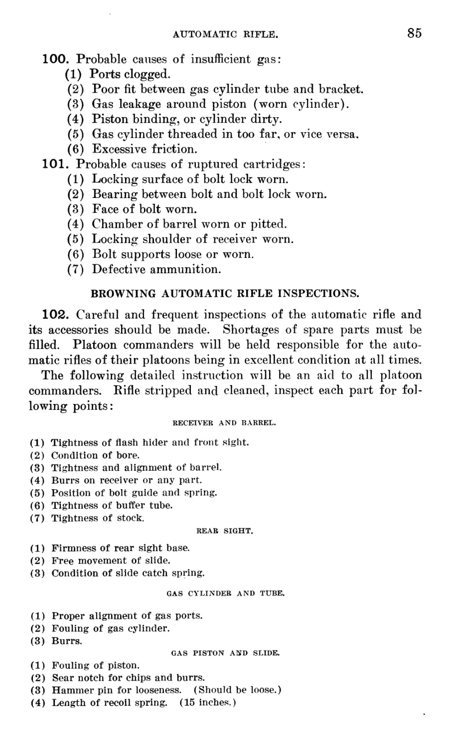
Notes for repairmen_______________________________________________88-101
Platoon commander’s inspection___________________________________102-103
Blank ammunition attachments for Browning automatic rifle:
General description and nomenclature (plate page 89)__________ 104
Detailed description ____________________________________________105-107
Instructions, safety precautions, and cleaning___________________108-110
5
6
AUTOMATIC RIFLE (BROWNING).
(MODEL OF 1918.)
GENERAL INFORMATION.
GENERAL DESCRIPTION AND DATA.
1. The Browning automatic rifle, model of 1918, is air cooled, gas
operated, and magazine fed. It is chambered for U. S. caliber .30,
model 1906, ammunition.
2. It has no special cooling system, the barrel being exposed to
the air, and the hand of the firer being protected on the under side
of the barrel by a large wooden forearm. Care must be taken to
avoid touching the barrel during firing.
3. The Browning automatic rifle is operated by the power fur-
nished by expanding powder gases following ignition of the car-
tridge. These powder gases expand through a port in the barrel and
act upon the head of a piston, driving it to the rear. During rear-
ward movement the processes of unlocking, extraction, ejection, and
compression of the recoil spring are effected; during the forward
movement, feeding, locking, and igniting the cartridges are accom-
plished.
4. The rifle is fed from a magazine having a capacity of 20 car-
tridges.
5. This rifle can be fired effectively from all positions prescribed
in the Small Arms Firing Manual. It is capable of being fired at
the rate of 150 rounds per minute, semiautomatic. The rate of fire,
however, which gives the best results in the normal case is 40 to 60
shots per minute, semiautomatic.
6. Right and left side of gun.
1. Weight of rifle, 15 pounds S ounces.
2. Weight of magazine, empty, 7
ounces.
3. Weight of magazine, filled, 1 pound
7 ounces.
4. Length of barrel, 24 inches.
5. Over-all length, 47 inches.
6. Sights graduated to 1,600 yards.
7. Caliber bore, 0.30 inch.
8. Gas port from muzzle, 6 inches.
9. Rate of uninterrupted automatic
fire (cyclic rate), 600 shots per
minute.
10. Chamber pressure, 47,000 to 50,000
pounds per square inch.
11. Muzzle velocity, about 2,680 feet per
second.
12. Habitual type of fire, semiauto-
matic.
13. Head space limits, 1.937 inches to
1.943 inches.
14. Length recoil spring, 15.5 inches.
7
8
AUTOMATIC RIFLE.
NOMENCLATURE.
7. Numerical (Plateg I, II, III):
1. Receiver.
2. Top plate.
3. Bolt support, right.
4. Bolt support, left.
5. Bolt support rivet.
10. Trigger guard.
11. Trigger guard retaining pin.
12. Trigger guard retaining pin han-
dle.
13. Trigger.
14. Trigger pin (same as 35).
15. Connector pin.
16. Connector.
17. Change lever.
18. Change lever spring.
19. Sear stop.
20. Change lever stop.
21. Change lever, stop spring.
22. Change lever stop spring pin.
23. Sear.
24. Sear pin.
25. Sear carrier.
26. Sear spring.
27. Connector stop.
28. Counter-recoil spring.
29. Ejector.
30. Ejector lock.
31. Ejector lock spring.
32. Magazine catch.
33. Magazine catch spring.
34. Magazine release.
35. Magazine catch pin (same as 14).
40. Recoil spring.
41. Recoil spring guide.
42. Recoil spring guide head.
45. Slide.
46. Gas piston.
47. Gas piston bushing.
48. Gas piston plug.
49. Gas piston retaining pin.
50. Gas cylinder.
51. Gas cylinder lock.
52. Gas cylinder tube.
53. Gas cylinder tube retaining pin.
54. Gas cylinder tube retaining pin
handle.
55. Gas cylinder tube retaining pin
key.
56. Gas cylinder tube bracket.
57. Gas cylinder tube bracket pin.
60. Barrel.
61. Front sight carrier.
62. Front sight carrier key.
63. Front sight carrier key pin.
64. Front sight blade.
65. Buffer tube.
66. Buffer.
67. Buffer friction cone (4).
68. Buffer friction cup (4).
69. Buffer nut.
70. Buffer spring.
72. Bolt guide.
73. Bolt guide spring.
75. Bolt.
76. Firing pin.
77. Extractor.
78. Extractor spring.
80. Bolt lock.
81. Bolt lock pin.
82. Link.
83. Link pin.
85. Hammer.
86. Hammer pin.
88. Operating handle.
89. Operating handle plunger.
90. Operating handle plunger pin.
91. Operating handle plunger spring.
94. Rear sight base.
95. Rear sight spring.
96. Rear sight spring screw.
97. Rear sight axis screw.
98. Rear sight axis screw nut.
99. Rear sight slide.
100. Rear sight slide catch.
101. Rear sight slide catch spring.
102. Rear sight slide stop screw.
103. Rear sight slide catch axis pin.
104. Rear sight leaf.
108. Magazine tube.
109. Magazine base.
110. Magazine follower.
111. Magazine spring.
114. Magazine filler.
115. Combination tool.
118. Forearm (wood).
119. Forearm screw (short).
120. Forearm screw (long).
121. Forearm escutcheon.
125. Butt stock.
126. Butt stock bolt.
PLATE_I
BOLT LOCK
MAGAZ-WE RELEASE
SECT/OHAL/ZED
— Ml— —
OPERATIMG HAMDLE
FOREARM
GAS CYL/HDER TUBE
GAS CYL/HDER TUBE BRACKET P/M
GAS CYL/MDER
FROM T SWIVEL BRACKET
BRACKET SWIVEL SCREW
BRACKET SWIVEL
GUM SL/MG SL/D/MG LOOP
GUM SL/MG STRAP - LOMG
GUM SL/MG
GUM SL/MG L/MK
FOREARM SCREW-LOMG
GAS CYL/MDER TUBE RETAIMIHG P/M HAMDLE
GUM
6ECT/mUZED
-3" 2.2.7-
PLATE Ш
BARREL----
645 CYLINDER TUBE^
GAS CYLINDER TUBE BRACKET PIN
GAS CYLINDER TUBE BRACKET~@) Gt) /'
OPERATING HANDLE BOLT GUIDE
OPERATING HANDLE PLi
FOREARH
•R I REAR SIGHT LEAF
i REAR SIGHT BASE BUTT STOCK
butt \late
FRONT SWIVEL BRACKET-
BRACKET SWIVEL SCREW
BRACKET SWIVEL-A^l
HANGE LEVER STOP
GUN SLING SLIDING , LOOP—
GUN SUNG STRAP-LONG—
GUN SUNG HOOK-
v___CHANGE LEVER
GUN SUNG LOOP
TRIGGER
GUN SLING LINK''
FOREARN SCREW-LONG-
FRONT SIGHT BLADE
GUN SLING
FRONT SIGHT CARRIER- -
TRIGGER GUARD RETAIH/HG PIN HA HOLE
-GUB 3LHYG STRAP-SHORT
CYL/HDER LOCK-
FLASH HIPER
ESCUTCHEOfY
FlA6ALLHYE TUBE
GAS CYLINDER TUBE RETAINING PHY HANDLE
PLATE
TRIGGER
MAGAZID'E
BOLT LOCK PHY
SECT/ONAL/ZED
12
AUTOMATIC RIFLE.
127. Butt stock bolt washer.
130. Butt plate.
131. Butt plate trap.
132. Butt plate trap spring.
133. Butt plate trap axis pin.
134. Butt plate trap spring screw.
136. Butt plate screw (long).
137. Butt plate screw (short).
140. Gun sling (complete).
141. Gun sling hook (3).
142. Gun sling sliding loop.
143. Bracket swivel (2).
144. Gun sling loop.
145. Front swivel bracket.
146. Gun sling hook rivets (9).
147. Bracket swivel screw (4).
148. Gun sling swivel (2).
149. Gun swivel link (2).
150. Butt swivel bracket.
151. Butt swivel bracket screw . (2).
152. Gun sling strap (long) .
153. Gun sling strap (short).
154. Flash hider.
8. Alphabetical:
60. Barrel.
75. Bolt.
72. Bolt guide.
73. Bolt guide spring.
80. Bolt lock.
81. Bolt lock pin.
4. Bolt support, left.
3. Bolt support, right.
5. Bolt support rivet.
143. Bracket swivel (2).
147. Bracket swivel screw (4).
66. Buffer.
67. Buffer friction cone (4).
68. Buffer friction cup (4).
69. Buffer nut.
70. Buffer spring.
65. Buffer tube.
130. Butt plate.
136. Butt plate screw (long).
137. Butt plate screw (short).
131. Butt plate trap.
133. Butt plate trap axis pin.
132. Butt plate trap spring.
134. Butt plate trap spring screw.
125. Butt stock.
126. Butt stock bolt.
127. Butt stock bolt washer.
150. Butt swivel bracket.
151. Butt swivel bracket screw.
17. Change lever.
18. Change lever spring.
20. Change lever stop.
21. Change lever stop spring.
22. Change lever stop spring pin.
115. Combination tool.
16. Connector.
15. Connector pin.
27. Connector stop.
28. Counter-recoil spring.
29. Ejector.
30. Ejector lock.
31. Ejector lock spring.
77. Extractor.
78. Extractor spring.
76. Firing pin.
154. Flash hider.
118. Forearm (wood).
121. Forearm escutcheon.
120. Forearm screw (long).
119. Forearm screw (short).
64. Front sight blade.
63. Front sight carrier key pin.
61. Front sight carrier.
62. Front sight carrier key.
145. Front swivel bracket.
50. Gas cylinder.
51. Gas cylinder lock.
52. Gas cylinder tube.
56. Gas cylinder tube bracket.
57. Gas cylinder tube bracket pin.
53. Gas cylinder tube retaining pin.
54. Gas cylinder tube re-
taining pin handle.
55. Gas cylinder tube re-
taining pin key.
46. Gas piston.
►Assembled.
47. Gas piston bushing.
48. Gas piston plug.
49. Gas piston retaining pin.
140. Gun sling (complete).
141. Gun sling hook (3).
142. Gun sling sliding loop.
144. Gun sling loop.
146. Gun sling hook rivets (9).
148. Gun sling swivel (2).
149. Gun sling link (2).
152. Gun sling strap (long).
153. Gun sling strap (short). .
85. Hammer.
86. Hammer pin.
PLATE IV.
BP REEL PBD GPS CYL/PPER GROUP
BRACKET SW/VEL
PLATE V.
RECEIVER ЛZXZ7 BUTT STOCK GROUP
BUFFER TUBE
BUFFER FR/CT/O/V CUP
BUTT STOCK BOLT
BUTT STOCK
BOLT WASREri Wo
(1 } REGE/VER gQ
BUFF STOCK
:'BOLT GUIDE
HANDLE PLUDGER&fn BUFFER
I ft OPERATIHG UARDLE
BUFFER^ FXwP\
^TuRGER^SPR^G^ eeiBOLT GUIDE SPRWE'-
PLUH^>EFc ornirfG ( DC
91
BUFFER SPR/,
BUFFER NUT—
ОРЕРАГ/NG HANDLE !’
PLUNGER Р1Л
BUTT faX
plrtei^'
SCREW (ZOtlG)
butt plate
fa. 1991 TRAPSPR/HG
(13E /'З’ SCREW -
Г BUTT PLATE TRAPSPAmG
BUTT PLATE TRAP
\_i BUTT PLATE
gg SCREWfSHOmi^, л,
BUTT PLRTEfa
BUTT PLATE TRAP AXIS Р/П
KEF
CHANGE LEVER STOP SPR/N
P/N—
BOLT SUPPORT
(RtGHT)
E \ BRACKETSMVr
21)
CHARGE LEVER STOP SPRHTG
BRACKETT SWIVEL SC.
BUTT SWIVEL
BRACKET SCREW
' 3 41
Wih
BOLT SUPPORT/I
(LEFT) И
^- 80LT SUPPORT
It-J 5 (RIVET I
СКАП6Е
%Ls!op
AUTOMATIC RIFLE.
15
82. Link.
83. Link pin.
109. Magazine base.
32. Magazine catch.
35. Magazine catch pin (same as 14).
33. Magazine catch spring
114. Magazine filler.
110. Magazine follower.
34. Magazine release.
111. Magazine spring.
108. Magazine tube.
69. Operating handle plunger.
90. Operating handle plunger pin.
91. Operating handle plunger spring.
97. Rear sight axis screw.
98. Rear sight axis screw nut.
94. Rear sight base.
104. Rear sight leaf.
99. Rear sight slide.
100. Rear sight slide catch.
103. Rear sight slide catch axis pin.
101. Rear sight slide catch, spring.
102. Rear sight slide stop screw.
95. Rear sight spring.
96. Rear sight spring screw.
1. Receiver.
40. Recoil spring.
41. Recoil spring guide.
42. Recoil spring guide head.
23. Sear.
25. Sear carrier.
24. Sear pin.
26. Sear spring.
19. Sear stop.
45. Slide.
2. Top plate.
13. Trigger.
10. Trigger guard.
11. Trigger guard retaining pin.
12. Trigger guard retaining pin
handle.
14. Trigger pin (same as 35).
GROUP NOMENCLATURE.
9. Barrel and gas cylinder tube group (Plate IV):
50. Gas cylinder.
51. Gas cylinder lock.
52. Gas cylinder tube.
53. Gas cylinder tube retaining pin.
56. Gas cylinder tube bracket.
- 57. Gas cylinder tube bracket pin.
60. Barrel.
61. Front sight carrier.
62. Front sight carrier .key.
63. Front sight carrier key pin.
64. Front sight blade.
118. Forearm (wood).
119. Forearm screw (short).
120. Forearm screw (long).
121. Forearm escutcheon.
143. Bracket swivel (2).
145. Front swivel bracket.
147. Bracket swivel screw (2).
154. Flash hider.
148-149. Gun sling swivel and link (2).
10. Receiver and butt stock group (Plate V):
1. Receiver.
2. Top plate.
3. Bolt support (right).
4. Bolt support (left).
5. Bolt support rivet (6).
20. Change lever stop.
21. Change lever stop spring.
22. Change lever stop spring pin.
65. Buffer tube.
66. Buffer.
67. Buffer friction cone (4).
68. Buffer friction cup (4).
69. Buffer nut.
70. Buffer spring.
72. Bolt guide.
73. Bolt guide spring.
88. Operating handle.
89. Operating handle plunger.
90. Operating handle plunger pin.
91. Operating handle nlunger spring.
125. Butt stock.
126. Butt stock bolt.
127. Butt stock bolt washer.
130. Butt plate.
131. Butt plate trap.
132. Butt plate trap spring.
133. Butt plate trap axis pin.
134. Butt plate trap spring screw.
136. Butt plate screw (long).
137. Butt plate screw (short).
143. Bracket swivel (2).
147. Bracket swivel screw (2).
150. Butt swivel bracket.
151. Butt swivel bracket screw,
PLATE VI.
TRIGGER-GUARD GROUP.
PLATE VII.
OPERATING GROUP.
161435°—20---2
17
PLATE VIII.
SIGHT GROUP.
PLATE IX.
GAS CYLINDER
OIL CAN CLEANING TOOL.
MARK К.
MAGAZINE FILLER
FABRIC COM TA IN ER-SMAUL.-
FOR RECOIL SPRING.
ACCESSORIES AND SPARE PARTS GROUP.
20
AUTOMATIC RIFLE.
11. Trigger guard group (Plate VI):
10. Trigger guard.
11. Trigger guard retaining pin.
13. Trigger.
14. Trigger pin (same as 35).
16. Connector.
17. Change lever.
18. Change lever spring.
19. Sear stop.
23. Sear.
24. Sear pin.
25. Sear carrier.
26. Sear spring.
28. Counter-recoil spring.
29. Ejector.
30. Ejector lock.
31. Ejector lock spring.
32. Magazine catch.
33. Magazine catch spring.
34. Magazine release.
35. Magazine catch pin (same as 14)
12. Operating group (Plate VII) :
40. Recoil spring.
41. Recoil spring guide.
43. Recoil spring guide head.
45. Slide.
46. Gas piston.
47. Gas piston plug.
49. Gas piston retaining pin.
75. Bolt.
76. Firing pin.
13. Sight group (Plate VIII) :
77. Extractor.
78. Extractor spring.
80. Bolt lock.
81. Bolt lock pin.
82. Link.
83. Link pin.
85. Hammer.
86. Hammer pin.
Rear sight group:
94. Rear sight base.
95. Rear sight spring.
96. Rear sight spring screw.
97. Rear sight axis screw.
98. Rear sight axis screw nut.
99. Rear sight slide.
100. Rear sight slide catch.
101. Rear sight slide catch spring.
Rear sight group:
102. Rear sight slide stop screw.
103. Rear sight slide catch axis pin.
104. Rear sight leaf.
Front sight group: ,
61. Front sight carrier.
62. Front sight carrier key.
63. Front sight carrier key pin.
64. Front sight blade.
14. Field spare parts and accessories (Plate IX) :
71 Magazines.
3 Magazine fillers.
1 Set luminous sights (Mark III) in
box.
1 Spare parts case, leather, contain-
ing:
1 Fabric container, large.
1 Fabric container, small.
1 Combination tool.
1 Thong cleaner.
1 Oil can (Mark II).
1 Gas cylinder cleaning tool.
1 Ruptured cartridge extractor
(Mark II).
1 Spare parts case, etc.—Continued.
1 Extractor (77).
1 Extractor spring (78).
1 Recoil spring (40).
2 Firing pins (76).
1 Sear spring (26).
1 Connector (16).
1 Magazine catch spring (33).
1 Gas cylinder tube retaining pin
(53).
1 Trigger guard retaining pin (11).
AUTOMATIC RIFLE.
21
METHODS OF INSTRUCTION.
15. In the company or platoon all men should be combined in one
class under one or more commissioned instructors. Each sergeant
will supervise his own section as assistant instructor, and each cor-
poral will act as instructor for his own squad.
It is contemplated that the sergeants and corporals shall have had
a thorough course of instruction prior to their men.
If possible a classroom should be provided with a blackboard, seats
for the entire class, and one rifle table per squad, sufficiently large to
permit the entire squad to be grouped around it while working on
the rifle.
SUBJECTS.
16. Mechanism will be taught by subjects in the following order:
(1) Stripping and assembling of rifle, except trigger mech-
anism.
(2) Stripping and assembling of trigger mechanism.
(3) Stripping and assembling of magazine.
(4) Functioning of gun proper, including the magazine.
(5) Functioning of the trigger mechanism.
(6) Accessories and spare parts.
(7) Stoppages and immediate action (classroom).
(8) Care and preservation.
Note.—Stoppages and immediate action will be practically taught on the
range during the marksmanship course.
DETAILED METHOD OF INSTRUCTION.
17. No discussion of functioning should be permitted prior to the
completion of stripping and assembling. Nomenclature will be
learned during the instruction of stripping and assembling and re-
viewed throughout the remainder of the course.
In each subject the following procedure will be observed:
INTRODUCTION.
The instructor will preface his instruction with a brief general
lecture leading up to the specific subject in hand. He must provide
ahead of time all material needed for the day’s work.
EXPLANATORY DEMONSTRATION.
The instructor will make a detailed explanation of the subject to
be taught, illustrating or demonstrating his explanation as he pro-
ceeds. This explanatory demonstration will be made to the class as
a whole; this results in uniform instruction for the entire class in
the beginning of each subject.
22
AUTOMATIC RIFLE.
IMITATION.
All men will repair to their rifles and each man in turn will
imitate the explanatory demonstration of his instructor. The
other members of the team will stand by with handbooks and check
up any errors.
PRACTICE.
All men will then practice the particular operations in hand until
they become proficient. The instructor will supervise this work,
correct errors, assist backward men, and give detailed instruction in
general. As men deem themselves qualified they will report to their
instructor for examination. He will require a perfect recitation be-
fore reporting a man qualified to the senior instructor.
INTERROGATION.
Men will frequently be examined as to their knowledge of the
work in hand. Questions will be framed with a view to bringing out
important points. This interrogation should be followed wherever
possible throughout the remainder of the course.
SCHEDULE OF INSTRUCTION.
18. Mechanism should be taught in a series of lessons which should
include all the instructional matter which follows. The subject in-
cluded in each lesson will depend upon the degree of intelligence of
the class and the length of the period allotted. Each lesson should
be mastered by the majority of the class prior to proceeding to the
next, and whenever possible the preceding lesson should be reviewed
with the current one.
Men should be encouraged to ask questions at all times, without,
however, going ahead of the subject in hand.
CLASSROOM REGULATIONS.
19. The following regulations should be observed in the class-
room during stripping and assembling:
(1) Force will not be used.
(2) The piece will not be stripped nor assembled against time.
(3) Magazines will be carefully handled and every precau-
tion taken to prevent denting or bending.
STRIPPING AND ASSEMBLING.
INTRODUCTION.
20. The instructor will give a brief talk introducing the rifle,
wherein he will cover its type, caliber, characteristics, and any such
other points of general interest as he deems advisable. He will
AUTOMATIC RIFLE.
23
then go over the rifle, naming and describing the various parts
externally visible. This he will follow by slowly stripping the
rifle, exclusive of the trigger mechanism and buffer, holding up,
naming, and describing each part as he removes it. He will call
attention to all cams, locks, slots, profiles, and springs, but will not
at this time describe their function. The instructor will assemble
the piece according to the same procedure. After this explanatory
demonstration, the teams being assembled at their rifles, the in-
structor will describe, step by step, how to strip and assemble the
rifle, naming and describing parts as before. He will require one
man at each rifle to imitate him as he finishes, describing each step,
the remaining members of the team observing. Every man in the
class will repeat names as called out by the instructor. No one will
be permitted to go ahead of this explanation and assistants will
keep the backward men up with the explanation.
SEQUENCE AND METHOD OF STRIPPING.
21. (1) Cock the piece.
(2) Gas cylinder tube retaining pin.
(3) Gas.cylinder tube (let mechanism forward easily).
(4) Trigger-guard retaining pin.
(5) Trigger guard.
(6) Recoil spring guide and recoil spring.
(7) Hammer pin through hammer pin hole in receiver.
(8) Operating handle.
(9) Hammer pin.
(10) Hammer.
(11) Slide.
(12) Bolt guide pushed out.
(13) Bolt, bolt lock, and link.
(14) Firing pin.
(15) Extractor.
22. Lay , the rifle on the table, barrel down, pointing to the left.
Cock the piece. This must be done in order that the gas cylinder
tube may clear the gas piston and gas cylinder bracket, female.
Remove the gas cylinder tube retaining pin by turning the handle
90° in a clockwise direction and lift out.
Remove gas cylinder tube.
Let the slide forward very canity in order to release the tension
of the recoil spring and avoid any damage to the rifle. Care must
be taken during stripping and assembling to avoid working against
tension of any springs.
Remove the trigger guard retaining pin by turning handle 90° in a
clockwise direction and lifting out.
24
AUTOMATIC RIFLE
LAY THE PIECE BARREL DOWN AND
POINTING TO THE LEFT, THE PIECE REST-
ING ON THE BARREL AND REAR SIGHT
COCK THE PIECE,AND PUSH
OPCRATING HANDLE FORWARD
WITH POINT OF CARTRIDGE UNLOCK
THE GAS CYLINDER TUBE RETAINING PIN. ..
...AND WITHDRAW IT TO TnE RIGHT.
...with the middle and index fingers of
left hand astride the piston--against
THE FORWARD end of the slide..........
REMOVE THE TRIGGER GUARD
. . . . AND REMOVE THE RECOIL SPRING AND
GUIDE TO THE REAR
NOW with the point of a cartridge insert-
ed IN THE DISMOUNTING HOLE IN THE OPERAT-
ING HANDLE .. .
SWING IT UPWARD....
REMOVE THE GAS CYLINDER
AND FOREARM TO THE FRONT OVER
PISTON.....
TUBE
The
.. .’Pull the trigger with the thumb
of the right hand....................
PLACE END OF INPEX FINGER ON CHECKERED
END OF RECOIL SPRING GUIDE HEAD....TURN IT
UNTIL DISENGAGED FROM ITS RETAINING
SHOULDERS
EXERT PRESSURE WITH CARTRIDGE POINT TO THE*
LEET SO THAT WHEN THE HAMMER PIN AND THE
Dismounting hole in receiver coincide...
....AND THE FOREFINGER OF THE LEFT HAND
PUSHING GENTLY BACKWARD ON THE OP -
CRATING HANDLE
AUTOMATIC RIFLE
25
REMOVE THE HAMMER PIN TO THE LEFT ...
HOOK THf INPEX FINGER OF THE LEFT ttANP
UNPCR THE* FRONT ENP OF THE HAMMER. ANP
LIFT THE BOLT LOCK ANO REMOVE THE
FIRING PIN ...
. . . USING THE FIRING PIN AS A PRIFT,
PUSH OUT THE LINK PIN.
26
AUTOMATIC RIFLE.
Lift out the trigger guard group.
Remove the recoil spring guide by pressing the right index finger
on the checkered surface of its head and turning it until the ends
are clear of the retaining shoulders. This may also be done by using
the index finger of the left hand and the middle finger of the right
hand.
Line up the hammer pin holes on the receiver and the operating
handle by inserting the point of the recoil spring guide or dummy
cartridge in the hole on the operating handle with the right hand,
press against the hammer pin and push the slide backward with the
left hand. The recoil spring guide will push the hammer pin through
its hole in the receiver as the hammer pin registers with the latter.
Remove the operating handle by pulling straight to the rear.
Push the hammer forward out of its seat in the slide and lift out
of the receiver.
Remove the slide by pulling forward out of the receiver, being
careful that' the link is pushed well down, thus allowing the slide
to clear. In removing the slide take care to avoid striking the gas
piston or rings against the gas cylinder tube bracket, female.
Force the bolt guide out with the left thumb or point of bullet.
Lift out the bolt, bolt lock, and link by pulling slowly to rear end
of receiver and up.
Pull out the firing pin from its way in the bolt.
Remove the extractor by pressing the small end of a dummy car-
tridge against the claw and exerting pressure upward and to the
front.
SEQUENCE AND METHOD OF ASSEMBLING.
23. (1) Extractor.
(2) Firing pin.
(3) Bolt, bolt lock, and link.
(4) Slide.
(5) Hammer.
(6) . Hammer pin (far enough to register all holes).
(7) Operating handle.
(8) Hammer pin fully seated.
(9) Recoil spring and guide.
(10) Trigger guard.
(11) Trigger guard retaining pin.
(12) Cock the piece.
(13) Gas cylinder tube.
(14) Gas cylinder tube retaining pin.
(15) Let slide forward easily.
(16) Test the piece.
AUTOMATIC RIFLE
27
REPLACE THE EXTRACTOR INTO ITS SEAT
IN THE BOLT
. REPLACE THE EXTRACTOR SPRING
28
AUTOMATIC RIFLE,
. .ANU TURN IT DOWN UNTIL IT CLICKS INTO ITS
LOCKED POSITION
NOW HOLD THE OPERATING HANDLE AND PULL THE
TRIGGER, ALLOWING THE MECHANISM TO MOVE SLOW-
4* FORWARD UNDER THE ACTION QT THE RECOIL
SPRING
AUTOMATIC RIFLE.
29
24. Replace extractor spring.
Replace extractor into its seat in the bolt.
Place the link and link pin with the shoulder of the link against
the flat surface of the bolt lock.
Lift the bolt lock and replace the firing pin.
Lay the piece barrel down and pointing to the left so that the
piece is resting on the barrel and rear sight.
With the bolt mechanism held in a perpendicular position, insert
it in the receiver, forcing the end of the bolt under the ends of the
bolt supports, and then press the bolt mechanism down so as to lie
flat in its place.
Push the bolt mechanism forward, swing the link down, then
replace the slide and push it all the way back.
With the hammer resting between the thumb and the forefinger,
lower and seat it properly in the receiver and push the slide forward.
With the thumb and forefinger of the right hand, align the ham-
mer pin holes of the link, hammer, and slide with the hammer pin
hole in the side of the receiver.
Insert hammer pin to the right until only one-fourth of an inch
of the hammer pin protrudes from the receiver.
Replace the operating handle.
Tap the end of the protruding hammer pin with sufficient force to
drive it home.
Replace recoil spring and guide.
With the end of the index finger on the checkered end of the re-
coil spring guide head, turn it until it is properly seated.
Replace the trigger guard and trigger guard retaining pin.
Cock the piece.
Slide the gas cylinder tube and forearm to the rear of the gas
piston.
Replace gas cylinder tube retaining pin.
Test the piece.
25. When this demonstration has been completed once, the remain-
ing members of the squad will strip and assemble the piece, naming
and describing each part as it is removed. The other members of
the team will stand by with handbooks and correct any errors of
nomenclature or method of stripping and assembling. Instructors
will supervise and assist students and will see that mistakes are
corrected as they are made. They will examine men whom they be-
lieve to be qualified and report to the senior instructor those who
make perfect recitations.
STRIPPING AND ASSEMBLING BLINDFOLDED.
26. After all men become thoroughly proficient in stripping and
assembling, and if time permits, they should be required to strip
30 AUTOMATIC RIFLE.
and assemble the rifle blindfolded. Instructors supervise this in-
struction to prevent wrong assembly or forcing of parts. Assistance
should be given if necessary. If any part is called for by its right
name, same will be furnished.
The other members of the squad not blindfolded will have various
parts put in their hands while placed so they can not see what these
parts are and will be required to identify them by feel. Extraneous
pieces of metal may be introduced in this latter exercise.
The purpose of this instruction is to so train the soldier as to
enable him to replace breakages and reduce stoppages in the dark.
TO REMOVE FIRING PIN OR EXTRACTOR WITHOUT STRIPPING THE
RIFLE.
27. After removing the trigger guard, turn the piece over with the
barrel up. Keep the bolt guide free of the bolt by inserting the base
of a dummy cartridge underneath it after it has been pushed out.
Draw the operating handle to the rear until the bolt mechanism drops
clear of the receiver. Let the mechanism forward and turn the gun
so that the bottom will be upward. With the left hand hold the bolt
and withdraw firing pin with right hand.
To assemble, replace the firing pin, draw the mechanism to the
rear, place the face of the bolt under the bolt supports and press
down the firing pin until bolt clears the bolt guide. Let the mechan-
ism forward and replace the trigger mechanism.
TO REMOVE EXTRACTOR.
28. Draw back mechanism and insert empty case or dummy car-
tridge between bolt head and chamber, exposing the extractor.
With the forefinger of the left hand force out the claw of the ex-
tractor, then place point of cartridge behind the extractor shoulder
and pry forward until extractor is free of the recess.
Remove- extractor spring.
With the thumb and forefinger of the left hand insert extractor
into extractor recess in bolt and force it to the rear until it is in
position. Draw operating handle to the rear and shake out empty
case.
STRIPPING AND ASSEMBLING TRIGGER MECHANISM.
SEQUENCE AND METHOD OF STRIPPING AND ASSEMBLING.
29. This stripping and assembling is not to be done in the field
except to replace breakages:
(1) Ejector.
(2) Magazine catch spring.
(3) Magazine catch pin.
31
32
161435°—20---3
34
35
36
AUTOMATIC RIFLE.
37
(4) Magazine catch.
(5) Magazine release.
(6) Sear spring.
(7) Trigger pin.
(8) Trigger and connector.
(9) Sear pin.
(10) Sear.
(11) Sear carrier and counter-recoil spring.
(12) Change lever spring.
(13) Change lever.
30. Dep ress the ejector lock with the point of a dummy cartridge.
Hold the thumb in front of the magazine catch spring to prevent it
flying out and slide the ejector out of its seat. Remove the magazine
catch spring. Remove the magazine catch pin and then the maga-
zine catch and magazine release may be lifted out.
To remove sear spring, insert the handle of the trigger guard re-
taining pin under the sear spring above the connector stop, pry up,
pressing against sear spring with thumb and pulling it out to the
rear. Push out the trigger pin to the right or left and then the
trigger and connector will fall out.
Push out sear pin with recoil spring guide. Remove sear. Pry up
on sear carrier and lift out.
Change lever spring is removed by prying the bent over rear end
out of its seat with the rounded end of the sear spring and moving the
change lever from front to rear. When clear of the change lever
it is pushed the rest of the way out by pressing with* the thumb
against'the sear stop.
Change lever is pulled out.
31. Sequence of assembling is in reverse order of stripping.
The following points should be observed in assembling:
(1) It is easy to seat the magazine catch spring if the ejector is
moved down until it is flush with the magazine catch spring before
attempting to compress the latter.
(2) % In assembling the change lever spring, first insert the ears in
the slots in the trigger guard and push spring forward a slight
distance, then insert the rounded end of the sear spring between
the rear end of the trigger guard and the change lever spring. By
prying up with the sear spring and at the same time pressing against
sear stop with thumb and rotating change lever from rear to front
the change lever spring is easily seated. Sear carrier and counter-
recoil spring are assembled to trigger mechanism by inserting
counter-recoil spring guide in the seat, then using the recoil spring
guide as a lever in the sear pin hole, prying the sear carrier forward
until its rear end is held by the ears on the change lever spring.
38
39
40
With point of a cartridge raise rear end of magazine base until indentations are clear to permit
withdrawal. Then slide the base to the rear.
Pull out magazine spring and shake out the follower.
(For assembling); Insert follower and magazine spring.
41
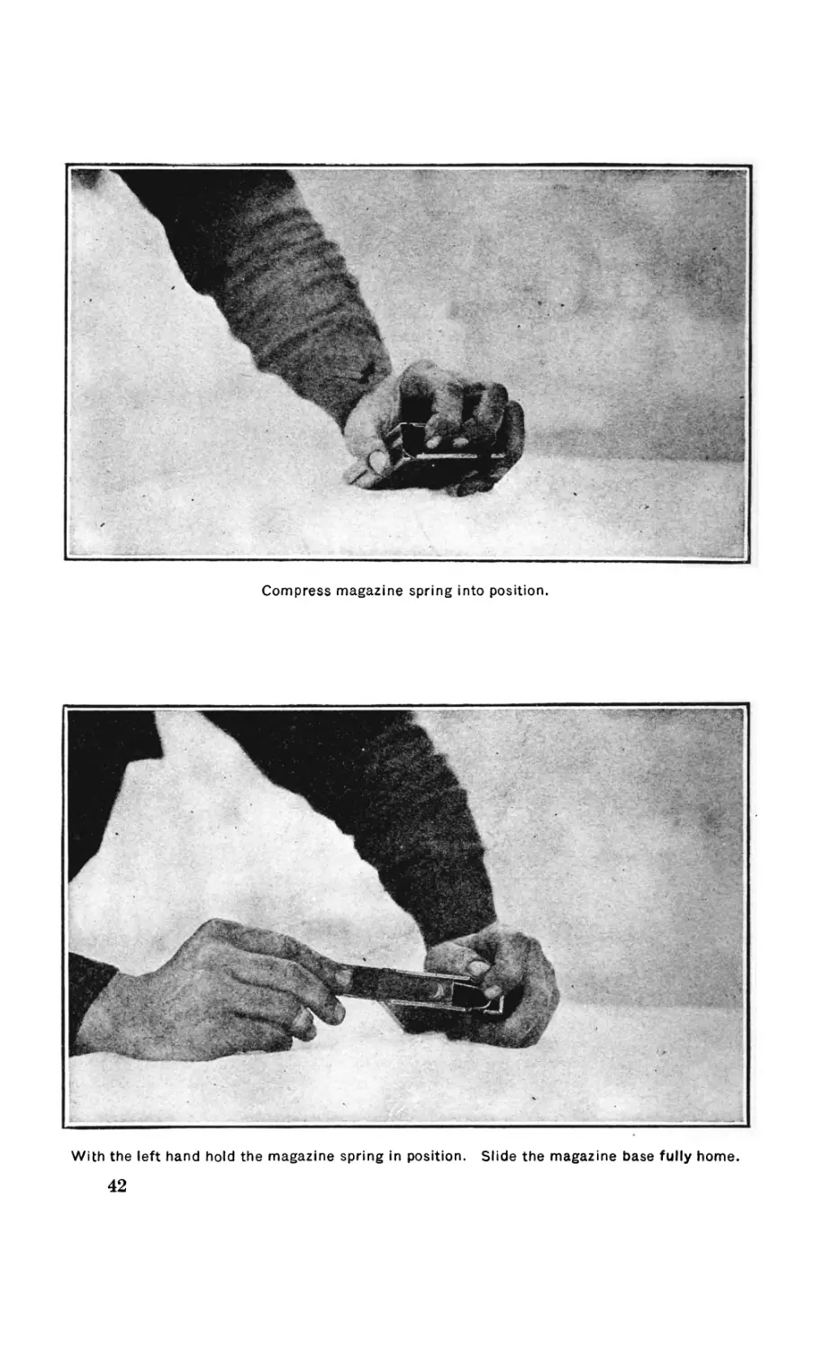
Compress magazine spring into position.
With the left hand hold the magazine spring in position. Slide the magazine base fully home.
42
AUTOMATIC TITLE.
43
The sear is now inserted and the recoil spring guide forced through
so as to register the holes in the sear, sear carrier, and trigger guard
for the sear pin, and is forced in by pressing it against a wooden sur-
face, thus forcing the recoil spring guide out.
(3) In assembling the connector, note that its head is in rear of the
connector stop.
(4) Be especially careful to see that the outside prongs of the
sear spring rest on their seats on the sear, and that the middle
prong rides freely in the slot formed by the walls of the sear carrier.
If this middle prong rests on one of these walls, instead of riding
freely between them, the trigger mechanism will not function when
the barrel is inclined below the horizontal.
STRIPPING AND ASSEMBLING MAGAZINE.
SEQUENCE OF STRIPPING AND ASSEMBLING.
(Not to be done in the field.)
33. (1) Magazine base.
(2) Magazine spring.
(3) Magazine follower.
To remove magazine base, raise the rear end until indentations
thereon are clear, then slide to the rear. The follower and spring
will then fall out.
ASSEMBLE IN REVERSE ORDER.
(1) Follower.
> (2) Spring.
(3) Magazine base.
Note that the bent over end of follower and the eye of spring
work against the inside of rear (notched) end of magazine.
Students must be taught that the magazine requires the same care
and preservation as the rifle. It must not be allowed to become dirty.
Dented magazines cause malfunctions. The greatest possible care
should be taken to prevent any damage whatever being done to the
lips of the magazine or to the notch for the magazine catch.
STRIPPING AND ASSEMBLING NOT ORDINARILY PERFORMED IN
THE FIELD.
FOREARM GROUP.
33. To strip the forearm group, unscrew the forearm screws, long
and short, and remove the wood forearm from the gas cylinder tube.
The forearm escutcheon should never be removed from the forearm.
Unscrew the two bracket swivel screws which allow the removal of
44
AUTOMATIC RIFLE.
the gun sling swivel, and the gun sling link. Spring the front
swivel bracket off over the gas cylinder tube.
Before removing the gas cylinder, note its setting carefully, so that
it can be reassembled to the same position. Then force out the gas
cylinder lock until its head clears the notch in the gas cylinder, which
can then be unscrewed from the gas cylinder tube. The gas cylinder
lock can be completely removed from the cylinder with a suitable
drift or by prying under the head with the combination tool.
To assemble the forearm group, replace the forearm on the gas
cylinder tube, and insert the forearm screws, long and short. Spring
the front swivel bracket over the gas cylinder tube, and replace the
gun sling link and swivel, fastening these in place by means of the
bracket swivel screws. All screws should be drawn up tight. Screw
the gas cylinder in the gas cylinder tube to its proper setting, and
push in the gas cylinder lock so that its head engages the notch in the
gas cylinder. The registration of gas port is indicated by the circle
marking on the front of the cylinder. When on the small port, the
smallest circle is toward the barrel and in this position the cylinder
should be about one turn from the shoulder. Unscrew one-third of a
turn successively to register the larger ports.
BARREL GROUP.
34. The barrel should never be removed until replacement is neces-
sary and then only in a properly equipped shop. Before removing
the barrel, strip the receiver of the gas operating, firing, and trigger
mechanism. Barrels can sometimes be unscrewed with the combina-
tion tool by engaging the spanner in the notch provided in the breech
end of the barrel. A special barrel dismounting wrench for the
Browning automatic rifle is provided for use in ordnance shops.
This wrench should be clamped tightly around the breech end of the
barrel with the handle extending to the right. The barrel can then
be started by a quick downward movement of the handle. The re-
ceiver may be held in a vise or by means of a block of wood inserted
up between the side walls of the receiver.
The components attached to the barrel should never be removed
except when replacements are necessary or for purposes of salvaging.
Unscrew the flash hider with the combination tool. Drive out the
front sight carrier key pin, drive the front sight carrier off to the
front, and remove the front sight carrier key. The gas cylinder tube
bracket can then be driven off to the front after the pin has been
driven out. These parts should be replaced in the reverse order.
When replacing a barrel always be sure that it is tight enough in
the receiver never to work loose. Screw the barrel into the receiver
until the draw line matches that of the receiver. Then assemble the
AUTOMATIC RIFLE.
45
gas cylinder tube to see if the gas cylinder tube bracket on the bar-
rel lines up properly. If it does not, the barrel should be turned very
slightly until the alignment is correct.
BUTT STOCK AND BUFFER GROUP.
35. The butt stock bolt can be unscrewed by inserting a long
screw driver through the hole in the butt plate after the butt plate
trap has been opened. To do this with the combination tool the butt
plate must first be removed by unscrewing the butt plate screws,
long and short. As soon as the butt stock bolt has been loosened the
butt stock can be withdrawn to the rear. To strip the butt plate,
unscrew and remove the butt plate trap spring screw and spring.
Then drive out the butt plate trap axis pin and remove the butt plate
trap.
The removal of the butt stock allows the stripping of the buffer
mechanism. Unscrew the buffer nut and remove to the rear in the
order mentioned, the buffer spring, the four sets of buffer friction
cups and cones, and the buffer. The buffer tube is threaded into the
receiver, and should never be removed except for replacement. In
order to assemble the butt stock and buffer mechanism, reverse the
method given above.
REAR SIGHT GROUP.
36. The rear sight is to be removed or stripped only when a re-
placement of certain part or parts is necessary. Remove the rear
sight spring screw, and drive the rear sight base out to the rear. Un-
screw the rear sight axis screw and nut, and take out the rear sight
leaf. The rear sight spring can then be removed from the base. Un-
screw the rear sight slide stop screw which will allow the slide to be
withdrawn from the leaf. With a small drift, drive out the sight
slide catch axis pin and take off the slide catch and spring. To re-
assemble the above components reverse the order given foi’ stripping.
46
AUTOMATIC RIFLE.
RECEIVER GROUP.
37. To strip the operating handle press in on the operating handle
plunger, and push out the operating handle plunger pin toward the
countersunk side of the plunger. The plunger and spring can then be
removed. Reverse the above method in reassembling.
The bolt guide spring may be lifted out of its seat in the bolt
guide with the rim of a cartridge. The guide and spring can then be
removed from the receiver. To reassemble these parts, insert the
longer turned-over end of the bolt guide spring in its hole on the
inside of the receiver. Then replace the bolt guide and hold it
while the spring is pushed over until the shorter turned-over end
engages the groove in the bolt guide. The change lever stop and
spring can be removed after the change lever stop spring pin has
been driven out. This is never to be done except when necessary.
FUNCTIONING.
DETAILED DESCRIPTION.
38. The rifle can best be described under two headings: The sta-
tionary portions and the moving portions.
The stationary portions consist of the receiver and parts directly
or indirectly attached thereto.
The receiver (1) is made of a single piece of steel formed at the
rear end to receive the butt stock (125) and the buffer tube (65),
which latter part is threaded into the receiver. The butt stock is held
in place by the butt stock bolt (126) which threads into the rear end
of the buffer. The buffer tube contains, from front to rear, the
buffer (66), four sets of buffer friction cups (68) and cones (67),
the buffer spring (70). and the buffer nut (69). The bronze buffer
friction cups fit over the steel cones and are split to allow expansion
when under pressure. The butt plate (130) is attached to the butt
stock by means of screws (136 and 137). Butt plate is provided
with a trap (131) which when open will allow the removal of the
butt stock bolt. The butt swivel bracket (150) is fastened to the
bottom of the butt stock by means of screws (151). To this bracket
is attached the gun sling swivel (148) and link (149), and the bracket
swivel (143) by means of bracket swivel screws (147). This swivel
arrangement provides a three-way motion for the gun sling strap
connection.
The marking for the rifle is rolled on the top of the receiver ait
the front end. In rear of this marking the top plate (2) is fitted
into dovetail guides in the receiver. The rear sight base (94) is
driven into dovetail grooves at the rear end of the top of the re-
ceiver. The rear sight base is further positioned by the rear sight
47
48
AUTOMATIC RIFLE.
spring screw (96). The rear sight leaf (104) is pivoted at the rear
of the rear sight base, its operation being controlled by the rear sight
spring (95). The rear sight slide (99) and slide catch (100) op-
erate up and down on the rear sight leaf in such a way as to give
a range adjustment of from 100 to 1,600 yards. The leaf is also
provided with a battle sight.
The ejection opening is located on the right side of the receive]?,
as is the hammer pin hole. The hammer pin hole is located so as
to allow the disassembling of the hammer pin and subsequent parts.
The left side of the receiver is provided with a guide for the
operating handle (88). The operating handle is fitted with a
plunger (89) which is held in place by a pin (90), and which is
operated by a spring (91) in such a way as to retain the operating
handle in the forward position unless force is applied to move it
toward the rear. The bolt guide (72) is held in the side of the
receiver above the operating handle by the bolt guide spring (73),
which is attached to the inside of the receiver. The edge of the bolt
guide projects inside the receiver forming a support for the bolt
(75) when it is in the rear position. The change lever stop (20) is
also assembled to the left side of the receiver, this part being held
in place by the change lever stop spring (21), which is pinned to
the inside of the receiver.
The bolt supports, right (3) and left (4), are riveted to the inside
of the receiver by means of three bolt support rivets (5) each, in
such a way as to support the bolt (75) when it is in its forward
position. The rear corners of the bolt supports are rounded so
as to aid by their camming action the raising of the bolt lock (80).
The inner edges of the bolt supports are formed to guide the car-
tridge into the chamber as it is stripped from the magazine. The
locking shoulder of the receiver is located just in rear of the top
plate. This shoulder supports the bolt lock and bolt when the car-
tridge is fired.
The bottom of the receiver is left open to receive the magazine at
the front end. The rear portion of the opening is closed by the
trigger guard (10), which fits up between the sides of the receiver.
The rear end of the trigger guard is supported by a tongue in the
receiver, which fits into a corresponding groove in the trigger guard.
The forward end of the trigger guard is held in place by the trigger
guard retaining pin (11). The trigger guard retaining pin handle
(12) locks in an indentation in the receiver, thus holding the pin in
place.
The ejector (29) is retained in a T cut at the front end of the
trigger guard by means of the ejector lock (30) and spring (31).
The top of the ejector extends upward in such a'way as to operate in
the ejector cut in the bolt. The magazine catch (32) is pinned to
AUTOMATIC' RIFLE.
49
the trigger guard. The upper end projects through the ejector,
and provides a catch which holds the magazine in place. The mag-
azine catch spring (33) is positioned between the ejector and the
magazine catch, below the pivot point of the latter. This holds the
upper end of the magazine catch in the forward position. The
magazine release extends forward from the trigger guard and
operates against the lower end of the magazine catch, thus moving
the upper end of the catch rearward when the release is pushed for-
ward.
The trigger (13) is pivoted to the trigger guard by the trigger
pin (14). The connector (16) fits loosely in the trigger, the lower
notch riding on the connector pin (15). The upper edge of the con-
nector comes in contact with the front end of the sear (23) when the
trigger is raised. The cam surface in rear of this edge engages the
corresponding surface of the sear carrier (25) if the change lever
(17) has been set at “ F.” The sear (23) is pivoted near the rear
end of the trigger guard by the sear pin (24) which passes through
the trigger guard and the sear carrier (25), the holes in the trigger
guard being slotted. The rear end of the sear is provided with a
nose which engages the sear notch in the slide (45). The under
surface of the front end of the sear engages the connector when it is
raised by the action of the trigger. The sear spring (26) is held in
grooves in the trigger guard. This spring is of the leaf type, the
middle tongue bearing against the connector holding this latter part
in position. The two outside tongues of the sear spring bear down-
ward against the forward end of the sear.
The change lever (17) extends laterally through the trigger
guard, being held in place by the front tongue of the change-lever
spring (18). This tongue also engages in notches around the shaft
of the change lever, thus holding the change lever in the various
positions. The handle of the change lever extends upward along the
left side of the receiver on which is marked the positions: “ F ’’ for
semiautomatic fire, “A” for full automatic fire, and “ S ” for safety.
The cuts and lugs on the under side of the change-lever shaft control
the action of the trigger and connector, thus giving the classes of fire
mentioned. The change-lever stop (20) in the receiver prevents
the change lever from being set at safety without intention. The
change-lever spring (18) is held in the trigger guard by means of
grooves. The sear stop (19) is assembled to the rear tongue of this
spring. The sear carrier (25) is held in place at the rear end by
the sear pin and at the front end by the trigger pin, the holes in
the sear carrier for the trigger pin being slotted so as to allow a
certain amount of movement of the sear carrier in a forward direc-
tion. This movement is arrested by the counter-recoil spring (28)
161435°—20---------4
50
AUTOMATIC RIFLE.
which surrounds the spindle at the front end of the sear carrier,
bearing against the front shoulder of the sear carrier and the oppo-
site shoulder of the trigger guard. Thus, when a shock is imposed
upon the sear it is transmitted to the sear carrier through the sear
pin, which operates in slotted holes in the trigger guard. The
trigger operates between the side walls of the sear carrier. The
connector stop (27) is in the form of a pin passing between these
side walls and forming a stop which prevents excessive forward
movement of the connector.
The forward end of the receiver near the top is threaded to receive
the barrel (60) which is screwed in tightly to the draw marks. The
barrel is of plain, light construction, the large diameter at the breech
end being carried well forward of the chamber. The chambering
and rifling of the barrel are of the usual design for U. S. caliber
.30, model 1906, ammunition. The gas port is provided on the
under side of the barrel about 6 inches from the muzzle end. This
port corresponds to a similar port in the gas cylinder tube bracket
(56) which surrounds the barrel at this point, being held in place
by the gas cylinder bracket pin (57). The gas port extends
through this bracket, which is provided urith a T cut which re-
tains the front end of the gas cylinder tube (52). The front-sight
carrier (61) surrounds the muzzle end of the barrel. This carrier
is held in place by the front-sight carrier key (62) and the front-
sight carrier key pin (63). The front-sight blade (64), which is
of the usual construction, dovetails transversely into the top of the
front-sight carrier. The front-sight blades vary in height in ac-
cordance with the requirements of targeting the rifle at the factory.
After targeting, the blade is staked in place with a prick punch.
The muzzle end of the barrel is threaded to receive the flash hider
(154), which is of plain, tubular construction, provided with a hole
at the rear end, which takes the combination tool.
The rear end of the gas cylinder tube (52) is held up into the re-
ceiver by the gas cylinder tube retaining pin (53), the handle of
which locks in an indentation in the left side of the receiver. The
tube provides a guide way for the gas piston (46), and is threaded
at the front end to receive the gas cylinder (50). This end is notched
to engage the gas cylinder lock (51). The ribs at the top engage the
T cut in the bracket of the barrel holding the gas ports in close con-
tact. The shoulder at the rear end of the tube provides a stop for the
front end of the slide (45). The lugs above this bear against the
barrel. The rear portion of the barrel and gas cylinder tube are pro-
tected on the bottom and sides by a large wooden forearm (118),
which is attached to the gas cylinder tube by means of the forearm
screws, long (120) and short (119). The forearm escutcheon (131)
AUTOMATIC RIFLE.
51
is permanently seated in the forearm, and acts as a nut for the fore-
arm screw, long. The outside of the forearm is cut to provide a good
gripping surface for the hand.
The recoil spring guide head (42) engages retaining shoulders in
the front end of the receiver. The rear surface of this head is
checkered to facilitate stripping and assembling. The recoil spring
guide (41) is riveted into the head which forms the rear seat for
the recoil spring (40). The rear portion of this spring is guided
by the recoil spring guide, the front portion being retained in the
hollow gas piston (46).
The front swivel bracket (145) clamps around the gas cylinder
tube in front of the forearm. The gun sling swivel and link (148-
149) and the bracket swivel (143) are attached to the front swivel
bracket by bracket swivel screws (147) in the manner described for
the butt swivel bracket.
The gas cylinder lock (51) fits in the transverse hole through the
head of the gas cylinder (50). The cylinder is provided with three
gas ports of varying size. These are located around the circumfer-
ence of the cylinder wall, the position and size of each being indi-
cated by circles marked on the cylinder head. The notches for the
head of the gas cylinder lock are located so as to register the gas port
in the cylinder, indicated by the circle marking nearest the barrel.
The inside of the gas cylinder is recessed at the forward end to pro-
vide clearance for dirt and powder fouling.
39. The moving portions consist of the operating, breech, and
firing mechanisms.
The rings at the front of the gas piston (46) operate in the gas
cylinder. The rear end of the piston threads loosely into the front
end of the slide (45), and is held from rotation by the gas piston
retaining pin (49). The piston is of hollow construction, the front
end being closed by the gas piston plug (48) and a bearing for the
forward end of the recoil spring being provided by the gas piston
bushing (47).
The slide (45) extends rearward in longitudinal grooves in the re-
ceiver, clearance for the magazine being provided between the sides
of the slide. The rear end of the slide is beveled slightly to form a
parallel line of contact against the buffer. A sear notch is cut in
the under side of the slide. The hammer (85) is held in the guides
in the slide by the hammer pin (86), which also acts as the lower
pivot for the link (82). After the breech has locked, the front face
of the hammer strikes the firing pin. The link is pinned to the bolt
lock (80) by the link pin (83). The upper and rearward projection
of the link forms a bearing surface against which the bolt lock rests
during the recoiling movement. This holds the rear end of the bolt
lock up.
52
AUTOMATIC RIFLE.
The rear locking surface of the bolt lock (80) bears against the
corresponding surface of the receiver as the cartridge is ignited. The
under side of the bolt lock is slotted, and a cam surface provided
which engages the retracting cam of the firing pin (76). The front
end of the bolt lock bears against the bolt (75) with which it is
permanently hinged by means of the bolt lock pin (81). The bolt
carries the firing pin (76), the retracting cam of the latter operating
in the slot in the rear tail, or firing pin guide, of the bolt. The head
of the firing pin extends rearward from this guide, and when struck
by the hammer causes the firing pin point to project through the
hole in the front face of the bolt, thus igniting the cartridge, the
base of which is supported by the face of the bolt. The extractor
(77) and extractor spring (78) are positioned in a recess at the front
end of the bolt so that the extractor will engage the rim of the
cartridge as it is driven forward into the-chamber. A lug on the
extractor engages a groove in the recess in the bolt and prevents the
extractor from pulling out to the front.
40. The magazine consists of four pieces: the magazine tube (108),
base (109), follower (110), and spring (111). The magazine tube
is formed to receive a staggered double row of cartridges. Maga-
zines having a capacity of 20 rounds are issued to rifle companies,
a 40-round magazine being used especially for antiaircraft fire.
A notch is cut in the rear edge of the tube which engages the
magazine catch. The upper lips of the tube are formed to facili-
tate feeding. The magazine follower operates upward against the
cartridges under the action of the magazine spring, which is sup-
ported at the bottom by the magazine base. The construction of 40-
round magazines is similar to the 20-round type, except the tube is
deeper and is fitted with two springs separated by a spacer.
BRIEF OF ACTION.
41. The functioning of the Browning automatic rifle is divided
into two phases based on the natural operation of the mechanism
when a shot is fired. These two phases are the backward action (first
phase) and the forward action (second phase). In making this
division the ignition of the cartridge in the chamber is assumed as
a starting or reference point.
First phase:
(1) Action of gas.
(2) Slide.
(3) Unlocking.
(4) Withdrawal of firing pin.
(5) Extraction.
(6) Ejection.
AUTOMATIC RIFLE.
53
(7) Termination of first phase.
Second phase:
(1) Action of recoil spring.
(2) Feeding.
(3) Locking.
(4) Ignition.
(5) Termination of second phase.
DETAILED FUNCTIONING.
42. The instructor will give a brief lecture explaining the dif-
ference between recoil-operated and gas-operated rifles, and that all
automatic weapons must have mechanical means for performing the
following functions: Extraction, ejection, feeding, locking the
breech while there is a high pressure in the bore, and igniting the
cartridge. He will define and illustrate any mechanical terms which
he uses; for instance, “ to cam ” is to change the direction of motion
of a part by means of sliding contact between two surfaces. In-
structor may illustrate this by showing how the bolt supports act on
the bolt lock during the operation of unlocking.
The operations of extraction, ejection, etc., are performed by vari-
ous cams, lugs, and springs, and the energy necessary to perform this
work and to overcome friction in the rifle is derived from the ex-
plosion of the powder in the chamber.
He will explain that these operations have a certain sequence in
various rifles and that some of them are concurrent, and that with the
Browning automatic rifle students will be expected to learn and
understand thoroughly the various operations separately, and then
to visualize them as they actually occur in the rifle during firing.
EXPLANATORY DEMONSTRATION.
43. This explanatory demonstration will be illustrated with an
assembled rifle, parts of rifles, drawing and sectional views, to-
gether with motion pictures and wooden models of the trigger
mechanism and the bolt, wherever possible to obtain them.
It is not desired to have the soldier memorize the distances given
below. He must have, however, an approximate idea of these dis-
tances ; for example, he should understand that the backward travel
of the bolt has been very little when the bolt lock is drawn com-
pletely down, but that, on the other hand, the slide has moved a con-
siderable distance.
FIRST PHASE.
ACTION OF GAS.
44. A cartridge having been ignited, the bullet, under the pressure
of the expanding powder gases, travels through the barrel, and
54
AUTOMATIC RIFLE.
when it reaches a point 6 inches from the muzzle, it passes a port in
the bottom of the barrel. The barrel pressure, which at this instant
is still very high, seeks this first natural vent. Registered with the
barrel port are other similar ports in the gas cylinder tube bracket,
gas cylinder tube and gas cylinder. The port in the gas cylinder is
the smallest and serves to throttle the barrel pressure. The ports in
the gas cylinder lead radially into a well about one-eighth of an inch
in diameter in the head of the gas cylinder. The throttled barrel
pressure is conducted through this well to the gas piston plug. This
pressure acts on the piston a very short time, namely, the time it takes
the bullet to travel the 6-inch distance from the barrel port to the
5HCM/1NG EXPANDING GASES PASSING THROUGH GAS PORT INTO -GAS CYLINDER . GAS
STRIKES PISTON PLUG WITH HAMMER LIKE BLOW DRIVING PISTON WITH SLIDE TO'THE REAR
SHOWING PISTON IN ITS REAR MOST POSITION
muzzle. Its effect is that of a sudden, severe blow on the piston plug.
Under the influence of this blow the gas piston is driven to the rear
and carries with it the slide to which it is assembled. When the
piston has traveled about nine-sixteenths of an inch backward, the
bearing rings on its head, also the gas piston plug, pass out of the
cylinder. The gas expands around the piston head and into the gas
cylinder tube, and is exhausted through 6 portholes in the tube, just
in rear of the gas cylinder tube bracket. The gas is prevented in a
large measure from traveling back through the gas cylinder tube by
two rings on the piston, about five-eighths of an inch apart and
inches from the piston head. These rings also serve as bearings to
hold the front end of the piston in the center of the gas cylinder tube
after the piston head has passed out of the gas cylinder.
AUTOMATIC RIFLE.
55
THE SLIDE.
Having traced out the action of the gas, the action of the mechan-
ism as it moves to the rear will be considered. The first and im-
mediate result of the backward movement of the slide is the begin-
ning of the compression of the recoil spring, thereby storing energy
for the forward action.
UNLOCKING.
The hammer pin is slightly in advance of the link pin. about 0.19
of an inch. The center rib of the hammer is very slightly in rear of
the head of the firing pin. When the slide begins its motion to the
rear it imparts no motion whatever to the bolt and bolt lock. The
slide moves back 0.19 of an inch and its only effect during this
travel is to carry the hammer from the firing pin and the hammer
pin directly under the link pin. At this point the unlocking begins,
the link revolves forward about the hammer pin, drawing the bolt
lock down and to the rear. The motion of the lock and bolt, which is
zero at the instant the hammer pin passes under the link pin, accel-
erates from this point until the slide has traveled about 1.2 inches, at
which point the lock is drawn completely down out of the locking
recess and away from the locking shoulder of the receiver. It is now
supported in front of the bolt supports, and the front upper shoulder
of the link has revolved forward and bears upon the locking shoulder
of the bolt lock. These two influences prevent the bolt lock from re-
volving down below the line of backward travel of the bolt.
WITHDRAWAL OF FIRING PIN.
As the bolt lock revolves down from its locked position, a cam
surface in a slot in the rear bottom side of the bolt lock comes in
contact with a similar cam surface on the firing pin lug, and cams
the firing pin from the face of the bolt.
EXTRACTION.
The backward motion of the bolt begins when the bolt lock has
been drawn down so that the circular cam surface on its under side
is operating on the rear shoulders of the bolt supports. This pro-
duces a strong lever action which slowly loosens the cartridge case.
The backward travel of the bolt has been slight, only about five
thirty-seconds of an inch when the firing pin is withdrawn; its
travel is about eleven thirty-seconds of an inch when the bolt lock
is completely drawn down. From this point the bolt moves to the
rear, drawn by the bolt lock and link, with the same speed as the
56
AUTOMATIC RIFLE.
slide, and carries with it the empty cartridge case, which is held
firmly in its seat on the face of the bolt by the extractor. The
extractor is on the upper right-hand side of the bolt next to the
ejection opening in the receiver. A slot cut in the left side of the
bolt lock near the back end passes over the bolt guide, which sup-
ports the bolt lock and bolt when they are in the rear position.
EJECTION.
When the slide reaches a point about one-quarter of an inch from
the end of. its travel, the base of the cartridge case strikes the ejector,
which is on the left side of the feed rib of the bolt, and opposite the
extractor. This action causes the cartridge case to be pivoted with
considerable force about the extractor, and through the ejection
opening in the receiver. The front-end of the cartridge case passes
first out of the receiver, and is pivoted so that it strikes the outside
of the receiver at a point about 1 inch in rear of the ejection open-
ing. It rebounds from the receiver toward the right front.
TERMINATION OF FIRST PHASE.
The backward motion is terminated when the rear end of the
slide strikes the buffer. The slide moves forward one-tenth of an
inch, after striking the buffer, under the action of the recoil spring,
but if the sear nose is not depressed, it engages the sear notch on
the slide, and the piece is cocked for the next shot.
Note.—It is to be noted that the motion of the bolt, bolt lock, and link mech-
anism began slowly at first and did not attain the speed of the slide until the
latter had traveled about li inches backward. This is a very important
characteristic of the rifle, since on this account the mechanism is not subjected
to an excess strain due to a sudden start at the instant the gas impinges upon
the piston. This slow start delays the opening of the chamber sufficiently to
allow the high barrel pressure to decrease.
SECOND PHASE.
ACTION OF RECOIL SPRING.
45. The sear nose is depressed, disengaging the sear, and the slide
moves forward under the action of the recoil spring. The position
of the link pin is slightly below a line joining the bolt lock pin and
the hammer pin; therefore as the slide starts forward the joint at
the link pin has a tendency to buckle downward. It is prevented
from doing this by the tail of the feed rib on the bolt which extends
backward under the bolt lock, also by the upper front shoulder of
the link being in contact with the locking surface of the bolt lock.
Since the joint can not buckle, the entire mechanism moves forward
AUTOMATIC RIFLE.
57
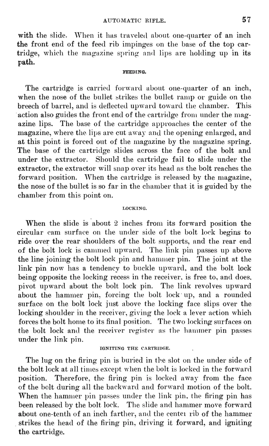
with the slide. When it has traveled about one-quarter of an inch
the front end of the feed rib impinges on the base of the top car-
tridge, which the magazine spring and lips are holding up in its
path.
FEEDING.
The cartridge is carried forward about one-quarter of an inch,
when the nose of the bullet strikes the bullet ramp or guide on the
breech of barrel, and is deflected upward toward the chamber. This
action also guides the front end of the cartridge from under the mag-
azine lips. The base of the cartridge approaches the center of the
magazine, where the lips are cut away and the opening enlarged, and
at this point is forced out of the magazine by the magazine spring.
The base of the cartridge slides across the face of the bolt and
under the extractor. Should the cartridge fail to slide under the
extractor, the extractor will snap over its head as the bolt reaches the
forward position. When the cartridge is released by the magazine,
the nose of the bullet is so far in the chamber that it is guided by the
chamber from this point on.
LOCKING.
When the slide is about 2 inches from its forward position the
circular cam surface on the under side of the bolt lock begins to
ride over the rear shoulders of the bolt supports, and the rear end
of the bolt lock is cammed upward. The link pin passes up above
the line joining the bolt lock pin and hammer pin. The joint at the
link pin now has a tendency to buckle upward, and the bolt lock
being opposite the locking recess in the receiver, is free to, and does,
pivot upward about the bolt lock pin. The link revolves upward
about the hammer pin, forcing the bolt lock up, and a rounded
surface on the bolt lock just above the locking face slips over the
locking shoulder in the receiver, giving the lock a lever action which
forces the bolt home to its final position. The two locking surfaces on
the bolt lock and the receiver register as the hammer pin passes
under the link pin.
IGNITING THE CARTRIDGE.
The lug on the firing pin is buried in the slot on the under side of
the bolt lock at all times except when the bolt is locked in the forward
position. Therefore, the firing pin is locked away from the face
of the bolt during all the backward and forward motion of the bolt.
When the hammer pin passes under the link pin. the firing pin has
been released by the bolt lock. The slide and hammer move forward
about one-tenth of an inch farther, and the centei rib of the hammer
strikes the head of the firing pin, driving it forward, and igniting
the Cartridge.
58
AUTOMATIC RIFLE.
TERMINATION OF SECOND PHASE.
The forward end of the slide strikes a shoulder at the rear end of
the gas cylinder tube which terminates the forward motion. The
forward motion is not terminated by the hammer on the firing pin.
This can be seen by examining the head of the firing pin when the
gas cylinder tube is assembled to the receiver, and the bolt mechanism
is in the forward position. The firing pin has still about one-
sixteenth of an inch clearance from its extreme forward position.
Note.—The locking shoulder of the receiver is inclined forward. Its sur-
face is perpendicular to the line through the bolt lock which the shock of the
explosion follows; therefore, the force of this shock is exerted squarely against
this normal surface. It should be noted that the speed of the bolt mechanism
is slowed down gradually from the instant that the bolt lock starts to rise until
the hammer pin passes under the link pin, when its speed is zero.
FUNCTIONING OF BUFFER.
46. The buffer system consists of a tube, in which are placed suc-
cessively from front to rear, the buffer head; a brass friction cup
with concave interior which is split to allow for expansion; a steel
cone to fit into the cup; four of these cups and cones are placed one
after the other in series. In rear of these is the buffer spring, and
finally the buffer nut, which is screwed into the end of the tube and
forms a seat for the spring.
THE ACTION.
The buffer head, struck by the rear end of the slide, moves to the
rear, forcing the cups over the cones and causing them to expand
tightly against the tube, consequently producing considerable fric-
tion as the cups move back and compress the buffer spring. Thus
the rearward motion of slide is checked gradually and there is prac-
tically no rebound. The spring returns the buffer head and friction
cups and cones to their original positions.
FUNCTIONING OF TRIGGER MECHANISM.
47. The trigger mechanism has three settings: (1) Automatic (A).
When so set the sear is depressed as long as the trigger is held back
and the piece will continue firing until the magazine is emptied. (2)
Semiautomatic (F). When so set the sear is depressed, thereby dis-
engaging the sear and sear notch when the trigger is pulled, but the
mechanism is so constructed that the sear rises and engages in the
sear notch when the slide comes back again, and the sear and sear
notch will not disengage until the trigger is fully released and then
pulled. With this setting the piece fires one shot for each pull and
-EJECTOR
Showing Trigger Mechanism Single Shot Firing. The Connector Cammed Forward from Under
the Forward End of the Sear by the Under Cam Surface of the Sear Carrier, permits the For-
ward End of the Sear to Return to Position Under Tension of Sear Spring, Causing the Rear End
of the Sear to engage in the Sear Notch in the Side.
EJECTOft
Showing Trigger Mechanism Set on Safe. Cylindrical Fortion of the Change Lever resting Over
the Heel of the Trigger prevents the Upward Movement of the Trigger and the Releasing of
the Sear.
ejector
Showing Trigger Mechanism Automatic firing. Toe of the Connector Engages Under the Connec-
tor Stud on the Change lever, preventing the Connector from Rising Sufficiently High to be
Cammed Forward from Under the Fore End of the Sear; head of the Connector Holding up Fore
End of Sear, Depressing Rear, preventing the Rear End of Sear from Engaging in the Sear
Notch of the Slide.
59
60 AUTOMATIC RIFLE.
release of the trigger. (3) Safe (S). When so set the sear can not
be released from the sear notch by pulling the trigger.
The action of the trigger mechanism is taken up in phases, and
should be followed on the mechanism itself as the explanation pro-
ceeds. Have the trigger guard stripped completely. Study the shape
of the change lever and note the following: (1) It is a bar about one-
quarter of an inch in diameter. (2) It has three shallow longitudi-
nal slots cut on top of the bar, as the handle is held vertically. (3)
The side of the bar is slotted in such a way as to leave a little tongue
of metal in the center and at the lower edge of the slot.
SETTING CHANGE LEVER.
Assemble the change lever and spring to the trigger guard. Note
that the toe of the change lever spring is seated in one of the longi-
tudinal slots on the change lever, and that as the lever is turned from
one position to another it seats in the other slots. The only function
of the spring and the longitudinal slots is to hold the change lever in
the position in which it is set.
Assemble the trigger and pin to the guard.
Turn the change lever to rear or safe position. Note that in this
position the slot is turned slightly upward, and that the full surface
of the bar is on the bottom. Pull the trigger. Note that the rear top
end of the trigger is slotted longitudinally, and that the metal on
each side of the slot forms two shoulders which rise against the bot-
tom of the change lever bar.
Push the change lever over to the vertical position, which is the
automatic setting. Pull the trigger as before and note that the slot
in the change lever is turned to the front, and that the two shoulders
of the trigger, which before engaged the full surface of the change
lever bar, now are free to pass up into the slot of the change lever;
also that the tongue of metal on the bottom of the change lever slot
passes through the longitudinal slot in the end of the trigger.
Now push change lever forward to single shot position.
Note that now the slot is turned partially down and that when the
trigger is pulled the rear end of the trigger passes up into the change
lever slot; also that the tongue of metal in the bottom of the change
lever slot is now turned back and does not pass through the slot in
the end of the trigger as it did in the automatic position.
Now observe the shape of the connector. It is shaped like a boot
with a toe and heel. It has a flat surface that slopes down and to-
ward the front from the head. (Sear spring ramp.) In rear of the
head the profile extends straight downward for about one-eighth of
an inch, then slopes slightly to the rear for 0.12 of an inch. (Sear
carrier ramp.) This last slope is used in a cam action to be explained
AUTOMATIC RIFLE.
61
later. Note the narrow, flat top surface of connector. Its function
is to raise the forward end of sear until cammed out from under the
latter.
Place the connector on the connector pin and set change lever to
safe, pull the trigger, and note that the connector is not raised, for
the obvious reason that the trigger itself can not be raised because the
change lever bar is in its way.
Turn change lever to automatic position, pull the trigger, and note
that the head of the connector is raised and held in a vertical posi-
tion and can not be tipped forward. The tongue on the change lever
engages the toe of the connector as the trigger is pulled and holds
the connector upright.
Turn the change lever to single shot position, pull the trigger, and
note that the tongue on the change lever does not now engage the toe
of the connector, and that the head of the connector can now be tipped
forward.
Observe now the cross pin on the sear carrier called the connector
stop; also that just in rear of the connector stop and on the under
side of the sear carrier is an inclined surface sloping upward in the
metal which joins the two sides of the sear carrier. This surface
has a cam action with the above-mentioned surface on the connector.
Completely assemble the trigger mechanism.
Note that the center leaf of the sear spring presses on the front
sloping surface of the connector and tends to press the head of the
connector backward. Set change lever on safe and pull trigger.
Note the head of connector is not raised above the sear carrier, for
reasons given previously. Therefore, the sear nose is not depressed
and hence the safe position. Change over to the automatic position
and pull the trigger; the head of the connector is raised and held in
the vertical position, thus depressing the sear nose and holding it in
this position, which obviously gives automatic fire as long as there
are cartridges in the magazine. The tongue on change lever tends
to hold connector vertically and the ramp on sear carrier tends to cam
connector forward. The forces exerted by these two parts on con-
nector are opposed, hence trigger mechanism is locked when trigger
has been pulled enough to release slide.
Set change lever for single shot, pull trigger slowly. Note that at
first the head of the connector rises and thereby depresses the sear
nose, which allows the slide to go forward. If the squeeze of the
trigger is continued the previously mentioned cam surface on the
connector comes in contact with the cam surface of the sear carrier,
and the head of the connector is cammed forward against the pres-
sure of the center leaf of the sear spring. The connector disengages
the front arm of the sear and the two outside leaves of the sear
62
AUTOMATIC RIFLE.
spring depress it, and the sear nose is thereby raised up in the path
of the slide and engages the sear notch when the slide moves back,
thus allowing only one shot to be fired. When the trigger is re-
leased the center leaf of the sear spring presses the head of the Con-
nector downward and back under the forward end of the sear, so that
when the trigger is pulled again the action is repeated and single shot
is fired.
In the semiautomatic position the connector stop prevents the
head of the connector being tipped so far forward that the sear
spring can not push it back in place when the trigger is released.
The only function of the change lever in the semiautomatic position
is the limiting of the upward travel of the trigger when its upper
rear shoulders strike the top of the slot in the change lever, which
in this position is turned down.
METHOD OF OPERATION.
FILLING THE MAGAZINE.
48. Place the wide end of the magazine filler over the top of the
magazine so that the groove in the magazine filler fits over the
catch rib of the magazine. Hold the magazine in the same relative
position that it occupies in the rifle; that is, with the catch rib toward
the operator. Then insert a clip of cartridges in the guides provided
in the filler, and with the right thumb near the base, strip the
cartridges into the magazine, guiding the bullet ends if necessary
with the left hand, Each magazine will hold four clips. Filling
exercise will be conducted with dummy ammunition. Students
should become proficient in this work.
INSERTING THE MAGAZINE.
49. The empty magazine may be withdrawn after pressing the
magazine release. Hold the loaded magazine with the base in the
palm of the right hand, cartridges pointing to the front. Insert
the magazine between the sides of the receiver in front of the trigger
guard, and push it home with the right hand. The magazine can
be inserted with the mechanism in either the cocked or forward
position. It is, however, ordinarily inserted after the rifle has been
cocked.
SETTING THE CHANGE LEVER.
50. For semiautomatic fire, or single shot, push the change lever
to the forward position, marked “ F.”
For full automatic fire or continuous fire to the capacity of the
magazine, set the change lever in the vertical position against the
change lever stop, marked ‘ A.”
AUTOMATIC RIFLE.
63
To set the rifle at safe, depress the change-lever stop and pull the
change lever rearward until it covers the change-lever stop. This
position is marked “S.”
It will be noted that the change-lever stop prevents the accidental
setting of the change lever at safe, and at the same time allows a
quick change from safe to either full automatic or semiautomatic
fire.
USE OF SPARE PARTS AND ACCESSORIES.
51. The nomenclature of the spare parts kit will be taught accord-
ing to the principles hereinbefore enunciated. This instruction will
include the proper method of packing the spare parts kit. It will
also include instruction in the contents of the gun box. The men
should be made thoroughly familiar with the proper use of the tools
and accessories provided.
SPARE PARTS.
52. The importance of knowing what is, and what is not, carried
as a spare part should be impressed on all automatic riflemen.
It is essential to know where to find any spare part that may be
required.
All spare, parts must be given their proper names; the use of
other names is forbidden.
A list of deficiencies should be kept inside each gun box.
Spare parts must be kept lightly oiled.
The necessity of checking spare parts whenever opportunity offers
must be emphasized.
Breakages and losses must be reported immediately.
Noncommissioned instructors will check their own spare parts at
the beginning and end of the instruction and will render a report
showing deficiencies.
Worn or defective parts should not be kept in the spare parts box.
Where any rifles are kept in reserve, care should be taken to see
that they are in the same condition of readiness for action as those
to be used in the firing line. They should not be utilized as a source
for obtaining spare parts.
SPARE PARTS CASE AND FABRIC CONTAINERS.
53. The spare parts case should be given the same care as other
leather equipment. The contents should always be properly packed.
The small fabric container is used to hold the recoil spring after it
has been coiled up. The remaining spare parts are packed in the
large fabric container.
64
AUTOMATIC RIFLE.
OIL CAN AND THONG CLEANER.
54. Care should be taken to avoid denting or otherwise damaging
the oil can. The nozzle should be kept screwed down firmly. The
thong cleaner is identical with that for the service rifle, and should be
used in the same manner.
RUPTURED CARTRIDGE EXTRACTOR, MARK II.
55. When a cartridge ruptures, it leaves the front end in the
chamber, which telescopes over the bullet end of the next cartridge.
As the operating handle is pulled back the live cartridge is extracted
and ejected, sometimes withdrawing the ruptured fragment with it.
In this case the use of the ruptured cartridge extractor is unneces-
sary.
If the ruptured end is not extracted by the following cartridge,
cock the rifle and remove the magazine. Then insert the ruptured-
cartridge extractor through the ejection opening, and push it for-
ward into the chamber. Let the bolt forward without excessive
shock so that the extractor engages the rim of the ruptured-car-
tridge extractor. Then draw the operating handle back, extracting
and ejecting the ruptured-cartridge extractor and the ruptured frag-
ment of the cartridge case. This fragment can sometimes be re-
moved from the extractor by depressing the front catches of the
sleeve, but it will usually be necessary to unscrew and remove the
spindle and sleeve from the head of the ruptured cartridge extractor.
Two, and sometimes more, ruptures can be extracted before it is
necessary to remove the fragments from the extractor sleeve.
Every precaution should be taken to avoid the loss of this very
important tool. In case it does become lost, it will sometimes be
possible to remove a ruptured cartridge case by the use of a cartridge
which has been oiled or moistened and coated lightly at the front
end with sand or dirt. Although the rifleman should know of this
method, its use should be prohibited except in cases of urgent
necessity, as the residue of grit may result in the scoring of the
polished surface of the chamber.
COMBINATION TOOL.
56. The small spanner at the head of the combination tool is used
to turn the gas cylinder, or the flash hider. Barrels which are not
excessively tight in the receiver can be removed and replaced by
the use of the larger spanner, although shop facilities are neces-
sary for the proper accomplishment of this work.
On tools of the latest design the catch end of this large spanner
is drawn out to provide a thin screw driver end, used for the
removal of the smaller screws on the rifle, such as the butt plate
AUTOMATIC RIFLE.
65
screws, the swivel screws, and the rear sight screws. The position
of this screw driver allows the use of a large amount of leverage.
Extreme care should, therefore, be exercised to avoid the breakage
of the screw driver point. The regular screw driver end is heavily
made and may be used for the removal of the butt stock bolt and
the forearm screws.
GAS CYLINDER CLEANING TOOL.
57. This tool is provided for the cleaning of the gas-operating
mechanism. These parts should habitually be kept clean and oiled.
For thorough cleaning remove the gas-cylinder tube, gas cylinder,
and slide. Care should be exercised to avoid scoring or damaging
the cylinder walls or the rings of the gas piston.
Using the tool as a hand reamer, insert the smooth end of the body
into the cylinder, turning it to the right as it is advanced toward the
cylinder head. As soon as it reaches the head, press down and give
the tool a few turns to cut the carbon from the inside surface of the
head. Then withdraw and reverse the tool, using the recess cutter
as a gauge to remove the carbon from the recess at the forward end
of the interior of the gas cylinder. This part should be thoroughly
cleaned, especially that portion near the edge of the operating sur-
face of the cylinder wall.
Using the drift point, clean the ports in the barrel, gas cylinder
tube, and gas cylinder. Scrape the carbon from the face of the piston
with the front cutting edge of the cleaning-tool body, and remove
the deposit from between the piston rings with the drift point. The
parts should then be washed in kerosene if this is available.
LUMINOUS SIGHTS, MARK III.
58. The luminous sights are made of light spring steel, the sight-
ing portions carrying glass tubes in which a radium luminous powder
is sealed. These sights are delicate attachments and should be
handled as such. Special attention should be given to keeping the
luminous surface of the glass tubes clean. The steel portions should
be kept lightly oiled to prevent rust. The luminous sights may be
quickly attached to the permanent sights on the rifle. Their spe-
cific use is for night firing and the men should be trained in attach-
ing and detaching them in the dark or when blindfolded.
To attach the sights snap the luminous front sight over the front-
sight carrier, allowing the luminous front-sight body to automati-
cally position itself over the front-sight blade. Care should be taken
to insure that the circular sections of the luminous front sight spring
properly around the front-sight carrier. Attach the rear luminous
sight to the rear-sight slide by hooking the upper spring under the
161435°—20--------5
66
AUTOMATIC RIFLE.
upper crosspiece of the rear-sight slide and pressing with thumb on
the lower protecting shelf of the luminous rear sight, thereby com-
pressing the spring and allowing the lower catch to engage over
the peep sight of the rear-sight slide. The luminous rear sight is
then in position and the peephole is registered with the peephole
of the rear-sight slide.
To detach the luminous sights, lift the luminous front sight up-
ward off the front-sight carrier. Remove the luminous rear sight
by pressing upward on the lower shelf until the lower catch is
released.
IMMEDIATE ACTION.
(Classroom instruction.)
INTRODUCTION.
59. The instructor will give definition of immediate action. (The
automatic and instinctive application of a probable remedy for a
stoppage, based on the position of the hammer pin, as determined
by pulling back operating handle.)
DEMONSTRATION—EXPLANATION.
60. The instructor will demonstrate the four positions of the
hammer pin and how to determine its position by pulling back the
operating handle until it strikes the hammer pin.
61. Each member of team is required to learn how to determine
the position of the hammer pin by setting the slide in the four posi-
tions (recoil spring removed and piston held) and then by placing
thumb in rear of trigger guard and fingers on operating handle,
squeezing operating handle back until it strikes the hammer pin.
Students will then be required to state in which position mechanism
was stopped.
62. (1) The instructor prepares the various stoppages for the first
position of the hammer pin.
(2) Explains the immediate action.
(3) Requires each member of the squad to perform immediate
action.
(4) Examines members of the squad.
Each phase of the first position is taught until all are proficient
before proceeding to the next phase.
IMMEDIATE ACTION TABLES.
EXPLANATORY NOTES.
63. The following tables will be utilized in teaching immediate
action, both in the classroom and on the range. In classroom work,
stoppages will be set up, not in,the soldier’s sight, and when he in-
AUTOMATIC RIFLE.
67
spects the gun he will find such conditions as would be present if
that stoppage occurred during actual firing. On the range these
stoppages will be set up so as to occur during firing.
64. Column I describes the four positions of the operating handle
in which it will strike the hammer pin when drawn back. Plates
show rearward position of the operating handle for each position.
These positions, which afford a ready indication of the correct
immediate action to be performed, must be recognized clearly by all
members of the squad before instruction proceeds.
65. Column II gives a detailed description of the immediate action
to’ be performed as soon as the position of the hammer pin, by draw-
ing back the operating handle, has been determined. This sequence
of actions must be taught until instinctive. Pulling back the oper-
ating handle forms the first step in each case.
66. Column III names the stoppages which will occur in each
given position, and Column. IV gives the causes of these stoppages.
Instructions should not proceect to this stage until it is certain that
immediate action can be correctly and rapidly performed by each
member of the squad.
67. A thorough knowledge of the causes of temporary stoppages
will not only afford a practical knowledge of the operation of the
rifle, but will also be an aid in the reduction of any unusual stoppage.
68. It is not essential to teach all soldiers the methods of setting
up stoppages, but all instructors and assistants should understand
this subject thoroughly.
68
AUTOMATIC RIFLE
Tables of immediate action for stoppages.
Position. Immediate action. Stoppage. Causes. Preparation for instruction.
Classroom (dummy ammunition). Range (ball ammu- nition).
FIRST. Operating handle fully home. SECOND. Operating handle strikes ham- mer pin between first posi- tion and the point at which operating handle plunger has ridden completely over raised shoulders on operating han- dle way. THIRD. Operating handle strikes ham- mer pin bet ween second posi- tion and point directly over “A” on receiver. I. Pull back operating handle, push magazine fully home, relay and fire. II. If stoppage recurs with rifle failing to fire, change firing pin and magazine. III. If stoppage recurs with rifle firing, regulate and clean gas ports. I. Pull back operating handle, relay and fire. II. If stoppage recurs, pull back operating handle, feel face of bolt, receiver, and chamber, for extraneous matter and burrs, clean, relay and fire. III. If stoppage recurs, dismount rifle, examine bolt lock and bolt- lock recess for extraneous mat- ter, clean, relay and fire. I. Pull back operating handle, relay and fire. II. If stoppage recurs, pull back operating handle, remove maga- zine: A. If operating handle sticks, use defective cartridge extractor to remove ruptured case,1 clean and oil chamber, oil cartridges, reload, relay and fire. A. Failure to fire. B. Failure to feed. Л. Failure to fire. B. Failure to feed. A. Insufficient gas. A. Faulty ammunition. A. Obstruction or burred surface. • A. Obstruction or burred surface. A. Faultyammunition. A. Ruptured cartridge. A. Defective ammunition. В. Magazine not fully home. 1. Broken firing pin. 2. Weak recoil spring. 3. Excessive friction. 1. Worn magazine catch. 2. Obstruction under lips of magazine. 3. Weak magazine spring. 4. Dirty or dented magazine. 1. Gas ports not registered. 2. Gas ports clogged. A. Battered round. 1. Extraneous matter on face of bolt or in receiver. 2. Burrs in receiver or cham- ber. A. Extraneous matter or burrs on bolt lock or in bolt-lock recess. A. Battered round. A. Excessive headspace. A. Insert dummy round. B. Magazine not home. A. Insert broken firing pin. B. Obstruction under lips of magazine. A. Failure to register gas ports. A. Insert battered round. 1. Extraneous matter on face of bolt. 2. Do not set up. A. Do not set up. A. Insert round battered at shoulder. A. Insert front end of rup- tured case in chamber. Same. Same. Same. Same. Same. Same. Same. Same. Same. Same. A. Use cartridge with groove filed J inch from base.
1 If no defective-cartridge extractor is available, oil the end of a cartridge and cover it with a small amount of dirt or sand, then place it in the chamber and let the bolt home
on it. Ruptured cases may often be removed in this manner. Clean and oil chamber and boie very carefully alter doing this.
AUTOMATIC RIFLE.
О
Tables of immediate action for stoppages—Continued.
Position. Immediate action. Stoppage. Causes. Preparation for instruction.
Classroom (dummy ammunition). Range (ball ammu- nition.
third—continued.
Operating handle strikes ham- mer pin betweensecond posi- tion and point direotly over “A” on receiver—Contd. B. If operating handle comes back easily, remove case with clean- ing rod, clean and oil chamber, feel for burr on shoulder of ex- tractor, reload, relay and fire. A. Failure to extract. B. Dirty or dry chamber. B. Insert cartridge with rim filed oft. Same.
III. If stoppage recurs, pull back operating handle, remove maga- zine, feel face of bolt for pro- truding end of broken firing pin, remove cartridge, change firing pin, reload, relay and fire. A. Failure to feed com- pletejy. A. Broken firing pin. A. Insert piece of metal to protrude beyond face of bolt. A. Do not set up.
FOURTH. IV. If mechanism sticks, remove trigger mechanism, and feel for obstruction between bolt sup- ports and bolt. Remove same, assemble, reload, relay and fire. A. Obstruction. A. Extraneous matter be- tween bolt and bolt sup- ports. A. Do not set up. A. Same.
Operating handle strikes ham- mer pin between third posi-
tion and as far back as it will go. I. Pull back operating handle, re- move magazine, feel for obstruc- tion between ejector and bolt, remove same, reload, relay ana fire. A. Obstruction. A. Extraneous matter be- tween ejector and bolt. A. Do not set up. A. Same.
II. If slide is not released by pulling trigger, remove trigger assembly, assemble properly, replace neces- sary parts, assemble, reload, A. Improper assembly. A. Middle prong of sear spring rides out of its channel, connector does not depiess sear nose. A. Assemble sear spring with middle prong out of channel. A. Same.
relay and fire. B. Broken pait. B. Middle prong of sear spring broken or bent. B. Do not set up. B. Same.
AUTOMATIC RIFLE.
AUTOMATIC RIFLE.
71
NOTES ON IMMEDIATE ACTION.
69. All stoppages which occur during firing may be classified
under two main headings:
(1) Temporary, due to—
A. Failure of some part of the rifle of which a duplicate is
carried.
B. Faulty ammunition.
C. Neglect of observance of points listed for—before, during,
and after firing. (Par. 86.)
D. Ignorance on the part of the auto rifleman.
(2) Prolonged, which are due to failure of some part which can
not be replaced or remedied in the field under fire, or without expert
assistance or machine shop facilities.
Upon the training of the auto rifleman in immediate action de-
pends the rapidity with which temporary stoppages will be remedied.
IMMEDIATE ACTION ON RANGE.
70. Stoppages will be set up on range, using prepared ammunition
and parts so as to cause them to occur during firing. It is essential
that stoppages be prepared accurately.
Student will fire. When stoppage occurs he will call First position,
Third position, or whatever position he thinks it is. As soon as he
has called the proper position, the instructor will command Immedi-
ate action, whereupon the soldier executes the necessary immediate
action. If time permits it is well to have soldiers perform the func-
tion of instructor for other members of the squad.
71. When the soldier has been thoroughly grounded in immediate
action by practice with individual stoppages he will be required to
fire two or three prepared magazines which are loaded half with live
rounds and half with rounds which will cause the various stoppages
desired. He will perform immediate action in each case without
command. He will keep on firing until the magazine is empty, and
a record will be taken of the time necessary for this firing. In this
manner all men will acquire speed and accuracy in reducing any
stoppages which are likely to occur during actual firing. Table
“A,” immediate action table, will be fired at some time during work
on the 1,000-inch range.
Table “A.”
Position. I Fire.
Target.
Shots.
Range.
Prone............
Prone............
Semiautomatic.... M. G. blank......
Automatic........ M. G. blank......
1 prepared magazine.......
1 prepared magazine.......
1,000-inch.
1,000-inch.
72
AUTOMATIC RIFLE.
NOTES ON STOPPAGES.
CAUSES.
72. Stoppages are caused by the following:
(1) Dirt (natural fouling incident to firing and also to careless
cleaning).
(2) Insufficient oil (from failure to oil and because of oil burn-
ing up during firing).
(3) Extraneous matter in working parts. (Due to poor cleaning,
brass chipped off from cartridges, breakages, blown primer, etc.)
(4) Improper assembly of rifle. (Gas ports not registered, middle
prong of sear spring riding on one wall of sear carrier, etc.).
(5) Breakages. (Due to wrong assembly, oversize or undersize
parts, burrs, incorrect heat treatment, overheating of parts incident
to firing, etc.)
(6) Burred parts. Due to use of force, grit, etc., improper
assembly, extraneous matter in mechanism.)
(7) Magazine troubles. (Due to bent or dented magazines, worn
magazines, catch notch, extraneous matter, as blown primer, between
lips of magazine and top cartridge.)
(8) Faulty ammunition. (Dented cartridges, failure of primer
or charge, etc.)
(9) Excessive play in parts. (Due to wear in stripping parts
not supposed to be stripped—as removing barrel from receiver, for
instance.)
(10) Ruptured cartridges. (Due to excessive head space.) Head
space is the distance between the face of the bolt and the shoulder
of a standard steel test cartridge. If excessive head space exists when
the cartridge is chambered properly, the cartridge case will be forced
against the walls of the chamber at' the instant of explosion. The
cartridge case base will be driven to the rear, as it is not supported
by the bolt. This results in rupture about one-half inch from
the base of the cartridge. In effect the action during the period of
gas pressure within the cartridge case is the same as if the chamber
gripped all the outer surface of the cartridge case except the part
about one-half inch near the head. The pressure within the cartridge
case being 50.000 pounds per square inch, the ungripped portion of
the case is torn from the gripped part and forced back against the
face of the bolt. (The case is never pulled apart by extractor.)
Analysis of various stoppages (as to cause).
FIRST POSITION.
73. Failure to feed.—Obstruction (usually a blown primer) be-
tween lips of magazine and top cartridge causes failure of pre-
sentation of a cartridge to feed rib and the bolt goes home on an
AUTOMATIC RIFLE.
73
empty chamber. S'ame result occurs when the magazine catch
notch becomes so worn as to permit the magazine to drop down
slightly and also when magazine catch breaks, or when magazine is
not pushed clear up in magazine opening.
74. Failure to fire.—Faulty primer or charge will cause a misfire,
as will also a broken or short firing pin. Frequently the beginner
will mistake a misfire due to an obstruction between the face of
the bolt and the breech for one due to a broken firing pin. He
should remember that the latter is a first-position stoppage and
the former a second-position stoppage. A misfire due to a broken
firing pin will not show any indentation on the primer. The second-
position stoppage almost invariably shows a slight indentation.
75. Insufficient gas.—A stoppage in the first position with an
empty case in the chamber is due to insufficient gas, which in turn may
be due to the gas ports not being properly registered or being
partially clogged, or to excessive friction because of lack of oil and
dirty chamber.
SECOND POSITION.
76. Failure to fire.—A deformed round bulged near the base or
an obstruction lodging between face of bolt and the breech, thus
holding firing pin away from primer. Primer will be slightly
dented. This stoppage is typical. When the piece stops in the
second position always look for an obstruction either on the face of
the bolt or in breech recess where bolt and receiver join. Most
frequent obstruction is the blown primer. Often it is difficult to see.
Frequently it drops off as the bolt is drawn back. If the stoppage
recurs it is sure that an obstruction is in the rifle between the face
of the bolt and the breech or between bolt lock and receiver top plate.
THIRD POSITION.
77. Ruptured case.—This stoppage is due to excessive head space.
When the immense pressure following the ignition of the charge is
taken up by the cartridge case, if this case is not properly supported
by the bolt it will rupture about five-eighths of an inch from the base.
The short end at the base will tKen be extracted and the larger
portion of the case will remain in the barrel. A temporary correction
for such a stoppage is to clean and oil the chamber thoroughly and oil
the cartridges.
78. Broken firing pin.—This stoppage is caused by the end of a
broken firing pin protruding through the firing pin hole in the face
of the bolt. The cartridge is then kept from sliding under the ex-
tractor as the bolt moves forward and a third-position stoppage will
result. The cartridge will show an abrasion near the base. To
remedy this stoppage the firing pin must be replaced.
74
AUTOMATIC RIFLE.
Mechanism wedged fast in third position.—This is a rare stoppage.
Slide can not be moved forward or backward. It occurs when any ob-
struction gets between one of the bolt supports and the bolt lock. As
the slide is driven to the rear the bolt lock is wedged fast by the
obstruction. This stoppage has been caused by blown primer or by a
piece of metal broken off the rear of the firing pin channel wall. It
should be reduced in a properly equipped shop.
FOURTH POSITION.
79. One fourth-position stoppage is when a blown primer wedges
itself between the points of the ejector and the face of the bolt,
thereby holding the bolt and mechanism back in the fourth position.
80. The other fourth-position stoppage is that in which the piece
is cocked and the trigger mechanism will not release the sear when
set at “ A ” or “ F.” This is due to a broken sear spring, a broken or
lost connector, and improper assembling of the sear spring, or to any
cause which has the effect of moving the middle prong of the sear
spring too far to the front with respect to the connector, so that
the connector is not cammed under the tail of the sear.
CARE AND ADJUSTMENT.
REGULATIONS CONCERNING HANDLING THE RIFLE.
81. All men must have impressed upon their minds the vital neces-
sity for properly caring for this weapon. They must understand
and appreciate that, in order to render efficient service, a most
careful cleaning and oiling is necessary at all times, especially in
the field. The rifle should be kept in the carrying case when not
in use, in order to minimize the accumulation of dirt, mud, and rust
in the mechanism, which may cause the rifle to fail to function.
CLEANING.
THE BARBEL.
The life of the barrel should be about 8,000 rounds if it is not
fired more than 200 rounds at a time.
The barrel should never be removed until completely worn out.
The barrel should be cleaned with sal soda solution (20 per cent
hot solution) to remove powder fouling, and with ammonia prepa-
ration to remove metallic fouling.
Note.—The ammonia preparation is to be used only under the supervision of
an officer, or an experienced noncommissioned officer designated by organisation
commander.
Ammonia preparation.—One-half teaspoon ammonium persul-
phate, one-half teaspoon ammonium carbonate, one-half pint 30 per
cent ammonia, one-fourth pint water, one-eighth teaspoon potassium
bichromate.
AUTOMATIC RIFLE.
75
Procedure.—Place cork in chamber and plug up gas port. Pour
in solution until barrel is full, after adding a few drops of sperm
oil, which prevents ammonia from evaporating. Do not permit
solution to remain in barrel longer than two hours. While the solu-
tion is acting, small bubbles come to the surface and the solution
turns blue. When bubbles stop rising, remove solution. After the
use of this solution, the bore should be thoroughly cleaned and
saturated with 20 per cent sal soda solution, then dried and coated
with a thin film of oil.
OTHER PARTS.
All parts must be clean and free from grit in order to avoid ex-
cessive wear.
All powder fouling must be removed from gun to insure proper
functioning.
Rifle should be dismounted, and all parts wiped dry and clean,
after which they should be covered with a thin coating of oil.
The gas cylinder, piston, and all parts coming in contact with gas
should be cleaned with sal soda solution, wiped dry, and coated with
a light film of oil.
Magazines should be carefully watched to avoid denting or bend-
ing during transportation or handling.
Rifles to be shipped or stored for any considerable time should
be cleaned, oiled, and cosmolined.
82. The following regulations are prescribed regarding the han-
dling of the Browning automatic rifle:
(1) Force will not be used in stripping and assembling.
(2) This piece will not be stripped nor assembled against time.
(3) The bore and working parts will be kept thoroughly cleaned
and oiled.
(4) The magazine will receive the same care as the rifle. Every
effort will be made to prevent bending or denting the magazines, be-
ing especially careful of the lips and magazine catch notch.
(5) The filing or altering of shape or parts will not be permitted.
83. The rifle is so constructed as to be taken apart and put to-
gether easily. Most parts are designed with a view to prevent wrong
assembling. Where difficulty ari^s in stripping and assembling
easily it is due to error on the part of the soldier, and the use of force
will only result in damage to the rifle.
The practice of stripping and assembling against time serves no
useful purpose and results in burring and damaging parts. Gradual
skill develops as men become more familiar with the rifle, and lost
motion is eliminated. Men should be taught in stripping to lay out
parts in obvious sequence of assembling, and should so thoroughly
learn the rifle that taking it apart and putting it together are matters
of second nature.
76
AUTOMATIC RIFLE.
Lubrication is necessary to the operation of the rifle. Dirt and
extraneous matter will prevent it from functioning and do it dam-
age. Instruction in care and preservation should be so thorough
that cleaning and oiling become a matter of habit.
Unless strict supervision is exercised, inexperienced men, and
sometimes experienced men, will file or otherwise alter parts which
do not need it. This results in damage to the rifle and usually fails
to remedy trouble. Filing and altering of parts are sometimes neces-
sary, but should'never be done except by an expert, under direction
of an officer competent to supervise the work.
Use for instruction in mechanism is hard on rifles. This fact
should be borne in mind and, in the company, after the completion
of the first course in mechanism, only a limited number of rifles
should be so used.
POINTS TO BE OBSERVED.
84. Before firing:
(1) Test trigger mechanism at safe, (A), and (F).
(2) See that bore is clear and clean.
(3) Work slide back and forth rapidly several times to see
that it moves freely and does not stick.
(4) Test ejector and extractor with dummy or empty case.
(5) Verify proper setting of gas port.
(6) Verify oiling.
(7) Verify cleaning.
(8) Examine magazines and eliminate faulty ones.
(9) See that kit contains oil can full of oil and full comple-
ment of spare parts.
85. During firing:
(1) Keep magazines and chamber protected from dirt.
(2) Do not allow rifle to become dry.
(3) Clean bore and gas system frequently.
86. After firing:
(1) Remove loaded magazine.
(2) Let bolt forward.
(3) Wipe out bore and oil rifle.
(4) Thoroughly clean rifle at first opportunity.
(5) Replenish spare parts.
(6) Reload magazines as soon as possible.
GAS ADJUSTMENT.
87. The rifle should normally be operated on the smallest port,
and this setting will never be varied unless the rifle shows signs of
insufficient gas. To align the smallest port, screw in the gas cylinder
with the combination tool until the shoulder of the gas cylinder is
about one turn from the corresponding shoulder of the gas cylinder
AUTOMATIC RIFLE.
77
tube, and the smallest circle on the cylinder head is toward the barrel.
Lock the cylinder in position. If, upon firing, the rifle shows signs
of insufficient gas, try setting the cylinder one complete turn on each
side of the original setting. As soon as the proper setting has been
obtained the rifleman will carefully note the position so that he can
quickly assemble the cylinder to the proper point without trial.
The larger ports are provided for use in case of emergency, when
the action of the rifle has been made sluggish through the collection
of dirt and grit, or the lack of oil, and the conditions render it im-
possible for the riflemen to correct these troubles. For this reason
the threads should be kept clean and oiled and the cylinder free to
turn if necessary. The extractor, ejector, and the chamber of the
barrel should be examined and cleaned and defects corrected when
possible. Under adverse conditions, and when signs of insufficient
gas become apparent, the cylinder should be unscrewed one-third
of a turn, thus registering the medium circle and aligning the medium
port with the gas orifice. Repeat this operation in order to connect
the largest port with the barrel.
Excessive friction or dirt may sometimes result in the failure of
the action to complete the forward movement under the action of
the recoil spring, which part may also have become permanently set
or short from continued use under conditions of excessive heat. In
such case replace the recoil spring.
RESULTS OF INSUFFICIENT GAS.
(1) Failure to recoil (usually due to a misaligned or excessively
clogged gas port, or extremely dirty mechanism).
(2) Failure to eject.
(3) Weak ejection.
(4) Uncontrolled automatic fire (exceptional).
RESULTS OF TOO MUCH GAS.
(1) Excessive speed, causing pounding.
(2) Excessive heat in gas operating mechanism.
NOTES FOR REPAIRMEN.
88. The following notes are prepared for the use of repairmen:
Filing, or otherwise altering parts, should only be done under the
strictest supervision, as this often fails to remedy the trouble and
results in damage to the rifle. Filing and altering of parts are
sometimes necessary, but should never be done except by an expert
repairman, under the direction of a commissioned officer competent
to supervise the work. All defective parts should be distinctly
marked or tagged to avoid their future use.
BARREL.
89. The barrel should not be removed until worn to such an extent
as to require replacement. This wear usually occurs in the rifling
78
AUTOMATIC RIFLE.
near the breech or in the chamber. A barrel is usually good for
8,000 rounds, after which time the accuracy depreciates quite
rapidly. A worn or pitted chamber may result in ruptured shells,
or in the shells swelling and sticking in the chamber, rendering ex-
traction difficult or uncertain.
The gas port through the barrel and gas cylinder tube bracket
may become stopped up and not allow sufficient gas to pass through
to insure positive action. To remedy this difficulty clear the port
with the gas cylinder cleaning tool. The lower surface, especially
that portion immediately surrounding the port of the gas cylinder
tube bracket, should fit closely to the corresponding surface of the
gas cylinder tube. Some wear at this point can be taken up by
bending the lips of the bracket down slightly, tapping them lightly
with a hammer, or by bending the retaining rib of the tube back at
each edge, thus bringing the surfaces into closer contact. A smooth,
close fit is desired. If the fit is excessively tight, some metal may be
removed from the surface of the gas cylinder tube bracket by the
use of the special hand scraper provided for this purpose, or with an
oilstone or dead smooth file. Care should be exercised not to remove
too much metal, especially from that surface near the port.
. GAS OPERATING MECHANISM.
90. The front retaining rib of the gas cylinder tube may become
too loose in the gas cylinder tube bracket, resulting in insufficient
gas and requiring adjustment as described above, or replacement.
The wall of the tube may become dented, thus binding the piston.
In some cases it may be possible to straighten this out until the
piston works freely. In replacing a gas cylinder tube see that it
correctly fits the bracket and that the rear hole lines up properly in
the receiver. The tube should never be twisted to secure a fit at this
point. In case of necessity a reamer may be run through the rear
hole to clean out a small amount of metal.
The ports of the gas cylinder may become clogged to such an ex-
tent as to render the action uncertain, or burnt powder deposited on
the inside of the gas cylinder, causing the piston to stick. The gas
cylinder cleaning tool may be used to clean these parts. Failure to
operate, due to insufficient gas, is sometimes the result of wrong assem-
bling of the gas cylinder, screwing it in one turn from the shoulder.
Unscrew one-third of a turn to change to the medium port, and one-
third of a turn farther to the large port. The relative sizes of the
ports are indicated by circles on the front end of the cylinder. The
threads of the gas cylinder should fit snugly enough to prevent ex-
cessive gas leakage. The fit of the gas cylinder and piston, although
free, should not be excessively loose, in order that the recoil may be
AUTOMATIC RIFLE.
79
uniform. Extreme wear would necessitate replacement. In replac-
ing a gas cylinder make sure that the piston works freely when the
cylinder is set at each port. Test as described below.
If the gas piston has become bent it may bind in the gas cylinder
or tube. Slight bends may be straightened and tested in the follow-
ing manner: Remove the trigger guard, bolt, and recoil spring. The
piston and slide should work back and forth easily as the muzzle of
the rifle is tilted first up and then down. Particular attention
should be given at the point where the piston enters the cylinder. In
replacing a piston, the new one should be tested in this manner. In
the case of the old type piston, which is threaded rigidly into the
slide, slight bending may be necessary in order to secure the proper
alignment.
RECEIVER.
91. Wear in the receiver usually occurs on the locking surface or
on the bolt supports. The fear cam surface of the bolt supports
must be accurately positioned in order to cam the bolt lock upward
at the proper time. The bolt supports must fit tightly in the re-
ceiver and be well riveted. The hammer used in riveting should be .
heavy enough to swell the rivets throughout their entire length.
An excessively loaded cartridge may spread the side of the receiver
slightly and loosen the bolt supports. In this case the sides of the
receiver should be carefully brought back into position, with the
aid of a vise, and the bolt supports reriveted.
FIRING MECHANISM.
92. The slide should fit freely in the receiver and the sides should
be straight. The slide should not be excessively loose in the re-
ceiver, as this may cause the hammer pin to batter the top of the
front end of the slot in the left side of the receiver, rendering it
difficult to pull back the operating handle when cocking the rifle.
To remedy this difficulty the slot can be smoothed over and widened
slightly by filing. Slight cracks may occur in the slide, extending
from the hammer pin hole to the upper surface. This does not in
general affect the operation of the rifle.
The hammer should have a good bearing against the seat in the
rear of the slide, and when assembled should not be loose enough to
allow any appreciable tilting when pressure is exerted in the upper
portion of the front face. In addition to this condition, excessive
wear or deformation of the front face may be the cause of misfires.
When the parts are in their forward position the hammer should
clear the firing pin, but not by more than one thirty-second of an
inch. The hammer should come up against the link when the gas
cylinder tube is not in place. The recoil spring should not become set,
80
AUTOMATIC RIFLE.
and hence too short for positive operation. In some cases this can
be corrected temporarily by pulling out the spring. In some cases
replacements will be necessary. The recoil spring should be 15
inches long.
In addition to the actual length of the firing pin the following
points determine the distance which the firing pin will protrude
through the bolt in the locked position (causing pierced primers at
one extreme and misfires at the other) : The distance from the face of
the hammer to its rear bearing surface against the slide, the distance
from this surface to the front stop shoulder of the slide, the distance
from the slide stop shoulder of the gas cylinder tube to the gas'
cylinder tube retaining pin hole, the distance from this hole to the
face of the receiver, the distance from the face of the receiver to
the locking surface and the distance from the locking surface of the
bolt lock to the front face of the bolt. Firing pin protrusion can
only be gauged when the rifle is assembled and the bolt is in the
locked position. It will be necessary to use a gauge extending from
the muzzle of the gun, or to take a wax impression of the projection
when the bolt is locked.
When the bolt is unlocked the link should bear on the locking
shoulder of the bolt lock, and should hold the bolt lock up so that it
just clears the bolt supports and guide as the holt is moved rear-
ward. Frequent blown or pierced primers may cause the rear head
of the firing pin to batter the front of the link. This battered surface
should not be allowed to develop a sharp edge which might catch or
break off the head of the firing pin.
The top rear corner of the firing pin head should be well rounded
to avoid the above-mentioned breakage. The shank of the firing pin
should be straight and the point not excessively deformed or pitted.
The retracting cam should be beveled on each side, and neither this
part nor the corresponding slot in the bolt lock should show battering
or signs of misalignment.
The bolt and bolt lock are an assembled unit and should never be
separated. There should be a good bearing between the two so that
none of the shock of the recoil is taken on the bolt lock pin. The
bolt lock pin may become loose with wear until one end projects
and catches on the inside of the receiver, resulting in stoppages and
mutilation of the receiver. Test by pushing the pin both ways with
the finger. It should not be possible to cause it to project on either
side. In case of projection, rerivet the pin. Considerable wear on the
locking shoulder of the bolt lock, in the joint between the bolt and
bolt lock, or on the face of the bolt, may result in excessive head
space, causing ruptured cartridges and, in some cases, blown primers.
During the rearward motion the bolt lock should never bear to any
AUTOMATIC RIFLE.
81
appreciable extent on the bolt supports or guide. If the firing pin
hole in the face of the bolt is enlarged or off center; the assembly
should be replaced, as this is often the cause of breakage of firing pin
points.
When the gun is assembled without the recoil spring, but with the
gas cylinder and gas cylinder tube in place, the recoiling parts should
slide back and forth freely as the gun is turned muzzle up and vice
versa, unless the breeching is snug. In that case they should move
freely when the bolt lock is disengaged from the recoil shoulder of
the receiver. On the forward movement the bolt lock should be
cammed up by the rounded rear ends of the bolt supports, but there
should be sufficient clearance between the bolt supports and the lock-
ing shoulder of the receiver to prevent excessive binding. When in
the locked position the front shoulder of the bolt should just clear
the rear shoulder of the barrel. If the bolt comes up against the
barrel, but does not interfere with the locking of the bolt lock, the
operation of the gun will not be affected unless dirt is allowed to
accumulate in front of the bolt.
The extractor should have particular attention to see that it has
retained its proper shape and that the cartridge fits the hook cor-
rectly. The inner radius of the extractor hook should closely fit the
bottom of the cannelure of the cartridge. The extractor notch just
back of the hook should be deep enough to allow the extractor to
come down into the cannelure, so that minimum cartridge will snap
in and be held up firmly in place. Faulty ejection may result if the
cartridge is allowed to drop even a short distance. To test this, re-
move the bolt and firing pin and insert a live cartridge under the
extractor. It should be able to withstand considerable shaking with-
out dropping down out of place. Examine to see if the extractor
hook bears against the bottom of the cannelure at all points and that
the base of the cartridge is held snugly against the face of the bolt.
About 0.01 of an inch clearance between the base of the cartridge and
the bolt face will not in general affect the operation of the rifle, but
more than this may cause weak ejection. The lower corners of the
extractor and lips of the bolt should be slightly rounded so as not to
chip brass from the cartridges as they slip up into place. The rear
face of the notch in the extractor, which bears against the lug of the
bolt during extraction, should be slightly undercut, thus tending to
prevent the extractor from slipping over the rim of the cartridge
or from pulling out. The rear face of the extractor hook should be
square and the extracting edges fairly sharp. An excessive amount
of dirt under the extractor may result in failure to extract or failure
to eject. The extractor should be a snug fit in the bolt. Side play
or twisting is especially liable to cause trouble. Worn or defective
161435°—20---------6
82
AUTOMATIC RIFLE
TRIGGER GUARD
SHOWING UNLOCKING OF BOLT AND WITHDRAWAL OF FIRING PIN
SHOWING FURTHER MQTION OF RECOIUNG PORTIONS TO REAR AND EXTRACTION
OF CARTRIDGE CASE
AUTOMATIC RIFLE.
83
extractors may often be corrected by proper and careful filing. The
extractor spring rarely causes any trouble.
TRIGGER GUARD MECHANISM.
' 93. The fit of the trigger guard in the receiver is not important
except that it should be fairly snug sideways. The sear should be
a loose fit in the sear carrier. The nose of the sear, as well as the
sear notch in the slide, should be correct in shape in order to main-
tain positive engagement. The sear pin should carry the tension
of the counter-recoil spring, leaving the trigger pin free. The
trigger should be a loose fit in the trigger guard and the connector
loose in the trigger. The trigger pull should be smooth and from
6 to 10 pounds. The change lever should work smoothly. The
ideal condition in semiautomatic fire is for the cam on the connector
to engage the sear carrier just at the moment the sear releases the
slide. The sear spring should fit in the trigger guard without an
excessive amount of slide play. The center leaf should have a
smooth and continuous bearing against the bevel surface of the con-
nector. The magazine catch should work freely and easily and
should hold the magazine up closely to the bolt supports.
The ejector should fit fairly close in the trigger-guard guides.
An excessive amount of play forward and backward may result in
weak ejection. This can sometimes be corrected by bending the
ejector slightly. The upper end of the ejector should spring slightly
when pressed back. The location of the working end of the ejector
for height and side position is of primary importance. To examine
this, draw back the mechanism until the bolt face is even with the
ejector. The ejector should fit up within one thirty-second of an
inch of the bolt but should not bind. A poor fitting ejector can be
corrected by bending until it fits up closely in the notch of the bolt.
The upper part of the ejector should not bend rearward. If the
ejection is correct the shells will be given a spinning motion as they
leave the rifle and will be thrown diagonally forward with consider-
able force. Test the ejection with a magazine filled with dummies.
First operate the rifle slowly by hand, which should result in posi-
tive ejection. Then operate rapidly, when the cartridge should be
ejected with force.
REAR SIGHT.
94. If the rear sight is properly assembled with a good driving
fit it will give little trouble. If the sight works loose from the re-
ceiver it may be necessary to replace the sight base. It may, how-
ever, be possible to swell the dovetail of the rear sight base by light
and careful peening with a hammer until the necessary drive fit is
obtained.
84
AUTOMATIC RIFLE.
BUFFER ASSEMBLY.
95. If properly assembled the buffer tube assembly will cause little
or no difficulty. Special attention should be given to see that the
buffer spring is always assembled behind the buffer friction cups and
cones. The bronze buffer friction cups sometimes split and in this
case should be replaced.
MAGAZINES.
96. Magazines should fit easily in the receiver and should be free
enough to drop out under their own weight. The form of the in-
turned lips is important. Cartridges should strip out smoothly and
without excessive friction, which might hold back the bolt to such
an extent as to cause failure to breech and misfires. The inside dis-
tance between the pressed-in ribs should be maintained within reason-
able limits. The magazine follower should work freely. Deformed
or battered magazines may be repaired by placing over the salvaging
tools and bringing back into shape with a lead hammer.
97. Probable causes of failure to extract:
(1) Defective extractor.
(2) Dirt under extractor.
(3) Dirt in chamber.
(4) Pitted chamber.
(5) Weak extractor spring.
(6) Defective ammunition.
98. Probable causes of failure to eject:
(1) Insufficient gas.
(2) Defective extractor.
(3) Dirt under extractor.
(4) Ejector does not fit up close to bolt.
(5) Ejector binds on bolt.
(6) Ejector has too much backward play.
(7) Ejector bent backward or otherwise defective.
(8) Weak extractor spring.
(9) Defective ammunition.
99. Probable causes of failure to breech:
(1) Dirt between bolt and rear end of barrel.
(2) Primer in mechanism, generally in front of bolt.
(3) Defective bolt lock or pin.
(4) Defective magazirie.
(5) Piston binding.
(6) Excessive friction.
(7) Recoil spring too short.
AUTOMATIC RIFLE.
85
100. Probable causes of insufficient gas:
(1) Ports clogged.
(2) Poor fit between gas cylinder tube and bracket.
(3) Gas leakage around piston (worn cylinder).
(4) Piston binding, or cylinder dirty.
(5) Gas cylinder threaded in too far, or vice versa.
(6) Excessive friction.
101. Probable causes of ruptured cartridges:
(1) Locking surface of bolt lock worn.
(2) Bearing between bolt and bolt lock worn.
(3) Face of bolt worn.
(4) Chamber of barrel worn or pitted.
(5) Locking shoulder of receiver worn.
(6) Bolt supports loose or worn.
(7) Defective ammunition.
BROWNING AUTOMATIC RIFLE INSPECTIONS.
102. Careful and frequent inspections of the automatic rifle and
its accessories should be made. Shortages of spare parts must be
filled. Platoon commanders will be held responsible for the auto-
matic rifles of their platoons being in excellent condition at all times.
The following detailed instruction will be an aid to all platoon
commanders. Rifle stripped and cleaned, inspect each part for fol-
lowing points:
RECEIVER AND BARREL.
(1) Tightness of flash hitler and front sight.
(2) Condition of bore.
(3) Tightness and alignment of barrel.
(4) Burrs on receiver or any part.
(5) Position of bolt guide and spring.
(6) Tightness of buffer tube.
(7) Tightness of stock.
REAR SIGHT.
(1) Firmness of rear sight base.
(2) Free movement of slide.
(3) Condition of slide catch spring.
GAS CYLINDER AND TUBE.
(1) Proper alignment of gas ports.
(2) Fouling of gas cylinder.
(3) Burrs.
GAS PISTON AND SLIDE.
(1) Fouling of piston.
(2) Sear notch for chips and burrs.
(3) Hammer pin for looseness. (Should be loose.)
(4) Length of recoil spring. (15 inches.)
86
AUTOMATIC RIFLE.
BOLT GROUP.
(1) Proper fitting of extractor.
(2) Security of bolt-lock pin.
(3) Clearance for firing pin in face of bolt.
(4) Bolt and bolt lock for wear and burrs.
(5) Shoulder of firing pin to see that it is cammed easily and in alignment, by
cutout portion on under side of bolt lock.
TRIGGER GUARD GROUP.
(1) Length and strength of sear spring.
(2) Wear and burrs on all parts.
(3) Verify presence of all springs.
(4) Worn magazine catch.
MAGAZINE.
(1) Shape of magazine lips.
(2) Dirty or dented parts.
(3) Fitting of magazine in receiver.
(4) Wear in magazine-catch notch.
103. After rifle is assembled, test for proper assembly and action,
especially trigger mechanism, and piston in gas cylinder.
BLANK AMMUNITION ATTACHMENTS FOR BROWNING
AUTOMATIC RIFLE.
(See cut, page 89.)
104. Blank ammunition attachments for functioning the auto-
matic rifle have been developed in order to use the automatic rifle in
maneuvers and for such purposes as the gun will be used to simu-
late service firing. The blank ammunition attachments are adapted
to fire model of 1909, blank ammunition. The blank ammunition,
model of 1909, is slightly modified by crimping the end of the shell
case slightly to facilitate the feeding in the magazine. The same
ammunition is used with the Browning machine gun, model of 1917.
This type of ammunition supersedes the old type, model of 1909
ammunition, and is being manufactured exclusively, inasmuch as it
will function in service rifles, machine guns, and automatic rifles.
The blank ammunition attachments for the Browning automatic
rifle consist of:
1. Muzzle piece.
2. Gas cylinder tube retaining pin and safety (assembled).
(a) Gas cylinder tube retaining pin.
(b) Gas cylinder tube retaining pin key.
(c) Gas cylinder tube retaining pin safety.
3. Magazine (blank ammunition).
(a) Magazine tube (standard altered).
(&) Magazine follower (standard altered).
(c) Cartridge guide (new).
(rf) Magazine spring (same as standard).
(c) Magazine base (same as standard).
AUTOMATIC RIFLE.
87
105. Muzzle piece— The muzzle piece is a cylindrical bar about
2 inches long 'with a raised annular ring around the center shaped
like a top; one end is tapped and threaded to fit the Browning auto-
matic rifle barrel. The inside of the tapped end is conical shape,
through which is drilled a small hole. A wrench slot is also pro-
vided similar to the flash hider for assembling and disassembling.
The muzzle piece resembles the flash hider in that the flash hider
is removed and the muzzle piece is screwed on the barrel in its
place. The peculiar toplike shape is made in order to readily dis-
tinguish the muzzle piece, so that it will not be left on the gun by
mistake. The conical shape allows the gases from the explosion to
be trapped and to burn the wad from the cartridge case.
106. Gas cylinder tube retaining pin and safety assembly.—The
gas cylinder tube retaining pin and safety assembly is very similar
in operation to the gas cylinder tube retaining pin used with the
automatic rifle. An additional arm is provided as a safety. When
the gas cylinder tube retaining pin and safety is assembled to the
gun the safety arm extends into the magazine space of the rifle.
The pointed nose of the.safety is then in such a position that the
blank ammunition magazine only can be fed into the gun.
107. Magazine (blank ammunition).—The magazine for firing
blank ammunition operates principally the same as the standard
magazine. The loading tool provided with the Browning magazine
will serve to load the blank ammunition from clips into the blank
ammunition magazine. The blank ammunition magazine is made
up by altering the standard Browning magazine and inserting the
cartridge guide to guide the blank cartridge from the magazine and
to block out service ammunition from the magazine. A V slot is
made in the left side of the magazine to allow clearance for the
safety on the gas cylinder tube retaining pin. This gives additional
safety by blocking out the service magazine, which would otherwise
make it possible to load service ammunition into the gun. The
standard service magazine follower is used with the changes noted.
The magazine spring and base are the same as are used in the service
magazine. The insertion of the magazine requires the least bit of
training as the lower part of the magazine must be tipped slightly
to the left side of the gun to allow the safety to enter the slot of
the magazine. This is made necessary in order to reenforce the
magazine at the top of the V slot. This could be eliminated by
extending the slot to the edge of the magazine; however, this would
have left it too weak. Should the magazine feed the cartridge too
high to enter the chamber properly, a slight closing in of the lips of
the magazine or a forcing down of the cartridge guide slightly, will
eliminate this malfunction.
88
AUTOMATIC RIFLE.
108. The following instructions will be strictly adhered to:
Before inserting the blank ammunition in the automatic rifle, first
observe the cartridge to make sure that it is a blank cartridge. The
space for the top cartridge will allow one service round of ammuni-
tion to be fed into the magazine. Two service cartridges can be fed
into the blank ammunition magazine. However, when the bolt goes
forward, the two service cartridges bind against the cartridge guide,
which prevents their feeding. When, by accident, a single round,
top cartridge, is fed into the magazine, it will feed, and every precau-
tion must be taken to make sure the top cartridge in the magazine
is a blank.
109. All magazines loaded with blanks must be inspected before
inserting in the gun. The safety on the gas cylinder tube retaining
pin will block out the service magazine, thereby making it safe
against loading service ammunition in the gun.
110. With the Browning automatic rifle made ready for firing,
remove the gas cylinder tube retaining pin, insert the gas cylinder
tube retaining pin and safety assembly. Make sure the gun is not
loaded, remove the flash hider, and screw, the muzzle piece in posi-
tion with the combination tool. Load the magazine in the ordinary
manner except use blank ammunition, model of 1909. This will be
packed in paper cartons marked “ 20 cal. .30 blank cartridges, model
of 1909, for service rifles, models of 1903 and 1917, automatic rifle
with muzzle attachment and machine gun with muzzle attachment.”
The note “ Dangerous within 20 feet ” applies to rifles and machine
guns when fired without these attachments. When fired with the
attachments, they are perfectly safe within 5 to 10 feet. To remove
the blank ammunition attachments, remove the muzzle piece first
and the gas cylinder tube retaining pin and safety assembly last.
The blank ammunition attachments and the rifle after firing should
be thoroughly cleaned with pure water, then soda solution if avail-
able, then dried thoroughly and oiled. Ammonia solution need not
be used after firing blank ammunition, as there is no metal fouling
to be removed. In case water or soda solution is not immediately
available after firing, a thorough oiling of the parts will prevent
corrosion until cleaning facilities are at hand.
AUTOMATIC RIFLE
89
в
161435е—20---7
О