/


Теги: weapons military affairs machine gun
Год: 1998


Текст
ARMY TM 9-1005-224-10
AIR FORCE T.O. 11W2-6 -4 -11
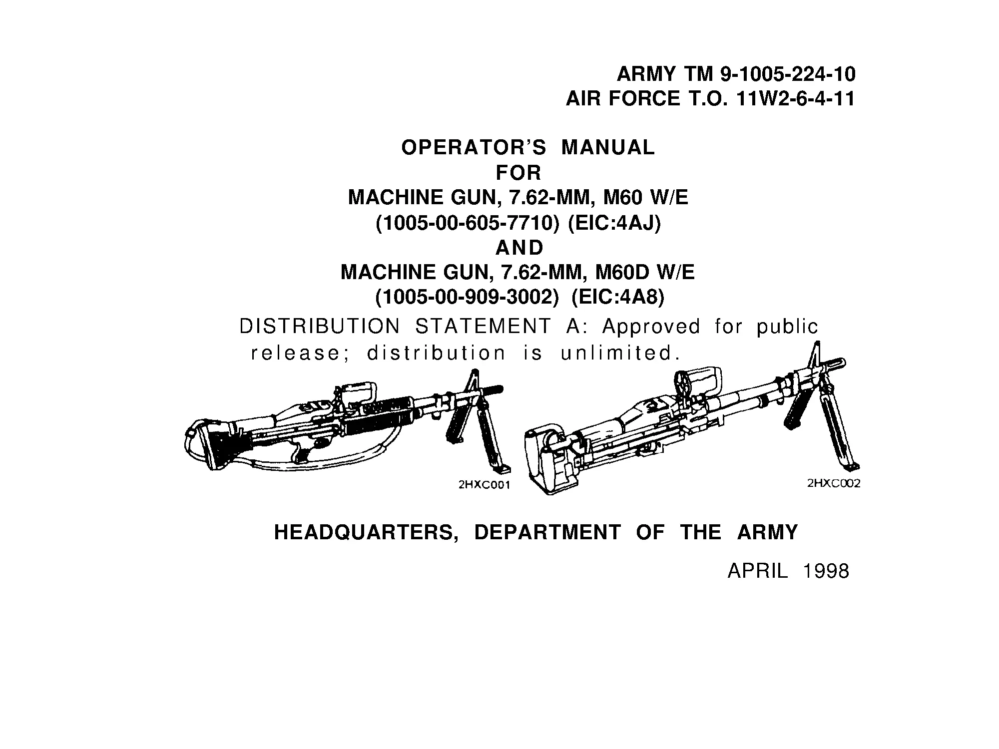
OPERATOR’S MANUAL
FOR
MACHINE GUN, 7.62-MM, M60 W/E
(1005-00-605-7710) (EIC:4AJ)
AND
MACHINE GUN, 7.62-MM, M60D W/E
(1005-00-909-3002) (EIC:4A8)
DISTRIBUTION STATEMENT A: Approved for public
release; distribution is unlimited.
HEADQUARTERS, DEPARTMENT OF THE ARMY
APRIL 1998
WARNING SUMMARY
Be sure to clear weapon before starting inspection.
If cover is opened on a hot cartridge (hot barrel), an open cover cookoff could
occur and result in serious injury or death. Evacuate area for 15 minutes and
then do REMEDIAL ACTION. Refer to WP 00011 00.
Never reload a runaway machine gun until it has been repaired. Be sure
machine gun is cleared before moving it.
When removing a stuck unfired cartridge, stay clear of the muzzle. Do not allow
cartridge to contact any hard surface. Cartridge may fire on contact. Remove a
stuck unfired cartridge using the same procedures for removing a stuck or
ruptured cartridge case.
Before field stripping check that the bolt is in forward position.
To prevent possible bodily injury, or aircraft/weapon damage, personnel should
not stand the weapon on its barrel assembly when disassembling or assembling
the weapon.
a
WARNING SUMMARY (cont)
Bolt assembly in under spring tension; it can twist and injure your hand.
Barrels issued for a specific gun will not be changed from gun to gun. Each
barrel and bolt assembly should be tagged during cleaning with the serial
number of the receiver (gun) and should remain together as initially assigned.
Interchanging barrels/bolts may result in injury or death.
The climate temperature in different regions will make a difference as to what
constitutes a hot gun. A hot, sunny day can cause a cookoff within 50 rounds,
weapon and ammunition in the sun.
Insert the hinge pin from one side and the hinge pin latch from the opposite
side.
After unloading dummy round, be sure the barrel is clear.
Ammunition to be used in machine gun is shown in WP 0031 00.
Keep weapon pointed at target - down range/impact area.
b
WARNING SUMMARY (cont)
Keep safety on 'S' (safe) until your ready to fire.
Always check the chamber/bore after clearing the weapon
Check barrel bore and chamber before firing.
Do not interchange bolt/barrel assemblies from one weapon to another. This
may cause injury or death to personnel.
Change hot barrels with your heat protective mitten only or by holding bipod
legs. (Refer to WP 0017 00 for additional hot barrel procedures.)
Do not interchange flat leaf springs from one model weapon to another.
Check that assigned and spare barrels have been headspaced and tagged to
your receiver. Rotate usage of the barrel.
c
WARNING SUMMARY (cont)
Do not fire blank ammunition toward personnel within 20 feet of the muzzle.
Fragments of a closure wad or particles of unburned propellant might inflict
injury within that range.
Dry cleaning solvent is FLAMMABLE and TOXIC and must be kept away from
open flames and used in a well ventilated area. Use of rubber gloves is
necessary to protect the skin when washing machine gun parts.
Appropriate eye protection is recommended when cleaning your weapon and/or
its parts.
For first aid information see FM 21-11.
d
TECHNICAL MANUAL
NO. 9-1005-224-10
*TM 9-1005-224-10
T.O. 11W2-6-4-11
HEADQUARTERS
DEPARTMENTS OF THE ARMY
AND AIR FORCE
Washington D.C . , 2 April 1998
Operator’s Manual
for
MACHINE GUN, 7.62-MM, M60 W/E
(1005-00 -605-7710)
and
MACHINE GUN, 7.62-MM, M60D W/E
(1005-00 -909-3002)
REPORTING ERRORS AND RECOMMENDING IMPROVEMENTS
You can help improve this manual. If you find any mistakes or if you know of a
way to Improve the procedures, please let us know. Mail your letter or DA Form
2026 (Recommended Changes to Equipment Publications and Blank Forms) direct
to: Director, Armament and Chemical Acquisition and Logistics Activity, ATTN:
AMSTA-AC-NML , Rock Island, IL 61299-7630. A reply will be furnished to you.
*This manual supersedes TM 9-1005-224 -10, dated 30 July 1985; TM 9-1005-
224-10HR, dated 18 May 1979; TB 9-1005-224-50-1, including all changes.
i
TABLE OF CONTENTS
WP Sequence No.
CHAPTER 1 - INTRODUCTION
General Information .................................... 0001 00
Equipment Description and Data ......................... 0002 00
CHAPTER 2 - OPERATlNG INSTRUCTIONS
Description and Use of Operator’s Controls
and Indicators .................................................. 0003 00
Preventive Maintenance Checks and
Services (PMCS) ................................................ 0004 00
Operation Under Usual Conditions:
Loading ........................................................ 0005 00
How to Mount M60 on M122 Tripod ............................. 0006 00
How to Mount M60 on M6 Pedestal/
M197 Mount .................................................... 0007 00
How to put M60D on Vehicles ................................ 0008 00
Clearing and Unlaoding ........................................ 0009 00
Initial Adjustments, Daily Checks,
and Self-Test .............................................. 0010 00
ii
WP Sequence No.
CHAPTER 2 - OPERATlNG INSTRUCTIONS (cont)
Operating Procedures.. ..............................................
0011 00
Removing Stuck/Ruptured Cartridge.. ........................ 0012 00
Operation of Auxiliary Equipment.. ............................. 0013 00
Preparation for Movement ......................................... 0014 00
Operation Under Unusual Conditions.. ....................... 0015 00
CHAPTER 3 - MAINTENANCE INSTRUCTlONS
Lubrication Instructions.. ............................................
0016 00
Troubleshooting Procedures.. .................................... 0017 00
Field-Stripping Machine Gun.. ....................................
0018 00
Maintenance of:
Barrel and Bipod Assembly
(Including Gas System). ...................................... 0023 00
Bolt Assembly ........................................................ 0019 00
Cover Assembly (M60/M60D). ................................ 0021 00
M60 Hanger and Cartridge Feed Tray Assembly
or M60D Cartridge Feed Tray Assembly.. ............ 0022 00
M60 Trigger Mechanism Grip Assembly ................. 0024 00
M60D Sear and Safety Housing Assembly .............. 0025 00
Operating Rod Assembly ........................................ 0020 00
Receiver ................................................................. 0026 00
iii
WP Sequence No.
CHAPTER 3 - MAINTENANCE INSTRUCTIONS (cont)
ReassemblyofMachine Gun.......................... 0027 00
Maintenance Checklist..................................002800
Function Check....................................... 002900
CHAPTER 4 - MAINTENANCE OF AUXILIARY
EQUIPMENT............................................003000
CHAPTER5 - AMMUNlTlON.......................... 003100
REFERENCES......................................003200
COMPONENTS OF END ITEM AND
BASIC ISSUE ITEMS LIST
Introduction ................................................ 003300
Components of End Item.............................. 003400
Basic Issue Items...... ............................... 0035 00
ADDlTlONAL AUTHORIZATION LIST
Introduction........................................003600
Additional Authorized List........................... 003700
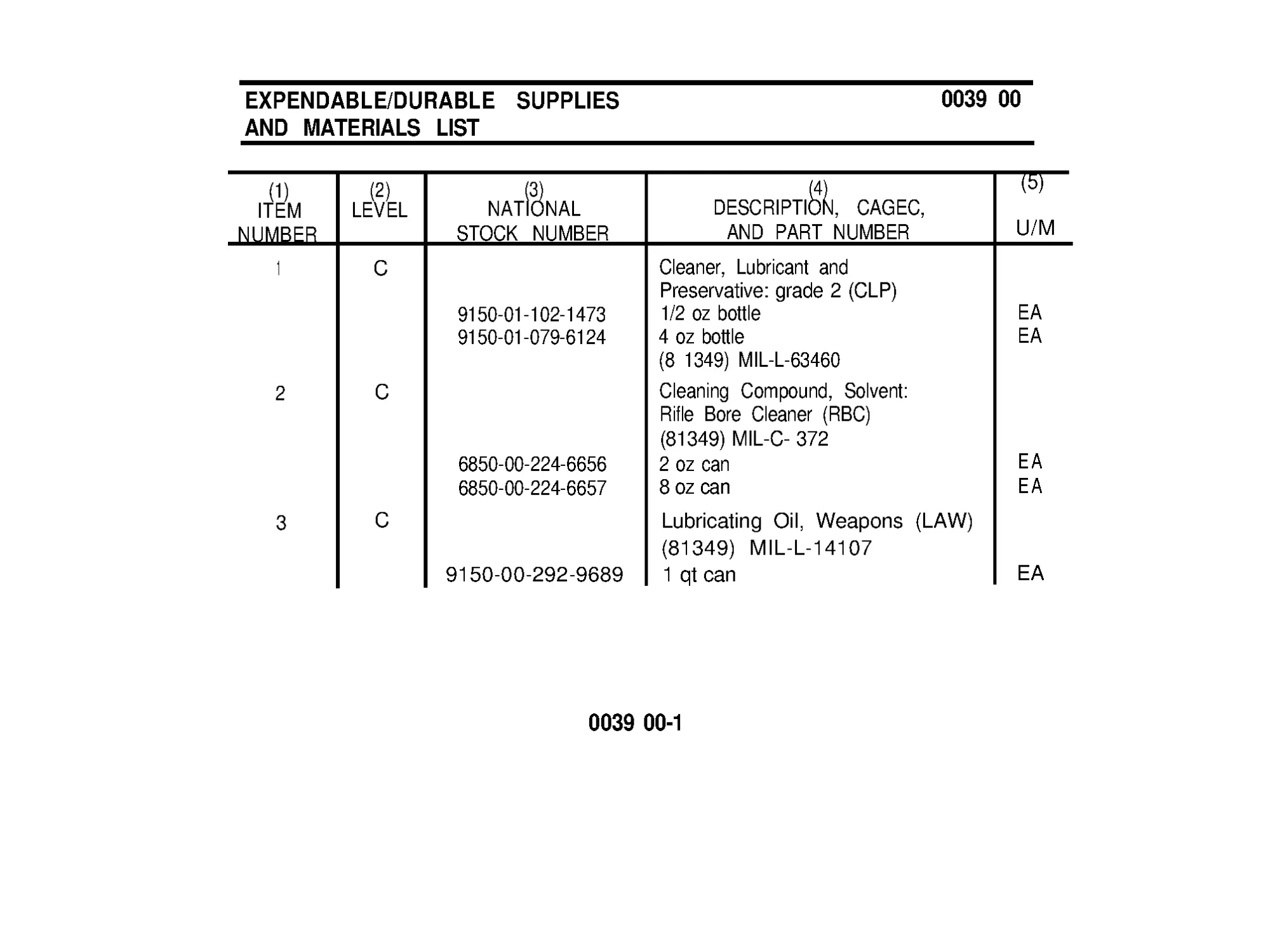
EXPENDABLE/DURABLE SUPPLIES
AND MATERIALS LIST
Introduction................................................ 0038 00
Expendable/Durable Supplies and
Materials List...........................................003900
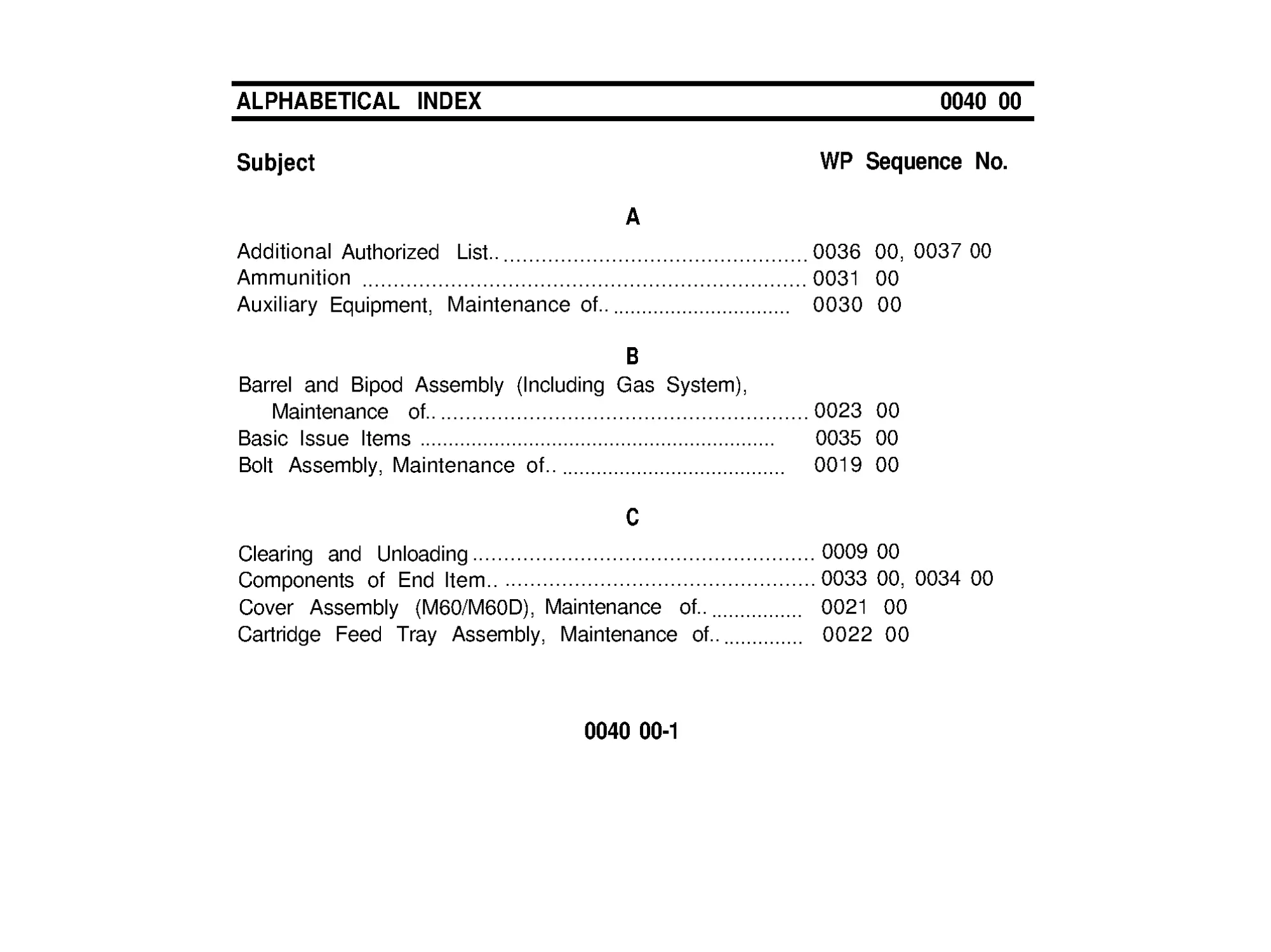
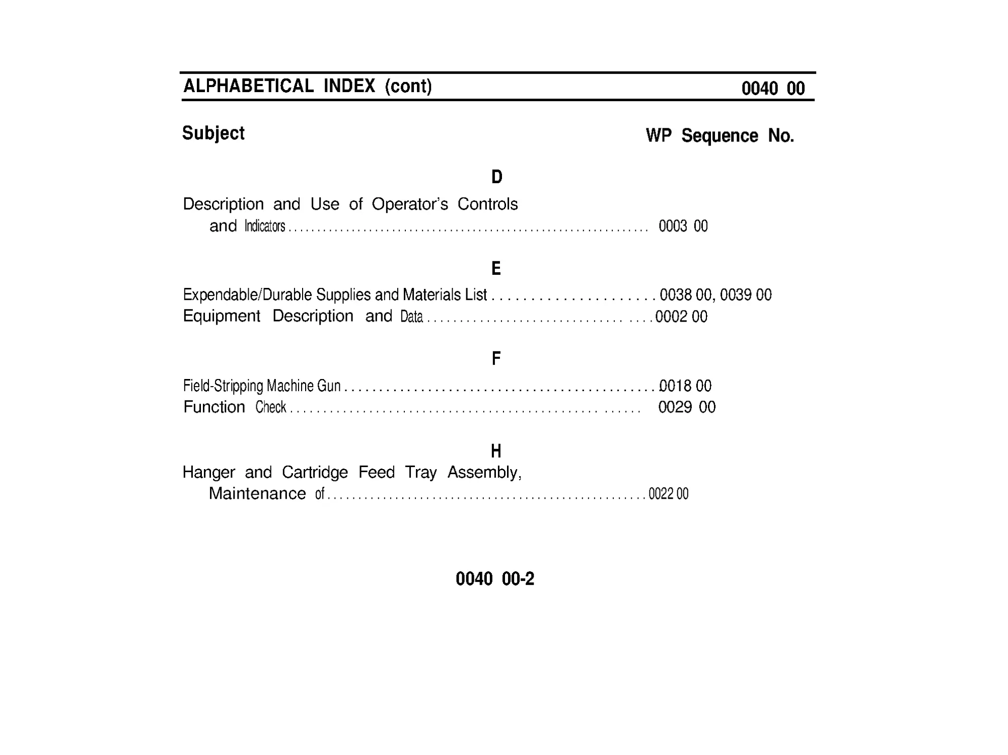
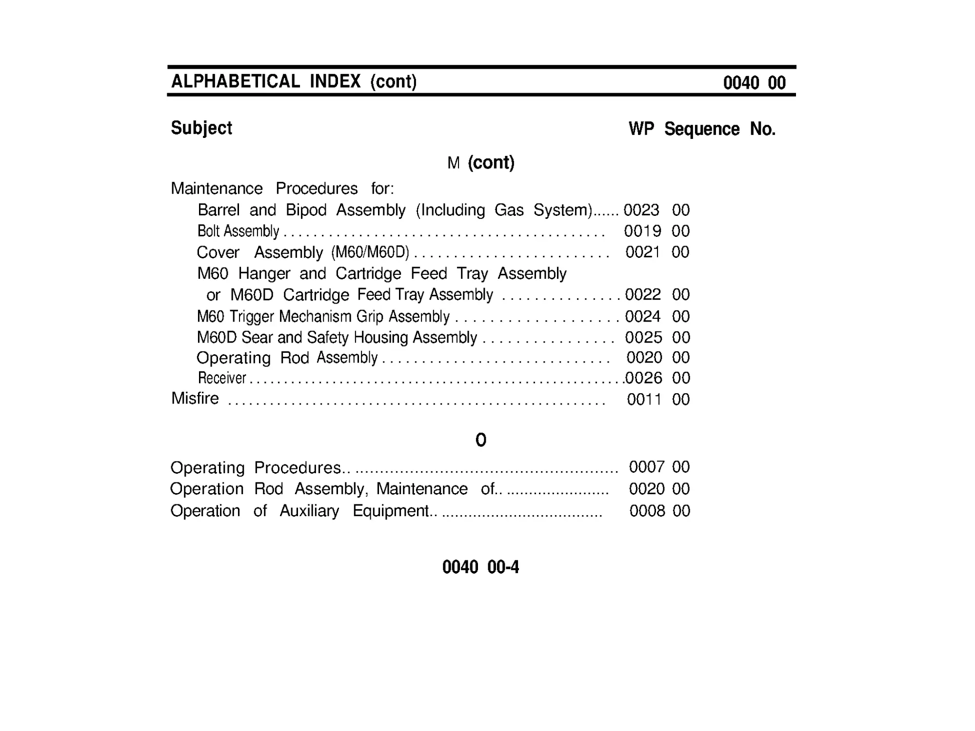
ALPHABETICAL INDEX.................................... 0040 00
iv
CHAPTER 1
INTRODUCTION
GENERAL INFORMATION
0001 00
SCOPE
Type of Manual: Operator’s Manual.
Model Numbers and Equipment Names: M60, 7.62mm, Machine Gun, and
M60D, 7.62mm, Machine Gun.
Purpose of Equipment:
The M60, 7.62mm, Machine Gun is a general purpose weapon capable of being
fired from several mounts or handheld. The weapons primary use is for ground
operations.
The M60D, 7.62mm, Machine Gun is a general purpose weapon capable of
being fired from several mounts. The weapons primary use is for support of
ground operations. The M60D is an aircraft door-mounted or vehicle-mounted
machine gun.
0001 00-1
GENERAL INFORMATION (cont)
0001 00
MAINTENANCE FORMS AND RECORDS
Department of the Army forms and procedures used for equipment
maintenance will be those prescribed by DA PAM 738-750, the Army
Maintenance Management System (TAMMS).
REPORTlNG EQUIPMENT IMPROVEMENT RECOMMENDATIONS (EIR’s).
If your machine needs improvement, let us know. Send us an EIR. You, the
user, are the only one who can tell us what you don’t like about your equipment.
Let us know why you don’t like the design or performance. Put it on an SF 368
(Quality Deficiency Report). Mail it to us at Commander, US Army Armament
Research, Development and Engineering Center, ATTN: AMSTA-AR-QAW-A ,
Rock Island, IL 61299-7630. We’ll send you a reply.
0001 00-2
EQUIPMENT DESCRlPTlON AND DATA
0002 00
EQUIPMENT CHARACTERISTICS, CAPABlLlTlES AND FEATURES.
The M60 and M60D are air-cooled and have fixed headspace allowing quick
barrel changes for cooling and maintenance when required. In order to extend
the life of the barrels, retain accuracy, and allow for continuous firing over long
periods of time, two barrel assemblies are issued with each gun. The machine
guns are gas-operated and fire from open bolt position.
0002 00-1
EQUIPMENT DESCRlPTlON AND DATA (cont)
0002 00
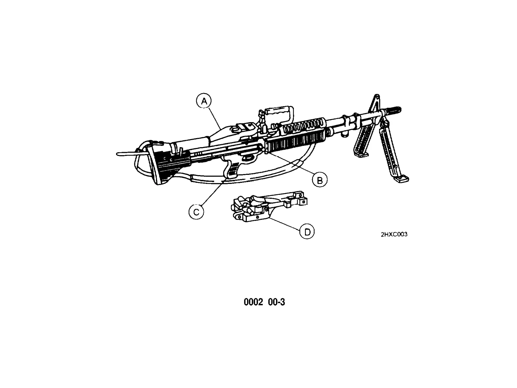
LOCATlON AND DESCRlPTlON OF MAJOR COMPONENTS.
M60 and M60D Machine Gun.
COVER ASSEMBLY - Positions and holds cartridge in place for
stripping, feeding link belt, and chambering rounds.
COCKING HANDLE ASSEMBLY - Provides a means to manually move
the bolt assembly to the rear.
TRIGGER MECHANISM AND GRIP ASSEMBLY (M60 ONLY) - Controls
the firing of the machine gun.
SEAR AND SAFETY HOUSING (M60D ONLY) - Controls the firing of the
machine gun.
0002 00-2
0002 00-3
EQUIPMENT DESCRlPTlON AND DATA (cont)
0002 00
LOCATlON AND DESCRlPTlON OF MAJOR COMPONENTS (cont)
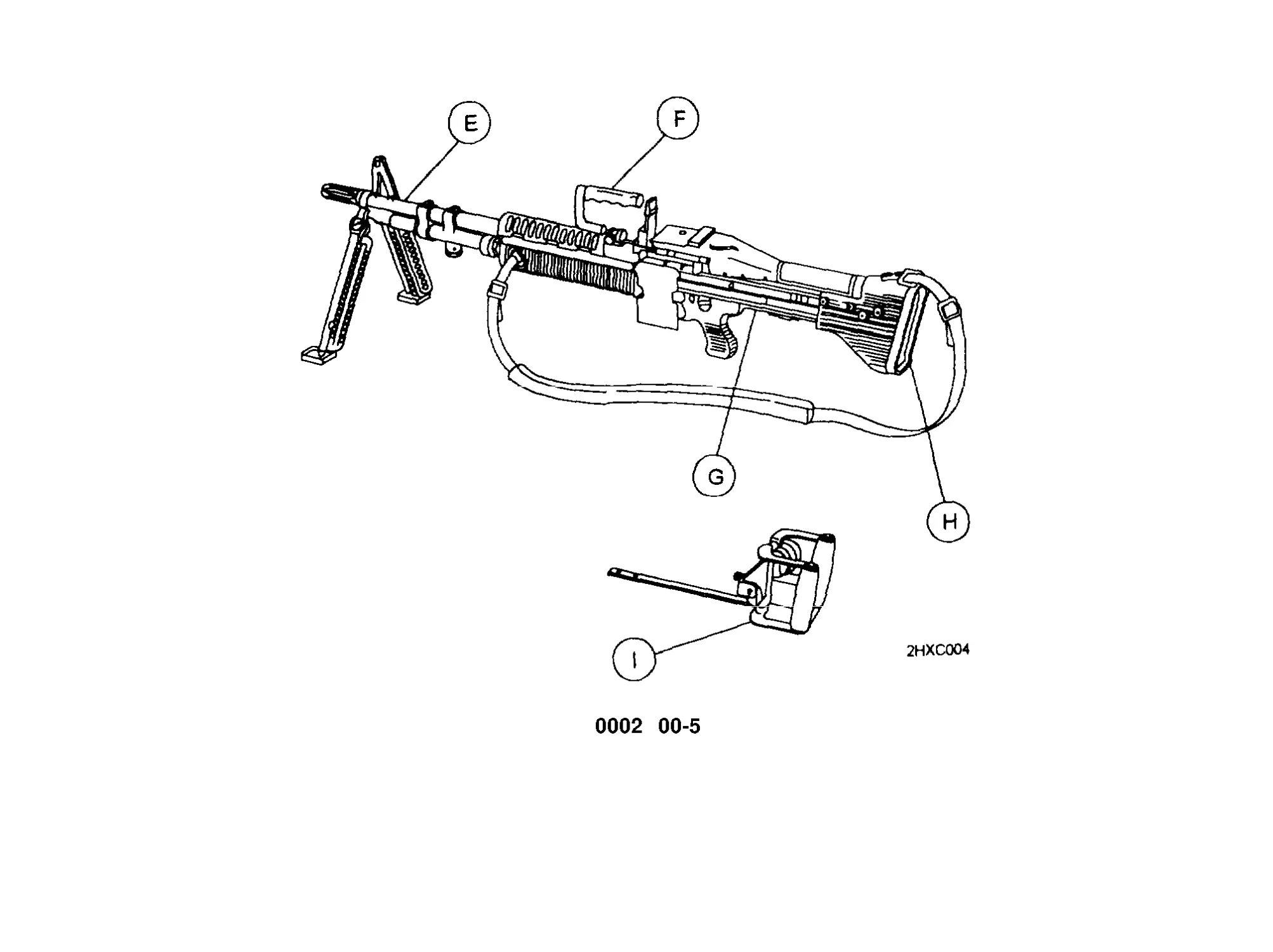
BARREL AND BIPOD ASSEMBLY - The barrel houses cartridges for
firing. The bipod assembly provides a semistable platform when the
machine gun is fired from the prone position.
CARRYING HANDLE ASSEMBLY - Provides a means to carry the
machine gun with one hand. The carrying handle assembly folds down
when the rear sight is used and the machine gun is fired.
RECEIVER ASSEMBLY - Supports all major components. Houses
internal parts and, through a series of cam ways, controls operation of
weapon.
SHOULDER GUN STOCK (M60 ONLY) - Provides a suitable surface to
stabilize the weapon against the shoulder while firing the machine gun
from any position except from the hip.
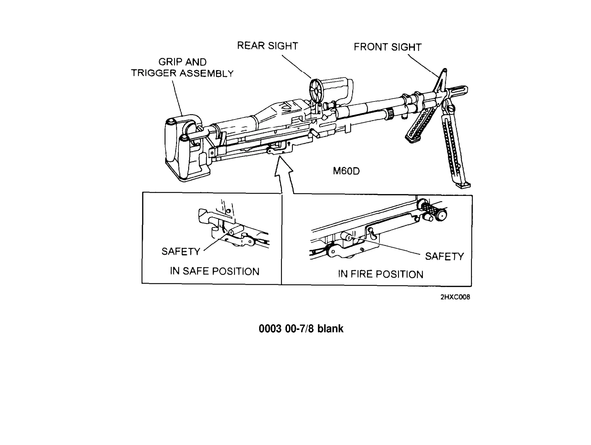
GRIP AND TRIGGER ASSEMBLY (M60D ONLY) - Provides handles to
move machine gun and houses the machine gun trigger.
0002 00-4
0002 00-5
EQUIPMENT DESCRIPTION AND DATA (cont)
0002 00
LOCATlON AND DESCRIPTION OF MAJOR COMPONENTS (cont)
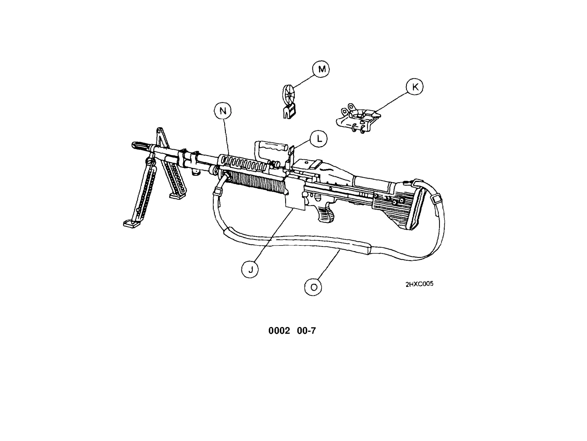
CARTRIDGE FEED TRAY AND HANGER ASSEMBLY (M60 ONLY) -
Guides cartridges for positioning and feeding. The hanger assembly
supports the bandoleer.
CARTRIDGE TRAY ASSEMBLY (M60D ONLY) - Guides cartridge for
positioning and feeding.
REAR SIGHT ASSEMBLY (M60 ONLY) - Provides a means to aim the
machine gun at the target with accuracy. The sight adjusts horizontally as
well as vertically.
REAR SIGHT ASSEMBLY (M60D ONLY) - Provides a means to aim the
machine gun in the general area of the target. The rear sight is
nonadjustable.
FOREARM ASSEMBLY (M60 ONLY) - Provides a hand hold when firing
from the hip or from a standing or kneeling position.
SMALL ARMS SLING (M60 ONLY) - Used for support during assault
firing and for transport.
0002 00-6
0002 00-7
EQUIPMENT DESCRIPTION AND DATA (cont)
0002 00
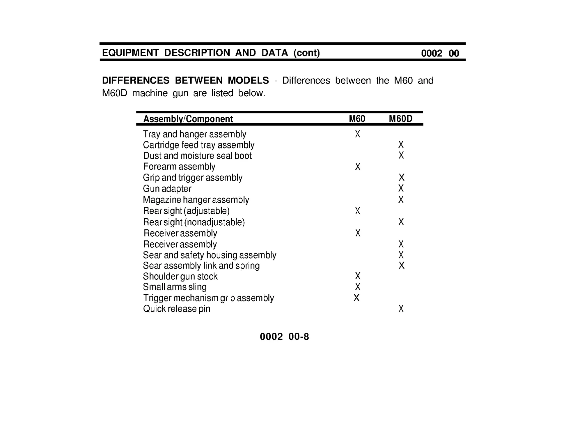
DIFFERENCES BETWEEN MODELS - Differences between the M60 and
M60D machine gun are listed below.
Assembly/Component
M60
M60D
Tray and hanger assembly
Cartridge feed tray assembly
Dust and moisture seal boot
Forearm assembly
Grip and trigger assembly
Gun adapter
Magazine hanger assembly
Rear sight (adjustable)
Rear sight (nonadjustable)
Receiver assembly
Receiver assembly
Sear and safety housing assembly
Sear assembly link and spring
Shoulder gun stock
Small arms sling
Trigger mechanism grip assembly
Quick release pin
0002 00-8
X
X
X
X
X
X
X
X
X
X
X
X
X
X
X
X
X
EQUIPMENT DATA
M60 Machine Gun.
Weight ............................................ 23 lb (10.43 kg)
Length ...................................... 43.5 in. overall (1.1m overall)
Range:
Maximum Effective Range ........... 1100meters
Maximum Range ................... 3725 meters
Tracer Burn Out ................... 900 meters or more
Rates of fire:
Sustained ..................................... 100 rd per min (4 to 6 seconds between burst)
Recommend barrel change every 10 min
Rapid ............................................... 200 rd per min (2 to 3 seconds between burst)
Recommend barrel change every 2 min
Cyclic .............................................. 550 rd per min (approx)
Recommend barrel change every min
Muzzle velocity .................................. 2800 FPS
Capacity of bandoleer ......................... 100 rds
Rifling:
Number of lands .......................... 4
Right hand twist ............................. One turn in 12 in (30.54 cm)
Trigger pull:
Maximum .................................... 11 .5 lb (5.2 Kg)
Minimum........................................6.0 lb (2.7 kg)
0002 00-9
EQUIPMENT DESCRIPTION AND DATA (cont)
0002 00
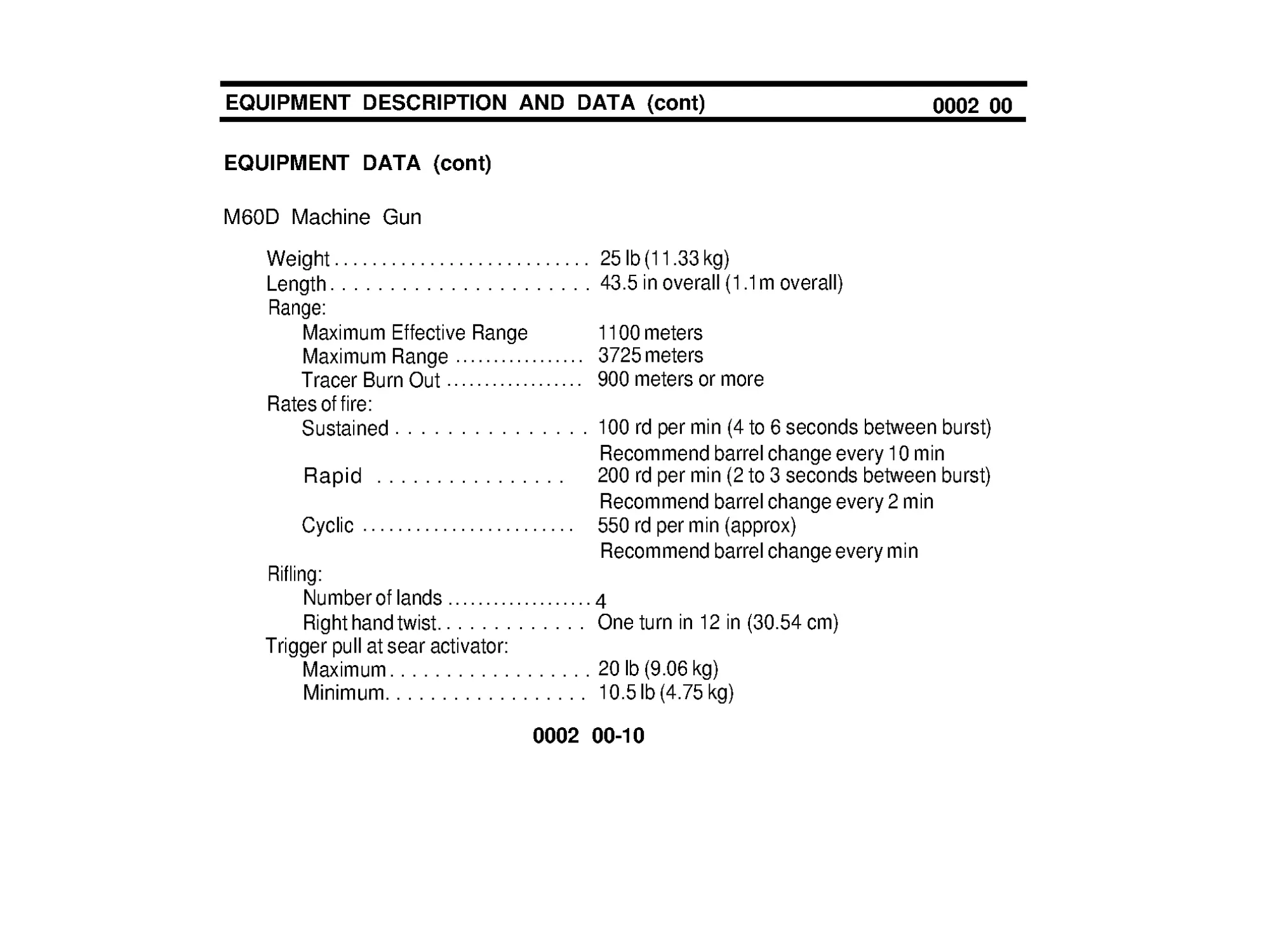
EQUIPMENT DATA (cont)
M60D Machine Gun
Weight ........................... 25 lb (11.33 kg)
Length ...................... 43.5 in overall (1.1m overall)
Range:
Maximum Effective Range
1100 meters
Maximum Range ................. 3725 meters
Tracer Burn Out .................. 900 meters or more
Rates of fire:
Sustained ............... 100 rd per min (4 to 6 seconds between burst)
Recommend barrel change every 10 min
Rapid ................ 200 rd per min (2 to 3 seconds between burst)
Recommend barrel change every 2 min
Cyclic ........................ 550 rd per min (approx)
Recommend barrel change every min
Rifling:
Number of lands ................... 4
Right hand twist. ............ One turn in 12 in (30.54 cm)
Trigger pull at sear activator:
Maximum .................. 20 lb (9.06 kg)
Minimum.................. 10.5 lb (4.75 kg)
0002 00-10
CHAPTER 2
OPERATING INSTRUCTIONS
This page intentionally left blank.
0003 00-1
DESCRIPTION AND USE OF OPERATOR’S CONTROLS
AND INDICATORS
0003 00
M60 MACHINE GUN
COCKING HANDLE. Pull back to move bolt rearward.
COVER LATCH. Holds cover closed. Pull back on lower end of latch to open.
BARREL LOCK LEVER. Locks barrel in place. To unlock barrel, push in on
barrel lock lever from left side of weapon and raise lever.
BIPOD LEG PLUNGER. Depress to extend or retract bipod foot.
TRIGGER. Pull rearward to fire weapon. Release to stop firing.
0003 00-2
0003 00-3
DESCRIPTION AND USE OF OPERATOR’S CONTROLS
AND INDICATORS (cont)
0003 00
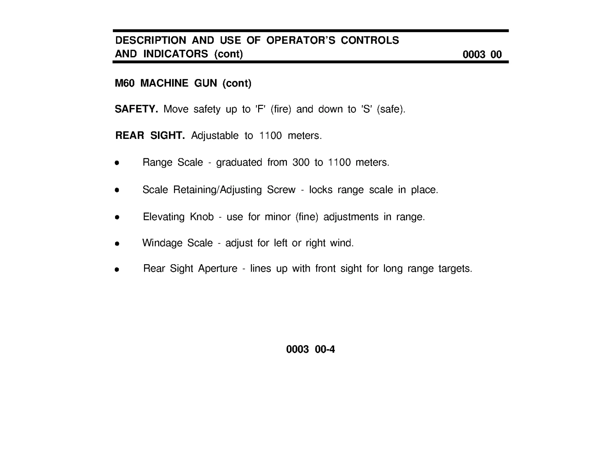
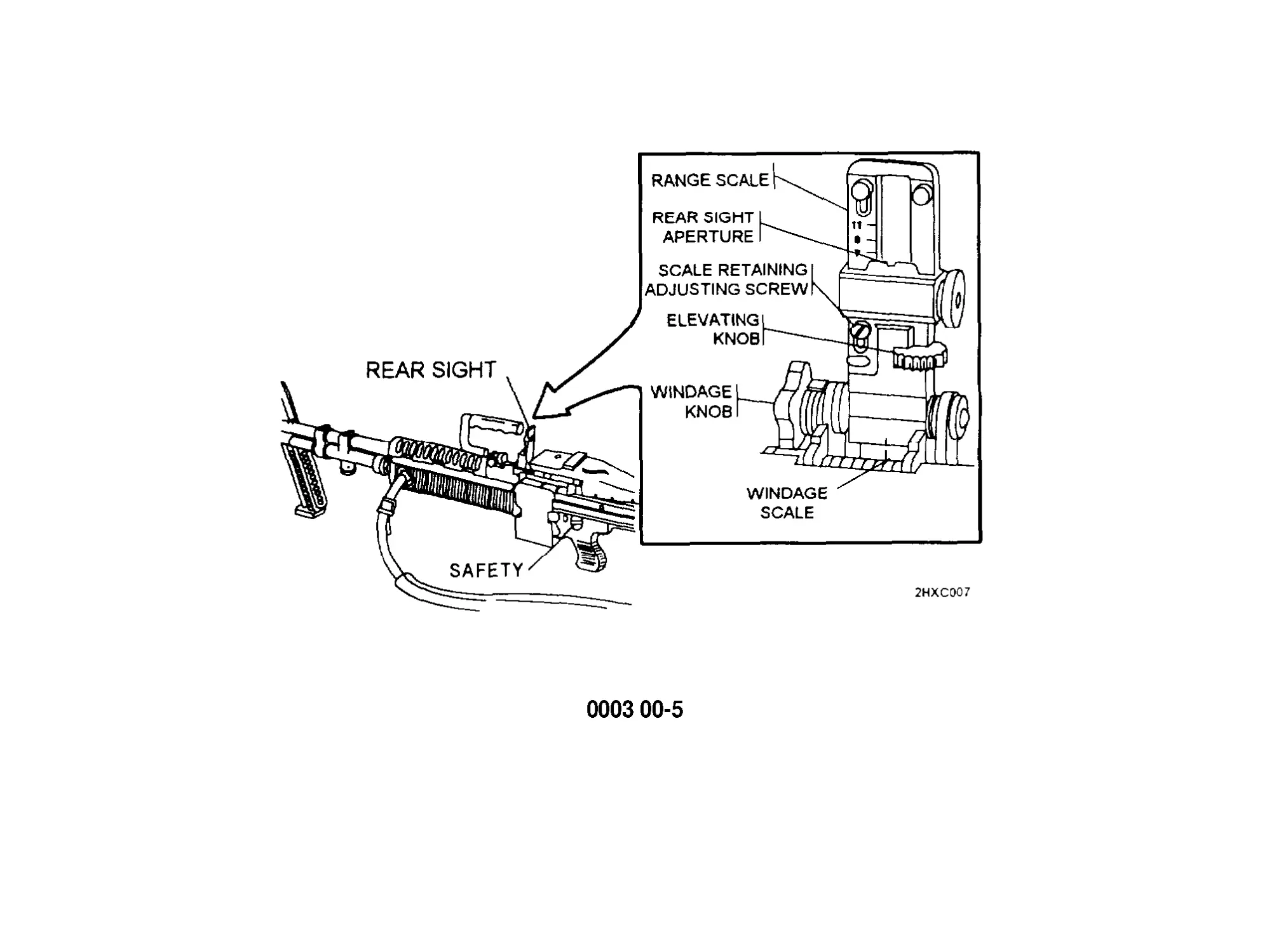
M60 MACHINE GUN (cont)
SAFETY. Move safety up to 'F ' (fire) and down to 'S ' (safe).
REAR SIGHT. Adjustable to 1100 meters.
Range Scale - graduated from 300 to 1100 meters.
Scale Retaining/Adjusting Screw - locks range scale in place.
Elevating Knob - use for minor (fine) adjustments in range.
Windage Scale - adjust for left or right wind.
Rear Sight Aperture - lines up with front sight for long range targets.
0003 00-4
0003 00-5
DESCRlPTlON AND USE OF OPERATOR’S CONTROLS
AND INDICATORS (cont)
0003 00
M60D MACHINE GUN
GRIP AND TRIGGER ASSEMBLY. Pull back on both triggers to fire. Release
to stop firing.
SAFETY. Push to right for safe 'S ', to left for fire 'F '.
REAR AND FRONT SIGHTS. Aim through the ring sight (rear sight) and front
sight to line up target. Fire. Adjust range by watching tracers.
0003 00-6
0003 00-7/8 blank
PREVENTlVE MAINTENANCE CHECKS
AND SERVICES (PMCS)
GENERAL
Always keep in mind the CAUTIONS and WARNINGS when performing your
before (B) or during (D) PMCS. The numbers in the item number column shall
be used for the "TM Number" column on DA Form 2404, Equipment Inspection
and Maintenance Worksheet, in recording results of PMCS. After you operate,
perform your after (A) PMCS.
Perform BEFORE PMCS if: (1) you are the assigned operator and the machine
gun has been stored and not used for a period of 90 days or(2) you have been
issued the machine gun for the first time.
WARNING
Do not interchange barrel assembly or bolt assembly from one
machine gun to another. Doing so may result in injury or death.
The climate temperature in different regions will make a difference
as to what constitutes a hot gun. A hot, sunny day can cause a
cookoff within 50 rounds, weapon and ammunition in sun.
0004 00-1
0004 00
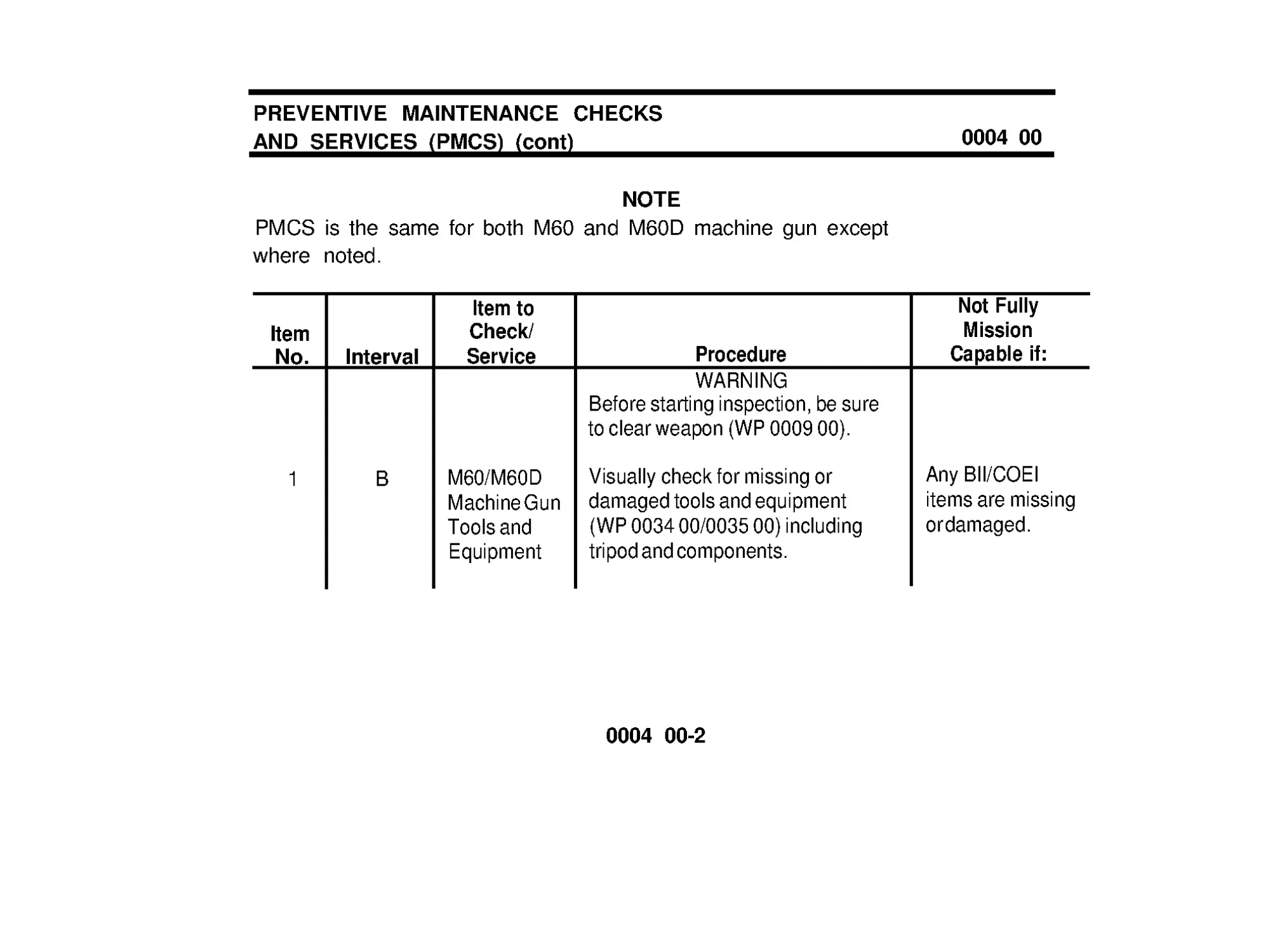
PREVENTIVE MAINTENANCE CHECKS
AND SERVICES (PMCS) (cont)
0004 00
NOTE
PMCS is the same for both M60 and M60D machine gun except
where noted.
Item
No.
1
Interval
B
Item to
Check/
Service
M60/M60D
Machine Gun
Tools and
Equipment
Procedure
WARNING
Before starting inspection, be sure
to clear weapon (WP 0009 00).
Visually check for missing or
damaged tools and equipment
(WP 0034 00/0035 00) including
tripod and components.
Not Fully
Mission
Capable if:
Any BII/COEI
items are missing
or damaged.
0004 00-2
Item to
Not Fully
Item
Check/
Mission
No. Interval
Service
Capable If:
2
B
Barrel
Gas piston will
3
Assemblies
B
Trigger
Mechanism
Grip
Assembly
(M60)/
Sear and
Safety
Housing
Assembly
(M60D)
Procedure
Open cover, pull bolt to rear, push
cocking handle forward and lock.
Close cover. place on safe (S). Tilt
weapon end to end to make sure
gas piston slides freely (a clicking
sound wiII be heard as the piston
slides In the cylinder). Run a dry
swab through the bore to remove
excess lubricant or obstructions.
Make sure flat leaf spring is in place
(WP 0018 00). Check that safety is
in 'F' position. Pull bolt to rear,
move safety to 'S' . Push cocking
handle forward and lock and pull the
trigger.
not slide.
Obstruction in
barrel.
Gas cylinder
vent, cylinder
plug, and cylinder
nut loose.
Weapon
functions with
safety at 'S'.
0004 00-3
PREVENTIVE MAINTENANCE CHECKS
AND SERVICES (PMCS) (cont)
Item
No.
4
Interval
B
Item to
Check/
Service
Cover
Assembly
Procedure
Lightly lubricate all moving parts
with lubricant on a clean swab
(item 6, WP 0038 00).
5
B
Gun
Check for free movement of cocking
Receiver
handle. Check barrel lock lever.
Assembly
Make sure it locks in place.
6
D
M60/M60D
Machine Gun
Erratic or sluggish firing may
indicate carbon buildup. Switch
barrels (WP 0018 00). If firing is still
erratic or sluggish, field-strip the
weapon and perform the necessary
maintenance to complete the tire
mission.
0004 00
Not Fully
Mission
Capable If:
Cocking handle
binds or barrel is
loose.
Weapon ceases
to operate.
0004 00-4
Item
No.
7
8
9
Interval
D
A
A
Item to
Check/
Service
Small Arms
Sling (M60)
M60/M60D
Machine Gun
M60/M60D
Machine Gun
(Inspection)
Procedure
Inspect sling for damage and for
missing or loose sling swivels.
Fieldstrip, clean, inspect and
lubricate entire weapon
(WP 0018 00).
Inspect operating rod assembly and
barrel assembly for burrs, cracks
and chips. Make sure the gas
piston slides back and forth freely.
Inspect components of trigger
assembly for wear. Place safety in
'F ' position, sear should move
slightly. Inspect breechbolt
assembly for defects (e.g. , cracks
or chips). Reassemble weapon and
check for proper functioning.
Not Fully
Mission
Capable If:
Swivels loose or
missing. Sling is
damaged.
Weapon fails to
function or has
damaged or
missing parts.
0004 00-5/6 blank
OPERATION UNDER USUAL CONDITIONS -
LOADING
0005 00
NOTE
The following procedures
illustrate the M60 machine gun
except where the M60 parts
differ from the M60D park,
then both weapons are
illustrated.
1 Point weapon down range.
2 Safety should be on F.
M60 - Move safety to F.
M60D-PushinonF.
0005 00-1
OPERATION UNDER USUAL CONDITIONS -
LOADING (cont)
0005 00
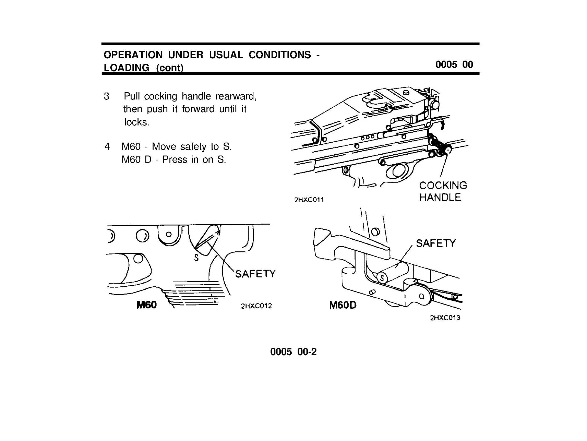
3 Pull cocking handle rearward,
then push it forward until it
locks.
4 M60 - Move safety to S.
M60D-PressinonS.
0005 00-2
CAUTION
Bolt assembly must be rearward when opening or closing the
cover.
5 Turn latch lever and open cover.
6 Raise cartridge feed tray and check chamber for ammunition.
0005 00-3
OPERATlON UNDER USUAL CONDITIONS -
LOADING (cont)
0005 00
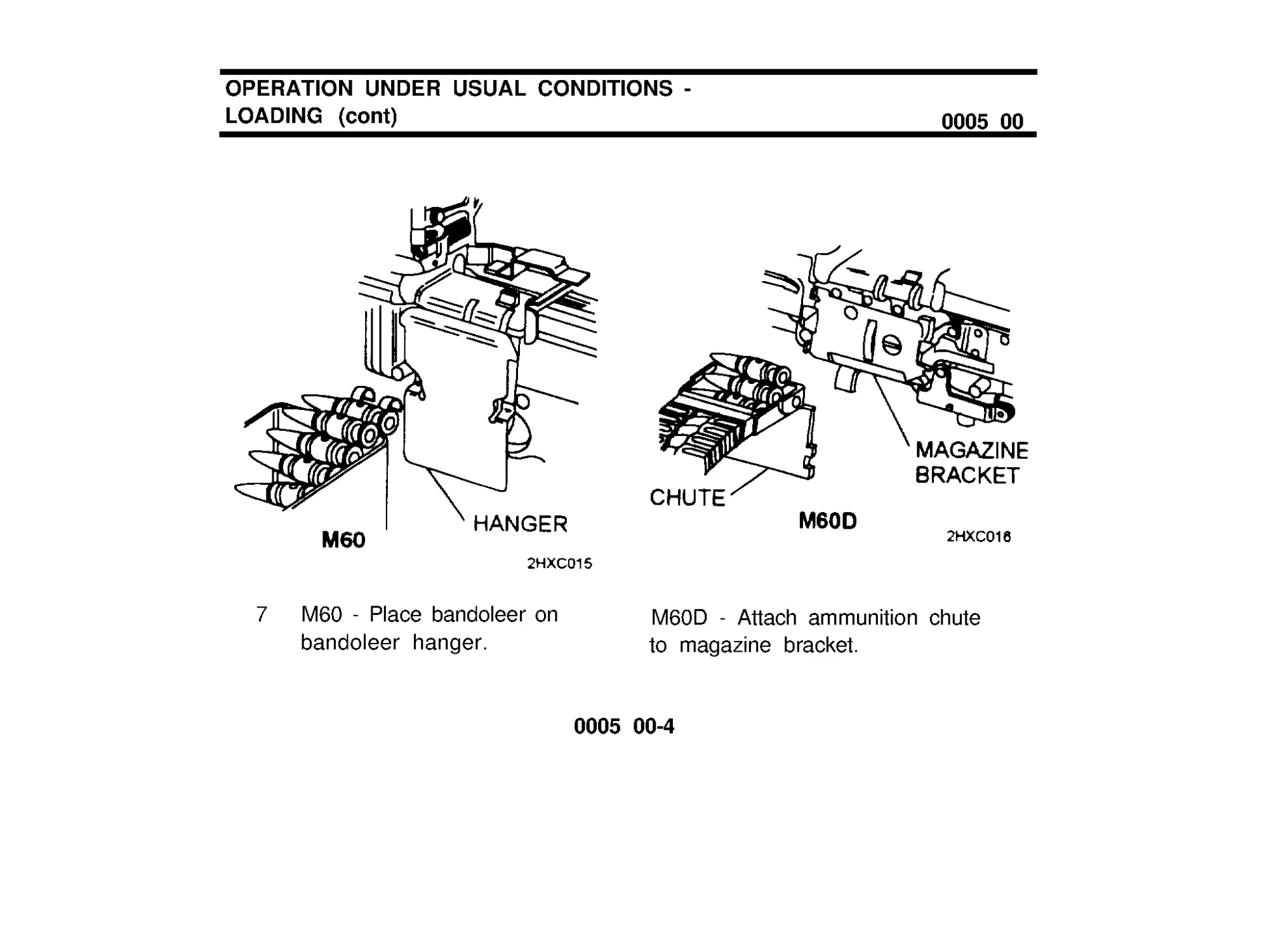
7 M60 - Place bandoleer on
M60D - Attach ammunition chute
bandoleer hanger.
to magazine bracket.
0005 00-4
8 Place ammunition on feed
tray, with open side of links
down and with first round in
the feed groove. (Make
sure cartridge retainer pawl
holds ammunition link on
feed tray.)
CAUTION
Bolt assembly must be rearward
when opening or closing the cover.
9 Close cover.
0005 00-5
OPERATION UNDER USUAL CONDITIONS -
LOADING (cont)
0005 00
10 M60 - Move safety to 'F '.
11 The gun is ready to fire.
M60D - Press in on 'F'.
0005 00-6
OPERATION UNDER USUAL CONDITIONS -
HOW TO PUT THE M60 ON THE M122 TRIPOD
0006 00
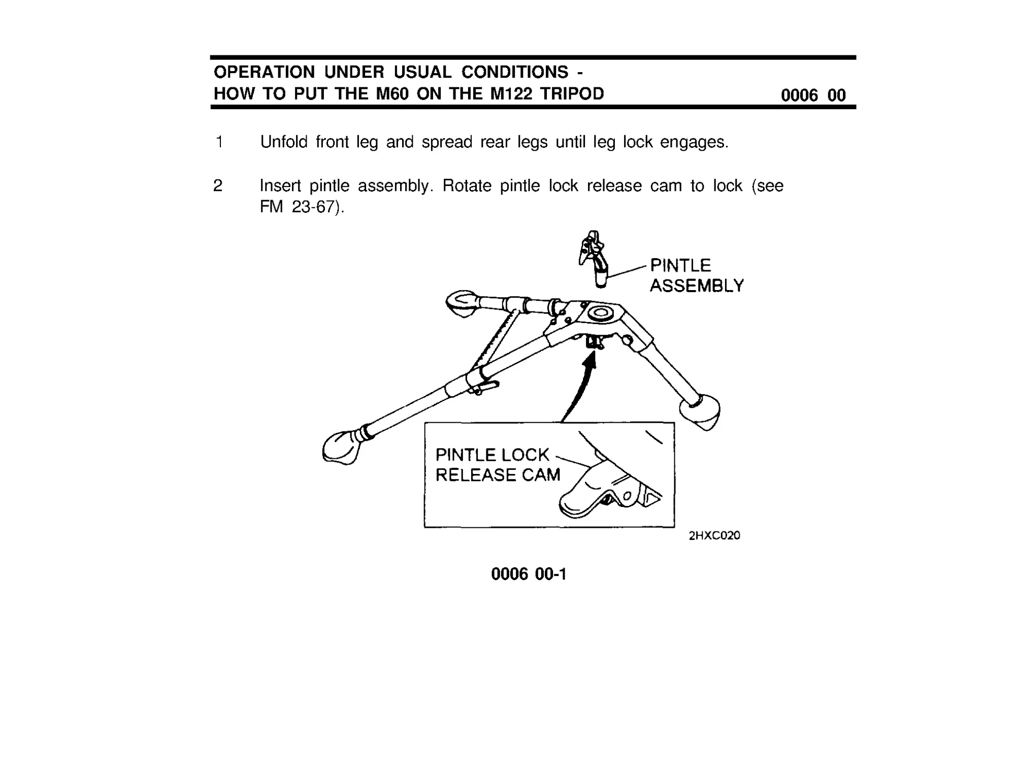
1 Unfold front leg and spread rear legs until leg lock engages.
2
Insert pintle assembly. Rotate pintle lock release cam to lock (see
FM 23-67).
0006 00-1
OPERATlON UNDER USUAL CONDITIONS -
HOW TO PUT THE M60 ON THE M122 TRIPOD (cont)
0006 00
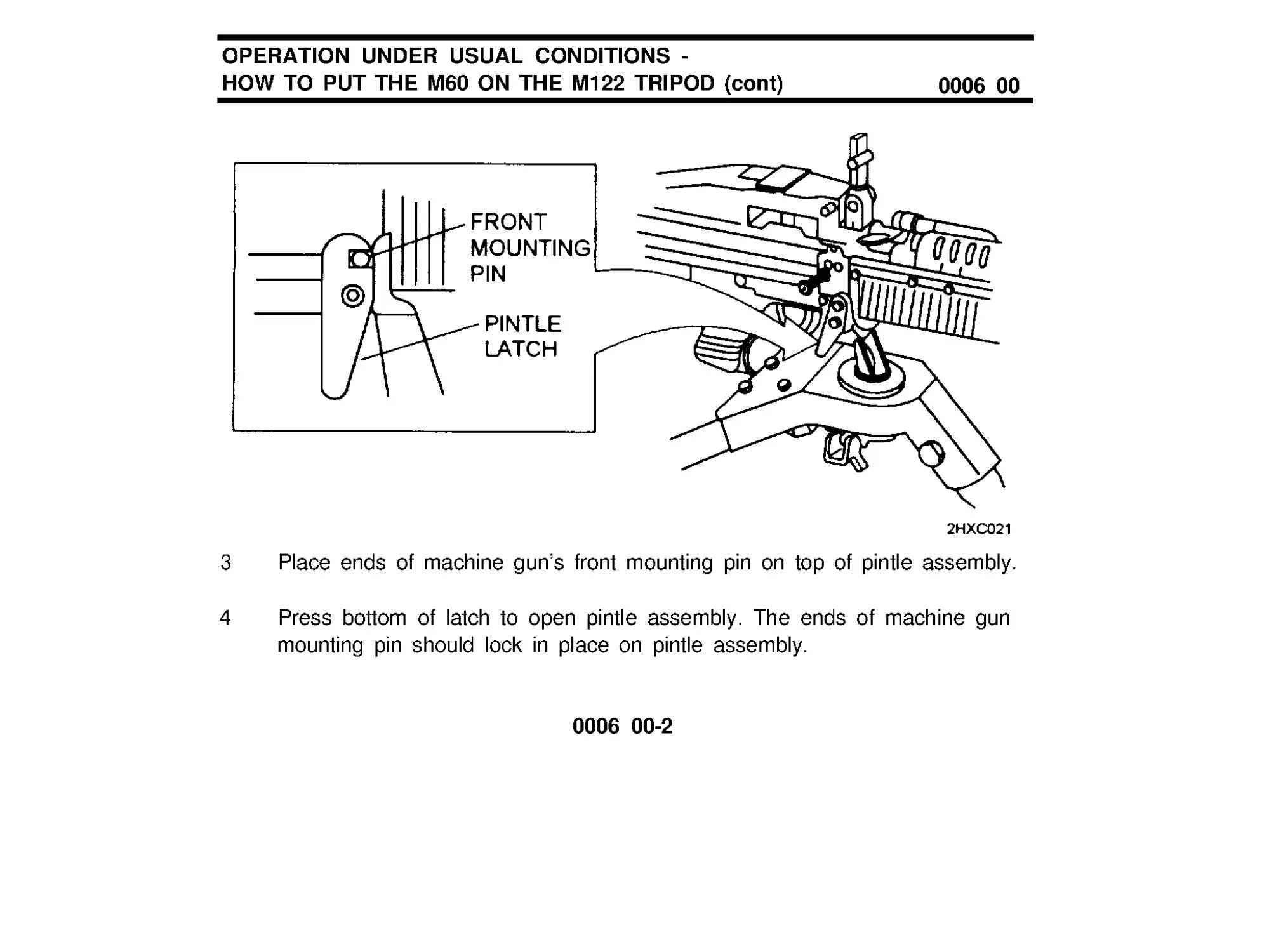
3 Place ends of machine gun’s front mounting pin on top of pintle assembly.
4
Press bottom of latch to open pintle assembly. The ends of machine gun
mounting pin should lock in place on pintle assembly.
0006 00-2
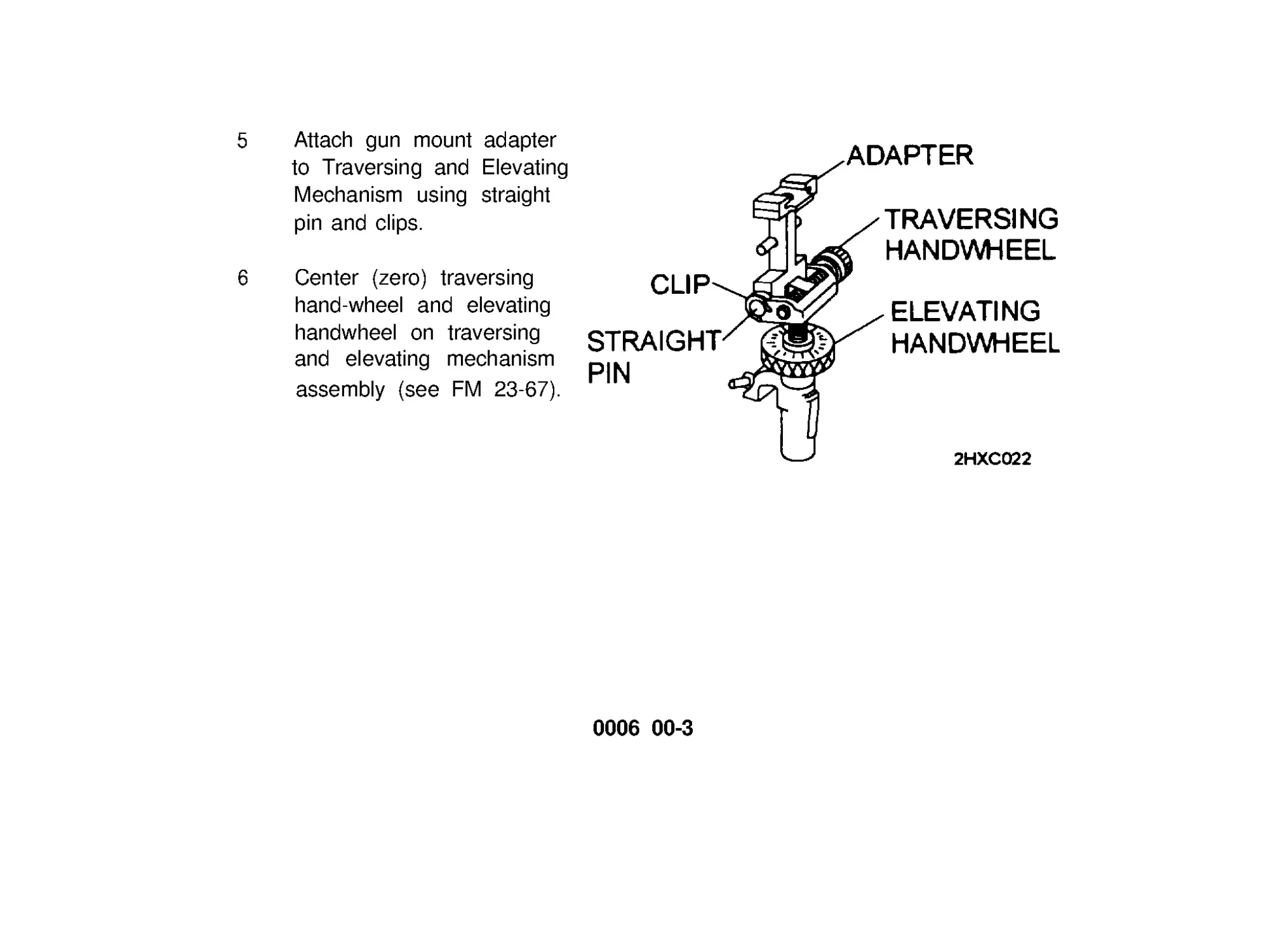
5 Attach gun mount adapter
to Traversing and Elevating
Mechanism using straight
pin and clips.
6 Center (zero) traversing
hand-wheel and elevating
handwheel on traversing
and elevating mechanism
assembly (see FM 23-67).
0006 00-3
OPERATlON UNDER USUAL CONDITIONS -
HOW TO PUT THE M60 ON THE M122 TRIPOD (cont)
0006 00
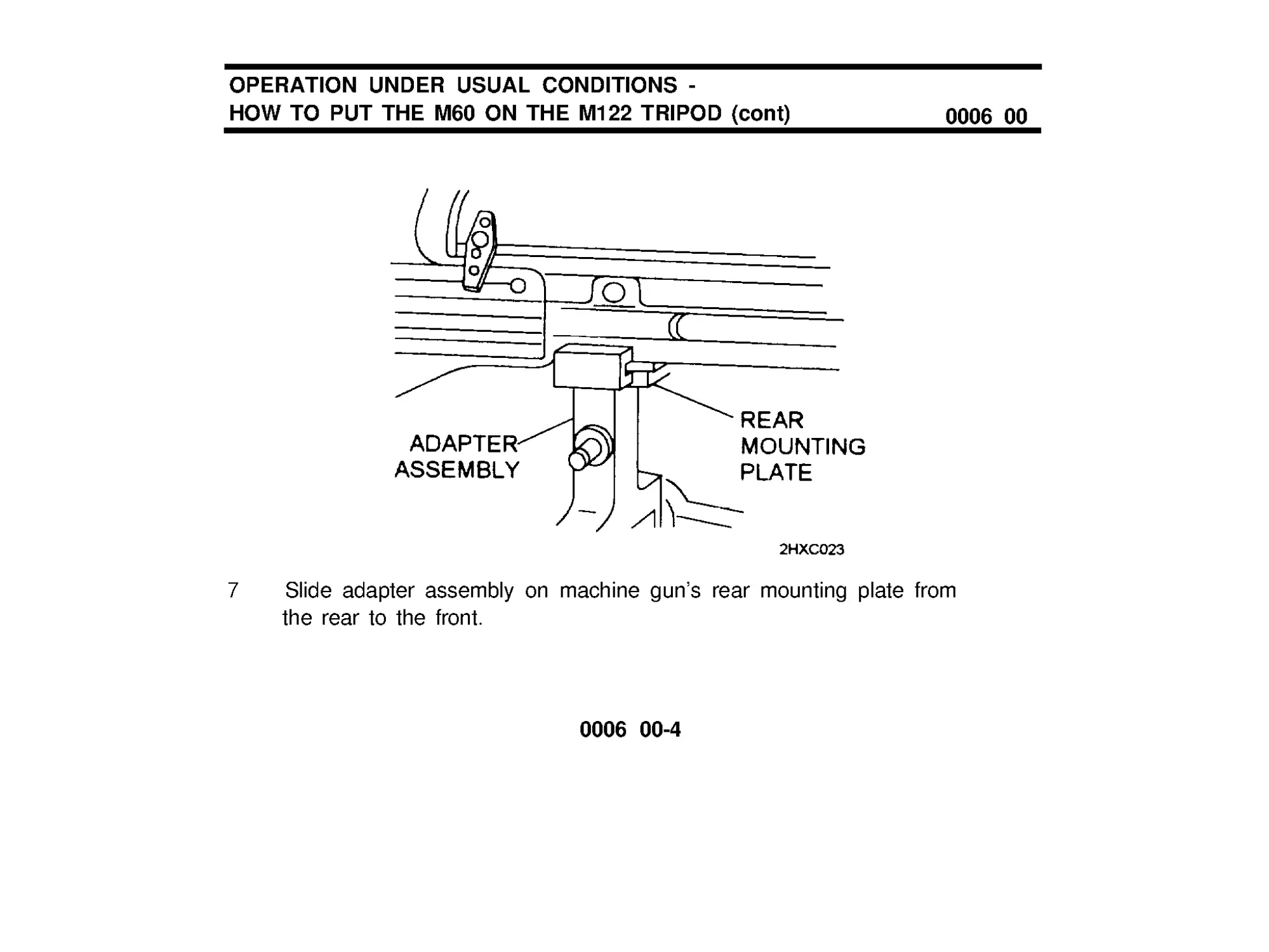
7 Slide adapter assembly on machine gun’s rear mounting plate from
the rear to the front.
0006 00-4
8 Position traversing and elevating mechanism assembly on traversing
bar. Rotate lock lever to secure.
0006 00-5/6 blank
OPERATION UNDER USUAL CONDITIONS -
HOW TO PUT THE M60 MACHINE GUN ON THE
M6 PEDESTAL MOUNT/ M197 MOUNT
NOTE
0007 00
For mounting instructions see TM 9-1005-245-13&P.
0007 00-1
OPERATION UNDER USUAL CONDITIONS -
HOW TO PUT THE M60 MACHINE GUN ON THE
M6 PEDESTAL MOUNT/ M197 MOUNT
WARNING
0007 00
The canvas cover above the driver and passenger seats should
always be in place when firing.
Firing on-the-move is not permitted from M998/M1038/M1097.
Firing on-the-move is restricted to 5 miles per hour cross-country
and 10 miles per hour on improved roads when mounted on
M1025 and M1026 HMMWVs (Armament Carriers).
Ground personnel should not be within 10 meters of the vehicle
when firing.
CAUTlON
When the weapon is not in use/manned it should be secured in the
travel lock. When not manned for extended cross-country travel
weapon should be removed from the mount,
0007 00-2
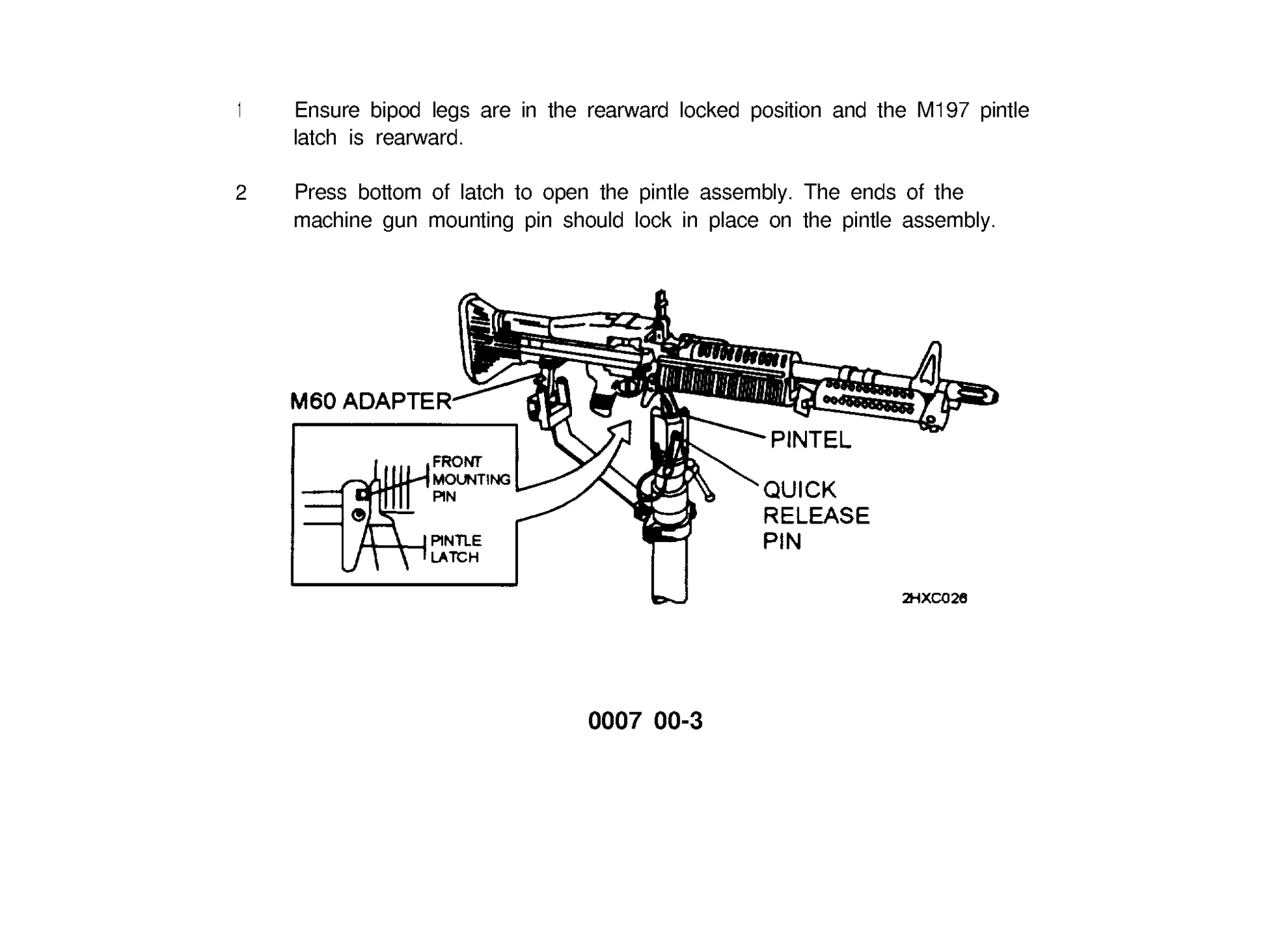
1
Ensure bipod legs are in the rearward locked position and the M197 pintle
latch is rearward.
2
Press bottom of latch to open the pintle assembly. The ends of the
machine gun mounting pin should lock in place on the pintle assembly.
0007 00-3
OPERATlON UNDER USUAL CONDITIONS -
HOW TO PUT THE M60 MACHINE GUN ON THE
M6 PEDESTAL MOUNT/ M197 MOUNT
0007 00
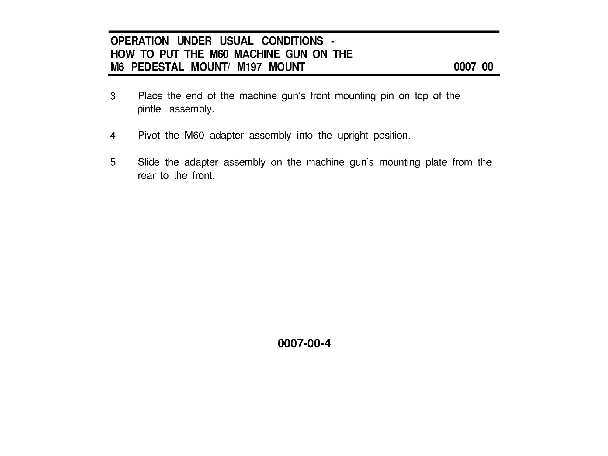
3 Place the end of the machine gun’s front mounting pin on top of the
pintle assembly.
4 Pivot the M60 adapter assembly into the upright position.
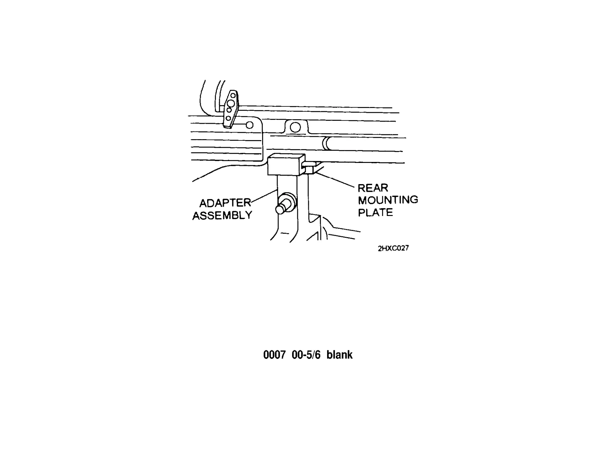
5 Slide the adapter assembly on the machine gun’s mounting plate from the
rear to the front.
0007-00 -4
0007 00-5/6 blank
OPERATION UNDER USUAL CONDITIONS -
HOW TO PUT M60D ON VEHICLES
0008 00
1
2
3
4
5
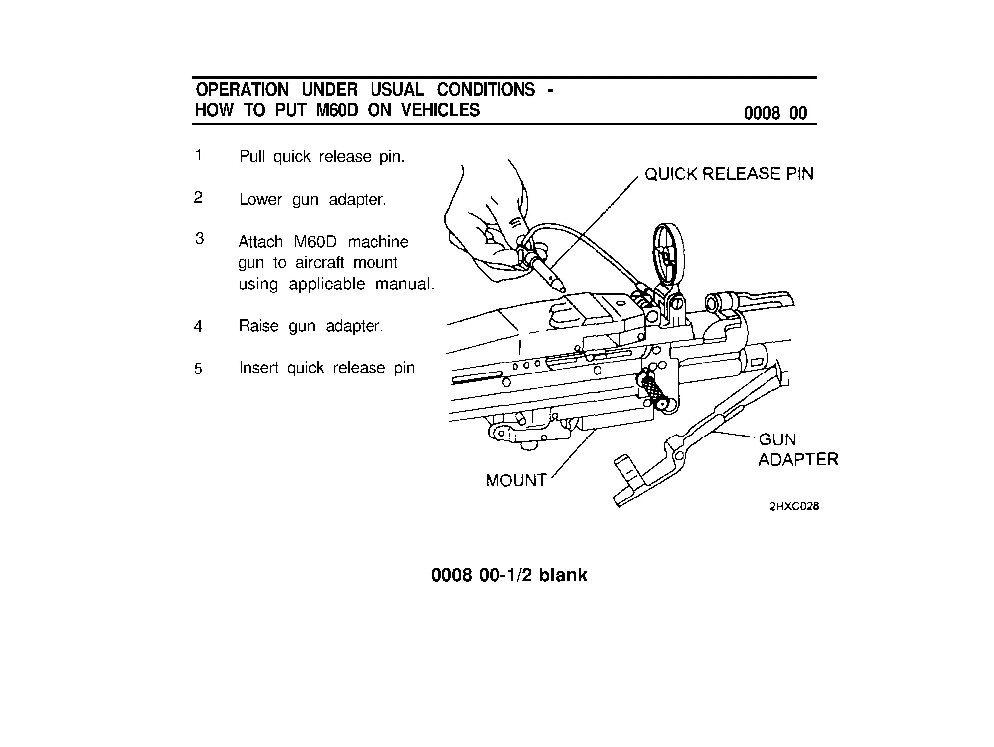
Pull quick release pin.
Lower gun adapter.
Attach M60D machine
gun to aircraft mount
using applicable manual.
Raise gun adapter.
Insert quick release pin
0008 00-1/2 blank
OPERATION UNDER USUAL CONDITIONS -
CLEARING AND UNLOADING
0009 00
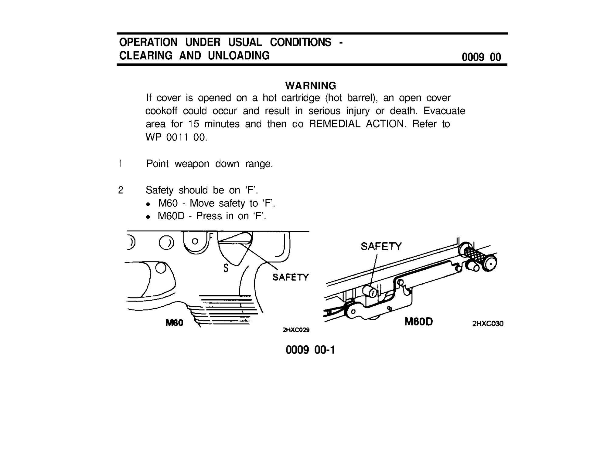
WARNING
If cover is opened on a hot cartridge (hot barrel), an open cover
cookoff could occur and result in serious injury or death. Evacuate
area for 15 minutes and then do REMEDIAL ACTION. Refer to
WP 0011 00.
1
Point weapon down range.
2
Safety should be on ‘F ’ .
l M60 - Move safety to ‘F’.
l M60D - Press in on ‘F’.
0009 00-1
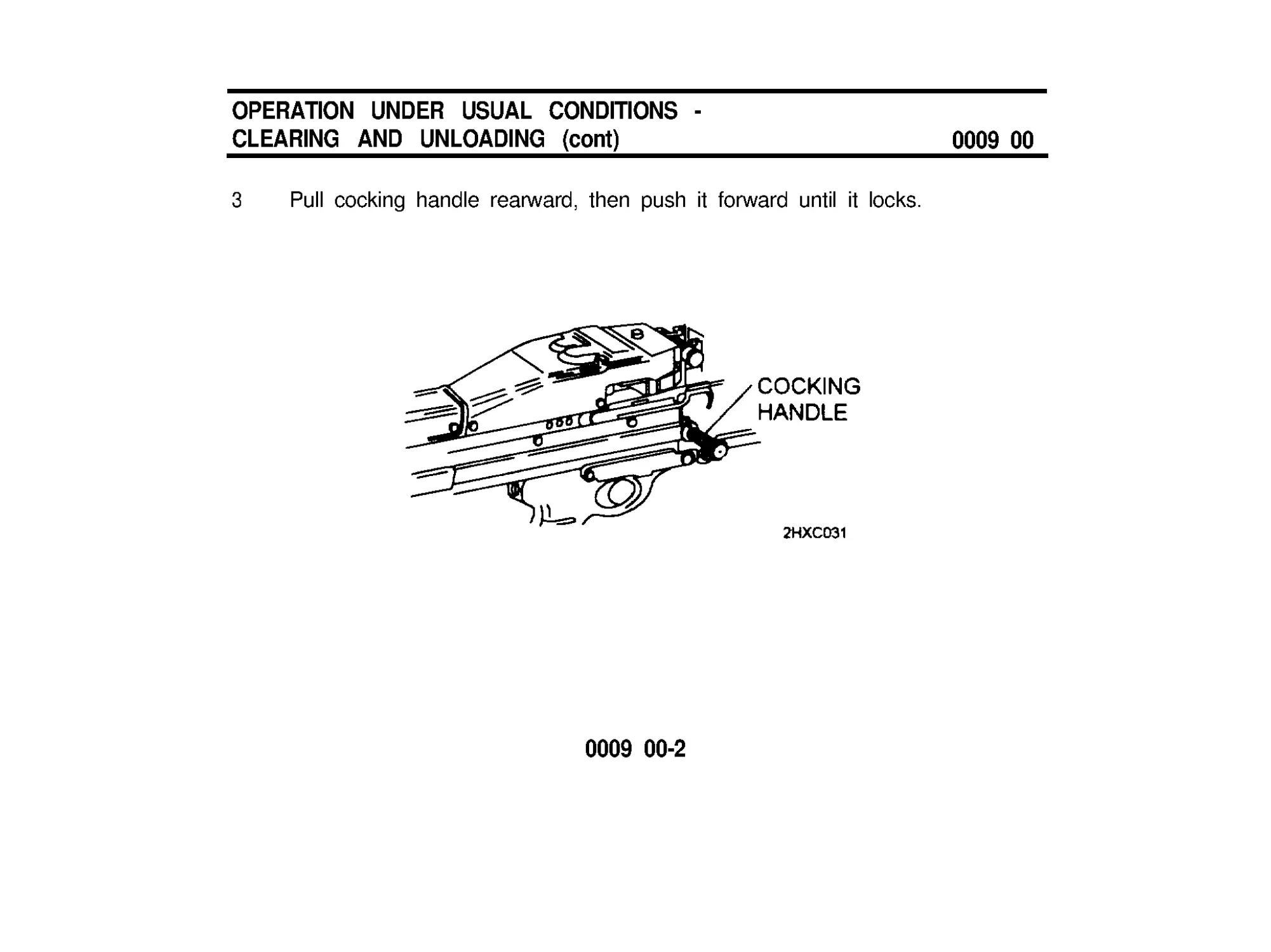
OPERATION UNDER USUAL CONDITIONS -
CLEARING AND UNLOADING (cont)
0009 00
3 Pull cocking handle rearward, then push it forward until it locks.
0009 00-2
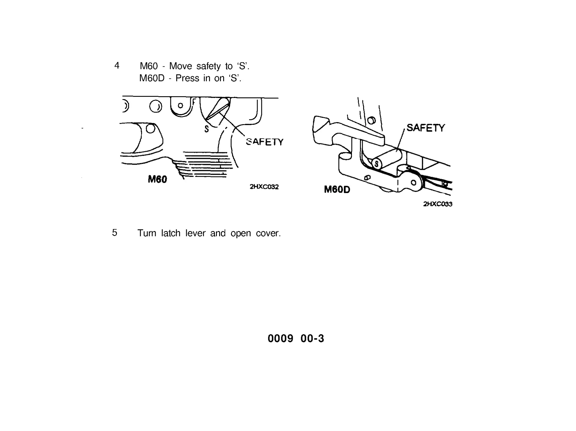
4 M60 - Move safety to ‘S’.
M60D - Press in on ‘S’.
5 Turn latch lever and open cover.
0009 00-3
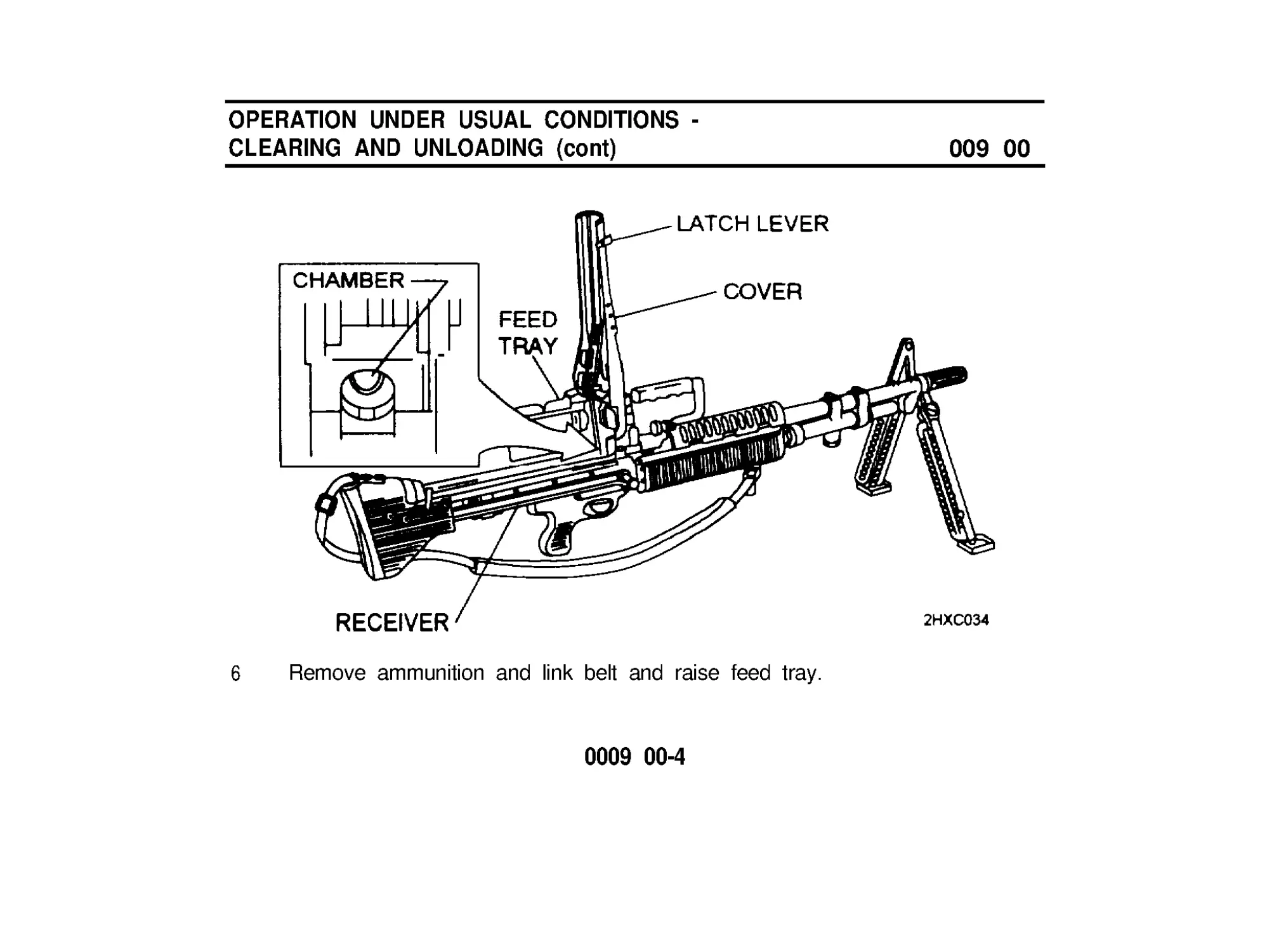
OPERATION UNDER USUAL CONDITIONS -
CLEARING AND UNLOADING (cont)
009 00
6 Remove ammunition and link belt and raise feed tray.
0009 00-4
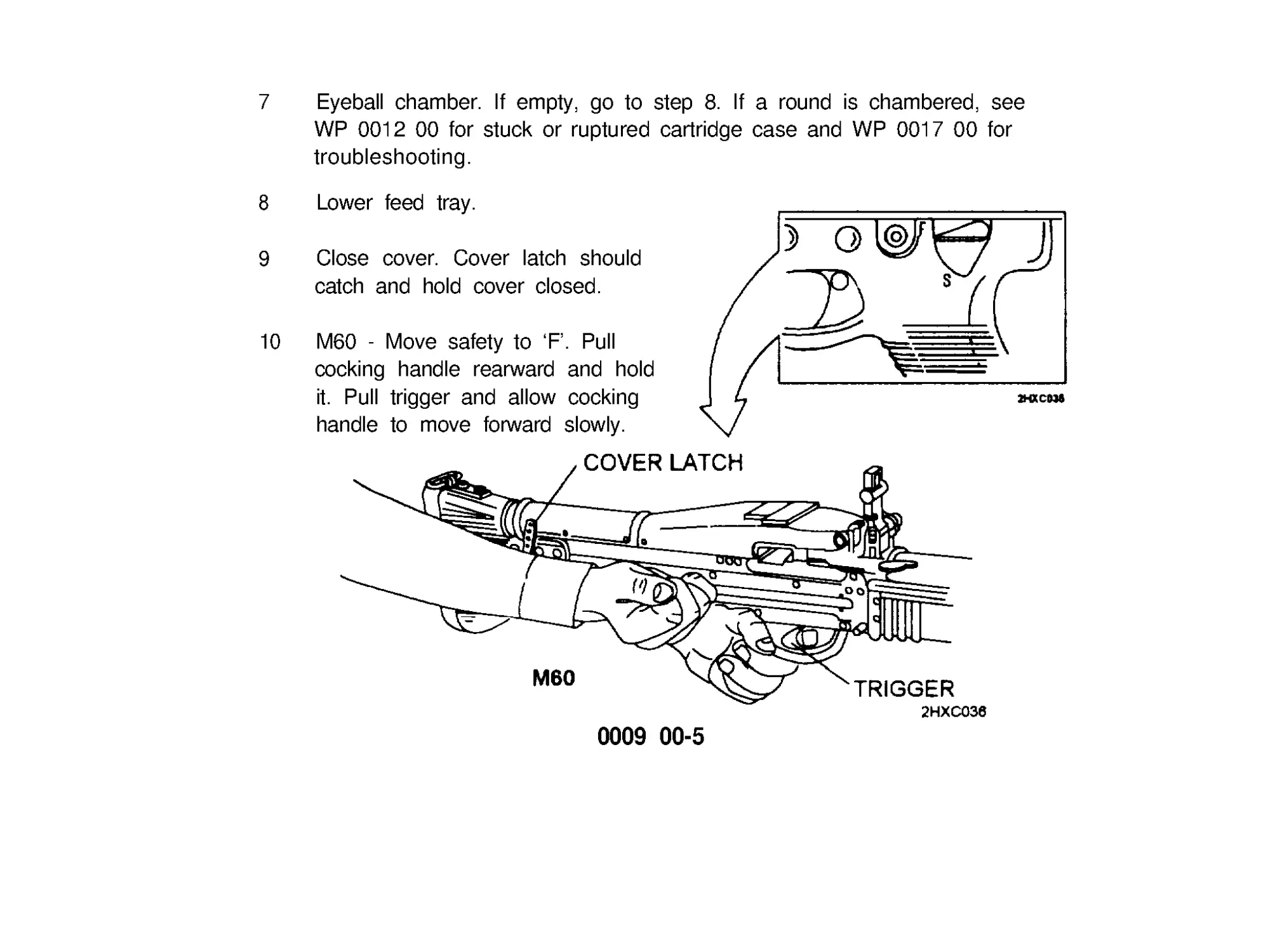
7
Eyeball chamber. If empty, go to step 8. If a round is chambered, see
WP 0012 00 for stuck or ruptured cartridge case and WP 0017 00 for
troubleshooting.
8 Lower feed tray.
9 Close cover. Cover latch should
catch and hold cover closed.
10 M60 - Move safety to ‘F’ . Pull
cocking handle rearward and hold
it. Pull trigger and allow cocking
handle to move forward slowly.
0009 00-5
OPERATlON UNDER USUAL CONDITIONS -
CLEARING AND UNLOADING (cont)
0009 00
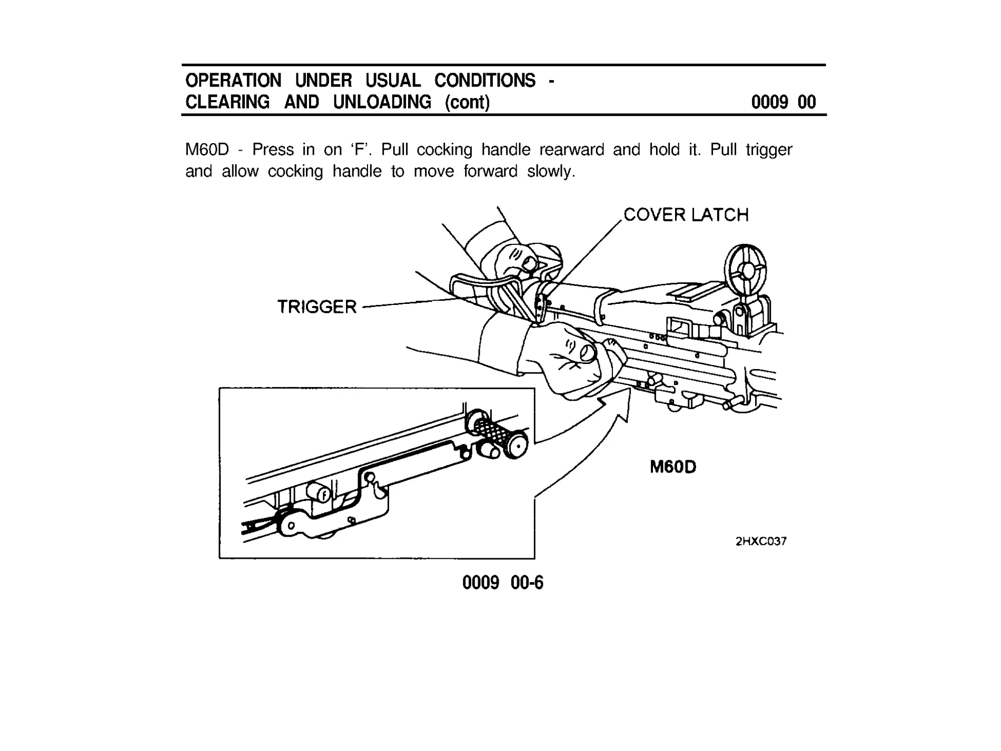
M60D - Press in on ‘F ’ . Pull cocking handle rearward and hold it. Pull trigger
and allow cocking handle to move forward slowly.
0009 00-6
INITIAL ADJUSTMENTS, DAILY CHECKS,
AND SELF-TEST
FlELD ZEROING
NOTE
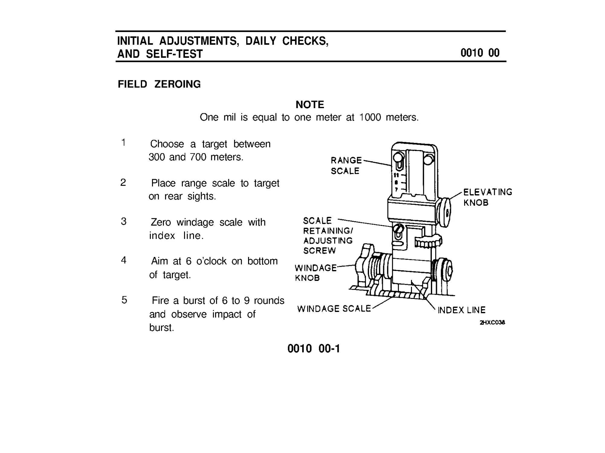
One mil is equal to one meter at 1000 meters.
0010 00
1
2
3
4
5
Choose a target between
300 and 700 meters.
Place range scale to target
on rear sights.
Zero windage scale with
index line.
Aim at 6 o’clock on bottom
of target.
Fire a burst of 6 to 9 rounds
and observe impact of
burst.
0010 00-1
INITIAL ADJUSTMENTS, DAILY CHECKS,
AND SELF-TEST (cont)
0010 00
FlELD ZEROING (cont)
6 Correct for left or right wind by adjusting windage knob. Then correct
range by adjusting elevating knob. Adjust until a burst of 6 to 9 rounds is
on target.
7 Loosen scale retaining/adjusting screw and adjust elevation scale to reflect
the range to the target.
0010 00-2
OPERATlNG PROCEDURES
0011 00
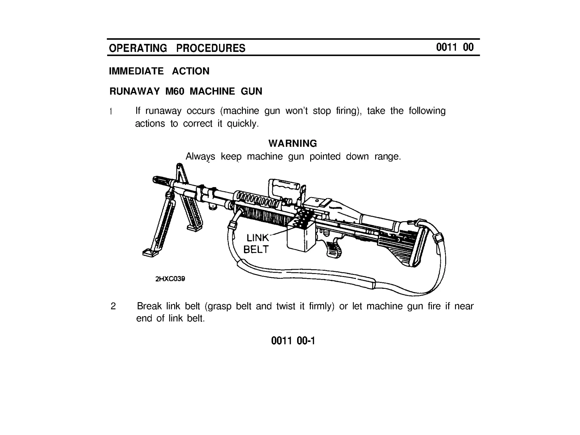
IMMEDIATE ACTION
RUNAWAY M60 MACHINE GUN
1
If runaway occurs (machine gun won’t stop firing), take the following
actions to correct it quickly.
WARNING
Always keep machine gun pointed down range.
2
Break link belt (grasp belt and twist it firmly) or let machine gun fire if near
end of link belt.
0011 00-1
OPERATlNG PROCEDURES (cont)
0011 00
IMMEDIATE ACTlON (cont)
RUNAWAY M60 MACHINE GUN (cont)
3
4
5
Pull cocking handle all the way back and hold it.Place safety to ‘S ’ and
remove link belt.
Clear machine gun (see WP 0009 00).
WARNING
Never reload a runaway machine gun until it has been repaired.
Be sure machine gun is cleared before moving it.
Notify unit maintenance for repair.
0011 00-2
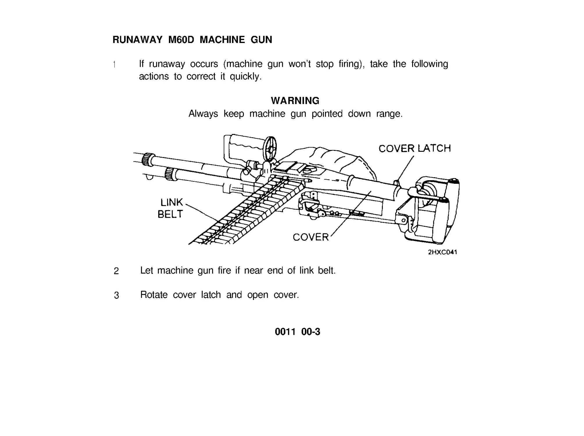
RUNAWAY M60D MACHINE GUN
1
If runaway occurs (machine gun won’t stop firing), take the following
actions to correct it quickly.
WARNING
Always keep machine gun pointed down range.
2
Let machine gun fire if near end of link belt.
3 Rotate cover latch and open cover.
0011 00-3
OPERATING PROCEDURES (cont)
IMMEDIATE ACTION (cont)
RUNAWAY M60 MACHINE GUN (cont)
4 Clear machine gun (see WP 0009 00).
0011 00
WARNING
Never reload a runaway machine gun until it has been repaired.
Be sure machine gun is cleared before removing it from mount.
5 Notify unit maintenance for repairs.
0011 00-4
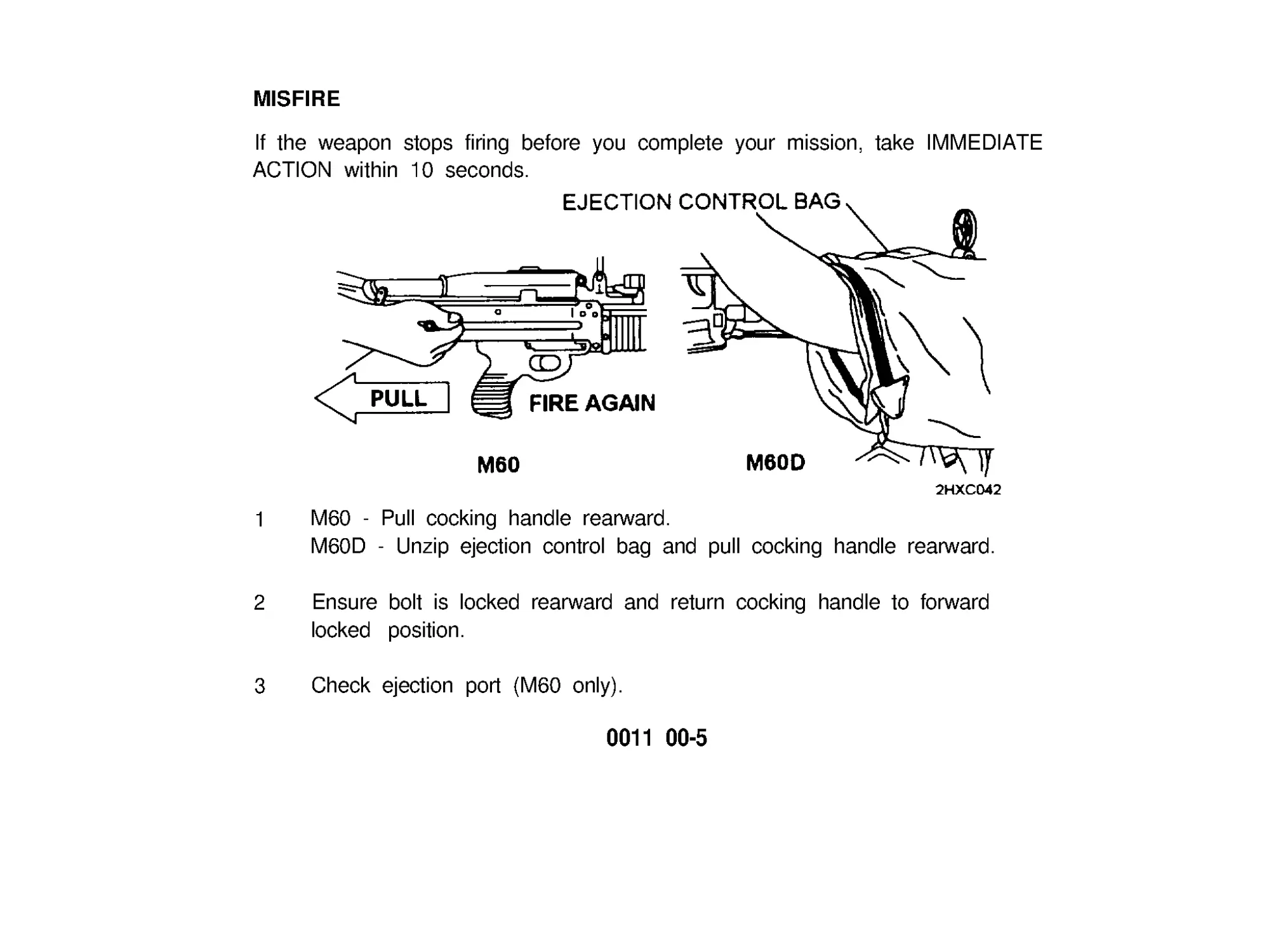
1 M60 - Pull cocking handle rearward.
M60D - Unzip ejection control bag and pull cocking handle rearward.
MlSFlRE
If the weapon stops firing before you complete your mission, take IMMEDIATE
ACTION within 10 seconds.
2
Ensure bolt is locked rearward and return cocking handle to forward
locked position.
3 Check ejection port (M60 only).
0011 00-5
OPERATING PROCEDURES (cont)
0011 00
MISFIRE (cont)
4
If a round or cartridge case is ejected, attempt to fire again.
WARNING
If cover is opened on a hot cartridge (hot barrel), an open-cover
cookoff could occur and result in serious injury or death. Close
cover and evacuate area for 15 minutes.
The climate temperature in different regions will make a difference
as to what constitutes a hot gun. A hot, sunny day can cause a
cookoff within 50 rounds, weapon and ammunition in sun.
5 If nothing is ejected and the barrel is hot enough to cause a cookoff (200
rounds fired within 2 minutes), watt at least 15 minutes (make sure bolt is
locked rearward). Repeat steps for IMMEDIATE ACTION.
6 If IMMEDIATE ACTION fails to remove cartridge case, take REMEDIAL
ACTION.
0011 00-6
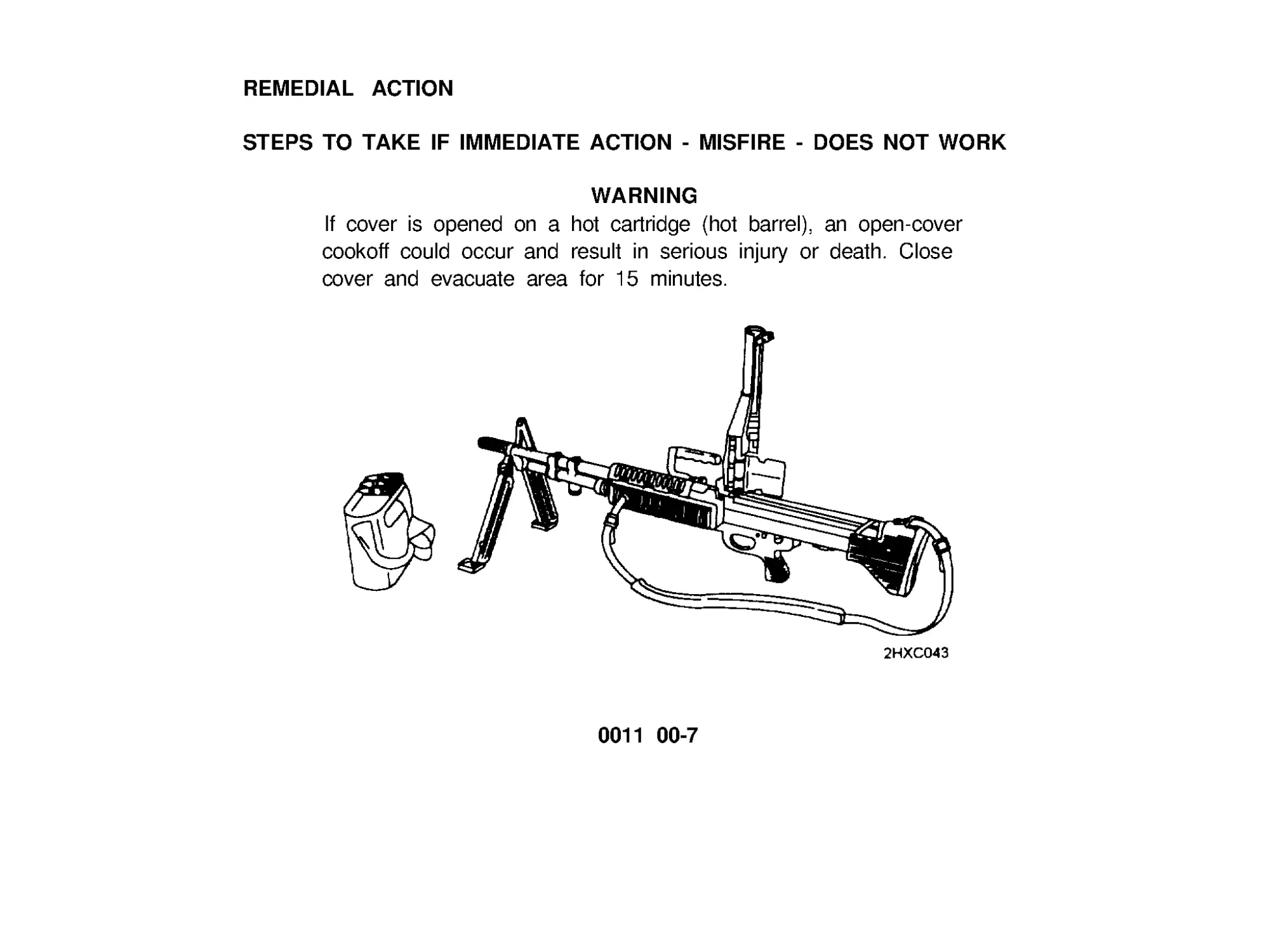
REMEDIAL ACTlON
STEPS TO TAKE IF IMMEDIATE ACTlON - MlSFlRE - DOES NOT WORK
WARNING
If cover is opened on a hot cartridge (hot barrel), an open-cover
cookoff could occur and result in serious injury or death. Close
cover and evacuate area for 15 minutes.
0011 00-7
OPERATlNG PROCEDURES (cont)
REMEDIAL ACTION (cont)
1
2
3
4
5
6
0011 00
Keep weapon on target (down range/impact area). Clear weapon when
barrel is cool (after 15 minutes wait) using the following steps.
Pull cocking handle rearward locking bolt to the rear. Return charging
handle to forward locked position.
If a round is not ejected:
M60 - Place safety to ‘S’.
M60D - Press in on ‘S’.
Open cover, remove ammunition link belt and raise feed tray.
Inspect receiver, chamber, ejector, and ammunition.
If a round is in chamber, lower feed tray and close cover.
0011 00-8
7 M60 - Place safety to ‘F’.
M60D - Press in on ‘F’.
6 Attempt to fire.
9 If a round is fired and ejected, reload and continue to fire.
10 If weapon does not fire or eject, clear and unload weapon, and notify
unit maintenance for repair.
0011 00-9/10 blank
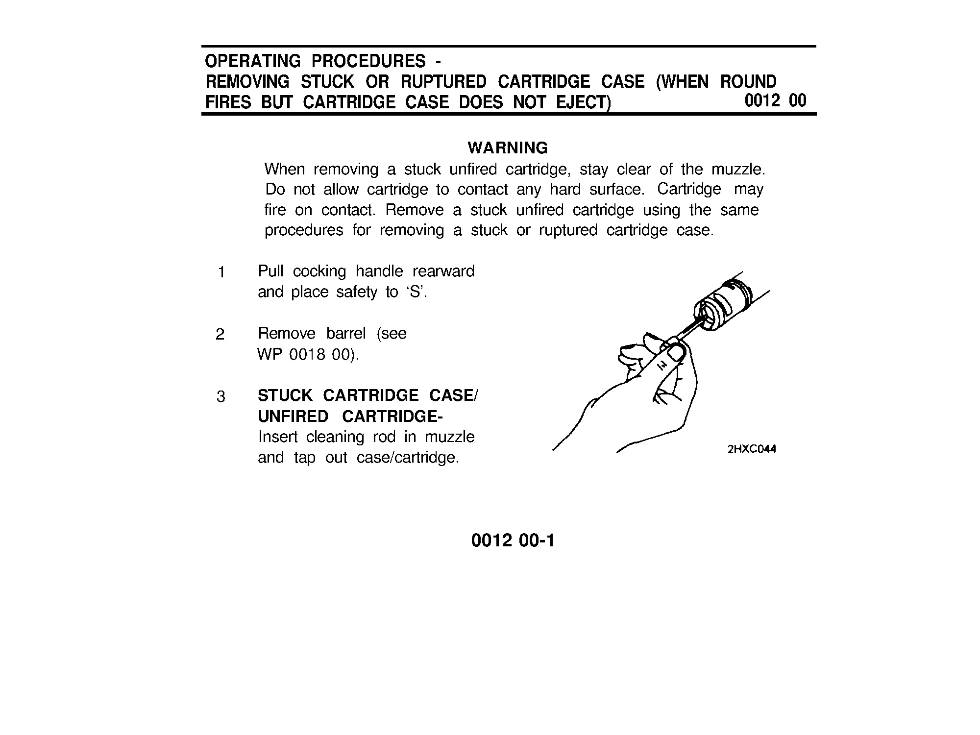
OPERATING PROCEDURES -
REMOVING STUCK OR RUPTURED CARTRIDGE CASE (WHEN ROUND
FlRES BUT CARTRIDGE CASE DOES NOT EJECT)
0012 00
WARNING
When removing a stuck unfired cartridge, stay clear of the muzzle.
Do not allow cartridge to contact any hard surface. Cartridge may
fire on contact. Remove a stuck unfired cartridge using the same
procedures for removing a stuck or ruptured cartridge case.
1 Pull cocking handle rearward
and place safety to ‘S’ .
2 Remove barrel (see
WP 0018 00).
3 STUCK CARTRIDGE CASE/
UNFlRED CARTRIDGE-
Insert cleaning rod in muzzle
and tap out case/cartridge.
0012 00-1
OPERATlNG PROCEDURES -
REMOVlNG STUCK OR RUPTURED CARTRIDGE CASE (WHEN ROUND
FlRES BUT CARTRIDGE CASE DOES NOT EJECT) (cont)
0012 00
3 RUPTURED CARTRIDGE CASE (cont)
a.
Push ruptured cartridge extractor inside ruptured case in chamber
until it seats.
b. Lightly tap out with cleaning rod.
c.
d.
Remove extractor from cartridge case.
Unscrew extractor tool and remove cartridge case. Reassemble
extractor tool.
0012 00-2
4 Install barrel (see WP 0018 00).
5 Close cover.
6 Hold cocking handle rearward.
7
Place safety to ‘F ’ .
8 Pull trigger and ease cocking handle forward.
9 Once weapon is cleared, do not place safety to ‘S’ when bolt is forward.
Leave safety at ‘F’ .
0012 00-3/4 blank
OPERATION OF AUXILIARY EQUIPMENT
0013 00
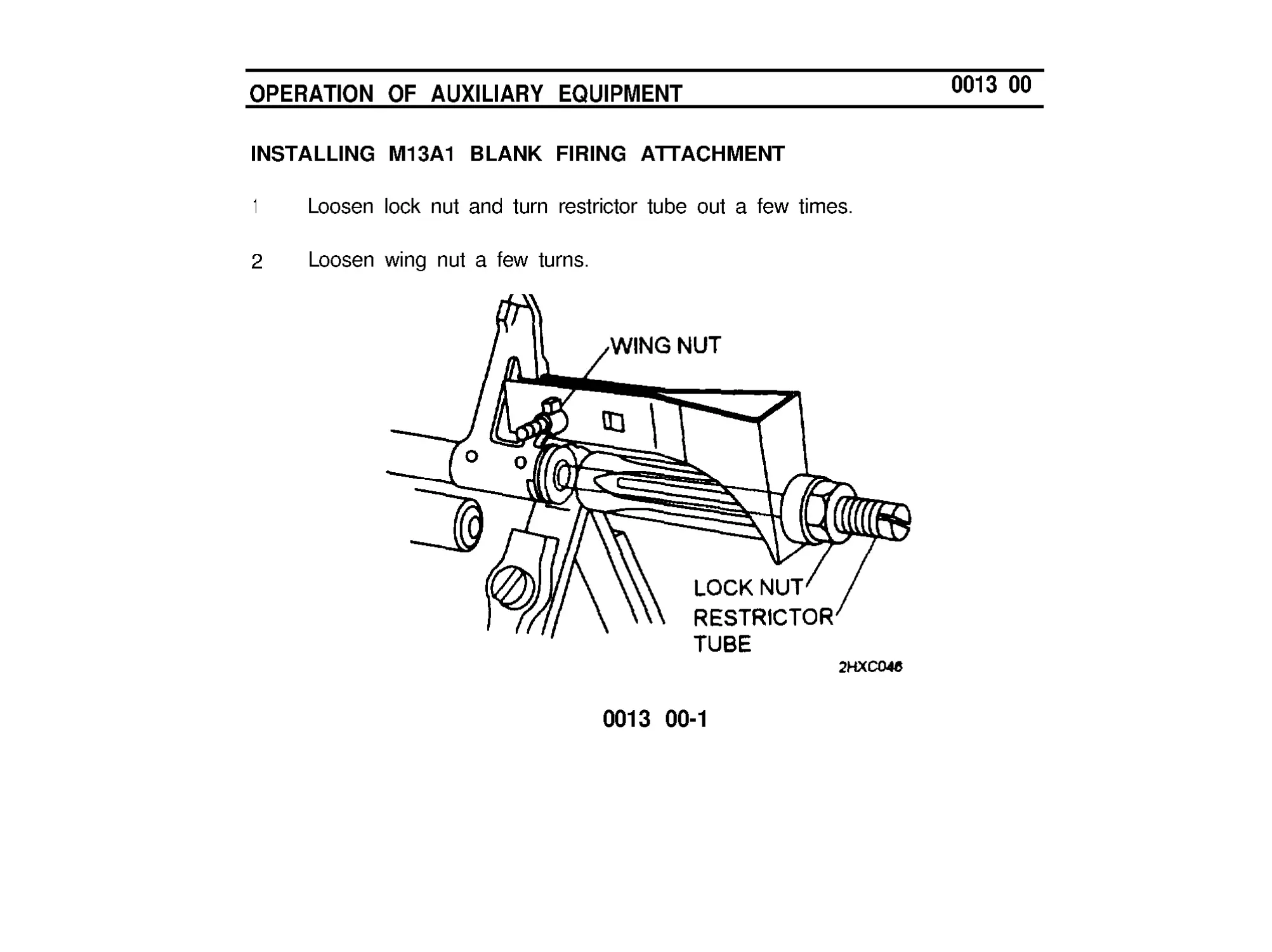
INSTALLING M13A1 BLANK FlRlNG ATTACHMENT
1
Loosen lock nut and turn restrictor tube out a few times.
2 Loosen wing nut a few turns.
0013 00-1
OPERATION OF AUXILIARY EQUIPMENT (cont)
0013 00
INSTALLING M13A1 BLANK FIRING ATTACHMENT (cont)
3 Slide restrictor tube in flash suppressor as far as possible,
4 Clamp blank firing attachment around front sight.
5 Tighten wing nut fingertight.
6 Screw restrictor tube in until it seats tight against muzzle end of barrel to
prevent gas leakage.
7 Tighten lock nut.
NOTE
After Firing 500 Blank Rounds: Clean gun including barrel
assembly, gas cylinder, gas piston, gas port, chamber bore, and
Blank Firing Attachment (BFA).
0013 00-2
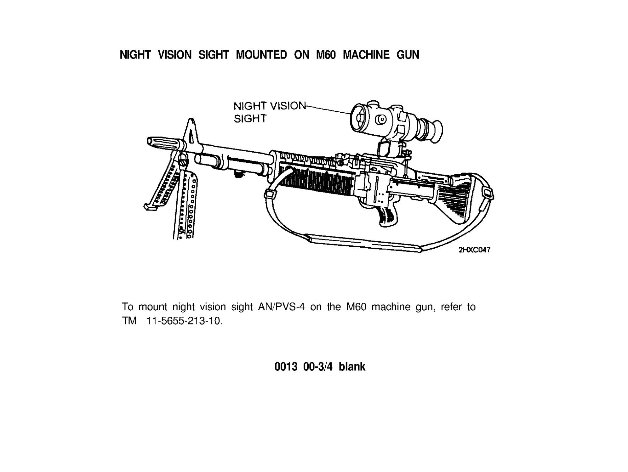
NIGHT VISION SIGHT MOUNTED ON M60 MACHINE GUN
To mount night vision sight AN/PVS-4 on the M60 machine gun, refer to
TM 11-5655-213-10.
0013 00-3/4 blank
PREPARATION FOR MOVEMENT
Refer to FM 23-67.
0014 00
0014 00-1/2 blank
OPERATION UNDER UNUSUAL CONDlTlONS
0015 00
Under unusual conditions, clean and lubricate machine gun more often.
HOT, DUSTY, AND SANDY AREAS. Clean often. Wipe oil from exposed
surfaces with clean wiping rag (item 5, WP 0039 00). Cover weapon as much
as possible to keep dust and sand out of parts.
HOT, WET CLIMATE. Inspect often. Dry, clean, and lubricate lightly as
necessary.
EXTREMELY COLD CLIMATE. Keep free of moisture. Lightly oil with LAW
(item 3, WP 0039 00).
AFTER EXPOSURE TO WATER. Disassemble, clean, oil and reassemble as
soon as possible. Make sure it’s dry.
NUCLEAR, BIOLOGICAL, AND CHEMICAL (NBC) DECONTAMINATION.
Decontamination procedures can be found in FM 3-5 .
0015 00-1/2 blank
CHAPTER 3
MAINTENANCE INSTRUCTIONS
LUBRlCATION INSTRUCTlONS
0016 00
LUBE GUIDE
Under all but the coldest arctic conditions, LSA (item 4, WP 0039 00), and CLP
(item 1, WP 0039 00) are the lubricants to use on your machine gun.
Remember to remove excessive oil from the bore before firing.
.
Lightly Lubricate. A film of lubricant barely visible to the eye.
.
Generously Lubricate. Heavy enough so lubricant can be spread with
finger.
NOTE
Lubrication instructions are mandatory. Do not mix lubricants on
the same machine gun. The weapon must be thoroughly cleaned
during change from one lubricant to another. Dry cleaning solvent
(available to unit maintenance) is recommended for cleaning
during change from one lubricant to another.
0016 00-1
LUBRICATION INSTRUCTIONS (cont)
0016 00
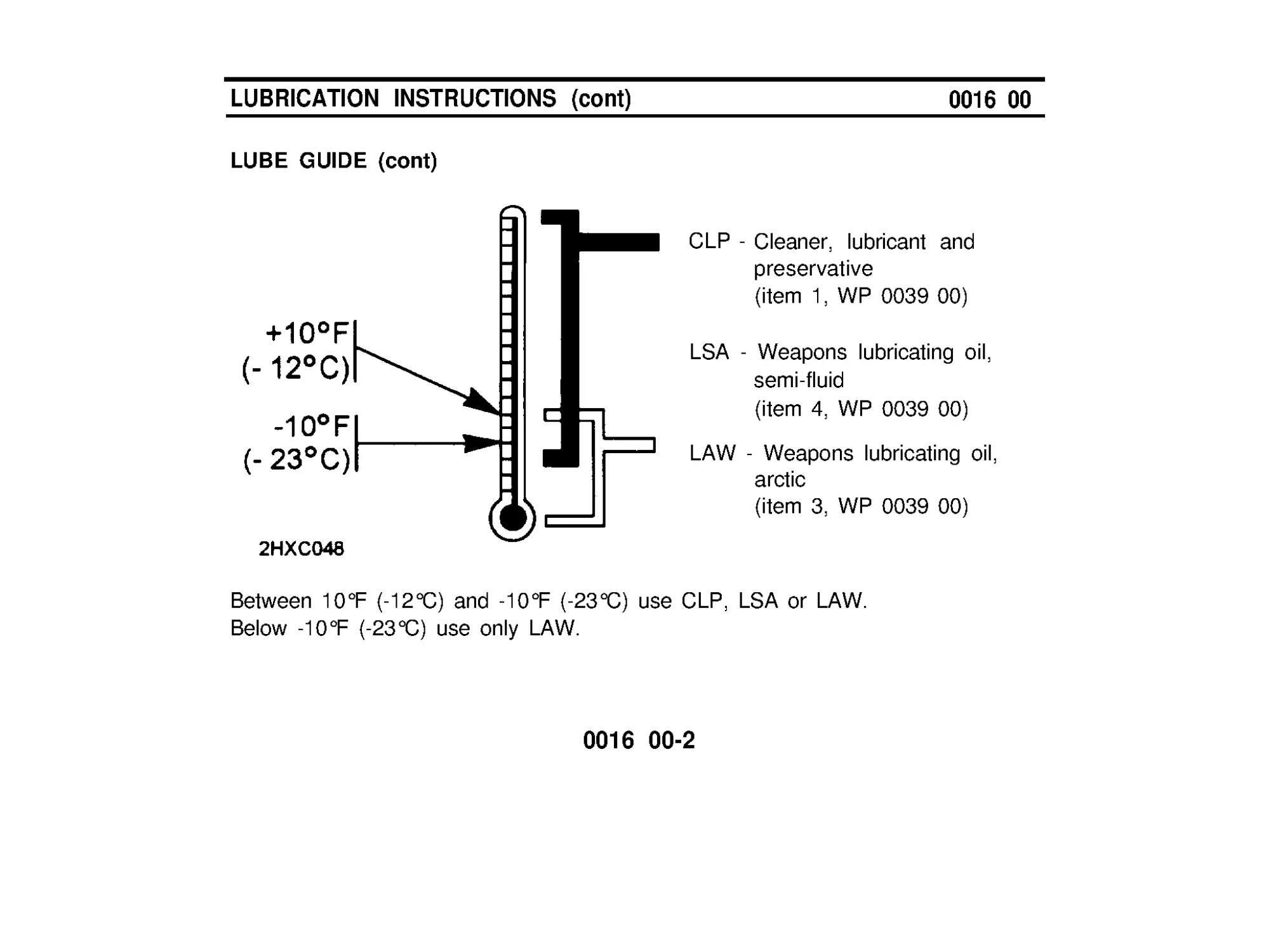
LUBE GUIDE (cont)
CLP -Cleaner, lubricant and
preservative
(item 1, WP 0039 00)
LSA - Weapons lubricating oil,
semi-fluid
(item 4, WP 0039 00)
LAW - Weapons lubricating oil,
arctic
(item 3, WP 0039 00)
Between 10°F (-12°C) and -10°F (-23°C) use CLP, LSA or LAW.
Below -10°F (-23°C) use only LAW.
0016 00-2
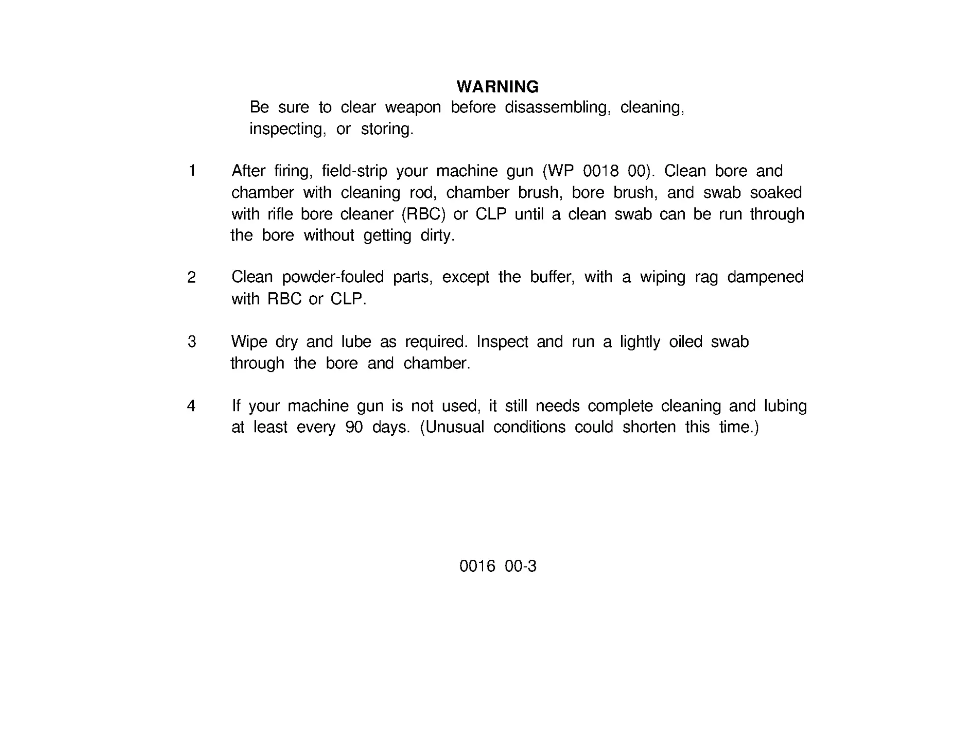
WARNING
Be sure to clear weapon before disassembling, cleaning,
inspecting, or storing.
1 After firing, field-strip your machine gun (WP 0018 00). Clean bore and
chamber with cleaning rod, chamber brush, bore brush, and swab soaked
with rifle bore cleaner (RBC) or CLP until a clean swab can be run through
the bore without getting dirty.
2
Clean powder-fouled parts, except the buffer, with a wiping rag dampened
with RBC or CLP.
3 Wipe dry and lube as required. Inspect and run a lightly oiled swab
through the bore and chamber.
4
If your machine gun is not used, it still needs complete cleaning and lubing
at least every 90 days. (Unusual conditions could shorten this time.)
0016 00-3
LUBRlCATlON INSTRUCTIONS (cont)
0016 00
LUBE GUIDE (cont)
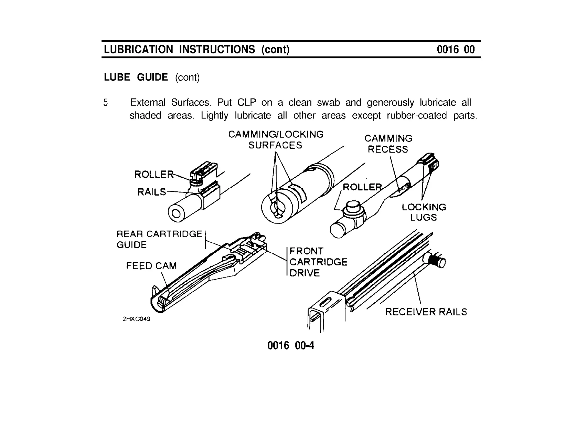
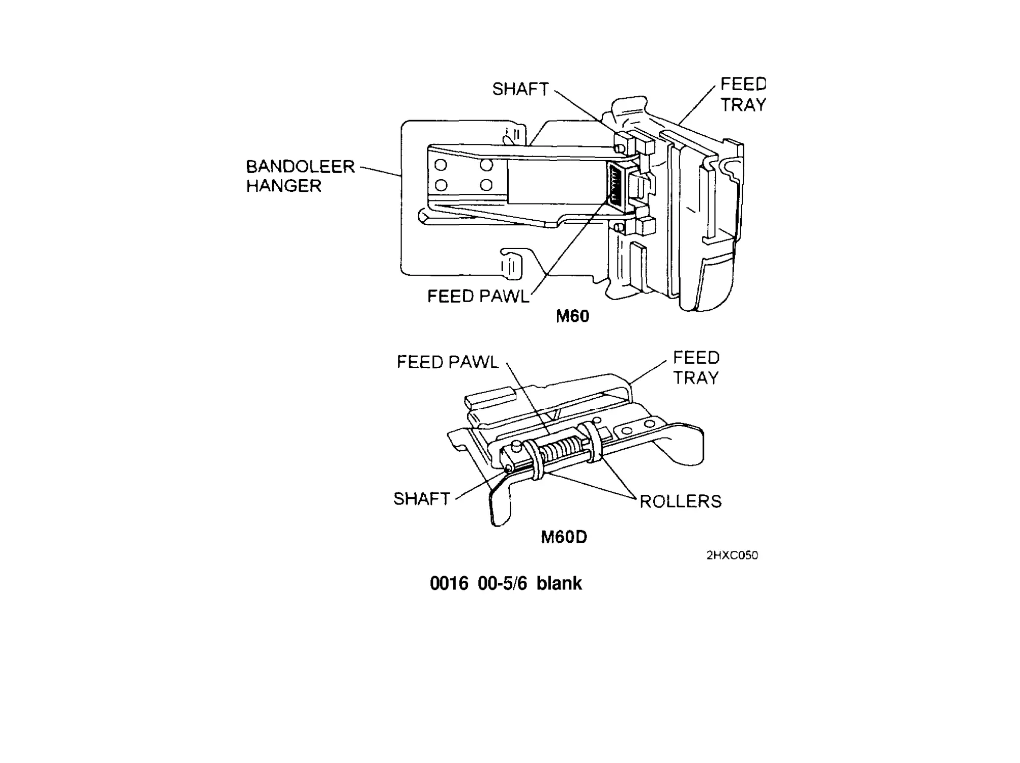
5
External Surfaces. Put CLP on a clean swab and generously lubricate all
shaded areas. Lightly lubricate all other areas except rubber-coated parts.
0016 00-4
0016 00-5/6 blank
TROUBLESHOOTING PROCEDURES
0017 00
INTRODUCTION
The table lists the common malfunctions which you may find during the
operation or maintenance of the machine gun or its components. You should
perform the tests/inspections and corrective actions in the order listed.
This manual cannot list all malfunctions that may occur nor all tests or
inspections and corrective actions. If a malfunction is not listed or is not
corrected by listed corrective actions, notify your supervisor.
TROUBLESHOOTING
WARNING
Keep weapon pointed at target impact area. Never stand in front
of weapon or expose body or hands to breech, ejection port, or
muzzle.
0017 00-1
TROUBLESHOOTING PROCEDURES (cont)
MALFUNCTION
TEST OR INSPECTION
COOKOFF*
Hot barrel
0017 00
CORRECTIVE ACTION
If you have tired 200 or more rounds
within 2 minutes (rapid rate of tire),
barrel will be hot enough to cause
cookoff.
Cool weapon for 15
minutes.
FAILURE TO
FIRE
Check ammunition.
Replace faulty
ammunition.
Check for broken or damaged firing
pin.
Notify unit maintenance
Check for weak or broken firing pin
spring, guide assembly, or driving
spring
Notify unit maintenance
FAILURE TO
EXTRACT
Broken extractor or spring.
Notify unit maintenance
* C OOKOFF - A misfire of a chambered round caused by the weapon overheating
0017 00-2
MALFUNCTION
FAILURE TO
EXTRACT (cont)
TEST OR INSPECTION
Short recoil.
Gas piston installed backwards
Dirty ammunition or chamber.
CORRECTIVE ACTION
Clean gas port, piston, gas
cylinder, operation rod
assembly, and chamber
(see WP 0023 00).
Install correctly.
Clean chamber and/or use
new ammunition.
SLUGGISH
OPERATION
WADDING AND
UNBURNED
POWDER
FAILURE TO
CHAMBER
Friction from dirt, carbon, burrs or lack
of lubrication.
Manually charge weapon (if firing
blanks)
Ruptured cartridge case
Carbon buildup in gas cylinder
Carbon buildup in receiver assembly.
0017 00-3
Clean and lubricate or
notify unit maintenance of
any burrs.
Clean and lubricate or
notify unit maintenance.
Remove cartridge case
(WP 00012 00).
Remove carbon.
Remove carbon
TROUBLESHOOTING PROCEDURES (cont)
MALFUNCTION
TEST OR INSPECTION
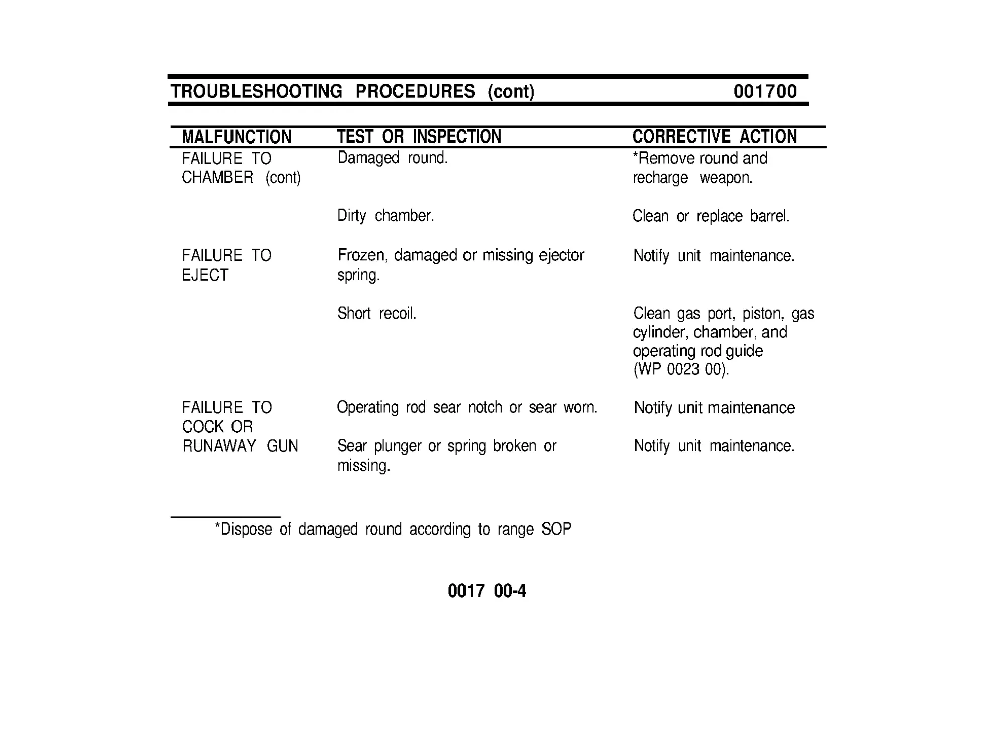
FAILURE TO
CHAMBER (cont)
Damaged round.
001700
CORRECTIVE ACTION
*Remove round and
recharge weapon.
Clean or replace barrel.
Notify unit maintenance.
Dirty chamber.
FAILURE TO
EJECT
Frozen, damaged or missing ejector
spring.
Short recoil.
FAILURE TO
COCK OR
RUNAWAY GUN
Operating rod sear notch or sear worn.
Sear plunger or spring broken or
missing.
*Dispose of damaged round according to range SOP
Clean gas port, piston, gas
cylinder, chamber, and
operating rod guide
(WP 0023 00).
Notify unit maintenance
Notify unit maintenance.
0017 00-4
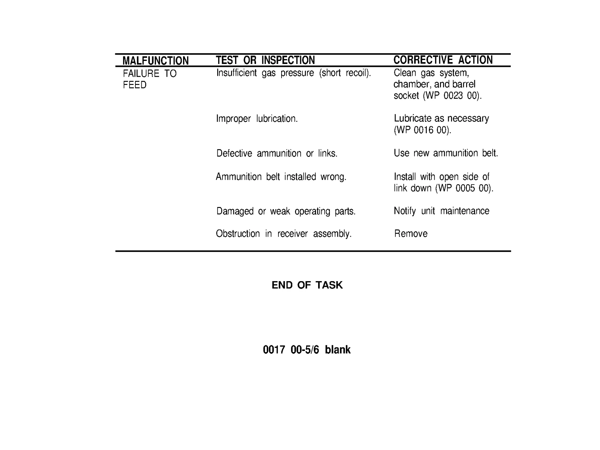
MALFUNCTION
FAILURE TO
FEED
TEST OR INSPECTION
Insufficient gas pressure (short recoil).
CORRECTIVE ACTION
Clean gas system,
chamber, and barrel
socket (WP 0023 00).
Improper lubrication.
Lubricate as necessary
(WP 0016 00).
Defective ammunition or links.
Ammunition belt installed wrong.
Use new ammunition belt.
Install with open side of
link down (WP 0005 00).
Damaged or weak operating parts.
Notify unit maintenance
Obstruction in receiver assembly.
Remove
END OF TASK
0017 00-5/6 blank
FIELD-STRIPPING MACHINE GUN
0018 00
M60 SHOULDER GUN STOCK
WARNING
Before field stripping, clear the weapon and check that the bolt
is in forward position.
NOTE
The following procedures illustrate the M60 machine gun except
where M60 parts differ from M60D pans, then both weapons are
illustrated.
1
Lift shoulder rest (1), insert
cleaning rod (2) in hole to
release latch. Pull shoulder
gun stock (3) from receiver.
2 Turn latch lever (4) and
open cover.
0018 00-1
FlELD-STRlPPlNG MACHINE GUN (cont)
0018 00
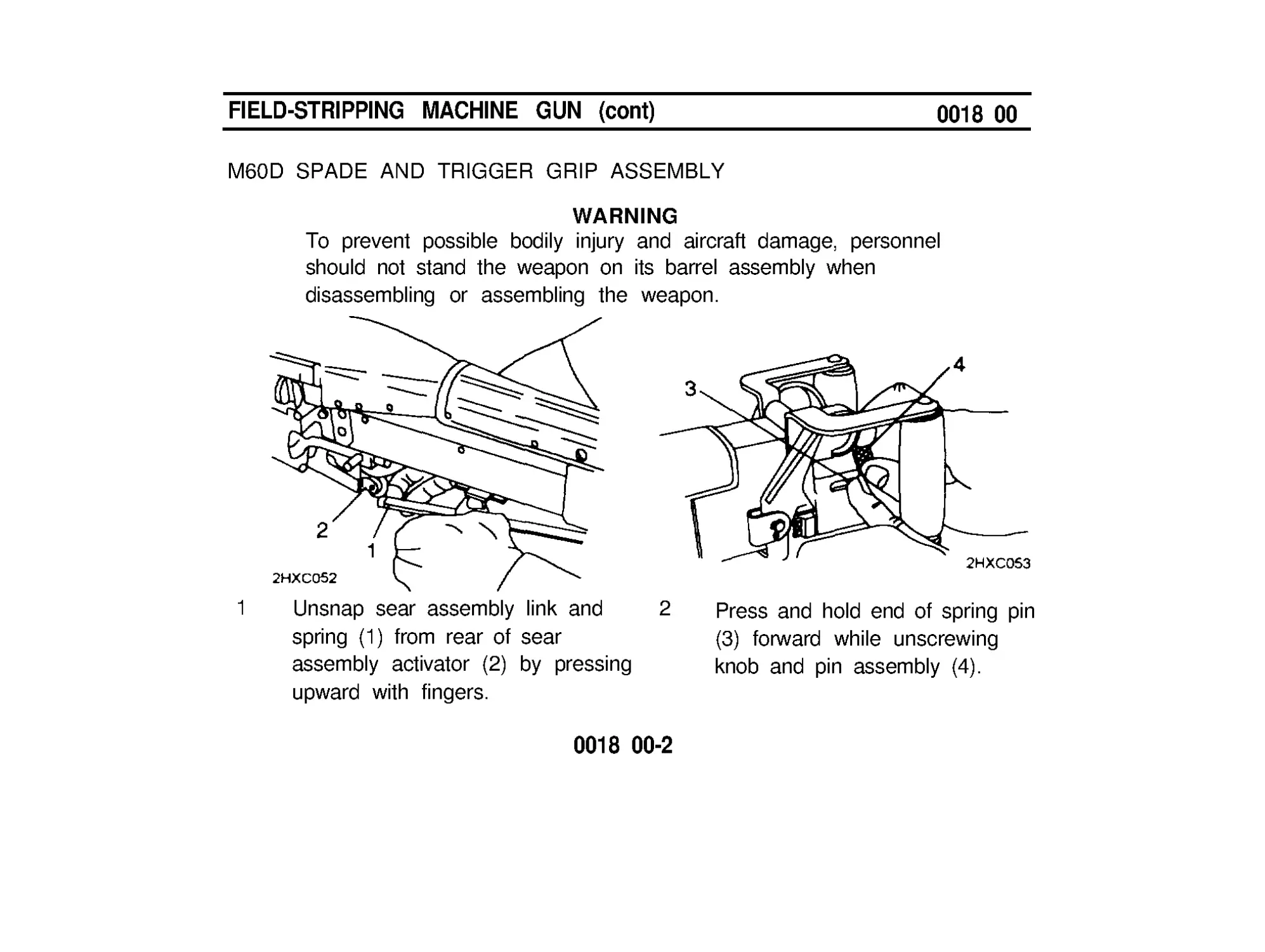
M60D SPADE AND TRIGGER GRIP ASSEMBLY
WARNING
To prevent possible bodily injury and aircraft damage, personnel
should not stand the weapon on its barrel assembly when
disassembling or assembling the weapon.
1 Unsnap sear assembly link and
2 Press and hold end of spring pin
spring (1) from rear of sear
(3) forward while unscrewing
assembly activator (2) by pressing
knob and pin assembly (4).
upward with fingers.
0018 00-2
3 Remove grip and trigger assembly (5) and dust and moisture boot (6).
4 Turn latch lever (7) and open cover.
0018 00-3
FlELD-STRlPPlNG MACHINE GUN (cont)
0018 00
BOLT ASSEMBLY AND OPERATlNG ROD ASSEMBLY
1
Apply slight palm pressure to rear
of hydraulic buffer assembly (1).
Lift out buffer retaining yoke (2)
and remove buffer assembly (1).
2
Remove guide assembly (3) and drive spring (4).
0018 00-4
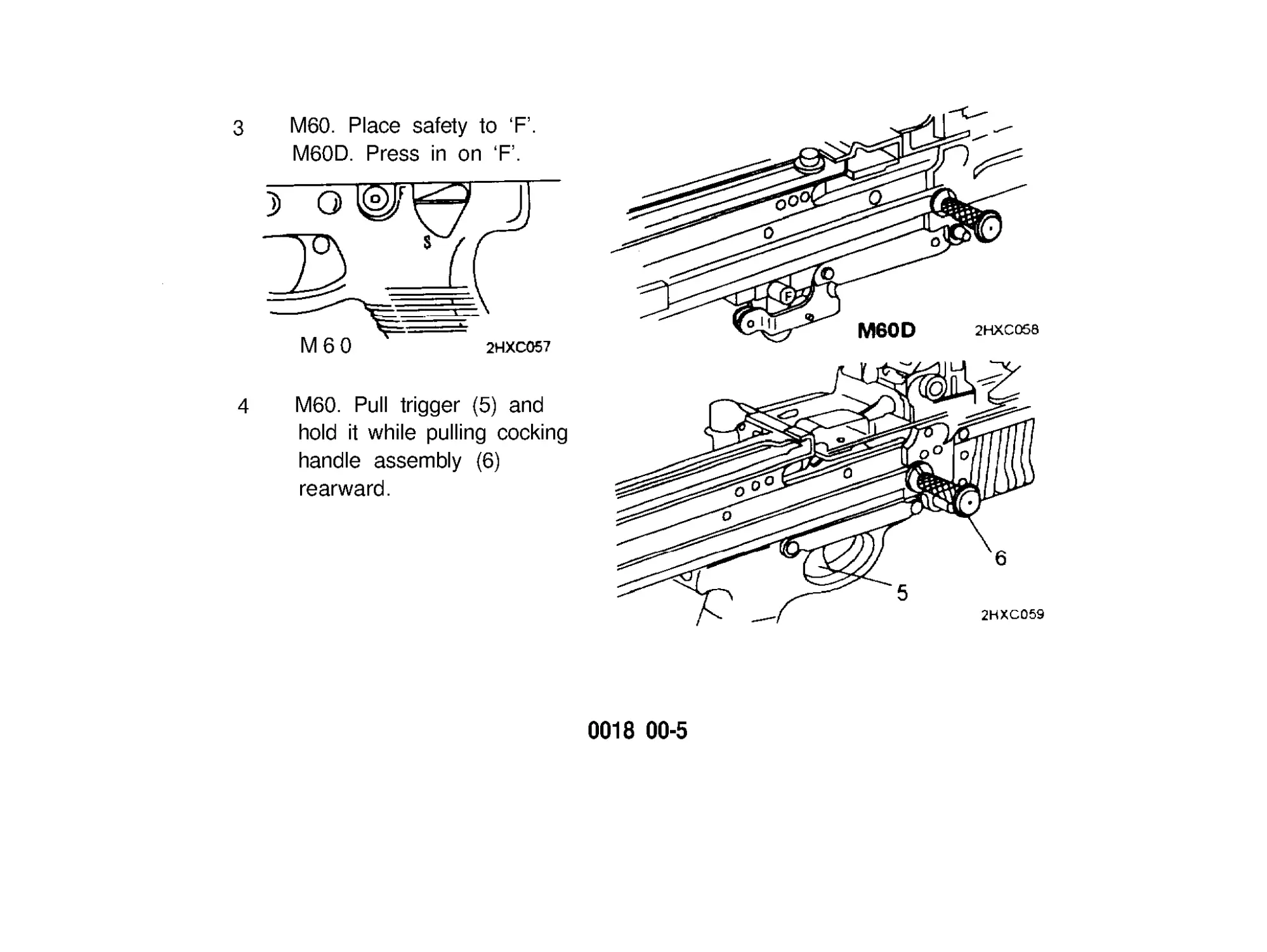
3 M60. Place safety to ‘F ’ .
M60D. Press in on ‘F ’.
M60
4 M60. Pull trigger (5) and
hold it while pulling cocking
handle assembly (6)
rearward.
0018 00-5
FIELD-STRIPPING MACHINE GUN (cont)
0018 00
BOLT ASSEMBLY AND OPERATING ROD ASSEMBLY (cont)
M60 D. Pull down and hold sear
assembly activator (7) while pulling
cocking handle assembly (6) rearward.
WARNING
Bolt assembly is under spring tension; it can twist and injure your hand.
5
Removing operating rod assembly (8) and bolt assembly (9) as a unit.
0018 00-6
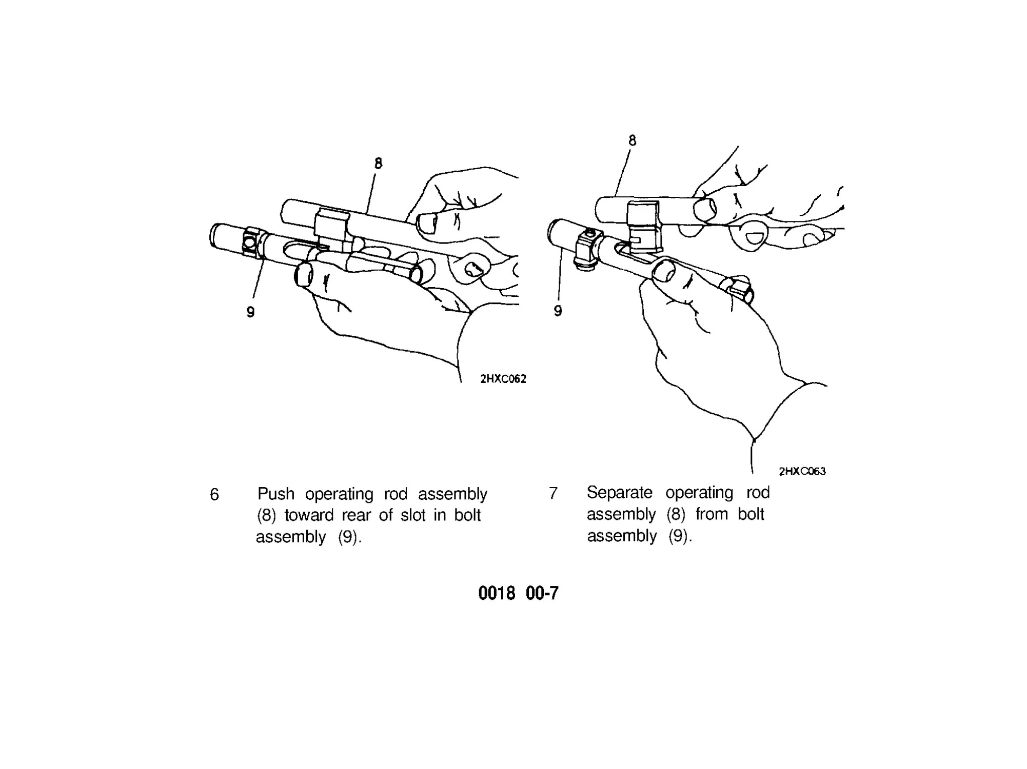
6 Push operating rod assembly
(8) toward rear of slot in bolt
assembly (9).
7 Separate operating rod
assembly (8) from bolt
assembly (9).
0018 00-7
FIELD-STRIPPING MACHINE GUN (cont)
0018 00
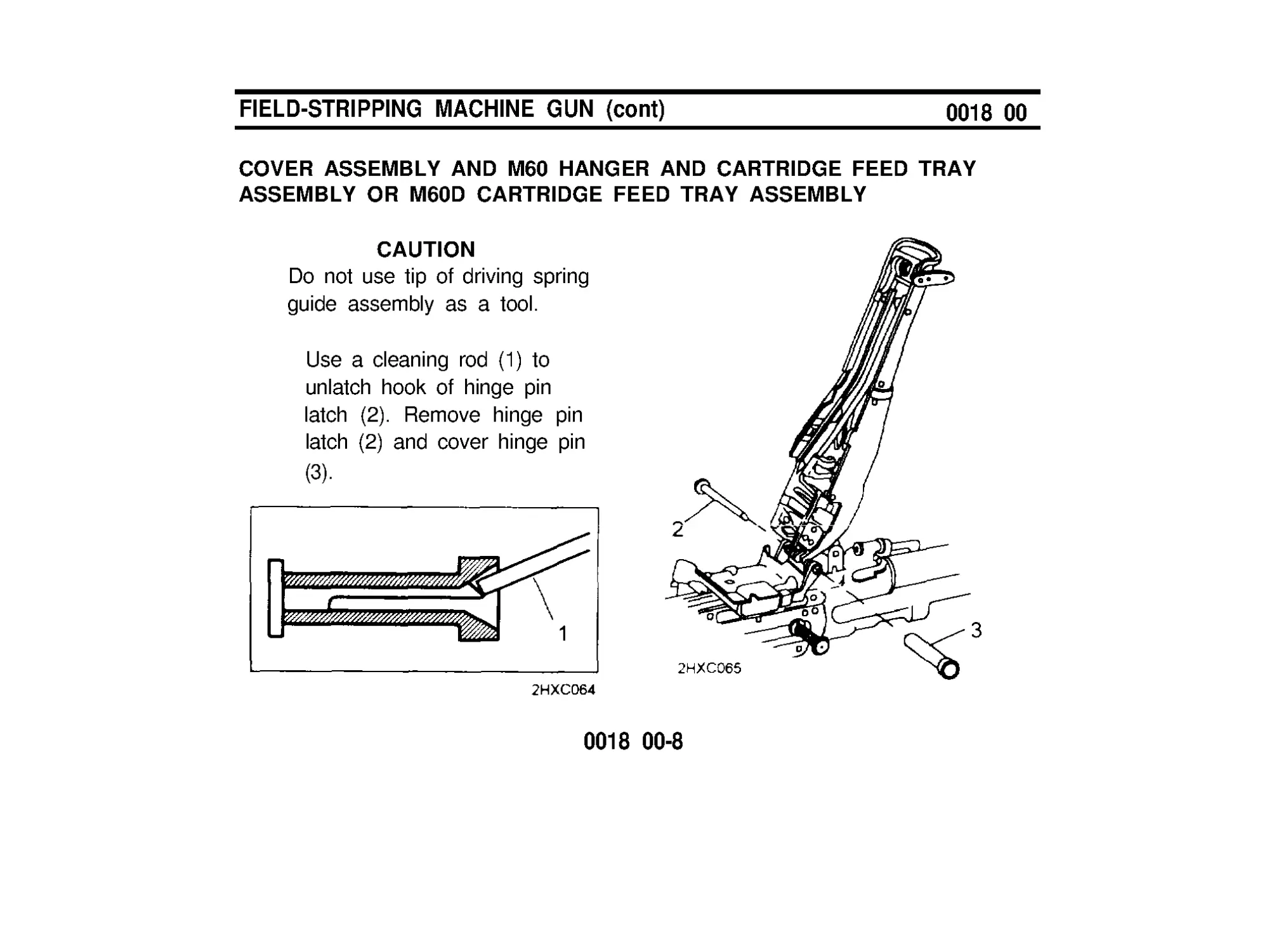
COVER ASSEMBLY AND M60 HANGER AND CARTRIDGE FEED TRAY
ASSEMBLY OR M60D CARTRIDGE FEED TRAY ASSEMBLY
CAUTION
Do not use tip of driving spring
guide assembly as a tool.
Use a cleaning rod (1) to
unlatch hook of hinge pin
latch (2). Remove hinge pin
latch (2) and cover hinge pin
(3).
0018 00-8
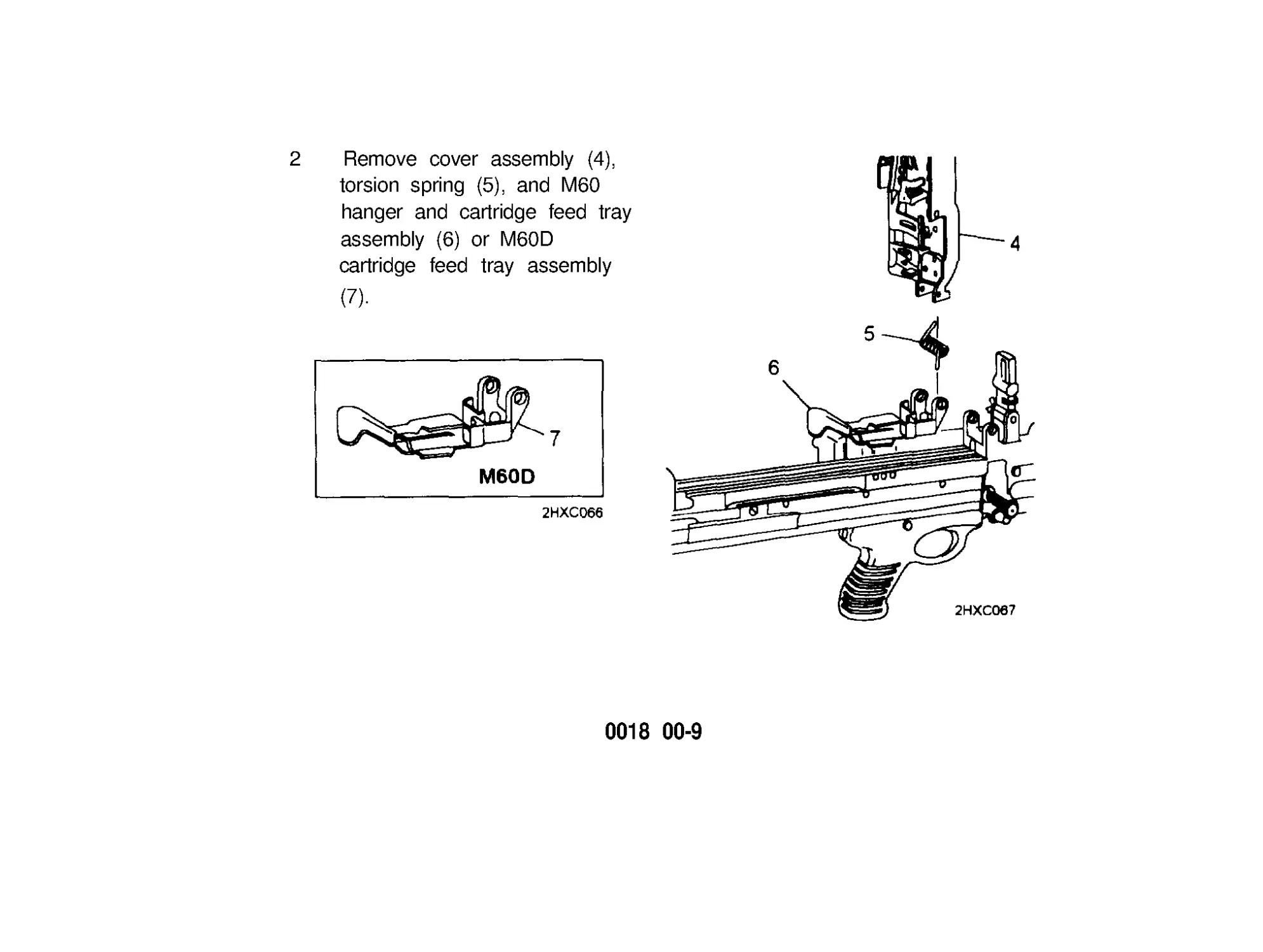
2 Remove cover assembly (4),
torsion spring (5), and M60
hanger and cartridge feed tray
assembly (6) or M60D
cartridge feed tray assembly
(7).
0018 00-9
FIELD-STRIPPING MACHINE GUN (cont)
0018 00
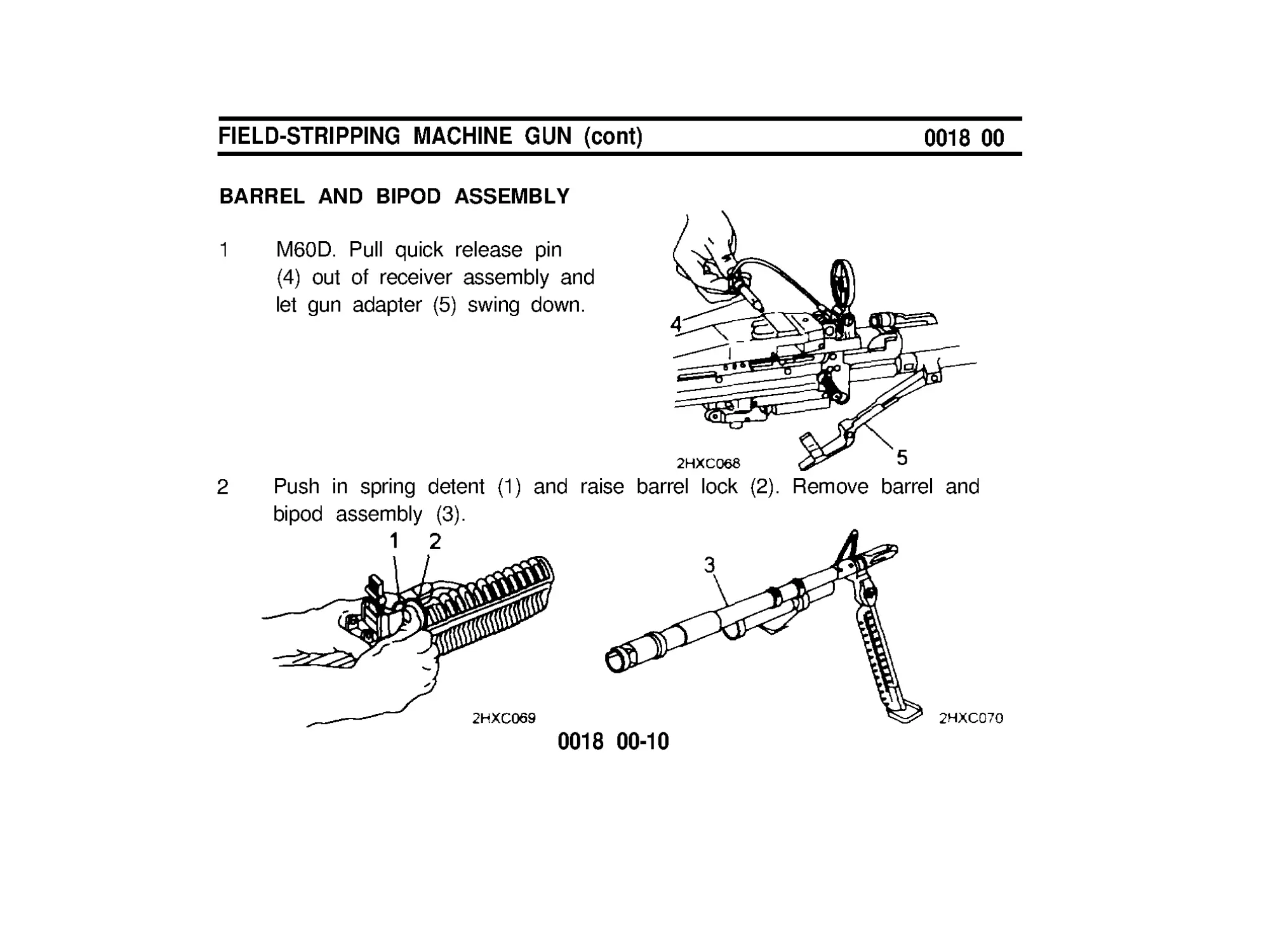
BARREL AND BIPOD ASSEMBLY
1
M60D. Pull quick release pin
(4) out of receiver assembly and
let gun adapter (5) swing down.
2 Push in spring detent (1) and raise barrel lock (2). Remove barrel and
bipod assembly (3).
0018 00-10
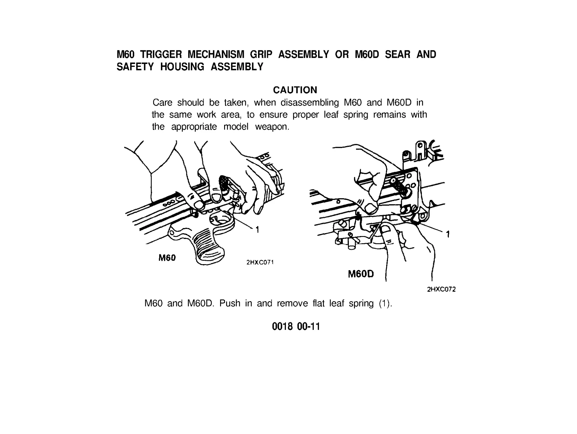
M60 TRIGGER MECHANISM GRIP ASSEMBLY OR M60D SEAR AND
SAFETY HOUSING ASSEMBLY
CAUTION
Care should be taken, when disassembling M60 and M60D in
the same work area, to ensure proper leaf spring remains with
the appropriate model weapon.
M60 and M60D. Push in and remove flat leaf spring (1).
0018 00-11
FlELD-STRIPPING MACHINE GUN (cont)
0018 00
M60 TRIGGER MECHANISM GRIP ASSEMBLY OR M60D SEAR AND
SAFETY HOUSING ASSEMBLY (cont)
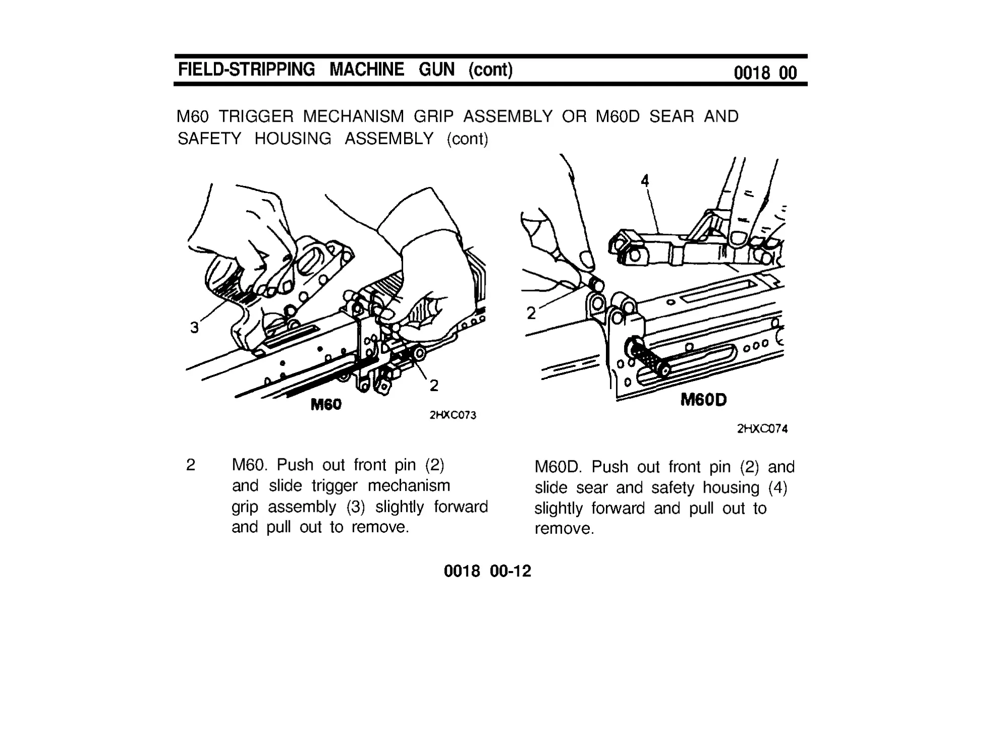
2
M60. Push out front pin (2)
and slide trigger mechanism
grip assembly (3) slightly forward
and pull out to remove.
M60D. Push out front pin (2) and
slide sear and safety housing (4)
slightly forward and pull out to
remove.
0018 00-12
FOREARM ASSEMBLY
1
Insert cleaning rod (1) or
CAUTION
combination wrench through
Be careful not to damage internal
opening in forearm assembly
ribs of forearm assembly.
(2) and push down on spring.
2
Lift and gently slide forearm
assembly (2) from receiver.
END OF TASK
0018 00-13/14 blank
MAINTENANCE OF BOLT ASSEMBLY
0019 00
INSPECT AND CLEAN
1
Inspect bolt assembly for burrs and cracks, especially in the locking lug
area.
2
Make sure roller (1) operates freely and is not cracked.
0019 00-1
MAINTENANCE OF BOLT ASSEMBLY (cont)
0019 00
INSPECT AND CLEAN (cont)
NOTE
Rotate cam actuator assembly so holes line up with headless
straight pin. Use reamer of combination wrench to remove or
replace headless straight pin.
3 Remove headless straight pin (2) and unscrew bolt plug assembly (3).
Remove cam actuator assembly (4) from breech bolt (5). Separate spring
(6), guide (7). and firing pin (8).
0019 00-2
4 Make sure spring (6) is not kinked.
5 inspect threads on bolt plug assembly (3) and in breech bolt (5) for
damage.
6 Clean powder fouling, corrosion, and dirt from all parts with CLP/RBC
(items 1 and 2,WP 0039 00).
7 Drop firing pin (8) into breech bolt (5). Assemble and drop guide (7) and
spring (6) into breech bolt (5).
8 Assemble cam actuator assembly (4) on breech bolt with roller to front.
Screw in bolt plug assembly (3) and align three holes. Insert headless
straight pin (2). Make sure cam actuator assembly (4) rotates freely when
headless straight pin (2) is fully seated.
END OF TASK
0019 00-3/4 blank
MAINTENANCE OF OPERATlNG ROD ASSEMBLY
0020 00
INSPECT AND CLEAN
1
Inspect operating rod
(1), yoke (2), sear notch
(3), and pins (4) for burrs,
cracks, and chips.
2
Make sure roller (5)
operates freely.
3
Inspect driving spring (6)
for tension, kinks, breaks,
and wear.
4 Check guide assembly (7) to make sure stop (8) is tight. If loose, notify
unit maintenance.
5 Clean powder fouling, corrosion, and dirt from all parts with CLP/RBC
(items land 2, WP 0039 00).
0020 00-1
MAINTENANCE OF OPERATlNG ROD ASSEMBLY (cont)
0020 00
INSPECT AND CLEAN (cont)
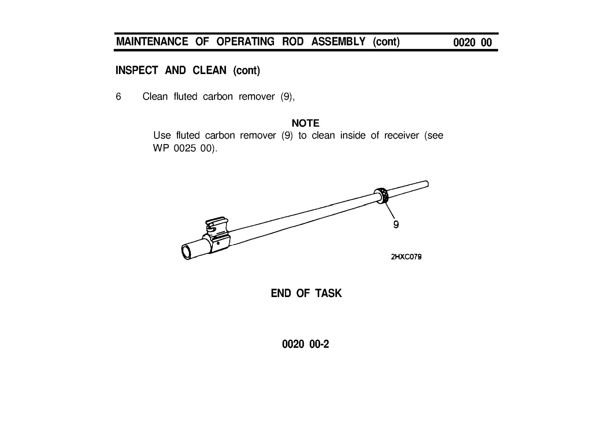
6 Clean fluted carbon remover (9),
NOTE
Use fluted carbon remover (9) to clean inside of receiver (see
WP 0025 00).
END OF TASK
0020 00-2
MAINTENANCE OF COVER ASSEMBLY
(M60 AND M60D)
0021 00
INSPECT AND CLEAN
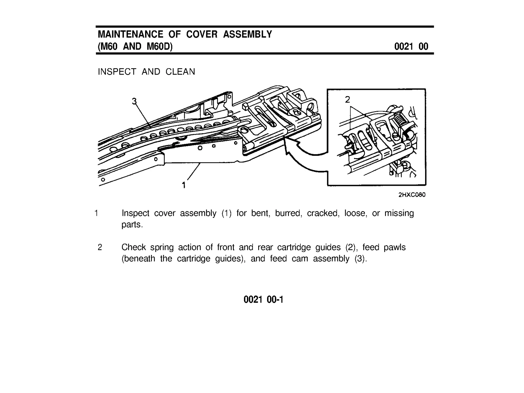
1
Inspect cover assembly (1) for bent, burred, cracked, loose, or missing
parts.
2
Check spring action of front and rear cartridge guides (2), feed pawls
(beneath the cartridge guides), and feed cam assembly (3).
0021 00-1
MAINTENANCE OF COVER ASSEMBLY
(M60 AND M60D) (cont)
0021 00
INSPECT AND CLEAN (cont)
3 Make sure feed cam assembly is secure and operates freely.
4 Clean powder fouling, corrosion, and dirt from all areas with CLP/RBC
(items 1 and 2, WP 0039 00).
END OF TASK
0021 00-2
MAINTENANCE OF M60 HANGER AND
CARTRIDGE FEED TRAY ASSEMBLY OR
M60D CARTRIDGE FEED TRAY ASSEMBLY
0022 00
INSPECT AND CLEAN
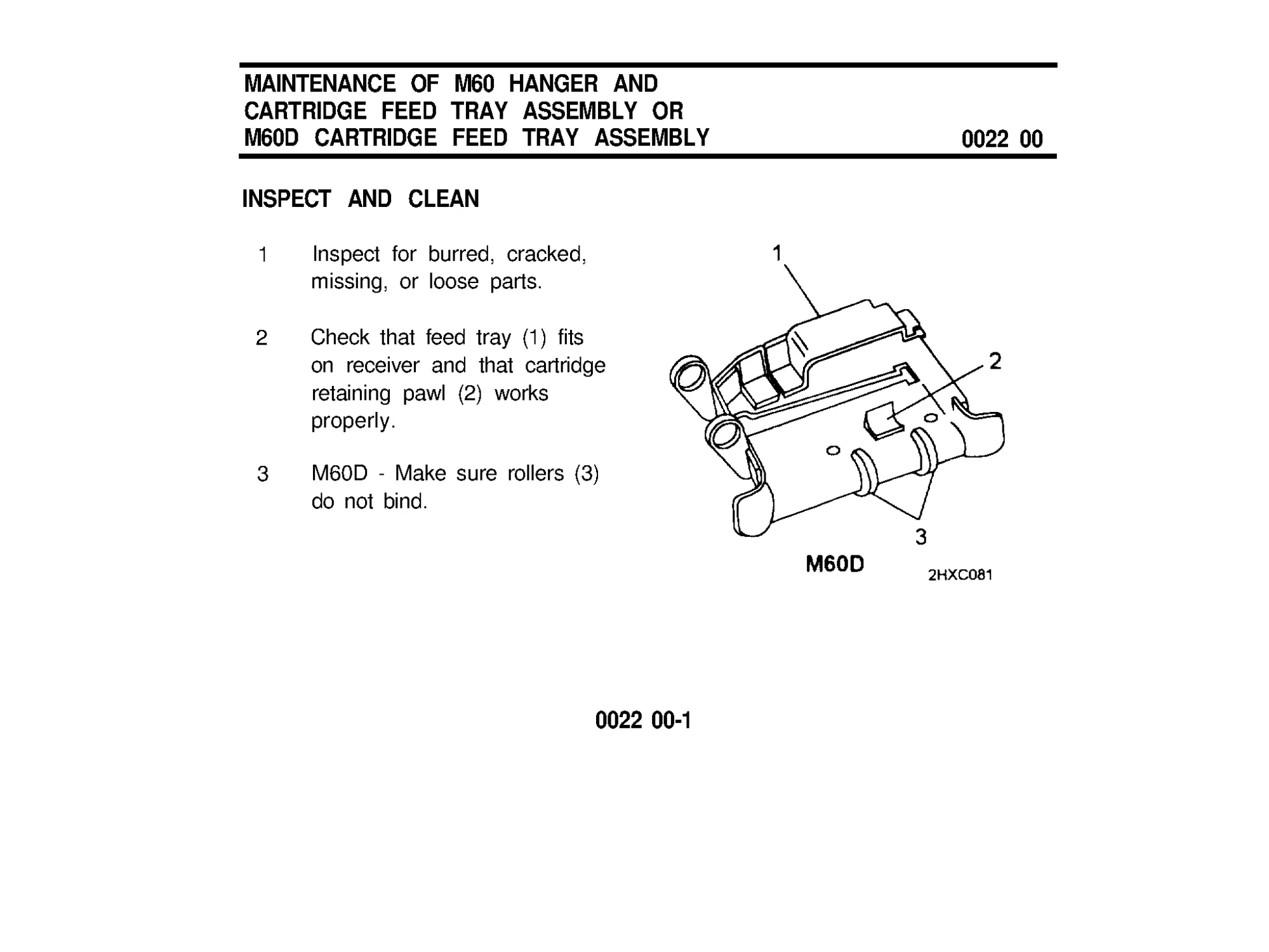
1 Inspect for burred, cracked,
missing, or loose parts.
2 Check that feed tray (1) fits
on receiver and that cartridge
retaining pawl (2) works
properly.
3 M60D - Make sure rollers (3)
do not bind.
0022 00-1
MAINTENANCE OF M60 HANGER AND
CARTRIDGE FEED TRAY ASSEMBLY OR
M60D CARTRIDGE FEED TRAY ASSEMBLY (cont)
0022 00
INSPECT AND CLEAN (cont)
4 M60 - Inspect for obstructions
in hanger (4).
5 Clean corrosion and dirt from
ail areas with CLP/RBC
(items 1 and 2, WP 0039 00).
6 Remove CLP/RBC from top
surface of feed tray (1) if gun
is to be fired.
END OF TASK
0022 00-2
MAINTENANCE OF BARREL AND
BIPOD ASSEMBLY (INCLUDING GAS SYSTEM)
0023 00
BIPOD ASSEMBLY
INSPECT AND CLEAN
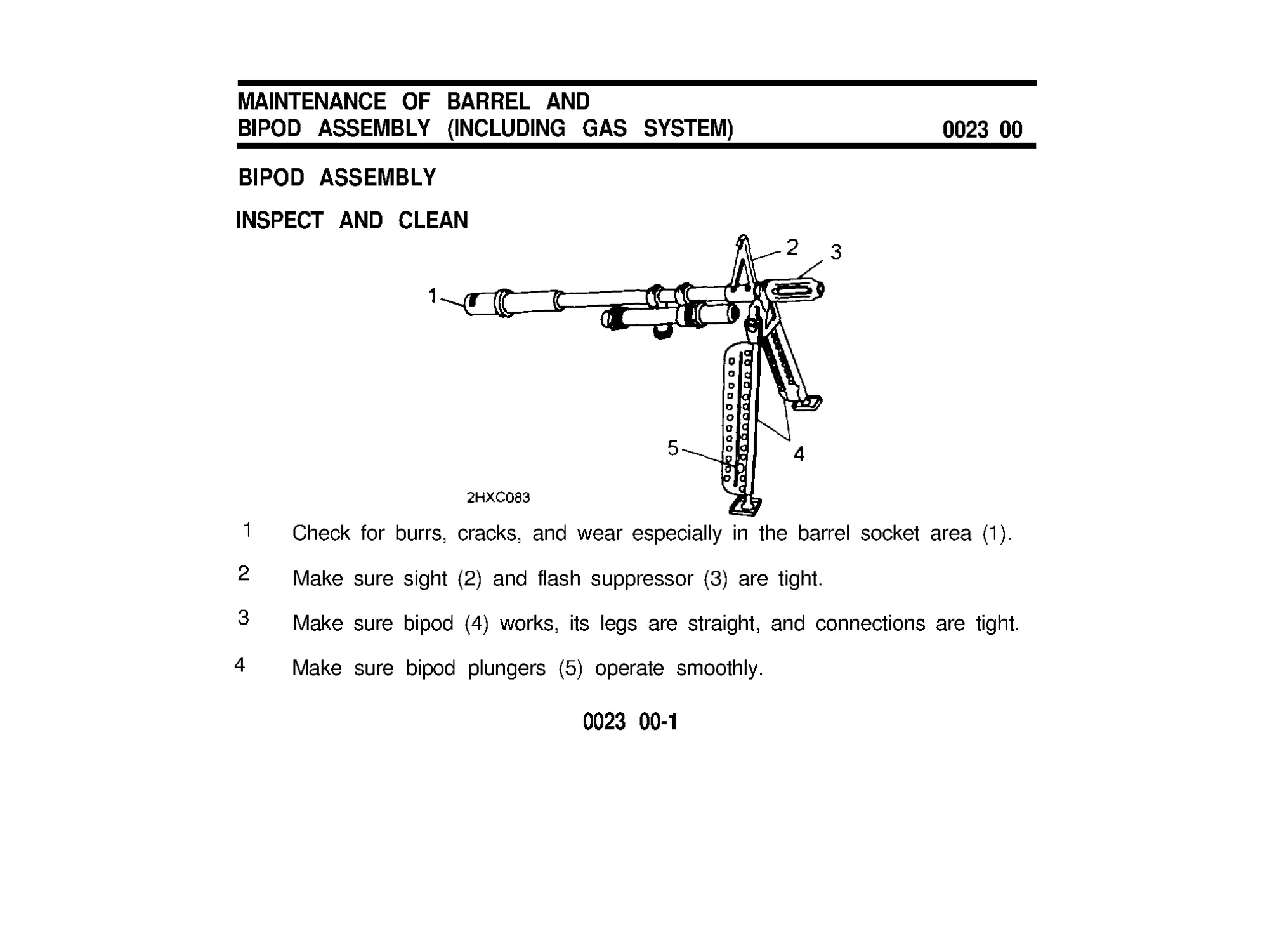
1
2
3
4
Check for burrs, cracks, and wear especially in the barrel socket area (1).
Make sure sight (2) and flash suppressor (3) are tight.
Make sure bipod (4) works, its legs are straight, and connections are tight.
Make sure bipod plungers (5) operate smoothly.
0023 00-1
MAINTENANCE OF BARREL AND
BIPOD ASSEMBLY (INCLUDING GAS SYSTEM) (cont)
0023 00
BIPOD ASSEMBLY (cont)
INSPECT AND CLEAN (cont)
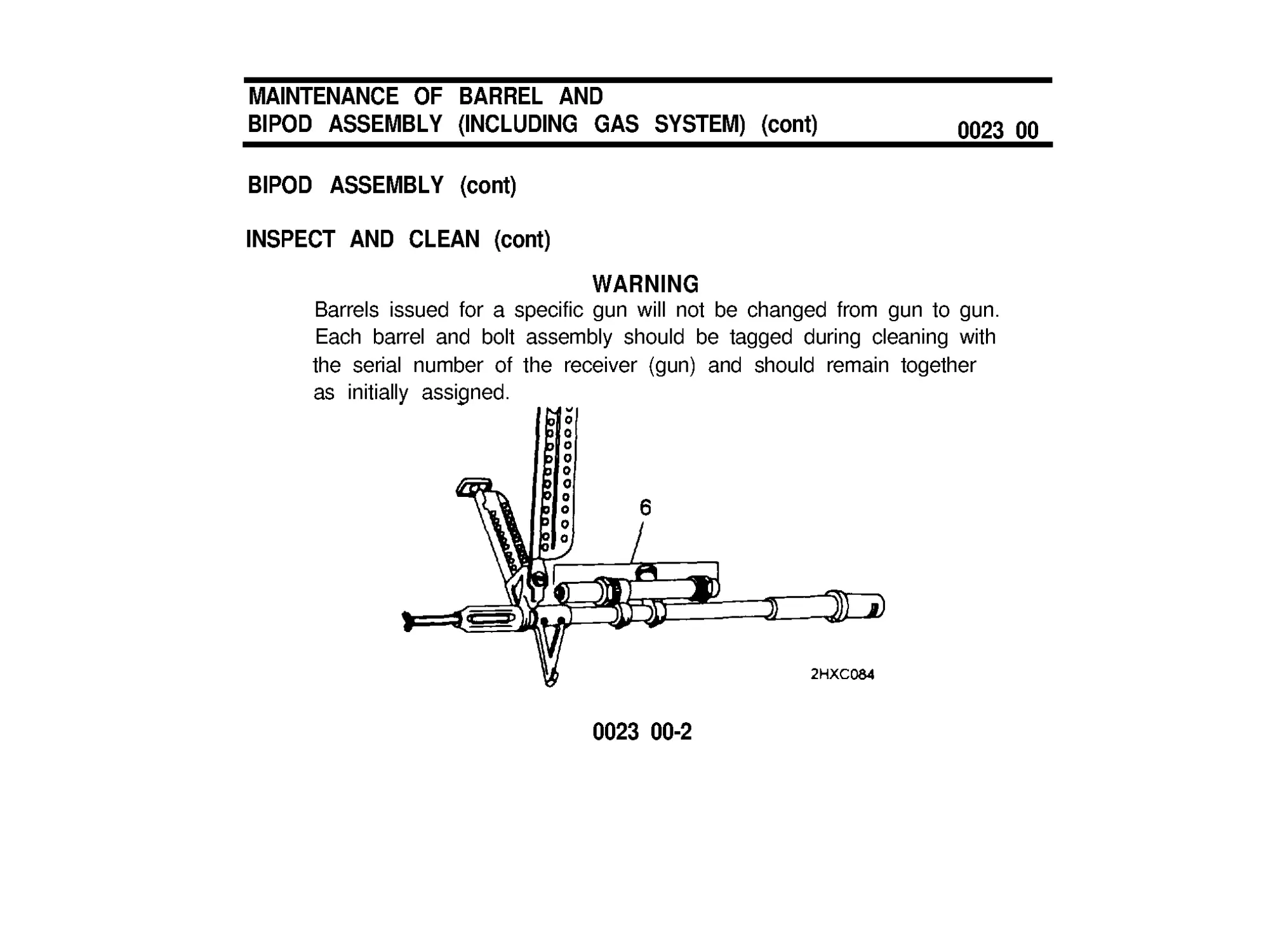
WARNING
Barrels issued for a specific gun will not be changed from gun to gun.
Each barrel and bolt assembly should be tagged during cleaning with
the serial number of the receiver (gun) and should remain together
as initially assigned.
0023 00-2
5 Turn barrel upside down for cleaning. This will keep gas piston and inside
of gas cylinder (6) dry.
6 Run a cleaning rod with swab (item, 6 WP 0039 00) saturated with CLP/
RBC (items 1 and 2,WP 0039 00) through bore. Leave bore wet.
0023 00-3
MAINTENANCE OF BARREL AND
BIPOD ASSEMBLY (INCLUDING GAS SYSTEM) (cont)
0023 00
GAS SYSTEM
INSPECT AND CLEAN
CAUTlON
No abrasive materials will be used to clean the gas piston or inside
the gas clinder.
NOTE
Gas piston clicks when barrel is tilted. Take gas system (gas
cylinder) apart only when you don’t hear a click.
1 Use combination wrench and clean swab (item 6, WP 0039 00) to clean
powder fouling, corrosion, and dirt from all parts.
0023 00-4
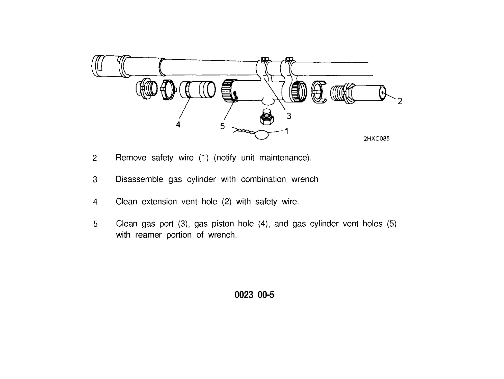
2
Remove safety wire (1) (notify unit maintenance).
3 Disassemble gas cylinder with combination wrench
4 Clean extension vent hole (2) with safety wire.
5 Clean gas port (3), gas piston hole (4), and gas cylinder vent holes (5)
with reamer portion of wrench.
0023 00-5
MAINTENANCE OF BARREL AND
BIPOD ASSEMBLY (INCLUDING GAS SYSTEM) (cont)
0023 00
GAS SYSTEM (cont)
INSPECT AND CLEAN (cont)
CAUTION
Insert reamer carefully to prevent damage.
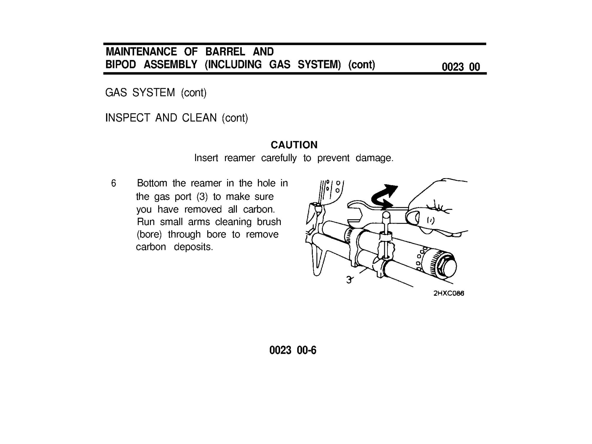
6 Bottom the reamer in the hole in
the gas port (3) to make sure
you have removed all carbon.
Run small arms cleaning brush
(bore) through bore to remove
carbon deposits.
0023 00-6
CAUTION
Make sure you do not install piston backward. Do not get CLP/
RBC in gas system.
7
Reassemble gas system (gas cylinder), making sure gas cylinder vent,
plug and nut are tight.
8 Notify unit maintenance to replace safety wire (1) promptly on completion
of mission.
9 When safety wire is not available, check gas system periodically for
tightness.
END OF TASK
0023 00-7/8 blank
MAINTENANCE OF M60 TRIGGER MECHANISM
GRIP ASSEMBLY
0024 00
INSPECT AND CLEAN
1 Hold down on sear (1) and
remove sear pin (2).
2 Remove sear (11, sear
plunger (3), and spring (4).
3 Remove trigger pin (5) and
trigger (6).
4 Clean powder fouling,
corrosion, and dirt from all
areas with CLP/RBC (items
1and2,WP003900)and
wipe with a small arms
cleaning brush.
0024 00-1
MAINTENANCE OF M60 TRIGGER MECHANISM
GRIP ASSEMBLY (cont)
0024 00
INSPECT AND CLEAN (cont)
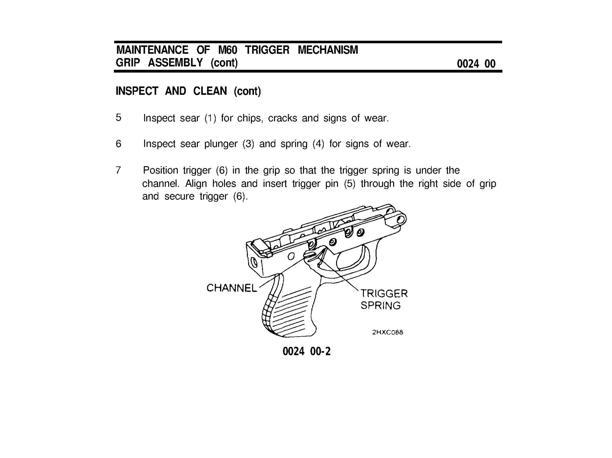
5 Inspect sear (1) for chips, cracks and signs of wear.
6 Inspect sear plunger (3) and spring (4) for signs of wear.
7 Position trigger (6) in the grip so that the trigger spring is under the
channel. Align holes and insert trigger pin (5) through the right side of grip
and secure trigger (6).
0024 00-2
8 Insert spring (4) and sear plunger (3) into hole. Position sear (1) and
apply slight pressure to align holes. Insert sear pin (2) through left side of
grip and secure sear.
9 Check safety while pulling trigger back:
•
‘F ’ - Sear moves freely.
•
‘S ’ - Sear moves slightly.
END OF TASK
0024 00-3/4 blank
MAINTENANCE OF M60D SEAR AND
SAFETY HOUSING ASSEMBLY
0025 00
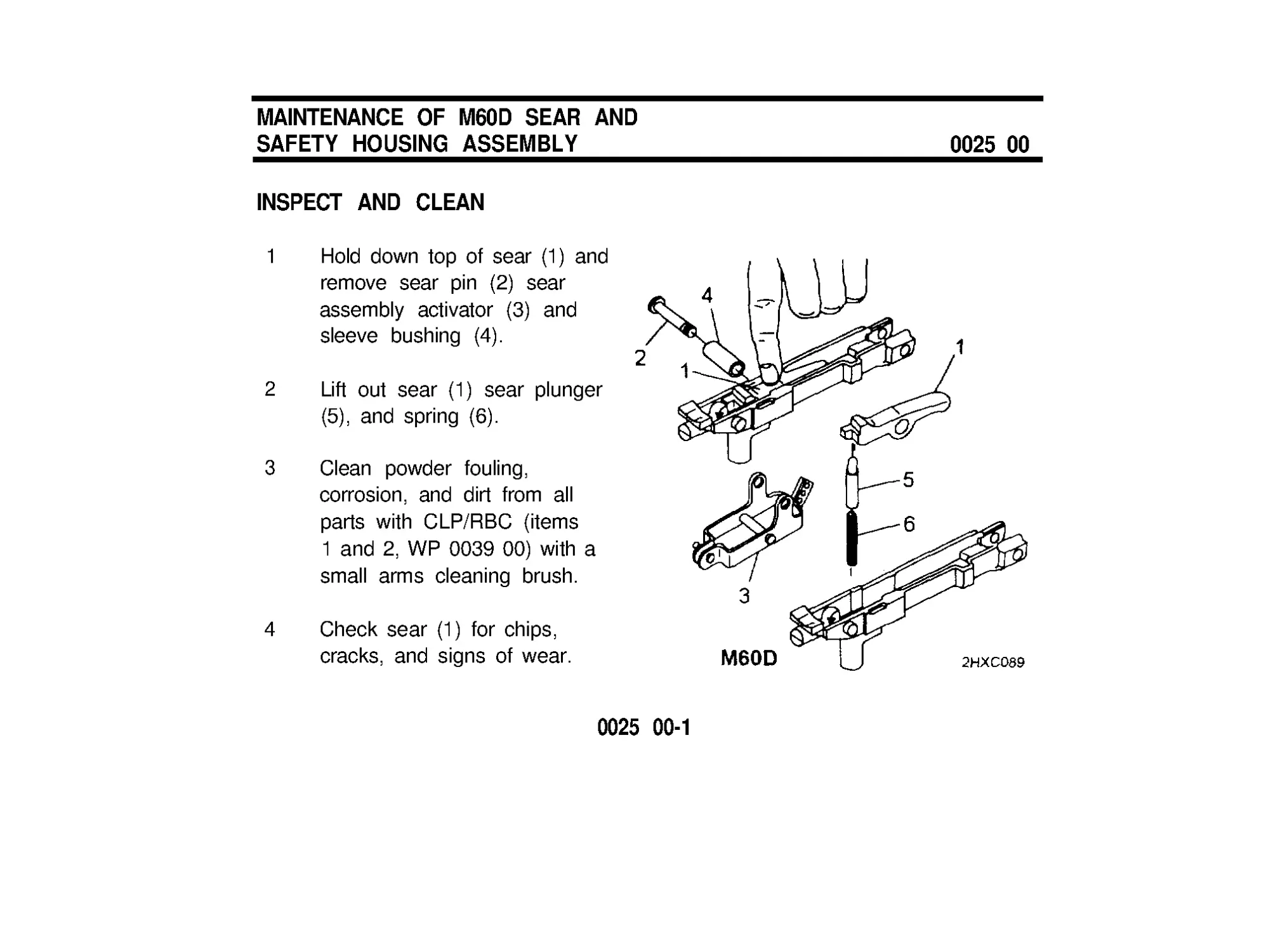
INSPECT AND CLEAN
1 Hold down top of sear (1) and
remove sear pin (2) sear
assembly activator (3) and
sleeve bushing (4).
2
Lift out sear (1) sear plunger
(5), and spring (6).
3 Clean powder fouling,
corrosion, and dirt from all
parts with CLP/RBC (items
1and2,WP003900)witha
small arms cleaning brush.
4 Check sear (1) for chips,
cracks, and signs of wear.
0025 00-1
INSPECT AND CLEAN (cont)
5 Check sear plunger (5) and
spring (6) for signs of wear.
6 Insert spring (6) and sear
plunger (5) into hole. Position
sear (1) into housing.
MAINTENANCE OF M60D SEAR AND
SAFETY HOUSING ASSEMBLY
0025 00
0025 00-2
7 Apply slight pressure to
align holes and insert sleeve
bushing (4).
8 Position sear assembly
activator (3) on bottom of sear
housing and secure with sear
pin (2).
9 Check safety while pulling
down on sear assembly
activator.
•
‘F ’ - Sear moves freely.
•
‘S ’ - Sear moves slightly.
END OF TASK
0025 00-3/4 blank
MAINTENANCE OF RECEIVER
0026 00
INSPECT AND CLEAN
1 Clean powder fouling, corrosion, and dirt from all areas with CLP/RBC
(items 1 and 2, WP 0039 00) and small arms brushes.
2 When weapon is disassembled, use fluted end of operating rod assembly
to remove carbon from operating rod guide of receiver (WP 0020 00).
0026 00-1
MAINTENANCE OF RECEIVER (cont)
0026 00
INSPECT AND CLEAN (cont)
3 Check receiver rails for burrs and wear.
4 Check that cocking handle moves freely.
END OF TASK
0026 00-2
REASSEMBLY OF MACHINE GUN
0027 00
M60 FOREARM ASSEMBLY
CAUTION
When installing forearm assembly, be careful not to damage
its internal ribs.
1 Slightly tip forearm assembly and slide it onto receiver.
2 Press in on bottom of forearm assembly to latch.
0027 00-1
REASSEMBLY OF MACHINE GUN (cont)
0027 00
M60 TRIGGER MECHANISM GRIP ASSEMBLY OR M60D SEAR AND
SAFETY HOUSING ASSEMBLY
1 M60. Position trigger mechanism
assembly (1) on bottom of receiver,
align holes, and install front pin (2)
from the left side.
M60D. Position sear and safety
housing assembly (3) on bottom of
receiver, align holes and install front
pin (2) from the left side.
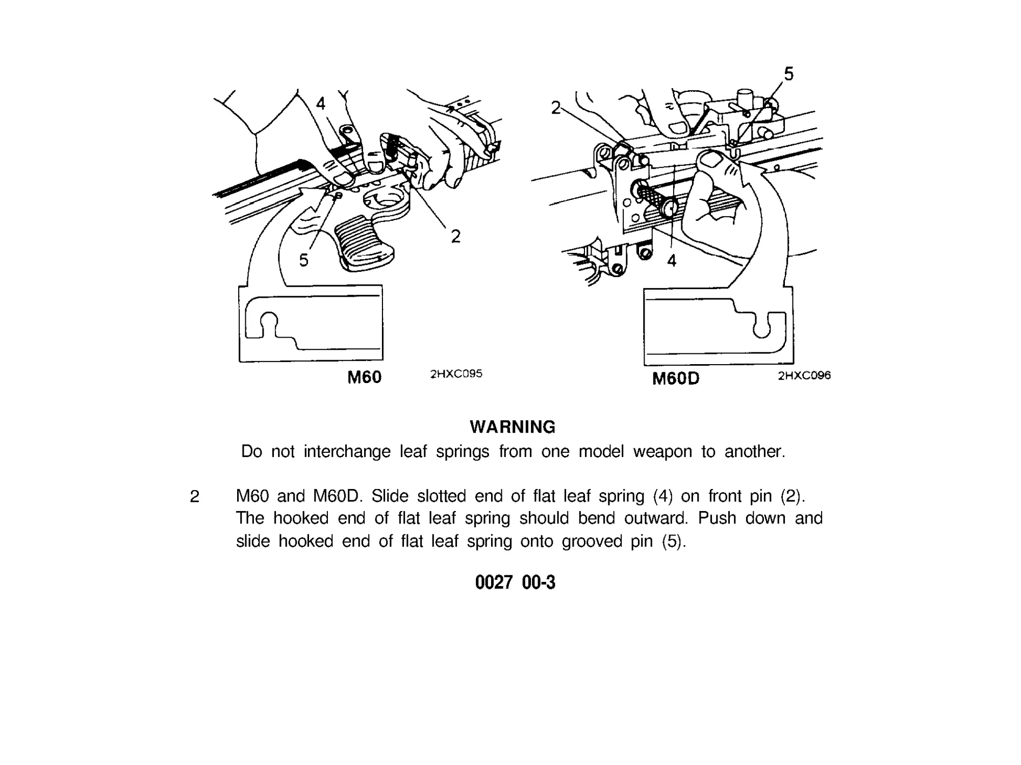
0027 00-2
WARNING
Do not interchange leaf springs from one model weapon to another.
2 M60 and M60D. Slide slotted end of flat leaf spring (4) on front pin (2).
The hooked end of flat leaf spring should bend outward. Push down and
slide hooked end of flat leaf spring onto grooved pin (5).
0027 00-3
REASSEMBLY OF MACHINE GUN (cont)
0027 00
BARREL AND BIPOD ASSEMBLY
M60 and M60D. Make sure barrel lock (3) is up (unlocked). Install barrel and
bipod assembly (4). Push barrel lock (3) down to lock.
0027 00-4
WARNING
To prevent possible bodily injury and aircraft damage, personnel
should not stand the weapon on its barrel assembly when disassembling
or assembling the weapon.
M60 D. Raise gun adapter (1), align holes, and insert quick release pin (2) to
secure gun adapter to receiver.
0027 00-5
REASSEMBLY OF MACHINE GUN (cont)
0027 00
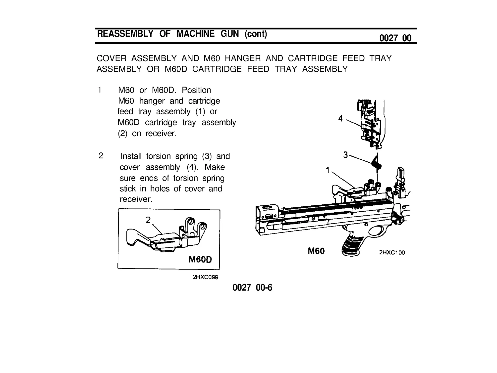
COVER ASSEMBLY AND M60 HANGER AND CARTRIDGE FEED TRAY
ASSEMBLY OR M60D CARTRIDGE FEED TRAY ASSEMBLY
1 M60 or M60D. Position
M60 hanger and cartridge
feed tray assembly (1) or
M60D cartridge tray assembly
(2) on receiver.
2 Install torsion spring (3) and
cover assembly (4). Make
sure ends of torsion spring
stick in holes of cover and
receiver.
0027 00-6
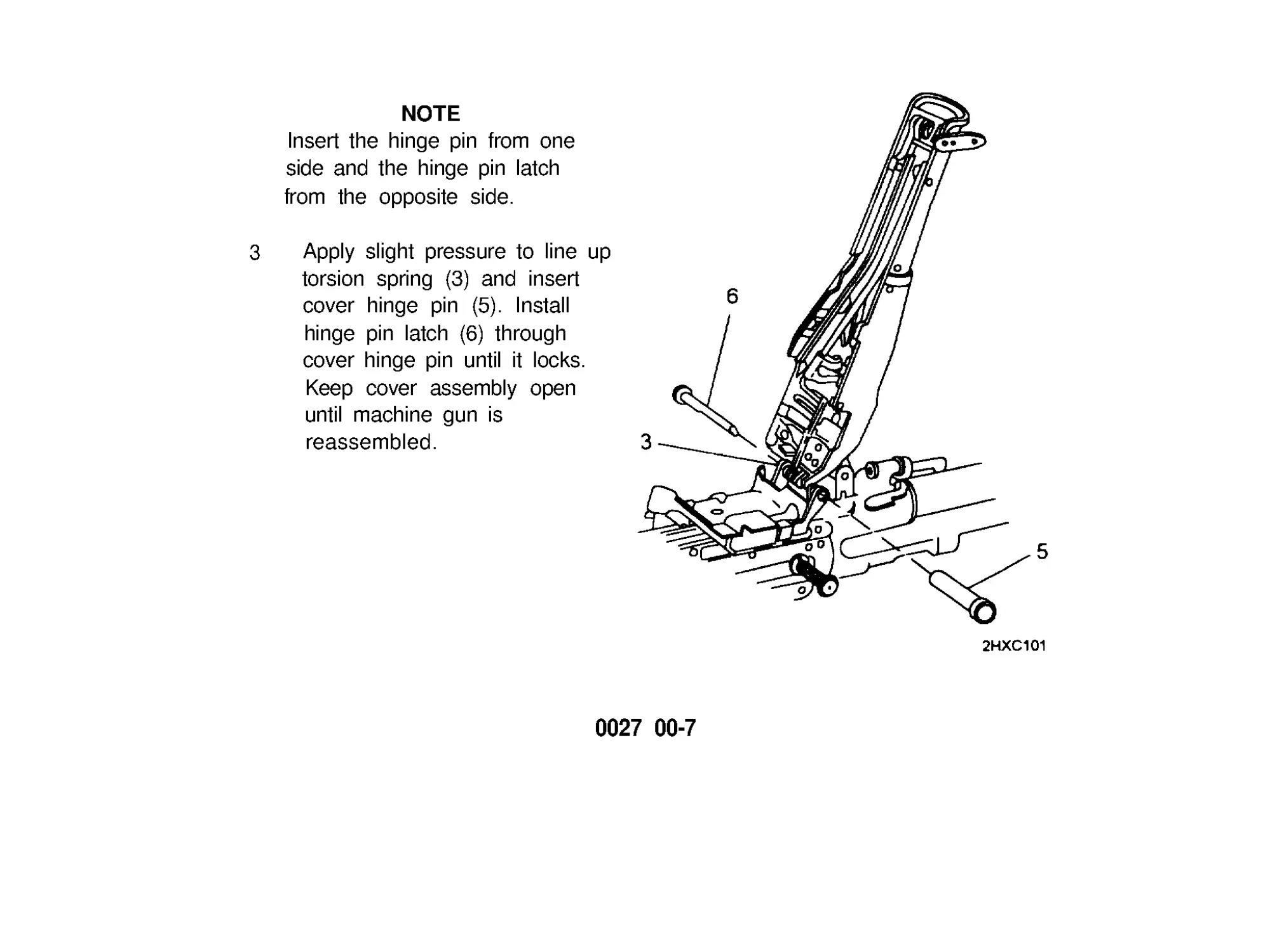
NOTE
Insert the hinge pin from one
side and the hinge pin latch
from the opposite side.
3 Apply slight pressure to line up
torsion spring (3) and insert
cover hinge pin (5). Install
hinge pin latch (6) through
cover hinge pin until it locks.
Keep cover assembly open
until machine gun is
reassembled.
0027 00-7
REASSEMBLY OF MACHINE GUN (cont)
0027 00
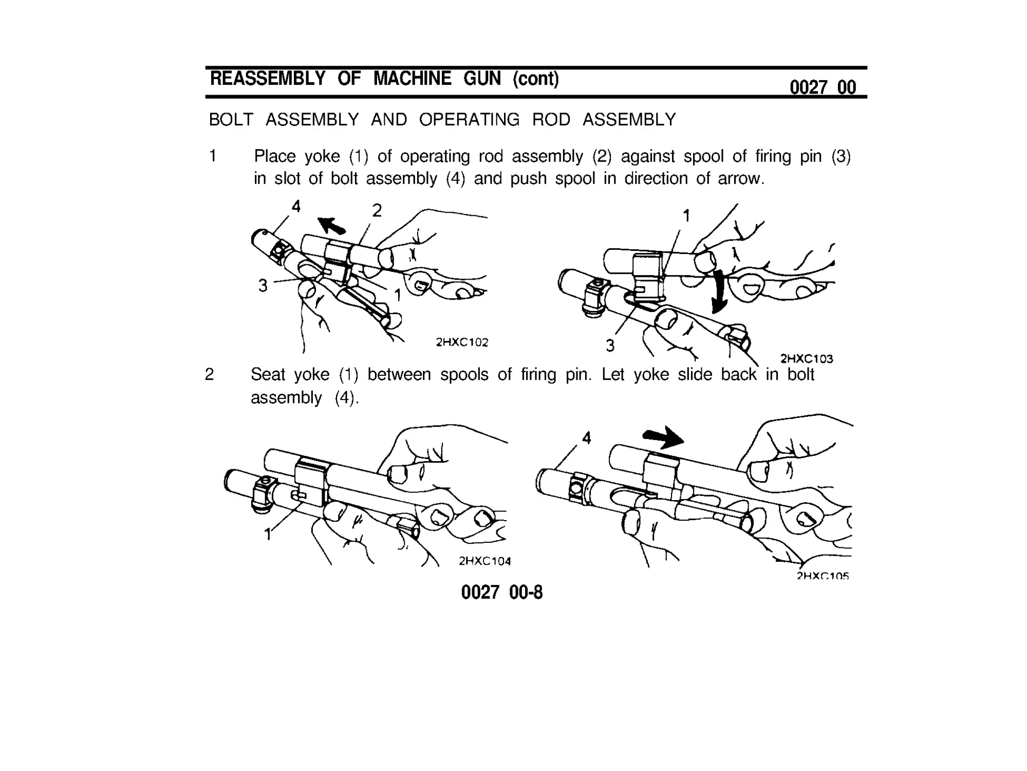
BOLT ASSEMBLY AND OPERATlNG ROD ASSEMBLY
1 Place yoke (1) of operating rod assembly (2) against spool of firing pin (3)
in slot of bolt assembly (4) and push spool in direction of arrow.
2 Seat yoke (1) between spools of firing pin. Let yoke slide back in bolt
assembly (4).
0027 00-8
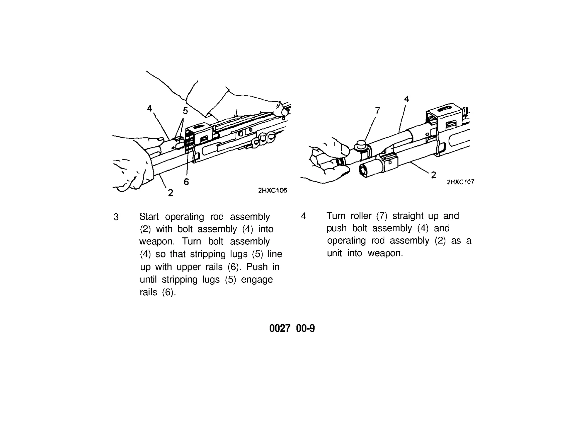
3 Start operating rod assembly
4 Turn roller (7) straight up and
(2) with bolt assembly (4) into
push bolt assembly (4) and
weapon. Turn bolt assembly
operating rod assembly (2) as a
(4) so that stripping lugs (5) line
unit into weapon.
up with upper rails (6). Push in
until stripping lugs (5) engage
rails (6).
0027 00-9
REASSEMBLY OF MACHINE GUN (cont)
0027 00
BOLT ASSEMBLY AND OPERATING ROD ASSEMBLY (cont)
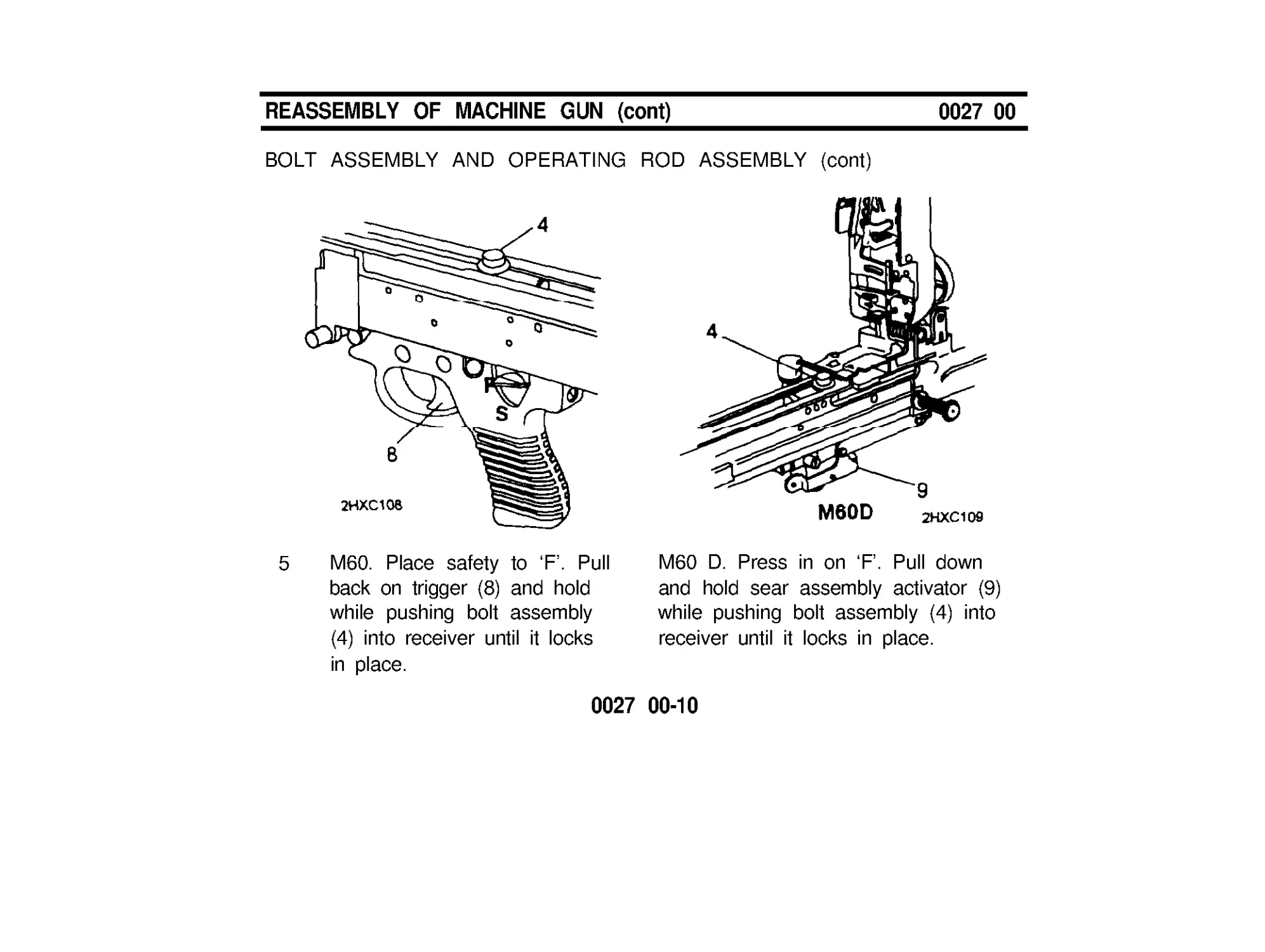
5 M60. Place safety to ‘F ’ . Pull
back on trigger (8) and hold
while pushing bolt assembly
(4) into receiver until it locks
in place.
M60 D. Press in on ‘F’ . Pull down
and hold sear assembly activator (9)
while pushing bolt assembly (4) into
receiver until it locks in place.
0027 00-10
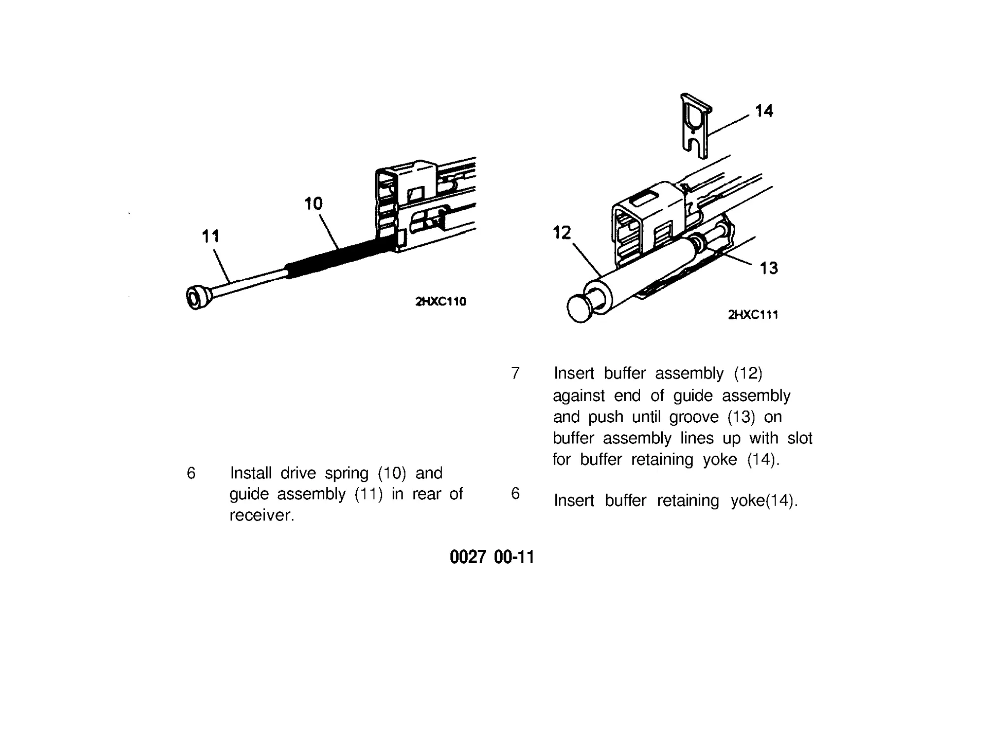
7 Insert buffer assembly (12)
against end of guide assembly
and push until groove (13) on
buffer assembly lines up with slot
6 Install drive spring (10) and
for buffer retaining yoke (14).
guide assembly (11) in rear of
6
receiver.
Insert buffer retaining yoke(14).
0027 00-11
REASSEMBLY OF MACHINE GUN (cont)
0027 00
M60 SHOULDER GUN STOCK
1 Position shoulder gun stock on rear of receiver and push until it snaps in
place.
2
Pull cocking handle rearward to lock bolt assembly to rear. Place safety
to ‘S’.
3 Close cover, move safety to ‘F’ position.
4 Hold charging handle, pull trigger, and ease charging handle forward.
0027 00-12
M60 SPADE AND TRIGGER GRIP ASSEMBLY
1 Install dust and moisture boot
(1) and position grip and trigger
assembly (2) on receiver.
2 Turn knob and pin assembly (3)
until clicking is heard. Then
press and hold spring pin (4) and
turn knob (3) until tight.
3 Release spring pin (4) and turn
knob and pin assembly (3) until it
locks.
0027 00-13
REASSEMBLY OF MACHINE GUN (cont)
0027 00
M60 SPADE AND TRIGGER GRIP ASSEMBLY (cont)
4
Pull cocking handle rearward to lock bolt assembly to rear. Press in on ‘S ’ .
5 Close cover (5).
6 Snap end of sear assembly link and spring (6) on end of sear assembly
activator (7).
7
Press safety in on ‘F ’ , hold cocking handle, pull trigger, and ease bolt
forward.
END OF TASK
0027 00-14
MAINTENANCE CHECKLIST
Check the cleanliness and overall condition of the following:
0028 00
.
.
.
.
.
.
.
.
.
.
.
.
.
.
.
Barrel assemblies. Chamber bore and flash suppressor, gas cylinder,
gas port, and gas piston.
Receiver assembly. Operating rod guide, rails, and rear bridge rivets.
Bolt assembly.
Front and rear sights.
M60 Shoulder gun stock.
Bipod assembly.
M60D Sear and safety housing assembly.
M60 Trigger mechanism grip assembly.
M60D Spade and trigger grip assembly.
Cocking handle assembly.
Cover assembly and M60 hanger and cartridge feed tray assembly.
Cover assembly and M60D cartridge feed tray assembly.
Forearm assembly.
Blank firing attachment (BFA). Clean after firing 500 rounds or after
each day’s firing, whichever comes first. Remember BFA causes carbon
fouling.
Small arms sling.
0028 00-1/2 blank
FUNCTION CHECK
0029 00
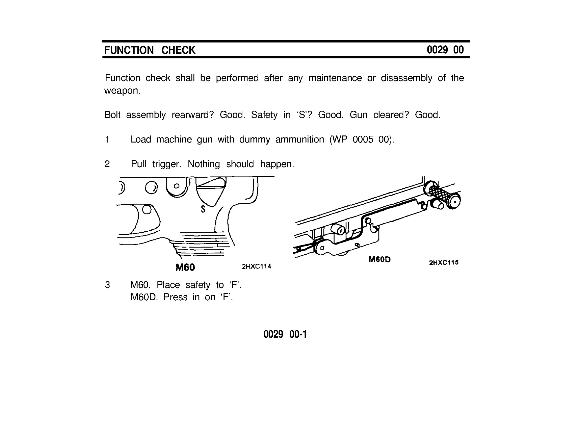
Function check shall be performed after any maintenance or disassembly of the
weapon.
Bolt assembly rearward? Good. Safety in ‘S’? Good. Gun cleared? Good.
1 Load machine gun with dummy ammunition (WP 0005 00).
2
Pull trigger. Nothing should happen.
3 M60. Place safety to ‘F ’ .
M60D. Press in on ‘F ’.
0029 00-1
FUNCTION CHECK (cont)
0029 00
4
5
6
7
Pull trigger. Bolt assembly should move forward, strip and chamber a
dummy round, and lock.
Pull cocking handle back. Dummy round should eject, and bolt assembly
should lock to rear.
WARNING
After unloading dummy round, be sure the barrel is cleared.
M60. Place safety to ‘S ’ .
M60D. Press in on ‘S ’.
Unload dummy ammunition and clear weapon (see WP 0009 00).
0029 00-2
8 Be sure that projectile stays on dummy round.
9 Close cover and latch.
10 M60. Place safety to ‘F ’ . Pull cocking handle, pull trigger, and ease bolt
assembly forward.
M60D. Press in on ‘F ’ . Pull cocking handle, pull trigger, and ease bolt
assembly forward.
END OF TASK
0029 00-3/4 blank
CHAPTER 4
MAINTENANCE OF
AUXILIARY EQUIPMENT
MAlNTENANCE OF AUXILIARY EQUIPMENT
0030 00
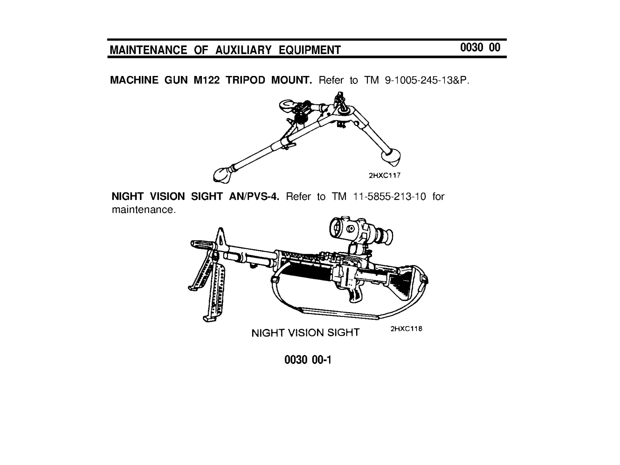
MACHINE GUN M122 TRIPOD MOUNT. Refer to TM 9-1005-245-13&P.
NIGHT VISION SIGHT AN/PVS-4. Refer to TM 11-5855-213-10 for
maintenance.
0030 00-1
MAINTENANCE OF AUXILIARY EQUIPMENT
0030 00
MOUNT PEDESTAL, MACHINE GUN, M6 AND MOUNT, MACHINE GUN
M197. Refer to TM 9-1005-245-13&P
0030 00-2
CHAPTER 5
AMMUNITION
AMMUNITION
0031 00
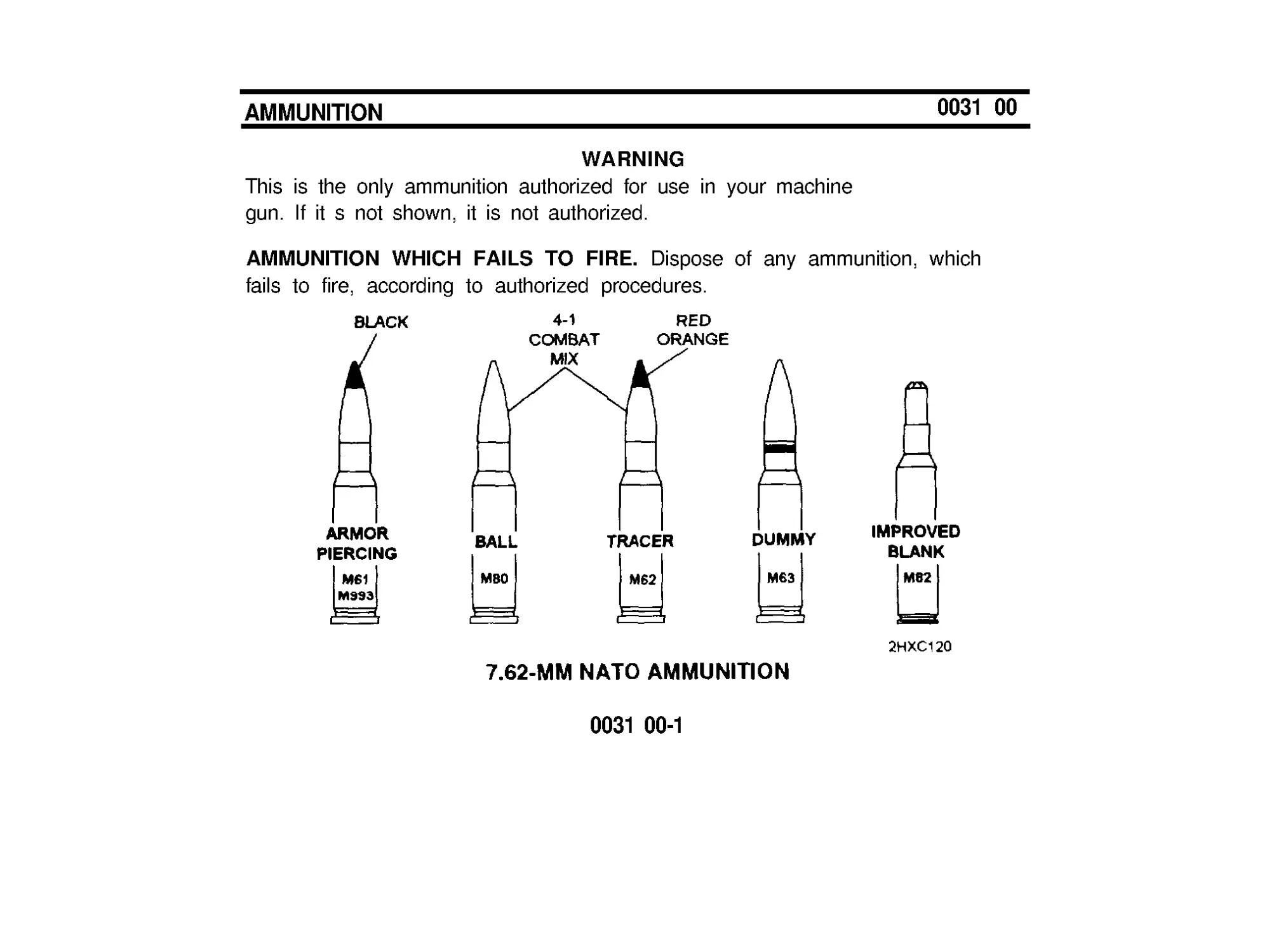
WARNING
This is the only ammunition authorized for use in your machine
gun. If it s not shown, it is not authorized.
AMMUNITION WHICH FAILS TO FlRE. Dispose of any ammunition, which
fails to fire, according to authorized procedures.
0031 00-1
AMMUNITlON (cont)
0031 00
CARE, HANDLING, AND PRESERVATION.
a.
b.
c.
d.
Do not open ammunition containers until the ammunition is to be used.
Ammunition removed from the airtight containers, particularly in damp
climates, is likely to corrode.
Protect ammunition from mud, dirt, and water. If the ammunition gets wet
or dirty, wipe it off prior to use. Wipe off light corrosion as soon as it is
discovered. Heavily corroded cartridges or cartridges which have dented
cases or loose projectiles should not be fired.
Do not expose the ammunition to the direct rays of the sun. If the powder
is hot, excessive pressure may be developed when the gun is fired.
Do not oil or grease ammunition. Dust and other abrasives collecting on
oiled or greased ammunition will damage the operating parts of the gun,
and oil on cartridges will produce excessive chamber pressure.
0031 00-2
REFERENCES
REFERENCES
SCOPE
0032 00
This appendix lists all forms, field manuals, and technical manuals referenced in
this manual.
CONSOLIDATED TABLE OF ALLOWANCES
CTA8-100................................Army Medical Department Expendable/
Durable Items
CTA50-970.............................. Expendable/Durable Items (Except: Medical,
Class V, Repair Parts, and Heraldic Items)
FlELD MANUALS
FM 3-87 .............,...................... Nuclear, Biological and Chemical (NBC)
Reconnaissance and Decontamination
Operations (How to Fight)
FM 21-11
First Aid for Sholdiers
FM 21-40
NBC (Nuclear, Biological and Chemical )
Defense
FM 23-67
Machine-gun 7.62-MM, M60
0032 00-1
REFERENCES (cont)
0032 00
FlRlNG TABLE
FT 7.62-A -2
Machine Gun, 7.62-MM: M60 on Mount,
Machine Gun: 7.62-MM, M122 and Machine
Gun, 7 .62-MM: M73 on Tank Combat, Full-
Tracked: 105-MM Gun, M60 Series and Rifle,
7.62-MM: M14: Firing Cartridge, 7.62-MM, Ball,
NATO, M59; Cartridge, 7.62-MM , Ball, NATO,
M80; Cartridge, 7.62-MM: AP, NATO,
M61/M993 and Cartridge, 7 .62-MM; Tracer,
NATO, M62
FORMS
DA Form 2028
Recommended Changes to Publications and
Blank Forms
SF 368
Quality Deficiency Report
0032 00-2
TECHNICAL MANUALS
TM 3-220
Chemical, Biological, and Radiological (CBR)
Decontamination
TM 11-5855-213-10
Operator’s Manual for Night Vision Sight,
Individual Served Weapon, AN/PVS-4
TM 9-1005-245-13&P
Machine Gun Mounts and Combinations for
Tactical/Armored Vehicles and Ground
Mounting
TM 9-4933-273-12&P
Boresighting Equipment, Weapon Small
Arms, M30
MISCELLANEOUS PUBLlCATlONS
DA PAM 738-750
The Army Maintenance Management System
(TAMMS)
0032 00-3/4 blank
COMPONENTS OF END ITEM
AND
BASIC ISSUE ITEMS LISTS
INTRODUCTlON
0033 00
SCOPE
These work packages lists COEI and BII for the M60/M60D machine gun to
help you inventory items required for safe and efficient operation of the
equipment.
GENERAL
The Components of End Item and Basic Issue Items Lists are divided into the
following lists:
Components of End Item (COEI). This list is for informational purposes only
and is not authority to requisition replacements. These items are part of the
M60/M60D machine gun. As part of the end item, these items must be with the
end item whenever it is issued or transferred between property accounts. Items
of COEI are removed and separately packaged for transportation or shipment
only when necessary. Illustrations are furnished to help you find and identify the
items.
0033 00-1
INTRODUCTlON (cont)
0033 00
GENERAL (cont)
Basic Issue Items (Bll). These essential items required to place the M60/M60D
machine gun in operation, operate it, and to do emergency repairs. Although
shipped separately packaged, Bll must be with the M60/M60D machine gun
during operation and whenever it is transferred between property accounts.
Listing these items is your authority to request/requisition them for replacement
based on authorization of the end item by the TOE/MTOE. Illustrations are
furnished to help you find and identify the items.
EXPLANATION OF COLUMNS IN THE COEI LIST AND BII LIST
Column (1) - lllus Number. Gives you the number of the item illustrated.
Column (2) - National Stock Number (NSN). Identifies the stock number
of the item to be used for requisitioning purposes.
Column (3) - Description, CAGEC, and Part Number. Identifies the Federal
name ( in all capitol letters) followed by a minimum description when needed.
The stowage location of COEI and Bll is also included in the column. The last
line below the description is the CAGEC (Commercial and Government Entity
Code) (in parentheses) and the part number.
0033 00-2
Column (4) - Usable On Code. When applicable, gives you a code if the item
you need is not the same for different models of equipment.
Code
Used On
023
Model M60
G79
Model M60D
Column (5) - Unit of Measure (U/M). Indicates the physical measurement or
count of the item as issued per the National Stock Number shown in column (2).
Column (6) - Qty Rqr. Indicates the quantity required.
0033 00-3/4 blank
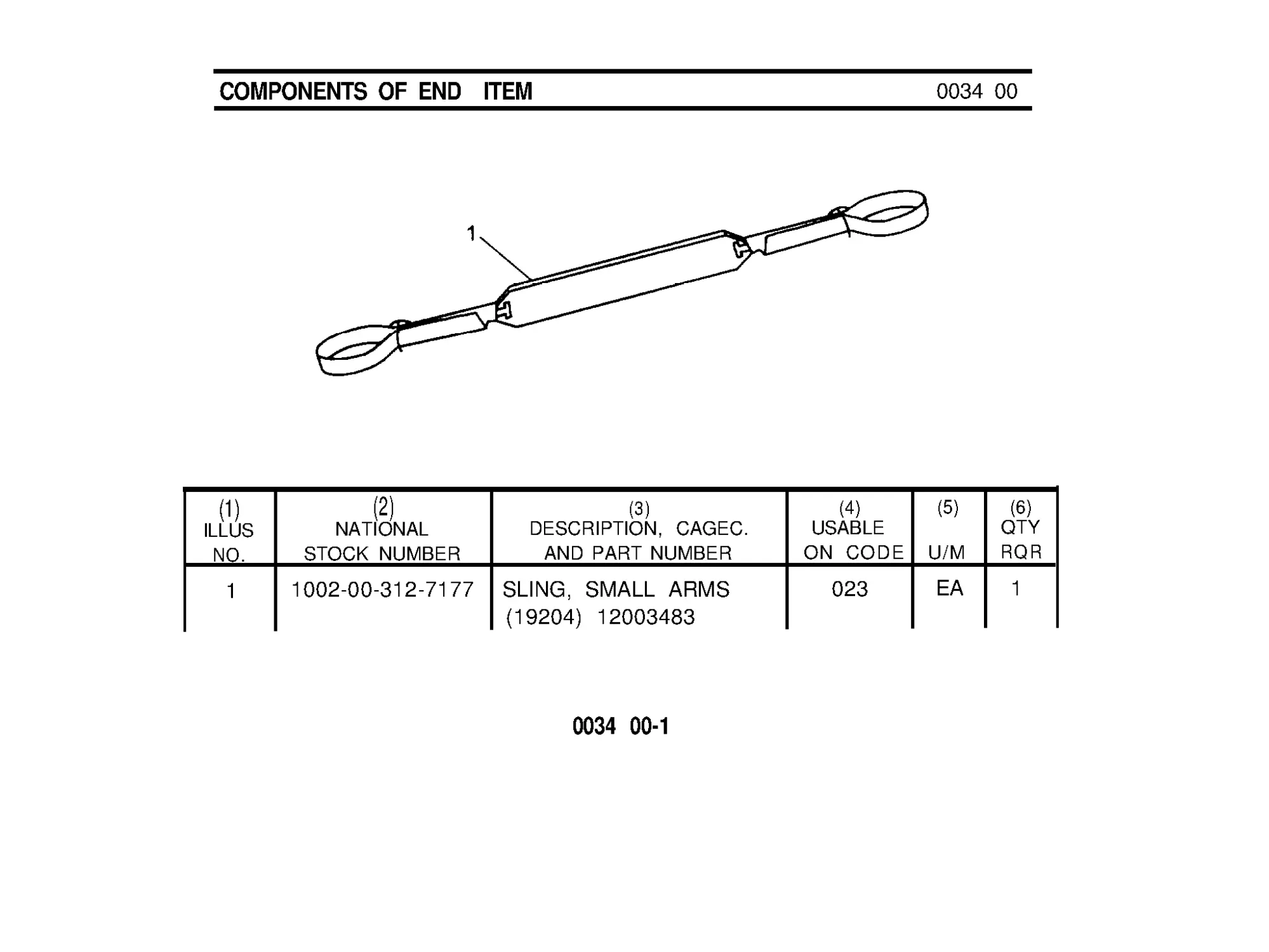
COMPONENTS OF END ITEM
0034 00
(1)
(2)
(3)
(4)
(5) (6)
ILLUS
NATIONAL
DESCRIPTION, CAGEC.
USABLE
QTY
NO.
STOCK NUMBER
AND PART NUMBER
ON CODE U/M RQR
1
1002-00-312-7177 SLING, SMALL ARMS
023
EA1
(19204) 12003483
0034 00-1
0034 00-2
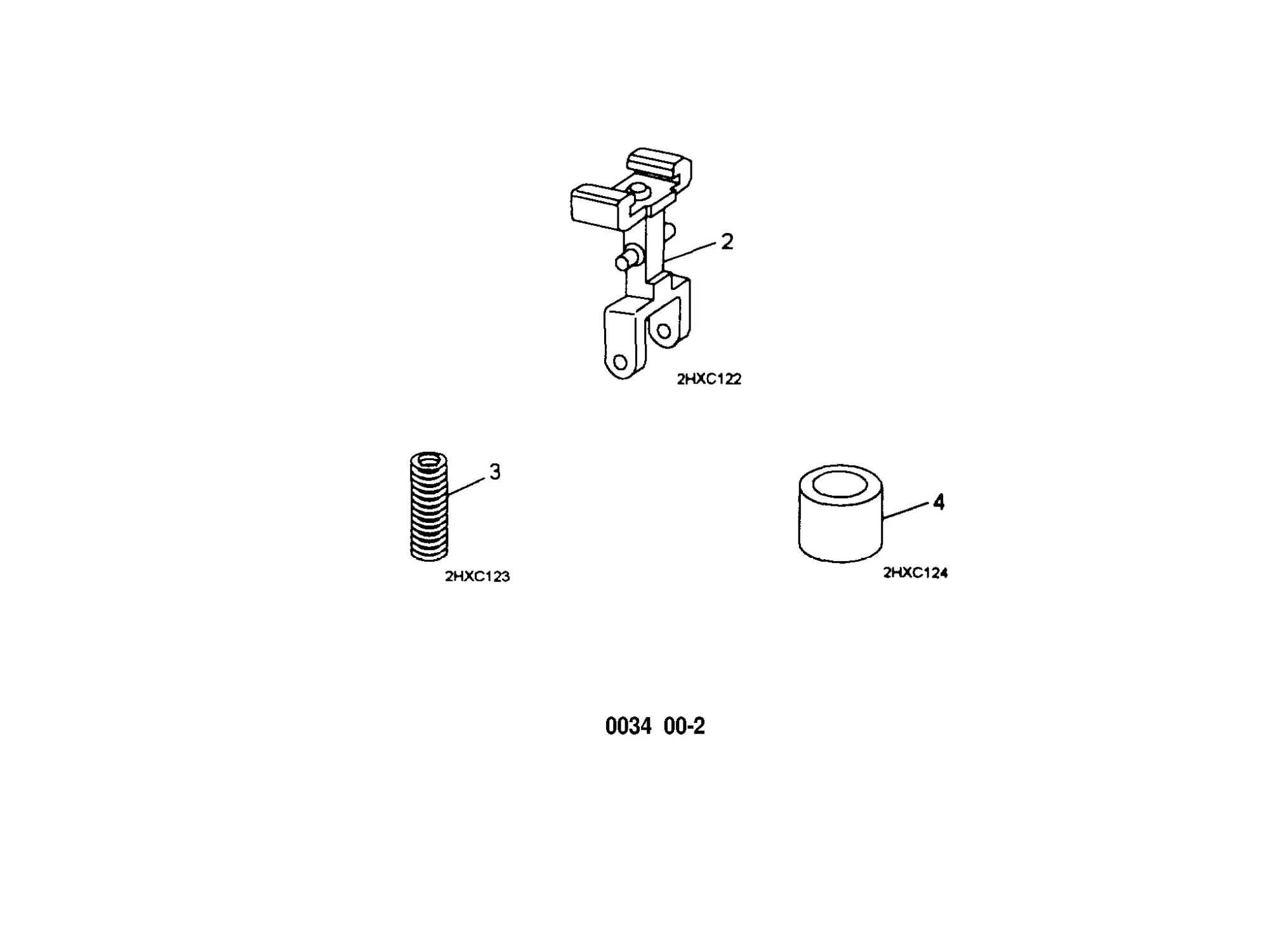
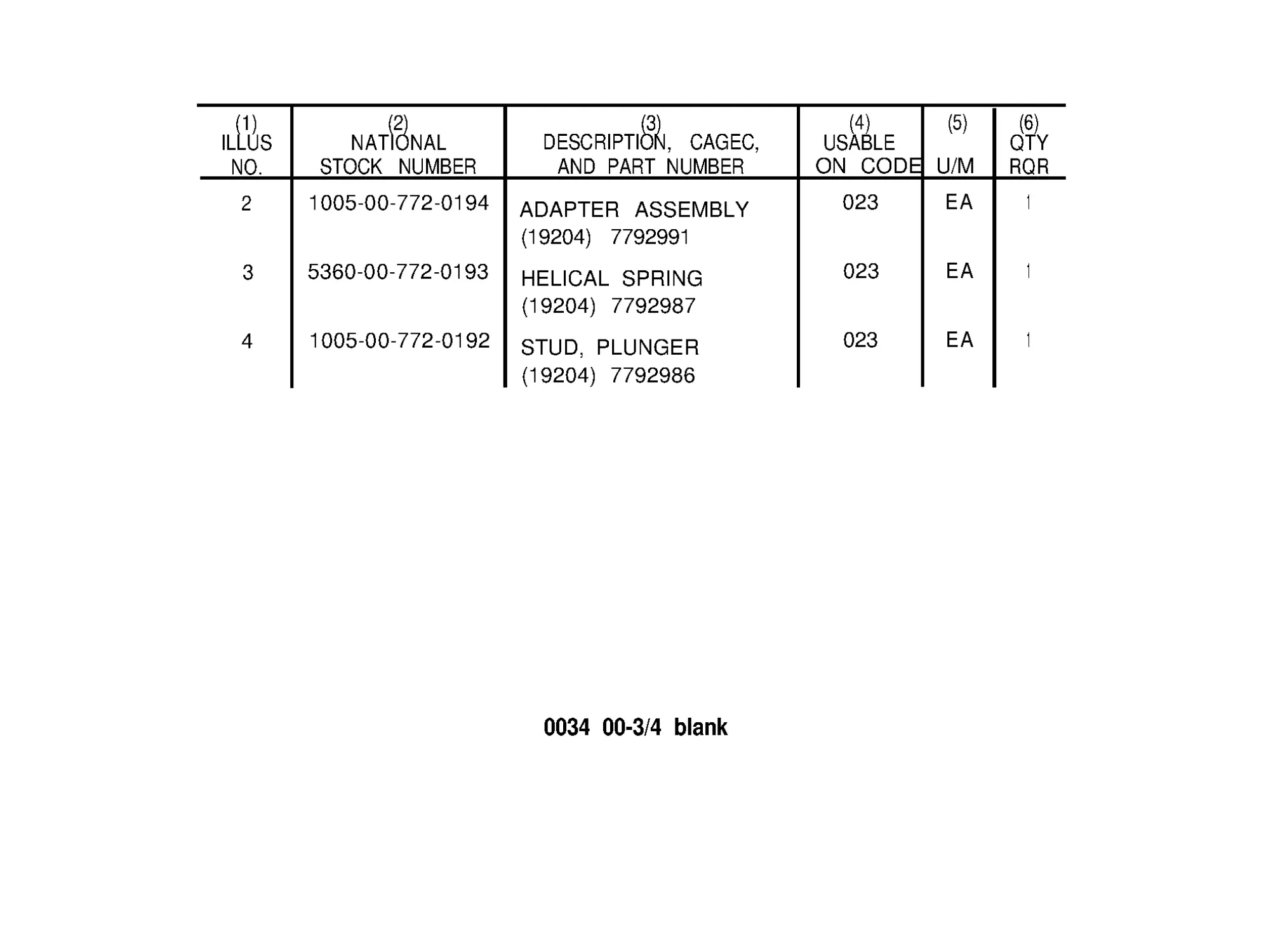
(1)
ILLUS
NO.
2
3
4
(2)
NATIONAL
STOCK NUMBER
1005-00-772 -0194
5360-00-772 -0193
1005-00-772 -0192
(3)
DESCRIPTION, CAGEC,
AND PART NUMBER
ADAPTER ASSEMBLY
(19204) 7792991
HELICAL SPRING
(19204) 7792987
STUD, PLUNGER
(19204) 7792986
(4)
(5) (6)
USABLE
QTY
ON CODE U/M RQR
023
EA
1
023
EA
1
023
EA
1
0034 00-3/4 blank
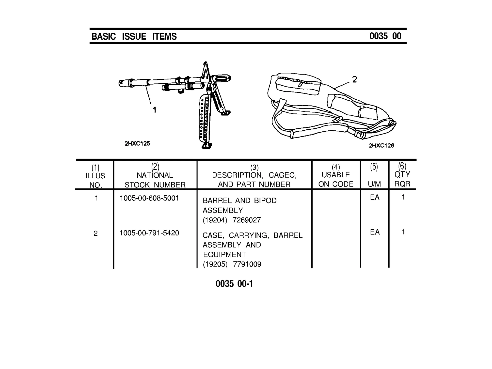
BASIC ISSUE ITEMS
0035 00
(1)
(2)
ILLUS
NATIONAL
NO.
STOCK NUMBER
1
1005-00-608 -5001
2
1005-00-791-5420
(3)
(4)
DESCRIPTION, CAGEC,
USABLE
AND PART NUMBER
ON CODE
BARREL AND BIPOD
ASSEMBLY
(19204) 7269027
CASE, CARRYING, BARREL
ASSEMBLY AND
EQUIPMENT
(19205) 7791009
0035 00-1
(5)
U/M
EA
EA
1
(6)
QTY
RQR
1
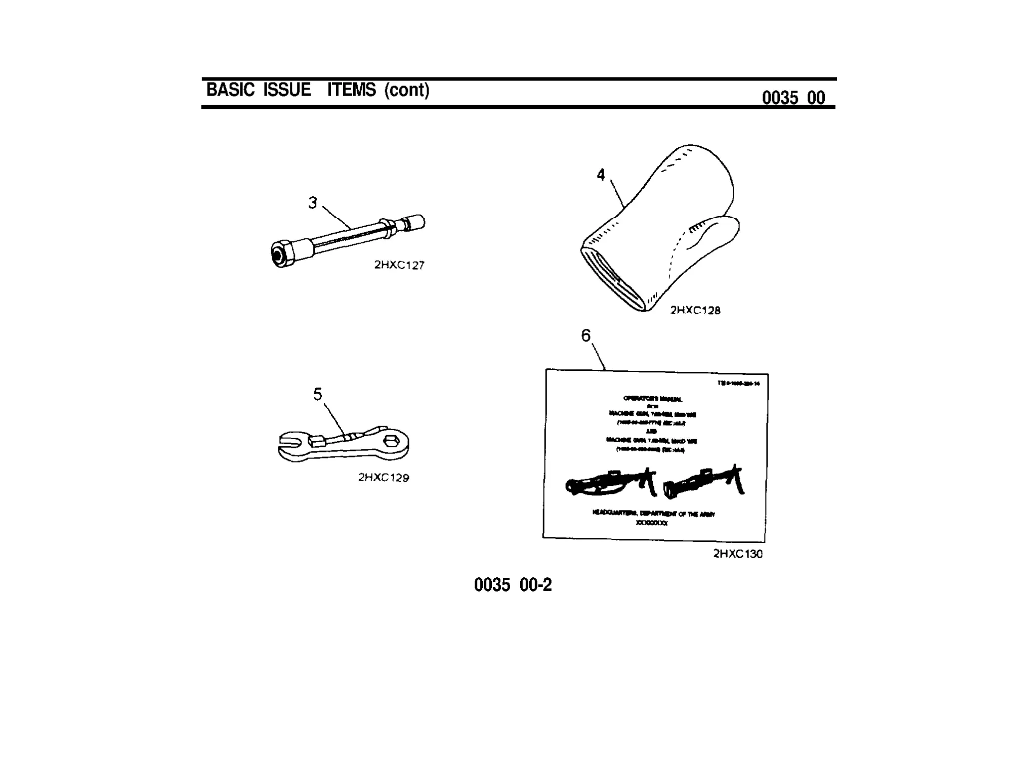
BASIC ISSUE ITEMS (cont)
0035 00
0035 00-2
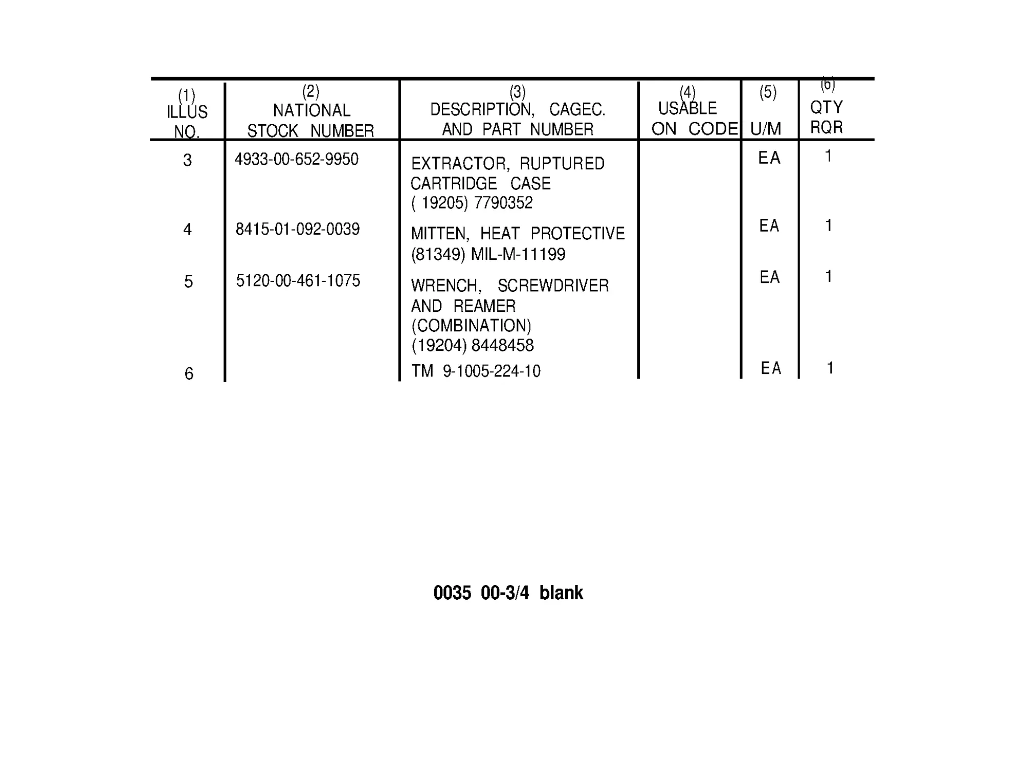
(1)
ILLUS
NO.
3
4
5
6
(2)
(3)
NATIONAL
STOCK NUMBER
4933-00 -652-9950
8415-01-092-0039
5120-00 -461-1075
DESCRIPTION, CAGEC.
AND PART NUMBER
EXTRACTOR, RUPTURED
CARTRIDGE CASE
( 19205) 7790352
MITTEN, HEAT PROTECTIVE
(81349) MIL-M-11199
WRENCH, SCREWDRIVER
AND REAMER
(COMBINATION)
(19204) 8448458
TM 9-1005-224 -10
(4)
(5)
USABLE
ON CODE U/M
EA
EA
EA
EA
(6)
QTY
RQR
1
1
1
1
0035 00-3/4 blank
ADDITIONAL AUTHORIZED LISTS
INTRODUCTlON
SCOPE
0036 00
This work package lists additional items you are authorized for the support of
the M60/M60D machine Gun.
GENERAL
This list identifies items that do not have to accompany the M60/M60D machine
gun and that do not have to be turned in with it. These items are all authorized
to you by CTA, MTOE, TDA , or JTA.
EXPLANATlON OF COLUMNS IN AAL
Column (1) - National Stock Number (NSN). Identifies the stock number of the
item to be used for requisitioning purposes.
Column (2) - Description, Commercial and Government Entity Code (CAGE),
and Part Number (P/N). identifies the Federal item name (in all capital letters)
followed by a minimum description when needed. The last line below the
description is the CAGEC (in parentheses) and the part number.
0036 00-1
INTRODUCTION (cont)
0036 00
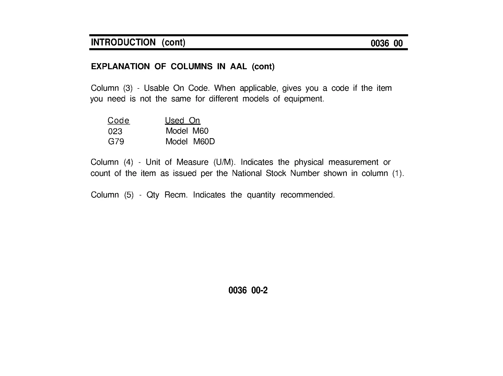
EXPLANATION OF COLUMNS IN AAL (cont)
Column (3) - Usable On Code. When applicable, gives you a code if the item
you need is not the same for different models of equipment.
Code
Used On
023
Model M60
G79
Model M60D
Column (4) - Unit of Measure (U/M). Indicates the physical measurement or
count of the item as issued per the National Stock Number shown in column (1).
Column (5) - Qty Recm. Indicates the quantity recommended.
0036 00-2
ADDITlONAL AUTHORIZED LIST
0037 00
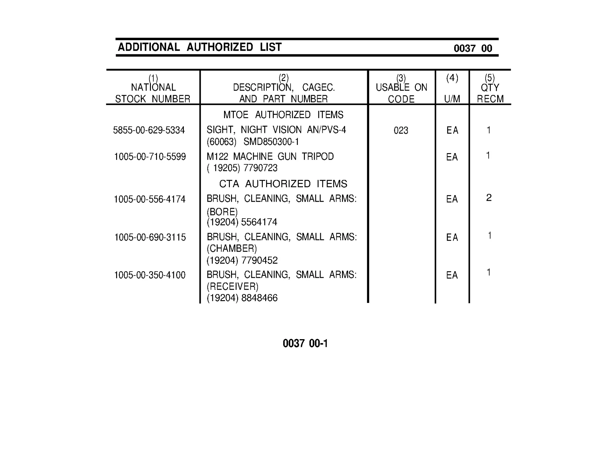
(1)
NATIONAL
STOCK NUMBER
5855-00 -629-5334
1005-00 -710-5599
1005-00 -556-4174
1
1
2
1
1
1005-00 -690-3115
1005-00 -350-4100
(2)
DESCRIPTION, CAGEC.
AND PART NUMBER
MTOE AUTHORIZED ITEMS
SIGHT, NIGHT VISION AN/PVS-4
(60063) SMD850300-1
M122 MACHINE GUN TRIPOD
( 19205) 7790723
CTA AUTHORIZED ITEMS
BRUSH, CLEANING, SMALL ARMS:
(BORE)
(19204) 5564174
BRUSH, CLEANING, SMALL ARMS:
(CHAMBER)
(19204) 7790452
BRUSH, CLEANING, SMALL ARMS:
(RECEIVER)
(19204) 8848466
(3)
USABLE ON
CODE
023
(4)
U/M
EA
EA
EA
EA
EA
(5)
QTY
RECM
0037 00-1
ADDlTlONAL AUTHORIZED LIST (cont)
0037 00
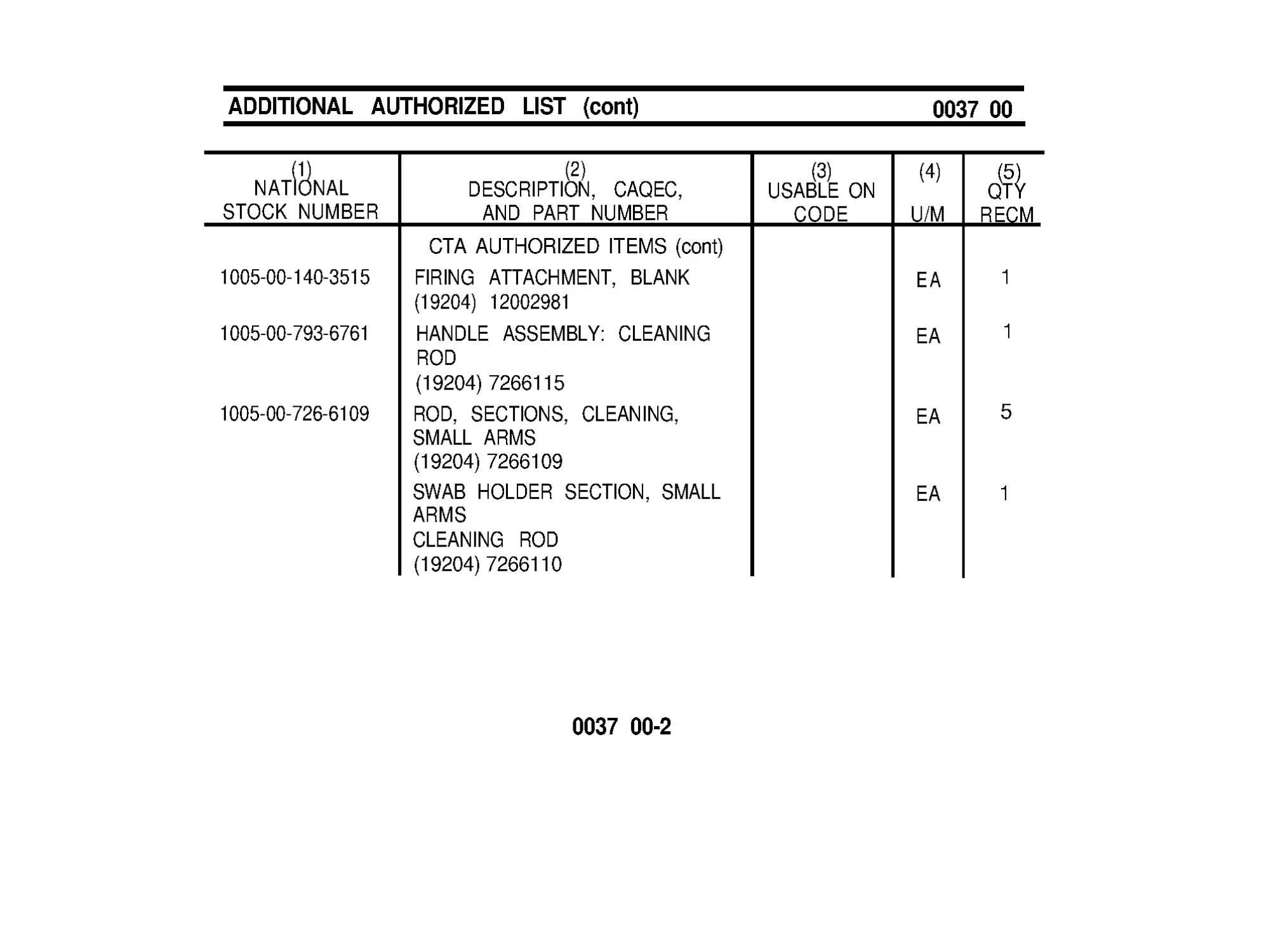
(1)
(2)
(3)
NATIONAL
DESCRIPTION, CAQEC,
USABLE ON
STOCK NUMBER
AND PART NUMBER
CODE
1005-00 -140-3515
1005-00 -793-6761
1
1
5
1
1005-00 -726-6109
CTA AUTHORIZED ITEMS (cont)
FIRING ATTACHMENT, BLANK
(19204) 12002981
HANDLE ASSEMBLY: CLEANING
ROD
(19204) 7266115
ROD, SECTIONS, CLEANING,
SMALL ARMS
(19204) 7266109
SWAB HOLDER SECTION, SMALL
ARMS
CLEANING ROD
(19204) 7266110
(4)
U/M
EA
EA
EA
EA
(5)
QTY
RECM
0037 00-2
EXPENDABLE/DURABLE SUPPLIES
AND MATERIALS LIST
INTRODUCTION
0038 00
SCOPE
This work package lists expendable and durable items that you will need to
operate and maintain the M60/M60D machine gun. This list is for information
only and is not authority to requisition the listed items. These items are
authorized to you by CTA 50-970, Expendable/Durable Items (Except Medical,
Class V Repair Parts, and Heraldic Items), or CTA 8-100, Army Medical
Department Expendable/Durable Items.
EXPLANATION OF COLUMNS IN THE EXPENDABLE/DURABLE ITEMS
LIST
Column (1) - Item Number. This number is assigned to the entry in the list and
is referenced in the narrative instructions to identify the item (e.g . , Use wiping
rag, (item 5, WP 0034 00).)
Column (2) - Level, This column identifies the lowest level ofmaintenance that
requires the listed item.
C - Operator/Crew
0038 00-1
INTRODUCTION (cont)
0038 00
EXPLANATlON OF COLUMNS IN THE EXPENDABLE/DURABLE ITEMS
LIST (cont)
Column (3) - National Stock Number (NSN). This is the NSN assigned to the
item which you can use to requisition it.
Column (4) - Item Name, Descprition, Commercial and Government Entity Code
(CAGEC), and Part Number (P/N). This column provides the other information
you need to identify the item.
Column (5) - Unit of Measure (U/M). This code shows the physical
measurement or count of an item, such as gallon, dozen, gross, etc.
0038 00-2
EXPENDABLE/DURABLE SUPPLIES
AND MATERIALS LIST
0039 00
(1)
ITEM
NUMBER
1
2
C
C
C
3
(2)
LEVEL
(3)
(4)
(5)
NATIONAL
DESCRIPTION, CAGEC,
STOCK NUMBER
AND PART NUMBER
U/M
9150-01-102-1473
9150-01-079-6124
Cleaner, Lubricant and
Preservative: grade 2 (CLP)
1/2 oz bottle
4 oz bottle
(8 1349) MIL-L -63460
Cleaning Compound, Solvent:
Rifle Bore Cleaner (RBC)
(81349) MIL-C - 372
2ozcan
8ozcan
6850-00 -224-6656
6850-00 -224-6657
9150-00-292-9689
Lubricating Oil, Weapons (LAW)
(81349) MIL-L-14107
1qtcan
0039 00-1
EA
EA
EA
EA
EA
EXPENDABLE/DURABLE SUPPLIES
AND MATERIALS LIST (cont)
0039 00
5
C
6
C
(1)
(2)
(3)
ITEM LEVEL
NATIONAL
NUMBER
STOCK NUMBER
4
C
9150-00-889 -3522
7920-00-205-1711
1005-00-288-3565
(4)
(5)
DESCRIPTION, CAGEC,
AND PART NUMBER
U/M
Lubricating Oil, Weapons:
semi-fluid (LSA)
(19204) 8436793
4 oz bottle
Rag, Wiping: (cotton)
(58536) A-A -531
50 lb bdl
Swab, Small Arms Cleaning:
(cotton)
(19204) 5019316
(1000 per pkg)
0039 00-2
EA
LB
PG
ALPHABETICAL INDEX
0040 00
Subject
WP Sequence No.
A
Additional Authorized List.. ................................................ 0036 00, 0037 00
Ammunition ...................................................................... 0031 00
Auxiliary Equipment, Maintenance of.. ............................... 0030 00
B
Barrel and Bipod Assembly (Including Gas System),
Maintenance of.. .......................................................... 0023 00
Basic Issue Items ..............................................................
0035 00
Bolt Assembly, Maintenance of.. ....................................... 0019 00
C
Clearing and Unloading ...................................................... 0009 00
Components of End Item.. ................................................. 0033 00, 0034 00
Cover Assembly (M60/M60D), Maintenance of.. ................ 0021 00
Cartridge Feed Tray Assembly, Maintenance of.. .............. 0022 00
0040 00-1
ALPHABETICAL INDEX (cont)
0040 00
Subject
D
WP Sequence No.
Description and Use of Operator’s Controls
andIndicators............................................................... 0003 00
E
Expendable/DurableSuppliesandMaterialsList.....................003800,003900
Equipment Description andData..................................000200
F
Field-StrippingMachineGun..............................................001800
Function Check..................................................... 002900
H
Hanger and Cartridge Feed Tray Assembly,
Maintenance of....................................................002200
0040 00-2
Subject
WP Sequence No.
H (cot)
How to Put the M60/M60D Machine Gun on:
M122 Tripod(M60)......................................... 000600
M6PedestalMount/M197Mount(M60)......................000700
Vehicles(M60D)............................................... 000800
I
Initial Adjustments, DailyChecks,andSelf-Test................0010 00
ImmediateAction...........................................001100
L
Loading........................................... 000500
LubricationInstructions........................................ 001600
M
Maintenance of Auxiliary Equipment.. ................................ 0030 00
Maintenance Checklist.. ..................................................... 0028 00
Maintenance Forms and Records .................................... 0001 00
0040 00-3
ALPHABETICAL INDEX (cont)
0040 00
Subject
Maintenance Procedures for:
M (cont)
WP Sequence No.
Barrel and Bipod Assembly (Including Gas System)...... 0023 00
BoltAssembly........................................... 0019 00
Cover Assembly(M60/M60D)......................... 0021 00
M60 Hanger and Cartridge Feed Tray Assembly
or M60D CartridgeFeedTrayAssembly...............0022 00
M60TriggerMechanismGripAssembly...................002400
M60DSearandSafetyHousingAssembly................ 002500
OperatingRodAssembly............................. 0020 00
Receiver........................................................002600
Misfire ...................................................... 001100
O
Operating Procedures.. ..................................................... 0007 00
Operation Rod Assembly, Maintenance of.. ....................... 0020 00
Operation of Auxiliary Equipment.. .................................... 0008 00
0040 00-4
ALPHABETICAL INDEX (cont)
0040 00
Subject
WP Sequence No.
O (cont)
Operation Under Usual Conditions:
Clearing/Unloading.......................................000900
How to Put the M60/M60D Machine Gun on:
M122 Tripod (M60)................................... 0006 00
M6PedestalMount/M197Mount(M60)................... 000700
Vehicles(M60D)......................................000800
Loading................................................... 000500
OperationUnder UnusualConditions .....................001000
P
PreparationforMovement..................................001400
Preventive Maintenance Checks and Services (PMCS) . . . . . . 0004 00
0040 00-5
ALPHABETICAL INDEX (cont)
0040 00
Subject
WP Sequence No.
R
ReassemblyofMachineGun.............................. 002700
Receiver,Maintenance of ................................... 002600
References................................................. 003200
Remedial Action...............................................001100
RemovingStuck/RupturedCartridgeCase..................... 001200
Reporting Equipment Improvement
Recommendations (EIR)............................... 0001 00
RunawayMachineGun....................................... 001100
S
Sear and Safety Housing Assembly, Maintenance of.......... 0025 00
T
Trigger Mechanism Grip Assembly, Maintenance of . . . . . . . . . . . 0024 00
TroubleshootingProcedures............................ 001700
W
WarningSummary.........................................a
0040-00-6
By Order of the Secretary of the Army:
DISTRIBUTION: To be distributed in accordance with
the initial distribution requirements IDN 400099,
for TM 9-1005-224-10.
PIN: 026382-000