/
Теги: weapons military affairs patent
Год: 2010

Текст
US 20100031812A1
(19) United States
(12) Patent Application Publication («» Pub. No.: US 2010/0031812 Al
Kerbrat et al. (43) Pub. Date: Feb. 11,2010
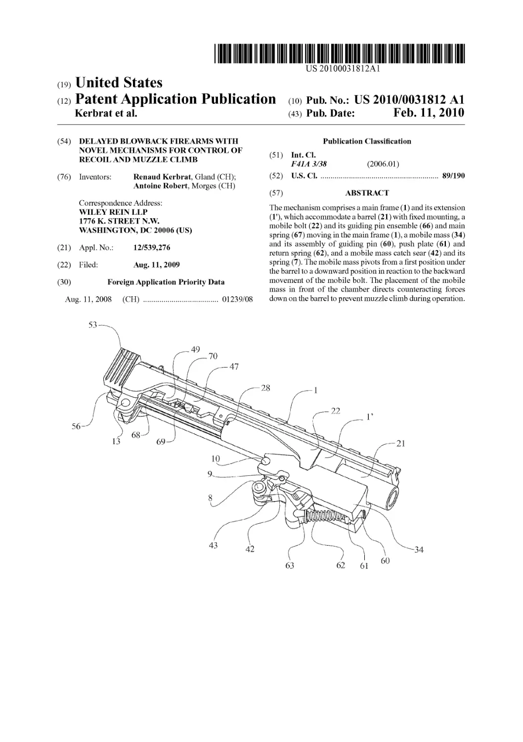
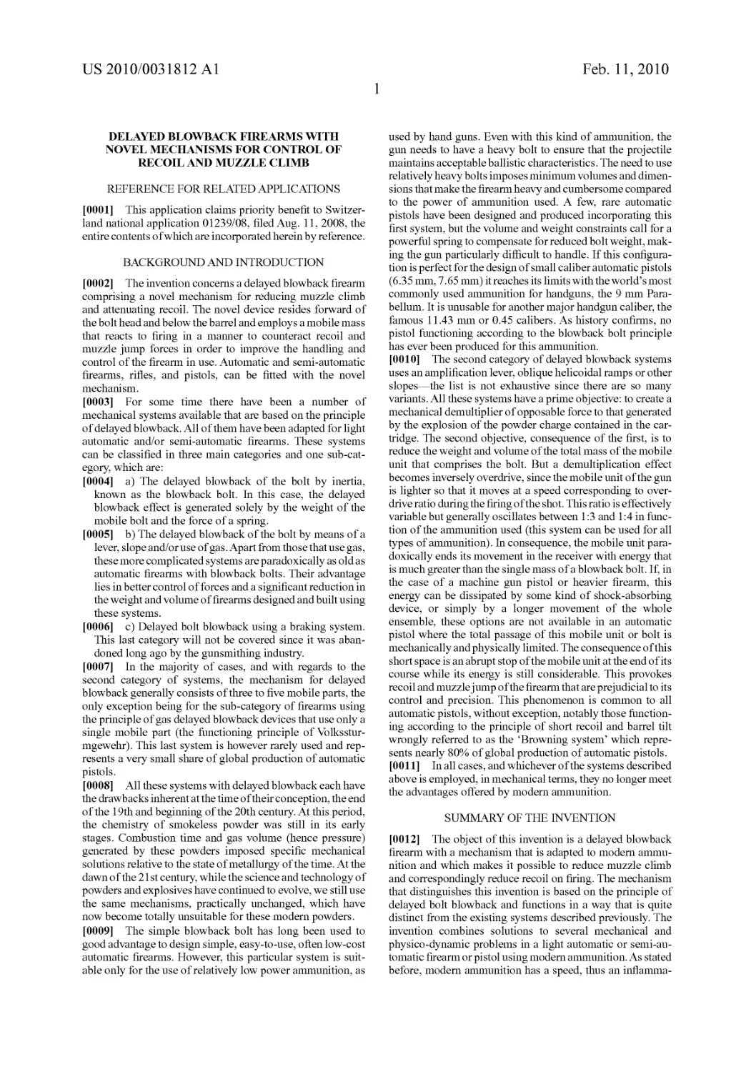
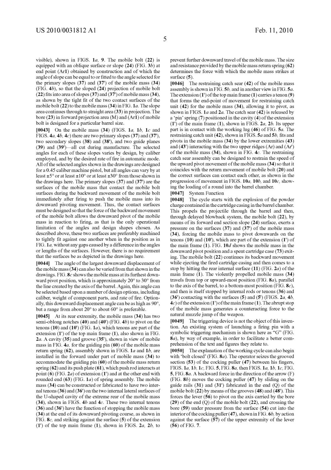
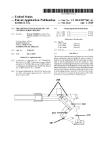
(54) DELAYED BLOWBACK FIREARMS WITH NOVEL MECHANISMS FOR CONTROL OF RECOIL AND MUZZLE CLIMB (76) Inventors: Renaud Kerbrat, Gland (CH); Antoine Robert, Morges (CH) Correspondence Address: WILEY REIN LLP 1776 K. STREET N.W WASHINGTON, DC 20006 (US) (21) Appl.No.: 12/539,276 (22) Filed: Aug. 11, 2009 (30) Foreign Application Priority Data Aug. 11,2008 (CH) 01239/08 53 —- ^—49 ЖЬ 70 56-^ 13 69—2 io__Jk>k 9 8к 43 42 Publication Classification (51) Int.Cl. F41A 3/38 (2006.01) (52) U.S. Cl 89/190 (57) ABSTRACT The mechanism comprises a main frame (1) and its extension (1'), which accommodate a barrel (21) with fixed mounting, a mobile bolt (22) and its guiding pin ensemble (66) and main spring (67) moving in the main frame (1), a mobile mass (34) and its assembly of guiding pin (60), push plate (61) and return spring (62), and a mobile mass catch sear (42) and its spring (7). The mobile mass pivots from a first position under the barrel to a downward position in reaction to the backward movement of the mobile bolt. The placement of the mobile mass in front of the chamber directs counteracting forces down on the barrel to prevent muzzle climb during operation. 28 ! (^ 63 62 61 60
Patent Application Publication Feb. 11, 2010 Sheet 1 of 7
US 2010/0031812 Al
Patent Application Publication Feb. 11, 2010 Sheet 2 of 7
US 2010/0031812 Al
Patent Application Publication Feb. 11, 2010 Sheet 3 of 7
US 2010/0031812 Al
59
VS2»10/0031813A1
67
pa,enfA№“-»"₽«b^
Fj§:10a
Feb. ц,
2010 Sheet 5 of 7
VS2°10/00318i2A1
pig:10b
Fig:10c
--7i
Patent Application Publication Feb. 11, 2010 Sheet 6 of 7
US 2010/0031812 Al
Patent Application Publication Feb. 11, 2010 Sheet 7 of 7
US 2010/0031812 Al
Figure 12
US 2010/0031812 Al
Feb. 11,2010
1
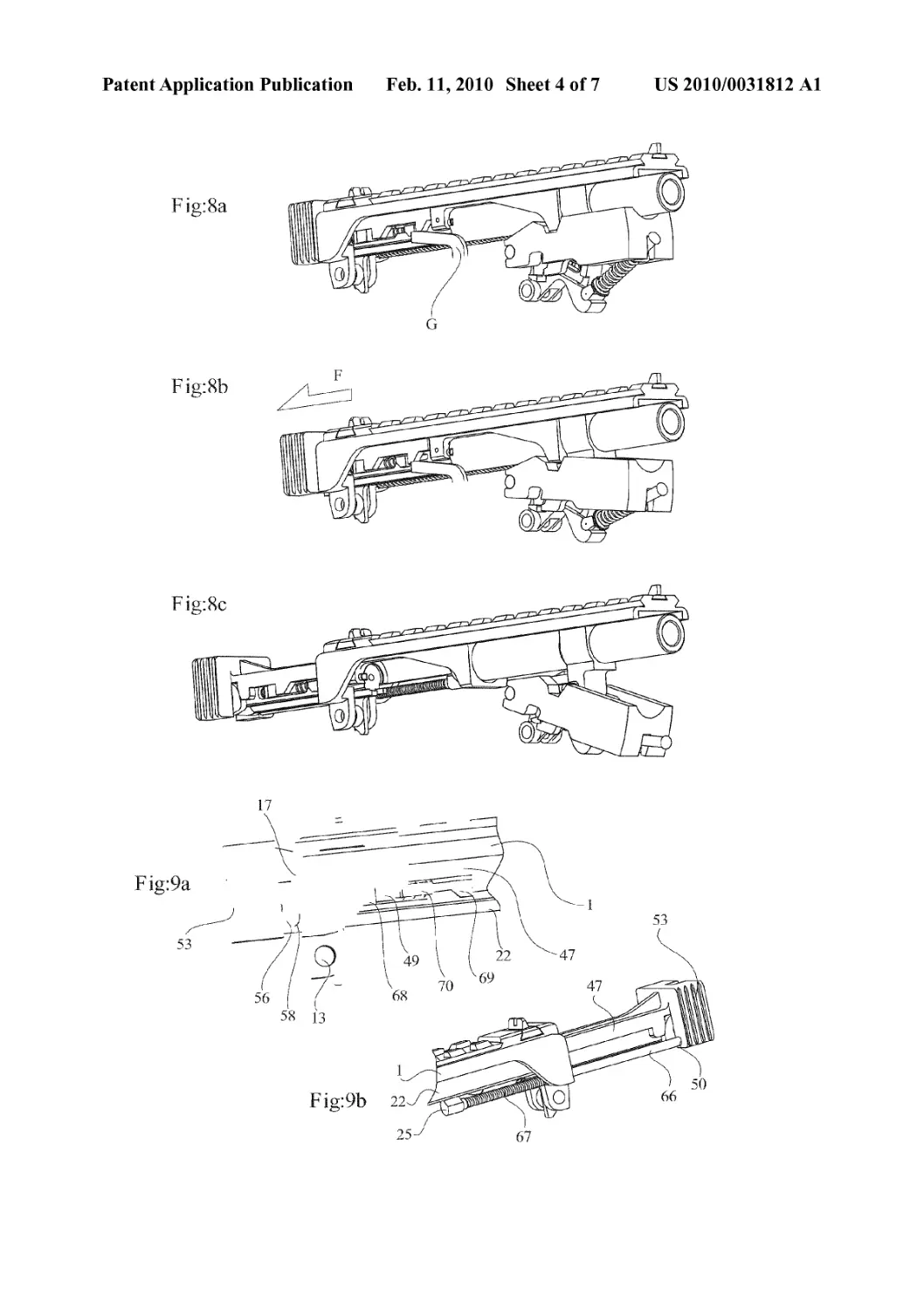
DELAYED BLOWBACK FIREARMS WITH
NOVEL MECHANISMS FOR CONTROL OF
RECOIL AND MUZZLE CLIMB
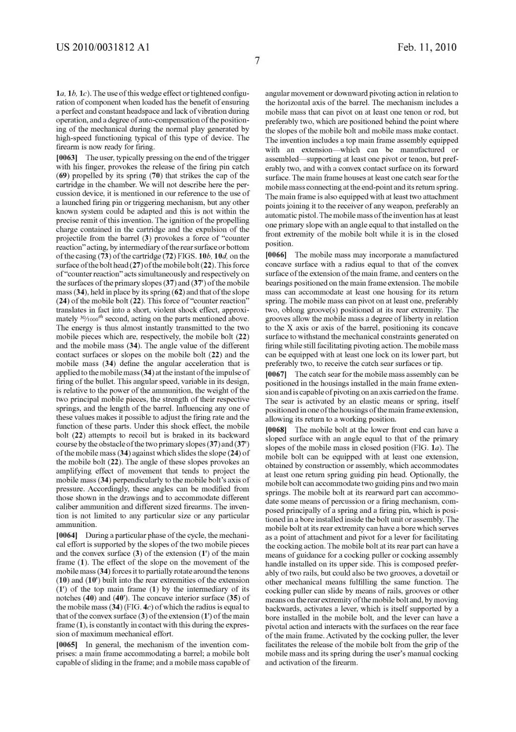
REFERENCE FOR RELATED APPLICATIONS
[0001] This application claims priority benefit to Switzer-
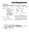
land national application 01239/08, filed Aug. 11, 2008, the
entire contents of which are incorporated herein by reference.
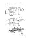
BACKGROUND AND INTRODUCTION
[0002] The invention concerns a delayed blowback firearm
comprising a novel mechanism for reducing muzzle climb
and attenuating recoil. The novel device resides forward of
the bolt head and below the barrel and employs a mobile mass
that reacts to firing in a manner to counteract recoil and
muzzle jump forces in order to improve the handling and
control of the firearm in use. Automatic and semi-automatic
firearms, rifles, and pistols, can be fitted with the novel
mechanism.
[0003] For some time there have been a number of
mechanical systems available that are based on the principle
of delayed blowback. All of them have been adapted for light
automatic and/or semi-automatic firearms. These systems
can be classified in three main categories and one sub-cat-
egory, which are:
[0004] a) The delayed blowback of the bolt by inertia,
known as the blowback bolt. In this case, the delayed
blowback effect is generated solely by the weight of the
mobile bolt and the force of a spring.
[0005] b) The delayed blowback of the bolt by means of a
lever, slope and/or use of gas. Apart from those that use gas,
these more complicated systems are paradoxically as old as
automatic firearms with blowback bolts. Their advantage
lies in better control of forces and a significant reduction in
the weight and volume of firearms designed and built using
these systems.
[0006] c) Delayed bolt blowback using a braking system.
This last category will not be covered since it was aban-
doned long ago by the gunsmithing industry.
[0007] In the majority of cases, and with regards to the
second category of systems, the mechanism for delayed
blowback generally consists of three to five mobile parts, the
only exception being for the sub-category of firearms using
the principle of gas delayed blowback devices that use only a
single mobile part (the functioning principle of Volksstur-
mgewehr). This last system is however rarely used and rep-
resents a very small share of global production of automatic
pistols.
[0008] All these systems with delayed blowback each have
the drawbacks inherent at the time of their conception, the end
of the 19th and beginning of the 20th century. At this period,
the chemistry of smokeless powder was still in its early
stages. Combustion time and gas volume (hence pressure)
generated by these powders imposed specific mechanical
solutions relative to the state of metallurgy of the time. At the
dawn of the 21 st century, while the science and technology of
powders and explosives have continued to evolve, we still use
the same mechanisms, practically unchanged, which have
now become totally unsuitable for these modern powders.
[0009] The simple blowback bolt has long been used to
good advantage to design simple, easy-to-use, often low-cost
automatic firearms. However, this particular system is suit-
able only for the use of relatively low power ammunition, as
used by hand guns. Even with this kind of ammunition, the
gun needs to have a heavy bolt to ensure that the projectile
maintains acceptable ballistic characteristics. The need to use
relatively heavy bolts imposes minimum volumes and dimen-
sions that make the firearm heavy and cumbersome compared
to the power of ammunition used. A few, rare automatic
pistols have been designed and produced incorporating this
first system, but the volume and weight constraints call for a
powerful spring to compensate for reduced bolt weight, mak-
ing the gun particularly difficult to handle. If this configura-
tion is perfect for the design of small caliber automatic pistols
(6.35 mm, 7.65 mm) it reaches its limits with the world’s most
commonly used ammunition for handguns, the 9 mm Para-
bellum. It is unusable for another major handgun caliber, the
famous 11.43 mm or 0.45 calibers. As history confirms, no
pistol functioning according to the blowback bolt principle
has ever been produced for this ammunition.
[0010] The second category of delayed blowback systems
uses an amplification lever, oblique helicoidal ramps or other
slopes—the list is not exhaustive since there are so many
variants. All these systems have a prime objective: to create a
mechanical demultiplier of opposable force to that generated
by the explosion of the powder charge contained in the car-
tridge. The second objective, consequence of the first, is to
reduce the weight and volume of the total mass of the mobile
unit that comprises the bolt. But a demultiplication effect
becomes inversely overdrive, since the mobile unit of the gun
is lighter so that it moves at a speed corresponding to over-
drive ratio during the firing of the shot. This ratio is effectively
variable but generally oscillates between 1:3 and 1:4 in func-
tion of the ammunition used (this system can be used for all
types of ammunition). In consequence, the mobile unit para-
doxically ends its movement in the receiver with energy that
is much greater than the single mass of a blowback bolt. If, in
the case of a machine gun pistol or heavier firearm, this
energy can be dissipated by some kind of shock-absorbing
device, or simply by a longer movement of the whole
ensemble, these options are not available in an automatic
pistol where the total passage of this mobile unit or bolt is
mechanically and physically limited. The consequence of this
short space is an abrupt stop of the mobile unit at the end of its
course while its energy is still considerable. This provokes
recoil and muzzle jump of the firearm that are prejudicial to its
control and precision. This phenomenon is common to all
automatic pistols, without exception, notably those function-
ing according to the principle of short recoil and barrel tilt
wrongly referred to as the ‘Browning system’ which repre-
sents nearly 80% of global production of automatic pistols.
[0011] In all cases, and whichever of the systems described
above is employed, in mechanical terms, they no longer meet
the advantages offered by modern ammunition.
SUMMARY OF THE INVENTION
[0012] The object of this invention is a delayed blowback
firearm with a mechanism that is adapted to modem ammu-
nition and which makes it possible to reduce muzzle climb
and correspondingly reduce recoil on firing. The mechanism
that distinguishes this invention is based on the principle of
delayed bolt blowback and functions in a way that is quite
distinct from the existing systems described previously. The
invention combines solutions to several mechanical and
physico-dynamic problems in a light automatic or semi-au-
tomatic firearm or pistol using modem ammunition. As stated
before, modem ammunition has a speed, thus an inflamma-
US 2010/0031812 Al
Feb. 11,2010
2
tion time, which is considerably shorter than those existing
when the principal systems used today in ‘modem’ pistols
were invented. This important characteristic makes it possible
to dispense with these old mechanisms designed to keep the
bolt closed for long enough to allow complete powder com-
bustion since this problem no longer exists today. Modern
powders have a velocity of nearly 2/ioooth second, which is at
least 2.5 times faster than powders of mid-20th century. The
mechanism that characterizes this invention makes it possible
to significantly reduce the time of bolt restraint at the point of
powder charge or explosion. To accomplish this reduction in
time, the invention makes use of a mobile mass, rather than a
lock, which acts in part as a blowback brake. This has the
advantage of being easily controllable because its movement
is physically dissociated from that of the mobile bolt and,
above all, because the inert mass of the mobile bolt and the
point of inertia for the mobile mass act according to different
directions and speeds.
[0013] The mechanism characterizing this invention allows
much better control of excess energy produced by powder
ignition by dividing and re-directing the forces produced at
firing and deflagration. This advantage makes it possible to
make more compact and/or lighter parts than those of an
automatic pistol functioning according to the Browning,
Walther, or other systems based on short barrel recoil (e.g.
Steyr) or classic delayed blowback (e.g. Heckler & Koch) and
in which their mobile units (often called transporters) or bolts,
move after the departure of the shot, in a generally linear way,
in (or on, in the case of pistols) the frame of the firearm. These
relatively heavy mobile units, which stop abruptly at the end
of their course, are at the origin of more than 60 to 70% of the
firearm’s recoil force (mechanical recoil). The other 30 to
40% are due to the blast provoked by the violent escape of gas
from the barrel (dynamic recoil). The mechanism described
in this invention has the advantage of making it possible to
reduce the weight of the mobile bolt, the only component
effecting a rearward translation on the X axis along the barrel,
by at least 100 grams.
[0014] Advantageously, the mobile bolt that can be used in
the mechanism characterizing this invention is or can be three
times lighter than a transporter (bolt) of a classic modern
pistol, of which we have cited some names by way of example
above. As a result, there is minimal recoil and muzzle climb
since the receiver is required to stop a mobile bolt being able
to weigh less than 100 grams and traveling at a speed no
greater than that of a classic firearm, and since its energy has
been essentially dissipated in the propulsion of a novel mobile
mass apparatus, by means that will be described below. The
laws of physics are inescapable. The mobile mass has a simi-
lar weight to that of the mobile bolt, although this can be
easily modified to increase or reduce the operational cycle
time (firing rate). As such, the mobile mass as described here
is the principal means for controlling energy.
[0015] Another advantage of this invention is that the
mobile mass undergoes an acceleration that is equivalent to
the value of the primary angle of its slopes that contact that of
the mobile bolt. This is the second means of energy control
and the mobile mass can thus propelled at a speed from about
3.5 to more than 4 times greater than that of the mobile bolt
(depending on ammunition used for the same barrel length).
The third means of energy control is the strength of the mobile
mass return spring, which is an important element for the
functioning of the mechanism. These characteristics of the
invention make it possible to transfer the mobile mass’s point
of inertia to the whole firearm and thus to the hand and arm of
the operator. This movement, from top to bottom, transmitted
throughout the whole firearm makes it possible to signifi-
cantly reduce the muzzle climb provoked by firing.
[0016] A further advantage lies in the fact that the amount
of energy dissipated by the action of the mobile mass, as it
stops suddenly in its course, is subtracted from that of the
inertial mass of the mobile bolt. So, at the end of its course, the
mobile mass gives back considerably more energy than that
dissipated by the mobile bolt in its backward] ourney (stroke)
and abrupt stop in the receiver. The mobile mass effects a
downward pivot force in relation to the X axis of the barrel,
making it possible to release its energy in a direction which is
definitely perpendicular to the axis of the barrel as well as the
initial pressure of the mobile bolt, and making it possible to
generate a dynamic effect in counter balance to the natural
muzzle climb of the firearm, especially during automatic
firing. The mechanism characterizing this invention can also
include a catch device at the end of the course of the mobile
mass. This catch unit or sear has two distinct functions: first,
it stops the mobile mass in a low or down position and pre-
vents it rebounding at the point of its abrupt stop in the
extension of the receiver. This is designed to allow the transfer
of all of its energy and prevent rebounding forces. The second
function of this catch sear is to hold the mobile mass until the
bolthas returned to firing position. If, for whatever reason, the
bolt does not go back to its initial position, the mass will not
be released.
[0017] A firearm designed using the mechanical principles
that characterize this invention also has the advantage of a
fixed barrel that does not directly participate in the function-
ing of the firearm—in other words, no barrel recoil is not
required. Thus, the barrel can be simply screwed, pinned, or
fixed using some kind of system common to the state of the art
in this area. This characteristic guarantees high precision in a
firearm, the barrel being mounted on a piece within the main
frame, the same piece that can support the sights and other
accessories. The main frame can easily accommodate on its
upper part, either by manufacture or fabrication, a system of
special sights or accessories, such as those compatible with
‘Picatinny rail’ type of accessories. The main frame is con-
nected to the lower part of the firearm, preferably with a
triggering mechanism and trigger and trigger guard, as for
example, in common pistol or rifle manufacture. Any existing
trigger assembly and firing mechanism and associated assem-
bly method could be selected for a suitable use with the
firearm mechanisms of the invention.
[0018] In another advantage brought about by this inven-
tion, the dimensions of the mobile bolt in particular and the
mobile parts in general allows for the design of light, compact
firearms. And a further benefit characterizing this invention
lies in the fact that, particularly for an automatic pistol, the
axis of the barrel can be positioned very low in comparison to
that of other pistols of the same caliber. The mechanism
characterizing this invention allows a reduction of nearly 15%
in this distance compared to classic arms design. This results
in a further possibility for reducing significantly the muzzle
climb of the gun, given that the primary pivotal axis of the
firearm is the firer’s hand or wrist joint. This natural pivotal
axis is invariably positioned under the axis of the barrel for
obvious ergonomic and morphological reasons. The reduc-
tion of the distance between the horizontal axis of the barrel
US 2010/0031812 Al
Feb. 11,2010
3
and the pivotal point of the firer’s hand also has a direct
influence on the phenomenon of muzzle climb as the bullet is
fired.
[0019] In various embodiments, a firearm of the invention
includes a counteracting mobile mass that is designed to
offset the muzzle climb recoil forces famous in a variety of
firearms, especially when operated in automatic firing or
burst firing modes. While not limited to an automatic firearm,
the invention can be most appreciated when joined with a
semi-automatic or automatic action. As stated, the mobile
mass is configured to move in reaction to firing and to counter
the recoil forces upon firing. Typically, a firearm of the inven-
tion includes as basic recoil controlling aspects a barrel with
a cartridge-chambering end and a firing end, as is conven-
tional. A mobile bolt configured to move along the axis of the
barrel from a forward to a rearward position, or in transla-
tional movement along the axis defined by the barrel is also
included. The mobile mass is generally configured to pivot
from a upward and cocked position under the barrel, and
generally forward of the chambering end of the barrel, to
pivot to a lower or downward position. The mobile mass and
mobile bolt each have at least one surface that forms a contact
between them, a contact that ultimately directs the mobile
mass to pivot downward. There are preferably more than one
contact surfaces on the mobile mass, but both the mobile mass
and mobile bolt can be designed with various contact sur-
faces. The contact surface of the mobile bolt can be in the
form of a projection that extends forward of the bolt head, the
forward projection including a region designed to contact the
mobile mass with an angled or sloped surface. A firearm also
includes a receiver and in the case of the invention here
comprises a top main frame part of a receiver that is config-
ured to allow the movement of the mobile mass from a for-
ward-most cocked position to a rearward position, while also
preferably confining the mobile bolt within the axis of the
barrel. This top main frame part of the receiver further
includes at least one forward extension assembly for fixing a
barrel and for connecting the mobile mass below the barrel
and forward of the chambering end of the barrel. A connec-
tion point for the mobile mass on the extension allows the
mobile mass to pivot. A further pivot point on the extension
can be used for a mobile mass return spring or restraining
device, so that the mobile mass and the assembly that confines
and directs its pivoting movement are both connected to the
extension, and preferably by separate pivot point on the
extension.
[0020] The mobile bolt itself includes in a preferred
embodiment a projection that is the surface that contacts the
mobile mass, which projection contacts the mobile mass at a
first angled surface of the mobile mass. Upon firing of the
firearm, the contact or action of the mobile bolt projection
pushing against the first angled surface of the mobile mass
directs the pivoting movement of the mobile mass downward,
and preferably away from the barrel. This downward move-
ment of the mobile mass counteracts the muzzle climb and
recoil forces upon firing.
[0021] In more particular embodiments, the first angled
surface of the mobile mass joins a surface of the mobile bolt,
or projection of the mobile bolt, so that substantially no gaps
exist along the length of the first angled surface in the loaded
or cocked position. In other embodiments, the mobile mass
has more than one angled surface, such as first and second
angled surfaces, the first angled surface contacting a surface
of the mobile bolt immediately after firing and/or in the
cocked or loaded position. The firearm can include a main
spring linked to the mobile bolt and configured to assist the
backward to forward movement of the mobile bolt during
cycling. The firearm can also have a spring linked to the
mobile mass, the spring configured to assist the pivot move-
ment from a lower position to an upward position. This spring
can also dissipate some of the recoil forces. A particular
embodiment also includes a spring-loaded catch sear within a
mobile mass assembly. It is a spring-loaded catch sear in that
part of the movement of the catch sear is resisted and/or
assisted by a spring or other resistance device. The catch sear,
in any embodiment, is linked to the mobile mass and is
capable of temporarily restraining, or in some embodiments
locking, the mobile mass from pivoting upward into a loaded
position. This can be a safety mechanism to prevent move-
ment of parts when proper loading or chambering is somehow
prevented.
[0022] The design of the mobile mass and its connection to
the frame can be one of many selected by the designer, based
upon many factors. In one option, the pivoting movement of
the mobile mass is in the same plane defined by the barrel and
is between about 10 to about 70 degrees of displacement from
the upward position to the lower and most-downward posi-
tion. While the movement may be confined in the plane of the
barrel, the size of the mobile mass itself need not be the same
size as the barrel. Thus, a mobile mass that exceeds the
diameter dimension of a selected barrel can be used. In fact,
the shape of the mobile mass is essentially one of the design-
er’s choice, only one of which is presented in the drawings
here. Similarly, the designer may select one of many angles
for the contact surfaces between the mobile mass and the
mobile bolt. In fact, the contact need not be a direct contact,
but linkages and rod can be used. The embodiments shown in
the drawings all have a direct contact point between the
mobile mass and the mobile bolt. A first angled surface of the
mobile mass can forms an angle of between about 10 degrees
and about 70 degrees with respect to a line perpendicular to
the longitudinal axis of the barrel, for example. Other angles
can be selected and ranges include 20-50, 10-30, 30-60, and
any number of angles. Accordingly, the invention includes
methods to vary the contact surfaces between the mobile mass
and the mobile bolt, the number of contact surfaces, the
angles of them, and the gap or play between the surfaces at the
loaded position or other positions, in order to design an opti-
mum system for a particular caliber, including an optimum
muzzle-climb control and optimum firing rate.
[0023] In addition, the firearm can employ a mobile mass
that has a partially hollowed central region configured to
move over a part of the top frame extension that extends
below the barrel. It can also be configured to cover a spring
linked to the mobile mass, where the spring assembly is
configured to assist the pivot movement of the mobile mass
from a lower position to an upward position.
[0024] In another general aspect, the invention can be a
firearm comprising a barrel having a firing end and a cham-
bering end and a counter-acting mobile mass positioned
below the barrel and at the firing end. The firearm includes a
mobile bolt that is formed with a surface to contact and/or
strike a surface of the mobile mass. The bolt generally has a
forward and a rearward position and is capable of pushing
against or striking the mobile mass at the forward position or
during movement from its forward-most position to a rear-
ward position. While a tight junction between the mobile
mass and the mobile bolt is preferred in the cocked or loaded
US 2010/0031812 Al
Feb. 11,2010
4
position, some play between the contact surfaces can be
designed into any embodiment of the invention. The firearm
also includes a top main frame formed to hold the barrel at the
firing end of the top main frame, the top main frame compris-
ing a surface for the mobile bolt to move from the forward to
the rearward position along the axis of the barrel during the
operation of the firearm. The frame also includes an extension
aspect, at the top main frame near the barrel end, comprising
a connection point for the mobile mass that is positioned
below where the barrel is fixed to the frame. The extension is
positioned at a fixed point at the firing end of the top main
frame, and wherein the connection to the mobile mass allows
the mobile mass to pivot downward from a cocked upward-
most position to a lowered, downward-most position, and
generally from near the barrel to away from the barrel. This
movement is in reaction to the rearward movement of the
mobile bolt after firing. The downward movement forced
upon the mobile mass by the movement of the mobile bolt in
reaction to firing counteracts the upward, muzzle climb recoil
forces known in the art.
[0025] Having generally described the invention and its
operation, we now refer to the drawings and the exemplary
embodiments that follow. These are examples and not limi-
tations of the scope of the invention.
BRIEF DESCRIPTION OF THE DRAWINGS
[0026] The invention will be revealed in more detail with
the aid of realization examples represented by the following
drawings. The drawings should not be taken as a limitation of
the extent of the invention, but merely an optional design
choice based upon the invention.
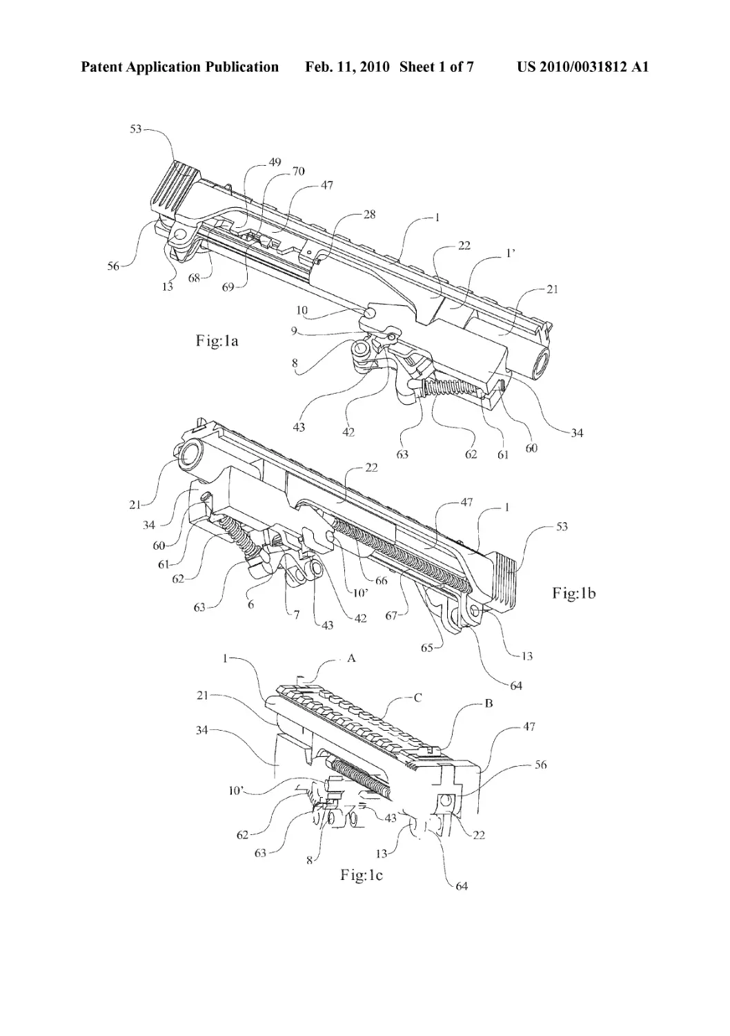
[0027] FIGS, la, lb, and 1c show different angles of the
ensemble of components that make up the delayed blowback
device as they particularly interact with a top frame of a
firearm.
[0028] FIGS, 2a and 2b show an exemplary main frame in
isolation, excluding the other principal mechanical elements.
[0029] FIGS. 3a and 3b show details of the mobile bolt.
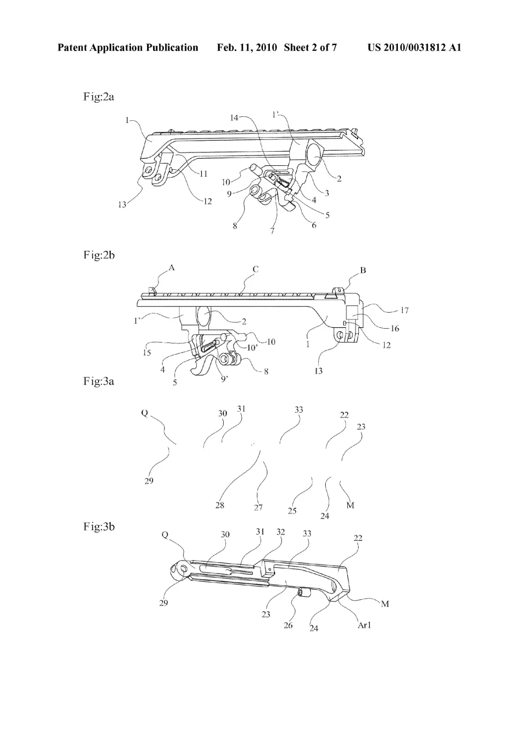
[0030] FIGS. 4a, 4b, and 4c show details of the mobile
mass.
[0031] FIGS. 5a and 5b show the end-point restraining
catch unit or catch sear.
[0032] FIGS. 6a and 6b show the cocking puller.
[0033] FIG. 7 shows the lever (came d’armament) that
resides within the handle for the cocking puller.
[0034] FIGS. Sa, Sb, and 8c show the working of the
weapon mechanism. The element “G” generically represents
a triggering mechanisms and its interaction with mechanism
of the invention. The type of triggering mechanism selected
for use is optional. The arrow at “F” represents the direction
of movement of the cocking puller and bolt in reaction to
firing.
[0035] FIG. 9a shows the position of the overdrive lever
during the action of the weapon.
[0036] FIG. 9b shows the guiding pin (25) of the main
spring in the rear-most position.
[0037] FIGS. 10a, 10/?, 10c and 10<7 show the complete
cycle of loading, firing, and ejection.
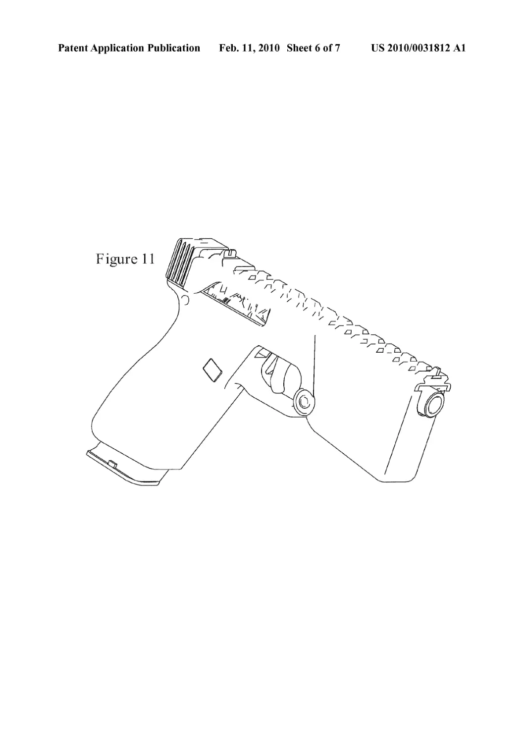
[0038] FIG. 11 shows an example of the invention incorpo-
rated into a pistol with covers or housings blocking the view
of the mechanisms.
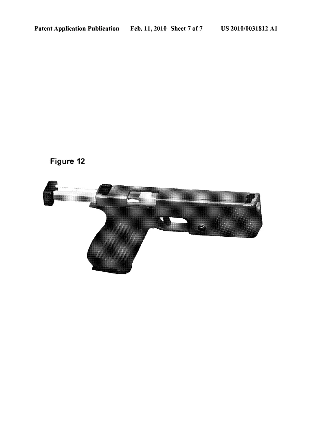
[0039] FIG. 12 depicts an exemplary pistol embodiment
with cocking puller extended.
EXEMPLARY DESCRIPTION OF THE
INVENTION
[0040] The following description is an example of how the
mechanisms of this invention could be realized, and referring
particularly to a pistol or small caliber firearm. However,
many other firearm sizes, types, and designs can be used in the
alternative. This description is not designed to exhaustively
detail all aspects of the invention, but is but to show one of the
many embodiments possible. As discussed in this document,
the directions “rear,” forward,” “rearward,” downward,”
“upward” etc., refer to positions relative to the barrel of a
firearm and from the perspective of an operator holding or
firing the firearm, where the firing end of the barrel is forward
and the chambering end rearward. The barrel also defines the
axis of the barrel or a longitudinal axis of the barrel.
[0041] FIGS, la, lb and 1c show the ensemble of parts
comprising the delayed blowback device in a pistol format.
This is composed of: a top main frame (1) unit and its exten-
sion (1') assembly, and as shown in FIGS. 2a, 2b, accommo-
dating a barrel (21), which is optionally screwed into the top
main frame (1) or attached by some other established means
into the aperture housing (2) of the extension (1') of the frame.
This part (1') is joined to the top main frame (1) either by
manufacture or fabrication. It is fixed to the top main frame
(1), and can be fixed, for example, by rivets, welding, or any
other known assembly method. The top main frame (1) has a
stirrup-shaped aperture (16) at its rear extremity, allowing the
bolt-end (Q) to partially protrude during its backward move-
ment, shown in FIG. 8c and FIG. 12. The rear extremity of the
main frame (1) accommodates a bore (12) FIG. 2b for a barrel
and can be positioned to allow the main spring guiding pin
(66) to slide during the backward movement of the mobile
bolt (22) and to allow restraint of the return spring (67), as in
FIG. lb. The top main frame (1) has two fixed pivot points
provided by the bores (8) and (13), as in FIGS, la, 2a, it being
possible to accommodate metal fixing pins orrods in any kind
of automatic firearms frame whether pistol or other, as shown
in FIG. 11, by way of example. The top main frame (1) can
house, by way of manufacture or some other process, an
attachment allowing rapid adaptation with a variety of sight-
ing or lighting apparatus and/or other accessories known as a
‘Picatinny rail’ (C). The top main frame (1) is typically
equipped with the usual aiming devices (A),(B) in FIG. 1c,
particularly at each of its extremities.
[0042] A mobile bolt (22) (FIGS. 3a, 3b) consists of a
surface or bolt head (27) for engaging a cartridge, an extractor
(28), a reception channel (30) for the firing pin, a catch pin
(25) and its housing (26), and the head of the guiding pin (66)
for the main spring (67), as in FIGS, lb, 3b. The complete
mobile bolt assembly (22) includes at its rear extremity,
shown as the bolt end (Q), a bore hole (29) in FIGS. 3a, 3b,
furnishing the pivoting axis point and fits with the holes (59)
of lever (56), shown as the lever of FIG. 7. This lever (56) is
used in cocking to ease the tension of the pressure required for
the operator to cock the firearm. The bolt end (Q) is equipped
with two guide rails (31) and (31') on each of its lateral
surfaces and accommodating the cocking puller (47) exten-
sion, which slides between the two rails (31) and (31') of the
bolt end (Q) by means of two grooves (48) and (48'), as shown
in FIG. 6a and FIG. 3a or 3b. The bolt end (Q) also carries the
return tappet (68) of the cocking puller (47) and its spring (not
US 2010/0031812 Al
Feb. 11,2010
5
visible), shown in FIGS, la, 9. The mobile bolt (22) is
equipped with an oblique surface or slope (24) (FIG. 3b) at
end point (Ari) obtained by construction and of which the
angle of slope can be equal to or fitted to the angle selected for
the primary slopes (37) and (37') of the mobile mass (34)
(FIG. 4b), so that the sloped (24) projection of mobile bolt
(22) fits into area of slopes (37) and (37') of mobile mass (34),
as shown by the tight fit of the two contact surfaces of the
mobile bolt (22) to the mobile mass (34) in FIG. la. The slope
area continues through to straight area (33) in projection. The
bore (23) in forward projection area (M) and (Ari) of mobile
bolt is designed for a particular barrel size.
[0043] On the mobile mass (34) (FIGS, la, lb, 1c and
FIGS. 4a, 4b, 4c) there are two primary slopes (37) and (37'),
two secondary slopes (38) and (38'), and two guide planes
(39) and (39')—all cut during manufacture. The selected
angles for each of these slopes varies by design, by caliber
employed, and by the desired rate of fire in automatic mode.
All of the selected angles shown in the drawings are designed
for a 0.45 caliber machine pistol, but all angles can vary by at
least ±5° oral least ±10° oral least ±30° from those shown in
the drawings here. The primary slopes (37) and (37') are the
surfaces of the mobile mass that contact the mobile bolt
surfaces during the backward movement of the mobile bolt
immediately after firing to push the mobile mass into its
downward pivoting movement. Thus, the contact surfaces
must be designed so that the force of the backward movement
of the mobile bolt allows the downward pivot of the mobile
mass in reaction to firing, as that is the only operational
limitation of the angles and design shapes chosen. As
described above, these two surfaces are preferably machined
to tightly fit against one another when in the position as in
FIG. la, without any gaps caused by a difference in the angles
or lengths of the surfaces. However, there is no requirement
that the surfaces be as depicted in the drawings here.
[0044] The angle of the largest downward displacement of
the mobile mass (34) can also be varied from that shown in the
drawings. FIG. 8c shows the mobile mass at its furthest down-
ward pivot position, which is approximately 20° to 30° from
the line created by the axis of the barrel. Again, this angle can
be selected based upon a number of design options, including
caliber, weight of component parts, and rate of fire. Option-
ally, this downward displacement angle can be as high as 90°,
but a range from about 20° to about 60° is preferable.
[0045] At its rear extremity, the mobile mass (34) has two
semi-oblong notches (40) and (40') (FIG. 4b) to pivot on the
tenons (10) and (10') (FIG. la), which tenons are part of the
extension (1') of the top main frame (1), also shown in FIG.
la. A cavity (35) and groove (35'), shown in view of mobile
mass in FIG. 4a, for the guiding pin (60) of the mobile mass
return spring (62), assembly shown in FIGS, la and lb, are
installed in the forward under part of mobile mass (34) to
accommodate the guiding pin (60) of the mobile mass return
spring (62) and its push plate (61), which push rod interacts at
point (6) (FIG. 2a) of extension (1') and at the other end with
rounded end (63) (FIG. la) of spring assembly. The mobile
mass (34) can be constructed or fabricated to have two inter-
nal tenons (36) and (36') on the two internal lateral surfaces of
the U-shaped cavity of the extreme rear of the mobile mass
(34), shown in FIGS. 4b and 4c. These two internal tenons
(36) and (36') have the function of stopping the mobile mass
(34) at the end of its downward pivoting course, as shown in
FIG. 8c, and striking against the surface (5) of the extension
(!') of the top main frame (1), shown in FIGS. 2a, 2b, to
prevent further downward travel of the mobile mass. The size
and resistance provided by the mobile mass return spring (62)
determines the force with which the mobile mass strikes at
surface (5).
[0046] The restraining catch sear (42) of the mobile mass
assembly is shown in FIG. 5b, and in another view in FIG. 5a.
The extension (1') of the top main frame (1) carries a tenon (9)
that forms the end-point of movement for restraining catch
unit (42) for the mobile mass (34), allowing it to pivot, as
shown in FIGS, la and 2a. The catch sear (42) is released by
a ‘pin’ spring (7) positioned in the cavity (4) of the extension
(1') of the main frame (1), shown in FIGS. 2a, 2b. Its upper
part is in contact with the working lug (46) of FIG. 5a. The
restraining catch unit (42), shown in FIGS. 5a and 5b, fits and
pivots in the mobile mass (34) by the lower extremities (43)
and (43') interacting with the two upper ridges (Ar) and (Ar')
of the mobile mass (34), shown in FIG. 4c. The restraining
catch sear assembly can be designed to restrain the speed of
the upward pivot movement of the mobile mass (34) so that it
coincides with the return movement of mobile bolt (20) and
the correct surfaces can contact each other, as shown in the
progression of movement in FIGS. 10c. 10/?, and 10c, show-
ing the loading of a round into the barrel chamber.
[0047] System Function
[0048] The cycle starts with the explosion of the powder
charge contained in the cartridge casing in the barrel chamber.
This propels the projectile through the barrel and then,
through delayed blowback system, the mobile bolt (22), by
means of its forward end section slope (24) surface, exerts a
pressure on the surfaces (37) and (37') of the mobile mass
(34), forcing the mobile mass to pivot downwards on the
tenons (10) and (10'), which are part of the extension (1') of
the main frame (1). FIG. 1 Od shows the mobile mass in the
downward pivot position and a spent cartridge case (73) exit-
ing. The mobile bolt (22) continues its backward movement
while ejecting the fired cartridge casing and then comes to a
stop by hitting the rear internal surface (11) (FIG. 2a) of the
main frame (1). The violently propelled mobile mass (34)
travels from top or upward-most position (FIG. 8a), parallel
to the axis of the barrel, to a bottom-most position (FIG. 8c),
and then is itself stopped by internal rods or tenons (36) and
(36') contacting with the surfaces (5) and (5') (FIGS. 2a, 4b,
4c) of the extension (1') of the main frame (1). The abrupt stop
of the mobile mass generates a counteracting force to the
natural muzzle jump of the weapon.
[0049] The triggering device is not the object of this inven-
tion. An existing system of launching a firing pin with a
symbolic triggering mechanism is shown here as “G” (FIG.
8a), by way of example, in order to facilitate a better com-
prehension of the text and figures they relate to.
[0050] The explanation of the working cycle can also begin
with ‘bolt closed’ (FIG. 8a). The operator seizes the grooved
section (53) of the cocking puller (47) between his fingers,
FIGS, la, lb, 1c, FIG. 5, FIG. 8a, then FIGS, la, lb, 1c, FIG.
5, FIG. 8a. A backward force in the direction of the arrow (F)
(FIG. 8b) moves the cocking puller (47) by sliding on the
guide rails (31) and (3T) fabricated in the end (Q) of the
mobile bolt (22) by means of the grooves (48) and (48'). This
forces the lever (56) to pivot on the axis carried by the bore
(29) of the end (Q) of the mobile bolt (22), and crossing the
bore (59) under pressure from the surface (54) cut into the
interior of the cocking puller (47), shown in FIG. 6b, by action
against the surface (57) of the upper extremity of the lever
(56) of FIG. 7.
US 2010/0031812 Al
Feb. 11,2010
6
[0051] The traction exerted during this movement by the
lower section (58) of the lever in contact with the surface (17)
of the rear extremity of the main frame (1), shown in FIG. 2b,
creates a leverage effect that can be greater than 5:1, as assists
the operator in cocking the firearm even under the forces of
the internal springs. This cocking action forcing the mobile
bolt (22) to move slightly backward as in FIG. 8b compared to
FIG. 8a. The cocking puller (47) is stopped in its backward
movement by the lever (56), itself restrained by its axis posi-
tively linked to the end (Q) of the mobile bolt (22). During this
displacement, the mobile mass (34) rotates towards the bot-
tom, provoked by the slide of the slope (24) on the extreme
front underside of the mobile bolt (22) and the slopes (37) and
(37') of the mobile mass (34), seen in FIGS. 4b, 8b.
[0052] The cocked position of the mobile mass (34) pre-
sents dynamic resistance to the movement of the mobile bolt
(22) corresponding to three principal factors, which are: the
angles of the slope surfaces (37) and (37') (which can be
represented as the angle formed between this surface and a
perpendicular line down from the line formed by the longi-
tudinal axis of the barrel of the firearm when the mobile mass
is at its forward position as in FIGS, la and 8a); the force of
the mobile mass return spring (62); and the bolt’s weight.
These factors make it possible to fine-tune forces and con-
straints for optimized operation of the mechanism character-
izing this invention—whichever type of ammunition is used.
The mobile bolt (22), still under the constraint of the traction
effort generated by the user in cocking, forces the mobile
mass (34) to pivot respectively on its semi-oblong notches
(40) and (40') FIGS. 4b, 4c, and on its tenons (10) and (10')
FIGS, la, 2a, housed in the extension (T) of the main frame
(1).
[0053] The ridge (Ari) of the slope (24), FIG. 3b, cut into
the extreme underside of the mobile bolt (22) continues back-
wards, and slides on the secondary slopes (38) and (38') of the
mobile mass (34). The angular value of these secondary
slopes (38) and (38') is, in this position, less than about 60°,
but can vary by design (again, the angle can be represented as
that formed between this surface in FIGS, la and 8a and a
perpendicular line down from the line formed by the longi-
tudinal axis of the barrel the angle). The mobile mass (34)
thus presents minimal resistance to the mobile bolt (22). Still
moving backwards, the ridge (Ari) of the slope (24) of the
mobile bolt (22) intersects with the two upper ridges (Ar) and
(Ar') (FIG. 4c) of the mobile mass (34). At this point, the
mobile mass (34) reaches its lowest point of angular displace-
ment—in the case of a pistol as presented in the present
drawings, about 20°, orwithin±10° or ±5° of20° (compared
to position parallel to the longitudinal axis of the barrel). This
value is purely indicative of the caliber and size of firearm
desired as in the drawings presented here, and naturally the
value can vary depending on the construction and dimensions
of the mechanism, the caliber and size of the firearm, and
other design options, including the weight and mass of the
mobile mass itself.
[0054] The mobile bolt (22) can continue its course back-
ward translational movement sliding on the surfaces (39) and
(39') of the mobile mass (34), shown in FIG. 4b, under the
effect of the traction still exerted by the user who no longer
has to combat the force of the main spring (67) FIG. lb. As the
mobile bolt (22) proceeds backwards, this translation releases
the restraining catch sear unit (42) of the end-point of the
mass (34), which under the effect of its spring (7) positioned
in the cavity (4) of the extension (!') of the top main frame (1),
in FIGS, la, 2a, engages its lower extremities (43) and (43'),
in FIGS. 5a, 5b in the notches (41) and (41') cut into the
surface of the mobile mass (34), as in FIG. 4b. The mobile
mass (34) is thus locked into its lowest position. The mobile
bolt (22) completes its backward movement striking with its
surface (32) in FIG. 3b against the internal rear surface (11) of
the top main frame (1), shown in FIG. 2a. The arming move-
ment of the mobile bolt (22) is completed as shown in FIGS.
8a, 8b and 8c.
[0055] Three design possibilities are now present:
[0056] a) The gun does not have a magazine catch—the
mobile bolt returns to its initial position under the effect of
the main spring while the charger is not engaged.
[0057] b) The gun is equipped with a magazine catch—the
mobile bolt and its components stay in the rear position if
the magazine is empty or disengaged.
[0058] c) The gun’s magazine is engaged and contains at
least one cartridge.
[0059] Only this last case is discussed here.
[0060] The user releases the grooved extension (53) of the
cocking puller (47) connected to the mobile bolt (22) through
intermediary parts (i.e., lever (56)), positively connecting
with the end (Q) of the mobile bolt (22) by a rod (not shown)
through its bore (29) and the bore (59) of the lever (56) (FIG.
7). The mobile bolt (22) unit begins a forward translational
movement under the pressure of the main spring (67) com-
pressed between the internal surface (11) (FIG. 2a) of the rear
extremity of the main frame (1) and the head of the guiding
pin (66) of the main spring (67), the front end of which
interlocks with the housing of the catch plate (26) (FIG. 3b)
on pin (25) (FIG. 3a). In this movement forward, the mobile
bolt (22) enters into contact with the bottom of the cartridge
(72), usually held by the lips on magazine (71), and extracts a
cartridge (72) from the magazine to load it into the barrel
chamber, as in FIGS. 10a, 10/?. At the same time, the cocking
puller (47) returns to its initial position under the effect of the
spring (not visible) of the return tappet (68) operating on the
finger or peg projection (49) of the cocking puller (47). The
mobile bolt finishes its movement forwards after having
introduced the cartridge (72) into the barrel chamber. In the
same movement, the bolt forward surface (M) (FIGS. 3a, 3b)
enters into contact with the surface of the catch sear (42) (FIG.
5a) at point (44) while assembled into the mobile mass assem-
bly, shown in FIGS, la, 8a, 8b, and 8c, forcing the catch sear
(42) to fall by means of pivoting about its bore (45) on the rod
(9) (FIG. la) of the extension (1') of the top main frame (1).
[0061] The catch sear (42) (FIGS. 5a, 5b) of the mobile
mass assembly, as it rotates, releases its ends (43) and (43')
into the notches (41) and (41') cut into the mobile mass,
shown in FIGS. 4a, 4b, 4c. The mobile mass (34), under the
impulse of its return spring (62) guided by the guiding pin
(60) and in contact with the housing (6) of the extension (1')
of the top main frame (1), is pushed by the push plate (61) into
its initial position.
[0062] In this position, the mobile mass (34) wedges the
mobile bolt (22) provoking contact between the primary
slopes (37) and (37') of the mobile mass with the slope (24) of
the mobile bolt (22) and the convex surface (3) (FIG. 2a)
installed on the external forward surface of the extension (1')
of the top main frame (1), as shown in FIG. 2a. Such a
mechanical configuration naturally provokes a tightened
position between the three principal components of the
mechanism characterizing this invention; the mobile bolt
(22), the mobile mass (34) and the main frame(l) (see FIGS.
US 2010/0031812 Al
Feb. 11,2010
7
la, lb, 1c). The use of this wedge effect ortightened configu-
ration of component when loaded has the benefit of ensuring
a perfect and constant headspace and lack of vibration during
operation, and a degree of auto-compensation of the position-
ing of the mechanical during the normal play generated by
high-speed functioning typical of this type of device. The
firearm is now ready for firing.
[0063] The user, typically pressing on the end of the trigger
with his finger, provokes the release of the firing pin catch
(69) propelled by its spring (70) that strikes the cap of the
cartridge in the chamber. We will not describe here the per-
cussion device, it is mentioned in our reference to the use of
a launched firing pin or triggering mechanism, but any other
known system could be adapted and this is not within the
precise remit of this invention. The ignition of the propelling
charge contained in the cartridge and the expulsion of the
projectile from the barrel (3) provokes a force of “counter
reaction” acting, by intermediary of the rear surface or bottom
of the casing (73) of the cartridge (72) FIGS. 10/?, Ilk/. on the
surface of the bolt head (27) of the mobile bolt (22). This force
of “counter reaction” acts simultaneously and respectively on
the surfaces of the primary slopes (37) and (37') of the mobile
mass (34), held in place by its spring (62) and that of the slope
(24) of the mobile bolt (22). This force of “counter reaction”
translates in fact into a short, violent shock effect, approxi-
mately зо/юоол second, acting on the parts mentioned above.
The energy is thus almost instantly transmitted to the two
mobile pieces which are, respectively, the mobile bolt (22)
and the mobile mass (34). The angle value of the different
contact surfaces or slopes on the mobile bolt (22) and the
mobile mass (34) define the angular acceleration that is
applied to the mobile mass (34) at the instant of the impulse of
firing of the bullet. This angular speed, variable in its design,
is relative to the power of the ammunition, the weight of the
two principal mobile pieces, the strength of their respective
springs, and the length of the barrel. Influencing any one of
these values makes it possible to adjust the firing rate and the
function of these parts. Under this shock effect, the mobile
bolt (22) attempts to recoil but is braked in its backward
course by the obstacle of the two primary slopes (37) and (37')
of the mobile mass (34) against which slides the slope (24) of
the mobile bolt (22). The angle of these slopes provokes an
amplifying effect of movement that tends to project the
mobile mass (34) perpendicularly to the mobile bolt’s axis of
pressure. Accordingly, these angles can be modified from
those shown in the drawings and to accommodate different
caliber ammunition and different sized firearms. The inven-
tion is not limited to any particular size or any particular
ammunition.
[0064] During a particular phase of the cycle, the mechani-
cal effort is supported by the slopes of the two mobile pieces
and the convex surface (3) of the extension (T) of the main
frame (1). The effect of the slope on the movement of the
mobile mass (34) forces it to partially rotate around the tenons
(10) and (10') built into the rear extremities of the extension
(T) of the top main frame (1) by the intermediary of its
notches (40) and (40'). The concave interior surface (35) of
the mobile mass (34) (FIG. 4c) of which the radius is equal to
that of the convex surface (3) of the extension (1') of the main
frame (1), is constantly in contact with this during the expres-
sion of maximum mechanical effort.
[0065] In general, the mechanism of the invention com-
prises: a main frame accommodating a barrel; a mobile bolt
capable of sliding in the frame; and a mobile mass capable of
angular movement or downward pivoting action in relation to
the horizontal axis of the barrel. The mechanism includes a
mobile mass that can pivot on at least one tenon or rod, but
preferably two, which are positioned behind the point where
the slopes of the mobile bolt and mobile mass make contact.
The invention includes a top main frame assembly equipped
with an extension—which can be manufactured or
assembled—supporting at least one pivot or tenon, but pref-
erably two, and with a convex contact surface on its forward
surface. The main frame houses at least one catch sear for the
mobile mass connecting at the end-point and its return spring.
The main frame is also equipped with at least two attachment
points joining it to the receiver of any weapon, preferably an
automatic pistol. The mobile mass of the invention has at least
one primary slope with an angle equal to that installed on the
front extremity of the mobile bolt while it is in the closed
position.
[0066] The mobile mass may incorporate a manufactured
concave surface with a radius equal to that of the convex
surface of the extension of the main frame, and centers on the
bearings positioned on the main frame extension. The mobile
mass can accommodate at least one housing for its return
spring. The mobile mass can pivot on at least one, preferably
two, oblong groove(s) positioned at its rear extremity. The
grooves allow the mobile mass a degree of liberty in relation
to the X axis or axis of the barrel, positioning its concave
surface to withstand the mechanical constraints generated on
firing while still facilitating pivoting action. The mobile mass
can be equipped with at least one lock on its lower part, but
preferably two, to receive the catch sear surfaces or tip.
[0067] The catch sear for the mobile mass assembly can be
positioned in the housings installed in the main frame exten-
sion and is capable of pivoting on an axis carried on the frame.
The sear is activated by an elastic means or spring, itself
positioned in one of the housings of the main frame extension,
allowing its return to a working position.
[0068] The mobile bolt at the lower front end can have a
sloped surface with an angle equal to that of the primary
slopes of the mobile mass in closed position (FIG. la). The
mobile bolt can be equipped with at least one extension,
obtained by construction or assembly, which accommodates
at least one return spring guiding pin head. Optionally, the
mobile bolt can accommodate two guiding pins and two main
springs. The mobile bolt at its rearward part can accommo-
date some means of percussion or a firing mechanism, com-
posed principally of a spring and a firing pin, which is posi-
tioned in a bore installed inside the bolt unit or assembly. The
mobile bolt at its rear extremity can have a bore which serves
as a point of attachment and pivot for a lever for facilitating
the cocking action. The mobile bolt at its rear part can have a
means of guidance for a cocking puller or cocking assembly
handle installed on its upper side. This is composed prefer-
ably of two rails, but could also be two grooves, a dovetail or
other mechanical means fulfilling the same function. The
cocking puller can slide by means of rails, grooves or other
means on the rear extremity of the mobile bolt and, by moving
backwards, activates a lever, which is itself supported by a
bore installed in the mobile bolt, and the lever can have a
pivotal action and interacts with the surfaces on the rear face
of the main frame. Activated by the cocking puller, the lever
facilitates the release of the mobile bolt from the grip of the
mobile mass and its spring during the user’s manual cocking
and activation of the firearm.
US 2010/0031812 Al
Feb. 11,2010
8
[0069] In general, a mechanism of the invention can com-
prise at least a mobile mass elastic return means or spring,
with one end in contact with a stop or rest surface located on
a point of the main frame extension, and the other end on the
interior front surface of a housing machined into the mobile
mass.
[0070] The claims that follow exemplify the invention but
should not be considered a limitation of the invention in any
sense. Many embodiments of the invention are possible from
the description and information provided here.
1. A firearm comprising a counteracting mobile mass con-
figured to move in reaction to firing and to counter the recoil
forces upon firing, the firearm comprising:
a barrel with a cartridge chambering end and a firing end;
a mobile bolt configured to move along the axis of the
barrel from forward to rearward and a rearward to for-
ward position during operation of the firearm;
a mobile mass configured to pivot from a upward and
cocked position under the barrel to a lower position and
having a surface to contact the mobile bolt during its
movement;
a receiver comprising a top main frame part configured to
allow the movement of the mobile mass from a forward-
most cocked position to a rearward position while con-
fining the mobile bolt within the axis of the barrel, the
top main frame part of the receiver further comprising a
forward extension assembly for fixing a barrel and for
connecting the mobile mass below the barrel and for-
ward of the chambering end of the barrel, the connection
to the mobile mass allowing the mobile mass to pivot,
wherein the mobile bolt comprises a projection that con-
tacts the mobile mass at a first angled surface of the
mobile mass, and upon firing of the firearm directs the
pivoting movement of the mobile mass downward away
from the barrel and wherein the downward movement of
the mobile mass counteracts the recoil forces upon fir-
ing.
2. The firearm of claim 1, wherein the first angled surface
of the mobile mass joins a surface of the mobile bolt so that
substantially no gaps exist along the length of the first angled
surface in the loaded or cocked position.
3. The firearm of claim 1 or 2, wherein the mobile mass has
first and second angled surfaces, the first angled surface con-
tacting a surface of the mobile bolt immediately after firing.
4. The firearm of claim 1-3, further comprising a main
spring linked to the mobile bolt and configured to assist the
backward to forward movement of the mobile bolt.
5. The firearm of claim 1-4, further comprising a spring
linked to the mobile mass and configured to assist the pivot
movement from a lower position to an upward position.
6. The firearm of claim 1-5, further comprising a spring-
loaded catch sear linked to the mobile mass capable of tem-
porarily locking the mobile mass from pivoting upward into a
loaded position.
7. The firearm of claim 1-6, wherein the pivoting move-
ment of the mobile mass is in the same plane defined by the
barrel and is between about 10 to about 70 degrees of dis-
placement from the upward position to the lower position.
8. The firearm of claim 1-7, wherein the first angled surface
of the mobile mass forms an angle of between about 10
degrees and about 70 degrees with respect to a line perpen-
dicular to the longitudinal axis of the barrel.
9. The firearm of claim 1-8, wherein the mobile mass has a
partially hollowed central region configured to move over a
part of the top frame extension that extends below the barrel,
and a spring linked to the mobile mass and configured to assist
the pivot movement of the mobile mass from a lower position
to an upward position.
10. The firearm of claim 1-9, wherein the receiver com-
prising a top main frame part comprises a pivot point for the
mobile mass and a pivot point for a catch sear, wherein the
catch sear is linked to the mobile mass and is capable of
temporarily preventing the mobile mass from pivoting
upward into a loaded position through a restraining spring.
11. A firearm comprising a barrel having a firing end and a
chambering end and a counter-acting mobile mass positioned
below the barrel at the firing end, the firearm further compris-
ing:
a mobile bolt formed with a surface to strike a surface of the
mobile mass, the bolt having forward and rearward posi-
tions and capable of striking the mobile mass at a for-
ward position or during movement from its forward-
most position to a rearward position;
a top main frame formed to hold the barrel at the firing end
of the top main frame, the top main frame comprising a
surface for the mobile bolt to move from the forward to
the rearward position along the axis of the barrel during
the operation of the firearm; and
and an extension connected to the top main frame compris-
ing a connection point for the mobile mass that is posi-
tioned below the barrel, the extension being positioned
at a fixed point at the firing end of the top main frame,
and wherein the connection allows the mobile mass to
pivot downward from a cocked position to a lowered
position away from the barrel in reaction to the rearward
movement of the mobile bolt after firing, whereby the
downward movement of the mobile mass counteracts
the upward recoil forces upon firing of the firearm.
12. The firearm of claim 11, wherein the mobile mass is
configured to have multiple surfaces to contact the mobile
bolt during the movement of the mobile bolt.
13. The firearm of claim 11-12, wherein the mobile mass is
linked to a spring and rod assembly whereby the spring is
compressed as the mobile mass pivots downward.
14. The firearm of claim 11-13, wherein the mobile mass
forms an angle of between 0 and 45 degrees with the longi-
tudinal axis of the barrel in its cocked position.
15. The firearm of claim 11-14, wherein the mobile mass
forms an angle of between about 10 and about 90 degrees with
the longitudinal axis of the barrel in it most lowered position.
16. A method of designing of firearm as claimed in one of
claim 1-15, wherein the angle of the contact surfaces between
the mobile bolt and the first angled surface of the mobile mass
in relation to the longitudinal axis of the barrel is modified
according to the choice of caliber of the firearm.
17. The method of claim 16, wherein the modification of
the contact surfaces further includes a selection of a desired
firing rate of the firearm.