/
Теги: weapons military affairs patent
Год: 1958
Текст
July 15, 1958
L. DEBUIT
2,843,023
RECOIL MECHANISM FOR RECOIL-OPERATED FIREARMS
Filed July 14, 1955
3 Sheets-Sheet 1
INVENTOR
LOUIS DEBUIT.
BY
ATTORNEY
July 15, 1958 l. debuit 2,843,023
RECOIL MECHANISM FOR RECOIL-OPERATED FIREARMS
Filed July 14, 1955
3 Sheets-Sheet 2
discharge
FIG. 8.
FIG. 9.
FIG. 10.
TENSIONED
FOR LOCKING
26
FIG. 13.
INVENTOR
LOUIS DEBUIT.
ATTORNEY
July 15, 1958 l. debuit 2,843,023
RECOIL MECHANISM FOR RECOIL-OPERATED FIREARMS
Filed July 14, 1955
3 Sheets-Sheet 3
FIG. 18.
FIG. 16.
,67
ЗГ-73
^-68
70 <64
INVENTOR
' LOUIS DEBUIT.
63
55
равная—
-»W)w
264 1\
FIG. 19.
ATTORNEY
2,843,023
Patented July 15, 1958
United States Patent Office
1
2,843,023
RECOIL MECHANISM FOR RECOIL-OPERATED
FIREARMS 5
Louis Debuit, Grenoble, France, assignor to Etablisse-
ments Merlin & Gerin, Grenoble, France
Application July 14, 1955, Serial No. 521,945
Claims priority, application France August 31, 1954 10
4 Claims. (CI. 89—132)
The invention refers to a recoil mechanism for recoil- 15
operated firearms, particularly automatic rifles, in which
the breech bolt of the firearm is controlled by a spring
tensioned flywheel system wherein the energy of the
recoil is accumulated and which, on the squeezing of the
trigger, is to cause the forward push of the breech bolt, 20
the firing of the firearm and thereupon the re-absorption
of the energy of the recoil under the re-tensioning of the
flywheel-spring.
More particularly, the invention is concerned with fire-
arms of the type in which the connection between breech 25
bolt and flywheel is such that, under the effect of the
kinetic energy of the recoil, the flywheel may traverse
the charged position, i. e. the position in which the fly-
wheel-spring is in tensioned condition for the firing of
the rifle. 30
The invention is specifically concerned with a develop-
ment of the recoil mechanism of firearms in which the
breech bolt and the flywheel are operatively connected
during the charging and discharging periods through an
eccentric pin, rigidly connected to, or of one piece with, 35
the flywheel and a guide groove for the eccentric pin
with which a crosspiece of the breech bolt is provided.
Eccentric pin and guide groove, moreover, are so ar-
ranged relatively to each other that the eccentric pin may
escape from the guide groove as soon as the breech bolt 40
has reached its rearward or charged position and may
thereupon, together with the flywheel, under the mo-
mentum imparted to the flywheel by the recoiling breech
bolt, continue its course of revolution beyond the charged
position. Subsequently, when the energy of the recoil is 45
exhausted, the flywheel, under the tension of the fly-
wheel-spring, will reverse the sense of its rotation and
the eccentric pin, as it approaches the rearward position,
will again be captured by the guide groove.
With regard to recoil mechanisms of this type, it is an 50
object of the invention to facilitate the detaching of the
flywheel with its spring and eccentric pin from the re-
ceiver chamber and its replacement thereat and to im-
prove the accessibility to the chamber.
Particularly, the object of the invention is a develop- 55
ment of the aforesaid mechanism such that the flywheel
with its accessories may be removed from and replaced
at the receiver without the necessity of threading to-
gether the cooperating members, eccentric pin and guide
groove, during the mounting operation or without being 60
otherwise impeded by obstructing structural parts of the
mechanism; such removal and replacement being for in-
stance necessary for the revision, cleaning and oiling of
the gun.
It is thus an object of the invention, to avoid, when 65
the flywheel with its accessories is to be inserted into
the receiver, any encumbrance by the breech bolt which
would require a certain practice and skill for entering
the eccentric pin into the guide groove. Moreover, it is
an object of the invention to avoid any insertion of the 70
eccentric pin into the guide groove which would further
require that the flywheel with its supporting structure
2
should be secured at the receiver by a bayonet catch
and should be attached to and detached from the firearm
by a rotary motion of about 90°; an arrangement which
would further require a circular shape of the base and
supporting structure of the flywheel unit with which the
unit is to be secured at the receiver and would corre-
spondingly require a circular opening at the receiver.
Furthermore, owing to this rotation, the position of the
eccentric pin, for inserting and withdrawing it, were to
be chosen such that, after the rotation for locking the
assembly at the receiver, the eccentric pin and the breech
bolt should be in the charged or rearward position of the
breech bolt. Consequently, before the locking rotation,
eccentric pin and breech bolt should be in a partly re-
leased position where the guide groove is in an inter-
mediate position, a position difficult to ascertain, since,
with the eccentric pin removed, the breech bolt would
be loosely displaceable within the receiver.
With these objects in view, the invention provides means
which make possible that the flywheel assembly or the
cup housing the same may be attached to and detached
from the firearm in a position where the eccentric pin is
at or near the extreme position it may take under the
recoil, a position in that part of the receiver space where
this space is free from structural parts and is left empty
by the breech bolt when the breech bolt is in the rear-
ward, charged position.
In accordance with this feature of the invention lock-
ing means are provided at the flywheel for locking the
same at its support, against the tension of the flywheel-
spring, in a position of super-charge of the flywheel, that
is beyond the position where the flywheel, operatively
connected with the breech bolt, is normally charged for
the release or forward push of the breech bolt and the
firing of the rifle. This position of the flywheel with its
eccentric pin is at an angular distance of between 270°
and 360° from the firing positions of the flywheel and
the breech bolt coupled therewith and where the percus-
sion of cartridge is to take place. The flywheel with
its accessories and support may then be taken off the
firearm without any rotary movement being required. The
support or cover of the receiver may thus be of any
desired contour so as to allow free, unimpeded access
to the receiver space.
These and other features and objects of the invention
will become apparent as the now ensuing specific de-
scription of the invention proceeds in which the inven-
tion will be described with reference to the accompanying
drawings which form part of this specification and which
by way of example illustrate an embodiment of my
invention.
These drawings, however, as will be readily under-
stood, are intended to be explicative of the invention but
not limitative of its scope. Other embodiments incorpo-
rating the principle underlying my invention are feasi-
ble without departing from the spirit and ambit of my
appended claims.
In the drawings:
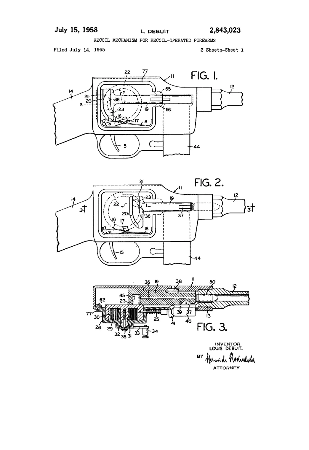
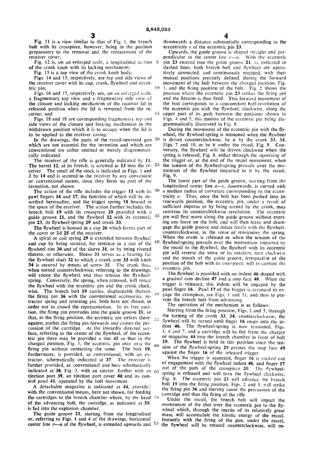
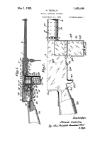
Fig. I is a side-view of the receiver with its cover
removed and with the breech bolt in the charged posi-
tion, the position of the flywheel with its eccentric pin
being indicated in dashed lines;
Fig. 2 is a similar view, with the breech bolt, how-
ever, at the firing, or spring-released position;
Fig. 3 is a cross section along line 3—3 of Fig. 2 of
the receiver with cover, flywheel and flywheel spring
mounted therein;
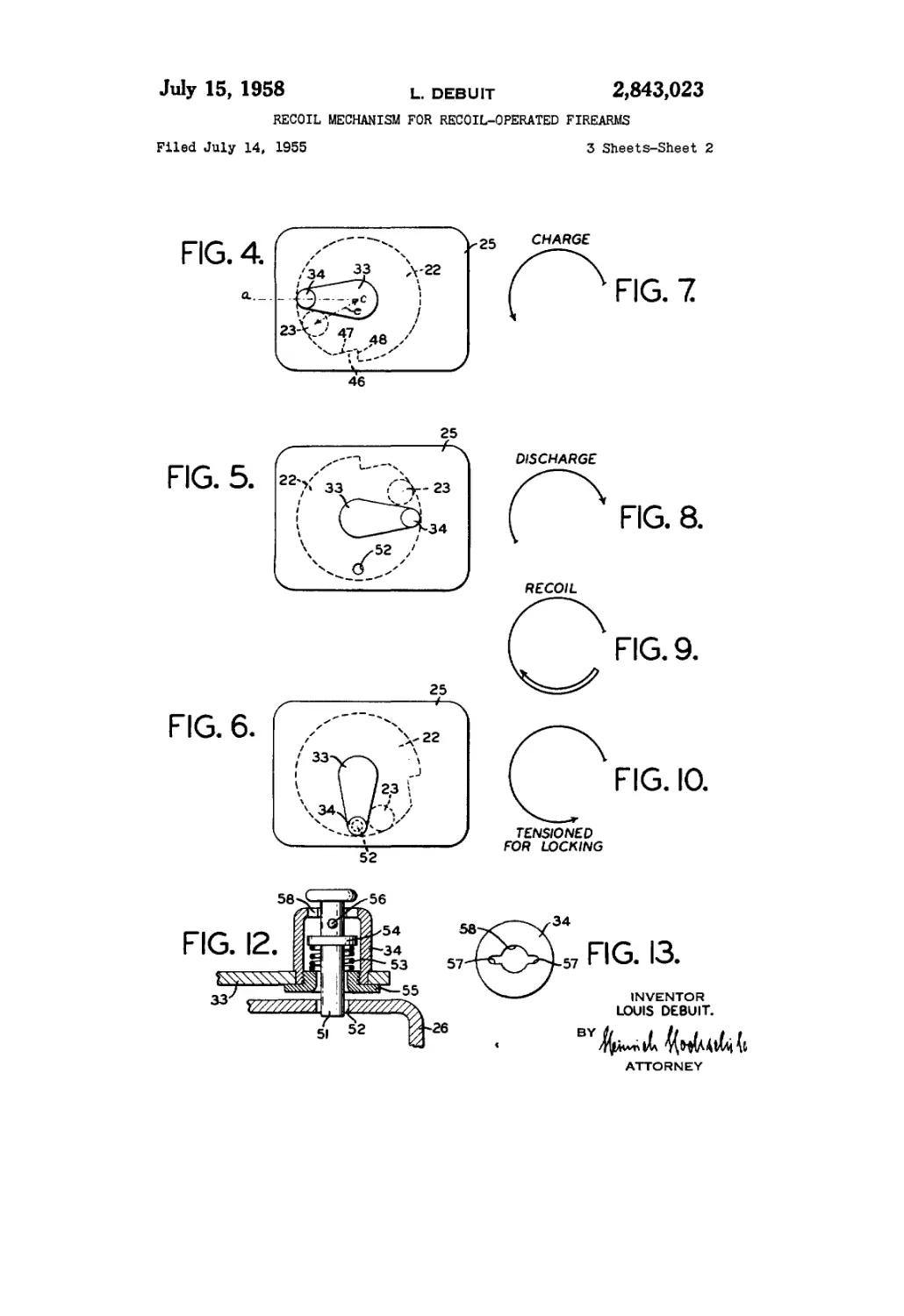
Figs. 4 to 6 are schematical views of the receiver
cover in various positions of the flywheel crank and
thus of the flywheel with its eccentric pin;
Figs. 7 to 10 are diagrams of the movements of the
eccentric pin in various phases of its operation;
3,843,023
3
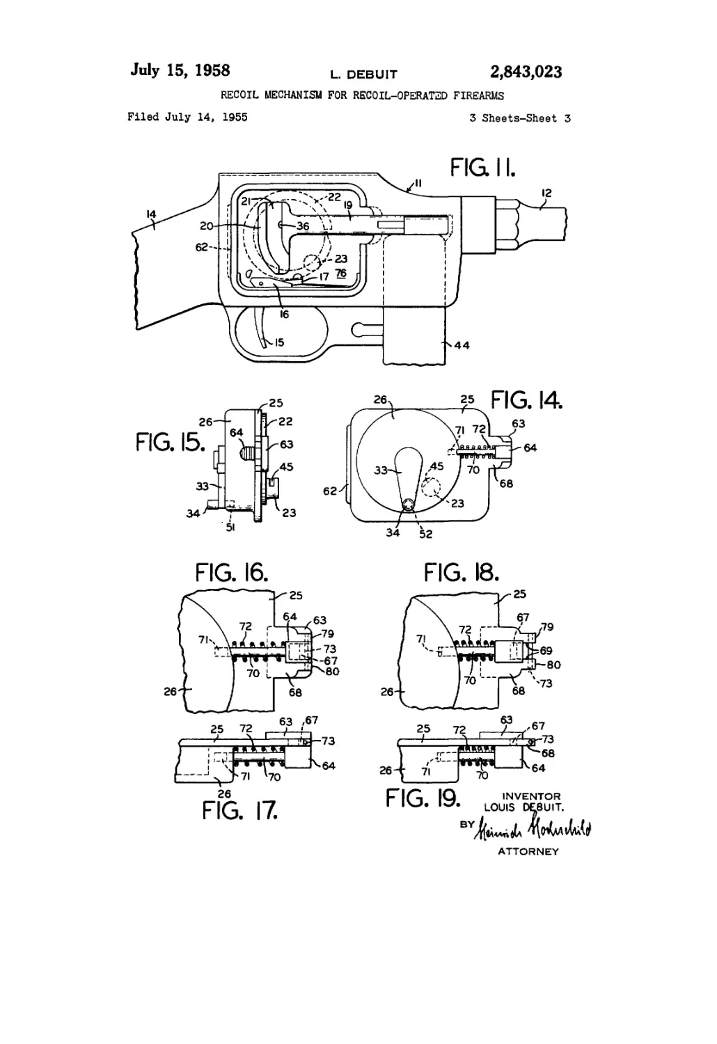
Fig. 11 is a view similar to that of Fig. I, the breech
bolt with its crosspiece, however, being in the position
preparatory to the removal and the replacement of the
receiver cover;
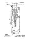
Fig. 12 is, on an enlarged scale, a longitudinal section
of the crank knob with its locking mechanism;
Fig. 13 is a top view of the crank knob body;
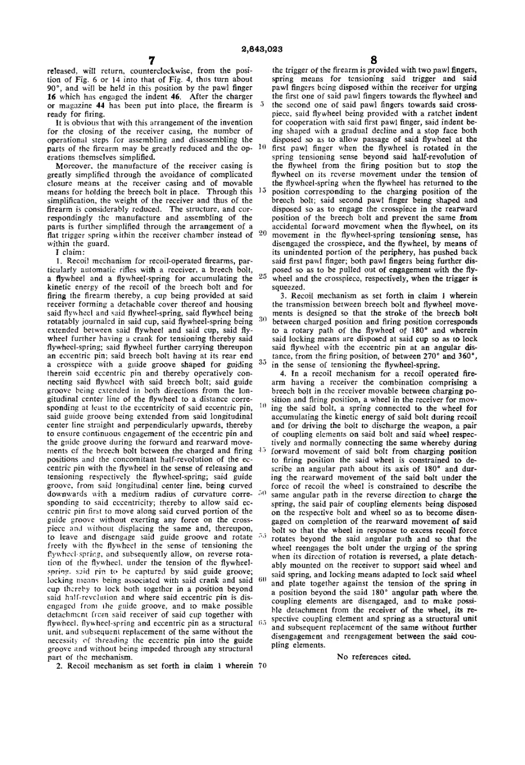
Figs. 14 and 15, respectively, are top and side views of
the receiver cover with its cup, crank, flywheel and eccen-
tric pin;
Figs. 16 and 17, respectively, are, on an enlarged scale,
a fragmentary top view and a fragmentary side view of
the closure and locking mechanism of the receiver lid in
released position when the lid is removed from the re-
ceiver; and
Figs. 18 and 19 are corresponding fragmentary top and
side views of the closure and locking mechanism in the
withdrawn position which it is to occupy when the lid is
to be applied to the receiver casing.
In the drawings, the parts of the recoil-operated gun
which are not essential for the invention and which are
conventional are cither omitted or merely diagrammati-
cally indicated.
The receiver of the rifle is generally indicated by 11.
The barrel 12, at its breech, is screwed at 13 into the re-
ceiver. The small of the stock is indicated in Figs. 1 and
2 by 14 and is secured to the receiver by any convenient
or conventional means, since they form no part of the
invention, not shown.
The action of the rifle includes the trigger 15 with its
pawl fingers 16 and 17, the function of which will be de-
scribed hereinafter, and the trigger spring 18 housed in
the space of the receiver. The action further includes the
breech bolt 19 with its crosspiece 20 provided with a
guide groove 21, and the flywheel 22 with its eccentric
pin 23, its flywheel-spring 29 and crank 33.
The flywheel is housed in a cup 26 which forms part of
the cover or lid 25 of the receiver.
A spiral or coil spring 29 is extended between flywheel
and cup by being secured, for instance in a slot of the
flywheel rim 30 and of the sleeve 31, or by being riveted
thereto, or otherwise. Sleeve 31 serves as a bearing for
the flywheel shaft 32 to which a crank arm 33 with knob
34 is secured by means of screw 35. The crank thus,
when turned counterclockwise, referring to the drawings,
will rotate the flywheel and thus tension the flywheel-
spring. Conversely, the spring, when released, will rotate
the flywheel with the eccentric pin and the crank clock-
wise. The breech bolt 19 carries, displaceable therein,
the firing pin 36 with the conventional accessories, re-
tractor spring and retaining pin. both here not shown, in
order not to crowd the representation. In its free posi-
tion, the firing pin protrudes into the guide groove 21, so
that, in the firing position, the eccentric pin strikes there-
against, pushes the firing pin forwards and causes the per-
cussion of the cartridge. At the inwardly directed sur-
face, referring to the center of the flywheel, of the eccen-
tric pin there may be provided a slot 45 so that in the
charged position, Fig. I, the eccentric pin may pass the
firing pin without contacting the same. The bolt 19,
furthermore, is provided, as conventional, with an ex-
tractor, schematically indicated at 37. The receiver is
further provided, as conventional and here schemalically
indicated at 38. Fig. 3, with an ejector, further with an
ejection port 39, an ejection port cover 40 and its con-
trol pawl 41, operated by the bolt movement.
A detachable magazine is indicated at 44, provided
with the conventional means, here not shown, for feeding
the cartridges to the breech chamber where, by the head
of the advancing bolt, the cartridge, as indicated at 50.
is fed into the explosion chamber.
The guide groove 21, starting from the longitudinal
or, referring to Figs. 1 and 4 of the drawings, horizontal
center line c—a of the flywheel, is extended upwards and
10
15
20
25
30
35
40
15
50
55
00
05
70
75
4
downwards a distance substantially corresponding to the
eccentricity e of the eccentric pin 23.
Upwards, the guide groove is shaped straight and per-
pendicular to the center line c—a. With the eccentric
pin 23 entered into the guide groove 21. as indicated in
dashed lines, both breech bolt and flywheel are opera-
tively connected, and continuously engaged, with their
mutual positions precisely defined, during the forward
movement of the bolt between the charged position. Fig.
1. and the firing position of the bolt. Fig. 2 shows the
position where the eccentric pin 23 strikes the firing pin
and the firearm is thus fired. This forward movement of
the bolt corresponds to a concomitant half-revolution of
the eccentric pin with the flywheel, clockwise, along the
upper part of its path between the positions shown in
Figs. 4 and 5, this motion of the eccentric pin being dia-
grammatically illustrated in Fig. 8.
During the movement of the eccentric pin with the fly-
wheel, the flywheel-spring is tensioned when the flywheel
is driven counterclockwise, be it by the crank 33. 34,
Figs. 7 and 10, or be it under the recoil, Fig. 9. Con-
versely, the flywheel will be driven clockwise when the
spring is released, Fig. 8, either through the squeezing of
the trigger or, at the end of the recoil movement, when
the tension of the flywheel-spring prevails over the mo-
mentum of the flywheel imparted to it by the recoil,
Fig. 9.
The lower part of the guide groove, starting from the
longitudinal center line a—c, downwards, is curved with
a median radius of curvature corresponding to the eccen-
tricity e. Thus, once the bolt has been pushed into its
rearwards position, the eccentric pin, under a recoil of
sufficient impetus or by being turned by the crank, may
continue its counterclockwise revolution. The eccentric
pin will first move along the guide groove without exert-
ing any force on the bolt, and will then leave and disen-
gage the guide groove and rotate freely with the flywheel,
counterclockwise, in the sense of tensioning the spring.
When the crank is released or when the tension of the
flywheel-spring prevails over the momentum imparled by
the recoil to the flywheel, the flywheel with its eccentric
pin will reverse the sense of its rotation, turn clockwise
and the mouth of the guide groove, irrespective of the
position of the bolt with its crosspiece, will re-capturc the
eccentric pin.
The flywheel is provided with an indent 46 shaped with
a gradual cam decline 47 and a stop face 48. When the
trigger is released, this indent will be engaged by the
pawl finger 16. Pawl 17 of the trigger is arranged to en-
gage the crosspiece, see Figs. 1 and 11. and thus to pre-
vent the breech bolt from advancing.
The operation of the mechanism is as follows:
Starting from the firing position, Figs. 2 and 5, through
the turning of the crank 33, 34, counterclockwise, the
flywheel will be turned until finger 16 snaps into the in-
dent 46. The flywheel-spring is now tensioned, Figs.
1, 4 and 7, and a cartridge will be fed from the charger
or magazine 44 into the breech chamber in front of bolt
19. The flywheel is held in this posilion since the ten-
sion of the flywheel-spring 29 presses the stop face 48
against the finger 16 of the released trigger.
When the trigger is squeezed, finger 16 is rocked cut
of engagement with the flywheel indent 46, and finger 17
out of the path of the crosspiece 20. The flywheel-
spring is released and will turn the flywheel clockwise,
Fig. 8. The eccentric pin 23 will advance the breech
bolt 19 into the firing position, Figs. 2 and 5, v. ill strike
the firing pin 36 and thereby cause the percussion of the
cartridge and thus the firing of the rifle.
Under the recoil, the breech bolt will impart the
momentum of the shot over the eccentric pin to the fly-
wheel which, through the inertia of its relatively great
mass, will accumulate the kinetic energy of the recoil.
Instantly with the firing of the gun, under the recoil,
the flywheel will be rotated counterclockwise, will ro-
2,843,028
5
turn, by means of the eccentric pin 23, the bolt 19 with
its crosspiece 20 into the charged position, while, through
the return movement of the bolt, the empty shell will
be ejected and a new cartridge fed into the breech
chamber.
Under the impetus of the recoil, the flywheel with its
eccentric pin will continue its rotation, counterclockwise,
beyond the half-revolution of Fig. 7 which corresponds
to the return stroke of the bolt, until the eccentric pin
reaches a position where finally the increasing tension of
the flywheel-spring prevails over the correspondingly de-
creasing momentum of the flywheel, Fig. 9.
This position will be reached unimpeded by the pawl
finger 16 since the cam decline 47, as it passes the pawl
finger 16, raises the finger 16 against the tension of the
trigger spring 18, should, with the firing of the gun,
the trigger have been released. With the release of
the trigger, even if finger 16 is pressed outwards by the
periphery of flywheel 22, pawl finger 17 will enter into
the path of the crosspiece and retain the crosspiece and
the bolt in the vicinity of its rearward position, Fig. 11.
On the return movement, clockwise, of the flywheel,
when the eccentric pin reaches its reaward position,
where it has again operatively engaged the guide groove,
finger 16 will enter the indent, and stop face 48 will
prevent further clockwise rotation of the flywheel. The
rifle is again in charged position.
However, should the trigger not have been released
but should the trigger still be held squeezed when the
flywheel at the end of its recoil movement is driven
clockwise under the tension of the flywheel-spring, the
pawl fingers will be held out of the paths of the flywheel
and the crosspiece, and the firearm will continue to
shoot until its magazine is empty or the trigger is no
longer pulled but is released.
When for the inspection and cleaning, the flywheel
with its cup is to be removed from the receiver and
thereafter is to be replaced, the difficulty arises that
for this operation the eccentric pin is to be threaded into
the guide groove, a difficulty which is the greater since
with the eccentric pin detached, the bolt with its cross-
piece is loosely displaceable within the receiver.
The invention avoids this difficulty by utilizing the
characteristic of the herein described recoil mechanism
that after the eccentric pin, starting from the firing posi-
tion, has completed an angular path exceeding a half-
revolution or 180°, it leaves the guide groove and moves
through a space of the receiver which, when the cross-
piece of the bolt is held back by the pawl finger 17, is
free from any encumbrance through structural parts of
the bolt or others.
The eccentric pin may be moved counterclockwise
from the firing position into this space, by being rotated
by the crank arm about an angle greater than 180°,
into a position at an angular distance preferably be-
tween 270° and 360° from the firing position, and may
then be locked in this position at the cup 26 or the plate
25 supporting the flywheel unit.
A mechanism for locking the crank arm is illustrated
in Figs. 12 and 13. The knob 34 of the crank arm 33
houses a locking bolt 51 which may be entered into a
locking opening 52 of the cup 26. Bolt 51 is urged up-
wards by a spring 53 coiled about bolt 51 and tensioned
between a collar 54 upon the bolt and a flange ring 55
screwed into the hollow knob and holding the knob
at the crank arm 33.
Near its head, the locking bolt is provided with two
bayonet bosses 56 which may be passed through con-
formably shaped recesses 57 of the opening 58 at the
top of the knob 34, through which the locking bolt 51
is passed.
When the crank 33 is rotated against the cup 26 until
the locking bolt 51 and the locking opening 52 are in
juxtaposition, the locking bolt may be depressed and
the bosses 56 passed through the recesses 57. By turn-
10
15
20
25
30
35
40
45
50
55
00
05
70
75
6
ing the locking bolt, the crank arm is locked at the cup
26 in the desired position.
The lid or receiver cover as exemplified in Figs. 14
to 19, is held in place at the one end by a tongue 62
which projects underneath the re-enforced rim 77 of
the receiver opening. At the other end of the cover
25, there is provided a movable locking plate 63 rigidly
secured to a push block 64. The movable locking plate
63, underneath the cover 25, may enter into grooves
65, 66 provided in the rim of the receiver opening.
As Figs. 16 to 19 illustrate on an enlarged scale, the
push block 64 is connected with the movable locking
plate 63 by means of a brace 67 so that both may slide
above and below a tongue 68 of the cover plate 25, the
brace 67 being passed through, and being guided in, a
slot 69 of tongue 68, Fig. 18.
The push block 64 is carried by a rod 70 slidable in
a bore 71 in the wall of the cup 26 and is urged out-
wards by a spring 72 wound about the rod 70 and ten-
sioned between the cup wall and the push block 64.
For limiting the outward stroke of the push block,
an abutment 73 in form of a pin is extended through
the slot 69 and passed through the branches 79, 80 of
the tongue 68 separated by the slot 69.
Tongue 68 is of the same contour as the locking plate
63 so that both cover each other when the push block
64 with its rod 70 is pushed back, that is to the left as
referred to Figs. 16 to 19, and into the position illus-
trated in Figs. 18 and 19.
Figs. 6 and 14 illustrate in dashed circles the position
which the eccentric pin is to occupy when the cover 25 is
to be removed from the receiver or is to be put in place,
that is a position of the eccentric pin at an angular dis-
tance of 270° or more from the released, firing position
of Fig. 2 or 5.
It will thus clearly be seen from Figs. 11 and 14 that
the eccentric shown as a dashed circle 23, is in the free
space 76 of the receiver.
Thus, in order to open the receiver casing, the crank
arm 33 will be turned counterclockwise, an angle of about
90° from the charged position, Figs. 1 and 4, into the
position of Fig. 6 where, relatively to the normal charged
position, the mechanism is super-tensioned and where the
crank arm 33 may be locked in the bore 52 of the cup.
In this position, the eccentric pin 23 is at an angular
distance of between 270° and 360° from the firing posi-
tion or the position where the spring is released, the
motion of the eccentric pin for the tensioning of the fly-
wheel-spring being diagrammatically illustrated in Fig.
10. In order to remove the cover 25, the push block 64
is first pushed to the left, the plate 63 thus disengaged
from the grooves 65. 66; thereupon the cover is slightly
lifted at lhe right hand side and slid to the right for
thus disengaging the tongue from underneath the rim 77.
In order to close again the receiver and replace the lid,
it will suffice to draw the trigger rearwards in order to
bring the pawl finger into the lower position, Fig. 11,
where it is removed from the periphery of the flywheel
when the flywheel is being entered into the receiver. The
crosspiece 20 with the bolt 19 will be pushed to the left
into the position illustrated in Fig. 4 where the crosspiece
will he held back by the pawl finger 17.
An empty space is thus provided within the receiver
and the cover 25 may now be placed upon the opening
of the receiver after the tongue 62 had been inserted
underneath the rim 77 and the push block 64 pushed
into its extreme left position where plate 63 and tongue
68 cover each other. Plate 25 is now completely seated
upon the seat provided by the re-enforced rim 77 and is
held in place by the tongue 62 and the locking plate 63
which, under the action of spring 72 upon push block
64, has engaged the grooves 65, 66 as soon as the push
block had been released.
When the cover is in place, the locking bolt 51 will be
withdrawn from the bore 52 and the crank arm 33, thus
2,848,023
7
released, will return, counterclockwise, from the posi-
tion of Fig. 6 or 14 into that of Fig. 4, thus turn about
90°, and will be held in this position by the pawl finger
16 which has engaged the indent 46. After the charger
or magazine 44 has been put into place, the firearm is
ready for firing.
It is obvious that with this arrangement of the invention
for the closing of the receiver casing, the number of
operational steps for assembling and disassembling the
parts of the firearm may be greatly reduced and the op-
erations themselves simplified.
Moreover, the manufacture of the receiver casing is
greatly simplified through the avoidance of complicated
closure means at the receiver casing and of movable
means for holding the breech bolt in place. Through this
simplification, the weight of the receiver and thus of the
firearm is considerably reduced. The structure, and cor-
respondingly the manufacture and assembling of the
parts is further simplified through the arrangement of a
flat trigger spring within the receiver chamber instead of
within the guard.
I claim:
1. Recoil mechanism for recoil-operated firearms, par-
ticularly automatic rifles with a receiver, a breech bolt,
a flywheel and a flywheel-spring for accumulating the
kinetic energy of the recoil of the breech bolt and for
firing the firearm thereby, a cup being provided at said
receiver forming a detachable cover thereof and housing
said flywheel and said flywheel-spring, said flywheel being
rotatably journaled in said cup, said flywheel-spring being
extended between said flywheel and said cup, said fly-
wheel further having a crank for tensioning thereby said
flywheel-spring; said flywheel further carrying thereupon
an eccentric pin; said breech bolt having at its rear end
a crosspiece with a guide groove shaped for guiding
therein said eccentric pin and thereby operatively con-
necting said flywheel with said breech bolt; said guide
groove being extended in both directions from the lon-
gitudinal center line of the flywheel to a distance corre-
sponding at least to the eccentricity of said eccentric pin,
said guide groove being extended from said longitudinal
center line straight and perpendicularly upwards, thereby
to ensure continuous engagement of the eccentric pin and
the guide groove during the forward and rearward move-
ments of the breech bolt between the charged and firing
positions and the concomitant half-revolution of the ec-
centric pin with the flywheel in the sense of releasing and
tensioning respectively the flywheel-spring; said guide
groove, from said longitudinal center line, being curved
downwards with a medium radius of curvature corre-
sponding to said eccentricity; thereby to allow said ec-
centric pin first to move along said curved portion of the
guide groove without exerting any force on the cross-
piece and without displacing the same and, thereupon,
to leave and disengage said guide groove and rotate
freely with the flywheel in the sense of tensioning the
flywheel-spring, and subsequently allow, on reverse rota-
tion of the flywheel, under the tension of the flywheel-
spring. said pin to be captured by said guide groove;
locking means being associated with said crank and said
cup thereby to lock both together in a position beyond
said half-revc-lulion and where said eccentric pin is dis-
engaged from the guide groove, and to make possible
detachment from said receiver of said cup together with
flywheel, flywheel-spring and eccentric pin as a structural
unit, and subsequent replacement of the same without the
necessity of threading the eccentric pin into the guide
groove and without being impeded through any structural
part of the mechanism.
2. Recoil mechanism as set forth in claim 1 wherein
10
15
20
25
30
35
ID
-15
.50
•)
60
65
70
8
the trigger of the firearm is provided with two pawl fingers,
spring means for tensioning said trigger and said
pawl fingers being disposed within the receiver for urging
the first one of said pawl fingers towards the flywheel and
the second one of said pawl fingers towards said cross-
piece, said flywheel being provided with a ratchet indent
for cooperation with said first pawl finger, said indent be-
ing shaped with a gradual decline and a stop face both
disposed so as to allow passage of said flywheel at the
first pawl finger when the flywheel is rotated in the
spring tensioning sense beyond said half-revolution of
the flywheel from the firing position but to stop the
flywheel on its reverse movement under the tension of
the flywheel-spring when the flywheel has returned to the
position corresponding to the charging position of the
breech bolt; said second pawl finger being shaped and
disposed so as to engage the crosspiece in the rearward
position of the breech bolt and prevent the same from
accidental forward movement when the flywheel, on its
movement in the flywheel-spring tensioning sense, has
disengaged the crosspiece, and the flywheel, by means of
its unindented portion of the periphery, has pushed back
said first pawl finger; both pawl fingers being further dis-
posed so as to be pulled out of engagement with the fly-
wheel and the crosspiece, respectively, when the trigger is
squeezed.
3. Recoil mechanism as set forth in claim 1 wherein
the transmission between breech bolt and flywheel move-
ments is designed so that the stroke of the breech bolt
between charged position and firing position corresponds
to a rotary path of the flywheel of 180° and wherein
said locking means are disposed at said cup so as to lock
said flywheel with the eccentric pin at an angular dis-
tance, from the firing position, of between 270° and 360°,
in the sense of tensioning the flywheel-spring.
4. In a recoil mechanism for a recoil operated fire-
arm having a receiver the combination comprising a
breech bolt in the receiver movable between charging po-
sition and firing position, a wheel in the receiver for mov-
ing the said bolt, a spring connected to the wheel for
accumulating the kinetic energy of said bolt during recoil
and for driving the bolt to discharge the weapon, a pair
of coupling elements on said bolt and said wheel respec-
tively and normally connecting the same whereby during
forward movement of said bolt from charging position
to firing position the said wheel is constrained to de-
scribe an angular path about its axis of 180° and dur-
ing the rearward movement of the said bolt under the
force of recoil the wheel is constrained to describe the
same angular path in the reverse direction to charge the
spring, the said pair of coupling elements being disposed
on the respective bolt and wheel so as to become disen-
gaged on completion of the rearward movement of said
bolt so that the wheel in response to excess recoil force
rotates beyond the said angular path and so that the
wheel reengages the bolt under the urging of the spring
when its direction of rotation is reversed, a plate detach-
ably mounted on the receiver to support said wheel and
said spring, and locking means adapted to lock said wheel
and plate together against the tension of the spring in
a position beyond the said 180° angular path where the.
coupling elements are disengaged, and to make possi-
ble detachment from the receiver of the wheel, its re-
spective coupling element and spring as a structural unit
and subsequent replacement of the same without further
disengagement and reengagement between the said cou-
pling elements.
No references cited.