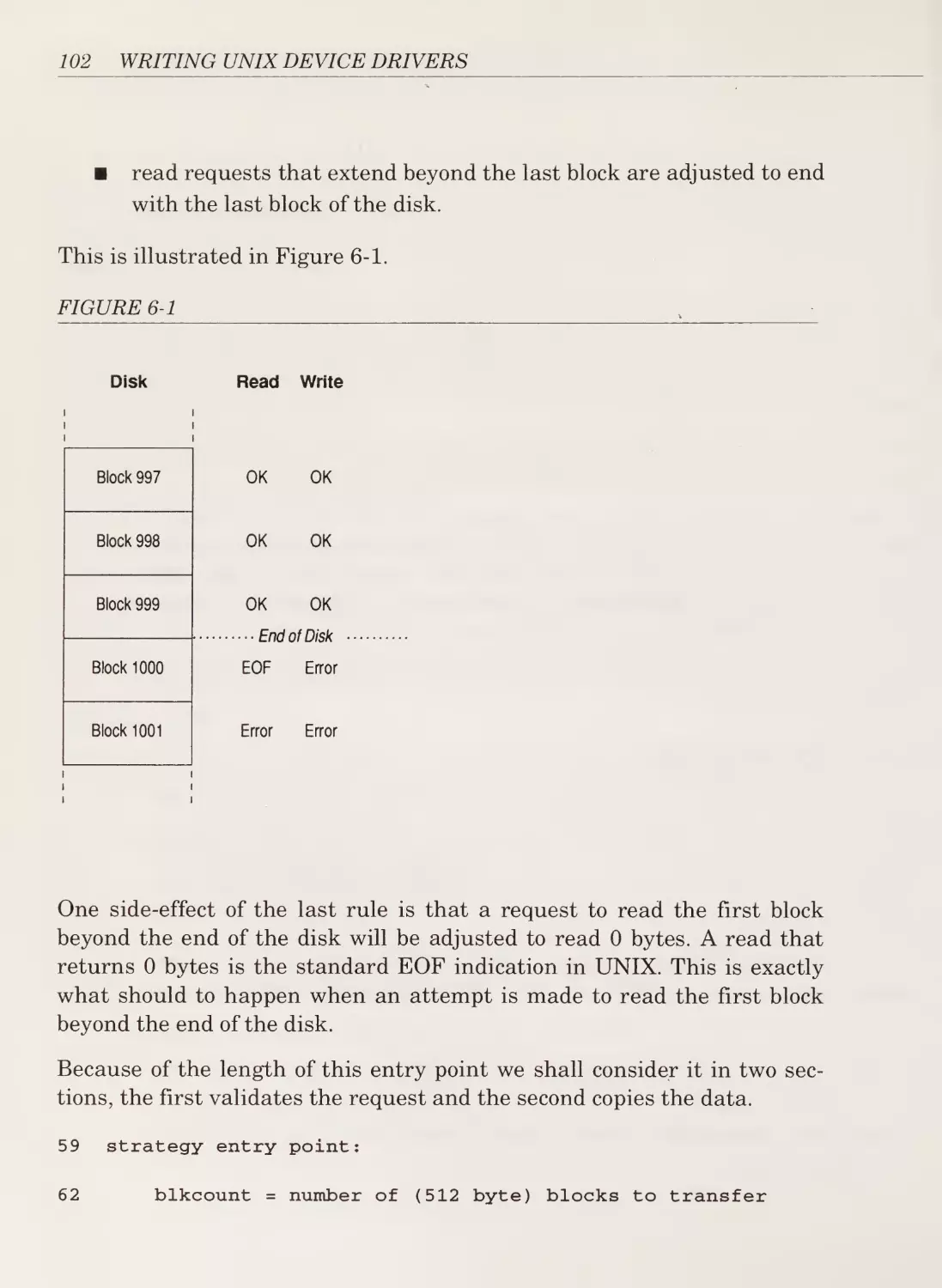
/


Автор: Pajari J.
Теги: programming languages programming computer science computer graphics unix operation system addison-wesley publishing
ISBN: 0-201-52374-4
Год: 1992


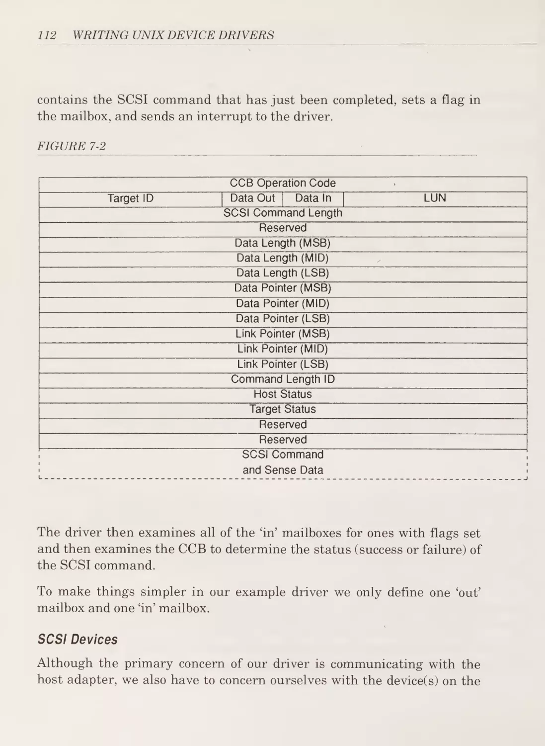
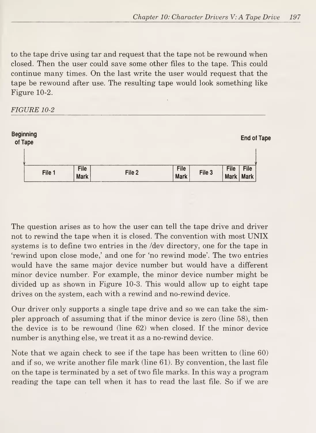
Текст
Digitized by the Internet Archive
in 2018 with funding from
Kahle/Austin Foundation
https://archive.org/details/writingunixdevicOOpaja_O
Writing UNIX® Device Drivers
George Pajari
Addison-Wesley Publishing Company, Inc.
Reading, Massachusetts
Menlo Park, California
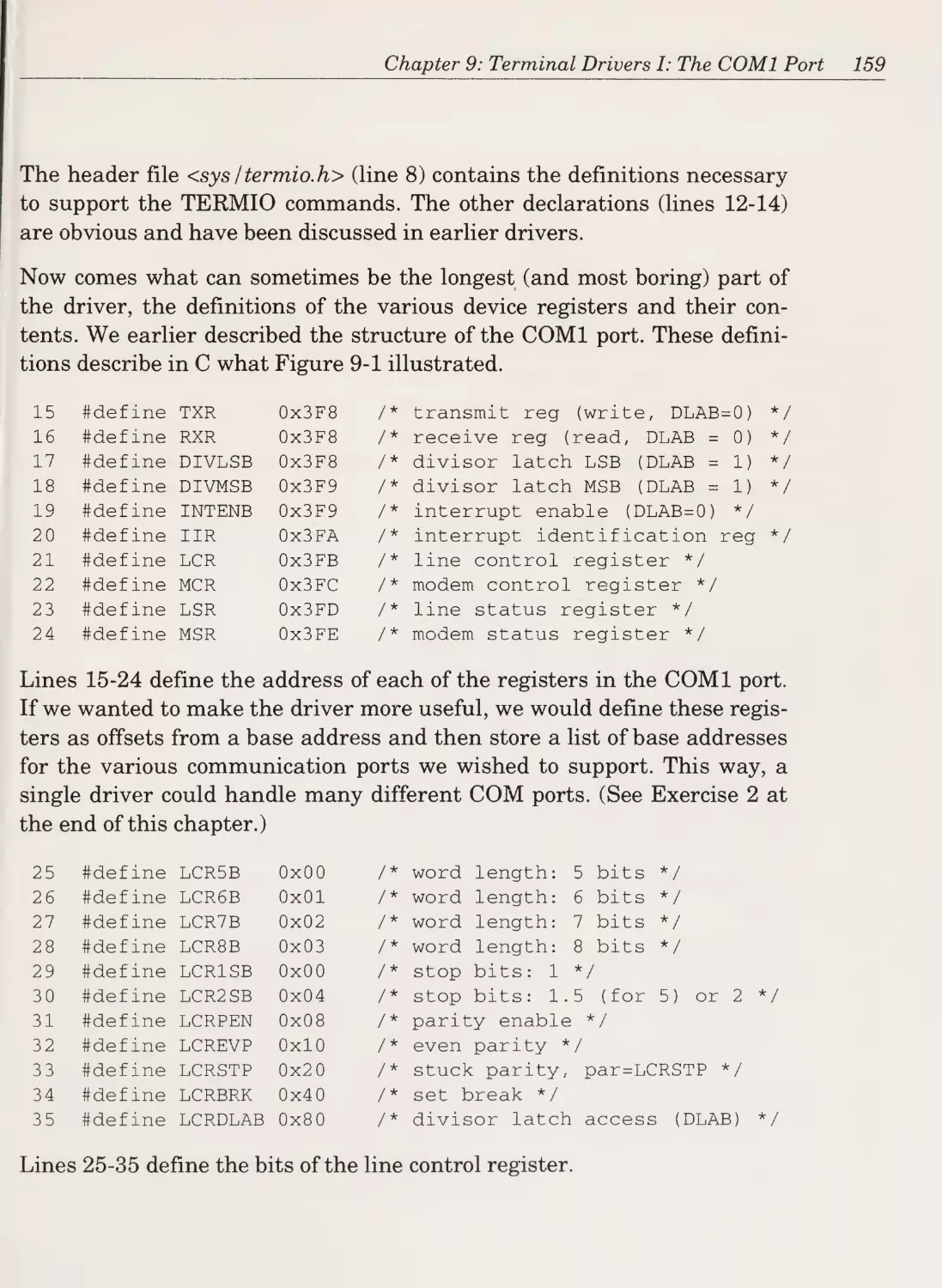
New York
Don Mills, Ontario
Wokingham, England
Amsterdam
Bonn
Sydney
Singapore
Tokyo
Madrid
San Juan
Paris
Seoul
Milan
Mexico City
Taipei
Many of the designations used by manufacturers and sellers to distin¬
guish their products are claimed as trademarks. Where those designa¬
tions appear in this book and Addison-Wesley was aware of a trademark
claim, the designations have been printed in initial capital letters.
The authors and publishers have taken care in preparation of this book,
but make no expressed or implied warranty of any kind and assume no
responsibility for errors or omissions. No liability is assumed for inciden¬
tal or consequential damages in connection with or arising out of the use
of the information or programs contained herein.
Library of Congress Cataloging-in-Publication Data
Pajari, George.
Writing UNIX device drivers / by George Pajari.
p. cm.
Includes index.
ISBN 0-201-52374-4
1. UNIX device drivers (Computer programs) I. Title.
QA76.76.D49P35
1991
005.4’3—dc20
91-42361
Copyright © 1992 by George Pajari
All rights reserved. No part of this publication may be reproduced, stored
in a retrieval system, or transmitted, in any form or by any means,
electronic, mechanical, photocopying, recording, or otherwise, without
the prior written permission of the publisher. Printed in the United
States of America. Published simultaneously in Canada.
ISBN 0-201-52374-4
Managing Editor: Amorette Pedersen
Set in 11-point New Century Schoolbook by Benchmark Productions
2 3 4 5 6 7 8 9-MW-95949392
Second printing, April 1992
This book is dedicated to Carol, who has taken the fun out of being alone.
Acknowledgments
«
To my colleagues at Driver Design Labs: Jeff Tate, who checked that it
made sense and helped make it somewhat understandable; Carolanne
Reynolds, who spent many hours reading and revising drafts trying to
convert it into something much closer to English; and to Frank Pronk who
provided a useful reality check. The unseen corrections and improvements
are theirs (many remaining problems and errors are mine).
To Harry Henderson, Mitch Waite, Rebecca Thomas, David Flack, Tom
Ward, Ben Smith, and Jane Tazelaar; all of whom have helped with one
or more of my previously published works on device drivers.
To Chris Williams and Amy Pedersen who, as editors of this book, exhib¬
ited patience and understanding above and beyond the call. No author
could ask for more, and aspiring authors of technical books are urged to
contact them.
To Jeff Kulick and the Department of Computing and Information Science
at Queen’s University at Kingston: both gave me the opportunity to play
with the UNIX kernel well over a decade ago and both have to take at
least some responsibility for all of this.
To Ed Palmer and the organizers of the annual UniForum Conference
and Exhibition, where the author has had the pleasure of delivering the
Writing UNIX Device Drivers tutorial for several years. The course notes
for those tutorials formed the basis for this book.
To the Scottish & Newcastle Breweries PLC Edinburgh, whose McEwan’s
Scotch Malt Liquor had a very enjoyable, if detrimental, effect on the
writing of this book.
To my parents and grandparents who have always encouraged and sup¬
ported me.
And most importantly to my wife, Carolanne Reynolds, for more reasons
than there is room in these notes to list.
in
Table of Contents
Chapter 1
y
What Is A Device Driver?
The Grand Design
The Details
Types of Device Drivers
The Gross Anatomy of a Device Driver
General Programming Considerations
Summary
1
1
3
6
10
12
13
Chapter 2
Character Driver I: A Test Data Generator
15
The Design Issues
The Driver
The Recapitulation
Summary
Exercises
16
19
29
31
32
Chapter 3
Character Drivers II: An A/D Converter
35
The Design Issues
The Driver
Exercises
37
37
54
iv
Table of Contents
Chapter 4
Character Drivers III: A Line Printer
55
The Device
The Driver
Summary
Exercises
56
56
78
78
Chapter 5
Block Drivers I: A Test Data Generator
81
The Design Issues
The Driver
Summary
Exercises
83
84
92
92
Chapter 6
Block Drivers III: A RAM Disk Driver
The Design Issues
The Driver
Summary
Exercises
Chapter
93
93
94
106
107
7
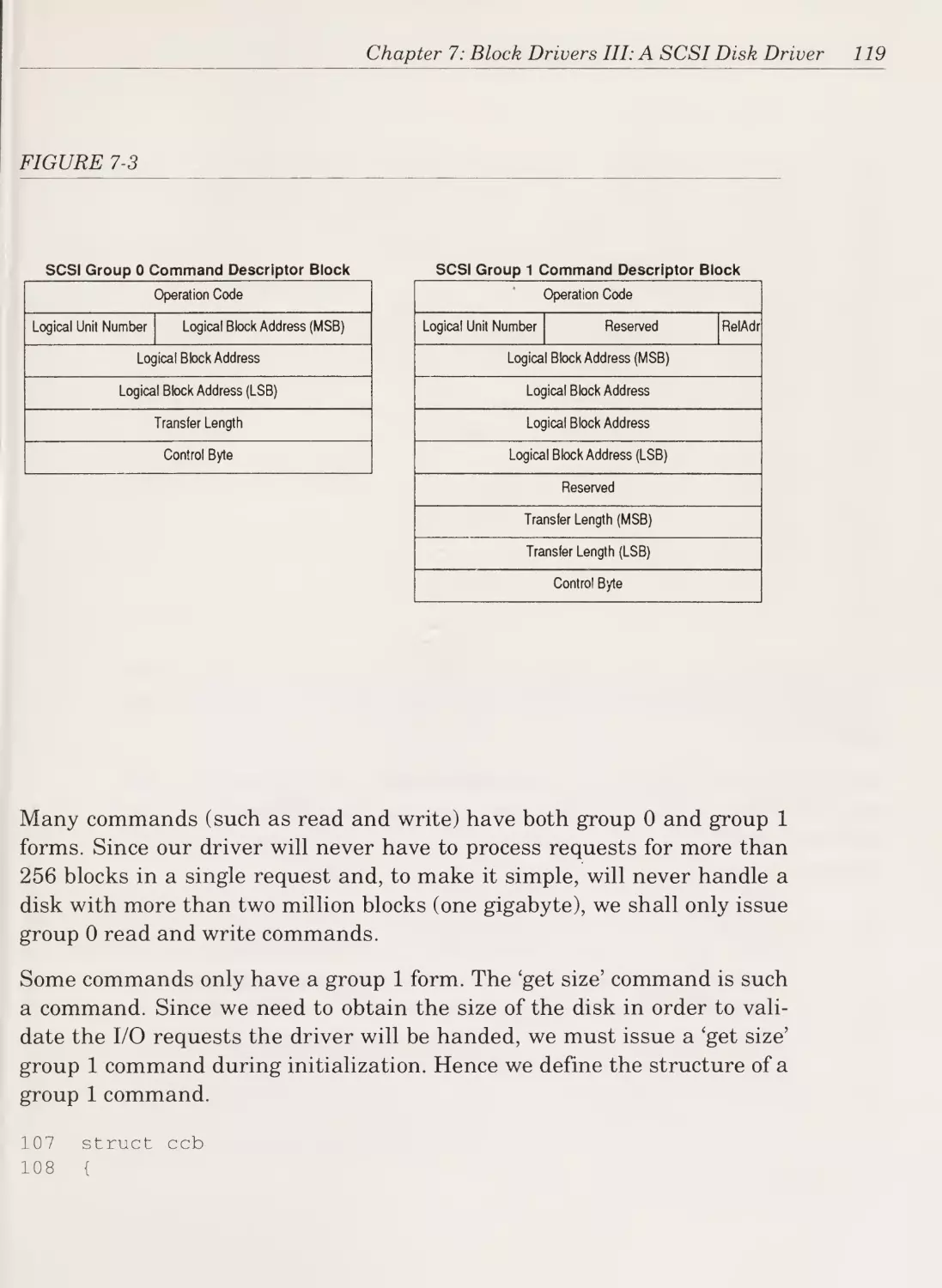
Block Drivers III: A SCSI Disk Driver
109
The Design Issues
The Device
Summary
Exercises
109
110
145
145
Chapter 8
Character Drivers IV: The Raw Disk Driver
147
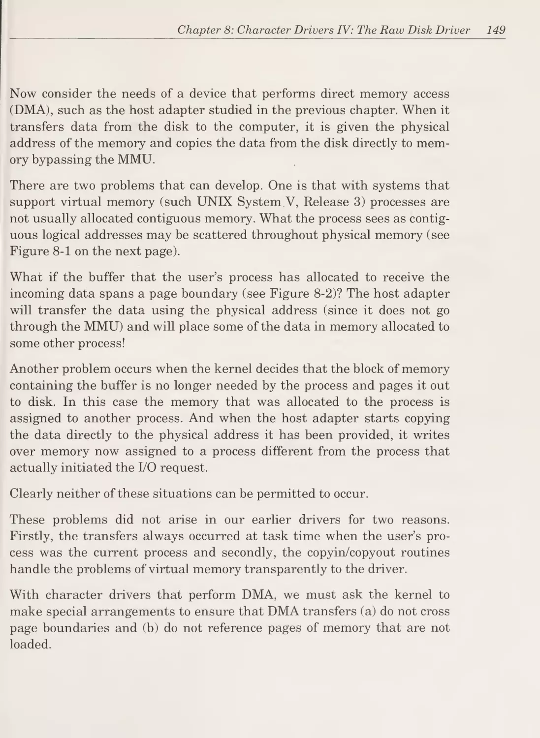
DMA and Character Drivers
The General Structure
Exercises
148
151
153
u
vi
WRITING UNIX DEVICE DRIVERS
Chapter 9
Terminal Drivers I: The C0M1 Port
155
Line Disciplines
The Device
The Driver
Beyond Line Disciplines
Summary
Exercises
156
156
157
185
185
186
Chapter 10
Character Drivers V: A Tape Drive
187
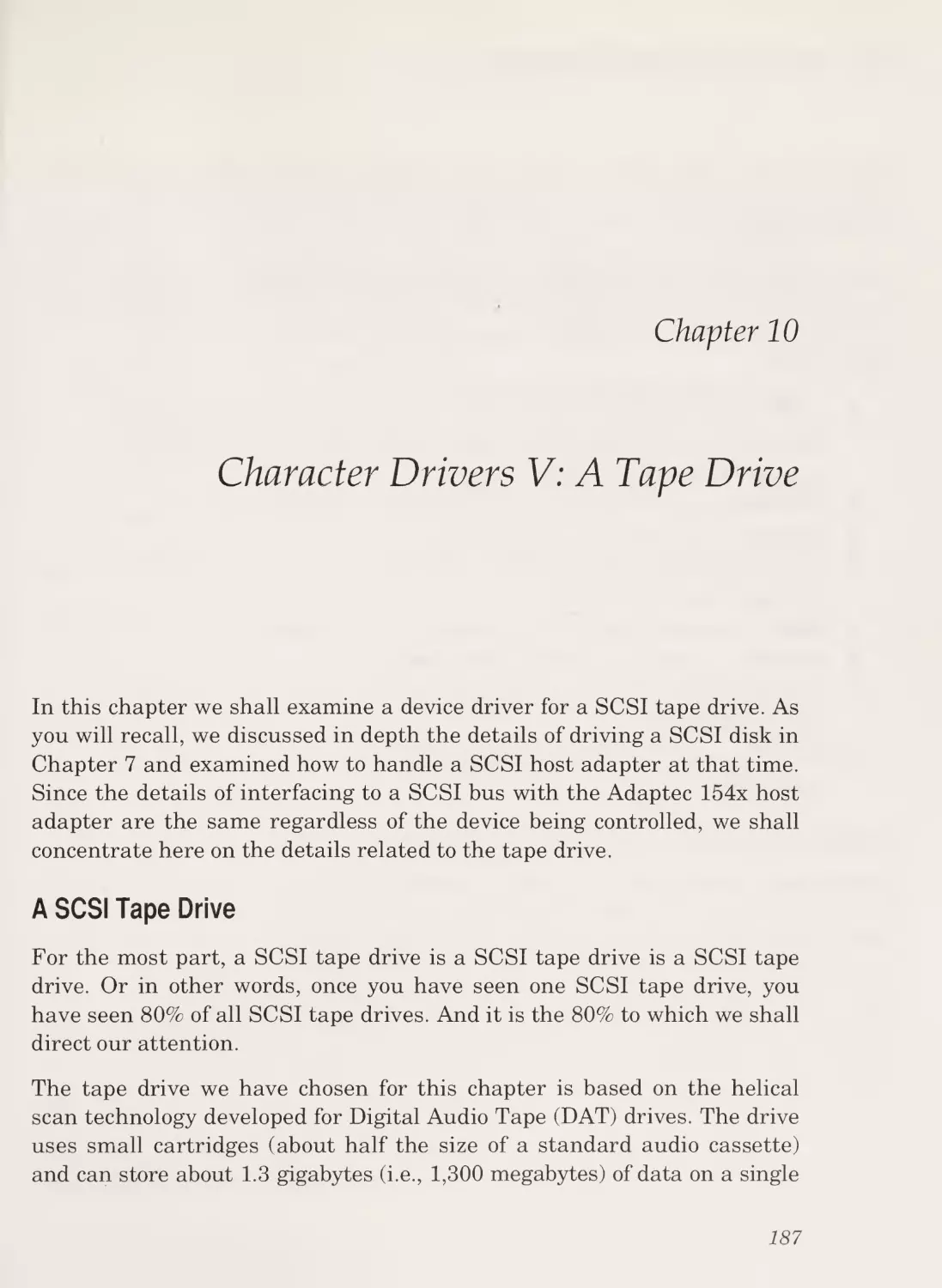
A SCSI Tape Drive
The Driver
Possible Enhancements
Summary
Exercises
187
189
207
209
209
Chapter 11
STREAMS Drivers I: A Loop-Back Driver
211
The Design Issues
A Loop-Back STREAMS Driver
Summary
Exercises
219
219
230
231
Chapter 12
Streams Drivers II: The COM1 Port (Revisited)
233
The Driver
Suggestions for Improvements
Summary
Exercises
234
273
274
274
Table of Contents
Chapter 13
Driver Installation
275
Compiling the Driver
Configuring the Kernel
Installing the New Driver
Building a New Kernel
Creating Entries in /dev
Rebooting the New Kernel
Installation Example
Advanced Driver Installation
Exercises
276
276
279
280
280
281
282
284
285
Chapter 14
Zen and the Art of Device Driver Writing
287
Preparing to Write a Driver
Debugging Device Drivers
Driver Performance
Unusual Driver Applications
Exercises
289
291
296
300
301
Chapter 15
Writing Drivers for System V Release 4
303
The Good News
The New Order
Sample SVR4 Drivers
Summary
Exercises
304
304
307
311
312
Index
313
vii
Preface
So you want to write a UNIX device driver. Or perhaps you just want to
learn a bit more about a topic that has historically been the exclusive
domain of systems gurus and programming wizards. In either case, this
book is written expressly for you.
Writing UNIX Device Drivers
Writing device drivers is one of the most challenging and interesting
types of programming. In contrast to applications programming, the
device driver writer has to be concerned with hardware details at the low¬
est levels as well as the problems of concurrency. These additional com¬
plexities not only make device driver programming much more difficult
and frustrating, they make it far more interesting and challenging.
Let us consider some of the problems that regularly arise during the
development of a device driver—problems which, by the way, rarely if
ever affect applications programmers.
Device drivers interface with the kernel using an entirely different set of
routines than those used by applications software. This programming
interface is all too often incompletely (or incorrectly) documented, fre¬
quently leaving the device driver programmer to debug the documenta¬
tion as well as the driver.
Device drivers usually interface with hardware (i.e., disk drives or tape
drives). Not only is this interface almost always incompletely documented,
it usually suffers from idiosyncrasies that are very different from software
interfaces. Some hardware devices will malfunction if their control regis¬
ters are written in the wrong order, or if written before being read, or if
vm
Preface
read before being written, or if written too quickly after being read, etc.
and etc.
What adds to the frustration is that these problems are very different
from those normally experienced by software developers.
For example, device drivers also have to deal with the problem of concur¬
rent execution. In other words, the driver may be handling one request
when another request from some other process arrives. The driver has to
make sure that multiple requests can be scheduled and processed without
confusion.
Another problem arises with hardware interrupts. Usually when the
device is finished with the last request it was given, it will interrupt the
computer. This can cause the computer to stop what it is doing and start
executing the driver’s interrupt handler. Since the interrupt can come at
any time, it may arrive while the driver is in the midst of handling
another request. The driver must take special steps to prevent data struc¬
tures from being corrupted in this situation.
These problems do not usually arise in applications programming or with
drivers for single-tasking operating systems such as MS-DOS.
Finally, the driver may have to perform certain operations under very
tight time constraints. For example, a driver handling an unbuffered
serial communications device will experience an interrupt every 500-mil¬
lionths of a second for a line running at 19,200 baud. The challenge is to
handle the data while still allowing the UNIX system to accomplish some
other work.
As if the design problems were not enough, testing and debugging drivers
is also more difficult than for applications software.
In order to operate as the master control program, the kernel runs with
few limitations on its actions. As a result many of the protections for stray
pointers and illegal operations provided for applications programs are not
available to the kernel and device drivers.
The traditional debugging tools will not work on the kernel, and the ker¬
nel usually cannot be breakpointed or single-stepped.
ix
X
WRITING UNIX DEVICE DRIVERS
Furthermore, driver problems can be very time-dependent. Interrupts can
arrive at any time and a driver may function correctly most of the time
only to fail when an interrupt arrives in the middle of a particular opera¬
tion.
Things can get even more frustrating when one adds printf statements to
the driver in an attempt to trace the operation of the driver only to find
that adding the printfs changes the behaviour of the driver.
Yet, as challenging and frustrating device driver writing can be, it can
also be particularly rewarding. Developing software that has to cope with
all of the problems mentioned and debugging it in the face of limited
debugging tools can be very satisfying.
There is also a special feeling of accomplishment that results from writing
software that: controls hardware; causes a tape drive to start moving, or
sends data across a communications link.
This book will introduce you to the techniques of addressing these prob¬
lems and enable you to enter this exciting realm of programming.
This Book’s Approach
The primary objective of this book is to explain, through the use of source
code for working drivers, the issues related to the design and implementa¬
tion of UNIX device drivers.
The approach is unusual in that most of the book consists of the examina¬
tion and discussion of the source for more than a dozen device drivers.
The source code is complete and unabridged. Every line of C that was
compiled during the testing of the drivers appears in this book.
This has several advantages over other approaches. As with any complex
subject, some of the concepts and issues related to the design of device
drivers can be somewhat abstract and difficult to grasp. In this presenta¬
tion everything is introduced in the context of an actual driver. This con¬
crete grounding of the material makes understanding easier since their
application can be seen immediately. It also helps the reader to organise
Preface
the subject material and to grasp the relationships between different
pieces of information.
Not only does this book provide sample drivers to illustrate the material,
it provides the complete source to each driver. Some books and courses
only provide excerpts from working drivers. Although useful, what they
leave out can be as important as what they include. And it is the
unfortunate programmer who, while trying to write his first driver, finds
out just how much was left out. Excerpts of drivers are just not enough.
To be truly useful, a text on writing device drivers must include the com¬
plete source to every driver. This book does just that.
Another advantage is based on the observation that no device driver is
ever written from scratch. The approach is to find a device driver that is
close to what is required and then to modify it to suit. This book provides
copious amounts of raw material from which to draw. With the complete
source to about a dozen drivers, any prospective device driver writer is
certain to find something close to what is needed.
It is the author’s belief that the best way to learn how to write device driv¬
ers is to write one, and the second best way is to study someone else’s.
This book is a useful companion to either endeavour.
This book also provides exercises after most chapters that suggest ways in
which the reader can modify the drivers. This can aid in the understand¬
ing of the sample drivers and the material itself.
Prerequisites
It is expected that the reader of this book have some experience develop¬
ing software for the UNIX operating system and be reasonably familiar
with the C programming language.
Note that this book is intended to serve as a textbook or self-study guide
for those wishing to learn how to write device drivers. It is not a reference
manual. There are many details that have had to be omitted in order for
the presentation to be clear, concise, and easily understood. These details
are more appropriate for a reference manual than the tutorial this book
endeavours to be. Before you actually start writing a device driver it
xi
xii
WRITING UNIX DEVICE DRIVERS
essential that you acquire and acquaint yourself with the device driver
reference manual for the version of the UNIX operating system you will
be using.
One other book that complements the coverage of this book is The Design
of the UNIX Operating System by Maurice Bach. While a detailed understanding of the UNIX operating system itself is not necessary in order to
write device drivers, it certainly would help. The book you are reading
will introduce the major concepts of the UNIX operating system as they
are encountered, but Bach’s book is a most readable account of the inter¬
nals of the UNIX operating system in their full glory.
Applicability
All of the drivers in this book, except for the STREAMS drivers in Chap¬
ters 11 and 12, have been written for AT&T UNIX System V Release 3. In
particular, they have been compiled and tested with The Santa Cruz
Operation’s SCO UNIX System V/386 Release 3.2 on various 386 and 486
computers. These drivers ought to compile and run with little or no
change on all Release 3.2 UNIX systems, and with some changes on any
Release 3 system that can support the devices described.
The STREAMS drivers and the drivers in Chapter 15 have been written
for AT&T UNIX System V Release 4 and were compiled and tested on
UHC’s Release 4 product running on various 386 and 486 computers.
Chapter 1
What is a Device Driver?
The Grand Design
A device driver is the glue between an operating system and its I/O
devices. Device drivers act as translators, converting the generic requests
received from the operating system into commands that specific periph¬
eral controllers can understand.
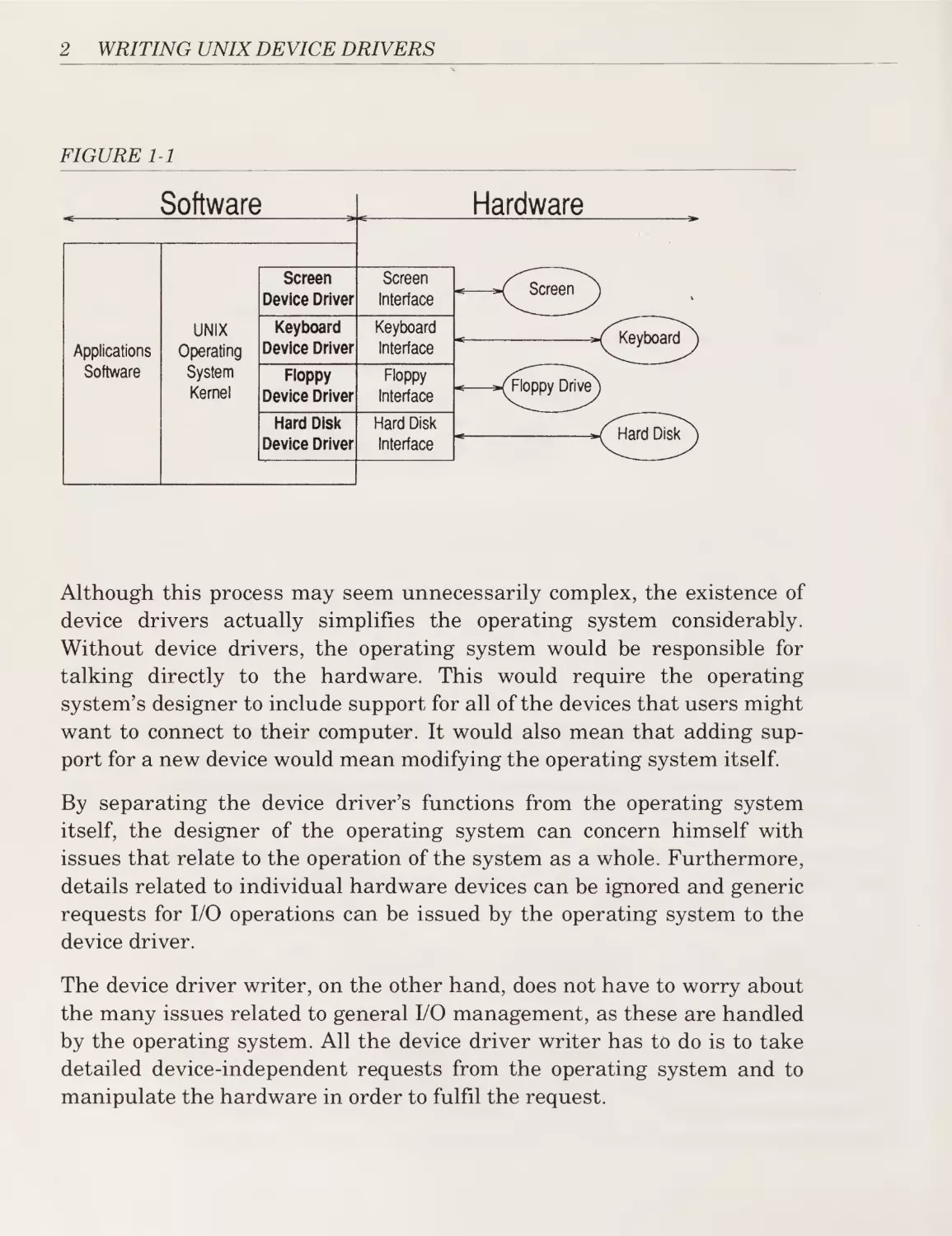
This relationship is illustrated in Figure 1-1. The applications software
makes system calls to the operating system requesting services (for exam¬
ple, write this data to file x).
The operating system analyzes these requests and, when necessary,
issues requests to the appropriate device driver (for example, write this
data to disk 2, block 23654).
The device driver in turn analyzes the request from the operating system
and, when necessary, issues commands to the hardware interface to perform
the operations needed to service the request (for example: transfer 1024
bytes starting at address 235400 to disk 2, cylinder 173, head 7, sector 8).
1
2
WRITING UNIX DEVICE DRIVERS
FIGURE 1-1
Software
Applications
Software
UNIX
Operating
System
Kernel
Hardware
Screen
Device Driver
Screen
Interface
Keyboard
Device Driver
Keyboard
Interface
Floppy
Device Driver
Floppy
Interface
Hard Disk
Device Driver
Hard Disk
Interface
Although this process may seem unnecessarily complex, the existence of
device drivers actually simplifies the operating system considerably.
Without device drivers, the operating system would be responsible for
talking directly to the hardware. This would require the operating
system’s designer to include support for all of the devices that users might
want to connect to their computer. It would also mean that adding sup¬
port for a new device would mean modifying the operating system itself.
By separating the device driver’s functions from the operating system
itself, the designer of the operating system can concern himself with
issues that relate to the operation of the system as a whole. Furthermore,
details related to individual hardware devices can be ignored and generic
requests for I/O operations can be issued by the operating system to the
device driver.
The device driver writer, on the other hand, does not have to worry about
the many issues related to general I/O management, as these are handled
by the operating system. All the device driver writer has to do is to take
detailed device-independent requests from the operating system and to
manipulate the hardware in order to fulfil the request.
Chapter 1: What is a Device Driver?
Finally, the operating system can be written without any knowledge of
the specific devices that will be connected. And the device driver writer
can connect any I/O device to the system without having to modify the
operating system. The operating system views all hard disks through the
same interface, and the device driver writer can connect almost any type
of disk to the system by providing a driver so that the operating system is
happy.
The result is a clean separation of responsibilities and the ability to add
device drivers for new devices without changing the operating system.
Device drivers provide the operating system with a standard interface to
non-standard I/O devices.
The Details
A UNIX device driver is a collection of functions, usually written in C,
that can be called by the UNIX operating system using the standard C
function-calling mechanism. These routines are often referred to as entry
points. The compiled code for the device driver is linked with the code for
the operating system itself and the result is a new file containing the
bootable operating system with all the device drivers.
In order to understand the relationship between the UNIX operating sys¬
tem and its drivers better, let us examine the result of running a simple
UNIX command that references the line printer driver. Consider the
result of typing the following command on a UNIX system:
echo hello,
world > /dev/lp
Since we are only interested in the issues related to UNIX device drivers
we shall ignore the details of how the shell command interpreter actually
processes this input.
The first part of interest occurs when the shell goes to open the file
/dev/lp. The C code that is executed is the equivalent of:
fileds = open("/dev/lp",
0_WR0NLY);
3
4
WRITING UNIX DEVICE DRIVERS
The UNIX operating system first examines the file /dev/lp and determines
that it is, in fact, not a normal data file but a special file. Special files are
files that can represent device drivers (among other things). If we were to
examine the /dev/lp file using the Is -1 command, we would find:
crw-
2
bin
bin
6,
0
Oct
4
1991
/dev/1^
There are two things in this display that differ from what we would nor¬
mally see if /dev/lp had been a normal data file. Note that the first charac¬
ter on the line is c. This indicates that this special file represents a
character device driver. Character drivers are one of the four different
types of drivers (more on the other three shortly). Also note that the num¬
bers 6, 0 appear in the place where we would normally expect to find the
size of the file. These are the major (6) and minor (0) device numbers for
this special file. The major device number specifies the device driver while
the minor device number is used by the driver to distinguish between dif¬
ferent devices under the control of a single driver.
When the UNIX operating system goes to process the open system call, it
sees that the file being opened is a character special file with major device
number 6. It uses the major device number to index into a table of all of
the character drivers installed on the system. The declaration of this table
looks something like the following:
struct
cdevsw
{
int
(*d_open)();
int
(*d_close)();
int
(*d_read)();
int
(*d_write)();
int
(*d_ioctl)();
struct
tty
struct
streamtab
char
*d_ttys;
*d_str;
*d_name;
};
extern
int
struct
cdevsw cdevsw[]
{
lpopen(),
lpclose(),
=
lpread() ,
lpwrite() ,
lpioctl In¬
Chapter 1: What is a Device Driver?
lpopen,
lpclose,
lpread,
lpwrite,
Ipioctl,
NULL,
NULL,
"lp",
};
This table is defined when a new operating system kernel is configured
and built. The kernel is the part of the UNIX operating system that is
always resident in memory when the system is running, and which sits
between the hardware and the processes. Device drivers are considered
part of the kernel.
Every member of the table is a structure containing pointers to each of
the five main entry points for each character driver. The remaining three
members of the structure are pointers to various data structures that are
not used by the line printer driver.
If the kernel has stored the major device number in a variable called
dev_major, it can invoke the driver’s open entry point using the expres¬
sion cdevsw[devjnajor]. d_open(.. J.
Similarly, when the echo utility goes to write the string “hello, world”, the
UNIX operating system passes the data to the line printer driver by
invoking the driver’s write routine (e.g., cdevsw[dev_major].d_write...).
In this manner, the connection is made between a UNIX process and the
device driver.
An important consideration is that the driver’s routines (entry points) are
linked into the rest of the UNIX kernel and form part of the operating
system. One result is device drivers execute with all of the privileges of
the operating system and can do things that normal applications software
cannot. They also can malfunction in ways never imagined by applications
programmers.
The Major Design Issues
To make studying the design of device drivers easier, we have divided the
issues to be considered into three broad categories:
5
6
WRITING UNIX DEVICE DRIVERS
1. Operating System/Driver Communications
2. Driver/Hardware Communications
3. Driver Operations
The first category covers all of the issues related to the exchange of infor¬
mation (commands and data) between the device driver and the operating
system. It also includes support functions that the kernel provides for the
benefit of the device driver.
The second covers those issues related to the exchange of information
(commands and data) between the device driver and the device it controls
(i.e., the hardware). This also includes issues such as how software talks
to hardware—and how the hardware talks back.
The third covers issues related to the actual internal operation of the
driver itself. This includes:
■
interpreting commands received from the operating system;
■
scheduling multiple outstanding requests for service;
■
managing the transfer of data across both interfaces (operating
system and hardware);
■
accepting and processing hardware interrupts; and
■
maintaining the integrity of the driver’s and the kernel’s data
structures.
When we proceed to study the actual drivers presented in this book, we
shall examine each in the context of these three general design issues.
Types of Device Drivers
UNIX device drivers can be divided into four different types based
entirely on differences in the way they communicate with the UNIX oper¬
ating system. The types are: block, character, terminal, and STREAMS.
The kernel data structures that are accessed and the entry points that the
driver can provide vary between the various types of drivers. These differ¬
ences affect the type of devices that can be supported with each interface.
Chapter 1: What is a Device Driver?
The following sections will describe these differences briefly and the types
of devices that each driver can support. As we study the drivers in the
remainder of this book we shall examine these differences in detail.
Block Drivers
Block drivers communicate with the operating system through a collec¬
tion of fixed-sized buffers as illustrated in Figure 1-2. The operating sys¬
tem manages a cache of these buffers and attempts to satisfy user
requests for data by accessing buffers in the cache. The driver is invoked
only when the requested data is not in the cache, or when buffers in the
cache have been changed and must be written out.
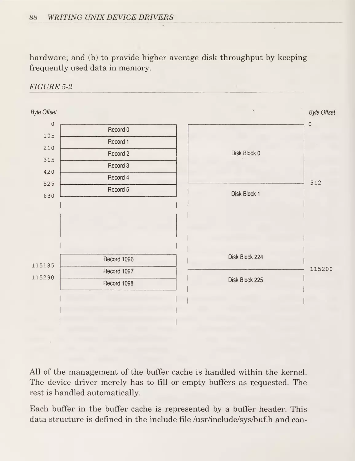
Because of this buffer cache the driver is insulated from many of the
details of the users’ requests and need only handle requests from the
operating system to fill or empty fixed-sized buffers.
7
8
WRITING UNIX DEVICE DRIVERS
Block drivers are used primarily to support devices that can contain file
systems (such as hard disks).
Character Drivers
Character drivers can handle I/O requests of arbitrary size and can be
used to support almost any type of device. Usually, character drivers are
used for devices that either deal with data a byte at a time (such as line
printers) or work best with data in chunks smaller or larger than the
standard fixed-sized buffers used by block drivers (such as analog-to-digital converters or tape drives).
One of the major differences between block and character drivers is that
while user processes interact with block drivers only indirectly through
the buffer cache, their relationship with character drivers is very direct.
This is shown schematically in Figure 1-3. The I/O request is passed
essentially unchanged to the driver to process and the character driver is
responsible for transferring the data directly to and from the user
process’s memory.
FIGURE 1-3
User Process
Kernel
Driver
read/write
system calls
read/write
"system call handler
read/write
entry points
Chapter 1: What is a Device Driver?
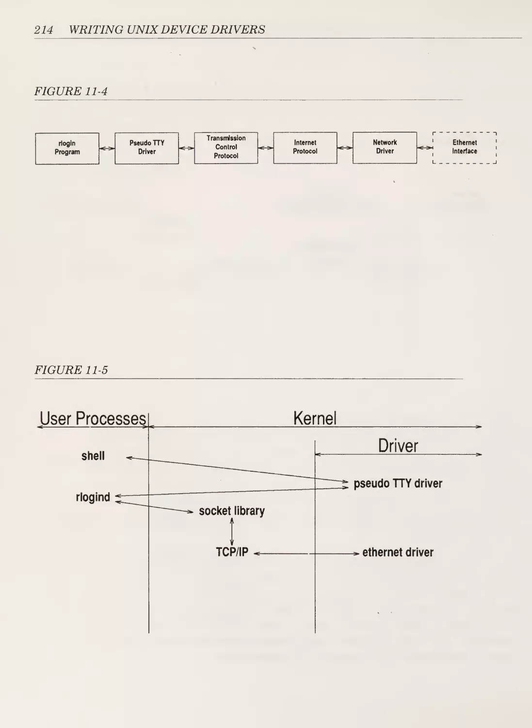
Terminal Drivers
Terminal drivers are really just character drivers specialized to deal with
communication terminals that connect users to the central UNIX com¬
puter system. Terminal drivers are responsible not only for shipping data
to and from users’ terminals, but also for handling line editing, tab expan¬
sion, and the many other terminal functions that are part of the standard
UNIX terminal interface described by the TERMIO manual page. Because
of this additional processing that terminal drivers must perform (and the
additional kernel routines and data structures that are provided to han¬
dle this), it is useful to consider terminal drivers as a separate type of
driver altogether. Compare Figure 1-4, which represents the special rela¬
tionship of a terminal driver with the kernel, with the earlier Figure 1-3
of a prototypical character driver.
FIGURE 1-4
9
10
WRITING UNIX DEVICE DRIVERS
STREAMS Drivers
STREAMS drivers are used to handle high-speed communications devices
such as networking adapters that deal with unusual-sized chunks of data
and that need to handle protocols. In System V Release 4, STREAMS
driveeers are also used to interface terminals.
Versions of UNIX prior to System V Release 3 supported network devices
using character drivers. This was unsatisfactory because the character
model assumes that a single driver sits between the user process and the
device. Remember that with character drivers the user process’s request
is handed directly to the driver with little intervention or processing by
the kernel.
Networking devices, however, usually support a number of layered proto¬
cols. The character model essentially required that each layer of the pro¬
tocol be implemented within the single driver. This lack of modularity and
reusability reduced the efficiency of the system.
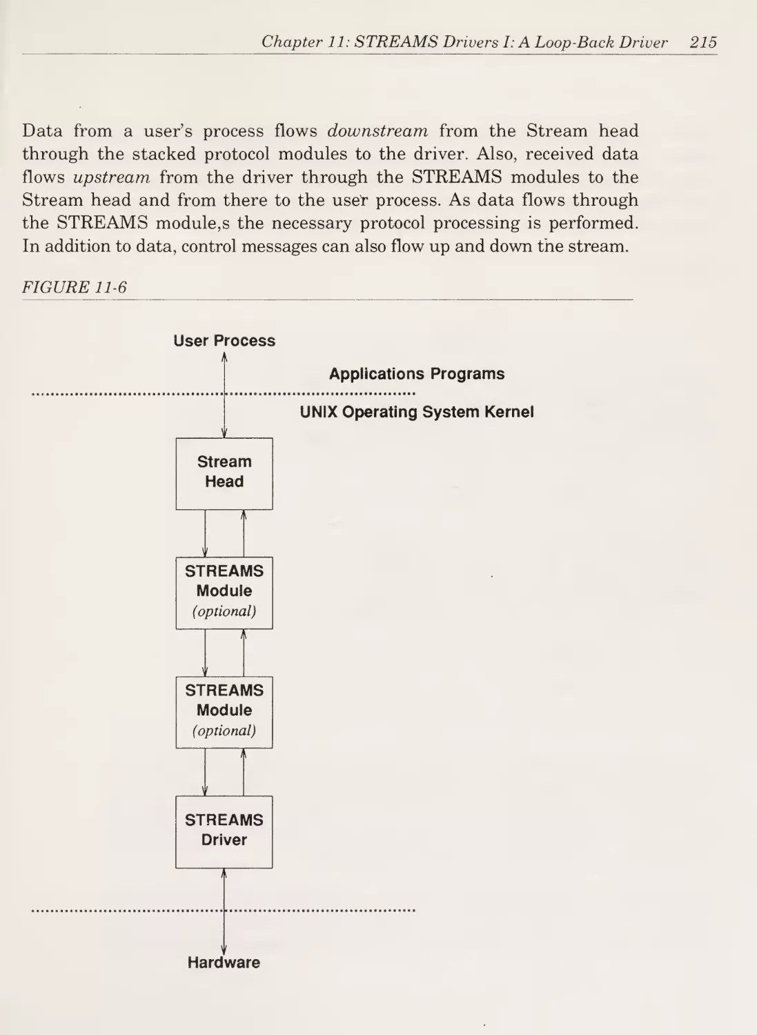
As a result, Dennis Ritchie of Bell Laboratories (one of the originators of
UNIX) developed an extension to the character driver model called
STREAMS (in uppercase). This new type of driver was introduced by
AT&T in UNIX System V Release 3 and makes it possible to stack proto¬
col processing modules between the user process and the driver. This can
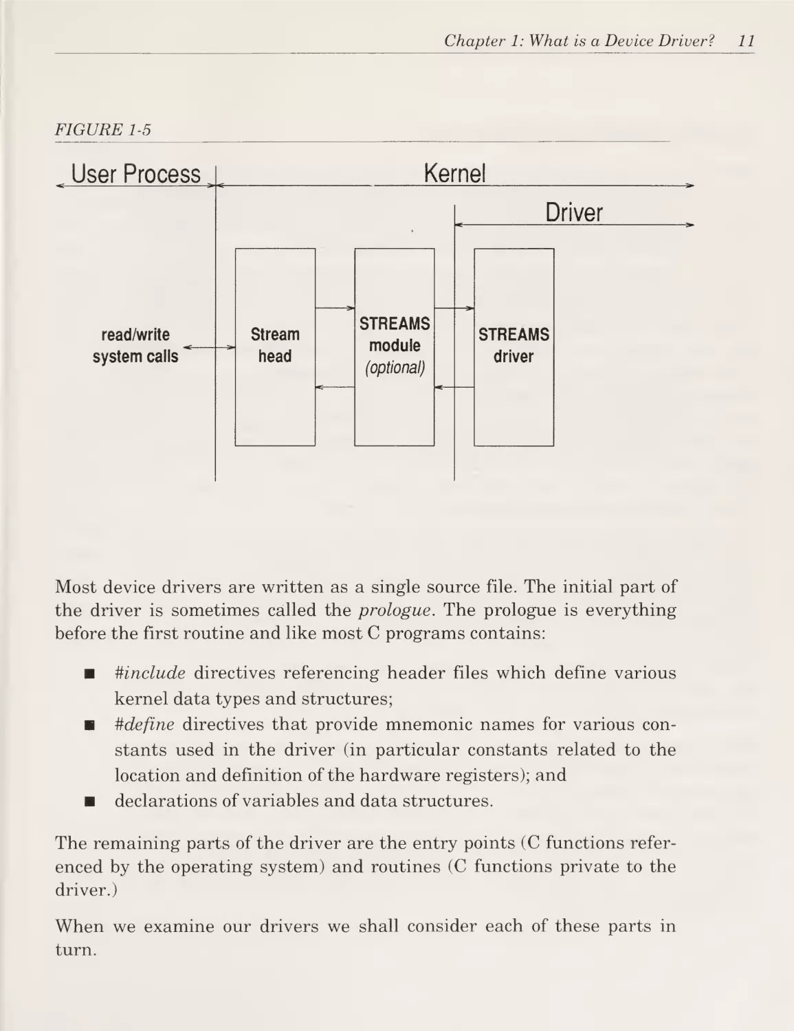
be seen on the next page in Figure 1-5. Stacking modules in this way
makes it much easier to implement network protocols.
The Gross Anatomy of a Device Driver
Each of the following chapters will present a complete driver for study.
But before we turn the page and start considering our first driver, it
might be helpful to consider the major components of a driver.
Recall that a driver is a set of entry points (routines) that can be called by
the operating system. A driver can also contain: data structures private to
the driver; references to kernel data structures external to the driver; and
routines private to the driver (i.e., not entry points).
Chapter 1: What is a Device Driver?
FIGURE 1-5
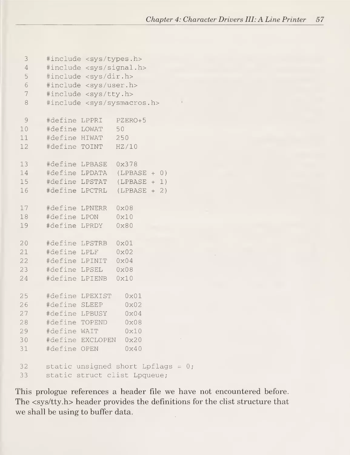
Most device drivers are written as a single source file. The initial part of
the driver is sometimes called the prologue. The prologue is everything
before the first routine and like most C programs contains:
■
#include directives referencing header files which define various
kernel data types and structures;
■
#define directives that provide mnemonic names for various con¬
stants used in the driver (in particular constants related to the
location and definition of the hardware registers); and
■
declarations of variables and data structures.
The remaining parts of the driver are the entry points (C functions refer¬
enced by the operating system) and routines (C functions private to the
driver.)
When we examine our drivers we shall consider each of these parts in
turn.
11
12
WRITING UNIX DEVICE DRIVERS
General Programming Considerations
As we shall see in the many examples in this book, writing device drivers
is somewhat different from writing applications programs in C. While
explanation of the subtle differences can wait until we encounter them, it
will be helpful to discuss the significant differences now.
As obvious as it sounds, the main difference is that device drivers are part
of the kernel and not normal user processes. This means that many of the
things that a normal C program can do a driver cannot. For starters, for¬
get about using any of the normal C library functions described in the
programmer’s reference for your UNIX system. These functions, normally
documented in sections 2 and 3 of your manual (or section S if you have
an SCO XENIX or UNIX operating system) are not supported by the ker¬
nel. The functions that are supported by your kernel may be found in the
device driver manual for your system. Note that although some of the ker¬
nel routines have the same name as standard C library functions (e.g.,
printf) they are somewhat different.
In addition, make frugal use of the stack (do not use recursive functions
and do not declare local arrays). The stack space available to the kernel is
limited and is not expandable on most UNIX systems. Also, do not use
floating-point arithmetic. Although your machine may have a floating¬
point unit, the kernel does not save the contents of the FPU’s registers
unless it is planning to switch processes. Therefore using the FPU at best
can cause incorrect results both in your code and some poor innocent
user’s program and at worst can cause the system to crash.
Do not busy wait (spin) within your driver waiting for an event to occur
unless the expected time to wait is less than the time to leave your driver
and re-enter it when an interrupt occurs (i.e., less than 200 microseconds
on a fast 386). User processes that spin will merely have the CPU taken
away from them and given to other processes in turn. The kernel, how¬
ever, always takes priority over any user process and a driver that is exe¬
cuting a spin loop will prevent the system from doing anything but
responding to interrupts.
Chapter 1: What is a Device Driver?
Summary
As the first figure in this chapter showed, device drivers stand between
an operating system and the peripherals it controls. Drivers accept stan¬
dard requests for I/O services from the operating system and convert
them into the hardware-specific commands and operations required to
support the peripheral’s interface. This not only relieves the operating
system of the burden of handling the details of all the different peripher¬
als, it makes it easy to support another peripheral just by adding a driver
and without having to modify the operating system itself.
The UNIX operating system supports four different types of drivers
(block, character, terminal, and STREAMS) which provide different inter¬
faces between the kernel and the driver. This makes it possible to select
the most appropriate driver model and interface for the type of device to
be supported.
A driver is implemented as a collection of routines, usually written in the
C language, that is linked into the kernel. When the operating system is
asked to open or write to a device, it selects the driver’s entry point from a
table of entry points.
The remainder of this book will be an examination of a selection of drivers
including at least one of each of the four types listed earlier.
13
'
;
*
■*?
.
.
'
•
^
•
1
1
:■
M
I
G
‘
- '
•
-:y4
h
tj
(j
>5
*
I |
B I
I j
M
Chapter 2
Character Driver I: A Test Data Generator
Instead of spending countless chapters droning on about the UNIX oper¬
ating system and the theory of drivers, let’s look at a real driver right
now!
The driver we are about to examine is actually a pseudo-device driver in
that it does not control any hardware. This will allow us to introduce the
basic concepts of a UNIX device driver without the complexity of having
to deal with a real device.
Read system calls on this pseudo-device will return the “Quick Brown
Fox” message repeated infinitely. Writes are just ignored.
This device driver can therefore be used to generate infinite amounts of
data for testing without consuming any disk space. For example, to test a
terminal, one could type:
cat /dev/testdata
to test a printer:
15
16
WRITING UNIX DEVICE DRIVERS
_a
cat /dev/testdata > /dev/lp
or to generate a one-megabyte data file:
dd if=/dev/testdata of=bigfile bs=lk count=1024
In the first two cases, the test would continue until the process was
stopped by typing the interrupt character on your terminal (DEL, AC, or
whatever you have it set to).
Since this driver will handle data byte by byte and reads of arbitrary size,
it is best structured as a character driver.
The Design Issues
Since this driver does not control any hardware, we need only concern
ourselves with two of the three categories of design issues: the
UNIX/driver interface and the internal driver operation. There are no
driver/hardware interface issues.
The Operating System/Driver Interface
How does the UNIX kernel tell the driver what it wants it to do?
As we shall see shortly, this is done in two steps. Firstly, the operating
system calls one of the device driver’s entry points (functions). This causes
control to pass to the device driver.
Secondly, the device driver examines the parameters passed and kernel
data structures for information on exactly what to do.
Each of the four types of device drivers has its own set of entry points that
the operating system expects to find and its own conventions for the
exchange of data and commands. A character driver may have any or all
of the following entry points:
■
init()
The init entry point is called by the kernel immediately after the system
is booted. It provides the driver with an opportunity to initialize the
Chapter 2: Character Driver I: A Test Data Generator
driver and the hardware as well as to display messages announcing the
presence of the driver and hardware.
■
startO
The start entry point is called by the kernel late in the bootstrap sequence
when more system services are available. It provides the driver with an
opportunity to perform initialization that require more system services
than are available at the time when init is called.
■
open(dev, flag, id)
The open entry point is called by the kernel whenever a user process per¬
forms an open system call on a special file that is related to the driver. It
provides the driver with an opportunity to perform initialization that
need to occur prior to handling read and write system calls.
■
close(dev, flag, id)
The close entry point is called by the kernel when the last user process
that has the driver open performs a close system call (or exits, causing the
operating system to close all open files automatically). Note that the
driver’s open entry point is called for every user open, while the driver’s
close entry point is called only for the last user close. It provides the
driver with an opportunity to release resources that may be needed only
while the device is open and to reset the device or otherwise place it in a
quiescent mode.
■
halt()
The halt entry point is called by the kernel just before the system is shut
down. It provides the driver with an opportunity to prepare the hardware
for the shutdown and to flush any data that may still be resident in the
driver.
17
18
WRITING UNIX DEVICE DRIVERS
■
intr(vector)
The intr entry point is called by the kernel whenever an interrupt is
received from the hardware. Interrupts are a signal from the hardware
that a significant event has occurred (usually the completion of the last
I/O operation) which requires the attention of the driver.
■
read(dev)
The read entry point is called by the kernel whenever a user process per¬
forms a read system call on a special file that is related to the driver. The
driver is required to accept the details of the I/O request, perform the nec¬
essary operations to obtain the requested data, and arrange for the trans¬
fer of the data to the user’s process.
■
write(dev)
The write entry point is called by the kernel whenever a user process per¬
forms a write system call on a special file that is related to the driver. The
driver is required to accept the details of the I/O request, arrange for the
transfer of the data from the user’s process to the driver (or directly to the
device), and perform the necessary operations to write the data to the
device.
■
poll(pri)
The poll entry point is called by the kernel 25 to 100 times a second
(depending on the version of UNIX). It provides the driver with an oppor¬
tunity to perform operations on a periodic basis or to check on the status
of the device on a regular basis.
■
ioctl(dev, cmd, arg, mode)
The ioctl entry point is called by the kernel whenever a user process per¬
forms an ioctl system call on a special file that is related to the driver. The
driver is required either to accept the details of the ioctl request and per¬
form the necessary operations, or reject the request with an error. Ioctl
calls are used to pass special requests to the driver or to obtain informa¬
tion on the configuration or status of the device and driver.
Chapter 2: Character Driver I: A Test Data Generator
The actual names of a particular driver’s entry points are the name of the
entry point (as above) plus a two- to four-letter prefix. For example, the
prefix we have chosen for this sample driver is chrl (character driver #1).
Therefore the init entry point is named chrlinit and the read entry point
chrlread. Each of these entry points will be discussed in detail as we
encounter them in the drivers we are about to study.
The Internal Operation of the Driver
The overall purpose of this driver is to transfer data from an internally
stored string (the “Quick Brown Fox” message) to a process’s buffer (area
in memory). When the process issues a read system call, it must specify
both the location of the buffer as well as the number of bytes to read. For
example, the line of code to perform the read might look something like
this:
count = read(fildes,
buffer,
sizeof(buffer));
where fildes is the file descriptor returned from the open system call and
buffer is a character array. The kernel handles this system call by calling
the read entry point for our driver and leaving the address of buffer as
well as the size of the read request (sizeof(bufferj in this example) in a
location known to the driver. This “known” location is within a data struc¬
ture called the user or u. (pronounced you-dot) area. The user area con¬
tains all of the information about a process that the kernel needs when
the process is in memory (i.e., not swapped out to disk for want of mem¬
ory). As mentioned, this data structure is also used to communicate
between the kernel and the driver as will be seen in detail when we con¬
sider the chrlread entry point below. The contents of the user area are
defined by the user structure (see the header file <sys / user.h>).
The Driver
What follows is the complete C source for this device driver. This driver,
as with all of the others we shall examine, has been divided into sections.
The first is the driver prologue which contains everything that must pre¬
cede the first entry point in the source file. The second and subsequent
sections are the entry points themselves.
19
20
WRITING UNIX DEVICE DRIVERS
x.
The Driver Prologue
The prologue of a device driver includes all of the definitions and declara¬
tions required by the rest of the driver. In particular, most prologues con¬
sist of three parts: references to the header files necessary to define
various kernel data types and structures; definitions that are local to the
driver; and declarations local to the driver.
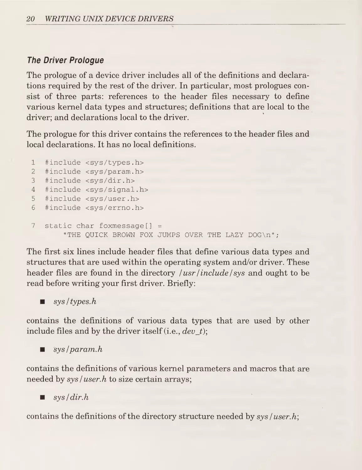
The prologue for this driver contains the references to the header files and
local declarations. It has no local definitions.
1
2
3
4
5
6
#include
#include
#include
#include
#include
#include
<sys/types.h>
<sys/param.h>
<sys/dir.h>
<sys/signal.h>
<sys/user.h>
<sys/errno,h>
7
static char foxmessage[] =
"THE QUICK BROWN FOX JUMPS OVER THE LAZY DOG\n";
The first six lines include header files that define various data types and
structures that are used within the operating system and/or driver. These
header files are found in the directory / usr / include / sys and ought to be
read before writing your first driver. Briefly:
■
sys / types, h
contains the definitions of various data types that are used by other
include files and by the driver itself (i.e., dev_t)\
■
sys / param. h
contains the definitions of various kernel parameters and macros that are
needed by sys / user.h to size certain arrays;
■
sys / dir. h
contains the definitions of the directory structure needed by sys / user, h;
Chapter 2: Character Driver I: A Test Data Generator
■
sys / signal, h
contains the definitions related to signals needed by sys / user.h;
■
sys / user, h
contains the definition of the user structure; and
■
sys/errno.h
contains the definitions of the various error codes that may be returned
from a driver.
The last line of our prologue declares the character array that contains
our “QUICK BROWN FOX...” message. Note that variables used only
within the driver are declared static so as not to risk conflict with global
variables defined in the kernel.
The remainder of the driver consists of the driver’s entry points.
The Init Entry Point
This entry point is called by the operating system shortly after the system
is booted. Few system services are available to the driver at this time (i.e.,
it must not attempt to read a disk file). The primary purpose of calling the
init routine is for the device driver:
■
to check that the device is actually installed on the machine;
■
to print a message indicating the presence (or absence) of the
device and driver;
■
to initialize the device (if necessary) prior to the first open; and
■
to initialize the driver and allocate local memory (if necessary)
prior to the first open.
Since the system itself is not completely initialized it is important not to
use certain system services that are not yet ready. In particular:
■
do not call the sleep, delay, or wakeup kernel support routines; and
21
WRITING UNIX DEVICE DRIVERS
■
do not attempt to reference any members of the user structure (the
u. area).
Note also that interrupts are not available at init time.
The init entry point is optional and need not be included in a driver,
although most drivers, even those that do not need to perform‘any initial¬
ization, provide one to announce their presence. Such is the case with the
init entry point for this driver.
8
9
10
11
chrlinit()
{
printf("Test Data Character Device Driver vl.0\n");
"
}
Remember that the printf called in line 10 is not the standard printf
available to normal applications C programs. It is a special version that is
implemented in the kernel for use by device drivers. It does not support
all of the options of the standard C printf function. Refer to the device
driver reference manual for your version of UNIX to determine exactly
what formatting options are available.
Also on most systems the kernel printf routine suspends all system activ¬
ity while the message is being sent to the console. Use it sparingly.
Beware of using it to report errors that may happen frequently if the
device malfunctions. Frequent printf messages can so tie up a machine as
to make it impossible to log users off and shut down the system properly.
The Read Entry Point
The read entry point of a character driver is called when the user’s pro¬
cess has requested data from the device using the read system call. This
routine must coordinate the transfer from the driver to the user’s process.
Although the read entry point is optional, it is necessary for any driver
that wishes to transfer data from a device (or driver) to a process (i.e., sat¬
isfy a read system call). Since our driver’s sole purpose is to transfer
“QUICK BROWN FOX...” messages from the driver to a process, it has a
read entry point.
Chapter 2: Character Driver I: A Test Data Generator
The pseudo-code for this entry point is below, followed immediately by the
actual driver code. This sequence will be used in this book whenever the
entry point is sufficiently complex to warrant a pseudo-code overview. In
this manner readers wishing an overview of the driver can skim the
pseudo-code and avoid the details of the actual driver. Since the line num¬
bers in the pseudo-code listing refer to the lines in the actual driver code,
the commentary on the code can be followed by referring to either the
pseudo-code or the actual code.
12 read entry point:
14
while (the user's read request is not completely satisfied)
15
{
16
copy 1 byte
from: foxmessage[indexed by u.u_offset]
to:
the user's buffer addressed by u.u_base
if
17-20
21-23
24
(an error occurs)
set u.u_error and return
update u.u_offset, u.u_base,
and u.u_count
}
The actual read entry point for this driver follows:
12
13
14
15
16
17
18
19
20
21
22
23
24
25
void chrlread(dev_t dev)
{
while (u.u_count)
{
if (copyout(&foxmessage[u.u_offset % sizeof(foxmessage)],
u.u_base, 1) == -1)
{
u.u_error = EFAULT;
return;
}
u.u_base++;
u.u_offset + +;
u.u_count--;
}
}
23
24
WRITING UNIX DE VICE DRIVERS
With the read entry point the information specifying the nature of the
transfer is passed to the driver in two ways. Firstly, the device number is
passed as a parameter to the read routine. Since we are only emulating
one (pseudo-)device, we can ignore the device number.
Secondly, the location of the data on the device, the number of bytes to
read, and the memory location to which the data is to be transferred is
stored in the user area.
The User Area
Every process has its own user structure but only the user
structure for the currently executing process is accessible directly to the
device driver. The kernel sets things up (either by using its memory man¬
agement unit or by copying the data) so that the kernel variable u refer¬
ences the user structure for the currently executing process. Therefore the
device driver can reference the (say) ujbase member of the user structure
for the current process by referring to u.ujbase.
The contents of the user structure are defined by the system header file
<sys / user.h>. There are a number of interesting members of this struc¬
ture, but the only ones of use to us are listed below:
Important Members of The User Structure
Member
u_error
ujuid
u_gid
ujbase
u_count
u_offset
Description
error return code
user id (UID) of the process
group id (GID) of the process
address in user memory of I/O buffer
number of bytes to transfer
position in file where next I/O is to occur
The u_offset value is used for devices that support addressing or direct
access (such as disks, etc.) and is the offset in bytes from the beginning of
the device to the position where the next read or write operation will
occur.
In the case of this driver, we use the u_offset value to determine which
byte of the message is to be transferred next. For example, if the user first
issued a read for five bytes, we would return “The Q”. If the user then
Chapter 2: Character Driver I: A Test Data Generator
issued a second read for ten bytes, we would want to transfer “UICK
BROWN”. We keep track of our current position in the message in u-off¬
set. To avoid having to reset u_offset to 0 when the last byte of the mes¬
sage is sent, we take the value of u_offset modulo the length of the
message. In other words, the location of the next byte in the foxmessage
string to transfer is foxmessage[u.u_offset % sizeof(foxmessage)]. This is
the essence of line 26 in the chrlread entry point above.
As an aside, continuous reads of this device can cause u_offset to eventu¬
ally overflow. This is not considered a problem, however, since it will not
happen until at least 48 million “QUICK BROWN FOX...” messages have
been generated.
Well, we know what we want to transfer (the message
starting at byte u_offset), we know how much to transfer (u_count), and
we know where to put it (ujbase). So why don’t we do something like the
following?
Address Spaces
chrlread(dev_t dev)
{
while
{
(u.u_count)
(A
*u.u_base++ = Message[u.u_offset % sizeof(Message)];
u.u_count-~;
}
}
The problem is that u.ujbase contains an address in the user’s address
space and the device driver runs in the kernel’s address space.
Look at Figure 2-1 on the next page. UNIX is able to run multiple pro¬
cesses at the same time. This means that multiple programs have to be
placed into memory at the same time. As a result, programs might be
placed anywhere in memory, and the same program run twice in a row
might be placed in different locations in memory. (To require otherwise
would be to hamstring UNIX.)
Therefore, things must be set up so that a process can run no matter
where in memory it resides. The most efficient way to do this is to fiddle
25
26
WRITING UNIX DEVICE DRIVERS
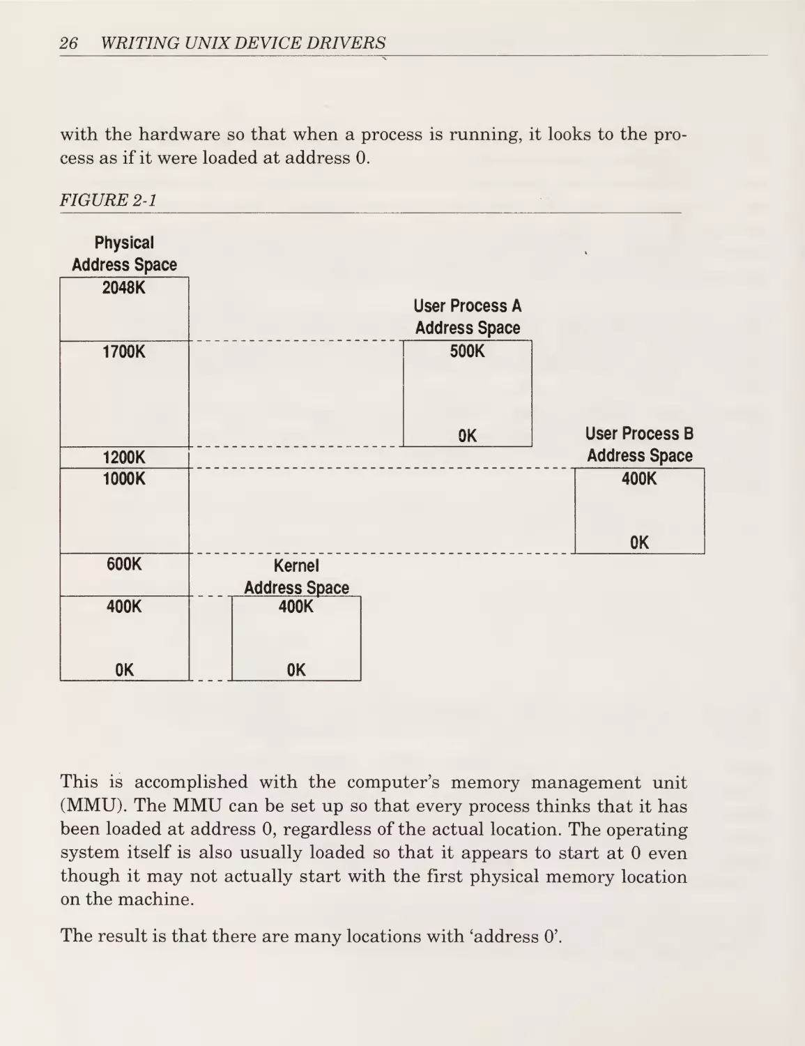
with the hardware so that when a process is running, it looks to the pro¬
cess as if it were loaded at address 0.
FIGURE 2-1
Physical
Address Space
2048K
User Process A
Address Space
500K
1700K
OK
1200K
1000K
User Process B
Address Space
400K
OK
600K
400K
Kernel
Address Space
400K
OK
OK
This is accomplished with the computer’s memory management unit
(MMU). The MMU can be set up so that every process thinks that it has
been loaded at address 0, regardless of the actual location. The operating
system itself is also usually loaded so that it appears to start at 0 even
though it may not actually start with the first physical memory location
on the machine.
The result is that there are many locations with ‘address O’.
Chapter 2: Character Driver I: A Test Data Generator
Firstly, there is the physical memory itself which will respond when the
value 0 is placed on the circuits connecting the memory to the CPU.
Addresses that refer to physical memory are called physical addresses or
addresses in the physical address space.
Secondly, the kernel’s address 0 may or may not refer to physical address
0. Addresses that refer to the kernel’s memory are called kernel addresses
or addresses in the kernel address space.
Finally, each user process will have an address 0. One process’s address 0
might refer to physical address 1,024,000 while another might refer to
3,456,458. There are as many user address spaces as there are processes
running on the system.
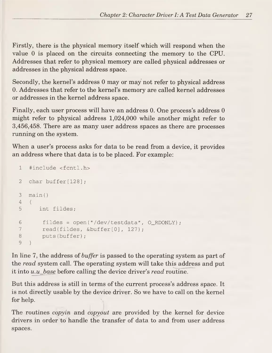
When a user’s process asks for data to be read from a device, it provides
an address where that data is to be placed. For example:
1
#include <fcntl.h>
2
char buffer[128];
3
main()
4
5
{
6
7
8
9
int fildes;
fildes = open("/dev/testdata",
read(fildes, &buffer[0], 127);
puts(buffer);
0_RDONLY);
}
In line 7, the address of buffer is passed to the operating system as part of
the read system call. The operating system will take this address and put
it into u.ujbasg before calling the device driver’s read routine.
But this address is still in terms of the current process’s address space. It
is not directly usable by the device driver. So we have to call on the kernel
for help.
The routines copyin and copyout are provided by the kernel for device
drivers in order to handle the transfer of data to and from user address
spaces.
27
28
WRITING UNIX DEVICE DRIVERS
Copyout takes: an address in kernel space where the data is to be found;
an address in the user space of the current process where the data is to be
put; and a count of the number of bytes to transfer. Similarly, copyin
takes a user address, a kernel address, and a count. Both routines return
-1 if they encounter a problem transferring the data.
So if we return to the listing of the chrlread routine we can see that the
entire routine is one large while loop from line 14 to line 24. This loop con¬
tinues until either: u.u_count is zero (i.e. all of the data has been trans¬
ferred); or an error has occurred (line 18).
Within the loop we call copyout (line 16) to copy one byte from the
Foxmessage string to the user’s buffer. If an error occurs (i.e., if copyout
returns -1), we set u.u_error to report an error in the transfer (line 18)
and return prematurely (line 19). If u.u_error is set, the read system call
in the user’s program will return -1 and the external variable errno, which
is accessible to the user’s program, will be set to the value of u.u_error
{i.e., EFAULT).
If the transfer has succeeded, then we update all of the u. variables (lines
21 through 23).
The result is that the data is transferred or an error is reported and the u.
variables are appropriately adjusted to reflect the data that was trans¬
ferred.
Other Entry Points
The other entry points that character drivers may support (such as open,
close, start, halt, read, write, poll, or ioctl) provide for functions that are
not supported by this driver and therefore need not be defined.
For example, there is no need to make any preparations prior to or after
reading the data from this driver so there is no need for open or close
entry points. Similarly, it does not make sense to write data to this device
so there is no write entry point.
Chapter 2: Character Driver I: A Test Data Generator
The Recapitulation
Now that we have seen and examined all of the parts of this driver, let us
tie it together by tracing the detailed flow of control and data as a user
process first opens and then reads data from our device driver. The follow¬
ing is a simple program that opens and reads from / dev / testdata.
ttinclude
<fcntl.h>
main()
{
int
fildes;
char buffer[1024];
fildes
=
open("/dev/testdata",
read(fildes,
write(l,
buffer,
buffer,
0_RD0NLY);
sizeof(buffer));
sizeof(buffer));
}
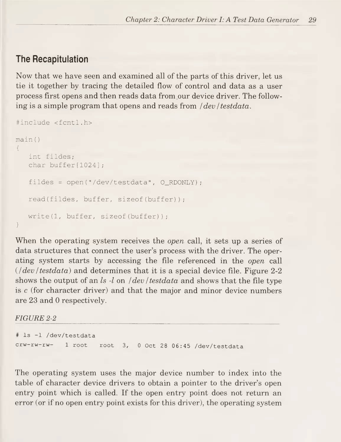
When the operating system receives the open call, it sets up a series of
data structures that connect the user’s process with the driver. The oper¬
ating system starts by accessing the file referenced in the open call
(/dev / testdata) and determines that it is a special device file. Figure 2-2
shows the output of an Is -l on /dev / testdata and shows that the file type
is c (for character driver) and that the major and minor device numbers
are 23 and 0 respectively.
FIGURE 2-2
# Is -1
/dev/testdata
crw-rw-rw-
1
root
root
3,
0 Oct 28
06:45 /dev/testdata
The operating system uses the major device number to index into the
table of character device drivers to obtain a pointer to the driver’s open
entry point which is called. If the open entry point does not return an
error (or if no open entry point exists for this driver), the operating system
29
30
WRITING UNIX DEVICE DRIVERS
continues to establish the data structures necessary to connect the pro¬
cess to the driver.
The information that was obtained from the file’s inode is placed in a free
entry in the inode table. If the hie was already open and in use by another
process, then the same inode table entry will be shared among ah pro¬
cesses that have opened the hie.
Next, the system allocates a new entry in the kernel’s hie table that
points to the inode table.
Finally, a free entry in the process’s hie table is located and set to point to
the new entry in the kernel’s hie table.
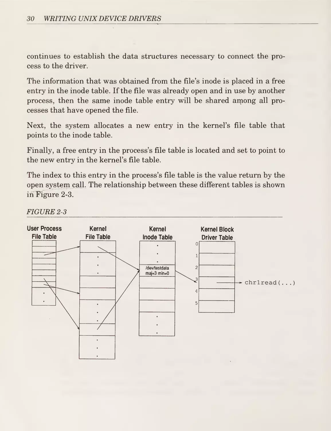
The index to this entry in the process’s hie table is the value return by the
open system call. The relationship between these different tables is shown
in Figure 2-3.
FIGURE 2-3
User Process
File Table
Kernel
File Table
Kernel
Inode Table
Kernel Block
Driver Table
/dev/testdata
maj=3min=0
chrlread(...)
Chapter 2: Character Driver I: A Test Data Generator
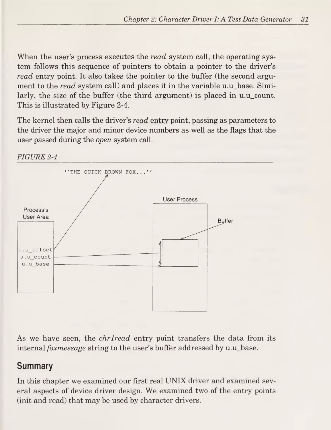
When the user’s process executes the read system call, the operating sys¬
tem follows this sequence of pointers to obtain a pointer to the driver’s
read entry point. It also takes the pointer to the buffer (the second argu¬
ment to the read system call) and places it in the variable u.ujbase. Simi¬
larly, the size of the buffer (the third argument) is placed in u.u_count.
This is illustrated by Figure 2-4.
The kernel then calls the driver’s read entry point, passing as parameters to
the driver the major and minor device numbers as well as the flags that the
user passed during the open system call.
FIGURE 2-4
As we have seen, the chrlread entry point transfers the data from its
internal foxmessage string to the user’s buffer addressed by u.ujbase.
Summary
In this chapter we examined our first real UNIX driver and examined sev¬
eral aspects of device driver design. We examined two of the entry points
(init and read) that may be used by character drivers.
31
32
WRITING UNIX DEVICE DRIVERS
We saw examples of the two ways that the operating system kernel can
communicate with a device driver: by passing parameters to an entry point
or by placing information in a known location (in this case the u. area).
We also learned that memory addresses come in several flavors and that a
driver cannot directly reference addresses in user memory. In order to
transfer the “QUICK BROWN FOX...” message from the driver to the
user’s process we had to use the kernel-supplied routine copyout.
We learned how a driver indicates to the user’s process that an error
occurred during the driver’s internal operation.
Finally, we tied it all together by tracing the flow of control and data from
the user process to the driver.
Exercises
1. Modify this driver to examine the device number and return a dif¬
ferent message depending on it. If the minor device number is 0,
then return the standard “Quick Brown Fox Message...” with the
first letter of each word capitalized. For device 1: return the QBF
message all in capitals. For device 2: return the message all in
lower case.
2. Modify this driver to transfer as many bytes as possible with each
call to copyout (instead of one byte per call as in the current
driver). For example, if the user asked for 100 bytes, u.u_offset
was 10, and the message was 44 bytes long, then the request could
be satisfied by (1) transferring 34 bytes starting with &foxmessage[10], then (2) transferring 44 bytes starting with &foxmessage[0], and then (3) transferring 22 bytes starting with
&foxmessage[0], leaving u.u_offset set to 22.
3. Modify this driver so that the user can write a message (up to
some limit such as 256 bytes) to the device and then read the mes¬
sage back, repeated infinitely. For example:
$ echo This is a test.
$ cat < /dev/testdata
1234567890 > /dev/testdata
Chapter 2: Character Driver I: A Test Data Generator
This
This
This
This
This
This
This
is
is
is
is
is
is
is
a
a
a
a
a
a
a
test.
test.
test.
test.
test.
test.
test.
1234567890
1234567890
1234567890
1234567890
1234567890
1234567890
1234567890
33
a.
Chapter 3
Character Drivers II: An A/D Converter
Having studied our first character driver and learned some basics, let us
now turn our attention to a driver that actually controls some hardware.
The driver presented in this section controls a simple analog to digital
(A/D) converter. This is a device that can measure analog signals such as
the temperature in a room by determining the voltage generated by a sen¬
sor that converts temperature to voltage.
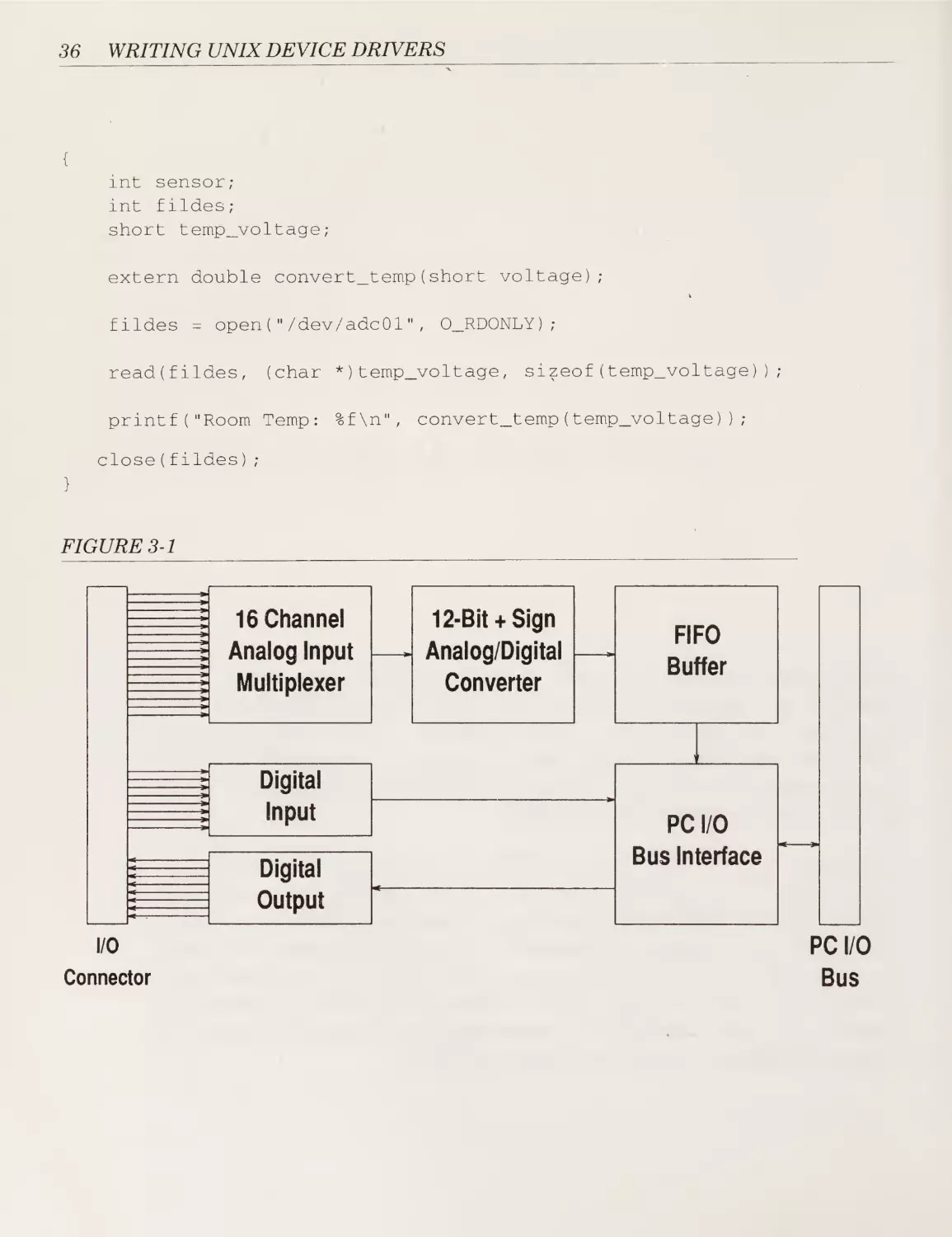
The device we are using is the PC-LPM-16 board from National Instru¬
ments. The board supports sixteen channels of analog input as well as
eight channels of digital output and eight channels of digital input. Figure
3-1 illustrates the general architecture of the LPM-16 board. Our device
driver will allow a user’s process to read the values of any of these input
channels or to set any of the output signals. For example, a program to
display the room temperature (assuming the appropriate sensor is
attached to channel 1) could be written as follows.
#include <fcntl.h>
main()
35
36
WRITING UNIX DEVICE DRIVERS
{
int
sensor;
int
fildes;
short
temp_voltage;
extern double
convert_temp(short
voltage);
v
fildes
=
open("/dev/adcOl",
read(fildes,
(char
printf("Room Temp:
0_RD0NLY);
*)temp_voltage,
%f\n",
sizeof(temp_voltage));
convert_temp(temp_voltage));
close(fildes);
}
FIGURE 3-1
I/O
PC I/O
Connector
Bus
Chapter 3: Character Drivers II: An A/D Converter
The routine convert_temp is used to convert between the voltage reading
and the temperature (in Fahrenheit or whatever).
Considering that this driver will handle data which is not in block-sized
units, it is best structured as a character device.
The Design Issues
Since this driver controls actual hardware we will have to consider all
three categories of design issues: the kernel/driver interface; the internal
operation of the driver; and the driver/hardware interface.
The kernel/driver interface is very similar to that illustrated in the previ¬
ous driver. The significant changes here include: (a) handling of multiple
“devices” (we consider each analog channel a separate “device”); (b) sup¬
port of both read and write system calls; and (c) actual hardware to iden¬
tify and initialize.
The internal operation of the driver is much more complicated than in the
previous driver since we now must manage an actual I/O device. In partic¬
ular, we will have to consider how to synchronize the driver with the
hardware (i.e., how to cope with the fact that the driver can execute faster
than the A/D converter can convert).
The driver/hardware interface was entirely missing in the previous driver
since it did not control any hardware (recall it was a pseudo-driver). In
this driver we must Talk’ to the hardware and we will have to consider
how software communicates with hardware.
All in all, this relatively simple hardware device provides an excellent
introduction to many of the issues that arise with drivers which control
hardware (as opposed to pseudo-drivers that do not interface to a hard¬
ware device).
The Driver
Recall from Figure 3-1 that this device supports sixteen analog input
channels, eight digital input channels, and eight digital output channels. A
simple and obvious way to structure the device would be to assign a different
37
38
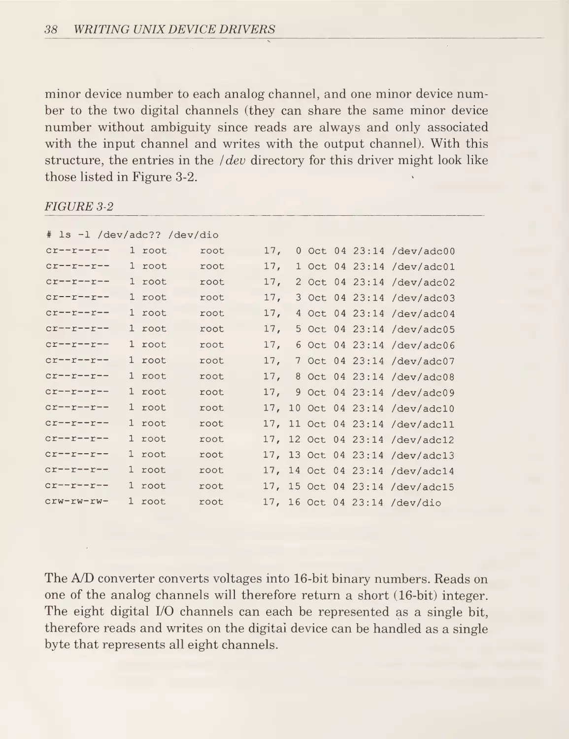
WRITING UNIX DEVICE DRIVERS
minor device number to each analog channel, and one minor device num¬
ber to the two digital channels (they can share the same minor device
number without ambiguity since reads are always and only associated
with the input channel and writes with the output channel). With this
structure, the entries in the /dev directory for this driver might look like
those listed in Figure 3-2.
FIGURE 3-2
# Is -1 /dev/adc??
/dev/dio
cr- -r- -r—
1
root
root
17,
0 Oct
04 23 :14
/dev/adc00
cr- -r- -r—
1
root
root
17,
1 Oct
04 23 :14
/dev/adcOl
cr- -r- -r—
1
root
root
17,
2 Oct
04 23:14
/dev/adc02
cr- -r- -r—
1
root
root
17,
3 Oct
04 23 :14
/dev/adc03
cr- -r- -r—
1
root
root
17,
4 Oct
04 23 :14
/dev/adc04
cr—-r- -r—
1
root
root
17,
5 Oct
04 23:14
/dev/adc05
cr- -r- -r—
1
root
root
17,
6 Oct
04 23 :14
/dev/adcO 6
cr—-r- -r—
1
root
root
17,
7 Oct
04 23 :14
/dev/adc07
cr—-r- -r—
1 root
root
17,
8 Oct
04 23 :14
/dev/adc08
cr-'-r- -r—
1
root
root
17,
9 Oct 04 23 :14
/dev/adcO 9
cr- -r- -r—
1
root
root
17,
10 Oct
04 23:14
/dev/adclO
cr-'-r- -r—
1
root
root
17,
11 Oct
04 23 :14
/dev/adcll
cr-'- r- -r—
1
root
root
17,
12 Oct
04 23 :14
/dev/adcl2
cr---r- -r—
1
root
root
17,
13 Oct
04 23:14
/dev/adcl3
cr---r- -r—
1
root
root
17,
14 Oct
04 23 :14
/dev/adcl4
cr---r—-r—
1
root
root
17,
15 Oct
04 23:14
/dev/adcl5
crw--rw'-rw-
1
root
root
17,
16 Oct
04 23 :14
/dev/dio
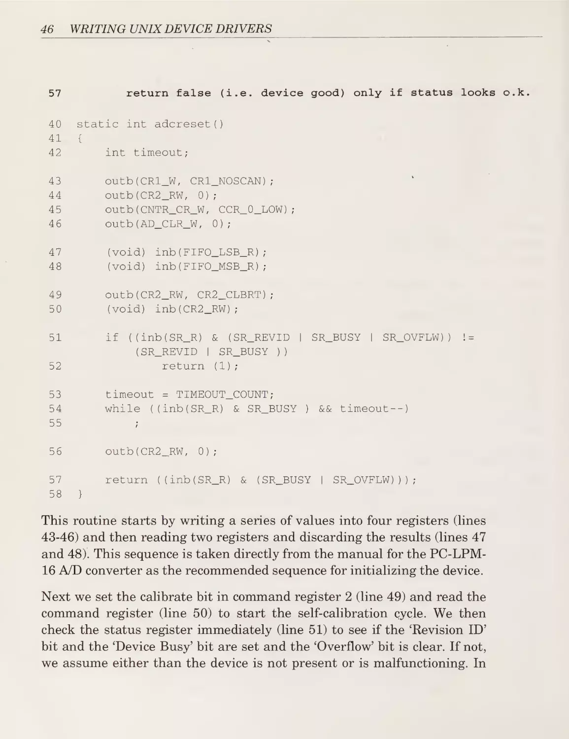
The A/D converter converts voltages into 16 -bit binary numbers. Reads on
one of the analog channels will therefore return a short (16-bit) integer.
The eight digital I/O channels can each be represented as a single bit,
therefore reads and writes on the digital device can be handled as a single
byte that represents all eight channels.
Chapter 3: Character Drivers II: An A/D Converter
This driver supports the following entry points:
■
init
■
open
■
read
■
write
In addition to these, there is one internal routine (adcreset) that is used
within the driver. As with the previous driver, the other entry points that
are available to character drivers are not required or supported.
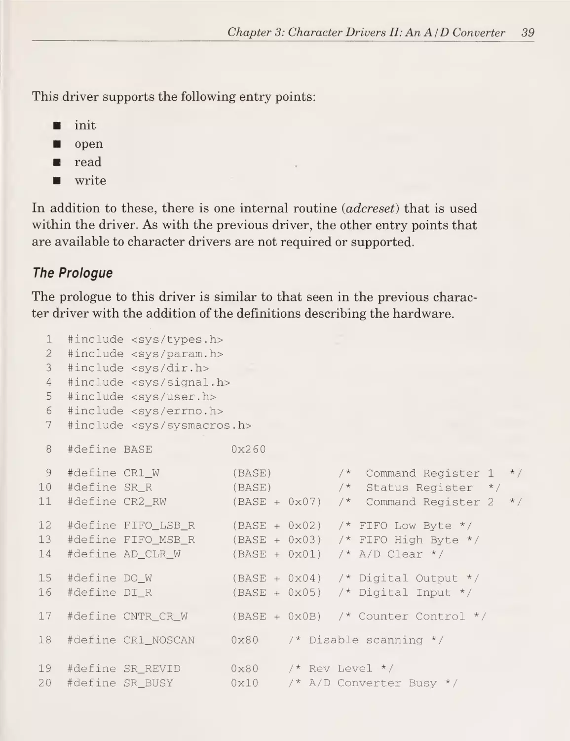
The Prologue
The prologue to this driver is similar to that seen in the previous charac¬
ter driver with the addition of the definitions describing the hardware.
1
#include <sys/types.h>
2
#include <sys/param.h>
3
#include <sys/dir.h>
4
ttinclude <sys/signal.h>
5
#include <sys/user.h>
6
#include <sys/errno.h>
7
#include <sys/sysmacros . h>
8
#define BASE
0x260
9
#define CR1_W
(BASE)
/*
Command Register 1
10
#define SR_R
(BASE)
/*
Status Register
11
#define CR2_RW
(BASE +
0x07)
/*
12
#define FIFO_LSB_R
(BASE +
0x02)
/*
FIFO Low Byte
13
#define FIFO_MSB_R
(BASE +
0x03)
/*
FIFO High Byte */
14
#define AD_CLR_W
(BASE +
0x01)
/* A/D Clear */
15
#define DO_W
(BASE +
0x04)
16
#define DI_R
(BASE +
0x05)
/* Digital Output */
/* Digital Input */
17
#define CNTR_CR_W
(BASE +
OxOB)
/*
18
#define CRl_NOSCAN
0x80
/* Disablei scanning */
19
#define SR_REVID
0x80
/ * Rev Level
20
#define SR_BUSY
0x10
/* A/D Converter Busy */
*/
Command Register 2
*/
Counter Control
*/
*/
39
40
WRITING UNIX DEVICE DRIVERS
21
#define SR_OVFLW
0x02
/*
FIFO Overflow */
22
#define SR_DREADY
0x01
/* FIFO Data Ready */
23
#define CR2_CLBRT
0x01
/*
Enable Auto-Calibration *
24
#define CCR_0_LOW
0x3 0
/*
set counter 0 output
25
#define CCR_0_HIGH
0x34
/*
set counter 01output high
26
#define DIO_DEV
16
27
#define TIMEOUT_COUNT
1000
28
static
short present;
29
static
int adreset(void);
low
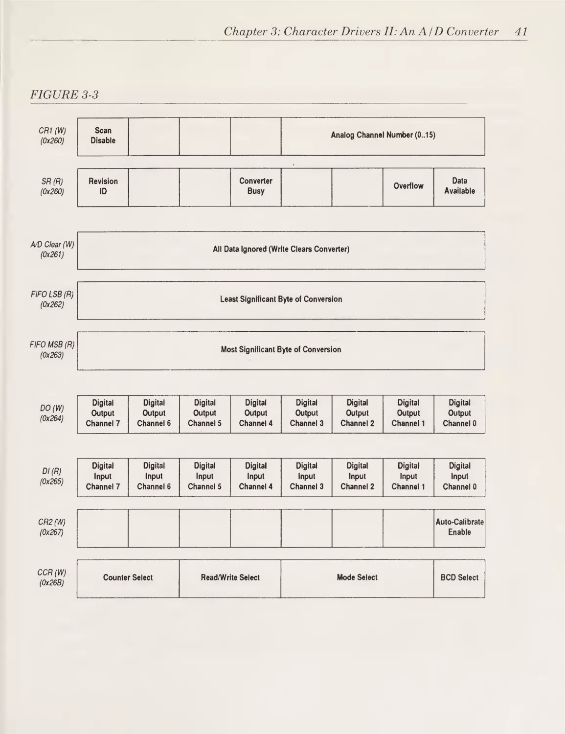
All of the header files were described in the previous chapter with the
exception of <sys /sysmacros.h>. This file contains various macros that are
useful within drivers. In our case, the macro of interest is minor() which
takes a device number and returns the minor device number component.
As we shall discuss shortly, the driver communicates with the hardware
through a set of registers. These registers are similar in many ways to
memory locations except that when data is written into a register it fre¬
quently causes the device to perform some operation. Similarly, if the
device wishes to communicate some information to the driver, it will set
certain bits in a register (or indeed the entire register) which can then be
read by the driver.
Figure 3-3, shown on the next page, shows the layout of the registers for
this A/D converter. The addresses used to access these registers is defined
on lines 8-17. The registers and register bits that are not shown in the fig¬
ure or defined in the prologue are for features that this driver does not
support.
The defines on lines 17 through 25 provide descriptive names for the vari¬
ous register bits or significant values written to various registers.
Line 26 defines the minor device number that represents the digital I/O
device, while line 27 defines a timeout value that limits the time we shall
wait for the A/D converter to convert a single channel.
Chapter 3: Character Drivers II: An A/D Converter
FIGURE 3-3
CR1 (W)
(0x260)
Scan
Disable
SR (R)
(0x260)
Revision
ID
Analog Channel Number (0..15)
Converter
Busy
A/D Clear (W)
(0x261)
All Data Ignored (Write Clears Converter)
FIFO LSB (R)
(0x262)
Least Significant Byte of Conversion
FIFO MSB (R)
(0x263)
Most Significant Byte of Conversion
DO (W)
(0x264)
DI(R)
(0x265)
Digital
Output
Channel 7
Digital
Output
Channel 6
Digital
Output
Channel 5
Digital
Digital
Input
input
Channel 7
Channel 6
Digital
Data
Available
Output
Channel 4
Digital
Output
Channel 3
Digital
Output
Channel 2
Digital
Output
Channel 1
Digital
Output
Channel 0
Digital
Digital
Digital
Digital
Input
Channel 5
Input
Channel 4
Input
Channel 3
Input
Channel 2
Digital
Input
Digital
Input
Channel 1
Channel 0
Auto-Calibrate
Enable
CR2 (W)
(0x267)
OCR (W)
(0x26B)
Overflow
Counter Select
Read/Write Select
Mode Select
BCD Select
41
42
WRITING UNIX DEVICE DRIVERS
Line 28 declares a variable that we shall use to record the presence (or
absence) of the hardware. Note that as with the driver in the previous
chapter, this variable is declared static to avoid possible name conflicts
with other variables in the kernel.
Finally, line 29 is a forward declaration of a routine used only within this
driver and defined after it is first used (see line 32 and lines 40-58).
The Init Entry Point
As discussed earlier, the init routine is responsible for performing those
operations required when the system is booted. The pseudo code for this
entry point, is:
30 init entry point:
32
if (the device cannot be reset or is not present)
33
print: device not found
34
else
36
print: device and driver installed
37
present = TRUE
The actual entry point:
30
void adcinit()
31
{
32
if
(adcreset())
33
printf("A/D Device NOT FOUND!\nM);
34
else
35
{
36
printf("A/D Device and Driver installed
37
present++;
38
39
.
(vl.0).\n");
}
}
The init entry point is called during system startup and provides the
driver the opportunity to prepare the device and driver. The archetypal
init routine ought to: (a) check that the device is indeed present (line 32);
(b) initialize the device (line 32); (c) initialize internal driver data struc¬
tures (line 37); and (d) display a message to that effect (line 36).
Chapter 3: Character Drivers II: An A/D Converter
In this driver we have taken the code that initializes the device (and veri¬
fies that it is indeed present) and put it into a separate routine (adcreset).
This routine attempts to initialize the device and if it is unable to do so or
believes that the device is not installed, it returns a non-zero (i.e., true)
value. This causes line 33 to execute. Otherwise, lines 36 and 37 are exe¬
cuted.
This code has been placed into a separate routine because there is another
place in the driver where we need to initialize the hardware. But before
we examine the code for adcreset we need to answer a key question about
the driver/hardware interface. How does a device driver talk to the device
it controls?
Hardware Device Registers
All devices contain internal registers that con¬
trol the operation of the device. These registers function like memory loca¬
tions in that they can be read and written. The difference is that the
contents of each register either affect the operation of the device or indi¬
cate the status of the device.
For example, with our A/D converter there is a register called “Command
Register 1” which controls several aspects of the conversion process. In
particular, the lower four bits of this register contain the number of the
channel to measure (convert). In addition, there is the “Status Register”
which provides information on the operation of the device. Bit 4 of this
register goes on (1) when a conversion is in progress and goes off when the
conversion has been completed. And finally, there is a register (actually
two, one to hold the most significant byte and the other for the low byte)
to contain the result of the voltage measurement. Figure 3-3 illustrated
the layout of the I/O registers for this device (some of the other bits in
these registers will be explained later).
But how do we actually read and write these registers? On some
machines, such as the M680x0, and the DEC PDP and VAX computers,
the device registers appear as fixed memory locations that are directly
addressable. For example, on a given computer the status register might
be located at FFFFCD02. We could then use code similar to the following
to access this register:
43
44
WRITING UNIX DEVICE DRIVERS
char ^status =
if
(char *)0xFFFFCD02;
(^status & 0x04)
{
/*
conversion is complete */
}
On other machines such as the Intel 386 or 486, the registers are accessed
using special instructions that use addresses allocated to I/O devices only.
On UNIX systems these special instructions are invoked by calling the
kernel support routines in and out (or inb and outb for byte access).
If our status register had an I/O address of FC2, then we would use the
following code to access it:
#define
if
STATUS
(inb(STATUS)
0xFC2
& 0x04)
{
/*
conversion is complete */
}
Since the driver we are examining is for UNIX on an Intel 386, it uses the
in/out instructions.
The addresses to which a device responds can usually be selected by set¬
ting switches on the controller board itself. On the A/D converter used for
our example, we have set the first register at 260. The other registers
appear immediately after.
Note that some registers are read-only or write-only. Also, sometimes two
registers (one read-only and one write-only) will share the same address.
A read to the address will access the read-only register while a write will
access the write-only register.
Chapter 3: Character Drivers II: An A/D Converter
Now that we better understand how soft¬
ware talks to hardware, we are ready to consider the problem of detecting
if our device has been installed again. In general, this is accomplished by
writing to certain registers and then reading certain registers looking for
certain values. If the values are found, we assume the hardware is pres¬
ent. Note that there is always the possibility that another device might
behave in the same manner and thereby be mistaken for the device of
interest. In order to prevent that occurrence, the init routine ought to
exercise some limited functionality in the device in order to reduce the
chance that another device would return the same value if probed in the
same manner.
Detecting the Presence of Hardware
So we read certain registers and check for known results. But what hap¬
pens if the device is not installed? This depends on the design of the sys¬
tem. On some computers, this is an error. On these computers, UNIX may
have to be set up to handle the possibility of this error when probing for
hardware that may not exist (refer to the reference manual for your com¬
puter). On machines with an IBM PC bus, the result is usually Oxff. For
this reason, we ought to arrange the hardware present test to return a
value other than Oxff from a certain register.
Let us return to our driver to see how this theory is put into practice.
The Adcreset Routine
The adcreset routine is internal to this driver and is responsible for reset¬
ting the A/D converter as well as verifying its presence. Again we present
the pseudo-code first followed by the actual code.
40
driver internal routine adcreset:
43-46
reset various device registers
47-48
read
49
set the calibrate command bit
50
start calibration by reading the command register
51
if
52
(and ignore)
various device registers
(status register bits
return true
(i.e.
!= expected pattern)
error indication)
53-55
spin until device is not busy or we get impatient
56
reset device
(i.e.
disable calibration mode)
45
46
WRITING UNIX DEVICE DRIVERS
57
return false
(i.e.
40
static int adcreset()
41
{
device good)
42
int timeout;
43
outb(CRl_W,
44
outb(CR2_RW,
45
outb(CNTR_CR_W,
46
outb(AD_CLR_W,
47
(void)
inb(FIFO_LSB_R);
48
(void)
inb(FIFO_MSB_R);
49
outb(CR2_RW,
50
(void)
51
if
only if status looks o.k.
CR1_N0SCAN);
0);
CCR_0_LOW);
0);
CR2_CLBRT);
inb(CR2_RW);
((inb(SR_R)
(SR_REVID
52
|
return
53
timeout
54
while
&
(SR_REVID
SR_BUSY
|
SR_BUSY
I
SR_OVFLW))
!=
))
(1);
= TIMEOUT_COUNT;
((inb(SR_R)
& SR_BUSY
)
&& timeout--)
55
56
outb (CR2__RW,
57
return
58
0);
((inb(SR_R)
&
(SR_BUSY
I
SR_0VFLW)));
}
This routine starts by writing a series of values into four registers (lines
43-46) and then reading two registers and discarding the results (lines 47
and 48). This sequence is taken directly from the manual for the PC-LPM16 A/D converter as the recommended sequence for initializing the device.
Next we set the calibrate bit in command register 2 (line 49) and read the
command register (line 50) to start the self-calibration cycle. We then
check the status register immediately (line 51) to see if the ‘Revision ID’
bit and the ‘Device Busy’ bit are set and the ‘Overflow’ bit is clear. If not,
we assume either than the device is not present or is malfunctioning. In
Chapter 3: Character Drivers II: An A/D Converter
either case, we return 1 (true) which will cause the init routine (line 33) to
declare the device as not present.
If the device passes this test we then loop (lines 54 and 55) until the
device is no longer busy. Since the device may malfunction and continu¬
ously report that it is busy, we set a limit (line 53) on the number of times
we will loop for the A/D converter to complete calibration.
Although spin loops are usually to be avoided in drivers, this one is
acceptable since it usually (a) occurs only during init time when the
machine is being bootstrapped and (b) executes for only a short time (100200 loops on a 20MHz 386).
After calibration, we clear 'Command Register 2’ (line 56) thus enabling
normal conversion mode (and disabling calibration mode). We then return
a value that is based on the status register (line 57). If either the 'Busy’ or
'Overflow’ bit is set, we return true indicating a malfunctioning device.
Otherwise we return false indicating the device is present and has been
successfully initialized. This will cause the init routine to announce the
presence of the device (line 36) and set the present variable (line 37). This
variable is checked by the open entry point to make sure that the open be
permitted to succeed.
The Open Entry Point
The open entry point is invoked when the user’s process executes an open
system call naming the device driver’s special file. (See the open call in
the program on the second page of this chapter.) If the device is opened by
more than one process (or by the same process more than once) the open
entry point will be called each time. It is the driver’s responsibility to han¬
dle multiple opens.
The open entry point is responsible for, among other things, validating the
device number (if used) and initializing the device and internal driver
data structures.
59
61
62
open entry point:
if
(minor device number not
set ENXIO error code
in valid range)
47
48
WRITING UNIX DEVICE DRIVERS
63
if
64
(device present flag not set earlier by init entry point)
set ENODEV error code
59
void adcopen(dev_t dev,
60
{
61
if
62
flag,
int
id)
> DIO_DEV)
u.u_error = ENXIO;
63
else if
64
65
(minor(dev)
int
(Ipresent)
u.u_error = ENODEV;
}
In this driver we verify that the minor device number is valid (line 42)
and that the device is actually present and functioning (line 44). Recall
that the variable present was set by the init entry point if the device was
found and successfully initialized by the adcreset routine.
If either of these tests fail, we set the appropriate error code into
u.u_error and return. This error code will cause the open system call
issued by the user process to fail and return an error indication.
The Read Entry Point
The read entry point is responsible for obtaining from the device the data
requested and transferring it to the user process.
In this driver the read entry point consists of two parts, the first handles
reads of the digital input channels and the second handles reads of an
analog input channel. We shall examine each part separately below.
66 read entry point:
71
if
73
(minor device number == digital I/O device)
if
(read count
>
0)
75
read digital input register and store in di
76
copy contents of di to user process
if
(an error occurred)
78-79
81
set error code and return
update u.u_count to reflect successful transfer
66
void adcread(dev_t dev)
67
{
68
int timeout;
Chapter 3: Character Drivers II: An A/D Converter
69
short value;
70
unsigned char di;
71
if
72
{
(minor(dev)
73
if
74
{
== DIO_DEV)
(u.u_count)
75
di
=
76
if
(copyout(&di,
77
{
inb(DI_R);
u.u_base,
78
u.u_error = EFAULT;
79
return;
80
}
81
u.u_count--;
1)
== -1)
}
82
83
49
}
We first check the minor device number (line 71) to see if this is a read of
the digital input channels. If so, we check to see if any data has been
requested (line 73). Since it is valid (although pointless) to issue a read for
0 bytes, this test is necessary.
Assuming all is well, we obtain the values for the eight digital input chan¬
nels by reading the 'Digital Input’ register (line 75). We then use the ker¬
nel supplied routine copyout to transfer this byte of data to the user
process. (Recall that the operation of copyout was discussed at length in
Chapter 2.)
If copyout fails, we set an error code and return (lines 78 and 79). Other¬
wise we decrement u.u_count to indicate that one byte was successfully
transferred (line 81).
The remainder of the read entry point handles the case of a read of an
analog input channel.
84
else
if
(i.e.
minor device number specifies analog input channel)
(count
>
size of a short integer
(i.e.
2 bytes))
86
set analog channel number = minor device number
87-88
trigger immediate conversion of specified channel
89-91
spin until device conversion done or we get
92
if
(conversion in error or not completed)
impatient
50
WRITING UNIX DEVICE DRIVERS
94
reset A/D converter
95-96
set error code and return
98
else
100-101
read low and high byte and assemble 16-bit value
102
transfer value to user process
if
(an error in the transfer)
104-105
set error code and return
107
update u.u_count to reflect successful transfer
84
else if
85
{
(u.u_count >= sizeof(short))
86
outb(CR1_W,
CR1_N0SCAN
87
outb(CNTR_CR_W,
CCR_0_LOW);
88
outb(CNTR_CR_W,
CCR_0_HIGH);
89
timeout - TIME0UT_C0UNT;
90
while
(((inb(SR_R)
&
I
minor(dev));
(SR_0VFLW
I
SR_DREADY))
==
0)
&&
timeout--)
92
if
93
{
((timeout
94
(void)
==
0)
II
u.u_error = EIO;
96
return;
}
98
else
99
{
100
value =
101
value
102
if
103
{
(inb(FIFO_LSB_R)
1=
(copyout(&value,
105
return;
107
108
109
& Oxff)
u.u_base,
u.u_error = EFAULT;
}
u.u_count
& Oxff);
((inb(FIF0_MSB_R)
104
106
& SR_0VFLW))
adcreset();
95
97
(inb(SR_R)
<<
8);
sizeof(short))
==
-= sizeof(short);
}
}
110
We first check (line 84) to see if the read is for at least two bytes (to han¬
dle the case where the user mistakenly issues a read for zero or one
-1)
Chapter 3: Character Drivers II: An A/D Converter
bytes). If there is enough room to put the result of the conversion we
select the desired analog channel by writing the minor device number into
'Command Register Y (line 86). The 'No Scan’ flag (CR1_N0SCAN) tells
the A/D converter that we wish to convert only one channel rather than
scanning multiple channels. We start the conversion by setting certain
bits in the 'Counter Control Register’ (lines 87 and 88). As its name implies,
the Counter Control Register is used to control counters internal to the
A/D converter. These counters can be used in advanced applications to
trigger conversions at fixed intervals. In our case, we only wish to perform
single conversions on demand so we set the counter to trigger a single,
immediate conversion.
We then loop (lines 90-91) until the device is no longer busy. Again we set
a counter (line 89) to ensure that the loop always terminates, even if the
device malfunctions and never stops being 'busy’.
As mentioned, spin loops are usually avoided in drivers. So why have we
one here? Well, in an early version of this driver we placed a printf state¬
ment immediately after the loop to determine how many times it looped
and found on a 20MHz 386 that the loop iterated between one and ten
times. Since the UNIX kernel cannot exit a driver read entry point, field
an interrupt, and reschedule the read in the time it takes to execute such
a simple loop ten times, we are far better off looping than using interrupts
to signal the completion of the conversion.
In the next chapter we shall examine a driver that can take a long time to
complete an I/O request and therefore requires the use of interrupts. Rut
here using a spin loop is actually more efficient than using interrupts.
A related issue is determining an appropriate value for TIMEOUT_COUNT,
the value used to limit the maximum number of iterations while waiting
for the device to complete an operation. As described, we used printf
statements to print the value of the timeout variable after every loop (here
and on lines 54-55) and determined that the longest loop was the calibra¬
tion loop (lnes 54-55) which normally took between 100 and 200 itera¬
tions. Setting TIMEOUT_COUNT to 1000 provided more than enough
headroom for this loop. Although the conversion loop (lines 90-91) usually
finished within ten iterations, it is not really necessary to specify a different
51
52
WRITING UNIX DEVICE DRIVERS
(lower) TIMEOUT_COUNT for this loop since its purpose is only to han¬
dle the exceptional failure of the hardware.
Once the loop completes we check to see if the iteration limit was reached
or if the 'Overflow’ flag is set (line 92). If either case is true, we attempt to
reset the device (line 94) and return an error indication (line 95).
Otherwise, the conversion was successful and we obtain the 16-bit value
by reading the 'Least Significant Byte’ (LSB) and ‘Most Significant Byte’
(MSB) registers and assembling the value (lines 100 and 101).
As an aside, it is important to read the documentation for the device and
determine if the registers need to be read in a specific order. In the case of
this device, reading the MSB causes both the LSB and MSB register to be
cleared. Needless to say, reading these in the wrong order would result in
the LSB always appearing to be 0.
A related trap for the unwary is trying to read these two registers in a
single statement similar to
value =
(inb (FIFO_LSB__R)
((inb(FIFO_MSB_R)
& Oxff)
& Oxff)
I
«
8);
Although this code looks correct, the ANSI C standard warns us that we
may not assume any particular sequence of operations within a single
expression such as this. The compiler is free to issue the second inb before
the first, thus reading the MSB first and causing the LSB to be cleared
before it is read.
Back in our driver we take the 16-bit value and pass it to the user process
using copyout (line 102). Errors are handled as before (lines 104-105). On
line 107 we update the u.u_count variable to reflect the two bytes that
were successfully transferred.
The Write Entry Point
The write entry point’s responsibilities in a driver are in some ways the
opposite of those for a read entry point. The write entry point must:
obtain the information to be written from the user process; instruct the
device to accept the data; and finally manage the transfer of data to the
Chapter 3: Character Drivers II: An A/D Converter
device. The entry point must also take care of housekeeping such as vali¬
dating the minor device number.
111
write entry point:
114
if
116
(minor device number == digital I/O device)
if (write count > 0)
118
obtain from user process data to be written
if
120- 121
(an error occurred)
set error code and return
123
update u.u_count to reflect successful transfer
124
write data to digital output register
127
else
128
set error code
111
void adcwrite(dev_t dev)
112
{
113
unsigned char data;
114
if
115
{
(minor(dev)
116
if
117
{
== DIO_DEV)
(u.u_count)
118
if
119
{
(copying(u.u_base,
&data,
120
u.u_error = EFAULT;
121
return;
122
123
}
u.u_count--;
124
outb(DO_W,
125
==
-1)
data);
}
126
}
else
127
128
129
1)
u.u_error = ENXID;
}
We check (line 114) to see if the minor device number is that associated
with the digital I/O device. If not, we report an error (line 128).
Otherwise we check that there is at least one byte to be written (line 116)
and we copy the byte from the user process to the driver’s data variable
using copying (line 118). Copyin is the opposite of copy out and transfers
53
54
WRITING UNIX DEVICE DRIVERS
data from a user process to the driver. Errors are handled in the usual
manner (lines 120-121).
If the byte was successfully obtained, we update the u.u_count variable
(line 123) to reflect that fact and then write the byte to the ‘Digital
Output’ register (line 124). This will cause the eight digital output lines to
take on the value associated with each bit of the written byte.'
Exercises
1. This driver assigns a channel to each “device” (minor device num¬
ber). This means that a program that wishes to read all sixteen
analog input channels would have to open sixteen files. Modify the
driver to provide yet another “device” that permits any or all channel
to be read through a single special file. (Hint: use the u.u_offset
value to specify the first channel to convert and u.u_count to spec¬
ify the number of channels to convert.)
2. This driver requires the user process to write all eight digital out¬
put lines at once. Modify the driver so that eight separate minor
device numbers are allocated, one for each digital output channel,
so that a user process can open and write a single digital output
channel without affecting any other channels.
Chapter 4
Character Drivers III: A Line Printer
Our study of character drivers has included a simple pseudo-device driver
that generated test data and a slightly more interesting driver for an ana¬
log to digital converter. Although the A/D converter driver controlled
actual hardware, the device was relatively simple.
In this chapter we shall consider a driver for a line printer controller. We
shall encounter a number of design issues in this driver for the first time.
The primary problem is that a user’s process can almost always generate
data faster than a printer can print it. It will therefore be necessary to
suspend the program while the printer is busy. In addition, we shall have
to store a certain amount of data within the driver so that we do not incur
the overhead of suspending and resuming the program every time the
printer is ready for another byte of data. Also, we will encounter inter¬
rupts that can arrive at any time as well as interrupts that do not arrive
at all.
In other words, this driver is an excellent example of how to talk to a real
world device, warts and all.
56
WRITING UNIX DEVICE DRIVERS
The Device
The registers for this device are illustrated by Figure 4-1. The data regis¬
ter contains the byte of data to be transferred to the printer. The status
register indicates whether the printer is ready for more data and if any
problems have been detected. The control register enables interrupts and
automatic line feeds as well as signals to the printer that the data in the
data register is valid. We shall see how these registers are used when we
examine the device driver.
FIGURE 4-1
DATA (W)
(0x378)
STATUS (R)
(0x379)
Data Out Port
Printer
Idle
Out of
Paper
CONTROL (R)
(0x37A)
Printer
Selected
No Error
Detected
Interrupt
Enable
Select
Printer
Reset Printer
(when 0)
Auto LF
Enable
The Driver
The device driver supports a single line printer. Data written to the driver
is buffered within the driver and fed to the line printer as fast as it will
accept it.
The Prologue
This prologue, as with those examined earlier, consists of the include
directives (lines 1-8), the definitions of useful constants (mostly related to
the register layout, lines 9-31), and the declaration of some local variables
(lines 32 and 33).
1
#include <sys/param.h>
2
#include <sys/errno.h>
Strobe
Data
Chapter 4: Character Drivers III: A Line Printer
3
#include; <sys/types.h>
4
#include! <sys/signal.h>
5
#include: <sys/dir.h>
6
#includei <sys/user.h>
7
#include! <sys/tty.h>
8
#includei <sys/sysmacros. h>
9
#define LPPRI
PZERO+5
10
#define LOWAT
50
11
#define HI WAT
250
12
#define TOINT
HZ/10
13
#define LPBASE
0x378
14
#define LPDATA
(LPBASE +
15
#define LPSTAT
(LPBASE +
16
#define LPCTRL
1)
(LPBASE + 2)
17
#define LPNERR
0x08
18
#define LPON
0x10
19
#define LPRDY
0x80
20
#define LPSTRB
0x01
21
#define LPLF
0x02
22
#define LPINIT
0x04
23
#define LPSEL
0x08
24
#define LPIENB
0x10
25
#define LPEXIST
0x01
26
#define SLEEP
0x02
27
#define LPBUSY
0x04
28
#define TOPEND
0x08
29
#define WAIT
0x10
30
#define EXCLOPEN
0x20
31
#define OPEN
0x40
32
static unsigned short Lpflags
33
static struct clist Lpqueue;
0)
This prologue references a header file we have not encountered before.
The <sys/tty.h> header provides the definitions for the clist structure that
we shall be using to buffer data.
57
58
WRITING UNIX DEVICE DRIVERS
The defines on lines 9 through 12 provide self-documenting names for
some constants that we shall need within the driver. The addresses of the
various line printer controller registers are the subject of lines 13 through
16, while the individual bits of these registers are given names in lines 17
through 24. Lines 25-31 define flags that may be set in the lpflags vari¬
able declared on line 32. The clist structure declared on line 33 will be dis¬
cussed when we start using it later in the driver.
The Init Entry Point
This init function is very similar to the previous one we studied. It per¬
forms all of the standard functions of a driver init entry point. It checks
that the hardware is present, initializes the hardware, prints a message
announcing the presence of the driver (and hardware), and initializes
data structures internal to the driver. The pseudo-code below outlines the
structure of the routine while the detailed code follows.
34
init entry point:
36
clear control register
37-38
if
39
write special value to control register
40-41
if
42
disable device by clearing control register
43
print:
44
set device exists flag
34
(control register
(control register
!= expected value)
!= expected value)
then return
then return
line printer exists message
lpinit()
35
36
outb(LPCTRL,
37
if
38
(inb(LPCTRL)
!=
OxeO)
return;
39
outb(LPCTRL,
40
if
41
0);
Oxfe);
(inb(LPCTRL)
!=
Oxfe)
return;
42
outb(LPCTRL,
43
printf("Line printer at address %x\n",
0);
LPBASE);
Chapter 4: Character Drivers III: A Line Printer
44
45
Lpflags = LPEXIST;
}
In this driver we take a slightly more involved approach to verify that the
hardware is present. Firstly (line 34), we zero the control register and
then check for the expected result. Then we set a specific value and make
sure that the result is as expected. Only then are we willing to declare the
hardware as present.
As an aside we ought to discuss how the ‘expected’ results were deter¬
mined. Briefly, an earlier version of the driver wrote several values to the
control register and printed the results. After running the driver on sev¬
eral different systems (with different brands of line printer interface
boards) the above algorithm was obtained. Sometimes one can determine
a reasonable sequence to test for the presence of the hardware just by
examining the documentation for the device. In most cases, however, judi¬
cious experimentation is required.
Back in the driver, we again zero the control register (line 40). This has
the effect of disabling the device totally until we need it.
Line 41 announces the presence of the device and driver and the next line
initializes the lpflags variable (and marks the device as “present”).
The Open Entry Point
The open entry point for this driver is very similar to the example in
Chapter 3. We check to see if the device has been detected and if so, ini¬
tialize it. Otherwise we return an error.
An additional feature supported by this driver is the exclusive-open flag.
When the user opens the device, the open call can include the 0_EXCL
flag indicating that no other open of the same device is to be permitted
while this process has the device open (for example, open("/dev/Ip"
OJVRONLY I OJEXCL);).
46
50
51
52
open entry point:
if
(device exists flag is not set)
set error code
else if
(device has already be opened exclusively)
59
60
WRITING UNIX DEVICE DRIVERS
set error code
53
54
else if
if
56
(device has already been opened)
(this open is for exclusive use)
57
set error code
else
59
61
clear lp data register
62
set line feed,
64
set Ip open flag
65
if
and select bits
init,
(this open is for exclusive use)
set exclusive open flag
66
46
lpopen(dev/
47
dev_t dev;
48
int
49
{
flags,
if
50
flags,
otyp)
otyp;
((Lpflags & LPEXIST)
==
0)
u.u_error = ENODEV;
51
else if
52
(Lpflags & EXCLOPEN)
u.u_error = EBUSY;
53
54
else if
55
{
if
56
(Lpflags & OPEN)
(flags •& FEXCL)
u.u_error = EBUSY;
57
58
59
}
else
60
{
61
outb(LPDATA,
0);
62
outb(LPCTRL,
LPLF
|
LPINIT
I
LPSEL)
63
64
Lpflags
65
if
(flags & FEXCL)
Lpflags
66
67
68
|= OPEN;
|= EXCLOPEN;
}
}
We start with a series of checks to see whether the device exists (line 50),
is already open for exclusive use (line 52), or is already open and this open
is for exclusive use (lines 54 and 56). In all cases, the appropriate error
code is returned by setting u.u_error.
If no errors are detected (and the device is not already open), we initialize
the printer (lines 61 and 62), mark the device as open (line 64), and check
Chapter 4: Character Drivers III: A Line Printer
to see if this open is for exclusive use (line 65) and if so, set a flag to
remember that fact.
The Close Entry Point
The close entry point for this driver has a problem none of our previous
drivers have had to cope with. It is possible for the driver still to be busy
processing previous output requests when the applications program
issues the close. Therefore, we must wait until the printer has printed
everything before we complete the close operation and shut down the
printer.
69
close entry point:
74
raise processor priority in order to disable
75
while
(lp busy flag
is
set)
77
set
flag
78
put
the user process
indicating we
clear all
81
clear
82
restore processor priority
lp control
lpclose(dev, flags,
dev_t dev;
int flags, otyp;
except
are waiting to close
to
80
69
70
71
72
73
flags
the
sleep until
lp exists
awakened
flag
register thus disabling the device
otyp)
{
int x;
74
75
76
77
78
79
x = spl5();
while (Lpflags & LPBUSY)
80
81
82
83
Lpflags = LPEXIST;
outb(LPCTRL, 0);
splx(x);
{
Lpflags |= WAIT;
sleep(&Lpflags, LPPRI)
}
}
interrupt;
f
61
62
WRITING UNIX DEVICE DRIVERS
In line 75 we check to see if the device is still busy. If so, we set a flag tell¬
ing the rest of the driver that we are waiting for the printer to complete
printing and then we go to sleep. As we shall see later, when the printer is
finished, the driver will check for the WAIT flag and if set, will issue a
wake up which will cause our call to sleep to return.
By line 80 we know that the printer is quiet so we clear all of the flags
except LPEXIST (line 80) and disable the printer (line 81).
We shall talk more about the call to sleep, as well as the spl5 and splx
routines later.
The Write Entry Point
The write entry point is the opposite of the read entry point seen in earlier
drivers. The write entry point is invoked whenever the user’s process
issues a write system call and is responsible for transferring the data to
be written from the user’s process to the driver.
The special problem this device presents is that printers are slow devices.
The user’s process can usually generate data faster than the printer can
print it. This means that we shall have to suspend the user’s process
when the printer is busy printing the data already passed to it.
The overhead of suspending a user’s process and later resuming it is sig¬
nificant, so we shall want to reduce the number of times this is done. In
other words, we want to maximize the amount of data that the user’s pro¬
cess can transfer to the driver between suspensions. To accomplish this
we shall store data within the driver, filling the buffer as quickly as possi¬
ble before suspending the user’s process and then passing the data along
to the printer.
84
write entry point:
90
92
while
(still data to be obtained from the user process)
copy one byte from the user process to the driver
*
if
94-95
set error code and return
97-98
update u.
99
while
101
•
(an error occurred during copy)
variables to reflect successful transfer
(more than HIWAT bytes in the clist buffer)
raise the process priority thus disabling interrupts
Chapter 4: Character Drivers III: A Line Printer
102
call lpwork to try to print some data
103
if
(more than HIWAT bytes in clist buffer)
set flag indicating we are waiting for more
105
room in the buffer
put user process to sleep
106
restore processor priority
108
place byte just copied from user process on clist
110
112
raise processor priority
113
call lpwork to try to print some data
114
restore processor priority
84
85
86
87
88
89
90
91
92
93
94
95
96
97
98
lpwrite(dev)
dev_t dev;
{
char c;
int x;
extern void lpwork();
while
(u.u_count)
{
if
(copyin(u.u_base,
1)
== -1)
{
u.u_error = EFAULT;
return;
}
u.u_base++;
u.u_count--;
while
99
100
(Lpqueue.c_cc > HIWAT)
{
x = spl5();
lpwork();
if (Lpqueue.c_cc > HIWAT)
101
102
103
104
105
106
107
108
109
}
110
putc(c,
111
&c,
{
Lpflags 1= SLEEP;
sleep(&Lpqueue, LPPRI);
}
splx(x);
}
ScLpqueue) ;
63
64
WRITING UNIX DEVICE DRIVERS
112
x = spl5();
113
lpwork();
114
splx(x);
115
}
Most of this routine is a while loop that starts at line 90 and ends at line
111 and continues as long as there is data to be transferred from the
user’s process to the device.
The first part of this entry point (lines 92-98) is relatively straightfor¬
ward. In line 92 we use the kernel-supplied routine copyin to obtain the
next byte of data the user’s process is writing to the printer. If copyin
reports an error, then we return an error indication (lines 94-95) to the
user. Otherwise, we merely update the user area variables that specify
where and how much data to transfer (lines 97-98).
The next part of this routine (lines 99-110) is concerned with taking the
data we have just obtained from the user’s process and storing it in our
internal buffer. But before we study this part of the driver, let us consider
the subject of clists.
Clist Buffers
Frequently within a device driver we have to store small
amounts (50-500 bytes) of data. While it is possible for each driver that
needs such buffering to declare its own local storage, it is more efficient
for the kernel to provide such buffering for all drivers. In this manner the
same space can be shared between all drivers and only those drivers that
are active and have to store data need consume space in the shared buffers.
In UNIX, the kernel provides a mechanism for storing smaller amounts of
data within drivers called clists. The definition of a clist header is con¬
tained in <sys/tty.h> (see lines 7 and 33). The kernel provides a number of
routines for storing a byte on a clist and for retrieving the next byte from
the clist. Clists function as a first in, first out (FIFO) data structure.
While the actual structure of the clist is of no concern to the device driver
writer (since all of the details are handled by the kernel-supplied rou¬
tines), Figure 4-2 shown on the next page provides a schematic of the clist
organization.
Chapter 4: Character Drivers III: A Line Printer
FIGURE 4-2
In line 99 we check to see if the clist is full. Obviously we do
not wish to use all of the memory available for clists—otherwise no other
device driver would be able to store data in a clist. So we establish an
arbitrary limit (called a high water mark, see line 11) to the amount of
data we will store in the clist.
Using Clists
If we have reached this limit we do two things. Firstly (line 102), we start
the printer. The lpwork routine will attempt to transfer some of the data
from the clist to the printer and may relieve the congestion. Secondly
(lines 103-107), we check if the clist is still full (i.e., lpwork was unable to
do anything) and if so, we suspend the user’s process. We shall talk
shortly about the sleep call (line 106) as well as the spl5 and splx func¬
tions (lines 101 and 108).
65
66
WRITING UNIX DEVICE DRIVERS
If we reach line 110, then we know that there are fewer than HIWAT
characters in the clist and so we add the character we have just copied
from the user’s process in line 92.
The loop (lines 90 to 111) continues until either there is no more data to
transfer (i.e„, u.u_count is 0) or the clist is full and the user’s process is
suspended.
When the loop terminates, we call lpwork to make sure the printer is
started.
The Lpwork Routine
The lpwork routine is not a true entry point (i.e., it is not called by the
operating system). It is a routine local to the driver that is called by other
parts of the driver to start activity on the device.
The lpwork routine is where the real work is done. As we have seen, the
lpwrite routine is responsible for copying the data to be printed from the
user’s process to the clist. Lpwork is responsible for copying the data from
the clist to the printer itself.
Why do we do things in two steps? Why not copy the data from the user’s
process directly to the printer? The reason is that the printer cannot
accept data as fast as we can copy it from the user’s process and further¬
more, by copying the data to a buffer we can reduce the number of times
we have to suspend the user’s process.
The first half of this routine (lines 122-135) is concerned with transferring
data from the clist to the printer. The remainder of the routine handles
cases such as the clist being empty.
Before we consider this routine in detail it would be useful to know when
this routine is called. The first case we have already seen: within the
lpwrite routine when the data has been put on the clist and the printer
ought to be started to print some of this data (see lines 102 and 113).
The other case (which we have not yet seen) occurs when an interrupt
arrives. The interrupt handler will call lpwork if the printer has finished
printing and there is still data in the clist to be printed.
Chapter 4: Character Drivers III: A Line Printer
So remember that lpwork may be called from the interrupt handler as
well as from lpwrite.
Our discussion of this routine is divided into two sections to make the
commentary appear closer to the code which it describes.
116 lpwork routine:
121
122
set flag indicating device is busy
while
(true i.e.
forever)
124-127
spin until device is ready for data or we lose patience
128
if we lost patience,
break out of loop
129
130
try to obtain byte from clist buffer
if
(no more data in clist buffer)
131
break out of loop
132
write byte to lp data register
133-134
tell printer to accept data
116
117
118
119
120
static void lpwork()
{
int ch;
short spinloop;
extern void lprestart();
121
Lpflags
1= LPBUSY;
122
123
124
125
while (1)
{
spinloop •= 100;
while (((inb(LPSTAT)
&
(LPNERRILPONILPRDY))
i -
126
127
(LPNERR|LPON|LPRDY))
128
129
if
(spinloop == 0)
break;
130
131
if
((ch = getc(&Lpqueue))
break;
132
outb(LPDATA,
ch);
&& --spinloop)
< 0)
67
68
133
134
135
WRITING UNIX DEVICE DRIVERS
outb(LPCTRL,
outb(LPCTRL,
LPSTRB
1
LPLF
LPLF
I
I
LPINIT
LPINIT
1
1
LPSEL);
LPSEL);
}
Now let us look at what lpwork does in detail.
To start, we set the LPBUSY flag (line 121). This is checked by the lpclose
routine to see if the printer is still printing and by the lpintr routine to
see if the interrupt came from a busy printer (spurious interrupts from
idle devices are not unheard of).
The loop from line 122 to 135 attempts to transfer as much data to the
printer as possible. Most printers print a line at a time and have a small
amount of memory in which to store the contents of the line before it is
actually printed. When we transfer data to the printer we find that while
we are filling that memor}^ the printer can accept data very quickly. But
when the memory is full, the printer starts to print and refuses to accept
any more data until the line has been printed.
In order to take advantage of this behavior, we keep on sending data to
the printer as long as it is accepting it relatively quickly (i.e., filling up its
memory). When it pauses to print a line, we leave the driver since print¬
ing the line can take many tenths of a second and waiting in the driver
will prevent other processes from running.
The variable spinloop (line 124) is used to limit the time we shall wait for
the printer to accept more data. We shall loop up to 100 times, waiting for
the printer. Although spin loops within device drivers are normally
frowned upon, the one in this driver actually improves system through¬
put.
If we were to feed one byte to the printer and wait for an interrupt, the
operating system would have to incur the overhead of fielding an inter¬
rupt and executing the interrupt handler (which would call lpwork to feed
another byte). It turns out that when the printer is accepting data it will
usually accept the next byte well within 100 loops, and furthermore, the
overhead of leaving the driver and fielding the interrupt is far greater
than 100 simple loops. Therefore, we spin on lines 125-127, waiting for
the printer to become ready to accept another byte.
Chapter 4: Character Drivers III: A Line Printer
If the loop exits because we spun 100 times without the device becoming
ready (i.e., line 128, spinloop is zero), then we stop trying to transfer data
from the clist to the printer (line 129). The limit of 100 was chosen after
some experimentation and may not be appropriate for all computers or
printers.
On the other hand, if spinloop is greater than zero, then the device must
be ready since we leave the loop only if the device is ready or spinloop is
zero.
We then try to fetch a character from the clist (line 130). If there are no
more characters in the clist, then we also stop trying to transfer data from
the clist to the printer (line 131).
By line 132 we know the printer is ready to accept data and we have data
to print. In line 132 we put the character in the data register and then
raise and lower the strobe line (lines 133 and 134). This signals to the
printer that there is data in the data register to be transferred to the
printer’s memory.
This loop (122-135) continues until either the printer takes longer than
100 loops to become ready to accept more data or there is more data in the
clist to print.
136
if
(room in clist and process is sleeping waiting for room)
138
clear flag indicating user process is sleeping
139
wake up sleeping process
141
if
(clist is empty)
143
clear device busy flag
144
if
(someone is sleeping waiting to close)
145
147
wake up process
else if
(timeout pending flag is clear)
149
request that lprestart be called in a tenth of a second
150
set timeout pending flag
152
136
137
138
enable device interrupts
if
((Lpqueue.c_cc < LOWAT)
{
Lpflags &= -SLEEP;
&&
(Lpflags & SLEEP))
69
70
WRITING UNIX DEVICE DRIVERS
139
140
141
142
143
144
145
146
147
148
149
150
151
152
153
wakeup(&Lpqueue);
}
if
{
(Lpqueue.c_cc <= 0)
Lpflags &= -LPBUSY;
if (Lpflags & WAIT)
wakeup(&Lpflags);
}
else if ((Lpflags & TOPEND) == 0)
{
timeout(lprestart, 0, TOINT);
Lpflags |= TOPEND;
}
outb(LPCTRL, LPLF I LPINIT I LPSEL
I
LPIENB);
}
When we have transferred as much data to the printer as possible, we
then check (line 136) to see if we have taken enough data from the clist
that we ought to wakeup the process waiting for more space in the clist
(lines 138, 139).
We also check (line 141) to see if there is any more data in the clist to
print. If not, then we mark the device as not busy (line 143) and check to
see if anyone is in the lpclose entry point waiting for us to become idle
(line 144). If so, we wake them up (line 145).
Lines 147 to 151 will be discussed later.
Finally, we enable interrupts (line 152).
Process Scheduling
We have now examined the two halves of the driver. The top end (the
lpwrite routine) takes data from the user’s process and stores it in the
clist. The bottom end (the lpwork routine) takes data from the clist and
sends it to the printer.
Since there is not an infinite amount of storage available in the clist, we
have to limit the amount of data we store in the clist. What we need to do
is to suspend the user’s process until lpwork can catch up.
Chapter 4: Character Drivers III: A Line Printer
We can suspend the user’s process by calling the kernel’s sleep function
from within the lpwrite entry point. Go back and look at the lpwrite entry
point and read the description about lines 99 through 109. As discussed, if
we have more than HIWAT characters in the clist and have just called
Ipwork (so we know the printer is busy and has taken as much data as it
can for now), then we have to suspend the user’s process. We do this by
calling sleep in line 106.
This causes the user’s process to be suspended until further notice. The
state of the user’s process (and the driver) is stored at that point and the
kernel removes the user’s process from the list of processes ready to run.
It then selects the process on the ready-to-run list that has the highest
priority. The sleep call will not return until a wakeup call is made from
elsewhere in the driver.
But how do we wake the process once the clist has drained and there is
room for more data? Eventually the printer will finish printing and signal
an interrupt. The interrupt handler calls Ipwork to send more data to the
printer. If we look back at the Ipwork routine (line 136) we check to see
whether there are fewer than LOWAT (low water mark) characters in the
clist and if we have suspended the user’s process (i.e., the SLEEP flag, set
in line 105, is present). If so, then we use the kernel’s wakeup routine to
unsuspend the user’s process (line 139). The kernel will then take the pre¬
viously suspended process (still in the driver’s Ipwork routine) and put it
on the ready-to-run list.
Note that the current execution of Ipwork will continue immediately after
making the wakeup call. The woken process will not resume (i.e., return
from the sleep call) until the current execution of Ipwork leaves the driver
and no other process has a priority higher than the woken process.
The first argument to sleep is an arbitrary number that is used to connect
the wakeup call with the sleep call. The trick is to select the same unique
number to use in the two calls. One could choose an integer at random,
but would still run the risk that another driver writer might choose the
same number. A more reliable technique is to take the address of a vari¬
able that is local to the driver. The data structure chosen is unimportant;
71
72
WRITING UNIX DEVICE DRIVERS
the only thing that is important is that both the sleep and wakeup calls
use the same address.
The second argument to sleep is the priority that the user’s process will
run at when it is resumed. With UNIX, the lower the priority number the
higher the scheduling priority. The actual number is relatively unimport¬
ant—except that if a process is put to sleep with a priority lower than or
equal to PZERO (see the file /usr/include/sys/param.h as well as line 9), then
it will be immune to signals (i.e., it will not be possible to kill it). Conversely,
sleeping at a priority above PZERO means that signals will cause the system
call to be interrupted and the signal handled in the normal manner.
Obviously, if you put a process to sleep at a priority lower than PZERO,
you must be absolutely positive that your driver will shortly wakeup the
process. If there is any possibility that the wakeup will never occur (i.e.,
the printer is turned off), then you must sleep above PZERO or risk creat¬
ing a process that hangs and can never be killed. In this driver, we sleep
at a priority above PZERO (line 9).
Another example of process scheduling occurs when the user’s process is
finished with the printer and wants to close the device. Because of the
clist, it is possible that up to HIWAT characters are still waiting to be
printed when the user’s process invokes the close entry point.
In line 75 we check to see if the printer is still busy, and if so, we set the
WAIT flag (line 77) and then suspend the user’s process. In lpwork, we
check to see if the WAIT flag is set (line 144) when we have finished print¬
ing everything that is in the clist. And if it is, it means that a user’s pro¬
cess was suspended in the close routine so we wake it up (line 145).
The Lpintr Entry Point
When the printer is finished printing and is ready for more data it will
signal the computer by raising an interrupt. Unless the interrupt has
been disabled, this will cause the CPU to stop whatever it is doing and
execute the interrupt handler for the printer (lpintr). It is important to
remember that when the interrupt arrives, the CPU could be executing
any process, not necessarily the process that originally sent the data to
the printer. Because of this the interrupt handler (and any routine such
Chapter 4: Character Drivers III: A Line Printer
as lpwork called by the interrupt handler) must not touch the contents of
the current user area (the u. area).
Note that while the interrupt handler is executing, the system automati¬
cally raises the CPU priority to disable further interrupts from this device
and coincidentally, all other devices of the same or lower priority. This
means that while the system is executing the interrupt handler (and any
routines called from the handler), other devices may be prevented from
interrupting the system. If interrupts are blocked for too long the perfor¬
mance of the system will be adversely affected and in some situations,
such as data being received on a serial port, data may be lost. For this
reason it is imperative to minimize the time spent within the interrupt
handler.
154 intr entry point:
157
if
158
return
159
if
160
154
155
156
157
158
159
160
161
(device busy flag is clear)
(i.e.
interrupt is spurious)
(there is at least one byte in the clist buffer)
call lpwork to try to print it
lpintr(dev)
dev_t dev;
{
if ((Lpflags & LPBUSY)
return;
if
== 0)
(Lpqueue.c_cc > 0)
lpwork();
}
Handling interrupts is simple.
If the device is not busy, we ignore the interrupt (lines 157 and 158).
Otherwise, if there is still work to do (i.e., data in the clist, line 159), then
we call lpwork to move more data from the clist to the printer (line 160).
73
74
WRITING UNIX DEVICE DRIVERS
Deferring Interrupts
Although handling the interrupt is simple, there are some very subtle
problems that can arise in drivers that use interrupts.
These problems all arise from the fact that unless precautions are taken,
interrupts can arrive at any time.
Let us consider an example of what can go wrong when interrupts arrive
at the wrong time. Look back at lines 103-107. At line 103, we determine
that there is no more room in the clist. We must therefore suspend the
user’s process until there is room. In line 105 we set the SLEEP flag indi¬
cating that we are waiting to add more data to the clist, and in line 106
we go to sleep.
But imagine that an interrupt arrives after we have executed line 105 but
before we execute line 106. We have set the SLEEP flag but have not
actually gone to sleep.
The interrupt routine calls the Ipwork routine (line 160). The lpwork rou¬
tine manages to transfer all of the data from the clist to the printer (lines
122-135 and then checks to see if anyone was sleeping (line 136).
The SLEEP flag was set so we clear it (line 138) and call wakeup (line
139). But remember that the interrupt arrived just before we executed the
sleep call in line 106. So the call to wakeup has no effect.
The lpwork routine finishes and the lpintr exits. The CPU then picks up
where it was interrupted and executes the call to sleep (line 106). Remem¬
ber, however, that when the interrupt came in it called lpwork which
cleared the SLEEP flag. So we have gone to sleep but without the SLEEP
flag set.
When the next interrupt comes in, the test at line 136 will always fail
because the SLEEP flag is not set, hence the wakeup in line 139 will
never execute. We have effectively gone to sleep forever.
This problem arises because we have two routines (Ipwork and lpwrite)
that access the same variable and which can be executed at the same
time. A section of code that can be adversely affected by the untimely execution
Chapter 4: Character Drivers III: A Line Printer
of another part of the code is called a critical section. Lines 103 through
107 comprise such a critical section. We must prevent an interrupt from
arriving during this critical section.
Process Priority
Each device that can interrupt the CPU is assigned a priority (more than
one device can share the same priority). The CPU keeps track of the cur¬
rent processor priority and will only service interrupts that are higher in
priority than the current processor priority. Note that processor priority is
totally unrelated to the concept of scheduling priority discussed in the
previous section.
When we want to prevent interrupts from our device, we raise the proces¬
sor priority to a level equal to the level of the interrupt our device gener¬
ates. The kernel provides a series of routines (i.e., spl4, spl5,
spl7) to
set the processor priority. When they are called, they will change the pro¬
cessor priority to the specified level and return the priority level to the
level prior to the change.
Since running with interrupts disabled can delay the system, the driver
must restore the priority level to the previous level as soon as possible
after the critical section. Restoring the processor priority is done by call¬
ing the splx routine and passing it the desired processor level (i.e., the
value returned by the previous spl_ call).
In this driver there are a number of critical sections protected using calls
to spl_. Examine lines 74 through 82 and 101 through 108. In fact, most of
the lpwork routine is a critical section so we must make sure we disable
interrupts whenever we call it. The calls to lpwork (lines 102 and 113) are
all made after calls to spl5.
The call to lpwork from lpintr (line 160) is automatically protected
because the CPU sets the processor priority equal to the level of the inter¬
rupt before calling the interrupt handler. Note that the driver may only
raise the processor priority and restore it to the original level. Never use
an spl routine to lower the current priority (except when restoring the
previous processor priority).
75
76
WRITING UNIX DEVICE DRIVERS
Dropped Interrupts
One last problem exists with this device. This driver depends on the line
printer’s interrupting the CPU when it is ready for more data. The lpwork
routine merely exits after sending as much data to the printer as possible.
It does not wait for the printer to finish, rather it depends on the inter¬
rupt causing lpintr to call lpwork to send more data to the printer.
But what if the expected interrupt never arrives? The user’s process will
sleep forever (at line 106) waiting for more room in the clist.
Most devices are quite reliable and always generate an interrupt when
they become ready for more data. The line printer controller on most PCbus computers is an exception, however. Frequently, the line printer con¬
troller will drop interrupts (i.e., the interrupt will either not be generated
or not be detected by the computer).
So what is a poor device driver writer to do?
Simple. Fake it.
When we are about to leave the lpwork routine expecting an interrupt to
come later, we ask the kernel to call us at some point in the future (say a
tenth of second later). If no interrupt arrives, the kernel will call us after
a tenth of a second and we shall check if the device is ready for more data.
In this manner we are protected from dropped interrupts.
Look back at line 149 in lpwork. The kernel-supplied routine timeout is
called with three parameters: the name of the routine to call later, the
single argument to pass that routine, and the delay before calling the rou¬
tine. The delay (defined in line 12) is measured in clock ticks. The fre¬
quency of the system clock is defined by HZ so that HZ/10 is one-tenth of
a second (regardless of the actual clock rate).
Note that interrupts do not always fail. Normally, an interrupt will arrive
well within the tenth of a second and lpwork will be called. The kernel can
only keep track of a limited number of timeout requests so we cannot just
ask for another timeout. Also, why incur the overhead of cancelling the
previous timeout request and issuing another? We just check to see if
there is a timeout pending (line 147) and call timeout only if there is not.
Chapter 4: Character Drivers III: A Line Printer
The Lprestart Routine
What happens when the timeout finally occurs? This will happen onetenth of a second after the call to timeout regardless of whether the
printer is busy or not, regardless of whether an interrupt has been
dropped or not. When the time delay specified in the call to timeout
expires, the kernel will call the specified routine (in this case lprestart).
162 lprestart routine:
165
clear the timeout pending flag
166
raise processor priority
167
call
168
restore processor priority
(disable interrupts)
lpwork
162
163
164
static void lprestart()
{
int x;
165
Lpflags &= -TOPEND;
166
167
168
169
x = spl5();
lpwork();
splx(x);
}
Lprestart first clears the timeout-pending flag (line 165) so that lpwork
knows (in line 147) that no timeout is pending. It then raises the process
priority and calls lpwork. This simulates a real interrupt. Compare this
with the lpintr routine.
If an interrupt has been dropped, then lpwork will start things going
again. If an interrupt has not been dropped, then lpwork will find the
printer still busy and will do nothing (other than posting another timeout
request).
In this manner we use the timeout kernel routine to protect against
dropped interrupts. Lpwork will handle the situation should a timeout
occur when an interrupt has not been dropped and the printer is busy
printing.
77
78
WRITING UNIX DEVICE DRIVERS
Summary
With this driver we start to see some of the complex design issues that
confront device driver writers. The slow speed of the printer (relative to
the computer) required us to schedule the user’s process and slow it down
to the speed of the printer. We also used the clist buffering mechanism
provided by the kernel to store data in order to reduce the number of
times we had to wakeup the user’s process to obtain more data.
The driver also had to cope with interrupts arriving at inopportune times.
We saw how critical sections of code can malfunction and how deferring
interrupts by raising the processor priority can prevent these problems.
Finally, we considered the problem of dropped interrupts and saw how we
could make sure that the driver continued to function even if the device
did not interrupt as it ought to.
If you have reached this point and feel that you understand even a part of
this driver, then congratulations. We have covered a lot of ground in this
one chapter. Take a rest and return to this chapter later.
that this driver makes more sense the second time through.
we had to postpone the discussion of various parts of the
had seen more of the driver. Now that you have seen the
these earlier parts will be easier to understand.
You will find
The first time
code until we
entire driver,
Exercises
1. Recall that this driver takes special precautions to prevent the loss
of an interrupt from disrupting things. In particular, the driver
posts timeouts that call the routine lprestart. This routine merely
calls lpwork to start the device again. Although this will work, if
interrupts are not often dropped, it can be very inefficient. Modify
lprestart to check if the printer is busy (use a test similar to line
125), and if so, merely post another timeout. If a timeout arrives
when the device is not busy, then call lpwork.
2. This driver takes one character at a time from the user’s process and
puts it on the clist. While this works well, it is somewhat inefficient. A
Chapter 4: Character Drivers III: A Line Printer
more efficient approach would be to transfer larger blocks of data
from the user’s process. Similarly, one can transfer multiple bytes
to the clist at once using the kernel routine putchp. This routine
takes three arguments: (1) the address of the clist structure, (2)
the address of the buffer, and (3) the number of bytes to transfer.
Putcbp returns the number of bytes successfully transferred.
Modify the driver to copy more than one byte at a time from the user
process to the clist.
79
*
v
id
i.-'o'.
'
.
.
Chapter 5
Block Drivers I: A Test Data Generator
After examining three character drivers of increasing complexity it is time
to turn our attention to block drivers.
The main difference between block drivers and character drivers is that
character drivers transfer data directly to and from the user’s process,
while block drivers transfer data to and from the kernel’s buffer cache.
This difference is illustrated in Figure 5-1 on the next page.
The purpose of this buffer cache is to optimize I/O to devices that (a) han¬
dle data in fixed blocks, and (b) can store a UNIX file system. Block driv¬
ers are ideally suited to support disk drives. Block drivers are
inappropriate for devices that typically perform I/O in variably-sized
blocks, possibly as small as a single byte. In contrast, while character
drivers are ideally suited to such devices, they cannot be used to support a
device that must contain a UNIX file system.
As we might expect, the different architecture for block drivers results in
a different kernel/driver interface. As compared with a character driver,
the entry points that a block driver must supply are different and the
81
82
WRITING UNIX DEVICE DRIVERS
method of communicating information between the driver and the kernel
and user process is different.
FIGURE 5-1
User Process
read/write
system calls
Kernel
_^
Driver
roaH/writo cvctam aq|| hanHIor
buffer manage iment routines
1i
\
r
i
f
~p> strategy
n
buffer cache headers
i
i
h-
H
i
i
i
i
buffer cache data
i
t
i
i
L
/
;
i
i
-
-
_
__
i
1
The first driver we shall examine is a test data generator. Reads to this
device return blocks of data that contain every possible eight-bit data pat¬
tern repeated infinitely. Writes are ignored.
This driver could be used, for example, to generate data to test a tape
drive using the following UNIX command:
dd if=/dev/blktest of=/dev/tape bs=10k count=1000
tape rewind
dd if=/dev/tape bs=10k | cmp - /dev/blktest
Chapter 5: Block Drivers I: A Test Data Generator
Since this driver is the block driver equivalent of the character test data
generator discussed in Chapter 2, it might be helpful to reread that chap¬
ter quickly and to compare that driver with the one presented in this
chapter.
The Design Issues
In general, the design issues are the same as for the character version of
the test data generator discussed in Chapter 2. What we shall concentrate
on here are the issues that are different for a block driver.
The Operating System/Driver Interface
Block drivers may provide all of the entry points that are available to
character drivers with the exception of read and write. With block drivers,
the function of these entry points is handled by a single strategy entry
point that is responsible for processing both read and write requests. The
strategy entry point is mandatory for all block drivers.
In addition, block drivers must supply a print entry point that may be
used by the kernel to report errors related to the device driver.
All other entry points are optional (except that some UNIX implementations
require open and close entry points, which may be empty).
The Internal Operation of the Driver
The different architecture of block drivers leads to a different mechanism for
transferring data to and from the driver and the rest of the UNIX system.
Recall that the read and write entry points of character drivers obtained
the details of the I/O request from variables in the u. structure. With
block drivers all I/O requests come from the kernel in the form of requests
to fill or empty block buffers in the cache (as illustrated earlier in Figure
5-1). As we shall see shortly, the strategy routine is passed a pointer to a
buffer header which contains all of the information describing the I/O
request.
83
84
WRITING UNIX DEVICE DRIVERS
Another difference is that the buffer pointed to by the buffer header is
within the kernel address space. This means that special routines like
copyin or copyout are not necessary, and no tests are needed to handle
errors that might occur during the transfer.
Let us now examine the driver itself to see how the different kernel/driver
interface affects the structure of the driver.
The Driver
The Driver Prologue
The prologue of a device driver includes all of the definitions and declara¬
tions required by the rest of the driver.
1
2
3
#include <sys/types.h>
#include <sys/buf.h>
#include <sys/cmn_err.h>
4
5
6
static char testpattern[1024] =
{
0x00, 0x01, 0x02, 0x03, 0x04,
133
134
0xf8,
0xf9,
Oxfa,
Oxfb,
Oxfc,
0x05,
0x06,
0x07,
Oxfd,
Oxfe,
Oxff
} ;
The include files <sys/bufh> and <sys/cmn_err.h> are new to us with
this driver. Buf.h contains the definition of the buffer headers that are
used to coordinate the transfer of data to and from block drivers.
Cmn_err.h contains definitions used by the error reporting routine that
appears later in this driver.
The missing lines (7.. 132) merely contain the remainder of the initializa¬
tion for the array testpattern.
The Init Entry Point
135
136
137
138
blklinit()
{
printf("Test Data Block Driver vl.0\n");
}
Chapter 5: Block Drivers I: A Test Data Generator
As a pseudo-driver that has no data structures needing to be initialized at
boot time, the init routine merely announces the presence of the driver.
The Open and Close Entry Points
Although this driver does not require an open or close entry point, some
UNIX systems (including the one used to test this driver) require all block
drivers to provide them even if they are empty.
139
140
141
blklopen(dev_t dev,
{
}
142
143
144
blklclose (dev__t dev,
{
}
int flag,
int id)
int flagm,
int id)
The Strategy Entry Point
The strategy entry point is one of the two entry points that exist in block
drivers but not in character drivers. The other is the print entry point dis¬
cussed later. It is responsible for handling requests for data (in or out) and
replaces both the read and write entry points found in character drivers.
Unlike character drivers which look in the user (u.) area to determine the
details of the I/O request, block drivers are given a pointer to a buffer
header that contains all of the necessary information describing the I/O
operation (including whether it is a read or a write).
This pointer is passed to the strategy routine when the kernel wishes to
fill or empty a buffer in the buffer cache. Unlike character drivers, the
block driver does not have to concern itself with process scheduling. If the
strategy routine cannot complete the I/O immediately, it merely returns.
When the I/O operation completes, the block driver notifies the kernel by
calling iodone(bp), passing it a pointer to the buffer that has been pro¬
cessed. If a user process is waiting for the I/O to complete, the kernel will
handle the process scheduling issues.
The strategy routine for this driver is even simpler than the read entry
point for the character test data driver we examined in Chapter 2.
85
86
WRITING UNIX DEVICE DRIVERS
145 strategy entry point:
148
if
149
(read request)
copy data
150
set
151
report
145
146
147
148
149
150
151
152
residual
that
from testpattern to buffer
count
the
to
0
(indicating a
successful
transfer)
I/O request has been completed
blklstrategy(bp)
struct buf *bp;
{
if (bp->b_flags & B_READ)
bcopy(testpattern,
paddr(bp),
bp->b_bcount);
bp->b_resid = 0;
iodone(bp);
}
The single parameter is the pointer to the entry in the buffer cache that is
to be read or written. The driver checks (line 148) to see if it is a read
request, and if so, calls bcopy to copy the contents of the testpattern to the
buffer. The driver then indicates to the driver that the I/O has completed
successfully (lines 150-151).
Since both the source of the data (testpattern) and the destination (the
buffer cache) are in the kernel address space, we could copy the data our¬
selves using a simple loop with two character pointers. We use bcopy
instead because it is optimized to transfer data quickly and will use spe¬
cial machine instructions where possible to copy the data faster than we
could ourselves. Unlike copyin or copyout which have to perform special
functions to transfer data to and from user address space (and which can
return errors if the user-supplied buffer address is invalid), bcopy does
nothing special other than copying data. Unlike copyin/copyout, bcopy
always succeeds and therefore has no return value.
Before we consider this code in greater detail, let us examine the nature
of the buffer cache more fully.
The Buffer Cache
The buffer cache is used by the UNIX kernel to store
data that has come from a block device, is going to a block device, or both
(has been read and changed, and will soon be written back). The buffer
Chapter 5: Block Drivers I: A Test Data Generator
cache provides two advantages: it allows user processes to perform I/O
without regard to the fundamental block structure of the device and it sig¬
nificantly improves the performance of the system.
Think a moment about how a user process accesses a disk and how a disk
operates. User processes usually access disk files using I/O requests of dif¬
fering sizes. For example, the record size for a particular file might be 105
bytes, and the user process wishes to read record 1097. Then the process
might change the record and write it back out. Or it might want to replace
record 4032 with another.
While these are entirely reasonable things for a user process to do, they
cause operating systems no end of trouble. Almost all disk drives are
structured as fixed-block devices. This means that the data on the disk is
stored in blocks of a fixed size (usually 512 or 1024 bytes). If the user pro¬
cess wants to reach record 1097, the operating system will have to read
the 224th block of the file and return the last 15 bytes, and then read the
225th block and return the first 90 bytes of that block. This is illustrated
in Figure 5-2 on the next page.
If the user process wants to write out a record, the work is even more
involved. Since the record does not span an entire block, the operating
system must first read in the block (or blocks) affected, change the appro¬
priate bytes, and then write the block back out to the disk.
Also, after reading a record, user processes frequently rewrite the same
record, or read the next record. So after reading record 1097 the process is
quite likely to want to change it or read record 1098. If the disk block(s)
containing these records is (are) still in memory, then these operations
can happen instantly without requiring any actual disk I/O operation.
The more disk blocks that are kept in the buffer cache, the greater the
probability that a read or write request from a user process will be able to
be satisfied from data already in the buffer cache. Obviously this can sub¬
stantially improve the performance of the system.
So we see the two purposes of the buffer cache: (a) to permit user pro¬
cesses to remain ignorant of the block structure of the underlying disk
87
88
WRITING UNIX DEVICE DRIVERS
hardware; and (b) to provide higher average disk throughput by keeping
frequently used data in memory.
FIGURE 5-2
Byte Offset
Byte Offset
0
512
Disk Block 224
115200
Disk Block 225
All of the management of the buffer cache is handled within the kernel.
The device driver merely has to fill or empty buffers as requested. The
rest is handled automatically.
Each buffer in the buffer cache is represented by a buffer header. This
data structure is defined in the include file /usr/include/sys/buf.h and con-
Chapter 5: Block Drivers I: A Test Data Generator
tains information about the contents of the actual buffer. The table below
defines the important members of this structure.
Important Members of the Buf Structure
Member
Description
b Jlags
flags
b _for w
pointer used by kernel to associate block with device
bjback
pointer used by kernel to associate block with device
avjorw
available list pointer
avjback
available list pointer
bjdev
major and minor device numbers
bjbcount
block count
bjblkno
block number
b_sector
sector number
bjresid
bytes not transferred
bjerror
error flags
paddr(bp)
kernel virtual address of buffer contents
The b_flags member contains information about the status of the buffer.
There are only two flags that drivers need be concerned about: B_READ
(which marks a buffer that is to be filled) and B_ERROR (which the
driver sets if the I/O fails). Note that the driver must take pains not to
disturb any other flags that may be set. Set a flag by using the OR opera¬
tor, not straight assignment. For example:
bp->b_flags
1= B_ERROR;
The b_forw and b_back pointers are used by the kernel to keep the buffer
on a doubly linked list of all buffers associated with a single device. The
driver never need access these members.
When the buffer is not busy (in the process of being read or written) it is
kept on a list of buffers available for re-use. The more recently used buff¬
ers are nearer the end of the list. When the kernel needs a buffer, it takes
the first buffer off the front of the available list. The av_forw and avjback
are used to maintain this list.
89
90
WRITING UNIX DEVICE DRIVERS
When the buffer is busy (as it always is when the driver is dealing with
it), then these members are not used by the kernel and are free for the
driver to use as desired. Drivers that cannot perform I/O immediately
(i.e., drivers for real disk drives) usually use the av_forw member to main¬
tain a list of outstanding I/O requests (buffers waiting for the disk).
We shall see how this is done in a later chapter when we study the driver
for a SCSI disk drive.
The b_dev member identifies the device (major and minor device number)
associated with this block. To access the minor device number, use code
similar to the following:
if
(minor(bp->b_device)
==
0)
(The minor macro is defined in the header <sys/sysmacros.h>.)
The bjbcount member specifies the number of bytes to be transferred. In
almost all block drivers this will be equal to the size of the buffers in the
cache as defined by BSIZE (from the header <sys/param.h>), usually 1024
bytes. The two exceptions are block drivers with raw interfaces (described
in Chapter 8) and on some systems, block drivers used to contain the sys¬
tem swap area.
The location on the disk that is to be read or written is specified by
b_blkno (which is in units of 512 bytes). The b_sector field is available for
use by the driver and will be explained in our SCSI disk driver.
If the driver encounters an error and is unable to complete the I/O request
it must put the number of bytes not transferred in b_resid, set the
B_ERROR flag in b_flags, and put the error code from the header file
<sys/errno.h> in b_error.
Remember that the buffer structure we have been studying is the buffer
header, not the buffer itself. The data associated with the buffer header is
stored in a separate area referenced by paddr(bp). The member of the
buffer structure that contains the address of the data has changed from
release to release of the UNIX kernel, so the macro paddr() has been
Chapter 5: Block Drivers I: A Test Data Generator
defined to provide a more portable way of accessing the buffer’s data area.
(The argument to paddr is a pointer to a buffer structure.)
With UNIX System V Release 3.2 and Release 4.0, the value of paddr(bp)
is a kernel address (recall the discussions on address spaces in Chapter 2).
On some other versions of the UNIX kernel paddr is a physical address.
Refer to the documentation that came with your system to determine the
type of address returned by paddr.
If we return to our driver, we see how (in
line 148) it checks to see if the request is a read or a write. The presence
of the B_READ flags in the b_flags member of the buffer header indicates
the request is a read. The absence of the B_READ flag indicates a write.
Although B_WRITE exists, it is defined as 0 and is intended to be used in
code such as the following:
The Strategy Entry Point (Revisited)
if
((bp->b_flags & B_READ)
== B_WRITE)
If the request is a read, we call on the kernel routine bcopy to transfer the
data from the testpattern array (declared and initialized in the driver pro¬
logue) to the buffer referenced by the buffer header.
Bcopy copies data which is given source and destination addresses that
are both in the kernel address space. The third argument is the number of
bytes to transfer. In this driver, the number would always be equal to one
block (i.e., B_SIZE blocks). Recall that paddr is a kernel macro that
returns the virtual (not physical as the name implies) address of the
actual memory used to store the contents of the buffer.
In line 150 we set the residual count to zero indicating the entire transfer
was successful (regardless of whether it was a read or a write), and then
we call the kernel routine iodone (line 151) to inform the kernel that we
are finished with the buffer.
The kernel will handle the transfer of the data in the buffer into the
user’s address space as well as the scheduling of any processes waiting for
the I/O to complete.
91
92
WRITING UNIX DEVICE DRIVERS
The Print Entry Point
Every block driver must provide a print entry point that may be used by
the kernel to report problems related to the driver. The entry point only
needs to print the error message on the console and usually calls upon the
kernel routine cmn_err (an extended version of print!) to display the mes¬
sage.
153
blklprint(dev,
154
dev_t dev;
155
char ^message;
156
{
.
157
158
message)
cmn_err(CE_WARN,
"blkl driver error:
%s\n",
message);
}
Summary
In this chapter we examined our first block driver. We saw how the inter¬
face between the driver and the kernel differed from the drivers we stud¬
ied earlier. We also examined the structure of the buffer cache and
learned how the kernel passes I/O requests to a block driver.
Exercises
1. One of the problems with using test data that is the same, block
after block, is that the loss of an entire block cannot be detected.
Modify this driver to mark each block of data returned with a
unique block number (i.e., the
bjblkno
value).
2. Modify this driver to examine the device number and return differ¬
ent test data based on its value. If the minor device number is 0,
then return blocks that contain only the value 0. If the minor
device number is 1, then return blocks that contain the value Oxff
only.
3. Modify this driver so that the user can write a single block of data
that replaces the contents of the testpattern array and that is
returned when the device is read.
Chapter 6
Block Drivers III: A RAM Disk Driver
Recall that one of the main differences between character drivers and
block drivers is that block drivers can support UNIX file systems. This
means that the device can be mounted and accessed as an extension of the
root file system for storing and retrieving data organized as files (within
directories).
This chapter will explore a simple driver that uses memory to emulate a
disk drive. This driver will help illustrate the key aspects of all block driv¬
ers that support storage devices which can contain file systems.
The Design Issues
There are no driver/hardware interface issues to consider since this
driver, like the previous one, does not control any hardware. The kernel/driver interface issues related to block drivers were discussed at
length in Chapter 5 and this driver does not introduce anything new in
this area. Where this driver differs significantly from the previous one is
in its internal operation.
93
94
WRITING UNIX DEVICE DRIVERS
In particular, we have two major concerns:
■
how to allocate the memory used for the RAM disk; and
■
how to handle I/O requests that start or extend beyond the last
block of the RAM disk.
V
We shall see in the open and close entry points for this driver how a
driver may request memory from the kernel. And in the strategy routine
we shall examine how to validate I/O requests.
The Driver
Since this driver does not control actual hardware, it is properly referred
to as a pseudo-device driver. As a RAM disk driver, this device driver will
allocate a part of the system’s main (RAM) memory and use it to store
data that is written to the device. Requests to read data will be satisfied
by accessing the data previously stored in the RAM memory. In this way
the device will appear to the operating system and applications programs
just like a disk storage device with an extremely fast access time.
This driver determines the size of the RAM disk to create by taking the
minor device number, adding one, and multiplying by 128K. Therefore, if
this driver were accessed using a special file with a minor device number
of 15, the driver would create a RAM disk two megabytes in size. Note
that this driver de-allocates the memory upon the last close of the device,
so maintaining the contents of the RAM disk requires the device remain
open.
For example, the following commands would first open the device (and
keep it open) while an mkfs command creates a file system on the RAM
disk and the mount command makes it accessible. The sleep command is
merely to keep the RAM disk open for the few seconds between the end of
the mkfs command and the issuing of the mount command.
sleep 60 <
/etc/mkfs
/etc/mount
/dev/ramdisk
/dev/ramdisk 4096
/dev/ramdisk /mnt
Chapter 6: Block Drivers III: A RAM Disk Driver
The mkfs and mount commands may only be issued by the system admin¬
istrator (i.e., root). The size of the file system (4096 in this example) is
specified in units of 512-byte blocks and must not be greater than the size
of the RAM disk.
•
The Driver Prologue
The prologue contains some of the header files we used in the previous
block driver as well as some from previous character drivers.
1
#include <sys/types.h>
2
#include <sys/param.h>
3
#include <sys/immu.h>
4
#include <sys/buf.h>
5
#include <sys/dir.h>
6
#include <sys/user.h>
7
#include <sys/errno.h>
8
#include <sys/cmn_err.h>
9
#include <sys/sysmacros.h>
10
#include <sys/open.h>
11
#define SIZE_UNIT
12
#define btoblkno(b)
(((b)
13
#define blknotob(b)
((b)
14
static
long sizebyte;
15
static
int
16
static caddr_t ramptr;
17
static
int multiopens;
18
static
int matchedopens;
19
static char SCCSid[]
128*1024
+
<<
511)
>> 9)
9)
sizeblock;
=
"@(#)RAM Disk Driver vl.0\n";
The header <sys/immu.h> (line 3) contains definitions used when
requesting memory from the operating system. The header <sys /open.h>
(line 10) contains the definitions of the values that may be passed as the
third argument (the id parameter) to the open entry point. We shall dis¬
cuss this further when we consider the open entry point.
95
96
WRITING UNIX DEVICE DRIVERS
The other header files we have seen from previous drivers. The only rea¬
son we bring in the user structure (line 6) is so that we can report errors
during the opening of the device.
SIZEJCJNIT (line 11) is used to determine the size of the RAM disk. We
calculate the size of the disk by adding one to the minor device number
and multiplying by SIZE_UNIT. For example, minor device number 7
specifies a RAM disk of 1Mb in size; 23 = 3Mb; 127 = 16Mb; and so on. If
this define is changed, then the size of the RAM disks will change.
The UNIX kernel specifies the offset (address) of the disk block to be read
or written as a block number calculated in 512-byte units regardless of
the actual block size used by the kernel (i.e., BSIZE) or the block size of
the device. The two macros defined on lines 12 and 13 provide conversions
between addresses (offsets) in block numbers and in bytes.
The variable sizebyte (line 14) will be used to store the size of the RAM
disk in bytes while sizeblock (line 15) will store the size of the RAM disk
in 512-byte blocks. If sizebyte is 0, then no RAM disk exists. If sizebyte is
not zero, then memory has been allocated and is pointed to by ramptr
(line 16).
The variables multiopens and matchedopens on lines 17 and 18 are used
to determine when the last close occurred and hence when the memory
allocated for the RAM disk may be freed. This will be discussed in detail
when we consider the open entry point.
Finally, line 19 contains the SCCS identification string for the driver.
SCCS (Source Code Control System) is a set of UNIX utilities for manag¬
ing source files. The what utility examines binary or executable files for
strings that start with the string ‘@(#)’ and prints them out. If we were to
install this driver on a UNIX system we could run what on the /unix file
and obtain the SCCS id strings for all of the drivers and kernel modules
that defined one. For example:
# what
/unix
/unix:
RAM Disk Driver vl.0
cfax.c
2.9
-
91/3/16
Chapter 6: Block Drivers III: A RAM Disk Driver
weitek.h 22.1
90/01/15
stream.h 22.3
90/02/15
The Init Entry Point
•
20
int ramdinit()
21
{
22
printf (ScSCCSid [4 ] ) ;
23
}
This init entry point need only announce our presence to the world.
Instead of declaring a separate string, we print the SCCS id string
(declared on line 19). By giving printf the address of byte number 4 (the
fifth byte), we skip the SCCS id prefix ‘@(#)\
The Open Entry Point
The open entry point performs several functions.
■
It keeps track of the number of opens so that the driver can deter¬
mine when the final close occurs.
■
It allocates memory for the RAM disk if not already done.
■
Otherwise (if memory has already been allocated) it checks that
the amount previously allocated matches the amount required by
this open.
24
28
open entry point:
if
(a
29
30
else
multiopens
request
=
=
RAM disk
1
size
(calculated
33
if
in bytes
from minor device number)
(no memory allocated yet)
35
allocate kernel memory
36
if
(no memory available
37
38
open)
increment matchedopens
31
32
layered open OR a mount
set
else
error code
to allocate)
97
98
WRITING UNIX DEVICE DRIVERS
remember
40- 41
else
44
if
in bytes
(memory previously allocated
set
45
size of RAM disk
!= request
error code
24
int ramdopen(dev_t dev,
25
{
26
long request;
27
extern caddr_t
28
if
int
flag,
sptalloc(int,
((id == OTYP_LYR)
11
int
int,
id)
int,
int ) ;
(id == OTYP_MNT))
matchedopens++;
29
30
else
multiopens
31
32
request
33
if
34
{
=
=
1;
(minor(dev)
(sizebyte ==
+1)
*
SIZE__UNIT;
0)
35
ramptr = sptalloc(btoc(request),
36
if
PG_P,
0,
1
(ramptr == NULL)
37
u.u_error = ENOSPC;
38
else
39
{
40
sizebyte = request;
41
sizeblock = btoblkno(sizebyte);
42
}
43
}
else if
44
(sizebyte
!= request)
u.u_error = EEXIST;
45
46
and
}
The variable request (declared on line 26) will be used during the calcula¬
tions of the RAM disk size while line 27 declares the kernel routine that
we shall be calling to obtain the necessary memory for the RAM disk.
Back in Chapter 2 when we first started talking about driver entry points,
we mentioned that a driver’s close entry point was only called when the
last user process that had opened the device issued a close system call.
While this is true for MOST drivers, it is not true for ALL drivers. In par¬
ticular, block device drivers that contain file systems may have their close
entry point called while other processes still have the device open.
Chapter 6: Block Drivers III: A RAM Disk Driver
This is of some concern to us since we wish to de-allocate the RAM disk’s
memory when the last user process is finished with it. But if we de-allocate
the memory while other processes still have the device open, we run the
risk of losing data or corrupting main memory. So we need to be able to
tell when we have received the last close.
A detail that has been omitted from our discussions to date is that there
are different types of opens. The third argument (id, see line 24) contains
a flag indicating the type of open. The possible values are listed in the
header <sys/open.h>. Using this argument we can determine how many
times our close entry point will be called: there will be one close for each
open of type OTYP_LYR or OTYP_MNT; and there will be one close for all
other opens.
On lines 28-29 we keep track of the number of closes that we can expect
from layered opens (of type OTYP_LYR) and from the opens related to file
system mounts (type OTYP_MNT). On line 31 we keep track of the num¬
ber of closes that we can expect from all other types of opens. As we will
see in a moment, the close routine decrements each of these counts when
appropriate so that when the total of multiopens and matchedopens is
zero we know we have received our last close.
We then (line 32) calculate the size of the desired RAM disk by multiplying
the minor device number (plus one) by SIZE_UNIT (128K, see line 11).
If sizebyte is 0 (line 33) then no space has been allocated for this RAM
disk. The kernel routine sptalloc is the kernel routine that will allocate
the requested amount of memory. The first argument is the size (in pages)
of the memory required. The actual size of the memory pages is immater¬
ial since the macro btoc (from the header <sys/sysmacros.h>) will convert
from bytes to memory pages for us.
The second argument specifies the page descriptor table entry field mask
and must always be PGJP (page present bit), which is defined in the
header <sys/immu.h>.
The third argument to sptalloc is the base address which must be set to 0
if we are requesting kernel memory allocation. Finally, the fourth argu¬
ment indicates whether we wish to wait if insufficient memory is free to
99
100
WRITING UNIX DEVICE DRIVERS
satisfy our request or if we wish an immediate return. A value of 1 indi¬
cates that sptalloc ought to return with a NULL pointer if the request
cannot be satisfied. Be warned that it is possible to go to sleep forever if
the request is so large that it can never be satisfied.
We then check to see if the memory was allocated (line 36). If not (line 37)
we report an error. The exact error code to return is up to the driver
writer and in this case we have chosen ENOSPC (not enough space) as a
reasonably descriptive error to return if insufficient memory exists to per¬
mit the RAM disk to be created.
If the RAM disk has been created we store the size of the RAM disk in
bytes (line 40) and in blocks (line 41).
If the original test (line 33) determined that the RAM disk had already
been allocated (by a previous open), then we check (line 44) if the size of
the existing RAM disk is the same as the one requested by this open. If
not, we return an error indicating that a RAM disk already exists (our
driver only supports the creation of one RAM disk at a time).
The Close Entry Point
Our close routine is responsible for determining when the last close has
occurred and de-allocating the memory that was used for the RAM disk.
47
close
48
if
entry point:
(a
49
layered open OR a mount
decrement matchedopens
50
else
51
clear multiopens
53
if
(matchedopens
55-56
+ multiopens
int ramdclose(dev_t dev,
48
{
if
((id == OTYP_LYR)
50
51
0
(i.e.
int
II
flag,
int
last
id)
(id = = OTYP_MNT)).
matchedopens--;
else
52
53
==
release memory allocated to RAM disk
47
49
open)
multiopens = 0;
if
((matchedopens + multiopens)
0)
close))
Chapter 6: Block Drivers III: A RAM Disk Driver
54
{
55
sptfree(ramptr,
56
sizebyte =
57
btoc(sizebyte),
1);
0;
}
58
}
We first adjust the counters that tell us when the last close has occurred
(lines 49-52). If this is a close that corresponds to a single open (line 49)
then we decrement the matchedopens counter (line 50). Otherwise, we
clear the multiopens counter (line 52).
If the total of these two counters is zero (line 53) then this is the last close
and it is time to de-allocate the memory used for the RAM disk.
In line 55 we call the kernel routine sptfree to free the allocated memory.
Remember that ramptr was used to store a pointer to the block of memory
allocated and that sizebyte contains the size in bytes of the RAM disk.
The final argument specifies that actual memory (as opposed to merely
memory-mapped address space) is to be freed.
We then zero sizebyte to indicate that no memory is currently allocated to
a RAM disk (line 33).
The Strategy Entry Point
The strategy routine is responsible for taking requests to read or write
data from or to the (RAM) disk, verifying that they are valid, and per¬
forming the necessary I/O. In our case, no actual I/O occurs. Rather, the
strategy routine will merely copy the data between the kernel buffer and
the memory allocated for the RAM disk.
The trick here is to handle properly requests that extend (or even start)
beyond the end of the RAM disk. The rules for handling such requests
are:
■
any request that starts more than one block beyond the end of the
disk is in error;
■
write requests that extend beyond the last block of the disk are in
error; and
101
102
WRITING UNIX DEVICE DRIVERS
■
read requests that extend beyond the last block are adjusted to end
with the last block of the disk.
This is illustrated in Figure 6-1.
FIGURE 6-1
Disk
Read
Write
Block 997
OK
OK
Block 998
OK
OK
Block 999
OK
OK
Block 1000
EOF
Error
Block 1001
Error
Error
i
i
i
i
i
i
i
i
i
i
One side-effect of the last rule is that a request to read the first block
beyond the end of the disk will be adjusted to read 0 bytes. A read that
returns 0 bytes is the standard EOF indication in UNIX. This is exactly
what should to happen when an attempt is made to read the first block
beyond the end of the disk.
Because of the length of this entry point we shall consider it in two sec¬
tions, the first validates the request and the second copies the data.
59
62
strategy entry point:
blkcount
= number of
(512
byte)
blocks
to transfer
Chapter 6: Block Drivers III: A RAM Disk Driver
if
63
((request
starts
at
64
((the
request
ends
65
(the
request
is
67
if
(the
or before the
at
or before
end of
the RAM disk)
the end of
the disk)
extends beyond the end of
the disk)
request
calculate number of bytes before end of
70
residual
count
(i.e.
that
trim request
to
fit
else
residual
76
count
=
0
(i.e.
mark request
81
report
82
return
that
as
the
59
ramdstrategy(struct buf
60
{
invalid
I/O request has been completed
*bp)
61
int blkcount;
62
blkcount = btoblkno(bp->b_bcount);
63
if
((bp->b_blkno <= sizeblock)
64
&&
((bp->b_blkno + blkcount <= sizeblock)
I I
(bp->b_flags & B_READ)))
65
{
67
if
68
{
(bp->b_blkno + blkcount > sizeblock)
69
blkcount = sizeblock - bp->b_blkno;
70
bp->b_resid = bp->b_bcount
71
bp->b_bcount = blknotob(blkcount);
72
}
else
73
74
75
successful
else
78- 80
66
transfer
bp->b_resid =
76
}
else
77
{
0;
78
bp->b_flags
|= B_ERROR;
79
bp->b_error = ENXIO;
80
bp->b_resid = bp->b_bcount;
81
iodone(bp);
end of
could not be
transferred)
74
OR
disk
= number of bytes beyond the
the disk
73
AND
a read)))
69
71
103
- blknotob(blkcount
104
WRITING UNIX DEVICE DRIVERS
82
83
return;
}
This entry point starts by (line 62) calculating the number of (512-byte)
blocks of data this request is for. This will help us determine if the
request attempts to access data beyond the end of the (RAM) disk. Note
that most block drivers will only see requests of BSIZE (usually 1024)
bytes, but for reasons we shall explore further in a later chapter, it is
always best to write our driver to accept requests of any size. It is permis¬
sible, however, to round requests up to a multiple of the block size.
The test that starts on line 63 consists of several parts. First (line 63) it
tests if the request starts before the end of the disk or starts with the first
block beyond the end. Next (line 64) it checks if the request does not
extend beyond the end of the disk. Last (line 65) it checks to see if the
request is a read request.
If the request starts before or at the end of the RAM disk and either does
not extend beyond the end of the disk or is a read request, then line 67 is
executed.
If the request starts beyond the end of the RAM disk, or extends beyond
the end of the disk and is not a read request, then it is an error and lines
78 through 82 are executed.
Line 67 checks to see if the request extends beyond the end of the disk,
and if so, adjusts the read to end with the last block of the (RAM) disk.
(We know that this is a read because if it had been a write request that
extended beyond the end of the disk we would not have got past lines 64
and 65.)
Line 69 computes the number of blocks until the end of the disk, line 70
determines how many bytes that were requested are beyond the end of
the disk and therefore cannot be read, and line 71 sets b_count to the
number of bytes that can actually be read.
Line 74 is executed if the request—read or write—does not extend beyond
the end of the disk. This clears b resid to indicate a successful transfer.
Chapter 6: Block Drivers III: A RAM Disk Driver
If the tests on lines 63-65 fail, we mark the request as being in error (lines
78-80), indicate to the kernel that the request is complete (line 81), and
return (line 82).
We now know the request is valid and that the request has been modified
if necessary to ensure that it does not extend beyond the end of the RAM
disk.
84
if
(a read request)
85
86
copy data
from RAM disk to buffer cache
copy data
from buffer cache
else
87
88
report
84
if
that
the
to RAM disk
I/O request has been completed
(bp->b_flags & B_READ)
85
bcopy(ramptr + blknotob(bp->b_blkno),
paddr(bp),
bp->b_bcount);
86
else
87
bcopy(paddr(bp),
ramptr + blknotob(bp->b__blkno),
bp->b_bcount);
88
89
iodone(bp) ;
}
If the request is a read (tested in line 84), then we call the kernel routine
bcopy (line 85) to copy the data from the RAM disk to the buffer. The
address of the first byte to copy from the RAM disk is obtained by taking
the pointer to the memory allocated and adding the offset to the first byte
of the desired block (obtained by converting b_blkno into bytes using the
macro defined in line 13).
The address of the kernel buffer is obtained by using the paddr macro
defined in the header <sys/buffer.h>. Note that in spite of its name, paddr
does not return a physical address but rather the kernel (virtual) address
of the data area associated with the buffer header pointed to by bp.
On the other hand, if the request is a write, then the routine bcopy is
called (line 87) to copy data from the buffer to the RAM disk. The argu¬
ments to bcopy are the same as in the previous call (just in a different
order reflecting the different direction of the data transfer).
105
106
WRITING UNIX DEVICE DRIVERS
The Print Entry Point
The print entry point is called by the kernel whenever it detects a prob¬
lem related to the driver. The driver merely has to report on the error
passed it by the kernel.
90
ramdprint(dev_t dev,
91
{
92
cmn_err(CE_WARN,
dev,
93
char ^string)
"Ramdisk error
(dev %x):
%s\n",
string);
}
This print entry point uses the kernel-supplied routine cmn_err (a glori¬
fied printf) to report a warning message. The first argument to cmn_err is
the severity of the warning while the remaining arguments are those
expected by printf.
Summary
In this driver we saw for the first time the structure of a relatively com¬
plete block driver. This driver managed memory and emulated the
functionality of a fixed disk drive. The result was a simple driver that
exhibited many of the important functions of a disk device driver which
could be used to store a UNIX file system.
We learned how to allocate and free memory, a technique that is fre¬
quently useful in drivers that wish to allocate buffers dynamically. By
using sptalloc, drivers can allocate memory only when they need it, rather
than statically declaring the space in the prologue and consuming mem¬
ory even when the driver is not in use.
This driver also showed us how to handle I/O requests that attempt to
access data beyond the end of the storage media. All disk drivers use code
to validate and adjust requests that is similar to the code we studied in
the strategy entry point to this driver.
As we continue examining block drivers in the next chapter , we shall see
that a real hard-disk device driver which is several times the size of this
driver, shares the same essential structure.
Chapter 6: Block Drivers III: A RAM Disk Driver
Exercises
1. One of the problems with this RAM disk driver is that the memory
allocated is freed immediately after the device is closed. Modify
the driver (a) to use the lower seven bits of the minor device num¬
ber to specify the size and (b) to allocate the memory permanently
if the most significant bit of the minor device is set. For example,
minor device 7 would specify a temporary RAM disk 1Mb in size
while minor device 143 would specify a permanent RAM disk 2Mb
in size.
2. Modify this driver to permit up to eight RAM disks of varying sizes
to be created and accessed at the same time.
107
Chapter 7
Block Drivers III: A SCSI Disk Driver
The time has come to examine a driver for a real block device. In this
chapter we shall consider the driver for a SCSI fixed disk that is con¬
nected to the computer using an Adaptec 1542 Host Adapter.
SCSI disks are a nice example to use since they are relatively straightfor¬
ward to control. Much of the low-level work is done by the disk controller,
yet this driver illustrates all of the important aspects of disk drivers. The
Adaptec is also a good adapter for this example since it hides many of the
details of the SCSI bus protocol that are not germane to our discussion
about UNIX device drivers. But even with these simplifications, this SCSI
disk driver is four times the size of the previous RAM disk driver.
The Design Issues
The kernel/driver interface issues for this driver are no different from
those encountered in the previous driver.
109
110
WRITING UNIX DEVICE DRIVERS
Although the internal operation of this driver is broadly similar to the
RAM disk driver, it differs in the details because of the complexity of
managing the host adapter and the SCSI disk.
The big difference between this and the RAM disk driver is the presence
of an actual device. This driver has to concern itself with the driver/hard¬
ware interface. Recall that in Chapter 3 we discussed device registers at
length. In this driver we will communicate with the host adapter using
device registers in much the same manner as the previous drivers that
controlled hardware.
In addition, however, this driver introduces the concept of direct memory
access (DMA). DMA is the ability of the device to transfer data directly to
and from main memory without the intervention of the CPU. In previous
drivers we always copied data ourselves using routines like copyout or
bcopy. In this chapter we shall see that with devices like the host adapter
the driver can supply the address in memory and the device will transfer
the data itself.
Although many devices support DMA transfer of data to and from main
memory and disks, the unusual aspect of the Adaptec host adapter is that
is also uses DMA to obtain control information describing the I/O
requests.
The Device
The device this driver controls is an Adaptec 1542 Host Adapter. This con¬
troller card provides the interface between the computer and a SCSI bus.
Up to seven devices can be attached to the SCSI bus. We shall assume
that the only device on the SCSI bus is a disk drive that responds as logi¬
cal unit 0.
The Adaptec controller is somewhat unusual in that it communicates with
the driver through two mechanisms. Firstly, it provides a set of five regis¬
ters (called “ports” in the Adaptec documentation) that are accessed using
three different I/O addresses (see Figure 7-1 on the next page). Secondly,
it has the ability to read and write main memory directly. During the ini-
Chapter 7: Block Drivers III: A SCSI Disk Driver
tialization of the board, the driver sets aside memory to contain
'mailboxes’ that are used to send messages to and from the host adapter.
FIGURE 7-1
CSP(R)
Hard
Soft
Interrupt
SCSI Bus
(0x330)
Reset
Reset
Reset
Reset
CSP(W)
Self Test
Diagnostic
Mailbox
(0x330)
in Progress
Failure
Initialisation
CDATAIO (R)
SCSI Adapter Cmd/Data Out
Idle
Port Full
Data In
Invalid
Port Full
Command
Command and Data Out Port
(0x331)
CDATAIO (W)
Data In Port
(0x331)
INTR
Any
SCSI Reset
Host Adapter
MBO Empty
MBI Full
(0x332)
Interrupt
Interrupt
Cmd Complete
Interrupt
Interrupt
For example, when the driver wants to send a certain SCSI command to a
device on the bus, it sets the appropriate values in a CCB (command and
control block) to describe the command. See Figure 7-2 on the next page.
It then writes the address of the CCB in the mailbox and sets a flag on
the mailbox. Finally, it sends a command to the host adapter by writing to
the command port telling it to check the mailbox(es).
The Adaptec reads the mailbox, copies the address of the CCB, clears the
flag, and reads the CCB to determine the SCSI command to process.
Conversely, when the Adaptec host adapter has completed the SCSI com¬
mand, it chooses an empty 'in’ mailbox, stores the address of the CCB that
111
112
WRITING UNIX DEVICE DRIVERS
contains the SCSI command that has just been completed, sets a flag in
the mailbox, and sends an interrupt to the driver.
FIGURE 7-2
Target ID
CCB Operation Code
Data Out
Data In
SCSI Command Length
Reserved
Data Length (MSB)
Data Length (MID)
Data Length (LSB)
Data Pointer (MSB)
Data Pointer (MID)
Data Pointer (LSB)
Link Pointer (MSB)
Link Pointer (MID)
Link Pointer (LSB)
Command Length ID
Host Status
Target Status
Reserved
Reserved
SCSI Command
and Sense Data
LUN
The driver then examines all of the 'in’ mailboxes for ones with flags set
and then examines the CCB to determine the status (success or failure) of
the SCSI command.
To make things simpler in our example driver we only define one hut’
mailbox and one ‘in’ mailbox.
*
*
SCSI Devices
Although the primary concern of our driver is communicating with the
host adapter, we also have to concern ourselves with the device(s) on the
Chapter 7: Block Drivers III: A SCSI Disk Driver
SCSI bus, in our case a disk drive. In order to determine the SCSI com¬
mands that the disk will accept, we need to refer to the programmer’s
manual that applies to the disk. In order to determine the exact format of
each SCSI command we must refer to the ANSI specification for the SCSI
bus (ANSI specification X3.131). This document is available directly from
the American National Standards Institute in New York and is essential
reading for a programmer working with SCSI devices.
Although the SCSI specification defines many possible commands for disk
devices, we only need to use three of them: read, write, and get disk size.
The Driver Prologue
The prologue for this driver is massive, over a third of the driver. This is
not uncommon for drivers that control actual devices. The number of
options, commands, and miscellaneous defines that are needed to control
the hardware can be truly amazing.
In previous chapters we have presented the entire prologue prior to dis¬
cussing it. In this case we shall break the prologue up into related sec¬
tions and follow each with a short commentary. We have also kept the
comments in the code both to clarify the code and to demonstrate the
appropriate level of internal documentation for driver prologues.
1
#include
<sys/types.h>
2
#include
<sys/param.h>
3
#include
<sys/buf.h>
4
#include
<sys/iobuf.h>
5
#include
<sys/dir.h>
7
tinclude
<sys/user.h>
8
#include
<sys/errno.h>
9
#include
<sys/sysmacros.h>
10
#include
<sys/cmn_err.h>
11
static
12
typedef
unsigned char uchar_t;
13
#define
spldev()
char
SCCSid[]
=
"©(#)
spl3()
SCSI
Device
Driver
1.00\n";
113
114
14
15
16
17
WRITING UNIX DEVICE DRIVERS
#define
#define
#define
#define
IOBASE
CSP
CDATAIO
INTR
0x330
(IOBASE)
(IOBASE+1)
(IOBASE+2)
/*
/*
/*
/*
adapter I/O addr */
cntrl/status port */
cmd and data I/O */
intr flags (RO) * /
The include files are the same as for the previous block driver. The
typedef on line 12 gives us a shorter name to use when declaring variables
and structure members of type unsigned char.
Line 13 assumes that this device will interrupt at level 3 and defines the
processor level to use to protect critical sections (see Chapter 4 for a com¬
plete discussion of critical sections).
Lines 14 through 17 define the I/O addresses used to communicate with
the Adaptec SCSI host adapter. Figure 7-1 graphically illustrates the
device registers and the definitions of the individual bits in those registers.
18
19
20
21
#define
#define
#define
#define
CSPWHRST
CSPWSRST
CSPWIRST
CSPWSCRST
0x80
0x40
0x2 0
0x10
/*
/*
/*
/*
22
23
24
25
26
27
28
#define
#define
#define
#define
#define
#define
#define
CSPRSTST
CSPRDIAGF
CSPRINIT
CSPRIDLE
CSPRCDF
CSPRDF
CSPRINVDCMD
0x80
0x40
0x2 0
0x10
0x08
0x04
0x01
/
/* self testing in progress
/* internal diag failure */
/* mailbox init required */
/* scsi adapter idle */
/* command/data (out) full
/
/* data (in) port full */
/* invalid adapter command
/
29
30
31
32
33
34
35
36
37
38
39
40
#define
#define
#define
#define
#define
#define
#define
#define
#define
#define
#define
#define
CMDNOP
CMDMBOXINIT
CMDSTARTSCSI
CMDSTARTBIOS
CMDINQ
CMDMBOXINTR
CMDSETSELTO
CMDSETBUSON
CMDSETBUSOFF
CMDSETXFERRT
CMDRTNDEVS
CMDRTNCONFIG
0x00
0x01
0x02
0x03
0x04
0x05
0x06
0x07
0x08
0x09
0x0a
0x0b
/*
/*
/*
/*
/*
/*
/*
/*
/*
/*
/*
/*
hard reset */
soft reset */
interrupt reset */
scsi bus reset */
No Operation */
Mailbox initialisation *
Start SCSI Command */
Start PC/AT Bios Command
Adapter Inquiry */
Enable MBO Avail Intr */
Set Selection Timeout */
Set Bus-On Time */
Set Bus-Off Time */
Set Transfer Speed */
Return Installed Devices
Return Config Data */
Chapter 7: Block Drivers III: A SCSI Disk Driver
41
42
43
#define CMDWRTFIFO
#define CMDREADFIFO
#define CMDECHO
Oxlc
Oxld
Oxl f
/* Write Adapter FIFO */
/* Read Adapter FIFO */
/* ECHO Command Data */
44
45
46
47
48
#define
#define
#define
#define
#define
0x80
0x08
0x04
0x02
0x01
/*
/*
/*
/*
/*
INTANY
INTSCRD
INTHACC
INTMBOE
INTMBIF
any interrupt */
SCSI Reset detected */
Adapter command complete
MBO empty */
MBI full */
•
These defines (lines 18-48) provide somewhat self-documenting names for
each of the bits or commands that can be written (or read) from the
Adaptec’s registers. The values (and in many cases the names) are
obtained from the hardware reference manual for the Adaptec controller.
Although many of these values are not used in the driver, it is common
practice to define all of the values during the initial design of the driver
just in case they might be used later.
The meaning of the four bits that can be written to the control port are
defined in lines 18-21. The seven different status bits that can be read
from the status port are defined in lines 22-28. The fifteen different com¬
mands that can be sent to the command port are defined in lines 29-43.
The five bits in the interrupt register are defined in lines 44-48.
49
#define SCSIDONE
1
/* MBI successful status */
50
51
52
#define GOREAD
#define G0WRITE
#define G1GETSZ
0x08
0x0a
0x25
/* SCSI Group O Read Cmd */
/* SCSI Group O Write Cmd */
/* SCSI Group 1 GetSize Cmd */
53
54
#define DATAOUT
#define DATAIN
0x10
0x08
/* Data out on SCSI bus * /
/* Data in on SCSI bus */
55
56
57
58
59
#define
#define
#define
#define
#define
0xd4
0xd6
0x00
0x01
OxcO
/* write single mask reg bit * /
/* write mode register */
/* clear mask bit */
/* DMA chan 5 (CH 1 chip 2) */
/* DMA cascade mode */
DMA2WSMR
DMA2WMR
DMACLRMSK
DMACH5
DMACASCADE
115
116
WRITING UNIX DEVICE DRIVERS
SCSIDONE is the value that the Adaptec controller writes in the mailbox
(to be discussed) when a SCSI command has completed. Lines 50-52
define the three different SCSI commands that this driver issues.
DATAOUT and DATAIN define the bits that are set in the CCB (see Fig¬
ure 7-2) to indicate to the host adapter the anticipated direction of the
data flow as a result of the SCSI command.
The DMA defines (lines 55-59) are used to initialize the DMA controller
on the computer and will be discussed further when they are used in the
driver.
60
struct mailbox
61
{
62
uchar._t
command;
/*
63
uchar _t
ptr_msb;
MSB */
64
uchar._t
ptr_mid;
/* CCB pointer,
/* CCB pointer,
65
uchar._t
ptr_lsb;
/* CCB pointer,
LSB */
66
}
67
struct <capacity
68
{
adapter command or status
middle */
!
69
uchar._t
lba_msb;
/*
logical block address
70
uchar _t
lba_nmsb;
/*
lba - next most
71
uchar._t
lba_lmsb;
/*
lba -
least MSB */
72
uchar._t
lba_lsb;
/*
lba -
least
73
bsz_msb;
74
uchar._t
uchar._t
/* block size - MSB */
/* block size - next MSB */
75
uchar._t
bsz_lmsb;
76
uchar._t
bsz__lsb;
77
}
*/
bsz_nmsb;
sig.
- MSB */
byte
*/
significant byte
*/
/* block size - least MSB */
/* block size - LSB */
/
The mailbox structure (lines 60-66) defines the format of the four-byte
mailbox used to communicate between the driver and the host adapter.
With SCSI disks it is possible to ask the driver itself how large the drive
is (in blocks) and the size of each block (in bytes). The command used to
obtain this information is the SCSI ‘get size’ command (see line 52). The
capacity structure defines the format of the data that is returned from the
disk drive when it receives this ‘get size’ command.
Chapter 7: Block Drivers III: A SCSI Disk Driver
Note that the result is actually two four-byte (i.e., long) values. The values
are stored from most-to-least-significant byte. If the C compiler used for
this driver stored long values in the same most-to-least-significant byte
order, then we could just declare the structure as shown below:
struct capacity
{
long lba;
long bsz;
};
There are two problems with this. Firstly, most compilers on 386
machines (the system used to test these examples) do not store data in the
correct order. Secondly, writing code that depends on the byte order used
by the system is not portable and less reliable than explicitly processing
each byte in turn.
Therefore, we declare each byte of the two four-byte values explicitly (see
lines 67-77). When we want to access the lha or hsz value, we have to put
the bytes together in the appropriate order. The following code illustrates
the technique:
lba =
(diskinfo.lba_msb
<< 24L)
|
(diskinfo.lba_nmsb << 16L)
I
(diskinfo.lba_lmsb <<
8L)
|
<< 24L)
I
diskinfo.lba_lsb;
bsz =
(diskinfo.bsz_msb
(diskinfo.bsz_nmsb <<
16L)
I
(diskinfo.bsz_lmsb <<
8L)
I
diskinfo.bsz_lsb;
Each byte of the four-byte value is shifted to its appropriate position and
ored in with the other bytes to produce a 32-bit value.
78
struct groupO
79
{
80
uchar_t
opcode;
/*
SCSI operation code
*/
117
118
WRITING UNIX DEVICE DRIVERS
81
uchar_t
lun_lba;
82
uchar_t
lba_mid;
83
uchar_t
lba_lsb;
84
uchar_t
length;
85
uchar__t
mi sc ;
86
uchar_t
sense[14] ;
87
}
88
struct groupl
89
{
/* LUN + LBA */
/* more logical block address
*/
/* more logical block address */
/* transfer length */
/* miscellaneous bit fields */
/*
sense data from adapter */
t
90
uchar_t
opcode;
/*
SCSI operation code
91
uchar_t
lun;
/*
logical unit number - */
92
uchar_t
lba_msb;
/*
logical block address
93
uchar_t
lba_nmsb;
/*
lba - next most
94
uchar_t
lba_lmsb;
/*
lba -
least MSB */
95
uchar_t
lba_lsb;
/*
lba -
least significant byte */
96
uchar_t
pad;
/*
reserved */
97
uchar_t
len_msb;
/*
transfer length
98
uchar_t
len_lsb;
/*
transfer length - LSB */
99
uchar_t
mi sc ;
100
uchar_t
101
}
102
union scsi
103
{
byte
*/
(for I/O cmds)
*/
r
struct groupO groupO;
105
struct groupl groupl;
}
- MSB */
/* miscellaneous bit fields */
sense[14] ; / * sense data from adapter */
104
106
sig.
*/
/
Let us examine these declarations in reverse order. On lines 102-106 we
declare that a SCSI command is either a group 0 command or a group 1.
The structure of a group 0 command is defined on lines 78-86 and a group
1 command on lines 88-101. The primary differences between group 0 and
group 1 commands are the lengths of the logical block field and the trans¬
fer length field. With group 1 commands, a larger logical block and larger
transfer length may be referenced. Figure 7-3 illustrates the two forms of
the SCSI command.
Chapter 7: Block Drivers III: A SCSI Disk Driver
FIGURE 7-3
SCSI Group 0 Command Descriptor Block
SCSI Group 1 Command Descriptor Block
Operation Code
Operation Code
Logical Unit Number
Logical Block Address (MSB)
Logical Unit Number
Reserved
Logical Block Address
Logical Block Address (MSB)
Logical Block Address (LSB)
Logical Block Address
Transfer Length
Logical Block Address
Control Byte
Logical Block Address (LSB)
RelAdr
Reserved
Transfer Length (MSB)
Transfer Length (LSB)
Control Byte
Many commands (such as read and write) have both group 0 and group 1
forms. Since our driver will never have to process requests for more than
256 blocks in a single request and, to make it simple, will never handle a
disk with more than two million blocks (one gigabyte), we shall only issue
group 0 read and write commands.
Some commands only have a group 1 form. The ‘get size’ command is such
a command. Since we need to obtain the size of the disk in order to vali¬
date the I/O requests the driver will be handed, we must issue a ‘get size’
group 1 command during initialization. Hence we define the structure of a
group 1 command.
107
struct ccb
108
{
119
120
WRITING UNIX DEVICE DRIVERS
/* CCB Operation Code */
109
uchar_
opcode;
110
uchar__t
target;
111
uchar_
/*
scsi_length;
112
uchar__t
padl;
113
uchar__t
/* reserved byte */
dlen_msb; /* data length */
114
uchar_
dlen_mid;
115
uchar__t
dlen__lsb;
116
uchar_
dptr_msb;
117
uchar__t
dptr_mid;
118
uchar_
dptr_lsb;
119
uchar_
lptr_msb;
120
uchar__t
lptr_mid;
121
uchar__t
lptr__lsb;
122
linkid;
/* command link ID */
123
uchar__t
uchar__t
hastat;
124
uchar__t
tarstat;
/* host status */
/* target status */
125
uchar__t
pad2 ;
/*
reserved byte
*/
126
uchar_
pad3 ;
/*
reserved byte
*/
127
union
128
scsi
scsi;
target
/*
ID,
Out/In,
LUN */
SCSI Command Length
*/
/* data pointer */
/* link pointer */
/* SCSI cmd block and sense bytes
} ;
The command and control buffer is used to communicate most of the
information to and from the Adaptec controller. Figure 7-4 illustrates this
data structure.
As we shall see in the driver, commands are sent to SCSI devices by fill¬
ing in the fields of the CCB structure and then handing the CCB to the
Adaptec host adapter. The documentation for the Adaptec controller
describes the contents of the various CCB fields in detail.
129
#define MBO
0
/* outgoing mailbox. */
/* incoming mailbox: */
130
#define MBI
1
131
static struct ccb ccbbuffer;
132
static struct mailbox mbox[2];
133
static
long disksize;
134
struct
iobuf scsi_tab;
135
static
int present;
136
#define TRUE
1
137
#define FALSE
0
/* Cmd Control Blk */
/* mboxes (in+out) */
/* Store disk size */
/* Buf
% •
list header
*/
Chapter 7: Block Drivers III: A SCSI Disk Driver
138
#define btoblkno(b)
(((b)
139
ttdefine blknotob(b)
((b)
+
<<
511)
>> 9)
9)
FIGURE 7-4
CCB Operation Code
Target ID
Data Out
Data In
LUN
SCSI Command Length
Reserved
—
—
Data Length (3 bytes)
Data Pointer (3 bytes)
—
—
—
Link Pointer (3 bytes)
—
Command Length ID
Host Status
Target Status
—
Reserved (2 bytes)
SCSI Command
and Sense Data
The method used to hand a CCB over to the Adaptec (and receive it when
the Adaptec has finished with it) is to place the address of the CCB into
an outgoing mailbox and set a flag indicating the mailbox is full. Simi¬
larly, when the Adaptec host adapter has completed processing a CCB, it
will place the address of the CCB into an incoming mailbox and set a flag.
A driver may have many CCB structures and many mailboxes so that
multiple requests may be passed to the Adaptec at one time. To simplify
our driver, we have chosen to declare only one CCB structure and one
pair of mailboxes (one incoming, one outgoing).
—
121
122
WRITING UNIX DEVICE DRIVERS
The defines on lines 129 and 130 indicate which mailbox is which. The
single CCB structure is declared on line 131 and the pair of mailboxes on
line 132. The variable disksize (line 133) will be used to store the size of
the disk. The iobuf structure scsijtab (line 134) will be used to maintain
the queue of outstanding disk requests. The variable present (line 135)
will be used to remember if a working Adaptec host adapter and disk were
detected during boot. Finally, the defines on line 136 and 137 state the
obvious, while the macros on lines 138 and 139 provide a method of con¬
verting between bytes and block numbers (assuming 512-byte blocks).
The Waitfor... Routines
The two waitfor routines are short functions that loop waiting for a speci¬
fied bit in one of the Adaptec host adapter’s registers to change from 0 to 1
(waitfor 1) or from 1 to 0 (waitforO).
140
waitforO
routine:
142-144
spin until
145
return TRUE only if bit
147
waitforl
specified bit
is
is
clear or we
(finally)
spin until
152
return TRUE only if bit
specified bit
140
static int waitforO(int
141
{
142
long i = 1000000;
143
while
((inb(ioaddr)
ioaddr,
& bit)
is
is
set
or we
(finally)
int bit)
&& --i)
144
return
146
}
147
static
148
{
(i
== 0);
int waitforl(int
149
long i
150
while
clear
routine:
149-151
145
lose patience
ioaddr,
int bit)
= 1000000;
(((inb(ioaddr)
& bit)
==
0)
&& --i)
lose patience
clear
Chapter 7: Block Drivers III: A SCSI Disk Driver
152
153
return
(i == 0);
}
The code for these two routines is essentially the same so only the first
will be discussed.
«
The loop on lines 143 and 144 is relatively straightforward. We merely
spin until the value of the register at address addr, when masked with
the bit pattern in bit, is not zero. To make sure we do not loop forever, we
keep a counter that runs from 1,000,000 down to 0. The value must be
this large so it will never reach 0 during the normal operation of the
Adaptec controller. In this driver the value was chosen after using printfs
in a test version of the driver to prove that the counter never normally
dropped below 900,000 (on a 20MHz 386).
Be careful, however, when running this driver on a much faster CPU. In
that situation the loop may execute so much faster that the counter
reaches zero while the Adaptec is still functioning normally.
If the counter should reach 0, it is an indication that the hardware has
malfunctioned and in this case the routine returns a non-zero value (indi¬
cating an error).
The Putbyte Routine
When writing commands or data to the host adapter’s data port (register),
it is first necessary to check the Command Data Full bit (see Figure 7-2)
to see that it is clear (i.e., the data port is not full). If the bit is set, it indi¬
cates that the microprocessor on the host adapter has not yet had the
opportunity to read the previously written byte.
This routine checks the bit, waits (if necessary) for it to clear, and writes a
byte to the data port.
154
157
putbyte routine:
wait
if
158
159
for
'data register full'
(it never clears)
return error indication
put byte in data register
flag to clear
123
124
WRITING UNIX DEVICE DRIVERS
X.
160
return indication of success
154
static int putbyte(byte)
155
uchar_t byte;
156
{
157
if
(waitforO(CSP,
158
return
(TRUE);
159
outb(CDATAIO,
160
return
161
CSPRCDF))
byte);
(FALSE);
}
Since the flag usually clears within a fraction of a millisecond, it is accept¬
able to loop waiting for the bit to clear. So in line 157 we call waitforO to
check the appropriate bit in the CSP register. If waitforO spins one million
times without (die bit clearing, it returns a true (i.e., non-zero) value
which is our signal to exit with an error (i.e., true) return value (line 158).
Otherwise everything is fine and we write out the byte (line 159) and
return a false (i.e., success) value (line 160).
The Waitforhacc Routine
When the host adapter has finished processing a command that was sent
to it (as opposed to a command sent to a device on the SCSI bus) it sets
the 'host adapter command complete’ bit in the interrupt register. If there
is an error it also sets bits in the status port.
During the initialisation of the host adapter there are times when we
want to wait for a command to complete rather than leaving the driver
and waiting for an interrupt. To simplify this process we have written a
routine waitforhacc (wait for host adapter command complete).
162 waitforhacc routine:
164
wait for host adapter command complete flag
166
if
(error or other unexpected status)
168
print:
169
return error indication
171
162
error message on console
return indication of success
static int waitforhacc()
Chapter 7: Block Drivers III: A SCSI Disk Driver
163
{
164
if
(waitforl(INTR,
165
return
166
if
INTHACC))
(TRUE);
((inb(CSP)
&
(CSPRIDLE
|
CSPRINIT
|
CSPRINVDCMD))
!=
CSPRIDLE)
167
{
168
printf("SCSI Adapter Command Failure\n");
169
return
170
}
171
return
172
(TRUE);
(FALSE);
}
The routine starts (line 164) by waiting for the host adapter command
complete bit (INTHACC, see line 46 and Figure 7-1) to be set. It then
checks (line 166) that of the three status bits idle, initialize, and invalid
command, only idle is set. If initialize or invalid command is set, or if idle
is not set, we have an error. This is reported on line 168 and we return
with an error indication (line 169).
Otherwise, everything is fine and we return a value indicating success.
The Reporterr Routine
If an error occurs during the processing of a SCSI command, the host
adapter will automatically query the device for details of the problem and
place the response from the device in the sense array at the end of the
CCB. The routine reporterr is used to display: the important registers
from the host adapter; the status bytes from the mailboxes and CCB; and
the sense bytes. This information can be used to diagnose the problem.
173
reporterr routine:
178
print:
contents of key variables and registers
179-182
print:
entire 14-byte sense array
173
static void reporterr(routine,
174
char ^routine;
175
uchar_t
176
{
177
int
i;
sense[];
sense)
125
126
WRITING UNIX DEVICE DRIVERS
178
printf("SCSI error(%s):
inb(CSP),
mbox[MBI].command,
ccbbuffer.hastat,
179
printf("SENSE:
180
for
181
=
0;
routine,
mbox[MBO].command,
ccbbuffer.tarstat,
inb(INTR));
");
i < 14;
printf("%x
182
183
(i
%x %x %x %x %x %x\n",
",
i
++)
sense[i]);
printf("\n");
}
The Init Entry Point
The init routine is responsible for performing any device and driver ini¬
tializations required when the system is first started (i.e., bootstrapped).
In this case, we need to initialize the host adapter and verify that it
passes its own self-diagnostic checks. That done, we then query the disk
to determine its capacity. This not only allows us to verify that the disk is
present and responding, it also provides us with information needed to
validate future requests passed to this driver by the kernel.
184
scsiinit entry point:
189
raise processor priority thus disabling interrupts
190
issue a
191
wait for host adapter to reset
if
193-194
196
198-199
(host adapter does not reset within a reasonable time)
(host adapter self-diagnostic tests have failed)
print an error message and return
if
203-204
to host adapter
print an error message and return
if
201
'hardware reset command'
(host adapter
'initialised'
flag is not set)
print an error message and return
184
scsiinit()
185
{
186
paddr_t mboxaddr,
187
int target,
188
extern int getcapacity();
189
spldev();
190 outb(CSP,
lun,
ccbaddr;
data,
CSPWHRST);
error;
Chapter 7: Block Drivers III: A SCSI Disk Driver
191
if
192
{
193
194
(waitforO(CSP,
CSPRSTST))
printf("SCSI Adapter Reset Timeoutin'');
return;
195
}
196
if
197
{
(inb(CSP)
Sc
CSPRDIAGF)
198
printf("SCSI Adapter Diagnostic Failurein");
199
return;
200
}
201
if
202
{
((inb(CSP)
& CSPRINIT)
==
0)
203
printf("SCSI Adapter Initialisation Failure\n");
204
return;
205
}
To initialize the host adapter we send a “hard reset command” (lines 190
and 18) which will cause the adapter to initialize itself and all devices on
the SCSI bus. It will also cause the adapter to perform a number of tests
on itself.
On line 191 we loop waiting for the “self-test in progress” bit in the host
adapter’s status register to clear. The waitforO routine will loop until
either the specified bit becomes 0 or a certain time has elapsed. If the
time-out occurs waitforO will return a TRUE value. We then assume that
the device has failed, report same, and leave the init entry point (lines 193
and 194).
When the self-test has completed, we check the “diagnostic failure” bit
(line 196). If set, this indicates that the host adapter has detected a prob¬
lem with itself. Again we report an error and exit the init entry point
(lines 198-199).
Next we check the “mailbox initialization required” bit. This is an indica¬
tion that the host adapter has successfully completed all of its initializa¬
tion tasks and is ready to receive the physical address of the mailboxes
that will be used to communicate between the driver and the host
adapter. If this bit is not set then something has gone wrong with the
127
128
WRITING UNIX DEVICE DRIVERS
adapter. Again we report an error and exit the init entry point (lines 203204).
206
mboxaddr = physical address of mbox array
208
send
209
send the number of mailboxes available to the adapter
210-212
send the physical address of the mailboxes to the adapter
213
if
'mail box initialise'
command to the host adapter
(any error sending info OR
host adapter command complete not detected)
print error message and return
215-216
206
mboxaddr = ktop(&mbox[0]);
207
error = 0;
208
error
|= putbyte(CMDMBOXINIT);
209
error
|= putbyte(1);
210
error
|= putbyte((uchar_t)((mboxaddr >>16)
211
error
|= putbyte((uchar_t)((mboxaddr >> 8)
212
error
|= putbyte((uchar_t)(mboxaddr & Oxff));
213
if
214
{
(error
I I
& Oxff));
& Oxff));
waitforhacc() )
215
printf("SCSI Adapter Mailbox Init Failure\n");
216
return;
217
}
The manner in which the mailboxes are used to communicate between the
driver and the adapter was discussed earlier when we examined the dec¬
laration of the mailboxes in the prologue. What we are concerned about
here is the method of telling the host adapter where in memory the mail¬
boxes are located so the adapter can read and write them directly.
The first step is to obtain the physical address of the mailbox array. We
must pass the physical address to the adapter because when the adapter
makes memory references it does so directly rather than through the
memory management unit (MMU). Remember (see the discussion in
Chapter 2) that all addresses from the CPU pass through the MMU which
converts virtual addresses into physical addresses. Addresses of data
structures within the kernel are called kernel addresses. The address of
the mailbox array (&mbox[0]) is a kernel address. To convert this logical
Chapter 7: Block Drivers III: A SCSI Disk Driver
address into a physical address we use the kernel-supplied routine ktop
(line 206).
The next step is to feed this physical address to the host adapter. We do
this by sending a five-byte sequence to the adapter’s data-in port. The
first byte is the “mailbox initialization” command byte (lines 208 and 30).
The second byte is the number of mailboxes available in each direction
(line 209). In this driver we have simplified things somewhat by only hav¬
ing one mailbox in each direction. The final three bytes are the low 24-bits
of the physical address of the mailbox array (lines 210-212), most-signifi¬
cant byte first.
Note that we use the putbyte routine to feed this data to the adapter. This
routine, as previously discussed, handles the necessary handshaking to
ensure that the data is not fed to the adapter faster than it can accept it.
If the adapter refuses to accept the data, the putbyte routine will timeout
and return a TRUE (i.e., error) value. Note that in lines 208 through 212
we or the return value with the variable error. As a result, if any putbyte
returned TRUE, error will be true.
In line 213 we check to see if the error is true and if so, we report the error
and exit the init entry point (lines 215 and 216). We also check to see if
the “host adapter command complete” bit has been set by the adapter
indicating the mailbox initialisation is complete. If not, the waitforhacc
routine will return TRUE and we will also report an error and return.
218
send interrupt reset command to host adapter
219
obtain physical address of ccb buffer
220-222
write physical address in outgoing mailbox
223-225
initialise pointers used to maintain list of I/O requests
226-227
initialise computer's DMA controller chip on motherboard
228
call getcapacity to determine size of disk
if
229
230
218
(any problem reported by getcapacity)
return
flag the device as being present
outb(CSP,
CSPWIRST);
129
130
WRITING UNIX DEVICE DRIVERS
219
ccbaddr = ktop(&ccbbuffer);
220
mbox[MBO].ptr_msb = ccbaddr >> 16;
221
mbox[MBO].ptr_mid = ccbaddr >> 8;
222
mbox[MBO].ptr_lsb = ccbaddr;
223
scsi_tab.b_actf = NULL;
224
scsi_tab.b_actl = NULL;
225
scsi_tab.b_active = 0;
226
outb(DMA2WMR,
227
outb(DMA2WSMR,
228
if
DMACASCADE
I
DMACH5);
DMACLRMSK
I
DMACH5);
(getcapacity())
229
return;
230
present = TRUE;
231
}
Every time the host adapter completes a command, it generates a com¬
mand complete interrupt. Although we are running with the processor
priority raised, the adapter still attempts to signal the interrupt and we
must clear the interrupt before proceeding (line 218).
We now initialize some of the data structures used in the driver. As dis¬
cussed earlier, the mailboxes are used to communicate between the driver
and the adapter. Each mailbox contains four bytes; the first is a flag indi¬
cating the mailbox is full; the remaining three bytes are the physical
address of the command and control buffer (CCB) being transferred
between the driver and the adapter.
Since our driver only uses one mailbox and one CCB, we can initialize the
CCB address part of the outgoing (i.e., to the adapter) mailbox once dur¬
ing init time rather than every time when we use the mailbox (as would
be required if we had more than one mailbox and/or CCB).
We use the ktop routine (line 219) to convert the kernel address of the
CCB into a physical address. We then chop the address up into three bytes
and place them in the appropriate parts of the mailbox (lines 220-222).
Chapter 7: Block Drivers III: A SCSI Disk Driver
131
We set the pointers to the queue of outstanding requests to NULL indicat¬
ing that the queue is empty (lines 223 and 224) and we zero the device
active flag indicating that the device is currently idle (line 225).
Channel five (CH 5) of the second DMA controller should be set to cascade
mode and the request mask cleared (lines 226 and 227). This initialises
the controller to accept requests for bus-master DMA transfers from the
host adapter on channel five. When we install the host adapter we must
make sure that the jumpers on the board are also set to use channel five.
The values used here were provided in the documentation supplied with
the host adapter.
Finally, we call the getcapacity routine (line 229) to verify that there is a
disk drive connected to the SCSI bus and to obtain the size of the drive
(which will be used later to verify that I/O requests are valid). If the call
to getcapacity returns without error, we set the present flag (line 230) to
indicate that everything is working properly and that processes are to be
permitted to open this device.
The Getcapacity Routine
The getcapacity routine is called once at boot time to determine the size of
the disk that is attached to the SCSI bus. Since this routine is executed at
boot time we can loop waiting for the disk to respond (instead of using
interrupts).
Because of this, this routine makes a good example of how to send a sim¬
ple SCSI command to the host adapter and on to the disk.
232 getcapacity routine:
239
raise processor priority thus disabling interrupts
240-264
build a ccb buffer that contains the SCSI
4
232
static
233
{
int getcapacity()
234
long i;
235
paddr_t physaddr;
236
int x;
237
long blocksize;
238
struct capacity diskinfo;
'get size'
command
132
WRITING UNIX DEVICE DRIVERS
239
x = spldev();
240
ccbbuffer.opcode =
241
ccbbuffer.target = DATAIN;
242
ccbbuffer.scsi_length = 10;
243
ccbbuffer.dlen_msb =
0;
244
ccbbuffer.dlen_mid =
0;
245
ccbbuffer.dlen_lsb =
8;
246
physaddr = ktop(&diskinfo);
247
ccbbuffer.dptr_msb =
(physaddr >>16)
248
ccbbuffer.dptr_mid =
(physaddr >> 8)
249
ccbbuffer.dptr_lsb = physaddr & Oxff;
250
ccbbuffer.lptr_msb =
0;
251
ccbbuffer.lptr_mid =
0;
252
ccbbuffer.lptr_lsb = 0;
253
ccbbuffer.linkid =
254
ccbbuffer.hastat
255
ccbbuffer.tarstat =
256
ccbbuffer.scsi.groupl.opcode = G1GETSZ;
257
ccbbuffer.scsi.groupl.lun = 0;
258
ccbbuffer.scsi.groupl.lba_msb =
259
ccbbuffer.scsi.groupl.lba_nmsb = 0;
260
ccbbuffer.scsi.groupl.lba_lmsb = 0;
261
ccbbuffer.scsi.groupl.lba_lsb =
262
ccbbuffer.scsi.groupl.len_msb = 0;
263
ccbbuffer.scsi.groupl.len_lsb = 0;
264
ccbbuffer.scsi.groupl.misc =
0;
& Oxff;
& Oxff;
0;
= 0;
0;
0;
0;
0;
Firstly (line 239), we raise the processor priority so that any interrupts
generated by the host adapter are ignored. Then we set the appropriate
fields in the command and control block (CCB) (lines 240-263). The opcode
is set to 0 indicating a SCSI command to be passed to a device on the bus.
The target field is set to indicate the device we wish to reach is target id 0,
logical unit 0; and the direction of data transfer will be from the device to
the host adapter (i.e., ‘in’ as opposed to ‘out’). The scsi_length field is set to
10 indicating a Group 1 SCSI command (a ten-byte command). The three
bytes of the dlen field are set to 8 indicating that we are expecting eight
bytes of data from the disk (i.e., the contents of the capacity structure).
Chapter 7: Block Drivers III: A SCSI Disk Driver
In line 246 we obtain the physical address of the capacity structure (see
line 67) by converting the kernel address (&diskinfo) to a physical
address. This is necessary because we must tell the Adaptec the actual
location in memory of the data structure that is to contain the data
received from the disk driver. When the host adapter receives the data, it
will transfer it directly to the diskinfo data structure using a mechanism
known as bus-master direct memory access (DMA).
With DMA, data is transferred directly between memory and the device
without the intervention of the CPU. With PC architecture machines
there are two types of DMA. One uses the DMA controller that is present
on the motherboard of every PC-type machine. The other relies on the
intelligence within the controller board to perform the transfer. This lat¬
ter method is referred to as bus-master DMA because the controller board
takes control of the bus.
Since the host adapter is going to transfer data directly to memory, it
needs to know the physical address of the memory that is to receive the
data. (See the discussion on address spaces in Chapter 2.)
In lines 247-249 we chop the physical address up into three bytes and
load them into the appropriate fields in the CCB. We then zero the link
pointer (lines 250-252), the link id (line 253), the host adapter status (line
254), and the target status (line 255).
The remaining initializations involve setting up the SCSI command block
itself (see Figure 7-3). The SCSI operation code for the get size operation
(hex 25, see line 52) is placed in the first byte of the SCSI block. The
remaining bytes are cleared. The lun field specifies the logical unit num¬
ber (assuming our disk is LUN 0). The remaining fields are not used for a
get size operation.
265-266
initialise computer's DMA controller chip on motherboard
267
raise flag on outgoing mailbox
268
send
273-275
spin until SCSI command is done or we lose patience
276
if
'start SCSI'
command to host adapter
(SCSI command not done)
278
call reporterr to report error
279
return error indication
133
134
WRITING UNIX DEVICE DRIVERS
•a.
281
clear incoming mailbox
282-283
assemble disk size and block size information
284
print disk size and block size information
285
if
(block size is not 512)
287-288
print message and give up
290
reset interrupts on host adapter
291
restore processor priority-
292
return with indication of success
265
outb(DMA2WMR,
DMACASCADE
I
DMACH5);
266
outb(DMA2WSMR,
DMACLRMSK
I
DMACH5);
267
mbox[MBO].command = 1;
268
if
269
{
(putbyte(CMDSTARTSCSI))
270
printf("SCSI Adapter Command Start FailureXn");
271
return
(TRUE);
272
}
273
i = 2000000;
274
while
275
((mbox[MBI].command == 0)
&& --i)
/
276
if
277
{
(mbox[MBI].command
!= SCSIDONE)
278
reporterr("getcapacity",
279
return
280
}
282
disksize =
ccbbuf fer.,scsi.groupl.sense);
(TRUE);
(diskinfo.lba_msb
<< 24L)
1
(diskinfo.lba_nmsb << 16L)
1
(diskinfo.lba_lmsb <<
1
8L)
diskinfo.lba_lsb;
283
blocksize =
(diskinfo.bsz_msb
<< 24L)
(diskinfo.bsz_nmsb <<
16L)
(diskinfo.bsz_lmsb <<
8L)
1
diskinfo.bsz_lsb;
284
printf("SCSI Disk size %ld blks,
disksize,
blocksize);
blk size %ld b.\n",
Chapter 7: Block Drivers III: A SCSI Disk Driver
285
if
286
{
(blocksize
!=
512)
287
printf("ERROR!
288
return
289
}
290
outb(CSP,
291
splx(x);
292
return
293
SCSI disk block size not
512.\n");
(TRUE);
CSPWIRST);
(FALSE);
}
On lines 265 and 266 we initialize one of the DMA controller chips located
on the motherboard. Although this host adapter uses bus-master DMA
(i.e., the host adapter manages the transfer of data itself), it must request
control of the bus (the connection between the host adapter and the main
memory) from the DMA controller. This arbitration of possibly competing
requests for control of the bus is done by the DMA controller chips. These
two lines set up the DMA controller chip so that the host adapter may
request (and obtain) control of the bus by asserting a request for DMA
channel five. When this happens, the DMA controller chip will take the
necessary steps to make sure no one else (including the CPU) can use
the bus and then it will tell the host adapter to proceed with its DMA
activity.
The actual values used here were provided by the Adaptec documentation.
In line 267 we set the flag on the mailbox indicating that a CCB is ready
to be sent to the host adapter, and then signal (line 268) the host adapter
to read all of its mailboxes—in this case one—looking for flags.
On lines 273 to 275 we loop waiting for the host adapter to raise a flag in
the ‘in’ mailbox indicating that the command we have just sent has been
processed.
On line 276 we check that the command completed successfully. If not, we
call reporterr to dump diagnostic information on the console and report
failure.
On lines 282 and 283 we take the eight bytes of data received from the
disk in response to the get size command and convert them into two
135
136
WRITING UNIX DEVICE DRIVERS
long-integers representing the number of blocks on the disk and the size
of each block. This information is displayed on the console (line 284) and
checked to ensure that the drive has been formatted with 512-byte blocks
(lines 285-289) since our driver cannot handle blocks of any other size.
On line 290 any interrupts that may have been signalled are cleared.
Remember we increased the processor priority on line 239 to ensure that
we were not disturbed by any interrupts. Although we could not have
been interrupted during this routine, we must clear any pending inter¬
rupts so that they do not occur when we lower the processor priority. We
then lower the processor priority (line 291) and return a value indicating
success (line 292).
The Open Entry Point
Our open entry point is very simple. We merely check to see if the host
adapter and disk were detected during boot time and if not, return an
error indicating that no device exists to open.
294
295
296
297
298
scsiopen(dev_t dev, int flags,
{
if ([present)
u.u_error = ENXIO;
}
int id)
The present flag is set at the end of the init entry point (line 230) only if
no problems were encountered during the initialization of the host
adapter and the sizing of the disk. The ENXIO error is defined as “No
such device or address” and is the standard error to return if the device
does not exist (i.e., was not detected or successfully initialized at boot
time).
The Strategy Entry Point
The strategy entry point is called by the kernel whenever it wishes to fill
or empty a buffer. The entry point must check that the request is valid;
place it in the queue of pending requests; and, if necessary send the next
request to the device.
Chapter 7: Block Drivers III: A SCSI Disk Driver
299
300
301
302
303
304
scsistrategy(struct buf *bp)
{
int minordev;
long lba;
long blkcnt;
short x;
305
306
307
308
309
if
310
blkcnt = btoblkno(bp->b_bcount);
311
312
313
314
315
316
317
318
319
320
321
322
323
324
325
326
327
328
if
(minor(bp->b_dev)
!= 0)
{
u.u_error = ENXIO;
return;
}
((bp->b_blkno <= disksize) &&
((bp->b_blkno + blkcnt <= disksize)
(bp->b_flags & B_READ)))
11
{
if
(bp->b_blkno + blkcnt > disksize)
{
blkcnt = disksize - bp->b_blkno;
bp->b_resid = bp->b_bcount - blknotobi
bp->b__bcount = blknotob(blkcnt);
}
}
else
{
bp->b_flags 1= B_ERROR;
bp->b_resid = bp->b_bcount;
iodone(bp);
return;
}
The first part of the strategy routine validates the request. Since code is
exactly the same as that discussed at length in Chapter 6 the explanation
is not repeated here.
329
raise processor priority thus disabling interrupts
330
set this request's
'next pointer'
to null
(preparing it to be the last of a linked list)
331
if
(no requests on linked list)
137
138
WRITING UNIX DEVICE DRIVERS
set the pointers to the first and last item on list
333-334
to point to this request
336
else
338
add this request to end of the linked list
339
set the pointer to the last item to point to this item
341
call scsiwork
(to process the next request on the list)
342
restore the processor priority
329
330
331
332
333
334
335
336
337
338
339
340
341
342
343
x = spldev();
bp->av_forw = NULL;
if (scsi_tab.b_actf == NULL)
{
scsi_tab.b_actf = bp;
scsi_tab.b_actl = bp;
}
else
{
scsi_tab.b_actl->av_forw = bp;
scsi_tab.b_actl = bp;
}
scsiwork();
splx(x);
V
}
By line 329 we know the request is valid and we elevate the processor pri¬
ority to prevent interrupts from the device from interfering with our
manipulation of the request queue.
We now must add the request to the queue of outstanding requests. In our
driver we take the simple approach of 'first-come, first-served’ and add
new requests to the end of the queue.
First set the ‘next’ pointer in the buffer header to NULL, indicating that
this request is the last in the queue. Then check to see if the queue is
empty (line 331). If so, add the request to the queue as the only request
(lines 333 and 334). If not, add the request to the end of the queue. Note
that scsi_tab.b_actl always points to the request at the end of the queue so
that adding a new request is easy. Figure 7-5 illustrates these queue
manipulations.
*
Chapter 7: Block Drivers III: A SCSI Disk Driver
FIGURE 7-5
struct buf
struct buf
struct buf
With the request added to the queue, we call scsiwork (line 344) to start
the device on this request (if it is not already busy). Finally, we reset the
processor priority (line 342) and exit.
The Scsiwork Routine
The scsiwork routine is called to make sure the device is busy. If it is not,
then scsiwork takes the next request from the queue, converts it into a
form that can be handled by the host adapter and disk, and passes it to
the adapter.
This routine is called from two places within the driver: from the strategy
entry point when a new request has been added to the queue and from the
139
140
WRITING UNIX DEVICE DRIVERS
interrupt handler when a request has been completed and the device is
idle.
344 scsiwork routine:
348
if
(no I/O requests on linked list)
349
return
350
if
(device is currently busy with another request)
351
return
352
if
(outgoing mailbox is full)
353
return
344
static
345
{
scsiwork()
346
register struct buf
347
paddr_t physaddr;
348
if
((bp = scsi_tab.b_actf)
349
350
== NULL)
return;
if
(scsi_tab.b_active)
351
352
*bp;
return;
if
(mbox[MBO].command
353
!=
0)
return;
The first check determines if there are any requests on the queue and if
not, exits immediately (lines 348-349). The next check sees if the device is
already busy with a request (line 350) and if so, exits (line 351). The last
check makes sure the outgoing mailbox is free (line 352-353).
The largest part of this routine analyzes the request at the head of the
queue (now pointed to by bp) and fills in the appropriate values in the
CCB.
354
if
(request is a read)
356-357
set ccb buffer to perform a read
359
else
361-362
set ccb buffer to perform a write
354
if
355
{
(bp->b_flags & B_READ)
Chapter 7: Block Drivers III: A SCSI Disk Driver
356
ccbbuffer.target = DATAIN;
357
ccbbuffer.scsi.groupO.opcode = GOREAD;
358
}
359
else
360
{
361
ccbbuffer.target = DATAOUT;
362
ccbbuffer.scsi.groupO.opcode = GOWRITE;
363
141
}
If the request is a read we set the data direction to 'IN’ (line 356) and the
SCSI command to ‘READ’ (line 357). Otherwise we set the data direction
to ‘OUT’ (line 361) and the command to ‘WRITE’ (line 362).
364-365
set ccb buffer opcode and SCSI command length
366-368
set ccb buffer data transfer length
369-372
obtain physical address of data buffer and put in ccb buffer
364
ccbbuffer.opcode =
0;
365
ccbbuffer.scsi_length =
366
ccbbuffer.dlen_msb =
(bp->b_bcount >>16)
367
ccbbuffer.dlen_mid =
(bp->b_bcount >> 8)
368
ccbbuffer.dlen_lsb = bp->b_bcount & Oxff;
369
physaddr = vtop(paddr(bp),
370
ccbbuffer.dptr_msb =
(physaddr >>16)
371
ccbbuffer.dptr_mid =
(physaddr >> 8)
372
ccbbuffer.dptr_lsb = physaddr &
6;
& Oxff;
& Oxff;
bp->b_proc);
& Oxff;
& Oxff;
Oxff;
The adapter opcode is always 0 indicating a SCSI command to be sent to
the specified device (line 364). The command length is always six bytes
(all group 0 commands are six bytes in length—line 365). The length of
the data transfer is taken directly from the byte count field in the
request’s buffer header (lines 366-368). The physical address of the data
buffer is obtained by converting the buffer’s virtual address (obtained
using paddr) into a physical address using vtop (line 369). This is then
divided into three bytes and placed in the appropriate locations in the
CCB (lines 370-372).
In certain circumstances (discussed in the next chapter) the address of
the buffer (paddr(bp)) can be a user address rather than a kernel address.
142
WRITING UNIX DEVICE DRIVERS
Unlike ktop, which is restricted to kernel addresses only, vtop can handle
user as well as kernel addresses.
373-378
complete initialisation of ccb buffer
379-381
place block number from request into SCSI command block
382
place size of request into SCSI command block
383
complete initialisation of ccb buffer.
373
374
375
ccbbuffer.lptr_msb = 0;
ccbbuffer.lptr_mid = 0;
ccbbuffer.lptr_lsb = 0;
*
376
377
378
ccbbuffer.linkid = 0;
ccbbuffer.hastat = 0;
ccbbuffer.tarstat = 0;
379
380
381
ccbbuffer.scsi.groupO.lun_lba = (bp->b_blkno >>16) & Oxlf;
ccbbuffer.scsi.groupO.lba_mid = (bp->b_blkno >> 8) & Oxff;
ccbbuf fer . scsi . groupO . lba_lsb = bp->b_blk.no & Oxff;
382
383
ccbbuffer.scsi.groupO.length = blknotob(bp->b_bcount);
ccbbuffer.scsi.groupO.misc = 0;
The link pointer and link id are not used and are always cleared (lines
373-376). The host adapter and target status flags are cleared so that any
errors can be detected (lines 377-378). Finally, the remaining parts of the
SCSI command itself are set up. The address of the start of the transfer is
loaded in to the proper fields (lines 379-381) as is the length of the trans¬
fer in bytes (line 382). An unused field in the SCSI command block is then
cleared (line 383).
384-385
initialise computer's DMA controller chip on motherboard
386
raise flag on outgoing mailbox
387
mark device as busy
388
send
'start SCSI'
command to host adapter
384
385
outb(DMA2WMR, DMACASCADE
outb(DMA2WSMR, DMACLRMSK
386
387
mbox[MBO].command = 1;
scsi_tab.b_active++;
I
|
DMACH5);
DMACH5);
Chapter 7: Block Drivers III: A SCSI Disk Driver
388
389
(void)putbyte(CMDSTARTSCSI);
}
The DMA controller is initialised to permit the host adapter to perform
bus-master DMA transfers (lines 384 and 385). The mailbox flag is raised
to indicate that it contains the (physical) address of a CCB that is to be
read and processes by the adapter (line 386). The 'device active’ flag is set
(line 387) and the 'start SCSI’ command is sent to the host adapter (line
388).
The adapter is now responsible for handling the request and will inter¬
rupt the CPU when it has finished with it. The driver exits the scsiwork
routine at this point. When the interrupt occurs, the kernel will cause the
scsiintr entry point to be executed.
The Intr Entry Point
The intr entry point is called by the system whenever the host adapter
generates a hardware interrupt. This indicates that the adapter has com¬
pleted a request. We need to check to: see if any errors occurred; remove
the request from the queue of requests; mark the request as complete;
and send the next request in the queue to the host adapter.
In our somewhat simplified driver, there can only be one request out¬
standing at a time so we know immediately which request has completed.
In a production driver we might have dispatched more than one request
to the host adapter and would have to check the mailbox to determine
which request caused the interrupt.
390 intr entry point
393
if
(device was not active
395-396
(i.e.
interrupt not expected))
print message and return
398
clear flag marking device as busy
399
obtain pointer to current request
400
if
(request not completed successfully)
402-404
406
407
mark request as failed
else
mark request as succeeded
408
take request off of the linked list of pending requests
409
notify kernel that request has been completed
143
144
WRITING UNIX DEVICE DRIVERS
410
clear incoming mailbox
411
call scsiwork
412
reset device interrupts
390
391
392
(to process the next
scsiintr(dev_t dev)
{
register struct buf *bp;
if
393
394
395
396
397
398
399
(scsi_tab.b_active == 0)
{
printf("Spurious SCSI interrupt.
return;
}
scsi_tab.b_active = 0;
bp = scsi_tab.b_actf;
if
400
401
402
403
404
405
406
407
(mbox[MBI].command
!= SCSIDONE)
{
reporterr("scsiintr", ccbbuf fer.
bp->b_error = B_ERROR;
bp->b_resid = bp->b_bcount;
}
else
bp->b_resid = 0;
408
409
410
scsi_tab.b_actf = bp->av_forw;
iodone(bp);
mbox[MBI].command = 0;
411
412
413
outb(CSP, CSPWIRST);
scsiwork();
}
We first check to see if the driver had marked the device as active (line
393). If not, then the interrupt cannot be related to this driver so we
report an error and ignore it.
Otherwise, we clear the active flag (line 398) and obtain a pointer to the
request that has just been completed (i.e., the request that caused the
interrupt) (line 399).
Chapter 7: Block Drivers III: A SCSI Disk Driver
We then check the incoming (from the adapter) mailbox to see if the com¬
mand completed successfully (line 400). If not, we report the error by
printing a message on the console (line 402) and set the appropriate fields
in the buffer header to indicate an error (lines 403 and 404). Otherwise
we clear the residual byte count to indicate that the entire transfer was
completed without error (line 407).
The next step is to remove the completed request from the queue (line
408) and indicate to the kernel that the request has been completed (line
409) . We clear the incoming mailbox flag (line 349) to indicate to the host
adapter that it may be used again. Finally, we call scsiwork to handle the
next request in the queue if any (line 411) and reset the interrupt (line
412).
Summary
Although this driver is roughly three times the size of any driver seen up
until now, most of it is concerned with the details of managing the host
adapter. The overall architecture is the same as for the RAM disk seen
previously.
The design issues that were introduced in this chapter were related to the
driver/hardware interface. In particular, we learned how DMA operates
and saw how it can be used to transfer command information as well as
data to and from memory and the device. Since DMA operates with physi¬
cal addresses, we had to recall the discussions on memory spaces from
Chapter 2. And we saw how we can use the ktop and vtop routines to con¬
vert from virtual addresses to physical addresses.
This chapter brings us to the end of our consideration of block drivers.
Our study of block drivers from the simple test data generator in Chapter
5 to the full-blown disk driver presented in this chapter has covered all of
the essentials of block drivers.
Special Note
On many systems the C compiler will introduce padding with the ccb
structure that the adapter does not expect. Tp avoid this problem, com-
145
146
WRITING UNIX DEVICE DRIVERS
piler directives such as #pragma pack (2) may need to be added before the
structure declarations.
Exercises
1. This driver assumes that the disk drive contains fewer than two
million blocks. With the increasing availability of drives over one
gigabyte in capacity, this is no longer a reasonable assumption.
Rewrite the driver to use group 1 read and write commands when¬
ever a request is received for a block beyond the limit of a group 0
command (i.e., with bp->b_blkno >= 2097152). The group 1 read
command is 0x28 and the group 1 write command is 0x2a (c.f.,
lines 50 and 51 of the example driver).
2. As discussed in the introduction to this driver, the Adaptec host
adapter can support multiple mailboxes. Modify this driver to
declare eight ‘in’ mailboxes and eight ‘out’ mailboxes (and eight
CCBs) and to be able to track up to eight simultaneous requests
that have been passed to the host adapter.
Chapter 8
Character Drivers IV: The Raw Disk Driver
In the past few chapters we studied how the kernel passes requests to
block drivers. As we saw, block drivers are normally used with storage
devices (i.e., disk drives) that contain UNIX file systems. The block inter¬
face has been developed to work with the buffer cache, which in turn is
used to support file systems.
Although the buffer cache and the block driver model is a particularly effi¬
cient method for managing file systems and handling the usual file I/O
performed by applications programs, it can be less than optimal when one
wishes to read or write many blocks of data sequentially on a disk.
Instead of optimising I/O activity, the buffer cache merely forces an addi¬
tional, unnecessary copy of the data.
Recall that one of the primary differences between character drivers and
block drivers is that character drivers transfer data directly between the
user’s process and the device, while block drivers always transfer data
between the buffer cache and the device. The kernel is responsible for the
transfers between the user’s process and the buffer cache.
147
148
WRITING UNIX DEVICE DRIVERS
What if we were to develop a character driver for a disk drive? Although
we could not use the driver to mount the disk as a file system, we could
use it to access the device directly. And for bulk data transfers (transfers
of multiple blocks) this would be much faster than going through the
buffer cache.
This is indeed what is frequently done with UNIX systems. A character
driver is developed in addition to the block driver for disk devices. The
character driver permits direct access to the device for bulk data trans¬
fers, while the block driver permits access by way of the buffer cache
(thereby supporting file systems). Because the character driver bypasses
the cache and permits the user’s process to control the disk directly, the
disk when accessed through the character driver is frequently referred to
as the 'raw’ device.
As we shall see in this chapter, developing a character driver for a device
that has an existing block mode driver is trivial. The kernel provides rou¬
tines to perform most of the tricky work, and the rest is done using the
existing strategy routine from the block driver.
DMA and Character Drivers
There are a couple of complications that arise when we start considering
DMA access directly to and from a user’s process. Most UNIX systems use
a form of memory management called virtual memory. This means that
the kernel manipulates the memory management unit (MMU) in such a
way as to make it appear to the user’s process that it has access to more
memory than it has actually been allocated. The contents of the memory
not currently allocated is stored on disk.
When the process accesses memory that has not actually been allocated,
the process is suspended, an area of memory is allocated, and the contents
of the memory loaded from disk. The process is then started again and
continues as if the accessed memory had always been present.
Similarly, when the kernel runs out of memory, it looks at all of the mem¬
ory allocated to each of the processes and determines which parts can be
copied back to disk and de-allocated. This technique is called paging.
Chapter 8: Character Drivers IV: The Raw Disk Driver
Now consider the needs of a device that performs direct memory access
(DMA), such as the host adapter studied in the previous chapter. When it
transfers data from the disk to the computer, it is given the physical
address of the memory and copies the data from the disk directly to mem¬
ory bypassing the MMU.
There are two problems that can develop. One is that with systems that
support virtual memory (such UNIX System V, Release 3) processes are
not usually allocated contiguous memory. What the process sees as contig¬
uous logical addresses may be scattered throughout physical memory (see
Figure 8-1 on the next page).
What if the buffer that the user’s process has allocated to receive the
incoming data spans a page boundary (see Figure 8-2)? The host adapter
will transfer the data using the physical address (since it does not go
through the MMU) and will place some of the data in memory allocated to
some other process!
Another problem occurs when the kernel decides that the block of memory
containing the buffer is no longer needed by the process and pages it out
to disk. In this case the memory that was allocated to the process is
assigned to another process. And when the host adapter starts copying
the data directly to the physical address it has been provided, it writes
over memory now assigned to a process different from the process that
actually initiated the I/O request.
Clearly neither of these situations can be permitted to occur.
These problems did not arise in our earlier drivers for two reasons.
Firstly, the transfers always occurred at task time when the user’s pro¬
cess was the current process and secondly, the copyin/copyout routines
handle the problems of virtual memory transparently to the driver.
With character drivers that perform DMA, we must ask the kernel to
make special arrangements to ensure that DMA transfers (a) do not cross
page boundaries and (b) do not reference pages of memory that are not
loaded.
149
150
WRITING UNIX DEVICE DRIVERS
FIGURE 8-1
Physical
Address Space
Chapter 8: Character Drivers IV: The Raw Disk Driver
FIGURE 8-2
Buffer Appears to
Address Space
The General Structure
The general structure of all raw disk drivers is the same. The read and
write routines call the kernel-supplied routine physck to validate the
request and the routine physio (a) to ensure that the addressed memory is
resident, (b) to convert the request into a block-type request by setting up
a buffer header, and (c) to call the strategy entry point to perform the raw
I/O, passing it a buffer header containing the details of the request.
xxread(dev)
dev_t dev;
{
if
(physck(xxdisksize,
physio(xxstrategy,
}
xxwrite(dev)
dev_t dev;
{
B_READ))
NULL, dev,
B_READ);
151
152
WRITING UNIX DEVICE DRIVERS
if
(physck(xxdisksize,
physio(xxstrategy,
B_WRITE))
NULL, dev,
B_WRITE);
}
The variable xxdisksize contains the number of 512-byte blocks on the
disk and is used by physck to validate the request. The physio routine
works by taking the request specified in the u.u_base, u.u_offset, and
u.u_count variables and creating a buffer header that appears to make
the same request. That is, the b_count field in the buffer header is set to
u.u_count; the bjblkno field is set to u.u_offset after conversion to block
numbers; and the pointer in the buffer header to the actual data area (i.e.,
paddr(bp)) is set up to point to the same place as u.u_base.
Physio then calls the specified strategy entry point to perform the actual
I/O. As far as the strategy entry point is concerned the request appears
the same as any other request from the kernel to empty or fill a buffer.
Physio performs a number of important functions in addition to obtaining
and initialising the buffer header. It locks the referenced pages in mem¬
ory so that they will not be paged out while the I/O request is being pro¬
cessed. It also breaks the request up if it should cross a page boundary or
a 64K segment boundary. Some devices cannot perform DMA across a
64K segment boundary.
Special Considerations with Strategy Entry Points
With strategy routines that are only called to empty or fill buffers in the
buffer cache, one need not be concerned with the b_count field, since it
will always be for a single block (defined as BSIZE, usually 1Kb).
i
When we add a raw interface to the block driver and start calling strategy
by way of physio, things change. The b_count field is set by physio and
can be as large as the page size of the machine (usually 4Kb). Note that
our SCSI and RAM disk drivers (covered in the previous two chapters)
were designed to handle requests of any size, but the first block driver dis¬
cussed cannot handle b_count values larger than IK.
Another concern is that the memory address of the buffer (paddr(bp)) is
now in a user address space rather than the kernel address space. This
Chapter 8: Character Drivers IV: The Raw Disk Driver
means that if the driver needs to obtain the physical address of the buffer,
it must use vtop (which can handle user address space pointers) rather
than ktop (which may not be able to in all cases). See line 369 of the SCSI
disk driver in Chapter 7.
«
Exercises
lo Add a raw interface to each of the block drivers that has appeared
earlier in this book.
2. Fix the block driver that appeared in Chapter 5 to handle requests
with b_bcount larger than 1Kb properly.
153
\ s.
'
■
Chapter 9
Terminal Drivers I: The COM2 Port
Terminal drivers are character drivers with attitude.
Although, strictly speaking, drivers for communications ports used to con¬
nect to user terminals are character drivers, there are a number of issues
unique to these drivers that justifies discussing them as a separate category of beast.
Unlike almost any other type of driver, terminal drivers are responsible
for a lot of the data processing. Most drivers only have to manage the flow
of data to and from the device, leaving any processing to the kernel and
the user process. Terminal drivers, on the other hand, must handle such
things as the conversion of carriage returns to new lines, the conversion of
tabs to spaces, the processing of erase and kill editing characters, and
more. Fortunately, the kernel provides routines to perform most of the
processing required of a terminal driver.
155
156
WRITING UNIX DEVICE DRIVERS
Line Disciplines
In early versions of UNIX the kernel provided one set of routines to assist
terminal drivers with character processing. While this helped substan¬
tially, it meant that users were limited to one approach to terminal pro¬
cessing.
As UNIX evolved someone came up with the idea of collecting all of the
routines related to terminal processing and referring to them as a line
discipline. The system provides a standard line discipline and other sys¬
tems programmers can add additional ones. Properly written terminal
drivers merely reference the 'current’ line discipline. In this manner it is
possible to add other line disciplines without affecting existing drivers or
line disciplines. We shall see in this driver how line disciplines are used.
TERMIO
The behavior of the general terminal interface including the standard line
discipline is described in the UNIX reference manual under the heading
TERMIO (terminal I/O). This section of the manual is required reading
for anyone who wishes to develop or modify a terminal driver. It describes
in detail all of the processing that must be performed by the terminal
driver and the line discipline. Although much of the work required will be
done by the line discipline code, it is still essential that the driver writer
be familiar with the manner in which the processing is specified, even if
he does not have to do it himself.
Casual readers of this chapter need not worry, however, as we shall
describe those parts of TERMIO that are necessary for a cursory under¬
standing of the driver discussed herein.
The Device
The communications ports that are used to connect terminals to UNIX
systems use a form of data communications referred to as asynchronous
serial communications. Asynchronous means that the data can be sent
whenever it is ready to be transmitted without being synchronized to a
clock signal. Serial means the data is sent one bit at a time (as opposed to
Chapter 9: Terminal Drivers I: The C0M1 Port
parallel where eight or more bits of data are sent across eight or more
wires, all in parallel).
Since UNIX systems deal with character information in units of bytes
(eight bits), and serial communications requires the data to be sent a bit
at a time; something has to take the byte and send it a bit at a time. Simi¬
larly, at the receiving end, something has to take the bits and collect them
into a byte that can be handled by the computer. The chip that performs
this job is usually referred to as a UART (universal asynchronous
receiver/transmitter, pronounced “y°u“art”)*
4
The basic COM1 port on an industry-standard PC is nothing more than a
UART and some support chips. Figure 9-1, shown on the next page, shows
the layout of the registers of the 8250 UART which is the standard chip
used for such COM ports.
The Driver
The Driver Prologue
The prologue for this driver is similar to ones we have seen for other driv¬
ers. The headers unique to terminal drivers are described below.
1
2
3
4
5
6
7
8
9
10
11
#include
#include
#include
#include
#include
#include
#include
#include
#include
#include
#include
<sys/types.h>
<sys/param.h>
<sys/sysmacros.h>
<sys/dir.h>
<sys/signal.h>
<sys/user.h>
<sys/tty.h>
<sys/termio.h>
<sys/conf.h>
<sys/file.h>
<sys/errno.h>
12
static char SCCSid[]="@(#)COMl Serial Device Driver 1.0\n";
13
14
#define TRUE
#define FALSE
(1)
(0)
157
158
WRITING UNIX DEVICE DRIVERS
FIGURE 9-1
TXR (W)
(0x3F8)
Transmit Data Port
RXR (R)
(0x3F8)
Received Data Port
DIVLSB(W)
(0x3F6)
LSB of Baud Rate Divisor
DIVMSB(W)
(0x3F9)
MSB of Baud Rate Divisor
INTENB (W)
(0x3F9)
Modem Status
Change
RX Status
Change
Transmitter
Ready
RX Data
Ready
Channel 3
Int Enb
Int Enb
int Enb
HR (R)
(0x3FA)
Interrupt identification Code
LCR (W)
(0x3FB)
Divisor
Access
Latch
Send
Break
Signal
Stuck
Parity
Enable
MCR (W)
(0x3FC)
Data
Terminal
Ready
Request
to
Send
Misc.
Output Line
LSR (R)
(0x3FD)
MSR (W)
(0x3FE)
Data
Carrier
Detect
1
Even
Parity
Parity
Enable
Number
of
Stop Bits
Framing
Error
Parity
Error
DCD
has
Changed
Rl
has
Word Length
Misc.
Output Line
2
Transmitter
Idle
Transmitter.
Ready for
Data
Break.
Signal
Detected
Ring
Indicate
Data
Set
Ready
Clear
to
Send
Changed
Data
Overrun
Error
Received
Data
Ready
DSR
CTS
has
Changed
has
Changed
Chapter 9: Terminal Drivers I: The C0M1 Port
The header file <sys /termio.h> (line 8) contains the definitions necessary
to support the TERMIO commands. The other declarations (lines 12-14)
are obvious and have been discussed in earlier drivers.
Now comes what can sometimes be the longest (and most boring) part of
the driver, the definitions of the various device registers and their con¬
tents. We earlier described the structure of the COM1 port. These defini¬
tions describe in C what Figure 9-1 illustrated.
15
16
17
18
19
20
21
22
23
24
#define
#define
#define
#define
#define
#define
#define
#define
#define
#define
TXR
RXR
DIVLSB
DIVMSB
INTENB
HR
LCR
MCR
LSR
MSR
0x3F8
0x3F8
0x3F8
0x3F9
0x3F9
0x3FA
0x3FB
0x3FC
0x3FD
0x3FE
/*
/*
/*
/*
/*
/*
/*
/*
/*
/*
transmit reg (write, DLAB = 0)
receive reg (read, DLAB = 0)
divisor latch LSB (DLAB = 1)
divisor latch MSB (DLAB = 1)
interrupt enable (DLAB=0) */
interrupt identification reg
line control register */
modem control register */
line status register */
modem status register */
*/
*/
*/
*/
*/
Lines 15-24 define the address of each of the registers in the COM1 port.
If we wanted to make the driver more useful, we would define these regis¬
ters as offsets from a base address and then store a list of base addresses
for the various communication ports we wished to support. This way, a
single driver could handle many different COM ports. (See Exercise 2 at
the end of this chapter.)
25
26
27
28
29
30
31
32
33
34
35
#define
#define
#define
#define
#define
#define
#define
#define
#define
#define
#define
LCR5B
LCR6B
LCR7B
LCR8B
LCR1SB
LCR2SB
LCRPEN
LCREVP
LCRSTP
LCRBRK
LCRDLAB
0x00
0x01
0x02
0x03
0x00
0x04
0x08
0x10
0x2 0
0x40
0x80
word length: 5 bits */
word length: 6 bits */
word length: 7 bits */
word length: 8 bits */
stop bits: 1 */
stop bits: 1.5 (for 5) or 2
parity enable */
even parity */
stuck parity, par=LCRSTP */
/* set break */
/* divisor latch access (DLAB)
/*
/*
/*
/*
/*
/*
/*
/*
/*
Lines 25-35 define the bits of the line control register.
159
160
WRITING UNIX DEVICE DRIVERS
_2s_
36
37
38
39
40
static short Divisors[] =
{
0, 2304, 1536, 1047,
192,
96,
64,
48,
} ;
857,
24,
768,
12,
576,
6,
384,
3
Lines 36-40 declare and initialize an array of divisors. These are the num¬
bers that, when loaded in the divisor registers (DTVLSB and DTVMSB),
will generate the proper clock signals for the various baud rates. The
baud rates (in order) that ought to be supported are: 0, 50, 75, 110, 134,
150, 200, 300, 600, 1200, 1800, 2400, 4800, 9600, 19200, and 38400 (from
<sys/termio.h>). The sixteen values in the Divisors array specify the val¬
ues that will generate each of these 16 baud rates. The actual divisor val¬
ues are obtained from the technical documentation for the COM1 port.
41
42
43
44
45
46
47
#define
#define
#define
#define
#define
#define
#define
LSRDR
LSROER
LSRPER
LSRFER
LSRBI
LSRTHRE
LSRTSRE
0x01
0x02
0x04
0x08
0x10
0x2 0
0x40
/* data ready (i.e. data in RXR)
/* overrun error */
/* parity error */
/* framing error */
/* break interrupt */
/* xmtr holding reg mt (TX rdy) *
/* xmtr shift reg mt (TX idle) */
48
49
50
51
#define
#define
#define
#define
IERRX
IERTX
IERRST
IERMST
0x01
0x02
0x04
0x08
/*
/*
/*
/*
receiver data ready int enb */
transmitter data ready int enb
receiver status interrupt enb
modem status interrupt */
Lines 41-47 define the line status register and lines 48-51 the interrupt
enable register.
52
53
54
55
#define
#define
#define
#define
MCRDTR
MCRRTS
MCROUTl
MCROUT2
0x01
0x02
0x04
0x08
/*
/*
/*
/*
data terminal ready */
request to send */
misc. modem control line 1 *
misc. modem control line 2 *
*
56
57
58
59
60
#define
#define
#define
#define
#define
MSRDCTS
MSRDDSR
MSRTERI
MSRDDCD
MSRCTS
0x01
0x02
0x04
0x08
0x10
/* delta CTS */
/* delta DSR */
/* trailing edge ring indicator
/* delta DCD */
/* CTS status */
Chapter 9: Terminal Drivers I: The COM1 Port
61
#define MSRDSR
0x20
62
#define MSRRI
0x40
/* DSR status */
/* RI status * /
63
#define MSRDCD
0x80
/* DCD status
*/
Lines 52-55 define the modem control register and lines 56-63 define the
modem status register. One quirk of most PC COM ports is that the
OUT1 bit must be set to enable data to be transmitted. This is not always
documented.
64
struct
65
#define ON
(MCRDTR
66
#define OFF
0x00
67
#define comldcd()
(inb(MSR)
& MSRDCD)
68
#define comldtr(state)
outb(MCR,
state)
69
#define spldev()
tty coml_tty[l];
/*
1
tty structure
MCRRTS
I
MCROUTl
for COMl
|
*/
MCROUT2)
spltty()
Line 64 defines an array of tty structures. One of these structures is
required for each communications port. The structure itself is defined in
the header <sys/tty.h>. Since our driver supports only one port, we
declare the array to have only one member. Obviously we could have just
declared a single structure but by declaring it as an array of one the rest
of the code will use array references that will better reflect the style of
most terminals drivers (which usually control multiple ports). Lines 65
and 66 define the modem control bits to set to turn the port 'ON’ and
‘OFF’. Line 67 defines a trivial macro that returns TRUE if the data car¬
rier detect (DCD) modem control signal is detected.
Line 68 defines a simple macro for setting the state of the data terminal
ready (DTR) and related modem control lines. This macro is used with the
defines on lines 65 and 66 (e.g., comldtr(ON)).
Line 69 defines the CPU priority that this driver will operate at. Spltty is
defined within the kernel as the priority at which all tty devices (and
related kernel routines) may operate at without fear of being interrupted.
161
162
WRITING UNIX DEVICE DRIVERS
The Init Entry Point
10
71
72
73
74
comlinit ()
{
printf(&SCCSid[4]);
outb(INTENB, 0);
}
Our init entry point for this driver merely announces its presence (line 72)
and then disables interrupts (line 73). A proper init routine would verify
the existence of the COM1 port hardware. (See Exercise 1 at the end of
this chapter.)
The Open Entry Point
The open entry point of a terminal driver is responsible for the following:
■
verifying the minor device number;
■
initializing the appropriate tty structure if the port is not already
open or blocked waiting to open;
■
waiting for the carrier detect modem control signal (if appropriate);
■
invoking the open routine for the line discipline; and
■
initializing the hardware.
75
open entry point:
81
if (minor device number != 0)
82-84
set error code and return
86
88-89
90
if
(this port is not already open)
initialize the tty structure for this port
set the port's communication parameters
92
93
94
95
96
97
increase CPU priority thus disabling interrupts
enable the port's DTR signal
if (terminal is local OR DCD signal is present)
mark carrier as being present
else
mark carrier as not being present
98
99
if
(device was opened without the no-delay flag)
while (carrier is not present)
Chapter 9: Terminal Drivers I: The COM1 Port
mark device as waiting for carrier
go to sleep (waiting for carrier)
101
102
104
105
106
75
76
77
78
79
80
call line discipline code to complete open
enable device's interrupts
restore processor priority
comlopen(dev, flag)
int dev, flag;
{
short x;
extern void comlproc();
extern void comlparam();
81
82
83
84
85
if
86
87
88
89
90
91
if
92
93
x = spldev();
comldtr(ON);
94
95
96
97
if
98
99
100
(minor(dev)
{
u.u_error = ENXIO;
return;
}
(!(coml_tty[0].t_state &
(ISOPEN
I
WOPEN)))
{
ttinit(&coml_tty[0]);
coml_tty[0].t_proc = comlproc;
comlparam(dev);
}
((coml_tty[0].t_cflag & CLOCAL) II
coml_tty[0].t_state 1= CARR_ON;
else
coml_tty[0].t_state &= ~CARR_ON;
if
comldcd())
(!(flag & FNDELAY))
while ( ! (coml_tty [0] . t_state & CARR__ON) )
{
coml_tty[0].t_state 1= WOPEN;
sleep((caddr_t) &coml_tty[0],
101
102
103
104
!= 0)
TTIPRI);
}
(*linesw[coml_tty[0].t_line].l_open)(&coml_tty[0]);
163
164
WRITING UNIX DEVICE DRIVERS
105
outb(INTENB,
106
splx(x);
107
IERRX
I
IERTX
|
IERRST
I
IERMST);
}
On line 81 we check to see if the minor device number is valid and if not
we set the error flag and return (lines 83 and 84).
We next check to see if this device is already open or waiting to open (line
86) and if not, we initialize the coml_tty structure using the kernel rou¬
tine ttinit (lines 88 and 89) and call comlparam to set the hardware
parameters (baud rate, parity, etc.).
We then disable interrupts (line 92) and make sure the data terminal
ready modem control signal is asserted (line 93).
Line 94 checks to see if this is a local terminal (i.e., modem control signals
are to be ignored), or if data carrier detect is present. If either condition is
true, we consider carrier to be on (line 95). If neither condition is true,
then carrier is absent (line 97).
If the device has not been opened in “no delay” mode (line 98), then we
wait until carrier is detected (lines 99-103). In detail, we check the carrier
on flag (line 99) and loop until it is set. Within the loop we set a flag indi¬
cating we are waiting for carrier (line 101) and go to sleep (line 102). The
wakeup that corresponds to this sleep is found on line 212.
Finally: we call the line discipline to perform any processing it wishes to
do to complete the processing associated with the open (line 104); we
enable all interrupts from the device (line 105); and we restore the proces¬
sor priority (line 106).
The Close Entry Point
The close routine of a terminal driver is responsible for several things:
■
if the HUPCL (hang up on close) flag is set, then the driver must
%
•
drop the data terminal ready (DTR) modem control signal (which
will cause the modem to hang up the line);
■
the line disciplines close routine must be invoked; and
■
the hardware must be shut down (i.e., interrupts disabled).
Chapter 9: Terminal Drivers I: The C0M1 Port
108 close entry point:
111
if ('hang up on close7 flag is set)
113
drop the DTR signal (will cause modem to hang up line)
114
delay for two seconds to make sure line is hung up
116
call line discipline to perform processing related to close
117
disable device's interrupts
108
109
110
111
112
113
114
115
116
117
118
comlclose(dev)
int dev;
{
if
(coml_tty[0].t_cflag & HUPCL)
{
comldtr(OFF);
delay(2 * HZ) ;
}
(*linesw[coml_tty[0].t_line].l_close)(&coml_tty[0]);
outb(INTENB, 0);
}
On line 111 we check to see if the hang up on close flag (HUPCL) has been
set. If so, we turn the data terminal ready (DTR) modem control signal off
(line 113) and delay for two seconds (line 114). The delay is necessary
since it is possible that on a fast machine the init process could spawn a
new getty on the terminal line quickly enough that the modem would not
see DTR drop for long enough to cause it to hang up the phone.
The line discipline’s close routine is invoked on line 116 to handle the
cleaning up of the buffers and finally we disable interrupts on line 117,
effectively shutting down the hardware.
The Read and Write Entry Points
As we have seen in previous drivers, the read and write entry points are
called to manage the transfer of data to and from the driver. In terminal
drivers this task is handled entirely by the line disciplines and hence the
read and write entry points collapse into single-line routines.
119
120
121
122
comlread(dev)
int dev;
{
(*linesw[coml_tty[0].t_line].l_read)(&coml_tty[0]);
165
166
WRITING UNIX DEVICE DRIVERS
123
}
124
125
126
127
128
comlwrite(dev)
int dev;
{
(*linesw[coml_tty[0].t_line].l_write)(&coml_tty[0]);
}
The loctl Entry Point
The ioctl entry point is responsible for handling ioctl requests from the
user processes. In terminal drivers this task is handled entirely by a ker¬
nel-supplied routine (ttiocom).
129
130
131
132
133
134
135
136
comlioctl(dev, cmd, arg, mode)
int dev, cmd, mode;
faddr_t arg;
{
extern void comlparam();
if
(ttiocom(&coml_tty[0),
comlparam(dev);
cmd,
arg,
mode))
}
On line 134 we call ttiocom to perform the processing of the ioctl request.
If changes to the hardware parameters are called for, ttiocom returns true
and we call comlparam to reset the hardware.
The Comlparam Routine
Almost every terminal driver has an xxparam routine that is responsible
for setting the hardware parameters. The communication parameters
that are usually handled by the hardware are stored in the t_cflag mem¬
ber of the tty structure for this port. The xxparam routine must examine
the flags of interest and set the hardware appropriately.
137
142
143
144
comlparam routine:
if
(parity is enabled)
if (odd parity is requested)
set parity enable bit (odd is default)
in ler
Chapter 9: Terminal Drivers I: The COM1 Port
145
else
146
set parity enable and even parity bits in lcr
147
switch
148-161
162
(based on number of data bits
(5,
6,
7 or 8))
set the number of bits appropriately in lcr
if
163
(two stop bits requested)
set two stop bits in lcr
164
increase CPU priority thus disabling interrupts
165
call the proc routine to suspend output
166
write lcr to the device's line control register
enable the
'divisor latch access bit'
168-170
set the two divisor registers based on requested baud rate
171
clear the
172
enable the modem control signals
173
enable interrupts
174
call the proc routine to resume output
175
restore processor priority
137
138
139
140
141
'divisor latch access bit'
static void comlpararn (dev)
int dev;
{
register short lcr = 0;
int x;
142
143
144
145
146
if
(coml_tty[0].t_cflag & PARENB)
if (coml_tty[0].t_cflag & PARODD)
lcr = LCRPEN;
else
lcr = LCRPEN I LCREVP;
147
148
149
150
151
152
153
154
155
156
switch
(coml_tty[0].t_cflag & CSIZE)
{
case CS5:
lcr |= LCR5B;
break;
case CS6:
lcr |= LCR6B;
break;
case CS7:
lcr |= LCR7B;
167
168
WRITING
UNIX DEVICE DRIVERS
__
157
158
159
160
161
break;
case CS8:
lcr 1= LCR8B;
break;
}
V
162
163
if
(coml_tty[0].t_cflag & CSTOPB)
lcr |= LCR2SB;
164
x = spldev();
165
(*(coml_tty[0].t_proc))(&coml_tty[0],
166
167
168
169
170
171
172
173
outb(LCR, lcr I LCRDLAB);
outb(DIVLSB,
Divisors[coml_tty[0].t_cflag & CBAUD] & Oxff);
outb(DIVMSB,
(Divisors[coml_tty[0].t_cflag■ & CBAUD] » 8) &
0 x f f) ;
outb(LCR, lcr);
outb(MCR, ON);
outb(INTENB, IERRX I IERTX I IERRST I IERMST);
174
(*(coml_tty[0].t_proc))(&coml_tty[0],
175
176
splx(x);
T_SUSPEND);
T_RESUME);
}
The first part of this routine is involved in examining specific bits in the
t_cflag member and setting the appropriate bits in the variable lcr which
will eventually be written to the line control register of the UART.
Lines 142-146 handle parity, lines 147-161 handle character size, and
lines 162-163 handle the number of stop bits. On lines 164 and 165 we
disable interrupts and output to ensure that the hardware is not touched
while we reset the parameters. On line 166 we load the new line control
register parameters and set the divisor latch access bit. The DLAB bit
enables us to load new values into the baud rate divisor register, which is
done on lines 167-170. Note that we take the baud rate value (a number
from 0 to 15) from t_cflag and use it as an index into the Divisors array
(see line 36) to obtain the proper value to place in the divisor register.
Chapter 9: Terminal Drivers I: The C0M1 Port
Because the divisor is a 16-bit value and the device registers are only 8
bits wide, we have to chop the divisor value up into its high and low bytes
and load them separately.
On line 171 we clear the DLAB bit, on line 172 we enable the modem control signals, on line 173 we enable interrupts, and on lines 174 and 175 we
re-enable output and lower the processor priority so that interrupts can
be fielded.
«
The Intr Entry Point
With most terminal communication devices, interrupts can be caused by
several events:
■
a character has been received;
■
a character has been sent and the transmit buffer is empty (and
available for the next character to be sent); and
■
a modem control line has changed state.
In this interrupt handling routine we first interrogate the device to deter¬
mine the cause of the interrupt and then we branch to one of three rou¬
tines to handle the interrupt. Since more than one interrupt can occur at
the same time, we loop until the device indicates we have responded to all
pending interrupts.
177
178
179
180
181
182
183
184
185
186
187
188
189
190
comlintr(vec)
int vec ;
{
register int interrupt;
extern void comlrxintr();
extern void comltxintr();
extern void comlmdintr();
while ((interrupt = inb(I
switch (interrupt)
{
case 0x04:
case 0x0 6:
comlrxintr();
break;
169
170
191
192
193
194
195
196
197
198
199
200
WRITING UNIX DEVICE DRIVERS
case 0x2:
comltxintr();
break;
case 0x0:
comlmdintr() ;
break;
default:
printf("Unidentified flying interrupt.\n");
}
We first (line 184) read the contents of the interrupt identification regis¬
ter (HR). This tells us what caused the interrupt. We then branch to one
of three interrupt handling routines based on this value (line 185).
Note that all of this code is enclosed in a loop (see line 184) that continues
until the HR indicates that all interrupts have been processed.
The Comlmdintr Routine
The comlmdintr routine is called when the comlintr routine has deter¬
mined that an interrupt has been caused by a change in one of the modem
control lines. This is usually caused by the data carrier detect (DCD) line
turning on or off.
201
comlmdintr routine:
205
if
206
207
209
(port is local
(i.e.
ignore modem control signals)
return
if
(we are waiting for the DCD signal)
if
(the DCD signal is now present)
211
mark carrier as being present
212
wakeup everyone waiting for carrier
215
217
else if
if
(port is currently open)
(the DCD signal is now present)
218
219
mark carrier as being present
else
(if carrier was present)
221
send everyone in this process group a hang-up signal
222
turn the DTR signal off
223
flush the read and write queues
224
mark carrier as not being present
(i.e.
hang-up the modem)
Chapter 9: Terminal Drivers I: The C0M1 Port
201
202
203
static void comlmdintr()
{
register short dcd;
204
dcd = comldcd();
205
206
if
(coml_tty[0].t_cflag & CLOCAL)
return;
207
208
209
210
211
212
213
214
215
216
217
218
219
220
221
222
223
224
225
226
227
if
(coml_tty[0].t_state & WOPEN)
{
if
(dcd)
{
coml_tty[0].t_state 1= CARR_ON;
wakeup((caddr_t) &coml_tty[0]);
}
}
else if
(coml__tty [0 ] . t_state & ISOPEN)
{
if
(dcd)
coml_tty[0].t_state 1= CARR_ON;
else if (coml_tty[0].t_state & CARR_ON)
{
signal(coml_tty[0].t_pgrp, SIGHUP);
comldtr(OFF);
ttyflush(&coml_tty[0], FREAD I FWRITE);
coml_tty[0].t_state &= ~CARR_ON;
}
}
On line 204 we get the current status of the DCD line. We then check to
see if this line is local (line 205) in which case we do not care about the
state of the modem control lines. Otherwise we check (line 207) to see if
we are waiting to open the device (i.e., are waiting for DCD). If we were,
and DCD is now on (line 209), we set the carrier detect flag (line 211) in
the tty state variable (t_state) and wake up (line 212) any processes wait¬
ing for DCD (see line 102).
171
172
WRITING UNIX DEVICE DRIVERS
Otherwise, if this device has already been opened (line 215) and we have
now lost DCD (line 219), we must handle the orderly shutting down of the
device.
On line 221 we send a hang-up signal to all processes in the process group
associated with this terminal. We then turn off the DTR signal (line 222),
flush the buffers (line 223), and clear the carrier detect flag in the tty
state variable.
Usually the hang up signal will cause all processes that have this device
open to terminate, thus forcing a close of the device.
The Comlrxintr Routine
The receive-interrupt handler is responsible for taking the received char¬
acter from the device and performing the preliminary processing prior to
handing the character over to the line discipline for further processing.
228 comlrxintr routine:
236
while
(there is still data in the device to be read)
238-239
read data and save it
240-244
if
242-243
245
report an error and return
if
246
247
(no place to put the data)
(7-bit mode is set)
strip the high bit from the read character
if
249
(flow control is enabled)
if
(output has been flow-controlled)
251
if
(received character is an X-ON OR
any character may restart output)
252
resume output
254
else
255
256
258
228
229
230
231
(received character is an X-OFF)
suspend output
if
(received character is either X-ON or X-OFF)
go to top of loop
static
void comlrxintr(status)
short status;
{
register short iflag;
(line 236)
Chapter 9: Terminal Drivers I: The C0M1 Port
232
233
234
short ch7 ;
short data[3];
short ndata = 1;
235
i f lag = coml_tty[0].t_iflag;
236
237
238
239
while
((status = inb(LSR))
&’(LSRDR
I
{
data[0] = inb(RXR) & Oxff;
ch7 = data[0] & 0x7f;
240
241
242
243
244
if
245
246
if
(coml_tty[0].t_iflag & ISTRIP)
data[0] = ch7;
247
248
249
250
251
if
(coml_tty[0].t_iflag & IXON)
(coml_tty[0].t_rbuf.c_ptr == NULL)
{
printf("No COM1 receive buffer!\n");
return;
}
{
if
(coml_tty[0].t_state & TTSTOP)
{
if
((ch7 = = CSTART)
||
(coml_tty[0].t_iflag & IXANY)
(*coml_tty[0].t_proc)(&coml_tty
252
253
254
255
256
257
258
LSRBI))
}
else if (ch7 == CSTOP)
(*coml_tty[0] .t_proc) (&coml_tty[0 ’
if
( (ch7 == CSTART)
continue;
I I
(ch7 == CSTOP)
}
Since we will be referring to t_iflag frequently, we
register variable (line 235). We then embark on
encompasses the entire routine. The loop continues
tus register indicates that data is ready (LSRDR)
rupt has been received (LSRBI).
make a copy of it in a
a loop (line 236) that
as long as the line sta¬
or that a break inter¬
173
174
WRITING UNIX DEVICE DRIVERS
On line 238 we take the character from the receive register and
immediately make a copy of it, masking out the lower seven bits (for rea¬
sons that will become obvious). On line 240 we check to make sure we
have a clist buffer in which to put the incoming data. On line 245 we
check to see if the ISTRIP bit is set indicating that the eighth bit of all
received data is to be stripped off. If so, we replace the received character
with the “stripped” copy we made earlier (line 246).
Lines 248 through 259 handle flow control and are executed only if flow
control is enabled (line 247). If flow control is enabled and output has
been stopped (line 249) and the received character is the start character
or the IXANY flag is set (line 251) (which indicates any received character
ought to restart output), then output is resumed (line 252).
Otherwise, if output is not stopped and the received character is the stop
character (line 254), then we stop output (line 255).
In any case, whenever flow control is enabled we discard any start or stop
characters that are received (lines 256 and 257).
259
if
261
(break interrupt was detected)
if
262
(break interrupts are to be ignored)
go to top of loop
263
if
(line 236)
(break interrupts are to cause a BREAK signal)
265
call line discipline to handle
266
go to top of loop
269
if
270
271
if
282
283-286
287-292
(status indicates parity,
if
274
276-280
(parity checking is turned off)
clear the parity error bit from the status
273
275
(line 236)
or overrun error)
('ignore characters with errors'
go to top of loop
if
framing,
is set)
(line 236)
('mark parity errors'
is set)
mark character by prepending with Oxff and 0x00
else if
('mark parity errors'
is set AND char is Oxff)
mark character by prepending with Oxff
place char
(and marks,
if any)
and pass to line discipline
in temporary read buffer
Chapter 9: Terminal Drivers I: The COM1 Port
259
260
261
262
263
264
265
if
(status & LSRBI)
{
if
(coml_tty[0].t_iflag & IGNBRK)
continue;
else if (coml_tty[0].t_iflag & BRKINT)
{
«
(*linesw[coml_tty[0].t_line].l_input)
(&coml_tty[0], L_BREAK);
continue;
266
267
268
}
}
269
270
271
272
273
274
if
if
(!(coml_tty[0].t_iflag & INPCK))
status & = -LSRPER;
(status & (LSRPER I LSRFER | LSROER))
{
275
276
277
278
279
280
281
282
if
(coml_tty[0].t_iflag & IGNPAR)
continue;
if
(coml_tty[0].t_iflag & PARMRK)
{
data[l] = 0;
data[2] = Oxff;
ndata = 3;
}
}
else if
283
284
285
286
((coml_tty[0].t_iflag & PARMRK)
(data[0] == Oxff))
&&
{
data[l] = Oxff;
ndata = 2;
}
287
288
289
290
291
while
292
293
294
}
(ndata)
{
*coml_tty[0].t_rbuf.c_ptr = data[--ndata];
coml_tty[0].t_rbuf.c_count--;
(*linesw[coml_tty[0].t_line].l_input)
(&coml_tty[0], L_BUF);
}
175
176
WRITING UNIX DEVICE DRIVERS
On line 259 we check to see if a break has been received. If so, we see if
breaks are to be ignored (line 261) or if breaks are to cause a signal to be
generated (line 263). In the former case, we continue the loop, thus ignor¬
ing the break (line 262). In the latter case, we call the line discipline rou¬
tine to handle the break (line 265).
The last thing we handle before passing on the data to the line discipline
are parity errors (lines 269 through 286). If parity checking on incoming
characters is disabled (line 269), we clear any parity error bits from the
status.
Otherwise, we check (line 271) to see if an error was detected. (We actu¬
ally consider of parity, framing, or overrun errors to be ‘parity’ errors.) If
there has been an error with this received character then we check to see
if we ought to ignore it (lines 273-274) or mark it (lines 275-280). Marking
a parity error involves adding the characters Oxff and 0x00 immediately
before the character in error. Note that the data array is read out in
reverse order so that the 0x00 and Oxff will appear before the received
character.
If no error was detected but parity marking is enabled (line 282) and the
received character is Oxff, we must insert a duplicate Oxff in the data
stream so that the single Oxff is not mistaken for a parity error marker
(lines 284-285).
Finally, we transfer the character (and any parity markers) to the raw
buffer (line 289) and call the line discipline routine to further process the
input (line 291).
The Comltxintr Routine
The transmit interrupt handler for a terminal device is responsible for
handling the front-line flow control tasks as well as informing the proc
routine that more data can be output to the device.
295
297
comltxintr routine:
if
(waiting to send X-ON)
299
mark device as busy
300
send X-ON
301
clear
'waiting to send X-ON'
flag
Chapter 9: Terminal Drivers I: The C0M1 Port
303
else if
(waiting to send X-OFF)
305
mark device as busy-
306
send X-OFF
307
clear
309
'waiting to send X-OFF'
flag
else
311
clear busy flag
312
call proc routine to send more output to the device
295
296
297
298
299
300
301
302
303
304
305
306
307
308
309
310
311
312
313
314
static void comltxintr()
{
if
(coml_tty[0].t_state & TTXON)
{
coml_tty[0].t_state 1= BUSY;
outb(TXR, CSTART);
coml_tty[0].t_state &= -TTXON;
}
else if
(coml_tty[0],t_state & TTXOFF)
{
coml_tty[0].t_state 1= BUSY;
outb(TXR, CSTOP);
coml_tty[0].t_state &= -TTXOFF;
}
else
{
coml_tty[0].t_state &= -BUSY;
comlproc(&coml_tty[0], T_OUTPUT);
}
}
We first check (line 297) to see if the TTXON flag is set indicating that we
ought to send a START character to cause the far-end device to resume
output. If so, we set the busy bit in the state variable (line 299), put a
START character in the transmit register (line 300), and clear the
TTXON bit from the state variable.
Otherwise, we check to see if the TTXOFF flag is set indicating that we
must send a STOP character to cause the far-end device to stop its output.
If so, we set the busy bit in the state variable (line 305), put a STOP char¬
acter in the transmit register (line 306), and clear the TTXOFF bit from
the state variable.
177
178
WRITING UNIX DEVICE DRIVERS
X
Finally, if none of the above two conditions hold, we clear the BUSY bit
indicating that the device is ready to send more data and we call the
comlproc routine to transfer more output to the device (line 312).
The Comlproc Routine
The proc routine is the do-it-all of a terminal driver. It is called both by
the line discipline and other parts of the driver to handle various func¬
tions. The possible commands that the routine must handle are listed in
the <sys/tty.h> header file.
The routine consists of two parts. The first part (lines 324 to 380) handles
most of the commands. The second part (lines 381 to 402) handles any
output that needs to be sent.
315
comlproc routine:
323
increase CPU priority thus disabling interrupts
324
switch
326
(based on command passed to routine)
T_BREAK:
(start sending a break)
327
start sending a break
328
set flag indicating a break is in progress
329
set a timeout to restart output in a quarter of a second
330
break out of switch statement
331
T_TIME:
(stop sending a break)
332
clear flag indicating a break is in progress
333
stop sending a break
334
set flag indicating output may be sent to device
335
break out of switch statement
336
337-338
T_WFLUSH:
(flush write buffers)
clear temporary output buffer
(fall into the next case)
340
341
T_RESUME:
(resume previously suspended output)
clear flag indicating output is suspended
(fall into the next case)
343
T_OUTPUT:
(send output
to device)
Chapter 9: Terminal Drivers I: The COM1 Port
344
set flag indicating output is to be sent to device
345
break out of switch statement
315
316
317
318
319
320
321
322
static void comlproc(tp,
register struct tty *tp;
int command;
command)
{
register struct ccblock *ccp;
int flag = FALSE;
extern ttrstrt();
short x;
323
x = spldev();
324
325
326
327
328
329
330
switch
case T_BREAK:
outb(LCR, inb(LCR) I LCRBRK);
tp->t_state |= TIMEOUT;
331
332
333
334
335
case T_TIME:
tp->t_state &= -TIMEOUT;
outb(LCR, inb(LCR) & - LCRBRK);
flag = TRUE;
break;
336
337
338
339
case T_WFLUSH:
tp->t_tbuf.c_size -= tp->t_tbuf.c_count;
tp->t_tbuf.c_count = 0;
/* fall into next case */
340
341
342
case T_RESUME:
tp->t_state &= TTSTOP;
/* fall into next case */
343
344
345
case T_OUTPUT:
flag = TRUE;
break;
(command)
{
timeout(ttrstrt,
break;
tp,
HZ/4);
179
180
WRITING UNIX DEVICE DRIVERS
The first step after disabling interrupts (line 323) is to branch based on
the received command (line 324).
The T_BREAK command causes a break signal to be transmitted. This is
done by setting the break bit (LCRBRK) of the line control register (line
327), setting a flag indicating that we are waiting for a timeout to com¬
plete (line 328), and requesting timeout to call the routine ttrstrt in a
quarter of a second. Ttrstrt will call the proc routine passing it the
T_TIME command.
The T_TIME command (line 331) causes the driver to clear the TIMEOUT
flag (line 332), clear the break bit in the line control register, and set the
flag variable true indicating that normal output may proceed. In this
manner, a break signal is sent for about 250 millseconds.
The T_WFLUSH command causes the output queues to be flushed. This
is done by clearing the internal transmit buffer (lines 337-338) and falling
into the code for the T_RESUME command.
The T_RESUME command causes the driver to resume output that may
have been previously suspended. The ‘output is stopped’ flag TTSTOP is
cleared (line 342) and the code falls into the T_OUTPUT command.
The T_OUTPUT command (line 343) indicates that an attempt ought to
be made to transfer data from the temporary transmit buffer to the
device. All that is done here is the variable flag is set. This variable will
be checked in the second part of the routine and will cause the driver to
perform the actual output.
346
T_SUSPEND:
(suspend transmission)
347
set flag indicating output is to be suspended
348
break out of switch statement
349
T_BLOCK:
350
clear
351
set
352
if
356
7 send X-ON7
flag
7 input is blocked7
flag
(device is busy)
353
354
(send flow-control character to block input)
set
7 send X-OFF7
flag
set
'device is busy7
else
flag
Chapter 9: Terminal Drivers I: The COM1 Port
357
359
transmit an X-OFF character
break out of switch statement
360
T_RFLUSH:
361
if
(flush read queue)
(input is not blocked)
362
break out of switch statement
(else fall into next case)
364
T_UNBLOCK:
365
clear
366
if
(send flow-control character to unblock input)
'input is blocked'
and
'send X-OFF'
(device is busy)
367
set
'send X-ON'
370
set
'device is busy'
371
transmit an X-ON character
368
373
374
flag
else
flag
break out of switch statement
T_PARM:
(set device parameters)
375
call comlparam routine
376
break out of switch statement
377
T_DISCONNECT:
(disconnect from modem)
378
drop DTR signal
379
break out of switch statement
346
347
348
case T_SUSPEND:
tp->t_state
break;
349
350
351
352
353
354
355
356
357
358
359
case T_BLOCK:
tp->t_state &= -TTXON;
tp->t_state 1= TBLOCK;
if (tp->t_state & BUSY)
tp->t_state 1= TTXOFF;
else
360
case T RFLUSH:
1= TTSTOP;
{
tp->t_state 1= BUSY;
outb(TXR, CSTOP);
}
break;
flag
181
182
WRITING UNIX DEVICE DRIVERS
361
362
363
364
365
366
367
368
369
370
371
372
373
if
(!(tp->t_state & TBLOCK
break;
/* fall into next case */
case T_UNBLOCK:
tp->t_state &= -- (TTXOFF | 1
if (tp->t_state & BUSY)
tp->t_state 1= TTXON;
else
374
375
376
case T_PARM:
comlparam(0);
break;
377
378
379
380
case T_DISCONNECT:
comldtr(OFF);
break;
{
tp->t_state 1= BUSY;
outb(TXR, CSTART);
}
break;
}
The T_SUSPEND command causes the driver to suspend output (this is
usually in response to a flow control request). All we do here is set the
TTSTOP flag indicating that output is to be stopped (line 347). This flag
will prevent the driver from transferring any more data to the device. It
will also cause the receive interrupt handler to watch for START charac¬
ters which indicate that output may be resumed (see lines 249-253).
The T_BLOCK command is a request to block (stop) input by sending a
flow control character (X-OFF) to the terminal that is transmitting data
to us. This command is called by the line discipline when (a) the receive
buffers within the line discipline are about to overflow, and (b) the user
has requested input flow control (the IXOFF bit in TERMIO).
We start (line 350) by clearing the flag that indicates that we are to send
an X-ON when we get an opportunity (see lines 297-302). We then set a
flag indicating that input is blocked (line 351) and check to see if the
device is currently busy (line 352). If the device is busy, we set a flag (line
Chapter 9: Terminal Drivers I: The C0M1 Port
353) indicating that we are to send an X-OFF when we get an opportunity
(see lines 303-308). If the device is idle, we mark the device as busy (line
356) and send the X-OFF character immediately (line 357).
The T_RFLUSH command is a request to flush the receive buffers. Since
we do not buffer any data within the driver itself all we need do is check
(line 361) to see if input is blocked. If so, we must re-enable it. We accom¬
plish this by falling into the T_UNBLOCK command.
The T_UNBLOCK command causes the driver to restart input that was
previously blocked (see lines 349-359). This is done by sending an X-ON
flow-control character. We clear the flag that indicates input is blocked
and the flag that indicates we are to send an X-OFF character as soon as
possible (line 365). We then try to send the X-ON. If the device is cur¬
rently busy (line 366) we set a flag (line 367) that means an X-ON ought
to be sent as soon as possible (see lines 297-302). Or else we mark the
device as busy (line 370) and send the X-ON right now (line 371).
The T_PARAM command is a request to reset the device parameters. This
is done by calling the comlparam routine (see lines 137-176).
Lastly, the T_DISCONNECT command causes the driver to drop the DTR
signal (line 378). This will cause the modem (if any is attached) to hang¬
up the phone line.
381
383
if
(flag is set
if
(indicating output ought to be attempted))
(device is busy,
or a break is in progress,
or output is suspended)
385
restore processor priority
386
return
388-389
391
if
(temporary output buffer is missing or empty)
if
392
393
(temporary output buffer is empty)
reset pointer to start of buffer
call line discipline to fill temporary buffer
if
(nothing to put into buffer)
395
restore processor priority
396
return
399
mark device as busy
183
184
WRITING UNIX DEVICE DRIVERS
400
transmit next character in buffer
401
decrement count of characters in !
403
restore processor priority
381
382
383
384
385
386
387
if
388
389
390
391
392
393
394
395
396
397
398
399
400
401
402
403
404
(flag)
{
if
(tp->t_state &
(BUSY
1
TIMEOUT
{
splx(x);
return;
}
ccp = &tp->t__tbuf;
if ((ccp->c_ptr == NULL)
|I
(ccp-
{
if
if
(ccp->c_ptr)
ccp->c_ptr -= ccp->c_size
(!(CPRES & (*linesw[tp->t_
{
splx(x);
return;
}
}
tp->t_state 1= BUSY;
outb(TXR, *(ccp->c_ptr++));
ccp->c__count--;
}
splx(x);
}
The flag tested in line 381 is set whenever the driver should to send data
to the device.
The first check (line 383) is to see if the device is currently busy (BUSY),
if we are in the midst of waiting for a timeout to expire (TIMEOUT), or if
output has been halted (TTSTOP). If so, we restore the CPU priority (line
385) and exit (line 386).
On line 388 we make a copy of the pointer to the transmit character con¬
trol block (the buffer of characters waiting to be transmitted). If the
Chapter 9: Terminal Drivers I: The C0M1 Port
pointer into the buffer is NULL or there is no data in the buffer (line 389)
we must attempt to obtain more data. One line 391 we check to see if the
pointer is not NULL and if not, we move it back to point to the start of the
buffer (line 392). We call the line discipline’s output routine (line 393) to
put more data in the transmit buffer. If this fails, then we restore the pro¬
cessor priority (line 395) and return (line 396).
By line 399 we are assured that there is data to transmit so we set the
BUSY flag indicating the device is active and take the next character
from the line discipline’s transmit buffer and pass it to the device to
transmit (line 400). We decrement the count of characters in the buffer
(line 401) and restore the processor priority (line 403) in preparation for
leaving this routine.
Beyond Line Disciplines
As UNIX developed and became used more and more in networked sys¬
tem (both local and wide area) it became apparent that the character
driver model—including the terminal driver model and line disciplines—
could not meet the needs of all communications devices adequately.
As a result, Dennis Ritchie at Bell Laboratories developed an extension to
UNIX referred to as STREAMS. STREAMS and STREAMS drivers pro¬
vide a more flexible method for implementing communications protocols
and drivers. In Release 4 of UNIX System V all terminal drivers are (sup¬
posed to be) implemented using the STREAMS model. In Chapter 12 we
explore such a STREAMS driver for the COM1 port.
Summary
In this chapter we explored a sub-class of character drivers called termi¬
nal drivers. These drivers are used to support communications devices
that connect users’ terminals to the UNIX system. As we saw, the charac¬
ter model has been extended to provide additional support for the termi¬
nal I/O (TERMIO) functions. We also learned how the work is shared
between the driver and the line discipline(s).
The structure of this driver is similar to all terminal drivers.
185
186
WRITING UNIX DEVICE DRIVERS
Exercises
1. Modify the init entry point to properly verify properly that the
COM1 port exists and is responding.
2. Modify the driver to handle the COM2 port (hex address 2f8) as
minor device 1 in addition to the COM1 port supported already.
This will require: changing the register definitions to offsets; add¬
ing the definition of an array of base addresses for COM1 and
COM2; and changing references to registers from the simple form
LSR to something like base_addr[minor(dev)] + LSR .
The macros defined on lines 67 and 68 will also have to be changed
to accept a base address.
Chapter 10
Character Drivers V: A Tape Drive
In this chapter we shall examine a device driver for a SCSI tape drive. As
you will recall, we discussed in depth the details of driving a SCSI disk in
Chapter 7 and examined how to handle a SCSI host adapter at that time.
Since the details of interfacing to a SCSI bus with the Adaptec 154x host
adapter are the same regardless of the device being controlled, we shall
concentrate here on the details related to the tape drive.
A SCSI Tape Drive
For the most part, a SCSI tape drive is a SCSI tape drive is a SCSI tape
drive. Or in other words, once you have seen one SCSI tape drive, you
have seen 80% of all SCSI tape drives. And it is the 80% to which we shall
direct our attention.
The tape drive we have chosen for this chapter is based on the helical
scan technology developed for Digital Audio Tape (DAT) drives. The drive
uses small cartridges (about half the size of a standard audio cassette)
and can store about 1.3 gigabytes (i.e., 1,300 megabytes) of data on a single
187
188
WRITING UNIX DEVICE DRIVERS
DAT cartridge. The actual model is the Wangtek 6130FS OEM drive
which is incorporated in several available products such as the Tallgrass
FS1300 product.
Although the DAT drive supports a number of extended features, we shall
concentrate for now on the basic tape drive functions. The SCSI command
set defines a number of standard commands for sequential access (i.e.,
tape) devices:
■
TEST UNIT READY—verify that the tape drive is connected to
the SCSI bus, is powered up, has a tape loaded, and is ready to
respond to read and write commands.
■
REWIND—cause the tape to be positioned at the beginning.
■
ERASE—cause the tape to be erased.
■
LOAD/UNLOAD/RETENTION—cause
the tape
to be loaded,
unloaded, or retentioned.
■
READ—transfer data from the tape to the host adapter.
■
WRITE—transfer data from the host adapter to the tape.
■
WRITE FILEMARK—write a mark on the tape that indicates the
end of the current file.
■
SPACE—move the tape forward the specified number of blocks or
filemarks.
We shall see how these commands are used when we consider the driver.
As mentioned earlier, one of the special considerations when using a tape
device is the size of the data blocks that are to be written. Most tape
drives place a fixed-sized gap between data blocks. Obviously the smaller
the data blocks the larger the amount of space wasted on inter-record
gaps. To minimize this inefficiency, most tape devices are implemented as
character drivers so they are not limited to the small fixed-sized blocks
used by most disk drives. As we shall see shortly, we have selected a max¬
imum block size of 10 Kbytes.
Chapter 10: Character Drivers V: A Tape Drive
The Driver
As mentioned, this driver presents the tape-drive-specific portion of the
complete driver. We assume that a driver exists which supports the SCSI
host adapter that provides a routine called scsi_command which takes the
following arguments:
■
a pointer to a SCSI command block;
■
the number of bytes in the SCSI command block (usually 6 for the
SCSI commands listed above);
■
an indication of whether data is to be read or written;
■
the number of bytes that is to be read or written; and
■
a pointer to the buffer to be read or written.
Such a driver would be very similar to the one presented in Chapter 7.
The Driver Prologue
1
2
3
4
5
6
7
8
9
10
#include
#include
#include
#include
#include
#include
#include
#include
#include
#include
<sys/param.h>
<sys/errno.h>
<sys/types.h>
<sys/signal.h>
<sys/dir.h>
<sys/user.h>
<sys/tty.h>
<sys/sysmacros.h>
<sys/file.h>
<sys/tape.h>
11
#include "scsi.h"
12
#define MIN(a,
13
14
#define MAXBSIZE
10240
static unsigned char tbuf[MAXBSIZE];
15
static short flags;
16
17
#define OPEN
0x01
#define DIRTY 0x02
b)
((a)
<
(b)
?
(a)
:
(b))
189
190
WRITING UNIX DEVICE DRIVERS
18
void writefm(),
19
int
20
#define TAPE_ID
readfm();
rewind();
ID 2
The only header file in our prologue that we have not encountered so far
in our studies is <sys /tape.h>. This file defines some standard ioctl com¬
mands that are used to manipulate tape drives. We shall discuss these
further when we reach this driver’s ioctl entry point.
Since it is expected that our system might have drivers for a number of
different SCSI devices, we place all of the definitions related to the com¬
mon SCSI support in a separate file scsi.h which we shall examine in a
moment.
As mentioned earlier, one of the special considerations when using a tape
device is the size of the data blocks that are to be written. Our driver will
support any size of data block up to 10 Kbytes. Recall from Chapter 7 that
the host adapter uses direct memory access (DMA) to transfer data to and
from memory. In other words, the host adapter will access the memory
directly, bypassing the memory management unit. This means that the
buffer which is being read or written must be contiguous in physical mem¬
ory. Normally, if we allocate memory dynamically within the driver (see
the driver in Chapter 6), the memory will be virtually contiguous but may
not be physically contiguous. This is illustrated in Figure 10-1. If we
attempt to perform DMA to a buffer that is not physically contiguous we
risk overwriting memory that is not allocated to us (since the DMA cir¬
cuitry bypasses the memory management unit and only deals in physical
addresses).
In this driver we get around the problem by declaring a fixed-sized buffer
within the driver (line 14). With all 3.2 UNIX machines, such array decla¬
rations are assured of being allocated contiguous physical memory when
the kernel is first loaded into memory. And since the kernel is never
paged, the array will remain contiguous. We shall discuss the issue of con¬
tiguous buffers further at the end of the chapter.
On line 15 we declare a local status variable that can contain the flags
defined on lines 16 and 17. OPEN marks the driver as currently open and
Chapter 10: Character Drivers V: A Tape Drive
DIRTY indicates that at least one block of data has been written to the
device. Lines 18 and 19 provide forward declarations for routines we wish
to use before defining them.
FIGURE 10-1
Physical Memory
Page Frames
Line 20 defines the SCSI target id for the tape drive (in this case ID #2).
The scsi.h File
1
#define GOREAD
0x08
2
#define GOTEST UNIT READY
0x00
3
#define GOLOAD UNLOAD
Oxlb
4
#define GOWRITE FILEMARK
0x10
5
#define GOSPACE
0x11
6
#define GOREWIND
0x01
191
WRITING UNIX DEVICE DRIVERS
7
#define GOWRITE
0x0a
8
#define GOERASE
0x19
#define G1GETSZ
0x25
#define DATAOUT
0x10
10
#define DATAIN
0x08
11
#define
ID_0
0x00
12
#define
ID_i
0x20
13
#define
ID 2
0x40
14
#define
ID 3
0x60
15
#define
ID_4
0x80
16
#define
ID_5
OxaO
17
#define
ID
6
OxcO
18
#define
ID 7
OxeO
19
#define LOAD BIT
0x01
20
#define RETEN BIT
0x02
21
#define LONG BIT
0x01
22
struct groupO
9
23
24
uchar_t
opcode;
/*
25
uchar_t
lun_lba;
/* LUN + LBA */
26
uchar_t
lba_mid;
/* more logical block address
*/
27
uchar_t
lba_lsb;
/* more logical block address
*/
28
uchar_t
length;
/* transfer length */
29
uchar_t mi sc ;
/* miscellaneous bit
30
uchar t
/*
sense data from adapter */
sense[14];
SCSI operation code
*/
fields
*/
31
32
struct groupl
33
{
34
uchar_t
opcode;
/*
SCSI operation code
35
uchar_t
lun;
/*
logical unit number */
36
uchar_t
lba_msb;
/*
logical block address
37
uchar_t
lba_nmsb;
/*
lba - next most
38
uchar_t
lba_lmsb;
/*
lba -
least MSB */
39
uchar_t
lba__lsb ;
/*
lba -
least
40
uchar_t pad;
/*
reserved */
41
uchar t
/* transfer length
len msb;
sig.
*/
- MSB */
byte
*/
significant byte
*/
(for I/O cmds)
*/
Chapter 10: Character Drivers V: A Tape Drive
42
uchar t
43
uchar t misc;
/* transfer length - LSB */
/* miscellaneous bit fields
44
uchar t
/*
len lsb;
sense [ 14] ;
45
};
46
typedef union scsi
47
{
•
48
struct groupO groupO;
49
struct groupl groupl;
50
}
51
extern int
*/
sense data from adapter * /
scsi t;
!
scsi
command(scsi t
*sp,
long slen,
long dlen
int datIO char *bp);
The scsi.h file contains definitions and declarations common to all SCSI
drivers that use the scsi_command interface. Lines 1 to 8 define the vari¬
ous SCSI command operation codes. Lines 9 and 10 define the direction of
data transfer (with respect to the host adapter) while lines 11 through 18
are the SCSI target id numbers for the desired target. These are ored in
with DATAIN or DATAOUT to provide the third argument to scsi_command indicating the direction of data transfer and the device to access.
Lines 19 through 21 define various option bits that can be used in certain
SCSI commands. Lines 22 to 50 define the structure of the SCSI command
block that is passed to the scsi_command routine. These declarations are
the same as those first used in Chapter 7. Finally, we provide an external
declaration of the scsi_command routine and its arguments (line 51).
The Init Entry Point
We assume that the driver for the SCSI host adapter has verified that the
host adapter itself is present. Given that the tape drive may not normally
be powered up, it would be premature for us to attempt to verify the pres¬
ence of the tape drive at this point. So we simply announce our presence.
21
datinit ()
22
{
23
24
printf("SCSI DAT Tape Device Driver vl.0\nM);
}
193
194
WRITING UNIX DEVICE DRIVERS
The Open Entry Point
The open routine is the earliest point when we can reasonably check for
the presence of the tape drive. We also check to see if the tape drive is
already open. If so, we return an error since it makes little sense to permit
two users to read or write the same tape drive at the same time.
25 open entry point:
29
if
(device
is
already open)
31
set error code
32
return
34-39
prepare a
40
send command to tape device
if
'Test Unit Ready'
SCSI
command block
(command fails)
42
send command to tape device
43
if
(command fails)
45
print
46
set error code
48
(again)
an error message
else
49
set
flag indicating device
is
open
else
51
52
set
flag indicating device
25
int datopen(dev_t dev,
26
{
27
scsi_t
28
int
29
if
int
is open
flag)
scmd;
retval;
(flags
& OPEN)
30
31
u.u_error = EBUSY;
32
return;
33
34
scmd.groupO.opcode = GOTEST UNIT READY;
35
scmd.groupO.lun_lba = 0;
36
scmd.groupO.lba_mid = 0;
37
scmd.groupO.lba_lsb = 0;
38
scmd.groupO.length = 0;
39
scmd.groupO.misc = 0;
Chapter 10: Character Drivers V: A Tape Drive
40
if
41
{
(scsi command(&scmd,
6
42
retval = scsi command
43
if
44
{
(retval)
45
printf("DAT ERR:
46
u.u error = EIO;
47
}
else
48
49
flags = OPEN;
50
}
el se
51
52
53
flags = OPEN;
}
If the device is already open (line 29), then return an error indicating the
device is busy (lines 31 and 32). Otherwise, create a SCSI command block
with the ‘test unit ready’ command. As defined in the manual for the tape
drive, “the TEST UNIT READY command provides a means to determine
if the logical unit is powered-on, the medium (cartridge) is in place and
loaded, and [the] logical unit is ready to accept a medium access
command”.
On line 40 we pass the SCSI command block to scsi_command indicating
that it is six bytes long (the standard length for a group 0 SCSI command)
and that no data is to be transferred. If the first attempt (line 40) fails, we
try again (line 42). The attempt will always fail with a ‘unit attention’
error the first command after the drive has been powered up or the tape
cartridge has been changed. Rather than bothering to check the reason
for the error, we just reissue the command. If it fails a second time then
we assume that the drive is really not ready (line 46).
If either attempt at issuing the command succeeds we mark the drive as
successfully opened (line 49 or 52).
The Close Entry Point
With a tape drive there are a couple of things that must be done when the
user is finished with the drive. If any data has been written to the device
then a file mark must be written out to mark the end of the data. Also, a
195
196
WRITING UNIX DEVICE DRIVERS
X
check must be made to determine if the tape is to be rewound after use
and if so, the appropriate command is issued to rewind the tape.
54
close entry point:
56
if
57
(tape has been written to)
write file mark
if
58
(tape was accessed in
if
60
(tape has been written to)
write
61
62
'rewind mode')
(another)
file mark
rewind tape
/
clear flag indicating device was open
64
54
int datclose(dev_t dev)
55
{
if
56
57
(flags
writefm();
58
if
59
{
(minor(dev)
if
60
(flags
== 0)
& DIRTY)
writefm();
61
rewind();
62
63
}
64
flags = 0;
65
& DIRTY)
}
We shall see shortly that the DIRTY flag is set whenever a block of data
has been written to the tape. When we are about to close the device, we
check to see if anything has been written (line 56). If it has, we call a rou¬
tine (discussed below) to write a single file mark.
WTe now consider whether or not to rewind the tape. Usually the user
wants to write only a single file (i.e., the output of a single tar or cpio com¬
mand) to tape and then wants the tape to be rewound in preparation for
being removed from the drive.
On most drives, however, it is possible to read and write multiple data file
on the tape. For example, the user could save some files in one directory
Chapter 10: Character Drivers V: A Tape Drive
to the tape drive using tar and request that the tape not be rewound when
closed. Then the user could save some other files to the tape. This could
continue many times. On the last write the user would request that the
tape be rewound after use. The resulting tape would look something like
Figure 10-2.
FIGURE 10-2
Beginning
End of Tape
of Tape
1
\
File 1
File
Mark
File 2
File
Mark
File 3
File File
Mark Mark
The question arises as to how the user can tell the tape drive and driver
not to rewind the tape when it is closed. The convention with most UNIX
systems is to define two entries in the /dev directory, one for the tape in
‘rewind upon close mode,’ and one for ‘no rewind mode’. The two entries
would have the same major device number but would have a different
minor device number. For example, the minor device number might be
divided up as shown in Figure 10-3. This would allow up to eight tape
drives on the system, each with a rewind and no-rewind device.
Our driver only supports a single tape drive and so we can take the sim¬
pler approach of assuming that if the minor device is zero (line 58), then
the device is to be rewound (line 62) when closed. If the minor device
number is anything else, we treat it as a no-rewind device.
Note that we again check to see if the tape has been written to (line 60)
and if so, we write another file mark (line 61). By convention, the last file
on the tape is terminated by a set of two file marks. In this way a program
reading the tape can tell when it has to read the last file. So if we are
197
198
WRITING UNIX DEVICE DRIVERS
about to rewind the tape and have written to it, we write two tape marks
indicating the furthest extent of data on the media.
FIGURE 10-3
No Rewind
On Close
crw-r- -r —
crw-r- -r —
crw-r- -r-crw-r- -r —
crw-r- -r —
crw-r- -r —
crw-r- -r-crw-r- -r-crw-r- -r —
crw-r- -r-crw-r- -r —
crw-r- -r —
crw-r- -r —
crw-r- -r —
crw-r- _r-crw-r- -r —
Tape Drive Number (0..7)
1
1
1
1
1
1
1
1
1
1
1
1
1
1
1
1
root
root
root
root
root
root
root
root
root
root
root
root
root
root
root
root
root
root
root
root
root
root
root
root
root
root
root
root
root
root
root
root
15,
0
15,128
15,
1
15,129
15,
2
15,130
15,
3
15,131
15,
4
15,132
15,
5
15,133
15,
6
15,134
15,
7
15,135
Oct
Oct
Oct
Oct
Oct
Oct
Oct
Oct
Oct
Oct
Oct
Oct
Oct
Oct
Oct
Oct
10
10
10
10
10
10
10
10
10
10
10
10
10
10
10
10
21:04
21:04
21:04
21:04
21:04
21:04
21:04
21:04
21:04
21:04
21:04
21:04
21:04
21:04
21:04
21:04
/dev/datO
/dev/datOnr
/dev/dat1
/dev/datlnr
/dev/dat2
/dev/dat2nr
/dev/dat3
/dev/dat3nr
/dev/dat4
/dev/dat4nr
/dev/dat5
/dev/dat5nr
/dev/dat6
/dev/dat 6nr
/dev/dat7
/dev/dat7nr
Before leaving we clear the flags (line 64) to indicate that the device is not
open.
The Write Entry Point
The write routine is relatively straightforward. We accept requests up to
the size of our internal buffer (see line 14), copy the data from the user
process’s buffer to our internal buffer, and then send a command to the
tape drive to copy that data to the tape.
Chapter 10: Character Drivers V: A Tape Drive
199
Remember that we have to perform this extra copy operation to make
sure that the data is physically contiguous before writing it to the tape.
66 write entry point:
71
copy data from user process to driver buffer
if
(transfer fails)
73
set error code
74
return
76-81
prepare a
82
send command to tape device
if
'Write'
SCSI command block
(command fails)
84
set error code
85
else
87-89
update u.
variables to indicate a successful operation
90
set flag indicating the tape has been written to
66
int datwrite(dev_t dev)
67
{
68
long count = MIN(u.u_count,
69
scsi_t
70
int
71
if
72
{
MAXBSIZE);
scmd;
retval;
(copyin(u.u_base,
tbuf,
73
u.u_error = EFAULT;
74
return;
count)
== -1)
75
}
76
scmd.groupO.opcode = GOWRITE;
77
scmd.groupO.lun_lba = 0;
78
scmd.groupO.lba_mid =
(count
>>
16)
79
scmd.groupO.lba_lsb =
(count
>>
8)
80
scmd.groupO.length = count
81
scmd.groupO.misc = 0;
82
retval = scsi_command(&scmd,6,
83
if
(retval
u.u error
84
85
!= 0)
else
EIO;
&
&
&
Oxff;
Oxff;
Oxff;
count,
DATAOUT|TAPE__ID,
tbuf);
200
WRITING UNIX DEVICE DRIVERS
86
{
87
u.u count
88
u.u base += count;
89
u.u offset += count,
90
flags
91
92
-= count;
|= DIRTY;
}
}
We initialize the count variable (line 68) to the lesser of the number of
bytes requested to be written and the size of our internal buffer. We then
use the kernel routine copyin (line 71) to copy the data from the user pro¬
cess to our buffer. If copyin fails, we return an error (lines 73 and 74).
On lines 76 through 81 we create a SCSI command block. The first byte of
the block is the op code for a WRITE command (line 76). The next byte
(line 77) specifies the logical unit number of the tape drive (among other
options).
It is important to note that the LUN is not the same as the target id. A
SCSI bus may have up to eight targets. Each target may support up to
eight separate logical units, although most tape devices only support a
single logical unit (LUN 0).
The third, fourth, and fifth bytes contain the size of the transfer in bytes
(lines 78-80). Finally, the last byte of the SCSI command block is not used
(line 81).
On line 82 we pass this command block to the host adapter driver to send
to the tape drive. If an error is detected (line 83), we set the error return
code (line 84). If everything goes smoothly, we then update the u_count,
ujbase, and u_offset variables to reflect the size of the actual transfer
(lines 87-89) and we mark the device as dirty (line 90).
The Read Entry Point
The read entry point is an almost perfect mirror of the write. A SCSI com¬
mand block is built to read the data from tape to our internal buffer and
then copyout is summoned to transfer that data to the user process.
Chapter 10: Character Drivers V: A Tape Drive
93
read entry point:
98-103
prepare a
104
send command to tape device
if
'Write'
SCSI command block
(command fails)
106
set error code
107
else
109
copy data from user process to driver buffer
if
110
111
(transfer fails)
set error code
else
113-115
update u.
variables to indicate a successful operation
93
int datread(dev_t dev)
94
{
95
long count = MIN(u.u_count,
96
scsi_t
97
int
98
scmd.groupO.opcode = G0READ;
99
scmd.groupO.lun_lba = 0;
MAXBSIZE);
scmd;
retval;
100
101
102
scmd.groupO.lba_mid =
(count
scmd.groupO.lba_lsb =
(count >>
103
scmd.groupO.misc = 0;
104
retval
105
if
scmd.groupO.length = count
>>
16)
8)
&
&
Oxff;
Oxff;
Oxff;
6,
count,
DATAIN|TAPE
u.u_base,
count)
== -1)
!= 0)
u.u_error = EIO;
107
else
108
{
if
109
(copyout(tbuf,
u.u_error = EFAULT;
110
111
else
112
{
113
u.u_count
114
u.u_base += count;
115
u.u_offset
116
118
&
scsi command(&scmd,
(retval
106
117
201
}
}
-= count;
+= count;
ID,
tbuf);
202
WRITING UNIX DEVICE DRIVERS
•V
Given the strong similarity between this and the previous entry point, no
additional discussion is necessary.
The loctl Entry Point
Just as the user process’s read and write system calls become calls to a
driver’s read and write entry point, so too do user ioctl calls become calls
to a driver’s ioctl entry point. We have discussed in earlier chapters how
the association is made and how the kernel knows which driver’s entry
point to call. What is of concern to us now is the purpose and nature of
ioctl system calls.
The ioctl system call is an essentially unlimited back door for device
requests that are not reads or writes. The general form of an ioctl system
call is:
retval = ioctl(fildes,
request,
arg);
In this call fildes is the file descriptor returned by the open system call;
request is a number representing the type of ioctl request; and arg con¬
tains additional information (either an integer or a pointer to a buffer).
The request and the arg are passed directly to the driver when its ioctl
entry point is called (as the second and third arguments to the entry
point).
The request number is an arbitrary integer that is agreed upon between
the writer of the device driver and the user of the device driver. In the
case of typical devices, there may be a series of ioctl requests already
defined. For example the <sys/tape.h> header file (see line 10) defines a
number of ioctl request values such as REWIND, which is defined as the
value (Cm « 8) I 3).
The reason for this strange expression is to lessen the likelihood that an
ioctl request intended for another class of device is misinterpreted if acci¬
dentally passed to an inappropriate device. Consider if the definition of
the REWIND ioctl request were just a simple integer, say 3. Further sup¬
pose the hard disk driver had an ioctl called FORMAT which did a lowlevel format of the disk and destroyed all of the data on the disk drive. If
the FORMAT request were also defined as the same simple integer (3),
Chapter 10: Character Drivers V: A Tape Drive
then the stage is set for a disaster when some systems manager makes a
mistake and runs the tape utility on the hard disk and requests the tape
be rewound. The REWIND request is nothing more than a request value
of 3 which the disk drive interprets as a request to do a low-level format.
To reduce the possibility of such problems the convention is to select a dif¬
ferent letter of the alphabet for each class of device. Then each ioctl
request for that calls of devices is assigned a number (i.e., 3 in the case of
REWIND) combined with the unique letter (shifted up one byte). The
result is an integer value that is probably unique among all ioctl requests.
As mentioned the arg can be an integer or a pointer value. In this driver
we do not use the arg value but it can be used to pass additional informa¬
tion in either direction. If arg is a pointer then the driver’s ioctl entry
point can use the kernel routines copyin or copyout to access the buffer
pointed to by the arg value.
119 ioctl entry point:
switch
123
(based on ioctl command)
MT_RETEN:
125
(retention tape)
126-131
prepare a
132
send command to tape device
if
'Retention Tape'
(command fails)
set error code
135
break out of switch statement
136
119
int datioctl (dev_t dev,
120
{
121
scsi__t
122
int
123
switch
124
{
125
SCSI command block
int
cmd,
caddr__t
arg,
int mode)
scmd;
retval;
(cmd)
case MT_RETEN:
126
scmd.groupO.opcode = G0LOAD_UNLOAD;
127
scmd.groupO.lun_lba = 0;
128
scmd.groupO.lba_mid = 0;
129
scmd.groupO.lba_lsb = 0;
130
scmd.groupO.length = RETEN_BIT
131
scmd.groupO.misc = 0;
|
LOAD_BIT;
203
204
WRITING UNIX DEVICE DRIVERS
132
if
((retval =
scsi_command (&scmd,
135
136
6,
0,
TAPE__ID,
NULL))
!= 0)
u.u_error = EIO;
break;
This ioctl entry point is one large switch statement (line 123) which
branches depending on the ioctl request (cmd). The retention ioctl (line
125) is a request to issue a LOAD/UNLOAD command with the retention
and load bits on (line 130). The appropriate SCSI command block is built
(lines 126-131) and then passed to the host adapter driver (line 132). If
scsi_command reports a problem we set the error return (line 135).
125
MT_ERASE:
call
139
if
(erase tape)
'rewind tape'
routine
(rewind fails)
break out of switch statement
140
141
else
143-144
prepare an
145
'Erase Tape'
SCSI command block
send command to tape device
if
(command fails)
148
set error code
(fall into next case)
152
MT_REWIND:
153
138
139
call
(rewind tape)
'rewind tape'
routine
case MT_ERASE:
if
(rewind())
break;
140
141
else
142
{
143
scmd.groupO.opcode = G0ERASE;
144
scmd.groupO.lun lba = LONG BIT;
145
if
((retval =
scsi_command(&scmd,
u.u_error = EIO;
148
150
}
151
/*
fall
into next case
*/
6,
0,
TAPE__ID,
NULL))
!= 0)
Chapter 10: Character Drivers V: A Tape Drive
152
case MT_REWIND:
153
rewind();
154
break;
The MT_ERASE ioctl (line 138) is a request to erase the entire tape. The
first step is to rewind the tape so that the erase operation will start with
the beginning of the tape (line 139). Rewind is a routine defined later in
this driver.
Once a successful rewind has been performed, we set up a SCSI command
block with the ERASE command combined with the LONG_BIT. This
indicates that the entire tape is to be erased (lines 143-144). If this com¬
mand fails, we set an error indication (line 148). In any case, we fall into
the next case and attempt to rewind the tape. This is necessary since the
tape drive documentation states that the position of the tape is undefined
after an erase command and that the tape must be rewound before fur¬
ther I/O is attempted.
The MT_REWIND command is handled by calling our rewind routine
(line 152-153).
155
156
158
MT_WFM:
call
MT_RFM:
159
call
161
default:
162
(write file mark)
'write file mark'
(read file mark)
'read file mark'
set error code
155
case MT_WFM:
156
writefm() ;
157
break;
158
routine
case MT_RFM:
159
readfm();
160
break;
161
default:
162
u.u error
163
break;
EIO;
routine
205
206
WRITING UNIX DEVICE DRIVERS
164
165
}
}
The remaining two ioctl requests, write file mark and read file mark, are
handled by calling simple routines that will issue the appropriate SCSI
command block.
If we do not understand the ioctl request (i.e., do not support it) we set an
error return code (lines 161-162).
The Support Routines
In order to make the code more manageable we have taken a number of
the tape operations and packaged them into simple routines that create a
SCSI command block to perform the operation and to pass it to the host
adapter driver to handle.
166
static int
167
{
rewind()
168
scsi_t
scmd;
169
int retval;
170
scmd.groupO.opcode = GOREWIND;
171
scmd.groupO.lun_lba = 0;
172
scmd.groupO.lba_mid = 0;
173
scmd.groupO.lba_lsb = 0;
174
scmd.groupO.length = 0;
175
scmd.groupO.misc = 0;
176
177
if
{
((retval = scsi_command(&scmd,
179
u.u_error = EIO;
180
return
181
}
182
return
(1);
(0);
183
}
184
static void readfm()
185
{
186
scsi_t
187
int
scmd;
retval;
6,
0,
TAPE_ID,
NULL))
!= 0)
Chapter 10: Character Drivers V: A Tape Drive
188
scmd.groupO.opcode = GOSPACE;
189
scmd.groupO.lun_lba = 1;
190
scmd.groupO.lba_mid = 0;
191
scmd.groupO.lba_lsb = 0;
192
scmd.groupO.length = 1;
193
scmd.groupO.misc = 0;
194
if
197
((retval = scsi_command(Sscmd,
6,
0,
TAPE_ID,
NULL))
!= 0)
TAPE_ID,
NULL))
!= 0)
u.u_error = EIO;
199
}
200
static void writefm()
201
{
202
scsi_t
203
int
204
scmd.groupO.opcode - G0WRITE_FILEMARK;
205
scmd.groupO.lun_lba = 0;
206
scmd.groupO.lba_mid = 0;
207
scmd.groupO.lba_lsb = 0;
208
scmd.groupO.length = 1;
209
scmd.groupO.misc = 0;
210
if
213
215
207
scmd;
retval;
((retval = scsi_command(&scmd,
6,
0,
u.u_error = EIO;
}
Since we have already examined code similar to that employed in each of
these routines, the detailed study of this code is left as an exercise for the
reader.
Possible Enhancements
There are a number of improvements that would need to be made to this
driver to turn it into a production quality driver.
The driver only supports a single tape drive with a fixed SCSI target ID
number. A proper tape driver would handle as many tape drives as the
SCSI bus could support (seven) and would take the SCSI target ID from
the minor device number (say the low three bits).
208
WRITING UNIX DEVICE DRIVERS
As with almost all of our drivers there is little useful information
returned when an error occurs. The tape drive will return detailed infor¬
mation in the sense vector attached to the SCSI command block (lines 30
and 44 of scsi.h). The driver ought to examine this information and deter¬
mine the detailed reasons for the error, perhaps printing a meaningful
message or selecting a more meaningful error number to .return. Also
some errors need to be reported (e.g. end of file, media changed, drive
powered up, etc.).
The DAT tape drive supports a number of options that this driver ignores.
DAT tapes can be formatted with two partitions. The driver at the very
least ought to support the special commands to switch partitions, if not
also support the command to format a tape with two partitions (the
default is one partition).
There are also several performance issues that could be addressed:
■
the driver’s buffer is permanently allocated and consumes space
even when the driver is not in use;
■
the maximum block size is small considering the transfer speed of
most tape drives; and
■
the data is copied twice (once from the user process to the driver
and once from the driver to the tape driver) instead of being trans¬
ferred directly.
The first two problems could be resolved by allocating physically contigu¬
ous memory dynamically when the device is opened. While there is no
standard way of allocating physically contiguous memory within a driver,
some UNIX implementations provide special kernel routines to support
this feature. Another possibility is to allocate non-contiguous memory
dynamically and to use the scatter-gather capability of some SCSI host
adapters to transfer a single large block of data from several smaller, dis¬
continuous buffers.
To resolve the third problem we not only need to generate scatter-gather
type requests, we need to ask the kernel to lock in memory (prevent pag¬
ing) of the user’s buffer so we can safely access it using DMA. This is not
Chapter 10: Character Drivers V: A Tape Drive
always possible, so most tape drivers make the extra copy and try to com¬
pensate by allocating large buffers (e.g., a megabyte or more) dynamically.
These are some of the details that we have left out of our driver so that we
could easily illustrate the key features of a tape device driver.
Summary
Most of this driver is an obvious extension of what we have learned to
date studying the SCSI disk driver in Chapter 7 and the other previous
character drivers. The only item that is relatively new with this driver is
the processing of ioctl requests.
We learned that ioctl system calls are a mechanism to pass requests to a
driver other than the traditional read and write commands. Because the
ioctl command provides two arguments that are passed untouched to the
driver, the possibilities are endless. By convention the first argument is
an integer that indicates the type of ioctl request being made. The second
argument can be a pointer to a buffer of any size that the driver can
access using copyin or copyout. Indeed, by defining READ and WRITE
ioctl one could do away with the traditional read and write entry points
and do everything (except open and close the device) through the ioctl
entry point.
Exercises
1. As mentioned at the beginning of the chapter, this driver requires
a SCSI host adapter driver that supports a routine called scsi_commancl which handles the details of passing the SCSI command
block to the host adapter and waiting for a response. Your mis¬
sion, should you choose to accept it, is to rewrite the driver pre¬
sented in Chapter 7 to provide such a routine.
2. On a related note, rewrite the disk-related portions of the driver in
Chapter 7 to use the same scsi_command routine as the interface
to the host adapter driver.
209
V
'
■
Chapter 11
STREAMS Drivers I: A Loop-Back Driver
STREAMS drivers are a relatively recent addition to the architecture of
the UNIX kernel. They were developed by Dennis Ritchie at Bell Labora¬
tories in the mid 1980s and first appeared in a commercial version of
UNIX with Release 3. STREAMS were designed to address some of the
limitations of the character driver model, especially in the area of net¬
working and communications.
You will recall that the character driver has a relatively direct connection
with user processes as illustrated in Figure 11-1 (shown on the next
page). As we have seen, this model works well with many types of devices.
The problems arise, however, when one tries to support a communications
device that requires additional processing of the data stream between the
process and the device.
Take a simple example such as remote terminals connected to a UNIX
system. As we discussed in Chapter 9, there is a significant amount of
processing that is done before the user process receives data from the
communications device. Figure 11-2 shown on the next page; shows the
211
212
WRITING UNIX DEVICE DRIVERS
X
user’s view of this process schematically while Figure 11-3 (shown on the
next page) represents how we implemented this architecture with our
driver in Chapter 9.
FIGURE 11-1
User Process
Kernel
Driver
read/write
system calls
read/write
system call handler
read/write
* entry points
FIGURE 11-2
“i
Communications
Port
i
r
l
KS-2N
I
_l
I
L
~i
User’s
Terminal
i
i
i
j
Chapter 11: STREAMS Drivers I: A Loop-Back Driver
FIGURE 11-3
Although this approach works for a simple protocol stack such as the line
discipline example, it becomes rapidly untenable as the protocol stack
increases in complexity. Consider the protocol stack required to log onto a
remote computer over ethernet using TCP/IP (see Figure 11-4). Although
this can be implemented using an approach similar to that illustrated in
Figure 11-5 we can see that as protocols become more complex and net¬
works more ubiquitous, the need for a driver model more suited to layered
procotols is needed.
It was these considerations that drove the development of STREAMS. The
essence of the STREAMS model is an implementation that mimics the
protocol stacks illustrated earlier. A typical STREAMS stack (shown in
Figure 11-6) consists of: a STREAMS driver at the bottom that handles
the interface to the hardware; zero or more STREAMS modules that
implement the various procotol layers; and a stream-head that handles
the interface between the stream and the user process.
213
214
WRITING UNIX DEVICE DRIVERS
FIGURE 11-4
Ethernet
Interface
1
_i
FIGURE 11-5
User Processes
--9*-
shell
Kernel
-^
Driver
-5*.
pseudo TTY driver
rlogind
^ ethernet driver
Chapter 11: STREAMS Drivers I: A Loop-Back Driver
Data from a user’s process flows downstream from the Stream head
through the stacked protocol modules to the driver. Also, received data
flows upstream from the driver through the STREAMS modules to the
Stream head and from there to the user process. As data flows through
the STREAMS module,s the necessary protocol processing is performed.
In addition to data, control messages can also flow up and down the stream.
FIGURE 11-6
User Process
Hardware
215
216
WRITING UNIX DEVICE DRIVERS
X
Figure 11-7 shows in detail the architecture of a stream. Note that the
primary data structure is the queue which is used to buffer messages
(data and control) as they wait to be processed by a module and passed
up- or down-stream. Each module or driver has a read and a write queue
where messages are stored prior to being processed by the module.
FIGURE 11-7
The structure of a message is shown in Figure 11-8 (on the next page). As
can be seen, the structure of a STREAMS message is such that it is easy
to prepend or append protocol information without having to copy the
body (data) of the message. This allows for the efficient addition of proto¬
col information to the data as it flows downstream.
\
*
The STREAMS model supports a number of message types. In addition to
the basic data message, there are messages sent to control the driver and
device, messages to control the Stream head, and messages to implement
Chapter 11: STREAMS Drivers I: A Loop-Back Driver
ioctl system calls. We shall further explain the message types that our
drivers support when we consider the drivers themselves.
FIGURE 11-8
217
218
WRITING UNIX DEVICE DRIVERS
STREAMS drivers have some similarities with the character drivers we
have already studied. As with character drivers, STREAMS drivers may
include init, start, halt, and intr entry points. They must include open
and close entry points. In addition, there are entry points that are specific
to STREAMS drivers: read and write queue service (xxsrv) and read and
write queue put (\(flxxput) functions. The put entry points, are required
(with the exception of the read-side of a driver). The service entry points
are optional.
The put and service entry points are associated with each queue, and
since each module and driver has two queues, each module and driver
may have two put and two service entry points. The put routine is called
to place a message on a queue and perform any processing that must be
done immediately; the service routine is called on a scheduled basis by the
kernel to perform less time-sensitive processing of messages on the queue.
Looking downstream in Figure 11-6, the Stream head converts a write
system call into a message and invokes the put routine for the down¬
stream module’s write queue. This routine examines the message, per¬
forms any processing that must be done immediately, and either passes
the urgent message downstream immediately by calling the put routine
for the write queue of the module next in line downstream or places it on
its own queue for later processing by the service entry point. On a periodic
basis, the kernel schedules the queue service routines for queues that are
not empty for execution. The service routines are responsible for perform¬
ing the less time-critical processing of messages and passing them down¬
stream to the next module or driver by calling its write queue put routine.
The same thing works on the upstream side of the STREAMS stack.
STREAMS device drivers are for the most part the same as any other
STREAMS module. On the write side they must provide a put entry point
that may be called by the upstream module to pass messages down the
stream to the driver. The driver may (but usually does not) also provide a
write-side service routine. Normally, the driver takes the data directly
from the queue and passes it to the device.
On the read side the driver usually does not provide a put routine since
there are no modules downstream to invoke it. Rather, the interrupt or
Chapter 11: STREAMS Drivers I: A Loop-Back Driver
poll routine takes the data from the device and either places it on the
driver’s read queue or passes it directly to the read queue of the first mod¬
ule upstream from the driver. If the driver places the data on its own
queue then it must provide a service entry point to process this data fur¬
ther and pass it up the stream.
«
The Design Issues
The prime purpose of this chapter is to introduce the changes to the kernel/driver interface and the internal operation of the driver because of the
STREAMS approach.
We shall see that the changes to the kernel/driver interface are substan¬
tial. In place of the read and write entry points of the character driver we
have put and srv (service) entry points that manage messages on queues.
No less are the changes to the internal operation of the driver. Instead of
accessing information in the u. area we shall receive all data and control
information in the form of messages. We shall dispense with copyin and
copyout and rely on a number of kernel-supplied routines to manage the
queues and messages. And we shall not be responsible for process sched¬
uling any more (i.e., the sleep and wakeup routines). The kernel will han¬
dle all of the process scheduling issues for us.
Some of these changes will be discussed in this chapter and more in the
next.
A Loop-Back STREAMS Driver
As an introduction to STREAMS drivers we shall examine a simple driver
that echoes or loops back any message written to it. Data written to the
Stream head will be passed to the driver’s write queue and the driver’s
write service routine will take the message and pass it back up the read
side to the Stream head.
In many ways this driver operates like a named pipe. A process may open
the device for reading and will be suspended until another process has
opened the device for writing and has written some data.
219
220
WRITING UNIX DEVICE DRIVERS
The device can be tested by running a simple process that consumes data
(i.e., cat) on one terminal and running a process that generates data (i.e.,
Is) on another terminal.
On terminal 1:
$
cat
<
/dev/slop
And on terminal 2:
$
Is
-1
/bin
>
/dev/slop
The output of the Is command ought to appear on terminal 1.
Note that unlike the drivers presented earlier in this book which were
written for UNIX System V Release 3.2, the drivers in this, the next, and
the last chaptei (Chapters 11, 12, and 15) are written for UNIX System V
Release 4. This is because the support for STREAMS is more complete in
Release 4. With minor changes to the prologues these drivers would, how¬
ever, compile and run on most Release 3.x systems. As mentioned in the
preface, all of these drivers have been tested on 386/486 machines.
The Driver Prologue
The prologue for STREAMS drivers differs somewhat from those we have
seen earlier in that many of the entry points of the driver are not exter¬
nally visible but rather referenced through a data structure that is visible
to the kernel.
1
2
3
4
5
6
7
8
9
#include
"sys/types.h"
#include
"sys/param.h"
#include
"sys/sysmacros.h"
#include
"sys/errno.h"
#include
"sys/stream.h"
#include
Msys/stropts.h"
#include
"sys/dir.h"
#include
"sys/signal.h"
#include
"sys/user.h"
10
#include
"sys/errno.h"
11
#include
"sys/cred.h"
12
#include
"sys/cmn
err.h"
Chapter 11: STREAMS Drivers I:A Loop-Back Driver
13
int
nodev(),
14
static
{
15
static
{
16
static
{
17
struct
{
18
int
slopopen(),
struct
41,
module_info m_info
"slop",
struct
NULL,
slopput,
256,
rinit
512,
winit
slopsrv,
&winit,
slopsrv();
=
256
};
slopclose,
NULL,
&m_info,
NULL
=
NULL,
slopinfo
slopput(),
=
slopopen,
qinit
streamtab
&rinit,
0,
qinit
NULL,
struct
slopcloseO,
NULL,
NULL,
&m__info,
NULL
};
=
NULL,
NULL
};
slopdevflag;
The header files that are distinctive to STREAMS drivers are
<sys /stream.h>, which contains definitions of the STREAMS data struc¬
tures and <sys /stropts.h>, which contains definitions of ioctl messages
and various defines for different message types. The header file
<sys /cred.h> is distinctive of Release 4 drivers and is not used in this
driver except to declare certain parameters to entry points. It includes
definitions of the credentials structure that can be used to verify the iden¬
tity and authorization of users attempting certain restricted operations.
Line 13 provides a forward declaration of the routines that we shall be
referencing in the initialization of the STREAMS data structures.
The remainder of the prologue declares and initializes the various data
structures that describe a STREAMS module or driver. Figure 11-9 on the
next page, provides a diagram of the relationship between these various
data structures.
Starting from the bottom up, we declare and initialize the module_info
structure on line 14 (see Figure 11-10). Although both the read and write
queues reference a module_info structure, they may share the same one,
as is done in this driver. The module_info structure provides the kernel
with information to identify the module or driver as well as default values
for various limits on messages on the queue.
};
221
222
WRITING UNIX DEVICE DRIVERS
FIGURE 11-9
The module id number ought to be unique but since one cannot determine
the module id numbers of other modules and drivers this is somewhat of a
guess. The number is used for logging and tracing only so it is not critical
to the operation of the system or the driver.
Chapter 11: STREAMS Drivers I: A Loop-Back Driver
FIGURE 11-10
struct module__info m__info
Member Type
Member Name
Description
Initial Value
ushort
mi idnum
ID Number
char *
mi idname
ID Name
short
mi minpsz
Minimum Packet Size
short
mi maxpsz
Maximum Packet Size
256
ushort
mi hiwat
High Water Mark
512
ushort
mi lowat
Low Water Mark
256
41
"slop"
0
The module name must be unique and is the same as the prefix used
when installing the module or driver in the system. Since the names of all
other modules are part of the system configuration files it is possible to
check the name before using it.
The minimum and maximum packet sizes as well as the low and high
water marks (all specified in bytes) in the module_info structure are used
to initialize the queue limits when the module or driver is first opened
and the actual queue data structure is created by the kernel. The low and
high water marks are used for flow control. Once copied to the queue
structure they may be modified directly by the driver.
The qinit structure contains pointers to the put, srv, open, and close,
entry points as well as a pointer to the module_info structure (see Figure
11-11). The pointer to the admin entry point and the statistics structure
are currently unused.
On line 15 we declare and initialize the qinit structure for the read queue
and on line 16 the write-side qinit structure. Note that the open and close
223
224
WRITING UNIX DEVICE DRIVERS
entry points are always taken from the read queue’s qinit structure and
need not be referenced in the write side qinit structure (hence the first
two NULLs in line 16). Both an open and close entry must be provided
even if the entry points contain no code (see lines 29-32).
FIGURE 11-11
struct qinit rinit
Member Type
Member Name
Description
Initial Value
int
(*) ()
qi_putp
Pointer to Put Entry Point
NULL
int
(*) ()
qi
Pointer to Service Entry Point
NULL
int
<*) ()
qi_qopen
Pointer to Open Entry Point
slopopen
int
(*) ()
qi_qclose
Pointer to Close Entry Point
slopclose
int
(*) ()
qi qadmin
Reserved (Not Used)
NULL
info
qi minfo
Pointer to Module Info
&m info
struct module_stat
qi_mstat
Reserved (Not Used)
NULL
struct module
srvp
Our driver does not use the read queue and hence there is no need for
either a put or service entry point for the read qinit structure. We there¬
fore specify NULL pointer values for the first two members of the read
qinit initialization (see line 15).
In both the read and write qinit structure we reference the shared module_info structure (see the second to last member in lines 15 and 16).
Finally, we tie it all together with the declaration and initialization of the
streamtab structure on line 17. This structure contains pointers to the
read and write qinit structures (the first two members). The other two
members are pointers to structures used for modules that operate as mul¬
tiplexors and are not usually used for STREAMS drivers. This declaration
Chapter 11: STREAMS Drivers I: A Loop-Back Driver
must be externally accessible (i.e., not declared static) so that it may be
accessed directly by the kernel.
The dev flag variable declared on line 18 must be externally visible (i.e.,
not static) and is used by the kernel to recognize the presence of a Release
4 driver. There are some small differences between Release 3 and Release
4 drivers in the open and close routines and the presence of this variable
alerts the kernel to use the Release 4 interface.
The Init Entry Point
In addition to the special open, close, srv, and put entry points available,
STREAMS drivers may also use the initialization entry points available
to character drivers such as init and start. This driver defines an init
point solely to announce its presence. Since this is a pseudo-device driver
there is no hardware to verify or initialize.
19
void
20
{
21
22
slopinitO
(void)
cmn_err(CE_NOTE,
"Test
Streams
Loop Driver vl.O");
}
Line 21 calls the cmn_err routine (preferred over printf for Release 4 driv¬
ers) to display information about this driver.
The Open and Close Entry Points
The open and close entry points for STREAMS drivers differ somewhat
from those entry point we have studied for character drivers. Also, unlike
character drivers, the open and close entry points are mandatory for
STREAMS drivers.
The first argument points to the read queue for the driver. The dev and
flag arguments are the same as for the character drivers we studied ear¬
lier. The sflag parameter indicates whether this is a normal open, a clone
open, or a module open. While the details of clone drivers are beyond the
scope of this book it is sufficient to know that this driver cannot handle
anything but a normal open. Lastly, the credentials structure pointer
225
226
WRITING UNIX DEVICE DRIVERS
X
references information that may be used to verify the identity of the user
who is performing the request.
23
static
int
slopopen (queue__t
int
24
*q,
sflag,
dev_t
dev,
cred_t
*cp)
int
flag,
{
25
if
26
(sflag)
return
27
return
28
(ENXIO);
(0 ) ;
}
As mentioned, our driver only handles normal driver opens, hence on line
25 we verify that the sflag argument is zero and return an error if it is
not. Note that with Release 4 drivers errors are indicated by the return
value of the entry point rather than by direct reference to the user struc¬
ture.
Our close entry point has nothing to do so it merely returns a value indi¬
cating success.
29
static
30
{
31
int
return
32
slopclose(queue_t
*q,
int
flag,
cred_t
*cp)
(0);
}
The Put Entry Point
A driver’s put entry point is responsible for accepting messages from the
module immediately upstream, performing the initial processing of the
message, and disposing the message. The put routine may dispose of a
message by:
■
placing it on its own queue;
■
returning the message to the upstream module; or
■
destroying the message and returning the memory associated with
it to the kernel.
Chapter 11: STREAMS Drivers I: A Loop-Back Driver
Usually the put routine processes only the urgent messages and places
the less important messages on the queue to be processed later by the ser¬
vice entry point.
33
put entry point:
35
switch
37-38
(based on message type)
M_DATA or M_IOCTL:
39
put message on queue for later processing
40
break out from switch statement
41
M_FLUSH:
42
if
('flush write q'
43
flag is set)
flush write q
44
if
('flush read q'
flag is set)
46
clear
47
send message back up write queue
49
(may not be set)
destroy message
break out from switch statement
51
52
default:
53
destroy message
33
static int
34
{
35
switch
36
{
slopput (queue__t
*q,
mblk_t
(mp->b_datap->db_type)
37
case M_DATA:
38
case M_IOCTL:
39
putq(q,
40
break;
42
flag
else
50
41
'flush write q'
mp) ;
case M_FLUSH:
if
(*mp->b_rptr & FLUSHW)
43
flushq(q,
44
if
45
{
FLUSHDATA);
(*mp->b_rptr & FLUSHR)
46
*mp->b_rptr &= -FLUSHW;
47
qreply(q,
48
}
49
else
mp) ;
*mp)
227
228
WRITING UNIX DEVICE DRIVERS
freemsg(mp);
50
51
break;
52
default:
53
freemsg(mp);
54
break;
55
56
return
(0);
57
Normally a driver that performs as little processing on messages as this
driver does would handle all messages in the put routine. It would not use
the queue or need a service routine. In this driver, however, we have
divided processing between the put and the server routine in order to
demonstrate several aspects of STREAMS drivers.
On line 35 we examine the message type to determine the type of process¬
ing required. The processing of data and ioctl messages is deferred until
service time by placing these messages on the queue (line 39). The putq
routine is provided by the kernel and is used to place a message on a
queue.
Flush messages are sent downstream to force ail modules and the driver
to delete any messages that are on the queues managed by the modules
and driver. The message may request either one or both of the read and
write queues be flushed. In the case of a request to flush the write queue
(line 42) the driver uses the kernel-supplied routine flushq (line 43) to
empty the driver’s write queue. In the case of a request to flush the read
queues (line 44), the driver must flush its own read queue (if it has one—
this driver has not) and then send the message back up the read side (line
47) to cause all modules upstream to flush their read queues. If the mes¬
sage is to flush the write queue only, then the message must be destroyed
after the write queue has been flushed (line 50).
Messages that are not understood (line 52) are destroyed (line 53).
Chapter 11: STREAMS Drivers I: A Loop-Back Driver
The Service Entry Point
The service routine is called by the kernel on a periodic basis to handle
the less urgent messages on the queue. When invoked, service routines
must process all the messages on the queue before returning. Service rou¬
tines dispose of messages in the following ways:
■
passing the message to another module or driver upstream or
downstream; or
■
destroying the message and returning the memory associated with
it to the kernel.
58
srv entry point:
61
while
62
(there are messages
switch
64
still on the queue)
(based on type of message)
M_DATA
65
send message back up write-side queue
66
break out
from switch statement
M_IOCTL:
67
68
change message
69
send message back up write-side queue
70
break out
58
static
59
{
int
60
mb lk
t
61
while
from switch statement
slopsrv(queue
t
*q)
*mp;
((mp = getq(q))
62
switch
63
{
!= NULL)
(mp->b datap->db type)
case M DATA:
64
65
qreply(q,
66
break;
case M
67
mp->b
69
qreply(q,
70
break;
}
mp) ;
IOCTL:
68
71
into a negative
datap->db
mp) ;
type
= M
IOCNAK;
acknowledgment
229
230
WRITING UNIX DEVICE DRIVERS
72
73
return
(0) ;
}
The service routine loops until all messages have been processed (lines 6171). The kernel-supplied routine getq returns the next message from the
queue or NULL if no more messages are left to process. The switch state¬
ment that starts on line 62 is similar to the one in the put routine.
The only types of messages we shall have to process are data and ioctl
messages since these are the only types of messages that the put routine
defers by placing on the read queue. Data messages are sent back
upstream by using the kernel-supplied routine qreply (line 65).
Ioctl messages must always be acknowledged (either positively or nega¬
tively). Our driver does not handle any ioctl messages so all such mes¬
sages are acknowledged negatively. We do this by overwriting the
message type with the M_IOCNAK (line 68) and then sending the revised
message back upstream (line 69).
Summary
As can be seen by the many figures in this chapter, the STREAMS model
for I/O provides flexibility and modularity at the cost of some complexity.
By making it possible to layer STREAMS modules on top of drivers
cleanly, it becomes much easier to support communications protocols and
to re-use the same procotol modules with different communications
devices. This power, however, requires a number of data structures that
make STREAMS drivers more involved than character drivers for the
same functionality.
In this chapter we reviewed the various data structures and examined the
changes to the kernel/driver interface as well as to the internal structure
of the driver that are involved with the STREAMS. We saw how a driver
can defer immediate processing of messages by placing them on its own
queue. And we considered some of the kernel-supplied functions that are
used to manage messages.
This chapter provided a brief introduction to STREAMS drivers by way of
a simple pseudo-driver. The next chapter completes our presentation of
Chapter 11: STREAMS Drivers I: A Loop-Back Driver
STREAMS drivers with a complete STREAMS driver for an actual com¬
munications device.
Exercises
1. We mentioned in discussions of this driver that the processing of
the messages was sufficiently simple that we really did not need
to defer some of the processing for processing by the service rou¬
tine. Rewrite this driver to perform all of the processing in the put
routine and remove all of the references to the service routine.
2. Currently this driver does not perform any processing on the data
that it echoes back upstream. Modify this driver to treat all mes¬
sages as text data and perform some simple transformation on
each byte (i.e., reverse the case of each letter, change every ‘A’ to
‘B’, every ‘B’ to ‘C’, etc.).
231
Chapter 12
Streams Drivers II: The COM1 Port
(Revisited)
The previous chapter described the general architecture of STREAMS
drivers and the advantages this approach has over character drivers
when supporting communications drivers. You will also recall that the
terminal driver in Chapter 9 relied on kernel-supplied routines to provide
support for the TERMIO functions required of a terminal device. Figure
11-3 illustrated this approach. Since STREAMS were designed to imple¬
ment protocol stacks cleanly, it is an obvious application to use them to
support terminal devices as well.
With Release 4 of UNIX, the old character driver approach with the driver
calling various line discipline routines directly was discarded in favour of
a STREAMS approach. All terminal devices under Release 4 are sup¬
ported using STREAMS drivers and a STREAMS module called LDTERM
that implements the line discipline and termio processing. This clean sep¬
aration of functions makes it easy to change line discipline modules and
to use existing line discipline modules on other protocol stacks.
233
234
WRITING UNIX DEVICE DRIVERS
This chapter takes the driver for a PC C0M1 communications port that
we studied in Chapter 9 and rewrites it as a STREAMS driver for Release
4. Since the device has already been explained in depth we shall concen¬
trate here on the driver itself.
The Driver
This driver has been written for UNIX System V/386 Release 4.
The Driver Prologue
/
1
#include
"sys/types.h"
2
#include
"sys/param.h"
3
#include
"sys/sysmacros.h"
4
#include
"sys/errno.h"
5
#include
"sys/stream.h"
6
#include
"sys/stropts.h"
7
#include
"sys/dir.h"
8
#include
"sys/signal.h"
9
#include
"sys/user.h"
10
#include
"sys/errno.h"
11
#include
"sys/cred.h"
12
#include
"sys/cmn
13
#include
"sys/fcntl.h"
14
#include
"sys/termio.h"
15
#define
16
extern
int
17
static
struct module_info
18
19
20
21
22
23
24
{
static
{
static
{
static
{
err.h"
spldev()
47,
sttyopen(),
"sttyM,
struct
NULL,
0,
qinit
rinit
0,
qinit
sttywput,
rm_info
winit
0
sttywputO,
sttyrsrv();
=
};
=
sttyclose,
wm_info
INFPSZ,
NULL,
0,
sttyopen,
module_info
"stty",
struct
sttyclose(),
INFPSZ,
sttyrsrv,
struct
47,
splstr();
256,
NULL,
&rm_info,
=
64
};
=
NULL,
NULL,
NULL,
&wm info,
NULL
};
NULL};
Chapter 12: Streams Drivers II: The C0M1 Port (Revisited)
25
struct
26
27
{
int
streamtab sttyinfo =
Srinit,
&winit,
NULL,
NULL
};
sttydevflag;
9
We have seen all of these header files (lines 1 through 14) before so no
further comment is necessary. The declarations and initialization on lines
16 through 27 are part of every STREAMS driver prologue and were dis¬
cussed extensively in Chapter 11. The main difference here is that we
have a a service routine for the read queue. Drivers never need a put rou¬
tine for the read queue since no module can exist downstream from a
driver. Even if the driver uses its own read queue to defer processing (as
this driver does) the driver places the messages on the queue directly and
does not need to use (or provide) a standard put routine.
0x001
/*
suspend output
#define STOP READ
0x002
/*
suspend input
30
#define OPENED
0x004
31
#define BREAK_IP
0x008
/* device is already open
/* break in progress */
32
#define DCDWAIT
0x010
33
#define DRAINW
0x020
34
#define CARRIER
0x040
35
#define
36
#define SEND_START
0x100
/* waiting for output to drain */
/* send STOP character */
/* send START character * /
37
#define DELAY IP
0x200
/*
38
struct
39
{
28
#define
29
STOP WRITE
SEND STOP
0x080
*/
*/
*/
/* waiting for carrier detect */
/* waiting for output to drain */
delay in progress
*/
strtty
40
queue t
*wq;
41
queue t
*rq;
42
struct termio t;
43
int
/* write: queue pointer
/* write: queue pointer
*/
*/
/* termio information */
flags;
44
};
45
static struct
strtty
ststate;
We define a structure strtty (lines 38-44) and use it to contain pointers to
both queues, a copy of the current termio flags, and a set of flags that
reflect the internal state of the driver. Lines 28-37 define the various
235
236
WRITING UNIX DE VICE DRIVERS
internal state flags that may be set. We shall discuss these flags as we use
them in this driver.
46
#define TXR
0x3F8
/* transmit
47
#define RXR
0x3F8
/*
48
#define DIVLSB
0x3F8
49
#define DIVMSB
50
#define
51
#define
DLAB=0)
*/
DLAB = 0)
*/
/* divisor latch LSB
(DLAB = 1)
*/
0x3F 9
/* divisor latch MSB
(D‘LAB = 1)
*/
INTENB
0x3F9
/*
interrupt enable
HR
0x3FA
/*
interrupt
52
#define LCR
0x3FB
/*
line control
53
#define MCR
0x3FC
/* modem control register */
54
'#def ine LSR
0x3FD
/*
55
#define MSR
0x3FE
/* modem status
register
56
#define LCR5B
0x00
/* word length:
5 bits
*/
57
#define LCR6B
0x01
/* word length:
6 bits
*/
58
#define LCR7B
0x02
/* word length:
7 bits
*/
59
#define LCR8B
0x03
/* word length:
8 bits
*/
60
#define LCR1SB
0x00
/*
stop bits:
1
*/
61
#define LCR2SB
0x04
/*
stop bits:
1.5
62
#define LCRPEN
0x08
/* parity enable
63
#define LCREVP
0x10
/* even parity */
64
#define LCRSTP
0x20
/*
stuck parity,
65
#define LCRBRK
0x40
/*
set break */
66
#define LCRDLAB 0x80
/* divisor latch access
67
static short Divisors[]
=
68
{
69
0,
2304,
70
192,
1536,
96,
1047 ,
64,
receive reg
768,
24,
(write,
(read,
(DLAB=0)
*/
identification reg */
line status
857,
48,
reg
register */
register */
576,
12,
*/
(for 5)
or 2
*/
*/
par=~LCRSTP
*/
(DLAB)
*/
384,
6,
3
71
};
72
#define LSRDR
0x01
/* data ready
73
#define LSROER
0x02
/* overrun error
74
#define LSRPER
0x04
/* parity error */
75
#define LSRFER
0x08
/*
76
#define LSRBI
0x10
/* break interrupt
77
#define LSRTHRE
0x20
/* xmtr holding reg mt
78
#define LSRTSRE
0x40
/* xmtr shift
79
#define
IERRX
0x01
/*
80
#define
IERTX
0x02
/* transmitter data ready int enb *
(i.e.
data in RXR)
*/
*/
framing error */
*/
reg mt
(TX rdy)
(TX idle)
*/
*/
receiver data ready int enb */
Chapter 12: Streams Drivers II: The C0M1 Port (Revisited)
81
#define
IERRST
0x04
/*
82
#define
IERMST
0x08
/* modem status
83
#define MCRDTR
0x01
84
#define MCRRTS
0x02
/* data terminal ready */
/* request to send */
85
#define MCROUT1
0x04
86
#define MCROUT2
0x08
87
#define MSRDCTS
0x01
88
#define MSRDDSR 0x02
89
#define MSRTERI
0x04
90
#define MSRDDCD
0x08
91
#define MSRCTS
0x10
92
#define MSRDSR
0x2 0
93
#define MSRRI
0x40
/* DSR status */
/* RI status */
94
#define MSRDCD
0x80
/* DCD
95
#define ON
(MCRDTR
96
#define OFF
0x00
97
#define
98
#define comldtr(state)
comldcd()
receiver status
/* misc.
/* misc.
interrupt enb */
interrupt
*/
mqdem control
line
1
*/
modem control
line 2
*/
/* delta CTS */
/* delta DSR */
/* trailing edge ring indicator */
/* delta DCD */
/* CTS status */
|
status
MCRRTS
|
*/
MCROUT1
|
(inb(MSR)
& MSRDCD)
outb(MCR,
state)
MCROUT2)
The definition of the various device registers and register bits (lines 4698) is taken directly from our earlier driver (Chapter 9) and need not be
discussed again here.
99 static void sttyrestart();
100
static void sttyrxintr();
101
static void sttytxintr();
102
static void sttymdintr();
103
static void sttyparam(struct
104
static void doioctl(queue_t
105
static int getmc(mblk_t
strtty *stp);
*q,
mblk_t
*mp);
**mpp);
In order to permit us to discuss the driver in a top-down approach we
have placed some of the routines internal to this driver at the end of the
listing. We therefore must provide forward declarations (lines 99-105) so
we may reference these routines before we define them.
237
238
WRITING UNIX DEVICE DRIVERS
The Init Entry Point
The init routine here is the same as in our previous COM1 driver with the
exception that we use the cmnjerr routine instead of the printf routine to
announce our presence. Although supported on most SVR4 systems, the
use of the printf routine is deprecated and drivers ought to use cmn_err
instead.
106
107
void sttyinitO
{
108
cmn_err(CE_NOTE,
109
outb(INTENB,
110
comldtr(OFF);
111
"Streams TTY Driver vl.O");
0);
}
The Open Entry Point
The open routine for this driver is a combination of the open routine from
our previous COM1 driver and the open routine for the STREAMS driver
in the previous chapter.
112 open entry point:
116
117
if
118
120-126
127
128
129
if
132
raise the processor priority
134
135
136
138
139
while
(not
return
(device
(error code)
is not
already open)
initialize device
state
set device parameters
structure
(call
sttyparam)
enable the DTR modem control
enable device
line
interrupts
(disabling interrupts)
(device opened NOT in no-delay or non-block mode AND
device
the DCD
set
is NOT a local terminal AND
signal
is NOT present)
flag indicating we are waiting for DCD
go to
if
141
142
a simple open)
sleep
(sleep is
rudely awakened)
clear flag indicating we are waiting for DCD
return
(interrupted sleep error code)
Chapter 12: Streams Drivers II: The COM1 Port (Revisited)
145
146
147
112
restore processor priority
mark device as open
return (success)
static int
sttyopen(queue_t
int
113
*q,
sflag,
dev_t dev,
cred_t
int
flag,
*cp)
{
114
int x;
115
struct msgb *mp;
116
if
117
(sflag)
return
118
if
119
{
(ENXIO);
((ststate.flags
& OPENED)
== 0)
120
ststate.rq = q;
121
ststate.wq = WR(q);
122
ststate.t.c_iflag = BRKINT;
123
ststate.t.c_oflag = OPOST
|
ONLCR
|
124
ststate.t.c_cflag = B9600
|
CS8
CREAD;
125
ststate.t.c_lflag = ISIG
126
ststate.t.c_line = 0;
127
sttyparam(&ststate);
128
comldtr(ON);
129
outb (INTENB,
130
IERRX
|
|
IERTX
|
ICANON
|
|
IERRST
TAB3;
ECHO
|
|
ECHOK;
IERMST) ;
}
131
132
x = splstr () ;
133
134
while
(0_NDELAY
(comldcd()
136
0_NONBLOCK))
== 0)
== 0)
&&
&&
== 0))
{
138
ststate.flags
139
if
140
{
|= DCDWAIT;
(sleep((caddr_t)
141
ststate.flags
142
return
}
143
144
|
( (ststate.t.c_cflag & CLOCAL)
135
137
(((flag &
}
Sststate,
&= DCDWAIT;
(EINTR);
STIPRI
|
PCATCH))
239
240
WRITING UNIX DEVICE DRIVERS
145
splx (x) ;
146
ststate.flags
147
return
148
|= OPENED;
(0) ;
}
As with our earlier STREAMS driver, we check the sflags argument to
verify that this is a normal open (line 116). If not, we fail the open (line
117).
If the device is not already open (line 118), we initialize the ststate struc¬
ture (lines 120-126). We copy the pointers to the read (line 120), write
(line 121) queues, and then set reasonable initial values for the TERMIO
communications parameters (lines 122-126). We then initialize the hard¬
ware by calling our internal sttyparam routine (line 127), turning the
data terminal ready (DTR) signal on (line 128), and enabling the device to
generate interrupts (lines 129).
In all cases, we raise the processor priority to ignore interrupts temporar¬
ily (line 132) and then check to see if we ought to wait for data carrier
detect (DCD). If the open has not set either of the 'no delay’ flags (line
134) , and the device is not flagged as a local (i.e., non-modem) device (line
135) , and the DCD signal from the modem is not present (line 136), then
we must wait until DCD is detected. We set a flag in our local status
structure indicating we are waiting for DCD (line 138) and then we go to
sleep (line 139). Note that we or PCATCH with the priority argument to
sleep. This tells sleep that if the sleep is interrupted, it is still to return to
the driver. Interrupted sleeps, however, return a value of one while nor¬
mally terminated sleeps (i.e., terminated by a call to wakeup) return a
value of 0. If the sleep is interrupted we clear the DCD WAIT flag (line
141) and return an error (line 142). Otherwise we loop (line 134-144) until
we are convinced that the conditions are proper to continue with the open.
We will see later (lines 391-398) how we detect the change in the state of
the DCD signal and issue the wakeup that terminates this sleep.
Before we leave the open routine we restore the previous processor prior¬
ity (line 145), note that the device has been successfully opened (line 146),
and return with a value that indicates success (line 147).
Chapter 12: Streams Drivers II: The C0M1 Port (Revisited)
241
The Close Entry Point
The responsibilities of the close routine are: to wait until all of the output
has been transmitted; to hang up the phone (if requested); and to put the
hardware in a quiescent state.
149
close entry point:
152
raise the processor priority (disabling interrupts)
153-154
while (there is work still to do)
156
set flag indicating we are waiting for output to complete
157
go to sleep
if (sleep is rudely awakened)
break out of loop (i.e. go to line 160)
160
restore processor priority
161
163
164
if
('hang up phone on close' flag is set)
drop the DTR modem control signal
wait for two seconds
166
167
168
disable interrupts
clear the 'device is open'
return success
149
static int
150
{
sttyclose(queue_t
151
int x;
152
x = splstr () ;
153
while
154
155
*q,
( (qsize(ststate.wq)
(ststate.wq->q_ptr
int
>0)
flag,
cred_t
*cp)
| |
!= NULL))
{
156
ststate.flags
157
if
|= DRAINW;
(sleep((caddr_t)
158
&ststate,
break;
159
}
160
splx (x) ;
161
if
162
{
(ststate.t.c_cflag & HUPCL)
163
comldtr(OFF);
164
delay (2
165
flag
}
* HZ) ;
STIPRI
|
PCATCH))
242
WRITING UNIX DEVICE DRIVERS
16 6
outb(INTENB,
167
ststate.flags
168
return
169
(0);
}
We check to see if there is any data still in the queue waiting to be trans¬
mitted (lines 153 and 154). Note that the queue pointer passed to the
close routine is for the read queue and we must check the state of the
write queue. We could either access the write queue by using the kernel
supplied routine WR (see line 121) or by using the previously stored queue
pointer as is done here.
As we will see later in the driver, the message data block that is currently
being transmitted is pointed to by the qjptr member of the write queue.
So even if the queue is empty (qsize == 0) there could still be one last mes¬
sage block waiting to be sent, hence the second test on line 154.
If there is data still to be sent, we set a flag indicating that we are waiting
for output to drain (line 156). We shall see later that this flag is checked
when the last character is sent to determine if a wakeup is in order (lines
318-319). With the flag set, we go to sleep (line 157). Again we or in the
PCATCH flag to ensure that the sleep call will always return. If the sleep
is interrupted, we exit the loop waiting for the output to drain.
Remember that, as has been our practice in previous drivers, we bracket
the loop with spl calls (lines 152 and 160) to ensure that an interrupt can¬
not happen between our test (lines 153 and 154) and our going to sleep
(lines 156 and 157).
Once the output has been drained, we check to see if the HUPCL flag is
set (line 161). If so, we must arrange to hang up the phone line (lines 163164). This is exactly the same as in our earlier COM1 driver.
We then turn off interrupts from the device (line 166), clear all internal
status flags (line 167), and return a value indicating a successful close
(line 168).
Chapter 12: Streams Drivers II: The C0M1 Port (Revisited)
The Write-Side Put Entry Point
Recall from our discussion of STREAMS drivers in Chapter 11 that the
put routine is responsible for performing the initial urgent processing of
messages and then: passing them to another queue; placing them on the
local queue for later processing; or disposing of the message altogether.
In this entry point we will see examples of all three options.
170
write-side put entry point:
175
177
178
179
180
switch (based on message type)
M_DATA or M_BREAK or M_DELAY:
put message on queue
call sttyrestart to process
break out of switch statement
181
182
183
184
185
186
M_IOCTL:
if (ioctl command is not TCSETAW)
put message on queue
call sttyrestart to process
else
call doioctl to process immediately
170
static int
171
{
sttywput(queue_t
q,
mbIk t
iocblk *ip;
172
struct
173
int x;
174
struct
copyresp *csp;
175
switch
(mp->b_datap->db_type)
176
177
{
case M_DATA:
case M_BREAK:
178
putq(q,
179
sttyrestart();
180
break;
181
182
case M_DELAY:
mp);
case M_IOCTL:
if
(((struct
iocblk
{
183
*mp)
put(q,
mp);
*)mp->b_rptr)->ioc_cmd
!= TCSETAW)
243
244
WRITING UNIX DEVICE DRIVERS
184
185
sttyrestart () ;
}
else
doioctl(q,
186
187
mp)
break;
We branch based on the type of message we have been passed (line 175).
Messages that are not of high priority or ought to be processed in
sequence with data messages are placed on the queue. In this driver this
means that M_DATA, M_BREAK, and M_DELAY messages are placed on
the driver’s write queue without any processing (line 177). Sttyrestart is
called in order to make sure that work is being done to process messages
on the queue (line 179).
If the M_IOCTL message contains a TCSETAW command (i.e., set com¬
munications once output has drained—line 182), it is placed on the queue
(line 183) to be processed in sequence with the data messages and
sttyrestart is called (line 184). Otherwise (line 186), it is passed to the
internal routine doioctl for immediate action. We shall consider this rou¬
tine later.
188
M_CTL:
189-190
change command to
191
send message back upstream
193
194
M_FLUSH:
if
( 'flush write q'
195
196
'please do all TERMIO processing'
flag is set)
flush write q
if
( 'flush read q'
flag is set)
198
clear
199
send message back up write queue
'flush write q'
flag
201
202
else
203
break out from switch statement
188
(may not be set)
destroy message
case M_CTL:
189
ip =
(struct
iocblk
190
ip->ioc_cmd = MC_DO_CANON;
191
qreply(q,
192
break;
mp) ;
*)mp->b_rptr;
Chapter 12: Streams Drivers II: The C0M1 Port (Revisited)
193
194
case M FLUSH:
if
(*mp->b rptr & FLUSHW)
195
flushq(q,
196
if
197
{
FLUSHDATA);
(*mp->b rptr & FLUSHR)
198
*mp->b rptr &= ~FLUSHW
199
qreply(q,
200
201
}
else
202
203
mp);
freemsg(mp);
break;
High-priority messages must be dealt with immediately. The M_CTL
message (line 188) is sent downstream by the LDTERM module to deter¬
mine what termio processing the device and its driver can handle. Our
response (MC_DO_CANON—line 190) indicates that we cannot perform
any line discipline processing and that we expect the LDTERM module to
handle everything. This response is generated by changing the message to
return MC_DO_CANON and sending the message back using the qreply
routine which places the message on the first upstream queue (line 191).
The M_FLUSH message (line 193) must be handled by all drivers and is
an instruction to flush the read and/or write queues of the driver. A
request to flush the write queue is acted upon immediately (lines 194 and
195) while a request to flush the read queues is sent back upstream (lines
196 and 200) where it will cause all upstream modules to flush their
queues. A message requesting the flushing of the write queues only is
destroyed once acted upon (line 202).
204
M_STOP:
205
set
206
destroy message
207
break out of switch statement
208
'suspend output'
flag
M_START:
209
clear
'suspend output'
flag
210
call sttyrestart to resume output
211
destroy message
212
break out of switch statement
245
246
204
WRITING UNIX DEVICE DRIVERS
case M STOP:
205
ststate.flags
206
freemsg(mp);
207
break;
208
|= STOP WRITE;
case M START:
209
ststate.flags
210
sttyrestart () ;
211
freemsg(mp);
212
break;
&= ~STOP_WRITE;
The M_START and M_STOP messages are commands to start and stop
output respectively. When the driver receives an M_STOP message, it
sets the STOP_WRITE flag so that output will be suspended (line 205). It
then frees the message (line 206).
In the case of the M_START message we clear the STOP_WRITE flag
(line 209) and call the sttyrestart routine (line 210) to resume output.
This routine will be examined shortly. Once handled, we free the message
(line 211).
213
M__STOPI:
214
set
215
raise the processor priority
216
call sttytxintr to try to send X-OFF
217
restore processor priority
218
destroy message
219
break out of switch statement
220
221
222
'suspend input'
and
'send X-OFF'
(disabling interrupts)
M_STARTI:
clear
set
'suspend input'
'send X-ON'
flag
flag
223
raise the processor priority
224
call sttytxintr to try to send X-ON
225
restore processor priority
226
destroy message
227
break out of switch statement
213
214
flags
(disabling interrupts)
case M_STOPI:
ststate.flags
|= STOP READ
|
SEND STOP;
Chapter 12: Streams Drivers II: The C0M1 Port (Revisited)
215
x = spldev();
216
sttytxintr();
217
splx(x);
218
freemsg(mp);
219
break;
220
case M STARTI:
221
ststate.flags
&= ~STOP_READ;
222
ststate.flags
|= SEND START;
223
x = spldev();
224
sttytxintr();
225
splx(x);
226
freemsg(mp);
227
break;
In contrast to the stop output messages just considered, the M_STOPI
and M_STARTI messages are instructions to stop and resume input,
respectively. In the case of an M_3TOPI message, we set flags (line 214)
to indicate that input ought to be halted and that a STOP character (usu¬
ally an X-OFF) ought to be sent to stop the connected device from sending
us data. To ensure that the STOP character is sent we simulate the
arrival of a transmit interrupt by (a) disabling interrupts (line 215), (b)
calling the transmit interrupt handler (line 216), and (c) re-enabling
interrupts (line 217). On line 218 we dispose of the M_STOPI message
since it has been completely processed.
The handling of the M_STARTI message is similar (lines 220-227).
228
230
232
233
234
235
226-237
238
240
241
243
244
M_IOCDATA:
switch (based on type of command)
TCGETA:
set return code based on success of copy
reply (send message back upstream)
break out of inner switch statement
TCSETA or TCSETAW:
if (copy failed)
destroy message
break out of inner switch statement
copy TERMIO parameters into local structure
set device parameters
247
248
WRITING UNIX DEVICE DRIVERS
245-251
modify message to acknowlege receipt of data
252
reply
254
255
break out of outer switch statement
default:
destroy message
256
259
228
(send message upstream)
return
(success)
case M_IOCDATA:
ip =
(struct
229
csp =
230
switch
231
{
232
iocblk
(struct
*)mp->b_rptr;
copyresp *)mp->b_rptr;
(csp->cmd)
case TCGETA:
233
mp->b_datap->db_type =
(cp->cp_rval
234
qreply(q,
235
break;
case TCSETA:
237
case TCSETAW:
if
239
{
:
M_I0CACK);
mp);
236
238
? M_I0CNAK
(csp->cp_rval)
240
freemsg(mp);
241
break;
242
}
243
ststate.t = *((struct termio
244
sttyparam(Sststate);
245
mp->b_datap->db_type = M_IOCACK;
246
mp->b_wptr = mp->b_rptr + sizeof(struct termio);
247
freemsg(mp->b_cont);
248
mp->b_cont = NULL;
249
ip->ioc_count -
0;
250
ip->ioc_error -
0;
251
ip->ioc_rval = 0;
252
qreply(q,
253
}
254
break;
255
default:
256
freemsg(mp);
mp);
*)mp->b_cont->b_rptr);
Chapter 12: Streams Drivers II: The C0M1 Port (Revisited)
257
break;
258
}
25 9
return
260
(0) ;
}
The M_IOCDATA message is sent by the Stream head in response to a
M_COPYOUT or M_COPYIN message from the driver. These messages
are generated by the driver to return or to obtain the information related
to an ioctl request. This is discussed in depth later when we consider the
doioctl routine in this driver.
In the case of a TCGETA ioctl command, the driver sends an
M_COPYOUT message with the information necessary to respond to the
TCGETA ioctl. The M_IOCDATA message is sent to the driver to indicate
the success or failure of the Stream head in copying the data to the user
process. In turn (line 233) the driver acknowledges the ioctl either posi¬
tively (IOCACK) or negatively (IOCNAK) depending on the return value
in the M_IOCDATA message.
With the TCSETA or TCSETA ioctl commands, the M_IOCDATA message
contains the detailed parameter information to complete the ioctl request.
We first check to see if the M_COPYIN request was successful (lines 238242). If it was, we copy this information into our local status structure
(line 243) and then call sttyparam to change the hardware parameters to
reflect the new information (line 244).
We then convert the message into a positive acknowledgment (line 245),
adjust the write pointer to indicate that we have read the data (line 246),
free any associated data blocks (lines 247 and 248), clear various fields
that were used when the message was an M_IOCDATA message (lines
249-251) and send the message back upstream (line 252).
If we receive a message we do not understand (line 255), we merely dis¬
pose of it by returning the message block(s) to the kernel (line 256).
The Read-Side Service Entry Point
The read service entry point is called by the operating system to process
messages that have been placed on the driver’s read queue (by the driver).
249
250
WRITING UNIX DEVICE DRIVERS
x.
Read messages contain data that has been received by the communica¬
tions device. Although the driver could immediately pass the message
upstream by calling the put routine of the module immediately upstream,
it is preferable for the driver to do as little as possible during interrupt
time (when the data is received). Therefore we place the data on our own
queue and wait for the kernel to schedule the service routine to process it.
As we shall see, the processing required is nothing more than passing it
upstream.
261 read-side service routine:
264
while
266
(messages on queue)
if
(room to pass message upstream)
267
pass message upstream
268
else
270
put message back on own queue
271
break out of loop
261
static int
262
{
263
mblk_t
264
while
265
{
266
if
sttyrsrv(queue_t
*mp;
((mp = getq(q))
putnext(q,
268
else
269
{
270
putbq(q,
271
break;
mp);
mp) ;
}
273
274
!= NULL)
(canput(q->q_next))
267
272
*q)
}
}
This is a relatively simple service routine that loops (starting at line 264)
as long as there are messages on the queue. The getq kernel routine
returns the next message on the queue or NULL if there are none.
If we have a message we then check, using the kernel routine canput, to
see if there is room on the upstream read queue. If there is, we put the
Chapter 12: Streams Drivers II: The COM1 Port (Revisited)
message on that queue (line 267). If not, we place the message back on our
own queue (line 270) and exit the loop (line 271). The kernel will resched¬
ule our service routine once the upstream queue has room to accept more
messages from us.
The Restart Routine
The restart routine is called from within our driver to try to restart out¬
put. It is called whenever an interrupt arrives that indicates a character
has been transmitted (and hence there is room in the device’s transmit
buffer) or whenever the driver wishes to make sure the device is busy.
Note that since it may be called when the device is already busy or when
there is actually no work to be done, the routine must be able to handle
these cases. The restart routine also ought to do as much work as possible
before exiting.
275 sttyrestart routine:
283
raise the processor priority
284
while
286
(disabling interrupts)
(work to do)
if
(no current data message to process)
287
try to get another message from queue
if
(no more messages)
if
289
(someone is waiting for output to complete)
wakeup waiting process(es)
290
return
291
else
293
save pointer to message
294
275
static void sttyrestart()
276
{
277
register queue__t
278
register mblk_t
279
char c;
280
int period;
281
int working = 1;
282
int x;
283
x = spldev();
*q = ststate.wq;
*mp;
251
252
WRITING UNIX DEVICE DRIVERS
284
while
285
{
286
if
(working)
((mp =
287
if
288
{
(mblk_t
*)q->q_ptr)
((mp = getq(q))
289
if
== NULL)
(ststate.flags
290
== NULL)
&
DRAINW)
wakeup(&ststate);
291
return;
292
}
293
else
294
q->qptr =
(caddr t)mp;
We ignore interrupts for the duration of our processing by increasing the
processor priority (line 283). We then loop (lines 284 to 335) while there is
still work to do. The variable working is initialized to 1 (line 281) and will
be set to zero when we know there is no more work to be done.
Every queue has a pointer (q_ptr) that can be used by the driver for inter¬
nal purposes. In this driver we use the q_ptr for the write queue to point
to the message we are currently processing. We check on line 286 to see if
q_ptr points to a message. If not, we try to obtain the next message on the
queue (line 287).
If there is no message pointed to by q_ptr and no messages on the queue
then there is no work to be done. Before leaving the restart routine, how¬
ever, we check to see if someone is waiting for all of the output to be
transmitted (line 289). If the DRAINW flag is set this indicates that the
driver is waiting for all of the output to be sent before closing the device
(refer back to lines 153-159). We issue a wakeup (line 290) to permit the
close entry point to complete. Then we exit this routine (line 291).
If, on the other hand, there is no message pointed to by q_ptr but there is
a message on the queue, we set q„ptr to point to the message (line 294).
295
297
298
switch
(based on message type)
MJDATA:
if
(output is not possible)
300
clear
301
break out of switch statement
303
while
'work to do'
flag
(device can take data AND
Chapter 12: Streams Drivers II: The C0M1 Port (Revisited)
304
there is data to send)
205
transmit data
306
clear
307
break out of switch statement
295
switch
'work to do'
flag if device is busy
(mp->b_datap->db__type)
296
297
298
case M_DATA:
if
(ststate.flags
&
(STOP WRITE|BREAK IP|DELAY IP))
299
300
working = 0;
301
break;
302
303
while
304
((inb(LSR)
&
LSRTHRE)
((c = getmc((mblk_t
outb(TXR,
305
306
working =
307
break;
&&
* *)&q->q_ptr))
!= -1))
c);
(inb(LSR)
&
LSRTHRE);
We check the message type and branch accordingly (line 294). In case of a
data message, we check to see if we are currently prohibited from trans¬
mitting data (the STOP_WRITE flag) or are waiting for a break or delay
to end (line 298). If any of these conditions hold, then we clear the work¬
ing flag (line 300) and exit the switch statement (line 301).
On line 303 we check to see if the device has room for another character in
its Transmit Holding Register. If so, we call our getmc routine to return
the next character from the message (line 304). If a character is available
then we place it in the Transmit Register (line 305). We continue the loop
(lines 303-305) until either the device has no more room or there is no
more data in the message. If the device has no more room, then there is
nothing more to do. If, however, there is room (i.e., we left the loop
because there was no more data in the message) then we will want to con¬
tinue the main loop (lines 284-335) in search of more work. We therefore
set working based on the test on line 306 to see if there is room in the
device...if there is...there is work to be done!
308
309
M_BREAK:
if
(device is not transmitting)
253
254
WRITING UNIX DEVICE DRIVERS
311
set
'break in progress'
312
start sending break
313
request sttybreak be called in 0.25 seconds
314
destroy message
315
clear pointer to
'current message'
317
clear
318
break out of switch statement
319
320
'work to do'
flag
flag if device is busy
M_DELAY:
if
(device is not transmitting)
322
set
'delay in progress'
323
obtain delay period from body of message
324
request sttytimeout be called after delay
325
destroy message
326
clear pointer to
'current message'
328
clear
329
break out of switch statement
308
'work to do'
flag
flag if device is busy
case M_BREAK:
309
if
310
{
(inb(LSR)
&
LSRTSRE)
311
ststate.flags
312
outb(LCR,
313
timeout(sttybreak,
314
freemsg(mp);
315
q->q_ptr = NULL;
316
}
317
working = 0;
318
break;
319
|= BREAK_IP;
inb(LCR)
|
LCRBRK);
0,
HZ/4);
case M_DELAY:
320
if
321
{
(inb(LSR)
&
LSRTSRE)
322
ststate . flags
323
period = Mint
324
timeout(sttytimeout,
325
freemsg(mp);
326
q->q_ptr = NULL;
327
}
328
working - 0;
break;
329
|= DELAY__IP;
*)mp->b_rptr;
0,
period);
Chapter 12: Streams Drivers II: The COM1 Port (Revisited)
Handling M_BREAK and M_DELAY messages is somewhat similar. The
M_BREAK message is a request to send a break signal. We first check
(line 309) to see if the device is busy transmitting data. Since it has some
internal buffering it might have room for another character but still be
busy transmitting. But we cannot start sending a BREAK signal until the
device is completely idle. So we check the TSRE bit in the LSR register
which indicates that the device is not transmitting. If it is not set, then
the device is busy and we just leave the routine. When the device is com¬
pletely idle we will receive an interrupt and will perform this test again.
If the device is idle we set a bit in our internal status flag (line 311) indi¬
cating that a break signal is in progress. We then set the 'send break’ bit
in the LCR register (line 312) and then request a timeout to be delivered
in a quarter of a second (line 313). When the timeout has elapsed, the rou¬
tine sttybreak will be called. As we shall see in a moment, this routine
clears the BREAKJP flag, clears the 'send break’ bit from the LCR regis¬
ter, and calls the restart routine to get things going again.
Having handled the M_BREAK message, we free the message (line 314)
and clear q_ptr (line 315) to indicate that there is no current message to
process.
The processing of the M_DELAY message is very similar (line 319). The
M_DELAY message is a request to delay output for a specified number of
clock ticks. Again we check to make sure the device is not currently send¬
ing any data (line 320). This is to ensure that the delay is accurately
timed (i.e., does not include the time to transmit previous characters). We
set a flag indicating that output ought to be suspended because we are
waiting for a delay to expire (line 322) and then access the delay period
specified in the body of the message (line 323). We then request a timeout
for the specified period (line 324), free the message (line 325), and clear
q_ptr (line 326).
We will encounter the routine sttytimeout shortly. This routine is called
when the timeout expires and is responsible for clearing the DELAY_IP
flag and restarting output.
330
331
M_IOCTL:
call doioctl to process message
255
256
WRITING UNIX DEVICE DRIVERS
332
clear pointer to
336
restore previous processor priority
330
case M_IOCTL:
331
doioctl(q,
332
q->q_ptr = NULL;
333
break;
334
mp);
}
335
}
336
splx(x);
337
'current message'
}
If the message is an ioctl request we pass it to our doioctl routine for pro¬
cessing (line 331). We then clear q_ptr to indicate that the current mes¬
sage has been handled and that a new message must be obtained from the
queue (line 332).
The loop that started on line 284 extends to line 335 continues while there
is still work to be done (and a device ready to transmit).
After leaving the loop we restore the processor priority (line 336) before
leaving the restart routine.
The Sttybreak and Sttydelay Routines
The sttybreak and sttydelay routines are scheduled to be called when the
time for a break and delay have expired. We have already seen where
arrangements were made to have these routines called (lines 313 and
324). As discussed, they are responsible for terminating the break or
delay condition and restarting output (by calling sttyrestart).
338
sttybreak routine:
340
stop sending break signal
341
clear
342
call sttyrestart to resume output
344
'break in progress'
flag
sttytimeout routine:
346
clear
'delay in progress'
flag
347
call sttyrestart to resume output
Chapter 12: Streams Drivers II: The COM1 Port (Revisited)
338
static void sttybreak()
339
{
340
outb(LCR,
inb(LCR)
341
ststate.flags
342
sttyrestart();
&
&= ~BREAK_IP;
343
}
344
static void sttytimeout()
345
{
346
ststate.flags
347
sttyrestart();
348
-LCRBRK);
&= ~DELAY_IP;
}
When the end of the break signal occurs, we clear the 'send break’ bit
from the LCR register (line 340), clear the 'break in progress’ flag from
our internal status variable (line 341) and restart output (line 342).
When a delay ends, we clear the 'delay in progress’ flag (line 346) and
restart output (line 347).
The Intr Entry Point
The intr entry point is called whenever the device signals a hardware
interrupt. The entry point is responsible for determining the reason for
the interrupt and handling it appropriately.
349
void sttyintr(int vec)
350
{
351
register int
352
while
interrupt;
((interrupt = inb(IIR))
353
switch
354
{
(interrupt)
355
case
0x04:
356
case
0x06:
357
sttyrxintr () ;
358
break;
359
case
0x2:
360
sttytxintr () ;
361
break;
362
case
0x0:
!= 1)
257
258
WRITING UNIX DEVICE DRIVERS
363
364
sttymdintr();
break;
365
default:
366
printf("Unidentified flying interrupt.\n");
367
368
}
}
v
Our interrupt handler here is taken directly from our earlier COM driver
in Chapter 9. We query the interrupt identification register (HR) on line
352 and loop as long as there are interrupts to process. We branch (line
353) to the appropriate routine based on the interrupt id code.
The Sttymdintr Routine
The sttymdintr routine is responsible for handling interrupts related to
the modem control signals.
369
sttymdintr routine:
372
obtain state of DCD modem control line
373
if
(someone is waiting for DCD)
if
375
(DCD now present)
377
wakeup all processes waiting for DCD
378
set
if
381
bit
(device is currently open)
if
383
'carrier is present'
(DCD now present)
384
set
385
else if
'carrier is present'
bit
(carrier was present AND
386
terminal is not local)
388
drop DTR signal
389
allocate a new message buffer
if
(buffer is allocated)
391
set message type to
392
send message upstream
369
static void sttymdintr()
370
{
371
register short dcd;
372
dcd = comldcdO;
373
if
374
{
375
(ststate.flags
if
(dcd)
& DCDWAIT)
'hangup'
Chapter 12: Streams Drivers II: The C0M1 Port (Revisited)
376
{
377
wakeup((caddr_t)
378
ststate.flags
379
&ststate);
|= CARRIER;
}
380
}
381
else if
382
{
383
if
384
(ststate.flags
(dcd)
ststate.flags
385
& OPENED)
else if
386
|= CARRIER;
((ststate.flags
& CARRIER)
&&
((ststate.t.c_cflag & CLOCAL)
387
== 0))
{
388
comldtr(OFF);
389
if
390
{
( (mp == allocb (0,
BPRI_HI))
!= NULL)
391
mp->b_datap->db_type = M_HANGUP;
392
putq(ststate.rq,
393
}
}
394
395
mp) ;
}
396
We obtain the current state of the data carrier detect (DCD) signal (line
372) and check to see if our open routine (lines 134-144) is waiting for the
DCD signal. If it is waiting and DCD is now present (line 375) we gener¬
ate a wakeup (line 377) and set the carrier present flag 378.
On the other hand, if the device is already open (line 381) then we check
to see if DCD is present (line 383). If it is, we set the carrier present flag
(line 384). If not, we check to see if the carrier was present (line 385) and
the device is not a local terminal (line 386). If both these conditions hold
then it means we are connected to a modem and have lost the connection.
We hang up the phone (line 388), allocate a message block (line 389), and
place a ‘hangup’ message (line 396) on the read queue (line 392). This
message will be sent upstream to notify the Stream head and user process
that the modem connection has been lost. The Stream head will take care
of generating the SIGHUP signal that we had to handle ourselves in our
earlier driver (Chapter 9).
259
260
WRITING UNIX DEVICE DRIVERS
The Sttyrxintr Routine
The sttyrxintr routine is called when the interrupt handler has deter¬
mined that the interrupt has been caused by a character being received or
a receive error being detected. This routine is responsible for processing
this interrupt and handling the received data, if any. A brief comparison
with the comlrxintr routine in Chapter 9 will reveal many similarities.
397 sttyrxintr routine:
406
while
(device has data to be read)
408
read and save data
409
if
411
(break interrupt detected)
if
(break interrupts are to be ignored)
412
go back to top of loop
else if
413
415
if
(line 406)
(breaks are to generate signals)
(can allocate message buffer)
417
set message type to BREAK
418
send message upstream
go back to top of loop
420
397
static void sttyrxintr()
398
{
399
short
status;
400
short
iflag;
401
short data[3];
402
short ndata = 1;
403
register char *cp;
404
register mblk t
405
iflag = ststate.t.c_iflag;
406
while
407
{
408
*mp;
((status = inb(LSR))
data[0]
(line 406)
= inb(RXR)
&
&
(LSRDR
|
LSRBI))
Oxff;
\
409
if
410
{
411
412
413
(status
if
&
*
LSRBI)
(ststate.t.c_iflag &
IGNBRK)
continue;
else if
(ststate.t.c iflag & BRKINT)
Chapter 12: Streams Drivers II: The COM1 Port (Revisited)
414
{
415
if
416
{
((mp == allocb (0,
BPRI HI))
!= NULL)
417
mp->b datap->db type = M BREAK;
418
putq(ststate.rq,
419
}
continue;
420
421
422
261
mp) ;
«
}
}
The routine is essentially a giant while loop extending from line 406 to
447. The loop continues as long as there is either data to be read from the
device (LSRDR) or a break has been detected (LSRBI). We start by read¬
ing the data register (line 408). We then check to see if the device has
detected a break condition (line 409). If so, we check to see if break condi¬
tions are to be ignored (line 411) and if so, continue the loop from the top
again (line 412). If break conditions are not to be ignored, then we check
to see if they are to generate an interrupt signal (line 413). If so, we
attempt to allocate a message block (line 415) and send an M_BREAK
message upstream (lines 417 and 418).
423
if
(parity checking is turned off)
424
425
clear the parity error bit
if
(status
427
if
if
429
else
or overrun error)
characters with errors'
loop
(line
('mark parity errors'
is
if
('mark parity errors'
set)
406)
is
set)
is
Oxff and 0x00
set AND char is
Oxff)
mark character by prepending with Oxff
437-440
attempt to allocate message block to contain data
if
(successful)
443-444
place
445
send message upstream
423
framing,
status
mark character by prepending with
430-434
441
('ignore
go to top of
428
436
indicates parity,
from the
if
424
if
426
{
(and marks,
(!(ststate.t.c_iflag &
status
425
char
(status
if any)
into message buffer
INPCK))
&= ~LSRPER;
&
(LSRPER
LSRFER
LSROER))
262
WRITING UNIX DEVICE DRIVERS
427
428
if
(ststate.t.c_iflag &
continue;
429
430
431
432
433
434
435
436
if
(ststate.t.c_iflag & PARMRK)
{
data[1] = 0;
data[2] = Oxf f;
ndata = 3;
}
else if
437
438
439
440
441
442
443
444
445
446
447
448
IGNPAR)
( (ststate.t.c _iflag & PARMRK)
(data[0] — Oxf f) )
&&
{
a a r a[1] = Oxff;
ndata = 2;
}
if
{
((mp == allocb(ndata,
BPRI_MED))
!= NULL)
while (ndata)
*(mp~>b_wptr)++ = data[--ndata];
putq(ststate.rq, mp) ;
}
}
}
By line 423 we know we have a character to process (it may of course be a
null character caused by the break condition). We check to see if input
parity checking is enabled (line 423) and if not, we clear any indication of
a parity error from our copy of the line status register (line 424). On line
427 we check to see if any of a parity, framing, or overrun error has been
detected. If so, we then check to see if characters with such errors are to
be ignored (lines 427 and 428). If not, we check to see if characters
received with errors are to be ‘marked’ (line 429). Marking a character
means inserting the sequence ‘Oxff 0x00’ before the offending data. We
place these bytes in the data array in opposite order since we read out the
contents of the data array from data[2] to data[0].
Chapter 12: Streams Drivers II: The COM1 Port (Revisited)
On line 436 we check to see if a legitimate Oxff has been received and if so,
we insert an additional Oxff (lines 438 and 439) so that the real Oxff char¬
acter is not confused with the first byte of a parity mark sequence.
Finally, we attempt to allocate a data block (line 441) and copy into it the
data we have received (lines 443 and 444). We then place the message on
our read queue (line 445) to be sent upstream later by our service routine
(refer to the section in this chapter on sttyrsrv, lines 261-274).
This loop (lines 406-447) continues as long as there is received data in the
device to be extracted and sent upstream.
The Sttytxintr Routine
The sttytxintr routine is called by our interrupt entry point to handle
transmit interrupts. These are generated when the device has transmit¬
ted a character. We need to check to see if a special flow control (i.e., XON or X-OFF) character must be sent, otherwise we merely call
sttyrestart to obtain more data to transmit. As with the earlier routine
there are strong similarities to the comltxintr routine in the character
driver from Chapter 9.
449 comltxintr routine:
451
if
(waiting to send X-OFF)
453
send X-OFF
454
clear
457
else if
'waiting to send X-OFF'
(waiting to send X-ON)
459
send X-ON
460
clear
462
463
449
450
451
452
453
454
456
457
458
flag
'waiting to send X-ON'
flag
else
call sttyrestart routine to send more output to device
static void sttytxintr ()
{
if (ststate.flags & SEND_STOP)
{
outb(TXR, ststate.t.c_cc[VSTOP]);
ststate.flags &= SEND_STOP;
}
else if (ststate.flags & SEND_START)
{
263
264
WRITING UNIX DEVICE DRIVERS
459
outb(TXR,
460
ststate.flags
461
&= -SEND START;
}
else
462
sttyrestart () ;
463
464
ststate.t.c cc[VSTART]);
}
We first check to see if we are to send a ‘stop’ or ‘start’ flow control charac¬
ter (lines 451 and 457). If so, send the character and clear the flag that
indicated that the character had to be sent (lines 453-455 and 459-460).
Otherwise, call sttyrestart to obtain more data and transmit it.
The Getmc Routine
The getmc routine returns the next character from a data message that
may contain many attached data blocks. It is called from sttyrestart to
obtain the next character to be transmitted.
465 getmc routine:
470
mp = pointer to message block
471
while
473
(no more data in this message block)
get next message block in chain
if
(there are no more message blocks)
475
free original message block
476
set pointer to message pointer to NULL
(indicating entire message gas vbbeen processed)
477
return
479
(error indication)
else
481
free original message block
482
set pointer to message pointer to next block in chain
483
mp = next message block
465
static int getmc(mblk_t
466
{
**mpp)
467
char c;
468
register mblk_t
*mp;
469
register mblk_t
*nmp;
470
mp = *mpp;
471
while
472
{
(mp->b_rptr == mp->b wptr)
Chapter 12: Streams Drivers II: The COM1 Port (Revisited)
473
if
474
{
((nmp = unlinkbi
475
freeb(mp);
476
*mpp =
(mblk t
return
(-1) ;
477
(
478
}
479
el se
480
{
481
freeb(mp);
482
*mpp = nmp;
483
mp = nmp;
484
485
265
NULL)
}
}
If the message’s rptr is the same as its wptr then there is no more data in
this message block (line 471). We call the kernel routine unlinkh to obtain
a pointer to the next message block (line 473). If there are no more mes¬
sage blocks then we free the message block we have just finished (line
475) and return with an indication that there is no more data to be
obtained from this message (lines 476 and 477).
If there is another message block, then we free the block we have just fin¬
ished (line 481) and update the pointers to refer to the new message block
(lines 482-483).
486
c = next character in message block
487
while
489
(no more data in this message block)
get next message block in chain
if
(there are no more message blocks)
491
free original message block
492
set pointer to message pointer to NULL
(indicating entire message gas vbbeen processed)
493
495
return
(error indication)
else
497
free original message block
498
set pointer to message pointer to next block in chain
499
mp = next message block
502
return
(character obtain on line 486)
266
WRITING UNIX DEVICE DRIVERS
X
486
c = *mp->b_rptr++;
487
488
489
490
491
492
4 93
494
495
496
4 97
498
499
500
501
502
503
while (mp->b_rptr == mp->b_wptr)
{
if ((nmp = unlinkb(mp)) == NULL)
{
freeb(mp);
*mpp = (mblk_t *)NULL;
return (c) ;
}
else
{
freeb(mp) ;
*mpp = nmp;
mp = nmp;
}
}
return (c);
}
The next character in the message block is pointed to by b_rptr and we
access it on line 486. We then check again to see if there is any more data
in this block, and if not, attempt to obtain the next message block in the
chain. The code on lines 487 to 501 is essentially the same as that just
examined on lines 473 to 584. At the end, we return with our character
(line 502).
The Doioctl Routine
Ioctl processing with STREAMS drivers is far more complex than with
character drivers. As we saw earlier in a couple of character drivers, the
normal method of handling ioctls is to process the command directly and,
if necessary, use copyin and copyout to transfer additional information
between the user process and the driver.
With STREAMS things become more complex since the ioctl issued by the
user process must be turned into a message by the Stream head, a mes¬
sage that could take a while to flow downstream to the driver. By the time
the driver has received the ioctl message, the user process that issued the
ioctl may not be the current process. This means that the driver cannot
Chapter 12: Streams Drivers II: The COM1 Port (Revisited)
267
simply reach out and exchange data using copyin or copyout. It must
instead send messages to the Stream head requesting the data be trans¬
ferred to and from the user process. If data is being requested from the
user process, we must use an M_COPYIN message. Otherwise we use an
M_COPYOUT message.
♦
Since drivers do not necessarily handle all possible ioctl commands we
must explicitly acknowledge every ioctl message either positively (we can
and have handled it) or negatively (we cannot and have not handled it).
This will become somewhat clearer once we have examined this routine
To make things easier the Stream head will sometimes recognize the ioctl
command and realize that either additional data must be sent to the
driver or that additional data is required from the driver. These ioctl mes¬
sages contain an indication that additional data is attached as part of the
message or that additional data must be attached to the acknowledgment.
Ioctl messages that do not contain or expect the additional data (and that
require the use of M_COPYIN and M_COPYOUT messages to exchange
the additional information) are called transparent ioctl requests.
504
doioctl
509
511-512
513
routine:
switch
(based on type of ioctl
command)
TCSETA or TCSETAW:
if
(request
is
a transparent
ioctl
command)
515
obtain pointer to message buffer
516
set user address
517-518
free
519-522
set up remainder of COPYIN message
523
send upstream to obtain data associated with ioctl
525
527-528
in copy request
chained message block
else
if
(message buffer contains
a termio
530
copy over the termio data
531
call
532-533
change the message
538
into a positive acknowlegement
else
change the message
into a negative acknowlegement
send reply upstream
539
542
sttyparam to set the device parameters
send reply upstream
534
536
structure)
break out
of
switch statement
268
WRITING UNIX DEVICE DRIVERS
504
static void doioctl(queue_t
505
{
506
struct
iocblk *ip =
507
struct
copyreq *cp;
508
int transparent = 0;
509
switch
510
{
case TCSETA:
512
case TCSETAW:
if
514
{
((struct
mblk_t
*mp)
iocblk *)mp->b_rptr);
(ip->ioc_cmd)
511
513
*q,
(ip->ioc_count == TRANSPARENT)
515
cp =
516
cp->cq_addr =
517
freemsg(mp->b_cont);
518
mp->b_cont = NULL;
519
cp->cq_size = sizeof (struct termio) ;
520
cp->cq_flag = 0;
521
mp->b_datap->db_type = M_COPYIN;
522
mp->b_wptr = mp->b_rptr + sizeof (struct termio) ;
523
qreply(q,
524
}
525
else
526
{
527
if
(struct
copyreq *)mp->b_rptr;
(caddr_t)
mp);
((ip->ioc_count == sizeof (struct termio))
(mp->b_cont
528
529
*(long * ) mp->b__cont->b_rpt r;
&&
!= NULL))
{
ststate.t =
530
*((struct termio
*)mp->b_cont->b_rptr);
531
sttyparam(&ststate);
532
mp->b__datap->db_type = M_IOCACK;
533
iocp->ioc_count = 0;
534
qreply(q,
535
}
536
else
537
{
mp);
538
mp->b_datap->db_type - M_IOCNAK;
539
qreply(q,
540
}
541
}
542
break;
mp);
Chapter 12: Streams Drivers II: The C0M1 Port (Revisited)
We branch depending on the ioctl command (line 509). The TCSETA and
TCSETAW commands (lines 511 and 512) are requests to set the parame¬
ters for the communications line. If the request is a transparent request
(line 513) then we must explicitly request the parameter information by
sending an M_COPYIN message upstream. We do this by converting the
received M_IOCTL message into an M_COPYIN message. We save a copy
of the pointer to the message buffer (line 515), copy over the address of
the parameter block in the user process (line 516), free any attached mes¬
sage blocks (lines 517 and 518), indicate how much data we want copied
in (line 519), clear the flag member (line 520), overwrite the message type
to be M_COPYIN (line 521), update the write pointer (line 522), and send
the message upstream.
If the message is not a transparent ioctl request then the parameter data
must be in a data block attached to this message. We check that the
amount of data attached is what we expected and that there is, in fact, an
attached data block (lines 527-528). If everything looks good, we use a
structure assignment to copy the data from the attached data block to the
termio structure in the strtty structure (line 530). We then call our
sttyparam routine to put the new parameters into effect (line 531). We
then convert the ioctl message into a positive acknowledgment message
(lines 532 and 532) and send it back upstream (line 534).
If the message was not a transparent ioctl request and yet did not contain
the expected attached data block, then we convert the ioctl message into a
negative acknowledgment and send it back upstream (lines 538 and 539).
543
TCGETA:
544
if
(request
is
a transparent
546
set
547-550
set up request part
552
if
is
command)
a transparent
request
of a COPYOUT message
(there are chained message blocks)
free them
553
554
flag indicating this
ioctl
allocate a message to hold a termio
if
(allocation
struct
failed)
556
convert
original message
557
set the error code to
558
send nak reply upstream
559
break out
of
into a negative
ack
suggest trying again
switch statement
later
269
2 70
WRITING UNIX DEVICE DRIVERS
561
copy current termio
562
if
(transparent
request
into message
flag was
finish setting up message as
564-565
567
structure
set)
a COPYOUT request
else
set up message as
569-570
an
IOCACK message
(positive acknowledgement with data attached)
572
send message upstream
573
break out
543
544
545
546
547
548
549
550
551
552
553
554
of switch statement
case TCGETA:
if
(ip->ioc_count == TRANSPARENT)
{
transparent++
cp =
(struct
copyreq *)mp->b_rptr;
cp->cq_size = sizeof (struct termio) ;
cp->cq_addr =
(caddr_t)
*(long *)mp->b_cont->b rpt r ;
cp->cq_flag = 0;
}
if
(mp->b_cont)
freemsg(mp->b_cont);
if
( (mp->b__cont =
allocb (sizeof(struct termio),
555
556
557
558
559
560
{
561
* ( (struct termio
562
563
564
565
566
567
568
569
570
571
if
BPRI MED))
== NULL)
mp->b_datap->db_type = M_IOCNAK;
ip->ioc_error = EAGAIN;
qreply(q,
mp) ;
break;
}
*)mp->b cont)
= ststate.t;
(transparent)
{
mp->b_datap->db_type = M_COPYOUT;
mp->b_wptr = mp->b_rptr + sizeof (struct termio);
}
else
{
mp->b_datap->db_type = M_IOCACK;
ip->ioc_count = sizeof (struct termio) ;
}
Chapter 12: Streams Drivers II: The C0M1 Port (Revisited)
572
573
qreply(q,
break;
mp) ;
The TCGETA command is a request to obtain the current communica¬
tions parameters. If the message is a transparent ioctl request (line 543)
then we remember it as such (line 546) and begin to convert the
M_IOCTL message into an M_COPYOUT message. We set the number of
bytes we are sending back (line 548), and take from the original M_IOCTL
message the address of where in the user process the data is to be placed
(line 549). We also clear the flag member of the structure (line 550).
Regardless of the type of M_IOCTL (transparent or not) we free any
attached message blocks (lines 552 and 553) since we will have to allocate
one of the appropriate size anyway (line 554).
If the attempt to allocate a message block fails we send upstream a nega¬
tive acknowledgment (line 556) with an indication to try the request again
(line 557), perhaps when more message blocks are available.
In line 561 we use a structure assignment to copy the current parameters
into the message block. We then check to see if we are handling a trans¬
parent ioctl or not (line 562). If we are, then this is an M_COPYOUT mes¬
sage (line 564) and we adjust b_wptr to indicate how much data is
actually in the attached data block (line 565). If not, then this is a positive
acknowledgment (line 569) with attached data. The ioc_count member
indicates the amount of attached data (line 570). In either case the
response is sent upstream (line 572).
If the request was a transparent ioctl then the Stream head will process
the M_COPYIN or M_COPYOUT messages and will send an
M_IOCDATA message in response. In the case of the M_COPYIN mes¬
sage, the M_IOCDATA will contain the requested information or an indi¬
cation that the information could not be obtained (i.e., the address in the
user process was not valid). In the case of the M_COPYOUT message, the
M_IOCDATA will contain only the indication of whether the attempt to
copy the data to the user process was successful.
The processing of M_IOCDATA messages is handled by the write-side put
entry point which has already been examined (refer to lines 228-254).
271
2 72
WRITING UNIX DEVICE DRIVERS
574
default:
575
convert
576
send nak reply upstream
574
575
576
577
578
579
original message
into a negative ack
default:
mp->b_datap->db_type = M_IOCNAK;
qreply(q,
mp);
break;
}
If we do not understand the command part of the ioctl message then we
return a negative acknowledgment upstream.
The Param Routine
The sttyparam routine is called from within the driver whenever the
hardware parameters of the COM port must be changed. It takes the
parameters from the termio structure member of the strtty structure
pointed to by the single argument to this routine.
580
581
582
583
static void sttyparam(struct strtty *stp)
{
register short lcr = 0;
int x;
584
585
586
587
588
if
(stp->t.c_cflag & PARENB)
if (stp->t.c_cflag & PARODD)
lcr = LCRPEN;
else
lcr = LCRPEN | LCREVP;
589
590
591
592
593
594
595
596
597
598
switch (stp->t.c_cflag & CSIZE)
{
case CS5:
lcr |= LCR5B;
break;
case CS6:
lcr |= LCR6B;
break;
case CS7:
lcr |= LCR7B;
Chapter 12: Streams Drivers II: The COM1 Port (Revisited)
599
600
601
602
603
273
break;
case CS8:
lcr |= LCR8B;
break;
}
«
604
605
if
606
x = spldev();
607
stp->flags
608
609
610
611
612.
613
outb(LCR, lcr | LORDLAB);
outb(DIVLSB, Divisors[stp->t.c cflag & CBAUD] & Oxff);
outb(DIVMSB, (Divisors[stp->t.c cflag & CBAUD] >> 8) &
outb(LCR, lcr);
outb(MCR, MCRDTR | MCRRTS | MCROUT1 | MCROUT2);
outb(INTENB, IERRX | IERTX | IERRST | IERMST);
614
stp->flags &= ~STOP_WRITE;
615
616
splx(x);
(stp->t.c cflag & CSTOPB)
lcr |= LCR2SB;
|= STOP WRITE;
}
Since this routine has been taken directly from the comlparam routine
with no significant changes it will not be discussed further. Please refer to
Chapter 9 for an explanation of this code.
Suggestions for improvements
Here are some suggestions for enhancements to this driver that would
make it of production quality. We could modify the driver:
■
to work with multiple devices of the same type (i.e., multiple com¬
munications ports) each with its own pair of queues;
■
to be more efficient in allocating messages for received characters
(see exercise 2 on the next page); and
■
to perform some of the line discipline functions itself rather than
depending on LDTERM to do everything. Recall that on line 190
Oxff);
2 74
WRITING UNIX DEVICE DRIVERS
we told the LDTERM module we were not prepared to perform any
line discipline processing. We could have instead indicated that
some functions would be handled by us. Refer to the STREAMS
driver reference manual for your system to determine exactly how
to do this.
Summary
As can be seen by comparing this driver to the earlier one in Chapter 9,
STREAMS drivers are considerably more complex than the equivalent
character mode driver. What that complexity buys us, however, is a much
cleaner and more modular architecture for communications devices.
In our earlier driver we had intimate knowledge of both the device and
the line discipline routines and directly managed the flow of data between
the two. With STREAMS we need only concern ourselves with the device
and the interface to STREAMS. The processing that may or may not be
done upstream is of no concern to us. And indeed the STREAMS architec¬
ture makes it trivial to replace or augment the standard line discipline
processing—something that could not be done as flexibly with the older
character driver approach.
Exercises
1. In our discussion of the close entry point we recalled that it was
standard practice to protect loops such as the one on lines 153-159
with spl calls. Describe what problems might arise in this driver if
the pair of spl calls on lines 152 and 160 were omitted.
.
2 This driver is relatively inefficient when it comes to receiving data
since it allocates a message for each single character received (see
lines 444-446). Modify the driver to buffer received characters
until either 64 characters have been received or three clock ticks
have occurred since the last character has been received. Then cre¬
ate a message of the appropriate size and send it upstream. (Note
that most UNIX systems support a poll entry point that is called
every clock tick.)
Chapter 13
Driver Installation
Now that you have written your driver it is time to install and test it. This
chapter will discuss how to install UNIX device drivers and the next will
make some suggestions on testing and improving your driver.
Installing a device driver in a UNIX system involves the following steps:
■
compiling the device driver;
■
modifying the kernel configuration tables and files;
■
linking the device driver with the kernel object files to produce a
new kernel;
■
creating the necessary entries in the I dev directory; and
■
rebooting the system with the new kernel.
Although the installation of any UNIX device driver will require the
above steps, the details vary widely between different versions of UNIX.
This chapter will outline the approach taken by Release 3.2 of UNIX. We
first consider these steps in detail and then take the driver from Chapter 4
275
2 76
WRITING UNIX DEVICE DRIVERS
as an example and illustrate how to compile and install the driver on SCO
UNIX System V/386 Release 3.2. Other systems such as XENIX and BSD
UNIX take very different approaches, although the net result is the same
as the list above.
In any case, the reader is strongly advised to consult the documentation
for his particular UNIX system before proceeding to install his driver.
Compiling the Driver
Compiling the driver is similar to compiling any other C program. Since
the driver is not a stand-alone program it is always compiled to produce
an object (i.e., the -c flag on most C compilers) rather than a linked exe¬
cutable file.
Also on some systems special flags are needed to ensure that the correct
parts of the include files are used and that the compiler generates a mod¬
ule appropriate for linking into the kernel. This information must be
obtained from your system’s documentation.
Configuring the Kernel
The next step is modifying the kernel configuration tables to reflect the
addition of the new driver. Again, the method varies between different
UNIX versions and you must consult the documentation for your system
to determine the actual method to use. The examples below are taken
from SCO UNIX System V Release 3.2 and apply to most SVR3.2 systems.
The two configuration files used by the system to generate a new kernel
are the mdevice and sdevice files in the / etc / conf/ cf.d directory. The
mdevice file contains an entry for each device driver that exists on the
system. The sdevice file contains information for each driver that is to be
incorporated into the kernel. Another way of looking at it is that the
mdevice file represents the menu of possible drivers available to the sys¬
tem administrator while the sdevice file represents his selection of the
drivers to be incorporated in the kernel.
Chapter 13: Driver Installation
The Mdevice File
The mdevice file consists of nine fields:
Device Name
This is the internal name of the device driver (up to eight
characters long).
«
Function List
This specifies the entry points that are declared within the
device driver. Each entry point is represented by a single letter (e.g., o =
open entry point, c = close, r = read, w = write, i = ioctl, etc.).
Driver Characteristics
This specifies the characteristics of the driver.
Again, the field consists of a list of letters with each letter representing a
characteristic (e.g., i = the device driver is installable, c = the device is a
character device, b = the device is a block device, t = the device is a tty, o =
this device may have only one sdevice entry, D = this option indicates that
the device driver can share its DMA channel, etc.).
Handler Prefix
This is the prefix used for each of the driver’s entry points
(e.g., 4lp’ in the line printer driver in Chapter 4). This string may be up to
four characters long and must be unique among all drivers installed on
the system.
Block Major Number
This is the major device number used to reference the
driver. This value is assigned automatically during the installation pro¬
cess and ought to be left as 0 by the driver writer.
Character Major Number
This is the major device number used to reference
the driver. This value is assigned automatically during the installation
process and ought to be left as 0 by the driver writer.
Minimum Units
This specifies the minimum number of these devices that
can be specified in the sdevice file.
Maximum Units
This specifies the maximum number of these devices that
can be specified in the sdevice file.
DMA Channel
This specifies the DMA channel that the device will use. If
DMA is not used, set the field to ‘-1’. On some systems different devices
may not share the same DMA channel (hence the value in the field must
be unique).
277
2 78
WRITING UNIX DEVICE DRIVERS
The installation example at the end of this chapter will illustrate how to
create a new entry in the mdevice file.
The Sdevice File
The sdevice file consists of ten fields:
This is the internal name of the device driver (up to eight
characters long). This must match the device name field for one of the
entries in the mdevice file.
Device Name
This indicates whether or not this driver ought to be incorpo¬
rated in the kernel. Appropriate values are ‘Y’ or ‘N’.
Configure
This specifies the number of units installed. The value must be
between the limits specified in the mdevice file. The value is not used by
the kernel or installation process directly, but is available to the driver. It
is usually used to represent the number of subdevices on a controller.
Unit
This specifies the CPU priority level at which interrupts will be pro¬
cessed (and which the driver’s interrupt handler will run). If the driver
has no interrupt handler, then put a 0 in this field.
Ipl
This specifies the interrupt architecture used by this
device. Appropriate values include:
Interrupt Type
■
The device does not require an interrupt line.
■
The device requires an interrupt line. If the driver supports more
than one hardware controller, each controller requires a separate
interrupt.
■
The device requires an interrupt line. If the driver supports more
than one hardware controller, each controller will share the same
interrupt.
■
The device requires an interrupt line. If the driver supports more
than one hardware controller, each controller will share the same
interrupt. Multiple device drivers having the same ipl level can
share this interrupt.
Chapter 13: Driver Installation
This specifies the interrupt vector used by this device (0 if no
interrupt vector). This number must match the hardware interrupt line
used by the hardware. Although it is possible for more than one device to
share an interrupt vector, some bus architectures (most notably the
PC/AT ISA bus) make this almost impossible without explicit cooperation
between the different devices.
Vector
This specifies the starting address on the I/O bus
through which the device communicates. If the device does not respond to
any I/O addresses, use 0.
Start I/O Address (SIOA)
This specifies the ending address on the I/O bus
through which the device communicates. If the device does not respond to
any I/O addresses, use 0.
End I/O Address (EIOA)
This specifies the starting address of
the device’s dual-ported memory (memory accessible both to the device
and to the host CPU). If the device does not respond to any memory
addresses, use 0.
Start Controller Memory Address (SCMA)
This specifies the ending address of
the device’s dual-ported memory (memory accessible both to the device
and to the host CPU). If the device does not respond to any memory
addresses, use 0.
End Controller Memory Address (ECMA)
Installing the New Driver
On some UNIX systems utilities are provided to make the process of
installing drivers easier. These tools will update the mdevice and sdevice
files and perform many of the other tasks needed to install a new driver
and update the system configuration files.
On SVR3.2 systems, the idinstall command will take the name of the new
driver as well as the driver object file and the new mdevice and sdevice
entries and install them in preparation for generating a new kernel. The
details of the use of the idinstall are described in the documentation that
accompanies SVR3.2 systems and are illustrated later in this chapter.
279
280
WRITING UNIX DEVICE DRIVERS
Building a New Kernel
Once the kernel configuration tables have been modified then you can
generate the new kernel. The command to build a new kernel varies
between different UNIX systems. On SVR3.2 systems the utility to run is
idbuild. This program will generate a new UNIX kernel.
On some SVR3.2 systems the idbuild utility will ask you if you want the
new kernel to boot by default. On others, the new kernel will automati¬
cally be used during the next boot.
Creating Entries in /dev
In order to access your driver you will need to create the special files in
the I dev directory that reference your device driver. On some UNIX sys¬
tems this must be done manually using the mknod command. On most
SVR3.2 systems this is done automatically Cor at least semi-automatically). When you install your device driver you may optionally provide a
Node file that defines the entries in /dev that you need. This file contains
four fields.
This is the internal name of the device driver (up to eight
characters long). It must match the device name field for the entry in the
mdevice and sdevice files.
Device Name
Node Name
This is the name of the special file to be created in the /dev
directory.
This specifies whether the special file is to be character (‘c’) or
block Ob’) type.
Node Type
Minor Device Number
This specifies the minor device number for this spe-
cial file.
The file may contain more than one entry (indicating that more than one
special file will be created.)
Note that you do not need to specify the major device number of the
driver. The device driver installation software will generate a unique
major device number automatically and associate it with the device name
Chapter 13: Driver Installation
given in the first field of the mdevice file. When the system examines the
Node file and goes to create the special files in /dev, it will use the device
name in the first field of the Node file to look up the major device number
assigned to this driver.
On most systems that support the Node file the entries in /dev will be
generated automatically when the system reboots with the new kernel.
On some systems the /dev entries will be created as part of the idbuild
process (and you may be asked if you want “the kernel environment
rebuilt” which is kernel-speak for creating the /dev entries). You may also
manually force the /dev entries to be created by using the idmkenv and
idmknod utilities.
Rebooting the New Kernel
If you are testing a new driver that you have written it is imperative that
before booting your new kernel you perform a complete and full system
backup. Because your new driver will be running as part of the new ker¬
nel without any protection against wild pointers or other illegal opera¬
tions, it is quite possible that a bug in your driver could erase the entire
file system from your disk. Indeed, drivers that have been almost com¬
pletely debugged are as dangerous as drivers being installed for the first
time. So it is essential to make sure that everything is safe before you
start testing your driver.
The second thing to ensure is that you have a copy of the old UNIX kernel
available. Usually the kernel build process will automatically save a copy
of the old kernel in / unix.old but it is essential to make an additional
copy of your own (called, say / unix.original). This is necessary since the
next rebuild of the UNIX kernel will overwrite /unix.old with the current
kernel (i.e., the one containing the first version of your driver).
If you find that your new kernel fails catastrophically it is possible on
most UNIX systems to tell the system bootstrap to boot the old (unix.old
or unix.original) kernel and thus restore normal operation.
Another option that is possible on some systems is to generate a bootable
tape or floppy. With this, one can boot the system and run a restricted
281
282
WRITING UNIX DEVICE DRIVERS
version of UNIX without using the hard disk. It is sometimes possible to
restore a damaged file system in this manner using fsck (file system
check) or fsdb (file system debugger). It may also be possible to mount the
hard disk and save any critical files that were on the hard disk.
Installation Example
As an example of an actual driver installation process let us examine the
installation of one of the device drivers we studied earlier in this book. We
shall use the line printer driver from Chapter 4 since it controls real hard¬
ware and will illustrate many of issues in driver installation.
The first step is to compile the driver. On SCO UNIX the command line
we enter is simple:
cc
-0 -c lp.c
mv lp.o Driver.o
This invokes the C compiler telling it to generate ‘optimised’ code (-0) and
to generate an object file (-c) only and not a linked executable. We rename
the object file Driver.o so that the idinstall command will be able to locate
the file.
The next step is to generate the entries for the mdevice and sdevice files.
These are placed in files called Master and System, respectively. The
Master file for our line printer driver is as follows:
lp
Iocrw
Hcio
lp
0
0
1
1
-1
Let us examine this in detail. The first field (‘lp’) specifies the driver’s
internal name. The second field (‘Iocrw’) indicates that the driver has init,
open, close, read, and write entry points. The third field (‘Hcio’) specifies
that the driver controls actual hardware, is a character driver, uses inter¬
rupts, and may only have one sdevice entry. The fourth field (‘lp’) indi¬
cates that the prefix for the entry point names is ‘lp’.
The fifth and sixth fields (‘0 O’) are place holders for the block and charac¬
ter major device numbers, respectively. Since this is a character driver
the fifth field (the block major number will never be used). The sixth field
Chapter 13: Driver Installation
will be filled in automatically by the installation utility once it has deter¬
mined the unique major device number to use for this driver.
The seventh and eighth field (‘1 1’) specify the minimum and maximum
number of units this driver will support. And finally, the ninth field (‘-1’)
indicates that no DMA channel is used by this device.
The System file for our line printer driver is as follows:
lp
Y
1
3
1
7
378
37f
0
0
The first field (dp’) specifies the driver’s internal name. This must be the
same as for the Master file. The second field (‘Y’) indicates that the driver
is to be incorporated into the kernel. The third field (‘1’) indicates the
number of units connected to the line printer controller. The fourth field
(‘3’) specifies the priority to assign interrupts from this device. The fifth
field (‘1’) indicates that this device requires exclusive use of its interrupt
line. The sixth field (‘7’) specifies the interrupt line (vector) used by the
line printer controller supported by this driver. The seventh and eighth
fields (‘378 37f) indicate the range of I/O addresses used by the line
printer controller. The last two fields (‘0 O’) indicate that no memory
addresses are used by this device.
We also create a Node file that defines the /dev entries we want created
automatically:
lp
lp
c
0
This indicates that we would like a character special file with minor
device 0 to be created with the name /dev /Ip.
Next, we create a scratch directory (say /tmp/driver) into which we copy
the Driver.o, Master, System, and Node files. We then move into that
directory and run the driver installation program idinstall, indicating
that we are adding a new driver and giving the name of the new driver:
/etc/conf/bin/idinstall
-a lp
The driver has now been installed in the system configuration files and
directories. We build a new kernel by running the idhuild utility:
283
284
WRITING UNIX DEVICE DRIVERS
/etc/conf/bin/idbuild
When this command is finished, we shall have installed our driver and
built a new kernel. When the system is rebooted, the new kernel with our
driver will be ready to test.
Advanced Driver Installation
Recall that one of the fields in the sdevice (or System) file specified the
number of units the driver was to handle. This raises two questions: How
does the driver determine how many units it has been configured to sup¬
port? How can the driver size arrays based on configuration information
such as the number of units?
On SVR3.2 systems there is an elegant two-part solution to this problem.
The first part is that the installation process allows the driver writer to
include a short C program (called Space.c) along with the Driver.o, Mas¬
ter, System, and Node files used by idinstall. This C program can contain
the declarations of arrays or other variables that the driver needs and
that can only be declared once the system has been configured (the
Space.c file is compiled and linked when the kernel is rebuilt).
The second part of the solution is the config.h file which is generated dur¬
ing the kernel build process and contains most of the information from the
Master and System files in the form of C defines.
For example, if the driver prefix (field 4 of the mdevice/Master file) was
called blat, then the define BLATJJNITS in config.h would represent the
number of units specified in the third field of the sdevice/System entry.
An examination of the config.h file (in /etc/conf/cf.d) will show how other
fields in the mdevice and sdevice fields are available to the driver writer.
Taking these two parts together, we can see that if the blat driver needed
to size an array based on the number of units configured, the driver
writer could include a Space.c file of the form:
#include
"config.h"
int blat_units = BLAT_UNITS;
int blat_flags[BLAT_UNITS];
Chapter 13: Driver Installation
Exercises
1. Select one of the other device drivers discussed earlier in this book
and write the Master, System, and Node files that could be used
to install it.
.
2 Study the documentation on driver installation for your UNIX
system and examine the directories that contain the configuration
information for the drivers already installed on your UNIX
system. On SVR3.2 systems the directories to examine are in
/ etc / conf.
285
'
.
Chapter 14
Zen and the Art of Device Driver Writing
In Chinese painting it is said that the key to mastery is learning where
not to paint, rather than where to paint. In this vein it might be appropri¬
ate to talk for a moment about when not to write a device driver. More
accurately, this section is a short compendium of some of the wrong rea¬
sons for writing drivers.
At the top of the list is the unstated wish of almost every systems pro¬
grammer: to try writing a device driver. As has been mentioned at the
start of this book, device drivers are properly considered among the most
challenging and demanding types of software to write. And what pro¬
grammer can resist the challenge?
Don’t get me wrong. There is nothing wrong with wanting to write a
device driver. The challenge and frustration is more than compensated for
by the feelings of accomplishment and triumph when the driver (and
device) are finally beaten into submission. The risk, however, is that the
programmer will try to justify developing the driver on other grounds in
order to obtain management approval for his endeavour.
287
288
WRITING UNIX DEVICE DRIVERS
The problems are not over when the driver is done and working. Compa¬
nies that rely on a single programmer to develop their drivers (either for
in-house use or as part of their products) must consider the critical issue
of support. The driver/kernel interface is not the subject of any POSIX or
X/OPEN standards. New releases of UNIX are free to mess with this
interface. And in the case of third-party products, the hardware engineers
can’t resist messing with the hardware interface. So with both interface
subject to change, the poor device driver writer has to modify his driver
continually just to maintain the same functionality. And this demand for
maintenance can place a company in a sticky position should their sole
driver wizard depart for other (possibly greener) pastures.
Again, this is not a reason to dismiss custom device drivers entirely but
rather a plea to consider the entire life cycle of the product and driver.
Solutions to this problem involve training other people in the company to
assist (and if necessary, replace) the primary driver writer. Another possi¬
bility is to use (or arrange to use) the services of a driver writing company
that has internal redundancy (i.e., more than one driver programmer) and
a long track record of successful drivers and satisfied customers.
One other reason sometimes used to justify the writing of a driver is the
need for performance and functionality that cannot be obtained merely by
writing an application program. While it is certainly true that drivers can
do many things efficiently that applications programs can do slowly if at
all, the gains are often illusory.
Given that machine performance is gaining so rapidly (and faster proces¬
sors are so cheap), the performance improvements have to be substantial
to justify the much higher development costs associated with writing a
driver. And since the driver/kernel interface is not standardised (as is the
kernel interface for applications software), the maintenance costs will be
much higher and the portability much lower for drivers than for applica¬
tions software. Sometimes moving parts of an application into a driver is
justified by the gain in performance and functionality. Frequently, how¬
ever, the gains are modest and the costs substantial.
Chapter 14: Zen and the Art of Device Driver Writing
Preparing to Write a Driver
One of the factors that makes device driver writing difficult is the lack of
complete and accurate documentation. Not only is the documentation on
the UNIX kernel and driver interfaces incomplete, the documentation on
the hardware device you are trying to support is often incomplete and full
of errors. This is a fact of life. While this section describes some things
that can be done to mitigate these problems, they will probably always
plague device driver writers.
The first step is to collect as much information as possible about all
aspects of the task at hand. Obtain every possible document on: the
machine you are using; the version of UNIX it runs (especially any device
writing guides for that release); and the device you wish to support. The
first rule of writing drivers is that you can never have too much documen¬
tation. (And while we’re on the topic of rules, note that the first corollary
to this rule is that significant portions of any document relied upon by a
driver writer will have significant errors or apply to another release of the
product. The second corollary is that at least one piece of information nec¬
essary to write a correctly functioning driver will be missing from the doc¬
uments. The third corollary is that you will locate the support engineer
who knows the critical piece of information only after you have worked it
out for yourself.)
The next step is to locate the life boats before you need them. This means
contacting the company that is responsible for the operating system you
are using and the hardware you are planning to support and obtain the
name(s) of the support engineers who know the system/device well
enough to answer the technical questions you will inevitably have. In the
case of some operating system vendors you may have to spend money to
obtain an advanced support contract that permits you to access these
engineers directly without delay. Spend it. This is money well invested.
The final step before picking up the pen (keyboard) and actually designing
the driver is to get into the right frame of mind.
289
290
WRITING UNIX DEVICE DRIVERS
Mental Preparation
One of the rudest awakenings that programmers receive occurs when
they start to write device drivers and learn (a) that hardware is not at all
like software, (b) hardware behaviour is at best probabilistic and at worst
random, and (c) that most hardware documentation is even less accurate
and complete than most software documentation.
These realisations can be extremely stressful, especially to one who has a
tight deadline, who has a conviction that computers (hardware included)
work logically, and who thinks that all that is necessary to emerge victori¬
ous is a strong will.
If you approach device driver writing as a 'mind over machine’ battle then
the odds are with the machine. It is critical that you adopt a patient zenlike detachment from the problems at hand and approach the problems
with an open mind, uncluttered with conventional wisdom such as logic,
electronics, and the expectation that any piece of hardware will work the
way its designers described.
As any experienced driver writer will attest, hardware is subject to timing
and sequencing sensitivities that can cause the most dedicated program¬
mer to begin to doubt his own sanity. When stuck, the master driver
writer tries things that seem not to have any relation to the problem at
hand.
The master driver writer will rearrange statements, change the order cer¬
tain registers are read or written, and make other changes that are math¬
ematically provable to have no effect whatsoever on the software. And the
master driver writer will frequently find that the hardware responds dif¬
ferently.
In summary, preparing one’s mind to become a master driver writer is
easy. All you need is peace of mind, patience, and a mind unbound to con¬
ventional hang-ups about determinism, causal theory, and other tenets of
Western thinking.
Chapter 14: Zen and the Art of Device Driver Writing
Writing the Driver
Here are two more rules for writing device drivers. One, never write a
driver from scratch: find a driver that is somewhat similar and modify to
suit. Two, Rome wasn’t built in a day: do not try to write the complete
driver during the first editing session.
Large parts of most drivers are similar to large parts of other drivers. Or
to put it another way, if you’ve seen one disk driver, you’ve seen roughly
50% of all disk drivers. Select a driver that supports a device similar to
the one at hand (either from this book or from other sources) and edit it
into the driver you need.
As for the second rule, start with the simplest possible driver that elicits
some sort of response from the device. And then iteratively refine this into
the complete production driver that you need, testing every step of the
way. Not only will this prevent you from having to rewrite large parts of
your driver when you find out the device works differently from the docu¬
mentation, it also breaks the testing down into manageable units.
The brute force approach involves writing a 2000-line driver in its
entirety, compiling it, and installing it. And then wondering why nothing
seems to work at all. The more productive and less stressful approach is
to add or modify 20 to 100 lines each time, testing as you go. If the driver
stops functioning, you know that it was working a little while ago and you
probably have only 20 to 100 lines to examine to locate the problem.
Debugging Device Drivers
Debugging device drivers can be particularly time consuming and frus¬
trating for several reasons. Firstly, it is not possible to use the same
debugging tools available for applications software. In particular, since
the kernel containing the driver under test is also running the system, it
is usually not possible to use breakpoints or single-step the kernel. Sec¬
ondly, the time it takes to recompile the driver, rebuild the kernel, and
reboot the system is much longer than the edit-recompile-test cycle for
applications software.
291
292
WRITING UNIX DEVICE DRIVERS
Finally, because of the asynchronous (interrupt-driven) nature of the ker¬
nel, device drivers can fall prey to timing-dependent bugs that are both
unknown to applications software and extremely intermittent. It is not
unheard of to have a driver bug that causes the kernel to crash only after
several days of operation, and the event that actually caused the crash
occurred hours before the actual crash. As mentioned earlier, problems
like these can cause you to doubt your own sanity.
Since the tools that are available on different UNIX systems vary consid¬
erably, we shall limit our discussion to general approaches and widely
available tools. Specific information must be obtained from the documen¬
tation for your particular system.
Printf Statements
Placing printf statements within your driver to trace the execution path
and to display the values of key variables is one of the simplest and yet
most widely used driver debugging techniques. The advantages are that it
is simple to use (i.e., no need to learn how to use a debugger) and that it
can provide almost any piece of information needed about the operation of
the driver. The disadvantages are: it can produce too much information;
the mere presence of the printf statements .can affect the timing of the
driver; and the time taken to change the printf statements, recompile,
rebuild, and test can slow the debugging process substantially.
The effect on timing is something that needs to be considered carefully. It
is surprisingly common to find that merely by adding or removing printf
statements a driver will malfunction or even start to function correctly.
Usually this will not be obvious at first and the change in behaviour with
the driver as printfs statements are added or removed will cause a great
deal of confusion and frustration. It is important always to be aware that
the presence of the printf statements may affect the driver and that the
behaviour of the driver with the printf statements may not be the same as
without the statements. If you will, this is the Heisenberg Uncertainty
Principle applied to device driver development (i.e., any attempt to mea¬
sure a physical phenomenon will affect the phenomenon itself). Adding
printf statements in order to trace the execution of the driver may affect
the execution of the driver.
Chapter 14: Zen and the Art of Device Driver Writing
The best defence against this problem is to keep detailed notes of every
testing session and copies of every driver that was tested so that when
you start to suspect the printf statements of affecting the operation of the
driver you can review your notes looking for additional information and
any patterns.
Indeed, this recommendation (keeping detailed notes and copies of all
drivers) is one of the most important in this section. Frequently when
debugging software, the current hypothesis as to the reason the driver is
failing blinds us to other possibilities. It is only once our pet theory has
been proven wrong that we start really to consider other explanations.
And it is then that reviewing earlier tests can provide insights that would
otherwise require running more tests with the delays associated with the
edit-build-test tedium of kernel driver development.
And as if it needed to be mentioned, do not rush it. Carefully plan the
debugging sessions and the placement of the printf statements. Carefully
consider the expected results and the actual results. And think before
repeating the cycle. In applications development it is so convenient to
rebuild the application that it is usually faster to try an idea in code than
to think it through. And most of us have developed this experimental
approach to debugging. With drivers, however, most systems take so long
to rebuild and reboot that it is usually faster to think more about the
changes and tests than when debugging an applications program.
There are a couple of techniques that can be used to control the output of
debugging messages without having to recompile the driver. The first is to
use unused bits in the minor device to control printf statements. For
example, if your device normally uses only minor devices 0 through 7,
then the top five bits of the minor device number can be used to control
debugging output. We can assign each of these five bits to a different cate¬
gory of printf statements:
#define DEBUG READ
0x40
293
294
if
WRITING UNIX DEVICE DRIVERS
(minor(dev)
& DEBUG_READ)
printf ( . ..) ;
If we then create a new entry in /dev (manually using the mknod com¬
mand) with minor device number 51, we will access minor device 3 with
the DEBUG_READ printf statements enabled.
%
Using a Debugger
Some systems provide a kernel debugger that will permit you to monitor
variables during the operation of the kernel and your driver. Sometimes
the debugger can even be used to breakpoint or single-step your driver. If
you have access to such a tool then things will be somewhat easier for you.
Remember that anything that changes the timing of the driver (i.e.,
breakpoints and single-stepping), will change the execution path through
your driver and affect its operation.
The vast majority of systems do not, unfortunately, provide a kernel
debugger. In these cases the standard applications debugger adb can usu¬
ally be used. Adb is normally used to analyze the stack trace and vari¬
ables of a program that has terminated abnormally and produced a core
image. When applied to the kernel, however, adb accesses the /dev Ikmem
pseudo-device. This permits you to access the current values of any global
variables within the kernel as well as to change these variables. It does
not, however, permit you to trace the execution of your driver directly.
This must be done either through printf statements or by changing vari¬
ables (that are observed by adb).
Earlier in this book we recommended that all variables declared within
the driver be of static scope so as to reduce the chance of conflicting with a
variable in the kernel or another driver. As valid as this suggestion is,
remember that static variables are not visible to debuggers such as adb.
Therefore when using adb during the testing of drivers you will have to
remove the static declaration from any variables that are declared outside
of functions if you wish to examine them using adb.
Chapter 14: Zen and the Art of Device Driver Writing
Analyzing Kernel Crash Dumps
On some versions of UNIX the system will generate a crash dump of the
entire system memory should a panic trap cause the system to crash. This
dump can be analyzed using a program called crash. A detailed discussion
of the output of crash is beyond the scope of this book since understanding
the output of crash requires a detailed knowledge of the entire UNIX ker¬
nel. But even without such knowledge crash can produce useful informa¬
tion such as the state of the various kernel data structures at the time of
the crash as well as a stack trace of the kernel and driver routines called
just prior to the crash. This last bit of information can be invaluable in
trying to determine what part of your driver was responsible for the
panic.
Other Debugging Techniques
In some cases none of the above techniques will help. You know that
something funny is happening within the driver but printf statements
affect the timing too much and mask the problem. And the event happens
too quickly to capture it using adb.
One possibility is to declare a large array and use it to buffer debugging
information. Then dump the array at some later time once the event to be
traced has occurred. For example, the array could be printed when a
device with a strange minor device number is opened. Or you could access
the array by reading it through /dev/kmem or by writing another small
driver similar to that shown in Chapter 2.
Finally, when you have no idea what is causing the problem or how to fix
it, try anything. Assume the most ridiculous possibility and change the
code to handle it. Change the order of statements when the order of those
statements obviously cannot affect anything. Try resetting a device that
does not need to be reset. Try setting bits that are automatically set or do
not need to be set. Try reading registers that do not need to be read. Try
anything.
Hardware is not software. There are often unknown and undocumented
aspects to reading and writing device registers that can cause no end of
problems...problems that are resolved merely by writing the registers in a
295
296
WRITING UNIX DEVICE DRIVERS
different order...or by reading an interrupt register that returns no useful
value merely to reset the interrupt logic (a point not mentioned in the doc¬
umentation).
And try not to lose your sanity.
Driver Performance
The first and most important thing that can be said about device driver
performance is that the fastest driver in the world is not worth bat dung if
it is not reliable and robust.
/
Do not start tweaking and poking your driver in an attempt to get higher
throughput before you have absolutely convinced yourself that your driver
is bullet proof. Unreliable drivers do not improve when modified to
increase performance and the last time you want to start debugging the
fundamental operation of your driver is when you are in the middle of
cranking the utmost out of it. Get it right...then get it fast.
Many of the general considerations with regard to driver performance are
the same as for any other piece of software. For example, beware of
assumptions. All too often programmers will assume that they know what
is consuming all of the CPU time and what needs to be rewritten only to
make significant changes and find a marginal difference in performance.
Another trap often fallen into by neophyte programmers is optimising
code that is rarely executed. Most programmers are paid to develop soft¬
ware. That means that the programmer must continually trade off the
cost of developing his code with the cost of running it. It is possible to
write code that is too efficient. Code that takes a long time to write, test,
and debug because it is unnecessarily complex in the mistaken attempt to
wring the last drop of performance out of the code. Code that is executed
so infrequently that the cost of developing and maintaining the code far
outweigh the savings in performance.
Software performance can be viewed at two levels. Micro-performance
issues include the use of register variables where possible, use of
machine-preferred constructs like *a++ on an M68000 rather than *++a,
recoding certain functions in assembler, etc. Macro performance issues
Chapter 14: Zen and the Art of Device Driver Writing
include selecting a heap sort algorithm instead of a bubble sort, or using
binary search instead of linear search.
Macro performance issues are almost always more important than micro
performance issues. Also, while micro performance issues can easily be
added to code after it has been written and tested, macro performance
issues must be considered from the start. Changing macro issues usually
means substantially rewriting the software. So make sure you understand
the problem and have chosen an appropriate algorithm and design before
cutting code.
On the other hand, if a simple algorithm exists that can be implemented
first to verify the operation of the device then it can sometimes be faster
to get a simple (slow) driver working and later replace the key algorithms.
Usually the driver/device interface will remain essentially the same and it
is this interface that can be debugged during the development of the sim¬
pler driver.
One of the best methods of determining what areas of a driver need con¬
sideration is to profile the software. Profiling means measuring the
amount of time spent in each routine (or portion of a routine). Some ver¬
sions of the UNIX operating system provide systems programmers with
the ability to profile the kernel. But unfortunately there is no built-in
mechanism in most computers to measure exactly the time spent execut¬
ing each routine. So most systems estimate the execution period by inter¬
rupting the CPU periodically and recording the program counter (i.e., the
address of the code that was being executed at that moment). Over time a
statistical analysis of these program counter values will provide an esti¬
mate of the time being spent in each part of the kernel.
The problems with this method are twofold. It is an approximation at best
based on statistical sampling and it is only accurate if the sampling inter¬
rupt occurs randomly with respect to the execution of the code being sam¬
pled. But since the kernel frequently disables interrupts, and the sample
interrupt is frequently clock based and many kernel routines also operate
from clock interrupts, the sample will not be random and uncorrelated.
Some routines will not appear at all, or will be overrepresented in the
297
298
WRITING UNIX DEVICE DRIVERS
sample merely because of these artifacts. So be aware when interpreting
the results that they do not necessarily represent reality.
One of the first things every hot programmer (who knows assembler)
thinks of when tweaking code to improve performance is to rewrite cer¬
tain frequently executed parts of the code in assembler. As everyone
knows hand-coded assembler is faster than machine-generated (i.e., com¬
piled) code.
Even if that were true (and it’s not: some optimising compilers generate
better code than humans in certain cases), it ignores several important
facts (alluded to earlier). Writing and maintaining assembler is extremely
expensive. If writing a driver routine in C costs x dollars, then rewriting it
in assembler (especially tight, fast assembler) will cost at least lOx, and
maintaining it over the life of the driver could easily cost lOOx.
And most routines rewritten in assembler (even to take advantage of spe¬
cial machine instructions) only run about two to four times faster. And
remember doubling the speed of the main loop of a driver is not going to
double the speed of the driver as a whole. And the driver is but one small
part of the system as a whole.
So when you figure it all out it becomes very hard to justify the substan¬
tial increase in development and life cycle costs with what is usually a
very modest improvement in the driver’s overall performance.
There are exceptions. Sometimes the only way to accomplish something is
to use assembler (for example to permit an unbuffered RS-232 port to
receive data at 38,400 baud). But think twice—no make that four times—
before succumbing to the temptation to write a little assembler.
When considering performance improvements, do not think only of
improving the performance of your driver, but also of how you can reduce
the performance impact on the system as a whole. For example, every
moment a device interrupt is disabled because your driver is executing
code at an elevated processor priority (ie. spl_) is a moment some hard¬
ware device remains unnecessarily idle. Reducing the code that is sur¬
rounded by the spl_...splx calls can also improve the performance of your
own driver if the interrupt you are blocking is one of your own.
Chapter 14: Zen and the Art of Device Driver Writing
Try to do as little as possible as fast as possible whenever interrupts are
disabled.
Interrupts are expensive so do what you can to avoid them. And when an
interrupt happens, do as much work each interrupt as possible if that will
allow you to avoid another interrupt.
There are a couple of examples. Let us consider a simple terminal commu¬
nications interface (similar to the one discussed in Chapter 9).
Perhaps the device has a four-character buffer on the transmit side and
has options to generate interrupts either when a character has been sent
or when the last character has been sent.
To minimise the overhead of handling interrupts, you ought to set the
device to interrupts when the buffer is empty and transfer four characters
from the driver to the device whenever an interrupt is received. While
this means doing up to four times as much work each interrupt, it will
result in almost one fourth the number of interrupts. The total work done
by the driver will be about the same but the overhead incurred from han¬
dling interrupts will be reduced by almost 75%.
Similarly, if the receive side of the device has a buffer, don’t just read a
single character every time an interrupt arrives; check to see if more than
one character has arrived. At the higher baud rates (where interrupt effi¬
ciency really counts) you may find that by the time you have responded to
the interrupt and processed the character that caused the interrupt,
another has arrived. Indeed, running the driver at a lower interrupt pri¬
ority can increase the chances of this happening and result in lower over¬
head.
This leads to the ironic situation in which lowering the priority of the
interrupts can increase the performance of the driver.
Indeed, if the buffer is large enough one can dispense with interrupts
altogether and use polling. Polling involves periodically checking the
device for data at a rate far lower than the maximum potential interrupt
frequency.
299
300
WRITING UNIX DEVICE DRIVERS
For example, instead of responding to each interrupt as a character is
received, merely poll the device once every twentieth of a second. At slow
data rates (less than twenty characters per second) the overhead of poll¬
ing will be higher than using interrupts, but at higher data rates (i.e.,
38,400) the driver will be able to service multiple bytes of data for each
poll, saving substantial overhead. The tradeoff is usually worth it. But
make sure, of course, that you poll frequently enough to prevent the
buffer from overflowing.
Hardware Design
Another area that is ripe for performance gains is the design of the hard¬
ware device itself. Usually the poor device driver writer has absolutely no
say in the design of the hardware and must develop his driver to work
with the hardware interface presented him.
In rare cases, however, you may be working with the company that is
developing the hardware you are supposed to support under UNIX. In
which case ask, nay, demand, to be involved in the hardware design. You
may find that the hardware engineers have design choices that have little
or no effect on hardware performance or manufacturing cost (the two holy
grails of electrical engineers) but have a massive effect on the complexity
of the software needed to support the hardware.
The best devices are almost always those that were designed by a team
considering both the hardware and software engineering involved. So if
the opportunity exists, or can be made, to participate in the hardware
design then seize it. You will find the benefits more than compensate for
the effort of having to explain software concepts to electrical engineers.
Unusual Driver Applications
The majority of this book has discussed how to write software to interface
hardware to the UNIX operating system. And indeed, that is the most
common use of device drivers. But there are other possibilities. As you will
recall, device drivers can do things no applications program can attempt.
Drivers have access to sub-second scheduling with strict priorities. Driv¬
ers can disable interrupts and operate without pre-emption (i.e., without
Chapter 14: Zen and the Art of Device Driver Writing
losing the CPU). Drivers can receive hardware interrupts directly and can
access the hardware directly.
On many real-time operating systems these facilities are available to
applications software but on most UNIX systems only drivers and the ker¬
nel itself have access to these features.
So when developing software for UNIX systems that need real-time fea¬
tures, consider migrating parts of the application into the kernel as a
pseudo-device driver.
This is, of course, not a decision to be taken lightly, since developing and
maintaining drivers is far more costly than for applications software.
Recall that debugging and testing drivers is more difficult than applica¬
tions software, and driver software is less portable than applications soft¬
ware because the interface is not standardized to the degree it is for
applications software.
Exercises
There is only one exercise possible that illustrates the concepts discussed
in this chapter:
1. Write a high-performance driver for a real hardware device. Extra
points awarded for supporting a device that was designed solely
by electrical engineers who have only programmed in FORTRAN
(if they have programmed at all).
301
Chapter 15
Writing Drivers for System V Release 4
This book so far has concentrated on writing device drivers for UNIX Sys¬
tem V Release 3.2 (SVR3), since that is one of the most popular UNIX
releases around. It is also available directly from a number of different
suppliers such as The Santa Cruz Operation, INTERACTIVE Systems
Corp., AT&T, Microport, and Esix (Everex).
The newest release of UNIX from AT&T (the ‘inventors’ of UNIX) is Sys¬
tem V Release 4 (SVR4). Although not nearly as widely available or
installed as Release 3.2 at the time this book was written, it will certainly
increase in popularity over the years to come.
As with the rest of this book, this chapter is not intended to be a reference
but rather a guide to the topic at hand. Please consult the reference man¬
uals for your Release 4.0 system for complete details prior to proceeding.
In addition, AT&T has arranged for a generic reference manual to be pub¬
lished by the UNIX Press titled UNIX SYSTEM V RELEASE 4 Device
Driver Interface I Driver-Kernel Interface (DDI / DKI) Reference Manual.
303
304
WRITING UNIX DEVICE DRIVERS
The Good News
The good news is that the changes between Release 3.2 and Release 4
from the driver writer’s point of view are, for the most part, more evolu¬
tionary than revolutionary. Some of the kernel support routines have
changed, many of the data structures have changed slightly,,but the over¬
all architecture of character and block drivers remains substantially the
same.
The one area where the change is radical, however, is with terminal driv¬
ers. Earlier in this book we discussed two approaches to terminal drivers:
the traditional approach using line disciplines as illustrated in Chapter 9
and the new STREAMS approach illustrated in Chapter 12. With almost
all UNIX systems up to and including Release 3.2, the traditional
approach was used, even if the system supported STREAMS. With
Release 4.0 the traditional approach is strongly deprecated in favour of
the STREAMS approach.
Although some Release 4.0 systems still support the traditional line dis¬
ciplines for backward compatibility, all of the new terminal drivers ought
to be written using the STREAMS mechanism.
The New Order
With Release 4 AT&T has defined two interfaces, the device driver inter¬
face (DDI) and the driver-kernel interface (DKI), and divided all of the
kernel support routines and interfaces (i.e. entry-point definitions) into
one of three categories. These are processor specific and intended to be
supported beyond Release 4.0 (DDI only); processor independent and
intended to be supported beyond Release 4.0 (DDI and DKI); and proces¬
sor independent but not guaranteed to be supported beyond Release 4.0
(DKI-only).
Obviously the goal is to write drivers that avoid as much as possible the
DDI-only and DKI-only parts of the interface in order to maximise porta¬
bility. In many drivers this will not be possible but at least the division of
the interface into these categories enables driver writers to recognise
areas of the interface that may cause portability problems in the future.
Chapter 15: Writing Drivers for System V Release 4
The Release 4.0 Driver Reference Manual cited earlier provides details on
the DDI and DKI interfaces. For example, the init, intr, and start entry
points are part of the DDI-only (i.e., processor-specific) interface. So too is
the vtop (virtual to physical) kernel support routine. None of the DKI-only
parts of the interface are available under Release 3.2 and hence we have
not discussed them.
Changes to the Driver Entry Points
Release 4.0 supports some additional entry points that were not available
under Release 3.2.
The chpoll entry point permits non-STREAMS drivers to support the poll
system call. The poll system call makes it possible for a user process to
monitor multiple file descriptors for data and events simultaneously.
The mmap and segmap entry points provide support for devices that let
user processes map some of the device’s dual-ported memory directly into
their memory (e.g., mapping in the video memory of a display adapter).
The size entry point returns the size in 512-byte blocks of the device’s
storage capacity.
The interrupt entry point has been renamed int from intr.
Many of the entry points discussed in this book now have additional
parameters under Release 4.0.
The ioctl has another parameter that permits it to set the return value
from the ioctl system call.
The read and write entry points have an additional parameter that pro¬
vides all of the information regarding the transfer of data to and from the
user process. In Release 4.0 character drivers there is no need to reference
the u. structure to obtain this information (see Chapter 2).
A number of entry points (including open, close, read, write, and ioctl) now
take an additional parameter which provides detailed information on the
identity (or ‘credentials’ as the documentation calls it) of the user/process
making the request.
305
306
WRITING UNIX DEVICE DRIVERS
In addition, several entry points that in the past indicated errors by set¬
ting u.u_error now return the error code as their function value (or 0 if no
error). These include open, close, read, and, write.
Changes to the Kernel Support Routines
V
Many of the changes to the kernel support routines affect lesser used rou¬
tines that have not been discussed in this book and therefore will not be
discussed here. Refer to the references mentioned earlier for these details.
We shall confine our attention to changes that affect the drivers we have
studied.
There are a number of routines that have changed their name but retain
the same definition. These include major and minor (renamed getmajor
and getminor); and iodone (renamed biodone).
The physck and physio routines used in Chapter 8 to handle raw (charac¬
ter) I/O with block devices have been combined and renamed physiock.
All of the routines to support clists (i.e., getc and putc used in Chapter 4)
have been removed without being replaced. (Buffering within drivers is
now handled either by implementing the driver as a STREAMS driver
and using message buffers and queues or by implementing private buffer¬
ing strategies within each driver.)
The copyin and copyout routines used in character drivers (see Chapter 4)
have been replaced by a single uiomove routine that handles all data
transfer between the driver and the user process without requiring refer¬
ences to be made to the u. structure. For single byte transfers there are
the ureadc and uwritec routines.
The memory allocation routine sptalloc (used in the RAM disk driver of
Chapter 6) has been replaced with kmemjalloc and many of the related
memory management routines have been replaced (i.e., ctob replaced by
ptob, sptfree replaced by kmem_free etc.).
All of the line discipline routines (such as ttinit, ttiocom, tty flush, etc.,
used in Chapter 9) and other routines used to support terminal drivers
(e.g., signal) have been deleted and not replaced. As mentioned earlier, all
Chapter 15: Writing Drivers for System VRelease 4
terminal drivers are now supposed to use the STREAMS model exclu¬
sively.
Changes to Kernel Data Structures
The two major changes are that the u. user structure is no longer sup¬
posed to be accessed directly and the support for the clist data structure
has been removed.
Other minor changes to other structures such as the buf structure do not
affect the drivers we have considered in this book.
Sample SVR4 Drivers
To illustrate the differences between SVR3 and SVR4 drivers we have
ported two of the drivers presented earlier in this book: the character test
data generator presented in Chapter 2 and the block test data presented
in Chapter 5. In addition, the STREAMS driver presented in Chapter 12
was actually tested under SVR4 and can be considered as a port to SVR4
of the COM1 driver originally presented in Chapter 9.
This discussion considers only the differences between these SVR4 drivers
and the SVR3 driver presented earlier. The reader is referred to those
chapters for a description of the general functionality and structure of the
drivers.
Sample SVR4 Character Driver
The prologue to the SVR4 version of the character test data generator is
very similar to the one we examined in Chapter 2.
1
#include <sys/types.h>
2
#include <sys/errno.h>
3
#include <sys/uio.h>
4
#include <sys/user.h>
5
#include <sys/cred.h>
6
#include <sys/cmn_err.h>
7
static char foxmsg[] =
"THE QUICK BROWN FOX JUMPS OVER THE LAZY DOG\n";
307
308
WRITING UNIX DEVICE DRIVERS
The <sys/uio.h> header file (line 3) includes the definition of the uio
structure which is used to describe the I/O request passed to the read or
write entry point.
The erect structure contains information on the identity and privileges of
the user who made the I/O request. The <sys/cred.h> header file (line 5)
defines this structure.
The <sys.cmn_err.h> header file was seen earlier when we used the
cmn_err utility to print messages in block drivers. In SVR4 cmn_err is
preferred to the special kernel version of printf.
i
The init entry point is the same as for the SVR3 driver with the exception
that we use the cmn_err function rather that printf to display our mes¬
sage.
8
void chrlinitO
9
10
{
11
}
(void)
cmn_err(CE_NOTE,
"chrlinit:
Test Data Driver vl.0M);
The primary difference between the two read entry points is that under
SVR4 the character driver obtains all of the information about the I/O
request from the uio structure which is pointed to by the second parame¬
ter (uio_p). Compare this with the earlier driver which referenced mem¬
bers of the u. structure.
Although Figure 15-1 illustrates the uio and related structures, these
details may be ignored for the most part since the kernel routines which
perform the transfer (uiomove, ureadc, or uwritec) interpret and update
these structures.
12
int
13
{
chrlread(dev t dev,
14
while
15
{
16
uio t
*uio p,
cred t
*cred p)
(uio p->uio resid)
*
if
(ureadc(foxmsg[uio p->uio offset
%
^
sizeof(foxmsg)],
uio
17
18
19
return
}
u.u offset
(EFAULT);
+= u.u count;
Chapter 15: Writing Drivers for System V Release 4
20
u.u_count = 0;
21
return
22
( 0) ;
}
FIGURE 15-1
iovect
int
off
t
t
*uio
iov
caddr_t
iov_base
uio
iovcnt
int
iov len
uio
offset
caddr_t
iov_base
A
uio
short
uio
segflg
int
iov len
short
uio
fmode
caddr t
iov base
short
uio
limit
int
iov len
short
uio
resid
iovcnt
V
The uio_resid member of the uio structure tells us how much data is still
to be transferred. We loop (lines 14-18) until all of the data has been
transferred. To transfer a byte of data from the foxmsg string to the user
process, we use ureadc (line 16). This routine is similar to copyout except
that we pass (a) the actual character (rather than a pointer) and (b) the
pointer to the uio structure which describes where in the user process the
data is to be placed. Ureadc updates the uio_resid count in the uio struc¬
ture (as well as other internal pointers).
If ureadc encounters a problem transferring the data, it returns a non¬
zero value (line 16) causing us to return the error code EFAULT (line 17).
Note the different method of indicating an error. With SVR3 we placed
the error code into u.u_error. With SVR4 we return the error code as the
return value for the entry point.
309
310
WRITING UNIX DEVICE DRIVERS
X
Once the transfer is complete, we update the u.u__offset and u.u_count
variables to reflect the successful transfer (lines 19 and 20). On some
SVR4 systems this is done automatically from the uio members. On these
systems lines 19 and 20 are not needed. Note that upon entry the uio_offset member of the uio structure (see line 16) is initialised to u.u_offset and
is maintained during the loop by ureadc. Finally, we return with a value
of 0 (line 21) indicating success.
Sample SVR4 Block Driver
The prologue to the SVR4 version of the block test data generator is sim¬
ilar to that seen in Chapter 5. All of the header files have been discussed
previously.
1
#include <sys/types.h>
2
#inciude <sys/open.h>
3
#include <sys/buf.h>
4
#include <sys/cred.h>
5
#include <sys/cmn_err.h>
6
static char testpattern[4096]
7
8
{
(char)0x00,
a
1031
1032
•
•
=
(char)0x01,
(char)0x02,
(char)0x03,
(char)Oxfd,
(char)Oxfe,
(char)Oxff,
•
(char)Oxfc,
} ;
The only slight difference is that our testpattern array is now declared and
initialised as 4K bytes in size as opposed to the IK size we used earlier.
Most SVR3 systems issue strategy requests to fill IK buffers. With SVR4,
however, the system uses 4K buffers. In order to keep the strategy routine
as simple as it was for SVR3 we make the testpattern array the same size
as the typical strategy request.
The init entry point is essentially the same
\
1033
1034
void blklinitO
{
1035
(void)
1036
}
cmn_err(CE_NOTE,
"blklinit:
•
Test Data Driver vl.2");
Chapter 15: Writing Drivers for System V Release 4
The open and close entry points do nothing (as with the previous driver).
With SVR4, however, they must return 0 to indicate no errors occurred.
1037
1038
1039
1040
int blklopen (dev__t dev,
{
return (0);
}
1041
1042
1043
1044
int blklclose(dev_t dev,
{
return (0);
}
int flag,
int flag,
int otyp,
int otyp,
cred__t *cred_p)
cred_t *cred_p)
The strategy entry point for the SVR4 version of the driver is identical in
structure to the SVR3 driver. The only change is the name of the kernelsupplied utility from iodone with SVR3 to biodone with SVR4.
1045
1046
1047
1048
1049
1050
1051
int blklstrategy (struct buf *bp)
{
if (bp->b_flags & B_READ)
(void) bcopy(testpattern,
paddr(bp),
bp->b_bcount);
bp->b_resid = 0;
biodone(bp);
}
The only change to the print entry point is explicit 0 return value which
indicates success.
1052
1053
1054
1055
1056
int blklprint(dev_t dev, char *str)
{
cmn_err(CE_WARN, MBlkl: %s", str);
return (0);
}
Summary
As we have seen, the changes to drivers from SVR3 to SVR4 are relatively
minor and easily understood. With the exception of terminal drivers
311
312
WRITING UNIX DEVICE DRIVERS
(which must now be implemented as STREAMS drivers), most SVR3 driv¬
ers can be ported to SVR4 without much effort.
It is expected that with the definition of the Driver/Kernel Interface (DKI)
and Device Driver Interface (DDI) it will be easier for device drivers to
know which parts of the kernel/driver interface are portable and which
parts are processor or UNIX-version specific.
As always, the portability and maintainability of code is dependent for the
most part on good coding practices. Well-structured code with meaningful
comments are at least as important as avoiding constructs known to be
tied to a specific architecture or UNIX implementation.
Exercises
1. Modify the SVR4 character test data driver to transfer as many
bytes as possible with each call to uiomove (instead of one byte per
call as in the current driver). For example, if the user asked for
100 bytes, u.u_offset was 10, and the message was 44 bytes long,
then the request could be satisfied by (1) transferring 34 bytes
starting with &foxmsg[10]; then (2) transferring 44 bytes starting
with &foxmsg[0]; and then (3) transferring 22 bytes starting with
&foxmsg[0], leaving u.u_offset set to 22.
The definition of the uiomove function is as follows: int
uiomove(caddr_t addr, long count, enum uio_rw reflag, uipjt
*uio_p);, where rwflag is one of UIO_READ or UIOJWRITE.
2. Defining a 4K array which contains all 256-byte values repeated
16 times makes for time-efficient code at the expense of memory.
Rewrite the SVR4 block test data driver to define a testpattern
array of only 256 bytes and modify the strategy entry point to still
handle 4K strategy requests properly.
Index
#define directives, 11
B
#include statement, 11
Block device drivers, 6-8, 81-145
/dev directory, new entries, 280-281
cache, 7
/dev/lp file, 4
close entry point, 98-99
A
iodone(bp), 85
A/D converter character device driver, 35-54
kernel communications, 81-82
/dev directory, 38
pointer to buffer, 85
adcreset routine, 43-47
RAM disk, 93-106
communicating with hardware through regis¬
SCSI disk, 109-145
ters, 40-45
System V Release 4, 310-311
data variable, 53
test data generator, 81-92
design issues, 37
bsz value, 117
header files, 40-42
btoc macro, 99
init entry point, 39, 42-45
buf structure, 88
minor/) macro, 40
av_back pointer, 89
open entry point, 39, 47-48
av_forw pointer, 89-90
prologue, 39-42
b_back pointer, 89
read entry point, 39-52
bjbcount member, 90
spin loops, 51
b_blkno member, 90
sys/sysmacros.h header file, 40
b_dev member, 90
timeout variable, 51-52
b_error member, 90
write entry point, 39, 52-54
b_flags member, 89-91
Adaptec 1542 Host Adapter, 109-114, 121-122,
b_forw pointer, 89
b_resid member, 90, 104
135
bits and commands from registers, 115
Buffer cache, 147
command and control buffer, 120
block device driver, 86-91
Command Data Full bit, 123-24
buffer header, 88-90
command port bits, 115
data, 7
control port bits, 115
busy wait signal, 12
interrupt register bits, 115
C
status port bits, 115
C library functions and device drivers, 12
adb debugger, 294
canput routine, 250
adcreset routine, 45-47
CCB structure, 120-121
Address spaces test data generator character
Character device drivers, 4-9, 15-77, 147-153,
device driver, 25-28
187-208
Asynchronous serial communications, 156-157
313
314
WRITING UNIX DEVICE DRIVERS
A/D converter, 35-54
param routine, 272-273
configuration or status, 18
prologue, 234-237, 245
DMA (direct memory access) and, 148-150
read-side service entry point, 249
entry points, 16-19
restart routine, 251-256
initializing, 16-17
strtty structure, 235
line printer, 55-77
sttybreak routine, 255-257
performing operations on periodic basis, 18
sttydelay routine, 256-257
raw disk, 147-153
sttymdintr routine, 258-259
SCSI tape drive, 187-208
sttyparam routine, 240
System V Release 4, 307-310
sttyrxintr routine, 261-263
table, 4-5
sttytimeout routine, 255
write routine, 5
sttyxintr routine, 260, 263-264
Character special file, 4
suggestions for improvements, 273-274
chpoll entry point, System V Release 4, 305
transparent ioctl requests, 267
clist buffers
working variable, 252
high water mark, 65
line printer character device driver, 64-65
Close entry point, 17
block device drivers, 98-99
write-side put entry point, 243-251
COM1 port terminal device driver, 155-185
asynchronous serial communications,
156-157
COM1 port STREAMS device driver, 241-242
close entry point, 164-165
COM1 port terminal device driver, 164-165
comlmdintr routine, 170-172
line printer character device driver, 61-66
comlparam routine, 166-169
loop-back STREAMS device driver, 225-226
comlrxintr routine, 172-175
RAM disk block device driver, 100-101
comltproc routine, 178-185
SCSI tape drive character device driver,
comltxintr routine, 176-178
195-198
comlxintr routine, 176
System V Release 4, 305
data carrier detect (DCD) line, 170-172
test data generator block device driver, 85
data terminal ready (DTR) macro, 161
cmn_err routine, 92, 238
device registers, 159-160
COM port hardware parameters, 272
divisors, 160
COM1 port STREAMS device driver, 233-274
init entry point, 162
close entry point, 241-242
interrupt enable register, 160
cmn_err routine, 238
interrupt identification register (HR), 170
data carrier detect (DCD), 240, 259
intr entry point, 169-170
data terminal ready (DTR) signals, 240
ioctl entry point, 166
device registers and
line control register, 159
register bits, 237
line status register, 160
doioctl routine, 266-272
local terminal, 164
getmc routine, 264-266
modem control register, 161
init entry point, 238
modem status register, 161
intr entry point, 257-258
open entry point, 162-164
open entry point, 238-240
parity, 168
Index
315
prologue, 157-161
read entry point, 165-166
Data
receive-interrupt handler, 172
cache buffers, 7
sys/termio.h header file, 159
flushing, 17
sys/tty.h header file, 161, 178
transferring from device to process, 22-24
tty structures, 161
UART (universal synchronous receiver/trans¬
mitter), 157
write entry point, 165-166
comlmdintr routine, COM1 port terminal device
driver, 170-172
comlparam routine, COM1 port terminal device
driver, 166-169
comlproc routine
Data blocks, SCSI tape drive character device
driver, 190
Data carrier detect (DCD), 240, 259
Data files, generating, 16
Data structures, initializing, 47-48, 130
Data terminal ready (DTR) macro, 240
COM1 port terminal device driver, 161
DAT AIN SCSI command, 116
DATAOUT SCSI command, 116
COM1 port terminal device driver, 178-185
Debugging device drivers, 291-296
T_BLOCK command, 182
delay kernel support routine, init entry point, 21
T_BREAK command, 180
devflag variable, 225
^DISCONNECT command, 183
Device driver interface (DDI), 304
T_OUTPUT command, 180
Device drivers
T_PARAM command, 183
#define directives, 11
T_RESUME command, 180
#include statement, 11
T_RFLUSH command, 183
advanced installation, 284
T_SUSPEND command, 182
block, 6-8, 81-145
T_TIME command, 180
building new kernel, 280
TJJNBLOCK command, 183
busy wait, 12
T_WFLUSH command, 180
C library functions, 12
comlrxintr routine, COM1 port terminal device
driver, 172-176
comltxintr routine, COM1 port terminal device
driver, 176-178
character, 4-9, 15-77, 147-153, 187-208
closing, 17
compiling, 276
config.h file, 284
Command complete interrupt, 130
configuring kernel, 276-279
Communications
debuggers, 294
high-speed devices, 10
debugging, 291-296
port device drivers, 155
declarations of variables and data struc¬
terminals, 9
config.h file, advanced device driver installation,
284
tures, 11
designing, 5-6
entry points, 3
Constants, mnemonic names, 11
floating-point arithmetic, 12
copyin routine, 27-28, 149, 203, 306
hardware design, 300
copyout routine, 27-28, 49, 149, 203, 306
installation, 275-284
interrupts, 299
kernel crash dumps, 295
316
WRITING UNIX DEVICE DRIVERS
major components, 10-11
doioctl routine, COM1 port STREAMS device
driver, 266-272
mnemonic names for constants, 11
performance, 296-300
Driver-kernel interface (DKI), 304
preparing to write, 289-291
E
printf statements, 292-294
Entry points, 3
profiling software, 297
ENXIO error, 136
programming considerations, 12
ERASE SCSI command, 188, 205
prologue, 11
Error codes, 21
pseudo, 15, 94
rebooting new kernel, 281-282
set of entry points, 10
stack usage, 12
STREAMS, 6, 10, 185, 211-274, 304
F
Files, closing, 17
Floating-point arithmetic, 12
flushq routine, 228
System V Release 4, 303-311
G
terminal, 6, 9, 155-185
getcapacity routine, SCSI disk block device
driver, 131-136
test data generator, 15-31
types, 6-11
getmajor routine, 306
unusual applications, 300-301
getmc routine, COM1 port STREAMS device
driver, 264-266
when not to write, 287-288
Devices
getminor routine, 306
checking if busy, 139-141
’get size’ command, 116-117, 119
checking status, 18
getq routine, 250
configuration or status, 18
H
dealing with data bytes, 8
halt entry point, 17
hard disks, 8
Hard disks, 8
initializing, 47-48
Hardware
limiting open, 59-61
communicating through registers, 40-45
SCSI, 112-113
design and device drivers, 300
supporting addressing or direct access, 24-25
detecting presence, 45
transferring data to process, 22-24
device registers, 43-44
validating number, 47-48
host adapter generating interrupt, 143-145
dev_major variable, 5
initializing, 16-17
Digital Audio Tape (DAT) drives, 187-188
preparing for shutdown, 17
Wangtek 6130FS OEM, 188
Direct memory access (DMA), 110
SCSI disk block device driver and, 110
Header files
Directory structure definitions, 20
A/D converter character device driver, 40-42
Disk drives, character driver, 148
defining kernel data types and structures, 11
disksize variable, 122
line printer character device driver, 56-58
Divisors, COM1 port terminal device driver, 160
loop-back STREAMS device driver, 221
DMA (direct memory access)
RAM disk block device driver, 95
character device drivers and, 148-150
SCSI disk block device driver, 116,131, 133
test data generator block device driver, 84
Index
I
K
I/O requests, 8, 10
Kernel, 5
317
idbuild utility, 280, 283
bcopy routine, 86, 105
idinstall command, 279, 283
building new, 280
idmkenv utility, 281
canput routine, 250
idmknod utility, 281
cmn_err routine, 92, 106
in routine, 44
communications with block device drivers,
init entry point, 16-17
81-82
A/D converter character device driver, 39, 42-45
configuring, 276-279
COM1 port STREAMS device driver, 238
copyin routine, 27-28, 44, 149, 203, 306
COM1 port terminal device driver, 162
copyout routine, 27-28, 44, 49,149, 203, 306
delay kernel support routine, 21
crash dumps, 295
initializing device and device driver, 126-128
defining data types and structures, 11
line printer character device driver, 58-59
filling or emptying buffer, 136-137
loop-back STREAMS device driver, 225
getmajor routine, 306
RAM disk block device driver, 97
getminor routine, 306
SCSI disk block device driver, 126-131
getq routine, 250
SCSI tape drive character device driver, 193
interrupt received from hardware, 18
sleep kernel support routine, 21
kmem_alloc routine, 306
test data generator block device driver, 84-85
ktop routine, 129-130, 153
test data generator character device driver,
manipulating memory management unit
(MMU), 148
21-22
user structure, 22
paging, 148
wakeup kernel support routine, 21
parameters and macros, 20
line printer character device driver, 73
physck routine, 151, 306
Interrupt identification register (IRR), 170
physio routine, 151-152, 306
Interrupts
physiock routine, 306
device drivers, 299
rebooting new, 281-282
line printer character device, 73-77
sleep function, 71-72
terminal communications devices, 169
spltty routine, 161
sptalloc routine, 99-100, 306
intr entry point, 18
COM1 port STREAMS device driver, 257-258
sptfree routine, 101
COM1 port terminal device driver, 169-170
System V Release 4 routine changes, 306-307
SCSI disk block device driver, 143-145
ttiocom routine, 166
System V Release 4, 305
unlinkb routine, 265
wake up routine, 71
ioctl entry point, 18
WR routine, 242
COM1 port terminal device driver, 166
SCSI tape drive character device driver,
kmem_alloc routine, 306
202-206
System V Release 4, 305
iodone(bp), 85
L
Iba value, 117
LDTERM, 233
318
WRITING UNIX DEVICE DRIVERS
Line disciplines, 156
streamtab structure, 224
Line printer character device driver, 55-77
sys/cred.h header file, 221
clist buffers, 64-65
sys/stream.h header file, 221
close entry point, 61-66
sys/stropts.h header file, 221
critical section, 75
write system call, 218
disabling interrupts, 74-75
Iprestart routine, line printer character device
dropped interrupts, 76-77
header files, 56-58
driver, 77
lpwork routine, line printer character device
init entry point, 58-59
installing, 282-284
driver, 66-71, 74, 76
lpwrite routine, line printer character device
interrupt handling, 73
driver, 63, 71
lpintr entry point, 72-73
Is -1 command, 4
Iprestart routine, 77
M
lpwork routine, 66-71, 74, 76
M-IOCDATA message, 249
lpwrite routine, 63, 71
Macro performance, 296-297
open entry point, 59-61
Mailbox structure, 116
0_EXCL flag, 59
location to host adapter, 128-129
process priority, 75
matchedopens variable, 96
process scheduling, 70-72
mdevice files, 276-277
prologue, 56-58
Memory management unit (MMU), 26
splx routine, 75
manipulated by kernel, 148
sys/tty.h header file, 57-58, 64
Micro performance, 296-297
write entry point, 62
minorO macro, A/D converter character device
LOAD SCSI command, 188, 204
Loop-back STREAMS device driver, 211-230
driver, 40
mkfs command, 94-96
close entry point, 225-226
mknod command, 280
data downstream flow, 214
mmap entry point, System V Release 4, 305
data upstream flow, 215
module_info, loop-back STREAMS device driver,
design issues, 219
221
devflag variable, 225
mount command, 94-96
flushq routine, 228
MT_REWIND SCSI command, 205
header files, 221
multiopens variable, 96
init entry point, 225
M_BREAK message, 244, 255, 261
message types, 216-217
M_COPYIN message, 249, 267, 269, 271
module_mfo, 221
M_COPYOUT message, 249, 267, 271
open entry point, 225-226
M_DATA message, 244
prologue, 220-225
M_DELAY message, 244, 255
put entry point, 226-228
M_FLUSH message, 245
putq routine, 228
M_IOCDATA message, 271
qinit structure, 223
M.IOCTL message, 244, 269, 271
queues, 216, 218
M_START message, 246
service entry point, 229-230
M_STARTI message, 247
Index
M_STOP message, 246
319
print entry point
M_STOPI message, 247
RAM disk block device driver, 106
N
test data generator block device driver, 83,
92
Networks, 10
Node files, 280
Printers
finish printing before close, 61-62
O
testing, 15-16
Open entry point, 17
A/D converter character device driver, 39,
47-48
COM1 port STREAMS device driver, 238-240
COM1 port terminal device driver, 162-164
line printer character device driver, 59-61
loop-back STREAMS device driver, 225-226
RAM disk block device driver, 97-100
SCSI disk block device driver, 136
SCSI tape drive character device driver,
194-195
System V Release 4, 305
test data generator block device driver, 85
transferring data to, 62-70
printf function, 22, 51, 97
SCSI disk block device driver, 123
printf statements, 292-294
Process priority, line printer character device
driver, 75
Pseudo-device drivers, 15, 94
put entry point, loop-back STREAMS device
driver, 226-228
putbyte routine, SCSI disk block device driver,
123-124, 129
putq routine, 228
Operating system, communicating with, 7
Q
Operating system/driver interface
qinit structure, 223
test data generator block device driver, 83
R
test data generator character device driver,
RAM disk block device driver, 93-106
16-19
bcopy kernel routine, 105
out routine, 44
btoc macro, 99
0_EXCL flag, 59
close entry point, 100-101
P
cmn_err kernel routine, 106
paddrO macro, 90-91, 105, 141, 152
design issues, 93-95
Paging, 148
header files, 95
param routine, COM1 port STREAMS device
init entry point, 97
driver, 272-273
matchedopens variable, 96
PC-LMP-16 board, 35
multiopens variable, 96
physck routine, 151, 306
open entry point, 97-100
Physical memory, SCSI tape drive character
paddr macro, 105
device driver, 190
print entry point, 106
physio routine, 151-152, 306
printf function, 97
physiock routine, 306
prologue, 95-97
plintr entry point, line printer character device,
request variable, 98
72-73
sizeblock variable, 96
poll entry point, 18
sizebyte variable, 96
present variable, 122
sptalloc kernel routine, 99-100
sptfree kernel routine, 101
320
WRITING UNIX DEVICE DRIVERS
strategy entry point, 101-105
command complete interrupt, 130
sys/immu.h header file, 95
DAT AIN command, 116
sys/open.h header file, 95
DATAOUT command, 116
what utility, 96
design issues, 109-110
Raw disk character device driver, 147-148,
151-153
direct memory access (DMA), 110
disksize variable, 122
general structure, 151-152
displaying errors from host adapter, 125-126
ktop kernel routine, 153
DMA controller, 116, 131, 133
paddr macro, 152
ENXIO error, 136
strategy entry point, 151-153
getcapacity routine, 131-136
vtop macro, 153
hardware and, 110
xxdisksize variable, 152
init entry point, 126-131
Read entry point, 18
A/D converter character device driver, 39,
48-52
initializing data structures, 130
intr entry point, 143-145
ktop kernel routine, 129-130
COM1 port terminal device driver, 165-166
lba value, 117
SCSI tape drive character device driver,
mailbox structure, 116, 128-129
200-202
open entry point, 136
System V Release 4, 305
paddr macro, 141
test data generator character device driver,
present variable, 122
22-28
printf function, 123
READ SCSI command, 188
prologue, 113-122
read-side service entry point, COM1 port
putbyte routine, 123-124, 129
STREAMS device driver, 249
Registers
reporterr routine, 125-126
SCSI commands, 118-119
communicating with hardware, 40-45
SCSIDONE command, 116
hardware device, 43-44
scsiwork routine, 139-143
reporterr routine, SCSI disk block device driver,
125-126
scsi_tab structure, 122
strategy entry point, 136-138
request variable, 98
vtop macro, 141-142
restart routine, COM1 port STREAMS device
wait for command to complete, 124-125
driver, 251-256
RETENTION SCSI command, 188
REWIND SCSI command, 188
waitfor routines, 122-123
waitforhaac routine, 124-125, 129
SCSI tape drive character device driver, 187-208
S
checking for tape drive, 194
SCSI devices, 112-113
close entry point, 195-198
SCSI disk block device driver, 109-145
data blocks, 190
’get size’command, 116-117, 119
data files, 196-197
Adaptec 1542 Host Adapter, 109-115,
init entry point, 193
120-124, 135
ioctl entry point, 202-206
bsz value, 117
open entry point, 194-195
CCB structure, 120-121
physical memory, 190
Index
possible enhancements, 207-208
sptalloc routine, 306
prologue, 189-191
Stack, device driver usage, 12
read entry point, 200-202
start entry point, 17
rewinding tape, 197
strategy entry point
321
SCSI command block, 206-207
RAM disk block device driver, 101-105
scsi.h file, 190-193
raw disk character device driver, 151-153
scsi_command routine, 189
SCSI disk block device driver, 136-138
support routines, 206-207
test data generator block device driver, 83-91
sys/tape.h header file, 190
write entry point, 198-200
STREAMS device driver, 6, 10, 185, 211-274
COM1 port, 233-274
SCSI tape drives, 187-188
LDTERM, 233
scsi.h file, SCSI tape drive character device
loop-back, 211-230
driver, 190-193
System V Release 4, 304
SCSIDONE SCSI command, 116
streamtab structure, 224
scsiwork routine, SCSI disk block device driver,
strtty structure, 235
139-143
scsi_command routine, SCSI tape drive charac¬
ter device driver, 189
scsi_tab structure, 122
sdevice files, 276, 278-279
segmap entry point, System V Release 4, 305
service entry point, loop-back STREAMS device
driver, 229-230
sttryxintr routine, COM1 port STREAMS device
driver, 263
sttybreak routine, COM1 port STREAMS device
driver, 255-257
sttydelay routine, COM1 port STREAMS device
driver, 256-257
sttymdintr routine, COM1 port STREAMS
device driver, 258-259
size entry point, System V Release 4, 305
sttyparam routine, 240
sizeblock variable, 96
sttyrxintr routine, COM1 port STREAMS device
sizebyte variable, 96
sleep routine, 71-72, 94
init entry point, 21
Software
macro and micro-performance, 296-297
profiling, 297
driver, 260-264
sttytimeout routine, COM1 port STREAMS
device driver, 255
Support routines, SCSI tape drive character
device driver, 206-207
sys/buf.h header file, 84
SPACE SCSI command, 188
sys/cmn_err.h header file, 84, 308
Space.c program, 284
sys/cred.h header file
Special files, 4
ioctl system call, 18
loop-back STREAMS device driver, 221
System V Release 4, 308
open system call, 17
sys/dir.h header file, 20
read system call, 18
sys/errno.h header file, 21
write system call, 18
sys/immu.h header file, 95
Spin loops, 51
sys/open.h header file, 95
spltty routine, 161
sys/param.h header file, 20
splx routine, line printer character device driver,
sys/signal.h header file, 21
75
sys/stream.h header file, 221
322
WRITING UNIX DEVICE DRIVERS
sys/stropts.h header file, 221
COM1 port, 155-185
sys/sysmacros.h header file, 40
line disciplines, 156
sys/tape.h header file, 190
TERMIO (terminal I/O), 156
sys/termio.h header file, 159
xxparam routine, 166
sys/tty.h header file, 57-58, 64, 161, 178
Terminals, testing, 15
sys/types.h header file, 20
TERMIO (terminal I/O), 9, 156
sys/uio.h header file, 308
Test data generator blo'ck device driver, 81-92
sys/user.h header file, 21, 24-25
bcopv kernel routine. 86
System V Release 4
buffer cache, 86-91
block device driver, 310-311
close entry point, 85
block device driver prologue, 310
design issues, 83-84
character device driver, 307-310
header files, 84
character device driver prologue, 307-310
init entry point, 84-85
chpoll entry point, 305
internal operation, 83-84
close entry point, 305
open entry point, 85
device driver interface (DDI), 304
operating system/driver interface, 83
device drivers, 303-311
print entry point, 83. 92
driver-kernel interface (DKI), 304
prologue, 84
intr entry point, 305
strategy entry point, 83, 85-91
ioctl entry point, 305
sys/buf.h header file, 84
kernel routine changes, 306-307
sys/cmn_err.h header file, 84
mmap entry point, 305
open entry point, 305
Test data generator character device driver,
15-31
read entry point, 305
address spaces, 25-28
segmap entry point, 305
data types, 20
size entry point, 305
driver prologue, 19-21
STREAMS device drivers, 304
error codes, 21
sys/cmn_err.h header file, 308
init entry point, 21-22
sys/cred.h header file, 308
internal operation, 19
sys/uio.h header file, 308
kernel parameters and macros, 20
uio data structure, 308-310
operating system/driver interface. 16-19
write entry point, 305
read entry point, 22-28
T
sys/dir.h header file, 20
Tape drive character device driver. See SCSI
sys/errno.h header file, 21
tape drive character
sys/param.h header file, 20
device driver
sys/signal.h header file, 21
TCGETA command, 271
sys/types.h header file, 20
TCSETA command, 269
sys/user.h header file, 21, 24-25
TCSETAW command, 244, 269
tracing flow of control and data, 29-31
Terminal communications devices, interrupts,
user structure, 24-25
169
Terminal device drivers, 6, 9, 155-185
transferring data from internally stored
string, 19
Index
323
TEST UNIT READY SCSI command, 188, 195
W
Timeout variable, A/D converter character device
waitfor routines, SCSI disk block device driver,
driver, 51-52
Transparent ioctl requests, 267
122-123
waitforhaac routine, SCSI disk block device
ttiocom routine, 166
tty structures, COM1 port terminal device
driver, 161
driver, 124-125, 129
wakeup routine, 71
wakeup kernel support routine, init entry point,
21
T_BLOCK command, 182
T_BREAK command, 180
Wangtek 6130FS OEM Digital Audio Tape
T_DISCONNECT command, 183
(DAT) drive, 188
T_OUTPUT command, 180
what utility, 96
T_PARAM command, 183
working variable, 252
T_RESUME command, 180
WR routine, 242
T_RFLUSH command, 183
write entry point, 18
T_SUSPEND command, 182
A/D converter character device driver, 39,
52-54
T_TIME command, 180
T_UNBLOCK command, 183
COM1 port terminal device driver, 165-166
T_WFLUSH command, 180
line printer character device driver, 62
U
SCSI tape drive character device driver,
198-200
u., 19
System V Release 4, 305
UART (universal synchronous receiver/transmit¬
ter), 157
WRITE FILEMARK SCSI command, 188
uio data structure, 308-310
WRITE SCSI command, 188, 200
UNIX operating system, 3-4
write system call, loop-back STREAMS device
driver, 218
device drivers, 3-5
kernel, 5
write-side put entry point, COM1 port
STREAMS device driver, 243-251
unlinkb routine, 265
UNLOAD SCSI command, 188, 204
X
Unsigned char variables, 114
xxdisksize variable, 152
user structure, 19, 21
test data generator character device driver,
xxparam routine, terminal device drivers, 166
24-25
u_base value, 25
u_count value, 25
u_offset value, 24-25
V
Virtual memory, 148-149
vtop macro, 141-142, 153
Writing UNIX Device Drivers
Sample Driver Order Form
Please send me a disk containing the sample drivers trom this book. I under¬
stand that the programs may vary slightly and that additional drivers may be
included on the disk. I have enclosed a check or money order for US $39.95 for
the disk.
Name:
Address
Please select one of the following formats:
□ 3.5-inch disk, MS-DOS format
□ 5.25-inch disk, MS-DOS format
□ 3.5-inch disk, SCO tar format
□ 5.25-inch disk, SCO tar format
Please make your check payable to Driver Design Labs and send it along with
this order form to:
Driver Floppy Offer
driver design labs
1497 Marine Drive, Suite 300
West Vancouver, BC
Canada V7T 1B8
UNIX Programming
>$32 . T5 USA
>$42 . T5 CANADA
A ►BENCHMARK BOOK
DfcwiCE PRivERS ■
ijMl i|ii|J .aasgga»r y,mr
,«jr ■jt «.
.
//W&l ill j//i
GEORGE PAJARI
riting UNIX9 Device Drivers provides application programmers
with definitive information on writing device drivers for the UNIX
operating system. It explains, through working examples, the
issues related to the design and implementation of these important components
of application programs.
.
Written by an acknowledged expert, the book uses full source code listings of
real devices to explain the underlying concepts. Complete source code is
provided for 12 drivers, including:
'
• block drivers for a SCSI disk and a line printer
• a character driver for an intelligent serial I/O device
• a streams driver for a token-ring card
Covering System V Releases 3 and 4, Writing UNIX Device Drivers provides
essential practical advice for all UNIX applications programmers.
George Pajari is the President and founder of
Driver Design Labs, a company that specializes in
the development of UNIX device drivers. His
articles on the topic have appeared in BYTE, UNIX
World, and The C Programmer’s Journal. He is a
regular speaker at UniForum.
532 9 5
Cover design by Ned Williams
ADDISON-WESLEY PUBLISHING COMPANY, INC.
9 780201 523744
ISBN 0-201-52374-4
52374