/


Текст
Theory of
Self-Reproducing Automata
JOHN VON NEUMANN
edited and completed by Arthur W. Burke
University of Illinois Press
URBANA AND LONDON 1966
L> Id Sc,h
© 1966 by the Board of Trustees of Ute University of Illinois.
Manufactured in the United States of America. Library of
Congress Catalog Card No. 63-7846.
CONTENTS
Preface xv
EDITOR'S INTRODUCTION
Von Neumann's Work on Computers 1
Von Neumann the Mathematician 2
Von Neumann and Computing 2
Logical Design of Computers fi
Programming and Flow Diagrams 12
Computer Circuits 15
Von Neumann's Theory of Automata 17
Introduction 17
Natural and Artificial Automata - 21
Mathematics of Automata Theory 23
PART ONE
THEORY AND ORGANIZATION OF COMPLICATED
AUTOMATA
First Lecture: Computing Machines in General. 31
Second Lecture: Rigorous Theories of Control and Information.. '12
Third Lecture: Statistical Theories of Information .17
Fourth lecture: The Role of High and of Extremely High
Complication - 04
Fifth Lecture: Re-evaluation of the Problems of Complicated
Automata—Problems of Hierarchy nnd Evolution 74
PART TWO
THE THEORY OF AUTOMATA: CONSTRUCTION,
REPRODUCTION, HOMOGENEITY
CHAPTER 1
GENERAL CONSIDERATIONS
1.1 Introduction 91
1.1.1.1 The theory of automata 91
1.1.1.2 The constructive method and its limitations 91
1.1.2.1 The main questions: (A)-(E) 92
1.1.2.2 The nature of the answers to be obtained 92
v
VI THBOBY OP &QLF-IU>PBODU01Na AUTOMATA
[1,1,2.3 Von Neumann's models of self-reproduction] 93
1.2 The Hole of Logics—Question (A) 99
1.2.1 The logical operations—neurons 99
1.2.2 Neural vs. muscular functions. 101
1.3 The Basic Problems of Construction—Question (B) 101
1.3.1.1 The immediate treatment, involving geometry,
kinematics, etc , 101
1.3.1.2 The non-geometrical treatment—structure of the
vacuum ...,.,,, 102
1.3.2 Statiouarity—quiescent vs; active states 103
1.3.3.1 Discrete vs. continuous framework 103
1.3.3.2 Homogeneity: discrete (crystalline) and continuous
(Euclidean) 103
1.3.3.3 Questions of structure: (P)-(R) 104
1.3.3.4 Nature of results, crystalline vs. Euclidean:
statements (X)-(Z) 105
[1,3.3.5 Homogeneity, quiescence, and self-reproduction].. 106
1.3.4.1 Simplification of the problems of construction by
the treatment according to Section 1.3.1.2 108
1.3.4.2 Quiescence vs. activity; excitability vs, unexeita-
bility; ordinary and special stimuli 109
1.3.4.3 Critique of the distinctions of Section 1,3.4.2 110
1.4 General Construction Schemes—Question (B) Continued.. 111
1.4.1.1 Construction of cell aggregates—the built-in plan.. 111
1.4.1.2 The three schemes for building in multiple plans—
the parametric form ., 112
1.4.2.1 The descriptive statement L for numerical
parameters 112
1.4.2.2 Applications of L 113
1.4.2.3 Use of L as an unlimited memory for (A) 113
1.4.2.4 Use of base two for L 114
[1.4,2.5 The linear array L] 114
1.5 Universal Construction Schemes—Question (C), 116
1.5.1 Use of L for non-numerical (universal) parametri-
zation 116
1.5.2 The universal type of plan 116
1.6 Self-Reproduction—Question CD) 118
1.6.1.1 The apparent difficulty of using L in the case of
self-reproduction 118
1.6.1.2 Circumvention of the difficulty—the types E
and Ep , 118
1.6.2.1 First remark: shape of L 119
CONTENTS
vii
US,2.2 Second remark: avoidance of collision in a single
reproduction 120
1.6.2.3 Third remark: analysis of the method for
overcoming tlie difficulty of Section 1.6.1.1—the role
ofL 121
1.6.3.1 Copyiug: use of descriptions vs. originals 122
[1.6.3.2 The Richard paradox and Turing machines]. 123
17 Various Problems of External Const ruction Intermediate
Between Questions (D) and (E) 126
1.7.1 Positioning of primary, secondary, ternary, etc 126
1.7.2.1 Constructed automata: initial state and sun-ting
stimulus 127
1.7.2.2 Single-action vs. sequential self-reproduction 12S
1.7.3 Construction, position, conflict 129
1.7.4.1 EP and the gene-functiou 130
1.7.4.2 EP and the mutation—types of mutation 130
1.8 Evolution—Question (IS) 131
CHAPTER 2
A SYSTRM 0\f 29 STATES WITH A GKNERAL
TRANSITION RULE
2.1 Introduction 132
2.1.1 The model: states and the transition rule 132
2.1.2 Formalization of the .spatial and the leniiwral
relations 132
2.1.3 Need for a pre-formalistic discussion of the states.. 134
2.2 Logical Functions—Ordinary Transmission States. 134
2.2.1 Logical-neuronal functions 134
2.2.2.1 Transmission states—connecting lines,,,. 135
2.2.2.2 Delays, comers, and turns in connecting lines.,., 136
2.3 Neurons—Confluent States 136
2.3.1 The + neuron 136
2.3.2 Confluent states: the ■ neuron 136
2.3.3 The - neuron 138
2.3.4 The split 13S
2.4 Growth Functions; Unexcitable State and Special
Transmission States 139
2.4.1 Muscular or growth function—ordinary vs. special
stimuli. 139
2.4.2 Unexcitable state 139
2.4.3 Direct and reverse processes—special transmission
states 140
VlU THEORY OF SELF-REPBODUCING AUTOMATA
2.5 TheReverse Process. 140
2.5.1.1 The reverse process for the ordinary states 140
2.5.1.2 The reverse process for the special states. 141
2.5.2 Origination of special stimuli 141
2.6 The Direct Process—Sensitized States 142
2.6.1 The direct process ..,. 142
2.6.2.1 Hirst remark: duality of ordinary and special
states 142
2.G.2.2 The need for the reverse process 143
2.6.3.1 Second remark: the need for fixed stimulus
sequences to control the direct process 143
2.6.3.2 Additional states required 145
2.6.4 Sensitized states 145
2.7 Even and Odd Delays 146
2.7.1 Even delays by path differences 146
2.7.2.1 Odd delays and single delays 146
2.7.2.2 Single delays through the confluent states 147
2.8 Summary 148
2.8.1 Rigorous description of the states and of the
transition rule. .....-. 148
2.8.2 Verbal summary 150
[2.8.3 Illustrations of the transition rule]....... .,,. 151
CHAPTER 3
DESIGN OP SOME BASIC ORGANS
3.1 Introduction 157
3.1.1 Free and rigid timing, periodic repetition, and
phase stop 157
3.1.2 Construction of organs, simple and composite 158
3.2 Pulsers 159
3.2.1 The pulser: structure, dimensions, and timing 159
3.2.2 The periodic pulser: structure, dimensions, timing,
and thePP(f) form , 162
3.3 The Decoding Organ: Structure, Dimensions, and Timing.. 175
3.4 The Triple-return Counter 179
3.5 The I vs. 10101 Discriminator: Structure, Dimensions, and
Timing 187
3.6 The Coded Channel 190
3.6.1 Structure, dimensions, and timing of the coded
channel... 190
3.6.2 Cyclicity in the coded channel 19S
CONTENTS IX
CHAPTBB 4
DESIGN OF A TAPE AND ITS CONTROL
4.1 Introduction , 201
[4.1.1 Abstract] 201
4.1.2 The linear array L 202
4.1.3 The construoting unit CU and the memory con-
trolMC, 204
4.1.4 Restatement of the postulates concerning the
construoting unit CU and the memory control MC.. 207
4.1.5 The modus operandi of the memory control MC on
the linear array L 207
4.1.6 The connecting loop Q 210
4.1.7 The timing loop d 213
4.2 Lengthening and Shortomng Loops Q and Cj, and Writing
in the Linear Array L 214
4.2.1 Moving the connection on L 214
4.2.2 Lengthening on L 216
4.2.3 Shortening on L 220
4.2.4 Altering Xn in L 224
4.3 The Memory Control MC 226
[4.3.1 The organization and operation of MC] 226
4.3.2 Detailed discussion of the functioning of MC 231
4.3.3 The read-write-erase unit RWE 237
4.3.4 The basic control organ CO in MC 243
4.3.5 The rcad-write-erase control RWEC 246
CHAPTER 5
[AUTOMATA SELF-REPRODUCTION]
[5.1 Completion of the Memory Control MC 251
5.1.1 The rest of the manuscript 251
5.1.2 Solution of the interference problem 259
5.1.3 Logical universality of the cellular structure 265
5.2 The Universal Constructor CU + (MC + L) 271
5.2.1 The constructing arm 271
5.2.2 Redesign of the memory control MC ,... 277
5.2.3 The constructing unit CU 279
5.3 Conclusion 286
5.3.1 Summary of the present work 286
5.3.2 Self-reproducing automata] 294
X
THBOBY OP SELF-REPRODTFCINO AUTOMATA.
Bibliography 297
Figures 305
Symbol Index 379
Author and Subject Index 3&1
TABLES
[Table I. External characteristics of periodic pulsers]., 173
Table II. Summary of the pulse sequences sent into loops C\
and C3 235
Table III. Summary of excess delay requirements for the
periodic pulsers stimulating loops C\ and C».., 236
Tabic IV. The pulsers used lo stimulate loops d and Cs 237
[Table V. How the control organs of RWEC control the
pulsers and periodic pulsers of RWE] 24S
LIST OF FIGURES
Saxmd lecture
Fig. 1. Neural network in which dominance is not transitive... 305
Fifth Lecture
Fig. 2. A binary tape constructed from rigid elements 306
Chapter J
Fig. 3. The basic neurons 306
ChapkrS
Fig. 4. The quadratic lattice 307
(a) Nearest (O) and next nearest (•) neighbors of X
(b) Unit vectors
(e) Nearest (O) and next nearest (•) neighbors of X
Fig. 5. Ordinary tmnsmisaion states 308
Fig. 6. Confluent states 310
(a) Achievement of a • neuron by using confluent (states
(b) Achievement of a split line by using confluent states
Fig. 7. Organization of on area 311
Fig. S. The need for both even and odd delays 311
Fig. 9. The 29 states and their transition rule 312
LT8T OF HCTUHES XI
Fig, 10. Succession of states in the direct process 313
Fig. 11. Illustrations of transmission and confluent states 314
(a) Realization of/(( + 3) = [a(0 + b(t + 1)]
(b) Realization of g(t +3)- [e(0. d(0]
(c) Conversion of ordinary stimuli into special stimuli by
confluent states, and wire-torching
Fig. 12. Illustration of the direct process 315
Fig. 13. Examples of the reverse process 316
(a) Special transmission state killing a confluent state
(b) Special and ordinary transmission states killing each
other
(c) Killing dominates reception but not emission
Fig. 14. Procedure for modifying a remote cell and returning the
constructing path to its original unexeitable state 317
Chapters
Fig. 15. Twopulsers 318
Fig. 16. Design of a pulser 319
Fig. 17. Two periodic pulsers 321
(a) Periodic pulser PP(10010001)
(b) Special periodic pulser PP(1)
Fig. IS. Design of a periodic pulser: initial construction 322
Fig. 19. Design of a periodic pulser: equalization of delays. 325
Fig. 20. Alternate periodic pulser PP(1) 329
Fig. 21. Decoding organ D(IOOIOOOOI) 329
Fig. 22. Design of a decoder 330
Fig* 23. Triple-return counter $ 332
Fig. 24. Design of triple-return counter $ 333
Fig. 26. 1 vs 10101 discriminator * 335
Fig. 26. Recognizer R(101001) 335
Fig. 27. A coded channel. 336
Fig. 28. Arranging inputs and outputs of a coded channel.. 337
Fig. 29. Pulsers and decoders of a coded channel 340
Fig. 30. CycKcity in a coded channel , 341
Chapter 4
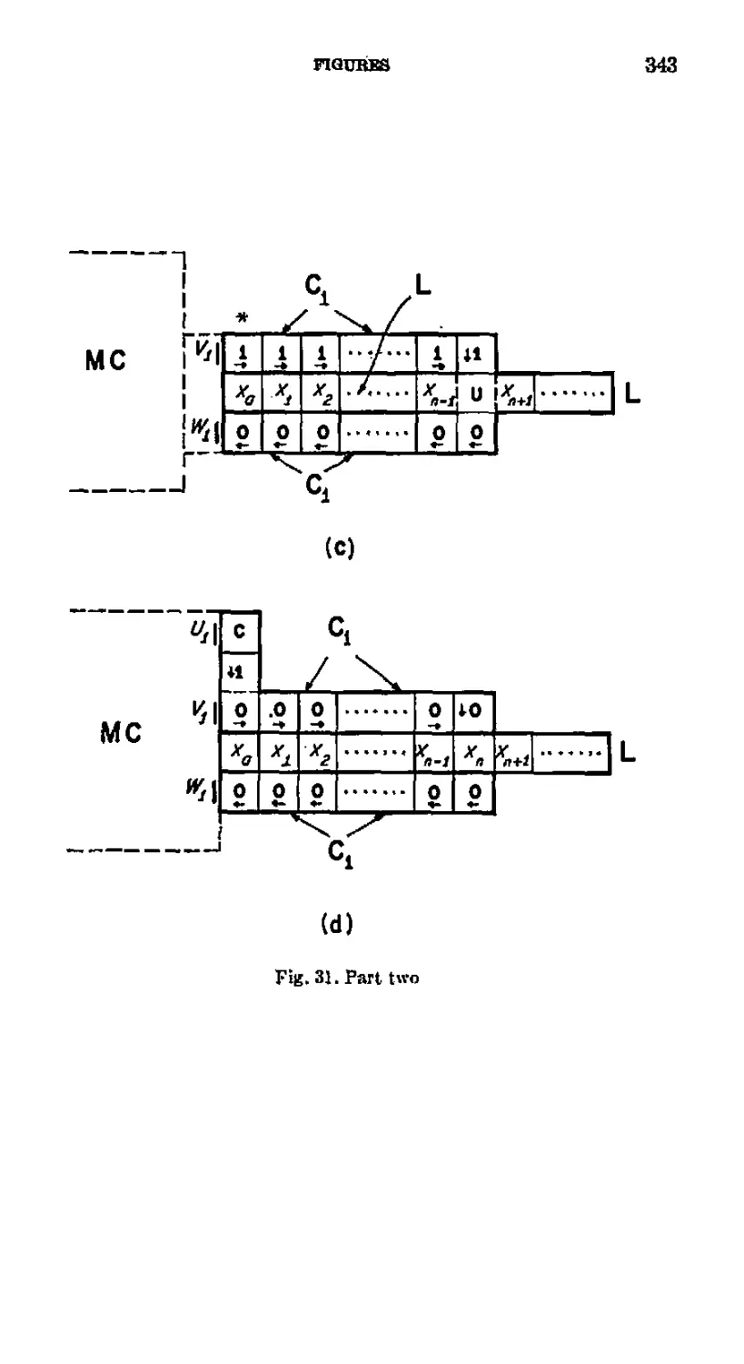
Fig 31. The linear array L, the connecting loop Q, and the timing
loopQ 342
Fig. 32. Lengthening the timing loop Cs 345
Fig. 33. Lengthening the connecting loop Ci 346
Fig 34. Shortening the timing loop Q 348
XII
THEORY OF SELF-BEPRODUCING AUTOMATA
Fig. 35. Shortening the connecting loop Q. , 350
Fig. 30. Writing "zero" in coll xn of the linear array L when
lengthening Ci -..... 352
Fig. 37, Tape unit with unlimited memory capacity 353
Fig. 33. The logical structure of the procedure followed by the
memory control MC 354
Fig. 39. Eead-write-erase unit RWE (Note: parts (a) and (b)
constitute one continuous drawing 355
(a) Upper part of RWE
(b) Lower part of RWE
Fig. 40. Control organ CO 357
Fig. 41- Read-writfr-erase control RWEC (Note: parts (a)-(f)
constitute one continuous drawing.) 35S
(a) Control organs for lengthening Q (COi and COa) and
for lengthening the lower part of G (COa and CO«)
(b) PP(1) to store the fact that a "zero" is to be written
in xK t and control organs for writing a zero and length-
ening the upper part of Q
(c) PP(I) to store the fact that a "one" is to be written in
xM , and control organs for leaving a one in cell xH and
lengthening the upper part of 0
(d) Control organs for shortening d
(e) Control organs and PP(1) for shortening the lower part
of Ci and writing in cell x*
(0 Control organs for shortening the upper part of Ci
Chapter 5
Fig. 42. Crossing organ 364
(a) Crossing organ
(b) Initial state of clock
Fig. 43. State organ SO of a finite automaton FA 365
Fig. 44. Constructing arm 360
Fig. 45. Horizontal advance of constructing arm 366
Fig. 46. Vertical advance of constructing arm 367
Fig. 47. Horizontal retreat of constructing arm with construction
of 7 and 5 368
Fig. 48. Vertical retreat of constructing arm with construction
of y and «. 369
Fig. 49. Injection of starting stimulus into the secondary
automaton. 370
Fig. 50. Operation of the constructing arm 371
LIST OF FIGURES Xlii
Fig. 51. New method of operating the linear array L 372
Fig. 52. Writing "one" in eell x* and lengthening the reading
loop 373
Fig. 53. Static-dynamic converter ..., 374
Fig. 54 The universal constructor jtf„* 375
Fig. 55. Self-reproduction 376
Fig. 56. Self-reproduction of a universal computer-constructor.. 377
PREFACE
In the late 1940's John von Neumann began to develop a theory
of automata. He envisaged a systematic theory which would be
mathematical and logical in form and which would contribute in an
essential way to our understanding of natural systems (natural
automata) as well as to our understanding of both analog and digital
computers (artificial automata).
To this end von. Neumann produced five works, in the following
order:
(1) "The General and Logical Theory of Automata." Read at the
Hixon Symposium in September, 1948; published in 1951.
Collected Works 5.2S8-32S.1
(2) "Theory and Organization of Complicated Automata." Five
lectures delivered at the University of Illinois in December,
1949. This is Part I of the present volume.
(3) "Probabilistic Logics and the Synthesis of Reliable Organisms
from Unreliable Components." Lectures given at the California
Institute of Technology in January, 1952. Collected Works 5.329-
378.
(4) "The Theory of Automata: Construction, Reproduction,
Homogeneity." Von Neumann started this manuscript in. the fall
of 1952 and continued working on it for ahout a year. This is
Part II of the present volume.
(5) The Computer and the Brain. Written during 1955 and 1956;
published in 1958.
The second and fourth of these were left at his death in a manuscript
form which required extensive editing. As edited they constitute the
two parts of tho present volume, which thus concludes von
Neumann's work on the theory of automata.
As a background for this editorial work I made a study of all of
von Neumann's contributions on computers, includuig the theory of
automata. I have summarized his contributions in tho "Introduction"
to the present volume.
Von Neumann was especially interested in complicated automata,
such as the human nervous system and the tremendously large com-
' Complete references are given in the bibliography. "Collected Works 5.288-
328" refere^to pp. 288-328 of Vol. V of von Neumann's Collected Works.
xv
XVI THBOUY OF SELF-REPRODUCING AOTOMATA
puters he foresaw for the future. He wanted a theory of the logical
organization of complicated systems of computing elements and
believed that such a theory was an essential prerequisite to constructing
very large computers. The two problems in automata theory that
von Neumann concentrated on are both intimately related to
complexity. These are the problems of reliability and self-reproduction.
The reliability of components limits the complexity of the automata
we can build, and self-reproduction requires an automaton of
considerable complexity.
Von Neumann discussed reliability at length in his "Probabilistic
Logics and the Synthesis of Reliable Organisms from Unreliable
Components." His work on self-reproducing automata is found chiefly
in the present volume. Part II, which constitutes the bulk of the
present volume, treats the logical design of a self-reproducing cellular
automaton. Though the shorter Part I is devoted to complicated
automata in general, its high point is the kinematic model of self-
reproduction (Fifth Lecture). It therefore seemed appropriate to use
the title "Theory of Self-Rep reducing Automata" for the whole
work.
It is unfortunate that, because of his premature death, von Neu-
niann was unable to put in final form any of the research he was
doing in automata theory. The manuscripts for both parts of the
present volume were unfinished; indeed, they were hoth, in a sense,
first drafts. There is one compensation in this: one can see von
Neumann's powerful mind at work. Early drafts by a thinker of von
Neumann's ability are not often available. For this reason, I have
tried hard to preserve the original flavor of von Neumann's
manuscripts, while yet rendering them easily readable. So that the reader
will know what the raw manuscripts are like, I will describe them
and the editorial changes I have made in them.
Von Neumann agreed to write a book on automata theory in
connection with his five lectures at the University of Illinois in
December, 1949. A tape recording of the lectures was made to aid him in
writing the book. Unfortunately, the recording and the typescript of
it turned out badly, with gaps in the text, unintelligible passages, and
missing words. Von Neumann himself never edited this typescript,
but instead planned to use the manuscript "The Theory of
Automata: Construction, Reproduction, Homogeneity" for the promised
book. The recording itself is not extant. Despite these circumstances,
the Illinois lectures deserve publication, and the recorded version,
highly edited of necessity, constitutes Part I of this volume.
Von Neumann prepared a detailed outline of the lectures in advance
PREFACE
xvH
of delivery, and the content of the lectures corresponded roughly to
this outline. The outline hore the title "Theory and Organization of
Complicated Automata," and began with the following three lines:
The logical organization and limitations of high-speed digital
computers.
Comparison of these and other complicated automata, hoth
artificial and natural
Inference from the comparison of the nervous systems
found in nature.
There followed the title of each lecture and a list of topics to be
covered in that lecture; these are reproduced verbatim at the beginning
of each lecture below, even though the lecture materials do not
correspond exactly to the list of topics.
Because of the state of the manuscript it has been necessary to do
much editing. The typescript of the recording is especially poor in the
more formal portions of the lectures, where von Neumann used the
blackboard. For these portions, particularly, I have found two sets
of notes taken at the lectures to be helpful. I have preserved von
Neumann's phraseology where feasible, but I have frequently found
it necessary to use my own words. 1 have sometimes felt it best to
summarize what von Neumann was saying rather than to attempt
to reconstruct the text. Several of the points von Neumann made in
the Illinois lectures also appear in his published writings, or arc well
known, and in these cases I have often summarized what von
Neumann said or given references to his published works.
Where the writing is strictly my own, it appears in brackets. The
reconstructed edition of von Neumann's words is not bracketed, but
it should be kept in mind that much of this unbracketed text isheavily
edited.
The manuscript "The Theory of Automata: Construction,
Reproduction, Homogeneity" was in a much better state. It seems to have
been a first draft, with the exception that there is an earlier outline
(with figures) of the procedure whereby the memory control MC
lengthens and shortens the connecting loop Ci and the timing loop
C* under the direction of the constructing unit CU (cf. Sees. 4.1 and
4.2). Despite its being a first draft, the manuscript was publishable
as it stood except for deficiencies of the following three types.
(1) First, the manuscript lacked many of those simple
mechanisms which make for easy reading. There were no figure titles.
Formulas, sections, and figures were referred to by number only, without
explicit indication as to whether the item referred to is a formula,
section, or figure. Section titles were listed on a separate sheet. Also
XV1U THBOIIT OP SELF-REPRODUCING AUTOMATA
on a separate sheet, von Neumann gave only brief indications for the
footnotes he planned. Organs were referred to by letter alone. For
example, von Neumann merely used "A" and "B" to refer to the
organs I have called the "constructing unit CU" and the "memory
control MC," respectively. I have worked through the manuscript
several times and each time I have been amazed at how von Neumann
could keep track of what he was doing with, so few mnemonic devices.
In editing the manuscript I have endeavored to supply these
devices. For example, where von Neumann wrote "CO" I often put
"control organ CO." I have added titles to the figures and completed
the footnote references. Von Neumann wrote some explanatory
remarks on the figures; these have been moved to the text. Similar
and related changes have been made, all without any indication in
the text.
In addition, I have inserted footnotes, commentaries, explanations,
and summaries at various places in the text, and have added a con-
including chapter (Ch. 5). All such additions are hi brackets. Von
Neumann's brackets have been changed to braces, except for his
usage "(0]" and "[1]" to refer (o ordinary and social symbols. In
connection with my bracketed additions, I have added Tables I mid
V and many figures. Figures 1-8, 16, 18, 19, 22, 24, 28-30, 38, 39,
and 41 are von Neumann's; the remaining figures arc mine.
(2) Second, the manuscript "Theory of Automata: Construction,
Reproduction, Homogeneity" contained many errors. These range
from minor slips (which I liave corrected without, any specific
indication), through errors of medium significance (winch 1 have corrected
or commented on in bracketed passages), to major errors requiring
considerable redesign (which I have discussed in Sections 5.1.1 and
5.1.2). All of these errors are correctable, but because organs designed
in the earlier parts of the manuscript are used in later parts, many of
these errors propagate and "amplify." In this connection, it should
be kept in mind that the manuscript was an early draft, and that
von Neumann was working out the design as he proceeded, leaving
many design parameters for later specification.
(3) Third, the manuseript "Theory of Automata: Construction,
Reproduction, Homogeneity" is incomplete, The construction stops
before the tape unit is quite finished, In Chapter 5 I show how to
complete the design of von Neumann's self-reproducing automaton.
The technical development of the manuscript is extremely
complicated and involved. The deficiencies just mentioned add to its
difficulty. In some respects it would have been editorially easier not
to edit the manuscript after Chapter 2 and instead work out the
PREFACE
xix
design of von Neumann's self-reproducing automaton along the lines
he last envisaged. But this was not a real alternative because of the
historical importance of the manuscript, and the opportunity it gives
to observe a powerful mind at work/1 have therefore endeavored to
make corrections and add comments so as to preserve the original
style of the manuscript while making it relatively easy to read.
I am indebted to a number of people for their assistance. The late
Mrs. Klara von Neumann-Eckardt gave me information ahout her
husband's manuscripts. Several people who worked with von
Neumann on computers gave me firsthand information: Abraham Taub,
Herman Goldstine, the late Adele Goldstine, and especially Julian
Bigelow and Stan Ulam; von Neumann often discussed his work on
automata theory with Bigelow and with Ulam, John Kemeny, Pierce
Ketchum, E. F. Moore, and Claude Shannon heard lectures by or
had discussions with von Neumann on automata theory. Kurt Gddcl's
letter at the end of the Second Lecture of Part I is reproduced with
liia kind permission. Thanks go to many of my graduate students
and research associates for teclinical assistance, particularly Michael
Fainmn, John Hamie, James Thatcher, Stephen Hedefcnicmi, Frederick
Snppc, and Ridhard Laing. Alice Finney, Karen Brandt, Ann Jacobs,
and Alice R, Burks have provided editorial assistance. M. Elizabeth
Brandt drew the figures. My editorial work was supported by the
National Science Foundation, None of these share any responsibility
for the editing.
Arthur W. Buhks
Ann Arbor, 1965
EDITOR'S INTRODUCTION
Von Neumann's Work on Computers
John von Neumann was horn on December 28,1903 in Budapest,
Hungary, and died in Washington, D.C., February 8, 1957.1 He
earned a doctorate in mathematics from the University of Budapest
and an undergraduate chemistry degree from the Eidgendssische
Technische Hochsehule in Zurich, Switzerland. He became a Privat-
docent at the University of Berlin in 1927 and a Privatdocent at the
University of Hamburg in 1929. In 1930 he eamc to the United States
as a visiting lecturer at Princeton University, ^vhere he \\-as made full
professor in 1931. In 1933 he joined the newly formed Institute for
Advanced Study as a professor and retained that post for the rest of
his life,3
In later life, while retaining his theoretical interests and
productivity, von Neumann developed strong interests in the applications
of mathematics. During the Second World War he became heavily
involved in scientific research on problems of defense. He played a
major role in the development of the atomic bomb, contributing
particularly to the method of implosion. He was a consultant to
many government laboratories and organizations and a member of
many important scientific advisory committees. After the war ho
continued these consulting and advisory activities. Altogether ho
ivn« involved in such diverse fields as ordnance, submarine warfare,
bombing objectives, nuclear weapons (including the hydrogen hoinb),
military strategy, weather prediction, intercontinental ballistic
missiles, high-speed electronic digital computers, and computing methods.
In October, 1954, the President of the United States appointed him
to the United States Atomic Energy Commission, a position he held
at the time of his death. He received many awards and honors during
his lifetime, including membership in tho National Academy of
Sciences, two Presidential Awards, and tho Enrico Fermi Award of the
Atomic Energy Commission. The latter was given especially for his
1 See Ulam, "John von Neumann," and Mrs. von Neumann's preface to The
Computer and the Brain,
1 See his Collected Works, edited by A. Taub. An excellent summary of von
Neumann's accomplishments is presented in the Bulletin of the American
Mathematical Society, Vol. G4, No, 3, Part 2, May, 1968.
1
2
•THEORY OF BELPVUEPRODUC1NG AUTOMATA
contributions to the development of electronic computers and their
uses.
Von Neumann the Mathematician. During the lost years of his life
John von Neumann devoted considerable effort to developing a
theory of automata. The present volume, edited from two unfinished
manuscripts, is his last work on this subject. Because of his premature
death he was unable to finish a volume which would present a
complete picture of what he wished to accomplish. It is therefore
appropriate to summarize here the main features of his projected theory
of automata. Since his conception of automata, theory arose out of
his work in mathematics and computers, wo will begin by describing
that work.
Von Neumann was a very great mathematician. He made many
important contributions m a wide range of fields. Von Neumann
himself thought his most important mathematical achievements
were m three areas: the mathematical foundations of quantum theory,
the theory of operators, and ergodie theory. His contributions in other
areas bear more directly on his computer work. In the late 1920'b he
wrote on symholic logic, set theory, axiomatic*, and proof theory.
In the middle thirties he worked on lattice theory, continuous
geometry, and Boolean algebra. In a famous paper of 1028 and in a
hook of 1&443 he founded the modern mathematical theory of games.
Starting in the late thirties and continuing through and after the
war he did much research in fluid dynamics, dynamics, problems in
the mechanics of eontinua arising out of nuclear technology, and
meteorology. During the war he became involved in computing
and computers, and after the war this became his main interest.
Von Neumann and Computing. Von Neumann was led into
computing by his studies in fluid dynamics. Hydrodynamieal phenomena
are treated mathematically by means of non-linear partial differential
equations. Von Neumann became especially interested in hydro-
dyuamicui turbulence and the interaction of shock waves. He soon
found that existing analytical methods were inadequate for obtaining
even qualitative information about the solutions of non-linear partial
differential equations in fluid dynamics. Moreover, this was so of
non-linear partial differential equations generally.
Von Neumann's response to this situation was to do computing.4
During the war he found computing necessary to obtain answers to
1 "Zur Theorie der GesoUschaftsaplel." Theory of Games and Economic Bt-
havior, with Oskar MorgenBtem.
* See Ulam, "John von Neumann," pp. 7-8, 28 ff., and Birkhcff,
Hydrodynamics, pp. 6, 25.
EDITOR'S INTRODUCTION
3
problems in other fields, including nuclear technology. Hence, when
the new high-speed electronic digital general-purpose computers were
developed during and after the war, he was quick to recognize their
potentialities for hydrodynamics as well as other fields. In this
connection he developed-a general method for using computers which is
of very great importance because it is applicable to a wide variety
of problems m pure and applied mathematics.
The procedure which he pioneered and promoted is to employ
computers to solve crucial cases numerically and to use the results
as a heuristic guide to theorizing. Von Neumann believed
experimentation and computing to have shown that there are physical
and mathematical regularities in the phenomena of fluid dynamics
and important statistical properties of families of solutions of the
non-linear partial differential equations involved. These regularities
und general properties could constitute the basis of a new theory of
fluid dynamics and of the corresponding non-linear equations. Von
Neumann believed that one could discover these regularities and
general properties by solving many specific equations and
generalizing the results, From the special cases one would gain a feeling for
such phenomena as turbulence and shock waves, and with this
qualitative orientation could pick out further critical cases to solve
numerically, eventually developing a satisfactory theory. See the First
Lecture of Part I of tills volume.
This particular method of using computers is so important and has
so much in common with other, seemingly quite different, uses of
computers that it deserves extended discussion. It is of the essence
of tins procedure that computer solutions are not sought for their
own sake, but as an aid to discovering useful concepts, broad
principles, and general theories. It is thus appropriate to refer to this as
the heuristic use of computers.5
The heuristic use of computers is similar to and may be combined
with the traditional hypothetical-deductivc-experimental method of
science. In that method one makes an hypothesis on the basis of the
available information, derives consequences from it by means of
mathematics, tests the consequences experimentally, and forms a
new hypothesis on the basis of the findings; this sequence is iterated
indefinitely. In using a computer heuristically one proceeds in the
same way, with computation replacing or augmenting
experimentation. One makes an hypothesis about the equations under mvestiga-
' Soe alao UIriii, A Collection of Mathematical Problems, Ch. 8, "Computing
Machines as a. Heuristic Aid."
4
THEORY OF SELF-RBPBODtlCING AUTOMATA
tion, attempts to pick out some crucial special oases, uses a computer
to solve these cases, checks the hypothesis against the results, forms
a new hypothesis, and iterates the cycle.
The computations may also be compared with experimental data.
When this is done the heuristic use of computers becomes simulation.
Computation in itself can only provide answers to purely
mathematical questions, so when no comparison is made with empirical
fact the heuristic use of computers contributes to pure mathematics.
Von Neumann thought that the main difficulties in fluid dynamics
stemmed from inadequate mathematical knowledge of non-linear
partial differential equations, and that the heuristic use of computers
would help mathematicians to construct an adequate and useful
theory for this subject. He pointed out that while much progress
had been made by means of wind tunnels, since the equations
governing the phenomena were known, these wind tunnels were being used
as analog computers rather than as experimental apparatus.
... many branches of both pure and applied mathematics are in great need
of computing instruments to break the present stalemate created by the
failure of the purely analytical approaoh to non-linear problems. ... really
efficient high-speed computing devices may, in the field of non-linear partial
differential equations as well as in many other fields, which arc now difficult
or entirely denied access, provide us with those heuristic hints which are
needed in all parts of mathematics for genuine progress.*
Von Neumann's suggestion that powerful computers may provide
the mathematician "with those heuristic hints which are needed in
ali parts of mathematics for genuine progress" is connected to his
strong conviction that pure mathematics depends heavily on empirical
science for its ideas aad problems. "... the best inspirations of
modern mathematics... originated in the natural sciences." 7 Ho
recognized that mathematics is not an empirical science and held that the
mathematician's criteria of selection of problems and of success are
mainly aesthetical.
I think that it is a relatively good approximation to truth—which is
much top complicated to allow anything but approximations—tliat
mathematical ideas originate m empirics, although the genealogy is sometimes long
and obscure. But once they are so conceived, the subject hegins to live a
peculiar life of its own and is hetter compared to a creative one, governed by
almost entirely aesthetical motivations* than to anything else and, in par-
8 Von Neumann and Goldstme, "On the Principles of Large Scale
Computing Machiues/' Collected Works 5.4.
1 "The Mathematician," Collected Works 1.2. The next quotation is from
the same article, 1.9.
EDITOR'S INTltODUCTION
5
ticular, to an empirical science. There is, however, a further point which, I
believe, needs stressing.... at a great distance from its empirical source, or
after much "abstract" inbreeding, a mathematical subject is m danger of
degeneration whenever this stage is reached, the only remedy seems to
me to be the rejuvenating return to the source: the relnjection of more or
less directly empirical ideas.
The role that empirical science plays in pure mathematics is a
heuristic one: empirical science supplies problems to investigate and
suggests concepts and principles for their solution. While von
Neumann never said so, I think it likely that he thought the computations
produced by the heuristic use of computers can play the same role
in some areas of mathematics. In the Jlrst Lecture of Part I below
he said that powerful methods in pure mathematics depend for their
success on the mathematicians having an intuitive and heuristic
understanding of them, and suggested that one can build this
intuitive familiarity with non-linear differential equations by using
computers heuristieally.*
It should be noted that in the heuristic use of computers the
human, not the machine, is the main source of suggestions, hypotheses,
heuristic hints, and new ideas. Von Neumann wished to make the
machine as intelligent as possible, but he recognized that human
powers of intuition, spatial imagery, originality, etc., are far superior
to those of present or immediately foreseeable machines. He wished to
iiugmeut the ability of a skilled, informed, creative human by the
use of a digital computer as a tool. This procedure would involve
considerable interaction between man and the machine and would
be facilitated by automatic programming and by input-output
equipment designed for direct human use.
Once he became interested in computing, von Neumann made
important contributions to all aspects of the subject and its
technology. The extant methods of computation hod been developed for
hand computation and punched card machines and hence were not
well suited to the new electronic computers, which were several orders
of magnitude faster than the old. New methods were needed, and von
Neumann developed many of them. He contributed at all levels. He
devised algorithms and wrote programs for computations ranging
from the calculation of elementary functions to the integration of
non-linear partial differential equations and the solutions of games.
1 In view of von Neumann's emphasis on the role of intuition in
mathematical discovery it is of interest to note that von Neumann's own intuition viae
auditory and ahstraet rather than -visual. See TJlam, "John von Neumann,
1903-1967," pp. 12, 23, end 38-39.
6 THEORY OP SlSkF-UEPUODUClNU AUTOMATA
He worked on general techniques for numerical integration and
inverting matrices. He obtained results in the theory of numerical
stability and the accumulation of round-off errors. He helped develop
the Monte Carlo method for solving integro-differential equations,
inverting matrices, and solving linear systems of equations by
random sampling techniques.0 In this method the problem to be solved
is reduced to a statistical problem which is then solved hy computing
the results for a sufficiently largo sample of instances.
Von Ncumanu also made importjuit contributions to the design
and programming of computers, and to the theory thereof, We will
survey his work in these areas next
Logical Design of Computers. With his strong interest in computing
and lus background in logic and physics it was natural for von
Neumann to become involved in the development of high-speed electronic
digital computers, The first such computer was the ENIAC, designed
and built at the Moore School of Electrical Engineering of the Uui.
versify of Pennsylvania during the period 1943 to 1046.10 Von Neu*
maim had some contacts with this machine, find so a few words about
it are in order.
The idea of constructing a general purpose highspeed computer of
electronic components originated with Joint Mauchly, who .suggested
to IT. II. Goldstinc of the Ordnance Department that the United
States Army support the development and construction of such a
machine, to be used primarily for ballistics computations. This sup.
port was given, the Army being impressed especially with the great
speed with which an electronic computer could prepare firing tables.
The ENIAC was designed and constructed by a number of people,
including the writer, under the technical direction of Mauchly and
J. P. Eckert. Von Neumann came to visit us while wc were building
the ENIAC, and he immediately became interested in it. By this time
the design of the ENIAC was already fixed, but after the ENIAC was
completed von Neumann showed how to modify it so that it was much
simpler to program. In the meantime he developed the logical design
for a radically new computer, which we will describe later.
The ENIAC was, of course, radically different from any earlier
•TFlam, "John von Neumann," pp. 33-34. Von Neumann Collected Work*
5.751-764. The method is described iu Metropolis &nd Ulam, "The Monte Carlo
Method."
"Seo Burlu, "Electronic Computing Circuits of the ENIAC" and "Super
Electronic Computing Machine," Goldstine and Goldstine, "The Eleotroutc
Numerical Integrator and Computer (ENIAC)," and Brntnerd and Sharplesa,
"The ENIAC."
BpCrOR'S TNTKODUCnON
7
computer, but interestingly enough, it was also quite different from
its immediate successors. It differed from its immediate successors in
two fundamental respects: the use of several semiautonomous
computing unite working simultaneously and Bemi-independently, and
the exclusive reliance on vacuum tubes for high-speed storage. Both
of these design features resulted from the electronic technology of the
time.
The basic pulse rate of the ENIAC circuits was 100,000 pulses per
second. To obtain a high computation speed all 10 (or 20) decimal
digits were processed in parallel, and, moreover, a large number of
computing units were constructed, each with some local programming
equipment, so that many computations could proceed simultaneously
under the overall direction of a master programming unit. There were
30 basic unite in the ENIAC: 20 accumulators (each of which could
store and add a 10-digit number), 1 multiplier, 1 divider and square-
rooter, 3 function table unite, on input unit, an output unit, a master
programmer, and 2 other units concerned with control. All of these
basic units could operate at the same time.
At that time the vacuum tube was the only reliable high-speed
storage device—acoustic delay lines, electrostatic storage systems, mag*
nctie cores, etc., all came later—and so of necessity vacuum tubes were
used for high-speed storage as well as for arithmetic and for logical
control. This entailed a severe limitation on the high-speed store, as
vacuum tubes are an expensive and bulky storage medium—the
ENIAC contained 18,000 vacuum tubes as it was, a sufficient number
for the skeptics to predict that it would never operate properly. The
limited high speed storage of 20 10-dlgit decimal numbers was
augmented by large quantities of low-speed storage of various types;
electromagnetic relays for input and output, hand operated mechanical
switches controlling resistor matrices in the function table unite for
the storage of arbitrary numerical functions and of program
information, and hand-operated mechanical switches and flexible plug-in
cables for programming.
A general purpose computer must be programmed for each
particular problem. This was done on the ENIAC by hand; by sotting
mechanical switches of the program controls of each of the computing
unite used in the problem, interconnecting these program controls with
cables, and setting the switches of the function tables.
This.programming procedure was long, laborious, and hard to cheok, and while it
was being done the machine stood idle. After the ENIAC was
completed, von Neumann showed how to convert it into a centrally
programmed computer in which all the programming could be done
S THEORY OF BBLF-31BPU01>UCINQ AUTOSIATA
by setting switches on the function tables. Each of the three function
table units had a switch storage capacity of 104 entries, each entry
consisting of 12 decimal digits and 2 sign digits. However, the pulses
used to represent numbers were the same size and shape as the pulses
used to stimulate program controls, so that the function table units
could also be used to store program information. On von Neumann's
scheme the outputs of the function tables were connected to the
program controls of the other units through sonic special equipment and
the master programmer, and the switches on the program controls
of these units were set. All of this was done in such u way that it need
not be changed from problem to problem. Programming was thus
reduced to setting switches by hand on the function table units.
In the meantime we were all concerned "with the design of much
more powerful computers. As mentioned earlier, the greatest weakness
of the ENIAC was the smallness of its high-speed storage capacity,
resulting from the technological fact that at the time the design of
the ENIAC was fixed the vacuum tube was the only known reliable
high-speed storage component. This limitation was overcome aud the
technology of computers changed abruptly when J. P. Eckert
conceived of using an acoustic delay line as a high-speed storage device.
Acoustic delay lines made of mercury had been used to delay pulses
in war time radar equipment. Eckert's idea was to feed the output of
a mercury delay line (through an amplifier and pulse reshaper) back
into its input, thereby storing a large number of pulses in a
circulating memory. A circulating memory of, say, 1000 bits conld be built
with a mercury delay line and a few tubes, in contrast to the ENIAC
where a double triode was required for each bit.
In the ENIAC the few numbers being processed were stored in
circuits that could be changed both automatically and rapidly; all other
numbers and the program information were stored in electromagnetic
relays, switches, and cable interconnections. It now became possible to
store all this information in mercury delay lines, where it would be
quickly and automatically accessible. The ENIAC was a mixed
synchronous, asynchronous machine. The use of pulses in the mercury
delay lines made it natural to build a completely synchronous machine
timed by a central source of pulses called the "clock." Eckert and
Mauchly designed circuits capable of operating at a pulse rate of 1
megacycle, 10 times the basic pulse rate of the ENIAC, and gave
considerable thought to the design of a mercury delay line machine.
Goldstine brought von Neumann in as a consultant, and we all
participated in discussions of the logical design of such a machine. It was
decided to use the binary system. Since the delay lines operated
EDITOR'S INTHODUCTION
9
serially, the simplest way to process the bits was seriatim. All of this
made it possible to build a machine much smaller than the ENIAG
and yet much more powerful than the ENIAG. The proposed machine
was to be called the EDVAG. It was estimated that it could be built
with about 3000 vacuum tubes.
Von Neumann then worked out in considerable deteil the logical
design of this computer. The result appeared in his First Draft of a
Report on the EDVAC*1 which was never published. Sinee this report
contained the first logical design of an electronic computer in which
the program could be stored and modified electronically, I will
summarize its contents. Of particular interest 10 us here are the following
features of his design: the separation of logical from circuit design, the
comparison of the machine to the human nervous system, the general
organization of the machine, and the treatment of programming and
control.
Von Neumann based his construction on idealized switch-delay
elements derived from the idealized neural elements of McCulloch and
Pitts." Each sueh element has one to three excitatory inputs, possibly
one or two inhibitor}' inputs, a threshold number (1, 2, 3), and a unit
delay. It emits a stimulus at time t -f- I if and only if two conditions
are satisfied at time t: (1) no inhibitory input is stimulated, (2) the
number of excitatory inputs stimulated is at least as great as the
threshold number,"
The use of idealized computing elements has two advantages. First,
it enables the designer to separate the logical design from the circuit
design of the computer. When designing the EN'IAC, wc developed
logical design rules, but these were inextricably tied in with rules
governing circuit design. With idealized computing elements oue can
distinguish the purely logical (memory and truth-functional)
requirements for a computer from the requirements imposed by the state of
technology and ultimately by the physical limitations of the materials
and components from which the computer is made. Logical design is
the first step; circuit design follows. The elements for logical design
" The initials abbreviate "Electronic Discrete Variable Automatic
Computer." The machine of this name actually constructed at the Moore School
of Electrical Engineering whh built after the people mentioned above were
no tongur connected with the Tvfoore School. The logical design of the
Cambridge University EDSAC was based on this report. Wilkes. "Progress in High-
SpuQ<t Calculating Nfachino Design" mid Automatic Digital Computers.
" "A Logical Calculus of the Ideas Immanent in Nervous Activity."
11 The threshold elements of "Probabilistic Logics and the Synthesis of
Reliable Organisms from Unreliable Components," Collected Works 5,332, arc
similar, but differ with respect (o the operation of inhibitory inputs.
10 THEORY OF SELF-REPRODUCING AUTOMATA
should be chosen to correspond roughly with the resultant circuits j
that is, the idealisation should not be so extreme as to be unrealistic.
Second, the use of idealized computing elements is a step in the
direction of a theory of automata. Logical design in terms of these
elements can be done with the rigor of mathematical logic, whereas
engineering design is necessarily an art and a technique in part.
Moreover, this approach facilitates a comparison and contrast between
different types of automata elements, in this case, between computer
elements on the one hand and neurons on the other. Von Neumann
made such comparisons in Pint Draft of a Report on ike EDVA C,
noting the differences as well as the similarities. Thus he observed that
the circuita of the EDVAG were to be synchronous (timed by a pulse
eloek) while the nervous system is presumably asynchronous (timed
autonomously by the successive reaction times of its own elements).
He also noted the analogy between the associative, sensory, and motor
neurons of the human nervous system on the one hand, and the
central part of the computer, its input, and its output, respectively.
This comparison of natural and artificial automata was to become a
strong theme of his theory of automata.
The organization of the EDVAG was to be radically different from
that of the ENIAG. The ENTAC had a number of basic uuits, all
capable of operating simultaneously, so that many streams of
computation could proceed at the same time. In contrast, the proposed
EDVAC had only one basic unit of each kind, and it never performed
two arithmetical or logical operations simultaneously. These basic
units were a high-speed memory M, a central arithmetic unit CA, an
outside recording medium R, an input organ I, on output organ O,
and a central control CC.
The memory M was to be composed of possibly as many as 25b'
delay lines each capable of storing 32 words of 32 bits each, together
with the switching equipment for connecting a position of M to the
rest of the machine. The memory was to store initial conditions and
boundary conditions for partial differential equations, arbitrary
numerical functions, partial results obtained during a computation,
etc., as well as the program (sequence of orders) directing the
computation. The outside recording medium R could be composed of
punched cards, paper tape, magnetic wire or tape, or photographic
film, or combinations thereof. It was to be used for input and output,
as well as for auxiliary low-speed storage. The input organ I
transferred information from R to M; the output organ O transferred
information from M to R. The notation of M was binary; that of R
was decimal.
The central arithmetic unit CA was to contain some auxiliary regis-
EJHTOIt'S INTRODUCTION
11
ters (one-word delay lines) for holding numbers. Under the direction
of the central control CC it was to add, subtract, multiply, divide,
compute square-roots, perform binary-decimal and decimal-binary
conversions, transfer numbers among its registers and between its
registers and M, and choose one of two numbers according to the sign
of a third number. The last operation was to be used for transfer of
control (jumping conditionally) from one order in the program to
another. Numbers were processed in CA serially, the least significant
bits being treated first, and only one operation was performed at a
time.
The first bit of each word was zero for a number, one for an order.
Eight bits of an order were allotted to the specification of the operation
to be. performed and, if a reference to M was required, thirteen bits to
an address. A typical sequence would go like tins. Suppose an addition
order with memory address x was located in position y of M, the
addend in the next position y -f-1, and the next order to be executed
in the next position y -f 2. The order at y would go into CC, the
addend at y -f- 1 into CA, and the augend would be found in CA; the
sum would be placed in position x of M. The order at position y -f- 2
would be executed next.
Normally orders were taken from the delay lines in sequence, but
one order with address z provided for CC to take its next order from
memory position s. When a number was transferred from CA to
address w of M, account was taken of the contents of to; if w contained
an order (i.e., a word whose first bit was one), then the 13 most
significant bite of the result in CA were substituted for the 13 address
bit« located in to. The addresses of orders could be modified
automatically by the machine in this way. This provision, together with
lite order for shift of control to an arbitrary memory position to and
the power of CA to choose one of two numbers according to the sign
of a third, made the machine a fully automatic stored program
computer.
At the same time that he worked out the logical design of the
EDVAC von Neumann suggested the development of a high-speed
memory incorporating the principle of the iconoscope." Information
is placed on the iconoscope by means of light and sensed by an electron
beam, Von Neumann suggested that information could also be placed
011 the inside surface of such a tube by means of an electron beam.
The net result would be storage in the form of electrostatic charges on
a dielectric plate inside a cathode-ray tube. He predicted that such a
14 Pint Draft of a Report on ths EDVAC, Section 12.8.
12 THEORY OF BELF-KEFRODtJCING AUTOMATA
memory would prove superior to the delay line memory. It soon
became apparent that this was so, and von Neumann turned his
attention to an even more powerful computer based on such a memory.
The new computer was to be much faster than any other machine
under consideration, mainly for two reasons. First, in an electrostatic
storage system each position is immediately accessible, whereas a bit
or word stored in a delay line is notaccessible until it travels to the end
of the line. Second, it was decided to process all (40) bita of a word in
parallel, thereby reducing the computation time. The logical design is
given in Preliminary Discussion of the Logical Design of an Electronic
Computing Instrument111 The proposed computer was built at the
Institute for Advanced Study by a number of engineers under the
direction of Julian Bigelow, and was popularly known as the JONIAC.1*
While the machine was still under construction, its logical and
circuit design was influential on many computers constructed in the
United States, including computers at the University of Illinois, Los
Alamos National Laboratory, Argonne National Laboratory, Oak
Ridge National Laboratory, and the Rand Corporation, as well as
some machines produced commercially. The JONIAC played an
important role in the development of the hydrogen bomb.17
Programming and Flow Diagrams, Von Neumann immediately
recognized that these new computers could solve large problems so
fast that new programming procedures would be needed to enable
mathematicians and programmers to make full use of the powers of
these machines. With the order code of the proposed Institute for
Advanced Study computer in mind he proceeded to develop new
programming methods. The results were presented in the influential
series of reports Planning and Coding of Problems for an Electronic
Computing Instrument,1*
One generally begins with a mathematical formulation of u problem
and then decides what uxpheit computational methods he will
employ. These methods are almost always highly inductive, involving
recursions within recursions many times over. What one has at this
« This was written in .collaboration with H. H. Goldstine and the. present
writer. It was typical of von Neumann that he wanted the patentable material
)a this report to belong to the public domain, and at his suggestion wo all signed
a notarized statement to this effect.
" It is described by EBlrin, "Hie Electronic Computer at the Institute for
Advanced Study." The original plan was to use the memory dssoribed hy
Rajohman in "The Selection—a Tube for Selective Electrostatic Storage," but
the actual memory consisted of cathode-ray tuhes operated in the manner
described by Williams in "A Cathode-Itay Digit Store."
» New York Times, Feb. 9, 1957, p. 19.
"Written In collaboration with H. H. Goldstine.
**.
EDITOR'S INTRODUCTION 13
stage is a general description of the desired computation, expressed in
the ordinary language and mathematical symbolism of the
mathematician. The task is now to transform this description into a program
expressed in machine language. This is not a simple, straightforward
translation task, however, partly because of the generality of the
description of the computation and partly because of the nature of
recursive procedures.
Recursive procedures, particularly when complicated, are better
understood dynamically (in terms of their step by stsp effecta) rather
than statically (iu terms of the static sequence of symbols defining
them). The corresponding aspect of the machine language, is that the
effect of an order is dependent on the very computation which it itself
is holping to direct: whether and how often an. order is used and to what
memory position it refers. All of these are a function of the whole
program and the numbers being processed* Thus a program, though a
static sequence of symbols, is usually best understood in terms of its
dynamic effects, that is, its control of the actual sequential
computational process.
To help bridge this gap between the mathematician's description of
the desired computation in his own language and the corresponding
program in the machine language, von Neumann invented the flow
diagram. A flow diagram is a labeled graph composed of enclosures
and points connected by lines. The enclosures are of various kinds:
operation boxes (specifying non-recursive fragments of the
computation as symbolized in the box), alternative boxes (corresponding to
conditional transfer of control orders and being labeled with the
condition for transfer), substitution and assertion boxes (indicating
the values of the indices of the recursions), storage boxes (giving the
contents of trucial parts of the memory at certain stages of the
computation), and labeled circles representing the beginning and terminus
tvnd interconnections. In executing the program corresponding to a
given flow diagram, the computer in effect travels through the flow
diagram, starting at the beginning circle, executing sequences of
orders described in operation boxes, cycling back or branching off to a
new part of the diagram according to the criteria stated in alternative
boxes, leaving an exit circle in one part of the graph to enter an
entrance circle in another part of the graph, and finally stopping at the
terminal circle. Direct lines are used to represent the direction of
passage through the graph, converging lines meeting at points of the
graph. An undirected line is used to connect a storage box to that
point of the graph which corresponds to the stage of computation
partly described by the contents of the storage box.
14 THEORY OP SBliF-lRBPnODUCINa AUTOMATA
It is unnecessary for the programmer to prepare arid code a
complete flow diagram for a complicated problem. A problem of any
considerable complexity is composed of many subprbblems, and flow
diagrams and subroutines can be prepared for these in advance. It
was planned to code subroutines corresponding to a large number of
basic algorithms employed in solving problems on a digital computer:
decimal-to-binary and bmary-to-detimal conversion, double precision
arithmetics, various integration and interpolation methods, meshing
and sorting algoritlims, ete. These subroutines would be available in a
library of tapes. To solve a particular problem, the programmer would
merely write a "combining routine" which would direct the computer
to take the proper subroutines from the tape and modify them
appropriately to that particular problem.
The use of combining routines and a library of subroutines was a
first step in the direction of using a computer to help prepare programs
for itself. Still, in this system, everything written by the programmer
must be in the clumsy "machine language." A better procedure is to
construct a "programmer's language" in which the programmer will
write programs, and then to write a translation program in machine
language which directs the machine to translate a program written in
the programmer's language into a program stated in machine
language. The programming language would be close to the natural and
mathematical language normally used by mathematicians, scientists,
and engineers, and hence would be easy for the programmer to use.
This approach is currently being developed under the name of
automatic programming. Von Neumann discussed it under the names
"short code" (programmer's language) and "complete code" (machine
language)."1
Von Neumann recognized that the idea of automatic programming
is a practical application of Turing's proof that there exists a universal
computing machine. A Turing machine is a finite automaton with an
indefinitely expandable tape. Any general purpose computer, together
with an automatic factory which can augment its tape store without
limit, is a Turing machine. Turing's universal computer U has this
property; for any Turing machine M there is a finite program P such
that machine U, operating under the direction of P, will compute the
same results as itf4 That is, U with P simulates (imitates) M.
Automatic programming also involves simulation. Let Uc be a
computer which operates with a machine language inconvenient for the
" The Computer and the Brain, pp. 70-73.
EDlTOn'B INTRODUCTION
15
programmer to use. The programmer uses his more convenient
programmer's language: It is theoretically possible to build a machine
which will understand the programmer's language directly; call this
hypothetical computer Mp, Let Pt be the program (written in the
language of machine U*) whioh translates from the programmer's
language to the machine language of Ue. Then Ue, operating under
the direction of Pt, will compute the same results as Mp. That is,
U€ with Pt simulates M9, which is a special case of Turing's
universal U with P simulating M,
Note that two languages arc employed inside Uc: a machine
language which is used directly and a programmer's language which
is used indirectly via the translation routine P,. Von Neumann
referred to these as the "primary" and "secondary" language of the
machine, respectively. The primary language is the language used for
communication and control within the machine, while the secondary
language is the language we humans use to communicate with the
machine. Von Neumann suggested that by analogy there may be a
primary and secondary language in the human nervous system, and
that the primary language is very different from any language we
know.
Thus the nervous system appears to be using a radically different system
of notation from the ones we are familiar with in ordinary arithmetics and
mathematics....
... whatever language the central nervous system is using, it is characterized
by less logical and arithmetical depth than what we are normally used to.
Thus logics and mathematics in the central nervous system, when viewed as
languages, must be structurally essentially different from those languages to
which our common experience refers.
... when we talk mathematics, we may be discussing a secondary language,
huilt on the primary language truly used by the central nervous system."
He thought that the primary language of the nervous system was
statistical in character. Hence his work on probabilistic logics was
relevant to this language. See his discussion of probabilistic logics
and reliability in the Third and Fourth Lectures of Part I below and
in "Probabilistic Logics and the Synthesis of Reliable Organisms
from Unreliable Components."
Computer Circuits. From the beginning von Neumann had an
interest in the circuits and components of electronic digital computers.
10 The Computer and the Brain, pp. 79-82.
16 THEORY OF SBfcF-MJPBQDUCINO AUTOMATA
He analyzed the basic physical and chemical properties of matter
with the purpose of developing improved computer components.21 In
his lectures on automata theory he compared natural and artificial
components with respect: to speed, size, reliability, and energy
dissipation, and he computed the thermodynamic minimum of energy
required for a binary decision. See the Fourth Lecture of Part I of the
present volume. His search for physical phenomena and effects that
could be used for computing led to his invention of a new component.
This is a subhoraionic generator which is driven by an excitation
(power) eource at frequency nf (n = 2, 3, 4, ■ • •) and which oscillates
at the subharmonic frequency /.32 The subhunnonic generator
circuit incorporates an inductance and capacitance circuit tuned to the
frequency/. Either the capacitance or inductance is non-linear, and
its value varies periodically under the influence of the exciting signal
(of frequency nf). Tho oscillation at frequency/ can occur in any of n
distinct phases. Each oscillation phase is highly stable when
established, but, when the oscillation begins, the choice of phase can easily
be controlled by a small input signal of frequency/ and of the desired
phase. Modulating (turning off and on) the exciting source (of
frequency nf) with a square wave (clock signal) of much lower frequency
produces alternate passive and active periods, and an input of
frequency / can select one of the n phases of oscillation as the exciting
signal appears.
To transfer the phase state of one subharmonic generator (a
transmitter) to another (a receiver), the transmitter and receiver arc
coupled through a transformer. The square-wave modulations into
transmitter and receiver are of the same frequency but of different
phase, so that the transmitter is still on while the receiver is just
11 Most nf bis idciis in Ibis area wore only discussed with others and never
published. A brief reference occurs in Preliminary Discussion of the Logical
Design of an Electronic Computing Inatrujucnt, Collected Works 5.39. Booth,
"The Future of Automatic Digital Computers/' p. 341, mentions a
superconducting atom go element discussed with von Neumann in 1047. Von Neumann
also did Bpme early work on the MASER. See Collected Works 5.420, Scientific
American (February, 1903) p. 12, and Scientific American (April, 1963) pp.
14-15.
** "Non-Linear Capacitance of Inductance Switching, Amplifying and
Memory Devices." Von Neumann's ideas arc also described by Wigington, "A
New Concept lit Computing."
The parametron, invented independently by E. Goto, embodies essentially
the same idea, but is far different ut the suggested speed of implementation. Soo
Goto, "Tho Farametrou, a Digital Computing Element which Utilizes
Parametric Oscillation." The hiRhest frequencies Goto reports are an exciting
frequency (2/) of 0 X 10e cycles per second and a clock, frequency of 10* cycles.
According to Wigington, op. cit., von Neumann estimated that an exciting
frequency (20 of 5 X 10" and a clook rate of 10* were feasible.
BDITOa'S INTRODUCTION
17
eoming oil As a result the receiver hcgins oscillating at frequency/in
phase with the transmitter. The receiver can later transmit its state
to another subharmonio generator, and so on down the line. One may
use three clock signals, all of the same frequency but of three different
phases, and, by exciting interconnected generators with the proper
clock signals, transfer information around a system of generators.
Each such generator then has an input and an output operating at
frequency/, beside the exciting input of frequency nf; the phasing of
the two different clock signals to two interconnected generators
determines which generator is the receiver and which is tho transmitter.
The output signal (at/) lias much more power than is required for the
input signal (at /) to control the phase of the oscillation, and so the
subharmonic generator is an amplifier at frequency/, the power for
amplification coming from the exciting signal of frequency nf.
Since the oscillation of the subharmonic generator is stable and
continues after the subharmonic input from another generator terminates,
the device clearly has memory capacity. Switching can also be done
with subharmonic generators, in the following way. Let « = 2; i.e.,
let there be two distinct phases of subharmonic oscillation at frequency
/, so that the system is binary. Connect the outputs of three
transmitting generators to the primary of a transmitter so that the voltages
of these outputs add; connect a receiver generator to the secondary
of this transformer. The voltage of the transformer secondary will then
Imve the phase of the majority of the transmitting generators, ho that
the receiving generator will oscillate in this phase. This arrangement
realizes a majority clement, Unit is, a three-input switch with delay
whose output state is "1" if and only if two or more inputs are u\
state "l".28 A negation element may be realised by connecting the
output of one generator to the input of another and reversing the
direction of the transformer winding. The constants "0" and "1" are
realized by sources of the two different phases of the signal of
frequency/. The majority element, negation element, and the constant
sources "0" and "1" are sufficient to do all computing, so that the
central part of a computer can be completely constructed from sub-
liarmonlc generators.3*
Von Neumann's Theory of Automata
Introduction. On reviewing the preceding sketch of von Neumann's
research accomplishments, one is immediately struck by the tremen-
u "Probabilistic Logics and the Synthesis of Heltable Organisms from
Unreliable Components," Collected Works 6.339.
14 Many computers are so constructed. Sea Goto, op. eit.
18 THEORY OF SBLF-BBPBODUCINa AUTOMATA
dous combination of breadth and depth revealed in those
accomplishments. Particularly notable is the extent to whieh von Neumann's
achievements range from the purely theoretical to the extremely
practical. It should be added in the latter connection that he was
among the first to recognize and promote the tremendous
potentialities in computers for technological revolution and the prediction and
control of man's environment, such as the weather.
Von Neumann was able to make substantial contributions to so
many different fields because he possessed a rare combination of
different abilities along with wide interests. His quick understanding and
powerful memory enabled him to absorb, organize, retain, and use
large quantities of information. His wide interests led him to work in
and keep contact with many areas. He was a virtuoso at solving
difficult problems of all kinds and at analyzing his way to the essence of
any situation.
This wide range of interests and abilities was one of von Neumann's
great strengths as a mathematician and made him an applied
mathematician par excellence. He was familiar with the actual problems of
the natural and engineering sciences, on the one hand, and the
abstract methods of pure mathematics on the other. He was rare among
mathematicians in his ability to communicate with scientists and
engineers. This combination of theory and practice was deliberately
cultivated by von Neumann. He was a careful student of the history
and nature of scientific method and its relation to pure mathematics16
and believed that mathematics must get its inspiration from the
empirical sciences.
Given his background and tyi^e of mind, it was natural for von
Neumann to begin to construct a general theory of computers, Being
aware of the important similarities between computers and natural
organisms, and of the heuristic advantages in comparing such different
but related systems, he sought a theory that would cover them both.
He called his proposed systematic theory the "theory of automata."
This theory of automata was to be a coherent body of concepts and
principles concerning the structure and organization of both natural
and artificial systems, the role of language and information in such
systems, and the programming and control of such systems. Von
Neumann discussed the general nature of automata theory at several
places in Part I and in Chapter I of Part II of the present volume.
Von Neumann's early work on computer design and programming
» See Chapter 1 of Theory of Games and Economic Behavior; "The
Mathematician," Collected Works 1.1-9; anil "Method in the Physical Sciences,"
Collected Work* 6.491-498.
EDlTOIt'S INTnODVCTION
10
led him to recognize that mathematical logic would play a strong role
in the new theory of automata. But for reasons to be mentioned later,
he thought that mathematical logic in its present form, though useful
in treating automata, is not adequate to serve as "the" logic of
automata. Instead, he believed that a new logic of automata will arise
which will strongly resemble and interconnect with probability theory,
thermodynamics, and information theory. It is obvious from all this
that von Neumann's theory of automata will, in the beginning at
least, be highly interdisciplinary.
Unfortunately, because of his premature death, von Neumann was
unable to put in final form any of the research he was doing in
automata theory. In his last work oil this subject he said that "it would be
very satisfactory if one could talk about a 'theory' of such automata,
Regrettably, what at this moment exists ... can as yet. be described
only as an imperfectly articulated and hardly formalized 'body of
experience'."" Von Neumann's accomplishments in this area were
nevertheless substantial. He outlined the general nature of automata
theory: its structure, its materials, some of its problems, some of its
applications, and the form of its mathematics, He began a
comparative study of artificial and natural automata. Finally, he formulated
itnd partially answered two basic questions of automata theory; How
run reliable systems be constructed from unreliable components?
What kind of logical organization is sufficient for an automaton to be
able Hi reproduce itself? The first of these questions is discussed in his
"Probabilistic Logics and the Synthesis of Reliable Organising from
Unreliable Components." The second question is discussed in the
Fifth Lecture of Part 1 and in Part II of the present volume,
I do not know how von Neumann was led to these two problems,
but on thebasis of his interests and what he has written it is plausible
that they arose out of his actual work with computers in the following
way. The new electronic computers were revolutionary because in
contrast to earlier computing systems (humans, mechanical and
electromechanical machines, and combinations thereof) they could do large
quantities of computation automatically and rapidly. The advances
through the ENIAC, the proposed EDVAC, and the Institute for
Advanced Study computer, were all big steps in the direction of more
powerful computers. His Interest in solving non-linear partial
differential equations in general, and in the equations for predicting the
weather in particular, would naturally lead him to desire ever more
powerful machines and to look for and try to remove the basic
limitations blocking the construction of such machines. As a consultant for
,e The Computer and the Brain, p. 2.
20 THEORY OP BELF-REPRODUCINO AUTOMATA
government and industry he was very influential in promoting the
design and construction of larger computers.
Von Neumann compared the beat computers that could be built at
the time with the most intelligent natural organisms and concluded
that there were three fundamental factors limiting the engineer's
ability to build really powerful computers; the size of the available
components, the reliability of these components, and a lack of a theory of
the logical organisation of complicated systems of computing
elements. Von Neumann's work on componentry was directed toward
the first limitation, and his results 011 reliability and self-reproduction
each contribute toward removing both the second and the third
limitations. In his "Probabilistic Logics and the Synthesis of Reliable
Organisms from Unreliable Components," he gave two methods of
overcoming the unreliability of the components, not by making them
more reliable, but by organizing them so that the reliability of the
whole computer is greater than the reliability of its parts. He regarded
his work on probabilistic logics as a step in the direction of the new
logic of automata. His work on self-reproduction also belongs to the
theory of complicated automata. He felt that there are qualitatively
new principles involved in systems of great complexity and searched
for these principles in the phenomenon of self-reproduction, wliich
clearly depends on complexity. It is also to be expected that because
of the close relation of self-reproduction to self-repair, results on self-
reproduction would help solve the reliability problem.
Thus von Neumann was especially interested in complex automata;
he wanted a theory of the logical organization of complicated systems
of computing elements. His questions about reliability and
self-reproduction are particularly germane to complex automata.
Two further points are relevant. First, von Neumann believed that
in starting a new science one should begin with problems that can be
described clearly, even though they concern everyday phenomena and
lead to well known results, for the rigorous theory developed to explain
these phenomena can provide a base for further advances.21 His prob*
lems of reliability and self-reproduction are of this kind. Second, von
Neumann believed that the lack of an adequate theory of complicated
automata is an important practical barrier to building more powerful
machines. He explicitly stated that until an adequate theory of
automata exists there is a limit in the complexity and capacity of the
automata we can fabricate.1*
n Theory of Garnet and Economic Behavior, Sees. 1.3 and 1,4.
** "The General and Logical Theory of Automata," Collected Works 5.302-
300.
: editor's introd.ucti on
21
Natural, and Artificial Automata. The scope of the thoory of auto*
mata and its interdisciplinary character are revealed by a
consideration of the two main types of automata.i the artificial and the natural
Analog and digital computers are the most important kinds of artificial
automata, but other man-made systems for the communication and
processing of information are also included, for example, telephone
and radio systems. Natural automata include nervous systems, self-
reproductive and self-repairing systems, and the evolutionary and
adaptive aspects of organisms.
Automata theory clearly overlaps communications and control
engineering on the one hand, and biology on the other. In fact,
artificial and natural automata are so broadly defined that one can
legitimately wonder what keeps automata thoory from embracing both
these subjects. Von Neumann never discussed this question, but there
are limits to automata thoory implicit in what he said. Automata
t lieory differs from both subjects in the central role played by
mathematical logic and digital computers. Though it has important
engineering applications, it itself is a theoretical discipline rather than a
practical one. Finally, automa&u theory differs from the biological
sciences in i\n concentration on problems of organization, structure,
language, information, and control.
Automata theory seeks general principles of organization, structure,
tangusige, information, and control. Many of these principles are
applicable to both natural and artificial systems, and so a comparative
study of these two types of automata is a good starting point. Their
similarities and differences should be described and explained.
Mathematical principles applicable to both types of automata should be
developed. Thus truth-functional logic and delay logic apply to both
computer components and neurons, as does von Neumann's
probabilistic logic. See the Second and Third Lectures of Part I of the
present volume. Similarly, von Neumann's logical design of a self'
reproducing cellular automaton provides a connecting link between
natural organisms and digital computers. There is a striking analogy
with the theory of games at this point. Economic systems are natural;
games are artificial. The theory of games contains the mathematics
common to both economic systems and games,3' just as automats
thoory contains the mathematics, common to both natural and
artificial automata.
Von Neumann liimself devoted considerable attention to the com^
11 Theory of Games and Economic Behavior, Sees. 14,2 and 4.1,3.
22 THEORY OF SEW-HBPBODUCING AUTOMATA
parison of natural and artificial automata,*" Scientific knowledge of
the automata aspects of natural organisms has advanced very rapidly
in recent years, and so there is now a much more detailed basis for tho
comparison than at the time von Neumann wrote, but his general
approach and conclusions are nevertheless of interest. We will outline
his reflections under the following headings: (1) The analog-digital
distinction, (2) the physical and biological materials used for
components, (3) complexity, (4) logical organization, and (5) reliability.
(1) Von Neumann discussed the analog-digital distinction at length
and found it to be an illuminating guide in his examination of natural
automata. See the First and Fourth Lectures of Part I. His most
general conclusion was that natural organisms are mixed systems,
involving both analog and digital processes. There are many examples,
of wbich two will suffice here. Truth-functional logic is applicable to
neurons as a first approximation, but such neural phenomena as
refraction and spatial summation are continuous rather than discrete.
In complicated organisms digital operations often alternate with
analog processes. For example, the genes are digital, while the enzymes
they control function analogically. Influenced by his knowledge) of
natural automata von Neumann proposed a combined analog-digital
computing scheme.31 This is a goad example of tho effect of the study
of natural systems on the design of artificial ones.
(2) Von Neumann compared the components in existing natural
and artificial automata with respect to size, speed, energy
requirements, and reliability, and he related these differences to such factors
as the stability of materials and the organization of automata.
Computer components are much larger and require greater energy than
neurons, though this is compensated for in part by their much greater
speed. These differences influence the organization of the system:
natural automata are more parallel hi operation, digital computers
more serial. Purt of the difference in size between a vacuum tube and a
neuron can be accounted for in terms of the mechanical stability of
the materials used. It is relatively easy to Injure a vacuum tube and
difficult to repair it. In contrast, the neuron membrane when injured
is able to restore itself Von Neumann calculated the thermodynarnical
minimum of energy that must be dissipated by a computing element
and concluded that in theory computing elements could be of the
" Norbert Wienor also made valuable comparisons of natural and artificial
systems In bis Cybernetics, though in a somewhat different way. Tho two men
wore aware of each other's work—see Cybernetics (particularly the
"Introduction") and von. Neumann's review of it.
" Sec. 12 of "Probabilistic Logics and the Synthesis of Reliable Organisms
from Unreliable Components/' Collected Works 5.372-377.
^EDITOR'S INTRODUCTION
23
order of 1010 times more efficient in the use of energy than neurons.
See the Fourth Lecture of Part I. His comparison of natural and
artificial components no doubt influenced his work on computer com-
ponents.
(3) Man is, inter alia, a natural automaton whicb is obviously very
mucb more complex than any artificial automaton he has so far con-
structed. Because of this complexity he understands tbe details of his
own logical design much less than that of the largest computer he has
built. Von Neumann thougbt that the chief problems of automata
theory center around the concept of complexity. This very concept
needs rigorous definition. Automata theory should relate tbe logical
organization of complex automata to their behavior. A. theory wbich
did tbis would enable us to develop the logical design of artificial
automata capable of carrying out some of the most difficult and
advanced functions performed by humans as well as many other complex
functions that humans cannot perform, such as solving large systems
of non-linear partial differential equations. The problem of reliability
is especially crucial in complex systems. Von Neumann speculated
that extremely complex systems involve new principles. He thought,
for example, that below a certain level, complexity is degenerative,
and self-reproduction is impossible. He suggested that, generally
speaking, in the case of simple automata a symbolic description of the
behavior of an automaton is simpler than the automaton it-self, but
that in the case of exceedingly complex automata the automaton is
simpler than a symbolic description of its behavior. See the Second
Lecture of Part I.
(4) In discussing the relative speeds of natural and artificial
components we noted that natural automata Lend to be more parallel in
operation and artificial automata tend to be more serial in operation.
When planning an automaton or a computation, one can choose
somewhat the extent to whieb it is parallel or serial, but there are definite
limits to this—e.g., in a serial computation a later operation may
depend on an earlier one and hence cannot proceed simultaneously
with it. Moreover, this choice affects other aspects of the machine,
Iiarticularly the memory requirements, for a datum that is to be
operated on later must be stored until it is needed. The memory of an
artificial automaton is generally organized in a hierarchy, different
levels of the hierarchy operating at different speeds. In a typical
computer there are high-speed electronic registers, slower speed magnetic
cores, and much slower magnetic tape units. In addition there is the
wiring of the machine itself, which provides the unalterable
organization of tbe system. Von Neumann discussed machine memory hier-
24 THEOBY OP saLF-HEpnODtJCINQ AUTOMATA
archies, and said that we should look for similar hierarchies in natural
automata. Pulses circulating in neuron cycles, tha change of neural
thresholds with use, the oi'ganization of the nervous system, and the
coding of the genes together constitute such a hierarchy.
The organization of an automaton is to be distinguished from the
organization of a particular computation in that automaton. When
both are taken into account, the difference between natural and
artificial automata with respect to serial vs. parallel operation seems
to be accentuated. Von Neumann spoke in this connection of the
"logical depth" of a computation.** A computation consists of a large
number of basic logical steps (switching and delay) ,the result of each
step depending on certain prior steps. We will call any sequence of
steps, each of which depends critically on its predecessor, a
"calculation chain." The logical depth of a computation is the number of
logical steps in its longest calculation chain. Because of their great
speed, digital computers are used to perform computations of
exceedingly great logical depth. For the final answer to be useful its error
must be kept small, and this results in a very strong reliability
requirement on each logical step. This brings us to von Neumann's fifth and
last main point of comparison between natural and artificial automata.
(5) The first electronic digital computers had little equipment for
the automatic; detection of failure. They were designed and wired with
extreme care and were constructed of components especially selected
for great reliability. Programs were written with care and laboriously
cheeked. Diagnostic programs were used to detect machine errors, and
various procedures (e.g., differencing) were employed iw check the
computed results. Thus these machines were designed, built, and used
in such a way that, hopefully, a single malfunction would be noted
before a second occurred. The machine would then be stopped and the
fault isolated by an analytic procedure. As von Neumann pointed out
in the Fourth Lecture of Part I, this method of handling errors would
obviously not be satisfactory for extremely complicated automata.
The very design and construction of such large automata would
result in many mistakes. Moreover, the large number of components
would result hi a very short mean free path between errors and make
localization of failures too difficult. Natural automata are clearly
superior to artificial ones in this regard, for they have stroug powers of
self-diagnosis and self-repair. For example, the buman brain can suffer
great damage from mechanical injury or disease and still continue to
nThe Computer and the Brain, pp. 27,79. He also apoke of (he logical depth
of a language. See ibid., pp. 81-82 and the discussion of the primary language
of the nervous system at p. 15 above.
editor's introduction
25
function remarkably well. Natural and artificial automata are thus
organized in very different ways for protection against errors. Von
Neumann's work onreliabilityservestolink these two types of
automata in this respect.
Mathematics of Automata Theory, Von Neumann blended the
theory of automata to be highiy mathematical and logical. The study
of actual automata, both natural and artificial, and of their operation
and interaction, provides the empirical source of this formal
component of automata theory. This is in keeping with von Neumann's
belief that mathematics derives inspiration and ideas from empirical
subject matter.
The close connection between mathematical logic and automata
was well known to von Neuniann when he wrote on automata theory.
Kurt Gddel had reduced mathematical logic to computation theory
by showing that the fundamental notions of logic (such as well-formed
formula, axiom, rule of inference, proof) are essentially recursive
(effective)," Recursive functions aro those functions which can be
computed on Turing machines, and so mathematical logic may be
treated from the point of view of automata.84 Conversely,
mathematical logic may be applied to the analysis and synthesis of
automata. The logical organization of an automaton can be represented
by a structure of idealized switch-delay elements and then translated
into logical symbolism. See the Second Lecture of Part I.
Because of the iutimale connection between automata and logic,
logic will be at the heart of the mathematics of automata theory.
Indeed, von Neumann often spoke of a "logical theory of automata"
rather than merely a "theory of automata." Nevertheless, he felt that
the mathematics of automata theory would also have some formal
characteristics very different from those of logic. Roughly speaking,
mathematics can be divided into the discrete and the continuous.
Logic is a branch of discrete mathematics and is highly combinatorial.
Von Neumann thought that automata mathematics should be closer
to the continuous and should draw heavily on analysis. He thought
that the specific problems of automata theory require this, and he felt
that there is a general advantage in an analytical as opposed to a
combinatorial approach in mathematics.
There is an important topic in the theory of automata that requires
u "Uber formal unentacheidbare Sfitsse tier Princtpk Mutuematicu uiid
vorwandlcr SyBteme I," The notion of theoremhood is not in general
recursive, but the theorems of a formal language are always recursively enumerable.
M Turing, "On Computable Numbers, witb an Application to the EntBchei-
dungsproblem" and "Computabillty itnd X-Pefinabfh'ty-"
2fi THBOBV OF SBLP-KaPBODUCma AUTOMATA
a more analytical treatment than is usual in logic. Automata theory
must; encompass the probability of failure of ft component.
Mathematical logic treats only the perfect or deterministic operation of
idealized switch-delay elements; it provides no theoretical treatment
of error. Hence in using mathematical logic for actual design, one must
supplement it by considerations that lie outside the subject itself.
Von Neumann wanted a probabilistic logic which would handle
component malfunction as an essential and integral part of automata
operation. While probability theory is strongly combinatorial, it also
makes important contacts with analysis.
Including the probability of failure in the logic of automata forces
one to consider the sue of a computation. The usual approach in
mathematical logic is to consider whether or not something can be
accomplished by an automaton in a finite number of steps, regardless
of how large the number is. But on any realistic assumption about
component failure, the larger the calculation the more likely the
machine will err during it, and the less likely the result will be correct.
This concern for the size of a computation also arises from our
practical interests in automata. Computers are built in order to produce
certain results in the available time. Since many of the functions we
desire computers to perform are now performed by humans, it should
be kept in mind in this connection that man is a finite automaton, not
a Turing machine. Von Neumann did not suggest how to construct a
theory of the sizes of computations. Presumably this theory would
be based on a quantitative notion of "amount of computation" which
would take into account both tbe length of a calculation (the "logical
depth" of p. 24 above) and its width (the amount of parallelism in it).
Thus a theory of the quantity of computation and the likelihood of
its being wrong must include continuous as well as discrete
mathematics.
All of this will lead to theories which are much less rigidly of an all-or-noae
nature than past and present formal logic. They will be of a much less
combinatorial, and much more analytical, character. In fact, there are numerous
indications to make us believe that this new system of formal logic will move
closer to another discipline which has been little linked in the past with logic.
This is thermodynamics, primarily in the form it was received from Bolts-
mann, and is tliat part of theoretical physics which comes nearest in some of
its aspects to manipulating and measuring information. Its techniques arc
indeed much more analytical than combinatorial, which again illustrates (he
point that I have heen trying to make above,11
" "The General and Logical Theory of Automata," ColUcted Works S.3C4,
The next quotation is from the same article, 5.303.
15DITOU-S INTRODUCTION
27
Von Neumann also held that there is a methodological advantage
in employing analysis in the mathcniaties of automata.
Everybody who lias worked in formal logic will confirm that it is one of the
technically most refractory parts of mathematics. The reason for tills is that
it deals with rigid, all-or-none concepts, and has very little contact with the
continuous concept of the real or of the complex number, that is, with
mathematical analysis. Yet analysis Is the technically most successful and best-
elaborated part of mathematics. Thus formal logic is, by the nature of itH
approach, cut off from the best cultivated portions of mathematics, and
forced onto the most difficult part of the mathematical terrain, into
combinatorics.
This comment is particularly significant since von Neumann made
important contributions to discrete mathematics. In Theory of Games
and Economic Behavior he stated that the mathero atics to be developed
for social theory should emphasize combinatorics and set theory
rather than differentia] equations."
In his own work in automata theory von Neumann moved from (ho
discrete toward the continuous. His probabilistic logic is an example.
After presenting this logic, he proposed a mixed analog-digital
computing system closely related to it.w His first models of
self-reproduction were discrete, but he hoped later to develop a continuous model
of self-reproduction. See Section 1.1.2.3 of Part II of the present
volume.
We noted before that von Neumann ofton referred to his theory of
automata as a "logical theory of automata." He also called it "theory
of automata and information" and sometimes just "theory of
information," indicating the strong role that he expected information
theory to play in the subject. He divided the theory of control and
information into two parts: a strict part and a probabilistic part The
rigorous or strict part includes mathematical logic as extended to
cover finite automata and Turing machines. The statistical or
probabilistic part includes the work of Shannon on information theory" and
von Neumann's probabilistic logic. Von Neumann regarded his
probabilistic logic as an extension of rigorous logic.
There is a close connection between information theory and
thermodynamics, both subjects employing the concept of probability in very
much the same way. See the Third Lecture of Part I, especially the
Quotation from von Neumann's review of Wiener's Cybernetics,
"« Sec. 4.8-3. Cf. Sec. 1.2.5.
17 Sec. 12 of "ProhablliBtio Logicn and the Synthesis of Itelluhla Organisms
from Unreliable Components," Collected Works 5.372-377.
n "A Mathematical Theory of Communication."
28 THBOBY OF SHLF-REPIlODUCINa AU9$MATA
Von Neumann mentioned two further connections between
thermodynamics and automata theory. First, he found an analog of
thermodynamic degeneration in the theory of self-reproducing automata;
below a certain minimum level, complexity and degree of
organization are degenerative, but ahove that level they are not degenerative
and may even increase. Second, he discussed the thermodynamic
aspect of tho cbneept of balance in computing machine design. The
efficiency of a computer depends on the proper balance of its different
parts with respect to speed and size. For example, in the memory
hierarchy the different kinds of memory (e.g., transistor, core, tape)
should be matched to one another in size and speed, A computer in
which the arithmetic unit is too fast for the memory, or the memory is
too small, is like a heat engine which is inefficient because large
temperature differences exist between two parts of it, The efficiency of a
computer must be defined relative to its environment (i.e., the
problems it is to solve), just as the efficiently of a heat engine depends on
its environment These problems of balance and matching are handled
empirically by engineers. Von Neumann wanted a quantitative theory
of balance akin to thermodynamics.
To conclude, von Neumann thought that the mathematics of
automata theory should start with mathematical logic and move toward
analysis, probability theory, and thermodynamics- When it is
developed, tho theory of automata will enable us to understand automata
of great complexity, in particular, the human nervous system,
Mathematical reasoning is performed by the human nervous system, and the
"primary" language in which mathematical reasoning takes place is
analogous to the primary language of a computing machine (p.
15 above). It is thus quite possible that automata theory will
affect logic and our fundamental concepts of mathematics.
1 suspect that a dccjwr mathematical study of the nervous system... will
affect our understanding of the aspects of mathematics itself that are
involved. In fact, it may alter the way in which we look on mathematics and
logics proper."
Now logic lies at the foundation of mathematics; therefore, if von
Neumann's suggestion is true, automata theory will move full circle:
starting at the foundation of mathematics and ending there.
Arthur W. Bubks
" The Computer and the Brain, p. 2; cf. pp. 70-S2. Soo ulso Ulam, "John
von Neumann, 1903-1957," p. 12.
part One
Theory and Organization of
Complicated Automata
EDITORIAL NOTE
[The editor's writing is in bracksts. The reconstructed edition
of von Neumann's work is not, bracketed, but much of the unbrack-
eted text is heavily edited. See the Preface.]
First Lecture
COMPUTING MACHINES IN GENERAL
Conceptual and numerical methods in mathematics. The role of the latter
in applied mathematics and in mathematical physics. Their role in pure
mathematics. The situation in analysis. Numerical procedures as heuristic
loots.
Various forms of the numerical approach: Analog and digital.
The analog procedure: The use of the physical experiment as a substitute
for computing. Analog computing machines.
The digital procedure: Manual computing. Simple machines. Fully auto*
matte computing.
The present status of computing machines. Present roles of analog mid
digital machines. Questions of speed, programming, and precision.
The concept of an elementary operation in a computing machine. 1 ts role
in analog machines and in digital machines. Observations on analog com*
jionentry, Observations on digital componentry.
The relay organ. Main forms: The eleetro-mcehanical relay. The vacuum
tube. Other possible relay organs.
Measurement of the length or complexity of a numerical calculation.
Logical and arithmetical operations. linear and non-linear arithmetical
operations. The role of the number of multiplications. Stability of the
statistical characteristics of various parts of mathematics. The special role of
analysis.
Various characteristic levels of length or complexity. Characteristic
problem lengths for automatic digital machines.
Precision requirements.
Memory requirements." Measurement of memory capacity. The decisive
characteristics of a memory: Access time and capacity. Seasons for a
hierarchic organization of memory. Actual memory requirements of an automatic
digital machine.
lniait-outptit: Main available media.
Tho concept of balance; Speed balauce of various coni|>onents. Balance
Ijctwecti memory capacity in various stages of the hierarchy and Speeds.
Balance between speed and precision. Balance between speed, memory
capacity, and programming capacity.
Thermodynainical aspects of the concept of balance. Thennodynamical
aspects of the memory capacity. Need for a quantitative theory, contrasted
31
32 THEORY OF SBLFrREPRODUCING AUTOMATA
with the present empirical procedures. Preliminary remarks on reliability aiid
errors.
Ladies and gentlemen, 1 wish to thank you for your very friendly
welcomo on my five occasions to talk to you, and I hope that I will be
able to offer something for the variety of interests which are
represented here, I will talk about automata—the behavior of very
complicated automata and the very specific difficulties caused by high
complication. I shall discuss briefly the very plausible, very obvious
analogies which come to mind between artificial automata and
organisms, which within a certain limit of their functioning are natural
automata. Wc must consider the similarities, the dissimilarities, the
extent to which the dissimilarities are due to our skill or clumsiness
(the latter being the more normal phenomenon), and tho extent to
which these dissimilarities are really matters of principle.
Today I will talk chiefly about artificial automata, and specifically
about one variety of artificial automata, namely, computing machines.
I will talk about their role in the near post and present and about what
(o expect from them in the future.
I am talking about computing machines partly because my interests
in the subject of automata are mathematical and, from the
mathematical point of view, computing machines are the most interesting
and most critical automata. But quite apart from this ex parte
argument from the mathematical side, there is the important question of
automata of very, very high complexity. Of all automata of high
complexity, computing mac)lines ore the ones which we have the best
chance of understanding. In the case of computing machines the
complications can be very high, and yet they pertain to an object
which is primarily mathematical and which we undci"stand better
than we understand most natural objects. Therefore, by considering
computing machines, we can discuss what we know and what we do
not know, what is right, and what is wrong, and what the limitations
are, much more clearly than if we discussed other types of automata.
You will see that our discussion of complex automata is very far from
perfect; and that one of our main conclusions is that we need very
badly a theory which we do not at this moment possess.
Let me first say something from the properly mathematical side,
namely, the role which computing machinery has played of might play
hi mathematics and in adjacent subjects. Speaking of numerical
computing in general, it is not necessary to discuss what role tt can play
hi many applications of mathematical methods. It's perfectly clear
that numerical computing plays a large role in engineering. If more
COMPUTING MACHINES
33
computing and faster computing could he done, one would have even
more uses for computing in engineering.
Let me come now to the less obvious tilings. In physics, particularly
in tbooretical physics, it is clear that mathematical methods play a
great role and that to a large extent they are of the same variety as
pure mathematics, that is, they are abstract and analytical. However,
effective computing plays a role in physics which is larger than the
role one would expect it to have in mathematics proper. For instance,
there are large areas of modern quantum theory in which effective
iterative computing could play a large role. A considerable segment of
chemistry could be moved from the laboratory field into the purely
theoretical and mathematical field if one could integrate the applicable
equations of quantum theory. Quantum mechanics and chemistry
offer a continuous spectrum of problems of increasing difficulty and
increasing complexity, treating, for example, atoms with increasing
numbers of electrons and molecules with increasing numbers of
valence electrons. Almost any improvement in our standards of
computing would open important new areas of application and would
make new areas of chemistry accessible to strictly theoretical methods.
However, I will not go into great detail on this subject cither but.
would like to give you a brief indication of what role this kind of
computing might play in mathematics proper, that is, in pure
mathematics. In pure mathematics the really powerful methods are only
effective when one already has some intuitive connection with the
.subject, when one already has, before a proof has been carried out,
some intuitive insight, some expectation which, in a majority of cases,
proves to be right. In this case one is already ahead of the game and
suspects the direction in which the result lies, A very great difficulty
in any new kind of mathematics is that there is a vicious circle: you
arc at a terrible disadvantage in applying the proper pure
mathematical methods unless you already have a reasonably intuitive
heuristic relation to the subject and unless you have had some
substantive mathematical successes in it already. In the early stages of
any discipline this is an enormous difficulty; progress has an auto-
catalytic feature. This difficulty may be overcome by some
exceptionally lucky or exceptionally ingenious performance, but there are
several outstanding instances where this has failed to happen for two,
three, or four generations.
One of these areas which has been conspicuous for some time is the
area of non-linear problems. The great successes of the nineteenth
century, as well as of modsrn analysis, were in linear problems. We
havo much less experience with non-linear problems, and we can say
34 THBOItY OF SELF-HEPRODUOTNG AUTOMATA
practically nothing about, the majority of non-linear partial
differential equations. We have never been successful with these at all, and
therefore we have absolutely no idea what the difficulties are.
In those few domains whore some progress had been made it was"
usually for different reasons, for instance, because some very usual
physical phenomenon was tied up with the mathematical problems,
and therefore one had a non-mathematical, physical approach. 1¾
these domains scientists discovered the most surprising types of sin-?
gularitics, which have absolutely no analogs in the linear domain we?
know so well, that is, absolutely no analogs in those parts of
mathematical analysis like complex number theory, and so on. These
experiences make a fairly oonvmcing case that completely new methods will
be needed for non-linear prohlems. The classical example for this is a
non-linear partial differential equation for compressible, non-viscous ■
flow, which led to the discovery of the phenomenon of shocks. In a
problem in which it seemed that only continuous solutions should
exist, discontinuous solutions suddenly play an enormous role, and
without proper regard fov these one cannot prove the uniqueness or
the existence of solutions. Furthermore, these irregular solutions
behave in a very i>cculiar manner and violate a number of the
regularities which we had reason to believe, from other forms of analysis, were
well established.
Another good example is the phenomenon of turbulence in the
viscous ease, where one suddenly discovers that the really important
solutions to a problem which has very high symmetry do not possess
that symmetry. From a heuristic point of view, the important thing
is not to find the simplest solution of the problem, but rather to
analyze statistically certain large families of solutions which have nothing
in common with each other except certain statistical traits. These
prevalent statistical traits are the real roots of the problem and cause
very peculiar singularities in many individual solutions. In all these
cases there is reason to believe that we will have great difficulty in
making analytical progress. The problom of turbulence has been
around for fiO years, and analytical progress in solving it has heen very
small.1
Almost, all of the correct mathematical surmises in this area have
come in a very liybrid manner from experimentation. If one could
calculate solutions in certain critical situations like those we have
mentioned, one would probably get much better heuristic idoos. I
11 See further von Neumana's Collected Works 5.2-5 and Birkhoffs Hydro-
dynamics.\
coMFTrrrNa machinbs
35
will try to give some indications of this later, but I wanted to point
out that there are largft areas in pure mathematics where we are
blocked by a peculiar Inter-relation of rigor and intuitive insight, each
of which is needed for the other, and where the unmathem&tical
process of experimentation with physical problems has. produced
almost the only progress which has been made. Computing, which is
not too mathematical either in the traditional sense but is still closer
to the central area of mathematics than this sort of experimentation
is, might be a more flexible and more adequate tool in these areas than
experimentation.
Let me come to the subject proper and first say a few things about
the general traits of computing processes and computing machines.
As you probably know, the main tyjies of computing machines
existing or being discussed ov planned at this moment fall into two large
classes: super-analog devices and digital devices. Let me first
describe the analog devices or the wider class, inasmuch as a proper
definition is usually given for the digital class, and analogs are
essentially everything else.
Roughly speaking, an analog calculation is one in which you look
at some physical process which happens to have the same
mathematical equations as the process you're interested in, and you investigate
this physical process physically. You do not take the physical process
which you are interested in, because that is your whole reason to oal-
(rulate. Yon always look for something which is like it but not exactly
the same thing.
The smallest modification you may make is lo use a different scalo,
which is possible in certain problems. A slightly larger modification
is (o use a different scale and also change certain things winch are not
exactly scales. For instance] when you try an aerodynamical
experiment in a wind tunnel you scale it, but you scale not only the linear
dimensions but also the velocity of sound. The only way to scale the
velocity of sound is to go to a lower temperature, and there you really
need insight. You must know that the phenomenon you're concerned
with does not depend on temperature. You then discover that it is
easier to try it at a lower temperature and with mueh smaller
dimensions than lo carry out the actual process you are interested in. In this
way i\ wind tunnel for aerodynamical experimentation is in a sense an
analog computing device. This is not a completely fair comparison
because a wind tunnel does a good deal beside computing, but still in
a large range of application (which is certainly not much less than SO
per cent) it is just an analog computing device.
You come very quickly then to cases in which you will not do
36 THEORY OF BEbF-BEPRODUClNQ:;AUTOMATA
exactly (his because U is not possible or not convenient to find a
physical process which has exactly the same equations as the problem you
are interested in. But you may still find, for example, three different
processes which have the same equations as three parts of the problem
and which ean be aligned in sueh a manner that tf you perform one
after the other you get the complete answer. From this there is a
continuous transition to situations where you actually break up the
problem mathematically into the elementary operations of arithmetic:
multiplication, addition, subtraction, and division.
[ Von Neumann next discussed physical analog processes for adding,
multiplying, subtracting, and dividing. He covered both electrical and
mechanical analog processes, and the way numbers.arc represented in
each. He said, "What passes in any axiomatic treatment of
mathematics for (he elementary operations of arithmetic, the four species
of arithmetical addition, subtraction, etc., need not be the elementary
operations of a computing machine, specifically of an analog
computing machine." He explained how a differential analyzer multiplies
two constants by integrating and subtracting. Sec The Computer and
the Brain 3-6, Collected Works 5.293.]
[Von Neumann then took up digital machines. He remarked (hat.
in the last iO years purely digital devices had become relatively much
more important than analog devices. He discussed the components of
digital machines (toothed wheels, electromechanical relays, vacuum
tubes, and nerve cells), the speeds of these components (including both
response lime and recovery time), and the need for power
amplification in these components. He stressed the role of the basic logical
operations (such as sensing a coincidence) in control mechanisms,
including "the most elaborate control mechanism known, namely, the
human nervous system." See The Computer and the Brain 7-10, 30,
39-47. He next turned to the problem of measuring the complexity
of automata.]
ft is not completely obvious how to measure the complexity of an
automaton, For computing machines, probably the reasonable way is
to count how many vacuum tubes are involved. This is somewhat
ambiguous, because certain current types of vacuum tubes are in
reality two vacuum tubes inside one envelope, in which case one is
never quite sure which one of the two he is talking about. Another
reason is that a great deal enters into computing machine circuitry
aside from vacuum tubes: electrical equipment like resistors,
capacitances, and possibly inductances. Nevertheless, the ratio of these to
the vacuum tubes is tolerably constant, and therefore the number of
tubes is probably a reasonable measure of complexity.
COMPUTING MACHINES
37
The largest calculating machine ever used to date contains twenty
thousand vacuum tubes.1 Now the design of tihis machine is very
different from -what any vacuum tube machine, of the future is likely
to be like, and so this machine is not quite typical. The computing
machines which most people are thinking about as the computing
machines of the immediate future are to be smaller than this, probably
having 2 to 5 thousand tubes. So, roughly speaking, the order of
magnitude of tho complexity of these machines is 10 thousand.
To give yon a comparison with natural organisms, the number of
nerve cells in a natural organism can be very different from this. The
number of nerve cells in the human central nervous system has been
estimated to be 10 billion. This number is so large that of course one
has absolutely no experience with sueh ordors of magnitude. It's
terribly difficult to form any reasonable gness as to whether things
which are as oomplex as the behavior of a human being can or cannot
be administered by 10 billion switching organs. No one knows exactly
what a human being is doing, and nobody has seen a switching organ
of 10 billion units; therefore one would be comparing two unknown
objects.
Let. me say a few things which relate more specifically to computing
machines. If you can repeat an elementary act like switching with a
vacuum tube I million times per second, that docs not mean of course
that you will perform anything tlmt is mathematically relevant 1
million times per second. In estimating how fast a computing machine
can operate, there are all kinds of standards. There's a reasonable
agreement that one ought to count the number of multiplications
l>erformed in a second. By multiplications I mean the multiplication
of two full sized numbers with the precision with which the machine
is running. There is good reason to believe that the precision with
which these things ought to run is of the order of 10,12, or 14 decimal
digits, A machine of reasonable design in which the elements have a
speed of about 1 million per second will probably multiply somewhere
in the neighborhood of 1 millisecond.
No matter how you organize a computing machine, you simply
cannot count on using it to get 100 per cent efficiency. By that I mean
that it's impossible, with our present information on the subject, to
organize the machine in sueh a manner that a multiplier which can
multiply in one thousandth of a second will really be fed the necessary
11 This is the ENIAC, whion is described In Buries, "Electronic Computing
Circuits of the ENIAC" and "Super Electronic Computing Machine," Gold-
atinc and Golds tine, "The Electronic Numerical Integrator and Computer
(ENIAC)," and Brainerd and Sharpies*, "The ENIAC'l
38 THEORY OF SELF-ltEPRODOClN'O AU'TOilATA
data for multiplication. There is a good deal else to be done, namely,
making up your mind what numbers you want, gelling the numbers,
disposing of the result, deciding whether you should do the same thing
once again or whether you should do something else, and so on. This
is remarkably similar to paper pushing and adding on paper directly,
except that what you're pushing is not on paper.
From a logical point of view (.lie efficiency is probably of (he order
of 1 in 10 or a little better. By that I mean (hat in any reasonable,
logical description of what you are doing, in a code which corresponds
to prevalent procedures in formal logics, somewhere between a fifth
and a tenth of the orders will be orders to multiply. Since
multiplication is somewhat slower than the other operations, in what most
people think is a well integrated, well balanced machine, you will
probably spend some tiling like one quarter to one half of the time
multiplying. So, if you have a multiplier which can effect a
multiplication in l millisecond, you arc doing fairly well to get 500
multiplications per second.
In human computing aided by a desk machine the same number will
be perhaps, 2 multiplications per minute. So the discrepancy, (he
acceleration factor could probably be pushed to iOO thousand or
something like that. But to get out of this range we'll probably have
to depart from present technique.1* quite radically.
From (he mathematical point of view the question arises whether
anything could be done with this speed if one had it. 1 would like to
point out very emphatically that there are very good reasons for
asking for anything (he traffic will bear, for (his speed, i0 times more,
a hundred times, a thousand times, or a million times. Problems there
are good reasons to solve would justify a great, deal 11101¾ speed than
anyone can tbink of at this moment. [Von Neumann gave as examples
quantum mechanical calculations on atomic and molecular wave
functions (where the combinatorial difficulties go up very fast as
the number of electrons goes up), and the problem of turbulence.]
Although it doesn't belong strictly to the subject, let me point out
that we will probably not want to produce vast amounts of numerical
material with computing machines, for example, enormous tables of
functions. The reason for using a fast computing machine is not that
you want to produce a lot of information. After all, the mere fact that
you want some information means that you somehow imagine that
you can absorb it, and, therefore, wherever there may be bottlenecks
in the automatic arrangement which produces and processes this
information, there is a worse bottleneck at the human intellect into
which the information ultimately seeps.
COMPUTING MACHINES
39
The really difficult problems are of such a nature that the number of
data which enter is quite small. All you may want to know is a few
numbers, which give a rough curve, or one number. All you may want
in fact is a "yes" or a "no," the answer as to whether something is or
is not stable, or whether turbulence has or has not set in. The point is
that you may not be able to get from an input of, say, 80 numbers, to
an output of 20 numbers without having, in the process, produced a
few billion numbers in which nobody is interested. But the process is
such that the volume of numerical material handled first expands and
(lien contracts again, and, while it starts on a low level, say with KM)
numbers, and ends on a low level, say with 10 numbers, its maximum
in between is large, say a few thousand, and the number of successive
generations is large, so that you have handled 10 billion numbers
before you are through. These figures are quite realistic; it would be
easy to find problems which have about this numerical makeup.
You may have noticed that I have already introduced one
distinction, namely, the total numerical material produced in a process. The
other (hing winch matters is how much you need simultaneously.
This is probably the most vexing pit>blem in modern computing
machine technology. It's also quite a problem from the point of view
of the human organism, namely, the problem of memory. You see,
nil these automata really consist of two important parts: the general
switching part (an active part which affects the logical operations
the automaton is supposed to perform), and the memory (whieli
stores information, chiefly intermediate results which are needed for
a while and are then discarded and replaced by others).
In computing machines, the methods to do the active part, the
arithmetical and control circuits, have been well known for years.
The memory questions were much more critical and much more open
throughout the last decade, and are even more critical and more open
now. l'n the human organism, we know tJiat the switching part is
composed of nerve cells, and we know a certain amount about their
functioning. As to the memory organs, we haven't the faintest idea
where or what they are. We know that the memory requirements of
the human organism are large, but on the basis of any experience
that one has with the subject, it's not likely that the memory sits in
the nervous system, and it's really very obscure what sort of thing it
is.1 Hence in both the computer and the human nervous system, the
dynamic part (the switching part) of the automaton is simpler than
the memory.
11 This point 1b discussed further ia Tft* Computer and thi Brain C3-69-1
40 THSOBY OF SELP-RaPIM»>tJCINO AUTOMATA
[Von Neumann next disouased how to measure memory capacity.
He suggested using the logaritlnn (to the base two) of the
configuration number (i.e., the number of alternatives). See Collected Works
5.341-342. He then estimated the meiuory capacity of an ordinary-
printed page to be about 20 thousand units, and remarked that this!
is about the memory capacity of the digital computers under con-;
federation at that time]
This shows where the real price of speed lies. A large modern
computing machine is a very expensive object, an object which it takes'
a long time to build and wliieh is a very tricky thing after you've gofr;
it. Vet it is supposed to get along on a memory which is equivalent to
a printed pagel When such a machine is properly run it will, in half
an hour, do the work which a computing group of 20 people would do
in about 2 or 3 years. Yet it's supposed to gel along on a memory of
one printed page. Imagine that you take 20 people, lock them up in
a room for 3 years, provide them with 20 desk multipliers, and
institute t>his rule: during the entire proceedings all of thorn together
may never have more than one page written full. They can erase any
amount, put it back again, but they are entitled at any given time
only to one page. It's clear where the bottleneck of this process lies.
The planning may he difficult, Input and output may be cumbersome,
and so on, but the main trouble is that it has a phenomenally low
memory for the computing to he done. The whole technique of
computing will be completely distorted by this modus operandi.
This is an extremely abnormal economy. By going to high speed,
you cut yourself off from the efficient methods of storing information
and push yourself into an inefficient one. A thousand-number
computer memory is a very large object, an object which it took yaars
to develop; all existing types are very much in an experimental stage
at (his moment, and none of (hem are small or cheap, Yet they arc
the equivalent of one printed page. The reason why one is forced to
use these memories is this. [Each multiplication requires certain
numbers from the memory and the product often goes to the memory.
There are other arithmetic operations, and these require access to
the memory. The orders to control these arithmetic operations come
from the memory.] One probably needs anywhere between five and
eight accesses to the memory for each multiplication. Thus it is
unreasonable to get a millisecond multiplier unless you have a memory
to which you can get access in something of the order of a tenth of
a millisecond. Now to get access to a printed book takes seconds, to
get access to anything punched or written on paper takes a fraction
of a second. Since one needs an access time of something like one
COMPUTING MACHINES
41
I en-thousandth of a second, one is forced out of those efficient
techniques of storing information, into a highly Inefficient and expensive
technique.
In comparing artificial with natural automata there is one very
important thing we do not know: whether nature has ever been
subject to this handicap, or whether natural organisms involve some
much belter memory device. That the secondary memory devices
which humans have developed, namely, libraries, etc., are so vastly
more efficient than this, is some reason to suspect that natural
mechanisms for memory may altso be quite as clumsy as (lie high speed
memories with which we think we have to operate. But we know
practically nothing about this.
Let. me, before I close today, mention one more thing. In any fast.
machine the memory you need is characterized by two data: (he
capacity and the access time. [Von Neumann said that at that
moment (here was no technique for building a memory with both an
adequate capacity and a sufficiently good access time. What is done
is to construct a hierarchy of memories. The first memory has the
required speed and is as large as you can make it, but it is not large
enough. The second memory is much larger, but slower. Numbers
arc iraiiaferred from the second memory (o the first memory when
needed. There may be a third memory which is larger but slower, and
no on. An electrostatic memory tube, a magnetic tape, and a card
file would constitute such a hierarchy of memories. See The Computer
and Ihe Brain 33-37.]
Second Lecture
RIGOROUS THEORIES OF CONTROL
AND INFORMATION
Theory of information: The strict part. The concept of information. The
corresponding mathematical-logical concept of sets and partitions,
CloBe connection with formal logics. Alternative approach by way of
model-automata. Common traits in these two approaches; AU-or-none
character. The work which connects these two approaches.
Methods of describing autcmata: Syntheses from components or treatment
as a whole.
Synthetic approach: Nature of the element-organs. Their similarity to
neurons. The program of McCulloch and Pitts: Formal neural networks. Their
main result.
Treatment as a whole: Turing's theory of automata. The relationship of
an automaton and of the mathematical problems that can be solved with, its
help. The concept of a universal automaton. Turing's main result.
Limitations of the McCulloch-Pitts and Turing automata. Input and
output organs. Generalizations of these. Interpretation as sensor and motor
organs.
[ Von Neumann said that there are two parts \o information theory:
the rigorous and the probabilistic. The probabilistic part is probably
more important, for modem computing machinery, but the rigorous
part is a necessary preliminary to it. The rigorous part of information
theory is just a different way of dealing with formal logics.]
[ He then explained some of the basic ideas of formal logics. He
discussed briefly truth-functional connectives such as "and," "not,"
"If ... then," and "not both," and their intcrdefinability. He
explained the idea of a variable and the quantifiers "all" and "some,"
He concluded; "If you have this machinery you can express anything
that is dealt with, hi mathematics; or that is dealt with in any subject,
for that matter, as long as it's dealt with sharply,"]
I am not going to go into this subject, because in order to make a
theory of information, another machinery which is quite closely re-
lated to this but looks somewhat different, is more cogent. This is con-
42
IU0OBOU8 THEORIES OV CONTROL AND INFORMATION 43
iiected with the work of McCulloch and Pitts,1 on the one hand, and
the logician Turing on the other,2 Both endeavors in the subject
replace formal logics as indicated here and as classically pursued, by
the discussion of certain fictitious mechanisms or axiomatic paper
Automata, which are merely outlined, but which nobody is particularly
concerned to build. Both of them show that their fictitious mecha-
uisnis are exactly co-cxtcnsional with formal logics; in other words,
that what their automata can do can be described in logical terms
;ind, conversely, that anything'which can be described rigorously in
logical terms can also be done by automata. [Von Neumann was as-
suming that a finite McCulloch-Pit is neuron net is supplied with an
infinite blank tape. The result \o which he referred is the equivalence
of Turing computability, X-definability, and general recursiveness.
See Turing's "Computability and X-Definability."]
I'm going to describe both the work of McCulloch and Pitts and
the work of Turing, because they reflect two very important ways to
get at t he subject: the synthetic way, and the integral way, McCulloch
and Pitts described structures which are built up from very simple
elements, so that all you have to define axiomaticolly are the ele-
merits, and (hen their combination can be extremely complex, Turing
started by axiomatically describing what the whole automaton is
supposed to be, without telling what its elements are, just by
describing how it's supposed to function,
The work of McCulloch and Pitta was definitely meant as a simple
mathematical, logical model to be used in discussions of the human
nervous system. That it wound up with something which is actually
an equivalent of formal logics is very remarkable and was part of the
point McCulloch and Pitts wanted to drive home, but only part of
that, point. Their model also has a meaning which concerns me at this
moment a little less, but about which I will tell, without immediately
staling where it ties in to formal logics. They wanted to discuss
neurons. They took the position that they did not want to get tied up
in the physiological and chemical complexities of what a neuron really
is. They used what is known in mathematics as the axiomatic method,
stating a few simple postulates and not being concerned with how
nature manages to achieve such a gadget
r l\ McCulloch and Pitia, "A Logical Calculus of the Ideas Immanent in
Xorvous Activity," See also Sees. 1-7 of von Neumann, "Probabilistic Logics
a tut the Synthesis of Itetfabte Organisms from Unreliable Components," Burks
t'titt Wright, "Theory of Logical Nets," and Kleeue, "Representation of Events
iu Norve Nets and Finite Automata."!
M Turing, "On Computable Numbers, with an Application totheEntschei*
tlungsproblem."!
4.4 THEORY OK SEtr-KBPHODUCING AUTOMATA
They went one step further. This has been emphasized very strongjy
by those who criticise their work, although it seems to me that trie
extent to which they went further can be justified. They said that they
did not want to axiomatize the neuron as it actually exists, but they
wanted to axiomatize an idealized neuron, which is much simpler
than the real one. They believed that the extremely amputated,
simplified, idealized object which they axiomatized possessed the
csseutial traits of the neuron, and that all else ore incidental
complications, which in a first analysis are better forgotten. Now, I am quite
sure that it, will be a long time before this point is generally agreed to
by everybody, if ever; namely, whether or not wThat one overlooks
in this simplification had really better be forgotten or not. But it's
certainly true that one gets a quick understanding of a part of the
subject by making this idealization.
The definition of what we call a neuron is this. One should perhaps
call it a formal neuron, because it certainly is not the real thing, though
it has a number of the essential traits of the real thing. A neuron will
be symbolically designated by a circle, which symbolizes (he body of
the neuron, and a line branching out from the circle, which symbolizes
the axon of the neuron. An arrow is used to indicate that the axon
of one neuron is incident' on the body of another. A neuron has two
states: it's excited or not. As to what excitation is, one need not tell.
Its main characteristic is its operational characteristic and that has a
certain circularity about it: its main trait is that it can excite other
neurons. Somewhere at the end of an involved network of neurons
(he excited neuron excites something which is not a neuron. For
instance, it. excites a muscle, which then produces physical motion; or
it excites a gland which can produce a secretion, in which case you get
,*i chemical change. So, the ultimate output of the excited state really
produces phenomena which fall outside our present, treatment,. These
phenomena will, for the sake of the present discussion, bo entirely
disregarded.
[Von Neumann stated the axioms governing the interaction of
neurons. Following MeCulloch and Pitts he assumed a uniform delay
and for the time being disregarded "the important phenomenon of
fatigne, the fact that after a neuron has been excited it is not usable
for a while." Fatigne plays an important role in the functioning of an
organism (see p. 48 below), but in spite of fatigue one can get
continuous action by using a chain of neurons, each feeding its successor.
Von Neumann defined the threshold of a neuron and introduced
inhibitory synapses, symbolized by a circle (instead of an arrowhead).]
[Von Neumann next presented what he called "the important
BiaORODS THEORIES OF CONTROL AND INFORMATION 45
result of MeCulloch and Pitts." Imagine a black box with a number
of inputs and a single output. Select two times, fc and It. Specify
which patterns of inputs from time h to time U are to produce an
output and which are not.] No matter how you formulate your
conditions, you can always put a neural network in the box which will
realize these conditions, which means that the generality of neural
systems is exactly the same as the generality of logics. The fact that
something has been done with the system means not more and not
less than you know what you are talking about, that you can state it
in a finite number of words unambiguously and rigorously. I will not
attempt to give the proof, which like all proofs in formal logics is not
quite easy to render, [We will sketch the proof very briefly. It follows
from the construction that von Neumann referred to that every
switching function (truth function, Boolean function) can be realized by a
neural network with some fixed delay. A cyclic neural memory of
arbitrary finite capacity can be attached te this switching net. When
this composite tietwork is augmented by an infinite tape, the result is
a Turing machine. Moreover, corresponding to each Turing machine
M, there is a network of this kind which computes the same number
as M,]
[ Von Neumann showed how to construct a few sample networks.
The first is a network in which a dominates 6, b dominates c, but c
dominates a, shown in Figure 1. Each neuron is excited (fires) if it is
-stimulated on its excitatory input (the input with an arrow) but is
not stimulated on its inhibitory input (the input with a small circle).
Hence if a and b are both stimulated, output « will be active but not
0; if b and c are both stimulated, output 0 will be active but not y,
while if a and c are both stimulated, output y will be active but not, a.
Von Neumann used this network to illustrate a certain point,. People
have made statements about the non-quantitative character of
human behavior, which statements seem to imply that in any
quantitative mechanism, if a is stronger than b and b is stronger than c,
then a is stronger than c. But in the above neural network a is stronger
than b and b is stronger than c, while c is stronger than a.]
[Von Neumann then synthesized a number of other networks:
simple memories, counters, and an elementary learning circuit. These
fire approximately the circuits of Collected Works 5.342-345. The
learning circuit has two inputs, a and &. It counts the number of times
a. stimulus of a is followed by a stimulus of 6. When this number
reaches 256, the circuit emits a pulse whenever b is stimulated,
independently of whether a is stimulated or not.] You see that you can
produce circuits which look complicated, but which are actually quite
46 THEOICV OF SELF-OtEPBODTJCINfl ADTOMATA
simple from the point of view of how they are synthesized and which
have about the same complexity that they should have, namely, the
complexity that grammar has. It is no more difficult to make this
drawing up than to make up a sentence which describes what you
warn, and the essence of the result of McCulloch and Pitts is that
there really isn't much difference between the two things. The rigorous
verbal description is co-extensive with the description in terms of
relay organs.
May I iwiiit out what follows from this from a philosoplucal point
of view, and what does not follow. It certainly follows that anything
that you can describe in words can also be done with the neuron
method. And it follows that the nerves need not be supernaturally
clever or complicated. In fact, they needn't be quite as clever and
complicated as they aro in reality, because an object which is a
considerably amputated and emasculated neuron, which has many fewer
attributes and responds in a much niorc schematic manner than a
neuron, already can do everything you can think up.
What is not demonstrated by the McCulloch and Pitts result is
equally important. It docs not prove that any circuit yon aro designing
in this manner really occurs in nature. It docs not follow that the other
functions of the nerve cell which have been dropped from ihis
description are not essential. It does not follow that there is not a considerable
problem left just in saying what you think is to be deacribed. Let me
try to put this in another way. If you consider certain activities of the
human nervous system, you find that some of them ai-e such that all
parts of them can be described, but one is flabbergasted by the totality
of what, has to he described.
Suppose you want to describe the fact that when you look at a
triangle you realize that it's a triangle, and you realize this whether
it's small or large. It's relatively simple to describe geometrically
what is meant: a triangle is a group of three lines arranged in a certain
manner. Well, (.hut's line, except, that you also recognize as a triangle
something whose sides are curved, and a situation where only the
vertices arc indicated, and something where the interior is shaded and
the exterior is not. You can recognize as a triangle many different
things, all of which have some indication of a triangle in them, but
the more details you try to put in a description of it the longer the
description becomes.
In addition, the ability to recognize triangles is just an infinitesimal
fraction of the analogies you can visually recognize in geometry,
which in turn is an infinitesimal fraction of all the visual analogies you
can recognize, each of which you can still describe. But with respect
RIGOROUS THEORIES OF CONTBOb AND INFORMATION 47
to the whole visual machinery of interpreting a picture, of putting
something into a picture, we get into domains which you certainly
cannot describe in those terms. Everybody will put an interpretation
into a Rorschach test, but what interpretation he puts into it Is a
function of his whole personality and his whole previous history, and
this is supposed to be a very good method of making inferences as to
what kind of a person he is.
In iine, now, all of this may seem a little arbitrary and accidental,
but the basic fact involved is this, that our brains are exceedingly
complicated. About one fifth of the brain is a visual brain, which, as
for as we know, does nothing except make decisions about visual
analogies. So, using the figures we have, which are not very good, but
which are probably all right for an orientation, we conclude that
apparently a network of about 2 billion relays does nothing but
determine how to organize a visual picture. It is absolutely not clear a
priori that there is any simpler description of what constitutes a
visual analogy than a description of the visual brain.
Normally, a literary description of what an automaton is supposed
to do is simpler than the complete diagram of the automaton. It is
not true a priori that this will always be so. There is a good deal in
formal logics to indicate that the description of the functions of an
automaton is simpler than the automaton itself, as long as the
automaton is not very complicated, but that when you get to high
complications, the actual object is simpler than the literary description.
I am twisting a logical theorem a little, but it's a perfectly good
logical theorem. It's a theorem of Gfidel that the next logical step, the
description of an object, is one class type higher than the object and
is therefore asymptotically [?] infinitely longer to describe. I say that
it's absolutely necessary; it's just a matter of oomplication when you
get to this point. I think that there is a good deal of reason to suspect
that this is so with tilings which have this disagreeably vague and
fluid impression (like "What is a visual analogy?"), where one feels
that one will never get to the end of the description. They may easily
be in this condition already, where doing a thing is quicker than
describing it, where the circuit-is more quickly enumerated than a
total description of all its functions in.all conceivable conditions.
The insight that a formal neuron network can do anything which
you can describe in words is a very important insight and simplifies
matters enormously at low oomplication levels. It is by no means
certain that it is a simplification on high complication levels. It is
perfectly possible that on high complication levels the value of the
theorem is in the reverse direction, that it simplifies matters because
48 THEORY OF SELP-REPHODUCING AUTOMATA
it guarantees liie reverse, namely, that you can express logics in
terms of these efforts and the converse may not be true. [Von
Neumann returned to this point on p. 51, after his discussion of Turing
machines.]
[Von Neumann next discussed two cases in which circuits'of
idealised neurons do not seem to provide an explanation of how the nervous
system actually performs a given function. The first case concerns the
transmission by a nerve of a continuous number which represents some
quantity such as blood pressure. The nerve does this by emitting
pulses at a frequency which is a monotone function of the blood
pressure. This behavior is explained in terms of neural fatigue: after a
neuron responds, it is unable to respond for a certain period, called
the refractory period, and the stronger the next stimulus the sooner
it responds. He then raised the question "Why has the digital notation
never been used in nature, as far as we know, and wiry has this pulse
notation been used instead?" and said that this was the kind of
question he was interested in. He suggested an answer: that the frequency
modulation scheme is move reliable than the digital scheme. See
Section 1.1.2.3 below, The Computer and the Brain 77-79, and Collected
Works 5.306-308 and 5.375-376.]
[ The second case in which circuits of idealized neurons do not seem
to provide an explanation of how the nervous system actually
performs a given function concerns memory. Von Neumann had earlier
synthesized memory circuits from idealized neurons and he remarked
that such memoiy circuits could be arbitrarily large. But he thought
it probable that (his is not the major mechanism used for memory hi
the nervous system.] This is not the way 10 make a memory for the
simple reason that to use a switching organ like a neuron, or six to a
dozen switching organs, as you actually would have to use because of
fatigue, in order to do as small a tiling as remember one binary digit,
is a terrible waste, because a switching organ can do vastly more than
store. In computing machines the classical example of a machine hi
which the switching organs were used to remember numbers is the
ENIAC, an enormous gadget which has about 20 thousand vacuum
tubes tn it. The ENIAC "is about, five times larger than later machines
which will presumably be far more efficient; it is an excellent machine
in many ways, but it has one phenomenal shortcoming, namely, a
very small memory. It has only a memory of 20 decimal numbers at
points where it matters; in spit* of this it is enormous. The reason is
that vacuum tubes, in other words, switching oi-gans, are used for
that memory. All improvements on this machine postulate that some
other components than standard vacuum tubes will be used for
memory.
mCOHOUS TIJEOHlEtS Ofc" CONTKOL ASH INrOHMATlOX 49
The memory requirements of the human nervOua system are
probably veiy large. Estimates have been made and they are of the order
of I0lfl binary digits. I will not attempt to justify this estimate; a great
deal can be said for any count. I think there is a good deal of reason to
believe that \0la switching organs, which is about what we have, is
probably not (he right order of magnitude for storing the kind of
memory that we use, and (hat iVs probably best to admit that wc
simply do not know where the memory is. One can make all kinds of
statements about it. One can surmise llmt the memory consists in a
change of the synapses of the nerve cells, which is uoi decided by
design. I don't know whether there is any good evidence for this, but
1 rather think there is not. You may suspect that (he nerve cells
eon lain a lot else than the switching trait, and that the memory sits
there. It may be so, but I think that we simply know nothing. It may
well be that (he memory oi'gans are of a completely different nature
than the neurons.
The main difficulty with the memory organ is thai n appears to be
nowhere in particular. It is never very simple to locate anything in
ihe brain, because the brain has an enormous ability to re-oi-ganizc.
Even when yon have localized a function in a particular part of it, if
you remove thai part, you may discover that the brain has reorganized
itself, reassigned Us responsibilities, and the function is again being
performed. The flexibility of the brain is very great, and (his make*
localization difficult. I suspect that the memory function is less
localized than anything else. [Cf. The Computer and the Brain 63-48.]
I wanted to mention these two things [fatigue and memory] as very
obvious lacunae in the McCulIoch and Pitts approach to the nervous
system. 1 want to talk next about the approach of Turing. In the
McCulIoch and Pitts theory the conclusion was that actual automata,
properly described and axiomatized, arc equivalent to formal logics.
In Turing's theory the conclusion is the reverse. Turing was interested
in formal logics, not in automata. He was concerned to prove certain
theorems about an important problem of formal logics, the so-called
tinteekeidungsproblem, the problem of decision. The problem is to
determine, for a class of logical expressions or propositions, whether
there is a mechanical method for deciding whether an expression of
this class is true or false. Turing's discussion of automata was really
a formal, logical trick to deal with this problem in a somewhat more
transparent and more consistent way than it had been dealt with
before.
[ Von Neumann then outlined Turing's definition of an automaton.
Whereas McCulIoch and Pitts started with components or elements,
Turing started with states. At any time the automaton is in one of a
50 xraxntr of self-kmpkoduoing automata
finite number of states. "The outside world" is a tape. The automaton
senses one square of the tape, and it can change the contents of the
square and move the tape one square to the left or right. A dictionary
specifies, for each state and each tape symbol, what the next state will
be and what will be done to the tape, The tape has a distinguished
square. A finite program may be placed on the tape initially. The
binary number computed by the automaton is recorded in alternate
squares, starting with the distinguished square.]
[ Von Neumann next described Turing's result concerning universal
automata. There is a universal automaton A with the following
properties: For each automaton A there is a sequence of instructions 14
such that for any sequence of instructions I, A supplied with both
instructions I a and I computes the same number as is computed by A
supplied with instructions /.] A is able to imitate any automaton,
even a much more complicated one. Thus a lesser degree of complexity
in an automaton can be compensated for by an appropriate increase ol
complexity of the instructions. The importance of Turing's research
is just this: that if you construct an automaton right, then any
additional requirements about the automaton can be handled by
sufficiently elaborate instructions. This is only true if A is sufficiently
complicated, if it has reached a certain minimum level of complexity.
In other words, a simpler thing will never perform certain operations,
no matter what instructions you give it; but there is a very definite
finite point where on automaton of this complexity can, when given
suitable instructions, do anything that can be done by automata at
all.
[Von Neumann then explained how the universal automaton A
simulates an arbitrary automaton A. The instructions IA contain a
representation of the automaton A in the form of a dictionary, which
tells, for each state of A and each tape symbol, the next state of A
and what is to be done to the tape. The universal automaton A has
the power to read any sueh dictionary and act on it. A writes on its
tape, in sequence, the successive states of A and what is produced on
the tape of A.] I will not go further in giving the details of this. I
have gone into it to the point to which I did in order to point out that
here, for the first time, one deals with something which has the
attribute of universality, which has the ability to do anything that
anybody can do. You also see that there is no vicious circle in it, because
of the manner in which the extra complexity is brought in (by giving
more elaborate instructions). You also see that the operation which
ultimately leads to universality is connected with a rigorous theory of
H1G0H0UB THEORIES OF CONTROL ANU INFOKMATlON 51
how one describes objects and a rigorous routine of Iiox to look up
statements in a dictionary and obey them.
The formal logical investigations of Turing went a good deal further
than this. Turing proved that there is something for which you cannot
construct an automaton; namely, you cannot construct an automaton
which can predict in how many steps another automaton which can
solve a certain problem will actually solve it. So, you can construct an
automaton which can do anything any automaton can do, but, you
cannot construct an automaton winch will predict- the behavior of any
arbitrary automaton. In other words, you can build an organ which
can do anything that, can be done, but. you cannot build an organ
which tells you whether it can be done.
This is connected with the structure of formal logics and is
specifically connected with a feature which I will not attempt to discuss,
but which I would like to mention in the proper jargon for those of
you who are familiar with modem formal logics. It, is connected with
the theory of types and with (he results of GSdcI. The feature is just
this, that you can perform within (ho logical type that's involved
everything that's feasible, but the question of whether something is
feasible in a type belongs to a higher logical type. It's connected with
the remark I made earlier (pp. 47—18): that it is characteristic of objects
of low complexity that- it is easier to talk about, the object than produce
it and easier to predict its properties than to build it. But in the
complicated parts of formal logic it is always one order of magnitude
harder to tell what au object can do (ban to produce (he object.. The
domain of the validity of the question is of a higher type thsui the
question itself.
[ This is the cud of von Neumann's Second Lecture. I will add a
commentary on his last two paragraphs, beginning with some general
remarks on Turing machines.
A Turing machine is basically a finite automaton with an
indefinitely extendible tape. But. there are many different ways of using a
Turing machine. Let the squares of the tape be numbered 0, 1, 2,
3, ■■■- , with even numbered squares reserved for working space and
odd numbered squares reserved for the program or problem statement
(if there is one) and for the answer. Let. the answer symbols be zero
and one, in addition to the blank; these could, of course, be coded
sequences of two basic symbols, a blank and a mark. Assume finally
that the macliine writes the answer digits (zero and one) in successive
answer squares,
A "concrete Turing machine" is a Turing machine which has a
53 THBOBV OF SiOLF-REPRODUCING AUTOMATA
finite "program" or problem statement on its tapo initially. An
"abstract Turing machine" is the class of all concrete Turing machines
which contain a given finite automaton. We can think of an abstract
Turing machine as a finite automaton with an indefinitely extendible
blank tape on which any program or problem may be placed initially.
Concrete Turing machines may be divided into two classes: the
circular and the circle-free. A "circular?* machine prints a finite
sequence of binary digits and "halts." A "circle-free" machine continues
lo print binary digits in alternate squares forever; we will speak of it
as computing an infinite sequence.
Von Neumann discussed above a universal Turing machine which
consists of a finite automaton A and an indefinitely extendible tape4
A universal Turing machine is on abstract Turing machine which
computes every sequence computed by Turing machines. More
precisely, for each concrete Turing machine with finite automaton A
and program J, there is a program lA such that machine A with
programs I a and I computes the ssquence computed by machine ^1 with
program I. A universal Turing machine can be characterized in
another way. Let T be the class of finite and infinite sequences
computed by concrete Turing machines. Then, every sequence of r is
computed by the abstract Turing machine A -{- IA + I, where Ia and
I 'mry over all programs. Since the concatenation of two programs is
a program, every sequence of V is computed by the abstract Turing
machine A + I, where I varies over all programs.
A "decision machine" for a given class of questions is an abstract
Turing machine which, when given a question of that class, prints
a one if tlie answer to the question is "yes" and a zero if the answer
to the question is "no."
The halting problem" is the problem of deciding whether an
arbitrary concrete Turing machine is circular (iyill halt sometime) or
circle-free. Turing showed that tho halting problem is undecidable,
that is, that there is no decision machine for halting.* The proof is
given below in Sec. 1.6.3.2 of Part II. Turing proved as a corollary to
this that there is no decision machine for deciding whether an
arbitrary concrete Turing machine will ever print a given symbol (for
example, a zero). Since both halting and printing a given symbol are
aspects of the behavior of a Turing machine, it follows from Turing's
results that automata behavior is not completely predictable by
automata. As von Neumann put it above, "you cannot construct an
' [ Turing, "On Computable Numbers, with an Application to tbe Eutscbei-
dungaproblem," See, 8.]
BIGOBOTJS THEORIES OF CON1BOL AND INFORMATION 53
automaton which will predict the behavior of any arbitrary
automaton."
Concrete Turing machines oan be enumerated and thereby placed
in one to one correspondence with the non-negative integers. Consider
all these machines and let the variable "t" range over the integers
representing them. Wc define the number theoretic function n(t) as
the number of steps which machine (takes to print its first zero. If
machine t never prints a zero, then n(0 is defined to be zero.
Note that a sequence of n ones followed by a zero can be
interpreted as the integer n. This leads to the question: Is there an abstract
Turing machine which can compute n(0 for any t? It follows
immediately from. Turing's corollary that there is not, for if we could
compute n(0 we could decide whether or not machine t ever prints a zero,
I think that this is what von Neumann had in mind when he said
"Turing proved that you cannot construct an automaton which can
predict in how many steps another automaton which can solve a
certain problem will actually solve it."
In the last paragraph of his Second Lecture von Noumann referred
to a theorem of G6del "that you can perform within the logical type
that's involved overything that's feasible, but the question of whether
something is feasible in a type belongs to a higher logical type,"
Since I knew of no such theorem by G5dcl I found this reference
puzzling, as well as the earlier reference to Godel (p, 47) and a related
reference in von Neumann's Hixon Symposium paper, "The General
and Logical Theory of Automata" (Collected Works 5,310-311). I
wrote Professor Kurt Godel to see whether he could throw any light
on it. His answer gives, I think, the most plausible explanation of the
reference, and so I mclude the relevant parts of our correspondence,
with minor editing.
I wrote to Professor G6del as follows: "I am engaged in editing tffo
of John von Neumann's uncompleted manuscripts on the theory of
automata. In one of these, a series of lectures he delivered at tho
University of Illinois in 1949, he makes a reference to your work which
I have been unable to figure out. Since there is the possibility he may
have discussed this point with you, I am taking the liberty of writing
you about it.
"The story begins with Johnny's Hixon Symposium talk at
Pasadena in 1948. He discusses there the problem of giving a rigorous
description of a visual analogy. In recognizing visual patterns, the
human eye and nervous system function as a finite automaton with
a certain behavior. Von Neumann seems to suggest that possibly the
simplest way to describe the behavior of this finite automaton is to
54 THEORY OF SBLF-KEPRODUCINQ AtpTOarATA
describe the structure of the automaton itself. This is certainly
plausible. But he then expresses the point in a way r do not understand:
'It is not at all certain that in this domain a real object might not
constitute the simplest description of itself. That is, any attempt to
describe it by the usual literary or formal-logical method may lead to
.something less manageable and more involved. In fact, same results in
modern logic would tend to indicate that phenomena like this have to
be expected when, we come to really complicated entities,' The
underlined passage seems to refer to your work, I enclose a copy of the full
context,
'Tn his Illinois lectures, given in 1949, Johnny seems to be making
the same point, namely, that the simplest way to describe accurately
what constitutes a visual analogy is to specify the connections of the
visual part of the brain. He then proceeds to say that there is a good
deal in formal logic which indicates that when an automaton is not
very complicated the description of the functions of that automaton
is simpler than u description of the automaton itself but that the
situation is reversed with respect to complicated automata. His
reference to you then appears explicitly. He says, 'I am a little twisting
a logical theorem, hut it's a perfectly good logical theorem. It's a
theorem of Godcl that, the next: logical step, the description of an
object, is one class type higher than the object and i« therefore
asymptotically [?] infinitely longer to describe.'
"He returns to this point later after discussing Turing machines
and mentioning Turing's result about the undcoidability of the1 halting
pioblcm. He then says that all of this is connected with the theory of
types and with your results. The recording transcript "is mangled at
this point and I will reconstruct it as best I can, 'It is connected with
the theory of types and with the results of GGdel. The feature is just,
this, that you can perform within the logical typo that's involved
everything that's feasible but the question of whether something is
feasible in a type belongs to a higher logical type. It's connected with
the remark t made earlier; that it is characteristic of objects of low
complexity that. it. is easier to talk about, the object, than produce it
and easier to predict its properties than to build it. But in the
complicated parts of formal logic it is always one order of magnitude
harder to tell what an object can do than to produce the object. The
domain of the validity of the question is of a higher type than the
question itself.' I enclose copies of the relevant pages of the Illinois
lectures.
"It is easy to regard the description of an object as of one type level
higher than the object itself, but beyond this I do not sec what von
RIGOROUS S-HBORIEIS OF CONTROL AND INFORMATION 55.
.Neumann has in mind. Two possibilities oeoured to me but both give
a result opposite to that which Johnny needs. One may regard a GOdel
number as a description of a formula. However, in some cases at least,
the G6dcl number of a formula may be described in fewer symbols
than the formula, else the self-referring undecidable formula could
not exist.* The other possibility concerns a theorem in your 1936
paper, "Cber die l&nge der Beweise." Given a system 5 and a larger
system Si. The theorem says that for every recursive function F,
there exists a sentence which is provable in both systems and such
that the shortest proofs in these two systems satisfy the inequality
that the Godel number of the proof in the smaller system is larger than
the recursive function F applied to the G6del number of the proof in
the larger system. This fits everything that von Neumann says except
that the result seems to go in the opposite direction; namely, the
higher the type the shorter the proof,
"I would appreciate very mueh any light that you could throw on
these puzzling passages of von Neumann,"
Professor G6del replied as follows, "I have some conjecture as to
what von Neumann may have had in mind in the passages you quote,
but sinee I never diseugsed these matters with him it is only a guess.
"t think the theorem of mine which von Neumann refers to is not
that on the existence of undecidable propositions or that on the lengths
of proofs but. rather the faet that a complete epistcmological
description of a language A cannot be given in the same language A, because
the eoncept of truth of sentences of A cannot, be defined in A, It is this
theorem whieh is the true reason for the existence of undecidable
propositions in the formal systems containing arithmetic. I did not,
however, formulate it explicitly in my paper of 1931 but only in my
Princeton lectures of 1934.6 The same theorem was proved by Tarski in his
paper on the concept of truth published in 1933 in Act, Soc. Sci, Lit,
Fars,, translated on pp. 152-278 of Logic, Semantics, and Melamathe-
malict,6
"Now this theorem certainly shows that the description of what a
mechanism is doing in certain cases is more involved than the descrip-
1 [ See GBdel'fl "ttbor formal unentechoidbare Sfttzo dor Principia Matheina-
tica und verwandter Syetome I." Tho undeoidablc formula has the Gttdel
number n and says "The formula whose GSdol number In n \e not a theorem."
Thus, via G6doVs coding, tho undecidoblo formula refers to itself. It is
undecidable in the eeneo that neither it nor its negation is a theorem of th& system
GMol la atudylng.l
B[G8dol, "On Undecidable Propositi one of Formal Mathematical Sys~
leina,"!
1 [ The exact reference to Tarski's papor was added later.l
56 THBOBT OF BELF-BHPRODUCINa A"0TOMATA.
tiou of the mechanism, in the sense that it requires new and more
abstract primitive terms, namely higher types. However, this implies
nothing as to the nnmber of symbols necessary, where the relationship
may very well be in the opposite direction, as you rightly remark.
"However, what von Neumann j>erhaps had in mind appears more
clearly from the universal Turing machine. There it might be said
that the complete description of its behavior is infinite because, in
view of the non-existence of a decision procedure predicting its
behavior, the complete description could be given only by an
enumeration of all instances. Of course this presupposes that only dccidabie
descriptions are considered to be complete descriptions, but this is in
line with the hnitistic way of thinking. The universal Turing machine,
where the ratio of the two complexities is infinity, might then be
considered to be a limiting case of other finite meehanisms. This
immediately lends to von Neumann's conjecture."]
Third Lecture
STATISTICAL THEORIES OF
INFORMATION
Theory of information: Probabilistic part. Relationship of strict and of
probabilistic logics. Keynes' interpretation of probability theory.
Exemplification of the relationship of logics to strict classical mechanics on the one
hand, and tc statistical mechanics on the other. Corresponding situation in
quantum mechanics.
The mathematical aspects of the transition from strict to probabilistic
logics. Analysis and eomhinatarics.
The thermodynamieal aspect: Information and entropy.
The theory of SzHard.
The theory of Shannon.
Additional remarks on the thevmodywmucal nature of the internal balance
of a roniputtng mtidiinc,
I conclude my remarks about strict und rigorous questions of
information at this point and pass on to statistical considerations involving
information. That this is the important thing hi dealing with automata
and their functions is fairly evident, for two reasons at least. The first
of these reasons may seem somewhat extraneous and accidental,
although I think it is not, but the second reason is certainly not.
The first reason is that hi no practical way can we imagine an.
automaton which is really reliable. If youv axiom at ize an automaton by
telling exactly what it will do in every completely defined situation
you are nussuig an important part of the problem. The axiomatization
of automata for the completely defined situation is a very nice exercise
for one \vho faecs the problem for the first time, but, everybody who
hiis had experience with it knows that it's only a very preliminary
stage of the problem.
The second reason for the importance of statistical considerations
in the theory of automata is this. If you look at automata which have
been built by men or whieh exist in nature you will very frequently
notice that their structure is controlled only partly by rigorous
requirements and is controlled to a mueh larger extent by the manner
57
58 THEOItY of self-reproducing automata.
in which they might fail and by the (more or less effective)
precautionary measures which have been taken against their failure, And to
say that they are precautions against failure is to overstate the case,
to use an optimistic terminology which is completely alien to the
subject. Rather than precautions against failure, they are arrangements
by which it is attempted to achieve a state where at least a majority
of all failures will not be lethal. There can be no question of
eliminating failures or of completely paralyzing the effects of failures. All we
can try to do is to arrange an automaton so that in the vast majority
of failures it ean continue to operate. These arrangements give
palliatives of failures, not cures. Most of the arrangements of artificial and
natural automata and the principles involved therein are of this sort.
To permit failure as an indspendent logical entity means that one
does not state the axioms in a rigorous manner. The axioms are not
of the form: if A and B happen, C wUlfollow. The axioms are always of
this variety: If A and B happen, C will follow with a certain specified
probability, D will follow with another specified probability, and so
on. In other words, in every situation several alternatives are
permitted with various probabilities. Mathematically it is simplest to
say that anything can follow upon anything in accordance with a
probability matrix. You may put your question in this manner: If A
and.fi have happened, what is the probability that C will follow? This
probability pattern gives you a probabilistic system of logics. Both
artificial and natural automata should be disoussed in this system as
soon as there is any degree of involvement.1 I will come later to the
question as to why it is just complexity which pushes one into this
kind of axiom atization instead of a strict one.3
Now this inclines one to view probability as a branch of logics, or
rather, to view logics affected with probability as an extension of
ordinary rigorous logics. The view that probability is an extension of
logics is not trivial, is not generally accepted, and is not the major
interpretation of probability. It is, however, the classical
interpretation. The competing interpretation is the frequency interpretation,
the attitude that logic is completely rigorous, and with respect to
phenomena about which you are not completely informed, you eari
only make statements of fi-equenc'ies.
This distinction was, I think, quite clear to Laplace, who pointed
1 [ See von Neumann's "Probabilistic LogicB and the Synthesis of Iteliable
Organs from Unreliable Components" for a detailed treatment of automats
from this point of view.l
1 [ For a given probability of malfunction of s component, the more complex
the automaton the more likely It is that a lethal failure will ocour.l
STATISTICAL THBOBIE& OF INFORMATION
59
out that there are two possible attitudes toward probability: the
frequency and the logical.1 In more recent times the distinction was
emphasized strongly and made the basis of a system by the economist
Keynes, who wrote Iris thesis on probability.4 He analyzed this
question in considerable detail and showed that, aside from the more
conventional frequency viewpoint about probability, the logical one also
exists. But he made no attempt to separate strict logics and
probability and simply said that, If you view a sequence of events A and B}
they have the quantitative characteristic, "the probability with which
B follows A" The only tie to strict logics is that when the probability
is one you have an implication, and when the probability is zero you
have an exclusion, and when the probability is close to one or close lo
zero you can still make those inferences in a less rigorous domain.
There arc undeniable weaknesses of the logical position. In some
ways of looking at probability it is opportune not to identify zero
probability with absurdity. Also, it is not quite clear 111 what sense a
low probability means that, one might expect, that the thing will not
happen. However, Keynes produced a self-consistent axiomatic
system. There's a great, deal in other modern theories, for instance, in
quantum mechanics, which inclines one very strongly to lake this
philosophical position, although the lost word about [his subject has
certainly not been said and is not going to he said for a long time.
Anyway, one is also tempted in the case of quantum mechanics to
modify one's outlook on logics and to view probability as intrinsically
tied to logics.11
[ Von Neumann discussed next two theories of probability and
information "winch are quite relevant in this context although they arc
not conceived from the strictly logical point of view." The first, is the
theory of entropy and information in (Jiermodynamics; the second
is Shannon's information theory.
In connection with entropy and information von Neumaim referred
»o Bollzmaim, Hartley, and Szilard, He explained at length the para-
11 A Philosophical Essay on Probabilities.}
* 1A Treatise on Probability.]
11 lit Ma "Qmtntum Logics (8lrict-!tnd-Probability-Logie«)''i von Neumnnn
rrmclndotl: "Probability logics cannot he reduced to strict logics, but constitute an
essentially wider system than the loiter, and statements of tJie form P(a, b) = tf>
(U < ¢. < 1) ore perfectly new and sui generis aspects of physical reality.
t "So probability logics (ippoitr us an essential extension of strict logics. Thi«
view, tlio so-called 'logical theory of probability' h ihc foundation of J. M.
Keynes's work on this subject."
Compare von Neumann and Birkhoff, "The Logic of Quantum Mechanics,"
and von Neumann and Morgenstem, Theory of Games and Economic Bettanor,
Sees. 3.35.1
60 THEORY OF SSLFVREPSODUCING AUTOMATA
dox of Maxwell's demon and how Sgilard resolved it by working out
the relation of entropy to information,6 Von Neumann said that
Shannon's theory is a quantitative theory of measuring the capacity
of a communications channel. He explained and illustrated the
concept of redundancy, He pointed out that redundancy makes it possible
to correct errors, for example, to read proof. Redundancy "is the only
thing which makes it possible to write a text which is longer than, say,
ton pages. In other words, a langnage which has maximum
compression would actually be completely unsuited to conveying information
beyond a certain degree of complexity, because you could never find
out whether a text is right or wrong. And this is a question of principle,
It follows, therefore, that the complexity of the medium in which you
work has something to do with redundancy."
In his review of Wiener's Cybernetics von Neumann made an
extended statement about entropy and information winch it is
appropriate to quote here, "Entropy for the physicist is a concept belonging
to the discipline of thermodynamics where the transformations among
the various forms of energy arc studied. It is well known that the
total energy of a complete, closed system is always conserved: energy
is neither created nor lost but only transformed. This constitutes (he
first fundamental theorem of thermodynamics, or the energy theorem.
There is, however, in addition, the second fundamental theorem of
thermodynamics, or entropy theorem, which states that a hierarchy
exists among the forms of energy; mechanical (kinetic or potential)
energy, constituting the highest form, thermal energies constituting
under it a decreasing hierarchical sequence in the order of decreasing
temperature, and all other forms of energy permitting a complete
classification relative to the gradations of this schema. It states,
furthermore, that energy is always degraded, that is, that it always moves
spontaneously from a higher form to a lower one, or if the opposite
should happen in a part of the system, a compensatory degradation
will have to take place in some other part. The bookkeeping that is
required to account for this continuing overall degradation is effected
by a certain well defined physical quantity, the entropy, which
measures the hierarchic position held or the degree of degradation suffered
by any form of energy.
"The thermodynamical methods of measuring entropy were known
in the mid-nineteenth century. Already in the early work on statistical
physics (L. Boltzmaiin, 1896) it was observed that entropy was closely
• [ There is a good expositfou of the work of Szilard, as wall as that of
Shannon and Hamming, inBrilloum's Science and Trtformation Tkeory.l
BTATISTICAt, THEORIES OF 1NPOBMATI0N
6.1
connected with information: Boltzmann found entropy to be
proportional to the logarithm of the number of alternatives which are
possible for a pbysical system after all the information that one possesses
about that system macroscopically (that is, on the directly, humanly
observable scale) has been recorded.7 In other words, it is proportional
to the logarithm of the amount of missing information. This concept
was elaborated further by various authors for various applications:
H. Nyquist and R, V. L. Hartley, for transmission of information in
the technical communication media (Bell System Technical Jownal,
Vol. 3, 1924, and Vol. 7, 1928); L. Szilard, for information in physics
in general (Zschr. f, Phys., Vol. 53, 1929); and the reviewer, for
quantum mechanics and elementary particle physics (Mathematical
Foundations of Quantum Mechanics, Berlin, 1932, Chapter V).
'The technically well-equipped reader is advised to consult at this
point sonic additional literature, primarily L. Szilard's work, referred
to above, which also contains a particularly instructive analysis of
the famous thcrmodynamical paradox of "Maxwell's demon," and
C. E. Shannon's very important and interesting recent work on the
"Theory of Information," "Artificial Languages," "Codes," etc.
(Bell System Technical Journal, Vol. 27, 1948). There is reason to
believe that the general degeneration laws, which hold when entropy
is used as a measure of the hierarchic position of energy, have valid
analogs when entropy is used as a measure of information. On this
basis one may suspect the existence of connections between
thermodynamics and new extensions of logics."
In the Illinois lectures von Neumann next discussed Hamming's
work on error-detecting and error-correcting codes. He then showed
how the digital system with a base (binary, decimal, etc.) is an
application of information theory. "Digitalisation is just a very clever trick
to produce extreme precision out of poor precision. By writing down
30 binary digits with 30 instruments, each of which is only good
enough that you can distinguish two states of it (with intrinsic errors
maybe on the 10 per cent level), you can represent a number to
approximately one part in a billion. The main virtue of the digital
system is that wo know no other trick which can achieve this. From the
information point of view it is clear that this can be done, because
the entropy in 30 binary instruments is 30 units, and something which
1 \ VorUaungen uber Gaxthcorie, Vol. 1, Sec. C. Boltzinann'« result appeared
urigintklly in 1877 in "Uber die Bezlehung zwiaohen dem aweiteii Hauptafitze
tier mcchanischen Wfirmetheorie und der Wahraohottiliclikeitareohnung respok-
tivo dcii SHtaen Qber das Warmiaiohgewioht," WisseTttchnftlieJut Abhandlunvent
Vol. II, pp. 164-223.1
62 THEOItY OF SELF-nEPUODtrCINQ AUTOMATA
is known to one part in a billion has an entropy of the logarithm of a
billion (to the base two), or about 30 units "
He then pointed out that while organisms use mixed analog-pulse
systems for transmitting information, they never (to the best of our
knowledge) use a coded digital system with a base. Rather, when
"the nervous, system transmits a number, it transmits it by what is
essentially a frequency modulation trick and not as a coded digital
aggregate." He suggested that the reason for this is that the frequency
modulation method is more reliable than the digital system.]
I have been trying to justify the suspicion that a theory of
information is needed and that very little of what is needed exists yet. Such
small traces of it which do exist, and such information as one has
about adjacent fields indicate that, if found, it is likely to be similar
to two of our existing theories: formal logics and thermodynamics.
It is not surprising that this new theory of information should be like
formal logics, but it is surprising that it is likely to have a lot in
common with thermodynamics,.
Though this new theory of information will be similar to formal
logics in many respects, it will probably be closer to ordinary
mathematics than formal logics is. The reason for this is that present day
formal logics has a very un-analytical, un-nmthematical
characteristic: it deals with absolutely iill-or-none processes, where
everything that either does or does uot happen is finitely feasible ov not
finitely feasible. These all-or-none processes are only weakly connected
lo analysis, which is the best developed and best known part of
mathematics, while they are closely connected to combinatorics, that part
of mathematics of winch we know the least. There is i-eason to believe
that the kind of formal logical machinery we will have lo use here
will be closer to ordinary mathematics than present day logics is.
Specifically, it will be closer lo analysis, because all axioms are likely
to be of a probabilistic and not of a rigorous character. Such a
phenomenon has taken place in the foundations of quantum mechanics,
Thermodynanneal concepts will probably enter into this new theory
of information. There are strong indications that information is similar
to entropy and that degenerative processes of entropy are paralleled
by degenerative processes in the processing of information. It is likely
that you cannot define the function of an automaton, or its efficiency,
without characterizing the milieu in which it works by means of
statistical traits like the ones used to characterize a milieu in
thermodynamics. The statistical variables of the automaton'a milieu will,
of course, be somewhat more involved than the standard thennody-
namical variable of temperature, but they will probably be similar
in character.
STATISTICAL THEOIUfcS OP INFORMATION 63
Also, it is quite clear from the practice of building computing
machines that the decisive properties of computing machines involve
balance: balances between the speeds of various parts, balances
between the speed of one part and the siscs of other parts, even balances
between the speed ratio of two parts and the sizes of other parts. I
mentioned this in the case of the hierarchic structure of memory
{p. 41]. All of these requirements look like the balance requirements
oue makes in thermodynamics for the sake of efficiency. An automaton
in which one part is too fast for another part, or where the memory is
loo small, or where the speed ratio of two memory stages is too large
for the sise of one, looks very much like a heat engine which doesn't
run properly because excessively high temperature differences exist
between its parts. I will not go into the details of this, but I would
like to emphasize that this thermodynamical link is probably quite
a close one.
Fourtii Lecture
THE ROLE OF HIGH AND OF
EXTREMELY HIGH
COMPLICATION
Comparisons between computing machiaes and the nervous systems.
Estimates of size for computing machines, present and near future.
Estimates for size for the human central nervous system. Excursus about
the "mixed" character of living organisms. Analog and digital elements;
Observations about the "mixed" character of all componentry, artificial as
well as natural. Interpretation of the position to l>c taken with respect to
these.
Evaluation of tlie discrepancy in si2e between artificial and natural
automata. Interpretation of this discrepancy in terms of physical factors. Nature
of the materials used.
The probability of the presence of other intellectual factors. The role of
complication and the theoretical penetration that it requires.
Questions of reliability and errors reconsidered. Probability of individual
errors and length of procedure. Typical lengths of procedure for computing
machines and for living organisms—that is, for artificial and for natural
automata. Upper limits on acceptable probability of error in individual
operations. Compensation by checking and self-correcting features.
Differences of principle in the way in which errors are dealt with in artificial
and in natural automata. The "single error" principle in artificial automata.
Crudeness of our approach in this case, due to the lack of adequate theory.
More sophisticated treatment of this problem in natural automata: The role
of the autonomy of parts. Connections between this autonomy and evolution.
After the broad general discussions of the last two lectures I would
like to return to the subject of the specific automata which we know.
I would like to compare artificial automata, specifically computing
machines, with natural automata, particularly the human nervous
system. In order to do this, I must say a few things in both cases
about components and I must make certain comparisons of sizes.
As I mentioned before, in estimating the size of the human nervous
system one is limited to a figure which ia not very well established,
but which is probably right in its order of magnitude. This is the
to
ROiai OF HIGH COMPLICATION
65
statement that there'are1 10'° neurons in the human brain. The
number of nerves present elsewhere in the human organism is proba-
blv much smaller than this. Also, a large number of these other
nerves originate in the brain anyway. The largest aggregation of
nerves of the periphery is on the retina, and the optic nerve going
from the retina to the brain is part of the brain.
Compared to this, the number of vacuum tubes involved in the
computing machines wc know of is very small, a million times, smaller.
The largest existing computing machine, the ENIAG, has 2 X 10*
vacuum tubes. Another large computing machine, the SSEG, which
belongs to the IBM Company, contains a mixture of vacuum tubes
and relays, about 10 thousand of each. The fastest computing
machines now under construction are designed to have several thousand
vacuum tubes, perhaps 3 thousand. The reason for this difference
in size between the ENIAG and the fast machines now under
construction is a difference in the treatment of memory, which I will
discuss later.
So the human nervous system is roughly a million times more
complicated than these large computing machines. The increase in
complexity from these computing machines to the central nervous
system is more than the increase in complexity from a single vacuum
lube to these computing machines. Even measuring complexity on a
logarithmic scale, which is highly generous, we have not yet come
half the way. I think that in any sensible definition of complexity,
it would be much less than half way.
There is, however, a factor in favor of these machines: they're
foster than the human brain. The time in which a human nerve can
respond is about J millisecond. However, that time is not a fair
measure of the speed of the neuron, because what matters is not the
time in which the neuron responds, but the time hi which it recovers,
the time from one response to the next potential response. That
time is, at best, 5 milliseconds. In the case of a vacuum tube it's
difficult to estimate the speed, but present designs call for repetition
rates which are not much in excess of a million per second.
Thus the nervous system has a-million times as many components
as these machines have, but each component of the machine is about
5 thousand times faster than a neuron. Counting what, can be done,
hour by hour, the nervous system outperforms the machine by a
factor of roughly 200. This estimate, however, favors the automaton,
because an n-fold increase in size brings much more tlian an n-fold
increase in what, can be done. What can be done is a matter of the
interrelationships between the components, and the number of
66 THEOBY OF SELF-REPRODUCING AUTOMATA
interrelationships increases with the square of the number of com-,
ponchts. And apart from this, what can be done depends on certain;
minima. Below a certain minimum level of complexity you cannot
do a certain thing, but above this minimum level of complexity you;
can do it
[Von Neumann next compared the human nervous system andi;
computers with respect to volume. The decisive factor is the space in;
which the control and amplifying functions are performed. In the case;
of the vacuum tube this is essentially the space between the cathode!
and the control grid, which is of the order of magnitude of a millime-r
ter. In the case of the nerve cell it is the thickness of the nerve
membrane, which is of the order of 1 micron. The ratio in size is about 100ft;
to 1, and this is also the ratio in voltege, so that the intensity of the;
field which is used for control and amplification is about the same im
the vacuum tube and the nerve cell. This means that differences in
total energy dissipation are mainly due to differences in size. "A dis--
orepancy of 10* hi linear size means a discrepancy of 10B in volume,
and probably a not very different discrepancy in energy." See also;
Collected Works 5599-302 and The Computer and the Brain 44-52.
He then calculated the energy which is dissipated "per elementary
act of information, that is, per elementary decision of a two-way
alternative and per elementary transmittal of 1 unit of information."
He did this for three cases: the thermodynamical minimum, the:
vacuum tube, and the neuron.
In the third lecture he said that thermodynamical information is
measured by the logarithm, to the base two, of the number of
alternatives involved. The thermodynamical information in the case of two
alternatives is thus one, "except that this is not the unit in which you
measure energy. Entropy is energy only if you specify the
temperature. So, running at low temperature you can say what energy should
be dissipated." He then computed the thermodynamical minimum
of energy per elementary act of information from the formula kT
logJV ergs, where k is Boltzmann's constant (1.4 X 10~16 ergs per
degree), T is the temperature in absolute units, and N is the number
of alternatives. For a binary act N = 2, and taking the temperature
to be about 300 degrees absolute, he obtained 3 X 10~u ergs for the
thermodynamical minimum.
Von Neumann then estimated that the brain dissipates 25 watts,
has 1010 neurons, and that on the average a neuron is activated about
10 times per second. Hence the energy dissipation per binary act in a
nerve cell is roughly 3 X 10⁻⁸ ergs. He estimated that a vacuum tube
dissipates 6 watts, is activated about 100,000 times per second, and
thus dissipates 6 X 10s ergs per binary act.]
ROLE OF HIGH COMPLICATION
67
So our present machinery is abont, 200 thousand times less efficient
(hi»> the nervous system is. Computing machines will be improved in
the next few years, perhaps by replacing vacuum tubes with
amplifying crystals* but even then they will he of the order of 10 thousand
times less efficient than the nervous system. The remarkable thing,
however, is the enormous gap between the thermodynamical
minimum (3 X 10"'* ergs) and the energy dissipation per binary act in the
neuron (3 X 10~3 ergs). The factor here is 10". This shows that the
thermodynamieal analysis is missing a large part of the story.
Measured on a logarithmic scale, the gap between our instrumentation,
which is obviously amateurish, and the procedures of nature, which
show a professional touch, is about half the gap between the best
devices we know about and the thermodynamical minimum. What
this gap is due to I don't know. I suspect that it's due to something
like a desire for reliability of operation.
Thus, for an elementary act of information, nature does not use
what, from the point of view of physics, is an elementary system with
two stable slates, such as a hydittgen atom. All the switching organs
iised arc much larger. If nature really operated with these elementary
systems, switching organs would have dimensions of the order of a
few angstroms, while the smallest switching organs we know have
dimensions of the order of thousands or tens of thousands of angstroms.
There is obviously something which forces one to use organs several
orders of magnitude larger than is required by (he strict, thenno-
dynnmicjil argument.. Thus, though the obsci-vatvon that information
is entropy tells an important part, of the story, it. by no means tells the
whole story. There is a factor of 10" still to be accounted for.
[ Von Neumann then discussed memory components. Vacuum
tubes, which, are swindling organs, may be used for memory. But
shine the standard circuit for storing a binary digit, lias two tubes, and
additional tubes are needed for transmitting the information in and
out, it. is not feasible to build a large memory out of vacuum tubes.
"The actual device* which are used are of such a nature that the
store is effected, not in a macroscopic object, like a vacuum tube, but.
m something which is microscopic and has only a virtual existence."
Von Neumann describes two devices of this sort: acoustic delay line
storage and cathode ray tube storage.
An acoustic delay line is a tube which is filled with a medium suoh
as mercury and which has a piezo-electric crystal at each end. When
the transmitting crystal is stimulated electrically, it produces an
acoustic wave that travels through the mercury and causes the
receiving crystal to produce an electrical signal. This signal is amplified,
^shaped, and retimed and sent to the transmitting crystal again.
68 THEORY OV SBLF-HBPRODTJCINa AUTOMATA
This acoustic-electrical cycle can be repeated indefinitely, thereby
providing storage. A binary digit is represented by the presence or
absence of a pulse at a given position at a given time, and since the
pulses circulate around the system, the digit is not stored in any fixed
position. "The thing which remembers is nowhere in particular."
Information may be stored in a cathode ray tube in the form of
electric charges on the inside surface of the tube. A binary digit is-
represented by the charge stored in a small area. These charges are
deposited and sensed by means of the electron beam of the cathode
ray tube. Since the area associated with a given binary digit must be
recharged frequently, and since this area may be moved by changing
the position of the electron beam, this memory is also virtual. "The
site of the memory is really nowhere organically, and the mode of
control produces the memory organ in a virtual sense, because no
permanent physical changes over occur."]
There's therefore no reason to believe that the memory of (ho
central nervous system is in the switching organs (the neurons). The
size of the human memory must be very great, much greater than
10" binary units. If you count the impressioas which a human gets in
his life or other things which appear to be critical, you obtain numbers
like I01S. One cannot place much faith in theso estimates, but I think
it likely that the memory capacity of the human nervous system is
greater than 1010. I don't know liow legitimate it is to transfer our
experience with computing machines to natural systems, but if our
experience is worth anything it is highly unlikely that the natural
memory should be in switching organs or should consist of anything
as unsophisticated and crude as the modification of a switching organ.
It has been suggested that memory consists in a change of threshold
at a synapse. I don't know if this is true, but the memory of
computing machines does not consist of bending a grid. A comparison
between artificial automata and the central nervous system makes it
probable that the memory of the latter is more sophisticated and more
virtual than this. Therefore, I think that all guesses about what the
memory of the human organism is, and where it sits, are premature.
Another tiling of which I would like to talk is this. I have been
talking as if a nerve cell were really a pure switching organ. It has
been pointed out by many experts in neurology and adjacent fields
that the nerve cell is not a pure switching organ but a very delicate
continuous organ. In the lingo of computing machinery one would
say it is an analog device that can do vastly more than transmit or
not transmit a pulse. There is a possible answer to this, namely, that
vacuum tubes, electromechanical relays, etc. are not switching devices
ROLE OF HKIH COM PId CATION
69
either, since they have, continuous properties. They are all
characterized by this, however, that there is at least one way to run them
where they have essentially an all-or-none response. What matters is
how the component runs when the organism is functioning normally.
Now nerve cells do not usually run as all-or-none organs. For
instance, the method of translating a stimulus intensity into a frc-
quency of response depends on fatigue and the time of recovery, which
is a continuous or analog response. However, it is quite clear that
the all-or-uone character of a neuron is u very important part of the
story.
The human organism is not a digital organ either, though one part
of it, the nervous system, is essentially digital. Almost all the nervous
stimuli end in organs which are not digital, such as a contracting
muscle or an organ which causes secretions to produce a chemical.
To control the production of a chemical and rely on the diffusion rate
of a chemical is to employ a much more sophisticated analog pro*
cedure than we ever use in analog computing machines. The most
important loops in tho human system are of this nature. A system of
nervous stimuli goes through a complicated network of nerves and
then controls the operation of what is essentially a chemical factory.
The chemicals are distributed by a very complicated hydrodynamical
system, which is completely analog. These chemicals produce
nervosa .stimuli which travel in a digital maimer through the nervous
system. There are bops where this change from digital into analog
occurs several times. So the human organism is essentially a mixed
system. But this does not decrease the necessity for understanding
the digital part of it.
Computing machines aren't purely digital either. The way we run
them now, their inputs and outputs are digital. But it's quite clear
that we need certain non-digital inputs and outputs. It's frequently
desirable to display tho result, not in digits, but, say, as a curve on
an oscilloscope screen. This is an analog output. Moreover, I think
that the important applications of these devices will come when you
can use them to control complicated machinery, for example, the
flight of a missile or of a plane. In this case the inputs will come from
an analog source and the outputs will control on analog process.
This whole trans*continuous alternation between digital and analog
mechanisms is probably characteristic of every field.
The digital aspect of automata should be emphasized at the present
time, for we now have some logical tools to deal with digital
mechanisms, and our understanding of digital medmnisms is behind our
understanding of analog mechanisms. Abo, it appears that digital
70 THlSOUY OV SBW-REPKODUCWO AUTOMATA
mechanisms are necessary for complicated functions. Pure analog
mechanisms are usually not suited for very complicated situations.
The only wily to handle a complicated situation with analog
mechanisms is to break it up into parts and deal with the parts separately
and alternately, and this is a digital trick.
Let me now come to (liefollowing question. Our artificial automata
arc much smaller than natural automata in what they do and in the
number of components they lmvo, and they're phenomenally more
expensive in terms of space and energy. Why is (his so? It's
manifestly hopeless to produce a (rue answer at. (Jve present time: We can
hardly explain why two objects are different if we understand one a
littlo and the other not at all. However, there are some obvious
discrepancies in the tools with which we operate, which make it. dear
that we would have difficulty in going much further with these tools.
The materials which wo are using are by their very nature not well
suited for the small dimensions nature uses. Our combinations of
metals, insulators, and vacuums are much more unstable than (he
materials used by nature; that (hey have higher (ensile strengths is
completely incidental. If a membrane is damaged it will reconstruct
itself, but if a vacuum tube develops a short bet-ween its grid and
cathode it. will not reconstruct itself. Thus the natural materials
have some soil, of mechanical stability and are well balanced with
respect, to mechanical properties, electrical properties, and reliability
requirements. Our artificial systems are patchworks in which we
achieve desirable electrical (.mils at the price of mechanically unsound
things. We use techniques which am excellent for fitting metal to
metal but are not very good for fitting metal to vacuum. To obtain
millimeter spaemgs in an inaccessible vacuum space is a great
mechanical achievement, and we will not be able to decrease the size by
large factors here. And so the differences in size between artificial
and natural automata are probably connected essentially with quite
radical differences in materials.
[ Von Neumann proceeded to discuss what he thought; was a deeper
cause of the discrepancy in size between natural and artificial
automata. This is that many of the components of tho natural system
serve to make the system reliable. As he noted in the third lecture,
actual computing elements function correctly with a certain
probability ouly, not with certainty. In small systems the probability
that the whole system will behave incorrectly is relatively small and
may often be neglected, but this is not the case with large systems.
Thus error considerations become more important as the system
becomes more complex.
Von Neumann made some very rough calculations to justify this
SOLB OF HIGH COMPLICATION
71
conclusion. Assuming that the system is designed in such a way that
the failure of a single element would result in. failure of the whole
system, he calculated the error probability required for a given mean
free path between system errors. For the human nervouB system he
used the following figures: 10" neurous; each neuron activated 10
times per second on the average; a mean free path between fatal
errors of 60 years (the average life span). Since 60 years is about
2 X 10» seconds, the product of these numbers is 2 X I020. Hence
an error probability of 0.5 X 10~10 for each activation of an element
is required under these assumptions. For a digital computer ho used
the figures: 5 X 10" vacuum tubes, 10s activations per tube per
second, and a desired mean free path between syBtem errors of 7 hours
(about 2 X 10* seconds). An error probability of lO-" per tube
activation is required for this degree of reliability. Compare the
calculations at Collected Works 5.366-367.
He [minted out that vacuum tubes, and artificial components
generally, do not have an error probability as low as 10~18, and that
neurons probably do not either. We try to design computing
machines so that they will stop when they make an error and the
operator can then locate it and correct it. For example, a computer may
perform a certain operation twice, compare the results, and stop if
the results differ.]
Hi's very likely that on the basis of the philosophy that every error
bus »o he caught, explained, and corrected, a system of the complexity
of the living organism would not run for a millisecond. Such a system
is stj well integrated that it can operate across errors. An error in it
does not in general indicate a degenerative tendency. The system is
sufficiently flexible and well organised that as soon as an error shows
up in any part of it, the system automatically senses whether this
error matters or not. If it doesn't matter, the system continues to
operate without paying any attention to it. If the error seems to the
system to be important, the system blocks that region out, by-passes
it, and proceeds along other channels. The system then analyzes the
region separately at leisure and corrects what goes on there, and if
correction is impossible the system just blocks the region off and
bypasses it forever. The duration of operability of the automaton is
determined by the time it takes until so many incurable errors have
occurred, so many alterations and permanent by-passes have been
made, that finally the operability is really impaired. This is a
completely different philosophy from the philosophy which proclaims
that the end of the world is at hand as soon as the first error has
occurred.
To apply the philosophy underlying natural automata to artificial
72 THEOHV OF 5BLf-aiiI»n0DL'CIN0 AUTOMATA
automata we must understand complicated mechanisms better than?
we do, we must have more elaborate statistics about what goes wrongs
and we must have much more perfect statistical informatiou about^
the milieu in which a mechanism lives than we now Iiave. An automj
aton can not be separated from the milieu to which it responds.!
By (hat I mean that it's meaningless to nay that an automaton £gj
good or bad, fast or slow, reliable or unreliable, without telling injj
wliat milieu it operates. The eliaracteristies of a human, for survival
arc well defined on the surface of the earth in its present state, thoiighli
for most types of humans you must actually specialize the situation]
a little further than this. But it is meaningless to argue how the huJ
man would survive on the bottom of the ocean or in a temperature am
1000 degrees centigrade. Similarly, in dismissing a computing iuachiu.e|
it is meaningless to ask how fast or how slow it is, unless you specify]
what type of problems will be given to it. j
It makes an enormous difference whether a computing muchiiicl
is designed, say, for more or less typical problems of mathematical1)
analysis, or for number theory, or combinatorics, or for translating;
a text. We have an approximate idea of how to design a machine to.
handle the typical general problems of mathematical analysis. I
doubt that wc will produce a machine which is very good for number
theory except- on the basis of our present knowledge of (he statistical
properties of number theory, 1 think we have very little idea as to
how to design good machines for combinatorics and translation.
What matters is that the statistical properties of problems of
mathematical analysis are reasonably well known, and as far ns we
know, reasonably homogeneous. Consider some problems in
mathematical analysis which look fairly different, from each other and which
by mathematical standards are very different; finding the roots of an
equation of the tenth order, inverting a matrix of the twentieth order,
solving a proper value problem, solving an integral equation, or
solving an integral differential equation. These problems are
surprisingly homogeneous with respect to the statistical properties which
matter for a computing maehine: the fraction of multiplications to
other operations, the number of memory references per multiplication,
and the optimal hierarchic structure of the memory with respect- to
access time. There's vastly less homogeneity in number theory. There
are viewpoints under which number theory is homogeneous, but we
don't know them.
So, it is true for all these automata that you can only assign them
a value in combination with the milieu which they have to face.
Natural automata are much better suited to their milieu than any
UOLE OF HIGH COMPIJCATION
73
artifacts we know. It is therefore quite possible that we are not too
far from the limits of complication which can be achieved in artificial
automata without really fundamental insights into a theory of
information, although one should be very careful with such statements
because they can sound awfully ridiculous 5 years later.
[ Von Neumann then explained why computing machines are
designed to stop when a single error occurs. The fault must be located
and corrected by the engineer, and it is very difficult for him to
localize a fault if there are several of them. If there is only one fault
he can often divide (he maclune into two pails and determine which
part nuidc the error. This process can be repeated until he isolates
(he fault. This general method becomes much more complicated if
(here are two or three faults, and breaks down when there are many
faults.]
The fact that natural organisms have such a radically different
attitude about errors and behave so differently when an error occurs
is probably connected with some other traits of natural organisms,
wliich are entirely absent from our automata. The ability of a natural
organism to survive in spite of a high mcidencc of error (which our
artificial automata are incapable of) probably requires a very high
flexibility and ability of (.he automaton to watch itself and reorganize
itself. And (Ms probably requires a very considerable autonomy of
parts. There is a high autonomy of parts in the human nervous
system. This autonomy of parts of a system has an effect which is
observable in the human nervous system but not in artificial automata.
When pnrts arc autonomous and able to reorganize themselves, when
there arc several organs each capable of taking control in an
emergency, an antagonistic relation can develop between the parts so that
tliey arc no longer friendly and cooperative. It is quite likely that
all these phenomena are connected.
Fifth Leciure
RE-EVALUATION OF THE PROBLEMS
OF COMPLICATED AUTOMATA—
PROBLEMS OF HIERARCHY
AND EVOLUTION
Analysts of componentry and analysis of integration. Although these parte
have to appear together in a complete theory, the present state of our
information does not justify this yet.
The first problem*. Reasons for not going into it in detail here. Questions
of principle regarding the nature of relay organs.
The second problem: Coincides with a theory of information and of auto*
mata. Reconsideration of the broader program regarding a theoretical
discussion of automata as Indicated at the end of the second lecture.
Synthesis of automata. Automats which can effect such syntheses.
The intuitive concept of "complication." Surmise of its degenerative
character: In connection with descriptions of processes by automata and in
connection with syntheses of automata by automata.
Qualifications and difficulties regarding this concept of degeneracy.
Rigorous discussion: Automata and their "elementary" parts. Definition
and listing of elementary parts. Synthesis of automata by automata. Tho
problem of self-reproduction.
Main types of constructive automata which are relevant in this connection:
The concept of a general instruction. The general constructive automaton
which can follow an instruction. The general copying automaton. The self-
reproducing combination.
Self-reproduction combined with synthesis of other automata: The
enzymatic function. Comparison with the known major traits of genetic and
mutation mechanisms.
The questions on which I've talked so far all bear on automata
whose operations are not directed at themselves, so that they produce
results which are of a completely different character than themselves.
This is obvious in each of the three cases I have referred to.
It is evident in the ease of a Turing automaton, which is a box
with a finite number of states. Its outputs are modifications of another
entity, which, for the sake of convenience, I call a punched tape.
74
COMPLICATED AUTOMATA—HIERARCHY AND EVOLUTION 7fl
This tape is not itself an object which has states between which it
can move of its own accord. Furthermore, it is not finite, but is
assumed to be infinite in both directions. Thus this tape is qualitatively
completely different from the automaton which does the punching,
and so the automaton is working into a qualitatively different
medium.
This is equally true for the automata discussed by McCulJoch and
Pitts, which are made of units, called neurons* that produce pulses.
The inputs and outputs of these automata are not the neurons but.
the pulses. It is true that these pulses may go to peripheral organs,
(hereby produciug entirely different reactions. But; even there one
primnrily thinks, say, of feeding the pulses into motor or secretory
organs, so it is still true that the inputs and outputs are completely
different from the automaton itself.
Finally, it is entirely true for computing machines, which can be
thought of as machines which are fed, and emit, some medium like
punched tape. Of course, I do not consider it essentially different
whether the medium is a punched card, a magnetic wire, a magnetized
metal tape with many channels on it, or a piece of film with points
photographed on it. In all these cases the medium which is fed to
the automaton and which is produced by the automaton is completely
different, from the automaton. In fact-, the automaton doesn't produce
any medium at all; it merely modifies a medium which is completely
different, from it. One can also imagine a computing machine with
an output- oi' pulses which are fed to control completely different.
entities. But again, the automaton is completely different from the
electrical pulses it emits. So there's this qualitative difference.
A complete discussion of automata can he obtained only hy taking
a broader view of these things and considering automata which can
have outputs something like themselves. Now, one has to be careful
what one means by this. There is no question of producing matter
out of nothing. Rather, one imagines automata which can modify
objects similar to themselves, or effect syntheses by picking up parts
and putiing them together, or take synthesized entities apart. In
order to discuss these things, one has to imagine a formal set-up like
this. Draw up a list of unambiguously defined elementary parts.
Imagine that there is a practically unlimited supply of these parts
floating around in a large container. One can then imagine an
automaton functioning in the following manner: It also is floating around
in this medium; its essential activity is to pick up parts and put them
together, or, if aggregates of parts are fouud, to take (hem apart.
This is an axiomatic ally shortened and simplified description of
76 THEORY OF BHLF-BEPUODUCING AtPSOMATA
what an organism does. It's true that this view has certain limitations,
but they are not fundamentally different from the inherent limitations
of the axiomatic method. Any result one might reach in this manner
will depend quite essentially on how one has chosen to define the
elementary parts. It is a commonplace of all axiomatic methods that
it is very difficult to give rigorous rules as to how one should choose
the elementary parts, so that whether the choice of the elements was
reasonable is a matter of common sense j udgment. There is no rigorous
description of what choice is reasonable and what choice is not.
First of all, one may define parts in such numbers, and each of
them so large and involved, tliat one has defined the whole problem
away. If you chose to define as elementary objects things which are
analogous to whole living organisms, then you obviously have killed
tho problem, because you would have to attribute to these parts
just those functions of the living organism which you would like to
describe or to understand. So, by choosing the parts too large, by
attributing too many and too complex functions to them, you lose
the problem at the moment of defining it.
One also loses the problem by defining tbe parts too small, for
instance, by insisting that nothing larger than a single molecule,
single atom, or single elementary particle will rate as a part. In this
case one would probably get completely bogged down in questions
which, while very important and interesting, are entirely anterior
to our problem. We arc interested hero in organizational questions
about complicated organisms, and not in questions about the
structure of matter or the quantum mechanical background of valency
chemistry. So, it is clear that one has to use some common sense
criteria about choosing the parts neither too large nor too snail.
Even if one chooses the parts in the right order of magnitude, there
are many ways of choosing them, none of which is intrinsically much
better than any other. There is in formal logics a very similar
difficulty, that tho whole system requires an agreement on axioms, and
that there are no rigorous rules on how axioms should bo chosen,
just the common sense rules that one would like to get the system
one is interested in and would not like to state in his axioms either
things which are really terminal theorems of his theory or things
which belong to vastly anterior fields. For example, in axiomatizing
geometry one should assume theorems from set theory, because one
is not interested in how to get from sets to numbers, or from numbers
to geometry. Again, one does not choose the more sophisticated
theorems of analytic number theory as axioms of geometry, because
one wants to out in at an earlier point.
COMPLICATED AUTOMATA—HIERARCHY AND EVOLUTION 77
Even if t,he axioms are chosen -within, the common sense area, it is
usually very difficult to achieve an agreement between two people
who have done this independently. For instance, in the literature of
formal logics there are about aa many notations as there are authors,
and anybody who has used a notation foT a few weeks feels that it's
more or leas superior to any other. So, while the choice of notations,
of the dements, is enormously important and absolutely basic for
an application of the jixiomatiti method, this choice is neither
rigorously justifiable nor humanly unambiguously justifiable. All one can
do is to try to submit a system which will stand up under common
sense criteria. 1 will give an indication of how one system can be
constructed, but I want to emphasize very strongly how relatively
I state this system,
I will introduce as elementary units neurons, a "muscle," entities
which make and cut fixed contacts, and entities which supply energy,
all defined with about that degree of superficiality with which the
formal theory of McCuIIoch and Pitts describes an actual neuron.
If you describe muscles, connective tissues, "disconnecting tissues,"
niid means of providing metabolic energy, all with this degree of
whematization, you wind up with a system of elements with which
you can work in a reasonably uncomplicated manner. You probably
wind up with something like 10 or 12 or 15 elementary parts.
By oxiomatizing automata in this manner, one has thrown half
of (ho problem out the window, and it, may be the more important,
linif. One has resigned oneself not to explain how these parts arc
mode up of real things, specifically, how these parts are made up of
aclual elementary particles, or even of higher chemical molecules.
One does not ask the most, intriguing, exciting, and important, ques-
I ton of why the molecules or aggregates which in nature really occur
tn these parts are the sort of things they arc, why they are essentially
very Ijirge molecules in some cases but large aggi'egations in other
niseK, why they always lie in a range beginning at a few microns and
ending at a few deeimcters. This is a very peculiar range for an ele*
inentary object, since it is, even on a linear scale, at least five powers
of ten away from the sizes of really elementary entities.
These things will not be explained; we will simply assume that
elementary parts with certain properties exist. The question that
one can then hope to answer, or at least investigate, is: What
principles arc involved in organizing these elementary parts into
functioning organisms, what are the traits of such organisms, and what
«rc the essential quantitative characteristics of such organisms? I
will discuss the matter entirely from this limited point of view.
78 THEOHV OF SEUr-BEPBODUCING AUTOMATA
[At this point von Neumann made the remarks on information,
logic, thermodynamics, and balance which now appear at the end of
the Third Lecture. They are placed there because thnt, is where von
Neumann's detailed outline located thorn. Those remarks are relevant
to the present discussion because the concept of complication which
von Neumann introduced next belongs to information theory.]
There is a concept which will be quite useful here, of which we have
a certain intuitive idea, but which is vague, unscientific, and
imperfect. This concept clearly belongs to the subject of information, nnd
quusi'thormodynainiciil considerations are relevant, to it. I know no
adequate name for it, but it is best described by calling it
"complication." It is effectivity in complication, or the potentiality to do things:
I am not, thinking about, how involved tlie object is, but how involved
its purposive operations are. In this sense, an object is of the highest
degree of complexity if it can do very difficult and involved things.
I mention this because when you consider automata whose normal
function is to synthesize other automata from elementary parts
(living organisms and such familiar artificial automata as machine
tools), you find the following remarkable thing. There are two stales
of mind, in cacti of which one can put himself in a minute, and in
each of which we feci that a certain statement is obvious. But. each
of these two statements is (he opposite or negation of the other]
Anybody who looks at living organisms knows perfectly well that
they can produce other organisms like themselves. This is their
normal function, they wouldn't exist if they didn't do this, and it's
plausible that this is the reason why they abound in the world. In
other words, living organisms arc very complicated aggregations of
elementary parts, and by any reasonable theory of probability or
thermodynamics highly improbable. That they should occur in (he
world at all is a miracle of the first magnitude; the only thing which
removes, or mitigates, (his miracle is that they reproduce I heiiiKeives.
Therefore, if by any peculiar accident there should ever be one of
them, from there on the rnles of probability do not apply, mid there
will be many of them, at least if the milieu is reasonable. But a
reasonable milieu is already ft thenuodyiiamically much less improbable
thing. So, the operations of probability somehow leave a loophole at
this point, and it is by the process of self-reproduction that they are
pierced.
Furthermore, it's equally evident that what goes on is actually one
degree better than self-reproduction, for organisms appear to have
gotten more elaborate in (he course of time. Today's orgmiisais are
phylogenetically descended from others which were vastly simpler
COMPLICATED.AUTOMATA—HIERARCHY AND EVOLUTION 79
than thoy are, so much simpler, in fact, that it's inconceivable how
any kind of description of the later, complex organism could have
existed in the earlier one. It's not easy to imagine in what sense a
gene, which is probably a low order affair, can contain a description
of the human being which will come from it. But in this cose you can
say that since the gene has its effect only within another human
organism, it probably need not contain a complete description of what
is to happen, but only a few cues for a few alternatives. However,
(his is not so in phylogeiietic evolution. That starts from simple
entities, surrounded by an unliving amorphous milieu, and produces
something more complicated. Evidently, these organ buns have the
ability to produce something more complicated than themselves.
The other line of argument, which leads to the opposite conclusion,
arises from looking at artificial automata. Everyone knows that a
machine tool is more complicated than the elements which can be
made with it, and that, generally speaking, an automaton A, which
can make an automaton B, must contain a complete description of
B and also rules on how to behave while effecting the synthesis. So,
one gets a very strong impression that complication, or productive
potentiality in an organisation, is degenerative, that an organization
which synthesizes something is necessarily more complicated, of a
higher order, than the organization it synthesizes. This conclusion,
arrived at by considering artificial automata, is clearly opposite to
our early conclusion, arrived at: by considering living organisms.
1 think that some relatively simple combinatorial discussions of
artificial automata can contribute to mitigating this dilemma.
Appealing to the organic, living world docs not help us greatly, because
we do not understand enough about how natural organisms function.
We will stick to automata which we know completely because we
made them, either actual artificial automata or paper automata
described completely liy some finite set of logical axioms. It is possible
in this domain to describe automata which can reproduce themselves.
So at. least one can show that on the site where one would expect
complication to be degenerative it is not necessarily degenerative at
all, and, in fact, the production of a more complicated object from a
less complicated object is possible.
The conclusion one should draw from this is that complication is
degenerative below a certain minimum level. This conclusion is quite
in harmony with other results in formal logics, to which I have
referred a few times earlier during these lectures.1 We do not now know
' 1 See the end of the Second Lecture.]
80 TUEOBY OF BBLF-HHPROO0CIKG AUTOMATA
what complication is, or how to measure it, but I think that
something like this conclusion is true even, if one measures complication
by the crudest possible standard, the number of elementary parts.
There is a minimum number of parts below which complication is
degenerative, in the sense that if one automaton makes another the
second is less complex than the first, but above which it is possible
for an automaton to construct other automata of equal or higher
complexity. Whore this number lies depends upon how you define
the parts. 1 think that with reasonable definitions of parts, like those
I will partially indicate later, which give one or two dozen parts with
simple properties, this minimum number is large, in the millions, I
don't have a good estimate of it, although I think that one will be
produced before terribly long, but to do so will be laborious.
There is thus this completely decisive property of complexity,
that, there exists a critical size below which the process of synthesis
is degenerative, but above which the phenomenon of synthesis, if
properly arranged, can become explosive, in other words, where
syntheses of automata can proceed in such a manner that each
automaton will produce other automata which are more complex and of
higher potentialities than itself.
Now, none of this can get out of the realm of vague statement
until one has defined the concept of complication correctly. And one
cannot define the concept, of complication correctly until one has
seen in greater detail some critical examples, that is, some of the
constructs which exhibit the critical and paradoxical properties of
complication. There is nothing new about this. It was exactly the
same with conservation and non-conservation properties in physics,
with the concepts of energy and entropy, and with other critical
concepts. The simplest mechanical and thermodynamic systems had
to be discussed for a long time before the correct concepts of energy
and entropy could be abstracted from them.
[Von Neumann only briefly described (he kinds of dements or
parts he planned to use. There are neurons like those of McCulloch
and Pitts. There are elements "that have absolutely no function
except that they are rigid and produce a geometrical tie between
(heir ends." Another kind of element is called a "motor organ" and
a "muscle-like affair"; it contracts to zero length when stimulated.
There is an organ which, when pulsed, "ean either make or break a
connection." He said that less than a dozen kinds of elements are
needed. An automaton composed of these parts can catch other parts
which accidentally come in contact with it; "it is possible to invent
a system by which it can sense" what part it has caught.
COMPMCATJib AUTOMATA—HiatLAllCHY AND EVOLUTION SI
In .June of 1948 von Neumann gave three lectures on antoinata
at the Institute for Advanced Study to a small group of friends. He
probably did this in preparation for the Hixon Symposium which
took place in September of that year.2 These lectures contained the
most detailed description of tlie parts of his self-reproducing
automaton that- I know of. For this reason, I have attempted to recon-
strut:!:, from the notes and memories of the audience, what he said
uljoui these parts and how they would function.
Von Neumann described eight kinds of parts. All seem to have
lieen symbolized with straight lines; inputs and outputs were
indicated at the ends and/or the middle. The temporal reference Frame
was discrete, cadi clement taking a unit of time to respond. It is not
I'Icar whether he intended this list to be complete; I suspect that he
had not yet made up his mind on this point.
Four of the parts perfoim logical and information processing opera-
tions. A stimulus organ receives and transmits stimuli; it receives
Uiem disjunctively, that is, it realizes the truth-function up or q."
A coincidence organ realizes the truth-function "p and q," An
inhibitory organ realizes the truth-function l<p and not-g." A stimuli
jjradveer serves as a source of stimuli.
The fifth pail- is a rigid member, from which a rigid frame for an
autumnton can be constructed. A rigid member does not carry any
stimuli; that is, it U an insulated girder. A rigid member may he
connected to other rigid members as well as to parts which are not
rigid members. These connections are made by a, fusing organ which,
when stimulated, welds or solders two parts together. Presumably
the fusing organ is used in the following way. Suppose point a of one
girder is to be joined to point 6 of another girder. The activo or
output end of the fusing organ is placed in contact with i>oints a and 6.
A stimulus into the input cud of the fusing organ at time t causes
points a and b to be Welded together at time t + 1. The fusing organ
can be withdrawn later. Connections may be broken by a cutting
organ which, when stimulated, unsolders a connection.
The eighth part is a muscle, used to produce motion. A muscle is
normally rigid. It may be connected to other parts. If stimulated at
lime l it will contract to length zero by time I + 1, keeping all its
connections. It will remain contracted as long as it is stimulated
Presumably muscles can be used to move parts and make connections
in the following way. Suppose that muscle 1 lies between point a of
* I "The General and Logical Theory of Automata." Collected Work* 5.288-
32$, It will be recalled that the Illinois lectures weta delivered in December of
1W9.1
82 THEOBY OF SBLF-UEPnODUClNQ AUTOMATA
one girder and point 6 of another girder, and muscle '2 lies between
point a and the active end c of a fusing organ, When both muscles
are stimulated, they will contract, thereby bringing points a, 6, and
c together. When the fusing organ is stimulated, it will weld points
a and 6 together. Finally, when the stimuli to the muscles are stopped;
the muscles will return to their original length, at least one end of
muscle I separating from the point ab. Von Neumann does not seem
to have discussed the question of how the connections between
muscles and other jiarts arc made and broken.
Von Neumann conceived of an automaton constructing other
automata in the following manner, The constructing automaton
floats on a surface, surrounded by an unlimited supply of parts. The
constructing automaton contains in its memory a description of the
automaton to be constructed. Operating under the direction of this
description, it picks up the parts it needs and assembles them into
the desired automaton. To do this, it must contain a device which
catches and identifies the parts that come in contact with it. The
June, 1948 lectures contain only a few remarks on how this device
might; operate. Two stimulus units protrude from the coastructing
automaton. When a part touches them tests cau be made to sec what
kind of part it is. For example, a stimulus organ will transmit a
signal; a girder will not. A muscle might be identified by determining
that it contracts when stimulated.
Vou Neumann intended to disregard the fuel and energy problem
in his first design attempt. He planned to consider it later, perhaps
by introducing a battery as an additional elementary part. Except
for this addition, von Neumauu's early model of self-reproduction
deals with the geometrical-kinematic problems of movement, contact,
positioning, fusing, and cutting, and ignores the truly mechanical
and chemical questions of force and energy. Hence I call it his
kinematic model of self-reproduction. This early model is to be contrasted
with his later cellular model of self-reproduction, which is presented
in Part II of the present work.
In his June, 1048 lectures von Neumann raised the question of
whether kinematic self-reproduction requires three dimensions. He
suspected that either three dimensions or a Eiemann surface
(multiply-connected plane) would be needed We will see in Part II that
only two dimensions are required for self-reproduction in von
Neumann's cellular model. This is a strong indication that two dimensions
are sufficient for kinematic self-reproduction.
We return now to the Illinois lectures. Von Neumann discussed
the general design of a self-reproducing automaton. He said that it
COMPLICATED AUTOMATA—HIERABCH.Y AND EVOLUTION S3
is in principle possible to set up a machine shop which can make a
copy of any machine, given enough time and raw materials. This shop
would contain a machine tool B with the following powers. Given a
pattern or object X, it would search over X and list its parte and
their connections, thereby obtaining a description of X. Using this
description, the tool B would then make a copy of X "This is quite
close to self-reproduction, because you can furnish B with itself."]
riut it is easier, and for the ultimate puri>ose just as effective, not
lo construct an automaton which can copy uny pattern or specimen
given to it, but to construct an automaton whieh can produce an
object starting from a logical description. In any conceivable method
ever invented by man, an automaton which produces an object by
copying a pattern will go first from the pattern to a description and
then from the description to the object. It first abstracts what the
thing is like, and then carries it out. It's therefore simpler not to
est met from a real object its definition, but to start from the
definition.
To proceed in this manner one must have axiomatic descriptions
of automata. You see, I'm coining quite close to Turing's trick with
universal automata, which also started with a general formal
description of automata. If you take those dozen elements I referred to in a
rather vague and general way and give exact descriptions of them
(which could be done on two printed pages or less), you will have a
formal language for describing automata unambiguously. Now any
notation can be expressed as a binary notation, which can be recorded
on it punched tape with a single channel. Hence any automaton
description could be punched on a piece of tape. At first, it is better
not to use a description of the pieces and how they fit together, but
rather a description of the consecutive stejKs to be used in building
the automaton.
[ Von Neumann then showed how to construct, a binary tape out of
rigid elements. Sec Figure 2. A binary character is represented at
each intersection of the basie chain; "one" is represented by an
attached rigid element, "zero" by the absence of a side element. Writing
and erasing are accomplished by adding and removing side elements.]
I have simplified unnecessarily, just because of a purely
mathematical habit of trying to do things with a minimum of notation.
Since I'm using a binary notation, all I'm attaching here is no side
chain, or a one-step side chain. Existing languages and practical
notations use more symbols than the binary system. There is uo
difficulty in using more symbols here; you simply attach more
complex side chains. In fact, the very linearity of our logical notation is
84 THEORY OF SELF-HEPRODUCJNG ATlTOitATA
completely unnecessary here, You could use more complicated looped
ohatns, which would be perfectly good carriers for a code, but it would!
not be a linear code. There is reason to suspect that our predilection^
for linear codes, which have a simple, almost temporal sequence, isi
chiefly a literary habit, corresponding to our not particularly higjj*
level of combinatorial cleverness, and that a very efficient language
would probably depart from linearity.3 "J
There is no great difficulty in giving a complete axiomatic account;
of how to describe any conceivable automaton in a binary code. Anw
such description can then be represented by a chain of rigid elements
like that of Figure 2. Given any automaton X, let 4>(X) designate tfiti
chain which represents X. Once you have done this, you can design'!?
universal machine tool A which, when furnished with such a chain
4>(X), will take it and gradually consume it, at the same time building-
up the automaton X from the parts floating around freely in the sur-jj
rounding milieu. All this design is laborious, but it is not difficult irg
principle, for it's a succession of steps in formal logics. It is not quails
tatively different from the type of argumentation with which Turing
constructed his nniversal automaton.
Another thing which one needs is this. I stated earlier that it might
be quite complicated to construct a machine which will copy an
automaton that is given it, and that it is preferable to proceed, not
from original to copy, but from verbal description to copy. I would
like to make one exception; I would like to be able to copy linear
chains of rigid elements. Now this is very easy. For the real reason it
is harder to copy an existing automaton than its description is that
the existing automaton docs not, conform with our linbil; of linearity,
its parts being connected with each other in all possible directions,
and it's quite difficult just to check off the pieces (hat hnve already
been described,* But it's uot difficult to copy a linear chain of rigid
elements. So I will assume that there exists an automaton B which
has this property; If you provide B with a description of anything,
it consumes it and produces two copies of this description.
Please consider that after I have described these two elementary
steps, one may stili hold the illusion that I have not broken the
principle of the degeneracy of complication. It is still not true that,
starting from something, I have made something more subtle and more
1 [ The programming language of flow diagrams, invented by vou Noumanu,
is a possible example. See p, 13 of the Introduction to Lho present volnme,]
*[Compere See, 1.0,3 of Part II, written about 3 yearn later. Here von
Neumaita gives a more fundamental reasou for having tbe constructing
automaton work from a. description of an automatou rather than from the
automaton itself,]
COMPLICATED AUTOMATA—HIBRAHGHY AND EVOLUTION 85
involved. The general constructive anion niton A produces only X
when a complete description of X is furnished it, and on any
reasonable view of what constitutes complexity, this description of X is as
complex as X itself. The general copying automaton B produces two
copies of 4>(X), but the juxtaposition of two copies of the same thing
is in no sense of higher order than the thing itself; Furthermore, the
extra unit B is required for this copying.
Now we can do the following thing. We can add a certain amount
of control equipment C to the automaton A + B. The automaton C
dominates both A and B, actuating them alternately according to
the following pattens The control C will first cause B to make two
copies of $(X). The control C will next cause A to construct X at the
price of destroying one copy of 0(X), Finally, the control C will tie
X and the remaining copy of 0(X) together and cut them loose from
the complex (4 + B + C), At the end the entity X + «(X) has been
produced.
Now elioose the aggregate (A + B -f C) for X. Tho automaton
(A + B + C) + 0<;i + B + O will produce (A + B + C) +
¢(/1 + B + C). Hence aulo-reproduction has takeu place,
[ The details are as follows. We are given the universal constructor
(.1 -f- B + C), to which is attached a description of Itself, 4>(A -f- B -f-
O. Thus the process of self-reproduction starts with (A + B -f C) +
¢(,1 -f- B + C). Control C directs B to copy (he description twice;
(he result is (A + B + C) + 0U + B + C) + $(A + B + C).
Then C directs A to produce the automaton A -f- -B + C from one
copy of the description; the result is (./1 -f- B -f- Q -f (.4 -f- B + C) +
¢(.4 -f- B -f- C), Finally, C ties the new automaton and its description
together and cuts them loose. The final result consists of the two
automata (A-f-B + C)andU + -B + C) + 4>(A + B -f- C). If
5 were to copy the description thrice, the process would start with
one copy of (A + B -f-1 (¾ + 0U -f- B + C) and terminate with
two copies of this automaton. In this way, the universal constructor
reproduces itself,]
This is not a vicious circle. It is quite tine that I argued with a
variable X first, describing what C is supposed to do, and then put
something which involved C for X. But I defined A and B exactly,
before I ever mentioned this particular X, and I defined C in terms
which apply to any X, Therefore, in defining At B, and C, I did not
make use of what X is to be, and I am entitled later on to use an X
which refers explicitly to A, B, and C. The process is not circular.
The general constructive automaton A has a certain creative ability,
the ability to go from a description of an object to the object. Like-
86 TUBonr of SELF-RflpnoDUcwa automata
wise, the general copying automaton B has the creative ability to. go
f mm an object to two copies of it. Neither of these automata, however ,■
is self-ropixxluetive. Moreover, the control automaton C is far from
having any kind of creative or reproductive ability. All it can do is to
stimulate two other organs so that they act in certain ways, tie ceiv
tain things together, and out these things loose from the original
system. Yet the combination of the three automata A, B, and C is
auto-reproductive. Thus you may break a self-reproductive system
into parts whose functioning is necessary for the whole system to be
self-reproductive, but which are not themselves self-reproductive.
You can do one more thing. Let Xhe A -f- B -f C -f Dt where Z?
is any automaton. Then (A + B + C) + 4>(A + B + C + D) pro:,
duces (A -f B + C + D) -f ¢(.-1 + B + C + D). In other words;
our constructing automaton is now of such a nature that in its normal
operation it produces another objecit D as well as making a copy of
itself. This is the normal function of an auto-reproductive organism:
it creates byproducts in addition to reproducing itself.
The system (A + B -f- C -f- D) ^uii undergo processes similar to
the process of mutation. Due of the difficulties in defining what one
means by self-reproduction is that certain organizations, such as
growing crystals, are self-rep reductive by uny naive definition of
self-reproduction, yet nobody is willing to award them the distiller
lion of being self-reproductive. A way around this difficulty is (o
m\y that self-re-production includes the ability i.o undergo inheritable
mutations as well as the ability to make another organism like the
original.
Consider the situation with respect to the automaton (.-i -f- J3 -f-
C -f- D) -f- 4>(A -f- B -f C -f D). By n mutation I will simply mean a
random change of one element anywhere. If an clement is changed
at; random in one of the automata A, Z?, or C, the system will usually
not completely reproduce itself. For example, if an clement is changed
in C, C may fail to stimulate A and B tit the proper time, or it may
fail to make the connections and disconnections which ore required.
Such a mutation is lethal.
If there is a change in the description <f>(A -}- B -f- C -f- D), the
system will produce, not itself, but a modification oF itself. Whether
the next generation can produce anything or not depends on where
the change is. If the change is in A, B, or C, the next generation will
be sterile. If the change occurs in D, the system with the mutation
is exactly like the original system, except that D has been replaced
by Df, This system can reproduce itself, but its by-product will be
COMPLICATED AUTOMATA—HTBSAECHY AND BVOLTJTTON 87
Df rather tliau D, Tills is the normal pattern of an inheritable
mutation.
So, while this system is exceedingly primitive, it has the trait of an
inheritable mutation, even to the point that a inutation made at
random is most probably lethal, but may be non-lethal and
inheritable.
PART
Two
The Theory of Automata:
Construction, Reproduction,
Homogeneity
EDITORIAL NOTE
[The editor's insertions, commentaries, explanations,
.summaries, and Chapter 5 are in brackets. The figures are at the end of
the volume.
The reader who wishes a general view of the contents of this
part should examine Sections 1.1,2.3,1.3.3.5, 2.8.2, 2.8.3, 4.1.1, 4.3.1,
and 5.3,]
Chapter 1
GENERAL CONSIDERATIONS
1.1 Introduction
LI .1 .1 The theory of automata. The formali&tic study of automata
is asubject lying in the intermediate area between logics,
communication theory, and physiology. It implies abstractions that make it an
imperfect entity when viewed exclusively from the point of view of
any one of the three above disciplines—the imperfection being
probably worst in the last mentioned instance. Nevertheless an
assimilation of certain viewpoints from each one of these three disciplines
seems to be necessary for a proper approach to that theory. Hence
it will have to be viewed synoptically, from the combined point of
view of all three, and will probably, in the end, be best regarded as a
separate discipline iti it? own right.1
1.1.1.8 The constructive vtethod and its limitations. The present
paper deals with a particular and limited phase of the fomialistic
theory of automata. The decisive limitation is that we will establish
certain existence theorems, without, however, being able to prove
that the constructions on which they are based are in any sense
optimal, or that the postulates that they use are in any sense minimal.
These questions of optimality and minimality could presumably be
treated only if the methods for the formation of invariant quantitative
concepts, and for their measurement, their evaluation, and the like,
had been much further evolved in this subject of automata, control,
and organization, than they are at present. We believe tliat such a
development is possible and to be expected, and that it will to an
important extent follow the patterns and the concept, formations of
thermodynamics.8 The methods that vrill be used in this paper eon-
w' IVuiv Neuroaim here referred t» Wicuer. Sec Wiener's Cybernetics and von
XeiiiiiHnn's review of lt.l
1 Vnn Neumann, "The General »ml Logical Theory of Automata" and
"Probabilistic Logics and the Synthesis of Reliable Organisms from Unreliable
Components." JSec also the Third and Fourth Lectures of Purl 1 of (he present
vwlumo.l
91
92 THEORY OF SELF-RBPHODUcma AUTOMATA
tribute, however, only very partially to the effort that is needed in,
that direction, and, at any rate, wc will limit ourselves at this occasion
to the establishing of certain existences (by suitable, ad hoc
constructions) in the sense outlined above.
1.1 J},1 The main questions: (A)-(B)„ Within the above limitations*
however, we will deal with problems that are rather central—at least
for the initial phases of the subject. We will investigate automata
under two important, and connected, aspects: those of logics and of
construction. We can organize our considerations under the headings
of five main questions:
(A) Logical universality. When ib a class of automata logically
universal, i.e., able to perforin all those logical operations that are;
at all performablc with finite (but arbitrarily extensive) means?!:
Also, with what additional—variable, but in the essential respects
standard—attachments is a single automaton logically universal?
(B) Constructibility. Can an automaton be constructed, i.e.,
assembled and built from appropriately defined "raw materials," by
another automaton? Or, starting from the other end and extending
the question, what class of automata can be constructed by one,
suitably given, automaton? The variable, but essentially standard,
attachments to the latter, in the sense of the second question of (A),
may here be permitted.
(C) Construction-universality. Making the second question of (B)
more specific, can any one, suitably given, automaton be eonstruction-
universal, i.e., be able to construct in the sense of question (B) (with
suitable, but essentially standard, attachments) every other
automaton?
(D) Self-reproduction. Narrowing question (C), can any
automaton construct other automata that are exactly like it? Can it be
made, in addition, to perform further tasks, eg., also construct
certain other, prescribed automata?
(E) Evolution. Combining questions (C) and (D), eon the
construction of automata by automata progress from simpler types to
Increasingly complicated types? Also, assuming some suitable
definition of "efficiency," ean this evolution go from less efficient to more
efficient automata?
UJBJt The nature of Hie answers to be obtained. The answer to
question (A) is known.' We will establish affirmative answers to
•Turing, "On Computable Numbers, with an Application to the Entschei-
dungsproblem." [See the disctwuion of Turing machines and universal Turing
machines at p. 49 ft", above. The indefinitely extendible tape of a Turing
machine Is the 'Variable, but essentially standard, attachment" von Neumann
referred to in questions (A) and (B) above.]
GENERAL CONSIDERATIONS
93
questions (B)-(D) as well.4 An important limitation to the relevance
of a similar answer to question (E) lies in the need for a more
unambiguous formulation of the question, particularly of the meaning of
"efficiency." In addition, we will be able to treat questions (A)-(E)
in this sense with much more rigid determinations as to what
constitutes an automaton, namely with the imposition of what is best
described as a crystalline regularity. In fact, this further result would
seem to be at least as essential and instructive as the ability to answer
questions (A)-(D) (and, to some extent question (E); cf. above}
affirmatively.
In the balance of Chapter 1 we carry out a heuristic and preliminary
discussion of questions (A)-(E). In Chapter 2 we develop a specific
model, withm the terms of which we can and will deal in full detail
and rigorously with questions (A)-(D). Chapter 3 contains the
analysis of another more natural, but technically more refractory, model.
Chapter 4 is devoted to further heuristio considerations, which are
more conveniently made after (and to some extent presuppose) the
detailed constructions of Chapters 2 and 3.
[1.1,23 Von Neumann's models of self-reproduction. The preceding
paragraph gives the plan von Neumann had in mind when he wrote
the present chapter. Unfortunately, vou Neumann was only able to
carry out his inteution through part of the planned Chapter 2. To
understand the plan, and the several references he makes to it in the
tmloitce of the present chapter, one must know something about the
various models of self-reproduction he considered. We will describe
these models briefly m the present subsection. Of necessity, much of
what we say here is based on personal communications from people
with whom von Neumann discussed his models of self-reproduction.
Altogether, von Neumann considered five models of
self-reproduction. We will call these the klnematio model, the cellular model, the
excitation-threshold-fatigue model, the continuous model, and the
probabilistic model.
The kinematic model deals with the geometric-kinematic, problems
of movement, contact, positioning, fusing, and cutting, but ignores
problems of force and energy. The primitive elements of the kinematic
model 01¾ of the following kinds: logical (awitcli) and memory (delay)
elements, which store and process information; girders, which provide
structural rigidity; sensing elements, which sense objects in the
environment; kinematic (muscle-like) elements, which move objects
amund; and joining (welding) and cutting elements, which connect
' Vou Neumann, "The General and Logical Theory of Automata," Collected
Works 5.316-318.
94 THEORY OF SELF-REPRODUCING AUTOMATA
and disconnect elements. The kinematio model of self-reproduction
is described m the fifth Lecture of Part I of the present work.-As
indicated there, von Neumann was thinking about it at least by 1948.
Von Neumann's second model of self-reproduction is his cellular
model. It was stimulated by S. M- Ulam, who suggested during a
discussion of the kinematic model that a cellular framework would be
more amenable to logical and mathematical treatment than the
framework of the kinematic model.6 In the cellular model, self-reproduction
takes place in an indefinitely large space which is divided into cells,
each cell containing the same finite automaton. Von Neumann spoke
of this space as a "crystalline regularity," a "crystalline medium," a
"granular structure," and as a "cellular structure."6 We will use.the
term cellular structure.
There are many possible forms of cellular structure which may be
used for self-reproduction. Von Neumann chose, for detailed
development, an infinite array of square eells. Each cell contains the same
29-statc finite automaton. Each cell communicates directly with its
four contiguous neighbors with a delay of at least 1 unit of tune. Von
Neumann developed this model in a manuscript entitled "Theory of
Automata: Construction, Reproduction, Homogeneity," which
constitutes the present Part II of the present volume- In a letter to me,
Mrs. Klara von Neumann said of her husband's manuscript: "I am
quite positive that it was started by him in late September 1952 and
that he continued working on it until sometime in mid lute 1953."
As far as I can tell, von Neumann did little or nothing with the
manuscript after 1953-
The manuscript as left by von Neumann had two completed
chapters and a long but incomplete third chapter. Chapter 1 of the maim*
aeript is the present chapter. Chapter 2 of the manuscript states the
transition rule governing the 29-stafce cellular system; this is Chapter
2 below. The incomplete Chapter 3 of the manuscript carries out the
fundamental steps in the design of a cellular self-reproducing
automaton; it appears below as Chapters 3 and 4. Von Neumann never
completed the design of his cellular self-reproducing automaton; I
indicate how to do tliis in Chapter 5 below.
Von Neumann's cellular model of self-reproduction should be
compared with some work of Ulam on cellular automata. In his .A CoUec-
* lSee footnote 17 of Sec, 1.3.1.2 below, luliis "Rundoni Processes and
Transformations,*' presented in 1950, Ulnm described a cellular framework briefly
and stated tlnit ft had been considered by von Neumann mid hini.J
* (Moore, "Machine Models of Self-Reproduction," suggested the name
"tessellation model."l
GENERAL CONSIDERATIONS
95
tion of Mathematical Problems, Ulam formulated a matrix problem
arising out of the cellular model- In his "On Some Mathematical
Problems Connected with Patterns of Growth of Figures'* and
"Electronic Computers and Scientific Research," Ulam studied the growth
of figures in cellular automata with simple transition rules. He also
studied the evolution of successive generations of individuals with
simple properties, each generation producing its successor m
accordance with a simple, but non-linear recursive transformation.
Under a covering letter dated October 28,1952, von Neumann sent
a copy of the present Chapter 1 to H. H, Goldstme. This letter
elaborates the plan of Section 1.1.2.2 above.
This is the introduction—or "Chapter 1"—that I promised you. It is
tentative and incomplete in the following respects particularly:
(1) It is mainly an introduction for "Chapter 2" which will deal with a
mode] where every cell has about 30 states. It refers only very incompletely
to "Chapter 3" in which a mode] with excitation-threshold-faligue
mechanisms alone will be discussed, and to "Chapter 4" where 1 hope to say
something about a "continuous" rallier than "crystalline" model. There, as far
tis 1 can now see, a system of non-Uncar partial differential equations,
essentially of the diffusion type, will be used.
(2) The write-up is still in a quite "unlucnwy" form, i.e., there arc no
footnotes (only their places are indicated), references, explanations of the
motivation, origin of the ideas, etc.
It is clear that when von Neumann wrote the present. Chapter I he
had the following plan in mind. Chapter 2 was to contain a complete
development of the cellular model of self-reproduction. Chapter 3
was to treat an excitation-threshold-fatigue model of self-rcproduc-
lion. Finally, Chapter 4 was to discuss a continuous model of self-
reproduction. Von Neumann finished the essential steps m the design
of the cellular model and then stopped. Unfortunately, he never found
time to finish the cellular model or write about the other two models.
Von Neumann delivered the Vanuxem Lectures at Princeton
University on March 2 through 5, 1953, There were four lectures,
entitled "Machines and Organisms-" The fourth was devoted to self-
reproduction; the kinematic model, the cellular model, the excitation-
Hireshold-fatiguc model, and the continuous model were all
mentioned. Since he had already agreed to give the manuscript "Theory
of Automata: Construction, Reproduction, Homogeneity" to the
University of Illinois Press, von Neumann did not himself want to
write up these lectures separately. Instead, it wus arranged that John
Kemeny should write an article based on these lectures and the first
two chapters of the manuscript. This was published in 1955 under
the title "Man Viewed as a Machine." Much of the material of the
90 THEORY OP SELF-ItEPItODUCING AUTOMATA
first three Vanuxom Lectures appeared later m The Computer and
the Brain,
The excilation'tkreshold-faiigv£ modeP of self-reproduction was t#
be based on the cellular model. Each esll of the infinite structure of the
cellular model contains a 29'State automaton. Von Neumann's idea"
was to construct this 29-state automaton out of a neuron-like element
which had a fatigne mechanism as well as a threshold. Since fatigul
plays an important role in the operation of neurons, an excitation^
threshold-fatigue model would be closer to actual systems than ihfe
cellular model. Von Neumann never discussed how an idealized neuron
with fatigne would work, but we can design one by combining whtilj
he said about idealized neurons without fatigue with his account o|
the absolute and relative refractory periods of an actual neuron (fiU
pp. 44-48 above and Collected Works 5.376-376). j
An idealized excitation-threshold-fatigue neuron has a designated]
threshold and a designated refractory period. The refractory period 1%
divided into two parts, an absolute refractory period and a relative^
refractory period. If a neuron is not fatigued, it becomes excited when-;
ever the number of active inputs equals or exceeds its threshold. Wheri
the neuron becomes excited two things happen: it. emits an output!
signal aftor a specified delay, and the refractory period begins. The}
neuron cannot be excited at all during the absolute refractory period;
it can be exeited during the relative refractory period, but only if the
number of active inputs equals or exceeds a threshold which is higher
than the normal threshold.
When an excitation-threshold-fatigue neuron becomes excited, it
must remember this fact for the length of the refractory period and
use this information to prevent input stimuli from having their normal
effect on itself. Hence this kind of neuron combines switehing, delay
of output, and an internal memory with feedback to control the effect
of incoming signals. Such a device is, in fact, a small finite automaton,
that is, a device with inputs and outputs and a finite number of
internal states. In the fourth Vanuxem Lecture von Neumann suggested'
that a neuron with threshold 2 and fatigue period 6 might supply most
of the states of the 29-state finite automaton needed in each cell of
his cellular framework.
T lit should bo noted that tho phenomenon that von Neumann calls fatigue
is more often called refractoriness. In this more common usage, fatigue is a
phenomenon involving many re frootory periods. The absolute refractorj'perSod;
of a neuron determines a maximum rate at which it can be fired. Repeated firing
of a neuron at, or close to, this rate produces an increase in threshold, making it
more difficult to fire the neuron. This lnorease la threshold is tlie phenomenon
commonly called "fatigue."]
GBNBRAT, CON9IDEKATIONS
97
The fourth model of self-reproduction which von Neumann
considered was a continuous model. Ho planned to base this on a system
of non-linear partial differential equations of the type which govern
diffusion processes in a fluid. Von Neumann had worked on
nonlinear partial differential equations, and wanted to use automata
heuristicoUy to solve theoretical problems about such equations (of.
pp. 33-^35 above). In the case of the continuous model of
self-reproduction, he planned to proceed in the reverse direction, using non-linear
partial differential equations to solve a problem of automata theory:
|,he logical and mathematical nature of the process of
self-reproduction. This was part of von Neumann's general plan to employ the
techniques and results of that branch of mathematics known as
analysis to solve problems in automata theory (cf. pp. 25-28 above).
The physics, chemistry, biology, and logic of a self-re producing
system are very complex, involving a large number of factors; for
example, mass, entropy, kinetic energy, reaction rates, concentration
of enzymes and hormones, transport processes, coding, and control.
,\11 the essential properties of the self-reproducing system must he
represented ?n the equations by functions or dependent variables.
Von Neumann recognized that a system of simultaneous non-linear
partial differential equations adequate to account for self-reproduction
would be much more complex than the systems usually studied.
Von Neumann hud been trained as a chemical engineer and was
therefore familiar with complex chemical reactions. He had also
applied mathematics to complex physical systems of various kinds.
He probably thought of the differential equations of self-reproduction
in connection with his proposed excitation-threshold-fatigne model
of self-reproduction. Assume that the cellular model is reduced to the
cjceitfltion-threshold-fatigue model. The task then becomes that of
formulating the differential equations governing the excitation,
threshold, and fatigue properties of a neuron. The following processes
are involved in neural activity.8 The neuron is stimulated by inputs
from other neurons. When the aggregate of these inputs reaches the
threshold of the neuron, it excites the neuron by triggering a flow of
sodium ions from the outside to the ihsido of the cell body. The flow
or diffusion of ions causes the cell body to become depolarised. This
diffusion and depolarization is then transmitted down the axon and
constitutes the firing of the neuron. The firing is followed by a
diffusion of potassium ions from the inside of the neuron to the outside,
8 [For & complete description see Eccles, The Neurophysioicgtcat Basis of
&find.]
08 THEORY OF SBLF-BEPRODOCING AUTOMATA
which repolarizes the neuron. The chemical balance of-sodium and
potassium is restored still later-
It is clear from the preceding description of the excitation,
threshold, and fatigue processes of tbe neuron that chemical diffusion plays
a fundamental role in these processes. This explains why von Neu^
mann chose partial differential equations of the diffusion type for his'
continuous model of self-reproduction. The reason for von Neumann^
choice of non-linear, rather than linear, differential equations is also
clear. The kinematic, cellular, and excitation-threshold-fatigue model|
all show that switching operations (e.g., threshold, negation) as well:
as control loops involving branching, feedback, and delay, ore essett?
tial to the logical, informational, and organizational aspects of self!
reproduction. To model these discrete phenomena in a continuous!
system it is necessary to use non-linear partial differential equations.
The preceding plan for constructing the continuous model starts
with a discrete system and pioceeds to a continuous system. The
cellular model of self-reproduction is developed first, it is then reduced
to the excitation-threshold-fatigue model, and finally, this model is
described by noa-liuear partial differential equations. The reverse
procedure is often followed in science, and von Neumann was, of
course, familiar with it. One takes a continuous system, such as a
fluid with shock waves hi it, and approximates this system by dividing
it up into discrete cells, treating everything in a cell as if it were in the
same state. In this way, the differential equations of the continuous
system are replaced by the difference equations of the discrete system.
One may then solve the difference equations on a digital computer,
and under appropriate conditions the solution will approximate the
solution of the differential equations.
But whatever the order of inquiry, a system of differential
equations and the corresponding difference equations represents essentially
the same phenomena. The transition rule for the cellular model (Ch.
•2 below) is the difference equation version of the system of partial
differential equations of the continuous model. The design of the
primary automaton which reproduces itself corresponds to the boundary
conditions on these partial differential equations. Another way to view
the contrast between the continuous and cellular models is in terms
of the difference between an analog and a digital computer. An analog
computer is a continuous system, and a digital computer is a discrete
system. Thus von Neumann's continuous model of self-reproduction
stands in the same relation to analog computers as his cellular model
of self-reproduction stands to digital computers. In Section 12 of his
"Probabilistic Logics and the Synthesis of Reliable Organisms from
GENERAL CONSIDERATIONS
99
Unreliable Components," he proposed a scheme for representing and
processing digital information in an analog device. His continuous
model of self-reproduction should be compared with this scheme.
Von Neumann's continuous model of self-reproduction should also
be compared with some work of Turing. In "The Chemical Basis of
Morphogenesis," Turing analyzed morphogenesis by solving
differentia! equations which describe the interaction, generation, and
diffusion of ehemical substances. Turing eonfined himself almost
entirely to linear differential equations, but he touched on non-linear
differential equations.
Von Neumann had been interested in the applications of probability
theory throughout his career; his work on the foundations of quantum
mechanics and. his theory of games are examples. When he became
interested in automata, it was natural for him to apply probability
theory here also. The Third Lecture of Part I of the present work is
devoted to this subject. His "Probabilistic Logics and the Synthesis
of Reliable Organisms from Unreliable Components" is the first work
on probabilistic automata, that is, automata in which the transitions
between states nre probabilistic rather than deterministic. Whenever
he discussed self-reproduction, he mentioned mutations, which are
random changes of elements (cf. p. 86 above and Sec. 1.7.4.2 below).
In Section 1.1.2.1 above and Section 1.8 below he posed the problems
of modeling evolutionary processes in the framework of automata
theory, of quantizing natural selection, and of explaining how highly
efficient, complex, powerful automata can evolve from inefficient,
pimple, weak automata. A complete solution to these problems would
give us a probabilistic model of self-reproduction and evolution.*]
1.2 The Role of Logies—Question (A)
ISA The logical operations—murom. In evaluating question (A),
one must obviously consider automata which possess organs that ean
express the essential propositions of logics and which need not possess
imy other organs. This can be done by using organs each of which
possesses two stable states, corresponding to the basic truth values
of true and false in logics. It is convenient to use a plausible
physiological analogy and to designate these organs (whatever they are or are
thought to be in reality) as neurons, and the two above states as
excited and quiescent, respectively. It is also convenient to attach to
these states digital (arithmetical) symbols, namely 1 and 0, respec-
* (For some rotated work, see J. H. Holland, "Outline for a Logical Theory of
Adaptive SyatomB," and "Concerning Eificient Adaptive Systems."!
100 THEORY OF BELP-BBPRODUCINQ AUTOMATA
tively.10 The familiar structure of logics can then bo conveyed to art
automaton built from sueh organs by connecting them with linei-
representiiig the logical implications, and by introducing a separate^
species of basie organs, t.e., of neurons, for each basic logical opera-,
tion.11 In the usual prepositional calculus these ore and, or, and notj.
to be designated by -, +, and —, respectively." The lines which^
control the neuron's behavior, i.e., whieh represent the logical vari&J
bles that enter into the basic logical operation or function to whi<ft|
the neuron corresponds, are its inpuis; the lines through which ikM
neuron expresses its resulting behavior, Le., which represent the vah«|
of the logical function in question, are the outputs. These are usually!
the inputs of other neurons. Instead of attributing to a neuron sever/atf
outputs, it is preferable to allow only one, and to split it afterward^
into as many branches as necessary. The time-element in the func^
tionuig of a neuron is best expressed by stipulating that the state;;
prescribed by the logical function corresponding to the neuron (i.e.^
the value of that function) is assumed a fixed delay time r after the''
neurons that control this behavior have assumed their relevant states..
That is, the response of a neuron (on its output line) occurs a fixed'
delay (*mc t after the stimuli (on its input lines). Il; is unnecessary to;
allow propagation delays along lines; i.e., an output may be
instantaneously active wherever it is an input. It is simplest to assume that
all relevant events take place at times i that are integer multiples
of r: t = nr, n = 0, ±l? ±2, • - ■ . Next, t may be chosen as the unit
of time: r = 1, and so always t = 0, ±1, ±2,
The basie neurons referred to above arc shown in Figure 3- Their
behavior is described by the following rules:
1. a, & are the input lines; c is the output line of this neuron.
2.1. The -{- neuron is excited at time t if and only if either the neuron
with output line a or the neuron with output line 6 is excited at
time i — 1.
2.2. The ■ neuron is excited at time i if and only if both the neuron
with output line a and the neuron with output line 6 are excited
at. time t — 1.
2.3. The — neuron ["miiius neuron"] is excited at time t if and only
if the neuron with output line a is not excited (i.e., is quiescent)
at time i — 1.
" Boolean algebra is thou applicable,
11 McCulloch and Pitt*, "A Logical Calculus of the Ideas Immanent in
Nervous Activity."
11 Von Neumann, "Probabilistic Logics and the Synthesis of Reliable Or-
gaiiinma from Unreliable Components/' Sec 4.
GBNBRAL C0NSIDBRATI0N3
101
The time delay caused by the operation of each neuron guarantees
the effective and constructive character of the logical system arrived
at in this manner." It is easily seen—in fact it is essentially inherent
in tlie correspondence between the species of neurons introduced and
the basic operations of logics (cf. above and Fig. 3)—that automata
built from these organs can express all propositioned functions in
logics.14 Beyond this, the inclusion of inductive processes, and more
generally, of all processes that arc permissible in finitistio logics,
requires a deeper analysis.15 It brings in one substantively new element:
the need for an arbitrarily large (finite, but freely adjustable in size)
memory. This ties in with question (B) and will be considered
subsequently.
1.%.% Neural vs. muscular functions. Question (A) involved merely
logical determinations; therefore it required only (at least directly
only; cf., however, the last remark in Sec. 1.2.1) organs with two
slates, true and false. These two states are adsquatcly covered by the
neural states of excitation and quiescence. Question (B), on the other
hand, calls for the construction of automata by automata, and it
necessitates therefore the introduction of organs with other than
logical functions, namely with the kincmatical or mechanical
attributes that are necessary for the acquisition and combination of the
organs that are to make up the automata under construction. To use
a physiological simile, to the purely neural functions must be added
nt. least the muscular functions.
At this jK)int several alternatives open up.
1-3 The BaBie Problems of Construction—Question (B)
L3J.1 The immediate treatment, involving geometry, kinematics, etc.
The most immediate approach is this. The constituent organs are the
neurons and lines necessitated by (A), plus such additional organs as
(B) (i.e., the present discussion) will require. These constituent organs
are to be conceived of as physical objects in actual space. Their
acquisition and combination (including the establishing of rigid connections
between them) must accordingly take place in actual space, i.e.,
3-dimensional, Euclidean space. (Further variations on the
dimensionality and geometrical character of the space are possible, but we
11 McCulloch and Pitts, op. cit. Von Neumann, op. tit,, Sees. 2.1 and 3.3.
" McCulloch and Pitts, op. cit. Von Neumann, op. cit., Sec. 3.
11 McCulloch and Pitta, op. cit. Von Neumann, op. cit., Sccb. 3.3 and 5.1.
IVon Neumann also mentioned Kleene. He probably Intended to refer to the
Uund Corporation version of "Representation of Events In Nerve Nets und
Finite Automata."!
102 THEOUY OF SELF-nSPROpUClNa AUTOMATA
will not consider them at this point. Cf., however, the crystal-lattice
discussions later on.) The constituent organs that are needed for the
automaton construction must thus be found and acquired in space^
they must be moved and brought into contact and fastened together
in space, and all automata must be planned as true geometrical (and,
kiueniatical and mechanical) entities. The functions that were de=.;
scribed above, rather symbolically, as muscular, will now be very*
nearly truly muscular, etc. Different degrees of abstraction are stijfc
possible; for example, one may or may not pay attention to Ihc truly?
mechanical aspects of the matter (the forces involved, the energy-
absorbed or dissipated, etc.). But even the simplest approach, which;
disregards the above-mentioned properly mechanical aspects entirely
requires quite complicated gcometrical-kinematical considerations;'^
Yet, oue cannot help feeling that these should be avoided in a firsfc
attempt like the present one: in this situation one ought to be able
to concentrate all attention on the intrinsic, logical-combinatorial
aspects of the study of automata. The use of the adjective formalhtic
at the beginning of Section 1.1.l.l was intended to indicate such an
approach—with, as far as feasible, an avoidance of the tmly
geometrical, kinematical, or mechanical complications. The propriety of this
desideratum becomes even clearer if one continues the above list of
avoidances, which progressed from geometry, to kinematics, to
mechanics. Indeed, it can be continued (in the same spirit) to physics,
to chemistry, and finally to the analysis of the specific physiological,
physico-chemical structures. All these should come in later,
successively, and about in the above order; but a first investigation might
best avoid them all, even geometry and kinematics. (A certain amount
of primitive geometry and vestigial kinematics will appear even so,
as will be seen later.)
IjS.LS The non-geometrical treatment—structure of the vacuum. A
more sophisticated approach, which goes far towards meeting the
desiderata expressed above, is this.17
The need tc use geometry (and kinematics) merely expresses the
fact that even the vacuum (the sites not now occupied, but
potentially occupiable, by the constituent organs of automata) has a
structure. Now 3-dunensionaI Euclidean space represents (or, represents
with an approximation that is sufficient in the situation envisaged)
the actual "structure of the vacuum." Nevertheless, this structure
involves a number of traits which are unnecessarily complicating.
» Von Neumann, "The General and Logical Theory of Automata," Collected
Works 5.3I5-3I8. (Sco also the Fifth Lecture of Part I abovo-I
" fVon Neumann was going to refer to S. Warn here. See Sea. 1.1.2.3 abuve.I
OBNBIIAL CONSIDERATIONS
103
While these will have tc be considered at a later stage, it is desirable
to eliminate them in the first approach. We will accordingly try to
do this.
1.3J! Stationarily—quiescent vs. active states. The main complication
that we wish tc remove is the influence of kinematics, that is, the
necessity of moving objects around. It is preferable to have stationary
objects only, normally in a quiescent state, and to postulate a system
which will! under suitably and precisely defined conditions, transfer
them from the quiescent state into an active state—or iiilo a particular
one of several possible active states.
1.33.1 Discrete vs. continuous framework. Next, these stationary
iind normally quiescent objects could be thought of as discrete
entities, or as (infinitesimal) elements of a continuously extended
medium. In the first case we will have a granular or cellular structure,
while in the second case we are led back to a continuous space,
more or less like that of Euclidean geometry.
1.8.8.2 Homogeneity: discrete (crystalline) and continuous!
(Euclidean). We now moke the simplifying, but also very restrictive
assumption," thut this spatial or quasi-spatial substratum be
homogeneous. That is, the granular structure of the first case must have
crystalline symmetry/' while the continuous space of the second case
must be Euclidean,"0 In both cases this degree of homogeneity falls
short of absolute homogeneity. Indeed, we have only postulated the
homogeneity of the spatial (or, more broadly, combinatorial) matrix
which carries the (quiescent or active) objects referred to above—the
basic organs—but net the homogeneity of the population of these
objects. That is, in the first (discrete) case, we have not postulated
that all the cells of the crystal behave according to the same rules;
and in the second (continuous) case, wc have not postulated that
(he continuous, space-filling medium be subject everywhere to the
same rules. Depending on whether this is, or is not, postulated, wc
will say that the system possesses, or does not possess, intrinsic, or
functional, homogeneity,*J
11 Calling for stronger results. (That 1b, il is more difficult to construct a self'
reproducing automaton In a homogeneous medium than in an in homogeneous
medium.)
16 [A crystal is a solid body having a regular internal structure and bounded
by symmetrically arranged plane surfaces intersecting at definite and
characteristic angles. The regular internal structure consists of the rows and patterns
of atoma of the crystal. The faeeB of the crystal express (his regular internal
structure externally.]
10 [Apparently von Neumann was going to explain In this footnote why he
was excluding the non-Euclidean spaces of Bolyal-Lobachovskl and lUemann.I
11 [In the discrete (crystalline, granular, cellular) cose, functional homoge-
10* THKQKY OF SKI,F-HEPnODUClNCl AUTOMATA
Beyond (.his, an even more complete homogeneity would exis(; if alii
(discrete or infinitesimal) elements were in the same slate, for exftm-tj
pie, in the quiescent state (cf, above), In this case wo will speak of>
total homogeneity or of total quiescence, respectively. This can obviously!
not be postulated in general, since it wonld exclude any positive anra
organized functioning of the automaton, for example, all moves iq|
the sense of questions (B)-(E) of Section 1.1.2.1 above. It is, liowjl
ever, quite reasonable lo strive to assume total quiescence us t]M
initial state of an automaton. This cannot he absolutely enforcecla
wince with the usual systems of fides total quiescence is a self-per.^
petuating state (ef. later). It will, however, be practical to assume ;»|
totally quiescent initial state and to proceed from there with this
injection of a minimum amount of externa! stimnlation (cf. later), q
1.3.3.3 Questions of structure: (P)-(R). The point made at thel
beginning of Section 1.3.3.2, namely, that the homogeneity assump-j
tioiis of Section 1.3.3.2 arc seriously restrictive, is worth elaborating-*
somewhat further. Indeed, even the manner in which the basic organs,
of the discussion of question (A) (the neurons of Section 1.2.1) aref
ordinarily strung together (cf. later), violates the first principle of.'
homogeneity formulated in Section I£32, that of the underlying/
granular structure, i.e„ its crystalline symmetry. This degree ofj
homogeneity can, however, he attained by some rather obvious and.
simple tricks, as will be seen later.
The .systems thnt arc thus obtained will, however, still violates
the further, stricter, principle of homogeneity formulated in Section1
1.3.3.2, that of functional homogeneity. Tins is clearly so, as long as:
several species of neurons are used (cf. Sec. 15.1, particularly Fig*
3) and these have to be distributed over (.he crystal lattice in an
irregular (i.e., not crystalline-symmetric) manner. However, tliis"
use of several species of neurons and this distribution of them in onc
irregular manner are natural if one approaches the problem in the;
way which is the obvious one from the point of view of the ordinary-;
logical and combinatorial techniques (cf. later). We will see that thisj
diffionlty, too, can be overcome and that functional homogeneity:
can be achieved. This, however, is considerably less easy, and it
constitutes, in fact, one of the main results of this paper.
The homogeneity problem also raises some ancillary questions,
which will successively occupy us when their respective turns come.
They are the following:
neity means that each cell is oooupiod by the same finlta automaton and oaoh
such automaton is connected to ita neighbors in the same way. The particular
cellular structure which von Neumann adopts iu Ch. 2 is functionally
homogeneous; see Sec. 13,3.5 holow.l
GENERAL CONSIDERATIONS 105
(P) Which is the minimum usable dimensionality? (This question
arises hoth in the first—discrete, crystalline—and m the second
—continuous, Euclidean—cases of Sees. 1,3.3.1 and 1.3.3.2.)
(Q) In connection with functional homogeneity, can we require
isotropy51 in addition to homogeneity? {In the crystalline case
this is meaningful for the regular crystal class only.*1 Gf. also
question (It).}
(R) In the crystalline case, which crystal classes are usable? Or, to
introduce our real aim explicitly, what is the highest degree of
regularity that can be used?"
With respect to question (P), one would expect that the
dimensionality 3 is usable- and probably minimal. In fact even 2 is usable,
while it seems unlikely that 1 should be, at least in combination
with any otherwise plausible postulates.*4 These questions will be
considered in some detail later.
Question (Q) will be considered later; it will appear that isotropy
can be achieved, although non-isotropic models, too, can be of
considerable interest.
As to question (It), we will use the maximum regularity, which is
reasonably interpreted as the (body-centered) cubic class in 3
dimensions, and the corresponding quadratic class in 2 dimensions, the
emphasis being, in view of what was said about question (P) above,
on (he latter. Some other classes, however, are also of interest, as will
lie seen later.
1.3.34 Nature of res-lilts, crystalline vs. Kuclidean: ntatemenis (X)-
(Z), To conclude this group of observations, we note this. We
surmise that the comparative study of the two cases of Section 1.3.3.1
{i.e., of the crystalline (discrete) and of the continuous (Euclidean)
easel will prove very rewarding. The available indications point
strongly towards these conclusions:
" [A MibsUnco or space b isotropic insofar us it has the same properties in
■'ill directions. In the cry^tlHue (discrete) cose, functional isotropy mentis that
each cell is connected to each uf its immediate neighbors in the sumo way. Tho
particular cellular structure which vou Neumann adopts in Ch. 2 is functionally
isotropic; see See. 1.3.3.5 he low. I
u Crystal classes in two and three dimensions. ICrystals are divided into
six groups or systems according to the numher snd nature of the axes of
symmetry. Crystals belonging to the cubic aystem (also oalled "the Isometric
system" and "the regular system") are the most symmetrical of oil crystals. In a
crystal of the eublo system the three erystollographic axes of reference are at
right angles to each other and are equal in length. Crystals having a cubic cell
mid crystals having an octahedral coll are the simplest of the forms of this
" (Von Neumann was going to make a reference to Julian Bigelow aud U.
H. Goldsttne here. They suggested modeling self'reproduction in 2 rather than
3 dimensions.]
100 THEOHV OF SELF-KBFHODUClNa AUTOMATA
(X) The general possibilities are ahout the same in tho two cases.
(Y) The continuous cose is mathematically much more difficult th&ni
the crystalline case. j
(Z) If and when the appropriate analytical methods to deal with the.
continuous case are developed, this case will be more
satisfactory and more broadly and relevantly applicable than the;
crystalline case. \
These matters will be discussed in somewhat more detail later.- \Vqi
will make now only one more observation, wliicih relates to the diffi,
culties referred to in conclusions (Y) and (¾). These difficulties ar$
due to the fact that, in the case in question, the mathematical problen^
becomes one of a system of non-linear, partial differential equations^
It may be of some significance that non-linear partial differential
equations, which in many directions define and limit our matheraatWl
cal horizon, should make their appearance in this context also. J
The difficulties referred to in (Y) and (Z) will cause us to dirccfc|
our attention primarily to the crystalline case. In fact, we will frond
now on always have this case in mind, except where the opposite is^
expressly stated. !
[ 1.3,3.5 Homogeneity, quiescence, and self-reproduction. In writing^
the present Part II of this volume, von Neumann was going through!
a process of reasoning which was to terminate in his cellular models
of self-reproduction. At these early stages of the process he was£-
exploring various possibilities, leaving specific choices until later. A*?
the inquiry pit>ceeded his terminology necessarily changed somewhat.:;
Thus the "quiescence" of Section 1.3.3.2 above divides into "unexcita-)
bility" and "quiescence of an excitable cell" in Sections 1.3.4.1 and.^
1.3.4.2 below. A brief preview of the final outcome may help the:;
reader to follow the development of von Neumann's thought.
Von Neumann's cellular structure is described in detail in Chapter^
2 below, lie chase nit infinite 2-dimensional army of square eellsJ
Each (s;Il is occupied by the same 29-stale finite automaton, and*
each such automaton is eoimeeted to its four immediate neighbors in'|
exactly the same way; that fe, the transition rule of Chapter 2 belowil
is the same for each cell. Hence this cellular structure is "functionally^
homogeneous" in the sense of Section 1.3.3.2 above. Since each 29-¾
state automaton is connected to each of its four neighbors in the same;!
way, this structure is also isotropic in the sense of Section 1.3.3.3^
above. Functional homogeneity and isotropy have only to do with.j
structure, however, and not with content or state. Consequently, if >
dilTeTent cells of a region of the cellular structure are in different \
states, one part of the region may act in one way and send informa- <
GENERAL CON til DURATIONS
107
(ion in one direction, while another pari, of the region acts in a
different way and sends information in a differeut direction.
Tile 29 states each cell is capable of assuming fall into throe
categories: unexcitable (1), cxeitable (20), and sensitized (8). These
are listed later in Figure 9.
The unexcitable state U is utterly quiescent. This state plays a
fundamental role with respect to the information content of the
cellular structure, for this structure is operated in sueh a way that at
each moment of time only a finite number of cells of the structure are
in sonic state other than (he unexcitable state. In this respect, the
unexcitable state of von Neumann's system is analogous to a blank
square on the tape of a Turing machine. Indeed, von Neumann
represented aero in his linear array L by the unexcitable state U; see
Section 1.4.2.5 below.
The 20 excitable states fall into three classes. There are 4 confluent
stales C„*, where t and t range over 0 and 1; the value "0"
symbolizes quiescence, and the value "I" symbolizes excitation. There
arc S ordinary transmission states Ti>at and S special transmission
slates Ti,,,, where a = 0, 1, 2, 3 and « = 0, i as before. Eight
transmission states are qiiicsccitl and S are excited. The sensitised states are
transient, in nature, each lasting exactly I moment; of time.
The set of 10 slates consisting of the unexcitable state U and the
quiescent states Cm , TNlrt (u = 0,1; a = 0,1,2,3) has this property:
if cv(;ry (-ell of the infinite cellular structure is in 1 of these 10 stales,
ihc* system will never change (i.e., no cell will ever change state).
The difference lieUvccn the unexcitable state U and the 9 quiescent
(but. excitable) states C«, T.,^o is in the way they respond to stimuli
(excitations). Stimuli entering u cell which is in the unexcitable state
II ronvcrt. (hat cell into 1 of the 9 quiescent states Con, T^n. This
I'nnvcrsion is the direct process of Section 2.(1 below. The direct process
lakes 4 or a units of time, the sensitized slates serving as intermc-
tiisiik'K in the process.
A stimulus entering a cell in I of the 20 excitable states C.«-,
'?»*, (ef /, n = 0, 1; a = 0, 1, 2, 3) does one of two things. It. may
change the cell back to the unexcitable state U; this is the reverse
process of Section 2,5 below. Alternatively, this stimulus may be
switched, combined with other stimuli, and delayed in the usual way.
In particular, a quiescent finite automaton may be embedded In an
area a of the cellular structure by putting each of the cells of a in 1
of the 10 states U, Coo, and T,,^. If such a finite automaton is
appropriately designed, it. will compute in the usual way when it is
stimulated (activated).
108 THEORY OP SELF-HKPnoDtJClNG AUTOMATA
The temporal reference frame for the cellular structure consists^
of the times * ■ ■ —3, —2, —1, 0,1» 2, 3, • ■ ■ . Von Neumann did 116¾
say exactly how he planned to use this temporal reference frame, but!
the following is consistent with what he said. All cells are in the uniexfi
citable state for negative times. Au initial ceU assignment, is a finite}
list of cells togetlier with an assignment of a state to each cell of thw
list. At time zero an initial cell assignment is imposed on the ceUularJ
structure from the "outside," all cells not in the assignment list bcin||
left in the unexeitablc state. Thereafter the cellular system rarija
according to the transition rule of Chapter 2, Koch initial cell arranged
ment determines a unique history of the infinite cellular strueturo|
Wc will call the infinite cellular structure together with an initiaj|
cell assignment, an infinite cellular automaton. |
An infinite cellular automaton which models sclf-reproductioii|
operates as follows. The finite automaton E of Section 1.6.12 below|
constitutes an initial cell assignment. More specifically, the initial!
or starting state of tins finite automaton E is an initial cell assignments
We impose this initial cell assignment on the cellular structure an
time zero, thereby embedding the finite automaton E in the cellularjj
structure. Let a he the area of cells affected, so that initially all cells|
outside Ct are unexeitablc. The logical structure of E is such that attf
some later time 7 another copy of E will appear in another area a']
of the cellular structure. That is, the state of each cell of a' at timejj
r is identical to the state of the corresponding cell of ft at time zero .^
Thus E reproduces itself in area ft'. In summary, this infinite cellular.'
automaton has only one copy of E embedded in it at time zero, bufe'
two copies of E embedded in it at time r. This is self-reproduction.
Let us look at the temporal development of an infinite cellular.'
automaton. At negative times it is totally homogeneous in the sense!
of Section 1.3.3.2 above, all cells being unexeitablc At time zero this!
total homogeneity is modified by the introduction of inhomogeneity|
in a finite area. This inhomogcueity will, in general, propagate into,
surrounding areas. In the case of self-reproduction, the in homogeneity-
of area ft spreads until area ft' is organized in the same way as area CI*
The above treatment of infinite cellular automata makes no esseu-;
tial use of negative times. Since all cells are uncxcitable at these times
we could use only the times 0,1,2,3, • * • without any loss of general-j
ifcy. Von Neumann did not say why he introduced negative times. It-
is possible that he planned to use them in connection with a
probabilistic model of self-reproduction and evolution (see the cud of Seci
1.1.2.3 above).]
L84-1 Simplification of the problems of construction by the treatment
GENERAL CONSIDERATIONS
109.
according to Section 1.3.1 ,& We can now return to the original thought
of Sections 1.2*2-1.3.3.1, that is, to the necessity of having organs
that perform analogs of the muscular rather than of the neural
function. In other words, we need organs which are concerned with the
acquiring, positioning, and connecting of the basic organs of the
automata under construction, rather than with purely logical
operations in the sense of Section 1.2.1. Since the properly kinematic
aspects of "acquiring" and "positioning" have been removed by the
observations of Sections 1.3.1.2 and 1J&2, the nature of the function,
referred to above as an "analog of the muscular," must now be
reconsidered.
Tlie remark at the end of Section 1.3.2 makes it clear that this
function now appears under the aspect of causing an object—or, to
use a terminology suggested by Sectiou 1.3.3.1, a cell—which is in a
quiescent state, to go over into a suitable active state. Now the logical
functions, as discussed in Section 1.2.1, also do this, but there is a
difference here or, at least, a possibility of a difference. The nature of
this difference can be best illustrated by a physiological simile.
1.34^ Quiescence vst activity; excitability vs. unexcitability; ordinary
and special stimuli. A neuron may be quiescent or active, but it is
at any rate potentially active; that is, it is an excitable cell. Connective
tissue, on the other hand, consists of unexcitable, truly passive cells,
•So far the difference between an excitable, but (momentarily)
quiescent cell, and a (permanently) passive cell is obvious. Now let us for
a moment introduce the fiction that the growth of neurons (i.e., of
excitable cells) occurs not by the formation of new eells, but by the
transformation of existing, unexcitable cells into excitable ones, It
should be noted that, while this is not so in reality, it is the
arrangement that- fits best into the picture of stationary cells introduced in
Section 1.3.2. To reconcile this with reality, one may have to
interpret the absence of a cell aa the presence of one hi a special,
particularly unexcitable state. This concept is in reasonable harmony with
the one relating to a "structure of the vacuum," as used in Section
I.3.1.2.
•Such a transformation must itself be induced by some special
stimuli, i.e., by some special active stetes of neighboring cells. The
ordinary stimuli (i.e„ the ordinary active states) which control the
logical functions discussed in Section 1.2.1 cannot do this. These
stimuli control transitions between quiescent and ordinary active
Ktates, but in excitable cells only, and without ever changing the
species (in the sense of Sec. 15.1) of the cell (neuron) in question.
Indeed it was just with respect to these ordinary stimulations that
110 TREOUT OF SELF-REPRODUCING AUTOMATA
unexcit&bility was defined above. In order to provide an equivalent
of growth, the.specjal stimulations referred to above must be able to!
cause transitions from unexci lability to excitability, and also to de?|
termine the specifie species (in the sense of Sec. 1.2.1) of the excitable!
cell (neuron) thus created. |
These concepts permit us to define the difference between quies*!
cence (with excitability) and unexcitability; the former responds tiM
(i.e., is removed by) ordinary stimuli, the latter only to special onggk
This has, of course, only shifted the distinction into one betweenl
ordinary and special stimuli, that is, into a distinction between ordj^j
nary and special active states. Leaving the physiological simile, aitiS
returning to the mathematical problem at hand, the matter sti}i|
presents some dubious aspects. %
1,3,4,3 Critique of the distinctions of Section 1,3J}$, Indeed, onq^
must now consider critically the usefulness of the distinction between;*
ordinary and special stimuli. As outlined above, the underlying idea'
is this. Ordinary stimuli are to be used for logical operations, taking'
the species of the neurons that are involved as fixed; that is, ordinary
stimuli are to be used for the control and utilization of already
satisfactorily organized sub-assemblies. Special stimuli are to be used
for growth operations, involving the Introduction of excitability,
together with a new determination of the neuronic species, into
previously unexcitable, or otherwise different areas. In other words,'
special stimuli are used for the organization (according to some
logically determined plan) of hitherto unorganized (or differently organ-.
ized) areas.
This distinction is certainly convenient for a first approach, since'
it permits ouc to keep conceptually fairly distinct functions quite
sharply distinct in their actual embodiment aad performance. We will'
therefore adhere to it strictly in our first constructions (cf, later).
However, it is quite possible to relax it by various logical and combma-.;
torial devices to varying degrees, up to (and including) complete"
obliteration. These turn out subsequently to 1¾ quite desirable fori
various mathematical and conceptual reasons, and wo will therefore,
introduce them in our later constructions (cf, later).
[Logical functions and growth functions are fairly distinct
conceptually. In his preliminary discussion von Neumann made a sharp
distinction between their respective representations in his cellular
system. Logical functions are performed by ordinary stimuli, and
growth functions arc perfonned by special stimuli. Later he relaxed
the distinction somewhat by using hoth types of stimuli for both
types of functions.
GENERAL CONSIDERATIONS
111
The final distinction between ordinary and special stimuli is shown
in Figure 9. Both ordinary and special transmission stimuli bring
about "growth" from the unexcitable stete U to one of the nine
quiescent states Cm , TUBo (u = 0,1;« = 0,1, 2, 3); this is the direct
process of Section 2,6 and Figure 10 below. Special transmission
stimuli change an ordinary transmission state To« (a = 0, 1, 2, 3;
€ = 0, 1) or a confluent state C„. (e, t = 0, 1) into the unexeitable
state U, while oi-dinary transmission stimuli change a special
transmission state Tja< («.= 0, 1, 2, 3; e = 0, 1) into the unexcitable
tftate U; this is the reverse process of Section 2,5 below.
The logical functions of disjunction, conjunction, and delay will
normally be performed by amiys of ordinary transmission and
confluent states. The logical function of negation is not directly
represented in von Neumann's system. Instead, negation will be
accomplished by breaking a communication path and later restoring it.
The breaking will be done by the reverse process and the restoring
by the direct process. An example is given in Figure 17 of Section 3.2
below.]
1A General Construction Schemes—Question (B) Continued
IJ^AA Construction of cell aggregates—the builuin plan. The
discussion up to this point (i.e., in Sees, 1.2,2-1,3.4,3) dealt only with the
first part, of question (B), the immediate problems of the
construction of one automaton by another automaton. We can now pass to
the seeond part of question (B), i.e,, consider by what means a single
automaton can be made to construct broad classes of other automata,
and how variable, but essentially standard, attachments can be used
to facilitate and extend this process.
Our discussion dealt so far only with the question: By what means
can a single cell of specified characteristics be created? In this respect
we developed some orienting principles. There remains the question
of how this operation is to be controlled in all its details. It is clear
that this will have to be done by the logical section of the primary
(parent) automaton, which was considered in Section 1.2.1. It is
also natural that this logical section of the primary automaton must
supervise and sequence the multiplicity of acts of single-cell creation,
which are necessary to produce the complete secondary (constructed)
automaton.
This "sequencing" of the single cell creations has to be controlled
by a logical pattern which is already laid out in the logical section of
the primary automaton. Such a "logical pattern" is obviously neither
more nor less than the complete "plan" of the secondary automaton
J12 THEORY OP BBUMRBPRODUCJNG AUTOMATA
—functionally laid out within the primary automaton in "terms'.';
that the primary automaton can *'understand" and act on.
Thus the plan of the secondary automaton muBt be "built into" the.
primary automaton, presumably in terms of logical connections in the
sense of Section 1.2.1. \
14-1-8 The three schemes for building in multiple plans—the para^
metric form. The conclusion of Section 14.1.,1 is that a primary autom-:
aton, constructed for this purpose, is prima facie (i.e., assuming?
the simplest type of design, which presents itself moat immediately^
suited to construct one and only one secondary automaton. General!-^
zfttions beyond this level are, however, immediate.
First, it ia, of course, possible to have the plans of several (different)'
secondary automata built into the primary. Second, it is possible to"'
incorporate the logical facilities that will make the primary autonw
aton construct a specific secondary several times, e.g., a certain^
preassigned number of times. Third, the plan of the secondary may
contain a number of numerical parameters; and this plan can be-
built into the primary in this (variable) parametric form, together
with facilities that make it possible to substitute any desired
numerical values for these parameters.
The third scheme—or, rather, the combination of the second and
the third schemes—is the most, general of these. In their immediate
form, however, these still contain a limitation, that is, a limitation of
the numbers that can be used for the parameter values (third scheme)
and for the number of repetitions (second scheme). Indeed, these
numbers must be present in some form in the interior of the primary
automaton, say in a digital representation. Assume that p such
numbers are involved, and that they are all integers ^ 0, say, vi, • • • ,
vv . Let each one of those cells, which are to be used for their
representation, have k states available for this purpose. It is beat to
interpret these states as the base k digits 0, 1, • •• , k — 1. Lei, nt
such cells be available for *<, where i — 1> • • ■ , p; this requires a
total of n = «i + - • ■ -f- np cells, v,- is thus expressed by n,- digits In a
base A* digital notation; hence it is limited to the fc"< values 0,1, • • • ,
kn< - 1.
14JM The descriptive statement L for numerical parameters. The
limitation just described can be circumvented by a simple trick: let
these cells lie "outside" (i.e., not within the area of the primary
automaton, but next to it), in the external, otherwise quiescent,
region of the crystal. They might, for example, form a linear array L
extending in the right hand (i.e., positive x) direction away from the
area of the primary automaton. The k states used for these "nota-
tional" purposes must, of course, also be of a quasi-quiescent charac-
GENERAL COKSEDBEATIONS
m
ter, i.e., such that they will normally not disturb (stimulate or
otherwise transform) each other or the surrounding quiescent cells. This,
however, is a desideratum that is easy to meet (cf. latex). The
primary automaton must then be endowed with the ability to establish
contact with all parts of this linear array L, and to have its operations
(lonlrolled, in the desired sense, by the "notetioiml" (i.e., base k
digital) states of the cells of L. One might, at first sight, expect
difficulties in trying to do this for all possible L (for all possible sizes
of L, i.c.t of «) with a fixed, limited primary automaton. All these
difficulties can, however, be overcome by fairly straightforward
methods, as will appear when this matter is considered in detail [See
Sec. 14.2.5 below]. We will mention here ouly one of them.
One might think that the "exploration" of L is not possible without
specifying—i.e., expressing within the primary automaton—the size
of L, i.e., n. In fact, it would seem natural that p and all the vt, * ■ ■ ,
vp, must be so specified. This would again limit p and m, -*■ , np,
since the primary automaton is a fixed entity, and hence it would
limit L and through it the numbers that it represents.
This difficulty can be removed as follows. Let each cell in L have
k states for notational purposes as before; i.e., the states corresponding
to the digits 0, 1, *** , k — 1, and two additional states to be called
comma and period. (All of these states must be "quasi-quiescent" in
the sense indicated above.) Within L, (he numbers p and vi, • • * ,
p> consist only of cells in digital states. Now let L be lined up as
follows (proceeding from left to right, i.e., in the positive u:-direciion).
The digits of p, a comma, the digits of n,, a comma, • • • , the digits
of vp, a period. The primary automaton, in "exploring" L, can sense
the comma and the period and thereby ascertain the sizes of p and
of the v, t " * , pp no matter what these are.
14.8.& Applications of L. The linear array L of Section 1.4.2.1
is the variable, but essentially standard attachment mentioned in
question (B). It is the simple addendum to the primary automaton,
which, although essentially quiescent and possessed only of the most
rudimentary structure, expands the active potentialities of that
automaton substantially, as appeared in Section 14.2.1. The
possibilities that are inherent in this device will, however, become really
clear ouly after this. The main application in this sense will be
described later [Sees. 1.5 and 1.6]. We will consider first a lesser
application.
MJJ.S Use of L as an unlimited memory for (A). The last
mentioned application relates to the attachments to a purely logical
automaton, referred to in question (A).
The setup for purely logical functions (in the sense of (A), as dis-
114 THEORY OF SELF-BEPUODUCINO AtTTOMATA
cussed in Section 1,24) fails to be universal because of the absence of i
one constituent; an arbitrarily large memory which is finite but of j
adjustable size (cf. the end of Sec; 1.2.1). The linear array h, '-*$§
described in Section 14.2.1, is jiist that. Hence L, with its ancillary
observation, exploration, and construction facilities, provides th|
(variable, but iu the essential respects standard) attachment to the
logical automaton, which bridges the gap to logical universality, :o|
indicated in question (A). It should be noted that the need fbr-tljj
facilities ancillary to L, referred to above, means that componentry
which is normally called for in the primary (construction) automatic
of (B) must also be introduced into the (logical) automata of (A$f
if logical universality is an aim. For the details of all this, cf. latej
[Chapters 4 and 5].
14.314 U&z of bass two for L. One more remark ahout the cells of
L is in order: we can choose lc = 2, i.e., let all representations bl
numbers be base 2. Then each cell in L must have k -\- 2 = 4 statcsj
for the purposes now under consideration (cft the discussiou ui Seclj
14.2.1). If it is now desired to keep the number of states for nota-|
tional purposes at 2, tins can still be achieved. It suffices (o replace;
each cell of L by 2 cells, since a pair of 2-valued states allows 2s = 4¾
combinations i
The digitalization and punctuation scheme for L meets all the rc-r
quirements of Section 1.4.2^1.11 is, however, not the only possible one*;.;
The following is an obvious variant. Keep the punctuation slates!
(the comma and the period), as iu Section 1.4.2.1. Instead of the twof
base 2 digital states, designated 0 and 1, use only one, designated 1.,;i
Designate a number v (an integer g 0), not by a sequence of 0's and'
l's, which express its base 2 digital expansion, but simply by a
sequence of v 1 's. This representation is a good deal longer than that!
of Section 1,4.2.1 (v symbols instead of n, where n is the smallest!
integer with 2" > v, i.e., with n > 2Iog v), but it is more simply]
defined, and more simply exploitable (in the sense of the ancillary^
functions referred to in Sec. 1.4.2.3). For a detailed consideration, efJ
later. j
[14-2-Q ZVtc linear array L. It may be helpful at this point toj
anticipate von Neumann's design of the mechanism for reading arid-]
writing on an arbitrary cell of the unlimited linear array L. "■
Let us begin with a Turing maclune, which is a finite automaton,
connected to an indefinitely extendible or infinite tape. The tape iaj
divided into squares, each of which contains any one of a finite num-y
ber of characters (i.e., is hi any one of a finite number of states) J
Let the basic alphabet consist of two characters: zero and one, repre-.
OBNERAL CONSIDERATIONS
115
sented by a blank and a mark, respectively. At any given time the
finite automaton senses one square of the tape. It can change the
contents of this square (make a mark or erase a mark already there)
and move the tape one square to the left or right, so that; at the next
moment of time it senses an adjacent square. Thus the finite
automaton can, in a finite amount of time, gain access to, read, and modify
any square of the tape.
It is clear that accessibility of an arbitrary tape square is the
import ant thing, and having tho tape move is only a means (;o this end.
Alternatively, we can have the tape stand still and the finite
automaton move back and forth along it. Or, we can have both the finite
automaton and the tape stand still, and let the finite automaton
communicate to an arbitrary square xn by means of a con tract able
and indefinitely extendible "wire," The finite automaton can sense
and modify the state of square xn through this wire. Then the finite
automaton can extend the wire to square x*+i, or contract it to
square xn-i ■
Thin last procedure is the one von Neumann used in his cellular
system. The details are given in Chapter 4 below. We will explain
the basic idea in connection with Figure 37, The memory control
MC is a finite cellular automaton occupying the area indicated in
that figure. L is an infinite array of cells extending to the right.
*'ZeroM is represented in cell xn by the uuexeitable state U, and "one"
is represented by the quiescent but excitable state Two, which Is an
ordinary transmission state directed downward.
To read cell xn, the momory control MC sends a sequence of
stimuli around (he connecting loop Ci in (.he direction of the arrows.
This sequence passes through -xH without affecting its neighbors
x„-\ mid .rw+i, is modified according to the state of xa , and returns
to the memory control MC with a representation of the contents of
jn. The memory control MC then writes on xn and either extends
(he loop Ci so that it passes through cell x„+i, or contracts the loop
Ci so that it passes through cell xn-i. The timing loop Q is used
in this extension-con traction process and is extended (or contracted)
along with loop Q .
There are finitely many basic characters to be represented on L,
including the period and comma. These are represented by binary
sequences of some length h, and each character is stored in h cells of
I- Initially, we will place a finite sequence of characters on L, of
which the last one, and only the last one, is a period- Now, the memory
control MC can sense the period and move it to the right or left as
11 expands or contracts the information on L. Hence, though MC is
116- THEORY' OJF SELF-REPRODUCING XUTbM^TA
of finite, fixed capacity, there is no bound to the amount of informal
tion on 1, with which it can interact,] '(
1*5 Universal Construction Schemes—Question (C) *
1.5.1 Use of L for non-numerical (universal) parametrization. The
schemes of Section 1.4.2.1 (together with Sec. 1.4.1.2) introduced an
important broadening of the class of secondary automata that arjj
construetible by one, suitably given, (fixed) primary automaton, ill
the sense of the second question of (B). They do not, however!
achieve immediately the construction universality that is the aim
of question (C). We will now get this, too, by introducing one further
variation into the methods of Section 1.4.2.1. Jj
The class of secondary automata which can be constructed accord^
ing to Section 1 A2.1 by a single primary automaton is limited in thisj
sense. (We disregard for a moment the influence of Sec. 1.4.1&j|
These (secondary) automata may represent a broad class, but theyj
must nevertheless all be particular specimens from a common species}
that is, their individual (construction) plans all derive from a common
master plan in which certain available parameters are specifically
numerically substituted. In other words, even though the specific)
plan of the secondary automaton must no longer be built into the
primary automaton, nevertheless the underlying, generic plan—the";
plan that controls all the subordinate plans—must be built iu there.
1.5.8 The universal type of plan. Consider an arbitrary (but
specifically giveu) secondary automaton and the possible ways to:
describe it. The following is certainly an adequate oiiei
(a) Specify the (two) x and the (two) y coordinates of the four
sides of a rectangular area iu which the eutire secondary automaton
is to be contained. Let these coordinates be xi, yi, Xt , and y* . These
coordinates should be counted from an origin which is at a suitably
designated point within the area of the primary automaton.
It is actually better to introduce the side lengths a = Xi — xi + 1,.
0 = y% — yi + 1 (assuming x\ £ x*, y\ £ y%) of the rectangular'
area containing the secondary, and to use the numbers x%, #i, a, 0,
(b) According to (a) above, each cell within the rectangle covering'
this secondary can be characterized by two coordinates! (= 0, 1, * ■ *,
« *-* 1), J (™ 0, 1, •■■ ,0 — 1). (To be precise, with respect to the;
system of coordinates used in (a) above, the coordinates of the cell;
i, j are n + i, yt + j.) This gives, as it should, a0 celle in the
rectangle covering the secondary, Let £ be the number of states that.
each one of these cells can assume, using accordingly an index X =
0, 1, ■ ** , JE' — 1 to enumerate these states. Designate by \fi the
G&NEBAL CONSIDERATIONS
117
state of cell (t, j) which is desired (on the basis of the plan of the
secondary automaton in question) for the moment when the
const-ruction of this automaton is just completed.
It is clear from (a) and (b) that the secondary automaton is
completely characterized by the specification, of the numbers x\,
Hi, a, 0 and 'ha for all pairs i = 0, 1, * * -, a — 1; j - 0, 1, - * ■ ,
0-1.
Note that these numbers have the following ranges:
11,2/1 -0, ±1, ±2--,
^,-0,1, *■■,£-1 for t = 0,1,---,<*-1;
i = 0,1,--.,0- 1.
To conclude, xi, y, are better ^presented by specifying their
absolute values |xi|, \yi\ and two numbers e, ij:
f= 0 for an£ 01 /= 0 for yi^0\
e \= 1 for on <: 0[, v \= 1 for yi<0\,
Thus the sequence (of integers SO)
U V, |xi|, \vA><*,0,
{*) <\h for : = 0, 1,->-,«- I; j = 0,1, ■-■ , 0 - 1
[ (the \{j are to be thought of as lexicographically ordered by i,j),
contains a complete description of the desired secondary automaton,
hi (he coudition—i.e., with the cell-statcs—actually desired for its
initial moment, immediately after completion.
This sequence of numbers may now be treated with the method
described in Section 1.4.2.1 for the simpler sequence that occurred
(here (the sequence p, v\, ■ ■ ■ , vP). That is, we ean form a linear
array of cells L, extending in the right hand (i.e., positive x)
direction, and made up as follows: the numbers enumerated in formula (*)
in the order in which they appear there, each representfid by its base
/* digital expansion, any two consecutive ones separated by a comma,
and the last one followed by a period. The general description above
plays now precisely the role of the general plan of a class of secondary
automata, which contains parameters, as described in connection
with the third scheme in Section 1.4.1.2. In addition to this, the linear
array L introduced above is the exact equivalent of the linear array
L introduced in Section 1.4.2.1; it specifies the numerical values thafe
have to be substituted for the parameters of the general description.
Thus the present description of an arbitrary secondary automaton has
been made to fit entirely into the parametrization pattern of the
118 THEORY OF-SBbF-nEPRODUCIHG AtTTOMATA
third scheme of Section 1.4.1.2, Since it is entirely unrestricted, thig£
means that the universality referred to in question (C) can h$|
achieved in this way. r
1.6 Self-Reproduction—Question (D) I
t JS.t.t The apparent di$cuUu of using L in the case of self-reprodii&£
tion. Let us now consider question (D), that is, the problem of sel||
reproduction. |
The a priori argument against the possibility of self-reproduetioii^
is that It is natural to expect the constructing automaton to be mora
complex than the constructed one—i.e., the primary will be mon^
complex than the secondary." This is confirmed by the results ouii^f
lined in Sections 1.2.2-1.4,1.1, i.e., those dealing with the first quga^
tion in (B): the primary must contain a complete plan of the
secondary (cf. Sec. 1.4.1.1), and in this sense the primary is more complex
than the secondary. This limitation is somewhat transformed, but;,
not removed, by the subsequent; developments of Sections 1.4.1,1-
1.5.2; even the strongest one among the results that arc discussed-
there (the answer to question (C) in Sec. 1.5.2, securing universality)':;
is subject, to one form of it. Indeed, this result wills for a complete,
description of the secondary, expressed by the linear array of cells L,
to be attached to the primary.
If one tried to pass from here directly to self-reproduction, it would ■
be necessary to have an automaton which can contain its own plan, for;
example, hi the form L. If the second question of (D) is included,
it would also have to contain the plan (i.e., the L) of another,
prescribed automaton.
With the scheme of Section 1.5.2, even the first is impossible: the
(secondary) automaton considered there has no more than a$ cells,
while L (according to formula (*) in Sec 1.5.2) consists of off + 6
digitalked numbers, a0 -f- 5 commas, and a period (i.e., 2n0 + 12
or more cells). Many variants on this theme are possible, but none
lms yet appeared which, when directly used, overcomes this
difficulty. However, there is an indirect method that circumvents it.
1 BAM Circumvention of the difficulty—the types TE and EF. This
method is as follows."*
Designate the universal (primary) automaton of Section 1.5.2 by
A. A constructs any secondary whose description L is attached to A*
as described in Section 1.5.2.
31 [See alBo pp. 70-80 above.!
34 Von Neumann,. ''The General and Logical Theory of Automata." (Soe
also pp. 84-87 above.!
GENERAL CONSIDERATIONS
119
It is possible to dcsigu and to position at a definite place adjacent
to A another automaton B with, the following function. B explores L
and produces an exact copy I/ of it, placing I/ in exactly the same
position with respect to the secondary that L is in with respect to
the primary A, The information necessary for this positioning can
be obtained by the investigation of L, since the latter contains the
numbers xy, yx, a, 0, which describe the position of the secondary
in question with respect to the primary A.
Consider finally an automaton C which controls the two previously
mentioned automata A and B as follows: C first causes A, as primary,
to build the secondary S described by L. C then causes B to make a
copy L' of L and to attach it to the secondary S as described above.
Now designate the total aggregate of all three automata A, B, C by D.
Designate the description L of this automaton D by LD . Note that
Ld must contain the numbers Xi» Vi (indirectly, by way of t, ij,
tnl» li/ih cf» formula (*) in Sec. 1.5.2), a, 0, which describe the
positioning of the desired secondary with respect to the primary. There
need be no doubt about the values of a, 0 that are to bo used here,
.since one can ascertain how largo a rectangle is needed to cover D.
Willi respect to zi, y^, however, there is a real choice; these two
coordinates define the relative position of the desired secondaiy with
respect to the primary. Let, us assume first that this choice will bo
made in some definite manner; it need only guarantee that the
secondary and its attachment l/ will lie wholly outside the primary and
its attachment L. Later on we will have somewhat more to say about
this.
Now consider the complex E which results from attaching Ld to
D. By going over the description given above, it is easily verified
(hat fi will construct precisely D with Ld , displaced as above. Thus
E is self-reproducing.
This answers the first question of (D), The second question of (D)
can now also be answered along the same lines. Indeed, assume that
in addition to self-reproduction, the construction of a further
automaton F is also wauted. In this case, form the L which describes D
followed by F: I^d+p * Now consider the complex Ep which results
from attaching Lu+P to D. It is clear that this will construct D,
attach LD+p to it, and also construct F. In other words, it self-reproduces
und constructs F in addition.
The following remarks serve to clarify somewhat further the nature
of the procedure outlined for (D).
1.63,1 First remark: shape of L. The construction of an automaton
was based on generating separately every correct state of every cell
120 THEORY OF BBW-KBPBODUOING AtJTOMATA
in a suitable covering urea {ef. Sec. 1.5.2 (b)» where thiB mo^ugj
procedeudi is indicated}. The covering area is conceived in a fflm-*;
plified, and therefore presumably often overextended, form asa^
rectangle {cf. Sec. 1.5.2 (a)(. The external attachment L is a lineal
array (cf. the last part of Sec. 1,5.2). These two geometrical shapes!
will not always fit together perfectly: covering tbom simultaneously!
hy a rectangle may force an inelegant overextension of the latter* ill
should be pointed out that there is nothing immutable about the'
linear shape of L, and that one might; well decide to change it (of!
latex). On the other hand, the linear shape has the virtue of easy!
overall accessibility (cf. later [Ch. 4]). -^
1.6.23 Second remark: avoidance of collision in a single reproduction*
As pointed out toward the end of Section 1,6.1.2, x\, y\ must be 80}
large that the secondary (whose position relative to the primary is"j
defined by the coordinates z{ t yx) and its attachment L will Kffj
wholly outside the primary and its attachment L. Hence they are*
affected by the size of L. (L/ is congruent to L.) This creates the
danger of a vicious circle, .since L contains |ari|, \u\V
However, this danger is not serious, and any one of the following
procedures will obviate it.
L (both for the primnry L itself and for the secondary L') extends
in one direction only (the positive ^-direction; cf. the end of Sec;
1.5.2), which implies that it is quite thin in the ^/-directions (especially
if it is linear; cf. above and also later). Therefore, a fixed minimum
value for \y\\ can be assigned, which guarantees that neither D nor
L of the primary and of the secondary collide, by virtue of their
separation in the ^-direction.
Alternatively, a base k notation for |ffi|, \ij\\ (cf. Sees. 1.4.1.2 and
1.4.2.1) guarantees that the area used for their designation, and
therefore L also, increases only as the slog of these numbers (ef. Sec,
1.4.2.4), whereas the separation that they provide is essentially that
of their own size. Clearly for sufficiently large numbers these will
overtake their own *Iog to any desired degree.
Finally, if each number is to be designated, as alternatively
suggested in Section 1 /15.4, by a sequence of as many ones as it expresses,
we ean still avoid any difficulty by, for example, agreeing that |xi|,
|f/i | are to be squares of integers and that the numbers to be
designated by the means indicated above will be their square roots. Thus
the required size of L will go with the square root of the separation
provided, which is, like the ^og, a slowly increasing function, sure
to be adequately overtaken when the numbers get sufficiently large.
As mentioned above, any one of these three devices is workable,
GENERAL CONSIDERATIONS
121
and they are not the only ones. The actual procedure will be
developed later.
L6J&.3 Third remark? analysis of the method for overcoming the
difficulty of Section 1J3J.1—the role of L. It is worth recapitulating
how the a priori argument against the possibility of self-reproduction,
as stated in Section 1,6,1-1, waB overcome in Section 1.6.1.2,
The essential step was that D contained a subassembly B which is
able to copy (and re-position) any linear array L. B is a fixed entity,
of fixed, finite size, and it is yet able to copy an L of any siae. It is
essentially this step of "copying" which transcends the otherwise
seemingly valid rule of the primary's necessary superiority (in size,
also in organization) over the secondary.
Now L = Lg is the description of the secondary G that is to be
constructed, as discussed in Section 1.5.2, (In our actual applications
in Sec. 1.6.1.2, D and D + F played the role of G.) One might ask
why the description Lg is preferable to the original G in controlling
(he copying device B. In other words, why can B not copy directly
G itself, i.e., why must the intermediary L0 be introduced? This
question is clearly of considerable semantic importance for the area
in which we are now working, i.e., for a theory of automata. Indeed,
it touches at the base of the entire question of notations and irepresen-
tations, i.e., of the significance and advantages of introducing "de-
.sdripttons" in addition to the original objects.
The reason is this. In order to copy a group of cells according to
the ideas of Section 1.6.1.2 concerning B, it is necessary to "explore"
that group to ascertain the state of each one of its cells and to induce
the same state in the corresponding cell in the area where the copy
is to be placed. This exploration implies, of course, affecting each cell
of this group successively with suitable stimuli and observing the
reactions. This is elearly the way in which the copying automaton B
can be expected to operate, i.e., to take the appropriate actions on
the basis of what is found in each case. If the object under
observation consists of "quasi-quiescent" cells (cf. the remarks made on this
subject in Sec. 1.45.1), then these stimulations can be so arranged
m to produee the reactions that B needs for its diagnostic purposes,
but no reactions that will affect other parts of the area which has to
be explored. If an assembly G, which may itself be an active
automaton, were to be investigated by such methods, one would have
to expect trouble. The stimulations conveyed to it, as discussed above,
for "diagnostic" purposes, might actually stimulate various parts of
G in such a manner that other regions could also get involved, i.e.,
have the states of their cells altered. Thus G would be disturbed;
122 1HEORT OF SBLF-BEPUODUCING. AUTOMATA
it could change in ways that are difficult to foresee, and, in any case,,;
likely to be incompatible with the purpose of observation; indeed^
observing and copying presuppose an unchanging original* The,;
virtue of 1¾ (as compared to G) is that, since it consists of qua&U
quiescent cells, no such complications (i.e., no spreading of the diag- ;
nostic stimulations) need be expected, (For the details of all this,-;:
cf. later [Ch.4j.) ;?
The above requires one more qualification. Our choice actually did:';
not lie between tho copying of G and the copying of L<;. It was rather.5
the copying of G on the one hand, and the copying of Lq , combined/;
with the construction of G from its description Lq, on the others
hand. The last step in the second procedure, however, is feasible;-:,'
since this is precisely what the universal constructing automaton in ■
tho sense of question (C) will do, according to Section 1.5.2.- Note:
also that the quasi-quiescent character of L = La is important in-
this construction step too; in fact, the observations of Section 1.4.2,1
concerning quasi-quiescence in L were aimed direetly at this
application,
1.6.3,1 Cupping: use of descriptions vs. originals. It is worthwhile
to observe at this point, too, why a third step, namely the
construction of Lq , based on a direct exploration of the original G, caunot be
carried out with these methods. Note that if this could be done, then a
suitable primary automaton could copy a given automaton G
without ever having been furnished with its description LG . Indeed, one
would begin with the step mentioned above, the construction of La
from G, and then proceed with the two steps mentioned previously,
the copying of LG and the construction of G from LG . The difficulty
is that the two last mentioned steps require only the observation of
the quasi-quiescent Lq , while the first mentioned step would also
call for the observation of the uncontrollably reactive G, If one
consider the existing studies concerning the relationship of automata
and logics, it appears very likely that any procedure for the direct
copying of a given automaton G, without the possession of a
description La , will fail; otherwise one would probably get involved in
logical antinomies of the Richard type"
To sum up, the reason to operate with "descriptions" Lq instead of
the "originals" G is that the former are quasi-quiescent (i.e.,
unchanging, not in an absolute sense, but for the purposes of the
exploration that has to be undertaken), while the latter are live and
reactive. In the situation in which we are finding ourselves here, the
" ]Von Neumann Indicated that lie was going to make a footnote reference
to Turing at tbia point. Sett See. 1.6.3-2 below.]
GENERAL CONSIDERATIONS
123
importance of descriptions is that they replace the varying and
reactive originals by quiescent and (temporarily) unchanging semantic
equivalents and thus permit copying. Copying, us we have seen
above, is the decisive step which renders self-reproduction (or, more
generally, reproduction without degeneration in size or level of
organization) possible.
[1JB.S.% The Ridiard paradox and Turing madiines. As indicated
above, von Neumann was going to make a footnote reference to
Turing in connection with the Richard paradox. I do not know what
he had in mind, but I think it likely that he. was going to mention
the parallelism between Richard's paradox48 and Turing's proof of
the undecidabillty of the halting problem. In any ea.se, this
parallelism is illuminating in the present context.
Richard's paradox may be generated in a suitable language £ as
follows. Let £q , q , e3, • • • be an enumeration of all the expressions of
£, which define two-valued number-theoretic functions of one
variable, that, is, Functions from the natural numbers to the two values
zero and one. The expression "x is odd" is such an expression; it
defines a function which is true (lias the value 1) for odd numbers
and is false (lias the value 0) for even numbers. Let /,-(n) be the
number-theoretic function defined by c*, and define —fi(n) by
-/,(«) -0 if /,(»)« 1
-/#(«)= Mf/<(») = 0.
Finally, let c' l>e the expression "the function — fn(n)"
We assume that e is expressible in £, and derive a contradiction.
(1) The enumeration eo, ci, c2, • • * contains all the expressions of £
which define two-valued number-theoretic functions of one variable.
Expression $ clearly defines a two-valued number-theoretic function
of one variable. Therefore expression e is in the enumeration e0,
ci, 6a, * * * . (2) But e is an explicit definition of the function —/„ («),
which differs from every function in the enumeration /o(«), fi(n)>
U(n)t "' . Therefore e does not define any of the functions fa(n),
/i fa), /«(»)» * * * • For each i, ff{n) is defined by cj. Consequently,
o is not hi the enumeration e0, ei, e2, * * * ,
Thus we have shown both that the expression e is in the
enumeration &}, e\, d, * > - and that it is not in this enumeration. The
appearance of this contradiction Is surprising, because it would seem that
expression e is a legitimate expression in a consistent language,
namely, the English language enriched with some mathematical
u lttitihard, ''Leu prmcipes das lUuthdmatiqueB el le probl&me des
ensembles." See also Kleene, Introduction to Mctamalhematics, pp. 38,341.]
124 THEORY OF SELF-SB PRODUCING AUTOMATA
symbols. Actually, the contradiction shows that if a language .£
consistent then e' cannot be expressed in it.
Let us turn next to the. halting problem for Turing machines. This
problem was explained at the end of the Second Lecture of Pari&§
above. A Turing machine is a finite automaton with an indefinii
extendible tope. A "concrete Turing machine" is a Turing macbin
which has a finite "program" or problem statement on its tope ini|
tially. A concrete Turing machine is said to be "circular" if it prinjtf
a finite sequence of binary digits and halts, while it is said to
"circle-free" if it continues to print binary digits in alternate sq
forever, Turing proved that there is no decision machine for lialtirajj
that is, no abstract Turing machine which can decide whether
arbitrary concrete Turing machine is circular (will halt sometime)
ot circle-free.
Turing's proof that there is no decision machine for halting maj
be put in a form which closely parallels the preceding proof concern^
big Richard's paradox. Let fo, fi, b , * * • , U t * * * be an enumeration*
of all the circle-free concrete Turing machines. Let Si(0), &i{iffl
*<-(2), **• , 8i(n)t '" be the sequence computed by machine {{'§§
Each 8{{n) is either zero or one, so machine U computes the two-;<
valued function s,*(n) in the sense of enumerating its values in their!
natural order. Now consider the function — «„(n). This function is1!
analogous to the function —/■(«) defined by expression e in the*
Richard paradox. j
To continue the parallelism, we assume that there is a circle-fre6|
concrete Turing machine t' which computes the function —«*(»]$
and derive a contradiction. (1) The enumeration U, h , fe , * * * con-|
tains all circle-free concrete Turing machines. Machine ^ is by hy-s
pothesis a circle-free concrete Turing machine. Consequently, machines
t' is in the enumeration 4>, /t, h, »" * (2) By definition, ( computes^
the function — s„(n), which clearly differs from every function iiij
the enumeration so(n), si(u), Si(n), *** - For each t, the function!
8{(n) is computed by the machine U. Consequently, machine i U
not in the enumeration U , (i, it, * * * .
Thus we have shown both that machine t' is in the enumeration!
'o»*i, U - * * and that it is not. The appearance of this contradictions
is not surprising, however, for we bad ho reason to believe thafcj
machine (' exists. In other words, the contradiction shows that nuvi
chine t' does not exist, and hence that the function — s„(tt) is notf;
computed by any circle-free concrete Turing machine. \
We assume next that there is a decision machine (* for halting, andj
derive a contradiction. There is a concrete Turing machine whiclv
GENERAL CONSIDERATIONS
125
can enumerate all the concrete Turing machines; call it t'. The output
of C can be fed into (* to produce a machine ('-}-(* which enumerates
all the circle-free concrete Turing machines. There is an abstract
Turing machine lu which can simulate each circle-free concrete
machine in turn, find s»(n) for each machine n, and print — sn(n).
Thus the machine J* + ¢^ + C computes the function —8,(71), and
is Lhe machine t', But we know from the preceding paragraph that
machine t' does not exist. Machines C and tu do exist. Therefore,
machine th does not exist. That is, there is no decision machine for
hulling. It follows also that machine C -+- th does not exist, i.e., there
is no machine which enumerates all the circle-free concrete Turing
machines.
The first part of the preceding proof that there is no decision
machine for halting establishes both that machine (' is in the enumeration
fCl U , h, * - ■ and that it is not. This closely parallels the earlier
proof, given in connection with Richard's paradox, that the
expression e is in the enumeration e«, ex, ea, - ■ * and that it is not. Both
use Cantor's diagonal procedure to define a function which is not
in a given enumeration. I suspect that it was because of this
parallelism that von Neumann was going to refer to Turing at this point.
It should be noted that the Richard paradox can be barred from a
language by imposing a "theory of types'* on that language.19 For
example, we can design the language so that every expression of Lhe
Janguage has a type number, and so that an expression of given type
can refer only to expressions of lower type. Suppose now that the
expressions eQ, ex, Cj, • «■- are of type m. Since expression e refers
to all these expressions, it must be of higher type, and therefore
cannot be in the list e0, ex, c*, •-• . This being so, our earner
derivation of Richard's paradox fails. See in this connection the letter
from Kurt G5dc] quoted at the end of the Second Lecture of Part I
above.
These considerations about self-reference are relevant to the
problem of designing a self-reproducing automaton, since such an
automaton must be able to obtein a description of itself. In Section 1.6.31
(entitled "Copying: use of descriptions vs.. originals") von Neumann
considers two methods for accomplishing this, which I will call the
H passive" and "active" methods. In the passive method the self-
reproducing automaton contains within itself a passive description
of itself and reads this description in such a way that the description
11 IRussell, "Mathematical Logic as Based on the Theory of Types." See
also Kleene, Tntroduetion to Metamathematics, pp, 44-46.]
126 THEORY OF SELF-BEMlOnUCINa ATfTOMATA
cannot interfere with the automaton's operations. In the activgj
method the self-reproducing automaton examines itself and thereby
constructs a description of itself. Von Neumann suggests that thi|
second method would probably lead to paradoxes of the Richard
type, and for this reason he adopts the first method- See also Section!
1.7.2.1,2.3.3,2.6.1, and 2.8*2 below. We will sec by the end of Chaptel
,5 below that a self-reproducing machine can indeed be constructed!
by means of the first method. This shows that it is possible for ^
automaton to contain a description of itself.]™ -1
1.7 Various Problems of External Construction Interraedia.|j|
Between Questions (D) and (E) J
1.7.1 Positioning of primary, secondary, ternary, etc. We pass ntfm
to an extension of question (D) which points the way toward^
question (E). This deals with the question of positioning the seconcU
ary that the self-reproducing primary E or E? constructs, and thff
initiation, timing, and repetitions of the act of self-reproduction. '■
Note that the positioning of F for EF need not create any new
problems; EF is D with LD+F attached (cf. the end of Sec. 1.0.1.2) an<$
hD+w is a description of D followed by a description of F. In this;
joint description of P with F (he Islter must, he unambiguously posi^
tioned with respect to the former, ami (his lakes care of what-is!
needed in (his respect.
Returning to the main question of positioning the secondary by E;
or EF, we can argue as follows. Assume that this positioning is donej
by the first method of Section 1.0.2.2, i.e., by choosing a # such that
I !/i | ^ § guarantees the separateness of the primary and the sceond-.
ary E or EF . (In the case of Ep we think of both primary and second-;
ary as provided with an F positioned according to LD4.F relatively,
to D; cf. above, although at the beginning of the process only the?
secondary need be accompanied by snch an F.) Let Lhe origin of the*
.t, ^-coordinate system referred to in Section 1.5.2 lie in th'ei
extreme lower left corner of the rectangle covering the primary?
i.e., at the point (hat corresponds lo (he one designated by xi, y$
in the secondary. Thus the secondary is translated by .tj , yx agaitistj
the primary. r
Since the secondary is otherwise identical with (he primary (except
for the addition of F in the secoiid case), it will again reproduce (ancli
produce another F in the second case), constructing a ternary. This
10 {Tlicra Is an interesting parallel between Gftdel's undccidable formula'
(sec p. Sfi ahove), which rafcra to Itiaelf, and von Neuamnn's self-reproducing
automaton, which contains a description of itself. See Burks, "Computation,
Behavior, and Structure lu Fixed and Growing Automata," pp. 19-21.]
GENERAL CONSIDERATIONS
127
will then produce a quaternary, followed by a quinary (each with
its concomitant F in the second case; cf. above), elc. The shifts
involved will be 2.ri, 2yj, then &ci, 3^j, then 4asj, iyx, et«.
Thus the shift between the p-ary and the ff-ary is (q — p)xit
(? — P)Vi ■ Since p, q — 1,2, ■ ■ ■ , therefore P ^ q implies
I q - P I - I, 2, • • ■ ,
and hence | (g — p)y\ | = | q — p [• \ yx | ^ #. Hence, in view of our
jibovc observation relating to Section 1.5.2, these two will not
intersect. That is, all the successively constructed descendants of
(lie primary will be distinct and non-interfering entities in space.
(To be more precise, these descendants will be distinct and non-
interfering entities in the underlying crystal [crystalline structure].)
Actually, this program of mutual avoidance among the primary and
its descendants must be extended to the paths within the ciystal
through which each one of these entities, acting as a primary for
il*s own reproduction, conneets with the site and operates on the
construction of its immediate successor in the line of descent, i.e.,
ils secondary.
This, however, presents no difficulties, and will be gone into in
the course of the detailed discussion.
1.7J2.1 Constructed automata: initial state and starting stimulus.
The next point to be gone into is that of initiation and Liming.
Consider the state of the secondary automaton wliich the
construction is designed to achieve, i.e., its so-called initial stale (cf.
Sec. 1.5.2 immediately after formula (*)}. In all states that lead up
to this, and therefore conveniently in this state too, the automaton
must be quasi-quiescent. This is clearly necessary for an orderly
process of construction, gin.ee the already-constructed parts of the
not yet completed secondary must not be reactive and changing,
while the construction—in adjacent as well as in other areas—is
still in progress.
The problem that is encountered here is not unlike the one
discussed in Section 1.6.2.3 relative to the quasi-quiescence of L.
However, it is less severe here. The stimuli that have to be used in
exploring L must be able to induce responses in the primary, if they
are to perform their function of inducing there appropriate actions
that depend on the information acquired in inspecting L. (Tins is
quite essentia] to the proper functioning of the primary, as was seen
in the discussion of the operation of constructing under the control
of instructions in Sec. 1.4.2.1, and again in the discussion of the
operation of copying in Sec. 1.6.2.3 and in Sec. 1.6.3») On the other
128 THBORY OP BELF-REPRODUCINa AUTOMATA
hand, the stimuli that create the desired coll states during the codl-J
struetion of the secondary need not have such effects on the elaag
of automata that is involved here, secondary or primaiy. This wilt-w
verified in detail later. Thus it was necessary to keep the "deseripl
tions" L of automata sharply apart from the "originals" (cf. See!
1.6.3.1), while it will be possible to construct the automata which
relevant here so that they have quasi-quiescent initial states. For
details and precise definitions, ef- later. uj
The crux of this matter is, of course, that once such a (secondary^
automaton is completed, and hence present in its quasi-qui(
initial state, it can then be transferred by some appropriate proc
of stimulation into its normal (i.e., intended) mode of activii
This process of stimulation is most conveniently thought of as|j
single stimulus, delivered to the appropriate point of the second*
at the appropriate time after completion, by the primary. Thls^a
the secondary's starling stimulus. This is, then, the concluding stej
of the primary in its construction of the secondary. For the detail
cf. later.
In the case of self-reproduction, i.e., for the E or £F discus
in Sections 1.6.1.2 and 1.7.1, the secondary (oroneof t-hc secondaries!
is a shifted copy of the primary. The starting stimulus activates thi|
secondary and makes it self-reproducing (as the primaiy had beeS
originally). This, then, maintains the iterative process of self-re|
production with which Section 1..7.1 dealt. 1
1.7&8 Singh-action vs. sequential self-reprodvciion. For the selfl
reproducing primary (E or Ey; cf. above) the next question is thisj
What does the primary do efter it has completed the secondary
and given it the starting stimulus? j|
The simplest arrangement would be to let it return to a quasij
quiescent state which is identical with its original state. Implicit
this is the assumption which fits discussions like the one of continue
reproduction in Section 1.7.1.
An alternative possibility is to finish with the quast-quiescenj
state, plus activity in a suitable terminal organ which imparts the
starting stimulus again. Tliis scheme leads to repeated self-rcprodue!
tions by the original primary, and of course similarly by all it
descendants in the first, second, third, ete. degree. However, it
not operable without one more elaboration.
Indeed, as it stands it would cause the primary to try to form aj]
successive secondaries with the same xt, yi t i.e., at the name location
in the crystal. This is obviously conflicting; at best the second coit-
struetion of a secondary would override and destroy the first specif
GENERAL CONSIDERATIONS
129
men. However, it is even more likely that the first secondary, which
by then is reactive, will interfere with the second (attempted)
construction, causing an unforeseeable class of malfunctions and
corrupting all reproduction. It is therefore necessary to change
xi, 2/] between the first and the second attempt to construct a
secondary, and similarly between the second and the third one, the third
and the fourth one, etc., etc. This changing of x\, yi must therefore
take place during (i.e., as a part of) the activity of the terminal
organ referred to above. The arithmetical rulea that control these
successive modifications of xi, y\ must be such that the whole
sequence of secondaries of the original primary do not conflict with
each other, nor with the possible F which accompany them (of.
the first part of Sec, 1.7.1), nor with the paths which are required
for their construction (cf. the end of Sec. 1.7.1). In addition, every
secondary of the original primary, since it is a shifted copy of the
latter, will behave m the same way. Thus a double sequence of
ternaries will he constructed from theso, then hy the same mechanisms
a triple sequence of quaternaries, then a quadruple sequence of
quinnries, etc., etc. The rules for the successive modifications of the
/i , tj] must hence be such that no two in all the orders of this
hierarchy ever interfere with each other, or with each other's possible F,
or with each other's construction paths.
This requirement sounds complicated, but it is not particularly
difficult to implement by suitable arithmetical rules concerning the
formaiiou of the successive xi, #i. This will be discussed later.
The above discussion thus distinguishes between two types of self-
reproduction: first, when each primary constructs only one
secondary, and second, when each primary keeps constructing secondaries
sequentially without ever stopping. Vie will designate these as the
singlc-action and the sequential type of self-reproduction, respectively.
1.7.3 Construction, position, confticl. Some remarks about
physiological analogs of the above constructions are now m order.
Comparing theso processes of construction and reproduction of
automata, and those of actual growth and reproduction in nature,
this? difference is conspicuous; in our case the site plays a more
critical role than it does in reality. The reason is that by passing from
continuous, Euclidean space to a discrete crystal, we have purposely
bypassed as much as possible of kinematics. Hence the moving
around of a structure which remains congruent to itself, but changes
its position with respect to the crystal lattice, is no longer the simple
flnd elementary operation it is in nature. In our case, it would be
about as complex as genuine reproduction. This means that all
130 THEORY OP SELF-REPRODUCING AUTOMATA
of our structures are rather rigidly tied to their original location, and
all conflieta and collisions between them are primarily confliets inj
location. J
It is true hi the natural setting, too, that conflicts and collision!
are due in the same way to location, but there the scheme has mor|
elasticity because of the possibility of motion. The limitations of tjto|
pattern due to this circumstance are obviously the price one has ra
pay for the simplicity obtained by our elimination of kinematics (oh
the discussions of Sees, 1,3.1.1-1.3.3.1). J
An essential preliminary condition for the mechanisms of reproj
duction that we have considered is the quiescence of the area>j|j
which they are to function (cf., e.g., the remarks in the first part-<j|
Sec. 1.7.2.1 and in the first part of Sec. 1.7.2.2). That is, the regioffl
of the crystal surrounding the primary must bo free of all reactive
organisms, and this must be true as far as the process of reproductioii
is expected to progress unhindered. It is quite clear that where the
reproductive expansion of the area under the influence of the primary;
collides with other reactive organisms, the "unforeseeable malfune4
Lions" referred to in Section 1.7.2.2 can set in. This is, of coursej
just another way to refer to the conflict situations involving several
independent organisms that lnive come into contact and interaction:
1.74.1 Ep and Ote gene-function. Another physiological analog
worth pointing out is the similarity of the beliavior of automata of
the EF type with the typical gene function.31 Indeed, Ep reproduces
itself and also produces a prescribed F. The gene reproduces itself
and also produces—or stimulates the production of—certain specific
enzymes.
1.7.4$ EF and the mutation—types of mutation. A further property
of EF that may he commented on is this. Assume that a cell of Ej
is arbitrarily changed. If this cell lies in tlie D-rcgiou of Ep, it may
inhibit or completely misdirect the process of reproduction. If, on
the other hand, it lies in the LD+F region of Ep , then Ey will construct-
a secondary, but this may not be related to it (and to F) in the de^
sired manner. If, finally, the altered cell lies in the LD+F region, and
more particularly hi tho description of F within it, modifying F intoi
say F', then tho production of EF* will take place, and in addition;
to it an F* will be produced.
Such a change of a cell within E? is rather reminiscent of a mutation
in nature. The first case would seem to have the essential traits of a,
lethal or sterilizing mutation. The second corresponds tc one without
*' Von Neumann, "The General and Logical Theory of Automata." Col-
lected Works 5.317-318.
GENERA!* CONSIDERATIONS
131
these traits, hut producing an essentially modified, presumably
.sterile, successor. The third one produces a successor which Is viable
and self-reproducing like the original but haa a different by-product
(Ff instead of F). This means a change of the hereditary strain*
Thus the main classification of mutations turns out to be quite
close to the one occurring in, nature.
] Jt Evolution—Question (E)
The observations of Section 1.7 tend towardB the transition from
question (D) to question (E). On (E), itself, the question of
evolution, we will only make a few remarks at this point
There is no difficulty in incorporating logical devices into automata
of the types E or EF which will modify the D, F areas in their Ld ,
Ln+F > respectively, depending on outside Btimuli which they may
have received previously. This would amount to a modification of the
mass of heredity that they represent by the occurrences (experiences)
of their active existence. It. is clear that this is a step in the right
direction, but it is also clear that it requires very considerable additional
analyses mid elaborations in become really relevant. We will make a
few remarks on this subject later.
In addition to this it must be remembered that, conflicts between
independent organisms lead to consequences which, according to the
theory of "natural selection," are believed to furnish im important
mechanism of evolution- As was seen at the cud of Section 1.7.3,
our models lead to such conflict situations. Hence this motive for
evolution might also be considered within the framework of these
models. The conditions under which it can be effective here may bo
quite complicated ones, but, they deserve study.
Chapter 8 4
I
A SYSTEM OF 29 STATES WITH A GENERAL *,
TRANSITION RULE -1
'?
2.1 Introduction .
BJ.l The model: slates and the transition rule. In this chapter w|
will develop the first model that possesses the potentialities of logic&j
and constructive universality and of self-reproduction (t!f. questions
(A)-(13) in Sec. 1.1.2.1), as well as the other attributes evolved ml
the course of the discussion of these in Chapter 1. This model &
based 011 a crystalline medium (cf. Sees. 1.3.3.1-1.3.3.3); we will bf
able to construct it in two dimensions and to use there the quadratic!
(regular) lattice J cf* the cud of See. 1.3A3, in particular question's'
(P) and (R)}. Each lattice point of this crystal will bo able to assume]
a finite number of different states (say JV states) and its behaviol
will bo described (or controlled) by an unambiguous transition rwfef
covering all transitions between these states, as affected by the stated
of the immediate neighbors. .:
We will, then, perform the major constructions called for by ques|
tious (A)-(E) in Section 1.1,2,1 (and the relevant subsequent
discussions of Ch. 1) for a specific model defined along these KnesJ
BJJS Formalization of the spatial and the temporal relations. At ttiiij
point we introduce some rigorous concepts and notations. '-
The lattice points of the quadratic crystal (cf. Sec. 2.1.1) are.
designated by two integer-valued coordinates, i, j. It js natural tw
treat the crystal as unlimited in all directions, at least as long as thera
does not emerge some definite reason for proceeding differently. Tina
determines the ranges of i, j:
(1) i,i = 0,dblt±2,*.-.
[It does not matter which lattice point is selected as the origin!
(0,0).] The pair i,j thus represents a point in the plane, but it is also]
convenient to view it as a vector, i.e., to treat it as an additive quan-'
1 IThe lattice points of a quadratic crystal lie at the camera of squares.] s
132
SYSTEM OF 29 STATES WITS A TRANSITION HDLB 133
tity. We write
(2) 0= ft J).
The nearest neighbors of ftj) are the four points (til,,;), fti± 1)«
The next neighbors are the four points (i ± 1, j ± 1). In FignreB 4a
and 4c the nearest neighbors of X are marked with small circles
(O), and the next nearest neighbors are marked with heavy dote
<•).
Put
(3)
and
(4)
K =(1,0),
W = (i,i),
y=-v*= (-i,-i),
»' =(0,1),
v' = -„' = (0,-1),
f6 =(-1,1),
v'=-v* = (1,-1).
See Figure 4b. The nearest neighbors of & are the 0 + va (a = 0, * • • ,
3), and the next neighbors of tf are the tf + y" (a - 4, ■ • • , 7).
One might hesitate as to whether the immediate neighbors of 0 re-
fmved to in Section 2,1.1 should be, among the # + «*, the four with
a = 0, • • • , 3 or tho oight with a = 0, • • • , 7, We will choose the
former, since it leads to a simpler set of tools,
hi Figures 4a and 4b the crystal lattice was shown in the usual
maimer, the lattice points being the intersections of tho lines. In
future figures we will use a different scheme: the lattice points will
be shown as squares, and immediate neighbors (which in Figs. 4a and
•Hj were connected by single edges) will now be squares in contact
(Le., with a common edge), furthermore, wc will always show only
those squares (i.e., only those lattiee points) which arc needed to
illustrate the point immediately at hand. Thus Figure 4a assumes
the appearance of Figure 4e.
As discussed in Section 1.2.1, the range of time I is
(5) t = 0,:4:1,:4:2,... .
ISach lattice point is a cell in the sense of Sections 1.3.3.1 and
1-4.1,1. It is able to assume N states (cf. Sec. 2.1,1); let these be
designated by an index
(0) n = 0,1, -.., ff-1.
The state of cell 0 = ft j) at time t will therefore be written
(7) *»'.
t34 THEORY OF SBLP-HEPItODUCINa AUTOMATA
Also, the JV numerals 0, 1, ■*■ , jV — l used in expression (G).to)
designate n may be replaced by any other JV symbola, according ti>\
convenience. ."
The system ig to be intrinsically homogeneous in the sense off
Section 1.3.3.2; i.e., the same rule will govern its behavior at eaehj
lattice point 0. This Tule is the traneftfon rvh referred to in Section]
2.1.1, which defines the state of the cell 0 at time I in terms of it®
own state and of the states of its immediate neighbors at. suitable
previous times. We will limit and simplify our system by restricting!
these "suitable previous times" to precisely the immediate prede^
cessor of t, i*e., ¢-1. Thus n*1 will be a function of n^'"1 and of tlifc;
flJ+U (a = 0, - -- , 3). That is, 1
(S) «#' = F(n*'M; nft. | a = 0, • •. , 3).
Let m take the place of n*' and let m" take the place of n$+,a. The*;
function F then becomes F(m; m* | a = 0, 1, 2, 3). This jV-valued;
function F of Ave JV-valued variables represents, therefore, the transit
tiou rule. It is the sole and complete rule that governs the behavior^
of this (intrinsically homogeneous) system.
Note that the range of F lias JV elements, while (he domain of F
(the set of all quintuplets) has iV6 elements. Hence there are
(9) ArtA"IJ
possible functions F, i.e., this many possible transition rules, or
models of the class under consideration.
2,1,3 Need-for a pre-fortnalinlic discussion of the slates. Let us now
discuss in a more heuristic way what the JV states of a cell should be.;
The nature of these states Is, of course, described not by their
enumeration (G), but by the transition rule (S). The only relevant
information contained in (6) is the number of states, iV. In accord with this;
the rigorous summation of these considerations will consist of a
specification of the transition rule (S), i.e., of the function F. In the
present, heuristic stage, however, it will be better to proceed with an
enumeration (6), attaching to each n of (6) a name and a verbal
description of the role that it is intended to play. In this connection
we will also make use of the possibility of notational changes, referred'
to in the remark after (6) and (7) in Section 2,1.2,
2.2 Logical Functions—Ordinary Transmission States
23.1 Lagical-Tieurtmal functions. To begin with, states are needed
to express the properly logical or neuronal functions, as discussed in
Section 1.2.1. This calls for tho equivalents of the neurons of Figure
3 and of their connecting linos.
SYSTEM OF 29 STATES WITH A TRANSITION HULE 135
2&$A Transmission states—connecting lines. We consider first
the connecting lines. These must now be rows of cells, i.e., of lattice
points; Since a line must be able to pass a (neural) stimulus, each one
of its cells must possess, for this purpose alone, a quiescent and an
excited state. The purpose that we consider here is to transmit a
(neural) stimulus. We call these therefore the transmission states
of the cell and designate them by the symhol T. We use an index
e = 0, 1; i.e., \ve write T, to indicate quiescence and excitation. Let
e = 0 designate the former and t = 1 the latter.
This transmission must be a directed process, since the lines (that
the cells in transmission states replace) were directed to connect
definite points, Hence we must set up certain limitations. We may
stipulate that a cell in a transmission state accepts a stimulus only
from one, definite direction, its input direction. That is, an excited
transmission cell brings an immediate neighbor (which is a quiescent
transmission cell) into the excited transmission state (or, if the latter
is found in that state, it keeps it there) only if the former lies in the
hitter's input direction. Alternatively, we may also stipulate that a
cell in a transmission state emits a stimulus only in one, definite
direction, its output direction. That is, an excited transmission cell
brings an immediate neighbor (which is a quiescent transmission
cell) into the excited transmission state (or, if the latter is found in
that state, it keeps it there) only if the latter lies in the former's
output direction. Finally, we may make both stipulations together.
After trying various models along these lines, it appeared most
convenient to stipulate a definite output direction. In order to avoid
certain uncontrolled, and hence undesirable, return -stimulation
phenomena, it seems desirable, while not prescribing any particular
input direction, to specify that the output, direction is insensitive to
inputs.
The p*(a = 0, * ■ * , 3) of Figure 4b enumerate all possible
directions for an immediate neighbor (cf. the remarks after expressions
(3) and (4) in Sec. 2.1.2). Hence the T, will be given a further index
a = 0, ■ • ■ , 3; TQ[, so that T«„ has the output direction yQ. The
above stipulations now assume this form: Ta>t at d' induces Taj at
i? (from Trf or Ta]) if and only if 0 = 0* + v"', but #' * 0 + va,
i.e., If and only If 0 - tf - va ^ -»'.
Let us now use the symhola Ta( (a — 0, * * • , 3; e = 0,1) m place
of some eight number values in expression (6) (cf. the remark after
expression (6) and (7) in Sec. 2.1.2). Let us also recognize the unit
time delay of the stimulus-response process, as discussed in Section
2.1.2. Then the above rule becomes:
136 THEORY OP SELF-IlEPItODUClNQ AUTOMATA
I Assume w^'"1 = T«.
Thenn,' = Tolifn^1 =Ta>}
for some &' with & - &' = v* ^ -v".
Otherwise n*' = T„b .
%.2£M Delays, corners, and turns in connecting lines. Note thai
this model for the connecting lines differs from the one considered r
Section 1.2.1 in that it introduces finite propagation delays. Welia>
now a unit time delay bet-ween immediate neighbors. However,
deviation from the pattern of Section 1.2.1 will have no rclci
undesirable consequences.
Note also that this model serves equally lo synthesize straigt:
connecting lines from transmission cells, and connecting lines wicl
corners or turns in them. Straight lines are shown in Figures 5a-5al
these represent the four possible "straight" directions in our lattice!
"Cornera" and "turns" are shown in Figures 5e and 5f. Fig
5a-5f are drawn according to the rules stated in Figure 4c. Figi
ua'-5f' are simplified (and more easily readable) versions of Figi
5a-5f, respectively, in which each T„, is replaced by the arrow of it
va (cf. 1'ig. 4b).
We consider next the specific neurons of Figure 3.
2-3 Neurons—Confluent States ,
2J&A The + neuron* The -f neuron merely calls for an excitably
cell which has an output and two possible inputs. There is, of course^
no harm done if it can accommodate more than two such inputs. Wej
defined a transmission cell in Section 25.2,1 so that it has three,
possible inputs. Every one of its four sides, excepting the output side,]
is an input. Thus our transmission cells not only fulfill the functioijj
of (elements of) connecting lines between neurons (this beiug thffi
function for which they were originally intended), but also fill thfe
role of + neurons. 1
The use of an ordinary transmission cell as a -f neuron, i.e., as-^j
connecting line junction, is shown in Figure 5g. This figure is drat
according to the scheme of Figures 5a-5^
23£ Confluent states; Oie * neuron. The ■ neuron calls for an excitaj
ble cell that has an output and two inputs, which must be stimulate*!
together in order to produce excitation. It would be quite practical
to introduce a class of such states. However, a free choice of an output]
direction and two input directions (from the totality of four posaiblej
directions, as represented by the v", a = 0, **• , 3), would require
(4 X 3 X 2)/2 — 12 kinds, and, since there must be a quiescent andj
an excited state for each kind, a total of 24 states. It is possible to]
SYSTEM OF 29 STATES WITH A TBAKS1TION RULE 137
ucliieve equally satisfactory results with moro economy, namely
with only one kind, and hence with two states. This can be done by
prescribing no particular input or output directions at all, i.e., by
stipulating that every direction is a possible input, as well as a possible
output. In addition to this, one can then prescribe as the prerequisite
of excitation a minimum of two stimulations, i.e., a minimum of two
excited transmission cells that are immediate neighbors and in whose
output direction our cell lies. However, it is still more convenient to
frame this condition more elastically and to stipulate that the cell
under consideration gels excited if every immediately neighboring
transmission cell, whose output direction points at this cell, is itself
excited. (This is to be taken with the exclusion of the subcase—which
is strictly logically admissible, but obviously conflicting with the
intention—that none of the immediate neighbors qualifies, i.e., is a
transmission cell and has its output direction pointing at this cell.)
This formulation of the rule lias the effect that the cell under
consideration can act as a neuron of threshold one (i.e., from the poiut
of view of inputs, like an ordinary transmission cell), or two (i.e.,
like the desired ■ neuron), or three (i.e., like a combination of two *
neurons), depending on whethor one, two, or three, respectively, of its
immediate neighbors are transmission cells with their output
directions pointing at it, (Siuce this cell should not ho able to stimulate
any transmission cell whose output direction is pointing at it—cf,
rule (10) and its adaptation to the present situation in rule (12)
below—it would be pointless to have all of its four immediate
neighbors in such a state. This situation would preclude any results of an
exultation of our cell.)
We will call these stoles of a cell confluent states, and designate
them by the symbol C. We again use the index e = 0, 1; that is, wc
write C, to indicate quiescence (« = 0) and excitation (e — 1). We
proceed now similarly as we did at the end of Section 2.2,2.1, We
iiw the symbols C« (e = 0, 1) in place of two nuinhor values in
expression (0) (cf. the remark after expressions (6) and (7) in See,
2.1.2). The rule that we formulated above now becomes, inasmuch
as it affects the inputs to C:
Assume n*~l = C,,
Then ru,* = Clt if hotli (a), (b) hold;
(11) | (a) n£l = T«»i for some #' with &-&'•= va'.
(h) Never ni"1 = T„.„ for an &' with 0 - t?' = v*'.
Otherwise m* = Co.
The portion of the rale that affects the outputs of C must be stated
138 THBony of sBLF-HEpaoDtrcwa aotomata
as a modification of rule (10), since it provides for a now way to|
excite a transmission cell, Le., to produce a Tai from a T„,. This
expressed by the following insertion between the second and thii
sentences of rule (10):
,,. /Also lit = Tai if n£l = Q for some #'
{1Z) \witht? - §' = f8^ -ba 0 = 0,--- ,3),
Note that the system of rules (10), (11), arid (12) provides foil
excitation of T by T, also of C by T, and T by C, but not for an excita]
tion of C by C, This arrangement, will have no relevant uudcsirabji
consequences.
A - neuron with its close surroundings is shown in Figure 6a.
figure is drawn according to the scheme of Figures oo.'-hf and 5g|
The confluent state C here makes its first appearance.
8,3.3 The — neuron. The — neuron calls for an excitable cell iiS
which the roles of quiescence and excitation are interchanged 1¾
comparison with the transmission states. It must be ordinarily cxcitecl
(i.e., able lo excite an immediately neighboring cell in a transmissions
state, at. which its output direction points), but it must, be madej
quiescent by an input stimulation (reverting to excitation when the|
stimulation ceases). We could introduce a class of such states—e.g;$
with a given output direction, all other directions being input direc~ji
tiona, just as in the transmission states. Since there are four possible!
directions, this would require four kinds, and with quiescence ancti
excitation for each kind, eight stales would be needed. However, weS
are reluctant to introduce a class of such states whose ordinaryi
unperturbed condition is not quiescence. This objection could be|
circumvented in various ways, with higher or lower degrees of econ>3
omy * We shall find that a class of states which we will introduce!
later for other reasons can be used to synthesize the function pi
the — neuron. We can therefore forego altogether taking care of m
at this stage.
234 The split, Although all the neuron species of Figure 3,
1 (Von Neumann here referred to the double line trick of his "Probabilisti
Logics and the Synthesis of Reliable Organisms from Unreliable Components/*
Collected Works 5.337, Using only + neurons and * neurons, he synthesized a
complete set of truth-functional primitives by using a pair of tinea with thai
codings 01 (for "zero") and 10 (for "one'[), In other words, each line of thai
pair is in the opposite state from the other line of the pair, so that negation majrj
be realized by interchanging (crossing) the two lines of a pair. But In the pres^
out manuscript von Neumann synthesized negation from the destructive
(reverse) and constructive (direct) proodSBes of Sees. 2.5 and 2.6 below. An exam-r
pie of this synthesis is given in Fig. 17 of Sec. 3.2 below.I
BYSTHWt OF 29 STATES WITH A TRANSITION RULE 139
%vell as their connecting lines, havo been disposed of, there remains
one more entity in this category to consider. Logical (i.e., neuronal)
networks in the sense of Section 1.2,1 must in most cases contain
connecting lines that lead from one output to several Inputs, i.e.,
output lines that have to be split, (This was mentioned in Sec. 1.2.1.)'
That is, transmission-like states with several outputs arc needed.
However, it suffices to note that our definition of the confluent
states takes care of this need. (Cf. Sec. 2.3.2, in particular the
discussion of the "threshold 1" geometry for this class of states, near the
tmd of Sec. 2.3.2. In this condition the cell hag one input, and
therefore up to three possible outputs.)
A split that is acluevcd by using the confluent states is shown in
Figure 6b. This figure is drawn according to the scheme of Figure 6a.
Tliis is also true of all subsequent- figures, with such exceptions and
modifications as are expressly stated.
2.4 Growth Functions: Unexcitable State and Special
Transmission States
24.1 Muscular or growth functions—ordinary vs, special sinmtli.
Having finished with the logical (i.e., neuronal) functions in the sense
of Section 1.2.1, wc can now pass to the others. In Section 1.2.2 these
were temporarily designated as muscular, but the discussion of Section
L3 showed that they are more properly viewed and treated as growth
functions (cf. in particular Sees, t.3.4.2 and 1.3.4.3). At any rate,
wc need states to express these functions.
We know (cf. the above references) that this loads over into the
problem of ordinary vs. special stimuli, i.e., of ordinary vs. special
excited states. The ordinary class is the one used for logical purposes,
i.e., the one considered up to now (specifically hi Sees. 2.1.3-2.3.2).
The special class is the one that, we will liave to introduce now, in
order to take eare of the functions referred to above.
24$ Unexritable slate. The purpose of the special class of excited
states is to induce growth in the sense of Sections 1.3.4.2 and 1.3.4.3,
i.e., to transfer cells from uncxcitable to excitable states, and within
the latter category also tc determine the state's species. As for the
last mentioned determination, we have already stipulated tbe
existence of several species: the transmission, or T states, which formed
four species, the Tn, a = 0, 1, - • • , 3; and the confluent species C
(i'f. Sees. 2.2.2.1 and 2.3.2)» Note that each of these actually corrc-
1 [hi his list of footnotes von Neumann wrotu here "Degeneration (?)/' 1
tl(> not know what ho intended. Possibly he was going to »u>- that power
amplification is needed when one input line drives two or more output linoa-l
140 THEORY OF BBL7-REPRODUCING AtXTbilATA
spends to two statesj with « — 0,1 (quiescent and excited); T«> Gi|
We need nevertheless refer to the species T«, C only, or, to be mt
precise, to tho states with « = 0 only: Too, Co. The reason is that
suffices to be able to create each excitable species in its quiesc*
state. If the excited state is wanted, it can be induced later by oi
nary stimuli (for the latter, cf. Sees. 1.3.4.2 and 2.4.1).
It is therefore necessary to introduce the unexcitable state (t
excitable by ordinary stimuli, ef. the above observations and re$
ences). We will designate it by U. Before we give a rigorous account
of its properties, however; we must discuss some connected matt^
$4$ Direct and reverse processes—special transmission stales, $
is desirable not only to be able to effect transfers from the lmexcit
state U into excitable states (for example, T and C; ef. the discussiqi
in Sec. 2.42), but also to have this process reversible, that is, to bt
able to effect transfers from the excitable states into U. Various uses
of this two-way operability will appear later. Now the stimuli whicftj
induce all these metamorphoses must be transmitted by cell stated
which sre not themselves affected by them in such a way. It is there?
fore advisable to introduce a new class of transmission states, say]
T', which are in their relationship to each other analogs of the TJ
We will therefore have eight such states: TH« (a = 0, * * * , 3; e =$
0, 1)—in analogy to the Ta, of Section 2.2.2.1. Accordingly, we pro*
ceed the way wc did for the T„,, i.e., in rule (10) of Section 22.2.1,(
We use the symbols TL, (a = 0, ■ ■ , 3; e ~ 0, 1) in place of some
eight-number values in expression (6) (cf. the remark after express
sions (6) and (7) in Sec. 2.1.2). The rule is:
(13)
(-i
a* -
Assume n* = T^,
Then n0' - t'„i if r^T1 = Tin for some tf'
with & - tf' = D*' 5* -»".
Otherwise h/ = T„o. I
2.5 The Reverse Process J
S.5JJ The reverse process for tfie ordinary slates. We can now give]
a rigorous definition of the reverse process, that is, the transfer of am
excitable state (T, C) into an unexcitable one (U) by the special!
stimuli (of T'). This takes the form of modifications of the T rules:
(10), (12) and of the C rule (11): j
Assume #*'~] = Ta, or C,.
Then the following rule overrides the rules of (10), (12) and
of (U):
ntl - U if 71,71 - T„n for some #' with tf - &' = v".,[
(14)
SYSTEM OF 29 STATES WITH A TRANSITION RULE 141
Note that # — #' 5^ — v* (in the T cose, of. the similar stipulations
in rules (10) and (12)} is not required; that is, the "kill" by a special
stimulus (from a T') is efficacious even in the output direction (ofT).
2.5.13 The reverse -process for the special states. The reasons which
make the existence of the reverse process (from excitable to unexcita-
ble; ef. Sec. 2.4.3 and later) desirable for the ordinary excitable
states (T, C), operate in the case of the special ones (T') too.
However, rule (14) could not be extended to the T' states; sueh an effect
of a T' on a T' is inadmissible for the same reason for which the
corresponding effect of a T on a T is inadmissible (cf. Sec. 2.4.3): it
would destroy the character of the T' as transmission states for
special stimuli, just as the corresponding effect would have destroyed
the character of the T as transmission states for ordinary stimuli.
The latter circumstance caused us to introduce the T' (to transfer
the T, as well as the C, into U); we can now make a similar use of the
T (to transfer the T' into U). It is advisable, however, not to endow
the C, too, with this property. Indeed, since every direction is an
output direction for C, giving this faculty to C would make it much
more difficult to direct and to control than is desirable. We introduce
therefore this rule, which modifies (13):
[Assume n*"1 = T„«.
(15) <Then the following rule overrides the rules of (13):
IV = U if ntfT1 = T*i for some &' with 6 — tf' - v"'.
The remark at the end of Section 2.5.1.1, concerning the outputs,
applies here, too.
2.5 SI Origination of special stimuli. We have not provided so far
For the origination of special pulses, i.e., for the excitation of the T*,
except by each other.
It is not necessary to introduce a complete (logical) neuronic
system for special stimuli, as we did for ordinary stimuli in Sections
2.2.2.1-2.3.4, We can handle all of logics with ordinary stimuli, as
was indeed intended In introducing them (cf. Sees. 1.3.4.2 and
1.3.4.3), and use these to start chains of special stimuli, whenever
necessary. (The physiological analog of this is that logics are
restricted to neuronal activity, and that muscular activity is always
induced and controlled by neuronal activity. See Sec. 1.2.2 for
the simile.) Hence we nsed a class of states which can respond to an
ordinary stimulus by emitting a special one, i.e., which can be excited
by a T and can excite a T\
Before introducing a new class for this purpose, let us see whether
we might not do it with the existing ones* T docs not excite T' {it
142 THEOItY OF BELF-BEPRODUCING AUTOMATA
"kills" H; cf. rule (15)}; hcnee we can use neither T uor T' for
purpose. This leaves only C. Now C is excited by a T; hence we neelj
only endow it with the ability to excite a T*. This win be done. (Thai
T* does not excite a C—but "kills" it; cf. Sec, 2,5,1.l^is irrelevari|
in this connection.) AH we need is to stipulate the analog of rule
for T/. Thus the duality of T and T\ already expressed by the duality
of rules (10) and (13), and by the duality of rules (14) aiid (15)>::^
further completed by the duality of (12) and of (16) that we wilt naff
state. This is to he viewed as an insertion between the second an$
third sentences of (13), and it is therefore, like the original (13¾
overridden by (15), Tlie rule follows; >i
/Also n#* = T'al, if njT1 = Q , for '*
1 ; \some &' with & - &' = if 9* -va 0 = 0,---,¾).
2.6 The Direct Process—Sensitized States
2.6A The direct process. The reverse process of Section 2.4.3 (tron$|
fer from excitable to uncxcitablc) having been taken care of, we pas^l
now to considering the (primarily required) direct process of Section^
2,4.2 (transfer from uncxcitable to excitable). j
The list of species that this process mast be able to create has been^
extended, Wc had the T<, and C in Section 2.4/2; to these we musl^
add, tunco Section 2.4.8, the T„. In other words, we must be ablej
to create the following states (for the role of « = 0 compare the;'
discussion in See. 2.4.2): !
(17) T„{i, T„o, Co.
This is a total of nine states. 1
Thus wo need u mechanism to transfer U into any one of (he nine?,
states of (17). Regarding this mechanism two remarks are in ordciv.j
2.6J8.1 First remark: duality of ordinary and special stales. We have|
two kinds of stimuli at our disposal:ordinary and special, correspoiuM
iug to the excitation of the. T (possibly together with the C) and o£'|
the T' states, respectively. Our original intention had been to use;!
only the special stimuli, i.e., the T' states, for transforming U intof
any one of the nine states of (17) (cf. Sees. 2.4.1 and 2.4.2).
Subsequently however, in dealing with the reverse process (cf. Sees. 2.4,3-^
2.5.2), we let the T (actually without the C) and the T* states play^
rather complementary and symmetric roles with respect, to each:
other (cf. the references to "duality" at the end of Sec. 2.5.2). It is ■
therefore tempting to assign to them similarly symmetric roles in<
connection with the direct process.
This might again be done in a dual way, i.c., by using the T* for
SYSTEM OF 29 STATES WITH A TttANBlTION BDXE 143
transfers from U to T (and to C) and tho T for transfers from U to
T'. However, even this limitation will prove to be unnecessary, and
a satisfactory system can be built by stipulating that T and T' havo
identical and interchangable effects on U for transfers into all states
T, C, and T' {i.eM all nine states of (17)].
This raises the question of why T' had to be introduced at all, if T
alono can induce and control oil transfers from U. The answer is that
the reverse process called for T' because of the contrast between
transmission mid causing transfer into U; compare rules (10) and
(12) with rule (14), and rules (13) and (16) with rule (15).
Moreover, the reverse process (transfer from T, T', or C into U) is ft
prerequisite for a proper control of the direct process (transfer from
U into T, T', or C—or even into T or C only). This point deserves
somewhat closer consideration.
2.6.2$ The need Jot the reverse process. In figure 7, cells 1,--- , 0
constitute an area of 3 X 3 cells (i.e.( lattice points; cf. the
explanation of Mg. 4c) which is to be organized, that, is, transferred from the
U suites into various (prescribed) states, e.g., T states. This
organisation of cells 1, * - - , 9 is to originate from and be controlled by area 0.
Consider the transfer of the middle cell, number 5. Whether this is
done by ordinary or by special pulses (i.e., by T or by T' excitations),
tin unbroken chain of (T or T') transmission cells must be laid down,
from the area of the origination and logical control of these excita-
iion« to the cell to be operated on, in this case number 5. In Figure 7
the cells marked with arrows form tho chain; they may be Ttt
according to Figure 5 or their corresponding 1*1. This chain must cross the
ring of cells that surround the target cell number 5, i.e., the ring of
cells numbered 1,. ■ ■ , 4, G, ■ ■ ■ , 9. In Figure 7 the chain crosses at
cell number 8.
Now the desired organisation of tho area 1,---,9 may provide
for the cell of the cross-over (in this case number 8; cf. above) another
(quiescent) state than Unit of the chain. (The latter must be a T„
or a Ta state, with oa in the direction of the chain; this is a = 1 in
the present case; cf. Figs. 4b and 7.) Hence the organization of this
cell cannot have occurred before that of cell number 5. If it is to occur
after that of cell number 5, then the (T or T*) cell of the chain that
is involved must be transferred into the desired state. Since- the direct
process allows the transfer from U into any desired state, it is simplest
lo provide for a way to transfer from the present (Tor T*) state into
U. Hence the reverse process is indeed necessary.
2.6.3.1 Second- remark: the need for fixed stimulus sequences to
control the direct process. We observed near the end of Section 2,65.1
144 THEORY OF SBLF-KBPRODDCING AttTOMATA
that the direct process {i.e., the transfer from U into the states of lia^S
(17)} should be effected by the stimuli due to T and T* excitations!
and that it will prove possible to let both (i.e., T and T') havel
exactly the same effects in this respect. It will also appear later thai
this arrangement is more economical in eome relevant ways than im
obvious alternatives. J
It is again advisable to exclude the C from this process. The reasons!
for using the direct process hero are the same as those given (in 8e$I
2.5.1.2) for using the reverse process. Note In addition that, jii|||
because every direction is au output direction for C, it is often nece&|
sary to protect certain sides of a C, and for this function a V m
natural (cf. later). Henee it would be most inconvenisnt if a C haw
any effect on.a U. 9
The direct process must provide for transfers from U into every otis!
of the nine states of list (17). These nine alternatives are too many tp|
be handled by a single stimulus, even if T and T* excitations hattl
different effects. Besides, we stipulated that T and T* have the same|
effects in this process. Hence the nine alternatives which are now^
needed must be expressed by some hinary coded stimulus sequence;*
In this binary code a digit 1 is expressed by a stimulus (T or T^-.
while a digit 0 is expressed hy the absence of a stimulus. Coded;
sequences of length three can express eight alternatives: 000,001, ■ ■ *,..
ill. Since nine alternatives are wanted, one of these—e.g., the first-
one, 000—must be made to express two further alternatives; i.e., it;';
must be continued to 0000 and 0001. Thus we end up with the nine-j
coded sequences
, . /0000, 0001, 001, 010, 011
U ' \100, 101, 110,111.
This must be made to correspond to the nine states of list (17).
The nine coded sequences of list (IS) will have to be built ups
successively from their constituent digits 0 and 1. That is, in the-^
(direct) process of transfer, U will have to go through intermediate^
Htates corresponding to the subsequences encountered in building-;
up the nine coded sequences of list (18), These coded suhsequencca;
are
, . /0,1,00,01,
KV) \l0, 11,000;
i.e., their number is seven. Finally, there must be a state correspond?
ing to the beginning of the process, where the formation of the coded
sequence {going through subsequences of list (19) to a sequence of
list (18)) h&s n°t yet begun. Here the coded subsequence is hesfc
SYSTEM OF 29 STATES W'l'H A TRANSITION 11DLB 145
interpreted as being (in its initial condition) the empty set, to be
designated
(20) 9,
2.63.2 Additional dales required. Let us use a common symhol 2
for the 17 coded sequences of lists (20), (19), and (18). These must
correspond to 17 states to be designated S» t However, the Si with
the 9 S of Kat (18) must he the 9 states of list (17); i.e., these are
not new states. In addition, we must consider whether it is not natural
and proper to make Ss with the 2 of (20) (i.e„, Stf) coincide with U.
The direct process goes from. Si through the Si of list (10) to the
Sz of list (18) [i.e., to the states of list (17)), by adding a digit 1 to
£ when a (T or T') stimulus occurs, and hy adding a digit 0 to 2
when no stimulus occurs. {Of course, this process of increasing 2 ceases
to operate when 2 has reached its maximum size (IS). Then we deal
with the states of list (17), and these are governed by the rules (10)-
(16).) This means that the evolution from S# to the final Ss (with 2
maximal, i.e., according to list (18)) is rigidly timed. The absence of
the stimulus has as definite an effect as the presence of one, and
therefore the stimuli that are required must be delivered at definite times,
without any delays other than the expressly required ones. On the
other hand, U was always conceived of as a quiescent state; it should
not change unless it receives a .stimulus, Combining these two facts,
we sec therefore that U and S* must not be identified. Thus we dome
out with eight new states, namely the Sr with the 2 of lists (20) and
00).
2.64 Sensitized stales. We call tho new states, to which Sections
2.6.3.1 and 2.6.3.2 lead us, sensitized states. To restate, these are the
Ss , with 2 according to lists (20) and (19), but not according to list
(18) {the latter being the old states of list (17)).
The rigorous rules that control the behavior of U and of the
sensitized states can now be extracted from the discussions of Sections
2,6.3.1 and 2.6.3.2. These rules are:
I Assume n/-1 ~ U.
Then n*1 = S, if n't1 = TV, orTla
for some &' with & - &' = v*\
Otherwise n/ = U.
Assume n*1"1 - & with a 2 of (20) or (10).
f22, I Then n,' = Sxi if nP = T<^ or TV,
K } | for eome #' with 0 - & = v* .
Otherwise nj = S»>.
[Note that Sw - S0, S#io = Su, Sim = Sm > etc. ]
140 THBOttT OF SELF-JlEPItODtJCING AUTOMATA
2.7 Even and Odd Delays
2.7.1 Even delays by path differences. We have completed the d'e^.
scription of the direct process of Section 2.4.2 (cf. Sec. 2.6), i.e., 0¾
the process that operates the transfers from U into the states of 1¾
(17). We noted in Section 2.6.35 that the direct process is rigldly-t
timed, that is, that each state of (17) calls for certain stimuli delivered^
at definite distances in time from each other. To he more specific^
to get from S* to the states of list (17), he., to the fe with 2 fron$
list (18), the uninterrupted stimulus-no-stimulus sequences of lis$
(18) are needed, according to rule (22). These are certain sequences*
of lengths three and four. Since wc actually want to start from XJ^j
we must also apply rule (21); that is, we must have one stimulus;
immediately before this sequence. Hence the complete requirement
prescribes certain uninterrupted stimulus-no-stimulus sequences of
lengths four and five.
In a properly organised control system such a sequence will be
induced by a suitable (single) control stimulus. To get a prescribed
train of stimuli during four or five consecutive momenta t [t is integer
valued-, cf. expression (5)| from a (single) control stimulus, some-
multiple delay system is needed. See Figure 8. If the (single) control
stimulus appears at a lattice point A, and if the prescribed stimulus-
no-stimulus sequence is wanted at a lattice point B, then it is
necessary to mute the excitation from A to B over .several patlis, which
produce, relatively to each other, definite delay differences. Indeed
let <P be the path from A to B, over which the excitation arrives first
to B. Then the other patlis from A to B, say (Pi, (Pa, " * , must
produce delays against tP that are equal to the distances of the stimuli
prescribed in the desired stimulus-no -stimulus sequence from its
first stimulus (the one required by rule (21); cf. above). Figure 8
exemplifies such a situation. [The delay on the output side of ceil A
to an input side of cell B is 7 along path (P, 17 along path (Pi, and 37
along path tPt. If these patlis are stimulated at time £ero, stimuli will
enter cell B at times 7, 17, and 37.J
2.7£.1 Odd delays and single delays, It is clear, however, that only
even delays can be produced in this manner: the lengths of any two
paths connecting two given points A and B.differ by an even number.
Yet the sequences of list (18) {as required by list (22)( preceded by a
(stimulus) digit 1 [as required by list (21)( may contain digits 1
(i.e., stimuli) at odd distances. This conflict must be resolved. The
resolution can be effected in various ways.
First, the principle of even difference of lengths between paths
connecting the same two points depends for its validity on the crystal
SYSTEM OP 29 STATES WITH A TRANSITION KULE 147
lattice used. It holds for the quadratic lattice that we use here, but
it fails for some other lattices. We might therefore consider changing
the crystal lattice.
Second, we could lengthen the sequences of list (18) by inserting
(no stimulus) digits 0, so as to make all the distances between the
(stimulus) digits 1 {including the prefatory 1 required by rule (21)(
even. This would increase the number of the subsequences
encountered in building up the sequences of list (18), i.e., the number of
the subsequences according to list (19). Thus there would have to be
more sensitised states.
Third, we can introduce the odd delays directly. It is clearly
sufficient to introduce a single delay. This means that we need an excited
state, which occurs at time t, not after a stimulation at time t — 1
(as in all cases so far considered, i.e., for T, T*, C), but after a
stimulation at time t — 2.
S.7.BJ2 Single delays through the conjlrteni slates. A closer inspection
indicates that, of the three alternatives described in Section 2.7.2.1,
the last one is most convenient, and particularly most economical
with respect to the number of new stales required. In this connection
two additional remarks are in order.
First, it suffices to supply a single delay mechanism for ordinary
(T) stimuli. Indeed, special (T') stimuli can be obtained from the
ordinary ones by a fixed delay conversion process {namely (16)(.
That is, if a rigidly timed sequence (in the sense of Sec. 2.7.1) of
.special (T') stimuli is wanted, it, is practical to produce it first (wiih
:t delay system according to Sec. 2.7.2.1) with ordinary (T) stimuli,
and then convert from ordinary- to special {with the help of rule (1(5)1
Second, in order to introduce a single delay for ordinary stimuli,
it is not necessary to introduce a new kind of state; it suffices to
utilize and expand an existing kind. Indeed, it is quite practical to
attribute this trait to C, because the other necessary functions of C
need not be impaired by such a change.
That this is so will become clear in the course of our actual uses of
C. For the present we will limit ourselves to formulating those changes
in the rules that govern the behavior of C which are needed to
introduce the desired (single) delay.
At present the excitation of C is described by rule (11). The
stimulating effect of C is described by rules (12) and (16); the
"killing" of C (i.e., its transfer into U) is described by rule (14).
Under these rules C has the states C«, where the index c = 0, 1
describes the present state of excitation. If the excitation is to be
delayed by a single tune unit, then C must remember for that length
(23)
148 THEORY OK SELP-BBPRODUC1NG AUTOMATA
of time what its state of excitation will be next. Heuce two indices)!
e,g., ts e', will be needed. The states will be CM», where the inde&|
( ■ 0, 1 describes the present state of excitation, and the incfe
t = 0, 1 describes the next state of excitation. The effects on
(11), and on rules (12), (14), and (16) are therefore the following, ;)jj
In rule (11): where C, (for t — 1) was transferred into C«« (fppj
0» »°w C«-, (for /-1) should be transferred into Ov (for (). a
In rules (12), (14), and (16): the role of C, (for /- 1) is tekeJ
over by CM», (for t — 1). jl
Furthermore, it is natural that in the list (17) the (quiescent)]
state Co should be replaced by the (completely quiescent) state Cyd
The rigorous statements of the necessary modifications are accord!
ingly these: I
In rule (11) replace nu'H = C* by
replace «*' = & by n» = C*'i, and
replace «*' = Co by n*' = C-o. '
In rules (12) and (10) replace «£' = Cj by n*,'1 = Ci,r^
in rule (14) replace n*'-1 = C, by n^~l = C«-.
In list (17) replace Co by Cm .
To conclude, we observe that with this method of introducing ar;
(single) delay we replace the two staLes C, by the four states C«»;
that in, we introdutied two new state.s,
2.8 Summary
2-8.1 Rigorous description of (he stales and of tlie transition nde.:
We can now give a rigorous summary, i.c, a complete list of states
and ail exhaustive transition rule.
Let us write T» , u = 0, 1, in place of T, T*, respectively.
Correspondingly, lot us call the ordinary stimuli and the special stimuli
stimuli [0] and stimuli [i], respectively.
The enumeration of states becomes this:
(S) The states:
The states are the following ones;
The transmission states Twat, where u = 0,1 correspond to ordinary
and special; a = 0,1,2, 3 to righiy up, left, down; t = 0,1 to quiescent
and excited.
The confluent states CM», where « = 0, 1 correspond to quiescent
and excited; «' — 0,1 to next quiescent and next excited.
The unexcitahU state U.
SYSTEM OF 29 BTATES WITH A TRANSITION BULE 149
The sensitized stales Si—-where. 2 has the range
(5.1) 2 = 0, 0,1, 00, 01,10,11, 000.
In addition, the Ss with
(5.2) 2 = 0000, 0001,001, 010, Oil, 100, 101, 110, 111,
in this order, are identified with
(5.3) Tua0 (« = 0, 1; a = 0,1, 2, 3) and Coo
in the order Two, Tow . Tan, Tow, Tjoo, Tuo, Tiw, TiM, Cm . This is
a total of 16 (transmission) + 4 (confluent) + 1 (unexcitable) +
8 (sensitised) = 29 states. Hence
(24) N = 29,
and the symbols THO, (w = 0,1; a- 0,1,2,3; c« 0, L),C,«> (e = 0,1;
e » 0,1), U, Ss {2 according to (S. 1)} will be used in place of the 29
number values hi expression (6) (ef« the remark after expressions (6)
and (7) in Sec. 2.1.2).
lxt us now consider the transition rule. Kirst, note Unit the
number of possibilities for this rule (i^e,, for the function F in the sense
of Sec. 2.1.2) is, according to expression (9) with N = 29,
(25) 20^^1080^000
(with three significant figures in the exponent). Second, the rules
(10)-(16) and (21)-(23) constitute together the transition rule,
and they can be summarized as follows.
(T) The transition rule;
Assume n/~J =■ Tum.
(a) n* = U if and only if n£Tl = T*.^ ,
for some #' with tf — #' — va\ and also u v*
u.
OS) nt = Tuo| if and only if (a) does not hold
{T .. 1 and either (a) or (b) holds:
] (a) Tt^T1 = T.rt for some #' with
tf - y = «"' ^ -va.
(b) ifc1 = C\r J;or some $' with
0 - y = /?* -v'ifi- 0, .-,3).
(?) nj' = Tua0 if and only if neither (a) nor (0)
holds.
150 THEOItY OF saLF-nEPnODUCING.AtJTOMATA
<1\2)
niT*
LU'I »
(T3)
Assume ■«# ' =
(a) ?i*' = U if and only if
for some tf' with 0 - tf' = «i"\
OS) n*' = C,-i if and only if (a) does not hold
and both (a) and (b) hold:
(a) n'c~l = To„-i for some & with
* - *' = va\
(b) Never n*7l = T0a'0
0 - §' = D°r.
¢7) nj' = C,-o if and only if neither (a) nor (,8)
holds.
Assume n^~l = U.
for an &' with
(a) Tij = S( if and only if
for some 0 with & — &' =
ntl = X
Utt'l
(0) n* = U if and only if (a) does not hold.
(T.4)
Assume ft* l
Ss (with 2 according to list (S.l)}.
(a) n*' = Sri if and only if »j7l = Tua'j,
for some t?' with 0-^ = u"r.
<J8) n*' = Sro if and only if (a) docs not hold.
2££ Verbal summary. The rigorous summary of Section 2.8.1 is:
a strict restatement of the verbal formulations and conclusions
arrived at in Sections 2.2-2.7. In this sense, a verbal statement of
the strict and formalistic contents of Section 2.8.1 is avnilable in
those sections. However, it seems desirable to give aL this point a
verbal restatement of the contents of Section 2.8.1, i.e., of its
descriptions of the states and of the transition nils. Indeed, the formalism
of Section 2.8.1 is not easy to follow without the verbal motivations
of Sections 2.2-2.7. On the other hand, the verbal elaborations of
those sections are lengthy and were arrived at stepwise. A direct
verbal restatement is therefore Indicated.
Such a restatement, covering the states and the transition rule
together, is given in what follows.
There exist 16 iransmitsion stales Tuai. The index « indicates the
class of the state: u = 0 for ordinary and n = 1 for special. The index
a indicates the orientation of the state: a = 0 for right, a — 1 for
up, a ~ 2 for left, and a = 3 for down. The index «indicates the
present state of excitation: e = 0 for quiescent, and « = 1 for excited.
A transmission state has one dulput direction and three input
directions: the former is the direction defined by its orientation; the latter
are all the others. A transmission state can be excited with a delay 1,
by any immediately neighboring excited transmission state of the
SYSTEM OF 29 STATES WITH A TRANSITION IKJLE 151
same class, provided that the former lies in the output direction of
the latter, which in turn must be lying in one of the former's input
directions-
There exist four cotijluenl states C„>. The index e indicates the
present state of excitation, the index *' indicates the next state of
excitation: e or « = 0 for quiescent, and « or t = 1 for excited. The
confluent states are viewed as being of class 0- For a confluent state,
all directions are available both for inputs and for outputs. [But at
any given time a direction cannot be used for both, an input and an
output.] A confluent state can be excited with a delay 2 by those
immediately neighboring transmission states of its own elass (i,e., 0)
in whose output direction it lies. The excitation will take place if
there exists at least one such immediate neighbor, and if all such
immediate neighbors (whatever their number) are excited.
A transmission state (of either class) can also be excited with a
delay 1 by any immediately neighboring excited confluent state,
provided that the latter lies in one of the former's input directions.
There exists an unexcitable state U, This state is viewed as
quiescent. Any transmission or confluent state is killed (i,e., transferred
into the unexcitable state) by any immediately neighboring excited
transmission state of the opposite class, provided that the former
lies in the latter's output direction.
All the above states (transmission and confluent) go into their
quiescent forms when no excitation or kill, according to the above
rules, is provided for.
There exist eight sensitized states Sr, with 2 according to list (S.l).
We will also use the symbol Ss with 2 according to list (S.2), but
these latter states are not considered to be sensitised ones. They are
identified with the quiescent transmission and quiescent confluent
states according to list (S.3). (For the references to lists (S.1)-(S.3),
t:f. See. 2.8.1.) A sensitized state S£ will in any case undergo a change
(immediately, i.e., with a delay I), namely into Sso or &i. The change
into Ssi will take place under the influence of any immediately
neighboring excited transmission state (of cither class), provided
that the sensitized state lies in the output direction of the latter.
Otherwise, a change into Sa> will take place.
We 1¾-emphasize that- this last mentioned rule applies only as long
as the state is sensitized, i.e., as long as 2 is according to list (S.l),
and not aeeordiug to list (S.2) (i.e., as long as it has not reached a
maximum size).
[ S3 8 Illustrations of the transition rule, Each cell of von Neumann's
infinite cellular structure is occupied by the same 29-state finite
152 THBORY OP BBLF-BBPRODUCINQ AUTOMATA
automaton. As explained m Section 1.3.3.5, an "infinite cellular^
automaton" consists of this infinite cellular structure together with-
an initial cell assignment An "initial cell assignment" is a finite list.
of cells together with an assignment of a state to each cell of the Eft^,
all cells not in the list are assigned the unexcitable state U. An initial;;
cell assignment determines the state of an infinite eellular automaton/:
at time zero. The history of the infinite cellular automaton is then;
determined by the transition rule, which gives the state of each.29»I
state finite automaton afc time t + 1 as a function of its own stati&v;
and the states of its four immediate neighbors at time (.
The 29 states and their transition rule arc summarized in Figures}::
9 and 10. Von Neumann also symbolized pairs of transmission states^
by a zero (for ordinary) or a one (for special), together with an arrow
indicating the output direction. For example, the pair of states Too,1
is represented by t, while Tu, is represented by f i.
There are many ways of viewing the 29-state automaton which
occupies a single cell of von Neumann's cellular structure. It can be
viewed as a finite automaton which is constructed from switch
elements and delay elements and which is connected to its four immediate
neighbors by wires crossing its four boundaries. In what follows ifc is
more fruitful to view it as a set of primitive elements (sub-automata)
together with control apparatus for switching back and forth among
these elements. This amounts to partitioning the 29-states of a cell
into subsets which correspond to certain functions.
Consider as an example the pair of transmission states Todd and
Tqqi , !,e-, T«, for e = 0,1. This pair of states functions as a
disjunction (-{- neuron) feeding a unit delay whose output is directed to the
right. The potential inputs of Tw, are from its immediate neighbors
above it, to its left, and below it These inputs come from confluent
states or from other ordinary transmission states which are directed
toward it. Tims in Figure 11a, the cell Too. behaves as follows. If
either Cw or TUi at t, then Tom at t -f 1; if both Cw and T«e at t,
then T«k» at I -f 1. In other words, as long as Figure 11a is limited
to the states shown there, the two states Too, can be thought of as
constituting a disjunctive element with inputs from the left and
below and on output (after unit delay) to the right (at/).
The scfcof four confluent states C,«- («, t = 0,1) perform the
functions of conjunction ("and", "*"), double delay, wire branching
(splitting), and conversion of ordinary stimuli into speeial stimuli;
von Neumann also symbolised these four states by C. These states
have no direction, the direction of their functioning being determined
by the directions of the transmission states (both ordinary and
SYSTEM OP 29 STATES WITH A TRANSITION RULE 153
special) in the four immediately neighboring cells. Consider a set of
states C„r occupying a given call. The Inputs to this set C„* are from
ordinary transmission states directed toward it. The outputs from
this set C.c' are to both ordinary and special transmission states not
directed toward it. See Figures lib and lie. In Figure lib the cell
C«' bebaves as follows. If both T«i and Ton at t, then C,n at t + 1
and CU" at ( + 2; if either Two or Tom at (, then C,-0 at ( + 1 and
Co,-* at t + 2. In other words, in the context of Figure lib, the four
states Cur can be thought of as constituting a conjunctive element
with inputs from the left and below and with output (after two units
of delay) to the right (at g).
It is convenient to think of the state c of a Tua, cell or a C,,- cell
as its output state at a given time, and to think of the composite
state of its immediate neighbors as its input state at that time. It is
also convenient to use short bars to indicate an input to a cell (a, b, c,
d, and e of Fig. 11) or as output from a cell (f, g, ft, £, and j of Fig.
11). Under this convention, we have for Figure 11:
/(« + 3) = [a(t) +6(^ + 1))
p(« + 3) = te(«M<01
h(t + 4) = e<()
7(( + 5) = e<()
j(t + 4) = e<().
All the outputs are ordinary stimuli except that (he output j is a
special stimulus.
Each switching function (truth function) of disjunction (+) and
conjunction (•) can be realised, with suitable delay, by a cellular
network of ordinary states (TCo« and C,,*). Storage loops may be
made of ordinary states. In Figure 12 the loop Bl, BS, As, Al stores
the sequence 10000, which will cycle around the square ad infinitum,
continually feeding Into cell CI, Negation is not represented directly
in the 29 states but Is synthesized from the destructive (reverse) and
constructive (direct) processes. See Section 3.2.2 and Figure 17 below.
The direct process changes a cell from the unexcitable state U into
one of the nine quiescent states Ttta0 (« = 0, 1; a = 0, 1, 2, 3) or
Cm , Transmission states (ordinary or special) directed toward U
initiate and control the direct process, and sensitized states serve as
intermediaries. Any (or several) T.^ directed toward U converts it
to Si , Thereafter Sr is followed by (a) Sa if some TKrt is directed
toward the cell, (b) Sro otherwise, until the direct process terminates
in a TMao or Coo m accordance with Figure 10, For example, when
sent into a cell which is in state If, the sequence 10000 produces
154 THEORY OF SELF-REPRODUCING AUTOMATA
Tooo, the sequence 1011 produces Two, and the sequence 1111 pror
duces Cod.
The direct process is illustrated in figure 12, As fndieated by the
subscripts (values of * and e ), the loop Bl, BB, AS, Al, stores the
sequence 10000 in that order at time zero. This sequence will cycle
around the loop ad infinitum, repeatedly feeding into cell CI, It
will pass through cell CI withaunitdelay.IteeircctoncellZ>J througli
time Is as follows:
Time; 01234 5 6 7
Input to Dl; 0 10 0 0 0 1 0
State of Dl; V V S» So S» Sddo Tom TW ••-,
The process will now repeat, with cell Dl feeding the sequence 10000
into the cell ou its right, causing H to pass through the sequence
Sj, So, Soo, Sow, Tiwo, Tooi, *. • . This process will again repeat^
ad infinitum. Thus an infinite cellular automaton which has the first
pattern of Figure 12 as Its initial cell assignment will grow an ever
lengthening communication channel 10.0. * * * to the right.
The reverse process (destruction, killing) chauges any transmission
state THO, and any confluent state C„> into U. An excited ordinary
transmission state TCnj kills a special transmission state TJa. toward
which it is directed, and an excited special transmission state T\^
kills an ordinary transmission stale Tea, or confluent state C„*
toward which it is directed. Examples are given in Figure 13, In
Figures 13a and 13b cells shown with question marks at time 1 are
so marked because their states at this time depend on tho states of
the cells in the surrounding environment Except for Figures 13a
and 13b, we always assume that the finite cellular arrays of our figures
are not affected by the direct or reverse process operating on them
from the environment. Note that the special and ordinary
transmission states of Figure 13b kill each other.
The reverae process dominates reception. If a "kill" stimulus enters
a cell at time t, that cell will be m state U at time t -f 1, no matter
what other stimuli may have entered the cell at time L On the other
hand, killing does not dominate emission, in the sense that If a cell is
prepared to emit a stimulus at time t it will ui fact emit that stimulus,
even though it also receives a kill stimulus at time t. We will illustrate
these facta with Figure 13c.
Assume in Figure 13e that ordinary stimuli enter input a at times 0
and 1, a special stimulus enters input c at time 1, and no other stimuli
enter the figure at any other time. The ordinary stimulus entering a
at time 0 enters cell Bl at time 1, leaves cell Bl at time 2, and leaves
SYSTEM OF 29 STATES WITH A TRANSITION RULE 155
cell Cl (output b) at time 3. The special stimulus which enters input
c at time 1 enters ecll Bl at time 2, causing cell Bl to be hi state U
at time 3. The ordinary stimulus entering a at time 1 enters cell Bl
at time 2, but, since the special kill stimulus also enters cell Bl at
time 1, the ordinary stimulus has no effect. Hence the first ordinary
stimulus into input a is transmitted through cells Al, Bjf Cl and is
emitted from output b, but the second ordinary stimulus into input a.
is dominated by the kill stimulus from Input c and is lost.
One fundamental construction in the cellular system is to change
the state of a remote cell by the direct process and then wipe out the
constructing path used for the construction. The technique is
illustrated in Figure 14. Ordinary stimuli are fed alternately into inputs
* and j, they travel along the path BS-DS, and cell DS is left in the
quiescent state. The sequences required are as follows (cf. Fig. 10).
(a) Inputt is supplied with 10000,10000, 1010, and 1111. The path
B2-D2 becomes an ordinary transmission channel, and cell Ds is
left; hi the desired state* C, as in Figure 14b. (b) Input j is supplied
with 1,1011; 1,1011; and 1, The cells Bs and Q% become U, S», S„, S«
:md Son (i*c» Tiw>) in (urn. The cell Dt becomes U, as in Figure 14c,
(c) The sequence 1,10000, and 1 into % produces Figure 14d, (d)
Finally, the .single stimulus 1 into j produces Figure 14ct Thus we
arc left with cell Ds in the desired state and with the constructing
path B2-D& in the unexcitablc state.
The transformations of Figure 14 require 37 time steps, measuring
time from the input sides of cell B2, As described above, stimuli come
from inputs i and j alternately, but, since (.he absence of a stimulus is
represented by "0," we can think of a sequence of length 37 going
into cell B2 via input * and a simultaneous sequence of length 37
going into cell B2 via input j. The path from input j to cell B2
requires 2 more units of time than the path from input i to cell BS;
hence tlic input toy must lead the input to i by 2 units of time.
Consequently, the transformation from Figure 14a to Figure 14e will be
brought about by the two 36-bit sequences of ordinary stimuli shown
at the bottom of Figure 14; in these sequences tune goes from left to
right. The sequence for iuput i may be obtained by prefixing i with a
sequence of 36 cells iu states T«(, each t being chosen according to
the needed input into i. Likewise, the sequence for input j may be
obtained by prefixing i with a sequence of 3G cells in the appropriate
Too, states.
The above teclmique may be used to construct an arbitrary finite
array a of quiescent cells, i.e., cells in the states U, T„ao (u = 0, 1;
a = 0, 1, 2, 3), or Cu. For each such array a, there are two binary
150 THEORY OF SELF-BBPRODlTCINa AWTQUATA
sequences of stimuli which, when fed into inputs t and j of Figure 14*.
will produce the array a to the right. Moreover, these two sequences,
will emanate from two linear arrays of cells in the states T««, witEJ
the e's properly chosen. These two linear arrays, together with eells$
Al, A4, B1-B4 of Figure 14 constitute an array <B, Thus we have thje§
following result about constructions in von Neumann's cellular^
stmcture: for each quiescent finite array Ct, there is a finite array ($1
and a time t such that array Ct will appear at time t in the infinite!
cellular automaton which has (B as its initial cell assignment. More-!
over, the limitation that the colls of array a be quiescent, whilfe^
important (cf. Sec. 1.6.3-2 above), is not serious, for the array (ji|
can impart a starting stimulus to array a before returning the cori»j
structing path to the unexcitable state. \
It is clear from the previous construction that area di is alwaysi:
larger (contains more cells) than Ct. Compare Section 1.6.1.1 above;
Von Neumann circumvents this difficulty by designing a universal
constructing automaton D and attaching to it a tape description of
itself LD; see Section l.ti.1.2 above. Tins universal constructing
automaton will have, among other powers, the power of a universal
Turing machine. The technique of Figure 14 will play an essential
role in the operation of this universal constructing automaton C.
See Chapters 4 and G below. ]
Chapter
DESIGN OF SOME BASIC ORGANS
3.1 Introduction
3.1 J Free and rigid timing, periodic repetition, and phase stop.
The organs that will be constructed in the sections that follow will
exhibit two relevant trails (separately or jointly): free timing and
rigid timing.
We have free timing when the emission of certain stimuli (at a
specified point and in a certain order) is provided for, but the time
intervals or delays from one such emission to the next are not.
proscribed.
We have rigid timing when the delays of the above pattern arc
numerically specified. We may alternatively express this by stating
that these delay periods are filled with "no stimuli." (Clearly there
will be tf — 1 of these for a delay period between a prescribed
stimulus and its successor, if the specified delay between these two is d.)
The rigidly timed sequence of stimuli can therefore also be described
us a "stimulus-no-simulus sequence" of uninterruptedly consecutive
events. In this form it will be designated by a sequence of O's and 1 's,
each 1 standing for a "stimulus," and each 0 for a "no stimulus":
t'i - ■ • t" (each f = 0, 1). Whenever this notation t» . ■ - t'« is used,
rigid timing is implied.
[The direct process of Section 2.6.3.2 above involves rigid timing.
As von Neumann said there, in rigid timing "the absence of a
stimulus has as definite an effect as the presenee of one, and therefore tho
stimuli that are required must be delivered at definite times, without
any delays other than the expressly required ones."
As we saw in Section 1.3.3.5, there is no bound on the number of
cells which can be in the excited state at any given time, though of
course this number is always finite. Thus von Neumann's cellular
structure allows for an indefinite amount of parallelism. But in
designing his self-reproducing automaton von Neumann did not make
much use of the potential parallelism of his cellular structure. Rather,
his self-reproducing automaton works like a serial digital computer,
167
168 THEORY OF SE LP-REPRODUCING -AUTOMATA 1
with most organs normally quiescent. In this respect it is similar fee
the EDVAC (see pp. 0-11 above).
When an organ of the self-reproducing automaton is stimulated bj
a sequence containing one or more stimuli, the organ will produce ai
output (response) after a delay. Usually the delay between inp«[
and output doesn't matter, because no other construction or coin
putation is going on simultaneously. Likewise, the delay betweei
one input to an organ and the next input to that organ does not usuallj
matter, provided that this delay is sufficiently great for the orgaj
to finish one action before starting the next. The main exception •#
these statements concerns the tape unit of Chapter 4 below.
method von Neumann used for lengthening and shortening the tap]
requires simultaneous (parallel) action iu two connecting loops.
By a periodic repetition of such a sequence i1 ... in a rigidly timedj
periodic repetition is meant, i.e., one with uninterruptedly consecutn
periods il.. • in, unless the opposite is expressly stated. Thus a periodic
cally repeated t'1 •. • i*, to be designated i1 •. • £", means il • • •. ?«£*
i*il ... t» Such periodic repetitions arc never intended to
go on indefinitely. By a stop in phase k (= 1, ... , n) in period■$
(= 1,2, • r •)( wc mean that the sequence is interrupted immediately
before the ik in the s-th period (i.e., no stimuli are emitted at this;
time or later). We may also call this a stop at step t with t = nx -f -M,
(/= 1,2, • • •). By a stop in period s (without stating a phase) we<(
mean one in phase 1 (i.e., at step «5 -f 1). 1
3.1.2 Construction of organs, simple and composite. We will nowJ
construct successively certain organs, going from the simpler to the;
more complicated. Most of these organs will be composites of previa!
ously defined organs with each other and with suitable controlling^
and coimeeting networks. Each one of the organs lo be defined willij
be given a name and a symbol, so that it can be identified when it^
occurs as a part, of a subsequent larger, composite organ. ]
[In some cases von Neumann gave algorithms for designing any]
organ of a given class; this is so for pulscrs (Sec. 3.2), decoding^
organs (See. 3.3), and coded channels (Sec. 3.6). In the case of thm
triple-return counter (See. 3.4) and the I vs. 10101 discriminator!
(Sec*. 3.5), he designed specific organs. To make von Neumann's-)
algorithms and constructions easier to follow, we discuss a completed
organ at the beginning of each section. |
Since von Neumann was interested in an existence proof of self- ]
reproduction he did not, in general, attempt to minimize his design.]:.
i
DESIGN' OF SOME BASIC OlIGANS 359
3.2 Pulsers
SJSJ The pulser: structure, dimensione, and timing.
[ Figure 15 shows two pulsers designed according to von Neumann's
nlgorithm. We will explain how they work.
A. stimulus (e.g., Tooi) into input a of pulser P(lll) at time t is
split at each confluent elemeut and produces a sequence 111 from
output 6 at limes t +- 9, t -f 10, and /+11. The cross-hatched
cell is in the unexeitabfo state U.
The characteristic lOOlQOPl contains three ones, so throe paths (B,
I), andF) are needed for P(l 0010001), with relative delays 0, 3, and
7, respectively. The confluent cells along the bottom produce relative
delays of 0, 1, and 2, respectively. Additional delays are achieved
in two ways. Replacing two ordinary-up transmission states by a
block like CSf C6, 1)5, and D6 adds two units of delay to a path;
by this means we get relative delays of 0, 3, and 0 in the three paths.
Replacing an ordinary transmission .state in row 2 by a confluent
state (e.g., FS) adds a unit of delay to a path; in tins way we
obtain relative delays of 0, 3, and 7 in the three path* B, D, and F,
respectively.]
We begin with the puher. This organ lias au input a and an output
b. Upon a stimulus at a it will emit a prescribed sequence i1 * * * i" at bt
The relation between the stimulus at a and the response nt b is
freely timed; i.e., the delay between these is not prescribed at this
point (cf., however, the remarks at the end of this subsection).
This pulser has the symbol P(zn ■ ■■ »"). The sequence i> ■ -. in,
which can he prescribed at will, is its characteristic; n is its order.
The principles involved in constructing a pulser are quite simple.
The actual network is successively developed in Figure 16. This
construction and the network that results from it will be discussed
in the balance of this section.
. Let vi, ■ ■ ■ , «fe be the v for which i* = 1, i.e., the positions of
the stimuli in the sequence i1 ■ ■ ■ «". Then 1 £ Vl < p* < ■ ■ - < vk £ n.
lienee vk £ h. Write
f jvtl — h = 2fi\ + r*,
[where pk = 0,1, 2, - ■ * ; r* = 0,1.
The input stimulus at a must be broken up, or rather multiplexed
tnto k distinct stimuli, numbers h = 1, ■ ■ ■ , fc, arriving at b with the
relative delays »-a (h= 1, -*■ ,k), respectively.
Consider first the network of Figure 16a. A stimulus arriving at a
160 THEORY OP SHtF-RHPnODXICING AWrOMATA j
has k paths available to reach hi on path number h(h = 1, * - * , M
it goes horizontally from a to the C number, h, then it turns vertioalil
up, ascends to the top line, and continues there horizontally ta^m
There are <2A - 1) + « -f <2(ft - A) + 1) = 2ft + u steps, bu|
since h of them are C's, the entire delay involved is (2¾ -f w) +™
That is, path number h has the relative delay (relatively to gjjj
other pathsl) A, . ,J1
Note that this network has the width 2ft — 1, but that its heigfil
u + 2 is still undetermined, along with «- -¾
We must now replace the relative delay h of the path numbers
in Figure 16a by a relative delay >>k (for each h = 1, * ■ • , k); i||l
we must increase it by »h — h » 2/i* + r* (ef. formula O-')]. "V^B
replace therefore each one of the k vertical branches in Figure 16«
by a suitable delay network, say branch number A by a netwoigf
Nh y as shown in Figure 16b. (We have also moved input a one sting
left, by placing a i. before the first C-) Hence jVa must producers
delay 2MA + r*. j
Nh is shown again in Figure 16c, indicating its input c\ and im
output dk. (ck is immediately above the C number h, dA above this!
under the top line, ie.t inunediately below the i number 2h —■ h
in the top line.) To achieve the desired delay 2jj* + a , Ni, may \M
built up by stacking fi\ delay-two blocks vertically, plus a singlel
delay-one block if r* = 1. The former are shown in Figure 16d; theicj
height Is 2. The latter is shown in Figure 16c; its height is 1. The
total height of JV* is then adjusted to the uniform value u by iri^
scrting an ordinary vertical ascent of length u — 2jn — n = u -i
(vh - h) = $k |cf. formula (l')|. This is shown in Figure 16f, <Th$
delays referred to above are, of course, always relative ones, compared:
to an ordinary vertical ascent.) It is best to put the p* blocks .6$;
Figure 16d at the bottom of N\, the (possible, single) block d|
Figure lGe at the top of Nh , and the vertical msertion of Figure 16j
in between. The reason for this last precaution is that a C of Figure
16e must never be in contact with a transmission state of Figur|
16d, since this might produce unwanted stimulations. The Unpadding-
in Figures 16e and 16f is such that the contact in question coulti
occur only between Figures 16e arid 16d, and then only with this
latter to the right of the former. Hence the top line of the Nh (h = 1¾
■ ■ * , k) must contain no Figure 16d block immediately to the right;
of a Figure 16e block.
In view of all this wo have, therefore, these conditions: always,
u^ % — A. If some r* = 1 (i.e., n — h odd, i.e., eome Fig. 16$
DESIGN 07 BOMB BASIC ORGANS 161
block in the top line), and the maximum of % — h is even, then
« > vh — h for every h. In other words: u £ i*0, whore
(2')
u° - Max (^ - h) + e°,
where e° = 1 if the Max is even but some ?*, — h is odd,
and e° = 0 otherwise.
It is, of course, simplest to put u = «.
[This rule is wrong when 1¾ — k «- 1, as in P(1010), for a
confluent state in the bottom row cannot directly drive a confluent
state above it. This oversight may be corrected in different ways.
We correct it by adding the following reatrietion to von Neumann's
rule (2'):
If vb — ft = 1, then « — 2.
Note that Max (» — h) — »>* — ft.
Von Neumann introduced t because he did not want a Figure 16d
to be immediately to the right of a Figure 16c, since the confluent
state of the latter figure would affect an ordinary transmission state
of the former figure. However, if Figure 16c is in the next to the top
row of the pulser, and Figure 16d occupies this row and the row
below it, this effect does not in fact change the output of the pulser.
Wc could therefore replace von Neumann's design algorithm by a
new algorithm with this simpler rule for determining m
If vk - k = 1, then w == 2
Otherwise,« = vk — It,
We will not make this replacement, however, since wo wish to keep
as close to von Neumann's original design as possible.]
This completes the construction. As Figure 16b shows, the area of
this network has the width 2fc and the height « + 2. An abbreviated
representation of this network is given in Figure 16g.
Note that the sequence i1 --- in, i.e., the relative delays *% (h =
1, ■ ■ ■ , ft)j is achieved with a certain preliminary absolute delay.
We saw that this was 2fc + u under the conditions of Figure 16a. The
insertion of the t before the first C in Figure 16b raises this to 2/c +
« + 1, Thus in the final arrangement, represented by Figure 16g,
a stimulus at a starts the sequence f1 ••• i" after a preliminary
(absolute] delay 2fc + u + 1 at 6. (This means that the first stimulus
or no-stimulus position of that sequence, t1, has a delay 2ft -f u + 2.)
If input a is stimulated several times, the emissions at b take place
concurrently, irrespectively of whether the sequences il • - • i" that
162 THEORY OF SELF-BEPnoDUCING AUTOMATA
are so induced overlap or not. That is, there is no corruption
interference in this network.
[We will summarize the external characteristics of the pule
P<£» -•• i«). See Figure 16g.
The width of the pulser is 2ft, where Ai is the number of ones in 1
characteristic ?> - - • '"»■. Von Neumann implicitly assumed
k £ 2; for k = 0 or k = 1 no organ is needed.
The height of the pulser is u + 2, where u is defined as fqllp^i
H, -' ■ » »k are the v for which f = 1. Von Neumann's rule for'1
as corrected, is
If i* — k ~ 1, then w = 2.
Otherwise, u = (¾ — fr) + e°, where
<c = 1 if (»>t - k) is even but some vh — h (h = 1, - •* , £)¾
odd,
e° = 0 otherwise.
Note that, k is the number of ones in the characteristic and tha|
ft is the superscript of the rightmost one; hence vk — ft is the totouj
number of zeros in the sequence preceding (he rightmost one of thl
characteristic- 1
The delay between the input puke going into a and the fusi*
output i1 emerging from b is 2k + u -}- 2.J j
3.2S The periodic ptttser: structure, dimensions, liming, aiid. Ofy
PP (I) form. ']
[ Figure 17 shows two pulsers designed according lo the algorithm!
von Neumann developed next. i
The periodic pulser PP (10010001) is (instructed from a pulsei*
P (10010001) which produces one occurrence of the desired sequence;'
a periodic repeater G4-G6 and H4-H6 of period eight, a mechanism;
Ill-US for turning the repealer off, and a pulser P (1111111111$
which produces the signals needed for turning the repeater off. J
A "start" stimulus into input a+ at time t will produce 10010001J
from an output b' of P(lOOlOQQl) at times ( -f 29 through ( -f 3§|
The sequence 10010001 is emitted repeatedly from output b until
the repeater is turned off. K "stop" stimulus into input o_ will cause
the top pulser to emit a sequence of 10 ones. These will pass through
the confluent slate 112, the special (ir&usmi&iion state HS, and intra
cell 114' The first five pulses will induce the transformation C««* -$!
U —» Sj —» Si -+ S,t —+ Sin (= CM), and the last five pulses will
repeat this transformation. No matter what the contents of the
periodic repeater are, they will be wiped out. Note in this connection
thai, since & sequence of ones is used to turn the repeater off, any
ones entering cell H4 from the left (i.e., from the repeater itself) are
DSBIQN OF SOME BASIC ORGANS 163
ineffectual, This is a motive for putting the confluent state at the
l>ottom of the periphery of the tree of Figure 10,
Since the periodic pulser PP(T) is used very often, von Neumann
elected to simplify the design for this special case. Here he used the
fact that, when Figure 17b is operating, there is a sequence of six
ones in its periodic repeater. Once the transformation of the confluent
state E3 is begun by a pulse from EB the transformation is completed
by (he four ones remaining in the periodic repeater (two ones being
lost when ES is killed). This periodic pulser does not, however,
work in all contexts. See the editorial discussion at the end of this
subsection.]
The next organ that we construct is the periodic pulser. This organ
tins two inputs a+, o_, and an output b. Upon a stimulus at a+ it
will begin to emit n prescribed, periodically repeated sequence, say
t1 . • * i" at ft. Upon a stimulus at a_ this emission at 6 will be stopped.
The relation between the stimuli at a+ and a_ and the (starting or
stopping of the) response at & is freely timed; i.e., the two delays
between these are not prescribed at this point (cf., however, the
remarks at the end of tlussection). __
This periodic pulser has the symbol PP(t* *• '=1"). The sequence
$ ■. * *", which can be prescribed tit will, is its characteristic; n is its
order.
The required network is successively developed in Figure IS. This
construction and the network that results from it arc discussed in
the balance of this section.
The operation of producing the periodically repeated sequence
i*t r.. j'n Ls best deconi])Osed into two suboperations. First, we produce
:t single sequence tl * - * ia\ second, we repeat it periodically. The
first task calls for the pulser P {il • - • in) of Section 32,1, according
to Figure 16g. We write a', b' for a, b there. Then our present input
a(. must either feed into or be the input a . The second task requires
attaching to the output b' an organ that will repeat any period of
length n to the output 6,
The simplest periodic repeater is a (closed) cycle of transmission
states. The shortest cycle of this kind has a period 4, as shown in
Figure 18a, Clearly any [such] cycle must have an even period; hence
the general cycle lias the period 2t} C = 2, 3, *" , A cycle of this
period is shown hi Figure 18b.
Our present output b must issue from this repeater. Hence at least
one of its cells must be able to stimulate in two directions (6, as
well as its mvn successor in the cycle); i.e., it must be a C The output
'» has two possible positions on this C: &i, &a.
184 TirmoRY op BBLP-uEpnoDircmQ automata
This is shown-In Figure ISe. The C raises the length of Hie perii
to 2tf -f 1, This is an odd period. If an even period is wanted, a eeconi
C must, be inserted (since the first one cannot be removed). This|
shown in Figure 18d; the period length is here 2t -f 2, (Note thi
the two C are not immediate neighbors, since a C cannot stimuw
a C.) Both alternatives are jointly represented by Figure ISe, whie
f = o for r = 1.
X
[ = C for r = 2.
Here the period is n = 2t -f r, where C = 2, 3, - • - ; r = 1, 2.
is, we can handle precisely the orders (periods) n = 5, 6, *.*yij
Thus the order n is subject to the condition
(3*) nS5.
If the condition (3') is violated, i,e., if tlte ovder n is <5, thet
the period i1 - * - i* may be repeated 0 times- This replaces u by 0rij
and wc need only choose 0 so that On fulfills (3 ), i.e., On ^ 5.
Let us now return to Figure ISe; The output b must be on the G|
as shown there. The input of the cycle, irc,, the point fed by oj
.should be; as close as possible to this C, to minimize the delay. It*
cannot be on the C itself, "because C's remaining free side (whichj
ever of bi , 6a is not used for b) will be needed for another purpose:.
We place it therefore immediately before C, at 6/ or k*. (The sense-
of the cycle has been arranged to maximize this accessibility.) j
Now the pulserP(i' ■■* in) of Figure 16g and the cycle of Figure^
ISe can be placed into actual contact. This is shown in Figure lSf^l
Where ■
n = 2t + n >
A
t = 2,3,.- ;r-l,2. I
f= T'forr- 1. i
X ■;!
= C for r = 2. \
1 J
Figure lSf is drawn as if t < u -f 2, but. t = u + 2 is equally possible.,;
Note that the cycle Is rotated against its previous form (Fig, ISe vaA
Fig, lSf), to have a convenient fit with Pf*1 - * * ift). In addition tho-
two organs are separated by a column of U's, to avoid the possibility-
of unwanted stimulations due to contacts between a C of one organ.
and a transmission state of the other,
The network of Figure lSf takes care of starting t1 ■»» j*; there
remains the task of providing a network for stopping i1 ,.. %".
DESIGN OF BOMB BASIC ORGANS
105
Since we have not Introduced any states (or stimuli) for expressing
the negation or inhibition directly, this must now be done by indirect
means. The obvious way to achieve this is by using special stimuli,
i.e., by changing the character of one of the transmission and
confluent states thai make up tho cycle of Figure lSe (which is, after a
rotation, part of Fig, ISf), This means that a_ should control a
stimulus [1] which Is directed figainst one of the exposed sides of the
cycle,1 Figure ISg shows the organ that will do tliis. Since it will be
convenient to stimulate this organ (from o_ via a) from above
and to attach it to the upper side of the cycle, Figure ISg shows it
in this position, Tho output b of this organ may be attached to any
cell of the cycle. In the position shown (of. Figs, 18f and ISg) this
can be the !!♦ or the C; in the two other possible positions (on Fig,
ISf, i.e., from the right or from below) it could be the C, any Jo,
the 1 (from the right), the ?_ or the X (from below).
With this arrangement, astimulus [0] from a_, arriving at a", would
excite C and then i*, and deliver a stimulus [1] at b" with a delay 3
(counted from a"). Hence, with a delay 4, that cell of the cycle winch
U in contact with b will go into the state U and cease to emit.
To this extent the stop has been effected. However, there remains
(.he question of the further fate of this cell. Indeed, this cell is now a
Uj hence the next stimulus [0] traveling through the cycle will
convert it into an S* (unless a stimulus [1] docs this, hy reaching the
cell earlier via b"). After this, stimuli ([0] via the cycle of [1] via
b")t as well as their absence, will transform it further, through the
sensitized states {the SB with 2 from list (S.l) of Sec. 2,8,1), to an
(ordinary or special) transmission state or to the confluent state
IT, Y or C, i.e., an S2 with 2 from list (S,2) of Sec. 2.8.1). Which
of these terminal suites will actually be reached depends on the
stimuli circulating hi the cycle (plus stimuli possibly delivered via
b ), i.e., on the sequence i1 ■ ■ ■ i\ as well as on the phase of this
occurrence.
In order to have a scheme that will work for oil j1 . ■■ %» and—
what is more important—for all phases in which the stop may be
ordered, It is best to see to it that U gets an adequate and
uninterrupted sequence of stimuli in any case. Hence it is best to deliver
these from b"'. Consequently they will be stimuli [1], The first one
will convert U into S$, and three more will transform this into
Sni — Cm . These stimuli [1] follow the original stimulus [1], which
produced the U, immediately. Hence a total of five consecutive
1 [As explained in Sec. 2.8.1 above, "[01" represents an ordinary stimulus,
and "[11" represents u special stimulue.1
lflli THEORY OP eELF-HKPRODUCING AUTOMATA
stimuli II] at b" is called for, i,e., five consecutive stimuli [0] -aV8||
However, before wo discuss these any further, let lis consider "*'
sequence of transformations that have been induced:
, Cycle cell (one of the C, X, 1,1 o, t) -*• ;I|
—* U —»Sfl —»$i —► Sii —► Sin >= c
In the end it will bo necessary to restore the cycle cell that
been so transformed to its original condition. It is simplest to use tl
sequence (4') itself for this purpose. This sequence ends with .a^JE
hence it should have begun with a C, too. That is, the cycle cell-ii
question should be the C in the cycle. This means that the fc*'||
Figure lSg must be the 6i of Figure ISf. Consequently the (ultimate
output b must bo b%. ■;:
Let us now return to the five stimuli [0] at a". These could hi
furnished by a pulser P(11111), whose output b* will then feed 6^%
while its input a* is fed by o_. However, one more point needs l<|j
be considered- i
The above 5 stimuli paralyze the output of the cycle cell of (4') 't0
the time when it goes into the state U, also at the 4 successive timefl||
when it goes into the states S(, S,, Su , Sm = 0»; and finally^
since C responds with a delay 2, there will also be no output fro'nj|
this cell at the next tunc. That is, this cell is silent for 6 consecutive;;
times. If the length n of the period is g(5, then this is sufficient toj
silence the cycle for good. However, if n > 0, then this sequence of 5¾
stimuli [1] at ft", i.e., of C stimuli [0] at a", must be repeated. Let;
us repeat it p times. It is clear from the above, that we could insert;
a 0 (no stimulus) between every two groups of 11111 (.r> stimuli),...
but it is ampler to omit tliis insertion. So we have a sequence 1 • • • JL--
of order &p. This will take the cycle cell p times through the sequence^
(4'), and thereby sileuce the cycle (i.e., its output b = b%) for 6p + l-;i
conaecntive times. Hence it will sileuce it for good if n £ 5p + 1,^
U.,if ]
(5 ) p & _-. %.
The simplest choice of J> is, of course, as the smallest integer that;
satisfies condition (5').
Thus the pulser referred to above (with its output b* feeding a
and its input a* fed from o_) must be P(l -•• 1) of order 5p. The-
entire arrangement is shown in Figure ISh, Starring all quantities;
that refer to this pulser, we see that n* = k* = 5p and va* — h(h =
DESIGN OF SOME BASIC ORGANS
107
1, - * • , 5p) obtain; hence «*° = 0 by rule (2') of Section 3,2.1, so
that we can choose u" = 0,
The border of 11¾ around the right and lower sides of the pulscr
in Figure ISh serves again to avoid the possibility of unwanted
stimulations due to border C's.
Before continuing, we will point out an important special ease,
where the introduction of the pulsei* of Figure lSli can be avoided.
This is the case of the simplest possible period, namely f. This haw
the order « = 1. In this case we proceed as follows.
The order n = 1 violates the condition (3'); hence we must 6-fold
it, so that Gn fulfills (3'), i.e,, with an 0 £ 5. (This would suggest
0 = 5, but we postpone the choice.) The new n is 0 (the previous
On); the cycle in Figure ISf has the period n = 0. Now assume that a
stimulus [1] at b\ of Figure ISf (i,e., at b" of Fig. lSg; cf, above),
converts the right upper C in this cycle (Fig. ISf) into a U. This
starts the sequence (d'). To complete this sequence 4 more stimuli
are needed. They are rigidly timed. In our discussion after sequence
(4') we made them [l]'s fit>m b", hut [0]'s from the cycle would do
just as well. After the cycle cell has undergone its first transformation
in (4') {i.e,, (C —» U)), the cycle will still deliver n — 2 stimuli
[0] to it. If n — 2 = 4, i.e., n = 6, than this is precisely what is needed
to complete the sequence (4'). At the same time the eyele will have
been silenced for good, as desired (cf. the discussion leading to
condition (»'), or condition (»') itself with it — 15, p - 1). Hence we
choose h = 0 = {). (Note that this fulfills our earlier condition 0 ^
it, hut it is not the minimum choice 0=5 referred to there!)
With this choice, then, u single stimulus [i] at b" (Fig. lSg)
suffices. In this case, therefore, the addition of Figure ISh to Figure lSg
is not needed. However, it is more convenient in this case to have the
input a" on the left, rather than on the upper side of the C. Also,
since the pulsor P(i ---1) of Figure ISh is now omitted, it is
convenient, for the unification of the notations, to identify a and a*.
This is shown in Figure ISi.
We can now perform the main synthesis by joining the network of
Figure ISf with the network of Figure ISh (the general case:
PP(t> ■■• in)} or the network of Figure ISi {the special case: PP (1)).
As noted before, the contact must be made at hn = &i, and the
(ultimate) output is b «- 6a. The result is shown in Figures lSj and
18k, respectively. Note that in the second case n = 6, also h = 6,
uk — A (A = 1, • • ■ , (1); hence by formula (2') we have w° = 0, so
that we can choose u = 0. Consequently, 2k = 12 and u -f- 2 = 2,
!{S8 THBOHT OP SELF-REI'KODUCINQ AUTOMATA
as shown in Figure 18k. Note also that though Figure lSj is dra*
as if t < u + 2 and lOp < 2fc + 1, either or both of t £ u 4- 2 safii!
IOjj ^ 2fc -f- 1 are equally possible.
Figures lSj and 18k contain certain delays, from the stimulation.
a+., or rather at a, to the start at b, and from the stimulation at
or rather at a*, to the stop at 6. We will determine these.
Consider the first case, i.e., Figure lSj. .{$
The path from a to 6a = 6 in Figure 18j lies entirely in the low|
half of the network, i.e., in the part, shown in Figure 18f. Using Fig
18f, we saw at the end of Section 3.2.1 that the stimuli of *t
appear at &' with an absolute delay of 2fc -f- u -f- 1 after the stimuli!
at a. To this absolute delay must be added the relative delays 1, ■■•
n, so that tlie sequence t1 • * • f" appears at b' with the delays 2ft
w + 2, • • • , 2fc -f- u -f- n + 1. The delay from b' to b is clearly 4
hence the first period of i1 ... t» appears at b with the delays 2ft
u + 0, * * * , 2ft + u + n -f 5. Thus the start at 6 (6 = &*; cf. Fig|
18j) is delayed against the stimulus at a by 2ft + u -f 6.
The path from a" to bs = b in Figure 18] consists of the part frdfi
a" to bi = b", followed by the part from h = b to 6* = 6. The pare
from a* to b" tics entirely in the upper half of the network, i.e., w
the part shown in Figure 18h. Using Figure 18h, we saw at the eri<$
of Section 3.2.1 that the .stimuli 1 ... 1 (order 5p) appear at ,#J
with an absolute delay of 2ft* + «*-{- 1 after the stimulus at a. Since;
ft* = 5p, u* = 0, this delay is lOp -f 1. To this absolute delay mus|
be added tlie relative delays 1, ■ ■■ , Up, so that the sequence 1 -. • K
appears at 6* with the delays lOp + 2, ■** , 15p + 1. The delay
from 6* to b" is clearly 5; hence the sequence 1-.-1 appears tt|
bi = h" with the delays 10p + 7,---, 15p + 6. Now a stimulus [lj
at 6i (Fig. 18f) inhibits the next output from the affected C |cf. th^
discussion of sequence (4')]. Hence the output at 6j is stopped withM
total delay of 10p + 8. Thus the stop at b (b = 62, cf. Fig. 18j) |
delayed against the stimulus at a* by lOp + 8.
Consider now tho second case, i.e., Figure 18k.
The lower halves of Figures 18j and 18k have the same structure*
hence the delay from a to the start at & is given by the formula de|
rived above for the first case. This is 2ft + u -f 6. Since now ft «*>
6, u = 0 (cf. the discussion of Fig. 18k), this delay is 18. j
The delay from a* = a" to the stop at &j = 6 in Figure 18k is also;
easy to determine. The path from a* to &i = b" is also shown in'
Figure 181. Its delay is clearly 3. The delay from a stimulus [1] at;
DESIGN OF SOM30 BASIC ORGANS
169
61 to a stop at 6» (Fig. 18f) is the same as in the first cose, that is, 1.
Thus the stop at h (6 ■= fa ;cf. Fig. 18k) is delayed against the
stimulus at a* (= a 1 cf. Fig. 18k) by 4.
We restate; The delay from a stimulus at a to the start at b is
2fc + u 4- 6 in the first (general) case (Fig. 18j) and 18 in the second
(special) case (Fig. 18k). The delay from a stimulus at a* to the stop
at 6 is 10p + 8 in the first (general) case (Fig. 183) and 4 in the second
(special) case (Fig. 18k).
In contrast with the situation at the end of Section 3,2,1, corrup.
tion by mterforence in this network is a definite posaibility. It is easily
verified that this is controlled by the following rules.
Throughout (G'.b)-(C'.d) stimulations at a, o* should be
viewed in a modified chronological ordering, which differs
from the ordinary one by certain systematic (relative)
shifts. All statements in (6'.b)-(G'.d) about simultaneity,
precedence, and ordering of such stimuli must accordingly
be understood in this modified chronology. This chronology
is defined as follows. The ordering of stimulations at a
relatively to each other is unchanged; also the ordering of
stimulations at a' relatively to each other is unchanged.
Stimulations at a are displaced relatively to stimulations
at <x* in accordance with the difference between the delays
from a to the start at b, and from a* to the stop at 6. In
other words, all these stimulations are ordered
chronologically, not by the times of their respective occurrences
(at a' or at a*), but by the times at which they take effect
(at by in the form of a start at b for a', and of a stop at b
for a*).
Multiple stimulations at a, between which no
stimulations at a* occur, simply superposes their effects.
One could therefore say, as at the cud of Section 3.2.1,
that no corruption by interference takes place in this ease.
However, it. must be noted that this means that the periodic
emission of the organ (at b ) may be changed in this process,
since each new stimulation at a superposes the period
with its own phase on the (possibly already composite)
period produced by the previous stimulations. Finally, this
change is void in the special case, where the period consists
of stimuli only (it is 11)» so that additional superpositions
cannot alter it.
170
THEORY OF BEUM1EPRODUCING ATJTOMATA
A stimulation at a* which follows upon stimulations at, ¢^
{for these cf. rule (6'.b)J stops the period generated^
these. Multiple stimulations at a" have no effect, beyonl
that one of the first one among them; i.e., the stop cat
(6;.e) \ by the first, one is maintained hy the others, but it woi
be equally maintained without them.2 It should be not
that if stimulations at a and ut a are simultaneous,
latter overrides the former; i.e., no emissions at b
occur,
A stimulation at, a which follows upon .stimulations
a* takes full effect [in the sense of (G',b)| only if it haS§L
delay S 5p + 1 (this is the general (rase; in the speei"
(G',d) \ case put p => 1) against the former. If it comes earliei
then those stimuli in the period whose first occurrence
would take place with a delay «i 5p + 1 will be perpetual!
removed from the period.
To conclude, we will make some adjustments to equalise the delays;
from a to the start at b and from a* to the stop at bt thereby eliminating
the complications caused by the special ordering of (o'.a) in (G'.b)4
((i'.d). This will be done by inserting suitable delay paths between
a+ and a on one hand, and betwecu a_ and o* on the other. We wiu
distinguish three sub-cases, as follows.
First, assume the case of Figure 18j and lOp < 2Jb -f- 1. Define zl
by IQp + zi = 2/.: + 1, so that «i — 1, 2, * ■ * . Attach the network
shown in Figure 19a to the left side of Figure I8j. The delay from o^l
to a is 3; hence- the delay from a+ to the start at 6 .is 3 + (2/f +?
« -{- 0) = 2k + u + 9. The delay from a_ to a* is u + zi; hence!
the delay from a_ to the stop at b is (w + 2i) + (10p + 8) » (10p-If,
zi) + (« + S) = (2k + 1) + (u + 8) = 2k + « + 9. "[
Thus both delays are 2k + » + 9, aud Figures 18] and 19a put
together assume the aspect of Figure 19c, This figure is drawn ils'i|
( < u + 2, but I £ u + 2 Is equally possible. j
Second, assume the case of Figure I8j and 10p ^ 2k + 1.. Defin$j
zi by (2ft + ]) + ^ *- 10p, so that 22 - 0,1, 2, ■ ■ • . Attach the nei|
work showu in Figure 19b to the left side of Figure 18j. The delox
from a+ to a is 3 + 22» hence the delay from a+ to the start at b is
(3 + ft)+ <2fr + u + 6) = ((2ft+ 1)+ft) + <u + 8) « lOp+j
u + 8. The delay from a_ to a* is w; hence the delay from a_ to tht£
stop at b Is w + (10p + 8) *- 10p + u + 8.
Thus both delays are lOp + 7/+8, and Figures 18j and 19b put
1 IThoro is an error here, which we will discuss at (he end of the tmbauction.1
DESIGN OP 80MB BASIC ORGAKS
171
together assume the aspect of Figure 19d. This figure is drawn as if
t < u -f 2, but C ^ u -J- 2 is equally possible.
Before gouig on to the third case, note that the common delay in
the first cose (where 10p < 2/: -f 1) is 2fc -f w + 9, while in the
second case (where lOp £ 2k -f 1) it is 1 Op + « + 8. Both cases
are covered by the expression M -f u -f S, where
(7') Jtf =- Max (\0p72ll + 1).
Also, Figures 19e aud lOd have hi every way (he same outward
appearance, except that the first has the width 2/c -f 4, while tha
second has the width lOp -f 3. Again both cases are covered by one
expression, namely by M -f 3. Hence Figure 19e represents both
Figures 19c and 19cL Figure 19e is drawn as if ( < u -f 2, but t £
u -H 2 is equally possible.
Third, assume the case of Figure 18k. Attach the structure shown
in Figure 19f lo the left side of Figure 18k, Also, identify a with a+ ,
Tlie delay from a+ lo the start at b is (hen the same as that one from
«.', that is, IS. The delay from a_ to a" is 14; henee the delay from a_
ia the stop at b is 14 + 4 = IS.
Thus both delays are IS, and Figures 18k and I9f put together
assume the nspeet of Figure 1.9 g.
Figures 19d and 19g are (-he desired network in the case of a general
PP (;' ■ ■ ■ 7") and of the special PP(T) | represented with n — (>, i.c.,
.is PP (111 111)1, respectively. It is worthwhile to introduce a joint
abbreviated representation for these. In the ca.se of Figure 19d we
bring it lo the uniform height of Ar -\- 3, where
<8') N = Max (« +2,0,
by filling iu U's as needed. Figure 19g need not he changed ut all. The
result is shown in Figure 19h, For the general ease of PP(^ - - - ?»):
K = M + 3, /, « N + 3, /-! - 2, Li = 4, U = I - 4,
Kor the special ca.«e of PP(I):
K = 15,1 = 4,/,, ~ 0, U = 3, U = 1.
Tlie delays from a+. to the start at 6 and from a_ to the stop at 6
are the same. This common delay is M -f- u -{- 8 in the general case
and IS in the special case. We can now reformulate the rules (6.a)-
(fi,d), with a+ in place of a and a_ in place of a*, and with the common
delay for starting and stoppiug. This eliminates, as observed earlier,
the need for the special ordering of rule (G ,a). We obtain accordingly
this.
172 THEORY OF SElsF-BEPRODOClNG AUTOMATA
The rules that govern possible corruption by interference are rioyi^
modified from their form in (6'.a)-(6'.d) m this way:
The special chronology for stimulations at a and a*, as $#$.
fined in (6'.a), is now replaced by the ordinary chronology)
of the occurrence of stimulations at a+ and o_ , That is, jail
(9') ^comparisons must now be mude according to the times a!
which stimulations occur at a+ and a_. With this modi!
ncation (and replacing a by o+ and a* by a_) the rules of
(6'.b)-(a'.d) remain valid.
[ As noted above, there is an error in von Neumann's rule (g'js|)
concerning the timing of a periodic pulser. There is also an important
case which von Neumann didn't discuss, namely, the case in which^j
"stop" stimulus precedes a "start" stimulus.
Let us consider first the timing of von Neumann's periodic pulsergJ
using fclgure 17 as an example. For the periodic pulser PP (10010001 j|
we have the following phasing. A "start" stimulus into input a+ a^
time t will cause the sequence 10010001 to enter ceil H4 from ceil GrM
at times t -f- 31 through t + 38. A "stop" stimulus into input o_ at|
time I will cause the sequence 1111111111 to enter cell II4 from cell!
HS at times t + 32 through t + 41. In this case notiiing is emitted!
from the output 6, since the killing signal from IIS dominates thel
transmission signal from G4- If the "stop" stimulus comes one moment^
later (at time t 4- 1), the sequence lllillllll enters cell 114 from^i
ceil HS at times I + 33 through t -f 42. In this case ceil H4 is in^
state Coo at time t 4- 31, in state Cm at time I 4- 32, in state Co at|
time I + 33 (and a pulse is emitted from 6 at time t + 33), and in.;
state tJ at time t 4- 34. '
Consider next the phasing of von Neumann's special periodic^
pulser PP(1). A "start" stinmlun into input a+ at time I produce?!
the sequence 111 i i I into ceil ES from ceil DS at times t + 16 throughj
I -f 21. A "stop" stimulus into input c- at time I enters ceil ES from/;
cull K2 at time I 4- 17. Consequently, nothing is emitted from b ifjj
the "start" and "stop" stimuli are simultaneous. If the "stop"?
stimulus comes one moment later, then one pulse is emitted from &,.]
as was the case with the periodic pulser PP( 10010001)- j
It should be noted that we have measured the delay from the input:;
a+, and a_ up to (but not including) the cell containing the confluent;;
state C which drives the output 6, Von Neumann measured these-
delays through this cell to the output 6. For a signal from the "stop"';
input a_ the delay through this final cell is only 1 unit, since lulling.':
takes only 1 unit of time, Hence the delay from both a+ and o_ to
DBS1QN OP BOMB BASIC ORGANS
173
the stop at 6 is 33 for PP (10010001) and 18 for von Neumann's
PP(1). See Table L _____
Thus the phasing for all periodic pulsers PP(# *". .~i») constructed
by von Neumann's algorithm Is as follows, Assume the pertodio
pulser Is as designed and is quiescent, If the "start" stimulus into
input a+ and the "stop" stimulus into input o_ are simultaneous,
nothing ts emitted from output b, and the periodic pulser is left in
its initial state. If the "stop" stimulus follows the "start" stimulus
by T{T > 0) units of time, the sequence t1 * * * i* is emitted v times
and then an initial sequent of it of length /i is emitted, where T =
np -f- fi, fi < n, and either v or ft may be zero. This phasing is as von
Neumann intended and is in accord with liis rules. But von Neumann
dtd not consider all the eases in which the "stop" stimulus precedes
the start stimulus (i.e., T < 0). Apparently, he planned to use each
periodic pulser in such a way that there would be a one to one corre*
spondence of "start" to "stop" stimuli, with the m'th "stop" stimulus
coming no earlier than the m'th "start" stimulus, with the m'th
"stop" stimulus preceding the (m -f- l)st "start" stimulus by a
sufficient length of time for the periodic repeater to be cleared
properly. But he did not state this intention, and in his subsequent use
of periodic pulsers he did not always conform to it.
Consider the effect of feeding the sequence 101 into the "stop"
input o- of PP(I0010001). This sequence will cause the upper pulser
P(llllllllll) to emit 12 (rather than 10) pulses and (depending
on the phasing of the "start" input a+) may leave cell H4 m an
undesired state. For some conditions of the phasing of 101 into o_
Tadle I
External characteristics of periodic pulsers
General Cam
In terms ol
parameters
FFU0DI0DD1)
Example ol
Special Cue
Von Neu.
manors
Altenuta
PF(fi
WidthK -
Height/,
Number of tells below an inpnt or
ontpnt
Inputo+........................
Inpnt o_........... -.....,......
Output b........................
Delay from inpnt a+tob. Also,
delay from inpnt a_ to fltop at fi..
M + 3
N + 3
2
4
L - 4
M+u + S
23
10
2
4
6
33
15
4
0
3
1
18
13
4
1
3
1
19
174 THEOBY OF SELF-REPRODUCING AtJTOSiATA
and T into a+ , the cell E5 may be killed to U. This difficulty may
be solved by the following rule of usage. The "stop" input cu of tf
"general case" periodic pulserPP(t1 ...'»») is never to be stimulated
twice in any time span of length n. Actually, all of Von Neumann's!
later uses of "general case" periodic pulsers conform to this rule.
There is a more serious problem in von Neumann's "special case"'
periodic pulser PP(T). A stimulus into the "stop" input au change?;
cell E3 into U, and then the four pulses in the pulser P (111111) or the?
periodic repeater (or both) operate by the direct process to leave ##
in the confluent state C. But suppose a "stop" stimulus precedes ft
"start" stimulus. Then cell B3 will not he left in the correct state!*
This fact causes no trouble when von Neumann's PP(I) is used itf
the triple-return counter (See. 3.4 below), but it docs cause incorrect:
operation of his control organ CO as it is used in the read-write-erase-
control RWEC (Sec 4.3.4 below). We could modify some of the
contextual circuitry of the CO, but it is better to use a PP(1) in the:
CO which is not contaminated if it is turned off before being turned
on.
This alternate PP(l) is shown in Figure 20. It uses two modified
pulsers P(lllll), one above and one below. A "start" stimulus into
input a+ at time t causes the sequence Hill to enter cell 63 from'
cell 64 at times t + 17 through t -f 21,If cell GS is in the confluent
state C this sequence will emerge from the output 6 at times t -f IS
through t + 23, so the delay from input a+ to 6 is 19 unite of time, A
"stop" stimulus into input o_ at time t causes the sequence 111 If
to enter cell 68 from cell GS at times t + 18 through t + 22. Since
killing takes only 1 unit of time, the delay from input a to the stop
at & is 19 units, which is the way von Neumann counted it. See Table I.
Note further that if the start input a+ is stimulated from 1 to 4
unite of time after the stop input a_ is stimulated, from 1 to 4 pulses
will be left in the repeater. Hence we stipulate the following rule of
usage for the alternate PP(l) of Figure 20: the stop input au is never
to be stimulated twice within 5 unite of time, and the start input
a+ is never to be stimulated from 1 to 4 units of time after the stop
input is stimulated. The structure of the read-write-erase'ControI
unit RWEC is such that this rule is always satisfied. When operated'
in an environment which conforms to this rule, the alternate PP(l)
functions as a "flip-flop." It is turned on at a+ , off at a_, and while
it is on it emits a continuous sequence of stimuli from 6 which may
be used to operate a gate (confluent state).
We will now summarize the external characteristics of periodic
pulsers. Von Neumann's special case PP(T) is shown in Figure 17b.
DESIGN OF 80MB BASIC ORGANS
175
Our alternate special case PP(T) is shown in Figure 20. The external
characteristics of both of these PP(1) are given in Table I.
The general case PPfc"1 ••- i«), with n-^ 5, isshown in Figure 19h.
If n < 5 and the special case does not apply, the characteristic is
iterated until n & 5; for example, if PP(lQl) is asked for, PP(iQiiQl)
is constructed. The general case PPd"1 ... »») contains the pulser
p(^i ... {n)t for which u and k are defined at the end of Section 35.1.
The following string of definitions leads to the parameters K (width)
and I (height) of PP (i1 • - - i*).
t - integer part of (n — 1 )/2
N ~ Maximum of u -f 2 and t
I = tf-f-3
p = The smallest integer such that op £ n — 1
M = Maximum of lOp and 2fc -f 1
K = M + 3.
Further information is given in Table I.]
3.3 The Decoding Organ: Structure, Dimensions, and Timing
[Figure 21 shows the decoding organ D(10010001). This decoding
organ has characteristic 10010001 and order 8. All sequences of length
S can be divided into two classes: those which are bitwise implied by
(contain all the stimuli of) the characteristic 10010001 (e.g., 10010001
and 11010011), and those which are not (e.g., 10000001 and
10010010). If a sequence of the former class is fed into input a, a
single stimulus will come from output b after a suitable delay, while a
sequence of the latter class produces no output.
A decoding organ is to be distinguished from a "recognizing'1 device
which produces an output for some particular sequence (e.g.,
10010001) and no other. Such devices are discussed in Section 3.5.
The decoder P(lOOlOOOl) works in this manner. Suppose the
sequence iWiHW**, with ^-1,^-1, and »* *■ 1, enters input a at
times t through t -f 7; the three stimuli i1, i4, and i5 enter with relative
delays 0, 3, and 7, respectively. Paths B and D meet at the confluent
state DJ with delays of 21 and 18, respectively; hence i1 and t* will
produce an output from cell DJ at time 23. This output will arrive at
cell Fl at time 24, coincident with the arrival of i8 via path Ft thereby
producing an output from 6 at time 26. Note that since there are
three ones in the characteristic 10010001, three paths {B, D, and F)
are needed in the decoder.
The design of a decoding organ is very similar to that of a pulser
(Sec. 3.2.1), Indeed, a pulser is in fact a coder. For the decoding
176 THEOBY OF SELF-EEPRODUCWG^ AUTOMATA
organ, however, confluent, states are needed along the top row to
detect coincidence. When confluent states are needed to introduce'
relative delays between pathe of odd amounts (e.g., as in cell B8}
of Fig. 21), then these confluent states must be isolated from those ji^
the top row by means of TM, states (as in row 2 of Fig. 21),] \
Our third construction is the decoding organ. This organ has;an-
input o and an output 6. The ideal form would be one which, upo^
the arrival of a prescribed sequence, say i1 • - • i", at a, and only therj^
will emit a single stimulus at b. However, for our specific application^
of this organ a simpler requirement will do, and this is the one thati
wc are going to use. It is as follows. Let a sequence, e.g., i1 • ----¾¾]
be prescribed. Upon arrival of any sequence j1 •■• j" at a, whieli;
contains all the stimuli of p- • • • »» (Le., such that -C = 1 implies"
f — 1), and only then, it will emit a single stimulus at b.
The relation between the actuating sequence,/1 • * • j* at a and the,
response at b is freely timed; i.e., the delay between these is not pre*
scribed at this point (cf., however, the remarks at the end of this
section).
This decoding organ has the symbol Df*1 ••• i»). The sequence
j1 *. • i", which can be prescribed at will, is its characteristic, and n is
its order.
The required network is successively developed in Figure 22. This
construction and the network that results from it are discussed in the
balance of this section. They have a great, deal in common with those
for the pulser P(£ •■• ?*«), as discussed in Section 3.2.1.
Let vi, ■ • * , 1¾ be the v for which *" « 1, i.e.; the positions of the
stimuli in the sequence t1 ■ ■ ■ $*. (At this occasion, unlike in Sec.
3.2.1, we are not interested in their monotone ordering.) Write
K u; 1 where ,1,' = 0,1,2, <•• ; r/- 0, 1.
(Note the difference between equation (10') and equation (1 )!)
The input stimuli at a must be compared, to see whether k stimuli
with the relative delays vi, **■ , y* are present there. This can be
done by multiplexing each stimulus that arrives at a to k distinct
stimuli, numbers h — 1, ■ * ■ , k, arriving at some comparison point
b' with the relative delays n — j> (h = i, * • • , fc), respectively. Then
the simultaneous arrival of k stimuli at b' is equivalent to the arrival
of k distinct stimuli, numbers h = 1, - ■ • , Jc, arriving at a with the
relative delays ei, • * • , i%.
Hence we need fc paths, numbers h — 1, • • • , k, from a to b't which
have the relative delays n — h {h «- 1, * • - , k), respectively, with
DESiaN OF BOME BASIC OBGANB
177
respect to each other. However, we cannot sense a &-fold coincidence
by a single act, at a single point, if k > 3. (fc = 3 is the maximum that
a single C can handle; cL Set. 2.3.2.) It is therefore best to bring
these k paths together pairwise. First* paths 1 and 2 merge at a
comparison point W (it is better to begin, with 6/ rather than with
ft,'; cf. below), so that joint path 2' continues from ft/; then paths 2*
and 3 merge at a comparison point foj, so that joint path 3' continues
from b»; then paths 3 and 4 merge at a comparison point &/, so
that joint path -t' continues from &/; • • • ; and finally paths (ft —
1)' and k merge at bk, so that joint path ft' continues from bk' directly
to the output b. In this successive way 2-fold coincidences at hi, • • • ,
bk replace the single fc-fold coincidence at b'. A C can, of course,
handle a 2-fold coincidence without difficulty (cf. Sec. 2.3.2).
This procedure clearly calls for a network of the type developed in
Figures 16a and 16b. Consider first Figure 16a. Here the stimulus
entering at a reaches b over lc different paths, and while the delays
that are desired for each one of these patha are not yet properly
adjusted, this can be attended to afterwards, with the means of
Figure 16b, i.e., with the networks N of Figure 16c, as detailed in
Figures I6d-16f. We discuss first, another imperfection that Figure
16a presents in the present situation. This is the following.
In Figure 10a the k paths that are produced by the C on the base
line are directly merged by those o on the top line that lie above the
C (on the base line) numbered 2,3, • • • , ft. These mergers are effected
by o cells, i.e., without any coincidence requirements. This is confor-
mal to the purposes of Figure 16a in Section 35.1 but not to our
present ones. The k — 1 cells o, in question, where these mergers
occur, are obviously the comparison points 6j, 6j', ■' * > &*'» refeiTed
to above. Hence these must be able to sense coincidences; i.e.r they
should be C, not o,. For reasons of symmetry we also replace the
g on the top line above the C (on the base line) numbered 1, by C,
and call it ft/. This new arrangement is shown in Figure 22a.
A stimulus arriving at a has k paths available to reach b. On path
1¾ {h — 1, • • ■ , k) it goes horizontally from a to the (base line) C
numbered A; then it turns vertically up, ascends to the top line (to
the Cat 6a') and continues there horisontally to b. (Up to this point,
and not further, we arc following the pattern of Fig. 16a.) These are
(2/t - 1) -f u -f (2(ft - h) -f 1) = 2fc -f u steps, but since h -f
(k — h -f 1) = fc -f 1 of them are C's, the entire delay involved is
8k -f u -f 1. That is, the delay is the same on all paths.
In view of this we must increase the delay on path number h by
n — vh — 2/«' -f th- [Cf. equation (10').} This can be achieved
01')
178 THEOBY OF SELF-REPRODUCING AUTOMATA
exactly as was its analog in Section .32.1-: each vertical br&ncn^f
replaced by a suitable delay network, say branch number A: byj
network 2V»'. This Nk is like the N* of Figure 16e; that is, it ifl■mi'1'
up of the parts shown in Figures 16d-J(if, except that now nhi r^a
replaced by nh, r*'. Thus Figure 22b results, which is related to
22a in the same way that Figure 16b is related to Figure 16¾.¾
height u obtains by repetition of the considerations of Section 3i2]j
that led up to condition (2').. {Now in,, r* are replaced by iiK,&„
i.e., the p* — fe of (l') are replaced by the n — vA of equation (16¾
We obtain the condition u £ uw (in analogy to condition (2')$ *'"*
the modifications mentioned above), where
V9 = Max (» - pA) + «'°,
where ¢^= 1 if the Max is even but some n — vh is odd#
and tra = 0 otherwise,
. i-
It is, of course, simplest to put u = it9.
[Von Neumann overlooked the need for an extra row of cells
between row « of Figure 22ft and the top row in case row « contains K
confluent state. Otherwise, the confluent st-ate of row « will be adja*-
cent to a confluent state in the top row, creating an open path, since;*]
confluent state cannot directly drive another confluent state. Row 2|
of Figure 21 is this extra row which von Neumann overlooked; Sfi
row 2 were deleted, the confluent states of cells Bl and B3 would Bi|
adjacent. , ?,
This oversight may be remedied without changing von Neumann-^
parameters as follows. Let 1 g vi < v2 < • • • < v* £ n. Then therej
are two cases, according to whether an extra confluent state occurs?
in the leftmost path (i.e., the path for j>i) or another path. If an extral
confluent state occurs in the leftmost path, replace it and the con&
fluent state above it (i.e., in the top row) by a block of four connect©^
ordinary transmission states. Thus in Figure 21, put a block of foligi
ordinary transmission states in cells A J, Bl} A3 and BS and delete;
row 2. If an extra confluent state occurs in a path other than thej
leftmost path, place it one cell lower.] ||
This completes the construction. As Figure 22b shows, the area.oil
this network has the width 2ft and the height« -f 2. An abbreviated!
representation of this network is given in Figure 22c. T
The delay from a to b throngb Figure 22a was 3ft -f u -f 1 on eacK
path. Through Figure 22b it is therefore 1 -f (3Jfc -f- u -f 1) -f (n —'■
vh) on path number h. The first term, 1, is due to the insertion of the;
o, before the first C in Figure 22a. Hence stimulus number yfc (with,
DESIGN OF SOME BASIC ORGANS
179
j** = 1) in thewquence i1 •••**'at a reaches 6 with a delay (3fc -f
« + 2) + n. This is counted from the time immediately before the
start of the sequence i1 ... t»; hence the delay counted exactly from
its start is 3fc -f V + n -f 1. This is the same for all A = 1, , h,
as it should be. Hence the stimulus indicating this fe-fold coincidence
(i.e., the presence of a sequence j1 ■ •* j», containing t1 ■ • • i", at a;
cf. above) will appear at 6 with a delay 3& + «: + n + 1. Thus,
in the final arrangement, represented by Figure 22c, there is from the
arrival of a sequence j* ■ * ■ j- (containing 0 ■ * ■ t") a delay 3fc + u -f
n + 1 to the response at b.
It is easily seen that in this network no corruption, by interference
occurs. That is, whatever stimuli may arrive at a, whenever there
occurs a sequence j1 • • ■ jn among them that contains #••■{", there
will be a response stimulus at 6, with a delay 3& + u -f n from the
beginning of that sequence.
[We will summarize the external characteristics of the decoding
orgau D(i> ■ ■ • i»). See Figure 22c.
The width of the pulser is 2fc, where h is the number of l's in the
characteristic t1 • • • i". Von Neumann implicitly assumed that k £
2; for k- = 0 and k = 1 no organ is needed.
The height of the decoding organ is u -f 2, where « is denned as
follows. The v\, • • * , n are the v for which i" •= 1. Note that n is the
length of the characteristic and the v\ is the superscript of the first
1; hence n — v\ is the number of bits in the characteristic which are
to the right of the first 1. Since all fa (h = 1, ■ ■ ■ , k) are positive,
Max (n — fa) = n — vi. Von Neumann's rule for u then becomes
u = (n. — v\) -f t"*, where
t'° = 1 If (» — v\) is even but some n — yk {h = 2, * ** , fc) is odd,
e'9 = 0 otherwise.
The delay between the input signal il entering input a and the
output pulse leaving 6 is 3fe -f « -f » -f 1J
3.4 The Triple-return Counter
[ In the preceding sections yon Neumann gave algorithms for de~
signing an arbitrary pulser P(t*"* tB), an arbitrary periodic pulser
PP(i» •*. i»), and an arbitrary decoder Df,*1 »"»• t"). He next
designed a specific organ, the triple-return counter*. The completed
organ is shown in Figure 23, though not to scale. The periodic pulsers
PP(T) are those of Figure 17, with width 15 and height 4; hence the
actual width of # is 24 and its actual height is 26. The long lines with
180 5PHEOBY OF 8ELF-BEPRODUCINa ATTTOMATA
arrows in Figure 23 symbolize sequences of ordinary transmission
states being used for transmission only, not for disjunction.
Von Neumann needed the triple-return counter for a specific
purpose, that of sending a pulse around a connecting loop (Gror Cs) of
the external tape L three times; see Figure 37. Suppose that fch&
secondary output d of $ is connected to the input 1¾ of connecting
loop Cs and that the output tva of loop G is connected to the second-
ary input e of $. A pulse into the primary input a of $ will go around
loop Ca three times and will then be emitted from the primary output
6 of*.
Wo assume as a rule of usage that once input a of $ is stimulated^ it
will not be stimulated again until a stimulus has been emitted from
output 6 of ¢. Under this assumption, the triple-return counter $
works like this. A start stimulus into a goes via a coding and decoding
network to a+\ where it starts the first periodic pulser, and also to
output d, where it is relayed to the input of C2. After a delay, the
output bl of the first periodic pulser will send stimuli along row 14 to
impinge on confluent cell F14, which functions as a gate. When the
output pulse from Cs enters $ at c, it travels along row 20 and into
column i), stimulating the three gates F14, F8, and FS. Only the
first of these gates (F14) is open; the pulse passes through this gate,
turns tlie first periodic pulser off, turns the second periodic pulser
on, and passes along row 13 and column J to the secondary output rf.
The next pulse entering secondary input c from Cs turns off the
second pulser, turns on the third pulser, and goes from secondary
output d back to Cs. When this pulse returns from Cs, it turns off
the third pulser and passes out the primary output 6. This completes
the operation of ¢.
Note that the path from primary input a to cell F18 crosses the
path from secondary input c to cell D14- Actually, no harm results
from the primary input stimulus going to cell D14 and thence to
gates F14, F8, and FS, since these gates are initially closed. But if
the pulses from c to D14 entered cell F18, a malfunction would result.
This is a special case of the general problem of wire-crossing. The
general problem is solved by means of the coded channel of Section
3.6 helow. The special problem is solved in $ by means of the coder
B17, B18, C17, CIS, which produces 101 when stimulated, and the
decoder D18, D19, E18, E19,F18, F19, which emits a 1 to F17 and
618 when it is stimulated by 101, but not when it is stimulated by 1.
The design principle of the triple-return counter can easily be
modified and generalised to give a counter which will count m pulses; that
is, will emit every m'th pulse it receives.]
DESIGN OF 60MB BASIC ORGANS
181
The three organs that we constructed in Sections 3.2 and 3.3 were
basic entities of rather general significance. The next ones will be
much more special; they correspond to specific needs that will arise
in the course of the first major, composite construction that we must
undertake. Their names, which refer to very special functions, also
express this fact.
The first organ in this series is the Ifiple-return counter. This organ
has two inputs a, c and two outputs b, d; a, b are-the primary input-
output pair and c, d are the secondary input-output pair.
In order to describe its functioning, it is necessary to assume that
its secondary output d and its secondary input c are attached to the
input c* and the output d*, respectively, of an (arbitrarily given)
other organ. This other organ is the responding organ, and we will,
for the time being, give it the symbol ft. Having been thus attached
to Q, the triple-return organ now has only its primary input-output
pair a, b free. Its desired functioning is as follows.
Upon stimulation at a it responds at d and thereby stimulates at
e*. Assume that ft responds, after a suitable delay, at d*, stimulating
c. This causes a second response at d, and hence a stimulation of 8
at■ c\ Assume that ft responds for the second time, after a suitable
delay, at d', stimulating at c. This causes a third response at d, and
hence a stimulation of Q at c*. Assume that ft responds at d* for the
third time, after a suitable delay, stimulating at c. This causes a
response at b and terminates the process.
The relation between the original actuation at a and the ultimate
response at b is freely timed; i,e,, the delay between these is not
prescribed at tins point. Note that the total process from a to 6 has
three phases, namely the three passages from d through c* and d*
(i.e., through Q) to c, whoso delays depend in any event on the
responding organ Q, and not on the organ to be constructed now.
However, the other phases of the total process from a to & (i.e., those from
a to d, twice from c to d, and finally from c to o) depend solely on the
organ to be constructed now. It is to these that the above observation
about free timing, i.e., the absence of prescriptions of specific delay
lengths, applies (cf., however, the remarks at the end of this
section).
The triple-return counter has the symbol*.
The required network is successively developed in Figure 24. This
construction and the network that results from it are discussed in the
balance of this section.
We require that the stimulation should pass precisely three times
from c* to d* (i.e., through ft). Or, which is more to the point, we
182 THEORY OF SELF-REPRODUCING AUTOMATA
require that when a stimulus arrives at c (from d* of 8) the first
two times, the consequences (in $) should be different from those
that take place the third time. Hence $ needs a memory that can';
distinguish the first two occasions from the third one, i.e., keep #
count up to three.
With our present means this is best achieved by three periodic?
pulsers PP (I), each of which is turned on (started) at the beginning
of the count-period that it represents, and turned off (stopped) aj|
its end. During that count-period, the corresponding PP(t) effect
tively indicates the presence of the count-period by the (continuous^
availability of its output stimulus. This stimulus must then be used);
to achieve the characteristic operations of the count-period in ques-)
lion. These are the following.
First count-period: A stimulus arriving at c is routed to d, and1'
after this the PP(T) of the first period is turned off and that of the;
second period is turned on.
Second count-period: A stimulus arriving at c is routed to d, and;
after this the PP (1) of the second period is turned off and that of:
the third period is turned on.
Third count-period: A stimulus arriving at c is routed to b, and
after this the PP(T) of the third period is turned off.
The initial stimulus at a must, of course, be routed to c, and it
must also turn on the PP (!) of the first period.
The obvious way in which the continuous emissions of a PP(I)
can be used to induce the desired consequences that are characteristic
of its count-period (cf. above), with the help of the stimulus at d
that actuates the period in question, is this. Use a confluent state C
as a coincidence organ by giving it the route from the output of the
PP(T) referred to above and the route from c as inputs (whose
coincident stimulations it is to sense). Then use this C to initiate
tbe characteristic responses enumerated above. [Sea cells F14, F8,
and F2 of Figure 28. Von Neumann thinks of the stimulus at d (i.e.,
c*) as actuating a given count-period. This stimulus will pass through
it and enter $ at c (Le., <f*).]
All these arrangements are shown in Figure 24a. Note that in this
figure the inputs and the output of the PP are designated by d+, J- and
5 (instead of a+,a_ and6, as in Figs. 19g and 19h). The upper and the
lower edges of the PP are protected by U's, to prevent unwanted
stimulations by C's across these boundaries. It is convenient not to
extend this protection to the left lower corner of each PP (to make
room for a transmission channel there); that this is permissible is
DESIGN OF SOME BASIC ORGANS
183
not indicated by Figure 19h, but it is by Figure 19g. [See also Figures
16b and 18k.]
In Figures 24a and 24b the following simplifications are used: A
straight line of states X is designated by a single arrow, and similarly
for the three other directions. A connected area of states U is eross-
hatched. The PP(T) are not shown in their true size (which is 4 X 15;
cf. Fig. 19g); the area of the network of Figure 24a is therefore
correspondingly contracted horizontally and vertically.
Figure 24a does not show how the transmission channels of the
secondary input-output pair c, d and of the primary input a reach
their proper endingc at c = d*, d = c* and a, respectively. (In the
figurec = dmtd = c*areshown;aisnotshownbutshould bethought
of as lying towards the lower left corner.) In the figure the
transmission channels in question end at d or c/, at d*, and at a/ or a/,
respectively. The primary output b is shown reaching its proper
ending. There is no difficulty in connecting d' with cf, but there is a
serious topological difficulty in connecting e/ or c% with c and at the
same time a\ or Oa' with a (without disturbing the connections of b
and of d in the process): It is clear that these paths must cross. Note
that it is not a rigid requirement that a, b, c, d be at the positions
indicated in the figure (regarding a, cf. the above remark); i.e.,
a, b, c, d could be moved around somewhat. However, it is necessary
tliat a, b be on the left edge of the network and that c, d be on its
right edge (cf. later [Fig. 39]), and this implies the topological
difficulty referred to above, i.c, the necessity of crossing paths. We may
therefore just as well leave a, b, c, d in the positions indicated above.
Wc must solve the problem of how to cross the channel from c/ or
d' to c and that one from at or Oa to a without corruption of
information by interference, i.e., without the information intended for one
channel getting into the other one, and thereby causing malfunctions
in the network.
The problem of crossing lines (which is a peculiarity of the 2-
dimensional case; of. Chapter 1 and also later) will be solved in a
general form by the construction of a specific organ for this purpose
later on [Sec. 3.6]. However, its present occurrence is particularly
simple, and it does therefore not seem worthwhile to appeal to the
general procedure referred to, but it is preferable to solve it ad hoc.
The. main simplification present is that, while it is necessary to
keep signals in the channel from c to c/ or c/ from getting into the
channel from a to a/ or a/, the reverse is not necessary. Indeed, the
first type of cross-talk between these channels would cause a pulse
to cycle indefinitely between the responding organ ft and the triple-
184 THEORY OF SELF-KEPRODUCDta ATPTOitATA
return counter *, thereby completely vitiating the operation. The?
second type of cross-talk, on the other hand, merely injects thi^i
original stimulus (from a) into the Cj -c% channel, thereby furnishing^
a stimulus to each one of the three coincidence-sensing C's (the$e^
are 2 squares to the right of the ei'-ft channel at the left edge of tb&$,
figure). An examination of the delays (cf. below) will show that..¾¾
this time none of the PP(I) is turned on yet, and therefore none df|
the C's in question receives the other stimulus required for a coincfc'
dence. Hence, the misdirected a-stimuli of this class are harmless, j!
Thus, we must only prevent c-stimuli from getting into the a/-<Ji'$
channel. This can be achieved by the same coding-and-decoding|
trick that we will use subsequently for the general purpose referr^dj
to above [see Sec. 3.6]. That is, we will use a pulser to replace an£
a-stimulus by a (coded) sequence of stimuli, and protect a/-aa' by>
placing a decoder in front of it which will respond only to this sequence}
of stimuli and not to a single stimulus. In this way an a-stimulus, in:
its expanded (coded) form, will be able to get through to a/-aa';
while a c-stimulus, which remains single, will not be able to reach
a/-<ii'. In addition, it is not worthwhile to appeal at this point to our
previous constructions of pulsars and decoders, but it is simplest to
make up the necessary primitive organs specifically for the present
purpose.
The coding of an a-stimulus need only be its replacement by two
stimuli, and it is somewhat more convenient to choose these as not
immediately consecutive. That is, we arc using 101 rather than TT.
This makes the coding, as well as the decoding operation quite simple.
The arrangements that achieve this are shown in Figure 24b. (Note
that Fig. 24b extends the lower end of Fig. 24a. Inspection of the
two figures shows clearly what their common elements are, i.e., in
what manner they must be superposed.) The position of a can be at
ai or aa. This stimulates the leftmost C which sends stimuli over
two paths with a differential delay of 2 to its right-hand neighbor jj..
Thus a sequence 101 arrives here, if the stimulation came from ai-Oa.
Note that this ^ is also fed by a i<» immediately under it, which
represents the channel coming from c. Through this channel only a
single 1 will eome in. Thus, the coding of an ai-Oa stimulus (and the
non-coding of a c-stimulus) has already taken place at this o,
(immediately to the right of the leftmost C), This stimulates the second C.
From here this stimulation travels, as it should, unimpeded to cj'
(whether coded or not). On the other hand, two paths, with the
differential delay 2, go from this (the second from the left) C to the
next (the third from the left) C, which now acts as a coincidence
DESIGN OF SOME BASIC ORGANS
185
organ. That is, this last C will respond only if the previous C hod
accepted two stimuli with the compensating delay 2, i.e., a sequence
101- In other words, only a stimulus coming from ai-aa (and not
one coming from c) can effect (by these indirect means) a stimulation
of this last C. This C coincides with that one in the lower left corner
of Figure 24a, i.e,, with the one adjacent to the ai -aa entries. Thus,
the transmission from ai-Oa together with the exclusion from c, to
ai'-oa', has been achieved, as desired.
Note that ai and as have both been utilized (their C needed two
accesses; cf. above), a may be at ai or a*. We use ax, since we want a
from the left. Of a' and Ca we have utilized Ca\ and a need not be
considered further. Figures 24a and 24b having been fitted together,
it is indicated to make a further addition to the left edge. Indeed, it
is desirable to straighten it, and to protect its C's (which could cause
unwanted stimulations in adjacent transmission states) by a border
of U's. We add accordingly a border of U's which fits the left edge
of Figures 24a and 24b and contains the necessary channels from the
new position of a to the old one, and from the new position of 6 to
the old one. This is shown in Figure 24c, the position relatively to
Figure 24b being indicated by the dashed line there. Finally, we fill
the strip around the right upper corner of Figure 24a, marked with a
dashed line, with U's, to complete the rectangular shape.
This completes the construction. The areas PP(I) in Figure 24a
have the width 15 and the height 4 according to Figure I9g. Hence
the area of the network of Figure 24a spans a rectangle of width 21
and of height 26. This has the consequence that the (rectangular)
area of the entire network (resulting from Figs. 24a-c) has the width
24 and the height 26. An abbreviated representation of this network
is given in Figure 24d. Figures 24c and 24d are further contracted in
comparison with Figures 24a and 24b.
The delay from a to ai is clearly 1 (cf. Fig. 24c); the delay from
ai (through three C's, and paying attention te the fact that because
of the coding-decoding procedure used, the shorter path between the
two first C*a must be combined with the longer one between the two
last C's, or vice versa, the same delay resulting in both ways) to fl+
is 11 (ef. Fig. 24b for this and for several estimates that follow).
This is also the delay to the output of the 10 immediately to the right
of the last C, i.e., te the entrance of the straight channel leading to
d. The delay through that channel to d (taking the true length of
PP(T) into consideration, which iB 15. according to Fig. 19g) is 18.
The delay from fl* through PP (I) to 5 is 18 (cf. the end of Sec. 3.2.1).
The delay from 5 to the first coincidence-C (2 squares to the right of
186 THKOny orjSBW-RBPBQDOCISG AUTOMATA. j
C at Ci'-ea' in Fig. 24a; it must again be remembered that the triil
length of PP(T) is 15 and that the true distance of b from the top oj
PP(T) is 2; cf. Fig. 19g) Is 22; Thus, the total delay from a to ti
first stimulation of Q at d = c* is 1 + 11 + 18 = 30. Furthermore;
the total delay from a to the moment when the first coincidence-G
becomes passable for stimuli coming from c/-ci' (because it is behraj
stimulated from the first PPtf); ef. Kg. 24a) is 1 + 11 + 18 f|
22 = 62. "*,
Note that it takes a pulse from aj that gets from the second g]
from the left into the ci'-V ehaiinel, a delay of 5 or of 7 (depending!
on which of the two available paths between the two first CV'||
followed; cf. Tig. 24b) to get there (i.e.t to emerge on the upper sidS
of the second C). The delay from hero to ca' is 5 (since the tiiiel
height of PP(T) is 4; cf. Tig. 19g), and from there to the firat coihej£l
dence-C (ef. Fig. 24a) is 3. Hence, the total delay from a to the first,
coincidence-C through this illegitimate channel, isl + 5 + 5 + 3=^
14, or 1 -f 7 + 5 + 3 =f 16. This delay increases by 9 for the second;
coincidence-C, and by 8 more for the third one. Hence it is at most
16 + 9-25 and 25 + 8 = 33 for these C, i.e., at most 33 overall
Now we saw that even the firat coincidence-C becomes passable for
stimulation from the C\-ct channel only with a delay of 52 after the
stimulation at a. (For the other coincidence-C this delay is, of course;
still longer.) Hence this illegitimate stimulation comes too soon to
cause trouble, confirming our earlier assertion to this effect.
[Von Neumann next considered the i'th response of Q at c = d*,
for i = 1, 2, 3. He calculated the delays through $ for each response
and made sure that the internal timing was correct. The crucial point
about timing is best explained in connection with Figure 23. Consider
the pulse which constitutes the first response of ft; let t be the time
it arrives at cell Dl4- At time t gate F14 is open and gates F8 and
F2 are closed. This pulse will pass through gate P14 and, among
other things, enter input a*2 (at time t + 9) to start the second
periodic pulser, which will in turn open gate F8. Will gate F8 be
opened in time to let the original pulse through to start the third
periodic pulser, thereby creating a malfunction? A calculation of the
delays along the two paths to cell F8 shows that this wilt not happen;
the original pulse reaches F8 from the left at time t + 12, while the
gating pulse reaches F8 from the right at time t + 49. A similar
calculation shows that there is no trouble at gate FS.]
This completes the discussion of the delays within * and the proof
of the consistency of its functioning. We Testate those of '*'» delay
characteristics that are externally relevant: from the stimulation at
DESIGN OF SOME BASIC ORGANS 187
a to the first stimulation of fi: 30; from the first response of 0 to the
second stimulation of 0: 66; from the second response of 0 to the
third stimulation of 0:83; from the third response of 0 to the output
At 6 (Fig.24d):59.
Let the delay from i'th stimulation of 0 to its i'th response be
IP,- (i = 1, 2, 3). (This is a property of 0, not of ¢1) Then the total
delay from a through $ (and three times through 01) to b is 30 +
^ + 66 + 1^ + 83 + 101 + 59 = 238 + Wi + «, + u)a.
3-5 The I vs. 10101 Discriminator: Structure,
Dimensions, and Timing
The next organ in this series is the T vs. 10101 discriminator. This
organ has an input a and two outputs 6, c. It performs a function
that we have consciously refrained from postulating for the decoder
(cf. the beginning of Sec. 3.3): it dUcriminates between two sequences,
one of which is part of the other. To be specific, the arrival of a single
stimulus at a causes an emission at b, provided that it is preceded by
n no-stimulus sequence of sufficient length. The arrival of a sequence
10101 at a causes an emission at c (but not at 6; i.e., it paralyzes the
effect of the single stimulus that it contains; cf. above)....
The relation between the actuating sequences 1 (or rather 0 * • • 01;
cf. above) and 10101 at a and the response at 6 and c is freely timed;
i.e., the delay between these is not prescribed at this point....
The I vs. 10101 discriminator has the symbol ¢-.
[ Von Neumann next developed his network for $■. For a reason to be
explained, we have replaced his design of ¢- by a simpler one.
The discriminator* is used in reading an arbitrary cell xn of the
infinite linear array L (Fig. 37). "Zero" is represented in cell xn by
the unexcitable stats U, and "one" is represented by the quiescent
but excitable state Toss, which is an ordinary transmission state
directed downward. Cell x« is read by sending the sequence 10101
to input m of connecting loop Ci and noting whether I or 10101
emerges from output tci of 0 . The sequence 10101 travels down the
upper half of G and enters cell xn . If cell x* is in state U, the sequence
1010 converts xn into state Tow , and the remaining 1 passes through
x„ and travels down the lower half of Ci to output «i. If xH is already
in state Ton, the complete sequence 10101 travels around Ci and
comes out at tci. Hence a 1 at Vh represents a "zero" at x«, while a
10101 at «jj represents a "one" at Xn. The t vs. 10101 discriminator
$■ discriminates between these two cases.
At the tune von Neumann designed his discriminator he did not
know what other sequences might be fed into it. As the discriminator
18S THEORY OP 8BLF-REPR0DUCING AUTOMATA
is actually used in the reud-write-erase unit RWE (Figs. 37 and 3Q.$£
no other case arises. By taking advantage of this knowledge, anil
improving von Neumann's design in another respect, we can greatljl
simplify both his discussion and his design. For this reason we repla<s$
von Neumann's discriminator by Figure 26. ' ■
Assume as a rule of usage that ¢- is normally quiescent, but that on
occasion either the sequence 10000 or the sequence 10101 enters
input a, starting at time /, and that once one of these two sequence^
enters input a, no further stimuli enter input a until $■ is quiescentf
again. 1
We will consider the two cases separately. In the first case, 1 enters'
input a at time i> travels along the path indicated by the long arro^
and is emitted from 6. at time t -f- 40. This I also enters the decodes
D (10101), but it dies there.
In the second case the sequence 10101 enters a at times t through
t -f- 4, producing two immediate effects. First, the sequence 10101 is
decoded by D (10101), so that a single pulse emerges from output
61 at time t -f- 21. Second, the sequence travels along the path from
input a to output 6, entering cell J14 at times t -f- 38 through t -f- 42.
This sequence would later be emitted from output 6, except that it is
blocked by the killing action from cell J13 in the following way. The
pulse from bl enters a3 at time t -f- 24, so P (11111) sends stimuli into
cell J14 at times t -f- 39 through t + 43. This means that any pulse;
entering cell J14 from cell 114 during times t -f- 38 to t -f- 43 inclusive
is lost. Since the sequence 10101 enters cell J14 from the left at times
¢ + 38 through t -f- 42, it is destroyed and there is no output from b.
The pulse from bl at time / + 21 is emitted from output c at. time
t + 25.
Combining both cases we have, for the discriminator $■ of Figure
25: if 10000 enters input a at times t through t -f- 4, a stimulus emerges
from output b at time t -f- 40, and nothing comes from output c; while
if 10101 enters input a at times i through t -f- 4, a stimulus emerges
from output c at time t -f- 23, and nothing comes from output b.
Hence ¥ performs the required discrimination.
We now summarize the characteristics of the discriminator $■ of
Figure 25 and von Neumann's design, putting the parameters for his
design in parentheses. The T vs. 10101 discriminator ¢- has width 10
(22), height 14 (20); the input a is 8 (1) cells above the bottom, the
output 6 is 0 (6) cells above the bottom, and output c is 13 (18) cells
above the bottom. The delay from input 0 to output b is 40 (86),
and the delay from input a to output c is 25 (49). It is possible to
make a much smaller 1 vs. 10101 discriminator than Figure 25, but
DESIGN OF SOME BASIC 0BGANS
189
Figure 25 is in the spirit of von Neumann's design and is quite
satisfactory for bur purposes. _
Discriminating between the two sequences 1 and 10101 is a special
case of the general task of discriminating among binary sequences.
Another instance of this general task oecurs in the coded channel of
the next section. Yon Neumann solved the problem there by using
sets of sequences such that no sequence bitwise implies (is covered by)
any other, even if the sequences are shifted, in time relative to one
another. The sequences 1011, 1101, 1110 constitute such a set. For
the sake of completeness we note that the general task of
discriminating among binary sequences could be accomplished by a unit which
"recognized" a given sequence and no other. An example of a
recognizer is given in Figure 26.
The recognizer R(101001) of Figure 26 performs the following
function. Suppose that at (relative) times 0 through 5 a sequence
iVa^W enters input a, and assume tliat this sequence is both pro-
ceded and followed by several zeros. Under these circumstances the
recognizer R (101001) emits a stimulus from output 6 at time 48 if
and only if the entering sequence is 101001 (ue.t il, «*t iB are 1 and
i\ i4, i6 are 0)> We will explain how the recognizer R (101001)
accomplishes its purpose. The general principle (algorithm) for desigukig
an arbitrary recognizer R&'H"1 ••• i») will be evident at the end of
tins explanation.
The following conditions obtain.
(I) The decoder D(101001) emits a pulse from output 61 at time
23 if and only jH\ **, t8 are all 1.
(II) The pulser P(1101) emits a pulse from output 6! at time 23 if
and only if f or t or t* is 1.
There are three cases to consider.
(A) First case: the input sequence is 101001, Le., il, i3, *8 arc 1 and
■i3t i\ i* are 0. Nothing comes from b3 or 68, and the pulse from
output bl is emitted from output b at time 48.
(B) Second case: i1, ft i6 are 1 and one or more of a3, i, i6 are 1.
Pulses are emitted from both b1 and b7 at time 23. These pulses
enter the confluent state IS at time 29, causing a pulse to enter
input oa at time 31* The pulser P(lllll) emits the sequence
llllli which enters cell Tl at times 47 through 51 inclusive.
The pulse from bl at time 23 zig-zags along rows 1 and £, entering
cell Tl at time 46, and is destroyed by the killing action of
11111 into cell Tl. Hence nothing is emitted.
(C) Third case: not all of i1, ta, i* are 1. No puke is emitted from
190 THBOBY OF SBLF-EBPRODUOINO AUTOMATA
output hl, and hence none from output 6. if a pulse is emitted
from 62, it is blocked at confluent state IS- !
This concludes our discussion of the recognizer R(IOIOOI).]
3.6 The Coded Channel
V
8.6.1 Structure, dimensions, and timing tf the coded efumneli i
[In 3-dimensional space, wires can cross one another without
intersecting, that is, without making any contact which transfers]
information from one to the other. In 2-dimentdonaI space it i|
topological^ necessary for communication channels to intersect, and
so there is a problem of sending information down a channel in suoKj
a way that it does not appear in intersecting channels. This problems
could be solved by adding a wire-crossing primitive. Such a wire*;
crossing primitive would itself involve extra states, and it would"
necessitate additional sensitized states for the direct (construction^
process. Von Neumann solved the problem in his 29-state cellular
system by means of a "coded channel."
Figure 27 shows an example of a coded channel constructed in
accordance with von Neumann's algorithm. There are inputs <t\, as,
a) and outpute bt, 6j, 6j; each input at- is associated with the
corresponding output (oi- outputs) bi. Thus a pulse into input at will
eventually appear at both 62 outputs (not simultaneously) and
nowhere else. The coded channel is made up of seven pulsers and
seven decoding organs (all shown in reduced size), together with a
"main channel" running from the output of P (10011) to the input
ofD(nooi),
The coding is done with six sequences of length five such that none
of these sequences bitwise implies (is covered by) any other. The
sequences 11100, 11010, 11001, 10110, 10101, 10011 are associated
with Oi, a, a«, bi, ft*, &j, in that order. The way the sequences
operate is best explained by means of an example. Suppose input a*
is stimulated. This will cause pulser P(11010) to inject ite
characteristic 11010 into the main channel. This sequence will travel to the
end of the main channel, but because it is distinct from every other
sequence used it will affect only deeoder D(11010). D(11010) will
then send a pulse to pulser P(10101), which will inject ite
characteristics 10101 into the main channel. The sequence 10101 will travel
to the end of the main channel, but because it differs from every other
sequence used it will affect only the two decoders D(10101), both
of which will emit pulses from their outpute 6a.
The inputs and outputs of the coded channel may be positioned in
any order. It is "because of this that two sequences are associated
DESIGN. OF SOME BABIC ORGANS
191
with each input-output pair, the conversion from one sequence to its
mate: taking,place at the top of Figure 27.
The'.inputsi to th& coded channel must be spaced sufficiently far
apart in time'to avoid corruption or eross talk. For suppose a\ and
oa were, stimulated so their outputs 11100 and 11010 followed each
other immediately in the main channel. The combined sequence
1110011010 contains the sequence 11001 which is assigned to input
aa, and hence which would operate D(H001) and eventually cause
an output1 flti hiJ
Our third construction in this series is the coded channel. Tip to
now it has been our policy to give an exact and exhaustive
description and discussion of each organ that we had in mind. In the present
case, however, it is preferable to depart from this principle; i.e., it is
much simpler and quite adequate for our purposes to proceed in a
more heuristic fashion. We will therefore discuss more broadly what
the need is that we wish to satisfy at this point, and by what means
we can do this. We will then deal with the essential, prototype special
cases, and develop a sufficient discussion, so that in our actual
subsequent application (cf. later) the specific organ that is needed will
emerge with little effort.
The coded channel performs a function which is necessitated by
the peculiar narrowness of 2-dimensional space. Indeed, a logical
network may easily require crossing of lines in a manner which cannot
be accommodated in 2-dimensional space. For example, if five pointe
a, 6, c, d, e are given and every one of them is to be connected to every
other, this, cannot be done in 2 dimensions without intersections, as
schematically shown in Figure 28a. The line connecting c to e is
missing in this figure and cannot be inserted without an intersection.
An actual instance of interconnections requiring intersections occurred
during the construction of the triple-return counter (cf, the middle
part of Section 3,4) in connection with the development of Figure
24b from Figure 24a.
It should be noted that this difficulty does not arise in 3-dimensional
space. However, since all other phases1 of our constructions can be
carried out jn 2 dimensions, just as well as in. 3, it is worthwhile to
keep the dimensionality to the former, low value, if this is otherwise
possible. For this reason we accept the subordinate difficulty of line-
crossing in 2 dimensions and the necessity of special constructions to
overcome it.
The obvious procedure would be to construct a special organ which
performs the elementary act of line-crossing, as schematically shown
in Figure 28b. A more detailed representation of this is given in Fignre
192 THEORY OF SELF-REPRODUCING AUTOMATA
28d: This organ has two inputea, b and two outputs c, d. It is desired
that a stimulation of input a elicit (with a suitable delay) a response
at output d, and a stimulation at input b (again with a suitable, and
possibly different delay) a response at output c. Note that the actual
cyclical arrangement of a, b, c, d is essential: if they are arranged as
shown in Figure 28e—or as shown schematically in Figure 28c—there
would obviously be no difficulty whatever.
It is preferable to aim immediately at somewhat more than this.
Indeed, if we only constructed organs as indicated in Figure 2Sd
which effect a single line-crossing, we would have to combine large
numbers of these in our subsequeut constructions. This would lead
to quite awkward geometrical configurations and make our general
design operations rather inconvenient. It is therefore better to
construct a multiple Hue-crossing organ, in the sense that we will describe
more fully below.
A multiple line-crossing organ that would be universally useful may
be described as follows. It is a rectangular area A, as shown in Figure
28f, on whose periphery there are various inpute and outputs. These
inputs and outputs are shown in Figure 28f, and in Figures 28g-28k
also, as bars. Every input is designated by a symbol a,, v *> 1, • • ♦ , n;
every output is designated by a symbol 6,, v = 1, • * *, n. There may
be several a, with the same v, and there may be several 6, with the
same », The order m which all of these a, and 6, arc arrauged around
the periphery of A may be prescribed in any manner whatsoever. It
is desired that upon stimulation of an a, (i.e., of any one of the—
possibly several—ar's with the v under consideration) all the 6,'s
(with the same v) should respond, with appropriate (and not
necessarily equal) delays.
However, for the purposes for which this device will be needed, a
slightly weaker requirement will do equally well, and this requirement
will be somewhat easier to implement, as will appear below. This
weakening of the requirement is as follows. We define a certain
cyclical sense of the periphery of A, as shown by the arrows in Figure
28g. We then break this cyclical arraugement; i.e., we.change it into
a linear one, by cutting it at the point designated by p—i,e,, it is
now thought, to begin at p, circle the periphery of A in the direction
of the arrows and end again at p. We now require that the stimulation
of an a, should cause responses only in those b, (with the same v)
which lie ahead of the a, in question in the direction of the arrows.
Finally we cut the periphery of A open at p; i.e., we replace it by an
open line. This line may be straight or broken; i.e., it may consist
of one or of more straight pieces, as shown in Figure 28h-28b. At
DESIGN OF SOKE BASIC ORGANS
193
any mte, the inputs a, and the outputs 6, remain attached to it as
before,, but we may also change (invert) the side of the line to which
they are attached. (For the latter, cf. Fig. 28k,) Figures 28h-28b
atao show that we keep indicating the (previously cyclical, now
linear) sense referred to above by arrows (as in Fig; 28g), and we
replace the point p by pi (beginning) and pt (end).
The obvious way to achieve the functioning described above is by
coding and decoding. To do this we correlate to every v = 1,---,11
a suitable stimulus-no-3timulus sequence i,1 • - - »„*. (The length m
of the sequence i,1 •■• i/» could have been made dependent on c,
but this is not necessary.) Now we attach to every input, a, a cod-
ing organ P(tV •-• */•), and to every output b, a decoding organ
D(iV * • • tym)' We connect all these iuputs and outputs by a
connected line of (ordinary) transmission states—^ or 10 or £ or 1«,
with the arrow each time pointing in the proper direction—following
the path indicated by the arrows in the illustrative figure (any one
of the l^igs, 28h-28k that one wishes to use for picturing this
procedure). To be more precise, the connecting links (for the entire system
of ag's and 6,'s) must consist of such transmission states. This is also
true for the places where the inputs (the ar's) are tied in. However,
at the places where the outputs (the 6/s) are tied in, the stimulus
must be able to progress in two directions (namely along the
subsequent transmission states and to the output; that is attached at the
point in question). Hence at each one of these places a confluent
state C is required. This chain of (ordinary) transmission states and
of confluent states will be called the main channel of the organ.
Figure 29 (which may be viewed as an elaboration of Figure 28i)
shows this in more detail. This figure shows a particular, but typical,
distribution of a„'s and 6,'s (v = 1, • • • , n) with n = 2. Note that in
Figure 29 the input of P(*V * * • iV*) is at the distance of one square
from the true input a,, and is designated by a,', while the output of
P(iV * * • »V") is designated by 6/. Also, the output of D(iV *** iV")
is at the distance of one square from the true output b,, and is
designated by b>", while the input to Dfc,1 - • • tV») is designated by of.
Note, furthermore, that each.P({,1 •*- 1» or D({,1 .. • ip) may be
rotated by any oneof the four angles 0°, 90°, 180°, 270°, and, if
necessary, also reflected about the horizontal or the vertical, against the
standard arrangements in Figures 16g and 22c. Clearly, this calls
merely for trivial transformations of the constructions of Figures 16
and 22, respectively.
We must now select the sequences i,1 • •• i>m, v =■ 1, * * * , «. Each
k, U., each D(tV *** iV*)( must respond to the ij ... i* with
194 THEORY OF SBOT-SLEPHODTJCING AUTOMATA
i* « ;-, and to no other. In view of the properties of theD(t* ■■ • $%.fl
{cf. the beginning of Sec, 3.3}, this means that no ij ■ ■ • ^™ withl
ft ?* v must contain ir* .*■ if*. In order to avoid "misunderstandings.'!
due to mis-poationing in time, this requirement must also be extended!
to the case wheu t,1 * - - i/» and tV •. ■ {« are shifted relatively ■ w|
each other (each one of these two sequences being both preceded an&
followed by a sufficiently long sequence of O's). 1
This is certainly the case if the & - • • ij*,v.= 1, * * * , n, are pausl
wise different, and if all of them begin with a stimulus and contain!
the same total number k of stimuli. We assume, therefore, that these!
conditions are fulfilled. J
Hence our problem is to find n pairwise different sequences i„s • • * i-M
(weneednotconsider»V,suiceitisl),correspondingtoi'== 1, ••> ,nf
each of which has the length m — 1 and contains precisely k — 1"
ones. The number of (different) sequences of this kind is obviously
(::0-
Consequently the choice in the above sense is possible if and only if
a*) .*(r:j).
Therefore the only task remaining on this count is that of choosing
m, k so that they fulfill condition (12').
It would be unreasonable to choose k so that k — 1, too, fulfills
condition (12') (with the same ?»}, Hence
(::0>fr:3.
which means fc — 1 <m — k-\- 1,2k <m-\- 2, and so 2ft £ m + 1,
i*e.,
(13-) kS^l.
Actually the choices fc — (m + 1)/2 and k — m/2 are usually the
practical ones.
These discussions make it clear how the construction of the coded
channel must be effected in each specific special case that may arise.
We will use for its abbreviated representation the schemata of Figures
2Sh-2Sk, with the arrows but without necessarily including the
letters pi, pi j and with each cell entry or exit marked with its a, or
6,, to the extent to which this is desirable.
DESIGN 0? SOME BASIC ORGANS
105
There still remain some questions of detail that need to be
considered.
All the organs Pfo1 -•• i,m) and D(t7 -• • i» of Figure 29 have
the same k (cf. Sees. 3.2.1 and 3.3 above), and therefore the same
length (cf. Figs. 16g arid 22c). As Figure 29 shows, the P (»V ■ - - tV)
and 1)(1,1 •■• i,m) are so arranged (oriented), that it is always this
length that defines the width of the parallel strip along the main
channel that they occupy. Hence this width is uniformly 2fc. Addiug
to it 1 for the main channel and 2 for two protecting strips of U's
along either side, we obtain the entire width of the parallel strip
along the main channel, which forms the organ (i.e., the coded
channel): 2fc + 3.
The heights of the various organs P (ij • • -1» and D (tV • • • n*1) >
it + 2 with their various it, might vary a priori (cf. Figs. 16g and
22c). Inspection of the definition of the ** of a P(tV ••• i,m) from
its it0 (cf. (2') and the remark before it in Sec. 3.2.1) shows that the
u of tho P(tV • • • tV") can be made all equal (as the maximum of all
w°). Let u' be the common w of all P(tV ... {,«•). Inspection of
the definition of the it of a D(tV -• • t") from its ua {cf. equation
(ll') and the remark before it in Sec. 3.3| shows that the u of the
D(iPl *•- tV) can be made all equal (as the maximum of all it'');
in addition, it is not hard to verify that all u° are automatically
equal. At any rate, let u bo the common it of all D(t,i ... f ■).
As Figure 29 shows, the P(y ... t,«) and DfcV ••• t,m) arc so
arranged (oriented), that it is always these heights that define the
distances of the organs P(tV ■■■ t» and D(t7 -■■ ir) along the
main channel. However, the distances obtained in this way are in
any event only lower limits: whenever it is desired to increase the
distance between two neighboring organs {from the P(iV •*• tV"),
D(iV ••* i,m) class), it suffices to replace the single separating line
of U's (as shown in Fig. 29) by a suitable, larger number of such lines.
The next question relates to delays. The delay from the
stimulation at a particular a, to the response at a particular h> is easily
determined byinspection of Figure 2ft. The [total] delay from 0/ through
P(V • - * t,") to fa/ is d' = 2fc + u + .2 (cf. the end of Sec- 3.2.1);
the delay from a," through D(t,i ... 1» to b" is d" — Zk + u" + m
(cf. the end of Sec. 3.3). Let A be the distance aloug the main channel
from the * (or to or °_ or io) where the a, is tied in to the C where
the b, is tied in (taking every C twice, and including the terminal
C, but not the initial 1—or to or t. or i«—into the count of squares,
i.e., the distance). Then the total delay from the stimulation at a, to
196 THE0BY OP SELF-KBPKODUCING AWPOMA.TA
the response at b, is 1 + d' + 2 + A + 1 + d* + 1 ^ A + a** -f-
<i* + 5.
We must also consider the question of corruption by interference;
which assumes here the following shape. Clearly the stimulation at
an aT will cause a response at every b¥ (assumed to lie ahead in the
direction of the arrows along the main channel). Also, the stimulation
at an a, will not cause a response at any 6* with m & "»provided that
no other stimulations (at one or more Ox's, with X's among which;
X = v as well as X ?* v may occur) have taken place. The question is
therefore.* Can stimulations at several o/s (with repeated or different;
v's) cause a response at any b„, where neither of the stimulations;
referred to above could have caused a response by itself? Or, to he
more specific: What rules must we establish for the stimulations at
the o„, to prevent such occurrences?
These rules will be given in the form of prescribing certain minimum
delays between a stimulation at an a, and a simultaneous or
subsequent stimulation at any other ax. (This includes X = p as well as
X ?* v; also for X = v and a subsequent stimulation, the two a, may
or may not be the same.)
Consider, accordingly, a 6„ . A response will take place there if its
D(tV -•• t/») receives, at its a/, a stimulus-no-stimulus sequence
containing V -•* «/\ Each a, can produce a sequence i,1 -• • t,».
What we must prevent is that a superposition of several shifted
specimens of these should contain a ij . -. i^ which did not actually
occur (in the correctly shifted position) as one of them.
This could only occur if two shifted i,1 • ** i,m (of different origin)
contributed together (but neither of them separately!) £ k stimuli
to the same sequence i1 • • *■ j*. Let this sequence/1 *•• j™ have
subsequences of lengths m, m", respectively, in common with thase two
sequences i,1 • * • tV". Then mt m" ^ 1, m -f- i»* £ fc. The distance
of the beginnings of the two shifted sequences i,1 • • • i/» must then
be either g | m - m" J Of they are both at the same end of the
sequence j1 • • • j*») or g 2m — m — m (if they are at opposite
ends of the sequence j' ... j«). The former Is *£ fc — 1, the latter
is ^ 2m — k, and (since (12') requires k ^ m) k — 1 ^ 2m — k.
Hence the distance in question is at any rate g 2m — k. Hence the
occurrence in question is excluded if the distance (of the beginnings)
of the two shifted sequences tV * ■ * t»* is > 2m — fc, i.e., ^ 2m -f-
1 -A.
Consider therefore two inputs a,, ax , such that the output 6, lies
ahead of them in the direction of the arrows along the main channel
CESIQN OF SOME BASIC ORGANS
107
(For the relationships between v, X, and between a,, a\, cf. above.)
By interchanging d,, (¾, if necessary, let a\ lie ahead of a, in the
direction of the arrows along the main channel. Let the distances
from the tie-in points of a,, a* to that one of 6, be A-', A", respectively,
and between the tie-in points of a* and of a\ (taking every C twice,
and including one, but not the other endpoint, into the count of
squares, i.e., the distance) A* = A* — a".
Now let a,, ax be stimulated at the times /', t", respectively. Then
the sequences tV - ■ * £,", t*1«- • iV\ that are thus created, appear at
fl/ at the times tl + 1 + <f + 2 + A; + 1,«"'+ 1 + d' + 2 +
a" + 1, respectively. The difference of these is ((' + A1) — (t" +
a") — (t* — tu) -f- A*. Hence our above condiUou becomes
| (t1 - t") + A* | £ 2m + 1 - fc. This means, that either (ir -
t") + A* £ 2m + 1 - A, i.e.,
(14') t' £ t" + (2m + 1 - k - A*),
or (t' - t") + A* g - (2m + 1 - Jfe), i.e.,
(15') t" ^ t' + (2m + 1 - k + A').
At, this point it is best to distinguish certain special cases, as
follows.
Hrat, t' ^ /", i.e., a stimulation (at aT) time tx) is followed by a
stimulation ahead of it in the direction of the arrows along the main
channel (at a*, time t"). First subcase; A* < 2m + 1 — k. In this
case condition (14') is unfulfillable and condition (15') requires that
ihe delay (from *' to t") be £ (2m + 1. — ft) + A\ Second subcase:
A* ^ 2m + 1 - k. In this case condition (14') requires that the
delay from (<' to t") be £ A* - (2m + 1 - k) and condition (15')
requires that it be £ (2m + 1 — £)-+- A*.
Second, /' ^ /", i.e., a stimulation (at a* , time /") is followed by
u stimulation behind it in the direction of the arrows along the main
channel (at a>, time t'). Third subcase: A* < 2»t + 1 — &. In
this case condition (14') requires that the delay (from tn to (1)
bo ^ (2m + 1 — k) — A*, and condition (15') is unfulfillable.
Fourth subcase: A* ^ 2m. + 1 — fc. In this caso condition (14') is
automatically fulfilled and condition (15') is unfulfillable.
These four subcases can now bo summarized, forming a rule, whose
observance excludes corruption by interference. This rule is given in
what follows.
19S TIIOORY OF SELF-REPRODUCING AUTOMATA
IF there has been a stimulation at an input % * then a
stimulation at. an input a„ is only permissible with a delay d (^0),
subject to the following conditions.
Let the distance between the tie-in points of afi and of <h
(taking every C twice, and including one, but not the other
end point, into the count of squares, i.e., the distance) be
A* (£0).
First ease; a, lies ahead of afi in the direction of the arrows
along the main channel. Then either d ^ (2m -f- 1 — k) -f-
A*( or, if A* £ 2m. + 1 - h, alternatively d £ A* - (2m +
1 - ft).
Second case: a* lies behind av in the direction of the arrows
along the main channel. Then there is a limitation only if
A* < '2m -f- 1 — /;, in which case d £ (2m + 1 — k) — A*.
S,€£ Cydicity m the coded channel. To conclude the discussion of
the coded channel, we come back to the question of eycliuity, which
was briefly referred to early in Section 3.6.1.
The reason for interrupting the main channel at p in Figure 28g,
that is, for not continuing it from ps to pi in Figures 28h-28k and
29, is clear. If such a conneotion existed, i.e., if the main channel were
a closed loop, then a sequence Q • * * i„M (injected by an a, into this
channel) would keep circulating in it forever, i.c., keep stimulating
each 6, periodically. This is not wanted—wo want a stimulus at an
a, to stimulate each 6, precisely once. However, there are various
ways to circumvent this difficulty. Wc are giving in what follows one
way that seems particularly simple.
Consider Figure 30a, which is the equivalent of Figure 28g, but.
without the interruption at p. We have nevertheless indicated a
direction along the main channel by the arrows, but this is now to be
viewed as cyclical. Wo have also put two points pt, pj on the main
channel, but these are not meant, as interruptions or terminations.
The unmarked bars on the main channel are the a, and 6,, as
described in connection with Figures 28f and 28g-28k. We now proceed
to transform the structure indicated by Figure 30a in the following
way.
In addition to the n index values v = I, • ■ * , nf we introduce n
additional index values v = l', ■ * , n. We may identify these with
n + 1, • - • , 2n, i\c., put i/ = » -f- n, but this is not relevant. However,
it is relevant that n has been replaced by 2n {e.g., in condition (12')].
We now cut. the periphery open between pi and pa, and attach the
continuations qi, pi and p*, 4¾ to the main channel at these two
points, as shown in Figure 30b. Along the original main channel, i.e.,
(16')
DESIGN OF SOMB BASIC ORGANS
199
Pipi, we leave the a, unchanged, but wo replace each b, by the
corresponding b* . This is indicated in Figure 30b by affixing an asterisk
to each bar along the original main channel, i;e., on the portion pips.
Next we place outputs 6i, * *• , 6„ (in this order) on the inner side
of Pi, ft (the one turned towards pj., qi), and the inputs ai<, * • •, a**,
(in this order) on the inner side of pi, ft (the one looking toward
pa, ft). We then connect each 6, (v = 1, * ** , n) directly to ite
corresponding <v . All this refers to the area in Figure 30b that is enclosed
by dashed line and cross hatched. These arrangements are shown in
detail on Figure 30c, which gives an enlargement of that area. Note
that the endings pi, ft and pi, q2 of the main channel are moved
apart in Figure 30c by as much as needed to accommodate the outputs
6i, - ■ ■ , 6» and the inputo av , ■ * * , &n>, that we introduced above
for this region. More specifically, each a* means that a P(tV • -■ tV")
is there, and each b, means that a D(tV • • - irn) is there. It is for
these that space (i.e., the necessary distance between pt, qt and
p2, ft) must be provided. The connection from b, to a,>, shown in
Figure 30ct therefore follows the pattern shown in Figure 29: the
output b" of D(iV *■ - *V") 's followed (by one square) by 6»; the
input ar. of P(tJ. *" i?,) is preceded (by one square) by a*>. The
connection from b» to att is shown in Figure 30c (by an arrow) as a
vertical channel (plausibly of lordinaryl transmission states io), but
it suffices to make it a direct contact of b„ and a,>. In fact, the single
U borders of D(»ri ... i>) between b," and 6, and of P(tJ< ••• i?,)
between at> and o»* (cf. the analogs to this in Fig. 29) can be identified
so that b" merges with <v , and br with a,<.
The functioning of this organ, according to Figures 30b-30u is now
easily analyzed. A stimulation at an a, (which must he one of the
bars marked with an asterisk on the portion pvpi of Fig. 30b) can only
stimulate a b,. There exists precisely one b,, and this lies ahoad of
the a, in the direction of the arrows along the main channel, namely
on the portion p^gi, as detailed in Figure 30c. Hence the b, will be
stimulated, and from it the stimulus goes directly (along the arrow)
to a,', on the portion ftpi, as detailed in Figure 30c. Thus the a,> is
stimulated, which can only stimulate 6/s. All 6»*'s lie ahead of the
(V , in the direction of the arrows along the main channel, namely,
on the portion p,^ of Figure 30b, i.e., among the bars marked with
asterisks. To sum up, a stimulus at an a, (necessarily at a bar marked
with an asterisk in Fig. 30b) will stimulate all the 6,* (all among the
bars marked with asterisks in Fig. 30b)—irrespective of their positions
relative to each other on the portion pip* of Figure 30b. Also, after
this has taken place the stimulus will die, i,e,, no periodic repetition
200 THEORY OF BKLF^ REPRODUCING AUTOMATA
will take place, since the main channel of Figure 30b is open (from
ffi to g*, i.e,, is not cyclical). Thus, from the point of view of Figure
30a, we have precisely the evente that were intended.
[ This concludes von Neumann's discussion of the coded channel. It
will be recalled that he concluded his discussion of the non-cycKc
coded channel (Sec. 3,6.1) with rule (16'), which concerns corruption
resulting from two stimuli entering the coded channel too close
together. It is natural to ask why he didn't state a corresponding rule
for the cyclical coded channel of Figure 30 (Fig. 27 is an example).
Von Neumann gave no reason, but. it may bo because he later
constructed the control organ for his universal self-reproducing
automaton with a non-cyelic coded channel; see Figure 37.]
Chapter 4
DESIGN OF A TAPE AND ITS CONTROL
4.1 Introduction
[4././ Abstract, In the present chapter von Neumann shows how
to embed an indefinitely extendible tape and its control in his infinite
cellular structure.
The following units are involved in the tape and its control:
(1) A linear array L for storing information; "zero" Is represented
in cell xn by state U and "one" is represented by state !0.
(2) A connecting loop d for reading an arbitrary cell x,t.
(3) A timing loop C2, vised in modifying the length of the connecting
loop Q .
(4) A memory control MC, used to control the operations of L, C,.
and Ca.
(5) The constructing unit CU, which controls MC.
Except for CUt all these units iiro shown in Figure 37, though not hi
correct proportion. See also Figure 50.
Von Neumann describes these unite in a general way in the
remainder of the present section. Ho develops the detailed operations
for lengthening and shortening loops Q and Ca and for writing in coll
xn in Section 4.2, He designs most of the memory control MC in
Section 4.3; the design will be completed in Section 5.1.
Von Neumann developed his design in several stages, which he
thought out as he proceeded. The final design operates as follows.
The constructing unit CU sends a pulse to the memory control
MC signifying that cell xK \n to be read. This pulse causes the sequence
10101 to enter the connecting loop Ci. The sequence 10101 then
enters cell x* with the following effect: if x„ is in state U the sequence
1010 changes it into state 10 and I returns to MC, while if j„ is in
state lo the whole sequence 10101 returns to MC, A I vs. 10101
discriminator ^ detects the output and informs the constructing unit
CU whether xn stored a "zero" or a "one." In either case cell xn is
left in state io.
The constructing unit CU then tells the memory control MC
201
202 THEORY OP SELF-nBPRODUCING AUTOMATA
whether the loop Q is to be lengthened so as to pass through cell
#n+i or shortened so as to pass through cell xn-i, and whether cell Xn
is to be left in state U ("zero") or 10 ("one"). ko°p Q is used to
time the lengthening (or shortening) of loop Cj. Then loop Cj is
used to time the lengthening (or shortening) of loop Q . The new
bit of information is written in cell x„ while loop Q is being lengthened
(or shortened). At the end of the whole process the memory control
MC sends a finish signal to the constructing unit CU.
We have indicated here only those functions of the constructing
unit CU which concern the memory control MC, The primary purpose
of CU is to carry out the construction of a secondary automaton
whose description is stored in L. Thus the universal constructing
automaton has two parts: the constructing unit CU, and an arbitrarily
large memory and its control (MC, L, Ci, and Q). See Section 1,6.1,2
and Chapter 5.]
4JJ! The linear array L. We have reached the point where the
subsidiary constructions are completed and our first major synthesis
can be undertaken. This highly composite organ that wo will now
construct has a single purpose, but it will actually account for
approximately half of the entire self-reproducing organism.
It is best, thorofore, to stop hore for a moment and make some
general observations regarding the overall organization that is to be
developed.
Wc will need an automaton that can carry out general logical
functions. The specific way in which this is integrated into the
effecting of self-reproduction will be worked out in detail later, but the
qualitative need for a general logical automaton should be clear a
priori. These matters were hroodly discussed in Chapter 1, They were
first brought up in the formulation of the questions (A)-(E) in
Section 1.1,2,1*, their elaborations ran through Sections 1.2 Us 1,7,
and they were particularly in the foreground in Sections 1.4 to 1,6,
Wc will therefore, for the time being, take the need for a general
logical automaton for granted and discuss the ways and means of
constructing one.
We noted in Sections 1,2,1 and 1.4.2.3 that a general logical
automaton is necessarily organized around two main parts. The first part
is a network that can carry out the elementary logical functions
(+, ',and —;cf, the main discussion in Sec, 1.2.1), and by combining
these can evaluate all prepositional functions in logics (cf, the end of
Sec. 1.2.1). The second part is an arbitrarily large (finite, but freely
adjustable) external memory, and the network that is needed to
control and to exploit that memory. Wo know that the first part,
DESIGN OF A TAPH AND ITS CONTROL
203
the machine for propositional functions, can be constructed with
relatively simple means; indeed, the principles that are involved in
this construction were in continuous use in our past constructions.
We will take thi3 part up in detail later. We turn our attention first
to the second part, i.e., to the arbitrarily large external memory and
its ancillary network.
The arbitrarily large external memory's physical embodiment is
the linear array L that was discussed in Sections 1.4.2.1-1A2.4. We
saw there that it was desirable to form it from cells, each of which
could be in any one of k preassigned states. It became clear in Section
1,4.2.1 that these states, in order to be convenient for their "nota-
tional" role, must be quasi-quiescent states, i.e., states like U or the
unexcited forms of transmission or confluent states. For a variety of
reasons it is most practical to use U'a and ordinary transmission
states. As indicated in Section 1.4.2.4 we will use a binary notation;
i,e., we put k = 2. Accordingly, we will use the state U and a suitable
ordinary transmission state. The orientation of the latter has to bear
a certain relation to the orientation of the linear array L. Specifically,
in view of the way in which we will use L, it is desirable that the
orientation of this transmission state be transversal to the direction
of L. The latter will be horizontal. Accordingly, it will be found
convenient to orient the transmission state vertically down, that is, to
11.¾ the state io, (io represents in this case the unexcited form of that
state, i.e., Tow; cf. Sec. 2.8.2.) In order to have a firm relationship
to the binary notation, we stipulate that U correspond to the digit 0,
and. io to the digit 1,
The linear array L should therefore be thought of us a sequence of
cells x«, « = 0, /, 8, •" , which form a continuous horizontal line,
and for each of which the two states U, io are available. With each
xn we associate a numerical variable £„ , which designates the binary
digit represented by x*. Thus, £„ = 0 indicates that x„ is U, £„ = 1
indicates that x„ is io. Strictly, the length of L should be finite; i.e.,
the range of n should terminate, say immediately before Ntn = 0,
1, * ^ * tN — J. In any case, it is best to assume that for sufficiently
large n, £, = 0. In view of this, the end of L merges into the field of
U's that we expect to find outside the specifically constructed organs.
It is therefore not important in what way L is actually terminated.
In order to make this external memory L useful, the ancillary
networks referred to above must be provided; that is, it is necessary to
construct the means for "exploring" L. This "exploration" includes
reading L at any prescribed place, and also altering it iu any desired
way at any prescribed place.
204 theory of sblf-rhphoducing automata
We are therefore passing to the discussion of these manipulations
on Lr reading and altering at assigned locations.
£2.3 The constructing unit CU and the memory control MC.1 Read?
ing L at an assigned location, say n, means to observe the value of
$„. Altoring it them means to change it from its present value, £„ , to
its next value, £„',
It ia convenient to use an index s (s = 0, 1, 2, ■ •* ) to enumerate:
the successive applications of this step. Hence the present value of a
£„ will be designated by &*, and its next value by &+1. Thus &*+1
replaces the fc/ that was used above.
The n involved in both operations (reading and altering), too,:
depends on s, and this dependence must be shown explicitly. Lot
therefore n* be the n used in the above sense at step number s.
The numher n' may be specified absolutely or relatively. The latter
will prove to be the preferable alternative. By this we mean the
following. It is not convenient—and if logical generality is absolutely
insisted on, it is not even possible—to limit the size of n (or of N;
cf- above). Hence, the number of binary digits of n is not limited
either. Consequently, n cannot be (or cannot be conveniently) held
"inside" the logical automaton, i.e., in its first main part according
to the partition defined in Section 4.1.2. On the other hand, it would
bo very inconvenient to hold n in the second main part, i.e., in the
unlimited "outside" memory L. In other words, it is undesirable at
this stage of our automaton development (although we will do it
later on, when the integration of our automaton will have progressed
further) to use L itself for "addressing" within L. These two
undesirable alternatives exclude between them the possibility of direct
addressing, Le., of "absolute" specification of n. The plausible
procedure is therefore to use "relative" specification of n. That is, each
time when it becomes necessary to specify n, we will not do this
dh'ectly, but rather by stating how the n to be used is related to the
n used immediately before. It suffices to allow for changing n at each
such unit time step by a single unit.' In other words, the n to bo
Considered, n*, will always be related to the one considered
immediately before it, n*~l, by
(17') n* = fTl + *' (c'= ±1).
' Won Neumann did not have titles for these two units but merely called
them "A" and "B", though the units aro not the same as his A and B of Sec.
1.6. His title for the present subsection was "The detailed functioning of L.
The networks A and B. The function of A and its relationship to B."]
'Turing, "On Computable Numbere, With an Application to the Eut-
scheidungBproblcm,"
DESIGN OF A TAPE AND HS CONTROL 205
The "relative" specification then consists of stating which of its
two possible values s*'assumes, i.e., whether e* = 1 or e = —1.
Let us now reconsider the two main parts into whicli the general
logical automaton was divided in Section 4.1.2. We can now make this
division more precise while reformulating it with some changes. The
first part is the network that carries out the elementary logical
functions and combines them to form general logical prepositional
functions. Let this port be designated by CU. The second part is the
external memory L, and the network that is needed to control and to
exploit L. Let the latter be designated by MC. Thus the second part,
in the sense of Section 4.1.2, is L plus MC. We can now define the
respective functions of CU and MC more precisely than heretofore.
[Fig. 37 shows the relation of the memory control MC to the linear
array L, the connecting loop Q , and the timing loop C%.]
We know that the function of the memory control MC is to read
and to alter L at assigned locations. We saw above what this involves
specifically. Given c', MC must replace n*~l by n* according to
equation (17'); it must sense the £• ; and given gft1, it must replace
&• by $ft\ The only portions of this definition that require further
explanation are those relating to the "given *'" and the "given
$ftl ". That is, we must specify by what processes «* and {ft1 are to
be obtained.
It is best to attribute this function (the obtaining of t and {ft1)
to the Constructing unit CU. The unit CU must form them as a
function of its own previous stato, and of the information obtained
in the process. The latter is, of course, the reading of £• that is
performed by the memory control.
The rending of &• by MC occurs after the formation of «f, i.e., of
n' {according to equation (17')|, but before the formation of {ft1. It
must therefore affect the latter, but not the former. However, it is
preferable to transpose these operations, i.e., to describe the
formation of n**1 from n't rather than that of n* from »*"'. This means
replacing s by s + 1 in equation (17')» i.e., replacing (17') by
(18') n"+1-»"+«**' (et+i- ±1).
Now we can define the functioning of units CU and MC as fellow's;
CU first gives a "start" pulse to MC, thereby starting MC on step
number $ (if this is the step that has beon reached at this point). The
memory Control MC then reads &< and communicates the result of
this reading to the constructing unit CU. This now information
changes the state of CU. The unit CU thereupon forms $ftl and e'+I
and Communicates these to MC. The unit MC now changes &« into
20fi THEORY OF 8BLF-RBPRODUCINO AUTOMATA
£m!; then MC forms n**1 according to equation (18') and establishes
the same contact with «*+I (i.e,, with #,,h-i in L) that it had previously
with n' (i.e.( with .rn» in L). This concludes step number s. The
memory control MC communicates this fact to CU. If it is so prescribed
for the stato in which CU is at that point, CU then gives the next
"start" pulse to MC, thereby starting MC on step number s -f- 1,
etc., etc.
For the time being, we wish to give only a schematic description
of the constructing unit CU. It suffices therefore to say that CU,
being a finite network, has only a finite mimber of states, say a. Let
these states be enumerated by an index a = 1, • • - , a. Let the state
of CU at the beginning of step number s be a.
Then the relevant facts involving CU and its relationship to MC
are contained in these specifications:
If CU is in the state a, and MC communicates to
it a vahie &», then CU goes ovor into the stato
a+l, given by
«'+1 = AW, £0.
If CU is in the state «*+I, thon it forms (and
communicates to MC) thm £^1 given by
?;V = X(atH).
If CU is in the state a'+l, then it forms (and
communicates to MC) the <ptl given by
CU deliveiis the "start" pulse for step number s to
MC if and only if its state a lies in the subset S of the a.
<«'.»)
(lO'.b)
(lU'x)
(19\d)
Thus the three functions
A(a, ?) (a - 1, --- , a; $ = 0, 1; values of A =
(20'.b) X(a) (a = I, • • • , a; values of X = 0, i),
(20'.c) E{a) (a = 1, - -- , 0/ values of E - ±1),
and the set
(20'.d) S (subset of tho set of all a = 1, • * • , a),
contain the operational description of CU and of its relationship to
MC, insofar as these are relevant for our immediate purposes. Later
208 THEORY OF SEli^RBPHonUCING AUTOMATA.
(6), with n = «*J. It must also be possible to move this Connection,
operating from MC, one square forward or backward {cf. postulate
(7)1-
The linear array L is a linear sequence of cells xn , n = 0, i, #, •- * .
We assume it to be horizontal, extending, and numbered, from left
to right, as shown in Figure 31a. We assume furthermore that MC
lies to the left of L, as shown in the same figure.
The obvious way for reading cell x» {with n = n'; cf. postulate (3)
in Sec. 4.1.4] consists of having a line of ordinary transmission states
leading to it from MC, and then back from it to MC. We place the
line from MC to xn on the upper side of L and the lino from xn back
to MC on the lower side of L. Together with a* these form a loop
from MC to MC, to be ealled the connecting hop and to be
designated Cj, as shown in Figure 31b. Now cell xM can be "read" by
sending a stimulus into the Q loop at its entry vi, and observing
what emerges at its exit wi. If xB is U (i.e., £„* = 0) then the stimulus
will not be able to pass through x„ (i.e., no response will appear at
Wi). If xn is J* (i.e., fc/ = 1) then the stimulus will pass through
xn (i.e., a response will appear at Wi).
Note that the stimulus coming from ii through d will nevertheless
affect -tn if it is U (i.e., if £«* = 0). It will transfer xn into the sensi-
tized state S$ (cf. Sec. 2.8 for this and for all subsequent discussions
of transitions between states). If nothing further happened, xn would
then go from the state S* spontaneously through certain successive
states, the complete sequence being
(21 ) U —* Sj —* So —* S» —> Sooo ~~* Smoo = T(hw = —
Now, it is preferable to have xn terminate in the same state in which
it would have been otherwise (i.e., if £„* = 1 had held instead of
6/ = 0), namely, the state J«. The reason for this is that our
subsequent operations with x» can be organized more Bimply if they are
known to start with a fixed state of xn under all conditions. The
state i° ib T0», i.e., Sow- Hence the original stimulus (which
transferred x„ from U into S ) should be followed by the stimulus-no-
stimulus sequence 010. Hence a total sequence 1010 (at ^) is ealled
for.
Injecting 1010 at Vi thus transforms xn , in the case £/ = 0,
successively according to
(22') U -> St -> S„ ->
Since the J" appears at the end, none of these stimuli is able to pass
DESIGN OF. A TAPE AND TIB CONTROL
209
through Xn, so no response appears at 1¾ . In the case £„' = 1, on
the other hand, x„ Is io; hence it is not modified, and all stimuli
pass through it, so that the response at W] is 1010- To sum up,
injecting 1010 at»! leaves ar„ at the end in any case in the state, j o and
it produces at w>i uo response or the response 1010, for &/ = 0, 1,
respectively.
This procedure still has one shortcoming: the criterion of "no
response at wi," which appears her© as the characteristic of £/ = 0,
is meaningless if it is not known at what time this "no response" at
to, is expected, since there is equally no response at 1¾ at other times,
when «, has not been "questioned" (stimulated). This means that
the delay from vi to ti* must be established by other means. This will
be needed for other purposes, too, and it will be achieved with the
help of the so-called timing loop (cf. later). However, for the present
purpose the desired result can be secured more simply by a direct
procedure, and we are therefore choosing this procedure.
Indeed, it suffices to add one more stimulus to the input sequence
1010 at 1¾ , i,c.f to use the sequence 10101 there. The cell x„ will be
in any event, in the state lo before the last stimulus; hence this
stimulus will pass, appear at w\, and still leave xn in the state i °,
Thus injecting 10101 at uf leaves x„ at the end in any case in the state
jo, and it produces at «?j the response I or 10101 for £,' = 0, 1,
respectively.
If the input 10101 at (¾ is followed by 00, then for £ft* = 0 the T
at tPj is also followed by 00, and since this I is certainly preceded by
0000 (cf. above), we have for £„' - 0 the sequence 0000100 at «t,.
This sequence cannot overlap with a sequence 10101 (which
corresponds to £,* = 1). Hence the response at Wj times itself and
discriminates unambiguously between fc/ = 0 and &,* = 1. The organ which
effects this discrimination is our T vs. 10101 discriminator (organ
* of Fig. 25).
Thus the problem of reading xn (with n = n') is solved, and the
outline of the construction of a network to implement this procedure
is clear. (For the actual construction, cf. later.)
[The operation of inserting the sequence 10101 is the first of a
complicated sequence of operations involving the linear array L,
the connecting loop O , and the timing loop C«. The remaining
operations arc developed in. the balance of the present section (4.1)
and the next section (4.2), and are summarized in Figure 38 of
Section 4.3.2, See also Figure 37.
When von Neumann's design is finished, the following sequence of
operations will be used to Toad from and write in cell X* of L, and to
210 THEORY OF SELF-REPnODUCING AUTOMATA
lengthen (or shorten) the connecting loop Q and the timing loop Q
preparatory to reading cell xB+i (or cellara-i):
(1) Head cell xn with the sequence 10101, leaving it in state i*.
(2) Lengthen (or shorten) the timing loop Q, using the connecting
loop Q to time this operation.
(3) Lengthen (or shorten) the bottom of the connecting loop Q ,
using the timing loop Q to time this operation.
(4) Change cell x» to U if necessary.
(5) Lengthen (or shorten) the top of the connecting loop Cj, using
the timing loop Q to time this operation,]
4.1.6 The connecting loop Q . The connecting loop Q , as denned
above, must also handle the problem of altering xn (with n = »*; cf.
postulate (6) in Sec. 4.1.4), that is, of transferring xn from that
state U, lo, which corresponds to £,* = 0, 1, respectively, into that
one which coixesponds to $„*41 = 0, 1, respectively.
It is natural, as well as simplest, to perform this transformation of
xn immediately after reading it according to Section 4.1.5. However,
we will see later that this conflicts with some other desiderata, and
we will therefore depart from this arrangement. Nevertheless, it is
instructive to cany out a preliminary discussion of the altering of
xu based on this assumption, to be corrected later on.
Consider, accordingly, the process of altering x„, as if it took
place immediately after the "reading" of xn. At that moment xR is
certainly in the state io (cfk above), which simplifies the task
somewhat. Indeed, it is now only necessary to distinguish between two
cases: fc,**1 = 1, in which case x* is already in the desired state and
nothing need be done; £/+I = 0, in which case iB must be transferred
from l° to U. (If x* had not been altered from its original form, there
would be three distinct cases, as follows. First, $/ = ^*+I | = 0, 1;
it is irrelevant which|, and nothing need be done. Second, £,* = 1,
&/"" = 0, and x* must be transferred from io to U. Third, &' = 0,
£n'+1 = 1, and xm must be transferred from U to l».)
Thus the only operational problem that has to be Considered here,
is that of transferring xn from i° to U, Since l o is on ordinary
transmission state, this cannot be done with ordinary stimuli. Hence we
have the problem of bringing special stimuli into the proper contact
with xn.
This can be done in the following manner. Let a special
transmission state be in direct contact with tbe first t in Q , i.e., the one next
to Vi and above xo. This can be done by placing a state U
immediately above the i in question, i.e., at the asterisk in Figure 31b. Now
a special stimulus from the asterisk will transfer the t in question
DESIGN OF A TAPE AND ITS COJJTBoIj
211
(Le., the one above a**) into U- It is desirable to transfer this further
into tiie state l, which is Tj» C*., Sou)* Hence the original, special
stimulus should be followed by the stimulus-iio-stimulus sequence
iOll. These could be ordinary or special stimuli, since both kinds
have the same effect on the sensitized states. It is simplest to keep
the entire sequence of one kind, i.e., of special stimuli only. This
means, then, injecting a total sequence of special stimuli 11011 from
the asterisk. Hence the square above 2¾ will be successively
transformed according to
(23') l -+ U -h. S» -> So -* Sdi -> Son = T100 = L
Now the square above aro is a -. Hence a second sequence of special
stimuli Hon injected from the asterisk will pass through the i. above
xo as special stimuli and hit the next % i.e.r the one above X\. It will
therefore put this square through the successive transformations of
expression (23 ), and in the end leave it as a i. Now the squares
above xu and X\ are both in state L. Hence a third sequence of special
stimuli i 1011 injected from the asterisk will pass through the two
1 above 3¾ and x\ as special stimuli and hit. the next. 2., i.e., the one
above x*. H will therefore put this square through the successive
transformations of expression (23'), and in the end leave it in state
!.. Now the squares above xa r a-i , and x* are all in state ~> Clearly
tliis process can be continued at will. After the injection of n sequences
of special stimuli 1101 i from the asterisk, the n squares above xu,
x\, • • • , ^-.1 are all in state L.
At this point the procedure should bo changed, since the square
above in must be transformed so that it will direct a special stimulus
to xa , and not to the next * (the one above xn+i)- That is, it should
become a t', which is T,M (i.e., Sue). Therefore a sequence of special
stimuli UUO should now be injected from the asterisk, transforming
the square above x* according to
(24') I -> U -h. S9 — Si -> Sji -> Suo = Tm = n.
Now wc have a continuous chain of special transmission states from
the asterisk to jrn; hence we can transform xu . This is a
transformation from t» to U, and a single special stimulus delivered fmm the
asterisk will induce this transformation.
Thus we need the following system of sequences of special stimuli
injected from the asterisk: n sequences 11011, followed by the
sequence 111101 (this is, of course, 11110 and then 1). The subsequent
condition of Q and L is shown in Figure 31c.
It is not desirable to leave the part of Q that has bsen so modified
212 THEORY OF SELF-REPRODUCING AUTOMATA
(i.e., its upper tine) in this condition. However, it is easy to return
it from its altered condition (in Tig. 31c) to its original condition (in
Fig. 3lb), leaving x, in its altered condition (which Is U). Indeed,
since the upper lino of Q now consists of special transmission states,
ordinary stimuli will do this/These can be injected at vi, The n first
squares (above xo, #i, l • * , tfn-i) should be transformed from i. into
°, which is Two (i.e., Shot)* Hence n sequences of ordinary stimuli
110000 must be injected at (¾ . The first one will transform the square
above xo from ~ into °, according to
(25 ) -i1 —► U —> St —► So —> Soo —* Sooo —► Soooo D Tom = 1 °.
The second one will do the same to the square above X\ , etc., etc.,
and the n-th will do the some to the square above xn„\. The square
above zv, can now be transformed from a into 1». This is Tow (te.,
Soio). Hence a sequence 11010 of ordinary stimuli must be injected
at Vi. This will transform the square above xH according to
(26') U -> U -* Si -> So -* Sqi -> Sun = TMQ = U.
Thus we need the following system of sequences of ordinary stimuli
injected at v% : n sequences 110000, followed by the sequence 11010.
The subsequent condition of C] and L is again that shown in Figure
31b, but with xH being U.
The above discussions show that ordinary as well as special stimuli
must be injected into C]. It is desirable to control both kinds by
ordinary stimuli from memory control MC. This calls for no extra
arrangements for the ordinary stimuli to Ci; they can be injected
directly at (¾ . However, further arrangements are nseded for the
special stimuli to Ci, which have to be injected from the asterisk
of Figures 31b and 31c. Thus there is nsed for an organ that converts
ordinary stimuli into special stimuli. We constructed such an organ
earlier for the purposes of the periodic pulsor. It is shown in Figures
I8g and ISi. The arrangement of Figure ISi is more convenient, Its
attachment to Ct and L is shown in Figure 31d. The input to this
subsidiary organ is designated by ui.
In this way we have a system where the original stimulations are
umformly made by ordinary pulses either at Uj or at fj. The former
cause the injection of special pulses into G ; the latter inject directly
ordinary pulses into Q—in both cases into the square above cell i0.
We can now give the final form of the description of the treatment
that transfers xn from U into n>, and leaves everything else in G and
L in its previous condition:
(27'.a) Inject n sequences 11011 at ux.
DESIGN OP A TAPE! AJTO ITS CONTROL 213
(27'.b) Inject a sequence 111101 at v*.
(27'.c) Inject n sequences 1X0000 at iti.
(27'.d) Inject a sequence 11010 at vi.
4*1.7 The timing loop Q - The scheme of the previous subsection,
as summarized in rules (27'.a-27'.d) is still incomplete in one respect.
Rules (27'.a) and (271 j) call for the ?t-fold repetition of certain
operations, injecting 11011 and 11000O at «i and Vi, respectively.
Tliis can be done with the periodic pulsers PP(UOU) and
PP(HOOOO), but these must then be turned off with the delays 5n
and 6«, respectively, after they have been turned on. How arc these
delays to be ascertained ?
Prima facie there would seem to be the same difficulty, connected
with the size of n, and its consequent ujisuitability for storage
"inside" MC, which we observed at the beginning of Section 4.1.3.
This difficulty can be overcome by essentially the same device:
relative instead of absolute definition of n. However, it is impractical
io sense nr with our present arrangements, on L itself. It is therefore
necessary to introduce a second "outside" organ to store n—or
rather to express it in so explicit a manner that its sensing for the
above purposes becomes immediately feasible. The best, way to do
this seems to bo tlio introduction of another loop from MC to MC,
whose length each way is n, or n plus a fixed amount. That is, we
:u*Hunie that there is, at a suitable distance below L and parallel to
it, a sequence of n ordinary transmission states t leading out from
MC, this sequence being terminated by an ordinary transmission
state 1», and immediately under this another line of n -(- 1 ordinary
transmission states !L leading back to MC. We position these below
the squares xt,, xi, • - • , x« of L. This will be called the timing loop
and designated Q , as shown in Figure 31e. Clearly a stimulus injected
into the timing loop at its input th will reappear at its output w$ with
a delay of 2n + 2. It will appear later on that it is desirable to
provide Q with the same additional facinties for the injection of special
stimuli, as were provided for Q . Hence we place again the equivalent
of Figure ISi above the t under x», and designate its input by t^ .
Tliis aiTangement defines the distance from Q to Q and the position
of both relatively to MC, as shown in Figure 31f.
Since the delay from vi to vh is 2n -f- 2, the delay three times around
this loop is 6n -(- 6. This differs from the delay 6n, required in
connection with operation (27'.c) of Section 4.1.6 by 6, which is a fixed
amount (i.e., independent of n). Hence it can be used to define the
delay called for in connection with operation (27',c), subject only
214 THEORY OF SEDF-KEPROIUJCING AIJTOSIATA
to the insertion of suitable fixed delays, which is feasible "inside"
MC.
The delay required in connection with operation (27^) of Section
4.1.6 is 5n, and no integer multiple of 2« + 2 differs from this by a
fixed amount (i.e., by one that is independent of n). This difficulty
can be circumvented by adding a 0 (i.e., a "no stimulus") to. the
sequence 11011 in operation (27 .a). This gives the sequence 110110;
i.e., it replaces operation (27'.a) as follows:
(27'.a') Inject n sequences 110110 at Ui.
Now operation (27'.a'), too, requires a delay Qn; i.e., it can be treated
precisely hke operation (27'.c).
The sensing of tliree trips around the timing loop can be effected
with the triple-return counter. This organ * is shown in Figure 23.
Its output d must then be attached to rj and its input c to 1¾. Let
the delay from d to t^ be &' and the delay from 1½ to c be &". In the
terminology of Section 3.4, Uien, U is the line from d to v%, plus C%
from ib to vh , pins the line from Wn to c. Hence the delay from c
through U to (I is &' + (2n, + 2) + fc". Consequently, according to
the end of Section 3.4 and Figure 24d, the delay from a through *
(aud B) to b is 238 + 3(«/ + (2« + 2) + &") - «« + (3(¾1 +
O + 244). Tills exceeds the delay 0«, called for in connection with
rules (27V) and (27'.c), by 3(&' + &") + 244, winch is a freed
amount, (i.e., independent of «)- Hence this can be adjusted for by
suitable fixed delays that can bo provided "inside" the memory
control MC.
4.2 Lengthening and Shortening Loops Ci and C2 ,
and Writing in the Linear Array L
4.2-1 Moving the connection on L. There remains one more problem
for our preliminary consideration: that of moving the connection of
MC with L one square forward or backward (cf. postulate (7) in
See. 4.1.4).
This means lengthening or shortening both lines of the connecting
loop Ci by oue square. Now we saw in Section 4.1.6 that the timing
loop Cj is expected to have the same length as the connecting loop
Q . Hence both lines of C«, too, must be lengthened or shortened
by one square.
It is desirable to perform these operations at a time when Ci forms
an uninterrupted loop, from «i to wt. (The loop C« is normally
uninterrupted from th to Wa.) This is the case when z„ is in state i».
We saw at the end of Section 4.1.5 and the beginning of Section 4,1,6
DESIGN OF A TAPE ANT> ITS CONTROL 215
that this can be guaranteed during the period between the reading
and the altering of xn . (The reading necessarily precedes the
altering.) We will therefore perform the operations in question
(lengthening or shortening each line of Q and of C% by one square) during this
period.
Beyond this point the two alternatives (t**1 = 1, lengthening, and
e'+1 =* — 1, shortening) are better considered separately.
1 The general process to be carried out is that of altering the loops
Ci and Cj at their ends, and perhaps modifying the contents of the
storage cell xn. The procedure for doing this was illustrated in Figure
t4 of Section 2,8.3. The construction path is changed back and forth
hetween a path of ordinaiy transmission states and a path of special
transmission states. A path of ordinary transmission states is
converted into a path of special transmission states by means of special
stimuli, and a path of special transmission states is converted into a
path of ordinary transmission states by means of ordinary stimuli.
The following inputs are used: «i and 1¾ for Q , and «s and vi for
Q . See Figures 31-37 and 39. A sequence of ordinary stimuli into
»i changes the upper part of Q into a path of special transmission
states, and a sequence of ordinaiy stimuli into 1¾ changes the upper
part of Ct back into a path of ordiuary transmission states. Similarly
for lit, Fa» and Ca.
The conversion of a cell from an ordinary transmission state to a
special transmission state (or vice*versa) takes six stimuli in the
worst case (see Fig. 10). Hence to change the path from 1¾ to x„
from ordinaiy to special states (or vice-versa) requires approximately
6«. pulses. Now n is an arbitrary finite number, and hence cannot
be stored in the finite automaton MC (or the finite automaton CU).
Von Neumann ingeniously solved tliis problem by introducing the
timing loop Cj.
The timing loop Cj is attached to a triple-rsturn counter *j; see
Figure 39. In the terminology of Section 3.4, the loop Cj is the
responding organ SJ of the triple-return counter ¢3 • Three times the
delay around loop Cj is approximately the variable part of the needed
delay 6n. The desired sequence of pulses into ui or 1¾ is obtained from
periodic pulsers PP^ViVtV) turned on for approximately this
period (in. Similarly, the triple-return counter *i of Figure 39 and
the loop Ci are used to time the sequence of pulses needed to modify
loop Cj. Finite sequences of pulses are needed for changing the ends
of Ci and C% and writing in cell xa ; these are easily obtained from
pulsers.
Before the lengthening (or shortening) process begins, cell x„ has
216 THEORY OP SELP-RHPRQIIUCING AUTOMATA
been read by means of a sequence 10101 find has been left in the state
1<> (see Sec. 4,1,5). When von Neumann lias finished his design thi
following sequence of operations will be used to lengthen (or shortens)
the loops Q and C« and write in cell av : j
(1) Lengthen (or Bhorten) the timing loop C« by means of periodic
pulsers and pulsers feeding into inputs u* and v*. The length1 of
time each periodic pulser is on is controlled by the triple-returrj
counter $j to which loop Q is attached as its responding organ ftl
(2) Mako the following modifications in loop Q and cell av : J
(a) Lengthen (or shorten) the bottom of loop Ct, gaining access
to it through, cell $,, so as not to disturb cells x«„i or ^+i||
(b) Leave cell x* in state U if a "zero" is to be stored; leave celu
Xn in state 1« if a "one" is to be stored. ,1
(c) Lengthen (or shorten) the top of loop Q . J
The stimuli required for this process ore fed into inputs «i oncl|
«i from periodic pulsers and plain pulsers. The length of t£m||
each periodic pulser is left on is controlled by the triple-returns
counter ¢- to which the loop Q is now attached us its reapondingj
organ JJ, J
At the end of these two steps cell x* is left in the desired .state, thel
connecting loop Q passes t;hrough cell ;r„+j on tlie lengthening option;]
and through cell xN-i on the shortening option, and the timing loop;
Cu is of the same length as loop Cj. ;
In Sections 4.2.2-4.2.4 von Neumann derived 31 formulas dei'
scribing the sequences to be fed into loops Q and Cj to accomplish;
the purpose just described. These formulas are all summarized in
Table II on p. 235 below. They are numbered 28',a through 3l'.h hi
Sections 4.2.2-4.2.4 and renumbered 0.1 through 0.31 in Table II. „
Table III on p. 286 below summarizes tho periodic pulsers needed?'
to produce sequences repeated approximately n times and the excess,
delays involved in timing these periodic pulsers by means of the;
triple-return counters *j and 4¾ and the loops Q and Ca *
Table IV on p. 237 below summarizes the pulsers needed to produce:]
the fixed sequences called for by the formulas.
The reader may find it helpful to refer to Tables II-IV while Y«ad-:
ing the rest of the present section,]
JfJtJ} Lengthening on L. Consider first the case e1*1 = 1
(lengthening). In performing this operation, n (or u 4- 1) ordinary
transmission states (i on the upper lines of Q and C«, J! on the lower lines
of C( and Cj) must be transformed repeatedly into the corresponding
special transmission states (i, «1, respectively), and conversely. This
requires arrangements like (27'.a ) and (27'.c) (for the —* class),
DESIGN OF A TAPE AND ITS CONTROL
217
and others similar to these (for the <— doss); hence there exists again
the necessity of measuring delays 6n (or Gn plus a fixed amount)
between the turning on and off of the periodic pulsers that are used.
While loop Q is being worked on, these delay measuremente can be
effected with the help of loop Ca (and the triple-return counter,
together with suitable fixed delays; cf. Sec. 4.1.7). While loop Ca
is being worked on, it is plausible to use loop Q for the same purpose
(with similar auxiliary equipment). This is a reason why Q should
at this time form an uninterrupted loop (from MC to MC), i.e.,
why cell xn should be in state jo (cf. above). We know that this
condition is satisfied when our present procedure begins; hence the
operations on loop Ca should be the first ones that are undertaken
(before those on loop Q).
Thus our first task is to lengthen both lines of loop Ca by one square.
This is best begun by transforming the entire upper line of Ca (the
squares of Cj under xc, x\, ■ ■ ■ , x»—their number is n + 1) into
!., i.e., from its original condition in Figure 32a into that of Figure
32b. Since these squares are originally «, i.e., ordinary states, special
stimuli are required. We saw in Section 4,1.6 [cf. the discussion of
operation (23')| that each transformation requires the stimulus-no-
stimulus sequence 11011, or, according to Section 4,1.7 {cf. the passage
from operation (27 .a) to operation (27'.a')|, the stimulus-no-stimu-
lns sequence 110110« Hence we have this requirement:
(2S'.a) Inject n + 1 sequences 110110 at m .
Note that this calls for a PPdHfiTtj), with a delay 6n + 6 between
turning on and off. It is appropriate to attach a triple-return counter
<fr (cf. Fig. 24) to loop Q , since the latter is now being used for
timing. Hence we attach the output d of $ to t?i and the input c of * to
wi, Let the delay from rf to pj be ¢/, and the delay from wi to c be
Si . The delay from t>\ through loop Q to wi is 2n + 3. In the
terminology of Section 3.4, fi is the path from d to vi, plus Q from Vi to
Wi, plus the path from wi to c. Hence the delay from d through fl
to c is ¢/ + (2«. + 3) + Si". Consequently, according to the end of
Section 3.4 and Figure 24 the delay from a through # (and U) to 6 is
238 + 3(V + (2n + 3) + O = 6n + (3(«/ + O + 247). This
exceeds tho delay 6» + 6, called for in connection with rule (2S'.a),
hy 3($/ + fi|") + 241, which is a fixed amount (i.e., independent of
n). Hence this can be adjusted by suitable fixed delays, that can be
provided "inside" MC.
Next we transform the square to the right of the last \ (which is
U) into l •, and the square under this (which is also U) into 1; i.e.,
218 THEOHT OP SELF-REPHODUC1NQ ATJTOMATA
we go from Figure 32b to Figure 32c. The state n is Tup (i.e,, Sno)
and the state 1 is Tom 0.e„ Swi). Hence the sequences 1110 and 1001
of special stimuli are needed, i.e.:
(28'.b) Inject the sequence 11101001 at «s .
Now the lower line of the timing loop Ca is in its desired condition,
and there remains the task of dealing with the upper line. This begins
by transforming all of it, except its last square (i.e., the squares under/
xo , Xt, • ■ • , ar„—their number is n + 1) into state t. This loop Ca is
transformed from its condition in Figure 32c into that of Figure 32d^;
Since the cells to be changed are in state I, ordinary stimuli are
required. We saw in Section 4.1.6 {cf. the discussion of operation (25')|
that each transformation requires the stimulus-no-stimulus sequence
110000. Hence we have this requirement:
(28'.c) Inject, n + 1 sequences 110000 at 1¾ .
This calls for a PP(llOOOO), with a delay Gn + 6 between turning
on and off. The same triple-return counter *, attached to Cj, that we
used m connection with operation (28'.a), can take care of this delay
too. The details are the same as in the discussion after operation
(28'.a); i.e., the delay from a to 6 (of. that discussion and Fig, 24|
exceeds the desired delay by 3(¾ + 6|") + 241, which, being fixed,
calls for adjustments that can be provided "insido" MC
Finally, we transform the square to the right of the last t, (which
is 11) into 1 o; i.e., we go from Figure 32d to Figure 32e. The state i o
is Tom (i-Q-. Sdiq). Hence the sequence 11010 of ordinary stimuli is
needed:
(28'.d) Inject the sequence 11010 at th .
This completes the lengthening of the timing loop Gj. We must now
perform the corresponding operation on the connecting loop Q .
The state of loop Q is shown in Figure 33a. It is best to begin the
lengthening operation on the lower line of Q, the access to it being
obtained througli the upper line of Q and the state 1° at the place of
xn. We transform accordingly the entire upper line, except its last
square (the equares above xa, x\, ■ * ■ , xn-i—their number is ft)
into i.. That is, we transform the upper line of Ci from its condition
in Figure 33a into that of Figure 33b. Since these squares are 2. (i.e.t
ordinary states), special stimuli are required. Just as for operation
(27'.a') for operation (28'.a)|, each transformation requires the
sequence 110110. Hence;
(29'.a) Inject n sequences 110110 at 1¾ .
DBSrGN OF A TAPE AND ITS CONTROL 219
This calls for a PP(llOliO), with a delay 6n between turning on
and turning, off. The timing can be achieved with a triple-return
counter tied to th , 1½ (with its d, c, respectively), precisely as in the
discussion after operation (27'.a')- However, the length of Ca is
now 1 unit greater than it was there; hence the delay through Ca
is increased by 2, and the delay 3 times through Ca is increased by 6.
Hence the fixed excess delay, which must be compensated by
adjustments "inside" the memory control MC, is increased by 6; i.e., it
is now 3(^ + &") +250.
Next we transform the equare to the right of the last i (which is
io) into H, the square under this (which is also 1*>) also into U,
the square under this (which is t) into I (these three are the square
above, at, and under the place of x„), and the square to the right of
this (which is U) into ij i.e., we go from Figure 33b to Figure 33c.
The state n is TiM (i.e., S»o), i. is Ti» (i.e., Sflu), 1 is Tom (i.e.,
Smi). Hence the sequences 11110, 11110, U011, 1001 of special
stimuli are needed, i.e.:
. i. v f Inject the sequence
**" *7} \ 1111011110110111001 at u,.
Now we may restore the squares at. and below the place of x„ to
their final condition. We must again get in through the upper line.
Hence we transform all of it, except its last square (the squares above
;r«, ;ri, - - * , z„_i—their number is n) into °; i.e., we go from Figure
3'.Jc to Figure 33d. Since the affected part of the upper line now
consists of special transmission states, ordinary stimuli will do this. Just
as for operation (27 .c), each transformation requires the sequence
110000, i.e.;
(29'x) Inject n sequences 110000 at d .
This calls for a PP(llOOOO), with a delay Gn between turning on
and turning off. It can be handled by the same timing arrangements
used for operation (29 .a).
Next we transform the square to the right of the last t (which is
11) into l •, the square under this (which is also l') into J *>, and the
square under this (which is -) into JL (these three are the squares
above, at, and under the place of ar„); i.e., we go from Figure 33d to
Figure 33e. The state mis Tom (U., Sou), t is Tom G-e>. Sow). Hence
the sequences 11010, 11010, 11001 of ordinary stimuli are needed,
i.e,:
(29'.d) Inject the sequence 110101101011001 at «,.
220 THHOUY OP SBLP-1U3PRODUCINO ATJTOMATA
Now we can carry out the lengthening of the upper Kne of Ct. Wo
begin by transforming the entire upper lino (the squares above ar0>;
x\. *l * i %n—their number is n + 1) into i.; Le., we go from Figure:
33e to Figure 33f, Since the upper line now consists of ordinary
transmission states, special stimuli will do this. Just as for operation:.
(29'.a), each transformation requires the sequence 110110, i*e**
(20 ,e) Inject n + 1 sequences 110110 at «i.
This calls for a PP(110110), with a delay 6» + 6 between turning;!
on and turning off. It can be handled by the same tuning arrange^
ments used for operation (29'.a), except that the delay to be tinled^
is now longer by 6, Hence the fixed excess delay, which must bej
compensated by adjustment* "inside" the memory control MC, iss
decreased by 6; i.e>, it is now 3 (ft/ + V) + 244, i
Next we transform the square to the right of the last i. (which is'!
U) into l»; i.e., we go from Figure 33f to Figure 33g. The state Jo )$■:
TcjD (i»c>, Sm)> Hence the sequence 1010 of special stimuli is needed,
ue.:
(29',f) Inject the sequence 1010 fit wi .
Finally we transform the balance of the upper line (the squares
above X&, 3¾, * * ■ , xn—their number is n + 1) into ij i.e., we go;
from Figure 33g to Figure 33h> Since the affected part of the upper
line now consists of special transmission states, ordinary stimuli will
do this. Just as for operation (27'*c), each transformation requires
the sequence 110000, i.e.:
(2°'.g) Inject » + 1 sequences 110000 at (¾ .
This calls for a PP (110000), with a delay Cm + 6 between turning
on and turning off. It can be handled by the same timing
arrangements used for operation (29 ,e).
This completes the lengthening of the connecting loop Ci t ier,
the entire first case, t'*1 = 1.
4&8 Shortening on L, Consider now the case e'41 =-1
(shortening). The treatment runs, in its main outline, parallel to that of the
first case. Hence the operations on d should again be undertaken
first (before thoso on Cj).
Thus our first task is to shorten both lines of Ca by one square.
Tliis is best begun by transforming tbe entire upper line of Ca, except
its last square (i.e., the squares under x<t, art, " ■ , #n-i—their
number is n) into I, i.e., from its original condition in Figure 32a into
that of Figure 34a. Since these squares are originally ° (i.e., ordinary
DESIGN OP A TAPH AND ITS CONTROL
221
states), special stimuli will do this. Just as for transformation (29'.a),
each transformation requires the sequence 110110, i.e.:
(30',a) Inject n sequences 110110 at Ut.
This calls for a PPOTOTlO), with a delay Qn between the turning
ou and turning off. It can be handled by the same timing arrange*
ments that take care of operation (28',a), except that the delay to
be timed is now shorter by 6._ Hence the fixed excess delay, which
must be compensated by adjustments "inside" the memory control
MC, is increased by 6; i.e., it is now 3(fc' + if) -f- 247,
Next wo transform the square to the right of the last I (which is
l°)into li, and the square under this (whichist) intoUji-e., we go
from Figure 34a to Figure 34b, The state i * is TiW (i.e., Sn0), Hence
the sequences 11110 and 1 of special stimuli are needed, i.e,;
(30',b) Inject the sequence 111101 at «2.
Now we restore the upper line of Ca, except its last square (i,e,,
the squares under io,ii,"'i £™-i—their number is n) into £; i.e.,
we go from Figure 34b to Figure 34c. Since these squares are now
special transmission states, ordinary stimuli will do this just as for
operation (2/,0), Hence each transformation requires the sequence
FIOOOO, i.e.:
(30'.c) Inject n sequences 110000 at 1¾ ,
This calls for a PP(UOOOO), with a delay 671 between turning on
and turning off. It can be handled with the same timing
arrangements that take care of operation G'lO'.a),
Next we transform the square to the right of the Last ° (which is
11) into U; I.e., we go from Figure 34c to Figure 34d< For tins a single
ordinary stimulus is needed, Le,:
(30',d) Inject a single stimulus at v*.
At this point the shortening of Ca is effected, since the two
rightmost squares have been transformed into IPs, but the rightmost
square of what is left of the upper line (the one under i»_i) is not in
the desired state (it is i instead of i°). We go on to correct this.
We transform the upper line, except its last square (the squares
under ar», xx, ♦ • • , xn-&—their number is n — 1) into 1; i.e., we go
from Figure 34d to Figure 34e. Since these squares are now ordinary
transmission states, special stimuli will do this. Just as for operation
(29',a), each transformation requires the sequence 110110, i.e.:
(30'.e) Inject n — 1 sequences 110110 at «2.
222 THEORY Oi? SBLF-REPKoUUCIKG AUTOMATA
This calls for a PP (110110), with a delay (In — t) between turning
on and turning cff. It can be handled by the same timing arrangeT
ments that take care of operation (30',a), except that the delay to
be timed is now shorter by 6* Hence the fixed excess delay, which.
must be compensated by adjustments "inside" MC, is increased by
6; i.e., it is now 3(8/ + 8i") + 253,
Next we transform the square to the right of the last I (which is
t) into 1°; i.e., we go from Figure 34e to Figure 34f. The state 10¼
Tom (i.e., Sow), Hence the sequence 11010 of special stimuli is needed;
i.e.;
(30'j) Inject the sequence 11010 at %,
Finally wo transform the balance of the upper line (the squares
under x0, Xi, • • • , ar„_a—their number is n — 1) into %; i.e., we go
from Figure 34f to Figure 34g. Since the affected part of the upper
line consists now of special transmission states, ordinary stimuli will
do this. Jtist as for operation (27/.c), each transformation requires
the sequence iloOOO, i.e.;
(30',g) Inject n — 1 sequences HOO00 at 1¾ .
This calls for a PP(liOOOo), with a delay &n — ft between turning
on and turning off. It can be handled by the same timing
arrangements that take care of operation (30'.e),
Tin's completes the shorteniug of Gi ♦ We must now perform the
corresponding operation on Q .
The state of C-i is shown hi Figure :*3a. It is best to begin the
shortening operation (just as we did the lengthening operation) on the
lower line of Ci, the aceess to it being obtained through the upper
line of Ci and the t» at the place of #« , We transform accordingly
first the entire upper line, except its last, square (the squares above
xo, #i, *** , ar„_i—their number is n) into 1; i,e„ from its condition
in Figure 33a into that in Figure 35a. Since these squares are 1 (i.e.,
ordinary states), special stimuli are requii'cd, Just as for operation
(29',a), each transformation requires the sequence 110110, i.e.:
(3l',a) Inject 71 sequences 110110 at «1.
This calls for a PP(110110), with a delay Qn between turning on
and turning off. The timing can be achieved with the same means that
were used after operation (29'.a). However, the length of C. is now 2
less than it was there; hence the delay through G is decreased by 4
and the delay three times through Ca is decreased by 12. Therefore,
the fixed excess delay, which must be compensated by adjustments
DESIGN OF A TAPE AND ITS CONTROL
223
"inside" the memory control MC, is decreased by 12; i.e., it is 3 (&' +
fc")+238.
Next we transform the square to the right of the last - (which is
jo) into li, the square under this (which is also 19) into H, and the
square under this (which is t.) into U (these three are the squares
above, at, and under the place of ar„); i.e., we go from Figure 35a to
Figure 35b. The state t* is Two (i.e., Sno). Hence the sequences
jlllO, 11110,1 of special stimuli are needed, i.e.:
(al'.b) Inject the sequence U110111101 at wi.
Now we may restore the square at the place of ar» to its final
condition. We must again get in tlirough the upper line. Hence we
transform first all of it, except its last square (the squares above xa,
A , ■ ■i , #»-:—their numbor is n) into i; i.e., we go from Figure 35b
to Figure 35c. Since the affected part of the upper line ucw consists
of special transmission states, ordinary stimuli will do this. Just as
for operation (27'.c), each transformation requires the sequence
110000, i.e.;
(3l'.e) Inject n sequences 110000 at Vi.
This calls for a PP (110000), with a delay 6n between turning on
and turning off. It can be handled by the (tame timing arrangements
that take care of operation (31 .a).
Next we transform the square to the right of the last ?, (which is
U) into t», mid the square under this (which is also i») also into i«
(these two are the squares above and at the place of i„); i.e., wc go
from rigure U5e to Figure 35d. The state 1» is Tom (i.e., Sow). Hence
the sequences 11010,11010 of ordinary stimuli are needed; i.e.:
(3l'.d) Inject, the sequence 1101011010 at vi.
Now we can carry out the shortenbig of the upper line of Q . We
begin by transforming the entire upper line, except its last square
(the squares above x0, a*, ■ • • , x*-i—their number is n) into \; i.e.,
we go from Figure 35d to Figure 35e, Since the affected part of the
upper line consists now of ordinary states, special stimuli will do this.
Just as for operation (29',a), each transformation requires the
sequence 110110, i.e.:
(Sl'.e) Inject n sequences 110110 at Ui.
This calls for a PP(llOHO), with a delay 6n between turning on
and turning off. It can be handled by the same timing arrangements
that take care of operation (3l'.a).
224 THEORY GF SELF-REPRoDUCING AUTOMATA
Xext we transform the square to the right of the lust - (which is
10) into Uj i.e., we go from Figure 35e to Figure 35f. For this a single
special stimulus is needed, ire.:
(3l',f) Inject a single stimulus at «:. ';
_t
At this point the shortening of G is effected, .since the two
rightmost squares have been transformed into U's, but the upper line is
not in its desired state. We go oh to correct Hus«
We transform the upper line, exeept- it« last squaw (the squares
above xo, Xi, • • • , x„_.j—their number is n — 1) into *; i.e., we go
from Figure 35f to Figure 35g. Since these squares am now spcriaj
transmission states, ordinary stimuli will do this. .Just as for operatioi
(27\c), each transformation requires the sequence 110000, i.e.:
(31 '.g) Inject 71 — 1 sequences 110000 at wi. ]
This calls for a PP (110000), with a delay 0» — 6 between turningj
on and turning off. It can be handled by the same timing arrange-|
ments that take care of operation (3l',a), except that the delay to be|
timed is new shorter by 6, Hence the fixed excess delay, which must}
be compensated by adjustments "inside" the memory control MC, i$
increased by ti; i.e., it is now 3 (fc' + 5.") + 244,
Finally, we transform the square to the right of the last ° (winch/
is-i) into 1°; i.e., we go from Figure 35g to Figure 35h. The state t»:
is Tew (i.e., Soio). Hence the sequoia 11010 of crdiniu-y stimuli is-
needed, i.e.:
(3l'.h) Inject the sequence 11010 at V|.
This completes the shortening of the connectiug loop Ct, Le., the:
entire second case, e,+l — —1.
4£.4 Atiering xn in L. We must now reconsider the procedure of
altering ar„, as discussed in Sections 4.1.6 and 4.1.7.
The assumption underlying the procedure of Sections 4.1.6 and
4,1.7 was that the altering of xn follows immediately upon the
"reading" of xn . However, in Sections 4.2,1-4.2.3 we carried out the
lengthening or the shortening of Q and Q as if it occurred between these
two, i.e., as if this lengthening or shortening followed immediately
upon the reading of xn . These two assumptions are in conflict, and
we now stipulate that the last mentioned assumption (i.e., the
assumption of Sees. 4.2.1 and 4.2,3) is valid, Hence Sections 4,1.6-
4,1,7 must be reconsidered,
The most natural procedure would be to review the changes that.
the lengthening or shortening has produced in the relevant structures
DESIGN OF A TAPE AND ITS CONTROL
225
—i.e., to Ci, on which Sections 4.1.6-4.1.7 operate, and to Ca,
which is used to time these operations—and to correct Sections 4.1.6-
4.1.7 to account for these changes. However, it is simpler to analyze
the procedures for the lengthening and the shortening themselves,
and to see in each cage where the operations of Sections 4.1.6-4.1.7,
or equivalent ones, fit in best. It turns out that these insertions can
he effected with the help of considerably simplified variants of
Sections 4.1.0-4.1.7.
The conclusion reached at the beginning of Section 4.1.6 still holds:
tu the case ft"1"1 = 1 nothing need be done, while in the case £Tl =
0, a must be transferred from io to U. Hence we need to consider
the latter case only. However, we must discuss the tw'o main
alternatives («"*"' = 1, lengthening, and «"+1 — —1, shortening) separately.
Consider first the case e*4: = 1 (lengthening). We must decide
where to insert the process of altering xa from 1 * into U into the
evolution of Q according to Figures 33a-33h. It is easily seen that it fits
best after Figure 33e, involving a change of the evolution through
Figures 33f-33h, i.e., of the steps (2S)'.e)-(29'.g).
We modify the passage from Figure 33e to Figure 33f by
transforming one squaro less, i.e,, into the passage from Figure 33e to Figure
3tia, This reduces tho number of iterations in operation (29'.c) by
one:
(29 -c ) Inject n sequences 110110 at «i,
This calls for a PP (110110) with a delay 6n between turning on
and turning off. It can be handled by the same timing arrangements
that take care of operation (29'.a).
Next wc transform the square to the right of the last i (which is
io) into 1*, and the square under this (which is also l°) iuto U (these
Uvo 01¾ the squares above and at the place of x*); ic, we go from
Figure 36a to Figure 30b. Hie state 11 is TMo (i,o., Sm). Hen(te the
sequences llllO, 1 of special stimuli are needed, i,e.:
(21)'/) Inject, the sequence IlliOl at «i,
Now we transform the entire upper line (the squares above xa,
xt, * ■ - , xn—their number is n + 1) into -; i.e., we go from Figure
36b to Figure 36c, Since the upper line.consists of special transmission
states, ordinary stimuli will do this, Just as for operation (27'.c),
each transformation requires the sequence 110000, i.e.:
(29'.g') Inject n + 1 sequences 110000 at vi,
This calls for a PP(110005) with a delay 6n + 6 botwecn turning
226 THEORY OP SELF-REPRODUCING AUTOMATA
on and turning off. It can be handled by the same timing arrangements
that take core of operation (29'.e).
Finally we transform the square to the right of the last - (which
is U) into l"; i.eP> we go from Figure 36c to Figure 36d. The state lo
is Togo (i.e«j Soio). Hence the sequence 1010 of ordinary stimuli is
needed, i.e.;
(2900 Inject the sequence 1010 at Vi.
This Completes the discussion of the first case, e'*1 = 1.
Consider now the cose e,+I = —1 (shortening). We must decide
where to insert the process of altering l° into U into the procedure of
Section 4.3.2, i.e., into the evolution of Q according to Figures 33a
and 35a-35h. It is easily seen that it fits best after Figure 35c, but it
affects only the step from there to Figuro 35d, i.e., the step (3l'.d),
Indeed, l° at the place of xn was made from H; hence it suffices
to make U instead. That is, tho second sequence mentioned before
step (3l',d) {it is 11010] must be replaced by a single stimnlns. Hence
operation (3l'.d) is replaced by this:
(3l'.d') Inject the sequence 110101 at vv.
Now the 1° at the place of xn is replaced by U hi Figure 35d, After
this the evolution through Figures 35e-35h, i.e., the steps (3l'.e)-
(3l'.h') can go on unchanged. In all Figures 35e-35h the only
alteration will be the same replacement of the lo at the place of i„ by U,
and this has no effect on the operations mentioned above.
This completes the discussion of the second case, e'+l = — 1,
4.3 Tho Memory Control MC
[4-8-1 The organization and operation of MC. Figure 37 is a
schematic diagram of the memoiy control MC and the organs it
coiitrolsi the linear array L, the connecting loop Ci, and the timing
loop Ca. This figure is not drawn to scale; MC is actually 547 cells
high and 87 cells wide. We will first describe the organization of MC,
and then we will explain how MC operates.
The most important parts of MC are the read-writo-erase unit
RWE and its control RWEC. Tho unit RWE is shown in Figure 39
and developed in Section 4.3.3, The organs marked "0.6," "0,10,"
etc., in Figure 39 are the pulsers of Tables III and IV. The pulscr
marked "0.0" is a P (10101) which sends the sequence 10101 into
input (¾ of loop Ci for the purpose of reading o"„; tho result which
emerges from, output Wj goes to the 1 vs. 10101 discriminator *.
The triple-return counter $! has loop Ci as its secondary organ U,
DESIGN OF A TAPE AND ITS CONTROL 227
and the triple-return counter ¢2 has loop G as its secondary organ.
The stimuli into RWE from the left come from decoders in CG ,
and the stimuli going from RWE to the left go into pulsers in CG .
The unit CG of RWE is part of the coded channel of MC.
The coded channel of MC consists of CG , CG, CG , X, Z, and
the main channel. The main channel goes from the solid circle to the
solid square- The unit CG contains decoders whose inputs come from
the main channel and whose outputs go into RWEC. The unit CG
contains pulsers whose inputs come from RWEC and whose outputs
go to the main channel. The units X, 7,, and CG contain both
decoders receiving their inputs from the main channel and pulsers
feeding their outputs into the main ehannel,
The read-write-erase control RWEC is shown in Figure 41 and
developed in Section 4.3.5, It contains 16 control units CO; each CO
contains a PP(l) which is active while that CO is in control (see
Fig. 40 and Sec, 4,3.4). The RWEC also contains four PP(T) which
are used to store the bit which is to be written in cell xn .
The inputs and outputs of RWEC are labeled to correspond to the
inputs and outputs of RWE. For example, a stimulus from vyl goes
into a pulser of CG wliich sends a coded sequence into the main
channel; litis sequence is recognized by a decoder of CG which sends
a pulse into input. iW of RWE, thereby stimulating the pulser
labeled "0,0" to send the sequence 10101 into vi for reading cell #„ .
The area V of MC is need only to transfer stimuli from outputs
02, oi, and o& of the constructing unit CU to pulsers in X, and to
transfer a stimulus from a decoder in X to input i% of CU.
The area W lias the following function, Each periodic pulser of
RWE is to Imj on for about On units of time, where xn is the cell of
L which is being scanned. The triple-return counter 4*1 (with G as
its secondary organ) is to supply this delay when a periodic pulser
is feeding loop G, and the triple-return counter ¢5 (with G as its
secondary organ) is to supply this delay when a periodic pulser is
feeding loop G • But time is lost between each of these triple-return
counters and its secondary organs, Moreover, the output of a triple-
return counter (*r& or ¢2-6) cannot be used to stop a periodic
pulser until it passes through CG , the main channel, CG» RWEC,
CG 1 the main channel again, and CG again. Altogether about 2000
units of time are lost in these two ways. Consequently, a periodic
pulser of RWE must be turned on about 2000 units of time later than
the triple-return counter associated with it. The exact amount of
delay needed varies with each of the 16 control organs CO of RWEC.
Von Neumann solved the problem by dividing the delay area W into
228 THEORY OP SELF-RKPRODTJdNO ATTTOMATA
four parts and associating one part with each periodic pulser of RWE-
Moat of the delay needed is obtained by sending a pulse through this
delay area. The variable part of the delay is obtained in the delay
area D of each CO (Fig. 40).
We will next explain briefly bow the memory control MC functions
under the general direction of the constructing unit CU (Figs. 37 and
50). The basic operation of reading, writing, and lengthening (or
shortening) the loops Q and Ca is earned out in two stages. First;
CU sends a signal to MC telling it to read; MC then reads coll xm
and sends the result to CU. Second, CU sends signals to MC telling
it what to write in cell .¾ and whether to lengthen or shorten the loops
Q and Ca ; MC then executes these instructions and sends a
completion signal to CU.
The first stage of the basic memory operation hegins when a
stimulus emerges from output Oj of CU and enters the top of RWEC, It
enters CCj at v^l, is coded by a pulser of CQ, enters the main
channel, enters CCi, is decoded by a decoder of CQ , enters RWE at
Vi'l, and stimulates the pulser P(10101) of RWE; this pulser is
labeled "0.0" in Figure 39a. The sequenee 10101 enters Q at 1¾ and
goes down the upper part of Q . If cell x„ is in state U (representing
a "zero") the sequence 10101 changes xn to state 1« and a I emerges
from exit t/^ of Q ; if cell xn is in state 1* (representing a "one"),
the complete sequence 10101 emerges from exit wi of Q . In both
cases the output goes to the 1 vs. 10101 discriminator * of RWE.
If xn stored "zero," a stimulus emerges from output 6 of * and goes
via ¥*6, CQ , the main ehannel, CCa, ¥*6, and RWEC (near the
top) to the input i| of CU. If x„ stored "one," a stimulus emerges
from output c of ¥ and goes via ¥*c, CQ , the main channel, CCa,
¥'C, and RWEC (near the top) to the input i2 of CU. The imit CU
now knows the contents of cell arB ■ This completes the first stage of
the basic memoiy operation of MC.
To start the second stage of the basic memory operation of MC
the constructing unit CU sends the following signals to the top of
MC:
(1) A stimulus from output 0, if "zero" is to be written in x*; a
stimulus from output oa if "one" is to be written in X*,
(2) A stimulus from output 04 if loops Q and Care to be lengthened;
a stimulus from output o* if loops d and C2 arc to be shortened.
We will trace the effects of these stimuli separately.
A stimulus from oj passes tliroirgh area Y and stimulates a pulser
in area X, This pulser emits a coded sequence which travels along
the main channel and enters two decoders in CCj. These decoders
DESIGN OP A TAPH AND ITS CONTROL 229
then turn on two PP(1) of RWEC. One of these PP(T) is shown at
the top of Figure 41b; it is used to control the writing operation if
loops Q and Ca are lengthened. The other PP(l) iB the upper PP(l)
of Figure 4le; it is used to control the writing operation if loops
Ci and Cj are shortened. Similarly, a stimulus from o* causes two
PP(1) of RWEC to be activated. One of these PP(T) is shown in
Figure 4lc; it is used to control the writing operation if bops Q and
C» we lengthened. The other PP(T) turned on by the signal from
tti is the tower PP(l) of Figure 41 e; it is used to control the writing
operation if loops Ci and C. arc shortened. Both PP(T) turned on by
signals from «2 (or Oj) are turned off at the end of the basic memory
operation by the completion signal that goes to input, ij of CU.
The signals from output ot of CU (signifying lengthening) and
output 0» of CU (signifying shortening) enter MC in different ways.
A stimulus from o4 enters the top of RWEC and turns on the first
control organ, namely CO|. After control organ COi directs RWE
to carry out certain operations, it is turned off and the control organ
COj is turned on. Then COj and CO* are ueed in a similar way. At
this point there is a branch. If a "zero" is to be written in xn, control
organs CO5 and COB are used; while if a "one" is to be written in
,r„, control organs CO7 and COs are used. When either COa or COfl
is finished, a pulse is emitted from the output it below it. This pulse
travels via CCj and the main channel to do two things: first, it enters
area X, passes through area Y, and enters input A of CU, signifying
that the basic operation of MC is finished; second, it enters CCa at
four places to turn off the two PP(T) of RWEC that were storing
the bit to be written in x„,
The signal from output o6 of CU (signifying shortening) passes
through Y, X, the main channel, and CCj, and enters the control
organ COe. Control organs CO», CO«, COn , COn , COw, and
COm are used in Unit order. The output 0 from COn is gated by the
PP(l) °f figure 41e. If a "zero" is to be written in xn, the signal
vr4 is used; while if a "one" is to be written in x„, the signal v^5
is used. In either ease the control organs COn and COp are then used.
When COn is finished, a pulse is emitted from the output -¾ below it.
As in the case of lengthening, this pulee does two things: it turns
off the PP(T) of RWEC that were storing the hit to be written in
x„ , and it enters input ia of CU to signify that the basic memory
operation of MC is finished. At the end of a basic operation the
memory control MC is left in its original state.
Table V summarizes tho effect of the control organs of RWEC on
the pulsers and periodic pulsers of RWE. We will illustrate how these
230 THEORY OF SEW-REPRODUCING AUTOMATA
control organs work by tracing the action of GOi, The design of a
CO is given in Figure 40; all CO are the same except for the length of
the delay path <B. The particular control organ COi is located at the
top of RWEC (Fig. 41a). The state of the connecting loop Q and
the linear array L at the time COi takes control is shown in Figure
33a; loop Q passes through cell x» and consists entirely of ordinary
transmission states. The state of the tuning loop Q at the time COi
takes control is shown in Figure 32a; the effect of COt on Q is shown
in Figures 32b nnd 32c.
The action of CO! is us follows. The stimulus from output ot of
CU (signifying lengthening) enters input a of COi and accomplishes
three tasks. First, it goes via the top and left sido of COt to enter
input a+. of the alternate PP(I) of COi, thereby activating this
periodic pulser, which will be on while COi is in control. Second, the
input a of COi goes from output c of COi into input 4vo of CQ ;
from there via CQ» the main channel, and CQ to output *j-a of
CQ; and from there into input a of the triple-return counter 4»t of
RWE (Fig. 39a), thereby starting this triple-return counter. Third,
tho input a of COi goes via the delay path <B of COt to output 6 of
COi; from there to input «s-a+. of CQ ; thence via CQ, the main
chamiel, and Z into the delay area W; through a portion of W and
back through Z to the main channel; through CC] to output v»*a+
of CCi ;and from there to input, a* of the periodic pulser PP(lT0110)
in the lower part of RWE (Fig. 39b); thereby starting this periodic
pulser. The sequence U0110 repeatedly enters input u» of loop Q.
Bach 110U0 converts a cell of the upper part of Ca from $ to I hi
the following way: TkiIIs_o to U, 1011 chnnges U to± at-cording to the
direct process of Figure 10, and the final 0 has no effect. Hence n
occurrences of the sequence ] 10110 into »2 will convert the upper part
of loop Q from the path shown in Figure 32a to the path shown in
Figure 32b.
The production of n sequences 110110 is controlled by the triple-
return counter *i of RAVE, which uses the loop Q as its secondary
organ U. The output from 6 of ¢, is used to turn off the PP(UoTl5)
of Figure 39b in the following way. The output from 6 of *i enters
CQ at $1-6, goes through CC] to the main channel and to CQ, and
enters input rf of each of the control organs COi, COj, COfl, COw,
CO» , and C01S. All these CO are inactive except for COi, so in
every case except tliis one the effect of the input to d to a CO is only
to attempt to turn off an alternate PP (1) which is already off. This
does no harm, as we saw at the end of Section 3.2.2. In the case of
COj, the input to d turns its PP(I) off and also passes through the
DESIGN OP A TAPE AMD ITS CONTROL 231
confluent cell at the lower right of COi and exits at e and /, The
"off" signal into a_ of PP (I) causes a stop at & too late to block the
emission from e and f.
The output from e of COj enters CCa at m-a_ ; gees through
CQ, the main channel, and CQ ; leaves CQ at wa-o_ and enters
PP(TlOUO) at a-. In this way PP(llQuO) is shut off after it has
emitted exactly ft sequences llOHO-
The output from/of CO! goes to two different places. First, it enters
CQ at 1¾ -1; it passes through CQ , the main channel, and CQ ; and
finally it leaves CQ at «5 -1 and enters the pulser P(1UQ10Q1), which
is marked H(0.2" in Figure 39b. The sequence H101001 then enters
input lis of Q . The first lialf (lllO) of this sequence changes a U to
11, while the last half (lOOl) of tliis sequence changes the next U to
£. Hence loop C% is left in the state shown in Figure 32c.
Second, the output from / of CO^ enters input 0 of COj f thereby
starting the operation controlled by COj. The periodic pulser of
RWE which is controlled by C03 produces the result given in Figure
32d, and the pulser of RWE which is controlled by COj produces the
result shown in Figure 32e, Thus the control organs COj and COj
together bring about the lengthening of the timing loop C%. The
control organ CO* then passes control to COj.]
4.3£ Detailed discussion of the functioning of MC. We enumerated
in Section 4.1.4 the specific functions of the memory control MC,
namely: a purely descriptive static statement in (1), the start in (2),
the substantive operations in (3) {reading #„), (6) {altering *„), and
(7) [moving xn , i.e., n = n'f; and the completion in (8). {All these
numbers refer to the listing in Sec. 4.1*4.) Postulate (1) calls for no
action. The implementation of (2) [responding to a starting signal
from CU to MC) and of (8) {delivering a completion signal from
MC to CU}, is easy; we will attach these where they obviously belong,
at the beginning of (3) and at the end of (8), respectively. Carrying
out the other substantive operations (3), (6), and (7) is, of course,
much more complicated; Sections 4.1.5-4.2.4 gave an outline of this.
Now that this outline is completed, we must perform the necessary
constructions in detail. In other words, we must fill in specific
componentry to execute the operations enumerated and discussed in
Sections 4.1,5-4.2.4. We proceed to do this in what follows.
We discussed operation (3) first in Section 4,1.5. We then took up
operation (6) in Sections 4.1.6-4.1.7, but this was only a preliminary
discussion; the final form was developed in Seetion 4.2,4. This form
was actually meant to be meshed with, the processing of operation
(7), The latter was discussed in Sections 4.2.1-4.25. Thus the com-
232 TUBOnT OF BEJjF-REMQDUCINQ automata
plete discussion must begin with Section 4.1.5 and then continue with
Sections 4,2,1-^4.2.3, the latter being combined with Section 4.2,4,
Section 4.1.5 requires us to inject the sequence 10101 (with a
guaranteed 00 thereafter) at iq and to feed the output of 1¾ into the
input a of the I vs. 10101 discriminator ¢- of Figure 25. The outputs
6 and c of ¢- then indicate I (i.e., ar„ = U and &. = 0) and 10101 (i.ev,
Xn = i°, and £„ = 1), respectively.
Sections 4.2,1-4,2-3, combined with Section 4.2.4, call for more
complicated arrangements. Section 4.2.1 does not describe any
specific operations. Sectinu 4.2.2 postulates a definite sequence of
operations: (28/.a)-(28/.d), and (29'.a)-(29'.g). Section 4.2.4
replaces operations (29\e)-(29'.g) by operations (29'.e')-(29'.h').
Section 4.2.3 postulates these operations: (30'.a)-(30'.g)and (3l',a)-
(3l\h). Section 4,2.4 replaces operation (3 l'.d) by operation (3l'.d').
Note that Sections 4.25 and 4.2.3 are alternative, depending on the
value of «'+I (whether e'+I = 1 or — 1, respectively), i.e., on the first
response of CU according to postulate (5) in Section 4,1.4. The
insertion of Section 4.2.4 into Sections 4.2.2 and 4.2.3 is also
conditional, depending on the value of &,**1 (it takes place only if f,/*1 = 0;
cf. the beginning of Sec. 4.1,6), i.e., on the second response of CU
according to postulate (5) in Section 4,1,4,
In order to describe the communications between CU and MC, and
in view of the fact that we will not describe here in detail the internal
functioning of CU, we must define certain specific inputs and outpute
of CU.
The inpute of CU correspond to the signals that go from MC to
CU according to postulates (1)-(9) in Section 4.1.4. These are the
following:
(«i) A signal according to (3), indicating that £„' (n = n') has been
read by MC and found to be 0; i.e., xn = U.
(fa) A riignal according to (3), indicating that £«* (» = ra') has been
read by MC and found to be 1; I.e., xm — 1".
(¾) The completion signal of MC according to (8).
For each one of these signals the symbol in parentheses which
precedes it is the designation of the input of CU to which it is to go.
That is, these inpute are ^-¾,
The outputs of CU correspond to the signals that go from CU to
MC according to postulates (1)-(9) in Section 4,1,4, These are the
following;
(oi) The start signal to MC according to (2),
(oj) A signal according to (5), indicating that f„*H (n = n§) has
been formed by CU and found to be 0.
DESIGN OF „\ TAPE AND ITS CONTROL 233
(oj) A signal according to (5), indicating that £,"*"' (» == ra') has
been formed by CU and found to be L
(Oi) A signal according to (5), indicating that e*+1 has been formed
by CU and found to be 1.
(<)fi) A signal according to (5), indicating that e"*"1 has been formed
by CU and found to be —1,
l?or each one of these signals the symbol in parentheses which
precedes it is a designation of the output of CU from which it is to
come. That is, these outputs are «|-o6'.
Our discussion above further shows that the signals from o« and
o( are immediately effective on MC; they determine whether MC
enters the action cycle (2S'&)-(2&'A), (29'.a)-(29',g) {with it
possible replacement of (29'.e)-(29'.g) by (29'.e')-(29'.h')| or the
action cycle (30',a)-(30'.g), (3l',a)-(3l'.h) {with a possible
replacement of (3l'4) by (3l'<d')|. Obviously, the signal from (¾ ,
too, is immediately effective on MC: it is a start signal.
On the other hand, the signale from 02 and o3 are not immediately
effective ou MC; they determine whether the replacements referred
to above will be made hi the action cycles generated by 0\ and ofi.
(ot causes the replacement to be omitted; o% causes it. to occur,)
Consequently, oa and o* cannot act directly on the modus operandi
of MC, They must, instead, activate two (alternative) memory
organs in MC which can then effect the operations of MC when they
reach those points where this is required. Let the memory organs
activated by «2 and oB be designated by ao and «i, respectively.
These considerations are summarized in Figure 38, which shows
schematically the logical structure of the procedure that MC is to
follow.
In this figure the arrows (horizontal and vertical) indicate the
path of stimulation. The double horizontal lines separate areas within
which the stimulation passes entirely through the channels in MC
to be constructed, while these double lines themselves are crossed
by processes that take place outside these channels, (As a rule these
processes take place in CU, but in one case, that of the second double
line from above, they take place within the discriminator *,)
The single horizontal lines separate alternatives; i,e,, tho two
processes at the two sides of such a single horizontal Kne, but between
a pair of double horizontal lines, represent alternatives that are in
fact mutually exclusive.
Each bracketed equation on the left margin indicates a value of
£«* or fc,**1 or «*+I that is characteristically associated with the
alternative shown next to the equation in question.
234 THBOBY OF SELF-RE PRODUCT J* G AUTOMATA
The figure contains seven groupa of operations, referred to by
the numbers {(28',a)-(3r,h)| by which they were designated la
Sections 455-4.2,4. These are restated explicitly in Table II,
We have given these operations new designations (0.1)-(0.31),
which are shown in Table II, for the sake of convenience, in
juxtaposition with the old designations (28^)-(31^). Among the 31
operations (04)-(0-31) there are 16 with an asterisk and 15 without
The former are repetitions (n or n + 1 or n — 1 repetitions; ef, there),
hence they have to be executed by suitable periodic pufeers (PP's),
for whose turning on and turning off arrangements with appropriate!
delays must be made. The latter are single operations; hence they
call for ordinary pulsers (P's) only. Two of these {(0.19) and (0.29))
require even no P, since they call for the injection of single stimuli
only.
The turning on and turning off and concomitant delay
arrangements for the PP (for the 16 operations with an asterisk) were
discussed in Sections 433-4,2.4. In each ease this required using.a
triple-return counter <fr (cf. Fig. 23). The use of this organ for this
purpose was introduced in Section 4.1,7, after operation (27\a')t
and in Section 4.1.9, after operation (28'.a). In the first case <fr had
to be attached to Cj, i.e., its output d to th and its input c to wi. In
the second case * had to be attached to Cj, i.e., its output d to t>i and
its input c to w^. The subsequent discussions in Sections 4.2.2-45.6
showed that these were the only two forms in which <fr was required.
We therefore provide two triple-return counters, <&i and ¢2, the first
one being attached to Ci (i.e., its input c = ci to wt and its output
d = di to fi), and the second one to Ca (i.e., its input c = cz to 1¾
and its output d = cfe to 1¾). The notations inti"oduced in Section
455 after operation (28\a), and in Section 4.1.7 after operation
(29'.a'), apply to ¢1 and *z, respectively. Thus fy" is the delay from
wi to ct and Si is the delay from di to v% (these refer to *i), while
&" is the delay from wi to c% and ft/ is the delay from cfe to v* (these
refer to ¢2).
Of the 16 operations with asterisks, 6 have to be timed by *i
((0.1), (0,3), (0.16), (0.18), (050), (052)) and 10 have to be timed
by ** ((0.5), (0.7), (0.9), (0.11), (0.13), (0.15), (0.23), (0.25),
(0.28), (0.30)). Of the 6 in the first elasS, 3 require a PP(non9)
with ite output attached to «11(0.1), (0.16), (050)) and 3 require
a PP(llOOOO) with ite output attached to ^1(03), (0.18), (052)).
Of the 10 in the second elass, 5 require a PP (110110) with its output
attached to w: ((0.5), (0.9), (0.13), (0.23), (0.28)) and 5 require a
PP(110000) with its output attached to v. ((0.7), (0.11), (0.15),
T.\BUt II
Summary of the ptilins sequences sent into loops Ci and Cs
Nor
Former
DceisnatloB
(7) Group («>
(0.1)*
(0.2)
(MJ*
(0.4)
(0.5)*
(O.fi)
(0-7)*
(0.8)
(0.9)-
(0.10)
(0.11J*
(0.12)
(0.13)«
(0.14)
(0.15)*
(28\a)
(28'.b)
(2S'.c>
(SS'.U)
(Stl'.n)
(20M»)
(29'.e)
(20'.cJ)
(//) (7™
(20'.e')
(29'J')
(29'.g')
(20'.h')
(7//) G>
(29'.(i)
(20'.f)
(20\g>
Operation
)-^S'.rfJ and ($9'.a)-(S9'.d) of Section 4&.Z
inject n 4- 1 sequences 110110 ut »j.
Inject the sequence 11101001 at us.
inject n + 1 Hoqumiecs 110000 ut (¾ .
Inject the neqtience 11010 at l'« .
Inject n sequences 110110 at ut.
Inject the sequence llllOllllOUOlllOOl Hi th .
inject n sequencer liOOOO at »i .
inject the sequence HOlOilOlOllOOl at i-i.
up (SB'.c')-(£9'.h') of Section 4*4
Inject n sequences 110110 sit «1.
Inject the sequence llllOl ut ui.
Inject n + 1 sequences 110000 at »n .
Inject the sequence 1010 at v% ,
oup (t9'.e)-(S9'.g) of Section i-SJt
Inject n + 1 sequences 110110 at ui .
Inject the sequence 1010 ut ui.
inject ti + 1 sequences UOOOO ai vi.
(IY) Group (ffl,a}-(SQ'.g) and (81',a)-(81'.c) of Section i.2£
(l).lli)*
(0.17)
(0.18)*
(0.1U)
(O.aoj*
(0/21)
(0.22)*
(0.23)*
(0.24)
(0.25)»
(0.2B)
(0.27)
(0,28)*
(0.20)
(0.30)*
(0.31)
(30'.a)
(30'.b>
(30'.c>
(SO'.tl)
(30'.e>
(30'.f)
(30'.g)
(31\u>
(31'.b>
Ol'.c)
(V)
[31'.d')
<f/
(31'.d)
(7//) C
(31\e>
(31'.f)
(31'.g)
<31'.U>
inject 11 sequences HOllO nt u=.
inject the sequence llllOl si tti -
Inject n sequences 110000 ut vt,
Inject n single stimulus at i'i.
inject it — 1 sequences U0110 ut n:.
inject the sequence 11010 ut u«.
inject n - 1 sequences 110000 ut v*.
Inject n sequences 110110 ut ut.
Inject, the sequence UllOlIilOl ut, m .
Inject n sequences 110000 ut, vt.
Group (Sl'.d') of Section 4J.4
Inject tiie sequences 110101 at vi.
Group (Sl'.d) of Section $3$
Injoct tho sequence 1101011010 ut v,.
roup (31'.c)-(81'.h) of Section 4-23
inject n sequences 110110 ut iu .
Inject u single stimulus at mi .
Inject « - 1 sequences 110000 at i>i.
Inject the sequence 11010 at i'i.
235
230 THEORY OF SBLF-UiSPRODUCINQ AUTOMATA
(0.25), (0.30)). The delay requirements were expressed in Sections;
4.2.2-4.2.4 by specifying the amount by which the delay from the
turning on to the turning off of each PP is exceeded by the delay fronx
the input a to the output b of its*. These excess amounts are restated
in Table HI, together with the <fr and PP data given above.
Regarding the 15 operations without an asterisk we need only
specify which one of the inputs «i, 1¾ of Cj and th, 1¾ of Ca eacji
operation feeds. Actually, 5 feed into uv {(0.6), (0.10), (0.14), (0.24¾
(059)), 5 feed into v. ((0.8), (0.12), (0.26), (0.27), (0.31)), 3 feed-
into«s{(0.2), (0.17), (0.21))Jand2feedint©fc((0.4), (0.19)).They,
are shown in a systematic arrangement in Table IV, togcthei witJijij
the pertinent P data. Wc also show in this table a reference to aff
additional sequence that has to be injected at fi at a certain occasion;'
This is the entry (0.0), which refers to the sequence 10101 that occurs;
in the top line of Figure 38. Finally, we show (for later use) for each;
P Its length and height. [ Thore were several eiTors in voa Neumann's
Table III
Summary of excess delay requirements for the periodic put&ers stimulating loops
CiandC*
Operation
£0.5)
(0.9)
(0.13)
(0.28)
(0.28)
(0.7)
(0,11)
(0.16)
(0.25)
(0.30)
(0.1)
(0.16)
(0.20)
(0.3)
CO. IS)
(0.22)
PPU»«d
Pl*(U011O)
PP(llOOOO)
1 -
PP<110110)
1
1
JPP(UOOOO)
J
Output of PP
Attached to
ttl
Pi
Ul
Pi
*U»d
*!
*I
ExwiaDelny
3(*s' + h") + «.,
wtierts as is
260
250
241
238
23!)
250
244
244
238
244
30i' + *i») 4- oi,
where ov is
241
247
253
241
247
253
DESIGN OF A TAPS AND ITS CONTROL 237
Table IV
The pulsers used to stimulate loops C\ and Cs
Operation
(0.6)
(0.10)
(0.14)
(0.24)
(0.20)
(0.0)
(0,8)
(0.12)
(0,20)
(0.27)
(0.31)
(0.2)
(0.17)
(0,21)
OU)
(0.19}
PUied
P(1111011110U0111001)
P(U1101)
P(1010)
P(11UQ111101)
Single stimulns
P(10101)
P(HOIOUOIOIIOOI)
P(1010)
P(UOIOI)
P(ilOlOllOIO)
P(UOIO)
P(UlOlOOl)
P(UHOl)
p(noio)
P(llOlO)
Single etifiMihia
Output of P
Attached to
Pi
} -
Lflojth
28
10
4
IS
8
IS
4
S
12
6
10
10
6
6
Hetfht
7
4
4
5
1
5
9
4
5
5
4
5
1
4
4
1
Table TV. These have been corrected according to the rule stated
in the editorial summary at the end of Section 3.2.1.]
4,83 The read-write'crane unit RWE.4 Figure 38 and the three
tables in Section 4.3,2, together with the other listings given there,
provide a definite basis for the construction announced at the
beginning of that subsection. We can therefore approach, this
construction now in more complete and specific terms.
The operations that we wish to instrument primarily affect Cj
and Ca ; i.e., they interact with the inputs ui, (¾ and «2, v* of these
organs and with their outputs W\ and 1¾ . It is therefore best to start
our constructions with the organs that are in direct contact with.
i<i, V|, vh and «2, 1b, wj - These are specified in Tables III and IV,
together with the ¢- referred to in lines 2-4 of Figure 38, The
functioning of all these organs is controlled hi the manner described in
Figure 38 and in Table II.
4 IVon Neumann's titJe for Uio present subsection was "The effector organs
uf Br Positioning and connecting these organs."1
238 THEORY OF SELF-REPRODUCING AUTOMATA
Hence we begin by providing and positioning the organs of Tables
III and IV, as well as ¥.
Table IV calls for 16 organs, 14 of which ave pulsers (P), while 2
are merely providers of single stimuli. Each of these is actuated by a
single input, coming from R.WEC (cf. Fig. 37), and has a single
output, feeding into one of «i, ft, «i, Vi.
Table III calls for the following organs, First, 2 periodic pulsers
[PP(UOHO) and PP(110000)) are required, but since each of these
is required with two different output connections («i and (¾ in the
first case, «a and 1¾ in the second case), therefore only 4 periodic
pulsers are actually needed, (Table III also shows that each one of
these PP is required in several different situations—their numbers
arc 5, 5, 3, 3, respectively—requiring different "excess delays." This
might incline one to introduce a separate PP for each such case, i.e.,
iG in all, instead of the above 4r However, it- is more convenient to
take care of this by oilier arrangements, which will appear further
below, and to introduce only 4 PP's, as indicated above,) Second,
Table III, requires a triple-return counter (*), but since this is
required with two different c, (/-connections (vi, W\ in one ease and
fc, )1¾ iii tire other) actually two such organs are called for. Each PP
is controlled by two inputs o+ and o_ , coming from MC, and has a
single output feeding into one of u\, vt, «a, t>-, Each * has an input-
output pair a, b connected tn MC, and an input-output pair c, d
connected to vt, wt or to 1¾, «■■; -
Finally, we need the T vs, lOiOl discriminator^. This has u single
input a which is attached tn tot and two outputs b, c going to
RWEC (cf. Fig. 38).
[ Von Neumann overlooked one point when attaching the input a of
* to the output wi of Ci. When Q is used to time the lengthening (or
shortening) of the timing loop Ca, single pulses will go from vh to the
triple-return counter <K m Figure 39. But these pulses will also enter
*, which will then indicate a T received to the constructing unit CU.
We will assume that the constructing unit CU will be built so as
to ignore these spurious signals. Alternatively, the input to ¥ could
be closed by a gate controlled from a PP(l) when 4¾ is in use. This
would, of course, change the design of RWE somewhat.]
All these organs are shown in Figure 39 in their relative positions
with respect to G , G (i.e., «i, v%, vh , «2, 1¾»tth) on one hand and
with respect to MC on the other. The sub-organs contained in this
assembly areP's (designated 0.6-0.24, 0.0-0.31, 0.2-0.21, 0.4), PP's,
*'s (designated ¢1, ¢3), and a ¢. Ali of these are not shown hi their
true sizes. The entire assembly is part of MC. To the ieft, across the
DESIGN OP A TAPE AND ITS CONTROL 239
vertical dashed line, it is attached to the remainder of MC. To the
right it is attached to Q , Cj, as indicated. The P of Table IV are
indicated by their 0 symbols, except for the two single-stimulation
organs which are shown as direct channels. All inputs and outpute of
the sub-organs that occur (P, PP, ¢, *) are properly indicated. The
various inputs and outputs that connect this assembly with the
remainder of MC are marked with symbols that are self-explanatory.
Inspection shows that there are 30 connections of the latter kind, of
which 4 are inputs to MC and 26 are outputs from MC,
Note, furthermore, that while tfaeP, PP, and * are in their standard
orientations, i.e., in the orientations of Figures 16,18, and 23, the*
is reflected about the vertical in comparison to its standard arrange-
racnt in Figure 25r Clearly, this calls merely for trivial transformations
of the construction, (Fig, 25 contains a P and a D, and these, too,
must be reflected about the vertical. This calls for corresponding
transformations in connection with Figs. 16 and 22. These, too, are
harmless; cfr the discussion in the middle part of Secr 3.6.1 in
connection with Fig, 29r)
The assembly of Figure 39 must be controlled, as we pointed out
at the beginning of this section, according to the scheme described in
Figure 38 and in Table II, The organs which effect this control must
occupy the deeper interior of MC. We saw in Figure 39 that the
number of connections between this region, and between the assembly
that was explicitly described, is quite large, 4 inputs and 26 outputs.
This makes it a practical certainty that the lines representing these
30 connections will have to cross each other many times in order to
find then* proper endings on the control organs within MCr This
means that the need for the organ thet circumvents the difficulties
of tine-crossing has arisen; i.er, we need the coded channel of Section
3.6,
We are not yet in a position to lay out the entire coded channel
that will be required, irer, to select the appropriate arrangement, as
discussed in the first part of Section 3,6-1 and schematically shown in
Figures 28g-28k. This will be done later. For the time being, we will
concern ourselves only with the portion that is adjacent to the
assembly of Figure 39, i.e., that may be thought of as extending along
the vertical dotted line on the left edge of that figure.
We saw above that 30 lines (4 inputs and 26 outputs) connect with
this portion. Each of these is stimulated (or stimulates) independently
of the others. That is, in the notations used at the beginning of
Section 3.6.1, they correspond to inputs o, or outputs b, (from the point
of view of the coded channel) with different ?. Hence the total range
240 THEORY OP SELF-REPRODUCING AUTOMATA
v = 1, ■ ■ ■ , n must allow for at least 30 different possibilities. That
is, necessarily n S 30. Actually it is advisable to choose n somewhat
larger, since further requiremente of the control MC will call for
additional v values for the inputo a, and outputs b, of the coded
channel. (Cf. below.)
On this basis we will now choose the m and k referred to in the
middle part of Section 3.6.1, which, determine the coded sequences
*,••*■ t> that correspond to the v (v = 1, ■ * * , n). In this respect
equation (12') and the observation following equation (13 ) are
relevant: given m, these observations determine ft ( — (m -\-1)/2 or
m/2, whichever is an integer) and the former determines
The following m are critical; '
ro 7 8 9
ft 4 4 5
Mnxn 20 35 70
Since we want n £ 30, with a reasonable margin to spore, m = 7 is
inadequate, m = 8 is marginal (it will prove to be inadequate, pi,
below), while m = 9 is presumably adequate (it will prove to be
adequate; cf. below). We choose therefore
(32') m = 9, k = 5
so that n is limited by
(33') n S 70
only.
According to Section 3,6.1, each sequence*,1 . t. j,« begins with a
1, has length m = 9, and contains ft = 5 T's, That is, it is It,3 ••• t,°,
where among the f, ---,1° there are four l's and four 0¾. We know
that there are precisely
(:: 1)- CD-
such sequences. Lot us order them lexicographically, and use the
v = 1, »»» , 70, to enumerate them in this order. This, then, defines
i,1 • * * iwm = ltf •" i'f8 for each v = 1, * ■ - , 70, thus certainly
including the v = 1, ••* , n {for any n according to condition (33')),
Let us assign to the 30 a„ and b, of Figure 39 (i-o>» to the «i *2, • * * ,
UESIGN OF. A TAPE ANP ITS CONTROL
241
$2-0 occurring there) the numbers v = 1, ■•■ , 30, iu a vertically
descending sequence, according to that figure.
[Von Neumann proceeded to calculate the dimensions of the
assembly of Fig. 39,
It turns out that the height of CQ is greater than the height of
RWE, Since von Neumann wanted to place eaeh puleer and decoder
of CQ nearly opposite the organ of RWE to which it is connected,
the height of CQ controls the height of the complex CCi-RWE, Now
CCi has 4 pulsers P and 26 decoders D. Von Neumann said that the
height of each is 7, and, allowing a protective strip of U's between
each two consecutive organs, he arrived at a height of 230 for CC| .
But this is wrong. The sequences von Neumann was using in his
coded channel are of length nine; each begins with a one and contains
four additional ones. By the rule of Section 3,3 for computing the
size of a decoder, the height of a decoder for a sequence of length
nine with five ones is either 10 or 11, depending on the specific
sequence. In fact, the rule of Section 3.3 often gives a height which is
greater than the actual height of a decoder constructed by the design
algorithm of Section 3.3, But even when this is taken into account,
a height of over 300 units is needed by the CCi of von Neumann's
design. Wliilc this is a mere error of calculation, it upsets most of
von Neumann's later calculations concerning the size of MC and the
delays through MC.
This error cannot be corrected simply by increasing the height of
CCi and thereby the height of MC. The reason it cannot be so
corrected concerns the proper phasing of the periodic pulsers PP and
triple-return counters * of RWE, Each PP chould be on for about
three times the delay around the loop Q or the loop Cj (see Table
II of Sec. 4-3.2), But there is a delay within each * and between the
secondary input-output of each $ and ite connecting loop. Moreover,
the PP of RWE are controlled from RWEC, Hence a primary output
from a * of RWE must go through CQ , the main channel, CCj ,
RWEC, the main channel again, and CQ again, all before it can
turn off the PP of RWE. Altogether, about 2000 time units are lost
in this way. Thus, for correct phasing, the starting of a PP of RWE
must be delayed about 2000 time units over the starting of its
associated triple-return counter ¢, Some of this delay is obtained in the
control organs CO of RWEC, but most of it is obtained in area W.
It will turn out that area W is not large enough to give the delay von
Neumann needed for his design.
Von Neumann's error can be corrected by extending area W to
the right. This destroys the rectangular shape of the memory control
242 THEORY OF SELF-aEPHODUCING AUTOMATA
MC, however, and there are a number of ways of correcting the error
without changing the size of MC. In Chapter 5 wo will redesign unite
Z and W so that their heights can be reduced enough to allow CCi
to extend into the area now occupied by Z.
Von Neumann calculated the width of RWE and of CCi as follows.
The widest organ in RWE is the pulsar labeled "0.6," which produces
a sequence with 14 ones (see Table II of Sec. 4,3.2).'This c&Jl^ for a
width of 28. All other organs of RWE are of width 24 or less. Von
Neumann added 1 unit for the vertical channel from this pulser to
input «i of loop Ci, obtaining a total width of 29 units for RWE.
The coded sequences entering and leaving CQ contain 5 ones each;
hence the pulsers and decoders of CCi are each of width 10. Voii
Neumann added a strip on each side in accordance with the design
of Figure 29. Hence CQ is 12 units wide. The combined width of
CCi-RWE is thus 41 units.
Actually there is a small error here too. The vertical channel from
the output of the pulser labeled "0,6" would pass by, and receive
stimuli from, the confluent state in the lower right-hand corner of this
pulser, so that the wrong sequence would enter input «| of loop Q ,
There are a number of ways in which this error can be corrected so
that the complex CG-RWE can be accommodated within a width of
41. The pulser can be turned upside down. The pulser can be re.
designed so as to be narrower and higher. The best way is to redesign
the coded channel, and hence CQ , as follows.
Let us count the number of pairwise distinct coded sequences
needed for the coded channel of MC The outputs o*, ot, o6 of CU
and the input u of CU pass through area X and require 4 coded
sequences. It will turn out that 4 coded sequences are needed in
area Z. An examination of Figures 39 and 41 shows that 31 additional
coded sequences are needed. Hence 39 pairwise distinct coded se.
quences are needed for the coded channel of MC.
Recall that m is the length of the coded sequence and k is the
number of ones it contains. As von Neumann correctly calculated above,
his algorithm calls for m = 9 and fc = 5 when 39 sequences are needed.
But a better choice is m = 9 and k = 4; this gives 50 different
sequences, which is more than enough. The pulsers and decoders for
k = 4 are of width 8, a saving of two units over von Neumann's
pulsers and decoders.
Von Neumann later used the width of 12 for CCs and CCt and
calculated a width of 18 for RWEC. He calculated a height of 545
for CCj i lesser heights are required for CQ and RWEC. Thus he
obtained a width of 42 and a height of 545 for the complex CCr
DESIGN OP A TAPE AND ITS CONTBOL
243
RWEC-CCj. But for this height of 645 to obtain, the decoders of
CQ cannot always be placed so that their outputs feed directly into
the organs of RWEC, and the pulserg of CC« cannot always be placed
so that their inputs come directly from the organs of RWEC. Vertical
channels are needed for tiieir connections. These vertical channele
can be provided within the limits of von Neumann's dimensions for
the complex CCt-RWEC-CCj by using decoders in GCj and pulsers
in CCt which are of width 8, so that CC» and CQ, can each be of
width 10 and RWEC can be of width 22.
Hence we modify von Neumann's design of the coded channel by
choosing m = 9 and k = 4, i,e., coded sequences of length 9 containing
4 ones. By the rule of Section 3.2.1 for computing the size of a pulser,
the pulecrs of this coded channel will be of width 8 and height 7.
By the rule of Section 3Ji for computing the sise of a decoder, the
decoders of this coded channel will be of width 8 and height 11, But
it turns out that every decoder constructed by the algorithm of
Section 3.3 has a height of 10. Tin's means that CQ can be
accommodated within u height of 320 and a width of 10, including insulating
strips of unexci table states.
We thus end up with the following dimensions for the memory
control MC and its main parts (cf. Kig. 37):
MC: 547 celb high, 87 cells wide
RWE: 320 cells high, 31 cells wide
RWEC: 545 cells high, 22 cells wide
CC|: 320 cells high, 10 cells wide
CCa: 545 cells high, 10 cells wide
CCj : 545 cells high, 10 cells wide.
These figures presuppose that the design can be completed without
enlarging any of the organs of RWE. This presupposition will be
confirmed in Chapter 5.]
4,34 The basic control organ CO in MC. We have completed the
first task formulated at the beginning of Section 4.3,3: providing and
positioning the organs of Tables III and IV in Section 4.3.2, and
of % i.e., of those organs that are hi direct contact with Wi, 01, W|, w2 ,
Hi, wi (i.e., with Q and Cj). We can therefore now pass to the second
task formulated there: controlling the organs referred to above, in
the manner described in Figure 38 and in Table II of Section 4.3.2.
It is advantageous to deftl first with a certain preliminary problem,
before coming to grips with the above task in its entirety. This
preliminary problem is that of controlling tlie functioning of the four
PP of Figure 39 according to the requirements formulated in Table
III m Section 4.32, and in the discussion immediataly preceding it.
244 THEORY OP SELF*REPRODUCING A]CTOMA.TA
According to these, each PP must first be turned on and then turned
off, so that the delay between these two evente exceeds by a specified
amount the delay from the stimulus at the input a of a certain $ to
the response at its output 6. Each PP is attached to one of «i, 1½.,
«1, Vt. Let us designate the one of these under consideration by ft.
Let us also designate ite * (¾ or ¢3) by ¢. Then we have to stimulate,
according to the above, first u-a+ and ¢-0, and then let the response
at ¢-6 stimulate u-a_. The delays of these processes must, in
addition, he so adjusted that they produce together the desired excess
delay (of fl-o+ to #-o_ over *-a to ¢-6) referred to above.
This control organ Jias the symbol CO.
[ Sec Figure 40, which differs from von Neumann's design in four
respecte. First, von Neumann placed output 6 above output c; our
positioning is better, since the stimulus from b needs to be delayed
relative to the stimulus from c. Second, von Neumann omitted the
insulating row of U's under the PP (I); this is needed since the bottom
row of a PP (T) contains some confluent states. Third, von Neumann's
CO had a width of 17, while the CO of Figure 40 has a width of 16.
Fourth, and most important, von Neumann used his PP(T) of Figure
17b, This is wrong for the following reason.
At most one control organ CO of RWJEC (Fig. 41) is on at any
time; when it is on it has control of RWE. Now the output from the
primary output of a triple-return counter ($t or $3) of JRWE (Fig.
39) causes stimuli to enter the stop iuputa a_ of several CO of RWEC,
As mentioned at the end of Section 3.2,2, if von Neumann's PP(I)
of Figure 17 is stimulated at the stop input a- when it is inactive, it
will be damaged. The alternate periodic pulser PP(f) of Figure 20
is not harmed under these circumstances, and therefore we have used
it in CO.]
There are 2 different PP, but they are attached to 4 different u
(ft determined the PP as well as its <&; ef. Table III); hence we might
expect that we will need 4 organs CO. However, these 4 cases ore
further subdivided into 16 sub-cases, according to Tables II and III,
each sub-case corresponding to a 0 with on asterisk in those tables.
Indeed, each formula (Ojt) with an asterisk requires a different
follow-up move and sequence of moves acooitling to Table II, and a
different excess delay according to Table III. (Those Hues of Table
III, which happen to call for the same excess delay, differ in their
fi.) Consequently we need 16 organs CO, one for each (0.x) with
an asterisk.
Consider now a specific CO, i.e., a specific (0.x) with an asterisk.
The input a is the primary input. A stimulus at a should go to u^a*
DESIGN OP A TAPE AND ITS CONTHOfc 245
and to $-a; these will therefore be connected to two outputs, to 6
and to c, respectively. Note that the tf-a+ and the $*o referred to
must be thought of as certain suitable inputs of the coded channel,
while the ¢-0+ and **a in Figure 39, which are the ones ultimately
aimed at, are outputs of the coded channel. Hence the functioning
of this organ, involving tf *a+ and *-a, will be affected by the
corresponding delays due to the use of the coded channel. This is equally
true for the uses involving tf*o_ and ¢-6, which will appear further
below. All these coded channel delays will affect, addltively or suh-
tractively, the excess delays prescribed in Table III. Hence precise
delay adjustments will have to be made in CO to account for these
things, and it will be possible to make a final determination of these
only after having effected the precise positioning of this CO with
respect to the coded channel, and the laying out and positioning of
the entire coded channel with respect to RWE. We must therefore,
for the time being, leave these delay adjustments in a schematic and
adjustable condition. Wo do this by assigning an area D, of as yst
unspecified dimensions, to the delay path from a to 6 which will
become necessary foi* this purpose; this delay path is indicated by
the symbol <B.
We can now go on to the other functions of CO. These are the
following. A response stimulus from *•& must stimulate i2*a_ , and
also the follow-up move that Table II (and, more broadly, the general
scheme of Fig. 38) prescribes for this CO case {i.e., for this 0 with an
astcriskj.
It would not do, however, to take a connection directly from
¢-6 to fi*o- and to the input of the follow-up move. Indeed, the same
$-6 corresponds to several (6 forth and 10 for^; cf. Table III) of
our CO cases. Accordingly, it corresponds to two possible tf's («2,
1¾ for ¢1 and 1¾ , vt for ¢1; cf. Table III) and to several possible
follow-up moves (6 or 10, respectively; cf. above). Hence our CO
must be provided with a memory, to cause the $ * b stimulus to ac tiyate
only its (the CO's) own U*a_ and follow-up move.
Actually, this is not necessary for the tf-a_ j i.e., 4»*6 could be
tied to all of «i-a_, tva- , «2*a_ , vj-a_ . This would merely turn off,
in addition to the one PP which lias been previously turned on (by
£-a+) and which it is intended to turn off now (because it
corresponds to the correct w), also the three other PP which had not been
previously turned on at all. Turning off a PP [of Fig. 39] which has
not been turned on has no effects whatever [cf. the end of Sec. 3.2.2.]
For the follow-up move, on the other hand, this special control
of the $*b stimulus is necessary. Indeed, if this stimulus were per-
246 THEORY OF SHLP-BEPnODXTCING AtWOMATA
mitted to start all the follow-up moves corresponding to its $ (6 or
10, respectively; cf. above) together, this would corrupt the
functioning of the automaton altogether. Since the special control of the
¢-6 stimulus is needed for its effects on the follow-up moves, it is
simplest to apply that control to the effects on C-tt- also. We will do
this in what follows.
This special control (i.e., the coincidence of the fact that the
specific CO under consideration is the one that has been activated,
with the response of <£•&) requires a memory organ, as noted above,
and a subsequent coincidence organ. The memory organ is, of course,
a PP(T), turned on from a of CO. The PP(T) then supplies
continuously one stimulus to the coincidence organ, the C in the lower
right corner of Figure 40. When the ¢-¾ response arrives (i.e., when
the input d is stimulated), then tho coincidence organ receives its
other stimulus. The response of the coiuddenee organ then emits
stimuli at the outputs e and /. Output e is connected to fl*a_ , while
output / is connected to the follow-up move.
The input d also clears the memory, i.e., turns the PP(l) off.
[An examination of Figs. 40 and 20 shows that] the turning off of
PP (T) comes too late to interfere with the coincidence-sensing
operation.
The delay area D is now allotted a width of 15, while its height h
is kept adjustable. We will choose k Inter, when the detailed laying-
out and adjusting, referred to above, will take place. The discussion
and determination of the delays within CO must, of course, also be
postponed until then.
43.5 The read-write-erase control RWEC.1 [See Fig. 41.] Let us
now consider the general problem outlined at the beginning of Section
4.3.4; controlling the organs that are in direct contact with the
connecting loop Q and the timing loop Cz (i.e., CCt plus R WE of Fig,
37), according to Figure 38 and Table II in Section 4.3.2. This will,
of course, be based on tho use of the control organ CO of Section 4.3.4.
Figure 38 shows that there is still a memory requirement to be
satisfied: the instructions "starts cm" (line 5) and "starts oti" (line 0)
amount to this.
Activities depending on one or the other of these two instructions
(marked "au active" or "ai active," in Hues 9 and 15) occur twice for
each. It is simplest to attach a "local" memory with this function at
each one of the four points referred to. Hence we will have to provide
four PP(T)'s for this purpose. Thus the activities referred to above,
1 IVoq Neumann's title was "The control-area in B. Overall dimensions of
B."l
DESIGN OF A TAPE AND ITS CONTHOt. 247
which depend on a9 or ai being "active" (lines 0 and 15) will be
derived from a coincidence organ (a C), which gets one stimulus
from the relevant PP, and the other stimulus from the logical
antecedent of the activity in question, according to Figure 38.
Finally, there exist two ordera "stops ao" and two orders "stops
aj" (whichever happened to be active; cf. lines 10 and 16); i.e., at
this point the two PP of aa or of ct\, respectively, must be turned off-
However, here a deviation from Figure 38 is permissible. Indeed,
these "stop," (i.e., turn-off) operations can be delayed to the end
of these sequences {i.e., to the points where i3 is stimulated (lines
12 and 19)|. Here all four sequences meet. Therefore, here all these
turn-offs can be effected by a single stimulus, which stops all four
PP's, In this way not only the two PP of that one of ao, ai which
was turned on will now be turned off, but also those of the other one,
which was not turned on at all. The latter measure, however, is
harmless; it has no effects whatever. [As explained at the end of
Section 3.22, this is so for von Neumann's general periodia pulser
PP,_but not for his PP(T) of Figure 17b. Therefore the alternate
PP(I) of Figure 20 should be used here. That is, the four PP(I) of
Figures 41b, 4 lu, and 4lc should be the alternate PP (l) of Figure 20.]
The stimulus to be used for this purpose is obviously tj itself.
Based on all these considerations, we arrive at the assembly slwvn
in Fignre 41.
The structure of this figuro is very similar to that of Figure 39.
The vertical dotted lines which border it on both sides have the same
role as the single vertical dotted line in Fignre 39. As discussed in
Section 4.3.3, the latter indicated the portion of the coded channel
adjacent to the assembly of Figure 39 (i.e., CQ , which is adjacent
to RWE in Fig. 37). Similarly now the two first mentioned fines
indicate the portions of the coded channel adjacent to the two edges
of our assembly in Fignre 41. We will discuss the relationship of these
three portions of the coded channel (CCi, CCa, and CCa) further
below; it will appear that they determine together most of the coded
channel of the memory control MC.
All inputs and outputs of the sub-organs that occur in Figure 41
(PP, CO) are properly indicated. The various inputs and outputs
that connect this assembly with the coded channel (i.e., with CCj
and CCj) and with the constructing unit CU ore marked with symbols
that are self-explanatory.
Everything on the CGj side of RWEC is an output of CCa ;
inspection shows that there are 33 of these. Repeatedly, there are several
specimens of the same output b, in positions that are immediately
Table V
How the control organs of RWEC control the putters and periodic putters of RWE
Opcnrion
Lengthening C: *nd Ct
Lengthen C*
Lengthen bottom of Ci
Lengthen top of & and
write "zero" in iH
Lengthen tnp of Ci atid
write "one" in x„
Control Orson
CO,
COj
CO,
CO.
CO,
CO,
CO,
co4
Onipalg of RWEC,
Inpats of RWE
us-a+, u--a_
«t-l
^1-0+, fs-a_
«i-ar, uj-«_
Ul-1
»i*a+, w»-fr-
«i-a+, wi-ou
«:-2
Pi-a+p vi-o-
u,-3
»i*«+, «i-a_
Triple-return
Coonicr Utcd
*i
*l
*i
*3
*i
*-
*i
*a
Sequence* into CMUxctfng toop Ct
or into Connecting Loop Cj
Inject n + 1 sequences 110110 at w* .
Inject 11101001 at Us ■
Inject n+1 sequences 110000 at vs .
Inject 11010 at tj, .
Inject n sequences 110110 at «■ .
inject mioimononiooi at «,.
Inject n sequences 110000 at ci .
Inject 110101101011001 at vt.
Inject n sequences 110110 at tii.
Inject 111101 at «i .
Inj'ect n + 1 sequences 110000 at »t -
Inject 1010 at t>i ,
Inject n + 1 sequences 110110 at «i.
Inject 1010 at Mi.
Inject n + 1 sequences 110000 at »t.
Effect an Ci or C*
Figs. 32a-32b
Figs* 32b-32c
Figs. 32c-32d
Figs. 32d-32c
Figs. 33A-33b
Figs. 33b-33c
Figs. 33c-33d
Figs. 33d-33o
Figs. 33e~36a
Figs. 30a-3Bb
Figs. 30b-36c
Figs. 3Go-30d
Figs. 33e-33f
Figs. 33f-33g
Figs. 33B-33h
Shortooiog Cj and Ct
Sliorten Cj
Shorten bottom of Ct
and write in cell z„
Shorten top of Ct
CO,
cott
co„
CO,-
COt,
coM
Write "zero"
Write "one"
CO,i
COu
«1-0+, us-a_
Wi-2
Pi-2
Wl-Oi, tti'fl-
Ua-3
tt|'0+, «i-0_
«i-4
fra*. »i«a_
iit-4
ui-5
«t'«+l BfOU
Fl-6
*!
*:
*l
*»
<f>.
*;
*j
<f>-
Inject n sequences 110110 at «3.
Inject 111101 at u..
Inject n sequences 110000 at us.
Inject a single stimulus at v*,
Inject n — 1 sequences 110110 at «i-
Injcct 11010 at «-.
Inject n — 1 sequences 110000 at pi .
Inject n sequences 110110 at ut •
Inject U110111101 at m .
Inject n sequences 110000 at en .
Inject I1010I at tfi .
Inject 1101011010 at i'i.
Inject n sequences 110110 at ui .
Iuject a Hinglo stimulus at u\.
Inject n — 1 sequences 110000 at d .
Inject 11010 at pi .
Figs. 328-¾ a
Figs. 34a-34b
Figs. 34b-34c
Figs.34c-3*d
Figs, 34d-34c
Figs. 34e-34f
Figs. 34f-34g
Figs. 33a-3fia
Figs. 35a-35b
Figs. 35b-35c
Figs. 35e-36d with
U at Zit
Figs. 35c-&5d
Figs. 35d-3Se
Figs. 35o-3fif
Figs. 35£-35g
Figs. 35g-35h
(See also Figures 39 and 41,)
250 THEORY OP SELF-RBPUODUCING AUTOMATA
adjacent to each other. (In one case two neighboring *i-6, in one
case four neighboring*!-6, and in fivo cases two neighboring #»•&,)
In each one of these cases it would have been possible to replace the;
complex of neighboring 6,'s by a single 6„, thus shortening (i.e.,
reducing the height of) the CCa side. However, the height of the CQ
side is even so not controlling (cf. further below); hence there is no
advantage in reducing it. On the other hand, a merger of 6,'s would
necessitate the introduction of vertical distribution channels in the
assembly to the right of CCa (leading to the various sub-organs CO
that these 6,, i.e., these 4v& and ¢3-6, feed), and thereby the width
of the assembly would be effectively increased.
Everything on the CCj side is an input of CCa ; inspection shows
that there are 68 of these.
In addition to these there arc two inputs, 1¾ and ot, and two
outputs, 1*1 and «3, 011 the top side of Figure 41.
The portions CCj and CCj of the coded channel that we have now
introduced have as inputs a. and outputs 6, (always from the point
of view of the coded channel, U., of CCj or CCj) all those that
occurred on CQ (in Fig. 39), and in addition the following new ones:
£, /i (these occur as both inputs and outputs), o*, ot, o6 (these occur
as outputs only). Tims the 30 distinct t> that were required for CQ
(cf. Sec. 4.3.3) are augmented by another 5. This ties into our
discussion of formulas (32') and (33'). It means that we have so far n ^ 35,
(There will be yet another increase of n; cf. later.)
[In the remainder of this section von Neumann calculated the
dimensions of CCa t RWEC, and CCa ; see the end of Section 4.3.3
for a discussion of his results.
We add Table V, whiuh collates the information in von Neumann's
Figures 32-36, 39, and 41 and Tables II-IV. Table V shows how the
control organs of RWEC control the piilsci's and periodic pulsers of
RWE.]
Chapter 5
AUTOMATA SELF-REPRODUCTION
5.1 Completion of the Memory Control MC
[6.1.1 The rest oj the manuscript. Von Neumann's manuscript
continues for six further sections and then abruptly terminates.
These sections are devoted mainly to detailed calculations of the
delays within the memory control MC. Most of these delay
calculations are wrong, owing to the errors von Neumann made in
designing and calculating the sizes of various organs and units in Chapter 3.
For this reason we will not reproduce the balance of the manuscript
hut will summarize it instead. The omitted portion of the manuscript
is of about the length of Chapter 3 and contains 7 figures,
The organization and operation of the memory control MC is
summarized in Section 4.3.1 and Figure 37. The status of von
Neumann's design of MC at the end of Chapter 4 is as follows.
Head-write-erase unit RWE: The pulsers, periodic pulsers, triple-
return counters, and discriminator that constitute RWE have been
designed and their order in RWE has been decided; see Figure 39.
Tlic exact positions of these organs in RWE have not been decided
upon, but each Is to be so placed that it is fed nearly directly by a
decoder of CQ and/or it feeds a pulser of CQ nearly directly. RWE
is to be 320 cells high and 31 cells wide. There is a wide range of choice
for the position of exit w2 of the timing loop d. Von Neumann placed
it 48 cells above the bottom of RWE.
Read-write-erase-control unit RWEC: RWEC is mainly composed
of control organs CO; these have been designed except for specifying
the size of delay area D and the design of the delay path <B (Fig. 40).
The 16 CO's and the 4 PP(I)'s are arranged as in Figure 41. The
exact positions of these organs in RWEC have not been decided
upon, but each organ is to be placed so as to satisfy as nearly as
possible the principle that a decoder of CCa feeds it directly and it
feeds a pulser of CO directly. RWEC is to be 545 cells high and 22
cells wide.
Coded channel: RWE C and RWE are to be positioned as in Figure
251
252 THEORY OP SELF-REPRODUCING AtJTOMATA
37. The coded channel consists of CCa, X, Z, CClf CCi., and the
main channel. The main channel extends from the solid dot near
the bottom middle of Figure 37 to the solid square in the upper left-
hand corner of the same figure—more specifically, the main channel
ends where it feeds the topmost pulser of CO.. The code to be used
in the coded channel has the following characteristics. Each coded
sequence will begin with a one, will contain exactly three other ones,
and will bo of length 9 or less. This code allows for 56 different
sequences; it will be confirmed later that less than this number of
sequences is required. These sequences have not yet been assigned to
the inputs and outputs of the coded channel. The pulecrs of the coded
channel will be of width 8 and height 7, and the decoders of width
8 and height. 10. CQ is to be of width 10 and height 320. CQ and
CG are each to be of width 10 and height 545.
The memory control MC will be 547 cells lugh and 87 cells wido,
assuming that the undesigned organs and units can be
accommodated in this space.
We will now summarize what voii Neumann accomplished in the
part of the manuscript we are not publishing. Ho first combined the
rcad-write-erase unit RWE and its control RWEC as in Figure 37.
An examination of Section 4.3.3 and Figure 39 shows that
information flows in both directions through CCt, so that CCt contains both
decoders and pulsers. An examination of Section 4.3.5 and Figure 41
shows that RWEC receives information only from CCa and
transmits information only to CO . Consequently, CCa contains only
decoders and CC8 contains only pulsers. Hence, the non-cyclic coded
channel of Figure 28k is adequate. TUis confirms that the coded
channel of Figure 37 is indeed adequate. Otherwise, the cyclic channel
of Figure 30 would be needed. If this were so, the coded sequences of
the main channel of Figure 37 would have to be receded when they
reached the end of the main channel and then transmitted to the
beginning of the main channel, as is done in Figure 27.
The area X was designed next. The outputs Oj, o*, and oj from the
constructing tin it CU pass through direct transmission channels in
Y, enter pulsers in X, enter the main channel of MC as coded
sequences, and pass through CCa into RWEC A completion signal
destined for input 13 of CU leaves RWEC at any one of the three
exits shown in Figure 37, is coded in CCa, enters the main channel, U
decoded in X, and passes through Y to the exit labeled %'\ Area X
thus contains three pulsers and one decoder, aud is of height 36 and
width 10. Von Neumann made area Y the same height as area X,
and area Z the same width as area X, thus specifying the dimensions
AUTOMATA SEUMtEPHODUCTlON
253
of areas Y, Z, and W. The actual design of area Y is left until later,
but it is very simple. Area Y contains four communicatiou lines
composed of ordinary transmission states; the rest of Y is unused.
We thus have the following dimensions:
Area X: 36 cells high, 10 cells wide
Area Y: 30 cells high, 31 cells wide
Area Z: 191 cells high, 10 cells wide
Area W: 191 cells high, 31 cells wide.
Von Neumann next considered the delays that are needed within
MC to exclude the possibility of corruption by interference among
the messages which circulate in this system. These fall into two
classes: those needed to prevent corruption in the main channel
and those needed to prevent corruption within RWE and RWEC
Von Neumann applied the rule (16') of Section 3.6.1 and concluded
that no corruption would occur. This conclusion is not correct,
however.
Consider the pulses from outputs e and / of the control organ CO
(Kigs. 40 and 41). The pulse from e enters CCj and thereby causes
a coded sequence to enter the main channel; this coded sequence is
decoded in CCi and causes a periodic pulser of RWE to stop. The
pulse from J usually enters CCa and produces a coded sequence which
eventually starts a pulser of RWE. The pulse from / also usually
enters the top of the next control organ CO, exits from c (among
oilier things), and enters CCa; this pulse eventually starts a triple-
return counter of RWE- Hence the pulses coming from e mid f of a
CO normally cause three coded sequences to enter the main channel
in close succession; the first sequence stops a periodic pulser of RWE,
the second sequence starts a pulser of RWE, and the third sequence
starts a triple-return counter of RWEv For some CO tliese sequencea
would overlap in the main channel if they were not, properly delayed
by means of delay paths between RWEC and CCa - There is ample
l'oom for these delay paths in RWEC.
A similar problem arises in RWE. Consider the input «i which
feeds the connecting loop Ci. The input u: is fed by both pulsers and
periodic pulsers, and when loop Q is being lengthened or shortened, a
sequence of pulses from a pulser follows immediately after a sequence
of pulses from a periodic pulser. These sequences must not overlap.
Similar remarks apply to input 1¾ of loop Ci and inputs «1 and v% of
loop Ca (see Sec. 4,2 and Table II of Sec. 4.3.2), This undesirable
overlap of sequences can be prevented by adding delays in RWE or
by changing the order of the periodic pulsers and puleers in RWE.
254 THEORY'OF SELF-REPRODUCING. AUTOMATA
These oversights are minor. A more important ease of interference
arises in the main channel when the periodic pulscrs and triple-return
counters of RWE are being used to lengthen or shorten the connecting
loops Q and Ca- When the upper half of each loop is very roughly
200 celle long, a periodic; pulser PP of RWE is started at about the
same time as a triple-return counter (*i or *») emits an output pulse
from its primary output b (1¾. 23). The coded sequence which starts
tho PP and the coded sequence coming from the decoder fed by *J»j
or *i will overlap in the main channel, causing contamination. A
full explanation of this interference problem, and its solution, will
be given in Section 5.1.2.
The proper performance of tho activities controlled by each of the
16 organs CO depends upon the observance of certain precisely
specified delays, each one of these delays being specific to the particular
CO involved. Each CO controls a lengthening or shortening operation
on one of the connecting loops Q or Ca, and tins is timed by means
of the other connecting loop and a triple-return counter. We will
illustrate this point by discussing the delays associated with control
organ CO* ^see Table V and Figures 39 and 41a.
The PP(llOliO) of RWE winch has inputs «i-fl+- and «t-a_ must
be turned on for approximately (in units of time, where x„ is the
square of L under scan at the beginning of the process. The quantity
6» is unbounded and hence cannot be stored in the finite automaton
MC In Section 4.1.7 von Neumann introduced the timing loop Ca
to store tho quantity 2», A pulse takes approximately Cm time steps
to travel around loop Ca three times; the delay is not precisely (in
because the loop Ca is lengthened or shortened before the loop Q is
lengthened or shortened. These tliree circuits around C3 are counted
by the triple-return counter 4>s. Clearly, the control interactions
between COi, on tho one hand, and PP (110110) and *i on the other,
take considerable time because RWEC is remote from RWE. Similar
remarks apply to the other CO's of RWEC.
We will enumerate the delays included in this control process,
measuring them from the output of tho confluent state in the upper
right-hand corner of CO*.
(At) Starting from output c of CO*, the delay through C&, the
main channel, and CCi, ending at input <Jva of RWE.
(Aa) The delay within **, the delay botween ¢5 and input v* of Ca
(this is &'); the delay between output w3 of Ca and ¢3 (this
is ft,*); and the delay within Ca. Remember that a pulse goes
around Ca three times. Tho total delay is 3 (ft/ -\- 62") -f- a3 plus
AUTOMATA SELF-BBPHOI) UCTlON
255
tho desired delay from the turning on to the turning off of
PPCllOlid); see Table III of Section 4,3.2.
(&) Startling from output4*>6 of RWE, thcdelay through CCi, the
main channel, and CCa; the delay from d to e of CO*; and the
delay through CC«, tho main channel, and CQ , ending with
input wi-o- of RWE. This is approximately a complete loop
around the memory control MC
(Aj) Tho delay through area D (along dolay path (B) of COs; the
delay from output b of COj through CCj and the main channel
to area Z; the delay tlirough Z, W, and Z again*, and the delay
through the 'main channel and CCi to input tti*o+. of RWE, The
exact amount of thodclay along <B and in Z and W has not beon
specified yet.
The memory control MC is 547 cells high and 87 cells wide, and so
the delay around its main channel is considerable. It is clear that
PP(llOlld) must be started much later than *a because of the excess
delay 3 (8* -f- &") +(¾ plus the delay from the output of 4¾ around
the coded channel of MC, through RWEC, and back down the coded
channel to the stop input W:*a~ of PP(llOlld). Hence the delays in
area D (path <B) of CO* and the delays in areas Z and W are indeed
necessary, Similar delays are needed for the other control organs
CO, but the exact amount of delay needed varies with each CO,
because tho positions of the CO's in RWEC and the positions of the
PP's and *'s in RWE all vary.
Von Neumann made a lengthy and detailed calculation of the
amount of delay needed in areas D, Z, and W for each CO. These
calculations are exceedingly long and complicated because of the
nature of von Neumann's design procedure. He had not yet specified
the details of the design of MC; the size of area D of CO had not been
fixed and the paths (B in the control organs COi through CO:s had
not been specified; the exact code of the coded channel had not been
chosen; and the exact locations of the organs of CCa, RWEC, Z(
W, and RWE had not been specified. In particular, the height of
RWE was determined by the height of CQ , and thero is in fact
much vacant space in RWE,
Von Neumann made his delay calculations with all these design
parameters unspecified, and then specified these parameters on the
basis of the results of his calculations. This is a very flexible design
procedure, but it makes the calculations tedious and involved.
Moreover, some of the dimensions von Neumann used at this point
were wrong, notably the height of CCi ; see the end of Section 4.3,3,
These errors vitiate most of his delay calculations. For these reasons
256 THEORY OP SHLF-REPHOIJUOIXCI AUTOMATA
we will not reproduce this part of the manuscript. Instead, we: wilt
summarize his chief results. These results show that vori Neumann's
design of the memory control MC does work, after certain
modifications are made in it.
The delays involved depend on design details which are not yet'
fixed, and on design parameters which must he altered to correct for*
von Neumann's design errors, Kor these reasons we will give only-
very rougli estimates of these delays. The delay 3 (ft/ + &") + atilf^
veiy roughly 000 units. The delay As from 4¾¾ of RWE through CO£
and back to wi«o_ of KWE is veiy roughly 1200 units. Note that]
according to von Neumann's calculation of the height of RWE (23¾
units—cf. Sec. 4.3.3), the upper PP (11011.0) is about 200 unitisj
above *j. The extra delay needed in areas D, Z, and W turns out to;
be very roughly 2000 units. The variation hi delay from one CO to;
another is no more than about 100 units.
The common part of the extra delay associated with each periodic;
pulser of RWE (i.e., about 2000 units of delay) will be taken care of
hi areas Z and W. The part of the extra delay unique to each C0.
(i.e., about 100 units of delay) will be taken caro of in the delay area D
of that CO. At. the end of Section 4.3.4 area D was allotted width 15,
while its height k was left adjustable. The height of RWEC was
controlled by the height of C&, which is 545. A height of 545 for
RWEC permits h = 21, so h is chosen to have this value. This givos
D of CO an area of 21 X 15, or 315 cells, which is more limit enough
to accommodate that pari of the extra delay which is unique to each
CO.
Von Neumann now proceeds to design the arena Z and W. He
divides W into four equal areas Wi, Wa, W8, and Wi, plus a slight
excess. He divides Z into the corresponding parts Zit Zj, Zj, and
Zt. Areas Zi and Wi are used to get the extra delay associated with
the upper PP(llOllO) of RWE, areas 3¾ and Wa are used to get
Hie extra delay needed for the upper PP(UOOOO) of RWE, and so
forth for the other periodic pulsers of RWE. _____
Take COj as an example again, COi controls the upper PP (110110)
of RWE, starting it at input «i'0+ (Figs, 39 and 41a). In the design;
of Section 4,3,5, the start pulse leaves COjatUi>a+, is coded in CCj,
travels through the main channel, is decoded at CCi» and enters
RWE at input Ui-a+ . This design is to bo modified now so as to add
ahout 2000 unite of delay to the path from CO, to RWE; this extra
delay is achieved by running the path through the areas Zi and Wi.
To make this path pass through areas Zi and Wi, we code the output
td«o+ of COi into a new coded sequence Ui**o+ , place a decoder for
AUTOMATA. SBLl^BEP ROD OPTION
257
Ui**a+ hi Zi, place apulser for Ui*tt+. in Zi, and connect the output
of the decoder to the input of the pulser by a long path which, travels
through Wi,
The delay path & from COi to input «i*a+ of RWE is now as
follows. A pulse leaves the confluent element at the upper right-hand
comer of COj and travels along path <B, exiting at «1**04. , which is
labeled u^a^ in Figure 41a. A pulser of CCj sends a coded sequence
corresponding to «/-0+ into the main channel; a decoder in 1\
detects this sequence and sends a pulse through a long path in area
Wl . This pulse stimulates a pulser in Zi wliich sends a coded sequence
corresponding to Uvtt+ into the main channel. Finally, a decoder
in CCi detects this sequence and sends a pulse into the start input
o+ of the upper PP (110110) of RWE.
Since control organs COs, CO71 CO», and COi» also control the
upper PP(llOlld) of RWE, their outputs 1/1*0+ should also be
changed to Ui*-a+ , and the pulsers which they stimulate in CCj
should be changed accordingly.
Similar arrangements should be made for the other CO's of RWEC
and the other parts of Z and W, so that a pulse from an output b
of CO will pass through areas Z and W before starting a periodic
pulser of RWE. For these arrangements coded sequences
corresponding to Uj**tt+ , «8**tt+ , and tfi*'tt+ are used.
Li short, the following modifications are to he made in the design
of MC as it was left at the end of Chapter 4. The labels «i-o+ ,
vra+ , Ufd+ , and vi-a+ of Figure 41 are to be replaced by the labels
Wi*'0+., fi*-tt+., Uj**tt+ , and vt*-a+ , respectively, and the pulsers of
CCj receded accordingly. Area Z| has a decoder for «i*«o+ and a
pulser for 1(1-0+, the output from the decoder feeding the pulser
through a long delay path in area Wj. Area Zj has a decoder for
t>i*-a+ and a pulser for vra+ , the former feeding the latter through
urea Wa. Similarly, a decoder for «**•*»+ in Zj feeds a pulser for u»'fl+
via WB, and a decoder for vt* -(1+. in Zi feeds a pulser for tyo+ via
It will be recalled that von Neumann made an error in calculating
the height of CC,; see the end of Section 4.3.3. Because of this error
he thought that W,, W2, Wa, and W* could each be of height 68.
Then- widths were to be 29, giving each an area of 1972 cells. He
planned to attain the needed delay by running a path of ordinary
transmission states back and forth through each area. He thus
expected to obtaiu a delay of 1972 units of time, which is slightly more
than he needed. Moreover, as he observed, additional delays could be
obtained in the areas D of the CO's. However, because of bis error
258 THEORY OF SELF-BE PRODUCING AUTOMATA
m calculating the height of CQ , the areas Wi, Wa, Wj, and Wt can
be of height 45 at most, which does not give enough, delay.
There are a number of ways this error can be corrected. The area
W can be extended to the right. The organs of MC can be rearranged
to take advantage of the unused space in X, Y, Z, RWE, and CO .
But there are two more elegant ways of making the correction.
In the first place, each of the areas W,, Wa, Wi, and W* can be
designed to give more than 1 unit of delay por cell. Since confluent
states do not feed one another, they can be alternated with ordinary:
transmission states to give an average delay of 1$ units per cell. Aa
even larger delay per cell can be obtained by counting processes;;
we will indicate one way in which this can be done. The repeater o£
Figure 18e (Sec. 32.2) will by itseif give a periodic sequence of th§
form 100« ■ 00. Let the pulse to be delayed in area Wi start two of
these repeaters, one producing a sequence of length 41 and the other..
a sequence of length 47, the numbers 41 and 47 being relatively primed
Feed the output from both repeaters to a confluent state. After 41 X:
47 (= 1927) units of time there will be a coincidence at this confluent
state. The resultant output pulse from the confluent state signals a
delay of 1927 units, and this pulse can be ueed to turn off the two
repeaters. In this way the delay of roughly 2000 units which von
Neumann needs can be obtained in area Wt, and similarly for areas.
W3, Wj, and W«.
Another way of getting the needed delays in the area W that von
Neumann actually had available is to replace the four delay patha
of area W by a single path. To do tl»B, break the connections from
the main channel to the decoders of Z, and connect each decoder of
Z directly to the pulser of Z which it formerly drove via a delay path
in W. For example, the output from the decoder for tti*-a+ will now
go directly into the pulser for itra+ ; see how D(11001) feeds
P (10011) at the top of the coded channel of Figure 27. Then make a
branch of the main channel which passes through tho top of Z,
goes through W to give a delay of about 2000 units in W, and then
feeds the four decoders of Z,
The design of areas Z and W adds 4 new coded sequences to the
coded channel, those symbolized by v^'-a^, vi"*a+, Uj"-a+ , and
«t*-o+.. There are 30 coded sequences associated with the decoders
and pulsers of CQ and 4 coded sequences associated with the
decoders and pulsers of X. A coded sequence is associated with the
output 0 of CO,4; otherwise CQ and CQ do not add any sequences to
the list already given. Thus the coded channel of the memory control
MC needs 39 different coded sequences. At the end of Section 4.3.3
AUTOMATA BELF-KEPHonUCmON
259
we tentatively assumed that a code with sequences of length 9
Containing four ones, which allows 56 different sequences, would be
adequate. This aasumption is.now confirmed,
This completes von Neumann's design of the memory control M.C.
The exact code of the coded channel has not been selected, and the
exact positions of many of the organs of MG have not been chosen,
but these arc minor matters of detail.
Von Neumann concluded the manuscript by calculating the
duration of the operations of the memory control MC. Equation (17') of
Section 4.1.3 specifies n* as the number of the square xn of the linear
array L whiuh is under scan at a given step s. Von Neumann found
the total time for lengthening to be approximately 30n" + 13,000,
and the total time for shortening to be approximately 48»' + 20,000.
0.1.2 Solution of the interference problem. The design of the memory
control MC is now complete and workable except for the interference
problem left unsolved in Section 5.1.1. In the present subsection we
will explain this problem and give methods for solving it.
The problem involves the rcad-write-erase control RWEC and the
vead-write-erase unit RWE. In certain circumstances, a signal from
ltWEC to RWE interferes with a signal from RWE to RWEC hi
the main channel.
Von Neumann used n' to represent the number of the square x* of
the Kiiear array L which is under scan at a given stsp s. For certain
values of n", a coded sequence used to start a periodic pnlser of RWE
will overlap a coded sequence coming from CQ to instruct RWEC to
stop that same periodic pulser. This overlap will occur in the main
channel between CQ and the end. In some cases this overlap will
produce conniption by interference; sec formula (16') of Section 3.6.1.
The two overlapping sequences will form a third sequence which will
stimulate a decoder of CQ that should not be stimulated at this
point in the operation of MC.
This interference problem involves all of the periodic pulser.s and
triple-return counters of RWE, but for the sake of concretcness we
will explain it in terras of the upper periodic pulser PP(UQLlfi) of
RW.IS and the triple-return counter 4¾ used in timing it. Consider
first the operation of PP(llOliO). It is started with a pulse into its
input tti'a+ at some time t+ and stopped with a pulse into its input
Ui «o_ ati some time t_ , where t± < t~ . Table V shows that t_ — t+
equals approximately 6n\ Hence- the time of the start at «i -04 is given
by
(i)
t±± t- - oV.
260 THEORY OF SELF-REPRODUCING AUTOMATA
Consider next the control of the stop at «i*o_^ This is controlled
by the pulse from the primary outputs*6 of the triple-return counter
*s at some time n . This pulse must travel from ¢3-6 through CCi,
the main channel, CCa, some control organ of RWEC (e.g., COa),
the main channel again, and CC, again, to stimulate ux>a-
and thereby stop PP (110110). The time required for this transit is
the delay A, of Section 5.1.1, and is very roughly 1200 unite. Hence
the time of the exit from ¢3.6 of RWE is very roughly
(2) Tb± t- - 1200.
Now compare equations (1) and (2), keeping in mind that n' is
the number of the square of L under scan. For n* = 0, t+ is about 1200
units larger (later) than t& . For large », t+ is very much smaller
(earlier) than rt. And for n* equal to about 200, the times r+ and
T& are equal. Hence when n* equals approximately 200, the coded
sequence ui-a+ will be hi the main channel near CQ at about the
some time the coded sequence ¢2-6 enters this part of the main
channel. The result will be corruption by interference in the coded channel.
Hence von Neumann's design of MC does not work correctly
when the loops Ct and & arc of certain lengths. Wc will give two
different solutions to this interference problem. The first consists in
avoiding the interference by never using those cells of L where it
arises. This may be done by programming MC in such a way that no
value of n* less than, say, 250 is used. The cells am, .ti , * • - , x<u* of
L will then never be u$ed. This implies that when MC begins life,
loop C] will pass through cell Xaa and loop d has a corresponding
length. And this in turn affects the arrangements for universal
construction, as we shall now see.
Von Neumann's arrangements for universal construction arc as
follows (Sees. 1.S.2 and 1.7.2.1). Enclose the secondary automaton to
be constructed in a rectangular area of side lengths a and 0. The
desired state of each cell (t, j) (i = 0, 1, ** * , a — 1; j = 0, 1, * ■ ■ ,
0 — 1) of this rectangular area is represented by \{,. The
construction process will leave an arbitrary cell (*,/) in any 1 of the 10 unex-
cited statesU, THOo (u = 0,1;« = 0,1,2, 3), and Cm (see Figs. 9 and
10), and so \t} is limited to 10 values. The desired construction is
described to the primary (parent) automaton by giving it the
sequence X», X01, • * * 1 a»uj-i) 1 Xio • * * * , X« 1 * * * , X(o-i) tf-i).
The secondary automaton to be constructed will in general have
an indefinitely extendible linear array L and a memory control MC
to eontrol it. This being so, von Neumann designed MC so that it
would be rectangular. Now on this first solution of the interference
AUTOMATA. BEtiF^HEPRODUCTION
201
problem, MC must be constructed so that initially loop Ca will pass
through cell xab and loop & has a corresponding length. To keep the
rectangular shape of MC, we extend the boundary of MC 250 cells
to the right, making MC 337 cells wide and 547 cells high (see Fig.
37). All but about 1 per cent of the cells in the added area will always
be in the unexcitable state U, which means that this new area is
being used very inefficiently.
Hence while this first solution to the interference problem is
workable, it is most, inelegant, and von Neumann would not have been
.satisfied with it. For this reason wc will suggest a second solution. This
solution is also of general interest because it illustrates some
fundamental features of von Neumann's cellular structure.
Von Neumann's cellular structure consists of an infinite iterated
array of the same 29-state finite automaton. Any finite number of
these automata can be active at a given time; therefore the cellular
structure is capable of an indefinitely large amount of concurrent
action or parallel data processing. In his design of the self-reproducing
automaton, von Neumann was not taking advantage of the parallel
data processing capability of his cellular structure. Rather, he was
designing the self-reproducing automaton so that for the most part
it would do only one thing at a time. In this respect, von Neumann's
logical design of the self-reproducing automaton is similar to his
logical design of the EDVAC (see pp. 10-11 above). Moreover, when
he did use parallel activity in the lengthening and shortening of loops
C: and Ca , he ran into timing problems. He needed the delay area
D of each CO (Fig, 40) and the delay area W of MC (Fig, 87) to
postpone the start of a periodic puleer of RWE, and in arranging
for the stop of this periodic pulser he ran into the Interference
problem we are now discussing.
This interference problem would not arise if two signal paths
(wires) could be crossed without intersecting; so let us look at the
possibilities for wire-crossing in von Neumann's cellular structure
and variations of it. Wires could cross naturally without touching
in a 8 -dimensional cellular structure, but von Neumann wanted to
construct a self-reproducing automaton in 2 dimensions (Sec. 1,3.3.3).
Keeping to his 2-dimensional structure, he could have incorporated a
crossing primitive into each cell. For example, his 29-state automaton
could be augmented by a new primitive consisting of Too. and T«(/
together, so that information could Mow through a cell from left to
right and from bottom to top simultaneously,1 Von Neumann did not
1 Cellular structures which have crossing primitives are conuidered
in Church, "Application of Recursive Arithmetic to the Problem of Circuit
262 THEORY OP SEW-REPRODUCING AUTOMATA
say why he didn't include a crossing primitive among the states of
his basic automaton, but it was probably because he wished to keep
the number of states small.
It is actually possible to synthesize a crossing organ in von
Neumann's cellular structure. Such an organ is shown in Figure 42a.a
The symbolism of this and subsequent figures is somewhat different
from von Neumann's symbolism. A single arrow is used to represent
an ordinary transmission state; later a double arrow will be used to
represent a special transmission state. A dot besides an arrow
indicates that the cell is initially active, i.e., is excited at time t = 0.
Figure 42b gives the initial state of each of the five "clocks" of the
crossing organ in von Neumann's notation.
Consider first the behavior of the crossing organ when the inputs
Oi and a% are 000 • • • . The clocks send alternate zeros and ones into
both inputs of each of the six confluent states C3, C6, F3t F6, El, and
H5. The phasing of the ones 0-^, pulses) as they enter these
confluent cells is indicated in Figure 42a by dashed and dotted lines. A
dashed line signifies a one (pulse) at every even time (t £ 4) and a
dotted line signifies a one (pulse) at every odd time (t £ 3), It is
clear from Figure 42a that the two sequences arriving at a confluent
state are out of phase. The function of these clock sequences is to
gate the sequences coming into a\ and aA so that they can cross each
other.
The sequence /0, ii, is, h , u • 4. ■" entering m is split into two
sequences by the confluent cell A 4- The clocks insert ones into
every even position of the upper sequence and into every odd position
of the lower sequence. The odd bits —, ii, —, U, —, h, * ■ * are
allowed by the gating pulses to pass along row 3 and out at 6i, while
the even bits iv, —, ia, —, it, —, ■" are allowed by the gating pulses
to pass along row G and out at b\. Similarly, the sequence jo, j\, j»,
J*, j* • j6, *" entering a* is split, with the even bits ja, —,,/;, —,
jt, —, '-- traveling np column G and the odd bits —, ji, —, j3,
—, j*6 • *' ■ traveling up column F, The phasing of the whole system
is such that the sequence jo, —, ji, —, j«, —■, * • * is interleaved with
i'o, —,**, —, u , —, • - ■ at cell C6 and with —, ii, —, *s, —, i*, - * -
at cell C3r Likewise, the sequence —, ji, —, j8, —, is,'" is inter-
Synthesis," Cellular structural; which have crossing primitives and also
permit the const met km of zero-delay paths of tmhuundcd (but Unite) length are
diecuafled in Burks, "Computation, Behavior, and Stricture in Fixed ami
Growing Automata," Holland, "A Umvartuil Computer Capable of Executing
an Arbitrary Number of Sub-Programs Simultaneously," and Holland,
"Iterative Circuit Computers.3'
1 The crossing organ of Figure 42 was designed by J. E. Gorman.
AUTOMATA SELF-ttEPROI>UCTTON
263
leaved with f«, —, i\, —-, iit —, - ■> ■ at cell F6 and with —, h, —-,
u t —"j H j " ■ ■ at cell F8, For example, the sequences entering and
leaving cell C6 are:
From the left: 0 0 10 1 io 1 n 1 U •* ■
From below: 0 0 0 L jo 1 is 1 i* 1 - ■-
Output: 0 0 0 0 0 0 jo ifl j* it j* *« * ■ ■
The sequences from cells C3 and F3 are combined in cell El to give
the output jfo, ji, ii, "' delayed 15 units of time. Similarly, the
seqiieuces from cells /"3 and F6 are combined in cell 115 to give the
output t"0, i\, ta, * * ■ delayed. 15 units of time. In this way
information passes from oi to by and from as to 6« without any cross
Interference.
We shall now employ the crossing organ to solve the interference
problem in von Neumann's design of the memory control MC. The
interference occurs when n' is very roughly 200. Under this
condition, a coded sequence «ra+ , »i-o+., «i-a+, or tu-o^. which is to start
a periodic pulser of RWE interferes with a coded sequence $s-b or
¢1-6 which sliould eventually (via ttWEC) stop this same periodic
pulser. By means of the crossing organ the signal <iv& can be sent
directly from ¢5 to stop an upper periodic pulser of RWE and can
then be sent into the coded channel to signal RWEC that this phase
of the lengthening of shortening of loop C: is finished. Likewise, Uic
signal ¢1 • b can be sent directly from *l to stop a lower periodic pulser
of RWE and thence into the coded channel. This modification of
von Neumann's design greatly reduces the amount of delay needed
in the delay areas D (of a CO) and W (of MC),
The simplest way to arrange for a direct stop of a periodic pulser
by a triple-return counter is this,
(1) In Figure 39a, exchange jho pulser labeled "0.0" with
PP(TioTO), aud invert PP(llOfld), The stop inputs of both
periodic pulscrs can now he connected; call the point of connection
ui'Vi'tt-. Similarly, in Figure 39b exchange the puleer labeled "0.4"
with PP(UOTO) and invert PP(110U3); call the common stop
input of these two periodic pulsers u%*Vf<L..
(2) Replace the single column of V states located between the
upward and downward portions of the main channel near the center
of MC by 12 columns of cells. This room will be used for the channels
and crossing organs of (3) and (4) below.
(3) Then take the primary output 6 of *i across the main tliannel
(by meaiis of a crossing organ), down, back across the main channel
(by means of a second crossing organ), into ife-tvo-, and also into
204 TIIEOKT OF SEUf-HEPRODUCINQ AUTOMATA
a pulser of CG (which will signal the appropriate CO of RWEC
that this phase of the lengthening or shortening of loop Cj is finished).
(4) Finally, take the primary output b of ¢2 across the main channel
(by means of a third crossing organ), up and outside of the channel
of (3), hack across the main channel (by means of a fourth crossing
organ), into «.i-yj-a_, and also into a pulser of CQ (which will
signal the appropriate CO of UWEC that this phase of the
lengthening or shortening of loop Q is finished).
These arrangements take only four crossing organs and
considerably reduce the delay circuitry of von Neumann's design; But they
raise a problem concerning the construction of the memory control
MC, and hence of the construction of any secondary automaton which,
contains an indefinitely extendible linear array L, The construction
process von Neumann envisaged has two stages (cf. Sees. 1.5.2 and
1.7.2,1). First, the primary (constructing) automaton puts each
cell of the secondary area in 1 of the 10 unexcited (quiescent) states
U, T.rf (« = 0, 1; a = 0, 1, 2, 3), and C« (see Figs. 9 and 10). Von
Neumann called the result of this process the initial state of the
secondary automaton. Second, the primary automaton stimulates the
secondary automaton at an appropriate point on its periphery, so that
the secondary may begin its intended activity. Von Neumann called
this starting signal the secondary automaton's starting stimulus.
Thus the secondary automata von Neumann wished to have
constructed by the primary constructing automaton (i.e., from within
his cellular structure) are all of a special kind: each cell of the
secondary is initially in 1 of the 10 quiescent states U, Tva0 (« = 0, 1; a =
0, 1, 2, 3), and Go *, and the automaton may be started by a stimulus
on its periphery. With this in mind, we define an initially qtmscenl
automaton to be a finite- area of von Neumann's 29-state cellular
structure every cell of which is in 1 of the 10 quiescent states U,
Tuao, and Coo -
Since the crossing orgun contains excited ordinary transmission
states and excited confluent states, any automaton containing it is
not initially quiescent. Consequently, the design of the memory
control MC must be further modified so that MC will contain no
excited cells initially, but that before it is ueed MC will contain the
four crossing organs described above.
The following procedure will work. Further enlarge the area in the
center of MC to allow for the four constructing devices and four
decoders described below. Modify each of the four crossing organs of
MC as follows: replace each active state (Ten , Go, Coi) of Figure 42
by the corresponding passive state (Tow, Cm , C«), and delete cells
AUTOMATA SEMMiEPnonuCTlON
205
.-1.5, B5} C5 (replace them, by U's) to make the center clock accessible
from the outside. Then provide, for each modified crossing organ, a
special-purpose constructing device and a decoder to start it. The
constructing device will employ the general procedure for modifying
n remote cell which was described on p. 155 and illustrated in Figure
14; by means of this procedure it can start the five clocks of the
crossing organ in phase and rebuild cells A5t B5, and Co. The constructing
device itself will be started by the decoder on signal from the main
channel.
Now arrange for the secondary automaton's starting stimulus to
put a (new) coded sequence into the main channel of MC, Tins
sequence will be sensed by each of the four decoders, which will in
tuni start the four constructing devices. Each constructing device
will send a constructing arm to its crossing organ, start each of the
five clocks of the crossing organ in proper phase, rebuild cells A6, B5,
C5 of Figure 42, and leave the neighborhood of the crossing organ
in the proper state. The memory control MC is then ready to operate,
and the secondary automaton containing it can proceed in its normal
way.
This completes the second solution of the interference problem in
von Neumann's design of the memory control MC. Neither solution
is ideal: the first solution is inelegant, mid the second solution is
rather complicated. A radically different and much better approach to
the design of MC will he suggested in Section o.2.2. However, the
inelegance or complexity of the final design of MC is not directly
relevant to von Neumann's central purpose. Von Neumaim was
necking an existence proof of self-reproduction, that is, a proof that
self-reproduction ia possible in his cellular structure (Sec, 1,15,1).
The construction of the memory control MC is a step towards this
proof, and for this purpose it suffices that there exists a workable MC.
Let us summarize the results which have been achieved so far.
The unlimitod linear array L together with its control MC 1b a tape
unit with an unlimited memory capacity, It may be constructed
(embedded) in the 29-state cellular structure as an initially quiescent
automaton. Hence, an initially quiescent automaton which performs
the functions of a tape unit vnth unlimited memory capacity can be
embedded in von Neumann's Estate cellular structure.
5.1.3 Logical universalUy of the cellular structure. Let us next
review briefly how von Neumann planned to use a tape unit with
unlimited memory capacity in his cellular structure.
He discussed Turing's universal automaton in the Second Lecture
of Part I of the present work, Early in Part II he stated the five main
26G THEORY OK SELF-REPRODUCING AUTOMATA
questions considered in this part-. (A) Logical universality: can any
single automaton perform all the logical operations which are per-
formable with finite (but arbitrarily extensive) means? (B) Con-
struetibility: can automata be constructed by other automate? (G)
Construction wiiverscUity: can any single automaton construct every
other automaton? (D) Self-reproduction; can any automaton
construct copies of itself? (E) Evohtlion; can the construction of automata
by automata progress from simple automata to increasingly
complicated automata? Von Neumann stated that Turing liad auswei-ed
the first question. That is, Turing's universal computing automaton
(machine) is logically universal. Von Neumann then promised to
establish affirmative answers to questions (B)-(D).
In discussing general construction schemes, von Neumann
introduced the unlimited memory array L and its "ancillary observation,
exploration, and construction facilities" (Sec. 1.4.2.3). The latter is
the memory control MC, the design of which we have just completed
(Sec. 5.1.2). Let us call the complex L + MC a "tape unit." In
Section 1.4.2.2 von Neumann stated in effect that this tape unit can
be used as the unlimited memory of a constructing automaton, in
Section 1.5 he indicated how to use it as the unlimited memory of a
universal constructing automaton, and in Section 1.6 he indicated
how to use a universal constructing automaton to obtain
self-reproduction. We will show in Sections 5.2 and 5.3 how* these results may
be achieved.
In Section 1.4.2.3 von Neumann stated that the tape unit can be
used as unlimited memory of a logically universal automaton or
universal Turing machine. Earlier, in the Second Lecture of Part I
above, he explained how5 a universal Turing machine works. And in
Sections 4.1,3 and 4.1,4 he outlined how the constructing unit CU
can operate the tape unit MC + L. Putting all these ideas together,
we will show how to design a universal Turing machine in von
Neumann's cellular structure.
A Turing machine has two main parts: a tape unit with an indefinite
memory capacity, and a finite automaton whieh can interact with
this tape unit. As outlined in Sections 4.1.3 and 4.1.4 above, a
constructing automaton has two corresponding parts: a tape unit MC -f-
L and a constructing unit CU which directs the construction of a
secondary automaton on tbe basis of the information stored in L.
Thus CU is a finite automaton which interacts with the tape unit
and also performs tbe function of construction. Hence our task is to
adapt von Neumann's outline for the interaction of CU and MC + L
to cover the operation of a Turing maelunc.
AUTOMATA 8ELF-RRPRODUCTION
267
A finite automaton PA has a finite number of states a = 1, * • * , a.
The automaton FA and the tape unit MC + L operate in. a succession
of steps 0, 1, 2, 3, • * * , s, s -f 1, • * • . Let the state of FA at step
number zero be state number one, let xm» be the cell of L under scan
at the beginning of step s, and let £*„# (= 0» 1) represent the content
of xn* at this time. The finite automaton FA is then defined by three
functions A, X, and JS:
The function A specifies the next state a'*1 as a function of
present state a' and the contents &■ of jn« at the beginning
of step a: a'*1 = A («', &.).
The function X specifies the number g$l to be written in x^
as a function of a' and &., or equivalently, as a function
of«*+I:fctl-Jr (a**).
The function E specifies the value of the
lengthening-shortening parameter e'*1 as a function of a'41: e'41 = i?(a'41).
The ranges of argumente and function values are:
a' and «"+l range over the finite automaton states 1, 2, * * • , a;
&* and £™41 range over 0 (representing "0" on xK) and 1 (representing
'T'onx*);
e'41 ranges over +1 (lengthening) and —1 (shortening).
An "initially quiescent automaton" is one in which every cell is
initially in 1 of the 10 quiescent states U, TBa0, aud Cm (Sec. 5.1.2).
We will show next how to embed any given finite automaton FA
in von Neumann's cellular structure, that is, how to construct an
initially quiescent automaton which will simulate FA.
Each of the a states of FA will be represented by a copy of the state
organ SO of Figure 43. The periodic pulscrs PP(I) of this figure are
the alternate periodic pulsers of Figure 20, which can bo turned off
without harm even when they have not been turned on. These PP (1)
are uot shown to scale in Figure 43; each is actually 13 cells long and
4 cells high. As in Fignre 42, single arrows are used to represent
ordinary transmission states.
The finite automaton FA consists of a copies of SO interconnected
by means of a coded channel (Sec. 3.6 and Fig. 27). The specific
interconnections within an FA are determined by ite three functions
A, X, and E* Within FA, control is shifted from one state organ SO«
to another state organ SO«» in accordance with the information FA
receives from MC. The automata FA and MC are interconnected
by eight channels. The inputs it, i*, is of FA come from the outpute
of MC which are so labeled (Fig. 37); the outputs oi, o*, oa, 04» and
ot, of FA go to tbe inputs of MC which are so labeled.
The relation of the SO's of FA to the coded cliannel of FA is very
268 THEORY OF SJ&F-RBPRODUCIKG AUTOMATA
much the same as the relation of the CO's of M G to the coded chamiel
ofMC (Fig. 37).
We will explain how the composite FA + (MC -f L) operates.
At the beginning of step * the following conditions obtain:
(la) A stimulus is arriving at input «« of FA, signifying that step
8 — 1 has been completed and it is tune to begin step s.
(lb) Cell av of L is under scan; Le., MC is connected to ar«« via
the connecting loop Ci. The contents of the cell xn» arc
designated to be &# (= 0,1).
(lc) FA is in state a'; i.e., the state organ SO<,« of FA is in control.
More specifically, the upper FP(D of Figure 43 is active. This
periodic pulser has been on (active) while loops Q and C%
of Figure 37 were being shortened or lengthened at the end of
stsp 8—1.
The reading process is now inaugnratod and control is shifted to
the lower PP(i) of SO,.:
(2a) The pulse entering input ;*a of FA goes via the coded channel
to the input 6 of each SO of FA. It affects only SO«., turning
off its upper PP(1), and passing through the confluent state
turned on by this PP(f) to exit from outputs j and /;.
(2b) The stimulus from exit j goes via the coded channel of FA to
output o\ of FA, and thence to input o\ of MC, where it starts
the process of reading cell xn> of L.
(2c) The stimulus from exit k of SO„« goes via the coded channel of
FA to input / of this same SO„i, where it starts the lower
PP(T). This PP(I) will be active while cell ;<v is being read
byMC.
The tape unit MC + L then reads the contents &. of cell av and
sends the result to FA:
If £«. = 0 (i.e., arB. stores a "zero"), then a stimulus gees
from output i\ of MC to input A of FA.
If &. — 1 (i.e., av stores a "one"), then a stimulus goes
from, output is of MC to input i* of FA.
We state next how these signals affect FA, using brackets to
indicate the effects of fi« = 0 and braces to indicate the effects of &i = 1.
(3a) The [input i\] [input ««| gees via the coded channel of FA to
enter [input d] [inputs e and g\ of every SO, These signals
affect only SO««.
(3b) The pulse from &] (¾) turns off the lower PP(l) of SO*..
(3c) The pulse from [ii] (¾) into [d] [g\ is passed by the [upper]
(lower) confluent state which is turned on by the output of the
lower PP (I)( and exits from outputs [i, mt n] (p, g, r\.
■ AUTOMATA SELF-REPftOOTJCTION
260
The pulses from [I, wi, n] (p, qt r] will determine the next state of
FA, what ts to be written in xn*, and whether loops Ci and Cs are to
be lengthened or shortened.
The specific connections of these outputs I, m, n, p, qt and r are
determined by the three functions A, X, and E which characterize
the given finite automaton FA. For each state organ SO„> (a =
1,2, ". ( a), these connections are made as follows:
(4a) The pulse from fl] [p] goes via the coded channel of FA to
input c of S0o«+i, where a** = A(a\ &•).
(4b) The pulse from [m\ [q] goes via the coded channel and outputs
of FA to:
input Ot of MC if £B*+1 - 0 (i.e„ *'0" is to be written in *«.)»
input os of MC if J,*"*"1 = 1 (i.e., "1" is to be written in i„i),
where fc,'44 - X(«,+I).
(Ac) The pulse from [n] [r] goes via the iwded channel and outputs
of FA to:
input ot of MC if e'+1 = 1 (i.e., loops Q and Q are to be
lengthened),
input Oj of MC if e*+1 =:.-1 (i.e., loops Q and Ca are to
be shortened),
where ^1 = tf(«*+1).
This completes our construction of an arbitrary finite automaton
FA in von Neumann's cellular structure, exuept for specifying the
state for step s => 0. This state was stipulated to be state number one
and hence is represented by the state organ Sty • If the confluent
cell in the upper right-hand corner of SOi were initially in the state
Cm , starting pulses would emerge from exits j and k of Sty , These
pulses would stimulate pulsers of the coded channel which in turn
would inject coded sequences 7/ and 7* into the main channel, and
FA would then operate as described above. However, such a device
would not be an initially quiescent automaton, for its initial state
would contain one cell in a stato other than U, TM„c, and Coo. To
make FA initially quiescent, we merely arrange for ite starting
stimulus to stimulate pulsers of the coded channel which will also
inject the coded sequences 7/ and 7¾ into the main channel of FA.
This concludes our demonstration that an arbitrary finite
automaton can be embedded in von Neumann's cellular structure as an
initially quiescent automaton. We saw at the end of Section 5.1.2
that a tape unit with unlimited memory capacity can be embedded
in this cellular structure as an initially quiescent automaton. Hence
any arbitrary Turing machine can be embedded as an initially
270 THEORY OF BHLF-RBPRODUCINQ AUTOMATA
quiescent automaton, and a fortiori a universal Turing machine can
be embedded as an initially quiescent automaton.
It should be noted that all these embedded devices will operate
slowly -with respect to the temporal reference frame of the cellular
structure. This temporal reference frame consists of the discrete time
steps I = 0f 1, 2, • ■ ■ , and the fundamental operations of the 29-state
automata of the cells take place in this reference frame (Sees. 1.2.1
and 1.3.3.5). The finite automata and Turing machines which are
embedded in the cellular structure operate in this temporal reference
frame too, but the succession of stsps s — 0, 1, 2, *** takes place
more slowly. In general, each of the stsps 8 takes several time unite
(. In the case of a tape unit MC + L, the steps s take longer and
longor as the loops C1 and Q get longer and longer.
Finite automata and Turing machines are usually regarded as
deviues which accomplish one step s in one unit of time *. In other
u'ords, s = I, aud the machines perform their computations in "real
time." The initially quiescent, automata of von Neumann's cellular
structure which simulato finite automata and Turing machines do
not operate at the same rate as the devices they simulate, but they
compute the same results.'
Von Neumann's main aim was to achieve construction, construe*
tion universality, and self-reproduction in his 29-state infinite cellular
structure (Sec. 1.1.2,1). Let. us summarize what has been
accomplished so far, and how it bears on his main aim.
We have shown haw to embed in von Neumann's 89*&tate cellular
structure an initially quiescent automaton which performs the computet'
tions of a universal Turing machine* Hetice this cellular structure is
logically universal.
In planning his universal constructing automaton, von Neumann
was guided by the parallel notion of a universal computing machine.
His universal constructing automaton will operate like a universal
computing machine, the chiof difference being that the output of the
computing machino is a computation, while the output of the con-
stracting automaton is a sequence of signals which constructs an
initially qmesceut secondary automaton. A universal computing
machine Mu is a complex FA + (MC + JL) with this property:
' The reat time performance of an automaton is usually oailod its "behavior"
and is to be contrasted with the computed answer or "computation" of an
automaton, For a discussion of behavior and computation in finite and infinite
systems hog Burks, "Toward a Theory of Automata Based on More Realistic
Primitive Elements," McNuughton, "On Nets Made up of Badly Timed
Elements," and Hoiiand, "Universal Embedding Spaces for Automata*"
AUTOMATA BELF-REPROrmCTTON
271
for each Turing machine.Mt there is a coded description S>'(M)
such that, when s/(Af) is stored on L, M* will simulate M, that is,
Mv will compute tlte same result that M computes. Analogously, the
universal constructor Me is a complex CU + (MC -f- L) with this
property: for each initially quiescent secondary automaton. AT, there
Is a coded description $>(M) such that, when D(M) is stored on L,
Ma will construe! 3/.*
Thus the essential step remaining in von Neumann's program to
achieve construction, construction universality, and self *rsproduction
in his cellular structure is to design the construction unit CUH
5,2 The Universal Constructor CU + (MC + L)
5.8A The constructing arm. Von Neumann's universal constructing
automaton consists of a constructing unit CU combined with a tape
unit MC + L (Sec, 4,1,1), He calls this the "primary automaton,"
and he calls the initially quiescent automaton to be constructed the
"secondary automaton" (Sec. 1,4), Since the tape unit has been
designed (Sec, 5,1,2), it remains to design the constructing unit.
We will first discuss the overall arrangements for construction. See
Figure 50. This figure is not drawn to scale, tho universal constructor
hchig very much lai-ger than shown here (cf. Fig. 37), Also, the loop
for rending L is not shown, nor the arrangement for lengthening and
shortening the loop (cf. Figs. 37 and 51),
Some point on the universal constructor is designated as the origin
(0,0) of a coordinate system for locating the secondary automaton.
The secondary automaton occupies a rectangular area of width a
and height 0, the lower left-hand corner of which is located at x\ t y\
with respect to the origin (Fig. 50),6 For the sake of simplicity we
will confine the secondary automaton to the first quadrant, so that
xx ^ 0 and yv ^ 0. The internal structure of the secondary automaton
is completely characterized by the sequence X,-j for i = 0, ** • ,
a — 1 and j = 0, *** , 0 — 1, where each X,v specifies one of tho
quiescent states U, Turf (tt = 0, 1; a = 0, 1, 2, 3), and C« ,
* Compare tho discussion of a universal Turing machine In tho Second Lee*
twre of Part I with tho discussion of tho universal constructor in Sco. 5.3.1
below. Sco also Burks, "Programming uttd the Theory of Automata."
The description of D'(3/) which U given to a universal Turing machine is
usually coded differently than the description S)(3f) which is given to a
universal constructor. D'(A/) is coded in terms of tho states of the finite part of
M, whereas D(Af) is coded in terms of the initial states of the cells of M. See
the next section.
1 Cf. Sec. 1.5.2. In von Neumann's reference system, a point auch as (xi,
yi) is located at the center of a cell rather than at a comer of a celi.
272 TOBOBY OF1 SBLP-KKPHOnXTCTNG AXITOMATA
The general procedure for construction is this. A coded
representation of xj, yi, a, ft and the X*/ is placed on the linear array L, The
constructing unit CU reads this information with the aid of the
memory control MC, interprets the information, and acts on it. The
primary automaton operates on the (possibly remote) secondary
area by means of a "constructing arm" or information path which
extends from the primary automaton to the secondary area. The
constructing unit CU first builds the constructing arm out to the
secondary area. Then CU sends signals down the arm which
construct the secondary automaton and provide its starting stimulus.
Finally, CU withdraws the constructing arm.
It is clear that the first step in designing the constructing unit
CU is to design the constructing arm which will be operated by CU
under control of the information received from the tape unit MC + L.
Actually, we have essentially used such a constructing arm before.
Figure 14 illustrates a procedure for extending a constructing path,
modifying a remote cell, and withdrawing the constructing path.
This same procedure is ueed for lengthening and shortening the loops
Ct and Cj and writing in cell xK of the linear array L (Sec. 4.2 and
Figs. 32-36). In this case, the upper half of each loop constitutes
the constructing path.
In lx)th of these cases « single path of transmission states
(sometimes ordinary, sometimes special) goes from the constructing device
to the area of construction. For this reason we will call this von
Neumann's "single path construction procedure." Let us look at this
procedure in detail to see if it can be employed for the constructing
arm needed now.
The construction of the secondary automaton takes place at the
end of the constructing path, in accordance with the rules summarized
in Figure 9. The two processes involved are the direct process (for
construction) and the reverse process (for destruction). Destruction
is as necessary as construction, for the operating terminus of the
construction path can be withdrawn only by changing a transmission
state T«mi into an unexcitable state U. Construction can be
accomplished in a given cell by feeding pulses into this cell from cither an
ordinary or a special transmission state, but destruction requires the
proper kind of transmission state: special kills ordinary but not
special, and ordinary kills special but not ordinary. This distinction
is necessary if information signals are to be distinguished from
destruction signals (Sec. 2.6.2.2).
Thus the operations at the end of the constructing path sometimes
require special transmission states and sometimes require ordinary
AUTOMATA BELTP-REPRpDUCTION
273
transmission states. In Von Neumann's single path construction
procedure this is accomplished as follows. The beginning of the
construction path is fed by both an ordinary transmission state (ag.,
cell Bl of Fig. 14) and by a special transmission state (e.g., cell B$
of fig. 14). Whenever the cell at the operating end (head) of the
constructing path needs to be changed from an ordinary transmission
state to a special transmission state (or vice versa), the whole path
is changed from ordinary transmission states to special transmission
states (or vice versa). Compare Figure 32a with Figure 32b (and
Figure 32c with Figure 32d).
Each change of the single construction path from ordinary
transmission to special transmission states (or vice versa) requires a pulse
sequence of length proportional to the length of the path. For example,
each such modification of the upper half of loop Q (and of loop Ca)
was accomplished with a sequence of length 6», where n is the number
of cells to be changed. The number n was represented by the loops
Q and Ca, each of these loope being approximately 2n cells long.
A delay of 6n units was obtained by using a triple return counter
with a loop (Ci or C.) as its responding organ (Sec. 4.2).
This single path construction procedure could be used for the
constructing arm which is operated by the universal constructor.
The arm would consist of a single path of transmission cells
(sometimes ordinary, sometime? special) going from the universal
constructor to the secondary area, and fed by both ordinary and special
transmission states. Let ( ho the number of cells in this single path.
To change this path from ordinary to special transmission states
(or vice versa), CU would send a sequence of length 6£ into it. CU
could determine t from the numbers x\, yi, a, 0, t, j, which specify
the location and size of the secondary automaton as well as the precise
place within the secondary where the constructing arm terminates.
The numbers xt. y\. a, and 0 are stored as L in explicit form, and
CU could infer t and j by counting the position of X,v in the sequence
of X's,
Though von Neumann could have used the single path
construction procedure for the constructing arm, ho actually planned to use a
different, and better, procedure. Four pages of rough notes
accompanied his manuscript "Theory of Automata; Construction,
Reproduction, Homogeneity," which constitutes the present, Part II of tho
present volume. These pages contain his design for a constructing
arm and an outline of a program for controlling it. His program is too
sketchy to be reconstructed, but his intended design of the construct-
274 THEORY OF SELF-REPRODUCING AUTOMATA
mg arm is plain enough, and once this is known it is not difficult to
write a program for it
Von Neumann's constructing arm is shown in Figures 44-50,
Ordinary transmission states are represented by singlo arrows, and
special transmission states are represented by double arrows. This
constructing arm consists of two adjacent, parallel paths, terminating
at a head in which one path normally points at the other path. One
path is of ordinary transmission states, and the other path is of special
transmission states. Thus, both ordinary and special transmission
states are always available at the head for the reverso (destruction)
process. This being so, it is never necessary to change a whole path
from ordinary to special transmission states or vice Ycrsa, as in the
single path construction procedure.
The constructing arm may be fed by the constructing unit CU
either from the left (using inputs s and o of Fig. 44) or from below
(using inputs 8 and o of Fig. 44). The arm may turn a corner, as hi
Figure 50.
Von Neumann's procedures for operating the arm, slightly
modified, are shown in Figures 44-50. We use a new method of symbolizing
pulse sequences in these figures. A pulse sequence which destroys
and constructs is represented by a sequence of symbols indicating
the quiescent states produced by this pulse sequence.
We will explain this method of symbolizing pulse sequences in
connection with the transition from Figures 45a-45b. If the following
pulse sequences are fed into s or 8 from special transmission or
confluent states, they produce the effects indicated.
1110 changes cell Cl from U to I
1101 changes cell CS from U to <=
I changes cell B$ from \ to U
10000 changes cell B2 from U to —►.
Thus 11101101110000 into s or s' is indicated by
t <= U —► into & or s'.
This method of symbolizing pulse sequences must ho used with the
constraints of von Neumann's transition rule in mind (Ch, 2). For
example, the sequence
Jl It U into s or 8
is not an allowable sequence for Figure 45b, because one special
transmission state cannot kill another special transmission state.
However, if the appropriate conditions are satisfied, a single pulee
AUTOMATA BSLF-BHPHODOCTION 275
will change a cell into a U, likewise, if the appropriate conditions are
satisfied,
10000 changes U into —»
10001 changes U into t
1001 changes U into «—
1010 changes U into 1
1011 changes V into =^
1100 changes U into ft
1101 changes U into <=
1110 changes U into Jl
1111 changes U into C.
Figures 45 and 46 show the procedure for advancing the
constructing arm 1 unit, either horizontally or vertically. Figure 47 gives the
procedure for withdrawing the arm 1 unit horizontally and leaving
the two vacated cells in the desired quiescent states y and S. The
pulse sequences used for y and 5 depend, of course, on the quiescent
states desired. For example, if the variable y has the value C, tlie
sequence fed into Figure 47c becomes
U=>IC into s or «\
This expression represente
1101111111 into « or s\
Figure 48 gives the procedure for withdrawing the constructing arm
one unit vertically and leaving the vacated cells in the desired
quiescent states y and S. Figure 49 shows how to inject a starting stimulus
into the secondary automaton.
This completes the description of von Neumann's five operations
for the constructing arm; horizontal advance, vertical advance,
horizontal retreat with y*$, vertical retreat with y*$, and injection
of the starting stimulus. These operations suffice for the construction
of any initially quiescent automaton in the first quadrant (i.e,, with
.Ti ^ 0 and T/i £ 0). Wo will now state an algorithm composed from
these operations which achieves this result.
Tlus construction algorithm presupposes that j3 is an even integer.
If 0 is odd, a row of U's can be added to the secondary to make 0
even, or tho algorithm may be modified slightly. The algorithm also
presupposes that the secondary's starting stimulus ts to be injected
from below into the cell whose center is at (xi + |, y, + £).
Otherwise, the instructions must be modified.
270 THEORY OP &BLF-REPHODUCING AUTOMATA
The algorithm for constructing and starting a secondary automaton
on the plan of Figure 50 is:
(1) The constructing arm is extended from the primary automaton
to the upper left-hand corner of the area of the secondary
automaton. This requires x\ + 2 horizontal advances and then yi + 0
vertical advances.
The constructing arm is now ready to advance to the right of the
secondary area and then to retreat, constructing two rows of the
secondary as it retreats,
(2) The following sequence of operations is repeated 0/2 tunes.
(a) The horizontal advance is repeated a — 2 times.
(b) The horizontal retreat with y-S is repeated a — 2 times.
(c) The vortical retreat with y-S is repeated twice.
At the end of operation (2) the secondary automaton is complete
and may now be started.
(3) A starting stimulus is injected from below into the cell located
at (i, + i,yi + £).
The secondary automaton now begins to operate, and the
constructing arm may be withdrawn.
(4) The constructing arm is withdrawn to the primary automaton by
yi vertical retreats with -y-S followed by xj + 2 horizontal
retreats with y-S, both y and 5 always being the uncxeitnble state
U.
This concludes the algorithm. The constructing arm could now be
used to construct another secondary automaton.
The pulse sequences which execute tins algorithm are injected into
inputs s and o of the constructing arm. These pulse sequences are a
function of the information stoi'ed on the linear array L. The way
the universal constructor transforms the passive information on L
into the correct pulse sequences will ho explained in Section 5.2.3.
Von Neumann's five constructing arm operations are adequate for
construction in the first quadrant, but not for construction m the
other quadrants. However, it is not difficult to redesign the head and
to program operations for advancing to the left, retreating from the
left, advancing down, etc. With these additional operations, the
universal constructor could construct a secondary automaton iu any
quadrant of the plane. This presupposes, of course, that the area for
the secondary autoniaton consists of unexcitable states, that there
is a sufficiently wide path of unexcitable states from the universal
constructor to this area, and that no other automaton interferes with
the construction process.
It is clear from Figures 45-49 that the execution of each of von
AUTOMATA 6ELF-REPR011TJCTI0N
277
Neumann's five constructing arm operations is accomplished by a
finite pulse sequence. The longest sequence needed is that for a
vertical retreat with y-S; if y and 5 are either —* or T, this operation
requires a sequence of length 47. Thus the length of the pulse sequence
required for each of these five operations is a constant, independent
of the length of the constructing arm. In contrast, von Neumann's
one-path construction procedure requires a pulBO sequence whose
length depends on the length of the path; if £ is the length of the path,
a sequence of length 51 or greater is required. In this respect, von
Neumann's two-path construction procedure is far superior to liis
one-path construction procedure. This superiority can have a
profound effect on the organs supplying the pulse.sequences for
construction, as we shall now see.
5.SJS Redesign of the memory control MC. Von Neumann's two-
path construction procedure can be used for operating the linear array
L. The new arrangement is shown in Figure 51; it should be compared
with the old arrangement of Figure 37.
The path for reading cell xH starts at input v, extends along row
1, passes through cell xn , returns along row 4, and terminates at
output w. Row 1 is also the ordinary transmission path of the two-
path constructing arm. Row 2 is the special transmission path of the
constructing arm. The head of the constructing arm consists of cells
C% Dlf and D2\ it differs slightly from the head of Figure 44a. The
stimuli into inpute u and v must come from ordinary transmission
states. Note that celle Al and A2 do not affect each other, since a
confluent state does not feed a confluent state.
The reading process is exactly the same as before (Sees. 4.1.1 and
4.1.5). The sequence 10101 is injected into v from a pulserP (10101).
This sequence will travel along row 1, down column Z), and into
cell Jn. What happens next depends upon whether cell xm is in state
U, signifying a "zero," or in state 1, signifying a "one."
(1) If cell xn is in state U, the first part 1010 of the sequence changes
xa into i , and the remaining part I of the sequence travels
back along row 4 and out at exit w.
(2) If cell xn is in state X , the complete sequence 10101 travels
through xn , back along row 4, and out at exit w.
Thus a T at w signifies a "jsero," while a 10101 at w signifies a '^one."
These two sequences may bo discriminated by means of the I vs.
10101 discriminator (Sec, 3.5 and Fig. 25), as before.
At the end of the reading process, the reading and constructing
paths are left as in Figure 51b, with cell xn in state 1. The next step
is to lengthen or shorten the reading and construction paths of L,
278 THEOnt OP SELF-BEKtODTXCINQ ATHCOMATA
and to leave cell x* in state U (representing a "zero") or state 1
(representing a "one"). There are four alternatives:
(LQ) Lengthen and leave cell xR in U
(LI) Lengthen and leave cell x* in J,
(50) Shorten and leave cell £» in U
(51) Shorten and leave cell #* in |.
These operations are similar to the: operations of horizontal
advance (Fig. 45), vertical advance (Fig. 46), horizontal retreat with
y-8 (Fig. 47), and vertical retreat with y-8 (Fig. 48), We will give
the pulse sequences for only one case, that of (Ll), i.e,, lengthening
and leaving cell x* in [. These are given in Figure 52, where the
method of symbolizing sequences is the same as in the earlier figures.
For example, starting with the situation of Figure 52a, the sequence
1111011110110111001 of ordinary stimuli into u passes through the
confluent state into the row of special transmission states and travels
down this row. This sequence changes cell xn , the cells above and
below it, and the cell below x„ + 1, into -I , -U , =*, and +-,
respectively. Figure 52b shows the situation produced by this neqnencc.
Thus this operation (Ll) is accomplished by sending a sequence
into u, then a sequence into v, another sequence into u, and another
sequence into v. Since the absence of a stimulus is represented by
"0," tills operation can be accomplished by sending simultaneously
a sequence into u and a sequence into t>; see the example of Figure
14 aud Section 2.8.3. These two sequences can be produced by pulscrs
which feed into u and v and which are stimulated in the proper phase
relative to one another (Sec. 3.2.1). The other lengthening,
shortening, and writing operations (L0), (SO), and (SI) can be handled
similarly.
It is important that each of the operations (LO), (Ll), (SO), and
(SI) may be accomplished by pulse sequences whose lengths are
independent of the lengths of the construction paths, i.e., independent
of the index n of the cell xn whieh is under scan. In contrast, von
Neumann's method of operating the linear array L requires pulee
sequences whose lengths depend on the length of the coustruction
path (CIi, 4). As a consequence, the memory control for the new
method of operating L can be much simpler than von Neumann's
memory control MC (Figs. 37, 39-41). In particular, those aspects
of von Neumann's MC concerned with obtaining and controlling a
delay of 6n (where n is the subscript of xn) are unnecessary in the
new method,
Since von Neumann's design of MC, as modified in Section 5.1.2,
AIJTOMATA SELF-REPRODUCTION 279
does work, we will not redesign MC here. The read-write-erase unit
RWE for the new method of operating L can be constructed from
nine pulsers and a I vs, 10101 discriminator, suitably arranged. By
receding and simplifying the control signals which pass between MC
and the constructing unit CU, one can eliminate the read-write-
erose control RWEC, so that MC will consist only of the simplified
RWE unit and a coded channel.°
At this point I should like to speculate on von Neumann's thoughts
concerning his design for a self-reproducing automaton at the time
he stopped working on the manuscript reproduced as Chapters 1-4
above. His design had turned out to be mueh more complex than
he had anticipated,7 After developing his two-path construction
procedure, he must have realized that it could be used on L, and
that this would greatly simplify the design of MC and of the whole
machine. Realizing this, he would have wanted to redesign liis self-
reprodueing automaton along new lines. This redesign would have
entailed revising Chapter 3 above and starting Chapter 4 afresh.
Von Neumann never found the time to revise and complete the
manuscript in this way.
Even though von Neumann's design of the memory control MC
can be greatly improved, it is nevertheless important. Historically,
it constitutes the first proof that a tape unit with unlimited memory
can be embedded in his 29-state cellular structure. Moreover, it
contains many ingenious design techniques for parallel data processing
in this cellular structure.
5.8,8 The constructing unit CU. After he liad designed the
constructing arm, there remained for von Neumann the task of designing
the constructing unit CU itself. As he recognized, CU is a finite
automaton which interacts with the tape unit MC + L and also
* The eompiete design of a memory control for a variant of the new method
of operating L ia given in Thatcher'a "Universality in the vob Neumann Ceiiu-
lar Model."
7 In a letter to Miodrag Muntyan of the University of Iiiinois Press, dated
Nov. 4, 1952, von Neumann says of hie manuscript:
I have written ao far the first chapter, which amounts to about 40
typewritten pages.... I am now working on the second chapter which, I
expect, wiii be somewhat longer, perhaps about twice as long. I wili
ulao have a third chapter and possibly a fourth one, but the length of
these m atiii uncertain. Also, when the whole is finished, I will have to
go over the entire text onoc more, imd this operation Ih likely to
increase the length some more.
Compare tliis with von Neumann's letter to Goldstine in Sac. 1.1.2.3 above.
These statements show that after completing Ch. 1 above, von Neumann
thought he could develop the design (Parting w|tii Ch. 2 above) in a chapter
about twice as long as Ch. 1.
280 THEORY OP SELF-BEMSODUCING AtlTOMATA
performs the function of construction. Hence the same kinds of
organs and design principles used m the design of the memory control
MC (Ch. 4) and an arbitrary finite automaton FA (Sec. 5,1.3) can
be used to design CU. Since von Neumann was a skilled designer and
programmer,8 he undoubtedly saw how to design the constructing
unit CU, and he may even have had a quite specifie design plan in
mind.
While it is not appropriate for us to work out the full design here,
we will say enough to show that a workable constructing unit CU
does in fact exist, A complete design for a constructing unit (as well
as for a universal constructing machine) is given in James Thatcher's
"Universality in the von Neumann Cellular Model." *
Von Neumann discussed the process of constructing several
secondary automata (Sec. 1.7), but it will suffice here to explain the
construction of a single secondary automaton in the first quadrant.
Tho information concerning the location and size of the secondary
automaton, as well as a complete description of tho secondary
automaton, is stored on the linear array L, as in Figure 30. First comes a
period. Then come the location and size parameters X\, y\, a, and 0,
each followed by a comma, Next comes the sequence of X,*/s describing
the secondary automaton cell by cell, for i = 0, * ■ ■ , a — I and
j = 0, - -- , /3 — 1. For the sake of simplicity we assume that the
Xi/s are stored in the order in which they are used by CU. The
sequence of \ij's is terminated by a period, which also marks the end of
the information on the tape.
This information may be coded in an alphabet of 14 diameters:
zero, one, comma, perind, and 10 values of the \tj. These 10 values
of the X,7 correspond to the 10 quiescent states Tuao (« = 0, 1 and
a = 0, 1, 2, 3), C«, and U. These 14 characters may be represented
by four binary digits (bits). It is convenient to avoid the all zero
sequence "0000." It is also convenient to employ a fifth bit position
for marking purposes. Thus each character is represented by a total
of five bits and is stored in five successive cells of the linear array L.
The number xi will be represented by a sequence of Xj + 1 of the
five-bit characters representing "one," and similarly for the numbers
H Sec pp. 6-15 of the "Introduction" to titc present work, as wcii as Che,
3 and 4.
8 See also Codd, "Propagation, Computation, and Construction in Two-
Dimensional Spaces." This contains a design for a univereai constructing
machine in a oeiiular system in which each oeii has four immediate neighbors,
but only 8 states, as contrasted witb von Neumann's 20 states. Dr. Thatcher
and Dr. Codd were acquainted with von Neumann's manuscript "The Theory
of Automata: Construction, Bcproduction, Homogeneity" in manuscript form.
ATJTOMATA SELF-REPRODUCTION
281
y\ i a, and £. This method of representation can clearly be improved,
but it will simplify our discussion to represent all information in the
same alphabet.
Let ft, 0i , ft , ft, ft be the five bits of a character, with 0O being
the marker bit. The constructing unit CU must be capable of
interpreting the sequence ft, 0j, 0», 0* as a unit. Suppose, for example,
that Coo is represented by -1010 on L, where the dash indicates the
position of the marker bit. If the character Xfj on L is -1010, CU must
put cell (i, j) of the secondary automaton in state Coo at the
appropriate stage of the construction process. CU will accomplish this by
replacing y or 8 in the sequences for horizontal or vertical retreat
(Figs. 47 and 48) by the sequence 1111, which is the sequence
required by the transition rule (Fig. 10) for constructing Coo * Hence
CUmust interpret the tape character -1010 as calling for the sequence
1111 in the appropriate context.
Now the four bits of 0i, 02, 0a» 04 lire stored in successive cells
#„+1, a-n+5, £n4s, Zn+i • When CU so instructs MC, MC will read a
cell and advance the reading loop to the next coll. The amount of
time required for this process is a linear function of the index n.
Consequently, the four bits % , A , ft , and 0« are received by CU at
widely varying times. In von Neumann's terminology (Sec, 3.1.1),
the sequence 1010 comes to CU freely timed, and in response CU
must send the rigidly timed sequence 1111 down the construction
arm. The four pulses of 1111 must enter the constructing arm at
successive times (t, r -f 1, t + 2, t + 3), since rigid timing is
required by the direct proeesB.
Hence the constructing unit CU must be able to convert the freely
timed sequence 0i, 0a, 0a, ft (eg., 1010) into a rigidiy timed sequence
(e.g., 1111). This may be accomplished in cither of two ways.
The first method employs state organs like Figure 43. Associate
with the 16 characters 0i0aft04 30 state organs SO0, SOi; SO«,---,
SOii; SOowo j *' * i SOmi, which are to be interconnected by tho
coded channel of CU. These organs are activated (take control)
under the influence of the bits 0t, 0a, 0j, 04 m the following manner.
When ft is transmitted by MC to CU, it has this conditional effect: if
0i is zero, 50» is activated; while if 0j is one, SOi is activated. Next,
the bit 08 shifts control from SOo or Sd to one of the state organs
SO«, SOm, S^OjSOu according to the rule: if ft is zero, SO#io is
activated, while if ft is one, SQtn is activated. That is, after CU has
received the two bits 8t and 0« from MC, the state organ SO*,j,
will be "in control." This process is repeated for the remaining bits 08
and 04, so that after all bits of 0i0aftft have been read from L, ex-
282 THEORY OF SHt,r-nEPRODUCING AUTOMATA
actly one of the 16 state organs SO^^i, of CU will be activated.
This state organ then controls the selection of a rigidly tamed
sequence. For example, the state organ SOioio will cause 1111 to be
substituted for y or 5 in one of the constructing sequences of Figures
47 and 48.
The conversion of the freely timed sequence 1010 into the rigidly
timed sequence 1111 is a static-dynamic conversion. Our second
m st hod of making this conversion employs the static-dynamic
converter of Figure 53, together with four state organs SO1, SOs, SO*,
and SO* to keep track of the four digit positions ft, ft, ft, and ft,
respectively. The inputs and outputs of the static-dynamic converter
and of these four state organs are all connected to the main channel
of CU. The periodic pulsers of Figure 53 are copies of the alternate
periodic pulser PP(1) of Figure 20. The organs in the left-hand
columns of Figure 53 are all decoders which receive their inputs from
the main channel. The figure is not, of course, drawn to scale.
The static-dynamic converter and the four state organs SO1, SO2,
SO3, SO* convert- a freely timed sequence ft, ft, ft, ft into the
corresponding coded rigidly timed sequence in the following way.
At the beginning of this conversion the state organ SO1 is in control
and directs the reading of ft. After ft is read by MC from L it is
transmitted to CU: a pulse from exit j\ of MC (Fig. 37) signifies that
ft is "zero," a pulse from exit ia of MC signifies that ft is "one."
Under the control of SO1, the pulse signifying "one" is coded into a
sequence which is recognized only by the Starti decoder of 1'igure 53
(input di) and control is transferred to SOa. Hence if ft is "one," the
PP(I) for 5, is activated, while if ft is "zero," the PP(i) for ft is loft
in the inactive state.
Similarly, bit ft is transferred to the PP (1) for ft by means of state
organ SO2 and the Starts decoder of Figure 53. The bits ft and ft are
handled in the same way. Hence, after the character -ftftftft has
been read by MC from L and transmitted to CU, the periodic pulscrs
of the static-dynamic converter represent ftftftft , the j'th periodic
pulser being off or on according to whether 0/ is "zero" or "one"
0* = 1( 2, 3, 4); The control unit CU next directs the conversion of
this static information into a rigidly timed sequence.
The static representation of the character —01¾¾¼ is converted
into the corresponding dynamic sequence ftftftft by a single pulse
sequence of the main channel which is recoguized by the conversion
decoders Di, Da, Da, and D4 of Figure 53. The operation of each
decoder D,- is as follows, for j = 1, % 3, 4. D/ emite a pulse which is
delayed in A/ and then impinges on the confluent state of column A,
ATJTOUATA SELF-REPRODUCTION
283
row j. If thePP(l) for 0/is on, this pulse is passed and enters channel
B; otherwise, this pulse is blocked and does not enter B. The pulse
sequence of the main channel which is recognized by the decoders
Di, Dj , D», and D4 enters these four decoders at different times. But
the delays Ai, As, Aj, and A4 can be adjusted so that the pulses
which do enter channel B are in proper phase. For example, if ft ,
ft, ft, and ft are all one, the sequence 1111 will be emitted from
output g,
Since the all-zero sequence is not used to represent; any character,
ft , ft, ft , and ft cannot all be zero, and at least one stimulus will be
emitted from g. Hence, stimulation of the conversion decoders Di,
Dj, Du, and D4 will cause the rigidly timed sequence ftftftft to leave
the static-dynamic converter at exit g. The periodic pulsers of the
static-dynamic converter eon then be "cleared" back to the inactive
state by stimulating the four stop decoders, whose inputs are labeled /■
This completes the discussion of the two methods for converting a
static tape character into a dynamic sequence. The second method
requires less apparatus thau the first.
We now have a method for reading characters from the tape. At
the end of Section 5.2.1 we gave an algorithm for constructing and
starting a secondary automaton. This algorithm describes the pulse
sequences to ho injected into the constructing arm as a function of the
information x\, y\, ai, £, Xoo, ■ * * , K-i.p-i stored on L, The design
of the constructing unit CU now becomes the task of translating this
algorithm into a machine design. We restate this algorithm here,
showing how CU obtains the necessary information for the
construction from the linear array L, We assume that initially the reading
loop of L passes through cell xo, i.e., through the marker bit of the
leftmost period on L.
The revised algorithm for constructing and starting a secondary
automaton (see Fig. 50) is:
(1) CU extends the constructing arm from itself to the upper left-
hand corner of the area of the secondary automaton. This is
accomplished by the following two sub-operations:
(a) CU sends pulse sequences into the constructing arm for
xi -\- 2 horizontal advances. The pulse sequences for each
horizontal advance are given in Figure 45. CU senses a
character (tally) of xi on L, sends the sequences of Figure
45, and then moves right to the next character on L. When
CU reads the comma on L, it sends pulses for two more
horizontal advances, and then goes to execute
sub-operation (b).
284 THEORY OF SELF-REPRODUCING AUTOMATA
(b) CU sends pulse sequences into the constructing arm for
Vi 4- /3 vertical advances. It does this as follows. CU senses
each character (tally) on L, sends the sequences of Figure
46 to the constructing arm, and advances to the next
character on L. When CU reaches the comma on L, it
passes over a to /3, sends the sequences of Figure 46 for
each character of & and then returns to the comma
preceding a.
The constructing arm is now in position to begin construction.
CU constructs two rows of the secondary automaton at a time, and
must do this /3/2 times, CU keepe count of these operations by
marking the marker positions of the characters of /3.
(2) CU senses if £ contains any unmarked characters. If |3 contains
no unmarked characters, CU unmarks all the characters of 0
and all the X's, and then proceeds to operation (3). If /3 contains
an unmarked character, CU marks two characters of /3 and
executes sub-operations (a), (b), and (c) in that order,
(a) CU repeats the horizontal advance a — 2 times. It
accomplishes this by passing over the first two tallies of a and
then sending the sequences of Fignrc 45 into tho
constructing arm for each of the remaining tallies of a.
(b) CU repeats the horizontal retreat with 7-5 for a — 2 times.
It docs this by marking two characters of a, and then
executing the following operation until all characters of a
are marked: mark an unmarked character of a and execute
the horizontal retreat with 7-5 of Figure 47.
The horizontal retreat with 7-3 requires the substitution
of pulse sequences for 7 and for 8 according to the states
X,v and X,-.,--i to be constructed in the cells at the terminus
of the constructing arm. To obtain these X's, CU must find
them on L and move the reading loop from a to them;
later CU must return the reading loop to a. In both cases,
CU can sense the place to stop by means of markers: each
time it uses a character of a or a X, CU will mark it. We are
assuming that the X's arc placed on L from right to left in
order of use.
After CU has executed the horizontal retreat with 7-5
for a — 2 times, it removes the markers from a and proceeds
to sub-operation (c),
(c) CU repeats the vertical retreat with 7-$ twice, using and
marking the next two X's on L.
At the end of operation (2), CU has completed the construction of
the secondary automaton and proceeds to start it.
AUTOMATA SBLF-REPnODTJcmON
285
(3) CU injects the starting stimulus into the secondary automaton
by means of the sequences of Figure 49. Exit e of this figure is
an input to the cell located at (x\ + |, j/i + $), and so this
presupposes that the secondary automaton is designed to receive
its starting stimulus through the bottom of this cell.
The secondary automaton now begins to operate and CU proceeds
to withdraw the constructing arm back to itself.
(4) CU withdraws the constructing arm by sending sequences into
it for Hi vertical retreats with 7*5 followed by ij + 2 horizontal
retreats with 7*5. The required sequences are given in Figures
48 and 47, respectively. In every case both 7 and & ore to be U,
which means that single pulses are to be used for each occurrence
of 7 and of 5. CU keeps count of these retreats by means of the
numbers j/j and xi on L.
This concludes the algorithm for constructing and starting a secondary
automaton. Note that at the end of the algorithm the universal
constructor CU -1- (MC + L) is again in its starting state.
Now that this algorithm is formulated, the design of the
constructing unit CU reduces to the problem of translating this algorithm
into a machine design. This can be done by using state organs SO
like Figure 43, interconnected by a coded channel, with the specific
interconnections between each state organ and the other state organs
reflecting the content of the algorithm. Control within CU is shifted
from one state organ SO to another under the influence of the
information on L according to the content of the algorithm. Note that
the memory control MC operates in n similar manner, with the
control organs CO playing the role of state organs.
In Section 5.1.3, we noted the resemblance of the constructing
unit CU to a finite automaton FA, and the similarity of von
Neumann's universal constructor to Turing's universal computing
machine. Let us look at these resemblances more closely.
A universal computing machine A/„ has two parts: a tape unit
MC + L and a finite automaton FA which interacts with this tape
unit. Correspondingly, the universal constructor Mc has the two
parts MC + L and CU. The constructing unit CU performs two
interrelated functions: it interacts with MC + L and it constructs
the secondary automaton whoso description is stored on L. The
processes involved in constructing a secondary automaton are not
novel: these processes ore already employed in the tape unit MC +
L. More specifically, the reading loop is moved from one cell to
another cell on L by means of the same kind of construction and
destruction steps used in constructing a secondary automaton. Thus
the constructing arm of Figures 44-50 is very similar to the construct-
286 THEORY OP SELP-REPHOnUClNG AUTOMATA
ing arm of ilgurea 51-52, and either arm could be used in place of
the other.
This comparison shows that the constructing unit CU is really a
special kind of finite automaton, and that the same kinds of organs
and design principles used in the design of the memory control
MC (Ch. 4) and an arbitrary finite automaton FA (Sec. 5.1.3) can
be used to design CU. This comparison shows also that in the
context of von Neumann's cellular structure, the output of the universal
computing machine Ma is not as different from the output of the
universal constructor Me as it might seem. The output of Mu is a
computation, while the output of Me is a construction, but both are
accomplished by sending signals into constructing arms.
This concludes our discussion of the constructing unit CU. We
have shown that it can be embedded in von Neumann's 29-state
cellular structure, and we have stated the general principles of its
design.
The constructing unit CU together with the tape unit MC + L
constitutes a universal constructor. Hence there can be embedded in von
Neumann's 29'Siate cellular structure a universal constructor Me with
ihif property: for each initially quiescent automaton Mt there is a coded
description O(Af) of M such Dial, when $>(M) is placed on a tape L
attached to Me, Me will construct 3/.
This answers von Neumann's question about construction
universality: can any single automaton construct every other automaton
(Sec. 1.1)? The only question remaining is his question about
automata self reproduction: can an automaton construct copies of
itself? We will present an affirmative answer to this question also,
after first summarizing von Neumann's accomplishments in the
present work.
5.3 Conclusion
SJ3J Summary of the present work. Von Neumann began the
present Part II by asking five main questions, some of which contain
sub-questions (Sec. 1.1.2.1). The first main question concerns
(A) Logical universality?
(Al) When is a class of automata logically universal?
(A2) Is any single automaton logically universal?
A finite automaton with an mdefinitely extendible tape is called a
Turing machine (sco the end of the Second Lecture of Part I above).
Turing showed that the class of Turing machines is logically universal
in the sense that any logical process (computation) that is at all
performablo by finite but arbitrarily extensive means can be per-
AUTOMATA SELF-REPRODUCTION
287
formed by a Turing machine. Turing further showed that there is a
universal Turing machine, that is, a Turing machine which cau
perform any given computation.
Thus, as von Neumann stated, Turing has answered these two
questions about logical universality. Von. Neumann then posed
analogous questions about construction.
(B) Con&fcucltb&ity:
(Bl) Can an automaton bo constructed by another
automaton?
(B2) What class of automata can be constructed by a single
suitable automaton?
(C) Construction universality? Is any single automaton construction
universal?
(D) Sdf-repraduciion:
(Dl) Is there a self-reproducing automaton?
(D2) la there an automaton which can both reproduce itself
and perform further tasks?
Von Neumann promised to answer all these questions affirmatively
by constructive means, that is, by designing various kinds of
constructing and self-reproducing automata.
Questions (C) and (D) lead to his last main question,
(13) Evolution:
(El) Can the construction of automata by automata progress
from simpler types to increasingly complicated types?
(E2) Assuming some suitable definition of efficiency, can this
evolution go from less efficient to more efficient
automata?
Von Neumann made a few remarks relevant to evolution in Sections
1.7 and 1.8 but never returned to this topic.10
After formulating the five main questions, von Neumann proceeded
to make questions (B)- (D) more precise. In effect, the rest of Chapter
1 and all of Chapter 2 are directed to this task- We will give a brief
summary of the development of these chapters.
Idealized neurons are adequate to handle the purely logical
functions of automata, but construction requires organs wliich can
perform those non-logical functions which are required for the acquisition
and combination of the organs of which, the constructed automata
are composed (Sec. 12). In his kinematic model, von Neumann
introduced girders, sensing elements, kinematic elements, joining
elements, and cutting elemente to achieve these non-logical functions
19 See also our discussion of his "probabilistic model of aetf-reproductiun
and evolution" at the end of Sea, 1.1.2.3,
288 THEORY OF SELF-HEL'HODUCIN'G AUTOMATA
(Fifth Lecture, Part I, mid Sec. 1.1.2.3). In the present attempt, he
preferred to avoid the kinematieal aspects of self-reproduction so that
he could concentrate on the logical-combinatorial aspecto of this
topic (Sec. 1.3.1.1). He was thus led to work with a space
(framework) in which the distinction between rest and motion is replaced by
a distinction between quiescent states and active states (Sees. 1,3.2
and 1.3.4.1).
Von Neumann then put various restrictions on tho space
(framework) in which he would cany out his automata constructions. He
wanted it to have a high degree of regularity. lie rettuired functional
homogeneity, though not total homogeneity, because the hitter is
incompatible with computation and construction (Sec. 1,3.3.2). He
further required isotropy, and selected a 2-dimcnsional space (Sen.
1.3.3.3). Because of tho difficulties in modeling automata construction
in a continuous space, ho decided to work with a discrete space (Sec.
1.3.3.4; cf. Sec, 1.1.2.3). In sum, he decided to carry out his automata
desigiis m a 2-dimensional, regular, cellular structure whiuh is
functionally homogeneous and isotropic.
He then decided to model the growth of neurons (excitable cells)
by the transformation of existing, unexcitable cells into excitable
cells. Such a transformation cannot be induced by ordinary stimuli
(the ordinaiy active states of neurons) since these control the logical
functions. Hence, to accomplish construction in Ids cellular structure
von Neumann introduced special stimuli, which cause trnii.sitious
from the unexoitablo stJiLc to different species of excitable states. Thus
growth is modeled by the transformation of unexeitable cells to
excitable cells by special stimuli (Sec. 1.3-4.2). This distinction between
ordinary and special stimuli, though modified later (Sees, 1.3.4,3,
2.5, and 2.6), is the basis for an answer to question (Bl), Can an
automaton be constructed by another automaton?
The next question is (B2), What elass of automata can be
constructed by a single suitable automaton? Von Neumann referred to
the eonstruoting and constructed automata as the "primary" and
"secondary" automata, respectively. In Section 1.4 he planned tho
general organization and mode of operation of a primary automaton
which ean construct any member of some infinite class of secondary
automata. A. description of the desired secondary automaton is to be
given to the primary automaton. The main problem concerns the
exact way this is to be done. Since there is no bound on the size of the
secondary to be constructed by a single primary, these descriptions
cannot be stored in the primary proper. "Working with the universal
Turing machine in mind, von Neumann introduced an indefinitely
AUTOMATA SEIiF-HBPBODUCTION
289
extendible linear array L, on which the description of any secondary,
or series of secondaries can be stored.
Thus the primary (constructing) automaton will eonaist of a
finite part plus an indefinitely expansible linear array L. A.
constructing automaton is analogous to a Turing machine, which consists of a
finite automaton plus an indefinitely expandJble tape. Indeed, as von
Neumann noted, the linear array L could also serve as an indefinitely
expansible tape for a Turing machine if the finite automaton part of
a. Turing machine could bo embedded in the cellular structure (Sec.
1.4.2.3; cf. Sec. 5.1.3). The detailed problem of actually designing, for
the cellular structure, finite automata which can interact with the
linear array L and carry out constructions and computations on the
basis of the information obtained from L, is solved in Sections 3.1
through 5.2. Thus, by the end of Section 5.2, question (B) has been
answered affirmatively. Moreover, question (A), as applied to von
Neumann's cellular system, has also been answered afiirmatively,
In the balance of Chapter 1, von Neumann reduced questions (C)
and (D) to question (B). He reduced question (C) to question (B)
by outlining a plan for converting the primary (constructing)
automaton into a universal constructor (Sec. 1.5). This plan is illustrated
in lfigure 50 for constructions in the first quadrant. The secondary
automaton is a cells wide and /3 cells high, and its lower left-hand cell
is located at {x\, y\). Let C be the number of states that each cell of
the secondary is to assume, and let X = 0, 1, ■ ■ ■ , t — 1, The state
of cell (i, j) is specified by \ti, where i = 0, 1, ■ * ■ , a — 1 and j =
0,1, ■ ■ ■ , 0 — 1. Henco the plan of any secondary automaton may be
given to the universal constructor by placing the sequence xi, y\, a,
&t V), * ■ ■ i X«-i,i9-i on the tape L, The universal constructor can
construct the secondary on the basis of the information contained in
this sequence. This reduces question (C) to question (B).
Von Neumann then reduced question (D) to question (C) by
Hhowing how to make the universal constructor reproduce itself (Sees.
1.9,1.7). In essence, he accomplished this by placing a description of
the universal constructor on its own tape L. He discussed two
interrelated points in this connection.
First, there is an apparent difficulty in using L for self-reproduction.
A self-reproducing automaton must contain a complete description
of itself. This might seem a priori impossible, on the ground that the
constructing automaton must contain a complete plan of the
constructed automaton, and in addition the ability to interpret and
execute this plan (Sec. 1.6.1.1; of. pp. 79-80 of Part I). The difficulty
is circumvented by designing the universal constructor so that it uses
290 THEORY OF SELF-REPRODUCING AUTOMATA
the information on L twice; once to construct a. secondary, and once
to make a copy of L which is attached to the secondary (See. 1.6.1.2;
cf. pp. S4-87" of Part I and Sec. 5.3.2 bolow). In this way, a self-
reproducing automaton stores a complete description of itself in a
proper part of iteelf, namely, on the tape L (cf. Fig. 55)« Likewise,
an automaton which is both a universal constructor and a universal
computer can store a complete description of itself in a proper part
of itself (Fig. SO)"
The second point, about using L in self-reproduction concerns some
alternatives. The universal constructor Ma constructs a secondary
automaton G whose description © (G) is stored on L. Might a
universal constructor be designed which could directly copy automaton G
itself (Sec. 1.6.2.3)? Alternatively, might an automaton bo designed
which could explore an automaton G and construct its description
©((?) (Sec. 1.6.3.1)? Von Neumann argued that these alternatives
-would be difficult, if not impossible, to carry out. In exploring one
part of an active automaton G, the exploring automaton might modify
an as yet unexplored part of G. More generally, the active G might
actively interfere with the exploratory activities of the exploring
automaton. This difficulty would be particularly acute in the ease of
self-reproduction. If a universal constructor were to work directly
from the secondary G, when the universal constructor attempted
to reproduce itself it would be trying to explore itself. Von Neumann
thought such an attempt would probably lead to paradoxes of the
Richard type (Sec. 1.6.3-2). None of these difficulties arise when the
universal eoustructor works with the quiescent description D((?)
(Sec. 1.4.2.1).
There is a parallel problem with respect to the construction of the
secondary automaton. If part of the secondary automaton were
active during construction, it tronld interfere with the construction
process. Von Neumann solved this problem by stipulating that the
initial state of the secondary automaton is to be composed entirely
of quiescent states (Sec. 1.7.2.1). In terms of the 29-state transition
function developed in Chapter 2, this means that the X,-/ are limited
to the 10 values U, Tuao (w = 0, 1; a = 0, 1, 2, 3), and C«. After
the secondary automaton has been completed, it may bo rendered
" We have already noted the parallelism between Turing machines and
constructing machines. This parallels™ extends to the present point, fur a
Tnrjng uiachtuo can contain a description of itself. See C. Y. Lac, "A Turing
Machine Which Prints its Own Code Script" and James Thatcher's "Tim
Construction of u Self-Describing Machine."
AUTOMATA 8HLF-KB3PBODDCTJON 291
active by a starting stimulus injected into its periphery. We have
already called such automata "initially quiescent automata" (Sec.
5.15).
Thus the class of automata eonstructible by the universal
constructing automaton is a proper subelass of the automata which can be
specified as part of an initial cell assignment (i.e., at time zero) of
von Neumann's cellular structure (Sec. 1.3.3.5). Actually, it is
possible to design in the 29-statc cellular structure constructing automata
which could construct every initially quiescent automaton and many
active automata as well. There is no need to do this, however, since
both the uuiversal constructor and a iimversal Turing machine can
be designed us initially quiescent automata (Sacs. 5.3.2, 5.1.3). More*
over, not all automata which can be specified as part of an initial cell
assignment of von Neumann's cellular structure can be constructed
from within the cellular structure. For example, the configuration of
Fignre 13b (time zero) when surrounded by a wide band of
unexcitable cells U cannot be so constructed. A. constructing arm can
construct the quiescent states Tjm and Two, but after it activates
them it cannot withdraw from the surrounding area before Tim and
T«i kill each other. A simple example of a non-eonstructiblc
automaton is the 3X3 configuration consisting of the sensitized state S*
surrounded by cells in state C« .12
This concludes our summary of Chapter 1. To make specific his
questions about automata construction, von Neumann had to chooso
a particular cellular structure. Chapter 2 is devoted to this task.
In Section 2.1.2 he selected a discrete temporal reference frame and
decided that the state of a cell at time ( + 1 will depend only on its
own state and the states of its four immediate neighbors at time t.
In tho remainder of the chapter he developed a set of 29 statos and
their transition rule. We refer to the result as "von Neumann's
29-statc cellular structure." It is summarized in Section 2.8 and
Figures 9 and 10.
11 Thatcher, "Universality in the vuu Ncumiinn Coliular Model," Sec 2.3.
Moore, "Machine Models of Self-Reproduction," called a configuration
winch can cxiat only at time zero a "Garden-of-Edcn" configuration. Every
Garden-e f-Edcn configuration is non-cons tructibie, though not conversely.
Moore established a necessary condition for Gardcn-of-Eden configurations
to exist in a cellular structure in which information requires at least 1 Unit of
time to pass from a ceil to its neighbors. Myhiil, "Tho Converse of Moore's
Garden of Eden Theorem," showed that this condition la also sufficient. This
condition is essentially that the cellular structure he non*backwards
deterministic in the sense of Burks and Wang, "The Logic of Automata," Sec. 3.3.
292 THEORY OF SELF-JIEPHODUCING ATPTOMATA
We now reformulate questions (A)- (D) so they apply to von
Neumann's 29*state cellular structure, at the same time modifying them
somewhat.
(A) Logical universality: Can an initially quiescent automaton which
performs the computations of a universal Turing machine be
embedded in von Neumann's 29-state cellular structure?
(B) Construclibility: Can an automaton be constructed by another
automaton within von Neumann's 29-state cellular structure?
(C) Construction-universality: Can there be embedded in von
Neumann's 29-state cellular structure a universal contractor Mc
with this property: for each initially quiescent automaton M,
there is a coded description S>(M) of M such that, when 3)(Af)
is placed on a tape L attached to M0, MB will construct JW?
(D) Self-reproduction:
(Dl) Can a self-reproducing automaton bo embedded in von
Neumann's 29-state cellular structure?
(D2) Can there be embedded in von Neumann's 29-state
cellular structure an automaton which can perform the
computations of a universal Turing machine and can
also reproduce itself?
All these questions are answered affirmatively in the present work.
The answer to the constructibility question (B) is given at the end of
Section 2.8.3 and in Figure 14. For each initially quiescent automaton
Ct, there are two binary (stimuli, no stimuli) sequences which, when
fed into inputs i and j of Figure 14, will construct the automaton a.
These two ssquences can be produced by two linear arrays of Tw<
cells, with the e's properly chosen. Hence, these two linear arrays,
together with the cells in columns A and B of Figure 14, will
construct a. This shows that for each initially quiescent automaton a
thore is an active automaton which will construct it.
Affirmative answers to the remaining questions arc based on the
constructions of Chapters 3 and 4.
In Chapter 3 von Neumann designed the basic organs to be used.
Let t» •. * i* be an arbitrary finite binary sequence, with "1"
representing a stimulus and "0" representing the absence of a stimulus.
i» ... t* represents an indefinite repstition of the sequence tl * * * t1*.
Von Neumann developed design algorithms forarbitrary pulsers
P(£i... t»), arbitrary periodic pulsers PP^ ..-~^»), and arbitrary
decoders Dft1 ■■ ■ t"). He designed two specifie organs: the triple-
return counter $ and the 1 vs, 10101 discriminator ¢-. He concluded
Chapter 3 with an algorithm which will design an. arbitrary coded
channel or wire crossing device.
AUTOMATA SBW-HEPBODTJCTION
293
Chapter 4 is devoted to the design of the memory control MC.
MC reads and writes on the tepe L under the direction of the
constructing uni+ CU. A block diagram of MC is given in Figure 37;
the operation of MC is outlined in Section 4.3.1. The basic operation
of reading cell X* of L, writing on Xn , and changing the connection
to cell ar«+i (lengthening) or cell ar,_j (shortening) is carried out in
two stages. First, when a pulse conies from the output of CU labeled
4 V to the input of MC having this same label, MC reads tlie cell
x„ by means of the connecting loop Q . If x„ stores "zero," MC sends a
pulse to input ii of CU; while if x* stores "one," MC sends a pulse to
input ^ of CU. Second, CU sends a pulse to input ^ or t>i of MC
according as "zero" or "one" is to be written in cell xn ; CU also sends
a pulse to iuput 04 or o$ of MC according as the loops Q and Cj
are to be lengthened or shortened, MC executes these operations, and
when they are finished it sends a pulse to input «j of CU signifying
completion.
The parts of the memory control MC are; the read-write-crase unit
RWE; the read-write-crase control RWEC; the delay area Wj the
transfer area Y; and the coded channel, consisting of the main
channel together %vith X, Z, CCi, CCa, and CC,.
Von Neumann did not qui to complete the design of MC, and what
he did finish contained many errors. We have corrected all but one
error as we have gone along (Ch. 4 and Sec, 5.1.1). This last error is
corrected and the design of MC is completed in Section 5.1-2. A
much improved design of MC is suggested in Section 5.2H2H
The memory control MC, the indefinite linear array L, the
connecting loop Ci, and the timing loop d together constitute a tape
unit with unlimited memory capacity H Moreover, MC is an initially
quiescent automaton which is started by a stimulus impinging on its
peripheiy (input o,), Henee an initially quiescent automaton which
performs the functions of a tape unit with unlimited memory capacity
can be embedded in von Neumann's 29-state cellular structure.
A. Turing machine consists of such a tape unit together with a
finite automaton which can interact with this tape unit. In Section
5.1,3 we showed how to simulate an arbitrary finite automaton by an
initially quiescent cellular automaton. Combining these results and
applying them to the specific case of a universal Turing machine, we
obtained a positive answer to von Neumann's question (A)i An
initially quiescent automaton which performs the computation of a
universal Turing machine can be embedded In von Neumann's
29-stato cellular structure.
Von Neumann's universal constructor Me consists of the construct-
294r THEOBY OP SELtf-BEPRODUCINQ AUTOMATA
ing unit CU combined with the tape unit (MC -f L)H See Figure 50.
The constructing arm is designed in Section 5.2,1, and the design of
the constructing unit CU is sketched in Section 5.2.3. Hence there Can
be embedded in von Neumann's 29-state cellular structure a universal
constructor Me with this property: for each initially quiescent
automaton A/, there is a coded description D(iW) of M such that, when
D(3f) is placed on a tape L attached to Me, Mc will construct M.
This answers von Neumann's question (C) and brings us to
question (D), concerning self-reproduction.
A comparison of the universal computer Mu and the universal
constructor MF shows that in von Neumann's cellular structure,
computation and construction are similar activities. Both M0 and Afu
are finite data processors which can interact with an indefinitely
extendible tape. Suppose the universal computer M„ is designed to
write its output answer on a fresh tape L. Then both M* and Mc
produce initially quiescent automata. The universal constructor Mc
produces rectangular initially quiescent automata besed on the 10
states U, TUh0 (w = 0, 1; a = 0, 1, 2, 3), and Coo - The universal
computer MH produces a linear initially quiescent automaton based on
the two states U and T0M (J.).
53JB Self-reprod-ucing automata. Our task is now to convert the
universal constructor Mt of Section 5.2.3 and Figure 50 into a
self-reproducing automaton.
Note first that the universal constructor Me is in fact an initially
quiescent automaton. Consequently, a description %>(Me) can bo
placed on the tape L attached to M0. When this is done and M.f, is
started, the complex M*. + 3)(ilO will produce a copy of Mc as
the secondary constructed automaton. This is not yet
self-reproduction, however, for the constructed automaton Me is smaller than the
constructing automaton Me -f- 2)(Me).
In this case the constructing automaton is larger and, in a sense,
more- complex than the constructed automaton because the
constructing automaton contains a completo plan ©(Me) of the constructed
automaton and, in addition, a unit Mc which interprets and executes
this plan (Sec. 1.6.1.1, pp. 79-80 of Part I). To obtain a primary
automaton which will construct a secondary as large as itseif, we
make some modifications in the universal constructor Mc (compare
Sec. 1.6.1-2 and pp. Si-Sti of Part I).
Let the secondary automaton to be constructed consist of an
initially quiescent automaton M together with a tape h which stores
some tape content 3(Af) initially. See Figure 54. Place the following
information on the tape L of the universal constructor: a period, the
ATJTOMAIA. BELF^BEPRQDUCTION
295
description 3)(3/), & second period, the tape content 0(Af), and a
third period- As, a special case we allow 3(M) and the third, period
to be omitted. It- is easy for the universal Constructor to detect that
3(3/) is omitted since 3(3/) is written m a five-bit code that does not
include the all-zero character (Sec, 5.2.3).
Now change Mt into a modified universal constructor M* which
executes the following three steps. First, M* uses 3)(3/) to construct
M, as before (Sees. 5.2.1 and 5.2.3). Second, M* produces a tape L
attached to M which stores a period, 3(3/), and a second period. If
Mc* finds that there is nothing stored on its tape beyond the second
period (i.e., 3(A/) is missing), 3// will then copy a period, 3)(3/),
and a second period onto the tape attached to 3/. Third, 3// will
give a starting stimulus to ii/.
The second of these steps is a simple tape-copying operation. It can
be carried out by the constructing unit CU and the constructing arm
in a way analogous to the way these organs construct. M. The coding
is different in the two cases, of course. A cell (t, j) of M is described
in £)(3/) by a five-bit character which is stored in five successive cells
of the tape of M*. In contrast, each cell of 3/'s tape is the same as the
corresponding cell of Jlf/'s tape.
For each choice of location fa, y\) of a copy of 3// there is a
description 3)(3//). Place this description 3)(3//) on the tape of
A//itself. The complex M* + 3)(3//) will construct A// + £>(A//).
This is seif-reproduction. See Figure 55.
Hence, a self-reproducing automaton can be embedded in von
Neumann's $9-siale cetltdar structure. This answers question (Dl).
It-crated construction and self-reproduction may be achieved by
further modification of the universal constructor (Sec. 1.7).
The initially quiescent automaton A/u is a universal Turing machine
(Sec. 5.1.3), Place the description 3)(3/,, + A//) on the tape L of
A/E* . The primary automaton 3/c* + 3)(Afu + 3//) will then
construct as secondary the automaton (3/« + 3//) + 3)(il/u -f-
A//). In this case the constructed automaton is larger, and in a
sense more complicated, than the constructing automaton.
Next, attach Mu to A// as in Figure 56. Place the description
3)(.1/,, + A//) on the tape of Ma -f- Af/. The automaton (A/* -f-
A//) + 2)(A/« + MS) will construct (Mu + A//) + 3)(A/U +
A//), and hence is self-reproductive. After it is completed, the
secondary (A/u + 3//) + 3)(3/w + Af/) can carry out a computation.
Alternatively, if 3/„ is supplied with its own tape, each (3/w +
A//) + 3)(3/H + A//) can compute and construct simultaneously.
Hence, there can be embedded in von Neumann's 29-atate cellular
296 THEORY OF SELF-BBPBODTXCING AUTOMATA
structure an automaion which can perform Ote computations of a
universal Turing machine and can also reproduce itself. This answers question
(I>2).
Ail of von Neumann's questions about automata construction and
computation (Sees. 1.1.2.1 and 5.3.1) have now been answered
affirmatively. His 29-state cellular structure is computation-universal,
construction-universal, and self-reproductive. In this cellular
structure, self-reproduction is a special case of cons true tion, and
construction and computation are similar activities.]
BIBLIOGRAPHY
BirkhgfT, Gan-ett. Hydrodynamics, A Study in Logic, Fact, and Similitude.
Princeton: Princeton University Prcsa, i960.
and John von Neumann. See John von Neumann.
Holtamann, Ludwig. Vorksimgen fiber Gas Theorie. Two volumes, Leipaig:
Joliann Bartli, 1896 and 1893.
. IVismischaftliche Abhandlungm. Edital by Fritz Hasenolirl. Three
volumes. Leipzig: Johann Barth, 1909.
Booth, Andrew D. "The Future of Automatic Digital Computers.1'
Communications of tiie Association for Computing Machines 3 (June, 1960)
339-341, 360.
Brainerd, J. G,, and T. K. Shatpless. "The ENIAC." Electrical Engineering
67 (Feb., 1048) 163-172.
Brillouin, Leon, Science and Information Theory. New York: Academic Presa,
1956.
Bulletin of (lie American Mathematical Society. "John von Neumann, 1903-
1957," Vol. 64, NTo. 3, Part 2, May, 1958,129 pages. This is a memorial
issue. Besides the articles by Ulam and Shannon listed separately In tills
bibliography, rt contains articles on von Neumann's work in lattice
theory, theory of operators, measure and crgodic theory, quantum
theory, and theory of games and mathematical economics,
llnrks, Arthur \Y, "Computation, Behavior, and Structure in Fixed and
Growing Automata." Behavioral Science A (1901) 5-22. Original version
and discission in Self-Organizing Systems (edited by Marshall Yovila
and Scott Cameron). New York: I'ergumon ft-eas, I960, pp. 282-311,
312-314,
. "Electronic Computing Circuits of the ENIAC," Proceedings of the
Institute of Radio Engineers 35 (August, 1947) 755-767.
. "Programming and the Theory of Automata." Pp. 100-117 of Computer
Programming and Formal Systeins, edited by P. Braffort and D. Hiriwh-
berg. Amsterdam: North-Holland Publishing Company, 1963.
. "Super Electronic Computing Machine," Electronic Industries 5 (July,
1946) 62-67, 96-
. "Toward a Theory of Automata Based on More Reatistio Primitive
Elements," Pp. 379-385 of Information Processing 1962, Proceedings of
IFIP Congress G8, edited by C. M. Popplewell. Amsterdam:
North-Holland Publishing Company, 1963,
■ and John von Neumann. See John von Neumann.
and Hao Wang. "The Logic of Automata." Journal of the Association
for Computing Machinery 4 (April, 1957) 193-218 and 4 (July, 1957)
279-297. (Reprinted in Wang, Hao, ;l Survey of Mathematical Logic, pp.
175-223. Peking: Science Press, 1962. Distributed by North-Holland
Publishing Company, Amsterdam,)
and Jesse B. Wright. "Theory °f Logical Nets." Proceedings of the
Institute of Radio Engineers 41 (October, 1953) 1357-1365, Reprinted in Se-
297
298 THEORY OP SELF-REPRODUCING AUTOMATA
quential Afaclnnes—Selected Papers, pp. 193-212. Edited by E. F. Moore.
Reading, Mass.; Addison Wesley, 1904.
Church, Alonzo. "Applications of Recursive Arithmetic to the Problem of
Circuit Synthesis." Summariesof Talks Presented at the Summer institute
for Symbolic Logic, Cornell University, 1957. Princeton: Institute for
Defenso Analysis, 1960.
Codd, Edgar Frank. "Propagation, Computation, and Construction In Two-
Dimensional Cellular Spaces." 152 pp. Ph.D, Dissertation, University
of Michigan, 1905.
Eecles, J. C. The Neiiropky Biological Basis of Afind. Oxford: Oxford
University Press, 1953.
Estrin, Gerald. "The Electronic Computer at the Institute for Advanced
Study," Mathematical Tables and Other Aids to Computation 7 (April,
1983) 103-114 and frontispiece.
Godcl, Kurt. <rUber formal unentscheldbare SStae der Principia Mathematics
und vcrwandtcr Systome 1." Monaisfiefte fUr MaUmnatik und Physik 38
(1931) 173-198. (English translation by Elliott Mendelson in The Un-
decidabk, edited by Martin Davis, pp. 4-38. Hewlett, New York: Raven
Press, 1965,)
. "On Undccidable Propositions of Formal Mathematical Systems."
Mimeographed notes on lectures delivered at the Institute for Advanced
Study, Princeton, New Jersey. February-May, 1934. 31 pages.
(Reprinted as pp. 39-74 of The Undccidable, above.)
. ,rtfber dfc Langc der Bcweise." Ergebnisse cities maUiemalischen Kol-
loquiums, Heft 7, pp. 23-24. (English translation by Martin Davis in
The Undccidable, above, pp. 82-88.)
Goidstiue, H. H., and Adele Goldstine. "The Electronic Numerical Integrator
and Computer (ENIAC)." lifathemattcal Tables and Other Aids la
Computation 2 (July, 1940) 97-110 and froutlsptocc.
and John von Neumann, See John von Neumann.
Goto, EHchi. "The Parametron, a Digital Computing Element whrc-h Utilizes
Parametric Oscillation." Proceedings of [he Institute of Radio Engin&crs
47 (August, 1959) 1304-1316.
Hamming, R, W. "Error Detecting and Error Correeting Codes." Belt
System Technical Journal 2Q (1950) 147-160.
Hartley, R, V. L. "Transmission of Information." Bell System Technical
Journal 7 (1928)535-563.
Holland, J. H. "Concerning Efficient Adaptive Systems." Pp. 215-230 of
Self-Organising System*—198&. Edfted by M. C. Yovfts, G. T. Jacobi,
and G. D. Goldstein. Washington, D. C.: Spartan Books, 1962.
. "Outline for a Logical Theory of Adaptive Systems." Journal of the
Association for Computing Machinery 9 (July, 1962) 297-314.
"Iterative Circuit Computers." Proceedings of the 1960 Western Joint
Computer Conference, pp. 259-265. Institute of Radio Engineers, I960.
. "Universal Embedding Spaces for Automata." To be published m
Progress in Brain Research, a festschrift for Norbert Wiener; Amsterdam:
Elsevier Pubtfsldng Company.
. "A Universal Computer Capable of Executing an Arbitrary Number
of Sub-Programs Simultaneously." Proceedings of the 1959 Eastern Joint
Computer Conference, pp. 108-113. Institute of Radio Engineers, 1959.
Kemeny, John. "Man Viewed as a Machine." Scientific American 192 (April,
BIBLIOGRAPHY
290
1955) 6I-HJ7. This Is based on von Neumann's Vanuxem Lecturea,
delivered at Princeton University In March, 1953.
Keynes, John Maynard. A Treatise on Probability. London: Macmillan and
Co., 1921.
Kleene, S. 0. Introduction to MctamaUiemaiics. New York: Van Nostrand,
1952.
. "Representation of Events rn Nerve Nets and Finite Automata." Pp.
3-41 of Automata Studies, edited by C. E. Shannon and J. McCarthy.
Princeton: Princeton University Press, 1956. (This appeared originally
as Rand Corporation Memorandum RM-704, 101 pp., dated December
15,1951.)
Laplace, Marquis Pierre Simon dc. A Philosophical Essay on Probabilities.
Translated by F. Wr. Truscott and F. L. Emory. New York; Dover
Publications, 1951. First French edition 1S14.
Lee, C. Y. "A Turing Machine Which Prints Its Own Code Script." Pp. 155-
164 of Proceedings of Uie Symposium on Mathematical Theory of A utomata,
New York, April, 1962. Brooklyn, New York: Polytechnic Press, 1953.
Metropolis, N., and Ulam, S. "The Monte Carlo Method." Journal of Uie
American Statistical Association 44 (1949) 335-41.
MeCulloch, W. S., and W. Pitts. "A Logical Calaulus of the Ideas Immanent
in Nervous Activity." Brdletin of Mathematical Biophysics 5 (1943);
115-133.
MeNaughton, Robert. "On Nets Made up of Badly Timed Elements, Part I;
Slow but Perfectly Timed Elements." Mimeographed, 30 pages.
Philadelphia: Moore School of Electrical Engineering, University of
Pennsylvania, 1951.
Moore, E, F. "Machine Models of Self-Reproduction." Pp, 17-33 of
Mathematical Problems in the Biological Sciences. Proceedings of Symposia in
Applied Mathematics, Vol. XIV. Providence, Rhode Island: American
Mathematical Society, 1902.
Morgenstern, Oskar, and John von Neumann, Sec John von Neumann.
Myhillj Joint "The Converse of Moore's Gordcn-of-Edcn Theorem,"
Proceedings of the American MaUiemalical Society 14 (August, 19f>3) 885-6S6.
Nyquist, H. "Certain Factors Affecting Telegraph Speed." Bell System
Technical Journal 3.(1924) 324-346.
Rajuliman, J. A, "The Selectron—A Tube for Selective Electrostatic
Storage." Mathematical Tables and Other Aids to Computation 2 (October,
1947) 359-361 and frontispiece-
Richard, Jules. "Les principes des mathematiques et le probleme des
ensembles." Revue generate dee sciences puree et apptiquees 16 (1905) 541-
543.
Russell, Bert rand. "Mathematical Logic as Based on the Theory of Types."
American Journal of MaUiematics 30 (1908) 222-202.
Shannon, C, E. "A Mathematical Theory of Communication." Bell System
Technical Journal 27 (194S) 379-423, 623-856. (Reprinted m C. E.
Shannon and W. Weaver, The MaUiematical Theory of Communication,
pp. 3-91. Urbana: University of Illinois Press, 1949.)
. "Von Neumann^ Contributions to Automata Theory." Bulletin of the
American Mathematical Society, Vol. 64, No. 3, Part 2, May, 1958, pp.
123-129. ^
Ssilard, L. "tiber die Entropieverminderung in einem thermodynamischen
300 THEORY OV BHUF-REPRODUCING AUTOMATA
System be: Eingriffen intclligenter Wesen." ZeUscfirift fur Physik 53
(1929) 840-85a (English translation by Anatol Rapoport and Mech-
thilde Knoller, "On the Decrease of Entropy m a Thermodynamic
System by the Intervention of Intelligent Beings." Behavioral Science 9
(October, 1964) 301-310.)
Tarski, Alfred. "The Concept of Truth m Formalized Languages." Pp. 152-
278 ot Logic, Semantics, MetamaUtematics (translated by J. H. Woodger);
Oxford: Oxfortl University Press, 1956. (Original Polish version 1933,
German translation 19300
Tliatclicr, James. "Tho Construction of n Self-Describing Turing Machine."
l*p. 165-171 of Proceedings of Iht Symposium on Maflwmatical Theory of
Automata, New York, April, 190S. Brooklyn, New York: Polytechnic
Press, 1953.
. "Universality in the von Neumann Cellular Model." 100 pp. Technical
Raport 03105-30-T, ORA, University of Michigan, 1965. To be
published in Essays on Cellular Automate, edited by A. W. Burks.
Turing, A. M. "The Chemical Basis of Morphogenesis.*' Phitosopliical
Transactions of the Royal Society of London. Series B, Biological Sciences, VoL
237, August, 1952, pp. 37-72.
. "Computsbility and X-Definability." The Journal of SymboHc Logic 2
(Dec, 1937) 153-153.
. "On Computable Numbers, With iin Application to the Entscheidunga-
problem." Proceedings of U\e London Matltematical Society, Series 2, 42
(1936-37) 230-265. "A Correction," Ibid., 43 (1937) 544-540. (Reprinted
in Tite Vndecidabk, edited by Martin Davis, pp. 115-154, Hewlett, New
York: Raven Press, 1985.)
Ulam, S. M. A CoScclion of MaUicmalical Problems. New York, liiterscience
Publishers, Ine., 1950.
> "Electronic Computers and Scientific Kesearch." Pp. 95-10S of The
Age of Electronics. Edited by C. \\ J. Overhagc. New York: McGraw-
Hill, 1952.
. "John von Neumann, 1003-1957," Bulletin ofUie American
Mathematical Society, Vol. 64, No. 3, Part 2, May, 1958, pp. 1-49. This contains
valuable biographical information, a summary account of von Neumann's
accomplishments, and a bibliography.
■ . "On Some Mathematical Problems Connected with Patterns of Growth
of Figures." Pp. 215-224 of Mathematical Problems in Uie Biological
Sciencesl Proceedings of Symposia in Applied Mathematics, Vol 14,
Providence, Rhode Island: American Mathematical Society, 1962.
. "Random Processes and Transformations." Proceedings of Ike
International Congress of Mathematicians, 1960, VoL II, pp. 264-275. Providence,
Rhode Island; American Mathematical Society, 1952.
John von Neumannr-CoUected Works. Six volumes. Edited by A, H. Taub.
New York: Macmillan, 1951-63. Vol. V is entitled Design of Computers,
Tlieory of Automata and Numerical Analysis. References to these volumes
will be made as follows; "Collected Works 5.288-328" refers to pp. 283-
328 of Vol V,
von Neumann, John. 37«s Compuier and the Brain. With a preface by Klara
von Neumann, pp. v-x. New Haven: Yale University Press, 1958. This
manuscript was prepared during 1955 and 1950 for the Silliman Lectures
BIBLIOGRAPHY
301
of Yale University, but von Neumann was never able to deliver the
lectures and never completed the manuscript.
. FirelDraftofa Report onthe EDVAC. Contract No. W-G70.ORD-4926,
between the United States Army Ordnance Department and the
University of Pennsylvania. Pp. x + 101 (double spaced) with 22 figures and a
table explaining the order code. Mimeographed, Moore School of
Electrical Engineering, University of Pennsylvania, June 30,1945. An earlier
typed version had more material. Both versions are incomplete, lacking
many cross references and terminating with the exposition of the order
code. But the logical design is essentially complete except for the control
and the.input and output organs.
. "The General and Logical Theory of Automata." Pp. 1-41 hi Cerebral
Medianiems in Behavior—The Hixon Symposium, edited by L. A.
Jeffress. New York: John Wiley, 1951. Collected Works 5.288-328. The
paper was read on September 20, 1948. Von Neumann's comments on
other papers are on pp. 58-63, 90, 109-111, 132, and 232 of Cerebral
Mcdian-isms in Behavior.
. Mathemalische Grundlagen der Quantentnedianik* Berlin*. Springsr, 1932.
(English translation by Robert Beyer, Princeton University Press, 1955.)
. "Non-Linear Capacitance or Inductance Switching, Amplifying and
Memory Devices." Collected Works 5.379^19. This is the basic paper
for United States Patent 2,815,488, filed April 2S, 1954, issued December
3,1957,
. "Probabilistic Logics and the Synthws'iR of Beliable Organisms from
Unreliable Components." Pp. 43-98 of Automata Studies edited by C. E.
Shannon and J. McCarthy. Princeton: Princeton University Press, 1956.
Collected Works 5.329-378. TMs paper Is based on notes taken on five
lectures given by von Neumann at the California Institute of Technology
in January, 1952, which were issued in a mimeographed editiou.
-. "Quantum bogies (Strict^ and Probability* Logics)." Written in about
1937. Collected Works 4.195-197.
-. Remarks in the discussion of Ralph Gerard's ,(Some of the Problems
Concerning Digital Notions in the Central Nervous System." In
Cybernetics, edited by H. von Foerster, pp. 19-31. New York, Josiah Macy,
Jr. Foundation, 1951. This is the transactions of n conference held in
March, 1950.
■ . Review of Norbert Wiener's Cybernetics, or Control and Communication
in tltc Animal and the Afachiw* Physics Today 2 (1949) 33-34.
■ . "ZurThcorie dcr Gesellschaftspiele," AfalhematischcAnnalen 100 (1928)
205-320. Collected Works fi.1-26.
■ , and Garrett Birkhoff. "The Logic of Quantum Mechanics." Annals of
Mathematics 37 (1936) 823-843. Collected Works 4.105-125.
, Arthur Burku, and H. 11. Goldstme. Preliminary Discussion of the
Logical Design of an Electronic Computing Instrument. Part I of a report
on the mathematical and logical aspects of an electronic computing in-
strument prepared on Contract W-3G-034-ORD-7481 for the Ordnance
Department of the United States Army. 42 pp. Princeton: Institute for
Advanced Study, 1946. Second edition, 1947, pp. vt + 42. Collected
Works, 5.34-79.
, and H. H. Goldstine. Planning and Ceding of Problems for an Electronic
302 TIIEOnY OP seut-beproducino awkwata
Computing Instrument. Part II of a report on the mathematical and
logical aspects of an electronic computing Instrument prepared on
Contract W-3G-034-ORB-74S1 for the Ordnance Department of the United
StnUs Army. Princeton: Institute for Advanced Study. Vol. l,pp. iv -f
69, 1947. Vol. 2, pp. iv + 68,1048. Vol. 3, pp. iii + 23, 194$, Collected
Works 5.80-235.
and Oakar Morgenstern. Theory of Games and Economic Beliawr.
Princeton: Princeton Univeraity Press, 1944. 2nd ed., Princeton, 1947", 3rd ed.,
Princeton, 1953.
Wiener, Norbert. Cybernetics, or Control and Communication in the Animal
and the Machine. New York: John Wiley & Sons, Inc., 194S. 2nd ed, with
additions, New York, 1961.
Wigington, R. L. "A New Concept m Computing." Proceedings of ike Institute
of Radio Engineers 47 (April, 1959) 516-523.
Wilkes, M. VT Automatic Digital Computers, London: Metbuen & Co., Ltd.,
1956.
. "Progress in High-Speed Calculating Machine Design." Nature 164
(August 27,1949) 311-343,
Williams, F. C. "A Cathode-Ray Tube Digit Store." Proceedings of Ike Royal
Society of London, Series A, Vol. 195 (22 December 1948) 279-284,
FIGURES
FIGURES
305
Fig. 1. Neural network in which dominance ia not transitive
306 THEORY OF SELF-flEPROimCINQ AUTOMATA
0 I I 0 I 0 0 I I 0
Fig. 2. A binary tape construe!ted from rigid cleaierits
+ neuron: ji _^
• neuron*- ? ^
— neuron: a —•*
or
or
a
b
a
b
Fig. 3. Tho basic neurons
FIQUBES
307
' >
t 1
».1
(a) Nearest (O) and next nearest (#)
neighbors of X
— V
1
0
Vs
(b)
V
s
/
Unit
)
/—
/
Sj
*
ve<
i/«
0
V'
:tor
s
•
0
•
0
X
0
•
0
•
(c) Nearest (O) and next
nearest (#) neighbors of X
Fig. 4. The quadratic lattice
308 THEORY OF SELF-REPROI)UCING AUTOMATA
(0)
(a1)
Too
Too
Too
Too
Too
(b)
(b'>
Tf0
T!0
Tf0
T(0
T(0
i
i
t
t
t
to
(c'>
Ttt
T»0
TM
\o
T»0
(d)
(d1)
TM
T»0
T«
T«
T»0
Fig. 5. Ordinary transmission states
FIGURES
309
(e)
(e1)
Too
-*
T6o
-
Too
-
^0
T»
Tso
*
*
*
(f)
(f>
T«
T»
Too
*
*
-*
\o
Too
-
-*
T*o
Too
-
-
T*o
Too
-
-*
1
1
1
Fig. 5. Part two
310 THEORY OF SHUMWRROIIUCINO AUTOMATA
-
-
-
c
t
t
t
-
-
-*
(a) Achievement of a • neuron by
using confluent states
-*
-
-*>
c
*
*
*
-
-
-
(b) Achievement of a split line
by using confluent states
Fig. 0. Confluent elates
FIGURES
311
(
r
-*
-*
-
I
4
7
-*■
2
5
8
t
t
t
3
6
9
Pig. 7. Organization of an area
-
-
t
A
*
*
-
/»
-
-
t
f>
4
P
1
\
\
8
t
t
-
■*-
-
-
-
-
Fig. 8. The need for both even itnd odd delays
1
♦a
*S
K
m
s
a
a»
3
a=
c
c
O
a
Q
s
m
S
•a
S
1
a
CQ
Symbol
U
c...
To„,
Tio«
f < = 0 (quiescent)
\« - 1 (excited)
jV = 0 (next quiescent)
\«' - 1 (next exoited)
0
0
1«
1
W
i
Close:
u = 0 (ordinary)
« - 1 (special)
Excitation:
€ = 0 (quiescent)
c - 1 (excited)
Output direction:
a = 0 [right)
a - 1 (Up)
a = 2 floft)
a - 3 (down)
Stot
/
/
/ ^S„
Si
\
Su
.3
E
P
1
4
S
S
s
Summary of transition rule -
Direct process changes V into aea-
Bitixed states and then into-
Twa. or C».
Reverse prooees kills Tua, or C„.)
into U. j
Receives conjunctively from Tial
directed toward it; emits wit$
double delay to all Tw ui now
directed toward it; 9
Killed to U by TioI directed tflj
ward it; killing dominates
reception, j
Receives disjunctively from T»^
directed toward it and fronfi
Cm*; emite in output direction!
with single delay j
(a) to T0o, not directed to*
ward it and to C„< 1
(b) to U or wnaitizod Btate*
by direct process 1
(c) to kill Tu, by reverse]
process.
Killed to TT by Tui directed tor
ward it; killing dominates re-:
ception.
Receives disjunctively from Ti„«;
directed toward it and from;
C,,-; emits in output direction!
with Bmglo delay
(a) to Ti„, not directed
toward it
(b) to V or sensitized states:
by direct proceBB
(c) to kill T0fl, or C„. by,
by reverse process.
Killed to U by ToBt directed toij
ward it; kllliug dominates re^|
ception.
These arc intermediary BtateB in
the direct process. T^i directed;
toward V converts it to S*J
Thereafter, Si is followed by
(a) Sm if some T-Bi \s
directed toward the cell
(b) Sz0 otherwise,
until the direct process
terminates in a TMat or Cgg. See;
Figure 10.
Fijc. 0. The 20 stateB and their traualtiou rule
FIGUSEB
313
"0000
<w
'«0001 tT0K>)
((1 vv00
Pig. 10. Succession of states in the direct process
314 THEOHT OF SELF-REPBODtfCING AUTOMATA
u
<*«•
u
u
W
W
\f
y,
to
i^
b b
(a) Realization of /(/+3) = [a{t) + £(/ + 1)]
u
Too<
u
u
c«'
To.<
g
m
to
(b) Realization of fir (/+3)= [<?(/) '</(/)]
/
u
W
u
To.e
c«*
T.»«
T0.€
TOI«
u
JlU
e\\ o
to
c
to
to
^
^
j
(c) Conversion of-ordinary stimuli into special stimuli
by confluent states, and wire-bronching
Fig. 11. lliustratkma of transmission and confluent bULob
FIGURES
315
/
2
A
Tooo
TOlO
B
c.o
020
C
Tooo
D
U
TimeO
/
2
A
Tooo
010
B
coo
To»
<7
T00l
D
u
Time I
/
^
A
Tooo
To.,
5
coo
020
<7
T000
77/7-
Z?
se
e2
1
2
A
T00l
T010
B
coo
T020
C
Tooo
D
so
Time 3
/
<?
4
Tooo
010
B
co,
T020
<7
000
Tim
D
Soo
e-?
/
2
A
Tooo
010
5
c.o
020
C
Tooo
7//77
Z?
sooo
e5
/
^
A
000
wo
5
coo
T02,
c
001
7//77
Z?
000
e 6
I
2
A
000
To„
B
coo
020
C
000
7//77
z?
001
?7
Fig. 12. Illustration of tho diroct process
318 THEORY OF BELF-BBPRODUCING AXITOXlATA
Time O Time I
u
u
u
u
T.o,
u
u
coo
u
u
u
u
?
?
?
■?
T100
■?
•?
u
?
9
?
?
(a)Special transmission state killing a confluent state.
u
u
u
Time 0
u
T<0.
u
u
T02.
u
u
u
u
■?
?
•?
Time 1
•?
u
9
■?
u
•?
•?
■?
7
(b) Special ond ordinary transmission states killing each other,
ABC
A B
Tooo
A
T001
Ti
Jooo
TIIO
c
me C
B
TOOI
T...
me i.
Tooo
?
C
Tooo
\»'
2
b I
2
y
°\
°\
TOOI
T
A
Tooo
T
Tooo
T..o
c
ime
B
u
Tno
c
ime>
Tooo
1
C
T001
\b,
2
b 1
2
3
(c) Killing dominates reception but not emission.
Fig. 13. Example* of the reverse process
FIGURES
317
A 8 C D
A B C D
t -a-
£.
£
10
u
V
c
u
f
u
u
01
/1^
A B
ABC
/I *
U
J
C D
/1
/1
£
£
10
£
II
c
u
u
c
fril
Prod
Fig.
*
uces
14b
u
0.
£
(0
£
V
c
£
10
c
(b)
u
£
£
(0
J_
M
c
J_
u
c
(c)
/
2
3
4
A B C D
j\
£
£
10
U
It
c
u
{
u
c
e)
/
2
3
4
Produces
Ftg.l4d
Into /■ 10000)000 0 f 0 I 0 I 1 i T oooooooooo o'i I oooo 1A
Into J' OOOOOOOOOOOOOOOOl I Ol I I lOl J lOOOOOOOlO
*■ v—■ ' v
~Y~
Produces
Fig. 14c
v
Produces
Fig.l4e
Fig- H. Procedure for modifying a remote celinnd returning the construct"
ing path to its original unexcitnble Btule
318 THEORY OF SELF-REPRODUCING AUTOMATA
%
£
0
c
0
£
0
c
0
0
0
c
I*
(a)P(lll)
>■
0
p.
to
to
to
to
to
c
Q.
i
0
to
0
a
to
to
to
to
0
c
0
#
0
to
5.
to
5.
0
c
to
i>
to
0
c
I'
(b) P(IOOIOOOI)
Fig. 15. TiVo puiuers
FIGURES
310
U
u-t
2
I
0
-*
to
to
t<
t(
)
>
c
2
0
-2.
o
-*
to
to
t<
t(
)
>
c
0
-*
0
-*
o
-*
to
to
t<
t<
>
>
0
-*
0
-*
2
±
o
-*
to
to
to
to
(a)
I*
l
1
f
-t
f
a\
u \
U
0
-*
Ni
o! c
-* J, ...
2
2
N*
2
c
0
-*
T
N3
0
-*
c
2
2
/ 1 S> *
old £7
(b)
Ftg. 16. Design of a p
ulBor
0
-*
0
-*
Nk
0
-*
c
ff
I*
320 THEOnV OF SELFJIEPH0DUC1NO AUTOMATA
U
u-t
dh
0
-•
to
to
£
NH
w:
2
I
(c)
u c
sk
2
t
u To
u to
u To
u to
(e)
(f)
(9)
li%. 10.1'art two
FIGURES
321
*-\
*♦!
A
2
£
10
10
10
10
5
Q*
r
'WSliS
to
to
0
wmmww,
olo 4 i
a
a si ojfi a\° \ o|a
0
£
^
G
**|fi
>/////////////,
V
p
lie
01C
00
b'\
1)
0
2
y
H
10
0
io
c
c
io
0
w
'///,
(al periodic Pulsw PPlK
,-J B C D E
'• [a a a;alq ai aia aj a alala a c >
"♦I
V///////////////^
pi
firm
*'l H.
V
n
N
4
(blsp&ciol Periodic Puiser PP (U
Fig. 17. Two poriodio pulsers
322
THBOaY OV SEW-BEPRODUCING AUTOMATA
0
-*
to
iO
0
4-
bB
bA
(°)
/ 2
c
to
0
0
•-
0
0
4-
iO
0
•-
0
to
0
-*
0
a
2
40
0
*-
J-t £
/ 2
bB
bA
(b)
/ 2
J.-i £
c
rO
0
-•
0
•-
2
2
40
C
J-l I
a<r*a
»2
(c)
b'/l
c
to
2
2
2
2
10
X
£-t£
(e>
(d
11
"*
w
1
1
1
1
u+2
1
t
t
I
1
t
i
t
*
isi
u
u
u
2
to
to
X
c
10
iO
p
(f)
Fig. IS. Design of a periodic pul&or: initial construction
FIGURES
323
a~~JL
C
a
b"
(g)
7*1-
^l-Uo
" \
2
i
u 1 u
PtF7!) (order 5p)
iOp -
u
u
u
u
is
u
u
10
c
u
(h)
b"
(i)
Kig. IS.Part two
324 THEORY OF SELFHEl'RODUCING AUTOMATA
b*
\
a~a*\
3
i
u+2
i
i
i
i
i
«t~° I
p(/J...;n)
i
^b2-b i
«r*'i
I—*~
2
-1:
<i>
f2
a -*ff*=ff"l
-4=*
^¼^
(k)
Fig. 18. Part three
4
1
t
t
1
1
u
1
1
1
1
1
u
0
to
to
to
to
u
«0
0
u
0
u
u
0
u
Iff'
zl
u
0
■+
u
u
2
u
1
1
1
t
1
1
1
u+2
1
I
1
1
t
1
f
(°)
i
u
\
u
0
to
to
to
to
u
10
iO
0
Iff*
0
0
--¾—
0
-*
0
-*
K
1
1
1
1
1
1
1
u+2
\
1
1
1
1
\
1
1
*
tb)
Fig. 11). Design of n periodic puisor: equalization of delays
326 rrnEoay op sklimusi'IIoduciku automata
(c)
(d
Fig. 19- Part two
FIGURES
327
(e!
«.1
2
"
0
u
0
-*
u
0
-•
u
0
u
0
u
w
14
(f:
1¾. ID. Port throe
328 THEG11V OF SELIMltiFHODUCIKG AUTOMATA
(9)
th)
Mr. i'.J. Purl four
FIQUttES
A
0
§
10
k
B
0
i
0
c
c
c
0
0
$
0
0
0
c
c
0
0
0
0
0
0
c
c
0
0
0
0
0
0
c
c
0
0
0
D
0
0
0
c
E
c
0
0
I
F
0
to
10
o
G
c
It
c
to
Fig. 20. Alternate periodic puiscr PI*(I)
A B C D E F
to
0
to
%
to
0
c
to
c
to
0
10
0
10
S
c
0
1
0
to
0
to
0
c
to
to
to
to
to
0
to
S
c
£
0
c
10
to
10
10
10
10
10
[0
c
1 £ c £
\b l
2
3
4
5
6
7
a
9
10
Fig. 21. Decoding organ »(10010001)
330 THEOKY OP SELF-REPRODUCING AUTOMATA
I
c
to
to
to
to
c
0
-•
0
-•
I
c
to
to
to
to
c
0
-•
0
-•
1
c
to
to
to
to
c
0
-•
0
-•
0
-•
0
-•
\
c
to
to
to
to
(o)
Fig. 22, Design of a decoder
iriaunEs
331
"
u
u-1
2
1
u
c
"/
o 1 "
£
5
c
*;
A
c
0
-•
c
4
j>
c
0
0
—*
0
c
*;
a
c
■I
/1
Old (7
(b)
I*
tc)
Fig. 22. Part two
332
THEORY OF SELF-KEPRODUCINO AUTOMATA
ABC
Fig. 23. Triple-return counter 4>
FlOUBBS
333
to 7/ 10
COCO
mm
40
PP(i) b\
7//////////////,
'i
10
i.
10
//////////////////////.
pp(T) t\
10
W//////////M
to
(a)
\c = d*
Fig. Si. Design of triple-return counter #
334
THEORY OF SELF-REPRODUCING AUTOMATA
iO
to
°A
°B
(O
L
to
PP(1
ff+
10
Ti
V/////////////////////«
to
u ..
0 \c
new j&l
0 0 0
I old b b\
newff
la-old a
(b)
t
i
i
i
■
3
■
i
T
f
$
-- 24-
Idl
Tig. 24. Part two
FIQTJHES
335
ABCDEFGHIJ
Fig. 25. 1 vs. 10101 discriminator *
A
i
c
(0
:o
to
to
c
B
w
i
0
c
D
///
\a2
D
uo
£
10
F
01)
6
b'\
///////////
_B
M1
ni
\
H
0
I
%
b*\
1
c
10
10
10
c
to
c
to
c
'//,
J
iO
0
n
17
K
0
TO
z.
iO
0
A/
0
to
/V
JO
0
C
0
to
p
10
S
////////////////
i?
0
to
R
10
2
S
0
to
////////
W//////////////M
^1
r
c
tl
c
to
'//,
WmmmW
7///////////////////////////////,
/TV
t(
\b I
2
J
4
S
6
7
B
9
JO
11
12
Fig, 26. Recognizer R (101001)
336 TIIEOaY OF SELFrREPRODUCINQ automata
°3
»A
"A
I
I
7,
D(llOOl)
P(IOOU)
D(HOIO)
P(IOIOI)
%i
D(iuoo)
V///////////
7/
P(ioiio)
'i
7>
P(iiooi)
1 D(ioiOi)
7L.
^ p(il
100)
D(lOOll)
7////////////
to
to
'////////////A
10
I
10
Y////////M
10
10
Ddoioi)
m
P(iiioo)
'i
7;
P(llOlO)
2
C 0
Ddoiio)
YL
A
A
°i
°2
"l
Figr 27. A eoded channel
FIGURES
337
«0
(b)
a»-
- c
b*.
+ d
(c)
*l
\d b\
I'
\c
(d)
(e)
(f)
Fig. 28. Arranging inputs and outputs of a coded channel
338 THEORY OF SELF-REPRODUCING ATJTOMATA
(9)
Pl
%
(h)
§
pl
(i)
Fig. 28. Part two
Fiouniss
339
pi
PB
U)
I I
I
I J
f
(k)
Fig. 28. Part thms
340 THEORY OF SELF-RHPHODUCrNO AUTOMATA
Fig. 20. Puiaera aad decoders of a coded channel
FIGUHE8
(0)
<b)
?-
»V
T> "*
\°„.
^i
(c)
Fig. 30. Cycticifcy in a codod channel
342 THEORY OP SULP-BEfHOnUCIKG AUTOSFATA
~"I
Xa
Xi
*2
*n-i
X
ft
*.♦/
(a)
MC
"1
\w,\
J
*
0
-*
Xo
0
0
-»
*1
0
•-
^,
0
-*
IT
0
♦-
^(
■■■■/■
,, /
:^
.L
0
*-/
0
*-
;0
X \X
ft tt*I
0
♦-
(b)
Fig, 31. The linear army L, the connecting loop Ci, and the timing loop C5
FIGURES
343
1
MC
N
j*«i
J
*
l
-*
*o
0
•-
1
-¾
0
•-
^
1
-*
*2
0
•-
cT
V
■■;/-
/
*
L
l In 1
** I 1
'Jute*
0 1 0 1
*- 1 *- 1
(c)
MC
"A
c
+1
0
-*
*c
0
•-
.0
-♦
*1
0
1
/ X
0
-•
X2
0
•-
(
0
-*
*-s
0
10
*»
0
•-
**i ■*
(d)
Fig. 31. Part two
3'M THEORY OF SELF-REPHODUCJNG AUTOMATA
"A
¥1
<?l
C
u
0
-*
*0
0
•-
0
-»
*t
0
•-
0
-*
**
0
♦-
0
-*
V*
0
•-
10
X
It
0
•-
ci
**
...
ci
....
*l
•41
0
P-
0
2
2
$
2
2
10
0
•-
(e)
41
¥1
"?l
MC
<tl
¥1
"51
c
il
0
-*
*0
0
•-
u
c
It
0
-*
0
•-
cz
2
*i
0
2
X
0
2
V;
0
10
X
It
0
•-
ci
*»«
ci
2
0
*-
,°
0
2
0
40
0
•-
(f)
Fif
;.31
Part thr
Cb
c2
41
*l
%\
c
a
0
-♦
0
*-
0
-*
0
•-
0
-»
0
•-
0
-»
0
♦-
10
0
•-
O 1 2 , n-i n n+1
(a)
4l
«1
*fl
c
1
-*
0
•-
1
-•
J.
1
2
i
2
i
2
0 1 2 .. .4... n-i n n*l
(b)
41
51
■51
c
a
i
-»
0
•-
-*
0
•-
1
-»
0
♦-
1
-*
0
1
-»
a
o i o
0 J 2 ..•■*.. n-1 n n+1
(O
<il
VI
"51
C
a
0
-»
0
•-
0
-*
0
•-
2
2
2
2
2
±
u
0
*-
0 3 2 • n-1 n n+J
(d)
41
SI
"51
c
a
0
-»
0
•-
0
-*
0
•-
0
-*
0
•-
0
-*
0
•-
0
-♦
0
•-
+0
0
•-
n-J n n*J
(e)
346
THEOHV OF SELF-BEPBODUCING AUTOMATA
tl
"/1
»,\
c
41
0
*o
111
0
-»
*,
L&J
9
^
Ll
o Uo
ci
*.-/j*° [**
0 1 0
*- 1 *-
C
(a)
4l
SI
"?l
c
11
i
^
0
1
•*
*t
0
*-
1
-»
*>
0
♦-
i
t.
40
Ci
*0 K*i
2 o
C.
(b)
4
^
c
11
1
-*
*o
0
•-
1
-♦
*s
0
*-
1
-♦
*g
0
4-
1
-*
A* ,
. ., p
inci
lli*J
oil !o j
(0
"il
11
*JI
c
41
0
-»
*e
0
*-
0
-*
*1
0
0
-*
**
B
0
-*
^-1
4i
41
S\k
^
**
Ld
c.
(d)
Fig. 33. Lengthening the connecting loop Ct
FIGURES
347
t\
1*1
«frl
"A
v*\
«fl
'Si
5l
WA
c
Xo
2
c
T
*0
0
C
il
1
*o
?
H\
VA
w(\
C
il
2
*0
IL
0
-*
*i
0
0
-*
*2
0
•-
1
-»
*i
0
I
**
0
1
-»
*/
0
♦-
1
-»
xe
0
♦-
0
-»
*J
0
•-
0
-»
*2
0
♦-
.......
0
-*
10
Ci
1 1
0 1 0 t 0
*. 1 *. r *-
(e)
s
1
x»-1
s
1
-»
10
0
♦-
. . c
u t *
K»t
0
♦-
(f)
c
i
-»
*-/
0
♦-
1
-»
10
0
•-
10
*»♦/
0
*-
ci
c«
(9)
-»
^
0
*-
0
-*
10
0
♦-
10
Ll
c«
c.
(h)
Fig. 33. Port two
348
THEORY OF SSLP-RHFROIIUCING AUTOMATA
<il
*l
»51
c
41
1
-»
0
•-
i
2
i
2
i
0
10
0
•-
(a)
o i
(b)
n-S n n*l
tl
SI
%\
C
il
1
-»
0
i
2
i
0
*IAI
0 i u
n-S n n*l
<i\
<i\
*l
c
11
7
i.
s
J.
2
2
0
il
o i u
*- 1
0 J 2 •*•*••< n-S n n*i
(C)
Pig. 31. SliorUining the timing Iwjjj d
PIOURES
<4l
«1
*l
c
it
0
-»
0
•-
5
0
•-
0
-*
0
♦-
0 1 u
** 1
0 1 u
(a:
(e)
aJ— c
n-1 n n+1
n\
¥1
"SI
c
11
T
0
•-
i
0
1
-»
0
♦-
1
-»
0
-»
0
•-
1
U 1
1
U 1
n-S n-I n n*J
"*\
tl
w,\
c
il
1
-»
0
♦-
1
-»
0
♦-
1
-»
0
•-
...
1
-»
10
0
•-
(f:
n-2 n-S n n*l
¢1
Bl
41
c
0
-*
0
4-
2
0
2
2
.,.
0
JO
0
•-
1 2 *-• n-2a-i a n+1
(g)
Fig. 34. Part Ivro
t\
«1
«fl
c
11
i
*0
2
i
*I
0
♦-
1
-»
**
0
*-
1 10
**
*-i
0
♦-
iO
0
•-
c,
Ci
(o)
«1
¥1
*?l
c
^
0
♦-
-»
*i
0
♦-
1
-*
^
0
•-
r
1 a *
^jA1 ft*
o i u 1
L^J—1 C.
(b)
«41
*l
HJI
c
it
0
-»
%
2
0
-»
*i
0
♦-
2
*>
s
0
-»
^-/
it
c
t
11 j^J
0 1 u
*- '
Ci
(c)
<il
•{1
"fl
c
it
0
^
0
0
-»
**
0
•-
0
-*
**
0
•-
% I10
cl
£ij*o 13^
0 t u
cl
(d)
Fig. 35. Shortening tlic connecting loop Ct
«1
*l
*l
C
it
1
*0
0
1
-*
*i
0
4
AT,
_0_
\
K,-j
\£.
*0
10
U
c«
**+*
c
1
]L
(e)
41
*l
*fl
c
41
A
^
0
•-
/*
i.
Aj
0
4
*>
0
4
**-/
u
10
0 1 u
«- 1
i
*.*!
C
■
<i
*5l2
(f)
^.
--. a
U I l
10
*.*
^a
BL
(9)
4l
Kl
«1
c
11
0
*o
0
♦-
2
$
2
0
xz
2
...
s
**
10
x*~s
0
♦-
ci
10
^*/
ct
(h)
Fig. »5. Part two
<4l
*l
*fl
c
it
I
*o
JL
i
^
i.
-*
*?
0
♦-
1
10
Ci
U* Ki
0 1 0 1 0
♦-1*1«-
c,
(a)
c
u
1
-»
^
0
♦-
i
*,
JLJ
1
-*
-¾
0
♦-
1 111
-» 1
K-i
0
*-
u
0
c.
£*J|
0
*-
c,
(b)
c
41
0
^
0
*-
0
-»
*1
0
♦-
0
-»
*2
0
*-
0
-»
**-*
0
♦-
s
u
0
*-
Y!Ci
K»i
0
♦-
c,
(c)
"A
VA
Hjl
C
u
0
-»
^
0
*-
0
-*
*1
0
*-
0
-*
*>
0
♦-
0
-»
**-;
111
0
-»
u
jj
10
*M
0
«-
4
c,
(d
Fig. 30. Writtoff "zero" in oeli z„ of tlie linear array L when iangllioning Ci
FiounEs
Input! to and Outputs front CU
/ \
RWEC
(Lengthening)
1 PPCl)
J (Write 0)
PPCl]
(Write 1)
CC.
4¾
°,WfS
RWEC
(Shadening]
I PP(!)
j (WrlteO)
pptf]
t Write |)
CC
w/w/fflw/mlL
V,4
CC.
w
(Ostay Area]
'TPUoiot
"U
<?
it
RWE
*~:
10
Memory Control MC
Fig. 37. Tape unit with unlimited memory capacity.
Note: the various organs and units are not drawn to scale.
THEORY OF SELF-HEPItODUClNG AUTOMATA
(A - 0)
ft?1 - 0)
(.'
1)
-1)
0)
101
6of*
cof 4
0>
Ot
04
—♦
—♦
'—*
'—♦
-.
-.
~~*
Inject, the sequence
o of*.
»V
»1.
Starle at.
Starts a).
(28'.a)-(28'.d)
(20'.a)-(2IK.d)
4
iSIoT at »,.
(«0 active.)
1
Stops «o.
(20'.e')-(20'.h')
o»
(<*i active.)
1
Stops «i.
(20'.e)-(29'.g)
J
it.
(3G'.e)-<30'.g)
(31'.a)-(3I'.c)
J.
(cto active.)
i
Stops a,.
(Sl'.d')
(«( active.)
1
Stops ai.
(31'.d)
(31'.e)-(31 Mi)
Fig. 38. The Iugioal fltmature of the procedure
followed by the memory oontroi MC-
¢./-
u,-z
U,-3
U,-4
1/,-5
",-*-■
4-v
V,1
v,-z
V,-3
V, -4.
V.-5
vrs
if-V
*,* —
$j-o
^.c
¥-*
Fig. 39. Reiid-write-
erasE unit RWK.
(a) Upper part of
RWE
356
THEORY OF SBLF-BJSPKODUCING AUTOMATA
u2-s
Ug-3
U2-a_
U2.a,
V2i
v2.2
Vzo_.
<£•*-
2
V.
?.
<////////////////y////y/////\
\°
0.2
*l
0.17
b\
0.21
*l
PP(llOllO) b\
K
t
0.4
*l
21
PP(110000) *
\»
A
$.
«1
c
cc.
RWE
Fig. 39. Read-writo-emse unit RWE. (b) Lower part of KWE. Note:
parts (a) and (b) of Figure 39 constitute one continuous drawing.
F10URES
357
Input lo
•lort CO
1 JT» trlpli-r«t»m couM«r
c] lnpul (ft■• orA'Stof
L«WE ' *
rlpla-rtllrfa wunlof
Th|» goti vf« dtlar ort* W
tftHftrl o parftufJcpultircf
II WE.
Tbti-o-^or IJ-tf«. 11¾
It utid.
It und.
To «op pirledle pjliiraf
ftWf
!> uud.
To(^'i»_of If •<>_ if 4
I* uhl *
To ttan palter of RWE (if nitdidhand
la it|h«r inn bixI CO or Mtid pain 1»/,
Fig. 40. Control organ CO
■Jfr
hiB1
k*&
II
K1?
III
II
31
m
o
o
o
111 111 III III 111 111 111 III 111 111 HI 111. Ill III 111 111
^ ■»& "S J5 J5 I& *R »K tfx J& ^ ip ^ s#
11
Jx '-'s tjs;
i^
FIQUBB3
359
I3 —*
Vt-2
%-b
*2
Y///////////////////////A
cc.
PP(I) b\
\°-
co,
coe
%
m
w&
*0
^
^
^
^*ff
Us.a+
%'a
%•<>+
Vro.
Vt-3
RWEC
CC.
Fig. 41. Road-wrHe-erase control RWEC. (b) PP(T) to store thu fact that
a "*cro" is to be written in x„ , and oontroi organs for writing ft zero osid
lengthening the upper pwt of Ci. CThis figure is continuod from p. 358.)
3()0 THEORY OIn SELF-REPHODUCINU AUTOMATA
o3
h
If*
%b
%*b
Y/////////////////A
z
Ura+
Uro.
Ur3
$2*a
V^a,
VA.a.
CC,
RWEC
CC.
Fig. 41. Kend-writc-cmsfi control HW15C. (ts) PP(1) to store tho fact tout a
"one" la to bo written in x„, And control organs for leaving a one m cell x* and
lengthening the upper part of Ci . (This figuro is continued from p. 359,)
II
II
o
o
o
o
#l#g#l#l#l
o
o
to
111 111
II 111 II
W
II
II
II 111 111 111 111 ill II
*■*
•^
Ct
%**>
%**
0
0
From output
f of CO, 2
IV////////////////W/WA
■%.'*
^:<7+
U^a.
Uj-4
%-o
V^a,
— Vj.o,
-/3
—■K-4
Vr5
cc_
RWEC
CC.
Fig. 41. Read-write-eraae control RWEC. (e) Control organs and PP(!)
for sbortening tbe lower part of Ci und writing in coll xn. (This figure is
continued from p. 361.)
Vr4 -~
Fig. 41. Rca
the upper pnrt
riGumcs
RWEC
w $ -(7
— ¢,-0
ZT'J
ns for sltortoning
d-write-erflfle control HWEC. (f) Control oripu
of Ci. (This completes Figure 41.)
THEORY OF SBLF-HEFItODUCI NG AUTOMATA
ABCDEFGH
ba
So
• \
-*
c
*
-
So
•f
1
Co,
-*
fi
%
-»
*
Co.
-
t
c
t
t
c
t
t
-j C:*-
V/A
-*
C10
■ t
-
%
c
%
-*
*
%
■*■
Va
-*
t
c
t
c
t
\
So
•f
-
1
5¾
-*
So
•t
*
Coi
i
*
C
t
*
%i
%
J
5
6
7
8
(a) Crossing organ
/1
Al
Output from
Output from
c
10
T0.1
9
i <.
e <
r
030
co.
f
ind
ind
\d
I*
/: 101010
fi 01010j
(b) Initial state of clock
Fig. 42. Crossing organ
From £cf MC,
signifying complellon
of preceding step
Slarl stimulus from
SO of preceding step
From £ of MC,sEgrrify[ng
thot *„ stores "o"
From ^ of MC
From output £
of Ihis figure
From £cf Magnifying
(hot *„ stores "l"
. JTo^of MC,tostort
■'[reodtng of j^of L
£ [to InpUl / Of Ihis figure
[to Input eof SO used
for ihe next step
m
[To o£ 0f MC if Vis io he written In x„
jjo Oj of MC if "l" Is to be written In xff
To Of of MC ir ^,¾ ore to be lengthened
To (¾ of MC if C^Cj ore to be shortened
JTo input c of SO used
P for the next step
To^of MCif'tfis to be written in jfe
^1 To og of MC if Vis to he written in x„
[To$ofMCifC1,Caoretobe
' [To os of M C If C^Cj ore 1 o'be
lengthened
shortened
Fig. 43. State orjifln SO of n, finite autoiimton FA
360 THEORY OP SELF-ItEPRODUCItfCI AUTOMATA
D E
*l
=>
^1
=Zr
t
a'
*l
»1
A
=>
-*
B
*
-*
C
=>
~*
D
=Zr
-*
E
*>
i
{a) Heod of constructing orm (b) Head fed from left
D E
J
2
J
4
5
(c) Heod fed from below
Kig. 'M. Constructing ami
=s>
ft
t
ft
*
■>
■
t
t
t
(a)
Siorting with
ABC
*l
*■
J'l
=>
t
u
u
1
2
(b)
{1-5= 0
O'
ABC
s\
into 5 or 5' produces 'I
sa
O'
(c)
u tu
ABC
s\
into ^ or a' produces L_
5'
o
Fig. 45. Horizontal advaoco of constructing arm
FIGURES
367
(a)
Starting with
(b)
u t <- * ft
(0
u
=> o =>
into ¢7 or 0' produces
into s or 5'produces
*l
A
U
=*■
*H
#
u
0
t
7?
*l
.4 £
*
*
*l
*-
t
t
w
s\
.4 £
=>
ft
F*l
=>
t
t
<7'
Fig, 46. Vortical advance of constructing jirjii
368 THEOnY OF SELF-HEPHODUCINQ AUTOMATA
(a)
Storling with
(b)
into a or 0' produces
le)
y <= y ^ into 5 or s' produces
Id)
U->0^0 S into a or a' produces "L^
(e)
U=> U y into 5 or s' produces
■i
•i
*i
*i
*i
=>
*y
=*
^
=*
j* i
=&
i*
5* 1
=>
-»
=4»
1
a'
s>
-»
*
t
ff'
=>
*
1*
<=
~ir
->
t
+
s
ff*
=>
t
r
s
<7'
Fig. 47. Horizontal retreiit t»f conut meting arm with const nictjon of 7 and 8
FIGTJIIES
(0)
Storting with
*l
(b)
into o or a' produces
*l
s'a\ t
(c)a
0 ft 0
0 y into s or s'produces
*l
a'
Id)
u H
into a or a' produces
*i
r
=s>
^1
s
t
t
(e)
U =
into 5 or s' produces
*l
0'
F/g. 48. Vertical retreat of constructing arm with construction of y an
370 TTTBORY OP SELF-REPRODUCING AUTOMATA
(a)
Starting with
(b)
U f
into a or a' produces
to
A pulse into a or o> exits ot e
as the stimulus to start the
secondary automaton
*l
*l
*l
y
*L
3
^1
a'
=>
*^
^
♦
7F
e
=?>
35
t
t
(d)
0 =>
into 5 or 5' produces
«
Fig. 40. Injection of starting stimulus into the secondary automaton
Notei The Universal Constructor MQ
Is not drawn to scale.
CV',1
io.o)
5II*
0\
Constructing
Unit
CU
Completed portion of
secondary automaton
Constructing arm
. Xj ,% ,a, {3t k0Q •■■ Xn-^^-f ■ | L
Universal Constructor
AC
* *l t
Uncompleted part
of I
secondary automaton I
I
Fig. 50. Operation of the constructing unn
J
372 THEORY OF SELF-RE PRODUCING AUTOMATA
(0)
Siort with
A B
v\
u\
w\
C D £
c
c
-»
=^-
M
*- *-
-»
=4»
"a
*-
-»
=*-
*j
*-
-»
=>
1
«-
-*
=?•
X
<-
1
4
X
0
■*•
*„.,
J
2
L •*
[n which ihe reoding loop posses ihrough cell X„ •
[b) The sequence 10101 into V produces:
(l)Iot W If Xn is U (represeniing "zero")
(2) foTol ot WW Xn is * (representing "one")
(3)ond leovea cetl Xn in state!:
v\
u\
w\
A
c
c
B
-*
=i»
^
•*•
■«-
-*
^*
*<7
■«-
->
=i»
^
«-
"»■
=s>
**
■*-
C
-»■
=*►
"...
<-
0
+
+
+
■*•
£
Xn+1
J
2
3
4
Fig. 61. Now iiicihod of iipernting tlio linear array L
(fl) Skirting with
"I
c
c
&
^
■*■
*•
^
^
-*■
■fr
"o
^
-»
■*
*1
*■
-*
=*-
^
«-
->
=>
1,
<■
*
i
i
«-
ft* J
(b) U |U | U^<- Into U produces-,
U\
W
c
c
-»
**■
^
<-
<-
-»
=*"
X
a
«-
-*
■*»
*i
«-
->
■*
^
'«-
-*■
*•
**
*•
+
9
0
^*
<-
(cl U * U * U *- into V produces!
u
w\
c
c
^
■«-
~>
=*-
^
«-
-»
x>
X
a
4-
->
X>
Xt
*-
-*
=^
^
<-
^
=5»
^
*-
f
f
*
*■
■*-
(d) U=>ft<=U -> Inlo U produces:
"1
u\
w\
c
c
*+
=>
M
-V
-*
=*-
X
o
*~
->
=i»
*i
<-
-*■
=i»
**
«-
"T
=>
i-i
"
-*
=*-
f
^
<>
ft
X
*•
(e) u 4- u 4-
Into V produces-.
v\
u\
w\
c
c
^
^
-»
=s>
^
■«-
-*
=>
o
«-
-*
x»
*i
^
->
^*
^
■*-
->
n>
^-1
«-
-*
^
*.
^
*
*
**
*•
Fig. 52, Writing "one" in cell z„ and lengthening the reading loop
374
THEORY OP SELF-REPRODUCING AUTOMATA
Decoders:
A B
Fig. 53, Static-dynamic converter
M
Constructing orm
Uiftllllli L
Universal
Constructor
M*
j)) > i rn rrr/r r 77 > Jt I.
Fig. 54. The universal constructor ;!/,♦
Universoi
Constructor
Constructing orm
rr f'TTri i i i Tf |_
Universoi
Constructor
Fig. 55. Self- reproduction
Universal
•Computer
M,.
Un'tversol
Consfrugtor
//////////
Uni verso (
Computer
M>
u
Constructing
ofm
77 ) i irfiit} i >) ]f l
Universal
Constructor
Fig. 56. Self- rep rod ttctitm of a universal computer-construotor
SYMBOL INDEX
Note: page references are to the text locations where symbols are defined oi
formally introduced, for the first time.
jl(or, Q (CU transition function), 206
C,«p (confluent state), I4S
Ci (connecting loop), 208
Ci (timing loop), 213
CC», CC,, CC, (coded channel of MC), 227
CO (control organ), 244
CU (constructing unit), 205
D (delay area of CO), 245
D(t' •-■<■) (decoding organ), 176
D(A/), D'(.V) (description of a Turing machine) 270-271
E{a) (CU output function), 206
FA (finite automaton), 267
i5 (cell vector), 133
i\, U, is (inputs to CU, outputs of MC), 232
il ■ ■ • t" (rigidly timed sequence), 157
t1 " -in (periodic repetition), 158
L (linear array), 202
jl/0 (universal constructor), 271
3/c* (modified universal constructor), 295
J/0 (universal computing machine), 270
MC (memory control), 205
nal (state of cell fl at time 0,133
n' (subsequent location Jo read value of £„), 204
0\,Qi,oi, 04, os (ositpsits of CU, inpute to MC), 232-233
p(fl ■■■i") (pulser), 159
pp(t-t... jn) (periodic pulser), 163
Rti1 ■■■!") (recognizer), 189
RWE (read-write-erase unit), 226
RWEC (read-write-erase control unit), 226
Sj (set of direct-process states), 145
SO„ (state organ), 267
(transmission state), 148
U (uncxcitable state), 140
W (delay area of MC), 227
Wi, Wi, Wa, W4 (sub-areas of W), 256
X(areaXofMC),227
x\, jfi (secondary automaton coordinates), 1 in
Xb (cell of L under scan), 208
X{a) (CU ositput function), 206
Y (transfer area of MC), 227
Z (area Z of MC), 227
Zi, Zi, Zi, Zt (sub-areas of Z), 256
370
3SQ
SYMBOL INDEX
a (length of secondary automaton), 110
0 (width of secondary automaton), 116
«■ (lengthcn-shorten parameter for Ci, C»), 204
\if (state of cell (t,j)), 117
£„' (value of the ntit cell of L), 204
* (triple-return counter), 181
* (1 vs. 10101 discriminator), 187
n (responding organ of ¢), 181
[0] (ordinary stimuli), 148
[1] (special stimuli), US
Z, r«,*-, lo (ordinary transmission states), 152
1, li,.., ii (special transmission states), 152
• ("and"), 100
- ("not"), 100
+ ("or"), »00
—, i, *-t l (ordinary tt-aiiHinfcsioti mates), 262
=s*, ltt*=, U (special transmission tstates), 262
• T , ■ ft, etc. (ordinary or special transmission states initially active), 202
AUTHOR-SUBJECT INDEX
Acoustic delay line. See Storage
devices
Analog computers, 21, 22, 36-36, 68-
70,98
Area X, 227, 252-253, 20¾
Area Z, 227, 253, 293
construction of, 25(1-257
Automata
artificial, 21-26. See also
Computers
complex, 20, 32, 79
complexity of, 30-37
complicated, 20
constructed. See Secondary
(constructed) automaton
constructing. See Primary
(constructing) automate ti
construction aspects of, 92 et
passim
efficiency of, 37-39, 91-92
fonimlifitie study of, 91, 102
human nervous system and. 9-10,
43-19
logical aspects of, 92 et jtwitsim
natural, 21-25, 04
timMwnstruittibfr, 291
probabilistic, 99
wlf-rcpHKlurfiig, 19, 21, 294-296.
See also Self-reproduction
HUigle-cell, 111
arc also Computers; Finite
automata; Infinite cellular
automata
Automata theory, 10,17-28
biology and, 21
communication and control
engineering and, 21
continuous mathematics and, 26-
27,97
mathematical logic and, 10, 19,
25, 43-45,47-48, 49-56
thermodynamics and, 28
Automatic programming, 5, 14-15
Automaton milieu, 72-73
Axiomatic method, 43-44, 76
Balance, 28,40-11, 63
Base two, 114
Behavior, 270
Bigelow,J., 12, 105
Birkhuff, G., 2, 34, 59
UiLwisc implication, 175
Black box, 45
Uoltzmann. 1,., 20, 59, 60-61
Iloltamanu's constant, 06
Boolean algebra, 100
Booth, A. 1)., 16
Braincrd, J. G., 6
Brillomn, L., 68
Burks, A. W.» 6,12, 37, 43, 126, 262,
270, 271, 29i
Calculation chain, 24
Cellular automata. See Cellular
structure; Infinite cellular
automata
Cellular model, description of, 100—
108
Cellular structure, 94, 103-106, 2S8
ranstruefion-imiverHalitv of, 92,
116
logical universality of, 265-271
tape-reading method in, 283
tape unit In, 26, 293
von Neumann's 29-state, 291-292
C-liunli, A., 261-262
Codd, E. y.t 2S0
Coded channel, ISO, 190-200, 227,
22S, 239-243, 252, 293
behavior described, 190-191, 227
capacity of in MC, 239-241
coastruction of, 192-194
corruption problems in, 191, 196-
198
eyeficity in, 198-200
dimensions of, 195, 242-243
function of, 190,191-192
main channel of, 193
rule for avoiding corruption in, 198
timing considerations for, 195-196
Coincidence organ, 81
381
382 THEOHV OP 3ELF-REPRODUCING MXTflMATA
Collision in angle reproduction,
avoidance of, 120-121
Combinatorics, 62
Communication channel, 60
Complexity, 22, 23, 54, 58, 65-73,
79-80, 118
reliability and, 23
Complication 47^8, 54-73, 78-86
complexity and, 79-80
degcneratioQ and, 79-80
Comjwneiit size, 20
Computation, 24, 270
quantity of, 26
size and reliability related, 26
speed of, 37-41
Computer components and
efficiency, 22, 66-67, 72-73
Computers, 32, 35-41, 75
applications of iu science, 33-34
circuits of, 15-17
efficiency of, 28
heuristic use of, 3-5, 33-35
human nervous system and, 9-10,
43-49
mixed synehi'onoua, asynchronous,
8
sec also Analog computers;
Automata; Digital computers
Confluent .state* C„p, 107, 136-139,
147
and the + neuron, 136
and the • neuron, 130-137, 138
Connecting loop Ci, 115, ISO, 208,
210-213, 228, 238, 246, 293
lengthening of, 216, 218-220
preliminary description of
behavior of, 210-213
shortening of, 222-224
Connecting organ, SO
Constructibility, 92, 156, 292
Constructing arm, 271-276
design of, 272-276
double path procedure, 273-277
head of, 274
operation of, 274-275
single path procedure, 272-273, 277
Constructing unit CU, 205-208, 238,
293
design of, 279-280, 295
function of, 201-202
input-output connections, 232-233
interconnections with MC, 205-
206, 228-229, 232-233
postulates for, 207
schematic description of, 206-207
viewed as special type of finite
automaton, 286
Construction, 101-132, 288 ¢( pa/trim
geometry and kinematics of, 101—
102
Construction -universality, 92, 116
of cellular structure, 286, 292
Constructive method, 91-92
Control organ CO, 227-22S, 229,230,
245
delay adjustments in, 244-245
operation of, 230
see also Memory control unit
Conversion of freely timed sequences
to ri^dly timed ones. See Static-
dynamic converter
"Copying," use of descriptions vs,
originals in self-reproduction, 84,
121-122
Crossing lines and patlis. .See Wire-
crufcairtg
Crossing organ, 262-253
dock sequences in, 202
n«*d to solve interference problem
for MC, 263-264
Crystal, 108
Crystal lattice, 104
Crystalline regularity, 93, 94
Crystalline structure, 132
Crystalline symmetry, 103-104
Cutting organ, 81
Decision maahine, 52
Decoding organ D(t] • - • i"), 175-179
behavior described, 175
characteristic of, 176
construction of, 175-179
dimensions of, 176-177,178
order of, 176
timing considerations for, 176,177,
178-179.
Degenerative processes, 62
Delay area D, 246
dimensions of, 256
Delay area W, 227, 241-242, 243
. AOTHOK-SUBJECT INDEX
3 S3
Construction ofj 256-257
delay conoiderations and, 257-25S,
293
Delay line. See Storage devices
Delay paths, 146
odd, 146-147
Delays, single, 147
through confluent states, 147
Descriptive statement L, for
numerical parameters, 112-113
Differential equations of
self'reproduction, 07, 106
Diffusion processes, 07-08
Digital computers, 21, 22,35,36, 60-
70,08
Digital notation, 48
Digital organ, 60-70
Dtgitatization, 61-62
Dimensionality, 104-105
Direct process, I07H 111, 142-145,
272
aeed for control by fixed stimulus
sequences, 143^145
Directed process, 135
Double line trick, 138
Ecclcs, J. C, 07
Eckcrt, J. 1'., 6, 8
EDSAC, 9
EDVAC, 0-11, 10, 158, 261
Efficiency, 28, 40, 48, 67, 03. See also
Computer component* and
efficiency
Elementary parts, 77
Energy and information, 61)-67
ENIAC,6-10, 10,37,48,65
Entropy, 50-63, 67
Entscheidung&problem, 49, 204. See
also Halting problem
Error-detecting and -correctingcodcs,
Error detection Snd correction, 24-
25,73
Estrin, G„ 12
Evolution, 79, 02-03, 00,131
Excitation, 44, 07-98
Failure, 58, 70-73
Fatigue, 44, 06, 07-08
Finite automata, 108, 114-115, 267,
286
embedded m cellular structure,
267-268, 293
Flip-flop, 174
Flow diagram, 13-14, 84
Free timing, 157
FuHing organ, 81
"Garclen-of-Eden" configuration, 291
Gene-function, 130
Gtidd, K„ 25, 53, 55-56, 125, 126
Gfldel number, 55
Gtidcl's theorems, 47, 51, 53-50
Otidcl's undceidable formula and
self-reproducing automata, 126
Goldstme, H. H„ 4, 6, 12, 37, 95,
105, 279
Gorman, J. E„ 262
Goto, K„ 16, 17
Growth, 109,110
Growth functions, 139-142
Halting problem, 52-53, 124-126
undecidability of and Richard's
paradox, 125-126
see also ISntscheidungejjrobkm
Hamming, It. W., 61
Hartley, It. V. L„ 59, 61
Heuristic, use of computers, 3-5, 33,
35
Hi.von Symposium, 53, SI
Holland, J. 11., 99, 262, 270
HomoKeaeity, 72,103-106
functional or intrinsic, 103-104,
106,288
total, 104
Homogeneous medium, 103
Hydrodynamics, 2-3, 34
computers anil, 3
Idealized computing elements and
computer design, 9-10
Idealized excitation - threshold - fa -
ttgue neuron, 96
Idealized neurons, 44 £f., 287
Idealized switch-delay elements, 25
Infinite cellular automata, IG& el
passim
384 THEORY OF BELF-RKPRODUOlXG AUTOMATA
spatial and temporal relations,
132-134, 152
Information, IS, 20, 57, 59-63, 66,
67,78
Information theory, 19, 27,42, 60-68
etpoasim
Inhibitory organ, Si
Initial cell assignment, I0S, 152, 291
Initially quiescent automats, 264,
291
Input direction, 135
Isotrophy, 105, 106, 288
JONIAC, 12
Kcmeny, J„ 95-96
Keynes, J. M., 59
Kinematics, 101
Kleene,S. C., 43,101, 123, 125
Language, complete cpistemologiaal
desaription of, 55
Laplace, P. S„ 58
Lee, C. Y., 290
Linear array L, 112-110, 202-204,
259,293
altering xn in, 210-212, 224-226
described, 203
function of, 203
function of Ci and d in
lengthening and shortening on, 214-216
lengthening on, 216-220
moving its connection with MC,
214-226
operations on summarized, 209-
210
read-write sequence of operations
on, 209-210
shortening on, 220-224
use of for non* numerical
(universal) parametriaation, 116
Logic, formal, 42-43
Logical depth, 24
Logical operators, 42, 99-101, 111
Logical organization, 20, 22, 23-24
Logical universality, 92, 265-271,
287,292
McCulloch, W., 9,43 £f., 77,100,101
MeCullochl^tts neuron nets, 43-49,
75,80
Machine language, 14-15
Machine-man interaction, 5
McNaughton, R,, 270
Main channel of coded channel, 193
MASER, 16
Mathematical logic, 10,19,25,43-45,
47-56
Mauchly, J., 6
Maxwell's demon, 60,. 61
Memory, 39-41, 67-68, lOl, 203
access to, 40-41
capacity of, 40-41, 68
hierarchical, 23-24, 41
human, 39,48-49
unlimited, 113-114
virtual, 68
see also Storage devices
Memory control unit MC, ll5, 201-
202, 205-206, 226-250, 251-252,
293, ef passim Ch. 4
constructing devices in, 264-265
control organ CO in, 243-246
corruption considerations, 253-255
delays in control processes in, 254-
259
design modifications of, 257, 264-
265
dimensions of, 244
dimensions of areas X, Y, Z, W,
253
function of, 205-206, 231-238
Interconnections with CU, 205-
206, 228-229, 282-233
modus operandi on L, 207-210
1010 as no-response
characteristic, 209
operation of, 228-229
organization of, 226-228
Ijostulates for, 207
redesign using double path pro-
cedure for reading L, 277-279
solution of interference problem in,
259-264
Mixed analog-digital systems, 22, 27
Monte Carlo method, 6
Moore, E. F., 94, 291
Morgenstern, 0., 2, 59
Morphogenesis, 99
Motor organ, SO
Muntyan, M., 279
Muscle organ, 77,80,31-82
AUTHOB-STTBJECT INDEX
385
Mutation, 87, 130
Myhill, J., 291
Natural selection, 131
Negation, synthesis of, 188
Neighbors, immediate, 133
Nervous system, 9-10, 39, 42-48, 64
complexity of, .37
languages of, 15
probablistio logics and, 15
Neuron fatigue, 48-49
Neuroa response, 100
Neuron stimulus, 100
Neurons, 77,99-101
excited, 44
quiescent, 44
Non-Euclidean spaces, 103
Non-linear partial differential
equations, 2, 19, 33-34, 97
of self-reproduotion, 97, 106
Nyqttist, H., 61
Fvs. 10101 discriminator*, 187-189,
209, 292
behavior described, 187
construction of, 188-189
dimensions of, 188-189
function of, 187
timing considerations for, 188-189
Optimally and miaimality, 91-92
Ordinary stimulus, 110-111
Ordinary transmission states Toa«,
107, 134-136
as connecting lines, 135-130
logical-neural functions and, 134
Output direction, 135
Parallel processing, 7, 22, 23, 157-
158,261
Parametroa, 16 ____,,=
Periodic pulser PP(i*-■-£"), 162-
175, 238, 292
alternate periodiepulscrPP(l), 174
characteristic of, 163
coastructioa of, 163-175
corruptioa of by iaterference, 169-
170
dimensions of, 1G8-I64, 170-171
external characteristics
summarized, 174-175
operation illustrated, 162-163
order of, 168
phasing for, 173-174
rules for avoiding corruptioa (final
version), 172
rules for avoiding corruptioa
(initial version), 169-170
special periodic pulser PP(I), 163,
167, 227
special periodic palser PP(1),
shown defective and altered,
174
start mechanism of, 164
stop mechanism of, 165-166
timing considerations corrected,
172-173
timing considerations for, 168-169,
170-171
Periodic repetition, 158
Pitts, W., 9,43 ff., 77, 100, 101
Primary (constructing) automaton,
82, 111,116,271,288,289
Probabilistic logics, 20, 26, 58-63, 99
Probability theory, 99
Programmer's language, 14-15
Programming, 12-15
Prepositional functions, 100-101
Pulser P(i* ■ •. i"), 159-162, 292
behavior described, 159
characteristic of, 159
construction of, 159-161
dimensions of, 159-161
external characteristics
summarized, 162
order of, 159
timing for, 160-161
Quadratic lattice, 132
Quantum mechanics, 59, 62
Quiescence, total, 104
Quiescent states, 99, 103, 106-107
Rajchman, J. A., 12
Read-write mechanisms, 114-116
Read-write-erasccontrolunit KWEC,
226, 227, 246-250, 251, 259, 293
control organs CO o(t 229-230
dimensions of, 242-243
funetion of, 246-247
ltead-write-crasc unit KWE, 226-
386 THEOllY 01? BBLF-BEPKODUCINO AUTOMATA
227, 230-281, 237-243, 261, 269,
293
construction of, 287-243
dimensions of, 241
Recognizer R(iH"» ■ ■ ■ t"), 189-190
Rccognizmg device, 175, See also
Recognizer
Recursive functions, 26
Redundancy, 60
Refractoriness, AG, See also Fatigue
Refractory period, 'IS, 96
Regularity, 105
Reliability, 22, 23, 24-25, 67, 70-73
Reliable systems, and unreliable
components, 19, 70-71
Responding organ fl, IS1, 215
Reverse process, 107, III, 140-142,
272
need for, 143
Richard, -1., 123
Richard paradox, 123-124
and self-reproduction, 122-123
Rigid binary tape, 83
Rigid member, 81
Rigid timing, 157
Russell, B., 125
Scientific method, 3
Secondary (conatructed) automaton.
111,271,288
algorithm for constructing and
starting, 270
ulgorithm for constructing and
" starting revised, 283-285
complete description of initial
conditions For, 117
construction of, 272,280-285, 290-
291
dimensions of, 110-117
initial state of, 117, 127-128
parametric form plan of, 112-113
plan of, 111-112
positioning of, 120-127, 129
starting stimulus for, 128
universal type of plan of, 116-1 IS
Self-reference and self-reproduction,
125-128
Self-reproducing cellulsr automaton,
294-298
Self-reproduction, 19-21, 78-86, 92,
95, 106, 289-291, 292
a prion argument against, 79,1 IS,
121
cellular model of, 93-95
circumvention of a priori
argument against, 118-119
conflicts and collisions of progeny,
130
eontmuoua model of, 93,95,97-99,
105-106, 2S8
differential equations of, 97, 106
excitation-threshold-fatigue model
of, 93, 95, 96
in a cellular structure, 294-200
kinematic model of, 80-87, 93-04,
287-288
physiological aspects of for
automata, 129-131
probabilistic model of, 93
sequential, 128-129
single-action, 128-129
Sequencing, 111—112
Serial processing, 22, 23
Shannon, C. B-, 27, 59-61
Sharpless, T. K, 6
Simulation, 14-15
Size, 64-65
Special stimuli, 110-111, 288
origination of, 141-142
Special transmission states Ti*,, 107
Speed, 65-00
Split, 139
SSEC, 65
State organ SO, 267-260
State transition rule
derived for confluent states, I3fi-
138
derived for ordinary transmission
states, 135-136 "
derived for sensitized states, 144-
145
derived for special transmission
statos, 140
illustrated, 151-156
modifications required by reverse
process, 140-141
modified for confluent states, 147-
14S
rigorous description of, 148-150
verbal summary, 150-151
States
active, 103
ATJTHpR-SUBJHCT INDEX 387
duality of ordinary and special,
142-143
excitable, 107,109, 288
excited, 99
initial, 108, 284
of cellalar automaton, verbal
summary, 150-151
sensitized, 107, 145
see aho Confluent states; Ordinary
transmission states; Special
transmission states; Unexcita-
bic state
Static-dynamic converter, 2S1-283
StaUonarity, 103
StimuK producer, 81
Stlmalus organ, SI
Stop at step t, 158
Step m period 8, 158
Step in phase k in period », 158
SteraRe devices, 7, 10, 41
acoustic delay line, 8, 67-53
cathode ray tube, 68
electrostatic, l L—12
film, 75
magnetic tape, 75
punched cards, 75
punched tape, 74
vacuum tubes, 7-8, 67
see also Memory
Strict logics, 59
Structure, 104-100
"Structure of the vacuum," 102-106,
109
Subharmonic generator, 16-17
Survival, 72, 73
Synthesis, 75-86
Szilard, L., 59, 50, 51
Tape and tape control components,
20i
Tape-copying operation, 295
Tape, indefinitely extendible, 9 2,
202-303, 289
Tarski, A., 56
Taub, A., I
Temporal reference frame, 108
Tessellation model. See Cellular
structure
Thatcher, J., 279, 280, 290, 291
Theorj* of games, 21
Thermodynanuc-based logics, 62-63
Thermodynamics, 19, 26, 28, 59-63,
66,91
Threshold, 97-98
Threshold neurons, 96
Threshold switches, 9
Timing loop Cs, 115, 180, 213-214,
228, 238, 246, 293
function of, 213, 215
lengthening of, 216-218
shortening of, 221-222
timing considerations for, 213-214
Tissues, 77
Total numerical material produced
m a process, 39
Transfer area Y, 227, 252-253, 293
Transition rule, 132,134
Transmission states T«i«f , 135. See
also Ordinary transmission states;
Special transmission states
Triple-return counter ¢, 179-187,
215, 227, 238, 292
behavior described, 180
coding and decoding
considerations for, 184-185
construction of, 181-185
corruption considerations for, 186
dimensions of, 179, 1S5-186
function of, 180
function of in MC, 234
primary and secondary input-out-
put pairs in, 131
timing considerations for, 181,
185-187
Turing, A., 14, 25, 43,49ff., 52, 83,
92, 09, 122, 204
Turing machine, 25, 45, 49-53, 54,
74-75, 107, 114-115, 289, 293
abstract, 52
automatic programming and, 14-
15
circle-free, 52, 124
circular, 52, 124
concrete, 51-52,124
3« also Universal Turin r machine
29-state finite automaton cell, 94,
106-108
Type theorj-, 51, 63-65, 126
Mam, S. M., 1,2,3,5,6, 28,94,95,
102
388 THEORY OF SELF? RE PRODUCING AUTOMATA
Unexcitable state U, 107, 109, 139-
140,288
Universal computing machine Mu ,
270-271, 285-286,294
Universal construction, affeoUxl by
interference problem for MC,
260-261
Universal constructor Af„ = CU +
(MC + L), 271-286, 289-291,294
general construction procedure, 272
modified to Me*> 295
see also Constructing ann;
Constructing unit
Universal Turiag machiae, 50-5),
52,56, 83, 288
designed in cellular structure, 266-
270
operation of in cellular space, 263-
269
Vanuxcm Lectures, 95-96
Visual pattern, 46-47,53-54.
Volume, 66
von Neumann, Mrs. K., 1, 94
von Neumann's five main questions,
92,292
Wang, II., 291
Wiener, N., 22, 27,00,01
Wigiiigum, R, L., 16
Wilkes, M. V.t 9
WillianiH, P. C„ 12
Wire-crossing, 180, 183, 190i 191-
192, 261-264
Wright, J., 43