/


Теги: weapons
Год: 1984


Текст
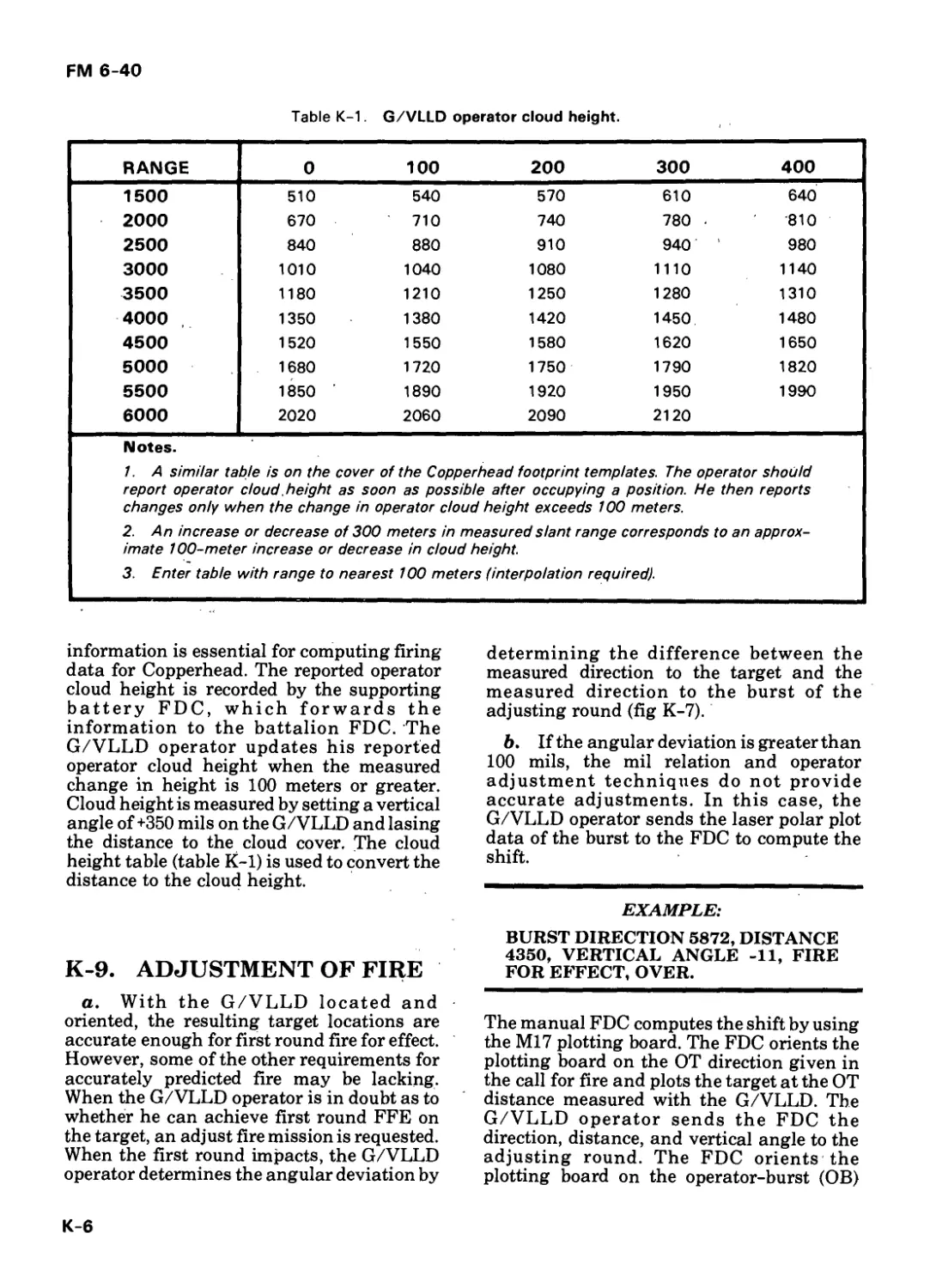
FM 6-40
*FM 6-40
Field Manual
No. 6-40
HEADQUARTERS
DEPARTMENT OF THE ARMY
Washington, DC, 7 December 1984
FIELD ARTILLERY CANNON GUNNERY
Table of Contents
PREFACE
CHAPTER 1. GUNNERY TEAM Page
1-1 Observer 1-1
1-2 Fire Direction Center 1-1
1-3 Firing Battery 1-2
1-4 Communications Links 1-2
CHAPTER 2. GUNNERY PROBLEM
2-1 Gunnery Problem Solution 2-1
2-2 Requirements for Accurate Predicted Fire 2-1
CHAPTER 3. BALLISTICS
Section I. Interior Ballistics 3-1
3-1 Description 3-1
3-2 Factors Affecting Muzzle Velocity 3-3
3-3 Muzzle Velocity Measurement 3-4
Section II. Exterior Ballistics 3-5
3-4 Description 3-5
3-5 Trajectory Elements— 3-5
3-6 Round-to-Round Variations 3-7
3-7 Dispersion Rectangles 3-7
3-8 Range Probable Error 3-8
3-9 Deflection Probable E rror — 3-9
3-10 Vertical Probable E rror 3-10
3-11 Height-of-Burst Probable Error 3-10
*This publication supersedes FM 6-40, 1 December 1978. In addition, this publication rescinds DA Form
4207, October 1978.
FM 6-40
Page
CHAPTER 4. FIRE DIRECTION CENTER OPERATIONS
4-1 BCS/Manual FDC 4-1
4-2 FADAC/Manual FDC 4-3
4-3 Manual FDC 4-5
4-4 Battalion FDC 4-6
4-5 3x8 Operations 4-7
4-6 Firing Data Checks 4-8
CHAPTER 5. SURVEYED FIRING CHARTS
Section 1. Types of Surveyed Firing
Charts. — 5-1
5-1 Description 5-1
5-2 Construction of Firing Charts . 5-2
Section II. Plotting Equipment and Preparation of Firing Charts 5-2
5-3 Chart Operation 5-2
5-4 Equipment 5-2
5-5 Point Plotting 5-5
5-6 Tick Marks 5-8
5-7 Construction of Azimuth Indexes . 5-10
5-8 Construction of Deflection Indexes . 5-12
5-9 6,400-Mil Charts 5-15
5-10 Methods Used in Plotting Targets _ 5-16
Section III. Chart Data 5-18
5-11 Chart Range and Chart Deflection . 5-18
5-12 Angle T 5-18
5-13 Subsequent Corrections . 5-19
5-14 Manual-to-Computer or Chart-to-Chart Checks . 5-19
CHAPTER 6. FIRE ORDER/FIRE COMMANDS/ MESSAGE TO OBSERVER
Section 1. Fire order . 6-1
6-1 Definition . 6-1
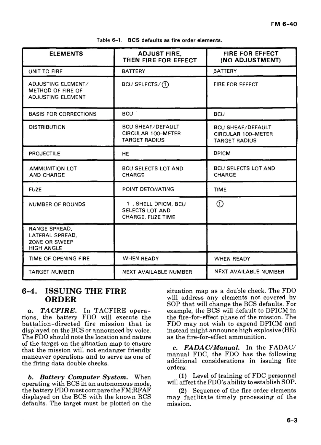
6-2 Considerations in Attacking a Target . 6-1
6-3 Fire Order Elements . 6-2
6-4 Issuing the Fire Order . 6-3
FM 6-40
Page
Section II.
Section III.
6-5 Battalion Fire Orders _ 6-4
6-6 Battery-Level Fire Orders _ 6-4
Fire Commands _ 6-6
6-7 Definition _ 6-6
6-8 Fire Command EI e m e nts _ 6-7
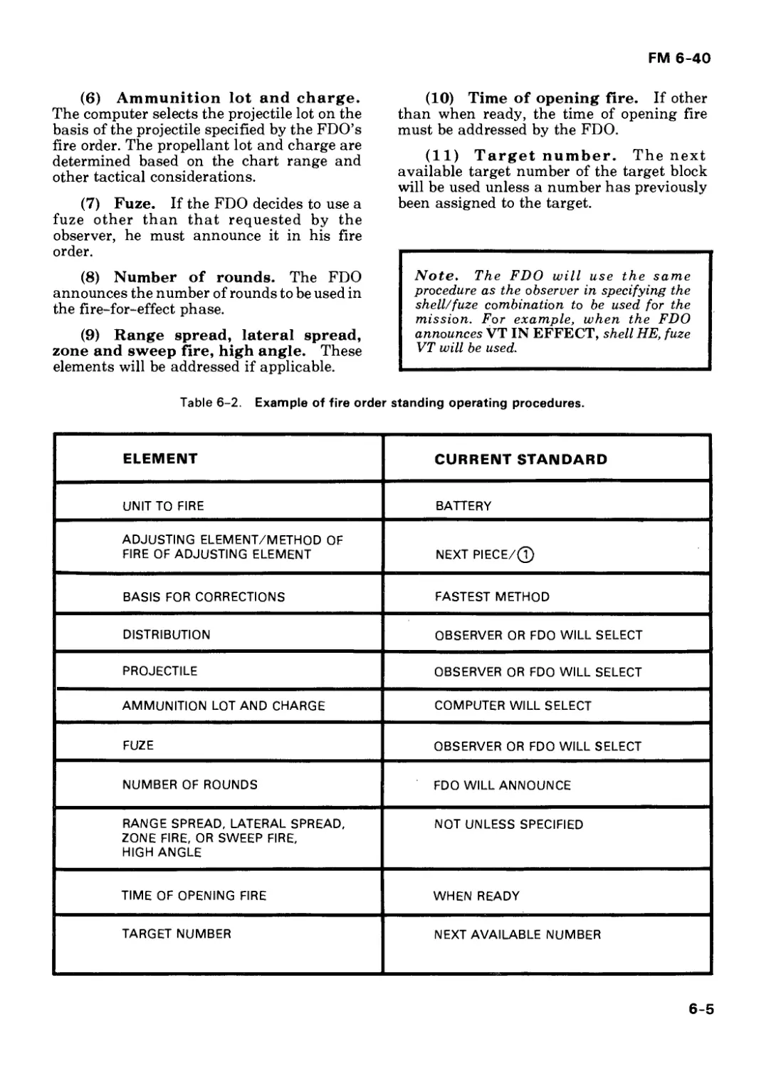
6-9 Standing Operating Procedures _ 6-8
6-10 Other Fire Commands _ 6-8
6-11 Reports _ 6-9
6-12 Repetition and Correction of Fire Commands _ 6-9
Message to Observer _ 6-9
6-13 Definition _ 6-9
6-14 Additional Information _ 6-14
CHAPTER 7. FIRING TABLES
Section 1. Graphical Firing Tables 7-1 7-1 Means of Determining Firing Data 7-1 7-2 Description and Use of the Low-Angle GFT 7-1 7-3 Construction of GFT Settings 7-3 7-4 Determination of Firing Data by Use of the GFT S ett i n g 7-4
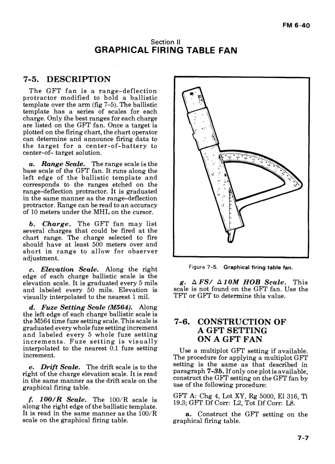
Section II. Graphical Firing Table Fan 7-7 7-5 Description 7-7 7-6 Construction of a GFT Setting on a GFT Fan 7-7 7-7 Determination of Firing Data With the GFT Fan 7-8
Section III. Tabular Firing Tables 7-8 7-8 Standards 7-8 7-9 Elements and Purpose of the TFT 7-9
Section IV. Graphical Site Tables : 7-9 7-10 Description 7-9 7-11 Determination of Vertical Interval 7-11
iii
FM 6-40
Page
7-12 Computations With the 7-11
GST
7-13 Determination of Angle of Site and Vertical Angle Without a GST 7-13
7-14 Determination of Vertical Interval Without a GST 7-13
7-15 Determination of Complementary Angle of Site Without a GST 7-13
7-16 Determination of Site Without a GST 7-14
7-17 Average Site 7-14
CHAPTER 8. REPLOT DATA
Section 1. Manual Procedures 8-2
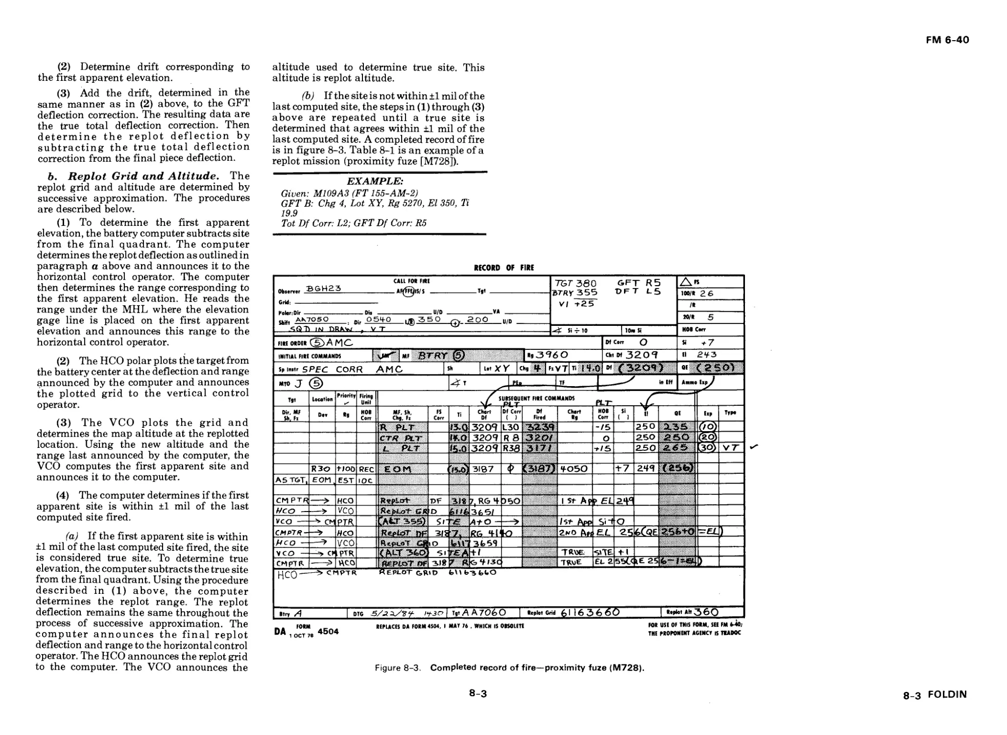
8-1 Point-Detonating and Variable Time Fuze (M728) Replot 8-2
8-2 Variable Time Fuze (M513/M514) Replot 8-5
8-3 Mechanical Time Fuze R ep lot —-— 8-6
Section II. Computer Procedures 8-8
8-4 FADAC Replot 8-8
8-5 Battery Computer System Rep lot 8-8
CHAPTER 9. FIRING DATA PROCEDURES
Section I. High-Explosive Munitions 9-3
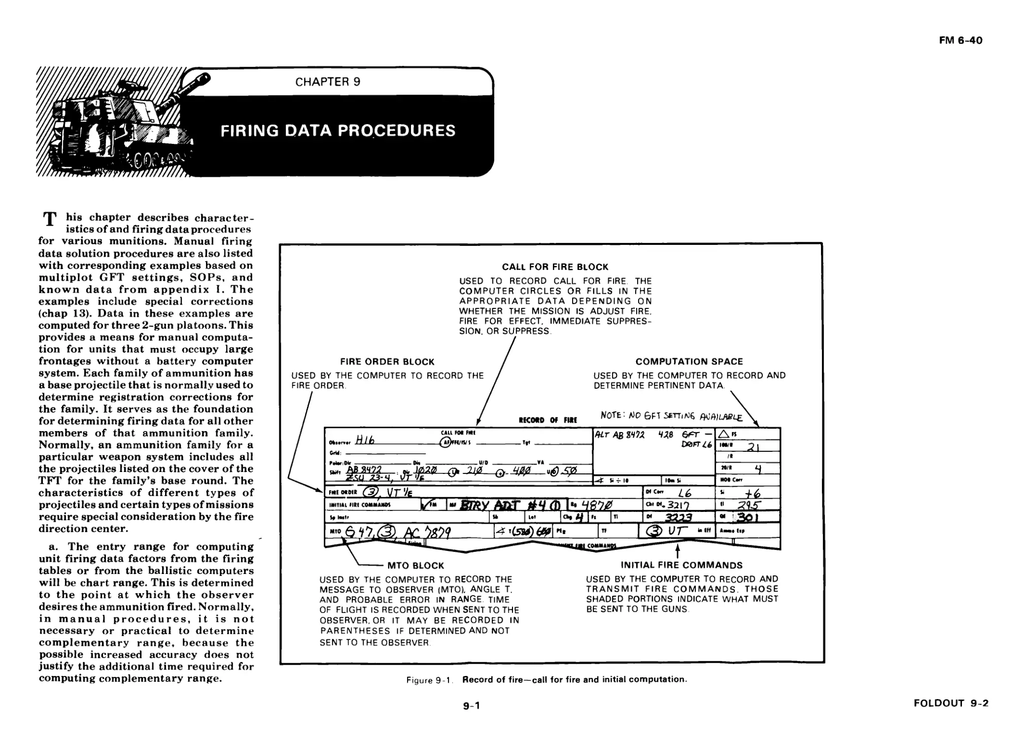
9-1 Characteristics 9-2 Computations for High- 9-3
Explosive Projectiles 9-3
9-3 Sample Mission 9-4
9-4 APICM Projectiles 9-6
9-5 Smoke Projectiles 9-6 Illuminating 9-9
Projectiles 9-7 Illuminating Projectile 9-13
Manual Procedures 9-14
Section II. Dual-Purpose Improved Conventional
M u n it io n s 9-18
9-8 Characteristics 9-18
9-9 DPICM Projectiles 9-18
iv
FM 6-40
Page
Section III.
Section IV.
9-10 9-11 DPICM Computations by Use of the GFT and TFT Computer Procedures for DPICM 9-18 9-21
9-12 FASCAM Projectiles 9-21
9-13 FASCAM Employment 9-22
9-14 FASCAM Computations 9-22
9-15 Aimpoint Selection Tables 9-24
9-16 Location of Aimpoints 9-28
9-17 Number of Projectiles per Aimpoint 9-28
9-18 Manual Data Determination 9-29
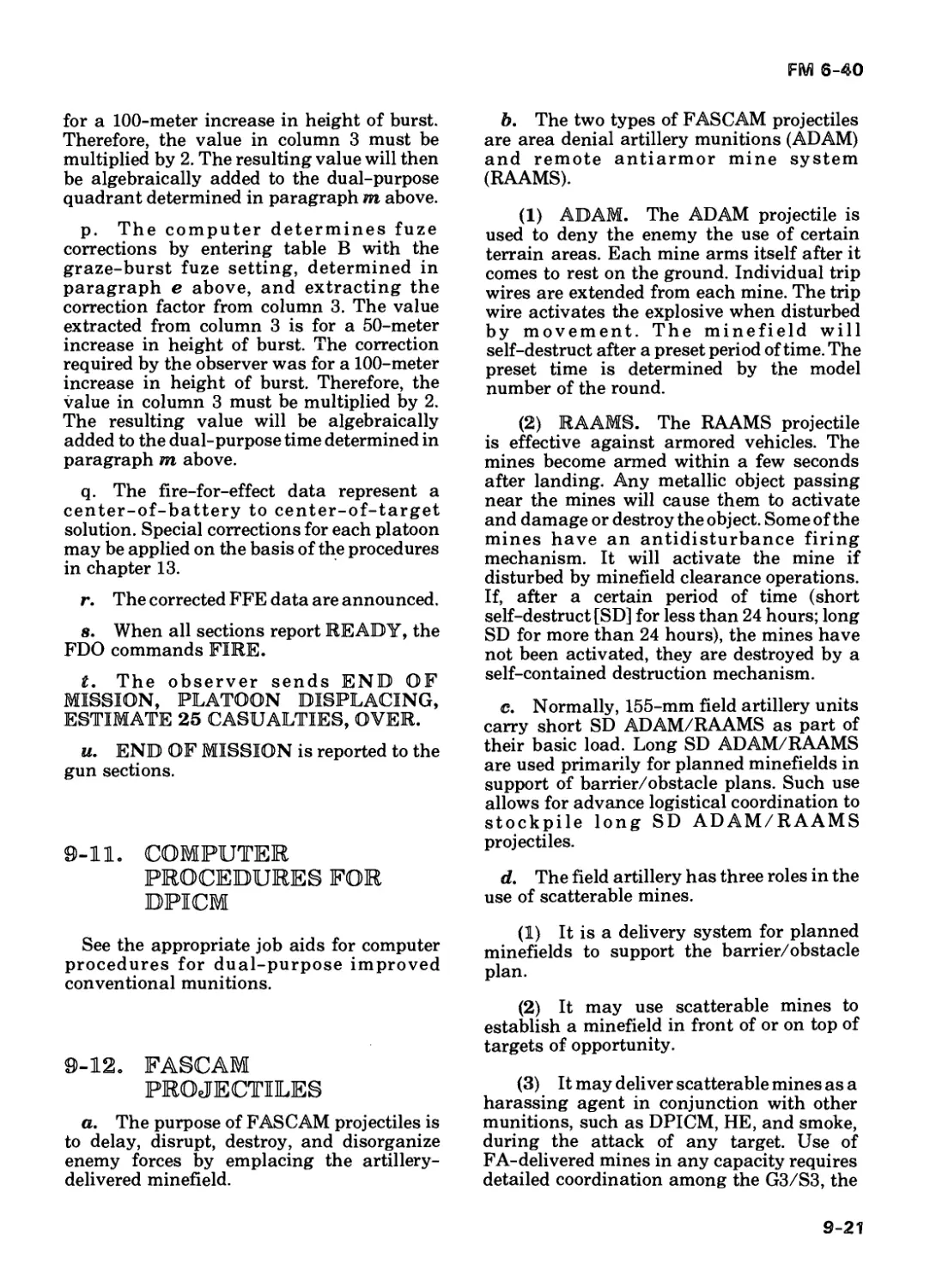
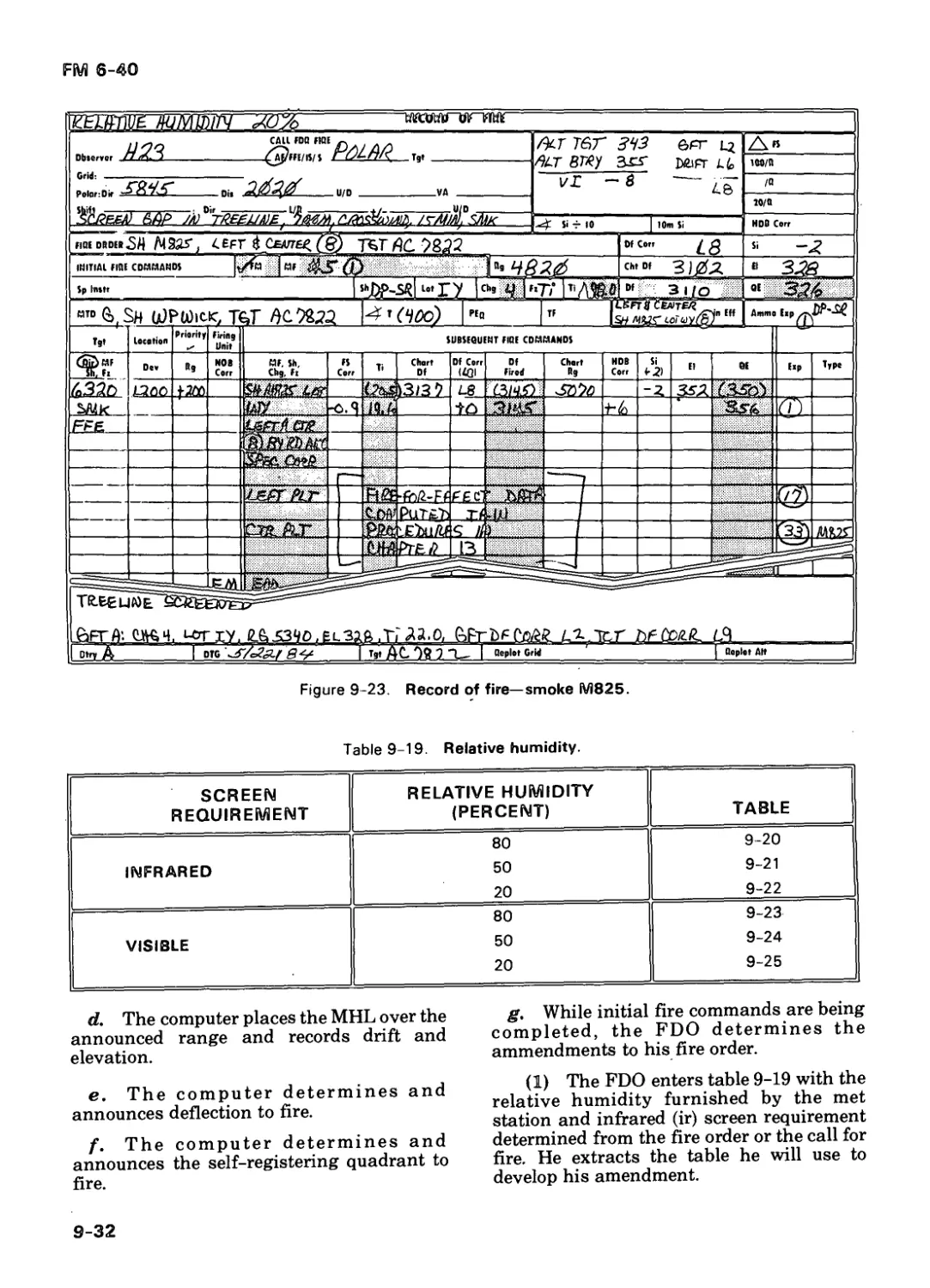
9-19 M825 Projectile 9-31
9-20 M825 Computation by Use of the GFT and TFT 9-31
Rocket-Assisted Munitions 9-35
9-21 Characteristi cs 9-35
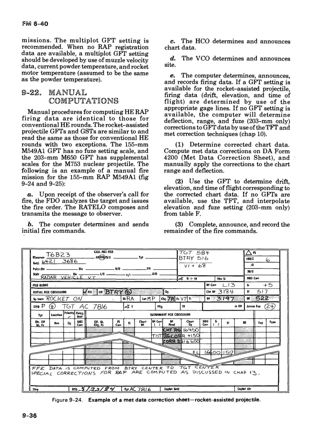
9-22 Manual Computation 9-36
9-23 Registration and Determination of the GFT Setting 9-38
Nuclear Munitions 9-38
9-24 Characteristics 9-38
9-25 M753 Delivery Techniques 9-39
9-26 Manual Data for К-Transfer Technique (M753) 9-39
9-27 Met + VE Technique 9-43
9-28 Observer Adjustment Technique 9-45
9-29 M422A1 Delivery Tec h n iq u e 9-46
9-30 M422A1 Computer Procedures 9-48
9-31 1 55-mm Howitzer Nuclear Gunnery 9-50
9-32 1 55-mm Nuclear Delivery T echniques 9-50
9-33 Manual Procedures for Shell Nuclear by Use of the GFT and TFT 9-50
9-34 Nuclear Fire Mission Processing 9-51
V
FM 6-40
Section V.
Page
Copperhead 9-52
9-35 Characteristics 9-52
9-36 Computations for Shell Copperhead 9-54
9-37 Mission Priority 9-55
9-38 Copperhead SOP 9-55
9-39 Voice Calls for Fire 9-55
9-40 Message to Observer (Autonomous) 9-56
9-41 Laser Pulse Repetition Frequency Code 9-56
9-42 Fire Order 9-56
9-43 Computation of Firing Data 9-56
9-44 Angle T and Target Cloud Height Check 9-57
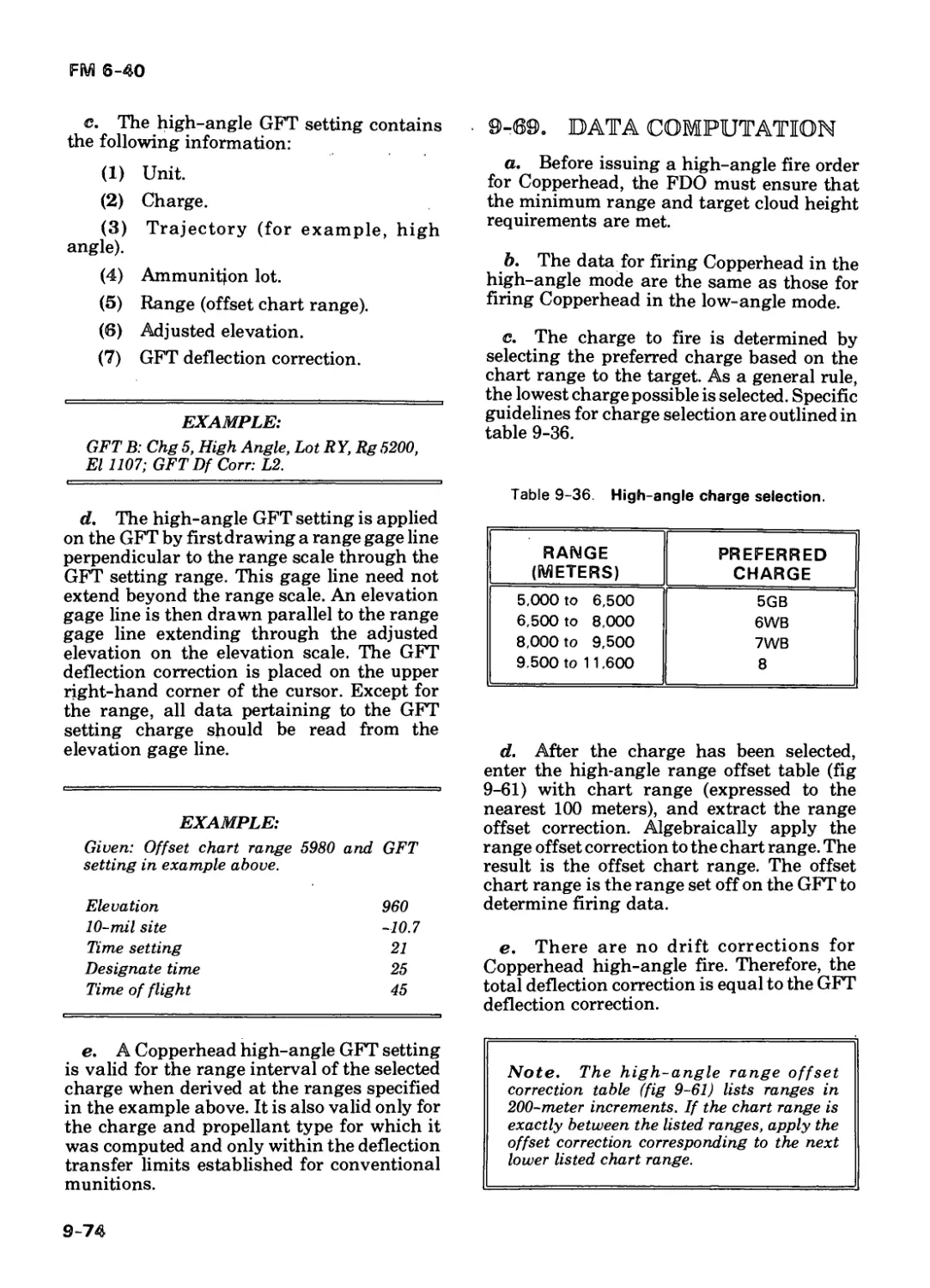
9-45 Determination of the Range Offset Correction 9-58
9-46 T rajectories 9-59
9-47 Description of M71 2 Low-Angle Ballistic GFT 9-60
9-48 Low-Angle Ballistic GFT Setting 9-60
9-49 Transfer Limits 9-62
9-50 Application of the GFT Setting 9-62
9-51 Data Read From the Low-Angle Ballistic GFT 9-63
9-52 M712 Low-Angle Glide Mode GFT 9-64
9-53 Determination of the Time S ett i n g 9-64
9-54 Determination of Elevation, Time of Flight, and Designate Time 9-65
9-55 Glide Mode Transfer Limits 9-65
9-56 Glide Mode GFT Setting 9-65
9-57 Switch Setting 9-67
9-58 Computation of Site 9-67
9-59 Computation of Deflection Correction 9-68
9-60 Computation of FADAC Data 9-68
9-61 Limits of the Battery Center Solution 9-68
9-62 Target Attack Contingencies 9-68
vi
FM 6-40
Page 9-68
9-63 Record of Fire
9-64 Fire Commands 9-70
9-65 Engagement Commands 9-71
9-66 High-Angle Fire 9-71
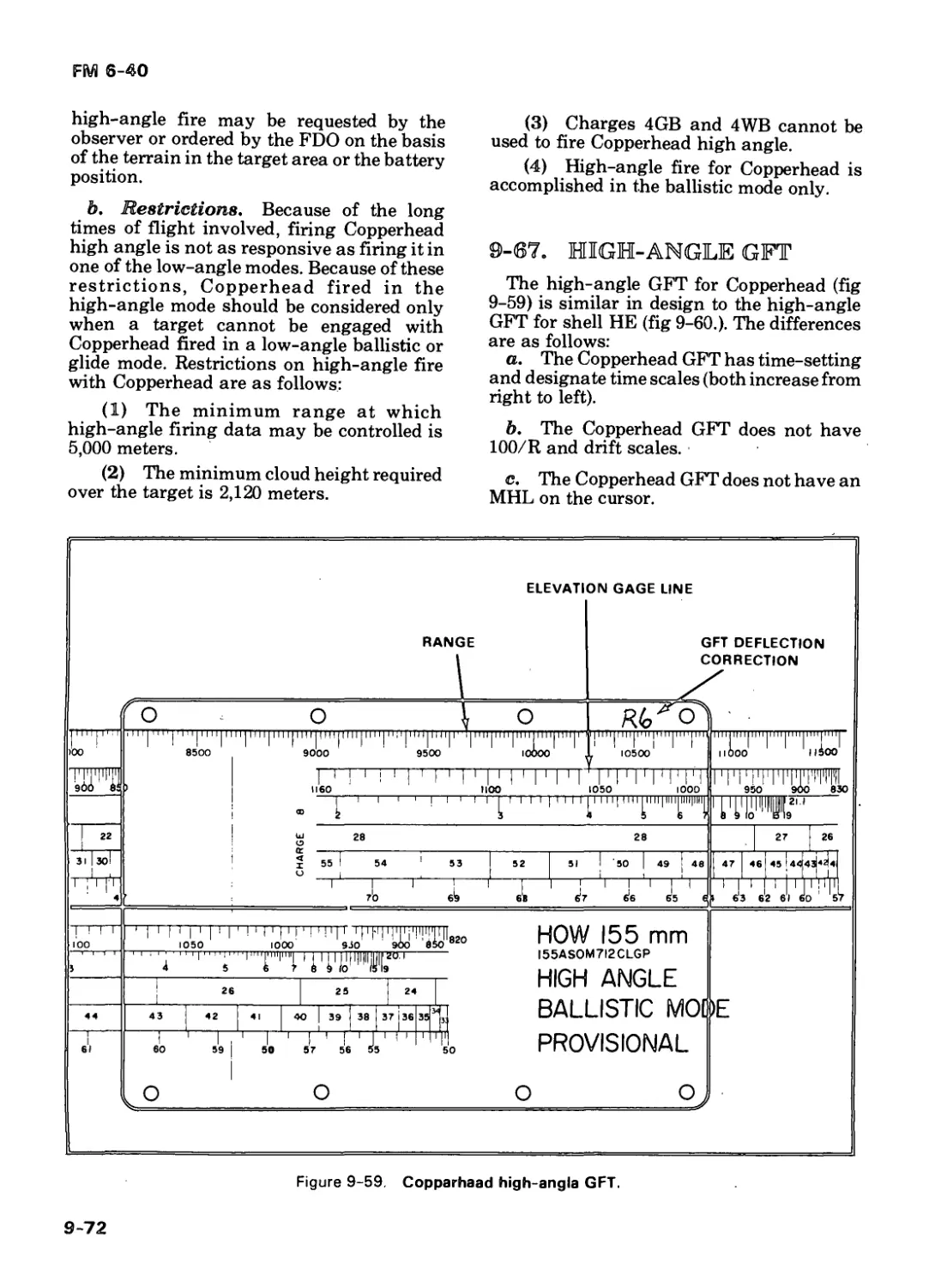
9-67 High-Angle GFT 9-72
9-68 High-Angle GFT Settings 9-73
9-69 Data Computation 9-70 Example of a High-Angle 9-74
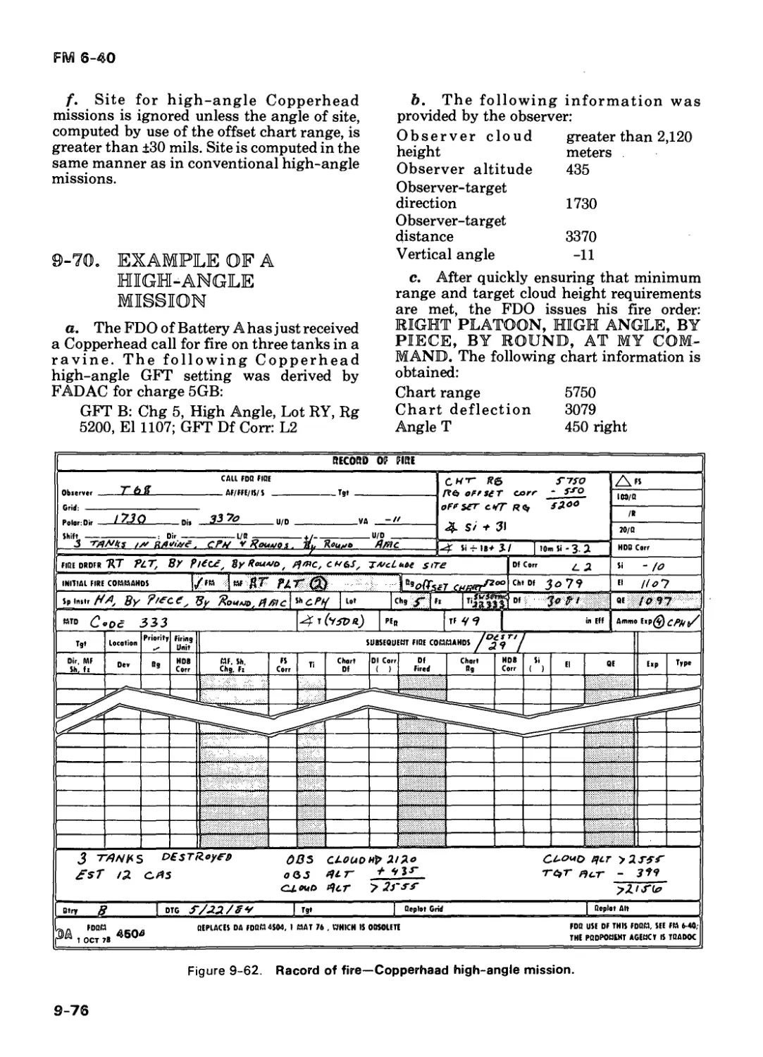
Mission 9-76
CHAPTER 10. METEOROLOGICAL CORRECTIONS AND VELOCITY ERROR
Section I. Purpose and Use of Met Messages 10-1
10-1 Nonstandard Conditions 10-1
10-2 Concurrent Met 10-2
10-3 Subsequent Met 10-2
10-4 Velocity Error 10-3
Section II. Met Messages 10-3
10-5 Characteristics , 10-3
10-6 Ballistic Met Message 10-3
10-7 Computer Met Message 10-6
10-8 Met Message Errors 10-9 Met Message Space and 10-8
and Time Validity 10-9
Section III. Concurrent Met 10-10
10-10 Characteristics 10-11 Sequence for Solution of a 10-10
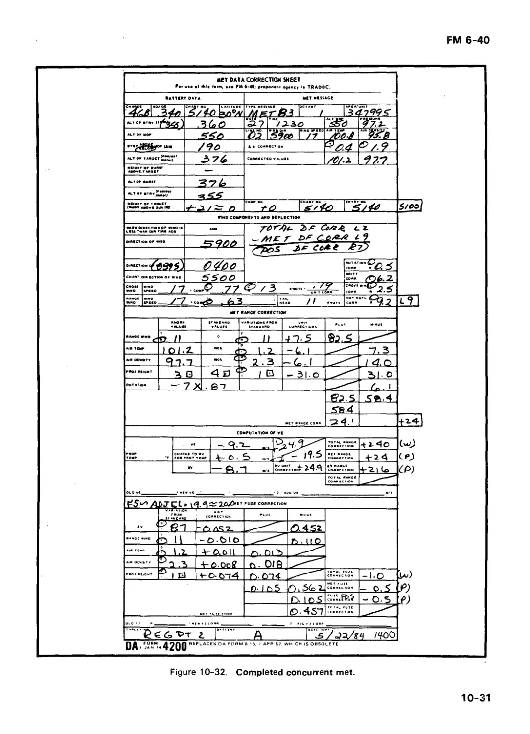
a Concurrent Met 10-12 Solution of a Concurrent 10-10
Met 10-11
10-13 Position Constants 10-30
Section IV. Subsequent Met 10-32
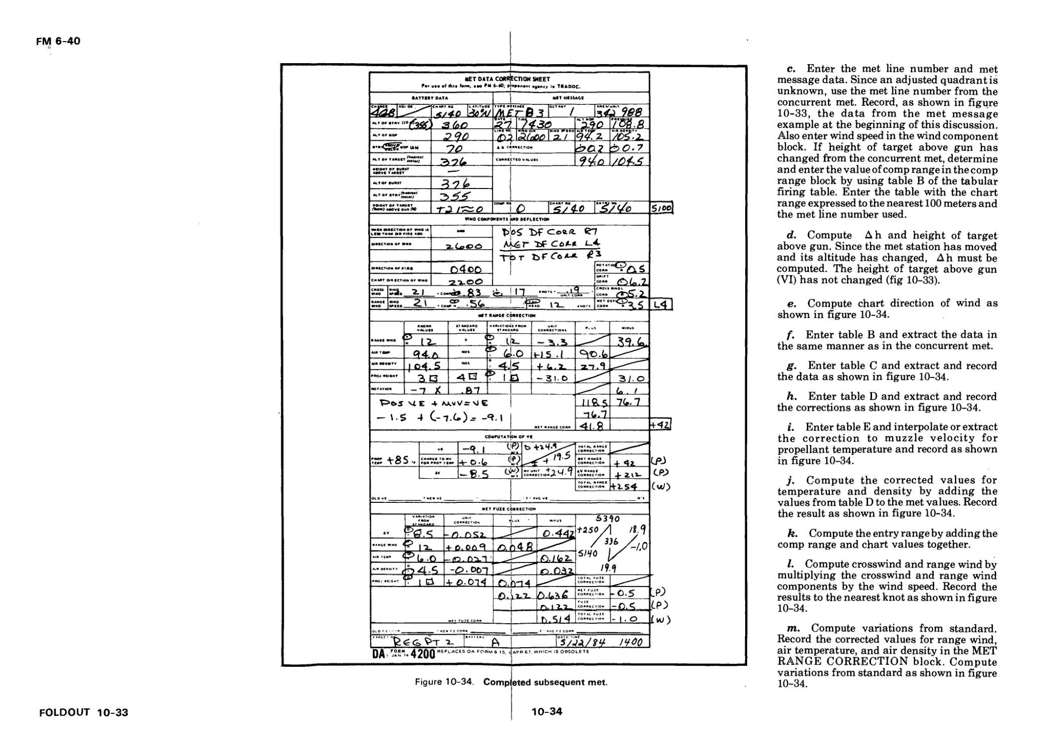
10-14 Characteristics 10-15 Sequence for Solution of 10-32
a Subsequent Met 10-16 Solution of a Subsequent 10-32
Met . 10-33
Section V. Subsequent Met Applications 10-35
10-17 Eight-Direction Met 10-18 Met to a Met Check 10-35
Gage Point 10-38
10-1 9 Met to a Target 10-38
vii
FM 6-40
Page
Section VI. Met Plus Velocity Error 10-42 10-42
10-20 Application of Velocity E rror
10-21 Manual Computation of a GFT Setting for an Unregistered C ha rge 10-42
CHAPTER 11. MUZZLE VELOCITY MANAGEMENT
11-1 Definitions 11-1
11-2 Calibration 11-2
11-3 Determination of Muzzle Velocity for Subsequent Lots— 11-6
CHAPTER 12. REGISTRATIONS AND APPLICATION OF REGISTRATION CORRECTIONS
Section I. Characteristics 12-1
12-1 Types of Registrations 12-1
12-2 Assurance Tables 12-2
12-3 When to Conduct Registrations 12-3
Section II. Precision Registrations 12-4
12-4 Definition and Objective 12-4
12-5 Initiation 12-4
12-6 Impact Portion of the Registration — 12-4
12-7 Registering Piece Displacement 12-6
12-8 Time Portion of the Registration 12-6
12-9 Multilot Precision Registrations 12-8
12-10 Abbreviated Registration With the G/VLLD 12-8
12-11 Determination of a GFT GFT Setting From a Registration 12-8
12-12 Met + VE With a Check Round 12-10
Section III. HB/MPI Registrations 12-10
12-13 0 bj ect i ve 12-10
12-14 Selecting an Orienting Poi nt 12-11
12-15 Orienting the 0 bs e rve rs 12-12
viii
FM 6-40
Page
12-16 Determining Firing 12-13
Data
12-17 Firing the HB/MPI Registration 12-14
12-18 Determining the Mean Burst Locat io n 12-15
12-19 Determining Chart Data 12-19
12-20 Determining Adjusted Data 12-19
Section IV. Radar Registrations 12-35
12-21 Employment 12-21
12-22 Advantages 12-22
12-23 Conducting a Radar Registration 12-22
12-24 Selecting an Orienting Po i nt 12-22
12-25 Radar Message to 0 bs e rve r 12-24
12-26 Determining Firing Data 12-24
12-27 Firing the HB/MPI Registration 12-26
12-28 Determining the Mean Burst Location 12-28
12-29 Determining Chart Data and Registration Corrections 12-27
Section V. Registration Corrections 12-27
12-30 Description 12-27
12-31 Computation of Total Range Correction 12-27
12-32 Computation of Total Fuze Correction 12-28
12-33 Computation of Total Deflection Correction 12-28
12-34 Registration Transfer Limits 12-29
CHAPTER 13. SPECIAL CORRECTIONS AND
SPECIAL SITUATIONS
Section I. Basic Correction Data 13-1
13-1 Piece Displacement 13-1
13-2 Estimation/Pacing 13-2
13-3 Hasty Traverse 13-2
13-4 S u rvey 13-2
13-5 Ballistic Computers 13-2
ix
FM 6-40
Реде
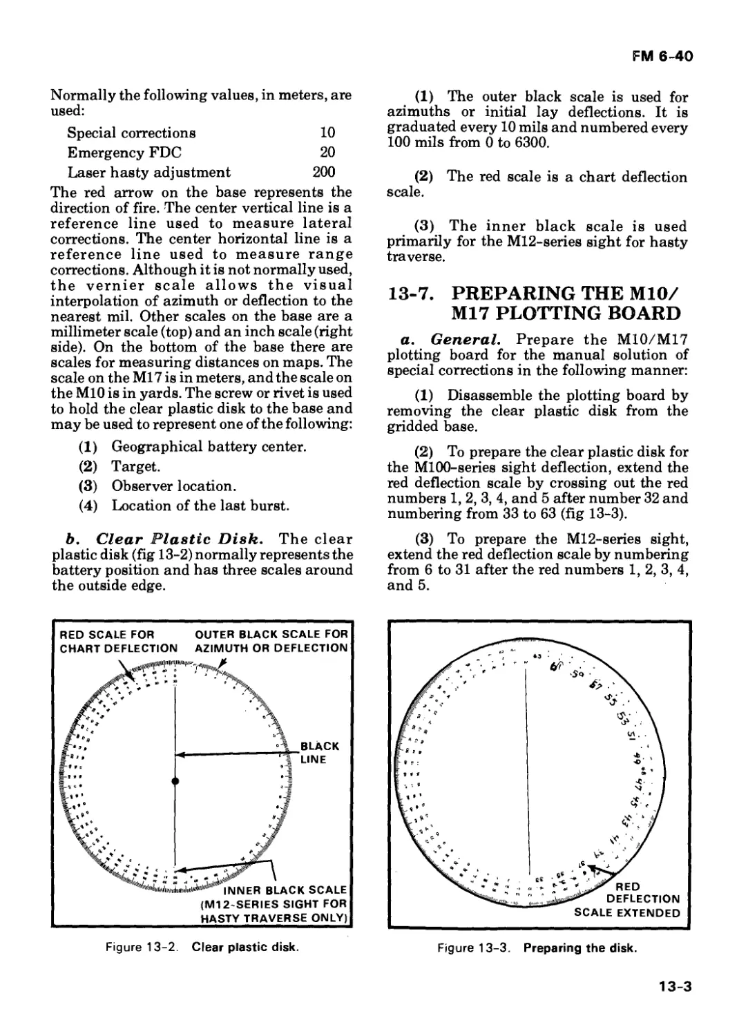
13-6 13-7 Description of the M10/M17 Plotting Board Preparing the М10/M1 7 Plotting Board 13-2 13-3
Section II. Position Corrections 13-11
13-8 Types of Position
Corrections 13-11
13-9 Registration/Special
Correction Work Sheet 13-12
13-10 Registration Portion 13-12
13-11 Hasty Correction Portion 13-14
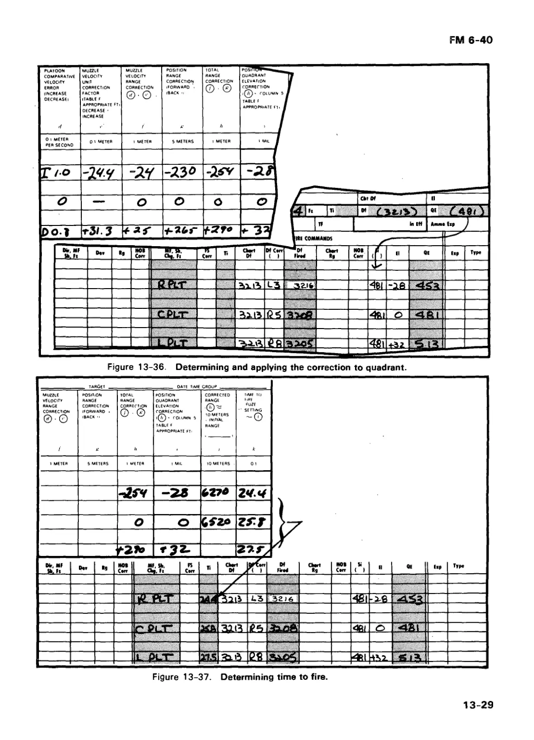
13-12 Special Correction Portion 13-15
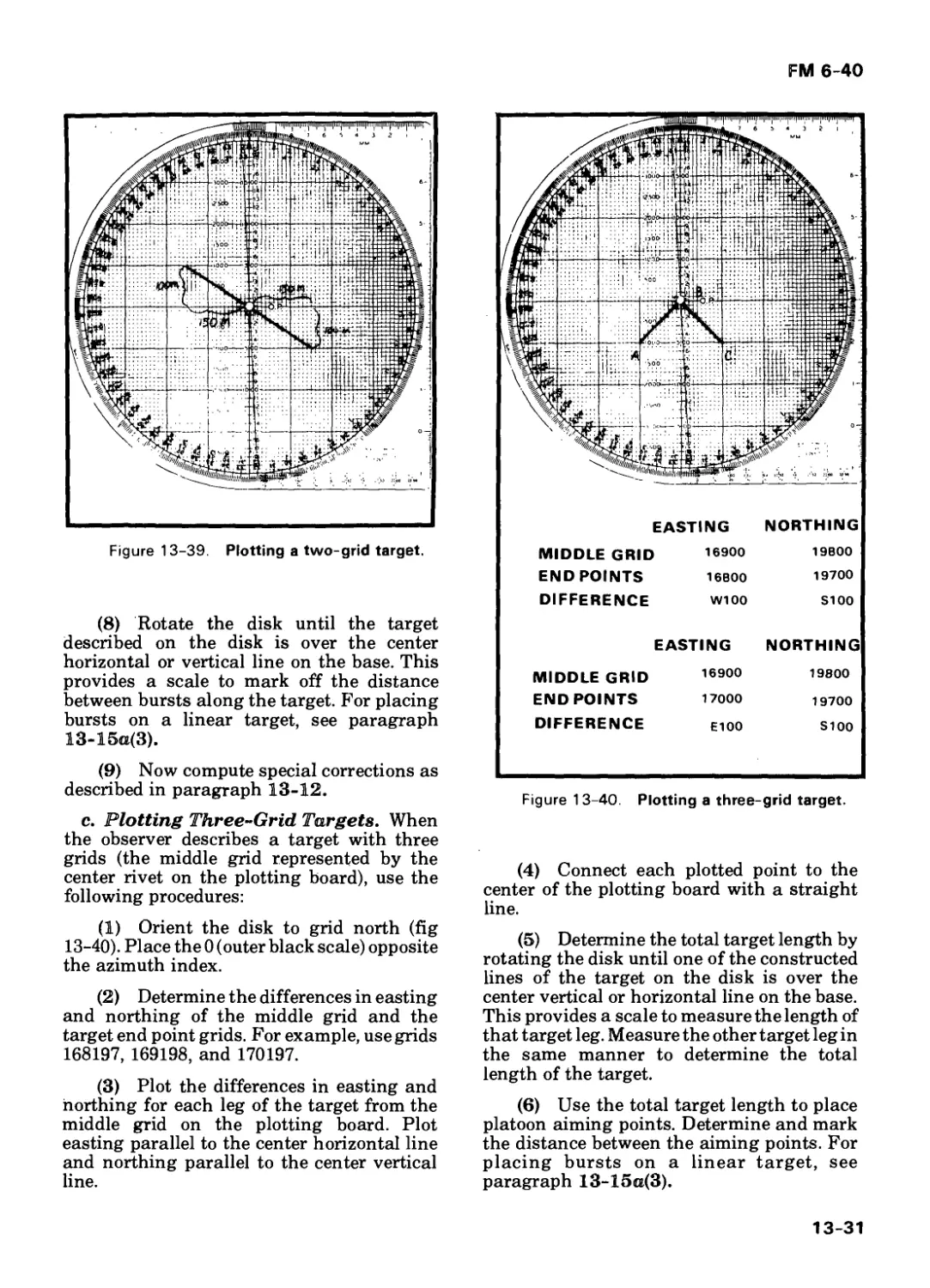
13-13 Parallel Sheaf 13-16
13-14 Converged Sheaf 13-16
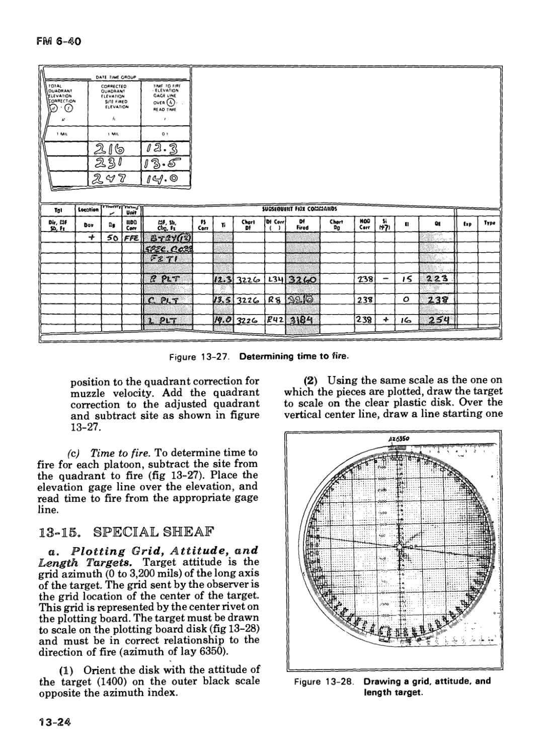
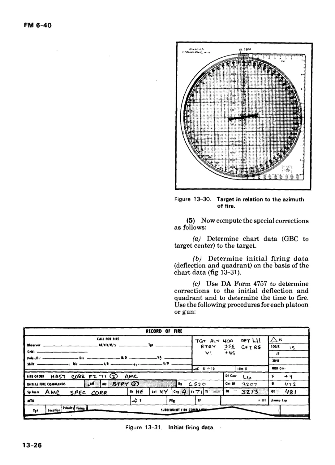
13-15 Special Sheaf 13-24
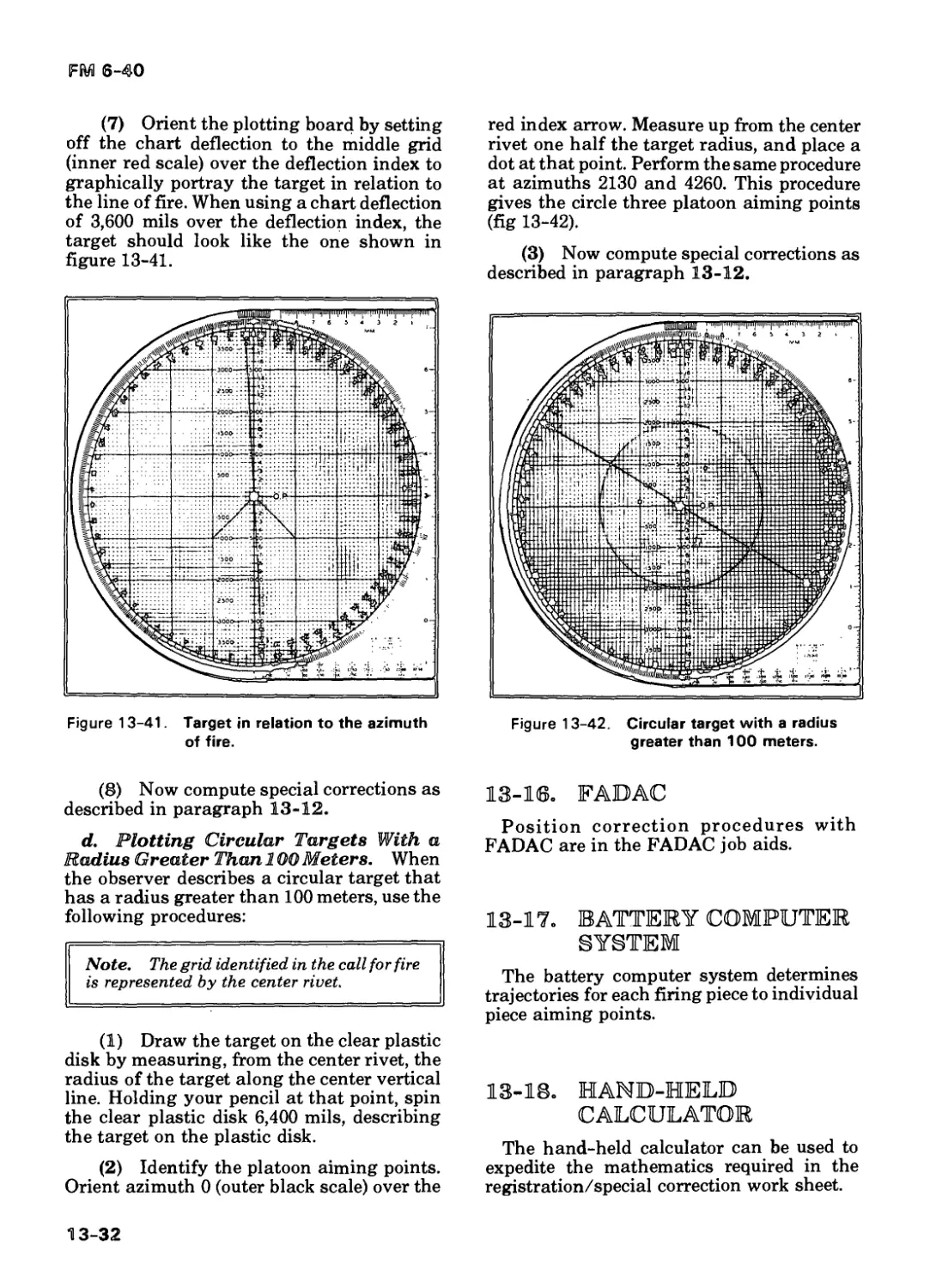
13-16 FAD AC 13-32
13-17 Battery Computer System 13-32
13-18 Hand-Held Calculator 13-32
Section III. Attack of Large Targets 13-33
13-19 Methods of Attack 13-33
13-20 Target Division Method 13-33
13-21 Massed Fire Distribution
Template Method 13-35
13-22 Sweep and Zone Fires 13-35
Section IV. Final Protective Fire 13-38
13-23 Description 13-38
13-24 Manual Computation of Data
With the GFT or TFT 13-39
Section V. 0 bservers 13-39
13-25 Air Observer Considerations 13-39
13-26 Observer Directions/
Spotting Lines 13-40
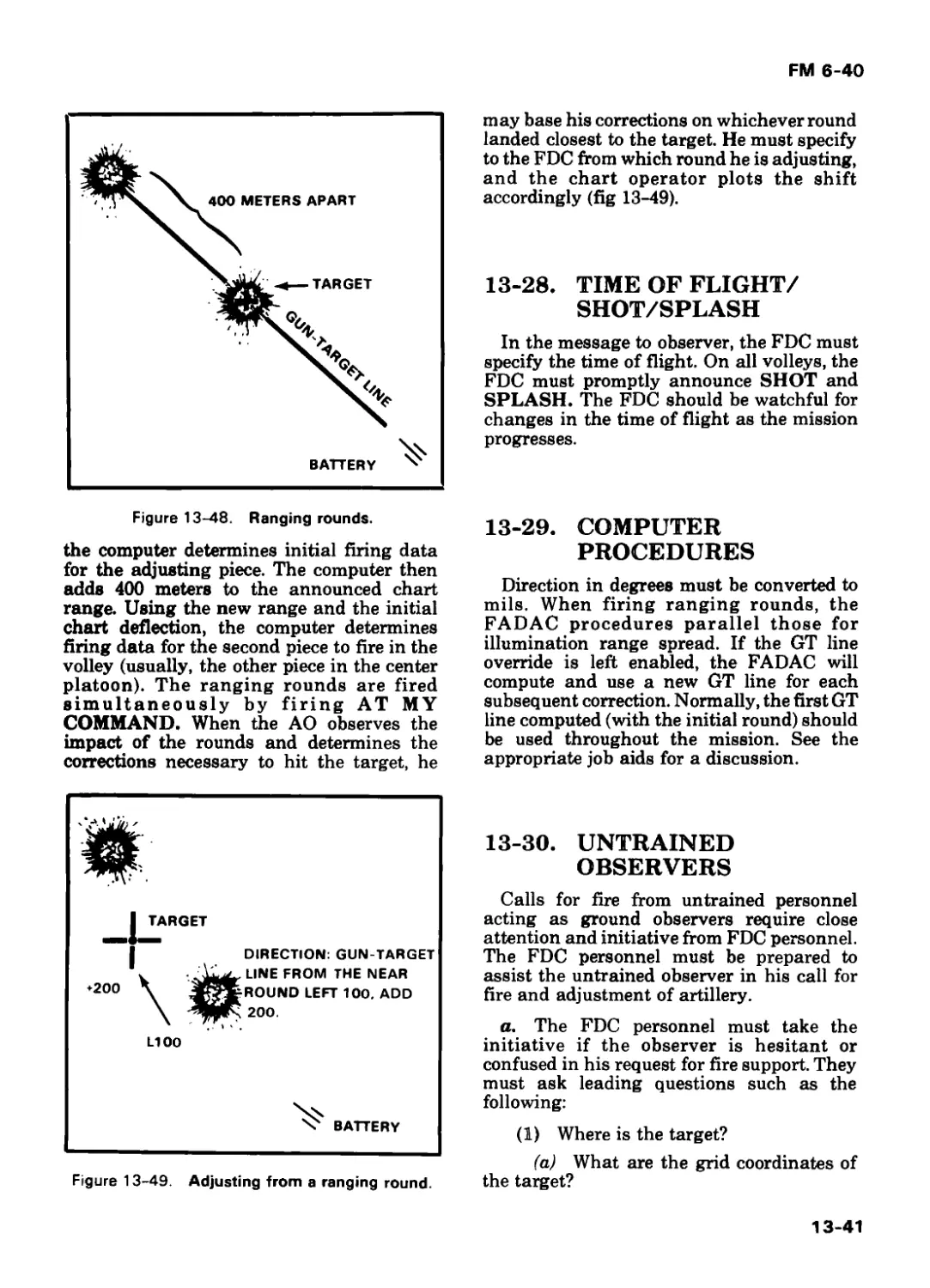
13-27 Ranging Rounds 13-40
13-28 Time of Flight/
S hot/S plash 13-41
13-29 Computer Procedures 13-41
13-30 Untrained Observers 13-41
Section VI. Zone-to-Zone Transformation 13-42
13-31 Description 13-42
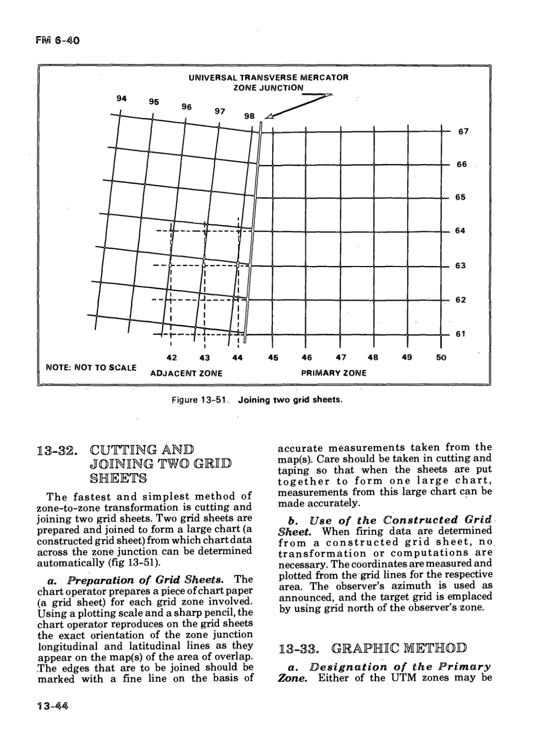
13-32 Cutting and Joining Two
Grid Sheets 13-44
X
FM 6-40
Page
13-33 Graphic Method 13-44
13-34 Computer Procedures 13-47
Section VII. High-Angle Fire 13-47
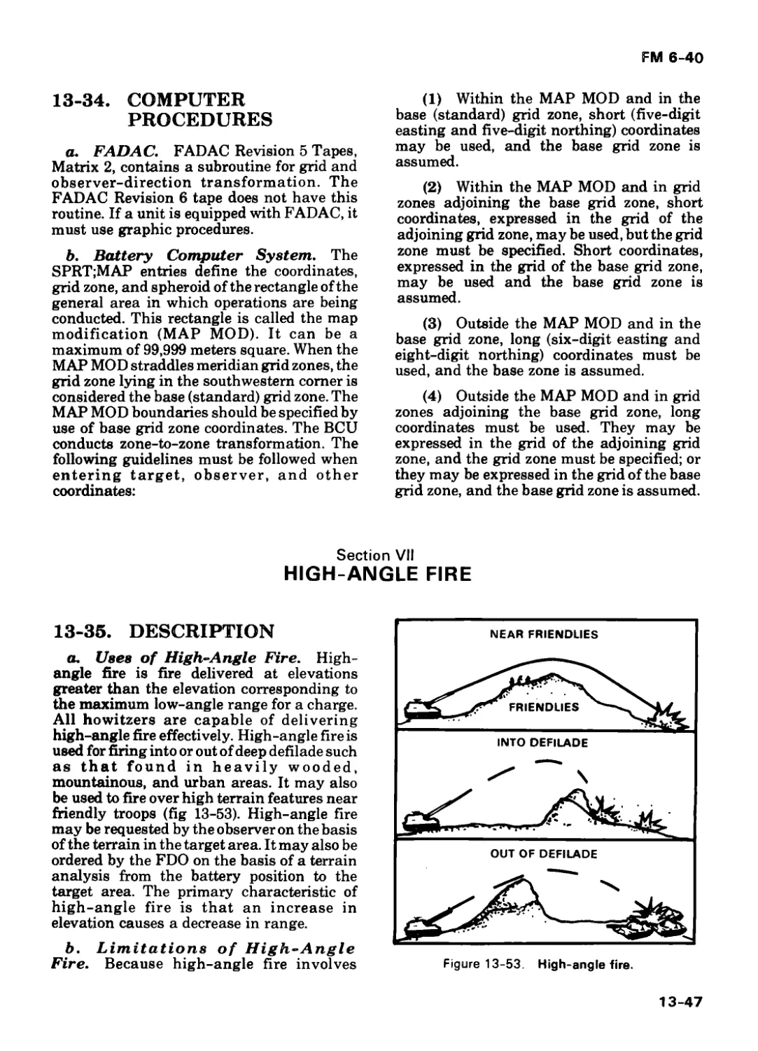
13-35 Description 13-47
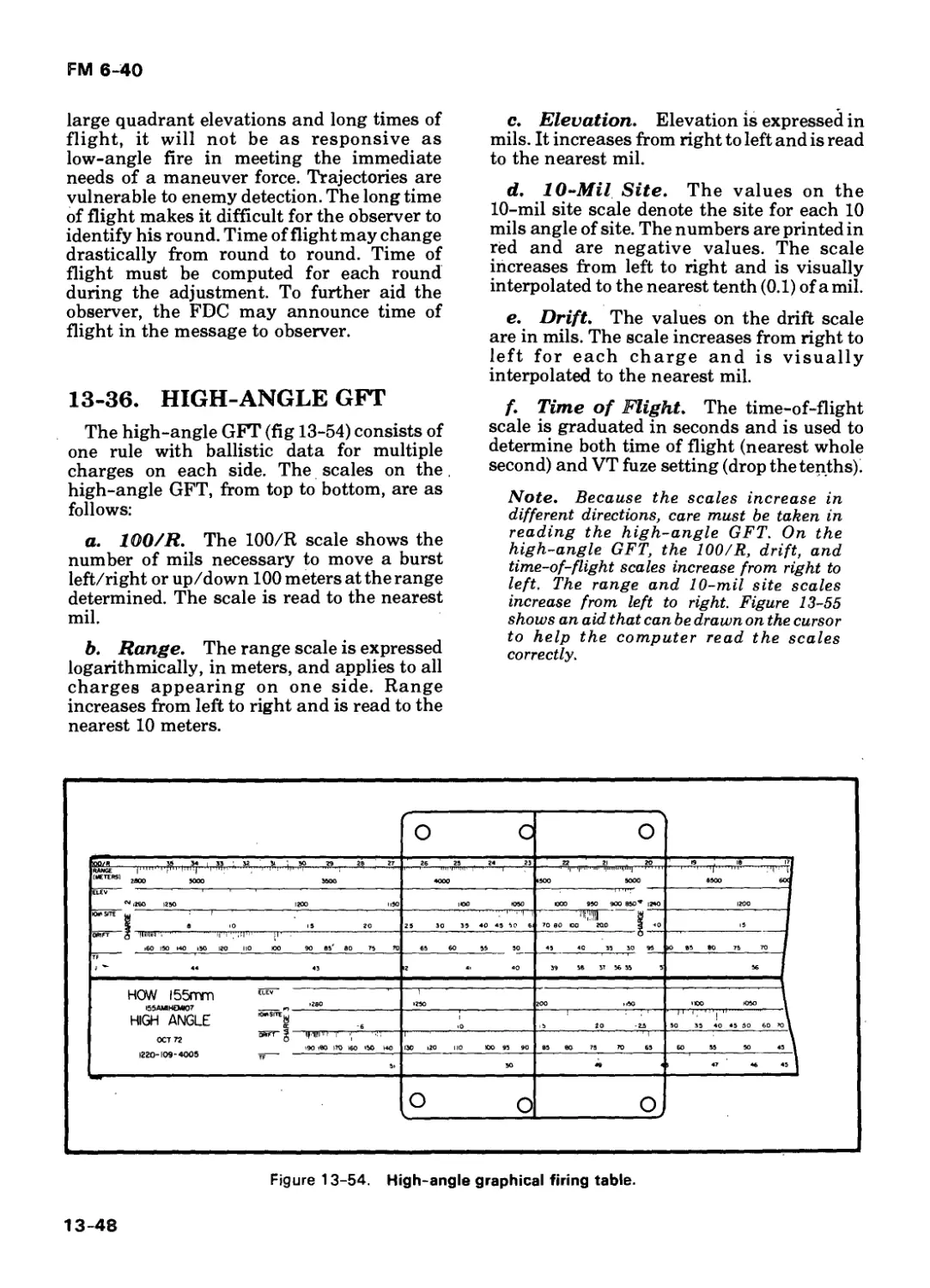
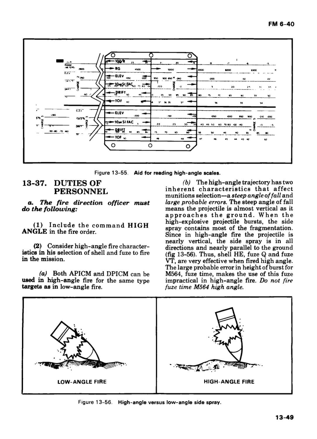
13-36 High-Angle GFT 13-48
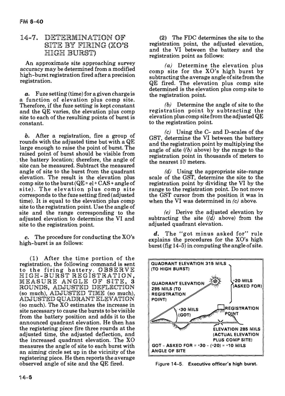
13-37 Duties of Personnel 13-49
13-38 HE High-Angle Missions 13-39 DPICM High-Angle 13-50
Registration 13-56
13-40 Computer Procedures 13-57
CHAPTER 14. EMERGENCY PROCEDURES/ OBSERVED FIRING CHARTS
Section I. Observed Firing Charts 14-1
14-1 Emergency Firing Charts 14-2 Construction of an Emergency Observed 14-1
Firing Chart 14-3 Battery Observed 14-2
Firing Charts 14-4 Determination of Direction for 14-4
Polar Plotting 14-5 Determination of Range and Altitude—Impact 14-4
Registration 14-6 Determination of Range and Altitude—Time Registration, 14-5
Site Unknown 14-7 Determination of Site by 14-5
Firing (XO's High Burst) 14-6
14-8 GFT Settings 14-9 Observed Firing Chart With 14-7
Incomplete Survey 14-10 Construction of Observed Firing Chart—Position Area Survey 14-7
Only 14-7
Section II. Use of the M10/M17 Plotting
Board 14-7
14-11 Determination of Map Data 14-12 Conversion of Map Data 14-7
Into Fire Commands 14-13 Determination of Data for 14-8
Subsequent Rounds 14-8
Section III. Map-Spot Surveyed Firing
Chart 14-9
xi
FM 6-40
Page
14-14 Determination of Surveyed
Location and Azimuth of Lay 14-9
14-15 Map-Spot Technique 14-10
14-16 Construction of a Map-Spot Surveyed Firing Chart
(Manual) 14-10
14-17 Transfer From Map-Spot to
Surveyed Firing Chart 14-10
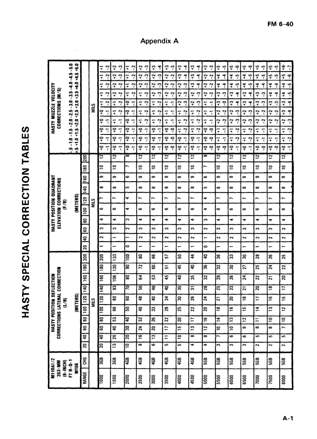
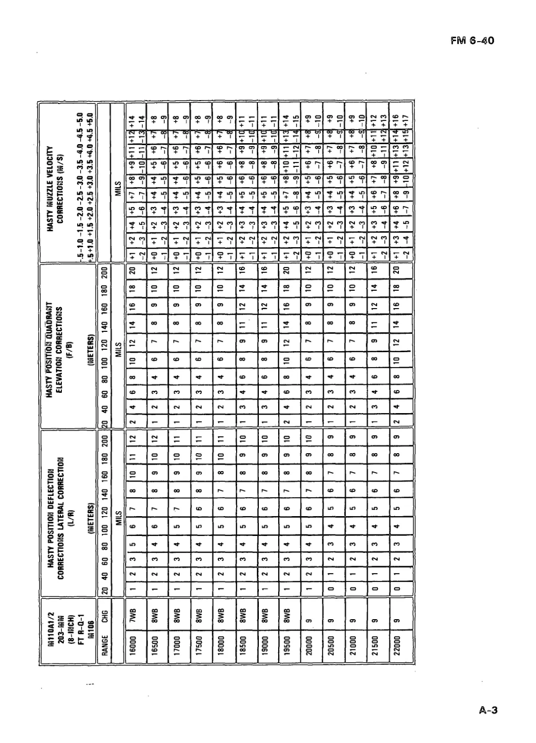
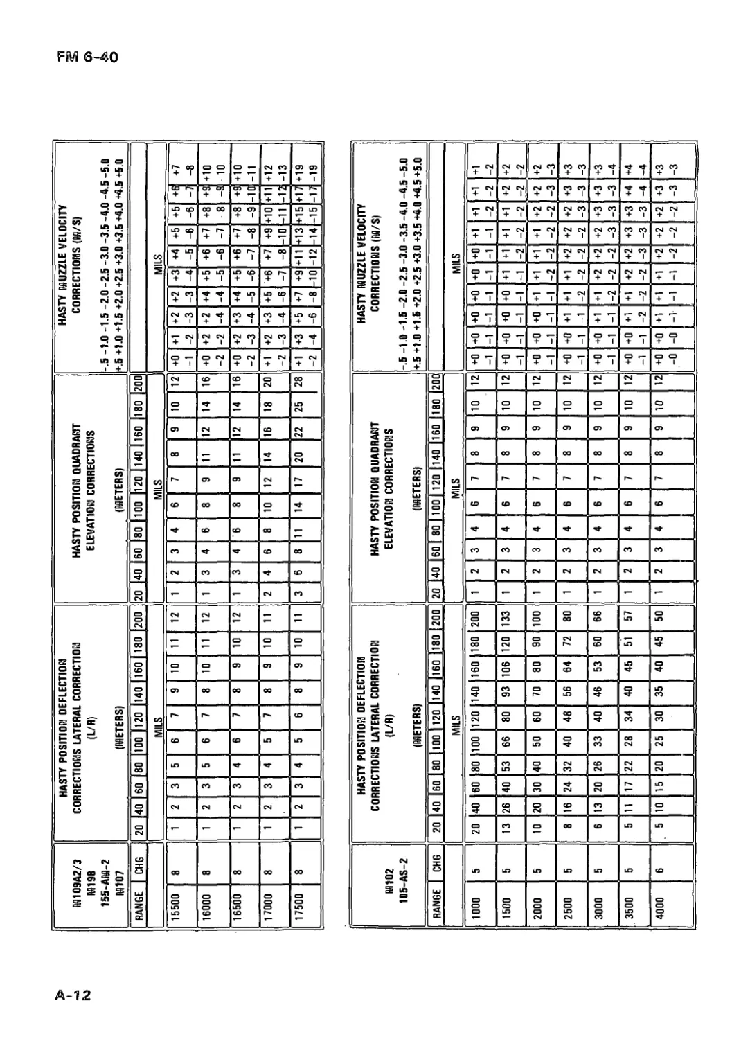
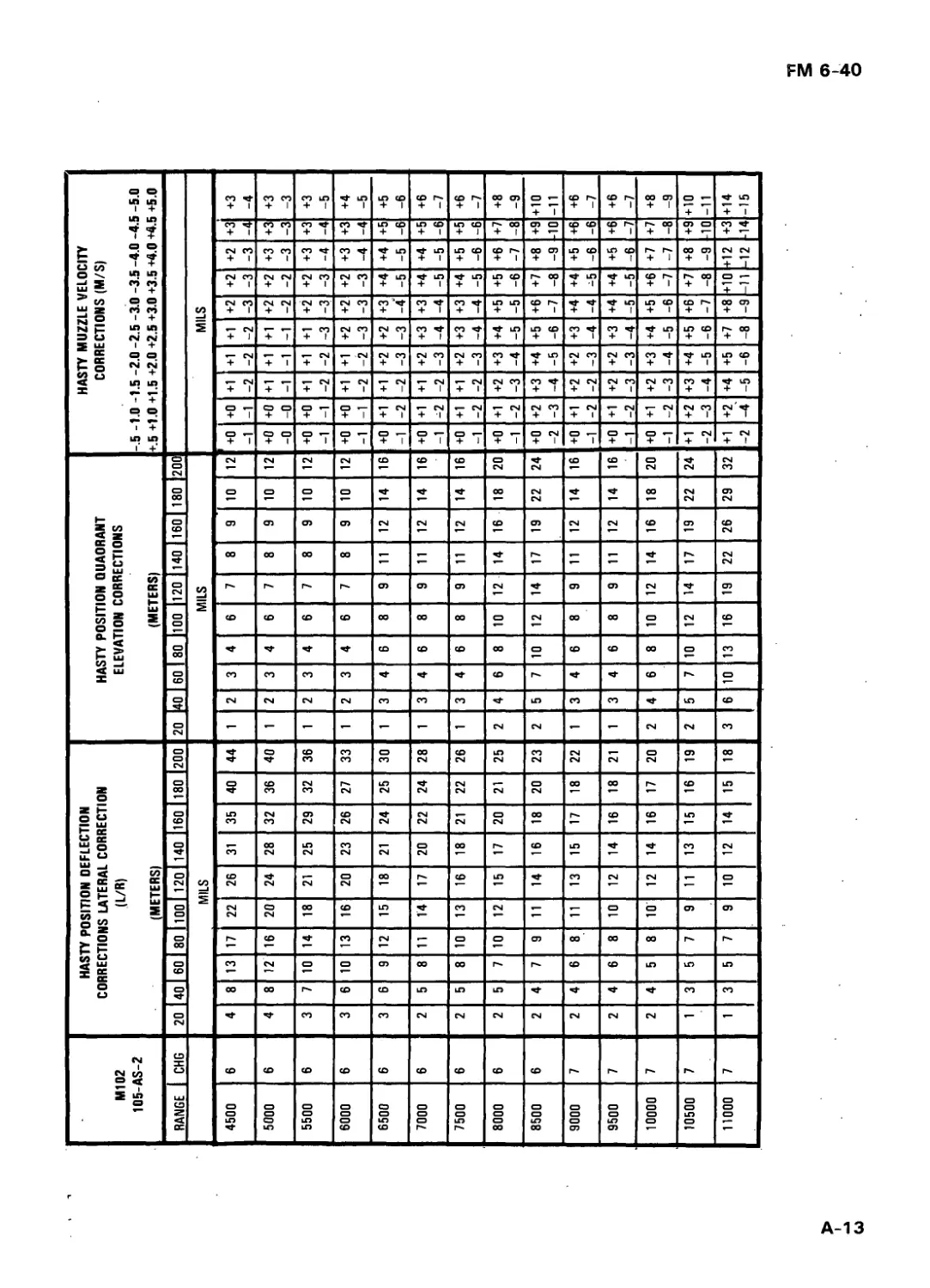
APPENDIXES A. HASTY SPECIAL CORRECTION TABLES A-1
B. INTERCHANGEABILITY OF AMMUNITION B-1
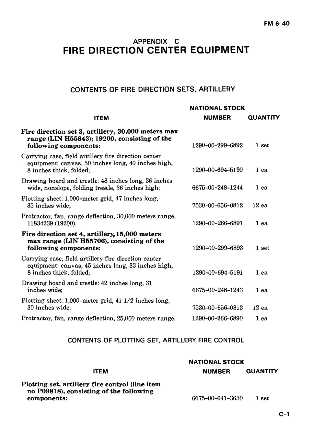
C. FIRE DIRECTION CENTER EQU 1 PM E NT C-1
D. EMPLOYMENT OF ARMOR IN INDIRECT FIRE D-1
E. INTERNATIONAL STANDARDIZATION AG R E E M E NTS E-1
F. STANDARDIZED PROCEDURES F-1
G. HOW TO TRAIN FIRE DIRECTION CENTER PERSONNEL G-1
H. TARGET ANALYSIS AND MUNITIONS EFFECTS H-1
1. SAMPLE PROBLEM KNOWN DATA 1-1
J. NEW DEPARTMENT OF THE ARMY FORMS J-1
K. GUNNERY TEAM PROCEDURES USING THE GROUND/VEHICULAR LASER LOCATOR DESIGNATOR K-1
GLOSSARY GLOSSARY-1
REFERENCES REFERENCES-1
INDEX INDEX-1
xii
FM 6-40
Preface
FM 6-40 provides an explanation of equipment and munitions and their
associated fire direction procedures for the field artillery (FA) cannon
systems. This publication serves as the basis for operational procedures for
technical fire direction and as a guide for unit training. It has been
developed with the five basic rules of combat applied: move, shoot,
communicate, secure, and sustain.
The target audience of this publication includes trainers and supervisors
of cannon fire direction centers, battalion/brigade operations sections, and
others who need an understanding of technical cannon fire direction.
Certain chapters are the “how to” references for 13E soldier’s manual tasks.
Users must be familiar with and use FM 6-20, FM 6-20-1, FM 6-30, FM 6-50,
and FM 6-141-1/2.
It is envisioned that this will be the final edition of FM 6-40. Changes to
this edition will be published as new equipment, ammunition, or procedures
are developed. A training circular (TC 6-1-2) and a job aids have been
published for the battery computer system (BCS). The backup computer
system (BUCS) program will be fielded in 1985. When this program is
completed and a decision on the hardware is made, a BUCS job aids will be
published. A new FM containing BCS and BUCS fire direction procedures
will be published and fielded in FY 86.
Field artillery doctrine concerning firing unit survivability requires
technical procedures that allow the unit to occupy large areas of terrain in
the best possible way. Occupation of a position greater than 250 meters by
150 meters requires special corrections to firing data.
a. The battery computer system automatically applies special aiming
points and sheafs for all weapons in the unit.
b. The field artillery digital automatic computer (FADAC) or manual
fire direction procedures require the application of special corrections to
firing data. Two methods may be used.
(1) Mass fires of the platoons (pit) onto the target. This procedure
requires plotting the platoon location on the firing charts and computing
separate sets of firing data for each platoon (or using FADAC mass fire for
the separate platoon centers).
(2) Use special corrections to battery (btry) center data for each
platoon. These corrections normally are done by using hasty corrections
from tables discussed in chapter 13 and included in appendix A. If time
permits, individual piece corrections may also be computed manually (chap
13).
c. When firing data are being computed manually, the unit commander
should consider positioning one weapon at the geographical battery center.
xiii
FM 6-40
This is not a requirement; however, manually computed fires will be more
accurate if the adjusting piece is located at the point used as the battery (or
platoon) center. In all cases, common sense and the tactical situation dictate
the emplacement of weapons and the selection of technical firing data
techniques.
The order of technical data computation is BCS, tactical fire direction
system (TACFIRE) modification solution, BUCS, manual, and hand-held
calculator (HHC). For further discussion, refer to chapter 4.
Included in this publication are guidelines for the interchangeabilty of
ammunition (app B), a listing of fire direction center equipment (app C), and
a discussion on employing armor in the role of indirect fire (app D).
Users of this publication are encouraged to submit recommended changes
or comments to improve the publication. Comments should be keyed to a
specific page, paragraph, or line of text in which the change is
recommended. Reasons should be included for each comment to ensure
understanding and complete evaluation. Changes and comments should be
prepared on DA Form 2028 (Recommended Changes to Publications and
Blank Forms) and forwarded directly to:
Commandant
US Army Field Artillery School
ATTN: ATSF-GA
Fort Sill, OK 73503
The provisions of this publication are the subject of standardization
agreement (STANAG)/quadripartite standardization agreement (QSTAG)
4119/220 and QSTAG 224. See appendix E.
This publication contains standardized procedures relevant to field
artillery cannon gunnery. Those procedures are denoted in the text by an
asterisk (*). See appendix F.
When used in this publication, "he," "him," "his," and "men"
represent both the masculine and feminine genders unless
otherwise stated.
iv
FM 6-40
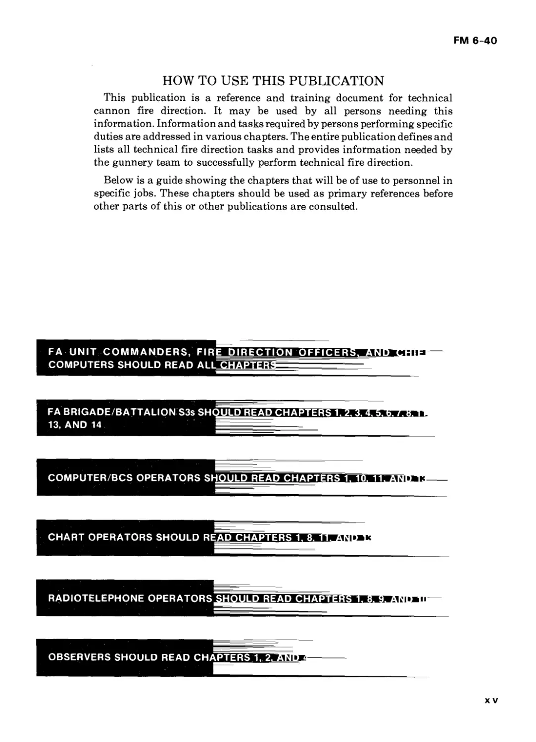
HOW TO USE THIS PUBLICATION
This publication is a reference and training document for technical
cannon fire direction. It may be used by all persons needing this
information. Information and tasks required by persons performing specific
duties are addressed in various chapters. The entire publication defines and
lists all technical fire direction tasks and provides information needed by
the gunnery team to successfully perform technical fire direction.
Below is a guide showing the chapters that will be of use to personnel in
specific jobs. These chapters should be used as primary references before
other parts of this or other publications are consulted.
F A U NIT С О M M A N D E R S, FI REDIRECTION OFFICER
COMPUTERS SHOULD READ ALL CHAP! ERS
FA BRIGADE/BATTALION S3s SHOULDREAD CHAPTERS 1
13, AND 14
CHART OPERATORS SHOULD READCHAPTERS 1. 8. 11. ANdT
x v
FM 6-40
rp he field artillery gunnery team con-
sists of the observer, the fire direc-
tion center (FDC), and the firing battery,
all linked by an adequate communica-
tions system.
1-1. OBSERVER
a. The observer/target acquisition assets
serve as the eyes of all indirect fire systems.
An observer detects and locates suitable
indirect fire targets (tgt) within his zone of
observation. When a target is to be attacked,
the observer, when necessary, transmits a
request for fire and adjusts the fires onto the
target. An observer provides surveillance
data of his own fires and any other fires in his
zone of observation.
b. Maneuver personnel may function as
observers. When an individual detects and
locates a suitable target, he transmits a
request for fire, adjusts the fires onto the
target when necessary, and provides
surveillance data of his fires and any other
fires in his zone of observation.
c. Target acquisition devices also
function as observers and provide accurate
and timely detection, identification, and
location of ground targets to collect
combat/target information, to orient/cue
intelligence sources, and to permit immediate
attack on specific areas. Once combat begins,
initial artillery targets will be located by the
use of the following field artillery target
acquisition assets:
(1) Moving-target-locating radar
sections.
(2) Weapon-locating radar sections.
(3) Sound ranging platoons.
(4) Remotely piloted vehicles (RPV).
Note. See FM 6-121 and FM 6-122 for a
discussion of these assets.
1-2. FIRE DIRECTION
CENTER
The FDC is the control center for the
gunnery team. The FDC personnel receive
fire requests from the observer and process
that information by using tactical and
technical fire direction procedures. They plot
the target on the firing chart or a map,
determine firing data, and issue fire
commands to the firing battery weapons
designated to fire the mission. The battery
FDC normally conducts technical fire
direction by using the BCS or a backup
means while the battalion (bn) FDC conducts
tactical fire direction with TACFIRE.
Technical fire direction is the process of
converting weapon and ammunition
characteristics (muzzle velocity, propellant
temperature, and projectile [proj] weight),
weapon (wpn) and target location, and
meteorological (met) information into firing
data. The results of this process are charge.
FM 6-40
fuze (fz) setting, deflection (df), and quadrant
elevation (QE). Tactical fire direction is the
process of analyzing fire requests and
determining appropriate fire method,
ammunition expenditure, unit(s) to fire, and
time of attack.
1-3. FIRING BATTERY
The firing battery consists of the howitzer
sections and the ammunition section.
Organization and employment con-
siderations are discussed in FM 6-50 and FM
6-20-1.
1-4. COMMUNICATIONS
LINKS
The gunnery team communications links
consist of voice and digital communications.
All members of the gunnery team must
aggressively ensure adequate com-
munications are established and maintained
at all times.
1-2
FM 6-40
JT ield artillery weapons normally are
emplaced in defilade to conceal
them from the enemy. Usually, this
emplacement precludes direct fire on
the target. Consequently, indirect fire
must be used to attack targets. The
gunnery problem is indirect fire. The
solution to this problem requires
weapon and ammunition settings
which, when applied to the piece and
ammunition, will cause the projectile to
burst on the target or at a proper height
above the target.
2-1. GUNNERY
PROBLEM SOLUTION
a. The steps in solving the gunnery
problem are as follows:
(1) Know the location of the gun and
determine the location of the target.
(2) Determine chart (map) data
(direction, range [rg], and angle T).
(3) Compensate for nonstandard
conditions that would have an effect on firing
data.
(4) Convert chart data to firing data
(charge [chg], fuze setting, deflection, and
quadrant elevation).
(5) Apply the firing data to the gun and
ammunition.
b. The solution to the problem provides
weapon and ammunition settings that cause
the projectile to burst on the target or at a
predetermined height above the target.
2-2. REQUIREMENTS
FOR ACCURATE
PREDICTED FIRE
In solving the gunnery problem,
requirements for timely and accurately
delivered cannon fire support must be met.
When maintaining the demanding level of
cannon fires, adjustment cannot be made in
every situation. The goal, instead, is to
achieve accurate predicted fires to produce
first-round fire-for-effect (FFE) missions.
Such nonadjusted firing has five
requirements that must be met to achieve this
goal (fig 2-1). These requirements are target
location and size, battery location,
ammunition and weapon information, met
information, and computational procedures.
If these requirements cannot be met
completely, degraded FFE missions may
result and may have to be replaced with time-
consuming adjust fire missions that would
reduce the effectiveness of cannon fire
support.
a. Target Location and Size. To
establish the range from the gun to the target,
the accurate and timely detection,
identification, and location of ground targets
and their size and disposition on the ground
must be determined so that accurate firing
data can be computed. To determine the
appropriate time and type of attack, the
target size (radius or other dimensions) and
the direction and speed of movement must
also be considered. Target location is
determined by the use of the assets mentioned
in paragraph 1-1.
b. Battery Location. Accurate range
and direction from the firing battery to the
2-1
FM 6-40
target also require the weapons to be located
accurately, and this location must be known
to the fire direction center. The position and
azimuth determining system (PADS) can
provide accurate survey information on the
battery location. Survey techniques a vailable
to the firing battery can also help in
determining the location of each weapon. The
BCS can identify the grid location of each
piece from the aiming circle and can compute
the geographical battery center grid. The
BCS uses each weapon location individually
to compute individual firing data. The term
‘’battery center” indicates the geographical
center of the weapons and does not
necessarily correspond to any weapon
location. No longer is there a base piece. For
an adjust fire mission, the BCS automatically
designates a different weapon for each
mission based on an algorithm in the
machine. The FDC, if required, may also
manually designate an adjusting piece to the
battery computer system.
c. Ammunition and Weapon Informa-
tion. In the battery computer system,
accurate firing data are based on the actual
performance of each weapon. The actual
performance is determined by the weapon’s
muzzle velocities. The firing battery can
measure actual muzzle velocity by using the
M90 velocimeter (chap 11) and correct it to
standard for each weapon, type of propellant,
and type of projectile. There is no longer a
requirement to conduct a formal calibration,
because calibration is conducted continu-
ously by using the M90. Firing tables and
technical gunnery procedures allow the unit
to account for specific ammunition
information (weight, fuze type, rocket motor
temperature, or timer temperature); thus,
accurate firing data are given.
d. Meteorological Information. The
effects of weather on the projectile in flight
must be considered. Use of current
meteorological information (chap 10) in the
computers and in manual computation
allows the firing data to compensate for
current weather conditions.
e. Computational Procedures. The
computation of firing data must be accurate.
Procedures programed in the ballistic
computers and the manual techniques
designed for firing data computation yield
accurate firing data.
Figure 2 1 Five requirements for accurate predicted fire.
2-2
FM 6-40
В allistics deals with the motion of
projectiles and the conditions that
affect that motion. An understanding of
ballistics is important because it is upon
the fundamentals of ballistics that fire
direction procedures are built. It is also
important to understand the factors
affecting round-to-round variations,
particularly in muzzle velocity, so that
they can be minimized and the goal of
accurate predicted fires can be achieved.
Section I
INTERIOR BALLISTICS
3-1. DESCRIPTION
Interior ballistics deals with the factors
affecting the motion of the projectile within
the tube. Interior ballistics determines the
developed muzzle velocity of a round when it
leaves the tube.
a. Propellant. Artillery propellant is a
low-order explosive that burns at a rate less
than 1,300 feet per second. A low-order
explosive burns rather than explodes. It
bums rapidly and releases gases as opposed
to exploding and causing an instantaneous
release of energy. The melting point for a
low-order explosive is lower than the
temperature required to cause it to chemically
react. Therefore, it requires a primer for
ignition.
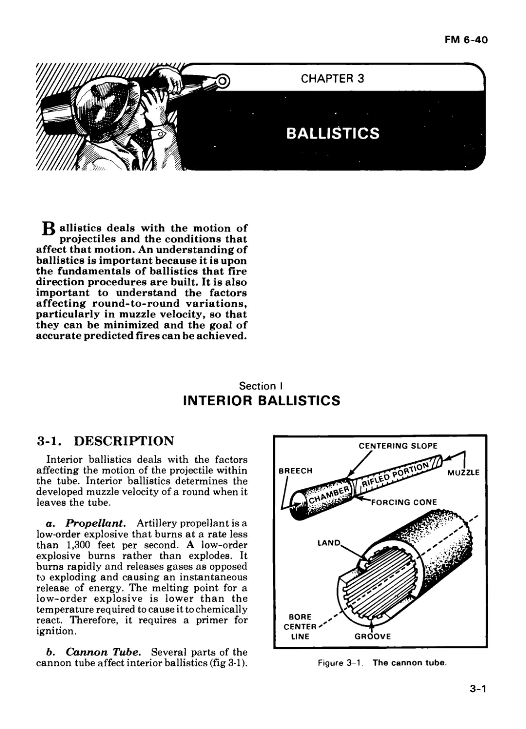
b. Cannon Tube. Several parts of the
cannon tube affect interior ballistics (fig 3-1).
Figure 3-1. The cannon tube.
3-1
FM 6-40
(1) The rifled portion of the tube
imparts spin to the projectile to cause
stability in flight. The groove is the
depression in the rifling. The land is the
raised portion. These parts engrave the
rotating band.
(2) The caliber of a tube is the inside
diameter of the tube as measured between
opposing lands.
(3) Caliber length is the length of the
tube in terms of its caliber. Caliber length
equals tube length divided by diameter.
Weapons can be classified by caliber.
Technically, mortars have 10 to 20 caliber
lengths, howitzers have 20 to 30 caliber
lengths, and guns have more than 30 caliber
lengths. All US artillery has a uniform right-
hand twistin rifling except the M102 lOo-min
howitzer, which has an increasing
right-hand twist. This exception was
required by the velocity and accuracy
requirements for the obsolete 105-mm charge
8 propellant.
(4) The forcing cone is the rear portion
of the main bore formed by the tapered lands.
It allows the rotating band to be engaged
gradually by the rifling.
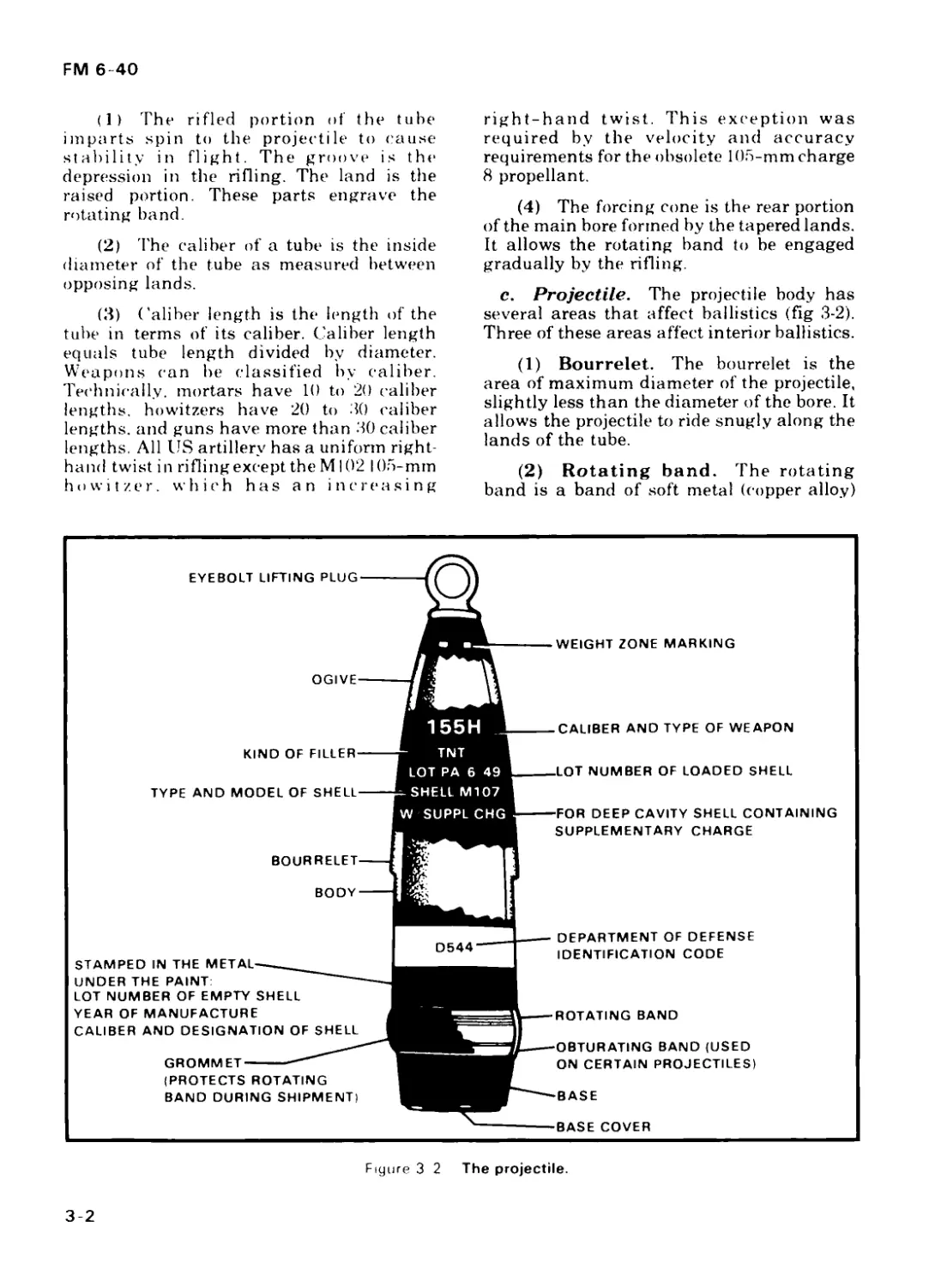
c. Projectile. The projectile body has
several areas that affect ballistics (fig 3-2).
Three of these areas affect interior ballistics.
(1) Bourrelet. The bourrelet is the
area of maximum diameter of the projectile,
slightly less than the diameter of the bore. It
allows the projectile to ride snugly along the
lands of the tube.
(2) Rotating band. The rotating
band is a band of soft metal (copper alloy)
Figure 3 2 The projectile.
3-2
FM 6-40
that is securely seated around the body of the
projectile. It provides forward obturation (the
seal required to develop pressure inside the
tube). The band prevents the escape of gas
pressure from around the projectile. When the
weapon is fired, the rotating band contacts
the lands and grooves and is impressed
between them. As the projectile travels the
length of the cannon tube, spin is imparted as
it twists over the lands and grooves. The
rifling for the entire length of the tube must be
smooth and free of burs and scars. This
permits uniform seating of the projectile and
gives a more uniform muzzle velocity.
(3) Obturating band. The obtura-
ting band is a nylon band that is on some
projectiles. It provides forward obturation
and prevents the escape of gas pressure from
around the projectile.
d. Actions Within the Cannon Tube.
(1) The projectile is rammed in the
cannon tube and rests on the bourrelet. The
rotating band contacts the lands and grooves
at the forcing cone.
(2) Propellant is inserted into the
chamber.
(3) The propellant is ignited by the
primer. Propellant burns rapidly and releases
large quantities of gas. Gases exert pressure
in all directions. Lateral forces are contained
by the walls of the chamber and the tube.
Longitudinal forces cause the projectile to
move—
(a) Forward. The projectile moves
toward the muzzle. This motion causes the
rotating band and obturating band (if
present) to be engraved by the rifling of the
tube.
(b) Rotationally. The engraved
rotating band follows the twist of the rifling
and imparts a rotational motion to the
projectile.
(4) Only about one third of the pressure
developed actually works to push the
projectile. The remaining two thirds is
absorbed by the recoiling parts or is lost
because of heat and metal expansion.
(5) The noise and shock of firing are
caused by the jet action of the round when it
encounters the atmosphere as it departs the
muzzle of the weapon.
3-2. FACTORS AFFECTING
MUZZLE VELOCITY
Applicable firing tables give the standard
muzzle velocity for each charge. These
standard values are based on an assumed
standard weapon. In gunnery techniques,
nonstandard velocity is expressed as
variation (plus or minus so many meters per
second [m/s]) from an accepted standard.
Actual measurements of the muzzle velocities
of a series of rounds corrected for
nonstandard conditions show the
performance of a certain weapon/ammu-
nition/charge combination and are
important in meeting the five requirements of
accurate predicted fire. Application of
corrections to compensate for nonstandard
muzzle velocity is one of the most important
elements in the preparation of accurate firing
data. The following discussion of factors that
cause nonstandard conditions treats each
factor separately, assuming there is no
influence from related factors.
a. Velocity Trends. Not all rounds (rd)
of a series fired from the same weapon and
using the same ammunition lot will develop
the same muzzle velocity. Under most
conditions, the first few rounds follow a
somewhat regular pattern rather than the
random pattern associated with normal
dispersion. This phenomenon is called
velocity trends, and the magnitude varies
with the cannon, charge, and tube condition
at the time each round is fired. Generally, the
magnitude of velocity trends can be
minimized when firing is started with a tube
that is clean and completely free of oil.
b. Ammunition Lots. Each lot of
projectiles and propellants has its own mean
performance level when related to a common
weapon. Each lot must be kept separate from
the others. (Fuzes are not separated by lots.)
c. Tolerances in New Weapons. All
new cannons will not necessarily develop the
same muzzle velocity. In a new tube, the
predominant factors affecting MV are
variations in the powder chamber and the
interior dimensions of the bore.
3-3
FM 6-40
d. Tube Wear. Continued firing of a
cannon wears away portions of the bore by
the actions of hot gases and chemicals and
movement of the projectile. These erosive
actions are more pronounced when higher
charges are fired. The greater the tube wear,
the more the muzzle velocity decreases.
Normal wear can be minimized by careful
selection of the charge and by proper
cleaning of both the tube and the
ammunition.
e. Nonuniform Ramming. Hard,
uniform ramming is required for all rounds.
Weak, nonuniform ramming causes a
combined effect of escaping gases and a
smaller propellant chamber. These factors
produce an increase in the dispersion pattern.
f. Rotating Bands. Rotating bands
allow uniform pressure buildup and provide a
minimum dragging effect on the projectile
once motion has started. Dirt or burs on the
rotating bands cause improper seating. This
increases tube wear and contributes to
velocity dispersion. If excessively worn, the
lands may not sufficiently engage the
rotating bands to impart the proper spin to
the projectile. Insufficient spin reduces
projectile stability in flight and can result in
dangerously erratic round performance.
When erratic rounds occur or excessive tube
wear is noted, ordnance teams should be
requested to determine the serviceability of
each tube.
g. Propellant and Projectile
Temperatures. Positive action must be
taken to maintain uniform projectile and
propellant temperatures. Failure to take this
action results in erratic firing. The effect of an
extreme change in projectile or propellant
temperature can invalidate even the most
recent registration corrections.
h. Moisture Content of Propellant.
Changes in the moisture content of
propellant are caused by improper protection
from the elements. These changes will affect
muzzle velocity.
i. Position of Propellant in the
Chamber. In fixed and semifixed
ammunition, the propellant has a relatively
fixed position with respect to the chamber. In
separate-loading ammunition, however, the
position of the propellant depends on how the
cannoneer inserts the charge. To ensure
proper ignition of the propellant, he must
insert the charge so that the base of the
propellant bag is flush against the obturator
spindle when the breech is closed.
j. Weight of Projectile. A heavier-
than-standard projectile causes a decrease in
velocity. A lighter-than-standard projectile
causes an increase in velocity.
k. Coppering. Coppering is the deposit
of a thin film of copper on the bore lands. It
occurs in the tube when the velocity is high
enough to develop sufficient friction to
remove the outer surface of the rotating band.
The amount of copper deposited varies with
velocity. Excessive coppering causes erratic
velocity performance by varying the
resistance of the bore to projectile movement.
Coppering may be reduced by firing lower
charges and removed by cleaning the bore.
I. Propellant Residue. Residue from
burned propellant and certain chemical
agents mixed with the expanding gases are
deposited on the bore surface. Proper care and
cleaning will alleviate pitting and other
damage to the tube.
m. Tube Conditioning. The tempera-
ture of the tube has a direct bearing on the
developed muzzle velocity. A cold tube offers
a different resistance to projectile movement
and is less susceptible to coppering, even at
high velocities.
n. Tube Memory. Tube memory is the
phenomenon that occurs when the tube fires
at a muzzle velocity similar to that of the last
charge fired, even if the charge is different.
For example, if tht charge fired was 5 green
bag (GB) and the next charge to be fired is 3
green bag, the tube will fire at a slightly
higher muzzle velocity than normal for
charge 3, because it ’’remembers" firing the
charge 5.
3-3. MUZZLE VELOCITY
MEASUREMENT
Various methods are used to determine the
developed muzzle velocity of a projectile. Use
of the M90 velocimeter is the preferred
method. It gives a real-time muzzle velocity
that can be used to better realize the artillery
goal of accurate predicted fires.
3-4
FM 6-40
Section II
EXTERIOR BALLISTICS
3-4. DESCRIPTION
Exterior ballistics deals with the factors
that affect the motion of a projectile outside
the tube.
3-5. TRAJECTORY
ELEMENTS
The trajectory is the path traced by the
center of gravity of the projectile from the
origin to the level point. The elements of a
trajectory are classified into three groups:
intrinsic, initial, and terminal.
a. Intrinsic Elements. Elements that
are characteristic of a trajectory, by
definition, are intrinsic elements.
(1) Origin—the location of the center of
gravity of the projectile when it leaves the
tube. It also denotes the center of the muzzle
when the piece has been laid.
(2) Ascending branch—that portion
of the trajectory that is traced by the center of
gravity while the projectile is rising from the
origin.
(3,) Descending branch—that portion
of the trajectory that is traced by the center of
gravity while the projectile is falling.
(4) Summit—the highest point of the
trajectory.
(5) Maximum ordinate—the differ-
ence in altitude (alt) between the origin and
the summit.
(6) Level point—the point on the
descending branch that is the same altitude
as the origin.
(7) Base of trajectory—the straight
line from the origin to the level point.
b. Initial Elements. Elements that are
characteristic at the origin of the trajectory
are initial elements (fig 3-3).
3-5
FM 6-40
(1) Line of elevation—the axis of the
tube extended when the piece is laid.
(2) Line of departure—a line tangent
to the trajectory at the instant the projectile
leaves the tube.
(3) Jump—the displacement of the line
of departure from the line of elevation that
exists at the instant the projectile leaves the
tube.
(4) Angle of site—the smaller angle in
the vertical plane from the base of the
trajectory to the straight line joining the
origin and the target. The angle of site
compensates for the vertical interval.
(5) Complementary angle of site—
an angle that is algebraically added to the
angle of site to compensate for the
nonrigidity of the trajectory.
(6) Site—the algebraic sum of the angle
of site plus the complementary angle of site
(comp site). Site is computed to compensate in
situations where the target is not at the same
altitude as the battery.
(7) Complementary range—the
number of meters range correction equivalent
to the number of mils complementary angle
of site.
(8) Line of site—the straight line from
the origin to a point, usually the target.
(9) Angle of elevation—the interior
angle at the origin in a vertical plane from the
line of site to the line of elevation.
(10) Quadrant elevation—the
interior angle at the origin in a vertical plane
from the base of the trajectory to the line of
elevation. It is the algebraic sum of site plus
the angle of elevation.
c. Terminal Elements. Elements that
are characteristic at the point of impact are
terminal elements (fig 3-4).
(1) Point of impact—the point at
which the projectile strikes the target area.
(2) Angle of fall—the vertical angle at
the level point between the line of fall and the
base of the trajectory.
(3) Line of fall—the line tangent to the
trajectory at the level point.
(4) Line of impact—a line tangent to
the trajectory at the point of impact.
(5) Angle of impact—the acute angle
at the point of impact between the line of
impact and a plane tangent to the surface at
the point of impact.
3-6
FM 6-40
3-6. ROUND-TO-ROUND
VARIATIONS
a. When several rounds are fired from a
piece under conditions as nearly identical as
possible, the points of impact of the
projectiles will be scattered both in range and
in direction. This scattering is called
dispersion. The area over the points of impact
is called the dispersion zone.
b. Dispersion is the result of errors. There
are three types of errors.
(1) Inherent errors—built-in errors
or inaccuracies in the weapon or ammunition
(for example, play in the recoil system of a
howitzer). Inherent errors cannot be
corrected for and are the primary cause of
dispersion.
(2) Human errors—mistakes made by
any member of the gunnery team (for
example, inaccurate directions sent by the
forward observer [FO] , improper
computation of data by the FDC, or improper
laying of the howitzer by the gunners).
Human errors can be corrected by training.
(3) Constant errors—errors that are
known of and are constant throughout the
mission. Constant errors (for example, drift,
VI, rotation of the earth) can be corrected by
use of the tabular firing table.
c. The center of the dispersion pattern is
called the mean point of impact (MPI). The
MPI of a small number of rounds will differ
slightly from that of a larger number of
rounds, since a smaller number of rounds
cannot be expected to give a representative
sample of the dispersion.
3-7. DISPERSION
RECTANGLES
a. If a rectangle is constructed around the
dispersion zone (excluding any erratic
rounds), it is called the 100-percent rectangle
(fig 3-5). If this rectangle is divided into eight
equal parts by lines drawn perpendicular to
the line of fire, the percentage of points of
impact to be expected in each part is indicated
in figure 3-6. This is called a range dispersion
3-7
FM 6-40
rectangle. Likewise, if this rectangle is
divided similarly by lines parallel to the line
of fire, the percentages will be as indicated in
figure 3-7. This is called a deflection
dispersion rectangle. Each division of these
dispersion rectangles is called 1 probable
error. Probable error is defined as the error
that is exceeded as many times as not when
considering all rounds either over or short or
left or right of the mean point of impact.
b. If the range and deflection dispersion
rectangles are superimposed, the result is the
assemblage of small rectangles shown in
figure 3-8. This result is called the dispersion
rectangle. The percentage of points of impact
in any particular small rectangle is the
product of the percentages in two strips,
range and deflection, whose intersections
form the small rectangle.
3-8. RANGE PROBABLE
ERROR
a. In figure 3-6, the line AB through the
center of impact is perpendicular to the line of
fire. There are as many points of impact in the
area between AB and CD as there are beyond
CD; that is, 25 percent of the points of impact
are in the area АВ-CD and 25 percent are
beyond CD. The depth of the area (AC) is
called 1 range probable error (PEr). The
range probable error for a given charge is
different at different ranges. The
approximate value of the range probable
error is given in the firing tables. This value
can be taken as an index of the accuracy of
the weapon. Firing table values for range
probable errors are representative of
carefully selected ammunition. The actual
probable errors of an ammunition lot can
vary from the table values. Probable error is
the value which, when added to or subtracted
from the expected range, will produce an
interval along the line of fire that should
contain 50 percent of the rounds fired.
Variations in muzzle velocity, angle of
departure, and total drag during flight affect
this value.
b. From studying figure 3-6, you will
determine that 50 percent of the rounds will
fall within 1 range probable error,
approximately 82 percent will fall within 2
Figure 3-6. Range dispersion rectangle.
3-8
FM 6-40
probable errors, and 96 percent will fall
within 3 probable errors of the mean point of
impact. For practical purposes, it is assumed
that all rounds will fall within 4 probable
errors of the mean point of impact. Actually, a
small percentage of the rounds (about 7 in
1,000) will fall farther than 4 probable errors
away from the mean point of impact. This
probable distribution of rounds (including
the fifth probable error) is given more
precisely in the probability tables in the
firing tables.
3-9. DEFLECTION
PROBABLE ERROR
In the deflection dispersion rectangle (fig
3-7), the points of impact to the right and left
of the long axis of the rectangle follow
principles of distribution similar to those in
paragraph 3-7. For practical purposes, the
deflection probable error (PEp)is taken as
one eighth of the width of the dispersion
rectangle. This value is listed in the tabular
firing tables (TFT).
LEFT L
i L
.02 .07 .16 .25 .25 .16 07 .02
.02 .0004 .0014 .0032 .0050 .0050 .0032 .0014 .0004
Г 2 .07 .0014 .0049 .0112 .0175 .0175 .0112 .0049 .0014
.16 .0032 .0112 .0256 .0400 .0400 .0256 .0112 .0032
C .25 .0050 .0175 .0400 .0625 .0625 .0400 .0175 .0050 LINE OF FIRE „ „
.25 .0050 .0175 .0400 .0625 .0625 .0400 .0175 .0050
.16 .0032 .0112 .0256 .0400 .0400 .0256 .0112 .0032
1/ '2 .07 .0014 .0049 .0112 .0175 1.0175 .0112 .0049 .0014
.02 .0004 .0014 .0032 .0050 |.0050 .0032 .0014 .0004
Rl( iHT 1 L MEAN POINT OF IMPACT
Figure 3-8. Dispersion rectangle.
3-9
CHAPTER 4
FIRE DIRECTION CENTER
OPERATIONS
JAifferent units may have different
types and amounts of FDC equip-
ment.
a. The battery FDC may be config-
ured with one of the following three
mixes of equipment:
(1) BCS/manual.
(2) FADAC/manual.
(3) Manual only.
b. The battalion will have TACFIRE
or will be a FADAC/manual fire
direction center.
c. Duties and responsibilities of
assigned personnel will vary depending
on the type and the amount of equipment
available in the fire direction center.
4-1. BCS/MANUAL FDC
a. Duties of Personnel. The highest
level of technical fire direction is found in a
TACFIRE-controlled/BCS-equipped bat-
tery FDC (fig 4-1). By tables of organization
and equipment (TOE), this FDC is authorized
eight people to fill four positions in two shifts
to facilitate 24-hour operations (TOE
6-365J). Methods of training FDC personnel
are in appendix G.
(1) One fire direction officer (LT)—
is responsible for all FDC operations. The fire
direction officer (FDO) actively supervises,
decides how to attack the target (app H),
ensures the required level of training is
attained, and ensures a check of all known
and firing data.
LEGEND: DMD DIGITAL MESSAGE DEVICE
FIST FIRE SUPPORT TEAM
GFT GRAPHICAL FIRING TABLE
G VLLD GROUND - VEHICULAR LASER LOCATOR DESIGNATOR
Figure 4-1. BCS-equipped fire direction center.
4-1
FM 6-4<
4-2 FOLDOUT
.FM 6-40
(2) One chief fire direction
specialist (E6)—is the technical expert in
the fire direction center. He ensures smooth
operation of the FDC in 24-hour operations.
He acts as a shift supervisor in the absence of
the fire direction officer.
(3) Two computer operators (E5)—
operate the battery computer unit (BCU) and
send fire commands to the guns.
(4) Two recorders (E4)—maintain
records of firing data. As a minimum, the
recorders should maintain the firing data of
the piece nearest the battery center and the
data required for backup with the hand-held
calculator.
(5) Two chart operators (E3)—are
the horizontal control operator (HCO) and
the vertical control operator (VCO). They
maintain a firing chart, follow each mission,
and check the BCS grid coordinates with
chart and situation map coordinates. These
double checks ensure that proper data are
being used in the BCS solution. They also use
the BUCS/graphical firing table (GFT) fan to
provide an additional check of BCS firing
data for the adjusting weapon during the
adjusting and fire-for-effect portions of the
mission.
b. Radio Communications. See
figure 4-2 for a diagram of the radio
communications used in a direct support (DS)
battalion equipped with TACFIRE and the
battery computer system.
c. System Degradation. With the
introduction of new technical equipment,
r-
ВГ
r:H = r.NFL 7
зСз СН4КЧЯ 1
- -P :
GDI
nn.
SCS
Br:s
СНЛЧ1ЧИ
Mill llillii
2
пЧ
I3==aD
TYPE I CONFIGURATION
TYPE II CONFIGURATION
Figure 4-2. Direct support battalion TACFIRE/BCS communications network.
FOLDIN 4-2
4-2
FM 6-40
certain situations can cause technical fire
direction system degradation. Acceptable
gunnery solutions are available, but they
necessitate additional actions by certain
personnel (table 4-1) and restructuring of
communications nets (fig 4-3).
4-2. FADAC/MANUAL FDC
a. Duties of Personnel. The FDO is
responsible for the operation of the FDC.
Duties include producing accurate and timely
firing data. The FDO analyzes the calls for
fire and instructs the FDC on how to attack
the target. He is also responsible for checking
and entering known data into FADAC/BCS/
BUCS/HHC and on the graphical
equipment. He and the chief fire direction
specialist (E6) actively supervise the rest of
the personnel as they perform their duties.
The chief fire direction specialist is the
primary technical advisor to the FDO, who
trains the section. The senior fire direction
specialist (E5) operates the FAD AC and
issues fire commands to the guns. The other
personnel serve as radiotelephone operator
(RATELO), recorder, and chart operator, as
directed. The FADAC/manual FDC is
shown in figure 4-4.
Figure 4-3. J-series battery fire direction nets used with the BCS.
4-3
FM 6-40
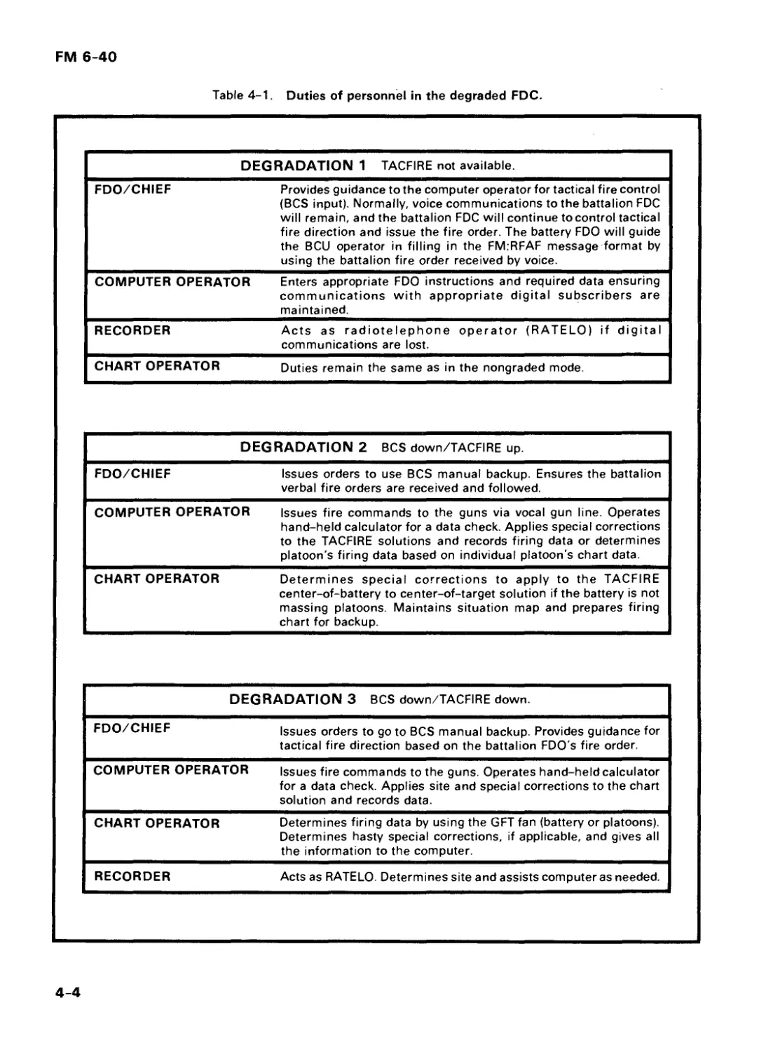
Table 4-1. Duties of personnel in the degraded FDC.
DEGRADATION 1 TACFIRE not available.
FDO/CHIEF Provides guidance to the computer operator for tactical fire control (BCS input). Normally, voice communications to the battalion FDC will remain, and the battalion FDC will continue to control tactical fire direction and issue the fire order. The battery FDO will guide the BCU operator in filling in the FM:RFAF message format by using the battalion fire order received by voice.
COMPUTER OPERATOR Enters appropriate FDO instructions and required data ensuring communications with appropriate digital subscribers are maintained.
RECORDER Acts as radiotelephone operator (RATELO) if digital communications are lost.
CHART OPERATOR Duties remain the same as in the nongraded mode.
DEGRADATION 2 BCS down/TACFIRE up.
FDO/CHIEF Issues orders to use BCS manual backup. Ensures the battalion verbal fire orders are received and followed.
COMPUTER OPERATOR Issues fire commands to the guns via vocal gun line. Operates hand-held calculator for a data check. Applies special corrections to the TACFIRE solutions and records firing data or determines platoon's firing data based on individual platoon's chart data.
CHART OPERATOR Determines special corrections to apply to the TACFIRE center-of-battery to center-of-target solution if the battery is not massing platoons. Maintains situation map and prepares firing chart for backup.
DEGRADATION 3 BCS down/TACFIRE down.
FDO/CHIEF Issues orders to go to BCS manual backup. Provides guidance for tactical fire direction based on the battalion FDO's fire order.
COMPUTER OPERATOR Issues fire commands to the guns. Operates hand-held calculator for a data check. Applies site and special corrections to the chart solution and records data.
CHART OPERATOR Determines firing data by using the GFT fan (battery or platoons). Determines hasty special corrections, if applicable, and gives all the information to the computer.
RECORDER Acts as RATELO. Determines site and assists computer as needed.
4-4
FM 6-40
Figure 4-4. FADAC/manual fire direction center.
6. Mission Processing. A call for fire
is received in the FDC by the RATELO. The
FDO analyzes the target and issues
instructions to the FDC on how to attack the
target.
(1) The computer operator alerts the
firing battery of a mission and operates
FADAC, which masses the individual
platoons. FADAC is the primary source for
determining firing data.
(2) The chart operator concurrently
determines firing data from the chart and
from the GFT fan. These data provide the
data check on FADAC data. The chart
operator maintains the situation map and,
based on guidance from the FDO, announces
average site or determines and announces the
site for that mission.
(3) The recorder records the mission on
the record of fire and prepares the hand-held
calculator to follow the mission as backup.
(4) The chart operator double-checks
the FADAC firing data with his GFT-fan-
determined firing data. If his center-of-
battery to center-of-target solution checks
within +3 mils deflection and quadrant
elevation and +0.1 fuze setting increment, he
announces CHECK. Otherwise, he
announces HOLD. Before firing the data, the
FDO ensures that data are checked. When
fire for effect is entered, platoons are massed
on the target center. If individual platoon
locations are plotted on the firing chart, a set
of firing data for each platoon to the target
may be determined instead of having hasty
corrections applied to battery center data.
c. System Degradation. When the
FADAC goes down, the FDC becomes a
manual fire direction center. The recorder
becomes the second chart operator, and the
computer acts as backup with the hand-held
calculator. (The manual FDC is shown in
figure 4-5.)
4-3. MANUAL FDC
a. Duties of Personnel. A manual
battery FDC is composed of the following:
(1) Fire direction officer—is
responsible for the training of all FDC
personnel, supervises the operation of the
FDC, establishes SOP, determines method of
attacking targets, and ensures accuracy of
firing data sent to the guns.
4-5
FM 6-40
FIRE DIRECTION
OFFICER
(LT/E6)
TI-59 HAND-
HELD
CALCULATOR
(ALTERNATE)
COMPUTER/
RECORDER (E5)
GFT FAN
BACKUP
CHART
OPERATOR (E4)
(VCO)
Figure 4-5. Manual fire direction center.
(2) Chief fire direction specialist-
serves as the FDO’s technical expert and
functions as the FDO in the FDO’s absence.
He ensures that all equipment is on hand and
operational, supervises computation of all
data, ensures that all appropriate records are
maintained, and assists the FDO as
necessary.
(3) Computer/senior fire direction
specialist—combines data provided by
other personnel. He determines and
announces firing data and fire commands.
He also records mission-related data and
other information, as directed, and
determines GFT settings.
(4) Horizontal control operator-
constructs the primary firing chart,
determines and announces chart data, and
checks firing data with the GFT fan.
(5) Vertical control operator-
constructs the secondary firing chart, checks
chart data, determines and announces site,
and provides corrections to firing data, by
platoon, from hasty correction tables, as
required.
(6) RATELO —receives/records call
for fire and maintains communications.
b. Mission Processing.
(1) A call for fire is received in the FDC
by the RATELO. The FDO analyzes the
situation and decides how the target will be
attacked. The chart operators plot the target,
announce chart data, and then determine VI
and compute and announce site. The
computer determines and announces firing
data (the HCO checks or holds) and
announces fire commands to the guns. In fire
for effect, the VCO enters hasty correction
tables and announces corrections to
center-to-center fire-for-effect data for each
platoon.
(2) The hand-held calculator (if
available) may be used as an alternate
method of checking chart or firing data.
4-4. BATTALION FDC
a. Duties of Personnel. A TACFIRE-
equipped battalion FDC is discussed in FM
6-1. A battalion FADAC/manual FDC is
composed of the following personnel:
(1) Fire direction officer—super-
vises the FDC, analyzes targets, and issues
the fire order.
(2) Chief computer—helps the FDO
as required and trains the FDC personnel.
(3) Assistant chief computer—is the
alternate for the chief computer.
4-6
FM 6-40
BATTERY В
FDC
LEGEND:
Figure 4-6. Employment of the fire direction nets (FADAC/manual).
BATTALION CF
Table 4-2. Duties of the battalion (tactical)
and battery (technical) fire
direction centers.
BATTALION FIRE DIRECTION CENTER BATTERY FIRE DIRECTION CENTER
Tactical fire direction Control of mass fires Technical backup to battery FDCs Control of scheduled fires Data update Technical fire direction Attack of other targets as assigned
(6) Vertical control operator—
determines and announces site and provides
corrections to firing data, by platoon, from
hasty correction tables as required.
(7) RATELO—has the same duties as
those of the RATELO in the battery fire
direction center.
b. Radio Communications. Figure
4-6 shows the radio nets normally employed
in a FADAC/manual DS battalion. Table 4-2
summarizes duties of the two fire direction
centers.
(4) Three computers —provide
primary communications between the
battery and the battalion fire direction
center. These people can provide technical
backup to the battery if its FDC has an
overload or is neutralized.
(5) Horizontal control operator—
has the same duties as the HCO in the battery
fire direction center and he operates the
FADAC.
4-5. 3x8 OPERATIONS
a. FM 6-50 describes the 3x8 concept in
the direct support field artillery battalion. If
the battalion is equipped with TACFIRE,
each four-gun platoon’s FDC has a battery
computer unit. As in 3x6 operations,
TACFIRE provides tactical fire direction,
while the BCS provides technical fire
direction and control.
4-7
FM 6-40
6. If no battalion FDC is available
(autonomous operations), one of the two
platoon FDCs is the controlling FDC for the
entire battery. All calls for fire are sent to the
controlling fire direction center. The FDO of
the controlling FDC reviews the message and
performs tactical fire direction. The four
options he may elect are discussed below.
(1) The controlling FDO may elect not
to fire the mission, and the BCU operator
deletes the fire request. If the controlling FDO
elects to fire the mission, he issues a fire order.
The BCU operator makes entries in the
FM;RFAF message format and processes the
message in accordance with the fire order.
(2) The target may be engaged by the
controlling platoon only. In this case, the fire
request is processed as in 3x6 operations.
(3) The target may be engaged by the
subordinate platoon only, and the mission is
handed off. The controlling platoon’s BCU
must have the subordinate platoon entered in
its BCS;INIT HOFFADD field. The BCU
operator enters an H in the FM;RFAF
handoff field and executes (EXEC) the
message. The FM;RFAF is transmitted to the
subordinate platoon’s BCU, where it is
processed as received. The observer
transmits all subsequent messages to the
controlling platoon. When executed, the
messages are transmitted to the subordinate
platoon.
(4) The target may be engaged by both
platoons. The FM;RFAF and all subsequent
messages are transmitted to the subordinate
platoon from the controlling fire direction
center. The messages are processed by both
platoon fire direction centers. For adjust fire
missions, one platoon must have DO NOT
LOAD control until the fire-for-effect phase.
c. If TACFIRE becomes inoperable,
tactical fire control will be provided by the
mutual support unit (MSU) if available.
Otherwise, the battalion FDC will perform
manual tactical fire direction, or the battery
will operate autonomously.
4-6. FIRING DATA CHECKS
There are three separate checks on firing
data that must be done in the fire direction
center. The FDO is responsible for seeing that
all firing data sent to the weapons are
technically correct and do not violate any
4-8
known restrictive measures or commander’s
guidance. The three checks are as follows:
a. Known Data Check. In every
battery FDC, there are at least two separate
firing data sources (for example, the BCS
with firing charts or FADAC with firing
charts). The FDO directs that all known data
input into the computers be recalled and
checked for accuracy by someone other than
the operator who entered the data. This check
ensures that all operator-applied data
(locations, met, muzzle velocities, or projectile
information) are correct. The ballistic
computers determine firing data based on
this information. The computation
procedures are correct, and, if known data are
correct, the firing data determined by the
ballistic computers will be correct. Charts
will be checked for construction accuracy as
described in chapter 5.
b. Grid Location Check. Grid
locations must be checked between the BCS
(or FADAC) and the firing chart. The initial
grid for the FM;FC, FM;RFAF, or FM;SUBS
is plotted on the chart, and a target grid is
oriented for direction over that point.
Subsequent corrections for the mission are
plotted on the chart, and the grid location of
the pin is checked against the grid location in
the CORD: field of the FM;SUBS message
after the correction has been executed.
Acceptable tolerance between the two sources
should be +30 meters in range. The hand-held
calculator may also be used to accomplish
chart verification. Accuracy depends on the
tolerance of the computer to the chart
verification done previously. If there are
unresolved discrepancies, BCS data should
be used.
c. Weapon Firing Data Check. A-
nother check may also be made as time and
the situation require. During the mission, the
adjusting or centermost piece ballistic
computer solution can be double-checked by
using graphical equipment. There will be
differences in firing data solutions between
the computer and the manual method. In all
cases, the ballistic computers are more
accurate than the manual solution, because
they account for more variables. The
magnitude of the difference will depend on
the chart-check tolerance, the validity of the
GFT setting being used, and whether or not
the adjusting piece location is actually
plotted on the firing chart oris displaced from
the location.
FM 6-40
f"'1 hart data consist of range, deflec-
tion from the firing unit to the tar-
get, and angle T. These three elements
may be determined by either electronic
(TACFIRE, BCS, HHC, and FADAC) or
manual means. The manual method
requires the construction and operation
of a firing chart.
a. There are two types of firing
charts that may be constructed in the
FDC: the surveyed firing chart and the
observed firing chart.
(1) The surveyed firing chart is a
chart on which the locations of all
required points (battery or platoon [3X8]
positions, registration points [reg pt],
and observation posts [OP]) are plotted.
These locations can be based on survey
or map inspection. All plotted points are
in correct relation to one another and
reflect actual map coordinates.
Additional information such as
locations of targets, maneuver
checkpoints, no-fire areas, and safety
diagrams (training environment) may
also be recorded.
(2) The observed firing chart is a
chart on which the relative locations
must be established by the adjustment of
fire, hence, the name “observed firing
chart.” Details on construction and use
of the observed firing chart are in
chapter 14.
b. In the BCS- or FADAC-equipped
fire direction center, a firing chart is
maintained as a backup and is
supplemented by a l:50,000-scale map
used to determine altitude. In the
manual FDC, two firing charts are
maintained. The vertical control
operator maintains the backup chart
and the l:50,000-scale supplementary
map with the overlay(s), and the
horizontal control operator maintains
the primary firing chart.
Section I
TYPES OF SURVEYED FIRING CHARTS
5-1. DESCRIPTION
A firing chart is a graphic representation of
a portion of the earth’s surface used for
determination of distance and direction. It
may be constructed by using a map, a
photomap, a grid sheet, or other material on
which the relative locations of batteries,
registration points, targets, and observers
can be plotted. Additional positions, fire
support coordinating measures, and other
data needed for the safe and accurate conduct
of fire may also be recorded.
5-1
FM 6-40
5-2. CONSTRUCTION OF
FIRING CHARTS
The most commonly used materials for
construction of firing charts are as follows:
a. Grid Sheet.
(1) A grid sheet is a plain sheet of paper
or plastic on which equally spaced horizontal
and vertical lines, called grid lines, are
printed. The intervals between these grid
lines will normally create 1,000-meter grid
squares on a scale of 1:25,000. This provides
the best compromise between accuracy and
convenience and is therefore the scale for
which standard plotting equipment is
graduated. The location of all points plotted
on the grid sheet must be determined by
either survey, map inspection, or firing.
(2) The grid sheet is numbered to
correspond to the map area of the zone of
action of the supported force. The lower left-
hand corner is assigned easting and northing
coordinates by the FDO, and the direction of
the long axis (east-west or north-south) is
designated. The grid sheet is numbered with
a 4H pencil. The rightmost and topmost grid
lines are not numbered.
b. Map. A map is a graphic representa-
tion, drawn to scale, of a portion of the earth’s
surface. Only maps based on accurate ground
survey should be used for construction of
firing charts. If the map scale is other than
1:25,000, the range readings obtained from
plotting equipment must be adjusted. For
example, if a l:50,000-scale map is used, the
ranges obtained from the range-deflection
protractor (RDP) must be doubled.
Deflections and azimuths are not affected. If
a map is not based on accurate and adequate
ground survey control, it should be used only
to obtain approximate locations and vertical
control to supplement a grid sheet firing
chart.
c. Ph otomap. A photomap is a
reproduction of an aerial photograph or a
mosaic of aerial photographs on which grid
lines, marginal information, and place
names are added. A photomap must not be
considered exact until its accuracy has been
verified. Errors caused by tilt, distortion
caused by relief, and errors caused by poor
assembly may be present in photomaps. If
points cannot be located on the photomap by
inspection, the scale must be determined
before they can be located on the photomap
by survey. Normally, vertical control can be
established by estimation only. The
determination of the scale of vertical control
of photographs is in FM 21-26 and TM
30-245. Some photomaps have spot altitudes,
but interpolation for altitude is difficult and
inaccurate.
PLOTTING EQUIPMENT AND
PREPARATION OF FIRING CHARTS
5-3. CHART OPERATION
To ensure the accuracy of the data shown
on the firing chart, FDC personnel should
construct and plot from a standing position
directly above the chart. Plotting pins must
be kept perpendicular to the firing chart. The
firing chart should be kept as clean as
possible at all times. If there are two charts in
the FDC, they must be checked against each
other for accuracy. If a chart is the backup for
another system, it should be verified against
that system for accuracy. Details on this
procedure are in section III.
5-4. EQUIPMENT
The following equipment is used in the
preparation of firing charts:
a. 6H Pencil. The 6H (hard lead)
pencil, sharpened to a wedge point (fig 5-1), is
used to draw all lines from which
measurements will be made.
b. 4H Pencil. The 4H pencil,
sharpened to a conical point (fig 5-2), is used
to letter and to accentuate tick marks.
5-2
FM 6-40
c. Plotting Pins. Plotting pins are
used to mark indexes and temporary
positions on the firing chart. On a
l:25,000-scale chart, the thickness of the
plotting pin equals 20 meters.
d. Aluminum Plotting Scale. The
aluminum plotting scale (fig 5-3) is a
square-shaped scale used to plot or determine
grid coordinates. The scale is graduated in
meters and yards at scales of 1:25,000 and
1:50,000. The meters scale is graduated every
20 meters, and locations can be visually
interpolated to the nearest 1 meter. Care must
be taken not to confuse the meters and yards
scales on this instrument. Paragraph 5-5
details the procedure for plotting points with
the aluminum plotting scale.
Figure 5-3. Aluminum plotting scale.
5-3
FM 6-40
e. Range-Deflection Protractor.
The range-deflection protractor (fig 5-4) is
used to measure angles in mils and distances
in meters. It is used to measure range and
deflection from a firing unit to a target and
direction and distance from an observer to a
target.
(1) The left edge of the instrument is the
arm and is used to measure range or distance.
It is graduated in 50-meter increments and
labeled every 500 meters on a scale of
1:25,000. Ranges and distances are visually
interpolated to an accuracy of 10 meters.
(2) The 1,000-mil arc of the RDP is
graduated in 5-mil increments. The 50-mil
increments are indicated by longer
graduations and are permanently numbered.
The arc is visually interpolated to an
accuracy of 1 mil.
(3) There are four different RDP
models. They differ by maximum range of the
arm (12,000, 15,000, 25,000, and 30,000
meters).
f. Target Grid.
(1) Description. The target grid is a
circular paper or plastic device on which grid
lines are printed (DA Form 4176 [Target
Plotting Grid Field Artillery Graduated in
Mils and Meters Scale 1:25,000]). These lines
match the scale of the 1:25,000 firing chart,
dividing a 1,000-meter grid square into
100-meter squares. An azimuth scale is
printed around the outside edge of the target
grid. It is graduated in 10-mil increments and
is numbered every 100 mils. An arrow
extends across the center of the target grid
and is used to indicate the observer-target
(ОТ) line (or other line of known direction).
The target grid should be labeled as shown in
figure 5-5. Tape may be applied to the reverse
side of the target grid to prevent the center
hole from becoming enlarged.
(2) Purpose and Use. The target
grid is used for plotting the positions of
targets located by shift from a known point
5-4
FM 6-40
(para 5-10c), plotting subsequent
corrections, and determining angle T (section
III).
5-5. POINT PLOTTING
To plot points that have been located by
grid coordinates, proceed as follows:
a. Grid Lines 1,000 Meters Apart.
(1) Place a plotting pin in the upper
right-hand comer of the grid square where
the point is to be plotted (for example, grid
60478 32859 [ @ , fig 5-6]). This pin will
prevent the inadvertent plotting of the point
in the wrong grid square.
(2) Place the aluminum plotting scale
along the left edge of the grid square with the
0 of the scale at the lower left-hand corner of
the grid square ( © , fig 5-6).
(3) Slide the scale to the right.Read
easting on the scale by using the north-south
grid line as an index ( © , fig 5-6).
(4) With the bottom edge of the scale
aligned precisely on the east-west grid line,
plot the northing on the vertical scale with a
plotting pin. This is the plotted location
( © , fig 5-6).
31 —
5B
59
Figure 5-6. Plotting with the aluminum plotting scale.
5-5
FM 6-40
6. Grid Lines Other Than 1,000
Meters Apart.
(1) When grid squares are smaller than
normal, plot the easting or northing by
inclining the aluminum plotting scale so that
the 0 of the scale is on one grid line and the
1000 is on the other (fig 5-7). The four-point
plotting technique (para (3) below) must be
used.
(2) When grid squares are larger than
normal, incline the aluminum plotting scale
so that the 0 of the scale is on one grid line and
2000 is on the other (fig 5-8). Multiply the
distance to be plotted by 2, and insert a pin at
that distance on the scale. For example, for
an easting of 62681, place the pin at (62)1362
on the scale.
(3) In both cases, only easting or
northing can be plotted at one time.
Therefore, the following four-point plotting
technique must be used to plot a critical point
when grid lines are less than 1,000 meters
apart.
(a) Locate the grid square in which
the point is to be plotted.
(b) Using plotting pins and the
aluminum plotting scale, plot the easting grid
in the grid squares above and below the grid
square in which the point is to be located.
Remove the pins and connect the points with
a fine line drawn with a 6H pencil through the
center of the pinholes (fig 5-9).
5-6
FM 6-40
Figure 5-8. Grid squares larger than normal.
Figure 5-9. Plotting the grid easting.
5-7
FM 6-40
(c) Plot the grid northing in the grid
squares to either side of the grid square in
which the point is to be located (fig 5-10).
Connect the pinholes with a line drawn with
a 6H pencil.
(d) With a plotting pin, mark the
point where the two lines meet (fig 5-11).
Erase the fine lines and identify the location
with a tick mark (para 5-6) (fig 5-12).
(e) The four-point plotting technique
may also be used on a standard 1:25,000-
scale firing chart. Easting is plotted along the
east-west grid lines bordering the grid square
where the point is located. Northing is plotted
on the north-south grid lines bordering the
grid square. Only when accuracy is more
important than speed should this technique
be employed.
1 — • 1
Figure 5-12. Identifying the location
with a tick mark.
5-6. TICK MARKS
The tick mark is the symbol used to mark
and identify the essential locations on a
firing chart.
a. The tick mark is constructed in the
form of a cross, with each arm beginning 40
meters from the pinhole on the chart and
extending 150 meters in length (1:25,000
scale) (fig 5-13).
b. The lines of the tick mark are drawn
parallel to the grid lines unless the labeling
interferes with a previously labeled tick mark
( (A) , fig 5-14) or the plotted point falls on or
near (within 80 meters) a grid line ( (g) , fig
5-14). In these cases, the tick mark is plotted
on an 800-mil (45°) angle to the grid line. All
tick marks are drawn with a 4H pencil except
5-8
FM 6-40
those for targets located by firing, which are
drawn in red, and for maneuver checkpoints,
which are drawn in blue.
c. The identification of the point is placed
in the upper right quadrant. The installation
or activity is designated in the following
manner:
(1) Battery. The letter designation is
shown in the appropriate color ( (Q) , fig
5-14) (that is, A-red, В-black, C-blue,
D-orange). If more than four batteries are
shown, the color coding starts over again
with red. If the pieces of the battery are widely
dispersed, it may be necessary to plot piece or
platoon locations (for example, platoons in
3x8 operations). Platoon or piece
designations should be labeled by using the
battery’s color code.
(2) Radar. The military symbol is
shown in green ( © , fig 5-14).
(3) Observation post. The military
symbol for an observer and the call sign
number which will be used by the observer to
identify himself are shown in black ( © ,
fig 5-14). If the observation post is assigned a
number, that number is shown in black in
place of the symbol and call sign number (for
example, 01).
(4) Registration point. The number
assigned to the registration point is shown in
black (for example, REG PT 2 [ (?) , fig
5-14]).
(5) Target. The assigned target
number is shown in black (for example,
CB2131 [ © , fig 5-14]).
(6) Checkpoint. The checkpoint tick
mark is shown in blue, while its number is
shown in black and circled (for example, Q)
[ ® , fig 5-14]).
d. The altitude (alt), in meters, of the
plotted point is placed in the lower left
quadrant in black ( (Ё) through (T) , fig
5-14).
e. If the plotted point has been fired on,
the fuze used in fire for effect may be placed in
the lower right quadrant ( (T) , fig 5-14).
f. If the plotted point has been fired on
with high-angle (HA) fire, the letters HA may
be placed in the upper left quadrant. The
charge that was used in the mission can also
be indicated ( (J) , fig 5-14).
5-9
FM 6-40
Figure 5-15. Numbering on the range-deflection protractor.
5-7. CONSTRUCTION OF
AZIMUTH INDEXES
a. Azimuth indexes are constructed for
points located on the firing chart from which
the polar plot method (para 5-10) of target
location may be expected (for example,
observation posts and radar sites). The RDP
must be prepared by numbering the 100-mil
graduations in black as shown in figure 5-15.
b. Azimuth (az) is always read as four
digits. The first digit (thousands of mils) is
read from an index that is drawn on the firing
chart. The last three digits are read from the
arc of the range-deflection protractor.
c. Azimuth indexes are constructed on the
firing chart at 1,000-mil intervals throughout
the target area except the 6000 and the 0
indexes, which are 400 mils apart (fig 5-16).
(1) Place the vertex of the RDP against
the pin in the observation post or radar
location, and align the arm parallel to a
convenient grid line. If you are using a
north-south grid line, plot the easting of the
observer with a plotting pin. If you are using
an east-west grid line, plot the northing of the
observer in a similar manner. When the RDP
is aligned with the vertex at the observer and
the arm against the pin, a reference line is
established at an azimuth of 0 (north), 1600
(east), 3200 (south), or 4800 (west). It is not
drawn.
(2) In (1) above, the RDP was oriented
in a cardinal direction. To establish the
azimuth index, place a pin opposite the
number on the arc corresponding to the last
three digits of the azimuth in which the arm
of the RDP is oriented. The location of the pin
represents an index. Its value is the value of
the first digit of the azimuth in which the arm
of the RDP is oriented. If the arm is oriented
toward north, two azimuth indexes will be
constructed, since north corresponds to 6400
and 0 mils (fig 5-16). These will be the 6000
and 0 indexes. Table 5-1 summarizes
indexing procedures for all orientations of the
range-deflection protractor.
Figure 5-16. Plotting the 6,400-mil and
О-mil temporary azimuth
indexes.
5-10
FM 6-40
Table 5-1. Indexing procedures.
If RDP is oriented NORTH (6,400 mils or 0 mils),
(1) Place pin opposite 400 on ARC; INDEX is
6000.
(2) Place pin opposite 0 on ARC; INDEX is 0.
If RDP is oriented EAST (1,600 mils),
place pin opposite 600 on ARC; INDEX is 1000.
If RDP is oriented SOUTH (3,200 mils),
place pin opposite 200 on ARC; INDEX is 3000.
If RDP is oriented WEST (4,800 mils),
place pin opposite 800 on ARC; INDEX is 4000.
(3) To replace the plotting pin with a
constructed index, move the RDP so the left
edge of the arm is against the pin ( @ , fig
5-17). Remove the pin and, with a 6H pencil,
draw the azimuth index through the center of
the pinhole ( (B) , fig 5-17). The index is a
fine line extending 1 inch on each side of the
pinhole. For example, in (B) , figure 5-17,
this line can be constructed by drawing a line
from range 8250 to range 9520 along the arm
of the RDP. Beginning one-eighth inch
beyond the pinhole, label the index with its
identification and azimuth value (for
example, OlAZO [ (5) , fig 5-17]). Lettering
is green for the radar symbol and its azimuth
labels and black for observation posts and
their azimuth labels.
Figure 5-17. Preparing an index.
5-11
FM 6-40
Figure 5-18. Constructing other azimuth
indexes.
(4) Other azimuth indexes can be
constructed by measuring successive
1,000-mil increments to the left and right of
the initial index. To locate an index for 2,000
mils, place a pin 1,000 mils right of the index
for azimuth 1000. The arc of the RDP
represents 1,000 mils. To locate an azimuth
index for 5,000 mils, place a pin 1,000 mils left
of the index for 6,000 mils (fig 5-18).
d. The value of the measured azimuth is
the sum of the azimuth marked on the
azimuth index plus the value read on the arc
opposite the index (fig 5-19). In this example,
the azimuth is 0863.
5-8. CONSTRUCTION OF
DEFLECTION INDEXES
Direction from a battery to a target
normally is measured and announced in
terms of deflection. Deflection is the
horizontal clockwise angle measured from
the line of fire (or the rearward extension of
the line of fire) to a designated aiming point,
with the vertex at the instrument. The RDP
must be prepared to measure deflection by
numbering the graduations of the arc in red
as shown in figure 5-20.
a. The deflection index is used with the
RDP to determine chart deflection. The
deflection index is constructed as follows:
(1) With the vertex of the RDP against
the pin in the battery position, orient the left
edge of the arm in the direction of the
battery’s azimuth of lay. Follow the
procedure outlined in paragraphs 5-7c(l)
and (2), and place a pin in the chart as a
temporary azimuth index. In figure 5-21, the
RDP is oriented to the nearest cardinal
direction (1,600 mils) and a pin is placed
opposite 600 on the azimuth scale. This is the
1000 index. Now move the RDP until the last
three digits of the azimuth of fire (read on the
azimuth scale of the RDP) are opposite the
pin. The left edge of the RDP is now oriented
in the direction of the battery azimuth of lay.
Figure 5-22 shows the RDP oriented on an
azimuth of lay of 1,900 mils.
(2) For the MlOO-series sight, the
common deflection is 3,200 mils. The firing
chart must be constructed so that the azimuth
of lay corresponds to the common deflection.
5-12
FM 6-40
Figure 5-20. The range-deflection protractor prepared for measurement of deflection.
Figure 5-21. Range-deflection protractor oriented to the east.
5-13
FM 6-40
To do this, orient the RDP on the azimuth of
lay (as above), and place a pin opposite the
200-mil graduation on the deflection scale
(fig 5-23). This is the 3,000-mil index for
deflection. Move the RDP so the left edge of
the arm is against the pin. Remove the pin
and draw a fine line (with 6H pencil) along
the range scale from ranges 8250 to 9520 on
the RDP. Label this index with the
appropriate color. Draw the arrowhead as
shown in figure 5-24 in the appropriate color
and one-eighth inch above the pinhole. For
the M12-series sight, with a common
deflection of either 2400 or 2800, the pin is
placed at 4 or 8, respectively, and the index is
labeled 2.
b. Locate supplementary indexes by
constructing indexes 1,000 mils left and right
of the primary index (fig 5-25).
c. Deflection indexes will be constructed
for all firing units plotted on the firing chart.
Figure 5-23. Construction of a common deflection index.
Л
37' 7 Л4
Figure 5-24. Construction of the primary deflection index.
5-14
FM 6-40
5-9. 6,400-MIL CHARTS
When firing in a 6,400-mil sector is
required, the firing units are plotted in the
center of the firing chart. The indexes are
constructed and numbered as shown in figure
5-26. Locally fabricated larger charts may be
necessary to achieve the maximum range
throughout the 6,400 mils.
5-15
FM 6-40
Goo \ V i —
V1*0 1
oo V» -120
L«o >V‘*
c )ISTAN( 0 •
E J/Ul t- Ю It -70 J > 9
i-oo r . J
V »o 1
В *0
t,e
20 01
I ю /
J 1
—J >70 Г
Figure 5-27. Polar plot the target location.
5-10. METHODS USED IN
PLOTTING TARGETS
a. Grid Coordinate. To plot points
located by the grid coordinate method, follow
the procedures outlined in paragraph 5-5.
b. Polar Plot. To plot points located by
the polar method, proceed as follows:
(1) Place the vertex of the RDP against
the pin at the OP, with the arc opposite the
proper azimuth index.
(2) Align the RDP in the direction
reported by the observer opposite the azimuth
index. In figure 5-27, the observer (01)
reported a direction of 6200.
(3) Place a pin along the left edge of the
arm of the RDP at the reported distance. This
is the location of the target. In figure 5-27, the
observer reported a distance of 8,700 meters.
c. Shift From a Known Point. A shift
from a known point target is located relative
to a known point by using ОТ direction, a
lateral shift, a range shift, and a vertical
shift. The following method is used in
plotting a target location:
(1) Place the center of the target grid
over the location of the known point on the
firing chart and fix it in position with a pin.
To orient the target grid, move the arrow
parallel to a north-south grid line, with the
arrow pointing north. Place a pin opposite 0
on the scale. Then, rotate the target grid until
the ОТ direction is opposite the pin. The
target grid is now oriented. In figure5-28, the
target grid is oriented in the direction
reported by the observer, 1,100 mils. If it is
anticipated that a location may be used as the
known point for future shift from a known
point target location (for example, a
registration point or a point recorded as a
target), a north azimuth index should be
constructed by use of the range-deflection
protractor. Position and orient the target grid
toward north as before. Instead of placing a
pin opposite the 0, construct an index
opposite 0. The index extends 1 inch above
and 1 inch below the target grid (approximate
range 2050 to 3300 on the RDP). Mark the
index N as shown in figure 5-29.
5-16
FM 6-40
Figure 5-28. Locating the target by shift
from a known point.
(2) Plot the shift given by the observer
(left or right, add or drop) on the target grid.
(Be sure to note the labeling of the target
grid.) The pin will be in the target location.
Figure 5-29. Construction of a north index.
EXAMPLE:
Observer reported (fig 5-28):
SHIFT REGISTRATION POINT 1,
DIRECTION 1100, RIGHT 150,
DROP 400, OVER.
(3) If the initial shift plots the point off
the target grid, reposition the target grid so
that both points fall on the target grid. Orient
the target grid in the ОТ direction and plot
the shift (fig 5-30).
(4) Recenter the target grid over the
target location and orient it to the reported
ОТ direction. This will permit the plotting of
subsequent corrections and/or refinement.
Once oriented, the target grid should be
secured at all times by at least two pins to
avoid unintentional movement.
EXAMPLE:
Observer reports:
SHIFT REGISTRATION POINT 1,
DIRECTION 1100, LEFT 500,
DROP 2500, OVER.
DROP 2500
L500
PIN USED
TO SECURE
TARGET GRID
OBSERVER TARGET
DIRECTION
REG PT 1
TARGET
LOCATION
FROM REG PT 1,
DIRECTION 1100
L500, DROP 2500
Figure 5-30. Locating the target when the initial
shift plots off the target grid.
5-17
FM 6-40
Section III
CHART DATA
5-11. CHART RANGE AND
CHART DEFLECTION
Chart range and deflection are measured
as follows:
a. Place the vertex of the RDP against the
pin in the battery position, and place the left
edge of the arm against the pin in the target
location.
b. Read the range, in meters, opposite the
pin in the target location. Measure and
announce the range to the nearest 10 meters.
c. Read the chart deflection on the arc
opposite the appropriate deflection index. To
obtain the deflection, combine the 1,000-mil
designation of the index with the reading on
the arc. Announce the deflection to the
nearest 1 mil.
5-12. ANGLE T
Angle T (fig 5-31) is the smaller interior
angle formed at the target by the intersection
of the GT and ОТ lines. It will therefore never
be larger than 3,200 mils. After the initial
chart range and deflection are announced,
the target grid is oriented over the target
location along the observer’s direction. Angle
T is then determined to an accuracy of 10 mils
and announced by the chart operator. It is
measured in the following manner:
a. With the target grid centered on the
target pin and oriented along the observer
direction, place the vertex of the RDP at the
firing unit location and place the left edge of
the arm against the target pin. Either the 0
(head of the arrow) or 3200 (tail of the arrow)
will be visible on the target grid to the left of
the arm. Measure angle T either
head-to-head or tail-to-tail. That is, if the 0
or head of the arrow is visible, determine the
number of mils between the head of the arrow
and the intersection of the arm of the RDP,
with the target grid azimuth scale farther
from the vertex (fig 5-32). If the 3200 or tail of
the arrow is visible, determine the number of
5-18
FM 6-40
mils between the tail of the arrow and the
intersection of the arm of the RDP, with the
target grid azimuth scale closer to the vertex
(fig 5-33).
b. When the pin is not centered on the
target grid and the FDO directs you to
measure angle T, move the target grid so that
the pin is centered and reorient the ОТ
direction. Read angle T as described above.
direction, and thus causes angle T to become
excessive (greater than 500 mils).
b. If the observer is not stationary, he
should report a new ОТ direction if it changes
more than 100 mils. To plot the new direction
(and subsequent correction), center the target
grid over the last pin location before
reorienting for direction.
Figure 5-33 Determine angle T
(tail to tail).
5-13. SUBSEQUENT
CORRECTIONS
a. After the chart operator has
determined chart range and deflection, he
positions and orients the target grid as
described in paragraph 5-1 la. He then
determines angle T. Subsequent observer
corrections are plotted in the same manner as
the shift from a known point. Corrections are
visually interpolated to an accuracy of 10
meters on the target grid. After the observer’s
correction is plotted, a new chart range and
deflection are determined. Angle T is not
determined for subsequent corrections unless
the observer requests it or changes his
5-14. MANUAL-TO-
COMPUTER OR
CHART-TO-CHART
CHECKS
a. One chart will differ slightly from any
other because of small differences in
construction caused by human limitations in
reading the graphical equipment. Because of
these differences, the following tolerances
between charts are permissible:
Range/distance: +30 meters
Azimuth/deflection: ±3 mils
b. To check the accuracy of two or more
charts, plot the same grid intersection on all
of the charts. Determine range and deflection
to that point from the same firing unit
location on all charts. All firing unit locations
must be checked for accuracy. If all ranges
agree within 30 meters and all deflections for
the firing unit location agree within 3 mils,
the checks are accurate for that firing unit
location. If not, all charts must be checked for
errors.
c. To ensure accuracy, sufficient points
should be checked in the firing unit s zone of
operations. For example, an error in plotting
the unit location on one chart could
compensate for an error in construction of the
deflection index on the other chart. Checking
at least two points will reveal the error. This
should be done as a matter of unit standing
operating procedure.
d. To perform chart verification with
BCS, use center of battery (the average of all
piece locations as displayed in the CORD
field of the AFU;UPDATE) and store as an
imaginary gun in BCS;PIECES. Center of
battery corresponds to the battery location on
the chart. Individual weapon locations are
not plotted on the chart.
5-19
FM 6-40
EXAMPLE:
Enter center of battery coordinates and altitude as gun 12 in BCS;PIECES format
in an ON (Y) status.
FM;RFAF Enter grid intersection coordinates and altitude of target. CORD: 68000/38000/361 PTF (adjusting piece to fire): 12
EXECUTE Gun orders displayed (DO NOT XMIT)
FM;SUBS Enter target number TGT: AB0021 Replot (rep) REP: X Altitude ALT: 361
EXECUTE Displayed will be: Replot range GTRG: Replot azimuth GT AZ:
Use the GTRG and GT AZ to verify chart
construction. When finished, change the
status of the imaginary gun 12 to OFF (N) in
BCS;PIECES. Accuracy tolerances are ±30
meters range/distance and ±3 mils
deflection/direction.
e. To perform chart verification with the
hand-held calculator, use the following
procedure: After battery setup in the HHC,
enter the grid to the chart check location as a
target. Use the battery altitude as the target
altitude. Determine deflection/direction and
range/distance from the HHC, and compare
these data to the chart data to the same
location. Accuracy tolerances are +30 meters
range/distance and ±3 mils deflection/
direction.
5-20
FM 6-40
CHAPTER 6
FIRE ORDER/FIRE
COMMANDS/MESSAGE
TO OBSERVER
rp here are three critical information-
al messages in the processing of a
fire mission. The messages are the fire
order, the fire commands, and the
message to observer. In the fire order,
the FDO tells the FDC how he has
decided to attack the target. The fire
commands give all required information
to the guns to begin, continue, and cease
firing. The message to observer informs
the observer of the FDO’s decision on
how to attack the target.
Section I
FIRE ORDER
6-1. DEFINITION
When a request for fire is received at the
FDC, the FDO must determine how the target
will be attacked if the unit is operating in an
autonomous mode. When operating with
TACFIRE, the battalion FDO checks the plot
on the digital plotter map and inspects the
TACFIRE solution. If he concurs with the
TACFIRE solution, he directs it to be
transmitted to the appropriate fire units. If he
disagrees with the TACFIRE solution, he
makes modifications and then transmits the
modified message to the units. TheTACFIRE
message is the fire order. In the autonomous
mode or when the unit is equipped with the
FADAC/manual system, the battery FDO
must inspect the target plot on the situation
map and conduct a brief analysis to
determine how the target will be attacked.
The result of his analysis is announced in the
fire order. A fire order is the fire direction
officer’s decision on how the target will be
attacked.
6-2. CONSIDERATIONS IN
ATTACKING A TARGET
The FDO must consider several factors in
determining how, if at all, to attack the
target. At the battalion FDC, the TACFIRE
will analyze the target based on the
commander’s criteria and then present a
firing solution to the FDO. The TACFIRE
technical firing solution will be for battery
center to target center only. At the battery
FDC working in an autonomous mode or in a
battalion FDC without TACFIRE, the FDO
must initially consider the following factors:
a. Location of Target. Check the
location relative to friendly forces, fire
coordination measures, zones of fire, and
transfer limits. Range will affect the choice of
fire unit(s) and the charge. Terrain may
influence ammunition selection or the type of
trajectory. High intermediate crests may
require selection of a lower charge or use of
high-angle fire.
6-1
FM 6-40
6. Nature of Target. The size and type
of target will affect the type and number of
rounds to fire, any corrections for sheaf, and
whether surprise is possible.
c. Ammunition Available. Consider
the ammunition available and the controlled
supply rate (CSR).
d. Fire Units Available. Consider the
number of fire units available at the time of
firing.
e. Commander’s Guidance/Standing
Operating Procedures. Operation
orders, restrictions on ammunition, and
SOPs may govern units and ammunition
selected, target attack priority, method of
attack, tactical mission, and desired
percentage of casualties.
f. Request for Fire. Consider the
observer’s request, since he is observing the
target and talking directly to the maneuver
commander.
g. Munitions Effects. Consider the
effects of munitions combinations as a guide
to selecting the best munition to use in an
attack.
h. Tactical Situation. Consider the
counterfire threat.
6-3. FIRE ORDER ELEMENTS
In autonomous operations, the battery
FDO must issue a fire order. This fire order
will address any information needed to
conduct the mission. If not covered by unit
SOP, the following elements will be
addressed (table 6-1):
a. Unit to Fire, Unit(s) to Follow the
Mission, and Unit to Fire for Effect.
Normally, BATTERY is announced as the
unit to fire. If the fire order originates in the
FADAC/manual battalion FDC and the
FDO decides to fire the entire battalion, the
element is announced as BATTALION. To
designate less than the entire battalion to
fire, ALFA AND CHARLIE, for example,
may be announced. Unit call signs should be
used when units to fire are being discussed
outside the fire direction center.
b. Adjusting Element/ Method of Fire
of Adjusting Element (if Applicable).
Normally, this will be the BCS-selected piece
firing one round. In manual operation, the
computer will select the adjusting piece.
c. Ba sis for Corrections. This
element specifies how data will be
determined. Normally, BCU is specified.
Those units not equipped with it may
designate FADAC, the graphical firing table,
the hand-held calculator, the graphical
firing table fan, or the fastest method.
d. Distribution. This is the pattern of
bursts in the target area. The BCS will
compute individual aiming points for each
weapon on the basis of target description and
layout in the battery area. If the FDO desires
a different sheaf, he will announce it here. In
a manual/FADAC fire direction center, the
distribution will be accomplished according
to BCU manual backup procedures or by
massing platoons with platoon center to
target center solutions.
e. Projectile. This is the proj ectile to be
fired in fire for effect.
f. Ammunition Lot and Charge. These
are the ammunition lots and charges used in
adjustment and fire for effect.
g. Fuze. This is the fuze to be used in
fire for effect.
h. Number of Rounds. This is the
number of rounds to be fired in fire for effect
by each howitzer.
i. Range Spread, Lateral Spread,
Sweep and Zone, and High Angle. These
are methods of attack used in special
situations.
j. Time of Opening Fire. This is the
time when the guns may commence firing.
They may fire when ready, at my command
(AMC), or time on target.
k. Target Number. Each mission will
be assigned a target number, normally by
TACFIRE, by BCS, or by the FDO if manual
operations are being conducted.
6-2
FM 6-40
Table 6-1. BCS defaults as fire order elements.
ELEMENTS ADJUST FIRE, THEN FIRE FOR EFFECT FIRE FOR EFFECT (NO ADJUSTMENT)
UNIT TO FIRE BATTERY BATTERY
ADJUSTING ELEMENT/ METHOD OF FIRE OF ADJUSTING ELEMENT BCU SELECTS/ф FIRE FOR EFFECT
BASIS FOR CORRECTIONS BCU BCU
DISTRIBUTION BCU SHEAF/DEFAULT CIRCULAR 100-METER TARGET RADIUS BCU SHEAF/DEFAULT CIRCULAR 100-METER TARGET RADIUS
PROJECTILE HE DPICM
AMMUNITION LOT AND CHARGE BCU SELECTS LOT AND CHARGE BCU SELECTS LOT AND CHARGE
FUZE POINT DETONATING TIME
NUMBER OF ROUNDS 1 , SHELL DPICM, BCU SELECTS LOT AND CHARGE, FUZE TIME
RANGE SPREAD, LATERAL SPREAD, ZONE OR SWEEP HIGH ANGLE
TIME OF OPENING FIRE WHEN READY WHEN READY
TARGET NUMBER NEXT AVAILABLE NUMBER NEXT AVAILABLE NUMBER
6-4. ISSUING THE FIRE
ORDER
a. TACFIRE. In TACFIRE opera-
tions, the battery FDO will execute the
battalion-directed fire mission that is
displayed on the BCS or announced by voice.
The FDO should note the location and nature
of the target on the situation map to ensure
that the mission will not endanger friendly
maneuver operations and to serve as one of
the firing data double checks.
b. Battery Computer System. When
operating with BCS in an autonomous mode,
the battery FDO must compare the FM;RFAF
displayed on the BCS with the known BCS
defaults. The target must be plotted on the
situation map as a double check. The FDO
will address any elements not covered by
SOP that will change the BCS defaults. For
example, the BCS will default to DPICM in
the fire-for-effect phase of the mission. The
FDO may not wish to expend DPICM and
instead might announce high explosive (HE)
as the fire-for-effect ammunition.
c. FADAC/Manual. In the FADAC/
manual FDC, the FDO has the following
additional considerations in issuing fire
orders:
(1) Level of training of FDC personnel
will affect the FDO’s ability to establish SOP.
(2) Sequence of the fire order elements
may facilitate timely processing of the
mission.
6-3
FM 6-40
d. The FDO must ensure that the fire
order is clear and concise. The key to the fire
order is that it is understood by all personnel
in the fire direction center.
(3) Normally, the FFE phase of an
adjust fire mission is controlled by
announcing WHEN READY. It can be an
AMC mission. Normally, time-on-target
missions are not used, because the element of
surprise is lost through adjustment.
6-5. BATTALION FIRE
ORDERS
a. Battalion Fire Order Format. In
normal TACFIRE operations, the battalion
fire order is transmitted to the fire units
through TACFIRE message formats. The
battalion FDO can agree with the TACFIRE
solution or make appropriate changes. The
approved message is sent to the fire units. In
non-TACFIRE operations, the battalion
sends voice fire orders. If a voice battalion fire
order is required, the fire order elements
previously discussed will be announced with
the following modifications:
(1) A warning order is issued to indicate
the type of mission (adjust fire [AF], FFE).
(2) In the unit to fire, the adjusting
battery and batteries to fire in effect will be
given. In adjust fire missions, the adjusting
battery will follow the unit to fire (for
example, BATTALION, A).
(3) The target location and altitude are
announced.
b. Control of Battalion Mass
Missions.
(1) Fire-for-effect mass missions on
stationary targets can best be controlled by
using time-on-target (TOT) techniques. The
time on target may be announced as a specific
time (for example, TIME ON TARGET
0915) or as a specific amount of time before it
is to occur (for example, TIME ON TARGET
5 MINUTES FROM.. .NOW). The preferred
method of use by BCS/TACFIRE is the
specific time method.
(2) Fire-for-effect mass missions on
moving targets or targets of a fleeting nature
are best controlled by using AT MY
COMMAND orWHEN READY (WR). Time
consumed in coordinating a TOT may result
in rounds missing the target. Missions
originated by use of the G/VLLD can be
coordinated by using the target prediction
method.
6-6. BATTERY-LEVEL FIRE
ORDERS
a. The driving force behind the fire order
should be the fire order SOP established by
the fire direction officer. An example of a fire
order SOP is shown in table 6-2. This is the
SOP used throughout the following
discussion.
b. As discussed in paragraph 6-3, all
elements of the fire order must be addressed
either verbally or by the SOP.
(1) Unit to fire. Unless verbally
changed, the unit to fire for effect will be the
battery.
(2) Adjusting element/method of
fire of adjusting element. The BCS will
conduct an automatic selection routine to
determine the adjusting piece for each
mission. In any FDC that is a degradation of
the TACFIRE/BCS fire direction center (no
BCS or BCS down), the FDO may elect to use
a similar process manually. For example, gun
number 1 will adjust in mission 1 and gun
number 2 will adjust in mission 2. The
adjusting piece will normally fire one round,
shell HE, fuze quick (Q) in adjustment.
(3) Basis for corrections. Normal-
ly, data are computed by use of the fastest
method available in the fire direction center.
(4) Distribution. The FDO an-
nounces the sheaf to be used based on the call
for fire (CFF) and target description. If the
FDO agrees with the sheaf requested by the
observer, no announcement by the FDO is
necessary.
(5) Projectile. If the FDO decides to
use the projectile that the observer requests,
he does not have to verbally address this
element. If the FDO decides to use a projectile
other than the one requested, he must
announce this in his fire order.
6-4
FM 6-40
(6) Ammunition lot and charge.
The computer selects the projectile lot on the
basis of the projectile specified by the FDO’s
fire order. The propellant lot and charge are
determined based on the chart range and
other tactical considerations.
(7) Fuze. If the FDO decides to use a
fuze other than that requested by the
observer, he must announce it in his fire
order.
(8) Number of rounds. The FDO
announces the number of rounds to be used in
the fire-for-effect phase.
(9) Range spread, lateral spread,
zone and sweep fire, high angle. These
elements will be addressed if applicable.
(10) Time of opening fire. If other
than when ready, the time of opening fire
must be addressed by the FDO.
(11) Target number. The next
available target number of the target block
will be used unless a number has previously
been assigned to the target.
Note. The FDO will use the same
procedure as the observer in specifying the
shell/fuze combination to be used for the
mission. For example, when the FDO
announces VT IN EFFECT, shell HE, fuze
VT will be used.
Table 6-2. Example of fire order standing operating procedures.
ELEMENT CURRENT STANDARD
UNIT TO FIRE BATTERY
ADJUSTING ELEMENT/METHOD OF FIRE OF ADJUSTING ELEMENT NEXT PIECE/(T)
BASIS FOR CORRECTIONS FASTEST METHOD
DISTRIBUTION OBSERVER OR FDO WILL SELECT
PROJECTILE OBSERVER OR FDO WILL SELECT
AMMUNITION LOT AND CHARGE COMPUTER WILL SELECT
FUZE OBSERVER OR FDO WILL SELECT
NUMBER OF ROUNDS FDO WILL ANNOUNCE
RANGE SPREAD, LATERAL SPREAD, ZONE FIRE, OR SWEEP FIRE, HIGH ANGLE NOT UNLESS SPECIFIED
TIME OF OPENING FIRE WHEN READY
TARGET NUMBER NEXT AVAILABLE NUMBER
6-5
FM 6-40
Section II
FIRE COMMANDS
6-7. DEFINITION
Fire commands are used by the FDC to give
the cannon sections all information needed to
start, conduct, and cease firing. They are sent
to the section over the gun display units
(GDU) in a battery operating with BCS or by
voice in a battery without BCS. The initial
fire commands include all elements
necessary for orienting, loading, and firing.
Subsequent fire commands include only
elements that are changed except quadrant
elevation, which is always announced
because it gives the howitzer section
permission to fire. Fire commands are
announced in sequence (table 6-3). Whether
the battalion has GDUs or has voice only, the
sequence of the fire commands is the same.
Table 6-3. Fire command elements.
SEQUENCE OF ELEMENTS WHEN ANNOUNCED
INITIAL FIRE COMMAND SUBSEQUENT FIRE COMMAND
1. WARNING ORDER ALWAYS NEVER
2. PIECES TO FOLLOW/ PIECES TO FIRE1/ METHOD OF FIRE WHEN APPLICABLE WHEN OTHER THAN STANDARD WHEN CHANGED WHEN CHANGED
3. SPECIAL INSTRUCTIONS DO NOT LOAD AT MY COMMAND HIGH ANGLE USE GUNNER'S QUADRANT AZIMUTH SPECIAL CORRECTIONS SWEEP/ZONE FIRE
4. PROJECTILE1 WHEN NOT STANDARD WHEN CHANGED
5. AMMUNITION LOT1 WHEN NOT STANDARD WHEN CHANGED
6. CHARGE ALWAYS WHEN CHANGED
7. FUZE’/FUZE SETTING1 WHEN NOT STANDARD WHEN CHANGED
8. DEFLECTION ALWAYS WHEN CHANGED
9. QUADRANT ELEVATION ALWAYS ALWAYS
10. METHOD OF FIRE FOR EFFECT WHEN APPLICABLE WHEN CHANGED
’These elements may be designated as standard only if in the manual mode. Elements so designated will be announced only when something other than standard is to be fired.
6-6
FM 6-40
6-8. FIRE COMMAND
ELEMENTS
a. Warning Order. A warning order is
always announced to alert the firing battery
to the mission. In a BCS battery, the warning
order is a steady alarm signal from the case
assembly of the GDU. The alarm indicates
the start of the fire mission. When a firing
battery is using voice commands, a warning
order of FIRE MISSION will be announced.
b. Pieces to Follow /Pieces to Fire/
Method of Fire. Pieces to follow indicates
those elements that will follow the mission
and fire when called upon. In a GDU-
equipped battery, the do not load (DNL)
indicator bars will be lit on the section chief
assembly (SCA). This signifies that a
particular piece is to follow the mission and
prepare to fire when commanded. When
using voice commands, the order BATTERY
ADJUST is given. This indicates that all
weapons will copy the commands, follow the
mission, and eventually participate in the fire
for effect. Pieces to fire/method of fire
indicates the weapon(s) that will fire the
initial data and how many rounds (rd) to fire.
On the SCA of the piece to fire, the display
will read 1 RD ADJ and the double indicator
lights will be under the word FIRE. Voice
commands will be NUMBER 3,1 ROUND.
This indicates that only that piece will fire
one round. If more than one weapon or the
entire battery is selected to fire, each
weapon’s SCA will have the FIRE indicator
bars lit, and the display will indicate the
number of rounds (for example, 02RD FFE).
A voice command of BATTERY, 2
ROUNDS indicates that the entire battery
will fire two rounds.
c. Special Instructions. Special
instructions are used when actions are
required that are different from normal.
Within the BCS-equipped battery, restrictive
commands (DO NOT LOAD or AT MY
COMMAND) are signified by the double
indicator bars under the DNL or AMC on the
section chief assembly. Other special
instructions of HIGH ANGLE, GUNNER’S
QUADRANT, AZIMUTH, or SWEEP/
ZONE FIRE will be specified as a digital
readout in the display window of the SCA
after the weapon’s section chief presses the
special instruction key. When using voice
commands, the FDC must announce the
particular special instruction(s) to be used.
(1) DO NOT LOAD is a restrictive
command that prohibits loading and firing.
It is used within the BCS/GDU battery or in
both the BCS/GDU and voice-commanded
batteries when it is anticipated that
significant time will elapse between loading
and firing. Cancellation of this command is
indicated by the double indicator bars being
lit under the command FIRE in the display
window of the section chief assembly. The
voice command is CANCEL DO NOT
LOAD, QUADRANT (so much).
(2) AT MY COMMAND is a restrictive
command that prohibits the battery from
firing until directed to do so by the fire
direction center. It is used during TOT
missions to ensure that all rounds impact
simultaneously. The guns fire when the
alarm is heard and the double indicator bars
are lit under the command FIRE. The voice
command FIRE may also be used. Within the
voice-commanded battery, AT MY COM-
MAND remains in effect until the command
CANCEL AT MY COMMAND is given.
(3) HIGH ANGLE is displayed or
announced to alert the crew that the mission
is high angle.
(4) USE GUNNER’S QUADRANT
is displayed or announced when the FDC
desires that the gunner’s quadrant (GQ) be
used.
(5) AZIMUTH is displayed or an-
nounced to alert the guns to a large shift in
direction of fire.
(6) SWEEP/ZONE FIRE is displayed
or announced to alert the crew that the
mission is a sweep/zone mission.
(7) SPECIAL CORRECTION is
displayed automatically as an individual fire
command to each firing piece in the BCS
technical solution. It must be announced as
part of the voice fire commands when a
separate time, deflection, and/or quadrant is
sent to one or more gun sections.
d. Projectile. The type of projectile
that is to be prepared and loaded is always
displayed in the section chief assembly.
When voice fire commands are being used,
6-7
FM 6-40
the projectile must be announced when it
differs from standard.
e. Ammunition Lot. Ammunition lot
numbers should be coded for simplicity.
Separate-loading ammunition has two
designators—the first letter for the projectile
and the second letter for the propellant.
Semifixed ammunition has only a one-letter
designation. The lot designators are
automatically displayed in the section chief
assembly. When voice fire commands are
being used, the lot designators must be
announced when they differ from standard.
f. Charge. The amount of propellant to
be used is displayed automatically in the
section chief assembly. Charge must always
be announced in initial voice fire commands.
It is not standardized.
g. Fuze/Fuze Setting. When a
projectile with a mechanical time (MT) or
proximity fuze is fired, the computer
determines a fuze setting that will cause the
fuze to function at the desired point along the
trajectory. The fuze/fuze setting is displayed
automatically on the section chief assembly.
Voice commands are announced as FUZE
TIME, TIME 17.6 or FUZE VT, TIME
17.0.
h. Deflection. Deflection to fire is
always displayed in the SCA as a four-digit
deflection. In voice commands, deflection is
always announced as four digits; for
example, DEFLECTION 3245 .
i. Quadrant Elevation. The quadrant
elevation is displayed/announced in the
initial and all subsequent fire commands.
The displayed/announced command (for
example, QUADRANT 309) is permission
for the chief of section to load and fire the
round unless otherwise restricted by special
instructions.
j. Method of Fire For Effect. The
method of fire for effect indicates the number
of rounds and types of ammunition to be used
in effect. This is displayed automatically in
the SCA. The method of fire for effect will be
announced by voice command after quadrant
elevation (for example, 2 ROUNDS, FUZE
VT IN EFFECT). This command allows the
nonadjusting elements to prepare the
ammunition for the fire-for-effect phase of
the mission.
k. Special Methods of Fire. Special
methods of fire include CONTINUOUS
FIRE and FIRE AT WILL. These are voice
commands only and cannot be displayed on
the section chief assembly. However, sweep
and/or zone fires, which are special methods
of fire, can be displayed on the SCA and can
be announced in voice commands.
6-9. STANDING
OPERATING
PROCEDURES
If no restriction has been imposed, unit
SOP may allow loading when deflection is
announced. This is discouraged for self-
propelled weapons, because the noise of the
rammer may keep the voice-announced
quadrant from being heard. Fire commands
for special missions such as coordinated
illumination should be addressed by unit
SOP according to the unit’s level of training.
6-10. OTHER FIRE
COMMANDS
a. Check Firing. The command
CHECK FIRING can be given by anyone
and will cause firing to cease immediately.
This command will be used when all data
have been sent to the guns and an item must
be changed. The SCA displays CHECK
FIRE.
b. Cease Loading. The command
CEASE LOADING allows the firing
battery to fire rounds that are loaded, but no
additional rounds may be loaded. It is a voice
command only, except in final protective fire
(FPF) missions with the BCS.
c. End of Mission. The command
END OF MISSION (EOM) means that the
fire mission is terminated. The guns should
return to the azimuth of lay (or priority target
data). The SCA displays EOM.
d. Planned Targets. The battery may
be assigned planned targets for which
current firing data must be maintained. The
FDC may designate targets as priority
targets for the battery or for each platoon.
6-8
FM 6-40
Each target is assigned a number, and each
weapon is laid on its assigned priority target.
In such cases, unit SOP usually designates a
command or prearranged signal to fire on the
priority target, bypassing the usual sequence
of fire commands. Assume target AC7343 has
been planned. On the command RIGHT,
SUPPRESS AC7343, the right platoon
engages target AC7343 with the previously
arranged method of fire. In defensive
operations, the command FIRE THE
FINAL PROTECTIVE FIRES causes the
firing battery to fire the final protective fires
on which it is laid.
6-11. REPORTS
The section chief reports to the FDC all
actions that affect the firing of his weapons
in support of the battery mission. During
firing, the following specific reports are made
in a voice operation:
a. SHOT NUMBER (so-and-so) after
each round has been fired.
b. ROUNDS COMPLETE NUMBER
(so-and-so) when the final round has been
fired in effect.
c. MISFIRE NUMBER (so-and-so)
when there has been a misfire.
d. Number of rounds expended by type
and lot number when requested by the FDC
(voice only or per SOP).
e. Errors if any round has been fired with
improper data. The section chief reports to
the FDC the actual data fired in error; for
example, NUMBER 2 FIRED DEFLEC-
TION (so much).
6-12. REPETITION AND
CORRECTION OF FIRE
COMMANDS
a. One section of the firing battery should
be designated to read back all voice fire
commands to ensure that the howitzer
sections have received the fire commands
correctly. When a command has not been
heard or is misunderstood, the request for
repetition is stated as a question; for example,
DEFLECTION NUMBER 3? When the
FDC replies, the repetition of commands is
always preceded by NUMBER (so-and-so),
THE COMMAND WAS (for example,
NUMBER 3, THE COMMAND WAS DE-
FLECTION 2768).
b. If an incorrect command has been
given but the command QUADRANT has
not been announced, the FDC commands
CORRECTION followed by the correct
command and all subsequent elements. If
QUADRANT has been announced, the FDC
commands CHECK FIRING. CANCEL
CHECK FIRING is announced followed by
the corrected element and all subsequent
elements.
Section III
MESSAGE TO OBSERVER
6-13. DEFINITION
After the manually equipped battery FDC
receives the call for fire, the FDO analyzes the
target. If he decides to fire the target with
artillery assets, he issues the fire order as his
decision. That decision is announced to the
observer in the form of a message to observer.
The message to observer consists of four
items and is composed by the radiotelephone
operator or is sent automatically by the
battery computer system.
a. Units to Fire—the battery or batteries
that will fire the mission. The units are
identified by their radio call signs to the
extent that they can be identified by the
observer. If a battalion is firing in effect with
one battery adjusting, the message to
observer designates the fire-for-effect unit
(battalion) and the adjusting unit (battery).
b. Changes to the Call for Fire-
changes the observer needs to be informed of
that have been made to his request for fire by
6-9
FM 6-40
the fire direction officer. That information is
passed to the observer in the second element
of the message to observer. For example, the
observer requests VT in effect, and the FDO
decides to fire DPICM in effect.The RATELO
announces T6H32, DPICM IN EFFECT.
c. Number of Rounds—the number of
volleys in fire for effect. For example, the
FDO decides to fire five rounds in effect. He
announces T6H32, DPICM IN EFFECT, 5
ROUNDS.
d. Target Number—the number
assigned to the mission for refer-
ence purposes. For example, the next
target number is AD3476. The FDO
announces T6H32, DPICM IN EFFECT, 5
ROUNDS, TARGET NUMBER AD3476.
6-14. ADDITIONAL
INFORMATION
a. Additional information may be
transmitted with or following the message to
observer.
(1) If the probable error in range for an
area mission is greater than or equal to 38
meters, the FDC will inform the observer. If
the probable error in range for a registration
is greater than 25 meters, the FDC will inform
the observer.
(2) Angle T is sent to the observer when
it is greater than or equal to 500 mils or when
it is requested by the observer. Angle T is
announced to the observer to the nearest 100
mils. For example, angle T is 580 mils. It is
announced as ANGLE T 600.
(3) The pulse repetition frequency for a
Copperhead mission is sent when applicable;
for example, PRF CODE 241.
(4) Time of flight is announced to the
nearest second. It is announced to observers
when targets are being engaged with shell
Copperhead, when moving targets are being
engaged, or when time of flight is requested;
for example, TIME OF FLIGHT 47. Time of
flight is always announced to an air observer.
(5) If high angle is used, it is included in
the message to observer if the observer did
not request it.
(6) SPLASH may be sent at observer’s
request (mandatory for air observers and
high-angle missions).
b. The BCU automatically generates a
standard format message to observer. This
message to observer contains many items
that allow the receiving digital message
device (DMD) to establish a mission file. See
the operator’s manual or the job aids for a
discussion.
c. The messages to observer for
registrations are in the following format:
(1) The precision registration message
to observer is initiated in the FDC. It tells the
observer to register at a specific point (known
point or encoded coordinates) and gives fuzes
(point detonating [PD] and/or time) and the
probable error in range if it is greater than 25
meters; for example, C8T16, THIS IS
D2B23, REGISTER ON REGISTRA-
TION POINT 1, QUICK AND TIME,
OVER. The observer will report his direction
to the FDC when he is ready to observe.
(2) The high-burst (HB)/MPI
registration message to observer is sent to the
observer(s) who will participate. It is
composed in the following format:
(a) A warning order alerts the
observers to prepare to observe a certain type
of registration; for example, T2H13, T2H37,
THIS IS B6H16, OBSERVE HIGH-
BURST REGISTRATION.
(b) Orienting data to the orienting
point (direction and vertical angle) for
observer 01 are sent; for example, O1
DIRECTION 0510, VERTICAL ANGLE
+16.
(c) 01 (or the single G/VLLD-
equipped observer) is directed to measure the
vertical angle; for example, MEASURE
THE VERTICAL ANGLE.
(d) Observer 02 (when applicable) is
oriented to the orienting point; for example,
02 DIRECTION 6130, VERTICAL
ANGLE +6.
(e) The observers are directed to
report when they are ready to observe; for
example, REPORT WHEN READY TO
OBSERVE.
6-10
FM 6-40
F ield artillery firing data are deter-
mined by use of firing tables. These
firing tables contain the fire control
information (FCI) for firing under
standard conditions and data for
correcting for nonstandard conditions.
The three types of firing tables are the
tabular firing tables, the graphical
firing tables/graphical firing table
fans, and the graphical site tables. The
TFT is the base document. It contains
fire control information in a tabular
format. The FCI is based on test firings
and computer simulations of the
ammunition listed. The data listed are
corrected to standard conditions. The
GFT/GFT fan and the GST are graphical
representations of tabular firing tables.
They expedite the computation of firing
data.
The Armies of the United States,
United Kingdom, and Australia and the
Canadian Forces (ABCA) agree to use
standard tabular firing tables for the
manual preparation of firing data. This
agreement is known as QSTAG 220.
The Armies of the United States and
her NATO allies agree to adopt the
standard firing tables format for NATO
artillery cannons for the manual
preparation of firing data. This
agreement is known as STANAG 4119.
Section I
GRAPHICAL FIRING TABLES
7-1. MEANS OF
DETERMINING FIRING
DATA
The GFT is developed from data in the
tabular firing tables. It is used as an
expedient method of interpolating data from
the tabular firing tables. Graphical firing
tables are prepared for each weapon for most
shell families.
7-2. DESCRIPTION AND
USE OF THE LOW-ANGLE
GFT
Each GFT is printed on a rule that has a
cursor with an engraved fine hairline. The
cursor serves as the index for reading data.
The hairline is perpendicular to the scales. It
is known as the manufacturer’s hairline
(MHL). The rule described in this section is
the HOW 155mm 155AM2HEM107
CHARGE 4GB (fig 7-1).
a. Scales on the Low-Angle GFT. The
scales on each rule are drawn at a slant to the
base, angling from upper left to lower right.
The scales appearing on the rule, from top to
bottom, are as follows:
(1) Improved conventional muni-
tions scale. An improved conventional
munitions (ICM) scale is on some graphical
firing tables. It is located above the DEFL
CORR/DRIFT scale. It consists of a QE scale
7-1
FM 6-40
and a fuze setting (FS) scale. The QE scale is
graduated in mils, and the fuze setting scale
is graduated in fuze setting increments. The
ICM scale applies to a specific type of ICM. It
has the model number at the left end of the
scale.
(2) Drift scale. The drift scale gives
the projectile drift correction (corr) in mils.
This correction is always made to the left,
since the projectile drifts to the right. Each
HE elevation (el) at which drift changes
(becomes 0.5 mil between the values) is
printed in red. Artillery expression is applied
to determine the value of drift at that
elevation. For example, at elevation 362, the
drift is actually 7.5, so it is applied as L8.
(3) 100/R scale. The 100/R scale
gives the number of mils necessary to move
the burst laterally or vertically 100 meters at
the given range. These numbers are printed
in red. The scale is based on the mil relation
formula (pi = W/R).
(4) Range scale. The range scale is
the base scale, and all other scales are based
on it. Range is expressed logarithmically in
meters. The scale varies for each charge. The
range scale is developed to give as large a
range spread as possible and still permit
graduations large enough to be read
accurately. Range is read to the nearest 10
meters.
(5) Elevation scale. The elevation
scale is graduated in mils and is read to the
nearest 1 mil. The numbers on this scale are
printed in red and black. The red numbers
denote the elevations that are within range
transfer limits for a one-plot GFT setting.
(6) Fuze setting scale. The fuze
setting scale gives the fuze settings for time
fuze M564 and is used for the time fuze M582
without modification. The values are read to
the nearest 0.1 fuze setting increment. The
fuze setting scale is also used to determine
time of flight and VT fuze settings.
(7) AFS/ Д10М height-of-burst
scale. The change to fuze setting that is
necessary for a 10-meter change in the height
of burst (HOB) is found on the AFS/ Д10М
HOB scale. This scale is read to the nearest
0.01 fuze setting increment. It indicates the
amount of correction that must be applied to
the M564 or M582 time fuze setting to raise or
lower the height of burst 10 meters along the
trajectory.
7-2
FM 6-40
Note. On GFTs produced before 1983, a
fork scale is drawn. The fork scale is not
used.
(8) Met check gage points. Above
the fuze setting line, there are red triangular
gage points. The apex of each triangle points
to the quadrant elevation that, under
standard conditions, results in the maximum
ordinate of the trajectory passing through a
whole line number of a met message. The
range and quadrant elevation at the met
check gage point are preferred for
registration aiming points, for met + VE
computations, and for determination of GFT
settings.
(9) Height-of-burst probable error
gage points. Height-of-burst probable
error gage points are found on some GFTs
above the fork scale or on the FS scale. They
are red right triangles. These gage points
indicate the range and fuze settings at which
the probable error in height of burst is 15
meters. Larger height-of-burst dispersion
must be expected when a time fuze is used
with a particular charge at a range exceeding
the gage point. Some charges have two such
gage points. The one on the left indicates the
range at which the probable error in height of
burst for the next lower charge is 15 meters.
(10) Range probable error gage
point. Above the A FS/ A10M HOB scale,
there is a black equilateral triangle. This
gage point indicates the range at which the
range probable error equals 25 meters. For all
ranges to the right of the gage point, range
probable error exceeds 25 meters.
(11) Range К line. The range К line
is a broken black line near the right edge of
the rule. The angle that the range К line
makes with the scales geometrically portrays
the predicted rate at which range К varies
with range. An elevation gage line drawn
parallel to the range К line for a one-plot GFT
setting provides elevation settings that vary
at the same rate as does range K. The range К
line is ignored for multiplot GFT settings.
(12) Fuze К line. The fuze К line is a
broken black line near the left edge of the rule.
The angle that the fuze К line makes with the
scales geometrically portrays the predicted
rate at which fuze К varies with range. A time
gage line drawn parallel to the fuze К line for
a one-plot GFT setting provides few settings
that vary at the same rate as does fuze K. The
fuze К line is ignored for multiplot GFT
settings.
b. Firing Data (No GFT Setting).
The procedure for determining the ele-
vation and fuze setting with the conven-
tional GFT when no corrections (no GFT
setting) are known is as follows:
(1) Place the MHL over the announced
chart range.
(2) Read the elevation under the MHL
from the elevation scale.
(3) Read the fuze setting (M564 or
M582) under the MHL from the fuze setting
scale.
(4) Determine the VT fuze setting by
reading the time on the fuze setting scale
corresponding to the elevation to be fired.
Always express variable time as a whole
value. Consequently, if the value read from
the time scale is not a whole value, drop the
tenths and express the value to the next lower
whole value (for example, express 17.8 as
17.0).
7-3. CONSTRUCTION OF
GFT SETTINGS
a. The GFT setting is used to apply
corrections for nonstandard conditions. The
corrections are determined by firing,
determined by met + VE, or inferred from the
computer. The preferred GFT setting is the
multiplot (the one with three or more sets of
corrections) (fig 7-2). The alternate one-plot
GFT setting should be used only if the unit
does not have access to a computer or has not
fired several registrations with the same
charge. The elements of each GFT setting are
always expressed and recorded in the
following sequence:
(1) Unit for which the GFT setting is
prepared (for example, GFT A).
(2) Charge (for example, Chg 5).
(3) Ammunition lot (for example, Lot
XY).
(4) GFT setting range (chart range or
achieved range used in computing the GFT
setting) (for example, Rg 4860).
7-3
FM 6-40
(5) Adjusted elevation (for example, El
222).
(6) Adjusted time (for example, Ti 14.6).
(7) Deflection correction (for example,
Total [Tot] Df Corr: L8; GFT Df Corr: L3).
b. There are no range limits for a
multiplot GFT setting. To apply a multiplot
GFT setting (preferred), use the following
procedures (fig 7—2):
(1) Slide the cursor until the MHL is
exactly over the GFT range on the range
scale.
(2) Using a soft-lead pencil, place a dot
on the cursor at the adjusted elevation along
the elevation scale.
(3) Place a second dot on the cursor at
the adjusted time along the M564 fuze setting
scale.
(4) Repeat these steps for all sets of
corrections until all the data have been
recorded.
(5) Using a straightedge and a
soft-lead pencil, connect all the elevation
dots, and label the line segment EL. Connect
the time dots, and label the line segment TI.
(6) Check the GFT setting by sliding
the cursor back to the ranges for the sets of
corrections, and read the data plotted for each
range.
(7) Take the average of the total
deflection corrections, and record it on the
upper left portion of the cursor and draw a
circle around it. Take the average of the GFT
deflection corrections, and record it on the
upper right portion of the cursor.
c. To apply a one-plot GFT setting (fig
7-3), use procedures in 6(1) through (3) above
and slide the elevation dot over the RG К line.
Trace the line and label it EL. Also, slide the
cursor until the time dot is over the FZ К line.
Trace the fuze К line and label it TI. Slide the
cursor back over the GFT range, and read the
original set of data. Apply the total deflection
correction on the upper left portion of the
cursor and draw a circle around it. Record the
value of the GFT deflection correction on the
upper right portion of the cursor.
7-4. DETERMINATION OF
FIRING DATA BY USE OF
THE GFT SETTING
a. Reading the GFT Scales.
(1) Improved conventional muni-
tions scale. Slide the cursor until the MHL
7-4
FM 6-40
Figure 7-3. One-plot graphical firing table setting.
is over the HE (or base projectile) quadrant
elevation on the elevation scale. Read the
ICM QE under the MHL on the ICM scale. To
determine the ICM fuze setting, place the
MHL over the M564/M582 fuze setting and
read the ICM time under the MHL on the ICM
fuze setting scale. See chapter 9, section I, for
instructions on the use of this scale.
(2) Drift scale. Move the cursor until
the MHL is over the range. Read drift under
an imaginary line that is parallel to the MHL
and crosses the elevation gage line at the
elevation scale. Drift can also be read by
placing the MHL over the elevation
determined and reading the value of drift
under the MHL. Drift is a function of
elevation but cannot be read directly under
the elevation gage line.
(3) 100/R scale. 100/R is a function
of range and is read under the manufacturer’s
hairline. Since it is based on the mil relation,
100/R is unaffected by corrections for
nonstandard conditions, charge, projectile,
or caliber.
(4) Range scale. Slide the cursor
until the MHL is over the range on the range
scale. The range scale is the base scale of the
graphical firing table.
(5) Elevation scale. Slide the cursor
until the MHL is over the range on the range
scale. Read the elevation under the elevation
gage line where it crosses the elevation scale.
(6) Fuze setting scale. Read the
time to be set on the M564/M582 fuze under
the TI gage line where it crosses the fuze
setting scale.
(7) Fork scale. Not used.
(8) Д FS/ Д1 ОМ HOB scale. Д FS is
a function of fuze setting but cannot be read
under the time gage line. It is read on the
Д FS/ Д10M HOB scale under an imaginary
line that is parallel to the MHL and crosses
the fuze setting scale at the same point as the
time gage line. It can also be determined by
placing the MHL over the fuze setting
determined and reading AFS/ Д10М HOB
under the manufacturer’s hairline.
(9) Variable time fuze setting or time
of flight. Variable time fuze setting or time
of flight is a function of elevation but cannot
be read under the elevation gage line. Read it
on the M564/M582 fuze setting scale under
an imaginary line that is parallel to the MHL
and crosses the elevation scale at the same
point as the elevation gage line. After reading
7-5
FNl 6-40
a -
incremen • -ng the МНЬ fro®
setting «Sing the setting * fu«
deto®to“S dtoppmg the te
FS sca taSmenl. . Flgure
settingin heGFTSet«’*’-corre<:t
b. BeoS£lly aisP1.a5'8?Jja from the
7-4 «/"for «8 Й®8
Shto' R"nB taWe'
EL
30
5
5500
&F*fUBE’'
hairline
graphical firing table-
7-4 Reading 9r P
figure /-*•
19
55
250
290
300
260
270
280
17
5000
55
DRIFT
1OO/R
21
ООО
RANGE
ELEV
230
240
375
I 2
21
19
‘vL |‘
22
"336----340----350 |
S—L..,.L—,-L..—Ц-1
s .Ш.3 ---------
—Ц___i........I ,1-L_—i—,J—ij—LI
18 19 20 J
268 309 1
FS M5S2 M564 1 1 1 I 1 1 1 ' |
FS/Д/ДЮМ HOB I
manufa1
hairline
CTURER'S
timegageline
hairline
PL GAGE LINE
7-6
FM 6-40
Section II
GRAPHICAL FIRING TABLE FAN
7-5. DESCRIPTION
The GFT fan is a range-deflection
protractor modified to hold a ballistic
template over the arm (fig 7-5). The ballistic
template has a series of scales for each
charge. Only the best ranges for each charge
are listed on the GFT fan. Once a target is
plotted on the firing chart, the chart operator
can determine and announce firing data to
the target for a center-of-battery to
center-of- target solution.
a. Range Scale. The range scale is the
base scale of the GFT fan. It runs along the
left edge of the ballistic template and
corresponds to the ranges etched on the
range-deflection protractor. It is graduated
in the same manner as the range-deflection
protractor. Range can be read to an accuracy
of 10 meters under the MHL on the cursor.
b. Charge. The GFT fan may list
several charges that could be fired at the
chart range. The charge selected to fire
should have at least 500 meters over and
short in range to allow for observer
adjustment.
c. Elevation Scale. Along the right
edge of each charge ballistic scale is the
elevation scale. It is graduated every 5 mils
and labeled every 50 mils. Elevation is
visually interpolated to the nearest 1 mil.
d. Fuze Setting Scale (M564). Along
the left edge of each charge ballistic scale is
the M564 time fuze setting scale. This scale is
graduated every whole fuze setting increment
and labeled every 5 whole fuze setting
increments. Fuze setting is visually
interpolated to the nearest 0.1 fuze setting
increment.
e. Drift Scale. The drift scale is to the
right of the charge elevation scale. It is read
in the same manner as the drift scale on the
graphical firing table.
f. 100/R Scale. The 100/R scale is
along the right edge of the ballistic template.
It is read in the same manner as the 100/R
scale on the graphical firing table.
Figure 7-5. Graphical firing table fan.
g. A.FS/ ШМ HOB Scale. This
scale is not found on the GFT fan. Use the
TFT or GFT to determine this value.
7-6. CONSTRUCTION OF
A GFT SETTING
ON A GFT FAN
Use a multiplot GFT setting if available.
The procedure for applying a multiplot GFT
setting is the same as that described in
paragraph l-3b. If only one plot is available,
construct the GFT setting on the GFT fan by
use of the following procedure:
GFT A: Chg 4, Lot XY, Rg 5000, El 316, Ti
19.3; GFT Df Corr: L2, Tot Df Corr: L8.
a. Construct the GFT setting on the
graphical firing table.
7-7
FM 6-40
Note. If several cursors are available
(NSN 5355-01-076-5554), place only one
GFT setting per charge on each cursor.
Place the total deflection correction on the
upper left-hand corner of the cursor.
b. Slide the cursor of the GFT fan until
the MHL is over the range of 5,000 meters on
the range scale.
c. Using a soft-lead pencil, place a dot
on the cursor of the GFT over elevation 316 of
the charge 4 elevation scale.
d. Place a second dot on the cursor at
the GFT time of 19.3 along the charge 4 M564
fuze setting scale.
e. On the charge 4 GFT, slide the cursor
until the MHL is over met check gage point
range 3730 (a met check gage point
representing the same line number used in
the registration). Read the corresponding
elevation (221) under the elevation gage line
and the fuze setting (13.7) under the time gage
line.
f. Slide the cursor of the GFT fan until
the met check gage point range 3730 is under
the manufacturer’s hairline. Place dots
corresponding to the met check gage point EL
and TI as above.
g. The GFT fan cursor now has four
dots on it. It has two elevation dots and two
fuze setting dots. With a straightedge, draw a
line through the elevation dots. Do the same
with the fuze setting dots. These lines
represent the elevation and time gage lines
and are parallel to the RG К and FZ К lines of
the graphical firing table. Label these lines
EL and TI respectively.
h. Place the GFT deflection correction
on the upper right-hand corner of the cursor.
7-7. DETERMINATION
OF FIRING DATA
WITH THE GFT FAN
The GFT fan can be used by the chart
operator to determine all manual firing data.
a. Charge. Once the target is plotted
and the fan aligned with it, the operator can
announce the optimum charge for the
mission.
b. Fuze Setting. If a time or proximity
fuze is designated in the fire order, the fuze
setting is determined and announced.
c. Deflection. Two brief mental
computations are required of the operator to
determine deflection.
(1) First, the operator must determine
the deflection correction by applying the GFT
deflection correction (average) to drift.
(2) Then, the operator must apply this
correction to the chart deflection to get the
deflection to fire.
d. Site. The VCO determines site.
e. Quadrant Elevation. The operator
reads elevation from the GFT fan and applies
site. He then announces quadrant elevation.
The site used may be an average site or one
computed with the graphical site table.
f. 20/R. If an airburst is required, 20/R
must be determined and applied to the
quadrant elevation. When M728 fuzes are
fired, 20/R is not applied.
Section III
TABULAR FIRING TABLES
7-8. STANDARDS
Tabular firing tables are based on the test
firing and computer simulations of a weapon
and its ammunition correlated to a set of
conditions that is defined and accepted as
standard. These standards are points of
departure. Corrections are used to
7-8
FM 6-40
compensate for variables in the weather/
weapon/ammunition combination that are
known to exist at a given instant and
location. The atmospheric standards
accepted in US firing tables reflect the mean
annual condition in the North Temperate
Zone.
7-9. ELEMENTSAND
PURPOSE OF THE TFT
a. The principal elements measured in
experimental firings include angle of
elevation, angle of departure, muzzle
velocity, achieved range, drift, and current
atmospheric conditions.
b. The main purpose of a TFT is to
provide the data to bring effective fire on a
target under any set of conditions. Data for
firing tables are obtained from firings
conducted with a weapon at various
quadrant elevations. Computed trajectories
based on the equation of motion are
compared with the data obtained in the
firings. The computed trajectories are then
adjusted to the measured results and data are
tabulated. Data for elevations not fired are
determined by interpolation. Firing table
data define the performance of a projectile of
known properties under conditions of
standard muzzle velocity, standard weather,
and a motionless earth. The introduction of
each TFT describes its contents and use.
Section IV
GRAPHICAL SITE TABLES
7-10. DESCRIPTION
a. Advantages of the GST. The GST
was developed to provide a quick, accurate
computation of vertical angle, angle of site,
and site. The GST can also be used to compute
VI when the site, charge, and range are
known; when the angle of site and range are
known; or when the vertical angle and
distance are known. The GST includes a
means for converting yards to meters or
meters to yards without any additional
movement of the slide or cursor. Each GST is
designed for a particular weapon, and site
computations are valid only for the weapon
specified on the graphical site table. When
angle of site is greater than +100 mils, the
GST cannot be used to compute site.
b. Components of the GST. The GST
described in this section is GST HOW 155
mm, FT 155-AM-2, PROJ HEM107. The GST
consists of a base, a slide, and a cursor (fig
7-6).
О
О
HOW 155 mm
FT BS-AM-2
PROJ НЕМЮ7
___ *0,00
4GB TA6tz^-
7WB
ТДС_Щ»_2
3GB—TB6
TBG^^
"Я *
гчх уха
3400'
------«яг
A 4o'
W' ' f ft
' ^Q ‘ ' 'ЧвТ ’
W ' ^2
, TAG
’ ли4*оо ,яи
'•$ TAG
1 st" TBG
4GB
^3GB 7WB-^
О
О
Figure 7-6. Graphical site table.
7-9
FM 6-40
(1) Base. The base is marked with the
D-scale (site and VI). The marking of the
D-scale is identical to that of the logarithmic
D-scale of the military slide rule. This scale
represents the values of VI, vertical angle,
angle of site, and site.
(2) Slide. The slide is marked with a
C-scale, gage points, and site-range scales.
(a) C-scale. The C-scale (range) is
used with the D-scale to perform
multiplication and division. The C- and
D-scales and the M-gage point are used for
computing VI, vertical angle, and angle of
site.
(b) Gage points. The C-scale is also
marked with meter (M) and yard (YD) gage
points. The M gage point is used to multiply
the value opposite the C-index by 1.0186.
This procedure gives an immediate and
precise solution to the mil relation (pi = 1.0186
W/R). Use of the M gage point is required
when the VI and range are in the same unit of
measure. The YD gage point is used to
multiply the value opposite the M-gage point
by 0.9144. This procedure gives an immediate
solution to the formula YARDS * 0.9144 =
METERS.
(c) Site-range scales. The site-
range scales are used to compute site when
the VI and range are known or to compute the
VI when the site and range are known. For
each charge indicated, there are two site-
range scales—one is black, marked TAG
(target above gun), and the other is red,
marked TBG (target below gun). Each scale is
placed in relation to the M-gage point so that
site is read on the D-scale opposite the Mgage
point when VI on the D-scale is divided by
range on the site-range scale. The TAG and
TBG scales are constructed to include comp
site. They differ from each other just as the
comp site factor for a plus angle of site differs
from the comp site factor for a minus angle of
site. The TAG scale is used when the VI or site
is plus, and the TBG scale is used when the VI
or site is minus. The value of site is read or
placed opposite the M-gage point.
(3) Cursor. The cursor has a vertical
hairline and serves the same purpose as the
indicator of a military slide rule; that is, it
enables the user to place or read a value on the
slide opposite another value on the base.
c. Range Changeover Point. On all
GSTs for all charges there is a point on all
TAG and TBG scales where the scales begin
to “double back”; that is, the cursor is moved
to the left rather than to the right for an
increase in range for a given vertical interval.
The range at which each scale reverses
direction is called the range changeover
point. The location of the changeover point
can be shown by plotting site as a function of
site in mils and range in meters. Remember,
site equals the angle of site plus comp site. In
figure 7-7 at the lower ranges (5,000 to 7,000
meters), the angle of site is decreasing more
than comp site is increasing; thus, site
decreases. At the longer ranges (8,000 to 9,000
meters), the angle of site is decreasing less
than the comp site is increasing; thus, site
increases. The site curve shows decreasing
values up to a range of approximately 7,600
meters and then shows increasing values
beyond. The range at which site is an
absolute minimum value is 7,600 meters and
is thus the range changeover point.
Figure 7-7. Range changeover point,
charge 4 GB.
7-11. DETERMINATION
OF VERTICAL
INTERVAL
When the altitude of the target is
determined and the altitude of the battery is
7-10
FM 6-40
known, the next step is to compute the VI
(difference in altitude between the battery
and the target). The altitude of the battery is
always subtracted algebraically from the
altitude of the target. The VI is computed to
1-meter accuracy and must be expressed as
plus or minus. For example, if the battery
altitude is 376 meters and the target altitude
is 354 meters, the VI is -22 meters (354 - 376).
A VI can also be computed in reference to an
observation post by algebraically
subtracting the altitude of the observation
post from the altitude of the target. If the
desired point of burst is to be at an altitude
other than the target altitude, the VI is
computed to the burst altitude instead of the
target altitude.
Note. The above computation is not
performed on the GST.
7-12. COMPUTATIONS WITH
THE GST
a. Multiplication and Division. The
scales are read and multiplication, division,
and rough computation for the decimal point
location are performed on the GST in the
same manner as they are on the military slide
rule.
b. Computation of Angle of Site. For
computation of angle of site, the range to the
nearest 10 meters and the VI to the nearest
meter are used. The answer is read opposite
the M gage point to the nearest 1 mil.
(1) Move the hairline over the VI value
on the vertical interval (D) scale.
(2) By moving the slide, set the range to
the nearest 10 meters on the range (C) scale
under the hairline.
(3) Read the value opposite the M gage
point on the D-scale. Determine the decimal
point location by making the value of the
angle as large as possible without exceeding
the value of the vertical interval. Express the
result to the nearest mil for the angle of site,
which must have the same sign as that of the
vertical interval.
EXAMPLE:
The VI is +37 meters and the range is 5,460
meters. To compute the angle of site, move
the hairline over 37 on the D-scale. Move the
slide until 5460 on the C-scale is under the
hairline. Read 691 opposite the M gage point.
The largest value that does not exceed 37 is
6.91. The VI is plus; therefore, the angle of
site is +6.91 expressed as +7 mils (fig 7-8).
Figure 7-8. Graphical site table position for
angle of site for a vertical
interval of +37 at a range of
5,460 meters.
c. Computation of Vertical Angle. A
vertical angle is computed in the same
manner as an angle of site.
d. Computation of Site. To compute
site, use the appropriate site-range scale
instead of the range (C) scale so that comp
site is automatically added to angle of site.
(1) Move the hairline over the VI value
on the vertical interval (D) scale.
(2) By moving the slide, set the range to
the nearest 10 meters on the appropriate
site-range scale under the hairline.
7-11
FM 6-40
(3) Read the value opposite the M-gage
point. Determine the decimal point location,
express the result to the nearest 1 mil, and use
the same sign as that of the vertical interval.
EXAMPLE:
The VI is +37 meters and the range is 5,480
meters. Charge 4GB GST 155-AM-2 is used.
To compute the site, move the hairline over
37 on the D-scale. Move the slide until range
5480 on the site-range scale (chg 4, TAG) is
under the hairline. Read 788 opposite the M
gage point. Site is +8 mils (+37 * 5 rough
division). See figure 7-9.
Figure 7-9. Graphical site table position for
computing site for a vertical
interval of =37 at a range of
5,480 meters.
e. Computation of Comp Site. Comp
site can be computed to the nearest one tenth
mil by use of the graphical site table.
(1) Compute the angle of site to the
nearest 0.1 mil.
EXAMPLE:
VI is +37 meters and range is 5,480 meters.
Charge 4GB GST 155-AM-2 is used. Angle of
site is +6.9 mils. Site is +7.9 mils. Therefore,
comp site is (+7.9) - (+6.9) = 1.0 mil.
f. Computation of Vertical Interval.
The VI can be computed with the GST by a
reverse procedure (multiplication by use of
the formula VI = piR) when the angle of site,
site, range or distance, charge, and weapon
are known.
(1) Move the slide until the M-gage
point is opposite the value of the angle (angle
of site, vertical angle, or site) on the D-scale.
(2) Move the hairline over the range (to
the nearest 10 meters) on the C-scale when
angle of site or vertical angle is known and on
the appropriate site-range scale when site is
known.
(3) Read the value under the hairline on
the D-scale. Determine the decimal point
location, express the result to the nearest 1
meter, and affix the same sign as that of the
angle.
EXAMPLE:
Site, range, and charge are known. The site is
+5 mils and the range is 4,650 meters. Charge
4GB GST 155-AM-2 is used. Compute the
vertical interval. Move the slide until the M
gage point is opposite 5 on the D-scale. Move
the hairline over range 4650 on the charge 4
TAG site-range scale. Read 211 under the
hairline on the D-scale. The VI is therefore
+21 meters f[+5] * [4.65]).
g. Limitations of the GST. The angle
of site limitation for use of the GST is +100
mils, because at this point, the mil relation
begins to break down, and an error exceeding
1 mil is introduced. When the angle of site
exceeds ±100 mils, use the following formula
Tan site = VI/R.
(2) Compute the site to the nearest 0.1
mil.
(3) Algebraically subtract the angle of
site from site.
(4) The remainder, with its sign, is
comp site to the nearest 0.1 mil.
EXAMPLE:
Vertical interval - 600 meters
Chart range = 5,000 meters
Tan 4. site = 600 - 5000 = 0.12000
2(. site tan 0.12 (TM 6-230, table IV) = 122
mils
7-12
FM 6-40
Then compute site as described in paragraph
7-15. If the limitations are not exceeded, the
maximum error in computations obtained
with the GST will not exceed 1 mil.
7-13. DETERMINATION OF
ANGLE OF SITE AND
VERTICAL ANGLE
WITHOUT A GST
a. Angle of Site and Vertical Angle
Less Than +100 Mils.
(1) Angle of site. When the VI and
chart range are known, the angle of site is
determined by mil relation (pi = W/R) where
pi is the angle of site, W is the VI, in meters,
between the piece and the target or point of
burst, and R is the range to the nearest 100
meters, expressed in thousands. For example,
range 4,060 is expressed as 4.1. Angle of site is
- computed to the nearest one tenth mil. The
angle of site is a signed value and has the
same sign as the VI. The angle of site is plus
when the target is above the piece. It is minus
when the target is below the piece.
(2) Vertical angle. Vertical angle is
computed in the same manner as angle of
site, except the observer altitude and distance
to the target are used instead of the battery
altitude and gun-target range.
b. Angle of Site and Vertical Angle
Greater Than ±100 Mils.
(1) Angle of site. An angle of site
greater than +100 mils must be computed by
use of the formula Tan л site = VI/R.
(2) Vertical angle. A vertical angle
greater than +100 mils is computed in the
same manner as angle of site greater than
+100 mils.
7-14. DETERMINATION
OF VERTICAL
INTERVAL
WITHOUT A GST
The VI can be computed (VI = pSR) when the
angle of site and range or the vertical angle
and distance are known.
EXAMPLE:
FT 155-AM-2, charge 4GB, is used. Battery
altitude is 431 meters. The following call for
fire is received:
ADJUST FIRE, SHIFT AF7821, OVER.
DIRECTION 5710, RIGHT 200, ADD
700, DOWN 30.
The chart range to the plotted target location
is 4,790 meters. Compute the angle of site.
Computation of target altitude:
Target AF7821 451 meters
Subtract 30 (observer’s
DOWN зо; —30 meters
Target altitude 421 meters
Computation of VI and angle of site:
Target altitude 421 meters
Subtract battery altitude -431 meters
Vertical interval -10 meters
Angle of site = VI/R= 10/4.8 = -2.08, or-2.1
mils.
The angle of site is minus, because the
target altitude is lower than the battery
altitude.
EXAMPLE:
An observer desires to determine the altitude
of a target. The altitude of the OP is 263
meters. The vertical angle from the OP to the
target is -4 mils. The estimated distance
from the OP to the target is 1,600 meters.
Compute the target altitude. Computation of
VI and target altitude is as follows:
Distance to target,
in thousands 1.6
Multiplied by the
vertical angle x (-4) mils
VI -6.4, -6 meters
OP altitude 263 meters
Add VI + (-6) meters
Target altitude 257 meters
7-15. DETERMINATION OF
COMPLEMENTARY
ANGLE OF SITE
WITHOUT A GST
a. The complementary angle of site is
computed by multiplying a plus (minus)
7-13
FM 6-40
angle of site times the value of the
complementary angle of site for a plus
(minus) 1-mil angle of site. This value is
found in column 12 (or 13) of the
supplementary data table (table G) of the
tabular firing table and is commonly called
the comp site factor. The comp site factor
must be determined by interpolation of the
chart range to the nearest 100 meters. Comp
site, which is computed to 0.1 mil, is a signed
quantity taking the sign of the comp site
factor.
b. A study of listed values for the comp
site factor reveals that for short ranges, the
comp site factor is negligible. As the range
increases, the factor increases for any given
charge. Thus, at greater ranges, the comp site
factor is significant, even for small angles of
site. The comp site factor also varies with the
charge for any given range.
EXAMPLE 1:
FT 155-AM-2, charge 4GB, is used. Chart
range is 5,000 meters and angle of site is +7.1
mils (target above battery position).
Compute the comp site.
Computation of site:
Comp site factor for a +1 mil angle of site,
range 5000 (table G, column 12, TFT
155-AM-2),
+0.103 mil
Multiplied by
angle of site *7.1 mils
Comp site +0.7313, ~ +0.7 mil
EXAMPLE:
FT 155-AM-2, charge 4GB, is used. Battery
altitude is 270 meters, target altitude is 301
meters, and chart range is 4,710 meters.
Compute the site.
Computation of VI:
Target altitude 301 meters
Subtract battery -270 meters
altitude
VI + 31 meters
Computation of angle of site = (+31) + (4.710) =
+6.6
Computation of comp site = (0.086) * (6.6) =
+0.5676» +0.6
Computation of site = (+0.6) + (+6.6)= +7.2 ^>+7
7-17. AVERAGE SITE
a. A considerable amount of time can be
saved in mission processing if average site
can be precomputed for the area of
operations.
b. As time permits, the VCO develops a
color-coded average altitude map (fig 7-10).
He then determines average site to each
color-coded band.
c. This technique may not be practical in
certain situations; for example, in
mountainous terrain or in fast-moving
situations where the VCO could use the
altitude of the nearest replotted target. If
speed is essential, the FDO can announce
IGNORE SITE in the fire order.
EXAMPLE 2:
FT 155-AM-2, charge 4GB, is used. Chart
range is 6,500 meters and angle of site is -1.2
mils (target below battery position).
Compute the comp site. Computation of the
comp site factor for a -1 mil angle of site
(table G, column 13, TFT 155-AM-2) is
-0.238. Comp site is -0.3 mil.
7-16. DETERMINATION OF
SITE WITHOUT A GST
Site is the algebraic sum of angle of site and
comp site. Site is a signed value and is
expressed to the nearest 1 mil.
Figure 7-10. The average altitude
map (color coded and marked
with average site).
7-14
FM 6-40
T n many instances, fire-for-effect
data may not reflect the actual loca-
tion of the target as defined by its chart
coordinates and altitude. This inac-
curacy results from errors in initial
target location and errors in deter-
mining the initial site fired in an adjust
fire mission. For the observer to
accurately shift from a known point
located by replot or for other units to
mass fires on the same point, the actual
target location and altitude must be
determined as accurately as possible. To
do this, the replot process is used.
a. Replot gives a deflection and
range with which the actual target
location can be polar plotted from the
location of the firing battery. The
manual replot procedures for point
detonating (PD) and VT fuzes are the
same. The procedures for a time fuze are
somewhat different. Targets are
replotted on request of the observer or
the fire support officer or when directed
by the fire direction officer.
b. At times, an observer is unable to
locate a target accurately. Inaccurate
target location may result in an
inaccurate altitude and an inaccurate
site being determined by the fire
direction center. For example (fig 8-1), if
the observer locates a target at a higher
Figure 8-1. Second target location.
8-1
FM 6-40
altitude than that of the actual target,
site is determined on the basis of an
incorrect altitude. The observer sends a
correction of DROP 400. The data are
computed to cause the round to impact at
point A, because no adjustment has been
made to altitude. The projectile
continues and impacts over the target.
In figure 8-2, it can be seen that with the
observer’s next correction (DROP 50),
accurate fire for effect is obtained. It can
also be seen that there is a difference
between the final pin location on the
firing chart and the actual target
location. Target replot is required to
correct for this error. Replot procedures
use successive approximation for fuzes
quick and variable time to determine the
true site and the actual (replot) range
and deflection to the target.
c. To replot a target accurately, a
map, accurate refinement data from the
observer, and a valid GFT setting are
required by the fire direction center. A
valid GFT setting is one that accurately
portrays the corrections for nonstand-
ard conditions at the time the mission
was fired. The GFT settings may prove
to be invalid because of weather
changes or survey errors. If a valid GFT
setting for the time of firing is
determined, it is used to replot the
target.
Figure 8-2 Observer's final correction.
Section I
MANUAL PROCEDURES
8-1. POINT-DETONATING
AND VARIABLE TIME
FUZE (M728) REPLOT
a. Replot Deflection. The replot (true)
deflection to the target may or may not be the
final piece deflection. Because drift may have
changed during the conduct of the
adjustment, the true total deflection
correction is determined as follows:
(1) After determining final piece data
from the observer’s refinement, determine the
first apparent elevation.
8-2
FM 6-40
(2) Determine drift corresponding to
the first apparent elevation.
(3) Add the drift, determined in the
same manner as in (2) above, to the GFT
deflection correction. The resulting data are
the true total deflection correction. Then
determine the replot deflection by
subtracting the true total deflection
correction from the final piece deflection.
b. Replot Grid and Altitude. The
replot grid and altitude are determined by
successive approximation. The procedures
are described below.
(1) To determine the first apparent
elevation, the battery computer subtracts site
from the final quadrant. The computer
determines the replot deflection as outlined in
paragraph a above and announces it to the
horizontal control operator. The computer
then determines the range corresponding to
the first apparent elevation. He reads the
range under the MHL where the elevation
gage line is placed on the first apparent
elevation and announces this range to the
horizontal control operator.
(2) The HCO polar plots the target from
the battery center at the deflection and range
announced by the computer and announces
the plotted grid to the vertical control
operator.
(3) The VCO plots the grid and
determines the map altitude at the replotted
location. Using the new altitude and the
range last announced by the computer, the
VCO computes the first apparent site and
announces it to the computer.
(4) The computer determines if the first
apparent site is within ±1 mil of the last
computed site fired.
(a) If the first apparent site is within
±1 mil of the last computed site fired, the site
is considered true site. To determine true
elevation, the computer subtracts the true site
from the final quadrant. Using the procedure
described in (1) above, the computer
determines the replot range. The replot
deflection remains the same throughout the
process of successive approximation. The
computer announces the final replot
deflection and range to the horizontal control
operator. The HCO announces the replot grid
to the computer. The VCO announces the
altitude used to determine true site. This
altitude is replot altitude.
(b) If the site is not within ±1 mil of the
last computed site, the steps in (1) through (3)
above are repeated until a true site is
determined that agrees within ±1 mil of the
last computed site. A completed record of fire
is in figure 8-3. Table 8-1 is an example of a
replot mission (proximity fuze [M728]).
EXAMPLE:
Given: M109A3 (FT 155-AM-2)
GFT B: Chg 4, Lot XY, Rg 5270, El 350, Ti
19.9
Tot Df Corr: L2; GFT Df Corr: R5
RECORD OF FIRE
Obierver Grid: Polar: Dir Shit, A^O5O eir IM DRA.V/ , CALL FOR FIRE AF@IS/S Tgt TGT 380 t>TW 355 V/ +25 &FT R5 OFT L5 A"
100/R 2 6
VA
Dis 0 54-0 V T /R
350 2oO urn WR 5
Si-MO | 10m Si HOB Corr
FIRE ORDER (5} A M C. Df Corr О я +7
INITIAL FIRE COMMANDS 1 mf| BTRY &) |rs346O смог 320 4 El 2УЗ
Sp mitr SPEC CORR AMC h 1.-ХГ Chg® FxVTltiiie и
MTO J (?) T 4 S in EH Ammo Exp^
Priority
location
Si
FS
Typo
Exp
Rg
Dev
Chart
Rg
Df
Fired
MF, Sh,
Chg, Fi
SUBSEQUENT FIRE COMMANDS
Df Corr
L30
R 8
R38
MM
320!
El
Tso"
250
250
Tri
Dir, MF
Sh, Fi
Firing
Unil
HOB
Corr
HOB
Corr
C7s
о
Chart
Df
3204
3204
3204
QE
3/ЗЁГ
z65
Ti
ML
n PLT
CTR PCT
l. Per
A5TGT,
R3O
EOM
tioo
EST
REC
IOC
£OH
3137
5
(3187)
4050
244
CM ptg
HCO —
vco —
vco -
CMPTR
HCO-
hco
VCQ
m.
HCO
vco
CHPTR
ЦСО
Btry /4
Mform
4504
1 OCT 78
DF
3IS
7, RG 4 350
.............’I
Ojio
i
3fc5/
RG % 1LQ
315^
-> UC3Ut
(ALT3&Q sircA+l___
fiEP/X>7 DFl 3)8__________
REPLOT GRID feiiblfctO
I st Apj> EL
/st App Sii
2no An EL
24c
SHE
El 2
356+0
55t?lE. 25
| DIG Д/СЗДУ?/ I TgtAA7Q6O | Replol Grid £, I 163660
REPLACES DA FORM 4504, I MAT 76 . WHICH IS OBSOLETE
| Rtplol Alt 36Q
FOR USE OF THIS FORM, SEE FM б4в;
THE PROPONENT AGENCT IS TUPOC
Figure 8-3. Completed record of fire—proximity fuze (M728).
8-3
8-3 FOLDIN
FM 6-40
FOLDOUT 8-3
Table 8-1. Example of replot mission—proximity fuze (M728).
STEP COMPUTER HORIZONTAL CONTROL OPERATOR VERTICAL CONTROL OPERATOR
1 Determines first apparent elevation: Final QE (256) - site fired (+7) = 249
2 Determines total replot deflection correction: GFT deflection correction (R5) + drift correspond- ing to the first apparent elevation (L5) = 0
3 Determines replot deflection: Total replot deflection correction (0) - final piece deflection (3187) = 3187
4 Determines range: Range corresponding to first apparent elevation 249 = 4050
5 Announces: REPLOT DEFLECTION 3187 RANGE 4130 Polar plots grid. Measures and announces grid to VCO: GRID 61163651 Plots grid. Determines altitude: Altitude 355 Determines vertical interval: VI = 355 - 355 = 0 Computes first apparent site: GST 4050(TAG) First apparent site = 0 Announces to computer: SITE ALFAO
6 Determines that the site determined is not within +1 mil of previous site fired; it is not the true site. Determines second apparent elevation: Final QE (256) - first apparent site (0) = 256
7 Determines and announces replot range: Range corresponding to elevation 256 = 4140 Announces: REPLOT DEFLECTION 3187 RANGE 4140 Polar plots range and deflection; measures and announces REPLOT GRID: Plots grid. Determines altitude: 360 Determines vertical interval: +5
8-4
FM 6-40
Table 8-1. Example of replot mission—proximity fuze (M728) (continued)
STEP COMPUTER HORIZONTAL CONTROL OPERATOR VERTICAL CONTROL OPERATOR
REPLOT GRID: 61173659 Computes second: apparent site: GST +5/4140 Second apparent site = +1 Announces: SITE ALFA +1
8 Determines that the-site determined is within + 1 mil of previous site computed; it is the true site. Determines true elevation: Final QE (256) - true site (+1) = 255
9 Determines and announces replot (true) range corresponding to elevation 255 = 4130 Announces: REPLOT DEFLECTION 3187 RANGE 4130 Polar plots final replot range and deflection; measures and announces: REPLOT GRID 61163660. He then tick marks in black and labels the final pin location. Announces: REPLOT ALTITUDE 360
10 Records replot grid and altitude on record of fire.
8-2. VARIABLE TIME FUZE
(M513/M514) REPLOT
When a target is attacked with VT fuze
M513/M514, a height-of-burst correction
(20/R initially determined) is added to raise
the trajectory. To replot with the VT fuze, that
height-of-burst correction must be
subtracted from the final quadrant. This
provides the final ground quadrant. The site
is subtracted from the final ground quadrant
to determine the first apparent elevation. The
procedures are then the same as those used
for the PD fuze.
EXAMPLE:
STEP COMPUTER
1 Determines final ground QE:
Final QE (374) - 20/R (*4) = 370
2 Determines first apparent
elevation:
Ground QE (370) - site fired
(-11) = 381
3 Supervises FDC team in
successive approximation
procedures
8-5
FM 6-40
Time replot.
Figure 8-4.
8-3. MECHANICAL TIME
FUZE REPLOT
a. When a target is attacked with a
mechanical time fuze, the height of burst is
adjusted by the observer to 20 meters above
the target. The final fuze setting provides an
accurate representation of the target location
and the altitude of a point 20 meters above the
target (fig 8-4). Consequently, when the time
gage line is placed over the final time, the
range and 100/R (read under the MHL) and
the elevation and drift correction (read under
the elevation gage line) are true. The replot
grid and altitude can then be determined.
b. The replot procedures are as follows:
(1) Place the time gage line over the
final time.
(2) Read replot range and 100/R under
the manufacturer’s hairline.
(3) Read drift under a line parallel to the
manufacturer’s hairline passing through the
elevation gage line.
c. To determine the true total deflection
correction, determine the replot deflection by
adding the drift determined in (3) above to the
GFT deflection correction. Then subtract this
true total deflection correction from the final
piece deflection.
d. Replot grid and altitude are determined
as follows:
(1) The computer determines replot
range and deflection as in b and c above and
announces them to the horizontal control
operator.
(2) The HCO polar plots the target by
using the replot range and deflection and
determines the replot grid.
(3) The computer subtracts the true
elevation from the final quadrant and
obtains true total site.
(4) To obtain true ground site, the
computer determines the value of 20/R and
subtracts the value from the total site fired.
(5) The VCO determines the VI by
multiplying the true ground site by the replot
range with the M gage point of the GST. He
then algebraically adds the VI to the battery
altitude and announces the sum to the
computer as the target altitude. A completed
record of fire is in figure 8-5. Table 8-2 is an
example of a replot mission (time fuze).
EXAMPLE:
Given: M109A3 (FT 155-AM-2)
GFT A: Chg 4, Lot XY, Rg 5140, El 335, Ti
18 9
GFT Df Corr: R5, Tot Df Corr: L2
8-6
FM 6-40
RECORD OF FIRE
CALL FM FIRE Observer bGH23 @FFE/IS/S Tgl Palar:INr 0» U/D VA SWt : Dir — UR : +/ «/О Я4Г /AZ TRkHCUUNS VT — TOT 34,*= R5 В7-/?У 35«b «_= VI T '° Дк .13 100/R а з /R 20/R c>
Si 4- 10 I 10» Si HOB Corr
FIRE ORDER Ti '/£ бЮ Df Corr Q « tZ
INITIAL FIRE COMMANDS (fm) Imp -&ТЧГ ADJ *4* Q) |«g mo CM OF 3i4b и 27 8
Sg Instr A lol “•в! Fl Ti M ЗИА в' 2.80
MTO T TI >/E ©T&T * A A706/ -4 T РЕ» TF ti meh Ама» Eip (p
T* Lecelioe Priority Firing Unit SUBSEQUENT FIRE COMMANDS
Dev Rs HOB Corr MF. Sb. Cbg, Ft FS Corr Ti Chart Df Df Corr (0) Df Fired Chart Rg NOB Corr Si |№) El QE Eip Тура
0700 LV-O */00 3/90 о *59-0 i2 284> 28» TF
Ti -50 fz t; Ж 3/97 о 3/97 ¥5/0 +5 + 7 28 ¥ (an)
D / 5FF E p-2( ) ГЗ/97
SPEC CORR
R PlT /5.5 3/97 LZk 32.23 -I3 29 I "атГ
СТЯ PLT /£.0 3/9 7 Rb 11 0 2Я\ 21/
L PLF 17.0 Bi 3/9 7 ЯЗЗ 3/6* Tl*f 29/ 305 (^7 Ti*'-
тчо •РБ M T/9/AL TIM E
Е.ОГЛ PIT i/T ЕОЛ7 t0.2 31*24 о чего - 1 T Io г 85 (210
£t- GL EL 288 DFT L6 7~/ CAbe Ik. 4 - - << mhl rg> asgq iqq/r аг
Biry А 1 OTO лгхад/su /*зо| hi ДА 70 к I I ««plot Grid 6 / /5 373. О 1 *•₽•<>• А» 351
REPLACES BA FORM 4504. I MAY 76 , WHICH IS OBSOLETE
FOR USE OF THIS FORM, SEE FM 6-40;
THE PROPOHEHT AGEHCT IS TRADOC
FORM
Myocttb 4504
Figure 8-5. Completed record of fire—time fuze.
Table 8-2. Example of replot mission—time fuze.
HORIZONTAL VERTICAL
CONTROL CONTROL
STEP COMPUTER OPERATOR OPERATOR
1 Places the time gage line over the final time and determines replot information:
Reads information from MHL:
100/R 22 Replot Range 4560
Reads information from elevation gage line:
True elevation 288 Drift L6
2 Determines total replot deflection correction:
GFT deflection correction (R5) + drift (L6) = L1
3 Determines replot deflection:
Final piece deflection (3188) - total replot Deflection correction (L1) - 3187
8-7
FM 6-40
Table 8-2. Example of replot mission—time fuze (continued).
STEP COMPUTER HORIZONTAL CONTROL OPERATOR VERTICAL CONTROL OPERATOR
4 5 6 7 Announces: REPLOT DEFLECTION 3187 RANGE 4560 Determines true ground site: Final QE 291 -True elevation 288 True total site +3 -20/R +4 True ground site -1 Announces: SITE ALFA -1 Records replot grid and altitude on record of fire. Polar plots data and announces: REPLOT GRID 61153720. Determines target altitude. True ground site -1 X range (GST) x4560 VI -4 +battery altitude 355 Announces: REPLOT ALTITUDE 351
Section II
COMPUTERS PPOCEDUPES
8-4. FADAC REPLOT
FADAC provides a quick means for
replotting targets. It determines the replot
location by recomputing the ballistic
trajectory and displaying the grid and
altitude of the point of impact. The replot
procedures are the same for all fuzes and are
found in the FADAC job aids.
8-5. BATTERY COMPUTER
SYSTEM REPLOT
The BCS performs replot functions similar
to those for manual procedures. Two operator
methods are used depending on whether the
observer requested the target be recorded or
not. These procedures are explained in the
BCS job aids.
8-8
FM 6-40
his chapter describes character-
istics of and firing data procedures
for various munitions. Manual firing
data solution procedures are also listed
with corresponding examples based on
multiplot GFT settings, SOPs, and
known data from appendix I. The
examples include special corrections
(chap 13). Data in these examples are
computed for three 2-gun platoons. This
provides a means for manual computa-
tion for units that must occupy large
frontages without a battery computer
system. Each family of ammunition has
a base projectile that is normally used to
determine registration corrections for
the family. It serves as the foundation
for determining firing data for all other
members of that ammunition family.
Normally, an ammunition family for a
particular weapon system includes all
the projectiles listed on the cover of the
TFT for the family’s base round. The
characteristics of different types of
projectiles and certain types of missions
require special consideration by the fire
direction center.
a. The entry range for computing
unit firing data factors from the firing
tables or from the ballistic computers
will be chart range. This is determined
to the point at which the observer
desires the ammunition fired. Normally,
in manual procedures, it is not
necessary or practical to determine
complementary range, because the
possible increased accuracy does not
justify the additional time required for
computing complementary range.
CALL FOR FIRE BLOCK
USED TO RECORD CALL FOR FIRE. THE
COMPUTER CIRCLES OR FILLS IN THE
APPROPRIATE DATA DEPENDING ON
WHETHER THE MISSION IS ADJUST FIRE.
FIRE FOR EFFECT. IMMEDIATE SUPPRES-
SION. OR SUPPRESS.
Observer &lh.
CrM: ------------
FIRE ORDER BLOCK
USED BY THE COMPUTER TO RECORD THE
FIRE ORDER.
RKMD Of Fltf
CALL FOR FMf
fAOFFWS
r«tor:Olr ------------------------Dh -------------------------U/0
COMPUTATION SPACE
USED BY THE COMPUTER TO RECORD AND
DETERMINE PERTINENT DATA.
Note: a)o 6ft setting mailable
M.r AB 24 « 42fi 6r=r -
D0FTZ6
IM/1
я
L(>
FMt MOfR
INITIAL FIRf COMMANM
w ЗЗДЗ
H Imtr
П
MTO
» Ck. 4J hl Tn
* 16
COMMA
MTO BLOCK
USED BY THE COMPUTER TO RECORD THE
MESSAGE TO OBSERVER (MTO). ANGLE T.
AND PROBABLE ERROR IN RANGE TIME
OF FLIGHT IS RECORDED WHEN SENT TO THE
OBSERVER. OR IT MAY BE RECORDED IN
PARENTHESES IF DETERMINED AND NOT
SENT TO THE OBSERVER
INITIAL FIRE COMMANDS
USED BY THE COMPUTER TO RECORD AND
TRANSMIT FIRE COMMANDS. THOSE
SHADED PORTIONS INDICATE WHAT MUST
BE SENT TO THE GUNS
Figure 9-1 Record of fire—call for fire and initial computation.
9-1
FOLDOUT 9-2
FM 6-40
FOLDIN 9-2
b. Firing data consist of the charge,
fuze setting (when applicable),
deflection, and quadrant elevation to be
fired. DA Form 4504 (Record of Fire) (fig
9-1 and 9-2) is a multipurpose form that
is organized to allow a smooth flow in
SUBSEQUENT CORRECTIONS BLOCK
USED BY THE RATELO/COMPUTER TO
RECORD OBSERVER'S SUBSEQUENT
CORRECTIONS. MAY ALSO BE USED TO
RECORD TARGET LIST.
AMMUNITION EXPENDITURE BLOCK
USED BY THE COMPUTER TO KEEP A
CUMULATIVE COUNT OF AMMUNITION BY
TYPE. CHECK MARKS INDICATE THAT THE
COUNT WAS TRANSFERRED TO OTHER
RECORDS/CHARTS.
in HF
Tgt 1 Location Priority ring ^Unit SUBSEQUENT FIRE COMMANDS
Dir. MFl Ж Fl Dov HOB Corr MF, $h, Chg. Fi FS Corr Ti Chart Df °!ЛГ Df Fired Chart Rs NOB Corr Si fa El QE Eip Type
445# и Q S
ш> 3201 тач Ч&Ч0 fin da) [JTx/
f.fft 3202 ilCi
23-4 NEUTjeALizer \
\ 1 DTG. | | H»pM Grid \ | Anptat Air
REPLACES Di FORM 4SO4, I MAY 76 , WHICH IS 0 SOLRE
FOR USE OF THIS FORM, SEE FM 6-40;
THE PIOPOHENT AGENCY IS TRADOC
DA 4504
COMPUTATION SPACE
USED TO RECORD SURVEILLANCE AND FOR
ANY
NECESSARY COMPUTATIONS.
ADMINISTRATIVE AND REPLOT DATA
USED TO RECORD ADMINISTRATIVE DATA.
DATE-TIME GROUP IS WHEN FIRE FOR------
EFFECT WAS FIRED. REPLOT DATA ARE
REcdRDED AS APPROPRIATE.
SUBSEQUENT FIRE COMMANDS
USED TO DETERMINE AND RECORD
SUBSEQUENT FIRE COMMANDS. SHADED
AREAS INDICATE DATA THAT MUST BE SENT.
PARENTHESES INDICATE DATA WERE
DETERMINED BUT NOT SENT, BECAUSE THE
DATA DID NOT CHANGE. DEFLECTION
CORRECTIONS AND SITE ARE RECORDED IN
PARENTHESES AS SHOWN. PLATOON
CORRECTIONS FROM THE HASTY CORREC-
TIONS TABLES ARE RECORDED IN THIS
SECTION.
Figure 9-2. Record of fire—subsequent corrections and fire commands.
9-2
FM 6-40
the processing and determination of
data. It is used for the following:
(1) Recording the call for fire.
(2) Computing firing data for all
types of missions.
(3) Keeping a permanent record of
fire missions.
Note. Major sections are shown with
heavy black lines. Shaded portions show
items that must be sent to the cannon
sections.
Section I
HIGH-EXPLOSIVE MUNITIONS
9-1. CHARACTERISTICS
The HE family of projectiles uses
conventional HE rounds as its base rounds.
These rounds are the 105-mm Ml, the
155-mm M107, and the 203-mm (8-inch)
M106 projectiles. Included in this ballistic
family are the antipersonnel improved
conventional munitions (APICM) (IGM:
105-mm M444,155-mm M449 series, 203-mm
M404), illumination (ilium) projectiles
(105-mm and 155-mm only), chemical
(including white phosphorus, VX, and GB)
rounds, and smoke (НС-type) rounds. The
introduction to the appropriate weapon TFT
has a description of the delivery techniques
for the HE base round.
9-2. COMPUTATIONS FOR
HIGH-EXPLOSIVE
PROJECTILES
a. Description. The HE projectiles are
hollow steel cases filled with explosive,
normally composition B. They can be fuzed
for air, graze, or subsurface burst.
b. High-Explosive GFTs. The high-
explosive GFTs are described in chapter 7.
c. Selection of Charge. Selection of
the charge to fire is the responsibility of the
fire direction officer. He may use the charge
selection table in the introduction of the TFT
to aid in his selection of the optimum charge
for each range. A standard charge can be
designated manually for the primary zone of
action.
d. Determination of Firing Data. In
the manual FDC, the FDO issues a fire order
after he receives the call for fire and after he
conducts his analysis of the target. If no
ballistic computers or hand-held calculators
are available, the HCO determines the chart
data to the target. The VCO in the manual
FDC determines the vertical interval between
the battery and the target. He determines and
announces site to the computer, who
determines the fuze setting (for MT or VT
fuzes), deflection, and quadrant elevation to
fire. Normally, the manually equipped FDC
uses a GFT fan with a GFT setting and
graphical site tables to determine firing data.
In the fire-for-effect phase, the VCO
determines corrections to the battery center
to target center firing data from the hasty
correction tables and announces these
corrections to the computer.
9-3
FM 6-40
9-3. SAMPLE MISSIONS
a. Adjust Fire, HE/Quick in Effect.
Figure 9-3 shows a record of fire for an adjust
fire mission with HE/quick in effect.
b. Adjust Fire, HE/VT in Effect.
Figure 9-4 shows a record of fire for an adjust
fire mission with HE/VT in effect.
c. Adjust Fire, HE/Time in Effect.
Figure 9-5 shows a record of fire for an adjust
fire mission with HE/time in effect.
Note. In determining corrections for fuze
VT, corrected deflection and quadrant are
first extracted from the hasty correction
tables. Site is then subtracted from the
corrected quadrant, and the resulting
elevation is used to determine the VT fuze
setting.
Notes. 1. In firing fuze time, 20/R must
be added to ground site, and the resulting
total site must be applied to the elevation.
2. The fuze setting is determined from the
initial time fuze setting.
3. The corrected fuze setting is determined
by placing the elevation gage line over the
corrected elevation and reading the corrected
fuze setting under the time gage line.
4. If the request for fire for effect includes a
height-of-burst correction, the fuze setting
correction is applied to the corrected fuze
setting.
ЙЕСО13О Of flOE
CALL FOO 1 IDE Obiorvor @}HIKIS ТЯ* Grid: 611362 Polar:Dir Ois U/0 VA Shift Dir r-—I/O +/_ U/D РЧ T6T 363 GFr ЙЧ ^-T BTgy 3£5~ D«)FT L4 ICO/D 2 rj
VI +8 DFCCWR $ /D JO/D
Si 4- 10 I ion Si HOD Corr
FIDE ORDER Q '/₽ (75") DI Corr Si
INITIAL EIDE COMMANDS j MF ft/j ft) °’ 3720 CM 01 3211 11 2 24
Sp Imtr h Lot |chg | Ft Ti 01 32П Qt 226...
a ' CM "" 1 ” 1 (&) in Ammo bp/74
T9t Location Priority Firing Unit SUBSEQUENT FIQE COMMANDS
fpir^MF Oe* Rg НОВ Corr MF, Sh, Chg, Ft FS Corr Ti Chart DI DI Corr (01 Df Fired Chart Rg NOB Corr Si («) II QE Ftp Type
1ЛМ 323 0 ..32M. 37Й0 /2 .723 ..23.1...
f5C( PFf ый> .0 ЗЙ20 232 (234)
SRX.MM.
R PhT 322 b L3*i 32Л.О -17 234
e®.put RR 0 234
1-. Plt~ 3236 R4S j Hft 234 & /
«10 Phh
Otry A Г £S7mT£ З' CflSUfKTlES г м R ?.c Pz-Г C-TR Plt /Pt-Г -H О + 4Г -I —Q- JlJ- Q. r/&>
I ото -S /^Д./ 8^ 1 »gi AC. ISAs- Ooplot Grid ] Ooplot Alt )DM, SEE FM 6-40; 5ENCT IS TDADOC
Ln FOQM QEPLACIS DA F0QM4SM, 1 MAY 76 , WNICN IS ОС^’ПЕ ^,OCT7B 4S0Z FOD USE OF THIS F( THE PDOPOl A
Figure 9-3. Low-angle adjust fire HE/quick mission.
9-4
FM 6-40
вша
wrw
Observer ____
с^.. ^45~388_______________
Polar: Dir ------------Dis -----——
ShrflS(JgUEy ~PA^Ti“' Va РГ
U/D
Tgf
»A ___
___U/D
76Г Л/-Г ЬМ “
Вл?у /R-Г 3£Г tXHTW
UT t3S Uo
FIRE ORDER (20
INITIAL FIRI COMMANDS
Sp Iflsfr
“T06.@, AC/
* BT£V AST »Я &~Ь 63/g
Sh
Lof
SH
К»
| 10m Si
Df Corr L-&)
<*w 3/2) ~
w 31A7
IJT i"»<
10/R
HOB Corr
1_____£2
° ЧЧ7
QE
TF
T,t Location Priority Firing Unit SUBSEQUENT FIRE COMMANDS
Ий) MF «Г Fi Dev R> HOB Corr MF. Sh. Chg. Fi FS Corr Ti Chart DI Df Fired Chart Rg NOB Corr 1 M El QE E<p Trpe
^5j2L LS0 FFE ftnev 3)li> /31») 63L5^ ±2_ 4ШХ.
vr
Q PLT 3131 lift ЗАЯ7 -21 w ЧЗ&
C_ А.Г 3131 Rh 3)26, AS3_ Jtfl.
L Plt 3)31 RM 3)<ЙЙ 453 _J£H_ l/Г
C-PlT
0
--g—
0
LPlt
tuf
_______________4-
+ 2?
| Repkit Ah~^*~
— К 1'L.T
PQ.C. -n
M\)e- —xJ2—
____________________________________________-21
I.DTG Л/сЗсЗ./^ iTgtflr 9я?£ | Replot Grid
Survey Pffin №ir gsr 10 cas
Blry A
Figure 9-4. Low-angle adjust fire HE/VT (M728) mission.
Otaerw -fi ShFFE/IS/S Tgf W4: 54537/ Potor:Mr Dis U/D VA SUH Dlr MR 4/ SFtbQT MF-S^ILF POS 1СГЛ Че BTRy ALT 355 OfT 1_ L, - V Г - 5 А» И IOO/R 2 / /R
U/D N/R If.
Si 4-10 I 10» Si НОВ Corr
EIRE ORDER J> (T)T\ '/t Df Corr L 2. « -/
INITIAL FIRE COMMAND» |v"¥m- | MF ^gftT^y 1*9 Ч-ЧЬО Chtof 35УЙ " 3 13
Sp loetr | Sh | lot •в» »R|fi |t; * 3^9
MTO GT) >/£- @ ДЛ7050 ^Ct(3'0) per TF (б) T 1 » EH Амне Eip (j) Q v'
Tri Location Priority Firing Umt SUBSEQUENT FIRI COMMANDS
Ыг. MF Sh. Fi Dev Rb NOB Corr MF, Sh. Chg, Fi FS Corr Ti Chart Of Di Corr (ui> Of Fired Chart Rs НОВ Corr Si (-П El Of f«R Type
6330 T / + SO FZ TI 3632 LZ 3534 5000 +ч n 32 3 6)
ЫО FFf KTR'JS И '363ЧА CizeA
PFE SPEC СЩ пае
R PLT w LZf txwtS -'4 32 A (з»г)
to.\ шя 355* зла 6?)
c Kt ITS 3534 '36£3) о 32.6
tOA Шй 352% 325
L PIT (Ж 3534 tis 324 <34/?
vo.l SM 3504
EM eS200000ftv*
AFS.n sH6crr ore. T>£s-TRoyEr> К X 1 PRC +/T^./ "TLT C Pa-T Z.PCT -14 О T)S О О О -_(4 о -EI5
Blry A I DECS/ЛЛ/9"¥ |FgtAA7O60 1 Replot Grid | Replot AH
Figure 9-5. Low-angle adjust fire HE/time mission.
9-5
FM S-40
Z Li £3 qecoqb Of fine
CALL KW FIQE X . /"X Т>ш ЛО T&T F\\_T 375 6FT Rtf BTRY ALT 355 BET L7 VI + 20 СЗ
toflcrw AFJFFEJIS/S Tpt iwq a. О
Pobr:Mr Mi 3980 lllrt UA SbWt J Sir - VQ + / INFM1TRT PIT Уо ICM ' la
U/D | 10(3 St та ц. HOD Corr + Ц
fide сама ~TI (/8) AM С. IM Ce" L « C+'O+a
INITIAL FIQE СОБАКИ fw |ИЕ ||0d SI4-O |atot 3ZOO в 335
Splm.fr >4G 5р£с со<гк № lot bt> i$. j Fi ti « СЗ<ФЗ>
иго GTI ®AA 7051 4 т «0 TF | и EH Дгагао Eip
To* Location Priority Firing Udt SUBSEQUENT FIQE СОСЗСЗДНМ
Kt, C3F Sb. Fi Dov D0 HOD Corr C3F, $b, Cfcg,»! FS Corr Ti Cborf M CM Corr ( ) M Fbod Chart ao HOD Corr Si ( ) El QE Ejip Typo
гз ят 3203 L24 S.CT -14- 343 34>)
ШяТЩШ 3203 Я4э .^7 о 3"f3 ...3«
L >LT 3203 R3O 3F?.3> H5 343 (iog TIIR
*
FLT T>lSP TO THE SOUTH R ‘P'-T C PLT L PLT EST CAS/7 PRC ° mvc О О Q L====i____>^ - tv- о -f-/s 1 Dtry | DTG | Tpl 1 в°рЫ Grid | П°рЫ ДН | L. ЮПИ DEPIACES DA FOOM ASM, 1 MAT 76 . СТИКИ IS OtSOltTt FDD USE OF THIS FC2M, SEE FM 6-AD; 1 OCT 70 THE PQOPOflEHT AGEHCT IS ТПДВОС
Figure 9-6. Low-angle fire-for-effect HE/time mission.
d. Fire For Effect, HE/ Time. Figure
9-6 shows a record of fire for a fire-for-effect
HE/time mission.
these ICMs can be based on HE firing data.
The APICM round is a base-ejection
projectile containing grenades that are
expelled at a predetermined height of burst
(table 9-1).
Note. 20/R is computed and recorded in
the HOB Corr block as shown.
9-4. APICM PROJECTILES
The APICM projectiles are available for the
105-mm, 155-mm, and 203-mm howitzers.
The projectile cases are ballistically similar
to the HE cases. Therefore, the firing data for
9-0
Table 9-1. Antipersonnel improved conventional
munitions.
CALIBER PROJECTILE NUMBER OF GRENADES
105 mm M444 18
155 mm M449 series 60
203 mm M404 104
FM 6-40
a. GFT Firing Data Computation.
(1) GFT APICM scales. Graphical
firing tables for the base HE projectiles have
APICM scales. There are ballistic differences
between the 155-mm M449 and the M449/E1
APICM projectiles. Therefore, different GFT
scales are required for each of these types of
rounds. Their firing data cannot be in-
terchanged. HOW 155 mm 155AM2HEM107
scales have both the M449 and the
M449A1/E1 scales printed on the face of the
graphical firing table. All other 155-mm
series GFTs have only the M449 scales. For
155-mm systems not using the HOW 155 mm
155AM2HEM107 data, the TFT solution
must be used to determine firing data for
M449A1/E1 projectiles (para c below).
(2) GFT ICM scale. An ICM scale
has two parts. One part is for quadrant
elevation, labeled QE, and the other part is
for fuze setting, labeled FS (fig 9-7). The scale
is constructed to compensate for ballistic
differences between the base HE projectile
and the APICM.
b. TFT Computation. Tabular firing
table addendums are published for APICM
projectiles to supplement the base HE tabular
firing tables. An addendum is divided into
sections. Each section contains ballistic
correction data for a given propelling charge.
Figure 9-8 shows an example section. Each
section contains tables as described below:
(1) Table A. Table A contains
corrections to convert the HE quadrant
elevation to the APICM quadrant elevation.
It contains range to impact for a
nonfunctioning APICM round and correction
factors for height-of-burst and range
changes.
(2) Table B. Table В contains
corrections to convert the M564/M582 fuze
setting (HE data) to the APICM fuze setting.
It also lists antipersonnel fuze setting
corrections for height-of-burst and range
changes.
(3) Table C. Table C contains
corrections to convert the M520A1 fuze
setting (HE data) to the APICM fuze setting.
(4) Tables D, E, and F. These tables
are designed for unit self-defense firing of
antipersonnel improved conventional
munitions.
Figure 9-7. M449 scale.
FT 155 400-1-1 TABLE * CHARGE
4G
PROJ. HE, M..9 MOOS QUADRANT ELEVATION
FUZE, MT, MSGS
L 2 3 4 5 6 7 в
QUADRANT ELEVATION FOR PROJ» M107 CORRECTIONS TO QUADRANT ELEVATION FOR PROJECTILES CORRECT IONS TO QUAD ELEV CORR FOR LOW LEVEL WIND OF I KNOT RANGE TO IMPACT
FOR AN 50 M IN HGT INC OF 100 M IN RG
M449AL M449 M449E1
MILS MILS MILS MILS MILS MILS METERS METERS
325 42 ЭВ 39 11.2 7.L 3.7 5633
330 41 37 39 LL.L 7.2 3.6 5BB3
335 41 36 36 LUO 7.3 3.6 5933
340 40 36 37 10.9 7.5 3.6 59B2
345 40 35 37 10.8 7.6 3.5 6032
350 39 34 36 L0.7 7.7 3.5 60B0
355 39 34 36 10.7 7.9 3.5 6129
360 36 33 35 10.6 810 3.4 6178
365 36 32 35 LD.6 8.1 3.4 6226
370 36 32 34 10.5 B.3 3.4 6273
375 37 31 33 10.5 8.4 3.3 6321
3B0 37 31 33 10.4 B.5 3.3 6Э6В
365 3T 30 33 10.4 8.7 3.3 6414
390 36 Э0 32 10.3 B.B 3.2 646 L
395 36 29 32 L0.3 9.0 3.2 6507
400 36 29 31 10.3 9.L 3.2 6552
405 36 2B 31 10.3 9.3 3. L 6597
410 35 2B 30 10.2 9.4 3. L 6642
415 35 •27 30 10.2 9.6 3.1 66B6
420 35 27 30 10.2 9.В 3.1 6730
CHARGE 4G TABLE В FUZE SETTING FT 155 ADD-f-L PROJ» НЕ» M449 MODS FUZE» MT, M565
I 2 3 4 5 6
M564 CORRECTIONS TO CORRECTIONS TO FS
FUZE SETTING FUZE SETTING FOR AN INCREASE OF
FOR OR PROJECT 1LE» 50 METERS LOO METERS
PROJ» ML07 M449AL M449 M449EL IN HEIGHT IN RANGE
9.6-10.6 -1. 3 -1.2 -1.3 0.4
10.7-14.2 -I. 2 -I.1 -1.2 0.0 0.4
14.3-17.В -I. 1 -I.1 -1.2 0. L 0.4
17.9-20.6 -L.0 -L.L-- -L.L 0. L 0.5
20.9-23.3 -0. 9 -L.L -I. L 0. L 0.5
23.4-25.4 -0.6 -1.1 -I. L 0. L 0.6
25.5-27.1 -0.7 -L.L -LiO 0.1 0.6
27.2-2B.5 -0.6 -L.L -1.0 0.2 0.7
26.6-29.7 -0. 5 -L.L -L.0 0.2 0.7
29.B-30.B -0.4 -l.L -1.0 0.2 O.B
30.9-31.6 -0. 3 -L.L -0.9 0.2 0.9
31.7-32.4 -0.2 -1.1 -0.9 0.3 0.9
32.5-33.0 -0. 1 -l.L -0.9 0.3 L.O
33.1-33.5 0.0 -L.L -0*9 0.3 L.L
33.6-34.0 0. 1 -l.L -0.6 0.4 1.2
34.1-34.4 0.2 -l.L -0.6 0.4 L.3
34.5-34.6 0.3 -l.L -0.B 0.5 L.5
34.9-35.1 0.4 -1.1 -0.6 0.5 L.6
35.2-35.4 0.5 -L.L -0.7 0.6 L.B
35.5-35.6 0.6 -L.l -0.7 0.6 2.0
35.7-35.6 0.7 -1.1 -0.7 0.7
35.9-36.0 0.6 -I. 1 -0.7 0.7
1..L-1A.Z 0.9 -I. 1 -0.7 0.6
Figure 9-8. Example of tabular firing table section.
9-7
FOLDIN 9-7
FM 6-40
FOLDOUT 9-7
c. Initial APICM Firing Data
Computation. Compute initial firing data
for APICM using the graphical firing table
(fig 9-9).
(1) Determine HE firing data to the
target. Do not include 20/R when
determining HE quadrant elevation.
(2) Using the ICM scales on the GFT,
convert the HE fuze setting to the ICM fuze
setting. Place the MHL over the HE fuze
setting on the FS M564 scale, and read the
ICM fuze setting from the appropriate ICM
fuze scale under the manufacturer’s hairline.
Note. The APICM piece deflection is the
same as the HE piece deflection.
(3) Convert the HE quadrant elevation
to the APICM quadrant elevation, and place
the MHL over the HE quadrant elevation on
the base HE elevation scale. Then read the
APICM quadrant elevation under the MHL
from the appropriate ICM elevation scale.
DEFLECTION CORRECTIoJ^^*
GFT SETTING (MANUAL METHOD)
14 GFT A CHARGE 01 XX R4NGE37?0 ELEVATlON^-^y^ TIME /3-/ TOTAL GFT
15 CHARGE 01 x у ””*44 10 ELEV4TI0^500 ,,ME / 7 3 z// /
16 0FT д CHARGE yy. L0T ХУ R4N0E 7070 ELEVAWN^^ у ™EA8.8
Observer fiihFFE/IS/S Tg' ... 1 LI AL| DrT L/ BTRY ALT 355 GET l5 vf -t25 lf‘2
100/R 2L0
Ortfl: :—* PoicnDir Di* U/D VA Shift : Oir - -r l/R +/ IWF CO ADVANCING., 1СЛА /R
U/D WR
Si + 10 I 10m Si HOB Corr
FIRE ORDER SHELL AP/|CM (*0 © * ) Of Corr l_ I 2. Si +-&>
INITIAL FIRE COMMANDS FM Y] .F “BTRY ADJ -*4- (I? 1” 5000 CM Of 2.9/0 «£13
Sp llUfr | | L°t Y | Ft | Ti * « 31Я
«•TO G,® TGT AC 722.4- ^ГтС2.40) Mr TF ДЛ SHELL. APICM. QLIlOT FyiFz.T|"fH Ammo Eip f 2_
Tr* location Priority Firing Umt SUBSEQUENT FIRE COMMANDS
Dir, MF She Fl Dev Rg NOB Corr MF. Sh, Chg. Ft FS CBrr Ti Chart Df Df Corr (</2) Fired Chart Rg HOB Corr Si (*b) El QE Ею Typo
DIR •RfcO +100 2892 L/2 »ж 5)60 ЗИ 3.2,5
0550 -so FF£ ВТ RY to 2396 LI2 29 OBI 5110 +6 ’315'1 HE DATA
spec coWt icm DATA
MKLL WH ЗЁГ) OTE f
LtfT FV.FZT»
B. VLT \
C ?LT 6 / гот ГЗГ J У 7
L TCT у ,2«|)
LlOO moo л.т' 24/5 LI 2 12427) 5)30 +t> 3V7 RE T А'ГД
RPT w f€31®S3EZlEl
TAP>B-2( TP Y> A 2.1 '333,) 1|E££
O- । и.p TLPLT <J=F. Л1ГП1 '"X ""
X 2. X 2 C PLT
0.2-L2 ггл +22 L. P+T A?ICH
Л/оте l /CM DATA /5 TKTRY CTR TO TGT CTR. 50LMTIOM , SPEC tAMST NOW "BE APPLIED SEE CHAPTER POP. PROCEDURES ^jLOT F is shell мч-4-Ч
Birr A I ОТО -5 /Л. 9 ч | Eg* AC.7 2.2-4~ 1 ReHet Grid | Repbt Alt
Figure 9-9. Sample APICM fire mission with multiplot GFT setting applied
(TFT 155-AM-1 data).
9-8
FM 6-40
d. Subsequent Firing Data Computa-
tion. Height-of-burst corrections cannot
be made by use of the GFT for antipersonnel
improved conventional munitions.
Therefore, the APICM tabular firing table
addendum must be used to compute all HOB
corrections. The correction values in tables A
and B, column 5, for an increase of 50 meters
in height of burst are applied as positive
values. To compute corrections for a decrease
in height of burst, change the sign of the
correction factor to a negative value.
Compute subsequent firing data for APICM
by using the graphical firing table and the
tabular firing table.
(1) Determine HE firing data for the
subsequent correction.
(2) Determine APICM data as
described in steps c(2) and c(4) above. If an
HOB correction is given, go to steps (3) and
(4) below.
(3) Correct the ICM fuze setting by
using table В of the appropriate ICM tabular
firing table addendum.
(a) Enter column 1 with the
M564/M582 HE fuze setting.
(b) From column 5, extract the
correction for a 50-meter increase in height of
burst.
(c) Multiply the factor by the number
of 50-meter increments needed.
(d) Apply the HOB correction to the
ICM fuze setting that was determined from
the ICM fuze setting scale on the GFT
corresponding to the HE data for the
subsequent correction.
Note. The ICM piece deflection is the HE
piece deflection determined for the
subsequent correction.
(4) Determine the APICM quadrant
elevation to fire by using table A of the
appropriate ICM tabular firing table
addendum.
(a) Enter column 1 with the HE
quadrant elevation to the nearest listed
value.
(b) From column 5, determine the
correction factor for a 50-meter increase in
the height of burst.
(c) Multiply the correction factor by
the number of 50-meter increments needed.
Express the answer to the nearest mil.
(d) Apply the HOB correction to the
APICM quadrant elevation corresponding to
the subsequent correction.
Note. Low-level wind corrections are not
used when computing data for antipersonnel
improved conventional munitions.
9-5. SMOKE PROJECTILES
a. Types.
(1) Hydrochloroethane. Hydrochlo-
roethane (HC) smoke projectiles are available
for 105-mm and 155-mm howitzers. They are
used for screening, spotting, and signaling
purposes. The projectile has no casualty-
producing effects. This base-ejection
projectile is ballistically similar to the HE
projectile. It is fitted with a mechanical time
fuze M565 or M577. The round expels smoke
canisters that emit smoke for 40 to 90 seconds
(sec).
(2) Burster-type white phosphorus.
White phosphorus projectiles are available
for 105-mm and 155-mm howitzers. They are
burster-type projectiles that can be fired with
PD or MT fuzes. The WP projectile has an
incendiary effect and is ballistically similar
to the HE projectile. Normally, shell WP is
employed for this incendiary effect. The
projectile can be used also for screening,
spotting, and signaling purposes.
(3) Enhanced smoke-producing
white phosphorus. The M825 WP
projectile is an enhanced smoke-producing
DPICM round. Employment of the M825
projectile is discussed in paragraph 9-19.
b. Employment. Smoke is employed
by use of quick smoke and immediate
techniques.
(1) Quick smoke.
(a) A quick smoke mission is fired to
build a deliberate smoke screen. The FDC
processes the quick smoke mission as shown
9-9
FM S-40
in figure 9-10. One, two, or three platoons
may fire in effect to screen an area of up to 600
meters. For planning purposes, obscuration
time could be maintained from 4 to 15
minutes. The following is a list of quick
smoke mission characteristics:
о Delivery technique: Quick smoke
(small-area suppression).
о Type of target: Small area of 100 to 600
meters.
о Number of guns: One, two, or three
platoons. (Responsiveness dictates
that quick smoke missions be fired by
platoon.)
о Type of ammunition: HC or WP.
о Sheaf: Parallel.
о Obscuration time: 4 to 15 minutes.
о Command and control: Approval of
maneuver battalion commander.
(b) Upon receipt of the call for fire
requesting quick smoke, the FDO takes the
following actions:
о Uses table 9-2 to determine the number
of platoons required to fire the mission.
He enters the table with caliber, wind
direction, and width of target to be ob-
scured and determines the number of
platoons to fire as two.
о Determines the rate of fire and total
number of rounds to fire per tube. He
enters the appropriate quick smoke
table (table 9-3, 9-4, 9-5, or 9-6) with
weather conditions (including wind
speed determined from the met message
or observation), and duration of smoke
screen requested by the observer.
Weather conditions are explained in
table 9-7.
о Issues his fire order.
EXAMPLE:
Weather conditions are observed as
favorable with 10-knot winds. The total
number of rounds to fire per tube is five, with
a rate of fire of one round per minute (min).
CALL FOO FIDE LJ О -Э T6T 37 5 GFT ЧЧ ВТХГ 3,55 T>FT l 1 v / -h L 3 Si *r 10 I Ют Si A"
Observer ' * Af/FFE/W/S ... AA4 Tgt ico/a a 0
Grid: Polar:Dir Dis U/D Shrft Dir I/O */ -SCREtAJ TREECJME . 5ОО1Л , C ROSb VvMd 7MII#! /« ! О
U/D . smk 7e 50/П HOO Corr
FIDE ODDEC 7? Ap t> С (/Ю Of Corr ,3 Si -f 4
INITIAL FIDE COMMANDS |чЛм | MF ^IGHT / CEIVTCR ADJ «2 Do 5/30 СМОГ 2.^69 И 33 4
Sp Instr | Sb Lot | Chg 1. |t. Df « Z5 3S
mtoG,S^jS/7A-,AC 7У2 6 T OEq Ammo F»p(T) Q
Tot Locotion Priority Firing Unit SUBSEQUENT FIDE COMMANDS
foir)MF Sb, Fi Dov Og MOD Corr MF, Sh, Chg, Fi FS Corr Ti Chert Df Df Corr ( ) Df Fired Chart Qg NOB Corr Si ( ) 11 QE tip Type
/8УО r SIA SMK laJ Jrwx
FZ Tt -20 33^ (T)
R4-OO- Vdo
Fee Житч-егц -20 L3 ’2+17л1 +630 t/o 2.33 <307^
w RDAMC
spec
fftbMT PLT fPLATC ION SPEC» AL C< >RRf CT ON<4 w
IcoVAT UTE Ъ AS < -W TtP>\
LZ (2-14
— —
5£/?££A/fD EOM —======^===>_ /А'л/ои^лх DATA Mlilt/ploT ~f~ GETTING \JG>ED )
Otry A 1 DIG 5 / 2-2./&2/ 1 111ДС78 2.6 1 Depict Grid | Depict Alt
Figure 9-10. Quick smoke mission example.
9-10
• Controls the firing of the rounds in ac-
cordance with the rate of fire extracted
from the quick smoke tables once the
unit is in fire-for-effect phase.
(c) The computer determines and
announces initial fire commands.
(d) The HCO determines and
announces chart range and deflection. The
VCO determines and announces site.
(e) The computer determines and
announces the fire commands for the HE
adjustment.
(f) The observer sends his subsequent
corrections.
Table 9-2. Quick smoke planning data.
WEAPON/ AMMUNITION WIDTH OF TARGET TO BE OBSCURED (METERS)
CROSS WIND DIRECTION HEAD/TAIL
HC 400 500 600 100 200 300
155 mm WP 200 300 400 100 200 300
HC 300 400 500 100 200 300
1 uo rnm WP 100 200 300 100 200 300
Platoons to fire 1 2 3 1 2 3
Table 9-3. Quick smoke data—155 mm, shell smoke, fire for effect.
DURATION REQUESTED BY
FORWARD OBSERVER (MINUTES)
WEATHER CONDITION WIND SPEED (KNOTS) RATE OF FIRE 4 5 6 7 8 9 10 11 12 13 14 15
IDEAL 5 1 RD/2 MIN 2 2 ROUNDS PER TUBE 7 7
3 3 4 4 5 5 6 6
FAVORABLE 5 1 RD/2 MIN 2 2 3 3 4 4 $ § 6 6 7 7
10 1 RD/1 MIN 2 3 4 5 6 7 9 9 IQ 11 12 13
15 1 RD/40 SEC 3 4 6 7 9 10 12 I3 15 16 18 19
MARGINAL 5 1 RD/40 SEC 3 4 6 7 9 10 12 I3 15 16 18 19
Table 9-4. Quick smoke data—155 mm, shell WP, fire for effect.
DURATION REQUESTED BY FORWARD OBSERVER (MINUTES)
WEATHER CONDITION WIND SPEED (KNOTS) RATE OF FIRE 2 3 4 5 6 7 8 9 10 11 12 13 14 15
IDEAL 5 1 RD/2 MIN 2 3 3 ROUNDS PER TUBE 8 8 9
4 4 5 5 6 6 7 7
FAVORABLE 5 1 RD/1 MIN 3 4 § Q 7 9 _S 1Q 11 12 13 14 15 IS.
10 1 RD/30 SEC 4 6 8 10 1? 14 16 18 20 22 24 26 29 30
15 1 RD/20 SEC 6 9 12 15 18 21 24 27 30 33 36 39 42 45
MARGINAL 5 EXCEEDS RATE OF FIRE
9-11
FM 6-40
Table 9-5. Quick smoke data—105 mm. shell smoke, fire for effect.
DURATION REQUESTED BY FORWARD OBSERVER (MINUTES)
WEATHER CONDITIONS WIND SPEED (KNOTS) RATE OF FIRE 3 4 5 6 7 8 9 10 111213 14 15
IDEAL 5 1 RD/1 MIN 2 3 4 ROUNDS PER TUBE 13 14
5 6 7 8 slldl ill 2
FAVORABLE 5 1 RD/1 MIN 2 3 4 5 7 3 _2 13 14
10 1 RD/30 SEC 3 s 7 9 1 13 15 12 £5 27
15 1 RD/24 SEC 4 6 9 11 4 16 19 21 SEE 31 34
MARGINAL 5 1 RD/20SEC 4 7 10 13 16 19 22 25 137 10
Table 9-6. Quick smoke data—105 mm, shell WP, fire for effect.
DURA FORWAR DON REC D OBSEF 1UESTED BY IVER (MINUTES)
WEATHER CONDITIONS WIND SPEED (KNOTS) RATE OF FIRE 3 4 5 6 7 8 9 10 11 12 13 14 15
IDEAL 5 1 RD/40 SEC 5 7 ROUNDS PER TUBE 22 23
E 10 11 13 14 16 17 19 20
FAVORABLE 5 1 RD/30 SEC § J u 12 14 16 If ?? 24 ?fi 30
Ю 1 RD/15 SEC 11 15 IS 23 27 31 35 33 43 47 51 55 59_
15 1 RD/10 SEC 16 22 2E 34 40 46 52 58 64 70 76 B2 38
MARGINAL 5 EXCEEDS RATE DF I L IR
Table 9-7. General atmospheric conditions and the effects on smoke.
SMOKE CONDITION (TEMPERATURE GRADIENT) TIME OF DAY WEATHER CONDITIONS EXPECTED SMOKE BEHAVIOR AS THE SMOKE DRIFTS DOWNWIND. WIND DIRECTION
IDEAL (Inversion) 1. Night—until 1 hour after sunrise. 2. Wind speed less than 5 knots. 3. Sky cover less than 30 percent. ALL THREE CONDITIONS MUST BE MET. st** Stable condition—ideal for smoke employment.
FAVORABLE This condition occurs most often 1 -2 hours before and after sunrise and when the wind speed is 5 knots or more and/or the sky cover is 30 percent or more. Neutral condition—favorable for smoke employment.
MARGINAL (Lapse) 1. Day-beginning 2 hours after sunrise 2. Wind speed less than 5 knots 3. Sky cover less than 30 percent. ALL THREE CONDITIONS MUST BE MET. Unstable corj/tion—marginal for W'“ smoke employment.
FOLDIN 9-11
FM 6-40
F0LD0UT 9-11
Note. In the example shell HE did not
require adjustment.
(g) The computer announces
subsequent fire commands to the adjusting
piece. He then determines shell smoke fuze
setting by reading the M564 fuze setting
under the time gage line and subtracting 2.0
seconds.
(h) The observer spots the round and
sends the correction.
(i) The FDO supplements his fire
order by saying BY ROUND AT MY
COMMAND, SPECIAL CORRECTIONS
BY PLATOON.
(j) The computer announces the
subsequent fire commands: RIGHT AND
CENTER 5 ROUNDS, BY ROUND AT
MY COMMAND, SPECIAL CORREC-
TIONS. (See chapter 13 for computation of
special corrections.)
(2) Immediate smoke.
(a) An immediate smoke mission may
be fired as a separate mission or as a followup
to immediate suppression. The FDC
processes the immediate smoke mission as
shown in figure 9-11. Immediate smoke
missions normally are fired by a two-gun
platoon. One gun fires shell WP, fuze quick,
and the other gun fires shell HC smoke, fuze
time, on the first volley. If additional volleys
are fired, both guns will fire shell HC smoke,
fuze time. When firing the M825 smoke round,
both guns will fire the M825 projectile for the
initial and any subsequent volleys. Unit SOP
should detail the number of volleys and
RECORD OF FIRE
CALL FOR FIRE Observer Я 23 AF/FFE/IS/S -SAI* c Ал %28 107 LTL
100/R
Grid: PolorOir — Di» U/D — -VA Shift Oir l/R +/ . /R
U/0 20/R
| 10m Si HOB Corr
FIRE ORDER
Die™ Si 70
INITIAL FIRE COMMANDS / /FM MF CTk ?LT 1 ” 10 CrilW) ChtDf 247) « 355
/ММЕЫМЕ SMOkE. h | Lot | Chg Ft TI Df лччз
MTO A T ptR TF in Eff Ammo Eip ® ЛЛ LOP v
T9t locotion Priority Firing Unit SUBSEQUENT FIRE COMMANDS
Dir, MF Sh, Fi Dev «9 HDB Corr MF, Sh, Chg, Fi FS Corr Ti Chert Df DI Corr ( ) Fired Chort Rg HDB Corr Si ( ) El QE Eip Type
EM
/lnACMWEfeU^ oasufc®
•try A- I MG I T9' АС7ЙЯЯ I Replot Grid | «.plot Alt
. . FORM REPLACES DA FORM ASM, 1 MAY 76 , WHICH IS OB$"'ETE FOR USE OF THIS FORM, SEE FM 6-40: JA 1 OCT П 460 THE PROPO, AGEHCT IS TRAOOC
Figure 9-11. Example of an immadiate smoka mission.
9-12
FM 6-40
dictate which gun will fire the WP and which
will fire smoke, if applicable, for these
missions. The following is a list of immediate
smoke mission characteristics:
о Delivery technique: Immediate smoke
(point suppression). The immediate
smoke technique can be used in an
immediate suppression mission on a
target of opportunity by unit SOP. A
mix of WP and HC normally will follow
the initial suppression rounds when
immediate smoke is requested.
о Type of target: Point or small area of
150 meters or less.
о Number of guns: One platoon (two
guns). Responsiveness dictates that
immediate smoke missions be fired by
platoon.
о Type of ammunition: First rounds, WP
or HC; second rounds, HC; or all rounds,
M825 smoke.
о Sheaf: Platoon center to target center.
о Obscuration time: Thirty seconds to five
minutes.
о Command and control: By SOP and/or
approval of maneuver company
Commander.
Note. Because speed is of the utmost
importance in an immediate type mission,
the hasty correction tables, while valid, may
be time consuming. Therefore, the
immediate smoke procedures call for use of
the alternate special correction method of
determining chart data from a plotted
platoon location on the firing chart. This
method negates the need for any platoon
corrections.
(b) Upon receipt of the call for fire, the
FDO determines and issues the fire order.
(c) The computer sends initial fire
commands.
(d) The HCO determines and
announces chart range and deflection from
the platoon location on the firing chart. The
VCO determines and announces average site.
(e) The computer sets the announced
range under the MHL for the appropriate
charge on the GFT. He determines the shell
HC fuze setting by reading the M564 fuze
setting under the time gage line and
subtracting 2.0 seconds. He does not
determine a fuze setting for the WP round,
because it is fired with a PD fuze.
(f) The computer determines
deflection to fire for both rounds by adding
the total deflection correction to the
announced chart deflection.
(g) The computer determines
quadrant elevation for both rounds by
reading elevation under the appropriate gage
line and applies the announced average site.
He ignores any corrections for projectile
weight differences.
(h) Fire commands are continued in
the normal manner.
(i) In anticipation of subsequent
corrections, the HCO/VCO places the grid
over the initial target location and orients the
target grid in the appropriate direction. After
receiving the correction, he plots the
correction and announces new chart data.
The computer then computes data and
announces fire commands as described
above.
(3) Computer procedures for
immediate smoke. Data are computed for
an immediate smoke mission by determining
shell HE/fuze Q data. The same deflection
and quadrant are fired for both WP and
smoke. The time settings for the smoke
rounds are determined by subtracting 2.0
from the displayed time of flight.
9-6. ILLUMINATING
PROJECTILES
a. Illuminating projectiles are available
for the 105-mm and the 155-mm howitzers.
They are used for illuminating a designated
area for observing enemy night operations,
for adjusting artillery fires at night, for
marking locations, or in G/VLLD missions.
b. Illuminating projectiles are
base-ejection projectiles fired with MT fuzes.
The filler consists of an illuminating canister
and a parachute assembly. The two models of
illuminating projectiles for the 105-mm
howitzer are the M314A2 and the newer
M314A3 that has a slightly longer burning
time. The 155-mm system also has two
9-13
FM (S-40
illuminating models. These models are the
Ml 18 and the newer M485A2 that has a
significant increase in illumination time.
c. Illumination is conducted by use of the
following techniques:
(1) The one-gun illumination pattern is
used when effective illumination can be
accomplished by firing one round at a time.
(2) The two-gun illumination pattern is
used when an area requires more
illumination than can be furnished by one
gun.
(a) The two-gun illumination range
spread pattern is used when the area to be
illuminated has greater depth than width
(fired parallel to the line of fire).
(b) The two-gun illumination lateral
spread pattern is used when the area to be
illuminated has greater width than depth
(fired perpendicular to the line of fire).
(3) The four-gun illumination pattern
is used to illuminate a large area. Four rounds
are fired simultaneously by using both the
lateral and the range spread patterns.
9-7. ILLUMINATING
PROJECTILE MANUAL
PROCEDURES
There are two manual methods that may be
used for computing data for the illuminating
round. One method uses a special
illuminating projectile GFT, and the other
method uses part 2 of the base HE tabular
firing table.
a. Illuminating GFT. Graphical
firing tables have been developed for use with
all 155-mm M485 illuminating projectiles
and with the 105-mm M314 and M314A2E1
projectiles. Figure 9-12 shows an
illuminating graphical firing table. The
scales on the illuminating GFT, from top to
bottom, are as follows:
(1) 100/R scale. The 100/R scale
denotes the number of mils necessary to shift
the burst 100 meters laterally for a given
range. 100/R is read to the nearest 1 mil.
(2) Range scale. The range scale is
the base scale on the graphical firing table.
All other scales are plotted with reference to
it. Range is read to the nearest 10 meters.
Figure 9-12. Illuminating graphical firing table.
9-14
FM 6-40
(3) Elevation-to-impact scale. The
elevation-to-impact scale is graduated in
mils. Low-angle elevation increases from left
to right and is read to the nearest 1 mil.
High-angle elevation increases from right to
left and is printed in red. The elevation-to-
impact scale is used to determine the range
(on the range scale) to which a nonfunction-
ing projectile will travel.
(4) Height-of-burst scale. The
height-of-burst scale is labeled at the left and
right of the main body of each set of scales.
These scales are graduated in 50-meter
increments. They extend from 350 meters to
850 meters.
(5) Quadrant elevation scale. The
QE scale indicated for each listed height of
burst gives the quadrant elevation to achieve
the height of burst and the desired range. The
QE scale is graduated in mils and is visually
interpolated to the nearest 1 mil.
(6) Fuze setting scale. The FS scale
consists of a red line for each whole fuze
setting increment for the MT fuze. The value
of each line is printed in red at the bottom of
the scale. The fuze setting is read for the
desired range and height of burst to an
accuracy of 0.1 fuze setting increment by
visual interpolation.
b. Charge Selection. The FDO selects
the charge to fire. He should select the lowest
practical charge to prevent a malfunction
caused by the parachute ripping when the
flare is ejected from the projectile.
c. One-Gun Illumination Mission. An
example of a one-gun illumination mission is
shown in figure 9-13. The manual FDC
processes the mission by use of the GFT in the
following manner:
(1) Upon receipt of the observer’s call
for fire, the FDO analyzes the target and
issues his fire order. The RATELO composes
and transmits the message to observer.
(2) The computer determines and sends
initial fire commands to the firing battery.
(3) The HCO plots the target and
announces chart data to the computer.
(4) The VCO determines and an-
nounces the vertical interval between the
battery and the target area to be illuminated.
The computer lists the information on the
record of fire. The vertical interval is
expressed to the nearest 50 meters.
(5) The computer records the chart
deflection on the record of fire as the
deflection to fire. No deflection correction is
applied.
Figure 9-13. Example, of a one-gun illumination mission.
9-15
FM 6-40
(6) The computer determines and
records the fuze setting and quadrant
elevation to fire. He places the MHL over the
announced chart range and determines the
data from the appropriate height-of-burst
scale.
(7) The computer completes and
announces the fire commands.
(8) When direction is announced by the
forward observer, the chart operators prepare
for subsequent corrections by orienting the
target grid in the normal manner.
d. Illumination Range Spread Firing
Data. When the observer requests a range
spread, the platoon closest to the battery
center should fire the mission. A value of 500
meters (400 meters for 105-mm weapons) is
added to chart range, and fuze setting and
quadrant are determined for one gun. A value
of 500 meters is then subtracted front the
chart range to determine fuze setting and
quadrant for the other gun. Both guns fire
chart deflection (fig 9-14).
e. Illumination Lateral Spread
Firing Data. If weapons in the battery are
spread far enough apart laterally, firing data
based on chart data from battery center can
be used without modification to achieve a
lateral spread. The optimum spread for
155-mm illuminating rounds is 1,000 meters.
The optimum spread for 105-mm illumi-
nating rounds is 800 meters. If modification
to deflection is necessary, 100/R may be
applied to achieve the desired spread (fig
9-15).
f. Range and Lateral Spread Firing
Data. To produce a range and lateral
spread, a combination of the above
procedures may be used to determine firing
data for four guns (fig 9-16).
(1) When the vertical interval is 0
meters, the 155-mm M485 illuminating round
has a 600-meter optimum height of burst. All
other illuminating rounds have a 750-meter
optimum height of burst. The computer
modifies the optimum height of burst by
adding the value of the vertical interval,
expressed to the nearest 50 meters. The result
is the appropriate height-of-burst scale
value.
(2) Using the 600-meter height-of-
burst scale on the GFT and the announced
chart range of 4,030 meters, the computer
determines the fuze setting (12.8) and the
quadrant elevation (438) to fire.
CALL FOR FIDE
Obierver &аИ23-
Grid: —^>36 ЗЬ I
Polar: Dir ----------------------Dll ----------------------U/D --------------------VA —
T9»
Alt Т&Г 435-
Ясг вку
vr + Зоя юс
10
I 10m Si
Df Corr
100/R
in
20/R
NOB Corr
Si
El
MF :
>7; |Ti /4-1
Sp Instr
SPgC,
тт. D.D.. ф
INITIAL FIRE COMMANDS
О Спил) ch,Df
I DI
MroA, 7бг/)С.Ш AT ₽’« TF j in Eff Ammo Eip^/^
/ T9» location Priority Firing Unit SUBSEQUENT FIRE COMMANDS
Dir, MF Sh, Ft Dev «9 HDB Corr MF, Sh, Chg. Ft FS Corr Ti Chart Df Df Corr ( I Df Fired Chart Rg HDB Corr Si ( ) El QE Eip Type
/?$ ior? 4>F . 7У О
Ш/li p(\ 959л + 579л QF t; /4J
== =====
Otry A
I DTG | Tgt PP I Dopbt Grid
| Deplot Alt
Figure 9-14. Record of fire—range spread illumination mission.
9-16
FM 6-40
CALL FOR FIRE 7a-t-375 (t>OO В7ХУ 3b< + o vi-f-2-^tao to о й Дн
Окмтг u/mittli Grid: бзб Э&3 Г«Мг:Мг De U/D . fklb . lit Tgt «о/» 2.1
'« /&5
U/D M/R
Лил»е.сГ£ь. M£H!ClF *k»VgWFMT 'llU/M СОТ ЯИ№МЗ_ Si-г II I 10м Si HOD Corr
FIRE ORDER Df Cwt'S I05/LI06 Si
INITIAL FIRE COMMANDS J0M | MF */**2М>Л^* <t) | «9 ? О »”» 26 Ь5 El
СОЯЯ I * ILL | 4 У |<** 4-1 f.Ti| * //>& « ¥7©
*T0A ЛС 7 BIZ «« TF hi Iff Аким Uf(^)lLLW
T|t location Priority Firing Unit SUBSEQUENT FIRE COMMANDS
Dir. MF Sh, Fi Dov >0 NOB Corr MF, Sh, Chg, Ft ti Corr Ti Chart Df Df Corr ( ) Df Fired Chart R| NOB Corr Si ( I II QE lip Tppt
»/DF 26* iip - 2.
kZDP Я6 ft + /05 - 2 TAO
Em - ЛМС
v&l > E ]
I DTG
A
Replot Grid
Figure 9-15. Racord of fire—lateral spread illumination mission.
CALL FOR FIRE M»rt«r 4>Н/«/1 T9t Grid: 8Л. &oe> BT*Y3S£ А» 100/R у у
Vf + Ло-О 83
А/ЛТ 20/R
JLs/tecfckf Ca /ALU/л t SFO/HD Si -r 10 1 10m Si HDB Corr
FIRE OODEI^t^ JF •<(t) Df Corr Si
INITIAL FIRE COMMANDS |^FM | MF «9 6000 Ch, El
Sp iMt /9/ЧС. Ish /44 I lot 44 «9 Ц 77*|Ti Df QE
midA ЯС- 7У/3 T pt« TF in Efl Ammo Eip
Tgt location Priority Firing Unit UBSEQUENT FIRE COMMANDS
Dir, MF Sh, Ft Dov 09 HOB Corr MF, Sh, Chg, Ft FS Corr Ti Chert Df Df Corr ( 1 Df Fired Chori Rg HOB Carr Si ( ) El QE Eip Type
#/£& Moo w MB® 431& *00, -V &Л5Й 0
Ti Л LLAL2
OF A' Ip
f, ^«2^4 J
'G/th Sot (of Л0
Л?.а- Ti -3>Л .2 ::
ri art 7 727
(if А4 42.
“TSa TTS Tht> Obser —
I DTG.4/Ja-^/F<r |^АГ
Replot Grid
Replot Alt
Figure 9-16. Record of fira—ranga and lateral spread illumination mission.
9-17
FM 6-40
Section II
DUAL-PUHPOSE fll^PTOVED COWEMTDOMAIL
Table 9-8. DPICM/FASCAM projectiles.
| ©POCRfl
WEAPON 155 mm 203 mm I PROJECTILE M483A1 M509E1 NUMBER OF SUBMUNITIONS 88 (64 M42s, 24 M46s) 195 M42s
FASCARfl AOARfl
WEAPON 155 mm PROJECTILE M692/M731 NUMBER OF MINES 36
RAARflS
WEAPON 155 mm PROJECTILE M718/M741 NUMBER OF MINES ; 9
S>-S., CHARACTERISTICS
Dual-purpose improved conventional
munitions and the family of scatterable
mines (FASCAM) are base-ejection,
payload-carrying rounds. They are fired with
MT fuzes (M577 or M724) and are filled with a
number of submunitions. During flighty the
base of the projectile is blown off, and the
submunitions are scattered about the target
area. Table 9-8 shows the number and type of
submunitions in the DPICM/FASCAM
rounds. The M825 enhanced smoke round is
another DPICM projectile.
capable of fragmentation for incapacitating
personnel. The M577 MT fuze is preset to
function over the target area and initiate the
expulsion charge. The expulsion charge
pushes the grenades out of the container and
onto the target area. The projectile can be
modified for the self-registration mode. The
self-registration mode causes the round to
point detonate so as to be visible to the
observer and destroy the submunitions. It
also may produce an airburst for conducting
high-burst registrations.
9-9. DPICM PROJECTILES
The DPICM projectiles contain two types of
dual-purpose grenades. Both types are
capable of penetrating more than 2.5 inches
of rolled homogeneous armor. They are also
9-10. DPICM COMPUTATIONS
BY USE OF THE GFT .
AND TFT
Dual-purpose improved conventional
munitions procedures for using of the GFT
and TFT are as follows:
9-18
FM 6-40
a. Upon receipt of a call for fire, the FDO
analyzes the target and announces his fire
order. Figure 9-17 shows a record of fire for a
DPICM mission.
Note. The GFT setting in effect is GFT A:
Chg 4, Lot IY, Rg 6080, El 460, Ti 25.5; GFT
Df Corr: R2, Tot Df Corr: L9. A GFT setting
for the M483A1 projectile can be determined
by firing any method of registration
(precision, high burst, abbreviated) or by
deriving a GFT setting by use of the met + VE
technique. The met + VE technique, using FT
155- AN-1, is the preferred method because of
the high cost of firing a DPICM registration.
RECORD OF FIRE
CALI KM FMI -5 “2 TGT г .4 &FT R2, кт ку г 5 6 орт «- б - и -4: Si-г-10 I lOaiSi Дн
Obsarvar fc-. AVFFUS/S GrW: 60 9 Tat ioo/b 2<=, /В
Shift : Oir UR :—4/ imf no, AREA rc/tA : U/D M/R NOB Carr
FUIMMB ,AMC- of с-. Я -/6
INITUl FIBE commands ||Ибм ж] MF “ВТЯ¥* Oil |>« »”» 3254 0 27//2.55
H l«tr SPCC/AL CaRgEcT/O^S.AMC | » 1.. iy Of «f F« Ti(M) Mil « csiai
mto 6®,/AC 7 8/6 4» «В TF hi Eff Aawaa Eip
T«t Lacatiaa Priority »<* Final UaH SUBSEQUENT FIRE COMMANDS
Oir, MF Sb. Ft Da» »» NOB Carr MF, Sh, Cb|, Fi FS Carr TI Chart Df Df Corr ( I Df Fired Chart R» HOB Carr Si ( I El Of Ежр T»p«
i&T PAT *“
r ' C.PI rC, 11 uJ r C>RRE.C TiC MS
ст.кт _ r ot reft < Ac ^2.4)
c
же -
>
S«2O \ fyoo-- -20< »loo 0 K297 z. v Sxoo* Ч-2.7П -|Ь гзг
RPT TAOa
rO.2< < ччосд taK
Z.SFT Per
• У r—
ISAME A5
IL J u -J
>2) DPtCrt
^Pt-7 2S To G.UWS—> £N\ TA%-B. ~r O O ТАЯ A +• GFF s^rr/лль: GET A, & /?CGOSO, GPT'tO.O £t»i6o, T/25.S яа <6 2. TOT L<T 2%.O
Btr» A 1 ото Ж>0 1 T»t AC 7 3 1 Ь 1 ’•>*>' | Roptot Ah
ГЪA KWM ЙКЛА REPLACES DA KMM 4SO4, 1 MAY 74 , WHICH К OBSOLHI FOR USE OF THIS FORM, SEE FM MO; BA 1 OCT 70 4504 THE PROPONENT AGENCY fS TRADOC
Figure 9-17. Racord of fire—DPICM mission.
9-19
FM 6-40
b. The RATELO announces the message
to observer.
c. The HCO determines and announces
chart data.
d. The computer announces initial fire
commands; places the MHL over the
announced range; and determines and
records elevation, drift, and the M577 fuze
setting from the appropriate gage line on the
base scale. The elevation and fuze setting
determined are for 0 meters height of burst
(graze-burst data).
e. The computer then determines the
graze-burst quadrant by algebraically
adding the announced site to elevation.
f. The computer now applies ballistic
corrections to graze-burst data. Ballistic
corrections can be applied by use of FT
155-ADD-J-l or the graphical firing table.
(1) Tabular firing table addendum
method. The computer enters the J-l
addendum with the appropriate charge and
extracts the ballistic corrections to apply to
quadrant. He enters column 1 of table A with
the nearest listed value to the graze-burst
quadrant determined in paragraph d above.
He extracts the ballistic correction from
column 2 and algebraically adds the ballistic
correction to the graze-burst quadrant
elevation. He then enters table В to determine
the ballistic correction to the fuze setting. He
enters column 1 with the graze-burst time
determined in paragraph d above. He
extracts the correction to the fuze setting
from column 2 and algebraically adds the
correction to the self-registering time.
(2) Graphical firing table method.
The computer determines dual-purpose time
by placing the MHL over the M577
graze-burst time, determined in paragraph d
above, on the M577 graze-burst time scale.
Without moving the MHL, read up to the fuze
scale labeled ICM M483A1, and read the
dual-purpose fuze setting from the
manufacturer’s hairline.
Note. Minor differences (+0.2 fuze setting
increment) between TFT and GFT data are
acceptable.
g. The computer now determines the
dual-purpose quadrant by placing the MHL
over the graze-burst quadrant, determinedin
paragraph e above, on the graze-burst
elevation scale. Without moving the MHL,
read up to the elevation scale labeled ICM
M483A1, and read the dual-purpose
quadrant from the manufacturer’s hairline.
Note. The dual-purpose ICM and
FASCAM quadrant scales on the
155AN1M483A1 are mislabeled EL rather
than QE.
h. The computer determines the
deflection to fire.
i. Next, the computer may apply platoon
special corrections (procedures are shown in
chapter 13), and he announces firing data to
each platoon.
j. When all gun sections announce
READY, the FDO gives the command to fire.
k. If the observer sends the subsequent
correction that includes a height-of-burst
correction, the HCO orients the target grid,
plots the deviation and range correction, and
announces chart data.
I. The computer determines graze-burst
data as described in paragraph d above.
m. To derive dual-purpose data, the
computer then applies ballistic corrections to
the graze-burst data. Ballistic corrections
may be applied by use of the TFT addendum
or the graphical firing table.
n. To compensate for the 100-meter
height-of-burst correction, the computer now
determines ballistic corrections. These
corrections must be found in the TFT
addendum, because the GFT does not list
height-of-burst corrections. Corrections are
determined for both quadrant and fuze
setting.
o. The computer determines quadrant
corrections by entering table A with the
graze-burst quadrant, determined in
paragraph e above, and extracting the
correction factor from column 3. The value
extracted from column 3 is for a 50-meter
increase in height of burst. In this example,
the correction required by the observer calls
9-20
FM 6-40
for a 100-meter increase in height of burst.
Therefore, the value in column 3 must be
multiplied by 2. The resulting value will then
be algebraically added to the dual-purpose
quadrant determined in paragraph m above.
p. The computer determines fuze
corrections by entering table В with the
graze-burst fuze setting, determined in
paragraph e above, and extracting the
correction factor from column 3. The value
extracted from column 3 is for a 50-meter
increase in height of burst. The correction
required by the observer was for a 100-meter
increase in height of burst. Therefore, the
value in column 3 must be multiplied by 2.
The resulting value will be algebraically
added to the dual-purpose time determined in
paragraph m above.
q. The fire-for-effect data represent a
center-of-battery to center-of-target
solution. Special corrections for each platoon
may be applied on the basis of the procedures
in chapter 13.
r. The corrected FFE data are announced.
s. When all sections report READY, the
FDO commands FIRE.
t. The observer sends END OF
MISSION, PLATOON DISPLACING,
ESTIMATE 25 CASUALTIES, OVER.
u. END OF MISSION is reported to the
gun sections.
9-11. COMPUTER
PROCEDURES FOR
DPICM
See the appropriate job aids for computer
procedures for dual-purpose improved
conventional munitions.
9-12. FASCAM
PROJECTILES
a. The purpose of FASCAM projectiles is
to delay, disrupt, destroy, and disorganize
enemy forces by emplacing the artillery-
delivered minefield.
b. The two types of FASCAM projectiles
are area denial artillery munitions (ADAM)
and remote antiarmor mine system
(RAAMS).
(1) ADAM. The ADAM projectile is
used to deny the enemy the use of certain
terrain areas. Each mine arms itself after it
comes to rest on the ground. Individual trip
wires are extended from each mine. The trip
wire activates the explosive when disturbed
by movement. The minefield will
self-destruct after a preset period of time. The
preset time is determined by the model
number of the round.
(2) RAAMS. The RAAMS projectile
is effective against armored vehicles. The
mines become armed within a few seconds
after landing. Any metallic object passing
near the mines will cause them to activate
and damage or destroy the object. Some of the
mines have an antidisturbance firing
mechanism. It will activate the mine if
disturbed by minefield clearance operations.
If, after a certain period of time (short
self-destruct [SD] for less than 24 hours; long
SD for more than 24 hours), the mines have
not been activated, they are destroyed by a
self-contained destruction mechanism.
c. Normally, 155-mm field artillery units
carry short SD ADAM/RAAMS as part of
their basic load. Long SD ADAM/RAAMS
are used primarily for planned minefields in
support of barrier/obstacle plans. Such use
allows for advance logistical coordination to
stockpile long SD ADAM/RAAMS
projectiles.
d. The field artillery has three roles in the
use of scatterable mines.
(1) It is a delivery system for planned
minefields to support the barrier/obstacle
plan.
(2) It may use scatterable mines to
establish a minefield in front of or on top of
targets of opportunity.
(3) It may deliver scatterable mines as a
harassing agent in conjunction with other
munitions, such as DPICM, HE, and smoke,
during the attack of any target. Use of
FA-delivered mines in any capacity requires
detailed coordination among the G3/S3, the
9-21
FM 6-40
engineer officer, and the fire support
coordinator.
9-13. FASCAM EMPLOYMENT
Upon receipt of a planned FA-delivered
minefield mission, the FDC determines data
on the basis of registration corrections
determined from the M483A1 (DPICM)
registration. Then, ballistic corrections are
applied for either shell M718/M741 (RAAMS)
or shell M692/M731 (ADAM). Normally, the
emplacement of a tactical minefield is a
fire-for-effect mission. When verification of a
location is needed, a forward observer may
adjust a tactical minefield.
9-14. FASCAM
COMPUTATIONS
The following are procedures to emplace a
planned minefield by use of the GFT and
TFT. Upon receipt of DA Form 5032-R (Field
Artillery Delivered Minefield Planning
Sheet) (fig 9-18), the FDO inspects sections A,
B, and C.
a. Section A has been completed by the
fire support coordinator at the requesting
unit. It identifies basic information about the
mission necessary for issuing a fire order and
computing data for a mission.
b. Section В has been completed by the
G3/S3/engineer. It includes remarks relative
to the mission.
c. Section C has been completed by the
fire support element (FSE)/FSO. It includes
remarks relative to the mission.
d. Section D will be completed by the
FDO. It will help him emplace the minefield.
(1) For planned minefields, the target
number is the same as that in section A, block
1. Unplanned minefields are given a target
number by the field artillery firing unit. If the
target is preplanned, the FDO fills in section
D, block 22, with the target number from
section A, block 1 (fig 9-18).
(2) The unit emplacing the minefield is
entered in section D, block 23 (fig 9-18).
(3) The HCO plots the minefield end
points, determines the minefield center, and
determines the range and deflection from the
battery to the minefield center. The range
from the firing unit to the minefield center is
entered in section D, block 24 (fig 9-18).
Range is necessary when computing the
safety zone and when determining the
number of aimpoints needed to emplace the
minefields.
(4) Use of high- or low-angle fire to
emplace the minefield is indicated by an X in
the appropriate box (section D, block 25)
corresponding to mines emplaced
(ADAM/RAAMS). The angle of fire is
necessary for computing the safety zone and
the number of aimpoints necessary to
emplace the minefield. The ADAM/RAAMS
minefield is based on a 400- by 400-meter
planning module except when RAAMS is
delivered by low-angle fire. In that case, a
200- by 200-meter module is used. Therefore,
the FDO considers this when determining the
delivery technique to provide the minefield
depth required (fig 9-18). Referring to
information in section A, block 5, and cross-
referencing that information with the size of
the minefield planning modules, the FDO
determines the type of trajectory he will fire
in the mission.
(5) The delivery technique used is
indicated in the appropriate location in block
26 (fig 9-18). Determination of the delivery
technique is necessary for computing the
safety zone and for selecting the number of
aimpoints necessary to emplace the
minefield. The FDO selects the delivery
technique on the basis of the location of the
target. Transfer is used if the minefield is
within the current GFT transfer limits. If the.
minefield is outside the current GFT transfer
limits, the met + VE delivery method is used.
. (6) Aimpoints are placed in section D,
block 27 (fig 9-18). If there is just one
aimpoint, the coordinates are entered in the
FROM space and NA is entered in the TO
space. The determination of individual
aimpoints is discussed in paragraph 9-15.
(7) Section D; block 28, is used for the
date-time group of the mission. This is the
time that emplacement of the minefield is
completed (time of impact of last mines fired).
9-22
FM 6-40
FIELD ARTILLERY DELIVERED MINEFIELD PLANNING SHEET Fot им* ol (his form $ee TC 6 20 5 The proponent agency <s TRAOOC
SECTION A MINEFIELD DATA
1 TARGET NUMBER АС18Ы 2 PRIORITY 3 REQUESTER (дЗ
4 MINEFIELD ENO POINTS (COORDINATES! «ом u3i3 АсггтиЪЕ (©330
5 MINEFIELD DEPTH MA 6 minefield width м A
7 ADAM lAPERS) DENSITY О . oo | 9 RAAMS (ATi DENSITY
9 SELF DESTRUCT TIME SHORT 53 LONG I] 10 SCHEDULED MINEFIELD .._y ' HRS MIN ON x.ALL
11 CAUTION Nil EMPLACEMENT TIME 12 APPROVAL AUTHORITY TYwil LIO LI 13 DATE TiMI GROUP iDtG« fcT<Sr
14 REMARKS isr is be
SECTION В G3/S3/ENGR
15 DTG RECEIVED ЪТб 16 DTG SAF f TY ZONE UISSF MINATf 0
17 REMARKS
SECTION C FSE FSO
19 OTG TO UNIT MO 19 DIG FROM UNIT >K>2- 20 ОТ(i 10 G3 S3 1 NGR /ЧЮВ.
21 REMARKS
SECTION D FDC DATA
22 TARGET NUMBER ftc 16 2.1 23 FIRING UNII A 24 RANGE TO MlNEI IUD CE NTE R
25 TRAJECTORY ADAM Q HIGH 2) LOW RAAMS П HIGH Г1 1 OW 26 DE LIVE RY ТЕ ('HNK)UI Mil • VE TH ANSI 1 H OBSI RvE R AD JUS’ { )
27 AIMPOINT COORDINATE (St (t f FT AND RIGHT OR SINGLE . f ROM 1 3 i(i Д haams 1 Hi iM (0
28 OTG MISSION COMPl f If D
29 REMARKS
DA Form 5032-K, Jan 82
Figure 9-18. Field artillery delivered minefield planning sheet.
9-23
FM (5-40
9-15. AIMPOINT SELECTION
TABLES
The aimpoint selection tables are used to
determine the number of aimpoints required
to ensure the emplacement of a given size
minefield as indicated by the field artillery
delivered minefield planning sheet.
a. To select the proper table, the FDC
must determine the following:
(1) From the field artillery delivered
minefield planning sheet, determine delivery
technique (transfer, met + VE, or observer
adjust), shell (M718/741 [RAAMS] or
M692/731 [ADAM]), and trajectory (low- or
high-angle fire).
(2) From the firing chart, determine the
battery-minefield angle. The battery-
minefield angle (BMA) is the smaller angle
formed by the intersection of the minefield
centerline with a line drawn from the battery
center to the center point of the minefield. For
example, the FDO inspects the firing chart
and determines that the battery-minefield
angle is greater than 800 mils.
b. Each table is constructed to coincide
with a particular set of parameters as defined
above. Use the matrix key (table 9-9) to
determine the minefield employment table to
be used. Enter the matrix key from the left
with the appropriate delivery technique,
shell, trajectory, and battery-minefield
Table 9-9. Matrix key to field artillery delivared scattarable mine employmant.
TABLE 1 2 3 4 5 6 7 8
| TRANSFER/MET + VE X X X X
I OBSERVER ADJUST X X X X
M718/741 (RAAMS) LOW ANGLE X X X X
M718/741 (RAAMS) HIGH ANGLE X X X X
M692/731 (ADAM) LOW/HIGH ANGLE c* X X X X
BMA 800 MILS X X X X
BMA £ 800 MILS X X X X
Table 9-10. Mine amployment tabla 1.
Delivery Technique: Transfer or met + VE Shell: M718/741 (RAAMS) Trajectory: Low angle
BMA: Equal to or less than 800 mils
DESIRED MINEFIELD WIDTH (METERS)
100 200 300 400 500 600 700 800 900 1,000
4,000 6,000 8,000 2 2 2 3 3 3 3 3 3 4 4 4 4 4 4 5 5 5 5 5 5 6 6 6 6 6 6 7 7 7
RANGE 10,000 3 3 I 4 4 f 5 5 Г 6 6 J / 7_
(METERS) 12,000 3 I 4 5 5 6 6 JI 7 7 II 8
14,000 16,000 4 4 4 4 5 5 5 5 6 6 ,: I 7 7 7 7 8 8 8 8
17,500 4 5 5 6 6 7 7 18 8 9
9-24
FM 6-40
angle. For example, the FDO enters the
matrix with met + VE, M692/731 ADAM
low/high angle, and a BMA greater than 800
mils and extracts table 4.
c. Enter table 4 with the range to the
minefield center (expressed to the nearest
2,000 meters [if exactly halfway between,
express to lower range]) and the desired width
of the minefield. Extract from the table the
number of aimpoints required to emplace the
minefield.
Table 9-11. Mine employment table 2.
Delivery Technique: Transfer or met + VE Shell: M718/741 (RAAMS) Trajectory: Low angle BMA: Greater than 800 mils
DESIRED MINEFIELD WIDTH (METERS)
100 200 300 400 500 600 700 800 900 1,000
4,000 1 2 2 3 3 4 4 5 5 6
6,000 1 2 2 3 3 4 4 5 5 6
8,000 1 2 2 3 3 4 4 5 5 6
RANGE 10,000 2 2 3 3 4 | 5 5 6
(METERS) 12,000 2 3 3 4 4 5 5 6 6 “7
14,000 2 3 3 4 4 5 5 6 6 7
16,000 3 3 4 4 5 5 1 6 7 7
17,500 3 3 4 4 5 5 6 6 7 7
Table 9-12. Mine employment table 3.
Delivery Technique: Transfer or met + VE Shell: M692/731 (ADAM) M718/741 (RAAMS) Trajectory: Low angle or high angle (ADAM) High angle (RAAMS) BMA: Equal to or less than 800 mils
DESIRED MINEFIELD WIDTH (METERS)
100 200 300 400 500 600 700 800 900 1,000
4,000 1 2 2 2 2 3 3 3 3 4
6,000 1 2 2 2 2 3 3 3 3 4
8,000 1 2 2 2 2 3 3 3 3 4
RANGE 10,000 2 2 2 2 J 3 3 3 3 J 4 4
(METERS) 12,000 2 2 2 1 3 3 3 3 4 4
14,000 2 2 j 3 3 3 3 4 4 4 4
16,000 2 2 1 3 3 3 3 4 4 4 4
17,500 2 3 3 3 3 4 4 4 4 5
9-25
FM 6-40
Table 9-13. Mine employment table 4.
Delivery Technique: Transfer or met + VE Shell: M692/731 (ADAM) M718/741 (RAAMS) Trajectory: Low angle or high angle (ADAM) High angle (RAAMS) BMA: Greater than 800 mils
DESIRED MINEFIELD WIDTH (METERS)
100 200 300 400 500 600 700 800 900 1,000
4,000 1 1 1 2 2 2 2 3 3 3
6,000 1 1 1 2 2 2 2 3 3 3
8,000 1 1 1 2 2 2 2 3 3 3
RANGE 10,000 1 1 г 2 2 2 2 I 3 3 3 3
(METERS) 12,000 1 2 2 2 2 3 3 3 3 4
14,000 1 2 2 2 2 3 3 3 3 4
16,000 2 2 2 2 3 3 3 3 4 4
17,500 2 2 2 2 3 3 3 3 4 4
Table 9-14. Mine employment table 5.
Delivery Technique: Observer adjust Shell: M718/741 (RAAMS) Trajectory: Low angle BMA: Equal to or less than 800 mils
DESIRED MINEFIELD WIDTH (METERS)
100 200 300 400 500 600 700 800 900 1,000
4,000 2 2 3 3 4 4 5 5 6 6
6,000 2 2 3 3 4 4 5 5 6 6
8,000 2 T3 3 4 4 5 5 6 6 7
RANGE 10,000 2 3 3 4 4 5 5 6 6 7
(METERS) 1 2,000 2 3 3 4 4 5 5 6 6 7
14,000 2 3 3 4 4 5 5 6 6 7
16,000 3 3 4 4 5 5 6 6 7 7
17,500 3 3 4 4 5 5 6 6 7 7
9-26
FM 6-40
Table 9-15. Mine employment table 6.
Delivery Technique: Observer adjust Shell: M718/741 (RAAMS) Trajectory: Low angle BMA: Equal to or less than 800 mils
RANGE (METERS) DESIRED MINEFIELD WIDTH (METERS)
100 200 300 400 500 600 700 800 900 1,00 4,000 1 2 23344556 17,500
Table 9-16. Mine employment table 7.
Delivery Technique: Observer adjust Shell: M692/731 (ADAM) M718/741 (RAAMS) Trajectory: Low angle or high angle (ADAM) High angle (RAAMS) BMA: Equal to or less than 800 mils
DESIRED MINEFIELD WIDTH (METERS)
100 200 300 400 500 600 700 800 900 1,00
RANGE 4,000 1 1 1 2222333
(METERS) 1.7,500
Table 9-17. Mine employment table 8.
Delivery Technique: Observer adjust Shell: M692/731 (ADAM) M718/741 (RAAMS) Trajectory: Low angle or high angle (ADAM) .High angle (RAAMS) BMA: Greater than 800 mils
DESIRED MINEFIELD WIDTH (METERS)
100 200 300 . 400 500 600 700 800 900 1,00
4,000 T 1 2 2 2 2 3 3 3 3
• 6,000 1 1 2 2 2 2 3 3 3 3
8,000 1 2 2 2 2 3 3 3 3 4
RANGE 10,000 1 2 2 2 2 3 3 3 3 4
(METERS) 12,000 1 2 2 2 2 3 3 3 3 4
14,000 1 2 2 2 2 3 3 3 3 4
i б,066 2 2 2 2 3 3 3 3 4 4
17,500 2 2 2 2 3 3 3 3 4 4
9-27
FM 6-40
9-16. LOCATION OF
AIMPOINTS
a. Module Size400*400Meters, Even
Number of Aimpoints. Place aimpoints
200 meters left and right of the center point
along the centerline. Place the others at
intervals of 400 meters (fig 9-19).
b. Module Size 400 * 400 Meters, Odd
Number of Aimpoints. Place the first
aimpoint at the center point of the minefield.
Place the others at intervals of400 meters left
and right of the center point along the
centerline (fig 9-20).
c. Module Size200 * 200Meters, Even
Number of Aimpoints. Place the
aimpoints 100 meters left and right of the
center point along the centerline. Place the
others at intervals of 200 meters.
d. Module Size 200 * 200 Meters, Odd
Number of Aimpoints. Place the first
aimpoint at the center point of the minefield.
Place the others at intervals of200 meters left
and right of the center point along the
centerline.
9-17. NUMBER OF
PROJECTILES PER
AIMPOINT
The number of projectiles required to
achieve the desired density within, each
module (as defined by each aimpoint) is
determined by entering table 9-18. Entry
arguments are the projectile type, trajectory,
and desired density.
1 aimpoint 2 I CENTER AIMPOINT / 1 POINT AIMPOINT 3
1 1 /inn 1 b _ ! J
Figure 9-20. Module size 400 * 400 meters, odd number of aimpoints.
Table 9-18. M718/M741 RAAMS and M731 ADAM rounds per aimpoint.
HIGH ANGLE RAAMS
Desired density Rounds per aimpoint 0.001 24 0.002 48 0.004 96
LOW ANGLE RAAMS
Desired density 0.001 0.002 0.004
Rounds per aimpoint 6 12 24
LOW ANGLE/HIGH ANGLE ADAM
Desired density 0.0005 0.001 0.002
Rounds per aimpoint 3 6 12
9-28
FM 6-40
EXAMPLE
On the basis of the minefield density
information from section A, block 7, of the
field artillery delivered minefield planning
sheet, the FDO determines that six rounds
should be fired at each aimpoint.
9-18. MANUAL DATA
DETERMINATION
a. The FDO can now issue the fire order.
See figures 9-21 and 9-22 for an example
ADAM mission. The GFT setting in effect is
GFT A: Chg 4, Lot IY, Rg 5340, El 378, Ti 21.9;
GFT Df Corr: L2, Tot Df Corr: L9.
b. After the fire order has been issued,
mission processing can begin. The computer
issues initial fire commands.
c. The HCO determines and announces
chart data to the minefield center, and the
VCO determines site.
d. The computer, with the data
determined in paragraph c above, records
drift and determines a graze-burst quadrant.
This quadrant is used as an entry quadrant to
enter FT 155-ADD-L-l to extract correction
factors for low-level wind corrections.
Note. Low-level winds will cause ADAM
mines to be blown away from the intended
aimpoint. Consequently, a modification, in
meters, to the location of the aimpoint must
be made, so that the mines land at the
intended location.
RECORD OF FIRE
CALL FM FIRI TGT 3>7 5 GfT La
> r\C 1
OlM. NM 'Ро/УТ.'бЗ/З^ОО <// r ' *8 /R
Polar; Dir Dis U/D VA Shift - Dir UP , - । / U/D ) WL 20/R
АТОТЛ 5ЦОЧТ -R4CT Crtl СМЛ. Si -MO I 10m Si HDB Corr
fireoroir* i.arFEiSPK SftEAFPTS , SIX , lot 4rZT| Df Corr Si -f
INITIAL FIRE COMMANDS I^FM (б) I'9 Cht Df
DKJL w By |ch9 FiTi |ti Df
MID I PEp TF in Iff Ammo lip
Tri Location Priority Firing Unit SUBSEQUENT FIRE COMMANDS
Dir, MF Sh, Ft Dor »5 HOB Con MF, Sh, Chg, Ft FS Corr Ti Chori Df Df Corr ( ) Df Firod Chart Rg NDB Corr Si ( ) El QE Eip Typo
ЙЯ ^•1 I/O S9 Ю Т У 434 0ИЗ)
( 54 I СВД-И)
аьЛ 2*8.44 plh
&2.- Ы гъчь L/O 5ЯЮ т¥ 437 ТпзТ
i (915)
23Л 2373 Ш1О
FROM uiNt . 02 MSG . \MI JD МЧ 5400 MIL 5
Wl I ND SI EED П ITS
ЕЛ/ТЧУ ЧУ. ТД1А TFT 1S5 - AD )-L-| •. LC W LEVt L V/IN! I co *rT h{ Krt
1Й253Й = -t *46 t и OM
ТЕТИ SR - NODE QE to IN/T/AL AIM PT. KMTER TBLA, AOP ~L-1 with QE TO ЕтТЯАс-Г LOVi UE^L vJIND соЧЧ , USE ivvo гАОЛ UNE 02 ov MET MSG To ЪЕТМ DISPLACEMENT FoK lEVEZ w/|NR. SEE 4. n
Btry A 1 DIG I T9t Ac. 7 82. | «eplorGrid 1 R.plorAh
ГЪ* ЛКЛЛ REPLACES DA FMM 4SO4, 1 MAT 76 . WHICH IS OBSOLETE FOR USE DF THIS FORM, SEE FM 6-40, M 1 ост 7S *004 THE PROPONENT agenct is tradoc
Figure 9-21. Record of fire—ADAM mission.
9-29
FRfl 3-410
FIELD ARTILLERY DELIVERED MINEFIELD PLANNING SHEET Foi ush o* <>»s form shc TC 6 20 & Th*. proponpot эрепсу ТЯДООС
SECTION A MINEFIELD DATA
1 TARGET NUMBER 2 PRIORITY J REQUESTER Tbiuitiou СЙЗ
4 MINEFIELD END POINTS (COORDINATES' FR0M <g3i3 зВэп йсггтиЪВ L
5 MINEFIELD DEPTH M к Ь MlNf III ID WIDTH м A
7 ADAM (APERS) DENSITY О . co | 8 RAAMS lATi Df NSlTY
9 SELF OBSTRUCT TIME SHORI^j LONgQ 10 SCHEDULED MtNfflfLD мне MtN ON CALL
11 CAUTION NLT EMPLACEMENT TIME 12 APPROVAL AUTHORITY Cjggtnui $.10 M 13 DATE TlMI GROUP iDTG-
14 REMARKS isr в be
SECTION В G3/S3/ENGR
15 DTG RECEIVED If. DTG SAH TY ZONI DtSSI MlNATf D t>7—&
! 7 REM A ~=__ ___ —.
SECTION C FSE FSD
IB DTG TO UNIT XiT" & 19 DIG FROM UNIT ЪТ <= ?() DU. IO c;3 S.1 I NGR ЪТ&
21 REMARKS
SECTION D FDC DATA
22 TARGf T NUMHE « 23 F HUNG UNI I A ?4 HANG! TO MINT MELD ( (Ml R £880
25 TRAJECTORY ADAM П HIGH RJ'.OW RAAMS П HIGH | ] М>Л 2f. D< i IV* RY Tf< HNlOUI Ml t Vl IRANS» 1 R OHSI Rvf R AQ.i, tS > | ]
2 / AIMPOINT COORDINATE tS> (LEFT AND RIGHT OR SINGU . {'""ЫЗОЯГ} FHilM 1 3 TCI U’
2R DIG MISSION C0MPIETH1 •5 Х2Э./7Ц- WOO
29
Figure 9-22. Field artillery delivered minefield planning sheet—ADAM mission.
e. The computer enters FT 155-ADD-L-1,
table A, column 1, with the entry quadrant.
From column 5, he extracts the correction for
a low-level wind of 1 knot.
f. The computer then extracts the wind
direction and wind speed from line 02 of the
current ballistic met message and multiplies
the wind speed by the low-level wind
correction factor.
g. The HCO places the target grid over
the minefield center, orients the target grid on
the wind direction, plots an add correction
equal to the value determined in paragraph/
above, and determines chart data to the new
displaced aimpoint.
h. The computer determines graze-burst
data to the corrected aimpoint.
i. The computer applies special
corrections to the graze-burst data
determined in paragraph h above. The
example uses gun 1 only.
9-30
FM 6-40
GUN 1
Ti (25.1) +(-0.1) = 25.0
Df (2856) + (R7) = 2849
QE (443) + (+2) =445
GUN 2
. Ti (25.1) + (-1.5) = 23.6
Df (2856) + (LI 7) = 2873
QE (443) + (-28) =415
j. The computer now applies the ballistic
correction to the graze-burst data that have
been modified by the special corrections. The
ballistic corrections can be applied by using
the GFT or FT 155-ADD-L-l.
(1) Ballistic corrections determined by
use of the TFT for gun 1 are as follows:
(a) The computer enters FT
155-ADD-L-l, table A, column 1, with the
graze-burst quadrant determined in
paragraph i above (for gun 1) and extracts the
ballistic correction from column 2.
(b) The computer algebraically adds
the ballistic correction to the graze-burst
quadrant.
(c) The computer enters FT
155-ADD-L-l, table B, column 1, with the
graze-burst fuze setting determined in
paragraph i above (for gun 1) and extracts the
correction factor from column 2.
(d) The computer algebraically adds
the correction to the graze-burst time.
(2) Ballistic corrections determined by
use of the GFT for gun 2 are as follows:
(a) The computer places the MHL
over the M577 graze-burst time (for gun 2)
determined in paragraph i above on the M577
self-registering scale. Without moving the
MHL, the computer reads up to the time scale
labeled ICM 692/731, and reads time under
the manufacturer’s hairline.
(b) The computer now determines the
dual-purpose quadrant by placing the MHL
over the graze-burst quadrant on the graze-
burst elevation scale for gun 2 determined in
paragraph (a) above. Without moving the
MHL, read up to the EL scale labeled ICM
692/731, and read the quadrant under the
manufacturer’s hairline.
k. The computer may now complete his
fire commands.
I. The FDO now computes section D,
block 27 of the field artillery delivered
minefield planning sheet and forwards it to
the fire support officer.
m. Procedures for emplacing a planned
RAAMS minefield are identical to those for
emplacing ADAM, except that low-level
wind corrections are not applied.
9-19. M825 PROJECTILE
The M825 projectile is a field artillery
delivered 155-mm base-ejection projectile
designed to produce a smoke screen on the
ground of 5 to 10 minutes duration. The
smoke screen is produced when the payload is
ejected from the projectile by a predetermined
fuze action. After ejection, the WP-saturated
felt wedges in the payload fall to the ground
in an elliptical pattern. Each wedge then
becomes a point source for smoke. The M825
is designed to be ballistically similar to the
M483A1 family of projectiles. It consists of
two major components—the projectile carrier
and the payload. The projectile carrier
delivers the payload, which consists of 116
WP-saturated felt wedges, to the target.
9-20. M825 COMPUTATION
BY USE OF THE GFT
AND TFT
Procedures for use of the M825 smoke
projectile by use of the GFT and TFT are as
follows: (See figure 9-23 for associated record
of fire.)
Note. The GFT setting in effect is GFT A:
Chg 4, Lot IY, Rg 5340, El 378, Ti 22.0; Tot Df
Corr: L9, GFT Df Corr: L2.
a. The FDO analyzes the target and
issues a partial fire order.
Note. The HE adjustment is conducted
with DPICM in the self-registering mode.
b. The computer issues the initial fire
commands.
c. The HCO determines and announces
chart data, and the VCO determines site.
9-31
FM 6-40
<1Х)Л CAIL FDD FIDE , л
Dbiervcr Л23.____________________^jjpFFE/lS/S /
Grid: ----------------------- ,
PolarDir £2d£._________ — Die 2020 _ U/D VA
Tint РОИ» 5H /МЭДГ, 4 EFT ^_C&W£<fg)
INITIAL ИПЕ СРММДНР1 tXM' j MF .........
tp Instr
T9'
/*Т Т&Г 343
VL -6
10
MJFT Lie
Z.B
| 10m Si
Of Co" L 8
~CMD(
fjBf 3iio
L6FTa C6AIT&?
&УЛ)«Г<а-цуГВ)"
100/R
/0
10/0
HDB Corr
« -2
й 328
« 324
Ammo lip
«а
TF
MTD Q>. Sh (jOPWicr,
T9t location Priority Firing Unit SUBSEQUENT FIDE COMMANDS
CdhSmf Sh, Fi Dev Й9 NOB Corr MF, Sh, Chg, fi FS Corr Ti Chart Df Df Corr <ZQI Df Fired Chart Й9 HDB Corr Si ^2) El QE Eip Type
632D 1200 41200 >3/3 7 L8 C3MJ0 3Z»<5 -2,
J&k— Ш. BM to
EEE. tgfrAcix
I-"—
UZfTPiT fW fr>/2-F^ FFC] F L/jd
Purth Ua)
СЖ&.Т m 'ХЫШ S // > 4^) M2£
13
— ——*
TR-EELIME.
Dtry
и, ьсттгу, e.ets39o ,EL3a&.
I dig | igt
;ла.о, fiprbFC^g.
)C Эй 3 T— I Grid
>/гЛ iS\
I Depict AH
Figure 9-23. Record of fire—smoke M825.
Table 9-19. Relative humidity.
SCREEN REQUIREMENT RELATIVE HUMIDITY (PERCENT) TABLE
INFRARED 80 50 20 9-20 9-21 9-22
VISIBLE 80 50 20 9-23 9-24 9-25
d. The computer places the MHL over the
announced range and records drift and
elevation.
e. The computer determines and
announces deflection to fire.
f. The computer determines and
announces the self-registering quadrant to
fire.
g. While initial fire commands are being
completed, the FDO determines the
ammendments to his fire order.
(1) The FDO enters table 9-19 with the
relative humidity furnished by the met
station and infrared (ir) screen requirement
determined from the fire order or the call for
fire. He extracts the table he will use to
develop his amendment.
9-32
FM 6-40
Table 9-20. M825—near infrared, 80 percent relative humidity.
WIDTH OF TARGET (METERS) RATE OF FIRE
ATMOSPHERIC CONDITIONS WIND VELOCITY (KNOTS) WIND DIRECTION MINUTES BETWEEN MINUTES BETWEEN
CROSS HEAD/TAIL ROUNDS (1 WEAPON) ROUNDS (1 PLATOON)
IDEAL 5 300 1,100 1,600 1,700 90 200 400 650 5 6
5 400 900 1,300 1,400 90 200 400 600 3 5.5
FAVORABLE 10 200 600 1,600 1,900 80 200 390 550 1 2.5
15 100 400 1.600 2,000 70 180 370 550 1 1.5
MARGINAL 5 100 150 450 500 40 150 340 440 1 1.5
PLATOON TO FIRE 1/2 1 2 3 1/2 1 2 3
Table 9-21. M825—near infrared, 50 percent relative humidity.
WIDTH OF TARGET (METERS) RATE OF FIRE
ATMOSPHERIC CONDITIONS WIND VELOCITY (KNOTS) WIND DIRECTION MINUTES BETWEEN MINUTES BETWEEN
CROSS HEAD/TAIL ROUNDS (1 WEAPON) ROUNDS (1 PLATOON)
IDEAL 5 500 1,000 1,300 1,400 90 200 400 600 3.5 5.5
5 200 600 1,100 1,200 80 200 400 600 2.5 4
FAVORABLE 10 80 300 1,000 1,300 60 180 350 550 1 1.5
15 60 200 700 1,300 50 160 330 500 .5 1
MARGINAL 5 60 150 350 450 30 100 300 350 1 1.5
PLATOON TO FIRE 1/2 1 2 3 1/2 1 2 3
Table 9-22. M825—near infrared, 20 percent relative humidity.
WIDTH OF TARGET (METERS) RATE OF FIRE
ATMOSPHERIC WIND VELOCITY (KNOTS) WIND DIRECTION MINUTES BETWEEN MINUTES BETWEEN
CONDITIONS CROSS HEAD/TAIL ROUNDS (1 WEAPON) ROUNDS (1 PLATOON)
IDEAL 5 350 800 1,300 1,400 80 200 400 600 2.5 5
5 150 500 1.000 1,100 70 200 400 550 2 3.5
FAVORABLE 10 50 250 700 1,100 50 160 330 500 1 1
15 30 150 500 800 40 140 300 450 .5 .5
MARGINAL 5 40 100 300 400 30 100 250 300 1 1
PLATOON TO FIRE 1/2 1 2. 3 1/2 1 2 3
9-33
9-33 FOLDIN
FM 6-40
Table 9-23. M825—visible infrared, 80 percent relative humidity.
WIDTH OF TARGET (METERS) RATE OF FIRE
ATMOSPHERIC CONDITIONS WIND VELOCITY (KNOTS) WIND DIRECTION MINUTES BETWEEN ROUNDS (1 WEAPON) MINUTES BETWEEN ROUNDS (1 PLATOON)
CROSS HEAD/TAIL
IDEAL 5 900 1,400 1,200 1,900 100 200 440 660 6.5 8
5 700 1,100 1,500 1,600 100 200 440 650 5 6.5
FAVORABLE 10 400 1,100 2,000 2,200 90 200 410 600 2 3.5
15 200 900 2,200 2,400 80 200 400 550 1.5 2
MARGINAL 5 140 250 500 600 50 150 350 460 1.5 2
PLATOON TO FIRE 1/2 1 2 3 1/2 1 2 3
Table 9-24. M825—visible infrared, 50 percent relative humidity.
WIDTH OF TARGET (METERS) RATE C IF FIRE
ATMOSPHERIC CONDITIONS WIND VELOCr (KNOTS FY O' WIND DIRECTION MINUTES BETWEEN MINUTES BETWEEN
CROSS HEAD/TAIL ROUNDS (1 WEAPON) ROUNDS (1 PLATOON)
IDEAL 5 800 1,200 1,700 1,800 100 200 430 640 5.5 7
5 500 900 1,400 1,500 100 200 430 620 3.5 6
FAVORABLE 10 200 700 1,400 1,900 90 200 400 580 1.5 2.5
15 100 500 1,400 2,000 80 200 380 540 1 1.5
MARGINAL 5 1.5 2
PLATOON TO FIRE 1/2 1 2 3 1/2 1 2 3
Table 9-25. M825—visible infrared, 20 percent relative humidity.
WIDTH OF TARGET (METERS) RATE OF FIRE
ATMOSPHERIC WIND VELOCIT (KNOTS Y WIND DIRECTION MINUTES BETWEEN MINUTES BETWEEN
CONDITIONS CROSS HEAD/TAIL ROUNDS (1 WEAPON) ROUNDS (1 PLATOON)
IDEAL 5 650 1,100 1,500 1,600 90 200 420 630 5 7
FAVORABLE 5 10 15 300 800 1,300 1,400 100 450 1,300 1,700 50 300 1,300 1,700 90 200 400 600 70 190 380 560 60 190 360 530 3 1 1 5.5 2 1.5
MARGINAL 5 50 150 400 500 40 140 330 400 1.5 1.5
PLATOON TO FIRE 1/2 1 2 3 1/2 1 2 3
FOLDOUT 9-33
9-34
FM 6-40
EXAMPLE:
Entering table 9-19 with a relative humidity
of 20 percent and no infrared requirement,
the FDO extracts table 9-25.
(2) The FDO enters table 9-25 with the
atmospheric conditions and wind speed
(determined from the current ballistic met
message or personal observation) and target
width and wind direction (as reported in the
call for fire).
(3) To determine the number of rounds
per gun to fire, the FDO divides the number of
minutes smoke is required by the number of
minutes between rounds.
(4) The FDO announces the amend-
ment to his fire order.
h. The observer sends the subsequent
correction and requests smoke.
(1) The HCO determines and an-
nounces chart data.
(2) The computer places the MHL over
the announced chart range and determines
graze-burst data.
(3) The computer enters FT 155-ADD-
Q-l with the appropriate charge and extracts
corrections for the smoke round.
(a) Table A contains corrections to
graze-burst quadrant and deflection. The
computer enters column 1 with a
self-registering quadrant. From column 2, he
extracts the corrections and applies them to
the graze-burst quadrant. From column 8, he
extracts the corrections and applies them to
the graze-burst deflection.
(b) Table В contains corrections to
graze-burst time. The computer enters
column 1 with the graze-burst time and
extracts the corrections and applies them to
the fuze setting.
(4) The computer announces firing data
for shell smoke.
(5) The round is fired and the observer
sends FIRE FOR EFFECT.
(6) The computer then computes special
corrections for each platoon (chap 13).
SECTION III
ROCKET-ASSISTED MUNITIONS
9-21. CHARACTERISTICS
a. Rocket-assisted projectiles (RAP) are
available for the 105-mm, 155-mm, and
203-mm howitzers. They are designed to
extend the range of the howitzers. The basic
rocket-assisted projectiles are filled with
high-explosive material. They produce blast
and fragmentation in the target area. The
203-mm system also has a rocket-assisted
nuclear projectile (M753) that is ballistically
similar to its base HE rocket-assisted
projectile. Computation procedures for the
three basic HE RAP are identical. The
ballistic computers and the hand-held
calculator can be used to determine firing
data for these projectiles. Consult the
appropriate job aids for specific instructions.
Manual procedures are discussed below. The
105-mm and 155-mm projectiles are fired
only in the rocket-on mode. The 203-mm
projectile may be fired in either the rocket-on
or rocket-off mode.
b. The 105-mm rocket-assisted projectile
is the M548. The 155-mm projectiles are the
M549 and M549A1. For the M109A2/A3
weapons, these projectiles are fired with
charges 7 (M4A2) and 8 (M119A1). The M198
howitzers may use charges 7 (M4A2), 8
(M119A1), 7R (M119A2), and 8S (M203 only
for the M549A1 projectile). The 203-mm HE
rocket-assisted projectile is the M650. It is the
base projectile for the 203-mm M753 rocket-
assisted atomic projectile. Rocket-assisted
projectiles should always be fired by use of
current GFT settings, because most RAP
missions are expected to be fire-for-effect
9-35
Fftfl 6-40
missions. The multiplot GFT setting is
recommended. When no RAP registration
data are available, a multiplot GFT setting
should be developed by use of muzzle velocity
data, current powder.temperature, and rocket
motor temperature (assumed to be the same
as the powder temperature).
9-22» MANUAL
COMPUTATIONS
Manual procedures for computing HE RAP
firing data are identical to those for
conventional HE rounds. The rocket-assisted
projectile GFTs and GSTs are similar to and
read the same as those for conventional HE
rounds with two exceptions. The 155-mm
M549A1 GFT has no fuze setting scale, and
the 203-mm M650 GFT has supplemental
scales for the M753 nuclear projectile. The
following is an example of a manual fire
mission for the 155-mm RAP M549A1 (fig
9-24 and 9-25):
a. Upon receipt of the observer’s call for
fire, the FDO analyzes the target and issues
the fire order. The RATELO composes and
transmits the message to observer.
b. The computer determines and sends
initial fire commands.
c. The HCO determines and announces
chart data.
d. The VCO determines and announces
site.
e. The computer determines, announces,
and records firing data. If a GFT setting is
available for the rocket-assisted projectile,
firing data (drift, elevation, and time of
flight) are determined by use of the
appropriate gage lines. If no GFT setting is
available, the computer will determine
deflection, range, and fuze (203-mm only)
corrections to GFT data by use of the TFT and
met correction techniques (chap 10).
(1) Determine corrected chart data.
Compute met data corrections on DA Form
4200 (Met Data Correction Sheet), and
manually apply the corrections to the chart
range and deflection.
(2) Use the GFT to determine drift,
elevation, and time of flight corresponding to
the corrected chart data. If no GFTs are
available, use the TFT, and interpolate
elevation and fuze setting (203-mm only)
from table F.
(3) Complete, announce, and record the
remainder of the fire commands.
Figure 9-24. Example of a met data correction sheet—rocket-assisted projectile.
9-36
FM 6-40
HET DATA CORRECTION SHEET
For uoo of fhlo lorm, ООО FM 6-40; proponent ogoncy io TRADDC.
DATTCBV DATA ttCT MESSAGE
charge^ CHART RG LATITUDE TYPE MESSAGE OCT AMT fl AREA/ UMIT
AL T OP OTRY (10 "•) DATE IX TIME л . 14 За ALT MOP prg&sure
ALT OP MOP LIME MO. 0k П1МО DIR DlMO S’ECD xz AIR DENSITY
0Tnv иа А D CORRECTION £ 0.3 $> 1-S, .
«.T OP ТАЯССТ CORRECTED VALUES 04.^ /ОГ.0.
ngignt op durst aoovc tarogt
AL TOP DURST 5^
MCIGHT OP TARGET (boot) AOOVG GUM ffO COMP RG CHART RG EMTRY RG _Lk^^L-
п|ио coapOwewTS and deflection
CHEN DIRECTION OP DIMO IS LESS THAN DIR PIRC ADO о aw bF © k ii 3
DIRECTION OP СЯМО
Qxgq T©r bIF LI'S
□.яаст.оя^^^ . k 1 (DO ROTATIQI^L^ t Л CORR R (• |
CHART OIRGCTIOM OF OIMO a/0O DRIFT «.on (Q {2..T
CROSS СЯМО »ceo • co^ . Ц Q X “-°" ‘ CROSS OlMOL CORP (g) /.Q
RAMGE СЯМО PBBO Z 3~ -COBP^ 2-2. «"0’5 22^ lIUL
К5Т BAHGE COflRECTIOM
RAMGE СЛМО И MOON VALUES ST AMOARD VALUES VARIATIONS FROM ST AMOARD UNIT CORRECTIONS PLUS MINUS
° ax
A|R TGBP ** Г ^.4 1 •(& fcB.k
AIR DENSITY ,и’ 4.П ^17.4» 3(e,2.0
PROJ OCIOMT 3 Ш P i £3 —<0.0 4o.o
ROTATION A H X 1 Ql.&a
vs P M.UV °- 5-2. fg v< ИПМИИ>> 3^0-X 4© 3.o
3^q.x
COMPUTATION OF VC Socket ме>-®А"ТЕ*д &
VE — ©Л M/S 1-Зо.§Х TOTAL RAMGE CORRECTlOM -43?^
CHANGE TO MvjQ FOR PROP TEM^f 4 i.& tvs _ MET RAMGE CORRECTION
tvW _.-u.q tvs NV UNIT <5^. Л CO R R E С T IO M*Y ЭХ/» AV RANGE CORRECTION ^2iB^°
£ Л
2 - Ave ve
NATION
IRECTION
Figure 9-25. Example of a record of fire—rocket-assisted projectile.
9-37
FM 6-4Ю
9-23. REGISTRATION AND
DETERMINATION OF
THE GFT SETTING
In a combat environment, the unit may
conduct registrations (chap 12), especially
high-burst, with the rocket-assisted round
for at least one weapon for a selected fire unit.
For 105-mm and 155-mm howitzers, the GFT
setting will provide increased accuracy in
firing the rocket-assisted projectile. The
M650 203-mm registrations will yield GFT
settings for the nuclear M753 K-transfer
technique and for other conventional (RAP)
203-mm fire missions. An inferred GFT
setting may also be computed if no
registration is fired. A met solved
concurrently with the GFT setting
determination will establish position
corrections for the met + VE technique.
Position constants are determined by the
solution of a concurrent met by use of the
tabular firing tables (chap 10). If the
rocket-on mode is used, range corrections for
rocket motor temperature must be included.
Section IV
WCILEAH DVWBWDCWS
9-24. CHARACTERISTICS
The US Army howitzers are capable of
delivering the M753 rocket-assisted nuclear
projectile (203-mm), the M422A1 nuclear
projectile (203-mm), and the M454 nuclear
projectile (155-mm). Nuclear delivery
techniques have the same accuracies and
tolerances as those for conventional
projectiles. Conventional rounds serve as the
base rounds for both nuclear projectiles.
Ballistic corrections are applied manually to
HE firing data to determine the nuclear firing
data.
a. The M753 projectile has an integral
rocket motor and is ballistically similar to the
M650A1 HE rocket-assisted projectile. The
M753 projectile uses the same charge as the
M650A1 projectile and is armed with the
M735 electronic fuze. Because the M650A1
and the M753 are ballistically similar, the
M650 projectile can be used to register and
derive GFT settings and position constants
for an M753 nuclear mission. The M650
projectile may also be used for observer
adjustment with the M753 nuclear projectile
fired in effect. All data computed for these
projectiles are computed by use of FT 8-S-l
and related graphical equipment. The rocket
motors in both projectiles may be fired either
rocket on or rocket off.
b. The M422A1 projectile uses the M106
HE projectile as the basic round on which
data are computed. It is armed by the M542 or
the T316E3 time fuze. Nuclear corrections to
HE Ml06 data are determined and applied
from FT 8-ADD-H-l.
c. The M424A1 high-explosive spotting
(HES) round is used only in peacetime
training to simulate a nuclear burst. It is not
used in connection with either of the 203-mm
nuclear projectiles. Firing table 8-ADD-I-l
(for training only) is used to determine
corrections for the HES round from M106
firing data in the same manner the FT 8-H-l
is used to determine data for the M422A1
round. If the Ml 06 GFT technique is used, a
valid M106 GFT setting must be available,
and the target must be accurately located
within transfer limits. For this technique, the
HE to nuclear/HES charge correlation in
table 9-26 is used. The M753 and M650
projectiles use the Ml, М2, and M188 or
M188A1 propellants in the same manner.
Table 9-26. Charge correlation.
HE M106 PROPELLANTS NUCLEAR M422A1 PROPELLANTS
CHARGE CHARGE
1G, M1 4G, M1 6W, М2 8, M188 or M188A1 1, M80 2, M80 3, M80 8, M188 or M188A1
9-38
FM 6-40
9-25. M753 DELIVERY
TECHNIQUES
The three M753 delivery techniques that
can be used are К-transfer, met + VE, and
observer adjustment. Regardless of the
technique used, all data are determined to the
same accuracy as data in standard gunnery
procedures. Firing data are recorded on DA
Form 5336-R (203-mm Nuclear Computa-
tion Work Sheet for M753 Rocket-Assisted
Projectile).
Note. Reproducible copies of new DA
forms are in appendix J. Two-page forms
should be reproduced head-to-head.
a. К-Transfer. With the K-transfer
technique, registration corrections from an
M650A1 RAP registration are used to
determine data for the nuclear projectile. The
M650 RAP data are modified to correct for
ballistic differences, propellant temperatures
(both the propelling charge and the rocket
motor), and weight differences between the
M650 RAP and the nuclear projectiles.
(1) Requirements. Use of the
К-transfer technique requires a valid GFT
setting from an M650 registration. Normally,
a high-burst registration is conducted. The
nuclear target must be accurately located and
must be within registration transfer limits.
(2) Accuracy. The accuracy of the
К-transfer technique depends on the validity
of the GFT setting. As the time from the
registration increases, the validity of the
GFT setting decreases. Sudden changes in
weather conditions will invalidate the GFT
setting.
(3) Speed. The К-transfer technique
is the fastest method of determining firing
data.
b. Met + КС. When an M650 registra-
tion is conducted, position constants should
be determined so that the subsequent met-to-
target technique (chap 10) can be used.
(1) Requirements. Use of the met +
VE technique requires that the target is
accurately located and that position
constants are available. A current met
message is also required. The requirements
for position constants are the same as those
for conventional firing. Position velocity
errors include errors in the firing chart, met
message, and survey. The position fuze
correction for the M582 fuze can be
transferred from one position to another. The
position deflection correction can be
transferred to a new location if common
directional control exists between all
positions.
(2) Accuracy. When the position VE
for the M650 projectile is available, the met +
VE technique is accurate. When registration
data are not current or the target is outside or
on the edge of the transfer limit, the met + VE
technique is preferred. The accuracy depends
on a current met message.
(3) Speed. The met + VE technique is
slower than the К-transfer technique,
because it requires the solution of a met to
target.
c. Observer Adjustment. The
observer adjustment technique requires the
observer to adjust onto the nuclear target
with the HE RAP and then fire for effect with
the M753 nuclear projectile.
(1) Requirements. The observer
adjustment technique requires an observer in
position to observe the target. The observer
must adjust for range and deviation. Since
the M753 projectile uses a proximity fuze,
there is no requirement to adjust height of
burst; thus, a PD fuze may be used in
adjustment.
(2) Accuracy. The accuracy depends
on the observer’s ability to adjust onto the
target accurately.
(3) Speed. The speed of an observer
adjustment mission depends on the speed of
the observer in adjusting onto the target.
Usually, observer adjustment is the slowest
technique.
9-2<S. MANUAL DATA FOR
K-TRANSFER
TECHNIQUE (M753)
a. The RAP nuclear (M753) K-transfer
technique requires the use of a GFT setting
and a GFT deflection correction. The example
(fig 9-26) uses the following GFT setting:
GFT B: Chg 7R, Lot MA, Rg 20,000, El 630, Ti
60.7; GFT Df Corr: L4, Tot Df Corr: L25.
9-39
FM 6-40
can too nai
obnnrwor E>££ ATTACHED MSG .
Grid: —
Polar: Dir
$bHt —
nt FC 7<g££
TGT Alt ч-оу-
bTRYALT^I^
-------Di»
: Dir -----
l/й -
U/D
.va ____
___U/D
tint DBDtn
iciiviai tit» commmos
St Instr A
/ /Й
at tfp
“a /Q72.O
| Юга ti
Df Corr
cm di 2.ЯЗО
^NuC i«» Q А «в
Figure 9-26. Record of fire—К-transfer technique.
b. The К-transfer technique requires
corrections for HE RAP and nuclear
projectile weights, propellant temperatures,
and rocket motor temperatures and requires
the determination of ballistic corrections.
The ballistic corrections for the nuclear
projectile are applied to the final fuze setting,
deflection, and quadrant elevation computed
for the HE RAP.
c. Usually, the target information is sent
to the unit in a message from higher
headquarters. It should contain the target
grid location, altitude, and desired height of
burst.
d. The chart range and deflection to the
target must be recorded on the record of fire.
The FDO must decide which of the three
techniques he will use. The data in the
example (fig 9-26) are within transfer limits
of the high-burst location, and the GFT
setting is valid. Therefore, he will use the
К-transfer method.
e. To compute the mission, the FDC must
have the propellant temperatures, projectile
weights, and rocket motor temperatures of
the HE RAP used in the registration. The
FDC also must have the weight, propellant
temperature, and rocket motor temperature of
the nuclear projectile at the time the mission
is being computed. For HE RAP, the
temperature of the rocket motor is assumed to
be the same as the temperature of the
propellant. Although the M753 nuclear
projectile uses the same propellant as the
M650, the propellant used to fire the M753
and that used to fire the M650 may be stored
separately. Therefore, provisions are made in
these calculations for variations between
propellant and rocket motor temperatures for
the nuclear projectile and those for the HE
RAP. The differences in propellant
temperatures, projectile weights, and rocket
motor temperatures must be determined; and
a corresponding range correction, in meters,,
must be applied to the chart range. The result
is a corrected range at which the firing data
will be computed.
f. DA Form 5336-R is used for 203-mm
nuclear computations (M753 projectile).
(1) Use blocks 1 through 8 (fig 9-27)
when determining entry range. An entry
range is necessary to determine unit
corrections for propellant temperatures,
projectile weights, and rocket motor
temperatures. Use the same procedure to
determine entry range as that used for
solving a met.
p===aaaa_:SS55^rf0CE0uW==::=:======s==s===--s-s=5 i^^^^VALuT^^
1 ALTITUDE OF TARGET (1 METERI
2 HEIGHT OF BURST ABOVE TARGET (1 METER)
3 ALTITUDE OF BURST 1 (T) * [T] ) |1 METERI 55^\
4 ALTITUDE OF BATTERY |1 METERI 314}
5 HEIGHT OF BURST ABOVE GUN 1 [J] - [4] | (1 METERI Л35
6 CHART RANGE TO TARGET (10 METERSl
7 COMPLEMENTARY RANGE (TABLE B) |1 METERI
В ENTRY RANGE 1 [б] ♦ Щ 1 < 0 [1 METERJ^.. ^Ц100 METERSl I&70qI
Figure 9-27. Determination of entry range—
K-transfer.
9-40
FM 6-40
(2) Use blocks 9 through 13 (fig 9-28)
when determining corrections for differences
in propellant temperatures, projectile
weights, and rocket motor temperatures.
(a) Propellant temperature. Deter-
mine the change to muzzle velocity to
compensate for the change in propellant
temperature (table 9-27). Determine the
difference (increase or decrease) between the
muzzle velocities (in fig 9-28, -0.4 meter per
second from -0.6 meter per second = a
decrease of 0.2 meter per second). The unit
correction factor (table F at entry range
18700, column 10, for decrease) is +36.6.
Determine the correction, in meters, for the
change in propellant temperature by
multiplying 0.2 x +36.6 = +7.32 ~ +7.
Figure 9-28. Corrections for difference in
propellant temperature—
K-transfer.
(b) Projectile weight. The weight of
the HE RAP is measured in squares, with 4
squares being standard. The weight of the
nuclear projectile is measured in pounds,
with 200.0 being standard. Firing table 8-S-l
gives corrections in range in terms of square
weight. To calculate a correction for a change
in weight (fig 9-29), convert the weight of the
HE RAP to pounds. Then find the difference
between that weight and the weight of the
nuclear projectile in pounds. Convert that
difference to squares. Then determine the
range correction. The standard weights of the
HE RAP are on page VI of the introduction of
FT 8-S-l. From the table, it is possible to infer
that a difference in weight of 1 square equals
a difference of 2.5 pounds.
16 DIFFERENCE I 0 • [jj] I
DIFFERENCE IN SQUARE
WEIGHT | (Гв] r 2 5|
Г4 NUCLEAR PROJECTILE WEIGHT
HIGH-EXPLOSIVE/ROCKET-
ASSISTED PROJECTILE WEIGHT
( 1 (PAGE VI. TFT)
UNIT CORRECTION (TABLE F
COLUMN 1B 191
CORRECTION FOR PROJECTILE
9 WEIGHT | 0 “ Ol I
NUCLEAR PROJECTILE ROCKET
MOTOR TEMPERATURE RANGE
CORRECTION (TABLE E 1)
)A FORM XXXA-R SEP 84
(I METER)
(CONFIDENTIAl\
Figure 9-29. Corrections for projectile weight—
K-transfer.
(c) Rocket motor temperature. De-
termine the difference (increase or decrease)
between range corrections by using FT 8-S-1,
table E.l, and by calculating the change
between HE RAP and rocket-assisted
nuclear projectiles (fig 9-30 and table 9-27).
The range correction for HE RAP rocket
motor temperature (+67° F) is 0 when using
the nearest listed temperature and range. The
nuclear range correction is 16 meters at a
Table 9-27. Example data.
PROJECTILE WEIGHT PROPELLANT TEMPERATURE ROCKET MOTOR TEMPERATURE
HE/RAP: 3 squares Nuclear: 201.0 pounds +67° F +65° F +67° F +65° F
9-41
FM 6-40
temperature of+65° F. The difference in range
from НЕ/RAP to nuclear is 0 to +16, or +16
meters. For rocket off missions, this step is
deleted.
Figure 9-30. Corrections for rocket motor
temperature—K-transfer.
elevation with the current GFT setting. With
the corrected range set under the MHL, read
the elevation under the elevation gage line
(block 24). Determine site and angle of site
with the GST, and enter the data in block 25.
Add site to elevation to determine HE RAP
quadrant elevation (block 26).
Figure 9-32. Determination of HE/RAP
quadrant elevation—K-transfer.
(d) Corrected range. Determine the
corrected range as shown in figure 9-31 by
adding the corrections, in meters, for the
projectile weight, propellant temperature,
and rocket motor temperature to the initial
chart range to the target and expressing the
total to the same accuracy as that for chart
range (10 meters). The corrected range must
be determined before any values on the GFT
can be determined.
Propellant temperature
correction
Projectile weight correction
Temperature correction—
rocket on
Initial chart range
+7 meters
+48 meters
+16 meters
+ 18,720 meters
Corrected range
Figure 9-31. Corrected range—K-transfer.
(3) Use blocks 24 through 26 (fig 9-32)
when determining HE RAP quadrant
elevation. Determine the HE RAP quadrant
(4) Use blocks 27 through 31 (fig 9-33)
when determining fuze settings. Determine
angle of site with the GST, and enter the data
in block 27. The fuze setting to fire is the M735
electronic time setting corresponding to
elevation plus comp site plus ballistic
correction from part 2, table B, of the tabular
firing table. Determine elevation plus comp
site (block 28) and place that number under
the elevation gage line. Read the fuze setting
under the time gage line. The ballistic
correction to be applied to the M735 electronic
time fuze is in part 2, table B, of the tabular
firing table.
18,791 meters
~ 18,790 meters
Figure 9-33. Determination of fuze setting—
K-transfer.
9-42
FM 6-40
(5) Use blocks 32 through 35 (fig 9-34)
when determining deflection to fire. Add a
ballistic correction from part 2, table A. Add
the deflection correction and ballistic
correction to the chart deflection as shown.
Figure 9-34. Determination of deflection—
K-transfer.
(6) Use blocks 36 through 38 (fig 9-35)
when determining nuclear quadrant
elevation. Determine the QE to fire by
applying a ballistic correction from part 2,
table A, to the HE QE already determined.
The fire commands are now complete.
(1 MIL)
HAfLECTION TO FIRE । |32) * )
36 QUADRANT ELEVATION FOR HIGH- EX PLOSIVE/ROCKET-ASSISTED PROJECTILE [2^ |1 MIL) 567
37 BALLISTIC CORRECTION FOR NUCLEAR PROJECTILE (PART 2. TABLE A| (1 MIL( 4* У
3B QUADRANT ELEVATION TO FIRE ( 1 _ (1 MIL)
** < — - „
Figure 9-35. Determination of nuclear quadrant
elevation—K-transfer.
9-27. MET + VE TECHNIQUE
a. The computation of met + VE for
nuclear missions requires a fuze setting
corresponding to elevation plus comp site and
a rocket motor correction. As in the
K-transfer technique, correct the ballistic
differences between the M650 and M753
projectiles by using values from part 2 of the
tabular firing table.
b. A message is received with target
information for the nuclear mission. The
example includes a height of burst of 95
meters. Use the met + VE technique.
Figure 9-36. Manual data for met + VE technique.
c. To determine the data to fire, solve a
met to target by using position constants and
the most current nuclear data (propellant
temperature, rocket motor temperature, and
projectile weight) (fig 9-36). If a quadrant
elevation can be implied, use table A of the
TFT to determine the met line number. If no
QE can be implied, use table B.
9-43
9-43 FOLDIN
FM 6-40
FOLDOUT 9-43
Figure 9-37. Corrected range—met + VE.
d. After the met is solved, perform the
remainder of the computations on DA Form
4200. To determine a corrected range, apply
the total range correction (from the met) to
the chart range (fig 9-37).
e. Determine the HE RAP quadrant
elevation by placing the MHL over the
corrected range (block 4). Then compute and
add site (fig 9-38). Determine angle of site and
enter the data on the form.
f. Determine the fuze setting for HE RAP
by placing the MHL over elevation plus comp
site. Add the total fuze correction from the
met (fig 9-39).
(1 METERI
1 HEIGHT DF BuRST ABOVE GUN (MET FDRM|
2 CHART RANGE TO TARGET 110 METERSl /7, 7ЛО
3 TOTAL RANGE CORRECTION (MET FORM) 110 METERS) 7-/V0
4 CORRECTED RANGE < [5] » [3] | IIO METERSl /7,84 0
5 ELEVATION — [3 IUSE MANUFACTURER S HAIRLINE) II Mill ччч
6 SITE (GFT, VERTICAL INTERVAL 1 AT RANGE 2) 11 Mill •А /X
7 QUADRANT ELEVATION FOR HIGH-EXPLOSIVE/ROCKET-ASSISTED PROJECTILE 1 [s] * [б] ) 11 MIU SOb
8_
Figure 9-38. Determination of НЕ/RAP quadrant elevation—met + VE.
ПСГУ CnilC.‘L INTERVAL 1 JU II i.I|LL~Lj •• II MIL)
7 QUADRANT ELEVATION FOR HIGH-EXPLOSIVE/ROCKET-ASSISTED PROJECTILE ( [б] Гб] ) (1 MILI 506
8 ANGLE OF SITE (GFT. C- AND D-SCALES) (1 MILI -A / /
9 ELEVATION ♦ COMPLEMENTARY ANGLE OF SITE ( [T| - [D 1 II MIL) ^95
10 FUZE SETTING — [s] (USE MANUFACTURER S HAIRLINE) (0 1 MILI 44.5
II TDTAL FUZE CORRECTION |MET FDRMI (0 1 MIL) - О.Ч-
12 FUZE SETTING FOR HIGH-EXPLOSIVE/ROCKET-ASSISTED PROJECTILE ( 0 • (Й) |0 1 MILI 44 • /
13__ f">^gABT 2. TABLE B| ——
Figure 9-39. Determination of НЕ/RAP fuze setting—met + VE.
9-44
FM 6-40
g. To determine the data to fire, apply the
ballistic corrections from part 2, tables A and
B, to the HE RAP deflection, fuze setting, and
quadrant elevation. Enter part 2 data at
items 13, 17, and 19 (fig 9-40 and 9-41).
Note. The fuze setting to fire is the fuze
setting for HE RAP plus the ballistic
correction (fig 9-40).
h. Determine the deflection to fire by
applying the total deflection correction from
the met and the ballistic correction to the
chart deflection (fig 9-41).
i. The quadrant to fire the HE RAP round
has already been determined. Determine the
nuclear QE by applying the ballistic
correction from part 2, table A. The fire
commands are complete for this mission (fig
9-41).
j. There may be rare occasions when a
position VE is not available and a
registration or observer adjustment is
impossible. When this happens, extract a
position VE from the approximate loss in
muzzle velocity table on page IX of the firing
table. Enter the table with the ordnance-
provided pullover gage reading (preferred
method) or equivalent full charge erosion
rounds.
9-28. OBSERVER
ADJUSTMENT
TECHNIQUE
a. If the requirements for the met + VE or
K-transfer technique cannot be met, an
observer may be used to adjust the HE RAP
onto the nuclear target. Shell nuclear is fired
in effect. If the observer adjustment
technique must be used, an observer will be in
position to observe the target. To adjust, use
M650 projectiles fuzed with M577 fuzes. The
fuze settings are not adjusted, because they
can be determined from the MPI registration
scale on the GFT for M735 fuzes.
12 FUZE SETTING FOR HlGH-EXPLOSIVE/ROCKET-ASSISTEO PROJECTILE ( 0 » Qj] 1 10.1 MIL)
13 BALLISTIC FUZE CORRECTION FOR NUCLEAR PROJECTILE |PART 2. TABLE B| (D 1 MIL) -Л.7
14 FUZE SETTING TO FIRE I [Tz] ♦ (7з) ) ID 1 MIL)
^TiiQm rCIIOII TO TARGET hflM
Figure 9-40. Determination of nuclear fuze setting—met + VE.
CHART DEFLECTION TO TARGET (1 MIL) 3354-
16 TOTAL DEFLECTION CORRECTION (MET FORM) (1 MIL) L30
17 BALLISTIC DEFLECTION CORRECTION (PART 2. TABLE A) ( [D. 1 MIL)) (1 MIL) О
18 DEFLECTION TO Fire | [Гб] • fe) ♦ 0 ) (1 MIL) (>384)
19 QUADRANT ELEVATION FOR HlGH-EXPLOSIVE/ROCKET-ASSISTED PROJECTILE ( 0 I (1 MIL)
2D BALLISTIC CORRECTION FOR NUCLEAR PROJECTILE (PART 2. TABLE A) (1 MILI + 4
21 QUADRANT ELEVATION TO FIRE ( [T9] . | (1 MIL)
Figure 9-41. Completion of fire commands—met + VE.
9-45
FM 6-40
b. To determine nuclear firing data,
recompute the site to include the height of
burst, and determine the fuze setting
corresponding to elevation plus comp site.
Recompute the new HE RAP quadrant
elevation with the new site. Entry arguments
into the ballistic correction tables of the TFT
are the new HE RAP quadrant elevation and
the M735 fuze setting. If there is a difference
in projectile weight and/or temperature, an
entry range must be computed by using
vertical interval, chart range, and part 1,
table B. The final chart range must be
modified by the range correction for projectile
weight, propellant temperature, and rocket
motor temperature before the HE RAP
quadrant elevation can be determined. This
procedure is the same as that for the
К-transfer technique.
c. Consult the BCS job aids to determine
firing data for the M753.
d. Consult the FADAC job aids to
determine firing data for the M650/M753
projectile combination.
9-29. M422A1 DELIVERY
TECHNIQUE
a. The only authorized computation
technique for the M422A1 nuclear projectile
is to use FT 8-ADD-H-l to determine
ballistic corrections for the round. FT
8-ADD-I-l is used in computing data for the
M424A1 HES training round. Both
projectiles use the same technique. Only the
addendum changes. There is no GFT
equipment for these projectiles. Any
previously used equipment is now obsolete.
All HE data in this section use FT 8-Q-l.
Correction factors from FT 8-ADD-H-l are
applied to the HE data to determine M422A1
firing data.
b. When an HE GFT setting and GFT
deflection correction are used, the
fire-for-effect data are modified. The fuze
setting, deflection, and quadrant elevation
are modified by corrections from the firing
table and the appropriate addendum. During
training missions, the M564 time fuze may be
used instead of the M582 fuze. The procedures
are the same, except that the expected
delivery accuracy may be less because of the
larger M564 fuze probable errors.
c. Range corrections are computed for the
nuclear propellant temperature and weight
differences. These corrections account for
changes in muzzle velocity.
(1) Projectile weight range corrections
are listed in FT 8-Q-l, table F, columns 18
and 19. Enter the appropriate charge at the
nearest listed range to the target. This table
lists range corrections, in meters, for a
difference of 1 square weight. Table 9-28 lists
the square weights of the HE, nuclear, and
HES projectiles based on weight in pounds.
(2) Propellant temperature corrections
are in table C of the addendum. Enter the
table at the nearest listed range and the
nearest listed temperature. Do not interpolate
when using this table. If the difference
between HE and nuclear (HES) propellant
temperatures is greater than +10° F,
recompute the GFT setting by using the
nuclear (HES) temperature in the subsequent
met (chap 10). If the difference is less than
+10° F, use the current HE GFT setting.
(3) Algebraically add the range
corrections for propellant temperature and
Table 9-28. Pound weight to square weight.
FUZED WEIGHT IN POUNDS
SQUARE WEIGHT HIGH EXPLOSIVE (M106) NUCLEAR M422A1 HIGH-EXPLOSIVE SPOTTING M424A1
3 197.5 238.3 to 240.7 238.3 to 240.7
4’ 200.0 240.8 to 243.2 240.8 to 243.2
5 202.5 243.3 to 245.7 243.3 to 245.7
’ Standard.
9-46
projectile weight to the chart range to
determine the corrected range.
d. Site is determined between the piece to
fire and the target (including height of burst).
Since the vertical interval will normally be
greater than 100 meters, comp site must be
determined and applied. Elevation plus comp
site is used to determine the fuze setting for
the M582 fuze.
e. The HE QE is determined by
algebraically adding elevation plus site.
f. The HE deflection is determined by
algebraically adding chart deflection plus
drift plus the GFT deflection correction.
g. The HE firing data are corrected to
compensate for differences between the two
projectiles.
(1) Enter table A of the appropriate
charge in the addendum. Use the HE
quadrant elevation, expressed to the nearest
listed value, and obtain the quadrant
elevation and deflection ballistic corrections
for shell nuclear (HES).
(2) Enter table В of the addendum with
the HE fuze setting. Obtain the correction to
fuze setting for the nuclear (HES) projectile.
(3) Algebraically add the corrections
to the appropriate HE data to determine the
nuclear (HES) firing data.
h. Figures 9-42 and 9-43 show a
completed record of fire and a completed DA
Form 5337-R (203-mm Nuclear Computa-
tion Work Sheet for M422A1). The following
data are used for computation.
RECORO OF FIRE
CALL FDR FIRE Observer AF/FFE/IS/ $
100/R
Grrt: r ,,, . PotanDir Dis U/D V* Shift : Dir L/R 4/ /R
U/D 20/R
Si -r ID I 10m Si HDB Corr
FIRE ORDER Df Corr Si
INITIAL FIRE COMMANDS ^FM MF (T) 1"» II Ч-5О Cht Df 2. 8 Я El
Sp •"«<' A C- | M U C. | L” N G | Chg HT| |ti 34? 330 6 QE
MTO Д T PEg TF in Efl Ammo Eip
rgt location Priority Firing Unit SUBSEQUENT FIRE COMMANDS
Dir, MF Sh, Fz Dev »g HDB Corr MF, Sh, Chg, Fz FS Corr Ti Chart Df Df Corr ( ) Df Fired Chart Rg HDB Corr Si ( ) El QE E«P Type
«try A 1 DTG5/JJ/?I| |WO I Tgl AZ. 10 0.51 AepbtGrid | Replpr Alt
Figure 9-42. Completed record of fire.
9-47
FM 6-40
- 1 203-MM NUCLEAR COMPUTATION WORK SHEET FOR M422A1 For use ol this form, see FM 6-40: proponent agency rs TRADOC
STEP ENTER
1 M106 GFT SETTING CHARGE 6 LOT XP RANGE /08. 50 ELEVATION w TIME 355 GFT DEFLECTION CORRECTION ^7
KNOWN DATA
2 BATTERY ALTITUDE TARGET ALTITUDE CHART RANGE //, 45 О DATE / . З/Л^/ 17
PROPELLANT TEMPERATURE HIGH-EXPLOSIVE PROJECTILE WEIGHT NUCLEAR PROJECTILE WEIGHT 239-8^30 TIME
ENTER THE INTRODUCTION TO FT B-ADD-H-1 FOR CORRESPONDING CHARGI FROM 1 ABOVE к Q Q
STEP PROCEDURE VALUE
3 RANGE CORRECTION FOR PROPELLANT TEMPERATURE |FT B AOD H 1. TABL : C).
4 RANGE CORRECTION FOR PROJECTILE WEIGHT DIFFERENCE (FT В Q 1. TABL F|. - /7
5 [3р0( CHART RANGE = CORRECTED RANGE . //753 и 450
6 ADD TARGET ALTITUDE AND HEIGHT OF BURST.
7 SUBTRACT BATTERY ALTITUDE FROM STEP[e]= VERTICAL INTERVAL . ЛД7 7
В DETERMINE SITE CORRESPONDING TO STEP [7] (G S T1 . t
9 IF VERTICAL INTERVAL ISGREATER THAN OR EQUAL TO 100. USE C ANDD SCA IFVERTICAL INTERVAL IS LESS THAN 100. GO TO STEPfjj] • LES TO DETERMINE ANGLE OF SITE, ~t~ <3. A
10 SUBTRACT STEP [9] FROM STEP [a] COMPLEMENTARY ANGLE OF SITE . —
11 DETERMINE ELEVATION — CORRECTED RANGE (STEP[s]| . + 7
12 DETERMINE FUZE SETTINGELEVATION + COMPLEMENTARY ANGLE OF SIT (STEP [10] 1 . ЧН7
13 ADD STEPS [8] AND[H] = HIGH-EXPLOSIVE OUAORANT ELEVATION - 35-7
14 ADD CHART DEFLECTION » DRIFT * GFT DEFL ECTION CORRECTION HE DEFL Jig? ACTION • 33/0
15 CORRECTIONS TO HIGH EXPLOSIVE QUADRANT ELEVATION FOR SHELL NUCL EAR (FT 8 ADD H 1. TABLE A) . ~Ч5-2-
16 CORRECTIONS TO HIGH EXPLOSIVE DEFLECTION FOR SHELL NUCLEAR (FT 8 ADO H 1 TABLE A).
17 CORRECTIONS TO HIGH EXPLOSIVE FUZE FOR M591 FUZE (FT 8 ADD H 1. TI BLE Bl . -О'Я
IB AOD STEPS (FD АН0|Г?] NUCLEAR TIME M591 . 54- 8
19 ADD STEPS 0 ANO [Гб] = NUCLEAR DEFLECTION - .33 06
20 ADD STEPS [Гз] ANO [Гб] - NUCLEAR QUADRANT ELEVATION .
DA FORM 5337-R SEP 84
(CONFIDENTIA
L WHEN FILLED IN)
Figure 9-43.
Completed DA Form 5337-R.
9-47 FOLDIN
FM 6-40
FOLDOUT 10-47
(1) Battery В has just conducted a
registration. The unit receives a nuclear fire
I fission. The mission message gives the
tjarget location, altitude, and height of burst.
The fire order and initial fire commands are
announced. The current GFT setting is GFT
B: Chg 6, Lot XY, Rg 10950, El 411, Ti 33.3;
<^FT Df Corr: L9. Charge 6WB, М2
corresponds to charge 3, M80 propellant.
Other known information is as follows:
(c) The corrected range is:
Chart range 11450
Propellant temperature
range correction +22
Projectile weight
correction -19
Corrected range
11453
«11450
M80 propellant charge temperature +38° F
М2 temperature +47° F
M422A1 projec- tile weight 239.8 pounds
M106 weight 4 squares
Chart range to target 11,450 meters
Chart deflection 3,289 mils
Vertical interval +247 meters
(2) Determine and apply range
corrections for propellant temperature and
projectile weight to the chart range. Enter FT
8-Q-l, table F, charge 6, at the nearest listed
range (11,400). From columns 18 and 19,
extract the range correction for a change in 1
square weight (decrease -19 meters, increase
+20 meters). Determine the difference in
square weight from HE to nuclear using table
9-28.
! HE weight - nuclear weight (239.8) =
I change in square weight
I 4 squares - 3 squares = decrease of 1
। square
I
। (a) Multiply the -19 meter decrease
square weight factor by 1 (square difference)
to yield a -19 meter range correction for
projectile weight change.
(b) Enter table C of the addendum
with the temperature expressed to the nearest
lasted value (+48 ~ +50) and the range
expressed to 11000. The range correction is
c etermined to be +22 meters.
(3) Now determine site by using chart
range (11450). The vertical interval is +247
meters. Site is +26 mils.
(4) Since the vertical interval is greater
than 100 meters, determine and add comp site
to elevation to determine the fuze setting (site
[+26] - angle of site [+22] = comp site [+4]). Fuze
setting is 35.7 corresponding to elevation plus
comp site (447).
(5) Determine high-explosive QE by
adding elevation plus site (469 mils).
(6) High-explosive deflection is 3,310
mils (chart deflection 3289 + drift L12 + GFT
deflection correction: L9).
(7) Correct the HE data by applying the
ballistic corrections from the addendum.
(a) From table A, extract the QE
correction (-45.2 mils) and the deflection
correction (R4.0) (fig 9-44).
(b) Enter table В with the HE fuze
setting (35.7) (use lines 34.6 through 36.8),
and extract a correction of -0.9.
(8) Complete, announce, and record the
rest of the fire commands as shown in figures
9-42 and 9-43.
9-30. M422A1 COMPUTER
PROCEDURES
The computer solution of firing data forthe
M422A1 and M424A1 projectiles cannot be
determined. High-explosive data can be
computed, and the ballistic corrections for
shell nuclear are applied manually. Consult
the job aids for specific instructions.
9-48
FM 6-40
CHARGE TABLE A FT 8 ADO-H-1
3 QUADRANT ELEVATION PROJ, ATOMIC, M422A1
FUZE, MT, M542
1 2 3
QUAD ELEV FOR PROJ, M106 WITH CHG 6W CORR TO QUAD ELEV for PROJ» M422A1 CORR TO DEFL FOR PROJ» M422A1
MILS MILS MILS
1175 10.3 R4.3
1180 1185 1190 1195 10.1 9.8 9.6 9.3 1Л Ь o n • • • • in in (X (X (X (X
1200 9.1 R5.7
1205 1210 1215 1220 8.9 8.7 8.5 8.2 m o -4) © © Ь- Г- (X (X (X £X
1225 8.0 R8.2
1230 1235 1240 1245 7.8 7.6 7.5 7.3 О О О О О О О Oj (X (X (X (X
1250 7.1 R13.4
1255 1260 1265 1270 6.9 6.8 6.6 6.5 1 1 1 О ® О © © О —• (\J (X (X (X (X
1275 6.4 R24.8
1280 6.2 R28.6
FT 8 PROJ» FUZE» ADD-H-1 TABLE В ATOMIC. M422A1 FUZE SETTING MT, M542
1 2
M582 FUZE SETTING FOR PROJ, МЮ6 WITH CHG 6W CORRECTION TO FUZE SETTING FOR PROJ, M422 WITH FUZE M54 i Al 2
11.3-12.3 12.4-14.0 14.1-16.1 * -0.9 -1.0 -1.1
16.2-19.2 -1.2
19.3-27.4 27.5-30.3 30.4-32.4 32.5-34.5 -1.3 -1.2 -1.1 -loO
34.6-36.8 -0.9
36.9-39.4 39.5-47.7 47.8-49.0 49.1-50.0 -0.8 -0.7 -0.8 -0.9
50.1-50.7 -1.0
50.8-51.3 51.4-51.9 52.0-52.4 52.5-52.8 -1.1 -1.2 -1.3 -1.4
52.9-53.2 -1.5
53.3-53.6 53.7-53.9 54.0-54.2 54.3-54.5 -l.S -1.7 -1.3 -1.9
54.6-54.8 -2.0
54.9-55.0 55.1-55.2 55.3-55.5 55.6-55.7 Illi ru ru rv ru • • • • • ** UJ CU •—
55.8-55.9 -2.5
56.0-56.1 56.2-56.3 56.4 56.5-56.6 Illi ru ru ru ru • • • •' © UD -4 O*
56.7-56.8 -3.0
Figure 9-44. FT 8-Q-1, tables A and B.
9-49
9-49 FOLDIN
FM 6-40
FOLDOUT 9-49
Table 9-29. HE-to-nuclear charge correlation.
M109A2/A3 M114A1, M198 M114A1 M109A2/A3, M198
HE, M107 PROPELLANTS CHARGE NUCLEAR PROJECTILE M454 PROPELLANTS CHARGE NUCLEAR PROJECTILE M454 PROPELLANTS CHARGE
4 (GB or WB) 5 (GB or WB) 7 (WB) 1 (M206) 2 (M206) 3 (M207) 1 (M206) 2 (M206) 3 (M197)
9-31. 155-MM HOWITZER
NUCLEAR GUNNERY
The US nuclear inventory includes a
155-mm nuclear projectile in addition to the
203-mm nuclear projectiles. The 155-mm
nuclear round consists of the atomic
projectile M454; a propellant charge M206,
M207, or M197; a sequential timer M32E1;
and a fuze system that has MT and VT
options. The VT fuze is armed by the
sequential timer and has a high or low option
that must be selected.
9-32. 155-MM NUCLEAR
DELIVERY
TECHNIQUES
Currently, К-transfer is the delivery
technique for the 155-mm nuclear round. The
firing data for this technique are determined
to the same accuracy as data for conventional
gunnery. With the К-transfer technique, an
HE GFT setting is used to determine HE data
to the target. These data are then modified for
the nuclear round.
Note. Although the К-transfer technique
is preferred, the met correction and observer
adjustment techniques are still valid. For
these techniques, use DA Form 4504 and DA
Form 4505 (155-mm Nuclear Computation—
Met Correction Technique).
a. Requirements. Use of the K-
transfer technique requires a valid HE GFT
setting. The target must be accurately located
and must be within the GFT setting transfer
limits. In applying HE corrections, the HE
charge to nuclear charge correlation in table
9-29 is assumed.
b. Accuracy. The accuracy of the
К-transfer technique depends on the validity
of the GFT setting. Changes in weather will
invalidate the GFT setting. A disadvantage
of the К-transfer technique is the error
induced by applying HE data in determining
firing data for the nuclear projectile. Use of
HE charges 4 and 5 green bag registration
corrections is preferred to use of charges 4
and 5 white bag, because the differences
between the standard muzzle velocities for
M3A1 (GB) and M206 are less than the
differences between M4A2 (WB) and M206.
9-33. MANUAL PROCEDURES
FOR SHELL NUCLEAR
BY USE OF THE GFT
AND TFT
When an GFT setting is determined and a
nuclear mission is anticipated during the
time that the GFT setting is valid, a nuclear
standard GFT corrects the HE GFT to a
standard projectile weight and a standard
powder temperature. The nuclear standard
GFT setting is used only when a nuclear
mission is received.
EXAMPLE:
The following HE GFT setting was deter-
mined:
GFT A: Chg 4, Lot XY, Rg 5140, El 335, Ti
18.9 FT Df Corr: R5; Tot Df Corr: L2
The propellant temperature at the time the
HE GFT setting was determined was +42° F.
The propellant weight of ammunition lot X is
6.
The lazy Z from the HE registration is as
shown in figure 9-45.
9-50
FM 6-40
Figure 9-45. Lazy Z—HE registration.
a. The computer determines the corrected
total range correction for a nuclear standard
GFT setting.
(1) Steps used to correct a standard
propellant temperature.
(a) To correct elevation to standard
powder temperature, the computer enters
table E of the HE TFT at the appropriate
charge and extracts the effect on muzzle
velocity due to propellant temperature at the
time of the registration.
(b) The computer enters table F with
chart range to the nearest 100 meters for the
appropriate charge and range and extracts
the range correction for a change in muzzle
velocity of 1 meter per second (column 10 or
11).
(c) The computer multiplies the effect
on MV due to propellant temperature by the
range correction for a change in MV to
determine a range correction value based on
standard propellant temperature.
(2) Steps used to correct elevation
to standard projectile weight.
(a) The computer determines the
square weight difference between the
registered projectile and the standard weight.
(b) The computer enters table F with
the GFT range and extracts the range
correction to correct for a change of 1 square
weight.
(c) The computer multiplies the range
change for a square weight difference of 1
square by the square weight change.
(3) The computer adds the range cor-
rection determined for powder temperature to
the range correction determined for projectile
weight and expresses this value to the nearest
10 meters.
(4) The computer then adds the total
range correction value determined in
paragraph (3) above to the total range
correction determined from the lazy Z in the
registration and begins to build a nuclear
standard GFT setting.
b. The computer determines the corrected
total fuze correction for a nuclear standard
GFT setting.
(1) Steps used to correct time to
standard propellant temperature.
(a) The computer enters table J with
the corrected time determined in the lazy Z
(fig 9-45) and extracts correction factors for
muzzle velocity and projectile weight.
(b) The computer multiplies the MV
correction factors by the change to muzzle
velocity determined in paragraph (a) above.
(2) Steps used to correct time to
standard for projectile weight.
(a) The computer multiplies the fuze
correction factor by the change in projectile
weight to determine the fuze correction factor
for projectile weight.
(b) The computer adds the fuze
correction factor for propellant temperature
to the fuze correction factor for projectile
weight expressed to the nearest tenth. This
value is the total fuze correction.
(c) The computer now adds the total
fuze correction value to the total fuze
correction determined from the lazy Z in the
registration and completes the nuclear
standard GFT setting.
(d) The computer records the nuclear
standard GFT setting.
9-34. NUCLEAR FIRE
MISSION PROCESSING
When a nuclear fire mission is received, the
firing data are computed by use of the nuclear
standard GFT setting to determine HE data.
9-51
FM 6-40
Ballistic corrections are then applied by use
of FT 155-AJ-2.
a. Upon receipt of a nuclear fire mission,
the FDO issues his fire order on the basis of
the information in the classified message.
b. The HCO determines and announces
chart data to the target. The VCO determines
site.
c. The computer announces initial fire
commands.
d. The executive officer reports the
nuclear propellant temperature and the
nuclear projectile weight.
e. The computer determines the range
correction for nuclear propellant
temperature.
(1) The computer enters FT 155-AJ-2,
table E, and extracts the effect of propellant
temperature on muzzle velocity.
(2) The computer enters table F with the
appropriate change and range to the target
and extracts from column 10 or 11 the range
correction for a change in muzzle velocity of 1
meter per second.
(3) The computer multiplies the effect
on muzzle velocity due to propellant
temperature by the change in range for a
change in muzzle velocity of 1 meter per
second. This determines the range correction
compensating for nuclear propellant
temperature.
f. The computer determines the range
correction for nuclear projectile weight.
(1) The computer determines the
difference between a standard nuclear
projectile (120.4 pounds) and the nuclear
projectile to be fired.
(2) The computer enters FT 155-AJ-2,
table F, with range to the target and extracts
from column 18 or 19 the meter correction for
a 1-pound difference in projectile weight.
(3) The computer multiplies the
projectile weight difference by the correction
value of a 1-pound weight difference.
g. The computer determines the total
range correction to compensate for projectile
weight and propellant temperature.
h. The computer adds the total range
correction to the range to the target.
i. The computer now determines HE data
by use of the nuclear standard GFT setting
and the corrected range.
j. The computer enters table О with the
high-explosive QE and extracts and applies
ballistic corrections to HE time, deflection,
and quadrant.
k. The computer enters table К with the
nuclear propellant temperature and the
intermediate time setting and extracts a
temperature correction to the nuclear fuze.
Note. If the mission called for fuze time in
effect rather than fuze VT, the corrected time
setting would be the time fired.
I. The computer enters table L with the
corrected time setting and the temperature of
the time fuze (nuclear propellant
temperature) to determine the backoff time
for firing the nuclear fuze with the VT option.
Section V
COPPER MEAD
9-35. CHARACTERISTICS
a. The cannon-launched guided
projectile (M712 Copperhead) is a
high-explosive antitank 155-mm projectile.
It is significantly heavier (137 pounds) and
longer (54 inches) than the standard 155-mm
high-explosive projectile. The nose of the
projectile houses a semiactive laser seeker in
a clear plastic cone. The body contains fins
and wings, which deploy in flight and allow
the round to maneuver. The projectile
9-52
FM 6-40
requires no special assembly or testing at the
firing site. The projectile is shipped and
stored in a sealed container (fig 9-46).
b. The Copperhead round can be fired in
either the ballistic mode or the glide mode.
The primary mode, for use in the minimum to
intermediate gun-target ranges, is the
ballistic mode. The projectile flies on a purely
ballistic trajectory similar to that of a
conventional artillery round until it reaches a
point on the descending branch of its
trajectory. At that point, the laser designator
operator is cued to begin designating the
target. The Copperhead projectile acquires
the reflected laser energy and initiates the
internal guidance and control that allow it to
maneuver to and hit the designated target. In
the intermediate to maximum ranges, the
Copperhead projectile flies in the glide mode.
In the glide mode, the round flies on a ballistic
trajectory to a point just beyond the
maximum ordinate. The projectile, using its
internal gyro as an inertial reference,
maintains a constant flyout angle (356 or 444
mils). This is the angle of fall. The projectile
maintains this angle of fall until impact. This
mode allows the projectile to fly under low
cloud cover and to fly out to extended ranges
not achievable in the ballistic mode.
c. The ground surface area in which the
round can maneuver is limited. The optimum
limit of maneuverability of the Copperhead
round is called a footprint. The size of the
footprint is determined with respect to the
ballistic aimpoint. This aimpoint is the point
on the ground where the Copperhead round
would impact if it did not maneuver. The
ballistic aimpoint is on the gun-target line,
usually short of the target location sent in by
the observer. The distance that the ballistic
aimpoint is short of the target location varies
and is called the offset correction. This offset
distance is used to ensure that the maximum
probability of hit occurs at the original target
location sent in by the observer. The larger
the target location error, the lower the
probability of hitting the target (fig 9-47).
Figure 9-47. Copperhead footprint and offset
correction.
9-53
FM 6-40
d. Copperhead missions, like conven-
tional missions, can be fired on either
planned targets or targets of opportunity.
(1) Planned targets. Firing on
planned targets (fig 9-48) achieves faster
response times. Planned targets fall into two
categories.
(a) Priority targets. For priority
targets, data are precomputed and set on the
guns. The Copperhead round is prepared and
placed in or near the howitzer. Unless
otherwise specified on the target list, two
Copperhead rounds are prepared in advance
for each Copperhead priority target.
(b) On-call targets. On-call targets
for Copperhead are handled in the same
manner as those for conventional missions.
Firing data will be held at the FIST and sent
to TACFIRE/BCS for processing as priority
targets or targets of oportunity.
(2) Targets of opportunity. A
Copperhead target of opportunity is
processed in nearly the same manner as a
target of opportunity for conventional
munitions. Since the FDC cannot begin to
compute firing data until the call for fire is
received, this method of engaging a target
with Copperhead has a slower response time
than that for planned targets.
9-36. COMPUTATIONS FOR
SHELL COPPERHEAD
a. Firing data for Copperhead targets can
be computed manually, with the BCS, or with
FADAC.
b. When a Copperhead target list is
received (voice) from the battalion FDC,
priority targets are processed first. Firing
data are sent to the guns assigned to each
priority target (normally one platoon per
target) and recorded in the battery FDC. The
guns prepare rounds and lay on these data
between other missions until otherwise
directed by the FDC. Firing data for the rest
of the Copperhead target list are then
computed and recorded, by target number, in
the fire direction center.
c. The target locations for all planned
Copperhead targets are stored in FADAC or
in the battery computer system. All
Copperhead firing data are updated (priority
targets first) as changes in weather and other
factors occur. Battery FDCs should know
how to use the Copperhead footprint template
and should know about the 800-mil angle T
requirement.
d. The observer must know when the
battery is prepared to fire on his targets.
Response time will be excessive if the
TARGET NO A&U/B TARGET LOCATION OBSERVER -Г'В PRIORITY (v/ -YES) FIRED ( v^-YES) PLATOONS TO FIRE К NO OF ROUNDS PLANNED s CHG See TRAJECTORY SWITCH SETTING //33J DEFLECTION QE 37/ TOF 2o DESIGNATE TIME 4
46«U/z 3578 «oh. Г)6 c. 5 5G8 &AL 12.333 mu 2J 4
A&JAIA. 54>П 4/лл r/e> 568 /2355 32/7 408 22. b
АВЛЛ13 3i>55 */>44 7/6 4 5 GB BAL. /J553 32UZ 45/ 14 7
Ав/лчо 37аа у o/7 ЗЛУ yZ c i> ИЧл/ 1177 11 (p
М22.4/ ПМчочн Эл-/ X 2. BAl /5 4 ц АЪ/5 УН 8>
В№5Ч/5/ элч * Л &АЛ /14 2> J 853 25 9
АВмз 2&/Л4//75 Элу c ftwd BAL /442/ 4 7?/ 27 //
ABMO ЗЧтл 4/4! г/57 z_ 6 7 u* Ым&ы 512.74 ЛЬоЧ 5A /7
АВ2Л7/ «57 * 4 QuyB. 5л*7ч ЛВ08 34 10
ABM). 40554255 N57 c. z 6»^ 5МЧ Л3 51 6/8 42.
ABms V/64 УМ КЯ 7Wfi Guxfjnt# 53274 248% Sil 48 J-7
Figure 9-48. Sample Copperhead planned target chart.
9-54
FM 6-40
Copperhead rounds and the guns are not
prepared in advance. The FDC transmits the
message to observer and the ready message
to tell the observer that the unit is prepared to
fire on the priority target at any time
thereafter. If target priorities change during
the battle, the firing unit must change the
data on the guns and the rounds quickly to
provide continued support. If the mission is
processed through TACFIRE, the battery
FDC does not need to send an MTO.
9-37. MISSION PRIORITY
Copperhead missions take priority over
conventional missions unless the tactical
situation or commander’s guidance dictates
otherwise. A firing unit may have both a
planned priority Copperhead mission and an
FPF mission. The firing platoon identified for
the Copperhead mission is laid on the
Copperhead data, while the rest of the battery
is laid on FPF data. Once the attacking forces
pass the Copperhead mission location or get
close to friendly defensive positions (within
1,000 to 1,500 meters of FPF data or known
observer locations), the FDC should
automatically have the entire battery lay on
assigned FPF data between fire missions.
Normally, the Copperhead target will not
have higher priority than the FPF once the
enemy is within 1,000 to 1,500 meters.
Therefore, it is important for the FDC to keep
accurately abreast of the overall tactical
situation at all times.
Note. Remember, the maneuver com-
mander’s guidance may override the general
rules in this publication.
9-38. COPPERHEAD SOP
Unit SOPs dealing with Copperhead
missions are helpful in rapidly disseminating
mission-essential information with a
minimum of discussion. When used with
extensive training, good unit SOPs can result
in more streamlined fire missions.
9-39. VOICE CALLS
FOR FIRE
a. An observer requesting Copperhead
fires will send a call for fire to the battery
FDC over an established fire net. Calls for fire
are sent to request fires on both planned
targets and targets of opportunity.
b. A voice call for fire for planned targets
contains the following elements:
ELEMENT
Observer
identification
Warning order
Target
description
Method of
engagement
Method of control
EXAMPLE
THIS IS Y4A71
FIRE TARGET
AY4781, OVER
FOUR TANKS
5 ROUNDS
AT MY
COMMAND,
OVER
(1) If the number of rounds to fire is not
specified in the call for fire, the FDC will fire
the number of rounds specified for that target
on the Copperhead target list. If the number
of rounds is not specified on the target list, the
FDC will fire two rounds at the target.
(2) When the observer requests AT MY
COMMAND, the Copperhead rounds will be
fired at intervals of at least 20 seconds after
the observer gives the command to fire. The
exact interval is established by the FDO in
his fire order or by unit SOP. When BY
ROUND AT MY COMMAND is requested,
the observer will control the firing of each
Copperhead round.
(3) To enhance mission responsiveness
when engaging priority targets, the observer
may omit the target description, method of
engagement, and method of control.
c. The FDC will fire the Copperhead
rounds at intervals of at least 20 seconds after
firing the first round.
d. Calls for fire for targets of opportunity
follow the same format as the standard call
for fire.
ELEMENT
Observer
identification
Warning order
EXAMPLE
Y5A57, THIS IS
Y4A71
FIRE FOR
EFFECT,
POLAR, OVER
9-55
FM 6-40
Location of target
Target description
Method of engage-
ment
Method of control
DIRECTION
1800, DISTANCE
3450, VERTICAL
ANGLE +5, OVER
TWO TANKS
COPPERHEAD,
3 ROUNDS
BY ROUND, AT
MY COMMAND,
OVER ;
9-40. MESSAGE TO
OBSERVER
(AUTONOMOUS)
a. After a call for fire has been received
and mission processing has started, an MTO
is sent as soon as possible before firing.
b. The MTO for Copperhead missions
includes the following elements:
ELEMENT
Unit firing
Number of rounds
Laser pulse repeti-
tion frequency code
Time of flight
EXAMPLE
A3Q27
3 ROUNDS
CODE 241
TIME OF
FLIGHT
c. If the battalion FDC is in tactical
control, it will send the MTO for planned
targets.
9-41. LASER PULSE
REPETITION
FREQUENCY CODE
For a Copperhead mission to be successful,
the three-digit PRF code set on the
Copperhead round must match the PRF code
set on the observer’s G/VLLD. The FDCs are
given a list of all observer PRF codes by call
sign. One PRF code is indicated as primary
for each observer. The FDC selects the proper
PRF code on the basis of the observer’s
identification in the call for fire and sends it
to the guns, where it is placed on the
Copperhead round. If the FDC sends the
observer a different code in the MTO than the
one set on the G/VLLD, the observer will
change the PRF code on his G/VLLD to
match the code sent by the fire direction
center.
9-42. FIRE ORDER
a. The elements set to standard are not
addressed unless a change to the standard is
desired.
b. Normally, a single platoon will handle
a given Copperhead fire mission. If the
tactical situation permits, the FDO, in his fire
order, may specify more than one platoon to
fire a Copperhead mission to facilitate attack
of the target.
9-43. COMPUTATION OF
FIRING DATA
a. Initial Chart Data. The computa-
tion of firing data for Copperhead begins
with determining chart data. This applies to
both planned targets (target locations are
taken from the Copperhead target list) and
targets of opportunity (target locations are
provided in the call for fire). The initial chart
data required for Copperhead missions are
chart range, chart deflection, and angle T.
Normally, chart data are determined by the
HCO in a manual fire direction center and by
the VCO in a manual/FADAC fire direction
center.
b. Charge and Trajectory Selection.
Given the chart range to the target, the FDO
or chief computer enters the Copperhead
charge selection table (table 9-30) in the
Copperhead TFT (FT 155-AS-O) under the
appropriate weapon system. The charge and
trajectory to fire are determined by
identifying the range interval for a listed
charge that includes the chart range. For
example, the charge for chart range 5630 is
charge 5GB. The ballistic mode trajectory is
selected. If the chart range falls exactly on
the range changeover point for two charges,
the lower charge and corresponding
trajectory are selected. The selected charge is
then announced to the computer.
Notes. 1. Copperhead trajectories are
explained later in this section.
2. It is important that the range intervals
for each listed charge be strictly adhered to,
since firing outside these intervals may
significantly degrade Copperhead's
performance.
9-56
FM 6-40
Table 9-30. Copperhead charge selection.
RANGE (KM) MODE CHARGE TARGET CLOUD HEIGHT MINIMUMS FOOTPRINT CODE
FROM TO M3A1 M4A2 M119A1
Low-Angle M109A1 and M109A1B Howitzers:
3.0 4.6 4.6 5.8 5.8 7.2 7.2 8.8 8.8 9.5 9.5 11.6 11.6 13.0 ballistic ballistic ballistic ballistic glide (356 mils) glide (356 mils) glide (444 mils) ® 4 5 ® © § 10% of range 10% of range 10% of range 10% of range 750 meters 600 meters 750 meters 900 meters A В C D E F blue H green G
Low-Angle M109A2, M109A3, and M198 Howitzers:
3.0 4.6 4.6 5.8 5.8 7.2 7.2 8.8 8.8 9.5 9.5 11.0 11.0 13.2 13.2 16.8 ballistic ballistic ballistic ballistic glide (356 mils) glide (356 mils) glide (356 mils) glide (444 mils) ® 4 5 ® © ® © ® ® 1 0% of range 1 0% of range 10% of range 10% of range 750 meters 600 meters 600 meters 750 meters 900 meters A В C D E F H blue H green J
High Angle—All Weapon Systems:
5.0 6.5 6.5 8.0 8.0 9.5 9.5 11.6 ballistic ballistic ballistic ballistic © 5 ® © ® 2,120 meters 2,120 meters 2,1 20 meters’ 2,120 meters К L M N
’M109A2, M109A3, and M198 howitzers only.
О Preferred charge.
9-44. ANGLE T AND TARGET
CLOUD HEIGHT CHECK
a. The angle T check, by either the FDO or
the chief computer, is made by listening to the
announced angle T and determining whether
it meets the angle T requirement for
Copperhead (800 mils or less). Copperhead
should not be fired when the angle T is
greater than 800 mils. An angle T of this
magnitude may seriously degrade the
round's ability to successfully acquire and
engage its intended target.
b. The target cloud height check is made
by computing the target cloud height,
expressing it to the nearest 50 meters, and
comparing it with the minimum cloud height
requirement for the charge selected. The
target cloud height can be computed in one of
two ways, depending on the method used to
locate the target.
9-57
FM 6-40
(1) If the target is located by grid
coordinates, the observer altitude is added to
the observer cloud height to obtain the cloud
altitude. The target altitude (taken from a
map) is then subtracted from the cloud
altitude to determine the target cloud height.
EXAMPLE:
Observer cloud heigt
Observer alt
Cloud alt =
Target alt
Target cloud height =
740 meters
+ 460 meters
1,200 meters
- 355 meters
845 meters
~ 850 meters
The FDO/chief computer then checks the
minimum, target cloud height requirement.
In a manual/FADAC fire direction center,
the FDO/chief computer normally performs
all functions associated with the target cloud
height check when data are computed
manually. When data are computed with
FADAC/BCS, the computer automatically
checks the target cloud height.
2. An ОТ VI of less than ±30 meters can be
ignored for targets of opportunity. In such
cases, target cloud height equals observer
cloud height.
3. When the target cloud height is below the
minimum required for the selected charge,
Copperhead rounds should not be fired.
Insufficient target cloud height will
adversely affect the accuracy of Copperhead
rounds.
(2) If the target is located by laser polar
plot, as will normally be the case of targets of
opportunity, compute the target cloud height
as follows: First, using the ОТ distance and
vertical angle reported by the observer,
compute the observer-target vertical interval
(ОТ VI) by use of the C- and D-scales of the
graphical site table. Then add ОТ VI to the
observer altitude to determine the target
altitude. Compute the cloud altitude by
adding the observer altitude to the observer
cloud height. Determine target cloud height
by subtracting the target altitude from the
cloud altitude.
9-45. DETERMINATION OF
THE RANGE OFFSET
CORRECTION
a. To facilitate Copperhead’s ability to
home in on the target, the computer applies a
range offset correction to the chart range
(tables 9-31 and 9-32). He obtains the range
offset correction by entering the range offset
table in the Copperhead TFT for the mode to
be fired with chart range expressed to the
nearest 100 meters.
EXAMPLE:
ОТ distance
Vertical angle
ОТ VI
Observer alt
£1340 meters
-32
-105 (from
GST)
460 meters
740 meters
Observer cloud height
Target alt - observer alt + ОТ VI = 460 + (-105)
= 355
Cloud alt = observer cloud height + observer
alt = 740 + 460 = 1200
Target cloud height = cloud alt - target alt =
1200 - 355 = 845 « 850
Notes. 1. In a manual FDC, the VCO
normally computes the target cloud height
•and reports it to the FDO or chief computer.
Table 9-31. Range offset—ballistic
mode (low angle).
RANGE OFFSET
CHART RANGE CORRECTION
(METERS) (METERS)
3,000 0
3,100 -50
3,200 -100
3,300 -150
3,400 -200
3,500 -250
3,600 -300
3,700 -350
3,800 -400
3.900 -450
4,000 and beyond -500
Chart range = 5,630 '?=’ 5,600 meters
Range offset correction = -500
9-58
FM 6-40
Table 9-32. Range offset—glide mode.
MODE CHART RANGE (METERS) RANGE OFFSET CORRECTION (METERS)
Glide—356 Mils1 Glide—444 Mils’ 6 000 and above 6,000 and above 0 -300
’Do not fire with cloud ceiling below 600 meters. ’Do not fire with cloud ceiling below 900 meters.
b. When the computer applies the range
offset correction to the chart range, the result
is the offset chart range.
to determine firing data from the Copperhead
graphical firing tables and site from the
Copperhead graphical site table.
EXAMPLE:
Chart range
Range offset
correction
Offset chart
range
5,630 meters
(+) -500 meters
5,130 meters
c. The offset chart range serves as the
entry argument for table F of the Copperhead
tabular firing table. It is also the range used
9-46. TRAJECTORIES
a. Low-Angle Ballistic Mode. The
primary mode for the minimum to
intermediate gun-target ranges is the
low-angle ballistic mode (fig 9-49). The
projectile travels in a purely ballistic
trajectory similar to that of a conventional
artillery round until it reaches a point on the
descending branch of its trajectory. At that
Figure 9-49. Comparison of low-angla ballistic and glide mode trajectories.
9-59
FM 6-40
point, the observer has begun designating the
target with the G/VLLD. The Copperhead
projectile acquires the reflected laser energy
and initiates internal guidance and control
that allow it to maneuver to the target.
b. Glide Mode. From the intermediate
to maximum ranges, the Copperhead
projectile travels in the glide mode (fig 9-49).
In the glide mode, the projectile travels in a
ballistic trajectory to a point just beyond the
maximum ordinate. Here the projectile, using
its internal gyro as an inertial reference,
maintains a constant angle of fall (356 or 444
mils). The projectile maintains this angle of
fall until laser acquisition. The glide mode
allows the projectile to fly out to extended
ranges not achieved in the low-angle ballistic
mode.
c. Firing Tables. Tabular and
graphical firing tables have been produced to
help the computer manually determine firing
data for the different Copperhead
trajectories. The GFTs are based on the range
intervals outlined in the charge selection
table.
d. High-Angle Fire. Firing Copper-
head high angle will be discussed later in this
chapter.
Note. The examples of the TFT, GFT, and
GST from this point on may show different
values than the actual fielded TFT, GFT, and
GST. The examples used in this section are
intended to stress format and procedures
only.
9-47. DESCRIPTION OF M712
LOW-ANGLE BALLISTIC
GFT
a. The basic design of the Copperhead
low-angle ballistic GFT (fig 9-50) is similar
to that of low-angle GFTs for conventional
munitions. The scales appearing on the rule
from top to bottom are as follows:
(1) Range scale. The range scale is the
base scale. Range is expressed logarithmi-
cally, in meters, and varies for each charge. It
increases from left to right and is read to the
nearest 10 meters.
(2) Elevation scale. The elevation
scale increases from left to right and is
graduated in mils. It is read to the nearest mil.
(3) Time-setting scale. The
time-setting scale provides the first two
digits of the five-digit switch setting sent to
the guns. The last three digits are the PRF
code. If a reading falls exactly on the
changeover point between two time settings,
the higher time setting will be used.
(4) Designate time scale. The FDC
sends DESIGNATE to the G/VLLD
operator approximately 20 seconds before
impact. The operator must designate the
target during the last 13 seconds of time of
flight. The designate time scale indicates the
maximum time the FDC can wait after the
round is fired to send DESIGNATE and still
allow the G/VLLD operator to designate the
target. If a reading falls exactly on the
changeover point between two designate
times, the lower value will be used.
(5) Time-of-flight scale. The time-
of-flight scale indicates the time to impact
after the Copperhead round is fired. It is
graduated in tenths of a second and is read to
the nearest whole second.
b. Some Copperhead GFT settings reflect
extremely large total range corrections. To
facilitate applying these settings to the GFT,
the Copperhead low-angle ballistic cursor
was produced without a manufacturer’s
hairline. A range gage line is drawn parallel
to the RG К line at any convenient location on
the cursor to read data from the low-angle
ballistic GFT. All data are read from the
constructed elevation gage line.
9-48. LOW-ANGLE BALLISTIC
GFT SETTING
a. Registrations are not fired with the
Copperhead round. Also, ballistic differences
between HE and Copperhead will not permit
the use of HE low-angle GFT settings with
Copperhead. Therefore, Copperhead
low-angle ballistic GFT settings are based
only on met, propellant temperature, and
muzzle velocity corrections. They are
obtained through FADAC/BCS (preferred)
or by use of subsequent met procedures to
manually solve a met. When manually
solving a met for Copperhead, apply the
following guidelines:
(1) Use a position deflection correction
of 0.
9-60
FM 6-40
Figure 9-50. Copperhead low-angle ballistic GFT.
(2) Use muzzle velocity variation
(MW) calibration data determined from the
M90 velocimeter as the position velocity
error.
Note. An MW for Copperhead deter-
mined by calibration may not be available.
When tube wear data become available for
Copperhead, the loss in muzzle velocity due
to tube erosion as determined from a recent
pullover gage reading or from equivalent full
charge rounds will be used as the position
velocity error. A position velocity error of 0
will be used in the absence of calibration
data for Copperhead. Manually derived GFT
settings apply to the ballistic mode only.
Examples are in the TFT.
(3) Total fuze setting corrections are not
computed.
b. If time permits, multi plot GFT settings
should be computed for the low-angle
ballistic GFT. This is especially important
when working with charges 6WB and 7WB.
The ranges used to compute the multiplot
GFT settings should come from the upper,
middle, and lower thirds of the range interval
for the charge. Use met check gage points if
they are available.
9-61
FM 6-40
Table 9-33. Preferred ranges for one-plot Copperhead GFT settings
in the low-angle ballistic mode.
CHARGE OFFSET CHART RANGE (METERS) CORRESPONDING CHART RANGE (METERS)
4GB or 4WB 3,550 4,050
5GB or 5WB 4,700 5,200
6WB 6.000 6,500
7WB 7,500 8,000
c. When time does not permit the
computation of multiplot GFT settings, one-
plot GFT settings should be computed. One-
plot GFT settings provide acceptable
accuracy for the computation of firing data.
The degree of accuracy for one-plot GFT
settings is higher for charges 4GB/WB and
5GB/WB than for charges 6WB, 7WB, and 8.
The ranges at which one-plot GFT settings
should be computed are shown in table 9-33.
9-49. TRANSFER LIMITS
A Copperhead low-angle ballistic GFT
setting is valid for the range interval
specified for the charge in the charge
selection table. The GFT setting is also valid
400 mils left and right of the azimuth of fire
for which it was computed. Accuracy of the
firing data will, however, degrade rapidly as
the transfer limits are approached.
Note. When GFT settings are determined
by manually solving a met, the range used
must be converted to an offset chart range.
When FADAC/BCS is used to derive GFT
settings, the uncorrected chart range is
entered. FADAC/BCS automatically
applies the range offset correction. The
derived GFT setting is then applied on the
GFT at the offset chart range. In all cases,
the range listed in the GFT setting is the
offset chart range.
d. A low-angle ballistic GFT setting
contains the following information:
(1) Unit.
(2) Charge.
(3) Trajectory (for example, low-angle
ballistic [LA bal]).
(4) Ammunition lot.
(5) Range (offset chart range).
(6) Elevation.
(7) GFT deflection correction.
EXAMPLE:
GFT A: Chg 5, LA Bal, Lot RY, Rg 4700, El
357; GFT Df Corr: R3.
9-50. APPLICATION OF THE
GFT SETTING
The procedures for applying the GFT
setting to the GFT are explained below. Use
the following low-angle ballistic GFT
setting:
GFT B: Chg 5, LA Bal, Lot RY, Rg 4700,
El 361; GFT Df Corr: L2.
STEP 1. Place the constructed range gage
line over range 4700 on the range
scale.
STEP 2. Place a pencil mark on elevation
361 on the elevation scale.
STEP 3. Slide the cursor so that the pencil
mark is over the RG К line.
STEP 4. Construct the elevation gage line
by drawing a line through the
pencil mark parallel to the RG К
line.
STEP 5. Place the constructed range gage
line over range 4700 to verify that
elevation 361 is read under the
elevation gage line.
STEP 6. Enter the GFT deflection
correction on the upper right-
hand corner of the cursor.
9-62
FM 6-40
Note. The location of the range gage line
may have to be adjusted to accommodate
placement of the elevation gage line.
9-51. DATA READ FROM THE
LOW-ANGLE BALLISTIC
GFT
To read data from the low-angle ballistic
GFT with a GFT setting applied (fig 9-51),
place the range gage line over the offset chart
range. Read elevation, time setting,
designate time, and time of flight under the
elevation gage line.
EXAMPLE:
Offset chart range 5110
Elevation 413
Time setting 12
Designate time 6
Time of flight 23
Figure 9-51. M712 low-angle ballistic GFT with GFT setting applied.
9-63
FM 6-40
9-52. M712 LOW-ANGLE
GLIDE MODE GFT
a. The Copperhead glide mode GFT (fig
9-52) allows the FDC to compute data for
Copperhead in the glide mode. Because of the
limited accuracy of the manual solution,
firing data computed by FADAC or BCS
should be used whenever possible.
b. The organization of the Copperhead
glide mode GFT differs from that of the
ballistic mode GFT. At the top of a glide mode
GFT is a common range scale. Beneath the
range scale are time-setting groups. Each
group has its own elevation, time-of-flight,
and designate time scales. The time-setting
groups are color-coded alternately red and
blue to help identify the scales belonging to
each group.
c. Charges 7WB and 8 have glide mode
GFTs for the 356-mil (20°) and 444-mil (25°)
glide angles. Charge 6WB has a glide mode
GFT for the 356-mil (20°) glide angle only.
d. As with the low-angle ballistic GFT,
there is no MHL on the cursor. A range gage
line has been drawn parallel to the RG К line
at a convenient location on the cursor. This
was done to facilitate applying GFT settings
with extremely large total range corrections.
9-53. DETERMINATION OF
THE TIME SETTING
The clear area within each time-setting
group is used in conjunction with the
constructed range gage line to determine the
time setting to be fired. This is done by
placing the range gage line over the offset
chart range (fig 9-52). The clear area
intersected by the range gage line determines
the time setting and time-setting group to be
used in computing firing data. If the range
gage line lies exactly between the clear areas
of two time-setting groups, the numerically
higher time setting and time-setting group
will be used.
(To
О
О
плисе
9900
57
10000 10900
ф.................‘4‘..
й——to-1—fa-1—tr—4?—
Ш <Jo ^T3t L
I «ПО
tiooo
58
___ __. __ ' 'вИ‘ ЧЫ
u 1 ‘.J ‘эо1 uT -il A
HOW 155 mm
O5ASOCLCPMn2
CHARGE 7w-G
GLIDE MODE - 444 *
PROVISIONAL
61
<2900
__ __ .1 *Ц*Ь1 н1^цГин1цц1ии1до1
ц*. i ,i j, 1 .ц!
-Lfa 1 fa1—fa1
» ‘ 5Г- «o’
-W
1‘V
'fa fa
W‘ ‘й 1 «li1
I1—1 la' 1 fa 1 fa1'x tJa 1
Y T Y It* Tfi
_ ___ ______ -- ' ivB 1 Iw1 ^LoB 1 Lfl L'*lJi r‘~d.
...tai...
5
’p
«2
&ES
.. _ ................ -fa-
iJ- —Ы—fcr1—fcH—
—u1 -*u1 ‘‘ J 11!>-
„ ' ‘ —fa fa' fa ' fa ' fa
11 ___i-.i......।... J
ti * W * Aj* •‘y J d ..
Sea1—W—W Ча* W *ы ‘wA
....1..1..1...L................... .X,
О
Figure 9-52. M712 low-angle glide mode GFT.
9-64
FM 6-40
9-54. DETERMINATION OF
ELEVATION, TIME OF
FLIGHT, AND
DESIGNATE TIME
Elevation, time of flight, and designate
time are all read under the elevation gage line
for the selected time-setting group.
Note. Under uncertain conditions, the
FAD A C may compute glide mode firing data
that differ from the manual solution firing
data. In these cases, the computer solution
should always be used. Computer-
determined firing data (FADA C or BCS)
should always be used when actually
firing Copperhead in the glide mode
during training.
9-55. GLIDE MODE
TRANSFER LIMITS
The Copperhead glide mode GFT setting is
valid for the range interval specified for the
charge and glide angle in the charge selection
table. Deflection transfer limits are 200 mils
left and right of the azimuth of fire for which
the GFT setting was computed. Accuracy of
the firing data degrades rapidly as the
transfer limits are approached.
9-56. GLIDE MODE GFT
SETTING
a. Graphical firing table settings must be
applied before firing data are extracted from
the Copperhead glide mode graphical firing
table. The Copperhead glide mode GFT is
never used without a GFT setting. Glide mode
GFT settings are always derived from
FADAC or other computer systems such as
the BCS or TACFIRE. Glide mode GFT
settings cannot be obtained by manually
solving a met or with a programable hand-
held calculator, since these methods are
based on purely ballistic trajectories only.
b. One-plot GFT settings are computed
for glide mode graphical firing tables. The
ranges at which FADAC or BCS GFT
settings for Copperhead glide mode GFTs are
computed are listed in table 9-34 for the
charges and glide angles.
Notes. 1. The glide mode offset range
correction for all 356-mil glide angles is 0.
The offset range correction for all 444-mil
glide angles is -300 meters.
2. The chart ranges listed in table 9-34 are
converted to offset chart ranges before the
derived GFT setting is applied to the GFT.
c. A glide mode GFT setting contains the
following information:
(1) Unit.
(2) Charge.
(3) Glide angle trajectory (for example,
356 mils glide).
(4) Ammunition lot.
(5) Range (offset chart).
Table 9-34. Ranges for GFT settings.
CHARGE WEAPON GLIDE ANGLE 356 MILS CHART RANGE (METERS) GLIDE ANGLE 444 MILS CHART RANGE (METERS)
6WB 7WB All M109A1 M109A1B 9,150 10,500 NA 12,300
7WB M109A2 M109A3 M198 10,250 NA
8 M109A2 M109A3 M198 12,100 15,000
9-65
FM 6-40
(6) Time-setting group.
(7) Elevation.
(8) GFT deflection correction.
EXAMPLE:
GFT C: Chg 7, 356 Mils Glide, Lot RT, Rg
10,500, Time-Setting Group 52, El 512; GFT
Df Corr: R5.
d. Using the example glide mode GFT
setting shown above, apply the GFT setting
to the glide mode GFT as outlined in figure
9-53.
STEP 1. Place the constructed range gage
line over range 10,500 on the
range scale.
STEP 2. Place a pencil mark at elevation
512 on the elevation scale of time-
setting group 52.
STEP 3. Move the cursor so that the pencil
mark is over the RG К line.
STEP 4. Construct the elevation gage line
by drawing a line through the
pencil mark parallel to the RG К
line.
STEP 5. Place the constructed range gage
line over range 10,500, and verify
that elevation 512 is read under
the elevation gage line in time-
setting group 52.
STEP 6. Enter the GFT deflection cor-
rection on the upper right-hand
corner of the cursor.
Figure 9-53. M712 glide mode GFT with GFT setting applied.
9-66
FM 6-40
9-57. SWITCH SETTING
The Copperhead switch setting consists of
five numbers (fig 9-54). The first two numbers
are the time setting determined by the fire
direction center. The last three numbers are
the PRF code of the G/VLLD operator. This
combination setting establishes a common
laser frequency between the round and the
G/VLLD.
9-58. COMPUTATION OF SITE
a. The VCO computes site for Copper-
head by use of the Copperhead GST (fig 9-
55). Three separate range scale slides have
been produced to accommodate all modes and
charges.
b. The Copperhead GST and the GST for
conventional munitions are used in nearly
the same manner. The difference is that the
offset chart range is used instead of chart
range on both the ballistic and the glide mode
GSTs and the appropriate time-setting group
must be used on the glide mode GST.
Figure 9-54. Explanation of the switch setting.
OFFSET CHART RANGE: 5920
6w
5300 551
:tag
G^
5300 55*00
90p0
5,5
HOW 155 mm
FTI55-AS-O
PROJ M7I2 CLGP
BALLISTIC MODE
6500 ao
6700 '
6.......‘
READ SITE X
VERTICAL INTERVAL: -66
tSTAG
^Qtbg
lihblihlililil
Figure 9-55. Copperhead graphical site table.
9-67
FM 6-40
й>-5й>о COMPUTATION
OF DEFLECTION
CORRECTION
There is no drift correction for the
Copperhead round. Therefore, the total
deflection correction is equal to the GFT
deflection correction and is applied
throughout that charge and mode without
modification.
S>-(SO<. COMPUTATION OF
FADAC DATA
The FADAC must be programed with
Revision 6A before it can compute firing data
for Copperhead. Information concerning
FADAC Revision 6A will be published
separately.
SMJ1. LIMITS OF THE
BATTERY CENTER
SOLUTION
a. Manual firing data for Copperhead are
initially computed from battery center. If the
center of the gun platoon firing the
Copperhead mission is located within 100
meters of battery center, the gun platoon can
use the firing data computed at battery
center. If the platoon center is located farther
than 100 meters from battery center,
deflection and elevation corrections for the
platoon should be computed and applied to
the battery center solution. The procedures
for computing these corrections are in
chapter 13. Corrections are made to the
battery center solution burst point.
b. When time for data computation is
limited, as is normally the case for targets of
opportunity, and the platoon center is located
farther than 100 meters from battery center,
the FDC should compute at least a deflection
correction. Because of the egg shape of a
Copperhead footprint, the Copperhead round
can compensate for errors in range easier
than it can for errors in deflection.
c. When computing data with FADAC,
the platoon centers should be stored as
battery locations if they are 100 meters or
farther from battery center. Data for the
platoons can then be computed by using the
mass fire function.
d. The BCS computes separate firing data
for each gun. Procedures to modify a battery
center solution do not apply to the battery
computer system.
S>-<82. TARGET ATTACK
CONTINGENCIES
a. If a target cannot be attacked by
Copperhead because of insufficient target
cloud height, the FDC must inform the
observer. Coordination to fire other types of
munitions on the target can then be made
between the observer and the FDC.
b. If a target cannot be attacked by
Copperhead because of the angle T (greater
than 800 mils), the battery FDC should
contact the battalion FDC to see if the
mission can be taken by another battery
having an angle T of 800 mils or less. If
another battery is available, the original
battery FDC tells the observer to contact the
FDC of the battery taking the mission. If no
other batteries are available, coordination to
fire other types of munitions on the target can
be made between the observer and the FDC.
9-<83. RECORD OF FIRE
a. Records of fire for Copperhead
missions are completed in nearly the same
manner as those for conventional fire
missions. The offset chart range is entered in
the range (Rg) block with the notation “offset
chart.” The switch setting is entered in the
fuze setting (Ti) block with the notation “sw
setting.” Designate time is written under the
time of flight (TF) block.
b. Normally, firing data for planned
targets can be computed by use of a
Copperhead planned target list work sheet or
board. The record of fire can then be used to
record the actual firing of the data. Figures
9-56 and 9-57 show how records of fire are
completed for various situations. The GFT
setting is as follows:
GFT B: Chg 5, LA Bal, Lot RY, Rg 4700,
El 356; GFT Df Corr: R3
9-68
FM 6-40
REC0R0 Of FIRE
Uli FOR FIRE
.AWFWrS/S .
chart RG. 5740
P.G OFFSET COR R, A - SOO
OFFSET CHART 52.40
Observer 7133.
Grid:---------------
PetorzOir -------Die ------U/D ------
Shift : Dir ------UR ——------+/----
ar»/XS; 4R0UKJDS(KV РОУМП AMC
FIRE ORDEB 2.ЕГ PZ-TB/ E/EGE, В У RD, ДМ С CHG 5 OFF S£ T__________________________
{Zfm |MFEJ=TRT*g^ *6<ff |rr ChQ-^T524-0 a** 3152
B/¥~
.va
___U/D
100/R
/R
20/R
NOB Corr
Of Corr R "5
н 42-5
| t*B 5 I h
Mr
Я.СРЙ
(Dcph)
Priority
SUBSEQUENT FIRE COMMANDS
Df
Df Corr
try
Dir, MF
Unit
NOB
INITIAL FIRE COMMANDS
SRlMtrRy p>£C£,^y RD, AUG
mto CODF BBS
MF, Sh,
Chg, Fi
£ M
Chori
ATANKS MtTWtfD 099A
GST f CAS O&5K
Cj OUD ACT
I QTG^/йа^н- /&o»l r*
.. FORM
DA 4504
t OCT 70
REPLACES DA FORM 4504. I MAY 76 . WHICH IS OBSOLETE
1вер1о^Н4
7^7* 6APb»Z> ffCT 1Э&
I Roplot AH
FOR USE OF THIS FORM, SEE FM 8-40;
THE PROPONENT AGENCT IS TRAOOC
Figure 9-56. Record of fire—target of opportunity.
RECORD DF FIRE
CALL FOR FIRE
-AF/FFt/IS/S FlAE. TgtAR22 3>5
Gridz ----------------
PohnOir ----------Die U/D
.Ttamhs, 4to\)>jn\ymc ~
EIRE ORDER PT PLT,B3 PIECE, ВУ RO, MAC OFFSE.T СНГ
INITIAL FIRE COMMANDS |у4м | MF XT PE-T | Rg
|«-CP H I Lot J Cha '<
VA ___
___U/D
| 10m Si
Df Corr
Spi"»rBX P/£fE,By ?Р,ДМС
"io GODE 33S
Chi Df
100/R
/R
20/R
NOB Corr
El
ь /£ЗЗЬ] м 3^7
«R
tf 2.2
in Eff
Priority
SUBSEQUENT FIRE COMMANDS /£>/
loeetion
Df Corr
Df
Chori
HDB
Chori
Rg
Dev
Tat
Dir, MF
Sh, Ft
Firing
Unit
HOB
Corr
Ц-Г 7
Ammo Eip^^ CPU
MF. Sh.
Chg, Ft
EM
тял/ks pESFKoyep
E5T Z-2 4AS
,,fT ь
FORM
, OCT 78 ^504
I DEGjyCEJtZr» /600 I Tgt
REPLACES DA FORM 4S04, I MAT 74 . WHICH IS OBSOLETE
] Replot Grid
| Roplot Alt
FDR USE OF THIS FORM. SEE FM 6-40;
THE PROPONENT AGENCT IS TRADOC
Figure 9-57. Record of fire—on-call target.
9-69
FM 6-40
9-64. FIRE COMMANDS
a. The order in which initial and
subsequent fire commands are given is the
same as that for conventional fire missions,
except that fuze is omitted and switch setting
is sent instead of time. Figure 9-58 is an
example of fire commands.
b. BY PIECE, BY ROUND, AT MY
COMMAND is sent to the guns for all
Copperhead missions, regardless of the
method of control specified by the observer.
For each round, the FDC gives the command
to fire to the howitzers firing the mission after
the observer has given the command FIRE
(when AT MY COMMAND or BY ROUND,
AT MY COMMAND has been specified by
the observer).
EXAMPLE:
The observer requested AT MY COM-
MAND in his call for fire and has given the
command to fire. The FDC initiates firing at
20-second intervals.
NUMBER 1 . . . FIRE (wait 20 sec);
NUMBER 2 . . . FIRE (wait 20 sec);
NUMBER 1 . .. FIRE (wait 20 sec);
NUMBER 2 . . . FIRE ....
9-70
FM 6-40
Note. If one howitzer is firing two rounds
and the other is firing one round, the
howitzer firing two rounds should be fired
first to give it maximum time to load its
second round. The FDC must closely monitor
the howitzer’s report of READY for each
round. If the next gun to fire is not ready, the
command to fire should be passed to the one
that is ready.
c. For priority missions, the FDC sends
firing data to the guns in a do not load status.
9-65. ENGAGEMENT
COMMANDS
a. Shot. As soon as the first
Copperhead round is fired in a mission, the
observer receives SHOT from the fire
direction center. If he specified AT MY
COMMAND or omitted the method of
control in the call for fire, he receives SHOT
only once. The subsequent rounds are fired at
intervals of at least 20 seconds without
notification. The exact interval will be set by
unit SOP. If the observer specified BY
ROUND AT MY COMMAND, he receives
SHOT for each round fired. If an observer
fails to acknowledge SHOT for a given
round, it is not retransmitted, because the
observer’s timing would be affected.
b. Designate (Voice).
(1) The next and most critical
engagement command is DESIGNATE.
When the observer receives the command
DESIGNATE from the FDC, he begins
designating the target with the G/VLLD.
This command is sent at least 20 seconds
before impact. If the time of flight is 20
seconds or less, SHOT and DESIGNATE
are sent in the same transmission.
(2) It is mandatory that the observer
designate the target during the last 13
seconds of time of flight. After the observer
has received SHOT, he should begin his own
countdown using the time of flight received in
the message to observer. If for some reason he
has not received a DESIGNATE message,
he should begin designation when 13 seconds
are left in his countdown.
(3) If the battery is firing the
Copperhead rounds automatically at
20-second intervals, the command
DESIGNATE is sent only for the first round
fired. The observer continues designating for
the subsequent rounds while moving the
laser spot to the next target.
(4) If SHOT is given for each round or if
the firing interval is greater than 20 seconds,
DESIGNATE is given for each round
c. Designate Now (Voice). If an
observer fails to acknowledge the
DESIGNATE command, the command
DESIGNATE NOW is sent by the FDC until
the observer acknowledges or the time of
flight of the round has elapsed. If the observer
fails to acknowledge the DESIGNATE
NOW command, SHOT and DESIGNATE
are sent on the next round fired, regardless of
the method of control. Time intervals
between transmission of this command may
be specified in unit SOP to allow the observer
time to acknowledge.
d. Rounds Complete. The FDC
reports ROUNDS COMPLETE after the
engagement command for the last round has
been sent and acknowledged. If the observer
wants to terminate firing before the last
round is fired and the FDC is controlling the
firing of subsequent rounds, he sends
CHECK FIRING, CANCEL CHECK
FIRING, END OF MISSION. If the
observer is controlling the firing of
subsequent rounds, he sends END OF
MISSION to terminate the mission.
e. Requests for Additional Rounds. If
additional rounds are required to engage the
target array, the observer may request them
by sending (so many) ROUNDS, REPEAT,
OVER after the last Copperhead round is
fired.
9-66. HIGH-ANGLE FIRE
a. Introduction. The tactical situation
may dictate engaging targets with
Copperhead by firing into or out of deep
defilade such as that found in heavily wooded
or mountainous areas. When such is the case,
9-71
FM 6-40
high-angle fire may be requested by the
observer or ordered by the FDO on the basis
of the terrain in the target area or the battery
position.
b. Restrictions. Because of the long
times of flight involved, firing Copperhead
high angle is not as responsive as firing it in
one of the low-angle modes. Because of these
restrictions, Copperhead fired in the
high-angle mode should be considered only
when a target cannot be engaged with
Copperhead fired in a low-angle ballistic or
glide mode. Restrictions on high-angle fire
with Copperhead are as follows:
(1) The minimum range at which
high-angle firing data may be controlled is
5,000 meters.
(2) The minimum cloud height required
over the target is 2,120 meters.
(3) Charges 4GB and 4WB cannot be
used to fire Copperhead high angle.
(4) High-angle fire for Copperhead is
accomplished in the ballistic mode only.
9-<87. HIGH-ANGLE GFT
The high-angle GFT for Copperhead (fig
9-59) is similar in design to the high-angle
GFT for shell HE (fig 9-60.). The differences
are as follows:
a. The Copperhead GFT has time-setting
and designate time scales (both increase from
right to left).
b. The Copperhead GFT does not have
100/R and drift scales.
c. The Copperhead GFT does not have an
MHL on the cursor.
ELEVATION GAGE LINE
RANGE
GFT DEFLECTION
CORRECTION
О
R6O
)00
10500
i lioo
22
31 IзоГ
100
61
1160
1100
1050
I 000
950 9d0 830
28
55 I 54
zb
28
1 'SO I 49 > 46
L 1 I 1 '
69 68 Й7 Й6
53
52
'Hl ’T1 Г! I ' N I 4 N И чч г г)1Н|1ИЧ|!|!|'|Ш1820
1050 1000 930 900 d50
11 1:1111Г"!'И'|'|И"|'||||11Н| iiii।iiniiiiiiHi^u.i----------
43
4 5
26
) 42
25
27
26
46 45
60
59 | 50
24
40 | 39 I 38 37 i 36
| । П"'Т 1 I I '
57 56 55
50
HOW 155 mm
I55AS0M7I2CLGP
HIGH ANGLE
BALLISTIC MODE
PROVISIONAL
L
€
О
Figure 9-59. Copparhaad high-angla GFT.
9-72
FM 6-40
Figure 9-60. High-angle GFT.
9-68. HIGH-ANGLE GFT
SETTINGS
a. As in the low-angle modes, a GFT
setting should be applied to the high-angle
GFT. Since registrations are not fired with
Copperhead, high-angle GFT settings are
obtained through FADAC or by manually
solving a met as described for the
Copperhead low-angle ballistic graphical
firing table.
b. The ranges for which high-angle GFT
settings are computed are in table 9-35.
Note. When a high-angle GFT setting is
computed by manually solving a met, the
offset chart range listed in table 9-35 for the
selected charge is used. If the FADAC/BCS
is used to derive a high-angle GFT setting,
the corresponding chart range listed in the
table for the selected charge is entered into
FADAC/BCS. FADAC/BCS automatically
applies the range offset correction. In all
cases, the GFT setting is applied on the GFT
at the offset chart range.
Table 9-35. High-angle GFT setting ranges.
CHARGE OFFSET CHART RANGE (METERS) CORRESPONDING CHART RANGE (METERS)
5GB or 5WB 5,200 5,750
6WB 6,770 7,250
7WB 8,360 8,750
8 10,270 10,550
9-73
FM 6-40
c. The high-angle GFT setting contains
the following information:
(1) Unit.
(2) Charge.
(3) Trajectory (for example, high
angle).
(4) Ammunition lot.
(5) Range (offset chart range).
(6) Adjusted elevation.
(7) GFT deflection correction.
EXAMPLE:
GFT B: Chg 5, High Angle, Lot RY, Rg5200,
El 1107; GFT Df Corr: L2.
9-<8S>. DATA COMPUTATION
a. Before issuing a high-angle fire order
for Copperhead, the FDO must ensure that
the minimum range and target cloud height
requirements are met.
b. The data for firing Copperhead in the
high-angle mode are the same as those for
firing Copperhead in the low-angle mode.
c. The charge to fire is determined by
selecting the preferred charge based on the
chart range to the target. As a general rule,
the lowest charge possible is selected. Specific
guidelines for charge selection are outlined in
table 9-36.
d. The high-angle GFT setting is applied
on the GFT by first drawing a range gage line
perpendicular to the range scale through the
GFT setting range. This gage line need not
extend beyond the range scale. An elevation
gage line is then drawn parallel to the range
gage line extending through the adjusted
elevation on the elevation scale. The GFT
deflection correction is placed on the upper
right-hand corner of the cursor. Except for
the range, all data pertaining to the GFT
setting charge should be read from the
elevation gage line.
EXAMPLE:
Given: Offset chart range setting in example above. 5980 and GFT
Elevation 960
10-mil site -10.7
Time setting 21
Designate time 25
Time of flight 45
Table 9-36. High-angle charge selection.
RANGE (METERS) PREFERRED CHARGE
5,000 to 6,500 5GB
6,500 to 8,000 6WB
8,000 to 9,500 7WB
9,500 to 11.600 8
d. After the charge has been selected,
enter the high-angle range offset table (fig
9-61) with chart range (expressed to the
nearest 100 meters), and extract the range
offset correction. Algebraically apply the
range offset correction to the chart range. The
result is the offset chart range. The offset
chart range is the range set off on the GFT to
determine firing data.
e. There are no drift corrections for
Copperhead high-angle fire. Therefore, the
total deflection correction is equal to the GFT
deflection correction.
e. A Copperhead high-angle GFT setting
is valid for the range interval of the selected
charge when derived at the ranges specified
in the example above. It is also valid only for
the charge and propellant type for which it
was computed and only within the deflection
transfer limits established for conventional
munitions.
Note. The high-angle range offset
correction table (fig 9-61) lists ranges in
200-meter increments. If the chart range is
exactly between the listed ranges, apply the
offset correction corresponding to the next
lower listed chart range.
9-74
FM 6-40
RANGE OFFSET
BALLISTIC MODE - ANGLE*
RANGE OFFSET IN METERS
TARGET RANGE (METERS) HEIGHT OF CLOUD CEILING
MIN (METERS) MAX
5000 -600 -600
5200 -590 -590
5400 -580 -580
5600 -560 -560
5800 -550 -550
6000 -540 -540
6200 -530 -530
6400 -520 -520
6600 -510 -510
6800 -500 -500
7000 -490 -490
7200 -480 -480
7400 -470 -470
7600 -450 -450
7800 -440 -440
8000 -430 -430
8200 -420 -420
8400 -410 -410
8600 -400 -400
8800 -390 -390
9000 -380 -380
9200 -370 -370
9400 -360 -360
9600 -340 -340
9800 -330 -330
10000 -320 -320
10200 -310 -310
10400 -300 -300
10600 -280 -280
10800 -270 -270
11000 -260 -260
11200 -250 -250
11400 -240 -240
11600 -230 -230
*USE ONLY FOR CLOUD CEILINGS ABOVE 2120 METERS OR
ABOVE THE MAXIMUM ORDINATE IF THE MAXIMUM ORDINATE
IS BELOW 2120 METERS
Figure 9-61. Range offset, ballistic mode (high angle).
9-75
FM 6-40
f. Site for high-angle Copperhead
missions is ignored unless the angle of site,
computed by use of the offset chart range, is
greater than ±30 mils. Site is computed in the
same manner as in conventional high-angle
missions.
S>-70. EXAMPLE OF A
HIGH-ANGLE
MISSION
a. The FDO of Battery A has just received
a Copperhead call for fire on three tanks in a
ravine. The following Copperhead
high-angle GFT setting was derived by
FADAC for charge 5GB:
GFT B: Chg 5, High Angle, Lot RY, Rg
5200, El 1107; GFT Df Corr: L2
b. The following information was
provided by the observer:
Observer cloud
height
Observer altitude
Observer-target
direction
Observer-target
distance
Vertical angle
greater than 2,120
meters
435
1730
3370
-11
c. After quickly ensuring that minimum
range and target cloud height requirements
are met, the FDO issues his fire order:
RIGHT PLATOON, HIGH ANGLE, BY
PIECE, BY ROUND, AT MY COM-
MAND. The following chart information is
obtained:
Chart range 5750
Chart deflection 3079
Angle T 450 right
RECORD 0? Pint
CALL FDD FIDE Observer 7“ 6 £ AF/FFE/IS/S Tgt Grid: Polar: Dir LZlQ Oil —ЗЛ U/D VA Shift : Dir UR X/ -// CWT- /?б S~7JV fle> offset corr - У-*~о offset C.KT RCr S2aa 4. Si т 31 Ди icto/a /R
U/D 20/Q
J 7ЛЛ4У CPH v Kouuos . 3^ AfflC si tB+ 3 | 10m Si - 3. Д HDD Corr
fide drdfr KT Pt-T, В У Р/Есё, Зу ЯеиА/оr flmc, ck&S, TA/cLote sere Df Corr / д Si - ю
INITIAL FIRE COMMANDS ZfM s MT MF CM DI Jo 79 « //07
sp initr By P/fce, By ^очая>, z?c|sh a PH Il’’ ch» T h DF s Jo / ot toflj
MT° C«oc 333 A '(flSVn) TTr TF H fl 1 »’ Ammo
Chart
Rg
Priority
SUBSEQUENT FIQE COMMANDS
location
DI Corr
Chart
Df
Df
Fired
MF. Sh,
Chg, Fx
Tat
Dir. MF
Sh. f>
Firing
Unit
HDB
Corr
HDB
3 DESTiloyes
£sT t2 c.fls
0BS CLOUDHpUZo
a QS
flcr > 2i'rf
fl<-T
TCf-r ACT - 3flfl
Btrr 8
^^eplotjiri^
UEPIACES DA FDDM4SM, I MAT 76 , ИН1СН IS OOSOIETE
^^T^epiotAit™'^^^^^^^
FDD USE DF THIS FDQM, SEE FM 6-40;
THE PQDPONtNT AGENCT IS TQADOC
| DTG Г/ЛЛ/SV
I
Figure 9-62. Racord of fire—Copperhead high-angle mission.
9-76
FM 6-40
d. Noting that the chart range falls
between 5000 and 6500, the computer selects
charge 5GB.
e. With the chart range expressed to the
nearest 200 meters (5,800 meters), the
computer enters the range offset table and
extracts the range offset correction of -550.
f. The computer now computes the offset
chart range by adding the range offset
correction to the chart range: Offset chart
range (5200) = chart range (5750) + range
offset correction (-550).
g. The initial firing data are obtained
from the Copperhead high-angle GFT by
setting off the offset chart range under the
range gage line.
Elevation 1107
10-mil site -3.2
Time setting 22
Designate time 29
Time of flight 49
h. The computer requests and obtains an
angle of site (+31) from the VCO.
i. Since the angle of site is greater than
+30 mils, the FDO amends his fire order by
announcing INCLUDE SITE, and site is
computed by the following method:
Site (-10) = 10-mil site factor (-3.2) x angle of
site-j-10 (3.1).
j. The completed record of fire for this
mission is shown in figure 9-62.
9-77
FM 6-40
CHAPTER 10
METEOROLOGICAL
CORRECTIONS AND
VELOCITY ERROR
rj1 he state of the atmosphere through
which a projectile passes is one of
the elements that affects a projectile
after it leaves the tube. The three
elements of the atmosphere that the
artillery considers in its gunnery
computations are wind (direction and
speed), air temperature, and air density.
The met message contains ballistic
information about these atmospheric
conditions.
Section I
PURPOSE AND USE OF MET MESSAGES
10-1. NONSTANDARD
CONDITIONS
a. To place accurate fires on targets of
known location without adjustment,
corrections must be applied to firing table
data to compensate for the effects of
nonstandard conditions of weather, materiel,
and position. The most accurate way to
determine these corrections is to conduct a
registration. Normally, a registration to
determine current corrections is prohibited or
not feasible. In such a case, closely
approximated corrections can be determined
by measuring deviations from standard
conditions and computing corrections for
these deviations. The techniques used to
measure deviations from standard and to
compute corrections for them are called met
corrections.
b. The firing tables used to produce firing
data for artillery cannons are based on an
arbitrary set of standard conditions for
weather, materiel, and position. To gain a
better understanding of the gunnery problem
and artillery meteorological procedures, you
must know the standard conditions on which
the firing tables and TACFIRE/BCS or
FADAC calculations are based. (Standard
conditions are identified in figure 10-1).
c. Variations from these standards create
nonstandard conditions that must be
corrected for by either registration or
computation. The manual computations
performed in the FDC to compensate for
nonstandard conditions are done on DA
Form 4200. There are two met techniques
used—the concurrent met and the subsequent
met.
10-1
FM 6-40
STANDARD WEATHER THE AIR TEMPERA- TURE IS 59° F. THE AIR DENSITY IS 1225 g/m3 AT SEA LEVEL. THERE IS ND WIND.
STANDARD POSOTOOM THE GUN AND TARGET ARE AT THE SAME ALTITUDE. THE RANGE IS ACCU- RATE. THERE IS ND ROTA- TION DFTHE EARTH.
STANDARD MATER BEL THE GUN REACTS TO FIRING THE SAME WAY EVERY TIME. ALL SETTINGS ARE PERFECT. THE PROJECTILE AND FUZE ARE MANUFACTURED PERFECTLY. THE PROPELLANT TEMPERATURE IS 70° F. THE MUZZLE VELOCITY IS STANDARD. THE TRUNNIONS ARE LEVEL.
Figure 10-1. Standard conditions.
10-2. CONCURRENT MET
a. A concurrent met is solved to separate
the total corrections determined by a
registration into two parts. These parts are
met corrections, which are made to the
elements that can be easily measured and
corrected, and position corrections, which are
made to the elements that cannot be
measured. The total corrections for range,
fuze setting, and deflection are caused by the
total variations from standard conditions of
weather, materiel, and position existing at
the time of registration. Weather information
is provided to artillery units by artillery met
sections in the format of a met message. For
the concurrent met technique to be used
successfully, it is important that the
registration be fired very close to the same
time that the met section is measuring the
actual weather conditions.
b. If a registration is fired at the same
time the met section is measuring the existing
weather conditions, it is possible to determine
the total corrections needed to compensate for
nonstandard weather conditions. When the
registration is fired, the following variable,
nonstandard conditions can be determined:
(1) The effects of wind, air temperature,
and air density.
(2) The projectile weight and propellant
temperature of the lot fired.
(3) The difference in altitude between
the gun and the target.
(4) The drift at the registration point
range.
(5) The effects of the earth’s rotation on
both range and deflection.
c. The nonstandard conditions that
cannot be measured are called position
corrections and are usually small, difficult to
measure, and relatively constant. When all
the variable nonstandard conditions have
been measured and the corrections computed,
it is then possible to subtract the met
(variable) corrections from the total
corrections and determine the amount of
position (constant) nonstandard conditions.
met corrections +
(variable)
position corrections
(constant)
total corrections =
d. The concurrent met technique starts
with total range, total fuze, and total
deflection correction from a registration. The
corrections due to met are subtracted to
isolate position corrections that are
considered constant.
total corrections -
met corrections =
position corrections
10-3. SUBSEQUENT MET
a. After a registration has been
conducted, the concurrent met has been
solved, and position constants have been
isolated, it will be unnecessary to register
again from the same position. Met messages
received after the concurrent met are called
subsequent mets. New total corrections and
10-2
FM 6-40
thus new GFT settings can be determined by
use of the subsequent met technique.
b. When a subsequent registration is not
possible, the subsequent met technique is
used to produce a current GFT setting. A
subsequent met is solved by using DA Form
4200. Other applications of the subsequent
met technique are eight-direction met, met to
a target, and met to a met check gage point.
new met corrections +
(new variables)
old position corrections =
(constant)
new total corrections
10-4. VELOCITY ERROR
a. Ballistic variations from firing table
standards that cannot be measured include
moisture content of the propellant, shell
surface finish, and survey or target-location
errors. Corrections for all unknown
variations are included in the total
corrections determined for registration.
Unknown variations affecting range are
totaled and are called position velocity errors.
Position velocity error variations include
factors affecting developed muzzle velocity;
factors affecting the ballistics of the
projectile; mechanical limitations; and errors
in survey, charts, FDC equipment, and fire
control instruments.
b. Position velocity errors are assumed to
be the measurement of weapon and system
performance. They are not considered subject
to change as are weather and other
measurable nonstandard conditions.
Velocity error is muzzle velocity variation
plus position velocity error expressed as
meters per second. The computed position
velocity error should be treated as a constant.
The position VE can be used to determine a
GFT setting when registration is impractical.
The process of determining the GFT setting
without registering is called met + VE.
Section II.
MET MESSAGES
10-5. CHARACTERISTICS
Current meteorological conditions must be
measured to correct for nonstandard
conditions caused by weather. This
measurement is done by the artillery met
section. One of the section’s jobs is to sample
the weather at various altitudes. These
sample weather data are converted,
manually or by computer, to give specific
weather information at specific altitudes.
These weather data are transmitted to the
artillery units in a fixed format called a met
message. There are five types of met
messages used by the field artillery—ballistic
(B), computer (CM), fallout (F), sound
ranging (SR), and target acquisition (TA).
The fallout message is used in nuclear and
chemical fallout predictions and will not be
discussed here. The sound ranging met
message is used by sound ranging platoons in
determining the locations of sound sources.
The target acquisition met message is used by
radar platoons of the target acquisition
battery.
10-6. BALLISTIC MET
MESSAGE
a. The ballistic met message is a coded
message containing information about
current atmospheric conditions. The two
types of ballistic met messages provided for
artillery fire are type 2 messages, which are
used in air defense artillery, and type 3
messages, which are used by field artillery
cannon units and field artillery rocket units
for firing at surface targets. Type 3 messages
are used to solve the met data correction
sheet. The introductory portion of the firing
tables for each weapon specifies which type
of met message is to be used for that weapon.
10-3
FM 6-40
BMTRODUCTBOM
METB31 (GROUP 1) 345982 (GROUP 2)
270950 (GROUP 3) 037991 (GROUP 4)
BODY
002107 029957
012208 029954
022309 033953
032410 037954
042610 039953
052812 042951
Figure 10-2. Ballistic met message.
Type 3 messages are used for all elevations
for all charges for all howitzers in
manual/hand-held calculator FDC
operations.
b. The ballistic met message is divided
into an introduction and a body (fig 10-2).
(1) The introduction of the ballistic met
message consists of four six-character
groups.
(a) Group 1. The first three letters
(MET) in group 1 identify the transmission as
a met message. The next letter (B) indicates
that it is a ballistic met message. The first
digit (3) indicates the type of met message.
The last digit (1) designates the octant of the
earth in which the met station is located. In
this case, 1 indicates that the met station is
between 90° W and 180° W longitude and that
it is north of the equator (north latitude) (fig
10-3). Figure 10-3 also contains the key to the
octant codes.
(b) Group 2. Group 2 designates the
center of the area in which the met message is
valid. This is expressed in tens, units, and
tenths of degrees of latitude and longitude
(345 = 34.5° = 30°30' north latitude and 982 =
98.2° = 98.12' west longitude) or, when the
number 9 is used to designate the octant, the
six digits or letters represent the coded
location of the met station that produced the
message.
(c) Group 3. The first two digits (27)
in group 3 represent the day of the month the
met message is valid. The next three digits
CODE MUMBER OCTAMT CODES
О North latitude, 0° to 90° west longitude.
1 North latitude, 90° to 180° west longitude.
2 North latitude, 180° to 90° east longitude.
3 North latitude, 90° to 0°, east longitude.
4 Not used.
5 South latitude, 0° to 90° west longitude.
6 South latitude, 90° to 180° west longitude.
7 South latitude, 180° to 90° east longitude.
8 South latitude, 90° to 0°, east longitude.
9 Used for coded identification.
Figure 10-3. Met station octant locations.
10-4
FM 6-40
(095) indicate the hour in tens, units, and
tenths of hours (095 = 09.5 hours = 0930) the
met message becomes valid. The hours refer
to Greenwich mean time. The last digit (0) in
group 3 indicates the number of hours the
message will remain valid. The United States
does not attempt to predict the length of time
a met message will remain valid. Instead,
during combat, the United States normally
obtains new met data every 2 hours.
Therefore, the last digit in group 3 of a
ballistic met message produced by the United
States will always be 0. Some allied nations
predict the length of time a met message will
remain valid. These predictions vary from 1
to 8 hours. Code figure 9 indicates 12 hours.
(d) Group 4. The first three digits
(037) of group 4 indicate the altitude of the
met station (meteorological datum plane
[MDP]) above mean sea level in multiples of
10 meters (037 = 370 meters). The next three
digits (991) indicate the atmospheric pressure
at the MDP expressed as a percentage (to the
nearest 0.1 percent) of the International Civil
Aviation Organization (ICAO) standard
atmospheric pressure at mean sea level (991 =
99.1 percent). When a value is equal to or
greater than 100 percent, the initial digit 1 is
omitted.
(2) The body of the met message can
consist of 16 met message lines (00 through
15). Each line consists of two six-number
groups. Each line contains the ballistic data
for a particular altitude zone. Ballistic data
are the weighted average of the conditions
that exist from the surface up through the
altitude zone indicated by the line number
and back to the surface (fig 10-4).
(a) The first two digits of the first
group ой the line identify the altitude zone (00
[surface] through 15 [18,000 meters]). Line 03
is used as an example.
(b) The next two digits (24) of the first
group indicate from which direction the
ballistic wind is blowing expressed in
hundreds of mils true azimuth (24 = 2,400
mils).
(c) The last two digits (10) of the first
group indicate the speed of the ballistic wind
in knots (10 = 10 knots).
(d) The first three digits (037) of the
second group on the line indicate the ballistic
air temperature expressed as a percentage (to
the nearest 0.1 percent) of the ICAO standard
temperature (037 = 103.7 percent). When a
value is equal to or greater than 100 percent
for temperature or pressure, the initial digit 1
is omitted.
(e) The last three digits (954) of the
second group indicate the ballistic air density
expressed as a percentage (to the nearest 0.1
percent) of the ICAO standard density (954 =
95.4 percent).
10-5
FM 6-^0
c. The message is recorded on DA Form
3675 (Ballistic Met Message) (fig 10-5).
10-7. COMPUTER MET
MESSAGE
The computer met message, like the
ballistic met message, is a coded message
that reports the atmospheric conditions in
selected layers starting at the surface and
extending to an altitude that will normally
include the maximum ordinate of field
artillery weapons that use these data. Unlike
the ballistic met message used in the manual
computations (where the weather conditions
existing in one layer or zone are weighted
against the conditions in lower layers and
reported as percentages of the standard), the
computer met reports actual average wind
speed, air temperature, and pressure in each
layer. The computer met message is used by
FADAC and the BCS and TACFIRE
computers in the computation of the
equations of motion used in the computer’s
II (ШЕЖОЕ MET МЕШ®Е IL. uoo_?? 000 6-15; the proponent ogoncy Io United Stotoo Continental Array CoranconcL
TYPE OCTAROT 1 • 1 к 1 о fl LOCATOORJ ЦЛсЛа ЦЛаЛ© ffi? ©ff ККК ййй DATE ; TOME ; DURATOOR) 1 (ШТ) 1 (MOURS) vy (4®A ! ® STATOOR! 1 MDP OflEOGHT 'PRESSURE (10'sRA) * % OF STD EdEdEd ] PPP
1 • / 373 782 27 • 070 • 0 037 ! 77/
П eallostocworjds BALLISTIC AOR
LORIE RO UM®ER ZZ DORECTOORJ (H00's RAILS) 00 2/ SPEED (KROOTS) PF TEMPERATURE (% OF STD) TTT DEROSOTY (% OF STD) ' A A A
00 07 027 737
®D 22. 23 0$ 027
02 07 033 73/
03 2/ /0 /0 037 7з/
2& 037 ^3
Figure 10-5. Ballistic met message.
10-6
FM 6-40
program. The computer met message is
divided into an introduction and a body and
is recorded on DA Form 3677 (Computer Met
Message) (fig 10-6).
a. The introduction of the computer met
message consists of four six-character
groups.
(1) Group 1. The first five letters
(METCM) identify the transmission as a
computer met message. The last figure (digit
1) is the designation of the octant of the earth
in which the station is located. The octant
code key is the same as the key for the
ballistic met message.
(2) Group 2. Group 2 in the computer
met message is the same as group 2 in the
ballistic met message.
(3) Group 3. Group 3 in the computer
met message is the same as group 3 in the
ballistic met message.
(4) Group 4. The first three digits
(049) of group 4 indicate the altitude of the
met station MDP above mean sea level in tens
of meters (490). The last three digits (987)
indicate the atmospheric pressure, in
millibars, at the met station. When the value
is greater than 99.9, the first digit 1 is omitted
(for example, 009 = 100.9).
b. The body of the met message consists
of 27 met message lines (00 through 26). Each
line consists of two eight-number groups.
Each line contains the actual average
weather data for a particular altitude zone.
(1) The first two digits of the first group
indicate the met line number that identifies
the zone. The lines are numbered in sequence
from 00 (surface conditions) through 26. Line
00 is used as an example.
(2) The next three digits (260) indicate
the direction from which the wind is blowing
expressed in tens of mils (2,600) true azimuth.
(3) The last three digits (018) indicate
the wind speed expressed in knots (18 knots).
(4) The first four digits of the second
group indicate the actual air temperature
expressed in degrees Kelvin to the nearest
tenth of a degree (269.8° Kelvin).
(5) The last four digits of the second
group indicate the actual air pressure, in
COMPUTER MET MESSAGE
For use o< this form, see FM 6-15; th» proponent agency is United States Continental Army Command.
OCTANT a LOCATION О-аО-аЦ l-o l-o l-o or or XXX XXX DATE YY TOME (GMT) G0G0G0 DURATION (HOURS) G STATION HEIGHT (10'sM) hhh MDP PRESSURE MB's . pdpdpd
/ 5/Л 0/8 07 095 О OV9 987
LONE I NUMBER \ ZZ ZONE VALUES
WIND DORECTION (10'sM) ddd WIND SPEED (KNOTS) FFF TEMPERATURE (1/10°K) TTTT PRESSURE (MILLIBARS) PPPP
00 .2.60 0/8 Л6 98 0987
01 ot 6 О 0/3 <26 89 097^
02 V О ^-6,^9 0955
03 300 ОЭ.З О 0900
04 з /о . 030 0 898
Figure 10-6. Computer met message.
10-7
FM 6-40
millibars, (0987) to the nearest millibar (987
millibars).
10-8» MET MESSAGE ERRORS
When the met message is received by the
FDC, it should be checked to ensure that it is
correct. The validity of the met message
should be questioned if any of the following
errors exist:
a. Ballistic Met Errors. Ballistic met
errors are as follows (fig 10-7):
(1) Drastic changes (over 1,000 mils) or
sudden reverses of wind direction from line to
line. Ballistic winds should flow in a fairly
uniform manner.
(2) Severe increases or decreases (10 to
15 knots) in wind speed from line to line.
(3) Temperature and density changing
in the same direction. As temperature
increases, density should decrease.
(4) Drastic changes (2 percent or more)
in density or temperature. Ballistic
temperature and density should change
smoothly between zones.
(5) Consecutive messages that do not
show a trend. Consecutive messages should
show a trend that relates to the actual
weather conditions unless the weather
conditions have changed during sunrise or
sunset transition periods or because of a
frontal passage, rain, snow, or a rapid
increase or decrease in cloud cover.
BALLISTIC MET MENAGE
For uoo об ihlo form» doo FM 6-15; Iho proponent ogoncy Io Unilod Slotoo Continental Army Command.
ype
ASG
.DCTANT
К
LOCATION
ЦЛаЦ
or
МММ
LoLoLjj
or
МММ
DATE . TOME
t (GMT)
.DURATION
। (HOURS)
W ;gogogo
G
STATION
HEIGHT
COO's M)
I MDP
PRESSURE
‘ % OF STD
1 ppp
BALLISTIC VillNDS
BALLISTIC AIR
LONE
NUMBER
ZZ
DORECTOON
(1100's MO LS)
dd
SPEED
(KNOTS)
FF
TEMPERATURE
(% OF STD)
TTT
DENSITY
(% OF STD)
QQ
01
90'7
03
04
05
06
07
OVER 1000г/ OVER 15 KNOTS
OVER 2% BOTH DECREASING
Figure 10-7. Ballistic met message errors.
10-8
FM 6-40
b. Computer Met Errors. Computer
met errors are as follows (fig 10-8):
(1) Drastic wind direction changes
(over 1,000 mils) or sudden reverses in wind
direction from line to line.
(2) Abrupt increases or decreases (10 to
15 knots) in wind speeds from line to line.
(3) Severe increase or decrease (over 20°
Kelvin) in temperature from line to line.
(4) Differences in identification line
pressure and surface pressure.
(5) Increases in pressure. Pressure
should decrease smoothly from line to line.
Pressure will never increase with height.
10-9. MET MESSAGE SPACE
AND TIME VALIDITY
a. Space Considerations. The
accuracy of a met message may decrease as
the distance from the meteorological
sounding site increases. Local topography
has a pronounced effect on the distance that
met data can be reasonably extended. In
mountainous terrain, distinct wind
variations occur over short distances. This
effect extends to much greater heights than
the mountain tops. Large bodies of water will
affect both time and space considerations of
the met message because of the land and sea
breezes and the effect of humidity on density.
Increases in humidity cause decreases in air
density. It would be impossible to compute an
I COMPUTER MET MESSAGE | For use of this form, see FM 6-15; the proponent agency is United Stotes Continentol Army Commend.
1 OCTANT \ 0 LOCATION LaLaLa L0L0L0 or or XXX XXX DATE J TOME i (GMT) YY J G0G0G0 DURATOON (HOURS) G STATION i MDP HEIGHT i PRESSURE (10’sM) 1 MB's hhh J PdPdPd
37V 9da. 17 '. /75 0 O3b !
/ LINE /NUMBER \ ZZ ZONE VALUES
WIND DIRECTION (10's M) ddd WIND SPEED (KNOTS) FFF TEMPERATURE (1/10°K) TTTT PRESSURE (MILLIBARS) PPPP
/ 00 3/O 007 >3030 Г О 76^ 1
/ 01 <=M9 jT ЗО/<Л- Г O9S3
/ 02 3/6 О/Л О9Л9
03 <505 OI3 з/99 0986 I
04 >57/ IOI =2 8S-2. O8Q8 1
\ 05 ^55 0/3 La. 7<ьл-
\ 06
/ 07
/ 08
/ 09
\ 10 OVER 1000j/ 101 KNOTS, DRASTIC PRESSURE OBVIOUS ERROR CHANGE INCREASE
Figure 10-8. Computer met message errors.
10-9
FM 6-40
exact distance for every combination of
weather and terrain that might exist. Over
gently rolling terrain, met messages for
artillery are considered valid up to 20
kilometers from the balloon release point
(met section). The validity distance decreases
proportionately with the roughness of the
terrain and the proximity of large bodies of
water.
b. Time Considerations. The passage
of time may decrease the accuracy of a
message because of the changing nature of
weather. With the present equipment, it is
extremely difficult for the artillery met
section to provide met messages more
frequently than every 2 hours over an
extended period of time. There are no specific
rules for determining the usable time. That
determination will depend on the
characteristics of the atmosphere, periods of
transition, met section movement, personnel,
supplies, equipment, and the altitude of the
met message (line number) required by the
artillery firing units. When the weather
pattern is variable, the usable time is
variable. If a frontal passage is forecast for
the area, the met section will take a new
sounding after the front passes. When the
weather pattern is stable and is forecast to
remain so, time between messages may be
extended up to several hours depending on
the time of day and existing weather
conditions.
c. Use of Met Data. Results of many
studies based on artillery firing and met data
show that the order of preference of various
sources of met data is as follows:
(1) . A current met message that is less
than 2 hours old (unless an exchange of air
mass has occurred since the met message was
produced or unless periods of transition are
involved) and is from a station within 20
kilometers of the midpoint of the trajectory
(upwind is best). A 4-hour-old met message
may be used except when day/night
transitions or frontal passages are occurring.
(2) A current met message from the
nearest station up to 80 kilometers from the
midpoint of the trajectory (upwind is, best)
and less than 2 hours old.
(3) Met messages over 2 hours old but
from a station within 20 kilometers of the
midpoint of the trajectory.
Section III
ССЖСиРШЕ5МТ IMET
10-10. CHARACTERISTICS
A concurrent met is solved to determine
position constants. Met corrections are
determined and then subtracted from the
total corrections to yield position constants.
The recommended sequence for solving a
concurrent met is to follow the sequence of the
tables in the tabular firing table. This
recommended sequence is outlined below.
10-11.• SEQUENCE FOR
SOLUTION OF A
CONCURRENT MET
a. Determine and enter the total
corrections from the GFT setting.
b. Enter the known data.
c. Determine the met line number from
table A of the tabular firing table.
d. Enter the met message data.
e. Compute A h, height of target above
gun, and chart direction of the wind.
f. Enter the TFT and determine the
following:
(1) Complementary range from table B.
(2) Wind components from table C.
(3) Corrections to temperature and
density from table D.
(4) Correction to muzzle velocity for
propellant temperature from table E.
10-10
FM 6-40
g. Compute corrected values for
temperature, density, entry range, crosswind,
range wind, and variations from standard.
h. Enter the TFT and determine the
following:
(1) Unit corrections from table F.
(2) Rotation corrections for range from
table H.
(3) Rotation corrections for azimuth
from table I.
i. Compute the met deflection correction
and position deflection correction.
j. Compute the met range correction and
position velocity error.
k. Enter variations from standard in the
MET FUZE CORRECTION block of DA
Form 4200, and determine unit corrections
from table J.
I. Compute the met fuze correction and
position fuze correction.
10-12. SOLUTION OF A
CONCURRENT MET
The sample problem below describes the
solution of a concurrent met by use of the
steps outlined in paragraph 10-11. The
following known data are given:
From the registration on Registra-
tion Point 2:
GFT A: Chg 4, Lot XY, Rg 5140, El
335, Ti 18.9
Adjusted deflection 2757
Chart deflection 2755
Adjusted QE 340
Direction of fire 0395
Lot Y is М3 Al (GB) propellant
From the executive officer:
Projectile weight 3 squares
Propellant temperature +82° F
From a map or firing chart:
Altitude of registration point 376
Altitude of battery 355
Latitude 30° N
10-11
FM 6-40
From the met station:
METB31 347985 271250 055972
005816 010954
015816 010956
025917 008958
036021 004960
046023 002962
From the MV record registering
gun:
MW Chg 4GB, Lot XY = -7.7
meters per second
a. Enter the total corrections from section
I of DA Form 4757 (Registration/Special
Corrections Work Sheet) (app J) (fig 10-9) on
the met data correction sheet (fig 10-10).
b. Enter the known data (fig 10-10.)
Entered data consist of the following:
(1) Charge.
(2) Adjusted quadrant elevation.
10-12
FM 6-40
MET DATA CORRECTION SHEET
For uio of fhic for*. coo PM t«40; proooniA» офоасу I» THADOC.
•ATTRRY DATA MCT MESSAGE
CHART 00 IlATiTUOI 4s 40 raz>5(/ TVPIMCSSAOI fOCTANT ГАМСА/UMTT
ОАТС TIM ALT MOP MICUUPC
ALT OP HOT LIMA MO. tNO OIM IOIN0MII0 AIM TCMP А1Й OIMSIT V
«’is::— 4 к correction * ♦
«..OF TO..,*;" sib CORRECTED VALUES
М1ОИТ OP OUftfT MOVI TAMIT
ALT OP OUOCT 37 b
ALT OP 3<4
RC10MT OP TAMOIT fNp*.) A1OVI OWN (M> COMP ЯО ICMANT MO IIMTMV MO 1 Я 40. ..1
MMD COMPONENTS AMD OtPLCCTMN
HIM ОТН1СТЮМ OP MIMO 11 LEM THAN сам PIRO AOO MM 7~0779c. ь^с-ае*. zz
OTRICTrON OP P«O 4444 ee>/t^
DM comm a
CHART MICTION OP VINO COMM L
СНОП IMO смен moi
«но 1PCCO " Mil t COMM COMM >
MAMOI TRO MHO tPCCO _ • COMP M = —ф'1”1 MIT OIPL L COMM M
MCT DAMOt CORRECTION
MAMOI « KMOOM VALUI1 ВТ AMOAAO VALOIS IT ANOAMO MBIT СОММССТЮМ1 PLMC MINUS
T M » T H
aim тат 0
AIM OINNTV Ю01 0
POOJ VIIOMT 30 4d о
МОТАТЮМ
MIT MAMOI COMM
COMPUTATION OF Vff
is: 46г. - VC TOTAL HANOI СОАНССТЮМ 4X40
CMANOI ГО MV POM PMOP TCMP w* MIT MAMOI СОННССТЮМ
AV w* MV UMlV CORMCCHOM СОММССТЮМ
TOTAL HANOI СОМЯССТЮЯ
OLD Vl • HEN VC - ~ t г *VC VC
MET FUZE CORRECTION
IV VARIATION STAMOARD UNIT CORRCCTlOL PLUS MINUS Sioo 4X41^/) /8.» 144
0
• Амос OlND и
aim timp 0
AIR OCNSlIV 0
PRO) BEIOHT ° tot AL full COMRCCTION - /.0
Ct race CORRCCTiON
ruzc CORMCCTlON
TOT AL TUIC CORRECTION
OLO fl_°____• NCR Г L CORR • • 1 AVG fl CORR _____
zCg~& PT Я I' " /)_______ Г " ' stz^/sy
ПД FORM Л ОЛП REPLACES °A FORM 6 ,5. I APR 67, WHICH IS OBSOLETEГ
Figure 10-10. Known data and total corrections.
10-13
FM 6-40
(3) Chart range.
(4) Latitude (nearest 10°).
(5) Battery altitude (nearest meter and
nearest 10 meters).
(6) Target altitude (nearest meter).
(7) Direction of fire (nearest mil and
nearest 100 mils).
(8) Projectile weight.
(9) Propellant temperature.
(10) Lazy Z.
(11) Total range.
(12) Total fuze correction.
(13) Total deflection correction (plus
basic formula for determining position
deflection correction).
(14) Target number.
(15) Date-time group.
c. Enter Table A for the appropriate
charge with the adjusted QE, and extract the
met line number (fig 10-11). The met line
number indicates the whole line of met
through which the maximum ordinate of the
trajectory passes.
FT 155-AM-2 TABLE A CHARGE 4G
PROJ, HE, M107 FUZE, PD, M557 LINE NUMBER
LINE NUMBERS OF METEOROLOGICAL MESSAGE
QUADRANT ELEVATION MILS LINE NUMBER
0.0- 146.3 0
146.4- 280.2 1
280.3- 421.8 2
421.9- 561.9 3
562.0- 686.1 4
686.2- 863.6 5
863.7-1119.8 6
1119.9-1300.0 7
NOTE - WHEN THE PROJECTILE MUST HIT THE TARGET ON THE ASCENDING BRANCH
OF ITS TRAJECTORY, USE HEIGHT OF TARGET IN METERS TO ENTER THE
TABLE ON PAGE XXIV TO DETERMINE LINE NUMBER.
Figure 10-11. Line numbers of met messages.
10-14
FM 6-40
1 MET MESSAGE
ADJ QE 340 chart rg 4/40 latitude вл/ TYPE MESSAGE в 3 OCT ANT AREA/uNlT
ALT ar .TRY 30>O DATE __ 27 TIME . /2 3o PRESSURE
ALT OF MDP 440 LINE NO. 02 WINO OIR 4900 WINO SPEED AIR TEMP /004 _ AlR DENSITY 243-
,TRY UN Д В CORRECTION ♦ ♦
ALT ОГ TARGET 3 7b> CORRECTED VALUES
HEIGHT OF BURST ABOVE TARGET -
ALT OF BURST 3 2b
ALTar.TRy£7~*' 344
HEIGHT DP TARGET COMP RG ENTRY RG
Figure 10-12. Entering the met data.
d. Enter the met message data (fig 10-12).
Record the data from the identification line
and the line determined in c above in the
MET MESSAGE block. Record the MDP
altitude, wind direction, and wind speed
values in the other blocks as indicated.
e. Compute Д h, height of target above
gun, and chart direction of wind (fig 10-13).
(1) Determine the difference in altitude
between the battery and the MDP to correct
the values for temperature and density.
"CHARGE TaOJ QE 4&3\ Chart rg tuatitude 4s4o &>'// TYPE MESSAOE OCT ANT ~ AREA/UNIT 34-7
ALT.r.TRY -3^0 DATE 2? T IME^ ALT MDP 440 PRESSURE
ALT OF MOP LINE Ла. 02 WIND SPEED у 7 AIR TEMP _ /ИйЛ
un /?£> b b CORRECTION ♦ ♦
ALT ОГ TARGET 37& CORRECTED VALUES
HEIGHT OF BURST ABOVE T ARGET
ALT OF BURST 3 7k
ALT ar ®try^*^7T*' tecefy 344
HEIGHT DF TRNOET (bunt) ABOVE GUN (W + 2/^0 COMP RG Chart rg 2740 ENTRY RG
WINO COMPONENTS ANO DEFLECTION
WHEN DIRECTION OF WIND IS LESS THuN DIR FIRE ADD •400
DIRECTION OF WIND 4900
DIRECTION ar ROT AT CORR ION L R
CHART DIRECTION ОЦЕШО» ORIFT __
Figure 10-13. Computation of Д h, height of target above gun, and chart direction of wind.
10-15
FM 6-40
(2) Determine height of target above
gun (vertical interval) to the nearest 100
meters. It will be used to determine
complementary range.
(3) Use the chart direction of the wind
to divide the wind direction into crosswind
and range wind components. Subtract
direction of fire from direction of wind to
determine chart direction of wind.
f. Enter table В (fig 10-14) with the chart
range to the nearest listed value and the
height of target above gun to the nearest 100,
and extract the complementary range.
Record as shown in figure 10-18.
CHARGE
4G
TABLE В
FT 155 AM 2 FT 155 AM 2
COMPLEMENTARY RANGE
LINE NUMBER
PROJ, HE. Ml07 PROJ. HE. МЮ7
FUZE. P0. M557 FUZE. P0. M557
CHANGE IN RANGE. IN METERS.
TO CORRECT FOR COMPLEMENTARY ANGLE OF SITE
LINE NUMBERS OF METEOROLOGICAL MESSAGE
LINE NO RANGE METERS 40C HEIGHT OF TARGET ABOVE GUN - METERS 300 400 HEIGHT OF TARGET ABOVE gun\\
300 200 -too 0 100 200 500 600 700
3500 -59 -46 -31 -.6 0 17 34 52 71 91 112 133 156\\
3600 -6/ -47 12 -.6 0 17 35 54 73 94 115 137 161 \
3700 -49 -33 -17 0 18 3b 56 76 97 119 142 166
0 3800 3900 -66 -68 -50 -52 -34 -35 -18 -18 0 0 18 19 38 39 57 59 78 bT 100 103 123 126 146 151 171 / 176#
4000 -70 -54 -37 -19 0 20 40 61 B3 106 130 155 18)7
4100 - 72 -55 -38 -19 0 20 41 63 B6 110 134 160 117
-5 7 -39 -20 0 21 42 65 67 BB 113 116 13B 142 165 170
4'JUO 4400 -59 -40 -41 -21 0 21
-79 -61 -21 0 22 45 69 94 120 147 175
4500 -82 -63 -43 -22 0 23 46 71 96 123 151 1B0
4600 -84 ~44 -22 0 23 4B 73 99 127 1B5
4700 66 -45 -23 0 24 49 75 102 130 160 190
4600 ~89 68 -47 -24 0 25 50 77 105 134 164 196
-fl 4900 -92 -70 -48 -24 0 25 52 79 108 138 169 202 2Э\
I 5000 -95 -72 -49 -25 0 26 53 82 111 142 174 207 242/)
5100 5200 -97 -100 -74 -76 -51 -«7 -26 -26 0 0 27 2B 55 56 84 86 114 117 146 150 179 1B4 213 219 24/ 2M
-103 -105 -79 -81 -53 -55 -27 -28 0 28 58 89 „ 121 154 189 226
5400 0 29 59 91 Г 1Й4 159 195 232
5500 -108 -83 -56 -29 0 30 61 94 128 163 200 239
5600 -in -85 -58 -30 0 31 63 65 66 68 J 131 168 173 178 183 206 212 218 225 246 253 261 269 28\
~5ЛВГ 5800 5900 -114 -117 -121 -87 -90 -92 -59 -61 -63 -30 -31 -32 0 0 0 32 32 33 99 102 105 135 139 143 306V 316
6000 -124 -95 -64 -33 0 34 70 10B 147 1BB 232 277 _ 32^
6100 -127 -131 -134 -138 Illi 34 0 35 72 111 151 194 239 2B6
2 6200 6300 6400 -100 -103 -106 -35 -36 -37\ 0 __0 37 39 74 77 79 114 118 121 156 161 166 200 206 213 240 254 262 315
6500 -142 -109 -74 -38 0 40 81 125 171 220 271 325
6600 6700 о 41 84 129 177 J227 280 337
-146 -150 -112 -115 76 -40 0 42] 86 133 1B2 235 243 252 290 300 312 349 362 377 4l\
6800 6900 -154 -159 -122 -81 -83 -41 -43 0 0 43 45 89 92 137 142 189 195 42$ 447
7000 -164 -126 -86 -44 0 46 95 147 202 261 324 393 46ц
2 3 4 1
Figure 10-14. Table B.
10-16
FM 6-40
g. Enter table C (fig 10-15) corresponding
to the chart direction of the wind, and extract
the range wind and crosswind. Record as
shown in figure 10-18.
CHARGE TABLE C FT 155 AM 2
4G
WINO COMPONENTS PROJ. HE, M107
FUZE. PO. M557
COMPONENTS OF A ONE KNOT WINO
CHART CROSS RANGE CHART CROSS RANGE
DIRECTION WINO WINO DIRECTION WINO WINO
OF WINO OF WINO
MIL KNOT KNOT MIL KNOT KNOT
0 0 HI. 00 3200 0 Ti .00
100 R. 10 H.99 3300 L.10 T.99
200 R.20 H.9B 3400 L.20 T.9B
300 R.29 H.96 3500 L.29 T.96
400 R.38 H.92 3600 L.38 T.92
500 R.47 H.8B 3700 L.47 T.8B
600 R.56 Н.8Э 3800 L.56 Т.ВЭ
700 R.63 H.77 3900 L.63 T.77
800 R.71 H.71 4000 L.71 T.71
900 R.77 Н.6Э 4100 L.77 Т.6Э
1000 R.B3 H.56 4200 L.B3 T.56
1100 R.BB H.47 4300 L.88 T.47
1200 R.92 Н.ЭВ 4400 L.92 T.3B
1300 R.96 H.29 4500 L.96 T.29
1400 R.9B H.20 4600 L.98 T.20
1500 R.99 H.10 4700 L.99 T.10
1600 R1.00 0 4B00 LI .00 0
1700 R.99 T.10 4900 L.99 H. 10
1800 R.9B T.20 5000 L.9B H.20
1900 R.96 T.29 5100 L.96 H.29
2000 R.92 Т.Э8 5200 L.92 Н.ЭВ
2100 R.B8 T.47 5300 L.B8 H.47
2200 R.83 T.56 5400 L.83 H.56
2300 R.77 T.63 5500 L.77 H.63
2400 R.71 T.71 5600 L.71 H.71
2500 R.63 T.77 5700 L.63 H.77
2600 R.56 T.83 5800 L.56 H.83
2700 R.47 T.88 5900 L.47 H.88
2800 R.38 T.92 6000 L.38 H.92
2900 R.29 T.96 5100 L.29 H.96
3000 R.20 T.98 6200 L.20 H.98
3100 R.10 T.99 6300 L. 10 H.99
3200 0 T1.00 6400 1 0 H1.00
NOTE - FOR A COMPLETE EXPLANATION OF THE USE OF THIS TABLE, SEE PARA-
GRAPH 13, EXPLANATION OF COMPONENTS OF A ONE KNOT WIND.
Figure 10-15. Tabla C.
10-17
FRfl 6-40
FT 155-AM-2 TABLE 0 CHARGE
4G
PROJ. KE. И107 TEMPERATURE
FUZE. PO. M557 AKO DENSITY CORRECTIONS
CORRECTIONS TO TEMPERATURE (DT) ANO DENSITY (DO). IN PERCENT.
TO COMPENSATE FOR THE DIFFERENCE IN ALTITUDE.
IN METERS, BEU+EEN THE BATTERY ANO THE MOP
OH 0 ♦ 10- ♦20- *30- ♦40- ♦50- +60- +70- •80 •90
0 от DO ♦ ICO- от DO ♦200- DT DO ♦300- DT DO 0.0 0.0 -0.2+ -1.0* -0.5* -2.0* -0.7* -3.0* 0.0 -0.1* -0.2* -1.1* -0.5* -2.1* -0.7* -3.1* 0.0 -0.2* -0.2* -1.2* -0.5* -2.2* -0.7* -3.2* -0.1* -0.3* -0.3* -1.3* -0.6* -2.3* -0.8* -3.3* -0.1* -0.4+ -0.3* -1.4* -0.6* -2.4+ -0.8+ -3.4+ -0.1 + -0.5+ -0.3 + -1.5+ -0.6+ -2.5+ -0.8+ -3.5+ -0.1» -0.6+ -0.3+ -1.6+ -0.6 + -2.6+ -0.8+ -3.6+ -0.2+ -0.7 + -0.4+ -1.7+ -0.7 + -2.7+ -0.9+ -3.7+ -0.2+ -0.8+ -0.4+ -1.8+ -0.7+ -2 8+ -0.9+ -3.8+ -0.2* -0.9+ -0.4+ -1.9+ -0.7 + -2.9+ -0.9+ -3.9+
NOTES - 1. DH IS BATTERY HEIGHT ABOVE OR BELO» THE MOP.
2. IF ABOVE THE MOP, USE THE SIGN BEFORE THE NUMBER.
3. IF BELOS THE MOP, USE THE SIGN AFTER THE NUMBER.
Figure 10-16. Table D.
h. Enter table D (fig 10-16) with Д h, and
extract the corrections that must be applied to
temperature and density to compensate for
the difference in altitude between the battery
and the MDP. Record as shown in figure
10-18.
i. Enter table E (fig 10-17) with the
propellant temperature to the nearest degree
Fahrenheit, and interpolate the change to
muzzle velocity. Record the value as shown in
figure 10-18. Interpolation is not necessary if
TABLE E PROPELLANT TEMPERATURE EFFECTS ON MUZZLE VELOCITY DUE TO PROPELLANT TEMPERATURE
TEMPERATURE OF PROPELLANT DEGREES F EFFECT ON VELOCITY M/S TEMPERATURE OF PROPELLANT DEGREES C
-40 -JO *20 -10 -6.4 -5.6 -4.8 -4.2 -40.0 -34.4 -28.9 -23.3
0 -3.5 -17.8
10 20 30 40 -2.9 -2.4 -1.8 -1.3 -12.2 -6. 7 -1.1 4.4
50 -0.9 10.0
60 70 80 90 -0.4 0.0 0.4 0.8 15.6- 21.1 26.7 32.2
100 1.2 37.8
110 120 130 1.7 2.1 2.5 43.3 48.9 54.4
Figure 10-17. Table E.
all values have been interpolated previously
and if a locally produced supplemental table
E has been constructed listing MV changes
for all temperatures. Standard propellant
temperature is +70° F. An increase in
propellant temperature increases muzzle
velocity. A decrease in propellant
temperature decreases muzzle velocity. Table
E lists the effects of propellant temperature
on muzzle velocity. Using the sample
problem, interpolate the change to MV for
propellant temperature as follows:
TEMPERATURE
OF
PROPELLANT
(° F)
EFFECT
ON
VELOCITY
(M/S)
।--------+90 +0.8--------------1
+10 I
।----+82 X---------------1 +0.4
+2 ?
1----+80 +0.4 -1 2-----
2 _ X
10 0.4
2.(0.4)= 10X
.8 = 10X
.08 = X = 1
+0.4 +80° F
+0.1 +2° F (80°-90°)
+0.5 m/s +82° F
Therefore,
A correction of +0.5 m/s corresponds to a
propellant temperature of +82° F.
10-18
FM 6-40
MET DATA CORRECTION SHEET
For use of this form, seo FM 6-40; proponenl ogency Io TRADOC
BATTERY DATA
Md MESSAGE
Chai
<✓&> kA
^2
3d?O
wloSY'* U"
Z2&
ALT OF TARGET
HEIGHT OF BURST
ABOVE TARGET
321c.
HEIGHT DF TARGET
(bnt> AMOVE GUN (Ю
OCT ANT
TYPE MESSAGE
WINO SPEED
/230
WIND DIP
/6О&
[ENSlTY
A A CORRECTION
CORRECTED VALUES
COMP RG
CHART RG
ENTRY RG
WINO COMPONENTS ANO DEFLECTION
WHEN DIRECTION OF WIND IS LESS THAN DIR FIRE ADD «400
DIRECTION OF WINO
(>400
CHART DIRECTION OF WIND 0000
7!>r^ Ателье Z 2-
7~
CROSS
WINO
WIND
SPEEO
RANGE
WIND
SPEED
• Com'
« COM
UNIT CORR
KNOTS
ROT AT ION CORR L R
DRIFT CORR L
CROSS WIN
CORR R
MET DEFL
CORR R
MET RANGE CORRECTION
KNOWN VALUES ST ANDARD VALUES VARIATIONS FROM ST ANDARD UNIT CORRECTIONS Pius MINUS
RANGE WIND T H 0 T M
AIR TEMP юо X 0 1
AIR DENSITY 1001 D
PROJ WEIGHT 3 0 0 I
ROTATION
-r VE M/S TOTAL RANGE CORRECTION У
CHANGE TO MV FOR PRO? T EMP /0'3 K's MET RANGE CORRECTION
&v MV UNIT CORRECTION AV RANGE CORRECTION
TOT AL RANGE CORRECTION
Figure 10-18. Complimentary range, range wind, crosswind, temperature and density corrections, and
propellant temperature.
10-19
FM 6-40
j. Compute the corrected values for
temperature and density by applying the
values extracted from table D to the met
message temperature and density.
k. Compute the range by adding the
complementary range from table В to the
chart range. Express the result to the nearest
100 meters.
I. Compute the crosswind and range wind
by multiplying the wind speed from the met
message by the crosswind and the range
wind components extracted from table C.
Express the values to the nearest knot.
ИЕТ DATA CORRECTION SHEET
For uoo el this Io rm, ooo FM 6*d0; proponent ogoncy io TRADOC*
Г OATTERY DATA MET MESSAGE
ICNMGE ADJ QE CHART RG L ATITUOE 3/<k) Зс>вЛ TYPE MESSAGE A/1ZT 3 OCT..T J AREA/UNtT 3^7 90S _
h'o’DT"y"^4S> 3&>o 7 TIME ALT MOP PRESSURE 47-2-
| ALT ОГ MOP LINE NO. /22 VINO DIR OtNQ SPEEO 77 AIR TEMP /мй AIR DENSITY
I cam 7 A 0 CORRECTION & 09
CORRECTED VALUES /07 2. 97. 7
I height op durst 1 ACOVE T AROET
ALT OP OUOST
Al - -(*»ООГОв< **’ °' “'"'o.,.)
NElONT op taroet fbtrafj ABOVE GUN fl® COMP RG CHART RG . CNTfrY RG Ц >740
СГ1М0 C03P0MCMTS AMD DEFLECTION
OMEN DIRECTION OP VINO IS ILaSS THAN 01R PIRD AOO 0400 l. a-
DIRECTION op VINO ^900 — MET C6/Z-A.
DIRECTION <0400 ROTATION L COAR R
CHART OIR ECTlON 0Г OINO ORIP T CORR L
CROSS VINO SPEEO / / 37 /3 CROSS
VINO и r UN|T CORN CORR R
RANGE V|ND OINO / fl SPEED / / - j-tfeA^ KNOTS HET 0£PL L CORR fl
МЙТ ЯАМСЕ CORRECTION
RANGE VIND К NOON VALUES ST ANO ARD VALUES V AAl AT IONS FROM St ANDARD UNIT CORRECTIONS Plus Minus
7/ ° / ^0 j//
ч! AIR TEMP /0/-2- Ю0Я Ю /.2.
AIR DENSITY 97. 7 toot ( 2- 3
PROJ VOIGHT 3£? ® /0
ROTATION
ME T RANGE CORR
COMPUTATION OF VE
ve TOTAL RANGE CORRECTION /2- </o
Change to mv FOR PRO"* r ЕМР ><0. .S’ «М NET RANGE CORREC TiON
GV MV UNIT CORRECTION EV RANGE CORRECTION
TO T AL RANGE CORR ECTION
OLD ve • MEN VE , - г AVQ VE M'S
Figure 10-19. Determination of corrected values and variations from standard.
10-20
FM 6-40
m. Compute variations from standard by
entering the values for range wind, air
temperature, air density, and projectile
weight in the MET RANGE CORRECTION
block and compare to the standard values
listed (fig 10-19).
n. Enter table F (fig 10-20) with the entry
range. Columns 8 through 19 list unit
corrections for drift, crosswind, muzzle
velocity, range wind, air density, air.
temperature, and projectile weight. Extract
azimuth corrections for drift and crosswind
charge
4G
FT 155-AM-2
PROJ, HE, M107
FUZE, PO, M557
TABLE F
CORRECTION FACTORS
CHARGE
4G
1 2 3 1 8 9 10 11 12 13 14 15 16 17 18 19
RANGE CORRECTIONS FOR
R A N G- E E L E V FS FoA GRAZA burstl CII7C AZIMUTH CORRECTIONS
MUZZLE VELOCITY 1 M/S RANGE WIND 1 KNOT AIR TEMP 1 PCT AIR DENSITY 1 PCT PROJ WT OF 1 SO (4 SO STD)
DRIFT L fCffiR cw OF 1 KNOT
M564 } TO L) DEC INC HEAD TAIL DEC INC DEC INC DEC INC
M MIL | MIL MIL M M M M M M M N M M
0 0.0 j 0.0 0.00 0.0 0.0 0.0 0.0 0.0 0.0 0.0 0.0 0 0
100 200 300 400 5.1 10.1 15.2 20.3 fl °0 1 0.0 1 0.1 fl 0-1 0.01 0.01 0.01 0.02 0.6 1.3 1.9 2.5 -0.6 -2.2 0.0 0.0 0.1 0.1 0.0 0.0 0.0 -0.1 0.0 0.1 0.2 0.3 0.0 -0.1 -0.1 -0.2 0.0 0.0 0.0 -0. 1 o.o o.o 0.0 0.1 -1 -2 -3 -4 1 2 Э 4
500 25.4 ll 02 0.02 3.1 -2. 7 0.2 -0.1 0.5 -0.2 -0. 1 0.1 -5 5
600 700 BOO 900 30.6 35.8 41.1 46.4 1.9 1 2.2 2.5 ' 2.8 0.3 0.4 0.5 1 0.6 0.03 0.03 0.04 0.04 3.6 4.2 4.7 5.3 -3.2 -3.7 -4.1 -4.5 0.3 0.4 0.5 0.6 -0.1 -0.2 -0.2 -0.2 0.6 0.9 1.1 1.4 -0.3 -0.4 -0.5 -0.6 -0. 1 -0. 2 -0.2 -0.3 0.1 0.2 0.2 0.Э -6 -7 -7 . -8 6 7 8 8
1000 51.7 3.2 | 0.7 0.04 5.8 -5.0 0.7 -0.3 1.7 -0.8 -0.3 О.Э -9 9
1100 1200 1300 1400 57.1 62.5 67.9 73.4 3.5 3.8 I 4.2 / 4.5 / ’ 0.8 0.8 0.9 1.0 0.05 0.05 0.05 0.06 6.3 6.В 7.3 7.9 -3.4 -3.8 -6.2 -6.6 0.8 0.9 1.1 1.2 -0.3 -0.4 -0.4 -0.3 2.0 2.3 2.6 2.9 -0.9 -1.0 -1.1 -1.3 -0,4 -0.4 -0.5 -0. 6 0.4 0.4 0.5 0.6 -10 -10 -11 -12 10 11 11 .12
1500 78.9 49/ 1.1 0.06 8.4 -7.0 1.4 -0.5 3.3 -1.4 -0. 7 0.6 -13 13
1600 1700 1800 1900 84.4 90.0 95.6 101.3 5 J si 5.1 6 4 1.2 1.3 1.4 1.6 0.07 0.07 0.07 0.0B 8.8 9.3 9.8 10.3 -7.3 -7.7 -8.1 -8.4 1.5 1.7 1.8 2.0 -0.6 -0.6 -0.7 -0.8 3.6 4.0 4.4 4.7 -1.6 -1. 7 -1.8 -2.0 -0. 7 -0.8 -0. 9 -1.0 0.7 0.8 0.9 1.0 -13 -14 -14 -15 14 14 15 16
2000 107.0 6 6| 1.7 0 08
10.8 -8.8 2.2 -0.8 5.1 -2.1 '1.1 1.1 -16 16
2100 2200 2300 2400 112.В 118.6 124.4 130.3 6.9 1 7.3 1 7.6 1 8.0 | 1.8 1.9 2.0 2.1 0.0B 0.09 0.09 0.09
11.3 11.7 12.2 12.7 oioioiO 1 1 I *4 2.3 2.5 2.7 2.8 -0.9 -1.0 -1.0 -1.1 5.5 5.8 6.2 6.6 -2.3 -2.4 -2.6 -2. 7 -1.2 -1.3 -1.4 -1.5 1.2 1.Э 1.4 1.5 -16 -17 -17 -18 17 17 18 19
2500 136.2 8.3 / 2.2 0.10
13.1 -10.6 3.0 -1.2 6.9 -2.9 -1. 7 1.6 -19 19
2600 2700 2800 2900 142.2 14B.2 154.3 160.4 8.7/ 9.1/ 9.4/ 9. J 2.3 2.5 2.6 2.7 0.10 0.10 0.11 0.11
13.6 14.1 14.5 15.0 -10.9 -11.3 -11.6 -12.0 3.2 3.4 3.5 3.7 -1.3 -1.3 -1.4 -1.5 7.3 7.6 B.O 8.4 -3.0 -3.2 -3.3 -3.4 -1.8 -1.9 -2.0 -2.2 1.6 1.9 2.0 2.2 -19 -20 -20 -21 20 20 21 22
3000 166.6 io.Д 2.9 0.12
15.4 -12.3 3.9 -1.6 8.7 -3.6 -2.3 2.Э -21 22
3100 3200 3300 3400 172.9 179.2 1B5.5 191.9 10.51 10.91 11.3 I 11.7 J 3.0 3.1 3.2 3.4 0.12 0.12 0.13 0.13
15.9 16.3 16.8 17.3 -12. 7 -13.0 -13.4 -13. 7 4.1 4.2 4.4 4.6 -1.6 -1. 7 -1.8 -1.9 9.1 9.4 9.8 10.1 -3.7 -3.9 -4.0 -4.1 -2.5 -2. 6 -2. 7 -2. 9 2.4 2.6 2.7 2.9 -22 -22 -23 -23 23 24 24 25
3500 198.4 12.0 | 3.5 0.13
17.7 -14.0 4.8 -1.9 10.4 -4.3 -3. 1 Э.1 -24 25
Figure 10-20. Table F.
10-21
FM 6-40
from columns 8 and 9 and record as shown in
figure 10-21. Extract the values in both
column 10 and column 11, because it is
unknown at this time whether the MVV will
be an increase or a decrease. Extract the other
values and record.
OMEN DIRECTION OF WINO IS LESS THAN DIR FIRE ADD oeoo
DIRECTION OF WINO 3400
<noo
Chart dir ection of bind £500
RANGE СЛНО . KNOWN VALUES ST ANO ARO VALUES VARIATIONS FROM St andaro UNIT CORRECTIONS PLUS MINUS
b II" 0 t и + 7-5
AIR TEMP ioi.z ,OOX ( fo л 2. — (d- /
AIR DENSITY Я7.2. 100 X ( to —- /
PROJ WEIGHT a 4~~ LZJ ' /ZZ7 -31.0
ROTATION
MET RANGE CORR
PROP 2- TEMP *F VE M/S D a / TOTAL RAMGE CORRECTION +2Ю
CHANGE TO MV FOR PROP T EMP O- S NET RANGE CORRECTION
AV M/S MV UNIT CORRECTION AV RAMGE CORRECTION
TOTAL RAMGE CORRECTION
Figure 10-21. Entering unit correction factors.
10-22
FM 6-40
о. Enter table H (fig 10-22) with the entry
range to the nearest listed value and the
azimuth of fire to the nearest listed value. If
the azimuth is between 0 and 3200, enter the
table from the top. If the azimuth is between
3200 and 6400, enter it from the bottom. The
table lists corrections that are applied to
range to compensate for the earth’s rotation.
FT 155-AM-2 TABLE H CHARGE
4G
PROJ, HE, M107 ROTATION - RANGE
FUZE, P0. M557
CORRECTIONS TO RANGE. IN METERS. TO COMPENSATE
FOR THE ROTATION OF THE EARTH
RANGE METERS AZIMUTH OF TARGET - MILS
0 3200 200 3000 400 2800 600 2600 BOO 2400 1000 2200 1200 2000 1400 1800 1600 1600
500 0 0 -1 + -1 + -2+ -2+ -2+ -2+ । -2 +
1000 0 -1 + -2+ -2+ -3+ -4* -4 + -4 + I 4*
1500 0 -1 + -3+ -4+ -5+ -5+ -6+ -6+ I -7+
2000 0 -2+ -3+ -5+ -6+ -7 + -8 + -8 + 9*
2500 0 -2+ -4+ 6+ -7+ -9+ -10+ -10 + •10+
3000 0 -2+ -5+ -7+ -9+ -10+ -11 + -12+ - 12+
3500 0 -3+ -5+ -8+ -10+ -12+ -13+ -14 + -14 +
4000 0 -3+ -6+ -9+ -11 + -13+ -14* -15+ -15+
4500 0 -3+ -6+ -9+ -12+ -14 + -16+ -16+ 17+
5000 0 -4 + -7+ -10+ -13+ -15+ -17+ -1B+ -1B+
5500 0 -4 + -7 + -11* -14+ -16+ -1B+ -19+ -19+
6000 0 -4 + -8+ -11* -14 + -17+ -1B+ -20+ -20+
6500 0 -4+ -8+ -11 + -14 + -17 + -19+ -20+ -20+
7000 0 -4 + -8+ -11 + -15+ -17 + -19+ -20+ -21 +
7500 0 -4 + -8+ -11 + -14 + -17 + -1B+ -20+ -20+
8000 0 -3+ -7+ -10+ -13+ -15+ -16+ -17 + -1B+
8000 0 -2+ -3+ -5+ -6+ -7 + -8+ -9+ -9+
7500 0 -1 + -1 + -1 + -2+ -2+ -2+ -3+ -3+
7000 0 0 +1- + 1- +1- *1- +2- + 2- +2-
6500 0 +1- +2- +3- +4- +5- +5- +5- +5-
6000 0 +2- +3- +5- +6- + 7- +8- +9- +9-
5500 0 +2- +5- +7- +9- + 10- + 11- + 12- + 12-
5000 0 +3- +6- +9- + 12- + 14- + 15- + 16- + 16-
4500 0 +4- +8- + 12- + 15- + 1B- +20- +21- +22-
3200 3400 3600 3800 4000 4200 4400 4600 ' 4800
6400 6200 6000 5800 5600 5400 5200 5000 4800
AZIMUTH OF TARGET - MILS
NOTES - 1. WHEN ENTERING FROM THE TOP USE THE SIGN BEFORE THE NUMBER.
2. WHEN ENTER I NG. FROM THE BOTTOM USE THE SIGN AFTER THE NUMBER.
3. AZIMUTH IS MEASURED CLOCKWISE FROM NORTH.
4. CORRECTIONS ARE FOR 0 DEGREES LATITUDE. FOR OTHER LATITUDES
MULTIPLY CORRECTIONS BY THE FACTOR GIVEN BELOW.
LATITUDE (DEG) 10 20 30 40 50 60 70
MULTIPLY BY .98 .94 .87 .77 .64 .50 .34
Figure 10-22. Table H.
10-23
FM 6-40
The sign associated with the correction is
minus when entering from the top and plus
when entering from the bottom. The value
extracted is for 0 degrees latitude and must be
modified by a correction factor shown below
the table. Record correction factors as shown
in figure 10-23.
Figure 10-23. Rotation correction (range).
p. Enter table I (fig 10-24) with the entry
range and azimuth of fire expressed to the
nearest 100 mils. Table I lists correction
factors to azimuth for rotation. Each page
contains a table for the appropriate latitude.
For northern latitudes, enter the table from
the top. For southern latitudes, enter it from
the bottom. Enter the sign before the number
when entering from the top. Enter the sign
after the number when entering from the
bottom. Extract the appropriate value and
record as shown in figure 10-25.
10-24
FM 6-40
FT 155-AM-2 TABLE I
PROJ. HE. M107 ROTATION - AZIMUTH
FUZE. PD. M557
CHARGE
4G
CORRECTIONS TO AZIMUTH. IN MILS. TO COMPENSATE
FOR THE ROTATION OF THE EARTH
30 DEGREES NORTH LATITUDE
AZIMUTH OF TARGET - MILS
RANGE 0 400 800 1200 1600 2000 2400 2800 3200
METERS 6400 6000 5600 5200 4800 4400 4000 3600 3200
500 L0.1R LO. 1R L0.1R L0.1R L0.1R L0.1R L0.1R L0.1R LO. IR
1000 L0.1R LO. 1R L0.1R L0.1R LO. 1R L0.1R LO. 1R L0.1R L0.1R
1500 L0.2R L0.2R L0.2R L0.2R L0.2R L0.2R L0.2R L0.2R L0.2R
2000 L0.2R L0.2R L0.2R L0.2R L0.2R L0.2R L0.3R L0.3R L0.3R
2500 L0.3R L0.3R L0.3R L0.3R L0.3R L0.3R L0.3R L0.3R L0.3R
3000 L0.3R L0.3R L0.3R L0.4R L0.4R L0.4R L0.4R L0.4R L0.4R
3500 L0.4R L0.4R L0.4R L0.4R L0.4R L0.5R L0.5R L0.5R L0.5R
4000 L0.4R L0.4R L0.5R L0.5R L0.5R L0.5R L0.6R L0.6R L0.6R
4500 L0.5R L0.5R L0.5R L0.5R L0.6R L0.6R L0.6R L0.7R L0.7R
5000 L0.5R L0.5R L0.6R L0.6R L0.7R L0.7R L0.7R L0.8R L0.8R
5500 L0.6R L0.6R L0.6R L0.7R L0.7R L0.8R L0.8R L0.9R L0.9R
6000 L0.6R L0.6R L0.7R L0.7R L0.8R L0.9R L1 .OR L1 .OR L1.0R
6500 L0.7R L0.7R L0.7R L0.8R L0.9R L1 .OR L1.1R L1.1R L1.2R
7 DOO L0.7R L0.7R L0.8R L0.9R L1 .OR L1 . 1R L1.2R L1.3R L1.3R
7500 L0.7R L0.8R L0.9R LI.OR L1.1R L1.3R LI ,4R L1.5R L1.6R
8000 L0.7R L0.8R L0.9R L1.1R L1 . 3R L1.6R L1,7R L1.9R L1,9R
8000 L0.5R L0.6R L0.8R L1.2R LI ,6R L2.1R L2.4R L2.7R L2.7R
7500 L0.3R L0.4R L0.7R LI. 2R LI ,8R L2.3R L2.8R L3.2R L3.3R
7oOO 0.0 L0.1R L0.5R L1 . 1R LI ,8R L2.5R L3.1R L3.5R L3.7R
6500 R0.3L lR0.1L L0.4R L1.1R LI ,9R L2.7R L3.4R L3.9R L4.0R
6000 R0.5L R0.4L L0.2R L1 .OR L1.9R L2.9R L3.7R L4.2R L4.4R
5500 R0.9L R0.6L 0.0 L0.9R L1,9R L3.0R L3.9R L4.5R L4.7R
5000 R1.2L R0.9L R0.3L L0.8R L2.0R L3.2R L4.2R L4.9R L5.1R
4500 R1.5L R1 ,3L R0.5L L0.6R L2.0R L3.3R L4.4R L5.2R L5.4R
3200 2800 2400 2000 1600 1200 800 400 0
3200 3600 4000 4400 4800 5200 5600 6000 6400
AZIMUTH OF TARGET - MILS
30 DEGREES SOUTH LATITUDE
NOTES - 1. WHEN ENTERING FROM THE TOP USE THE SIGN BEFORE THE NUMBER.
2. WHEN ENTERING FROM THE BOTTOM USE THE SIGN AFTER THE NUMBER
3. R DENOTES CORRECTION TO THE RIGHT. L TO THE LEFT.
4. AZIMUTH IS MEASURED CLOCKWISE FROM THE NORTH
Figure 10-24, Table I.
Figure 10-25. Rotation correction (azimuth).
10-25
FM 6-40
q. Compute the met deflection correction
by multiplying the crosswind unit correction
factor (table F, column 9) by the crosswind
value and recording as shown in figure 10-26.
Then total the values for rotation, drift, and
crosswind and express to the nearest mil.
This value represents that part of the total
deflection correction due to measurable (met)
conditions.
r. Compute the position deflection
correction (constant) by subtracting the met
deflection correction from the total deflection
correction. This value represents that part of
the total deflection correction due to
unmeasurable (position) conditions.
s. Compute the met range correction by
multiplying the variation from standard in
the MET RANGE CORRECTION block by
the unit correction factors. Record these
values in the proper column (to the nearest
0.1). Add the columns. Algebraically add the
smaller value to the larger value, and express
the result to the nearest meter. Record as
shown in figure 10-26.
ЙЕТ DATA CORRECTION SHEET
For use ol this lorm, «00 FM 6*40; proponent ogoncy is TRaDDC.
одттеот DATA
^^2
нс* UM
нет message
Д7 /Л30
ION
(ЬвЫ) ABOVB CUN
COM* RG
1 CHART RG [ENTRY RC
5/00
HIND COMPONENTS ANO DEFLECTION
DIRECTION OF WIND
- MET
2^1
CROSS
9.2
RANCE CORRECTION
RAMOC СЛND К MORN VALUES IT AMDARO VARIATIONS Г ROM STANOARO UNIT CONNECTIONS Minus
п H 0 I ;n // /7.5
A|A TEN* /ОЛ2 "°* 7 /-2 -6. / 3-
AIR OCMUTV 97.7 1001 V -7.3 /$, O-
*ROJ VSlCKT P / £1 - 3/. О 1 3/.0
ROTATION - /7 67 >
• MET «‘NGl CORN fa. 5 <6.9
- 5R.4
74.! 2^J
COMPUTATION OF VE
F”
Figure 10-26. Met deflection correction and position deflection correction.
10-26
FM 6-40
FM 6-40
t. Compute position velocity error. The
total range correction represents the
correction for all nonstandard conditions.
The met range correction represents the
correction for met nonstandard conditions.
The AV range correction represents what is
left and is determined by algebraically
subtracting the met range correction from the
total range correction. The symbol AV
represents the total variation from the
standard muzzle velocity, and the А V range
correction represents the magnitude of the
correction, in meters, required to offset the
variation in muzzle velocity. Since MV is
measured in meters per second, the AV
range correction must be converted from
meters to meters per second to express the
total variation from standard ( А V). The
conversion is accomplished by dividing the
А V range correction by the appropriate MV
unit correction factor extracted from table F.
.Determining which correction factor to use
requires a complete understanding of the А V
range correction. A positive AV range
correction shows that an increase in range is
needed. It follows that the velocity developed
was not enough to achieve the range desired.
Therefore, the MV was less than standard, or
a decrease. Since the velocity was a decrease
value, the decrease unit correction factor is
used. The unit correction factor indicates how
many meters correction is necessary for each
1-meter-per-second decrease from the
standard. When the MV decreases from
standard, a plus range correction is needed.
When the MV increases from standard, a
minus range correction is needed. In this
sample problem, a plus AV range correction
has been determined (+216), indicating a
decrease in muzzle velocity (fig 10-27). The Д
V range correction (+216) is divided by the
MV unit correction factor (+24.9) to determine
the amount of decrease in muzzle velocity.
The result is expressed to the nearest
one-tenth of a meter per second. Since the MV
has been determined to be a decrease from
standard, the variation must be a minus,
yielding a-8.7 AV. AV represents the total
variation from the standard muzzle velocity.
This total variation is made up of propellant
temperature effect, which can be measured;
the position VE, which is due to elements that
cannot be easily measured (for example,
chart errors, survey errors, tube wear, and
projectile ballistic coefficient); and muzzle
" velocity variation. Since the total ( A V) is
known (-8.7) and a part (+0.5) due to
propellant temperature is known, the
remaining part (VE) can be determined by
algebraically subtracting the change to MV
for propellant temperature from Д V ([-8.7
m/s] - [+0.5 m/s] = [-9.2 m/s]). The position
VE is determined by algebraically
subtracting the value of the MW from the
VE ([-9.2 m/s] - [-7.7 m/s] = [-1.5 m/s]). The
VE, as determined above, may change over
MET DATA CORRECTION SHEET for ив* of thio form, • •• FM 6*40; proponent agency io TRADOC.
BATTERY DATA MET MESSAGE
CHANGE ADI QE CHART RG L ATlTuDE TYPE MESSAGE OCTANT AREA/UNIT
*vro' •’"тИ'ЖгЗ 36л GATE ^7 "/.230
ALT ОГ MOP LIME MO. 02. |NO D|R letNO SPEED /7
__ 7^ A к CORRECTION ^.4 Ф Z9
*LT OP TARGET ^TXr**' .57^ CORRECTED VALUES /0/.2. <?7. 7
HEIGHT ОГ »UR»T AMOVE T AAOtT
А<ТОГ DURST 37b
«IT o, •
HEIGHT OPTARGET amove вин W COMP RG 7-0 CHART RG 4/40 57Л»|
VINO COMPONENTS AND DEFLECTION
OMEN OIRECTtOM ОГ WIND It LtU THAR OiR Г|НС ADD •«00 ~ГЪ 7»C. 7 2.
DIRECTION ОГ OIMO
CHART OIR CCTlOfc ОГ «(NO
CROSS WIND /7_ Г77 /5 — ^"^2.5
RAMGE VtHO sprro /"7 ’COII^ . // «HOTS
MET RANCE CORRECTION
RANGE «IMO К HOM VALUES STANDARD VALUES ARIATlOHS ГНОМ ST ANOARO CORRECTIONS Pl US Minus
ь // ° t'~ 7 // + 7.S €12. S
AtR TEMP ~ /О/.Д- 2 /,A -LJ 7* 3
AIR DENSITY Q7.7 ,0», C ? ^3 t 14. О
PRO/ «EIGHT 3 0 4G ’ 5 /£J -3/.O Ъ/-О
ROTATION 4«/
- q .2. - l-Sy 92.5 58- 4
5b.4
^44 + 1
COMPUTATION dp VE СРУ
PROP TEMP 'Г VE - 7. a- >7 TOTAL RANCE CORRECTION i-W
CHANGE TO MV TOR PRO” T EMP re-* CORREC ТЮМ
AV XORRECTlON У” CORRECTION f-Z Ito
TOT AL RANCE CORREC TiON
OLO VE 1 HE» VE __ • t ‘ AVG VE M'S
Figure 10-27. Met range correction and position velocity error.
time but is considered valid until a new VE is
determined from a later registration and
concurrent met or a new MW is determined.
The VE is the sum of the MW and position
VE ([-1.5 m/s] + [-7.7 m/s] = [-9.2 m/s]). The
MW is constantly updated (chap 13).
However, the position VE is a constant for all
projectile combinations in that firing
position except for the M712 Copperhead
projectile.
10-27
10-27 FOLDIN
FOLDOUT 10-27
FM 6-40
и. Enter variations from standard in the
MET FUZE CORRECTION block (fig 10-28).
COMPUTATION OF VE
PROP TEMP *F VE M/S TOTAL RANGE CORRECTION
CHANGE To MV FOR PRO? T EMP M/S MET RANGE CORRECTION
AV M/S MV UNIT CORRECTION ftV RANGE CORRECTION
TOT AL RANG E CORRECTION
OLD VE ♦ NEW VE - 2 ’ AVG VE MS
MET FUZE CORRECTION
V AR| ATION FROM ST ANDARD UNIT CORRECT ЮК PLUS Mir-us 3380
AV ?g.7
RANGE WIND cD / 5 WO 335 /3-9
AtR TEMP , Л2 ^<1.0
AIR DENSITY Ф 2 . 3» /7 .°!
u I PROJ WEIGHT Э / /ту TOTAL FU ze CORRECTION
ME Г FUZE CORRECTION
FUZE CORRECTION
MET FUZE CO RR TOT AL FUZE CORREC TlON
Old f z cuap _ ' NEW F Z CORR C 2 > AvG F Z CORR
DA F0RM <4200 REPLACES DA FORM 6 1 5, I APR 67. WHICH IS OBSOLETE
Figure 10-28. Entering variations from standards.
v. Enter table J (fig 10-29) with the fuze
setting corresponding to the adjusted
elevation expressed to the nearest whole fuze
setting increment, and determine unit
corrections. Extract the values from the
appropriate increase or decrease column.
w. Enter unit corrections from table J in
the MET FUZE CORRECTION block (fig
10-30).
x. Compute the met fuze correction in the
same manner as the met range correction (fig
10-30).
10-28
FM 6-40
CHARGE TABLE J FT 155-AM-2
4G
FUZE CORRECTION FACTORS PROJ, HE, M557
FUZE, MTSQ, M564
1 2 3 5 6 ? 8 9 10 11
FS FUZE CORRECTIONS FOR
MUZZLE RANGE AIR AIR PROJ WT
VELOCITY WIND TEMP DENSITY OF so
1 M/S 1 KNOT 1 PCT 1 PCT (4 SO STD)
DEC. INC HEAD TAIL DEC INC DEC INC DEC INC
0
1 2 -.006 .006 ,000 .000 -.001 .000 ,000 .000 .011 -.011
3 -.009 .009 -.001 .000 -.001 .001 .000 .coo .015 -.015
4 -.012 .011 -.001 .000 -.003 .001 .000 .000 .020 -.020
5 -.014 .013 -.001 .001 -.004 .002 .001 -.001 .024 <024
6 -.017 .016 -.002 .001 -.005 .003 ;001 -.001 .028 -.028
7 -.020 .016 -.002 .001 -.007 .003 .001 -.001 .031 -.032
8 -.022 .020 -.003 .001 -.009 .004 .002 -.001 .035 -.036
9 -.025 .022 -.004 .002 -.010 .004 .002 -.002 .039 -.040
10 -.027 .024 -.004 .002 -.012 .005 .002 -.002 .042 -.044
11 -.030 .026 -.005 .002 -.014 .006 .003 -.003 ,045 -.047
12 -.032 .026 -.006 .002 -.015 .007 .003 -.003 ,049 -.051
13 -.035 .030 -.006 .003 -.017 .007 .004 -.004 .052 -.055
14 -.037 .032 -.007 .003 -.018 .008 .004 -.004 .055 -.059
15 -.039 .034 -.007 .003 -.020 .008 .005 -.004 .059 -.062
16 -.042 .036 -.008 .003 -.022 .009 .005 -.005 .062 -.066
17 -.044 .036 -.009 .004 -.023 .010 .006 -.006 .065 -.070
18 -.047 .040 -.009 .004 -.025 .010 .006 -.006 .068 -.073
19 -.049 .042 -. 010 .004 -.026 .011 .007 -.007 .071 -.077
20 -.052 .044 -.010 .004 -.027 .011 .008 -.007 .074 -.081
21 -. 054 .046 -.011 .005 -. 029 .012 .008 -.008 .078 -.084
22 -.057 .048 -.011 .005 -.030 .012 .009 -.009 ,081 -.088
23 -.059 .050 -.012 .005 -.031 .013 .010 -.009 ,084 -.091
24 -.062 .052 -.012 .005 -.032 .013 .010 -.010 .087 -.095
25 -.064 .054 -.013 .006 -.034 .014 .011 -.011 .090 -.099
26 -.067 .056 -.013 .006 -.035 .014 .012 -.012 .093 -.103
27 -.069 .059 -.013 .006 -.036 .014 .013 -.012 .096 -. 107
28 -.072 .061 -.014 .006 037 .015 .013 -.013 .100 -. 110
29 -.074 .063 -.014 .006 -.038 .015 .014 -.014 .103 -.114
30 -.077 .065 -.015 .007 -.039 .015 .015 -.015 .107 -. 118
31 -.079 .057 -.015 .007 -.040 .016 .016 -.016 .110 -.121
32 -.082 .070 -.015 .007 -.041 .016 .017 -.016 .114 -. 125
33 -.084 .072 -.015 .007 -. 041 .016 .018 -.017 .118 -.128
34 -.087 .074 -.016 .007 -.042 .017 .019 -.018 .122 -.132
35 -.089 .077 -.016 .008 -.043 .017 .019 -.019 .127 -.135
Figure 10-29. Table J.
AV VARIATION FROM IT ANOARD UNIT CORRECT iqk LU» HIHU5 5300 ’'XI 5l«O 3.35 18.5 19.9
? 8.7 -0.052.
RANGE «t«o Э II -O.OlO
AM TEMP ? 1.2. + 0.011
AM OEN»|TY ? 2.3 + 0.008
rroj eight JtO.074_J TOTAL FUIC 1 .CORREСT1 on J ~~ 1 , О
Figure 10-30. Entering unit correction values.
10-29
FM 6-40
(u>) CP> CP)
VARIATION FROM ^ZTANQARQ _ UNIT CORRECTION PLUS MINUS 53S IM IM
- , о Si . 4$^
ялмсе oiho Iq Ц Ц ~ 0,010 o HO
-S-O.OH O.OB
AtR density <2-3 ъо.оов
PROJ «EIGHT D If <0.074 0=07^ TOTAL FUZE CORRECTION -1.0
MET FUZE CORR 0=805 . 1 ©5 . MET FUZE CORRECTION -as
.4si FUZE CORRECTION -as
^~0o5 TOTAL FUZE CORRECTION
OLD FZ f C*’P _ i _ ♦ NEO FZ CORR ' ' 2 ‘ AVG FZ CORR
’“'gtePTi •‘”"4
ВД I REPLACES DA FORM 6 15- 1 A₽R 67- WHlCH IS OBSOLETE
Figure 10-31. Fuze correction factors and met fuze correction.
y. Compute the position fuze correction
(constant) by algebraically subtracting the
met fuze correction from the total fuze
correction as shown in figure 10-31. A
completed concurrent met is shown in figure
10-32.
Note. The position fuze correction
(constant) determined should be considered
a fuze characteristic, not a correction for
existing weather conditions.
10-13. POSITION
CONSTANTS
The purpose in solving a concurrent met is
to isolate the position constants. These
constants can be used later with subsequent
mets to obtain met + VE GFT settings without
conducting another registration.
a. When a registration is fired and a
concurrent met (valid ballistic met) is
available, the met will be solved to determine
position constants. Position constants are
considered valid only for the position in
which they are determined.
10-30
FM 6-40
MET DATA CORRECTION SHEET
•ATTEftT DATA NET MESSAGE
CmARAE iaojqe 4M\ 3/n CHANT NO LATITUDE S/4-0 чРл TVPE MESSAGE Ioctamt Iarea/unit MrhBAL 1 \34199£
~ ЗЬо °SL1 ’“Ул Jo
^2о &2 VlNOOl* IViNO SPEED 5900 L/7 ~/Sbj
A к coMMccTfOM $04
2>7й> CORRECTED TALUIS 76/.X 927
MCtoNT op oumst AMOvG.TAROtT —
ALT OF OUMST 31b
«.t.r *££
HEIGHT OP TARGET fW*) AOOVK GUM (W ±^/~. a COMP RG ICHART NO 1СМТАТ RO 1 1 2/44
S/eol
VtMO COMPONENTS ANO DEFLECTION
HIM DIRECTION OP VINO IS LOSS THAN OlM PlAa ADO MM
OtRRCTtON OP VINO *2900
o,..c„o.
CHANT OIR ACTION OP VINO 5 Soo
2>f <-1
- Л7£Г Г ы CeM L 9
ROT АТЮН
COMM M 4
мои
T3
SPttO
МЕТ «ANGE CO<<ECT<ON
VALUES STANDARD VALUES VARIATORS PRON STANDARD UMlT CORRECTIONS Pius VIRUS
RANG! VINO b. n 0 b I) 41.5
AIR ТСИР 1OI-2- КЮЕ D l-Z -4,, 1 -7.3
AIR OtNSITV 91.1 •OCX C ^2.3 -6,. 1 / 4.C>
PROJ V(>QHT 3 G 4fl ‘ ? ID - 3l.o ’ 2>|. О
ROTATION - 7X . e~i 1
62.5 5®.4
SB.4
MET RAMGE COR* ^4.' 1
CONFUTATION OF VE
Vl -9.1- «. TOTAL RANCE CORRECTION -t i4o
PROP Change tq mv POM PROP T ENP 4-o.S NET RANGE CORRECTION 4-2.4
AV — АЛ ГоЛ’^.юТк- 2.4.Я <V RANGE CORRECTION +*2-1 ^0
ГОТ AL RANGE CORRECTION *
OL 0 Mt S NCR VE ' • : - AVG VE ws
CP)
юге соняесгюн
AV ' _. ST ANOARO UNIT CORRECT iOS Plus -.IMS
^ei O.4S2
Ь u -О-ЫО Л . (to
5 1.2. 4-0.011 r,.
... OI.I.T. .3 4-OOO? n. 01Й
PROJ AtiCHT ® । ra +- o- o-?4 n>. 614 TOTAL Putt CORNEC I lO« -).o
MEI • U It CORR f)-1 r>5 ^.5k2u CORRECTION - c.S
D. iOS CORRE^fio^? - o.$
(D-4S7 ТС T AL PUIE CORRCC TiOH
i*>)
Л>
DA 4200
REPLACES DA FORM 6 IS. J APR 6?. WHICH IS OBSOLETE
/у-оо
A
Figure 10-32. Completed concurrent met.
10-31
FM 6-40
b. When a unit has displaced to a new
position and cannot register immediately, the
MW and the position fuze constant from the
last position may be used as a basis to
determine a met + VE GFT setting by solving
a subsequent met. Use of this technique may
incur slight inaccuracies, but it will produce
the most accurate data possible until a
registration can be conducted. Any fire
mission that is used to determine, total
corrections is a registration. As soon as
possible, new position constants based on
firing are determined in the new position.
Once new position constants are determined,
the position constants from the old position
should not be used.
Note. The position deflection constant
should not be transferred from an old
position to a new position unless common
survey directional control exists between
positions.
. Section IV
SUBSEQUENT OVOET
10-14. CHARACTERISTICS'
A subsequent met is solved to determine
new total corrections when registration is not
possible. Solving a subsequent met produces
new met corrections, which are added to the
position corrections determined from the
concurrent met. Adding the met and position
corrections yields new total corrections that
are used to determine a new GFT setting.
10-15. SEQUENCE FOR
SOLUTION OF A
SUBSEQUENT MET
Note. Asterisks indicate the values that
may be the same as those for the concurrent
met if the battery and met station have not
moved. If the battery moves, the MW and
the position fuze correction will be valid in
the new position. If common direction exists
between positions, the position deflection
correction is also valid in the new position.
a. Enter position deflection correction
and position fuze correction, and compute
and enter VE (position VE + MW = VE).
b. Enter known data.
c. Enter met line number and met
message data.
*d. Compute Д h and height of target
above gun.
e. Compute chart direction pf wind.
f. Enter tables and determine the
following:
*( 1) Complementary range from table B.
(2) Wind components from table C.
*(3) Corrections to temperature and
density from table D.
(4) Correction to MV for propellant
temperature from table E.
*g. Compute corrected values for
temperature, density, and entry range.
h. Compute crosswind and range wind.
i. Compute variations from standard.
j. Enter tables and determine the
following:
* (1) Unit corrections from table F.
* (2) Rotation corrections for range from
table H.
* (3) Rotation corrections for azimuth
from table I.
10-32
FM 6-40
k. Compute met deflection correction and
total deflection correction.
I. Compute met range correction, total
range correction, and adjusted elevation.
m. Enter variations from standard in the
MET FUZE CORRECTION block, and
determine corrections from table J.
n. Compute met fuze correction and total
fuze correction.
o. Determine GFT setting.
10-16. SOLUTION OF A
SUBSEQUENT MET
The sample problem below describes the
solution of a subsequent met by use of the
steps outlined in paragraph 10-15. The
position constants and known data from
paragraphic-12iwill be used. The following
met message is valid (notice that met station
has moved):
METB31 342988 271450 029088
002216 951036
012320 950040
022621 942052
032921 941058
043125 940060
Propellant temperature +85° F
The updated MVV for charge 4GB, lot XY
correction is -7.6 meters per second.
a. Enter the position deflection
correction, enter the position fuze correction,
and compute and enter VE as shown in figure
10-32.
b. Enter known data as shown in figure
10-33. The following data are always known
data in a subsequent met if the battery and
met station have not moved: charge, chart
range, latitude, battery altitude, target
altitude, altitude of the MDP, Д h corrections,
height of target above gun, comp range, entry
range, direction of fire, crosswind unit
correction factor, drift correction, rotation
correction, projectile weight, propellant
temperature, and values for a decrease or
increase in muzzle velocity. In this problem,
the met station has moved, so MDP altitude
and Д h have changed.
MET DATA CMRECnOH SHEET
of thia form, too FM 6*40; propooont ogoncy ТЯАООС.
•ATTEftY DATA MIT MK4SAGI
си jo at [adj oe ALT OP J CHART *0 |LATlTUOt SlAoWM TYPt MEtlAOE (OCTANT lAREA/UN'T ллег Ь i 1 I 4 8S
ЗСвО 4x9 О
ALT OF ИОО LINE NO. 02 •iMO ОЮ lOlNOSPaiD 2CoOO 2.1 Ain oEniity
A 0 CORRECTION
2,“"“ corrected valuei
MRIOMT OF «UNIT AOOVI TM0ET
ALT OF OUMT Ъ 7
-•’<>' t>55
MC1OMT OF TARGET fVo) Aitova оим (M> +11 * o COMPAQ ICMARTRQ . 1CNTRT RG О | 514 о i 5 14 C
5>eol
vtno соеагоявмт» and deflection
MIN DIRECTION OP VINO II LEU THAN CNN FIRE AOO MOO fcoS J>₽ CMS. Z7 лл <£ г DF Co |ь
«•ЕСТЮМ OP VINO
TOT t>P CoA-fe.
C>4 oo s
GP6,.Z
CROM •NO »••• • ... “°'* — CROII NlNOL COMA «
AANOE •IMO «•NO t T , 1 T *!L «ча _ 1 • co» n | мело HHOTt IT OIPL l CONN A
RANCE CORRECTION
RANGE N»o VALUE» IT ABOARD VALUE! VARIATION! PNOM IT AMOARO UNIT CORRECTION» Rlul NlNUI
T M 0 H
Д1А TEHP •00* 0
AIA оаммтт 00* °
PROJ «аюнт 0
ROTATION -7 К . a 7
PoSVE 4-aa.vv =\je -1.6 MIT RAMGE COAA
computation of ve
PROP TEMP *F VI Сиднее то NV РОА РАО? TEMP -q i .. ws TOTAL PANG! СОАРЕС ТОЙ MET RANGE CORRECTlOM
AV *1 MV VMlT COAACCTlQN AV RANGE CORRECTlOM V
TOTAL RAMGE CORRECTION
ol о ve •нс» VE . - > • avg ve M'l
FUZE CORRECTION
AV FROM It AHDARn UNIT CORRECT ION PLUS MlHUI 5/4P .
0 I
RANGE WINO T
AlA TEMP 0
AIR DENSITY 0
PRO? WEIGHT о V. TOTAL Hilt CORRECTlOM
MET full CORRECTION
CUTE CORRECTION -r>. 9
TOT AL PMtE CORRECTION
DA --«4200
A
Figure 10-33. Known data.
10-33
10-33 FOLDIN
FM 6-40
it
НЕТ DATA CORR For use of this form, smo FM 6-40; p СПОН SHEET tportORl o9oitcy it TRAOOC.
•ATTEST ОЛТА MET MESSAGE
СИ1М1 ADJ ОС , -и* Chart no [latitude /Й7 ТбзГ’/ 34 T9ee
ALT OP OTRY ' 3(oO DATE I ")43O 7W.fi
ALY OP BOP LIME MO. /f>2 VINO DIR [VINO SPEED ^.(edO Z2- / AIR density /£>5.2.
»» '70 о 0 CORRECTION &O.2 ±>0.7
«..<>,Й5" CORRECTED VALUES I 9 </.C>
NCIOMT OP BURST ABOVE TAAOET
ALTO* burst 3 £>
»’ •’•*2.127'
KBIOHT OP TАЛвЛТ ABOVE OWN (W r J rxz-o COMP • ! [CHART RO О \ss4-0 "J'/Ve 5/oo|
VtBO COMPONENTS к I NO DEFLECTION
wta мовстюм op oino it LEM VRAM MR PIRC ABO MM A* >5 T>F <2©ай. «7
DIRECTION OP «NO 2-toCO if Co ar l4
>T ЪГЛМ
DIRECTION OP PIMO C>4oo
CHART ORCCTlON OP VINO xoO £>6.-2.
CROSS «NO sx_,2.) Rs_I 17 —aS—- * I UN|T CORR CROSS MNOL co.. . 2.
RANGE «NO -»» 2.1 o’ чс. 1 speed *•»» । • comp n • ' |~MEAO I "i—. «HOTS J=±l
MET RANCE CORRECTION
RANOS «NO 1 К HORN STANDARD VALUES AAlATlONS PROM STANOAAO CORRECTIONS Pl Ul MINUS
• 4 5 ik - 3.5
AIR TOSP 44. л w« * - 5 b -O AS .1
AIROENBTY 1 S toot -4. 4 L.l 2Т.Я
PRO* VEIOHT за 5 ti a -31-0 3/.O
ROTATION -7 X B7 4> . t
T=>e>s ME 4 aavV=\)E - \ S 4 C-i.G)-Я. 1 | MET RANGE CORA lift. 5 K..1
-1G.-7
41- R 44zl
COMPUTATION OF VE Cft) CP2 («/)
Ж -V8 S ; vt -9. 1 4 P) ъ TOTAL RANCE CORRECTION
CHANGE TO MV -+-O-U 4 CORRECTION 4 42.
AV -E-5 4 MV UNIT + -) </ Q ul CORRECT ION ^ ~ * 1 CORRECTION + 21»-
TOTAL RANGE CORRECTION 4154
old ve • ин vc • i = avc ve NS
МВТ FUZC CORRECTION
*v VAA<AT<O<A PNOM UNIT CORRECTION US Ml»:ut 5390 +350/] /?Л Av 5)40 /9.9
-Л. OS1 0-44^
ANGE WHO 1 12 + 0.064 <0.^4 R
....... -0.6^1 (Cj./fcZ.
AlR DENSITY b4-S -O • Db-| 0.031
PROJ AtiGMT 4- 0-014 TOTAL PuZE CORRECTION -PJ> (vu)
2.1 С>л<л& CORRECTOR -0.5
ГУ 1 17- FUZE -o.c;
r.SM COAAEC TlON -1.0
2 - AvC Г1 CORA
t- Г""' P, |°5ЛМ/У¥ /WO
DA J*! м 4200n£₽LAC£S 0A роям 615
l| APR 6 7. WHICH IS O0SOLE IE
Figure 10-34. Completed subsequent met.
c. Enter the met line number and met
message data. Since an adjusted quadrant is
unknown, use the met line number from the
concurrent met. Record, as shown in figure
10-33, the data from the met message
example at the beginning of this discussion.
Also enter wind speed in the wind component
block. If height of target above gun has
changed from the concurrent met, determine
and enter the value of comp range in the comp
range block by using table В of the tabular
firing table. Enter the table with the chart
range expressed to the nearest 100 meters and
the met line number used.
d. Compute Ah and height of target
above gun. Since the met station has moved
and its altitude has changed, Ah must be
computed. The height of target above gun
(VI) has not changed (fig 10-33).
e. Compute chart direction of wind as
shown in figure 10-34.
f. Enter table В and extract the data in
the same manner as in the concurrent met.
g. Enter table C and extract and record
the data as shown in figure 10-34.
h. Enter table D and extract and record
the corrections as shown in figure 10-34.
i. Enter table E and interpolate or extract
the correction to muzzle velocity for
propellant temperature and record as shown
in figure 10-34.
j. Compute the corrected values for
temperature and density by adding the
values from table D to the met values. Record
the result as shown in figure 10-34.
k. Compute the entry range by adding the
comp range and chart values together.
I. Compute crosswind and range wind by
multiplying the crosswind and range wind
components by the wind speed. Record the
results to the nearest knot as shown in figure
10-34.
m. Compute variations from standard.
Record the corrected values for range wind,
air temperature, and air density in the MET
RANGE CORRECTION block. Compute
variations from standard as shown in figure
10-34.
FOLDOUT 10-33
10-34
FM 6-40
n. Enter table F and determine the unit
corrections.
o. Enter table H and determine the
rotation correction for range.
p. Enter table I and determine the
rotation correction for azimuth.
q. Compute the met deflection correction
in the same manner as in the concurrent met.
r. Compute the new total deflection
correction by adding the position deflection
correction and the met deflection correction.
s. Compute the met range correction as
shown in figure 10-34.
t. Compute the total range correction. To
determine a new total range correction,
determine the AV range correction and add
to the met range correction (fig 10-34.) First,
determine the AV by adding the position VE
to the current MW for that charge and lot to
determine the velocity error. Add the VE to
the change to muzzle velocity for propellant
temperature. Convert the AV to a AV range
correction by multiplying AV by the
appropriate MV unit correction factor. If AV
is minus, use the decrease factor. If AV is
plus, use the increase factor. Then add the A
V range correction to the met range
correction. Express the total range correction
to the nearest 10 meters.
u. Compute the adjusted elevation by
adding the total range correction to the chart
range. Set the MHL of the GFT over this
range.
v. Enter variations from standard and
determine values from table J (fig 10-34).
Enter the variations from standard in the
MET FUZE CORRECTION block, and
extract the appropriate values. The entry
argument for table J is the fuze setting
corresponding to the adjusted elevation
expressed to the nearest whole fuze setting
increment.
iv. Compute the met fuze correction and
the total fuze correction. Determine the met
fuze correction in the same manner as in the
concurrent met (fig 10-34). To determine a
total fuze correction, add the met fuze
correction to the position fuze correction.
x. Determine the GFT setting. The new
GFT setting is the same as the old one except
for a new adjusted time and elevation.
Determine the GFT deflection correction by
subtracting drift corresponding to the new
adjusted elevation from the new total
deflection correction.
EXAMPLE:
GFT A: Chg 4, Lot XY, Rg 5140, El 336, Ti
18.9;
Tot Df Corr: R3
Drift S3 AdjEl336 = L7
GFT Df Corr R4
Section V
SUBSEQUENT MET APPUCATDONS
10-17. EIGHT-DIRECTION
MET
Certain combat conditions may require a
firing unit to provide accurate artillery
support throughout a 6,400-mil zone.
Transfer limits define an area within which
registration corrections are assumed to be
valid. These transfer limits place a severe
limitation on a 6,400-mil firing capability.
Registration corrections may be obtained by
conducting a registration in each 800-mil
sector of the unit’s area of responsibility.
Such registrations, however, would be costly
and would endanger unit survivability.
Ballistic computers (BCS, FADAC, and
TACFIRE) provide corrected firing data
throughout 6,400 mils. These computers can
also provide data for use in determining a
GFT setting and a GFT deflection correction
10-35
FM 6-40
for each 800-mil segment of a unit’s area of
responsibilty. However, when BCS or
FADAC is not available, a manual solution
for determining corrections throughout 6,400
mils must be used. The application of current
registration or met + VE corrections produces
accurate results within range and deflection
transfer limits. The 6,400-mil capability can
be provided by conducting a registration or
by calculating a GFT setting for each 800-mil
sector by use of the met + VE technique.
a. The eight-direction met procedure
provides corrections to range, deflection, and
fuze setting to compensate for the effects of
ballistic wind direction and velocity and for
rotation of the earth throughout the firing
unit’s area of responsibility. When these
corrections are combined with known
position corrections, lateral transfer limits
can be eliminated for ranges of 10,000 meters
or less (fig 10-35). For ranges greater than
10,000 meters, there will be areas between the
800-mil segments that are not covered by
valid corrections, because the lateral transfer
limits are valid 4,000 meters right and 4,000
meters left of the battery registration point.
When needed, corrections must be computed
by use of a met to a target to cover these areas.
(Procedures for solving a met to a target are
discussed in paragraph 10-19.) The
eight-direction met technique consists of two
steps:
(1) Solution of a met message
concurrent with a registration to determine
the position VE, position deflection
correction, and position fuze correction.
(2) Solution of a met message for other
800-mil segments by use of the met + VE
technique and the position VE, position
deflection correction, and position fuze
correction to determine the GFT settings for
those octants.
Note. The major change is the direction of
fire for each octant and its effect on wind and
rotation corrections.
b. Using the known data from paragraph
10-16, the FDO decides to determine a GFT
setting for octant II, 800 mils to the right (fig
10-36).
10-36
FM 6-40
MET DATA CORRECTION SHEET
form, FM 4*40; ргоролфп» opvncr I* TRApOC.
ATTCRT DATA MET NISIACE
[chant no [интим S/4o аолг TVPtflCUAOa fact AMT <*flEAzWMIT ЛК.& г A 3 1 la 4X^66.
ALT OF ОТЯ» (/0 <"J 3GO T-T TINE 1Ч30 хяо FTEWUNE - iob. a
AL'ОРИОН 1^0 LIME fl© 02 VINO QIN ]»>HO SFttO Tbool 2.1 ЪЗ.г Al A OtNlirv IOS. z.
+ TO a » connection |d> £>.2. |д <0.7
’*•••’2X7' 3 ss connected »*luii 94л0 io4.S
hoioht of auRir UOVI TAfloat
ALT OF Aufltf X sz
«.TO* .'*<7~' 35TS
иеюиг of t Afloat Avova bvn (M> О С0ИРАС ICMAflt flQ lENTNYNG e> 1 s7*o l</4o
WMO COMRONENTt AMO Of FLECTION
ONtfl OlflCCTlOM OF VINO II LIU THAN 01 fl Flflt AQO «400
WflKCTIOfl OF Wlflp iicoo
oifltcriON o^ii|k| (1-0 0
CHANT PIN action or VINO 1400
CN01I
E> p cot- Л. <2-4
CON*
31
, 9/3 <*? 2J
• COMO----------------------14:
MET HANCE CORRECTION
2г_
it COflA
4.0
HANOI mup MOflH VALUEI ETAMOANO V*LVtt vaniArioH» bOn ITAnUANO CONNECTIONS P .Л • IflUI
• ( Ь 4- tJ-S _2>0.0
Atfl тамг Q4.0 XW1 ( Pg.o 4- IS- I
AfH OCMtltV PNOJ «CrONf 1Q4-.-5 <3 Q WE 40 4 b ^.5_ P ita -3 LO •Э--1Л
OTAtlOM -n X S7 I4.B
’pO $ V£ 4- MV v - V E. - bS +- C-<n. 1 MET NANCE CO»» 4s.fi
4s.fi
101.7 ±1йЗ|
COMMUTATION OF VC
4- <P (g
~ ft.5.
IT-в X
сонаестюн
^±2^3
AW ' и» T CCAACC1 lOk 5<feO +iK>/| 5140 ( a©
^5 — . DS2- <442
A4GC AINO — .0(0 . CAb
— rU.0- -° 1- оа-ч, —. OC1 . IIpZ.
— Г 1 Q Ь -07 4 .074 TO T AL fu >1
. e>i4 .(o7fc> ГПРА | l 1 'Ли -a. g
.074 LiiRBf 1' r irt« - 0. 5
. U>OZ - T.rtN '1
Dc-TP-M Г ГЕ. I
DA .W. 4200
A
Figure 10-36. Eight-direction met.
10-37
FM 6-40
(1) Known or unchanged data from
concurrent met are recorded.
(2) Target altitude is the same as the
battery altitude.
(3) Met line number is the same as that
in the concurrent met.
(4) The fuze setting corresponding to
new adjusted elevation yields the same entry
argument for table J. This entry argument
may change.
(5) GFT setting for octant II is as
follows:
GFT A: Chg 4, Lot XY, Rg 5140, El 342,
Ti 49.3.
GFT Df Corr = total - drift
Rll = R4 - L7
(4) The GFT settings to the two met
check gage points are as follows:
GFT A: Chg 4, Lot XY, Rg 3730, El 225,
Ti 12.8
GFT A: Chg 4, Lot XY, Rg 5580, El 374,
Ti 21.0
(5) The GFT setting from the
registration is:
GFT A: Chg 4, Lot XY, Rg 5140, El 335,
Ti 18.9
(6) The average GFT deflection
correction is R4: (R5) + (R5) + (R2) = R12 -r 3 =
R4.
(7) The average total deflection
correction is L2: (L2) + (Rl) + (4)= L5-r3= LI.67
« L2.
(8) The multiplot GFT setting is applied
to the GFT.
10-18. MET TO A MET CHECK
GAGE POINT
a. When data from a registration and two
met + VE computations to met check gage
points are known, a more accurate GFT
setting can be determined. When a three-plot
GFT setting is constructed, it may be used for
the full range of the GFT without regard to
range transfer limits. Solution of the met to
the met check gage point will yield a total
range correction, a total deflection correction,
and a total fuze correction at each met check
gage point range. The met check gage points
selected should be the ones farthest away (in
range) from the registration point range that
are usable.
b. Using the data from the concurrent
met sample problem (para 10-12), the FDO
decides to determine a multiplot GFT setting
by using ranges 3730 (fig 10-37) and 5580 (fig
10-38) and the original range to the
registration point.
(1) Target altitude is the same as the
battery altitude.
(2) Met line number is determined from
table B.
(3) Figures 10-37 and 10-38 show the
completed met forms.
10-19. MET TO A TARGET
a. A met to a target must be completed if a
target appears in an area not covered by a
current GFT setting. The manual solution for
a nuclear mission may also require the
solution of a met to a target. A met to a target
is solved by using the same procedures as
those used in solving a subsequent met. The
met message line number is determined from
table В by using chart range to the target and
VI expressed to the nearest 100 meters. The
direction of fire is the chart direction to the
target.
b. Assume a target is to be engaged in an
area outside the octants for which GFT
settings have been determined. Chart data to
the target are as follows:
Target number AA7079
Range 4100
Deflection 3853
Altitude 345
(1) Data that are known or unchanged
from the concurrent met (para 10-12) should
be recorded.
(2) The firing battery reports no change
in propellant temperature.
(3) The met line number is determined
from table B.
10-38
FM 6-40
MET DATA CORRECTIOH SHEET I For ua* of thia form, FM *-40; proponent оделст ia TRAOOC. I
BATTERY DATA MET MES1AGE
CNAROC _ 1*01 QC еъяктяс (latitude Z>7 ЪО тт*а иеп*сс ioctaht i area whit
М5 т- R3I 1 В< 74es
alt or otav WO»J 4 G,O е»т« I.IME мо^ iz^o ALT ND* 5S D Hu
ALT ОГ M0F <5<го О 1 VINO pjv IVIND SF(tO SBoO 1 to *7©t.o 4G.0.
•’•Нйф- »" 1^0 4 к CORRECTION ‘ ^0/4 l.Q
«.то» т«..тХ7.’”' со*«естао yalui* 1Ш-4 QT9
нсюит or auniT above r маеет
alt op ouaar 3 55
«.TOT •’•’2X5'' 355
NUONT OP TARGET (киш) Apovc cu* W О CONF nc [СИАкТ яс о втзо twTRr NG 37.Q
•IMP COMPONENT! ДМО DEFLECTION
«MCA DIRECTION OF VINO «1 Lt>t ’**• D*A Fine ADD а«м т>г>& ЪГ евл-А it-!
OlAtCTlOM OP NINO 5 Seo Д<£-Г“ ОТ L.
—_ -А. Г + Л. А Л О t
\ от иг ~ • L.4
04 оО ^Т- 3FT t>F cofc м. Es
chant dr астюч op апмо .54-00 co з.в
CAOM VINO ГЛ. \(л .«Л> .влФ_13 -°"- Л. - v । ,g
RANDI VINO S?«. 1Ь -е-гЪ А т-»Т “:rv<P l .o i-U
ШТ RAMGE CORRECTION
~ > IVGrt CORRECTION
v*ai«r>ON FROM —U_LNP«0 CORNCC’ 10 A Plus N.ri U1 4>ПО «r
^B,7 — . D5>7 . . 3.1Y-
range vi"0 S> Q —. DO7 « OCaS 3730 a 25 «•»
w ( э l4 -V ООЙ .Oil . J. -ОЛ
V . 004 .006 4».(o
1 peqj «tiftMT F 1 ta A- . 055 . П55 TOT AL •Utt COBeeC’iO" -о.ъ
.074 . bS>5 NC r ru Ji. СОЯЯГ.С Г1ОН -©.5
.014 CONNECTION
N£« <Ult ',J"« •5 U TOTAL »uir I ОЯЧС1 1‘OK
l‘H Г t « e « f >u>. t г ояя
t’ P PT 2- Г’“' A ° ’l^ZX2/Fy
DA 4200nepLAcE!i da f°hm 6 15, 1 APR 6 J. WHICH I OBSOLETE
Figure 10-37. Met to a met check gage point—
range 3730.
MET DATA CORRECTION SHEET Fe« vie of thia lorm, aoe FM 4*40; proponent ogency ii TftAOOC.
BATTERY Data MET MESSAGE
с«мсе ««|*PJPC -—*x< alt of Chant rq luriitjot 6SBb koeA4 Ъьо rvPla(l|>Ct |осгамт [AREA UNIT
ЛА£т 'B3J 1 A< HRBS FRUSuna 47.2-
T7 TIHI (2-2.0 ALT №• S.So
ALT OP NOF Ф Loz VINOD.N IVINOSFCtO 57 QO Г 17 Al* TCNF (COfi Aik OC"llT. 9S.B
14 0 4 В COANCCTION ^£>4 1.Я
ALT OF TAAGCT ?,S5 СОАЯССТ CD VALWat J 0I.2- АИ..
HCIGHT OP eUNIT ABQVC 1 ANCd
ALT OF ai/F»T
«.t,».t.,^7„7' 3S5
tlCMT OP TANDCT far*!) ANOVt «UN (W О CONF RC ICHAHTRG ICNTRrRC О 1 RKflolSSeo S&ool
WMD COMPONENT) AMD DEFLECTION
men B>F<Ct«N OF VINO 1» t an than din *i*t *0Q 4*00 Pe>s> t>P co ar t£7
OinaCTION Of VIND 5=100 K6-T- bF СоД-А _L Ц
TO Г Ъ f С ь *-<. l4
-OFF 40’ATiOK^l)^— f CORR 7> <fc
CfllRI DIN (CtiON er OIND =?ScoO) DRIFT _ CORR 1.3
CHOU an nq ГЛо П _ • — ?_ .11 <5>_ 1 Ъ • Z- J {M»i vi яjTi.^
им. т e »« Knars СОяА нет о ссчч -_z. 1
чдяса VINO Fttp 1*1 • eoi^O t (О I 1 kID
MET RANCE CORRECTION
NANoe тио HOkM VALUCC |TANO»NO «Jiufl aN.ATiOMt FROM IT 4NUAND COANf CTiOHS HlNUi
4s | | ° , a © 1 4-8.3.
AIR tcmf '101,1 -Ъ 1.2- -U.L 7. 4
AjN 0СИЫТТ Q-}.n WY ( J ? а л -7.^ (L.a
FNOJ et.OHT ?SQ Afl (! 1 a -33.0 2.3.0
ROTATION - 7 X . gl L . i
NC T A«MQC СОЯА O| (Л л.4. a
0.7,4 + 2-6
COMPUTATION OF VE
::s 4-8*-, we CNANCa >0 мы FOR PROi TCNP -Я.1 4-0.5 L-<2.i.xX TOT *L ЧАЯСС COAACCTIOM M(T ЯямСС CONAIC ГЮН +-2-S
4W —S.7 4V NAHCC CORRECTION Ч- X31
TOT *L ЯЯИСР. CORRECTION tMeS WJ
•Р^«_ДССГ l-l_«T,F“ie С0ИИЕСТ10Н
.. <! UN. T toeacr1.DA PIUS N.»:US S84o +14>o(/'| $$go 378 a,-5 11.5 "',e>
^R.n -.057 .4c|t
R«HG£ FINO 11 -,O(I 1 ?-j
Ъ '‘JL 4-. Dll- . t> 14
А.Я bCh&ll r " 1. ъ + 007 .0-2- 1
F«OJ Rt’CHT 1 + dQI . ОЙ1 tor AL 1 U tE CORRFL TION
ME Г > i. . Г JI Io (ft 1*7 COFNLCTION -D.5_
. Il Io »«f C’ ION -©•5 _
, 5©l Г O«»E., 1 KM - 1-0-
dA
1.5/22/94
LACES ОЛ FORM 615, i APR б J. WHICH «S OBSQLt ТЕ
Figure 10-38. Met to a met check gage point—
range 5580.
10-39 FOLDIN
10-39
L
FM 6-40
FOLDOUT 10-39
MET DATA CORRECTION SHEET
rm, •«• FMA-40; proponent ag«*<y i't TftAOOC.
•attcdt data MET MtSlACC
CHANT RO |L*rlruot 4 l DD bo°w rt»t nCSSAqc IOC'*"' метй5 / ? 6 s
"2>~t ’ 12.3>o SSC> r s^4
5Sc? LINE NO. ©J.. •INC DIR •INC SNEED SBoo l(z> AIM TEWF tot.О liAJWHJrTV _ ^G.D
Ho А к CONNECTION ®O-4 1. A
CO«*CCTCO vAuUtt i oi-4 Al.9
ciom* o* ru*st »»OVt tAftett
AlTOP <U*1T
555
HEIGHT Of ТАЙБЕГ f^ot? AVON QUH Ж -/o £2 1 4 1 0-0- <4iO<s
«IMD COMPOMEMTJ AMD DEFLECTION
ой)
MCM DIRECTION pF VINO » LUS THAN №R FlRE APO AMA
DIRECTION OF OINO 5ft oo
DIRECTION OF ' Sloe
C" ART OS* CCS ION OF FIND ©1 oo
C*O1»
DRIFT CS54-. ~l
CROttVlMOl СОЧА fb O3
_U:-^
MET DanCE COODECTION
NOVN VALVES »T AI>OA*0 VALUES w«*<A?iOnE IKK ST ARMAND UNIT CO**ECT>QM» »L 5 NINOS
HANOI BIND Ь 1 u ’ t *> i ко - 4-S.3
Al* ТЩ» 101.4 - 4 p I -l.l z. 4
NAOITF’T . 91.1 «0* ( ? X. I - -»>.© B.Q_
•ROA «eight . 2» о 4£J* ? I n -2-9 □ A.O
ROTATION 15 .1,
^.4
^54
«1 AANGC СОЯ* ьм + (ol .1
COMMUTATION OP YE
VC TOTAL RANCE CO**£Cf ION
?s 4 fib CHANCE <o NV FOR РАО-' TENp +- D . (o Nl 1 RANGE CORRECT'D* 4 to /
AV —fi. U ^.4-114 CONNECTION + 149
COMtrVo^* ±4SS
FUtE CORRECTION
RANGE *140 .„Xma | N.KUS
?S.(o Ь IL b 1.4 i -. V noS| .004 4- . DOS i .0(0 - 12^
- P | El 4- . OtoG i . О (o(o • or Al Iutt 1 O»»FL »• N
1 . 4 24 FIT Г .1 /1 r^o.4
1 0Я0 . г-uar c • i-l» - 0.0
I .444 r IT M rurt -0.4
b 1лрн<;< which is OHSOte те
Figure 10-39. Met to a target.
10-40
FM 6-40
(4) The unit will fire charge 4GB, fuze
time (M577), shell DPICM.
(5) The azimuth to the target is
determined as follows:
Common deflection 3200
Chart deflection to target Deflection 3853
increases 653
(azimuth decreases 653) Azimuth of lay 6350
Change in azimuth -653
Azimuth to target 5697
(6) Position fuze correction is 0 for the
M577 fuze, since it is not similar to the M582
fuze used in registration.
(7) The completed met to a target is
shown in figure 10-39.
(8) Firing data determined (for battery
center) (fig 10-40) are as follows:
Time 15.8
Deflection 3851
Quadrant elevation 328
RECORD OF FIRE
’9' Localion Priority firing Unit SUBSEQUENT FIRE COMMANDS
Dir, MF Hi, Fl De* >9 HOB Corr Mf, $*, Chg, Fi FS Corr Ti Chart IM Df Corr < ) IN Fired Chori >9 NOB Corr Si I 1 It DE tup Type
bid RA
Figure 10-40. Met to a target — DPICM mission.
10-41
Section VI
MET PLUS VELOCITY ERROR
10-20. APPLICATION OF
VELOCITY ERROR
It is undesirable to register each time there
is a significant change in weather. To keep
range corrections current in such situations,
a technique called met + VE is used. The
major change in corrections is due to changes
in met conditions and propellant
temperature. A new met message will provide
current met conditions. Velocity error is
virtually constant. A total range correction is
determined by adding current met range
corrections to A V range corrections
determined from the position average VE in
meters per second and current corrections to
MV for propellant temperature. The total
range correction is applied to the GFT setting
range in the same manner as a range
correction determined from a registration.
10-21. MANUAL COMPUTA-
TION OF A GFT
SETTING FOR AN
UNREGISTERED
CHARGE
The sample problem below describes the
manual computation of a GFT setting for an
unregistered charge. The following situation
exists: A registration has been conducted
firing charge 4GB, propellant lot Y. A
concurrent met has been solved. The FDC
desires a GFT setting for charge 5GB, lot Y.
An MVV for lot Y of -1.4 meters per second
was measured for the adjusting piece during
the charge 4GB registration.
a. Determine the range to a met check
gage point on the charge 4GB graphical
firing table. This will be used as the chart
range on the met data correction sheet. The
entry range will be the met check gage point
range expressed to the nearest 100 meters.
b. Compute the GFT deflection correction
as follows:
(1) Compute the met deflection
correction by use of the met data correction
sheet.
(2) Add the position deflection
correction determined from the charge 4GB,
lot Y, concurrent met to the newly computed
met deflection correction for charge 5GB, lot
Y. The sum is the total deflection correction
for charge 5GB, lot Y.
Note. The position, deflection correction
generally accounts for errors in survey and
chart construction. These errors are
independent of charge in that they remain
constant regardless of the charge fired.
Therefore, it is valid to apply a position
deflection correction determined for one
charge to other charges.
(3) Subtract the drift correction
corresponding to the adjusted elevation for
charge 5GB from the total deflection
correction. The remainder is the GFT
deflection correction for charge 5GB, lot Y.
c. Compute total range correction and
adjusted elevation as follows:
(1) Remember that VE is caused by
factors such as chart errors, survey, tube
wear, and projectile ballistic coefficient.
From this statement, it can be concluded that
the position VE is made up of the MVV that
can be measured and the other factors that
can be determined only by firing.
Note. Velocity errors caused by survey
and chart errors are charge independent
and, therefore, can be transferred to other
charges. Muzzle velocity variations can be
transferred to all charges within the same
charge group and lot (chap 13).
(2) Transfer the position VE and the
charge 4 MVV, add them, and then use the
sum as the charge 5GB velocity error.
(3) Now add the MV correction for
propellant temperature to yield the charge
5GB AV.
FM 6-40
(4) Multiply AV by the charge 5GB MV
correction factor to determine the AV range
correction.
(5) Add the computed met range
correction for charge 5GB to the AV range
correction to determine the total range
correction.
(6) Add the total range correction to the
range of the met check gage point to
determine the range corresponding to
adjusted elevation.
(7) Set the adjusted range under the
MHL of the GFT, and read the adjusted
elevation for charge 5GB.
d. Compute the total fuze correction as
follows:
(1) Compute the fuze correction.
(2) Add the met fuze correction to the
position fuze correction determined for the
charge 4GB concurrent met. The sum is the
total fuze correction, which is applied to the
fuze setting corresponding to the adjusted
elevation to determine the adjusted fuze
setting for the GFT setting for charge 5GB.
10-43
FM 6-40
rp he muzzle velocity developed by a
x howitzer is the measurement of the
total forces acting on it. To obtain
accurate artillery fire, the firing unit
must know the shooting strengths of the
weapons, the propellant lots, and the
projectile/fuze combinations. Firing
tables give standard muzzle velocities
for standard weapons firing standard
ammunition under standard conditions.
However, muzzle velocities achieved in
actual firing differ from the standard
muzzle velocities because of variations
in the manufacture of the weapon and
ammunition, the wear in the weapon,
nonstandard conditions, propellant lot
efficiency, or a combination of these
factors. The M90 velocimeter enables a
firing unit to continually update MV
data.
11-1. DEFINITIONS
a. Propellant Type—the type of
propellant used for a particular charge; for
example, M3A1, M4A2, and M206 (BCS
powder model [PMOD]).
b. Powder Model—the calibrated
charges within the propellant type associated
with a projectile family (table 11-1).
c. Muzzle Velocity Variation—the
change in MV of a weapon from the standard
MV expressed in meters per second.
d. Firing Unit MW—the average MW
for all weapons in the firing unit for a powder
model.
e. Projectile Family—a group of
projectiles that have exact or very similar
ballistic characteristics.
Table 11-1. Example of projectile family and propellant data.
M109A1/A2/A3 PROPELLANT TYPE/PROJECTILE COMBINATIONS
POWDER MODEL PROPELLANTS
PROJECTILE FAMILY М3 SERIES M4 SERIES M119 SERIES M206 Ml 97
HIGH EXPLOSIVE 2-5 ALL ALL NO NO
NUCLEAR NO NO NO ALL ALL
ROCKET ASSISTED 2-5 ALL ALL NO NO
DPICM 3-5 ALL ALL NO NO
COPPERHEAD 4-5 4-7 ALL NO NO
NO-not valid projectile/propellant combinations.
11-1
FM 6-40
f. Calibration—the determination of an
MVV for every weapon in the firing unit. In a
calibration, all weapons fire the same or an
adjacent charge of a propellant and projectile
lot.
g. Propellant Lot — a group of
propellants made by the same manufacturer
at the same location with the same
ingredients. Individual propellant canisters
within the same lot will develop the same MV
when fired with the same projectile family.
h. Preferred Charges—the charges
preferred for measuring muzzle velocities for
each propellant type. These charges produce
consistent, predictable muzzle velocities. The
MWs they produce will not vary more than
±1.5 meters per second. Therefore, the MW
determined for one charge of the propellant
type will be similar (within ±1.5 meters per
second) to another charge of the same
propellant type and lot. Preferred charges are
identified in table 11-2.
Table 11 -2. Preferred charges.
PROPELLANT TYPE PREFERRED CHARGES
M67 2, 5, 7
M176 7
M3A1 3, 4, 5
M4A2 5, 6, 7
Ml 19 SERIES ALL
M197 ALL
M206 ALL
M207 ALL
M1 3, 4, 5
М2 5, 6, 7
M80 ALL
M188 SERIES ALL
I. Measured Muzzle Velocity—cali-
brated MV from the first-lot calibration
entered on the muzzle velocity record.
11-2. CALIBRATION
a. Muzzle Velocity Data. The M90
velocimeter makes current MV data
available to the FDC for use with
concurrent/subsequent mets and for position
corrections. Use of the M90 velocimeter and
the proper management and recording of
data are critical in the use of these data. The
following discussion outlines MVV
management procedures.
b. Muzzle Velocity Logbook.
(1) Sectioning the logbook. The FDO
sections the major portions of his logbook by
the projectile families (fig 11-1).
Figure 11-1. Muzzle velocity logbook sectioned
by projectile family.
(2) Tabbing the logbook. Each
section (projectile family) of the MV logbook
is tabbed with all possible powder models (fig
11-2). After the MV logbook has been
sectioned and tabbed, it will be ready for
entry of data.
i. Inferred Calibration—the determin-
ation of MVV data for all firing unit weapons
by mathematical procedures.
j. Readout Average—the average M90
readout of a group of projectiles.
k. Calibrated Muzzle Velocity—the
MV of a group of projectiles when corrected to
standard conditions by applying corrections
for propellant temperature and projectile
weight to the measured muzzle velocity.
Figure 11 -2. Muzzle velocity logbook tabbed by
powder model.
FM 6-40
c. Calibration.
(1) Determination of data. The
howitzer section mounts the M90 velocimeter.
The executive officer directs the velocimeter
operator to record all administrative data on
DA Form 4982-1-R (M90 Velocimeter Work
Sheet) (fig 11-3 and app J). The M90 readout
values are recorded on the bottom portion of
the form. Normally, data from six usable
rounds are used to maximize accuracy. These
six rounds can be from any fire mission
received by the battery. Specially conducted
calibration missions or firing sessions are not
required. Fewer than six rounds can be fired
in a calibration, or fewer than six rounds may
M90 VELOCIMETER WORK SHEET For use of this form, see FM 6-40, ihe proponent agency is TRADOC
CHARGE GROUP . л л OATE/TTME Ao 5£0 PROJECTILE/FAMILY
PROJECTILE MODEL /М/О7 POWDER LOT NUMBER ' W/j-23-£?4>/ PROJECTILE WEIGHT . 4 3
ITEMS a GUN 1 CHARGE b GUN 2 CHARGE f GUN 3 CHARGE d GUN 4 CHARGE GUN 6 CHARGE f GUN 6 CHARGE К
1. WEAPON BUMPER NUMBER A-22. А-г 4 /4-*-C> /4-3o /4-52
2. WEAPON TUBE NUMBER //zz 2233 33 44 44 66 £>£77
3 - STARTING POWDER TEMPERATURE 7o
4. ENDING POWDER TEMPERATURE 70
S. AVERAGE POWDER TEMPERATURE 70
M90 VELOCIMETER READOUT
ROUND 1 /
ROUND 2 $47 7
ROUND 3 /
ROUND 4 662/7£
ROUND & 561.2
ROUND 6 .5ьо-3
ROUND 7 б 7/.
ROUND В ^51.7
READOUT AVERAGE
6. MUZZLE VELOCITY CORRECTION FOR NONSTANDARD CONDITIONS о. о
7. CALIBRATED MUZZLE VELOCITY 667 6
8. NUMBER OF WARMUP ROUNDS FIRED JZ,
REMARKS
DA FORM 4982-1-R SEP 84 EDITION OF MAY 1981 IS OBSOLETE
Figure 11-3. Determining M90 readout values on DA Form 4982-1-R.
11-3
FM 6-40
be determined to be usable rounds. In these
situations, the calibration validity is reduced
in the same manner the validity of a
registration is reduced when fewer than the
normal amount of rounds are fired. Refer to
table 12-1 for validity information and the
effect of reduced rounds on the calibration
data. Powder temperature differences
between rounds decrease the validity of the
calibration. To reduce powder temperature
changes from round to round, use good
propellant handling and storing procedures
in the firing battery, and fire all rounds to be
measured for a calibration within a
20-minute time period. Follow these
procedures for the calibration of all weapons.
When the administrative data and the M90
velocimeter readout data are completed on
the form for all guns, give the form to the fire
direction center.
(2) Determination of M90 readout
average. The FDO inspects the readout
values for all rounds and deletes any invalid
readout values (errors). The FDC then
determines the readout average for the usable
rounds by adding all usable readout values
and dividing the sum by the number of usable
readouts. The readout average is the actual
speed, in meters per second, of the average of
the usable projectiles as they left the tube.
This value includes the effects of
nonstandard propellant temperature and
projectile weight.
(3) Correction to standard. The M90
velocimeter readout is not used in its present
form, because it contains the effects of
projectile weight and propellant temperature
on the muzzle velocity. The MVV determined
from the readout average can be used only
after it is corrected to standard projectile
weight and standard propellant temperature.
The corrections for projectile weight and
propellant temperature are applied by
extracting the value for the MV correction
from the appropriate table in MVCT-M90-1
correction tables (fig 11-4) and applying this
MVCT M90-1
CHARGE HOWITZER» 155MM, M109A1 ANO M198
4G PROJ, HE, M107
CORRECTIONS TO MUZZLE VELOCITY IN METERS PER SECOND
TO COMPENSATE FOR DIFFERENCES IN
PROJECTILE WEIGHT AND PROPELLANT TEMPERATURE
TEMPERATURE OF PROPELLANT DEGREES F PROJECTILE WEIGHT IN SQUARES TEMPERATURE DF PROPELLANT DEGREES C
1 SQ 2 SQ 3 SQ * 6 SO 7 SC
4 SQ 5 SQ
-40 1.2 2.9 4.6 6.3 6.0 9.7 11.4 -40.0
-30 .6 2.3 4.0 5.7 7.4 9.1 10.9 -34.4
-20 .1 1.8 3.5 5.2 6.9 8.6 10.3 -28.9
-10 -.5 1.2 2.9 4.6 6.3 8.0 9.7 -23.3
0 -1.1 .6 2.3 4.0 5.7 7.4 9.2 -17.8
10 -1.7 .0 1.7 3.4 5.2 6.9 8.6 -12.2
20 -2.3 -.6 1.2 2.9 4.6 6.3 8.C -6.7
30 -2.9 -1.1 .6 2.3 4.0 5.7 7.5 -1.1
40 -3.4 -1 .7 .0 1.7 3.4 5.2 6.9 4.4
SO -4.0 -2 .3 -.6 1.1 2.9 4.6 6.3 10.0
60 -4. 6 -2.9 -1.2 .6 2.3 4.0 5.8 15.6
70 -5.2 -3.5 -1.7 0.0 1.7 3.5 5.2 21.1
80 -5.8 -4.D -2.3 -.6 1.2 2.9 4.6 26.7
90 -6.4 -4.6 -2.9 -1.1 .6 2.3 4.1 32.2
100 -7.0 -5.2 -3.5 -1.7 .0 1.8 3.5 37.8
110 -7.5 -5.8 -4.0 -2.3 -.6 1.2 2.9 43.3
120 -8.1 -6.4 -4.6 -2.9 -1.1 .6 2.4 48.9
130 -8.7 -7.0 -5.2 -3.4 -1.7 .1 1.8 54,4
Figure 11-4. Extract of MVCT-M90-1 tables.
11-4
value to the readout average. The correction
tables contain data to reflect what the
readout average would have been if the
reading had been determined with a
4-square-weight projectile and a propellant
temperature of 70° F. Enter MVCT-M90-1
with the appropriate weapon system and
projectile family. Locate the page containing
the table for the same charge fired in the
calibration. Enter the table with the
temperature of the propellant at the time of
the calibration and the weight of the
projectile fired in the calibration. Interpolate
the value to correct the readout average to
standard, and apply that value to the readout
average.
EXAMPLE:
Given:
Propellant temperature: +46° F
Projectile weight: 3 squares
Readout average: 559.5 m/s
MVCT-M90-1 extract (fig 11-5)
Determine the calibrated muzzle velocity.
1. Enter MVCT-M90-1 table using
propellant temperature to nearest 1° F and
projectile weight to nearest listed value as
entry arguments. (Interpolation of data from
tables will be required.)
2. The value extracted from the table is the
correction factor which, when applied to the
readout average, corrects the data to reflect
the standard propellant temperature (70° F)
and the standard projectile weight (4
squares). Since interpolation will be
required, extract the range of values that
contains the correction factor.
From table:
-p=40D
I
6°
I---46o
10°
------50°
0 m/s
X
-0.6 m/s
-0.6 m/s
6/10 =X/-0.6
10X =-3.6
X= -0.36 » -0.4 m/s
0 m/s + (-0.4) m/s = -0.4 m/s
3. Determine the calibrated muzzle velocity
by adding the MVCT-M90-1 correction
factor determined in step 2 to the readout
average.
Readout average 317.1 m/s
MVCT-M90-1 corr factor + (-0.4) m/s
Calibrated muzzle velocity 316.7 m/s
(4) Use of muzzle velocity record
form. DA Form 4982-R (Muzzle Velocity
Record) (fig 11-5 and app J) is the record of a
calibration or a partial calibration. The top
portion of the form (FIRST LOT CALIBRA-
TION) is used to determine the weapon MVV
and MV for a specific charge. The bottom
portion of the form (SECOND LOT
CALIBRATION/INFERENCE) is used to
infer MVV data for a second lot of
propellant/ammunition.
(5) Determination of first-lot piece
MVV. From the TFT, extract the standard
MV for the charge fired in the calibration.
Compare the calibrated MV to the standard
MV to yield the MVV for each piece.
(6) Determination of the weapon
muzzle velocity. Apply the piece MVV to
the standard MV to determine the weapon
MV for that powder model. Now enter the
muzzle velocity record in the muzzle velocity
logbook in the appropriate shell family and
powder model for future reference. The
appropriate data are entered in the computer
system available to the battery and are made
available to the executive officer for entry on
DA Form 2408-4 (Weapon Record Data). If a
computer system is not available, use DA
Form 4758 (Section Chief’s Card,
Computation Work Sheet).
(7) Use of MW. To determine position
VE, subtract the MVV from the VE
determined in a concurrent met. A position
VE can be used in a subsequent met to
determine the VE by adding the position VE
to any MW from any powder model (POS VE
+ MVV = VE). Muzzle velocity variation is
also used to determine a comparative MW
with deliberate or hasty position corrections.
11-5
FM 6-40
MUZZLE VELOCITY RECORD I For use of this form, see FM 6-4Q; the proponent agency is TRADOC. DATE 22 W 34- POWDER GROUP /4+А2
FIRST LOT CALIBR ATION
SHELL/FAMfLY , FIRST POWDER LOT NUMBER W4-23-576/ GUN NUMBER/CHARGE FIRED
ITEMS 1/ z/ 3/ «/7 5/ •/
1. WEAPON BUMPER NUMBER A-22 a-; A-26 A-28 A -30 A-32
2. WEAPON TUBE NUMBER //22 гг 33 33W Ч-Ч-55 5566 (0I0H
3. FIRST LOT CHARGE STANDARD MUZZLE VELOCITY 565-V- 566 4 565.4 5654
4. CALIBRATED MUZZLE VELOCITY 562-Я !-8 Б63Я 563-2 563-0 5633
5. FIRST LOT PIECE MUZZLE VELOCITY VARIATION -2.5 -2 . 6 -/.5 -2.2 -2.4 -0-1
SECOND LOT CALIBRATION/INFERENCE
SHELL/FAMlLY POWDER GROUP GUN NUMBER/CHARGE FIRED ггмду sw-
ITEMS v 2/ 3/ 4/7 Za по'Л S/ •/
6- SECOND LOT CHARGE STANDARD MUZZLE VELOCITY Z E>65A
7. SECOND LOT CALIBRATED MUZZLE VELOCITY 562-5
8. FIRST LOT PIECE MUZZLE VELOCITY variation I5J -2.2
9 CHANGE IN MUZZLE VELOCITY VARIATION -0.7
Ю. FIRST LOT PIECE MUZZLE VELOCITY VARIATION IS) -2-2
11. CHANGE IN MUZZLE VELOCITY VARIATION |9) -0-7
12. SECOND LOT INFERRED FIRING UNIT MUZZLE VELOCITY VARIATION 564-7
13. SECOND LOT STANDARD MUZZLE VELOCITY S64-.4
14. SECOND LOT CALIBRATED MUZZLE VELOCITY
15 SECOND LOT PIECE MUZZLE VELOCITY VARIATION
DA FORM 4982 -R SEP 84 edition i if may ibbi is obsolete
—
Figure 11-5. Muzzle velocity record.
11-5 FOLDIN
FOLDOUT 11-5
FM 6-40
11-3. DETERMINATION OF
MUZZLE VELOCITY
FOR SUBSEQUENT
LOTS
During the course of firing or during
tactical operations, subsequent lots of
propellant will be delivered to a firing unit.
Because of operational constraints,
calibration of those subsequent lots may be
difficult or impossible to conduct before the
MW data are required. In these cases, an
inferred calibration can be performed by use
of the following procedures:
a. Determination of Calibrated
Muzzle Velocity. An adjusting piece is
assigned to determine the calibrated MV of
the second lot by firing six rounds of the
subsequent lot. The M90 velocimeter readout
values are averaged, and correction values
from MVCT-M90-1 are applied.
b. Determination of Subsequent Lot
MW. Using the muzzle velocity record,
complete the administrative information for
the subsequent lot inference. Enter the
subsequent lot calibrated muzzle velocity
(determined from the firings) on the form,
and determine the muzzle velocity variation.
c. Determination of the Change in
MW. Compare the calibrated lot piece MV
to the subsequent lot piece MV to determine
the change in MW between the two lots. The
calibrated lot and the subsequent lot do not
need M90 readout values determined with the
same charge as long as both charges are
preferred charges.
d. Determination of Subsequent Lot
Inferred Piece MVV. Determine the
subsequent lot inferred piece MVV by
applying the change in MVV to the
calibrated lot piece MW. This procedure is
possible, since calibration is primarily a
measurement of propellant efficiency. The
observed performance of a calibrated/
subsequent lot may be used as an indicator of
the subsequent lot in the noncalibrated
weapons. Determine a change in MW by
comparing the subsequent lot MVV with the
previous lot MW for the same weapon. This
change in MW shows a difference in the
efficiency of the individual pieces in the use of
the two propellants. It is assumed that the
same change in MW is constant among all
weapons in the unit. Apply the change in
MVV to the previously calibrated lot MVV for
each piece in order to infer the subsequent lot
noncalibrated MVV for each weapon.
11-4. CALIBRATION OF
SUBSEQUENT LOTS
If time or the tactical situation permits, the
subsequent lot of ammunitipn should be
calibrated. The lower portion of the muzzle
velocity record is provided for recording the
calibration and for computing muzzle
velocity variations (fig 11-5).
11-6
FM 6-40
Chapter 12
REGISTRATIONS AND APPLICATION
OF REGISTRATION CORRECTIONS
T f all conditions of materiel, posi-
tion, and weather are standard,
flring a cannon at a particular elevation
will cause the projectile to travel the
range shown in the firing table
corresponding to that elevation. See
figure 10-1 for a list of standard
conditions. Similarly, if the proper
deflection is set on the weapon, the
projectile will burst on the gun-target
line. However, standard conditions of
materiel, position, and weather do not
exist simultaneously. Thus, the
projectile will rarely hit the target when
fired with standard data for the range
and deflection.
Inaccurate surveys, inaccurate flring
charts, and nonstandard conditions of
materiel, position, and the atmosphere
will contribute errors. The number of
meters short or over, left or right of the
target is the combined effect of these
errors. The magnitude of the cumulative
errors and the corrections for those
errors can be determined by registra-
tion.
SECTION I
CHARACTERISTICS
12-1. TYPES OF
REGISTRATIONS
The two types of registrations are precision
and HB/MPI. In the two categories, there are
alternative methods of registering that may
be more suitable to the current tactical
situation.
a. Precision Registration. The
precision registration is a technique used for
determining, by adjustment, the firing data
that will place the MPI of a group of rounds
on a point of known location. This point is
called a registration point.
b. HB/MPI Registration. The HB
and MPI registrations determine the mean
burst location (MBL) of a group of rounds
fired with a single set of firing data.
c. Alternate Registration Types.
(1) Radar-observed registration.
The radar registration is a form of the
HB/MPI registration and is thoroughly
discussed in the latter part of this chapter.
(2) Abbreviated registration. Any
registration that is conducted by using fewer
usable rounds than recommended by the
precision HB/MPI techniques is an
abbreviated registration. The use of fewer
rounds results in the degradation of
registration correction data. However, the
use of fewer rounds to determine the MBL or
the use of a larger “acceptance box” (for
example, 2 PEs rather than 1 PE from the
MPI) is acceptable if the decreased accuracy
is acceptable to the commander and if it is for
the accomplishment of the mission.
12-1
FM 6-40
(a) Abbreviated HB/MPI registra-
tion. An abbreviated HB/MPI registration is
conducted exactly like an HB/MPI
registration, except that as few as one, two, or
three rounds are actually fired.
(b) Met + VE and check round(s). This
form of abbreviated registration requires the
solution of a subsequent met to an accurately
located target and determines adjusted data
by adjusting a round(s) fired by use of the met
+ VE firing data. Corrections are determined
on the basis of observer refinement.
(c) Abbreviated G/VLLD registra-
tion. The abbreviated G/VLLD registration
determines adjusted data by comparing the
target location with the location of the lased
round.
(d) Adjust fire missions. Any adjust
fire mission conducted on an accurately
located target or by an accurately located
observer by use of a G/VLLD can be used to
improve firing accuracy by determining
registration corrections on the basis of the
observer adjustments. In this case,
refinement data must be sent by the observer.
The validity of the GFT setting is directly
proportional to the accuracy of the target
location.
Note. Use of the G/VLLD enables an
observer to accurately locate a target to
registration-required accuracy.
(3) Offset registration. A platoon or
offset position as much as 1,000 to 2,000
meters away from the battery center can be
used to conduct a registration. The GFT
setting determined from the offset position is
assumed to be valid for the primary position
if common survey and common direction
exist between the two positions. A
registration from a flank platoon may reduce
the vulnerability of the battery.
(4) To the rear registration.
(a) Registering to the rear (or at some
azimuth significantly different from the
primary azimuth of fire) results in a GFT
setting that does not include the primary
azimuth of fire within its deflection transfer
limits.
(b) To derive a GFT setting for the
primary azimuth of lay, apply eight-
direction met techniques as follows:
• Determine position corrections by
working a concurrent met for the
registration azimuth.
• Using subsequent met techniques,
determine total corrections (in the
direction of the azimuth of lay) by
reworking the met. See chapter 10 for a
discussion of the eight-direction met
technique.
12-2. ASSURANCE TABLES
A registration conducted with fewer rounds
than recommended will degrade the accuracy
of the determined corrections. Accuracy
decreases as fewer rounds are used. Table
12-1 lists the percentage of probability that
the mean location of a particular number of
rounds is within 1 or 2 probable errors in
range of the actual mean point of impact. As
more rounds are fired, the MPI is more
accurately located. If the tactical situation
dictates that registrations be abbreviated,
the assurance received from a full
registration may have to be reduced.
Table 12-1. Assurance of registration validity.
NUMBER OF ROUNDS FIRED 1 2 3 4 5 6
WITHIN 1 PROBABLE ERROR 50% 66% 76% 82% 87% 90%
WITHIN 2 PROBABLE ERRORS 82% 94% 98% 99% 99% 99%
12-2
FM 6-40
12-3. WHEN TO CONDUCT
REGISTRATIONS
a. A mission conducted only for the
purpose of registering does not cause any
damage to the enemy. It does, however,
expose the firing unit to enemy target
acquisition devices. In addition, missions
conducted solely for the purpose of
registering require additional ammunition
and time. Therefore, when possible,
registration missions should be integrated
into other missions, especially when the
observer is equipped with a G/VLLD (app K).
b. Computer-derived GFT settings or met
+ VE GFT settings should be used when
accurate MVVs, met data, and survey are
available. The amount of corrections
necessary to adjust onto a target will be
minimal and can most likely be accounted for
in the observer’s first adjustment. Firing two
check rounds for an inferred GFT setting can
be an abbreviated registration. Any
refinement sent by the observer should be
used to adjust the GFT setting and computer
residuals.
c. Registrations (fig 12-1) are not
necessary if you—
(1) Have confidence in weapon location
and directional control.
(2) Have confidence in met.
(3) Have confidence in muzzle velocity.
(4) Have a valid derived GFT setting.
d. The accuracy gained by conducting a
mission solely for registering should be
weighed carefully against the vulnerability
to enemy detection and against the
expenditure of ammunition and time.
DO YOU HAVE CONFIDENCE IN:
Figure 12-1. Registrations.
12-3
FM 6-40
Section II
mECDSDOh!! ^EGDST^ATOOMS
12-4. DEFINITION AND ';
OBJECTIVE
a. Definition. Precision registration is
a technique that requires an observer to
adjust a group of rounds fired from the same
gun so that their mean point of impact occurs
at a point of known location. The point of
known location is called a registration point.
Registration points should be small, hard
targets that are easily identified, immobile,
accurately located, and not likely to be
completely destroyed if hit. Registration
points should be surveyed points, and their
locations should be provided by a target area
survey of the intended zone of operations. If a
target area survey has not been conducted,
registration points can be selected and
located by the forward observer.
b. Objective. The observer’s objective
in a precision registration is to obtain
spottings of two OVERS and two SHORTS
along the observer-target line from rounds
fired with the same data or from rounds fired
with data 25 meters apart (50 meters apart
when PEr is greater than or equal to 25
meters). This normally requires the spottings
of four separate rounds. However, a
TARGET HIT or RANGE CORRECT will
be spotted by the observer as both an OVER
and a SHORT. The objective of the time
portion of the registration is to correct the
mean height of burst offourrounds fired with
the same data to 20 meters above the
registration point. The FDC’s objective in a
precision registration is to determine
corrections to firing data on the basis of the
observer’s corrections.
12-5. INITIATION
a. The decision to register is based on the
considerations in section I. After the decision
to register has been made, the FDO
announces a fire order. As in all fire orders,
the FDO tells the FDC, clearly and concisely,
how to conduct the registration according to
unit SOP; for example, PRECISION
REGISTRATION, NUMBER 4, 1
ROUND, LOT XY, CHARGE 4, QUICK
AND TIME. In this example, PRECISION
REGISTRATION tells the FDC the type of
mission to be fired. QUICK AND TIME tells
the FDC the correction to be determined for
both quick and time fuzes. The registering
piece is selected as the piece closest to the
GBC and by its average shooting strength; in
this case, number 4 firing one round. If there
is more than one registration point available
or if a second lot is to be registered, that
information is also specified in the fire order;
for example, PRECISION REGISTRA-
TION, REGISTRATION NUMBER 4, 1
ROUND, CHARGE 4, QUICK AND
TIME, REGISTRATION POINT 1 or
PRECISION REGISTRATION NUM-
BER 4,1 ROUND, LOT XY, CHARGE 4,
QUICK AND TIME, LOTS X AND W.
b. When the RATELO hears the fire
order, he will send a message to observer to
alert the observer. C8T16, THIS IS C8T23,
REGISTER ON REGISTRATION
POINT 1, QUICK AND TIME. OVER.
The registration point is always specified to
the observer. The range probable error is also
announced in the message to observer when
it is greater than 25 meters. See FM 6-30.
c. Digital transmission procedures are
discussed in the DMD and BCS operator’s
manuals.
12-6. IMPACT PORTION OF
THE REGISTRATION
a. Fire direction procedures for the
impact portion of the registration are
identical to those for any adjust fire mission.
All corrections are entered into the computer,
entered on the calculator, or plotted on the
firing chart. Data are computed and
transmitted to the adjusting piece.
b. The firing data corresponding to
standard conditions (chart data) when
compared to the firing data with observer
12-4
FM 6-4o
refinement applied to it (adjusted data) result
in registration corrections. The adjusted data
account for the sum of the nonstandard
conditions.
c. Examples of the determination of
manual firing data for the impact portion of a
registration appear in figure 12-2. If a
previously fired or derived GFT setting is
available, the FDO must decide the validity
of that GFT setting and, on the basis of that
decision, decide whether to use that GFT
setting for the registration. In figure 12-2, the
FDO decided the current GFT setting was
invalid.
RECORD OF FIRE
CALL FM FIRE Mtorver _j£_3XAk AF/FFI/FS/S Reg Pt 377 OFT A”
— Tgt BTRY 355 LG VI Lfe too/' 20
Grid: PolenDir Dis U/D VA 6X^8 2' /А
U/D N/< Z|
] iom si - HOB Corr
nilMDti pREC. REG.REG PT\*4 LOT KY CHG 4 Df Corr Я +5
INITIAL FIRE COMMANDS fm | MF ADJ 1 «1 5070 «'w 3304 11 310
Sp mm | J* | i»’ XY I*4 Fi | Ti 1 w 3310 « 315
*’0 REG,Ou REG ₽T | TF in EH Ammo Eip
T|1 Location Priority Firing Unit SUBSEQUENT FIRE COMMANDS
Dir. MF SA», Ft Dev l HOI Corr MF, Sh, Chg, Ft FS Corr Ti Chert Df Df Corr (LG) Df Fired Chert Rf HOB Corr Si (*Я El QE lip Type
LlO +2oo 33O\ LG 5J2RO + 5 327 35Д
-IOC 3^07 LG 3313 5180 + 5 3iq злч 6)
+ 50 3305 LG 33 и 52 40 +5 324 ЗЛЯ <S>
+<?5 3304 lG 33io 5 2 GO 45 325 330 &
-25 ,-ffl 33OS LG 5240 + 5 324 32Я
Rio + 10 REC 3303 l6 5230 З24
As Rl :g pt I EM
Fbo DECIDES CuRREUT GFt 5ETTIUG IS (UV.ALIb
Itry A I DIG | Tgt MS 32-00 I Rtplol Grid ] Reptol Ah
ПА FORM ЛКПА REPLACES DA FORM 4504, 1 MAT 76 , WNKN FS OBSOLETE FOR USi OF THIS FORM, SEE FM 6-40; 1 OCT 70 4504 TNI PROPONENT AGINCT IS TRADOC
Figure 12-2. Impact registration.
12-5
FM 6-40
12-7. REGISTERING PIECE
DISPLACEMENT
a. When the registering piece is not over
battery center, the chart range measured
from battery center is not the range actually
achieved. With the registering piece behind
the battery center, the achieved range is
greater than the chart range. The difference
between chart range and achieved range
must be taken into account when using the
results of the registration as the basis for a
GFT setting.
b. When the registering piece is left or
right of battery center, the correction
deflection (circled on the record of fire) is not
the adjusted deflection.
c. Assume the registration used in
previous paragraphs was conducted and the
registering piece was not over battery center.
The steps to account for piece displacement
are shown on section I of DA Form 4757 (fig
12-3).
(1) Determine the achieved range.
(a) Enter the chart range in [1] of the
registration computation section.
(b\, Enter the piece displacement
(B20) in [2].
(c) Add or subtract (as indicated by
the displacement forward or back) the piece
displacement to the initial chart range. The
result is the achieved range (the range that
the projectile actually traveled). Enter the
result in Гз].
(d) Now use the achieved range
instead of the initial chart range in
determining registration corrections.
(2) Determine the adjusted deflection.
(a) Enter the correct deflection
(circled on the record of fire) in [tj.
(b) Enter the lateral displacement
(L130) in I 4 I, and use the previously
computed achieved range to convert the
displacement in meters to a correction in
mils.
(c) Using the GST (C- and D-scales
and M-gage point), divide the lateral
displacement by the achieved range in
thousands of meters and record the result in
[ 6 I (130 meters т 5.09 = L26).
(d) Add the corrected deflection (l~7~i)
to the piece displacement correction (181). The
result is the adjusted deflection (|~9|Х
12-8. TIME PORTION OF THE
REGISTRATION '
tn. The time portion of the registration can
begin when the observer requests fuze time
(fig 12-4).
Figure 12-3. Registering piece displacement.
12-6
FM 6-40
PgEC BEG Q£-T1
RECORD Of FIRE
CALL FOR FIRI PEG PT2 37 6» GFT L2H Ah II
Observer OGHA3 АГ/HUIJ/J Tft В TRY 353 DFT L7 100/R и
Grid: VI *21 L31 /t
20/R
Shift : Mr vt +/- U/D
DIR 0200 ... Ji -г II I 10a Si HOI Cort
Fili OtMt pget BEG, REG PT 2 ,*2-, LOT XV , CWG 4| QCTI M Corr L3I Si +5
INITIAL TIM COMMAHDS ||>JM | MF #2. A&3~ | »f 5 5340 Chf M 27 55 (1 34 G
Ц laetr Sh let chi ЯЙИi l Ti M Ot
mto g£G OMteGpTZ Q4T\ и»«25') tt QcLti "ih Amo ti| О
SUKIDUIHT Hit COMMANDS
locvtiM
T|«
Unit
Dir, MF
Da»
g2DO
HOI
MF, Sh,
CH, Ft
LIO
AS Ввь
Sept
tee, as
Itry
-Zoo
~hoo
-25
-ID
PT2 Q
ВЕС
gPT
111
A
DtD
2£AA
Ж
£M
-0.4
Rt
♦0.1
Chart
Ы
2735
2727
272 3
Z72G
2723
272?
M Corr
MO
L31
L31
L2L
L3I
JJL
L3I
M
FirW
2764
, 1754
L-ШХ
3754
22Ж
Chert
Hot
Si
(**)
5ЮО
5lRQ
52 HD
52 20
5240
52 30
±1
GFT A: CHGRi LOT XX, BS5OR0 ,£L324 GFT CFCoeeLW
tuSEG Fou THIS BEGlStBATiop)
.. ЮНМ
>*! OCT re 4504
I PTC 5/^l/gV Г Ttl g6G PT 2 I «аНаТёйа
MHACtS OA Г01М «06. I MAT 76 . WHICH К OBSOltTt
SECTION I REGISTRATION COMPUTATION
ACHIEVED RANGE
t CHART RANGE 15 3 (о 0 110 M E T E R S i
2 REGISTERING PIECE DISPLACEMENT |F B*i 3» 0 <10 METERSl
3 ACHIEVED RANGE I 0 • 0 । 0 ilD METERSl
REGISTERING PIECE DISPLACEMENT CORRECTION
LATERAL DISPLACEMENT IL Rl
j5 METERSl
ACHIEVED RANGE ([J] I
REGISTERING PIECE DISPLACEMENT CORRECTION
I И - [Ё IL- R
(I MlLl
332
334
34.Я
MM
JfLL
1И1
31
325.
Ж
Ж
| tealel Ah
5
FOR USt OF THIS FORM, Stt FM 6-44
THt FROPONtNT AGtNCT IS TRAM
3 HO
.110 METERSl
DEFLECTION CORRECTION
7 CORRECTED DEFLECTION 1REG1STRAT1ONI J-7 11 MILI
8 REGISTERING PIECE DISPLACEMENT CORRECTION 0 <L- R i _ _ 11 MIL;
9 ADJUSTED DEFLECTION t [7] • 0 i JL737 .....
10 CHART DEFLECTION . g^.7 *5*^ n MIL,
»’ TOTAL DEFLECTION CORRECTION i’9' hoi hL- R i I t MlLl
12 DRIFT CORRECTION 1 - ADJUSTED ELEVATlONi )L> _ 7 _„MIL,
13 GRAPHICAL FIRING TA8LE iGFTi DEFLECTION CORRECTION I II 12 । И MlLl
DEFLECTION CORRECTION
GFT SETTING (MANUAL METHOD)
ELEVATION
ELEVATION
^35
bange
RANGE
Figure 12-4. Precision registration—quick and time.
12-7
FfVi 6-40
6. The observer’s refinement corrections
move the mean point of impact to the
registration point and provide an adjusted
deflection and elevation. The fuze setting for
the first round fired in the time portion of the
registration corresponds to the adjusted
elevation determined in the impact portion of
the registration.
Note. If a GFT setting was used during the
impact portion of the registration, it will be
discarded before the time portion begins.
When firing the registration, determine the
first fuze setting for the time portion by
placing the MHL over the adjusted elevation
from the impact portion of the registration
and reading time from the time scale. Any
known position fuze correction can be
applied to the time determined from the
MHL. Determine A FS at this fuze setting.
c. When firing manually, add 20/R to the
ground site to determine total site. Add the
total site to the adjusted elevation to
determine quadrant to fire for the time
portion of the registration.
d. Determine the adjusted time by
applying the observer’s height-of-burst
refinement to the final time. The adjusted
time setting is not fired.
12-10. ABBREVIATED
REGISTRATION WITH
THE G/VLLD
a. In the conduct of a precision
registration (fig 12-6), the operator uses the
G/VLLD to determine corrections as
described in the procedures for using the
G/VLLD in the adjustment of fire. When the
adjusting round is brought within 50 meters
of the registration point (100 meters when the
probable error in range is 25 meters or more),
the adjustment procedures outlined in FM
6-30 are used.
b. The tactical situation or ammunition
constraints may prohibit conducting a full-
scale registration. In such cases, the FDO
may direct that an abbreviated registration
be conducted. An abbreviated registration
may be ended when the observer believes that
his correction would put the next round on the
registration point. In an abbreviated
registration, the operator lases the burst of
the first adjusting round and transmits the
correction. The FDC computes the data and
fires a second adjusting round. The operator
lases the burst of the second round and
determines corrections. Registration data are
based on the data computed to the final
refinement data. If a time correction is
required, one airburst is fired to establish the
height of burst. The operator sends
corrections to adjust the height of burst to 20
meters.
12-9. MULTILOT PRECISION
' REGISTRATIONS
Multilot precision registrations (fig 12-5),
are conducted in the same manner as
single-lot registrations. The fuze correction
remains the same for all propellant lots. Each
registered lot has a separate impact
registration conducted. The adjusted time for
the subsequent lot GFT setting is determined
by adding the fuze correction from the first lot
to the fuze setting corresponding to the
subsequent lot adjusted elevation. The
adjusted deflection determined upon
completion of the impact portion of the first
lot will be used as the adjusted deflection for
subsequent lots.
12-11. DETERMINATION OF
A GFT SETTING FROM
A REGISTRATION
a. When the time portion of a registration
has been completed, the computer should
circle the three elements of the adjusted data.
These are adjusted deflection, adjusted
elevation, and adjusted time.
b. Adjusted data and initial chart data
from the registration are used to determine a
GFT setting. Figure 12-5 shows a record of
fire and the supporting registration / special
correction work sheet for a precision
registration, quick and time, conducted with
a previous GFT setting.
12-8
FM 6-40
REC0R0 OF FIRE
SMamr RC-H Z3>
MW ------------
cau fm n*s
4@hwis/$ -
Alt Beg> Pt 2. 3IU gftlti
♦2)
FalaclHr -------------Oto
SWt -------------: 0<r -
Dig П8ОП
wo
t/R
,VA __
___WO
An 0.10
TOW» 19
/R
w«
4
ИО* Can
notOROtt Pg£C RfcG OM g£G> PT2, *3, Urg УУ£хр,СН&4, O<T\
Si
a
см и 2755
«» №GO
IHIHAI SIR! COMMANDS
гм IМГ WSAOZT
S. la«tr iii la, ХУ < Ti M г 301 OF || _31k_
“T0 PEG ом Peg Pr2, Q4ti, 2 lots 4 T (ЧОО) «R (C.25) TF |q4 T,i LUTS Ш Armm txy j Э
t«> locatioR Priority Firing Unit SUBStQUINT FIRt COMMANDS
Dir, MF Sh, Ft Dov «• NOB Corr MF. Hi, 0ч. Fi FS Corr Ti Chert M M Corr M FirW Chert «I NOB Corr Si (-И) (1 Of In T.P*
Pro ♦406 2714 L4G SG PO +5 352 СгЗ
-loo 2720 LHC. 2744. 5ЬСЪ ♦5 3Sl 3S4 “35"
*50 27)9 L.4C sc,qo +5 354 354 ja_
-?5 <S) 2720 UfC. 5G2o +-5 -35г 35:7 (?)
ж + 25 Ф 2712 L4fc 27G4 3440 +5 354 3^1 УУи
420 -IO JZec 2715 L.4C гл 3430
is Keg Prz gpT F2T* ZTCat + 4 +4 354 3I»3 £
FPT SY & Ti u
uio -0.1 1
£c as: 7 EEG PT 2- 0₽s !£Vfe
secowi > LOT 4*5 354 354 ф“
LIO -so Z7IU L4G 2742 ♦5 Зчв ©
♦25 1 2715 L4C. ' 2741 +5 351 3<S ILO1
-25 г лг: 2710» L4G -Ш + 5 34? £3- I © |*Pi^
♦/O Лаг. -О-/ Cae.<O2775 ГЛО.МТ <~4t. *5 (зИ)
Qpr a : cMgy iotx у вс 5300 £ G32&.T 1 tq.i gft op coee l34
Rtn A I ото -SfAaJlf I T^ B6S Pt 2- | r.*«c*
RIFUCCS DA FORM 4504, I MAT 76 , WHO 1$ OKOLfTT
| Raplal AN
FOR USt OF THIS FORM, SH FM
THS raOTONIHT «МИСТ К TRADOC
£____
k. FMM
4504
ACHIEVED RANGE
1 CHART RANGE ^^<3 (о .О . ПО METERSi
2 REGISTERING PIECE DISPLACEMENT IF 8 * I СО 0 ЦО METERSi
3 ACHIEVED RANGE 1 [7] • (7] » 0 (10 METERS)
REGISTERING PIECE DISPLACEMENT CORRECTION
4 LATERAL DlSPLACEMEN'^Rl i5 METERSi
S ACHIEVED RANGE 1 [э] 1 ^5 0 110 METERSi
6 REGISTERINGJJtfCE DISPLACEMENT CORRECTION <0-0 Суя _(f MILi
DEFLECTION CORRECTION
7 CORRECTED DEFLECTION 1REG1STRAT1ON1 ^2/76J_ _ Il MlLl
в REGISTERING PIECE DISPLACEMENT CORRECTION Ё ©R 1 _ 11 MIL)
9 ADJUSTED DEFLECTION 1 [7] • [ё] I ^7-^6 _ <1 MlLl
Ю CHART DEFLECTION _ (1 MIL)
11 TOTAL DEFLECTION CORRECTION 1 [9] (ToJ I IL- R I 1 11 MIL)
12 DRIFT CORRECTION (—ADJUSTED ELEVAT1ON1 iL) 7 _ 11 MIL)
>3 GRAPHICAL FIRING TABLE (GFTi DEFLECTION CORRECTION 1 |T7; hj?j 1 Co 11 MIL)
DEFLECTION CORRECTION
GET SETTING (MANUAL METHOD)
14 GfI A CHARGE L0T X у ™l53oo ELEVATION f у TIME и* <2.0.3 TOTAL GFT
15 A CHARGE 01 Xp RANGE 9 _ <33 00 ELEVATION T'ME * ы ^.0.3 LIS L6
'.6 GFT CHARGE LOT RANGE ELEVATION TIME
Figure 12-5. Multilot precision registration.
12-9
RECORD vf FIRE
CAU ro* rm Oteemr &6И2Э. AT/m/n/S Tl’ Grid: ManlHr Mt U/0 SWt Mr U« +/ 7Ъ7 ЗЮ
_VA eSKf 355
vt +/$
U/D
Si 4-1»
GFTl-7
DFT^
A" •//
IOO/R
/•
M/K
7.И1ОИЦ.Д0В
1ИГТ1А1 FIAt С0ММАИИ _... :. I?» 33ao
Sp fulr Л ***
| IO«5i ~
M Corr Д//
a,M 337£
NOt Corr
мто/ОДд йв» Т&ГАС-И Й7. 0^77 W | •"*« Ammo Hp
T»t Ucvtwn Priority FHi»f Unit SUBSCOUI NT NRt COMMANDS
ЯЕУ Do» *1 HOB Corr МГ. SA, СА». Si FS Corr Own M M Cdtt Wl) 1 M 1 FlrH Cfcert u NOt Corr Si +5) II OS hp Type
OU49 £50 нч® S35D ut ЛЗ^^Г A4V0 Лсп mi? 1SZ
‘Ta M0 St*. S3FV
Г Т/ ₽PT ..JQE..TZ jg# -t(a ЛИ JliU
Р4Г -#-0Л|
K" R»y /Рт fm ййЙййй&Ш®
T,
I r»r Ac ~>яа~1 I It«H»r frH
NMM
DA 4504
Л?У
О* ГММ <504, 1 MAT 76 , ШИКИ К 0ИМШ1
A
FOR USt OF THIS FORM. SH FM 6-40;
THt PROPONENT AGtNCT IS TRADOC
REGISTRATION/SPECIAL CORRECTION WORK SHEET
For use of ibis form see FM 6-40. o'opo iem agency is TRADOC
SECTION I. REGISTRATION
COMPUTATION
ACHIEVED RANGE
1 CHART RANGE О ^^(10 METERSi
2 REGISTERING PIECE DISPLACEMENT (F B-i _ (to METERSi
3 ACHIEVED RANGE i [7] • (7] 1 >3^90 no METERSi
REGISTERING PIECE DISPLACEMENT CORRECTION
4 lateral Displacement (l ri \5 iS METERS)
5 ACHIEVED RANGE i [T) 1 v D HO METERSi
6 REGISTERING PIECE DISPLACEMENT CORRECTION 10 - [V| 1 L- R • . 1 ^7 11 MIL)
DEFLECTION CORRECTION
CORRECTED D^LECTiON (REGISTRATION)
REGISTERING PIECE DISPLACEMENT CORRECTION
ADJUSTED DEFLECTION | Q] • [б] t
CHART DEFLECTION
TOTAL DEFLECTION CORRECTION ( [9] 1 |L- R|
DRIFT CORRECTION
(—ADJUSTED ELEVATION! (Ll
GRAPHICAL FIRING TABLE |GFT)
DEFLECTION CORRECTION ( [ГТ] (П) )
(1 M
33 8Д-.П м
Lq
33fa5
Л5
GFT SETTING (MANUAL METHOD!
DEFLECTION CORRECTION
CHARGE
CHARGE
RANGE
LOT
ELEVATION
RANGE
ELEVATION
,IME /3-0
4Ж,
Figure 12-6. Abbreviated registration by use of the G/VLLD.
12-9 FOLDIN
FOLDOUT 12-9
=М 6-40
12-12. MET + VE WITH A
CHECK ROUND
Met + VE with a check round is an
abbreviated form of a precision registration
in which adjusted data are determined with
one or more rounds.
a. The first step of this procedure is to
obtain firing data for the round(s) to be fired
by solving a met to target (chap 10).
b. After the round has been fired and the
observer’s refinement has been obtained,
determine the adjusted data by plotting the
refinement and determining data to that
point. Total corrections and the GFT setting
are obtained in the same manner as in a
precision registration—by comparing
“chart” to “adjusted” and compensating for
any piece displacement.
Section III
HB/MPI REGISTRATIONS
12-13. OBJECTIVE
a. When it is necessary to register, clearly
defined and accurately located registration
points may be limited or not available. Dense
vegetation or ground fog may prevent the
abservers from seeing the ground. At night,
the adjustment of fire on a registration point
is impossible without some type of
illumination. The high-burst or mean-point-
of-impact registrations overcome these
problems.
6. In both the HB and the MPI
registrations, a number of rounds (usually
six) are fired with the same set of firing data.
These rounds are observed by two observers
in surveyed positions, usually designated Ol
and 02, who can measure the direction to
each bursting round. The MBL is determined
and plotted on the basis of the observer’s
average directions. Chart data are then
determined and compared to the adjusted
data that were fired.
c. The HB registration is fired by use of
time-fuzed rounds and offers an advantage
over the MPI by allowing the FDC to
determine a fuze correction for future
missions. The high burst is also easier to
observe, especially at night, and registration
corrections may be determined in areas
where the observers cannot see the ground.
d. If the unit can use G/VLLD-equipped
observers, the HB/MPI registration can be
accomplished with one observer during
wartime or with two observers during
peacetime. Laser safety requirements for
peacetime may prohibit G/VLLD live lasing
above the skyline. The G/VLLD registra-
tion with one observer is handled as a radar
registration in BCS or FADAC, because the
observer can provide burst grid and altitude
when equipped with the FIST digital
message device. In peacetime, two observers
equipped with laser-safe G/VLLDs (shorting
plugs installed) could provide azimuth and
vertical angle information to the fire
direction center. This registration is
computed as an HB/MPI registration by
using two observers. If no G/VLLD observers
are available, observers equipped with
aiming circles or battery commander
periscopes can be used.
12-10
FM 6-40
e. The requirement for surveyed observer
locations is the primary limitation of the HB
and MPI registrations.
f. There are six basic steps in an HB/MPI
registration.
(1) Select an orienting point.
(2) Orient the observers.
(3) Determine firing data to the
orienting point.
(4) Fire the HB/MPI registration.
(5) Determine the mean burst location.
(6) Determine chart data and
registration corrections.
12-14. SELECTING AN
ORIENTING POINT
a. The S3 or FDO selects an orienting
point at which all of the rounds will be fired.
This point may be located at a grid
intersection for convenience. The orienting
point is only a temporary point on the firing
chart. After the firing data have been
determined, the orienting point is no longer
needed.
b. For an HB and an MPI registration,
the orienting point should—
(1) Be visible to both observers.
(2) Be close to the center of the area of
responsibility unless eight-direction met is to
be used to determine a valid GFT setting.
(3) Ensure the apex angle is greater
than 150 mils (preferably 300 mils). The apex
angle is the angle formed by the lines from
each observer to the orienting point (fig 12-7).
(4) For an MPI registration, the
orienting point should be in a relatively flat
(level) area that is free of obstructions.
(5) For an HB registration, the
orienting point must be high enough to
ensure an airburst. Fifty meters above the
ground is usually sufficient, but the selected
height of burst must be at least 2 PEpjB above
the ground. For example, the FDO for an
M109A3 unit has selected an orienting point
for an HB registration. The range to the
orienting point is 4,550 meters. The unit will
be firing charge 4GB. Enter table G of the
TFT for charge 4 with the range expressed to
the nearest 500 meters. Extract an 8-meter
PEHB from column 5. Two probable errors
would be 16 (2 * 8 = 16), rounded up to the
nearest 10 meters (16 ~ 20); thus, the lowest
height of burst that should be selected is 20
meters.
c. The HB or MPI registration starts with
the fire order: HIGH BURST REGISTRA-
TION AT GRID 6137, HEIGHT OF
BURST 50, NUMBER 4, LOT XY,
CHARGE 4, FUZE TIME, AT MY
COMMAND. HIGH BURST REGIS-
TRATION AT GRID 6137 notifies the
FDC of the type of mission to be fired (an HB
registration) and the location of the orienting
point (grid 6137). HEIGHT OF BURST 50
METERS tells the VCO the desired height of
burst above ground level (at grid 6137) for
determining site. NUMBER 4 designates the
piece that will register. LOT XY designates
the registration lot. CHARGE 4 designates
the charge to be used. FUZE TIME indicates
the fuze type. AT MY COMMAND means
that the FDO wants to control the exact time
each round will be fired. AT MY
COMMAND is used to ensure that each
observer sees the burst from each round. Any
elements of the fire order already addressed
in unit SOP need not be announced to the fire
direction center.
12-11
FM 6-40
12-15. ORIENTING THE
OBSERVERS
a. After the orienting point has been
selected and the fire order has been issued,
the two observers must be told where to look
to observe the rounds. The observer’s
locations are plotted on the firing chart, and
the direction and distance from each observer
to the orienting point are measured. The VCO
uses the distances and the VI between each
observation post and the orienting point to
determine the vertical angle for each
observer. The vertical angle is determined by
use of the C- and D-scales of the graphical
site table.
b. A message to observer is sent to both
observers. The message to observer contains
the information needed to tell the observers
where to orient their instruments to see the
bursts. It is recorded on DA Form 4201
(High-Burst [Mean Point of Impact]
Registration). The message contains the
following parts:
(1) A warning order (OBSERVE
HIGH-BURST REGISTRATION). The
warning order instructs the observers to
prepare to observe a registration and tells
them for what type of registration they are
preparing.
(2) Orienting data for observer Ol
(Ol DIRECTION 0383, VERTICAL
ANGLE PLUS 17). The HCO has measured
the chart data from 01 to the orienting point.
The direction reported to the observer is the
direction determined on the firing chart. The
VCO determines the altitude of the grid
intersection (grid 6137) and then adds the
HOB to determine the altitude of the
orienting point.
EXAMPLE:
Orienting point altitude = ground altitude +
HOB
Ground altitude 375
+ HOB + 50
Orienting point altitude 425
The VCO subtracts the altitude of the
observer (370) from the altitude of the
orienting point to determine the VI (425 - 370
= +55). The VCO determines Ol’s vertical
angle (+17) by use of the C- and D-scales of
the GST, the VI (+55), and the distance
measured by the HCO (3,380 meters).
Knowing the vertical angle and direction
reported to observer 01 will enable 01 to
orient on the orienting point.
EXAMPLE:
WiR = m
VI т distance = VA
(+55) D-scale + (3.38) - +16.56 (M-gage point,
D-scale) ~ +17
(3) A directive to 01 to measure the
vertical angle. 01 is normally the control
observation post. It has been more accurately
located and has the most experienced
observer. Observer 01 measures the vertical
angles that will be used to compute the
altitude of the mean burst location. Only one
observer’s vertical angle is required.
(4) Orienting data for observer 02.
The HCO measures the chart data from 02 to
the orienting point. The VCO subtracts the
altitude of the observer (391)-from the altitude
of the orienting point (425) to determine the
VI (425 - 391 = +34). The VCO determines O2’s
vertical angle (+11) by use of the C- and
D-scales of the GST, the VI (+34), and the
distance measured by the HCO (3,060
meters). Knowing the vertical angle and
direction reported to observer 02 will enable
02 to orient on the orienting point.
(5) A directive to the observers to
report when they are ready to observe.
When the observers report they are ready to
observe, the FDC can begin the registration.
c. Each observer orients his instrument
on the direction and vertical angle
announced to him and reports to the FDC
when he is ready to observe.
d. The survey section provides the
direction and distance from 01 to 02. The
following are provided:
Direction 01 to 02 1,464 mils
Distance 01 to 02 2,475.1 meters
The computer records this information on DA
Form 4201 (fig 12-8) and determines the
direction from 02 to 01 by adding (or
12-12
FM 6-40
subtracting) 3200 to (from) the direction from
Ol to 02.
12-16. DETERMINING
FIRING DATA
a. The HCO determines the range and
deflection from the battery to the orienting
point and announces the data to the
computer. The computer records the data on
the record of fire (fig 12-9).
6. The VCO subtracts the altitude of the
battery (355) from the altitude of the orienting
point (425) to determine the VI (425 - 355 =
+70). The VCO determines the site to be +17by
HIGH BURST (MEAN POINT OF IMPACT) REGISTRATION For use of this form, see FM 6-40: the Proponent oqency is US Army Troining ond Doctrine Commond. COMPUTATION OF HB (MPI) LOCATION
Message to Observers oes не> teecs oi оie, съез +• П MEASURE. THE VA O’- ЫЕ. •+ ц PORT WIVN fcOAbM Tfc Dis Ol -02 Az 0I — 02 l-M
+ 3200
—-'А? — Qi -
Figure 12-8. Message to observer.
RECORD OF FIRE
call for fere SRMvz>Z)tT 37S A”
Observer AF/FFl/IS/S Tgl + ioo/« 2 7
Grid: -и PoInnDir Oir U/D V* V)4 mb Фч /R
Shift : Oir U« +/ U/D f 70
Si -r 10 I 10m Si HDD Corr
FIRE ORDER//// Of Corr Si / 7
INITIAL FIRE COR IMANDS |Uf^' | Ml ADZJ ] *• • chl w < J-222. El
Sp Instr /lAlC- iS" I1»1 T/^/&Z0' «1
MTO A 1 pl» TF in Iff Ammo lip
T>| Locotion Priority Firing Unit SUBSEQUENT FIRE COMMANDS
Dir, MF $6. Fi Dev «9 NOR Corr MF, Sh, Chg, Fi FS Corr Ti Chart Df Df Corr ( ) Df Fired Chart >g NOR Corr Si ( I El QE tip T»l>«
A^r^zx PI 57У
'Г Лбе/ Z>5 s VA tn
р/ 4 ir ,.T3
у/ <
7Z7A C7 о г. 2>ZS 1 1 -/-/I
if
g
dry
OTG
DEPLACtS 6* FORM 4504. I M»T 76 , WHICH IS 00S0UTI
Replot Alt
Replot Grid
Tgt
FOR USE OF THIS FORM, Sil FM 6-40;
TNI PROPOF AGENCY Й TRADOC
FORM л
PA, OCT 7» 4504
Figure 12-9. High-burst record of fire.
12-13
FM 6-40
using the D-scale and the site-range scale
(charge 4, TAG) of the GST. The VCO
announces the site to the computer.
c. The computer records the site on the
record of fire and determines and announces
the fire commands to the battery. No GFT
setting is available.
12-17. FIRING THE HB/MPI
REGISTRATION
a. After both observers have reported
they are ready to observe and the base piece
announces it is ready to fire, the FDO begins
firing the registration. The first round that is
fired may not be observed by either of the
observers. Nonstandard conditions may
cause the round to burst outside the field of
vision of the observer’s instrument. After the
first round, both observers should adjust
their instruments so that the actual burst
location of the round is in the center of the
field of vision of their instruments. There
may be times when the nonstandard
conditions cause the round to land behind a
hill or in a ravine (out of sight of one or both
observers). If this happens, the firing data to
the orienting point are changed until both of
the observers can see the bursting rounds.
Remember, if the orienting point is changed
to a location that is not near the original
orienting point, new orienting data must be
sent to the observers (a new message to
observer) so they can orient on the new
location. Sometimes, graze bursts will occur
at the start of a high-burst registration. The
observer’s data for these rounds cannot be
used to determine the mean burst location. In
this case, the HOB is raised by at least 2
probable errors in HOB (table G of the TFT).
The firing data are recomputed.
b. Once the observers have oriented on
the actual location of the bursting rounds, the
firing data are not changed. All rounds used
to locate the MBL must be fired with the same
set of firing data. Once the observers have
located the actual burst and are oriented, the
method of fire may be changed to NUMBER
4,6 ROUNDS (or however many rounds are
required) AT (so many) SECONDS. The
time interval between rounds must be long
enough for the observers to identify each
round and record the data to that round.
c. When both observers have reported
that they have observed the bursting round,
the computer transfers the firing data to DA
Form 4201 and writes “See attached record of
high burst (MPI)” on the record of fire. All
remaining information from the registration
is recorded on the DA Form 4201.
d. After each round fired has been
observed, the observers report the direction to
each round from their location, and observer
01 reports the vertical angle from his
location. The computer records the data on
DA Form 4201 as they are sent by the
observers. The FDO must determine if any
rounds fired were erratic and should be
disregarded. There are no exact rules for
determining which rounds are erratic. The
following are three ways in which erratic
rounds may be determined. They are meant
as guidelines only.
(1) Determine the mean burst location
by use of graphic intersection (para 12-18).
Using the range to the mean burst location
expressed to the nearest 500 meters,
determine the PEr and PEjj and construct a
box (8 PEr x 8 PE[j) centered over the MBL
and along the gun-target line. Reject any
rounds that plot outside this box (fig 12-10).
Figure 12-10. PER box for a high-burst
registration.
(2) At the range to the mean burst
location expressed to the nearest 500 meters,
determine the PEpjB- Using the Ol’s reported
vertical angles, the measured distance from
01 to the MBL, and the ground altitude,
determine the altitude of the mean burst
12-14
FM 6-40
location. Determine the altitude of each
round, and compare this altitude with the
average altitude. Reject any round that falls
outside the average altitude +4 PEjjg.
(3) The FDO may use his judgment and
experience in determining if a round should
be rejected. Care must be taken to ensure that
erratic rounds are not used or that usable
rounds are not rejected. If a round is
considered erratic because of the reported
direction or vertical angle from one observer,
the data from the other observer must also be
disregarded.
12-18. DETERMINING THE
MEAN BURST
LOCATION
a. The observer’s measured azimuths are
listed, in order for each round, on DA Form
4201 as they are sent to the FDC by the
observers (fig 12-11). As the round is fired, the
round number is circled to record the
expenditure of rounds during the
registration. Some rounds may be considered
Figure 12-11. Observer's measured azimuth.
erratic. Erratic rounds are crossed out, and
rounds may be fired to replace them.
b. After the data from the six usable
rounds have been recorded, the FDC
determines the mean burst location. The
location is determined by one of three
methods. The methods are listed in
increasing order of accuracy and time of
computation. The method used by the FDC
will be determined by the tactical situation.
In most cases, the graphic intersection
method is acceptable. However, when it is
necessary to increase accuracy (nuclear fire
mission), the other methods should be used if
time permits.
(1) Graphic intersection. The
observer’s average directions are drawn on
the firing chart. The point at which the
directions intersect is the mean burst
location.
(2) Polar plot. The direction and
distance from 01 to the MBL are determined,
and the MBL is polar plotted on the firing
chart.
(3) Grid coordinates. The actual grid
coordinates of the mean burst location are
computed and then plotted on the firing
chart.
c. Procedures for use of the graphic
intersection method are as follows:
(1) The usable observer readings are
totaled on the form, and the average reading
is obtained by dividing the total by the
number of usable rounds (in this case six).
The averages are determined to the nearest
mil.
(2) Using the RDP, the HCO sets off the
average direction from 02 to the HB and
draws a construction line along the left edge
of the RDP with a 6H pencil. He then sets off
the average direction from 01 to the HB. The
point at which the two lines intersect is the
mean burst location. A pin is placed at the
MBL, and the distance from 01 to the HB is
measured.
(3) The computer uses the distance from
01 to the MBL and Ol’s vertical angle to
determine the altitude of the mean burst
location.
12-15
FfVi 6-40
(a) The HCO uses the RDP and
measures the distance from 01 to the mean
burst location. He announces the result to the
VCO (Ol DISTANCE 3450).
(b) The VCO uses Ol’s average
vertical angle (+20), the distance (3450), and
the GST to determine the VI between 01 and
the MBL ([+20 x 3450], C- and D-scales of
GST = VI [+68 meters]). The VCO announces
VI +68 METERS.
(c) The computer adds the VI to the
altitude of 01 (370 + [+68] - 438). The altitude
of the MBL is 438.
d. Procedures for use of the polar plot
method are as follows:
(1) Determine the average observer
readings as explained in paragraph c above.
(2) Using the next section of the form,
determine the interior angles of a triangle
formed by the two observers and the mean
burst location (fig 12-12 and 12-13). If 01 is
on the left of 02, cross out the section marked
01 on the right. If 01 is on the right of 02,
cross out the section marked 01 on left.
Note. 01 is left or right of 02 with respect
to how they are looking at the orienting
point.
Figure 12-12. Determining interior angles.
(3) Completing the appropriate side of
the form, determine the angle at 02 at 02)
(fig 12-13).
Interior Angies
Ol on Lefl 01 on Right
Az Ol -* H8 (MPI) \z 02 -* H8 (MPI)
+ 6400 if necessory ^400 + Люо if neces&sry
TqIOI Toiai \
—Az O2-O-H0 (MPI) -Az Ol — H8 oMPI)
APEX Ol-| В APEX x-X \
bz 02 —*H8 (MPI) 5°i BO Az 02 — 01 /
+ 6400 if necessary + 6400 if / necessoty /
TC’O' 5°i Bo To:ai /
-Az 02 Ol -Az/O2->H8 (MPI)
ol 02 of C 2
Figure 12-13. Polar plot method.
12-16
FM 6-40
(4) After the angle at 02 has been
determined, compute the distance from 01 to
the mean burst location by using logarithms
found in TM 6-230. Use the section of the
form labeled Distance 01 HB (MPI) to
determine the distance 01 to the mean burst
location (fig 12-14). You may also use a slide
rule or a calculator to compute the distance
from 01 to the mean burst location. Use the
formula in figure 12-15.
Distance Ol HB (MPI) f
Log bote Ol -► 02 3!
+ Log ol 02 А l(o53\
Sum Q rj \n <0 <T)
— Log sin Apex Angie 9!to9,'OQ'7l
diff Log disl Ol HB (MPI)
Diet Ol -*HB (MPI)
Figure 12-14. Determining the distance from 01
to the mean burst location.
Figure 12-15. Computing the distance
from 01 to the mean burst
location.
(5) The distance from 01 to the mean
burst location is expressed to the nearest 10
meters (3,437 meters w 3,440 meters).
(6) The HCO places the vertex of the
RDP on 01 and moves the RDP to the average
direction determined for 01 to the mean burst
location (0356 mils). The HCO places a pin at
12-17
Fft/i 6-40
the distance determined for Ol to the mean
burst location (3,440 meters). This is the mean
burst location.
(7) The VCO uses the average vertical
angle determined for Ol (+20), the distance
from Ol to the mean burst location (3,440
meters), and the GST to determine the VI
between Ol and the MBL (20 x 3,440 meters,
C- and D-scales of GST = VI +68). Add the VI
(+68) to the altitude of Ol (370) to determine
the altitude of the MBL (370 = (+68) = 438).
e. Procedures for use of the grid
coordinate method are as follows:
(1) Compute the average directions,
interior angles, and distance from Ol to the
mean burst location as in paragraphs c and d
above.
(2) Determine the bearing angle from
Ol to the mean burst location. Using the
diagram (with the top of the form
representing north or 0 mils), draw a line
approximately along the average azimuth
from Ol to the mean burst location. Draw this
line in one of the four quadrants of the
diagram. In each quadrant are the
instructions for determining the bearing
angle in that quadrant (fig 12-16).
IC
si 02
ToiOl
4- Average
I Dieianco Ol HB (MPI)
Log baoo oi -<* 02
+ Log Pin^-^ at 02 in » — -4 CF|
Sum
— Log Pin Apox Angie Я [ осл
dif♦ • Log diet Ol HB (MPI) 3;
Diol Ol -oHB (MPI) 1 31457
flooring * Ai
Bearing >
6400 - Az
dE - dN + dE +• dN +
Ш П
dE - dE +
dN - dN -
flooring = Bearing »
Az - 3200 3200 - Az
flooring
At 0»-*HB(MPI)
Bearing
Log of dE, dN, and dH
oiU'h'b (mpi) 315ЗД23Я o?’J'h8 (mpi) 3 o’VhB (MPI) 2>' 53(c>! <2.^
Log cos flooring Log Ton Ven
Sum = Log dN | Bibo*!! iSfc Sum = Log dH | i i fasiaas.
Coordinoloo of Ol e ;5Ч1|74й;С
+ | T—r U | « n r-r | F -E ! I ;m;i i з;ггф
Location of HB (MP1) J it>oiqas;i
COMPUTATION OF GFT SETTING
Of corr
Chori data to HB (MPI) locolion
Deflection eS Range
GFT * Char да
Range _ ElevOtion
Alt HB (MPI) OE fired
— All Btry — Site VI/H8 (MPI) Rg
Vt + *Ad) Elev
FORM
M
Figure 12-16. Computation of mean burst location.
12-18
FM 6-40
(3) Using the log of difference in
easting (dE), difference in northing (dN), and
difference in height (dH) portion of the form
and the surveyed coordinates of 01,
determine the coordinates of the mean burst
location. The distances determined for dE
and dN are either subtracted from or added to
the surveyed coordinates of 01 depending on
the quadrant entered by the bearing angle.
Each quadrant lists whether dE and dN are
plus (+) or minus (-). If the average VI is plus,
the value of dH is subtracted from Ol’s
altitude. A slide rule or a calculator may be
used to compute the MBL and altitude.
(4) The MBL is plotted on the chart in
the same manner as on any surveyed
location.
12-19. DETERMINING
CHART DATA
a. After the MBL has been plotted on the
chart, the HCO measures the range and
deflection to the plotted position from the
battery that fired the mission. The range and
deflection measured are the chart range and
chart deflection and are recorded as shown in
figure 12-17.
b. The VCO determines site by
determining the VI between the MBL and the
battery. Using the GST, divide this value by
the chart range.
12-20. DETERMINING
ADJUSTED DATA
a. Adjusted Elevation. The quadrant
elevation used to fire the six usable rounds in
the registration is the adjusted quadrant
elevation. The site is subtracted from the
adjusted quadrant elevation, and theresultis
the adjusted elevation (fig 12-18).
b. Adjusted Deflection.
(1) If the firing weapon is over battery
center, the deflection used to fire the six
usable rounds in the registration is the
adjusted deflection.
COMPUTATION OF GFT SETTING
All H8 (MPI) QE fired Chori doto to HBJMPii locotion Deller.t>7 aS Ronoe Of сои
— Ait Btry — Sila VI/H8 (MPI) Rg GFT * “ Chorge Lot Range Eievohon Time
VI + Adj Eiev
FORM Д201 REPLACES DA FORM 6-55. I NOV 67. WHICH IS OBSOLETE.
Figure 12-17. Measured range and deflection.
All H8 (MPI) QE fired Л87 Chori doto to H8 IMP1) locotion Deflechon aS Ronoe M Df corf TOT
-Alt Btry — Site VI/H8 (MPI) Rg 4-0-0 GFT Xnr Charge_^^___ Lot Ronoe О EievatiofO Time lS
VI Adj Eiev 6>FT
DA 420 1 REPLACES DA FORM 6-55. 1 NOV 67. WHICH IS OBSOLETE.
Figure 12-18. Computation of a GFT setting.
12-19
FM 6-40
(2) If the firing weapon is not over
battery center, the deflection used to fire the
six usable rounds is the correct deflection.
The adjusted deflection is determined in the
same manner as the adjusted deflection for a
precision registration when the piece is not
over battery center (fig 12-19).
c. Adjusted Time.
(1) If the VI between the battery and the
MBL is less than or equal to 100 meters, the
fuze setting used to fire the six usable rounds
is the adjusted time.
(2) If the VI is greater than 100 meters,
the adjusted time must be modified to correct
for an inaccuracy introduced by the large
complementary angle of site (fig 12-20). The
100-meter VI is only a rule of thumb. The
CAS may affect adjusted time at Vis less
than 100 meters. The FDO should check the
effects of CAS any time he feels it will affect
adjusted time.
REGlSTRATION/SPECIAL CORRECTION WORK SHEET
SECTION I REGISTRATION COMPUTATION
ACHICVtO RANGE OEFlECnON CORRECTION
1 CHART RANCE Д О _H0 METERSi 1 CORRECTED DEFLECTION <RE G®TRATONi
2 REGISTERING P«CE DISPLACEMENT t’ B-i _ ’ _no MET(R$I В REGISTERING PIECE DISPLACEMENT CORRECTOR ® IL. R 1 ,1 Ml.
) ACHIEVED RANGE • E • Qj ' 4(^0 .ОМ,,»,. 1 ADJUSTED DEFLECTOR f ® ® i &J-53 ,.M..
REGISTERING Rtf Cl DISPLACEMENT CORRECTION Ю CHART DEFLECTION -ЗЛЛ57 M.u
« LATERAL DISPLACEMENT u Rt 11 TOTAL DEFlECTiON CORRECTION! T hci tL- R> ^-/<9
1 ACHIEVED RANGE r [TJ ' О .10 METERS! 12 DRIFT CORRECTOR i - ADJUSTED Elevation- >Li ,.Wl
• REQtSTERWG MECI DISPLACEMENT CORRECTION <a -s-l-r «I GRAPHICAL FIRING TABLE iGFT( OEFlECTiON CORRECTION । м Ц > |1 MIL I
OfHtcnON CORRECTION
GFT SETTING iMANUAl METHOD*
GFT
CHARGE
flEvATON
CHARGE
ElEVATON
CHARGE
ElEVATON
RANGE
,M1 /6Л,
A
HeG pifi’ce di&p
JU 30 QJ-O
»A FORM 4767 SEP 64
FDiTiQN O< OCTOBER iS OBSOLETE
Figure 12-19. Registration/special correction work sheet tor the high-burst registration.
12-20
FM 6-40
(a) Fuze setting is determined as a
function of the elevation and CAS. When the
VI is less than or equal to 100 meters, the CAS
is so small that it has little effect on the
quadrant and fuze setting fired and is
disregarded. The CAS is small when
compared to the elevation and will not affect
the fuze setting.
(b) If the VI is greater than 100
meters, the value of the CAS becomes
increasingly large and begins to affect the
fuze setting. In this case, the CAS must be
added to the elevation to determine the proper
fuze setting.
(c) As the CAS increases, the fuze
setting must be increased to reach the desired
bursting location. If the effect of CAS is not
included in the fuze setting, the projectile will
burst before reaching the desired location.
(d) The adjusted time when the VI is
greater than 100 meters is determined as
follows:
• Determine site and angle of site to the
mean burst location by use of the
graphical site table.
• Determine the CAS by subtracting the
angle of site from site (si -^Lsi - CAS).
• Add the CAS to the adjusted elevation,
and determine the fuze setting
corresponding to this value (FS ~ el +
CAS).
• Subtract the fuze setting corre-
sponding to elevation + CAS from the
fuze fired to determine the total fuze
correction ([FS fired] - [FS ~ el + CAS]
= tot fz corr).
• Add the total fuze correction to the fuze
setting corresponding to the adjusted
elevation. The result is the adjusted
time ([FS « adj el]) + [tot fz corr] = adj
ti).
EXAMPLE:
Given: Registration charge: charge 4
Adjusted elevation: 302
Vertical interval: +150
Chart range: 5,000 meters
Fuze setting fired
during registration: 18.1
• Determine site and the angle of site (VI
= 150, charge 4 at 5,000 meters, GST
site-range scale = 134). (Angle of site VI
= 150, C- and D-scales of GST at range
5000 = +31.)
• Determine CAS. Site - angle of site =
CAS. (+34 - [x3f ] = +3).
• Determine the elevation + CAS.
Adjusted elevation + CAS = el + CAS
(302 + [3] = 305).
• Determine the fuze setting corre-
sponding to elevation plus CAS. Place
the MHL of GFT on 305, and read the
fuze setting of 18.4 under the MHL.
• Determine the total fuze correction.
Fuze setting fired in registration - fuze
setting corresponding to the elevation +
CAS = total fuze correction (18.1 - 18.4 =
-0.3).
• Determine adjusted time. Fuze setting
corresponding to adjusted elevation +
total fuze correction^ adj time (18.2-0.3
= 17.9).
(adj el)
302-----+3 (CAS) ,xl8.1 (time fired)
305 (el + CASj^X^ -0.3 total fz corr
18.4 '
18 2
-0.3 (TFC)
17.9 (adj ti)
Section IV
RADAR REGISTRATIONS
12-21. EMPLOYMENT
Field artillery radars can conduct
registrations. The conduct of a radar
registration is similar to that of other
HB/MPI registrations. The unique
procedures and requirements for the
12-21
Fft/i 6-40
AN/MPQ-4 and the AN/TPQ-36/37 radar
systems are discussed in this section.
12-22. ADVANTAGES
The advantages of a radar registration are
as follows:
a. It requires only one observation post—
the radar.
b. It requires less survey, fewer
communications facilities, and less
coordination.
c. It can be conducted quickly.
d. It can be conducted during periods of
poor visibility. The AN/MPQ-4 radar may
conduct only MPI registrations during
periods of poor visibility.
e. It gives the grid and altitude of the
MBL or the grid and altitude of each round.
12-23. CONDUCTING A
RADAR
REGISTRATION
a. The six steps in conducting a radar
registration are—
(1) Selecting an orienting point.
(2) Orienting the radar.
(3) Determining firing data to the
orienting point.
(4) Firing the HB/MPI registration.
(5) Determining the mean burst
location.
(6) Determining chart data and
registration corrections.
b. Radar registrations with the
AN/TPQ-36/37 radar require only an
electrical line of sight from the radar to the
orienting point. High-burst registrations
conducted with the AN/MPQ-4 radar require
an optical line of sight and an electrical line
of sight. The MPI registrations with the
AN/MPQ-4 radar require only an electrical
line of sight.
c. The AN/TPQ-36/37 radar operator
reports the grid and altitude of each burst
location. The AN/MPQ-4 radar operator
reports the grid and altitude of the MBL after
the last round has been located.
12-24. SELECTING AN
ORIENTING POINT
Coordination and mutual understanding
must exist between the FDC and radar
personnel in the choice of an orienting point.
a. High Burst.
(1) AN/MPQ-4 radar. For a
high-burst registration conducted with the
AN/MPQ-4 radar, the selected orienting
point must be optically visible from the radar.
For the radar operator to optically observe
elevation deviations above and below the
selected point, the pointing elevation of the
radar must be at least 10 mils above the
elevation to the radar screening crest. The
radar operator measures the elevation from
the radar along the azimuth to the selected
burst point by sighting through the optical
telescope.
(2) AN/TPQ-36/37 radar. A
high-burst registration conducted with the
AN/TPQ-36/37 requires only an electrical
line of sight to the selected point. The
on-board computer controls the radar to
enable it to intersect the trajectory above the
screening crest. The radar will track the
round until the airburst is detected.
b. Mean Point of Impact.
(1) A characteristic of the radar MPI
registration is that the rounds usually cannot
be observed at impact, because the radar is
usually positioned behind a mask.
(2) The AN/MPQ-4 radar must observe
the round at some point in space where the
round passes through the radar beam. This
point in space is called the selected datum
plane—the theoretical horizontal plane of the
radar beam from which radar personnel in
the AN/MPQ-4 radar system can compute
the location of the usable rounds (fig 12-21).
(3) The AN/TPQ-36/37 radar systems
set up a “window” through which the
projectile will pass (fig 12-22). The window is
referred to as the friendly fire search fence.
The search fence allows for the best
probability of detection. After the orienting
point has been selected, the FDO issues his
fire order.
12-22
FM 6-40
(a) When conducting an MPI
registration (observed with an AN/TPQ-
36/37 radar), the orienting point must be in
the friendly fire search fence. Therefore, the
orienting point must include an HOB value.
Firing data for the AN/TPQ-36/37 radar
MPI registration will not include the 20/R
value, and fuze quick will be fired.
Figure 12-21. The selected datum plane—AN/MPQ-4 radar.
Figure 12-22. Projectile tracking—AN/TPQ-36/37 radar.
12-23
FM 6-40
(b) Because of the size of the radar’s
memory queue, no more than six rounds
should be fired without coordination with the
radar section. Rounds should be fired at
30-second intervals with an angle T of less
than 1,000 mils.
(c) The projectile is tracked until it
reaches the datum plane height. The grid and
altitude of the projectile at that point are
reported to the fire direction center.
(d) Quadrant elevation to be fired.
Note. If available, angle of fall from the
appropriate TFT, table G, column 8, can be
substituted for quadrant elevation. This may
provide a higher probability of first-round
detection.
12-25. RADAR MESSAGE
TO OBSERVER
The message is to inform the radar operator
of the mission and to provide the information
required to prepare the radar set for the
mission. The message is slightly different for
each radar system. If a DMD is available, the
DMD format will be used.
a. Warning Order. The warning order
must always be included in the message to
observer. It is OBSERVE HIGH BURST
(or MPI) REGISTRATION FOR (unit call
sign). This informs the radar of the type of
registration and for whom it is to be fired.
Communications security procedures must
be observed when transmitting information.
6. Orienting Data.
(1) To orient the AN/MPQ-4 radar, the
radar operator is provided with the grid or
polar data to the orienting point.
(2) To orient the AN/TPQ-36/37 radar,
the radar operator is provided with the
following:
(a) Grid and altitude of the orienting
point.
(b) Grid and altitude of the firing unit.
(c) Maximum ordinate (to the nearest
meter) from the appropriate TFT.
Note. When determining the maximum
ordinate from BCS or from FADAC,
subtract the battery altitude from the
displayed value.
(e) Time of flight.
(f) Target number.
c. Altitude Report. When a high-
burst registration is being conducted with the
AN/MPQ-4 radar, the command REPORT
ALTITUDE is sent after the orienting data
have been transmitted. The radar operator
determines and reports the minimum altitude
the radar can use. The orienting point
altitude must be 2 РЕцв above the ground
altitude of the orienting point. If the altitude
sent by radar is not 2 PEhB above the
ground, the FDC raises the orienting point to
the required altitude by applying the amount
of 2 PEHB t° the radar-reported altitude. The
FDC then announces the new altitude to the
radar operator.
d. Report Order. Regardless of the
radar used, the report order REPORT
WHEN READY TO OBSERVE must be
included.
Note. See examples in figures 12-23 and
12-24 for sample mission formats
(non-DMD).
12-26. DETERMINING
FIRING DATA
Firing data for radar registrations are
determined in the same manner as in
HB/MPI registrations. Site for a registration
conducted with the AN/MPQ-4 radar is
determined after the altitude has been
determined.
12-24
FM 6-40
HIGH BURST (MEAN POINT OF IMPACT) REGISTRATION
form, see FM 6*40; the Proponent oqency is US Army Troining ond Doctrine Commend.
COMPUTATION OF HB (MPI) LOCATION
3200
Az 02-*0l
162 ;?3g;
Location of MB IMP
2____
OBSERVE- AAF*I
Ц L₽U» , (SR. it> C₽33<s» >
Po«.t itxj c>e.
2ePort-T wfrf m to
Az Ol — 02
COMPUTATION OF GFT SETTING
Alt H8 IMPIl 4zz_ DE fired Chort doto to HB IMPIl locotion л n*t 1»м;ллл О 5 Ronoe » ttJO м Of COrr
-AH Bfry 348 - Site Vi/НВ |MP| | Rg + <7 j GFT * * Charge lot Range тЯЗО Fiewotian Tim| 4 to
VI 74 Adj Eiev 307 /2/2.
DA 4201
Figure 12-23. Example of an AN/MPQ-4 radar-observed MPI registration.
HIGH BURST (MEAN POINT OF IMPACT) REGISTRATION For use of this form, see FM 6-40: the proponent oqency is US Army Troining ond Doctrine Connard, COMPUTATION OF HB (MPI) LOCATION
Message to Observers ObCEftve t+B Ror-TZ. МЦ AT~(s>R. lb bXV} ALT 4.00. V/Lonv LOCb nil yzXB^ACT Ъ5£ ъъ5 , ^XPoTL-r 'ыисн R£AW to oftssAue. Di« Ol *02 Az Ol -* 02
+ ' 3200
Az 02-*0l
Ooto Fired | Chg j Of X FS iL>.-4 lot xen
Observer Reodinge
m 01 02 Of on Left 01 on Right
At VA Ar
Э ©85 At 0) — HB I MP I) At 02 HB IMPI)
a w + 6400 .f necessary + 6400 it necessoty
s tt Totol Total
3 4 -At O2*-MB IMPIl -At Ol — HB (MP11
и APEX APEX
s _ 4 — At 02 -*H0 IMPIl + 6400 !< 1 —
Location of HB |MP|| j £
COMPUTATION OF GFT SETTING
Alt HB |MPI) <4o3 DE fired □-Б7
-AH Btry — Site Vi/не (MPD Rg
VI 4B Adj Eiev -^5.
Chort doro to HB IMPI) locotion _/ty\
Oe bee tian I Ф * Range CfG
GF
_* Charge
DA 4201
Of corr rZi S Lror1)
LS COFT>
1^2-0
Figure 12-24. Example of an AN/TPQ-36/37 radar-observed high-burst registration.
12-25
FfVi 6-40
Note. The AN/TPQ-37 radar section will
request SHOT, will request SPLASH, and
may make mission at their command.
12-21. FIRING THE HB/MPI
REGISTRATION
a. AN/MPQ-4 Radar.
(1) The report for the AN/MPQ-4 radar
includes the altitude of the orienting point. To
reduce transmission time, the radar operator
will queue the radar for each round fired.
Therefore, the mission will be fired AMC, and
SPLASH will be sent. ALTITUDE 450, AT
MY COMMAND, REQUEST SPLASH,
READY TO OBSERVE, OVER.
(2) When the radar reports READY
TO OBSERVE and the firing piece reports
READY, firing begins. If the first round is
not visible in the telescope reticle and on the
В-scope of the radar, the antenna is
reoriented to the center of the burst, and the
round is not used. If the first round burst more
than 5 mils below the center of the reticle, the
altitude must be increased and the round
must not be used. After each round is fired,
the radar operator reports OBSERVED or
UNOBSERVED. If the report OB-
SERVED is followed by REQUEST SITE
INCREASE, the burst is occurring too low.
The quadrant elevation must be increased by
the number of mils necessary to raise the
burst approximately 2 PEgg. All of the
previous rounds are discarded.
(3) After the rounds have been fired, the
FDO has a number of options for determining
the number of usable rounds he will need to
determine the registration corrections.
(a) The FDO may allow the radar
operator to determine which rounds are
usable. The operator reports to the FDC the
number of usable rounds and the grid and
altitude of the mean burst location.
(b) The FDO may issue separate
guidance on how the usable rounds will be
determined.
(c) The FDO may request the grid and
altitude of each round fired and determine the
usable rounds himself.
b. AN/TPQ-36/37 Radar.
(1) The radar on-board computer uses
the orienting data to check the trajectory and
to determine whether it fits the radar’s
capabilities. Before firing, the radar operator
determines whether the data are acceptable,
marginal, or unacceptable. The radar section
reports when they are ready to observe. AT
MY COMMAND (REQUEST SPLASH),
READY TO OBSERVE, OVER. Since the
radar operator checks the acceptability of the
orienting data before firing begins, all rounds
fired should be acquired by radar. If the first
round is not visible, an error has occurred.
The radar operator informs the FDC that the
round was unobserved. The FDC should
verify firing data. If no errors are found and
the next round is unobserved, the FDC should
compute new orienting data and send it to the
radar operator.
(2) If the grid and altitude of each round
are reported, the FDO will determine the
usable rounds.
12-28. DETERMINING THE
MEAN BURST
LOCATION
a. AN/MPQ-4 Radar.
(1) On completion of an HB registra-
tion, the radar operator will normally
compute and report the grid and altitude of
the MBL for the usable rounds. In an MPI
registration, the radar operator computes
and reports the grid of the MBL and the
altitude of the selected datum plane.
(2) If the grid and altitude of each burst
are reported, the FDO will determine the
MBL by averaging the reported grids and
altitudes of the usable rounds.
b. AN/TPQ-36/37 Radar. The radar
operator reports the grid location and altitude
of each burst. The FDO averages the grids
and altitudes of the usable rounds to compute
the mean burst location.
12-26
FM 6-40
12-29. DETERMINING CHART
DATA AND REGISTRA-
TION CORRECTIONS
After the MBL and altitude have been
determined, the procedures for computing
chart data and registration corrections are
the same as those for regular HB/MPI
registrations.
Section V
REGISTRATION CORRECTIONS
12-30. DESCRIPTION
a. Registration corrections consist of
total range, fuze, and deflection corrections.
The FDC computes these corrections by
comparing the initial chart data to the
adjusted data resulting from a registration.
In situations in which a registration is not
feasible, the corrections may be mathe-
matically obtained through solution of a met
(chap 10) and used as the basis for a GFT
setting.
b. When properly applied, registration
corrections make it possible to fire for effect
on accurately located targets within transfer
limits without an adjustment phase.
Registration corrections also facilitate replot
of targets located by adjustment of fire (chap
8).
c. The corrections determined by the
registration are applied to the GFT.
Registration corrections can be computed by
and stored in the ballistic computers (BCS,
TACFIRE, and FADAC). The computers
automatically apply these corrections to
firing data.
Note. The TI-59 hand-held calculator is
not used to derive GFT settings. It can
store/apply only one set of residuals per
charge.
12-31. COMPUTATION OF
TOTAL RANGE
CORRECTION
a. When standard conditions exist, the
elevation fired to achieve the chart range is
the elevation listed in the firing tables for
that chart range. When nonstandard
conditions exist, an adjusted elevation must
be fired to achieve the same chart range.
6. The total range correction is the
difference, in meters, between the initial
chart range from battery center and the firing
table range corresponding to the adjusted
elevation. Determine the total range
correction as follows:
(1) From theTFT or the GFT, determine
the range to the nearest 10 meters
corresponding to the adjusted elevation.
(2) Subtract the initial chart (or
achieved) range from the range corre-
sponding to the adjusted elevation. The result
is the total range correction. The total range
correction is always a signed value.
EXAMPLE
An M109A3 howitzer battery has
registered using charge 4GB. The GFT
setting has been corrected to compensate for
adjusting piece displacement. The initial
chart range was 4,620 meters, and the
adjusted elevation was 267.
• By use of the GFT, the range
corresponding to the adjusted elevation
of 267 is determined to be 4,500 meters.
• The initial chart range is subtracted
from range corresponding to the
adjusted elevation. The result is a total
range correction of-120 meters (4,620 -
4,500 = -120 meters).
• The above procedures can be portrayed
by use of a portion of the lazy Z.
12-27
FM 6-40
4500
^1
267
chart
16.0
TOTAL FUZE CORRECTION
TOTAL RANGE CORRECTION
-120
4620
The difference between the initial
range and the range corresponding to the
adjusted elevation is -120. The total range
correction is used in solving the concurrent
met message.
12-32. COMPUTATION OF
TOTAL FUZE
CORRECTION
a. The time portion of a registration
results in an adjusted time (fuze setting). The
time corresponding to the adjusted elevation
is the time that must be compared to the
actual adjusted time determined by firing.
The difference between the time corre-
sponding to the adjusted elevation and the
adjusted time is the total fuze correction.
b. The total fuze correction is determined
by subtracting the time corresponding to the
adjusted elevation (or elevation plus CAS if
the VI is greater than 100) from the adjusted
time.
12-33. COMPUTATION OF
TOTAL DEFLECTION
CORRECTION
a. The total deflection correction is the
correction that must be added to the chart
deflection to correct for the effects of
nonstandard conditions. The total deflection
correction is determined on DA Form 4757.
b. The total deflection correction is
determined by subtracting the chart
deflection from the adjusted deflection.
c. A GFT deflection correction is
determined by subtracting the drift
corresponding to the adjusted elevation from
the total deflection correction. The GFT
deflection correction remains the same for all
elevations fired with the registered charge.
The total deflection correction may change
because of changes in drift depending on the
elevation being fired.
EXAMPLE:
Continuing the example above, the battery
obtained an adjusted time of 16.2. The time
corresponding to the adjusted elevation is
16.0. The time corresponding to the adjusted
elevation is subtracted from the adjusted
time to determine a total fuze correction (16.2
-16.0 = +0.2). This procedure is portrayed by
using the other half of the lazy Z.
EXAMPLE:
The battery’s chart deflection is 3237, and
adjusted deflection is 3255. The total
deflection correction is L18. The drift
corresponding to the adjusted elevation (267)
(from the GFT) is L5. The GFT deflection
correction is L13 (fig 12-25).
SECTION I. REGISTRATION COMPUTATION
ACHIEVED RANGE DEFLECTION CORRECTION
1 CHARI RANGE llOMETERSi 7 CORRECTED DEFLECTION (REGISTRATION) 1 Ц _ MlLl
2 REGISTERING PIECE DISPLACEMENT (F 0-1 (10 METERSi В REGISTERING PIECE DISPLACEMENT CORRECTION I 0 (L- R 1 | _ 0 MIL)
3 ACHIEVED RANGE ( [jj • [7] 1 110 METERSi 9 ADJUSTED DEFLECTION ! 0 [б] > | M|L(
REGISTERING PIECE DISPLACEMENT CORRECTION 10 CHART DEFLECTION. 1 %? 3 2/ 1 / И MIL)
4 LATERAL DISPLACEMENT iL R| >5 METERS) TOTAL DEFLECTION CORRECTION I QF] fuDlKL' Rl 1 tl MlLl
ACHIEVED RANGE I [5] > _ HO METERS) 12 DRIFT CORRECTION 1 J 1--ADJUSTED ELEVATlONl (L) | _ ' (1 MlLl
—- > 1 MH )
Figure 12-25. Deflection correction.
12-28
FM 6-40
12-34. REGISTRATION
TRANSFER LIMITS
The corrections determined from a
registration are valid only within certain
range and deflection limits. The registration
corrections for nonstandard conditions are
valid only when firing toward the
registration point. For example, when firing
on a different azimuth, the wind will not
affect the round in the same manner as it did
along the azimuth to the registration point.
Registration corrections are valid only for the
position from which the registration was
fired (except for offset registrations).
a. Range Transfer Limits.
(1) One-plot GFT setting. The range
limits for a one-plot GFT setting are shown
on the graphical firing table. As long as the
chart range of the registration point is
between the leftmost and the rightmost met
check gage points, the target is within the
range transfer limits. The charge 4 GFT
range limits are from range corresponding to
elevation 150 (the first red-numbered
elevation) to elevation 630 (the last. red
number on the elevation scale).
(2) Two-plot GFT setting. The range
limits for a two-plot GFT setting are between
the two ranges used to apply the GFT
settings. This type of GFT setting begins to be
invalid outside these two ranges.
(3) Multiplot GFT setting. The range
limits for a multiplot GFT setting are
eliminated when three or more sets of
corrections are available for the same charge.
When using the multiplot GFT setting, there
are no range transfer limits.
b. Deflection Transfer Limits.
(1) The registration corrections are
valid only within certain deflection transfer
limits.
(2) When the chart range to a target is
10,000 meters or less, the deflection
corrections are valid within an area 400 mils
left and 400 mils right of a line between the
battery and the registration point (mean
burst location) (fig 12-26).
Figure 12-26. Registration transfer limits—
*10,000 meters or less.
(3) When the chart range to a target is
greater than 10,000 meters, the registration
corrections are valid within an area 4,000
meters left and 4,000 meters right of a line
drawn between the battery and the
registration point (mean burst location) (fig
12-27).
(4) Registration corrections may be
determined throughout the entire 6,400 mils
around the battery by using the eight-
direction met technique.
Figure 12-27. Registration transfer limits-
greater than 10,000 meters.
12-29
FM 6-40
о enhance survivability on the
battlefield, a unit must take max-
imum advantage of the natural cover
and concealment offered by the terrain
and vegetation. When a unit is so
positioned, corrections are required to
obtain an acceptable burst pattern
(sheaf) in the target area. These
corrections, known as hasty corrections
and special corrections, compensate for
the differences in muzzle velocities
between platoons and for the position-
ing of the weapons.
Survivability considerations require
the occupation of positions in excess of
400 by 200 meters. Terrain gun position
corrections do not allow for the
occupation of battery positions in excess
of400 by 200 meters without sacrificing
effectiveness in the target area.
Therefore, terrain gun position
corrections have extremely limited use
on the battlefield. Applying special
corrections to a mission satisfies the
requirement to place effective fires on
the target without limiting the size of
the battery position.
There are certain types of missions the
FDC must be prepared to conduct that
require special attention. These
situations require special processing
and are discussed in this chapter. These
types of missions include the following:
• Attacking large targets.
• Delivering final protective fires.
• Answering fire requests from an
air observer.
• Talking an untrained observer
through a fire mission.
• Firing across grid zones.
• Using high-angle fire.
Section I.
BASIC CORRECTION DATA
13-1. PIECE DISPLACEMENT
a. Manual procedures for determining
special corrections require that the relative
position of pieces in the battery area be
known (piece displacement). The FDC locates
each weapon in the firing unit by use of the
information provided by the advance party.
Piece displacement is the number of meters
that the piece is displaced forward or back
and right or left of the geographical battery
center grid. It is measured on a line parallel to
(forward/back) and perpendicular to
(right/left) the azimuth of lay.
b. Piece displacement can be determined
by estimation/pacing, hasty traverse, or
survey. Usually, estimation and pacing are
not accurate enough for the large distances
encountered at battery positions. The hasty
13-1
FM 6-40
traverse technique is a quick, accurate means
of determining piece displacement by use of
the M10/M17 plotting board. The survey
technique provides grid coordinates for each
weapon location.
13-2. ESTIMATION/PACING
a. Estimation is the least desirable
method. Using this method, the battery
commander or executive officer estimates the
displacement of the pieces from the GBC,
parallel and perpendicular to the azimuth of
lay.
b. The pacing method provides fair
accuracy in small open areas, but it is time
consuming. Using this method, the battery
commander or executive officer determines
piece displacement by pacing from the GBC,
parallel and perpendicular to the azimuth of
lay.
13-3. HASTY TRAVERSE
The hasty traverse method is a rapid and
accurate way to determine piece displace-
ment. It is a graphic solution for piece
displacement that uses the M10/M17 plotting
board. The advance party provides the FDC
with initial lay deflection and distance to the
geographical battery center (GBC) and to
each gun position.
13-4. SURVEY
Survey (grid and" altitude) to each gun
position, provided by field artillery survey
crews, is the most accurate method. Piece
displacement is computed by determining the
difference between the grid coordinates from
the GBC to each weapon position.
13-5. BALLISTIC
COMPUTERS
The BCS does not consider piece
displacement in firing data computation. It
locates each weapon by grid coordinates and
uses this information when it computes
individual trajectories. The FADAC accounts
for individual grid locations for each firing
unit.
13-6. DESCRIPTION OF THE
M10/M17 PLOTTING
BOARD
The M10/M17 plotting board is used to
compute special corrections. The plotting
board consists of three basic parts.
a. Gridded Base. The gridded base (fig
13-1) normally represents the target area.
The small red squares may be assigned any
value depending on the intended use.
13-2
FM 6-40
Normally the following values, in meters, are
used:
Special corrections 10
Emergency FDC 20
Laser hasty adjustment 200
The red arrow on the base represents the
direction of fire. The center vertical line is a
reference line used to measure lateral
corrections. The center horizontal line is a
reference line used to measure range
corrections. Although it is not normally used,
the vernier scale allows the visual
interpolation of azimuth or deflection to the
nearest mil. Other scales on the base are a
millimeter scale (top) and an inch scale (right
side). On the bottom of the base there are
scales for measuring distances on maps. The
scale on the Ml 7 is in meters, and the scale on
the M10 is in yards. The screw or rivet is used
to hold the clear plastic disk to the base and
may be used to represent one of the following:
(1) Geographical battery center.
(2) Target.
(3) Observer location.
(4) Location of the last burst.
b. Clear Plastic Disk. The clear
plastic disk (fig 13-2) normally represents the
battery position and has three scales around
the outside edge.
(1) The outer black scale is used for
azimuths or initial lay deflections. It is
graduated every 10 mils and numbered every
100 mils from 0 to 6300.
(2) The red scale is a chart deflection
scale.
(3) The inner black scale is used
primarily for the M12-series sight for hasty
traverse.
13-7. PREPARING THE М10/
M17 PLOTTING BOARD
a. General. Prepare the M10/M17
plotting board for the manual solution of
special corrections in the following manner:
(1) Disassemble the plotting board by
removing the clear plastic disk from the
gridded base.
(2) To prepare the clear plastic disk for
the MIOO-series sight deflection, extend the
red deflection scale by crossing out the red
numbers 1, 2, 3, 4, and 5 after number 32 and
numbering from 33 to 63 (fig 13-3).
(3) To prepare the M12-series sight,
extend the red deflection scale by numbering
from 6 to 31 after the red numbers 1, 2, 3, 4,
and 5.
RED SCALE FOR OUTER BLACK SCALE FOR
CHART DEFLECTION AZIMUTH OR DEFLECTION
(M12-SERIES SIGHT FOR
HASTY TRAVERSE ONLY)
Figure 13-2. Clear plastic disk.
13-3
FM 6-40
(4) Reassemble the plotting board.
(5) To describe targets on the plotting
board for the M100- or M12-series sight,
construct an azimuth index.
(a) Orient the 3200 (outer black scale)
over the red index arrow.
(b) Opposite the azimuth of lay (outer
black scale), mark an azimuth index on the
base. The relationship between azimuth and
deflection has now been established. To set
off an azimuth, turn the azimuth on the outer
black scale opposite the azimuth index.
(6) The plotting board is now ready for
use in special corrections.
b. Plotting Hasty Traverse Data
(MIOO-Series Sight). Apply hasty
traverse data to the M10/M17 plotting board
in the following manner:
(1) Plotting the aiming circle
location. To plot the aiming circle (AC)
location (fig 13-4), place the initial deflection
from the AC to the GBC over the red index
Figure 13-4. Plotting the aiming circle location-
hasty traverse (M100-series sight).
arrow. Use the outer black scale (0 to 6300).
Measure the distance from the GBC to the AC
along the center vertical line from the center
rivet toward the red index arrow. Place a dot
there, circle it, and label it AC.
(2) Plotting the weapon location.
To plot the weapon location (fig 13-5), place
the initial lay deflection from the AC to the
gun position (outer black scale) over the red
index arrow. Measure the distance down from
the AC on a line parallel to the center vertical
line. Place a dot there and circle it. Label the
dot to correspond to the weapon number. Use
this procedure for all other weapons.
Figure 13-5. Plotting the weapon locations—
hasty traverse (M100-series sight).
(3) Plotting the platoon center
location. To plot the platoon center location,
identify the dots representing the two guns of
a platoon. Using a straightedge, draw a light
line between the two dots. Place a dot at the
midpoint of the line. This dot represents the
platoon center. Label the dot with the
appropriate platoon designation.
5fc(4) Determining and recording
piece displacement on the computer’s
checklist. To determine piece displacement
(fig 13-6), rotate the 3200 (inner red scale)
over the red index arrow, and read piece
displacement left/right and forward/back of
the GBC, represented by the center rivet.
Record the piece displacement on DA Form
5338-R (Computer Checklist) (fig 13-7 and
app J).
13-4
FM 6-40
Figure 13-6. Determining piece displacement.
FIRE ORDER STANDARDS ADJUST FIRE FIRE FOR EFFECT PIECE DISPLACEMENT DATA
1. UNIT TO FIRE z?7/ev B7PY GUN NUMBER GRID DISPLACEMENT
2, ADJUSTING ELEMENT/METHOD OF FIRE OF ADJUSTING ELEMENT £CU Meet FF£ LATERAL RANGE
3. BASIS FOR CORRECTION BCU ЗСл. 1 P330 -Л£,й
4. DISTRIBUTION 'oon 7&г£лм> /ООН TbtGAOttif 2 R/O
5. PROJECTILE н-е DPltH 3 RhS -Л.З
6- AMMUNITION LOT/CHARGE Rf и запет BCbGetscr 4 +J3>e> + ло
7. FUZE T/M£ 5 1.3.5 -f-^o
8. NUMBER OF ROUNDS &&Р/СГЛ & 6 PGT7O
9. RANGE SPREAD, LATERAL SPREAD. ZONE OR SWEEP AIMING CIRCLE
10. TIME OF OPENING FIRE /?£йиУ lAfltfA/teocltf
11. target number Hext PRIORITY TARGET INFORMATION final protective fire / COPPERHEAD
FIRE COMMAND STANDARDS ADJUST FIRE FIRE Foil EFFECT
12. WARNING ORDER GRID TARGET NUMBER
13, PIECE TO FOLLOW/PlECE TO FIRE/METHOD OF FIRE (D
14. SPECIAL INSTRUCTIONS 6АЗУ mil 3?a AQjeiSV
15. PROJECTILE H-e PPXtfA
xY. jcy
BATTERY AMMUNITION COUNT BATTERY DATA GRlD/ALTlTUD^ T AZIMUTH CALL SIGN DOG-
HE 400 4 ЫЗа-f Ь55о Ga
KNOWN POINT TARGET LOCATION .TIME ON target UNIT OF Fire
WB 30 4,0 e>58 Jj.b4o ЬЗЗО Зл7
Q3 43o C-* 6ОУ7А ЬЗЗь У5У 5940 /305 РЛ-Т
PD 430 /s/з втру
7/ 2.0 ЛЛ-70М /3 a B7&
2i .highexplosive^XV4,G47 V, X/, P&JZfy, ЛЛГ + //ZT GfrA, chf У, Л** ХУ/ &з #f-£Slta.£J37v 7/Л/а, б^гм
Figure 13-7. Computer checklist—piece displacement data.
13-5
FM 6-40
EXAMPLE:
The following data are provided to demonstrate plotting hasty traverse on the M10/M17
plotting board and to determine piece displacement for a unit with the MlOO-series sight.
Battery B’s advance party has completed its preparation of a new position. The advance party
provides the following hasty traverse data to the fire direction center:
FROM AC TO: DEFLECTION DISTANCE
Geographical battery center 2060 230
Gun 1 1276 465
Gun 2 1092 250
Gun 3 1881 280
Gun 4 2628 145
Gun 5 2721 385
Gun 6 3361 400
Azimuth of lay 6350
The FDC plots the data on the М10/Ml 7 plotting board and determines the following piece and
platoon displacement data:
RIGHT/ FORWARD/ RIGHT/ FORWARD/
WEAPON LEFT BACK PLATOON LEFT BACK
1 230R 250F right R120 F235
2 10R 220F
3 65R 25F center L35 F5
4 130L 20B
5 35L 240B left L150 B265
6 270L 295B
c. Plotting Hasty Traverse Data (M12-Series Sight). Apply hasty traverse data to the M10/M17 plotting board in the following manner: (1) Plotting the aiming circle location. To plot the AC location (fig 13-8), place the initial lay deflection (outer black scale) from the AC to the GBC over the red index arrow. Measure the distance from the GBC to the AC along the center vertical line toward the red index arrow. Place a dot there and circle it. Label the dot AC. (2) Plotting the weapon location. To plot the weapon location (fig 13-9), place the initial lay deflection over the red index arrow. (a) When the weapon is to the right of the AC in relation to the 0 to 3200 line, use the outer black scale. (b) When the weapon is to the left of the AC, use the inner black scale. (c) When the deflection from the AC to any weapon is exactly 3200, the following apply: • If the weapon is behind the AC, use the outer black scale. • If the weapon is forward of the AC, use the inner black scale. (d) Measure the distance down from the AC on a line parallel to the center vertical
13-6
FM 6-40
Figure 13-8. Plotting the aiming circle location— hasty traverse (M12-series sight).
Fjgure 1.3-9. Plotting the weapon location— hasty traverse (M12-series sight).
13-7
FM 6-40
line. Place a dot there and circle it. Label the
dot to correspond to the weapon number. Use
this procedure for all other weapons.
(3) Applying the deflection index.
Orient the 3200 on the outer black scale over
the red index arrow. Without moving the
clear plastic disk, place a mark on the base
corresponding to the common deflection
(2400 or 2800, inner red scale). Label it the
deflection index.
(4) Determining and recording
piece displacement. With the 3200 (outer
black scale) over the red index arrow, read
piece displacement left/right and
forward/back of the GBC represented by the
center rivet (fig 13-10).
Figure 13-10. Determining and recording piece displacement—hasty traverse (M12-series sight).
13-8
FM 6-40
EXAMPLE:
The following situation demonstrates hasty traverse determination with the M12-series sight.
Battery C’s advance party has completed its preparation of a new position. The advance party
provides the following hasty traverse data to the fire direction center.
FROM AC TO:
Geographical battery center
Gun 1
Gun 2
Gun 3
Gun 4
Gun 5
Gun 6 (Gun is left of aiming circle)
Common deflection 2400
DEFLECTION DISTANCE
2060 230
1276 465
1090 250
1881 280
2629 140
2725 385
0169 400
The FDC plots the data on the M10/M17 plotting board and makes a deflection index on the
base opposite 2400 (inner red scale) and determines the following piece and platoon
displacement data:
RIGHT/ FORWARD/ RIGHT/ FORWARD/
WEAPON LEFT BACK PLATOON LEFT BACK
1 230R 250F right R120 F235
2 10R 220F
3 65R 25F center L35 F5
4 130L 20B
5 35L 240B left L150 B265
6 270L 295B
d. Plotting Hasty Traverse by Use of
Two Aiming Circles. Two ACs may be
required to lay the battery when widely
dispersed position areas are being occupied.
One of two situations must exist before hasty
traverse with two ACs can be used.
(1) The geographical battery center is
visible from both ACs. After plotting the first
AC, as outlined in paragraph b or c above, use
the same procedures to plot the second AC.
(2) The two ACs are visible to each
other, but one AC does not have line of sight
with the geographical battery center.
(a) Plot the AC that has line of sight
with the GBC as described in paragraphs b
and c above.
13-9
FfVl 6-40
(b) To plot the second AC, rotate the
deflection from AC 1 to AC 2 over the red
index arrow.
(c) Mark off the distance down from
AC 1, parallel to the center vertical line. Place
a dot there, circle it, and label it AC 2. Each
weapon will then be plotted on the plotting
board from the AC from which it was laid.
e. Plotting Estimated/Paced Data
(All Sights).
(1) The advance party gives the FDC
piece location data based on estimation/
pacing in relation to the azimuth of lay.
(2) The FDC applies the data to the
M10/M17 plotting board by use of the
following steps:
(a) Place 3200 (inner red scale) over
the red index arrow. This aligns the common
deflection with the deflection index.
(b) Using the center rivet as the GBC,
place off the estimated/paced displacement
for each weapon. Place a dot at the
corresponding location, and label it with the
appropriate weapon number.
(c) Without moving the clear plastic
disk, make the azimuth index on the base
correspond to the azimuth of lay read on the
outer black scale.
EXAMPLE:
Battery B’s advance party has completed its
preparation of a new position. The advance
party provides the following estimated/
paced data to the fire direction center. Data
provided are from the geographical battery
center.
RIGHT/ FORWARD/
WEAPON LEFT BACK
1 R230 F250
2 RIO F220
3 R65 F25
4 L130 B20
5 L35 B240
6 L270 B295
f. Plotting Survey Data (All Sights).
(1) The field artillery survey party gives
the FDC the survey, grid, and altitude of each
weapon and the altitude of the geographical
battery center.
(2) The FDC applies the data to the
M10/M17 plotting board.
EXAMPLE:
Remove the clear plastic disk, and construct
the grid reference system on the base of the
M10/M17 plotting board so that the grid
coordinates to the GBC will correspond to the
center rivet to the nearest 10 meters.
GUN GRID
POSITION COORDINATES ALTITUDE
1 61082 32918 353
2 60861 32882 355
3 60920 32689 354
4 60728 32637 349
5 60839 32417 351
6 60604 32354 350
Azimuth of lay 6350
STEP 1. Prepare the M10/M17 base by use of
GTA«-3-2|7)
a grid reference system.
13-10
FM 6-40
STEP 2. Replace the clear plastic disk, and
construct the azimuth index.
STEP 3. Orient the clear plastic disk to grid
north.
STEP 4, Plot and label the weapon locations
on the clear plastic disk.
STEP 5. Determine platoon centers (example
uses right platoon only).
Easting gun 1
Easting gun 2
Total value
61082
+ 60861
121943
Total value divided by 2 equals platoon easting.
121943 ±2 = 60971.5
Northing gun 1
Northing gun 2
Total value
« 60972
32918
+ 32882
65800
Total value divided by 2 equals platoon northing.
65800 i 2 = 32900
Right platoon center = grid 65800 32900
Platoon altitude = 353 4- 355 = 708 4 2 = 354
GTA 6-5-2i7)
Section II
POSITION CORRECTIONS
13-8. TYPES OF
POSITION
CORRECTIONS
Position corrections are applied to
fire-for-effect data to modify the sheaf. This
ensures the fire-for-effect burst will have
maximum effect on the target. The two types
of position corrections are special corrections
and hasty corrections.
13-11
FfVi 6-40
a. Fire-for-Effect Mission. For a
fire-for-effect mission, special corrections
are determined and applied on a
mission-by-mission basis depending on the
time available, target size, target shape,
friendly troop locations, and accuracy of the
target location. Special corrections are
categorized by the type of sheaf applied to the
fire-for-effect data.
(1) Parallel sheaf. All guns fire the
same time, deflection, and quadrant. This
type of sheaf is the least effective, but it is the
most responsive.
(2) Converged sheaf. Each gun fires a
unique time, deflection, and quadrant that
cause all fire-for-effect rounds to impact at
the same point. This special correction is used
with point targets.
(3) Special sheaf. Each gun fires at
separate aiming points on the target for
maximum munition effects. The special sheaf
is the preferred sheaf for attacking circular
targets that have a radius greater than 100
meters or that have specific shapes or
attitudes.
b. Adjust Fire Mission. For an adjust
fire mission, hasty corrections are applied to
platoon firing data by use of the hasty
correction tables (app A).
Note. If a firing unit is unable to
effectively attack a target because of target
posture, target size, munition effects, etc.,
other methods of attack should be
considered. Other methods are discussed in
section III.
13-10. REGISTRATION
PORTION
Section I of DA Form 4757 is used to
compute registration corrections for a firing
unit (fig 13-11). It is designed to compute
achieved range, the displacement correction,
and the deflection correction for the
registering piece when the piece is not over
the geographical battery center. A portion is
provided to record GFT settings and
computer and hand-held calculator
registration residuals.
a. Achieved Range. Use the achieved
range portion in the following manner:
(1) Enter in Qj the chart range to the
registration point (tcT the nearest 10 meters).
(2) Enter in [~2~| the registering piece
displacement (to the nearest 10 meters) and
the appropriate sign (forward [-] or back [+]).
(3) Algebraically add П~1 and [~2~| to
determine the registration achieved range (to
the nearest 10 meters), and enter it in |3~] .
b. Registering Piece Displacement
Correction. Use the registering piece
displacement correction portion of the form
in the following manner:
(1) Enter in [~4~| the registering piece
lateral piece displacement (to the nearest 5
meters) and the appropriate letter (L for left,
R for right).
(2) Enter in 5 the value determined
from [~3~| (to the nearest 10 meters).
(3) Divide 141 by 5 to determine
the registering piece displacement correction
(left or right) (to the nearest mil), and enter it
in Тб] .
c. Deflection Correction. Use the
deflection correction portion of the form in
the following, manner:
13-9. REGISTRATION/
'.' SPECIAL
- - CORRECTION
WORK SHEET
;DA Form 4757 is provided for determining
and recording computations and data for
registrations, GFT settings, and special
corrections.
(1) Enter in 7 the registration
corrected deflection (to the nearest mil).
8
(2) Enter in | 8 the registering piece
displacement correction from 6 (to the
nearest mil).
(3) Algebraically add fj] and ПЯ to
determine the adjusted deflection (to the
nearest mil), and enter it in |9| .
13-12
FM 6-40
(4) Enter in flOl the chart deflection
(to the nearest mil).
(5) Subtract ilOi from |9| and
enter the total deflection correction (to the
nearest mil) and the appropriate sign in
fill
(6) Enter in |121 the value of the drift
correction corresponding to the adjusted
elevation (to the nearest mil). Drift correction
is always a left (add) value.
e. GFT Setting. To determine a GFT
setting when the registering piece is not over
the geographical battery center, use—
(1) The computed achieved range
instead of the initial chart range.
(2) The registering piece displacement
correction to determine the adjusted
registration GFT deflection correction.
(3) The adjusted GFT deflection
correction.
(7) Determine the GFT deflection (to the
nearest mil) by subtracting |12| from
ПИ , and enter it in {13]
d. Lazy Z. After applying the
corrections for achieved range, registering
piece displacement, and deflection, use the
space in the REMARKS block at the bottom
of the form to determine the lazy Z for the
registration.
EXAMPLE:
Battery A has just completed registering
with gun 4. The piece displacement for gun 4
is L130, B20. Chart range to the target is
5,070 meters, and chart deflection is 3304.
The uncorrected GFT setting from the
registration is GFT A: Chg 4GB, LotXY, Rg
5070, El 324; GFT Df Corr: R2, Tot Df Corr:
L5. The corrected GFT setting accounting for
registering piece displacement is computed
on DA Form 4757 (fig 13-11).
13-13
FM 6-40
SECTION II. HASTY CORRECTIONS
INITIAL CHART DATA
L 0 0 N POSITION LATERAL CORRECTION (LEFT RtGHTI П HASTY POSITION DEFLECTION . CORRECTION — PLATOON COMPARATIVE MUZZLE VELOCITY VARIATION HASTY MUZZLE — CORRECTION — (i) POSITION RANGE CORRECTION .FORWARD BACK • ' HASTY POSITION quadrant ELEVATION CORRECTION / TOTAL QUADRANT ELEVATION CORRECTION ©© A’ CORRECTED OUADRANT ELEVATION SITE FIRED ELEVATION b (IMF 10 HRF . ELEVATION GAGE LINE OVER (?). READ TIME
5 METERS AS LISTED 0 1 METER PER SECOND AS LISTED 5 METERS AS LISTED i mil 1 MIL ° ' 1
1 2/<2,0 L34- 11.0 -/ -Л 35 -/5 <=2/6 /Л.З
c Z./3O £ & 0 о 5 о О «23 / /3.5
4 4/60 К 42- D 0-3 + / +Л65 +/5 / &> e=Z¥ 7 /4-0 1
SECTION III. SPECIAL CORRECTIONS
Figure 13-12. Section II of DA Form 4757.
13-11. HASTY CORRECTION
PORTION
Use section II of DA Form 4757 to compute
hasty corrections by platoon (fig 13-12).
Enter the initial chart deflection, chart range,
target number, and date-time group at the
top of section II.
a. Deflection Corrections.
(1) A positive lateral correction is the
number of meters left or right that each
platoon center is from the GBC on the basis of
the azimuth of lay. Determine this value by
use of the Ml 0/M 17 plotting board, and enter
it in column a.
(2) A hasty position deflection
correction is the correction value applied to
the fire-for-effect adjusted deflection.
Determine this value by entering the hasty
position deflection correction portion of the
appropriate hasty special correction table.
Enter the table with the initial range and
initial platoon displacement (on the basis of
the azimuth of lay) to the target. Extract the
position deflection correction, and enter it in
column b.
b. Quadrant Corrections.
(1) Enter in column c the platoon
comparative muzzle velocity.
(2) Enter in column d the hasty MV
correction factor extracted from the hasty
MV correction portion of the appropriate
hasty special correction table (app A). Enter
the table with the platoon comparative MV
and the initial range to the target.
(3) The position range correction is the
number of meters (forward or back) from the
platoon location to the platoon aiming point.
Determine this value by use of the M10/M17
plotting board, and enter it in column e.
(4) Enter in column / the hasty position
quadrant elevation correction extracted from
the hasty position quadrant elevation
correction portion of the appropriate hasty
special correction table. Enter the table with
the position range correction and the initial
chart range.
(5) To determine the total quadrant
elevation correction, add column d to column
/. Enter the total in column g.
c. Determination of Time.
(1) Enter in column h the corrected
quadrant minus the fired site.
(2) Determine the time to fire
corresponding to column h from the
appropriate gage line. Enter it in column i.
13-14
FM 6-40
13-12. SPECIAL
CORRECTION
PORTION
Use section III of DA Form 4757 to compute
special corrections by gun or by platoon (fig
13-13). Enter the initial chart deflection,
chart range, target number, and date-time
group at the top of section III.
a. Deflection Corrections.
(1) Determine the position lateral
correction from the platoon position to the
platoon aiming point by use of a properly
oriented M10/M17 plotting board. Enter the
correction in column a.
(2) Enter in column b the 100/R value
determined at chart range to the target.
(3) Compute the position deflection
applied to the initial deflection to fire by
multiplying column a by column b and
dividing by 100. Enter the value in column c.
b. Quadrant Corrections.
(1) Extract the platoon comparative
MVV from the battery MV logbook and enter
it in column d.
(2) Enter in column e the MV correction
factor extracted from table F, column 10 or 11.
(3) Compute the range correction due to
muzzle velocity in column f by multiplying
column d by column e.
(4) Determine the position range
correction from the platoon position to the
platoon aiming point by use of a properly
oriented M10/M17 plotting board. Enter the
correction in column g.
(5) Determine the total range correction
in column h by adding columns f and g.
(6) Determine the position quadrant
elevation correction in column i by dividing
the value in column h by the change in range
per 1-mil change in elevation extracted from
table F, column 5. Apply this value to the
initial quadrant to fire.
SECTION III. SPECIAL CORRECTIONS
INITIAL CHART DATA DEFLECTION RANGE . TARGET DATE TIME GROUP
A 0 0 N G U N N U M В E R POSITION LATERAL CORRECTION (LEFT RIGHTt 100 R < GRAPHICAL FIRING TABLE POSITION DEFLECTION CORRECTION (LEFT RIGHT) 0 0 100 PLATOON COMPARATIVE VELOCITY ERROR (INCREASE DECREASE. MUZZLE VELOCITY UNIT CORRECTION FACTOR (TABLE F APPROPRIATE FT. DECREASE INCREAS^ MUZZLE VELOCITY RANGE CORRECTION ®0 POSITION RANGE CORRECTION "0RWARD , -MCK -I L' iOtal RANGE CORRECTION 0® I, POSITION QUADRANT ELEVATION CORRECTION - COLUMN 5 TABLE F APPROPRIATE FT. CORRECTED RANCE ®- )0 METERS • INITIAL RANGE 1 IMF >1. ' iRf FUZE SETTING ~® k
S METERS 1 MIL 1 MIL 0 1 METER PER SECOND 0 * METER 1 METER 5 METERS 1 METER ) MIL )0 METERS 0 1
К
LIH5 2-4 ТЛО -/6 -220 -236 -/7 3970 /3.?
c
% 35 Л.Ч- 0 0 0 - 5 - 5 о 4130 /*4.9
L
/2/80 24 DO‘8> +J.O.4 f!5O V*>Z + /7 4-500 /6.0
REVERSE OF DA FORM 4757 SEP 84 EDITION OF OCTOBER 1970 IS OBSOLETE
Figure 13-13. Section III of DA Form 4757.
13-15
Fft/i 6-40
c. Determination of Time to Fire.
(1) Determine the corrected range in
column j by adding the initial chart range to
column h expressed to the nearest 10 meters.
(2) Determine the time to fire by placing
the MHL over the value in column j. Read
time from the appropriate gage line.
13-13. PARALLEL SHEAF
a. Fire for Effect. All guns fire the
time, deflection, and quadrant computed by
the FDC on the basis of the chart data
determined from the GBC and the target
center.
b. Adjust Fire. All guns fire the time,
deflection, and quadrant determined by the
adjustment when fire for effect was requested
by the observer.
13-14. CONVERGED SHEAF
a. Fire-for-effect missions.
(1) Determine chart data (GBC to target
center) to the target.
(2) Determine initial firing data
(deflection and quadrant) on the basis of the
chart data (fig 13-14).
PobcDir - Dio . — — _U/D VA — I JfclW : «Г l/a +/ we 1 - ... - .... Я-j-IO I 10a Si м/a HDD Corr
rial oaosa CmwEBSEO sheaf, ут Аслс_ | wCo" О я +q
1Й1Т1Д1 FIDS С0ИИАИ05 | Ft3 иг (Й) - i “s Ц2Ъо |«»m 3094 11
Jptartr SPECIAL CoSR.AaaC. Sh Lot | Chg 'VT «
ит0 G, VT , © AC Т83Ц -41 _ Plfl | П j i« III Д<л<ло Stp^
Priority
location
To»
HOD
M Corr
Typo
ei
(I
Dov
00
ЗРЧ.Ч
ill
Firing
Ucit
M
Firod
Chart
M
Dir, ttF
Sh, Ft
SUDSSQUENT FfOS COMMAMDS
Chart
Of
BOO
Corr
BF, $h,
Cbg, Ft
FS
Corr
1
211
3094
Figure 13-14. Initial firing data.
13-16
FM 6-40
(3) Use the registration/special
correction work sheet to determine
corrections to the initial deflection and
quadrant and to determine the time to fire.
Use these procedures for each platoon.
(a) Deflection corrections. Determine
deflection corrections as follows:
• Orient the M10/M17 plotting board
(fig 13-15). Place the chart deflection
(inner red scale) over the weapon
deflection index.
• Determine, from the plotting board,
the position lateral correction. This
correction is the number of meters, left
or right, that it takes to move a platoon
center from its location on the clear
plastic disk to the vertical red line.
Enter this value (to the nearest 5
meters) on DA Form 4757, column a.
Figure 13-15. Determining position lateral corrections and recording the data.
13-17
FM 6-40
о Determine the deflection correction.
From the graphical firing table,
determine the 100/R value from the
MHL at the chart range. Enter this
value on DA Form 4757, column b. On
the form, in column c, determine the
position deflection correction (fig
13-16). Determine this value by
multiplying the position lateral
correction by the 100/R value and
dividing the product by 100. Apply the
position deflection correction to the
initial firing deflection.
INITIAL CHART DATA DEFLECTION
p L A T 0 0 N G U N N U M В E R POSITION LATERAL CORRECTION (LEFT/RIGHT) a 100/R 1 GRAPHICAL FIRING TABLE 1 6 POSITION DEFLECTION CORRECTION (LEFT RIGHT) 100 (
5 METERS 1 MIL 1 MIL
R
L9O 2 %- L12
C I
29-
1
29- ЯЗО
To» locoffoa Priority Fhfcg Urat suDsieuitn Fiat commands
Mr. KF Sb. Fi Dov So ИОО Corr KF. Sh. Chg, Ft FS Corr Ti Chart M M Corr) M . ( J I a0 HOQ Corr Si ( ) tf ei tip Typo
£?Pl_T Зоям 21|
Xi. PCT 3<ЯЧ Rlt MB® 211
_3O3H_ 2l|
J —
Figure 13-16. Determing deflection correction and correcting the initial deflection.
13-18
FM 6-40
(b) Quadrant corrections. Determine
quadrant corrections as follows:
• Determine the muzzle velocity range
correction by extracting the platoon
comparative VE from the FDC muzzle
velocity logbook. Enter that value as
an increase (I) or a decrease (D) to the
nearest 0.1 meter per second on DA
Form 4757, column d. Extract the MV
unit correction factor from table F,
columns 10 and 11, of the appropriate
TFT, and enter it on DA Form 4757,
column e. Determine the range
correction due to platoon MV by
multiplying the platoon comparative
VE by the MV unit correction factor,
and express the value to the nearest
meter (fig 13-17).
• Determine the position range
correction. This correction is the
number of meters, forward or back,
that it takes to move a platoon center
from its location on the clear plastic
disk to the horizontal red line. Enter
this value (to the nearest 5 meters) on
DA Form 4757, column g (fig 13-18).
PLATOON COMPARATIVE VELOCITY ERROR (INCREASE/ DECREASE) d MUZZLE VELOCITY UNIT CORRECTION FACTOR (TABLE F. APPROPRIATE FT) DECREASE ДО.? INCREASE -/6.f e MUZZLE “• VELOCITY RANGE CORRECTION I О ’ О f I
D I METER PER SECOND 0 1 METER 1 METER 1
11.0 -/&> V /£> I
0 1
DO.8 ^.9 / /
Figure 13-17. Determining range correction due
to muzzle velocity.
p L A T 0 0 N G U N N U M В E R POSITION LATERAL CORRECTION (LEFT/RIGHT) a 1 POSITION 1 DEFLECTION 1 CORRECTION 1(LEFT/RIGHT) x CE) I 100 / f PLATOON COMPARATIVE VELOCITY ERROR (INCREASE/ DECREASE) d MUZZLE VELOCITY UNIT CORRECTION FACTOR (TABLE F. APPROPRIATE FT) DECREASE * INCREASE - e MUZZLE VELOCITY RANGE CORRECTION 0 « 0 = f POSlTid RANGE! C0RREC1 (FORWAB (BACK •) I Д 1
5 METERS / 1 MIL D 1 METER PER SECOND 0.1 METER 1 METER 5 METERSi
f II.О -/6 4
к
c 0 0 О \
D^3 + r7
Figure 13-18. Recording the position range correction.
13-19
FfVi 6-40
о Determine the total range correction
with the position range correction.
о Determine the quadrant correction by
converting the total range correction to
a position quadrant elevation
correction. Enter table F, column 5, of
the appropriate GFT, and extract the
change in range for a 1-mil change in
elevation. On DA Form 4757, divide
the total range correction by the value
from table F, column 5 (fig 13-19). The
quotient is the position quadrant
correction. Apply that value to the
initial firing quadrant.
PLATOON COMPARATIVE VELOCITY ERROR (INCREASE/ DECREASE) d MUZZLE VELOCITY UNIT CORRECTION FACTOR (TABLE F. APPROPRIATE FT) DECREASE ♦ INCREASE - e MUZZLE VELOCITY RANGE CORRECTION О ' О = f POSITION RANGE CORRECTION (FORWARD -)’ (BACK ‘) H TOTAL RANGE CORRECTION’ 0 » 0 = h POSITION QUADRANT ELEVATION CORRECTION (0r- COLUMN 5 TABLE F. APPROPRIATE FT) f j
D I METER ft PER SECOND D.1 METER 1 METER 5 METERS 1 meter 1 MIL
I/.O у '/6 -ль/ -/? I
I
0 о О О о 1
DO.8 у-гол y-W -fcX/
—: uw 1/ ' — fl =& - — , —, - . — — - - —— — - - Si -г 10 I lOm Si K$> Corr
нмоаип^ЛМгмг 5he&-P V+® AM# Of Con 0 /« -+-q
INITIAL HOC СОИИДИО!1 | FM | HI ChlDf^O^ / 11 <₽гб^-
Sp fatfr 1 1 *‘°1 | Chg fl I * ГД7/)
ито <g, v-f- ДС- ТЪЗЧ- «0 TI I / iff Ammo lip
Figure 13-19. Determining total range correction and quadrant correction and correcting the
initial quadrant.
13-20
FM 6-40
(c) Time to fire. Determine time to fire
as follows:
• Add the total range correction (to the
nearest 10 meters) on DA Form 4757,
column h, to the initial chart range.
• Place the MHL over the corrected
range and read time from the
appropriate gage line (fig 13-20).
b. Adjust Fire Missions.
(1) Determine adjusted data to the
target (fig 13-21).
TOTAL
RANGE
CORRECTION
0©
i METER
О
№
RANGE
Wo
POSITION
QUADRANT
Elevation
CORRECTION
। (7?) - • O( UMN h
JABi F T
APPROPRIATE 1 I
10 METERS
ча.зо
П o
CORRECTED
RANGE
©^
/oO
Tgt Location Priority Firing Unit / SUBSEQUENT FlBI COMMANDS
Dir, MF Sh, Fx Dev «5 NOB Corr MF, Sh, Chg, Ft FS Corr li Chart Df Of Corr ( ) Df Fired Chart Kg HOB Corr Si ( ) El QE Eip T»P«
я Ar. /y.O 3<> ГЧ <22 Д7/ -/<? 2Г2.
c...Fat ZCo zr 27/ Z) Я.7/
L PC-T n • R3o 3oW Д7/ *2/
Figure 13-20. Determining time to fire.
mt мои (Tz) Fz_ti '/e. Df Corr Q Si 4- 2
INITIAL PINE COMMANDS *иГ I*’ - frTJW AO» ***< !«• 37 20 Chi M 311) « 2.24
Sp Instr И1 — lot Chi Fi Ti «И 32Ц os 226
*T0 G @ AC. «4 T 600 ТГ | (tb) 1 1,1 Ammo lip Q
T|< Location Priority Firing Unit SUBSEQUENT FfRE COMMANDS
Dir, MF Sh, Ft Dev «• HOB Corr MF, Sh, Chg. Ft FS Corr Ti Chart 01 DI Corr ( ) Df Fired Chart «• NOB Corr Si tf-2) El QE tip Typo
OSZO 2100 -50 fff. 32.34 о 3710 + 2 2.2Я
о fszxc.'l 31 20 +5 + 7 231
SPee c«e«
Рите -n
Figure 13-21. Adjust fire mission.
13-21
FM 6-40
M109A2/3 Ml 98 155-AM-2 M107 HASTY POSITION DEFLECTION 1 CORRECTIONS LATERAL CORRECTION | (L/R) I (METERS) 1
RANGE CHG 20 |40 | 60 | 80 1100 120 1140 1160 11»
MILS /
1000 4GB 20 40 60 80 100 120 140 160 l|
1500 4GB 13 26 40 53 66 80 93 106 "IM
2000 4GB 10 20 30 40 50 60 70 80 90|
2500 4GB 8 16 24 32 40 48 56 64 72i
3000 4GB 6 13 20 26 33 40 46 53 617
3500 4GB 5 11 17 22 28 34 40 45
4000 5GB 5 10 15 20 25 30 35 40
4500 5GB 4 8 13 17 22 26 31 35
5000 5GB 4 8 12 16 20 24 28 32 3(1
Figure 13-22. Hasty position deflection
corrections table.
(2) Determine corrections to the final
adjusted firing data for the platoons.
Appendix A contains correction tables for
each weapon system.
(a) Deflection corrections. Enter the
hasty position deflection corrections table
(fig 13-22) with initial chart range and
platoon lateral displacement. Extract the
correction value and apply it to the adjusted
deflection as shown in figure 13-23.
(b) Quadrant corrections. Determine
quadrant corrections as follows:
о Determine corrections for platoon
comparative MV by entering the hasty
muzzle velocity corrections table (fig
13-24) with the nearest listed value.
Extract the quadrant correction for
muzzle velocity and apply it as shown
in figure 13-26.
о Determine corrections for platoon
location by entering the hasty position
quadrant elevation corrections table
(fig 13-25) with initial chart range and
platoon range displacement. Extract
the quadrant correction for position
and apply it as shown in figure 13-26.
° Determine the quadrant correction by
adding the quadrant correction for
13-22
FM 6-40
M109A2/3 M198 155-AM-2 M107 HASTY MUZZLE VELOCITY CORRECTIONS (M/S) -.5 -1.0 -1.5 -2.0 -2.5 -3.0 -3.5 -4.0 -4.5 -5.0 +.5 +1.0 +1.5 +2.0 +2.5 +3.0 +3.5 +4.0 +4.5 +5.0
RANGE CHG
MILS
1000 4GB +0 -0 +0 -0 +1 -0 + 1 -1 + 1 -1 + 1 -1 + 1 -1 + 1 -1 +2 -1 +2 -2
1500 4GB +0 -1 +0 -1 +0 -1 + 1 -1 + 1 -2 + 1 -2 + 1 -2 +2 -2 +2 -2 +2 -3
2000 4GB +0 -1 +0 -1 +1 -1 + 1 -2 +1 -2 +2 -2 +2 -2 +3 -3 +3 -3 +3 -3
2500 4GB +0 +0 +1 + 1 +2 +3 +3 +3 +4
3000 4GB
3500 4GB Tip -1 +0 -1 +1 -2 + 1 -2 +1 -2 +2 -3 +2 -3 +3 -4 +3 -4 +3 -4
+0 -0 +0 -0 +1 -1 +1 -1 +2 -2 +2 -2 +2 -2 +3 -3 +3 -3 +4 -4
5500 5G^ +0 -0 +0 -0 +1 -1 + 1 -1 +2 -2 +2 -2 +3 -3 +3 -3 +3 -3 +4 -4
6000 5GB +0 -1 +0 -1 +1 -2 +1 -2 +2 -3 +2 -3 +3 -4 +3 -4 +4 -5 +4 -5
6500 5GB +0 -1 +0 -2 +1 -2 + 1 -2 +2 -3 +2 -3 +3 -4 +3 -4 +4 -5 +4 -5'
M109A2/3 M198 1S5-AM-2 M107 HASTY POSITION QUADRANT ELEVATION CORRECTIONS (METERS)
20 40 60 80 100)120 | 140 |160 |180 20(
RANGE | CHG MILS
1 2 3 4 6 7 8 9 10 i;
1000 4GB
1 2 3 4 6 7 8 9 10 11
1500 4GB
1 2 3 4 6 7 8 9 10 i;
2000 4GB
1 2 3 4 6 7 8 9 10 i;
2500 4GB
1 2 3 4 6 7 8 9 10 12
3000 4500 4 GB 5GB
1 2 3 4 6 7 8 9 10 12
5000 5GB T
1 2 3 4 6 7 8 9 10
5500 5GB
1 2 3 4 6 7 8 9 10 12
5000 5GB 1 2 3 4 6 7 8 9 10 12
5500 5GB 1 3 4 6 8 9 11 12 14 IE
Figure 13-24. Hasty muzzle velocity
corrections
Figure 13-25. Hasty position quadrant elevation
corrections table.
"МШ 1 COMPARATIVE MUZZLE VELOCITY VARIATION HASTY MUZZLE — CORRECTION — Q<J position range correction i forward BACK • i HASTY position quadrant elevation correction f TOTAL QUADRANT elevation correction 0-0 и
0 1 METER PER SECONO AS LISTED 5 METERS as listed 1 MIL
r / о -/ -ЛЗз’ — /
D о — О 0
Do- T / •f- / / b
T.l
IT FIKE COMMA!
Dir, MF Hi, Fi El NOB Corr MF, Sh, Chj, Fi FS Corr Ti Chori Of Df Corr ( ) Df Fired Chort «9 tai Co\ Si ( ) El QE tip Type
№ FTF 3224. о ( 32 2 Cl з-gzo \+7 23! 1
Sr>ee.<?orr.
Fz ti
a put 322U 324.0 2?8 — /3 223
C. PLT 322 4. 32 2 TV c 23»
L- PLT 3224. PV2- 23? . Get
Figure 13-26. Applying hasty position quadrant elevation corrections.
13-23
FA/П 6-40
__________ DATE TIME GROUP__
Yl TOTAL. UOUAORANT № LEvAtiON (CORRECTION ©© CORRECTED quadrant ELEVATION Site fired elevation A TIME TO f(Rf ' ELEVATION Gage line over (a)- READ TIME
II » MIL 1 MIL 0 1
Toi tocolion УТНгЛГГу Uflit SUDSEflUEHT FlCtE COMMANDS “"" — _
Dir, MT St), h Dov n> HDD Corr MT, Sh, Chg, Ti FS Corr Ti Chori Df Df Corr ( ) Df Firod Chert l>0 HOD Corr Si №7) El QE tip
50 FEE ...
v’ZTT
S ptv 322t> L3t| 32^0 133 — 223
...C РТ-Т ts.s 322G RS 233 о Й'
_2- J?vr 3L2A.. £42 |..3^. 23S iCo
Type
Figure 13-27. Determining time to fire.
position to the quadrant correction for
muzzle velocity. Add the quadrant
correction to the adjusted quadrant
and subtract site as shown in figure
13-27.
(c) Time to fire. To determine time to
fire for each platoon, subtract the site from
the quadrant to fire (fig 13-27). Place the
elevation gage line over the elevation, and
read time to fire from the appropriate gage
line.
13=15. SPECIAL SHEAF
a. Plotting Grid, Attitude, and
Length Targets. Target attitude is the
grid azimuth (0 to 3,200 mils) of the long axis
of the target. The grid sent by the observer is
the grid location of the center of the target.
This grid is represented by the center rivet on
the plotting board. The target must be drawn
to scale on the plotting board disk (fig 13-28)
and must be in correct relationship to the
direction of fire (azimuth of lay 6350).
(1) Orient the disk with the attitude of
the target (1400) on the outer black scale
opposite the azimuth index.
(2) Using the same scale as the one on
which the pieces are plotted, draw the target
to scale on the clear plastic disk. Over the
vertical center line, draw a line starting one
Figure 13-28. Drawing a grid, attitude, and
length target.
13-24
FM 6-40
half the target length above the center rivet
and extend the line to one half the target
length below the center rivet.
(3) To place individual platoon aiming
points on a linear target, divide the length of
the target by the number of firing units
(platoons) minus one unit (fig 13-29).
(4) Set off the chart deflection to the
target (inner red scale) over the red index
arrow. The target is now graphically
portrayed with respect to the line of fire.
Figure 13-29. Placing individual aiming points.
EXAMPLE:
The following call for fire is received:
RECORD OF FIRE
CALL FOR FIRt Observer В (о H23 Af^lS/S Tgl Grid: —4>oQ3 3g?-7 l*olnr:Oir Dis i U/D VA Shift —; Dir . I/O +/ U/D CoQVOY 0>J goftO L£/J&TH 2О0ЛЛ ALTiTVt* 14QQ — Ди fOO/R /• 20/R
Si t- IO I 10m Si NOR Corr
FIRI ORDER Df Corr si
INITIAL FIRE COMMANDS ||.F M || MF h Cht Df El
Draw the target on the M17 plotting board as described in paragraphs (1), (2), and (3) above.
The battery has three platoons (3 - 1 = 2). A 200-meter-long target divided by 2 equals 100
meters. Plot the first burst point at one end of the target, and then move toward the other end in
100-meter increments. The last burst point should plot at the other end of the target. When the
initial azimuth of lay is 6,350 mils and the initial chart deflection is 3,207 mils, the plotting
board should look like that shown in figure 13-30.
13-25
FM 6-40
Figure 13-30. Target in relation to the azimuth
of fire.
(5) Now compute the special corrections
as follows:
(a) Determine chart data (GBC to
target center) to the target.
(b) Determine initial firing data
(deflection and quadrant) on the basis of the
chart data (fig 13-31).
(c) Use DA Form 4757 to determine
corrections to the initial deflection and
quadrant and to determine the time to fire.
Use the following procedures for each platoon
or gun:
RECORD OF FIRE
CALL FOR FIRI Observer AF/FFi/IS/S Grid: Poler:Dir Dis U/D _ SAHt Dir L/R r,i TCt Alt qoo oft L\\ В-rev GFfRS v! -r 45 100/R , /Й
.4/ U/D 20/R
-- - - - — - _ - — _ —. — Si 10 1 10m Si NOB Corr
FiltODOU HA57 QjDftft FT- TI © АЬЛС- Df Corr Si +9
INITIAL FIRI COMMANDS | Ы srtey |«s cs2o Cht Df 3207 II Z/7 2
spimir AmC SP£C CSbRR. 1sh 11"1 W 1 Chg r>T||ri — w 32 /3 « 4% I
MTO TF I in EH Ammo Exp
Figure 13-31. Initial firing data.
13-26
FM 6-40
REFLECTION - RANGE
l 0 . 0 N G u N H U M В E Я POSITION LATERAL CORRECTION (LEFT RlGHTi a. 100 R GRAPHICAL Firing TABLE POSITION DEFLECTION CORRECTION ILEFT RIGHT! O® 100 platoon COMPARATIVE VELOCITY error (INCREASE • DECREASE' d MUZZLE VELOCITY UNIT CORRECTION fACTOR iTABLE f APPROPRIATE DECREASE - INCREASE
5 METERS 1 Mil 1 mil 0 i MEIER PER SECOND 0 1 METEE
/? /
2 z. 2.0
c 3
¥
L
Figure 13-32. Determining position lateral
corrections and recording the data.
Determine deflection corrections as
follows:
Orient the M10/M17 plotting board.
Place chart deflection (inner red scale)
over the red index arrow.
Determine the position lateral
correction from the platoon center to
the red vertical line that passes
through the platoon aiming point.
Enter this value (to the nearest 5
meters) on DA Form 4757, section III,
column a (fig 13-32).
Determine the deflection correction.
From the graphical firing table,
determine the 100/R value from the
MHL at the chart range. Enter this
value on DA Form 4757, column b.
On DA Form 4757, column c,
determine the position deflection
correction by multiplying the position
lateral correction by the 100/R value
and dividing the product by 100. Apply
the position deflection correction to the
initial firing deflection (fig 13-33).
Figure 13-33. Determining the deflection correction and applying it to the initial deflection.
13-27
FM 6-40
о Determine quadrant corrections as
follows:
Determine the muzzle velocity range
correction by extracting the platoon
comparative VE from the FDC muzzle
velocity logbook. Enter the value as an
increase (I) or a decrease (D) to the
nearest 0.1 meter per second on DA
Form 4757, column d. Extract the MV
unit correction factor from table F,
columns 10 and 11, of the appropriate
TFT, and enter the value on DA Form
4757, column e. Determine the range
correction due to platoon comparative
muzzle velocity by multiplying the
platoon comparative VE by the MV
unit correction factor. Express the MV
range correction to the nearest meter
(fig 13-34).
rtPEFLECTiON _ . RANGE _ TARV\
П POSITION UOEFLECTION VCORRECTlON VLEFT RIGHT» I® ® П ’°0 PLATOON COMPARATIVE VELOCITY ERROR (INCREASE DECREASE» d MUZZLE VELOCITY UNIT CORRECTION FACTOR (TABLE F APPROPRIATE FT| DECREASE • INCREASE MUZZLE VELOCITY RANGE CORRECTION O'© f POSlTiO^A RANGE Vk CORRECTldX (FORWARD ’ft (BACK -i
1 1 MIL 0 1 METER PEA SECOND 0 1 METER 1 METER 5 МЕТЕМ
T/.O •2^.V д*
। I о — &
0o. S'
Figure 13-34. Determining the muzzle velocity
range correction.
Determine the total range correction
by adding the MV range correction to
the position range correction (fig
13-35).
Determine the correction to
quadrant by converting the total range
correction to a position quadrant
elevation correction (fig 13-36). Enter
table F, column 5, and extract the
change in range for a 1-mil change in
elevation. Divide the total range
correction by the value from table F,
column 5. The quotient is the position
quadrant correction. Apply that value
to the initial firing quadrant.
Figure 13-35. Determining the position range
correction.
Determine the position range
correction. This correction is the
number of meters (forward or back)
that it takes to move a platoon center
from its location on the clear plastic
disk to the horizontal red line that
passes through the platoon aiming
point. Enter the value (to the nearest 5
meters) on DA Form 4757, section III,
column g.
о Determine time to fire as follows:
Determine the corrected range by
adding the total range correction (to
the nearest 10 meters) on DA Form
4757, column h, to the initial chart
range.
Determine the time to fire by placing
the MHL over the corrected range and
reading time from the appropriate
gage line (fig 13-37).
13-28
FM 6-40
PLATOON COMPARATIVE VELOCITY ERROR (INCREASE OECAEASEi </ MUZZLE VELOCITY UNIT CORRECTION FACTOR TABLE F APPROPRIATE FT, DECREASE • INCREASE MUZZLE VELOCITY RANGE CORRECTION ©0 / POSITION RANGE CORRECTION FORWARD iBACK •, A' TOTAL RANGE CORRECTION 0© h POSH QUADRANT ELEVATION CORRECTION '(Д) ' rotUMN b TABLE f APPROPRIATE fh
0 i METER PER SECOND 0 1 METER 1 METER 5 METERS i METER i Mil
Г/-0 -лг -ЯЗ*
о — о о о о CM Of El
j n । n mi w CWV) «
1 TF I in iff Amme (ip J
Dot rJ/.J +2T«
IlBi COMMANDS — —
Dir, MF Sh. Ft Dbv «• NOB Cort Ml, !L. Cbf, Ft rr C»rr Fi Own Df Df C»rr ( ) **"Df FM Own Ri NOB Cort ( ) II Oi lip Type
у z*
1-3 '.....saii'.
в
|астжзд ft8? 4ft I о КЖИ1
" !W|w»!®w«W8888
Figure 13-36. Determining and applying the correction to quadrant.
TARGET DATE Time GROUP
MUZZLE VELOCITY RANGE CORRECTION ©•© / POSITION RANGE CORRECTION IFQRWARO • iBACK " A! TOTAL RANGE CORRECTION ©© h POSITION QUADRANT ELEVATION CORRECTION I® - COLUMN 5 TABLE F APPROPRIATE FTi CORRECTED RANGE ©- 10 METERS . INITIAL RANGE IiMf 10 HRF FUZE •• SETTING -o k
1 METER 5 METERS 1 METER 1 MIL 10METERS • 0 1
6274 2«.*f
о О G£24 zrr
>2* гъг.
Dlr, MF Sb, Ft ptv >9 NOB Cnrr MF, Sh, СЦ, Fl FS Cnrr Ti Own Of > DFTnrr 4 ) Df FirH Own Rg NOB Cnrr Si ( ) II Oi eip T»P«
1 да х'4ч1Ж яш££ A3 5 32)6 ? P3iss=iraso
i»a — 4R| о КЖЯ1
—
4RI 1Si4
•» -> I c V г
Figure 13-37. Determining time to fire.
13-29
FM 6-40
b. Plotting Two-Grid Targets.
(1) When a target is described by two
grids by the observer, the location of the
center grid of the target must be computed to
allow determination of chart range and chart
deflection to only one point. This
computation also allows the center of the
target to be represented by the center rivet.
Using grids 168198 and 171196, determine
the center grid. The center grid can be
determined very rapidly by inspection by use
of the following procedures:
(a) Determine the difference in
eastings announced by the observer.
17100
-16800
300 meters
16800 numerically smaller easting
+150
16950 easting to center of target
(d) Perform steps (a) and (b) above for
northing.
19800
-19600
200 meters
200 т 2 — 100 meters
(e) Add 100 meters to the numerically
smaller northing. The resulting value is the
northing to the center of the target.
19600 numerically smaller northing
+100
19700 northing to center of target
(f) The center grid to the target is
16950 19700.
(2) Determine the difference in easting
and northing from the target center to the
grids sent by the observer.
(b) Divide the 300 meters by 2.
300 + 2 - 150 meters
(c) Add 150 meters to the numerically
smaller easting. The resulting value is the
easting to the center of the target.
EASTING NORTHING
Target center 16950 19700
Target grid 16800 19800
Difference 150 100
(3) Visualize the attitude the two
requested grids would form on a map (fig
13-38).
Figure 13-38. Visualizing the attitude of
the target.
(4) Orient the disk with the 0 (outer
black scale) opposite the azimuth index. This
orients the clear disk north. The center of the
plotting board represents target center grid;
for example, 1695 1970.
(5) On the plotting board, measure the
differences in easting from the center rivet
along the center horizontal line.
(6) On the basis of visualization of the
target attitude, measure the differences in
northing along a line parallel to the center
vertical line. Make marks on the clear plastic
disk at those points. The target grids sent by
the observer are now portrayed on the
plotting board.
(7) Connect the two plotted points by
drawing a straight line through the center of
the plotting board. The target has now been
described on the clear plastic, disk (fig 13-39).
13-30
FM 6-40
Figure 13-39. Plotting a two-grid target.
(8) Rotate the disk until the target
described on the disk is over the center
horizontal or vertical line on the base. This
provides a scale to mark off the distance
between bursts along the target. For placing
bursts on a linear target, see paragraph
13-15a(3).
(9) Now compute special corrections as
described in paragraph 13-12.
c. Plotting Three-Grid Targets. When
the observer describes a target with three
grids (the middle grid represented by the
center rivet on the plotting board), use the
following procedures:
(1) Orient the disk to grid north (fig
13-40). Place the 0 (outer black scale) opposite
the azimuth index.
(2) Determine the differences in easting
and northing of the middle grid and the
target end point grids. For example, use grids
168197, 169198, and 170197.
(3) Plot the differences in easting and
northing for each leg of the target from the
middle grid on the plotting board. Plot
easting parallel to the center horizontal line
and northing parallel to the center vertical
line.
EASTING NORTHING
MIDDLE GRID 16900 19600
ENDPOINTS 16B00 19700
DIFFERENCE W100 S100
EASTING NORTHING
MIDDLE GRID 16900 19800
ENDPOINTS 17000 19700
DIFFERENCE E100 S100
Figure 1 3-40. Plotting a three-grid target.
(4) Connect each plotted point to the
center of the plotting board with a straight
line.
(5) Determine the total target length by
rotating the disk until one of the constructed
lines of the target on the disk is over the
center vertical or horizontal line on the base.
This provides a scale to measure the length of
that target leg. Measure the other target leg in
the same manner to determine the total
length of the target.
(6) Use the total target length to place
platoon aiming points. Determine and mark
the distance between the aiming points. For
placing bursts on a linear target, see
paragraph 13-15a(3).
13-31
FfVi 6-40
(7) Orient the plotting board by setting
off the chart deflection to the middle grid
(inner red scale) over the deflection index to
graphically portray the target in relation to
the line of fire. When using a chart deflection
of 3,600 mils over the deflection index, the
target should look like the one shown in
figure 13-41.
red index arrow. Measure up from the center
rivet one half the target radius, and place a
dot at that point. Perform the same procedure
at azimuths 2130 and 4260. This procedure
gives the circle three platoon aiming points
(fig 13-42).
(3) Now compute special corrections as
described in paragraph 13-12.
Figure 13-41. Target in relation to the azimuth
of fire.
Figure 13-42. Circular target with a radius
greater than 100 meters.
(8) Now compute special corrections as
described in paragraph 13-12.
d. Plotting Circular Targets With a
Radius Greater Than 100 Meters. When
the observer describes a circular target that
has a radius greater than 100 meters, use the
following procedures:
Note. The grid identified in the call for fire
is represented by the center rivet.
(1) Draw the target on the clear plastic
disk by measuring, from the center rivet, the
radius of the target along the center vertical
line. Holding your pencil at that point, spin
the clear plastic disk 6,400 mils, describing
the target on the plastic disk.
(2) Identify the platoon aiming points.
Orient azimuth 0 (outer black scale) over the
13-16. FADAC
Position correction procedures with
FADAC are in the FADAC job aids.
13-17. BATTERY COMPUTER
SYSTEM
The battery computer system determines
trajectories for each firing piece to individual
piece aiming points.
13-18. HAND-HELD
CALCULATOR
The hand-held calculator can be used to
expedite the mathematics required in the
registration/special correction work sheet.
13-32
FM 6-40
Section III
ATTACK OF LARGE TARGETS
13-19. METHODS OF ATTACK
In a FADAC/manual FDC or an FDC
equipped with the BCS operating
autonomously, the FDO decides how to
attack a target. He should use the graphical
munitions effectiveness table (GMET) and
the joint munitions effectivess manual
(JMEM) as guides when determining the
volume of fire to place on a target. Many calls
for fire may have targets larger than can be
considered by use of the GMET. The largest
target radius considered by use of the GMET
is 250 meters. Large or irregularly shaped
targets require special fire distribution
techniques to ensure proper coverage with the
most effective use of the ammunition
available. This section describes various
successful methods of attacking large
targets. It does not include all possible
methods. The FDO and S3 should use the
technique that best accomplishes the
mission.
13-20. TARGET DIVISION
METHOD
a. Targets that exceed the firing
capability of one battery should be sent to
battalion FDC for additional fires. However,
there are times when the battery is forced to
fire on such targets. When this occurs, the
battery FDO may divide the target into
subtargets to distribute the fires effectively.
(1) A call for fire from an observer is
received by the battery FDC.
T2A16, THIS IS B6H23,
FIRE FOR EFFECT, OVER.
GRID 614376, OVER.
WHEELED VEHICLE CONVOY ON
ROAD,
LENGTH 600, ATTITUDE 1600,
OVER.
(2) The battery FDO requests
additional fires from battalion, but the other
batteries are engaged.
(3) The FDO can divide the target into
three 200-meter lengths (fig 13-43). The FDO
must compare the target attitude with the
direction of fire to determine how best to
divide the target. In this case, the battery first
fires on one third of the target and then fires
on the other two thirds.
6. The battlaion FDO normally divides
large or irregularly shaped targets into
subtargets for each battery. In the battalion
fire order, the appropriate subtargets are
announced for each battery. The subtargets
announced to each battery may require
further division. The battalion FDO should
issue guidance in his fire order on how to
subdivide the subtarget. For example, a
target is submitted to the battalion FDC by
division artillery.
GRID 630363, 600 by 100,
ATTITUDE 650.
(1) A map inspection indicates that the
center battery can fire grid 630363, the
leftmost battery can fire grid 632366, and the
rightmost battery can fire grid 629361.
13-33
FM 6-40
(2) If the subtargets described above
had required further subdivision (for
example, sweep and zone), the battalion FDO
could have designated how the batteries were
to attack the target.
FIRE FOR EFFECT, BATTALION,
ALPHA GRID 632366,
BRAVO GRID 630363,
CHARLIE GRID 629361,
ATTITUDE 365, DPICM 4 ROUNDS,
SWEEP AND ZONE, TIME ON
TARGET.
(3) As an alternate method, the FDO
could have said:
FIRE FOR EFFECT, BATTALION,
ALFA GRID 632366,
BRAVO GRID 630363,
CHARLIE GRID 629361,
ALTITUDE 650, ATTITUDE 365,
PLACE BURSTS 65 METERS APART,
DPICM, 4 ROUNDS, TIME ON
TARGET.
This indicates to each battery not only the
center grid but also the type of sheaf
(indicated by a width of 65 meters between
piece aiming points) they are to fire.
c. The linear target table may be used to
divide linear targets into battery or two-gun
platoon subtargets. Table 13-1 is used for the
155-mm howitzer, but a table may be
constructed for any caliber or configuration.
The first column lists the target length. The
second column lists the number of meters
each battery must add or drop along the long
axis of the target to determine the end-point
grid for its subtarget. The third column lists
the interval between platoon targets.
EXAMPLE:
The battalion FDC receives the following
call for fire:
D26 THIS IS D12,
FIRE FOR EFFECT, OVER.
GRID 938182, OVER.
INFANTRY IN TREE LINE,
LENGTH 800, ATTITUDE 1900,
OVER.
(1) The chart operator plots the target
and orients the target grid along the attitude
of the target.
(2) All computers ensure that each
battery has monitored the call for fire, or they
pass the call for fire to the battery.
(3) Each battery chart operator also
plots the target and orients the target grid.
(4) The battalion FDO examines the
plot and, on the basis of the attitude of the
Table 13-1. Linear target table—155-mm howitzer.
TARGET LENGTH (METERS) NUMBER OF METERS +/- PLATOON INTERVAL
1,500 700 165
1,400 650 150
1,300 600 140
1,200 550 130
1,100 500 120
1,000 450 110
950 425 100
900 400 100
850 375 90
800 350 85
750 325 80
700 300 75
650 275 70
600 250 65
550 225 55
500 200 50
13-34
FM 6-40
target with reference to the position of the
firing batteries, determines that Battery C
will attack the left portion of the target,
Battery В will attack the center of the target,
and Battery A will attack the right portion of
the target. Using the linear target table, the
FDO determines the number of meters a
battery will add or drop and the platoon
aiming point interval. He then issues the fire
order.
FIRE FOR EFFECT, BATTALION,
ALFA, LEFT PLATOON, DROP 350,
INTERVAL ADD 85;
BRAVO, CENTER PLATOON,
INTERVAL 85;
CHARLIE, RIGHT PLATOON, ADD
350, INTERVAL DROP 85;
ALTITUDE 370,
3 ROUNDS, TIME ON TARGET.
(5) The Battery C chart operator drops
350 meters along the attitude and announces
the chart data for the left platoon. He adds 85
meters and announces the data for the center
platoon. He then adds another 85 meters and
announces the data for the right platoon.
(6) The Battery В chart operator
announces the chart data to the announced
grid for the center platoon, adds 85 meters,
and announces the data for the right platoon.
He drops 85 meters from the center of the
target and announces the data for the left
platoon.
(7) The Battery A chart operator adds
350 meters along the attitude and announces
the chart data for the right platoon. He then
drops 85 meters and announces the data from
the center platoon and drops another 85
meters and announces the left platoon.
over the plotted target to allow the user to
determine the optimum aiming points for the
required number of firing elements to mass
fires.
a. Constructing the Template. Over-
lay paper is the best material for constructing
the template. Each tick mark placed on the
template represents an aiming point for a
firing element (fig 13-44). A separate
template is required for each caliber,
munition type, and size of firing element (one
gun, platoon, or battery). The distance
between tick marks is based on the radius of
effects of the particular weapon system and
munitions to be fired. Refer to FM 101-60-17
(C) and the appropriate JMEM. Each tick
mark represents the center mass of rounds
fired by a firing element (weapon, platoon, or
battery).
104* +
+ + + + + + + +
8 + + + + + + -fl* НН -fl*
+ + + + + + +
5+ + + + ф + + + +
+ + + + + +
+ + + + + + +
А В C D I f G Й I
Figure 13-44. Example of a high-explosive
distribution template.
b. Using the Template. Place the
center tick mark (E-5 in fig 13-44) over the
center of the target or the nearest grid
intersection. Orient the template north-south
or east-west. Then determine the points
within the target area to attack.
13-21. MASSED FIRE
DISTRIBUTION
TEMPLATE METHOD
Large or irregularly shaped targets are
plotted on the firing chart by the massed fire
distribution template method. A locally
constructed massed fire distribution template
drawn to scale for the firing chart is placed
13-22. SWEEP AND ZONE
FIRES
In rare instances a battery (or a 3*8
platoon) may fire alone on a large target on
which sweep and/or zone fires are required.
Surprise is lost as multiple volleys are fired.
The fire unit may also be in greater danger of
13-35
FfVi 6-40
being located by enemy target acquisition
devices. When firing sweep or zone fires, each
platoon will first be assigned an aiming point
by use of special sheaf techniques. Then
manual computations can be done to
determine the number of additional sets of
firing data for the sweep or zone fires. Sweep
or zone techniques cannot be controlled
effectively for units occupying large areas
unless the special sheaf technique is applied
before sweep or zone instructions are
assigned. These techniques parallel the BCS
procedures for computing sweep and zone
fires.
a. Sweep Fire. When the target is wide
enough (in relation to the direction of fire),
sweep fires may be used. In sweep fire, the
weapons fire constant quadrant elevations
with several different deflections (fig 13-45).
Figure 13-45. Example of sweep fire for a
three-platoon battery.
Note. The above table is based on
unclassified data from FM 6-141-1.
(1) Determine the total number of
deflections to be fired. Divide the width of the
target by the munitions effective burst width.
Express the value to the next higher whole
number. This value is also the number of
rounds to fire.
Table 13-2. Munitions effective burst
widths.
CALIBER MUNITION TYPE EFFECTIVE BURST WIDTH (METERS)
105 mm HE 30
ICM 35
1 55 mm HE 50
APICM 60
DPICM 50
203 mm HE 80
APICM 70
DPICM 80
(2) Determine the sweep (in mils).
Divide the effective burst width by the range
to the target (in thousands).
Munitions effective burst width = sweep (in mils)
Range to target (in thousands)
EXAMPLE:
An Ml09A3 battery is occupying a very large
position. The FDC receives an urgent call for
fire on a target 750 meters wide and 250
meters deep along the direction of fire. No
other fire units are available to mass. The
FDO decides to attack the target with
platoon special sheaf and sweep fires by use
of HE rounds.
Given:
Range to the
center of the
target 5,000 meters
Deflection to the
center of the
target 3,218 mils
The FDC assigns platoon aiming points
along the target center line, perpendicular to
the line of fire. The FDC determines the
number of deflections to be fired.
Target width_________________
Munitions effective burst width
= 750 - 15 deflections
50
The FDC determines the sweep (in mils).
Effective burst width________
Range to target (in thousands)
= 50 = 10 mils
5
13-36
FM 6-40
(3) Fire commands for sweep fire are
as follows:
BATTERY (so many) ROUNDS,
SWEEP (so many) MILS,
(so many) DEFLECTIONS, CHARGE
(so and so)
Deflection and quadrant are also announced
for each platoon. The weapons fire the
deflection and quadrant announced in the
fire command first. The remaining data are
fired according to the order stated in unit
SOP.
b. Zone Fire. When the target is deep
enough in relation to the direction of fire, zone
fires may be used to attack the target. In zone
fire, the weapons fire constant deflections
with several different elevations (fig 13-46).
DIREC OF FIF TION IE
TARGET DEPTH = 750 METERS
Figure 13-46. Example of zone fire for a
three-platoon battery.
(1) Use special sheaf techniques to
assign aiming points on a line perpendicular
to the direction of fire from the center of the
fire unit to the center of the target.
(2) Determine the total number of QEs
to be fired. Divide the depth of the target by
the munitions effective burst width. Express
the value to the next higher whole number.
Target depth______
Munitions effective
burst width
= total QEs to fire
(3) Determine the mil change for zone
fire.
(a) Add the value of the munitions
effective burst width to the range to the target
center.
(b) Determine the QE for the range
determined in (a) above.
(c) Determine the QE for the range to
the target center.
(d) Subtract the QE for the center
range of the target from the QE determined in
paragraph (b) above. The results are the zone
mil change.
(4) Announce zone fire in the fire
commands as follows:
BATTERY (so many) ROUNDS,
ZONE (so many) MILS,
(so many) QUADRANTS,
CHARGE (so and so), DEFLECTION
(so and so), QUADRANT ELEVATION
(so and so)
Deflection is announced for each platoon.
The weapons fire the deflection and QE
announced in the fire command first. The
remaining data are fired according to the
order given in unit SOP.
EXAMPLE:
An Ml 09A3 battery is occupying a very large
position. The FDC receives an urgent call for
fire on a target that is 750 meters deep and
250 meters wide along the direction of fire.
No other fire support means are available.
The FDO decides to attack the target with
platoon special sheaf and zone fires by useof
HE rounds. Charge 4GB is being fired, and a
current GFT setting is in effect.
Given: Range to the center of the target is
5,000 meters and site is *4 mils. The FDC
assigns platoon aiming points along the
target center line. The FDC determines the
number of quadrants to be fired.
Target depth
Munitions effective burst width
750
- 50 -15 Quadrants
Munitions effective burst width
The FDC determines the mil change for zone
fire.
13-37
FM 6-40
Munitions effective
burst width 50 meters
Range to target +5,000 meters
5,050 meters
QE corresponding to range 5,050 meters
el 328
si + 4
QE 332
QE corresponding to range 5,000 meters
el 323
si + 4
QE 327
Difference in QEs
332
-327
5 mils
Therefore each weapon will fire QE 327 and seven
QEs over and seven QEs short of QE 327 in 5-mil
increments.
Quadrant elevation:
362 357 352 347 342 337 332 I 327 1 322 317 312 307 302 297 292
c. Combination Sweep and Zone
Fires. When very wide and very deep
targets are to be attacked by one fire unit, a
combination of sweep and zone fires can be
used.
Section IV
FINAL PROTECTIVE FIRE
13-23. DESCRIPTION
A final protective fire is an immediately
available, prearranged barrier of fire
designed to protect friendly troops and
installations by impeding enemy movements
across defensive lines or areas. The normal
use of FPF is to establish prearranged
close-in defense. This defense includes other
artillery fires, minefields, obstacles, final
protective machine gun lines, small arms fire,
and mortar final protective fire. Each battery
can be assigned one FPF and normally is laid
on the FPF data when not firing other
missions. The FPF may be fired on a
prearranged signal or fired on call from the
supported unit. An FPF may be repeated on
call as often as necessary. When time,
ammunition, and the tactical situation
permit, the data for the FPF may be verified
or corrected by the firing of check rounds. A
battery FPF may be fired either individually
or in coordination with the FPF of other
batteries.
13-38
FM 6-40
a. Width (or Length) of the Final
Protective Fire. The width (or length) of
the FPF that can be covered by a single
battery without shifting its fire should not
exceed six effective burst widths of the type
ammunition to be fired. When necessary, the
artillery commander and the commander of
the supported unit may agree to increase the
width of the final protective fire. However,
increasing the width of the FPF will decrease
the effectiveness of fire.
b. Preparation and Update of
Data. The actual grid location and attitude
of the FPF are reported by the FIST. Since the
FPF usually is located within a very short
distance of positions occupied by friendly
troops, precise computational procedures
must be used, and all available corrections
must be applied. Special corrections in the
form of calibration corrections and position
corrections, obtained by use of the M17
plotting board, are determined and applied as
individual piece corrections. It is critical that
FPF data be constantly updated with
changes in met, propellant temperature, and
projectile and propellant lots. The FPF data
must also be updated when survey is updated
or when more current registration data
become available for the ammunition,
charge, and angle of fire to be used in the final
protective fires.
c. Ballistic Computers. Ballistic
computers are also used for computation of
final protective fire data. See the appropriate
job aids for a more detailed discussion.
13-24. MANUAL
COMPUTATION OF
DATA WITH THE GFT
OR TFT
a. Observer-Adjusted Final Protec-
tive Fire. In an observer-adjusted FPF,
the observer adjusts the center weapon in the
battery onto the center point of the FPF line.
The adjusted data are used as the initial
firing data to apply special corrections as
described in section II. Each individual piece
should be adjusted if time and the tactical
situation permit.
b. Final Protective Fire Not
Adjusted. When the situation does not
permit the adjustment of the center weapon
onto the center point of the FPF line, the FDC
computes special corrections for each weapon
to an aiming point on the FPF line as
described in section II.
Section V
OBSERVERS
13-25. AIR OBSERVER
CONSIDERATIONS
Air observers (AO) often encounter three
problems that require special assistance from
the fire direction center.
a. The AO seldom has a fixed direction to
the target. Normally, he is flying up and
down, in and around the target area.
Therefore, FDC personnel must be prepared
for unusual and changing observer directions
or spotting lines. Every adjustment will
probably have a different observer direction.
b. The AO may lose his perception of
distances while in the air. He may request
ranging rounds (two rounds impacting 400
meters apart) as an aid to visualizing
distances in the target area. The observer and
the FDC personnel must realize that ranging
rounds fired along the gun-target line may
disclose to the enemy the firing unit’s general
location.
c. The AO must minimize the time he is
exposed to enemy detection. In forward areas,
the pilot must fly close to the earth and
behind cover as much as possible. The AO
13-39
FM 6-40
and his pilot therefore require from the FDC
very accurate time of flight, shot, and splash
so that the pilot can unmask the aircraft 2 to 3
seconds before the round impacts.
13-26. OBSERVER
DIRECTIONS/
SPOTTING LINES
a. Grid Coordinates and Gun-Target
Line. If the AO knows the location of the
firing unit in relation to the target, he may
choose to adjust along the gun-target line.
When he announces DIRECTION,
GUN-TARGET LINE or implies GT line by
his omission of a direction, the chart operator
plots the target and centers the target grid
along the arm of the RDP over the target.
This sets up the GT line on the chart.
b. Shift From a Known Point Along
the Gun-Target Line. The AO may
designate DIRECTION, GUN-TARGET
LINE for a shift from a known point. In this
instance, the chart operator plots the known
point, centers the target grid, and orients it
for the gun-target line. The chart operator
plots the AO’s shift and determines chart
data. He then rotates the target grid around
the new pinhole so that the arrow is parallel
to the gun-target line (the arm of the RDP).
c. Cardinal Direction. The AO may
choose to adjust along a cardinal direction
(one of the eight principal points of the
compass) (fig 13-47). The RPV will always
Figure 13-47. Cardinal direction.
use grid north to adjust rounds. When the AO
announces a cardinal direction, the chart
operator converts the direction into mils and
orients the target grid to that direction.
Direction southwest (SW) is converted to
direction 4,000 mils by the fire direction
center. The AO may also shift from a known
point by use of a cardinal direction.
d. Helicopter Instrument Readings
for Direction. When the AO’s aircraft is
changing locations and popping up and
down and in and around the target area, he
may use the aircraft instrument readings for
his observer direction. Since this direction is
expressed in degrees, FDC personnel must
convert the reading to mils by use of the
following relationship:
Direction in degrees x 17.8 = direction in
mils
Direction: 250°
250° * 17.8 mils = direction 4,450 mils
Note. In preparation for AO missions, the
chart operator should mark a target grid in
degrees or prepare a conversion chart for
quick conversion from degrees to mils.
e. Spotting Line. The AO may adjust
along lines formed by natural or man-made
terrain features such as roads, railroads,
canals, or ridge lines. Prior to flight, if
possible, the AO selects the line, determines
the direction, and notifies the fire direction
center. While in flight, he may select a line
that is readily identifiable and convenient.
The AO may describe the feature in detail and
have FDC personnel determine the direction
from a map by use of a protractor. The chart
operator orients the target grid on that
direction.
13-27. RANGING ROUNDS
In his call for fire, the AO may announce
REQUEST RANGING ROUNDS. This
indicates that he desires to see a volley of two
rounds that impact 400 meters apart at
relatively the same time. Ranging rounds are
fired only as a last resort. They are fired along
the gun-target line (fig 13-48). The chart
operator determines initial chart data, and
13-40
FM 6-40
Figure 13-48. Ranging rounds.
the computer determines initial firing data
for the adjusting piece. The computer then
adds 400 meters to the announced chart
range. Using the new range and the initial
chart deflection, the computer determines
firing data for the second piece to fire in the
volley (usually, the other piece in the center
platoon). The ranging rounds are fired
simultaneously by firing AT MY
COMMAND. When the AO observes the
impact of the rounds and determines the
corrections necessary to hit the target, he
may base his corrections on whichever round
landed closest to the target. He must specify
to the FDC from which round he is adjusting,
and the chart operator plots the shift
accordingly (fig 13-49).
13-28. TIME OF FLIGHT/
SHOT/SPLASH
In the message to observer, the FDC must
specify the time of flight. On all volleys, the
FDC must promptly announce SHOT and
SPLASH. The FDC should be watchful for
changes in the time of flight as the mission
progresses.
13-29. COMPUTER
PROCEDURES
Direction in degrees must be converted to
mils. When firing ranging rounds, the
FADAC procedures parallel those for
illumination range spread. If the GT line
override is left enabled, the FADAC will
compute and use a new GT line for each
subsequent correction. Normally, the first GT
line computed (with the initial round) should
be used throughout the mission. See the
appropriate job aids for a discussion.
TARGET
200
L100
DIRECTION: GUN-TARGET
> LINE FROM THE NEAR
ж ROUND LEFT 100. ADD
200.
BATTERY
Figure 13-49. Adjusting from a ranging round.
13-30. UNTRAINED
OBSERVERS
Calls for fire from untrained personnel
acting as ground observers require close
attention and initiative from FDC personnel.
The FDC personnel must be prepared to
assist the untrained observer in his call for
fire and adjustment of artillery.
a. The FDC personnel must take the
initiative if the observer is hesitant or
confused in his request for fire support. They
must ask leading questions such as the
following:
(1) Where is the target?
(a) What are the grid coordinates of
the target?
13-41
FM 6-40
(b) Where is the target in relation to a
readily identifiable natural or man-made
feature?
(c) What is your location? How far is
the target from your location and in what
direction?
(2) Is the target personnel, vehicles,
armored, or wheeled?
(a) What is the size of the enemy
force?
(b) What are they doing at present?
(c) If they are moving, which way are
they headed? How fast are they moving?
(3) How close is the target to you? If
they are within 600 meters or closer to other
friendly troops, the observer must “creep” the
rounds to the target.
(4) What is your direction to the target?
(a) What is the azimuth in degrees or
mils?
(b) What is the cardinal direction (N,
NE, E, SE, S, SW, W, NW)?
(c) Is the direction along a natural or
man-made feature?
(5) What effect on the target do you
need?
(a) Is the target shooting at you?
(b) Is it necessary to obscure the
target’s vision?
(c) Do we need to neutralize the target
or destroy it?
b. Explain to the observer what artillery
fire he is getting.
(1) You will see one round that will look
like a cloud of dust. You will get more rounds
when you move the burst within 50 meters or
so of the target.
(2) The round is now on the way and
will impact in 10 seconds.
c. Help the observer make corrections.
The FDC personnel must help the observer
move the rounds to the target and must be
prepared for unusual shifts or combinations
of shifts. To obtain corrections, they should
ask leading questions such as the following:
(1) Where did the round(s) land in
relation to the target?
(a) Did it land left or right? How
much?
(b) Did it land over or short? How
much? (Ask for dimensions in meters or in the
number of football-field lengths.)
(2) Did the round land closer to the
target than the previous round?
Note. The FDO should consider
employing shell WP to mark the center of
sector.
d. Use sound judgment. The FDC
personnel must decide whether or not to
require the observer to authenticate his
mission. They must be on the watch for
possible observer misorientation. Also, FDC
personnel must help the observer determine
when a satisfactory effect on the target has
been achieved. In all cases, the FDC must
take the initiative in these situations.
Section VI
ZOh5E-TO-ZOh5E TRAh5SFOGWATDOh5
13-31. DESCRIPTION
a. Zone-to-zone transformation is the
method used to change coordinates and/or
azimuths of one zone to coordinates and/or
azimuths of the adjacent zone.
b. In the universal transverse mercator
(UTM) grid system, there are several areas
around the world in which artillery units may
have to fire across UTM zone junctions.
When this occurs, it is necessary to transform
the grid coordinates of points and grid
azimuths of lines of one zone to those of the
adjacent zone.
c. Figure 13-50 shows two adjacent UTM
zones—14 and 15. The coordinates for (P)
13-42
FM 6-40
in the 14th zone are 800370. If (?) were to be
expressed in the terms of zone 15, its
coordinates would be much different. The
same situation exists in terms of direction
from point (&) to trig marker @ . In zone
14, it is obviously different from what it would
be in zone 15.
d. Zone-to-zone transformation can be
accomplished by the following three means:
(1) Cutting and joining two grid sheets.
(2) Using the graphic method.
(3) Using the computation method.
e. Maps printed by the Army map service
show the differences between UTM grid
zones. Maps that cover an area within 25
miles of a UTM zone junction are printed with
two sets of grid line numbers around the
border—one set for each zone. One set is
printed in black; the other set is printed in
blue and corresponds to the adjoining grid
zone. Marginal information on the maps also
indicates the color that applies to each zone.
13-43
Fft/i 6-40
Figure 13-51. Joining two grid sheets.
13-32. CUTTING AND
JOINING TWO GRID
SHEETS
The fastest and simplest method of
zone-to-zone transformation is cutting and
joining two grid sheets. Two grid sheets are
prepared and joined to form a large chart (a
constructed grid sheet) from which chart data
across the zone junction can be determined
automatically (fig 13-51).
a. Preparation of Grid Sheets. The
chart operator prepares a piece of chart paper
(a grid sheet) for each grid zone involved.
Using a plotting scale and a sharp pencil, the
chart operator reproduces on the grid sheets
the exact orientation of the zone junction
longitudinal and latitudinal lines as they
appear on the map(s) of the area of overlap.
The edges that are to be joined should be
marked with a fine line on the basis of
accurate measurements taken from the
map(s). Care should be taken in cutting and
taping so that when the sheets are put
together to form one large chart,
measurements from this large chart can be
made accurately.
b. Use of the Constructed Grid
Sheet. When firing data are determined
from a constructed grid sheet, no.
transformation or computations are
necessary. The coordinates are measured and
plotted from the grid lines for the respective
area. The observer’s azimuth is used as
announced, and the target grid is emplaced
by using grid north of the observer’s zone.
13-33. GRAPHIC METHOD
a. Designation of the Primary
Zone. Either of the UTM zones may be
13-44
FM 6-40
designated as the primary zone. Designation
of the primary zone is based on the tactical
situation, unit SOP, the directives of the
commander, or the anticipated location of
future operations.
b. Preparation of the Map.
(1) After the primary zone has been
designated, the map of each zone should be
prepared for transformation. If two maps are
used, they are lined up along the common
UTM zone junction longitudinal line.
(2) The FDO and a chart operator,
using the arm of the RDP or a long
straightedge, trace the grid lines of the
primary zone into the secondary zone on the
map.
(3) The east-west grid lines of the
primary zone are extended by use of the tick
marks around the border and are numbered
with the appropriate values. The north-south
grid lines are constructed similarly. The
superimposed grid lines should be drawn
with a colored pen to facilitate the rapid
transformation of data and to reduce the
possibility of errors.
c. Determination of Chart Data.
(1) Number the firing chart with the
number designations of the grid lines of the
primary zone.
(2) When the call for fire is received and
the observer’s target location lies in the
adjacent zone, plot the target location on the
map by using the normal grid lines of the
adjacent zone.
(3) Using the superimposed grid lines of
the primary zone, determine a new set of
coordinates for the target. Plot the new
coordinates on the firing chart, and
determine chart data by use of standard fire
direction procedures.
(4) For adjust fire missions, the next
step is to convert the observer direction in the
secondary zone to the corrected direction in
the primary zone. In this case, the observer
has not done this previously using his own
map.
(5) Compute the correction factor
applied to the observer’s direction by use of
table 14 of the current Army Ephemeris (fig
13-52).
N C DIFF IN C DIFF IN N F
G I 00 000 0.0 0.84? .84? .84? ★ 0.18 ★ ) 6.2’4
200 (.00 1.684 .84] 0.26 7.62
300 000 ? .525 .84? 0.31 8.08
400 (lOO 3.367 . 84 ] 0. 36 3.8 1
SOO 000 4.208 .84 1 0.40 8.0
600 00.0 5.04Q .841 0.44 2.54
700 000 5.890 .840 0.48 2.18
РОЛ ООО 6.730 . 840 0.41 1 .41
чоо ^^^^7 .570 .8 40 0.84 1
^^^To 0 00 4 1 /76^^^*
^6 200 000 42.537 .769 1 . 2 9^^fc о . ?0
5 700 000 43.306 .767 1 . 30 о . 30
5 400 000 44.073 .764 1 . 31 0 . ?Q
5 500 000 44.837 .761 1 . 32 0 . ? 9
(5 АОЛ OOff) (45.598) .768 1 . 33 0 . ?8
5 700 000 46.356 .756 1.35 0.28
5 800 000 47.112 .752 1 . 36 0.27
5 900 000 47 .864 .75Q 1.37 0 . ? 7
F CORRECTION NOT REQUIRED (not current year)
Figure 13-52. Extract of table 14 of the Army Ephemeris.
13-45
FfVl 6-40
(a) Using the superimposed grid
lines, determine the northing coordinate
(seven significant digits) of the target in the
primary zone. Also, using the printed grid
lines, determine the northing coordinate of
the target.
(b) Add the values of the coordinates,
and divide the sum by 2 to obtain the average
northing.
EXAMPLE:
Primary grid from map 5551650
Secondary grid from FO. +5552100
11103750
11103750 + 2 = 5551875
(c) Using the average northing and
the latitude of the target at the nearest listed
value, enter table 14, column N. Find the
correction factor, in mils, in coJumn^C. The
listed value nearest 5551875 is 560000. The
correction factor is 45.598.
(d) Express the correction factor to
the nearest 10 mils (45.598 50), and apply it
to the ОТ direction using the following rules:
о When the point is transformed in the
Northern Hemisphere from east to
west, the sign is (-). When the point is
transformed from west to east, the sign
is (+).
о When the point is transformed in the
Southern Hemisphere from east to
west, the sign is (+). When the point is
transformed from west to east, the sign
is (-).
(e) If the observer is in the Southern
Hemisphere, subtract the average northing
coordinate from 10,000,000 before entering
the table.
(6) Use the corrected direction to orient
the target grid, and determine the chart data
for the adjustment using standard fire
direction procedures.
EXAMPLE:
East to west transformation—change sign
to minus (-).
Direction (azimuth) 1,870 mils
Correction factor + (-50)
Corrected direction 1,820 mils
d. Observer in the Secondary Zone
With Battery in the Primary Zone.
(1) Polar plot. A corrected direction
must be determined before the target location
on the firing chart is plotted. The northing
coordinates of the observer’s location in both
zones are used to determine the average
northing.
(2) Shift from a known point. The
corrected direction must be determined before
the target is plotted on the firing chart. The
northing coordinates of the known point are
used to determine the average northing. The
target grid is oriented by use of the corrected
direction. Then the shift is plotted in the
usual manner.
(3) Observer procedures. The
observer determines target location and ОТ
direction as he does for any mission. He is not
required to superimpose an additional grid
over his map. When the observer sends target
location, he must prefix his grid with the
letter designator of the UTM grid zone in
which he is located.
EXAMPLE:
ADJUST FIRE, GRID PK 515478
e. Observer in the Primary Zone With
Battery in the Secondary Zone.
(1) Either zone may be designated as
the primary zone. The procedures are
essentially the same in both cases. The firing
battery and the target or observer location
must be plotted on a common grid when the
firing chart is constructed. The ОТ direction
must be corrected before the target grid is
oriented for plotting subsequent corrections.
(2) Because the battery may have to fire
into either zone, when the observer’s grid
zone is designated as primary, the following
alternatives exist:
(a) The firing battery must be plotted
twice on the firing chart. This requires double
numbering.
(b) Two charts must be constructed.
(c) One chart covering both zones
must be constructed. This requires
superimposing one grid over another.
13-46
FM 6-40
13-34. COMPUTER
PROCEDURES
a. FADAC. FADAC Revision 5 Tapes,
Matrix 2, contains a subroutine for grid and
observer-direction transformation. The
FADAC Revision 6 tape does not have this
routine. If a unit is equipped with FADAC, it
must use graphic procedures.
b. Battery Computer System. The
SPRT;MAP entries define the coordinates,
grid zone, and spheroid of the rectangle of the
general area in which operations are being
conducted. This rectangle is called the map
modification (MAP MOD). It can be a
maximum of 99,999 meters square. When the
MAP MOD straddles meridian grid zones, the
grid zone lying in the southwestern comer is
considered the base (standard) grid zone. The
MAP MOD boundaries should be specified by
use of base grid zone coordinates. The BCU
conducts zone-to-zone transformation. The
following guidelines must be followed when
entering target, observer, and other
coordinates:
(1) Within the MAP MOD and in the
base (standard) grid zone, short (five-digit
easting and five-digit northing) coordinates
may be used, and the base grid zone is
assumed.
(2) Within the MAP MOD and in grid
zones adjoining the base grid zone, short
coordinates, expressed in the grid of the
adjoining grid zone, may be used, but the grid
zone must be specified. Short coordinates,
expressed in the grid of the base grid zone,
may be used and the base grid zone is
assumed.
(3) Outside the MAP MOD and in the
base grid zone, long (six-digit easting and
eight-digit northing) coordinates must be
used, and the base zone is assumed.
(4) Outside the MAP MOD and in grid
zones adjoining the base grid zone, long
coordinates must be used. They may be
expressed in the grid of the adjoining grid
zone, and the grid zone must be specified; or
they may be expressed in the grid of the base
grid zone, and the base grid zone is assumed.
Section VII
HIGH-ANGLE FIRE
13-35. DESCRIPTION
a. Uses of High-Angle Fire. High-
angle fire is fire delivered at elevations
greater than the elevation corresponding to
the maximum low-angle range for a charge.
All howitzers are capable of delivering
high-angle fire effectively. High-angle fire is
used for firing into or out of deep defilade such
as that found in heavily wooded,
mountainous, and urban areas. It may also
be used to fire over high terrain features near
friendly troops (fig 13-53). High-angle fire
may be requested by the observer on the basis
of the terrain in the target area. It may also be
ordered by the FDO on the basis of a terrain
analysis from the battery position to the
target area. The primary characteristic of
high-angle fire is that an increase in
elevation causes a decrease in range.
b. Limitations of High-Angle
Fire. Because high-angle fire involves
Figure 13-53. High-angle fire.
13-47
FM 6-40
large quadrant elevations and long times of
flight, it will not be as responsive as
low-angle fire in meeting the immediate
needs of a maneuver force. Trajectories are
vulnerable to enemy detection. The long time
of flight makes it difficult for the observer to
identify his round. Time of flight may change
drastically from round to round. Time of
flight must be computed for each round
during the adjustment. To further aid the
observer, the FDC may announce time of
flight in the message to observer.
13-36. HIGH-ANGLE GFT
The high-angle GFT (fig 13-54) consists of
one rule with ballistic data for multiple
charges on each side. The scales on the
high-angle GFT, from top to bottom, are as
follows:
a. 100/R. The 100/R scale shows the
number of mils necessary to move a burst
left/right or up/down 100 meters at the range
determined. The scale is read to the nearest
mil.
b. Range. The range scale is expressed
logarithmically, in meters, and applies to all
charges appearing on one side. Range
increases from left to right and is read to the
nearest 10 meters.
c. Elevation. Elevation is expressed in
mils. It increases from right to left and is read
to the nearest mil.
d. 10-Mil Site. The values on the
10-mil site scale denote the site for each 10
mils angle of site. The numbers are printed in
red and are negative values. The scale
increases from left to right and is visually
interpolated to the nearest tenth (0.1) of a mil.
e. Drift. The values on the drift scale
are in mils. The scale increases from right to
left for each charge and is visually
interpolated to the nearest mil.
f. Time of Flight. The time-of-flight
scale is graduated in seconds and is used to
determine both time of flight (nearest whole
second) and VT fuze setting (drop the tenths).
Note. Because the scales increase in
different directions, care must be taken in
reading the high-angle GFT. On the
high-angle GFT, the 100/R, drift, and
time-of-flight scales increase from right to
left. The range and 10-mil site scales
increase from left to right. Figure 13-55
shows an aid that can be drawn on the cursor
to help the computer read the scales
correctly.
о c о
Ш0/Я 35 34 I 33 ' 52 Si 50 29 25 27 26 25 24 23 22 21 . 20 « : ie
«Яке '“ЕТ™ ООО 3000 KOO 4000 1 'J 1500 5000 , .j.. .... .T.. 6500 60
ei£v 1 >250 1200 USO ICO Ю50 ООО 950 900 850* 12*0 1200
jy 1 ' 5 в 10 >5 20 25 30 35 40 45 50 6 КЯ 8 70 80 DO 200 -J -<0 >5
OftlFT 3 'IHIIHH". "' ' 'l|"l JI111 II1 . >60 150 140 >50 120 НО Ю0 90 65* 80 75 70 65 60 55 50 45 40 35 30 95 Ю 85 80 75 TO
Tf J 44 43 >2 41 40 39 36 ST 36 35 5 56
HOW 155mm 155АМНЕМЮ? <n >2e0 1 >250 200 >>50 ПОО Ю5О '
HIGH ANGLE >0 5 20 -25 50 35 40 45 SO 60 70
OCT 72 "*’* 1 W" 11 '90 >90 >70 >60 >50 >40 130 >20 110 ЮО 95 90 65 90 75 70 65 60 55 SO 45
1220-109-4005 TF b> 50 4» « I 47 46 4
° О o.
Figure 13-54. High-angle graphical firing table.
13-48
FM 6-40
Figure 13-55. Aid for reading high-angle scales.
13-37. DUTIES OF
PERSONNEL
a. The fire direction officer must
do the following:
(1) Include the comman d HIGH
ANGLE in the fire order.
(2) Consider high-angle fire character-
istics in his selection of shell and fuze to fire
in the mission.
(a) Both APICM and DPICM can be
used in high-angle fire for the same type
targets as in low-angle fire.
(b) The high-angle trajectory has two
inherent characteristics that affect
munitions selection—a steep angle of fall and
large probable errors. The steep angle of fall
means the projectile is almost vertical as it
approaches the ground. When the
high-explosive projectile bursts, the side
spray contains most of the fragmentation.
Since in high-angle fire the projectile is
nearly vertical, the side spray is in all
directions and nearly parallel to the ground
(fig 13-56). Thus, shell HE, fuze Q and fuze
VT, are very effective when fired high angle.
The large probable error in height of burst for
M564, fuze time, makes the use of this fuze
impractical in high-angle fire. Do not fire
fuze time M564 high angle.
Figure 13-56. High-angle versus low-angle side spray.
13-49
FM 6-40
b. The VCO computes and announces
angle of site rather than site.
c. The computer will—
(1) Select the charge to be fired.
High-angle fire has two characteristics that
affect the selection of the charge—a shorter
range span for each charge and a range
overlap between charges. The range span
within which accurate fires can be delivered
by a particular charge is less for high-angle
fire than for low-angle fire. This may cause a
problem during a high-angle fire mission,
because a large observer correction may
move the round outside the capabilities of the
initial charge fired. This will necessitate
changing charges. Changing charges during
a high-angle fire mission is sometimes
unavoidable, although it is not desirable. For
this reason, the computer initially selects the
charge that is least likely to require
changing. As a guideline, he selects the
lowest charge that allows for a range shift of
at least 500 meters short of and 500 meters
beyond the initial chart range.
EXAMPLE:
Using GFT 155-AM-2 as shown in figure
13-54 and a chart range of 4,700 meters, the
computer selects charge 3, because charge 2
does not allow for a large observer correction.
(2) Include drift corrections. Drift is
appreciably greater in high-angle fire than
in low-angle fire. Because drift changes
greatly for a relatively small elevation
change, a correction to compensate for drift is
included in each deflection to be fired. The
correction is always applied to the left. The
correction is determined from the high-angle
GFT and is added to the sum of the chart
deflection and the GFT deflection correction,
if available.
(3) Include site corrections. If the
FDO announces INCLUDING SITE, the
computer applies site to elevation to
determine quadrant elevation to be fired.
(a) Site has a relatively small effect
because of the large angle of fall in
high-angle fire. Site is included when angle
of site is greater than ±30 mils, when firing a
high-angle registration, or when firing in a
mass mission. When several batteries are to
mass on a target and only one battery is to
adjust, site should be computed at the initial
range for each battery. Site should be
recomputed for the nonadjusting batteries
when it is necessary to recompute site for the
adjusting battery; for example, if the
adjusting battery changes charges. Site
should also be recomputed for an individual
nonadjusting battery if it changes charges.
When adjustment is required before massing
and when only one battery is to adjust,
normally, the battery that is most centrally
located should be designated as the adjusting
battery to minimize large differences in range
for the nonadjusting batteries.
(b) If site is to be used, the FDO
announces INCLUDE SITE in the fire
order. Since one of the criteria for including
site is an angle of site greater than ±30 mils,
the FDO may have to wait for the VCO to
compute and announce angle of site. In this
situation, the FDO issues a fire order and
later supplements it with the command
INCLUDE SITE.
(4) Announce high angle. Announce
HIGH ANGLE as a special instruction
when sending initial fire commands to the
guns.
d. The RATELO may announce TIME
OF FLIGHT in the message to observer and
will announce SPLASH for each round.
13-38. HE HIGH-ANGLE
MISSIONS
a. High-Angle Mission Computed
Without a GFT Setting.
(1) Upon receipt of the call for fire
requesting a high-angle method of
engagement, the FDO issues the fire order
(fig 13-57).
(2) The computer announces the initial
fire commands (fig 13-57).
(3) The RATELO announces the
message to observer on the basis of the fire
order (fig 13-57).
(4) The chart operator determines chart
data.
(5) The VCO announces angle of site
greater than ±30 mils, and the FDO amends
the fire order to include site.
13-50
FM 6-40
RECORD OF FIRE
CALL FOA FlAt Observer (Jf^Fi/IS/5 Tit TGT Brey sss A FS
100/A
Grid: —— -————— —
/А
romr:Dir On WM . vn - — SAMI • Dir L/A +/- U/D 20/R
ГААлРАМУ LiATEC POILIT HA VT T/f" | lOmSi HOI Cort
mtoion SPEC. CoftR 65 Df Corr Si
INITIAL H«t COMMANDS | MF AfttF & 3(1} J «1 Z. £>40 cm of 3 II
Sp Initr ЦД 1 Sh 1 Lol Chp Ft Ti Df QE
mto G,65,tGt AC 7'827 -4’<2So') pi. n in Iff Ammo Eip
W Locotion Priority Firing Unit SUBSEQUENT FIAE COMMANDS
Dir. MF Sh. Ft Dev •l NOB Corr MF. Sh, Chg. Ft FS Corr Ti Chort Df Df Corr ( ) DI Fired Chort Ag HOB Corr Si 1 ) El QE Eip Type
Dip G34o —
| Beplot Alt
DTG
FOAM
DA 4604
**М 1 OCT 78
REPLACES DA FOAM4S04, I MAY 76 . WHICH 1$ OBSOLETE
FOB USE OF THIS FOAM. St! FM 6-40.
THE PROPONEHT AGENCT IS TRADOC
Figure 13-57. High-angle fire order, initial fire commands, and message to observer.
(6) The computer determines and
announces initial firing data (fig 13-58) by—
(a) Selecting the charge. The
computer places the MHL over the chart
range and determines that the charge to fire
is charge 4.
(b) Determining deflection. The
computer applies drift corresponding to
elevation to determine deflection.
(c) Determining quadrant elevation.
• The computer determines the ele-
vation to fire from the graphical firing
table.
• The computer determines site by—
Determining the 10-mil site factor
(negative value) from the graphical
firing table.
Dividing the announced angle of site
by 10 and multiplying that quotient by
the 10-mil site factor.
Figure 13-58. High-angle initial firing data.
13-51
FfVi 6-40
The computer determines the quadrant
elevation by algebraically adding site
to elevation.
Note. High-angle site always takes the
sign opposite angle of site.
(d) Announcing fire commands.
(7) The RATELO announces SHOT
and SPLASH to the observer.
(8) Subsequent fire commands are
computed. Drift is determined and applied to
every deflection computed (fig 13-59).
(9) Whenhasty or special corrections are
beings used, the sign for high-angle
quadrant correction is reversed.
RECORD Of FIRE
Observer В 3» H Grid; S I-2 3,^5 kolnr:Dir Dis ChMt Dir CALL FOB FIDE (fl$hf/IS/S Tgl U/D VA ио л / U/D TGT 56 5 BtPY 3 55 V| +210 4Si -+ ST- Ab IOT/D I 5 /0 20/D
uMtEiQ Роют kA vt T/f'' Si-? 10+3? llOmSi-Л.Ч HOB Corr
Fiat oooio SPEC Cose , (fi) , iMCLuOe SITE Df Corr Si -||
INITIAL FIOE COMMANDS - | |mf BtRV |o, G640 Chtoi 3402. 11 11 0-8
SP Inilr HA 1 Sh | Lol | Chg Zj 1 Fl | Ti Of sq5| °! 1047
“I0 <5, @ ( tgt Лс 7327 ^t/z-so) «0 _ ” *1-1 @ Fz VT i"W' Ammo (ip
Priority
SUBSEQUENT FIDE COMMANDS
Locolion
Firing
Unit
NOB
Corr
Ta>
Dir, MF
Mi, Fl
Dig
&з>до
Dev
Og
MF, Sh,
Chg, Fi
£.!&&
L3O
-2<X>
+50
Chert
Df
3393
Df Corr
Chert
HOB
Corr
(ip
Type
FFe
£/*
5pgc c<rfg.
A fit__
.Uz/.
S
54,6
53.0
<2.e
3>U4$
ЗЧЧ2
15'
2-/8
gq
g-L-L
Fz
5£2 KE.?/*____
£L. (eF BPfr
Si-re * cL if-
net-
ПЧ ? -C-
LJT
ЭЧЧ5
Я.
34U>
B
Ж
±21
DF CoPP
-32
450
И 24
///3
///3
M12l
OF COt'F ___
' MR & 7f €
Vo
..Ш1_
-Ш
//42
J1UL
l£lSL
QQ
Q
DEFLECTION __ — RANGE _ -ri DATE TIME CROUP
A 0 0 N G U N N U M В E R POSITION LATERAL CORRECTION ILEFT/RlGHTI a 100/R 1 GRAPHICAL FIRING TABLE! b POSITION DEFLECTION CORRECTION (LEFT/RIGHT) 0- ® 100 c PLATOON COMPARATIVE VELOCITY ERROR (INCREASE/ DECREASEl d MUZZLE VELOCITY UNIT CORRECTION factor (TABLE F. APPROPRIATE FT) DECREASE « INCREASE - MUZZLE VELOCITY RANGE CORRECTION ©© f POSITION RANGE CORRECTION (FORWARD -I (BACK *) g TOTAL RANGE CORRECTION 0 ®- h POSITION QUADRANT ELEVATION CORRECTION + COLUMN 5 TABLE F APPROPRIATE FT) CORRECTED RANGE ®~ 10 METERS . INITIAL RANGEi / TIME TO Fire IFUZE SETTING -0. k
5 METERS 1 MIL 1 MIL 0 1 METER PER SECOND 01 METER 1 METER 5 METERS 1 METER 1 MIL 10 METERS 0 1
Д 1
2. 1-12.0 /€> C./? T/.O -27.0 -Z7.0 -2 3$ ~2(>2 t-г^
G 5> T
4 К 30 /S R Ч- о - 5 -s -7-1
G S
b R»5O /5 RZ2. Do.«a 7-241 -Zg.
EDITION OF OCTOBER 197B IS OBSOLETE
REVERSE OF DA FORM 4757 SEP B4
Figure 13-59. Subsequent high-angle adjustments.
13-52
FM 6-40
b. High-Angle Registration. If the
battery position is in defilade or if most of the
targets are in defilade and the tactical
situation will allow it, a high-angle
registration may be conducted. Only the
impact portion of a precision registration or
an MPI registration can be conducted with
high-angle fire because of the large РЕцв
with the time fuze (M564).
(1) True adjusted elevation. The
adjusted elevation, determined from a
high-angle impact registration, often
includes a false site. This false site is caused
by the relationship of the comp site to total
site. Comp site is a function of elevation. In
low-angle fire, small changes in elevation
cause small changes in comp site. On the
other hand, in high-angle fire, small changes
in elevation cause large changes in comp site.
In a high-angle registration, the comp site
determined at the initial elevation and
applied throughout the mission often differs
substantially from the comp site
corresponding to the adjusted elevation. This
false comp site, when added to the angle of
site, produces a false site. To provide accurate
data, the FDC must determine the true site
and subtract it from the adjusted QE to
compute the true adjusted elevation. To
determine the true site, successive
approximation is used. The procedures for
successive approximation are as follows:
(a) At the conclusion of a registration,
the computer subtracts the site fired from the
adjusted QE to determine the first apparent
elevation.
EXAMPLE:
Angle of si - 10 = +1.5
10m si factor = -4.6
First app si = -6.9TH-7
(c) If the first apparent site is not
within 1 mil ofthe site fired, the computer will
continue the same process to determine a
second apparent elevation. To compute a
second apparent site, he will use the 10-mil
site factor corresponding to the second
apparent elevation and the angle of site. If
the second apparent site is within 1 mil of the
previously computed site, the second
apparent site is the true site.
EXAMPLE:
Adj QE - 1st app si
1062 - (-7)
lOpt si factor & el 1069
2d app si = -4.5 * +1.5
- 2d app el
= 1069
= -4.5
= -6.75 W -7
(d) If the second apparent site is not
within 1 mil of the previously computed site,
the computer will continue the process until
the last computed site is within 1 mil of the
previously computed site. The last site
computed is the true site.
(e) To compute the true adjusted
elevation, the computer will subtract the true
site from the adjusted QE.
EXAMPLE:
Adj QE 1062
Si fired - (-5)
First app el 1067
(1062 - (-5) = 1067)
(b) The computer then determines a
new site by multiplying the angle of site
divided by 10 by the 10-mil site factor
corresponding to the first apparent elevation.
This yields a new site called the first apparent
site. If the first apparent site agrees within 1
mil of the site fired, the first apparent site is
the true site.
EXAMPLE:
The second apparent site is within 1 mil of
previously computed site. This is true site
(-7).
Adj QE 1062
True si - (-7)
True adj el 1069
(2) High-angle GFT setting.
(a) The GFT settings for high-angle
fire are written in the same manner as those
for low-angle fire.
13-53
FM 6-40
(b) The high-angle GFT setting is
constructed on the GFT by placing the MHL
over the adjusted elevation for the charge and
drawing a range gage line through the GFT
setting range on the range scale (fig 13-60).
The MHL becomes the elevation gage line,
and all data except range and 100/R are read
under the manufacturer’s hairline. The GFT
deflection correction and charge are recorded
on the cursor.
Figure 13-60. High-angle GFT setting.
(3) High-angle registration
transfer limits. The registration correction
for a registered charge will transfer to all
ranges and charges in that powder model.
c. High-Angle Mission Computed
With a GFT Setting. A high-angle
mission computed with a GFT setting applied
is computed as described in paragraph
13-37a, except that data are read under the
elevation gage line (MHL) (fig 13-61).
Note. The sign for column i reverses for
high angle.
13-54
FM 6-40
RECORD OF FIRE
CALL FOR FIRE Observer — AF/@IS/S Tgl Grid: ^2» l*olnr;Dir Pit U/P VA _ Shift : Pir l/« +/ U/ С^мРЛтУ /’OS-Tf VT 0 T&r 345 I5* GFtz.ii VI - 10 Oft L 49 ^Si- -2. Дн IOP/R /(, /R 20/R
Si -r 10 I 10m Si HOB Corr
пн prpir SP&2 Oo₽₽ <3) HA AMO PfCorr U(eO Si 1 GdJO£€
fNITfAL FIRE COMMANDS втеу (2> 1'5 &35o Chtpf 33C.Z/ II /1/3
Spimir Д^с SPEC 0002 HA lsh ME I 101 XV |CI,S Ц нху-ф 53/3 °' 3414
МГР G® TGt AC 7829 A7 «« TF in Eff Ammo Eip
SUBSEQUENT FlftE COMMANDS
Location
Firing
Unit
Dir, MF
Sh, Fi
Dev
Priority
HOB
Corr
MF. Sh,
Chg, Ft
Chari
Of
Of Corr
Chert
HOB
Corr
g30
£57
+70
25
£ОЛ*
gxis
<2 PLT
L PLT
JSS**
S!i2.
SLQl
O.
3424
3474
Зчгч
i-l?
gS
£гч
in
ЗЧоо
72 fa
-O
-2¥
ШЗ
1U3.
ШУ
J.M3L
'4.
GFT A CHG 4 LOT xy ЙС6.7 40 ELI069
GFT OF Coeg LII
A
Btry
FPtM
DA 4504
t OCT 78
| PTG 2.4 [Ion I Tpf /IC7j?2g I Яерют Grid
REPLACES DA FOftM 4504. I MAT 76 , WNICH IS OBSOLETE
FOB USE DF THIS FOBM. SEE FM 640,-
THE PROPONENT AGENCT IS TBAOOC
L T 0 0 N G U N N U M в E R POSITION LATERAL CORRECTION (LEFT RIGHT) a 100 R I GRAPHICAL FIRING TABLE! h POSITION deflection CORRECTION (LEFT RIGHT! ® • ® 100 PLATOON COMPARATIVE VELOCITY ERROR (INCREASE DECREASE) rf MUZ2LE VELOCITY UNIT CORRECTION FACTOR (TABLE F APPROPRIATE FT> DECREASE • INCREASE MUZ2LE VELOCITY RANGE CORRECTION ®-o f POSITION RANGE CORRECTION (FORWARD ( (BACK -i A’ TOTAL RANGE CORRECTION 0® h POSITION OUAORANT ELEVATION CORRECTION t(h)~ COLUMN 5 TABLE F APPROPRIATE FT) coarecA RANGE 1 ®-\ 10 METERSl . INITIAL 1 RANGE, I Я5о\
5 METERS 1 MIL 1 MIL 0 1 METER PER SECOND 0 1 METER 1 METER 5 METERS ; METER 1 MIL 10 METERSl
Д/Л0 /6 LI4 I/.O '263
c
£ Л0 /0 РЪ ———’ —1 - 3>" - ь" о
L.
7*24- T>8 /3/^ -f-ЯЗО -л-f
EDITION OF OCTOBER 197B IS OBSOLETE
IEVERSE OF DA FORM 4757 SEP 84
Figure 13-61. High-angle mission computed with a GFT setting.
13-55
FM 6-40
13-39. DPICM HIGH-ANGLE
REGISTRATION
a. A registration with DPICM (M483A1)
is conducted in the self-registration mode.
b. If the terrain in the target and/or
battery area indicates that high-angle fire
must be used, a high-angle high-burst
registration can be conducted by use of the
M577 fuze. (It has a small height-of-burst
probable error.) This type of registration is
conducted with the DPICM projectile in the
self-registration mode. The procedures are
the same as those for a low-angle high-burst
registration with the following exceptions:
(1) A minimum of 4 РЕдВ (TFT, table
G [fig 13-62]) or 50 meters, whichever is
greater, is added to the orienting point
ground altitude.
(2) In a high-burst high-angle
registration, the fuze setting to fire is the fuze
setting corresponding to elevation plus comp
site. Comp site in high-angle fire will be a
CHARGE TABLE G FT 155-AM-2 4G SUPPLEMENTARY DATA PROJ, HE, M107 FUZE, PD, M557
1 2 3 4 5 6 7 8 9 10 11 12 13
R A N G E E L E V PROBABLE ERRORS ANGLE OF FALL COT ANGLE OF FALL TML VEL M0 COMP SITE FOR ANGLE OF SITE
R D FUZE M564
HB ТВ RB ♦ 1 MIL SITE -1 MIL SITE
M MIL M M M SEC M MIL M/S M MIL MIL
0 0.0 4 0 0 316 0 0.000 0.000
500 1000 1500 2000 25.4 51.7 78.9 107.0 4 5 7 8 0 1 1 1 1 2 2 0.06 0.07 0.07 18 19 21 26 53 83 113 39.4 19.1 12.3 9.0 308 301 296 290 3 13 30 54 0.001 0.002 0.005 0.010 0.000 -0.002 -0.005 -0. 010
2500 136.2 9 2 3 0.08 22 146 6.9 285 87 0.017 -0.016
3000 3500 4000 4500 166.6 198.4 231.7 267.0 11 12 14 16 2 2 3 3 4 5 7 8 0.08 0.09 0.09 0.10 23 25 26 27 180 217 256 297 5.6 4.6 3.9 3.3 280 276 272 268 129 181 244 319 0.026 0.038 0.054 0.075 -0. 024 -0. 035 -0. 049 -0. 068
5000 304.5 18 4 10 0.11 29 341 2.9 265 410 0.103 -0. 093
5500 6000 6500 7000 344.9 389.0 438.3 495.5 20 23 25 28 4 5 5 6 12 14 17 20 0.11 0.12 0.13 0.14 30 32 33 35 389 441 500 566 2.5 2.2 1.9 1.6 262 259 257 255 517 647 804 1002 0.142 0.199 0.287 0.445 -0. 125 -0. 171 -0. 238 -0. 347
7500 566.7 31 7 24 0.15 37 647 1.4 254 1269 0.831 -0. 553
8000 ft ft ft ft ft 8000 677.4 ft ft* ft ft ft ft 886.8 34 ft ft ft 37 8 ft ft ft' 9 32 ft ft ft 46 0.17 ft ft ft ft ft 0.19 39 ft ft ft ft' 38 768 ft ft ft ft ft 977 1.1 ft ft ft ft ft 0.7 255 ft ft ft 260 1714 ft ft ft ft ft • 2597 ft ft ft ft ft ft 4 -1. 191 ft ft ft ft ft ft ft 2.216
7500 996.2 35 10 53 0.21 35 1078 0.6 263 3042 -1.849 1.576
7000 6500 6000 5500 1066.3 1122.1 1169.8 1211.6 32 30 27 24 10 9 9 9 57 60 63 65 0.21 0.22 0.22 0.22 32 30 27 24 1142 1193 1238 1279 0.5 0.4 0.4 0.3 265 267 268 269 3309 3508 3665 3793 -1. 461 -1.301 -1.208 -1. 146 1.3"7 1.250 1.183 1.131
5000 1248.5 21 8 67 0.23 21 1317 0.3 269 3897 -1. 101 1.092
4500 1280.7 8 69 0.23 18 1355 0.2 269 3980 -1.066 1.061
Figure 13-62. Table G.
13-56
FM 6-40
relatively large number. Comp site is
determined by entering the TFT, table G,
column 12 or 13 (fig 13-62), to the nearest 500
meters in range listed and extracting the
comp site factor for a +1 mil angle of site. The
angle of site is multiplied by the comp site
factor. The result is comp site. The comp site
is applied to the elevation determined from
the high-angle graphical firing table. The
manufacturer’s hairline is moved over the
value of elevation plus comp site and read
from the time-of-flight scale to the nearest
0.1 fuze setting increment.
Note. The difference between the fuze
setting and the time of flight does not vary
more than 0.1 increment on the graphical
firing table.
(3) Drift and elevation are determined
from the high-angle graphical firing table.
(4) Site is determined by use of the
10-mil site factor corresponding to the
adjusted elevation multiplied by the new
angle of site determined.
c. The adjusted elevation for a
high-angle high-burst registration is
determined in the same manner as in a
low-angle high-burst registration. However,
the new angle of site is based on the altitude
of the mean burst location.
d. The adjusted time is determined in the
same manner as in a low-angle high-burst
registration. The adjusted time is used to
determine a total fuze correction, which is
applied to the fuze setting corresponding to
the adjusted elevation when firing with a
GFT setting. In solving a concurrent met to
determine position constants, the total fuze
correction is used as a known correction. The
total fuze correction is determined by
subtracting the time corresponding to
elevation plus comp site from the time fired.
13-40. COMPUTER
PROCEDURES
a. FADAC. The method used for
determining firing data in high-angle
missions is the same as that used for
low-angle missions with the following
exceptions:
(1) The FADAC operator enables the
high-angle function.
(2) The FADAC operator does
designate a charge.
b. BCS Procedures. The BCS will use
a high-angle trajectory—
(1) When the BCU operator selects the
high-angle function.
(2) When the BCS encounters a mask
violation. The BCS will automatically
attempt a high-angle solution if an
attempted low-angle solution encounters a
mask violation.
13-57
FM 6-40
J mmediate delivery of supporting
fires must not be delayed because of
incomplete survey or the lack of suitable
maps. When survey control and maps
are not available, emergency pro-
cedures, to include construction of an
emergency firing chart, construction of
an observed firing chart, or use of the
M10/M17 plotting board, can be used to
develop effective firing data. An
emergency firing chart is used when
immediate attack of a target is required,
when a GFT setting is not available, and
when there is no time to register. The
FDC may register later and develop the
observed firing chart. The M10/M17
plotting board is normally used by the
firing battery officer at the weapon
positions to convert observer data to
range and deflection for the computa-
tion of firing data. This emergency
procedure is used when the battery FDC
is not available and other technical fire
direction means are not provided.
Section I.
OBSERVED FIRING CHARTS
14-1. EMERGENCY FIRING
CHARTS
a. The battery emergency firing chart is
an observed firing chart constructed without
a registration. The battery center is assigned
an assumed grid and an assumed altitude; for
example, grid 20004000, altitude 400 meters.
The grid sheet is appropriately numbered on
the basis of the assumed battery location. A
deflection index is constructed on the basis of
the battery azimuth of lay. The relative
locations of the battery and a target can be
determined by the adjustment of fire.
b. The observer’s call for fire may include
MARK CENTER OF SECTOR as the
target location. The FDO determines the
direction of fire and a safe range on the basis
of the tactical situation and announces
IGNORE SITE AND DEFLECTION
CORRECTION in the fire order. The chart
operator determines the data for the initial
round from the estimated direction and range
to the center of the battery’s sector. To help
the observer locate the first round, the unit
may fire white phosphorous, smoke, or a high
airburst of high explosive or white
phosphorous. Subsequent firing data are
based on the observer’s corrections. Fire
direction procedures in the conduct of fire are
the same as those used with a surveyed firing
chart. After the mission has been completed,
the observer may use the target as a known
point in reporting other target locations.-If
the observer wishes to use the target as a
known point, the FDC must plot the target
location on the firing chart.
14-1
FM 6-40
c. As long as the ballistic variables of
weather, materiel, and ammunition remain
relatively constant, any previously fired
target may be refired with the same firing
data. If the ballistic conditions do not remain
constant, inaccuracies will develop in
subsequent firings. The battery should
conduct a registration as soon as possible to
provide a means of determining subsequent
ballistic changes and to increase the
accuracy of relative locations.
d. The FDC should plot the targets
located by fire on the firing chart to provide
an additional means of target location if
requested by the observer or directed by the
fire direction officer. The last pinhole
marking a target located by fire will provide
sufficient accuracy and should be noted with
a red tick mark and a target number. In
shifting from the red tick mark, do not include
site or deflection correction, because they
were accounted for in the final pin location.
Include computation for site if an up or down
correction is given.
14-2. CONSTRUCTION OF
AN EMERGENCY
OBSERVED FIRING
CHART
The FDC constructs the emergency
observed firing chart on any suitable flat
surface to convert observer corrections to
firing data. The following steps are used to
construct the emergency observed firing
chart.
a. Representing the Battery
Location. Place the RDP in the middle of
the surface chosen to represent the
emergency firing chart. The vertex will
represent the battery center. Place a pin
there.
b. Establishing the Azimuth of Fire
and Common Deflection. Without
moving the RDP, establish the primary
deflection index by placing a pin opposite the
graduation on the arc of the RDP (fig 14-1).
14-2
FM 6-40
c. Plotting the Range to the Center of
Sector or Target Location. Without
moving the RDP, place a pin opposite the
range to the center of sector or at the location
of the target as reported by the observer (fig
14-2).
Figure 14-2. Pin location of initial round.
d. Establishing a Grid North Index.
(1) Center a target grid over the pinhole
to the center of sector or the target location.
(2) Align the 0-3200 line of the target
grid with the left edge of the arm of the
range-deflection protractor. The arrow on the
target grid should face away from the vertex
of the RDP, since the left edge of the RDP is
pointing along the azimuth of lay (fig 14-3).
(3) Place a pin opposite the graduation
on the target grid corresponding to the
azimuth of lay (fig 14-3).
Note. Notice that this pin. now represents
grid north index, since the 0-3200 line and
the arrow on the target grid coincide with the
edge of the RDP, which represents the
azimuth of lay. In other missions, depending
on the azimuth of lay, the pin may have to be
moved to establish this index.
e. Orienting the Target Grid. Rotate
the target grid until the announced ОТ
direction is opposite the north index (fig
14-4). Plot subsequent corrections in the
same manner as those on surveyed firing
charts.
Figure 14-4. Oriented target grid.
14-3
FM 6-40
f. Plotting the Refinement. After
plotting the end of mission refinement
corrections from the observer, determine the
final chart range and deflection.
g. Tick Marking the Final Pin
Location. The tick mark for the target is
constructed in the same manner as for any
other target located by firing (red). It is not a
permanent location on the firing chart,
because it only temporarily establishes the
relative location of the target point. Firing an
occasional check round will enable the FDC
to keep the relative location updated.
h. Establishing a Permanent Battery
Location. At the pin representing the
battery, draw a tick mark and label it by use
of standard procedures.
i. Constructing a Grid North Index
for the Target. Since the observer may
wish to shift from this new known point,
establish a grid north index as follows:
(1) Recenter the target grid over the
location of the target tick mark. Place the
edge of the RDP against the pin. Align the
0-3200 line of the target grid with the arrow
end pointing away from the vertex along the
edge of the range-deflection protractor.
(2) Determine the azimuth to the final
pin location by converting the final chart
deflection to an azimuth.
EXAMPLE:
Initial df (3200) - final df (3238) - L38 df
change
Az of lay (1700) - df change (L38) = 1662
Since this is the direction represented by the
edge of the RDP, use the same procedure that
was demonstrated earlier in this paragraph;
that is, place a pin opposite the graduation on
the target grid corresponding to the azimuth
to the target (1662).
Note. This pin now represents a grid north
index, since the 0-3200 line and arrow on the
target grid coincide with the edge of the RDP,
which represents the azimuth to the finalpin
location.
j. Establishing Permanent Deflec-
tion Indexes. At the deflection index pin,
using normal plotting techniques, construct a
permanent deflection index for the plotted
battery position.
Note. If it appears that the unit will be
remaining in the same position for a
sustained period of time, transfer operations
to a surveyed firing chart as soon as possible.
Get off the emergency chart as soon as
possible.
14-3. BATTERY OBSERVED
FIRING CHARTS
Battery observed firing charts are
constructed when time permits the unit to fire
a registration. Normal procedures and
sequence in the construction of a battery
observed firing chart are as follows:
a. Have an observer select a registration
point near the center of the battery’s zone of
fire.
b. Arbitrarily assign this registration
point an assumed altitude and assumed grid
coordinates. Plot this location on the firing
chart. For simplicity, assign the point a grid
intersection; for example, grid 20004000,
altitude 400 meters.
c. Conduct a precision registration.
Include fuze time if possible.
d. Determine the adjusted data.
e. From the adjusted data, determine the
direction (azimuth) and distance (range) from
the registration point to the battery.
f. Polar plot the battery center from the
registration point.
14-4. DETERMINATION OF
DIRECTION FOR POLAR
PLOTTING
a. At the completion of the registration,
the firing battery measures the azimuth or
the orienting angle (if an orienting line has
been established).
b. When an orienting line has not been
established, the azimuth of fire is measured
.after the registration. The battery center is
14-4
FM 6-40
polar plotted on the back azimuth of the
measured azimuth. Drift should be
subtracted from this back azimuth before the
battery is plotted.
c. When an orienting line has been
established, the battery will measure the
orienting angle after the registration. The
azimuth of fire is computed (azimuth of
orienting line minus the orienting angle
equals the azimuth of fire). The battery center
is polar plotted from the registration point as
in paragraph b above.
14-5. DETERMINATION OF
RANGE AND
ALTITUDE-IMPACT
REGISTRATION
a. When maps and survey data are not
available, the determination of accurate site
is impossible. Every effort must be made to
determine approximate site. If the
determination of an approximate site is not
feasible, site is assumed to be 0.
b. Thie range for polar plotting the firing
unit location center grid is the range
corresponding to the adjusted elevation
(adjusted QE minus the site and any
height-of-burst correction 20/R. Place the
manufacturer’s hairline of the GFT over the
adjusted elevation, and read the range under
the hairline.
c. Estimate the VI between the battery
and the registration point if possible. Use the
estimated VI in determining site by
successive approximation. Determine the
battery altitude in the following manner:
(1) Determine the range corresponding
to the adjusted quadrant.
(2) Use the determined range and the
estimated VI to compute the first apparent
site.
(3) Apply the site to the adjusted QE to
determine an elevation.
(4) Determine the range corresponding
to the determined elevation.
(5) Use the range corresponding to the
determined elevation and the estimated VI to
compute the second apparent site.
(6) Continue successive approximation
until the site agrees with or is within 1 mil of
the previously computed site. Use the last site
computed to determine the adjusted
elevation. Use the adjusted elevation to
determine the polar plot range.
(7) Apply the VI to the assumed altitude
of the registration point to determine the
altitude of the battery.
14-6. DETERMINATION OF
RANGE AND
ALTITUDE—TIME
REGISTRATION, SITE
UNKNOWN
a. The major sources of errors in range in
an observed firing chart, impact registration,
are the lack of an accurate site and
nonstandard conditions. If the site is
unknown or incorrect, the derived adjusted
elevation is in error by the amount of error in
site. Determining the polar plot range from
false elevation produces a false range.
However, the effect of site on fuze setting is
less severe. Therefore, the adjusted time can
be used as a good indicator of the adjusted
elevation and the polar plot range.
b. Derive a site by subtracting the
elevation corresponding to the adjusted time
(minus any position fuze correction, if any)
from the adjusted quadrant elevation. Using
the graphical site table, determine the VI by
multiplying the polar plot range by the
derived site. Determine range by placing the
MHL of the GFT over the adjusted time and
reading range from beneath the MHL on the
RG scale. Determine the altitude of the
battery by applying the VI to the assumed
altitude of the registration point.
c. When an average fuze correction is
known, increase the accuracy of site and
elevation by determining the adjusted
elevation in the following manner:
(1) Subtract the average fuze correction
from the adjusted time.
(2) Read the adjusted elevation
corresponding to the corrected adjusted time.
14-5
FM 6-4)0
14-7. DETERMINATION OF
SITE BY FIRING (XO’S
HIGH BURST)
An approximate site approaching survey
accuracy may be determined from a modified
high-burst registration fired after a precision
registration.
a. Fuze setting (time) for a given charge is
a function of elevation plus comp site.
Therefore, if the fuze setting is kept constant
and the QE varies, the elevation plus comp
site to each of the resulting points of burst is
constant.
6, After a registration, fire a group of
rounds with the adjusted time but with a QE
large enough to raise the point of burst. The
raised point of burst should be visible from
the battery location; therefore, the angle of
site can be measured. Subtract the measured
angle of site to the burst from the quadrant
elevation. The result is the elevation plus
comp site to the burst (QE = el + CAS + angle of
site). The elevation plus comp site
corresponds to the fuze setting fired (adjusted
time). It is equal to the elevation plus comp
site to the registration point. Use the angle of
site and the range corresponding to the
adjusted elevation to determine the VI and
site to the registration point.
c. The procedure for conducting the XO’s
high-burst is as follows:
(1) After the time portion of the
registration, the following command is sent
to the firing battery. OBSERVE
HIGH-BURST REGISTRATION,
MEASURE ANGLE OF SITE, 3
ROUNDS, ADJUSTED DEFLECTION
(so much), ADJUSTED TIME (so much),
ADJUSTED QUADRANT ELEVATION
(so much). The XO estimates the increase in
site necessary to cause the bursts to be visible
from the battery position and adds it to the
announced quadrant elevation. He then has
the registering piece fire three rounds at the
adjusted time, the adjusted deflection, and
the increased quadrant elevation. The XO
measures the angle of site to each burst with
an aiming circle set up in the vicinity of the
registering piece. He then reports the average
observed angle of site and the QE fired.
(2) The FDC determines the site to the
registration point, the adjusted elevation,
and the VI between the battery and the
registration point as follows:
(a) Determine the elevation plus
comp site for the XO’s high burst by
subtracting the average angle of site from the
QE fired. The elevation plus comp site
determined is the elevation plus comp site to
the registration point.
(b) Determine the angle of site to the
registration point by subtracting the
elevation plus comp site from the adjusted QE
to the registration point.
(c) Using the C- and D-scales of the
GST, determine the VI between the battery
and the registration point by multiplying the
angle of site ((b) above) by the range to the
registration point in thousands of meters to
the nearest 10 meters.
(d) Using the appropriate site-range
scale of the GST, determine the site to the
registration point by dividing the VI by the
range to the registration point. Do not move
the GST cursor from the position it was in
when the VI was determined in (c) above.
(e) Derive the adjusted elevation by
subtracting the site ((d) above) from the
adjusted quadrant elevation.
d. The “got minus asked for” rule
explains the procedures for the XO’s high
burst (fig 14-5) in computing the angle of site.
QUADRANT ELEVATION 315 MILS .
(TO HIGH BURST)
(ACTUAL ELEVATION
PLUS COMP SITE)
GOT - ASKED FOR = +30 - (+20) = +10 MILS
ANGLE OF SITE
Figure 14-5. Executive officer's high burst.
14-6
FM 6-40
14-8. GFT SETTINGS
Construct the GFT setting by placing the
MHL over the chart range (polar plot range)
and drawing the elevation gage line through
the adjusted (derived) elevation and the time
gage line through the adjusted time.
Construct the elevation and time gage lines
even though they may be on the
manufacturer’s hairline.
14-9. OBSERVED FIRING
CHART WITH
INCOMPLETE SURVEY
A position area survey may be used in
conjunction with the observed firing chart
until the surveyed firing chart is available.
The part of the chart established by firing
must be plotted to the same scale as that part
obtained by survey.
14-10. CONSTRUCTION OF
OBSERVED FIRING
CHART-POSITION
AREA SURVEY ONLY
The procedure for constructing a battalion
observed firing chart on the basis of the
registration of one battery having completed
a position area survey is as follows:
a. Establish a common orienting line
(OL) for the battalion.
b. Starting at any point, run a traverse to
locate all battery positions horizontally and
vertically in relation to each other and to
establish common directional control for all
orienting lines.
c. Plot the battery positions, altitudes,
and orienting lines on tracing paper to the
same scale as that of the chart to be used. This
overlay, including the measured grid
azimuth of the orienting lines, constitutes the
position area survey as known in the fire
direction center.
d. Register one battery on the registration
point. From the adjusted data, start the
observed firing chart by plotting the
registered battery.
e. Derive the azimuth of fire from the
measured orienting angle of the registering
battery. Use the derived azimuth of fire for
the direction of fire of the battery on the
overlay.
f. Orient the overlay so the battery center
of the registering battery is over the same
location on the chart. Rotate the overlay until
the direction of fire lines on the chart and the
overlay coincide. Pinprick the locations of the
nonregistering batteries, and then label them
with the proper altitudes in relation to the
registering battery.
g. Measure the azimuth from each
nonregistering battery to the registration
point. The azimuth of each battery’s
orienting line minus the determined direction
of fire equals the orienting angle for laying
the battery.
Section II.
USE OF THE MW/MU PLOTTDIfMG ВОДНО
14-11. DETERMINATION OF
MAP DATA
There may be situations when use of the
emergency chart procedures discussed so far
may not be possible. In these cases, the XO
may have to compute firing data himself by
using the M10/M17 plotting board.
a. The observer transmits the call for fire
to the fire direction center. He transmits
target locations by use of any of the accepted
methods of target location. However, the
request MARK CENTER OF SECTOR
should be avoided unless maps are
unavailable.
b. Upon receipt of the call for fire, the XO
must determine the direction and range to the
target. He can do this by use of one of the
following methods:
(1) Given a MARK CENTER OF
SECTOR call for fire or no map, he can use
14-7
FM S-40
his knowledge of the tactical situation to
estimate an initial range and direction
(azimuth) to the target.
(2) He can estimate the range and
direction to the target from a map, if
available.
(3) He can measure the range and
direction from a map by using a
range-deflection protractor.
14-12. CONVERSION OF MAP
DATA INTO FIRE
COMMANDS
Several steps are involved in the
conversion of map data into initial fire
commands when the M10/M17 plotting
board must be used.
a. Determine the initial deflection to fire
by comparing the azimuth to the initial target
location with the azimuth of lay. Then, using
the LARS rule, apply the difference to the
common deflection of 3200. In mark center of
sector missions and situations when the XO
must estimate initial azimuth to the target,
the initial deflection fired will normally be
the deflection corresponding to the azimuth
of lay; for example, deflection 3200. This will
not be the case when the XO can measure a
more accurate azimuth from his map.
b. Ignore site unless a large VI is
indicated.
c. Determine elevation by using the range
to the target obtained from the appropriate
tabular firing table or graphical firing table.
d. Announce the initial fire commands in
the usual manner.
e. Compute angle T by comparing the ОТ
direction from the observer’s call for fire and
the azimuth from the battery to the target (GT
direction). Throughout the mission, retain
the angle T determined initially unless the
weapons are shifted more than 200 mils from
the deflection used to fire the initial round.
f. Determine 100/R at the initial range
and record. It will be used in the computation
of subsequent deflection shifts.
14-13. DETERMINATION OF
DATA FOR
SUBSEQUENT
ROUNDS
a. Prepare the M10/M17 plotting board
for observer’s subsequent corrections by
placing a mark on the clear plastic disk at the
number on the outer black scale that
corresponds to the ОТ direction and another
mark opposite the GT direction. Label these
marks О and G respectively so that by
rotating the disk until one of the marks is
opposite the head of the arrow (red zero) on
the base of the plotting board, you can obtain
a graphical representation of each
subsequent correction in relation to either the
ОТ line or the GT line.
b. The observer follows normal
procedures during the adjustment. Thus, his
subsequent corrections can be plotted on the
M10/M17 plotting board and converted into
corrections in relation to the GT line by
remembering that the center of the plotting
board always represents the location of the
last burst.
(1) Using the procedures in b and c
above, select an appropriate scale; that is,
assign a convenient value to the squares on
the plotting board. Most shifts can be plotted
when a value of 10 or 20 meters is assigned to
each small square. Use the 10-meters-per-
square scale whenever possible, because it is
easier to use and is more accurate.
(2) Rotate the disk until the mark
representing the ОТ direction is over the red
arrow on the base. The plotting board is now
in ОТ position; that is, oriented in the ОТ
direction.
(3) Remembering that the center of the
plotting board represents the impact of the
last round fired, plot the observer’s correction
on the disk.
(4) Rotate the disk until the G mark is
over the red arrow. The plotting board is now
in the GT position, or oriented along the GT
direction (GT line).
(5) Starting from the center of the
plotting board, measure the observer’s
correction in relation to the GT line as now
represented by the red index arrow on the
14-8
FM 6-40
base. Note that the observer’s shift in relation
to the ОТ line remains unchanged.
c. Firing data for subsequent rounds can
now be determined as follows:
(1) Deflection. Determine deflection
to fire the next round in an adjust fire
mission. Convert the deviation correction (in
meters) in relation to the GT line to a
correction in mils. Apply the mil correction to
the previous deflection fired as follows:
(a) Multiply the value of 100/R for the
range to the target by the meter deviation,
and divide the product by 100.
EXAMPLE:
100/R* meters deviation ,
1qq “ deviation
100/R can be determined by the following
formula:
________________100__________________
Initially determined range (in thousands)
(b) To produce the deflection to fire,
apply the correction, in mils, to the last
deflection sent to the guns.
(2) Elevation. Both the GFT and the
TFT can be used to determine elevation as
follows:
(a) Using the GFT, first determine the
range to fire the next round by adding/
subtracting the observer’s range correction
along the G T line to the last range fired. Then
move the MHL over the new range. If there is
a current GFT setting, read the elevation to
fire the next round under the elevation gage
line. If there is no current GFT setting, read
the elevation to fire the next round under the
manufacturer’s hairline.
(b) Using the TFT, apply the
following steps:
• Determine the C-factor (change in
elevation for a 100-meter change in
range) at the initial chart range by
subtracting the elevation corresponding
to the initial chart range from the
elevation corresponding to a range 100
meters greater than the initial range.
Express the amount to the nearest mil.
This value is the C-factor that will be
used throughout the mission.
• Compute the change in elevation
required for the observer’s range
correction along the GT line by
multiplying the C-factor by the change
in range in hundreds.
C-factor x range
correction = change in elevation
100
• Apply the change in elevation to the last
fired elevation. The result is the new
elevation to fire.
Section III.
MAP-SPOT/SURVEYED FIRING CHART
14-14. DETERMINATION OF
SURVEYED LOCATION
AND AZIMUTH OF LAY
a. The surveyed location and azimuth of
lay should be established as soon as possible.
Surveyed locations are determined by the
following:
(1) Map spot. Map spot is fast, but it
is less accurate.
(2) Survey. Survey is more accurate,
but it is slower.
b. If survey teams cannot provide the
necessary data immediately, a map-spot
survey is conducted by the battery to
establish the battery center and azimuth of
lay. To accomplish map-spot survey,
associate terrain features with their locations
on the map, and locate the battery center in
relation to the terrain features. Use hasty
survey methods.
14-9
FM S-40
14-15. MAP-SPOT
TECHNIQUE
a. Map-Spot Survey. A map-spot
survey is the application of basic map and
terrain association. Be as accurate as
possible. The preferred technique for
establishing the battery center by map-spot
survey is three-point resection. The
map-spotted location of the battery center
will include eight-place grid coordinates and
altitude (in meters).
b. Directional Control. Directional
control must also be provided; that is, an
orienting station (OS) and the direction to the
end of the orienting line (EOL). Common
directional control should be established as
soon as possible, preferably by simultaneous
observation or directional traverse during the
day, or the Polaris-Kochab method at night.
If none of these procedures can be
accomplished quickly, the battery must be
laid magnetically. FM 6-50 contains a more
detailed discussion of the techniques
mentioned here.
14-16. CONSTRUCTION OF A
MAP-SPOT SURVEYED
FIRING CHART
(MANUAL)
a. The FDC must be provided three items
of information to construct a map-spot
surveyed firing chart.
(1) Assumed grid coordinates of the
battery center.
(2) Assumed altitude of the battery.
(3) Assumed azimuth of lay.
b. When the above information is
received, the FDC constructs the firing chart.
c. When met + VE techniques cannot be
used, the battery will register by firing as the
situation permits.
d. A map-spot surveyed firing chart is
only as accurate as—
(1) The map-spotted location of the
battery center and the registration point.
(2) The azimuth of lay.
(3) The construction of the chart.
e. When using a map-spot surveyed
firing chart, the orienting angle must be
measured and recorded after the battery is
laid. This will facilitate determining the
actual azimuth of lay when directional
control is provided.
f. Replot any fired targets.
g. If the FDO suspects an error in either
the map-spotted location of the battery or the
registration point, or both, the GFT setting is
most likely incorrect if a registration has
been conducted. The GFT setting should be
discarded until better information is
available.
14-17. TRANSFER FROM
MAP-SPOT TO
SURVEYED
FIRING CHART
a. When the position and target area
surveys are completed, the following
information is provided to the fire direction
center:
(1) Battery center—coordinates and
altitude to the nearest 0.1 meter and azimuth
to the EOL to the nearest 0.1 mil.
(2) Registration point—coordinates
and altitude to the nearest 0.1 meter.
b. The surveyed firing chart is
constructed to reflect the accurate locations
of the battery center and the registration
point and the actual azimuth of lay.
c. When the battery was initially laid, the
orienting angle was measured and recorded.
When the surveyed azimuth to the EOL is
determined, the actual azimuth of lay must be
computed by use of the following formula:
Azimuth to EOL - orienting angle =
azimuth of lay
The initial (map-spot) azimuth of lay may be
in error. The actual azimuth on which the
battery was laid before survey was most
likely not the azimuth obtained after the
battery was relaid on survey data.
d. When survey data are provided, the
FDC must—
(1) Construct a surveyed firing chart.
(2) Recompute GFT settings.
14-10
А-1
HASTY SPECIAL CORRECTION TABLES
M110A1/2 203-MM (8-INCH) FT R-0-1 М10Б HASTY POSITION DEFLECTION CORRECTIONS LATERAL CORRECTION (L/R) (METERS) HASTY POSITION QUADRANT ELEVATION CORRECTIONS (F/B) (METERS) HASTY MUZZLE VELOCITY CORRECTIONS (M/S) -.5 -1.0 -1.5 -2.0 -2.5 -3.0 -3.5 -4.0 -4.5 -5.0 +.5 +1.0 +1.5 +2.0 +2.5 +3.0 +3.5 +4.0 +4.5 +5.0
RANGE CHG 20 40 60 80 100 120 140 160 | 180 200 20 |40 |60 80 100 ]l20 40 |16O |18O 200
MILS MILS MILS
1000 3GB 20 40 60 80 100 120 140 160 180 200 1 2 3 4 6 7 8 9 10 12 +0 -1 +0 -1 +0 -1 +0 -1 +0 -1 +1 -2 +1 -2 +1 -2 +1 -2 +1 -2
1500 3GB 13 26 40 53 66 80 93 106 120 133 1 1 3 4 6 7 8 9 10 12 +0 -1 +0 -1 +0 -1 +1 -1 +1 -2 +1 -2 +2 -2 +2 -2 +2 -3 +2 -3
2000 4GB 10 20 30 40 50 60 70 80 90 100 0 1 2 3 4 4 5 6 7 8 +0 -1 +0 -1 +0 -1 +0 -1 +0 -1 +0 -1 +1 -2 +1 -2 +1 -2 +1 -2
2500 4GB 8 16 24 32 40 48 56 64 72 80 1 2 3 4 6 7 8 9 10 12 +0 -1 +0 -1 +0 -1 +1 -2 +1 -2 +1 -2 +1 -2 +2 -3 +2 -3 +2 -3
3000 4GB 6 13 20 26 33 40 46 53 60 66 1 2 3 4 6 7 8 9 10 12 +0 -1 +0 -1 +0 -1 +1 -2 +1 -2 + 1 -2 +2 -3 +2 -3 +2 -3 +3
3500 4GB 5 11 17 22 28 34 40 45 51 57 1 2 3 4 6 7 8 9 10 12 +0 -0 +0 -0 +0 -0 +1 -1 +1 -1 +1 -1 +2 -2 +2 -2 +2 -2 +3 -3
4000 4GB 5 10 15 20 25 30 35 40 45 50 1 2 3 4 6 7 8 9 10 12 +0 -1 +0 -1 +1 -2 +1 -2 +1 -2 +2 -3 +2 -3 +2 -3 +3 -4 +3 -4
4500 4GB 4 8 13 17 22 26 31 35 40 44 1 2 3 4 6 7 8 9 10 12 +0 -1 +0 -1 +1 -2 +1 -2 +1 -2 +2 -3 +2 -3 +3 -4 +3 -4 +3 -4
5000 5GB 4 8 12 16 20 24 28 32 36 40 0 1 2 3 4 4 5 6 7 8 +0 -0 +0 -0 +0 -0 +1 -1 +1 -1 +1 -1 +2 -2 +2 -2 +2 -2 +3 -3
5500 5GB 3 7 10 14 18 21 25 29 32 36 1 2 3 4 6 7 8 9 10 12 +0 -0 +1 -1 +1 -1 +2 -2 +2 -2 +3 -0 +3 -3 +4 -4 +4 -4 +5 -5
6000 5GB 3 6 10 13 16 20 23 26 30 33 1 2 3 4 6 7 8 9 10 12 +0 -1 +1 -2 +1 -2 +2 -3 +2 -3 +3 +3 +4 -5 +4 -5 +5 -6 .
6500 5GB 3 6 9 12 15 18 21 24 27 30 1 2 3 4 6 7 8 9 10 12 +0 -1 +1 -2 +1 -2 +2 -3 +2 -3 +3 +3 +4 -5 +4 -5 +5 -6
7000 5GB 2 5 8 11 14 17 20 22 25 28 1 2 3 4 6 7 8 9 10 12 +0 -0 +1 -1 +1 -1 +2 -2 +2 -2 +3 -3 +3 -3 +4 -4 +5 -5 +5 -5
7500 5GB 2 5 8 10 13 16 18 21 24 26 1 2 3 4 6 7 8 9 10 12 +0 -0 +1 -1 +1 -1 +2 -2 +2 -2 +3 -3 +4 -4 +4 -4 +5 -5 +5 -5
8000 5GB 2 5 7 10 12 15 17 20 22 25 1 2 3 4 6 7 8 9 10 12 +0 -1 +1 -2 + 1 -2 +2 -3 +3 -4 +3 -4 +4 -5 +4 -5 +5 -6 +6- -7
Appendix A
А-2
M110Al/2 203-MM (8-IN CH) FT R-0-1 Ml 06 HASTY POSITION DEFLECTION CORRECTIONS LATERAL CORRECTION (L/R) (METERS) HASTY POSITION QUADRANT ELEVATION CORRECTIONS (F/B) (METERS) HASTY MUZZLE VELOCITY CORRECTIONS (M/S) -.5 -1.0 -1.5 -2.0 -2.5 -3.0 -3.5 -4.0 -4.5 -5.0 +.5 +1.0 +1.5 +2.0 +2.5 +3.0 +3.5 +4.0 +4.5 +5.0
RANGE CHG 20 40 60 80 100 120 140 160 180 200 20 40 60 80 100 120 140 160 180 200
MILS MILS MILS
8500 5GB 2 4 7 9 11 14 16 18 21 23 1 2 3 4 6 7 8 9 10 12 +0 -1 +1 -2 +1 -2 +2 -3 +3 -4 +3 -4 +4 -5 +4 -5 +5 -6 +6 -7
9000 5GB 2 4 6 8 11 13 15 17 20 22 1 3 4 6 8 9 11 12 14 16 +0 -1 +1 -2 +2 -3 +3 -4 +4 -5 +5 -6 +6 -6 +6 -7 +7 -8 +8 -9
9500 5GB 2 4 6 8 10 12 14 16 18 21 1 3 4 6 8 9 11 12 14 16 +0 -1 +1 -2 +2 -2 +3 -3 +4 -3 +5 -4 +6 -4 +7 -5 +8 -5 +8 -6
10000 5GB 2 4 6 8 10 12 14 16 18 20 1 3 4 6 8 9 11 12 14 16 +0 -1 +1 -2 +2 -3 +3 -4 +4 -5 +5 -6 +6 -7 +7 -8 +8 -9 +9 -10
10500 5GB 1 3 5 7 9 11 13 15 17 19 2 4 6 8 10 12 14 16 18 20 +1 -2 +2 -3 +3 -4 +4 -5 +6 -6 +7 -8 +8 -9 +9 -10 +10 -11 +12 -12
11000 7WB 1 3 5 7 9 10 12 14 16 18 0 1 2 3 4 4 5 6 7 8 +0 -1 +0 -1 +1 -2 +1 -2 +2 -3 +2 -3 +3 -4 +3 +4 -5 +4 -5
11500 7WB 1 3 5 6 8 10 12 13 15 17 0 1 2 3 4 4 5 6 7 8 +0 -1 +0 -1 +1 -2 +1 -2 +2 -3 +2 -3 +3 -4 +3 -4 +4 -5 +4 -5
12000 7WB 1 3 5 6 8 10 11 13 15 16 1 2 3 4 6 7 8 9 10 12 +0 -1 +1 -2 +2 -3 +2 -3 +3 -4 +4 -5 +5 -6 +5 -6 +6 -7 +7 -8
12500 7WB 1 3 4 6 8 9 11 12 14 16 1 2 3 4 6 7 8 9 10 12 +0 -1 +1 -2 +2 -3 +2 -3 +3 -4 +4 -5 +5 -6 +5 -6 +6 -7 +7 -8
13000 7WB 1 3 4 6 7 9 10 12 13 15 1 2 3 4 6 7 8 9 10 12 +0 -1 +1 -2 +2 -3 +3 -3 +3 -4 +4 -5 +5 -6 +6 -6 +6 -7 ' +7 -8
13500 7WB 1 2 4 5 7 8 10 11 13 14 1 2 3 4 6 7 8 9 10 12 +0 -1 +1 -2 +2 -3 +3 -4 +3 -4 +4 -5 +5 -6 +6 -7 +6 -7 +7 -8
14000 7WB 1 2 4 5 7 8 10 11 12 14 1 2 3 4 6 7 8 9 10 12 +0 -1 +1 -2 +2 -3 +3 -4 +3 -4 +4 -5 +5 -6 +6 -7 +6 -8 +7 -8
14500 7WB 1 2 4 5 6 8 9 11 12 13 1 2 3 4 6 7 8 9 10 12 +0 -1 +1 -2 +2 -3 +3 -4 +3 -4 +4 -5 +5 -6 +6 -7 +7 -8 +7 -8
15000 7WB 1 2 4 5 6 8 9 10 12 13 1 3 4 6 8 9 11 12 14 16 +1 -2 +2 -3 +3 -4 +4 -5 +5 -6 +6 -7 +7 -8 +8 -9 +9 -10 +10 -11
15500 7WB 1 2 3 5 6 7 9 10 11 12 1 3 4 6 8 9 11 12 14 16 +1 -2 +2 -3 +3 -4 +4 -5 +5 -6 +6 -7 +7 -8 +8 -9 +9 -10 +10 -11
FM S-40
Ml 10 Al/2 203-MM (8-INCH) FT R-Q-1 M106 HASTY POSITION DEFLECTION CORRECTIONS LATERAL CORRECTION (L/R) (METERS) HASTY POSITION QUADRANT ELEVATION CORRECTIONS (F/B) (METERS) HASTY MUZZLE VELOCITY CORRECTIONS (M/S) -.5-1.0 -1.5 -2.0 -2.5 -3.0 -3.5 -4.0 -4.5 -5.0 K5+1.0 +1.5 +2.0 +2.5 +3.0 +3.5+4.0 +4.5 +5.0
RANGE CHG 20 40 60 80 100 120 140 160 180 200 20 40 60 80 100 120 140 160 180 200
MILS MILS MILS
16000 7WB 1 2 3 5 6 7 8 10 11 12 2 4 6 8 10 12 14 16 18 20 +1 -2 +2 -3 +4 -5 +5 -6 +7 -7 +8 -9 +9 -10 +11 -11 +12 -13 +14 -14
16500 8WB 1 2 3 4 6 7 8 9 10 12 1 2 3 4 6 7 8 9 10 12 +0 -1 +1 -2 +2 -3 +3 +4 -5 +4 -5 +5 -6 +6 -7 +7 -8 +8 -9
17000 8WB 1 2 3 4 5 7 8 9 10 11 1 2 3 4 6 7 8 9 10 12 +0 -1 +1 -2 +2 -3 +3 -4 +4 -5 +4 -6 +5 -6 +6 -7 +7 -8 +8 -9
17500 8WB 1 2 3 4 5 6 8 9 10 11 1 2 3 4 6 7 8 9 10 12 +0 -1 + 1 -2 +2 -3 +3 -4 +4 -5 +5 -6 +5 -6 +6 -7 +7 -8 +8 -9
18000 8WB 1 2 3 4 5 6 7 8 10 11 1 2 3 4 6 7 8 9 10 12 +0 -1 +1 -2 +2 -3 +3 +4 -5 +5 -6 +6 -6 +6 -7 +7 -8 +8 -9
18500 8WB 1 2 3 4 5 6 7 8 9 10 1 3 4 6 8 9 11 12 14 16 +1 -1 +2 -2 +3 -3 +4 -4 +5 -5 +6 -6 +8 -8 +9 -9 +10 -IE +11 -11
19000 8WB 1 2 3 4 5 6 7 8 9 10 1 3 4 6 8 9 11 12 14 16 +1 -1 +2 -2 +3 -3 +4 -4 +5 -5 +6 -6 +8 -8 +9 -9 +10 -10 +11 -11
19500 8WB 1 2 3 4 5 6 7 8 9 10 2 4 6 8 10 12 14 16 18 20 +1 -2 +2 -3 +4 -5 +5 -6 +7 -8 +8 -9 +10 -11 +11 -12 +13 -14 +14 -15
20000 9 1 2 3 4 5 6 7 8 9 10 1 2 3 4 6 7 8 9 10 12 +0 -1 +1 -2 +2 -3 +3 -4 +4 -5 +5 -6 +6 -7 +7 -8 +8 -9 +9 -10
20500 9 0 1 2 3 4 5 6 7 8 9 1 2 3 4 6 7 8 9 10 12 +0 -1 +1 -2 +2 -3 +3 -4 +4 -5 +5 -6 +6 -7 +7 -8 +3 +9 -10
21000 9 0 1 2 3 4 5 6 7 8 9 1 2 3 4 6 7 8 9 10 12 +0 -1 +1 -2 +2 -3 +3 -4 +4 -5 +5 -6 +6 -7 +7 -8 +8 -9 +9 -10
21500 9 0 1 2 3 4 5 6 7 8 9 1 3 4 6 8 9 11 12 14 16 +1 -2 +2 -3 +3 -4 +5 -6 +6 -7 +7 -8 +8 -9 +10 -11 +11 +12 +12 +13
22000 9 0 1 2 3 4 5 6 7 8 9 2 4 6 8 10 12 14 16 18 20 +1 -2 +3 -4 +4 -5 +6 -7 +8 -9 +9 -10 +11 +12 +13 +13 +14 +15 +16 +17
А-3
FM S-40
А-4
M110A2 FT 8-S-1 M650 HASTY POSITION DEFLECTION CORRECTIONS LATERAL CORRECTION (L/R) (METERS) HASTY POSITION QUADRANT ELEVATION CORRECTIONS (F/B) (METERS) HASTY MUZZLE VELOCITY CORRECTIONS (M/S) -.5 -1.0 -1.5 -2.0 -2.5 -3.0 -3.5 -4.0 -4.5 -5.0 +.5 +1.0 +1.5 +2.0 +2.5 +3.0 +3.5 +4.0 +4.5 +5.0
RANGE CHG 20 140 160 |80 |100 1120 140 |16O 1180 200 20 60 80 100 120 140 160 180 200
MILS MILS MILS
2000 4GB 10 20 30 40 50 60 70 80 90 100 0 1 2 3 4 4 5 6 7 8 +0 -1 +0 -1 +0 -1 +0 -1 +0 -1 +0 -1 +0 -1 +1 -2 +1 -2 +1 -2
2500 4GB 8 16 24 32 40 48 56 64 72 80 1 2 3 4 6 7 8 9 10 12 +0 -1 +0 -1 +0 -1 +0 -1 +1 -2 +1 -2 +1 -2 +1 -2 +1 -3 +2 -3
3000 4GB 6 13 20 26 33 40 46 53 60 66 1 2 3 4 6 7 8 9 10 12 +0 -1 +0 -1 +0 -1 +0 -2 +1 -2 +1 -2 + 1 -2 +1 -3 +2 -3 +2 -3
3500 4GB 5 11 17 22 28 34 40 45 51 57 1 2 3 4 6 7 8 9 10 12 +0 -1 +0 -1 +0 -1 +1 -2 +1 -2 +1 -2 +1 -3 +2 -3 +2 -3 +2 -3
4000 4GB 5 10 15 20 25 30 35 40 45 50 1 2 3 4 6 7 8 9 10 12 +0 -1 +0 -1 +0 -1 +1 -2 +1 -2 +1 -2 +1 -3 +2 -3 +2 -3 +2 -4
4500 4GB 4 8 13 17 22 26 31 35 40 44 1 2 3 4 6 7 8 9 10 12 +0 -1 +0 -1 +0 -2 + 1 -2 + 1 -2 +1 -3 +2 -3 +2 -3 +2 -3 +3
5000 4GB 4 8 12 16 20 24 28 32 36 40 1 2 3 4 6 7 8 9 10 12 +0 -1 +0 -1 +1 -2 +1 -2 + 1 -2 +2 -3 +2 -3 +2 -3 +3 -4 +3
5500 4GB 3 7 10 14 18 21 25 29 32 36 1 2 3 4 6 7 8 9 10 12 +0 -1 +0 -1 +1 -2 +1 -2 +1 -2 +2 -3 +2 -3 +3 -4 +3 -4 +3 -4
6000 5GB 3 6 10 13 16 20 23 26 30 33 1 2 3 4 6 7 8 9 10 12 +0 -1 +1 -2 +1 -2 +2 -3 +2 -3 +3 +3 +4 -5 +4 -6 +5 -6
6500 5GB 3 6 9 12 15 18 21 24 27 30 1 2 3 4 6 7 8 9 10 12 +0 -1 +1 -2 +1 -2 +2 -3 +2 -3 +3 -4 +3 -5 +4 -5 +5 -6 +5 -6
7000 5GB 2 5 8 11 14 17 20 22 25 28 1 2 3 4 6 7 8 9 10 12 +0 -1 +1 -2 +1 -2 +2 -3 +2 -3 +3 -4 +4 -5 +4 -5 +5 -6 +5 -6
7500 5GB 2 5 8 10 13 16 18 21 24 26 1 2 3 4 6 7 8 9 10 12 +0 -1 +1 -1 +1 -1 +2 -2 +3 -3 +3 -3 +4 -4 +4 +5 -5 +6 -6_
8000 5GB 2 5 7 10 12 15 17 20 22 25 1 2 3 4 6 7 8 9 10 12 +0 -1 +1 -2 +1 -2 +2 -3 +3 -4 +3 -4 +4 -5 +5 -6 +5 -6 +6 -7
8500 5GB 2 4 7 9 11 14 16 18 21 23 1 2 3 4 6 7 8 9 10 12 +0 -1 +1 -2 +1 -2 +2 -3 +3 +3 +4 -5 +5 -6 +5 -6 +6 -7
9000 5GB 2 4 6 8 11 13 15 17 20 22 1 3 4 6 8 9 11 12 14 16 +0 -1 +1 -2 +2 -3 +3 -4 +4 -5 +5 -6 +6 -7 +7 -8 +8 -9 +9 -9
FM S-40
А-5
M110A2 FT 8-S-1 M650 HASTY POSITION DEFLECTION CORRECTIONS LATERAL CORRECTION (L/R) (METERS) HASTY POSITION QUADRANT ELEVATION CORRECTIONS (F/B) (METERS) HASTY MUZZLE VELOCITY CORRECTIONS (M/S) -.5-1.0 -1.5 -2.0 -2.5 -3.0 -3.5-4.0 -4.5 -5.0 *5 +1.0 +1.5 +2.0 +2.5 +3.0 +3.5 +4.0 +4.5 +5.0
RANGE CHG 20 40 60 80 100 120 140 160 180 200 20 40 60 80 |l00 120 140 160 180 |200 MILS
MILS MILS
9500 5GB 2 4 6 8 10 12 14 16 18 21 1 3 4 6 8 9 11 12 14 . 16 +0 -1 +1 -2 +2 -3 +3 -4 +4 -5 +5 -6 +6 -7 +7 -8 +8 -9 +9 -10
10000 5GB 2 4 6 8 10 12 14 16 18 20 1 3 4 6 8 9 11 12 14 16 +0 -1 +1 -2 +2 -3 +3 -4 +4 -5 +5 -6 +6 -7 +7 -8 +8 -9 +9 -10
10500 5GB 1 3 5 7 9 11 13 15 17 19 2 4 6 8 10 12 14 16 18 20 + 1 -2 +2 -3 +3 +5 -5 +6 -7 +7 -8 +8 -9 +10 -10 +11 -12 +12 -13
11000 6WB 1 3 5 7 9 10 12 14 16 18 1 2 3 4 6 7 8 9 10 12 +0 _d_ +1 -? +2 -? +3 -4 +3 -4 +4 -5 +5 -6 +6 -7 +7 -8 +7 _X_
11500 6WB 1 3 5 6 8 10 12 13 15 17 1 2 3 4 6 7 8 9 10 12 +0 -1 +1 -2 +2 -3 +3 -4 +3 -4 +4 -5 +5 -6 +6 -7 +7 -8 +7 -8
12000 6WB 1 3 5 6 8 10 11 13 15 16 1 2 3 4 6 7 8 9 10 12 +0 -1 +1 -2 +2 -3 +3 -4 +4 -5 +4 -5 +5 -6 +6 -7 +7 -8 +8 -9
12500 6WB 1 3 4 6 8 9 11 12 14 16 1 3 4 6 8 9 11 12 14 16 +1 -2 +2 -3 +3 -4 +4 -5 +5 -6 +6 -7 +7 -8 +8I+10 —9|—10 +11 -12
13000 6WB 1 3 4 6 7 9 10 12 13 15 1 3 4 6 8 9 11 12 14 16 +1 -2 +2 -3 +3 -4 +4 -5 +5 -6 +6 -7 +8 -8 +9 -10 +10 -11 +11 -12
13500 6WB 1 2 4 5 7 8 10 11 13 14 2 4 6 8 10 12 14 16 18 20 +1 -2 +2 -3 +4 -5 +5 -6 +7 -8 +8 -9 +10 -11 +11 -12 +13 -13 +14 -15
14000 8 1 2 4 5 7 8 10 11 12 14 0 1 2 3 4 4 5 6 7 8 +0 -1 +1 -2 +1 -2 +2 -3 +2 -3 +3 -4 +3 -4 +4 -5 +5 -5 +5 -6
14500 8 1 2 4 5 6 8 9 11 12 13 0 1 2 3 4 4 5 6 7 8 +0 -1 +1 -2 +1 -2 +2 -3 +2 -3 +3 -4 +3 -4 +4 -5 +5 -6 +5 -6
15000 8 1 2 4 5 6 8 9 10 12 13 0 1 2 3 4 4 5 6 7 8 +0 -1 + 1 -2 +1 -2 +2 -3 +2 -3 +3 -4 +4 -5 +4 -5 +5 -6 +5 -6
15500 8 1 2 3 5 6 7 9 10 11 12 0 1 2 3 4 4 5 6 7 8 +0 -1 +1 -2 +1 -2 +2 -3 +2 -3 +3 -4 +4 -5 +4 -5 +5 -6 +5 -6
16000 8 1 2 3 5 6 7 8 10 11 12 0 1 2 3 4 4 5 6 7 8 +0 -1 + 1 -2 +1 -2 +2 -3 +3 -3 +3 -4 +4 -5 +4 -5 +5 -6 +6 -6
16500 8 1 2 3 4 6 7 8 9 10 12 0 1 2 3 4 4 5 6 7 8 +0 -1 +1 -2 +1 -2 +2 -3 +3 -4 +3 -4 +4 -5 +4 -5 +5 -6 +6 -7
FM S-40
A-S
M110A2 FT 8-S-l ПЯ650 HASTY POSITION DEFLECTION CORRECTIONS LATERAL CORRECTION (L/R) (METERS) HASTY POSITION QUADRANT ELEVATION CORRECTIONS (F/B) (METERS) HASTY MUZZLE VELOCITY CORRECTIONS (M/S) -.5 -1.0 -1.5 -2.0 -2.5 -3.0 -3.5 -4.0 -4.5 -5.0 +.5 +1.0 +1.5 +2.0 +2.5 +3.0 +3.5 +4.0 +4.5 +5.0
RANGE CHG 20 |40 160 | 80 |100 |120 |140 |160 jl80 |200 20 40 |60 |80 |100 ]l 20 |140 |l60 |180 |200
MILS MILS MILS
17000 8 1 2 3 4 5 7 8 9 10 11 0 1 2 3 4 4 5 6 7 8 +0 -1 +1 -2 +1 -2 +2 -3 +3 +3 -4 +4 -5 +4 -5 +5 -6 +6 -7
17500 8 1 2 3 4 5 6 8 9 10 11 1 2 3 4 6 7 8 9 10 12 +0 -1 +1 -2 +2 -3 +3 -4 +4 -5 +5 -6 +6 -7 +7 -8 +8 -9 +9 -10
18000 8 1 2 3 4 5 6 7 8 10 11 1 2 3 4 6 7 8 9 10 12 +2 -3 +3 -4 +4 -5 +5 -6 +6 -7 +7 -8 +8 -9 +9 -10
18500 8 1 2 3 4 5 6 7 8 9 10 1 2 3 4 6 7 8 9 10 12 +2 -3 +3 -4 +4 -5 +5 -6 +6 -7 +7 -8 +8 -9 +9 -10
19000 8 1 2 3 4 5 6 7 8 9 10 1 2 3 4 6 7 8 9 10 12 +0 -0 +1 -1 +2 -2 +3 -3 +4 +5 -5 +6 -6 +7 -7 +8 -8 +9 -9
19500 8 1 2 3 4 5 6 7 8 9 10 1 2 3 4 6 7 8 9 10 12 +0 -2 +1 -2 +2 -3 +3 -4 +4 -5 +5 -6 +6 -7 +7 -8 +8 -9 +9 -10
20000 8 1 2 3 4 5 6 7 8 9 10 1 3 4 6 8 9 11 12 14 16 + 1 -2 +2 -3 +4 -4 +5 -6 +6 -7 +8 -8 +9 -10 +10 -11 +12 -12 +13 -14
20500 8 0 1 2 3 4 5 6 7 8 9 1 3 4 6 8 9 11 12 14 16 +1 -2 +2 -3 +4 -5 +5 -6 +6 -7 +8 -9 +9 -10 +10 -11 +12 -13 +13 -14
21000 9 0 1 2 3 4 5 6 7 8 9 1 2 3 4 6 7 8 9 10 12 +1 -2 +2 -3 +3 -4 +4 -5 +5 -6 +6 -7 +7 -8 +8 -9 +9 -10 +10 -11
21500 9 0 1 2 3 4 5 6 7 8 9 1 2 3 4 6 7 8 9 10 12 + 1 -2 +2 -3 +3 -4 +4 -5 +5 -6 +6 -7 +7 -8 +8 -9 +9 -10 +10 -11
22000 9 0 1 2 3 4 5 6 7 8 9 1 2 3 4 6 7 8 9 10 12 + 1 -2 +2 -3 +3 -4 +4 -5 +5 -6 +6 +7 +8 +11 -11 +9 -in +10
22500 9 0 1 2 3 4 5 6 7 8 8 1 3 4 6 8 9 11 12 14 16 +1 -1 +2 -2 +4 -4 +5 -5 +7 -7 +8 -8 no -10 +12 -12 +14 -14
23000 9 0 1 2 3 4 5 6 6 7 8 1 3 4 6 ' 8 9 11 12 14 16 +1 -2 +2 -3 +4 -5 +5 -6 +7 -8 +8 -9 +10 -11 +11 -12 +12 -14 +14 -15
23500 9 0 1 2 3 4 5 5 6 7 8 2 4 6 8 10 12 14 16 18 20 + 1 -1 +3 -3 +5 -5 +7 -7 +9 -9 +10 -11 +12 -12 +14 -14 +16 -16 +18 -18
24000 8R 0 1 2 3 4 5 5 6 7 8 1 2 3 4 6 7 8 9 10 12 +1 -2 +2 -3 +3 -4 +4 -5 +6 -7 +7 -8 +8 -9 +9 -10 +11 -11 +12 -13
FM S-40
M110A2 FT 8-S-1 M650 HASTY POSITION DEFLECTION CORRECTIONS LATERAL CORRECTION (L/R) (METERS) HASTY POSITION QUADRANT ELEVATION CORRECTIONS (F/B) (METERS) HASTY MUZZLE VELOCITY CORRECTIONS (M/S) -.5 -1.0 -1.5 -2.0 -Z.5 -3.0 -3.5 -4.0 -4.5 -5.0 +.5 +1.0 +1.5 +Z.0 +Z.5 +3.0 +3.5 +4.0 +4.5 +5.0
RANGE CHG 20 | 401 60 | 80 |l00| 120 |140| 160 1180 |200 20 J40 |60 | 80 1100 11201 140 160 |180 1200
MILS MILS MILS
24500 8R 0 1 2 3 4 4 5 6 7 8 1 3 4 6 8 9 11 12 14 16 +1 -1 +3 -3 +4 -4 +6 -6 +8 -8 +9 -9 +11 -11 +13 -13 +14 -14 +16 -16
25000 8R 0 1 2 3 4 4 5 6 7 8 1 3 4 6 8 9 11 12 14 16 +1 -2 +3 -4 +5 -6 +6 -7 +8 -9 +10 -11 +11 -12 +13 -14 +15 -16 +16 -17
25500 8R 0 1 2 3 3 4 5 6 7 7 2 4 6 8 10 12 14 16 18 20 +2 -3 +4 -5 +6 -7 +8 -9 +10 -11 +12 -13 + 14 -15 +16 -17 +19 -20 +21 -22
26000 9R 0 1 2 3 3 4 5 6 6 7 0 1 2 3 4 4 5 6 7 8 +0 -1 +1 -2 +2 -3 +3 -4 +4 -5 +5 -6 +6 -6 +7 -7 +7 -8 +8 -9
26500 9R 0 1 2 3 3 4 5 6 6 7 1 2 3 4 6 7 8 9 10 12 +1 -2 +2 -3 +4 -4 +5 -6 +6 -7 +8 -8 +9 -10 +10 -11 +12 -12 + 13 -14
27000 9R 0 1 2 2 3 4 5 5 6 7 1 2 3 4 6 7 8 9 10 12 +1 -2 +2 -3 +4 -5 +5 -6 +7 -7 +8 -9 +9 -10 +11 -11 +12 -13 + 14 -14
27500 9R 0 1 2 2 3 4 5 5 6 7 1 2 3 4 6 7 8 9 10 12 +1 -2 +2 -3 +4 -5 +5 -6 +7 -8 +8 -9 + 10 -10 +11 -12 + 13 -13 +14 -14
28000 9R 0 1 2 2 3 4 5 5 6 7 1 2 3 4 6 7 8 9 10 12 +1 -2 +3 -3 +4 -5 +6 -6 +7 -8 +9 -9 +11 -11 +12 -12 +14 -14 +15 -15
28500 9R 0 1 2 2 3 4 4 5 6 7 1 3 4 6 8 9 11 12 14 16 +2 -3 +4 -5 +6 -7 +9 -9 +11 -11 +13 -13 +16 -15 +18 -17 +20 -19 +23 -21
29000 9R 0 1 2 2 3 4 4 5 6 6 2 4 6 8 10 12 14 16 18 20 +3 -3 +6 -6 +9 -9 +12 -12 +15 -14 +18 -17 +21 -20 +24 -23 +27 -26 +30 -28
FM S-40
А-8
M109A2/3 M198 155-AN-1 483A1 HASTY POSITION DEFLECTION CORRECTIONS LATERAL CORRECTION (L/R) (METERS) HASTY POSITION QUADRANT ELEVATION CORRECTIONS (F/B) (METERS) HASTY MUZZLE VELOCITY CORRECTIONS (M/S) -.5-1.0 -1.5 -2.0 -2.5 -3.0 -3.5 -4.0 -4.5 -5.0 +.5+1.0 +1.5 +2.0 +2.5 +3.0 +3.5+4.0 +4.5 +5.0
RANGE CHG 20 140 160 | 80 1100 |12O |l40 |16O |l80 |200 20 |40 |60 180 jlOO |12O |14O |l60 1 180 |200
MILS MILS MILS
1000 4GB 20 40 60 80 100 120 140 160 180 200 1 2 3 4 6 7 8 9 10 12 +0 -1 +0 -1 +0 -1 +0 -1 +0 -1 +1 -2 +1 -2 +1 -2 +1 -2 +1 -2
1500 4GB 13 26 40 53 66 80 93 106 120 133 1 2 3 4 6 7 8 9 10 12 +0 -1 +0 -1 +0 -1 +0 -2 +0 -2 +1 -2 +1 -2 +1 -3 +1 -3 +1 -3
2000 4GB 10 20 30 40 50 60 70 80 90 100 1 2 3 4 6 7 8 9 10 12 +0 -1 +0 -1 +1 -2 +1 -2 +1 -2 +2 -2 +2 -3 +2 -3 +3 -3 +3 -3
2500 4GB 8 16 24 32 40 48 56 64 72 80 1 2 3 4 6 7 8 9 10 12 +0 -1 +0 -1 +1 -2 +1 -2 +2 -2 +2 -3 +3 -3 +3 -4 +4 -4 +4 -4
3000 5GB 6 13 20 26 33 40 46 53 60 66 1 2 3 4 6 7 8 9 10 12 +0 -1 +0 -1 +1 -2 +1 -2 +1 -2 +2 -3 +2 -3 +2 -3 +3 -3 +3 -4
3500 5GB 5 11 17 2 28 34 40 45 51 57 1 2 3 4 6 7 8 9 10 12 +0 -1 +0 -1 +1 -2 +1 -2 +1 -2 +2 -3 +2 -3 +3 -3 +3 +3 -4
4000 5GB 5 10 15 20 25 30 35 40 45 50 1 2 3 4 6 7 8 9 10 12 +0 -1 +0 -1 +1 -2 +1 -2 +2 -3 +2 -3 +2 -3 +3 -4 +3 +3 -4
4500 5GB 4 8 13 17 22 26 31 35 40 44 1 2 3 4 6 7 8 9 10 12 +0 -1 +0 -1 +1 -2 +1 -2 +2 -3 +2 -3 +3 -3 +3 -4 +4 -4 +4 -5
5000 5GB 4 8 12 16 20 24 28 32 36 40 1 2 3 4 6 7 . 8 9 10 12 +0 -1 +0 -1 +1 -2 +1 -2 +2 -3 +2 -3 +3 -4 +3 -4 +4 -5 +4 -5
5500 5GB 3 7 10 14 18 21 25 29 32 36 1 2 3 4 6 7 8 9 10 12 +0 -1 +1 -2 +1 -2 +2 -2 +2 -3 +3 -3 +3 -4 +4 -4 +4 -5 +5 -5
6000 5GB 3 6 10 13 16 20 23 26 30 33 1 3 4 6 8 9 11 12 14 16 +0 -1 +1 -2 +2 -3 +3 -3 +3 -4 +4 -5 +5 -5 +6 -6 +6 -7 +7 -8
6500 5GB 3 6 9 12 15 18 21 24 27 30 1 3 4 6 8 9 11 12 14 16 +0 -1 +1 -2 +2 -3 +3 -4 +4 -4 +4 -5 +5 -6 +6 -6 +7 -7 +8 -8
7000 5GB 2 5 8 11 14 17 20 22 25 28 1 3 4 6 8 9 11 12 14 16 +0 -1 +1 -2 +2 -3 +3 -4 +4 -4 +5 -5 +6 -6 +6 -7 +7 -8 +8 -8
7500 7WB 2 5 8 10 13 16 18 21 24 26 0 1 2 3 4 4 5 6 7 8 +0 -1 +0 -1 +1 -2 + 1 -2 + 1 -2 +2 -3 +2 -3 +3 -4 +3 -4 +3 -4
8000 7WB 2 5 7 19 12 15 17 20 22 25 0 1 2 3 4 4 5 6 7 8 +0 -1 +0 -1 +1 -2 +1 -2 +2 -2 +2 -3 +2 -3 +3 -4 +3 +4 -4
FM S-40
A-S
M109A2/3 M198 155-AN-1 483A1 HASTY POSITION DEFLECTIOM CORRECTIONS LATERAL CORRECTIOM (L/R) (METERS) HASTY POSITION QUADRANT ELEVATION CORRECTIONS (F/B) (METERS) HASTY MUZZLE VELOCITY CORRECTIONS (M/S) -.5 -1.0 -1.5 -2.0 -2.5 -3.0 -3.5 -4.0 -4.5 -5.0 +.5 +1.0 +1.5 +2.0 +2.5 +3.0 +3.5 +4.0 +4.5 +5.0
RANGE । CHG 20 |40 |60 |80 |l00 |l20 |l40 |l60 |l80| 200 20 [40 |60 |80 |1OO |l20 |l40 |l60 |l 80 |200
MILS MILS MILS
8500 7WB 2 4 7 9 11 14 16 18 21 23 0 1 2 3 4 4 5 6 7 8 +0 -1 +0 -1 +1 -2 +1 -2 +2 -3 +2 -3 +2 -3 +3 -4 +3 -4 +4 -5
9000 7WB 2 4 6 8 11 13 15 17 20 22 0 1 2 3 4 4 5 6 7 8 +0 -1 +0 -1 +1 -2 +1 -2 +2 -3 +2 -3 +2 -3 +3 -4 +3 -4 +4 -5
9500 7WB 2 4 6 8 10 12 14 16 18 21 1 2 3 4 6 7 8 9 10 12 +0 -1 +1 -2 +1 -2 +2 -3 +3 -4 +3 -4 +4 -5 +5 -6 +5 -6 +6 -7
10000 7WB 2 4 6 8 10 12 14 16 18 20 1 2 3 4 6 7 8 9 10 12 +0 -1 +1 -2 +1 -2 +2 -3 +3 -4 +4 -4 +4 -5 +5 -6 +6 -6 +6 -7
10500 7WB 1 3 5 7 9 11 13 15 17 19 1 2 3 4 6 7 8 9 10 12 +0 -1 +1 -2 +2 -3 +2 -3 +3 -4 +4 -5 +4 -5 +5 -6 +6 -7 +6 -7
11000 7WB 1 3 5 7 9 10 12 14 16 18 1 2 3 4 6 7 8 9 10 12 +0 -1 +1 -2 +2 -3 +2 -3 +3 -4 +4 -5 +4 -5 +5 -6 +6 -7 +6 -7
11500 7WB 1 3 5 6 8 10 12 13 15 17 1 2 3 4 6 7 8 9 10 12 +1 -1 +1 -1 +2 -2 +3 -3 +4 -4 +4 -4 +5 -5 +6 -6 +6 -6 +7 -7
12000 7WB 1 3 5 6 8 10 11 13 15 16 1 3 4 6 8 9 11 12 14 16 +0 -1 +1 -2 +2 -3 +3 -4 +4 -5 +5 -6 +6 -7 +7 -8 +8 -9 +9 -10
12500 7WB 1 3 4 6 8 9 11- 12 14 16 1 3 4 6 8 9 11 12 14 16 +0 -2 +2 -2 +2 -3 +4 -4 +4 -5 +6 -6 +6 -7 +8 -8 +8 -9 +10 -10
13000 7WB 1 3 4 6 7 9 10 12 13 15 2 4 6 8 10 12 14 16 18 20 +1 -2 +2 -3 +3 -4 +5 -6 +6 -7 +7 -8 +9 -9 +10 -11 +11 -12 +12 -13
13500 7WB 1 2 4 5 7 8 10 11 13 14 2 5 7 10 12 14 17 19 22 24 +1 -2 +3 -4 +4 -5 +6 -7 +7 -8 +9 -10 +11 -11 +12 -1.3 +14 -15 +15 -16
14000 7WB 1 2 4 5 7 8 10 11 12 14 4 7 11 14 18 22 25 29 32 36 +2 -2 +5 -5 +7 -7 +10 -10 +12 -12 +15 -14 +17 -17 +20 -19 +22 -21 +25 -26
14500 8WB 1 2 4 5 6 1 9 11 12 13 1 2 3 4 6 7 8 9 10 12 +0 -1 + 1 -2 +2 -3 +3 -3 +3 -4 +4 -5 +5 -6 +6 -6 +6 -7 +7 -8
15000 8WB 1 2 4 5 6 8 9 10 12 13 1 3 4 6 8 9 11 12 14 16 +0 -2 +2 -3 +3 -4 +4 -5 +5 -6 +6 -7 +7 -8 +8 -9 +9 -10 + 10 -11
15500 8WB 1 2 3 5 6 7 9 10 11 12 1 3 4 6 8 9 11 12 14 16 + 1 -2 +2 -3 +3 -4 +4 -5 +5 -6 +6 -7 +7 -8 +8 -9 +9 -10 +10 -11
16000 8WB 1 2 3 5 6 7 8 10 11 12 1 3 4 6 8 9 11 12 14 16 +1 -2 +2 -3 +3 -4 +4 -5 +5 -6 +6 -7 +7 -8 +8 -9 +9 -10 +10 -11
16500 8WB 1 2 3 4 6 7 8 9 10 12 2 4 6 8 10 12 14 16 18 20 + 1 -2 +2 -3 +4 -5 +5 -6 +6 -7 +8 -9 +9 -10 +11 -11 +12 -13 +13 -14
FM 6-40
А-10
M109A2/3 Ml 98 155-AN-1 483A1 HASTY POSITION DEFLECTION CORRECTIONS LATERAL CORRECTION (L/R) (METERS) HASTY POSITION QUADRANT ELEVATION CORRECTIONS (F/B) (METERS) HASTY MUZZLE VELOCITY CORRECTIONS (M/S) -.5 -1.0 -1.5 -2.0 -2.5 -3.0 -3.5 -4.0 -4.5 -5.0 +.5 +1.0 +1.5 +2.0 +2.5 +3.0 +3.5 +4.0 +4.5 +5.0
RANGE | CHG 20 ko ko 80 100 f 120 1140 |16O |l80| 200 20 |40 160 180 |l00 |l 20 |l40 |l60 |l80 |200
MILS MILS MILS
17000 8WB 1 2 3 4 5 7 8 9 10 11 3 6 10 13 6 19 22 26 29 32 +2 -2 +5 -4 +7 -7 +9 -9 12 11 +14 -13 + 16 -15 + 18 -18 +20 -20 +23 -22
M109A2/3 Ml 98 155-AM-2 Ml 07 HASTY POSITION DEFLECTION CORRECTIONS LATERAL CORRECTION (L/R) (METERS) HASTY POSITION QUADRANT ELEVATION CORRECTIONS (METERS) HASTY MUZZLE VELOCITY CORRECTIONS (M/S) -.5 -1.0-1.5 -2.0 -2.5 -3.0 -3.5 -4.0 -4.5 -5.0 +.5 +1.0 +1.5 +2.0 +2.5 +3.0 +3.5 +4.0 +4.5 +5.0
RANGE CHG 20 | 40 | 60 | 80 1100 1120 |140 |16O 1180 1200 20 [40 |60 | 80 [100[120 |140 |160 |180 |200
MILS MILS MILS
1000 4GB 20 40 60 80 100 120 140 160 180 200 1 2 3 4 6 7 8 9 10 12 +0 -0 +0 -0 +1 -0 + 1 -1 + 1 -1 + 1 -1 +1 -1 + 1 -1 +2 -1 +2 -2
1500 4GB 13 26 40 53 66 80 93 106 120 133 1 2 3 4 6 7 8 9 10 12 +0 -1 +0 -1 +0 -1 +1 -1 +1 -2 + 1 -2 +1 -2 +2 -2 +2 -2 +2 -3
2000 4GB 10 20 30 40 50 60 70 80 90 100 1 2 3 4 6 7 8 9 10 12 +0 -1 +0 -1 +1 -1 +1 -2 +1 -2 +2 -2 +2 -2 +3 -3 +3 -3 +3 -3
2500 4GB 8 16 24 32 40 48 56 64 72 80 1 2 3 4 6 7 8 9 10 12 +0 -1 +0 -1 +1 -2 +1 -2 +2 -2 +2 -3 +3 -3 +3 -3 +3 -4 +4 -4
3000 4GB 6 13 20 26 33 40 46 53 60 66 1 2 3 4 6 7 8 9 10 12 +0 -1 +1 -1 + 1 -2 +2 -2 +2 -2 +3 -3 +3 -3 +4 -4 +4 -4 +5 -4
3500 4GB 5 11 17 22 28 34 40 45 51 57 1 2 3 4 6 7 8 9 10 12 +0 -1 +1 -1 +1 -2 +2 -2 +2 -3 +3 -3 +4 -4 +4 -4 +5 -5 +5 -5
4000 5GB 5 10 15 20 25 30 35 40 45 50 1 2 3 4 6 7 8 9 10 12 +0 -1 +0 -1 +1 -2 +1 -2 + 1 -2 +2 -3 +2 -3 +2 -3 +3 -4 +3 -4
4500 5GB 4 8 13 17 22 26 31 35 40 44 1 2 3 4 6 7 8 9 10 12 +0 -1 +0 -1 + 1 -2 + 1 -2 +1 -2 +2 -3 +2 -3 +3 -4 +3 -4 +3 -4
5000 5GB 4 8 12 16 20 24 28 32 36 40 1 2 3 4 6 7 8 9 10 12 +0 -0 +0 -0 +1 -1 +1 -1 +2 -2 +2 -2 +2 -2 +3 -3 +3 -3 +4 -4
5500 5GB 3 7 10 14 18 21 25 29 32 36 1 2 3 4 6 7 8 9 10 12 +0 -0 +0 -0 +1 -1 + 1 -1 +2 -2 +2 -2 +3 -3 +3 -3 +3 -3 +4 -4
6000 5GB 3 6 10 13 16 20 23 26 30 33 1 2 3 4 6 7 8 9 10 12 +0 -1 +0 -1 +1 -2 + 1 -2 +2 -3 +2 -3 +3 -4 +3 -4 +4 -5 +4 -5
6500 5GB 3 6 9 12 15 18 21 24 27 30 1 3 4 6 8 9 11 12 14 16 +0 -1 +0 -2 +1 -2 + 1 -2 +2 -3 +2 -3 +3 -4 +3 -4 +4 -5 +4 -5
FR/1 S-40
А-11
М109А2/3 М198 155-AM-2 Ml 07 HASTY POSITION DEFLECTION CORRECTIONS LATERAL CORRECTION (L/R) (METERS) HASTY POSITION QUADRANT ELEVATION CORRECTIONS (F/B) (METERS) HASTY MUZZLE VELOCITY CORRECTIONS (M/S) -.5 -1.0 -1.5 -2.0 -Z.5 -3.0 -3.5 -4.0 -4.5 -5.0 +.5 +1.0 +1.5 +Z.0 +2.5 +3.0 +3.5 +4.0 +4.5 +5.0
RANGE CHG 20 |40 160 |80 |100 1120 |140 11601 180 ]200 20 40 |60 180 1 100 |12O 1140] 160 |l80 |200
MILS MILS MILS
7000 5GB 2 5 8 11 14 17 20 22 25 28 1 3 4 6 8 9 11 12 14 16 +0 -1 +1 -2 +2 -3 +2 -3 +3 -4 +4 -5 +4 -5 +5 -6 +6 -7 +6 -7
7500 5GB 2 5 8 10 13 16 18 21 24 26 1 3 4 6 8 9 11 12 14 16 +0 -1 +1 -2 +2 -3 +2 -3 +3 -4 +4 -5 +5 -6 +5 -6 +6 -7 +7 -8
8000 5GB 2 5 7 10 12 15 17 20 22 25 2 4 6 8 10 12 14 16 18 20 +0 -1 +1 -2 +2 -3 +3 -4 +4 -5 +5 -6 +6 -7 +7 -8 +8 -9 +9 -10
8500 6WB 2 4 7 9 11 14 16 18 21 23 1 2 3 4 6 7 8 9 10 12 +0 -1 +1 -2 +1 -2 +2 -3 +2 -3 +3 -4 +4 -5 +4 -5 +5 -6 +5 -6
9000 6WB 2 4 6 8 11 13 15 17 20 22 1 2 3 4 6 7 8 9 10 12 +0 -1 +1 -2 +1 -2 +2 -3 +3 -4 +3 -4 +4 -5 +4 -5 +5 -6 +6 -7
9500 6WB 2 4 6 8 10 12 14 16 18 21 1 3 4 6 8 9 11 12 14 16 +0 -1 +1 -2 +2 -3 +3 -4 +4 -5 +5 -6 +5 -6 +6 -7 +7 -8 +8 -9
10000 6WB 2 4 6 8 10 12 14 16 18 20 1 3 4 6 8 9 11 12 14 16 +0 -1 +1 -2 +2 -3 +3 -4 +4 -5 +5 -6 +6 -6 +6 -7 +7 -8 +8 -9
10500 6WB 1 3 5 7 9 11 13 15 17 19 1 3 4 6 8 9 11 12 14 16 +0 -1 +1 -2 +2 -3 +3 -4 +4 -5 +5 -6 +6 -7 +7 -8 +8 -8 +8 -9
11000 6WB 1 3 5 7 9 10 12 14 16 18 2 4 6 8 10 12 14 16 18 20 +1 -2 +2 -3 +3 -4 +4 -5 +5 -6 +6 -7 +8 -8 +9 -9 +10 -11 +11 -12 .
11500 7WB 1 3 5 6 8 10 12 13 15 17 1 2 3 4 6 7 8 9 10 12 +0 -1 +1 -2 +1 -3 +2 -3 +3 -4 +4 -5 +4 -5 +5 -6 +6 -7 +6 -7
12000 7WB 1 3 5 6 8 10 11 13 15 16 1 2 3 4 6 7 8 9 10 12 +0 -1 +1 -2 +2 -3 +2 -3 +3 -4 +4 -5 +4 -5 +5 -6 +6 -7 +6 -7
12500 7WB 1 3 4 6 8 9 11 12 14 16 1 3 4 6 8 9 11 12 14 16 +0 -1 +1 -2 +2 -3 +3 -4 +4 -5 +5 -6 +6 -7 +7 -8 +8 -9 +9 -10
13000 7WB 1 3 4 6 7 9 10 12 13 15 1 3 4 6 8 9 11 12 14 16 +0 -1 +1 -2 +2 -3 +3 -4 +4 -5 +5 -6 +6 -7 +7 -8 +8 -9 +9 -10 ,
13500 7WB 1 2 4 5 7 8 10~ 11 13 14 2 ' 4 6 8 10 12 14 16 18 20 +1 -2 +2 -3 +3 -4 +4 -5 +6 -7 +7 -8 +8 -9 +9 •10 +11 -11 +12 ' -13 I
14000 7WB 1 2 4 5 7 8 10 11 12 14 2 5 7 10 12 14 17 19 22 24 +2 -1 +3 -3 +5 -5 +6 -6 +8 -7 +9 -9 HI -10 •12 -12 + 14 -13 +15 -15
14500 8 1 2 4 5 6 8 9 11 12 13 1 2 3 4 6 7 8 9 .10 12 +0 -1 +1 -2 +2 -3 +2 -3 +3 -4 +4 -5 +4 -5 +5 -6 +6 -7 +7 -8
15000 8 1 2 4 5 6 8 9 10 12 13 1 2 3 4 6 7 8 9 10 12 +0 -1 +1 -2 +2 -3 +2 -3 +3 -4 +4 -5 +5 -6 +5 -6 +6 -7 +7 _=8_J
FM 6-40
А-12
M109A2/3 M198 155-AM-2 M107 HASTY POSITION DEFLECTION CORRECTIONS LATERAL CORRECTION (L/R) (METERS) HASTY POSITION QUADRANT ELEVATION CORRECTIONS (METERS) HASTY MUZZLE VELOCITY CORRECTIONS (M/S) -.5 -1.0 -1.5 -2.0 -2.5 -3.0 -3.5 -4.0 -4.5 -5.0 ♦.5 +1.0 +1.5 +2.0 +2.5 +3.0 +3.5 +4.0 +4.5 +5.0
RANGE | CHG 20 |40 160 |80 |l00 |l20 140 |l60 1180 1200 20 40 60 80 |l00 |l 20 1140 1160 |l80 |200
MILS MILS MILS
15500 8 1 2 3 5 6 7 9 10 11 12 1 2 3 4 6 7 8 9 10 12 +0 -1 +1 -2 +2 -3 +2 -3 +3 -4 +4 -5 +5 -6 +5 -6 +6 +7 -8
16000 8 1 2 3 5 6 7 8 10 11 12 1 3 4 6 8 9 11 12 14 16 +0 -2 +2 -2 +2 -4 +4 -4 +5 -5 +6 -6 +7 -7 +8 -8 +10 -10
16500 8 1 2 3 4 6 7 8 9 10 12 1 3 4 6 8 9 11 12 14 16 +0 -2 +2 -3 +3 -4 +4 -5 +5 -6 +6 -7 +7 -8 +8 -9 +9 -10 +10 -11
17000 8 1 2 3 4 5 7 8 9 10 11 2 4 6 8 10 12 14 16 18 20 +1 -2 +2 -3 +3 -4 +5 -6 +6 -7 +7 -8 +9 -10 +10 -11 +11 -12 +12 -13
17500 8 1 2 3 4 5 6 8 9 10 11 3 6 8 11 14 17 20 22 25 28 +1 -2 +3 -4 +5 -6 +7 -8 +9 -10 +11 -12 +13 -14 +15 -15 +17 -17 + 19 -19
FM S-40
M102 105-AS-2 HASTY POSITION DEFLECTION CORRECTIONS LATERAL CORRECTION (L/R) (METERS) HASTY POSITION QUADRANT ELEVATION CORRECTIONS (METERS) HASTY MUZZLE VELOCITY CORRECTIONS (M/S) -.5 -1.0-1.5 -2.0 -2.5 -3.0 -3.5 -4.0 -4.5 -5.0 +.5 +1.0 +1.5 +2.0 +2.5 +3.0 +3.5 +4.0 +4.5 +5.0
RANGE CHG 20 |40 |60 180 |l00 1120 |l40 |l60 |l80 1200 20 |40 |60 | 80 1 100 1 120 1140 |l60 1180 |200j
MILS MILS MILS
1000 5 20 40 60 80 100 120 140 160 180 200 1 2 3 4 6 7 8 9 10 12 +0 -1 +0 -1 +0 -1 +0 -1 +0 -1 +0 -1 +1 -1 +1 -2 +1 -2 +1 -2
1500 5 13 26 40 53 66 80 93 106 120 133 1 2 3 4 6 7 8 9 10 12 +0 -1 +0 -1 +0 -1 +0 -1 +1 -1 +1 -2 +1 -2 +1 -2 +2 -2 +2 -2
2000 5 10 20 30 40 50 60 70 80 90 100 1 2 3 4 6 7 8 9 10 12 +0 -1 +0 -1 +0 -1 +1 -1 +1 -2 +1 -2 +1 -2 +2 -2 +2 -3 +2 -3
2500 5 8 16 24 32 40 48 56 64 72 80 1 2 3 4 6 7 8 9 10 12 +0 -1 +0 -1 +1 -1 +1 -2 +1 -2 +2 -2 +2 -2 +2 -3 +3 -3 +3 -3
3000 5 6 13 20 26 33 40 46 53 60 66 1 2 3 4 6 7 8 9 10 12 +0 -1 +0 -1 +1 -1 +1 -2 +2 -2 +2 -2 +2 -3 +3 -3 +3 -3 +3 -4
3500 5 5 11 17 22 28 34 40 45 51 57 1 2 3 4 6 7 8 9 10 12 +0 -1 +0 -1 +1 -2 +1 -2 +2 -2 +2 -3 +3 -3 +3 -3 +4 +4 -4
4000 6 5 10 15 20 25 30 35 40 45 50 1 2 3 4 6 7 8 9 10 12 +0 -0 +0 -0 +1 -1 +1 -1 +1 -1 +2 -2 +2 -2 +2 -2 +3 -3 +3 -3
Ml 02 105-AS-2 HASTY POSITION DEFLECTION CORRECTIONS LATERAL CORRECTION (L/R) (METERS) HASTY POSITION QUAORANT ELEVATION CORRECTIONS (METERS) HASTY MUZZLE VELOCITY CORRECTIONS (M/S) -.5 -1.0 -1.5 -2.0 -2.5 -10 -3.5 -4.0 -4.5 -5.0 +.5 +1.0 +1.5 +2.0 +2.5 +3.0 +3.5 +4.0 +4.5 +5.0
RANGE CHG 20 40 60 80 1100 I 120 1140 160 180 200 20 40 60 | 80 |l00 |l20 140 160 1 180 | 200
MILS MILS MILS
4500 6 4 8 13 17 22 26 31 35 40 44 1 2 3 4 6 7 8 9 10 12 +0 -1 +0 -1 +1 -2 +1 -2 +1 -2 +2 -3 +2 -3 +2 -3 +3 -4 +3 -4
5000 6 4 8 12 16 20 24 28 32 36 40 1 2 3 4 6 7 8 9 10 12 +0 -0 +0 -0 + 1 -1 + 1 -1 + 1 -1 +2 -2 +2 -2 +3 -3 +3 -3 +3 -3
5500 6 3 7 10 14 18 21 25 29 32 36 1 2 3 4 6 7 8 9 10 12 +0 -1 +0 -1 +1 -2 +1 -2 +1 -3 +2 -3 +2 -3 +3 -4 +3 -4 +3 -5
6000 6 3 6 10 13 16 20 23 26 27 33 1 2 3 4 6 7 8 9 10 12 +0 -1 +0 -1 +1 -2 +1 -2 +2 -3 +2 -3 +2 -3 +3 +3 -4 +4 -5
6500 6 3 6 9 12 15 18 21 24 25 30 1 3 4 6 8 9 11 12 14 16 +0 -1 +1 -2 +1 -2 +2 -3 +2 -3 +3 -4 +4 -5 +4 -5 +5 -6 +5 -6
7000 6 2 5 8 11 14 17 20 22 24 28 1 3 4 6 8 9 11 12 14 16 +0 -1 +1 -2 +1 -2 +2 -3 +3 -4 +3 -4 +4 -5 +4 -5 +5 -6 +6 -7
7500 6 2 5 8 10 13 16 18 21 22 26 1 3 4 6 8 9 11 12 14 16 +0 -1 +1 -2 +1 -2 +2 -3 +3 -4 +3 -4 +4 -5 +5 -6 +5 -6 +6 -7
8000 6 2 5 7 10 12 15 17 20 21 25 2 4 6 8 10 12 14 16 18 20 +0 -1 +1 -2 +2 -3 +3 -4 +4 -5 +5 -5 +5 -6 +6 -7 +7 -8 +8 -9
8500 6 2 4 7 9 11 14 16 18 20 23 2 5 7 10 12 14 17 19 22 24 +0 -2 +2 -3 +3 -4 +4 -5 +5 -6 +6 -7 +7 -8 +8 -9 +9 -10 + 10 -11
9000 7 2 4 6 8 11 13 15 17 18 22 1 3 4 6 8 9 11 12 14 16 +0 -1 +1 -2 +2 -2 +2 -3 +3 -4 +4 -4 +4 -5 +5 -6 +6 -6 +6 -7
9500 7 2 4 6 8 10 12 14 16 18 21 1 3 4 6 8 9 11 12 14 16 +0 -1 +1 -2 +2 -3 +2 -3 +3 -4 +4 -5 +4 -5 +5 -6 +6 -7 +6 -7
10000 7 2 4 5 8 10 12 14 16 17 20 2 4 6 8 10 12 14 16 18 20 +0 -1 +1 -2 +2 -3 +3 -4 +4 -5 +5 -6 +6 -7 +7 -7 +7 -8 +8 -9
10500 7 1 3 5 7 9 11 13 15 16 19 2 5 7 10 12 14 17 19 22 24 +1 -2 +2 -3 +3 -4 +4 -5 +5 -6 +6 -7 +7 -8 +8 -9 +9 -10 + 10 -11
11000 7 1 3 5 7 9 10 12 14 15 18 3 6 10 13 16 19 22 26 29 32 +1 -2 +2 +4 -5 +5 -6 +7 -8 +8 -9 +10 -11 +12 -12 +3 14 +14 -15
А-13
FM 6-40
FM 6-40
APPENDIX В
INTERCHANGEABILITY OF AMMUNITION
Refer to FM 6-50 for information on the interchangeability of ammunition.
B-1
FM 6-40
APPENDIX C
FIRE DIRECTION CENTER EQUIPMENT
CONTENTS OF FIRE DIRECTION SETS, ARTILLERY
NATIONAL STOCK
ITEM NUMBER QUANTITY
Fire direction set 3, artillery, 30,000 meters max range (LIN H55843); 19200, consisting of the following components: 1290-00-299-6892 1 set
Carrying case, field artillery fire direction center equipment: canvas, 50 inches long, 40 inches high, 8 inches thick, folded; 1290-00-694-5190 1 ea
Drawing board and trestle: 48 inches long, 36 inches wide, nonslope, folding trestle, 36 inches high; 6675-00-248-1244 1 ea
Plotting sheet: 1,000-meter grid, 47 inches long, 35 inches wide; 7530-00-656-0812 12 ea
Protractor, fan, range deflection, 30,000 meters range, 11834239 (19200). 1290-00-266-6891 1 ea
Fire direction set 4, artillery, 15,000 meters max range (LIN H55706), consisting of the following components: 1290-00-299-6893 1 set
Carrying case, field artillery fire direction center equipment: canvas, 45 inches long, 33 inches high, 8 inches thick, folded; 1290-00-694-5191 1 ea
Drawing board and trestle: 42 inches long, 31 inches wide; 6675-00-248-1243 1 ea
Plotting sheet: 1,000-meter grid, 41 1/2 inches long, 30 inches wide; 7530-00-656-0813 12 ea
Protractor, fan, range deflection, 25,000 meters range. 1290-00-266-6890 1 ea
CONTENTS OF PLOTTING SET, ARTILLERY FIRE CONTROL
NATIONAL STOCK
ITEM
NUMBER QUANTITY
Plotting set, artillery fire control (line item
no P09818), consisting of the following
components:
6675-00-641-3630 1 set
C-1
FM 6-40
NATIONAL STOCK)
ITEM
NUMBER QUANTITY
Chest, plotting equipment: command post, 81349 C-12044, D7242-1 6675-00-049-5132 1 ea
Map tack: metal, spherical head, 100 per box: FED spec FF-T-51, type 1 Black, 0.25-inch head, steel pin, 0.50 inch long 7510-01-045-3527 2 boxes
Blue, 0.25-inch head, steel pin, 0.50 inch long 7510-01-046-5086 2 boxes
Green, 0.25-inch head, steel pin, 0.50 inch long 7510-01-045-3528 2 boxes
Red, 0.25-inch head, steel pin, 0.50 inch long 7510-01-045-3529 2 boxes
Black, 0.25-inch head, steel pin, 0.625 inch long 7510-01-046-5087 2 boxes
Pad, writing paper: ruled-two sides, white, 10 1/2 inches long, 8 inches wide, 100 sheets per pad, 12 pads per package, 81348 UU-P-21 7530-00-285-3038 1 Pkg
Paper, tracing: high transparency, white: Substance 25 to 29 per 1,000 sheets of 17 * 22 inches. Basic size 18 inches long, 12 inches wide, 100 sheets per pad 81348 UU-P-00561 type III 7530-00-235-4033 1 pad
Substance 31 to 35 per 1,000 sheets of 17 * 22 inches. Basic size 20-yd roll, 21 inches wide. 81348 UU-P-561 type III 7530-00-236-9305 1 roll
Pencil: thin lead, wood-cased, class A: Blue 76364 mephisto 1345 7510-00-233-2027 1 doz
Green 81348 SSP201 7510-00-264-4610 1 doz
Orange 75364 mephisto 1343 7510-00-189-7869 1 doz
Red 75364 mephisto 1340 7510-00-233-2021 1 doz
Drawing, black, w eraser, FED spec SS-P-1605 noH: No H 7510-00-264-4614 1 doz
No 3H 7510-00-189-7881 1 doz
No 5H 7510-00-189-7883 2 doz
General writing, black, thin lead, medium hard- ness, no 2, w eraser, 81348 SS-P-166, type IV 7510-00-281-5234 2 doz
Glazed surface marking, extra thick lead, paper-cased: Black, 12 per package class C 7510-00-240-1526 1 doz
Blue, 12 per package class A 7510-00-436-5210 1 doz
Red, 12 per package class В 7510-00-174-3205 1 doz
C-2
FM 6-40
• ' — - f ITEM NATIONAL STOCK NUMBER QUANTITY
Pencil pointer: flint, 7 1/4 inches 1 1/4 inches wide, 1/8 inch thick, 81348 SS-P-551, type II 7510-00-237-4926 2 ea
Plastic sheet: cellulose acetate, transparent, matte finish 1 side, colorless, 0.0075 inch thick, 20 inches wide, 50-ft roll, 81348 L-P-504,type I 9330-00-282-8324 1 roll
Plotting needle: red head, tapered shaft, 11/16 inch long, 0.020- to 0.030-inch diameter; 11/8 inches long, 4 per folder (package) 81349 FF-T-51 7510-00-851-9354 12 pkg
Protractor, semicircular: brass, 4 1/4 inch, 1-degree graduations, numbered 0 to 180 degrees, 81348 GG-P-681, type I, class A, style 1 6675-00-641-3166 1 ea
Plastic; 16-inch diameter, graduation units, mils, and meters, scales 1 to 25,000 and 1 to 50,000, 10-mil graduations numbered 100 to 3,100 mils, 81349 MIL-P-20385, type I 6675-00-556-0118 1 ea
Scale, plotting: Aluminum, flat, eight bevel, hollow square shape, graduation units, meters, and yards; scales 1 to 25,000 and 1 to 50,000; 4 inches square outside and 2 inches square inside; 81349 MIL-S-10987 6675-00-283-0018 4 ea
Wood and plastic, triangular, relieved facet, graduation units, 1 to 25,000 yd, 1 to 25,000 meters, 1 to 50,000 and 1 to 62,500 inches and centimeters, 12 inches long, 81348 GG-8-161/7, shape D, notice 2 6675-00-283-0040 2 ea
Sharpener, pencil: pocket size, draftsman’s point cut, 75364 catalog no 1000 7520-00-227-1451 2 ea
Shears, straight trimmers: steel blade and handle, sharp pointed blades, 9 inch, 81348 GGG-S-00278, type I, class 1, style A 5110-00-161-6912 1 1 ea
С-3
FM S-40
APPENDIX D
EMPWYMEDMT OF DM
DNDffiECT FORE
D-l. PURPOSE
Although tanks are traditionally direct fire
weapons, under exceptional circumstances,
the force commander may decide to use them
in an indirect fire role. The tank unit may be
attached to the field artillery unit, or it may be
given a reinforcing role. This appendix
discusses the gunnery techniques to be used
and other factors to be considered by the field
artillery crew member when the tank unit is
under field artillery control.
D-2. REQUIREMENTS
a. Because of the small bursting radius of
the high-velocity, flat-trajectory
ammunition and the short tube life of the
main gun, tanks normally are not used in the
field artillery (indirect fire) role.
b. When the tank unit is attached to or
reinforcing a field artillery unit, the field
artillery unit is responsible for fire control,
communications, and survey. If the tank unit
is attached, the field artillery unit is also
responsible for ammunition, fuel, rations,
and other supplies.
c. Whether attached or reinforcing, the
tank unit must be able to revert immediately
to its primary role. Therefore, the tank unit’s
basic load of ammunition should not be used
in the indirect fire role. If possible,
ammunition should be prestocked for this
purpose.
d. For information on the mission and
tactical employment of tank units, on the
characteristics of tanks and tank fire control
equipment, and on direct fire with tank
weapons, see the 17- and 71-series field
manuals.
e. The normal position area width of a
tank platoon front is about 150 meters. For
tanks, a parallel sheaf produces an effective
pattern of bursts with this position area
width. For position areas of different widths,
it is necessary to adjust the width of the sheaf
to obtain the most effective pattern of bursts.
D-3. AMMUNITION
The HEP and WP projectiles are available
for the 105-mm tank guns (M60, M60A1,
M60A2, M60A3, M48A5, and Ml tanks).
Separate fuzes are not available. All
projectiles are fixed with PD fuzes.
Note. See TM 43-0001-28 for further
information on ammunition.
D-4. OBSERVER
PROCEDURES
Field artillery observer procedures are used
in conducting indirect fire with tanks.
D-5. FIRE DIRECTION
a. Firing Chart. The location of each
tank platoon is plotted on a firing chart. A
deflection index is constructed at 0 deflection
by orienting the left edge of the arm of the
RDP in the direction on which the tanks are
laid and drawing the index on the chart at the
center graduation of the mil scale on the arc.
The RDP is numbered for reading shifts of
500 mils right or left of the direction of lay as
follows:
(1) Number the center graduation 0.
(2) Number each succeeding 100-mil
graduation to the right LI through L4 and
each succeeding graduation to the left R1
D-1
FM S-40
through R4. The last graduation on each end
need not be numbered. For reading shifts
greater than 500 mils, additional indexes
must be constructed. If tank weapon firing
tables are not available to the FDC, the tank
unit usually fires only observed fires in the
indirect role. If a TFT is available, a
registration should be conducted and
corrections applied. Corrections sent by the
observer during adjustment are plotted on the
target grid as outlined in chapter 5. The
armor fire control officer (FCO) will compute
a range К for his weapons.
b. Fire Commands.
(1) Fire command information is sent
from the FDC to the tank unit FCO, who is the
tank platoon commander and is responsible
for tank fire. The FCO converts this
information to a platoon fire command and
sends it to the tanks. The FCO requires the
range from the platoon to the target, the
difference in altitude, the direction, and the
target description.
(a) The range information is given to
the nearest 100 meters.
(b) When the target is at a different
altitude from that of the tank, an angle of site
is computed, in mils, and is included in the
fire commands. The comp site for
high-velocity guns is negligible and is
ignored.
(c) The direction information is given
in terms of a reference point. In the indirect
fire role, the tanks are laid on an azimuth.
This azimuth is considered the reference
point. When the tank is laid, the azimuth
indicator is zeroed, and directions are given
as right or left of the reference point. Aiming
posts may be set out and aligned on a
common deflection (usually at 0) or 2,600 or
2,800 mils to the right front. Since the tank
does not have a panoramic sight, the aiming
post deflection is merely an offset angle.
During lulls in the firing, the gunner checks a
tank’s displacement by using the aiming
posts. He does not traverse the turret (tube)
back to the aiming circle.
(d) The nature of the target is
announced to the tanks as a portion of their
fire command.
(2) Once the fire control officer has the
firing information of range, altitude,
direction, and target description, he must
convert these data so that a fire command
can be sent to the tanks.
(a) The range information must be
received as a quadrant reading, which
includes angle of site and the elevation
corresponding to the range.
(b) The direction command must be
modified sb that it can be placed on the tank’s
fire control instruments.
(c) An example of a platoon fire
command issued by the fire control officer is
shown below:
PLATOON
HEP
MORTARS FIRING
3127 RIGHT
QUADRANT +430
AT MY COMMAND, FIRE
о PLATOON. The normal method of
employing tanks in an indirect fire role
is by platoon (five tank guns). To alert
all firing weapons that they will fire, the
command is PLATOON. To alert all
pieces to follow with one tank firing in
adjustment, the command is PLA-
TOON ADJUST, NUMBER THREE
(the number three piece firing in
adjustment).
о HEP. The ammunition command is
similar to that for field artillery except
that the word shell is omitted.
о MORTARS FIRING. The nature of
the target is announced to the tank unit
as a portion of the fire command.
о 3127 RIGHT. This portion of the fire
command is the direction and must be
computed by the FCO by use of the
direction information sent from the
FDC and drift data in tank firing tables.
Once the direction of the gun has been
computed and drift accounted for, the
data must be converted to a reading that
can be applied to the tank azimuth
indicator. The tank azimuth indicator is
numbered left from 0 to 3,200 mils and
D-2
FM 6-40
from that point again from 0 to 3,200
mils; Because of this, a direction and an
azimuth to the left of the reference point
are the same, but to the right, the two
numbers are different and always total
3200. A direction RIGHT or LEFT
must be included in the command, since
this determines which direction along
an axis the tubes point.
QUADRANT +430. The FCO
obtains the superelevation angle from
the firing tables and combines it with
the angle of site announced by the fire
direction center. The tank weapons may
be laid for elevation by using either the
gunner’s quadrant or the elevation
quadrant. Since the range of most tank
weapons is limited by the inability to
elevate to high angles, it may be
necessary either to dig in the rear of the
tanks or to place the tanks on a ramp
that slopes away from the direction of
fire.
AT MY COMMAND, FIRE. The
command AT MY COMMAND tells
the tank crew to notify the FCO when it
is ready to fire. The command to open
fire is FIRE. In tank gunnery, this
command is the last element in the
sequence of a fire command, because the
tank gunner is trained to hold his fire
until the command FIRE is received.
Note. When, required, other fire commands
used by the artillery (for example, pieces to
fire and method of fire) are sent to the tanks
in the simplest and most understandable
manner. Common sense and liaison between
artillery and armor should overcome
difficulties caused by lack of formal
procedure. These difficulties are further
alleviated through the use of prearranged
data sheets.
D-5. ALTERNATE METHODS
Other methods that may be used in
controlling the indirect fire of tanks are as
follows:
a. Independent Method. The tank
unit uses fire direction equipment and
personnel organic to the tank battalion to
form, with artillery assistance, a fire
direction center.
6. Semi-independent Method. The
tank unit handles its own indirect fire
missions from prearranged data sheets.
Survey control, meteorological computa-
tions, prearranged data sheets, and
assistance in laying the tanks may be
provided by the supported artillery.
Interdiction and harassing missions are the
types of missions handled most effectively by
use of data sheets.
D-3
FM 6-40
APPENDIX E
INTERNATIONAL STANDARDIZATION
AGREEMENTS
E-l. DEFINITION
Standardization agreements (STANAGs
and QSTAGs) are international agreements
designed to facilitate allied operations. Upon
ratification by the United States, these
standardization agreements are binding
upon the United States forces (entirely or
with exceptions as noted).
E-2. STANAG
A STANAG is an international agreement
wherein the nations of a specific treaty
organization agree to certain operational
actions to enhance the allied operation. The
status of STANAGs associated with field
artillery cannon gunnery, which the United
States agrees to implement and promulgate,
are categorized as in table E-l.
Table E-1. Standardization agreements.
STANAG SUBJECT STATUS
2144 Call for Fire Procedures USAFAS changes to US-ratified STANAG 2144 are included in this publication.
2867 Radio-Telephone Procedures for the Conduct of Artillery Fire USAFAS changes to US-ratified STANAG 2867 are included in this publication.
2875 4119 Calls for Destruction, Smoke, Illumina- tion, and Danger Close Missions Adoption of Standard (Common) Artil- lery Firing Table Format USAFAS changes to nonratified (draft) STANAG 2875 are included in this publication. ABCA ratified.
E-1
FM 6-40
E-3. QSTAG
A QSTAG is an international agreement
wherein the ABCA nations (United States,
United Kingdom, Canada, Australia) form a
quadripartite alliance and agree to certain
operational and procedural techniques to
enhance the allied operation. Status of
QSTAGs associated with field artillery
cannon gunnery, which the United States
agrees to implement and promulgate, are
categorized in table E-2.
Table E-2. Quadripartite standardization agreements.
QSTAG SUBJECT STATUS
220 Adoption of Standard (Common) Artil- lery Firing Table Format ABCA ratified.
224 Manual Fire Direction Equipment, Target Classification, and Methods of Engagement for Post-1970 ABCA ratified.
225 Call for Fire Procedures USAFAS changes to US-ratified QSTAG 225 are included in this publication.
246 Radio-Telephone Procedures for the Conduct of Artillery Fire USAFAS changes to US-ratified QSTAG 246 are included in this publication.
E-4. IMPLEMENTATION
The doctrine, procedures, and techniques
promulgated in the above STANAGs and
QSTAGs are implemented in this publication
only as indicated in the status shown for each
STANAG/QSTAG. As ratification details
occur, specifically concerning those
agreements that have been changed by
USAF AS, subsequent implementation and
promulgation action will be made
accordingly. Tables E-3 through E-6 are
examples of basic cannon gunnery
procedures as promulgated in the various
QSTAGs and STANAGs and are included
here to allow member nation units to operate
with United States Army units when this
publication is the only reference available.
E-2
FM 6-40
Table E-3. Example of call for fire other than US.
SERIAL GENERAL HEADING SPECIFIC EXAMPLE
1 Observer's identification 20, THIS IS 21
2 Warning order FIRE MISSION BATTERY
3 Location of target including direction GRID 123456 ALTITUDE 100 DIRECTION 1640
4 Target description PLATOON DUG IN ON RIDGE 200 BY 50, ATTITUDE 4850
5 Method of engagement
a. Type of engagement DANGER CLOSE
b. Trajectory HIGH ANGLE
c. Ammunition VT IN EFFECT 10 ROUNDS
d. Distribution of fire OPEN
6 Method of fire and control AT MY COMMAND TWO GUNS PLATOON RIGHT ADJUST FIRE
Table E-4. Example of US call for fire.
SERIAL GENERAL HEADING SPECIFIC EXAMPLE
1 Observer's identification A57, THIS IS A71
2 Warning order ADJUST FIRE, SHIFT AB2176
3 Location of target DIRECTION 5210, LEFT 380, ADD 400, DOWN 25
4 Target description PLATOON DUG IN ON RIDGE 200 BY 50, ATTITUDE 1650
5 Method of engagement
a. Type of engagement DANGER CLOSE
b. Trajectory HIGH ANGLE
c. Ammunition VT IN EFFECT 10 ROUNDS’
d. Distribution of fire OPEN
6 Method of fire and control TWO GUNS AT MY COMMAND
'US observer will not specify number of rounds.
E-3
FM 6-40
Table E-5. Example of an area target engaged by a battery of US artillery
when the observer is from another member nation.
SERIAL OBSERVER'S REQUEST REPORTS TO OBSERVER
1 2 3 4 5 6 7 8 9 10 11 12 13 14 15 16 17 (Observer's identification) FIRE MISSION GRID 321456, ALTITUDE 120 DIRECTION 5100 VEHICLES PARKED IN WOODS 200 BY 100, ATTITUDE 2850 ADJUST FIRE RIGHT 100, ADD 400 DROP 200 DROP 100 DROP 50, FIRE FOR EFFECT END OF MISSION. THREE VEHICLES BURNING (Battery identification), 6 ROUNDS ZP7115 SHOT SHOT SHOT SHOT SHOT ROUNDS COMPLETE
Table E-6. Example of an area target engaged by a battery of artillery (not US)
when the observer is from the US.
SERIAL OBSERVER'S REQUEST REPORTS TO OBSERVER
1 2 3 4 (Observer's identification) ADJUST FIRE GRID 321456 SIX ARMORED PERSONNEL CARRIERS
E-4
FM 6-40
Table E-6. Example of an area target engaged by a battery of artillery (not US)
when the observer is from the US (continued).
SERIAL OBSERVER'S REQUEST REPORTS TO OBSERVER
5 (Battery identification) 6 ROUNDS
6 SHOT
7 DIRECTION 1680, RIGHT 120, ADD 400
8 SHOT
9 DROP 200
10 SHOT
11 DROP 100
12 SHOT
13 ADD 50, FIRE FOR EFFECT
14 SHOT ROUNDS COMPLETE
15 END OF MISSION, TWO PERSONNEL CARRIERS DESTROYED
E-5
FM 6-40
APPENDIX F
STANDARDIZED PROCEDURES
F-l. IDENTIFICATION
This appendix contains the following standardized procedures relevant to
cannon fire direction:
SUBJECT PAGE
Surveyed Firing Charts । । ...... ............ .... 5-1
Firing Chart Numbering
Positioning and Orienting the Target Grid
Plotting Points on the Firing Chart
Target Symbiology on Firing Charts
Establish Azimuth Indexes on Firing Charts
Establish Deflection Indexes on Firing Charts
Determine Initial Chart Data
Elements and Format for Announcing Chart Data
Chart Data Tolerances
Manual Chart Verification
Muzzle Velocity Management .........1 " .* ....... " П-1
M90 Velocimeter Work Sheet
Muzzle Velocity Record
Muzzle Velocity Log
Computer’s Checklist 13-4
Ammunition Status
Weapons Data
Planned Firing Data
Prepare and Update Firing Charts G-l
Attack Targets ————————————————————————————————— G-4
Determine and Apply Registration Corrections -и— -и - G-7
Initialize BCS for Operation . ...— .— — G-10
Determine Replot Data ——————————————————————————— G-12
Determine and Apply Met Corrections ——————————————— G-14
Establish and Maintain Communications 1.* "" G-17
Prepare for Dedicated Battery Operations —— G-21
Manage and Apply Muzzle Velocity Information"™ .* - — G-23
Initialize the Hand-Held Calculator for Operation . 1 G-24
Initialize FADAC for Operations " " । । —————— G-26
Determine Special Corrections G-28
Note. The above procedures are denoted by an asterisk (*) in the text.
F-1
FM 6-40
F-2. APPROVED FDC LAYOUTS
Included in this appendix are the approved layouts of the battery FDCs in
the M577 and M561 command post vehicles. Detailed drawings and
discussions are available from:
Commandant
US Field Artillery School
ATTN: ATSF-GA
Fort Sill, OK 73503
FRONT
REAR
WITH THE BATTERY COMPUTER SYSTEM, THE
3-KW, 400-HZ GENERATOR SHOULD BE
DELETED.
Figure F-1. External top view of battery FDC in M577A1 command post vehicle.
F-2
FM 6-40
co
n
co
4
>
BATTERY COMPUTER
SYSTEM WITH
TABLE ON MOUNT
RADIO SHELF ~~
(SEE
COMMUNICATIONS
DETAIL)
co
FREQUENCIES CHART
WEAPONS RACK
О
О
4
FRONT
RAMP
CANVAS CHART OPERATOR'S KIT
STORAGE
m
cn
a
л
m
О
NBC EQUIPMENT
3- BY 4-FOOT CHART
MAP BOARD
COMPUTER
SITS HERE
ELEVATED
STORAGE
SHELF
3
3
Figure F-2. First tier of BCS-equipped battery FDC in M577A1 command post vehicle.
F-3
FM 6-40
SMALL UNIT
TRANSCEIVER
Figure F-4. Left side view of BCS-equipped battery FDC in M577A1 command post vehicle.
SAFE BOTTOM AND TOP RADIO SHELF (SEE COMMUNICATIONS DETAIL) TOP SHELF
FADAC WITH TABLE ON MOUNT EQUIPMENT STORAGE
IL
^FREQUENCIES CHART
WEAPONS RACK
RAMP
CANVAS CHART OPERATOR'S KIT . i< PLOTTING CHEST 4\fire ORDER/ FIRE COMMANDS
STORAGE NBC EQUIPMENT
ELEVATED STORAGE SHELF
J 3- BY 4-FOOT CHART MAP BOARD COMPUTER SITS HERE
Figure F-5 First tier of FADAC-equipped battery FDC in M577A1 command post vehicle.
FM 6-40
Figure F-6. Second tier of FADAC-equipped battery FDC in M577A1 command post vehicle.
Figure,E-7. Left side view of FADAC-equipped battery FDC in M577A1 command post vehicle.
F-5
FM S-40
Figure F-8. Right side view of BCS- or FADAC-equipped battery FDC in M577A1 command post
vehicle.
Figure F-9. Sample computer's desk made from a footlocker for M561 command post vehicle.
F-S
FM 6-40
F-7
FM S-$0
SITUATION MAP
STEPS
Figure F-11. Top view of manual FDC in the M561 command post vehicle.
F-8
FM 6-40
Appendix G
HOW TO TRAIN FIRE DIRECTION
CENTER PERSONNEL
G-l. RESPONSIBILITY
Training the FDC personnel involves
teaching and sustaining proficiency in
individual and collective skills that the FDC
needs to accomplish its mission. The
commander is responsible for developing and
implementing the best mix of individual and
collective training that will help soldiers
learn and sustain proficiency in the required
skills. The levels of training are as follows:
a. Field training exercise (FTX)—a
live-fire exercise.
b. Situational training exercise (STX)—
an ARTEP task.
c. Crew drill—an ARTEP subtask (a
collective training task);
d. Individual task—a soldier’s manual
task.
G-2. FDC CREW DRILLS
a. Crew training drills provide a unit with
practical and efficient methods to facilitate
and integrate individual and collective
training. These drills consist of standardized
techniques and procedures that facilitate the
performance of the subtask.
b. Drills have traditionally been used as
an effective method of integrating individual
and leader skills at the lowest echelon to
enable personnel to perform collective tasks.
Drills are considered the most effective
method of training FDC subtasks, because
drills reinforce individual task proficiency
while preparing the FDC section for more
complex collective tasks.
c. The following crew drills have been
prepared by the United States Army Field
Artillery School. They are included as a
source for training. Other drills may be
developed by the unit to meet training
guidance provided by the commander. The
drills may be trained in garrison and in the
field. Wherever trained, these drills offer
many advantages such as the following:
(1) They assist inexperienced junior
leaders to plan, prepare, and implement
training.
(2) They allow soldiers to practice their
individual skills and teach them how, when,
and where to use these skills during unit
performance of ARTEP tasks.
(3) They minimize training costs and
resources.
*G-3. PREPARE AND UPDATE
FIRING CHARTS
a. General. This drill is an integral
part of the battalion training system and was
developed from the ARTEP and soldier’s
manuals. It trains ARTEP 6-100 subtask
3—1—6—lb. It applies to all FADAC/manual
units.
b. Prerequisites. Certain crew drills,
ARTEP tasks, and individual skills must be
mastered before this drill can be trained. The
pretraining requirements include the
following:
(1) ARTEP subtask: 3-I-6-1
(2) Individual soldier’s manual tasks:
061-280-1000
061-280-1001
061-280-1004
(3) References:
ARTEP 6-100
FM 6-13E1/2/3
G-1
FM S-40
c. Practice. Following pretraining, the
section must practice this drill to achieve
initial proficiency. After initial proficiency
has been achieved, sustainment training
every 4 months is recommended. More
frequent training may be necessary if the unit
has a high turnover of personnel, infrequent
related training, loss of key personnel such as
chief computer/computer, or unit-peculiar
problems that degrade drill proficiency.
d. Recommended Training Support.
(1) Personnel and equipment. A
battery FDC section TOE and a battery FDC
section crew are required to train this drill.
(2) Time requirements. It is
estimated that the battery FDC section crew
will require 2 hours of initial training and 30
minutes of sustainment training.
(3) Training area requirements.
Each FDC section undergoing training will
require a 50- by 50-meter area for
emplacement of the section vehicle or for a
classroom of sufficient size to accommodate
the TOE equipment and the crew.
(4) Standards. The drill standards are
based on the following assumptions:
(a) All TOE personnel and equipment
are available and operational.
(b) All personnel are MOS-qualified.
(c) Unless otherwise specified in the
conditions, no other competing actions are
ongoing, and weather conditions are
favorable.
e. Training Procedures. The chief
computer will have the FDC crew occupy the
training area. When this has been done, he
will immediately direct the section to prepare
the firing chart.
(1) Preparing the firing chart. To be
proficient at this task, the section should be
trained to construct firing charts when
survey control is available and when survey
control is not available, but a map is
available. The chief computer will provide
plotting sheets, plotting equipment, and
pertinent data. Time and drill sequence will
begin when the section has occupied the
position/training area.
(2) Updating the firing chart. The
update phase of the drill will follow the
preparation phase. The section should be
trained to update firing charts on the basis of
the following conditions:
(a) Survey control is brought to the
battery location after a map spot has been
established.
(b) The battery is required to
maintain a 6,400-mil firing capability.
(3) Evaluation. The chief computer
evaluates the actions of the section and notes
all training deficiencies and omissions. An
after-action review is given to the FDC
section after the drill has been completed. The
drill is trained until no deficiencies are noted
by the chief computer.
Table G-1. Prepare and update firing charts drill.
TASK CONDITIONS TRAINING/EVALUATION STANDARDS
Battery has occupied a position area. Plotting sheets and plotting equipment are avail- able. Number the grid on the firing chart. Plot known critical points; for example, OPs, battery locations, and radars. Construct azimuth and deflection indexes. Verify firing chart construction. deflection/azimuth +30 meters range
G-2
FM 6-40
Table G-1. Prepare and update firing charts drill (continued).
TASK CONDITIONS TRAINING/EVALUATION STANDARDS
CHIEF COMPUTER This drill should be completed within 8 minutes of occupation of the position to allow the section to process calls for fire.
Issue order to prepare/ The FDC section and equipment During occupation of position, direct the personnel
update firing charts. are in position and are to establish and maintain the FDC. Firing charts
occupying the battery area. should be prepared as soon as possible. Organize the section beforehand to ensure rapid and orderly occupation. Assign duties and ensure that tasks are understood. Assign section priorities for preparation. Ensure section members are thoroughly familiar with unit and section SOPs.
Verify the preparation The FDC section and equipment Ensure chart operators have the correct data.
of firing charts. are positioned, and charts are
HCO being prepared. Announce the coordinates found in the lower left-hand corner of the chart. Ensure firing charts are constructed properly. Ensure FADAC/chart verification is performed.
If FADAC is not avail- able, construct a firing You will be given— Number the grid lines for easting and northing.
chart. ° A grid sheet. ° The number for the lower Plot, tick mark, and label locations within +30 meters of the true location.
left-hand corner of the chart. ° The coordinates and Construct and label the primary deflection index for each of the firing batteries within +3 mils.
altitudes of three firing batteries Construct and label azimuth indexes for OPs and
and other critical points. radars within +3 mils.
° The azimuth of lay and referred deflection information Verify firing chart construction.
for the batteries. Set up the chart within 8 minutes of receipt of information for the battery. Complete the firing
° An RDP. ° An aluminum plotting scale. ° Plotting pins. ° Pencils and an eraser. ° A map indicating the zone of action of the supported unit. chart for all locations within 14 minutes.
Transfer from a map- You will be given all chart Transfer from a map-spotted firing chart to a
spotted firing information including surveyed surveyed firing chart without error within 8
grid coordinates and altitudes, minutes.
G-3
FM S-40
Table G-1. Prepare and update firing charts drill (continued).
TASK CONDITIONS TRAINING/EVALUATION STANDARDS
chart to a surveyed firing chart. vco Construct a firing chart. Transfer from a map- spotted firing chart to a surveyed firing chart. the range and range to the fired-on targets, and the new azimuth of fire. You will be given— ° A grid sheet. ° The number for the lower left-hand corner of the chart. ° The coordinates and altitudes of three firing batteries and other critical points. ° The azimuth of lay and referred deflection information for the batteries. ° An RDP. ° An aluminum plotting scale. ° Plotting pins. ° Pencils and an eraser. ° A map indicating the zone of action of the supported unit. You will be given all chart information including surveyed grid coordinates and altitudes, the range and range to the fired-on targets, and the new azimuth of fire. Note. If FADAC is not available in the FDC, the HCO will construct and maintain the primary firing chart and determine chart data. If FADAC is available, the HCO will operate the FADAC.
Number the grid lines for easting and northing. Plot, tick mark, and label locations within +30 meters of the true location. Construct and label the primary deflection index for each of the firing batteries within +3 mils. Construct and label azimuth indexes for OPs and radars within +3 mils. Verify firing chart construction. Set up the chart within 8 minutes of receipt of information for the battery. Complete the firing chart for all locations within 14 minutes. Transfer from a map-spotted firing chart to a surveyed firing chart without error within 8 minutes.
Not®. If FADAC is not available in the FDC, the VCO's chart becomes the check chart. The VCO determines site. If FADAC is available, the VCO's chart becomes the only chart and will be used in conjunction with FADAC in the fastest method for data determination.
*G-4. ATTACK TARGETS a. General. This drill is an integral part of the battalion training system and was developed from the ARTEP and soldier’s manuals. It trains ARTEP 6-100 subtask 3-I-6-2 or 3-I-6-7. It applies to all units. b. Prerequisites. Certain crew drills, ARTEP tasks, and individual skills must be mastered before this drill can be trained. The pretraining requirements include the following: (1) ARTEP subtask: 3-I-6-3 or 3-I-6-8 G-4 (2) Individual soldier’s manual tasks: 061-280-1001 061-280-1010 061-280-1020 061-281-1001 061-281-2001 (3) References: ARTEP 6-100 FM 6-13E1/2/3 FM 6-141-1 FM 6-141-2 FM 101-60 series
FM 6-40
c. Practice. Following pretraining, the
section must practice this drill to achieve
initial proficiency. After initial proficiency
has been achieved, sustainment training
every 4 months is recommended. More
frequent training may be necessary if the unit
has a high turnover of personnel, infrequent
related training, loss of key personnel such as
chief computer/computer, or unit-peculiar
problems that degrade drill proficiency.
d. Recommended Training Support.
(1) Personnel and equipment. A
battery FDC section TOE and a battery FDC
section crew are required to train this drill.
(2) Time requirements. It is
estimated that the battery FDC section crew
will require 4 hours of initial training and 1 to
2 hours of sustainment training.
(3) Training area requirements.
Each FDC section undergoing training will
require a 50- by 50-meter area for
emplacement of the section vehicle or for a
classroom of sufficient size to accommodate
the TOE equipment and the crew.
(4) Standards. The drill standards are
based on the following assumptions:
(a) All TOE personnel and equipment
are available and operational.
(b) All personnel are MOS-qualified.
(c) Unless otherwise specified in the
conditions, no other competing actions are
ongoing, and weather conditions are
favorable.
e. Training Procedures. To train this
drill, the chief computer will have the FDC
crew occupy the training area. The chief
computer evaluates the actions of the section
and notes all training deficiencies and
omissions. An after-action review is given to
the FDC section upon completion of the drill.
The drill is trained until no deficiencies are
noted by the chief computer.
Table G-2. Attack targets drill.
TASK CONDITIONS TRAINING/EVALUATION STANDARDS
Fire Direction Officer A fire mission has been received. Commander's target attack guidance, weapon/ ammunition status, and situation are known. The level of control has been established. Fire order standards have been posted. Maintain current weapon, ammunition, and situation information. Determine whether or not to attack the target. Determine effects desired and munitions required.
Determine method of Target location and description Use the GMET or JMEM to determine the
target attack. have been received. Com- mander's attack guidance is known. following: ° Precedence of attack. ° Desired effects. ° Most suitable ammunition. ° Most suitable method of engagement. ° Aiming points needed.
Issue battery fire order. Target attack analysis has been completed. Battery fire order standards have been des- ignated. Issue complete fire order specifying any changes from the fire order standards.
Process battalion fire order (FADAC/ manual). Battery has received a battalion fire order. Issue the battery fire order.
G-5
FM 6-40
Table G-2. Attack targets drill (continued).
TASK CONDITIONS TRAINING/EVALUATION STANDARDS
Chief Computer Supervise target attack. Computer Issue fire commands to the howitzer section. Determine and an- nounce firing data. FADAC/HHC Operator Determine and an- nouce firing data. HCO/VCO Determine chart data. Determine site. RATELO Transmit the message to observer. Fire order has been issued. Fire order has been issued. Fire command standards are posted. Fire mission is in progress. Chart data are announced. Fire mission is in progress. Fire mission is in progress. Computer requests site. Fire mission is in progress. Direct and supervise personnel during fire mission processing. Ensure the section computes firing data in accordance with the fire order by use of the ' appropriate source (BCS, FADAC, or manual). Ensure fire commands are issued correctly. Ensure firing data are computed correctly. Ensure message to observer is sent correctly. Ensure subsequent corrections are processed correctly. Issue fire commands in the correct sequence. Determine initial firing data for adjusting piece or center platoon (FFE) within 30 seconds. Announce fire commands. Determine subsequent corrections to firing data, and announce subsequent fire commands/FFE commands (include special corrections). Determine and announce firing data to the computer. Plot the target or subsequent corrections. Determine and announce chart range. Determine and announce chart deflection. Measure and announce angle T if ОТ direction is given or if it changes. Determine and announce site within 1 minute. Determine and transmit the message to observer.
G-6
FM 6-40
*G-5. DETERMINE AND
APPLY
REGISTRATION
CORRECTIONS
a. General. This drill is an integral
part of the battalion training system and was
developed from the ARTEP and soldier’s
manuals. It trains ARTEP 6-100 subtask
3-I-6-ld. It applies to all FADAC/manual
units.
b. Prerequisites. Certain crew drills,
ARTEP tasks, and individual skills must be
mastered before this drill can be trained. The
pretraining requirements include the
following:
(1) ARTEP subtask: 3-I-6-3a
(2) Individual soldier’s manual tasks:
061-280-1103 061-280-2009
061-280-1104 061-280-2702
061-280-2003 061-281-1006
061-280-2004 061-281-1009
061-280-2005 061-281-1104
061-280-2006 061-281-1702
061-280-2007 061-282-2006
(3) References:
ARTEP 6-100
FM 6-13E1/2/3 .
FM 6-30
c. Practice. Following pretraining, the
section must practice this drill to achieve
initial proficiency. After initial proficiency
has been achieved, sustainment training
every 4 months is recommended. More
frequent training may be necessary if the unit
has a high turnover of personnel, infrequent
related training, loss of key personnel such as
chief computer/computer, or unit-peculiar
problems that degrade drill proficiency.
d. Recommended Training Support.
(1) Personnel and equipment. A
battery FDC section TOE and a battery FDC
section crew are required to train this drill.
(2) Time requirements. It is
estimated that the battery FDC section crew
will require 4 hours of initial training and 1 to
2 hours of sustainment training.
(3) Training area requirements.
Each FDC section undergoing training will
require a 50- by 50-meter area for
emplacement of the section vehicle or for a
classroom of sufficient size to accommodate
the TOE equipment and the crew.
(4) Standards. The drill standards are
based on the following assumptions:
(a) All TOE personnel and equipment
are available and operational.
(b) All personnel are MOS-qualified.
(c) Unless otherwise specified in the
conditions, no other competing actions are
ongoing, and weather conditions are
favorable.
e. Training Procedures. To train this
drill, the chief computer will have the FDC
crew occupy the training area. The chief
computer evaluates the actions of the section
and notes all training deficiencies and
omissions. An after-action review is given to
the FDC section upon completion of the drill.
The drill is trained until no deficiencies are
noted by the chief computer.
Table G-3. Determine and apply registration corrections drill.
TASK CONDITIONS TRAINING/EVALUATION STANDARDS
The battery has registered. Adjusted data have been determined. Manual—Determine GFT setting and deflection corrections within 2 minutes of receipt of adjusted data and end of mission of the registration. Send GFT settings to battalion FDC (if applicable). FADAC—Determine, record, and apply FADAC residuals within 4 minutes of receipt of adjusted data.
G-7
FM S-40
Table G-3. Determine and apply registration corrections drill (continued).
| TASK CONDITIONS TRAINING/EVALUATION STANDARDS
Chief Computer Survey data not available at the time of the registration are now available. Determine multiplot GFT settings and deflection corrections within 2 minutes of applying FADAC registration residuals. Send GFT settings/residuals to battalion FDC(if applicable). HHC —Determine, record, and apply HHC registration corrections within 4 minutes of receipt of the manual GFT setting. Manual—Using survey data, determine new chart data to the registration point. Recompute site. Determine new adjusted elevation and total deflection correction. Determine new adjusted time if corrected VI is greater than 100 meters. Determine new GFT setting within 3 minutes of receipt of survey data. FADAC—Enter survey data into FADAC. Determine and apply new FADAC residuals. Using FADAC, derive a new multiplot GFT setting within 4 minutes of receiving survey data. HHC—Determine, record, and apply HHC registration corrections within 4 minutes of receipt of the manual GFT setting.
Issue order to prepare/ The battery has registered. Direct and supervise personnel during
update GFT settings/ Adjusted data have been determination and application of registration. BCS
computer residuals. determined. residuals should be determined and applied within 2 minutes of receipt of adjusted data. FADAC and HHC registration residuals should be determined within 4 minutes of receipt of adjusted data. Organize the section beforehand to ensure rapid, accurate, and orderly computation. Assign duties and ensure tasks are understood. Ensure section members are thoroughly familiar with unit and section SOPs.
Verify the preparation Registration corrections are Ensure computer has correct adjusted data and
of registration correc- tions. being determined and applied. is applying the data correctly in the computations. Ensure the FADAC and HHC operators have the correct adjusted data and are applying the data correctly. Assign ranges for multiplot GFT settings.
G-8
FM S-40
Table G-3. Determine and apply registration corrections drill (continued).
TASK CONDITIONS TRAINING/EVALUATION STANDARDS
Ensure GFT settings check at the met check gage points; verify between GFTs. Ensure GFT settings are prepared and transmitted to battalion FDC (if applicable).
Computer
Determine and apply A registration has been Determine and apply GFT setting without error
GFT settings and deflection corrections to graphical equipment. conducted. Adjusted firing data and chart data are known. within 2 minutes of receipt of adjusted data. Determine the GFT settings in the proper sequence. Determine the total deflection correction. Determine the GFT deflection correction. Apply the GFT setting to the GFT. Announce the GFT setting to the GFT fan operator.
Determine a new GFT Survey data not available at the Determine and apply new GFT setting and GFT
setting when transfer- time of registration are now deflection correction without error within 3
ring from a map-spot firing chart to a sur- veyed firing chart. available. minutes of receipt of survey chart data to the registration point. Determine the new adjusted elevation. Determine the new total deflection correction. Determine the GFT deflection correction. Apply the GFT setting to the GFT. Announce the GFT setting to the GFT fan operator.
Determine total correc- The battery has registered. The Determine total corrections withouPerror within 3
tions from a registra- tion. GFT setting and initial chart data to the registration point are known. minutes. Determine total range correction. Determine total deflection correction. Determine total fuze correction. Determine and apply the second-lot GFT setting without error within 4 minutes.
Determine a GFT set- ting for a second- A second propellant lot has been registered with the first lot. Determine the adjusted deflection.
lot registration. FADAC OpereHor । Adjusted data and total fuze correction from the first-lot registration, the site, and the chart range to the final pin location on the firing chart from the second-lot registration are known. Determine the adjusted elevation. Determine the adjusted time. Determine the second GFT setting in the proper sequence and apply it to the GFT.
Using FADAC, com-; FADAC is prepared for action. Compute, store, and transfer registration
pute, store, and trans- All known data are entered. A corrections without error within 4 minutes of
fer registration registration is being conducted. receipt of adjusted data.
G-9
FM S-40
Table G-3. Determine and apply registration corrections drill (continued).
TASK CONDITIONS TRAINING/EVALUATION STANDARDS
corrections. Derive adjusted data for a multiplot GFT setting. HHC Opsraitoir Using the computer set, FA general, compute and store registration corrections. Chaiirt Opisrator Determine and an- nounce chart data. Determine and an- nounce site. Registration corrections are stored in FADAC. Ranges to two met check gage points are announced. You have set up the HHC for action. A GFT setting is announced. A registration is being con- ducted. The computer requests site. Determine firing data for the adjustment of the registration, and end the mission. Determine registration corrections. Store registration corrections as directed, and transfer corrections to nonregistering fire units. Derive adjusted data for a multiplot GFT setting without error within 4 minutes. Compute and store registration corrections (residuals) without error within 4 minutes. Determine and store range K. Determine and store deflection correction. Determine and store fuze K. Determine and announce chart data for initial, adjusting, and final corrections. Determine and announce site as requested.
*G=(So INITIALIZE
BCS FOR
OPERATION
a. General. This drill is an integral
part of the battalion training system and was
developed from the ARTEP and soldier’s
manuals. It trains ARTEP 6-100 subtask
3-I-6-6. It applies to all BCS-equipped units.
b. Prerequisites. Certain crew drills,
ARTEP tasks, and individual skills must be
mastered before this drill can be trained. The
pretraining requirements include the
following:
(1) ARTEP subtask: 3-I-6-6
(2) References:
FM 6-1
FM 6-50
FM 24-1
FM 24-18
TM 11-5985-357-13
TM 11-7440-283-12-1
STANAG 2867
c. Practice. Following pretraining, the
section must practice this drill to achieve
initial proficiency. After initial proficiency
has been achieved, sustainment training
every 4 months is recommended. More
frequent training may be necessary if the unit
has a high turnover of personnel, infrequent
related training, loss of key personnel such as
chief computer/computer, or unit-peculiar
problems that degrade drill proficiency.
d. Recommended Training Support.
(1) Personnel and equipment. A
G-10
FM S-40
battery FDC section TOE and a battery FDC
section crew are required to train this drill.
(2) Time requirements. It is
estimated that the battery FDC section crew
will require 2 hours of initial training and 30
minutes of sustainment training.
(3) Training area requirements.
Each FDC section undergoing training will
require a 50- by 50-meter area for
emplacement of the section vehicle or for a
classroom of sufficient size to accommodate
the TOE equipment and the crew.
(4) Standards. The drill standards are
based on the following assumptions:
(a) All TOE personnel and equipment
are available and operational.
(b) All personnel are MOS-qualified.
(c) Unless otherwise specified in the
conditions, no other competing actions are
ongoing, and weather conditions are
favorable.
e. Training Procedures. To train this
drill, the chief computer will have his FDC
crew occupy the training area.
(1) After the training area has been
occupied, the chief computer will provide the
XO’s report and known battery, weapon, and
map data. The unit tactical mission and the
current met message are available. This task
should be completed when occupation of the
position is completed. Chart/BCS
verification and application of multi plot GFT
settings should be done without delay.
(2) The chief computer evaluates the
actions of the section and notes all training
deficiencies and omissions. An after-action
review is given to the FDC section after
completion of the drill. The drill is trained
until no deficiencies are noted by the chief
computer.
Table G-4. Initialize BCS for operation drill.
TASK CONDITIONS TRAINING/EVALUATION STANDARDS
Chief Compuitteir You will be given an operational BCS and an adequate power source. Initialize BCS for operation. Perform a chart check. Derive multiplot GFT settings and apply to graphical equipment.
Issue order to initialize the BCS. Perform chart checks, and derive multiplot GFT setting. Information required for initialization is available. Charts and graphical equipment are available. Announce the order to the section.
Verify the initialization Fire direction center personnel Recall selected initialization data/message, and
procedures. have completed initialization. spot-check for accuracy. Ensure that chart checks with the BCS are within standards (+3 mils). Ensure that the derived GFT setting is properly applied to graphical equipment.
BCS Opeiratoir
Apply power to BCU. Use available power source. Operate from vehicle power/generator.
Initialize BCS. Information required for initialization is available. The BCU is properly cabled, and radios are on proper fre- quencies. Correctly complete and execute the following messages: BCSJNIT AFU;BAMOUP BCS;SWITCHES BCS;MVD
G-11
FM 6-40
Table G-4. Initialize BCS for operation drill (continued).
TASK CONDITIONS TRAINING/EVALUATION STANDARDS 1
BCS;SBT FMjOBCO 1 SPRT;MAP SPRT;GEOM AFU.UPDATE MET;CM BCS;PIECES Perform chart check, and derive multiplot GFT settings. |
*G-7. DETERMINE
REPLOT DATA
a. General. This drill is an integral
part of the battalion training system and was
developed from the ARTEP and soldier’s
manuals. It trains ARTEP 6-100 subtask
3-I-6-lg. It applies to all FADAC/manual
units.
b. Prerequisites. Certain crew drills,
ARTEP tasks, and individual skills must be
mastered before this drill can be trained. The
pretraining requirements include the
following:
(1) ARTEP subtask: 3-I-6-3
(2) Individual soldier’s manual tasks:
061-280-1005 061-280-2013
061-280-1006 061-281-1001
061-280-1100 061-281-1005
061-280-2012
(3) References:
ARTEP 6-100
FM 6-13E1/2/3
FM 6-30
c. Practice. Following pretraining, the
section must practice this drill to achieve
initial proficiency. After initial proficiency
has been achieved, sustainment training
every 4 months is recommended. More
frequent training may be necessary if the unit
has a high turnover of personnel, infrequent
related training, loss of key personnel such as
chief computer/computer, or unit-peculiar
problems that degrade drill proficiency.
d. Recommended Training Support.
(1) Personnel and equipment. A
battery FDC section TOE and a battery FDC
section crew are required to train this drill.
(2) Time requirements. It is
estimated that the battery FDC section crew
will require 2 hours of initial training and 30
minutes of sustainment training.
(3) Training area requirements.
Each FDC section undergoing training will
require a 50- by 50-meter area for
emplacement of the section vehicle or for a
classroom of sufficient size to accommodate
the TOE equipment and the crew.
(4) Standards. The drill standards are
based on the following assumptions:
(a) All TOE personnel and equipment
are available and operational.
(b) All personnel are MOS-qualified.
(c) Unless otherwise specified in the
conditions, no other competing actions are
ongoing, and weather conditions are
favorable.
e. Training Procedures. To train this
drill, the chief computer will have his FDC
crew occupy the training area.
(1) After the training area has been
occupied, the chief computer will provide the
XO’s report and known battery, weapon, and
map data. The unit tactical mission and the
current met message are available. This task
should be completed when occupation of the
position is completed. Chart/BCS
verification and application of multiplot GFT
settings should be done without delay.
(2) The chief computer evaluates the
actions of the section and notes all training
deficiencies and omissions. An after-action
review is given to the FDC section after
completion of the drill. The drill is trained
until no deficiencies are noted by the chief
computer.
G-12
FM 6-40
Table G-5. Determine replot data drill.
TASK CONDITIONS TRAINING/EVALUATION STANDARDS
Chief Computer The battery has fired a mission. The observer has requested RECORD AS TARGET, or the FDO has-directed that replot be performed. Accurate target location is required to allow future use of the target. Obtain refinement data from the observer. Determine replot grid and altitude. Report replot grid to the FIST.
Issue order to deter- mine replot data. Replot is required on a target that has been fired. Direct and supervise the personnel during determination and use of replot data.
Verify the determina- tion of replot data. Replot is being conducted. Ensure the personnel are determining replot data correctly.
Computer
Determine and an- nounce replot data (fuze quick or VT). Replot is directed. Successive sites are determined by the VCO. Determine and announce replot data without error within 90 seconds. Determine and announce initial replot range.
Determine and announce replot deflection. Determine and announce final replot data. Record replot location.
Determine and an- nounce replot data (fuze time). Replot is directed. Determine and announce all replot data without error within 3 minutes. Determine and announce the initial replot range.
Determine and announce replot deflection.
Determine site.
Determine and announce final replot data.
FADAC Operator Replot targets with FADAC. Replot is directed. Record replot location. Determine initial firing data. Determine fire-for-effect data. Determine replot data.
HCO Record replot data.
Replot targets and determine and an- nounce grid location. Replot is directed. Replot targets without error within 8 minutes. Polar plot the location of the target from the battery center as directed.
Determine and announce eight-digit grid coordinates of the polar plot location.
Tick mark and label in black.
Compute and an- nounce successive sites. Site is requested. Compute and announce site without error within 1 minute.
G-13
FM 6-40
Table G-5. Determine replot data drill (continued).
TASK CONDITOONS TRAINING/EVALUATION STANDARDS
KATELO Prepare and transmit replot location message to FIST. Replot has been conducted. Transmit replot location to FIST.
*G-8. DETERMINE AND
APPLY MET
CORRECTIONS
a. General. This drill is an integral
part of the battalion training system and was
developed from the ARTEP and soldier’s
manuals. It trains ARTEP 6-100 subtask
3-I-6-le. It applies to all FADAC/manual
units.
b. Prerequisites. Certain crew drills,
ARTEP tasks, and individual skills must be
mastered before this drill can be trained. The
pretraining requirements include the
following:
(1) ARTEP subtask: 3-I-6-1
(2) Individual soldier’s manual tasks:
061-280-1700 061-281-1001
061-280-1701 061-281-1009
061-280-1703 061-281-1702
061-280-2205 061-282-2206
061-280-2206 061-282-2700
061-280-2702 061-282-2701
061-280-2704
(3) References:
ARTEP 6-100
FM 6-13E1/2/3
c. Practice. Following pretraining, the
section must practice this drill to achieve
initial proficiency. After initial proficiency
has been achieved, sustainment training
every 4 months is recommended. More
frequent training may be necessary if the unit
has a high turnover of personnel, infrequent
related training, loss of key personnel such as
chief computer/computer, or unit-peculiar
problems that degrade drill proficiency.
d. Recommended Training Support.
(1) Personnel and equipment. A
battery FDC section TOE and a battery FDC
section crew are required to train this drill.
(2) Time requirements. It is
estimated that the battery FDC section crew
will require 6 hours of initial training and 2
hours of sustainment training.
(3) Training area requirements.
Each FDC section undergoing training will
require a 50- by 50-meter area for
emplacement of the section vehicle or for a
classroom of sufficient size to accommodate
the TOE equipment and the crew.
(4) Standards. The drill standards are
based on the following assumptions:
(a) All TOE personnel and equipment
are available and operational.
(b) All personnel are MOS-qualified.
(c) Unless otherwise specified in the
conditions, no other competing actions are
ongoing, and weather conditions are
favorable.
e. Training Procedures. To train this
drill, the chief computer will have his FDC
crew occupy the training area.
(1) When information becomes
available, the chief computer will order his
section to derive met corrections and apply
the corrections to graphical equipment.
(2) The chief computer evaluates the
actions of the section and notes all training
deficiencies and omissions. An after-action
review is given to the FDC section after
completion of the drill. The drill is trained
until no deficiencies are noted by the chief
computer.
G-14
FM 6-40
Table G-6. Determine and apply met corrections drill.
TASK CONDITIONS TRAINING/EVALUATION STANDARDS
Determine met correc- tions. Chief Computer Order that position constants be deter- mined. A registration has been conducted. Total corrections and GFT settings have been determined. Ballistic and computer met messages current atthetimeoftheregistration are available. Position corrections are available from a prior registra- tion. The tactical situation precludes firing another registration. Subsequent ballistic and computer met messages are received. The battery has not displaced. A firing capability along azimuths significantly different from unit's primary azimuth of fire is required. Accuracy requirements and target-engagement ranges necessitate computation of a multiplot GFT setting. All information necessary to compute the corrections is available. Manual Determine position deflection correction, position velocity error, and position fuze correction. Time: 12 minutes. Time starts upon receipt of met message and registration data.
N ote. FAD A C/HHC/BCS residuals may require subsequent recomputation if they were initially computed by use of the last or standard met and a met is received later that was current at the time of the registration.
Manual/HHC Update GFT setting and GFT correction. Time: 11 minutes from receipt of met messageto completion of GFT setting and deflection corrections. 11 minutes for HHC. FADAC/BCS Input new met data. Time: 5 minutes (manual) 1 minute (met tape—FADAC only) Manual Determine a valid GFT setting for each 800-mil segment of unit's area of responsibility by use of the eight-direction met technique within 45 minutes. FADAC Derive GFT settings for applicable octants.
Note. For RAP missions, apply propellant temperature range correction (manual, FADAC, and HHC).
Determine second and third multiplot GFT settings by use of the met to a met check gage point technique. Select met check gage points that are farthest (in range) from the registration point. Announce order to the section.
G-15
FM S-40
Table G-6. Determine and apply met corrections drill (continued).
TASK CONDITIONS TRAINING/EVALUATION STANDARDS
Spot-check data. Fire direction center personnel have completed determining position constants. Spot-check for the following: ° Use of proper TFT. ° Math errors. ° Use of proper met line. FADAC ° Entry of met message into FADAC. ° Input of proper adjusted data when determining residuals. ° Application of residuals to the FADAC anc record of residuals in the FADAC logbook.
Order GFT settings be computed to selected octants. Octants are identified, and met check gage point ranges are based on the tactical situation. Announce order to the section.
Order firing data to be computed to a target outside the transfer limits of currently computed GFT settings. A target is received outside transfer limits. Current met data and position constants/ residuals are applied. Announce order to the section.
Computer Determine position corrections. A current met message and registration data are available. Manual Determine position deflection correction. Determine position VE. Determine position fuze correction.
Determine GFT setting Met data have been identified, Manual—shell HE, DPICM, RAP
for a 6,400-mil met. and position constants are available. Determine multiplot GFT settings for required octants.
Update the GFT setting. Compute data to a New met data have been identified. Current met data and position Manual-shell HE, DPICM, RAP Determine a new adjusted elevation for a multiplot GFT setting. Determine a new adjusted time for a multiplot GFT setting. Determine new total and GFT deflection corrections for a multiplot GFT setting. Apply the multiplot GFT setting.
target outside transfer constants are available. The fire Determine the quadrant to fire.
limits. order has been issued identify- ing charge, ammunition, and propellant lot. Chart data have been determined. Determine the time to fire. Determine the deflection to fire.
G-16
FM S-40
Table G-6. Determine and apply met corrections drill (continued).
TASK CONDITIONS TRAINING/EVALUATION STANDARDS
HCO (FADAC Oper- ator)
Determine residuals. Current met data are applied to the FADAC. Determine and apply FADAC residuals.
Derive a GFT setting for a 6,400-mil met. Current met data and residuals are applied to the FADAC. Determine multiplot GFT settings for shell HE, DPICM, and RAP.
Update the GFT setting. New met data have been identified. Input new met data. Derive multiplot GFT settings for shell HE, DPICM, and RAP.
Determine position corrections. A current met message and registration data are available. Determine position deflection correction. Determine position VE. Determine position fuze correction. Shell HE, DPICM, and RAP
Determine a GFT set- ting for a 6,400-mil met. Met data have been identified, and position constants are available. Determine multiplot GFT settings for required octants. Shell HE, DPICM, and RAP
Update the GFT setting. New met data have been identified. Determine multiplot GFT settings for required octants.
ESTABLISH AND
MAINTAIN
COMMUNICATIONS
a. General. This drill is an integral
part of the battalion training system and was
developed from the ARTEP and soldier’s
manuals. It trains ARTEP 6-100 subtasks
3-I-6-la and 3-I-6-6a. It applies to all units.
b. Prerequisites. Certain crew drills,
ARTEP tasks, and individual skills must be
mastered before this drill can be trained. The
pretraining requirements include the
following:
(1) FM 6-50, chapter 10.
(2) Individual soldier’s manual tasks:
061-280-1006 113-587-3077
061-280-3000 113-596-1068
113-573-4003 113-600-1015
113-573-7017 113-622-1066
113-573-8006 113-622-2004
113-587-2043 113-622-2005
(3) References:
FM 6-30
FM 6-50
FM 21-2
FM 24-1
FM 24-18
STANAG 2867
TM 11-5820-401-10-1
TM 11-5820-401-10-2
TM 11-5820-477-12
TM 11-5830-340-12
TM 11-5985-357-13
TM 38-750
c. Practice. Following pretraining, the
section must practice this drill to achieve
initial proficiency. After initial proficiency
has been achieved, sustainment training
every 4 months is recommended. More
frequent training may be necessary if the unit
has a high turnover of personnel, infrequent
related training, loss of key personnel such as
chief computer/computer, or unit-peculiar
problems that degrade drill proficiency.
G-17
FM S-40
d. Recommended Training Support.
(1) Personnel and equipment. A
battery FDC section TOE and a battery FDC
section crew are required to train this drill.
(2) Time requirements. It is
estimated that the battery FDC section crew
will require 2 hours of initial training and 30
minutes of sustainment training.
(3) Training area requirements.
Each FDC section undergoing training will
require a 50- by 50-meter area for
emplacement of the section vehicle or for a
classroom of sufficient size to accommodate
the TOE equipment and the crew.
(4) Standards. The drill standards are
based on the following assumptions:
(a) All TOE personnel and equipment
are available and operational.
(b) All personnel are MOS-qualified.
(c) Unless otherwise specified in the
conditions, no other competing actions are
ongoing, and weather conditions are
favorable.
e. Training Procedures. To train this
drill, the chief computer will have his FDC
crew occupy the training area.
(1) Immediately upon occupation of the
training area, the chief computer will direct
the section to establish radio and wire
communications. To be proficient at this
task, the section must be trained to maintain
communications in all types of weather, on
any terrain, and under electronic warfare
conditions. This drill must be maintained
continuously during all training and
operational conditions. The chief computer
will provide pertinent CEOI and operations
order information. Time and drill sequence
will begin when the section has occupied the
position/training area. The maintenance
phase of the drill will follow the
establishment phase.
(2) The chief computer evaluates the
actions of the section and notes all training
deficiencies and omissions. An after-action
review is given to the FDC section after
completion of the drill. The drill is trained
until no deficiencies are noted by the chief
computer.
Table G-7. Establish and maintain communications drill.
TASK CONDITIONS TRAINING/EVALUATION STANDARDS
Chief Computetr. The battery is conducting either middle- or high- intensity combat operations (simulated). Install FM radio set, and secure radio equipment to facilitate best transmission/reception. Use antenna group RC-292/OE-254 correctly. Use remote radio setting. Enter external radio nets as directed. Establish/maintain wire communications with the howitzer sections, battery operations center, and field storage location (if applicable).
Issue the order to The FDC section and equipment Direct the personnel during occupation of the
establish and maintain communications. are in position. position to establish and maintain FDC communications. Communications should be established with a high priority. Organize the section beforehand to ensure rapid and orderly occupation. Assign duties and ensure that tasks are understood. Assign section priorities for establishing the position.
G-18
FM 6-40
Table G-7. Establish and maintain communications drill (continued).
I TASK CONDITIONS TRAINING/EVALUATION STANDARDS
Ensure section members are thoroughly familiar with unit and section SOPs.
Verify the establish- ment and maintenance of communications. The FDC section and equipment are in position. Communications are being established. Ensure the RATELO and other section members have the correct communications operating data. Ensure the FDC has entered all radio nets properly.
Ensure the FDC has installed all communications equipment correctly.
Ensure all required wire nets are operational.
Use FDC procedures to receive the firing battery and enemy transmissions. RATELO The section is in a middle- or high-intensity combat environ- ment (simulated). Use procedures that hinder the capability of enemy targeting agencies in detecting and locating field artillery positions. Ensure that communications security procedures are rapidly followed by all radio or telephone operators operating in fire direction nets or FDC wire communications.
Prepare/operate FM radio sets. Install and operate a field telephone. You have all required equipment and forms. Install batteries in the AN/GRA-39. Install control units on site. Install field wire between the sites.
Install radio set control group AN/GRA-39. Update DA Form 2404.
Note. To dismount the set, reverse the procedures. Observe all applicable warnings.
Operate radio set control group AN/ GRA-39. You have properly installed the AN/GRA-39. You have an operational FM radio, another radio station with which to communicate, a CEOI extract, and an operator/attendant for the radio site. Perform starting procedures. Conduct telephone communications check between local and remote control units. Conduct radio transmission and reception check. Conduct stopping procedures (when required).
Note. Starting procedures and communications checks must be performed within 10 minutes.
Install antenna group OE-254/GRC. You have an antenna group OE-254/GRC, a designated site for installation, two assistants, and a supervisor. WARNING: If you must erect these long-range antennas near power lines, power-line poles, towers, or buildings with overhead power line connections, never put the antenna closer than twice the antenna height from the base of the power line, pole, tower, or buildings. Do not erect the antenna during a power storm.
G-19
FM S-40
Table G-7. Establish and maintain communications drill (continued).
TASK CONDITIONS TRAINING/EVALUATION STANDARDS
Operate intercom- munications system AN/VIC-1 with FM radios (tracked vehicles only). Perform preventive maintenance checks and services (PMCS) on communications equipment. Use an automated CEOI. Prepare/submit oper- tor's meaconing, intru- sion, jamming, inter- ference (MUI) report. Prepare and transmit messages to observers. Encode and decode messages using KTC 600 tactical operations code (OPCODE). You will have a vehicle with an AN/VIC-1 installed; FM radio sets mounted, connected, and operational; and a CEOI extract. You will be given all required equipment, materials, and forms. You are operating an FM radio within a net. An interfering signal of undesignated origin occurs. You have a CEOI extract, a pencil, paper, a compass or a map, and a watch or other time-determining source. You will be given an observer's call for fire, the fire order, and the fire order standards. You will be given a CEOI extract with KTC 600. Evaluate the installation site. Lay out the installation site. Assemble the antenna. Erect the antenna. Connect the antenna.
Nott®. The antenna must be properly instelled within 20 minutes.
Observe all warnings and cautions. Set intercom switches and controls. Connect audio accessories. Operate the radio intercom system Perform routine checks. Perform operator's daily PMCS. Perform operator's weekly PMCS (as necessary). Perform operator's monthly PMCS (as necessary).
Mote. Perform all PMCS within 20 minutes (30 minutes if the installation includes an intercom system).
Submit the report to the net control station (NCS). Prepare the initial MUI report. Submit the initial MUI report. Assemble additional information for the follow-up MUI report. Transmit the message to observer in sequence. Transmit angle T (if necessary). Transmit probable error in range (if necessary). Transmit time of flight (if necessary). Encode and decode a message within 30 seconds per code or word/phrase. Observe security precautions.
G-20
FM 6-40
*G-10. PREPARE FOR
DEDICATED BATTERY
OPERATIONS
a. General. This drill is an integral
part of the battalion training system and was
developed from the ARTEP and soldier’s
manuals. It trains ARTEP 6-100 subtasks
3—1—6—If and 3-I-6-6d. It applies to all
105-mm and 155-mm units.
b. Prerequisites. Certain crew drills,
ARTEP tasks, and individual skills must be
mastered before this drill can be trained. The
pretraining requirements include the
following:
(1) ARTEP subtask: 3-I-6-1
(2) Individual soldier’s manual tasks:
061-280-1001
061-280-2019
(3) References:
ARTEP 6-100
FM 6-13E1/2/3
FM 6-20
c. Practice. Following pretraining, the
section must practice this drill to achieve
initial proficiency. After initial proficiency
has been achieved, sustainment training
every 4 months is recommended. More
frequent training may be necessary if the unit
has a high turnover of personnel, infrequent
related training, loss of key personnel such as
chief computer/computer, or unit-peculiar
problems that degrade drill proficiency.
d. Recommended Training Support.
(1) Personnel and equipment. A
battery FDC section TOE and a battery FDC
section crew are required to train this drill.
(2) Time requirements. It is
estimated that the battery FDC section crew
will require 2 hours of initial training and 30
minutes of sustainment training.
(3) Training area requirements.
Each FDC section undergoing training will
require a 50- by 50-meter area for
emplacement of the section vehicle or for a
classroom of sufficient size to accommodate
the TOE equipment and the crew.
(4) Standards. The drill standards are
based on the following assumptions:
(a) All TOE personnel and equipment
are available and operational.
(b) All personnel are MOS-qualified.
(c) Unless otherwise specified in the
conditions, no other competing actions are
ongoing, and weather conditions are
favorable.
e. Training Procedures. To train this
drill, the chief computer will have his FDC
crew occupy the training area.
(1) During normal operations in the
area, the chief computer will inform the
section that the battery will be dedicated to a
company/team maneuver force in a
movement to contact and that preparations
to assume this role must be accomplished. To
be proficient at this task, the section should
be trained to react to hasty transition to
dedication and deliberate transition to
dedication. This drill should be accomplished
during operations in an area and upon receipt
of a properly authenticated order for
dedication. The chief computer will provide
the section crew.
(2) The chief computer evaluates the
actions of the section and notes all training
deficiencies and omissions. An after-action
review is given to the FDC section after
completion of the drill. The drill is trained
until no deficiencies are noted by the chief
computer.
Table G-8. Prepare for dedicated battery operations drill.
TASK CONDITIONS TRAINING/EVALUATION STANDARDS
The battery has been given a dedicated role to support a Post maneuver force scheme of maneuver on situation map.
G-21
FM S-40
Table G-8. Prepare for dedicated battery operations drill (continued).
TASK CONDITIONS TRAINING/EVALUATION STANDARDS
company/team to contact. in a movement Plot control measures and checkpoints on the firing chart in blue.
Receive the fire support plan.
Note. The deliberate fire support plan is received from battalion FDC/squadron fire support section. The hasty fire support plan is received by the battery FDC from the FIST (usually less then 5 minutes before dedication).
Obtain maneuver call signs and frequencies. Monitor maneuver company/team command net.
Process planned targets. Plot and compute firing data for all planned targets and checkpoints. Send data for suppressive targets to howitzer section.
Chief Computer N ot®. Priority targets are assigned one per firing platoon.
Issue order to prepare for battery operations. The section is to prepare for dedicated battery operations. Direct and supervise the personnel during preparation.
Organize the section beforehand to ensure rapid and proper preparation.
Assign duties and ensure that tasks are understood.
HCO Ensure section members are thoroughly familiar with unit and section SOPs.
Plot control measures and checkpoints on firing charts. Plot targets and deter- mine and announce chart data. Fire support received. plan has been Plot checkpoints in blue. Include planned targets and checkpoints. Mark grid north for each target checkpoint for use with the target grid. Input data in computer files.
VCO
Post maneuver force scheme of maneuver on the situation map. Fire support received. plan has been Use the most current information. Update as new information is received.
Computer
Process planned targets. Fire support received. plan has been Compute firing data for all planned targets and checkpoints.
Send data for suppressive targets to howitzer sections, one priority target per firing platoon.
1 Update firing data as required.
G-22
FM S-40
Table G-8. Prepare for dedicated battery operations drill (continued).
TASK CONDITIONS TRAINING/EVALUATION STANDARDS
RATELO Obtain maneuver call signs and frequencies. Fire support plan has been received. Monitor maneuver company/team command net.
*G-11. MANAGE AND
APPLY MUZZLE
VELOCITY
INFORMATION
a. General. This drill is an integral
part of the battalion training system and was
developed from the ARTEP and soldier’s
manuals. It trains ARTEP 6-100 subtasks
3-1-6-1 and 3-I-6-6. It applies to all units.
b. Prerequisites. Certain crew drills,
ARTEP tasks, and individual skills must be
mastered before this drill can be trained. The
pretraining requirements include the
following:
(1) Individual soldier’s manual task:
061-380-3910
(2) References:
FM 6-1
FM 6-50
TM 11-7440-240-10
TM 11-7440-283-12-1
MCTV-90-1
c. Practice. Following pretraining, the
section must practice this drill to achieve
initial proficiency. After initial proficiency
has been achieved, sustainment training
every 4 months is recommended. More
frequent training may be necessary if the unit
has a high turnover of personnel, infrequent
related training, loss of key personnel such as
chief computer/computer, or unit-peculiar
problems that degrade drill proficiency.
d. Recommended Training Support.
(1) Personnel and equipment. A
battery FDC section TOE and a battery FDC
section crew are required to train this drill.
(2) Time requirements. It is
estimated that the battery FDC section crew
will require 2 hours of initial training and 30
minutes of sustainment training.
(3) Training area requirements.
Each FDC section undergoing training will
require a 50- by 50-meter area for
emplacement of the section vehicle or for a
classroom of sufficient size to accommodate
the TOE equipment and the crew.
(4) Standards. The drill standards are
based on the following assumptions:
(a) All TOE personnel and equipment
are available and operational.
(b) All personnel are MOS-qualified.
(c) Unless otherwise specified in the
conditions, no other competing actions are
ongoing, and weather conditions are
favorable.
e. Training Procedures. To train this
drill, the chief computer will have his FDC
crew occupy the training area.
(1) The chief computer will provide the
necessary blank forms and MV data. He will
then direct the section to determine updated
MW data, record the data, and prepare a
velocimeter rotation schedule for upcoming
firing. The drill sequence will begin when
directed. The section should be trained to
update MVV data when a new lot of
propellant is being fired and when a set of
calibration data has been determined for the
fire unit.
(2) The chief computer evaluates the
actions of the section and notes all training
deficiencies and omissions. An after-action
review is given to the FDC section after
completion of the drill. The drill is trained
until no deficiencies are noted by the chief
computer.
G-23
FM S-40
Table G-9. Manage and apply muzzle velocity information drill.
TASK CONDITIONS TRAINING/EVALUATION STANDARDS
Chief Computer Issue the order to determine updated MW data for the unit and apply the informa- tion. Determine MW data. The battery has completed measuring a set of calibration data by use of the M90 velocimeter. The FDC section has just been directed by the FDO to update MW data on the basis of. a new set of M90 velocimeter measurements. You receive an M90 velocimeter record from the firing battery. Determine and apply MW data for all weapons in the unit. Record the data in the unit ballistic computer. Update the unit MV logbook. Schedule the rotation of the M90 velocimeter. This drill should be accomplished within 30 minutes of receipt of a complete set of ’M90 velocimeter measurements from the firing battery. Direct and supervise the personnel during MW update. MW data should be updated and recorded as soon as possible. Organize the section beforehand to ensure rapid and accurate computation. Assign duties and ensure that tasks are understood. Ensure section members are thoroughly familiar with unit and section SOPs. Average the powder temperatures. Determine the usable rounds. Determine the MW data. Record MW data in the MV logbook. Direct MW data be entered in ballistic computers or on manual met forms. Determine muzzle velocities. Announce muzzle velocities to the XO.
INITIALIZE
THE HAND-HELD
CALCULATOR FOR
OPERATION
a. General. This drill is an integral
part of the battalion training system and was
developed from the ARTEP and soldier’s
manuals. It trains ARTEP 6-100 subtask
3-1-6-1. It applies to all units.
b. Prerequisites. Certain crew drills,
ARTEP tasks, and individual skills must be
mastered before this drill can be trained. The
pretraining requirements include the
following:
(1) ARTEP subtask: 3-1-6-1
(2) Individual soldier’s manual tasks:
061-282-2000
061-282-2001
061-282-2006
(3) References:
ARTEP 6-100
FM 6-13E1/2/3
G-24
FM 6-40
c. Practice. Following pretraining, the
section must practice this drill to achieve
initial proficiency. After initial proficiency
has been achieved, sustainment training
every 4 months is recommended. More
frequent training maybe necessary if the unit
has a high turnover of personnel, infrequent
related training, loss of key personnel such as
chief computer/computer, or unit-peculiar
problems that degrade drill proficiency.
d. Recommended Training Support.
(1) Personnel and equipment. A
battery FDC section TOE and a battery FDC
section crew are required to train this drill.
(2) Time requirements. It is
estimated that the battery FDC section crew
will require 2 hours of initial training and 30
minutes of sustainment training.
(3) Training area requirements.
Each FDC section undergoing training will
require a 50- by 50-meter area for
emplacement of the section vehicle or for a
classroom of sufficient size to accommodate
the TOE equipment and the crew.
(4) Standards. The drill standards are
based on the following assumptions:
(a) All TOE personnel and equipment
are available and operational.
(b) All personnel are MOS-qualified.
(c) Unless otherwise specified in the
conditions, no other competing actions are
ongoing, and weather conditions are
favorable.
e. Training Procedures. To train this
drill, the chief computer will have his FDC
crew occupy the training area.
(1) After the training area has been
occupied, the chief computer will provide the
XO’s report and known battery, weapon, and
map data for a registration or a derived GFT
setting.
(2) The chief computer evaluates that
actions of the section and notes all training
deficiencies and omissions. An after-action
review is given to the FDC section after
completion of the drill. The drill is trained
until no deficiencies are noted by the chief
computer.
Table G-10. Initialize the hand-held calculator for operation drill.
TASK CONDITIONS TRAINING/EVALUATION STANDARDS
You will be given an operational HHC and an adequate power supply. Initialize the HHC for operation. Perform a chart check, and check firing data to a target.
Chief Computer
Issue order to initialize the HHC for operation. Information required for initialization is available. Recall selected initialization information, and spot check for accuracy.
Verify the initialization process. Fire direction center personnel have completed initialization. Ensure that the range (+30 meters) and azimuth check with the chart within standards (+3 mils).
Ensure that firing data computed to a target with the HHC are compatable with the BCS.
HHC Operator
Prepare the HHC for operation. You have been given an operational HHC. Perform steps to prepare for action. Perform program setup.
G-25
FM 6-40
Table G-10. Initialize the hand-held calculator for operation drill (continued).
TASK CONDITIONS . TRAINONG/EVALUATION STANDARDS
Input known data. You have been given an operational HHC. Input battery data. Determine and apply residuals.
*G-13. INITIALIZE FADAC
FOR OPERATION
a. General. This drill is an integral
part of the battalion training system and was
developed from the ARTEP and soldier’s
manuals. It trains ARTEP 6-100 subtask
3-1-6-lc. It applies to all FADAC 105-mm,
155-mm, and 203-mm units.
b. Prerequisites. Certain crew drills,
ARTEP tasks, and individual skills must be
mastered before this drill can be trained. The
pretraining requirements include the
following:
(1) FM 6-50, chapter 6.
(2) Individual soldier’s manual tasks:
061-281-1000 061-281-1013
061-281-1001 061-281-1104
061-281-1012
(3) References:
ARTEP 6-100
FM 6-13E1/2/3
TM 5-2805-203-14
TM 5-6115-271-14
TM 9-1220-221-10
TM 9-1220-221-10-1
TM 38-750
c. Practice. Following pretraining, the
section must practice this drill to achieve
initial proficiency. After initial proficiency
has been achieved, sustainment training
every 4 months is recommended. More
frequent training may be necessary if the unit
has a high turnover of personnel, infrequent
related training, loss of key personnel such as
chief computer/computer, or unit-peculiar
problems that degrade drill proficiency.
d. Recommended Training Support.
(1) Personnel and equipment. A
battery FDC section TOE and a battery FDC
section crew are required to train this drill.
(2) Time requirements. It is
estimated that the battery FDC section crew
will require 2 hours of initial training and 30
minutes of sustainment training.
(3) Training area requirements.
Each FDC section undergoing training will
require a 50- by 50-meter area for
emplacement of the section vehicle or for a
classroom of sufficient size to accommodate
the TOE equipment and the crew.
(4) Standards. The drill standards are
based on the following assumptions:
(a) All TOE personnel and equipment
are available and operational.
(b) All personnel are MOS-qualified.
(c) Unless otherwise specified in the
conditions, no other competing actions are
ongoing, and weather conditions are
favorable.
e. Training Procedures. To train this
drill, the chief computer will have his FDC
section crew occupy the training area.
(1) While the section is occupying the
training area, the chief computer will provide
the XO’s report, the azimuth of fire, and the
battery grid locations. The unit tactical
mission is known. The chief computer will
provide the HCO with known battery,
weapon, and map data and a current met
message. This task should be accomplished
immediately upon occupation of the position.
Chart/FADAC verification and application
of mulitplot GFT settings should be done
without delay.
G-26
FM 6-40
(2) The chief computer evaluates the
actions of the section and notes all training
deficiencies and omissions. An after-action
review is given to the FDC section after
completion of the drill. The drill is trained
until no deficiencies are noted by the chief
computer.
Table G-11. Initialize FADAC for operation drill.
TASK CONDITIONS TRAINING/EVALUATION STANDARDS
The FADAC is operational, and known battery, weapon, and map data have been received. A Perform program tests, and set up and enter known data into FADAC.
current computer met message is available. Note. This task should be accomplished immediately upon occupation of the position and completion of chart verification. The computer/VCO should apply the multiplot GFT setting to the GFT/GFT fan.
Chief Computer
Issue order to initialize FADAC for operation. The FDC section and equipment are in position. Direct the personnel during occupation of the position to establish and maintain the FDC.
Organize the section beforehandto ensure rapid and orderly occupation.
Assign duties and ensure that tasks are understood.
Assign section priorities for establishing the position.
Ensure section members are thoroughly familiar with unit and section SOPs.
Verify the initialization of FADAC for operation. The FADAC is being initialized. Ensure the HCO and other section members have the correct known data.
Ensure program tests, and setup are performed correctly, and ensure known data are entered into FADAC.
Ensure chart/FADAC checks are performed and that checks are within tolerance.
HCO (FADAC Operetor) Ensure the multiplot GFT setting is derived properly and is placed on the GFT/GFT fan.
Operate a generator set (FADAC). You have been given an operational FADAC and a generator. Prepare the generator set for starting. Place the generator set under load, and make adjustments as necessary. Stop the generator engine (when required).
Prepare the FADAC for operation. You have been given a FADAC, a FADAC table, a generator, and required power cables. Start the generator set. Perform program tests 1 through 3. Set up each fire unit.
G-27
FM S-40
Table G-11. Initialize FADAC for operation drill (continued).
TASK CONDITIONS TRAINING/EVALUATION STANDARDS
Enter known data into FADAC. Derive a multiplot GFT setting by use of FADAC. Service the generator set (FADAC). You have set up the FADAC and have known data. You have prepared the FADAC for operation. You are given three met check gage points for a propelling charge. You have been given a gener- ator set, required manuals and forms, and pencil and paper. Enter known data without error within 10 minutes. Enter battery data. Enter weapon and ammunition data. Enter map/area data. Enter met message. Enter and store observers' locations, Enter and store target, known point, and registration point information. Derive the multiplot GFT setting without error within 4 minutes. Perform PMCS on the generator set. Perform PMCS on the generator engine. Enter data on DA Form 2404.
*G-14. DETERMINE
SPECIAL
CORRECTIONS
a. General. This drill is an integral
part of the battalion training system and was
developed from the ARTEP and soldier’s
manuals. It trains ARTEP 6-100 subtask
3-1-6-3j. It applies to all FADAC/manual
units.
b. Prerequisites. Certain crew drills,
ARTEP tasks, and individual skills must be
mastered before this drill can be trained. The
pretraining requirements include the
following:
(1) Individual soldier’s manual tasks:
061-280-2800
061-280-2801
(2) References:
ARTEP 6-100
FM 6-13E1/2/3
c. Practice. Following pretraining, the
section must practice this drill to achieve
initial proficiency. After initial proficiency
has been achieved, sustainment training
every 4 months is recommended. More
frequent training may be necessary if the unit
has a high turnover of personnel, infrequent
related training, loss of key personnel such as
chief computer/computer, or unit-peculiar
problems that degrade drill proficiency.
d. Recommended Training Support.
(1) Personnel and equipment. A
battery FDC section TOE and a battery FDC
section crew are required to train this drill.
(2) Time requirements. It is
estimated that the battery FDC section crew
will require 2 hours of initial training and 30
minutes of sustainment training.
(3) Training area requirements.
Each FDC section undergoing training will
require a 50- by 50-meter area for
emplacement of the section vehicle or for a
classroom of sufficient size to accommodate
the TOE equipment and the crew.
(4) Standards. The drill standards are
based on the following assumptions:
G-28
FM S-40
(a) All TOE personnel and equipment
’ are available and operational.
(b) All personnel are MOS-qualified.
* (c) Unless otherwise specified in the
’conditions, no other competing actions are
„ongoing, and weather conditions are
favorable.
e. Training Procedures. To train this
drill, the chief computer will have his FDC
crew occupy the training area. After the
training area has been occupied, the chief
computer will provide the XO’s report
containing piece displacement and platoon
MVV data. The chief computer evaluates the
actions of the section and notes all training
deficiencies and omissions. An after-action
review is given to the FDC section after
completion of the drill. The drill is trained
until no deficiencies are noted by the chief
computer.
Table G-12. Determine special corrections drill.
TASK CONDITIONS TRAINING/EVALUATION STANDARDS
CDtief Compirtetr Issue the order to apply deliberate special corrections to a fire- for-effect mission. Issue the order to apply hasty special correc- tions to an adjust fire mission. Computer Determine deliberate special corrections, and announce them to each platoon. Determine hasty spe- ci'^'^corrections, and ( pee them to each Upon receipt and computation of a call for fire, the FDC applies special corrections (FFE mission) or hasty corrections (adjust fire mission) by use of deliberate or hasty special corrections to the fire-for-effect data. The FDC has received a fire-for-effect mission. The radius of the target is 100 meters or less. The FDC has received an adjust fire mission. The radius of target is 100 meters or less. You will be given a completed record of fire with initial firing data, a prepared M10/M17 plotting board, and MV data for each platoon. You will be given a completed record of fire with initial firing data, fire-for-effect data, platoon displacement data, and MV data for each platoon. The FDC will apply special or hasty corrections to the firing data. Announce the order to the fire direction center. Announce the order to the fire direction center. Compute deflection, quadrant, and time correction values. Apply correction values to initial firing data to determine each platoon's firing data. Announce special corrections to each platoon. Compute deflection, quadrant, and time correction values. Apply correction values to fire-for-effect data for each platoon. Announce special corrections to each platoon.
FM 6-40
APPENDIX H
TARGET ANALYSIS AND
MUNITIONS EFFECTS
H-1. PURPOSE
Battalion and battery FDOs are
responsible for supervising all operations
within the fire direction center. The first step
in processing any fire mission received in the
FDC is issuing the FDO’s fire order. The fire
order is based on the call for fire and the
FDO’s assessment of the target. The fire
order specifies a method of attack that will
place a desired effect on the target. This
appendix discusses the decision procedures,
publications, and equipment used by the
FDO to analyze and attack a target properly.
H-2. TARGET ANALYSIS
a. Target analysis is the examination of a
potential surface target to determine the most
suitable attack weapon/ammunition and the
most suitable method of attacking a target.
b. All targets should be analyzed as they
are received in the FDC and fire planning
action initiated. The analysis of a target is
valid only for the level at which it was
performed. For example, a battalion FDO
might consider an automatic weapon an
insignificant threat to the brigade mission.
However, the same weapon may be of critical
importance to the battery FDO of a dedicated
battery supporting a maneuver platoon in
contact.
c. The amount of time devoted to target
analysis and the thoroughness of the
analysis depends on the following:
(1) Amount of target information.
(2) Availability of weapons to attack
the target.
(3) Urgency of the engagement.
H=3. DETERMINING THE
PRECEDENCE OF
ATTACK
a. General. When an FDO receives a
fire mission, he has the following options:
(1) Attack the target immediately.
(2) Defer attacking the target until an
existing fire mission is complete.
(3) Pass the fire mission to another fire
direction center.
(4) Cancel the mission. An FDO selects
a particular precedence of attack after
considering the following:
(a) Target characteristics.
(b) Target location.
(c) Terrain.
(d) Weather.
(e) Commander’s criteria.
b. Target Characteristics.
(1) Targets encountered on the
battlefield vary considerably in composition,
degree of protection, shape, mobility, and
recuperability. To simplify the comparison of
effectiveness of particular weapons and
rounds, targets have been divided into four
categories (table H-l). Examples are listed in
each category. Under certain conditions,
Table H-1. Categories of targets.
CATEGORY EXAMPLE
Area (personnel) Squad Platoon Battery Company
Small (personnel) Observation post Small patrol Command post
Small (materiel) (point) Tank Armored personnel carrier Bunker, machine gun
Area (materiel) Armored formation Truck park Ammunition dump
H-1
FM S-40
some examples could be listed in more than
one category. For example, a motorized rifle
battalion could be both a first category and a
fourth category target.
(2) For personnel targets in particular,
the posture of the target is extremely
important. Normally, target postures used for
personnel targets are standing, prone, and in
foxholes. For computation, it is assumed that
the personnel are wearing helmets and that
personnel in foxholes are in a crouching
position. In describing a target’s posture,
consideration must be given to the protection
afforded by the terrain. For example, an
infantry platoon may be attacking in a
standing posture. However, irregular terrain
may provide protection equivalent to the
prone position. Usually, personnel targets
will seek a more protective posture during an
engagement; for example, from a standing to
a prone position. This change is called
posture sequencing. Posture sequencing
causes considerable degradation of effects as
additional volleys are fired and is the reason
for the continual emphasis on surprise or
mass fires. For the purpose of analysis,
personnel targets in the offense are
considered to be one half standing and one
half prone during the first volley of fire and
all prone for subsequent volleys. In a
defensive configuration, personnel targets
are considered to be one half prone and one
half in foxholes during the initial volley and
all in foxholes for subsequent volleys.
(3) A target must be analyzed to
determine its weak points. Where the target is
most vulnerable and what fires will best
exploit its weaknesses are influenced by the
degree of damage desired. Often there is a
tendency to overkill the target when less
combat power would suffice. On the basis of
the commander’s criteria, the FDO must
ascertain the degree of effects needed
(destruction/neutralization/suppression) to
support the tactical plan (fig H-l). The
acceptable degree of damage is that level that
yields a significant military advantage. For
example, fire from a heavily protected
machine gun emplacement may be silenced
by obscuration through smoke and
subsequent engagement by direct fire as
opposed to the expenditure of an excessive
number of HE rounds required for
destruction.
H-2
c. Target Location. The proximity of
the target to friendly troops and the accuracy
of the target location must be weighed. The
importance of certain targets that are not
accurately located may justify the fire of
several units to ensure coverage. Close-in
direct support fire requirements may dictate
the use of a specific caliber of weapon.
d. Terrain. The terrain in the target
area has a direct effect on the vulnerability of
the target. Rugged terrain affords
considerable natural cover and makes target
location difficult. Certain terrain provides
complete protection from some angles of
approach but not others, thus influencing the
unit and munitions to be employed. The
nature of the vegetation in the target area
should be considered in the selection of
ammunition.
e. Weather. Weather is of little
consequence when evaluating a target to be
attacked with high-explosive/quick.
However, precipitation and wind are of
particular importance in evaluating a target
to be attacked with ICM, smoke, or FASCAM
or when using illumination projectiles. Low
clouds, thick fog, surface water, and rain
degrade the effectiveness of VT fuze
M513/M514.
f. Commander’s Criteria. All phases
of target analysis are conducted within
constraints established by the commander.
In determining the precedence for attacking a
target, primary consideration should be
given to the commander’s target priorities.
On the basis of ammunition constraints, a
commander will also specify the type effects
he desires to be attained against specific
target categories. The three target effects
categories are discussed below.
(1) Suppression. Suppression of a
target limits the ability of enemy personnel to
perform their mission. Firing HE/VT reduces
the combat effectiveness of personnel and
armored targets by creating apprehension or
surprise and causing tanks to button up.
Smoke is used to blind or confuse. The effect
of suppressive fires usually lasts only so long
as the fires are continued. This type fire is
used against likely, suspect, or inaccurately
located enemy firing units. It can be delivered
by small delivery units or means and requires
little ammunition.
FM 6-40
Figure H-1. Determining the precedence of attack.
H-3
FM 6-40
(2) Neutralization. Neutralization of
a target knocks the target out of the battle
temporarily. Ten percent or more casualties
will neutralize a unit. The unit will become
effective again when the casualties are
replaced and damage is repaired.
Neutralization fires are delivered against
targets located by accurate map inspection,
by indirect fire adjustment, or by a target
acquisition device. The assets required to
neutralize a target vary according to the type
and size of the target and the weapon/
ammunition combination used.
(3) Destruction. Destruction puts
the target out of action permanently. Thirty
percent casualties or materiel damage
inflicted during a short time span normally
renders a unit permanently ineffective.
Direct hits are required to destroy hard
materiel targets. Targets must be located by
accurate map inspection, by indirect fire
adjustment, or by a target acquisition device.
Destruction usually requires a large amount
of ammunition from many units. Destruction
of armored or dug-in targets with artillery
weapons is not economical.
H-4. DETERMINING THE
MOST SUITABLE
AMMUNITION
When an FDO decides to attack a target, he
must select a weapon/ammunition
combination that can achieve a desired effect
with a minimum expenditure of available
ammunition stocks. Figure H-2 depicts
weapon/ammunition selection.
a. Munitions.
(1) Ammunition type and quantity.
The nature of the target and its surroundings
and the desired effects dictate the type and
amount of ammunition to be used. For a
detailed discussion of ammunition and fuzes,
refer to FM 6-141-1 and FM 6-141-2. The
ammunition resupply system may sometimes
rule out the best ammunition selection. For
example, extensive smoke fires may be
needed to screen maneuver movement, but
such fires would probably cause a resupply
problem. Some types of fires require more
ammunition than others. Suppression and
neutralization fires usually use less
ammunition than destruction fires.
(2) Troop safety. Troop safety is a
major concern when considering the
weapon/ammunition selection for firing
close-in targets. The FDO must ensure that
fires do not endanger troops, equipment, and
facilities.
(3) Residual effects in target area.
Residual effects from special ammunition
will influence the occupation of an area, and
FASCAM munitions may alter the direction
of movement of supported elements.
Conditions may be hazardous for supported
troops occupying an area immediately
following attack by certain munitions.
Weather changes may alter choices of certain
Figure H-2. Weapon/ammunition selection
H-4
FM 6-40
a. Aiming Points. Normally, the size
of the area to be attacked is determined by the
size of the target or the size of the area in
which the target is known to be located or
suspected to be located. A single aiming point
located on the center of the target is used to
attack small targets. When attacking large
targets, multiple aiming points must be
designated to distribute the fires and insure
adequate coverage. Chapter 13 gives
procedures for establishing multiple aiming
points.
b. Density and Duration of Fires.
Intense fires of short duration generally
produce the best target effect. However, the
tactical situation may require fires to be
continued over a long period of time. Some
examples are harrassing and interdiction
fires during darkness, screening smoke fires,
continuous illumination fires, and
suppressive fires supporting a maneuver
final assault on an objective.
H-6. PREDICTING WEAPONS
EFFECTS
The most important step in performing a
target analysis is determining the number
and type of rounds required to produce a
desired effect on a target. The battalion or
battery FDO determines attack data by
referring to the appropriate JMEM, by using
the GMET, or by relying on experience.
H-7. JOINT MUNITIONS
EFFECTIVENESS
MANUALS
Effectiveness tables published in joint
munitions effectiveness manuals for
surface-to-surface weapons (JMEM/SS)
provide guidance for determining the
expected fraction of casualties to personnel
targets or damage to materiel targets. The
JMEM/SSs are published as field manuals.
The manuals currently available for all
systems are listed in FM 6-141-1. The basic
data for these manuals were obtained from
test firings, actual combat performance, and
mathematical modeling. Using JMEMs to
determine attack data requires considerable
H-6
time. Because of time constraints, use of
JMEMs at battalion and battery FDC levels
is not recommended for engaging targets of
opportunity. The effects data included inthese
manuals incorporate reliability, delivery
accuracy, and munitions lethalty against a
representative spectrum of targets. The
computational assumptions, defeat criteria,
and instructions for use are included in each
manual. Effects are listed for the following
targets and conditions:
a. Personnel Targets. Target radii of
50, 100, 150, 200, and 250 meters for cannon
systems. Data for standing, prone, and
foxhole postures are listed.
b. Materiel Targets. A short
description of the following targets and their
vulnerabilities: 150-mm rocket and launcher,
FROG-4 rocket and associated launcher,
AAA fire control radar, 152-mm field
gun/howitzer, T-55 medium tank (M109A1
manual only), and ZIL-157 truck (M109A1
manual only). Additional materiel targets are
added to the JMEMs as data become
available. Thus, manuals for some systems
will include more targets than those for other
systems.
c. Environment. Open terrain, marsh
grass, and temperate forest.
d. Methods of Delivery. Observer
adjusted and met + VE.
e. Battery Formations. Lazy W, star,
and diamond.
f. Ammunition. High explosive, ICM,
and chemical.
CAUTION: There is no assurance that
the expected fraction of damage or
casualties will be provided by any
number of volleys in a given situation.
Although not precisely within the
mathematical definition, the method of
averaging data used for the tables will
result in less damage being realized for
approximately 50 percent of the rounds
and, conversely, greater damage for the
other 50 percent of the rounds.
FM S-40
munitions (for example, smoke, illumination,
and special ammunition). The incendiary
effects of munitions may make areas
untenable for supported forces. These effects
can also deny the enemy use of selected
terrain.
(4) Effectiveness. When properly
delivered against appropriate targets,
artillery fire support can be the decisive
factor in a battle. The FDO must ensure that
maximum effectiveness is attained from
every mission fired. To match a munition to a
target, the FDO must know what damage a
munition can produce as well as the damage
required to defeat a target. The lethality of a
munition must be matched to the specific
vulnerability of the target. Thus the FDO
must understand the damage potential
(blast, cratering, fragmentation, incendiary,
and penetration) of specific munitions.
Specific information regarding the effects of
various munitions is found in the appropriate
JMEM, FM 6-141-1, and FM 6-141-2. How to
predict weapon effects will be discussed later
in this appendix.
b. Weapons.
(1) Caliber and type available. In
certain instances, an FDO may control the
fires of reinforcing or general support
reinforcing (GSR) units that are firing a
different caliber. The FDO must have a
thorough knowledge of the characteristics,
capabilities, and vulnerabilities of each
weapon system. Weapons that have slow
rates of fire and poor delivery accuracy are
suited for long-range fires. Weapons that
have rapid rates of fire and good delivery
accuracy are suited for close fires.
(2) System response time. An FDO
must ascertain the urgency of each fire
mission received in his FDC. Small and
medium weapons have a quicker firing
response time than heavy weapons. Fire
missions sent by the DS battalion to
reinforcing or GSR units require more
processing time than those sent directly to
the DS units’ own firing batteries.
(3) Predicted fire capability. The
FDO must know the current survey,
registration, and met status of all firing units
under his control. The FFE missions should
be assigned to units that have the best
predicted fire capability.
H-5. DETERMINING THE
METHOD OF ATTACK
The final step in the FDO’s target analysis
is the selection of a method of attack. The
FDO must select a method of attack that
ensures target area coverage and desired
target effects. To determine the best method
of attack, the FDO must consider aiming
points, density, and duration of fires. Figure
H-3 shows the method of attack selection
considerations.
H-5
I
FM 6-40
H-8. GRAPHICAL
MUNITIONS EFFECTS
TABLES
a. General. The FM 6-141 series of
manuals provides doctrine for target
analysis procedures and the employment of
weapon systems. The JMEMs provide
excellent effectiveness, data. The usefulness
of the above-mentioned publications to the
FDO during field operations is limited by
their volume, by the lack of accessibility, and
by the difficulty in comparing ammunition or
weapon systems. The GMETs overcome these
limitations by providing quick access to
average comparative values for selected
situations that the user may use as a
guideline when making the engagement
decision. The use of GMETs to determine
target attack data is highly recommended.
(1) A complete listing of GMETs is
shown in table H-2.
(2) The unclassified GMET (training
edition for medium artillery) (fig H-4) will
generally require slightly greater
expenditures of ammunition than the
M109A1 GMET in a given situation.
6. Table Description.
(1) Composition. The table consists
of a body and a plastic runner or cursor. The
open or clear portion of the cursor is the
window. The marginal notes provide certain
assumptions for the GMET calculations.
(2) Content. The user can determine
the number of battery or battalion volleys
required to achieve a specified average
expected fraction of casualties against enemy
personnel in the open in either an offensive or
a defensive posture. The user can also
determine the expected effects to be achieved
with one battery or battalion volley.
(3) Organization. All of the five
blocks on each side of the table (for example,
observer adjusted, MET + VE 0 TLE) are
identical in format. Provision is made for
target location error (TLE) of up to 250 meters
and for three levels of effectiveness in
addition to the effects of one volley.
(4) Target size. Data are provided
for personnel targets ranging in size from 50
to 250 meters radius. The cursor is labeled
with these radii of target (RT) for both battery
and battalion volleys. The assumed radii for
various size elements (for example, squad 50
to 100 meters) are listed on the cursor. The
user should consider the following additional
information when using the GMET:
(a) If the dimensions of a target are
less than the width of an open sheaf or less
than 250 meters deep, consideration should
be given to firing a converged sheaf to
increase the expected fraction of casualties or
to decrease the required number of volleys.
(b) If the dimensions of a target
exceed the width of an open sheaf or exceed a
depth of 250 meters, consideration should be
given to creating multiple aiming points, to
firing sweep and/or zone, or to shifting fires.
(c) If the target is long and narrow,
such as a convoy on a road, a series of
50-meter targets preceded by a multiplier to
cover the length of the convoy can be used to
determine the number of volleys to attack the
target provided special corrections are
applied to the weapons.
(5) Target postures. See note 6 on
the right edge of the body of the table for an
explanation of the postures used in
computing weapons effects.
r — ASSIFIED ITIONS EFFECTS TABLE • “ “ - " 1 NOTES (con't) 5. % CASUALTIES AVERAGE EXPECTED FRACTION OF CAS. 6. TGT POSTURE: a. OFFENSE FIRST VOLLEY 1/2 STANDING 1/2 PRONE - SUBSEQ VOL'S ALL PRONE b. DEFENSE FIRST VOLLEY 1/2 PRONE 1/2 FOXHOLES SUBSEQ VOLLEYS ALL FOXHOLES
NOTES 1. LAZYW FORMATION 2. VOLLEYS PER FIRING UNIT AT 2/3 MAXIMUM RANGE. 3. CENTER OF BATTERY AIMED AT TARGET CENTER. 4. P- PROHIBITIVE OVER 30 BATTERY VOLLEYS. Е» EXCESSIVE FOR SPECIFIED FRACTION OF CASUALTIES. TRAINING EDITION FOR MEDIUM %CAS FA/SHELL RT 50 BTRY 100 VOL 150 200 250 50 BN 100 VOL 100 200 250 ASSYNED RT'S SQD 50—100m HQ 100-150m PLT 150—200m CO 250m BN 250—500m I PERSONNEL IN OFFENSIVE POSTURE
OBSERVER ADJUST MET + VEOTLE * VE 75 TLE MET + VE 150 [TLE MET + VE 250 TLE
.30 .20 .it .30 .20 .10 1 VOL .10 1 VOL .30 .20 |.1O 1 VOL .30 .20 .10 1 VOL
PO VT ICM PO VT ICM PD VT PD VT ICM PD VT ICM PD VT ICM PD VT ICM :m PD iVT ICM PD VT ICM PD VT ICM PD VT ICM pd| >/T ICM PD VT ICM PD VT ICM PD VT ICM PD VT ICM PD VT ICM
RY VOLLEYS 1
17 s 3 12 5 2 7 4 p 17 4 p 11 3 21 6 E .01 .03 .12 3 15 6 E .01 .02 .10 p p S p 25 4 23 IS 2 .01 .01 .06 p p 27 p p 11 p 21 5 — .01 .03
22 10 4 17 7 3 9 4 p 20 5 p 12 3 2S 7 E .01 .02 .11 3 22 7 2 .01 .02 .09 p p 10 p 30 5 28 25 2 .01 .01 .06 p p P p p 12 p 23 5 — .01 .03
2S 13 5 27 10 3 12 7 p 26 6 p 15 4 p 10 1 .01 .02 .10 4 30 S 2 .01 .01 •OS p p 12 p p 6 p 29 3 — .01 .05 p p p p P. 12 p 25 5 — .01 .03
p 24 7 p 16 4 20 10 p p 7 p 23 4 p 14 2 — .01 .OS 6 p 10 3 — .01 .06 p p 14 p p 7 p p 4 — — .04 p p p p P 14 p P 5 — .01 .03
p P 9 p 26 6 p 13 p p 9 p P 6 p 19 3 — .01 .05 6 p 15 3 — — .05 p p 1S p p 11 p p 4 — — .03 p p p p P 18 p p 6 — — .02
LION VOLLEYS 1
5 3 E 3 2 E E E p 6 1 7 4 E 3 2 E .06 .09 .30 E 4 2 E .05 .07 .25 p p 3 p 8 2 5 1 3 E .02 .04 .17 p p 9 p P 4 p 7 2 .01 .02 .09
7 4 E 4 2 E 2 E, p 7 2 s 4 E 3 2 E .05 .06 .27 E 4 2 E .04 .06 .23 p p 4 p 10 2 8 1 4 E .02 .04 .16 p p 10 p P 4 p 8 2 .01 .02 •OS
10 5 2 6 3 E 3 nl p 9 3 9 5 E 4 3 E .04 .07 .23 1 6 3 E .03 .05 .20 p p 4 p p 3 P 4 E .02 .03 .14 p p p p P 5 p p 2 .01 .01 .08
p s 3 10 4 E 6 3 p p 4 P 6 2 5 4 E .03 .06 .18 2 9 3 E .03 .04 .16 p p 5 p p 3 p 5 E .01 .03 .13 p p p p P 5 p p 3 .01 .01 .08
p p s p 6 3 10 3 p p 5 p 10 3 s 6 E .02 .05 .13 3 p 4 E .02 .03 .12 p p 6 p p 4 p 1 6 2 .01 .02 .09 p p p p p 6 p p 3 - .01 .06
Ч-- 1220-01-021-7277 .ASSIFIED 1 7. ICMlSAP
Table H-2. Available GMET.
National Stock Number Description
1220-01-021-7278 (C) 1220-01-021-7279 (C) 1220-01-021-7276 (C) 1220-01-021-7277 Scale, Graphical Munitions Effects (GMET-JMEM) for M102(U) Scale, Graphical Munitions Effects (GMET-JMEM) for M109A1(U) Scale, Graphical Munitions Effects (GMET-JMEM) for M110 (U) Scale, Graphical Munitions Effects, Training (GMET-JMEM)
Note. These tables are expendable items authorized by СТА 50-970.
r " 1 - - —“ UNCLASSIFIE GRAPHICAL MUNITIONS EFF 1 NOTES (con'tl 5. % CASUALTIES AVERAGE EXPECTED FRACTION OF CAS. 6. TGT PDSTURE: a. DFFENSE FIRST VOLLEY 1/2 STANDING • 1/2 PRONE - SUBSEQ VOL'S ALL PRONE b. DEFENSE FIRST VDLLEY 1/2 PRONE 1/2 FOXHOLES SUBSEQ VOLLEYS ALL FOXHOLES
NOTES 1. LAZYW FORMATION 2. VOLLEYS PER FIRING UNIT AT 2/3 MAXIMUM RANGE. 3. CENTER OF BATTERY AIMED AT TARGET CENTER. 4. P » PROHIBITIVE OVER 30 BATTERY VOLLEYS. E = EXCESSIVE FOR SPECIFIED FRACTION OF CASUALTIES. TRAINING EDITION FOR MEDIUM FIELD ARTILLERY DEFENSIVE POSTURE
%CAS FA/SHELL RT 50 BTRY 100 VOL 150 200 250 50 BN 100 VOL 100 200 250 ASSYNED RT’S SQD 50-100m HQ 100—150m PLT 150—200m CO 250m BN 250-500m
OBSERVER ADJUSTED MET + VEOTLE MET + VE 75 TLI MET + VE 150 TLE + VE 250 TLE
.10 .05 .02 1 VOL .10 .05 .02 1 VOL .10 .05 .o: .10 .05 '02 1 VOL .02 1 VOL
PD VT ICM PD VT ICM PD VT ICM PD VT ICM PD VT ICM PD VT ICM PD VT ICM PD VT ICM PD VT ICM PD VT ICM PD VI PD VT ICM PD VT ICM PD ICM PD VT ICM ICM PD VT ICM PD VT ICM
BATTERY VOLLE 1
P 16 3 p 5 E S E E .01 .03 .06 p 29 5 p 12 1 p 2 E .01 .02 .05 p p 7 P 15 2 p 5 p p 12 P 27 4 P 10 E — .01 .03 11 p 20 2 - - .02
p 20 4 p 6 E 12 1 E .01 .02 .06 p p 5 p 14 1 p 3 E .01 .01 .05 p p 8 p 17 2 p 6 p p 12 p p 5 p 11 1 — .01 .02 12 p 22 2 — — .02
p 25 6 p 10 2 26 3 E .01 .01 .05 p p 7 p 20 2 p 4 E - .01 .04 p p 9 p 20 3 p 7 p p 14 p p 6 p 12 1 — .01 .02 13 p 24 3 — — .01
p p 8 p 15 2 p 7 E — .01 .04 p p 9 p 29 3 p S E - .01 .03 p p 11 p 27 5 p 9 p p 1S p p 7 p 14 1 — — .02 13 p p 3 - — .01
p p 12 p 27 5 p 11 1 — .01 .02 p p 13 p p 5 p 12 1 — - .02 p p 15 p P 7 p 12 p p 20 p p 8 p ki 2 — — .02 14 p p 4 - - .01
BATTALION VOLL i
p 2 E 6 E E E E E .03 .07 .18 p S E p 2 E 3 E E .02 .04 .15 p p E p 3 E 5 E p p 2 p 9 E p |2 E .01 .02 .07 2 p 5 E .01 .01 .04
p 4 E 9 E E 1 E E .02 .06 .16 p 10 E p 3 E 4 E E .01 .03 .13 p p E p 4 E 7 E p p 2 p 10 E p I2 E .01 .02 .07 2 p 5 E — .01 .04
p 6 E P 3 E 5 E E .01 .04 .13 p p E p 4 E 6 E E .01 .03 .11 p p 2 p 6 E 9 1 p p 3 p p E p 1 2 E .01 .01 .06 3 p 6 E — .01 .03
p p 1 p 6 E 7 E E .01 .03 .10 p p 2 p 7 E 10 1 E .01 .02 .09 p p 3 p 9 E p i p p 4 p p 2 p |4 E — .01 .05 3 p 7 E — .01 .03
p p 2 p 10 E p 3 E .01 .01 .07 p p 3 p p E p 3 E - .01 .06 p p 4 p p E p 3 p p 6 p p 2 p |6 E — - .04 4 p 7 E - - .03
1220-01-021-7277 UNCLASSIFIE I 7. ICM IS AP /
© © © ©J
Figure H-4. Graphic munitions effects tables.
H-7
H-7 FOLDIN
FOLDOUT H-7
f M 6-40
I (6) Percentage of casualties. The
percentage of casualties (% CAS) is expressed
as the average expected fraction of
casualties. For example, if on one occasion,
'the fraction of casualties is 50 percent; on
/another occasion, 25 percent; and on a third
occasion, 25 percent; the average expected
fraction of casualties would be 33 percent.
There is no probability or assurance
associated with the percent of casualties.
(Against personnel targets in an offensive
posture, the assumed desired average
expected fractions of casualties are 30, 20,
and 10 percent. For targets in a defensive
posture, the assumed casualties are 10,5, and
2 percent. The casualty percentages for the
defense are lower than for the offense because
of the greater shielding of targets in a
defensive posture. Shown also is the average
'expected fraction of casualties for one battery
’and one battalion volley. The number of
expected casualties is the product of the
average expected fraction of casualties and
the number of personnel in the target area.
(7) Shell/fuze combinations. The
GMET contains effectiveness data for the
standard HE shell (for example, M107 for
155-mm howitzer) with PD or proximity (VT)
fuze and the antipersonnel improved
^conventional munitions.
(8) Volleys required. The GMET
lists the number of battery or battalion
volleys required to achieve a specified
percentage of casualties against personnel
for each size target, method of delivery,
shell-fuze combination, and target location
error. The letter P indicates that the number
,of volleys required is over 30 battery volleys
or 10 battalion volleys and is considered
prohibitive, because any additional volleys
(will not achieve a significant increase in
casualties. The letter E indicates that the
casualties obtained would be more than the
specified casualty level.
' (9) Met + VE delivery technique.
Effects tables are based on the average
.weather change that could take place when
using a 4-hour met message. Thus, when
using met data that are older than 2 hours,
more volleys will be required to achieve the
'desired fraction of casualties. Conversely, if
jmore accurate data are being used, fewer
volleys will be required.
(10) Obsterver adjusted delivery
techniques. The tables are based on the
assumption that the observer has conducted
sufficient adjustment to place the center of
the sheaf(s) on the adjusting point (target).
c. Other Considerations.
(1) Volley versus time-on-target
fires. The GMET assumes that battery or
battalion volley fire will be used. The greatest
effects are achieved when surprise fires with
maximum intensity are used. Normally, use
of the TOT technique will reduce the GMET
expenditure for a given situation because of
the reduced time the enemy has to seek or
increase his protection.
(2) Materiel targets (area fire). None
of the weapons is considered effective against
armored targets in area fire. The probability
of obtaining a hit is remote. Undoubtedly,
there will be bonus effects at times, but they
should be considered only as bonus effects
and should not be relied on. This is not to say
that exposed personnel on or adjacent to
materiel targets cannot be attacked
successfully with artillery.
(3) Round-off rule. In some
instances, the required expenditure for a
required casualty level may appear excessive
on the basis of one-volley effects. (See GMET
Training Edition, Defensive Posture Side,
MET + VE 250 TLE, 50 M RT.) The effects are
calculated to four decimal places and rounded
to two decimal places; thus, the one-volley
effects of .02 may range from .0151 to .0250,
and either one or two volleys may be required
to achieve exactly .02 level of effects.
EXAMPLE:
Given:
Unit: 155 155-mm howitzer battalion.
Target: Platoon of infantry in the attack
(assume offensive posture, radius of target
150 meters, target location error ofO meters).
Ammunition: Sufficient conventional
ammunition with VT fuze is available.
Effects desired: Minimum average
expected fraction of casualties of 30 percent.
Procedure: Slide the cursor to MET + VE
delivery technique 0 TLE on the offensive
posture.
FM 6-40
side of the GMET. Look under the window for
30 percent casualties to see that nine
battalion volleys of VT-fuzed ammunition
would be required to achieve 30 percent
average expected fraction of casualties.
Solution:
The FDO orders the battalion to fire nine
volleys VT fuzed ammunition to achieve 30
percent average expected fraction of
casualties.
H-9. QUICK REFERENCE
TABLES
a. If JMEMs or GMETs are not available,
the FDO can use the guide for cannon attack
of typical targets (table H-3). The table lists
selected personnel and materiel targets and
indicates the order of effectiveness of each
shell/fuze combination. Targets not
indicated should be equated to targets that
are listed. The table can be used for all
calibers. Use of the table is explained in the
notes.
Table H-3. Guide for cannon attack of typical targets.
TARGET TYPE OBSERVATION WEAPON PROJECTILE HE FUZE RESULTS DESIRED ——————— x REMARKS
PERSONNEL
In open or in foxhole with- out overhead cover Observed/ unobserved All HE Proximity (VT), time Destruction Massing is required.’ TOT missions are most effective. First volley is most effective.
All HE Proximity (VT), time Neutralization Massing is required except for small targets.
All HE Quick, proximity, time Suppression Response time is critical against active targets. Preferred fuze is prox- imity.
All APICM NA Destruction Massing is required on large targets. TOT mis- sions are most effective.
All APICM Neutralization Cannon battery volleys are sufficient.
In foxhole with over- head cover Observed All HE Quick/delay (ricochet) Neutralization Massing is required. TOT missions are most effec- tive. Consider use of WP to drive personnel out of foxholes.
All HE Proximity, time, delay, quick Suppression Response time is critical against active targets. Proximity fuze is pre- ferred. Consider use of smoke for obscuration.
All APICM NA Neutralization Massing is required. TOT missions are most effec- tive.
£11 APICM NA Suppression Consider use of ICM on intermittent basis for increased effectiveness.
In dugouts or caves Observed All (prefer- ably 155 mm or larger) HE Delay, quick Destruction Use direct fire or assault techniques. Fire HE quick at intervals to clear away camouflage, earth cover, and rubble.
H-9
Fft/i S-40
Table H-3. Guide for cannon attack of typical targets (continued).
TARGET TYPE OBSERVATION WEAPON PROJECTILE HE FUZE RESULTS DESIRED REMARKS
Attacking battery position Observed 105 mm All Beehive HE APICM Time Destruction Set fuze to detonate on the ascending branch of the trajectory for close-i n defense of battery area.
VEHICLE2
Tanks Observed All HE Proximity, time Suppression Fire projectile HE to force tanks to button up and personnel outside to take cover or disperse. WP may blind vehicle drivers, and fires may be started from incendiary effect on outside fuel tanks. WP or fires may obscure adjustment. DPICM is preferred mu- nition for unobserved fire.
Observed/ unobserved 155 mm DPICM NA Suppression See paragraph 7-7, FM 6-141-2. Massing is effective; ICM is pre- ferred.
203 mm DPICM NA Suppression See FM 6-141-2. Mass- ing is effective; ICM is preferred.
Observed 155 mm FASCAM NA NA Both antitank and anti- personnel projectiles should be used.
Observed 155 mm Copperhead NA Destruction
Direct fire 105 mm HEP, HEP-T HEAT NA Destruction
Armored personnel cerriers Observed All HE Proximity, time Suppression Force vehicles to button up and personnel out- side to take cover or dis- perse.
Observed/ unobserved 155 mm APICM DPICM NA Neutralization See FM 6-141-2. Mass- ing is effective.
203 mm APICM DPICM NA Neutralization See FM 6-141-2. Mass- ing is effective.
155 mm FASCAM NA NA See remarks for tanks.
Observed 155 mm Copperhead NA Destruction
Trucks Observed/ unobserved All HE Proximity, time Destruction ICM is preferred muni- tion.
155 mm DPICM NA Destruction
203 mm DPICM NA Destruction
H-10
Fft/i S-40
Table H-3. Guide for cannon attack of typical targets (continued).
TARGET TYPE OBSERVATION WEAPON PROJECTILE HE FUZE RESULTS DESIRED REMARKS
WEAPONS Antitenk missile Observed All HE Quick Suppression Response time is critical. Intermittent lire may be required. Change to fuze proximity or DPICM for materiel damage if anti- tank guided missile plat- form on BRDM is raised.
Air defense ZSU-23-4 SA 6 Observed/ unobserved All 155 mm 203 mm HE DPICM DPICM Proximity NA Firepower kill Firepower kill Firepower kill Smoke may also be used to obscure gunner’s line of sight to friendly air- craft. ICM is preferred munition. Consider con- verged sheaf if weapon is point target and accu- rately located.
SA B, 9 Observed All All HE HE Quick Quick Suppression Firepower kill Response time iscritical. Intermittent fire may be required. Same as above.
Towed FA mortars multiple rocket launcher Unobserved All All 155 mm HE, WP APICM FASCAM Proximity, time NA NA Firepower kill NA WP is used to ignite materiel. See personnel targets for results de- sired. See personnel targets section for results de- sired. TOT missions are most effective. Massing is usually required. Use ADAM projectile in conjunction with HE or ICM for sustained ef- fects.
Self- propelled FA battery Unobserved All All (less 105 mm) 155 mm HE, WP DPICM FASCAM Proximity, time NA NA Suppression Suppression NA WP is used to ignite materiel. ICM is preferred muni- tion. Use ADAM projectile in conjunction with HE or ICM for sustained ef- fects.
H-11
FM S-40
Table H-3. Guide for cannon attack of typical targets (continued).
TARGET TYPE OBSERVATION WEAPON PROJECTILE HE FUZE RESULTS DESIRED REMARKS
Surfece- to-surfece missile Unobserved All (less 105 mm) All (less 105 mm) HE DPICM DPICM Proximity, time NA Firepower kill Firepower kill Use converged sheaf if time and target location accuracy permit. TLE in excess of 200 meters requires massing of fires. ICM is preferred munition. Same as above.
MISCEL- LANEOUS Radar Unobserved All 155 mm 203 mm HE DPICM DPICM Quick, time proximity NA Firepower kill Firepower kill Use converged sheaf if time and target location accuracy permit. TLE in excess of 200 meters re- quires massing of fires. ICM is preferred muni- tion. Same as above.
Artillery command end obser- vation posts Observed All 155 mm 203 mm HE DPICM DPICM Quick NA Suppression Suppression Intermittent fire may be required. HE is preferred munition when re- sponse time is critical.
Command post Unobserved All 155 mm 203 mm HE DPICM DPICM Proximity, time NA Neutralization or destruction NA Use ADAM for sustained effects. When target contains personnel and light materiel targets, DPICM is preferred munition. See above.
Supply installation Boots Unobserved Observed All All HE, WP HE Quick Time Fires Suppression Large target location errors require massing to ensure target cover- age. Attack as moving per- sonnel target.
H-12
FM 6-40
Table H-3. Guide for cannon attack of typical targets (continued).
TARGET TYPE OBSERVATION WEAPON PROJECTILE HE FUZE RESULTS DESIRED REMARKS
Bridges Observed/ unobserved All (prefer- ably 155 mm or larger) HE Quick, CP, delay Destruction Direction of fire is pref- erably with long axis of bridge. Destruction of permanent bridges is best accomplished by knocking out bridge sup- port. Fuze quick is used for wooden or pontoon bridges.
Observed 155 mm Copperhead NA Destruction
Fortifications Observed All (prefer- ably 155 mm or larger) HE CP, delay, quick Destruction Use highest practical charge in assault and direct fire.
155 mm Copperhead NA Destruction
’Targets, regardless of type, with an estimated target radius of greater than 150 meters usually require massing for effective attack. 2The first objective of firing on moving vehicles is to stop the movement. For this purpose, a deep bracket is established so that the target will not move out of the initial bracket during adjustment. Speed of adjustment is essential. If possible, the column should be stoppedat a point where vehicles cannot change their route and where one stalled vehicle will cause others to stop. Vehicles moving on a road can be attacked by adjusting on a point on the road and then timing the rounds fired so that they arrive at that point when a vehicle is passing it. A firing unit or units, if available, may fire at different points on the road simultaneously.
b. The expected area of coverage table
(table H-4) can be used to determine the
appropriate size of a battery one volley or
battalion one volley of both HE and ICM for
the various caliber weapon systems. The
FDO can use table H-4 to determine the size
target that can be attacked by use of battery
or battalion volleys. The density of coverage
is not considered, but the density of coverage
of ICM is much greater than that of HE.
Table H-4. Expected area of coverage (meters).
MUNITIONS 105 mm 155 mm 203 mm
ICM (AP) BTRY 0 BN (?) BTRY Q BN ф BTRY Q BN ©
Square 250 x 250 380 x 380 266 x 266 390 x 390 239 x 239 320 x 320
Circle (Radius) 140 215 150 220 135 180
HE BTRY 0 BN © BTRY 0 BN Q BTRY 0 BN ©
Square 248 x 248 380 x 380 275 x 275 390 x 390 239 x 239 319 x 319
Circle (Radius) 140 215 155 220 135 180.
H-13
FM 6-40
c. The expected fraction of casualties/
personnel table (table H-5) can be used to
determine the optimum method of attacking
a personnel target of 50 meters radius to
achieve the commander’s criteria. Table H-5
cannot be used for materiel targets.
Table H-5 Expected fraction of casualties/personnel.
PROJECTILE IF TARGET R/ kDIUS 50 = METER ICM (AP) S, THEN: HE/VT HE/PD
105 mm BTRY 1 BN 1 07 20 07 20 04 12
155 mm BTRY 1 BN 1 15 35 05 16 03 11
203 mm BTRY 1 BN 1 15 38 03 10 02 05
H-14
FM 6-40
APPENDIX I
SAMPLE PROBLEM KNOWN DATA
I-l. KNOWN DATA
The known data in tables I-l through 1-8
are used for all sample problems throughout
this publication unless otherwise noted.
a. The map used for all sample problems
is the Lawton, Series V783, Sheet 6353 III,
1:50,000 map.
b. The azimuth of lay for all batteries is
6,350 mils.
c. The MVVs (table 1-6) are for all types of
ammunition unless otherwise noted. The
values are the averages of the weapon MVVs.
d. The target numbering blocks
authorized are FDC: AC7800 to AC7850 and
FIST: AA7050 to AA7199.
Table 1-1. Battery locations.
BATTERY1 GRID COORDINATES ALTITUDE (METERS)
A 61321 324B9 335
В 60858 32640 352
C 60478 32859 348
’All batteries are 155-mm M109A3 howitzer batteries
except where purposes. otherwise noted for instructional
Table 1-3. Targets that are known points.
TARGET GRID COORDINATES ALTITUDE (METERS)
AA7056 6155 3670 389
AA7059 6258 3835 363
AA7052 5950 3706 350
AA7054 6234 3826 390
AA7050 6068 3644 363
Reg Pt 1 60553 37465 377
Reg Pt 2 63341 37425 376
Table 1-4. Piece locations for Battery A (from
geographical battery center).
GUN LOCATION (RIGHT/LEFT) LOCATION (FORWARD/BACK)
1 R230 F250
2 R10 F220
3 R60 F25
4 L130 B20
5 L35 B240
6 L270 B295'
Table I-2. Observer locations.
OBSERVER GRID COORDINATES ALTITUDE (METERS)
01 59748 33872 370
02 62213 34190 391
Radar 61550 32572 358
Table 1-5. Platoon center locations for
battery A.
PLATOON GRID COORDINATES ALTITUDE (METERS)
Right 61441 32624 355
Center 61291 32491 355
Left 61171 32224 355
1-1
FM S-40
Table 1-6. Muzzle velocity variations.
PLATOON MUZZLE VELOCITY VARIATION
Right +1.0 m/s
Center 0
Left -0.8 m/s
Table 1-7. Lot designations.
PROJECTILES LOT PROPELLANTS LOT
HE X GB Y
ADAM-S В GB (ODD LOT) 0
ADAM-L c M206 J
DPICM I M80 (203-mm
RAAMS-S E example) C
RAAMS-L D WB P
HE-RAP M M119A1 R
NUC-RAP Q M207 G
HC H M188 (203-mm
WP (M825) W example) A
WP z
CHEMICAL (GB) G
CHEMICAL (VX) V
ILLUMINATION L
NUCLEAR N
Table 1-8. Call signs.1
AGENCY CALLSIGNS
FIST B6H23
Battery A FDC T2G12
Battery В FDC T2J27
Battery C FDC T2V54
Battalion FDC Z4E76
'Digital addresses are not used in the examples.
GFT A: Chg 4, Lot XY, Rg 5140, El 335, Ti
18.9
GFT A: Chg 4, Lot XY, Rg 5580, El 374, Ti
21.0
Average total deflection correction: L2
Average GFT deflection correction: R4
Note. For all problems and examples, use
TFT 155-AM-2 and associated graphical
equipment when possible.
1-3. STANDING OPERATING
PROCEDURES
The following is a summary of the unit
SOPs that apply to the examples in this
publication.
a. Normally, the unit fires one round,
shell HE, fuze quick in adjustment. The odd
lot powder will be used in adjustment before
the main lot (registered) that is to be used for
fire-for-effect missions.
b. In fire-for-effect missions, shell
DPICM is fired, and the registered powder lot
from the DPICM self-registering mode
registration is used.
c. In the interest of speed and accuracy,
the unit uses the hasty correction tables in
appendix A in adjustment and fire-for-effect
missions. Platoon locations, plotted on the
firing chart, are used in immediate-type
missions instead of the hasty correction
tables.
Note. Most fire mission examples in this
publication do not have a gun located over
the geographical battery center; this was
done to show the technique of applying
special corrections.
1-2. MULTIPLOT GFT
SETTING
The following multiplot GFT setting is used
in the examples unless otherwise noted:
GFT A: Chg 4, Lot XY, Rg 3730, El 225, Ti
12.8
d. Immediate suppression missions are
fired with a platoon two rounds, shell HE,
fuze VT. Immediate smoke missions are fired
with a platoon two rounds. The left gun fires
shell HC, fuze time, and the right gun fires
shell WP, fuze quick.
e. The computer selects and assigns the
next unassigned target number to each
mission.
1-2
FM 6-40
APPENDIX J
NEW DEPARTMENT OF THE ARMY FORMS
The new DA forms shown in figures J-l through J-6 are for use in field
artillery cannon gunnery procedures. DA Form 5336-R, DA Form 5337-R,
DA Form 5338-R, DA Form 4982-R, and DA Form 4982-1-R are reproducible.
J-1
J-3 FOLDOUT
203-MM NUCLEAR COMPUTATION WORK SHEET FOR M753 ROCKET-ASSISTED PROJECTILE (Use with firing teble 8-5-1.) For use of this form, see FM 6-40; proponent agency is TRADOC.
DATE-TIME GROUP BATTERY PIECE NUMBER TARGET CHARGE
К TRANSFER
STEP PROCEDURE VALUE STEP PROCEDURE VALUE
1 ALTITUDE OF TARGET (1 METER) 21 HIGH-EXPLOSIVE/ROCKET-ASSISTED PROJECTILE ROCKET MOTOR TEMPER- ATURE RANGE CORRECTION (TABLE E.1) (1 METER)
2 HEIGHT OF BURST ABOVE TARGET (1 METER)
3 ALTITUDE OF BURST ( [T] + [2] ) (1 METER) 22 DIFFERENCE! - [2]] ) |1 METER)
4 ALTITUDE OF BATTERY (1 METER) 23 CORRECTED RANGE ( Й + Ёз| + [fsj + [22] ) (10 METERS)
5 HEIGHT OF BURST ABOVE GUN ( [3] - [4] ) (1 METER)
24 ELEVATION — 0 (HIGH-EXPLOSIVE/ ROCKET-ASSISTED PROJECTILE GFT SETTING) (1 MIL)
6 CHART RANGE TO TARGET (10 METERS)
7 COMPLEMENTARY RANGE (TABLE В) (1 METER) 25 SITE (GFT. VERTICAL INTERVAL — [5] AT RANGE [б] ) (1 MIL)
8 ENTRY RANGE ( [б] + [7] ) ( [1 METER]) (100 METERS) 26 QUADRANT ELEVATION FOR HIGH-EXPLOSIVE/ROCKET-ASSISTED PROJECTILE ( |24j + |25| ) (1 MIL)
9 AMUZZLE VELOCITY (TABLE E) (NUCLEAR PROJECTILE POWDER (0.1 METER TEMPERATURE [ °F]) PER SECOND) 27 ANGLE OF SITE (GST. C- AND D-SCALES) (1 MIL)
28 ELEVATION + COMPLEMENTARY ANGLE OF SITE ( ^ - ^ ) (1 MIL)
10 A MUZZLE VELOCITY (TABLE E) (HIGH-EXPLOSIVE/ROCKET- ASSISTED PROJECTILE POWDER (D 1 METER TEMPERATURE [ °F]) PER SECOND) 29 FUZE SETTING — (HIGH-EXPLOSIVE/ ROCKET-ASSISTED PROJECTILE GFT SETTING) (0.1)
30 BALLISTIC FUZE CORRECTION FOR NUCLEAR PROJECTILE (PART 2, TABLE B) (0.1)
11 DIFFERENCE ( Гэ| - Ио| ) — 1—1 DECREASE/INCREASE
12 UNIT CORRECTION (TABLE F, COLUMN 10/11) (0.1) 31 FUZE SETTING TO FIRE ( [29j + g ) (0.1)
13 CORRECTION FOR PROPELLANT CHARGE TEMPERATURE ( [П] x [12} ) (1 METER) 32 CHART DEFLECTION TO TARGET (1 MIL)
14 NUCLEAR PROJECTILE WEIGHT (D I POUND) 33 DEFLECTION CORRECTION (GFT DEFLECTION CORRECTION + DRIFT'—ELEVATION |24j ) (1 MIL|
15 HIGH-EXPLOSIVE/ROCKET- ASSISTED PROJECTILE WEIGHT ( I (PAGE VI. TFT) (0.1 POUND)
34 BALLISTIC DEFLECTION CORRECTION (PART 2, TABLE A) ( [0.1 MIL]) (1 MIL)
16 DIFFERENCE ( IT4] - Ffgl ) {0'1 POuND> ’ ILJ LL2I ' DECREASE/INCREASE
17 DIFFERENCE IN SQUARE (0.1) WEIGHT ( [Гб] 2.5) DECREASE/INCREASE 35 DEFLECTION TO FIRE ( [32] + |33] + ^4] ) (1 MIL)
_UNELGQR R E CILQOLLTAB LE.E. —
COLUMN 18/19) (1 METER) 36 EXPLOSIVE/ROCKET-ASSISTED PROJECTILE (1 MIL)
19 CORRECTION FOR PROJECTILE WEIGHT ( [Гт| x [Ta] ) (1 METER)
37 BALLISTIC CORRECTION FOR NUCLEAR PROJECTILE (PART 2. TABLE A) (1 MIL)
20 NUCLEAR PROJECTILE ROCKET MOTOR TEMPERATURE RANGE CORRECTION (TABLE E l) (1 METER)
38 QUADRANT ELEVATION TO FIRE ( + |37| ) (1 MIL)
DA FORM 5336-R SEP 84 (CONFIDENTIAL WHEN FILLED IN)
(This form together with DA Form 5337-R, Sep 84, replaces DA Form 4207, Oct 78)
FM 6-40
203-MM NUCLEAR COMPUTATION WORK SHEET FOR M422A1 For use of this form, see FM 6-40; proponent agency is TRADOC
STEP ENTER
1 M106 GFT SETTING CHARGE LOT RANGE ELEVATION TIME GFT DEFLECTION CORRECTION
KNOWN DATA
2 BATTERY ALTITUDE TARGET ALTITUDE CHART RANGE DATE
PROPELLANT TEMPERATURE HIGH-EXPLOSIVE PROJECTILE WEIGHT NUCLEAR PROJECTILE WEIGHT TIME
ENTER THE INTRODUCTION TO FT 8-ADD-H-1 FOR CORRESPONDING CHARGE FROM 1 ABOVE
STEP PROCEDURE VALUE
3 RANGE CORRECTION FOR PROPELLANT TEMPERATURE (FT 8-ADD-H-1. TABLE C).
4 RANGE CORRECTION FOR PROJECTILE WEIGHT DIFFERENCE (FT 8-Q-1. TABLE F).
5 @♦0* CHART RANGE = CORRECTED RANGE .
6 ADD TARGET ALTITUDE AND HEIGHT OF 8URST.
7 SUBTRACT BATTERY ALTITUDE FROM SТЕр[б] = VERTICAL INTERVAL .
8 DETERMINE SITE CORRESPONDING TO STEP 0 (GST).
9 IF VERTICAL INTERVAL IS GR EATER THAN OR EQUAL TO 100, USE C- AND D-SCALES TO DETERMINE ANGLE OF SITE; IF VERTICAL INTERVAL IS LESS THAN 100, GO TO STEP^ •
10 SUBTRACT STEP [э] FROM STEP [в] = COMPLEMENTARY ANGLE OF SITE .
11 DETERMINE ELEVATION — CORRECTED RANGE (STEP[б] ) .
12 DETERMINE FUZE SETTING ELEVATION + COMPLEMENTARY ANGLE OF SITE (STEP |w]
13 ADD STEPS [8] AND [П] = HIGH-EXPLOSIVE QUADRANT ELEVATION .
14 ADD CHART DEFLECTION + DRIFT + GFT DEFLECTION CORRECTION = HE DEFLECTION . + + -
15 CORRECTIONS TO HIGH-EXPLOSIVE QUADRANT ELEVATION FOR SHELL NUCLEAR (FT 8-ADD-H-1, TABLE A) .
16 CORRECTIONS-TO HIGH-EXPLOSIVE DEFLECTION FOR SHELL NUCLEAR (FT 8-ADD-H-1, TABLE A).
17 CORRECTIONS TO HIGH-EXPLOSIVE FUZE FOR M591 FUZE (FT 8-ADD-H-1, TABLE B) .
18 ADD STEPS [T2j AND 0 NUCLEAR TIME M591 .
19 ADD STEPS 0 AND [Гб]: NUCLEAR DEFLECTION .
20 ADD STEPS (Tf AND [ГЦ - NUCLEAR QUADRANT ELEVATION .
DA FORM 5337-R SEP 84 (CONFIDENTIAL WHEN FILLED IN)
(This form together with DA Form 5336-R, Sep 84, replaces DA Form 4207, Oct 78)
FM 6-40
COMPUTER CHECKLIST For use of this form, see FM 6-40; the proponent agency is TRADOC.
FIRE ORDER STANDARDS ADJUST FIRE FIRE FOR EFFECT PIECE DISPLACEMENT DATA
1. UNIT TO FIRE GUN NUMBER GRID DISPLACEMENT
2. ADJUSTING ELEMENT/METHOD OF FIRE OF ADJUSTING ELEMENT LATERAL RANGE
3 .'BASIS FOR CORRECTION 1
4. DISTRIBUTION 2
5. PROJECTILE 3
6. AMMUNITION LOT/CHARGE 4
7. FUZE 5
8. NUMBER OF ROUNDS 6
9. RANGE SPREAD, LATERAL SPREAD. ZONE OR SWEEP AIMING CIRCLE
10. TIME OF OPENING FIRE
11. TARGET NUMBER PRIORITY TARGET INFORMATION FINAL PROTECTIVE FIRE/ < COPPERHEAD
FIRE COMMAND STANDARDS ADJUST FIRE FIRE FOR EFFECT
12. WARNING ORDER GRID TARGET NUMBER
13. PIECE TO FOLLOW/PIECE TO FIRE/METHOD OF FIRE
14. SPECIAL INSTRUCTIONS
15. PROJECTILE
16. AMMUNITION LOT
17. FUZE/FUZE SETTING
18. DEFLECTION
19. QUADRANT ELEVATION
20. METHOD OF FIRE
BATTERY AMMUNITION COUNT BATTERY DATA GRID/ALTITUDE AZIMUTH CAL’L SIGN 25. FIRE PLAN
. KNOWN POINT/ TARGET LOCATION TIME ON TARGET UNIT OF FIRE
V'
BATTERY GFT SETTINGS
21. HIGH EXPLOSIVE
22 . DUAL-PURPOSE IMPROVED CONVENTIONAL MUNITIONS
23. ROCKET-ASSISTED PROJECTILES
24. NUCLEAR STANDARD
REMARKS
DA FORM 5338-R SEP 84
J-7 FOLDOUT
FM 6-40
MUZZLE VELOCITY RECORD For use of this form, see FM 6-4D; the proponent agency isTRADOC DATE POWDER GROUP
FIRST LOT CALIBRATION
SHELL/FAMILY FIRST POWDER LOT NUMBER GUN NUMBER/CHARGE FIRED
ITEMS 1/ 2/ 3/ 4/ 5/ 6/
1. WEAPON BUMPER NUMBER
2. WEAPON TUBE NUMBER
3. FIRST LOT CHARGE STANDARD MUZZLE VELOCITY
4. CALIBRATED MUZZLE VELOCITY
5. FIRST LOT PIECE MUZZLE VELOCITY VARIATION •
SECOND LOT CALIBRATION/INFERENCE
SHELL/FAMILY POWDER GROUP GUN NUMBER/CHARGE FIRED
ITEMS 1/ 2/ 3/ 4/ 6/ 6/
6. SECOND LOT CHARGE STANDARD MUZZLE VELOCITY
7. SECOND LOT CALIBRATED MUZZLE VELOCITY
8. FIRST LOT PIECE MUZZLE VELOCITY VARIATION (5)
9. CHANGE IN MUZZLE VELOCITY VARIATION
10. FIRST LOT PIECE MUZZLE VELOCITY VARIATION (5)
11 CHANGE IN MUZZLE VELOCITY VARIATION (9)
12. SECOND LOT INFERRED FIRING UNIT MUZZLE VELOCITY VARIATION
13 SECOND LOT STANDARD MUZZLE VELOCITY
14. SECOND LOT CALIBRATED MUZZLE VELOCITY
15 SECOND LOT PIECE MUZZLE VELOCITY VARIATION
EDITION OF MAY 1981 IS OBSOLETE
J-9 FOLDOUT
FM 6-40
M90 VELOCIMETER WORK SHEET For use of this form, see FM 6-40; the proponent agency is TRADOC.
CHARGE GROUP DATE/TIME PROJECTILE/FAMILY
PROJECTILE MODEL POWDER LOT NUMBER PROJECTILE WEIGHT
ITEMS a GUN 1 CHARGE b GUN 2 CHARGE c GUN 3 CHARGE d GUN 4 CHARGE e GUN 5 CHARGE f GUN 6 CHARGE g
1. WEAPON BUMPER NUMBER
2. WEAPON TUBE NUMBER
3 . STARTING POWDER TEMPERATURE
4 . ENDING POWDER TEMPERATURE
5. AVERAGE POWDER TEMPERATURE
M90 VELOCIMETER READOUT
ROUND 1
ROUND 2
ROUND 3
ROUND 4
ROUND 5
ROUND 6
ROUND 7
ROUND 8
READOUT AVERAGE
6. MUZZLE VELOCITY CORRECTION FOR NONSTANDARD CONDITIONS
7. CALIBRATED MUZZLE VELOCITY
8. NUMBER OF WARMUP ROUNDS FIRED
REMARKS
EDITION OF MAY 1981 IS OBSOLETE
FORM 4982-1-R SEP 84
J-11 foldout
FM 6-40
APPENDIX К
GUNNERY TEAM PROCEDURES USING THE
GROUND/VEHICULAR LASER
LOCATOR DESIGNATOR
K-l. SELF-LOCATION
a. An observer equipped with the
ground/vehicular laser locator designator
(G/VLLD operator) can use its distance-,
direction-, and azimuth-determining
capability to locate himself. In this
procedure, he uses the G/VLLD to determine
the direction, distance, and vertical angle to
two known points separated by at least 150
mils and preferably more than 300 mils.
Normally the G/VLLD will be used with the
FIST DMD for self-location. In static
situations, the FDC may locate the G/VLLD
position on the firing chart (by resection) by
constructing an arc with a radius of the
reported distance from each prearranged
point in the general direction of the back
azimuth to the points. The intersection of the
arcs is the G/VLLD location. The separation
of the prearranged points ensures that the
arcs will intersect at a distinct point. After
determining the G/VLLD location, the FDC
measures the correct orienting azimuth to one
of the prearranged points. The location and
azimuth are then sent to the G/VLLD
operator through secure means. The FDC
may also use the hand-held calculator.
b. Location of the G/VLLD by the FDC
can be done by use of two known points, one
known point and one burst, or two bursts.
K-2. LOCATION OF THE
G/VLLD BY USE OF
TWO KNOWN POINTS
a. The G/VLLD operator uses two known
points as the prearranged points (fig K-l).
Known points may be established by survey,
firing, or measuring from a map. The two
known points method is used when the FIST
DMD is not available. When measuring from
a map, two techniques can be used.
(1) The G/VLLD operator can provide
eight-place grids to the known points.
(2) The G/VLLD operator can give the
FDC the general location (six-place grid) and
description of the known point. Then the FDC
determines an accurate location (eight-place
grid) through map/terrain analysis by use of
a map and a coordinate scale.
b. Once the known point locations have
been established by the FDC, the operator
K-1
FM 6-40
reports G/VLLD polar plot data to the FDC
for each of the known points.
Note. All numerical values in the
following examples are encoded.
there is a difference, the determined
G/VLLD location may be adjusted along the
azimuth, midway between the azimuths of
the two known points to a point where the
map altitude matches the computed
G/VLLD operator’s altitude. Only minor
adjustments should be needed, if any.
EXAMPLE:
T2A42 THIS IS B6H23, SELF-
LOCATION, OVER.
KNOWN POINT FLATTOP, DIREC-
TION 6238, DISTANCE 1570, VERTI-
CAL ANGLE -8, OVER.
KNOWN POINT CADDO, DIRECTION
5057, DISTANCE 1230, VERTICAL
ANGLE -10, OVER.
c. The FDC determines the location of the
G/VLLD as follows:
(1) On a firing chart, the chart operator
constructs an arc from each known point by
use of an RDP at the distance reported by the
G/VLLD operator. The arc is centered along
the back azimuth of the G/VLLD operator’s
reported direction to the known point. The
intersection of the two arcs is the G/VLLD
location.
Note. The G/VLLD location can be
further refined by taking the reported
distance and vertical angle of each known
point and computing the G/ VLLD operator’s
known point VI by use of a GST (chap 9).
Each VI can then be applied to its known
point altitude to determine the, G/VLLD
operator’s altitude. The altitude of the arc
intersection is then compared with the
computed G/VLLD operator’s altitude. If
(2) The chart operator measures the
correct azimuth to one of the known points
from the plotted G/VLLD location.
(3) The FDC encodes and sends the
G/VLLD operator his location (eight-place
grid) and his direction to the known point.
EXAMPLE:
T2A54 THIS IS B6L54, LOCATION
4725 3824, DIRECTION TO CADDO
5039, OVER.
(4) From a map, the FDC determines
the altitude of the G/VLLD operator’s
location if not already determined.
(5) The FDC records the G/VLLD
operator’s location and altitude and stores
them in the FDC ballistic computer. Location
by use of two known points is the most
accurate method of locating a G/VLLD.
K-3. LOCATION OF THE
G/VLLD BY USE OF
ONE KNOWN POINT
AND ONE BURST
a. If only one known point is available to
the G/VLLD operator, he may request that a
round (HE or WP) be fired to establish the
second known point (fig K-2). The G/VLLD
K-2
FM 6-40
operator will provide the location for the
round to burst. Graze bursts should be used.
two rounds be fired to establish the known
points (fig K-3). Graze bursts should be used.
EXAMPLE:
Observer sends to the FDC—
T2A42 THIS IS K3M47, SELF-
LOCATION, 1 ROUND, OVER.
KNOWN POINT CADDO, DIRECTION
1743, DISTANCE 3180, VERTICAL
ANGLE +/0, OVER.
1 ROUND GRID 598360, OVER.
(round fired and observed)
DIRECTION 2105, DISTANCE 3420,
VERTICAL ANGLE -12, OVER.
b. The procedures used by the FDC to
determine the location of the G/VLLD are the
same as those used for two known points. The
grid of the burst location is reported by the
G/VLLD operator and is used instead of the
second known point. The vertical angle
reported to the one known point can be used to
further refine the G/VLLD location. The
determined G/VLLD location can be
adjusted along the azimuth to the known
point to a point where the map altitude
matches the computed G/VLLD operator’s
altitude.
K-4. LOCATION OF THE
G/VLLD BY USE OF
TWO BURSTS
a. When no known points are available to
the G/VLLD operator, he may request that
EXAMPLE:
T2A24 THIS IS T2A58, SELF-
LOCATION, 2 ROUNDS, OVER.
1 ROUND, GRID 603368, OVER.
(round fired and observed)
DIRECTION 6398, DISTANCE 4110,
VERTICAL ANGLE -9, 1 ROUND,
GRID 564381, OVER.
(round fired and observed)
DIRECTION 5927, DISTANCE 3840,
VERTICAL ANGLE -11, OVER.
b. The procedures used by the FDC to
determine the G/VLLD location are the same
as those used for the two methods previously
described. After determining the G/VLLD
location, the FDC measures the azimuth to
the second burst. The determined G/VLLD
location and azimuth are sent to the G/VLLD
operator.
EXAMPLE:
T2A58 THIS IS T2A24, LOCATION
58723 34231, DIRECTION TO SEC-
OND ROUND 5918. OVER.
c. Self-location by use of two bursts is the
least accurate method, because accuracy
depends on the accuracy of the firing data
being used. This method is not recommended
unless current registration corrections or
accurate muzzle velocities, battery location,
and met are available.
DIRECTION
DISTANCE
VERTICAL ANGLE
Figure K-3. Location by use of two bursts.
K-3
FM 6-40
K=5. G/VLLD LOCATION BY
USE OF FADAC/BCS
The reported self-location data can be
processed by use of the SURVEY (E4)
function in the FADAC or BCS SPRT
location routines.
K-6. SECOND G/VLLD
OPERATOR
ASSISTANCE
An operator emplacing a G/VLLD may
have no known points in his area (fig K-4).
Rather than accept the inherent inaccuracies
of self-location by use of two bursts, the FDC
may recommend that the G/VLLD operator
contact a nearby operator that has an
accurately located G/VLLD and have him
establish some known points in the area of
the G/VLLD being located. Both G/VLLD
operators must be able to see a common area
well enough to clearly identify and locate
prominent objects that can serve as known
points. Once agreeable points have been
identified, they can be established as known
points as in figure K-4.
Figure K-4. Second G/VLLD operator
assistance.
EXAMPLE:
A G/VLLD operator (T2A23) has no
known points in his area. The FDC /В6Н16)
instructs him to contact a nearby G/VLLD
operator having an accurately located
G/VLLD (T2A47) for assistance in
establishing known points. in his area.
Acceptable points have been identified. They
are sent to the FDC as known points.
B6H16, THIS IS T2A47, KNOWN
POINTS FOR T2A23, OVER.
KNOWN POINT TREE, DIRECTION
0832, DISTANCE 5740, VERTICAL
ANGLE -9, OVER.
KNOWN POINT TANK BODY, DIREC-
TION 0947, DISTANCE, 6370,
VERTICAL ANGLE -11, OVER.
The FDC plots the known point locations.
T2A23 initiates self-location by use of two
known points.
B6H16, THIS IS T2A23, SELF-
LOCATION, OVER.
KNOWN POINT TREE, DIRECTION
5823, DISTANCE 6240, VERTICAL
ANGLE -10, KNOWN POINT TANK
BODY, DIRECTION 6207, DISTANCE
5970, VERTICAL ANGLE -14, OVER.
T2A23, THIS IS B6H16, LOCATION
3837 4512, DIRECTION TO TREE
5818, OVER.
Note. All transmissions should be made
on the same communications net so that all
three stations can monitor the information
being passed.
K-7. LOCATION BY
SIMULTANEOUS
OBSERVATION
a. During periods of limited visibility, a
G/VLLD operator with an accurately located
G/VLLD can help determine the location of
another G/VLLD by performing simultane-
ous observation with the other G/VLLD
operator on two illumination rounds. Both
G/VLLD operators must be able to see and
K-4
FM 6-40
lase the flares (fig K-5). The operator with the
accurately located G/VLLD acts as the
controlling station and initiates the call for
fire.
Figure K-5. Location by simultaneous
observation.
EXAMPLE:
T2A47 is the operator of the accurately
located G/VLLD. T2A23 is the operator of
the G/VLLD being located. B6H16 is the
battery fire direction center. Coordination
between T2A47 and T2A23 has already been
accomplished.
B6H16 THIS IS T2A47, SIMULTANE-
OUS OBSERVATION WITH T2A23,
OVER.
1 ROUND, GRID 374522, 1 ROUND,
GRID 391516, OVER.
ILLUMINATION, BY ROUND AT MY
COMMAND, OVER.
T2A47, THIS IS T2A23, READY TO
OBSERVE, OVER.
T2A47, THIS IS T2A16, READY,
OVER.
b. As each illumination round is fired, the
operator with the accurately located
G/VLLD coordinates simultaneous lasing of
the flares. Both operators lase each flare
simultaneously and send the data to the fire
direction center.
EXAMPLE:
B6H16, THIS IS T2A47, DIRECTION
0437, DISTANCE 3780, VERTICAL
ANGLE +21, OVER.
B6H16, THIS IS T2A23, DIRECTION
6377, DISTANCE 4120, VERTICAL
ANGLE +23, OVER.
c. When observation data for both rounds
have been obtained, the FDC determines the
location of the previously unlocated
G/VLLD. This is done by using the polar plot
data from the accurately located G/VLLD
and placing a plotting pin at the location of
each illumination round at the time of lasing.
These pin locations are used as known points.
The location of the unlocated G/VLLD is
then determined by using the same
procedures used by the FDC for self-location
by use of two known points. After the
G/VLLD location has been determined, the
azimuth to the pin location representing the
second illumination round is measured. The
resulting information is sent to the operator
of the newly located G/VLLD.
EXAMPLE:
T2A23 THIS IS H6E26, LOCATION
9164 3842, DIRECTION TO SECOND
ROUND 0317, OVER.
K=8. OPERATOR CLOUD
HEIGHT
In addition to his location, the G/VLLD
operator reports the height of the clouds over
his position (operator cloud height) to the
battery FDC supporting him (fig K-6). This
Figure K-6. Determining operator cloud height.
К-Б
FM 6-40
Table K-1. G/VLLD operator cloud height.
RANGE 0 100 200 300 400
1500 510 540 570 610 640
2000 670 710 740 780 • •810
2500 840 880 910 940 ’ 980
3000 1010 1040 1080 1110 1140
3500 1180 1210 1250 1280 1310
4000 , 1350 1380 1420 1450 1480
4500 1520 1550 1580 1620 1650
5000 1680 1720 1750 1790 1820
5500 1850 ’ 1890 1920 1950 1990
6000 2020 2060 2090 2120
Notes.
7. A similar table is on the cover of the Copperhead footprint templates. The operator should
report operator cloud .height as soon as possible after occupying a position. He then reports
changes only when the change in operator cloud height exceeds 100 meters.
2. An increase or decrease of 300 meters in measured slant range corresponds to an approx-
imate 100-meter increase or decrease in cloud height.
3. Enter table with range to nearest 100 meters (interpolation required).
information is essential for computing firing
data for Copperhead. The reported operator
cloud height is recorded by the supporting
battery FDC, which forwards the
information to the battalion FDC. The
G/VLLD operator updates his reported
operator cloud height when the measured
change in height is 100 meters or greater.
Cloud height is measured by setting a vertical
angle of +350 mils on the G/VLLD and lasing
the distance to the cloud cover. The cloud
height table (table K-l) is used to convert the
distance to the cloud height.
K-9. ADJUSTMENT OF FIRE
a. With the G/VLLD located and
oriented, the resulting target locations are
accurate enough for first round fire for effect.
However, some of the other requirements for
accurately predicted fire may be lacking.
When the G/VLLD operator is in doubt as to
whether he can achieve first round FFE on
the target, an adjust fire mission is requested.
When the first round impacts, the G/VLLD
operator determines the angular deviation by
determining the difference between the
measured direction to the target and the
measured direction to the burst of the
adjusting round (fig K-7).
b. If the angular deviation is greater than
100 mils, the mil relation and operator
adjustment techniques do not provide
accurate adjustments. In this case, the
G/VLLD operator sends the laser polar plot
data of the burst to the FDC to compute the
shift.
EXAMPLE:
BURST DIRECTION 5872, DISTANCE
4350, VERTICAL ANGLE -11, FIRE
FOR EFFECT, OVER.
The manual FDC computes the shift by using
the M17 plotting board. The FDC orients the
plotting board on the ОТ direction given in
the call for fire and plots the target at the ОТ
distance measured with the G/VLLD. The
G/VLLD operator sends the FDC the
direction, distance, and vertical angle to the
adjusting round. The FDC orients the
plotting board on the operator-burst (OB)
K-6
FM 6-40
direction and plots the burst at the distance
measured with the G/VLLD. The FDC
reorients the plotting board on the ОТ
direction and determines the lateral and
range shifts required to move the burst of the
adjusting round to the target. The accuracy is
sufficient to permit fire for effect on the target
following a large shift from the initial
adjusting point.
c. If no plotting board is available, sine
and cosine functions can be used to determine
the correct shift. Rough sine functions from
the TFT or from TM 6-230 are used. See the
introduction of TM 6-230 for explanation of
its use. Angular values can also be
determined by use of the hand-held
calculator.
K-10. AUXILIARY AIMING
POINT
a. To achieve surprise on a target when
FFE is not possible, the auxiliary aiming
point method may be used. This method
identifies an adjusting point that will place
an adjusting round 100 to 300 mils away from
the intended target.
EXAMPLE:
B6H16, THIS IS T2A23, ADJUST FIRE,
SHIFT AUXILIARY ADJUSTING
POINT, OVER.
TARGET DIRECTION 220, DISTANCE
3680, VERTICAL ANGLE +2, OVER.
ADJUSTING POINT GRID 633374,
OVER.
BATTALION ASSEMBLY AREA, ICM
IN EFFECT, OVER.
b. When the adjusting round bursts, the
G/VLLD operator lases the burst and sends
the data to the FDC (fig K-8). The FDC
determines the shift required to move the
burst to the auxiliary adjusting point. That
shift is applied to the target location, defining
the target aiming point location.
Fire-for-effect data are then computed at the
target aiming point.
Figure K-7. Use of the G/VLLD to determine subsequent corrections.
Figure K-8. Adjust fire from auxiliary aiming point.
K-7
FM 6-40
K-ll. REGISTRATIONS
a. High-Burst or Mean-Point-of-
Impact Registration. The G/VLLD may
be used to conduct an HB/MPI registration.
Orienting data are provided by the FDC, and
one G/VLLD-equipped observer is required.
He determines the direction, distance, and
vertical angle for each burst and provides the
round-by-round data to the FDC. The FDC
determines the average direction, distance,
and vertical angle to the high burst. Using
these averages, the FDC determines the
location of the HB/MPI and registration
corrections as in a normal HB registration.
The G/VLLD must be accurately located and
oriented before this technique can be used.
In an abbreviated registration; the G/VLLD
operator lases the burst of the first adjusting
round and determines corrections in the same
manner as for the adjustment of fire by use of
the G/VLLD. The FDC computes the data for
the second round and fires it. The G/VLLD
operator lases the second burst and reports
the corrections. The FDC determines
adjusted data. These adjusted data are not
fired. Registration data are based on the data
obtained on the two adjusting rounds. If a
time registration has also been requested, two
airbursts are obtained to establish the mean
height of burst. The operator sends
corrections to adjust the mean height of burst
to 20 meters.
CAUTION: Safety restrictions in
training may prevent lasing a high burst
if it is above the skyline. Lasing above
the skyline requires permission from
range control.
b. Precision Registration. In the
conduct of a precision registration, the
operator uses the G/VLLD to determine
corrections as described in the procedures for
using the G/VLLD in the adjustment of fire.
When the adjusting round is brought within
50 meters of the registration point (100 meters
when the probable error in range is 25 meters
or more), the adjustment procedures for
normal precision fire are used. Precision
registrations should be conducted only when
the G/VLLD has not been accurately located.
K-12. ABBREVIATED
REGISTRATION
TECHNIQUES
The tactical situation or ammunition
constraints may prohibit conducting a
full-scale HB/MPI or precision registration.
EXAMPLE:
T2A23, THIS IS B6H26, ABBREVI-
ATED REGISTRATION, REGISTRA-
TION POINT 1, QUICK AND TIME,
OVER.
B6H26, THIS IS T2A23, DIRECTION
6216, OVER.
(First adjusting round is fired. Angle of
deviation is greater than 100 mils.)
DIRECTION 6327, DISTANCE 5430,
VERTICAL ANGLE -11, OVER.
(Data are computed and second adjusting
round is fired. Angle of deviation is less than
100 mils.)
LEFT 30, ADD 50, RECORD AS
REGISTRATION POINT 1, TIME,
REPEAT, OVER.
(Adjusted deflection and elevation are
determined. Data for fuze time are computed.
One HE round at a time is fired with fuze
time until an airburst is obtained. Then two
HE/time rounds are fired.)
DOWN 25, RECORD AS TIME REGIS-
TRATION POINT 1, END OF MISSION.
(Adjusted time is determined.)
K-8
FM 6-40
GLOSSARY
DEFINITIONS OF COMMON TERMS
A
ablation
—the loss of surface material by burning or
charring caused by the friction of a fluid
moving past an object at high speed
and/or temperature. The effect is used to
advantage in cooling high-speed bodies
such as ballistic missile warhead sections
or other space reentry vehicles.
ADD
—a correction reported by an observer or a
spotter to indicate that an increase in range
along the observer- target line is desired.
ADJUST
—an order to the observer or spotter to initiate
an adjustment on a designated target.
adjusted elevation
—elevation based on firing and computed to
place the center of impact at a given or
known range.
ADJUST FIRE
— an order or request to initiate an
adjustment.
—a method of control transmitted in the call
for fire by the observer or the spotter to
indicate that he will control the
adjustment.
adjustment
—a process used in artillery and naval
gunfire to obtain the correct direction,
range, and height of burst (if time fuzes are
used) in engaging a target by observed fire.
AIR
—a spotting or an observation by a spotter or
an observer to indicate that a burst or group
of bursts occurred before impact (also see
graze).
airburst
—an explosion of a bomb or projectile above
the surface as distinguished from an
explosion on contact with the surface or
after penetration of the surface.
—the explosion of a nuclear weapon in the air
at a height of burst greater than the
maximum radius of the fireball.
ammunition lot number
—the code number that identifies a particular
quantity of ammunition from one
manufacturer. The number is assigned to
each lot of ammunition when it is
manufactured.
angle of departure
—in artillery, the vertical angle between the
tangent to the trajectory at the origin and
the horizontal or base of the trajectory.
angle of fall
—the vertical angle between the tangent to
the trajectory at the level point and the
level base of the trajectory.
angle of site
—the vertical angle between the level base of
the trajectory/horizontal and the line of
site.
angle T
—the angle formed at the target by the
intersection of the gun-target line and the
observer-target line.
AT MY COMMAND
—the command used to indicate desire to
control the exact time of delivery of fire.
axis of tube
—the straight line through the center of the
bore at the breech end and the center of the
bore at the muzzle end.
В
ballistic density
—the computed constant air density that
would have the same total effect on a
projectile during its flight as the varying
densities actually encountered.
ballistics
—the science or art that deals with motion,
behavior, appearance, or modification of
Glossary-1
FM 6-40
missiles or other vehicles acted upon by
propellants, wind, gravity, temperature, or
any other modifying substance, condition,
or force.
barrel
—a metal or plastic tube through which
ammunition is fired and which controls the
initial direction of the projectile.
—a standard unit of measure of liquids in
petroleum pipeline and storage
operations—42 US standard gallons.
barrel erosion
—the wearing away of the inner surface of
the bore due to the combined effects of
gas, washing, scoring, and mechanical
abrasion. Barrel erosion causes a reduction
in muzzle velocity.
base of trajectory
—a line extending from the muzzle of the tube
that intersects the trajectory at the same
altitude as the muzzle.
BATTERY ADJUST
—a command given to alert all pieces of the
battery.
battery center
—a point materialized on the ground at the
approximate geometric center of the
battery position; the chart location of the
battery.
battery front
—the lateral distance between the flank guns
of a battery.
battery (troop) left (right)
—a method of fire in which weapons are
discharged from the left (right), one after
the other, at 5-second intervals.
BATTERY 1 (or more) ROUND
—a method of fire announced as a fire
command that directs that all pieces be
fired at the same time.
beehive (ammunition)
—a type of ammunition designed for use in
defending a position against massed
personnel attacks.
boat tail
—the conical section of a ballistic body that
progressively decreases in diameter toward
the tail to reduce overall aerodynamic drag.
boost cutoff
—the point in a trajectory of a rocket or
missile at which the boost phase
terminates.
bracketing
—a method of adjusting fire in which a
bracket is established by obtaining an
OVER and a SHORT along the spotting
line and then successively splitting the
bracket in half until a TARGET HIT or
desired bracket is obtained.
breechblock
—a movable steel block that closes the breech
of a cannon.
breech ring
—the breechblock housing, screwed or
shrunk onto the rear of a cannon tube, in
which the breechblock engages.
burster
—an explosive charge used to break open and
spread the contents of chemical projectiles,
bombs, or mines.
c
caliber
—the diameter of the bore of a gun. In rifled
gun barrels, the caliber is obtained by
measuring between opposite lands. A
caliber .45 revolver has a barrel with a land
diameter of 45/100 of an inch.
—the diameter of a projectile.
—a unit of measure used to express the length
of the bore of the weapon. The number of
calibers is determined by dividing the
length of the bore of the weapon, from the
breech face of the tube to the muzzle, by the
diameter of its bore. A gun tube with the
bore 40 feet (480 inches) long and 12 inches
in diameter is said to be 40 calibers long.
call for fire
—a request for fire containing data necessary
for obtaining the required fire on a target.
cancel
—when coupled with an order other than
quantity or type of ammunition, rescinds
that order.
cannon
—a complete assembly consisting of an
artillery tube, a breech mechanism, a firing
Glossary-2
FM 6-40
mechanism, and a sighting system
mounted on a carriage.
cannoneer
—a member of an artillery gun or howitzer
crew whose primary duty is servicing the
piece.
cannot observe
—a type of fire control which indicates that
the observer or spotter will be unable to
adjust fire but believes a target exists at the
given location and is of sufficient
importance to justify firing on it without
adjustment or observation.
centrifugal force
—the force acting on a rotating body that
tends to move its parts outward and away
from the center of rotation.
charge
—the propellant of semifixed or separate-
loading ammunition.
CHECK FIRING
—a command used to cause a temporary halt
in firing.
chemical agent
—a chemical compound which, when
suitably disseminated, produces
incapacitating, lethal, or damaging effects
on men, animals, plants, or materials.
circular error probable
—an indicator of the accuracy of a missile
(projectile) used as a factor in determining
probable damage to a target. It is the radius
of a circle within which half the missiles
(projectiles) are expected to fall.
complementary angle of site (comp site)
—the correction to compensate for the error
made in assuming rigidity of the trajectory.
complementary range (comp range)
—range corrections corresponding to the
complementary angle of site. These range
corrections are tabulated in the firing
tables and are a function of chart range and
height above (below) the gun.
complete round
—a term applied to an assemblage of
explosive and nonexplosive components
designed to perform a specific function at
the time and under the conditions desired.
Examples of complete rounds of
ammunition are separate loading,
consisting of a primer, a propelling charge,
and, except for blank ammunition, a
projectile and a fuze; and fixed or
semifixed, consisting of a primer, a
propelling charge, a cartridge case, a
projectile, and, except when a solid
projectile is used, a fuze.
computer
—a mechanical or electromechanical
instrument used to solve mathematical
problems. It is used to obtain data for
artillery and for navigation. A computer
used with air defense artillery receives
continuous present-position data on
aircraft or other moving targets and
continuously calculates firing data for use
against such targets; data computer.
—a fire direction center operator who
computes data for laying and firing
artillery guns.
continuous fires
—fire conducted at a normal rate without
interruption for applying adjustment
corrections.
—in field artillery and naval gunfire, loading
and firing as rapidly as possible, consistent
with accuracy, within the prescribed rate of
fire for the weapon. Firing will continue
until the command CHECK FIRING,
CEASE LOADING, or END OF
MISSION is given.
continuous illumination
—a type of fire in which illuminating
projectiles are fired at specified time
intervals to provide uninterrupted lighting
on the target or specified area.
CONVERGE
—a request or command used in a call for fire
to indicate that the observer or spotter
desires a sheaf in which the planes of fire
intersect at a point.
converged sheaf
—a type of sheaf in which each gun fires at a
unique time, deflection, and quadrant
elevation to cause the rounds to impact at
the same point.
cook off
—the functioning of a chambered round of
ammunition initiated by the heat of the
weapon.
Glossary-3
FM 6-40
coordinated illumination
—the firing of illuminating rounds to
illuminate a target and the surrounding
area only at the time required for spotting
and adjusting high-explosive fire.
coppering
—metal fouling left in the bore of a weapon by
the rotating band or jacket of a projectile.
Coriolis effect
—the apparent change in range or azimuth
caused by the rotational effects of the earth.
correction
—any change in firing data to bring the mean
point of impact or burst closer to the target.
—a communications proword to indicate that
an error in data has been announced and
that corrected data will follow.
crest
—a terrain feature of such altitude that it
restricts fire or observation in the area
beyond, resulting in dead space, limitation
of the minimum elevation, or both.
CRESTED
—a report that indicates that engagement of
a target or observation of an area is not
possible because of an obstacle or
intervening crest.
□)
deflection
—the setting on the scale of the sight of a
weapon to place the line of fire in the
desired direction.
—the horizontal clockwise angle between the
axis of the tube and the line of sight.
deflection index
—a fine line constructed on the firing chart
and used to measure deflection with the
range-deflection protractor.
deflection limits
—right and left traverse limits that establish
the lateral limits of a designated impact
area.
deflection probable error
—the directional error caused by dispersion
that will be exceeded as often as not in an
infinite number of rounds fired at a single
deflection. It is one eighth the width of the
dispersion pattern at its greatest width.
This value is given in the firing tables.
delay action
—the predetermined delayed explosion of an
ammunition item after activation of the
fuze.
description of target
—an element in the call for fire in which the
observer or spotter describes the
installation, personnel, equipment, or
activity to be taken under fire.
destruction flre
—fire delivered for the sole purpose of
destroying materiel objects.
deviation
—the distance by which a point of impact or
burst misses the target.
—the angular difference between magnetic
and compass headings.
direction
—a term used by a spotter or an observer in a
call for fire to indicate the bearing of the
spotting line.
dispersion pattern
—the dispersion of a series of rounds fired
from one weapon or a group of weapons
under conditions as nearly identical as
possible. The points of bursts or impacts
are dispersed about a point called the mean
point of impact.
dispersion rectangle
— a table that shows the probable
distribution of a succession of shots fired
with the same firing data. A dispersion
rectangle consists of a diagram made up of
64 zones. The table shows the percentage of
shots that may be expected to fall within
each zone.
doubtful
—a term used by the observer or spotter to
indicate that he was unable to determine
the difference in range between the target
and a round or rounds.
DOWN
—a term transmitted in a call for fire to
indicate that the target is at a lower altitude
than the reference point used in identifying
the target.
Glossairy-4
FM 6-40
—a correction reported by an observer or a
spotter in time fire to indicate that a
decrease in height of burst is desired.
drag
—the resistance of the atmosphere to the
movement of a projectile through it. Drag is
directly proportional to the diameter and
velocity of the projectile and the density of
the air.
drift
—the lateral deviation of the trajectory from
the plane of departure caused by the
rotation of the projectile. As a result of the
deviation, the horizontal projection of the
trajectory would be a curved line rather
than a straight line. The deviation is
always to the right with a projectile having
a right-hand spin.
DROP
—a correction reported by an observer or a
spotter to indicate that a decrease in range
along the observer-target line is desired.
E
elevate
—to raise the muzzle or warhead end of a
weapon.
elevation
—the vertical angle between horizontal and
the axis of the bore or rail of a weapon
required for a projectile to reach a
prescribed range.
emplacement
—a prepared position for one or more
weapons or pieces of equipment for the
purpose of protection against hostile fire or
bombardment.
—the act of fixing a gun in a prepared
position from which it may be fired.
END OF MISSION
—an order given to terminate firing on a
specific target.
ephemeris
—a tabular statement of the assigned places
of celestial bodies for regular intervals.
exterior ballistics
—a subdivision of ballistics that deals with
the phenomena associated with the
aerodynamic performance of missiles.
F
final protective fire
—an immediately available, prearranged
barrier of fire designed to impede enemy
movement across defensive lines or areas.
fins
—aerodynamic surfaces externally attached
to a missile or projectile designed to provide
stability and control during flight.
FIRE
—the command given to discharge a weapon.
fire control
—all operations connected with the planning,
preparation, and actual application of fire
on a target.
fire direction
—the tactical employment of firepower. The
exercise of tactical command of one or more
units in the selection of targets, the
concentration or distribution of fire, and
the allocation of ammunition for each
mission. Fire direction also includes the
methods and techniques used in fire
direction centers to convert target
information into appropriate fire
commands.
fire direction center
—the element of a command post consisting
of gunnery and communications personnel
and equipment by means of which the
commander exercises fire direction and/or
fire control. The fire direction center
receives target intelligence and requests for
fire and translates them into appropriate
fire direction.
FIRE FOR EFFECT
—a command to indicate that fire for effect is
desired.
fire for effect
—fire that is intended to achieve a desired
effect on the target.
FIRE MISSION
—an order used to alert the battery area and
to indicate that the message following is a
call for fire.
fire mission
—a specific assignment given to a fire unit as
part of a definite plan.
Glossary-5
FM 6-40
firing data
—all data necessary for firing an artillery
piece at a given objective. Such data may be
determined by computation and then
transmitted by verbal commands or may be
applied electromechanically by one of the
several types of directing devices.
firing table
—a table or chart giving the data needed for
firing a weapon accurately on a target
under standard conditions. It also gives the
corrections that must be made for special
conditions such as winds or variations of
temperature.
fixed ammunition
—ammunition in which the cartridge case is
permanently attached to the projectile.
FUZE
—a command or request to indicate the type
of fuze action desired; for example, delay,
quick, time, or VT.
fuze
—a device used in munitions to initiate a
detonation.
fuze delay
— a fuze that has a delay element
incorporated into the fuze train.
fuze super quick
—a fuze that functions immediately upon
impact of the projectile with the target.
Action of this type of fuze is the quickest
possible. The firing pin is driven into the
primer immediately upon first contact of
the missile with the target; hence, the
missile functions at the surface of the
target. Also called instantaneous fuze.
fuze time
—(fuze mechanical time super quick) a fuze
that contains a graduated time element to
regulate the time interval after which the
fuze will function.
fuze VT
—see proximity fuze.
<s
GRAZE
—a spotting or observation reported by a
spotter or an observer to indicate that all
bursts occurred on impact.
grid
—a term used when giving the location of a
geographic point by grid coordinates.
—two sets of parallel lines intersecting at
right angles and forming squares. The grid
is superimposed on maps, charts, and other
similar representations of the earth’s
surface in an accurate and consistent
manner to permit identification of ground
locations with respect to other locations
and to permit the computation of direction
and distance to other points.
grid convergence
—the angular difference in direction between
grid north and true north. It is measured
east or west from true north.
grid coordinates
—numbers and letters of a coordinate system
that designate a point on a gridded map,
photograph, or chart.
grid line
—one of the lines in a grid system; the line
used to divide a map into squares.
East-west lines in a grid system are X lines,
and north-south lines are Y lines.
grid magnetic angle
—the angular difference in direction between
grid north and magnetic north. It is
measured east or west from grid north. Grid
magnetic angle is sometimes called
grivation and/or grid variation.
grid north
—the northerly or zero direction indicated by
the grid datum of direction reference.
grid system
—imaginary lines dividing the earth into
sectors to aid in the location of points.
gun-target line
—an imaginary straight line from the gun to
the target.
height of burst
—the vertical distance from the earth’s
surface or the target to the point of burst.
—for nuclear weapons, the optimum height of
burst for a particular target (or area) at
which it is estimated a weapon of a
specified energy yield will produce a certain
desired effect over the maximum possible
area.
Glossary-6
FM 6-40
HIGH ANGLE
—an order or request to obtain high-angle
fire.
high-angle fire
—fire delivered at elevations greater than the
elevation of maximum range. The range of
fire decreases as the angle of elevation
increases. Mortars deliver high-angle fire.
high-order detonation
—complete and instantaneous explosion.
I
index
—a scribed mark on an instrument indicating
the number to be read.
indirect fire
—fire delivered at a target that cannot be seen
by the aimer.
—fire delivered on a target that is not used as
a point of aim for the weapon or the
director.
interior ballistics
—a subdivision of ballistics that deals with
the phenomena associated with imparting
kinetic energy to missiles.
intermediate crest
—a crest lying between the firing point and
the forward line of own troops (FLOT) that
is not visible from the firing point. The
minimum quadrant elevation to clear this
crest is the intermediate crest minimum
quadrant elevation.
L
lands
—the raised portion between the grooves in
the bore of a gun. Spiral channels cutin the
bore of a gun are called grooves.
lateral spread
—a technique used to place the mean point of
impact of two or more units 100 meters
apart on a line perpendicular to the
gun-target line.
lay
—to direct or adjust the aim of a weapon.
—the setting of a weapon for a given range or
for a given deflection or for both.
level point
—the point on the descending branch of the
trajectory that is at the same altitude as the
point of origin. The point at which the
trajectory cuts the base. It is sometimes
referred to as point of fall.
LINE
—a spotting or an observation reported by a
spotter or an observer to indicate that a
burst occurred on the spotting line.
line of departure
—a line designated to coordinate the
departure of attack or scouting elements; a
jump-off line.
line of elevation
—the axis of the bore prolonged.
line of fall
—the line tangent to the trajectory at the level
point.
line of sight
—line of vision.
—the straight line between two radio
antennas.
line of site
—a straight line joining the origin and a
point, usually the target.
LOST
—a spotting or an observation reported by a
spotter or an observer to indicate that
rounds fired by a gun or mortar were not
observed.
low-angle fire
—fire delivered at angles of elevation at or
below the elevation that corresponds to the
maximum range of the gun and
ammunition concerned.
M
maximum ordinate
—the highest point along the trajectory of a
projectile. The difference in altitude
(vertical interval) between the origin and
the summit.
maximum quadrant elevation
—the greatest vertical angle at which an
artillery piece can be laid. The angle is
limited generally by the mechanical
structure of the piece.
Glossary-7
FM 6-40
mean height of burst
—the average of the heights of burst of a
group of rounds fired with the same firing
data.
mean point of impact
—the point whose coordinates are the
arithmetic mean of the coordinates of the
separate points of impact of a finite number
of projectiles fired or released at the same
aiming point under a given set of
conditions.
mechanical time fuze
—a fuze with a clocklike mechanism that
controls the time at which the fuze will
function.
meteorological data
—meteorological facts pertaining to the
atmosphere such as wind, temperature, air
density, and other phenomena which affect
military operations.
meteorological datum plane
—the reference plane assumed as a basis or
starting point for atmospheric data
furnished to artillery. Its altitude is that of
the meteorological station.
mil
—a unit of measure for angles based on the
angle subtended by 1/6400 of the
circumference of a circle. A mil is the angle
subtended by one unit at 1,000 units.
—1/1000 of an inch (wire measurement).
mine action
—the explosion of a shell below the surface of
the ground.
minimum quadrant elevation
—the minimum vertical angle of the tube for a
specific charge which, when fired, will
ensure that the round impacts in the
designated impact area.
minimum range
—the least range setting of a gun at which the
projectile will clear an obstacle or friendly
troops between the gun and the target.
—the shortest distance to which a gun can
fire from a given position.
misfire
—failure to fire or explode properly.
—failure of a primer or the propellant of a
projectile to function wholly or in part.
—failure of the propellant to ignite when the
firing circuit is completed.
MIXED
—a spotting or an observation reported by a
spotter or an observer to indicate that the
rounds fired resulted in ah equal number of
airbursts and impact bursts.
MIXED AIR
—a spotting or an observation reported by a
spotter or an observer to indicate that the
rounds fired resulted in both airbursts and
impact bursts, with a majority of the bursts
being airbursts.
MIXED GRAZE
—a spotting or an observation reported by a
spotter or an observer to indicate that the
rounds fired resulted in both airbursts and
impact bursts, with a majority of the bursts
being impact bursts.
muzzle velocity
—the velocity of a projectile with respect to
the muzzle at the instant the projectile
leaves the muzzle of the weapon.
muzzle velocity variation
—the change in muzzle velocity of a weapon
from the standard muzzle velocity
expressed in meters per second.
И
northing
—the northward (that is, from bottom to top)
reading of grid values on a map.
number of rounds
—the number of projectiles per tube to be fired
on a specified target.
О
observation post
— a position from which military
observations are made or fire directed and
adjusted and which possesses appropriate
communication. It may be airborne. The
point selected for the observation and
correction of fire.
observer-target line
—an imaginary straight line from the
observer or the spotter to the target.
Glossary-8
FM 6-40
observer-target range
—the distance along an imaginary straight
line from the observer or the spotter to the
target.
obturation
—any process that prevents the escape of
gases from the tube of a weapon during the
firing of a projectile.
ogive
—the curved forward part up to and including
the pointed end of a projectile; also called
head.
on-call targets
—planned targets, other than scheduled
targets, on which fire is delivered when
requested.
open sheaf
—a type of sheaf in which each gun fires at a
unique time, deflection, and quadrant
elevation to cause the rounds to impact in a
straight line, perpendicular to the GT
azimuth and centered on the target, with
bursts separated by one bursting radius.
origin of the trajectory
—the center of the muzzle of a gun at the
instant the projectile leaves it.
OUT
—(in conduct of fire procedures only)
indicates the end of a transmission, but the
same station is expected to transmit. It also
indicates the termination of a read back.
—(in normal radiotelephone procedures other
than conduct of fire) indicates that this is
the end of the transmission, and no answer
is required or expected.
OVER
—a spotting or an observation used by a
spotter or an observer to indicate that a
burst has occurred beyond the target in
relation to the observer-target line.
—(for normal radiotelephone procedures
other than conduct of fire) indicates that
this is the end of the transmission, and an
answer is expected.
P
point-detonating fuze
—a fuze located in the nose of a projectile that
is initiated upon impact.
polar coordinates
—the direction, distance, and vertical shift
from a known point to another point; for
example 6,200 mils, 300 meters, up 20 mils.
—consists of the direction, distance, and
vertical correction (shift) from the
observer’s position to the target.
polar plot
—the method of locating a target ora point on
the map by means of polar coordinates.
predicted fire
—the term used to describe the ultimate
delivery technique of applying accurately
computed corrections (not determined by
firing) to standard firing data for all
nonstandard conditions of the weather/
weapon/ammunition combination and for
the rotation of the earth. It implies the
capability of delivering accurate surprise
nonnuclear or nuclear fires on a target of
known location in any direction from the
weapon position and limited in range only
by the characteristics of the weapon and
ammunition used.
probable error
—the measurement of the impact distribution
in the dispersion pattern around the mean
point of impact.
projectile
—an object projected by an applied exterior
force and continuing in motion by virtue of
its own inertia such as a bullet, bomb, shell,
or grenade. A term also applied to rockets
and to guided missiles.
propellant
—that which provides the energy required for
propelling a projectile. Specifically, an
explosive charge for propelling a bullet,
shell, or the like. Also a fuel, either solid or
liquid, for propelling a rocket, missile, or
the like.
propelling charge
—a powder charge that is set off in a weapon
to propel a projectile from it; the
propellant. Burning of the confined propel-
lant produces gases that force the
projectile out.
propellant increment
—a distinct portion of a propelling charge
designed to permit separation from the
total charge for range-adjustment
purposes.
Glossary-9
FM 6-40
proximity fuze
—a fuze designed to detonate a projectile,
bomb, mine, or charge when activated by
an external influence in the close vicinity of
a target. The variable time fuze is one type
of proximity fuze.
a
quadrant elevation
—the angle between the level base of the
trajectory/horizontal and the axis of the
bore when laid. It is the algebraic sum of
the elevation, angle of site, and
complementary angle of site.
If?
range
—the distance between any given point and
an object or a target.
—the extent or distance limiting the
operation or action of something such as
the range of an airplane, a vehicle, or a gun.
—the distance that can be covered over a hard
surface by a ground vehicle, with its rated
payload, using the fuel in its tanks and in
cans normally carried as part of the ground
vehicle equipment.
—an area equipped for practice in shooting at
targets (also called target range).
range correction
—a change in firing data necessary to allow
for deviation of range due to weather,
ammunition, or other nonstandard
conditions.
range-deflection protractor
—a device used to measure range and
deflection.
range К
—a correction expressed in meters per 1,000
meters range to correct for nonstandard
conditions.
range probable error
—the range error caused by dispersion that
will be exceeded as often as not in an
infinite number of rounds fired at the same
elevation. It is one eights the length of the
dispersion pattern at its greatest length.
The value is given in the firing tables.
range spread
—the technique used to place the mean point
of impact of two or more units 100 meters
apart on the gun-target line.
REPEAT
—an order or request to fire again the same
number of rounds with the same method of
fire.
rotating band
—the soft metal band around a projectile near
its base. The rotating band makes the
projectile fit tightly in the bore by centering
the projectile, thus preventing the escape of
gas and giving the projectile its spin.
round
—one shot fired by a weapon.
—all of the parts that make up the
ammunition necessary to fire one shot. A
round consists of a primer, a propelling
charge, a projectile, and a fuze. In fixed
ammunition, these parts of a round are held
together with a shell case. In small arms
ammunition, the projectile is called a
bullet, and the complete round is called a
cartridge.
ROUNDS COMPLETE
—the term used to report that the number of
rounds specified in fire for effect have been
fired.
S
sheaf
—planned planes of fire that produce a
desired pattern of bursts with rounds fired
by two or more weapons.
SHELL (specify)
—a command or request indicating the type
of projectile to be used.
shell
—a hollow projectile filled with explosive,
chemical, or other material as opposed to
shot, which is a solid projectile.
—a shotgun cartridge.
—to bombard; to fire a number of rounds at a
target.
shift
—the transfer of fire from one target to
another.
—to transfer fire from one target to another.
Glossary-*! 0
FM 6-40
— the deflection difference from one
designated point to another used in
opening or closing the sheaf of artillery or
mortar units.
SHORT
—a spotting or an observation reported by a
spotter or an observer to indicate that a
burst occurred short of the target in relation
to the spotting line.
short
—a round that strikes or bursts on the near
side of the target; a round fired without
sufficient range to reach the target.
shot
—pellets, small balls, or slugs used in
shotgun shells, canisters, and some other
types of ammunition.
—a report that indicates that a gun or guns
have been fired.
side spray
—fragments from a bursting shell that are
thrown sideways from the line of flight.
special sheaf
—a type of sheaf in which each gun fires a
unique time, deflection, and quadrant
elevation to cause the rounds to impact in a
specific geometrical pattern.
SPLASH
—a word transmitted by a firing ship or
artillery fire direction center to the spotter 5
seconds before the estimated time of the
impact of a salvo or a round.
spotting
—a process of determining, by visual or
electronic observation, deviations of
artillery or naval gunfire from the target in
relation to a spotting line.
—the process of supplying necessary
information for the adjustment or the
analysis of fire.
spotting line
—the gun-target line, the observer-target
line, or a reference line used by the spotter
or observer in making spot corrections.
square
—in artillery, a mark or measurement on
projectiles to denote standard weight or
deviation from a standard weight.
supplemental charge
—a cylindrical container, usually filled with
trinitrotoluene, used in deep-cavitized
projectiles to fill the void between an
ordinary fuze and booster combination and
the bursting charge.
sustained rate of fire
—the actual rate of fire that a weapon can
continue to deliver for an indefinite length
of time without seriously overheating.
target grid
—a device for converting the observer’s
target locations and corrections with
respect to the observer-target line to target
locations and corrections with respect to
the gun-target line.
time of flight
—the time, in seconds, from the instant a
projectile leaves the muzzle of a weapon to
the instant it strikes or bursts.
trajectory
—the path of a projectile, missile, or bomb in
flight.
transfer limit
—the maximum difference in direction and
range from the location of a checkpoint
within which limits corrections computed
for the checkpoint are assumed to be
sufficiently accurate to warrant
application to any target justifying its
attack by a transfer of fire.
u
UP
—a term transmitted in a call for fire to
indicate that the target is higher in alti-
tude than the point that has been used as
a reference point for the target location.
—a correction used by a spotter or an observer
to indicate that an increase in height of
burst is desired.
V
vertical angle
—the angle measured vertically, up or down,
from a horizontal plane of reference. The
vertical angle is expressed as plus or minus
depending on whether the position is above
Glossary-11
FM 6-40
(plus) or below (minus) the horizontal
plane.
vertical clearance
the vertical distance by which a projectile
must clear an intervening crest.
vertical interval
the difference in altitude between two
specified points or locations; for example,
the battery or firing ship and the target, the
observation post and the target, the
location of a previously fired target and a
new target, the observer and a height of
burst, and a battery or,firing ship and a
height of burst.
—the difference in height between the
weapon and the desired burst point.
ACRONYMS AND ABBREVIATIONS
AC aiming circle CSF complementary angle of site
ADAM area denial artillery factor
munitions CSR controlled supply rate
adj adjust, adjusting, adjusted ctg cartridge
AF adjust fire
alt altitude dE difference in easting
AMC at my command df deflection
AO air observer dH difference in height
APICM antipersonnel improved DMD digital message device
conventional munitions dN difference in northing
app apparent DNL do not load
ATGM antitank guided missile DPICM dual-purpose improved
az azimuth DS conventional munitions direct support
bal ballistics DTG date-time group
BCS battery computer system EFC equivalent full charge
BCU battery computer unit el elevation
BMA battery-minefield angle EOL end of the orienting line
bn battalion EOM end of mission
btry battery EXEC execute (TACFIRE and BCS)
BUCS backup computer system
cal caliber FA field artillery
CB center of battery FADAC field artillery digital
CEOI communications-electronics automatic computer
operation instructions FASCAM family of scatterable mines
CF command fire FCI fire control information
CFF call for fire FCO fire control officer
chg charge FDC fire direction center
comp site complementary angle of site FDO fire direction officer
corr correction FFE fire for effect
Glossary-12
FM 6-40
FIST fire support team
FLOT forward line of own troops
FO forward observer
FPF final protective fires
FS fuze setting
FSE fire support element
FSO fire support officer
FT firing table
FTX field training exercise
fz fuze
GB green bag
GBC geographical battery center
GDU gun display unit
GFT graphical firing table
GMET graphical munitions effectiveness table
GQ gunner’s quadrant
GSR general support reinforcing
GST graphical site table
GTAZ gun-target azimuth
GTRG gun»-target range
G/VLLD ground/vehicular laser locator designator
HA high angle
HB high burst, height of burst
HC hydrochloroethane
HCO horizontal control operator
HE high explosive
HEP high explosive plastic
HES high explosive spotting
HET high explosive tracer
HHC hand-held calculator
HOB height of burst
IAW in accordance with
ICAO International Civil Aviation Organization
ICM improved conventional munition
ilium illumination
ir infrared
JMEM JMEM/SS LA joint munitions effectiveness manual joint munitions effectiveness manual for surface-to- surface weapons low angle
m meter
m/ mil
MAP MOD map modification
max maximum
MDP meteorological datum plane
met meteorological, meteorology
MHL manufacturer’s hairline
MIJI meaconing, intrusion,
jamming, interference
min minute
MPI mean point of impact
m/s meters per second
MSU mutual support unit
MT mechanical time
MTO message to observer
MTSQ mechanical time super quick
MV muzzle velocity
MW muzzle velocity variation
NBC nuclear, biological,
chemical
NCS net control station
OL orienting line
OB operator-burst
OP observation post
OPCODE operations code
OS orienting station
ОТ observer-target
ОТ VI observer-target vertical
interval
PADS position and azimuth
determining system
PD point detonating
Glossary-13
FM 6-40
PED deflection probable error SCA section chief assembly
PEHB height-of-burst probable SD self-destruct
error sec seconds
PEr range probable error si site
perb range-to-burst probable smk smoke
error STANAG standardization agreement
% CAS percentage of casualties (on GMET) STX situational training exercise
РЕпри time-to-burst probable error
1 -D PEy vertical probable error TACFIRE tactical fire direction system
PMCS preventive maintenance TAG target above gun
checks and services TBG target below gun
pit platoon TF time of flight
PMOD powder model TFC total fuze correction
PRF pulse repetition frequency TFT tabular firing table
proj projectile tgt target
prox proximity ti time
PTF piece to fire TLE target location error
TOE tables of organization and
equipment
Q quick TOT time on target
QE quadrant elevation tot total
QSTAG quadripartite standardization
agreement UTM universal transverse mercator
RAAMS remote antiarmor mine VA vertical angle
system VCO vertical control operator
RAP rocket-assisted projectile VFMED variable format message
RATELO radiotelephone operator entry device
rd round VI vertical interval
RDP range-deflection protractor VT variable time
reg pt registration point WP white phosphorus
rep replot wpn weapon
rg range WR when ready
RPV remotely piloted vehicle
RT radii of target, radius of target yd yard
Glossary-14
FM 6-40
REFERENCES
PUBLICATION INDEXES
Department of the Army pamphlets of the 310-series should be consulted frequently for the
latest changes or revisions to references in this appendix and for new publications relating to
material covered in this publication.
ARMY REGULATIONS (AR)
310-25 310-50 385-63 Dictionary of United States Army Terms Catalog of Abbreviations and Brevity Codes Policies and Procedures for Firing Ammunition for Training, Target Practice, and Combat
DEPARTMENT OF THE ARMY PAMPHLETS (DA PAM)
310-1
Consolidated Index of Army Publications and Blank Forms
DEPARTMENT OF ARMY FIELD MANUALS (FM)
3-10 6-1 6-2 6-13E1/2/3 Employment of Chemical Agents Field Artillery Fire Direction System TACFIRE Operations Field Artillery Survey Soldier’s Manual: 13E, Cannon Fire Direction Specialist (Skill Levels 1/2/3)
6-15 6-20 (HTF) 6-20-1 (HTF) 6-20-2 (HTF) Field Artillery Meteorology Fire Support in Combined Arms Operations Field Artillery Cannon Battalion Division Artillery, Field Artillery Brigade, and Field Artillery Section (Corps)
6-30 6-40-3 The Field Artillery Observer Operation of the Gun Direction Computer M18, Cannon Gunnery Application
6-50 6-121 6-122 6-141-1 Field Artillery Cannon Battery Field Artillery Target Acquisition Field Artillery Sound Ranging Field Artillery Target Analysis and Weapons Employment: Nonnuclear
6-141-2 (C) Field Artillery Target Analysis and Weapons Employment: Nonnuclear (U)
6-161 6-300 21-2 21-6 Field Artillery Radar Systems Army Ephemeris, 1983-1987 Soldier’s Manual of Common Tasks, Skill Level 1 How to Prepare and Conduct Military Training
References-1
FM 6-40
21-26 23-90 23-91 23-92 24-1 (HTF) 24-18 25-2 (Test) 100-5 (HTF) 101-5-1 (HTF) 101-31-1 Map Reading 81-mm Mortar Mortar Gunnery 4.2-Inch Mortar, M30 Combat Communications Field Radio Techniques How to Manage Training in Units Operations Operational Terms and Graphics Staff Officers’ Field Manual: Nuclear Weapons Employment Doctrine and Procedures
101-60-17 (C) Basic Effectiveness Manual, Surface-to-Surface
TECHNICAL MANUALS (TM)
5-241-2 Universal Transverse Mercator Grid: Zone-to-Zone Transformation Tables
5-2805-203-14 Operator, Organizational, Intermediate (Field) (Direct Support and General Support) and Depot Level Maintenance Manual: Engine, gasoline, 6 HP
5-6115-271-14 Operator’s, Organizational, Direct Support and General Support Maintenance Manual for Generator Set, Gasoline Engine Driven, Skid mtd, Tubular Frame 3 KW, 3 Phase, AC, 120/208 and 120/240 V, 28 V DC (Less Engine) (DOD Model MEP-016A), 60 HZ, (Model MEP-021A) 400 HZ and (Model MEP-021A), 400 HZ and (Model MEP-026A) 28 V DC
6-230 9-1220-221-10/1 Logarithmic and Mathematical Tables Operator’s Manual for Computer, Gun Direction, M18 (Counterfire FADAC)
9-1229-242-12&P Operator’s and Organizational Maintenance Manual, Including Repair Parts and Special Tool List for Computer Set, Field Artillery, General and Computer Set, Field Artillery, Missile
9-1260-477-12 Operator’s and Organizational Maintenance Manual for Electro-Optical Target Designator Set, AN/TVQ-2 (G/VLLD) and G/VLLD M113A1 Vehicle Adapter
9-1300-200 9-6920-361-13&P Ammunition, General Operator, Organizational and Direct Support Maintenance Manual (Including Repair Parts and Special Tools List): Field Artillery Trainer Kits (With Field Artillery Trainer M31)
11-5820-401-1 Operator’s Manual: Radio Sets, AN/VRC-12, AN/VRC-43, AN/VRC-44, AN/VRC-45, AN/VRC-46, AN/VRC-47, AN/VRC-48 and AN/VRC-49 (Used Without an Intercom System)
11-5820-401-10-2 Operator’s Manual: Radio Sets, AN/VRC-12, AN/VRC-43, AN/VRC-44, AN/VRC-45, AN/VRC-46, AN/VRC-47, AN/VRC-48 and AN/VRC-49 (Used With an Intercom System)
References-2
FM 6-40
11-5820-477-12 Operator’s and Organizational Maintenance Manual: Radio Set Control Groups AN/GRA-39, AN/GRA-39A and AN/GRA-39B
11-5830-340-12 Operator’s and Organizational Maintenance Manual (Including Repair Parts and Special Tools Lists): Intercommunication Set, AN/VIC-1(V) Controls, Intercommunications Set, C-10456/VRC, C-10680/VRC and Amplifier, Audio Frequency, AM-7046/VRC
11-5860-201-10 11-5985-357-13 Operator’s Manual: Laser Infrared Observation Set AN/GVS-5 Operator’s, Organizational, and Direct Support Maintenance Manual for Antenna Group, OE-254/ GRC
11-7440-283-12-1 Operator’s and Organizational Maintenance Manual for Computer Group, Gun Direction, OL-200/GYK-29(V)
38-750 43-0001-28 The Army Maintenance Management System (TAMMS) Army Ammunition Data Sheets for Artillery Ammunition: Guns, Howitzers, Mortars, Recoilless Rifles, Grenade Launchers, and Artillery Fuzes (Federal Supply Class 1310,1315, 1320, 1390)
TRAINING CIRCULARS (TC)
6-1-2 6-20-3 Battery Computer System Fire Support Operations in Brigade-Size Units
DA FORMS (AVAILABLE THROUGH NORMAL AG PUBLICATIONS
SUPPLY CHANNELS)
2028 2408-4 3675 3677 4176 Recommended Changes to Publications and Blank Forms Weapon Record Data Ballistic Met Message Computer Met Message Target Plotting Grid Field Artillery Graduated in Mils and Meters Scale 1:25,000
4200 4201 5336-R Met Data Correction Sheet High Burst (Mean Point of Impact) Registration 203-mm Nuclear Computation for M753 Rocket-Assisted Projectile
5337-R 4504 4505 4757 4758 5338-R 4982-R 4982-1-R 5032-R 203-mm Nuclear Computation Work Sheet for M422A1 Record of Fire 155-mm Nuclear Computation—Met Correction Technique Registration/Special Correction Work Sheet Section Chiefs Card, Computation Work Sheet Computer’s Checklist Muzzle Velocity Record M90 Velocimeter Work Sheet Field Artillery Delivered Minefield Planning Sheet
FIRING TABLES (FT)
8-Q-l Cannon, 8-Inch Howitzer, M201 on Howitzer, Heavy, Self- Propelled: 8-Inch, M110A1 and Cannon, 8-Inch Howitzer,
References-3
FR/3 6-40
M201A1 on Howitzer, Heavy, Self-Propelled: 8-In ch M110A2 and Firing Projectile, HE, M106
8-S-l Cannon, 8-Inch Howitzer: M201A1 on Howitzer, Heavy, Self-Propelled, 8-Inch: M110A; Firing Projectile, HE, RA: M650 and Projectile, Atomic: XM753
155-ADD-I-1 Addendum to FT 155-AM-l for Projectile, HE, M449A1 (M449E2); M449 (T379) and M449E1
155-ADD-J-l 155-ADD-L-l Addendum to FT 155-AN-1 for Projectile, HE, M483A1 Firing Table Addendum to FT 155-AN-l for Projectile, HE, M692 and Projectile, HE, M731
155-AJ-2 Cannon: 155-mm Howitzer, M126A1 and M126 on Howitzer, Medium, Self-Propelled: 155-mm, M109; Cannon: 155-mm Howitzer, M185 on Howitzer, Medium, Self-Propelled: 155-mm, M109A1; Cannon: 155-mm Howitzer, M1A2 on Howitzer, Medium, Towed: 155-mm, M114A2; Cannon: 155-mm Howitzer, DM2 on Howitzer, Medium, Self-Propelled: 155-mm, M109G; Cannon: 155-mm Howitzer, M199 on Howitzer, Medium, Towed: 155-mm, M198 and Firing Projectile, Atomic: M454
155-AN-1 Cannon, 155-mm Howitzer, M185 on Howitzer, Medium, Self-Propelled, 155-mm, M109A1 and Howitzer, Medium, Self-Propelled, 155-mm, M109A1B Firing Projectile, HE, M483A1
Note. Because of the rapidly changing status of firing tables, the Gunnery Department, USAF AS,
publishes annually a list of current firing table information. The publication is Gunnery R&A
Division Reference Note 1. Users may request a copy and be placed on the mailing list by writing:
Commandant
US Army Field Artillery School
ATTN: ATSF-GA
Fort Sill, OK 73503
MISCELLANEOUS PUBLICATIONS
ARTEP 6-100 STANAG 4119 QSTAG 220 The Field Artillery Cannon Battery Adoption of a Standard (Cannon) Artillery Firing Table Format Cannon Artillery Equipment and Procedures for the Manual Determination of Firing Data for Nonstandard Conditions for Post 1970
QSTAG 224 Manual Fire Direction Equipment, Target Classification and Methods of Engagement for Post 1970
QSTAG 225 QSTAG 246 MVCT-M90-1 Call for Fire Formats Radio-Telephone Procedures for the Conduct of Artillery Fire Muzzle Velocity Correction Tables, M90 Velocimeter
Rieferences-4
FM 6-40
Note. A copy of MVCT-M90-1 may be obtained by writing:
Commandant
US Army Field Artillery School
ATTN: ATSF-GA
Fort Sill, OK 73503
USAFAS TRAINING SUPPORT PUBLICATIONS
Note. A copy of the Field Artillery Catalog of Instructional Material may be obtained by writing:
Commandant
US Field Artillery School
ATTN: ATSF-CR-TS
Fort Sill, OK 73503
References-5
FM 6-40
INDEX
ADAM; 9-12, 9-13, 9-14, 9-15,
9-18
Adjust fire; 9-3
Adjusted deflection; 7-3, 10-16,
12-20
Adjusted elevation; 7-3, 10-16,
12-20
Adjusted time; 7-3, 10-16, 12-20
Air observer; 1 3-25
Angle of site; 3-5, 7-13
Angle T; 5-12, 6-14, 9-44
APICM; 9-4
Ascending branch; 3-5
Assurence table; 12-2
Azimuth index; 5-7
Ballistic met; 10-6
Ballistic mode; 9-35, 9-46
BCS FDC; 1-2, 4-1
Bourrelet; 3-1
Calibreted muzzle velocity; 11-1,
11-2
Calibretion; 11-1
Cannon tube; 3-1
Charge selection; 9-43
Chert; 5-3
Chert operetor; 4-1, 4-2, 12-19,
13-33
Chief computer; 4-1 through 4-4
Circuler targets; 13-15
Cloud height; 9-44
Complementery renge; 3-5, 10-11
Copperheed; 9-35 through 9-40,
9-42, 9-43, 9-47, 9-48
Coppering; 3-2
Correction to air temperature and
density; 10-11
Correction to muzzle velocity;
10-11
Deflection correction; 10-21
Deflection index; 5-8
Degradation; 4-1,4-2
Descending brench; 3-5
Designete; 9-35, 9-65
Dispersion rectengle; 3-7
DPICM; 13-39
Elevetion; 3-5
Elevetion gage line; 7-2
Emergency firing chart; 14-1, 14-2
Estimation/pecing; 13-3
Executive officer's high burst; 14-7
FADAC FDC; 4-2
FASCAM; 9-8
Finel protective fires; chap 13, sec IV
Fire command elements; 6-8
Fire commands; chap 6, sec III
Fire command reports; 6-11
Fire direction center; 1 -2
Fire direction equipment; 5-4
Fire direction officer; 4-1 through
4-3
Fire order; chap 6, sec I, 6-5, 9-42
Fire in effect; 6-5, 13-8, 13-13,
13-14
Firing deta checks; 4-1, 4-2, 4-6
Firing unit muzzle velocity verietion;
11-1
Footprint; 9-35
Glide mode; 9-35
Grephical firing teble; chap 7, sec I,
9-47, 9-52. 9-67, 13-36
Graphical firing table fen; chap 7, sec
II, 7-3, 7-5, 7-7
Graphicel firing table setting; 7-3,
7-6, 9-48, 9-50, 9-56, 9-68.
12-11
Graphicel site teble; chap 7, sec IV
Grid coordinates; 5-5, 5-10, 12-18
Hesty treverse; 13-2
HB/MPI registretion; 12-13
High angle; 9-66, 9-67, 9-70, chap
13, sec III, 13-37, 13-38
High explosive; 9-2
Horizontel control operator; 4-1,
4-3
llluminetion projectile; 9-6, 9-7
Inferred celibration; 11-1
Massing fires; 6-5, 13-21
Meximum ordinate; 3-5
Measured muzzle velocity; 11-1,
11-3
Message to observer; chap 6, sec III,
9-40
Met
ballistic; 10-6, 10-16
concurrent; 10-1, 10-2, 10-10,
10-11, 10-12, chap 10, sec III
computer: 10-7
corrections: 10-2, 10-11
errors; 10-8
message; 10-5
subsequent; 10-1, 10-3, 10-14
through 10-17, chap 10, sec IV
validity; 10-9
met + VE; 10-4, chap 10, sec VI,
12-12
Muzzle velocity measurement; 11-2
Muzzle velocity verietions; 3-2,
11-1
MVCT-90-1; 11-2
lndex-1
FM 6-40
Nonstandard conditions; 10-1
Nuclear gunnery
155-mm howitzer delivery; 9-31,
9-32
K-transfer; 9-33, 9-34
203-mm howitzer delivery; 9-24,
9-25, 9-29
computer; 9-30
K-transfer; 9-25, 9-26
met + VE; 9-25, 9-27
observer adjustment; 9-25, 9-28
Observed fire chart; 14-2 through
14-10
Observer; 1-1, chap 13, sec V
Obturator band; 3-1
Offset correction; 9-45
On-call target; 9-35
Origin; 3-5
Piece displecement; 12-7, 13-1
Plenned targets; 9-35
Plotting board, M 10/M 17; 13-6,
13-7, chap 14, sec II
Polar plot; 5-10, 13-33
Position constants; 10-2, 10-13,
10-15, 10-16
Position corrections; 13-8, 13-14
Powder model; 11 -1
Preferred charge; 11-1
Priority targets; 9-35
Probable error; 3-7
deflection; 3-9
height of burst: 3-11
range; 3-8
Projectile; 3-1, 3-2
Projectile femily; 11-1
Copperhead; chap 9, sec V
DPICM: chap 9, sec II
high explosive; chap 9, sec I
nuclear; chap 9, sec IV
rocket assisted projectile; chap 9,
sec V
Propellant; 3-1, 3-2
Propellant lot; 11 -1
Propellent residue; 3-2
Propellant type; 11 -1
Pulse repetition frequency; 6-14,
9-41
RAAMS; 9-8, 9-12 through 9-14
Renge-deflection protractor; 5-4
Range gege line (MHL); 7-2
Ranging rounds; 13-27
Readout everage; 11-1
Record of fire (DA Form 4604); chap
9 introduction, 9-63
Registrations
abbreviated G/VLLD; 12-1, 12-10
abbreviated HB/MPI; 12-1
abbreviated precision; 12-1
adjust fire mission; 12-1
DPICM; 13-39
HB/MPI; 12-1, 12-13, 12-17
multilot: 12-9
offset; 12-1
precision; 12-1, 12-4, 12-5, 12-6,
12-8
radar; 12-1
to the rear: 12-1
Registration/special correction
work sheet (DA Form 4767); 12-7,
13-12
Replot; chap 8, sec I
Rotating band; 3-1, 3-2
Rotation corrections; 10-11
Round-to-round variations; 3-6
Sheaf
converged: 13-8, 13-14
parallel; 13-8, 13-14
special; 13-8, 13-15
Shift from a known point; 5-10
Site; 3-5, 7-10, 7-12, 7-16, 7-17,
9-58, 13-37
Smoke projectile (M825 and HC);
9-5, 9-20
Splash; 6-14
Survey; 13-4
Surveyed firing chert; 5-1, 5-2,
14-14 through 14-17
Sweep end zone fire; 13-22
Switch setting; 9-57
Tabular firing teble; chap 7, sec III,
12-12, 10-16
Target grid; 5-4
Three-grid target; 13-15
Tick mark; 5-6
Time gage line; 7-3, 7-4
Time setting; 7-2, 7-4, 7-5, 9-53
Time fuze correction; 10-12, 10-16,
10-21
Totel range correction; 10-12,
10-16, 10-21
Trajectory; 3-5, 9-46
Trajectory elements; 3-5
Transfer limits; 9-49, 9-55, 10-17,
13-38
Tube conditioning; 3-2
Tube wear; 3-2
Two-grid target; 13-15
Trained observer; 13-30
Unit corrections; 10-11
Velocity error; 10-4, 10-20, 10-21
Velocity trends; 3-2
Vertical angle; 7-12, 7-13, 12-15
Vertical control operator; 4-1, 4-3
Vertical intervel; 3-5, 7-14
Wind components; 10-11
Zone-to-zone transformation; chap
13, sec VI
lndex-2
FM 6-40
7 DECEMBER 1984
By Order of the Secretary of the Army:
JOHN A. WICKHAM, JR.
General, United States Army
Chief of Staff
Official:
DONALD J. DELANDRO
Brigadier General, United States Army
The Adjutant Genera!
DISTRIBUTION:
Active Army, ARNG, and USAR.To be distributed in accordance with DA Form 12-11 A, Require-
ments for Field Artillery Cannon Gunnery (Qty rqr block no. 44); Operation of the Gun Direction
Computer M18, Cannon Gunnery Application (Qty rqr block no. 48) and Field Artillery Cannon
Battalions and Batteries (Qty rqr block no. 72).
Additional copies may be requisitioned from the US Army Adjutant General Publications Center,
2800 Eastern Boulevard, Baltimore, MD 21220.
DEPARTMENT OF THE ARMY
U. S. ARMY AG PUBLICATIONS CEr
2800 EASTERN BOULEVARD
BALTIMORE. MARYLAND 21220-2896
OFFICIAL BUSINESS
PENALTY FOR PRIVATE USE $300
- UW J I •» -
SPECL 4Th CL RT
23/60 CCNMANDEP
DIP CF TNG CFV (ATZK-TD)
USA ARFCP SCHOOL
FT KNOX KV 40121
M0432
DA PUBLIC A1IONIFORM number Cmo or OAT| PUB fP 6-40
LOCATION QUANTITY UHlTO*4EU( 5 INI T . I ACTION AON DATE 1ST.
P«Q 8121 ITEM MO Bulkircpt Date BAGPC 85030-01466
BAGPC Label 2 (TEST) 1 J un 83
HOT LINE: 584-2533 (AUTOVON) OR (301) 871-2533 (COMM'L)
iTTOfflOUOf
DEPARTMENT OF THE ARMY
мслооимтм инггта <тни ммг тямшм *no мегам сомам*
мал номам. умами шагни
ATIM-SP (25)
1 3 SEP 1994
MEMORANDUM FOR Commander, U.S. Army Publications and Printing
Command, ATTN: ASQZ-PD, 2461 Eisenhower Avenue,
Alexandria, VA 22331-0302
SUBJECT: ,
Restricted
Jxite^ature^ ADTL) with
1. Field manuals listed at enclosure have been reviewed by the
respective proponents. Restrictive^ distribution .statements „
st^ld^M^Rhange4»to--8ta€emSn^A^^>pr^e£n^r - pubXioSmXease,
distribution JLs .unlimited. "^^Futuro reprints should be released
withtba.unlunitedJlistxibution statement. " *
2. Recommend the next change to DA Pam 25-30, Consolidated Index
of Army Publications and Blank Forms, delete footnote code 09 for
these publications. In addition, request publications be made
available to National Technical Information Service (NTIS).
3. Point of contact is Caroline Whiteed, DSN 680-2237, or COMM
(804) 727-2237.
FOR THE COMMANDER:
Encl
as
WILLIAM M. GUERRA
Colonel, GS
Deputy Chief of Staff
for Information Management
Enclosure
is list—
extracted
below
CF: 1
Commander, |
USAAVNC (ATZQ-TDO-P)
USAIC & Fort Huachuca (ATZS-TD
USAOC&S (ATSL-CD—CS)
USASSI (ATSG-TSR)
USACASCOM (ATCL-CLD)
USAHSC (HSOP-ST)
USAJFKSWCS (AOJK-DTD-M)
I CONSOLIDATED LIST OF ADTL THAT MAY HAVE THE
П RESTRICTIVE DISTRIBUTION STATEMENT REMOVED
(UPDATED
SEP 94)
Commandant,
USAADASCH (ATSA-DT)
USAARMS (ATSB-AC)
(CONT)
I
FM 24-22 FM 54-30
FM 24-24 FM 54-40
FM 24-27 FM 54-50
FM 24-30 FM 55-1
FM 24-40 FM 55-9
FM 25-4 FM 55-10
FM 25-5 FM 55-15
FM 25-100 FM 55-20
FM 25-101 FM 55-21
FM 26-2 FM 55-50
CONSOLIDATED LIST OF ADTL THAT MAY HAVE THE
RESTRICTIVE DISTRIBUTION STATEMENT REMOVED
(UPDATED SEP 94)
FM 1-100 FM 6-20 FM 11-53 FM 24-22 FM 54-30
FM 1-101 FM 6-20-1 FM 11-54 FM 24-24 FM 54-40
FM 1-102 FM 6-20-2 FM 11-55 FM 24-27 FM 54-50
FM 1-103 FM 6-20-10 FM 11-58 FM 24-30 FM 55-1
FM 1-104 FM 6-20-30 FM 11-59 FM 24-40 FM 55-9
FM 1-107 FM 6-20-40 FM 11-70 FM 25-4 FM 55-10
FM 1-108 FM 6-20-50 FM 11-75 FM 25-5 FM 55-15
FM 1-109 FM 6-30 FM 11-76 FM 25-100 FM 55-20
FM 1-111 FM 6-4П FM 11-82 FM 25-101 FM 55-21
FM 1-112 FM 6-40A FM 12-6 FM 26-2 FM 55-50
FM 1-113 FM 6-50 FM 12-50 FM 31-19 FM 55-60
FM 1-114 FM 6-60 FM 14-6 FM 31-24 FM 55-65
FM 1-116 FM 6-121 FM 14-7 FM 31-25 FM 55-501
FM 1-117 FM 6-141-1 FM 16-1 FM 31-27 FM 55-501-2
FM 1-118 FM 6-300 FM 19-1 FM 31-82 FM 55-509
FM 1-120 FM 7-7 FM 19-4 FM 34-10-1 FM 55-509-1
FM 1-140 FM 8-27 FM 19-10 FM 34-13 FM 55-509-3
FM 1-202 FM 8-34 FM 19-15 FM 34-35 FM 55-511
FM 1-203 FM 9-6 FM 19-20 FM 34-37 FM 63-1
FM 1-220 FM 9-13 FM 19-25 FM 34-40-2 FM 63-2
FM 1-230 FM 9-35 FM 19-30 FM 34-40-7 FM 63-2-1
FM 1-240 FM 9-38 FM 19-35 FM 34-80 FM 63-3
FM 1-300 FM 9-43-1 FM 19-40 FM 34-82 FM 63-4
FM 1-302 FM 9-43-2 FM 19-60 FM 34-85 FM 63-20
FM 1-400 FM 9-43-3 FM 20-22 FM 38-85-1 FM 63-21
FM 1-402 FM 9-59 FM 21-16 FM 38-746 FM 63-23
FM 1-500 FM 9-207 FM 21-17 FM 43-12 FM 63-24
FM 1-506 FM 10-18 FM 21-75 FM 43-20 FM 71-2
FM 1-508 FM 10-27 FM 21-76 FM 44-1 FM 71-100
FM 1-511 FM 10-52 FM 21-305 FM 44-3 FM 71-100-1
FM 1-513 FM 10-52-1 FM 21-306 FM 44-4 FM 100-2-1
FM 5-36 FM 10-67 FM 22-9 FM 44-5 FM 100-2-2
FM 5-100 FM 10-69 FM 22-101 FM 44-8 FM 100-15
FM 5-101 FM 10-70 FM 22-103 FM 44-11-2 FM 100-15-1
FM 5-103 FM 10-70-1 FM 23-24 FM 44-15 FM 100-22
FM 5-116 FM 10-200 FM 23-27 FM-44-15-1 FM 100-37
FM 5-134 FM 10-427 FM 23-35 FM 44-16 FM 101-5
FM 5-233 FM 11-29 FM 23-67 FM 44-18 FM 101-5-1
FM 5-335 FM 11-30 FM 23-91 FM 44-18-1 FM 700-80
FM 5-551 FM 11-37 FM 24-1 FM 44-30 FM 701-58
FM 6-2 FM 11-38 FM 24-2 FM 44-31
FM 6-15 FM 11-41 FM 24-10 FM 44-63
FM 6-16 FM 11-43 FM 24-11 FM 44-90
FM 6-16-1 FM 11-44 FM 24-12 FM 44-100
FM 5-15-2 FM 11-45 FM 24-18 FM 46-1
FM 5-15-3 FM 11-51 FM 24-15' FM 54-23