/


Теги: weapons
Год: 1974


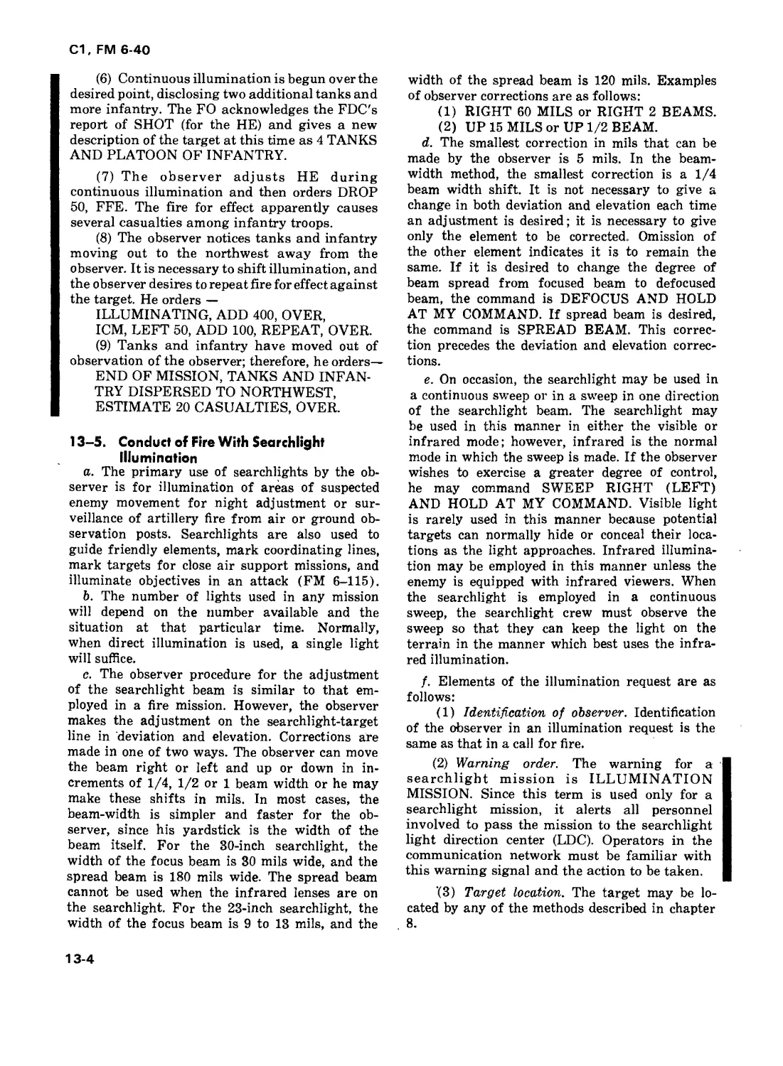
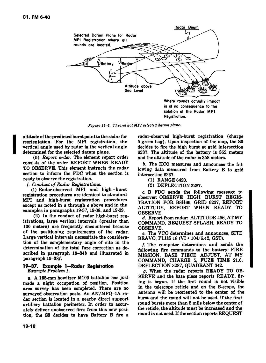
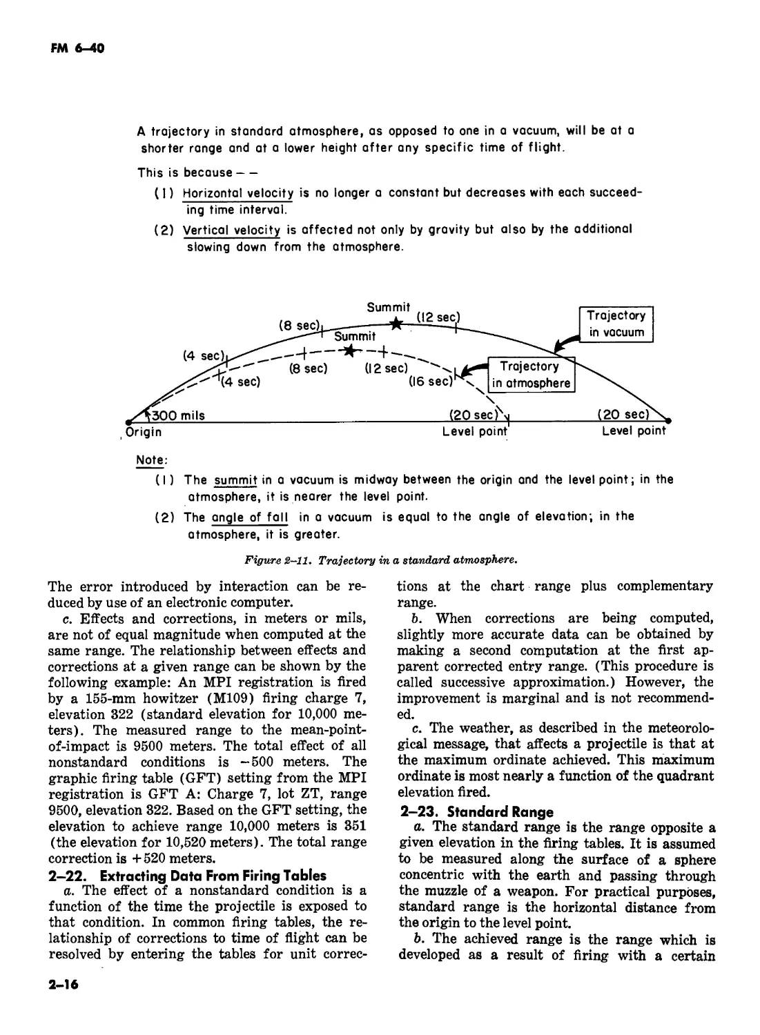
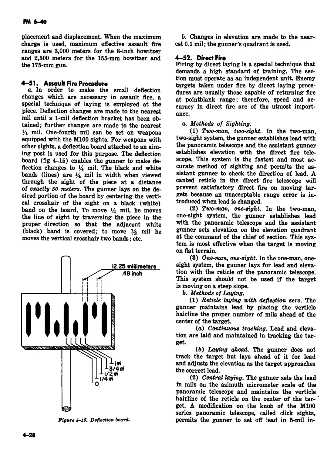
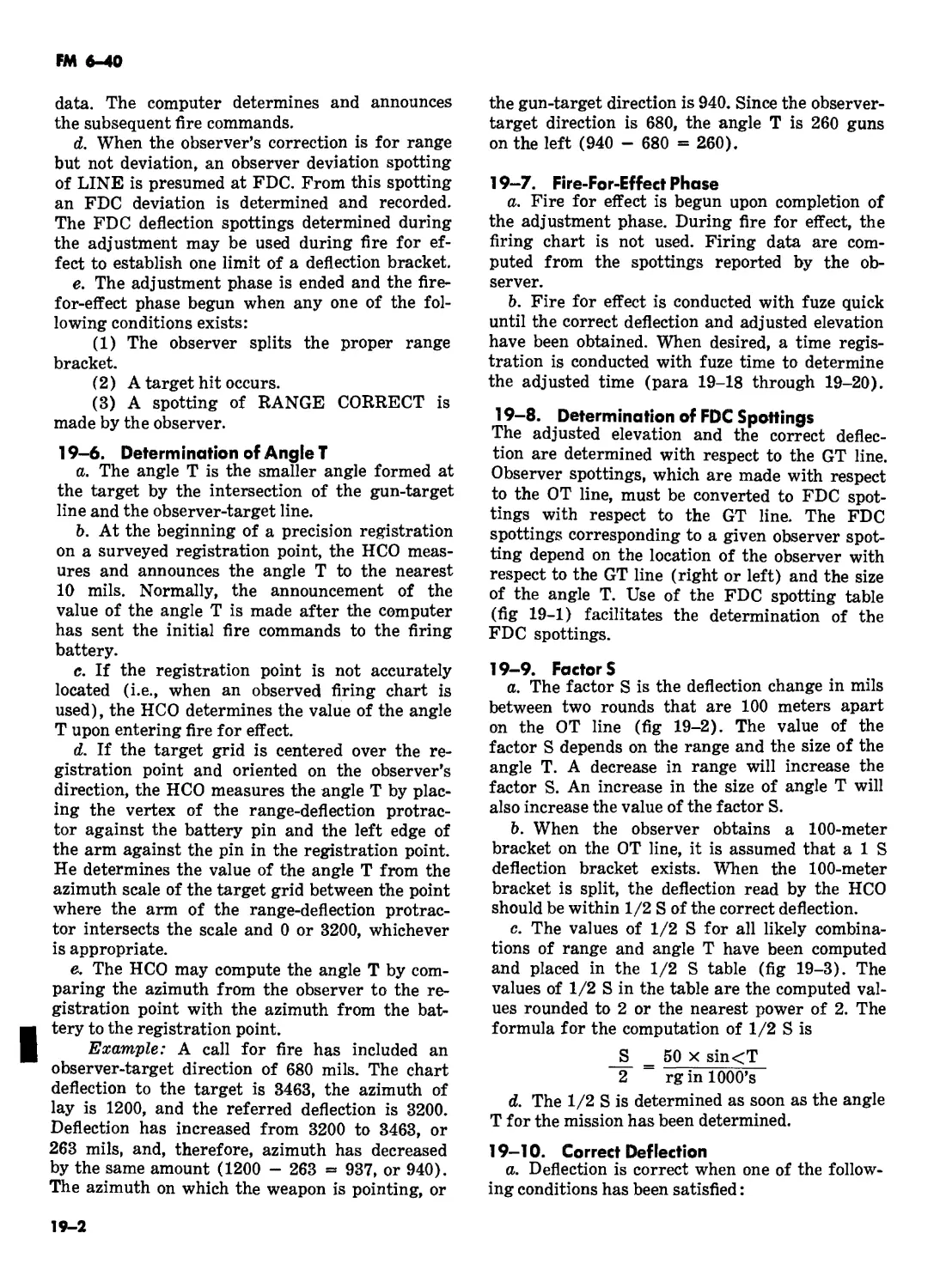
Текст
FM 6-40
FIELD ARTILLERY
CANNON GUNNERY
r
t I
HEADQUARTERS, DEPARTMENT OF THE ARMY
FM 6-40
Cl
Change
No. 1
HEADQUARTERS
DEPARTMENT OF THE ARMY
WASHINGTON, D.C. 30 September, 1976
FIELD ARTILLERY CANNON GUNNERY
FM 6-40, 28 June 1974, is changed as follows:
,1. Using pen and ink, make the following corrections:
Page Paragraph
1-1 1-1
1-1 1-3
1-2 Section II
title
1-2 1-8
1-2 1-9
1-5 Section III
1-5 1-10
1-5 1-14
2-5 Fig 2-5
2-9 2-106
2-27 2-41
2-34
2-34
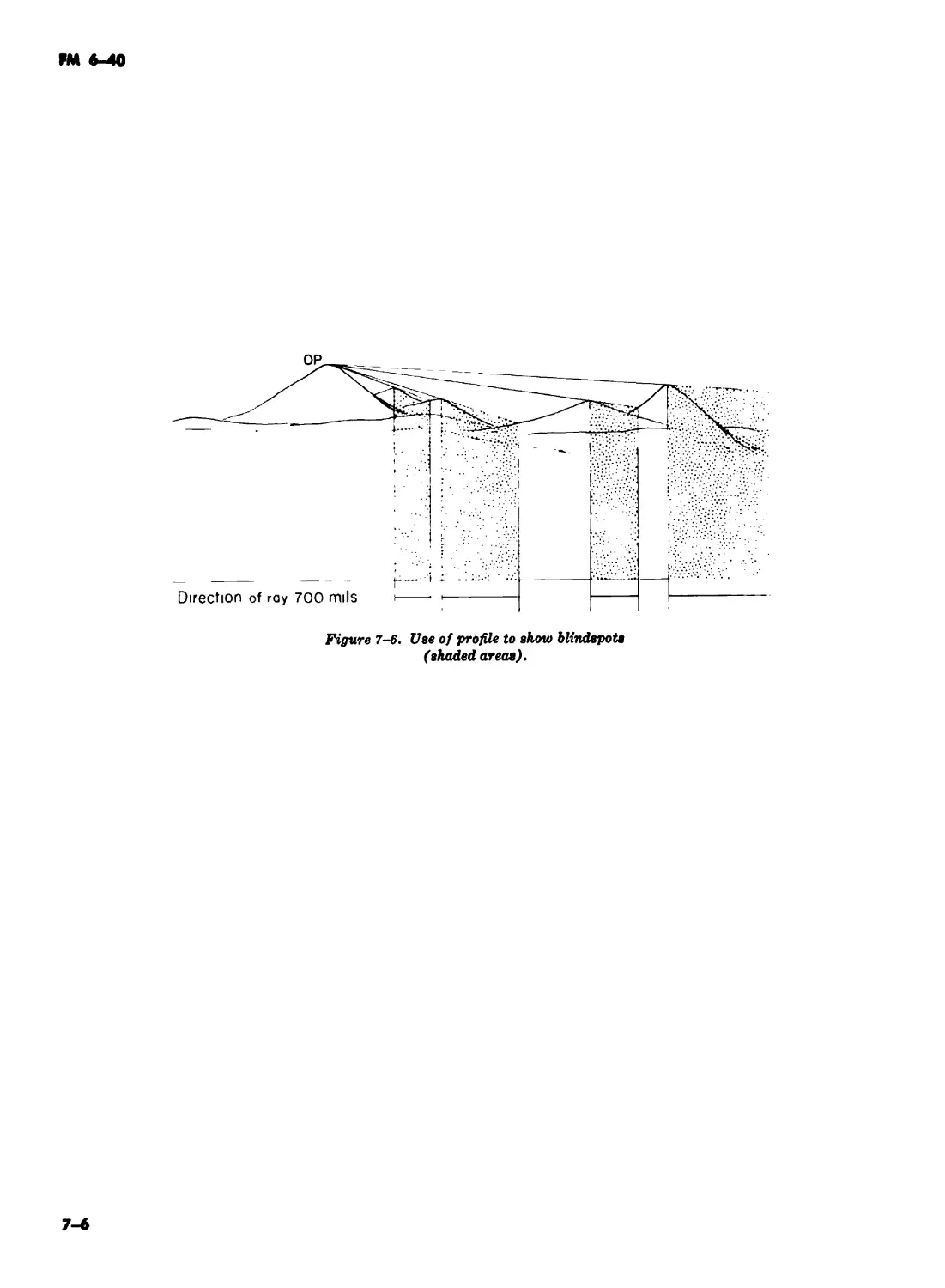
7-1 7-16
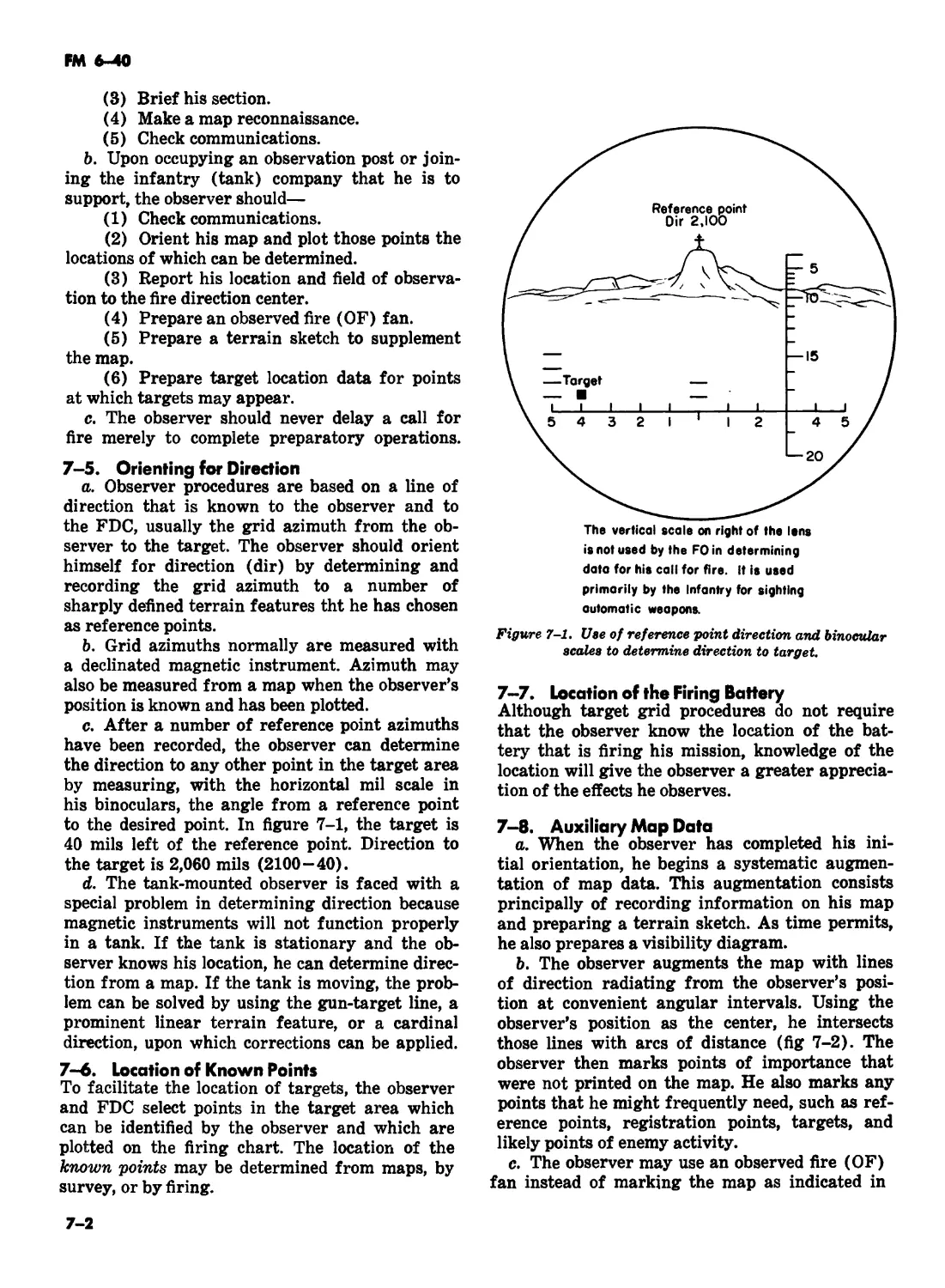
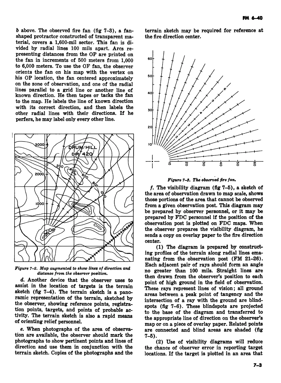
7-1 7-3
7-2 7-5d
19-13 19-29c
19-13 19-ЗОс
19-14 19-ЗЗс
20-1 20-3
20-2 Fig 20-1
20-3 20-7a
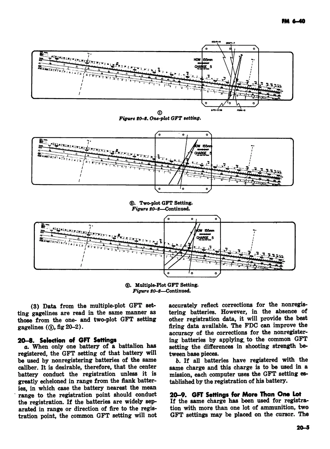
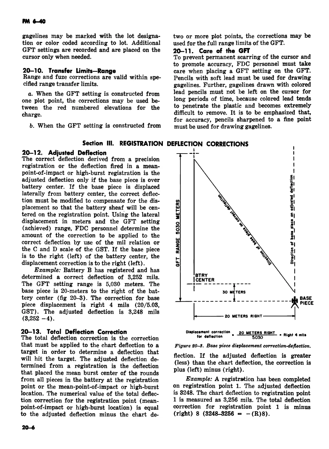
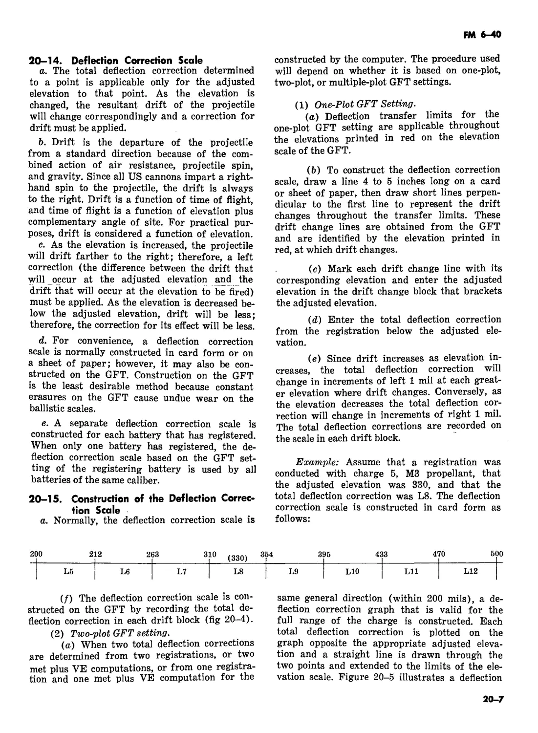
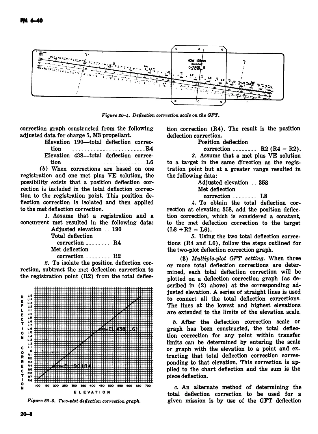
20-5 20-7
20-6 20-12,
Fig 20-3
21-2 Section II
title
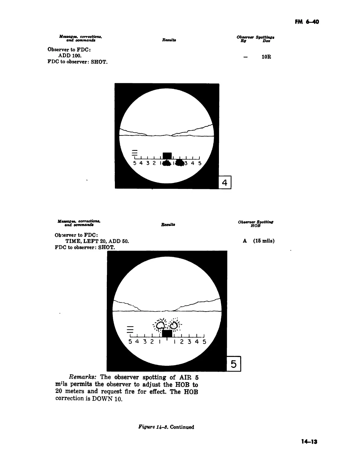
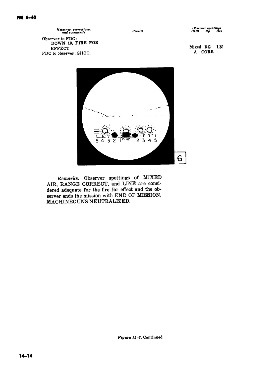
Remarks
Change last sentence to read "...in the significant loss of either speed or
accuracy without marked improvement in artillery support should be
questioned."
Change "ATSF-CTD-DL" to read "ATSF-TD-TM".
Delete.
Change title to read "Classes of Cannon Artillery".
After paragraph title add "(deleted)"; delete remainder of paragraph.
Change to read "Section II".
Delete last sentence.
Delete the note
Label left side of graph "Muzzle Velocity Variation from First Round
Fired."
In third line, change "fixed" to read "fired".
After paragraph title add "(deleted)"; delete remainder of paragraph.
Add the following: "2-48 Delivery Accuracy. (See FM 6-40-5 for a detailed
discussion of delivery accuracy)."
After page number add: "(next numbered page is 4-1)".
Change last sentence to read "Employment . . . described in appropriate
doctrinal manuals."
Change "6-140" to read "6-40-5".
After last sentence, add "See FM 6-40-5 for a more detailed discussion of
observer duties and tactics on the highly mobile modern battlefield."
Change "paragraphs 13-17 and 13-18" to read "chapter 13, section IV."
In line 4, change "... 1 ROUND," to read ". . . ADJUST,"
Change "HCD" to read "HCO".
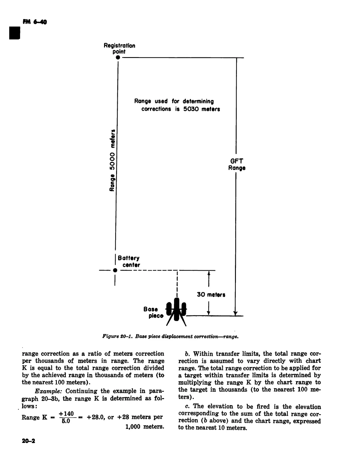
In the Example, line 4, change "The base piece" to read "The registering
piece".
Change "base piece" to read "registering piece".
In line 9, change "base" to read "registering".
Add "e. See FM 6-40-5 on how to apply GFT settings to the GFT fan."
Change all references to "base piece" to read "registering piece".
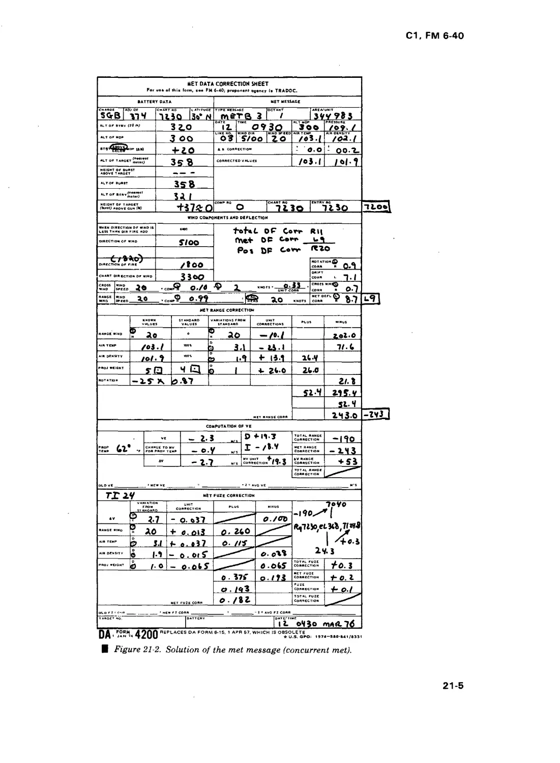
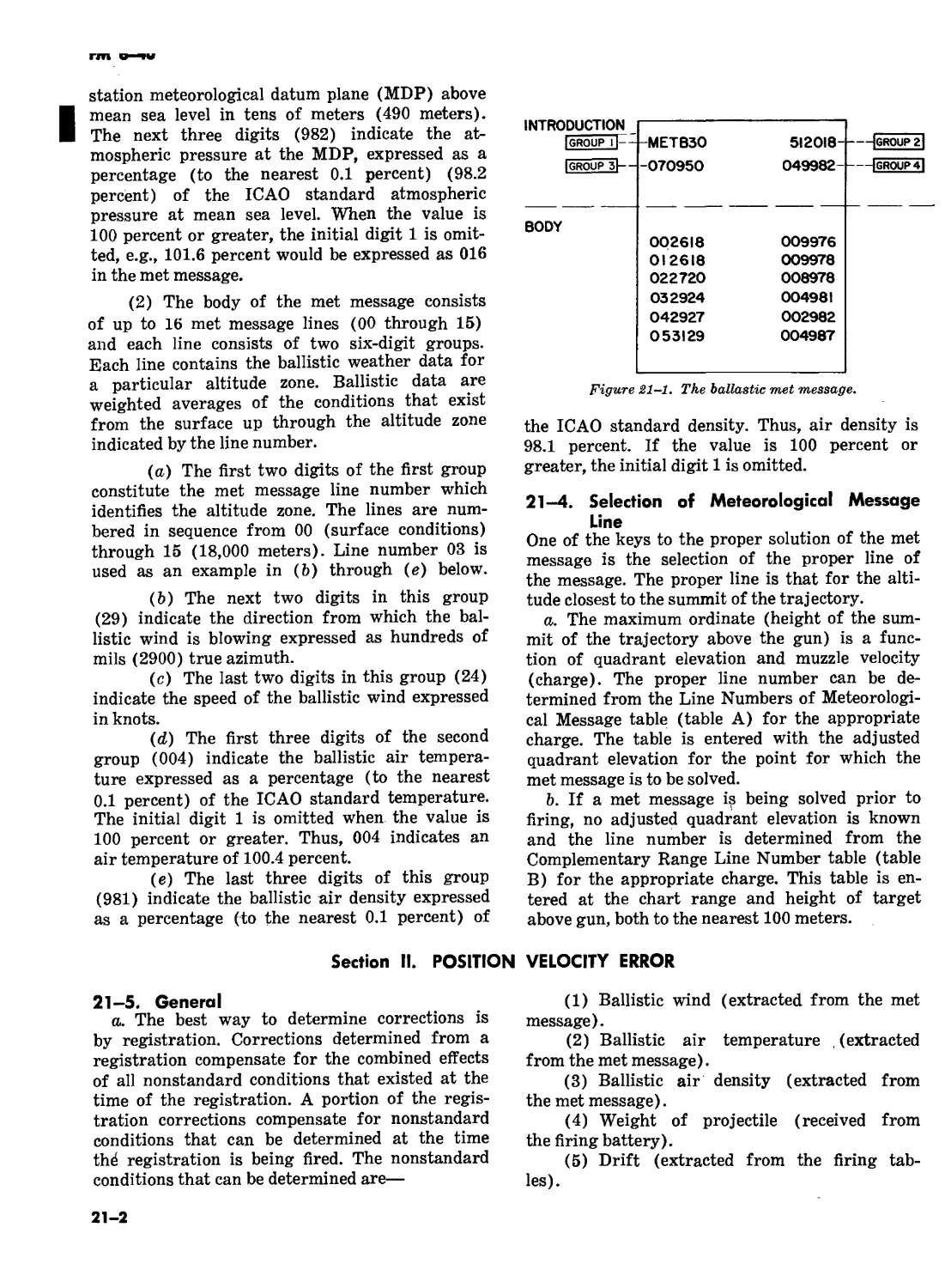
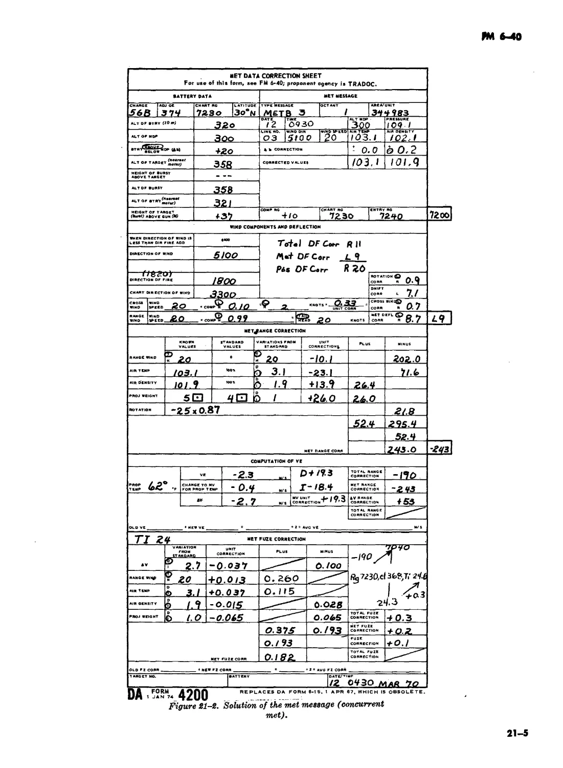
After title, add "(Concurrent met)".
1
С1, FM 6-40
Page Paragraph Remarks
21-3 21-7a In line 13, change "nearest meters" to read "nearest 100 meters"; in line 14, change "may be" to read "is not."
21-3 21-7a 21-76 In the example, change "above gun +263." to read "above gun +300."; in Height of target above gun, delete "(+263)" and "(+72.3)"; change "+72 meters" to read "+83 meters"; change "7092 (7020 + 72)" to read "7103 (7020 + 83)." Delete.
21-11 21-166 In line 6, change "graphically" to read "manually."
21-12 21-16# In lines 1 and 4, change "base piece" to read "registering piece."
22-4 22-11c Delete "the weapons may be laid for direction by any of the methods de- scribed in chapter 4."
22-5 22-11c Change last sentence to read ". . . be located by survey."
22-5 22-1 Id In first sentence, change "the target acquisition battalion" to read "a target acquisition unit."
22-5 22-1 Id In line 11, change sentence to read "the OP’s must be located by accurate survey. Each observer records. . . "
22-5 22-13a In line 1, change sentence to read "When a target acquisition unit pro- vides. . . "
22-6 22-146(3) In line 4, change "(table G)" to read "(table G, TFT)".
22-7 22-166 In line 1, change “(table F)” to read “(table F, TFT)’’
22-7 22-17a In line 2, change "(table Е)" to read "(table E, TFT)".
23-2 23-2c In line 8, change "invididual" to read "individual."
24-1 24-4c Delete.
24-2 24-56(2) Change first sentence to read "Determine (at the initial chart range) from the Ground Data Table, (Table F, TFT) the correction. ..."
24-2 24-56(4) In the example, add "Initial chart range 5980 meters"; delete "Comp range (VI + 30 meters)...+ 6 meters." Change entry range to read "Entry range (5980 = 6000)....6000 meters." Change "corrected range...." to read "Corrected fire-fbr-effect range...."
24-2 24-6, 24-7 After each paragraph title add "(See FM 6-40-5)"; delete remainder of paragraphs.
24-3 24-9a Change "13-6 and 13-7" to read "13-3 and 13-4".
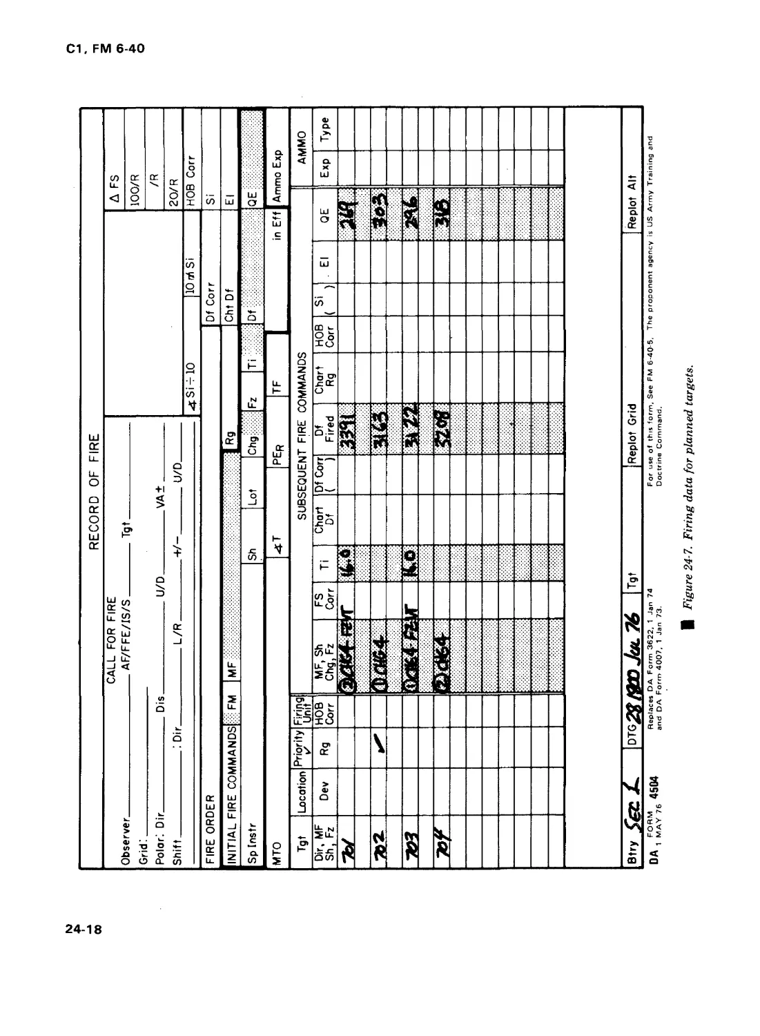
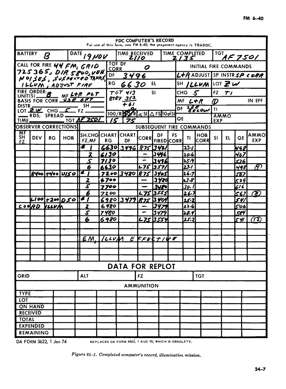
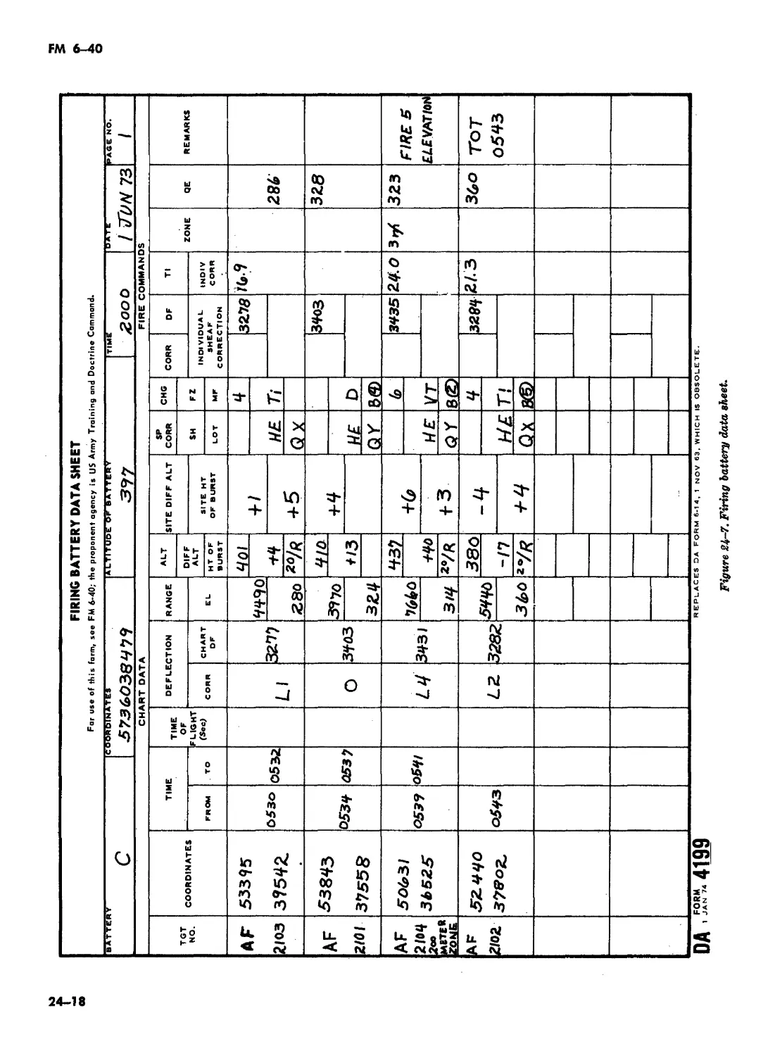
24-6 24-18 Change "computer’s record" to read "Record of Fire".
24-6 24-18/ Change "13-7" to read "13-4".
24-9 24-236 Change "S3" to read "FDO".
24-9 24-24 Delete remainder of paragraph; after paragraph title, add "(See FM 6- 40-5)".
24-10 24-27a Change "13-5 through 13-20" to read "13-12 through 13-17"; change "S3" to read "FDO".
24-12 24-35a After "Firing Battery" add "(See FM 6-50)"; delete remainder of subpara- graph.
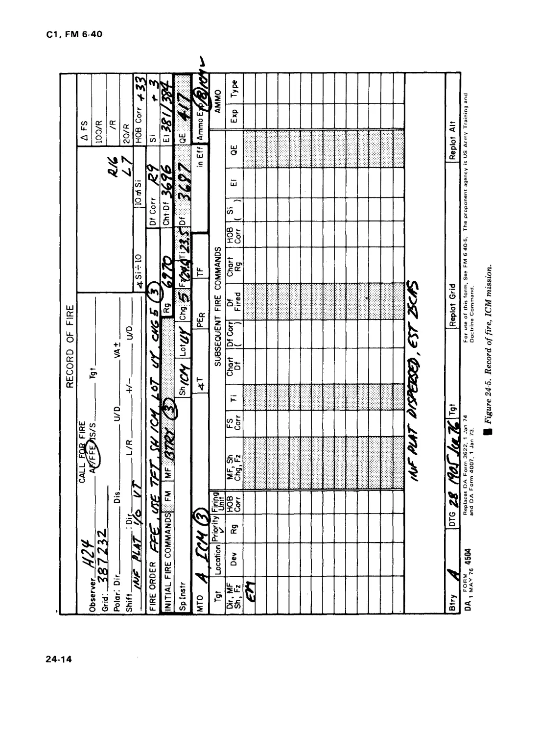
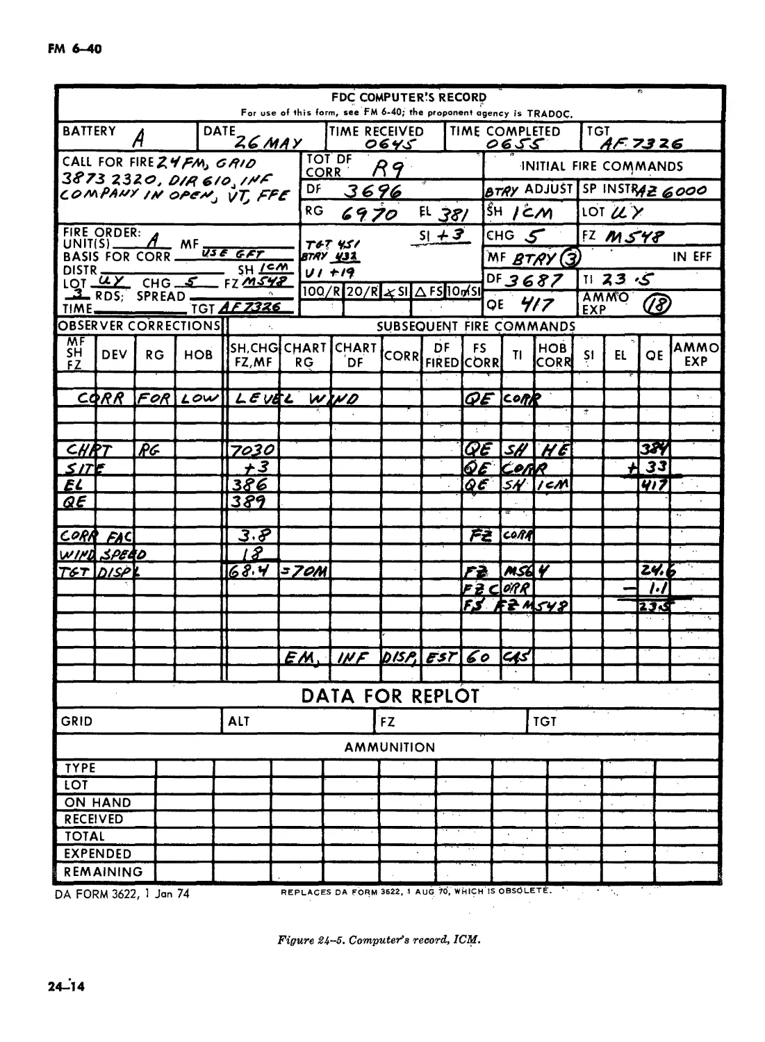
24-15 24-36a-d Delete all down to 24-36e.
24-15 24-36e Change subparagraph title to read "Determination of QE and Fuze Setting for HE Projectile"; delete "to the wind-displaced plot", add "Chart range 6970 meters."
24-15 24-36/(2) In line 1, change “table A" to read “table A, FT 155-ADD-E-l, chg 5G,...”
24-20 24-456(2) Change "total" to read "GFT".
24-20 24-47c(2) Change "concurrent" to read "current".
2
Cl, FM 6-40
Page Paragraph Remarks
24-41 24-696(2) In line 5, delete "10 or..."
26-3 26-7c(l) Change "average fuze" to read "known fuze"; add a second sentence: "Place the manufacturer’s hair line (MHL) over this value."
26-3 26-7c(2) Change "adjusted time" to read "corrected time under the MHL."
26-8 26-23d Delete "...and separate deflection correction scales."
26-12 26-366 In line 2, change "the deflection correction scale to..." to read "the GFT deflection correction to ..."
26-13 26-37a(l) Delete last sentence.
26-13 26-39 In title and in line 1, change "Computer’s Records" to read "Records of Fire."
26-13 26-39c(l) In line 3, change "FROM" to read "SHIFT."
26-13 26-39d In line 7 of the Example, change "AF 7401" to read "AF 741"; in line 13, change "Total deflection correction from deflection correction scale" to read "Total deflection correction."
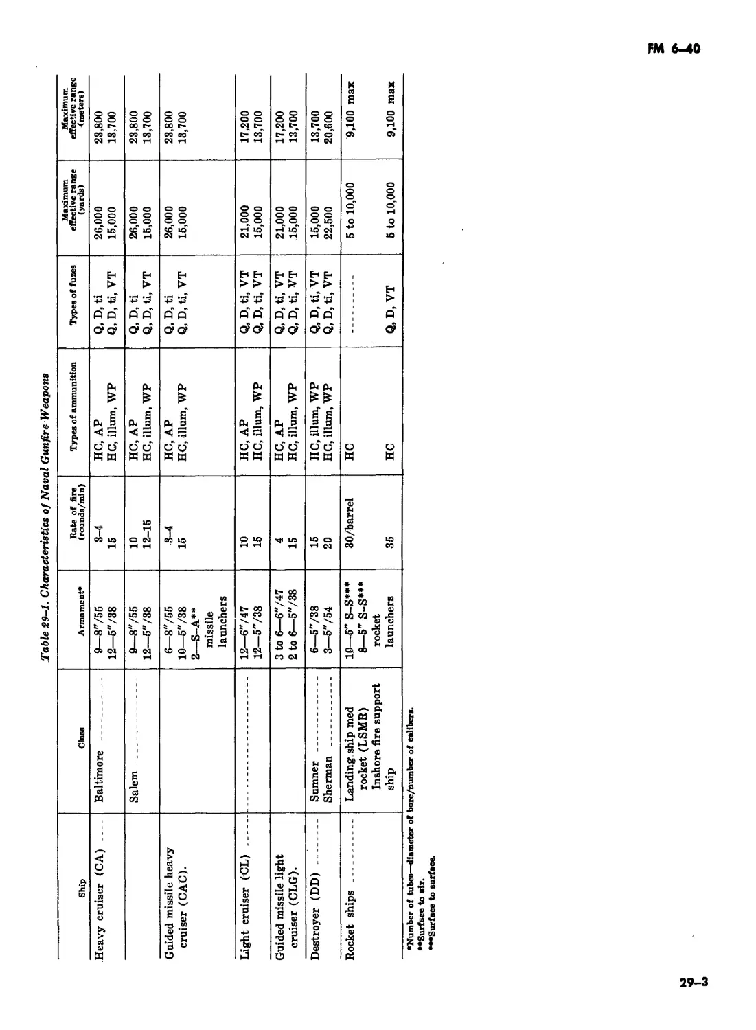
29-3 Table In next-to-last column, change "Maximum effective range (yards)" to read
29-1 "Maximum effective range (meters)"; delete last column.
30-1 30-1 a Change first sentence to read "Tank guns normally are not used in the field artillery (indirect fire) role because of the small bursting radius of the high velocity, flat trajectory ammunition and the short tube life of the tank guns."
30-1 30-4a(2) In line 12, delete "as outlined in chapter 20".
2. Remove old pages and insert new pages as indicated below. New or changed material is indicated by
a vertical bar in the margin of the page. New or revised illustrations, tables, paragraphs, or sections are
indicated by a vertical bar adjacent to the identification number.
Remove pages Insert pages
i through iv (blank) i through iv (blank)
1-3, 1-4 1-3, 1-4
2-1 through 2-4 2-1 through 2-4
3-1 through 3-4 (blank) None
4-1 through 4-30 (blank) 4-1 through 4-6
5-1 through 5-10 None
6-1 through 6-6 None
8-1 through 8-8 8-1 through 8-6
9-1 through 9-6 (blank) None
10-1 through 10-12 10-1 through 10-10 (blank)
11-1 through 11-4 (blank) 11-1, 11-2
12-1 through 12-4 (blank) 12-1 through 12-4 (blank)
13-1 through 13-16 13-1 through 13-14 (blank)
14-1 through 14-16 None
15-1 through 15-4 15-1 through 15-4
16-1 through 16-16 (blank) 16-1 through 16-14
17-1 through 17-4 17-1 through 17-4
18-1 through 18-18 18-1 through 18-16
19-1 through 19-12 19-1, 19-2
19-15 through 19-22 (blank) 19-15 through 19-22 (blank)
20-7 through 20-12 20-7 through 20-10
21-5 through 21-10 21-5 through 21-10
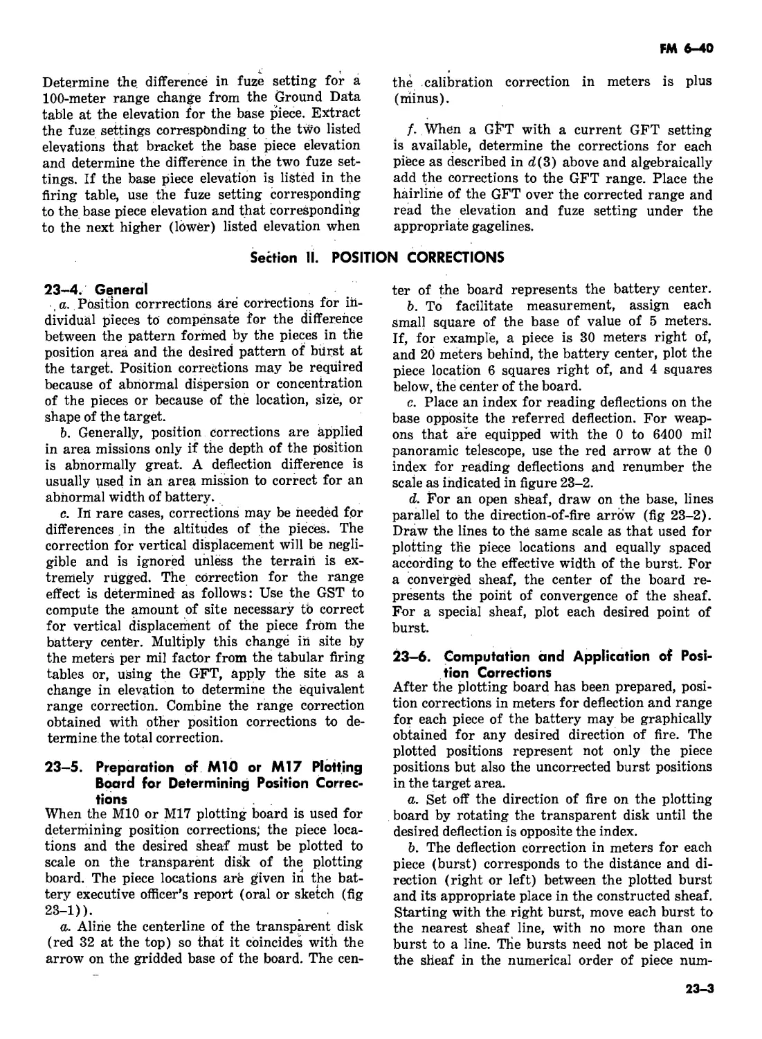
23-3 through 23-8 (blank) 23-3 through 23-8
3
Cl, FM 6-40
Remove pages
24-7, 24-8
24-13, 24-14
24-17, 24-18
24-21 through 24-40
25-1 through 25-8 (blank)
27-1 through 27-8 (blank)
28-1 through 28-8 (blank)
A-l through A-4 (blank)
Index-1 through Index-16
B-l through B-14
C-l through C-8 (blank)
Insert pages
24-7, 24-8
24-13, 24-14
24-17, 24-18
24-21 through 24-40
25-1 through 25-6
27-1, 27-2 (blank)
None
A-l through A-4
Index-1 through Index 18 (blank)
None
None
3. The word “he” as used in this publication is intended to include both the masculine and the feminine
genders. Any exceptions to this will be so noted.
4. These transmittal sheets should be filed in front of the manual for reference purposes.
By Order of the Secretary of the Army:
FRED C. WEYAND
General, United States Army
Chief of Staff
Official:
PAULT. SMITH
Major General, United States Army
The Adjutant Genera!
DISTRIBUTION:
Active Army, US AR, ARNG.Tobe distributed in accordance with DA Form 12-11 A, Requirements
for Field Artillery Cannon Gunnery (Qty rqr block no. 44).
Additional copies can be requisitioned (DA Form 17) from the U.S. Army Adjutant General
Publications Center, 2800 Eastern Boulevard, Baltimore, MD 21220.
4
С1
* FM 6-40
FIELD MANUAL
No. 6-40
HEADQUARTERS
DEPARTMENT OF THE ARMY
Washington, D.C., 28 June 1974
FIELD ARTILLERY CANNON GUNNERY
Paragraphs Pa^e
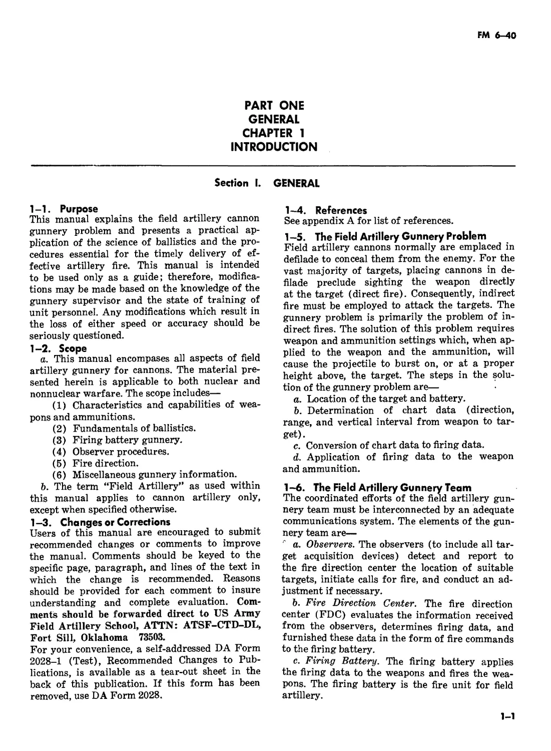
PART ONE. GENERAL CHAPTER 1. INTRODUCTION Section I. General .. 1-1—1-9.1 1-1
II. Cannon artillery (Deleted) IL Ammunition .. 1-10—1-14 1-5 1
CHAPTER 2. FUNDAMENTALS OF FIELD ARTILLERY GUNNERY Section L Elements of firing data ... 2-1—2-5 2-1
II. Interior ballistics ... 2-6—2-9 2-3
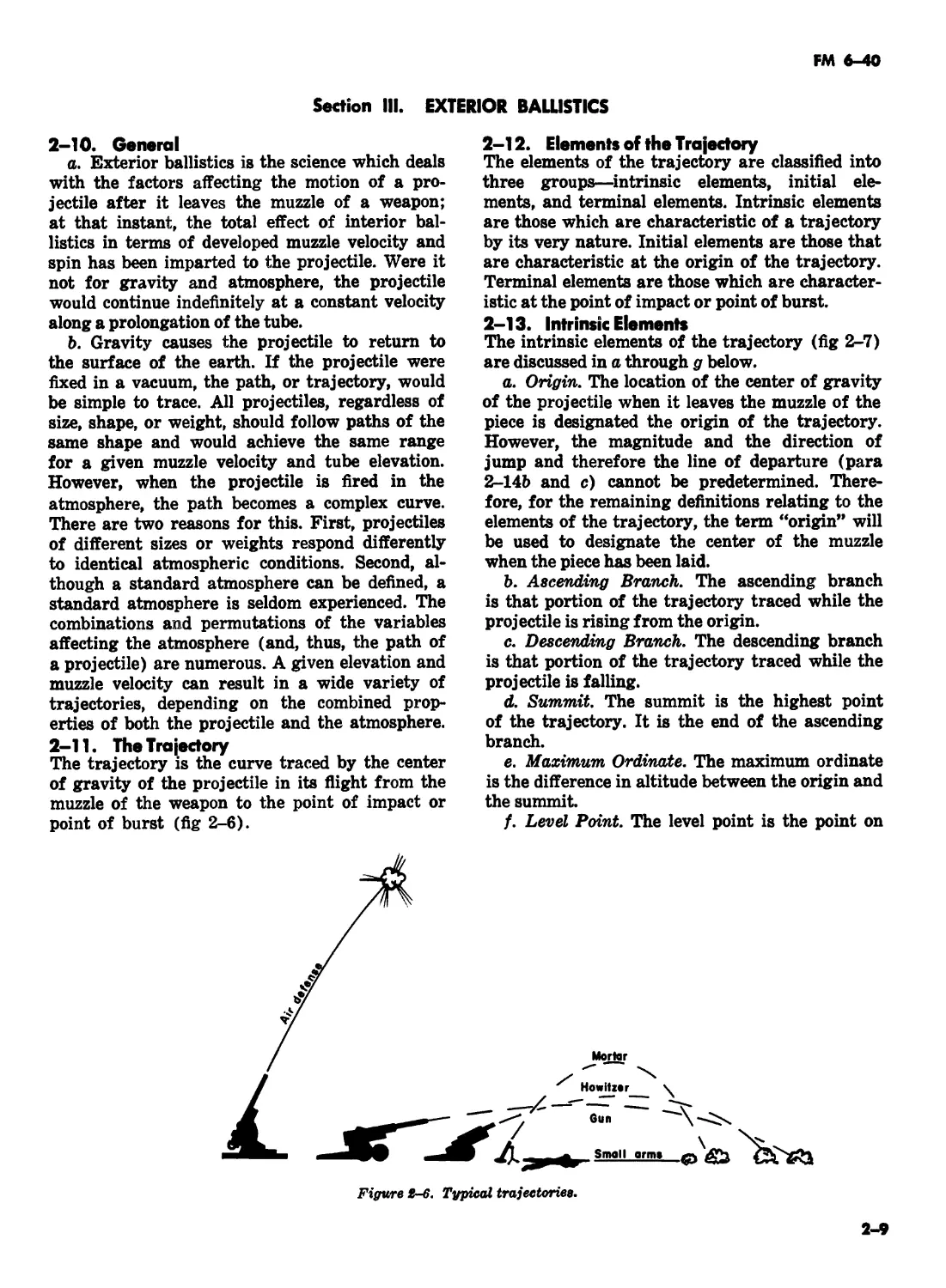
III. Exterior ballistics — ... 2-10—2-27 2-9
IV. Dispersion and probability ... 2-28—2-48 2-20
PART TWO. FIRING BATTERY CHAPTER 3. FIRING BATTERY, GENERAL (Deleted) 4. FIRING BATTERY PROCEDURES Section I. Laying the battery (Deleted) IL Minimum quadrant elevation (Deleted) III. Determining and reporting data(Deleted) IV. Fire commands and their execution ...4-1—4-19 4-1
V. Assault and direct fire (Deleted) CHAPTER 5. FIRING BATTERY OPERATIONS AND TRAINING (Deleted) CHAPTER 6. DUTIES OF THE SAFETY OFFICER (Deleted) PART THREE. OBSERVED FIRE CHAPTER 7. FIELD ARTILLERY OBSERVER Section I. Introduction ... 7-1-7-3 7-1
II. Preparatory operations ... 7-4—7-8 7-1
CHAPTER 8. LOCATION OF TARGETS ... 8-1-8-8 8-1
CHAPTER 9. CALLS FOR FIRE (Deleted) I
10. ADJUSTMENT PROCEDURE BY GROUND OBSERVER SECTION I. General ... 10-1—10-6 10-1
II. Adjustment of deviation ... 10-7, 10-8 10-4 |
III. Adjustment of range ... 10-9—10-11.1 10-5 I
IV. Adjustment of height of burst ... 10-2—10-16 10-6 I
V. Subsequent corrections ... 10-17—10-33 10-7
CHAPTER 11. FIRE FOR EFFECT Section I. Precision fire (Deleted) — II. Area fire ... ...11-5—11-8 1
CHAPTER . 12. ADJUSTMENT OF FIRE BY THE AIR OBSERVER Section I. Introduction ... 12-1—12-3 12-1
II. Preflight preparations ... 12-4, 12-5 12-1
III. Determination of initial data ... 12-6—12-9 12-1
IV. Adjustment procedures ... 12-10—12-12 12-2 |
CHAPTER 13. ADJUSTMENT PROCEDURE FOR SPECIAL SITUATIONS Section I. Conduct of fire with chemical projectiles ... 13-1, 13-2 13-1
II. Battlefield illumination ... 13-3—13-5 13-1 I
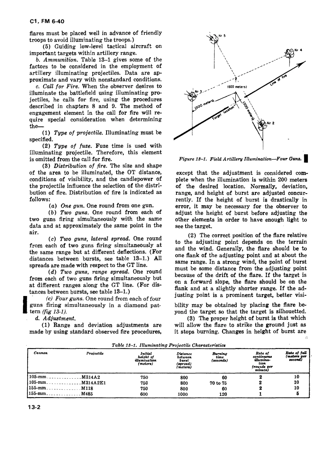
III. Conduct of assault fire ... 13-6—13-11.1 13-6 1
* This manual supersedes FM 6-40, 5 October 1967, including all changes, and FM 6-135,
14 February 1969.
С1, FM 6-40
Paragraphs Page
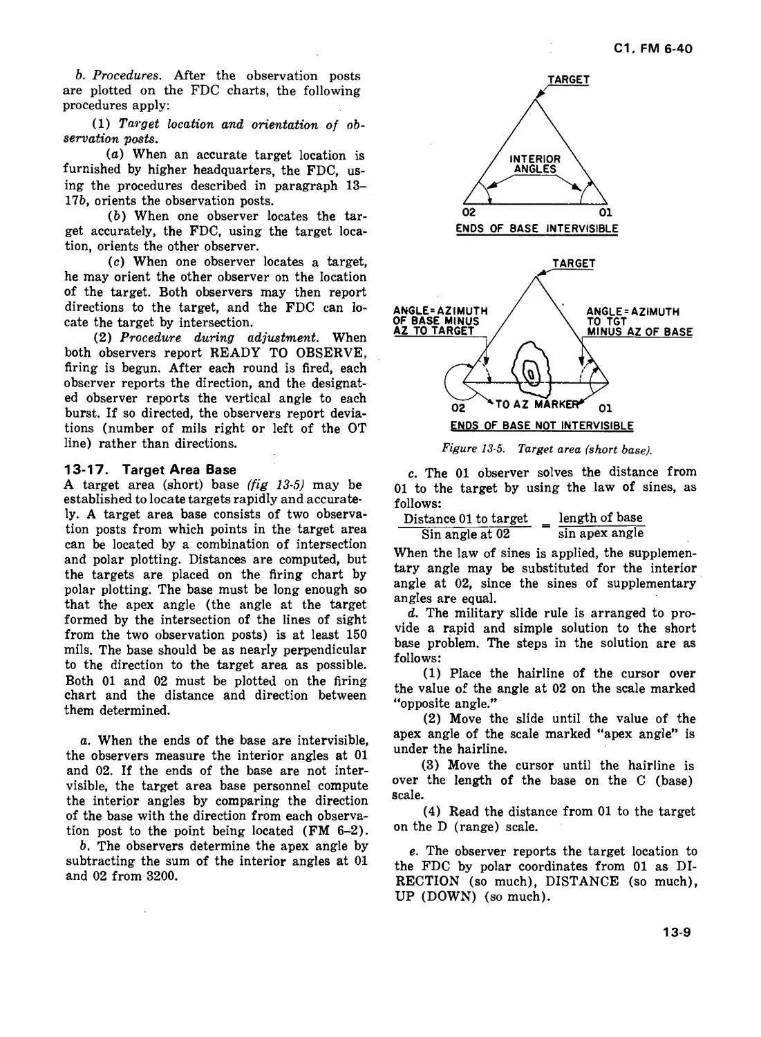
IV. Conduct of fire by use of combined observation . 13-12—13-17 13-8
V. Adjustment of high-angle fire and auxiliary
adjustment point . . . 13-18—13-22 13-10
VI. Conduct of fire when observer is not oriented . 13-23—13-25 13-10 |
VII. Adjustment of fire by sound . . . 13-26, 13-7 13-11
VIII. Aerial field artillery (Deleted)
IX. ABC A precision fire (Deleted) 13-11 I
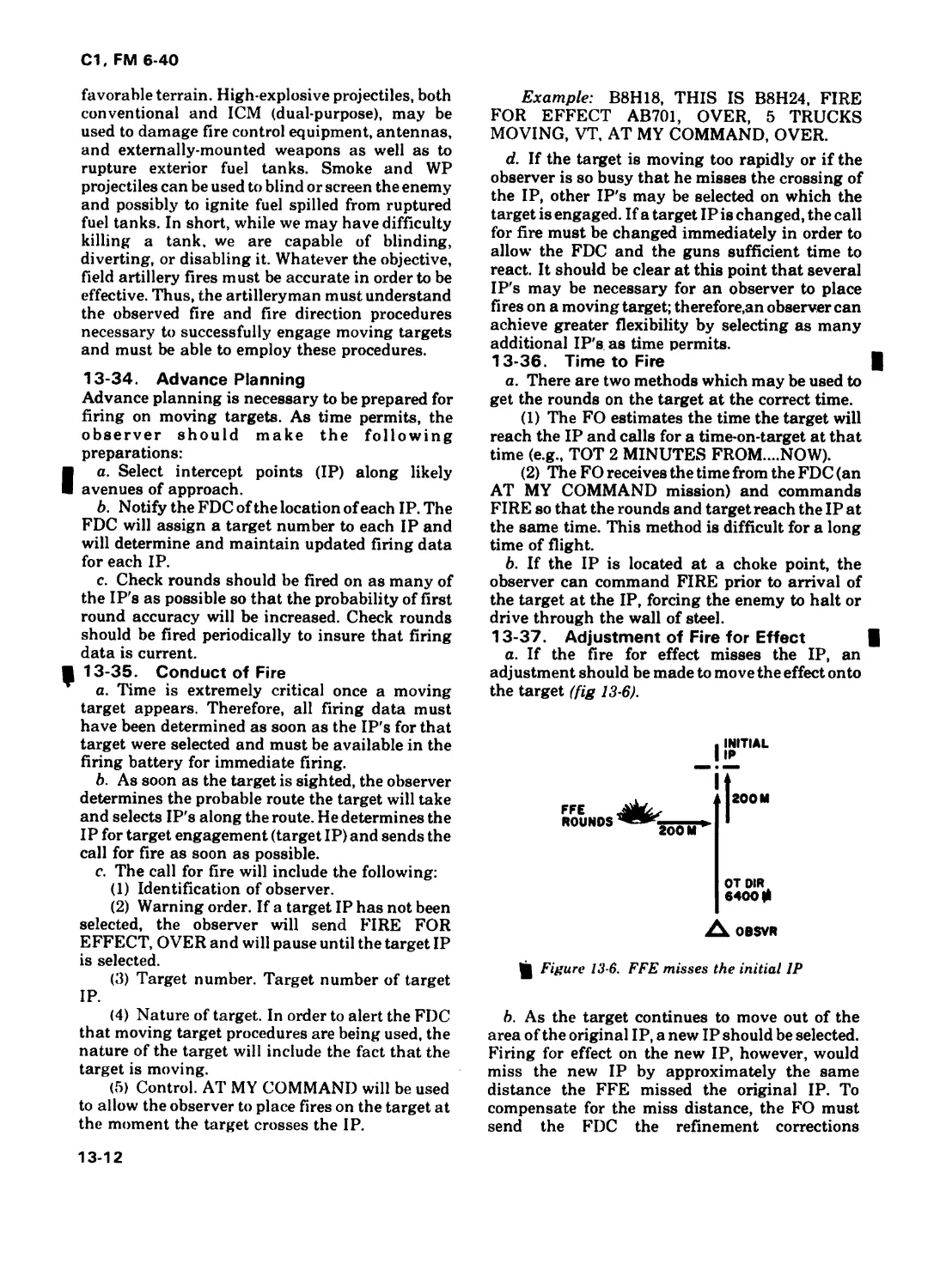
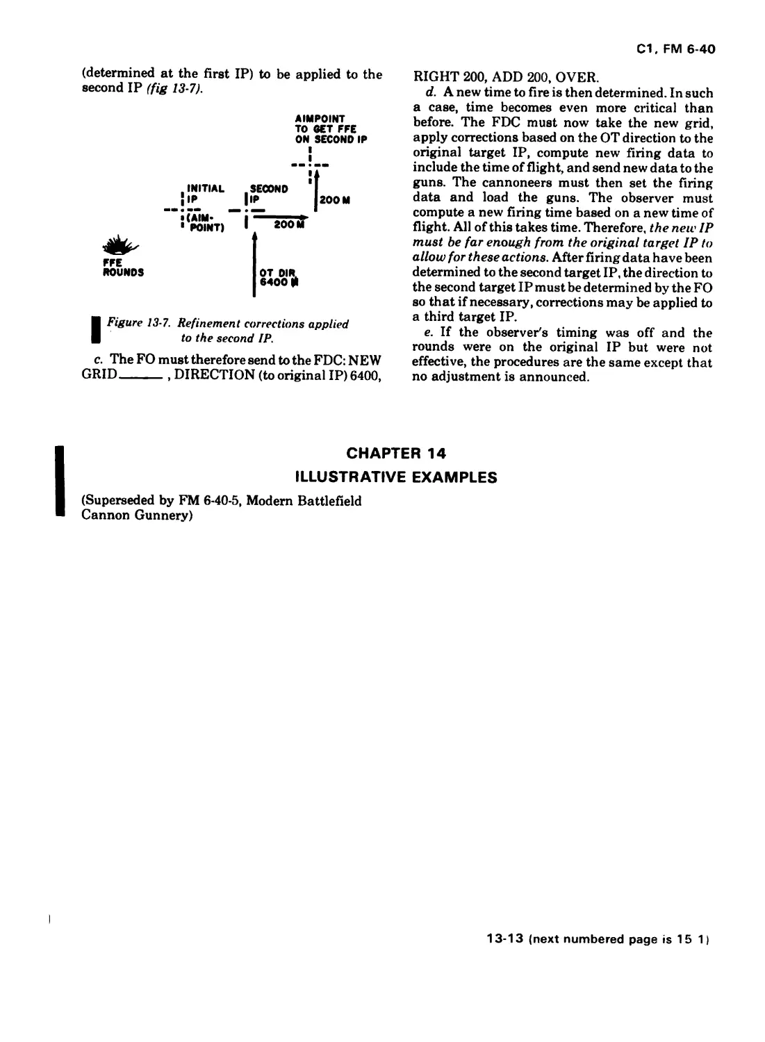
X. Moving target missions . 13-33—13-35
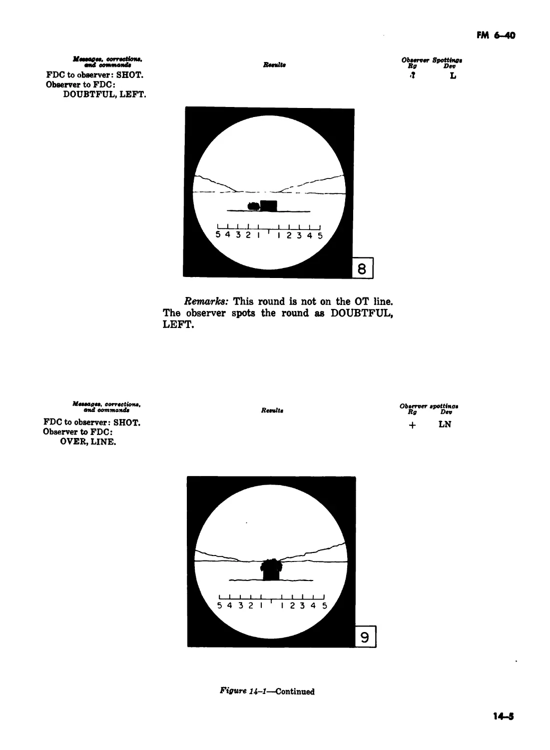
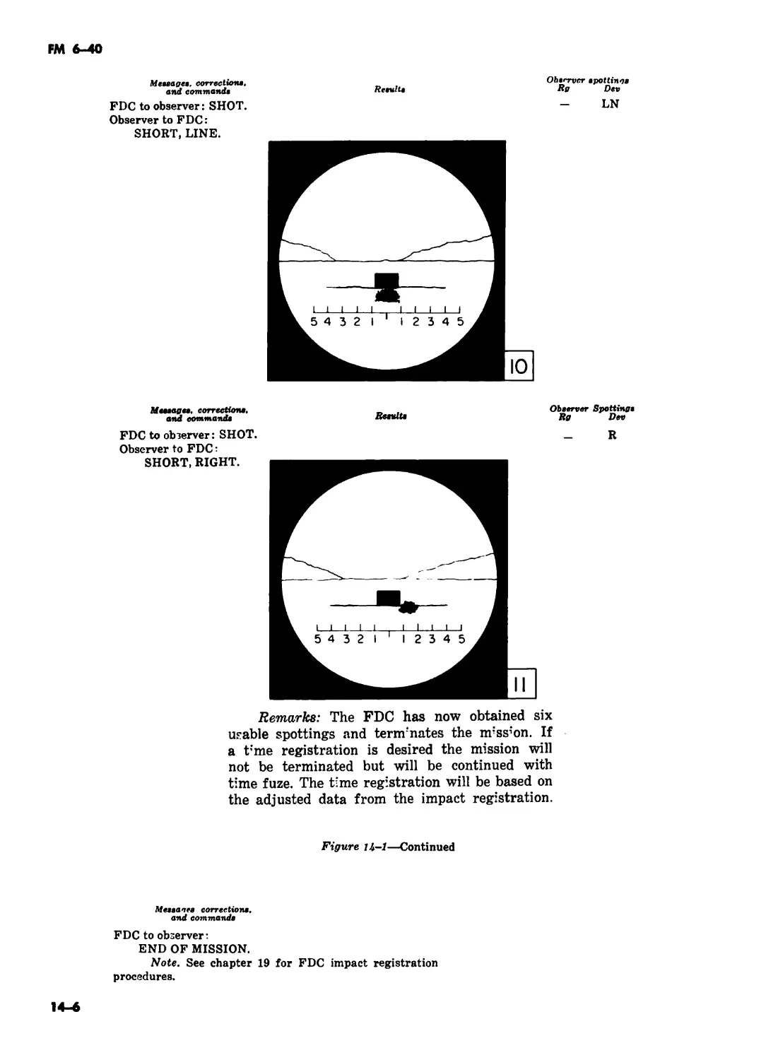
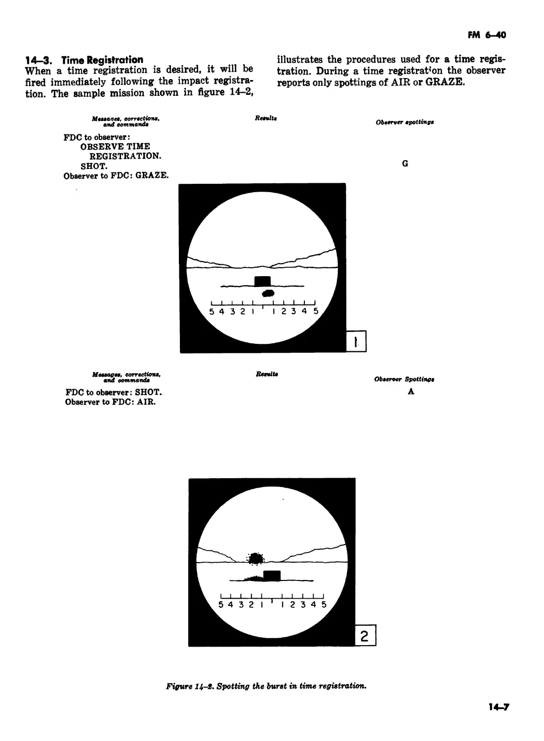
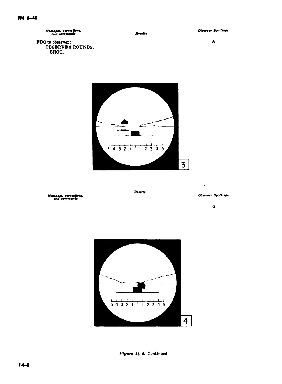
CHAPTER 14. ILLUSTRATIVE EXAMPLES (Deleted)
PART FOUR. FIRE DIRECTION
CHAPTER 15 FIRE DIRECTION, GENERAL
Section I. Introduction . 15-1—15-3 15-1
II. Fire direction center, general . 15-4—15-6 15-1
III. FDC personnel in the battalion . 15-7—15-16 15-2
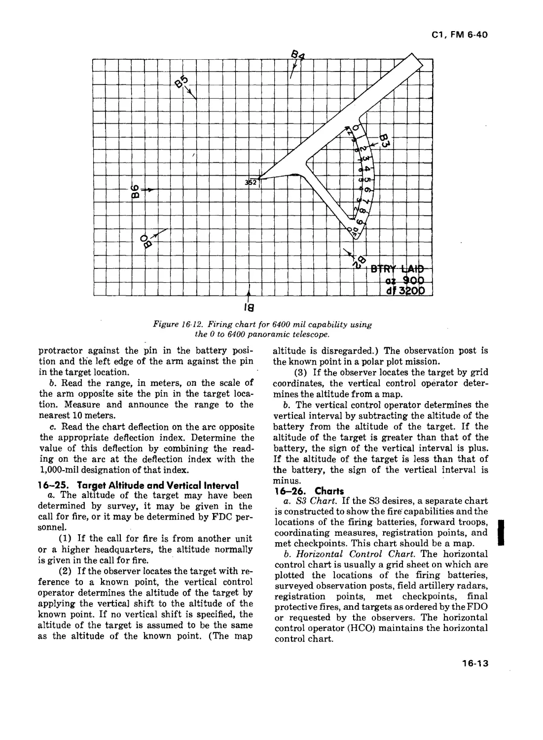
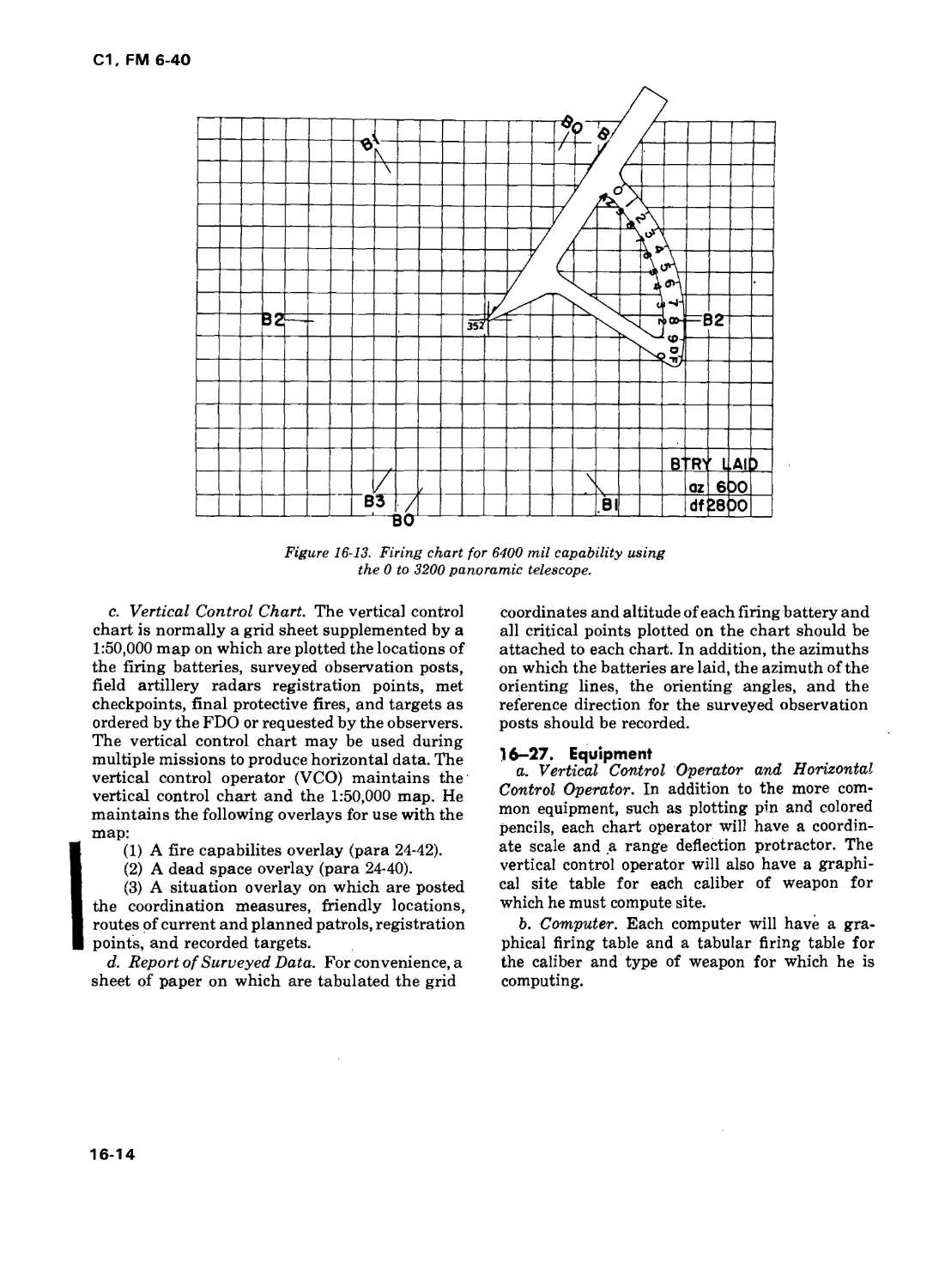
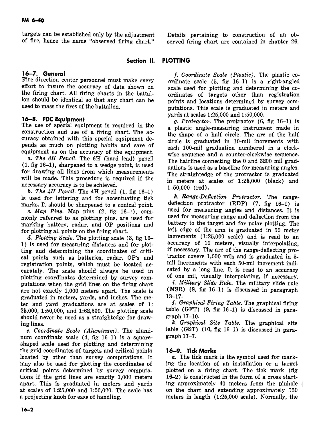
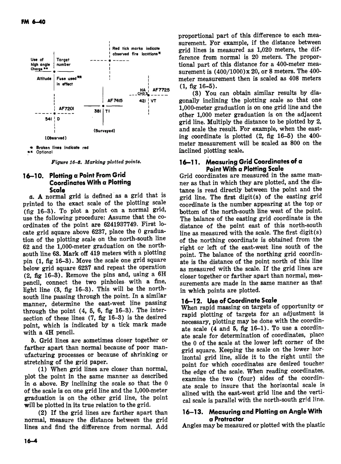
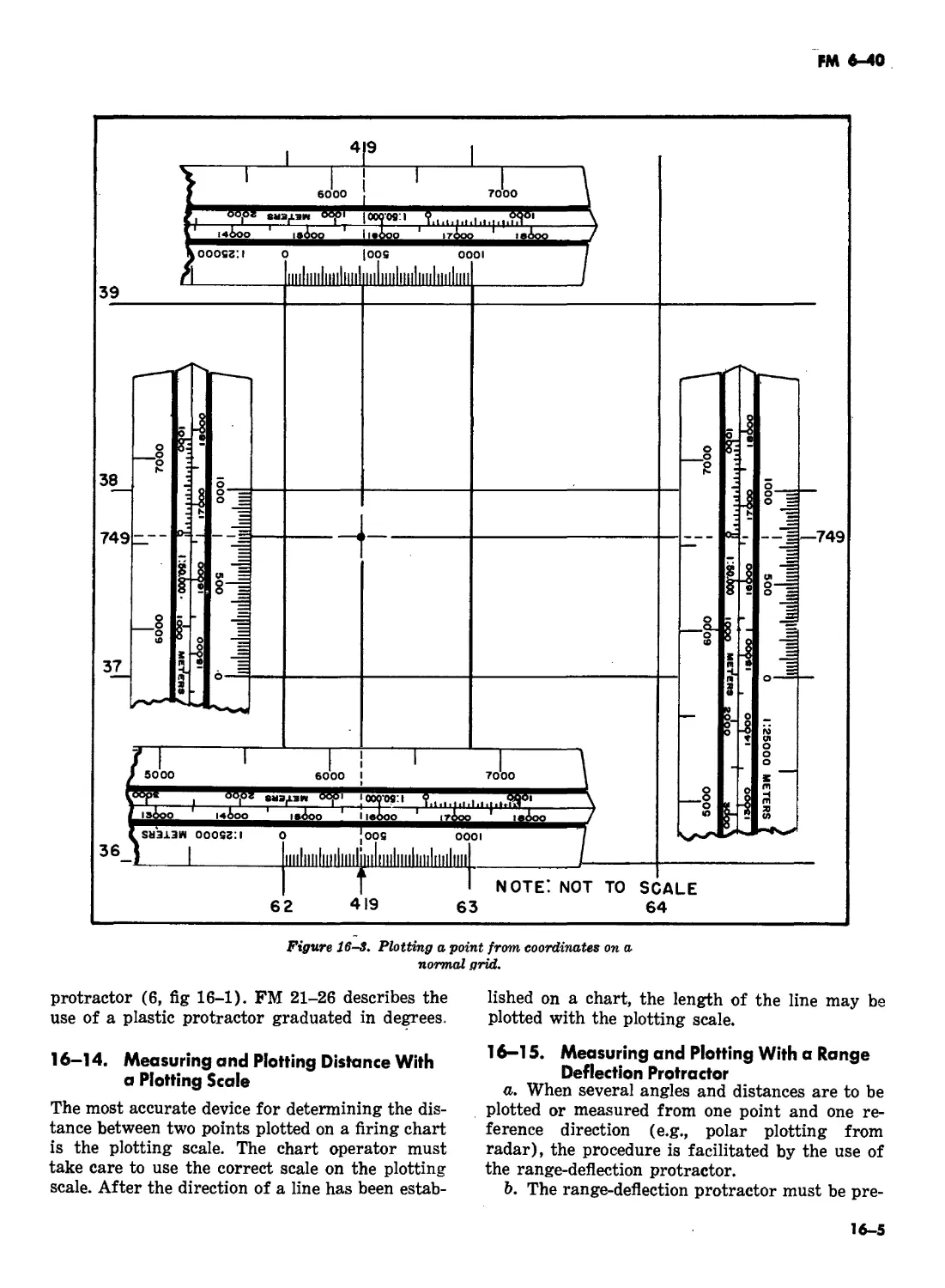
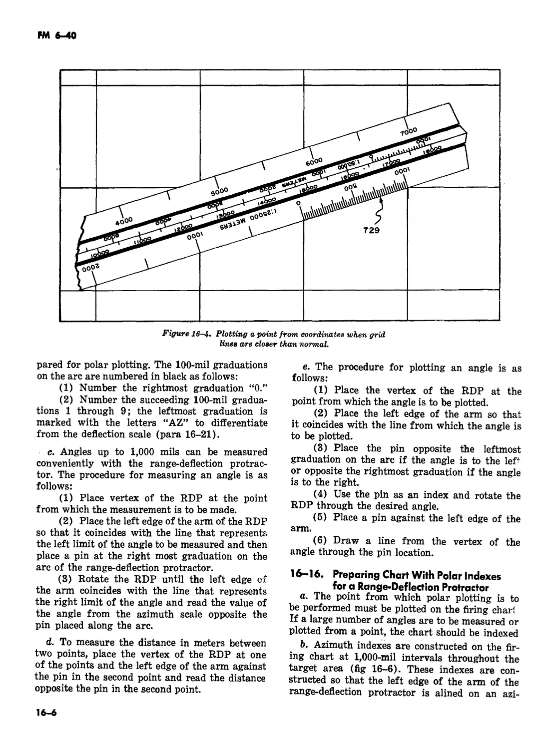
CHAPTER 16. CHART DATA
Section I Firing charts . 16-1—16-6 16-1
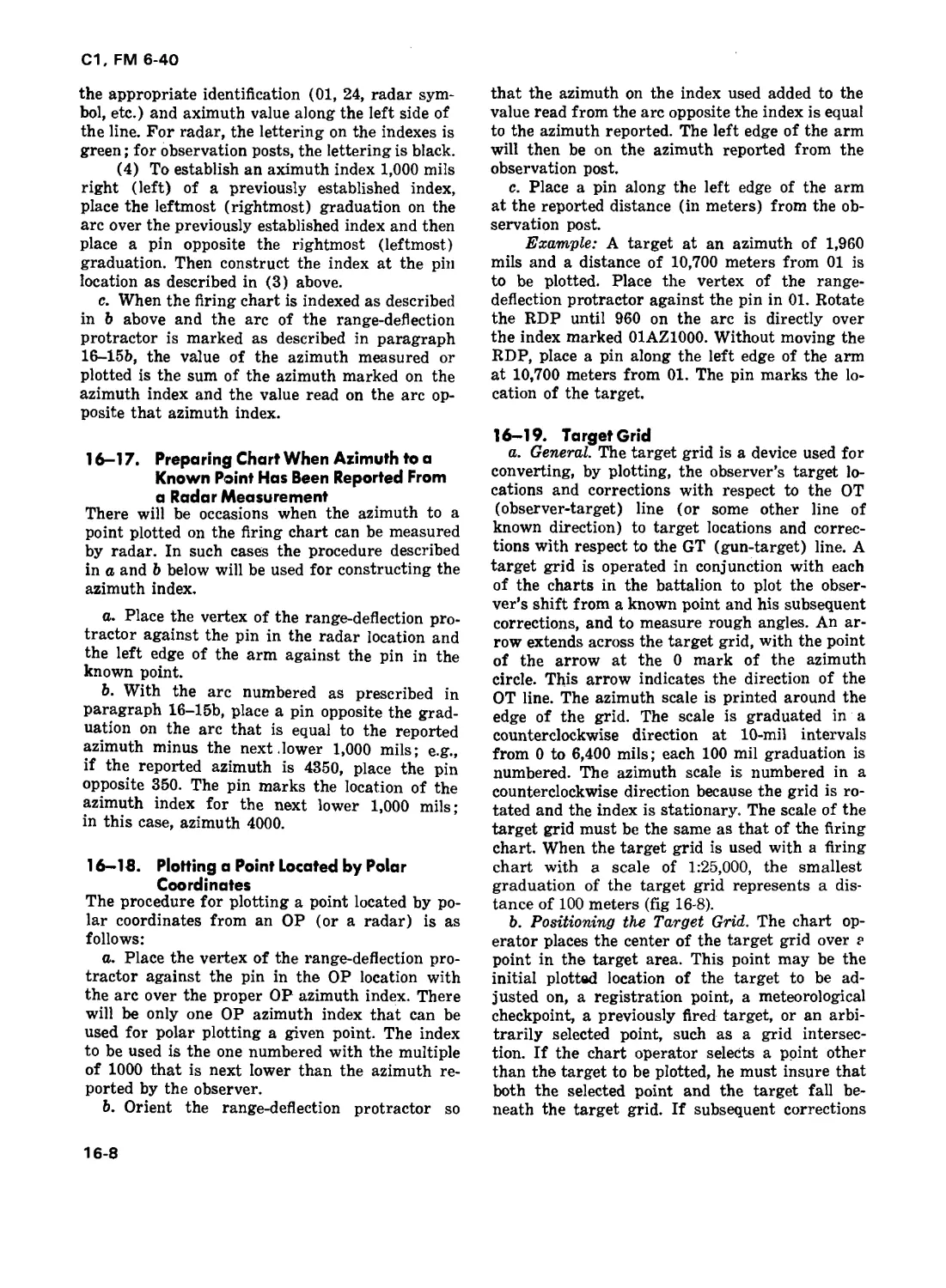
II. Plotting . 16-7—16-19 16-2
III. Determination of chart data .16-20—16-27 16-11 |
CHAPTER 17. FIRING DATA . 17-1—17-13 17-1 1
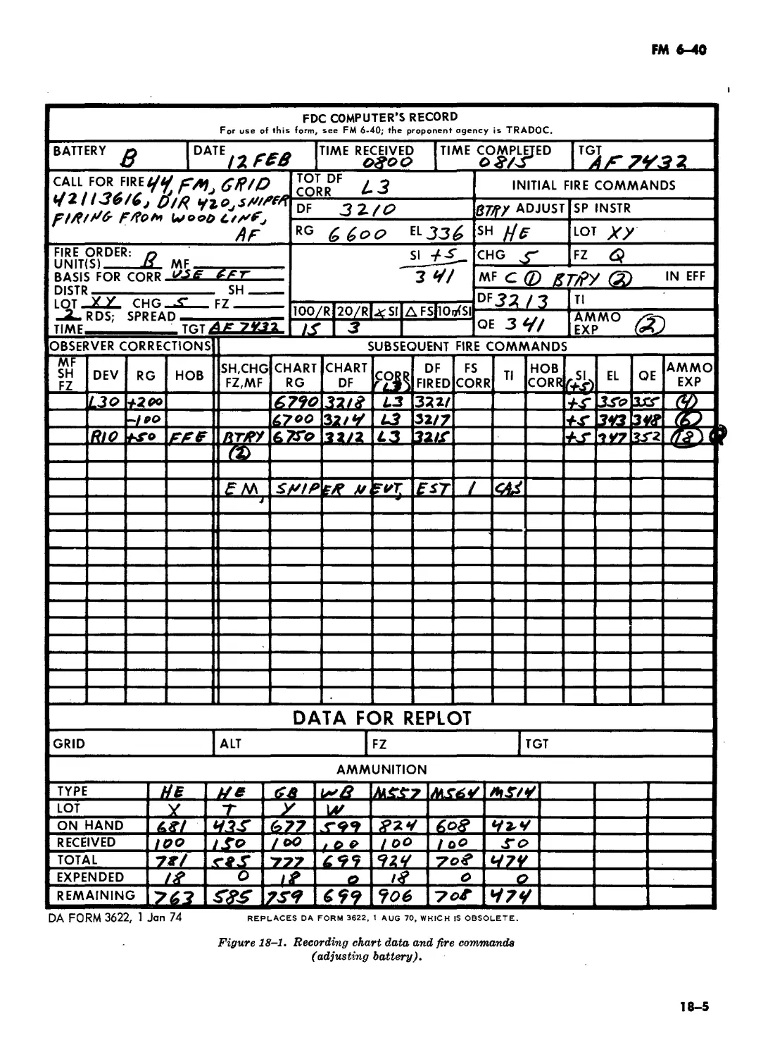
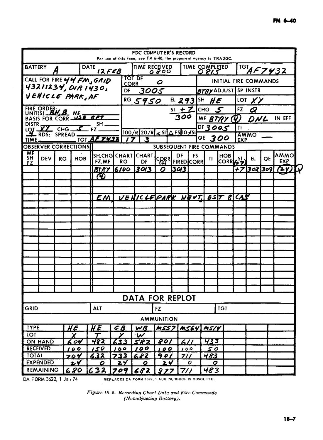
CHAPTER 18. FIRE DIRECTION PROCEDURES
Section I. Battalion FDC procedures . 18-1—18-22 18-1
II. Battery fire direction . 18-23—18-25 18-11
III. Communications . 18-26, 18-27 18-11
IV. Sample missions . 18-28, 18-29 18-13
CHAPTER 19. CONDUCT OF REGISTRATIONS
Sections I. General . 19-1—19-3 19-1
II. Precision registration (Deleted)
III. V alidity of registrations (Deleted) -
IV. Mean-point-of-impact and high-burst registrations . 19-27—19-39 19-2
V. Registration with more than one ammunition lot .... . 19-40, 19-41 19-20
VI. Fire direction procedures for ABC A precision
fire (Deleted)
CHAPTER 20. DETERMINATION AND APPLICATION OF
REGISTRATION CORRECTIONS
Section I. Introduction . 20-1, 20-2 20-1
II. Registration range corrections . .20-3—20-11 20-1
III. Registration deflection corrections . 20-12—20-16 20-6
IV. Replotting targets . 20-17—20-22 20-7 |
CHAPTER 21. METEOROLOGICAL CORRECTIONS AND
VELOCITY ERROR
Section I. The meteorological message .21-1—21-4 21-1
II. Position velocity error (Concurrent Met) . 21-5—21-10 21-2
III. Application of meteorological and velocity error
corrections (subsequent met) .21-11—21-16 21-7 |
IV. Experience corrections .21-17—21-21 21-12
CHAPTER 22. CALIBRATION
Section I. General —- - 22-1—22-7 22-1
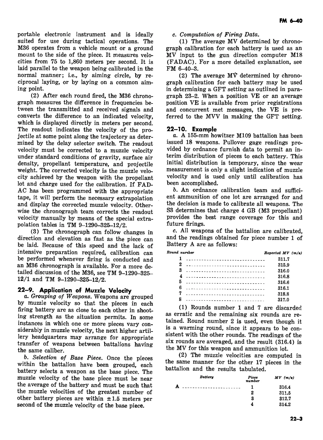
II. Chronograph calibration . 22-8—22-10 22-2
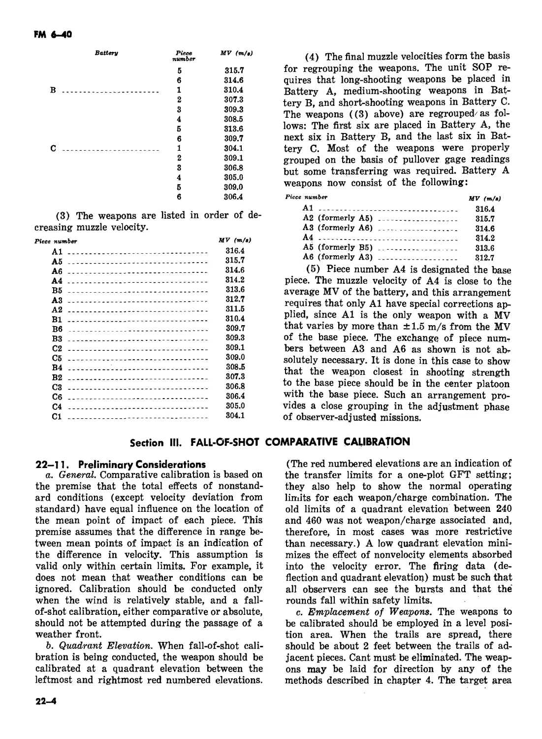
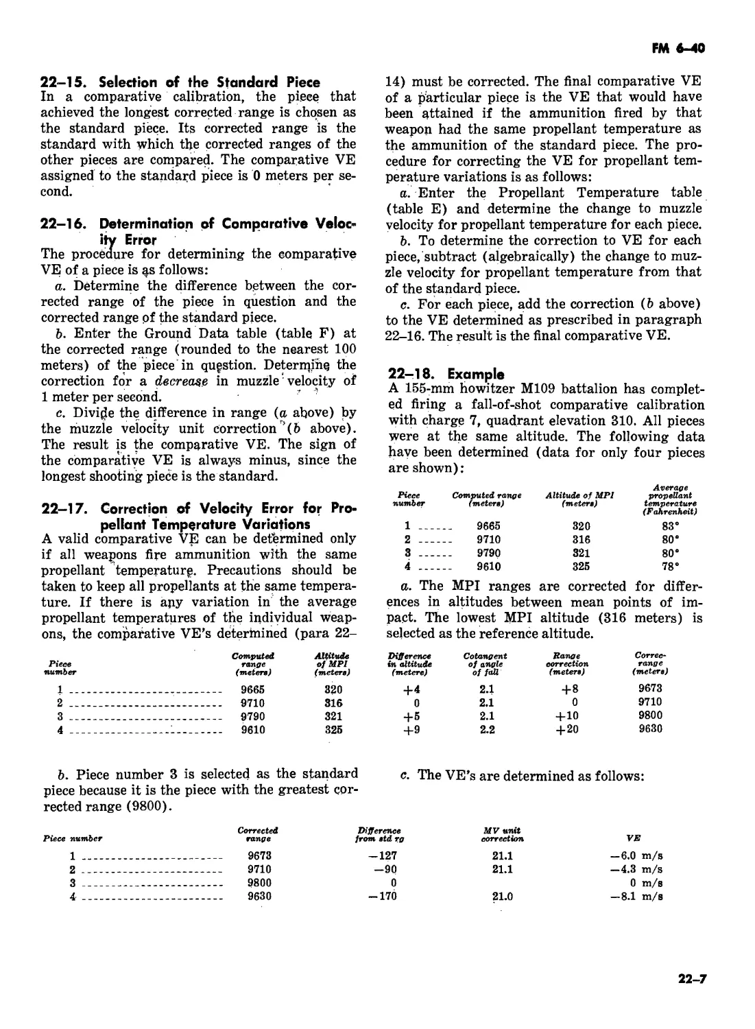
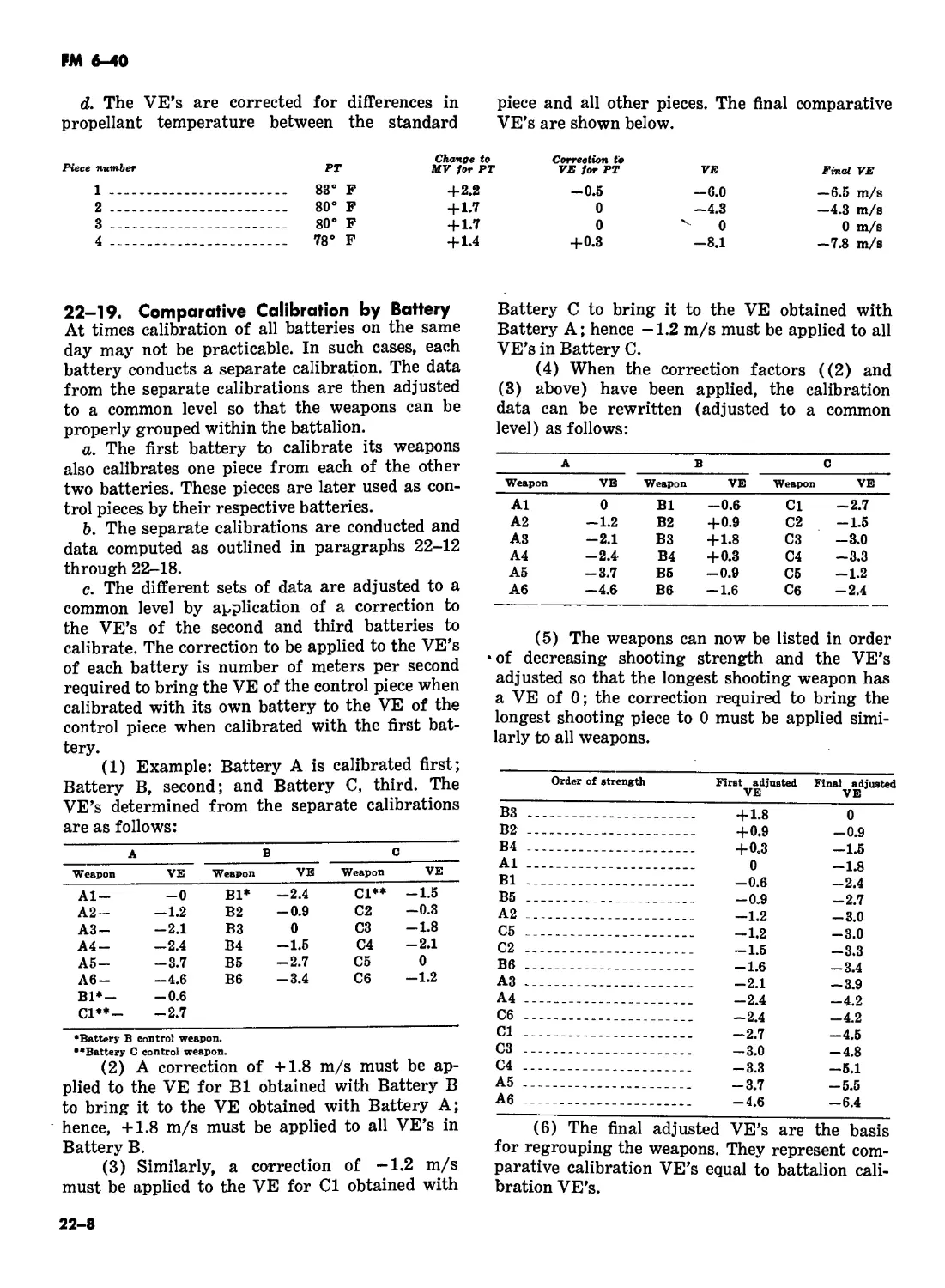
III. Fall-of-shot comparative calibration .22-11—22-19 22-4
IV. Fall-of-shot absolute calibration . 22-20—22-23 22-9
V. Redistribution of weapons . 22-23, 22-24 22-10
CHAPTER 23. CALIBRATION, POSITION, AND SPECIAL
CORRECTIONS
Section II. Calibration corrections .. 23-1—23-3 23-1
II. Position corrections .. 23-4—23-6 23-3
III. Special corrections .. 23-7—23-9
CHAPTER 24 FDC PROCEDURES FOR SPECIAL SITUATIONS
Section I. Introduction .. 24-1, 24-2 24-1
II. Chemical projectiles .. 24-3—24-8 24-1
С1, FM 6-40
III. Illuminating projectiles . 24-9—24-18 24-3
IV. Propaganda projectile . 24-19, 24-20 24-8
V. Assault fire . 24-21, 24-22 24-8
VI Destruction missions . 24-23, 24-24 24-9
VII. Final protective fires . 24-25, 24-26 24-10
VIII. Combined adjustment . 24-27, 24-28 24-10
IX. Sound, flash, and radar missions . 24-29—24-34 24-11
X. Gunnery procedures for improved conventional
munitions . 24-35, 24-36 24-12
XI. Dead space . 24-37—24-40 24-15
XII. Miscellaneous . 24-41—24-43 24-17
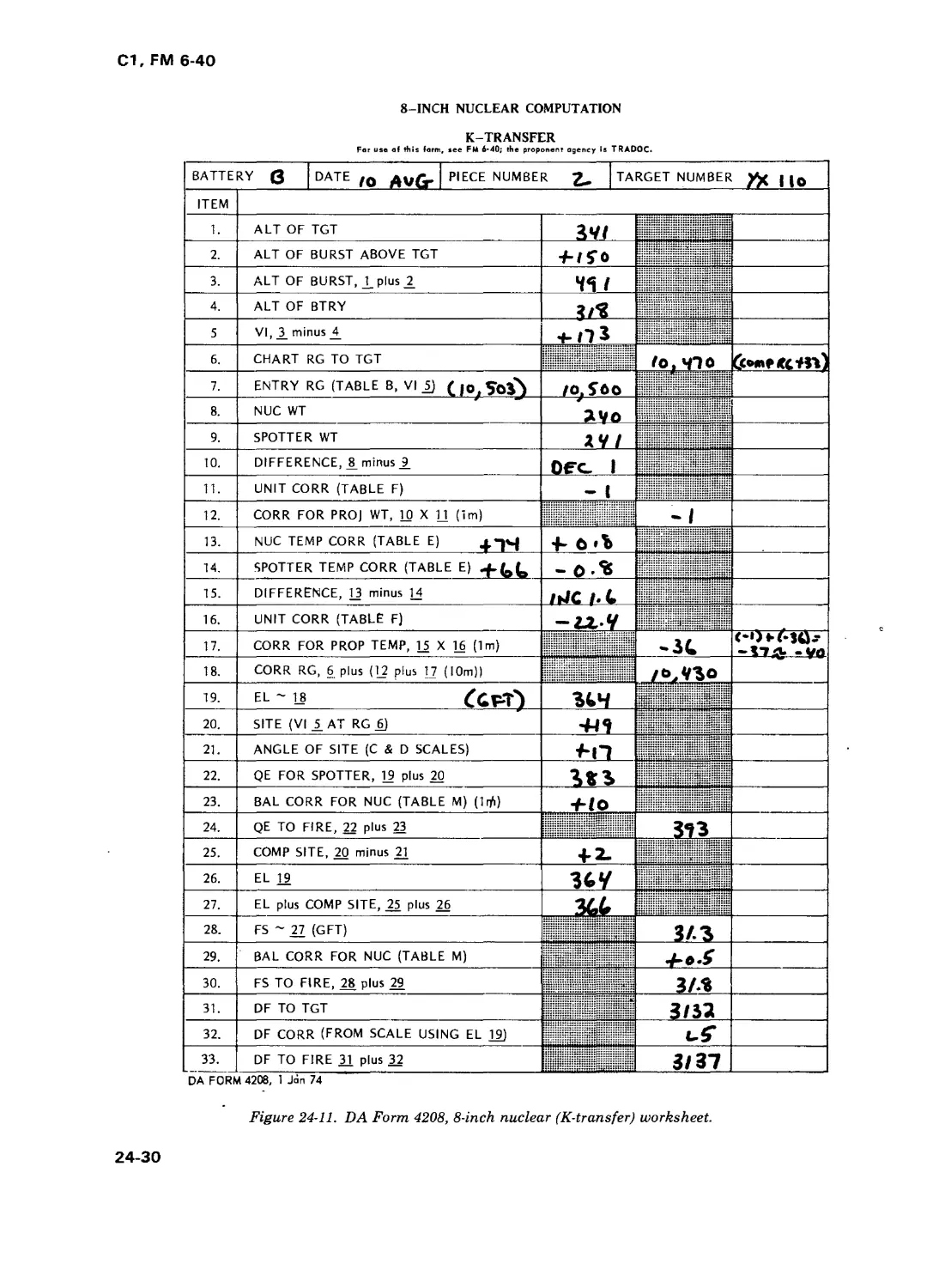
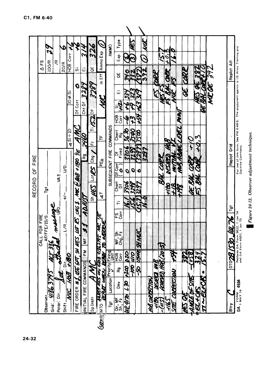
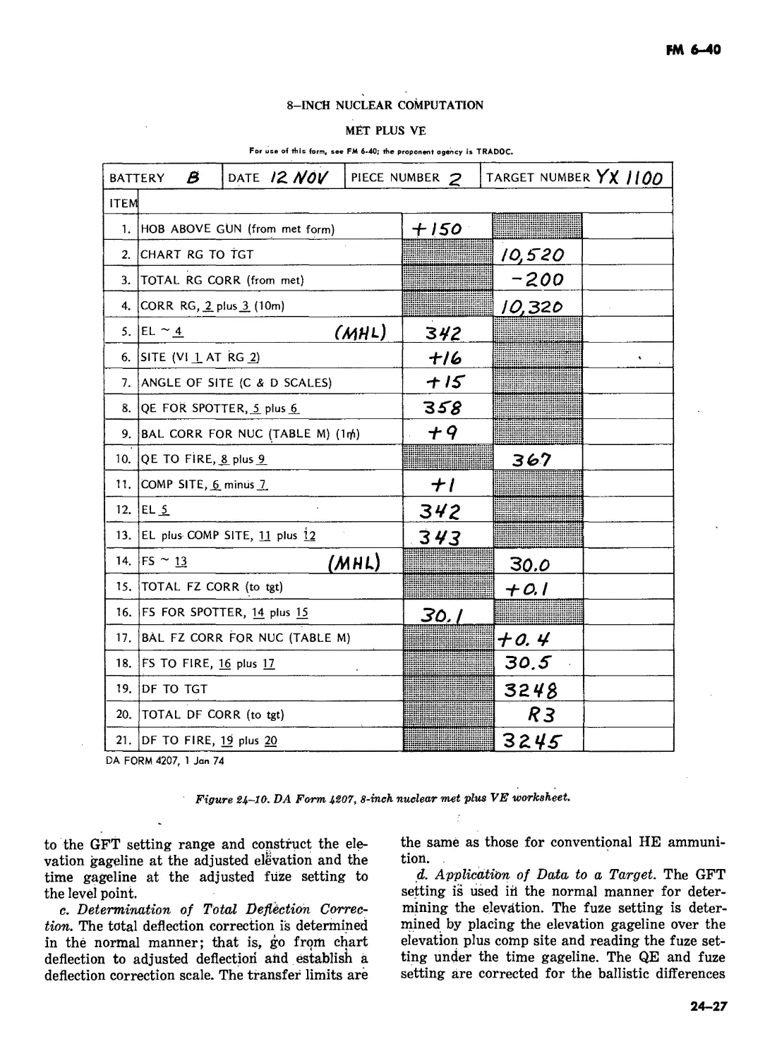
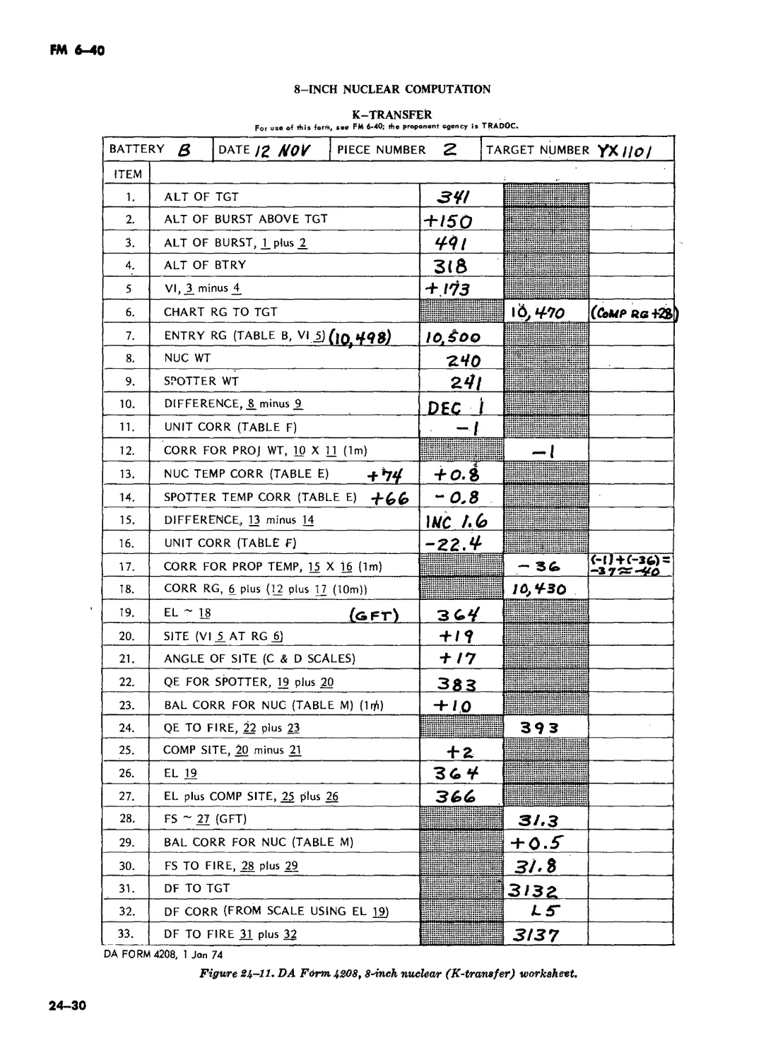
XIII. 8-inch howitzer nuclear delivery . 24-44—24-56 24-20
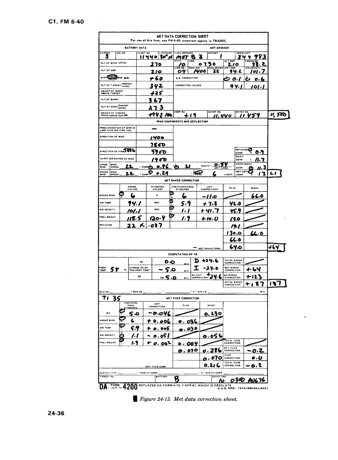
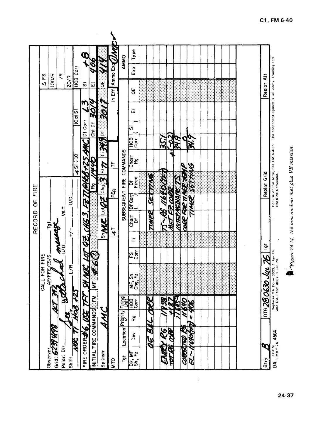
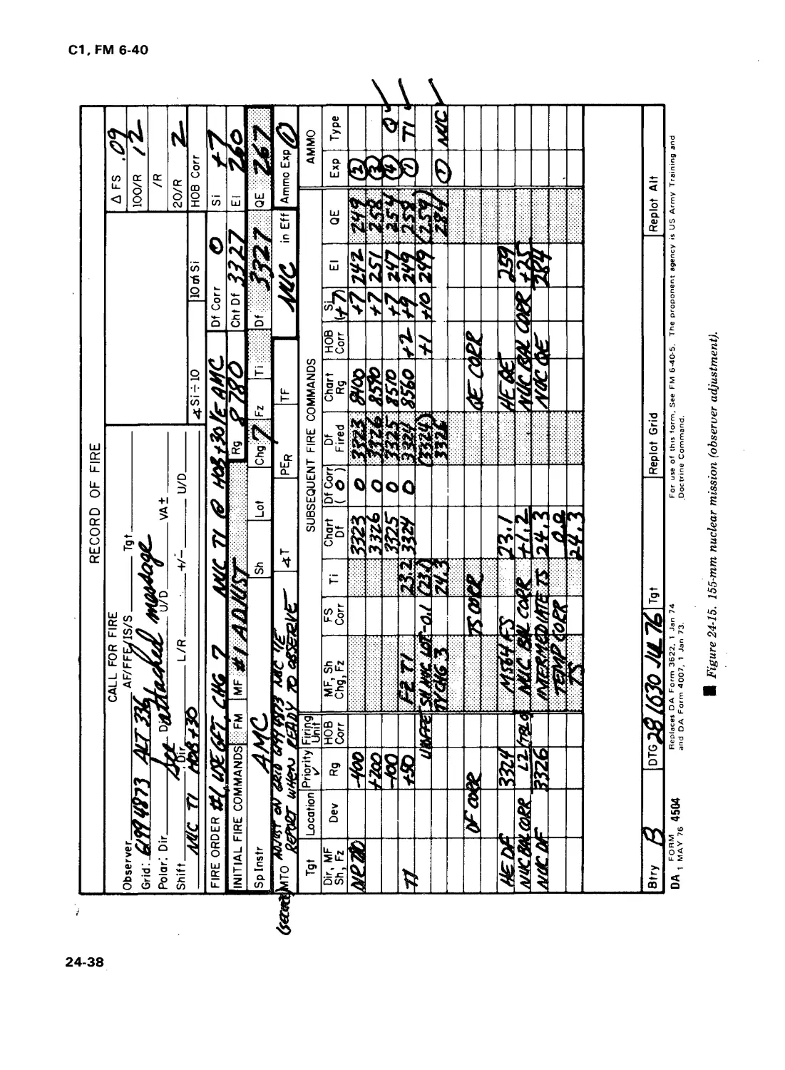
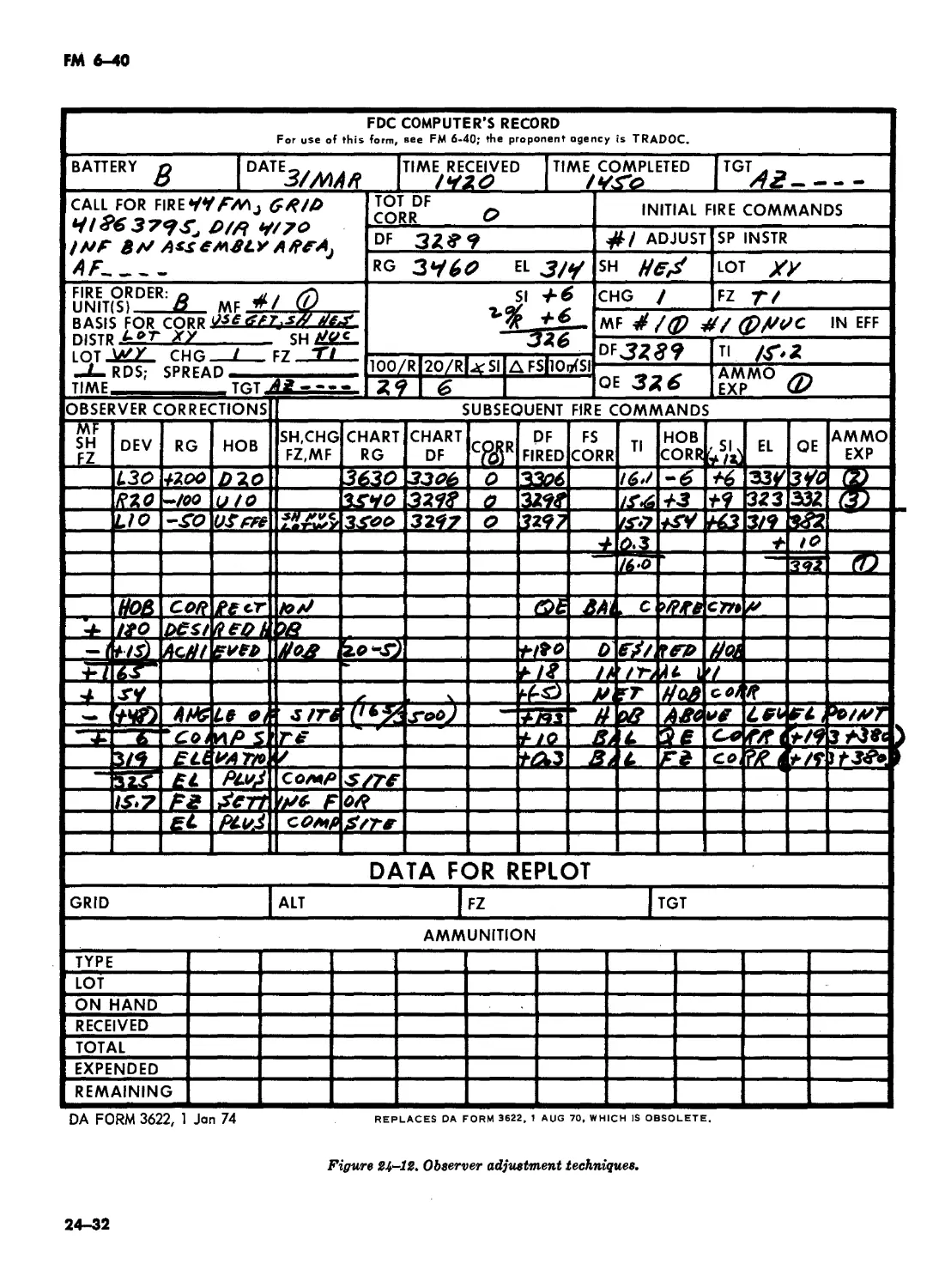
XIV. 155-mm howitzer nuclear delivery . 24-57—24-64 24-33
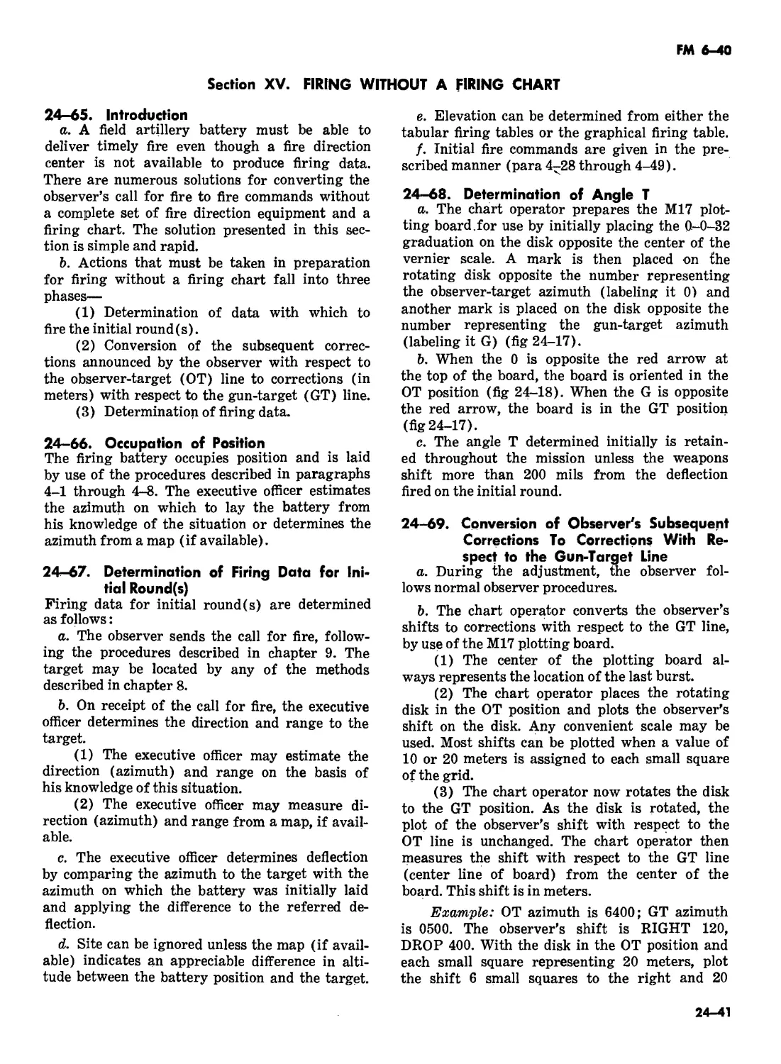
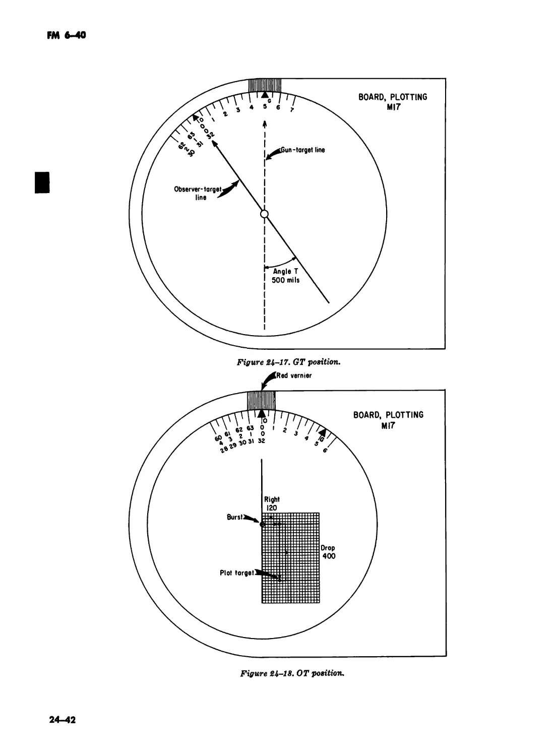
XV. Firing without a firing chart . 24-65—24-72 24-41
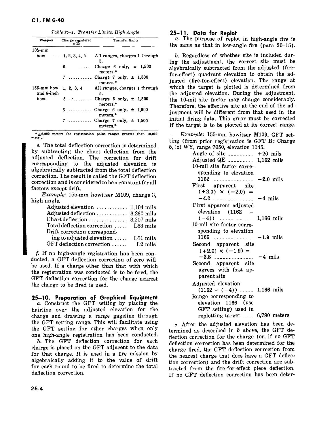
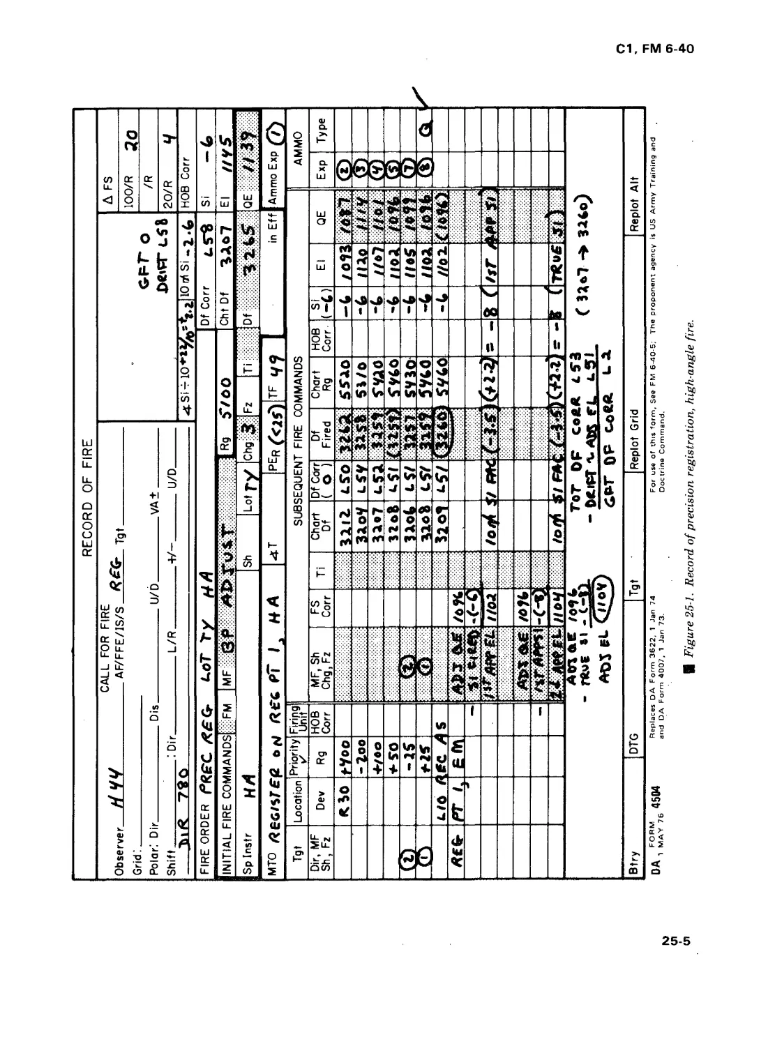
CHAPTER 25. FDC PROCEDURES FOR HIGH-ANGLE FIRE 25-1—25-13 25-1
CHAPTER 26. OBSERVED FIRING CHARTS
Section I. Introduction . 26-1, 26-2 26-1
II. Battery observed firing charts 26-3—26-11 26-1
III. Battalion observed firing chart . 26-12—26-15 26-4
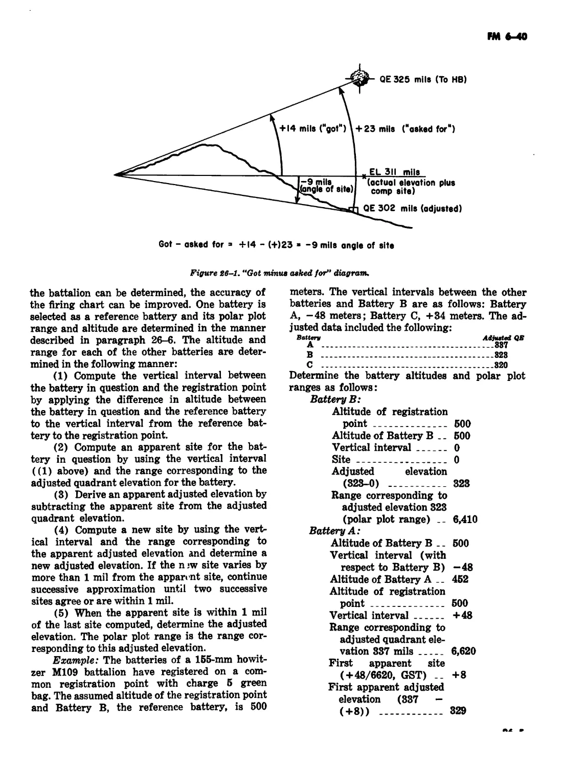
IV. Replotting targets on the observed firing chart . 26-16—26-20 26-7
V. Observed firing chart for more than one battalion . 26-22—26-24 26-8
VI. Observed firing chart with incomplete survey . 26-25, 26-26 26-9
VII. Radar firing charts . . 26-27—26-34 26-9
VIII. Transfer from observed firing chart to survey firing
chart . 26-35—26-39 26-12
PART .. FIVE. MISCELLANEOUS
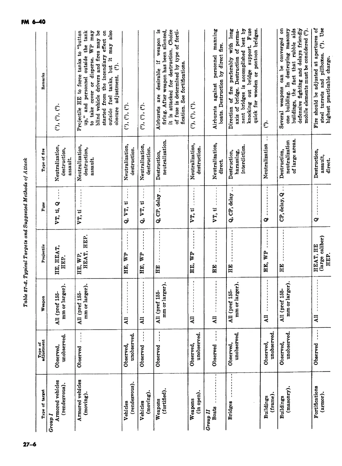
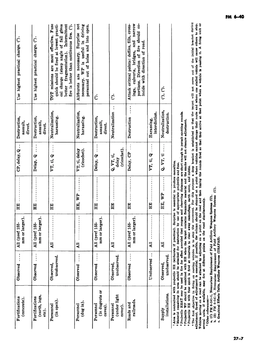
CHAPTER 27. TARGET ANALYSIS AND ATTACK (Deleted) 27-1
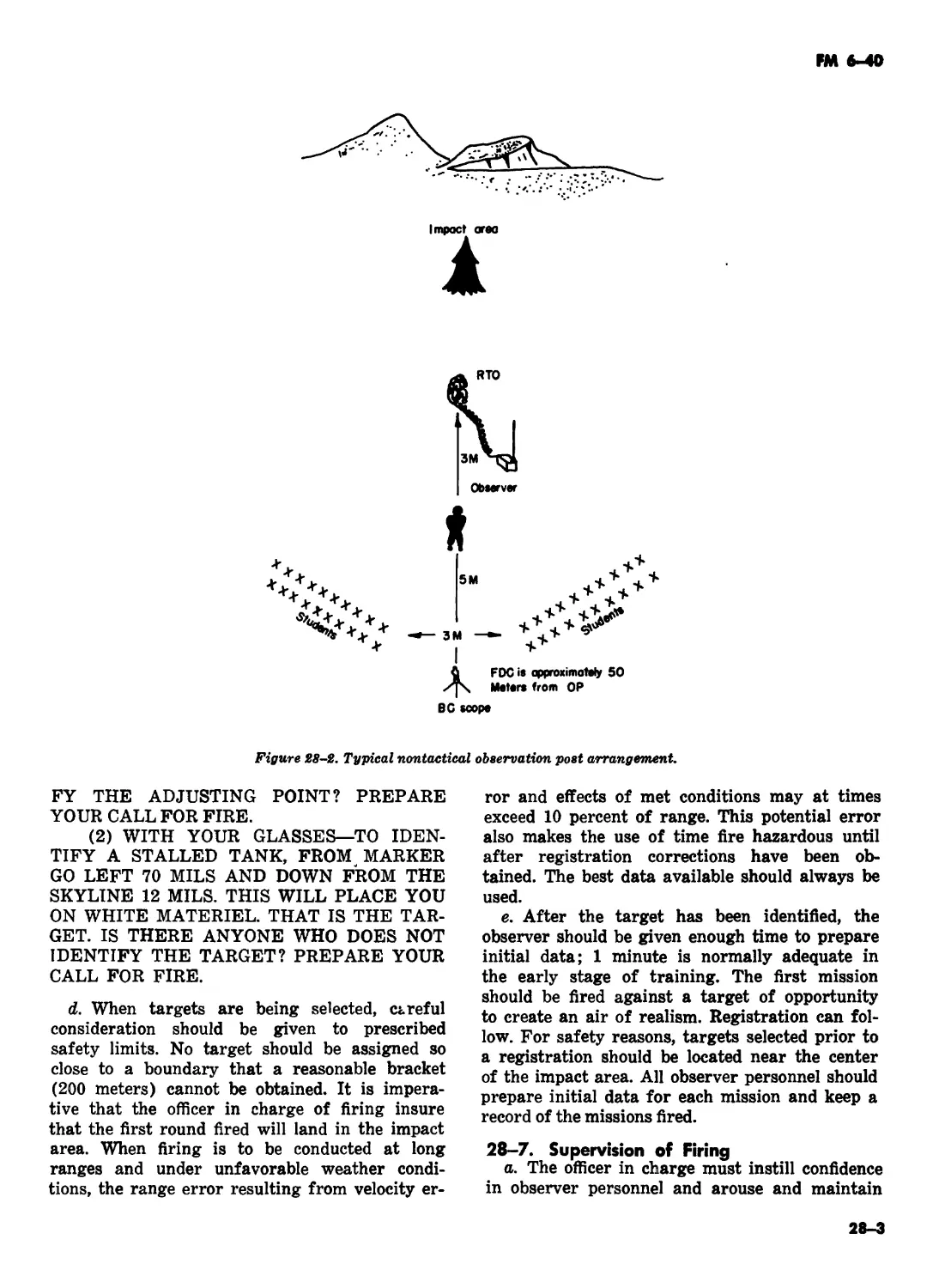
CHAPTER 28. SERVICE PRACTICE (Deleted)
CHAPTER 29. NAVAL GUNFIRE SUPPORT
Section I. Introduction . 29-1—29-3 29-1
II. Call for fire :................. . 29-4, 29-5 29-1
III. Adjustment procedure . 29-6, 29-7 29-4
CHAPTER 30. ARMOR EMPLOYED IN A FIELD ARTILLERY
MISSION . 30-1—30-6 30-1
APPENDIX A. REFERENCES A-l
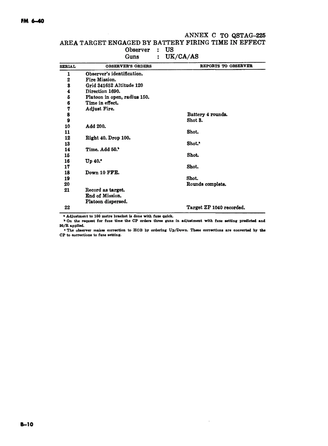
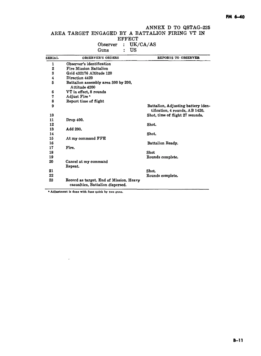
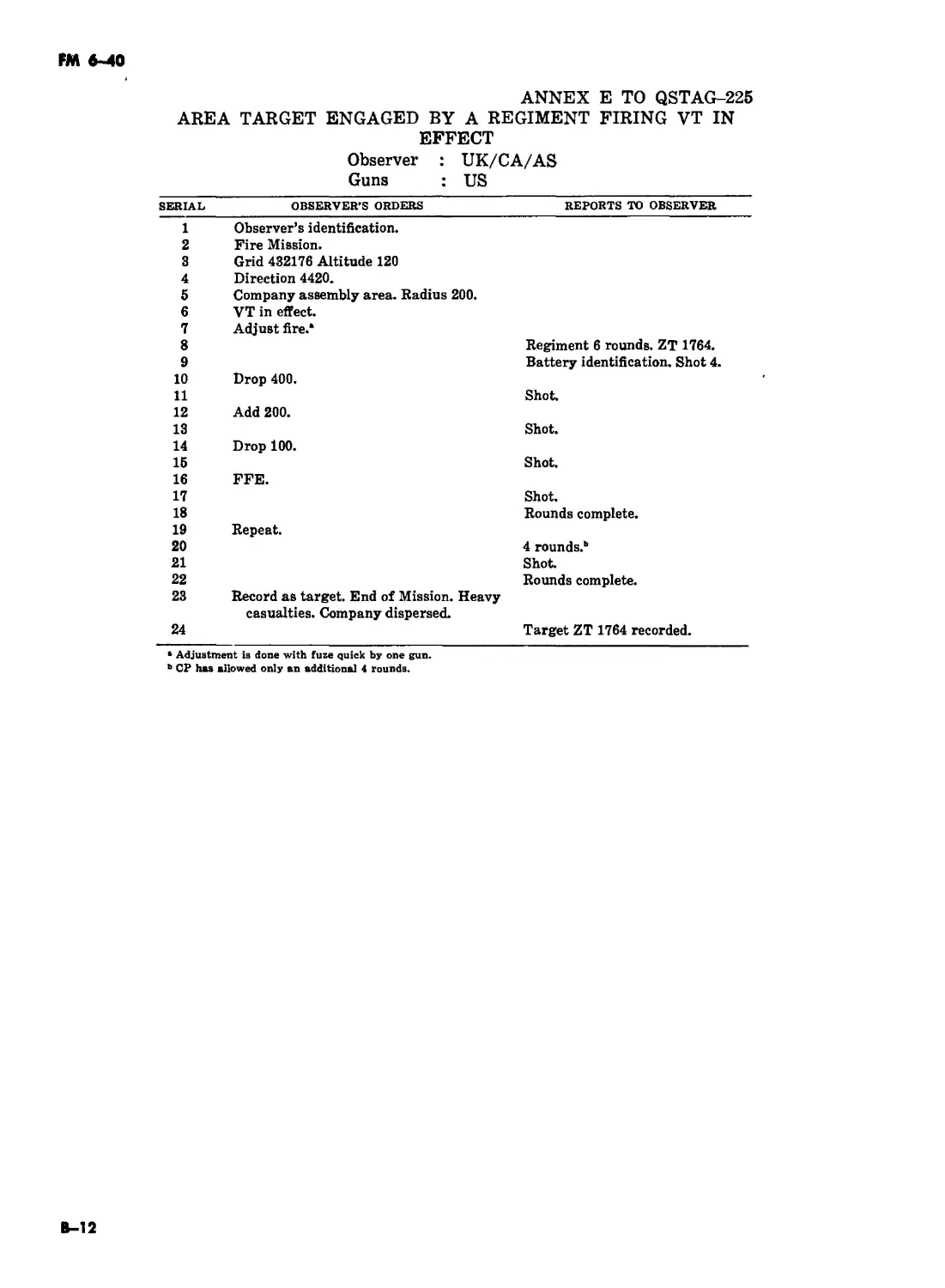
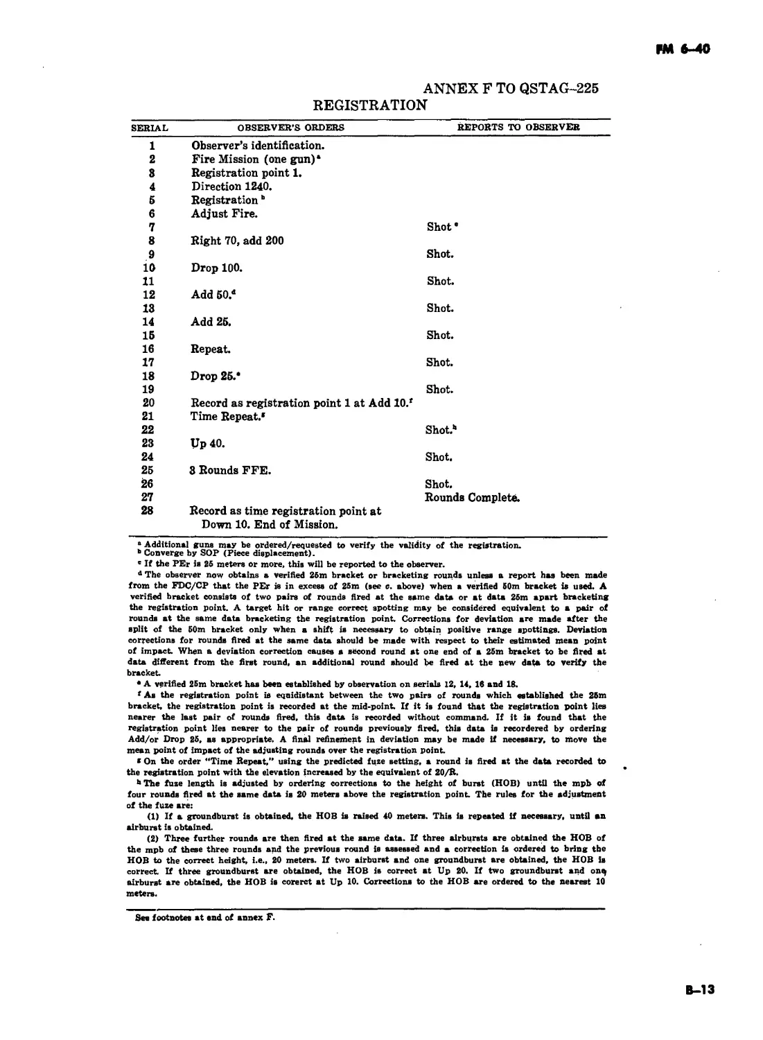
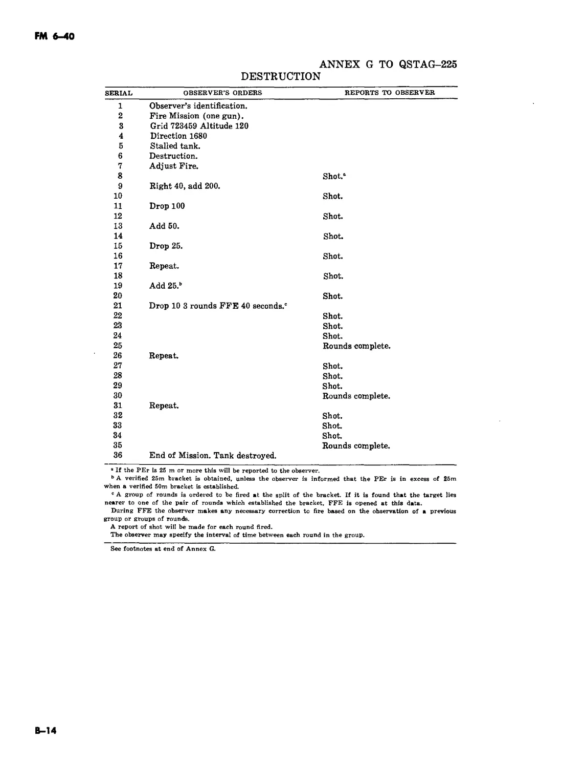
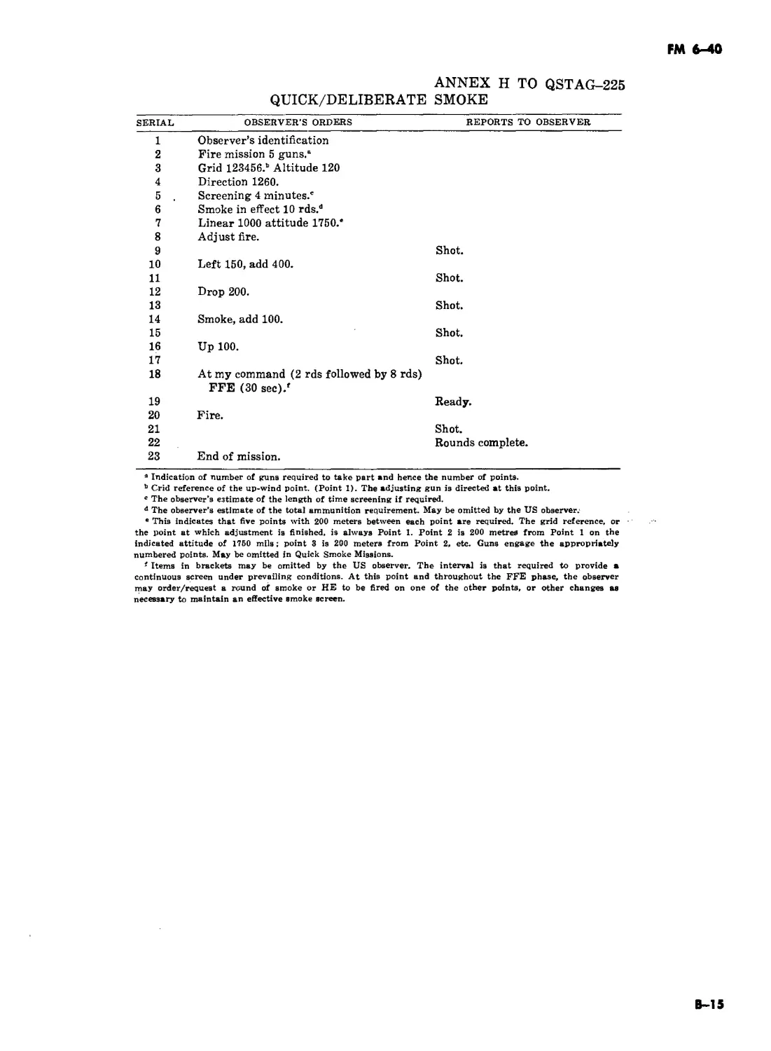
B. QSTAG 225, CALL FOR FIRE FORMATS (Deleted)
C. QSTAG 246, RADIO TELEPHONE
PROCEDURES FOR THE CONDUCT OF ARTILLERY FIRE (Deleted)
INDEX Index-1
iii
(iv BLANK)
С1, FM 6-40
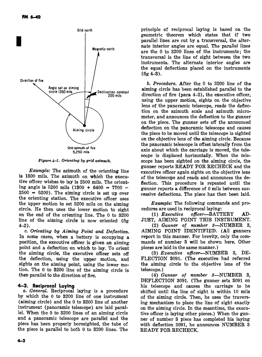
| 1-9. Map and Azimuth Terms
The map and azimuth terms used in the firing
battery are defined in a through j below.
a. Grid line. A grid line is a line extend-
ing north and south or east and west on a map,
photomap, or grid sheet. A grid is composed of two
intersecting sets of lines. The east-west lines are
parallel to the central meridian and the north-
south lines are perpendicular to the central meri-
dian of the grid zone in question. The parallel lines
are normally 1,000 meters apart and are used to
measure grid coordinates (1:50,000 maps).
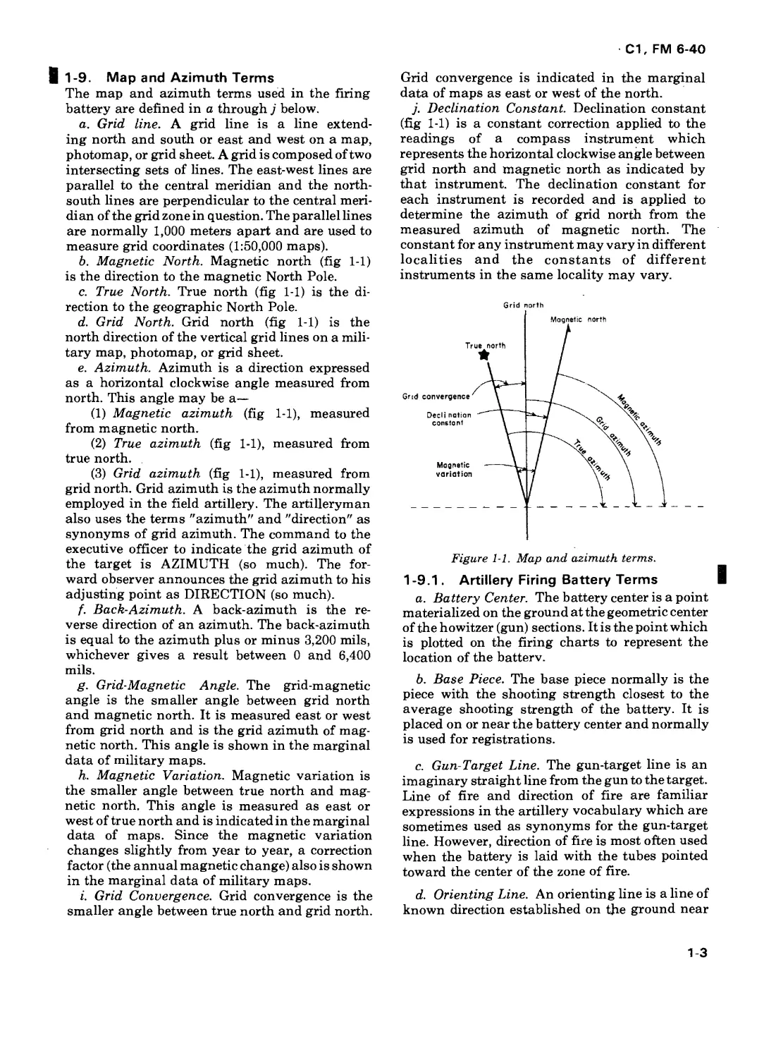
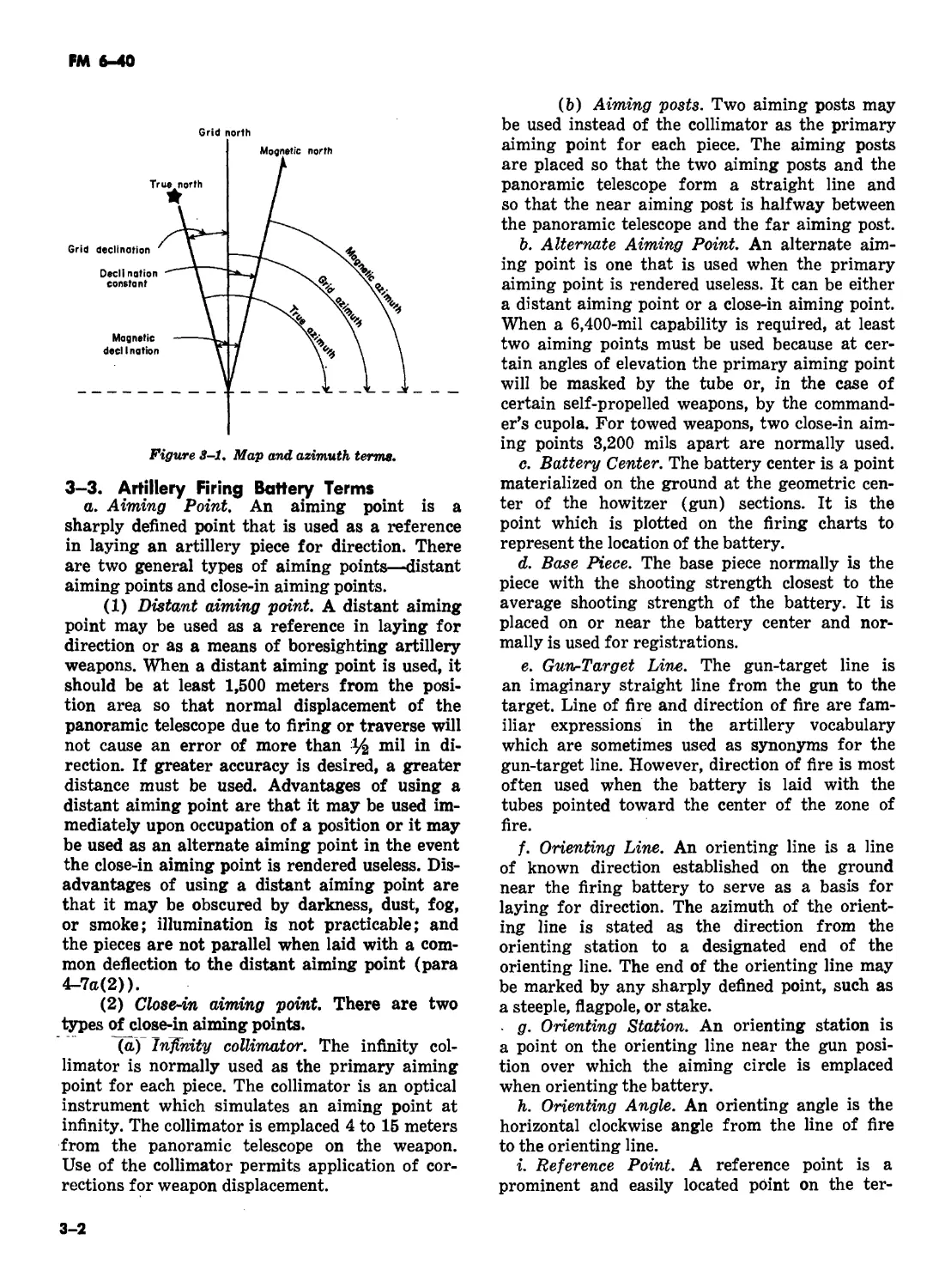
b. Magnetic North. Magnetic north (fig 1-1)
is the direction to the magnetic North Pole.
c. True North. True north (fig 1-1) is the di-
rection to the geographic North Pole.
d. Grid North. Grid north (fig 1-1) is the
north direction of the vertical grid lines on a mili-
tary map, photomap, or grid sheet.
e. Azimuth. Azimuth is a direction expressed
as a horizontal clockwise angle measured from
north. This angle may be a—
(1) Magnetic azimuth (fig 1-1), measured
from magnetic north.
(2) True azimuth (fig 1-1), measured from
true north.
(3) Grid azimuth (fig 1-1), measured from
grid north. Grid azimuth is the azimuth normally
employed in the field artillery. The artilleryman
also uses the terms "azimuth" and "direction" as
synonyms of grid azimuth. The command to the
executive officer to indicate the grid azimuth of
the target is AZIMUTH (so much). The for-
ward observer announces the grid azimuth to his
adjusting point as DIRECTION (so much).
f. Back-Azimuth. A back-azimuth is the re-
verse direction of an azimuth. The back-azimuth
is equal to the azimuth plus or minus 3,200 mils,
whichever gives a result between 0 and 6,400
mils.
g. Grid-Magnetic Angle. The grid-magnetic
angle is the smaller angle between grid north
and magnetic north. It is measured east or west
from grid north and is the grid azimuth of mag-
netic north. This angle is shown in the marginal
data of military maps.
h. Magnetic Variation. Magnetic variation is
the smaller angle between true north and mag-
netic north. This angle is measured as east or
west of true north and is indicated in the marginal
data of maps. Since the magnetic variation
changes slightly from year to year, a correction
factor (the annual magnetic change) also is shown
in the marginal data of military maps.
i. Grid Convergence. Grid convergence is the
smaller angle between true north and grid north.
Grid convergence is indicated in the marginal
data of maps as east or west of the north.
j. Declination Constant. Declination constant
(fig 1-1) is a constant correction applied to the
readings of a compass instrument which
represents the horizontal clockwise angle between
grid north and magnetic north as indicated by
that instrument. The declination constant for
each instrument is recorded and is applied to
determine the azimuth of grid north from the
measured azimuth of magnetic north. The
constant for any instrument may vary in different
localities and the constants of different
instruments in the same locality may vary.
Figure 1-1. Map and azimuth terms.
1-9.1. Artillery Firing Battery Terms
a. Battery Center. The battery center is a point
materialized on the ground at the geometric center
of the howitzer (gun) sections. It is the point which
is plotted on the firing charts to represent the
location of the batterv.
b. Base Piece. The base piece normally is the
piece with the shooting strength closest to the
average shooting strength of the battery. It is
placed on or near the battery center and normally
is used for registrations.
c. Gun-Target Line. The gun-target line is an
imaginary straight line from the gun to the target.
Line of fire and direction of fire are familiar
expressions in the artillery vocabulary which are
sometimes used as synonyms for the gun-target
line. However, direction of fire is most often used
when the battery is laid with the tubes pointed
toward the center of the zone of fire.
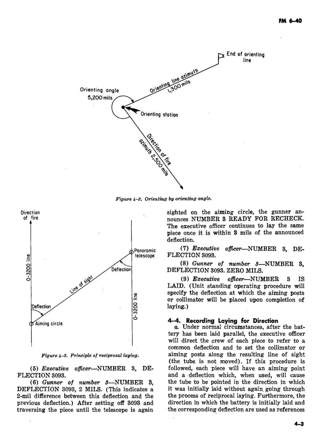
d. Orienting Line. An orienting line is a line of
known direction established on the ground near
1-3
Cl, FM 6'40
the firing battery to serve as a basis for laying for
direction. The azimuth of the orienting line is
stated as the direction from the orienting station
to a designated end of the orienting line. The end
of the orienting line may be marked by any
sharply defined point, such as a steeple, flagpole,
or stake.
e. Orienting Station. An orienting station is a
point on the orienting line near the gun position
over which the aiming circle is emplaced when
orienting the battery.
f. Orienting Angle. An orienting angle is the
horizontal clockwise angle from the line of fire to
the orienting line.
g. Reference Point. A reference point is a
prominent and easily located point on the terrain
and is used for orientation. This may be used as a
distant aiming point or as an alternate aiming
point.
h. Deflection. Deflection is the horizontal,
clockwise angle measured from the line of fire, or
the rearward extension of the line of fire, to the line
of sight to a designated aiming point, with the
vertex at the instrument.
i. Refer. To refer is to measure the deflection to
a given point without moving the tube of the
weapon or the orientation (0 to 3200) line of the
instrument. The command REFER means to
measure and to report the deflection. If the
deflection is to be recorded, the command,
RECORD REFERRED DEFLECTION, is given.
1-4
С1, FM 6-40
CHAPTER 2
FUNDAMENTALS OF FIELD ARTILLERY GUNNERY
Section I. ELEMENTS OF FIRING DATA
2-1. General
a. The data required to lay (point) an artil-
lery cannon so that the projectile, when fired, will
burst at the desired location are called firing
data. These data are based on the direction, hori-
zontal range, vertical interval, and meteorological
conditions from the weapons to the target and on
the desired pattern of bursts at the target.
b. The principal unit of angular measurment
in field artillery is the mil. A mil is the angle
subtended by an arc which is 1/6400 of the cir-
cumference of a circle.
2-2. Direction
Direction is expressed as a horizontal angle mea-
sured from a fixed reference. The field artillery
normally uses grid north (the direction of the
north-south grid lines on a military map) for the
fixed reference and measures the angle clockwise
from grid north. When pieces are emplaced, they
are laid for direction, and the direction in which
they are laid is used as a basis for angular shifts
to point the pieces at the target. The direction to
the target may be computed, determined graphi-
cally or estimated.
2-3. Range
Range is the horizontal distance from the gun to
the target and is expressed in meters. Range may
be computed, measured graphically, or estimated.
The range achieved by a projectile is a function of
the charge (muzzle velocity) and the vertical
angle (elevation) to which the tube is raised. (For
other factors affecting range, see paragraph 2-9).
2-4. Vertical Interval
Vertical interval is the difference in altitude be-
tween the battery or observation post and the
target or point of burst. The altitudes are deter-
mined from a map, by surveys, or by a shift
from a known point.
2-5. Distribution of Bursts I
Distribution of bursts is the pattern of bursts in
the target area. Normally, all pieces of a battery
fire with the same deflection, fuze setting, and
quadrant elevation. When firing units occupy
terrain rather than geometric formations, it may
be necessary to adjust the pattern of bursts. This is
done by computing and applying individual piece
corrections (terrain gun position corrections; see
FM 6-40-5). Also, since targets may be of various
shapes and sizes, it is sometimes desirable to
adjust the pattern of bursts to the shape and size of
the target (see chapter 23).
2-5.1. Sheaf |
The term "sheaf' is used to denote the lateral
distribution of the bursts of two or more pieces
fired together. The width of the sheaf is the lateral
distance (perpendicular to the direction of fire)
between the centers of the flank bursts. The front
covered by any sheaf is the width of the sheaf plus
the effective width of one burst. A sheaf may be
formed in any one of the following patterns:
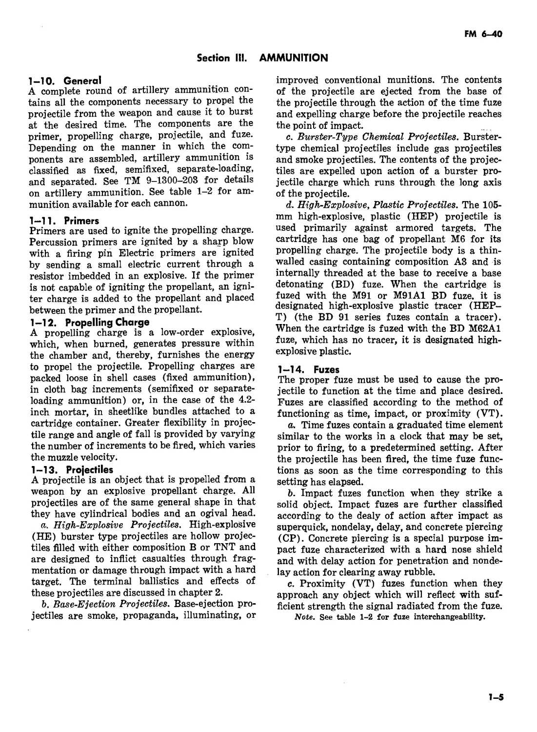
a. Parallel Sheaf. A parallel sheaf is one in
which the trajectories of all pieces are parallel (fig
2-1).
| Figure 2-1. Parallel sheaf.
2-1
С1, FM 6-40
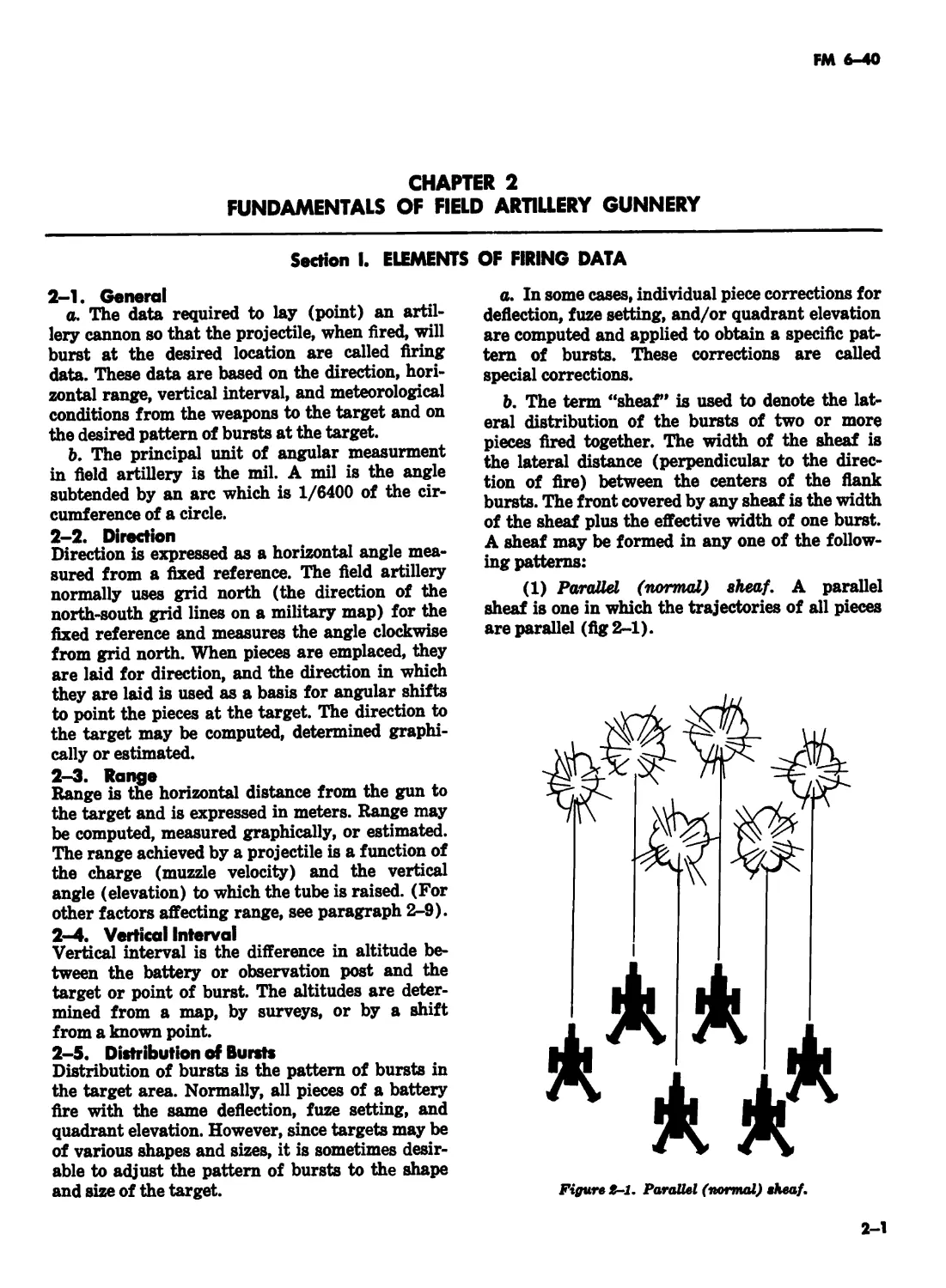
b. Converged Sheaf. A converged sheaf is one
in which the horizontal and vertical planes of the
trajectories intersect at the target (fig 2-2).
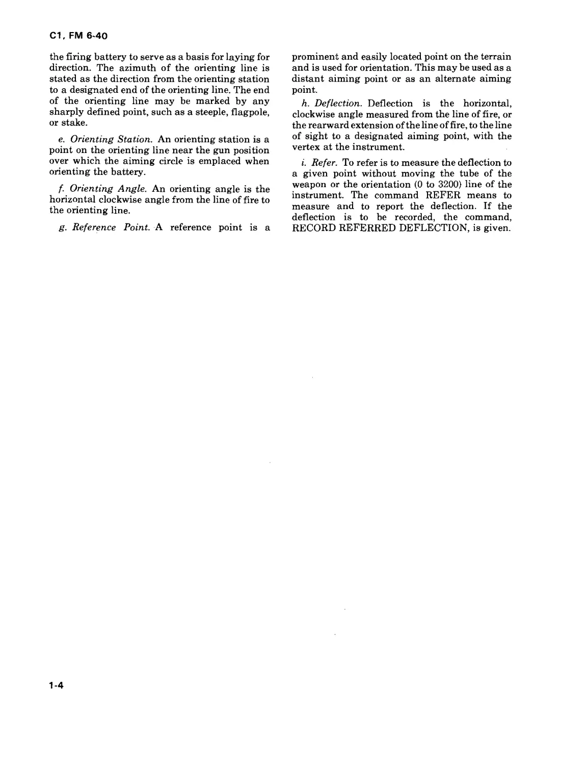
c. Open Sheaf. An open sheaf is one in which
the lateral distance between the center of two
adjacent bursts is equal to the maximum effective
width of one burst (table 2-1 and fig 2-3).
d. Standard Sheaf. A standard sheaf is the
sheaf used in the computation of terrain gun
position corrections (table 2-1.1 and fig 2-3.1).
e. Special Sheaf. A special sheaf is any sheaf
other than the one of those described in a through
d above.
| Figure 2 3.1. Standard sheaf.
2-2
С1, FM 6-40
| Table 2-1. Open Sheafs
Caliber Width (in meters) of open sheaf Front (in meters) covered by an open sheaf
2-piece battery 4—piece battery 6-piece battery 2-piece battery 4-piece battery 6—piece battery
105—mm 30 90 150 60 120 180
155—mm 50 150 250 100 200 300
175—mm 95 285 — 190 380 —
8—inch 80 240 — 160 320 —
ц Table 2-1.1. Standard Sheafs
Caliber Width (in meters) of standard sheaf Front (in meters) covered by a standard sheaf
2-piece battery 4-piece battery 6-piece battery 2-piece battery 4—piece battery 6—piece battery
105-mm 20 60 100 50 90 130
155—mm 40 120 200 90 170 250
175-mm 60 180 — 155 275 —
8—inch 60 180 — 140 260 —
Section II. INTERIOR BALLISTICS
2-6. General
Interior ballistics is the science which deals with
the factors affecting the motion of projectiles be-
fore they leave the muzzle of the piece. The total
effect of all interior ballistic factors determines
the velocity with which the projectile leaves the
muzzle. This velocity is called the muzzle velocity
and is expressed in meters per second. Actual mea-
surements of the muzzle velocity of a series of
rounds, corrected for nonstandard conditions, de-
pict the performance of a certain weapon-
ammunition combination. The variation from
standard can be obtained by comparison of the
results of these measurements with the standard
velocities listed in the firing table for the charge
fired. Application of corrections to compensate
for nonstandard muzzle velocity is one of the most
important elements in the preparation of accurate
firing data.
2-7. Nature of Propellants and Projectile
Movement
a. A propellant is a low-order explosive which
burns rather than detonates. In artillery cannons
using separate-loading ammunition, the propel-
lant is burned in a chamber consisting of the
powder chamber and the base of the projectile;
in cannons using fixed and semifixed ammuni-
tion, the propellant is burned in a chamber con-1
sisting of the shell case and the base of the pro-
jectile. When the gases generated by the burning
propellant develop pressure sufficient to overcome
initial bore resistance, the projectile begins to
move.
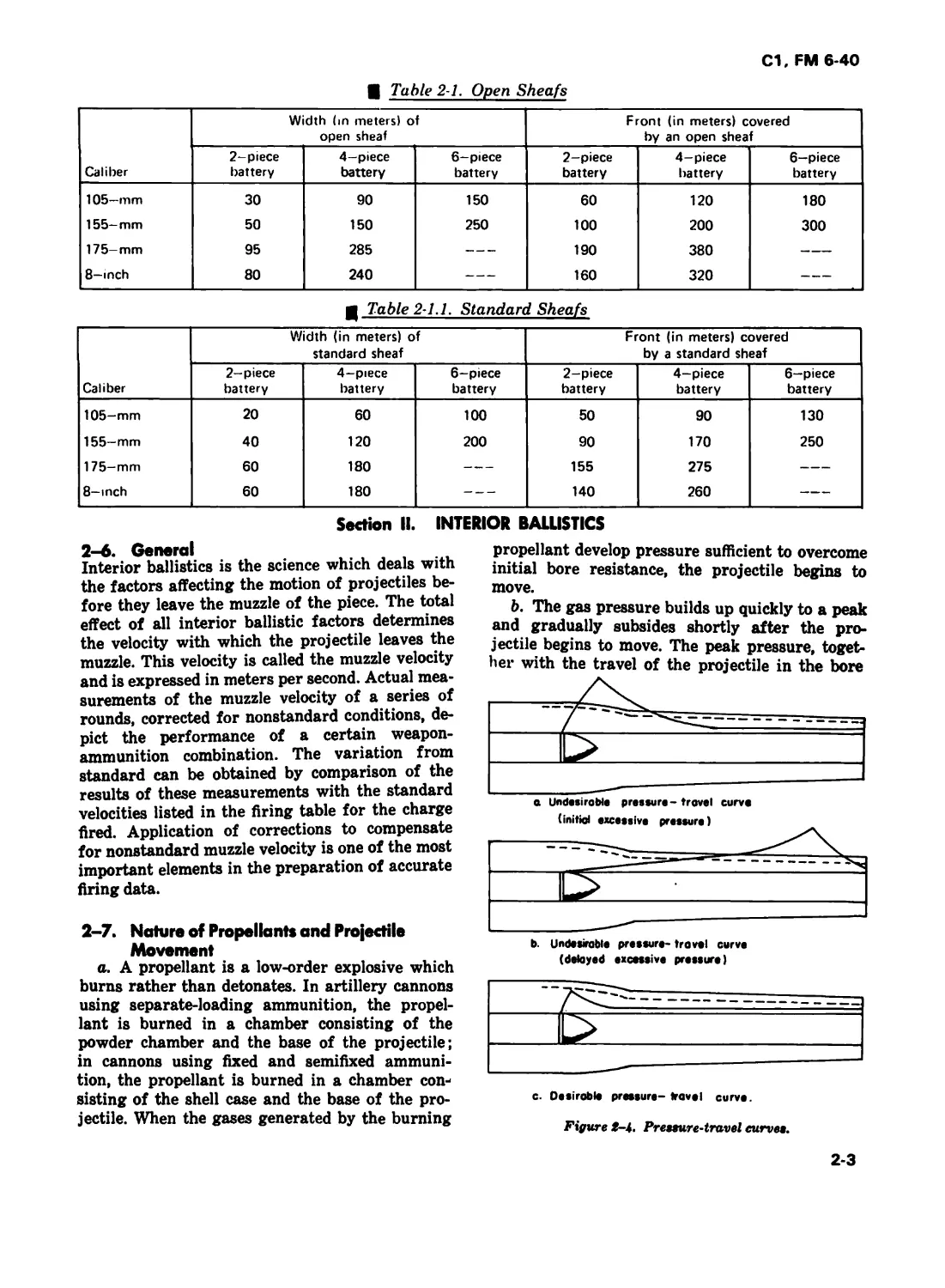
b. The gas pressure builds up quickly to a peak
and gradually subsides shortly after the pro-
jectile begins to move. The peak pressure, toget-
her with the travel of the projectile in the bore
b. Undesirable pressure- trovel curve
(delayed excessive pressure)
c. Desirable pressure- travel curve.
Figure i-k. Prenure-travel curve».
2-3
FM e-40
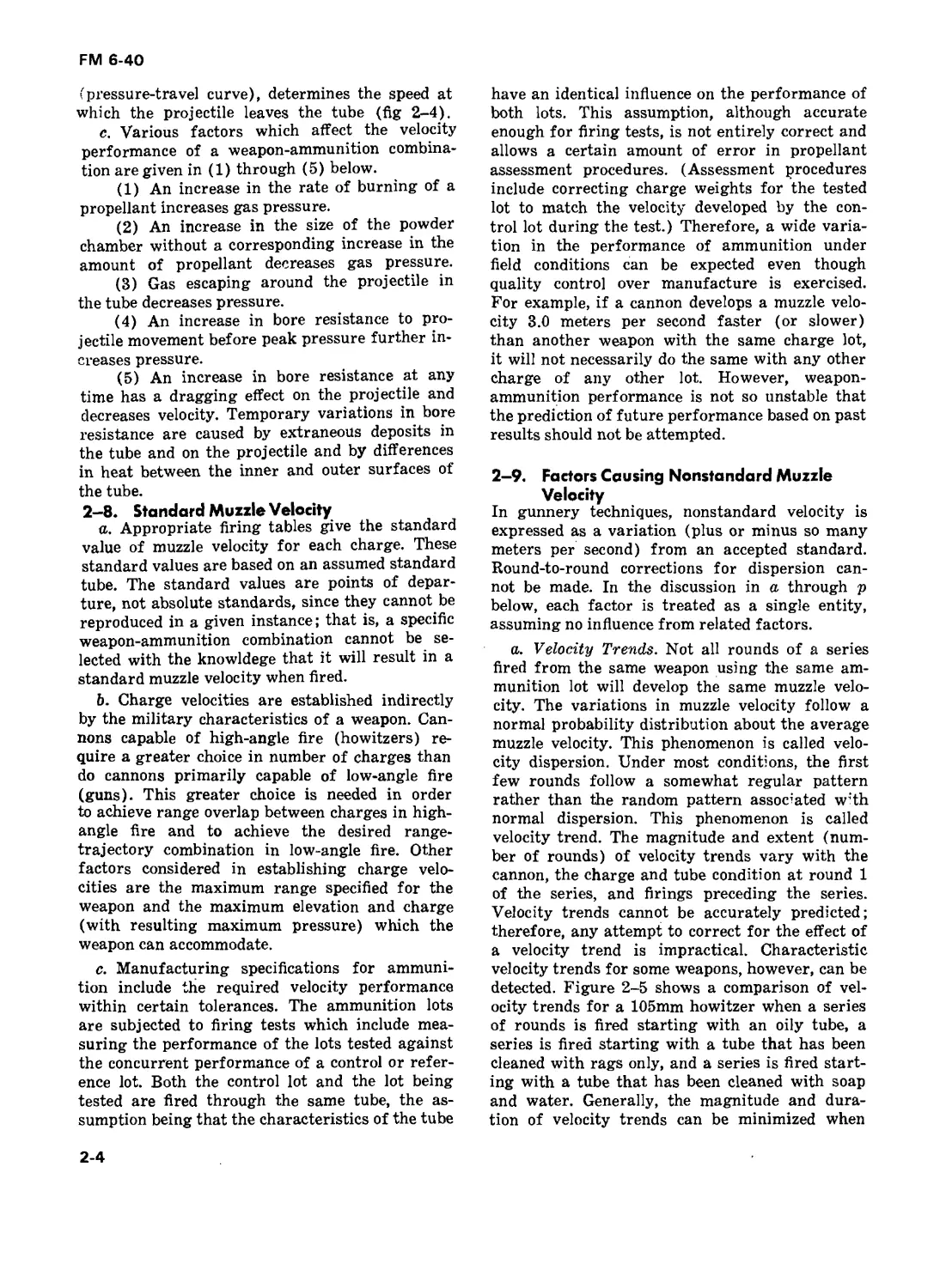
(pressure-travel curve), determines the speed at
which the projectile leaves the tube (fig 2-4).
c. Various factors which affect the velocity
performance of a weapon-ammunition combina-
tion are given in (1) through (5) below.
(1) An increase in the rate of burning of a
propellant increases gas pressure.
(2) An increase in the size of the powder
chamber without a corresponding increase in the
amount of propellant decreases gas pressure.
(3) Gas escaping around the projectile in
the tube decreases pressure.
(4) An increase in bore resistance to pro-
jectile movement before peak pressure further in-
creases pressure.
(5) An increase in bore resistance at any
time has a dragging effect on the projectile and
decreases velocity. Temporary variations in bore
resistance are caused by extraneous deposits in
the tube and on the projectile and by differences
in heat between the inner and outer surfaces of
the tube.
2-8. Standard Muzzle Velocity
a. Appropriate firing tables give the standard
value of muzzle velocity for each charge. These
standard values are based on an assumed standard
tube. The standard values are points of depar-
ture, not absolute standards, since they cannot be
reproduced in a given instance; that is, a specific
weapon-ammunition combination cannot be se-
lected with the knowldege that it will result in a
standard muzzle velocity when fired.
b. Charge velocities are established indirectly
by the military characteristics of a weapon. Can-
nons capable of high-angle fire (howitzers) re-
quire a greater choice in number of charges than
do cannons primarily capable of low-angle fire
(guns). This greater choice is needed in order
to achieve range overlap between charges in high-
angle fire and to achieve the desired range-
trajectory combination in low-angle fire. Other
factors considered in establishing charge velo-
cities are the maximum range specified for the
weapon and the maximum elevation and charge
(with resulting maximum pressure) which the
weapon can accommodate.
c. Manufacturing specifications for ammuni-
tion include the required velocity performance
within certain tolerances. The ammunition lots
are subjected to firing tests which include mea-
suring the performance of the lots tested against
the concurrent performance of a control or refer-
ence lot. Both the control lot and the lot being
tested are fired through the same tube, the as-
sumption being that the characteristics of the tube
have an identical influence on the performance of
both lots. This assumption, although accurate
enough for firing tests, is not entirely correct and
allows a certain amount of error in propellant
assessment procedures. (Assessment procedures
include correcting charge weights for the tested
lot to match the velocity developed by the con-
trol lot during the test.) Therefore, a wide varia-
tion in the performance of ammunition under
field conditions can be expected even though
quality control over manufacture is exercised.
For example, if a cannon develops a muzzle velo-
city 3.0 meters per second faster (or slower)
than another weapon with the same charge lot,
it will not necessarily do the same with any other
charge of any other lot. However, weapon-
ammunition performance is not so unstable that
the prediction of future performance based on past
results should not be attempted.
2-9. Factors Causing Nonstandard Muzzle
Velocity
In gunnery techniques, nonstandard velocity is
expressed as a variation (plus or minus so many
meters per second) from an accepted standard.
Round-to-round corrections for dispersion can-
not be made. In the discussion in a through p
below, each factor is treated as a single entity,
assuming no influence from related factors.
a. Velocity Trends. Not all rounds of a series
fired from the same weapon using the same am-
munition lot will develop the same muzzle velo-
city. The variations in muzzle velocity follow a
normal probability distribution about the average
muzzle velocity. This phenomenon is called velo-
city dispersion. Under most conditions, the first
few rounds follow a somewhat regular pattern
rather than the random pattern associated w:th
normal dispersion. This phenomenon is called
velocity trend. The magnitude and extent (num-
ber of rounds) of velocity trends vary with the
cannon, the charge and tube condition at round 1
of the series, and firings preceding the series.
Velocity trends cannot be accurately predicted;
therefore, any attempt to correct for the effect of
a velocity trend is impractical. Characteristic
velocity trends for some weapons, however, can be
detected. Figure 2-5 shows a comparison of vel-
ocity trends for a 105mm howitzer when a series
of rounds is fired starting with an oily tube, a
series is fired starting with a tube that has been
cleaned with rags only, and a series is fired start-
ing with a tube that has been cleaned with soap
and water. Generally, the magnitude and dura-
tion of velocity trends can be minimized when
2-4
Cl, FM 6-40
PART TWO
FIRING BATTERY
CHAPTER 3
(Superseded by FM 6-50, THE FIELD ARTILLERY CANNON BATTERY}
FIRING BATTERY PROCEDURES
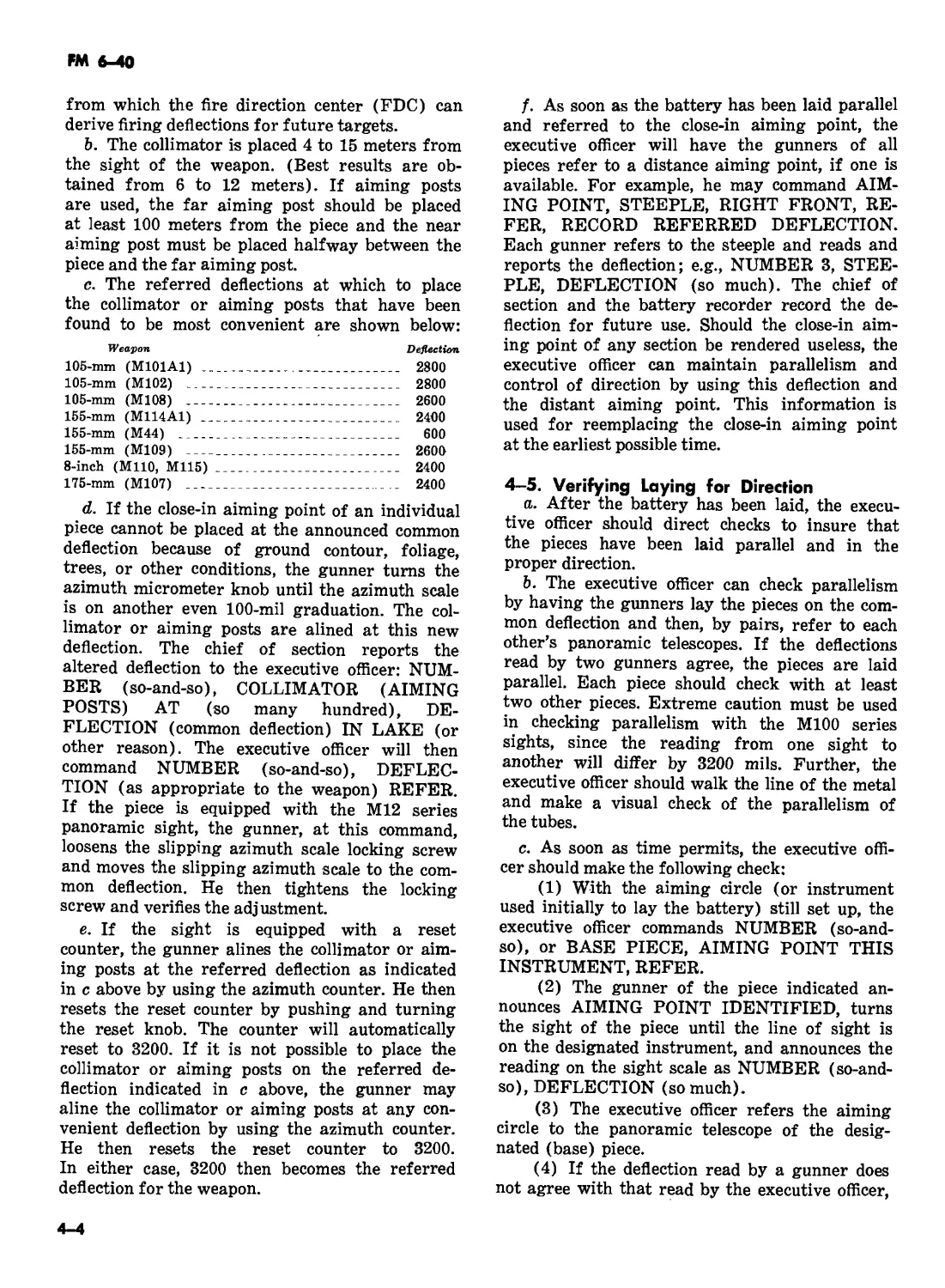
CHAPTER 4
Sections I, II, III, and V
(Superseded by FM 6-50, THE FIELD ARTILLERY CANNON BATTERY)
| Section IV. FIRE COMMANDS AND THEIR EXECUTION
4-1. General
a. Fire commands are the means by which the
FDC gives the cannon section all of the
information it needs to start, conduct, and cease
firing. The initial fire commands include all
elements necessary for laying, loading, and firing
the pieces. Subsequent fire commands include
only those elements that are changed, with the
exception of quadrant elevation, which is always
announced.
b. Normally, fire commands come from the fire
direction center. The FDC receives fire missions
from a forward observer, from a supported unit, or
from the FDC of another headquarters and
converts this mission information into fire
commands. The fire commands are sent to the
cannon sections by the best available means of
communications.
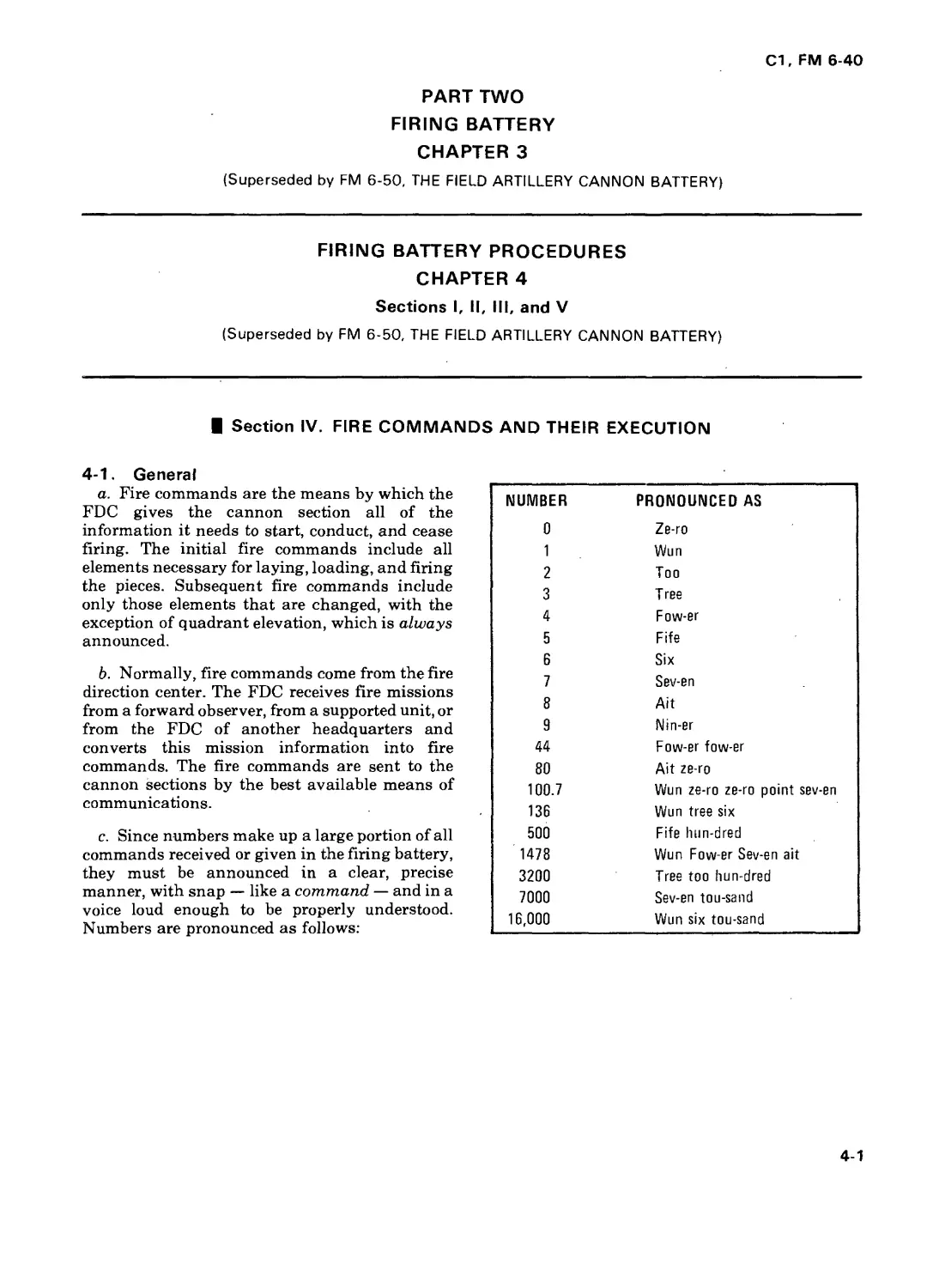
c. Since numbers make up a large portion of all
commands received or given in the firing battery,
they must be announced in a clear, precise
manner, with snap — like a command — and in a
voice loud enough to be properly understood.
Numbers are pronounced as follows:
NUMBER PRONOUNCED AS
0 Ze-ro
1 Wun
2 Too
3 Tree
4 Fow-er
5 Fife
6 Six
7 Sev-en
8 Ait
9 Nin-er
44 Fow-er fow-er
80 Ait ze-ro
100.7 Wun ze-ro ze-ro point sev-en
136 Wun tree six
500 Fife hun-dred
1478 Wun Fow-er Sev-en ait
3200 Tree too hun-dred
7000 Sev-en tou-sand
16,000 Wun six tou-sand
4-1
С1, FM 6-40
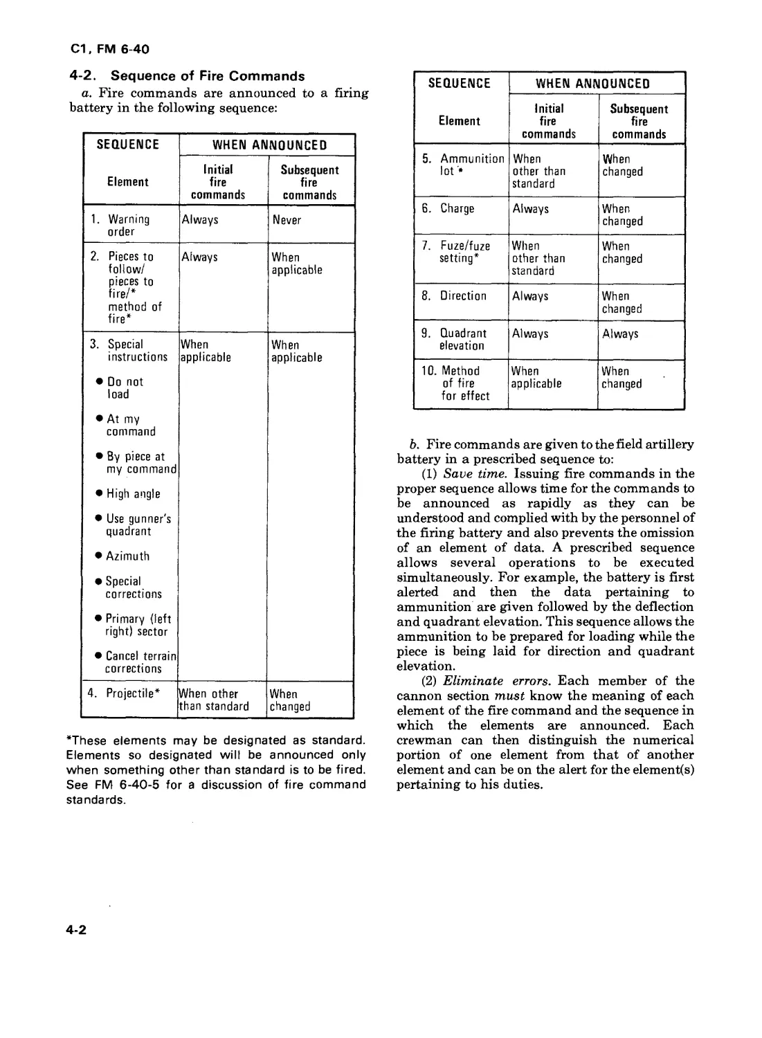
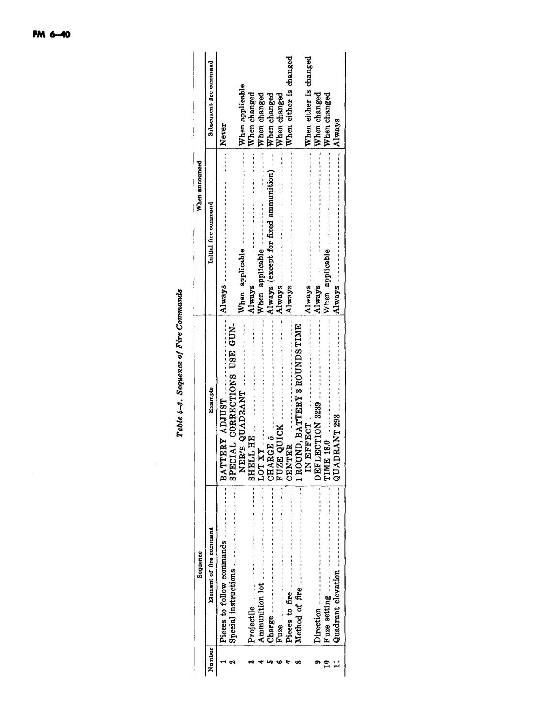
4-2. Sequence of Fire Commands
a. Fire commands are announced to a firing
battery in the following sequence:
SEQUENCE Element WHEN ANNOUNCED
Initial fire commands Subsequent fire commands
1. Warning order Always Never
2. Pieces to follow/ pieces to fire/* method of fire* Always When applicable
3. Special instructions • Do not load • At my command • By piece at my command • High angle • Use gunner's quadrant • Azimuth • Special corrections • Primary (left right) sector • Cancel terrain corrections When applicable When applicable
4. Projectile* When other than standard When changed
*These elements may be designated as standard.
Elements so designated will be announced only
when something other than standard is to be fired.
See FM 6-40-5 for a discussion of fire command
standards.
SEQUENCE Element WHEN ANNOUNCED
Initial fire commands Subsequent fire commands
5. Ammunition lot '• When other than standard When changed
6. Charge Always When changed
7. Fuze/fuze setting* When other than standard When changed
8. Direction Always When changed
9. Quadrant elevation Always Always
10. Method of fire for effect When applicable When changed
b. Fire commands are given to the field artillery
battery in a prescribed sequence to:
(1) Save time. Issuing fire commands in the
proper sequence allows time for the commands to
be announced as rapidly as they can be
understood and complied with by the personnel of
the firing battery and also prevents the omission
of an element of data. A prescribed sequence
allows several operations to be executed
simultaneously. For example, the battery is first
alerted and then the data pertaining to
ammunition are given followed by the deflection
and quadrant elevation. This sequence allows the
ammunition to be prepared for loading while the
piece is being laid for direction and quadrant
elevation.
(2) Eliminate errors. Each member of the
cannon section must know the meaning of each
element of the fire command and the sequence in
which the elements are announced. Each
crewman can then distinguish the numerical
portion of one element from that of another
element and can be on the alert for the elements)
pertaining to his duties.
4-2
Cl, FM 6 40
c. The chief of section is not permitted to fire his
weapon until he has received a complete set of
commands. Explanations and examples of all
elements of the fire commands are presented in
paragraphs 4-3 through 4-17. Some of the elements
listed are used only under special circumstances
and are not announced when they do not apply.
4-3. Warning Order
A warning order of FIRE MISSION will be
announced to the guns as a fire mission is received
by the battery. This will alert the crews to stand by
their posts and be ready to receive data.
4-4. Pieces to Follow/Pieces to Fire/
Method of Fire
This element designates the weapons to follow
the mission and actually take part in firing.
a. Pieces to follow/pieces to fire alert the
battery as to which sections will fire on the target,
either initially or after an adjustment has been
made. This command also tells the battery which
sections should follow the commands and load if
appropriate. BATTERY ADJUST indicates that
fire will be adjusted onto the target and that the
entire battery should follow the commands and
fire on the target after the adjustment has been
completed. The method of adjustment and rounds
to be fired in effect are announced in later
elements. Any weapon or combination of weapons
may be announced in this element, e.g., LEFT
ADJUST, NUMBER 3 ADJUST BATTERY (so
many) ROUNDS indicates that a fire for effect
mission (no adjustment) is to be fired. Any
combination of weapons may be announced here
also.
b. Method of fire tells the battery how many
rounds are to be fired during the adjustment and
in what manner. This portion may be
standardized; e.g., the base piece fires one round.
If a weapon other than the designated standard is
to be fired, this information must be announced at
this time. BATTERY ADJUST, NUMBER 4 ONE
ROUND indicates that the battery is to follow the
commands and fire after the adjustment is
completed and that number 4 is the adjusting
piece for this particular mission. Special methods
of fire used in unusual circumstances are
discussed in paragraph 4-13.
4-5. Special Instructions
Special instructions are used whenever actions
different from normal are required. They include:
a. DO NOT LOAD is a restrictive command
that prohibits the loading and firing of the
weapon(s). The section cuts the charge, sets the
fuze setter, and lays the weapon on the given
deflection and quadrant elevation or applicable
loading elevation, but does not load the round into
the weapon. When these tasks have been
completed, the chief of section reports NUMBER
(so-and-so) IS LAID. When the round(s) is to be
fired the FDC commands CANCEL DO NOT
LOAD and gives the appropriate quadrant
elevation.
b. AT MY COMMAND (or BY PIECE AT MY
COMMAND) is a restrictive command that
prohibits the battery (section) from firing until
directed to do so by the FDC. The sections lay and
load their weapons and the chiefs of section report
to FDC, NUMBER (so-and-so) IS READY. The
FDC will tell the section chief(s) when to fire. To
return control of firing to the section chiefs, the
FDC announces — CANCEL ATMYCOMMAND
(BY PIECE AT MY COMMAND) and gives the
appropriate quadrant elevation.
c. HIGH ANGLE is announced to alert the crew
that the mission is to be fired at an angle of
elevation over 800 mils. Light artillery weapons
can be elevated before loading to expedite the
mission; medium and heavy artillery weapons
must be loaded at a loading elevation.
d. USE GUNNER’S QUADRANT is
announced whenever FDC desires that the
gunner’s quadrant be used.
e. AZIMUTH, followed by an azimuth in mils,
may be sent to the guns to alert them to a large
shift in azimuth.
f. SPECIAL CORRECTIONS is announced
any time that a separate time, deflection, and/or
quadrant will be sent to one or more gun sections.
g. PRIMARY (LEFT) (RIGHT) SECTOR is
announced when terrain gun position corrections
are being used. Ordinarily, the corrections for the
primary sector are set on the gunner’s aids of all
the weapons in the battery. These corrections are
announced administratively. To change sectors,
FDC commands LEFT SECTOR or RIGHT
SECTOR. Upon termination of the mission, the
howitzer sections reapply the corrections that
were in effect prior to the mission.
h. CANCEL TERRAIN CORRECTIONS
indicates that all howitzer sections are to set their
gunners aid counters to zero. After completion of
the mission, the terrain gun position corrections
that were in effect prior to the mission will be
reapplied unless the FDC indicates otherwise.
4-3
Cl, FM 6-40
4-6. Projectile
The type of projectile that will be used to attack a
target is announced in the initial commands
unless it has been designated as standard. The
projectile is not announced in the subsequent
command unless a change is desired.
4-7. Ammunition Lot
a. The element ammunition lot indicates the lot
number to be fired. The lot number is announced
in the initial fire commands unless a specific lot
has been designated standard. The lot number is
not repeated in subsequent commands unless a
change is desired.
b. The lot numbers for semifixed ammunition
pertain to an assembled projectile-propellant
combination and, for simplicity, are coded lot X,
lot Y, etc. The lot numbers for a specific projectile-
propellant combination of components of
separate-loading ammunition are combined. For
example, in the command LOTXY,\ indicates the
projectile lot and Y indicates the propellant lot.
c. Large-quantity lots are set aside to be fired
during registrations, and missions when more
uniform effect is important. Small-quantity lots
should be used for adjust fire and other missions
when uniform effect is not critical. The sections
must segregate ammunition by lot number and
maintain accurate records of the number of
rounds on hand, by lot number.
4-8. Charge
The element charge indicates the amount of
propellant to be used. As soon as the charge is
announced, all powder increments for the round
being fired are inspected and excess increments
are removed.
4-9. Fuze/Fuze Setting
The type of fuze to be used is announced in the
initial fire commands only when it is other than
the designated standard. It is announced as a
subsequent command only when a change is
desired. When VT or time fuzes are fired, this
element includes the fuze setting; e.g., FUZE VT,
59.0.
4-10. Direction
Direction is always announced as a four-digit
deflection; e.g., DEFLECTION 3248. The gunner
sets the commanded deflection on his panoramic
telescope and traverses the tube until he is sighted
on the proper aiming point.
4-11. Quadrant Elevation
The command QUADRANT (so much) is
permission for the chief of section to load and fire
the round unless otherwise restricted by special
instructions. Alternative procedures may be
adopted by the firing battery as local SOP. These
procedures often impact on the FDC and, hence,
require FDC personnel to be knowledgeable in
handling these situations. Three of the more
prominent of these alternatives are:
Loading on the command DEFLECTION (so
much).
Adjusting piece(s) loading subsequent rounds
immediately after firing.
Nonadjusting pieces loading the shell to be fired
in effect upon receipt of initial fire commands.
THE DECISION TO USE THESE
TECHNIQUES IS MADE BY THE
COMMANDER, AND IS INFLUENCED
BY THE STATE OF TRAINING OF
THE FDC AND GUN CREWS.
a. Loading on deflection. This procedure is
especially effective for those units where loading
will not interfere with receipt of the remaining fire
commands. For self-propelled units, adoption of
this procedure may require that the FDC pause
momentarily between the commands for
deflection and quadrant. In any case, the FDC
must insure that there are no long delays between
the commands deflection and quadrant so that
rounds are not loaded and left in the tube for an
extended period of time.
b. Adjusting piece(s) load subsequent rounds
immediately after firing. Using this SOP, it is
possible, when entering FFE, that the adjusting
piece(s) may not have the correct shell/fuze
combination loaded. The chief of section will at
the end of the mission, (as always), report if his
piece fired other than the ammunition announced
in the fire command. In the example, NUMBER 4
FIRED 1 QUICK AND 2 VT IN EFFECT*, the
FDC will correct the ammunition count on the
Record of Fire to reflect the report.
*Rather than 3 VT.
c. Nonadjusting pieces load the shell to be
fired in effect upon receipt of the initial fire
commands. This SOP is particularly valuable
when the FFE fuze is fuze quick and is obviously
not applicable to mechanical time fuzes. When the
FFE fuze is fuze VT, the FDC calculates and sends
to the nonadjusting pieces the VT fuze setting to
the initial target location. If terrain, weather, and
enemy capabilities allow it, an alternative
procedure is to use the VT minimum safe time.
4-12. Method of Fire for Effect
This element indicates the number of rounds, and
type of ammunition to be used in effect, when
4-4
С1. FM 6-40
applicable. It is announced after the quadrant in
adjust fire missions so as not to delay the firing of
initial data. For example, if the initial commands
include BATTERY ADJUST, the method of fire
for effect might be 2 ROUNDS IN EFFECT.
4-13. Special Methods of Fire
a. ZONE FIRE. This method of fire is used
when the standard sheaf does not adequately
cover the target and more depth is required. The
number of mils in the zone and the number of
quadrants to be fired will be announced by the
FDC. For example, upon receipt of the command
ZONE 5 MILS, 5 QUADRANTS, each chief of
section computes the required quadrants and then
fires them after the initial quadrant announced in
the fire command. If in this example, the
announced quadrant is 310, it would be fired first;
the remaining quadrants would be 320, 315, 305,
and 300, fired in any order.
b. SWEEPING FIRE. This method of fire is
similar to zone fire but provides for firing several
deflections with one quadrant. For example,
SWEEP 10 MILS, 3 DEFLECTIONS. As in zone
fire, each chief of section computes the required
deflections and fires them after the initial
deflection has been fired. For example, if. the
announced deflection is 3220, it would be fired
first; the remaining deflections would be 3230 and
3210 and would be fired in any order.
c. ZONE AND SWEEP. This method of fire
combines zone fire and sweeping fire. The chief of
section will first fire the announced deflection and
quadrant and then fire all combinations of the
computed deflections and quadrants. For
example, SWEEP 10 MILS, 3 DEFLECTIONS,
ZONE 4, MILS, 3 QUADRANTS. If the
announced deflection is 3200 and the announced
quadrant, 310, the three deflections to be fired
would be 3200, 3210, and 3190 and the three
quadrants to be fired would be 310, 306, and 314.
Each quadrant would be fired with each deflection
(total of nine rounds). Deflection 3200 and
quadrant 310 would be fired first.
d. CONTINUOUS FIRE. When it is desired to
fire continuously at a target, the command is
CONTINUOUS FIRE. At this command, the
crews load and fire as rapidly as possible,
consistent with accuracy and within the
prescribed rates of fire for the pieces. The crews
continue to fire until commanded to CHECK
FIRING or CEASE LOADING.
e. FIRE AT WILL. If the method of fire is for
pieces to fire at will, the command is TARGET (so-
and-so), FIRE AT WILL. If a method of close
defense has been prearranged, the command is
simply FIRE AT WILL. At this command, the
designated piece or pieces fire under the control of
the chief(s) of section as the situation and target
necessitate.
4-14. Check Firing/Cease Loading
a. The command CHECK FIRING is normally
given by the FDC but may be given by anyone
present. On this command, regardless of its
source, firing will cease immediately. The signal
for CHECK FIRING is to raise the hand in front of
the forehead, palm to the front, and swing the
hand and forearm up and down in front of the face.
Another signal for CHECK FIRING is one long
blast on a whistle. Firing is resumed at the
announcement of CANCEL CHECK FIRING and
the quadrant elevation.
b. The command CEASE LOADING is similar
to CHECK FIRING. Upon receipt of this
command, the cannoneers may fire the weapons
that are already loaded, but no additional rounds
may be chambered. Firing is resumed at the
announcement of CANCEL CEASE LOADING
and the quadrant elevation.
4-15. End of Mission
The command END OF MISSION means that
the fire mission has been completed. All
corrections applied to the fire control equipment
for that mission are to be removed. Primary
terrain gun position corrections are to remain on
the gunners aid counters unless commanded
otherwise by the fire direction center. If a priority
target has been assigned, each gun will lay on the
firing data for its assigned target.
Note. The assigned targets may not always be
located in the primary sector so the applicable
position corrections (primary, left, right) must be
applied to the gunners aid prior to setting off and
laying on the assigned target data.
4-16. Repetition of Commands
a. Voice Communications. Chiefs of section
repeat the commands FIRE, CHECK FIRING,
and CEASE LOADING. Any other fire
commands are repeated only when requested or
when they obviously have not been heard or
understood. The request for repetition is stated as
a question; e.g., DEFLECTION NUMBER (so-
and-so)?
b. Intrabattery Communications. When radio
or wire communications are used between the
FDC and the individual gun sections, the
readback of elements of the fire commands is
governed by unit SOP. One piece should be
designated to read back all fire commands. If the
howitzer loudspeakers are not working, the person
designated by the chief of section to operate the
radio or telephone must announce each element of
the fire command to the section.
4-5
С1, FM 6-40
с. FDC. The repetition of commands by the
FDC is always preceded by THE COMMAND
WAS; e.g., THE COMMAND WAS DEFLEC-
TION 2768.
4-17. Planned Targets
a. At times the battery will be assigned planned
targets which must be fired quickly. One of these
will be designated by the FDC as the priority
target, and each weapon will be laid on its
assigned priority target when not actively
engaged in a mission. Appropriate ammunition
will be kept on hand and personnel at the piece will
begin firing the weapon as soon as a command is
received.
b. One common type of priority target is the
final protective fire (FPF). To order the FPF to be
fired, the command FIRE THE FPF or a
prearranged signal is given.
c. In offensive operations, suppressive fires are
frequently delivered by the artillery battery. Some
of these may be planned fires; if so, each section
maintains firing data on these targets as directed
by the FDC. These targets are recorded at the
section as follows:
that affect the firing of his weapon in support of
the battery mission. In the conduct of firing the
following specific reports are made:
a. SHOT NUMBER (so-and-so) after each
round of a fire mission has been fired. If around or
fuze other than the one announced by the FDC is
fired, it must be reported to the FDC.
b. ROUNDS COMPLETE NUMBER (so-and-
so) when the final round of fire for effect (other
than one round) has been fired.
c. MISFIRE NUMBER (so-and-so) when there
has been a misfire. The chief of section reports
NUMBER (so-and-so) IS READY when the piece
is ready to fire.
d. NUMBER (so-and-so) IS OUT (reason) when
a piece has been called out of action.
e. Number of rounds expended, by type and lot
number (when required).
f. Errors. Chiefs of section must tell the FDC if
any round has been fired with improper data. The
executive officer has the error(s) corrected and
reports to the FDC, e.g., NUMBER 2 FIRED 20
MILS RIGHT.
PRIORITY TARGETS
TGT NO. SP INST RDS SH LOT CHG FZ Tl DF 0E
43 —— 2 HE XY 6 Q — 3210 402
54 — 2 HE XY 6 VT 29.0 3190 418
57 —1 4 SMK TY 6 Tl 31.0 3182 432
In this case the sections in the platoon would lay
on target 43. The command from FDC to fire would
be (so-and-so) SUPPRESS, followed by the target
number; e.g., RIGHT SUPPRESS, 43. If target 54
or 57 are to be fired, the command would be
RIGHT SUPPRESS 54 which means the platoon
would re-lay and fire the data for target 54.
4-18. Reports
The section chief reports to the FDC all actions
4-19. Correcting Fire Commands
a. If an incorrect command has been given but
the command QUADRANT has not been
announced, the FDC commands CORRECTION
and then gives the correct command and all
subsequent elements.
b. If QUADRANT has been announced, the
FDC commands CHECK FIRING. Then
CANCEL CHECK FIRING, is announced
followed by the proper element and all subsequent
elements.
CHAPTER 5
FIRING BATTERY OPERATIONS AND TRAINING
(Superseded by FM 6-50, THE FIELD ARTILLERY CANNON BATTERY)
CHAPTER 6
DUTIES OF THE SAFETY OFFICER
(Superseded by FM 6-50, THE FIELD ARTILLERY CANNON BATTERY)
4-6 (next numbered page is 7-1)
С1, FM 6-40
CHAPTER 8
LOCATION OF TARGETS
8-1. General
The most accurate means available are employed
in locating targets and determining initial data in
order to insure the safety of friendly troops, to save
ammunition, to save time in adjustment, and to
increase the effectiveness of fire. Full use is made
of data from all previous firing in the area and of
maps, photographs, diagrams, or panoramic
sketches of the area. The preparatory operations
discussed in chapter 7 are desirable and
necessary; however, failure to complete them on
occupation of an observation post will not
preclude the observer from calling for fire as soon
as he locates a target. Firing often begins before
the preparatory phase is completed, whether the
firing be precision fire in which fire is placed on a
specific point, or area fire in which a given area is
covered with fire. In area fire, the observer
conducts the fire mission by using a standard
sequence and procedure as follows:
a. He locates the target.
b. He makes the call for fire to the FDC.
c. He adjusts fire, if necessary.
d. He conducts surveillance of fire for effect.
8-2. Target Location
a. Methods. There are three methods by which
the observer can designate the locations of targets
so that FDC personnel may plot them on their
charts:
(1) By grid coordinates (para 8-5).
(2) By shift from a known point (para 8-6).
(3) By polar coordinates (para 8-7).
b. Accuracies and Announcement of Data. All
data for target locations in calls for fire and
subsequent corrections are determined to an
accuracy consistent with the equipment used for
determination. The observer will normally
announce his data as follows:
(1) Direction to the nearest 10 mils.
(2) Deviation to the nearest 10 meters.
(3) Vertical change to the nearest 5 meters.
(4) Range to the nearest 100 meters.
(5) Grid coordinates to the nearest 100 meters.
8-3. Determination of Distance
The observer must be able to determine quickly
and accurately the distance between objects, tar-
gets, or bursts in order to determine basic data
and to adjust artillery fire effectively. Distances
can be determined by estimation or by computa-
tion.
a. Estimation of Distance. The observer can
facilitate estimation of distance by establishing
a yardstick on the ground in the target area.
This yardstick can be established by ranging
rounds that are 400 meters apart in range. The
ranging rounds may be fired by a single piece or
by a platoon. The observer can also establish a
known distance in the target area by determining
from his map or photograph the distance be-
tween two points that he can identify positively
both on the map and on the ground. The observer
can estimate the approximate distance from his
position to a sound source (e.g., bursting shell,
weapon firing, etc.) by timing sound. The speed
of sound in still air at 59° F. is approximately
340 meters per second. Wind and variations in
temperature alter this speed somewhat. For pra-
ctical use, the observer may assume the speed of
sound to be 350 meters per second under all con-
ditions. He can time the sound with a watch or
by counting from the time a burst or flash ap-
pears until he hears the sound. For example, the
observer counts “one-thousand one, one-thousand
two” (and so on), to determine the approximate
time in seconds. He then multiplies the time in
seconds by 350 to obtain the approximate dis-
tance in meters.
Example: The observer desires to determine
the approximate distance from his position to
a burst. He begins counting when the burst ap-
pears and stops counting when he hears the sound.
He counts 4 seconds; therefore, the distance from
the burst to his position is approximately 1,400
meters (350 X 4).
b. Computation of Distance. Using the angle
measured from one point to another and the
known lateral distance between the two points,
the observer may compute the distance by ap-
plying the mil relation. The mil relation is based
on the assumption that an angle of 1 mil will
8-1
С1, FM 6-40
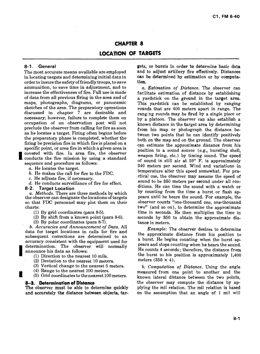
subtend a width of 1 meter at a distance of
1,000 meters. The relation is expressed as i/it =
W
where ijh. is the angular measurement in mils
К
between the two points, R is the distance in
thousands of meters (expressed to the nearest
ICO) to the known point, and W is the width in
meters between the points from which angle ifa.
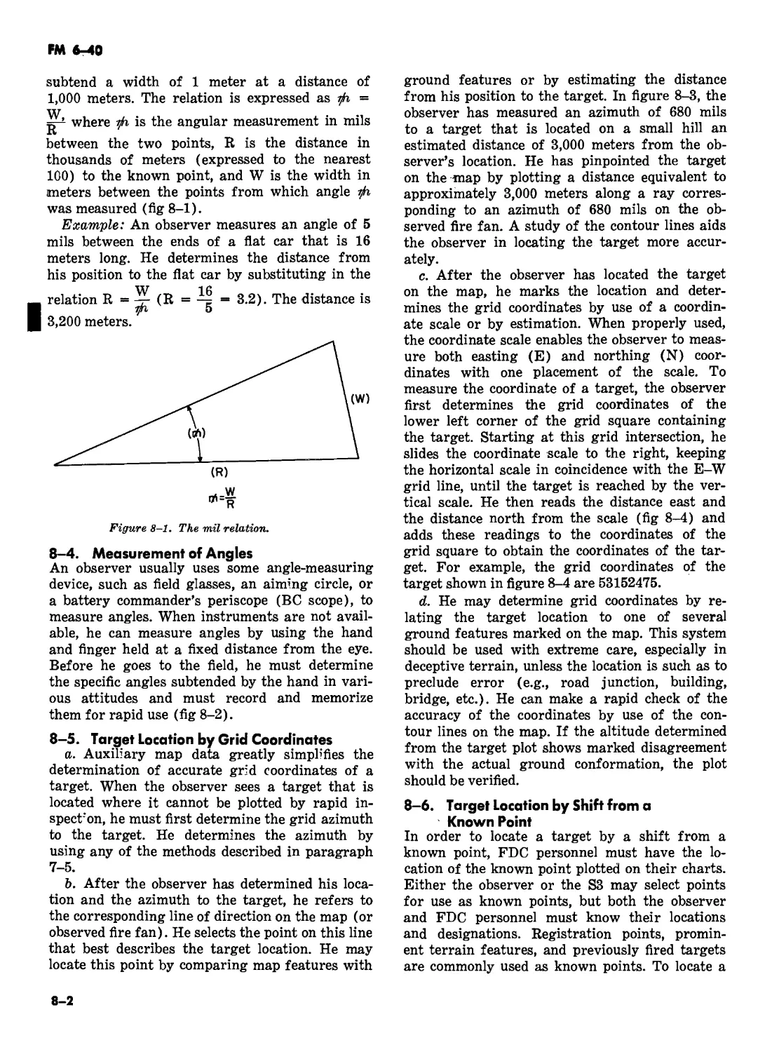
was measured (fig 8-1).
Example: An observer measures an angle of 5
mils between the ends of a flat car that is 16
meters long. He determines the distance from
his position to the flat car by substituting in the
Figure 8-1. The mil relation.
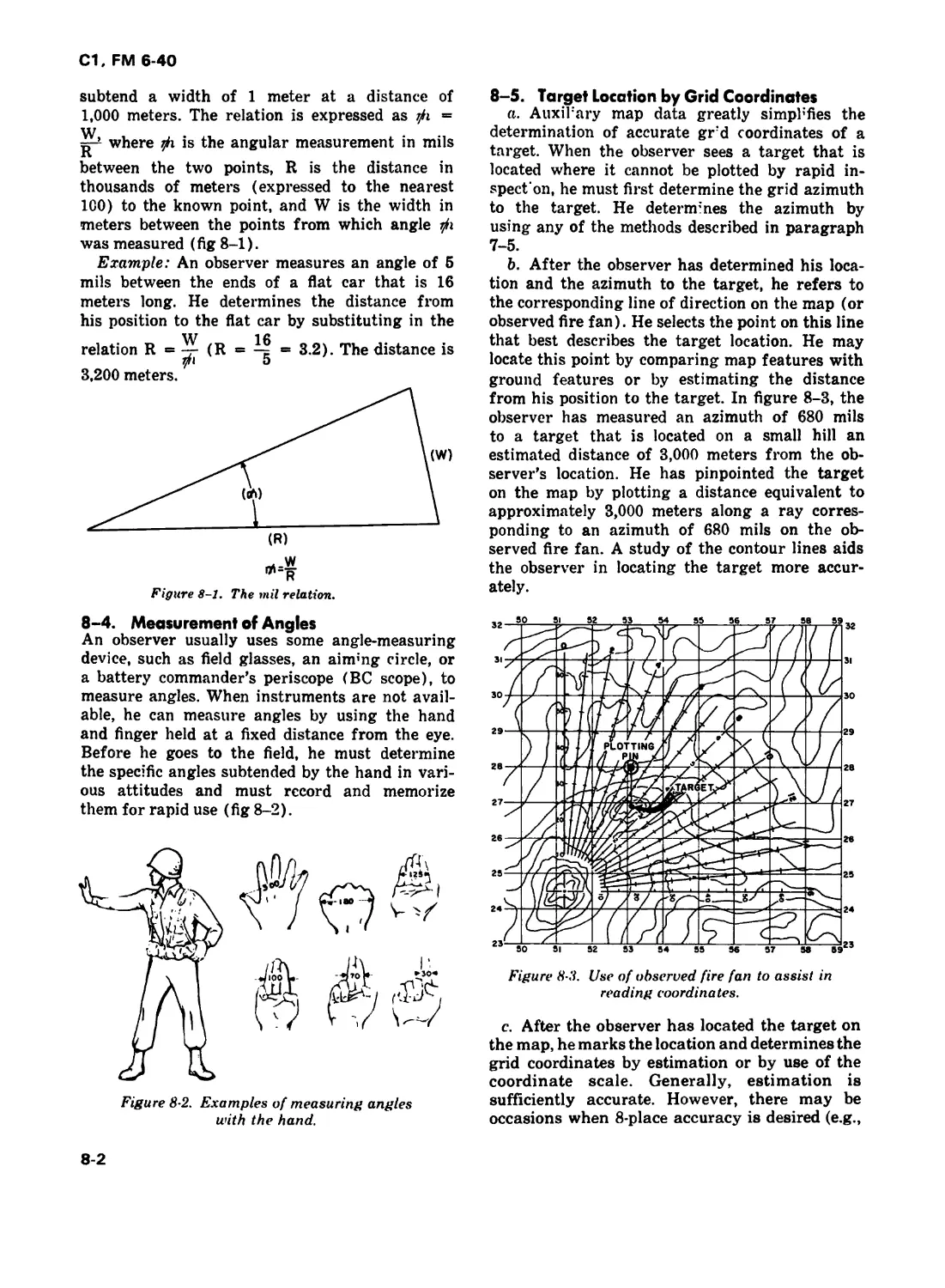
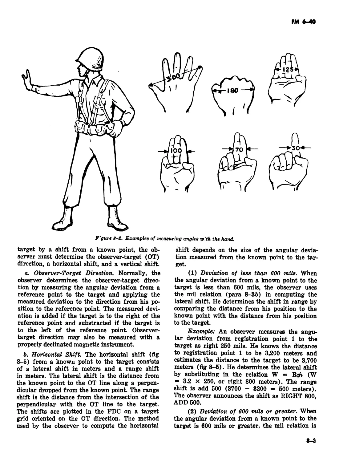
8-4. Measurement of Angles
An observer usually uses some angle-measuring
device, such as field glasses, an aim’ng circle, or
a battery commander’s periscope (BC scope), to
measure angles. When instruments are not avail-
able, he can measure angles by using the hand
and finger held at a fixed distance from the eye.
Before he goes to the field, he must determine
the specific angles subtended by the hand in vari-
ous attitudes and must record and memorize
them for rapid use (fig 8-2).
Figure 8 2. Examples of measuring angles
with the hand.
8-5. Target Location by Grid Coordinates
a. Auxiliary map data greatly simpl’fies the
determination of accurate grd coordinates of a
target. When the observer sees a target that is
located where it cannot be plotted by rapid in-
spect on, he must first determine the grid azimuth
to the target. He determines the azimuth by
using any of the methods described in paragraph
7-5.
b. After the observer has determined his loca-
tion and the azimuth to the target, he refers to
the corresponding line of direction on the map (or
observed fire fan). He selects the point on this line
that best describes the target location. He may
locate this point by comparing map features with
ground features or by estimating the distance
from his position to the target. In figure 8-3, the
observer has measured an azimuth of 680 mils
to a target that is located on a small hill an
estimated distance of 3,000 meters from the ob-
server’s location. He has pinpointed the target
on the map by plotting a distance equivalent to
approximately 3,000 meters along a ray corres-
ponding to an azimuth of 680 mils on the ob-
served fire fan. A study of the contour lines aids
the observer in locating the target more accur-
ately.
Figure 83. Use of observed fire fan to assist in
reading coordinates.
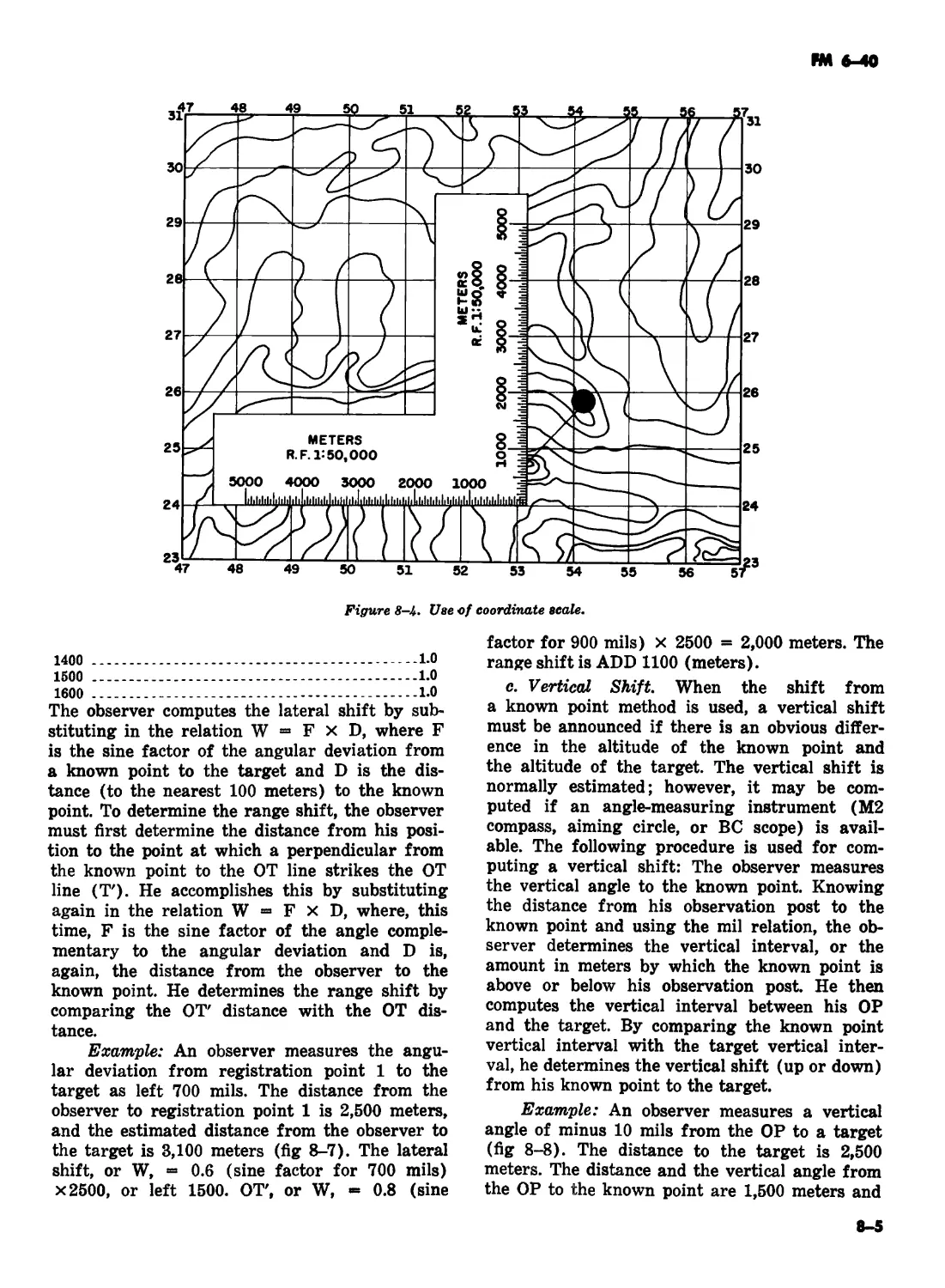
c. After the observer has located the target on
the map, he marks the location and determines the
grid coordinates by estimation or by use of the
coordinate scale. Generally, estimation is
sufficiently accurate. However, there may be
occasions when 8-place accuracy is desired (e.g.,
8-2
С1, FM 6-40
registration point). When properly used, the
coordinate scale enables the observer to measure
both easting (E) and northing (N) coordinates
with one placement of the scale. To measure the
coordinates of a target, the observer first
determines the grid coordinates of the lower left
corner of the grid square containing the target.
Starting at this grid intersection, he slides the
coordinate scale in coincidence with the E-W grid
line, until the target is reached by the vertical
scale. He then reads the distance east and the
distance north from the scale (fig 8-4) and adds
these readings to the coordinates of the target. For
example, the grid coordinates of the target shown
in figure 8-4 are 53152475.
Figure 8-4. Use of coordinate scale.
d. He may determine grid coordinates by
relating the target location to one of several
ground features marked on the map. This system
should be used with extreme care, especially in
deceptive terrain, unless the location is such as to
preclude error (e.g., road junction, building,
bridge, etc.). He can make a rapid check of the
accuracy of the coordinates by use of the contour
lines of the map. If the altitude determined from
the target plot shows marked disagreement with
the actual ground conformation, the plot should be
verified.
8—6. Target Location by Shift from a
Known Point
In order to locate a target by a shift from a
known point, FDC personnel must have the lo-
cation of the known point plotted on their charts.
Either the observer or the S3 may select points
for use as known points, but both the observer
and FDC personnel must know their locations
and designations. Registration points, promin-
ent terrain features, and previously fired targets
are commonly used as known points. To locate a
target by a shift from a known point, the observer
must determine the observer-target (ОТ) direction,
a horizontal shift, and a vertical shift.
a. Observer-Target direction. Normally, the
observer determines the observer-target direction
by measuring the angular deviation from a
reference point to the target and applying the
measured deviation to the direction from his
position to the reference point. The measured
deviation is added if the target is to the right of the
reference point and subtracted if the target is to
the left of the reference point. Observer-target
direction may also be measured with a properly
declinated magnetic instrument.
b. Horizontal Shift. The horizontal shift from a
known point to the target consists of a lateral shift
in meters and a range shift in meters. The lateral
shift is the distance from the known point to the
ОТ line along a perpendicular dropped from the
known point. The range shift is the distance from
the intersection of the perpendicular with the ОТ
line to the target. The shifts are plotted in the FDC
on a target grid oriented on the ОТ direction. The
method used by the observer to compute J.he
horizontal shift depends on the size of the angular
deviation measured from the known point to the
target.
(1) Deviation of less than 600 mils. When
the angular deviation from a known point to the
target is less than 600 mils, the observer uses
the mil relation (para 8-3b) in computing the
lateral shift. He determines the shift in range by
comparing the distance from his position to the
known point with the distance from his position
to the target.
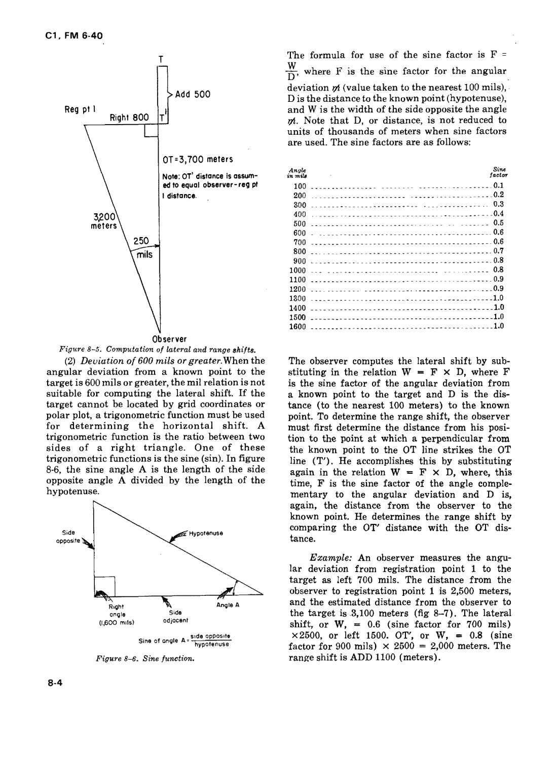
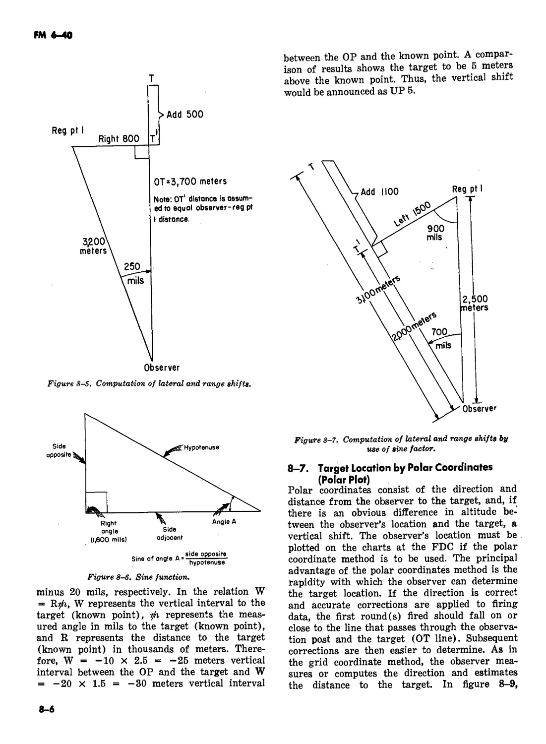
Example: An observer measures the angu-
lar deviation from registration point 1 to the
target as right 250 mils. He knows the distance
to registration point 1 to be 3,200 meters and
estimates the distance to the target to be 3,700
meters (fig 8-5). He determines the lateral shift
by substituting in the relation W = Ifyh (W
= 3.2 x 250, or right 800 meters). The range
shift is add 500 (3700 - 3200 = 500 meters).
The observer announces the shift as RIGHT 800,
ADD 500.
8-3
С1, FM 6-40
Figure 8-5. Computation of lateral and range shifts.
(2) Deviation of 600 mils or greater. When the
angular deviation from a known point to the
target is 600 mils or greater, the mil relation is not
suitable for computing the lateral shift. If the
target cannot be located by grid coordinates or
polar plot, a trigonometric function must be used
for determining the horizontal shift. A
trigonometric function is the ratio between two
sides of a right triangle. One of these
trigonometric functions is the sine (sin). In figure
8-6, the sine angle A is the length of the side
opposite angle A divided by the length of the
(i,600 mils) odjacenf
Sine of angle Д =
side opposite
hypotenuse
Figure 8-6. Sine function.
The formula for use of the sine factor is F -
ур where F is the sine factor for the angular
deviation r/i (value taken to the nearest 100 mils),
D is the distance to the known point (hypotenuse),
and W is the width of the side opposite the angle
Note that D, or distance, is not reduced to
units of thousands of meters when sine factors
are used. The sine factors are as follows:
Angle Sine
in mile factor
100 ____________________________________________________ o.l
200 ____________________________ -_______________________0.2
300 ___________________________________________________ 0.3
400 __________________________________________ 0.4
500 __________________________________ -- ________ 0-5
600 - ___________________________________________0.6
700 _____________________________________________0.6
800 ______________- -_____________________________0.7
900 _____________________________________________0.8
1000 ... _____________________________ - -........ 0.8
1100____________________________________________ 0.9
1200 ... --------------------------------------- 0.9
1300 ______________________________________________1.0
1400 -------------------------------------------- 1-0
1500 ______________________________________________1.0
1600 ______________________________________________1.0
The observer computes the lateral shift by sub-
stituting in the relation W = F X D, where F
is the sine factor of the angular deviation from
a known point to the target and D is the dis-
tance (to the nearest 100 meters) to the known
point. To determine the range shift, the observer
must first determine the distance from his posi-
tion to the point at which a perpendicular from
the known point to the ОТ line strikes the ОТ
line (T'). He accomplishes this by substituting
again in the relation W = F x D, where, this
time, F is the sine factor of the angle comple-
mentary to the angular deviation and D is,
again, the distance from the observer to the
known point. He determines the range shift by
comparing the ОТ' distance with the ОТ dis-
tance.
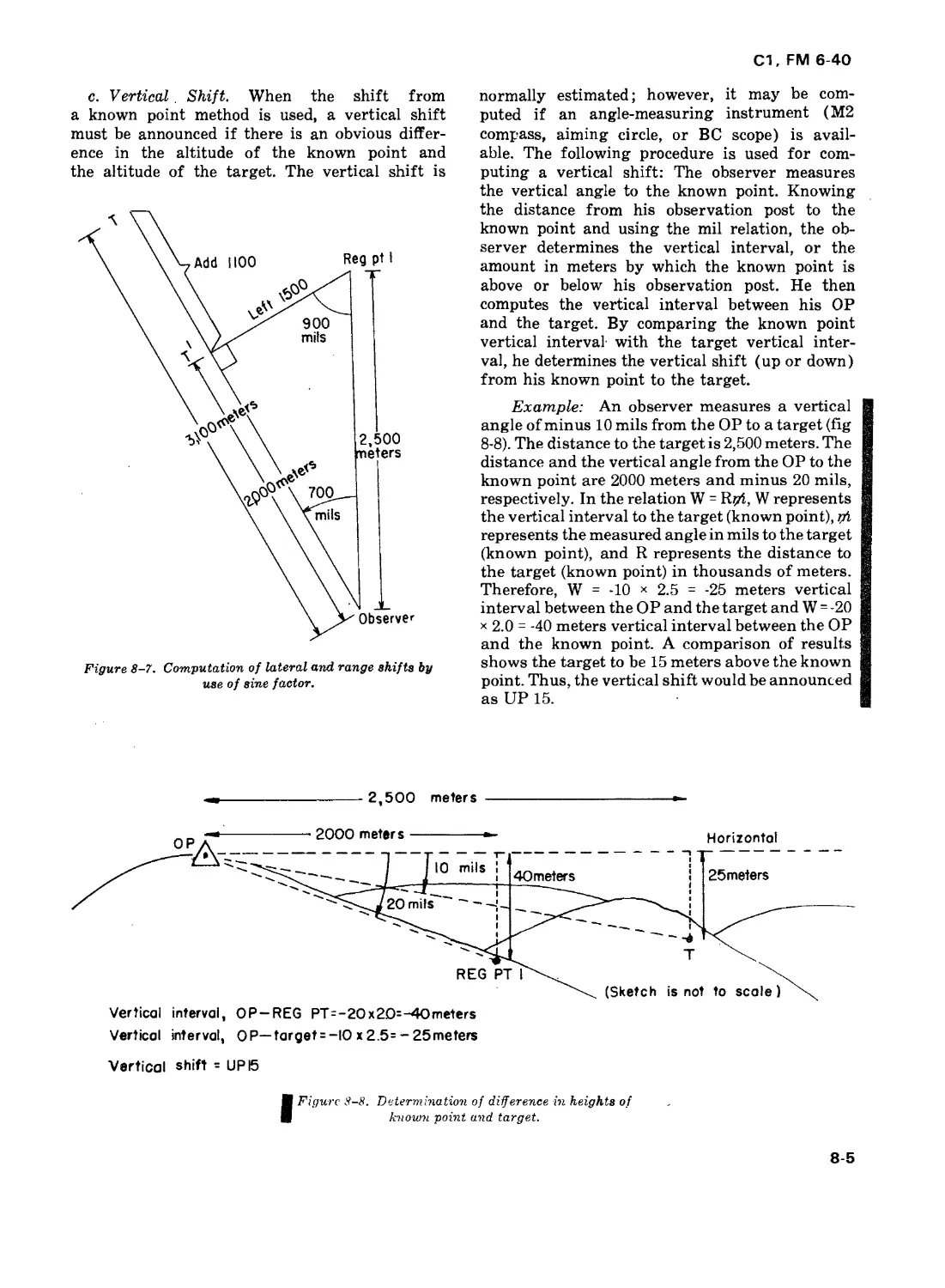
Example: An observer measures the angu-
lar deviation from registration point 1 to the
target as left 700 mils. The distance from the
observer to registration point 1 is 2,500 meters,
and the estimated distance from the observer to
the target is 3,100 meters (fig 8-7). The lateral
shift, or W, = 0.6 (sine factor for 700 mils)
X2500, or left 1500. ОТ', or W, = 0.8 (sine
factor for 900 mils) x 2500 = 2,000 meters. The
range shift is ADD 1100 (meters).
8-4
Cl, FM 6-40
c. Vertical. Shift. When the shift from
a known point method is used, a vertical shift
must be announced if there is an obvious differ-
ence in the altitude of the known point and
the altitude of the target. The vertical shift is
Figure 8-7. Computation of lateral and range shifts by
use of sine factor.
normally estimated; however, it may be com-
puted if an angle-measuring instrument (М2
compass, aiming circle, or BC scope) is avail-
able. The following procedure is used for com-
puting a vertical shift: The observer measures
the vertical angle to the known point. Knowing
the distance from his observation post to the
known point and using the mil relation, the ob-
server determines the vertical interval, or the
amount in meters by which the known point is
above or below his observation post. He then
computes the vertical interval between his OP
and the target. By comparing the known point
vertical interval' with the target vertical inter-
val, he determines the vertical shift (up or down)
from his known point to the target.
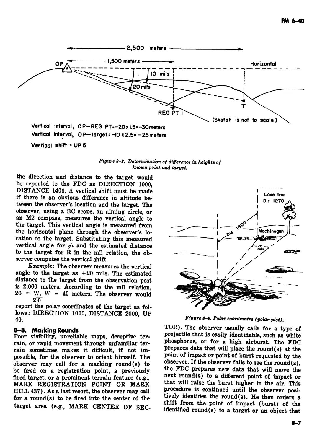
Example: An observer measures a vertical
angle of minus 10 mils from the OP to a target (fig
8-8). The distance to the target is 2,500 meters. The
distance and the vertical angle from the OP to the
known point are 2000 meters and minus 20 mils,
respectively. In the relation W = R?zi, W represents
the vertical interval to the target (known point), n't
represents the measured angle in mils to the target
(known point), and R represents the distance to
the target (known point) in thousands of meters.
Therefore, W = -10 x 2.5 - -25 meters vertical
interval between the OP and the target and W - -20
* 2.0 = -40 meters vertical interval between the OP
and the known point. A comparison of results
shows the target to be 15 meters above the known
point. Thus, the vertical shift would be announced
as UP 15.
-------------------2,500 meters ----------------------------•-
Vertical interval, OP— target = -IO x 2.5= - 25meters
Vertical shift = UP 15
(Figure 8-8. Determination of difference in heights of
known point and target.
8-5
С1, FM 6-40
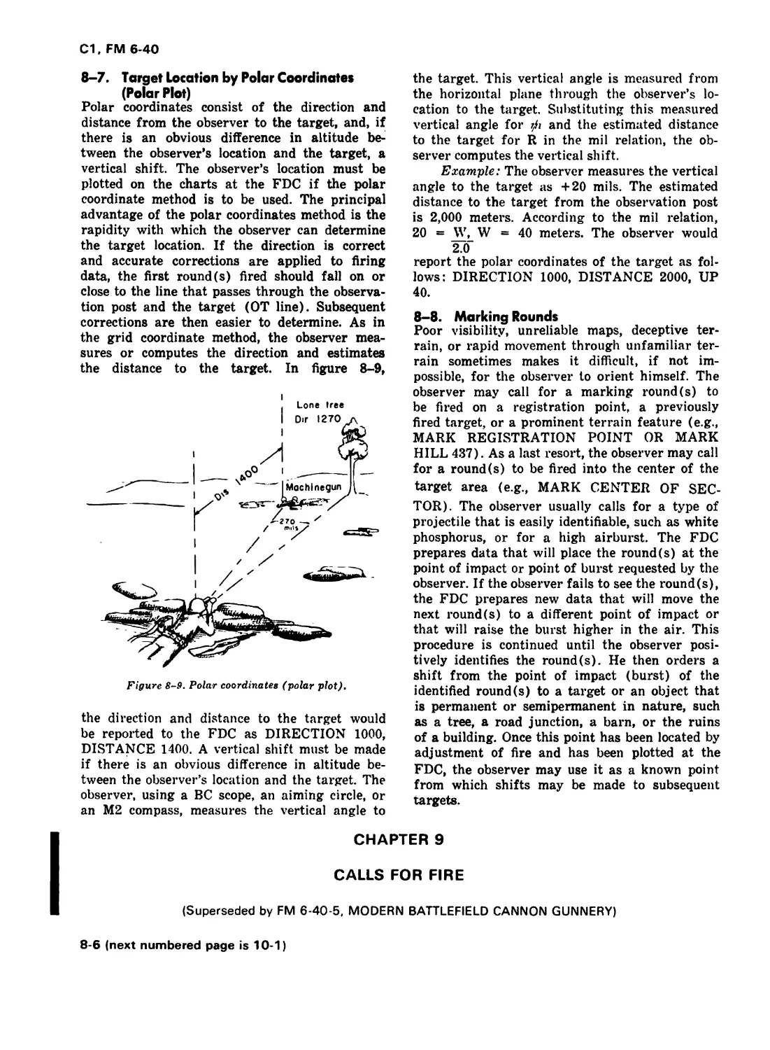
8-7. Target Location by Polar Coordinates
(Polar Plot)
Polar coordinates consist of the direction and
distance from the observer to the target, and, if
there is an obvious difference in altitude be-
tween the observer’s location and the target, a
vertical shift. The observer’s location must be
plotted on the charts at the FDC if the polar
coordinate method is to be used. The principal
advantage of the polar coordinates method is the
rapidity with which the observer can determine
the target location. If the direction is correct
and accurate corrections are applied to firing
data, the first round (s) fired should fall on or
close to the line that passes through the observa-
tion post and the target (ОТ line). Subsequent
corrections are then easier to determine. As in
the grid coordinate method, the observer mea-
sures or computes the direction and estimates
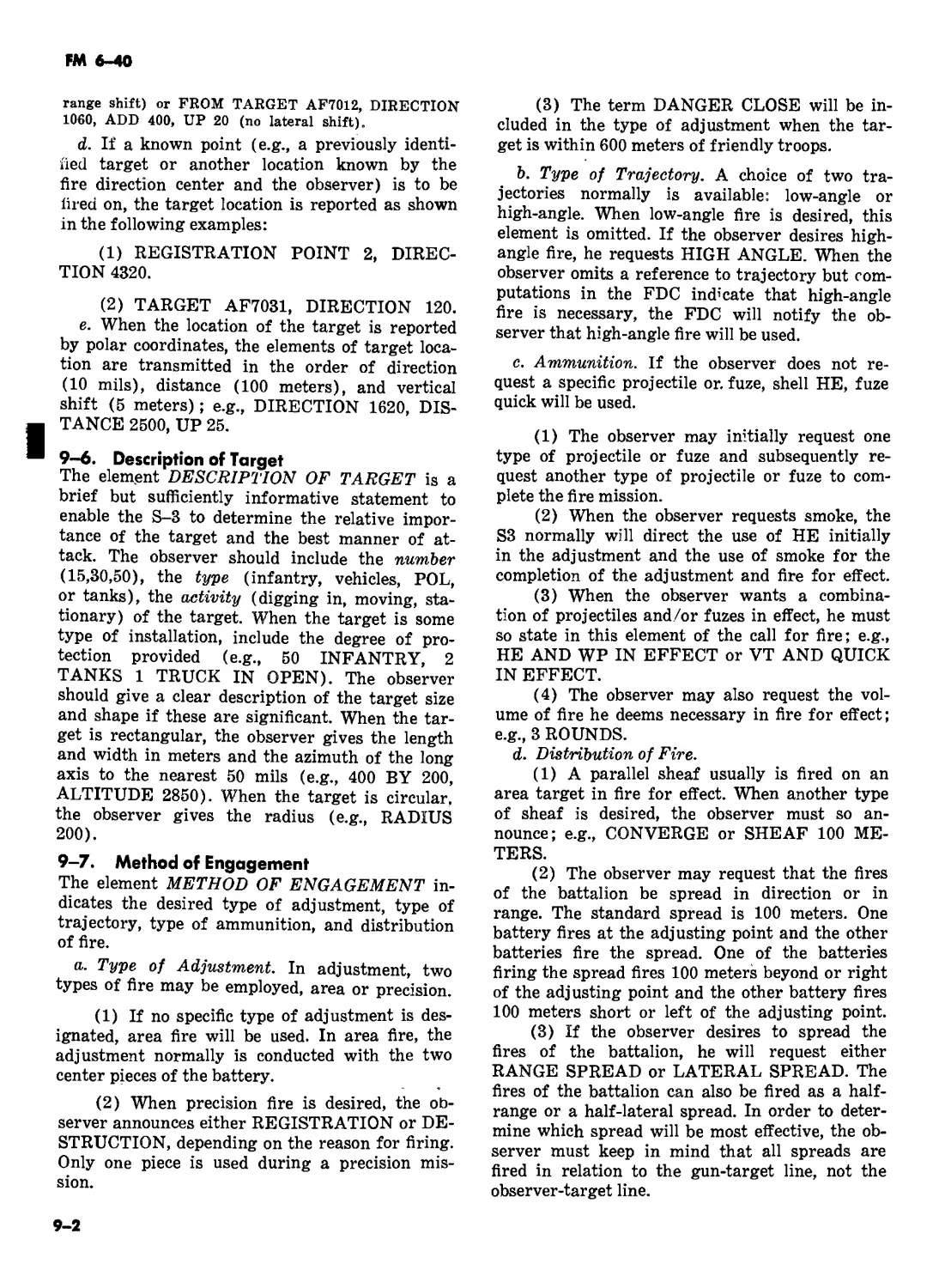
the distance to the target. In figure 8-9,
Figure 8-9. Polar coordinates (polar plot).
the direction and distance to the target would
be reported to the FDC as DIRECTION 1000,
DISTANCE 1400. A vertical shift must be made
if there is an obvious difference in altitude be-
tween the observer’s location and the target. The
observer, using a BC scope, an aiming circle, or
an М2 compass, measures the vertical angle to
the target. This vertical angle is measured from
the horizontal plane through the observer’s lo-
cation to the target. Substituting this measured
vertical angle for and the estimated distance
to the target for R in the mil relation, the ob-
server computes the vertical shift.
Example: The observer measures the vertical
angle to the target as +20 mils. The estimated
distance to the target from the observation post
is 2,000 meters. According to the mil relation,
20 = W, W = 40 meters. The observer would
2.0"
report the polar coordinates of the target as fol-
lows: DIRECTION 1000, DISTANCE 2000, UP
40.
8-8. Marking Rounds
Poor visibility, unreliable maps, deceptive ter-
rain, or rapid movement through unfamiliar ter-
rain sometimes makes it difficult, if not im-
possible, for the observer to orient himself. The
observer may call for a marking round (s) to
be fired on a registration point, a previously
fired target, or a prominent terrain feature (e.g.,
MARK REGISTRATION POINT OR MARK
HILL 437). As a last resort, the observer may call
for a round(s) to be fired into the center of the
target area (e.g., MARK CENTER OF SEC-
TOR). The observer usually calls for a type of
projectile that is easily identifiable, such as white
phosphorus, or for a high airburst. The FDC
prepares data that will place the round(s) at the
point of impact or point of burst requested by the
observer. If the observer fails to see the round(s),
the FDC prepares new data that will move the
next round(s) to a different point of impact or
that will raise the burst higher in the air. This
procedure is continued until the observer posi-
tively identifies the round(s). He then orders a
shift from the point of impact (burst) of the
identified round(s) to a target or an object that
is permanent or semipermanent in nature, such
as a tree, a road junction, a barn, or the ruins
of a building. Once this point has been located by
adjustment of fire and has been plotted at the
FDC, the observer may use it as a known point
from which shifts may be made to subsequent
targets.
CHAPTER 9
CALLS FOR FIRE
(Superseded by FM 6-40-5, MODERN BATTLEFIELD CANNON GUNNERY)
8-6 (next numbered page is 10-1)
С1, FM 6-40
CHAPTER 10
ADJUSTMENT PROCEDURE BY GROUND OBSERVER
Section I. GENERAL
10—1. When to Adjust
When the observer cannot locate the target with
sufficient accuracy to warrant firing for effect,
he will conduct an adjustment. Lack of accuracy
in the location may be the result of poor visibil-
ity, deceptive terrain, poor maps, or difficulty on
the part of the observer in pinpointing the tar-
get. If, in his opinion, fire for effect can be de-
livered on the basis of the target location and
surprise is desired, he will request FIRE FOR
EFFECT (FFE) in his call for fire. If registra-
tion has not been accomplished recently, the fire
direction officer may direct that an adjustment be
conducted, regardless of the accuracy of the target
location. Normally, one gun is used in adjustment.
Special situations where more than one gun is
used are so noted throughout the text.
10-2. Adjusting Point
The observer must select a point upon which to
adjust (adjusting point). In precision fire, the
adjusting point is the target. In area fire, the
adjusting point should be a well-defined point
near the center of the area occupied by the tar-
get (fig 10-1).
Figure 10-1. Adjusting point in area fire.
10-3. Appearance of Bursts
The observer must be able to identify the type
of shell and fuze used from the appearance of the
burst(s). Descriptions of the types of shells and
fuzes with which an observer normally will be
concerned are given in a through g below; how-
ever, the sizes of the bursts will vary in accord-
ance with the caliber of the weapon.
a. Shell HE, Airburst, Fuze Time or Fuze VT.
A fuze time or fuze VT airburst is characterized
by a flash, a sharp explosion, and a puff of black
smoke that becomes elongated along the tra-
jectory. The effect of fragments on the terrain
may be seen below the burst if the burst is not too
high and soil conditions are favorable.
b. Shell, HE, Fuze Delay, Ricochet. A ricochet
burst is a low airburst characterized by a flash,
a sharp explosion, and a ball of smoke (usually
black). Dirt is kicked up by the shell fragments
from the side and base spray. Burst appearance
depends on the nature and condition of the soil
and the attitude of the projectile as it bursts.
The characteristic flash, black smoke, and sharp
explosion of an airburst are indications of an
effective ricochet burst.
c. Shell HE, Fuze Quick. A burst resulting
from a fuze quick detonation is characterized by
black smoke, discolored by dirt, which spreads
both upward and outward. If the impact occurs
on a hard surface, such as a rock, a flash may
also appear. Fuze quick fired into a wooded area
will sometimes result in an airburst caused by
the projectile striking the trees and detonating
before it reaches the ground.
d. Shell HE, Fuze Delay, Mine Action. A mine
action burst is characterized by the eruption of
a vertical column of earth, often with clods of
earth. There is very little smoke, and the explo-
sion is muffled.
e. HC Smoke, Fuze Time. Functioning of an
HC smoke shell with fuze time is characterized by
a small burst in the air, produced by the expelling
charge, which ejects the smoke canisters from the
base of the shell. As the canisters fall to the
ground, they emit smoke in thin streams. The
smoke streams travel an appreciable distance and
then billow out.
f. Shell WP, Fuze Quick. A fuze quick WP shell
burst is characterized by a fountain of brilliant
white smoke and burning phosphorus. Small par-
ticles of phosphorus are spread upward and out-
ward as a pillar of smoke forms and rises. .
g. Improved Conventional Munitions
(ICM). Functioning of an ICM shell with fuze
time is characterized by a small burst high in the
10-1
С1, FM 6-40
air produced by the expelling charge which ejects
bomblets from the base of the shell. These
bomblets spread out as they fall, distributing their
lethality over a large area rather than
concentrating it in a limited area of wasted
overkill. Small airbursts, near ground level,
appear as each bomblet detonates.
10-4. Fuze Selection for High-Explosive
Projectiles
The effect obtained with an HE projectile depends
on the fuze action.
a. Fuze VT. A VT fuze is a radio-activated
fuze that detonates the projectile automatically
at a predetermined height above the earth’s sur-
face. Therefore, a height-of-burst adjustment is
not required. There is a point detonating back-
up mechanism in case of failure of the radio
activation. During the adjustment, fuze quick
normally is employed to obtain greater speed
and to facilitate observer spottings. Fuze VT is
suitable for use against—
(1) Personnel in the open.
(2) Personnel in entrenchments (low-angle
fire only).
(3) Area targets when neutralization is de-
sired.
b. Fuze Time. A time fuze detonates the pro-
jectile on operation of a preset time mechanism
or on impact. The height of burst is controlled
by the observer. Since the observer must adjust
the height of burst, use of this fuze is more
time consuming than use of fuze VT. However,
with fuze time the observer may obtain any
height of burst desired. Fuze time is ineffective
in high-angle fire, because of the large height-
of-burst probable error involved in the long time
of flight. Fuze time is suitable for use against the
same types of targets as those against which
fuze VT is used, within the limits imposed by
the vertical probable error of the fuze.
c. Fuze Delay. When delay action of the fuze
is used, the projectile has time after impact and
before detonation either to penetrate and pro-
duce mine action or to ricochet and produce a
low airburst. Fuze delay is used with shell HE
for destruction missions that require penetra-
tion and for ricochet fire.
(1) Factors which determine whether a
shell will ricochet are the angle of impact; shape,
weight, and terminal velocity of projectile; the
use of fuze delay; and the condition of the sur-
face of the ground, including the composition of
the soil.
(2) When the angle of impact is small, the
projectile tends to ricochet rather than to pene-
trate the ground. As the angle of impact in-
creases the tendency to penetrate increases.
When the projectile penetrates the ground, the
burst will produce either a crater or a camou-
flet, depending on the depth of the burst, type of
soil, and force of detonation. If the penetration
is very great, the burst may produce a camou-
flet; that is, a hole will be formed underground,
but the surface of the ground will remain un-
cratered.
(3) When penetration occurs and the shell
is in the earth at the instant of detonation, frag-
mentation effect above the ground is very small.
Penetration into a bunker or dugout will produce
casualties by blast effect and fragmentation.
Penetration into a structure built of logs, sand-
bags, or similar materials results in the blowing
apart of constituent units. The effectiveness de-
pends on the amount of high-explosive filler in
the penetrating projectile. Use of concrete-
piercing (CP) fuze increases the depth of pene-
tration and the angle at which penetration may
be obtained against reinforced concrete or heavy
masonry targets.
(4) Ricochet fire should be used only against
personnel in shallow foxholes or shallow trench-
es. The effect obtained with ricochet fire against
these targets is somewhat better than the effect
obtained with VT or time fuze because of the
lower height of burst and the nose-up attitude of
the projectile. The lowered height of burst re-
duces the effect obtained against deeply en-
trenched targets. In order for a given number of
rounds fired with fuze delay to be as effective as
the same number of rounds fired with fuze quick
against troops prone in the open, 50 percent of
the rounds fired with fuze delay must produce
ricochet action. Therefore, ricochet fire is not
used against troops in the open. Factors which de-
termine whether a projectile will ricochet cannot
be evaluated for a particular point of impact until
the bursts are spotted. Ricochet fire must be ob-
served. Another type of fuze must be used if rico-
chet action cannot be expected from at least 50
percent of the rounds fired in fire for effect.
d. Fuze Quick. Quick (superquick) fuze action
bursts the projectile immediately on impact.
Ease of spotting a fuze quick burst, together
with the fact that no height-of-burst adjustment
is necessary, makes possible a rapid adjustment.
Fuze quick is suitable for use against—
(1) Personnel standing in the open (very
effective in high-angle fire).
(2) Personnel in sparsely wooded terrain
where tree bursts give the effect of low airbursts.
10-2
С1, FM 6-40
(3) Materiel when penetration of the ma-
terial is not required for producing damage.
(4) Armored vehicles when the concussion
effect of heavy artillery is sufficient for produc-
ing damage.
e. Combined Fuze Action in Fire for Effect.
When the target is such that more than one type
of fuze action will add to the effectiveness of fire
for effect, the observer will include the fuzes de-
sired in the call for fire or in subsequent correc-
tions.
10-5. Spottings
Determination by the observer of the location of a
burst or group of bursts with respect to the
adjusting point as observed along the ОТ line is
called a spotting. Spottings are made for range,
deviation, and height of burst. Spottings must be
made by the observer at the instant the burst
occurs except when it is necessary to delay a
spotting to take advantage of drifting smoke or
dust.
a. The observer should be required to announce
his spottings during his early training. As an
observer gains experience, spottings need not be
announced.
b. Under certain conditions the observer may
be able to make a spotting even though he is
unable to see the burst. For example, if the
observer hears but does not see a burst and the
only possible place where the burst could occur
and not be visible to the observer is in a ravine
beyond the adjusting point, then he should
assume that the burst is beyond the adjusting
point.
c. If visibility is temporarily impaired (e.g., FO
had to take cover from incoming enemy fire or
target area visibility obstructed by smoke, dirt,
etc.), or if the observer is unable to obtain an
accurate spotting (e.g., when FO cannot determine
which burst among several is his), he reports
UNOBSERVED, REPEAT.
d. If the observer is unable to identify the burst,
the round is spotted as lost.
(1) A round may be lost for various reasons: it
may be a dud, resulting in no visual or audible
identification; the terrain may prevent the
observer from sighting the round or its smoke; the
weather may also prevent the observer from
hearing or seeing it; the FO may simply have
failed to spot the round; and finally, errors by the
observers, FDC, or the firing piece may cause the
round to be lost.
(2) When dealing with a lost round, the FO
must consider his own experience, the level of
FDC/gun training, and the location of friendly
elements with respect to the target. The observer
should take corrective action based on his
confidence in the target location, the accuracy of
fire on previous missions, whether the lost round
is an initial round or a subsequent round, and the
urgency of the mission.
(1) When a round is lost, positive action must
be taken. The observer can initiate a number of
corrective procedures, such as one or more of the
following:
(a) Initiate a data check throughout the
system starting with his target location data and
his call for fire.
(b) Request a 200 meter air burst on the next
round.
(c) Repeat.
(d) End the mission and initiate a new
mission.
(e) Make a bold shift. The observer should
exercise caution before making a bold range or
deviation change when the target plots in the
vicinity of friendly troops.
10-6. Corrections
The observer causes the mean point of impact or
burst to be placed on, or sufficiently close to, the
target by making appropriate corrections during
the adjustment. From his spottings, the observer
determines deviation and range corrections in
meters; he announces these corrections to the FDC
using the sequence of subsequent corrections as
shown in section V.
10-3
С1. FM 6-40
Section II. ADJUSTMENT OF DEVIATION
10-7. Deviation Spottings
a. Deviation is the lateral distance from the
burst center to the ОТ line. A deviation spotting is
the angular amount and direction of the deviation.
During the conduct of fires, the observer
measures, in mils, the angular deviation from the
ОТ line to the center of each burst or group of
bursts (fig 10-2).
Figure 10-2. Deviation.
b. к burst, or the center of a group of bursts,
may be on the ОТ line, or it may be right or left of
the ОТ line. A deviation spotting is determined as
LINE or (so much) RIGHT (LEFT). For example,
the observer sees a burst and measures the
angular deviation as 20 mils to the right of the ОТ
line. His deviation spotting in this instance is 20
RIGHT.
10-8. Deviation Corrections
a. A deviation correction is the distance in
meters perpendicular to the ОТ required to move a
subsequent group of bursts to the ОТ line. In the
adjustment phase on an area mission, minor
deviations (20 meters or less) should be ignored.
b. The observer computes a deviation correc-
tion by multiplying the deviation spotting by
the ОТ factor. The ОТ factor is the ОТ distance
in thousands of meters. If the ОТ distance is 1,000
meters or greater, the ОТ factor is expressed to
the nearest thousand. If the ОТ distance is less
than 1,000 meters, the ОТ factor is expressed to
the nearest hundred. The following are examples
of computations of deviation corrections:
от от
dietance factor
3600 ........... 4
3400 ............ 3
800 .......... 0.8
Deviation
Spotting correction
40 RIGHT......LEFT 160.
50 LEFT ______RIGHT 150.
40 LEFT_______RIGHT 30.
c. The deviation correction is expressed to the
nearest 10 meters and is announced to the FDC
as LEFT (RIGHT) (so much). The direction of
the correction is always opposite the direction
of the spotting.
d. When the angle between the ОТ line and the
gun target (GT) line (angle T) is 500 mils or
greater, the fire direction center will notify the
observer of this fact after the first SHOT is given
(fig Ю-3). |
Figure 10-3. Angle T.
When the angle T is large, the observer should
consider the range dispersion of the weapon when
determining corrections. What the observer sees
as deviation may be due, wholly or partly, to range
dispersion, which cannot be corrected by
deviation corrections. In figure 10-4 the two
rounds shown were fired at the same deflection
and quadrant elevation. The difference in
locations of the bursts is due to range dispersion
along the GT line. As viewed by observer 1, from
whose location the angle T is relatively small,
there appears to be little difference in the amount
of deviation correction needed to bring the bursts
to the ОТ line. However, as viewed by observer 2,
the second burst appears to be twice as far from
the ОТ line as the first burst.
10-4
С1, FM 6-40
е. The observer must exercise caution in mak-
ing deviation corrections in the direction of
friendly troops who are close to the target.
Adjusting piece
Figure 10-4. The effect of angle T when viewing
range dispersion.
Section III. ADJUSTMENT OF RANGE
10-9. General
A technique for the adjustment of range is to
establish a bracket along the ОТ line (fig 10-5). A
bracket is established when one round falls over
the adjusting point and one round falls short of the
adjusting point. The observer establishes the
bracket early in the adjustment and then
successively decreases the size of the bracket until
it is appropriate to enter fire for effect. See FM 6-40-
5 for other techniques used in the adjustment of
10-10. Range Spottings
a. Definite range spottings are required for
making a proper range adjustment. Any range
spotting other than LOST (UNOBSERVED) is
definite.
(1) A burst or group of bursts on the ОТ line
normally gives a definite range spotting. Figure
10-6 is a guide showing approximate areas for the |
various spottings.
Direction of
ОТ line
(2) The observer may make a definite range
spotting when the burst(s) is not on the ОТ
line by using his knowledge of the terrain, drift-
ing smoke, shadows, and wind. However, even
experienced observers must exercise caution and
good judgment when making such spottings.
(3) Spottings of airbursts for range are based
10-5
С1, FM 6-40
on the locations of the burst fragmentation pat-
terns on the ground.
b. Possible range spottings are as follows:
(1) Over. A burst(s) that appears beyond
the adjusting point is spotted OVER.
(2) Short. A burst (s) that appears between
the observer and the adjusting point is spotted
SHORT.
(3) Target. An impact burst that hits the
target is spotted TARGET. This spotting is used
only in precision fire.
(4) Range correct. A burst or center of a group
of bursts that is at the proper range is spotted
RANGE CORRECT.
(5) Doubtful. A burst that can be observed
but cannot be determined as over, short, target, or
range correct is spotted DOUBTFUL.
10-11. Successive Bracketing
The hasty bracket technique is preferred, but
when using the successive bracketing technique,
the observer should make a range correction that
can be expected to result in a range spotting in the
opposite direction; e.g., if the first definite range
spotting is SHORT, the observer should add
enough to obtain an OVER on the next round or
group of rounds.
b. Once a bracket has been established, it is
successively decreased, normally by splitting,
until it is appropriate to enter fire for effect. Fire
for effect is normally asked for in area fire when a
100-meter bracket is split or when fire on the target
is observed.
c. The procedures in a and b above are not to be
considered inflexible. The observer must use his
knowledge of the terrain, knowledge gained from
previous firing and general experience, and good
judgment in determining the size of the initial and
subsequent range changes. For example, if the
observer adds 800 after an initial range spotting of
SHORT, and the second range spotting is OVER,
but the bursts are much closer to the adjusting
point then the initial rounds, a range change of
DROP 200 would be appropriate.
d. When the observer requests an adjustment
on a target close to friendly troops, he makes range
corrections toward friendly elements in
increments that he considers safe. He does not
necessarily attempt to bracket the target with any
successive corrections. As his corrections bring
the bursts closer to the target, definite range
spottings can be easily made. Making small, safe
shifts rather than establishing the normal bracket
may result in a greater expenditure of ammunition
and time but may be necessary to insure safety (fig
10-7). An adjustment made in this manner is
referred to as creeping and should be used
exclusively during DANGER CLOSE missions.
Trajectory
of fir»l round
Figure 10-7. Need for creeping when clo.se to
friendly troops.
10-11.1. Hasty Bracket
See FM 6-40-5 for hasty bracketing and other
techniques used in adjustment of fire.
Section IV. ADJUSTMENT OF HEIGHT OF BURST
10-12. General
In firing fuze time in area fire, the observer
must adjust the height of burst. The observer
conducts the adjustment of deviation and range
with fuze quick and then, upon splitting the ap-
propriate range bracket, normally 100 meters, or
obtaining a range correct spotting, begins the
adjustment of height of burst. Normally, further
corrections to deviation and range are not re-
quired. The observer spots height of burst and
determines the corrections to the nearest 5 meters
to raise or lower the bursts to the desired height.
He announces the correction as UP (DOWN) (so
much). He computes height-of-burst shifts by
using the mil relation in the same manner as for
10-6
deviation shifts. The proper height of burst for
fire for effect is normally 20 meters above the
target. Any time two bursts are widely separ-
ated in height, the observer must report this fact
to the FDC. When fuze delay is being used for
ricochet fire, no correction for height of burst can
be made. When VT fuze is used, only malfunc-
tions and graze bursts are reported.
10-13. Height-of-Burst Spottings
Height-of-burst spottings for fuze time are as fol-
lows:
a. Air. A round or group of rounds bursting
in the air is spotted AIR.
b. Graze. A round or group of rounds burst-
ing on impact is spotted GRAZE.
С1, FM 6-40
с. Mixed. A group of rounds resulting in an
equal number of air-bursts and graze bursts is
spotted MIXED.
d. Mixed Air. A group of rounds resulting in
both airbursts and graze bursts is spotted MIXED
AIR when the majority of the bursts are air-
bursts.
e. Mixed Graze. A group of rounds resulting
in both airbursts and graze bursts is spotted
MIXED GRAZE when the majority of the bursts
are graze bursts.
10—14. Height of Burst Adjustment
a. The adjustment of time fuze (with 2 guns) is
begun with the objective of obtaining a 20-meter
height of burst. Fire for effect is entered only when
a correct height of burst (20 meters) is assured.
b. During the adjustment of time fuze with
two pieces, there are three possible height-of-
burst spottings—AIR, GRAZE, or MIXED. Rules
for height-of-burst adjustment are as follows:
(1) When the initial rounds are AIR, the
observer adjusts to a 20-meter height of burst
and enters fire for effect. However, if very high
airbursts are obtained and the observer is not
sure that the next correction will produce a 20-
meter height of burst, a correction to height of
burst without entering fire for effect is appropri-
ate (judgment and experience are the governing
factors).
(2) When the initial rounds are GRAZE, the
observer applies UP 40 and continues the
adjustment. A 40-meter height-of-burst correction
will be applied until spottings of AIR or MIXED
are obtained and then the rule in (1) above or (3)
below applies.
(3) When the initial rounds are MIXED, the
observer applies UP 20 and enters fire for effect.
(4) The observer must report widely separ-
ated bursts to the FDC and, in most cases, give
a repeat command: e.g., REPEAT, 100-METER
HEIGHT-OF-BURST SPREAD; 60-METER
MEAN HEIGHT OF BURST.
c. The observer determines the height of burst
by measuring the vertical deviation in mils be-
tween the target and the burst or the center of
the group of bursts and then multiplying the
vertical deviation by the ОТ factor. He com-
putes the correction by comparing the height of
burst thus determined with the desired height of
burst.
Example: The ОТ factor is 3. The observer
measures the vertical deviation from the target
to the burst as plus 20 mils. Therefore, the height
of burst is 60 meters above the target (W — R
x — 3 x 20). The correction is DOWN 40,
FFE (the desired height of burst is 20 meters
and the 60 meters is 40 meters above the desired
height of burst).
10-15. Fuze Delay
When fuze delay is employed for ricochet action,
no adjustment of height of burst is possible. The
observer notes the number of airbursts and graze
bursts. If 50 percent or more of the rounds that
establish the appropriate range bracket result in
airburst, the observer enters fire for effect with
fuze delay. If more than 50 percent of the rounds
result in graze bursts, the observer requests VT or
QUICK, whichever is more appropriate, in fire for
effect.
10-16. FuzeVT
No adjustment of height of burst is possible with
fuze VT. Burst height is controlled by the
mechanism within the fuze.
Section V. SUBSEQUENT CORRECTIONS
10-17. General
a. After the initial burst(s) appears, the ob-
server transmits subsequent corrections until the
mission is completed. These corrections include
appropriate changes in elements previously trans-
mitted and the necessary corrections for devia-
tion, range, and height of burst. Elements that
may require correcting and the order in which
corrections are announced are as follows:
(1) Observer-target direction
(2) Danger close
(3) Trajectory
(4) Method of fire
(5) Distribution
(6) Projectile
(7) Fuze
(8) Volume
(9) Deviation
(10) Range
(11) Height of Burst
(12) Control
(13) Splash
b. Any element for which a change or correc-
tion is not desired is omitted.
10-7
Cl, FM 6-40
10-18. Change in Observer-Target Direction
A change in observer-target direction is given
when it deviates from the announced direction by
100 mils or greater. For example, an observer
begins an adjustment on several self-propelled
guns, using a tree at direction 5620 as the
adjusting point. During the adjustment, the self-
propelled guns move to a new position an
appreciable distance from the adjusting point.
The observer selects a new adjusting point in the
vicinity of the target and measures direction 5840
to that point. The first element of his next
correction is DIRECTION 5840.
| 10-19. Danger Close
It may become necessary for an observer to adjust
artillery fire close to friendly troops. If artillery
fires come within 600 meters of friendly troops, the
observer must transmit DANGER CLOSE to the
FDC to inform them of this fact. This will alert the
FDC to have the gun sections use their gunners
quadrants in setting quadrant elevations on the
guns. The observer will have to adjust the entire
battery, rather than just one gun, when firing
Danger Close. The observer should make range
changes by creeping the rounds to the target
rather than making large range corrections, thus
insuring greater protection for friendly troops. If
the adjustment of fire moves the rounds more than
600 meters from friendly troops, the observer
transmits CANCEL DANGER CLOSE.
10-20. Change in Trajectory
The observer requests a change in the trajectory
during a low-angle adjustment when it becomes
apparent that high-angle fire will be necessary or
during a high-angle adjustment when it becomes
apparent that high-angle fire is no longer re-
quired. For example, an observer is making an
adjustment on some moving armored personnel
carriers. During the adjustment the carriers move
into a deep gully for cover. Knowing from pre-
vious firing in the area that high-angle fire will
be necessary to bring effective fire into the gully,
the observer requests HIGH ANGLE. Conver-
sely, an observer is making a high-angle adjust-
ment on a column of vehicles halted in a town
along a street with tall buildings. During the
adj ustment the vehicles move out toward the edge
of town. As soon as he notices the vehicles em-
erging from the town, the observer should re-
quest CANCEL HIGH ANGLE to expedite the
firing.
10-21. Change in Method of Fire
The observer must announce any change he de-
sires in the method of fire. For example, in
order to change from pieces firing simultaneously
to pieces firing in order from left to right, the
observer requests PLATOON LEFT. He may
request this change to take advantage of the wind
when smoke shells are being fired or to clarify
spottings when one burst is obscuring another. He
cancels PLATOON LEFT by announcing.
CANCEL PLATOON LEFT.
10-22. Change in Distribution
If the observer desires a sheaf other than parallel,
he must specify the type desired; e.g., CON-
VERGE (OPEN), SHEAF 100 METERS. If the
observer wishes to change to a parallel sheaf
during adjustment or fire for effect, he requests
CANCEL CONVERGE (OPEN), SHEAF 100'
METERS.
10-23. Change in Projectile
When the observer desires to change the type of
projectile, he announces the desired change; e.g.,
WP or HC.
10-24. Change in Fuze
When the observer desires to change the type of
fuze or fuze action, he announces the desired
change; e.g., VT or DELAY.
10-25. Change in Volume
When the observer desires to change the volume of
fire, he announces the desired change; e.g., TWO
ROUNDS or THREE ROUNDS.
10-26. Correction for Deviation
The observer transmits deviation corrections to
the nearest 10 meters as RIGHT (LEFT) (so much).
In area fire missions, deviation of 20 meters or less
are ignored. See FM 6-40-5 for a discussion of
deviation corrections in precision fire missions.
10-27. Correction for Range
The observer transmits range corrections as ADD
(DROP) (so much).
a. ADD. ADD is used by the observer to move
subsequent burst(s) away from the observer along
or parallel to the ОТ line. If the burst(s) falls short
of the target, the observer commands ADD (so
much).
b. DROP. DROP is used by the observer to move
subsequent burst(s) toward the observer along or
parallel to the ОТ line. If the burst(s) appears
beyond the target, the observer commands DROP
(so much).
10-28. Correction for Height of Burst
The observer transmits height-of-burst
corrections to the nearest 5 meters as UP (DOWN)
(so much).
10-8
Cl, FM 6-40
| 10-29. Change in Control
When the observer desires to change the method of
control (other than AT MY COMMAND), he
announces the new method of control; e.g., FIRE
FOR EFFECT.
| 10-30. Splash
If an observer is having difficulty identifying his
rounds due to other fire missions being conducted
in the area, he may request assistance from the
FDC by requesting SPLASH. The FDC will
inform the observer that his round is about to
impact by announcing SPLASH five seconds
prior to impact. The observer may terminate this
help by announcing CANCEL SPLASH.
10-31. Repeating Previously Fired Data
a. REPEAT is used by the observer to indicate
that he desires a subsequent round or group of
rounds fired with no corrections to deviation,
range, or height of burst. For example, if sev-
eral rounds burst in the area of observation simu-
ltaneously and the observer could not determine
which rounds to observe, he would request RE-
PEAT or WP REPEAT.
b. REPEAT is also used by the observer to in-
dicate that he wants fire for effect repeated with
or without changes or corrections to any of the
elements; e.g., ADD 50, REPEAT.
10-32. Correction of Errors
If the observer discovers an error in the
transmission or read-back of a subsequent
correction, he corrects the error as outlined in FM
6-40-5.
10-33. Additional Information
If the observer desires to transmit information
necessary to the conduct of a mission and there
is no specific format prescribed, he should trans-
mit the information in clear, concise language
and in the sequence least likely to cause con-
fusion and most likely to expedite the mission.
10-9
(10-10 Blank)
Cl, FM 6 40
CHAPTER 11
FIRE FOR EFFECT
Section I. PRECISION FIRE
11-1 through 11-4. (Deleted)
(Superseded by FM 6-40-5, MODERN BATTLEFIELD CANNON GUNNERY)
S Section II. AREA FIRE
11-5. General
a. In area fire, the observer normally requests
fire for effect at the conclusion of an adjustment.
However, he may fire for effect when his target
location is accurate enough to preclude the need
for adjustment.
b. The type and volume of fire delivered in fire
for effect are determined by the FDO. His decision
is based on the observer’s request, the description
of the target, the effect sought, and the status of
ammunition supply, and on other considerations.
If fire for effect is ineffective or insufficient, the
necessary corrections are made and additional
fire for effect is requested.
c. Upon completion of fire for effect, the
observer sends refinement data and END OF
MISSION. He reports the effect observed.
11-6. Fire for Effect After Adjustment
a. Deviation. Deviation errors of 30 meters or
more are corrected during the adjustment by the
observer. Therefore, it should not be necessary to
make a large shift upon entering fire for effect.
b. Range. The adjustment of range is complete
when the observer has obtained a burst at the
same range as the adjusting point (range correct
or target hit) or when he has split the appropriate
range bracket. When the target is fixed, of little
depth, and clearly visible or when the fires of more
than one battery are massed on the target, it is
appropriate to split a 100-meter range bracket.
When the target is moving, is of substantial depth,
or is poorly defined, it may be appropriate to enter
fire for effect on splitting ,a 200-meter range
bracket. When the range probable error is 38
meters or larger, the FDC will notify the observer
to enter fire for effect on splitting a 200-meter
frange bracket.
c. Height of Burst. When time fuze is being
used, fire for effect is not called for until the height
of burst is correct or until a correction can be
expected to result in the correct height of burst
(para 10-14). When fuze delay is being used for
ricochet fire, fire for effect is entered with fuze
delay only if 50 percent or more of the bursts that
established the final range bracket were airbursts.
11-7. Distribution
a. Normally, the FDO determines the proper
distribution of fire for a target. His decision is
based on the observer’s call for fire and other
available information. Unless the FDO directs,
because of the nature and the size of the target, the
use of a sheaf other than that normally fired,
artillery fires are delivered at center range in a
parallel sheaf (see d below). The FDO may also
direct the battery or batteries to fire through
different elevations for greater range coverage.
b. When appropriate, the observer may call for
a special sheaf. This should be announced in the
call for fire when possible. It may be announced in
subsequent corrections if the sheaf being fired
does not provide satisfactory distribution. In
making such a request, the observer announces
the type of sheaf desired; e.g., OPEN or SHEAF, 50
METERS.
c. When the number of pieces allocated to the
mission is not adequate to cover the target with an
open sheaf, the observer may make successive
shifts in fire for effect to insure coverage of the
target.
d. When the unit has occupied by terrain, TGP
corrections are fired based upon the appropriate
standard sheaf for the caliber of weapon.
11-8. Surveillance of Fire for Effect
The observer carefully observes the results of the
fire for effect and then takes whatever action is
necessary to complete the mission.
a. If the fire has been effective and sufficient,
the observer announces END OF MISSION and
reports the effect observed; for example, 20
CASUALTIES, INFANTRY DISPERSED. If the
mean point of impact (mean point of burst) is not
directly on (20 meters above) the adjusting point,
the observer will make a correction to improve the
11-1
С1, FM 6-40
accuracy of the replot of the target and end the
mission; e.g., LEFT 20, DOWN 5, immediately
followed by END OF MISSION
b. If the fire has been insufficient but accurate,
including an effective height of burst, the observer
may request REPEAT to obtain additional fire.
c. If any element of the fire for effect (deviation,
range, or height of burst) was sufficiently in error
that the effect sought was not obtained, the
observer should correct the element(s) in error and
continue fire for effect; for example, ADD 50,
DOWN 10, REPEAT.
d. If ricochet action with fuze delay was desired,
but was not obtained from at least 50 percent of the
rounds fired in fire for effect, and additional fire is
needed, the observer must request a change to fuze
VT, time, or quick and repeat fire for effect. He
could also change to shell ICM.
e. If the observer desires that the target be
replotted for future use, he announces the
appropriate corrections (e.g., RIGHT 10,
RECORD AS TARGET, END OF MISSION) arid
reports the effect observed.
11-2
Cl, FM 6-40
CHAPTER 12
ADJUSTMENT OF FIRE BY THE AIR OBSERVER
Section I. INTRODUCTION
12-1. General
Observation and adjustment of artillery fires
may be accomplished from the air by use of or-
ganic Army aircraft or Air Force high-perform-
ance aircraft. An air observer normally is em-
ployed, since it is difficult for a pilot to navigate
and observe at the same time. However, the
pilot should be well trained in the adjustment of
fire, since such knowledge is invaluable in training
a new air observer and enables the pilot to adjust
fire in the event an observer is not available.
12-2. Observation From Army Aircraft
a. Observation from organic Army aircraft
normally is limited to altitudes and locations that
allow the aircraft to avoid enemy ground fire and
enemy fighter aircraft.
b. For a detailed discussion of employment and
,operations of the air observer team in a high-
threat air defense environment, see TC 6-40-6, The
Field Artillery Aerial Observer Team Operations.
12-3. Observation From High-Performance
Aircraft
Use of high-performance aircraft provides obser-
vation deep into enemy territory beyond the limits
of organic Army aircraft. The pilot and observer
can fly over enemy territory to sufficient depth
to observe and adjust long-range artillery fire.
Usually two aircraft are used on a mission—one
to adjust the fire and the other to observe for
hostile aircraft. Danger from both hostile air
defense artillery and hostile planes usually in-
creases as the duration of the flight and the
depth into hostile territory increase. For this
reason the air observer must minimize the time
required for an adjustment.
Section II. PREFLIGHT PREPARATIONS
12-4. General
The air observer and pilot should be given a pre-
flight briefing by the intelligence officer (S2) and
operations officer (S3).
12—5. Preflight Briefing
a. All pilots and observers flying a mission
should be briefed on all points pertinent to the
mission, including—
(1) The locations of battery position areas,
registration points, confirmed targets, known
points, suspected targets, and areas to be search-
ed and the spotting lines to be used in making
corrections (if the GT line is not used).
(2) The tactical situation, to include the lo-
cations of friendly troops, no-fire and fire sup-
port coordination lines and the zones of action of
supported troops.
(3) The surveillance required, the time of
the mission, the type of adjustment to be made,
the maps and photographs to be used, known
enemy air defense, flight instructions, and secu-
rity restrictions.
(4) The communication details, to include
the locations of ground radios and panel stations,
the channels to be used, the call signs to be u~ed,
the check-in time(s), and prearranged signals.
b. All important enemy locations, lines and
areas discussed in the briefing are recorded on
appropriate maps. Photographs, oblique or verti-
cal, are gridded when possible and the direction
and locations of critical points, lines, and areas
are marked on the photographs.
Section III. DETERMINATION OF INITIAL DATA
| 12-6. Call for Fire
The procedures used by the air observer are similar to those used by the ground observer. The call for fire
and subsequent corrections from an air observer are transmitted in the same manner as those from a
ground observer.
12-1
С1, FM 6-40
I 12-7. Determination of the Spotting Line
Since the aircraft is constantly moving, the
observer’s perspective of the target (and hence his
ОТ line) will also change. In some cases it may be
convenient for the aerial observer to establish a
constant direction along which all corrections are
made. This is called the spotting line. The FDC
must know the correct spotting line in order to
accurately convert corrections to firing data for
the guns. Examples of spotting lines are:
a. Gun-Target Line. The air observer may
select as his spotting line the gun-target line. If he
knows the location of the adjusting battery and
can identify that location while in flight, he can
visualize the gun-target line. If he does not know
the location of the adjusting battery, he can
request RANGING ROUNDS in his call for fire
(distribution of fire). In such a case, the FDC
personnel will cause the adjusting battery to fire
two rounds at the same deflection but 400 meters
apart in range so that the air observer can
visualize the gun-target line. After the air observer
has determined the gun-target line, he should
select a terrain feature, such as a road, stream, or
ridgeline, that will assist him in remembering the
direction of the gun-target line. If the spotting line
has not been prearranged with the FDC and the
air observer does not indicate a spotting line in his
call for fire, the gun-target line will be used.
b. Other Line of Known Direction. The air
observer may select as his spotting line a terrain
feature, such as a road, railroad, stream, or
ridgeline, or a series of terrain features. The air
observer, either prior to or during flight, must
make known to the FDC personnel the
identification of the feafure(s) so that they can
determine the direction established thereby. If the
air observer can accurately visualize a cardinal
compass direction on the ground, he may use the
cardinal direction as a spotting line.
12-8. Location of Targets
When a target is observed, its location is
determined and transmitted to the FDC using:
a. Grid coordinates.
b. Shift from a known point and the spotting
line. If no direction is sent, the shifts will be made
on the G-T line.
c. Prearranged code to fire on a previously
coordinated target.
12-9. Determination of Distance
The observer can determine distance on the
ground by requesting RANGING ROUNDS. The
400-meter range spread obtained from ranging
rounds not only will allow accurate visualization
of the GT line (para 12-7a) but also will establish a
yardstick for estimating subsequent range and
deviation corrections.
Section IV. ADJUSTMENT PROCEDURES
12-10. General
Adjustment procedures for the air observer are the
same as those for the ground observer except as
noted in paragraph 12-11.
a. Considerations for the selection of an
adjusting point are the same for both air and
ground observers.
b. The air observer can adjust artillery fire at
night by using standard procedures. However,
artificial illumination may be necessary to make
the target area discernible. The illumination may
be accomplished by searchlight, illuminating
shells, or parachute flares. When parachute flares
are used, the flares should be released from an
aircraft other than the observer’s aircraft so that
the observer will not be looking into the target
area directly past a burning flare. Night
adjustment missions should be planned during
daylight hours. Plans should include a daylight
Ц recon of the proposed area of operation for the
selection of checkpoints and for general terrain
orientation. The air observer must consider the
different shapes and shadows that will be formed
in the target area as a result of the illumination.
Orientation may also be a problem, especially on
very dark nights. However, effective fire can be
placed on the target by a well-trained observer.
c. The air observer may use AT MY
COMMAND during the adjustment so that the
aircraft can be positioned for proper observation
of each group of rounds. The time of flight is
always sent to the observer immediately following |
the message to the observer to facilitate aircraft
orientation. A new time of flight will be
announced when it changes more than 5 seconds
from that originally announced. A 5-second
splash warning is transmitted from the FDC to
the observer for each group of rounds.
12-11. Adjustments
a. Adjustment of Deviation. The air observer
determines deviation in meters, with respect to the
spotting line, and announces corrections in
meters. In some instances, it may be faster and
more accurate to bracket the spotting line for
deviation than to attempt precise deviation
corrections to the spotting line.
12-2
Cl, FM 6-40
b. Adjustment of Range. The air observer spots
bursts for range with respect to the chosen
spotting line and the target. Using the bracket
method of adjustment, he announces range
corrections in meters.
c. Adjustment of Height of Burst. The air
observer cannot readily determine differences in
height of burst, consequently, he seldom will be
requested to adjust height of burst. The observer
can differentiate between air and graze bursts and
may be asked to observe Tl or VT missions for that
specific purpose.
12-12. Fire for Effect
The air observer calls for fire for effect and
announces refinements during fire for effect in the
manner described for a ground observer.
12-3
(12-4 blank)
Cl, FM 6-40
CHAPTER 13
ADJUSTMENT PROCEDURE FOR SPECIAL SITUATIONS
Section I. CONDUCT OF FIRE WITH CHEMICAL PROJECTILES
13-1. Chemical Projectiles
Chemical projectiles for cannon artillery consist
of HC smoke projectiles, white phosphorus (WP)
projectiles, and gas projectiles.
a. HC Smoke. HC (white) smoke is a base-
ejection projectile that is fired with a time fuze.
HC smoke is used primarily for screening against
enemy observation; it produces no casualty ef-
fect. HC smoke may be used for signaling, for
marking a target for an airstrike, and for aid-
ing an observer in locating his rounds under dif-
ficult observing conditions.
b. White Phosphorus. White phosphorus is a
burster-type projectile that usually is fired with
an impact fuze. In some cases wherein white phos-
phorus is used for aiding an observer in locating
his rounds under difficult observing conditions, it
is fired with a time fuze. White phosphorus is
very effective in the initial buildup of a smoke-
screen, but it is not as effective as HC smoke in
maintaining a smokescreen because the white
phosphorus smoke rises rapidly. Since white
phosphorus possesses incendiary and casualty-
producing effects as well as smoke effect, the
proximity of friendly troops must be carefully
considered when it is used for screening. When
white phosphorus is used against frame houses
or other objects of flammable material, some fuz-
es should be set at delay to effect penetration
before bursting and thus increase the incendiary
effect of the burning phosphorus particles. Cas-
ualties are caused by the small particles of phos-
phorus adhering to the clothing and skin, caus-
ing painful burns.
c. Gas. The gas projectile is a burster-type
projectile that is fired with an impact fuze or
a time fuze, depending on the type of filler. Gases
available are irritant agents and lethal agents.
13-2. Types of Missions
(See FM 6-40-5 for a detailed discussion of the
types of smoke missions.)
Section II. BATTLEFIELD ILLUMINATION
13-3. General
The purpose of battlefield illumination is to pro-
vide friendly forces with light to assist them in
night ground operations, offensive or defensive.
The artillery observer is concerned primarily
with two means of illumination—illuminating
projectiles and searchlights. When properly used,
night illumination increases the morale of friend-
Jy forces, facilitates operations, and harasses and
blinds the enemy. The artillery is responsible
for providing illumination with illuminating pro-
jectiles and searchlights. Any artillery observer
may be called upon to conduct an illumination
mission.
13—4. Conduct of Fire With Illuminating
Projectile
a. Uses. Illuminating projectiles are used
for—
(1) Illuminating areas of suspected enemy
movements.
(2) Providing illumination for night adjust-
ment or surveillance of artillery fire by an air
observer or a ground observer.
(3) Harassing enemy positions or installa-
tions.
(4) Furnishing direction to friendly troops
for attacks or patrol activities. (Illumination
13-1
С1, FM 6-40
flares must be placed well in advance of friendly
troops to avoid illuminating the troops.)
(5) Guiding low-level tactical aircraft on
important targets within artillery range.
b. Ammunition. Table 13-1 gives some of the
factors to be considered in the employment of
artillery illuminating projectiles. Data are ap-
proximate and vary with nonstandard conditions.
c. Call for Fire. When the observer desires to
illuminate the battlefield using illuminating pro-
jectiles, he calls for fire, using the procedures
described in chapters 8 and 9. The method of
engagement element in the call for fire will re-
quire special consideration when determining
the—•
(1) Type of projectile. Illuminating must be
specified.
(2) Type of fuze. Fuze time is used with
illuminating projectile. Therefore, this element
is omitted from the call for fire.
(3) Distribution of fire. The size and shape
of the area to be illuminated, the ОТ distance,
conditions of visibility, and the candlepower of
the projectile influence the selection of the distri-
bution of fire. Distribution of fire is indicated as
follows:
(a) One gun. One round from one gun.
(b) Two guns. One round from each of
two guns firing simultaneously with the same
data and at approximately the same point in the
air.
(c) Two guns, lateral spread. One round
from each of two guns firing simultaneously at
the same range but at different deflections. (For
distances between bursts, see table 13-1.) All
spreads are made with respect to the GT line.
(d) Two guns, range spread. One round
from each of two guns firing simultaneously but
at different ranges along the GT line. (For dis-
tances between bursts, see table 13-1.)
(e) Four guns. One round from each of four
guns firing simultaneously in a diamond pat-
tern (fig 13-1).
d. Adjustment.
(1) Range and deviation adjustments are
made by using standard observed fire procedures,
Figure 18-1. Field Artillery Illumination—Four Guns.
except that the adjustment is considered com-
plete when the illumination is within 200 meters
of the desired location. Normally, deviation,
range, and height of burst are adjusted concur-
rently. If the height of burst is drastically in
error, it may be necessary for the observer to
adjust the height of burst before adjusting the
other elements in order to have enough light to
see the target.
(2) The correct position of the flare relative
to the adjusting point depends on the terrain
and the wind. Generally, the flare should be to
one flank of the adjusting point and at about the
same range. In a strong wind, the point of burst
must be some distance from the adjusting point
because of the drift of the flare. If the target is
on a forward slope, the flare should be on the
flank and at a slightly shorter range. If the ad-
justing point is a prominent target, better visi-
bility may be obtained by placing the flare be-
yond the target so that the target is silhouetted.
(3) The proper height of burst is that which
will allow the flare to strike the ground just as
it stops burning. Changes in height of burst are
Table 18—1. Illuminating Projectile Characteristics
Cannon Projectile Initial height of illumination (meter») Dietance between buret (opread) ( meter») Burning time (aeeonde) Rate of continuous illumina- tion (round» per minute) Rate of fall (meter» per eeeond)
105-mm M314A2 750 800 60 2 10
105-mm M314A2E1 750 800 70 to 75 2 10
155-mm M118 750 800 60 2 10
155-mm M485 600 1000 120 1 Б
13-2
С1, FM 6-40
made in multiples of 50 meters. Variations in
the time of burning of flares cause any finer ad-
justment of the height of burst to be useless.
(4) When the point of burst is too high, the
height-of-burst change is estimated from the
height of the flare at the time it burned out.
When the point of burst is too low, the change
required is estimated from the length of time
(T) in seconds that the flare burned on the
ground. By multiplying T by the approximate
rate of fall of the projectile flare, the observer
can determine the approximate correction re-
quired.
Example: An M314A2 projectile flare burned
13 seconds on the ground; 13 X 10 = 130; the
correction is UP 150 (answer rounded off to
nearest 50 meters). (Refer to table 13-1 for rate
of fall for different types of ammunition.)
(5) After the observer has adjusted the
flare to the desired location, he should control the
rate of fire and number of pieces firing to reduce
ammunition expenditure to the minimum neces-
sary for the required observation.
e. Illumination for HE Adjustment.
(1) If the adjustment of illuminating pro-
jectile discloses a suitable artillery target, the ob-
server should request CONTINUOUS ILLUMI-
NATION while he adjusts HE fire on the tar-
get.
(2) As soon as the observer has located a
suitable target for HE fire, he should initiate a
normal call for fire. If no better means of de-
signating the location of the target is possible,
the burst center of the illumination can be used
as a reference point.
(3) If the HE adjustment is made on an
immobile target, such as a disabled tank or a
bridge, the observer may be able to conserve
illuminating ammunition by coordinating
illumination with the adjustment of HE. The
observer requests COORDINATED ILLUMI-
NATION instead of CONTINUOUS
ILLUMINATION. When the illumination has
, been adjusted to yield the best light, the observer
announces ILLUMINATION MARK to the FDC
to notify the FDC of the exact time when the target
is best illuminated. The FDC times the interval
between the actual firing of the illuminating
round and receipt of the observer's
ILLUMINATION MARK. By comparison of this
time interval with the time of flight of the HE, the
FDC can control the firing of both the HE and
illumination rounds so that the HE arrives at the
target during the period of maximum
illumination. An alternate method is to include by
SHELL, AT MY COMMAND in the method o;f
control. This indicates that both HE and
illuminating rounds will be fired only at the
observer's command. As soon as the FDC reports
that illuminating and HE fires are ready, the
observer gives the command to fire the
illuminating round and then gives the command
to fire the HE rounds so that the HE rounds will
arrive during the period of maximum illumination
of the target.
f. Example Mission
(1) The observer hears a number of heavy
vehicles at an azimuth estimated at 5800. He
cannot detect any lights and the entire area is in
complete darkness. Judging from the sounds and
a study of his map, the observer estimates the
source of the noises as grid 725365. This is about
2,000 meters from his observation post. He sends
the following fire request:
B8H18 THIS IS B8H25 ADJUST FIRE,
OVER. GRID 725365, OVER.
ILLUMINATING, 1 GUN, OVER.
(2) The first illuminating round bursts about
100 mils left of the suspected area and 150 meters
too high. Using an ОТ factor of 2, the observer
transmits —
DIRECTION 5800, RIGHT 200,
DOWN 150, OVER.
(3) The second round bursts short near the ОТ
line but is too low; the round bums 4 seconds on
the ground. The observer requests —
ADD 400, UP 50 (4 x Ю = 40^50),
OVER.
(4) The third round bursts at the appropriate
height over the suspected area; but haze, along
with the distance of the area from the observer,
makes visibility poor with only one round of
illuminating shell. The observer feels that two
rounds will be adequate but desires a lateral
spread along a section of road that he is observing
in order to extend the visible area and reduce
shadows. The observer requests —
2 GUNS, LATERAL SPREAD, OVER.
(5) Two rounds burst in a spread over the
suspected area, and the observer notices two tanks
and a number of infantrymen moving over to the
right at the extreme edge of the illuminated area.
He determines a shift from the center of
illumination and transmits —
RIGHT 400, CONTINUOUS ILLUMINA-
TION, FROM ILLUMINATION, DIREC-
TION 6100, ADD 200, 2 TANKS AND
PLATOON OF INFANTRY, ICM IN
EFFECT, ADJUST FIRE , OVER.
13-3
С1, FM 6-40
(6) Continuous illumination is begun over the
desired point, disclosing two additional tanks and
more infantry. The FO acknowledges the FDC's
report of SHOT (for the HE) and gives a new
description of the target at this time as 4 TANKS
AND PLATOON OF INFANTRY.
(7) The observer adjusts HE during
continuous illumination and then orders DROP
50, FFE. The fire for effect apparently causes
several casualties among infantry troops.
(8) The observer notices tanks and infantry
moving out to the northwest away from the
observer. It is necessary to shift illumination, and
the observer desires to repeat fire for effect against
the target. He orders —
ILLUMINATING, ADD 400, OVER,
ICM, LEFT 50, ADD 100, REPEAT, OVER.
(9) Tanks and infantry have moved out of
observation of the observer; therefore, he orders—
END OF MISSION, TANKS AND INFAN-
TRY DISPERSED TO NORTHWEST,
ESTIMATE 20 CASUALTIES, OVER.
13-5. Conduct of Fire With Searchlight
Illumination
a. The primary use of searchlights by the ob-
server is for illumination of areas of suspected
enemy movement for night adjustment or sur-
veillance of artillery fire from air or ground ob-
servation posts. Searchlights are also used to
guide friendly elements, mark coordinating lines,
mark targets for close air support missions, and
illuminate objectives in an attack (FM 6-115).
b. The number of lights used in any mission
will depend on the number available and the
situation at that particular time. Normally,
when direct illumination is used, a single light
will suffice.
c. The observer procedure for the adjustment
of the searchlight beam is similar to that em-
ployed in a fire mission. However, the observer
makes the adjustment on the searchlight-target
line in deviation and elevation. Corrections are
made in one of two ways. The observer can move
the beam right or left and up or down in in-
crements of 1/4, 1/2 or 1 beam width or he may
make these shifts in mils. In most cases, the
beam-width is simpler and faster for the ob-
server, since his yardstick is the width of the
beam itself. For the 30-inch searchlight, the
width of the focus beam is 30 mils wide, and the
spread beam is 180 mils wide. The spread beam
cannot be used when the infrared lenses are on
the searchlight. For the 23-inch searchlight, the
width of the focus beam is 9 to 13 mils, and the
width of the spread beam is 120 mils. Examples
of observer corrections are as follows:
(1) RIGHT 60 MILS or RIGHT 2 BEAMS.
(2) UP 15 MILS or UP 1/2 BEAM.
d. The smallest correction in mils that can be
made by the observer is 5 mils. In the beam-
width method, the smallest correction is a 1/4
beam width shift. It is not necessary to give a
change in both deviation and elevation each time
an adjustment is desired; it is necessary to give
only the element to be corrected. Omission of
the other element indicates it is to remain the
same. If it is desired to change the degree of
beam spread from focused beam to defocused
beam, the command is DEFOCUS AND HOLD
AT MY COMMAND. If spread beam is desired,
the command is SPREAD BEAM. This correc-
tion precedes the deviation and elevation correc-
tions.
e. On occasion, the searchlight may be used in
a continuous sweep or in a sweep in one direction
of the searchlight beam. The searchlight may
be used in this manner in either the visible or
infrared mode; however, infrared is the normal
mode in which the sweep is made. If the observer
wishes to exercise a greater degree of control,
he may command SWEEP RIGHT (LEFT)
AND HOLD AT MY COMMAND. Visible light
is rarely used in this manner because potential
targets can normally hide or conceal their loca-
tions as the light approaches. Infrared illumina-
tion may be employed in this manner unless the
enemy is equipped with infrared viewers. When
the searchlight is employed in a continuous
sweep, the searchlight crew must observe the
sweep so that they can keep the light on the
terrain in the manner which best uses the infra-
red illumination.
f. Elements of the illumination request are as
follows:
(1) Identification of observer. Identification
of the observer in an illumination request is the
same as that in a call for fire.
(2) Warning order. The warning for a
searchlight mission is ILLUMINATION
MISSION. Since this term is used only for a
searchlight mission, it alerts all personnel
involved to pass the mission to the searchlight
light direction center (LDC). Operators in the
communication network must be familiar with
this warning signal and the action to be taken.
’(3) Target location. The target may be lo-
cated by any of the methods described in chapter
8.
13-4
С1, FM 6-40
(4) Description of target. The description
of the target is preceded by the word
SUSPECTED if the target cannot be positively
identified. If the target is identified, the proce-
dure is the same as that for a call for fire. This
element will enable the LDC to determine the
priority of the mission.
(5) Method of engagement.
(a) Type of adjustment. If the type of
adjustment is omitted in the illumination request,
the observer will receive one light in adjust-
ment. The observer may request two or more
lights if he desires.
(b) Type of illumination. The observer
has a choice of direct or indirect illumination.
Direct illumination (fig 13-2) requires a clear line
of sight between the searchlight and the target
area.
Figure 13-3. Indirect illumination, reflected light.
Visibility into the illuminated area is nearly
equivalent to daylight observation if the light
source is behind the observer. When a single beam
is used at a low angle of elevation, deep shadows
are cast by brush and other small objects.
Intersecting beams may be used to eliminate
shadows in the immediate target area. Direct
illumination eases control. It is, however, more
vulnerable to enemy fire than indirect
illumination. Direct illumination may impair the
night vision of friendly forces and may silhouette
friendly troops and installations. The observer
must avoid both of these situations. If the observer
does not specify indirect illumination, the LDC
will assume that he desires direct illumination.
Indirect illumination utilizes the diffused or
reflected light rays from the main searchlight
beams (fig 13-3 and 13-4).
Figure 13-4. Indirect illumination, diffused light.
For an observer looking away from the light
source, visibility in the illuminated area is equal to
visibility under a quarter moon. The diffused light
of indirect illumination reaches into hollows,
draws, and tree-lined roads. An observer in an
area illuminated by diffused light can detect with
the naked eye a man standing at ranges up to 150
meters. With the aid of binoculars, an observer can
detect a man moving at considerably greater
ranges. Indirect illumination can be employed for
longer periods of time than direct lighting because
the light source is less vulnerable to enemy
interference. However, indirect illumination does
provide sufficient light for limited surveillance.
When the observer is looking away from the light
source, visibility in the illuminated area is
approximately three times as great as that when
he is looking toward the light source.
13-5
Cl, FM 6-40
(c) Degree of beam spread. The observer
requests the beam spread necessary to illuminate
the area under observation. The degree of beam
spread is designated in the illumination request
as FOCUS, DEFOCUS, or SPREAD BEAM. If
the observer omits this element, focus beam will
be used.
(6) Control. ADJUST LIGHT is the only
method of control used with searchlights. If the
observer desires to control the time of turning
the light on, he includes AT MY COMMAND
immediately preceding ADJUST LIGHT. To pre-
vent personnel from misinterpreting fire com-
mands, the observer uses the command FLICK
to order the lights turned on.
g. Some of the terms used in an illumination
mission that are not common to field artillery
are defined in (1) through (4) below.
(1) FLICK—Put light in action (corres-
ponds to the command FIRE).
(2) ACTION COMPLETE—Pointing data
have been set on light (corresponds to the com-
mand SHOT).
(3) CUT—Put light out of action (corres-
ponds to the command CHECK FIRING).
(4) HOLD—Keep the light on the same
azimuth, elevation, and beam spread (corres-
ponds to the command REPEAT).
h. Searchlight mission
(1) The observer hears movement and
suspects that an attempt is being made to repair a
disabled tank that is blocking a road in his sector.
Searchlights are available and a study of the
terrain indicates that it is possible to illuminate
the tank directly. He sends the following mission:
B8T 18, THIS IS B8T 25, ILLUMINATION
MISSION, OVER. GRID 672444,. OVER,
SUSPECTED ACTIVITY VICINITY
DISABLED TANK, 2 LIGHTS, ADJUST
LIGHTS, OVER.
(2) The left beam appears below the target,
and the right beam is 2 beam widths to the left. He
orders —
DIRECTION 780, NUMBER 1, RIGHT
2 BEAMS; NUMBER 2, UP 1/2 BEAM,
OVER.
(3) Both beams having been centered on the
target, the observer orders HOLD. The command
HOLD causes the lights to be held on the target
and allows the observer to call for a destruction
mission on the tank. After the tank has been
destroyed, the observer will terminate the mission
as indicated below.
END OF MISSION, STALLED TANK
DESTROYED, OVER.
(4) If, in the course of the HE mission, the
observer decides that it is better to cut off the lights
yet he wants to hold the position of the lights, he
orders HOLD, CUT. To restore light to the target,
he next orders FLICK.
(5) Using these commands, together with his
artillery fire AT MY COMMAND, the observer is
able to light the target for surveillance or
adjustment and hold to a minimum the exposure
of friendly light positions.
Section HI.
13-6. General
a. Assault fire is a special technique of indirect
fire in which the maximum charge that will clear
intervening crests is used to effect maximum
muzzle velocity and penetration. Firing is
conducted at short range from a defiladed weapon
position to attain pinpoint accuracy against a
stationary target. The short range and flat
trajectory make possible successive hits on the
same portion of the target. Only one gun is used on
a mission, and the FDC for the mission normally
is located at or near the weapon position.
b. Assault fire is used for the destruction of
caves, pillboxes, or other fixed fortifications by
firing on the vertical portion of the target.
13-7. Materiel Used For Assault Fire
a. Weapons. Any artillery cannon can be used
for assault fire; however, any caliber smaller than
155-mm is considered uneconomical and
CONDUCT OF ASSAULT FIRE
ineffective. Self-propelled artillery is best suited
for this task because of its maneuverability and
ease of emplacement and displacement.
b. Projectile. Shell HE normally is used for
assault fire.
c. Fuzes. Concrete-piercing (CP) fuzes are
appropriate for destruction of fortifications. Fuze
quick or fuze concrete-piercing, nondelay, is used
for adjustment and for clearing away rubble. Fuze
concrete-piercing, delay, may be used in fire for
effect to effect penetration. Fuze M557, delay, may
be used in fire for effect if concrete-piercing fuze is
not available. Fuze M557, quick, is used to cut
through a parapet or an earth covering, after
which the appropriate fuze, CP or M557, delay, is
used to effect destruction of the fortification. If
excessive ricochets result from the use of concrete-
piercing delay fuze, nondelay fuze should be used
until enough cratering has been effected to
prevent ricochet of the delay fuze.
13-6
С1, FM 6-40
13—8. Preparatory Operations
The observer and all personnel concerned with
an assault fire mission should prepare detailed
plans for the mission. Thorough planning, recon-
naissance, and coordination must be completed
before the weapon position is occupied. The ob-
server must occupy an observation post as near
as possible to the target and on or near the gun-
target line.
13—9. Initial Data
Normally, personnel prepare initial data in ad-
vance by use of the best means available (usu-
ally survey) to locate the target with respect
to the assault weapon position. Therefore, in
most cases, a complete call for fire from the ob-
server is not necessary.
13-10. Adjustment
The observer uses a modified adjustment pro-
cedure in which he exercises complete control of
fire throughout the mission. He gives corrections
in meters for each successive round until the
point of impact is on the desired portion of the
target. The observer corrects an off-line burst to
bring subsequent bursts to the line through norm-
al adjustment procedure except that he gives
deviation corrections to the nearest meter. He
brackets the target for range, and successively
splits the bracket.
13-11>. Fire for Effect
a. When the observer splits a 50-meter range
bracket, he is in fire for effect although no an-
nouncement of fire for effect is made. At this
time the observer normally is able to estimate
vertical error more accurately than he can esti-
mate range error. Therefore, the observer makes
corrections for altitude rather than range. After
a 50-meter range bracket has been split, the
smallest appropriate correction in direction or
altitude is one-half meter. The observer con-
tinues to send a correction to the FDC for each
round fired. All rounds are fired singly or as
requested by the observer to permit the desired
corrections or changes in ammunition to be
made between rounds. The observer is responsible
for controlling and ending the mission.
b. The observer usually will be able to see
each round in flight as it travels to the target.
By noting the position of each round at the in-
stant before the burst rather than by judging
from the burst itself, the observer can make
more accurate spottings and thus can make the
small corrections necessary for pinpoint accur-
acy.
13-11.1 Sample Mission
The target is a concrete pillbox on the forward
slope of a hill. The pillbox has several gun ports
from which machineguns are firing; one opening
faces the observer. The mission is to neutralize the
pillbox. The material is a 155-mm howitzer (SP);
gun-target range, 2,000 meters; observer-target
distance, 500 meters. The mission has been
prearranged in detail, and a complete call for fire
is unnecessary. The observer reports when he is
ready to adjust, and the FDC announces
commands to the gun to fire the first round. Table
13-2 below reflects the sequence of events.
Ц Table 13-2. Conduct of Assault Fire
Remarks Observer corrections
First round bursts 20 mils right of ОТ line, short on terrain. Second round bursts 8 mils left of ОТ line, over on terrain. Third round strikes pillbox 4 mils above center. (Vertical instead of range changes are now appropriate.) Fourth round strikes at lower left corner of opening. Fifth round strikes center causing great damage. Sixth round strikes same hole. Rubble now closing opening. (Observer requests nondelay fuze to blast away rubble). Seventh round strikes pile of rubble, blasting most of it away. Eighth round pierces pillbox, explodes inside. No further activity from pillbox. LEFT 10, ADD 50, OVER RIGHT 4, DROP 25, OVER CONCRETE-PIERCING, DELAY, DOWN 2, OVER RIGHT 1/2, UP 1, OVER REPEAT, OVER CONCRETE-PIERCING, NONDELAY, REPEAT, OVER CONCRETE-PIERCING, DELAY, REPEAT, OVER END OF MISSION, PILLBOX DESTROYED, RESISTANCE CEASED, ESTIMATE 6 CASUALTIES, OVER
13-7
С1, FM 6-40
Section IV. CONDUCT OF FIRE BY USE OF COMBINED OBSERVATION
13—12. General
a. Combined observation is that type of ob-
servation in which two or more observers at dif-
ferent locations are employed to obtain spottings
on the same target. For effective conduct of fire
by use of combined observation, the angle of in-
tersection of the ОТ lines should not be less than
150 mils. An angle of 300 to 500 mils is pre-
ferred.
5. Combined observation is used for the fol-
lowing types of missions:
(1) High-burst registration.
(2) Mean-point-of-impact registration.
(3) Fire to obtain surprise through use of
fire-for-effect transfers.
(4) Surveillance of planned fires.
c. Observation posts should be established dur-
ing daylight so that instruments may be oriented
and a line materialized on the ground for orien-
tation after dark. The ОТ directions of targets
discovered during daylight are recorded by all
observers. An observer may locate a target at
night by placing the illuminated crosshairs of
an observing instrument on the flash of an
enemy weapon. The vertical angle and direction
are recorded if adjustment is not started at once.
As an expedient, the direction to a flash may be
materialized on the ground by a piece of white
tape or two stakes.
13—13. Equipment
a. To obtain optimum accuracy, each observ-
er should be equipped with a BC scope or an aim-
ing circle.
b. If a line of known direction is not available,
initial direction to the target can be obtained
by the use of a compass. Subsequent deviations
from the ОТ line can be measured with binocu-
lars if a BC scope or an aiming circle is not
available. However, the Use of a compass and
binoculars for combined observation is inaccur-
ate. Lack of a BC scope or an aiming circle
may preclude the use of combined observation
during darkness.
13—14. High-Burst Registration
a. General, At night, visual adjustment of fire
on a ground registration point is impossible
without illumination. In desert, jungle, or arctic
operations, clearly defined registration points in
the target areas often are not available. Special
procedures have been developed to permit regis-
tration under these conditions. One such pro-
cedure is the high-burst registration in which
time fuze is used. (For FDC procedures, see
paragraphs 19-27 through 19-36.)
b. Orientation of Observer. In a high-burst
registration, two observers (01 and 02) usually are
employed. The location of each observer and the
desired point of burst must be known at the fire
direction center. The fire direction center will
determine and furnish to each observer the
direction and vertical angle to the expected point
of burst. A typical message to the observers from
the FDC is as follows: OBSERVE HIGH-BURST
REGISTRATION. 01 DIRECTION 1164,
VERTICAL ANGLE PLUS 12, MEASURE THE
VERTICAL ANGLE. 02 DIRECTION 718,
VERTICAL ANGLE MINUS 3. REPORT WHEN
READY TO OBSERVE.
c. Conduct of Registration. Each observer ori-
ents his instrument on the direction and vertical
angle given and reports when ready to observe.
(As soon as practicable after orientation of his
instrument, the observer will set out, on a known
direction, a stake that can be equipped with a
light for night orientation.) The FDO directs the
firing of one orienting round. The observer will
orient the center of the reticle of his instrument
on the point of burst. After the orienting round,
the observer will not change the orientation of
his instrument. Instead, he combines the ob-
served deviation on the reticle with the reading
set on the azimuth scale and azimuth microm-
eter to derive the measured direction. The same
general procedure is used to measure the verti-
cal angle. Both observers report direction read-
ings, but only the designated observer will re-
port the vertical reading (e.g., on the message
to the observers in b above, only 01 would re-
port vertical angles.)
13—15. Mean-Point-of-Impact Registration
A mean-point-of-impact registration is conducted
in the same manner as a high-burst registra-
tion (para 13-17) except that impact fuze is
used instead of time fuze.
13—16. Combined Observation for Missions
Other Than High-Burst or Mean
Point of Impact Registration
a. General. At long ОТ distances (more than
4,000 meters), the use of combined observation
may conserve ammunition. Combined observa-
tion is especially important for heavy artil-
lery, since observing distances are normally so
great that adjustment by normal procedure is
very difficult.
13-8
С1, FM е-40
b. Procedures. After the observation posts
are plotted on the FDC charts, the following
procedures apply:
(1) Target location and orientation of ob-
servation posts,
(a) When an accurate target location is
furnished by higher headquarters, the FDC, us-
ing the procedures described in paragraph 13-
17b, orients the observation posts.
(b) When one observer locates the tar-
get accurately, the FDC, using the target loca-
tion, orients the other observer.
(c) When one observer locates a target,
he may orient the other observer on the location
of the target. Both observers may then report
directions to the target, and the FDC can lo-
cate the target by intersection.
(2) Procedure during adjustment. When
both observers report READY TO OBSERVE,
firing is begun. After each round is fired, each
observer reports the direction, and the designat-
ed observer reports the vertical angle to each
burst. If so directed, the observers report devia-
tions (number of mils right or left of the ОТ
line) rather than directions.
13-17. Target Area Base
A target area (short) base (fig 13-5) may be
established to locate targets rapidly and accurate-
ly. A target area base consists of two observa-
tion posts from which points in the target area
can be located by a combination of intersection
and polar plotting. Distances are computed, but
the targets are placed on the firing chart by
polar plotting. The base must be long enough so
that the apex angle (the angle at the target
formed by the intersection of the lines of sight
from the two observation posts) is at least 150
mils. The base should be as nearly perpendicular
to the direction to the target area as possible.
Both 01 and 02 must be plotted on the firing
chart and the distance and direction between
them determined.
a. When the ends of the base are intervisible,
the observers measure the interior angles at 01
and 02. If the ends of the base are not inter-
visible, the target area base personnel compute
the interior angles by comparing the direction
of the base with the direction from each observa-
tion post to the point being located (FM 6-2).
b. The observers determine the apex angle by
subtracting the sum of the interior angles at 01
and 02 from 3200.
TARGET
ENDS OF BASE NOT INTERVISIBLE
Figure 13-5. Target area (short base).
c. The 01 observer solves the distance from
01 to the target by using the law of sines, as
follows:
Distance 01 to target _ length of base
Sin angle at 02 sin apex angle
When the law of sines is applied, the supplemen-
tary angle may be substituted for the interior
angle at 02, since the sines of supplementary
angles are equal.
d. The military slide rule is arranged to pro-
vide a rapid and simple solution to the short
base problem. The steps in the solution are as
follows:
(1) Place the hairline of the cursor over
the value of the angle at 02 on the scale marked
“opposite angle.”
(2) Move the slide until the value of the
apex angle of the scale marked “apex angle” is
under the hairline.
(3) Move the cursor until the hairline is
over the length of the base on the C (base)
scale.
(4) Read the distance from 01 to the target
on the D (range) scale.
e. The observer reports the target location to
the FDC by polar coordinates from 01 as DI-
RECTION (so much), DISTANCE (so much),
UP (DOWN) (so much).
13-9
С1, FM 6-40
Section V. ADJUSTMENT OF HIGH-ANGLE FIRE AND AUXILIARY
ADJUSTING POINT
13-18. General
a. Fire delivered at elevations greater than
the elevation for maximum range is called high-
angle fire. High-angle fire is often required when
the weapons fire out of deep defilade, from with-
in cities, or over high terrain features near
friendly troops. High-angle fire may also be re-
quired when the targets are located directly be-
hind hill crests, in jungles, or in deep gullies or
ravines and cannot be reached by low-angle fire.
b. Most artillery weapons are capable of high-
angle fire. Generally, those cannon with a maxi-
mum elevation substantially in excess of 800 mils
have the capability of firing high-angle fire.
13—19. Determining Requirements for High-
Angle Fire
Usually, an observer can determine whether
high-angle fire is required for any given target;
if he cannot determine this, he notifies the FDC
that high-angle fire may be necessary. In that
case; the FDO decides whether high-angle fire is
to be used and notifies the observer.
13—20. Call for Fire
a. When high-angle fire is desired, the observ-
er so indicates in his call for fire.
b. The excessive height-of-burst probable er-
ror associated with a long time of flight makes
fire with mechanical time fuze undesirable for
use in high-angle fire. Because of the steep angle
of fall, ricochet fire is seldom possible.
c. Quick and VT fuzes give excellent effect
from side spray because of the steep angle of
fall. VT fuzes produce a lower height of burst
than that normally obtained with low-angle fire.
13-21. Adjustment
a. The observer procedure for the adjustment
of high-angle fire is the same as that for the ad-
justment of low-angle fire.
b. The observer must realize that small devia-
tion corrections during adjustment may be un-
necessary and time consuming because of the
increased dispersion experienced during high-
angle fire.
c. Since the time of flight is long in both ad-
justment and fire for effect, the FDC will an-
nounce SHOT when the round (s) is fired and
will announce SPLASH 5 seconds before the
burst(s) occurs.
13—22. Auxiliary Adjusting Point
In order to achieve surprise, the observer may
decide not to adjust on the target but to adjust
on a nearby point. This nearby point, the auxili-
ary adjusting point, must be far enough away
from the target that the real purpose of the ad-
justment is obscured. At the same time, the
auxiliary adjusting point must be so selected
that an accurate (preferably lateral) shift to
the target can be determined. When the adjust-
ment on the auxiliary adjusting point is com-
plete, the shift to the target is made.
Section VI. CONDUCT OF FIRE WHEN OBSERVER IS NOT ORIENTED
13—23. General
In a fast-moving situation, an observer may be- 5
come confused and disoriented. An observer in a
moving vehicle has a problem in orientation be-
cause his ОТ direction is constantly changing.
To bring fire upon a target when the direction
is changing rapidly or is unknown, both the ob-
server and the FDC must exercise judgment and
initiative.
13—24. Target Location
If possible, the target location is determined by
use of the procedures prescribed in chapter 8.
If target location by normal means is not pos-
sible, the observer must request that a round be
fired at a point where he can identify it and use
that round as his known point.
13—25. Gun-Target Line Method of
Adjustment
When the observer cannot determine the ОТ di-
rection or when the ОТ direction is changing fre-
quently (for example, when the observer is with an
armored or mechanized infantry unit), the ob-
server may decide to adjust with respect to the
gun-target line. To determine the direction of the
GT line, it may be necessary for the observer to
request ranging rounds (two rounds fired at the
same deflection but 400 meters apart in range;
corrections are made from the NEAR or FAR
round). If the observer does not identify from
which rounds he is making corrections, the FDC
will call and ask. When the observer is adjusting
with respect to the GT line, the battalion FDO
should select a unit to fire whose location will
result in the smallest angle T.
13-10
С1. FM 6-40
Section VII. ADJUSTMENT OF FIRE BY SOUND
13—26. General
During operations when observer visibility is
restricted, fire may be adjusted by the use of
sound alone.
13-27. Adjustment of Fire by Sound
a. Target Location. Target locations may be
reported to the observer by the supported unit,
or they may be determined by the observer. If
the observer can hear noises at the enemy posi-
tion (for example, weapons firing, vehicles, or
troop movement), he can estimate a direction
and distance from his position.
b. The Call for Fire. When adjustment by
sound is to be used, the observer so indicates
in the call for fire.
c. Adjustment.
(1) Upon hearing the burst of the adjusting
round, the observer estimates the direction to
the burst and compares it with the direction
to the target. He converts the deviation to a
lateral shift in meters by using the estimated
distance from his position to the target.
(2) Distance to the adjusting burst is dif-
ficult to judge; therefore, it may be necessary
for the observer to use creeping techniques to
adjust onto the target. He can determine dis-
tance by measuring the time that it takes for
the sound of the burst to reach him and multi-
plying the time interval by the speed of sound,
which is 350 meters per second. (In this case,
the time of impact must be announced by the
fire direction center.)
(3) The observer must exercise caution in
very broken terrain. In hills or mountains the
sound may travel around a hill mass before it
reaches the observer and thus produce a false
direction to the burst. If this occurs, it may be
necessary to fire a high airburst(s) initially.
d. Adjustment With More Than One Observ-
er.
(1) A more accurate target location can be
derived if two or more observers can hear the
noises produced at the enemy location. Each ob-
server reports an estimated direction to the
enemy location. The FDC can plot the data and
determine the ground location by intersection.
(2) During the adjustment, each observer
reports the direction to the burst, and the FDC
plots the data. The FDC determines the impact
point of the round by intersection and applies
the appropriate corrections to the subsequent
round to bring it to the target.
Section VIII. AERIAL FIELD ARTILLERY (DELETED)
13-28. (Deleted)
Ж Section IX. ABCA PRECISION FIRE (DELETED)
13-29 through 13-32. (Deleted)
(See FM 6-40-5 for detailed discussion of precision fire.)
Section X.
В 13-33. General
The field artilleryman cannot ignore the fact that
there will be times on the modem battlefield when
he will find himself assigned the task of attacking
highly mobile targets with indirect fire. Armored
vehicles belong to this category of targets. The
difference between armor and other types of
moving targets is that an armored vehicle is an
extremely hard target and is therefore difficult to
destroy with indirect artillery fire. With the
munitions currently available, our objective will
normally be to reduce the effectiveness of armor
rather than to destroy it. Field artillery fire forces
the enemy armor to button up. The importance of
MOVING TARGET MISSIONS
this action cannot be taken lightly, since it
restricts the enemy's vision, makes his command
and control more difficult, and increases his
vulnerability to other antitank weapons. Fire of
sufficient intensity can demoralize the enemy and
break up his attack or force him to deploy
prematurely into attack formations. Artillery fire
can be used to separate accompanying infantry
from armored vehicles, thus making the enemy
armor more susceptible to successful engagement
by other armor-defeating means. These fires can
also be used to canalize enemy armor toward our
strongest anti-tank defenses or toward the least
13-11
С1. FM 6-40
favorable terrain. High-explosive projectiles, both
conventional and ICM (dual-purpose), may be
used to damage fire control equipment, antennas,
and externally-mounted weapons as well as to
rupture exterior fuel tanks. Smoke and WP
projectiles can be used to blind or screen the enemy
and possibly to ignite fuel spilled from ruptured
fuel tanks. In short, while we may have difficulty
killing a tank, we are capable of blinding,
diverting, or disabling it. Whatever the objective,
field artillery fires must be accurate in order to be
effective. Thus, the artilleryman must understand
the observed fire and fire direction procedures
necessary to successfully engage moving targets
and must be able to employ these procedures.
13-34. Advance Planning
Advance planning is necessary to be prepared for
firing on moving targets. As time permits, the
observer should make the following
preparations:
a. Select intercept points (IP) along likely
avenues of approach.
b. Notify the FDC ofthe location of each IP. The
FDC will assign a target number to each IP and
will determine and maintain updated firing data
for each IP.
c. Check rounds should be fired on as many of
the IP's as possible so that the probability of first
round accuracy will be increased. Check rounds
should be fired periodically to insure that firing
data is current.
13-35. Conduct of Fire
a. Time is extremely critical once a moving
target appears. Therefore, all firing data must
have been determined as soon as the IP's for that
target were selected and must be available in the
firing battery for immediate firing.
b. As soon as the target is sighted, the observer
determines the probable route the target will take
and selects IP's along the route. He determines the
IP for target engagement (target IP) and sends the
call for fire as soon as possible.
c. The call for fire will include the following:
(1) Identification of observer.
(2) Warning order. If a target IP has not been
selected, the observer will send FIRE FOR
EFFECT, OVER and will pause until the target IP
is selected.
(3) Target number. Target number of target
IP.
(4) Nature of target. In order to alert the FDC
that moving target procedures are being used, the
nature of the target will include the fact that the
target is moving.
(5) Control. AT MY COMMAND will be used
to allow the observer to place fires on the target at
the moment the target crosses the IP.
Example: B8H18, THIS IS B8H24, FIRE
FOR EFFECT AB701, OVER, 5 TRUCKS
MOVING, VT, AT MY COMMAND, OVER.
d. If the target is moving too rapidly or if the
observer is so busy that he misses the crossing of
the IP, other IP's may be selected on which the
target is engaged. If a target IP is changed, the call
for fire must be changed immediately in order to
allow* the FDC and the guns sufficient time to
react. It should be clear at this point that several
IP's may be necessary for an observer to place
fires on a moving target; therefore,an observer can
achieve greater flexibility by selecting as many
additional IP's as time permits.
13-36. Time to Fire |
a. There are two methods which may be used to
get the rounds on the target at the correct time.
(1) The FO estimates the time the target will
reach the IP and calls for a time-on-target at that
time (e.g., TOT 2 MINUTES FR0M....N0W).
(2) The FO receives the time from the FDC (an
AT MY COMMAND mission) and commands
FIRE so that the rounds and target reach the IP at
the same time. This method is difficult for a long
time of flight.
b. If the IP is located at a choke point, the
observer can command FIRE prior to arrival of
the target at the IP, forcing the enemy to halt or
drive through the wall of steel.
13-37. Adjustment of Fire for Effect |
a. If the fire for effect misses the IP, an
adjustment should be made to move the effect onto
the target (fig 13-6).
INITIAL
IP
FFE
ROUNDS
200 M
ОТ DIR
64000
Д OBSVR
Figure 13-6. FFE misses the initial IP
b. As the target continues to move out of the
area of the original IP, a new IP should be selected.
Firing for effect on the new IP, however, would
miss the new IP by approximately the same
distance the FFE missed the original IP. To
compensate for the miss distance, the FO must
send the FDC the refinement corrections
13-12
С1, FM 6-40
(determined at the first IP) to be applied to the
second IP (fig 13-7).
AIMPOINT
ТО 6ET FFE
ON SECOND IP
I
I
INITIAL .SECOND J
J IP |lP 1200 M
'^NT) I 200 M
FFE
ROUNDS ОТ DIR
6400 Й
Figure 13-7. Refinement corrections applied
to the second IP.
c. The FO must therefore send to the FDC: NEW
GRID_____________ DIRECTION (to original IP) 6400,
RIGHT 200, ADD 200, OVER.
d. A new time to fire is then determined. In such
a case, time becomes even more critical than
before. The FDC must now take the new grid,
apply corrections based on the ОТ direction to the
original target IP, compute new firing data to
include the time of flight, and send new data to the
guns. The cannoneers must then set the firing
data and load the guns. The observer must
compute a new firing time based on a new time of
flight. All of this takes time. Therefore, the new IP
must be far enough from the original target IP to
allow for these actions. After firing data have been
determined to the second target IP, the direction to
the second target IP must be determined by the FO
so that if necessary, corrections may be applied to
a third target IP.
e. If the observer's timing was off and the
rounds were on the original IP but were not
effective, the procedures are the same except that
no adjustment is announced.
CHAPTER 14
ILLUSTRATIVE EXAMPLES
(Superseded by FM 6-40-5, Modern Battlefield
Cannon Gunnery)
13-13 (next numbered page is 15 1)
С1, FM е-40
PART FOUR
FIRE DIRECTION
CHAPTER 15
FIRE DIRECTION, GENERAL
Section I. INTRODUCTION
15-1. Definitions
a. Fire Direction. Fire direction is the tactical
employment of fire power and includes the
exercise of tactical command of one or more units
in the selection of targets, the concentration or
distribution of fire, and the allocation of
ammunition for each mission. Fire direction
incorporates the method and techniques used in
fire direction centers to convert calls for fire into
appropriate fire commands.
(1) Tactical Fire Direction. Tactical fire
direction is the exercise of tactical command of
one or more units in the selection of targets, the
designation of units to fire, and the allocation of
ammunition for each mission.
(2) Technical Fire Direction. Technical fire
direction is the conversion of calls for fire to
appropriate firing data and fire commands.
b. Fire Direction Center. The fire direction
center (FDC) is the element of the artillery
headquarters that consists of the operations,
intelligence, and communications personnel and
equipment with which the commander directs
artillery fire.
15-2. Objectives of Fire Direction
The methods employed in fire direction must
insure that the following objectives are met:
a. Continuous, accurate, and timely fire support
under all conditions of weather, visibility, and
terrain.
b. Flexibility sufficient to engage all types of
targets over a wide area.
c. Prompt massing of fires of all available units
in any area within range of the units.
d. Prompt distribution of fires simultaneously
on numerous targets within range.
15-3. Command and Scope
a. Artillery headquarters control the fires of
subordinate units. The headquarters may allocate
reinforcing artillery fires in order to further the
plan of the force commander. Division, group, and
corps, and artillery headquarters are concerned
with tactical fire direction.
b. Fire direction, as exercised by a cannon
artillery battalion, consists of technical fire
direction as well as tactical fire direction.
c. This manual is concerned primarily with
technical fire direction for field artillery cannon
battalions and batteries. For a discussion of
tactical fire direction, see FM 6-20.
Section II. FIRE DIRECTION CENTER, GENERAL
15-4. Role of the Fire Direction Center
The fire direction center is the element of the
gunnery team that receives the call for fire from
the observer or higher headquarters, determines
the firing data, and announces the fire commands
to the firing battery. The fire direction center also
determines and applies corrections to standard
firing table values in order to achieve the accuracy
in firing that is characteristic of field artillery.
15-5. Production of Firing Data
Observer fire missions may be received and
converted to firing data and fire commands by
either the battalion FDC (centralized system) or
the battery FDC’s (decentralized system).
a. Centralized System. This manual is
concerned primarily with a centralized fire
direction system. In this centralized system
observer fire missions are normally received and
converted to firing data and fire commands by the
battalion FDC. However, this process may be
accomplished in a battery FDC under the
following conditions:
(1) The battery is operating independently.
(2) The battery FDC is directed to process a
mission. For example, if the battalion FDC is
processing two missions simultaneously, the
battery FDC may be directed to produce data for a
mission.
15-1
С1, FM 6-40
b. Decentralized System. (For details, see FM 6-
40-5.)
(1) In the decentralized mode, tactical fire
direction is still the responsibility of the battalion
FDC, but technical fire direction, i.e., computation
of firing data, is generally performed at battery
level (though battalion provides a back-up and
overload capability as well as orchestration for
massed fire missions). The forward observer sends
his call for fire to the appropriate FDC; most
targets of opportunity go to the battery FDC;
large, important targets and counterfire requests
go directly to battalion. The battalion FDC
monitors all fire nets and hears all fire requests
(either directly or by listening to the battery FDC’s
readback to the FO). The responding battery FDC
begins computation of firing data without delay.
If the battalion FDO feels a battalion mass
mission is appropriate and the battery does not
request it, he will immediately interject his order
to that effect. If he disagrees with the volume or
type of ammunition selected by the battery FDO
(as indicated by the Message to Observer), he can
override that decision. If he agrees with the
battery’s plan of attack, he gives his approval by
remaining silent. When the latter situation
prevails, this system provides the maximum in
responsiveness. No time is lost in filtering the fire
request through the battalion FDC before
computations begin. Alternatively, no wasted
motion is expended in having all batteries begin
computations pending battalion issuing a fire
order. Excessive radio communications are
avoided by not computing data in the battalion
FDC.
(2) The decentralized system is designed for
maximum responsiveness. Although the
battalion FDO is kept in the loop, more
responsibility is placed on the shoulders of the
battery FDO than in the centralized system.
c. Options Available. Fire direction systems do
not have to be totally centralized or totally
decentralized — there is a whole range of options
in between. The amount of control exercised by the
battalion FDO will depend on:
— the quality, experience, and state of training
of the battery FDO’s
— the amount of detailed guidance issued by the
commander or battalion FDO
— the existence of unit orders and SOP’s for the
attack of certain types of targets
~ the habitual presence (or absence) of the
battery commander or XO in the battery FDC
— the tactical situation.
If, for example, the battery FDO’s are all capable,
experienced officers and have been given firm
guidance (e.g., "ask for a battalion mass on any
target larger than a squad"), the battalion FDO
can generally operate as described in paragraph b
above. If not, he can institute a variety of
measures to give himself more positive control
over each mission. He could, for example, pick one
of these (in ascending order of centralization):
— battalion FDC specifically acknowledges
having monitored the fire request; silence
thereafter implies consent
— battalion FDC specifically concurs in the
battery plan of attack
— battery FDO consults with battalion FDO
before issuing his fire order
— battalion FDO issues an abbreviated fire
order to the battery ("hit it with 3 rounds of ICM")
~ all missions are sent directly to battalion
where the FDO issues a complete fire order
— all data is computed at battalion and fire
commands are sent to the battery (totally
centralized).
The battalion FDO must adopt the method of
operation which best fits his circumstances. He
may in fact loosen or tighten his control as the
situation changes.
15-6. (Deleted)
Section III. FDC PERSONNEL IN THE BATTALION
15—7. Organization
H A typical battalion FDC team is composed of the
S3, the assistant S3, one chief fire direction compu-
ter, one assistant chief fire direction computer, one
computer for each firing battery organic or
attached to the battalion, one horizontal control
operator (HCO), one vertical control operator
(VCO), and the number of radiotelephone oper-
ators necessary to monitor and operate the radio
and wire communication nets of the FDC. In ad-
dition to these personnel, a switchboard operator
is assigned from the battalion communications
platoon to install and operate the battalion FDC
switchboard.
15-8. Battalion S3 (Assistant S3)
The S3 is the operations and training officer cf
the battalion. FM 6-20 contains a detailed dis-
cussion of his duties. The S3 is also the battalion
gunnery officer. He plans, coordinates, and super-
vises the activities of the battalion and battery
fire direction centers and is responsible for the
15-2
С1, FM 6-40
training of the fire direction personnel. The as-
sistant S3 assists the S3 in the performance of
His duties and must be able to perform the duties
of the S3. The duties , of the S3 when engaged in
fire direction are to-
ft. Actively supervise the battalion fire direc-
ion center.
b. Supervise the functioning of the battalion
fire direction wire and radio nets.
c. Inspect the plot of each reported target, de-
cide how to attack the. target, and issue the fire
order..
d. Direct and supervise the computation and
transmission of corrections such as registration,
meteorological and velocity error (VE) correc-
tions. . ' ' •••'
, e. Insure that appropriate ,fire: direction ^rec-
ords are maintained. ,
/. Supervise the: preparation and execution of
prearranged fires.
Note.. In order to maintain continuous (24-hour)
operation in the FDC, it is necessary to use officers other
than the ЙЗ, the assistant S3, and the assistant executive
officer in the battalion and battery fire direction centers.
The term fire direction officer (FDO), as used in this
manual, refers to the officer in charge of the FDC at that
particular time.. "
15-9. Chief Fire Direction Computer
(Assistant Chief Fire Direction
Computer)
The chief fire direction computer is the senior
enlisted member, of the battalion fire, direction
center. He must be thoroughly proficient, in .both
gunnery and communication procedures. He
must be capable of operating, and supervising, the
operation of the communication facilities within
the fire, direction center. His specific duties are
tO— . .
ft. Supervise all enlisted members of the fire
direction center. . .
b. Supervise the computation of registration/
M met, and velocity error corrections.
c. Inform the battalion §2 of. the status of,
fire missions and render a report of firing1 to the
S2 on the termination of each fire mission...
d. Insure proper maintenance.of the necessary
FDC records.
15-10. Computer
There is one fire direction computer fb’r each bat-
tery in the battalion fire direction center. The
duties of the computer are to—
a. ReCord calls for fire, fire orders, firing data,
corrections, and all other data aS directed by the
fire direction officer.
. b.: Maintain the necessary FDC records.
c. Compute firing data, convert firing data to
fire commands, and transmit the fire commands
to the battery in the proper sequence.
d. .Announce total height-of-burst correction to
the nonadj usting battery computers when he is
acting as the computer of the adjusting battery
in a battalion mass mission.
, e. Assist in the conduct of registrations and
the determination and application of registration
corrections..
/. Compute met, VE, and special corrections
when so directed.
g. Determine data for replot, with the assist-
ance of the vertical control operator and the
horizontalcontrol operator.
. h. Transmit current chart data and correc-
tions to the battery fire direction center.
i. Record the battery executive officer’s report.
Prepare data sheets and maintain the record
of data sheets for prearranged fires sent to the
firing battery.
15-11. Horizontal Control Operator
The duties of the horizontal control operator are
a. Prepare and maintain the horizontal con-
trol chart.
b. Plot target locations.
c. Determine and announce chart data.
7 d. Determine the size of angle T and announce
it when necessary.
e. Assist the computer and vertical control op-
erator1 in determining replot data.
f. Operate the gun direction computer M18
(FADAC).
15-12. Vertical Control Operator
The specific duties of the vertical control opera-
tor are to—
,a. Prepare and maintain the vertical control
chart, normally a grid sheet supplemented by a
± 1:50,000 map.
b. Maintain overlays to include situation, fire
capabilities, and dead space overlays.
c. Inform fire direction officer when calls for
fire plot .close to friendly locations or patrols or
within no-fire lines.
d. . Plot targets, record their altitudes, and an-
nounce the altitudes when required.
e. Compute the site for each battery, when
necessary, and announce that site to the appro-
priate computer when requested.
/..Assist the computer and the horizontal con-
trol operator in determining replot data.
15-3
С1, FM е-40
д. Act as the horizontal control operator in
the event of multiple missions.
h. Provide a check for the horizontal control
operator as time permits.
г. Assist the chief fire direction computer as
directed.
15—13. Radio Telephone Qperator(s)
The radiotelephone operator(s) must be trained
in FDC communications procedures. His specific
duties are to—
a. Operate a radio or telephone in the fire di-
rection center.
b. Install remote control or radio-wire inte-
gration circuits from the radio vehicle to the
fire direction center as necessary.
c. Repeat calls for fire received by telephone
or radio and send the message to observer.
d. Make communications checks as directed.
15—14. Switchboard Operator
The switchboard operator must be trained in
FDC communications procedures. His specific
duties are to—
a. Install and operate the FDC switchboard.
b. Assist in the installation of radio-wire in-
tegration and local FDC circuits.
c. Prepare and maintain a traffic diagram.
d. Perform the necessary communications
checks to insure that the FDC circuits operate
properly.
15-15. Continuous FDC Operation
The fire direction center in any unit must be
organized for 24-hour operation. This means that
additional personnel must be trained in FDC
procedures so that they may perform the duties
of assigned FDC personnel when necessary. Al-
lowing fatigued personnel to work in the FDC
promotes the possibility of error. Personnel cross-
trained in FDC procedures ordinarily are ob-
tained from sections that perform similarly ex-
acting work, such as the battalion target ac-
quisition platoon.
15-16. Battery Fire Direction Center
The battery fire direction center is manned by
personnel assigned to the firing battery head-
quarters. Its composition is similar to that of
the battalion FDC except that it is organized
on a smaller scale. The battery executive officer
or, when directed, the assistant executive officer
serves as the battery fire direction officer. There
is only one fire direction computer, and in some
cases one chart operator may serve as both
the horizontal control operator and vertical con-
trol operator.
15-4
С1, FM 6-40
CHAPTER 16
CHART DATA
Section 1. FIRING CHARTS
16-1. General
The firing chart is a photomap, a grid sheet, or a
sheet of plain paper on which are shown the rela-
tive locations of batteries, registration points,
and targets and other details needed in pre-
paring firing data.
16-2. Map
A map is a graphic representation, drawn to
scale, of a portion of the earth’s surface as seen
from above. Maps (normally 1:50,000) are used
as supplements to firing charts. A map is only
as accurate as the ground survey from which it
is made. Maps based on accurate ground survey
require the least amount of additional survey for
field artillery use. These maps provide direc-
tion and horizontal and vertical control and can
be used as the basis for field artillery survey.
If the map is not based on accurate and adequ-
ate ground control, it should be used only for
obtaining approximate locations and vertical con-
trol to supplement a grid sheet firing chart.
16-3. Photomap
a. A photomap is a reproduction of an aerial
photograph or a mosaic on which are added
grid lines, marginal information, and place
names. A photomap must not be considered exact
until its accuracy has been verified. Errors caus-
ed by tilt, distortion due to relief, and errors due
to poor assembly may be present in photomaps.
Points which cannot be located on the photomap
by inspection may be located by survey. It will
be necessary to determine the scale of the map
before points can be located by survey. Normally
vertical control can be established only by esti-
mation. Some photomaps have spot elevations,
but interpolation is difficult and inaccurate.
b. Even though the photomap may be used ini-
tially, survey is started at once. This survey
provides a check on the accuracy of the photo-
map. If the photomap proves to be inaccurate,
a grid sheet firing chart based on survey is con-
structed.
16-4, Grid Sheet
A grid sheet is a sheet of plain paper on which
are printed equally spaced horizontal and verti-
cal lines called grid lines. Since the grid sheet
bears no relation to the ground and basic infor-
mation must come from other sources, any scale
desired may be used. Grid sheets used by the
field artillery are normally printed to a scale of
1:25,000, with the distance between grid lines
representing 1,000 meters. The locations of all
points placed on the grid sheet must be deter-
mined either by survey or by firing. Horizontal
and vertical control charts usually are grid
sheets.
16-5. Purpose of Firing Chart
The firing chart is used for determining the range I
and direction from the gun(s) to the target. The
effectiveness of artillery fires depends, to a large
degree, on the accuracy and completeness of the
firing chart.
16—6. Type of Firing Charts
There are two types of firing charts used in an
FDC—the surveyed firing chart and the ob-
served firing chart. The procedures described in
this chapter for determining data are applic-
able to both the surveyed firing chart and the
observed firing chart.
a. The surveyed firing chart is a chart on
which the locations of all critical points (bat-
tery positions, registration points, OP’s) are
based either on survey (FM 6-2) or on map in-
spection. All plotted points are in correct rela-
tion to one another and are tied together by
actual map coordinates. When determination of
actual map coordinates has not been completed,
assumed coordinates may be used initially to
tie together the points to be plotted.
b. The observed firing chart is a chart on
which all chart locations must be established by
firing. Relative locations of the batteries and
16-1
Cl, FM e-40
targets can be established only by the adjustment
of fire, hence the name “observed firing chart.”
Section II.
16-7. General
Fire direction center personnel must make every
effort to insure the accuracy of data shown on
the firing chart. All firing charts in the battal-
ion should be identical so that any chart can be
used to mass the fires of the battalion.
16-8. FDC Equipment
The use of special equipment is required in the
construction and use of a firing chart. The ac-
curacy obtained with this special equipment de-
pends as much on plotting habits and care of
equipment as on the accuracy of the equipment.
a. The 6H Pencil. The 6H (hard lead) pencil
(1, fig 16-1), sharpened to a wedge point, is used
for drawing all lines from which measurements
will be made. This procedure is required if the
necessary accuracy is to be achieved.
b. The Ml Pencil. The 4H pencil (1, fig 16-1)
is used for lettering and for accentuating tick
marks. It should be sharpened to a conical point.
c. Map Pins. Map pins (2, fig 16-1), com-
monly referred to as plotting pins, are used for
marking battery, radar, and OP positions and
for plotting all points on the firing chart.
d. Plotting Scale (Aluminum). The aluminum
plotting scale (3, fig 16-1) is a square-shaped
scale used for plotting and determining the grid
coordinates of targets and critical points. This is
graduated in meters and yards at scales of
1:25,000 and 1:50,000. The scale has a projecting
knob for ease of handling.
e. Plotting Scale. The plotting scale (4, fig 16-1)
can be used for measuring distances and for
plotting and determining the coordinates of
critical points such as batteries, radar, OP’s and
registration points, which must be located
accurately. The scale can be used in plotting
coordinates determined by survey computations
when the grid lines on the firing chart are not
exactly 1,000 meters apart. The scale is graduated
in meters, yards, and inches. The meter and yard
graduations are at scales of 1:25,000,1:50,000, and
1:62,500. The plotting scale should never be used
as a straightedgb for drawing lines.
f. Coordinate Scale (Plastic). The plastic co-
ordinate scale (5, fig 16-1) is a r:ght-angled
scale used for plotting and determining the co-
ordinates of targets other than registration
Details pertaining to construction of an ob-
served firing chart are contained in chapter 26.
PLOTTING
points and locations determined by survey com-
putations. This scale is graduated *n meters and
yards at scales 1:25,000 and 1:50,000.
g. Protractor. The protractor (6, fig 16-1) is
a plastic angle-measuring instrument made in
the shape of a half circle. The arc of the half
circle is graduated in Ю-mil increments w4h
each 100-mil graduation numbered in a clock-
wise sequence and a counter-clockwise sequence.
The hairline connecting the 0 and 3200 mil grad-
uations is used as a baseline for measuring angles.
The straightedge of the protractor is graduated
in meters at scales of 1:25,000 (black) and
1:50,000 (red).
h. Range-Deflection Protractor. The range-
deflection protractor (RDP) (7, fig 16-1) is
used for measuring angles and distances. It is
used for measuring range and deflection from the
battery to the target and for polar plotting. The
left edge of the arm is graduated in 50 meter
increments (1:25,000 scale) and is read to an
accuracy of 10 meters, visually interpolating,
if necessary. The arc of the range-deflecting pro-
tractor covers 1,000 mils and is graduated in 5-
mil increments with each 50-miI increment indi-
cated by a long line. It is read to an accuracy
of one mil, visually interpolating, if necessary,
г. Military Slide Rule. The military slide rule
(MSR) (8, fig 16-1) is discussed in paragraph
13-17.
j. Graphical Firing Table. The graphical firing
table (GFT) (9, fig 16-1) is discussed in para-
graph 17-10.
k. Graphical Firing Table. The graphical site
table (GST) (10, fig 16-1) is discussed in paragraph
17-7.
I. GFT Fan. See FM 6-40-5.
16-9. Tick Marks
a. The tick mark is the symbol used for mark-
ing the location of an installation or a target
plotted on a firing chart. The tick mark (fig
16-2) is constructed in the form of a cross start-
ing approximately 40 meters from the pinhole
on the chart and extending approximately 150
meters in length (1:25,000 scale). Normally, the
ie-2
| Figure 16—1. FDC equipment.
lines of the tick mark are drawn parallel to the
grid lines; however, if the plotted point falls on
or very close to a grid line, the tick mark is
drawn at a 45° angle to the grid lines. The tick
mark for a point located by firing (recorded
targets) is drawn in red.
b. The identification of the point is placed in
the upper right quadrant of the tick mark. The
installation or activity is indicated in the follow-
ing manner (fig 16-2):
(1) Battery. The letter designation is
shown in the appropriate color; i.e., A—red, В—
black, C—blue, D—orange. If more than four
lettered batteries are assigned to one battalion,
the color coding starts again with red and con-
tinues in the same sequence. The pieces of an ar-
tillery battery are sometimes widely dispersed,
and it may be necessary to plot the location of
each piece or each platoon center. '
(2) Radar. The military symbol is shown .
in green.
(3) Forward observation post. The military
symbol and the call number of the observer are
shown in black. (If the observer is from another
unit, both the call sign and the call number
will be used.)
(4) Battalion observation post. The as-
signed number of the observation post is shown
in black; e.g., 02.
(5) Registration points. The registration
point and the number assigned are shown in
black; e.g., reg pt 3.
(6) Targets. The assigned target number is
shown in black; e.g., AF741.
(7) Checkpoints. A blue tickmark with
checkpoint number added in upper right-hand
corner.
c. The altitude, in meters, of the plotted point
is placed in the lower left quadrant in black.
d; If the plotted point has been fired on, the
fuze used in fire for effect may be placed in the
lower right quadrant.
e. If the target has been fired on with high-
angle fire, the letters HA may be placed in the
upper left quadrant.
The charge fired may also be placed in the
upper left quadrant.
16-3
С1, FM 6-40
RED TICK MARKS INDICATE
OBSERVED FIRE LOCATIONS
USE OF
HIGH ANGIE
CHARGE (
TARGET
NUMBER
FUSE USED
IN EFFECT
ALTITUDE
HA
CHG3
-----•--------
421 VT
AF741
' AF720
---•---------
541 . D
(OBSERVED)
38) Tl
(SURVETED)
BROKEN LINES INDICATE RED
OPTIONAL
(BLUE TICKMARK)
Figure 16-2. Marking plotted points.
I 16-10. Numbering the Firing Chart
The firing chart is numbered to correspond to a
mapped area of the zone of action. The southwest
comer of the grid sheet is assigned easting and
northing Coordinates so that the area of opera-
tions is covered and there is sufficient space to
plot all necessary points on the chart. The firing
chart is numbered with a 4H pencil.
| 16-10.1 Plotting Critical Points
Critical points are those points that are located by
survey, normally to an accuracy of 1 meter (10-
digit grid). Battery locations, observer locations,
radar locations, and registration points are
examples of critical points. To plot a critical point,
one of the following procedures is used:
a. Grid square lines 1000 meters apart (fig 16-3).
(1) Locate the grid square in which the target
is to be plotted ф.
(2) Place the scale along the left edge of the
grid square with the 0 of the scale at the lower left
comer of the grid square (2).
(3) Slide the scale to the right; read the
easting on the horizontal scale using the N-S grid
line as an index®.
(4) Plot the northing on the vertical scale
using a plotting pin. This is the plotted location of
the critical point®. (The same procedure is used
for plotting targets or noncritical points.)
b. Grid lines not 1000 meters apart. Grid lines
are sometimes closer together or farther apart
than normal because of poor manufacturing
processes or because of shrinking or stretching of
the grid paper.
EASTING
16-4
С1, FM 6-40
(1) When grid lines are closer than normal,
plot the point by inclining the scale so that the 0 of
the scale is on one grid line and the 1,000-meter
graduation is on the other grid line, the point will
be plotted in its true relation to the grid (fig 16-4).
Figure 16-4. Grid square lines closer than 1000
meters apart.
(2) If the grid lines are farther apart than
normal, again incline the plotting scale so that the
0 of the scale is on one grid line and the 2,000 meter
graduation is on the adjacent grid line (fig 16-5).
Multiply the distance to be plotted by 2, and scale
the result. For example, to plot an easting of62650,
place pin at 1300 of plotting scale.
Figure 16-5. Grid square lines greater than 1000
meters apart.
(3) In both cases, only easting or northing can
be plotted at one time. Therefore, a four-point
plotting technique must be used to determine the
location of a critical point when grid lines are not
1000 meters apart (fig 16-6). The chart operator
should:
(a) Locate the grid square in which the
target is to be plotted.
(b) Using plotting pins and an aluminum
plotting scale, plot the easting grid in the grid
squares immediately above and below the grid
square in which the critical point is located ®.
Remove the plotting pins and, with a 6H pencil
(wedge point), connect the pin holes with a fine,
light line. This establishes an easting line on
which the critical point is located.
(c) In a similar manner, plot the northing of
the critical point in the grid squares immediately
to the right and left of the grid square in which the
critical point is located®. Remove the pins and,
again using a 6H pencil, connect the pinholes with
a fine, light line®.
(d) With a plotting pin, mark the point at
which the two pencil lines cross. This is the plotted
location of the critical point.
(e) Erase the fine lines drawn while plotting
and tickmark the critical point®.
Figure 16-6. Four-point plotting technique.
16-5
Cl, FM 6-40
Note. The plotting scale, triangular, may be used
in a similar manner to plot critical points.
16—11. Measuring Grid Coordinates of a
Point With a Plotting Scale
Grid coordinates are measured in the same man-
ner as that in which they are plotted, and the dis-
tance is read directly between the point and the
grid line. The first digit (s) of the easting grid
coordinate is the number appearing at the top or
bottom of the north-south line west of the point.
The balance of the easting grid coordinate is the
distance of the point east of this north-south
line as measured with the scale. The first digit(s)
of the northing coordinate is obtained from the
right or left of the east-west line south of the
point. The balance of the northing grid coordin-
ate is the distance of the point north of this line
as measured with the scale. If the grid lines are
closer together or farther apart than normal, mea-
surements are made in the same manner as that
in which points are plotted.
16-12. Use of Coordinate Scale
When rapid massing on targets of opportunity or
rapid plotting of targets for an adjustment is
necessary, plotting may be done with the
| coordinate scale (5, fig 16-1). To use a coordinate
scale for determination of coordinates, place the 0
of the scale at the lower left corner of the grid
square. Keeping the scale on the lower horizontal
grid line, slide it to the right until the point for
which coordinates are desired touches the edge of
the scale. When reading coordinates, examine the
two sides of the coordinate scale to insure that the
horizontal scale is alined with the east-west grid
line and the vertical scale is parallel with the
north-south grid line.
16-13. Measuring and Plotting an Angle With
a Protractor
Angles may be measured or plotted with the plastic
protractor (6, fig 16-1). FM 21-26 describes the
use of a plastic protractor graduated in degrees.
16—14. Measuring and Plotting Distance With
a Plotting Scale
The most accurate device for determining the dis-
tance between two points plotted on a firing chart
is the plotting scale. The chart operator must
take care to use the correct scale on the plotting
scale. After the direction of a line has been estab-
lished on a chart, the length of the line may be
plotted with the plotting scale.
16-15. Measuring and Plotting With a Range
Deflection Protractor
a. When several angles and distances are to be
plotted or measured from one point and one re-
ference direction (e.g., polar plotting from
radar), the procedure is facilitated by the use of
the range-deflection protractor.
b. The range-deflection protractor must be pre-
pared for polar plotting. The 100-mil graduations
on the arc are numbered in black as follows:
(1) Number the rightmost graduation “0.”
(2) Number the succeeding 100-mil gradua-
tions 1 through 9; the leftmost graduation is
marked with the letters “AZ” to differentiate
from the deflection scale (para 16-21).
c. Angles up to 1,000 mils can be measured
conveniently with the range-deflection protrac-
tor. The procedure for measuring an angle is as
follows:
(1) Place vertex of the RDP at the point
from which the measurement is to be made.
(2) Place the left edge of the arm of the RDP
so that it coincides with the line that represents
the left limit of the angle to be measured and then
place a pin at the right most graduation on the
arc of the range-deflection protractor.
(3) Rotate the RDP until the left edge of
the arm coincides with the line that represents
the right limit of the angle and read the value of
the angle from the azimuth scale opposite the
pin placed along the arc.
d. To measure the distance in meters between
two points, place the vertex of the RDP at one
of the points and the left edge of the arm against
the pin in the second point and read the distance
opposite the pin in the second point.
e. The procedure for plotting an angle is as
follows:
(1) Place the vertex of the RDP at the
point from which the angle is to be plotted.
(2) Place the left edge of the arm so that
it coincides with the line from which the angle is
to be plotted.
(3) Place the pin opposite the leftmost
graduation on the arc if the angle is to the leP
or opposite the rightmost graduation if the angle
is to the right.
(4) Use the pin as an index and rotate the
RDP through the desired angle.
(5) Place a pin against the left edge of the
arm.
(6) Draw a line from the vertex of the
angle through the pin location.
16-6
С1, FM 6-40
16-16. Preparing Chart With Polar Indexes
for a Range-Deflection Protractor
a. The point from which polar plotting is to
be performed must be plotted on the firing chart
If a large number of angles are to be measured or
plotted from a point, the chart should be indexed
b. Azimuth indexes are constructed on the
firing chart at 1,000-mil intervals throughout the
target area (fig 16-7). These indexes are
constructed so that the left edge of the arm of the
range-deflection protractor is alined on an azi-
muth that is a multiple of 1000 when the appro-
priate index is opposite the rightmost gradua-
tion on the are. The procedure for establishing the
appropriate azimuth indexes is as follows:
(1) Place the vertex of the RDP against a
pin in the OP or radar position and aline the arm
parallel to a convenient grid line. This estab-
lishes a reference line (not drawn) at an azi-
muth of 1,600, 3,200, 4,800, or 0 mils.
(2) Place a pin opposite the number on the
arc of the RDP corresponding to the last three
digits of the azimuth in which the arm of the RDP
is oriented. This value will be 600, 200, 800, 400,
or 0, depending on the initial orientation of the
range-deflection protractor. The location of the
pin represents an azimuth index of 1,000, 3,000,
4,000, 6,000, or 0 mils, respectively. To locate an
azimuth index for 2,000 mils, place a pin 1,000
mils right of the index for 1000, for 5,000 mils
place a pin 1,000 mils right of the index for
4000.
(3) Move the RDP so that the left edge of
the arm is against the pin, remove the pin, and
draw the azimuth index with a wedge-pointed
6H pencil. The index is a fine line approxima-
tely 2 inches long, extending 1 inch above and 1
inch below the pinhole. Beginning approximately
1/8 inch beyond the pin hole, label the index with
Figure 16-7. Range-deflection procractor and chart
prepared for polar-plotting.
16-7
С1, FM 6-40
the appropriate identification (01, 24, radar sym-
bol, etc.) and aximuth value along the left side of
the line. For radar, the lettering on the indexes is
green; for observation posts, the lettering is black.
(4) To establish an aximuth index 1,000 mils
right (left) of a previously established index,
place the leftmost (rightmost) graduation on the
arc over the previously established index and then
place a pin opposite the rightmost (leftmost)
graduation. Then construct the index at the pin
location as described in (3) above.
c. When the firing chart is indexed as described
in b above and the arc of the range-deflection
protractor is marked as described in paragraph
16-15b, the value of the azimuth measured or
plotted is the sum of the azimuth marked on the
azimuth index and the value read on the arc op-
posite that azimuth index.
16-17. Preparing Chart When Azimuth to a
Known Point Has Been Reported From
a Radar Measurement
There will be occasions when the azimuth to a
point plotted on the firing chart can be measured
by radar. In such cases the procedure described
in a and b below will be used for constructing the
azimuth index.
a. Place the vertex of the range-deflection pro-
tractor against the pin in the radar location and
the left edge of the arm against the pin in the
known point.
b. With the arc numbered as prescribed in
paragraph 16-15b, place a pin opposite the grad-
uation on the arc that is equal to the reported
azimuth minus the next dower 1,000 mils; e.g.,
if the reported azimuth is 4350, place the pin
opposite 350. The pin marks the location of the
azimuth index for the next lower 1,000 mils;
in this case, azimuth 4000.
16—18. Plotting a Point Located by Polar
Coordinates
The procedure for plotting a point located by po-
lar coordinates from an OP (or a radar) is as
follows:
a. Place the vertex of the range-deflection pro-
tractor against the pin in the OP location with
the arc over the proper OP azimuth index. There
will be only one OP azimuth index that can be
used for polar plotting a given point. The index
to be used is the one numbered with the multiple
of 1000 that is next lower than the azimuth re-
ported by the observer.
b. Orient the range-deflection protractor so
that the azimuth on the index used added to the
value read from the arc opposite the index is equal
to the azimuth reported. The left edge of the arm
will then be on the azimuth reported from the
observation post.
c. Place a pin along the left edge of the arm
at the reported distance (in meters) from the ob-
servation post.
Example: A target at an azimuth of 1,960
mils and a distance of 10,700 meters from 01 is
to be plotted. Place the vertex of the range-
deflection protractor against the pin in 01. Rotate
the RDP until 960 on the arc is directly over
the index marked 01AZ1000. Without moving the
RDP, place a pin along the left edge of the arm
at 10,700 meters from 01. The pin marks the lo-
cation of the target.
16—19. Target Grid
a. General. The target grid is a device used for
converting, by plotting, the observer’s target lo-
cations and corrections with respect to the ОТ
(observer-target) line (or some other line of
known direction) to target locations and correc-
tions with respect to the GT (gun-target) line. A
target grid is operated in conjunction with each
of the charts in the battalion to plot the obser-
ver’s shift from a known point and his subsequent
corrections, and to measure rough angles. An ar-
row extends across the target grid, with the point
of the arrow at the 0 mark of the azimuth
circle. This arrow indicates the direction of the
ОТ line. The azimuth scale is printed around the
edge of the grid. The scale is graduated in a
counterclockwise direction at 10-mil intervals
from 0 to 6,400 mils; each 100 mil graduation is
numbered. The azimuth scale is numbered in a
counterclockwise direction because the grid is ro-
tated and the index is stationary. The scale of the
target grid must be the same as that of the firing
chart. When the target grid is used with a firing
chart with a scale of 1:25,000, the smallest
graduation of the target grid represents a dis-
tance of 100 meters (fig 16-8).
b. Positioning the Target Grid. The chart op-
erator places the center of the target grid over ?
point in the target area. This point may be the
initial plotted location of the target to be ad-
justed on, a registration point, a meteorological
checkpoint, a previously fired target, or an arbi-
trarily selected point, such as a grid intersec-
tion. If the chart operator selects a point other
than the target to be plotted, he must insure that
both the selected point and the target fall be-
neath the target grid. If subsequent corrections
16-8
С1, FM 6-40
Figure 16-8. Plotting a target with the target grid by
shift from a known point.
16-9
Cl, FM 6-40
cause the target to plot off the target grid, the
chart operator moves the target grid to a suit-
able new position and reorients it on the same
azimuth given in the call for fire.
c. Orienting the Target Grid. To use the target
grid for plotting a shift from a known point or
for plotting the observer’s subsequent corrections,
the chart operator constructs a north index on the
chart at the edge of the target grid. He places
the center of the target grid over the known
point or target location and rotates it until the
arrow (or a line on the target grid parallel to the
arrow) is parallel to a north-south grid line and
the arrowhead is pointing north. The chart oper-
ator constructs a permanent north index if the
chart is being prepared to plot a shift from a
known point. He draws the index at 0 azimuth on
the chart 1 inch above and 1 inch below the edge
of the target grid and marks the index “N” to
prevent its being confused with other indexes
on the chart. If subsequent corrections are to be
plotted, the chart operator will not construct a
permanent north index. A pin set out at 0 azi-
muth in the same manner as described above is
sufficient since the initial target location is usually
only transitory. The chart operator orients the
target grid for both a shift from a known point
and for subsequent corrections by rotating it un-
til the figure opposite the north index is the same
as the ОТ direction announced by the observer.
This operation places the arrow and all lines
parallel to it on the same direction as the ОТ
line (fig 16-8).
d. Procedures to Correct a Misoriented Target
Grid. If it appears to the FDC that the ОТ
direction sent by the FO is incorrect, the FDC
should contact the FO and have him verify his
direction. If an observer (e.g., an untrained
observer) is unable to send a correct ОТ direction,
the FDC can use the following technique to correct
the direction.
(1) In figure 16-9, the observer’s first
correction is ADD 400 (a line spotting). The chart
operator moves the target pin to a point equivalent
to 400 meters up the ОТ line, and a round is fired.
(2) The observer’s next correction of RIGHT
200 indicates that the reported direction is in error
(second round should have been a line shot if
direction was correct). The chart operator moves
the target pin to a point 200 meters right of its last
position and notes the position of the constructed
line shot.
(3) While a round is being fired with these
data, the chart operator rotates the target grid
until the arrow is parallel to the line formed by the
line shot and constructed line shot.
(4) The ОТ direction now represented by the
target grid is the correct ОТ direction.
(5) This procedure should be used only if the
observer is using the observer-target line to adjust.
Figure 16-9. Correcting a misorientation of the
target grid.
e. Plotting a Target by Shift From a Known
Point.
(1) To use the target grid for plotting a
target by the shift from a known point method,
a north index must have been constructed for
the known point. To construct the north index,
the chart operator places the center of the target
grid over the known point and rotates the target
grid so that the arrow and all lines parallel to
the arrow are parallel to the north-south grid
lines on the firing chart. He draws the index on
the chart, at 0 azimuth, extending 1 inch above
and 1 inch below the edge of the target grid
•and labels it “N” to prevent its being con-
fused with other indexes on the chart. The chart
operator orients the target grid by rotating it un-
til the azimuth reading opposite the north index is
the same as the ОТ direction announced by the ob-
server. This operation places the arrow and all
lines parallel to it on the same direction as the
ОТ line (fig 16-8).
16-10
С1, FM 6-40
(2) То use the target grid when targets are
located by any means other than a shift from a
known point, a north index need not be con-
structed. A pin set out at 0 azimuth in the same
manner as described above is sufficient since the
target location will not normally be known.
/. Plotting Subsequent Corrections. Once the
HCO has announced to the computer the initial
range and deflection to the target, he will orient
the target grid for subsequent corrections. This
is accomplished as described in c above. The tar-
get grid should be oriented only once for subse-
quent corrections unless the observer’s corrections
are so large that the plot does not fall under
the target grid.
g. Measuring an Angle. The target grid may be
used for measuring angles when a high degree
of accuracy is not required. The chart operator
measures an angle by placing the center of the
target grid over the apex of the angle to be mea-
sured and the 0 of the azimuth circle over the
right side of the angle. He then reads the size of
the angle at the point on the azimuth circle that
is intersected by the left side of the angle. See
paragraph 18-11 for a discussion on determina-
tion of angle T.
h. Marking the Target Grid. For convenience
in plotting the chart the operator may mark the
target with a plus sign in the first and fourth
quadrants, a minus sign in the second and third
quadrants, an R to the right of the arrow near
4800, and an L to the left of the arrow near
1600 (fig 16-8).
Section III. DETERMINATION OF CHART DATA
16-20. General
The purpose of a firing chart is to provide a gra-
phic means for determining chart data. Chart
data consists of the range (in meters), direction
(deflection in mils), and vertical interval from
the battery center to the target.
a. A horizontal control chart (usually a gr d
sheet) is used for determining range and direc-
tion (deflection from the battery to the target).
The range-deflection protractor is the device used
for measuring range and deflection.
b. A vertical control chart (usually a grid sheet
supplemented by a 1:50,000 map) is used for
determining the vertical interval between the bat-
tery and the target. It may also be used for deter-
mining range and direction.
16-21. Numbering the Range-Deflection
Protractor for Deflection
Direction normally is measured and announced
in terms of deflection. To facilitate the determina-
tion of deflection, number the mil scale on the
arc of the range-deflection protractor as follows:
Number the left graduation of the mil scale 0.
Number the graduations in black to the right in
100-miI increments but omit the zeros represent-
ing hundreds; for example, write the numbers
100, 200, and 300 as 1, 2, and 3, (fig 16-10). The
last graduation on the right end of the arc is
marked "DF" to differentiate from the azimuth
scale.
16-22. Preparing the Firing Chart
Before the firing chart can be used for deter-
mining chart data, the battery center must be
plotted, and the deflection indexes must be con-
structed. When each piece or each platoon center
is plotted on the firing chart, tick marks and de-
flection indexes are identified by using the stand-
ard battery color code together with the number
of the piece or platoon.
a. Deflection Index. The deflection index is used
in conjunction with the range-deflection protrac-
tor for determining chart deflection (fig 16-11).
This index is constructed as follows:
(1) With the vertex of the range-deflection
protractor against the pin in the battery posi-
tion, orient the left edge of the arm in the direc-
tion in which the battery is laid. If the battery
is laid on a grid azimuth, plot the azimuth from
the battery position. Using the procedure de-
scribed in paragraph 16-165 (1) and (2), place
a pin in the chart to represent the azimuth cor-
responding to the largest multiple of 1000 con-
tained in the azimuth of fire. (Do not draw an
index, since indexes are drawn only for OP’s
and radar positions.) Move the RDP until the
last three digits of the azimuth of fire, as read
from the azimuth scale of the RDP, are opposite
the pin. The left edge of the RDP is now oriented
on the direction in which the battery is laid. If
the battery is laid on the registration point, place
the left edge of the RDP against the pin in the
registration point.
(2) Now place the pin in the chart at the
200-mil graduation. Move the RDP so that the
left edge of the arm is against this pin, remove
the pin, and draw a fine line (with a 6H pencil)
on the chart along the range scale. Extend the line
1 inch above and 1 inch below the pinhole. Label
16-11
С1' FM 6-40
this index with the appropriate battery designa-
tion and the number 3. The 3 represents 3,000
mils. (For referred deflections of 2400 and 2800
the pin would be placed at the 4 and 8, respective-
ly, and the index would be labeled 2 for 2,000
mils).
Figure 16-10. Range-deflection protractor numbered
for measuring deflection and azimuth.
(3) Draw an arrowhead on the index point-
ing toward the battery at a point 1/8 inch beyond
the pinhole. Use the appropriate battery color to
mark the arrowhead, battery designation, and
number.
b. Supplementary Deflection Indexes. Locate
the right (left) supplementary index by placing
the leftmost (rightmost) graduation on the arc
of the range-deflection protractor over the de-
flection index and placing a pin opposite the
rightmost (leftmost) graduation. Draw the in-
dex as described in a(2) and (3) above. For
weapons with referred deflection of 3200, label
the left supplementary index with the battery
designation and the number 4 and the right sup-
plementary index with the battery designation
and the number 2.
Figure 16-11. Deflection indexes.
16-23. Preparing the Firing Chart for
6,400-Mil Capability
When firing in a 6,400-mil sector is required and
the batteries are plotted in the center of the firing
chart, the indexes are constructed and numbered
as shown in figures 16-12 and 16-13.
a. Speed of adjustment is slowed somewhat by
the large deflection shifts sometimes required in
providing 6,400-mil coverage. The fire direction
officer can minimize this loss of time caused by
shifting trails by announcing a rough azimuth or
a rough deflection as a special instruction. One
method of determining and directing this rough
orientation is as follows. The howitzer crew
places azimuth stakes out in the firing battery for
the cardinal directions. The HCO initially
determines a rough azimuth by visual estimation
or from a target grid placed face down over the
battery position and oriented on grid north. The
computer announces this azimuth in the special
instructions. The howitzer crew, using the
azimuth stakes, immediately begins pointing the
weapon in the appropriate direction.
b. When indexing the firing chart for 6,400-
mil capability, the chart operator may find that
the RDP will measure a few mils more or less
than 6,400 mils. When this is the case, he should
apply a proportionate part of the error to each
of the 1,000-mil deflection indexes. This will place
a small error in each deflection index rather
than place all the error at one point.
16-24. Determination of Chart Range and
Deflection
Chart range and deflection are measured as fol-
lows :
a. Place the vertex of the range-deflection
16-12
Cl, FM 6-40
Figure 16-12. Firing chart for 6400 mil capability using
the 0 to 6400 panoramic telescope.
protractor against the pin in the battery posi-
tion and the left edge of the arm against the pin
in the target location.
b. Read the range, in meters, on the scale of
the arm opposite site the pin in the target loca-
tion. Measure and announce the range to the
nearest 10 meters.
c. Read the chart deflection on the arc opposite
the appropriate deflection index. Determine the
value of this deflection by combining the read-
ing on the arc at the deflection index with the
1,000-mil designation of that index.
16-25. Target Altitude and Vertical Interval
a. The altitude of the target may have been
determined by survey, it may be given in the
call for fire, or it may be determined by FDC per-
sonnel.
(1) If the call for fire is from another unit
or a higher headquarters, the altitude normally
is given in the call for fire.
(2) If the observer locates the target with re-
ference to a known point, the vertical control
operator determines the altitude of the target by
applying the vertical shift to the altitude of the
known point. If no vertical shift is specified, the
altitude of the target is assumed to be the same
as the altitude of the known point. (The map
altitude is disregarded.) The observation post is
the known point in a polar plot mission.
(3) If the observer locates the target by grid
coordinates, the vertical control operator deter-
mines the altitude from a map.
b. The vertical control operator determines the
vertical interval by subtracting the altitude of the
battery from the altitude of the target. If the
altitude of the target is greater than that of the
battery, the sign of the vertical interval is plus.
If the altitude of the target is less than that of
the battery, the sign of the vertical interval is
minus.
16-26. Charts
a. S3 Chart. If the S3 desires, a separate chart
is constructed to show the fire capabilities and the
locations of the firing batteries, forward troops,
coordinating measures, registration points, and
met checkpoints. This chart should be a map.
b. Horizontal Control Chart. The horizontal
control chart is usually a grid sheet on which are
plotted the locations of the firing batteries,
surveyed observation posts, field artillery radars,
registration points, met checkpoints, final
protective fires, and targets as ordered by the FDO
or requested by the observers. The horizontal
control operator (HCO) maintains the horizontal
control chart.
16-13
С1. FM е-40
Figure 16-13. Firing chart for 6400 mil capability using
the 0 to 3200 panoramic telescope.
c. Vertical Control Chart. The vertical control
chart is normally a grid sheet supplemented by a
1:50,000 map on which are plotted the locations of
the firing batteries, surveyed observation posts,
field artillery radars registration points, met
checkpoints, final protective fires, and targets as
ordered by the FDO or requested by the observers.
The vertical control chart may be used during
multiple missions to produce horizontal data. The
vertical control operator (VCO) maintains the
vertical control chart and the 1:50,000 map. He
maintains the following overlays for use with the
map:
(1) A fire capabilites overlay (para 24-42).
(2) A dead space overlay (para 24-40).
(3) A situation overlay on which are posted
the coordination measures, friendly locations,
routes of current and planned patrols, registration
points, and recorded targets.
d. Report of Surveyed Data. For convenience, a
sheet of paper on which are tabulated the grid
coordinates and altitude of each firing battery and
all critical points plotted on the chart should be
attached to each chart. In addition, the azimuths
on which the batteries are laid, the azimuth of the
orienting lines, the orienting angles, and the
reference direction for the surveyed observation
posts should be recorded.
1 6-27. Equipment
a. Vertical Control Operator and Horizontal
Control Operator. In addition to the more com-
mon equipment, such as plotting pin and colored
pencils, each chart operator will have a coordin-
ate scale and a range deflection protractor. The
vertical control operator will also have a graphi-
cal site table for each caliber of weapon for
which he must compute site.
b. Computer. Each computer will have a gra-
phical firing table and a tabular firing table for
the caliber and type of weapon for which he is
computing.
16-14
С1, FM 6-40
greater than 100 mils must be computed by use of
the military slide rule and tangent function.
b. The procedure for determining site is as
follows: Move the hairline to the vertical inter-
val in meters on the D scale, set the range in
meters under the hairline on the appropriate site-
range scale for the selected charge, and read the
site on the D scale opposite the M gagepoint.
(Use the TAG scale if the vertical interval is
positive; use the TBG scale if the vertical inter-
val is negative.) Since the si'te-range scales are
graduated every 100 meters, visual interpolation
is usually necessary for setting off the range. If
the range for the charge being fired is not in-
included on the GST, site must be determined from
the firing tables as explained in paragraph 17-6/.
c. The procedure for determining vertical in-
terval when the angle of site and the range are
known is as follows: Set the M gagepoint over
the angle of site on the D scale, set the range
under the hairline on the C scale and read the
vertical interval under the hairline on the D
scale. The procedure for determining vertical in-
terval when the site and the range are known is
as follows: Set the M gagepoint over the site on
the D scale, set the range under the hairline on
the appropriate site-range scale, and read the
vertical interval under the hairline on the D scale.
The vertical interval takes the sign of the angle
of site.
17—9. Quadrant Elevation
Quadrant elevation is the sum of elevation and
site or the sum of the angle of site and the eleva-
tion corresponding to range plus complementary
range. Quadrant elevation is announced as
QUADRANT (so much).
17—10. Firing Tobies
The current tabular firing tables for each cannon
constitute the basic source of ballistic data for
that cannon and, in most cases, the required data
can be extracted from the tables. However, deter-
mination of data from the tabular firing tables
is time consuming. Graphical firing tables (GFT)
provide a simple means of quickly determining
firing data. Graphical firing tables are used prin-
cipally for determining elevations for ranges de-
termined from the firing chart. Each table con-
sists of one or more rules, and each rule consists
of a base and a cursor. The construction of the
rules depends on whether the GFT is for low-
angle or high-angle fire. The high-angle GFT is
described in paragraph 25-2. The low-angle
GFT is described in paragraph 17-11.
17-11. Low-Angle Graphical Firing Table
(GFT)
The base of the GFT is 18 inches long and ЗУг
inches wide. On each side of the base are a set of
ballistic scales for a single charge (discussed in
order from top to bottom in a through h below),
gagepoints (г, j, and k below), a range К line {I
below), and a fuze К line (m below).
a. ICM Scale. On all new GFT’s, an ICM scale
is located above the HE scales. It consists of a
quadrant elevation (QE) scale and a fuze setting
scale for determining ICM firing data. The QE
scale is graduated in mils and the fuze setting
scale to the nearest 0.1 fuze setting increment.
This scale is applicable only for the ICM model
number indicated at the left end of the scale.
b. Drift Scale. The drift (DRIFT) scale shows
projectile drift in mils; printed in black. Drift is
always to the right. Therefore, the correction is
always left. Elevations at which drift changes are
printed in red above the scale.
c. 100/R Scale. The 100/R scale gives the
number of mils necessary to shift the point of burst
laterally or vertically 100 meters for a given range.
The numbers on the scale are printed in red.
d. Range Scale. The range scale is the basic
scale and all other scales are plotted with
reference to it. Range is expressed logarithmically
in meters and varies for each charge. The range
scale is developed to give as large a range spread
as possible and still permit graduations large
enough for accurate readings. Range is read to the
nearest 10 meters.
e. Elevation Scale. The elevation (ELEV) scale
is graduated in mils to show elevation; elevation
increases from left to right and is read to the
nearest 1 mil. The numbers on this scale are
printed black and red. The red numbers denote the
elevations that are within range transfer limits for
the one-plot GFT setting. For the one-plot GFT
setting, the range to the registration point or met
checkpoint must be between the leftmost and
rightmost red elevation numbers.
f. Fuze Setting Scale. The fuze setting (FS)
scale gives the fuze setting for the M564 fuze and is
read to the nearest 0.1 increment.
g. Fork Scale. The fork scale shows the change
in elevation necessary to move the mean point of
impact 4 range probable errors. The numbers on
this scale are printed in red.
h. Change to Fuze Setting for a 10-Meter
Change in Height of Burst Scale. The change to
fuze setting for a 10-meter change in height of
burst (AFS/A 10 MHOB) scale is graduated in 0.1
increments and is read to the nearest 0.01
17-3
С1, FM 6-40
increment. This scale indicates the amount of
correction that must be applied to the M564 fuze
setting to raise or lower the height of burst 10
meters at a given range.
i. Met Check Gagepoints. Aboe the fuze setting
line are red triangular gagepoints. The apex of
each triangle points to the quadrant elevation
that, under standard conditions, results in the
maximum ordinate of the trajectory passing
through a whole line number of a met message.
The ranges and quadrant elevations at the met
check gagepoints are preferred for met plus VE
computations.
j. Height-of-Burst Probable Error Gagepoints.
Above the fork scale on all GFT’s (except that for
charge 1) are two red triangular gagepoints. The
gagepoint on the right indicates the range and
fuze setting at which the probable error in height
of burst is 15 meters. Large height-of-burst
dispersion must be expected when time fuze is
used with a particular charge at ranges exceeding
that indicated by the right gagepoint. The
gagepoint on the left indicates the range at which
the probable error in height of burst for the next
lower charge is 15 meters.
k. Range Probable Error Gagepoint. Above the
change in fuze setting for a 10-meter change in
height of burst scale is a black triangular
gagepoint. This gagepoint indicates the range and
elevation at which the range probable error is 25
meters. If the rule for a charge has no range
probable error gagepoint shown, the range
probable error does not reach 25 meters for that
charge.
I. Range К Line. The range К line is a broken
black line near the right edge of the rule. The angle
made by the range К line with the scales
geometrically portrays the predicted rate at which
the range К varies with range. An elevation
gageline drawn on the cursor parallel to the range
К line will indicate elevations that vary at the
same rate as does range K.
m. Fuze К Line. The fuze К line is a broken
black line near the left edge of the rule. The angle
made by the fuze К line with the scales
geometrically portrays the predicted rate at which
the fuze К varies with range. A time gageline
drawn on the cursor parallel to the fuze К line will
indicate fuze settings that vary at the same
predicted rate as does fuze K.
17-12. GFT Fan
The GFT fan consists of an RDP modified on the
range arm to accept an all-charge ballistic scale.
The scale consists of the following subscales:
a. Range Scale. A range scale matching the
range scale on the RDP arm is drawn on the left
side of the ballistic scale.
b. Charge Scales. For each charge there are
three scales (described from top to bottom):
(1) An M564 fuze setting scale (in red)
graduated every whole fuze setting increment and
read to the 0.1 fuze setting increment.
(2) An HE elevation scale (in black) used as
the elevation scale on the GFT.
(3) A drift scale (in black) again used as the
drift scale on the GFT.
c. 100/R Scale. In black down the right side of
the ballistic scale are the 100/R values used as the
100/R values on the GFT.
17-13. Determining Data With the GFT or
GFT Fan
a. The procedure for determining the elevation
and fuze setting with the graphical firing table
when no corrections are known is as follows:
(1) Place the hairline over the measured chart
range (GFT) or place the target pin in the vertex of
the cursor (GFT fan).
(2) Read the elevation under the hairline from
the elevation scale.
(3) Read the fuze setting under the hairline
from the fuze setting scale.
b. Corrections determined from registration are
applied to the GFT as described in chapter 20.
c. See FM 6-40-5 for a discussion of applying
GFT settings to the GFT fan.
17-4
С1, FM 6-40
CHAPTER 17
FIRING DATA
17—1. General
The data determined from the firing chart must
be converted to settings to be placed on the can-
non and ammunition so that the projectile may
hit the point to which the chart data have been
measured. These data, called firing data, normal-
ly are computed in the fire direction center. Fir-
ing data consists of the charge, deflection, fuze
setting (when applicable), and quadrant eleva-
tion.
17-2. Charge
For cannons that fire semifixed or separate-load-
ing ammunition, the amount of propellant may
be varied. The propellant is packaged in incre-
ments, and the amount to be used is expressed in
increments as, for example, CHARGE 5. Charge
5 contains increments 1 through 5.
17-3. Fuze Setting
a. When time fuze is to be fired, the computer
will determine a fuze setting to be placed on the
fuze to cause it to function at the desired point
along the trajectory. The fuze setting is a function
of elevation plus complementary angle of site.
When the complementary angle of site is small,
the fuze setting may be considered a function of
elevation alone.
b. The fuze setting corresponding to the
elevation (or elevation plus comp site) for fuze
M564 may be determined from either the tabular
or graphical firing tables. —
c. The fuze setting is announced as FUZE
TIME, (so much).
17-4. Deflection
The deflection to be fired is termed the piece
deflection. The computer determines the piece
deflection by applying, according to the LARS
rule, the total deflection correction determined
from the deflection correction scale to the chart
deflection announced by the horizontal control
operator. The piece deflection is announced in the
fire commands as DEFLECTION (so much).
17-5. Elevation
a. In order that an artillery piece, firing a
given charge, may cause a projectile to achieve
a prescribed range, the tube must be elevated
from the horizontal to a vertical angle known as
elevation. The elevation can be determined from
the tabular or graphical firing tables.
b. In the tabular firing tables, range is listed
every 100 meters and an elevation, valid under
certain assumed standard conditions, is given for
each listed range. Elevations corresponding to
ranges between listed ranges are determined by
interpolation.
c. On the GFT’s and GFTfans, elevation, valid |
under assumed standard conditions, is
determined from the elevation scale. The hairline
of the cursor is placed over the range in question
and the elevation is read under the hairline on the
elevation scale.
17—6. Site
-a. If the target is at an altitude other than
that of the artillery piece(s) to be fired, the
trajectory may not pass through the target. This
difference in altitude is a value known as the
vertical interval (VI). The sign of the vertical
interval depends on whether the target is above
or below the weapon(s) (e, below).
b. The elevation from the firing tables com-
pensates for the horizontal range (para 17-5a).
The vertical interval must also be compensated
for; otherwise, in the case of a positive VI, a
round fired at the firing table elevation will fall
short. The opposite is true of a negative vertical
interval. The VI is compensated for by the com-
putation of a vertical angle known as angle of
site. The angle of site takes the algebraic sign of
the vertical interval.
c. Another characteristic of the trajectory in
the atmosphere is that of nonrigidity. Unless this
is compensated for, a round fired from a tube
raised to an angle the sum of elevation plus angle
of site will not strike the target. The value of the
angle which compensates for nonrigidity of the
trajectory is the complementary angle of site or
comp site. The comp site will also compensate for
the slant range. The comp site is a signed value.
In low angle fire it has the same sign as the angle
of site. In high angle fire it always has the op-
posite sign.
17-1
С1, FM 6-40
d. The algebraic sum of the angle of site and
the comp site is that value known as site. Site
is defined as the angle formed by the base of the
trajectory and the line of site.
e. The vertical control operator determines site.
He may determine site by use of the tabular
firing tables (/ below) or by use of the graphical
site table (GST) (para 17-8). Normally, the
preferred method, because of its speed and ac-
curacy, is by use of the graphical site table. Re-
gardless of the method used, he must first de-
termine the vertical interval. He determines the
vertical interval by subtracting the altitude of
the battery from the altitude of the target. If the
altitude of the target is greater than that of the
battery, the sign of the vertical interval is plus.
If the altitude of the target is less than that of
the battery, the sign of the vertical interval is
minus.
/. Once the vertical control operator has deter-
mined the vertical interval, he may determine
site by individually determining its component
parts, angle of site and comp site, and then
algebraically adding them together.
(1) Angle of site is determined to the near-
est 1/10 mil. For angles of site of 100 mils or less,
the VCO uses the mil relation fa — W/R, in which
i/b - angle of site, W = vertical interval, and
R = chart range in thousands to the nearest 100
(e.g., range 4060 is expressed as 4.1). For angles
of site greater than 100 mils, he uses the formula
tangent of the angle of site equals the vertical
interval divided by the chart range. The angle of
site takes the sign of the vertical interval.
(2) Comp site is determined to the nearest
one-tenth mil. The VCO extracts the appropriate
comp site factor from table G of the firing tables.
He multiplies the angle of site ((1) above) by
the comp site factor. The comp site takes the
same sign as the comp site factor.
(3) Site is the sum of the angle of site and
comp site. Site is expressed to the nearest mil.
17—7. Graphical Site Table (GST)
The determination of site by use of angle of site
and the comp site factor from the tabular firing
tables is time consuming. Use of the graphical
site table facilitates the computation of angle of
site (vertical angle) or site. The GST can also
be used for determining the vertical interval
when the site or angle of site (vertical angle)
and the range (distance) are known. The GST
consists of a base, a slide, and a cursor (a piece
of clear plastic with a vertical hairline through
the center).
a. The base contains the D scale, which is
identical with that of any slide rule. The D scale is
the base scale of the GST and is used in all
computations made with the GST.
b. The slide contains the C scale (range), yard
(YD) and meter (M) gagepoints, and the site-range
scales.
(1) The C scale, which is identical with
that on any slide rule, can be read in meters and
yards.
(2) The M and YD gagepoints may be used
for converting yards to meters or for converting
meters to yards. To convert yards to meters
(meters to yards), place the M gagepoint (YD
gagepoint) opposite the range in yards (meters)
on the D scale. Opposite the YD gagepoint (M
gagepoint), read the range in meters (yards).
(3) Two site-range scales are provided for
each charge—one in black, marked “TAG” (tar-
get above gun), and one in red, marked “TBG”
(target below gun). The site-range scales are
used, along with the D scale in computing site
or vertical interval. The site-range scales include
the effect of comp site. This is reflected in the
spacing of the 100-meter graduations on each
site-range scale. The TAG and TBG scales differ
by small amounts because the comp site factor
for a minus angle of site differs from that for a
plus angle of site.
c. The GST possesses certain limitations,
which are printed in red on the back of the GST.
These limitations must not be exceeded or an
error greater than 1 mil may be introduced into
the computations. A short explanation of its use
and illustrative examples are also printed on the
back of the GST.
17—8. Computations With the GST
The GST may be used for computing angles of
site of 100 mils or less, for computing site, or for
computing vertical interval when the angle of
site (vertical angle) or site and the range (dis-
tance) are known.
a. Angles of site of 100 mils or less are deter-
mined by use of the mil relation and the C and
D scales. The procedure is as follows: Move the
hairline to the vertical interval in meters on the
D scale, set the range in thousands of meters
under the hairline on the C scale, and read the
angle of site on the D scale opposite the M gage-
point. The angle of site is determined to the
nearest whole mil. Reading the value of the
angle of site under the meter gagepoint refines
the error in the mil relation (1.0186) that would
be incurred by straight division and, therefore,
produces a more accurate solution. Angles of site
17-2
С1, FM 6-40
CHAPTER 18
FIRE DIRECTION PROCEDURES
Section I. BATTALION FDC PROCEDURES
I 18-1. General
The fire direction procedures presented in this
section are for technical fire direction conducted at
battalion level (centralized). See FM 6-40-5 for a
discussion of technical fire direction at the battery
level (decentralized). In either case the basic
principles remain the same.
18-2. FDC Organization
The personnel of the fire direction center are
assigned specific duties. To provide efficient fire
control, FDC personnel perform their duties in a
prescribed sequence and manner. The organiza-
tion of the FDC and duties of FDC personnel
are covered in chapter 15.
18-3. Recording the Call for Fire
a. Missions coming to the battalion FDC by
wire or radio are recorded and read back by a
radio-telephone operator (RTO). The radio-
telephone operator insures that all members of the
FDC are alerted to the mission by announcing
FIRE MISSION.
b. All computers not actively engaged in
another mission record the call for fire on DA
Form 4504 (Record of Fire). (DA Form 4504 is
available through normal AG publication supply
channels.)
18-4. Plotting the Target Location
When a call for fire is received, each chart opera-
tor not engaged in another fire mission immedi-
ately plots the location of the new target.
18-5. Fire Order
a. When a target is plotted, the FDO examines
the target plot. He analyzes the targeton the basis
of its location relative to friendly forces, fire
coordination measures, the zones of fire, and
registration points. From his analysis, he decides
whether the mission should be fired, and if so, how
the target should be attacked.
b. If the mission is to be fired, the FDO issues
the fire order, which informs the FDC of the
manner in which the mission will be fired. The fire
order consists of some or all of the elements in (1)
through (10) in the sequence in which they are
transmitted.
(1) Unit to fire.
(2) Adjusting element/method of fire of
adjusting element.
(3) Basis for corrections.
(4) Distribution.
(5) Projectile.
(6) Ammunition lot and charge.
(7) Fuze.
(8) Number of rounds.
(9) Range spread, lateral spread, zone or
sweep.
(10) Time of opening fire.
c. To shorten and streamline the fire order,
designate fire order standards (see FM 6-40-5).
Every element of the fire order must be addressed
either in the established fire order standards or in
the verbal fire order issued before each mission.
The computer will be guided entirely by the fire
order standards and the fire order issued by the
FDO. Silence does not mean agreement with the
call for fire, it means the standard is to be used.
Note. When operating in a centralized fire
direction mode, standards are only established in
the battalion FDC. In the decentralized mode,
they are established only in the battery FDC’s.
d. The considerations affecting the elements of
the fire order are explained in (1) through (10)
below.
(1) Unit to fire. At battalion level, this
element gives the unit(s) to fire for effect and, if
necessary, the adjusting unit. BATTALION
BRAVO means the battalion will fire for effect
with Bravo battery adjusting. BRAVO means "B"
battery will adjust and fire for effect by itself. For
registrations and missions requiring battalion
fires, it is usually better to use the midrange
battery as the adjusting battery. If the battalion
consists of different caliber weapons, the battery
with the smallest caliber is normally used for
adjusting. The selection of the battery or bat-
teries to fire for effect in a mission depends on —
(a) The number of batteries available.
(b) The size of the area to be covered
and the accuracy of the location.
18-1
С1, FM 6-40
(с) The caliber and type of weapons and
the number of weapons per battery.
(d) Whether or not surprise fire is possi-
ble.
(e) The importance of the target.
(/) The locations of batteries relative to
each other and to the target.
(p) The type of fire desired (destruction,
neutralization, harassing or interdiction).
(h) The battery with the most recent or
the best corrections in the zone to be covered.
(i) The status of ammunition.
(j) The policies of the commander.
(2) Adjusting element/method of fire of
adjusting element. This element directs which
piece(s) within the adjusting unit ((1) above) will
actually fire the adjustment. Unless the observer
requests a different method of fire, one gun will be
used during the adjustment (i.e., NUMBER 3,
ONE ROUND).
(3) Basis for corrections. The standard for
this element is usually "Fastest Method". The
FDO may order "USE GFT", "USE FAD AC", or
"USE TFT".
(4) Distribution. When the FDO desires or
the observer has requested a pattern of bursts
other than that set as the standard, the fire order
must include a command for distribution. When
special corrections are desired, the FDO
commands SPECIAL CORRECTIONS followed
by a description of the sheaf desired; e.g.,
SPECIAL CORRECTIONS, CONVERGED
SHEAF. When the FDO wishes to adjust only the
width of the sheaf by the rapid computation and
application of a deflection difference, he indicates
that wish by announcing the desired width of
sheaf; e.g., SHEAF 100 METERS.
(5) Projectile. The projectile or combination
of projectiles selected depends on the mission and
the nature of the target.
(6) Ammunition lot and charge.
(a) There can be an appreciable differ-
ence in the ballistic characteristics of different
propellant lots of ammunition. Disregard of pro-
pellant lot numbers can seriously impair the ac-
curacy of fire. Mixing propellant lots in a single
observed fire mission can materially increase the
dispersion pattern, and can even invalidate an
adjustment. Large propellant lots normally are
reserved for registrations and subsequent trans-
fers (observed and unobserved). Small propel-
lant lots are expended on battery missions when
adjustment is necessary. Accurate ammunition
records, to include a record of lot numbers, must
be maintained at section, battery, and battalion
levels.
(b) For fixed and semifixed ammunition,
the ammunition lot number pertains to an as-
sembled projectile-propellant combination. For
simplicity, the lot number may be coded; e.g.,
lot X. Letters at the beginning of the alphabet
are used as prefixes of target numbers and should
not be used to designate lots. This will prevent
confusion in the fire order. For separate-loading
ammunition, the lot number pertains to a specific
projectile-propellant combination. The lot may
be coded, for example, as lot XY, with X de-
signating the projectile lot and Y designating
the propellant lot. Segregation and coding of
fuzes by lot number is necessary for time fuzes
only.
(c) The mission, nature of the target and
terrain, ammunition available, type of fuze to be
used, range, and effects sought govern the
selection of the charge to be used.
(d) If high angle fire is to be used, the FDO
will replace the charge selection with the phrase
HIGH ANGLE. The computer will then select the
charge.
(e) Each computer will have readily
available a list of GFT settings showing the lot
numbers and charges used.
(f) When a mission requiring adjustment is
to be fired by only one battery, the lot number
specified should be one that implements the
battery commander’s plans and policies with
respect to expenditure of lots on hand; e.g.,
consume the smallest of the odd lots first.
(g) If the battalion FDO desires to change
the lot or charge for a particular mission, he
announces: BATTALION, ALFA, USE GFT;
ALFA AND BRAVO LOT XRAY ZULU,
CHARGE 5; CHARLIE, LOT XRAY YANKEE,
CHARGE 4.
(7) Fuze. The mission, description of target
and terrain, fuzes available, range, and effects
sought govern the selection of the fuze to be used.
(8) Number of rounds. The mission, the
description of target, the batteries and
ammunition available, and pertinent orders from
higher headquarters govern the number of rounds
to be fired in fire for effect. Each cannon within the
unit to fire element ((1) above) will fire the number
of rounds specified.
(9) Range spread, lateral spread, zone or
sweep. The area to be covered, the accuracy of the
target location, and the probable error of the
weapon should be considered in determining the
range spread, lateral spread, zone, or sweep to be
used. Normally, a battalion should not fire with a
range spread greater than 1 C (100 meters)
18-2
Cl, FM 6-40
between batteries, because a greater spread will
not give uniform coverage of the target area. When
a zone (sweep) is to be fired, the fire order should
specify the zone (sweep) in terms of mils and
quadrants (deflections); e.g., ZONE (SWEEP) 5
MILS 5 QUADRANTS (5 DEFLECTIONS). If
three quadrants (deflections) are to be fired, only
the zone (sweep) need be stated; e.g., ZONE
(SWEEP) 5 MILS.
(10) Time of opening fire. The mission, the
description of the target, and the effect desired
govern the selection of time of opening fire. The
time of opening fire may be stated as TIME ON
TARGET (TOT), AT MY COMMAND, or any
specific time according to a prearranged schedule.
e. Table 18-1 is an example of a standard
battalion level fire order in a centralized fire
direction system.
Table 18-1. Battalion Fire Order Standards
ELEMENT STANDARD
UNIT TO FIRE BN, В
ADJ ELEMENT/MOF OF ADJ ELEMENT # 3 (T)
BASIS FOR CORRECTIONS FASTEST METHOD
DISTRIBUTION PARALLEL
PROJECTILE HE
AMMO LOT & CHG A & B: RT/4 C: RT/5
FUZE Q
NUMBER OF ROUNDS Ф
RANGE SPREAD, LATERAL SPREAD, ZONE OR SWEEP CENTER RG&DF
TIME OF OPENING FIRE WHEN READY
f. Table 18-2 is an example of how the "B"
Battery computer would extract data from Table
18-1 as it applies to his battery. It would be "B"
battery’s standard fire order (and the standard
fire order that will be used throughout this
manual).
g. See FM 6-40-5 for more discussion of the fire
order.
18-6. Announcing and Recording the Fire
Order
a. The fire order is announced to all personnel
in the fire direction center. Each computer not
actively engaged in another mission records the
call for fire on DA Form 4504 as shown in figure
18-1.
b. In area fire, the unit to fire in effect (para 18-
Table 18-2. ”B" Battery Fire Order Standards.
ELEMENT STANDARD
UNITTO FIRE BATTERY
ADJ ELEMENT/MOF OF ADJ ELEMENT # 3 (T)
BASIS FOR CORRECTIONS FASTEST METHOD
DISTRIBUTION PARALLEL
PROJECTILE HE
AMMO LOT&CHG RT/4
FUZE Q
NUMBER OF ROUNDS
RANGESPREAD, LATERAL SPREAD, ZONE OR SWEEP CENTER RG & DF
TIME OF OPENING FIRE WHEN READY
56(1)), the adjusting element (para 18-55(2)), the
number of rounds (para 18-56(8)), and any
element(s) of the fire order that differs from the
corresponding element(s) of the call for fire are
transmitted to the observer. See FM 6-40-5 for a
discussion of the message to observer.
c. When DANGER CLOSE is included in the
call for fire, the range probable error, in meters,
will be included as the last element of the message
to observer.
18-7. Determining, Recording, and Trans-
mitting Preliminary Fire Commands
Immediately upon receiving the fire order, each
computer determines, transmits to the battery,
and records all initial fire commands except those
determined from the chart and graphical
equipment.
a. The adjusting battery computer records the
call for fire and the fire order on DA Form 4504.
From the fire order, he determines the initial fire
commands and records them on the form (fig 18-1).
6. The procedure for the nonadjusting batteries
is the same as that for the adjusting battery (a
above) except that the fire commands must
include DO NOT LOAD; e.g., BATTERY 2
ROUNDS, DO NOT LOAD. The transmission of
commands to nonadjusting batteries together
with DO NOT LOAD permits preparation of the
ammunition and laying the pieces in the
approximate direction to the target to minimize
the time required for preparing to fire when the
command to fire for effect is received.
c. The computer transmits the remaining fire
commands to the firing battery in the proper
sequence as they are determined.
18-3
RECORD OF FIRE
tt CALL FOR FIRE Observer К ЧЧ ^^FE/1S/S & П Tgt Grid: ЧДI 36 3» Polar; Dir Dis U/D VA± Shift : D i r L / R +/- U/D /Х₽ СОГИР I" Г£Е£ЫЫ£ ” A FS 100/R /S' ZR 20/R 3
^.Si-rlO 1 0Ort Si HOB Corr
FIRE ORDER USE 6РГ; С H fr S' (2> Df Corr О Si rtf
initial fire commands : FM MF фАТТЕАУ 4X>yuST 4Rg ChtDf 32/0 El 336»
Sp Instr Sh Lot Chg Fz Ti • Df Ж 0£ jy/
MT° В 6 Б ® p per TF | in Eff I Ammo Exp
Tgt Location Priority Firing Unit subsequent fire commands AMMO
Dir, MF Sh, Fz Dev Rg HOB Corr MF, Sh Chg, Fz FS Corr Ti Chart Df Df Corr ( 0 ) Df Fired Chart Rg HOB Corr Si El QE Exp Type
DlC VZO 1)0 FZj&O 31/8 0 OB €770 rtf 3tfD MS' (?)
“/oo n : П/У 0 П/У 67oo ЗУЗ ЗУ8
f5® iTRrfi 32/6 О П/6 €750 341 <x 1
/N₽ CO/nP CAS
etry в DTG // /уо® /H*76 Tgt Replot Grid Replot Alt
ПД form дклд
1 MAY 76 чзич
Replaces DA Form 3622, 1 Jan 74
and DA Form 4007, 1 Jan 73.
For use of this form. See FM 6-40-5, The proponent agency is US Army Training and
Doctrine Command.
C1, FM 6-40
в.Figure 18-1. Recording chart data and fire commands (adjusting battery).
С1, FM 6-40
18—8. Determining and Recording Chart Data
a. Initial chart data for all batteries to fire
are determined by the horizontal control opera-
tor. The HCO announces range and deflection
to each computer concerned* by saying, for ex-
ample, BRAVO, RANGE 6600, DEFLECTION
3213.
b. The data for the adjusting battery are an-
nounced first. The SOP should designate the se-
quence to be followed in announcing data for the
nonadjusting batteries.
c. During the adjustment, data are determined
and announced for all batteries.
18—9. Determining and Announcing Site
a. Using the graphical site table, the vertical
control operator computes the site for each bat-
tery to fire and records the computed site.
b. When each computer desires site, he re-
quests it by saying, for example, SITE BRAVO.
The VCO announces the site to each computer as
requested by saying, for example, SITE BRAVO,
PLUS 5. The computer repeats SITE BRAVO,
PLUS 5 to insure he has received the correct
site.
18-10. Determining and Recording Fire
Commands Based on Chart Data
a. After receiving the chart data, the computer
determines and announces the following data:
(1) Deflection. The computer applies the total
deflection correction (if any) to the chart deflection
and announces the total as DEFLECTION (so
much). The total deflection correction remains
constant throughout a low-angle mission.
(2) Quadrant elevation. The computer de-
termines the elevation by placing the hairline
of the GFT over the chart range and reading
the elevation under the elevation gageline. If
no elevation gageline has been constructed, he
reads the elevation under the hairline. He then
adds the site, determined by the VCO, to the
elevation and announces the sum as QUADRANT
(so much).
b. The computer records on the Record of Fire
(DA Form 4504) (figs 18-1 and 18-2) the chart data
announced by the HCO, the site announced by the
VCO, and the fire commands determined by the
computer.
18-11. Measuring and Announcing the
Angle T
a. Angle T is the smaller angle formed at the
target by the intersection of the gun-target line
and the observer-target line.
b. At the beginning of a mission, the HCO
measures and announces the angle T to the
nearest 10 mils. Normally, the announcement of
the value of the angle T is made after the computer
has sent the initial fire commands to the firing
battery.
c. If the target grid is centered over the target
and oriented on the observer’s direction, the HCO
measures the angle T by placing the vertex of the
range-deflection protractor against the battery
pin and the left edge of the arm against th6 pin in
the adjusting point. He determines the value of the
angle T from the azimuth scale of the target grid
between the point where the arm of the range-
deflection protractor intersects the scale and 0 or
3200, whichever is appropriate.
d. The HCO may compute the angle T by
comparing the azimuth from the observer to the
target with the azimuth from the battery to the
target.
Example: A call for fire has included an
observer-target direction of 680 mils. The chart
deflection to the target is 3463, the azimuth of lay
is 1200, and the referred deflection is 3200.
Deflection has increased from 3200 to 3463, or 263
mils, and, therefore, azimuth has decreased by the
same amount (1200 - 263 = 937, or 940). The
azimuth on which the weapon is pointing, or the
gun-target direction is 940. Since the observer-
target direction is 680, the angle T is 260, guns on
the left (940 - 680 = 260).
e. The size of the angle T, to the nearest 100
mils, is always announced to the observer when it
is 500 mils or greater. The size of the angle T may
be requested by the observer at any time.
18-12. Procedure During Fire for Effect
a. When fire for effect is requested, the HCO
determines and announces chart data for all bat-
teries that are to fire.
b. The adjusting battery computer announces
to the nonadjusting battery computers any
change in fuze and the total correction to height
of burst made during adjustment. For example,
if in a fuze time mission the observer’s total
height-of-burst correction during adjustment
was down 10 meters, the adjusting battery com-
puter would announce TOTAL HOB CORREC-
TION, DOWN 10. If no change in fuze or correc-
tion to height of burst was made, the adjusting
battery computer would announce CORREC-
TIONS, NONE.
c. All computers convert the chart data to fir-
ing data. Fire commands, including the method
of fire specified in the fire order and the firing
data are announced to the firing battery.
18-5
RECORD OF FIRE
0Ь$еГ<У2^ -^°e/,s'Rs^_ t„ Polar; Dir Dis U/D VA± Shift A : Dir LZB +/- U/D CO /4/ raeEUAJC L FS
100/R
/R
20/R
.4 Si-10 10art Si HOB Corr
FIRE 0RDER £Д£<&Г.<&6 Df Corr ^Z-
INITIAL FIRE COMMANDS^ FM | M F " . Rg 5V5O Cht Df
Sp Instr ^Tsh Lot Chg •tz Ti ' Df 3oox
MT0 ® 4T PE -R TF I in Eff I Ammo Exp
Tgt Location Priority Firing Unit SUBSEQUENT FIRE COMMANDS AMMO
Dir, MF Sh, Fz Dev Rg HOB Corr MF, Sh Chg, Fz FS Corr Ti Chart Df Df Corr ( 4?) Df Fired Chart Rg HOB Corr (/^1 El QE Exp Type
ДК42С L%> /ЙО 3(5/2 О 6/40 л.
-00 О &65O
-4W«,ZM|L ЗЛ/О П £160
ft 1
f
• •.i
M<₽-G0 A)Stri €Sr-2^(AS
Btry /} T9f R' »plot Grid Replot Alt
ПД FORM 45Q4
1 MAY 76 4344
Replaces DA Form 3622, 1 Jar» /4
and DA Form 4007, 1 J.m 73
Fur use of tK»s lorm, See FM 6 40 6. I he proponent у is US Army Training and
DcX irine Command
| Figure 18-2. Recording chart data and fire commands (nonadjusting battery).
Cl, FM 6-40
d. When a range spread or 1/2 range spread
has been directed in the fire order, the batter-
ies will fire at different ranges. All chart data
will be determined at center range. Normally,
the adjusting battery computer will determine
firing data based on the chart data announced
by the horizontal control operator. One nonad-
justing battery will fire beyond center range,
and the other will fire short of center range.
One nonadjusting battery computer will add 50
meters or 100 meters, whichever is appropriate,
to the chart range announced by the horizontal
control operator. The other nonadjusting bat-
tery computer will subtract 50 meters or 100
meters, whichever is appropriate, from the
chart range announced by the horizontal control
operator. The nonadjusting battery computers
determine firing data based on the modified
chart range and the announced chart deflection.
A procedure for a two battery mission should be
established so that all personnel, including ob-
servers, will know whether the non-adjusting
battery is to fire beyond or short of the adjusting
battery.
e. Each battery fires for effect as soon as it is
ready, except when delayed fire for effect has
been requested by the observer. Delayed fire for
effect may be used advantageously when the
personnel or vehicles constituting the target are
not at the adjusting point but their arrival there
at is anticipated; for example, at a construction
site, bridge, or crossroad. Time-on-target
procedures can be used in such a situation.
f. When the first rounds are fired, the firing
battery reports SHOT to the fire direction cen-
ter. The fire direction center transmits shot to the
observer, who reads back SHOT. When the last
battery to fire has reported ROUNDS COM-
PLETE, the fire direction center transmits
ROUNDS COMPLETE to the observer and he
acknowledges with ROUNDS COMPLETE.
g. When the observer sends END OF MIS-
SION (EM) and the results of the mission, the
fire direction center reads back arid records the
message.
h. Each battery computer records the observer’s
report and, on completion of the mission,
announces to the battery END OF MISSION.
18-13. Multiple Fire Missions
a. Two fire missions can be . processed in the
battalion FDC simultaneously. All calls for fire
received at the FDC are acknowledged and
recorded. When a battalion fire mission is in
progress and another mission is received, the
mission is recorded by a second radiotelephone
operator and is plotted by the vertical control
operator so that the FDO can examine the target
plot and reach a decision to fire. If the target is
suitable for attack by a battery, the FDO should I
assign the mission to a battery FDC to be I
processed. Since only two fire missions (one per
chart) can be conveniently processed concurrently
in the battalion FDC, the FDO must make a
decision when two or more requests (requiring
more than one battery) are received in the fire
direction center. The FDO may stop firing a
mission in order to attack a more important target;
he may take the mission and notify the observer
that there will be a delay, he may call on an
attached or reinforcing battery^ he may request
the fire through higher headquarters, or he may
decide that the target is not sufficiently important
to be attacked and treat the call for fire only as
intelligence information and so inform the
observer.
b. If a battalion adjust fire mission is in
progress and the FDC receives a call for fire that
requires the use of only one battery, the FDO may |
assign the new mission to one of the nonadjusting
batteries at once. The FDO would order the
selected battery to SUSPEND ON CURRENT
FIRE MISSION. The call for fire, which has
already been recorded, would be repeated to the
selected battery computer. A fire order for the
mission would be announced. END OF MISSION
followed by the new call for fire would be
announced by the computer to the firing battery. If
the battery should complete its mission before the
battalion mission is in fire-for-effect status, the |
FDO might order this battery to RESUME ON
PREVIOUS MISSION.
18-14. Registration g
Normally, the FDO supervises registrations.
When directed, to do so by the battalion FDC, a
battery may conduct a registration. To insure
uniform application of corrections, the officer who
conducts the registration will immediately
transmit the corrections to all batteries and to the
battalion fire direction center. The corrections are
not applied until the FDO so directs. Each
computer maintains a record of current GFT
settings and total deflection corrections.
18-15. Procedure for Time Fuze Fire
A 20-meter height of burst is a mean height
suitable for all cannon artillery and will produce
effective results without an excessive number of
graze bursts or high airbursts because of the
18-7
С1, FM 6-40
vertical probable error. When time fuze is being
used, the fuze is not cut until the command
CANCEL DO NOT LOAD is received. This
procedure will preclude the setting of the fuze more
than once if a different fuze setting is required
when the final time is announced.
a. When time fuze is to be used in fire for
effect, the adjustment is conducted with fuze
quick. When the appropriate range bracket (nor-
mally 100 meters) is split or when a range cor-
rect spotting is obtained, the observer will re-
quest time fuze and conduct the adjustment of
height of burst.
b. The computer determines the fuze setting
for time fuze by placing the hairline of the GFT
over the chart range and reading the fuze setting
under the time gageline. If no time gageline has
been constructed, he reads the fuze setting cor-
responding to the elevation to be fired. He an-
nounces the fuze setting as TIME (so much).
c. For the initial rounds of time fuze, the com-
puter must compute an angle of site, based on a
vertical interval of 20 meters and the initial GT
(chart) range and add the angle of site to the
site determined for the ground location. (Com-
plementary angle of site for the increased verti-
cal interval is insignificant and is ignored.) De-
termination of this angle of site is simplified
by use of the 100/R scale on the GFT. The value
of 100/R is a function of range and indicates
the number of mils required to move the burst
100 meters vertically or laterally. The value of
100/R is determined at the initial chart range.
Since, only a 20-meter height of burst is desired
in time fire, only 0.2, or 1/5, of 100/R (20/R) is
required. For example, when the range to the
target is 6,000 meters, the 100/R factor is 17
mils. One-fifth, or 0.2, of 17 is 3.4 mils; thus,
3 mils must be added to the site to achieve a 20-
meter height of burst. The computer combines
the angle of site for the height of burst with the
site announced by the VCO and the elevation to
determine the quadrant elevation. He announces
quadrant elevation as QUADRANT (so much).
d. When a height-of-burst correction is given
by the observer, the computer converts the cor-
rection to a correction to fuze setting by deter-
mining, from the GFT, the change to fuze set-
ting for a 10-meter change in height of burst
and multiplying it by the number of 10-meter
increments in the observer correction. For ex-
ample, for charge 5 and a fuze setting of 17.5,
the change to fuze setting for a 10-meter change
in height of burst is 0.12. Assuming a height-of-
burst correction of UP 40, the correction to fuze
18-8
setting is 4 x 0.12 = 0.48, or -0.5. Applying
-0.5 to 17.5, the computer determines a fuze
setting to fire of 17.0. Assuming the observer’s
next correction to be DOWN 20, FIRE FOR
EFFECT, the correction to fuze setting is 2 x
0.12 = 0.24 or + 0.2. Applying this correction to
the last fuze setting fired, 17.0, the computer de-
termines the new time to be fired to be 17.2
(17.0 + 0.2). Height of burst corrections by the
observer are announced to the nearest 5 meters.
The change to fuze setting for a 10-meter
change in height of burst is determined at the
initial fuze setting. In the case of a battalion
mass mission, the nonadjusting batteries deter-
mine FS at the final pin location. This procedure
is the same as that used by the adjusting bat-
tery. When the adjusting battery computer an-
nounces total height of burst corrections (para
18-125), the nonadjusting battery computers de-
termine the fire for effect time by applying the
proper number of FS increments to the fuze
setting to the final pin location.
e. Because fuze quick is used during the
adjustment, the initial fire commands to the
adjusting battery will state, as part of the method
of fire for effect, the number of time-fuzed rounds
to be used in fire for effect. Typical fire commands
for an adjusting battery would be FIRE
MISSION, BATTERY ADJUST, CHARGE 5,
DEFLECTION 3132, QUADRANT 345, 3
ROUNDS TIME IN EFFECT.
/. For purposes of refinement data or repeat-
ing fire for effect, the observer may desire to
change the mean burst location. When this is the
case the following procedures will apply:
(1) Range and/or deviation. If the observer
sends a correction for range or deviation or if he
sends corrections for both range and deviation,
the HCO will plot the correction (s) and deter-
mine new chart data. The computer will deter-
mine new firing data and will apply to the new
fuze setting the total fuze setting correction de-
termined during the adjustment.
(2) Height of burst. If the observer sends
a correction for height of burst only, the correc-
tion is applied to the total site by use of the
100/R factor, because a change in fuze setting
will cause both a range change and a deviation
change. (The amounts of the changes depend on
the size of the angle T.)
(3) Range and/or deviation and height of
burst. If the observer sends a correction for
range or deviation and a correction for height of
burst or if he sends corrections for range, devia-
tion, and height of burst, the procedures out-
lined in (1) and (2) above apply.
С1. FM 6-40
18-16. Procedure using VT fuze
a. When VT fuze is used, as when time fuze
is used, an additional angle of site must be added
to the site determined for the ground location.
The additional angle of site for VT fuze is de-
termined in the same manner as that for time
fuze (para 18-15c). Application of this addition-
al angle of site compensates for the shortened
range that would result if the fuze functioned
on a trajectory determined for a ground impact
location (fig 18-3). The heights of burst (and,
thus, the ranges) obtained with VT fuzes vary
in different types of terrain. If an unsatisfactory
range results, the observer must make a range
correction to bring the effect to the desired loca-
tion. For future missions in the same area, a
similar correction may be applied for fire for ef-
fect with VT fuze. There is no need to compen-
sate for the shortened range in high-angle fire,
since the descending branch of the trajectory is
nearly vertical.
added
Figure 18-3. Result of height of burst correction
to VT fuze effect.
b. When VT fuze is to be used in fire for effect,
adjustment is made with fuze quick in order to
facilitate spotting. The fire commands to the
adjusting battery include, as a part of the method
of fire for effect, the number of VT-fuzed rounds to
be used. Typical fire commands for an adjusting
battery would be FIRE MISSION, BATTERY
ADJUST, CHARGE 5, DEFLECTION 3359,
QUADRANT 352, 3 ROUNDS VT IN EFFECT.
c. The adjusting battery computer computes the
height-of-burst correction (using 100/R at initial
chart range) and applies it as part of site on
entering fire for effect. The nonadjusting battery
computers determine the height-of-burst
correction and apply it in the initial commands,
which are sent with DO NOT LOAD.
d. When VT fuzes are used and the source of
data is tabular firing tables or graphical equip-
ment that includes time-of-flight data, a fuze
setting corresponding to the time of flight to the
target is determined. The time of flight to the
target is that corresponding to the elevation to
be fired. If the time of flight to the target is not
a whole number, the next lower whole number
is used. For example, if the time of flight corres-
ponding to the elevation to be fired is 24.2
seconds; the fuze setting for the VT fuze is 24
seconds. This is announced as TIME 24.0.
e. When VT fuzes are used and the source of
data is graphical equipment that does not include
time-of-flight data, the fuze setting for the VT fuze
is the fuze setting for MTSQ that corresponds to
the elevation to be used. If this fuze setting is not a
whole number, the next lower whole number is
used.
f. Since fuze quick is used in adjustment, the fire
command "FUZE VT (so much)" is announced
with fire for effect data for the adjusting battery.
The command "FUZE VT (so much)" is included
in the initial commands for nonadjusting
batteries (the time is not cut). However, the time
they fire is that time corresponding to the
elevation at the final pin location. If the observer
reports that VT fuzes are bursting on impact, the
fuze setting for the VT fuze is decreased by 1.0.
g. New types of VT fuzes are being developed
that will produce a height of burst of approxi-
mately 5 meters. When firing these fuzes, it is
not necessary to apply a correction to site to
compensate for the shortened range as the
amount of the shortened range is insignificant.
18—17. Procedure for Mission by Air
Observer
a. The air observer, with no fixed location,
normally omits direction in his call for fire. He
usually adjusts with respect to the gun-target
line. If grid coordinates are used initially to
locate the target, the chart operator centers the
target grid on this plot and orients the grid so
that the 0 to 3200 line is parallel to the arm of
the range-deflection protractor. The vertex of the
range-deflection protractor is at the adjusting
battery pin and the edge is against the pin at the
initial target location. The chart operator plots
the observer’s first correction with the target
grid oriented as described above, and determines
the chart data. The target grid need not be
reoriented after subsequent corrections unless
there has been a change of 200 mils or more in
direction of fire during the mission. If neces-
sary, the chart operator may reorient the target
grid (using the target pin location as a pivot
point) by rotating the grid until the 0 to 3200
line is again parallel to the arm of the
range-deflection protractor.
18-9
С1, FM 6-40
b. To plot a target location as a shift from a
registration (known) point, the chart operator
must center the target grid over the registration
point and orient the 0 to 3200 line parallel to
the center battery-registration point line. The
chart operator plots the observer’s shift and de-
termines the chart data. He then reorients the
target grid parallel to the adjusting battery-
target line. Thereafter, the target grid need not
be reoriented during the mission unless the direc-
tion of fire changes more than 200 mils.
c. The chart operator may also orient the tar-
get grid with respect to a spotting line, such as a
railroad, or the direction announced by the ob-
server. In this case, the chart operator centers
the target grid over a predesignated point and
orients the 0 to 3200 line parallel to the spotting
line. The observer’s corrections are with respect
to the spotting line; so the target grid needs
no reorientation.
d. When the observer’s call for fire includes
MARK CENTER OF SECTOR, the chart opera-
tor centers the target grid over the point selected
as the center of sector and orients the grid so
that the 0 to 3200 line is parallel to the adjusting
battery-target line. After he has plotted the ob-
server’s shift from this point, he follows the
procedures outlined in b above.
18-18. Procedure When Ground Observer
is Moving Rapidly
a. Occasionally, a ground observer, especially
one mounted in a tank, finds it necessary to ad-
just with respect to the gun-target line. The
fire direction procedures involved are the same
as those prescribed for the air observer (para
18-17a and b).
b. When an observer is moving rapidly while
adjusting on the ОТ line, his ОТ direction may
change considerably during a mission.
18-19. Procedures When Engaging Moving
Targets
a. Time is extremely important in the engage-
ment of moving targets. The FDC should, as
much as possible, prepare in advance f£r the
attack of moving targets. For each likely inter-
cept point (IP) received from the (firing officer)
FO, a target number will be assigned. For
each of its firing units the FDC (battalion and
battery) should compute firing data to each IP.
This data should be recorded to save time and
should be updated immediately upon re-registra-
tion (chap 20), receipt of a new met message
(chap 21), etc. Check rounds should be fired on
as many IP’s as possible. These points should
18-10
be replotted (chap 20) if they are not surveyed
locations. Check rounds should be fired for the
observer to insure that firing data is correct.
b. The moving target mission will normally
be fired as an “AT MY COMMAND, FIRE FOR
EFFECT” mission. As standard procedure for
moving target missions the FDC will include
TF in the message to observer.
c. If the fire is not effective, the fire-for-effect
must be adjusted. If the fires were accurate, the
mission would continue on as before on a new
IP. If the fires were inaccurate, a reasonably
valid assumption (if the IP location was correct)
may be made that conditions which caused the
fire to miss the original IP will apply equally
to the new IP, both in direction and amount.
The procedure for repeating fire-for-effect would
then essentially be a repetition of the initial
fire-for-effect except that the correction to bring
the fire to the first IP is applied to the grid of
the new IP. The new IP is first plotted on the
firing chart and then the observer corrections
must be applied to this new point using the old
ОТ direction. Once these corrections are applied,
new firing data for each unit will be computed.
Once the firing data has been computed, the new
ОТ direction will be used.
18—20. Procedure for Time-on-Target Missions
a. The time-on-target (TOT) technique is a
special technique of firing the pieces of several
units so that the projectiles of all the units firing
arrive at the target at the same time. This tech-
nique gains the full value of the element of
surprise. The fire direction officer may set the
time on target by giving the time of day that
fire is to be delivered. For example, the order
may state TIME ON TARGET is 0915 HOURS
(TIME IS 0905 __________NOW). Time on target
may also be ordered as TIME ON TARGET IS
(so many) MINUTES FROM __________________ NOW.
b. In time-on-target missions, the target is
plotted and firing data and fire commands are
determined as usual except for the method of fire.
The fire order includes AT MY COMMAND and
TIME ON TARGET. The fire commands initially
transmitted to the firing battery include DO NOT
LOAD. At the appropriate time, the method of fire
is changed to include AT MY COMMAND, TIME
ON TARGET (so many) MINUTES FROM ................
NOW. Each battery coordinates the time of
loading so that the rounds are in the chambers for
the shortest possible time prior to firing and
reports when the battery is ready. The appropriate
time for the battery to load can be determined by
subtracting the time of flight plus 30 seconds from
the time on target.
С1, FM 6-40
с. То coordinate the firing of all batteries, the
battalion FDO initiates a count down
approximately 10 seconds before the battery with
the longest time of flight must fire. The count
down is continued until all batteries have fired.
Each battery is given the command FIRE when
the battalion FDO announces the time in his
counting which corresponds to the time of flight
for the battery plus 2 seconds. This 2 seconds is
added to the time of flight to allow for the interval
between the announced count and the actual
firing of the pieces.
d. For example, the following message has been
received from a division artillery fire direction
center:
THIS IS (call sign), FIRE MISSION,
BATTALION, TARGET ALFA YANKEE
210, INFANTRY BATTALION ASSEMBLY
AREA, VT 2 ROUNDS, TIME ON TARGET
IS 10 MINUTES FROM ............... NOW.
| The battalion FDO starts his stopwatch at the
command NOW and begins his count by
announcing, at the appropriate time, "TIME ON
TARGET IS 60 SECONDS FROM NOW 50
40 30,29, 28,27,26," etc., until
all batteries have fired. The computer of a battery
which has a time of flight of 13 seconds for this
target would command fire at the announced
count of 15.
18—21. Report on Firing to Battalion S2
The chief computer will report all missions fired
to the battalion S2 as soon after the end of the
mission as possible. For example:
BATTALION FIRED 48 ROUNDS ON 100
INFANTRY DIGGING IN AT 60053687,
ESTIMATE 20 CASUALTIES, REMAIND-
ER WITHDRAWING.
18-22. Records
a. The battery computers will maintain a
temporary file of Records of Fire (DA Form 4504)
for possible future reference.
b. A blackboard or sheet of acetate may be used
for posting current GFT settings, registration and
met data, and any other information of immediate
use to the fire direction personnel. A record of
registration and met data as well as velocity errors
developed with specific ammunition lots should be
kept for reference.
c. The battalion chief computer and the battery
computers should maintain a temporary file of
registrations.
d. The computer maintains a temporary file of
data sheets for all prearranged fires sent to the
battery.
e. The battery computers maintain a current
record of all ammunition present in the battery.
f. The battalion chief computer keeps a current
master ammunition record that will be a
consolidation of the ammunition records of the
battery computers plus the amount of ammunition
in the battalion train.
Section II. BATTERY FIRE DIRECTION
I 18-23. General
a. The battery fire direction center is the
installation within the firing battery where firing
data is determined. The battery fire direction
center is manned by personnel assigned to the
firing battery headquarters.
b. A battery in a battalion that normally
exercises technical fire direction will determine
fire commands only when —
(1) Operating independently.
(2) Directed to do so by the S3.
c. Firing charts — one or two, the number being
left to the discretion of the commander — are
maintained at the battery. If only one chart is
maintained, it should be a grid sheet
supplemented by a 1:50,000 map.
18-24. Procedure at the Battery When the
Battalion is Determining Fire
Commands
a. When fire commands are being produced at
the battalion FDC, the commands are transmitted
to the battery fire direction center by the computer
at the battalion fire direction center. The battery
FDC is responsible for insuring that the fire
commands are received, recorded, read back, and
relayed to the pieces. The fire commands are
relayed to the pieces rapidly and accurately. A
wire bridge may connect the radiotelephone
operator’s telephone and the computer’s telephone
in the battery FDC, enabling the computer in the
battalion FDC to send commands directly to the
guns. If a wire bridge has not been established, or
the radiotelephone operator is receiving
commands over the radio, the radiotelephone
operator reads back the commands to the
battalion fire direction center. The computer in the
battery FDC records the commands and relays
them to the pieces. The FDO must supervise the
operations of the computer.
b. During lulls in firing, the battery chart
operator(s) and computer receive, from the
battalion FDC, data for the construction of the
18-11
С1, FM 6-40
firing chart and current registration and met data.
The GFT settings are kept current so that the
battery can determine fire commands when
required.
18-25. Procedures When the Battery is
Producing Fire Commands
When the battery is required to produce fire
commands, appropriate personnel of the firing
battery headquarters constitute the FDC and
assume the functions of their battalion
counterparts; e.g., the executive officer (or
whoever is in charge of the firing battery at the
time) assumes the duties of the S3, the battery
computer assumes the duties of the computer in
the battalion FDC, and so forth. See FM 6-40-5 for
a discussion of decentralized technical fire
direction.
Section III. COMMUNICATIONS
18-26. General
a. Separate radio and wire systems are in-
stalled to provide the communications necessary
for fire direction. These systems should parallel
each other so far as possible to provide an al-
ternate means of communication if either sys-
tem should fail. The radio and wire systems can
readily be adapted to units regardless of caliber
or mission. All FDC personnel should be trained
in both communication and gunnery techniques.
Neither wire nor radio can be considered the pri-
mary means of communication, since the presence
of both types of communication permits a selec-
tion of the best means to meet any situation.
Highest priority must be given to installing the
wire lines between the battalion FDC and the
fire direction centers in the firing batteries. For
detailed instructions pertaining to wire and ra-
dio communications, see FM 6-10.
b. Maximum use will be made of fire direction
personnel to set up the communications within
the fire direction center. For example, wire per-
sonnel normally will lay wire to a terminal near
the fire direction center. The FDC personnel
are responsible for the communications from the
terminal to and throughout the fire direction
center. Radio operators will remote the radios.
The switchboard operator will conduct the nor-
mal wire checks for those lines terminating in
the switchboard.
18-27. Wire
The extent of the wire system installed depends
on the length of time a position is occupied.
a. If a battalion position is occupied for a
short period, lack of time may preclude develop-
ing the wire system beyond installing the fire
direction lines to the batteries. In this case, radio
will carry traffic to fire support officers and for-
ward observers.
b. If a battalion position is occupied for a
sufficient length of time, a complete wire system
is installed. The installation of wire is started on
completion of reconnaissance. The system is ex-
panded and improved until the unit displaces
from the position. Wire circuits parallel the radio
circuits. As the wire system is improved, radio
traffic is reduced.
18-12
С1, FM 6-40
Section IV. SAMPLE MISSIONS
18-28. One Battery, Fuze VT
a. General. A 155-mm howitzer (M109)
battalion has established OP’s and a registration
has been conducted. A GFT setting derived from a
registration is GFT B: charge 5, lot RT, range
6900, elevation 380, time 24.4. The installation of
wire lines to the OP’s has not been completed.
Again the standard battery fire order that will be
used throughout this manual is given in table 18-3.
b. Procedures During Mission. (As Prescribed
by ACP 125). See Figure 18-4.
Table 18-3. Standard Battery Fire Order.
ELEMENT STANDARD
UNIT TO FIRE BATTERY
ADJ ELEMENT/MOF OF ADJ ELEMENT #' 37D
BASIS FOR CORRECTIONS FASTEST METHOD
DISTRIBUTION PARALLEL
PROJECTILE HE
AMMO LOT & CHG RT/4
FUZE Q
NUMBER OF ROUNDS Ф
RANGE SPREAD, LATERAL SPREAD, ZONE OR SWEEP CENTER RG & DF
TIME OF OPENING FIRE WHEN READY
FO radiotelephone operator: B8H66, THIS IS B8H44, ADJUST FIRE, OVER.
FDC radiotelephone operator FIRE MISSION.
(to alert FDC personnel):
FDC radiotelephone operator: B8H44, THIS IS B8H66, ADJUST FIRE, OUT.
FO radiotelephone operator: GRID 983642, OVER.
FDC radiotelephone operator: GRID 983642, OUT.
FO radiotelephone operator: INFANTRY COMPANY DIGGING IN, VT IN EFFECT, OVER.
FDC radiotelephone operator: INFANTRY COMPANY DIGGING IN, VT IN EFFECT, AU-
THENTICATE PAPA ALFA, OVER.
FO radiotelephone operator: I AUTHENTICATE OSCAR, OUT.
The chart operators plot the target. The location of the target is checked against fire coordination
measures and the location of friendly troops. The S3 decides how to attack the target and issues the fire
order.
S3: BRAVO, USE GFT, CHARGE 5, 5 ROUNDS VT IN EFFECT.
FDC radiotelephone operator: BRAVO, 5 ROUNDS, OVER.
FO radiotelephone operator: BRAVO, 5 ROUNDS, OUT.
FO radiotelephone operator: DIRECTION 2140, OVER.
FDC radiotelephone operator: DIRECTION 2140, OUT.
Battery В computer (to battery): FIRE MISSION, BATTERY ADJUST, CHARGE 5, 5 ROUNDS
VT IN EFFECT.
Battery В telephone operator: FIRE MISSION, BATTERY ADJUST, CHARGE 5, 5 ROUNDS
VT IN EFFECT.
HCO: BRAVO RANGE 7240.
Battery В computer: BRAVO RANGE 7240.
HCO: DEFLECTION 3229.
Battery В computer: DEFLECTION 3229.
Battery В computer determines and applies a deflection correction of LI.
Battery В computer (to battery): DEFLECTION 3230.
Battery В telephone operator: DEFLECTION 3230.
Battery В computer (to VCO): SITE BRAVO?
VCO: SITE BRAVO, PLUS 3.
Battery В computer: SITE BRAVO, PLUS 3.
18-13
18-14
RECORD OF FIRE
CALL FOR FIRE Observer H ЧЦ (^FFE/IS/S Tgt „ Grid: ^ЧД, Polar: Dir Dis U/D VA Shift : Dir L/R +/- , + GFT Al QftlPT <- 3 Д FS 100/R /у /R
_ U/D 20/R J
/*₽ CompANy /rf И 7 »/G <4Si-M0 lOnrtSi HOB Corr
FIRE ORDER Df Corr c.f Si 4 3
INITIAL FIRE COMMANDS ®FM At>XubT il 12 VO Cht Df 32Z1 El У0?
Sp Instr Sh Lot Chg ; Fz Ti> ШШш 0E y/z
MTO g © ^T P eR TF 1б?) V/ inEH I Ammo Exp
Tgt Location Priority Firing Unit SUBSEQUENT FIRE COMMANDS AMMO
Dir, MF Sh, Fz Dev Rg HOB Corr MF, Sh Chg, Fz FS Corr Ti Chart Df Df Corr ( Ul ) Df Fired Chart Rg HOB Corr Si (±12 El QE Exp Type
to -zxo г г 14 4 згго ТоГО 7-3 3?^ <3>
ЛЗо f-/oo 3 2. го Cf mi 7/ ¥0 yoo
-SO FFF to ни LI згго 7Q ?Q 7-_6 W/ УГ
w vT
evr cx>s z gemA/^oen OfsP
Btry з dtg // /уЗоЯи€7Стд* R eplot Grid Replot Alt
ПД FORM лаги
UM 1 MAY 76
Replaces DA Form 3622, 1 Jan 74
and DA Form 4007, 1 Jan 73.
For use of this form. See FM 6*40-5, The proponent agency is US Army Training and
Doctrine Command.
C1, FM 6-40
| Figure 18-4. Completed Record of Fire, fuze VT mission.
Cl, FM 6-40
Battery В computer adds the site, +3, to elevation 408 and announces the sum to the firing battery
as quadrant.
Battery В computer (to battery): QUADRANT 411.
Battery В telephone operator: QUADRANT 411.
As time permits, Battery В computer will determine 100/R and 20/R and enter them on the Record
of Fire for use in determining the height of burst for VT fuze.
Battery В telephone operator: SHOT.
Battery В computer: SHOT.
FDC radiotelephone operator: SHOT, OVER.
FO radiotelephone operator: SHOT, OUT . . . DROP 200, OVER.
FDC radiotelephone operator: DROP 200, OUT.
HCO: RANGE 7050.
Battery В computer: RANGE 7050.
HCO: DEFLECTION 3219.
Battery В computer: DEFLECTION 3219.
Battery В computer (to battery): Battery В telephone operator: DEFLECTION 3220. DEFLECTION 3220.
Battery В computer (to battery): QUADRANT 395.
Battery В telephone operator: QUADRANT 395.
Battery В computer: SHOT.
FDC radiotelephone operator: SHOT, OVER.
FO radiotelephone operator: SHOT, OUT . . . RIGHT 30 ADD 100, OVER.
FDC radiotelephone operator: HCO: RIGHT 30, ADD 100, OUT. RANGE 7140.
Battery В computer: RANGE 7140.
HCO: DEFLECTION 3220.
Battery В computer: DEFLECTION 3220.
Battery В computer (to battery): Battery В telephone operator: DEFLECTION 3221. DEFLECTION 3221.
Battery В computer (to battery): Battery В telephone operator: QUADRANT 403. QUADRANT 403. .
Battery В computer: SHOT.
FDC radiotelephone operator: SHOT, OVER.
FO radiotelephone operator: SHOT, OUT . . . DROP 50, FIRE FOR EFFECT, OVER.
FDC radiotelephone operator: DROP 50, FIRE FOR EFFECT, OUT.
Battery В computer (to battery): Battery В telephone operator: BATTERY 5 ROUNDS, FUZE VT. BATTERY 5 ROUNDS, FUZE VT.
HCO: RANGE 7090.
Battery В computer: RANGE 7090.
HCO: DEFLECTION 3219.
Battery В computer: DEFLECTION 3219.
Battery В computer adds 20/R, site, and elevation together to determine the quadrant to fire
(395 + (+3) + (+3) = 401.
Battery В computer (to battery): TIME 25.0, DEFLECTION 3220, QUADRANT 401.
Battery В telephone operator: TIME 2510, DEFLECTION 322.0, QUADRANT 401 ... . SHOT.
Battery В computer: SHOT.
FDC radiotelephone operator: SHOT, OVER.
FO radiotelephone operator: SHOT, OUT.
Battery В telephone operator: ROUNDS COMPLETE.
Battery В computer: ROUNDS COMPLETE.
FDC radiotelephone operator: ROUNDS COMPLETE, OVER.
18-15
С1, FM 6-40
FO radiotelephone operator: ROUNDS COMPLETE, OUT ... END OF MISSION, ESTIMATE
25 CASUALTIES, REMAINDER DISPERSED, OVER.
FDC radiotelephone operator: END OF MISSION, ESTIMATE 25 CASUALTIES, REMAINDER
DISPERSED, OUT.
Battery В computer (to battery): END OF MISSION.
Battery В telephone operator: END OF MISSION.
18-29. Common Errors and Malpractices in
the Fire Direction Center
a. The formation of proper habits in training
and the use of independent checks are the means
of eliminating the common errors and malprac-
tices that occur in the fire direction center.
b. Common errors and malpractices in plot-
ting are—
(1) Using an improper scale of the coordin-
ate scale.
(2) Using the yard scale instead of the
meter scale.
(3) Plotting the grid from the wrong grid
line in the wrong direction, when the firing
chart is so placed that north is toward the plot-
ter.
(4) Reading azimuths 1,600 or 3,200 m’ls
in error.
c. Common errors and malpractices pertain-
ing to the range-deflection protractor, and the
GFT are—
(1) Reading the wrong elevation or time
gageline when more than one line is placed on a
cursor.
(2) Failing to seat the vertex of the range-
deflection protractor against the pin in the bat-
tery position when data are being determined
or against the pin in an OP or radar position for
polar plotting.
(3) Reading the data on the GFT from a
position other than directly above the index and
scale, thus introducing parallax errors.
(4) Reading deflections from the deflection
index of the wrong battery.
(5) Misreading the deflect’on.
(6) Using the ballistic scale for the wrong
charge.
(7) Reading drift instead of fork (F) or
vice versa.
d. Common errors and malpractices with the
target grid are—
(1) Miscounting in increments of 100 me-
ters in plotting shifts on the grid.
(2) Failing to orient the target grid prop-
erly by using the azimuth scale, which is gradu-
ated in a counterclockwise direction.
(3) Failing to label or construct the north
index correctly. This error is especially common
when direction of fire is other than north.
(4) Reversing the observer’s target location,
for example, plotting SHIFT REGISTRATION
POINT, RIGHT 500 as 500 METERS LEFT (or
over, or short) of the registration point.
18-16
Cl, FM 6-40
CHAPTER 19
CONDUCT OF REGISTRATIONS
Section I.
19-1. Introduction
If all conditions of materiel and weather were
standard, firing a cannon at a particular eleva-
tion would cause the projectile to travel the dis-
tance shown in the firing table corresponding to
that elevation. Similarly, if the proper deflection
were set'on the weapon (including the drift cor-
rection from the firing table), the projectile
would burst on the gun-target line. However,'
standard conditions of materiel and weather sel-
dom exist simultaneously; thus, the projectile
will rarely hit the target when fired with stand-
ard data for the chart range and deflection. In-
accuracies in survey and the firing chart and
nonstandard conditions of material and the at-
mosphere may all contribute errors. The number
of meters by which the projectile bursts over or
short and right or left of the target is the com-
bined effect of these errors. The magnitude of
the cumulative errors and the corrections for
those errors can be determined by registration.
19-2. Purpose of Registrations
The purpose of a registration is to determine the
GENERAL
firing data (called adjusted data) that will
place the mean burst location of rounds fired
with that data at a point of kr^own location.
Registration data are used for determining
corrections which, when applied, will compensate
for the cumulative errors caused by the factors
listed in paragraph 19-1. Chapter 20 discusses the
determination and application of registration
corrections.
19-3. Types of Registrations
The types of registration are—
a. Precision Registration. Precision registra-
tion is a technique for determining, by adjust-
ment, the firing data that will cause the mean
point of impact of a group of rounds to occur
at a point of known location, called a registra-
tion point.
b. High-Burst and Mean-Point-of-Impact Reg-
istrations. High-burst and mean-point-of-impact
registrations are techniques for determining the
mean burst location of a group of rounds fired
with a single set of firing data.
Section II. PRECISION REGISTRATION
19-4 through 19-21 (Deleted)
Section III. VALIDITY OF REGISTRATIONS
19-22 through 19-26 (Deleted)
(Superseded by FM 6-40-5, MODERN BATTLEFIELD CANNON GUNNERY)
19-1
С1, FM е-40
Section IV. MEAN-POINT-OF-IMPACT AND HIGH-BURST
REGISTRATIONS
19-27. General
a. The opportunities to conduct registrations
on clearly defined, accurately located registration
points in the target area may be limited. At
night, the adjustment of fire on a registration
point without some type of illumination is im-
possible. In desert, jungle, or arctic operations,
clearly defined registration points normally are
not available. Either of two alternate registra-
tion procedures may be used to overcome these
limitations. These procedures are known as the
mean-point-of-impact (MPI) registration, and
the high-burst (HB) registration. In an MPI or
HB registration, the mean burst location of a
group of rounds (normally six) fired with a
single set of data is determined. The HB and
MPI registrations are very similar in that the
six rounds considered must be visible to two
surveyed observers, usually designated 01 and
02. This requirement for survey is the major
limitation of the HB and MPI registrations.
b. An HB registration offers distinct advan-
tages over an MPI registration because time fuze
is employed. Since airbursts are used, deflection,
range, and fuze corrections may be determined
simultaneously. A HB registration is easier to
observe than a MPI registration, especially at
night, and corrections may be obtained for areas
concealed from ground observation.
19-28. Selection of Point at Which to Register
a. The FDO selects the point toward which the
HB/MPI registration will be fired. This point is
known as the orienting point. For convenience,
the FDO normally selects a grid intersection as
the orienting point. Once he has selected the
orienting point, the FDO initiates the registration
by issuing the fire order; e.g., HIGH BURST
REGISTRATION AT GRID 6138, HEIGHT OF
BURST 50 METERS, USE GFT, FUZE TIME, AT
MY COMMAND. The FDO will usually include
AT MY COMMAND in the fire order because he
must choose, from among the rounds fired, six
usable rounds and, once they have been chosen,
terminate the registration.
b. The point at which a mean-point-of impact
registration is to be fired should be—
(1) Close to the center of the zone into
which the unit is expected to fire.
(2) In a relatively level area, free of ra-
vines and objects that might obscure bursts.
(3) In an area visible to the observers.
(4) Located so that the apex angle is at
least 300 mils in order to provide the required
survey accuracy.
c. The point at which a high-burst registra-
tion is to be fired should be—
(1) Over the center of the zone into which
the unit is expected to fire.
(2) High enough to be visible to the obser-
vers.
(3) High enough that airbursts are assured
but not so high that the quadrant elevation and
the vertical interval to the predicted burst point
computed from the battery exceed the limitations
stated on the reverse side of the appropriate
GST. Exceeding these limitations introduces un-
acceptable errors. Fifty meters above the ground
is usually a good height of burst, but in no case
should the predicted burst height be less than
2 height-of-burst probable errors.
(4) Located so that the apex angle is at
least 300 mils in order to provide the required
survey accuracy.
19-29. Orientation of the Observers
a. Once the orienting point has been selected.
19-2 (next numbered page is 19-13)
С1, FM 6-40
cion to the fuze setting corresponding to the
elevation plus complementary angle of site to
the target. This is done by placing the elevation
gageline over the elevation plus comp site and
reading the fuze setting under the time gageline
(para 19-36, example problem 2).
19-35. Example High-Burst Registration
a. A 155-mm howitzer M109 battalion has just
made a night occupation of position. Survey has
been completed. In order to accurately fire a pre-
dawn preparation, the S3 decides to fire a high-
burst registration (charge 5). After studying the
map, the S3 decides to fire the high burst at
grid intersection 6242 with a desired height of
burst above the ground of 60 meters. The altitude
at the grid intersection is 407 meters.
| b. Survey has furnished the following data:
Coordinates of Battery В _ _ 5708538148
Altitude of Battery В _____ 381 meters
Coordinates of 01_________ 6159939123
Altitude of 01____________ 436 meters
Coordinates of 02_________ 6039639620
Altitude of 02____________ 431 meters
Distance 01 to 02_________ 1,302 meters
Azimuth 01 to 02 _________ 5,199 mils
с. В HCO constructs a firing chart and plots the
location of 01, 02, and all batteries on the chart. He
measures the azimuths and distances from 01 and
02 to the 6242 grid intersection.
(1) 01 to 6242—aximuth 141 mils, distance
2,900 meters.
(2) 02 to 6242—azimuth 604 mils, distance
2,870 meters.
d. The VCO computes the vertical angles from
01 to 02 to the desired location of the high burst.
(1) Desired altitude of the high burst is
467 meters (407 + 60).
(2) 01 vertical interval = +31 (467 —436).
Vertical angle = 11 mils (31/2900, GST).
(3) 02 vertical interval = +36 (467 —431).
Vertical angle = +13 mils (36/2870, GST).
e. The FDC sends the following message to
the observers: OBSERVE HIGH-BURST REG-
ISTRATION; 01,. DIRECTION 141, VERTI-
CAL ANGLE PLUS 11, MEASURE THE VER-
TICAL ANGLE; 02, DIRECTION 604, VERTI-
CAL ANGLE PLUS 13, REPORT WHEN
READY TO OBSERVE.
f. The HCO measures and announces the fol-
lowing chart data for Battery В: BRAVO,
RANGE 6240, DEFLECTION 3177.
g. The VCO computes and announces site
BRAVO, PLUS 15.
(1) Vertical interval = +86 (467 —381).
(2) Site = +15 mils ( + 86/6240, GST,
charge5).
h. The computer determines and sends to the
battery the following fire commands: FIRE
MISSION, BASE PIECE ADJUST, AT MY
COMMAND, CHARGE 5, FUZE TIME 20.8,
DEFLECTION 3177, QUADRANT 327.
i. The base piece and both observers report
READY, and firing is begun. (As each round is
observed, the observers report in numerical or-
der; e.g., 01, DIRECTION (So much), VERTI-
CAL ANGLE (so much); 02, DIRECTION (so
much). FDC Personnel record the directions and
vertical angles, and the next round is fired.
When six usable rounds have been observed, the
mission is ended.)
j. The coordinates of the mean burst location
are computed as shown in figure 19-5.
The grid coordinates of the high burst are
6190341930; the altitude is 455.
k. The chart operators plot the high-burst lo-
cation and determine the following chart data:
(1) HCO: range 6130; deflection 3178.
(2) VCO: vertical interval +74 (455 —
381); site 13 mils ( + 74/6130, charge 5).
The following is a tabulation of the essential
information derived from this registration:
Chart data Adjusted (fired) data
Deflection 3,178 mils_________ Deflection 3,177 mils
Range 6,130 meters____________ QE 327 mils
Site +13 mils_________________ Elevation 314 mils
(327 - ( + 13))
Time 20.8
19—36. Radar Registrations
a. General. The AN/MPQ-4A radar system is
designed for employment in the countermortar
and counterbattery role. However, the capabili-
ties of this radar are such that it can be pro-
fitably employed in observing high-burst and
mean-point-of-impact registrations. When prop-
er techniques and procedures are employed, the
accuracy of registration corrections obtained by
the radar observed method is comparable to that
of corrections obtained by other methods.
b. Employment. Employment and position re-
quirements for the radar set depend on the tacti-
cal mission assigned the radar section and on
certain technical and tactical factors that in-
fluence the operation of the equipment. The com-
plete suitability of a radar site can be determined
only by the accomplishment of the assigned mis-
sion from that site. The radar position should be
located adjacent to one of the firing batteries.
19-15
С1, FM 6-40
HIGH BURST (MEAN POINT OF IMPACT) REGISTRATION
For use of this form, see FM 6-40; the proponent agency is US Army Training and Doctrine Command.
COMPUTATION OF HB (MPI) LOCATION
Message la Observers observe Httn виеьт fcfis/sne/i non. Ol'DxfcBtnon /91, уе/гг/сди AtfGLE + 11 y M FA 3U/C e 7Ж V£»ncAL ANGtF; Ol, Difc₽cT70rf GOW, l/E«ncAL At/GUs 9-/3y rttPofLy «JZ/r/V ЯеЯО/ 7*0 ofiSEAi/jE' Dis 01 *02 Az 01 — 02 57??
+ 3200
Az 02 — 01 /???
Data Fired j Chg £ j Of 3/77 fs 2.Q . % |0E ЗД7
Observer Readings Interior Angles
Rd 01 02 Ol on Left 01 on Right
No Az VA Az
1 Л/ 01 —* HB (MPI) Az 02 —HB (MPI) 58 ?
▼в Г 7ff 57 8-
2 i/a 1 3 S70 + 6400 if necessary + 6400 if necessary
3 to)/ 8 5"88 Total Tolal
4 nt* 7 58? -Az 02—HB (MPI) -Az 01—НЭ (MPI) f/0
5 ns' 7 APEX APEX ччч
6 „ Az 02 —HB (MPI) Az 02 — 01 /999
7 /07^ -7 5УО + 6400 if necessary + 6400 >f necessary
8 fH * 2 S"?d? Tolal Total 1 ???
9 -Az 02 — 01 -Az 02—HB (MPI) 519
10 >f ol 02 at 02 /У/О
fcfel* fy Total Bearing - 6400 - Az Bearing - Az Az OI-*HB (MPI)* Bearing
Uol 7 512. Average dE - dN + * ffdN +J
Distance Ol HB (MPI)
Log base Ol 02
Sum
3;//w; gh
?{??*! Уоо
П
“Log sin Apex Angie
diff * Log dist Ol HB (MPI)
Dist Ol -*HB (MPI)
?! gsg; So?
3; УЯ)| soi
!.&> м
dE -
dN -
Bearing •
Al - 3200
dE +
_____________dN -
Bearing =
3200 - Аг
Bearing
fil HOC
Log sin
Bear ing
Lag dE
HB (V H 3 yyo! 80а
а; угз 1350
Coordinates of 01
Log of dE, dN, and dH
01—HB(MPI)3j У 5*0
'?
3} Уу2! AG</
Log cos
Bearing
Sum =
Log dN
-dE
Location of HB (MPI)
U
—4^
И 7оЗ!
о,—hb (mpd 3 । У5О 1 So A
7! sn! /os'
/1^7 1707
j_____
! У*Г!
Lag dH
-- I a>go7;
! 411 ?3oi
-dN
-dH
COMPUTATION OF GFT SETTING
All HB (MPI) QE fired 3X7
-All Bfty 5*1 - Site VI/HB (MPI) Rg +• 13
VI ©7У Adj Elev 314
Chart data io HB1MPI) location . j » Def lection 3 i 7 Д eft Range W 1 J_0 M GFT " P " Chn«i« I nl dC 7“ Range 30 Elevation 7/ У тime \ P Df carr n>f>zRl OftlG/T . uG GFTR1
DA 4201
E
E
N
I Figure 19-5. Computation of high burst registration.
19-16
С1, FM 6-40
When selecting the optimum radar site, the radar
officer should consider the range capabilities of
the radar in order that as many batteries as
possible may take advantage of the registration
capabilities of the radar. This should be done
without degradation of the countermortar or
counterbattery role. The radar should be placed in
defilade to afford personnel and equipment
protection from hostile fire and to reduce the
effects of electronic countermeasures.
c. Capabilities. A radar registration, when
compared with other methods of conducting a
registration, has certain advantages. The primary
advantage is the reduction in the time required to
prepare for observing the registration. Less
survey is required for radar than is required for
sound, flash, or target area bases, since only the
radar and the registering piece must be on a
common grid. Fewer communications facilities
are required since only the radar and the FDC
need communicate. A radar-observed mean-point-
of-impact (MPI) registration can be conducted by
the radar, since accuracies are maintained
within acceptable limits. High-angle registrations
may be conducted by use of radar MPI techniques.
Depending on the tactical situation, the radar
section can report data in one of the following
ways: individual round, polar plot data;
individual round grid and vertical angle; average
grid and altitude; and average polar plot data.
Distances reported by the radar are slant
distances. However, for plotting and
computational purposes, the horizontal error
introduced is insignificant and the radar distance
is considered to be horizontal distance.
d. Selection of Orientation Point. Some coordi-
nation and mutual understanding must exist be-
tween the FDC and radar personnel in the choice
of a high-burst (MPI) orientation point. The
quadrant elevation and the vertical interval to
the predicted burst point computed from the bat-
tery center must not exceed the limitations stated
on the reverse of the appropriate GST. Exceed-
ing these limitations introduces unacceptable er-
rors.
(1) For a high-burst registration, the selected
point must be optically visible from the radar. In
order for the radar to measure the vertical angle,
the pointing elevation of the radar must be at least
10 mils above the elevation to the radar screening
crest. The radar operator measures the elevation
to the screening crest from the radar along the
azimuth to the selected burst point by sighting
through the optical telescope. The pointing
elevation of the radar should not exceed 50 mils.
(2) For a radar MPI registration, only ele-
ctrical line of sight is necessary. However, the
pointing elevation to the selected point is deter-
mined in the same manner as for the high-
burst registration to insure electrical beam clear-
ance. A characteristic of the radar MPI regis-
tration is that the rounds normally cannot be
observed at impact because the radar is usually
sited behind a mask. Therefore, it is necessary
that the radar observe the artillery rounds at
some place in space where they all pass through
the radar beam. This place in space is called the
selected datum plane—the theoretical horizontal
plane of the radar beam from which the radar
personnel compute the “did hit,” or chart, loca-
tion of the six usable rounds (fig 19-6).
e. Message to Observer. If radar registrations
are to be conducted efficiently and rapidly, cer-
tain data must be furnished to the radar section
by the FDC. To provide these data, the FDC
prepares a message to observer. The message to
observer consists of five elements which are dis-
cussed below in the sequence in which they are
transmitted.
(1) Warning Order. The element warning
order must always be included. It consists of the
order OBSERVE HIGH BURST (MPI) REG-
ISTRATION. This element informs the radar
section of the type of registration to be fired and
that preparations are to begin immediately.
(2) Unit to fire. The element unit to fire
may be eliminated by standing operating proce-
dure when it is unnecessary for the radar section
to contact the battery to fire or to know the bat-
tery location. It consists of the word FOR, and
the call sign or code name of the unit to fire.
(3) Orienting Data. The element orienting
data must always be included. It specifies the grid
of the orienting point.
(4) Altitude Report. The element altitude
report must always be included and consists of the
command REPORT ALTITUDE. The radar
section will determine the vertical angle based on
the radar elevation to a point 10 mils above the
crest along the direction determined to the grid of
the orienting point in the message to observer.
Using the vertical angle and the distance from the
radar to the orienting point, the radar will
determine the altitude of the orienting point. For a
high burst registration>the orienting point must be
2 PEhb above the ground. If the altitude
determined is not 2 PEhb above the ground,the
FDC will raise the orienting point to that altitude
required and determine and announce the new
19-17
Cl, FM 6-40
solution of the Radar MPI
Registration.
Figure 19-6. Theoretical MPI selected datum plane.
altitude of the predicted burst point to the radar for
reorientation. For the MPI registration, the
vertical angle used by radar is the vertical angle
determined for the selected datum plane.
(5) Report order. The element report order
consists of the order REPORT WHEN READY
TO OBSERVE. This element instructs the radar
section to inform the FDC when the section is
ready to observe the registration.
f. Conduct of Radar Registrations.
(1) Radar-observed MPI and high-burst
registration procedures are identical to standard
MPI and high-burst registration procedures
except as noted in a through e above and in the
examples in paragraphs 19-37, 19-38, and 19-39.
(2) In the conduct of radar high-burst reg-
istrations, large vertical intervals (greater than
100 meters) are frequently encountered because
of the positioning requirements of the radar.
Large vertical intervals necessitate the considera-
tion of the complementary angle of site in the
determination of the total fuze correction as de-
scribed in paragraph 19-34& and illustrated in
paragraph 19-38/.
19-37. Example 1—Radar Registration
Example Problem, 1.
a. A 155-mm howitzer M109 battalion has just
made a night occupation of position. Position
area survey has been completed. There are no
surveyed observation posts. An AN/MPQ-4A ra-
dar section is located in a nearby direct support
artillery battalion perimeter. In order to accur-
ately deliver unobserved fires from this new posi-
tion, the S3 decides to have Battery В fire a
radar-observed high-burst registration (charge
5 green bag). Upon inspection of the map, the S3
decides to fire the high burst at grid intersection
6237. The altitude of the battery is 352 meters
and the altitude of the radar is 358 meters.
b. The HCO measures and announces the fol-
lowing data measured from Battery В to grid
intersection 6237.
(1) RANGE 6420.
(2) DEFLECTION 3287.
с. В FDC sends the following message to
observer: OBSERVE HIGH BURST REGIS-
TRATION FOR B8H66, GRID 6237, REPORT
ALTITUDE, REPORT WHEN READY TO
OBSERVE
d. Report from radar: ALTITUDE 456, AT MY
COMMAND, REQUEST SPLASH, READY TO
OBSERVE.
e. The VCO determines and announces, SITE
BRAVO, PLUS 18 (VI + 104/6.42, GST).
f. The computer determines and sends the
following fire commands to the battery: FIRE
MISSION, BASE PIECE ADJUST, AT MY
COMMAND, CHARGE 5, FUZE TIME 21.6,
DEFLECTION 3287, QUADRANT 342.
g. When the radar reports READY TO OB-
SERVE and the base piece reports READY, fir-
ing is begun. If the first round is not visible
in the telescope reticle and on the В-scope, the
antenna will be reoriented to the center of the
burst and the round will not be used. If the first
round bursts more than 5 mils below the center of
the reticle, the altitude must be increased and the
round is not used. If the section reports REQUEST
19-18
SITE INCREASE (DECREASE) early in the
registration, the burst is occuring too low (HIGH).
The quadrant elevation must be increased
(decreased) by the number of mils necessary to
raise (lower) the burst approximately 2 PEhb .
(1) The computer determines the PEH from
the firing tables, interpolating with range to the
nearest 100 meters: PEHb ~ 17, 2 PEHb = 30
(17 x 2 = 34). 100/R = 16. and Site increase
= +5 mils (30 x 16).
100
(2) The quadrant previously fired is in-
creased by 5 mils and the computer announces
QUADRANT 347 (342 + 5).
(3) If the bursts continue to be either to
low or to high, a further increase or decrease of
the quadrant in smaller increments may be deem-
ed necessary. This precludes further orientation
of the radar and permits the radar section to
provide optimum data to the mean location of the
usable rounds.
h. Assuming the FDC has asked for average
polar data, the radar section computes the mean
polar data and sends the following message to the
FDC: HIGH BURST REGISTRATION
OBSERVED, AVERAGE DIRECTION 6225,
AVERAGE DISTANCE 5840, AVERAGE
VERTICAL ANGLE PLUS 14.
i. The chart operators polar plot the announced
high-burst location from the radar location and
determine and announce the following chart data:
(1) HCO: RANGE 6310, DEFLECTION
3282.
(2) VCO: SITE PLUS 15 (VI +86/6.31,
GST).
Note. Since the vertical interval does not exceed
100 meters, standard procedures are followed.
j. The following data
registration:
Chart data
Deflection _________ 3282
Range -------------- 6310
Site ________________ +15
are derived from this
Adjusted data
Deflection _______ 3287
QE ________________ 347
Elevation _________ 332
(347 - (+15) )
Time _____________ 21.6
GFT B: Chg 5, lot XZ, rg 6310, el 332, ti 21.6.
Total deflection correction L5.
19-38. Example 2—Radar Registration
The following problem illustrates the conduct of
a high-burst registration and the determination
of registration corrections when the vertical in-
terval from the battery to the reported altitude
of the radar high burst exceeds 100 meters.
a. The S3 decides to have Battery A fire a
radar-observed high-burst registration at grid in-
tersection 6337. The altitude of the battery is
C1, FM 6-40
355 meters and the altitude of the radar is 358
meters.
6. The HCO measures and announces the fol-
lowing data measured from Battery A to grid
intersection 6337.
(1) RANGE 6530.
(2) DISTANCE 3198.
c. A FDC sends the following message to
observer: OBSERVE HIGH BURST REGIS-
TRATION FOR B8H66, GRID 6337, REPORT
ALTITUDE, REPORT WHEN READY TO
OBSERVE.
d. Report from radar: ALTITUDE PLUS 536,
AT MY COMMAND, REQUEST SPLASH,
READY TO OBSERVE.
e. The VCO determines and announces: SITE
ALFA, PLUS 32 (VI + 181/6.53 GST).
f. The computer determines and sends the
following fire commands to the battery: FIRE
MISSION, BASE PIECE ADJUST, AT MY
COMMAND, CHARGE 5, FUZE TIME 22.0,
DEFLECTION 3198, QUADRANT 363.
Note. The computed data cannot exceed the previously
stated limitations.
g. Again, the radar section computes the mean
polar data and sends the following report to the
FDC: HIGH BURST REGISTRATION
OBSERVED, AVERAGE DIRECTION 6310,
AVERAGE DISTANCE 5850, AVERAGE
VERTICAL ANGLE PLUS 28.
h. The chart operators polar plot the announced
high-burst location from the radar location and
announce the following chart data:
(1) HCO: RANGE 6340, DEFLECTION
3191.
(2) VCO: SITE PLUS 30 (VI +167/6.34,
GST).
ANGLE OF SITE +27 (167/
6.34, C and D scales, GST).
Note. Since the vertical interval exceeds 100 meters,
the complementary angle of site must be considered in
the determination of the total fuze correction.
i. The computer determines the total fuze
correction and the adjusted fuze setting at the
level point.
(1) Complementary angle of site is +3 ( +
30 - (+27)).
(2) Adjusted elevation is 333 (363 — ( +
30)).
(3) Adjusted elevation plus complementary
angle of site is 336 (333 + (+3)).
(4) Fuze setting for adjusted elevation plus
complementary angle of site is 22.3.
(5) Total fuze correction is —0.3 (22.0
-22.3).
19-19
Cl, FM 6-40
(6) Fuze setting for adjusted elevation is
22.1.
(7) Adjusted fuze setting at the level point
is 21.8 (22.1 + (-0.3)).
y. The following data are derived from this
registration:
Chart data
Deflection ____3,191 mils
Range _._______ 6,340 meters
Site____________ +30 mils
Adjusted data
Deflection _.. 3,198 mils
QE ___________ 363 mils
Elevation_____ 333 mils
Time__________ 21.8
(at level point)
GFT A: Chg 5, lot QN, rg 6340, el 333, ti 21.8.
Total deflection correction L7.
19-39. Example 3—Radar Registration
a. Battery C (155-mm howitzer) has just oc-
cupied a position during an intense fog. Survey
is complete but, because of the fog, the estab-
lished OP’s have very limited visibility. An
AN/MPQ-4A radar section is located in an ad-
jacent battery perimeter. The battery fire di-
rection officer decides to fire a radar-observed
mean-point-of-impact registration at grid inter-
section 6336 (charge 4). The altitude of the
battery is 348 meters and the altitude of the
radar is 358 meters.
b. The HCO measures and announces the fol-
lowing data measured from Battery C to grid
intersection 6336.
(1) RANGE 5180.
(2) DEFLECTION 3047.
с. C FDC sends the following message to
observer: OBSERVE MPI REGISTRATION
FOR B8H66, GRID 6336, REPORT ALTITUDE,
REPORT WHEN READY TO OBSERVE.
d. Report from radar: ALTITUDE 422, AT MY
COMMAND, REQUEST SPLASH, READY TO
OBSERVE.
e. The VCO determines and announces SITE
CHARLIE, PLUS 17 (VI +74/5.18, GST).
f. The computer determines the following fire
commands and sends them to the firing battery:
FIRE MISSION, BASE PIECE 1 ROUND, AT
MY COMMAND, SHELL HE, LOT LIMA
SIERRA, CHARGE 4, DEFLECTION 3047,
QUADRANT 337.
g. This time the radar section computes the
average grid and altitude of the mean point of
impact in the selected datum plane.
h. The chart operators plot the announced MPI
location and determine the following data:
(1) Horizontal control operator: Range 4830,
deflection 3053.
(2) Vertical control operator: Vertical
interval +86 (434 -348). Site +20 (+86/4.83, GST).
i. The following data are derived from this
registration:
Chart data
Deflection ____ 3,053 mils
Range ________ 4,830 meters
Site__________ +20 mils
Adjusted data
Deflection . _. 3,047 mils
QE ____________ 337 mils
Elevation______ 317 mils
(337 - ( + 20))
GFT C: Chg 4, lot LS, rg 4830, el 317.
Total deflection correction R6.
Section V. REGISTRATION WITH MORE THAN ONE
AMMUNITION LOT
19-40. General
Although the ballistic characteristics of
propellants vary from one lot to another, the
ballistic differences between projectile lots are
negligible. The corrections for difference in weight
of projectile can be computed. Because of this,
registration with the same propellant lot and
different projectile lots provide no appreciable
gain in accuracy and is not necessary. Only when
a large quantity of propellant from a particular lot
is on hand should a registration be made with the
lot. The procedure described in this section applies
when more than one large quantity propellant lot
is on hand.
19-41. Procedure for Registration With More
Than One Lot
a. As soon as the adjusted quadrant elevation
has been determined for the first lot, registration
is begun with the second lot. The observer is sent
the message OBSERVE SECOND LOT, which
notifies him to reestablish the appropriate range
bracket and complete the second lot registration
by using the same procedures as for the first lot.
b. The first round of the second lot is fired with
the adjusted quadrant elevation of the first lot.
c. The correct deflection established for one lot
is used for all lots because deflection is not affected
appreciably by the ballistic difference between
lots.
19-20
С1, FM 6-40
d. If a sufficient number of impact fuzes of
one lot are available, fuzes of that lot should be
used throughout the impact registrations with
the first propellant lot and other propellant lots
of multiple-lot registrations. However, the use of
impact fuzes of different lots will not affect the
impact registration.
e. Time fuzes of one lot must be used through-
out a given time registration. However, if time
fuzes of one lot are to be used with two or more
propellant lots, the total fuze correction deter-
mined for that fuze lot with one of the propel-
lant lots normally is valid for use with the other
propellant lots.
f. See FM 6-40-5 for more details.
| Section VI. FIRE DIRECTION PROCEDURES FOR ABCA PRECISION FIRE
19-42 through 19-44 (Deleted)
(Superseded by FM 6-40-5, MODERN BATTLEFIELD CANNON GUNNERY)
19-21
(19-22 BLANK)
С1. FM 6-40
20-14. Deflection Corrections
a. The total deflection correction determined
to a point is applicable only for the adjusted
elevation to that point. As the elevation is
changed, the resultant drift of the projectile
will change correspondingly and a correction for
drift must be applied.
b. Drift is the departure of the projectile
from a standard direction because of the com-
bined action of air resistance, projectile spin,
and gravity. Since all US cannons impart a right-
hand spin to the projectile, the drift is always
to the right. Drift is a function of time of flight,
and time of flight is a function of elevation plus
complementary angle of site. For practical pur-
poses, drift is considered a function of elevation.
c. As the elevation is increased, the projectile
will drift farther to the right; therefore, a left
correction (the difference between the drift that
will occur at the adjusted elevation and the
drift that will occur at the elevation to be fired)
must be applied. As the elevation is decreased be-
low the adjusted elevation, drift will be less;
therefore, the correction for its effect will be less.
d. See FM 6-40-5 for a discussion of total and
GFT deflection corrections and their application.
20-15. Transfer Limits — Range
a. One-Plot GFT Setting. Deflection transfer
limits for the one-plot GFT setting are applicable
throughout the elevations printed in red on the
elevation scale of the GFT.
b. Two-Plot GFT Setting. Deflection transfer
limits for the two-plot or multi-plot GFT setting
are applicable throughout the full range of the
charge.
20—16. Transfer Limits—Deflection
a. Deflection corrections determined by regis-
tration or met plus VE computation are valid
within specified deflection transfer limits.
(1) When the GFT setting range is 10,000
meters or less, deflection corrections are valid
between 400 mils left and 400 mils right of the
battery-registration point line.
(2) When the GFT range is greater than
10,000 meters, deflection corrections are valid
between 4000 meters left and 4000 meters right
of the battery-registration point line.
b. Deflection corrections may be used through-
out 6,400 mils if valid meteorological data have
been determined and applied in the form of an
8-directional met. The 8-directional met tech-
nique is described in paragraph 21-16.
Section IV. REPLOTTING TARGETS
20-17. General
a. Fire-for-effect chart data, particularly alti-
tude (site), sometimes are not precise. Within
the battalion, fire-for-effect data, if used again
without changing the ammunition lot, usually
will cause effective fire to fall on the target. How-
ever, if the target location is to be sent outside
the battalion, the coordinates and altitude sent
must reflect the actual ground location as ac-
curately as possible. These may be determined
by a process known as replot. A valid GFT set-
ting for the time at which the target was fired
is required for accurately replotting a target.
The degree to which the target data determined
by replot correspond to the actual ground loca-
tion of the target depends on the accuracy of
the corrections applied—the more accurate the
corrections, the more accurate the target data.
b. FDC personnel replot a target only when the
observer has requested or the FDO/FSO has
directed that the target be recorded. Replot data
consist of the grid and altitude of the target, the
type of fuze fired in effect, and the target number.
The procedure used for determining replot data
differs for each type of fuze used in fire for effect.
20—18. Point Detonating Fuze (Quick
and Delay)
a. During the adjustment of point-detonating
fuze, the observer seldom corrects for difference
in altitude; therefore, the site fired is often not
the true site to the target. Any error in site will
be reflected as a range error on the firing chart.
If the true site to the target is determined and
then subtracted from the quadrant elevation
used in fire-for-effect, the resulting elevation can
be used to determine the true chart range to
the target. FDC personnel, using a map, deter-
mine true site by successive approximation.
b. Since the total deflection correction may not
have been applied during the mission, or if used,
may not have been the most valid, a replot
deflection must be determined that will reflect the
actual chart deflection to the target. The replot
deflection will be the fire-for-effect deflection to the
final pin location minus the total deflection
correction that corresponds to the fire-for-effect
elevation to the final pin location (g below).
20-7
Cl, FM 6-40
c. The battery computer announces the replot
deflection and range to the HCO. The replot
deflection is determined as in b above and the
replot range is the range read under the hairline
when the elevation gageline is placed over the
elevation corresponding to the final pin location.
The HCO polar plots the target from the battery
center of the adjusting battery at the range and
deflection announced by the computer, and
determines and announces the grid to the VCO.
The VCO plots the grid and determines the map
mines the map altitude at the replotted location.
Using this altitude and the replot range last
announced by the computer, the VCO computes
the first apparent site and announces this site
to the computer.
d. If the site announced by the VCO does not
agree within 1 mil of the site fired, the computer
subtracts the new site from the quadrant eleva-
tion and uses the resulting elevation to deter-
mine a new replot range. The replot deflection
remains the same.
e. The HCO polar plots the new data and an-
nounces the grid to the vertical control operator.
The VCO plots these grid coordinates and deter-
mines the map altitude of the replotted location.
This procedure, referred to as successive approxi-
mation, is repeated until the site announced
by the VCO agrees within 1 mil of the site pre-
viously computed.
/. When the site announced by the VCO agrees
with, or within 1 mil of, the previous site com-
puted, the computer uses the final site to com-
pute the final replot elevation.
ff. The computer announces the final replot
range based on the final elevation. The HCO
polar plots the target at the deflection and range
announced by the computer. He then announces
to the computer the grid to be recorded. The
VCO announces the altitude used to determine
the final site. The computer records on the com-
puter’s record the grid, altitude, fuze used in
fire for effect, and target number.
Example: The GFT setting of Battery A
(155-mm howitzer M109) is GFT A: Charge 4,
lot ZT, range 5270, elevation 350. The total de-
flection correction from registration is left 8.
The altitude of the battery is 405 meters.
Fire-for-effect data: Target AF761 (charge 4, fuze quick), x
Deflection fired ______________________ _____ _____________ ___________ 3,214 mils
Chart deflection . __________________ .........._______________________ 3,206 mils
Quadrant fired ___________ _____ ______________________________________ 373 mils
Site initially computed _______________________________________________ —11 mils
Elevation corresponding to final pin location (373 — ( — 11)) _________ 384 mils
Computer to HCO:
Beplot deflection (fire-for-effect deflection minus total deflection correc-
tion L9) ____________________________________________________________ 3,205 mils
Beplot range (range corresponding to elevation 384) ___________________ 5,630 meters
The HCO polar plots deflection 3205 and range 5630. He reads and
announces the grid 43713421 to the VCO. The VCO plots the grid
and determines the altitude of the point to be ---------------------- 366 meters
The VCO computes the first apparent site and announces it to the
computer (vertical interval —39 meters, range 5630) .................... —8 mils
The computer determines the second apparent elevation (373 — ( — 8)) . 381 mils
Computer to HCO:
Beplot deflection _____________________ _______________________________ 3,205 mils
Beplot range (range corresponding to elevation 381) ------------------- 5,600 meters
The HCO polar plots, these data and announces grid 43743417 to the
VCO. The VCO plots the grid and determines the altitude of this
point to be _________________________________________________________ 363 meters
The VCO computes the second apparent site and announces it to the
computer (vertical interval —42 meters, range 5600) ----------------- —9 mils
Site agrees within 1 mil of last site computed. The computer determines
the final replot elevation (373 — (—9)) ----------------------------- 382 mils
Computer to HCO:
Beplot deflection ----------------------------------------------------- 3,205 mils
Beplot range (range corresponding to elevation 382) ------------------- 5,610 meters
The HCO polar plots these data and announces replot grid 43733416
to the computer. The VCO announces the altitude used to determine
final site (—9 mils): —---------------------------------------------- 363 meters
Beplot data are:
Grid 43733416, altitude 363, fuze quick, target AF761.
20-8
Cl, FM 6-40
20-19. Fuze VT
The procedure for replotting a target attacked
with VT fuze is the same as that for replotting
a target attacked with point-detonating fuze
(para 20-18) except that the quadrant eleva-
tion and site used in the successive approxima-
tion are the quadrant elevation and site used in
fire for effect minus the height-of-burst correc-
tion that was fired.
20—20. Fuze Time
a. The procedure for replotting a target at-
tacked with fuze time is based on the assumption
that the observer adjusted the height of burst to
20 meters and, thus, that the final fuze setting
is accurate. Consequently, when the time gage-
line is over the fire-for-effect time, the range
read under the hairline is assumed to be the
correct range and the elevation read under the
elevation gageline is assumed to be the correct
elevation. Therefore, no successive approxima-
tion is required. To obtain replot data, the com-
puter places the time gageline over the fire-for-
effect time, reads 100/R and the range under
the hairline, and reads the elevation under the
elevation gageline.
b. The computer announces to the HCO the
replot deflection (FFE deflection minus total de-
flection correction) and the range just deter-
mined (replot range). To determine total site,
the computer subtracts the correct elevation just
determined from the fire-for-effect quadrant ele-
vation. This total site is the algebraic sum of
ground site and 20/R. The computer determines
ground site by subtracting the 20/R correspond-
ing to the replot range from total site. He then
announces ground site to the VCO.
c. The HCO announces to the computer the
replot grid of the plotted pin location. Using the
GST, the ground site announced by the com-
puter, and the replot range, the VCO determines
the vertical interval. He then algebraically adds
the VI to the battery altitude and announces the
sum to the computer as the target altitude.
Example: The GFT setting of Battery A
(155-mm howitzer battalion (M109)) is:
GFT A: Charge 4, lot ZT, range 5270, ele-
vation 350, time 19.9 deflection correction L7.
The altitude of the battery is 405 meters.
Fire-for-effect data: Target AF762 (Charge
4, fuze time)
Deflection fired________________ 3,218 mils
Chart deflection________________ 3,211 mils
Quadrant fired ___________________ 307 mils
Fire-for-effect time__________ 16.8
The computer places the time gageline over the
fire-for-effect time and reads the following data
under the hairline: range = 4,590 meters, 100/R
= 22 mils. Under the elevation gageline the
computer determines the elevation to be 292 mils
and the total deflection correction corresponding
to elevation 292 to be L7:
Computer to HCO:
Replot
deflection___3,211 mils (3218 — L7)
Replot range _ _ 4,590 meters
The HCO polar plots these data and announces
the grid of the pin location to the computer:
grid 43863427. The computer records the coor-
dinates and determines the ground site as fol-
lows:
Quadrant elevation___________________ 307
Minus correct elevation ____________ 292
Total site _.. ____________________ +15
100/R at replot range is 22 mils. Therefore
20/R is 4 mils.
Total site __________________ +15
Minus 20/R___________________ -( + 4)
Ground site _________________ +11
Computer to VCO: Site +11.
The VCO, using the GST, ground site, replot
range, and altitude of the battery, determines
the target altitude and announces it to the com-
puter:
Vertical
interval _____ +46 meters ( + 11 x 4.59)
Plus battery
altitude______ 405 meters
Target altitude _ 451 meters
Replot data are: 43863427, altitude 451, fuze
time, target AF762.
20-21. Replotting Targets with Refinement
Data
a. Point-Detonating Fuze. When a mission
fired with point-detonating fuze is ended with
refinement data, the corrections are plotted on
the firing chart and new chart data are deter-
mined. A new FFE deflection and QE are deter-
mined and replot is performed as outlined in
paragraph 20-18.
b. Proximity Fuze. The procedure for re-
plotting a target fired with proximity fuze
when refinement data are announced is the same
as that described for a target fired with point-
detonating fuze except that the quadrant eleva-
tion used in the successive approximation is the
quadrant elevation determined to the final pin
location minus the height-of-burst correction
(20/R) that was fired.
20-9
С1, FM 6-40
с. Mechanical Time fuze. The procedure for
replotting a target fired with mechanical time
fuze when refinement data are announced de-
pends on the type(s) of correction(s) included
in the refinement data.
(1) Range and/or deviation. If the refine-
ment data include a correction for range or de-
viation or corrections for both range and devia-
tion, but no correction for height of burst, it
must be assumed that the observer adjusted the
height of burst to 20 meters. The horizontal con-
trol operator plots the corrections on the firing
chart and determines new firing data. The new
deflection is the replot deflection. The computer
determines a new fuze setting and a new quad-
rant elevation based on the new range. He ap-
plies the total fuze setting correction (deter-
mined during the adjustment) to the new fuze
setting to determine the fuze setting that would
be used if the data were to be fired. With the
fuze setting, deflection and quadrant elevation
to fire, the target is replotted as outlined in para-
graph 20-20.
(2) Range and/or deviation and height of
burst. If the refinement data include a correction
for range or deviation (or corrections for both
range and deviation) and a correction for height-
of-burst, FDC personnel initially ignore the
height-of-burst correction. If the height-of-burst
correction were considered in determining a new
fuze setting, an error would be introduced into
the replot location by the Д FS used. For example,
the observer sends LEFT 20, ADD 30, DOWN
10, RECORD AS TARGET, END OF MISSION.
FDC personnel plot the range and deviation cor-
rections (ignoring the height-of-burst correc-
tion) and determine the deflection, quadrant ele-
vation, and fuze setting as described in (1)
above. It is assumed that these data will produce
a mean burst location of range correct, line, and
a height of burst of 30 meters. The computer
now applies the height-of-burst correction (down
10) to the last site fired, using the 100/R factor,
and applies the new total site to the refinement
data elevation to determine the QE to fire. With
the fuze setting, quadrant elevation, and deflec-
tion to fire, the target is replotted as outlined in
paragraph 20-20.
(3) Height of burst. If the refinement data
include a correction for height of burst only, it
must be assumed that range and deviation are
correct but that the height of burst is other than
20 meters. For example, the observer sends UP
10, RECORD AS TARGET, END OF MISSION.
The computer applied the height-of-burst cor-
rection (up 10) to the last site fired, using the
100/R factor, to determine the quadrant to fire.
The target is then replotted in the normal man-
ner.
20-22. Use of Corrections
a. Valid corrections for nonstandard condi-
tions must be available if replot is to be con-
ducted. These corrections must be valid for the
time at which the target to be replotted was
fired upon. These corrections are not necessarily
those that were used to fire on the target, since
an outdated GFT setting or no GFT setting at
all may have been used at that time. However, if
valid corrections for the time of firing are deter-
mined after firing, they are used in replotting
the target.
b. Similarly, if replot is to be conducted and the
mission was fired with an outdated total
deflection correction or with no total deflection
correction, then the valid total deflection
correction for the time of firing must be available.
It is the total deflection correction corresponding
to the fire-for-effect elevation from the mission.
The total deflection correction is subtracted from
the fire-for-effect piece deflection. The result is the
chart deflection and is used as the replot
deflection.
20-10
С1, FM 6-40
MET DATA CORRECTION SHEET
For use of this form, see FM 6-40; ргоролеп» agency TRADOC.
BATTERY DATA MET MESSAGE
CHARGE 1AO3 OE SCrBl 314 CHART RG } LATITUDE 1130 l3tf N TYPE MESSAGE [OCTANT 1 AREA/UNIT mere 3 f ЗУУУВЗ
Alt of btry (10 /»•/ По DATE 12. ™E ОУЗО ALT MOP 300 PRESSURE /09. /
ALT OF MDP 3 00 LINE NO. 03 WINO DIR [WIND SPEED 5/00 го AIR TEMP /43 J AIR DENSITY /04./
BT’,4i?S^,Dp + го 4 h CORRECTION 0.0 - 00.г.
*LT °- TA-OET 358 CORRECTEO VALUES /03.1 ±•14.
HEIGHT Of BURST ABOVE TARGET
ALT OF BURST 358
»lt or L за 1
HEIGHT OF TARGET (burst) ABOVE GUN -4- «А» £ 0 COMP RG [CHART RG [ENTRY RG О 1 TOO 1 12.30
WIND COMPONENTS AND DEFLECTION
WHEN DIRECTION DF WIND IS LESS THAN DIR FIRE ADD «400
DIRECTION OF «IND S/oo
C/9 АО/ DIRECTION OF FtRE /too
CHART DIRECTION OF WIND 3300
fhct* op Corr
Poi D₽
re го
ROTATION^ —
____R 0*1
DRIFT
CORR
CROSS
W,HO 5Л
SPEED X”
00,-9 o./< =9
KNOTS « О » S
UNI T CORR
RANCE
WIND
WINO
SPFfD
coJL o.y?
CROSS WiNtQ
CORR R O* f
Ao
KNOTS
NET OEFL (V) Ж
CORR R Q« /
MET RANCE CORRECTION
RAMGE WIND KNOWN VALUES STANDARD VALUES VARIATIONS FROM ST AM CARD UNIT CORRECTIONS PLUS MINUS
? ao 0 ? ao -/0./ Zal.O
AIR TEMP /oi.Z 100% а ЗЛ - u.l 7/.L
AIR DENSITY /0/. 1 100% » b4 4- 13-1 ICY
PRO/ WEIGHT 50 ч Q 0 i 4- 2S.0 2U.0
ROTATION -If Ж 0Л1 г/.з
MET RANGE CORR SI -4 X1S.Y
SI. 4
243.0 -ltd
COMPUTATION OF VE
PROP / 8 TEMP *F VE - 23 M/S ? 2 4 । 0 н total range Correction -И0
change TO MV FOR PROP TEMP - o.y M/S MET RANGE Correction -xiS
AV -27 M/S MV UNIT Кл 9 CORRECTION l|«J SV RANGE CORRECTION + S3
TOTAL RANGE CORRECTION
OLD VE ♦ NEW VE __ - 2 - avG V E M'S
my
MET FUZE CORRECTION
.V VARIATION FROM st anoard UNIT CORRECTION PLUS MIKUS 7©Yo 24 3
?> *7 - O. «31 O./OD
RANGE WINO ? AO 4* 4.013 0. 2L0
AIR TEMP b 3.1 4- 0. e37 O. H'S
AIR DENSITY 0 M - 0 . Of S’ 0.
₽ROJ WEIGHT 0 /0 - o.oSS 6.0И TOTAL FUZE CORRECTION /0.3
MET FU2E CORR 0.375 0/73 MET FUZE CORRECTION i-o. I
0 . /ОЗ FUZE CORRECTION ±0./
0 . /82 TOTAL FUZE Correction
_‘ NEW F 2 CORR
I IL оЧЗо /ПйЛ.7<$
П A FORM А ОЛЛ REPLACES DA FORM 6-15. 1 APR 67. WHICH IS OBSOLETE
UM * 1 JAN?4*f£UU О U.S. GPO: 1974-940*441/6331
I Figure 21-2. Solution of the met message (concurrent met).
21-5
FM 6-40
I. Compute the crosswind correction and then
add rotation correction for azimuth, dirft cor-
rection, and crosswind correction to determine
the met deflection correction.
m. Enter the Fuze Setting Factors table
(table J) at the chart time to the nearest listed
value. (Chart time is the time corresponding to
the adjusted elevation and is read under the
hairline on the GFT.) For example, the time
corresponding to adjusted elevation 368 mils is
24.3. Enter table J with a value of 24 and ex-
tract the unit corrections for muzzle velocity
(extract both values), range wind, air temper-
ature, air density, and projectile weight. Enter
the unit corrections in the appropriate spaces
on the form. (The procedure for determining
the met fuze correction is explained in para-
graph 21-10.)
n. Determine the met range correction as fol-
lows:
(1) Multiply the variations from standard
by the unit corrections and enter the results un-
der the column headed Plus or Minus, whichever
is appropriate. The sign of each range correc-
tion is the same as the sign of the corresponding
unit correction.
(2) Add the values in each column. Find
the difference between the two columns (Plus
and Minus) and round off to the nearest meter;
the result is the met range correction.
Note. Exercise particular care in using the firing
tables to insure that the correct values are extracted. For
instructions regarding entry into tables A, D, H, and I,
read the note at the bottom of each of those tables.
21-9. Average Position Velocity Error
a. A position VE is computed whenever а
registration and a met message are concurrent.
The position VE includes all nonmeasurable vari-
ations from standard conditions. Some variations
are relatively constant (for example, tube wear
and ballistic coefficient) whereas others are un-
predictable (for example, propellant variation
and minor weather variations). In order to
smooth out these errors, FDC personnel aver-
age each new position VE determined with the
previous velocity error (which may be an aver-
age VE) determined at the same position. This
method gives most weight to the most recently
determined VE but does not disregard the pre-
vious velocity errors.
Example:
VE determined at 0800 -3.2 m/s
VE determined at 1000 —3.8 m/s
Average VE to be used after 1000 —3.5 m/s
( — 3.8) + (-3.2)
( 2 )
VE determined at 1400 —4.5 m/s
Average VE to be used after 1400 —4.0
m/s
(-4.5) + (-3.5)
( 2 )
b. A position VE is considered valid only for
the position, weapon, charge, and propellant for
which it was determined. When a unit has dis-
placed and cannot register immediately, the aver-
age VE from the previous position may be used
but transfers may not be accurate. Where posi-
tion VE for the new position has been deter-
mined, it is used while the unit is in that posi-
tion. It is also averaged with VE’s from pre-
vious positions for use in a future position when
registration is not possible.
21—10. Computation of Meteorological Fuze
Correction
a. The fuze setting corresponding to the ad-
justed elevation plus complementary angle of
site approximates the correct fuze setting. In
low-angle fire, comp site usually is negligible and
has little effect on fuze setting. For this reason,
comp site normally is considered only for nuclear
fires or for firing large vertical angles or ex-
treme ranges. Since, under nonstandard condi-
tions, fuze setting varies at a slower rate than
does elevation, a more accurate fuze setting can
be obtained by correcting, for nonstandard con-
ditions, the fuze setting corresponding to the
adjusted elevation. The Fuze Setting Factors
table (table J) is designed to compensate for
the same nonstandard conditions that affect
range.
(1) Met fuze correction. The met fuze cor-
rection is equal to the algebraic sum of the indi-
vidual fuze setting corrections required to com-
pensate for variations from standard conditions
and is determined as follows: Extract the unit
corrections from the firing tables. Multiply each
variation from standard by the appropriate unit
correction. Add separately those changes that
increase and those that decrease the fuze setting.
Subtract the smaller sum from the larger sum.
The result expressed to the nearest tenth is the
met fuze correction. The sign of the correction is
that of the column with the larger sum.
(2) Total fuze correction. Determine the to-
tal fuze correction by subtracting the fuze set-
ting corresponding to the adjusted elevation
from the adjusted time.
21-6
С1, FM 6-40
(3) Position fuze correction. Determine the
position fuze correction by subtracting the met
fuze correction from the total fuze correction.
b. The use of the Fuze Setting Factors table
eliminates the error in assuming that the total
fuze correction is constant. The technique in-
volved is similar to that for determining velocity
error in that the effect of nonstandard condi-
tions on fuze setting is computed at the time of
the registration and subtracted from the total
fuze correction. When a current met message is
received, a met fuze correction is computed in
much the same manner as a met range correc-
tion. The fuze setting corresponding to the new
adjusted elevation is determined and the total
fuze correction (met fuze correction plus the po-
sition fuze correction) is added to this fuze set-
ting to obtain the new adjusted fuze setting.
Example: This is a continuation of the ex-
ample in paragraph 21-8. GFT B: Charge 5, lot
XY, range 7,230, elevation 368, time 24.6. The
total fuze correction is +0.3(24.6 —24.3). The
concurrent met message is solved and yields a
met fuze correction of +0.2. This is subtracted
from the total fuze correction and the resulting
position fuze correction ( + 0.1) is filed for fu-
ture use. Later, a new met message is received.
This message is solved as described in para-
graph 21-11, and results in the following GFT
setting: GFT B: Charge 5, lot XY, range 7,230,
elevation 370. The met fuze correction deter-
mined from the new met (+0.1) is added to
the position fuze correction determined from the
earlier met ( + 0.1) to obtain the total fuze cor-
rection (+0.2) to be applied to the fuze setting
corresponding to the met corrected elevation
(370). Thus, the GFT fuze setting is 24.6 (24.4
+ ( + 0.2)).
Section III. APPLICATION OF METEOROLOGICAL AND VELOCITY ERROR
CORRECTIONS (SUBSEQUENT MET)
21-11. Application of Velocity Error
Frequently, it is undesirable to register each
time there is a significant change in weather.
In order to keep corrections for nonstandard con-
ditions current in such a situation, FDC person-
nel use a technique called met plus VE. The ma-
jor changes in registration corrections are due to
changes in met conditions and propellant temper-
ature. A new met message will provide data on
correct met conditions; position VE and position
fuze correction are virtually constant.
a. Determine a new current total range correc-
tion by adding the current met range correction
to a aV range correction determined from the
position average VE in meters per second and the
current correction to muzzle velocity for propel-
lant temperature (6 below). Determine a new
current total fuze correction by algebraically ad-
ding the position fuze correction to the current
met fuze correction. Now use the updated total
range and total fuze corrections to determine an
updated GFT setting (c below). A met message
solved by the met plus VE technique is referred
to as a subsequent met. (fig 21-3).
b. Convert the aV in meters per second to a
AV range correction by multiplying the aV by
the muzzle velocity unit correction; the result is
always given the sign of the unit correction used.
The unit correction is determined at the range
used to solve the met message and is taken from
the Decrease column if the AV is minus and from
the Increase column if the aV is plus.
c. Use the total range and total fuze correc-
tions to determine an updated GFT setting as
follows: Algebraically add the total range correc-
tion to the GFT setting range. The result is the
range corresponding to the adjusted elevation.
Place the hairline on the GFT over this range
and under the hairline read the elevation and the
fuze setting. The elevation is the new adjusted
elevation for the GFT setting. The fuze setting
is the new chart time. Express the chart time to
the nearest whole unit to determine the entry ar-
gument into table J. Determine the chart time
before determining the met fuze correction. Alge-
braically add the met fuze correction to the posi-
tion fuze correction to determine the current total
fuze correction. Algebraically add this total fuze
correction to the chart time to determine the
new adjusted time for the GFT setting.
Example: 155-mm howitzer Ml 09. A subse-
quent met is being solved for charge 5 green bag
to determine an updated GFT setting. The GFT
setting range is 5,880 meters. The total range
correction is +110 meters. The range correspond-
ing to the adjusted elevation is 5,990 meters
(5880+ ( + 110)). The hairline is placed over range
5,990, and elevation 295 and fuze setting 19.8 are
read under the hairline. The elevation is the
adjusted elevation and the time is the new chart
21-7
С1, FM 6-40
MET DATA CORRECTION SHEET
For uoo of thio form, »e« FM 6'40; proponent ogency is TRADOC.
&
BATTERY DATA MET MESSAGE
CHARGE 1 ADJ QE 5GB I TH CHART RG (LATITUDE 1150 |3g°n TYPE MESSAGE (OCTANT | AREA/UNIT мег в з 1 3YV V33
ALT OF BTRY (10 m) 310 °7z T,ME изо alt mop Boo PRESSURE /оЗ./
ALT OF MDP 3oo LINE NO. 03 WINDDiR IWIND SPEED /8 AIR TEMP /Of. / AIR DENSITY vs. 4
,ТЙ,<Й^1И-»» 4-to Д В CORRECTION 6.0 6 oz
ALT OF TARORT as8 CORRECTED VALUES fof.t n.y
HEIGHT OF BURST ABOVE TARGET
ALT OF BURST 35*8
ALTON OTRY^"™*' 3Z.I
HEIGHT OF TARGET (bast) ABOVE GUN GC 4-^0 COMP RG [CHART RG (ENTRY RG 0 1 1130 1 u?o
izoo
WIND COMPONENTS AND DEFLECTION
WHEN DIRECTION OF WIND IS LESS TRAM 01R Fire ADD «400
DIRECTION DF WIND 4100
DIRECTION OF FIRE^ft^^ / too
CHART DIR ECTJON OF WIND 2-Yoo
(%’S BF Cayx*
nKc. OP
ROTATION'S
CORR R С.Ч
CROSS
WINO
RANCE
WINO
WINO /
speed / Q
WINO / ft
SPEED . fft
и COM яд>0.7/ 6 —1.3
COMPEL 0-7/
pTJJ
UNIT CORR
KNOTS
7/
CROSS WINDL
CORR ф У> 3
MET OEFL^p _
CORR
CORA
ьЗ
MET RANGE CORRECTION
RANGE WIND KNOWN VALUES STANDARD values VARIATIONS FROM STANDARD UNIT CORRECTIONS PLUS MINUS
? 13 0 ? /3 -/©.<
AIR TEMP lot . 1 100 X В Ы -гз.1 is. V
AIR DENSITY К.Ч Ю0 4 ” ?.u -13.8 43.7
PROJ WEIGHT ГСП vzn э / +2tt> 14 о
rotation - IT A 047 IL 8
MET RANGE CORR 14. о ъгз.г
1LO
Zoll -a>d
COMPUTATION OF VE
PROP 1 • TEMP Ъ I *F VE -2. 3 M/S D +Й-3 I-lVI total range CORRECTION
CHANGE TO MV FOR PROP TEMP 4 Of M/S MET RANGE CORRECTION -lot
AV - Af М/ s MV UH1T * Correction /”♦ з SV RANGE CORRECTION 4- 35“
TOTAL RANGE CORR ECTION - M -no J
N/S
TI AV
MET FUZE CORRECTION
4s
4V VARIATION FROM STANDARD UNIT CORRECTION PLUS MINUS 7G<»0 -ПО'Х/ |/+-о.г 1VV
? /.8 ООП 0 • Obi
RANGE WIND ? 15 c. 0 (3
AJR TEMP 6 LI p. on O.OYZ
AIR DENSITY Г s.fe с. ®/ Ь o. oft
PROJ WEIGHT О l-o - 0. ObS o« ofeS TOTAL FUZE CORRECTION
MET FUZE CORR 0. ZbS o. /31 MET FUZE CORRECTION + 0/
o. Hl FUZE CORRECTION 4-o /
o. (St TOTAL FUZE CORRECTION + 0.1.
TARGET NO.
OtOQ XvL 7L
РД t FORM^ 4200 BEPLACeS DA FOBM 6’15' ’ AFB 67- WHICH IS OBSOLETE
I Figure 21-3. Application of velocity error.
21-8
С1, FM 6-40
time. Table J is entered with a value of 20 (19.8
~ 20). The met fuze correction is algebraically
added to the position fuze correction to determine
the total fuze correction ( — 0.2). This value is
added to the chart time (19.8) to determine the
new adjusted time of 19.6 (19.8 +(—0.2). Thus,
the updated GFT setting is GFT A: Charge 5,
lot XY, range 5880, elevation 295, time 19.6.
21—12. Determination of Range Corrections for
Targets Outside Transfer Limits
a. The use of the position VE is not restricted to
transfer limits of the point at which the VE
was determined. However, corrections determin-
ed close to minimum and maximum usable ranges
for the charge are less accurate.
b. Corrections for targets outside transfer
limits can be computed by use of the met plus
VE technique. The met corrections are deter-
mined by use of the chart range, vertical interval,
and direction to the target in question. AV is
converted to a AV range correction by use of the
MV unit correction determined at the entry
range for the target.
21-13. Deflection Corrections
a. Corrections for deflection and range are best
determined from a registration. As a result of the
initial registration, a GFT deflection correction is
determined (GFT DF CORR = TOTAL DF CORR -
DF CORR FOR DRIFT). The GFT deflection
correction is used to determine the total deflection
correction for a given elevation. The total
deflection correction is equal to the met deflection
correction plus the position deflection correction.
b. A bhange of the total deflection correction as
determined from a second registration or by the
met plus VE technique will modify this GFT
deflection correction. To modify the total
deflection correction by the correction determined
from a met message, FDC personnel must know
the amount of the total deflection correction that
was due to weather. This can be determined from a
met message taken concurrently with the
registration. If a later met message indicates a
weather change, a new GFT deflection correction
must be determined. The new total deflection
correction will be the algebraic sum of the posi-
tion deflection correction brought forward and
the new met deflection correction.
c. For example, a registration has been con-
ducted and a concurrent met message has been
solved for a 155-mm howitzer M109 firing charge
5 green bag.
(1) Corrections from the registration and
met message are as follows:
Chart deflection______ 3200 mils
Adjusted deflection
(initial registra-
tion at 1600
hours ______________3186 mils
Total deflection cor-
rection at the ad- a
justed elevation (1600 hours) R 14 mils
Met deflection cor- rection (1600 hours) R 8 mils
Position deflection correction R 6 mils
Note. The position deflection correction is held
constant and used only in the position for which it was
determined.
(2) At 2200 hours, a new met message is
computed (no registration):
Met deflection cor-
rection (2200
hours) . Position deflection R 10 mils
correction Total deflection cor- R 6 mils
rection at met cor- rected elevation (R 10 + R 6) . _. R 16 mils
(3) The next morning at 0600 hours a se-
cond registration is conducted and a new met
message is computed:
Chart Deflection
(0600 hours) .. ... 3200 mils
Adjusted deflec- tion Total deflection cor- rection at the ad- 3191 mils
justed elevation Met deflection cor- rection at 0600 R 9 mils
hours Position deflection R 1 mil
correction Average position deflection correc- R 8 mils
tion _ _. (R6 + R8 = R14/2) R 7 mils
Note. The position deflection corrections are
averaged to give most weight to the most recently deter-
mined position deflection correction.
(4) At 1000 hours, new met corrections are
computed (no registration):
Met deflection cor-
rection (1000
hours) ___________ L 2 mils
21-9
Cl' FM 6-40
Average position de- tion (1400
flection correc- hours) R 3 mils
tion R 7 mils Average position
Total deflection cor- deflection correc-
rection at met tion R 7 mils
corrected eleva- Total deflection cor-
tion R 5 mils rection at met cor-
(5) At 1400 hours, a new message is com- rected elevation R 10 mils
puted (no registration): d. The data in c above may be tabulated for
. Met deflection correc- ready reference as follows:
Registration Data
Time Chart df Adj df Regie df corr Met df eorr Pos df corr Avg pos df corr Total df corr
1600 3200 3186 R14 R8 R6 R 14
2200 R10 R6 R 16
0600 3200 3191 R9 R1 R8 R7 R9
1000 - - L2 • R7 R 5
21—14. Deflection Corrections Outside Transfer
Limits
The FDC can determine a total deflection cor-
rection for an accurately located target outside
transfer limits by solving the current met mes-
sage and determining the met deflection correc-
tion to the target. The met deflection correction
to the target is applied to the position deflection
21-10
FM 6-40
Determine the difference in fuze setting for a
100-meter range change from the Ground Data
table at the elevation for the base piece. Extract
the fuze settings corresponding to the two listed
elevations that bracket the base piece elevation
and determine the difference in the two fuze set-
tings. If the base piece elevation is listed in the
firing table, use the fuze setting corresponding
to the base piece elevation and that corresponding
to the next higher (lower) listed elevation when
the calibration correction in meters is plus
(minus).
/. When a GFT with a current GFT setting
is available, determine the corrections for each
piece as described in c?(3) above and algebraically
add the corrections to the GFT range. Place the
hairline of the GFT over the corrected range and
read the elevation and fuze setting under the
appropriate gagelines.
Section II. POSITION CORRECTIONS
23-4. General
a. Position corrrections are corrections for in-
dividual pieces to compensate for the difference
between the pattern formed by the pieces in the
position area and the desired pattern of burst at
the target. Position corrections may be required
because of abnormal dispersion or concentration
of the pieces or because of the location, size, or
shape of the target.
b. Generally, position corrections are applied
in area missions only if the depth of the position
is abnormally great. A deflection difference is
usually used in an area mission to correct for an
abnormal width of battery.
c. In rare cases, corrections may be needed for
differences in the altitudes of the pieces. The
correction for vertical displacement will be negli-
gible and is ignored unless the terrain is ex-
tremely rugged. The correction for the range
effect is determined as follows: Use the GST to
compute the amount of site necessary to correct
for vertical displacement of the piece from the
battery center. Multiply this change in site by
the meters per mil factor from the tabular firing
tables or, using the GFT, apply the site as a
change in elevation to determine the equivalent
range correction. Combine the range correction
obtained with other position corrections to de-
termine the total correction.
23-5. Preparation of MW or Ml 7 Plotting
Board for Determining Position Correc-
tions
When the MIO or M17 plotting board is used for
determining position corrections, the piece loca-
tions and the desired sheaf must be plotted to
scale on the transparent disk of the plotting
'board. The piece locations are given in the bat-
tery executive officer’s report (oral or sketch (fig
23-1)).
a. Aline the centerline of the transparent disk
(red 32 at the top) so that it coincides with the
arrow on the gridded base of the board. The cen-
ter of the board represents the battery center.
Ъ. To facilitate measurement, assign each
small square of the base of value of 5 meters.
If, for example, a piece is 30 meters right of,
and 20 meters behind, the battery center, plot the
piece location 6 squares right of, and 4 squares
below, the center of the board.
c. Place an index for reading deflections on the
base opposite the referred deflection. For weap-
ons that are equipped with the 0 to 6400 mil
panoramic telescope, use the red arrow at the 0
index for reading deflections and renumber the
scale as indicated in figure 23-2.
d. For an open sheaf, draw on the base, lines
parallel to the direction-of-fire arrow (fig 23-2).
Draw the lines to the same scale as that used for
plotting the piece locations and equally spaced
according to the effective width of the burst. For
a converged sheaf, the center of the board re-
presents the point of convergence of the sheaf.
For a special sheaf, plot each desired point of
burst.
23-6. Computation and Application of Posi-
tion Corrections
After the plotting board has been prepared, posi-
tion corrections in meters for deflection and range
for each piece of the battery may be graphically
obtained for any desired direction of fire. The
plotted positions represent not only the piece
positions but also the uncorrected burst positions
in the target area.
a. Set off the direction of fire on the plotting
board by rotating the transparent disk until the
desired deflection is opposite the index.
b. The deflection correction in meters for each
piece (burst) corresponds to the distance and di-
rection (right or left) between the plotted burst
and its appropriate place in the constructed sheaf.
Starting with the right burst, move each burst to
the nearest sheaf line, with no more than one
burst to a line. The bursts need not be placed in
the sheaf in the numerical order of piece num-
23-3
Cl, FM 6-40
H Figure 23-1. Executive officer’s sketch of an abnormal battery position.
bers. Convert the correction in meters to a cor-
rection in mils by dividing the shift in meters
by the chart range in thousands to the nearest
hundred meters (mil relation). If a GST is avail-
able, divide the shift in meters by the chart
range in thousands to the nearest 10 meters by
use of the C and D scales and the M gage point
(e(l) below). Use procedures outlined in para-
graph /(1) below whenever the GST is available.
c. The range correction in meters for each
piece (burst) corresponds to the distance and di-
rection (over or short) between the plotted burst
and the line at chart range (center of board)
perpendicular to the direction of fire.
(1) Convert the range correction in meters
to a correction in mils of elevation by dividing
the correction in meters by the meters per mil
factor.
(2) Convert the range correction to a time
correction in the manner described in paragraph
23-3e.
d. The following example illustrates the pro-
cedure for computing and applying position cor-
rections by use of the plotting board. A 155-mm
howitzer M109 battery has been laid, collima-
tors have been emplaced, and deflection has been
reset to 3200. The pieces are distributed as shown
in figure 23-1. The final protective fire assigned
tc the battery is at a chart range of 5,710 meters.
The chart deflection to the FPF is 2,850 mils.
The long axis of the FPF is perpendicular to the
direction of fire. Determine position corrections
for charge 5,. GB, (М3 propellant), fuze quick,
open sheaf.
(1) Remove the disk from the plotting board
and draw six lines parallel to the arrow 50 meters
apart, with one of the two centerlines 25 meters
right and the other 25 meters left of the arrow.
(Scale is one small square = 5 meters.)
(2) Replace the disk and orient the 0-3200
line of the disk over the arrow, with the red 32
on the disk at the head of the arrow.
(3) Plot the pieces on the disk.
(4) Rotate the disk until 2850 (red scale)
is opposite the red arrow.
(5) Determine the deflection correction in
meters required to move each burst to the ap-
propriate place in the sheaf.
Number 1 right 55 meters
Number 2 right 60 meters
Number 3 right 25 meters
Number 4 left 47 meters
Number 5 left 6 meters
Number 6 left 64 meters
(6) Convert the deflection correction in me-
ters to a correction in mils by dividing the cor-
rection in meters by the chart range in thousands
to the nearest hundred meters.
Number 1 right 10 (55/5.7)
Number 2 right 11 (60/5.7)
Number 3 right 4 (25/5.7)
Number 4 left 8 (47/5.7)
Number 5 left 1 (6/5.7)
Number 6 left 11 (64/5.7)
23-4
(7) Determine the range correction in me-
ters required to bring each burst to the line at
chart range perpendicular to the direction of
fire.
Number 1 — 14 meters
Number 2 — 48 meters
I Number 3 0 meters
Number 4 — 33 meters
Number 5 + 38 meters
| Number 6 + 22 meters
(8) Convert the range correction in meters
to a correction in mils of elevation by dividing
the correction in meters by the meters per mil
factor for the chart range to the nearest 100
meters.
Number 1 — 1 mil (— 14/16)
Number 2 — 3 mils (— 48/16)
В Number 3 0 mils (0/16)
Number 4 —2 mils ( — 33/16)
Number 5 +2 mils (+38/16)
Number 6+1 mil (+ 22/16)
e. Position corrections may also be applied by
using the GFT in conjunction with the M17 plot-
ting board. This method should be employed when-
ever possible, and especially when a valid' GFT
setting is being used. If a valid deflection correc-
tion scale is available, the total deflection correc-
tion must be determined and algebraically ap-
plied to the position correction for deflection.
(1) The deflection correction for each piece
is determined as in b above except that the cor-
rection in meters is converted to mils, using the
GST, by dividing the shift in meters by the
chart range in thousands to the nearest 10 me-
ters. The total deflection correction (determin-
ed from the deflection correction scale at the
elevation corresponding to the target range and
using the GFT setting) is algebraically added to
the correction determined above. The result is
applied to the chart deflection using the LARS
rule.
(2) The individual elevations and times to
be fired are obtained by applying the range cor-
rections determined from the plotting board to
the chart ranges. The hairline is placed over
these corrected ranges and the corrected elevations
and times are read under their respective gage-
lines.
/. The following example illustrates the pro-
cedure for applying position corrections by use
of the GFT in conjunction with the plotting board.
Battery and target data are the same as those in
the example in d above. The GFT setting in use
is GFT B: Chg 5, lot XY, rg 6360, el 344, ti
21.8.
C1, FM 6-40
(1) Prepare the plotting board by following
the steps in d(l) through (4) above.
(2) Determine the deflection correction in
meters for each piece (d(5) above).
(3) Convert each deflection correction in
meters to a deflection correction in mils by use
of the C and D scales and M gagepoint on the
GST.
Number 1 R10 (R55/5.71)
Number 2 Rll (R60/5.71)
Number 3 R4 (R25/5.71) I
Number 4 L8 (L47/5.71)
Number 5 LI (L6/5.71)
Number 6 Lil (L64/5.71)
(4) Determine the deflection correction to
be applied in the following manner. With the
manufacture’s hairline over the chart range (57-
10) the elevation (298) is read under the eleva-
tion gageline. Enter the deflection correction
scale and extract the total deflection correction
(L2). This value is then applied as follows :
Number 1 R10 + L2 = R8
Number 2 Rll + L2 - R9 |
Number 3 R4 + L2 = R2
Number 4 R4 + L2 - R2 I
Number 5 LI + L2 = L3
Number 6 Lil + L2 = L13
The corrections j^ist determined are applied
to the chart deflection (2850) to determine the
deflection to fire each piece:
Number 1 2850 + R8 = 2842
Number 2 2850 + R9 = 2841 I
Number 3 2850 + R2 = 2848 I
Number 4 2850 + L10 = 2860
Number 5 2850 + L3 = 2853
Number 6 2850 + L13 = 2863
(5) Determine the range correction in me-
ters for each piece (d(7) above).
(6) Determine the corrected range for each
piece by applying the range correction to the
nearest 10 meters to the chart range.
Number 1 —14 ( —10)
Number 2 — 48 (—50)
Number 3 0 (+0) |
Number 4 -33 ( — 30)
Number 5 +38 (+40)
Number 6 +22 (+20)
Note, Since chart range is determined to the
nearest 10 meters each range correction is also expressed
to this accuracy.
(7) Determine the elevation and times for
each piece (e(2) above'.
23-5
9EZ
•pxpoq e-wi^ojd ziyi aifl /о asfi ‘Z~SZ ajnfyg
2*61 668 9 isqiunjq V6T 868 g jaqumfq
8’61 008 g jaquinN 6*81 S68 Z jaqiunN
0*6T 968 f «quinfq Г6Т £68 X aaqiunx
aiatj uot^a^13 aiajjj u&ij.vaai3
0fr-9 lAld 40
С1, FM 6-40
23-6.1. Computation of Deflection
Difference
a. When the width of the desired sheaf is
different from the width of the battery front, the
deflection difference method can be used under the
following conditions:
(1) The azimuth of fire to the target is close to
the primary azimuth of fire.
(2) The pieces are positioned generally
perpendicular to the primary azimuth of fire with
approximately equal distance between guns.
b. The sheaf is opened or closed on any desired
piece (normally the base piece) a computed
number of mils. The amount by which the sheaf is
opened or closed is determined in the following
manner:
(1) Determine the difference between the
width of the desired sheaf and the width of the
battery front (with respect to the direction of fire).
(2) Divide the value determined in (1) above
by the number of pieces minus one.
(3) Divide the value determined in (2) above
by the range in thousands of meters.
c. The sheaf is opened when the width of the
desired sheaf is greater than the width of the
battery front and closed when the width of the
desired sheaf is less than the width of the battery
front.
d. No corrections are applied to equalize the
lateral intervals between adjacent bursts.
Example: A 155-mm howitzer battery is in
position with a battery front 250 meters wide. The
FDO decides that he wants a SHEAF 100
METERS AT 5000. He determines that the
difference between the width of the desired sheaf
(100 meters) and the width of the battery front (250
meters) is 150 meters. He divides 150 meters by 5
(six pieces in the battery). He divides the result (30)
by the range in thousands of meters (5.0). The
amount by which the sheaf is to be closed is 6 mils.
The fire commands to the howitzers will include
DEFLECTION 3239, ON NUMBER 3, CLOSE 6.
Section III. SPECIAL CORRECTIONS
23-7. General
Special corrections are individual piece
corrections applied to deflection, fuze setting, and
quadrant elevation to place the burst in a precise
pattern so that the burst of each piece falls
(theoretically) at a planned point on the target. In
the rare cases in which they are used, special
corrections normally are computed at the fire“
direction center. Special corrections are a
combination of calibration corrections and
position corrections.
23-8. Determination of Special Corrections
a. Deflection. The special correction for de-
flection is solely a position correction and is de-
termined as described in paragraph 23-6&. If a
total deflection correction can be determined it
is applied as outlined in paragraph 23-6/.
b. Range. To determine the special correction
for range for each piece, add the calibration
correction in meters and the position correction
for range in meters. Then, convert the total cor-
rection in meters to a correction in mils of ele-
vation by dividing the total correction by the
meters per mil factor determined at chart
range. When the GFT is being used, add the
special correction for range in meters to the
chart range to determine the corrected range.
To determine the elevation and time for each
piece, place the hairline of the GFT over the
corrected range and read the elevation and time
under the hairline or, if a GFT setting has been
constructed, under the respective gagelines.
c. Time. The special correction for fuze setting
is determined by the following formula:
Special correction for
Special fuze correction range injneters
difference in fuze — 100 meters
setting for a 100-meter
change in range
Use the procedure described in paragraph 23-6e,
determine the difference in fuze setting for a
100-meter change in range at the elevation to
the target before special corrections are applied.
23-9. Application of Special Corrections
a. Deflection. The position correction for de-
flection is added to the chart deflection and total
deflection correction, and the total deflection for
each piece is announced.
b. Time. The special correction for time is ap-
plied to the common fuze setting, and the total
time for each piece is announced.
c. Elevation. The special correction for eleva-
tion is added to the common quadrant elevation
and the total quadrant elevation for each piece
is announced.
23-7
С1, FM 6-40
d. Example. The following is an example of the
commands for special corrections:
FIRE MISSION
BATTERY 1 ROUND
SPECIAL CORRECTIONS
CHARGE 5
FUZE TIME #1, 23.9; #2, 24.2; #3, 23.8; #4,
23.9; #5, 24.4; #6, 24.4.
DEFLECTION #1, 3249; #2, 3250; #3, 3250;
#4, 3253; #5, 3249; #6, 3252.
QUADRANT #1, 371; #2, 376; #3, 369; #4,
371; #5, 380; #6, 379.
23-8
RECORD OF FIRE
- CALL FOR FIRE Observer /7 ^4- @FFE/IS/S Tgt Grid: 2^5 Polar: Dir Dis U/D VA± Shift : Dir L/R +/- U/D j 4 GUM ZT 4- г 4^0° - A FS 100/R /5* Гое/R 7,5- 20/R
djiSi-MO lOcrtSi HOB Corr
FIRE ORDERZ/tf £FT . CHG<№i5 ?fFAb, A«CC )f Corr 0 Si
INITIAL FIRE COMMANDS iFM MF Д//? 4 b J . . 4630 C :m Of -34^ El
Spinstr 5p ЛМС |shJztMMLot^<u Chg 5* "z Ti ( )f QE
MTO g лТ P Er TF | in Eff l Ammo Exp
Tgt Location Priority Firing Unit SUBSEQUENT FIRE COMMANDS AMMO
Dir, MF Sh, Fz Dev Rg HOB Corr MF. Sh Chg, Fz FS Corr Ti Chart Df Df Corr ( ) Df Fired Chart Rg HOB Corr Si ( ) El QE Exp Type
34Я4 Uzl i6 30 49?
<2. ; 6/30 ШШ:.
2W 7/30 Ггзб .
. 4^ 3o 4^» : Q)
l?4oo Moo &/£Ъ < i г(.7- Ш о Я7Г 3*<5>Г 720>4
* Z 34»t :67dO 12Ш
— 7 70>d
X 7 S’ 72 00 Г47 7^
L /oc> -Zeo 347?
*1 347? foi
L*..JT. гм 74 8О
1*4 4 7f &sw 3o ££
£<A
Ajo M^CMlNT
Btry 5 PTG2g T” R eplot Grid Replot Alt
□д FORM 45ПД
UM 1 MAY 76
Replaces DA Form 3622f 1 Jan 74
and DA Form 4007, 1 Jan 73.
For use of this farm, See FM 6-40-5,: The proponent agency is US Army Training and
Doctrine Command.
Figure 24-1. Completed record of fire, illumination, mission..
C1, FM 6-40
Cl, FM 6-40
Section IV. PROPAGANDA PROJECTILE
24—19. General
a. Artillery may be used for delivering psy-
chological warfare leaflets. Pinpoint accuracy is
not required for propaganda missions. Twenty-
five rounds from a 105-mm howitzer normally
will cover an area 500 by 500 meters. Corps ar-
tillery or higher headquarters normally issue the
order to fire propaganda projectile and specify
the area to be covered and the amount of am-
munition to be expended.
b. There is no standard propaganda projec-
tile. Ordnance prepares and issues the ammuni-
tion. Usually, an HC smoke projectile with the
filler and booster replaced by leaflets is used. Or-
dnance must weigh the projectile and mark the
weight on the projectile.
24—20. FDC Procedure for Firing Propaganda
Projectile
The data for firing propaganda projectile are
determined in the same manner as that for an
HE mission with the following exceptions:
a. The height of burst above ground is ini-
tially 100 meters. Wind velocity and direction
may affect the leaflets in such a way that a lower
height of burst may be requested by the observer.
b. A correction to compensate for the varia-
tion in weight from that of a standard projectile
must be determined and applied to chart range.
Elevation and fuze setting are determined at the
corrected range by use of the GFT. If available,
a GFT setting for HE should be used.
Section V. ASSAULT FIRE
24—21. General
a. Assault fire is a special technique of indi-
rect fire. One weapon, emplaced in defilade, fires
on a target at a short range with the maximum
charge that will clear the intervening crests.
Because of the small vertical probable error of
artillery weapons, assault fire is most effective
against a target with a significant vertical di-
mension.
b. The FDC for the mission normally is located
at or near the weapon. Observer procedures for
assault fire are discussed in paragraphs 13-6
through 13-11.1.
c. The assault fire mission must be carefully
planned and executed. FDC personnel, as part of
the assault fire team, plot the target on the firing
charts, compute initial data, and prepare deflec-
tion shift and quadrant change cards. Careful
preparations and planning and accurate initial
data result in a short adjustment phase in an as-
sault fire mission.
24-22. FDC Procedures for Assault Fire
a. Normal observed fire and FDC procedures
are used during the adjustment of an assault fire
mission. If FADAC is not available, the tabular
firing tables normally are used for determining
initial firing data because the shorter ranges for
the higher charges are not shown on the graphical
firing tables.
b. After the initial firing data have been de-
termined, the M17 (M10) plotting board is used
for determining corrections until the observer
announces vertical corrections rather than range
corrections. During the remainder of the mis-
sion, a two-man team, consisting of a deflection
computer and a quadrant computer, determines
the data that will place the burst directly on the
target.
Note. If the angle T is less than 100 mils, the FDC
team may use the 100/R and C factors during the adjust-
ment phase rather than plot the observer’s corrections on
the M17 plotting board.
(1) Before the start of the mission, the de-
flection computer prepares a deflection shift card
(fig 24-2) for the chart range to the target as
an aid in computing the required deflection
changes. He prepares the card by using the C and
D scales and M gagepoint of any GST. He sets
Deflection shift cord Chart range 1,500 meters
Observer's deflection Deflection shift
Correction (in meters) (in mils)
1/2 1/4
1 3/4
2 1 1/4
3 2
4 3
5 3
6 4
7 5
8 5
9 6
10 7
Figure 24-2. Deflection shift card.
24-8
Cl. FM 6-40
b. Observer.
(1) ICM is most effective against soft targets,
such as troops in the open. The observer must be
familiar with and must be capable of advising the
supported commander on the effects produced by
HE, and those produced by ICM and the
effectiveness of ICM in various types of terrain.
(2) Some malfunctions (duds) do occur with
ICM, particularly from low air bursts. The
observer must report all duds and erratic rounds.
Duds should be treated as potential mines or
boobytraps.
(3) Surprise fire is most effective and
desirable with ICM. When current corrections are
not available, the observer should adjust with HE
on a point near the target and then shift and fire
for effect with ICM on the target.
(4) Procedures for the adjustment of ICM are
similar to those for the adjustment of HE. Range
and deviation are corrected from the center of the
effects pattern. Height of burst is corrected in 50-
meter increments. How far UP or DOWN the
observer should go depends on the experience
gained with adjustment of this round. The basic
criterion is that if a large number of duds are
observed or if the effects pattern appears too
small, the observer should give an UP correction.
This correction should not exceed 100 meters until
the observer becomes familiar with the effects of
changes in height of burst.
(5) When adjusting close-in fires with ICM,
the observer must start the adjustment at least 600
meters from friendly troops, depending on the
relative positioning of the weapons, target, and
friendly troops and on the wind direction and
speed. The adjustment should be made with the
entire battery and corrections should be made
from the near edge of the effects pattern.
(6) See FM 6-40-5 for more details on observer
adjustment of ICM.
c. Fire Direction Center.
(1) The procedure for computing data for
firing ICM is applicable under the following con-
ditions:
(a) Observer adjustment. The adjustment
may be conducted with either HE or ICM. Ad-
justment with ICM is not recommended since
it eliminates the element of surprise.
(t>) Met plus VE. Current met correc-
tions must be available.
(c) К-transfer. Current registration cor-
rections must be available.
(2) FDC procedures for ICM involve the use of
appropriate firing table addenda for determining
ballistic corrections to give the proper trajectory
for ICM.
(3) See FM 6-40-5 for a graphical solution to
the ICM gunnery problem.
24-36. Example
The following example illustrates the procedures
for firing ICM. Although the M449A1 projectile
and M109 howitzer are used in the example, these
procedures are applicable to all weapons when
firing ICM (fig 24-5).
a. Known Conditions.
Battery coordinates_________ 3971016255
Battery altitude ___________ 432 meters
Target coordinates _ _____ .. 3873023200
Target altitude ____________ 451 meters
Battery laying:
Azimuth -------.. _ .. . _ _ 350 mils
Referred deflection ...... 3,200 mils
GFT setting:
GFT A: Chg 5, lot YZ, rg
6480, el 344, ti 22.4
GFT deflection correction... R16
24-13
24-14
RECORD OF FIRE
CALL£pfilFIRE Observer ПСГ A/^FFE^IS/S Tg t 367232. ' Polar: Dir Dis U/D VA± Shift „ : Dir ж L/R +/- U/D ./AX’ /447 </c> vr Z7 Д FS 100/R /R 20/R
41 Si-10 К Dtf Si HOB Corr /^3
FIRE ORDER ppp. <ЛЕ 7/РГ. W /Of L&T t/f. CPU S Df Corr Si < 3
INITIAL FIRE COMMANDS ™ MF prpy /Т) |R« 4770 Cht Df 36?^ ^$8f/3№
Sp Instr Chg.^jT Df-B- W qe: 4f7
MT0 A fc/4(T) 4.T P eR TF I inEfflAmmoEX ЛУЛУ IMO
Tgt Location Priority Firing Unit SUBSEQUENT FIRE COMMANDS Mi
Dir, MF Sh, Fz Dev Rg HOB Corr MF, Sh Chg, Fz FS Corr Ti Chart Df Df Corr ( ) Df Fired Chart Rg HOB Corr Si ( El QE Exp Type
B- — :
4. . .
ЖГР14Г № ,€5Г25С*3
etry j z£ ftaTJatTC R eplot Grid Replot Alt
ПА FORM дкпд
им 1 MAY 76 чэич
Replaces DA Form 3622, 1 Jan 74
and DA Form 4007. 1 Jan 73.
For use of this form. See FM 6 40-5; The proponent agency is US Army Training and
Doctrine Command.
Cl, FM 6-40
В Figure 24-5. Record of fire, ICM mission.
Cl, FM 6-40
Section XII. MISCELLANEOUS
| 24-41. Data Recording
Since prearranged fires are fire-for-effect
missions, the FDC must determine and maintain
up-to-date firing data for planned targets. To
facilitate maintaining current chart and firing
data, FDC personnel normally predetermine these
data and record them on acetate covered
charts/forms in the FDC. If time permits,this data
is transferred to the Record of Fire (DA Form 4504)
for each cannon section. A sample Record of Fire
is shown in figure 24-7. The form is self
explanatory in such that the subsequent
correction columns are retitled "Tgt", "Location",
"Priority", and "Firing Unit".
| 24—42. Fire Capabilities Overlay
The fire capabilities overlay of the battalion
shows the area that can be reached by the
combined capabilities of the batteries of the
battalion as directed. The fire capabilities overlay
of the battalion, as reported to higher artillery
headquarters, may show the area that can be
reached by each battery or may show the
combined coverage of all the batteries. The
overlay is used in conjunction with the dead space
overlay (made from the dead space chart) for
determining areas not covered by units to fire on
targets.
24-43. Universal Transverse Mercator Grid
Zone Transformation
a. General. Occasionally, throughout the
world, operations may take place in an area where
artillery is required to fire from one grid zone
into another. When this situation occurs, the grid
coordinates of points and the azimuth of lines
from the grid of one zone must be transformed
to the grid of the adjacent zone. This transforma-
tion will put the target and the firing unit on a
common grid. Transformation of grid coordinates
and azimuths can be accomplished by means of
computations as outlined in FM 6-2 graphically
as outlined in b below, or by FADAC as outlined
in FM 6-40-3.
b. Graphical Zone to Zone Transformation.
(1) Map construction. Each US military map
that covers an area within 25 miles of a UTM
grid zone junction has printed around the border
two sets of grid line numbers. One set is printed
in black and the other, corresponding to the ad-
joining zone, is printed in blue. The marginal
information indicates the color that applies to
each zone.
(2) Designation of the primary zone.
(a) Either of the two adjoining zones may
be designated as the primary zone.
(&) Designation of the primary zone is
dependent on one or more of the following:
1. Where most of the action is expected
to occur.
2. Unit SOP.
3. The commander’s guidance.
4. Anticipated future operations.
(c) Generally, unit SOP dictates how the
primary zone will be designated and which pro-
cedure will be used to determine the grid conver-
gence factor; however, in the absence of an SOP,
these decisions are made by the controlling artil-
lery headquarters.
(3) Preparation of the maps.
(a) Once the primary zone has been de-
signated, the map is prepared for transformation
of data from one zone to another. If more than
one map is used, fasten the two maps together,
using the common UTM zone junction longitudinal
line for orientation.
(&) Superimpose the grid of the primary
zone over the adjacent zone by use of a straight-
edge.
(c) Draw the east-west grid lines into the
adjacent zone by alining the straightedge with the
tick marks around the border and number the
grid lines with the appropriate values.
(d) Draw the north-south grid lines by
alining the straightedge with the appropriate
24-17
24-18
RECORD OF FIRE
CALL FOR FIRE Observer AF/FFE/IS/S Tgt Grid; Polar; Dir Dis U/D VA± _ Shift : Dir L/R +/- U/D Д FS
1OO/R
/R
20/R
^Si^LO 1 Dot Si HOB Corr
FIRE ORDER Df Corr Si
INITIAL FIRE COMMANDS Ifm mf |Rg Cht Df El
Sp Instr Sh Lot Chgig:-: ;; Fz Ti Df QE
MTO ^T p Er TF 1 212 1 Ammo Exp
Tgt Location Priority Firing Unit SUBSEQUENT FIRE COMMANDS AMMO
Dir, MF Sh, Fz Dev Rg HOB Corr MF, Sh Chg, Fz FS Corr T Chart Df Df Corr ( ) Df Fired Chart Rg HOB Corr Si ( ) El QE Ex P Type
T 133 ЗЯ1
ЕГО 90%
Г 1
ton iScOKuElzSC
1 1
TO? : 31Й
°^2S19aoJac76 T9' R eplot Grid Replot Alt
пл FORM 45Q4
UM 1 MAY 76
Replaces DA Form 3622, 1 Jan 74
and DA Form 4007, 1 Jan 73.
For use of this form. See FM 6-40-5, The proponent agency is US Army Training and
Doctrine Command,
C1, FM 6-40
I Figure 24-7. Firing data for planned targets.
С1, FM 6-40
accuracy should equal or, possibly, exceed that of
the met plus VE technique. In the fringe areas
of the transfer limits, the accuracy can be ex-
pected to decrease.
(3) The observer adjustment technique is
the least desirable method for several reasons.
The accuracy of this technique depends on the
ability of the observer to see the effect of the
burst on the ground and on the size of the
observer’s bracket. This technique is used when
the other techniques cannot be used. The disad-
vantages are the time consumed, loss of surprise,
requirement for an observer to be in position,
inaccuracy of fire (normally, a 100-meter bracket
is split), and number of rounds (HES) used in
adjustment.
d. Time Requirements. The time required to
prepare the fire commands for delivery of a nu-
clear round depends on the situation and the data
available. If a current GFT setting is available,
the К-transfer technique will be the fastest. The
next most rapid solution is met plus VE. The re-
transfer technique will be the slowest if a regis-
tration must be fired, because of the time re-
quired to register. The time required for the ob-
server adjustment technique depends on the speed
of adjustment.
e. Ballistic Correction. Except for table M,
the firing tables used for determing firing data for
delivery of the 8-inch nuclear round (projectile
NUC M422) are based on firing of the spotting
round (projectile HES M424). Table M is based
on comparative firing of projectile HES M424 and
projectile NUC M422. Because of ballistic differ-
ences, a spotting round and a nuclear round fired
with the same data will not burst at the same
point. Therefore, when a nuclear round is to be
fired, corrections to quadrant elevation and fuze
setting must be determined. For each quadrant
elevation listed, table M gives a correction for
quadrant elevation and a correction for fuze
setting to compensate for the ballistic differ-
ences between the two rounds. To determine the
corrections, enter table M with the final quadrant
elevation determined for projectile HES M424 to
the nearest listed value and the height of burst
above gun to the nearest 1 meter. The values of
the corrections can usually be determined by
visual interpolation.
f. Determination of Total Fuze Correction.
(1) Because of the large vertical intervals
involved in the delivery of nuclear rounds, com-
plementary angle of site (complementary range)
must be considered in the determination of the
total fuze correction. A greater fuze setting is
required for delivering a projectile to a point at a
given range with a plus 200-meter vertical interval
than to a point at the same range but at the same
altitude as the weapon. This difference in fuze
setting is in direct relationship to the
complementary angle of site (complementary
range). (This is also true in the delivery of
conventional high-explosive projectiles for all
weapons. However, in firing conventional HE
projectiles, the vertical intervals and
complementary angles of site are normally small
and, consequently, have a negligible effect on the
fuze setting.) The procedure for determining the
total fuze correction is as follows:
(a) Determine the angle of site and site
(GST).
(b) Determine the complementary angle
of site (site minus angle of site).
(c) Determine the fuze setting for the
adjusted elevation plus the complementary angle
of site (GFT).
(d) Subtract the fuze setting for the
adjusted elevation plus the complementary angle
of site from the fuze setting fired.
Note. When using the tabular firing tables for
determining the total fuze correction, add the comple-
mentary range to the chart range for the achieved high-
burst location and then interpolating for elevation plus
complementary angle of site in table F of the firing
tables.
(2) The following example illustrates the
determination of the total fuze correction with
the GFT and GST (charge 1, projectile HES):
Chart data to high-burst location:
Range------------------ 3,490 meters
Height of burst
above gun-------------- +162 meters
Adjusted Data for the
high burst:
QE---------------- 389 mils
Fuze setting______ 15.9
Total fuze correction:
Fuze setting fired___15.9
Site to high burst
( + 162/3490; chg
1, TAG, GST) ____ +53 mils
Angle of site (+162/
3490; C and D
scales GST)_______ +47 mils
Comp site (+53 —
( + 47))--------------- +6 mils
Adjusted elevation
(389 — ( + 53))------ 336 mils
24-21
С1, FM 6-40
Adjusted elevation plus
comp site (336 +
( + 6))______________ 342 mils
Fuze setting for ad-
justed elevation plus
comp site (GFT)_________ 16.5
Total fuze correction
(15.9 - 16.5)___________ -0.6
(3) The total fuze correction is added to the
fuze setting for the elevation plus complementary
angle of site to the target.
g. Position Velocity Error.
(1) Position VE includes the total deviation
from standard for the weapon, ammunition, fir-
ing chart, and survey which cannot be accounted
for and for which corrections cannot be deter-
mined except by firing. The following factors in
relation to position VE for nuclear delivery must
be considered:
(a) Nuclear delivery units will have a
higher survey priority than other units.
(b) If registration is permitted, only one
registration may be fired for each position.
(c) Manufacturer’s tolerances are more
exacting for the spotting and nuclear rounds than
for conventional ammunition.
(2) Accordingly, the position VE is contin-
ually averaged at every opportunity. Judgment
must be used in the continual averaging of these
velocity errors. A large deviation of a new posi-
tion VE from the average position VE should be
viewed critically, and the reason for the deviation
should be determined and isolated. If the reason
cannot be determined, it is usually better to omit
this position VE when the average is being com-
puted.
24-48. Met Plus VE
a. Determination of Position Velocity Error,
and Total Deflection Correction. The procedures
for determining the position VE and total de-
flection correction for shell HES are the same as
those for determining the position VE and total
deflection correction for HE as described in chap-
ter 21. The position VE and total deflection
correction for nuclear delivery should be deter-
mined as soon as possible after occupation of posi-
tion and should not be delayed until the receipt
of a nuclear mission.
b. Determination of the Total Fuze Correction.
The procedure for determining the total fuze cor-
rection for shell HES is the same as that for
determining the fuze correction for HE as out-
lined in chapter 21 except that comp site must
be taken into account as outlined in paragraph
24-47/.
24-49. Example—Determination of Position
VE, Position Deflection Correction, and
Position Fuse Correction
a. Chart Data to Point Selected for High Burst.
Deflection_________________ 3,148 mils
Range______________________ 11,220 meters
Height above gun____________ +180 meters
b. Determination of Firing Data for High-
Burst Registration (Charge 3, Shell HES). It
is mandatory that the first round of the high-
burst registration be observed. Therefore, the fir-
ing data for the high-burst registration must re-
flect as many of the known nonstandard condi-
tions as possible. The average position VE of the
weapon and current met data should be applied
to the firing data.
(1) QE to be fired.
Total range correction
based on the average
position VE and cur-
rent met ....................-130 meters
Elevation for corrected
range (11,220 +
-130)........................ 388 mils
Site (+180/11,220; chg
3, TAG, GST)..............+19 mils
QE (388 + (+19))........... 407 mils
(2) Fuze setting to be fired.
Angle of site (+180/
11,220; C and D
scales, GST) .......... +16 mils
Comp site (+19 -
(+16)).......................+3 mil
Elevation plus comp
site (388+ (+3))............. 391 mils
Fuze setting EL + CPS........33.5
Met fuze correction..........0.0
Average position fuze
correction.................... -0.1
Fuze setting to fire.........33.4
(3) Deflection to be fired.
Current met deflection
correction...................R4 mils
Deflection (3148 +
R4)........................... 3,144 mils
Note. When using the tabular firing tables for de-
termining the quadrant elevation and fuze setting to be
fired, determine the entry range from the complementary
range table. Use the entry range to determine the eleva-
tion plus complementary angle of site to determine the
quadrant elevation.
c. Chart Data to the Achieved High-Burst Lo-
cation (Graphic Solution or Computed).
Deflection ......................3,140 mils
Range_________________________11,240 meters
Height of burst above gun ..... +157 meters
24-22
C1, FM 6-40
d. Determination of the Total Range Correc-
tion.
QE fired ...................... 407 mils
Site (+157/11,240, chg 3,
TAG, GST)......................+16 mils
Adjusted elevation (407
-(+16)) .....................391 mils
Range for elevation 391
(GFT)....................... 11,140 meters
Total range correction
(11,140-11,240)................-100 meters
Note. When determining the total range correction
from the tabular firing tables, subtract the range corre-
sponding to the elevation plus complementary angle of
site from the entry range to the achieved high burst.
e. Determination of the Total Fuze Correction.
Fuze setting fired ...........33.4
Angle of site (+157/11.24,
GST) .........................+14 mils
Comp site (+16 -
(+14))........................+2 mil
Elevation + Comp (site
391 +(+2)) ................... 393 mils
Fuze setting corresponding
to elevation plus comp
site (393).................... 33.6
Total fuze correction
(33.4-33.6)...................-0.2
f. Determination of the Total Deflection Cor-
rection.
Deflection fired..............3,144 mils
Deflection to chart location
of high burst.................3,140 mils
HB registration deflection
correction (total deflec-
tion correction)..............L4 mils
g. Determination of the Met Range Correction,
Met Deflection Correction, and Met Fuze Cor-
rection. The met corrections are determined as
shown in figure 24-8.
Battery laid on azimuth,
0800, deflection 3200
Azimuth fired................. 856 mils
Weight of projectile.......... 244 pounds
Altitude of gun............... 365 meters
Altitude of burst............. 522 meters
Propellant temperature.......64° F
Latitude of gun................34° N
Concurrent ballistic met
message:
METB39 MIFMIF 251500 025982
002618 009976 012618 009978
022720 009978 032927 004981
042818 002980 053129 004987
h. Determination of Position VE and Position
Fuze Correction. The position VE and position
fuze correction are determined as shown in figure
24-8.
i. Determination of Position Deflection Cor-
rection.
Total deflection correction .... L4 mils
Met deflection correction.......R2 mils
Position deflection correc-
tion ...........................L6 mils
j. Results.
Avg position VE.................-1.5 m/s
Avg position fuze correc-
tion............................-0.2
Avg position deflection
correction......................L6 mils
24-50. Application of MET Plus VE |
a. The met plus VE technique will be used
when the target is outside transfer limits or if
the GFT setting is not correct. When the met
plus VE technique is used, the data will be
computed to the target.
b. The ballistic corrections are determined as
indicated in the example in paragraph 24-51.
24-51. Example—Application of Met Plus VE |
This example is a continuation of the example
in paragraph 24-49. The worksheet for the com-
putations (DA Form 4207) is shown in figure
24-10. DA Form 4207 is attached to the Record
of Fire, on which are recorded the fire mission,
the fire order, the initial fire commands, and the
statement "See attached nuclear worksheet."
a. Chart Data to Target.
Range....................... 10,520 meters
Desired height of burst
above gun...................+150 meters
Deflection ................. 2,752 mils
b. Solution of Met Message for Met Range
Correction, Met Deflection Correction, and Met
Fuze Correction. The met message is solved as
shown in figure 24-9.
Weight of projectile..............241 pounds
Propellant temperature........75° F
Altitude of battery........... 365 meters
Altitude of target............ 375 meters
Height of burst above
target......................+140 meters
Chart deflection to target.... 2,752 mils
Battery laid on azimuth....... 800 mils
Referred deflection........... 3,200 mils
Position VE...................-1.5 m/s
Position deflection cor-
rection ....................L6 mils
Position fuze correction......-0.2
Charge........................3
24-23
Cl, FM 6-40
MET DATA CORRECTION SHEET
For use of this form, see FM 6-40; proponent agency is TRADOC.
BATTERY DATA MET MESSAGE
CHARGE ADJ QE 3 УП CHART RG LATITUDE НЛЧО 3orJ TYPE MESSAGE mer ВЛ OCTANT AREA/UNIT mr P-m/F
ALT OF STAY (JO m) OATE /О TIME /5“oo ALT MDP 35*0 PRESSURE 7?,2_
ALT OF MOP 5 5“ О line no. oy WINO DfR 28oo WIND SPEED /8 AIR TEMP ZC/0-2. AIR DENSITY 990
BTRV^^D₽ •»*> -/• / о Д в CORRECTION o-O О o*/
Alt OF TAftGET anter** fit CORRECTED VALUES ZOO. 2. 77Л
HEIGHT OF BURST above target —
ALTOF BURST г 2.2-
ALT OF BTRY^Mreel meier>
HEIGHT OF TARGET (burst) ABOVE GUN ОД */5'7*2'***’ COMP RG __ CHART RG r/avo ENTRY RG
WJHD COMPONENTS AND DEFLECTION
WHEN DIRECTION QF WIND IS LESS THAN DIR FIRE ADD «400
DIRECTION OF WIND 28oo
DIRECTION OF FlRE^^^t of oo
CHART DIR ECTION OF WIND
П>7 DP co£A СУ
Co« ftL
-/И ЕГОР
po$ DP CORA
RO T AT IQ^T .
СОЯЯ r.Q
DRIFT
CROSS
WIND /ф
SPEED Г W
/I
« COMо /7
«,»£> *27
KNOTS ____________
UNIT CORR
knots
CORA
54
MET RANGE CORRECTION
RANGE wind KNOWN ST AND ARD VALUES VARIATIONS FROM STANDARD UNIT CORRECTIONS PLUS MINUS
? $ 0 ? г -//* / ' Sf-S
AIR TEMP /00. г. 100% Ь 'г -*/о*Э гг.
AIR DENSITY f?*f 100% ? XI -v/.r 87.2.
PROJ WEIGHT 2YV Ь Л О
ROTATION -Xi X *?7
MET RAHgE CORR Л?-3
-/ал -«zJ
COMPUTATION OF VE
F VE -al x - TOTAL RANGE CORRECTION -/л
CHANGE TD MV FOR PROP TEMP I • i MET RAHGE CORRECTION -A7
AV -2.9 MV UNIT % • A CORRECTION fr J &v Range CORRECTION
TOTAL RAHGE CORR ECTION
OLD VE У + NEW WE ** * 3 - 2 - AVG VE ' X* M'S
MET FUZE correction
.v 1 V ARI ATlON FROM . STANDARD UNIT CORRECTION PLUS MINUS _ ///Vo 11240 FC 3*91 1 И.Г'
£ - .oKT . 130
RANGE WIND » r .0^S
AIR TEMP D ‘X .0*2.
AIR DENSITY ’ 2.1 o57 ./2 0
PROJ WEIGHT Ь a - . 4/0 . olo TOTAL FUZE CORRECTION — e.2.
MET FU ZE CORR ./У5 ./Г0 MET FUZE CORRECTION 6*0
. /УГ FUZE CORRECTION
TOTAL FU ZE CORRECTION
4 NEW FZ CORA
AVG FZ CORR
П-У
TARGET NO. — _ {BATTERY "ZZ iOATE/TIME ~ ~~
I В_________________________I /О /ooo 4uC74
nt FORM ЛППЛ REPLACES DA FORM 6-15, 1 APR 67. WHICH IS OBSOLETE
UM ' JAN7**T4UU Л U.S. GPO: 1Э7Л-5Е0-В41/В331
I Figure 24-8. Met data correction sheet (DA Form 4200) (К-transfer, 8-inch nuclear round).
24-24
С1, FM 6-40
MET DATA CORRECTION SHEET
For us* of this form, see FM 6-40; proponent agency is TRADOC.
BATTERY DATA MET MESSAGE
CHARGE ACM QE 3 369 CHART RG LATITUDE lOzno type message mere 3 OCTANT AREA/UNIT
AU T OF BTRY (10 36o DATE ITIME /0 07 5o ALT MOP ЗГО PRESSURE 77. C
ALT OF MDP ЗГО LINE HO. [WIND DIR o'/ Vloo BIND SPEED AIR TEMP /оО^Ъ AIR DENSITY
втяу4О^°₽ <лм -//0 A A CORRECTION 1 0.0 e> о* I
37Г CORRECTED VALUES /00 *f ff.t
HEIGHT OF BURST above target h
ALT DF BURST РГ
/ReArwef ALT ОГ ВТКГ^* JCT
HEIGHT OF TARGET (burst) ABOVE GUN (M) //JD^42eo COMP RG 41? CHART RO /о, no ENTRY RG
WIND COMPONENTS AND DEFLECTION
WHEN DIRECTION OF WIND IS LESS THAN DIR F|RE ADD 8800
DIRECTION OF WIND 42<TD
DIRECTION DF FIRE izn
CHART DIRECTION DF WIND Зове
~ROTATiOH^fc
DRIFT
CROSS
WIND
WIND
• « Zo 3
UNIT CORR
CORR
RANGE
»«NO
» comp4
KNOTS
CORR
MET RAMGE CORRECTION
RANGE wind KNOWN VALUES STANDARD £ALUES VARIATIONS FROM ST ANDARD UNIT CORRECTIONS PLUS MINUS
? /Г 4 ? 'f /УУ.0
AIR TEMP /00 •? ioOx be?
AIR DENSITY «301 Bn < AZ. -37? Vf.S*
PROJ WEIGHT AV/ 2V1- 1 * / — /.0 /.©
ROTATION -3* * 0*7
MET RANGE CORR 260.7
A 60.7
*<l1
5*^
COMPUTATION OF VE
PROP TEMP F VE - MS X - W’V TOTAL range CORRECTION
change to mv FOR PRO° T EMp ¥ /.O m/s MET RANGE CORRECTION -26l
4V - O-S m/s ™r10tLb.O &v range Correction + 1 «•
TOTAL RANGE CORRECTION -2-VI -г$~о 1
MET FUZE CORRECTION
4V VARIATION FROM ST ANDARD UNIT CORRECTION plus MINUS f 0170 foS2ot£l*b1 29 Л
P o.$ -0. ovf 0 ’OLO
RANGE WINO ? <S O.060
AIR TEMP Й * '-o, po3 0.00г.
AIR DENSITY i? /.1 t-o,o^0 0 .060
PROJ WEIGHT f 0.0/0 TOTAL FU ZE CORRECTION
MET FUZE CORR 0 »|30 0 .oil- MET FUZE CORRECTION 4-O‘l
a. eu. FUZE CORRECTION
О ./8T TOTAL FUZE CORRECTION —0 • 1
OLD FZ < CMP * NEW FZ CORR = " 2 - AVG FZ CORR
TARGET NO BATTERY OATE'TlNE л <3 /0 0Z0b Auc 7<*
JIA FORM Л ЛЛЛ REPLACES DA FORM 6-15, 1 APR 67, WHICH IS OBSOLETE
UM' J*N 7’ CtZUU • U.S. GPO: 19 7*—930-94 1/8 33 >
P S 19.7
f Figure 24-9. Met data correction sheet (DA Form 4200) (met plus VE, 8-inch nuclear round) plus VE.
24-25
Cl, FM 6-40
Current ballistic message:
METB39 MIFMIF 260750 035996
004211 011970 014214 011971
024320 009971 034422 009973
044215 008973 054229 008972
Note. The line number to be used in solving the
met message can be determined by use of table B. How-
ever, a more accurate determination can be made by use
of an inferred QE and table A. A QE can be inferred
from the current GFT setting and the chart data to the
target.
c. Application of Position VE. The application
of position VE to determine the total range cor-
rection is shown in figure 24-9.
d. Determination of Quadrant Elevation.
Total range correction........-250 meters
Chart range................... 10,520 meters
Corrected range
(10,520 +-250) ............... 10,270 meters
Elevation for corrected
range......................... 339 mils
Site (+150/10,520, GST).......+16 mils
QE ........................... 355 mils
QE correction for ballistic
difference....................+9 mils
(Enter the ballistic correction table, table
M, in the tabular firing table with the
nearest listed QE and the height of burst
above gun to the nearest meter. If the
QE falls exactly halfway between two
listed values, the more even entry argu-
ment is selected. For example, HES QE
315 falls halfway between listed values 310
and 320. Therefore, 320 is selected as the
entry argument into table M).
QE to be fired_________________ 364 mils
Note. When determining the QE from the tabular
firing tables, obtain the elevation plus complementary
angle of site for the total range correction plus the entry
range (chart range plus complementary range) to the
target and add the angle of site and the ballistic cor-
rection to determine the quadrant elevation to be fired.
e. Determination of the Fuze Setting.
Angle of site (+150/10,520;
C and D scales................+14 mils
Comp site (+16-(+14))...........+2 mils
Elevation plus comp site.......341 mils
Fuze setting for elevation
plus comp site...............29.8
Position fuze correction.......-0.2
Met fuze correction............+0.1
Total fuze correction..........-0.1
Fuze setting (29.8 + (-0.1)). 29.7
Fuze correction for the
ballistic difference.........+0.4
(Enter the ballistic correction table, table M,
in the tabular firing table, with the nearest
listed QE and the height of burst above gun
to the nearest meter. These are the same
entry arguments used to obtain the ballistic
correction for QE).
Fuze setting to be fired ........ 30.1
Note. When determining the fuze setting from
the tabular firing tables, add the fuze setting corre-
sponding to the elevation plus complementary angle of
site (d above) to the total fuze correction and the fuze
correction for the ballistic difference.
f. Determination of Deflection.
Chart deflection .............. 2,752 mils
Position deflection cor-
rection ..................... L6 mils
Met deflection correction...... L5 mils
Total deflection correction .... Lil mils
Deflection to be fired .......... 2,763 mils
g. Firing Data.
Fuze setting................. 29.7
Deflection .................... 2,763 mils
QE...................... 364 mils
24-52. К-Transfer GFT Technique I
a. General. The К-transfer GFT technique is
based on a GFT setting and a GFT deflection
correction. Corrections are determined from an
HB registration, normally with three rounds of
HES shell. The ballistic difference between the
spotting round and the nuclear round must be
applied in the same manner as in the met plus VE
technique. The difference, if any, between the
projectile weights and the propellant
temperatures of the spotting round and the
nuclear round must also be applied.
b. Determination of GFT Setting. The proce-
dure for determining the GFT setting is the same
as that for HE ammunition except in the con-
struction of the time gageline which is construct-
ed as follows:
(1) Determine the complementary angle of
site.
(2) Determine the fuze setting for the ad-
justed elevation plus comp site.
(3) Determine the total fuze correction by
subtracting the fuze setting corresponding to ele-
vation plus comp site from the fuze setting used
to fire the high-burst registration.
(4) Add the total fuze correction to the fuze
setting corresponding to the adjusted elevation.
The result is the adjusted (GFT) fuze setting
at the level point. Move the hairline of the cursor
to the GFT setting range and construct the ele-
vation gageline at the adjusted elevation and the
time gageline at the adjusted fuze setting to
the level point.
c. Determination of GFT Deflection Correction.
The total deflection correction is determined in the В
24-26
Cl, FM 6-40
8-INCH NUCLEAR COMPUTATION
MET PLUS VE
For use of this form, see FM 6-40; the proponent agency is TRADOC.
BATTERY 0 DATE /О PIECE NUMBER 2- TARGET NUMBER уд
ITEM
1. HOB ABOVE GUN (from met form) -/-/So
2, CHART RG TO TGT /0^52.0
3. TOTAL RG CORR (from met) - 2,00
4. CORR RG,_2_plu$Jl (10m) /0,33»
5. Ohl) №.
6. SITE (VIJ_AT RG_2)
7. ANGLE OF SITE (C & D SCALES)
8. QE FOR SPOTTER, Ji plus 6. 3 ft
9. BAL CORR FOR NUC (TABLE M) (Irfi) *7
10. QE TO FIRE, J. plus 9. 3C7
11. COMP SITE, _6_ minus J7_ + /
12. EL_5_
13. EL plus COMP SITE, Ц plus 12 ЗЧЛ
14. FS ~ u б/и/fc) Зь.о -
15. TOTAL FZ CORR (to tgt) +6-1
1.6. FS FOR SPOTTER, 14 plus 15
17. BAL FZ CORR FOR NUC (TABLE M) + M
18. FS TO FIRE, 16 plus U 3o.5
19. DF TO TGT ЗЛУ*
20. TOTAL DF CORR (to tgt) *3
21. DF TO FIRE, 19 plus 20
DA FORM 4207, 1 Jan 74
Ц Figure 24-10. DA Form 4207, 8-inch nuclear met plus VE worksheet.
normal manner; that is, go from chart deflection to
adjusted deflection and establish a deflection
correction scale. The transfer limits are the same
as those for conventional HE ammunition.
d. Application of Data to a Target. The GFT
setting is used in the normal manner for deter-
mining the elevation. The fuze setting is deter-
mined by placing the elevation gageline over the
elevation plus comp site and reading the fuze set-
ting under the time gageline. The QE and fuze
setting are corrected for the ballistic differences
as indicated in paragraph 24-47e. The deflection
correction is determined in the same manner as is
done with conventional ammunition.
24-53. Example—Determination of GFT
Setting, and GFT Deflection
Correction
a. Known Data.
Shell _______________________ HES
Lot__________________________ XY
Charges _____________________ 3
Weight of projectile_________241 pounds
24-27
Cl, FM 6-40
Propellant temperature 66° F
Altitude of battery ________ 318 meters
b. Fired (Adjusted) Data for High-Burst
Registration.
Deflection__________________ 3,239 mils
Fuze setting _ ...______ 26.7
QE__________________________ 325 mils
c. Chart Data to High-Burst Location.
Deflection __ ______________ 3,235 mils
Range ._____________________ 9,370 meters
Height of burst above gun _ _ +184 meters
d. Determination of Adjusted Elevation.
Site ( + 184/9370; chg 3,
TAG, GST) ________________ . +21 mils
Elevation (325 - ( + 21) ... 304 mils
e. Determination of GFT Fuze Setting.
Site________________________ +21
Angle of site ( + 185/9370 C
and D scales, GST)________ +20 mils
Comp site (+21 — ( + 20)) +1 mil
Adjusted elevation____________ 304 mils
Adjusted elevation plus comp
site (304 + ( + 1))_______ 305 mils
Fuze setting fired _________ 26.7
Fuze setting for elevation
plus comp site____________ 27.1
Total fuze correction (26.7 —
27.1 ) __________________ 0.4
Fuze setting for adjusted
elevation_________________ 27.1
GFT fuze setting____________26.7
f. Determination of Total Deflection Correction.
Total deflection correction .... L4
-Drift EL304 ................... -L5
GFT DF correction .........R1
g. Results.
GFT В: Chg 3, lot XY, rg 9370,
el 304, ti 26.7
Total deflection correction _ _ Left 4 mils
The worksheet (DA Form 4208) for the com-
putations used in determining the GFT setting,
total fuze correction, and total deflection correc-
tion is illustrated in figure 24-11.
24-54. Example—Application of «-Transfer
Technique
This problem is a continuation of the problem
in paragraph 24-53. Projectile weight (shell nu-
clear) is 240 pounds; current propellent tempera-
ture is 74° F.
a. Chart Data to Target.
Range______________________ 10,470 meters
Deflection_________________ 3,132 mils
Altitude of target_________ 341 meters
Desired height of burst above
target_____________________ +150 meters
b. Determination of Entry Range. Entry range
is necessary for determination of unit correc-
tions for projectile weight and propellant temper-
ature (c below). Visual interpolation usually is
possible because entry range is used to the near-
est 100 meters.
Complementary range (Enter
table В at chart range and
height of burst above gun
to the nearest listed value)... +33 meters
Chart range.............. 10,470 meters
Entry range................. 10,503 meters
c. Determination of Corrections for Difference
in Projectile Weight and Propellant Temperature.
(1) Correction for projectile weight.
Weight of projectile
(nuclear) ___________ 240 pounds
Weight of projectile
used for registration _ 241 pounds
Variation from registra-
tion value___________ Decrease/1
pound
Unit correction deter-
mined at entry range
(10,500) ______________ —1 meter
Correction ____________ —1 meter
(2) Correction for propellant temperature.
Change to muzzle veloc-
ity for current pro-
pellant temperature
(74° F) _______________ +0.8 m/s
Change to muzzle veloc-
ity for propellant tem-
perature at registra-
tion (66° F)___________ —0.8 m/s
Variation from registra- Increase
tion value___________ 1.6 m/s
Unit correction (deter-
mined at entry range) — 22.4 meters
Correction ____________ —36 meters
(3) Total range correction for projectile
weight and propellant temperature.
Correction for projectile
weight plus correction
for propellant tem-
perature ((— 1) +
(-36) = -37 or
-40.)
d. Determination of Quadrant Elevation.
Range plus projectile weight
and propellant tempera-
ture differences (10,470 +
24-28
С1, FM 6-40
(—40))____________________ 10,430 meters
Elevation (use GFT with
GFT setting)______________ 364 mils
Site ( + 173/10,470; chg 3,
TAG, GST)_________________ +19 mils
QE shell HES (364 +
( + 19))__________________ 383 mils
QE ballistic correction (En-
ter the ballistic correction
table in the tabular firing
tables with the QE to the
nearest listed value and the
HOB above gun to the
nearest meter.)------------- +10 mils
QE to be fired______________ 393 mils
e. Determination of Fuze Setting.
Site_______________________ +19 mils
Angle of site ( + 173/10,470
C and D scales, GST)_____ +17 mils
Comp site (( + 19) - ( + 17)) +2 mils
Elevation _________________ 364 mils
Elevation plus comp site (364
+ ( + 2))________________ 366 mils
Fuze setting for elevation
plus comp site {time gage-
line) ___________________ 31.3
Ballistic fuze correction
(table M)________________ +0.5
Fuze setting to be fired___31.8
f. Determination of Deflection to be Fired.
Chart deflection............3,132 mils
Deflection correction
(R1+L6 = L5)..............Left 5 mils
Deflection to be fired......3,137 mils
g. Firing Data.
Target......................YX110
Shell ......................Nuclear
Lot.........................WY
Charge......................3
Fuze setting................31.8
Deflection .................3,137 mils
QE.......................... 393 mils
h. Computation of the К-transfer problem is
simplified by use of a К-transfer worksheet (DA
Form 4208) (fig 24-11).
24—55. Observer Adjustment
a. General. If the information necessary to
employ either the met plus VE or the K-transfer
technique is not available, an adjustment may be
made with shell HES followed by fire for effect
with shell NUC. The procedure will differ from
the normal HE adjustment in that the observer
must conduct a simultaneous adjustment of de-
viation, range, and height of burst to the normal
20 meters. Deflection, elevation, site, 100/R, and
fuze setting are determined in the same manner
as those for the HE projectile. The fuze setting
is not determined by use of the elevation plus
comp site method during the adjustment phase
because the vertical interval will automatically
correct for small errors during the adjustment.
b. Initial Data. For the first spotting round,
an angle of site based on a vertical interval of 20
meters and the GT range must be computed and
added to the site for the ground location in the
same manner as that for conventional time fire.
When a subsequent height of burst correction
is given by the observer, the computer uses the
100/R factor to determine the height-of-burst
correction in mils which is applied to the previous
site. For example, the observer’s height-of-burst
correction is UP 20, 100/R is 29 mils, and the
previous site is +8 mils. Multiply 29 mils by 0.2
and determine a height-of-burst correction of
+ 5.8 mils, or +6 mils. Combine this with the
previous site and determine a new site of +14
mils.
c. Fir e-for-Effect Data.
(1) The chart data are determined in the
same manner as in the adjustment phase. The
observer’s fire-for-effect request should place the
burst over the target with a height of burst of 20
meters. The height above the target must be cor-
rected by the difference between the height of
the last round in the adjustment and the desired
height above target for the nuclear round. For
example if the observer requests LEFT 20, ADD
50, UP 5, FIRE FOR EFFECT and the desired
height of burst above target for the nuclear
round is +180 meters, a height-of-burst correc-
tion of UP 165 must be applied. Since the ob-
server is striving for a 20-meter height of burst,
the request for UP 5 indicates that the last round
was 15 meters (20 — 5 — 15) above the target.
Subtracting the 15 meters already achieved from
the desired 180 meters results in a height-of-burst
correction of UP 165 meters. If the observer
requests LEFT 20, ADD 50, FIRE FOR EF-
FECT and the desired height above target is
+ 180 meters, a height-of-burst correction of UP
160 must be applied (180 — 20 = 160). Since
the observer did not make a height-of-burst correc-
tion, the height of burst is correct (20 meters).
(2) Because of the large height-of-burst cor-
rection required, site (angle of site plus comp
site) instead of the 100/R value (which is only
an angle of site) must be considered. Also, the
fuze setting must be corrected by the amount of
24-29
Cl, FM 6-40
8-INCH NUCLEAR COMPUTATION
K-TRANSFER
Far use af this farm, see FM 6-40; the proponent agency is TRADOC.
BATTERY (3 DATE AUG" PIECE NUMBER Z- TARGET NUMBER ft । |0
ITEM
1. ALT OF TGT 3.41
2. ALT OF BURST ABOVE TGT
3. ALT OF BURST, X Plus 2 *и/
4. ALT OF BTRY
5 VI, 3 minus 4 4- ПЗ
6. CHART RG TO TGT r. /О, что
7. ENTRY RG (TABLE В, VI _5J /0. Soo
8. NUC WT Я9О
9. SPOTTER WT ДУ/
10. DIFFERENCE, 2 minus 2 OCC. 1
11. UNIT CORR (TABLE F) - 1
12. CORR FOR PROJ WT, 10 X И (im) -1
13. NUC TEMP CORR (TABLE E) +“|4 +- 6
14. SPOTTER TEMP CORR (TABLE E) -(>.«
15. DIFFERENCE, 13 minus 14 iM I- c
16. UNIT CORR (TABLE F) -гл.4
17. CORR FOR PROP TEMP, 1_5 X 1.6 (Im) -зс -174. -yn
18. CORR RG, 6 plus (1_2 plus 17 (10m)) /»,пв
19. EL ~ 18
20. SITE (VI 2 AT RG 6)
21. ANGLE OF SITE (C & D SCALES)
22. QE FOR SPOTTER, 19 plus 20
23. BAL CORR FOR NUC (TABLE M) (1 rfi) +lo
24. QE TO FIRE, 22 plus 23
25. COMP SITE, 20 minus 21
26. EL 19 uy
27. EL plus COMP SITE, 25 plus 26 364
28. FS ~ 27 (GFT) t злз
29. BAL CORR FOR NUC (TABLE M)
30. FS TO FIRE, 28 plus 29
31. DF TO TGT к. з/за
32. DF CORR (FROM SCALE USING EL 19)
33. DF TO FIRE 31 plus 32 I 3/37
DA FORM 4208, 1 Jan 74
Figure 24-11. DA Form 4208, 8-inch nuclear (К-transfer) worksheet.
24-30
Cl, FM 6-40
comp site involved. Therefore, both site and angle
of site must be computed by use of the height-
of-burst correction and the fire-for-effect range.
The site is included as the height-of-burst cor-
rection to the last site fired. The comp site is
determined (site minus angle of site) and added
to the elevation for the fire-for-effect range in
determining the fuze setting. A range correction
for the differences in projectile weight and in
propellant temperature must be applied, if ap-
propriate, before the elevation and the fuze set-
ting are determined.
(3) The QE for the spotting round is the
elevation corresponding to the chart range plus
the range corrections for propellant temperature
and the projectile weight, plus the site for the
additional height above target, plus the last site
fired.
(4) Ballistic corrections to QE and fuze set-
ting are determined at the QE for the spotting
round and the total height of burst above gun
(sum of initial vertical interval, the observer’s
net height-of-burst corrections, and the desired
height of burst above the target).
(5) The QE to be fired is the QE for the
spotting round ((3) above) plus the ballistic
QE correction.
(6) The fire-for-effect deflection is the chart
deflection to the final target pin location.
(7) The time to be fired is the fuze setting
corresponding to the elevation plus comp site,
plus the total fuze correction (if any), plus the
ballistic correction ((4) above).
24-56. Example—Observer Adjustment Tech-
nique
The FDC Record of Fire for an observer adjusted
mission is shown in figure 24-12.
a. Chart data to Initial Location Requested by
Observer.
Range_______________________ 3,460 meters
Deflection________________3,289 mils
Altitude of the battery_____ 318 meters
Map altitude of the target _ _ 336 meters
Desired height of burst above
target-------------------- +180 meters
Projectile weight (HES and
NUC) --------------------- 242 pounds
Projectile temperature (HES
and NUC) __________________ 70° F
b. Determination of Initial Data For Charge
1. The initial data for charge 1 are shown in
figure 24-12.
c. Determination of Subsequent Data. Subse-
quent data are shown in figure 24-12.
d. Determination of Fire-for-Effect Data. Fire-
for-effect data are shown in figure 24-12.
(1) Determination of quadrant elevation.
Height of burst in rela-
tion to the target and
the last round fired
(20-5) _______________ +15 meters
Desired height of burst
above target________ +180 meters
Height-of-burst correc-
tion (180 — 15)_____ +165 meters
Site correction ( + 165/
3500; chg 1, TAG,
GST)__________________ +54 mils
Entry range (3500 +
(+63)) (not required
in this example be-
cause PT and PW cor-
rections are not neces-
sary --------------- 3,563 meters
Elevation for range 3500
(GFT) ______________ 319 mils
Site (last site fired (+9)
+ site correction
( + 54))______________ +63 mils
QE for spotting round _ 382 mils
Total target height
above gun (desired
HOB above target
( + 180) + vertical
interval ( + 18) +
observer’s net correc-
tion (—5)) _________ +193 meters
QE ballistic correction
( + 193 HOB and 380
QE)___________________ +10 mils
QE to fire nuclear
round _______________ 392 mils
(2) Determination of fuze setting.
Angle of site for HOB
correction (+165/
3500; C and D scales,
GST) _________________ +48 mils
24-31
24-32
RECORD OF FIRE
Tgt
L/R
____VA±_
+/-U/D.
CALL FOR FIRE
Observer AF/FFE/IS/S.
Grid- Ш377Г АСГЗК
Polar: Dir.
Shift______ '. D i r__
MIC M>B +ЯО
FIRE ORDER .м/с/go '/& .
Chg$j><< Fz
10 гл Si
INITIAL FIRE COMMANDS
Sp Instr
FM
1ЙИМУ
A/ИС lDfc°^
“I ICht Df .7-2/7
,JLT0 у/Л>туг 4^ >/^r
/ггЛЛ-б^ГМ. АЛМ? Л *AG9i£-
Sh
PEr
Tiz£lDf
J2fL
Д FS
1QQ/R
ZR
20/R
HOB Corr f./
Si ^6
El 3/±
QE
72^
TF
Tgt Location Priority Firing Unit SUBSEQUENT FIRE COMMANDS AMMO
Dir, MF Sh, Fz Dev Rg HOB Corr MF, Sh Chg, Fz FS Corr Ti Chart Df Df Corr ( & ) Df Fired Chart Rg HOB Corr SL (WZ> El QE Exp Type
№.4ЛЬ L3° pzo 3?0i О ЛУ ззш.
Ш1 О 3540 t3
-Я> ьбЯЧ <C7 3&7 6 7JW КЗ 3?7
3TZ A/dC
№!a& »
? i
-C-usi AM&. ^30 ::: It CO /s~. 7
0ЙЫЙ f^gAL оее i
t£SQt, ЪВВвЙ ML.. jr AfOt / it. 7
-iti 44Ж. Mb г Г
** 1У2
eL+c ^<7^ >0
, J 12УЦ ',Ъ
h_Z snzL;.';...
Btry c
ПА FORM дкпд
UH 1 MAY 76 43U4
DTG2g Z£2?J0£% 1та*
Replaces DA Form 3622, 1 Jan 74
and DA Form 4007, 1 Jan 73.
Replot Grid
Replot Alt
For use of this form. See FM 6-40-5; The proponent agency is US Army Training and
Doctrine Command.
£ Figure 24-12. Observer adjustment technique.
C1, FM 6-40
С1, FM 6-40
Elevation + comp site
(382 — 58)________________ 324 mils
Fuze setting for eleva-
tion plus сорт site,
(324 ............... 15.7
Ballistic fuze correction
( +198 HOB and 380
QE)____________________ +0.3
Fuze setting to fire
( + 15.7 + (+0.3)) 16.0
(3) Determination of deflection.
Deflection (chart deflec-
tion to FFE location) 3,297 mils
(4) Fire-for-effect data.
Deflection______________ 3,297 mils
Fuze setting____________ 16.0
QE ...__________________ 392 mils
Section XIV. 155-MM HOWITZER-NUCLEAR DELIVERY
24-57. General
a. Procedure. This section describes the fire
direction techniques for delivery of the 155-mm
howitzer nuclear round. Nuclear delivery tech-
niques for the 155-mm howitzer parallel standard
gunnery procedures whenever possible; however,
the lack of a ballistically matched spotting round
requires modifications to normal procedures. Test
firings have indicated that corrections derived
from a high-burst registration with projectile
HE M107 introduce errors when these corrections
are applied to data for the nuclear round. The
magnitude of these errors is comparable to that
of errors introduced when the position VE and
position fuze correction for the nuclear rounds
are assumed to be zero. When the met correction
technique is used, all nonmeasurable conditions
(position VE and position fuze correction) are
assumed to be standard and corrections are com-
puted only for those conditions which are re-
ported in a met message and by the firing bat-
tery. In those cases in which survey or met data
are not available, an adjustment may be con-
ducted on the target with HE projectiles armed
with mechanical time fuzes. When the adjust-
ment phase is completed, the ballistic corrections
are added to the HE data and the nuclear round
is fired in effect. If current met data are not
available but a valid HE GFT setting exists, the
К-transfer procedure can be used when weapon
and target locations are known and the target
is within transfer limits. The HE data to the
target are computed, ballistic corrections are ad-
ded, and the nuclear round is fired in effect.
b. Nomenclature. The 155-mm nuclear round
consists of the M454 projectile, the XM32E1
sequential timer, the T361 VT fuze, and the M72
propellant.
c. Preferred Technique. The preferred tech-
nique for the delivery of nuclear rounds from a
155-mm howitzer is the met correction technique,
in which position VE and position fuze correc-
tions are assumed to be zero.
d. Alternate Techniques. If the information
for the employment of the preferred technique
is not available, the following techniques may be
used: •
(1) Adjustment with HE rounds and fire
for effect with nuclear rounds.
(2) К-transfer (HE GFT setting).
24-58. Requirements for Delivery Techniques
The requirements for the use of the various de-
livery techniques for 155-mm nuclear rounds are
as follows:
a. Met Correction Techniques. The following
data must be available:
(1) Accurate survey data for the gun and
target.
(2) Current met data.
b. Observer Adjustment. The observer must
be in a position from which he can observe and
adjust the rounds.
c. К-Transfer (HE GFT Setting).
(1) A valid GFT setting and a valid deflec-
tion correction must be available.
(2) The target location must be accurate.
(3) The target must be within transfer
limits.
24-59. Accuracy
All data are determined to the same accuracy as
that for standard gunnery procedures.
24-60. Selection of Delivery Technique
a. Considerations in Selection of Delivery
Technique. Listed below are some of the consider-
ations in the selection of a delivery technique.
The S3 must evaluate all considerations in mak-
ing his decision.
(1) The tactical situation.
(2) The commander’s guidance.
(3) The desirability of surprise.
24-33
Cl, FM 6-40
(4) The availability of met.
(5) The time available.
(6) Restrictions on registration.
(7) Survey.
(8) The validity of the GFT setting and
deflection correction.
b. Registrations. It is anticipated that the unit
will have adequate met support and will obtain
a valid HE GFT setting and a total deflection
correction by registering or by computation.
c. Accuracy of Techniques. The accuracy of
each technique depends on the situation and the
available data. There are so many variables that
one technique cannot be considered the most ac-
curate technique under all conditions. General
guides are as follows:
(1) The met correction technique will pro-
bably be the most accurate method under most
conditions. Even though a current met message
and an HE deflection correction are available,
the assumption that the VE and fuze correction
are zero introduces some errors into the met
correction technique. These errors are approx-
imately the same as those that would occur if cor-
rections obtained from registering with HE pro-
jectile, MS or М3 Al propellant (charges 4 and 5),
and fuze time were applied to. nuclear data
(charges 1 and 2). Theses errors are less than
those that would occur if corrections obtained
from registering with HE projectile and M4A1
or M4A2 propellant (charge 7) were applied
to nuclear data (charge 3). The accuracy of this
technique depends on the amount (unknown) by
which the VE varies from standard, on the vali-
dity of the met message, and on the accuracy
of the target location.
(2) The observer adjustment technique is
required when a current met message is not avail-
able or when the battery or target is not ac-
curately located. The disadvantages are the time
and HE ammunition consumed, the loss of sur-
prise, the inaccuracy of applying HE data to the
nuclear round, and the inaccuracy of fire (nor-
mally, a 100-meter bracket is split).
(3) The accuracy of the К-transfer techni-
que when current registration data are used
depends on the validity of applying HE data to
the nuclear round. If the target is accurately
located and is in proximity to the registration
point, the accuracy should approximate that of
the observer adjustment technique. In the fringe
areas of the transfer limits or outside the trans-
fer limits, the accuracy can be expected to de-
crease. The principal advantages are the capa-
bility of delivering nuclear fires without adjust-
ment and elimination of the requirement for a
current met message and computation of correc-
tions for the target.
d. Time Requirements. The time required to
prepare fire commands for firing a nuclear round
depends on the situation and the data available.
If a current GFT setting is available, the K-
transfer technique will be the fastest. The next
most rapid solution is the met correction tech-
nique. The К-transfer technique will be the slow-
est if a registration must be fired, because of the
time required to register. The time required for
the observer adjustment technique depends on
the speed of adjustment.
e. Ballistic Corrections. The 155-mm howit-
zer firing tables used for nuclear delivery are con-
structed for projectile, atomic, M454. When HE |
projectile M107 is used in the observer adjust-
ment technique or when an HE GFT setting is
used for determining corrections, correction for
deflection, fuze setting, and quadrant elevation
to compensate for ballistic differences between
the HE projectile and the nuclear projectile must
be determined from table О of the firing tables.
Table О is entered with the final QE for projectile
HE.
24-61. Example—Met Correction Technique
The met data correction sheet and Record of
fire for the following sample mission are shown
in figure 24-13 and figure 24-14, respectively.
a. W eapon-Ammunition Data.
155-mm howitzer M109
Altitude of battery_________ 273 meters
Latitude of battery_________ 34° N
Laying information:
Azimuth________________ 5,700 mils
Deflection_____________ 3,200 mils
Propellant temperature 54° F
Projectile weight______ 118.5 pounds
Charge_________________ 3 GB (М3
propellant)
Timer temperature___________ 54° F
b. Chart Data.
Deflection to registration
point_______________________ 3,180 mils
Deflection to target_________ 3,014 mils
Azimuth to target____________ 5,886 mils
Range to target___________ 11,440 meters
Altitude of target__________ 342 meters
Height of burst above target +25 meters
c. Data from Registration.
Adjusted deflection_________3,176 mils
Met deflection correction___R6 mils
24-34
С1, FM 6-40
Total deflection correction _ _ R4 mils
Position deflection correction L2 mils
d. Recent Ballistic Meteorological Message.
METB31 344983 260750 021982
001409 984017 011312 984025
021115 968031 031217 959026
041422 942017 051527 920009
e. Qudrant Elevation. Add the entry range to
the total range correction (fig 24-13) to deter-
mine the corrected entry range. Determine the
elevation plus comp site for the corrected entry
range and the angle of site to obtain the quadrant
elevation.
Corrected entry range
(11,458+ (+187)).............. 11,640 meters
Elevation plus comp site for
corrected entry range....... 406 mils
Angle of site.................+8 mils
Quadrant elevation............414 mils
f. Deflection. Add the new met deflection
correction and the position deflection correction at
the registration point to the chart deflection.
Corrected deflection..........3,017 mils
g. Timer Setting.
Timer setting for 11,640
meters......................35.1
Intermediate timer setting
(35.1+ (-0.2))................ 34.9
Correction for timer
temperature................
Timer setting ...............
h. Fire-For-Effeet Data.
Timer setting ...............
Deflection ..................
QE ..........................
0
34.9
34.9
3,017 mils
414 mils
24-62. Example—Observer Adjustment
Technique
The Record of Fire for the following sample
mission is shown in figure 24-15.
a. Weapon-Ammunition Data.
155-mm howitzer M109
Laying information:
Azimuth.....................
Deflection ................
Ml 07 charge...............
M454 charge................
Timer temperature ...........
b. Chart Data.
Deflection to target.........
Range to target..............
Site to target...............
100/R........................
Desired height of burst
(M454)......................
800 mils
3,200 mils
7
3
85° F
3,327 mils
8,780 meters
+7 mils
12 mils
+30 meters
c. Adjustment with Projectile M107, Fuze
Time, for 20-Meter Height of Burst.
1 -400
2 +200
3 -100-
4 Time R10+ 50
5 U10, FFE
d. Data Obtained from Round 5.
Projectile....................M107
Fuze..........................M564
Deflection ................... 3,324 mils
Time .........................23.1
QE............................ 259 mils
e. Site Correction for 30-Meter Height of Burst
for Projectile M454.
+10 (12/100) = +1 mil
f. Corrected QE for Projectile M107.
258 + (+1) = 259 mils
g. Corrections from Table O, FT 155AJ-2.
Deflection ...................L2 mils
Timer setting ................+1.2
QE............................+25
h. Corrections from Table K, FT 155-AJ-2.
Correction to timer for
timer temperature............0
i. Fire-for-Effeet Data for Projectile M454.
Timer setting ................ 24.3
Deflection ................... 3,326 mils
QE ........................... 284 mils
24-63. Example—К-Transfer Technique
The Record of Fire for the following sample
mission is shown in figure 24-16.
a. Weapon-Ammunition Data.
155-mm howitzer Ml09
Laying information:
Azimuth.................... 6,200 mils
Deflection ................ 3,200 mils
M454 charge................3
Timer temperature ...........60° F
b. Chart Data.
Deflection to target.........3,142 mils
Range to target..............9,910 meters
Vertical interval ...........+47 meters
Desired height of burst......30 meters
c. GFT Setting and GFT Deflection Correction.
GFT B: Chg 7, lot XY, rg 10,420, el 354, ti
30.8
GFT deflection correction....R3 mils
d. Data for Projectile M107.
Site..........................+9 mils
Deflection ..................3,146 mils
Time ........................28.7
QE .......................... 335 mils
24-35
Cl, FM 6-40
MET DATA CORRECTION SHEET
For иве of this form* see FM 6*40; proponent ogency is TRADOC.
BATTERY DATA
MET MESSAGE
3
1144030^
TYPE MESSAGE
/И£Т В 3
23°
TIME
1AREA/UN1T
34Y 973
гю
.INE NO
.oZ
WIND DIR IwtNO SPEI
/¥00 I 11
PRESSURE -
Y3-Z-
AIR DENSITY
/<>/«7
iCjp (Ah)
A h CORRECTION
HEIGHT OF BURST
Ж
/oil
3^7
17 3
(tUT9t) ABOVE GUN (M)
W zoo
COMP RG {CHART RG I ENTRY RG
____££2_______I //"wo I /f VSI
WIND COMPONENTS AND DEFLECTION
WHEN DIRECTION OF WIND IS LESS THAN DIR FIRE ADD «400
DIRECTION DF WIND /VOO
DIRECTION OF FIRE^S^V 57<ro
CHART DIR ECTION DF WIND /9ГО
ROTATION^ A
CO RM R О
CROSS
WINO
speed
coxpga o.9C_<b 14
RANGE
WIND
WIND
COM# o.M
khqTS. o-5Y
.UNIT CDRR
KNOTS
CORR
CORR
MET RANGE CORRECTION
RANGE WIND KNOWN VALUES STANDARQ VALUES VARIATIONS FROM STANDARD UNIT CORRECTIONS PLUS MINUS
? L 0 ? L -//.0
AIR TEMP TV/ ЮО % I J-T У6.4 ^MM***'**
AIR DENSITY /0/,/ toot ? t.l + 4I.~7 V£9
PRO/ WEIGHT //3 ao-y ? f.1 4-Ю.О /f.o
ROTATION 2X A • ОЭ7 /у./
MET RANGE CORR /Зе.о 44-0
4U
fc*/.o
COMPUTATION OF VE
PROP £ Лл TEMP } У ’F VE Ojq M/S I -ЛУ О TOTAL RANGE CORRECTION
CHANGE TO MV FDR PROP TEMP - 9 -Q M/S MET RANGE CORRECTION 4-G4
AV — 9 «0 MV UNIT / CORRECTION J* ftV RANGE CORRECTION •bit's
TOTAL RANGE CORR ECTION ItT 1
TI 3S
MET FUZE CORRECTION
4V VARIATION FROM ST ANDARD UNIT CORRECTION PLUS MINUS
-О.ОУ4 0.130
RANGE WIHD P 4 b 0-ooL о. Q%C
AIR TEMP f- O. 04$ «.Л©,
AIR DENSITY 0 t-l - 0 0^/ ф.о9 t
PRO/ WEIGHT ? /л ь 0. осЛ О . oov Total fuze CORRECTION
MET FUZE CDRR 07° 0.2f G MET FUZE CORRECTION *0.2-
0. p7o FUZE CORRECTION o.O
o.Zi C TOTAL FUZE CORRECTION -0.1
* NEW FZ CORR
/о РЭФ АКЧ4
ОД 1 J°NM74 4200 REf>LACES DA FORM 6-15, * 1 APR 67- WHICH <S OBSOLETE
I Figure 24-13. Met data correction sheet.
24-36
RECORD OF FIRE
Ob se r ve r _ Grid CALL FOR FIRE AF/FFE/IS/S r U/D Tat A FS
100/R
VA +
Polar: Dir /R
Shift x ^r _ l/r _+/- U/D 20/R
4ЙС 77 . ZZF .4 Si-r 10 lOr/iSi HOB Corr
fire orders ТРГ.ММС 2ОГ<&. CMS3. £277MM+25АИС 13 Si y-e
INITIAL'FIRE COMMANDS ;KFM MF;<<:^^^) |Rg //WD cht pt El 406
<4MC ChgJ? '77 TiJfJD' 55P/7 47/
in
MIO
Tgt Location Priority Firing Unit SUBSEQUENT FIRE COMMANDS AMMO
Dir, MF Sh, Fz Dev Rg HOB Corr MF, Sh Chg, Fz FS Corr Ti Chart Df Df Corr ( ) Df Fired Chart Rg HOB Corr Si ( ) El QE Exp Type
77/^5e SEI
// *4^1 3^/
'XL 1
77i //WS5-1
1 z/l fp л
ж serr# J6
4
5
24-37
В*ГУ В
□A , 4504
7£> h1
Replaces DA Form 3622, 1 Jan 74
and DA Form 4007, 1 Jan 73.
Replot Grid
Replot Alt
For use of this form, See FM 6-40-5,
Doctrine Command.
^.'''Figure 24-14. 155-mm nuclear met plus VE mission.
Cl, FM 6-40
24-38
RECORD OF FIRE
Ob s e r ve r
Grid: afftfTK
Polar; Dir___
Shift ______
ЛК Ti иЫ/35
CALL FOR FIRE
L/R
VA±_____
____ U/D.
FIRE ORDER
INITIAL FIRE
#/.Z6£&7s/Wa ?____________M/4 7/ MiWrMC-
commands!?;; fm |mf
Sp Instr
Д FS
10 m Si
Si
20/R
HOB Corr
100/R /
/R
Cl, FM 6-40
Sh
Lof
chg|^
per
Fz
Ti
Df Corr
CMDf /У-27
Df:
«let
El
QE
TF
Tgt Location Priority Firing Unit SUBSEQUENT FIRE COMMANDS AMMO
Dir, MF Sh, Fz Dev Rg HOB Corr MF, Sh Chg.Fz FS Corr Ti Chart Df Df Corr ( o ) Df Fired Chart Rg HOB Corr El QE Exp Type
Q Z/Z- zv? Ж
Moo 33Zt> a /5Я? Z57
-&a 3325L 0 /57© f7 а/Ж w
7/ Ж 77 ЙЦ зш Q W <?Яо +7 0 Т/ 4
r # и -fV шл Т<2Й //
am 71,3 л^С
bF<& fi£-s (dra
MED/ MS&h . ...... dRte
:<аде_ 1Л- к МИГА
AidCDt r ??76 рж /Y4C<
'Off 4-a
mg?
__DT6^ !630 ЛеК.™ Rep lot Grid Replot Alt
пл FORM 450Д
UM 1 MAY 76 4304
Replaces DA Form 3622, 1 Jan 74
and DA Form 4007, 1 Jan 73.
For use of this form, See FM 6-40-5, The proponent agency is US Army Training and
Doctrine Command.
Figure 24-15. 155-mm nuclear mission (observer adjustment).
Cl, FM 6-40
e. Corrections from Table O, FT 155-AJ-2.
Deflection ...................L2 mils
Timer setting ................+1.0
QE ...........................+20
g. Corrections from Table L, FT 155-AJ-2.
Backofftimefor VT fuze........-1.8
h. Fire-for-Effect Data For Projectile M454.
Deflection ...................3,148 mils
Timer setting ................27.9
QE............................ 355 mils
24-64. VT Fuze
Firing the M454 projectile with the variable time
option provides a higher probability of achieving
the desired height of burst than firing the
projectile with the sequential timer option. When
the variable time option is used, the T361E2 VT
fuze is armed by the XM32E1 sequential timer at a
predetermined time. Establish this predetermined
time by subtracting a back-off time from the fuze
setting computed for the XM32E1 sequential
timer. The back-off time varies with the fuze
temperature. Table L of the M454 firing tables lists
the value to be subtracted from the computed time
in determining the time to be set on the XM32E1
sequential timer.
24-39
24-40
RECORD OF FIRE
CALL FOR FIRE Observer AF/FFE/IS/S Tgt tt72 3?/3 л ьллМ' &T-&3 Д FS
100/R
U/D VA+ _ /R
Polar! Dir Shift i
5?^ Ои L/R +/- U/D 20/R
A/uC l/T ff/trf fffO&rfb) I Si ~ 10 lOtf Si HOB Corr
fire wow*/,(j&GFritfMCl45T£StC#63 E )f Corr ~ Si у 7
(INITIAL- FIRE COMMANDS &FM MFSgO# * /7} 1"» <1<ПО c !ht Df El Z26!
Isp Instr Sb^d» Lot Chg J-'l arsn .Mir) '
MT0 4T P eR TF | Tn Eft I Ammo Exp
Tgt Location Priority Firing Unit SUBSEQUENT FIRE COMMANDS AMMO
Dir, MF Sh, Fz Dev Rg HOB Corr MF, Sh Chg, Fz FS Corr Ti Chart Df Df Corr ( ) Df Fired Chart Rg HOB Corr Si ( ) El QE Exp Type
j 313 5/^7 7<T
bFcOi %T~ 25^^
f i/ДОС
i AMCC
b&te 'ТЫ /UJtd
MW MAC j — салаги AC ^<7 —
in 37ty 4. .. .
Btry д 76 T gt R eplot Grid Replot Alt
Replaces DA Form 3622, 1 Jan 74
and DA Form 4007, 1 Jan 73.
For use of this form. See FM 6-40-5, The proponent agency is US Army Training and
Doctrine Command.
C1, FM 6-40
пл FORM 4504
U” 1 MAY 76
I Figure 24-16. 155-mm nuclear К-transfer mission.
С1, FM 6-40
CHAPTER 25
FDC PROCEDURES FOR HIGH-ANGLE FIRE
25-1. General
a. High-angle fire is fire delivered at elevations
greater than the elevation corresponding to the
maximum range for a charge. Consequently,
within the high-angle elevations for charge, range
decreases with an increase of elevation and
increases with a decrese of elevation. High-angle
fire is used in firing into or out of deep defilade. It
may be requested by the observer or ordered by the
| FDO.
b. Most howitzers are capable of attacking
targets effectively with high-angle fire. High-
velocity weapons (guns) normally are not used
for high-angle fire because their high velocities
result in extremely high maximum ordinates,
long times of flight, and large probable errors.
Even with howitzers, high-angle fire results in
high maximum ordinate* and correspondingly
long times of flight.
c. To assist the observer in identifying his
rounds, FDC personnel will announce SPLASH
5 seconds prior to impact. They may give the
time of flight when they announce SHOT. They
must always announce time of flight to an air
observer. To provide security for the battery lo-
cation, the FDC may code the time of flight.
d. The principal difference between low-angle
fire and high-angle fire is that in high-angle
fire an increase in elevation will cause a decrease
in range.
25-2. High-Angle GFT
In high-angle fire, as in low angle fire, the basic
sources of ballistic data are the current tabular
firing tables for each cannon. To simplify the
determination of firing data FDC personnel may
use the high-angle GFT. The high-angle GFT
consists of one rule, with ballistic data for
charges 1 through 5 on one side and data for
charges 5 through 7 on the other side. Data for
charge 5 is included on both sides to facilitate
changing charges during a mission. The scales
on the high-angle GFT, from top to bottom, are
as follows:
a. 100/R. The high-angle 100/R scale is identi-
cal to the low-angle 100/R scale.
b. Range. The range scale, on which range is
expressed logarithmically in meters, is applic-
able to all charges appearing on one side of the
base. Range is read to the nearest 10 meters.
c. Elevation. Elevation is expressed in mils
and increases from right to left. Elevation is read
to the nearest mil.
d. 10-mil site. The values on the 10-mil site
scale denotes the site for each 10-mil angle of
site for the elevation and charge selected. Num-
bers are printed in red. The sign of the site is
opposite that of the angle of site.
e. Drift. The values on the drift scale are ex-
pressed in mils and denote projectile drift. Drift
is always to the right.
f. Time of flight. The time of flight scale is
graduated in seconds and indicates projectile
time of flight.
g. Care must be taken in reading the high-
angle GFT so as not to read the scales incor-
rectly. On the high-angle GFT, the elevation,
drift, and time of flight scales increase in the
direction opposite to the range scale.
25-3. Fire Order
When high-angle fire is to be used, the FDO will I
omit the charge from the fire order. The charge is
determined by the battery computer (para 25-5). If
the decision to fire high angle is made by the FDO, |
based on his estimate of the situation, the words
"high angle" will be substituted in the fire order
for charge.
25-4. Fire Commands
a. Fire commands for high-angle fire must
include the command HIGH-ANGLE to alert the
gun crews that a high-angle mission is to be fired.
This command is a special instruction. All other В
commands are the same as those for low angle fire. |
b. The charge (which may change during the
adjustment), the fuze setting (for VT fuze),
and the quadrant elevation (which cannot be
used until the piece is to be loaded) are omitted
in the initial fire commands to the nonadjusting
batteries. For example—
25-1
С1, FM 6-40
Adjusting Battery
FIREMISSION...........
BATTERY ADJUST........
HIGH ANGLE............
CHARGE 4..............
DEFLECTION 2992.......
QUADRANT 1173 ........
Nonadjusting Battery
FIRE MISSION
BATTERY 4 ROUNDS
HIGH ANGLE
(no charge given)
DEFLECTION 2847
WAIT, OUT (further com-
mands are not given until
fire for effect).
c. The charge, the fuze setting (if any), and the
quadrant elevation for the nonadjusting batteries
are determined and announced when fire for effect
is ordered.
25-5. Selection of Charge
In selecting the charge to be used, the computer,
| supervised by the FDO, selects the charge that is
least likely to require changing because of
subsequent corrections from the observer. There is
some degree of overlap in ranges covered by
various charges. If there appears to be a choice
between two charges, the computer selects the
lower charge in order to reduce time of flight and
tube wear. It may be necessary to change charges
during an adjustment if the observer’s initial
target location was inaccurate.
25-6. Fuze
The most effective fragmentation of any burst
occurs in a plane at approximately right angles
to the line of fall. This fragmentation is almost
parallel to the ground in high-angle fire. Conse-
quently, if time fuze is fired, a very slight error
in height of burst may result in a burst suffi-
ciently high to cause significant loss of fragmen-
tation effect. Because of the large height-of-burst
probable error, time fuze normally is not em-
ployed in high-angle fire. The steep angle of fall
eliminates the possibility of ricochet fire. Fuze
quick or fuze VT normally is used.
a. Fuze quick is very effective when used in
high-angle fire against personnel in the open be-
cause the projectile is almost vertical at the in-
stant of detonation. Since the side spray of the
burst contains most of the fragmentation, the
effect is a spray in all directions out from the
point of impact approximately parallel to, and
very near, the ground.
b. The maximum lethality against personnel
in the open is attained with high-explosive pro-
jectile and fuze VT. This combination has the
advantages of a lateral spray effect obtained
with fuze quick and the effectiveness of a very
low airburst.
c. Because the side spray is horizontal, high-
angle fire normally is less effective than low-
angle fire against personnel in trenches or fox-
holes, regardless of the fuze used.
25-7. Deflection
a. Drift is a function of time of flight. (For
convenience in low-angle fire, drift is considered
a function of elevation.) Thus, drift is appre-
ciably greater in high-angle fire than in low-
angle fire because of the increased time of flight.
b. In high-angle fire, drift changes rapidly.
Because drift changes a great amount for a
relatively small range change, a correction to
compensate for drift, which is determined at the
elevation to be fired, is included in each deflection
to be fired. Since drift is to the right, the correction
is always to the left. The correction is always
applied to the sum of the chart deflection and the
GFT deflection correction (if any).
Example: 155-mm howitzer, charge 5, high
angle.
GFT
Chart Deflection Drift Piece
Range Elevation deflection correction correction deflection
8500 1062 3200 0 L45 3245
25-8. Site
Although site has a relatively small effect be-
cause of the large angle of fall in high-angle
fire, site always is included in a registration, in
a transfer mission, and in a mass mission. In
other high-angle missions, site is ignored if the
angle of site is no larger than plus or minus 30
mils. Since in high-angle fire range decreases as
elevation increases and range increases as eleva-
tion decreases, a minus site must be used to
compensate for a plus vertical interval and a plus
site must be used to compensate for a minus ver-
tical interval.
a. Standard FDC procedures concerning site
in high-angle fire are as follows:
(1) The VCO computes and announces the
angle of site for each high-angle mission. Since
there is no GST for high-angle fire, the VCO
computes the angle of site by use of the C and
D scales of any graphical site table.
(2) Considering the size of the angle of
site and the type of mission to be fired, the com-
puter decides whether site will be included.
(3) Regardless of whether site is included,
the computer does not include the height-of-
burst correction (20/R) when VT fuze is to be
fired because the decending branch of the tra-
jectory in high-angle fire is almost vertical.
b. When the tabular firing tables are used /in
computing site, the computer extracts from the
supplementary data table for the charge the com-
25-2
С1, FM 6-40
plementary angle of site factor corresponding
to the initial elevation to be fired. The sign of the
complementary angle of site factor for a plus
angle of site is minus; for a minus angle of site,
it is plus. Because the complementary angle of
site factor in high-angle fire always is greater
than 1 mil, the complementary angle of site al-
ways will be greater than the angle of site. To
determine the site, the computer algebraically
adds the complementary angle of site to the
angle of site, which produces a site with sign
opposite that of the angle of site.
c. Use of a special site scale on the high-angle
graphical firing table simplifies the determina-
tion of site for high-angle fire. The site scale is
located just below the elevation scale. This scale
is referred to as the 10-mil site scale. The read-
ing obtained from this scale gives the site for a
10-mils angle of site at the elevation and charge
that is being used. To determine the site for any
point, divide the angle of site to that point by
10 and multiply the quotient by the factor read
from the 10-mil site scale. The value obtained
will be slightly less accurate than the value
computed from the tabular tables. The 10-mil
site factor, considered negative, when multi-
plied by the angle of the site and divided by 10,
will produce the proper sign and amount of the
site. The sign of the site will be opposite that of
the angle of site.
Example: 155-mm howitzer M109, charge 5
(GFT).
Chart range____________ 8,500 meters
Elevation corresponding
to chart range______ 1,062 mils
Altitude of battery____ 400 meters
Altitude of target_____ 509 meters
Vertical interval______ +109 meters
Angle of site (C and D
scales, GST)____... +13 mils
10-mil site factor
(GFT) ______________ -4.1
Site (13/10 x (-4.1) _ -5 mils
Quadrant elevation
(1062 + (-5))_______ 1,057 mils
d. If a change in charge is required during the
conduct of the mission, site should be recomputed
for the new charge.
25-9. Precision Registration
High-angle precision registration procedures dif-
fer from low-angle precision registration proced-
ures in several respects.
a. High-angle fire introduces large amounts of |
drift into the trajectory. Additionally, the value
of drift changes with each small change in
range. This increased rate of change in drift in-
troduces a unique situation whereby deflections
fired at various elevations contain different
amounts of drift. In order to minimize the error
caused by this condition the FDC must give spe-
cial consideration to the computation of the cor-
rect deflection.
b. Site must be algebraically subtracted from |
the adjusted quadrant elevation to determine the
adjusted elevation. The correct site can be de-
rived only by successive approximation, since
comp site is a function of elevation and not of
chart range. Correct site is determined when the
site computed agrees with or is within 1 mil of
the previously computed site. The last site com-
puted is the correct site.
Example: 155-mm howitzer M109, charge 3
(fig 25-1) (DA Form 4504 (Record of Fire)).
Angle of site................... +22 mils
Adjusted QE................... 1,096 mils
Site fired during registration ... -6 mils
First apparent EL 1096-(-6) .... 1,102 mils
10-mil site factor correspond-
ing to elevation 1102........ -3.5 mils
First apparent site (22/10 x
(-3.5) =-7.7)................... -8 mils
Adjusted QE................... 1,096 mils
-Firstapparent site........... -(-8) mils
Second apparent EL............ 1,104 mils
10-mil site factor correspond-
ing to elevation 1104........ -3.5 mils
Second apparent site
(22/10 x-3.5) = -7.7).......... -8 mils
Adjusted QE =................. 1,096 mils
- Site........................ -(-8) mils
Adjusted EL................... 1,104 mils
c. GFT settings for high-angle fire are |
established in the same manner as those for low-
angle fire. For the example in b above, the GFT
setting is GFT B: Charge 3, lot ZT, range 5420,
elevation 1104.
d. Standard transfer limits are not applicable I
to high-angle fire because of the short range
span of each charge. Corrections are considered
valid for the charge used in determining the cor-
rections and are considered valid for other
charges as shown in table 25-1.
25-3
С1, FM 6-40
Table 25-1. Transfer Limits, High Angle
Weapon Charge registered with Transfer limits
105-mm how ..._ 1, 2, 3, 4, 5 All ranges, charges 1 through
6 5. Charge 6 only, ± 1,500
7 meters.* Charge 7 only, ± 1,500
155-mm how 1, 2, 3, 4 meters.* All ranges, charges 1 through
and 8-inch how. 5 5. Charge 5 only, ± 1,500
6 meters.* Charge 6 only, ± 1,500
7 meters.* Charge 7 only, ± 1,500
meters.*
* + 2,000 meters for registration point ranges greater than 10,000
meters.
e. The total deflection correction is determined
by subtracting the chart deflection from the
adjusted deflection. The correction for drift
corresponding to the adjusted elevation is
algebraically subtracted from the total deflection
correction. The result is called the GFT deflection
correction and is considered to be a constant for all
factors except drift.
Example: 155-mm howitzer M109, charge 3,
high angle.
Adjusted elevation............... 1,104 mils
Adjusted deflection.............. 3,260 mils
Chart deflection................. 3,207 mils
Total deflection correction..... L53 mils
Drift correction correspond-
ing to adjusted elevation ....... L51 mils
GFT deflection correction........ L2 mils
f. If no high-angle registration has been con-
ducted, a GFT deflection correction of zero will
be used. If a charge other than that with which
the registration was conducted is to be fired, the
GFT deflection correction for the charge nearest
the charge to be fired is used.
25-10. Preparation of Graphical Equipment
a. Construct the GFT setting by placing the
hairline over the adjusted elevation for the
charge and drawing a range gageline through
the GFT setting range. This will facilitate using
the GFT setting for other charges when only
one high-angle registration has been conducted.
b. The GFT deflection correction for each
charge is placed on the GFT adjacent to the data
for that charge. It is used in a fire mission by
algebraically adding it to the value of drift
for each round to be fired to determine the total
deflection correction.
25—11. Data for Replot
a. The purpose of replot in high-angle fire is
the same as that in low-angle fire (para 20-15).
b. Regardless of whether site is included dur-
ing the adjustment, the correct site must be
algebraically subtracted from the adjusted (fire-
for-effect) quadrant elevation to obtain the ad-
justed (fire-for-effect) elevation. The range at
which the target is plotted is determined from
the adjusted elevation. During the adjustment,
the 10-mil site factor may change considerably.
Therefore, the effective site at the end of the ad-
justment will be different from that used in the
initial firing data. This error must be corrected
if the target is to be plotted at its correct range.
Example: 155-mm howitzer M109, GFT set-
ting (from prior registration is GFT B: Charge
5, lot WY, range 7050, elevation 1145.
Angle of site__________ +20 mils
Adjusted QE____________ 1,162 mils
10-mil site factor corre-
sponding to elevation
1162 __________________ -2.0 mils
First apparent site
( + 2.0) x (-2.0) =
—4.0___________________ —4 mils
First apparent adjusted
elevation (1162 —
(-4)) _______________ 1,166 mils
10-mil site factor corre-
sponding to elevation
1166 ________________ -1.9 mils
Second apparent site
(+2.0) x (-1.9) =
-3.8 ________________ -4 mils
Second apparent site
agrees with first ap-
parent site
Adjusted elevation
(1162 - (-4)) _______ 1,166 mils
Range corresponding to
elevation 1166 (use
GFT setting) used in
replotting target ___ 6,780 meters
c. After the adjusted elevation has been de-
termined as described in b above, the GFT de-
flection correction for the charge (or, if no GFT
deflection correction has been determined for the
charge fired, the GFT deflection correction from
the nearest charge that does have a GFT deflec-
tion correction) and the drift correction are sub-
tracted from the fire-for-effect piece deflection.
If no GFT deflection correction has been deter-
25-4
RECORD OF FIRE
CALL FOR FIRE Observer П ЧЧ AF/FFF/1S/S Tgt Grid: Po 1 ar: Dir Dis U/D VA± Shift Dir L/R +/- U/D M 79g GFT О X>e»PT u5B Д FS 100/R /R 20/R </
*5^10**^*т.г|10!* Si^.fe HOB Corr
FIRE ORDER (“RfC XeG- АОТТ/ Df Corr L.*rfc Si — 4>
(INITIAL FIRE COMMANDS MF Оф#: А1>ГО*Т iRg 5*/OO ChtDf ЧА07 El //У5-
jsplnstr |sh Lc >ту Ch9 -z Ti о* QE ft 3?
MTO Z^EG/sre p t>N REC ₽7 1, НА ЛТ p ^(<2S yiF 4<f 1 inEff JAmmo Exp
Tgt Location Priority Firing Unit SUBSEQUENT FIRE COMMANDS AMMO
Dir, MF Sh, Fz Dev Rg HOB Corr MF, Sh Chg, Fz FS Corr Ti Chart Df Df Corr ( О ) Df Fired Chart Rg HOB Corr Si (-C) El QE Exp Type
AbO f’Yoo 3111 450 55A0 -c /on мп ©
•Boo 3Xo¥ _L££ 51/0 -<> /Uo d)
f/eo U«7 4$gi Utt 5 ¥40 -c /М7 нт M
*50 32o8 :<ШЙ SVtQ i/04 w
КС» 3Xob L$l Я®. SV30 /•it V/
(Tb *25 m ЭДоВ c$7 ™2i£2 51t0 _//ол 1
L/O / IfC / S 3201 <-57 SV60 •<₽ //01 (Mi)
AfG fT L /6 ft
J — *<««& -<-<2
/«дата //04 /0^4 < 7 Rh . (ну —e 8 ( НГ /
4....
/oft
iTirWsl -c-«2 L Z K-
ItQH /©/]A Г/F* №4 =• - В ( ТЛчб 4ГГ}
АЮ&Е TOT OF соая 453 AGS Ql^f) OP coEA L a
Btry DTG Tgt R eplot Grid Replot Alt
DA FORM ЛЯПА
UM 1 MAY 76
Replaces DA Form 3622, 1 Jan 74
and DA Form 4007, 1 Jan 73.
For use of this form, See FM 6-40-5; The proponent agency is US Army Training and
Doctrine Command.
25-5
Я Figure 25-1. Record of precision registration, high-angle fire.
Cl, FM 6-40
С1, FM 6-40
mined, only the drift correction is subtracted
from the fire-for-effect piece deflection. The re-
sult is the deflection for replotting the target.
Example: 155-mm howitzer M109, charge 5.
FFE piece deflection 3,245 mils
Adjusted elevation 1,166 mils
Drift correction corre-
sponding to adjusted
elevation_______________ L62 mils
GFT deflection correc-
tion for charge 5 L15 mils
Total deflection correc-
tion (L62 + LI5) L77 mils
Replot deflection (3245
- L77) _____________ 3,168 mils
d. If the terrain is rugged Gr if a large range
change has been made since the angle of site
was first computed (the angle of site may be first
computed at the beginning of the mission or at
the onset of determining replot data), the angle
of site is recomputed for the replotted location
of the target. The new map altitude is used in
determining the new angle of site. If the new
angle of site differs by more than 1 mil from the
angle of site previously computed, a new adjust-
ed elevation and a corrected range for replotting
the target must be obtained. This process is re-
peated until the correct angle of site (one that
agrees with or is within 1 mil of that previously
computed) and adjusted elevation have been de-
termined. The procedure for reporting data is the
same as that used for low-angle fire except that
the type of fire and charge used are included:
for example, GRID , ALTITUDE
, FUZE, HIGH ANGLE,
CHARGE________________, TARGET
25-12. Massing and Transfers
a. Because of the high maximum ordinates
and long times of flight encountered in high-
angle fire, massing or transfer of fire is less reli-
able in high-angle fire than in low-angle fire.
However, under stable weather conditions, suc-
cessful transfers of fire within a single charge
are practicable. The small area of range cov-
ered by each charge prevents establishment of
definite transfer limits. Consequently, every ef-
fort should be made to obtain observation and
to adjust each battery that is to fire on the
target.
b. If several batteries are to mass on a target
when only one battery is to adjust, site should
be computed at the initial range for each battery.
Site should be recomputed for the nonadjusting
batteries whenever it is necessary to recompute
site for the adjusting battery (e.g., when the
adjusting battery changes charges) or should
be recomputed for an individual nonadjusting
battery when it changes charges.
c. During an adjustment, the 10-mil site fac-
tor may change considerably. As a result, the site
at the end of the adjustment will differ from
that used in the initial commands. However, the
error in range due to false site will be essentially
the same for all batteries.
25—13. Duties of Fire Direction Personnel
The duties of fire direction personnel in high-
angie fire are the same as those in low-angle
fire except for minor modifications as shown be-
low:
a. If the observer does not request high-angle
fire but the FDO decides that high-angle fire will
be used, the command HIGH ANGLE will be
given in lieu of the charge in the fire order.
Example: USE GFT, LOT ZULU TANGO,
HIGH ANGLE, 2 ROUNDS, VT IN EFFECT.
b. When adjustment is required before mass-
ing the battalion, the battery that is centrally
located should normally be designated as the
adjusting battery to eliminate large differences
in range.
c. For all mass missions, batteries should fire
center range, since large range dispersion can
be expected.
d. The VCO determines and announces angle
of site for all missions.
e. The computer—
(1) Selects the charge to be fired.
(2) Combines the drift correction, the
GFT deflection correction, and the chart deflec-
tion to determine the deflection to fire.
(3) Determines site when the angle of site
is larger than a plus or minus 30 mils or when a
registration, transfer mission, or mass fire mis-
sion is to be fired.
25-6
С1, FM 6-40
PART FIVE
MISCELLANEOUS
CHAPTER 27
TARGET ANALYSIS AND ATTACK
(Superseded by FM 6-141 -1, FIELD ARTILLERY TARGET ANALYSIS AND
WEAPONS EMPLOYMENT: NONNUCLEAR)
CHAPTER 28
SERVICE PRACTICE
(Superseded by FM 6-40-5, MODERN BATTLEFIELD CANNON GUNNERY)
(next numbered page is 29-1)
27-1
(27-2 blank)
С1, FM 6-40
APPENDIX A
REFERENCES
A-l. Publication Indexes
Department of the Army Pamphlets of the 310-series should be consulted frequently for latest changes
or revisions of references given in this appendix and for new publications relating to material cov-
ered in this manual.
A-2. Army Regulations 75-1 Malfunctions Involving Ammunition and Explosives, Reports Control Symbol AMC-132 (MIN)
310-25 310-50 385-63 Dictionary of United States Army Terms Authorized Abbreviations and Brevity Codes Regulations for Firing Ammunition for Training, Target Practice, and Combat
A—3. Department of Army Pamphlets (DA PAM)
108-1 310-series Index of Army Motion Pictures and Related Audio-Visual Aids. Index of Military Publications
A—4. Field Manuals (FM)
6-2 Field Artillery Survey
6-20 Fire Support for Combined Arms Operations
I 6-40-5 Modern Battlefield Cannon Gunnery
1 6-50 The Field Artillery Cannon Battery
6-75 105-mm Howitzer M101 Series, Towed
6-77 105-mm Howitzer M52, Self-Propelled
6-79 105-mm Howitzer Ml08, Self-Propelled
6-81 155-mm Howitzer Ml 14, Towed
6-88 155-mm Howitzer M109 and M109A1, Self-Propelled
6-90 8-inch Howitzer М2, Towed
6-92 155-mm Howitzer M44, Self-Propelled
6-94 175-mm Gun M107, Self-Propelled and 8-inch HowitzerMllO Self-Propelled
6-115 The Field Artillery Searchlight Battery
6-120 The Field Artillery Target Acquisition Battalion and Batteries
6-122 Artillery Sound Ranging and Flash Ranging
6-125 Qualification Tests for Specialists, Field Artillery
6-140 Field Artillery Organizations
1 6-141-1 Field Artillery Target Analysis and Weapons Employment: Nonnuclear
6-161 Radar Set AN/MPQ-4A
1 11-40 Tactical Audio-Visual Doctrine
17-12 Tank Gunnery
21-5 Military Training Management
21-6 Techniques of Military Instruction
21-26 Map Reading
21-30 Military Symbols
23-92 4.2-inch Mortar M30
(C) 32-5 Signal Security (SIGSEC) (U)
(C) 32-20 Electronic Warfare (U)
100-5 Operations of Army Forces in the Field
A-1
С1, FM 6-40
А—5. Technical Manuals
5-581A
6-230
6-240
9-325
9-1015-215-12
9-1015-234-12
9-1025-200-12
9-1300-200
9-1300-203
9-2300-216-10
9-2300-216-20
9-2350-217-10
9-2350-217-20
11-287
30-245
38-750
A—6. Firing Tables (FT)
8-J-4
8-ADD-A-l
8-0-4
105-H-7
1O5-ADD-B-2
155-ADD-E-l
155-ADD-F-l
155-AH-2
(TM)
General Drafting
Logarithmic and Mathematical Tables
Slide Rule, Military, Field Artillery
Operator and Organizational Maintenance Manual: Howitzer, Light,
Towed, 105-mm M101 and M101A1.
Operator and Organizational Maintenance Manual: Mortar 4.2-inch:
Cannon M30 on Mount M24 or M24A1; and Mortar, Sub-caliber, 60-mm:
M31
Operator and Organizational Maintenance Manual: (Including Repair
Parts and Special Tools Lists) Howitzer, Light, Towed: 105-mm, M102
Operator and Organizational Maintennce Manual: Howitzer, Medium,
Towed: 155-mm M114 and M114A1; and Howitzer, Medium, Towed,
Auxiliary Propelled, 155-mm, M123A1
Ammunition, General
Artillery Ammunition
Operator’s Manual, Gun, FA, SP, 175-mm, M107 (2350-436-6635)
and Howitzer, Heavy, SP, 8-Inch, MHO (2350-439-6243)
Organizational Maintenance Manual, Gun, FA, SP, 175-mm, M107 (2350—
436-6635) and Howitzer, Heavy, SP, 8-Inch, M110 (2350-439-6243)
Operator’s Manual, Howitzer, Light, SP, 105-mm, M108 (2350-440-8810)
and Howitzer, Medium, SP, 155-mm, M109 (2350-440-8811)
Organizational Maintenance Manual, Howitzer, Light, SP, 105-mm, M108
(2350-440-8810) and Howitzer, Medium, SP, 155-mm, M109 (2350-440-
8811)
Radio Sets AN/VRQ-1, AN/VRQ-2, and AN/VRQ-3
Image Interpretation Handbook
The Army Maintenance Management System
Cannon, 8-inch Howitzer; М2 and M2A1 on Howitzer, Heavy, Towed:
8-inch, Ml 14 Cannon, 8-inch Howitzer; M47 on Howitzer, Heavy, Self-
Propelled, Full-Tracked: 8-inch, M55 Cannon, 8-inch Howitzer: M2A1E1
on Howitzer, Heavy, Self-Propelled: 8-inch, MHO Firing Projectile,
HE, M106, Projectile, Chemical, M426.
Firing Table Addendum to FT 8-J-4 for Projectile HE, M404
Cannon, 8-inch Howitzer: М2 and M2A1 on Howitzer, Heavy, Towed:
8-inch, M115, Cannon, 8-inch Howitzer: M2A1E1 on Howitzer, Heavy,
Self-Propelled: 8-inch, MHO Cannon, 8-inch, Howitzer: M47 on Howit-
zer, Heavy, Self-Propelled, Full-Tracked: 8-inch, M55; Firing Projec-
tile HES. M424. Projectile, Atomic, M422.
Cannon, 105-mm Howitzer, M2A2 and M2A1 on Howitzer, Light, Towed,
105-mm, M101A1 and M101 and Cannon, 105-mm Howitzer, M49 on
Howitzer, Light, Self-Propelled, Full-Tracked, 105-mm, M52A1 and
M52, Firing Cartridge, HE, Ml; Cartridge, Gas, Persistent H and HD,
M60, Cartridge, Gas, Nonpersistent, GB, M360, Cartridge, Smoke, WP,
M60, Cartridge, Smoke, BE, M84 and M84B1 (HC and Colored), Car-
tridge, Smoke, HC, BE, M84A1 (M84E1), Cartridge, Illuminating,
M314A2E1; Cartridge, HEP-T, M327 Cartridge, Antipersonnel, XM546
Firing Table Addendum to FT 105-H-6 for Cartridge, HE, M444
Projectile, HE, M449A1(M449E2); Projectile HE, M449(T379), Projectile,
HE, M449E1
Addendum to FT 155-Q-4 for Projectile, HE, M449A1 (M449E2), Pro-
jectile, HE, M449(T379) Projectile, HE, M449E1
Cannon, 155-mm Howitzer, M126E1 and M126 on Howitzer, Medium, Self-
Propelled: 155-mm, M109, Firing Projectile, HE, M107; Projectile,
A-2
С1, FM 6-40
Smoke, WP, MHO; Projectile, Smoke, BE, M116 and M116B1 (HC and Colored); Projectile, Gas, Persistent, HD, M110; Projectile, Gas, Per- sistent, H, M110; Projectile, Gas, Nonpersistent, GB, M121A1; Pro- jectile, Gas Persistent, VX, M121A1; Projectile, Illuminating, M118, MH8A1, M118A1B1, M118A2 and M118A2B1; Projectile, Illuminating, M485E2, M485E1 and M485
155-AJ-2 Firing Tables for Cannon, 155-mm, Howitzer, M126E1 and M126 on Howitzer, Medium, Self-Propelled
155-AM-1 Firing Tables for Cannon, 155-mm Howitzer, M185 on Howitzer, Medium, Self-Propelled, 155-mm, M109A1 and Howitzer, Medium, Self-Propelled, 155-mm M109A1B Firing Projectile, HE M107 Projectile, Smoke, WP, MHO Projectile, Smoke BE, MH6, M116B1 (HC and Colored/Projec- tile); Projectile, Gas,Persistent, H and HD, MHO projectile, gas, nonper- sistent, GB, M121A1 Projectile, Gas Persistent, VX, M121A1 Projectile Illuminating, M485A2 and M485A1
105-AS-2 Cannon, 105-mm Howitzer, M102, oh Howitzer, Light, Self-Propelled: 105-mm, M108, and Cannon, 105-mm, M137E1 and M137 on Howitzer, Light, Towed, 105-mm, M102, Firing Cartridge, HE, Ml; Cartridge, Per- sistent, H, M60; Cartridge, Gas, Persistent, HD, M60; Cartridge, Gas, Nonpersistent, GB, M360; Cartridge, Smoke, WP, M60; Cartridge, Smoke, BE, M84 and M84B1, (HC and Colored); Cartridge, Illuminating, M314A2E1; Cartridge, HEP-T, M327; Cartridge, Antipersonnel, XM546
105-ADD-F-l 155-Q-4 Firing table Addendum to FT 105-AS-2 for Cartridge, HE, M444 Howitzer, Medium, Towed, 155-mm, M114A1 and M114; Howitzer, Medi- um, Self-Propelled, Full-Tracked, 155-mm M44A1 and M44; Howitzer, medium, Towed, Auxiliary Propelled, 155-mm, M123A1; Firing Pro- jectile, HE, M107; Projectile, Smoke, WP, M110; Projectile, Smoke, BE, M116 and M116B1 (HC and Colored); Projectile, Gas, Persistent, HD, MHO; Projectile, Gas, Persistent, H, MHO, Projectile, Gas, Non- Persistent, GB, M121 Al; Projectiles, Gas Persistent, VX, M121 Al; Projectile, Illuminating, M485E2, M485E1 and M485.
175-A-l Cannon, 175-mm gun: M113, M113E1 on gun, Field Artillery, Self-Pro- pelled: 175-mm, M107 Firing Projectile, HE, M437A2, M437A1.
| A—7. DA Forms (Available through normal AF publications supply channels.)
2408-4 4176 4200 4201 4207 4208 4504 -4505 4506 Weapon Record Data Target Plotting Grid Field Artillery Graduated in Mils and Meters (1:25,000) Met Data Correction Sheet High Burst (Mean-Point-of-Impact) Registration 8-inch Nuclear Computation — Met Plus VE 8-inch Nuclear Computation — К Transfer Record of Fire 155-mm Nuclear Computation — Met Computation Technique FDC Template for Hasty Fire Plan, Field Artillery, Graduated in Mils and Meters (1:25,000)
A-8. Miscellaneous Publications
164 Joint Radio and Telephone Procedure for Conduct of Artillery and Naval Gunfire
A-3
Cl, FM 6-40
A-9. Army Training and Evaluation Program (ARTEP)
6-105 Field Artillery 105-mm Howitzer, Towed, Infantry, Airmobile, Airborne Divisions and Separate Brigades
6-165 6-365 General Support Cannon Units Field Artillery, 155-mm, SP, Direct Support Units
A-10. Training Circulars (TC)
6-40-6 The Field Artillery Aerial Observer Team Operations
APPENDIX В
CALL FOR FIRE FORMATS
(QSTAG 225)
APPENDIX C
RADIO TELEPHONE PROCEDURES FOR THE CONDUCT
OF ARTILLERY FIRE
(QSTAG 246)
(Superseded by FM 6-40-5, MODERN BATTLEFIELD CANNON GUNNERY)
A-4
С1
FM 6-40
NOTE: Publications superseding material in this manual are indicated as follows:
* FM 6-50
* * FM 6-40-5
* ** fm 6-141-1
* *** Applicable ARTEP
INDEX
Paragraphs Page
Paragraph Page
ABCA Precision fire ** Use of bracket 10-11 10-6
Absolute calibration 22-1, , 22-1 When to adjust 10-1 10-1
22-2 Aiming circle:
22-11 22-4 Common mistakes *
Absolute VE, computation 22-22 22-9 Description and schematic dia-
Accidents, firing battery * gram *
Accuracies, target location by obser- Determining instrument direction *
ver . 8-2 8-1 Distances from metallic objects .. *
Accuracy requirements, firing * Reciprocal laying *
battery Measuring azimuth to a point *
Adjust, definition * Orientation : „ *
Adjust fire 9-8 9-3 Aiming point and deflection *
Adjusted azimuth: (See correct Aiming point, distant *
azimuth) Aiming posts:
Adjusted deflection: Accuracy requirement *
Determination with base piece Deflections by caliber weapon .... *
displacement 20-12 20-6 Description *
Registration with more than one Distances for placement *
lot.. 19-41 19-21 Airbursts:
Adjusted elevation: Appearance 10-3 10-1
Mean point of impact and high Effect with fuze delay
burst registrations 19-34 19-14 (ricohet) ***
Computation ** Effect with fuze time ***
Adjusted time ** Effect with fuze VT ***
Adjusting point 10-2 10-1 Air density 2-24 2-17
Adjusting point, auxiliary 13-22 13-10 Air observer:
Adjustment: Adjustment of fire 12-11 12-2
Assault Fire 13-10 13-7 Adjustment procedures 12-10 12-2
Combined 24-27 24-10 FFE 12-12 12-3
FFE after 11-6 11-1 Initial data 12-6 12-1
Gun-target line method 13-25 13-10 Missions, FDC procedure 18-17 18-9
Height of burst 10-12 10-6 Preflight preparations 12-4 12-1
High-angle fire 13-21 13-10 Air resistance, factors affecting 2-25 2-17
Adjustment of: Air temperature 2-10, 2-9,
Artillery fire 10-1 10-1 2-25 2-17
Fire, air observer 12-1, 12-1, Aircraft, laying *
12-10 12-2 Altitude 2-4 2-1
Fire by sound 13-26 13-11 Ammunition:
Illuminating shell 13-4 13-1 Care and handling *
Long-range artillery 12-3 12-1 Components of complete round .. 1-10 1-5
Range, bracketing 10-9, 10-5, Field storage *
10-11 10-6 For assault fire 13-7 13-6
Range, spottings 10-10 10-5 For attack of armor targets ***
Smoke base ejection, FDC 24-6 24-2 For illumination 13-4 13-1
Adjustment phase: Fuze 1-14 1-5
Area 10-2 10-1 Primer 1-11 1-5
Precision registration ** Projectile 1-13 1-5
Adjustment procedure: Propelling charge 1-12, 1-5,
Air observer 12-1, 12-1, 5-12 5-6
12-10, 12-2 Rate of consumption ***
12-11 Replacing in containers *
Index-1
Cl, FM 6-40
Paragraph Page
Types Ammunition lot and charge, fire order element 1-10 18-5 1-5 18-2
Ammunition lot:
Fire command 4-7 4-4
Registration with more than one 19-41 19-20
Ammunition lots:
Manufacturing specifications .... 2-8 2-4
Record *
Segregation *
Ammunition, separate loading: Positioning of propellant in the
chamber 2-9 2-4
Angle:
Fall 2-15 2-10
F all, effect on VT fuze 10-4 10-2
Impact 2-15 2-10
Measurement by target grid 16-19 16-8
Site 2-14 2-10
Site, complementary 2-14 2-10
Site, computation 17-6 17-1
Site to crest, measuring *
Yaw 2-25 2-17
Angles, measurement:
By hand 8-4 8-2
With panoramic telescope *
Angle T: Determination in precision regis-
tration 19-6 19-2
Determination without firing
chart 24-67 24-41
Effect when large 10-8 10-4
Effect when small 10-8 10-4
Measuring and announcing 18-11 18-5
Announcement of numbers 4-1 4-1
Antitank shell (HEP) 1-13 1-5
Apex angle: Determination from two deflec-
tions *
Target area base 13-17 13-9
Appearance of bursts 10-3 10-1
Application of special corrections,
example 23-9 23-7
Area fire, FFE 11-6 11-1
Area fire, mission, example 14-4 14-4
Arm signals *
Arming time, VT fuzes *
Armor:
Ammunition for attacking ***
30-2 30-1
Employed in a field artillery mis-
sion 30-1 to 30-6 30-1
Artillery:
Characteristics and capabilities 1-9 1-2
Emplacement 1-5 1-1
Employment, principles 1-7 1-2
Projectiles, lethality — ***
Targets, methods of attack ***
Types л - 1-8 1-2
Paragraph Page
Units, standards of proficiency .. ****
Artillery fire, accuracy and speed
standards ....................... ****
Assault fire:
Adjustment..................-.. 13-10 13-7
Ammunition....................... 13-7 13-6
Conduct of....................... 13-6 13-6
FDC procedures................... 24-22 24-8
FFE.............................. 13-11 13-7
Initial data .................... 13-9 13-7
Mission example................. 14-7 14-9
Preparatory operations.......... 13-6 13-6
Procedure ....................... *
Sample mission................... 13-11.1 13-7
Assurance and assurance graphs .. 2-45 2-29
Assurance, SSHP ................... 2-45 2-29
Atmosphere, standard .............. 2-19 2-14
At my command:
Control element of call for fire. 9-8 9-3
Method of fire .................. 4-4 4-3
Attack of target. (See target, attack)
Augmentation of map data .......... 7-8 7-2
Auxiliary adjusting point.......... 13-22 13-10
Azimuth:
Back ............................ 1-9 1-3
Correction for error in boresight-
ing ............................ *
Definition ...................... 1-9 1-3
Indexes (Range-deflection pro-
tractor) ........................ 16-16 16-7
Measuring correct (by executive) *
Reporting correct (by executive) *
Shift ........................... *
Azimuth to a point, measuring...... *
Back-azimuth ...................... 1-9 1-3
Ballistic coefficient ............. 2-25 2-17
Ballistics:
Definition ...................... 2-6, 2-3,
2-10 2-9
Exterior.......................... 2-10 2-9
Interior.......................... 2-6 2-3
Measurable nonstandard condi-
tions ......................... 2-19 2-14
Bands, rotating (velocity disper-
sion) ............................. 2-9 2-6
Barrel curvature .................. 2-25 2-17
Base ejection projectile .......... 1-13 1-6
Base of trajectory ................ 2-13 2-7
Base piece ......................... 1-9.1 1-3
Base piece displacement, correc-
tions ............................. 20-12 20-6
Battalion:
FDC, personnel .................. 15-7 to 15-2
15-14
Fire order....................... 18-5 18-1
S3, duties....................... 15-8 15-2
Battalion observed firing chart. (See
observed firing chart, battalion).
Battery:
Center............................ 1-9.1 1-3
Index-2
С1, FM 6-40
Paragraph Page
Executive, duties............... *
Executive, records and data
checked .................... *
Executive, report............... *
Observed firing chart. (See ob-
served firing chart, battery.)
Battlefield illumination ...... 13-3 13-1
Bias targets (SSHP)............. 2-43 2-28
Book:
Gun ......................... *
Weapon record ............... *
Boresighting:
Correction for after registration .. *
Definition ................... *
Bracket, hasty.................. 10-11.1 10-6
Bracket, use ................... 10-11 10-6
Bracketing ..................... 10-11 10-6
Burst, height of, adjustment ... 10-12 10-6
Burst, point.................... 2-15 2-10
Bursts:
Air, effect................... ***
Appearance ................... 10-3 10-1
Distribution ................. 2-5 2-1
Impact, effect................ ***
Ricochet, effect ............. ***
By piece at my command .......... 4-5 4-3
C, change in elevation without fir-
ing chart ...................... 24-67 24-41
CP fuze......................... 10-4 10-1
C VT fuzes. (See variable time fuzes.)
Caliber, field artillery weapons _ 1-8 1-2
Calibration:
Absolute fall of shot ........ 22-20 22-9
Adjustment of ranges for differ-
ences in altitude............ 22-14 22-6
Comparative calibration by bat-
tery ......................... 22-19 22-8
Comparative, fall of shot .... 22-11 to 22-4
22-18
Frequency...................... 22-4 22-1
Grouping of pieces after ..... 22-9 22-3
Heavy artillery .............. 22-6 22-2
New weapons................... 22-4. 22-1
Ordnance support.............. 22-4 22-1
Selection of standard piece... 22-15 22-7
Tube conditioning ............ 22-9 22-3
Types ......................... 22-1 22-1
Calibration corrections:
Application................... 22-4 22-1
For individual pieces of a bat-
tery, example ................. 22-10 22-3
Calls for fire:
Corrections................... **
10-6 10-3
From higher headquarters...... **
Sequence of elements........... **
Subsequent.................... 10-17 10-7
Cannot observe.................. **
Capabilities of field artillery wea-
pons ............................ 1-9 1-2
Paragraph Page
Card, safety ........................ 6-5 6-2
Cartridge cases, care and hand-
ling ...................... *
Center, battery...................... 1-9.1 1-3
Center of sector, marking rounds .... 8-8 8-6
Change:
Control........................... 10-29 10-9
Dangerclose........................10-19 10-8
Distribution ...................... 10-22 10-8
Fuze .............................. 10-24 10-8
Method of fire..................... 10-21 10-8
ОТ direction ...................... 10-18 10-8
Repeating previously fired data .. 10-31 10-9
Splash ............................ 10-30 10-9
Volume............................. 10-25 10-8
Trajectory ........................ 10-20 10-8
Type of projectile_________________ 10-23 10-8
Characteristics of field artillery
weapons.............................. 1-9 1-2
Charge.............................. 17-2 17-1
Fire command ...................... 4-1 4-1
Propelling......................... 1-12 1-5
Selection in attacking a target .... ***
Selection in high-angle fire ...... 25-5 25-2
Charges:
Correlation between............... 2-9 2-4
Range overlap between ............. 2-8 2-4
Chart:
Dead space ........................ 24-37 24-15
Observed firing.................... 26-1 to 26-1
6-34
S-3 ............................... 16-26 16-13
Chart data:
Illuminating projectile .......... 24-9 24-3
Mean-point of impact and HB reg-
istration ........................ 19-33 19-14
Recording ......................... 18-10 18-6
Chart deflection, determination...... 16-24 16-12
Chart range, determination........... 16-24 16-12
Charts, firing. (See firing charts.)
Check firing:
Signals............................ 4-14 4-5
Chemical projectiles ................ 24-3, 24-1
***
Burster type ...................... 1-13 1-5
Care and handling .............. *
Chief fire direction computer, duties
15-9 15-2
Chronographs......................... 22-8 22-2
Circle, aiming. (See aiming circle.)
Classification, field artillery wea-
pons ..................—.............. 1-8 1-2
Coefficient, ballistic............ 2-25 2-17
Coefficient change, ballistic (BCC) 2-25 2-17
Collimator, infinity ................
Colored smoke burst, appearance .. 10-3 10-1
Combined adjustment............... 13-12 13-8
• FDC procedure, О P's plotted....... 24-28 24-11
Combined observation:
Mean point impact and HB regi-
stration ...................... 13-16, 13-8,
Index-3
С1, FM 6 40
Paragraph Page 13-9 13-8
Conduct of fire 13-17 13-12
Equipment 13-13 13-8
Other missions 13-16 13-8
Commands, fire:
Common mistakes in execution .. *
Correction 4-19 4-6
Examples *
Initial fire 4-1 4-1
Repetition 4-16 4-5
Sequence 4-2 4-2
Common errors and malpractices,
FDC 18-29 18-16
Common mistakes and malprac-
tices, FB *
Communication:
Fire direction 18-26, 18-12
Intrabattery and voice 18-27 4-16 4-5
Radio, fire direction 18-26 18-12
Wire, fire direction 18-27 18-12
Comparative calibration 22-1 22-1,
22-19 22-8
Comparative calibration, fall of shot. (See calibration, compara- tive, fall of shot.) Comparative VE: Correction for propellant temper-
ature variation 22-17 22-7
Determination 22-16 22-7
Determination of, example 15-9 15-2
Compass М2 laying for direction by
grid azimuth *
Complementary angle of site (comp
site) 2-14, 2-10
17-6 17-1
Complementary range 2-14 2-10
Comp site 17-6 17-1
Computer:
Duties 15-10 15-3
Duties during high-angle fire 25-13 25-6
Computer, chief fire direction 15-9 15-3
Concrete piercing fuze *** 18-13
Conditioning of tube 2-9 2-4
Conditions, nonstandard, deter-
mination 2-24, 2-17,
20-1 20-1
Conduct of fire:
Absolute calibration „ 22-22 22-9
Assault fire 13-6 13-6
Combined observation 13-12 13-8
Comparative calibration «„• 22-11 22-4
Gas projectile **
Illuminating projectile 13-4 13-1
Observer not oriented 13-23 13-10
Searchlight illumination 13-5 13-4
Smoke projectile **
Continuous fire 4-13 4-5
Control, call for fire **
Control change 10-27 10-8
Paragraph Page
Control chart:
Horizontal.................-... 16-20 16-11
Vertical ...................... 16-20 16-11
Control lot ................... 2-8 2-4
Control operator:
Horizontal..................... 15-11 15-3
Vertical ...................... 15-12 ® 15-3
Converged sheaf.................. 2-5 2-1
Opening by individual shifts... *
Conversion:
Yards to meters (GFT).......... 17-7 17-2
Yards to meters (GST).......... 17-7 17-2
Conversion of data for direction,
executive's procedure............. *
Coordinate scale:
Measuring and plotting ........ 16-8 16-2
Use of......................... 16-8 16-2
Coordinates:
Determination of (coordinate
scale)........................ 8-5 8-2
Target location ............... 8-5 8-2
Coppering ..................... 2-9 2-7
Correct deflection, precision regi-
stration, FFE ................. **
Correct azimuth:
Correction for error in boresight.. *
Measuring by executive ........ *
Reporting by executive .......... *
Corrections:
Application:
Calibration .................. 22-24 22-11
Met and VE.................... 21-15 21-11
Registration................. 20-2 20-1
Ballistics..................... 2-10 2-9
Base piece displacement........ 20-3 20-1
By observer.................... 10-6 10-3
Calibration, computation, and
application .................. 23-1 23-1
Call for fire, errors in ...... **
Change in weight of projectile. 2-9 2-4
Data for computation .......... *
Deflection:
Determination for high-angle
fire.......................... 25-7 25-2
Met .......................... 21-14 21-10
Registration................. 20-12 20-6
Outside transfer limits ..... 21-14 21-10
Determination with respect to GT
line ......................... 24-69 24-41
Deviation ..................... 10-8 10-4
Errors......................... **,
10-29 10-9
Fire commands ................. 4-19 4-6
Fuze total after registration.. 20-5 20-3
Height of burst................ 10-26 10-8
Met ........................... 21-8 21-3
Met, experience ............... 21-19 21-12
Nonstandard conditions ........ 2-9 2-4
Range, determination........... 20-3 20-1
Range total.................. 21-7 21-3
Index-4
С1, FM 6-40
Paragraph Page
Registration Scale, deflection (construc- tion of) 20-1 20-15 20-1 20-7
Site by observer, assault fire .... 13-9 13-7
Special. (See special correc-
tions.)
Unit 2-21 2-15
Velocity error, application 21-11 21-7
Velocity error, propellant
temperature variation 22-17 22-7
Counterbattery radar 24-31 24-11
Counterbattery radar, FDC proce-
dure 24-32 24-12
Creeping (adjusting close to friendly
forces) 10-11 10-6
Crest:
Determination of MQE *
Measuring angle of site *
Measuring range *
Curvature, barrel 2-25 2-7
Curvature of earth, effect on pro-
jectile 2-25 2-17
Curve, normal probability 2-33 2-22
Data, firing 2-1 2-1
Data for replot:
High-angle fire 25-11 25-4
Low-angle fire 20-17 20-7
Data sheets, section 24-41 24-17
Dead space:
Chart 24-40 24-16
Determination 24-39 24-16
Limits 24-38 24-15
Profile 24-37 24-15
Declination constant 1-9 1-3
Deflection 1-9.1 1-3
Adjusted 20-12 20-6
Base piece displacement correc-
tion 20-3 20-1
Chart, determination 16-24 16-14
Computer's determination **
Correct **
Correct, reporting *
Correction, announced in initial
fire command 4-5 4-3
Correction for error in boresight *
Correction, high-angle fire 25-7 25-2
Corrections, registration, total .... 21-11 21-9
Difference, computation 23-6.1 23-7
Difference, use and computation *
Difference (fire command) *
Dispersion zones 2-32 2-20
Effects of exterior ballistics 2-26 2-19
FFE phase of precision registra-
tion **
Fire command 4-2 4-2
Firing data 17-4 17-1
High-angle fire 25-7 25-2
Limits, safety diagram *
Limits, high-angle fire safety dia-
gram *
Paragraph Page
Mean.............................. 2-29 2-21
Outside transfer limits ......... 21-12 21-9
Probable error ................... 2-36 2-23
Referred, for each caliber wea-
pon ............................ *
Special corrections.............. 23-8 23-7
Deflection board ................... *
Deflection correction scale:
Differences in drift............. 20-13 20-6
GFT............................... 20-14 20-7
GFT fan........................... 20-15 20-7
Met ............................... 21-14 21-10
Deflection index:
Construction ..................... 16-22 16-11
Supplementary, construction ...... 16-22 16-11
Deflection shift card, assault fire .... 24-22 24-8
Deflections for placement of aiming
posts ............................ *
Delay fuze:
Effect of an air burst (ricohet) _ 10-3, 10-1
***
Mine action....................... 10-3, 10-1
***
Ricochet action 10-3, 10-1,
10-15 10-7
Density, air 2-25 2-17
Departure, line 2-14 2-10
Description of target **
Destruction mission—FDC pro-
cedure **
24-24 24-9
Detonation, premature *
Deviation corrections 10-8 10-4
Deviation spottings:
Air observer 12-11 12-2
Ground observer 10-7 10-4
Diagram:
Safety *
Safety stake *
Visibility 7-8 7-3
Direct fire *
Direct illumination, searchlight
mission 13-5 13-4
Direct laying *
Direction:
Definition 2-2 2-1
Fire command 4-10 4-4
Of fire, measuring the azimuth .... *
Verifying laying *
Dispersion:
and probability 2-28 2-20
Deflection probable error 2-36 2-23
Deflection zones 2-32 2-21
Fork — 2-35 2-23
Pattern 2-31 2-21
Probability curve 2-33 2-22
Range probable error 2-34 2-23
Range zones 2-32 2-21
Rectangle 2-32 2-21
Scale .• 2-32 2-21
Index-5
С1, FM 6-40
Paragraph Page
Scale, use..................... 2-32 2-21
Velocity ...................... 2-9 2-4
Vertical probable error ....... 2-37 2-23
Displacement, base piece, correc-
tions .......-.......—........... 20-3 20-1
Distance, determination by:
Air observer ................... 12-9 12-2
Computation ................... 8-3 8-1
Estimation .................... 8-3 8-1
Distant aiming point, use........ *
Distribution (element of fire order) 18-5 18-1
Distribution, change ............ 10-21 10-8
Distribution:
Bursts......................... 2-5 2-1
Fire on a target............... 11-7 11-1
Pieces ........................ 4-4, 4-3,
22-23 23-10
Do not load (method of fire) .... 4-5 4-3
Drag ............................ 2-25 2-17
Drag coefficient................. 2-25 2-17
Drift:
Deflection correction scale.... 20-14 20-7
Effect on deflection........... 2-26 2-20
High-angle fire ................. 25-7 25-2
Droop, muzzle .................... 2-25 2-17
Earth curvature, effect on pro-
jectile ......................... 2-25 2-17
Earth, rotation:
Effect on deflection............. 2-26 2-20
Effect on range ................. 2-26 2-20
Effects:
Air density ..................... 2-25 2-17
Ballistic coefficient ........... 2-25 2-17
Curvature of earth .............. 2-25 2-17
Deflection ...................... 2-26 2-20
Drift ......................... 2-26 2-20
Droop ........................... 2-25 2-17
Lateral jump..................... 2-26 2-20
Lateral wind................... 2-26 2-20
Muzzle velocity ................. 2-25 2-17
Nonstandard air temperature.... 2-24 2-17
Range.......................... 2-25 2-17
Range wind....................... 2-25 2-17
Rotation of earth................ 2-25 2-17
Time of flight .................. 2-27 2-20
Weight of projectile............. 2-25 2-17
Elements of calls for fire....... **
Elevating the tube .............. *
Elevation:
Accuracy requirement........... *
Adjusted ...................... 19-34 19-14
Adjusted, computation ......... **
FFE phase of precision registra-
tion ............................. **
Firing data ................... 17-5 17-1
Illuminating projectile ....... 24-14 24-5
Line of ........................ 2-14 2-10
Maximum (low angle) ........... *
Minimum quadrant............... *
Quadrant....................... 2-14, 2-10,
4-11 4-4
Paragraph Page
Elevation gagelines, construction .. 20-7 20-3
Employment of fire power ......... 1-7 1-2
End of mission................... 4-15 4-5
Entry range ..................... 21-7 21-3
Equipment, plotting.............. 16-8 16-2
Erosion ......................... 2-9 2-4
Error, probable. (See probable
error.)
Errors, correction .............. 9-10, 9-5,
10-29 10-11
Execution of fire commands, com-
mon mistakes...................... *
Executive's command post ________ *
Executive's high burst (site by fir-
ing .............................. *
Executive's report............... *
Executive:
Conversion of data for direction .. *
Correcting fire commands ......... 4-19 4-6
Determination of MQE with
MQE card ..................... *
Duties ......................... *
Measuring the azimuth.......... *
Measuring the orienting angle .... *
Reporting corrected azimuth..... *
Reporting corrected deflection .... *
Reports made..............-.... *
Training and operation of firing
battery........................ *
V erifying laying of guns...... *
Experience corrections........... 21-17, 21-12,
21-21 21-13
Exterior ballistics.—............ 2-10 2-9
FDC (See fire direction center.)
Factor, ОТ....................... 10-8 10-4
Factor, sine..................... 8-6 8-3
Fall:
Angle.......................... 2-15 2-10
Line........................... 2-15 2-10
Fan, observed fire............... 7-8 7-2
Field artillery:
Firepower...................... 1-7 1-2
Gunnery team................... 1-6 1-1
Observation.................... 7-1 7-1
Weapons, caliber............... 1-8 1-2
Weapons, characteristics and
capabilities................... 1-9 1-2
Field storage of ammunition...... *
Final protective fires........... 24-25 24-10
Fire:
Area........................... 11-5 11-1
Assault........................ 24-21 24-8
At my command.................. 4-4 4-3
At will........................ 4-13 4-5
Continuous...................... 4-13 4-5
Destruction.................... 24-23 24-9
Direct......................... 1-5 1-1
Do not load.................... 4-5 4-3
FPF............................ 24-25 24-10
Harassing........................ ***
High angle...................... 13-18, 13-10,
Index-6
Cl, FM 6-40
Paragraph Page
25-1 25-1
Indirect....................... 1-1 1-1
Intensity....................... ***
Interdiction................... ***
Massed......................... 1-7 1-2
Maximum rates................... ***
Method, change................. 10-20 10-8
Methods........................ 4-5 4-3
Neutralization................. ***
Precision..................... **
Results desired................ ***
Signal......................... 4-14 4-5
Transfer of, high angle....... 25-12 25-6
Fire capabilities overlay........ 24-42 24-17
Fire commands:
Common mistakes in execution.... *
Correction...................... 4-19 4-6
Determining and announcing
from chart data............... 18-8 18-5
Examples....................... *
Preliminary.................... 18-7 ..18-3
Purpose of..................... 4-1 4-1
Recording by computer.......... 18-22 18-11
Repetition..................... 4-16 4-5
Sequence....................... 4-2 4-2
Fire direction:
Battery procedures............... 18-23, 18-11,
to 18-25 18-12
Command........................ 15-3 15-1
Communication.................. 18-26 18-12
Principles...................... 15-2, 15-1
15-5
Tactical and technical......... 15-1 15-1
Fire direction center............ 1-6, 1-1,
15-4 15-1
Charts......................... 16-26 16-13
Chief fire direction computer.. 15-9 15-3
Common errors and mal-
practices...................... 18-29 18-16
Communication__________________ 18-26 18-12
Equipment...................... 16-27 16-14
Fire order....................... 18-5 18-1
Firing, report of battalion S2_ 18-21 18-11
Organization................... 18-2 18-1
Personnel, battalion........... 15-7 15-2
Personnel, duties in high-angle
fire........................... 25-13 25-6
Plotting target locatins....... 18-4 18-1
Principles of operation........ 15-5 15-1
Procedure during adjustment of
smoke base ejection........... 24-3, 24-1
24-5
Procedure for assault fire..... 24-21 24-8
Procedure for illuminating pro-
jectile....................... 24-9 24-3
Procedure for high-angle fire.. 25-1 25-1
Procedure for missions by air
observer...................... 18-17 18-9
Fire direction center:
Paragraph Page
Procedure in destruction
mission....................... 24-23 24-9
Procedure in time on target
mission....................... 18-20 18-10
Procedure using time fuze..... 18-15 18-7
Procedure using VT fuze....... 18-16 18-9
Procedures for propaganda
projectile.................... 24-19 24-8
Procedures for targets located by
sound, flash or radar......... 24-29 24-11
Records....................... 18-22 18-11
Spottings, FFE phase of pre-
cision registration........... **
Fire direction computer_________ 15-10 15-3
Fire for effect:
Assault fire.................... 13-6 13-6
FDC procedure................. 18-12 18-5
General.........................
Observer adjusted mission..... 11-6 11-1
Precision registration........ **
Surveillance.................. 11-8 11-1
Fire missions:
Communication procedure......... 18-28 18-13
Multiple...................... 18-13 18-7
Observer adjustment, phases... 28-11 28-4
Sample mission................ 18-28 18-13
Sequence of processing thru FDC 18-5 18-1
Fire order:
Announcing...................... 18-6 18-3
Elements...................... 18-5 ‘ 18-1
High-angle fire............... 25-3 25-1
Recording..................... 18-6 18-3
Firing, report to battalion S2.. 18-21 18-11
Firing battery:
Accidents........................ *
Accuracy requirements......... *
Common terms.................. 1-9.1 1-3
• Equipment checks.............. *
Operation...................... *
Organization.................. *
Procedures..................... *
Purpose..................... 1-6 1-1
Recorder's duties............. *
Recorders and data maintained... *
Training..................— *
Firing charts:
Firing without__________________ 24-65 24-41
Initial....................... 24-67 24-41
Maps.......................... 16-2 16-1
Observed...................... 26-1 26-1
Purpose......-................ 16-5 16-1
Preparation................... 16-22 16-11
Radar......................... 16-17, 16-8,
26-34 26-12
Surveyed...................... 16-6 16-1
Types......................... 16-6 16-1
6400-mil capability........... 16-23 16-12
Firing data:
Determination without a firing
chart.......................... 24-65 24-41
lndex-7
Cl, FM 6-40
Paragraph 24-67 Page 24-41 Ballistic scale Paragraph . 17-10 Page 17-3
General 17-1 17-1 Care of..... 20-11 20-6
Illuminating projectile 24-12, 24-4, Deflection correction scale.... 20-14 20-7
24-13 24-4 Setting..... 20-7 20-3
High-burst registration . 19-31 19-13 Supplementary deflection
Mean point of impact 19-31 19-13 indexes 16-22 16-11
Firing tables: Graphical firing table (GFT) set-
Extracting data from .. 2-22 2-16 ting. (See settings, GFT)
Purpose — 2-20 2-14 Graphical firing tables..... 17-11 17-3-
Unit corrections 2-21 2-15 Graphical site table 17-7 17-2
Flare, laying * Graphs, assurance. 2-45 2-29
Flash ranging 24-31 24-11 Grid azimuth:
FDC procedure..... 24-33 24-12 Correction for error in bore-
Flash reducers, care and handling.. * sighting *
Flash to bang 8-3 8-1 Laying for direction (aiming
Fork: circle) *
Definition 2-35 2-22 Laying for direction (М2
FFE phase of precision registra- compass). *
tion ** Measuring with protractor 16-7 16-2
Forward observer. (See observer.) Grid declination 1-9 1-3
Friendly troops, firing close to by Grid line 1-9 1-3
observer..... 10-11 10-6 Grid north. 1-9 1-3
Fuze action, calls for fire ** Grid Sheet firing chart 16-4 16-1
Experience 21-20 21-12 Grid, target 16-19 16-8
Meteorological, computation of.... 21-18 21-12 Gun book. *
Total 20-15 20-7 Gun target line:
Fuze, fire command 4-9. 4-4 Air observation 12-7 12-2
Fuze interchangeability chart 1-10 1-5 Method of adjustment. 13-25 13-10
Fuze setting: Gunnery:
Computer's determination 17-3 17-1 Problem and solution 1-5 1-1
Fire command 4-9 4-4 Team 1-6 1-1
Illuminating projectile 24-12 24-4 HE bursts, effects 10-3 10-1
Minimum, safety officer's HE projectile 1-13 1-5
determination * For use with VT fuze *
Fuzes: Hand measurement of angles 8-4 8-2
Care and handling * Harassing fire ***
Change in, subsequent spottings. 10-23 10-8 Hasty bracket 10-11.1 10-6
Concrete piercing *** Heavy artillery 1-8 1-2
Delay 10-4, 10-2, Calibration 22-6 22-2
10-15 10-7 Computation of data for safety
Employment according to type limits *
target — 10-3, 10-1 Wear tables 22-5 22-1
*** Height of burst:
High-angle fire 25-6 25-2 Adjustment 10-12 10-6
Impact 1-14 1-5 Corrections 10-26 10-8
Interchangeability 1-14 1-5 Corrections for illuminating
Quick 10-4 10-2 projectile 24-15 24-5
Quick, effect of impact *** Delay fuze 10-15 10-7
Quick, replotting of targets Probable error 2-28 2-20
attacked 20-18 20-7 Spottings 10-13 10-6
Time 1-14, 1-5, VTfuze 10-16 10-7
10-4 10-2 High-angle fire:
Types..... 1-14 1-5 Adjustment 13-18 13-10
VT. (See Variable time fuze.) 1-14, 1-5, Charge 25-5 25-2
10-4 10-2 Data for replot 25-11 25-4
Gagelines, elevation and time 20-7 20-3 Deflection 25-7 25-2
Gas projectiles: Determination of safety limits *
Care and handling. ** Employment 13-18 13-10
Conduct of fire. 13-1 13-1 FDC equipment, preparation 25-10 25-4
Graphical firing table (GFT): FDC personnel duties 25-13 25-6
Index-8
С1, FM 6-40
FDC procedure Fire commands Paragraph 25-1 to 25-12 25-4 Page 25-1 to 25-6 25-1 Angle Fuzes Line Paragraph 2-15 1-14 2-15 Page 2-10 1-5 2-10
Fire order 25-3 25-1 Point 2-15 2-10
Fuze 25-6 25-2 Impact burst, effect of ***
Massing and transfer of fires 25-12 25-6 Impact registration verification .... **
Maximum quadrant elevation .... * Increments, powder, disposal of .. 5-12 5-7
Record of precision Index:
registration 25-9 25-3 Deflection, construction 16-22 16-11
Registration 25-9 25-3 Supplemenatary deflection,
Replot data 25-11 25-4 construction 16-22 16-11
Site — 25-8 25-2 Indirect:
Transfers 25-12 25-6 Fire 1-5 1-1
High burst: Illumination 13-5 13-4
Executive's (site by firing) * Laying *
Laying * Initial:
High-burst registration: Data phase, observer adjusted
Adjusted elevation, mission 28-11 28-4
determination 19-34 19-14 Elements of trajectory 2-14 2-10
Advantages 19-27 19-2 Firing chart 26-2 26-1
Chart data 19-33 19-14 Instructions, special (fire
Example 19-35 19-15 command) 4-13 4-5
Firing data 19-30 1'9-13 Instrument direction, deter-
Firing procedure 19-31 19-13 mination *
Orientation of observers 19-29 19-2 Intensity of fire ***
Selection of point at which Interchangeability of fuzes 1-10 1-5
register 19-28 19-2 Interdiction fire ***
High-explosive bursts effects 10-3 10-1 Interior ballistics 2-6 2-3
High-explosive projectile 1-13 1-5 Interval, vertical 2-4 2-1
High-explosive projectile, for use Intrinsic elements of trajectory .... 2-13 2-9
with VT fuse * Invalid impact registration **
Horizontal control chart 16-20 16-12 Invalid registrations, causes **
Horizontal control operator Invalid registrations, abbreviated
(HCO) 15-11 15-3 procedure **
Horizontal velocity component 2-18 2-14 Jump 2-25 2-17
Hundred-over-R (100/R) 17-11 17-3 Jump, lateral 2-26 2-20
Hundred percent (100 percent) Lateral limits, executive's report .. *
rectangle 2-31 2-21 Lateral shift, computation using
Improved conventional sine factors 8-6 8-3
munitions 24-35 24-12 Lateral wind, deflection effect 2-26 2-20
Identification of observer, call for Latitudinal effects on projectile 2-25 2-17
fire ** Laying:
Igniter charge 1-11 1-5 By aircraft, high burst or flare ... *
Igniter pads, disposal * Direct *
Illuminating projectile: Indirect *
Charge, selection 24-10 24-3 Reciprocal *
Chart data 24-11 24-3 Verification *
Conduct of fire 13-4 13-1 Without aiming circle *
Corrections 24-16 24-5 Level point of trajectory 2-13 2-9
Employment, factors affecting . 13-3 13-1 Light artillery — 1-8 1-2
Firing data 24-12 24-4 Limits, lateral (executive's report). *
General 24-9 24-3 Limits, transfer 20-6, 20-3,
Safety diagram * 20-16 20-7
lllluminating mission, example ... ... 24-18 24-6 Line, grid 1-9 1-3
Illumination: Line, orienting 1-9.1 1-3
Battlefield 13-3 13-1 Line number, met message 21-4 21-2
Direct and indirect 13-5 13-4 Line:
Mission, air observer 12-10 12-2 Departure 2-14 2-10
Searchlight 13-5 13-4 Elevation 2-14 2-10
Impact: Fall 2-15 2-10
Index-9
Cl, FM 6-40
Paragraph Page Paragraph Page
Impact 2-15 2-10 Message to observer 18-5 18-1
Site - 2-14 2-10 Met and VE, application 21-15 21-11
Location of target (call for fire) 8-1, 8-1 8-direction met technique 21-16 21-11
Lot, ammunition: ** Met corrections, computation 21-8 21-3
4-7 4-4 Met corrections, experience 21-17 21-12
Fire command Met data correction sheet „ 21-8 21-3
Registration with more than 19-40 19-21 Met deflection correction 21-13 21-9
one Met deflection correction scale 21-13 21-9
Lots, ammunition: Manufacturing specifications .... 2-9 2-4 Met message, NATO: Contents 21-3 21-1
Record Segregation М2 compass, laying for direction by grid azimuth M10 plotting board: Firing without a firing chart 4-7 * * 24-65 4-4 24-41 Line number Octant designation code Solution of, example Types Meteorological datum plane (MDP) Meters to yards conversion, GST .... Method of engagement Method of fire and control 21-4 21-3 21-15 21-2 21-3 21-2 21-1 21-11 21-1 21-1
Use for determining position corrections Magnetic azimuth 23-5 1-9 23-3 1-3 17-7 ** 4-4 17-2 4-3
Magnetic declination 1-9 1-3 Change 10-20 10-8
Magnetic north 1-9 1-3 Mil, definition 2-1 2-1
Map and azimuth terms 1-9 1-3 Mil relation, observer 8-3 8-1
Map pins 16-8 16-2 Military slide rule:
Marking rounds (observer's) Massed fires High-angle fire 8-8 1-7 25-12 8-6 1-2 25-6 Arrangement Mine action, fuze delay Mine action burst, appearance 13-17 *** 10-3 13-9 10-1
Matchbox problem Minimum quadrant elevation:
Maximum elevation, high-angle Computation *
lire Determination *
Maximum ordinate Maximum quadrant elevation: 2-13 2-9 High-angle fire Low-angle fire * *
High-angle fire To clear visible crest .... *
Low-angle fire * 2-21 2-21 Vertical clearances *
Mean deflection Mean point-of-impact 2-29 2-29 Minimum quadrant elevation card Misfires, procedure * *
Most probable postion 2-41 2-27 Mission, destruction (See
Mean point-of-impact registration: destruction missions.)
Adjusted elevation & time 19-34 19-14 Multiple fire missions 18-13 18-7
Advantages 19-27 19-2 Muzzle velocity:
Chart data 19-33 19-14 Determination 2-9 2-4
Example problem Firing data Firing procedure 19-35 19-30 19-31 19-15 19-13 19-13 Factors affecting New weapon tolerances Nonstandard, factors causing .... 2-25 2-9 2-9 2-17 2-4 2-4
Location after firing 19-32 19-13 Standard 2-8 2-4
Orientation of observers 19-29 19-2 Variation (MVV) 22-9 22-3
Selection of point at which to 19-28 2-29 19-2 2-21 NATO met message 21-3 21-1
register Mean Range Naval gunfire support 29-1 to 29-7 29-1
Measuring: Neutralization fire ***
Correct azimuth „ * New weaponstolerances 2-9 2-4
Angle of site to crest Nonstandard conditions:
Azimuth to a point * Determination 2-22 2-15
Orienting angle * Effect 2-24 2-16
Range to crest * Nonstandard muzzle velocity, fac-
Measuring and plotting: tors causing 2-9 2-4
Coordinate scale 16-12 16-6 Nonuniform ramming ..... 2-9 2-4
Plotting scale 16-14 16-6 Normal probability curve 2-33 2-21
Protractor (angle) 16-13 16-6 North:
Range deflection protractor 16-15 16-6 Grid 1-9 1-3
Medium artillery 1-8 1-2 Magnetic 1-9 1-3
Index-10
С1, FM 6-40
True Paragraph 1-9 Page 1-3 / known Paragraph 26-8 Page 26-3
Nuclear delivery techniques: Determination of range and
8-inch howitzer 24-44 to 24-20 altitude, time plot, site
24-56 unknown 26-7 26-2
155-mm howitzer 24-57 to 24-33 Determination of site by firing
24-64 (executive's HB) 26-9 26-3
Numbers, announcement 4-1 4-1 GFT setting Observed firing chart for more than 26-11 26-4
ОТ direction: one battalion:
Changein 10-18 10-8 Construction of (Plotting) 26-23 26-8
Determination 8-6 8-3 Construction of (tracing paper
ОТ factor 10-8 10-4 method) ...: — 26-24 26-8
Observation: General 26-22 26-8
For calibration 22-11 22-4 Observer:
From high performance Adjustment of precision
aircraft .. 12-3 12-1 registration **
General .. 7-1 7-1 Auxiliary map data 7-8 7-2
Purpose of 7-2 7-1 Axial (HB registration) 19-29 19-2
Sound, flash and radar 24-31 24-11 Corrections — 10-6 10-3
Visual and electronic 1-7 1-2 Determination of distance 8-3 8-1
Observation, combined: Duties 7-3 7-1
Conduct of fire 13-12 13-8 Identification, call for fire **
Equipment 13-13 13-8 Location of known points 7-6 7-2
Other missions 13-12 13-8 Marking rounds 8-8 8-6
Mean point of impact and Measurement of angles 8-4 8-2
HB registration 13-14, 13-8, Moving, FDC procedure 18-18 18-10
19-27 19-2 Orientation, mean-point-of-
Observation post, procedures impact or HB registration 19-29 19-2
during service practice 28-5 28-2 Orienting for direction 7-5 7-2
Observed fire fan .... 7-8 7-2 Preparatory operations 7-4 7-1
Observed firing charts: Purpose 1-6, 1-1,
Battalion 26-12 to 26-4 7-2 7-1
26-15 Spottings - 10-5 10-3
Battery .. 26-3 to 26-1 Sequence of processing a
26-11 mission 9-1 9-1
Description 26-1 26-1 Target location when
For more than one battalion 26-22, 26-8 disoriented 13-23 13-10
26-24 Observer, air:
Initial firing chart 26-2 26-1 Adjustment procedures 12-10 12-2
Transfer to surveyed chart 26-35 26-12 Fire for effect 12-12 12-3
With incomplete survey 26-25, 26-9 Initial data - 12-6 12-1
26-26 Preflight preparations 12-4 12-1
Observed firing chart, battalion: Range estimation 12-9 12-2
Determination of direction Spotting line 12-7 12-2
for polar plotting 26-13 26-4 Observer-target direction:
Determination of range and Change 10-18 10-8
altitude: Determination 8-6 8-3
Percussion plot 26-14 26-4 Observer-target factor 10-8 10-4
Determination of range and Officer in charge of firing **
altitude, time plot 26-15 26-6 Oily tube — 2-9 2-4
General 26-12 26-6 One hundred over R(100/R) 17-11 17-3
Observed firing chart, battery: One hundred percent (100 percent)
Deflection indexes .. 26-10 26-4 rectangle 2-31 2-20
Determination of direction for Open sheaf 2-5 2-1
polar plotting 26-5 26-2 Operator:
Determination of range and Horizontal control (HCO) 15-11 15-3
altitude: Vertical control (VCO) 15-12 15-3
Percussion plot 26-6 26-2 Radiotelephone, FDC 15-13 15-3
Determination of range and Ordinate, maximum 2-13 2-9
altitude, time plot, site Orientation, observer 7-5 7-2
Index-11
С1, FM 6-40
Paragraph Page
Orienting angle:
Computation ..................... *
Correction for error in bore-
sight ......................... *
Description..................... 1-9.1 1-3
Measuring................... - *
Orienting the aiming circle .. *
Shift ......................... *
Orienting line.................. 1-9.1 1-3
Orienting station ................ 1-9.1 1-3
Origin of trajectory.............. 2-13 2-9
Panoramic telescope, description
and use.......................... *
Parallel sheaf.................. 2-5 2-1
Pattern, dispersion............. 2-31 2-21
Pattern, elliptical ............ 2-31 2-21
Percussion plot, observed firing
chart.............................. 26-6 26-2
Percussion primers................ 1-11 1-5
Photomap ....................... 16-3 16-1
Pieces to fire ................. 4-4 4-3
Pieces to follow ............... 4-4 4-3
Plotting:
By polar coordinates ........... 16-18 16-8
Common errors and mal-
practices .................... 18-29 18-16
Equipment .................... 16-8 16-2
Observed firing chart for more
than one battalion ........... 26-22 26-8
Target locations at FDC ...... 18-4 18-1
Tick marks ................... 16-9 16-2
Using coordinate scale ........ 16-12 16-6
Using plotting scale.......... 16-11 16-6
Using protractor.............. 16-13 16-6
Using range deflection
protractor ................... 16-15 16-6
Using target grid............. 16-19 16-8
Plotting board MIO:
Firing without firing chart... 24-72 24-44
Use for determining position
corrections .................. 23-5 23-3
Plotting equipment ............. 16-8 16-2
Plotting pins................... 16-8 16-2
Plotting scale:
Measuring and plotting distances 16-14 16-6
Measuring coordinates of a
point......................... 16-11 16-6
Point:
Adjusting ......................... 10-2 10-1
Aiming........................ *
Measuring azimuth ............ *
Ofburst ....................... 2-15 2-10
Of impact..................... 2-15 2-10
Reference..................... 1-9.1 1-3
Polar coordinates:
Plotting ..................... 16-18 16-8
Target location .............. 8-7 8-6
Polar plot:
Example ......................... 8-7 8-6
Paragraph Page
Indexes on chart (range deflec- tion protractor) Sequence of target locating ele- ments 16-16 ** 16-7
Polar plotting:
Determination of direction 26-5 26-2
Position area sketch *
Position corrections 23-4 23-3
Computation and application 23-6 23-3
Use of M10 plotting board 23-4 23-3
Powder:
Bags, disposal *
Bags, position in chamber 2-9 2-4
Care and handling *
Moisture content 2-9 2-4
Residues 2-9 2-4
Precision fire **
Precision registration:
ABCA **
Adjustment phase **
Angle T, determination **
Correct deflection, conditions **
Correct deflection, FFE phase **
Examples „ **
Fire for effect phase **
Fuze quick **
Fuze time **
High-angle fire 25-9 25-3
Initial fire commands, example .. **
Record of:
Impact **
High-angle fire 25-9 25-3
Time **
Verification **
Pressure-travel curves 2-7 2-3
Primer, ammunition 1-11 1-5
Primers:
Care and handling *
Percussion 1-11 1-5
Probability:
and dispersion 2-28— 2-20
2-46
Computation 2-28 2-20
Curve 2-33 2-22
Single Shot 2-42 2-27
Tables 2-40 2-25
Tables, use 2-39 2-25
Probable errors:
Application 2-39 2-25
Definition 2-30 2-21
Deflection 2-36 2-23
Developed 2-46 2-29
Height of burst 2-38 2-23
Range 2-34 2-23
Vertical 2-37 2-23
VT fuzes 2-38 2-23
Profile:
Dead space 24-37 24-15
Use 7-8 7-2
Index-12
С1, FM 6-40
Paragraph Page
Projectile:
Care and handling .............. *
Change in type (call-for-fire) . 10-23 10-8
Effect of HE .................. 10-3 10-1
Element ofcall for fire ........ **
Fire command ................... 4-6 4-4
Horizontal velocity component .. 2-18 2-14
Initial velocity................ 2-16 2-10
Lay (due to rotation of earth).... 2-25 2-17
Rotational effects during flight .. 2-25 2-17
Types .......................... 1-13 1-5
Projectile, weight:
Computing corrections .......... *
Exterior ballistics............. 2-10 2-9
Interior ballistics ............ 2-6 2-3
Variation in muzzle velocity ___ 2-25 2-17
Weight zone .................... 2-9 2-4
Propaganda projectile............ 24-19 24-8
FDC procedure................... 24-20 24-8
Propellant:
Care and handling .............. *
Moisture content................ 2-9 2-4
Performance, charge-to-charge .. 2-9 2-4
Residues ....................... 2-9 2-4
Temperature..................... 2-9 2-4
Temperature, correction of VE .... 22-17 22-7
Propellants, nature ............ 2-7 2-3
Propellants, separate loading:
Positioning in chamber.......... 1-12, 1-5,
2-9 2-4
Propelling charge:
Care and handling .............. *
Increments ..................... 1-12 1-5
Positioning in chamber.......... 1-12, 1-5,
2-9 2-4
Variation in MV ................ 2-9 2-4
Protractor:
Description..................... 16-8 16-2
Measuring and plotting of an
angle......................... 16-13 16-6
Radar firing charts............. 26-27 26-9
Protractor, range deflection:
Common errors and malprac-
tices ........................ 18-29 18-17
Measuring and plotting ........ 16-15 16-6
Numbering for measurement of
deflection..................... 16-21 16-11
Proximity fuzes. (See Variable time
fuzes.)
Quadrant change card, assault fire 24-22 24-8
Quadrant elevation:
Determination by computer....... *
Fire command ................... 4-11 4-4
Firing data .................... 17-9 17-3
Maximum, high-angle fire ....... *
Maximum, low-angle fire ....... *
Method of computation............. 2-14 2-10
Minimum, high-angle fire ....... *
Minimum, low-angle fire ........ *
Paragraph Page
Special corrections applied .. 4-5 4-3
Quick fuzes. (See fuzes: quick.)
Radar, counterbattery .......... 24-31 24-11
Radar, countermortar ........... 24-31 24-11
Radar chart:
Construction ................. 26-30 26-10
Evaluation ................... 26-33 26-12
Observed firing .............. 26-31 26-11
Registering piece located ...... 26-34 26-12
Radar registrations ............ 19-37 19-18
Radar improved chart:
Advantages ...................... 26-29 26-10
Construction ................. 26-30 26-10
Radar improved time plot observed
firing chart.................... 26-28 26-9
Radar ranging, FDC procedure ... 24-28 24-11
Radio communication, fire direction 18-26 18-12
Radiotelephone operators, FDC... 15-13 15-4
Ramming-uniform and nonuniform 2-9, 2-4
*
Range:
Adjustment, ground observer___ 10-9 10-5
Adjustment, air observer ........ 12-11 12-2
Bracket, successive .......... 10-11 10-6
Chart, determination.......... 16-24 16-14
Complimentary ................. 2-14 2-10
Correction, determination .... 20-1 20-1
Correction, targets outside trans-
ferlimits .................... 21-12 21-9
Corrections (call for fire)... 9-10, 9-5,
10-6 10-3
Dispersion zones.............. 2-31 2-21
Horizontal distance .......... 2-3 2-1
Ramming, nonuniform............. 2-9 2-4
Range:
Definition ...................... 2-3 2-1
Effects ...................... 2-25 2-17
Estimation by air observer...... 12-9 12-2
Mean............................ 2-29 2-21
Probable error ............... 2-34 2-23
Spottings..................... 10-10 10-5
Special corrections........... 23-7 23-7
Standard (relation of air resist-
ance and projectile efficiency).... 2-23 2-16
To crest, measuring .......... *
Wind........................... 2-25 2-17
Range and deflection corrections for targets outside transfer limits Range deflection protractor: (See Protractor, range deflection) 21-12, 21-14 21-9, 21-10
Range spread: Call for fire 9-7 9-2
Element of fire order 18-5 18-1
Ranging: Flash 24-31 24-11
Index-13
Cl, FM 0-40
Paragraph Page Paragraph Page
Radar 24-31 24-11 Deflection range 2-25, 2-17,
Sound 24-31 24-11 2-26 2-20
Ranging rounds 12-9 12-2 Round, ammunition. (See ammuni-
Rates of fire, maximum *** tion.)
Reciprocal laying * S3 duties 15-8 15-2
Record as target 11-8 11-1 Safety card *
Recorder, duties „ * Safety diagram:
Recording call for fire 18-3 18-1 Construction from visible refer-
Recording laying for direction * ence point *
Record of fire, illustrations Deflection limits after registra-
Adjusting battery 18-1 18-4 tion *
High angle 25-1 25-5 Receipt of safety card *
ICM 24-5 24-14 Safety officer:
Illumination 24-1 24-7 Duties before firing *
Nonadjusting battery 18-2 18-6 Duties during firing 4
Nuclear, K-transfer technique .... 24-16 24-40 Sample problem *
Nuclear, observer adjustment General duties *
technique 24-12, 24-32, Safety precautions, ammunition .... *
24-15 24-38 Safety stake diagram *
Planned targets 24-7 24-18 Safety stakes *
VT mission 18-4 18-6 Sample missions 18-28 18-13
Rectangle: Scale:
Dispersion 2-31 2-21 Ballistic, GFT 17-10 17-3
Hundred percent (100 %) 2-31 2-21 Coordinate 16-8 16-2
Refer - 1-9.1 1-3 Coordinate, use by observer 8-5 8-2
Reference point 1-9.1 1-3 Deflection correction 20-13 20-6
Referred deflection, by caliber wea- Deflection correction, GFT 20-14 20-7
pon * Deflection ocrrection, met 21-13 21-9
Registration — 18-4 18-7 Plotting 16-8 16-2
Application of corrections 20-2 20-1 Plotting, plotting critical
Mean point-of-impact 24-34 24-12 points 16-10.1 16-4
Corrections 20-1 20-1 Screening 13-2, 13-1,
High-burst 19-27 19-2 24-3 24-1
Point, characteristics ** Searchlight illumination:
Point, marking rounds to orient Conduct of fire 13-3 13-1
observer 8-8 8-6 Sample mission 13-5 13-4
Precision. (See precision registra- Section data sheets 24-41 24-17
tion.) Self-propelled artillery 1-8 1-2
Purpose 19-2 19-1 Service ofthe piece drill *
Time. (See time registration.) Service practice:
Types ** Accuracy and speed standards for
Validity ** artillery fire ****
With more than one lot 19-40 19-20 Key personnel ...
Replot data 20-17 20-7 OP procedures **
Replot data, high-angle fire 25-11 25-4 Preparation **
Replotting targets 20-17 20-7 Standards of proficiency ****
Report, executive's * Table of timing ****
Reports 4-18 4-6 Training, prior **
Reporting correct azimuth * Settings:
Reporting correct deflection * During firing, checking 4
Request, fire. (See calls for fire.) Fuze 4-9 4-4
Ricohet burst: Settings, GFT:
Appearance 10-3 10-1 Corrections for base piece dis-
Effect *** placement 20-3 20-1
Factors which determine rico- General 20-7 20-3
chet 10-4 10-2 More than one lot 20-9 20-5
Height of burst adjustment 10-14 10-7 Nonregistering battery, exam-
Rotating bands-cause of velocity pie 23-2 23-1
dispersion 2-9 2-4 Range and fuze corrections 20-4, 20-1,
Rotating of earth: 20-5 20-3
Jndex-14
С1, FM 6-40
Paragraph Page Paragraph Page
Selection 20-8 20-5 Smoke base ejection, FDC pro-
Surveyed firing chart 16-6 16-1 cedure in adjustment 13-2 13-1
Sheaf: Smoke burst, appearance 10-3 10-1
Converged 2-5.1 2-1 Smokescreen 13-2, 13-1,
Converged, opening by individual 24-6 24-2
gun shifts * Smoke projectiles 24-4 24-1
Open 2-5.1 2-1 Sound ranging 24-31 24-11
Parallel .. 2-5.1 2-1 Special corrections:
Special 2-5.1 2-1 Announcement by computer 4-5 4-3
Shell: (See Projectile.) Application 23-9 2,3-7
Armor piercing 1-13 1-5 Applied to fuze setting 4-5 4-3
Base ejection 1-13 1-5 Applied to QE 4-5 4-3
Burster-type chemical 1-13 1-5 Determination 23-8 23-7
Chemical 13-1, 13-1, Instructions 4-5, 4-3,
24-3, 24-1 23-7 23-7
*** Obtaining pattern of bursts 2-5 2-1
High explosive 1-13 1-5 Special instructions fire command 4-5 4-3
High explosive, for use with VT Special sheaf 2-5 2-1
fuze * Spottings:
ICM 24-35 24-12 By observer 10-5 10-3
Illuminating 24-8 24-2 Determination by FDC 19-8 19-2
Propaganda 24-19 28-8 Deviation 10-7 10-4
Smoke 24-4 24-1 Height of burst 10-13 10-6
Toxic chemical 13-1, 13-1, Range 10-10 10-5
24-8 24-2 Spotting line determination by air
White phosphorous (WP) 24-4 24-1 observer 12-7 12-2
Shift from a known point: Stakes, safety *
Location 8-6 8-3 Standardization of Terminology,
Plotting with target grid 16-19 16-8 call for fire **
Sequence in call for fire ** Standard range 2-23 2-16
Shift from a known point and a spot- Station, orienting 1-9.1 1-3
ting line, air observation 12-8 . 12-2 Storage of ammunition in the field *
Shift from an azimuth to an orient- Summit of trajectory 2-13 2-9
ing angle * Superquick fuze. (See fuzes: quick.)
Shift from one azimuth to another * Supplementary deflection indexes,
Shift from one orienting angle to construction 16-22 16-11
another ... * Surprise fire . 1-7 1-2
Shifts by observer 8-6 8-3 Surveillance of fire for effect 11-8 11-1
Shot 4-18 4-6 Surveyed firing charts:
Signals, arm and hand 4-14 4-5 GFT settings and deflection index 26-36 26-12
Sine factors 8-6 8-3 Target replot, example 20-18 20-7
Single shot hit probability (SSHP): Transfer 26-35 26-12
Computation 2-42 2-27 Transfer, to, percussion fuze 26-37 26-12
For bias targets 2-43 2-28 Transfer, to, time fuze 26-38 26-13
Site: Types 16-6 16-1
Angleof 2-14 2-10 Switchboard operator, FDC, duties 15-14 15-4
By firing (executive's HB) Complementary angle of (comp * Table, graphical firing 16-8 16-2,
site) 2-14 2-10 17-10 17-3
Determination and announce- Table, graphical site 17-7 17-2
mentbyVCO 18-9 18-4 Table:
Firing data 17-6 17-1 Effect on concrete (weapons) ***
High-angle fire 25-8 25-2 Fuze interchangeability 1-14 1-5
Line of 2-14 2-10 Maximum rate of fire ***
Observer corrections during as- Open sheafs 2-5 2-1
saultfire 13-10 13-7 Service practice timing **
To crest, measuring angle'of * Standards of proficiency (speed)
Sketch, terrain 7-8 7-2 of artillery fires ****
Skyscreen equipment 22-8 22-2 Standard sheafs 2-1.1 2-3
Slide rule, military ., 13-17 13-9 The call for fire **
index-15
Cl, FM 6-40
Paragraph Page Paragraph Page
Tables, probability „ . 2-40 2-25 Time, adjusted **
T actical fire directi on 15-1 15-1 Time, arming (VT fuzes) *
Target: Time, determination of fuze setting
Altitude, determination 16-25 16-13 by computer 18-15 18-8
Area base 13-17 13-9
Circular, conversion to equivalent Time correction, experience 21-20 21-12
square . 2-44 2-29
Description ...... ** Time fuzes:
Designation, sound, flash and Adjusting height of burst 10-12, 10-6,
radar 24-30 24-11 10-14 10-7
Grid, common errors and mal- Adjusting with low height of
practices 18-29 18-16 burst .... 10-13 10-6
Grid, misorientation, procedure to Calibration correction 23-3 23-2
correct 16-19 16-8 Effect of air burst ***
Grid, use 16-19 16-8 FDC procedure 18-15 18-7
Nature .. ** Functioning 1-14, 1-5,
Target analysis and attack: 10-4 10-2
Description *** In precision fire **
Maximum rate of fire *** Replotting of targets attacked 20-20 20-11
Registration and survey control.. *** Special corrections 23-8, 23-7
Results desired *** 23-9
Target hits 19-6 19-2 Targets employed against 10-4 10-2
Target location: Time of flight 2-27 2-20
Accuracies 8-2 8-1 Time of opening fire 13-36 13-12
By air observer 12-8 12-2 Time on target missions, FDC pro-
Data, sequence of announcement ** cedure 18-20 18-10
Grid coordinates 8-5 8-2
Marking rounds 8-8 8-6 Time plot observed firing chart:
Methods 8-2, 8-1 Determination of range and alt-
** tude, site known 26-8 26-3
Observer disoriented 13-23 13-10 Determination of range and
Plotting 16-10.1 16-4 altitude, site unknown 26-7 26-2
to 16-15 Time registration:
Polar coordinates 8-7 8-6 Abbreviated procedure **
Shift from known point 8-6 8-3 Example **
Targets: Fuze setting **
Armor, ammunition for attack- Procedures for determining ad-
ing ’ 30-2 30-1 justed time **
Bias(SSHP) 2-43 2-28 Validity conditions **
Located by sound, flash, or radar, Verification **
FDC procedures 24-31 24-11 Time setting 4-9 4-4
Replotting 20-17 20-9 Tolerances of new weapons 2-9 2-4
Total fuze correction 20-5 20-3
Targets, attack: Towed artillery 1-8 1-2
Ammunition available *** Toxic chemical projectile 13-1, 13-1,
Area to be attacked *** 24-8 24-2
Method of engagement ** Training of firing battery *
Selection of units to fire *** Trajectory:
Techniques *** Angle of fall 2-15, 2-10,
Technical fire direction 15-1 15-1 2-18 2-14
Telescope, panoramic * Base 2-13 2-9
Temperature, air 2-25 2-17 Change .. 10-19 10-8
Definition 2-11 2-9
Temperature powder: Elements 2-12 2-9
Effects 2-9 2-4 Form 2-16 2-10
Executives report * In atmosphere 2-17 2-14
For computation of corrections .... * In vacuum 2-16 2-10
Terminal elements of trajectory 2-15 2-10 Initial elements 2-14 2-10
Terrain sketch 7-8 7-2 Intrinsic elements 2-13 2-9
Tickmarks 16-9 16-2 Origin 2-13 2-9
Index-1 6
Paragraph Page Paragraph Page
Site and comp site 2-14 2-10 General 21-5 21-2
Summit 2-13, 2-9, Propellant temperature variation
z 2-18 2-14 correction 22-17 22-7
Terminal elements - 2-15 2-10 Velocity trends 2-9 2-4
Transfer limits 20-10, 20-6, Verification:
20-16, 20-7 Impact registration **
21-12 21-9 Time registration **
Trends velocity .. 2-9 2-4 Vertical:
True azimuth 1-9 1-3 Clearance, MQE *
True north .. 1-9 1-3 Control chart 16-26 16-13
Tube conditioning 2-9 2-4 Control operator (VCO) 15-12 15-3
Tube wear . 2-9 2-4 Dispersion 2-37 2-22
Interval 2-4, 2-1,
Unloading the piece . * 16-25 16-13
Unobserved firemissions .. 13-26 13-11 Interval, determination 16-25 16-13
Probable error 2-37 2-23
Valid time registration ** Shift 8-6 8-3
Validity of registrations ** Velocity components 2-18 2-14
Variable time fuzes: Visibility diagram 7-8 7-2
Angle of fall 10-16 10-9 VT fuzes. (See variable time fuzes.)
Arming time *
Care and handling * Warning Order (call for fire) 9-4 9-1
Computation of MPQ (low-angle Weapon record book *
fire) * Wear of tube 2-9 2-4
Crest clearances * Wear tables 22-23 2240
Effect of air burst *** Weight of projectile 2-9, 2-4,
FDC procedure, when using 18-16 18-9 2-25 2-17
Functioning 1-14, 1-5, White phosphorous (WP) projectile:
10-4 10-2 Action 24-4 24-1
Probable error, determination .... 2-30 2-20 Adj ustment of, FDC procedures .. 13-2, 13-1,
Replotting of targets attached .... 20-19 20-9 24-5 24-1
Targets employed against 10-4 10-2 And HE **
Velocity, muzzle. (See muzzle velo- Appearance of burst 10-3 10-1
city.) Care and handling *
Velocity components 2-18 2-13 Wind:
Velocity dispersion 2-9 2-4 Lateral 2-26 2-20
Velocity error: Range 2-25 2-17
Absolute, computation 22-22 22-9 Wire communications, fire direction 18-27 18-12
Application 21-11 21-7
Average 21-19 21-12 Yaw, angle 2-25, 2-17,
Comparative, determination 22-16 22-7 2-26 2-20
Computation of 21-9 21-6
Corrections, experience 21-16 21-11 Zone and sweep fire 4-13 4-5
Determination of V 21-6 21-3 Zone dispersion 2-32 2-21
Index-17
(Index-18 blank)
FM 6-40
Field Manual
No. 6-40
HEADQUARTERS
DEPARTMENT OF THE ARMY
Washington, D.C., 28 June 1974
FIELD ARTILLERY CANNON GUNNERY
Paragraphs Page
Part One. GENERAL
Chapter 1. INTRODUCTION
Section I. General_________________________________________ 1-1—1-7 1-1
II. Cannon artillery_______________________________ 1-8,1-9 1-2
III. Ammunition_____________________________________1-10—1-14 1-5
Chapter 2. FUNDAMENTALS OF FIELD ARTILLERY
GUNNERY
Section I. Elements of firing data________________________2-1—2-5 2-1
II. Interior ballistics ___________________________2-6—2-9 2-3
III. Exterior ballistics ___________________________ 2-10—2-27 2-9
IV. Dispersion and prcbability ____________________ 2-28—2-47 2-19
Part Two. FIRING BATTERY
Chapter 3. FIRING BATTERY, GENERAL _______________________3-1—3-5 3-1
4. FIRING BATTERY PROCEDURES
Section I. Laying the battery_____________________________4-1—4-8 4-1
IL Minimum quadrant elevation ____________________4-9—4-15 4-10
III. Determining and reporting data_________________ 4-16—4-27 4-15
IV. Fire commands and their execution _____________ 4-28—4-49 4-20
V. Assault and direct fire _ .. . ________ _______ 4-50—4-52 4-27
Chapter 5. FIRING BATTERY OPERATIONS AND
TRAINING
Section I. General________________________________________5-1—5—5 5—1
II. Field operations of the firing battery_ _______ 5-6—5-8 5-2
III. Care and handling of ammunition__________.... 5-9—5-23 5-6
IV. Common mistakes and malpractices_______________ 5-24—5-27 5-9
Chapter 6. DUTIES OF THE SAFETY OFFICER __________________6-1—6-14 6-1
Part Three. OBSERVED FIRE
Chapter 7. FIELD ARTILLERY OBSERVER
Section I. Introduction ___ _____. ...____________________7-1—7-3 7-1
II. Preparatory operations ......... . ______ . . 7-4—7-8 7-1
Chapter 8. LOCATION OF TARGETS .. .......... 8-1—8-8 8-1
Chapter 9. CALLS FOR FIRE ____________ .. _. 9-1—9-11 9-1
10 . ADJUSTMENT PROCEDURE BY GROUND
OBSERVER
Section I. General_____________________________________. 10-1—10-6 10-1
II. Adjustment of deviation _______________________10-7,10-8 10-3
III. Adjustment of range . 10-9—10-11 10-5
IV. Adjustment of height of burst___________________ 10-12—10-16 10-8
V. Subsequent corrections_________________ _______10-17— 10-10
10-30
Chapter 11. FIRE FOR EFFECT
Section I. Precision fire __________________________________ 11-1—11-4 11-1
IL Area fire ... . __ ________________________11-5—11-8 11-2
Chapter 12. ADJUSTMENT OF FIRE BY THE AIR
OBSERVER
Section I. Introduction___________________________________12-1—12-3 12-1
IL Preflight preparations ________________________12-4,12-5 12-1
III. Determination of initial data__________________12-6—12-9 12-1
IV. Adjustment procedures _________________________12-10—12-12 12-3
Chapter 13. ADJUSTMENT PROCEDURE FOR SPECIAL
SITUATIONS
Section I. Conduct of fire with chemical projectiles______13—1,13-2 13—1
IL Battlefield illumination_______________________13-3—13-5 13-3
III. Conduct of assault fire________________________13-6—13-11 13-7
IV. Conduct of fire by use of combined observation_13-12—13—17 13-8
*This manual supersedes FM 6-40, 5 October 1967, including all changes, and FM 6-135, 14 Feb-
ruary 1969.
Paragraphs Page
V. Adjustment of high-angle fire and auxiliary
adjusting point . --------------------------------13-18— 13-10
13-22
VI. Conduct of fire when observer is not oriented-... 13-23— 13-11
13-25
VII. Adjustment of fire by sound___________________ 13-26,13-27 13-11
VIII. Aerial field artillery------------------------13-28 13-12
IX. ABCA precision fire __________________________13-29— 13-12
13-32
X. Moving target missions ... _______________13-33— 13-15
13-35
Chapter 14. ILLUSTRATIVE EXAMPLES ________________________14-1—14-7 14-1
Part Four. FIRE DIRECTION
Chapter 15. FIRE DIRECTION, GENERAL
Section I. Introduction--------------------------------15-1—15-3 15-1
II. Fire direction center, general _______________15-4—15-6 15-1
HI. FDC personnel in the battalion________________15-7—15-16 15-2
Chapter 16. CHART DATA
Section I. Firing charts ------------------------------16-1—16-6 16-1
П. Plotting--------------------------------------16-7—16-19 16-2
III. Determination of chart data___________________ 16-20— 16-12
16-27
Chapter 17. FIRING DATA ----------------------------------- 17-1—17-12 17-1
18. FIRE DIRECTION PROCEDURES
Section I. Battalion FDC procedures -------------------18-1—18-22 18-1
II. Battery fire direction________________________ 18-23— 18-12
18-25
HI. Communications _______________________________ 18-26,18-27 18-13
IV. Sample missions ______________________ 18-28,18-29 18-14
Chapter 19. CONDUCT OF REGISTRATIONS
Section I. General-------------------------------------- 19-1—19-3 19-1
II. Precision registration _______________________19-4—19-21 19-1
III. Validity of registrations .. -----------------19-22— 19-9
19-26
IV. Mean-point-of-impact and high-burst registrations . 19-27— 19-12
19-39
V. Registration with more than one ammunition lot .. 19-40,19-41 19-21
VI. Fire direction procedures for ABCA precision fire .. 19-42— 19-21
19-44
Ch'PTER 20 DETERMINATION AND APPLICATION OF
REGISTRATION CORRECTIONS
Section I. Introduction---------------------------------- 20-1,20-2 20-1
II. Registration range corrections________________ 20-3—20-11 20-1
HI. Registration deflection corrections___________ 20-12—20-16 20-6
IV. Replotting targets ___________________________ 20-17—20-22 20-9
Chapter 21’ METEOROLOGICAL CORRECTIONS AND
VELOCITY ERROR
Section I. The meteorological message____________________21-1—21-4 21-1
II. Position velocity error ______________________21-5—21-10 21=2
III. Application of meteorological and velocity error
corrections _______________________________________21-11—21-16 21-9
IV. Experience corrections _______________________21-17— 21-12
21-21
Chapter 22. CALIBRATION
Section I. General-----------------------------------------22-1—22-7 22-1
II. Chronograph calibration ______________________.22-8—22-10 22-2
HI. Fall-of-shot comparative calibration____________ _ 22-11—22-19 22-4
IV. Fall-of-shot absolute calibration______________ 22-20—22-23 22-9
V. Redistribution of weapons _______________________ 22-23, 22-24, 22-10
Chapter 23* CALIBRATION, POSITION, AND SPECIAL
CORRECTIONS
Section I. Calibration corrections..................... 23-1—23-3 23-1
II. Position corrections _________________________23-4—23-6 23-3
HI. Special corrections___________________________23-7—23-9 23-7
FM 6-40
Paragraphs Page
Chapter 24. FDC PROCEDURES FOR SPECIAL
SITUATIONS
Section I. Introduction------------------------------------ 24-1,24-2 ЭД-1
П. Chemical projectiles ___________________________24-3_24-8 24-1
HI. Illuminating projectiles----------------------- 24-9—24-18 24-3
IV. Propaganda projectile -------------------------- 24-19,24-20 24-8
V. Assault Are ____________________________________ 24-21,24-22 24-8
VI. Destruction missions____________________________ 24-23 24-24 24-9
VII. Final protective fires-------------------------- 24-25,24-26 24-10
VIII. Combined adjustment ____________________________ 24-27,24-28 24-10
IX. Sound, flash, and radar missions________________ 24-29_ 24-11
24-34
X. Gunnery procedures for improved conventional
munitions_______________________________________ 24-35, 24-36 24-12
XI. Dead space _____________________________________ 24-37— 24-15
24-40
XII. Miscellaneous __________________________________24-41— 24-17
24-43
XIII. 8-inch howitzer nuclear delivery_______________24-44— 24-20
24-56
XIV. 155-mm howitzer nuclear delivery________________ 24-57— 24-33
24-64
XV. Firing without a firing chart __________________24-65— 24-41
24-72
Chapter 25. FDC PROCEDURES FOR HIGH-ANGLE FIRE .. 25-1—25-13 25-1
Chapter 26. OBSERVED FIRING CHARTS
Section I. Introduction____________________________________ 26-1,26-2 26-1
II. Battery observed firing charts------------------ 26-3—26-11 26-1
III. Battalion observed firing chart________________ 26-12—26-15 26-4
IV. Replotting targets on the observed firing chart_ 26-16—26-20 26-7
V. Observed firing chart for more than one battalion _ _ 26-22—26-24 26-8
VI. Observed firing chart with incomplete survey____ 26-25, 26-26 26-9
VII. Radar firing charts ____________________________ 26-27—26-34 26-9
VIII. Transfer from observed firing chart to survey firing
chart -------------------------------------------- 26-35— 26-12
Part Five. MISCELLANEOUS 26-39
Chapter 27. TARGET ANALYSIS AND ATTACK______________________ 27-1—27-10 27-1
28. SERVICE PRACTICE
Section I. Service practice procedures____________________ 28-1—28-9 28-1
II. Standard times for artillery fire_______________ 28-10—28-12 28-4
Chapter 29. NAVAL GUNFIRE SUPPORT
Section I. Introduction___________________________________ 29-1—29-3 29-1
II. Call for fire _ ___ ____________________________ 29-4,29-5 29-1
III. Adjustment procedure ......____________________29-6,29-7 29-4
Chapter 30. ARMOR EMPLOYED IN A FIELD ARTILLERY
MISSION________________________________ .. 30-1—30-6 30-1
Appendix A. REFERENCES . .._______________________________________ A-l
B. QSTAG 225, CALL FOR FIRE FORMATS________________ _____ B-l
C. QSTAG 246, RADIO TELEPHONE
PROCEDURES FOR THE CONDUCT OF
ARTILLERY FIRE . _____________________________ _____ C-l
Index ------ _. --------- ---------------------------- Index-1
iii
FM 6-40
PART ONE
GENERAL
CHAPTER 1
INTRODUCTION
Section I.
1-1. Purpose
This manual explains the field artillery cannon
gunnery problem and presents a practical ap-
plication of the science of ballistics and the pro-
cedures essential for the timely delivery of ef-
fective artillery fire. This manual is intended
to be used only as a guide; therefore, modifica-
tions may be made based on the knowledge of the
gunnery supervisor and the state of training of
unit personnel. Any modifications which result in
the loss of either speed or accuracy should be
seriously questioned.
1 -2. Scope
a. This manual encompases all aspects of field
artillery gunnery for cannons. The material pre-
sented herein is applicable to both nuclear and
nonnuclear warfare. The scope includes—
(1) Characteristics and capabilities of wea-
pons and ammunitions.
(2) Fundamentals of ballistics.
(3) Firing battery gunnery.
(4) Observer procedures.
(5) Fire direction.
(6) Miscellaneous gunnery information.
b. The term “Field Artillery” as used within
this manual applies to cannon artillery only,
except when specified otherwise.
1—3. Changes or Corrections
Users of this manual are encouraged to submit
recommended changes or comments to improve
the manual. Comments should be keyed to the
specific page, paragraph, and lines of the text in
which the change is recommended. Reasons
should be provided for each comment to insure
understanding and complete evaluation. Com-
ments should be forwarded direct to US Army
Field Artillery School, ATTN: ATSF-CTD-DL,
Fort Sill, Oklahoma 73503.
For your convenience, a self-addressed DA Form
2028-1 (Test), Recommended Changes to Pub-
lications, is available as a tear-out sheet in the
back of this publication. If this form has been
removed, use DA Form 2028.
GENERAL
1-4. References
See appendix A for list of references.
1 -5. The Field Artillery Gunnery Problem
Field artillery cannons normally are emplaced in
defilade to conceal them from the enemy. For the
vast majority of targets, placing cannons in de-
filade preclude sighting the weapon directly
at the target (direct fire). Consequently, indirect
fire must be employed to attack the targets. The
gunnery problem is primarily the problem of in-
direct fires. The solution of this problem requires
weapon and ammunition settings which, when ap-
plied to the weapon and the ammunition, will
cause the projectile to burst on, or at a proper
height above, the target. The steps in the solu-
tion of the gunnery problem are—
a. Location of the target and battery.
b. Determination of chart data (direction,
range, and vertical interval from weapon to tar-
get).
c. Conversion of chart data to firing data.
d. Application of firing data to the weapon
and ammunition.
1—6. The Field Artillery Gunnery Team
The coordinated efforts of the field artillery gun-
nery team must be interconnected by an adequate
communications system. The elements of the gun-
nery team are—
a. Observers. The observers (to include all tar-
get acquisition devices) detect and report to
the fire direction center the location of suitable
targets, initiate calls for fire, and conduct an ad-
justment if necessary.
b. Fire Direction Center. The fire direction
center (FDC) evaluates the information received
from the observers, determines firing data, and
furnished these data in the form of fire commands
to the firing battery.
c. Firing Buttery. The firing battery applies
the firing data to the weapons and fires the wea-
pons. The firing battery is the fire unit for field
artillery.
1-1
FM 6-40
1 -7. Basic Principles of Employment of Field
Artillery Firepower
a. Field artillery doctrine demands the timely
and accurate delivery of fire to meet the require-
ments of supported units. All members of the artil-
lery team must be continuously indoctrinated
with a sense of urgency; they must strive to re-
duce by all possible measures the time required to
execute an effective fire mission.
b. For artillery fire to be effective, it must be
of suitable density and must arrive at the target
at the proper time and with the appropriate pro-
jectile and fuze.
c. Good observation permits delivery of the
most effective fire. Limited observation results in
a greater expenditure of ammunition and less ef-
fective fire. Some type of observation is desirable
for every target fired on in order to insure that
fire is placed on the target. Observation of close-
in battle areas is usually visual. When targets
are hidden by terrain features or when greater
distances or limited visibility is involved, observa-
tion may be either visual (air or flash) or elect-
ronic (radar or sound). When observation is avail-
able corrections can be made to place artillery
fire on targets by adjustment procedures; how-
ever, lack of observation must not preclude firing
on targets that can be located by other means.
d. Field artillery fires must be delivered by the
most accurate means which time and the tacti-
Section II. CA
1—8. General
a. Cannon artillery is classified according to
caliber and maximum range capability as light,
medium, heavy, and very heavy.
(1) Light—120mm and less.
(2) Medium—Greater than 120mm but less
than or equal to 160mm.
(3) Heavy—Greater than 160mm but less
than or equal to 210mm.
(4) Very heavy—Greater than 210mm.
b. Cannon artillery is also classified according
to the method of organic transportation.
cal situation permit. When possible, survey will
be used to locate the firing position and targets
accurately. Under some conditions, only a rapid
estimate of the relative location of weapons and
targets may be possible. However, survey of all
installations should be as complete as time permits
in order to achieve the most effective massed fires.
Inaccurate fire wastes ammunition and reduces
the confidence of supported troops in their art-
illery support.
e. The immediate objective is to deliver a mass
of accurate and timely fire so that the maximum
number of casualties are inflicted. The number of
casualties inflicted in a specific target area can
be increased in most instances by surprise fire.
If surprise massed fires cannot be achieved, the
time required to bring effective fire on the tar-
get should be reduced to the minimum.
/. The greatest demoralizing effect on the
enemy can be achieved by delivering a maximum
number of rounds from many pieces in the short-
est possible time and without adjustment. Accur-
ate massed fire with one round per weapon from
six batteries will be much more effective than six
rounds per weapon from one battery, provided
that all rounds arrive on the target simultaneously.
g. Field artillery units must be prepared to
handle multiple fire missions when the situation
so dictates.
ON ARTILLERY
(1) Towed—Cannons mounted on carriages
designed to be towed behind prime movers.
(2) Self-propelled—Cannons permanently in-
stalled on full-track vehicles which provide motive
power for the piece and from which the weapon
is fired.
1—9. Characteristics and Capabilities
Some of the characteristics and capabilities of
field artillery weapons used in an indirect fire
role are listed in table 1-1.
1-2
7. 8-INCH HOWITZER MHO, SP 1 6. 175-mm GUN M107, SP 5. 155-mm HOWITZER M109A1, SP I 4. 155-mm HOWITZER M109, SP | 3. 155-mm HOWITZER Ml 14Al, TOWED 2. 105-mm HOWITZER M102, TOWED 1. 105-mm HOWITZER M101A1, TOWED CALIBER AND MODEL 1
at £ CO at A h* at 2 £ A СП MAXIMUM MUZZLE VELOCITY M/S
16,800 32,700 18,000 14,600 14,600 009‘H 11,000 MAXIMUM RANGE (METERS)
at at 1/1 for 60 Min * О о MAXIMUM CHARGE RATE OF FIRE (rd/min) (first 3 min)»
at bi 1/3 after 60 Min k-* Cd Cd SUSTAINED RATE OF FIRE (rd/min)
М2 Al and M2A1E1—7,600 Ml 13—400 Ml 13A1—1,200 M185E1—5,000 M126—5,000 M126E1—7,500 Ml—2,000 M1A1—7,500 M137—5,000 M137E1—5,000 M2A1—5,000 M2A2—7,500 LIFE IN FULL SERVICE ROUNDS (See TM 9-1000-202-10)
4- Cd at 4- Cd at 1 at Cd I at Cd <p 1 00 CO 1 co о MINIMUM ELEVATION (mils)
i i use 991'1 1,333 1,333 1,156 1,333 1,155 MAXIMUM ELEVATION (mils)
at co Cd at Cd Cd A i^ A i^ £ CD 2 s MAXIMUM RIGHT TRAVERSE (mils)
at Cd co at Cd Cd О О CD О g MAXIMUM LEFT TRAVERSE (mils)
ta о C© at CO at CO at Cd Cd Cd Cd WEIGHT OF HE PROJECTILE (nearest pounds)
28,500 62,100 53,436 52,461 12,700 j 3,140 4,980 WEIGHT, COMBAT LOADED
to 1^ A «1,2,3 28'9" to °? to If* о в CO 00 LENGTH, TRAVELING (feet-inches) (approx)
10'4" g ’Ч to to 00 о A if* * WIDTH, TRAVELING (feet-inches) (approx)
c© -J at * <= 10'0" at % at Cd at HEIGHT, TRAVELING (feet-inches) (approx)
co at if* Cd TIME TO EMPLACE (minutes)
1 1 1 1 6-TON HEL PRCT i Vi- ton HEL 2%- TON PRIME MOVER
6-94 T 1^ 88-9 00 2 T О T at FM
9-2300-216-10 9-2300-216-10 9-2350-217—10 9-2350-217-10 9-1025-200-12 9-1016-234-12 9-1016-203-12 TM
Table 1-1. Characteristics and Capabilities of Field Artillery Cannons
Ofr-9 Wd
1
3
6-40
FUZE
MTSQ
Table 1-2. Cartridge / projectile-fuze combinations for field artillery cannons.
MT
PROX
Г -X- This chart is not authority to fire listed
combinations as they are subject to change.
NOTE: VT fuze will not be fired with charge 7,
i05-mm Howitzer.
CARTRIDGE / PROJECTILE
X APERS-T, XM 546
X X X BE, H84, H84BI
X X CS, XM 629
X X X X X X X| X X X HE, Ml (NORMAL CAVITY)
X X X X X X X X X X X X HE, Ml (DEEP CAVITY)
X HE, M 413 (ICM )
X X HE, M 444 (ICM )
X HEAT, M67
X HEAT-T, M 67
X HEP, M 327
X HEP-T, M 327
X X X X X X X X X HE, RA, XM 548
X GB, M 360
X ILLUM, M3I4A2, M 5I4A2BI
X X ILLUM , M 3I4A2EI
X X X X X X X X X SMOKE, WP OR GAS, H, HD, M 60
X X X BE, MII6
X X CS, XM 631
X GB, OR VX, M 121 Al
X X X X X X X X X X HE, MI07 (NORMAL CAVITY)
X X X X X X X X X X X X HE, MI07 (DEEP CAVITY)
i X X X X HE, RA, M 549
X X X HE, M 449 (ICM )
X X HE, M 483 ( ICM )
X ILLUM, MII8 SERIES
X X ILLUM, M485 SERIES
X X X X X X X X X SMOKE, WP OR GAS, HD, MHO
X X X X X X X X X SMOKE, WP, MI05
X X X GB OR VX, M426
X X X X X X X X X X HE, M 106 ( NORMAL CAVITY )
X X X X X X X X X X X X HE, MI06 (DEEP CAVITY )
X X X HE, M404 (ICM)
X X X X HE, M437
155 MILLIMETER
8-INCH
175 MILLIMETER
WEAPON
105 MILLIMETER
FM 6-40
Section III. AMMUNITION
1—10. General
A complete round of artillery ammunition con-
tains all the components necessary to propel the
projectile from the weapon and cause it to burst
at the desired time. The components are the
primer, propelling charge, projectile, and fuze.
Depending on the manner in which the com-
ponents are assembled, artillery ammunition is
classified as fixed, semifixed, separate-loading,
and separated. See TM 9—1300—203 for details
on artillery ammunition. See table 1-2 for am-
munition available for each cannon.
1—11. Primers
Primers are used to ignite the propelling charge.
Percussion primers are ignited by a sharp blow
with a firing pin Electric primers are ignited
by sending a small electric current through a
resistor imbedded in an explosive. If the primer
is not capable of igniting the propellant, an igni-
ter charge is added to the propellant and placed
between the primer and the propellant.
1 -12. Propelling Charge
A propelling charge is a low-order explosive,
which, when burned, generates pressure within
the chamber and, thereby, furnishes the energy
to propel the projectile. Propelling charges are
packed loose in shell cases (fixed ammunition),
in cloth bag increments (semifixed or separate-
loading ammunition) or, in the case of the 4.2-
inch mortar, in sheetlike bundles attached to a
cartridge container. Greater flexibility in projec-
tile range and angle of fall is provided by varying
the number of increments to be fired, which varies
the muzzle velocity.
1-13. Projectiles
A projectile is an object that is propelled from a
weapon by an explosive propellant charge. All
projectiles are of the same general shape in that
they have cylindrical bodies and an ogival head.
a. High-Explosive Projectiles. High-explosive
(HE) burster type projectiles are hollow projec-
tiles filled with either composition В or TNT and
are designed to inflict casualties through frag-
mentation or damage through impact with a hard
target. The terminal ballistics and effects of
these projectiles are discussed in chapter 2.
b. Base-Ejection Projectiles. Base-ejection pro-
jectiles are smoke, propaganda, illuminating, or
improved conventional munitions. The contents
of the projectile are ejected from the base of
the projectile through the action of the time fuze
and expelling charge before the projectile reaches
the point of impact.
c. Burster-Type Chemical Projectiles. Burster-
type chemical projectiles include gas projectiles
and smoke projectiles. The contents of the projec-
tiles are expelled upon action of a burster pro-
jectile charge which runs through the long axis
of the projectile.
d. High-Explosive, Plastic Projectiles. The 105-
mm high-explosive, plastic (HEP) projectile is
used primarily against armored targets. The
cartridge has one bag of propellant M6 for its
propelling charge. The projectile body is a thin-
walled casing containing composition A3 and is
internally threaded at the base to receive a base
detonating (BD) fuze. When the cartridge is
fuzed with the M91 or M91A1 BD fuze, it is
designated high-explosive plastic tracer (HEP-
T) (the BD 91 series fuzes contain a tracer).
When the cartridge is fuzed with the BD M62A1
fuze, which has no tracer, it is designated high-
explosive plastic.
1—14. Fuzes
The proper fuze must be used to cause the pro-
jectile to function at the time and place desired.
Fuzes are classified according to the method of
functioning as time, impact, or proximity (VT).
a. Time fuzes contain a graduated time element
similar to the works in a clock that may be set,
prior to firing, to a predetermined setting. After
the projectile has been fired, the time fuze func-
tions as soon as the time corresponding to this
setting has elapsed.
b. Impact fuzes function when they strike a
solid object. Impact fuzes are further classified
according to the dealy of action after impact as
superquick, nondelay, delay, and concrete piercing
(CP). Concrete piercing is a special purpose im-
pact fuze characterized with a hard nose shield
and with delay action for penetration and nonde-
lay action for clearing away rubble.
c. Proximity (VT) fuzes function when they
approach any object which will reflect with suf-
ficient strength the signal radiated from the fuze.
Note. See table 1-2 for fuze interchangeability.
1-5
FM 6-40
CHAPTER 2
FUNDAMENTALS OF FIELD ARTILLERY GUNNERY
Section I. ELEMENTS OF FIRING DATA
2-1. General
a. The data required to lay (point) an artil-
lery cannon so that the projectile, when fired, will
burst at the desired location are called firing
data. These data are based on the direction, hori-
zontal range, vertical interval, and meteorological
conditions from the weapons to the target and on
the desired pattern of bursts at the target.
b. The principal unit of angular measurment
in field artillery is the mil. A mil is the angle
subtended by an arc which is 1/6400 of the cir-
cumference of a circle.
2-2. Direction
Direction is expressed as a horizontal angle mea-
sured from a fixed reference. The field artillery
normally uses grid north (the direction of the
north-south grid lines on a military map) for the
fixed reference and measures the angle clockwise
from grid north. When pieces are emplaced, they
are laid for direction, and the direction in which
they are laid is used as a basis for angular shifts
to point the pieces at the target. The direction to
the target may be computed, determined graphi-
cally or estimated.
2-3. Range
Range is the horizontal distance from the gun to
the target and is expressed in meters. Range may
be computed, measured graphically, or estimated.
The range achieved by a projectile is a function of
the charge (muzzle velocity) and the vertical
angle (elevation) to which the tube is raised. (For
other factors affecting range, see paragraph 2-9).
2-4. Vertical Interval
Vertical interval is the difference in altitude be-
tween the battery or observation post and the
target or point of burst. The altitudes are deter-
mined from a map, by surveys, or by a shift
from a known point.
2-5. Distribution of Bursts
Distribution of bursts is the pattern of bursts in
the target area. Normally, all pieces of a battery
fire with the same deflection, fuze setting, and
quadrant elevation. However, since targets may be
of various shapes and sizes, it is sometimes desir-
able to adjust the pattern of bursts to the shape
and size of the target.
a. In some cases, individual piece corrections for
deflection, fuze setting, and/or quadrant elevation
are computed and applied to obtain a specific pat-
tern of bursts. These corrections are called
special corrections.
b. The term “sheaf” is used to denote the lat-
eral distribution of the bursts of two or more
pieces fired together. The width of the sheaf is
the lateral distance (perpendicular to the direc-
tion of fire) between the centers of the flank
bursts. The front covered by any sheaf is the width
of the sheaf plus the effective width of one burst.
A sheaf may be formed in any one of the follow-
ing patterns:
(1) Parallel (normal) sheaf. A parallel
sheaf is one in which the trajectories of all pieces
are parallel (fig 2-1).
Figure Z-I. Parallel (normal) eheaf.
2-1
FM 6-40
(2) Converged sheaf. A converged sheaf is
one in which the horizontal and vertical planes
of the trajectories intersect at the target (fig 2-
2).
(3) Open sheaf. An open sheaf is one in
which the lateral distance between the center of
two adjacent bursts is equal to the maximum ef-
fective width of one burst (table 2-1 and iig 2-3).
(4) Special sheaf. A special sheaf is any
sheaf other than one of those described in (1)
through (8) above.
Table 2—1. Open Sheafs
Caliber Width (in meters) of open sheaf Front (in meters) covered by an open sheaf
2-plece battery 4-piece battery 6-piece battery 2-piece battery 4-piece battery 6-piece battery
105-mm 30 90 150 60 120 •180
155-mm 50 150 250 100 200 •300
175-mm 95 285 190 380
8-inch 80 240 160 320 ....
•For fire planning purposes. final protective fires by a 6-piece howitzer battery normally will be—
a. 200 meters for 105-mm.
b. 800 meters for 166-mm.
Figure 2-2. Converged sheaf .
2-2
FM 6-40
Figure 2-8. Open sheaf.
Section IL INTERIOR BALLISTICS
2-6. General
Interior ballistics is the science which deals with
the factors affecting the motion of projectiles be-
fore they leave the muzzle of the piece. The total
effect of all interior ballistic factors determines
the velocity with which the projectile leaves the
muzzle. This velocity is called the muzzle velocity
and is expressed in meters per second. Actual mea-
surements of the muzzle velocity of a series of
rounds, corrected for nonstandard conditions, de-
pict the performance of a certain weapon-
ammunition combination. The variation from
standard can be obtained by comparison of the
results of these measurements with the standard
velocities listed in the firing table for the charge
fired. Application of corrections to compensate
for nonstandard muzzle velocity is one of the most
important elements in the preparation of accurate
firing data.
2-7. Nature of Propellants and Projectile
Movement
a. A propellant is a low-order explosive which
burns rather than detonates. In artillery cannons
using separate-loading ammunition, the propel-
lant is burned in a chamber consisting of the
powder chamber and the base of the projectile;
in cannons using fixed and semifixed ammuni-
tion, the propellant is burned in a chamber con-
sisting of the shell case and the base of the pro-
jectile. When the gases generated by the burning
propellant develop pressure sufficient to overcome
initial bore resistance, the projectile begins to
move.
b. The gas pressure builds up quickly to a peak
and gradually subsides shortly after the pro-
jectile begins to move. The peak pressure, toget-
her with the travel of the projectile in the bore
b. Undesirable pressure- trovel curve
(delayed excessive pressure)
c. Desirable preesure-travel curve.
Figure 2-4. Pressure-travel curves.
2-3
FM 6-40
(pressure-travel curve), determines the speed at
which the projectile leaves the tube (fig 2-4).
c. Various factors which affect the velocity
performance of a weapon-ammunition combina-
tion are given in (1) through (5) below.
(1) An increase in the rate of burning of a
propellant increases gas pressure.
(2) An increase in the size of the powder
chamber without a corresponding increase in the
amount of propellant decreases gas pressure.
(3) Gas escaping around the projectile in
the tube decreases pressure.
(4) An increase in bore resistance to pro-
jectile movement before peak pressure further in-
creases pressure.
(5) An increase in bore resistance at any
time has a dragging effect on the projectile and
decreases velocity. Temporary variations in bore
resistance are caused by extraneous deposits in
the tube and on the projectile and by differences
in heat between the inner and outer surfaces of
the tube.
2-8. Standard Muzzle Velocity
a. Appropriate firing tables give the standard
value of muzzle velocity for each charge. These
standard values are based on an assumed standard
tube. The standard values are points of depar-
ture, not absolute standards, since they cannot be
reproduced in a given instance; that is, a specific
weapon-ammunition combination cannot be se-
lected with the knowldege that it will result in a
standard muzzle velocity when fired.
b. Charge velocities are established indirectly
by the military characteristics of a weapon. Can-
nons capable of high-angle fire (howitzers) re-
quire a greater choice in number of charges than
do cannons primarily capable of low-angle fire
(guns). This greater choice is needed in order
to achieve range overlap between charges in high-
angle fire and to achieve the desired range-
trajectory combination in low-angle fire. Other
factors considered in establishing charge velo-
cities are the maximum range specified for the
weapon and the maximum elevation and charge
(with resulting maximum pressure) which the
weapon can accommodate.
c. Manufacturing specifications for ammuni-
tion include the required velocity performance
within certain tolerances. The ammunition lots
are subjected to firing tests which include mea-
suring the performance of the lots tested against
the concurrent performance of a control or refer-
ence lot. Both the control lot and the lot being
tested are fired through the same tube, the as-
sumption being that the characteristics of the tube
2-4
have an identical influence on the performance of
both lots. This assumption, although accurate
enough for firing tests, is not entirely correct and
allows a certain amount of error in propellant
assessment procedures. (Assessment procedures
include correcting charge weights for the tested
lot to match the velocity developed by the con-
trol lot during the test.) Therefore, a wide varia-
tion in the performance of ammunition under
field conditions can be expected even though
quality control over manufacture is exercised.
For example, if a cannon develops a muzzle velo-
city 3.0 meters per second faster (or slower)
than another weapon with the same charge lot,
it will not necessarily do the same with any other
charge of any other lot. However, weapon-
ammunition performance is not so unstable that
the prediction of future performance based on past
results should not be attempted.
2—9. Factors Causing Nonstandard Muzzle
Velocity
In gunnery techniques, nonstandard velocity is
expressed as a variation (plus or minus so many
meters per second) from an accepted standard.
Round-to-round corrections for dispersion can-
not be made. In the discussion in a through p
below, each factor is treated as a single entity,
assuming no influence from related factors.
a. Velocity Trends. Not all rounds of a series
fired from the same weapon using the same am-
munition lot will develop the same muzzle velo-
city. The variations in muzzle velocity follow a
normal probability distribution about the average
muzzle velocity. This phenomenon is called velo-
city dispersion. Under most conditions, the first
few rounds follow a somewhat regular pattern
rather than the random pattern associated with
normal dispersion. This phenomenon is called
velocity trend. The magnitude and extent (num-
ber of rounds) of velocity trends vary with the
cannon, the charge and tube condition at round 1
of the series, and firings preceding the series.
Velocity trends cannot be accurately predicted;
therefore, any attempt to correct for the effect of
a velocity trend is impractical. Characteristic
velocity trends for some weapons, however, can be
detected. Figure 2-5 shows a comparison of vel-
ocity trends for a 105mm howitzer when a series
of rounds is fired starting with an oily tube, a
series is fired starting with a tube that has been
cleaned with rags only, and a series is fired start-
ing with a tube that has been cleaned with soap
and water. Generally, the magnitude and dura-
tion of velocity trends can be minimized when
FM 6-40
firing is started with a tube which is clean and
completely free of oil.
b. Ammunition Lots. Each lot of ammunition
has its own mean performance level when related
to a common tube. Although the round-to-round
probable error (PE) within each lot is about the
same, the mean velocity developed by one lot may
be much higher or lower than that of another
lot. For separate-loading ammunition, both the
propellant and the projectile lots must be identi-
fied. Variations in the projectile, e.g., the diameter
and hardness of the rotating band, affect muzzle
velocity. (Projectile variations have a much more
apparent effect on exterior ballistics.)
c. Tolerances in New Weapons. All new cannons
of a given caliber and model will not necessarily
develop the same muzzle velocity. In a new tube,
the predominant factors affecting muzzle velocity
are variations in the powder chamber and the
interior dimensions of the bore. If a battalion
armed with new cannons fired all the cannons with
a common lot of ammunition, a velocity spread
of 3 or 4 meters per second between the cannon
with the highest muzzle velocity and the cannon
with the lowest muzzle velocity would not be
unusual. Therefore, cannons must be calibrated
even though they are new.
d. Wear of Tube. Continued firing of a cannon
wears away portions of the bore by the action of
hot gases, by chemical action, and by movement of
the projectile. These erosive actions are more
pronounced when higher charges are being fired.
Increased tube wear tends to decrease muzzle
velocity by allowing the projectile to be seated
farther forward in the tube and thereby allow-
ing more room for expanding gases, by allowing
the expanding gases to escape past the rotating
band, and by decreasing resistance to initial pro-
jectile movement which lessens pressure buildup.
Although normal wear cannot be prevented, it can
be minimized by careful selection of the charge
and by proper cleaning of both weapon and am-
munition. Calibration data must be kept current,
since losses in velocity do not uniformly follow
an increase in measured wear.
e. Nonuniform Ramming. Although a weak ram
would decrease the volume of the propellant cham-
ber and thereby theoretically increase the push
given the projectile (the pressure of a gas varies
inversely with the volume), this is only a partial
effect. Improper seating (cocking) of the pro-
jectile, caused by improper ramming, allows some
of the expanding gases to escape and results in
lower velocity. The combined effect of escaping
gases and a smaller propellant chamber is hard
to predict. Weak, nonuniform ramming produces
an increase in the dispersion pattern. Hard, uni-
form ramming is required for all rounds. When
fixed and semifixed ammunition are being fired,
the principles of varying the volume of the pro-
Velocity change from round I
Weapon 105-mm howitzer
Charge 5
Tube at rd I (cold and previously fired
with charge 5 )
Oily:__________________________
Cleaned with rags only_________
Cleaned with soap and water
2-5
FM 6-40
pellant chamber and escape of gases still apply,
especially in worn tubes. Since the obturation of
the cartridge case serves as the gas check to the
rear in fixed and semifixed ammunition, proper
handling and seating of the case is important in
reducing escape of gases.
f. Rotating Bands. Ideal rotating bands allow
proper seating, provide obturation, create proper
resistance to initial projectile movement to allow
uniform pressure buildup, and also provide a mini-
mum dragging effect on the projectile once motion
has started. Dirt or burs on the rotating band
cause improper seating, which increases tube wear
and contributes to velocity dispersion. If excessive-
ly worn, the lands may not sufficiently engage the
rotating bands to impart the proper spin to the
projectile. Insufficient spin reduces projectile sta-
bility in flight and can result in dangerously short,
erratic rounds. When erratic rounds occur or ex-
cessive tube wear is noted, ordnance ballistic and
technical service teams should be requested to
determine the serviceability of each tube by wear
measurements and other checks.
g. Propellant Temperature. Any combustible ma-
terial burns more rapidly when it is heated prior
to ignition. When a propellant burns more rapidly,
the resultant pressure on the projectile is greater
and muzzle velocity is increased. The firing tables
show the magnitude of this change. Appropri-
ate corrections to firing data can be computed;
however, such corrections are valid only as they
reflect the true propellant temperature. The tem-
perature of propellants in sealed packing cases
remains fairly uniform, though not necessarily
standard (70° F). Once the propellant has been
unpacked, its temperature tends to approach the
prevailing air temperature. Exposure of ammuni-
tion to weather results in variations in propellant
temperature between rounds as well as variations
in mean propellant temperature between firing
sections. The extent of the variations depends on
the time and type of exposure. It is not practical
to measure propellant temperature and apply cor-
rections for each round fired by each cannon.
Positive action must be taken to maintain uniform
propellant temperatures; failure to do so results
in erratic firing. The effect of a sudden change in
propellant temperature can invalidate even the
most recent registration corrections.
(1) Ready ammunition should be kept off
the ground; should be protected from dirt, mois-
ture, and the direct rays of the sun; and should
have an airspace between the ammunition and
protective covering. This procedure allows pro-
pellants to approach atmospheric temperature at
a uniform rate.
(2) A sufficient number of rounds should be
unpacked in advance so that it is not necessary
during a mission to mix freshly unpacked am-
munition with ammunition which has been opened
for some time.
(3) Rounds should be fired in the order in
which they are unpacked.
(4) Propellant temperatures of ready am-
munition should be taken at random points in the
ammunition stack and checked periodically at
intervals dependent on the changes in ambient
temperatures. The rounds so checked should not be
removed from the rest of the ammunition but
should be measured in place so that a true mean
temperature can be obtained. The thermometer
should penetrate the propellant and must not
touch any metal.
(5) Propellants should be exposed to a
heated powder chamber for the shortest possible
time.
h. Moisture Content of Propellant. Changes in
the moisture content of propellant are caused by
improper handling and storage. These changes will
affect muzzle velocity. The moisture content of
the propellant cannot be measured or corrected
for; therefore, ammunition must be provided
maximum protection from the elements.
i. Position of Propellant in Chamber. In fixed
and semifixed ammunition, the propellant has a
relatively fixed position with respect to the
chamber—the chamber being, in effect, the cart-
ridge case. In separate-loading ammunition, how-
ever, the position of the propellant depends on
how the cannoneer inserts the charge. In order
to insure ignition of the propellant, he must insert
the charge so that the base of the propellant bag
is flush against the obturator spindle at the in-
stant of firing of the primer. Variations in the
diameters of the bags also affect propellant per-
formance. An increase in the bag diameter for
the same amount of propellant tends to increase
the rate of burning and the resultant velocity.
Loose tie straps or wrappings have the effect of
increasing the bag diameter from the original
diameter; therefore, the cannoneer should check
the wrappings for tightness even when the full
charge is being used. The straps should never be
tied over the ignitor pad.
j. Weight of Projectile. The weights of like
projectiles vary within certain weight zones. For
most projectiles the appropriate weight zone is
stenciled on the projectile. For these projectiles
that are not grouped in weight zones, the
2-6
FM 6-40
weight is marked in pounds. A heavier than stand-
ard projectile is harder to push throughout the
length of the tube and therefore, its velocity is
lower than normal. A lighter projectile than
standard is easier to push throughout the length
of the tube and therefore, its velocity is higher
than standard. (Weight of projectile is also a fac-
tor in exterior ballistics.)
k. Coppering. Coppering is the deposit of a
thin film of copper on the bore. Coppering occurs
in the tube when the velocity is high enough
to develop sufficient friction to remove the outer
surface of the rotating band. The amounts of
copper deposited vary with velocity. Coppering
is more pronounced in high-velocity weapons than
in low-velocity weapons, and firing with higher
charges results in more coppering than does firing
with lower charges. Slight coppering, such as
that resulting from firing a few rounds at the
higher charges with a howitzer tends to increase
muzzle velocity; excessive coppering causes erratic
velocity performance by varying the resistance
of the bore to projectile movement. The removal
of excessive copper is an ordance function.
I. Propellant Residues. Residues from the
burned propellant and certain chemical agents
mixed with the expanding gases are deposited
on the bore surface. Unless the tube is properly
cleaned and cared for, these residues aggravate
subsequent tube wear by causing pitting and aug-
menting the abrasive action of the projectile.
m. Tube Conditioning. The temperature of the
tube has a direct bearing on the developed velo-
city. For example, a cold tube offers a different
resistance to projectile movement than a warm
tube. A cold tube is less susceptible to coppering
even at high velocities. Additional factors are
the weapon, the charge fired, oiliness of the tube,
and the degree of coppering.
(1) Ammunition is tested in tubes which
have been thoroughly conditioned to a desired
velocity level by firing several warmup rounds.
Tubes which are not conditioned will not allow
propellants to perform as they did when tested.
Also, the round-to-round variation is much greater
during the conditioning period.
(2) If the velocity for a certain weapon-
ammunition combination is at its true level only
after sustained fire at a specified rate of fire,
either increases in the rate of fire or lulls in
firing can upset this true level. A change of charge
can have a noticeable effect on velocity level.
For example, if a 105-mm howitzer is conditioned
(brought to the true velocity level) with charge
7 (MV 465), it will be slightly overconditioned
for charge 4 (MV 262). Also, if firing is performed
immediately with the lower charge, a tendency
toward higher than normal velocities will be
experienced on the first one or two rounds. Going
from a lower to higher charge also introduces the
possibility that the first one or two rounds will
have a lower than normal velocity. It is doubtful
whether firing with the lowest charge only can
truly condition a tube to normal operating vel-
ocity levels, since the warming up process is so
slow at low velocities. For example, the average
variation from standard velocity for the 105-mm
howitzer when firing is started with charge 3 may
be 3.0 to 4.6 meters less than that when firing with
charge 3 is preceded by firing with charge 7. The
tactical situation seldom allows the firing of con-
ditioning rounds. However, the lack of tube con-
ditioning is a factor that the S3 must consider in
attacking targets without adjustment or in firing
close to friendly troops. Likewise, possible velo-
city trends should be considered in mean-point-of-
impact (MPI) and high-burst (HB) registrations
and calibration firing.
(3) In general tube conditioning involves
two different effects. One effect is that of heating
the tube until the temperature differential from
inner to outer surfaces is stabilized for the rate
of fire and charge to be used. The other effect is
that of bringing the bore resistance from copper-
ing and propellant residues to a stabilized condi-
tion at the rate of fire and charge to be used.
The first few rounds show the greatest differ-
ence from the intended level. However, these are
the very rounds that determine the accuracy of
fire-for-effect missions. It is not possible at the
present time to include corrections for these
trends in firing data. It may never prove feasible
to include such corrections for most cannons
because of the many variations between the con-
ditioned tube and the unconditioned tube.
(4) When calibration involves more than one
charge, the higher charge is fired first, since con-
ditioning for the lower charge occurs with fewer
rounds if the first rounds are fired at the highest
velocity. Two to four rounds should be sufficient
when the highest charge is fired; however, the
observed results are the only valid criteria. When
calibrations are conducted with the lower charges
of the 105-mm, 155-mm, and 8-inch howitzers and
the 175-mm gun without prior conditioning with
higher charges, more rounds will be required for
reaching a conditioned tube status. If conditioning
has been accomplished with one charge and a
change to another charge is required, at least one
2-7
FM 6-40
conditioning round should be fired with the new
charge»
(5) Guns are more sensitive to changes in
the rate of fire than howitzers. The accuracy of
preparation fire is adversely affected by rapid
firing followed by intermittent lulls of varying
length.
(6) The previous conditioning of any weap-
on is affected by lulls in firing and the ambient
air temperature. If the lull is no longer than 1
hour, the firing of one round will normally bring
the cannon to the previous velocity level. If the
tube is cleaned during relatively short lulls, er-
ratic velocities may be experienced for the first
few rounds after cleaning. If the cleaning is
accomplished during long lulls, the normal velo-
city trends described in a above may be expect
ed. The conditioning of the tube is destroyed more
quickly during lulls in firing in extremely cold
temperature than in warm temperature. During
cold weather, the firing of more rounds may be
necessary to bring the cannon to the proper
velocity level.
(7) Oil or moisture in the tube or on the
rotating band tends to increase the velocity of a
particular round by causing a better initial gas
seal and reducing projectile friction on the bore
surface. The oily tube condition usually exists con-
currently with the cold tube condition. Hence,
the high velocities induced by oil, combined with
the erratic velocities characteristic of a cold
tube, complicate normal velocity trends. When
these factors are coupled with the effects of
coppering and powder residues, it is hard to pre-
dict corrections for velocity trends. Moisture on
the projectile normally affects only that particular
round. Generally, firing with a cold, dry tube is
preferable to firing with a cold, oily tube, and
projectiles should be dry regardless of tube con-
ditions. Figure 2-5 illustrates velocity trends
measured under the conditions stated. The graph
in figure 2-5 is not to be construed as the basis
for determining corrections to firing data. It is
merely an example of observed results which most
nearly portray the cannon and condition speci-
fied after repeated observations.
n. Determination of Muzzle Velocity.. The ac-
curacy of artillery fires could be improved if
actual muzzle velocities developed by each tube
at the time of firing were known. Obtaining such
data is not feasible at the present time. There-
fore, knowledge of past performance of a weapon-
ammunition combination must be relied on for
the data needed and velocity performance must
be predicted on this basis. The velocity level of
each weapon must be determined at every op-
portunity. Methods used to determine compara-
tive and absolute velocity performance of a group
of weapons are discussed in chapter 22. Some of
the factors involved in calibration are discussed
in detail in paragraphs 2-10 through 2-27.
o. Charge-to-Charge Propellant Performance.
One of the major problems in gunnery is how
best to extend to all other charges the data de-
veloped from firing one charge. From the view-
point of muzzle velocities only, there is no basis
in available data for stating that charge-to-
charge performance follows a convenient ratio.
Since propellants are manufactured to provide
standard performance within any given charge,
a variation from standard in one charge does not
fix a similar or proportional variation in another
charge. The velocity level for a charge of a parti-
cular lot can be determined only by firing. Once
the velocity level has been determined, its relative
level, with respect to other charges of that lot
similarly determined, remains fairly stable. The
velocity level developed at a given time by a
certain charge is influenced by the state of the
tube conditioning. This is particularly noticeable
in the lower charges.
p. Projectile Temperature. The effect of tem-
perature on the projectile casing and the filler
may cause a warping of the projectile casing,
including the fuze cavity (specifically the threads
in the cavity). This effect may then result in
improper seating of the projectile in the tube.
When this occurs, the sealing action of the
rotating band may not be complete and gases
may escape upon combustion of the propellant.
The result will be a loss in developed muzzle
velocity and a subsequent decrease in range.
When the fuze well does not permit the proper
seating of the VT fuze, either fuze quick or fuze
time should be fired with that projectile or the
projectile should be rejected. Improper seating
of the VT fuze may cause it to activate pre-
maturely. Since there is no method of detect-
ing the effect of temperature on the projectile
casing with regard to proper seating, positive
action must be taken to prevent sudden changes
or varying changes in the temperature of the
projectile. Those procedures that apply to the
storage of propellants are also applicable to pro-
jectiles.
FM 6-40
Section III. EXTERIOR BALLISTICS
2-10. General
a. Exterior ballistics is the science which deals
with the factors affecting the motion of a pro-
jectile after it leaves the muzzle of a weapon;
at that instant, the total effect of interior bal-
listics in terms of developed muzzle velocity and
spin has been imparted to the projectile. Were it
not for gravity and atmosphere, the projectile
would continue indefinitely at a constant velocity
along a prolongation of the tube.
b. Gravity causes the projectile to return to
the surface of the earth. If the projectile were
fixed in a vacuum, the path, or trajectory, would
be simple to trace. All projectiles, regardless of
size, shape, or weight, should follow paths of the
same shape and would achieve the same range
for a given muzzle velocity and tube elevation.
However, when the projectile is fired in the
atmosphere, the path becomes a complex curve.
There are two reasons for this. First, projectiles
of different sizes or weights respond differently
to identical atmospheric conditions. Second, al-
though a standard atmosphere can be defined, a
standard atmosphere is seldom experienced. The
combinations and permutations of the variables
affecting the atmosphere (and, thus, the path of
a projectile) are numerous. A given elevation and
muzzle velocity can result in a wide variety of
trajectories, depending on the combined prop-
erties of both the projectile and the atmosphere.
2-11. The Trajectory
The trajectory is the curve traced by the center
of gravity of the projectile in its flight from the
muzzle of the weapon to the point of impact or
point of burst (fig 2-6).
2-12. Elements of the Trajectory
The elements of the trajectory are classified into
three groups—intrinsic elements, initial ele-
ments, and terminal elements. Intrinsic elements
are those which are characteristic of a trajectory
by its very nature. Initial elements are those that
are characteristic at the origin of the trajectory.
Terminal elements are those which are character-
istic at the point of impact or point of burst.
2-13. Intrinsic Elements
The intrinsic elements of the trajectory (fig 2-7)
are discussed in a through g below.
a. Origin. The location of the center of gravity
of the projectile when it leaves the muzzle of the
piece is designated the origin of the trajectory.
However, the magnitude and the direction of
jump and therefore the line of departure (para
2-14b and c) cannot be predetermined. There-
fore, for the remaining definitions relating to the
elements of the trajectory, the term “origin” will
be used to designate the center of the muzzle
when the piece has been laid.
b. Ascending Branch. The ascending branch
is that portion of the trajectory traced while the
projectile is rising from the origin.
c. Descending Branch. The descending branch
is that portion of the trajectory traced while the
projectile is falling.
d. Summit. The summit is the highest point
of the trajectory. It is the end of the ascending
branch.
e. Maximum Ordinate. The maximum ordinate
is the difference in altitude between the origin and
the summit.
f. Level Point. The level point is the point on
2-9
FM 6-40
the descending branch of the trajectory which is
at the same altitude as the origin.
g. Base of Trajectory. The base of the trajec-
tory is the straight line from the origin to the
level point.
2-14. Initial Elements
The initial elements of the trajectory (fig 2-8)
are discussed in a through j below.
a. Line of Elevation. When the piece is laid,
the line of elevation is the axis of the tube ex-
tended.
b. Line of Departure. The line of departure is
a line tangent to the trajectory at the instant the
projectile leaves the tube.
c. Jump. Jump is the displacement of the line
of departure from the line of elevation that exists
at the instant the projectile leaves the tube. Jump
is caused by the shock of firing during the in-
terval from the ignition of the propelling charge
to the departure of the projectile from the tube.
d. Angle of Site. The angle of site is the smal-
ler angle in the vertical plane from the base of
the trajectory to the straight line joining the
origin and the target. The angle of site is plus
when the target is above the base of the trajec-
tory and minus when the target is below the base
of the trajectory. The angle of site compensates
for the vertical interval (para 2-4).
e. Complementary Angle of Site. The comple-
mentary angle of site (comp site) is an angle
which is algebraically added to the angle of site
to compensate for the nonrigidity of the trajec-
tory. The trajectory may be rotated vertically
about the origin an amount equal to small angles
of site without significantly affecting its shape.
When large angles of site or the longer ranges
for any one charge are involved, significant error
is introduced because the shape of the trajectory
changes. The value and sign of the complemen-
tary angle of site depends on the angle of site,
the range, the shape of the trajectory (low- or
high-angle fire), and the muzzle velocity. The
complementary angle of site for ±1 mil angle
of site (comp site factor) is listed in the firing
tables.
f. Site. Site is the algebraic sum of the angle
of site plus the complementary angle of site.
g. Complementary Range. Complementary
range is the range correction equivalent to the
complementary angle of site. Complementary
range can be determined from the firing tables.
h. Line of Site. The line of site is the straight
line constructed from the origin at the angular
distance from the base of the trajectory equal to
site.
2-10
i. Angle of Elevation. The angle of elevation is
the smaller angle at the origin in a vertical plane
from the line of site to the line of elevation.
j. Quadrant Elevation. The quadrant eleva-
tion is the smaller angle at the origin in a verti-
cal plane from the base of the trajectory to the
line of elevation. Quadrant elevation is the alge-
braic sum of site plus the angle of elevation.
Quadrant elevation can also be computed by alge-
braically adding the angle of site to the angle of
elevation corresponding to range plus comple-
mentary range. The two methods of computing
quadrant elevation, one using the complementary
angle of site and the other using complementary
range, both compensate for the nonrigidity of
the trajectory. Either complementary angle of
site or complementary range may be used when
the firing data are being determined from the
firing table; complementary angle of site is used
when site is being determined with the graphical
site table.
2—15. Terminal Elements
The terminal elements of the trajectory (fig 2-
9) are discussed in a through e below.
a. Point of Impact. The point of impact is the
point at which the projectile first strikes in the
target area. (The point of burst or point of ejec-
tion for base ejection projectile, is the point at
which a projectile bursts or ejects in the air.)
b. Line of Fall. The line of fall is a line tangent
to the trajectory at the level point.
c. Angle of Fall. The angle of fall is the verti-
cal angle, at the level point, between the line of
fall and the base of the trajectory.
d. Line of Impact. The line of impact is a line
tangent to the trajectory at the point of impact.
e. Angle of Impact. The angle of impact is
the acute angle, at the point of impact, between
the line of impact and a plane tangent to the
surface at the point of impact. This term should
not be confused with the term “angle of fall.”
2—16. The Trajectory in a Vacuum
a. The factors on which a firing table for fir-
ing in a vacuum is based are the angle of de-
parture, the muzzle velocity, and the acceleration
due to the force of gravity. The initial velocity
imparted to a projectile consists of two compo-
nents—a horizontal velocity and a vertical velo-
city.
b. The relative magnitudes of horizontal and
vertical velocity components vary with the angle
of elevation. For example, if the elevation were
0, the initial velocity imparted to the projectile
would be horizontal; there would be no vertical
FM 6-40
Figure 2-7. Intrinsic elements of the trajectory.
Figure 2-8. Initial elements of the trajectory.
(2) Hypotheticol (rigid) trajectory
Origin
(3) Actual ( nonrigid ) trajectory
Figure 2-8—Continued.
2-11
FM 6-40
Origin
2: Complementary angle of site
3= Site
4: Angle of elevation
5» Quadrant elevation
Origin
l> Angle of site
2’ Complementary angle of site
3» Site
4* Angle of elevation
9< Quadrant elevation
Figure 2-8—Continued.
2-12
FM 6—40
LINE OF IMPACT
TRAJECTORY
LEVEL POINT
Figure 2-9. Terminal elements of the trajectory.
2-13
FM 6-40
component. If the elevation were 1,600 mils (dis-
regarding the effect of rotation of the earth), the
initial velocity imparted to the projectile would
be vertical; there would be no horizontal compo-
nent.
c. Gravity causes a projectile in flight to fall
to the earth. Because of gravity, the height of the
projectile at any instant is less than it would be
if no such force were acting on it. In a vacuum,
the vertical velocity would decrease from the ini-
tial velocity to 0 on the ascending branch of the
trajectory and would increase from 0 to the ini-
tial velocity on the descending branch. Zero
vertical velocity would occur at the trajectory
summit. For every vertical velocity value upward
on the ascending branch there would be an equal
vertical velocity value downward equidistant
from the summit on the descending branch. Since
there would be no resistance to the forward mo-
tion of the projectile in a vacuum, the horizontal
velocity component would be a constant. The
acceleration due to the force of gravity (9.8
meters per second 2) would affect only vertical
velocity.
d. In a vacuum, the form of the trajectory
would be determined entirely by the elevation of
the tube, the muzzle velocity, and gravity. The
form would be parabolic; that is, the angle of fall
would be equal to the angle of elevation. The
summit would be a point halfway between the
origin and the level point. The trajectory in a
vacuum is shown in figure 2-10.
2-17. Standard Atmosphere
The resistance of the air to a projectile depends
on the air movement, density, and temperature.
An air structure, called the standard' atmosphere,
is derived from assumed conditions of air density
and air temperature and a condition of no wind.
This standard atmosphere is used as a point of
departure for computing firing tables.
2—18. Characteristics of Trajectory in Standard
Atmosphere
The most apparent difference between the tra-
jectory in a vacuum and the trajectory in stand-
ard atmosphere is the reduction of the range
(fig 2-11). This reduction occurs mainly because,
in the atmosphere, the horizontal velocity compo-
nent is not a constant but is continually de-
creased by the retarding effect of the air. The
vertical velocity component is likewise affected
by air resistance. The characteristics of a trajec-
tory in standard atmosphere differ from the char-
acteristics of a trajectory in a vacuum as fol-
lows:
2-14
a. The velocity at the level point is less than
the velocity at the origin.
b. The mean horizontal velocity of the projec-
tile beyond the summit is less than the mean
velocity before the summit; therefore, the pro-
jectile travels a shorter horizontal distance, the
descending branch is shorter than the ascending
branch, and the angle of fall is greater than the
angle of elevation. Also, since the mean vertical
velocity beyond the summit is less than the mean
vertical velocity before the summit, the time of
descent is greater than the time of ascent.
c. Because of air resistance, the response of
the projectile to the initially imparted spin is
different from that in a vacuum.
d. The trajectory in standard atmosphere, will
be shorter and lower than that in a vacuum after
any specific time of flight. The summit is nearer
to the level point than to the origin, and the
angle of fall is greater than the angle of elevation.
The reasons for these differences are—
(1) Horizontal velocity is no longer a con-
stant but decreases with each succeeding time in-
terval.
(2) Vertical velocity is affected not only by
gravity but also by the additional retardation ef-
fect of the atmosphere.
2-19. Standard Conditions and Corrections
a. Certain atmospheric, position, and mate-
riel conditions are accepted as standard. These
conditions are outlined generally in the introduc-
tion to firing tables.
b. When variations from standard conditions
are experienced, the trajectory will not conform
to the predicted trajectory. Some of these varia-
tions can be measured, and corrections can be
made to compensate for them. Among the condi-
tions for which corrections may be determined
are—
(1) Vertical interval.
(2) Propellant temperature.
(3) Drift.
(4) Ballistic wind.
(5) Muzzle velocity.
(6) Air temperature.
(7) Air density.
(8) Weight of projectile.
(9) Rotation of the earth.
2—20. Firing Tables
a. Firing tables are based on actual firings
of the piece and its ammunition under, or cor-
related to, a set of conditions defined and accept-
ed as standard. These standards are points of
departure and corrections are used to compensate
for variables in the weapon-weather-ammunition
FM 6-40
Were it not for gravity,
projectile would continue
to rise along this line at
a constant vertical velocity
of 110.2 m/s.
Drop
Drop
Trajectory
(-85.7 m/s)
300 mils
^(-IIO.2jn/s)
(110.2 m/s)
Drop
702 m
Drop
312 m
Summit.
(0 m/s)(-7.6 m/s) “—JI
(31.4 m/s) (-46.6 m/s)
Seconds 0
2 4 6
14 16 18 20 22 24
Horizontal velocity is a constant from origin to level point; hence the projectile will travel 363.2 meters in the
horizontal plane during each second.
Vertical velocity decreases from 110.2 m/s to 0 m/s on ascending branch and increases from 0 m/s to
110.2 m/s on descending branch both at a rate of 9.8 m/s2. Vertical velocities are shown in parenthesis.
Figure 2—10. Trajectory in a vacuum.
Dfop
combination that are known to exist at a given
instant and location. The atmospheric standards
accepted in US firing tables reflect the mean an-
nual condition in the North Temperate Zone.
b. The principal elements measured in experi-
mental firings include angle of elevation, angle
of departure, muzzle velocity, achieved range,
drift, and concurrent atmospheric conditions.
c. The main purpose of a firing table is to
provide the data required to bring effective fire on
a target under any set of conditions. Data for
firing tables are obtained from firings conduct-
ed with the weapon at various quadrant eleva-
tions. Computed trajectories, based on the equa-
tions of motion, are compared with the data
obtained in the firings. The computed trajectories
are then adjusted to the measured results and
data are tabulated. Data for elevations not fired
are determined by interpolation. Firing table
data define the performance of a projectile of
known properties under conditions of standard
muzzle velocity and weather and a motionless
earth.
2—21. Unit Corrections
a. Firing tables list unit corrections as range
correction for an increase (decrease) in each of
the following factors: muzzle velocity, range
wind, air temperature, air density, and projectile
weight. The appropriate unit correction for each
listed range is given in meters.
b. Each correction is computed on the assump-
tion that all other conditions are standard. Ac-
tually, any given correction will differ slightly
from that computed if one or more of the other
conditions are nonstandard. The amount of dif-
ference depends on the effect of the other non-
standard conditions. The effect of one nonstand-
ard condition on the effect of another nonstand-
ard condition is known as an interaction effect.
2-15
FM 6-40
A trajectory in standard atmosphere, as opposed to one in a vacuum, will be at a
shorter range and at a lower height after any specific time of flight.
This is because----
(1) Horizontal velocity is no longer a constant but decreases with each succeed-
ing time interval.
(2) Vertical velocity is affected not only by gravity but also by the additional
slowing down from the atmosphere.
Note:
(I J The summit in a vacuum is midway between the origin and the level point; in the
atmosphere, it is nearer the level point.
(2) The angle of fall in a vacuum is equal to the angle of elevation; in the
atmosphere, it is greater.
Figure 2—11. Trajectory in a standard atmosphere.
The error introduced by interaction can be re-
duced by use of an electronic computer.
c. Effects and corrections, in meters or mils,
are not of equal magnitude when computed at the
same range. The relationship between effects and
corrections at a given range can be shown by the
following example: An MPI registration is fired
by a 155-mm howitzer (M109) firing charge 7,
elevation 322 (standard elevation for 10,000 me-
ters). The measured range to the mean-point-
of-impact is 9500 meters. The total effect of all
nonstandard conditions is — 500 meters. The
graphic firing table (GFT) setting from the MPI
registration is GFT A: Charge 7, lot ZT, range
9500, elevation 322. Based on the GFT setting, the
elevation to achieve range 10,000 meters is 351
(the elevation for 10,520 meters). The total range
correction is + 520 meters.
2-22. Extracting Data From Firing Tables
a. The effect of a nonstandard condition is a
function of the time the projectile is exposed to
that condition. In common firing tables, the re-
lationship of corrections to time of flight can be
resolved by entering the tables for unit correc-
tions at the chart range plus complementary
range.
b. When corrections are being computed,
slightly more accurate data can be obtained by
making a second computation at the first ap-
parent corrected entry range. (This procedure is
called successive approximation.) However, the
improvement is marginal and is not recommend-
ed.
c. The weather, as described in the meteorolo-
gical message, that affects a projectile is that at
the maximum ordinate achieved. This maximum
ordinate is most nearly a function of the quadrant
elevation fired.
2—23. Standard Range
a. The standard range is the range opposite a
given elevation in the firing tables. It is assumed
to be measured along the surface of a sphere
concentric with the earth and passing through
the muzzle of a weapon. For practical purposes,
standard range is the horizontal distance from
the origin to the level point.
b. The achieved range is the range which is
developed as a result of firing with a certain
2-16
FM 6-40
elevation of the tube. If actual firing conditions
duplicate the ballistic properties and meteoro-
logical conditions upon which the firing table is
based, the achieved range and standard range
will be equal.
c. The corrected range is the range which cor-
responds to the elevation that must be fired to
reach the target.
2—24. Effect of Nonstandard Conditions
a. Deviations from standard conditions, if not
corrected in computing firing data, will cause
the projectile to impact or burst at a point other
than the desired point.
b. Corrections for nonstandard conditions are
made to improve accuracy. The accuracy of artil-
lery fires depends on the accuracy and complete-
ness of the data available, computational proce-
dures used, and care in laying the pieces. Ac-
curacy should not be confused with precision.
Precision is related to tightness of the dispersion
pattern without regard to its proximity to a de-
sired point. Accuracy is related to the location of
the mean point of impact with respect to a de-
sired point.
2-25. Range Effects
a. Vertical jump is the angle formed by the
line of elevation and the line of departure. The
shock of firing causes a momentary vertical and
rotational movement of the tube prior to the
ejection of the projectile. Vertical jump has the
effect of a small change in elevation. The effect
of vertical jump depends mainly on the eccen-
tricity of the center of gravity of the recoiling
parts with respect to the axis of the bore. In
modern weapons, vertical jump cannot be pre-
dicted and is usually small. For these reasons
vertical jump is not considered separately in the
gunnery problem; it is a minor contributing fac-
tor to range dispersion.
b. Droop is the algebraic sum of barrel curva-
ture: untrueness of the breech quadrant seats,
and untrueness in assembling the tube to the
breech. Its magnitude is defined as the difference
between the elevation measured at the muzzle
and the elevation measured on the breech quad-
rant seats. Firing tables are constructed on the
basis of measurements at the muzzle. For example,
if droop for a certain weapon is -3 and an eleva-
tion of 360 is set in the normal manner the tube
elevation is only 357 mils; if it is desired to fire
a true 360-mil elevation, a setting of 363 will be
necessary. For most weapons, droop is absorbed
into the computed velocity error, although in
reality it is an elevation error.
c. Muzzle velocity is the speed of the projec-
tile at the time it is projected from the muzzle;
the greater the velocity of a given projectile the
greater the achieved range. Velocity error often
becomes a catch-all for many nonvelocity ele-
ments. When this occurs, accuracy is adversely
affected in subsequent applications of the velocity
error.
d. The weight of the projectile affects muzzle
velocity. Two opposing factors affect the flight of
a projectile of nonstandard weight. A heavier
projectile is more efficient in overcoming air re-
sistance; however, because it is more difficult to
push through the tube, its muzzle velocity is
normally lower. An increase in projectile effi-
ciency increases range, but a decrease in muzzle
velocity decreases range. In firing tables, correc-
tions for these two opposing factors are com-
bined into a single correction. The change in
muzzle velocity predominates at shorter times of
flight; the change in projectile efficiency predo-
minates at longer times of flight. Hence, for a
heavier than standard projectile, the correction
is plus at the shorter times of flight. The re-
verse is true for a lighter than standard pro-
jectile.
e. Air resistance affects the flight of the pro-
jectile both in range and direction. The compo-
nent of air resistance in the direction opposite to
that of the forward motion of the projectile is
called drag. Because of drag, both the horizontal
and vertical components of velocity are less at
any given time of flight than they would be if
drag were zero, as in a vacuum. This decrease in
velocity varies directly in magnitude with drag
and inversely with the mass of the projectile.
This means, in terms of achieved range, the
greater the drag, the shorter the range and the
heavier the projectile, the longer the range—all
other factors being equal. Several factors con-
sidered in the computation of drag are—
(1) Air density. The drag of a given pro-
jectile is proportional to the density of the air
through which it passes. For example, an increase
in air density by a given percentage increases
the drag by the same percentage. Although air
densities may vary widely with changes in loca-
tion and time, the effect of altitude changes on
air density can be determined by special com-
putations considering temperature and moisture
conditions, for this reason, the standard trajec-
tories reflected in the firing tables are computed
with a fixed relation between density and altitude.
(2) Velocity. The faster a projectile moves,
the more the air resists its motion. Examination
2-17
FM 6-40
of a set of firing tables shows that for a constant
elevation, the resistance of 1 percent air density
(hence, 1 percent drag) increases with an in-
crease of charge; that is, an increase in muzzle
velocity. The drag is approximately proportional
to the square of the velocity until the projectile
approaches the velocity of sound. When the velo-
city approaches the velocity of sound, drag in-
creases more rapidly because of the increase in
pressure behind the sound wave.
(3) Diameter. Two projectiles of identical
shape but different size will not experience the
same drag. For example, a large projectile will
offer a large area for the air to act upon; hence,
its drag will be increased by this factor. For pro-
jectiles of the same shape, drag is proportional to
the square of the diameter of the projectile.
(4) Drag coefficient. The drag coefficient
combines several ballistic properties of typical
projectiles. These properties include yaw (the
angle between the direction of motion of the pro-
jectile and the axis of the projectile (fig 2-12))
and the mach number (the ratio of the velocity
of the projectile to the speed of sound (fig 2-13) ).
f. The shell surface finish affects muzzle velo-
city. A rough surface on the projectile or fuze
will increase air resistance and thereby decrease
range.
д. The ballistic coefficient of a projectile re-
lates its efficiency in overcoming air resistance
to that of an assumed standard projectile. For
ease in computations, all projectile types are
classified into certain standard groups. Each pro-
jectile, however, has its own efficiency level. Each
projectile lot has its own average efficiency level;
that is, ballistic coefficient. In order to establish
firing tables, it is necessary to select and fire one
specific projectile lot. Based on the performance
of this lot, standard ranges are determined. The
ballistic coefficient of this particular projectile
lot becomes the firing table standard. However,
other projectile lots of the same type may not
have the same ballistic coefficient as the one re-
flected in the firing tables. A more efficient lot
(that is, a lot with a higher ballistic coefficient
than the firing table standard) will achieve a
greater range when fired. The reverse is true for
a less efficient projectile lot. In present gunnery
procedures, variations in ballistic coefficient are
considered an element of muzzle velocity.
h. As the air temperature increases, the drag
decreases, and range increases. This does not
hold true as the velocity of the projectile ap-
proaches the speed of sound. Here drag is re-
(Air resistance is least when center of pressure
is on the trojectpry; that is, zero yow)
Figure 2-19. Yaw of projectile in flight.
2. The speed of sound is faster in warmer air; hence an
increase (decrease) in air temperature decreases (increases)
the mach number.
3. A change in the mach number can change the value af the
drag coefficient either upward or downward, depending on
the mach number at which the change occurs.
4. An increase (decrease) in the value of the drag coefficient
decreases (increases) the developed range.
Figure 2-1S. Effect of velocity (mach number) on drag
coefficient of projectile type 1.
lated to the mach number and the relationship
changes abruptly in the vicinity of mach 1.
t. The effects of air density on drag, and thus
on range, are discussed in e(l) above.
j. Range wind is that component of the bal-
listic wind blowing parallel to the direction of
fire and the plane of fire. The plane of fire is
a vertical plane that contains the line of eleva-
tion. Range wind changes the relationship be-
tween the velocity of the projectile and the velo-
city of the air near the projectile. If the air is
moving with the projectile (tailwind), it offers
less resistance to the projectile and results in a
longer range. A headwind has the opposite effect.
k. Although the earth rotates at a constant
rate, corrections for rotation vary with a number
of factors and, therefore, rotation is more readily
2-18
FM 6-40
considered a nonstandard condition. Factors in-
fluencing the effect of rotation of the earth on the
travel of a projectile are the direction of fire,
the angle of departure, the velocity of the pro-
jectile, the range to the target, and the latitude
of the gun. Corrections for these factors are
combined in convenient tabular form in firing
tables. The correction tables provide all the data
needed to compensate for rotation in the gun-
nery problem. However some background theory
of rotational effects may assist in an understand-
ing of ballistics.
(1) Because of rotation of the earth, a
point on the Equator has an eastward linear
velocity of approximately 457 meters per second.
This linear velocity decreases to 0 meters at either
pole. Consider a gun on the Equator firing due
east at a target. (Q, fig 2-14). During the time
of flight of the projectile, the gun and target will
travel from G to G' and from T to T', respec-
tively, along the circumference of the earth.
The projectile, however, will travel in a vertical
plane, the base of which is parallel to the origi-
nal plane of departure established at the time of
firing; that is, it is pivotal to the circumference
of the earth at the gun but not at the target.
At the end of a given time of flight the pro-
jectile will be at F when the target is at T'. Hence
the projectile will continue along an extended
trajectory and land east of, or in this instance,
beyond, the target. The normal trajectory of the
projectile is interrupted. Consider the same gun
firing westward ((j), fig 2-14). Again, the pro-
jectile will fall to the east of the target, but in
this instance, the round is short of the target.
The effect in each example is as if the quadrant
elevation fired where in error by the amount of
angle a, which is the angle formed by the base
line GT' and a tangent to the earth at G'. When
the gun is firing eastward, angle a is plus (range
over); when the gun is firing westward, angle
a is minus (range short).
(2) A second consideration is the curvature
effect. Curvature effect exists because the range
used in computing firing data is measured on a
map, on which the surface of the earth is as-
sumed to be flat, whereas the actual range is
measured on a sphere. The gun-target (GT)
range is computed for a plane tangent to the
surface of the earth at the gun. When the pro-
jectile reaches this range, it is still above the
curved surface of the earth and will continue to
drop. Therefore the true range will be slightly
longer than the desired range. This effect is of
little significance except at very long ranges. It
is disregarded when firing tables are used, since
firing table ranges include curvature effect.
(3) A final rotational effect is described as
the latitudinal effect. When the gun and target
are at different latitudes, the eastward rotational
velocity of the projectile is different to the rota-
tional velocity of the target. For example, if the
gun is nearer the Equator (Q, fig 2-15), the
projectile will travel faster and therefore farther
to the east than the target (the effect left or
right depends on the hemisphere). When the gun
and target are at the same latitude (®, fig 2-15),
the projectile will also be deflected away from
Rotational effects on range firing westward
Figure t-Ц. Rotational effects.
2-19
FM 6-40
the target. This is because the projectile tends
to travel in the plane of the great circle con-
taining the gun and target at the time of firing.
Because of the rotation of the earth, this great
circle plane is continuously changing with re-
spect to its original position. As viewed from
above, the great circle containing the gun and
target would appear to be turning with respect
to tiie great circle followed by the projectile. An
additional latitudinal effect is pictured in (з),
figure 2-15. When the latitude is other than the
Equator, the projectile is pulled out of its origi-
nal vertical plane by the force of gravity, which
operates from the center of the earth but is not
perpendicular to the axis of the earth.
2-26. Deflection Effects
a. Lateral jump is caused by a slight lateral
and rotational movement of the tube at the in-
stant of firing. It has the effect of a small error in
deflection. The effect is ignored, since it is small
and varies from round to round.
b. Drift is defined as the departure of the pro-
jectile from standard direction because of the
combined action of air resistance, projectile spin,
and gravity. In order to fully understand the
forces that cause drift, it is necessary to under-
stand the angle of yaw, which is that angle be-
tween the direction of motion of the projectile
and the axis of the projectile. The direction of
this angle is constantly changing in a spinning
projectile—right, down, left, and up. This initial
yaw is at a maximum near the muzzle and
gradually subsides as the projectile stabilizes.
The atmosphere offers greater resistance to a
yawing projectile; therefore, it is fundamental
in the design of projectiles that yaw be kept to
a minimum and be quickly damped out in flight.
At the summit, where the descending branch of
the trajectory begins, summital yaw is intro-
duced and the effect on the projectile is to keep
the nose pointed slightly toward the direction of
the spin. Therefore, since artillery projectiles
have a clockwise spin, they drift to the right
in the descending branch of the trajectory. The
magnitude of drift (expressed at lateral distance
on the ground) depends on the time of flight
and rotational speed of the projectile and the
curvature of the trajectory.
c. Crosswind is that component of the ballistic
wind blowing across the direction of fire. Cross-
wind tends to carry the projectile with it and
causes a deviation from the direction of fire.
However, the lateral deviation of the projectile
is not as great as the movement of the air caus-
ing it. Wind component tables simplify the reduc-
tion of a ballistic wind into its two components
with respect to the direction of fire.
d. The effects on deflection from the rotation
of the earth are described in paragraph 2-25fc
(3) and illustrated in figure 2-15.
2-27. Time of Flight
Those nonstandard conditions which affect range
also affect time of flight. The fuze settings for
current time fuzes, although approximating time
of flight, are not interchangeable with the time
of flight.
Section IV. DISPERSION AND PROBABILITY
2—28. General
a. If a number of rounds of the same caliber
and same lot of ammunition are fired from the
same weapon with the same settings in quadrant
elevation and deflection, the rounds will not fall
at a single point but will be scattered in a pat-
tern of bursts. In discussions of artillery fires,
the natural phenomenon of chance is called dis-
persion. The array of the bursts on the ground is
the dispersion pattern.
b. The points of impact of the projectiles will
be scattered both laterally (deflection) and in
depth (range). Dispersion is the result of minor
variations of many elements from round to round
2-20
FM 6-40
and must not be confused with variations in point
of impact caused by mistakes or constant errors.
Mistakes can be eliminated and constant errors
compensated for. Those inherent errors which
are caused in part by—
(1) Conditions in the bore. Muzzle velocity
is affected by minor variations in weight, mois-
ture content, and temperature of the propelling
charge; by variations in the arrangement of the
powder grains; by differences in the ignition of
the charge; by differences in the weight of the
projectile and in the form of the rotating bands;
by variations in ramming; and by variations in
the temperature of the bore from round to round.
Variations in the bourrelet and rotating band
may cause inaccurate centering of the projectile
and, hence, inaccurate flight.
(2) Conditions in the carriage. Direction
and elevation are affected by play (looseness) in
the mechanisms of the carriage, by physical limi-
tations on precision in setting scales, and by
nonuniform reaction to firing stresses.
(3) Conditions during flight. Air resistance
is affected by differences in weight, velocity,
and form of projectile and by changes in wind,
air density, and air temperature from round to
round.
2—29. Mean Point of Impact
For any large number of rounds fired, it is pos-
sible to draw a diagram showing a line perpendi-
cular to the line of fire that will divide the points
of impact into two equal groups. Half of the
rounds considered will be beyond the line, or
over, when considered from the weapon; half
will be inside the line, or short, when considered
from the weapon. For this same group of rounds,
the diagram will also show a line parallel to the
line of fire that will divide the round into two
equal groups. Half of the rounds will fall to
the right of the line; half will fall to the left
of the line. The first line, perpendicular to the
line of fire, represents the mean range; the
second line, parallel to the line of fire, represents
the mean deflection. The intersection of the two
lines is the mean point of impact (MPI) (fig
2-16).
2-30. Probable Error
Consider for a moment only the rounds that have
fallen over the mean point of impact. At some
point along the line of fire beyond the mean
point of impact, a second line perpendicular to
the line of fire can be drawn that will divide
the overs into two equal parts (line A A, fig 2-
17). All the rounds beyond the mean point of
impact manifest an error in range—they are all
over. Some of these rounds are more in error
than others. If the distance from the mean point
of impact to line AA is a measure of error, it is
clear that half of the rounds over manifest a
greater error and half of the rounds over mani-
fest a lesser error. The distance from the mean
point of impact to line AA thus becomes a con-
venient unit of measure. This distance is called
one probable error (PE). The most concise de-
finition of a probable error is that it is the error
which is exceeded as often as it is not exceeded.
Probable error is also manifested by the rounds
which fell short of the mean point of impact.
2-31. Dispersion Pattern
In a normal burst pattern the number of rounds
short of the mean point of impact will be the
same as the number of rounds over the mean
point of impact. The probable error will be the
same in both cases.
a. It is a coincidence of nature that for any
normal distribution (such as the artillery dis-
persion pattern) a distance of 4 probable errors
on either side of the mean point of impact will
include virtually all the rounds in the pattern.
This is not precisely true, since a very small
fraction of the rounds (approximately 7 out of
1,000) will fall outside 4 probable errors on either
side of the mean point of impact, but it is true
for all practical purposes.
b. The total pattern of a large number of
bursts is roughly elliptical (fig 2-17). However,
since 4 probable errors on either side of the mean
point of impact (in range and deflection) will
encompass virtually all rounds, a rectangle nor-
mally is drawn to include the full distribution
of the rounds. This rectangle is the 100-percent
rectangle (fig 2-18).
2-32. Dispersion Scale
If 1 probable error is used as the unit of measure-
ment to divide the dispersion rectangle evenly
into eight zones in range, the percentage of
rounds falling in each zone will be as indicated
in figure 2-18. By definition of probable error,
the 50 percent of rounds nearest the mean range
line (line through the mean point of impact)
fall within 1 probable error. The other percent-
ages have been found to be true by experiment.
Again, what is true in range will be true also
in deflection. If range dispersion zones and de-
flection dispersion zones are both considered, a
set of small rectangles is created. The percent-
ages of the rounds falling in each rectangle are
shown in figure 2-19.
2-21
FM 6-40
Figure 2-17. Range probable error.
2—33. Normal Probability Curve
a. The dispersion of artillery projectiles fol-
lows the laws of probability and normal distribu-
tion. The pattern of bursts on the ground can
be graphed with a normal probability curve, a
common method of representing the probability
of the occurrence of an error of any given mag-
nitude in a series of samples.
Ъ. Distances of points on the horizontal (base)
line (fig 2-20) measured to the right and left
of the center represent errors in excess (over)
or in deficiency (short). The area under the
curve enclosed by vertical lines cutting the base
line and the curve represents the probability of
the occurrence of an error within the magnitudes
represented by the ends of the base line segment
considered. In figure 2-20 the shaded area re-
presents the number of rounds falling over and
within 1 probable error of the mean point of
impact, which is 25 percent.
c. The curve (fig 2-20) expresses the following
facts:
(1) In a large number of samples, errors in
excess and errors in deficiency are equally fre-
2-22
FM 6-40
Figure 2-18. The 100-percent rectangle.
.02
.07
.16
.25
.25
. 16
.07
.02
.02 .07 .16 .25 .25 .16 .07 .02
.0004 .0014 0032 .0050 .0050 .0032 .0014 .0004
.0014 .0049 .0112 .0175 .0175 .0112 .0049 .0014
.0032 .0112 .0256 .0400 .0400 .0256 .0112 .0032
0050 .0175 .0400 .0625 .0625 .0400 .0175 .0050
0050 0[75 .0400 .0625 .0625 .0400 .0175 .0050
0032 .0112 .0256 .0400 0400 .0256 .0112 .0032
.0014 .0049 .0112 .0175 .0175 .0112 .0049 .0014
.0004 .0014 .0032 .0050 .0050 .0032 .0014 .0004
Line
of
fire
Figure 2-19. Dispersion rectangle.
quent (probable), as shown by the symmetry
of the curve.
(2) The errors are not uniformly distri-
buted. The smaller errors occur more frequently
than the larger errors, as shown by the greater
height of the curve in the middle.
2—34. Range Probable Error
The approximate value of the probable error in
range (PEr) is shown in the firing tables and
can be taken as an index of the precision of the
piece. Firing table values for probable errors are
based on the firing of specific ammunition under
controlled conditions. The actual round-to-round
probable error experienced in the field will nor-
mally be larger.
2-35. Fork
Fork is the term used to express the change in
elevation in mils necessary to move the mean
point of impact 4 range probable errors. The
value of the fork is given in the firing tables. For
example, for a 155-mm howitzer (M109) firing
charge 5 green bag at a range of 6,000 meters,
the fork is 3 mils.
2—36. Deflection Probable Error
The value of the probable error in deflection
(PEd) is given in the firing tables. For cannons,
the deflection probable error is considerably
smaller than the range probable error.
2-37. Vertical Probable Error
The range probable error given in the firing
tables is based on firing on a horizontal plane. If
the target is a vertical surface (or even a steep
incline), the probable error for range will be
different. If the target is truly vertical, the prob-
able error against the target surface is equal to
the range probable error divided by the cotan-
gent of the angle of fall (fig 2-21). Precise
computation of the size of the probable error
against a vertical or steep surface is seldom
made. It suffices to recognize that the vertical
dispersion is a function of the range dispersion,
the angle of fall, and the angle of the target
surface with respect to the horizontal. Except in
high-angle fire, the vertical probable error
(PEH) will normally be smaller than the range
probable error.
2-38. Airburst Probable Error
a. Time to Burst Probable Error. The value of
probable error in time to burst (PETB) is shown
in the firing tables and can be taken as the
weighted average (root mean square) of the pre-
cision of the timing mechanism of the fuze and
the actual time of flight of the projectile.
b. Height of Burst Probable Error. When the
projectile is fuzed to burst in the air, the prob-
able error in height of burst (PEHb) is the
vertical component of 1 time to burst probable
error times velocity. Values of the height of
2-23
FM 6-40
(1 probable error in range)
COTANGENT
1PEH
THEREFORE*
Figure 2-20. Areas under the normal probability curve.
ASSUME THAT TERMINAL ENO OF
TRAJECTORY IS A STRAIGHT LINE
1 VERTICAL PROBABLE
ERROR (PEh>
, p₽ _1 PEr
* COTANGENT
ANGLE OF FALL
1 RANGE PROBABLE ERROR (PErf
Figure 2-21. Vertical dispersion.
burst probable error for a particular time fuze
are given in the firing tables. Height of burst
probable error for VT fuze cannot be predicted
because the height of burst varies with the type
of terrain over which the projectile is passing.
The height of burst probable error for fuze VT
can be estimated by observing and analyzing re-
sults obtained from firing over a given terrain.
c. Range to Burst Probable Error. When the
projectile is fuzed to burst in the air, the total
probable error in range to burst (PERB) is 1
2-24
FM 6-40
time to burst probable error times the horizontal
component of velocity.
2-39. Application of Probable Errors
a. Normal distribution is expressed in terms
of probable errors because the distribution of
bursts about the mean is the same, regardless
of the magnitude of the probable error. Firing
tables list probable errors for range, deflection,
height of burst, and time to burst at each listed
range. It is possible to express a given distance
in terms of probable errors and solve problems
by using the dispersion scale or probability ta-
bles.
b. To compute the probability of a round land-
ing within an error of a certain magnitude, re-
duce the specified error to equivalent probable
errors in one direction along the dispersion
scale and multiply the sum by 2. For example, a
155-mm howitzer (M109) has fired a number
of rounds with charge 7 and the mean point of
impact has been determined to be at 11,500 me-
ters. What is the probability that the next round
fired will fall within 60 meters of the mean point
of impact?
Solution:
PEr at 11,500 meters (charge 7) = 30
meters
Equivalent PEK for 60 meters (60/30) = 2
Percentage of rounds falling within 2
PEK - 2 (25% + 16%) = 82% (fig
2-18)
2-40. Probability Tables
The computation of probability is simplified by
the use of a probability table (table 2-2).
a. The entire area under the normal prob-
ability curve is unity, or 100 percent. The ratio
of any particular portion of the area to the
total area represents the probability that the
burst in question will occur within the interval
over which the particular area stands. For ex-
ample, consider that portion of the total area
which stands over the interval from the mean to
a distance of 1 probable error on one side of the
mean. This is 25 percent of the total area under
the curve. Numbers in the body of the table are
areas under the normal probability curve. The
arguments are distances, expressed in probable
errors. In the first vertical column are distances,
expressed in probable errors to the nearest tenth;
horizontally across the top of the table is the
breakdown in hundredths of probable errors. En-
try into the table is similar to entry into a table
of logarithms. The total area under the prob-
ability curve is taken as one. Note that the maxi-
mum area defined in the body of the table is
0.5000, or 50 percent, or У%. Therefore, the num-
bers in the body of the table actually represent
the probability that the event in question will
occur within various probable errors from the
mean and on one side only of the mean. Inter-
polation in the tables is an unnecessary refine-
ment. A complete set of probabilities for one side
of the mean is shown in table 2-2.
Table 2-2. Normal Probability Table, Areas of the Normal Probability Curve
(t is expressed in probable errors.)
t 0.00 0.01 0.02 0.03 0.04 0.06 0.06 0.07 0.08 0.09
0.0 0.0000 0.0027 0.0054 0.0081 0.0108 0.0135 0.0162 0.0189 0.0216 0.0243
0.1 .0269 .0296 .0323 .0350 .0377 .0404 .0431 .0457 .0484 .0511
0.2 .0538 .0565 .0591 .0618 .0645 .0672 .0699 .0725 .0752 .0778
0.3 .0804 .0830 .0856 .0882 .0908 .0934 .0960 .0986 .1012 .1038
0.4 .1064 .1089 .1115 .1140 .1166 .1191 .1217 .1242 .1268 .1293
0.5 .1319 .1344 .1370 .1395 .1421 .1446 .1472 .1497 .1522 .1547
0.6 .1572 .1597 .1622 .1647 .1671 .1695 .1719 .1743 .1767 .1791
0.7 .1815 .1839 .1863 .1887 .1911 .1935 .1959 .1983 .2007 .2031
0.8 .2054 .2077 .2100 .2123 .2146 .2169 .2192 .2214 .2236 .2258
0.9 .2280 .2302 .2324 .2346 .2368 .2390 .2412 .2434 .2456 .2478
1.0 .2500 .2521 .2542 .2563 .2584 .2605 .2626 .2647 .2668 .2689
1.1 .2709 .2730 .2750 .2770 .2790 .2810 .2830 .2850 .2869 .2889
1.2 .2908 .2927 .2946 .2965 .2984 .3003 .3022 .3041 .3060 .3078
1.3 .3097 .3115 .3133 .3151 .3169 .3187 .3205 .3223 .3240 .3258
1.4 .3275 .3292 .3309 .3326 .3343 .3360 .3377 3393 3410
1.5 .3442 .3458 .3474 .3490 .3506 .3521 .3537 .3552 .3567 .3582
1.6 .3597 .3612 .3627 .3642 .3657 .3671 .3686 .3700 .3714 .3728
1.7 .3742 .3756 .3770 .3784 .3798 .3811 .3825 .3838 .3851 .3864
1.8 .3877 .3890 .3903 .3915 .3928 .3940 .3952 .3964 .3976 .3988
1.9 .4000 .4012 .4024 .4035 .4047 .4058 .4069 .4080 .4091 .4102
2.0 .4113 .4124 .4135 .4146 .4156 .4167 .4177 .4187 .4197 .4207
2.1 .4217 .4227 .4237 .4246 .4256 .4265 .4274 .4283 .4292 .4301
2-25
FM 6-^0
t 0.00 0.01 0.02 0.03 0.04 0.0Б 0.06 0.07 0.08 0.00
2.2 .4310 .4319 .4328 .4336 .4345 .4353 .4361 .4369 .4377 .4385
2.3 .4393 .4401 .4409 .4417 .4425 .4433 .4441 .4448 .4456 .4463
2.4 .4470 .4477 .4484 .4491 .4498 .4505 .4512 .4519 .4526 .4533
2.5 .4540 .4547 .4553 .4560 .4566 .4572 .4578 .4584 .4590 .4596
2.6 .4602 .4608 .4614 .4620 .4625 .4630 .4636 .4641 .4646 .4651
2.7 .4657 .4662 .4667 .4672 .4677 .4682 .4687 .4692 .4697 .4701
2.8 .4705 .4710 .4714 .4718 .4722 .4727 .4731 .4735 .4739 .4743
2.9 .4748 .4752 .4756 .4760 .4764 .4768 .4772 .4776 .4780 .4783
3.0 .4787 .4790 .4793 .4796 .4800 .4803 .4806 .4809 .4812 .4815
3.1 .4818 .4821 .4824 .4827 .4830 .4833 .4826 .4839 .4842 .4845
3.2 .4848 .4851 .4853 .4855 .4857 .4859 .4862 .4864 .4866 .4868
3.3 .4870 .4873 .4875 .4877 .4879 .4881 .4883 .4885 .4886 .4888
3.4 .4890 .4892 .4893 .4895 .4897 .4899 .4901 .4902 .4904 .4906
3.5 .4908 .4909 .4911 .4913 .4915 .4916 .4917 .4919 .4921 .4922
3.6 .4923 .4924 .4926 .4927 .4928 .4929 .4931 .4933 .4934 .4935
3.7 .4936 .4938 .4939 .4940 .4941 .4942 .4944 .4945 .4946 .4947
3.8 .4948 .4949 .4950 .4951 .4952 .4953 .4953 .4954 .4955 .4956
3.9 .4957 .4958 .4959 .4960 .4960 .4961 .4962 .4963 .4964 .4965
4.0 .4965 .4966 .4967 .4967 .4968 .4969 .4969 .4970 .4971 .4972
4.1 .4972 .4973 .4973 .4974 .4974 .4975 .4975 .4976 .4976 .4977
4.2 .4978 .4978 .4979 .4979 .4980 .4980 .4980 .4981 .4981 .4981
4.3 .4982 .4982 .4982 .4983 .4983 .4983 .4983 .4984 .4984 .4985
4.4 .4985 .4985 .4986 .4986 .4986 .4987 .4987 .4987 .4988 .4988
4.5 .4988 .4989 .4989 .4989 .4989 .4990 .4990 .4990 .4990 .4991
4.6 .4991 .4991 .4991 .4991 .4992 .4992 .4992 .4992 .4992 .4992
4.7 .4993 .4993 .4993 .4993 .4993 .4993 .4994 .4994 .4994 .4994
4.8 .4994 .4994 .4994 .4995 .4995 .4995 .4995 .4995 .4995 .4995
4.9 .4995 .4996 .4996 .4996 .4996 .4996 .4996 .4996 .4996 .4996
5.0 .4996 .4996 .4997 .4997 .4997 .4997 .4997 .4997 .4997 .4997
5.1 .4997 .4997 .4997 .4997 .4998 .4998 .4998 .4998 .4998 .4998
5.2 .4998 .4998 .4998 .4998 .4998 .4998 .4998 .4998 .4998 .4998
5.3 .4998 .4998 .4998 .4998 .4998 .4998 .4999 .4999 .4999 .4999
5.4 .4999 .4999 .4999 .4999 .4999 .4999 .4999 .4999 .4999 .4999
5.5 .4999 .4999 .4999 .4999 .4999 .4999 .4999 .4999 .4999 .4999
5.6 .4999 .4999 .4999 .4999 .4999 .4999 .4999 .4999 .4999 .4999
5.7 .4999 .4999 .4999 .4999 .4999 .4999 .4999 .4999 .4999 .4999
5.8 .5000 .5000 .5000 .5000 .5000 .5000 .5000 .5000 .5000 .5000
5.9 .5000 .5000 .5000 .5000 .5000 .5000 .5000 .5000 .5000 .5000
b. The example in paragraph 2-39 b can be
solved by the use of the probability table as
follows:
Equivalent PER’s for 60 meters_____2.0
Value from table 2-2_______________0.4113
Probability (0.4113 x 2)______ 82.26 percent
The answer differs slightly from that obtained
by use of the dispersion scale because probability
tables are to an accuracy of four decimal places
and are entered with probable error expressed
to the hundredth, whereas the dispersion scale
is to an accuracy of only two decimal places and
is entered with whole probable errors. Probabil-
ity tables provide the more accurate answer.
c. In some problems, the probability is re-
quired for only one side of the mean, in which
case the multiplication by 2 is omitted. For ex-
ample, the mean height of burst is 350 meters
above the ground and the height of burst prob-
able error is 75 meters. What is the probability
2-26
that a burst will be closer to the ground than
100 meters?
Solution:
Specified error (meters) = 350 — 100 =
250; 250 meters below the mean is
100 meters above ground.
Error in PEHB = 250/75 = 3.33
From table 2-2, 3.33 corresponds to
0.4877, which is the probability that
the burst will be between the mean
and 100 meters above the ground.
Since the total probability for a burst
being below the mean is 0.5000, then
the probability of a burst being less
than 100 meters above the ground,
(that is, more than 250 meters below
the mean) is 0.5000 - 0.4877 « 1.23
percent.
By extension, the probability that the burst will
occur at either less than 100 meters above the
ground (250 below the mean) or more than 600
FM 6-^0
meters above the ground (250 above the mean)
is 1.23 percent + 1.23 percent = 2.46 percent. Any
combination of height limitations above the
ground can be similarly solved. The maximum
and minimum limits specified need not reduce
the same error from the mean as in the fore-
going example. Each is solved independently, and
the probabilities are added.
d. It is emphasized that the probability tables
give the probability of not exceeding a certain
error or, by subtraction, the probability of mak-
ing an error equal to or less than a specified error.
The probability tables cannot give the probability
of making a particular error. Though there is
little application for the computation in artillery,
a computation could be made to give the proba-
bility of making an error falling within a pre-
scribed range. By combining some of the com-
putations already discussed, it would be relatively
simple to determine the probability of making an
error greater than 100 meters or less than 100
meters.
e. The major reason for the difference in fig-
ures derived from the dispersion scale and those
from the probability table is that linear inter-
polation is used with the dispersion scale when
the conversion of a distance to probable errors
results in a fractional value. The assumption that
the distribution of bursts is uniform within the
limits of 1 probable error is false.
2-41. Most Probable Position of the Mean
Point of Impact
Thus far, only the probability of an outcome of a
future event has been considered. This is not al-
ways the problem. For example, the observer’s
spottings in the fire-for-effect phase of a reg-
istration are the outcome of the rounds fired, but
they do not in themselves define the relative
location of the mean point of impact and
target which yielded the spottings. The problem
is to find the most probable relative locations.
a. There are simple methods of determining
the most probable location of the target with
respect to the mean point of impact. These meth-
ods are based on, first, the fact that the definite
range spottings used are of two outcomes only—
either over or short—and, second, the assumption
that the small number or rounds observed fol-
lows normal distribution exactly.
b. For example, if five shorts and one over are
obtained, % or 83.33 percent, of the rounds fell
short of the target. According to the dispersion
scale, the target must be 1.52 probable errors
8 33
beyond the mean point of impact (1 PE +
lo
PE, or 1.52 PE beyond the mean point of impact).
By definition, 50 percent of the rounds fell short
of the mean point of impact; therefore, 33.33
(83.33 - 50.00) percent of the rounds fell be-
tween the mean point of impact and the target.
In the probability tables, 0.3333 represents 1.43
probable errors, to the nearest hundredth, which
is a more accurate estimate of the distance of the
target from the mean point of impact. Use of the
preponderance formula described in chapter 19
indicates the target to be 1.33 probable errors
beyond the mean point of impact.
5 shorts — 1 over
2X6
x fork - y3 fork = 1.33 PE.
Probability tables provide the most accurate
answer; however, the preponderance formula is
used because of its simplicity and because the
small number of rounds considered (six) does
not warrant striving for the extra theoretical
precision of the probability table.
2-42. Single Shot Hit Probability and Assur-
ance
Single shot hit probability (SSHP) is the pro-
bability of hitting a target or an area of finite
dimensions with any one round.
a. The probability of a round hitting in any
one of the areas bounded by 1 range probable
error and 1 deflection probable error is the prod-
uct of the probability of not exceeding that
range error and the probability of not exceeding
that deflection error. This basic principle is ap-
plied in computing the single shot hit pro-
bability. Before the probability tables can be
used, the specified error must be reduced to equi-
valent probable error.
b. Computation of single shot hit probability
is based on the assumption that the mean point
of impact is adjusted to the exact center of the
target or area. This means, for example, that
the limit of error is 20 meters if the target is
40 meters deep (fig 2-22). The same principle
is true for deflection. Therefore, in order to re-
duce target dimensions to equivalent probable
errors, it is first necessary to determine the limit
of error for range (i.e., 1/2 that target dimen-
sion parallel to the GT line) and for deflection
(i.e., У2 that target dimension perpendicular to
the GT line). Then, the limits of error are di-
vided by the respective firing table probable er-
rors for the weapon, charge, and range being used.
The quotient (t) is the limit of the error expres-
sed in probable errors and is the argument for
entering the probability tables to determine the
range probability and the deflection probability.
2-27
FM 6-40
Since the range probability determined is for
only half the dimension (fig 2-22), it must be
multiplied by 2 to determine the SSHP for range
(SSHPK). The same is true for deflection (SS-
HPD). The SSHP for the entire target is the
product of SSHPK times SSHPD.
Figure 2-22. Single shot hit probability.
c. For example, the target is a bridge 10 me-
ters by 40 meters with the long axis parallel tp
the direction of fire. Range to target is 9,870
meters. The mean point of impact is adjusted on
the center of the target by use of precision fire
techniques. After the mean point of impact has
been correctly adjusted on the center of the tar-
get, the single shot hit probability, for an Ml09
howitzer, firing charge 7, is determined as fol-
lows:
PEK = 27 meters
PEd = 4 meters
Range t ® - 0.74
Range probability = (0.1911) X 2 = 0.3822
Deflection t = 9^ = 1.25
4
Deflection probability = (0.3003) X 2 = 0.6006
SSHP = (0.3822) (0.6006) = 22.95 percent
2-43. Single Shot Hit Probability for Bias Tar-
gets
Direction
Figure 2-23. Bias target.
b. The tabulation below can be used to approx-
imate the effective dimensions. Greater accuracy
is not warranted in view of the approximate di-
mensions of the target itself and the approxima-
tion of the angle of bias. The angle of bias is
the smaller angle measured between the long axis
of the target and the direction of fire.
c. For example, the target is a bridge 8 meters
by 40 meters with the long axis at an 800-mil
angle to the direction of fire. The range is 11,040
meters. After the mean point of impact has been
adjusted to the center of the target, the single
shot hit probability for a 155-mm howitzer M109
firing charge 7 is determined as follows:
a. A target is said to be biased when its spe-
cified dimensions are neither parallel to nor at
right angles to the direction of fire. The only
change in procedure required is that the specified
dimensions of the target must first be converted
to an effective depth and width to fit the disper-
sion pattern with respect to the GT line. Once the
effective depth and width are known, the single
shot hit probability is computed as discussed in
paragraph 2-42. Figure 2-23 illustrates a bias
target.
Angle of biot between
0 and 400 mils
401 and 650 mils
651 and 950 mils
951 and 1,200 mils _
1,201 and 1,600 mils
Actual length
---------------------------- 2 x actual width_________________________________
1.41 x actual width --------------------------
Effective depth = 1.41 (from b above) x
8 meters = 11.28 (use 11)
PEr = 29 meters
n . i/2 (11) 11
Range t = 29 = 58 = 0,19
Range probability = (0.0511) X 2 = 0.1022
Effective width = 0.71 (from b above) x
40 meters = 28.40 (use 28)
PEd = 4 meters
Deflection t = = 3.50
4
Effective depth Effective width
Actual width
0.5 X actual length
0.71 x actual length
0.87 X actual length
Actual length
1.15 X actual width_________________________
Actual width _______________________________
2-28
FM 6-40
Deflection probability - (0.4908) X 2 =
0.9816
SSHP = (0.1022) (0.9816) = 10.03 percent
2-44. Conversion of a Circular Target to an
Equivalent Square
a. Many targets are described as circular. In
order to compute single shot hit probability for a
circular target, it is necessary to convert the
target to a square of the same area. This conver-
sion is necessary because the dispersion pattern
of cannons is elliptical and can be reasonably de-
fined by a rectangle.
b. A circular shape is converted to a square
shape by multiplying the radius of the circle by
1.7725 (1.7725 is the square root of ir). The prod-
uct is the length of a side of a square which has
an area equal to the area of the original circle.
2-45. Assurance and Assurance Graphs
Assurance is a broad term associated with the
probability of hitting a target with any given
number of rounds, assuming a constant single
shot hit probability.
a. The assurance formulas for a specified num-
ber of hits may be graphed as shown in figures
2-24 through 2-26. The only computation neces-
sary is that for the single shot hit probability.
Once that is known, the graph can be used for
rapidly determining either the assurance ob-
tainable from firing a specified number of rounds
(N) or the number of rounds required for a
desired assurance.
b. The number of rounds is indicated along
the bottom of the graph, the single shot hit pro-
bability is indicated on either side of the graph,
and the assurance is indicated by the curves
drawn within the graph. When the assurance
graph is used, the intersection of the two known
elements is found and then the desired element is
read opposite this intersection. Interpolation be-
tween numbered graduations is permissible.
c. For example, what is the assurance of get-
ting at least one hit when 20 rounds are fired
and the single shot hit probability is 0.045?
(Answer: 0.60, fig 2-24). What is the number of
rounds required for at least two hits when the
single shot hit probability is 0.08 and the desired
assurance is 0.70. (Answer: 30 rounds, fig 2-25.)
d. Although it is impossible to be certain of
the number of rounds needed to hit or destroy a
target, use of the graphs will provide an approxi-
mation. Probability (assurance) is a substitute
for fact, and, until the fact is actually known,
probability provides the best guide as to what to
expect. Unfortunately, the single shot hit proba-
bility and assurance levels are usually less than
those derived from the method in a through c
above, because the mean point of impact usually
is not at the center of the target as assumed.
For example, an apparent mean point of impact
located by the mean of 12 rounds is more accurate
than one located by the mean of only 6 rounds.
An estimate of the probable error of the mean
point of impact as a function of the number of
rounds from which it was determined can be
found by multiplying the firing table probable
error by the appropriate factor shown below.
Number
of rounds
2_______________________________________________
4_______________________________________________
6_______________________________________________-
8_______________________________________________
10_______________________________________________
12_______________________________________________
14_______________________________________________
16_______________________________________________
18_______________________________________________
20_______________________________________________
Factor
0.7
0.5
0.4
0.4
0.3
0.3
0.3
0.3
0.2
0.2
e. In the example shown in paragraph 2-42c
for the 155-mm howitzer, if the adjusted data of
the mean point of impact were based on six
rounds, then the range probable error of the mean
point of impact at that time would be 11 meters
(0.40 x 27 = 10.80). This has the effect in
SSHP computations of an apparent increase in
the weapon probable error. The magnitude of the
apparent weapon probable error is approximate-
ly equal to the square root of the sum of the
squares of the weapon probable error and the
mean point of impact probable error or, in this
case, \ (27)* + (11)* equals 29 meters to the
nearest meter. Hence, 29 meters would be used
in the place of 27 meters in the computation of
single shot hit probability. If the target is to be
attacked without adjustment, the apparent weap-
on probable error is assumed to be twice the
weapon probable error. The deflection probable
error can be found in a similar manner although
the change normally will not be significant. The
method outlined above is valid for only one round
in fire for effect. Thus, it is not to be used with
the assurance graphs.
2-46. Developed Probable Error
Firing tables indicate the probable errors of a
cannon in various dimensions (range, deflection,
height of burst, and time to burst). The use of
round-to-round data from mean-point-of-impact
registrations and fall-of-shot calibrations will
provide a positive check on the performance of
cannons and crews. The developed probable error
2-29
FM 6-40
Figure Assurance of at least one hit for “N” rounds
•when single shot hit probability is known.
can be approximated by multiplying the maxi-
mum dispersion observed (longest range minus
shortest range) in a group of rounds by the ap-
propriate factor from the following tabulations
(n is the number of rounds in the group).
n Factor
2 0.60
3 0.39
4 0.33
5 0.29
6 0.27
7 0.25
8------------------------------------------------------ 0.24
ti Factor
9 0.23
10_______________________________________________________ 0.22
11_______________________________________________________ 0.21
12_______________________________________________________ 0.21
For example: the maximum observed range dis-
persion in a group of eight rounds is 150 meters.
The approximate developed range probable error
is 36 meters to the nearest meter (0.24 x 150
= 36.0).
2-47. Circular Error Probable (CEP)
a. In this manual, one CEP represents the
2-30
FM 6-40
Figure 2-25. Assurance of at least two hits for “N”
rounds when single shot hit probability is known.
radius of a circle which will contain 50 percent
of all battery volley mean points of impact,
where the mean of the distribution pattern re-
presents target center. Figure 2-27 is a graphical
representation of normal circular distribution
about the intended center of impact for a large
number of battery volleys. A 2-CEP circle, which
is twice the radius of a 1-CEP circle, includes
approximately 94 percent of the volleys fired. A
4-CEP circle contains essentially all battery vol-
leys fired. Some volleys, though very few, may
fall outside the 4-CEP circle.
b. For example, assume that in order to
achieve 40 percent coverage of a circular target
area, the center of the effects pattern must fall
within 100 meters of the center of the target.
Further, assume that a weapon system has a 1-
CEP system error of 50 meters due to K-transfer
fire direction procedures. Under the stated condi-
tions, the probability of the next effects pattern
covering at least 40 percent of the target is 0.937.
1 CEP = 50 meters
2 CEP = 100 meters.
2 CEP = 0.937 (probability).
2-31
FM 6^10
Figure 2-26. Assurance of at least three hits for “N”
rounds when single shot probability is known.
c. Computation of circular error probabilities
can be facilitated by using table 2-3. For ex-
ample, it is assumed that in order for a certain
weapon system to achieve a required coverage
the center of the volley effects pattern must fall
within 1.6-CEP of the center of the target. From
the table it can be determined that there is a
0.83 probability that the next volley mean point
of impact will fall within 1.6-CEP of target cen-
ter.
d. If a circle is drawn about a distribution
mean, using any radius selected at random, the
number of battery volley mean points of impact
enclosed by the circle divided by the total volleys
fired is the probability that the next battery
volley mean point of impact will land within the
circle.
2-32
FM 6-40
CIRCULAR PATTERN-NORMAL DISTRIBUTION
Table 2-3. Volumes Under the Normal Circular Probability Surface
T* 0.00 0.01 0.02 0.08 0.04 0.0Б 0.06 0.07 0.08 0.09
0.0 0.0000 0.0001 0.0003 0.0006 0.0011 0.0017 0.0025 0.0034 0.0044 0.0055
0.1 .0068 .0083 .0099 .0116 .0134 .0154 .0175 .0198 .0222 .0247
0.2 .0273 .0301 .0330 .0360 .0391 .0424 .0458 .0493 .0529 .0566
0.3 .0604 .0644 .0685 .0727 .0770 .0814 .0859 .0905 .0952 .1000
0.4 .1050 .1100 .1151 .1203 .1256 .1310 .1365 .1420 .1476 .1533
0.5 .1591 .1650 .1709 .1769 .1830 .1892 .1954 .2017 .2080 .2144
0.6 .2208 .2273 .2339 .2405 .2472 .2539 .2606 .2674 .2742 .2810
0.7 .2879 .2949 .3019 .3089 .3159 .3229 .3299 .3370 .3441 .3512
0.8 .3583 .3654 .3726 .3797 .3869 .3940 .4011 .4082 .4154 .4225
0.9 .4296 .4367 .4438 .4509 .4580 .4651 .4721 .4791 .4861 .4931
1.0 .5000 .5069 .5138 .5207 .5275 .5343 .5411 .5478 .5545 .5611
1.1 .5677 .5743 .5808 .5873 .5938 .6002 .6065 .6128 .6191 .6253
1.2 .6314 .6375 .6436 .6496 .6555 .6614 .6673 .6731 .6788 .6845
1.3 .6901 .6956 .7011 .7066 .7120 .7173 .7225 .7277 .7329 .7380
1.4 .7430 .7479 .7528 .7576 .7624 .7671 .7718 .7764 .7809 .7854
1.5 .7898 .7941 .7984 .8026 .8068 .8109 .8149 .8189 .8228 .8266
1.6 .8304 .8341 .8378 .8414 .8449 .8484 .8519 .8553 .8586 .8619
1.7 .8651 .8682 .8713 .8744 .8774 .8803 .8832 .8860 .8888 .8915
1.8 .8942 .8968 .8993 .9018 .9043 .9067 .9091 .9114 .9137 .9159
1.9 .9181 .9202 .9223 .9244 .9264 .9284 .9303 .9322 .9340 .9358
2.0 .9375 .9392 .9409 .9425 .9441 .9457 .9472 .9487 .9502 .9516
2.1 .9530 .9543 .9556 .9569 .9582 .9594 .9606 .9618 .9629 .9640
2.2 .9651 .9662 .9672 .9682 .9692 .9701 .9710 .9719 .9728 .9737
2.3 .9745 .9753 .9761 .9769 .9776 .9783 .9790 .9797 .9804 .9810
2.4 .9816 .9822 .9828 .9834 .9839 .9844 .9849 .9854 .9859 .9864
2.5 .9869 .9874 .9878 .9882 .9886 .9890 .9894 .9898 .9902 .9905
2.6 .9908 .9911 .9914 .9917 .9920 .9923 .9926 .9929 .9932 .9935
2.7 .9937 .9939 .9941 .9943 .9945 .9947 .9949 .9951 .9953 .9954
2.8 .9956 .9958 .9960 .9961 .9963 .9964 .9966 .9967 .9968 .9969
2.9 .9971 .9972 .9973 .9974 .9975 .9976 .9977 .9978 .9979 .9980
3.0 .9981 .9981 .9982 .9982 .9983 .9984 .9984 .9985 .9985 .9986
2-33
FM 6-^0
0.00 0.01 0.02 0.03 0.04 0.0Б 0.06 0.07 0.08 0.09
3.1 .9987 .9988 .9988 .9989 .9989 .9990 .9990 .9991 .9991 .9992
3.2 .9992 .9992 .9992 .9993 .9993 .9993 .9993 .9994 .9994 .9994
3.3 .9995 .9995 .9995 .9995 .9995 .9996 .9996 .9996 .9996 .9997
3.4 .9997 .9997 .9997 .9997 .9997 .9997 .9998 .9998 .9998 .9998
3.5 .9998 .9998 .9998 .9998 .9998 .9998 .9998 .9999 .9999 .9999
3.6 .9999 .9999 .9999 .9999 .9999 .9999 .9999 .9999 .9999 .9999
3.7 .9999 .9999 .9999 .9999 .9999 .9999 .9999 .9999 1.0000 1.0000
•Expressed in circular errors probable.
2-34
FM 6-^0
PART TWO
FIRING BATTERY
CHAPTER 3
FIRING BATTERY, GENERAL
3—1. Introduction
The firing battery is that component of the gun-
nery team that executes the fire commands gen-
erated at the fire direction center. The firing bat-
tery consists of the firing battery headquarters,
the howitzer (gun) sections, and, in some units,
an ammunition section. Battery fire direction
personnel are assigned to the firing battery head-
quarters and maintain the charts necessary for
the processing of fire missions. Fire direction pro-
cedures are discussed in part four.
3-2. Mop and Azimuth Terms
The map and azimuth terms used in the firing
battery are defined in a through i below.
a. Grid Line. A grid line is a line extending
north and south or east and west on a map,
photomap, or grid sheet. A grid is composed of
two intersecting sets of lines. The east-west lines
are parallel to the central meridian and the north-
south lines are perpendicular to the central meri-
dian of the grid zone in question. The parallel
lines are normally 1,000 meters apart and are
used to measure grid coordinates.
b. Magnetic North. Magnetic north (fig 3-1)
is the direction to the magnetic North Pole.
c. True North. True north (fig 3-1) is the di-
rection to the geographic North Pole.
d. Grid North. Grid north (fig 3-1) is the
north direction of the vertical grid lines on a mili-
tary map, photomap, or grid sheet.
e. Azimuth. Azimuth is a direction expressed
as a horizontal clockwise angle measured from
north. This angle may be a—
(1) Magnetic azimuth (fig 3-1), measured
from magnetic north.
(2) True azimuth (fig 3-1), measured from
true north.
(3) Grid azimuth (fig 3-1), measured from
grid north. Grid azimuth is the azimuth normally
employed in the field artillery. The artilleryman
also uses the terms “azimuth” and “direction” as
synonyms of grid azimuth. The command to the
executive officer to indicate the grid azimuth of
the target is AZIMUTH (so much). The for-
ward observer announces the grid azimuth to his
adjusting point as DIRECTION (so much).
f. Back-Azimuth. A back-azimuth is the re-
verse direction of an azimuth. The back-azimuth
is equal to the azimuth plus or minus 3,200 mils,
whichever gives a result between 0 and 6,400
mils.
g. Grid-Magnetic Angle. The grid-magnetic
angle is the smaller angle between grid
north and magnetic north. It is measured east
or west from grid north and is the grid azimuth
of magnetic north. This angle is shown in the
marginal data of military maps.
h. Magnetic Variation. Magnetic variation is
the smaller angle between true north and mag-
netic north. This angle is measured as east or
west of true north and is indicated in the mar-
ginal data of maps. Since the magnetic varia-
tion changes slightly from year to year, a cor-
rection factor (the annual magnetic change) al-
so is shown in the marginal data of military
maps.
i. Grid Convergence. Grid convergence is the
smaller angle between true north and grid north.
Grid convergence is indicated in the marginal
data of maps as east or west of the north.
j. Declination constant. Declination constant
(fig 3-1) is a constant correction applied to the
readings of a compass instrument which repre-
sents the horizontal clockwise angle between
grid north and magnetic north as indicated by
that instrument. The declination constant for
each instrument is recorded and is applied to
determine the azimuth of grid north from the
measured azimuth of magnetic north. The con-
stant for any instrument may vary in different
localities and the constants of different instru-
ments in the same locality may vary.
3-1
FM 6-40
3—3. Artillery Firing Batteiy Terms
a. Aiming Point. An aiming point is a
sharply defined point that is used as a reference
in laying an artillery piece for direction. There
are two general types of aiming points—distant
aiming points and close-in aiming points.
(1) Distant aiming point. A distant aiming
point may be used as a reference in laying for
direction or as a means of boresighting artillery
weapons. When a distant aiming point is used, it
should be at least 1,500 meters from the posi-
tion area so that normal displacement of the
panoramic telescope due to firing or traverse will
not cause an error of more than mil in di-
rection. If greater accuracy is desired, a greater
distance must be used. Advantages of using a
distant aiming point are that it may be used im-
mediately upon occupation of a position or it may
be used as an alternate aiming point in the event
the close-in aiming point is rendered useless. Dis-
advantages of using a distant aiming point are
that it may be obscured by darkness, dust, fog,
or smoke; illumination is not practicable; and
the pieces are not parallel when laid with a com-
mon deflection to the distant aiming point (para
4-7a(2)).
(2) Close-in aiming point. There are two
types of close-in aiming points.
(a) Infinity collimator. The infinity col-
limator is normally used as the primary aiming
point for each piece. The collimator is an optical
instrument which simulates an aiming point at
infinity. The collimator is emplaced 4 to 15 meters
from the panoramic telescope on the weapon.
Use of the collimator permits application of cor-
rections for weapon displacement.
(b) Aiming posts. Two aiming posts may
be used instead of the collimator as the primary
aiming point for each piece. The aiming posts
are placed so that the two aiming posts and the
panoramic telescope form a straight line and
so that the near aiming post is halfway between
the panoramic telescope and the far aiming post.
b. Alternate Aiming Point. An alternate aim-
ing point is one that is used when the primary
aiming point is rendered useless. It can be either
a distant aiming point or a close-in aiming point.
When a 6,400-mil capability is required, at least
two aiming points must be used because at cer-
tain angles of elevation the primary aiming point
will be masked by the tube or, in the case of
certain self-propelled weapons, by the command-
er’s cupola. For towed weapons, two close-in aim-
ing points 3,200 mils apart are normally used.
c. Battery Center. The battery center is a point
materialized on the ground at the geometric cen-
ter of the howitzer (gun) sections. It is the
point which is plotted on the firing charts to
represent the location of the battery.
d. Base Piece. The base piece normally is the
piece with the shooting strength closest to the
average shooting strength of the battery. It is
placed on or near the battery center and nor-
mally is used for registrations.
e. Gun-Target Line. The gun-target line is
an imaginary straight line from the gun to the
target. Line of fire and direction of fire are fam-
iliar expressions in the artillery vocabulary
which are sometimes used as synonyms for the
gun-target line. However, direction of fire is most
often used when the battery is laid with the
tubes pointed toward the center of the zone of
fire.
/. Orienting Line. An orienting line is a line
of known direction established on the ground
near the firing battery to serve as a basis for
laying for direction. The azimuth of the orient-
ing line is stated as the direction from the
orienting station to a designated end of the
orienting line. The end of the orienting line may
be marked by any sharply defined point, such as
a steeple, flagpole, or stake.
. g. Orienting Station. An orienting station is
a point on the orienting line near the gun posi-
tion over which the aiming circle is emplaced
when orienting the battery.
h. Orienting Angle. An orienting angle is the
horizontal clockwise angle from the line of fire
to the orienting line.
i. Reference Point. A reference point is a
prominent and easily located point on the ter-
3-2
FM 6-40
rain and is used for orientation. This may be
used as a distant aiming point or as an alternate
aiming point.
j. Deflection. Deflection is the horizontal,
clockwise angle measured from the line of fire,
or the rearward extension of the line of fire, to
the line of sight to a designated aiming point,
with the vertex at the instrument.
k. Refer. To refer is to measure the deflection
to a given point without moving the tube of the
weapon or the orientation (0 to 3200) line of the
instrument. The command REFER means to
measure and to report the deflection. If the de-
flection is to be recorded, the command,
RECORD REFERRED DEFLECTION, is
given.
I. Indirect Laying. Indirect laying is the aim-
ing of a piece by sighting on an aiming point.
The piece is laid for direction by setting a given
deflection on the sight and traversing the tube
until the line of sight of the panoramic telescope
is on the aiming point and by leveling the ap-
propriate bubbles. The piece is laid for elevation
by setting the quadrant elevation on the eleva-
tion quadrant or gunner’s quadrant and elevat-
ing or depressing the tube until the appropriate
bubble is level.
m. Direct Laying. Direct laying is the aiming
of a piece by sighting directly on the target.
3—4. Aiming Circle
a. The aiming circle is an instrument for
measuring horizontal and vertical angles. It is
the instrument usually used for laying the bat-
tery. The head of the instrument has two
motions, called the lower (nonrecording) motion
and the upper (recording) motion. On the lower
motion, which may be locked in any desired posi-
tion, is an azimuth scale (fig 3-2), graduated
every 100 mils and numbered every 200 mils.
The scale is numbered from 0 to 62 (6200); the
upper half of the scale, (the half numbered 32
to 62 (3200 to 6200) ), has a second set of num-
bers (in red) from 0 to 30 (0 to 3000). The
upper motion has an index (for the azimuth
scale on the lower motion), an azimuth
micrometer (graduated in mils from 0 to 100),
a magnetic needle, a reticle used in centering
the magnetic needle, and a telescope. The reticle
for centering the needle is located directly below
the axis of the telescope. When the needle is
centered in the reticle, the line of sight of the
telescope is in the direction in which the needle is
pointing. When the upper motion is moved with
Figure 3—2. Schematic drawing of aiming circle.
respect to the lower motion, the horizontal clock-
wise angle from the 0 to 3200 line of the lower
motion to the line of sight of the telescope can
be determined by combining the values read op-
posite the appropriate indexes on the azimuth
scale and the azimuth micrometer.
b. When the magnetic compass of the aiming
circle is being used, all objects (helmets, small
arms, etc.) which may attract the needle must
be kept away from the instrument. The aiming
circle should be set up no closer to the objects
listed below than the distances indicated.
Meiere
High-tension powerlines ______________________________ 150
Railroad tracks_______________________________________ 75
Medium and heavy towed artillery pieces and all
self-propelled artillery pieces _______________________ 60
Light towed artillery pieces, telegraph wire, and
vehicles ______________________________________________ 4Q
Barbed wire and small metal objects____________________ 10
3-5. Panoramic Telescope
The panoramic telescope (sometimes called the
sight or pantel) is mounted on the piece and
measures horizontal clockwise angles in mils.
Panoramic telescopes used on current field artil-
lery weapons are as follows:
Weapon Series Max Df
M101A1 M12 3200
ММ2 M100 6400
M107 M100 6400
M108 M100 6400
M109 MM0 6400
MHO M100 6400
M114A1 M12 3200
3-3
FM 6-^0
CHAPTER 4
FIRING BATTERY PROCEDURES
Section I. LAYING THE BATTERY
4—1. General
a. When a battery occupies a position, the
tubes of the pieces must be pointed in a known
direction. The known direction should be the di-
rection toward the center of the assigned zone
of fire. The direction in which the battery is to
be laid may be furnished to the battery executive
officer, or it may be estimated by the executive
officer on the basis of his knowledge of the situa-
tion.
b. Normally, the battery is laid in two steps:
(1) The 0 to 3200 line of the aiming circle
is established parallel to the direction of fire.
(2) The howitzer (gun) tubes are laid
parallel to the 0 to 3200 line of the aiming circle
(reciprocal laying (para 4-3) ).
c. In rare cases, the battery may be laid with-
out an aiming circle (para 4-7).
4-2. Orienting the Aiming Circle
There are several methods that can be used to
orient the 0 to 3200 line of the aiming circle in
the direction of fire, but the three methods de-
scribed in a through c below (azimuth, orient-
ing angle, and aiming po;nt and deflection) are
the ones used most often. The three methods are
similar in that a deflection (the horizontal clock-
wise angle from the axis of the tube to an aiming
point) is determined and set on the aiming cir-
cle and the lower motion of the aiming circle
is then used to sight on the aiming point.
a. Orienting by Grid Azimuth. Magnetic
north is used as the aiming point in orienting by
grid azimuth. To orient the 0 to 3200 line of
the aiming circle on a grid azimuth, the execu-
tive officer must determine the horizontal clock-
wise angle from that azimuth to magnetic north,
set that reading on the aiming circle with the
upper motion, and sight on magnetic north by
centering (with the lower motion) the magnetic
needle. He computes the deflection to be set on
the aiming circle by subtracting the grid
azimuth from the declination constant of the in-
strument (adding 6400 to the declination con-
stant, if necessary).
Example: The executive officer receives the
command LAY ON AZIMUTH 5250. The decli-
nation constant of the aiming circle is 200 mils.
Solution:
Declination constant _______ 200
+ 6,400
6,600
Minus the grid azimuth_______ 5,250
Deflection to be set on the
aiming circle _____________ 1,350
After the aiming circle has been set up where
it is away from all magnetic attractions and
where it is visible to all pieces (if possible), 1350
is set on the aiming circle with the upper motion.
The magnetic needle is centered with the lower
motion without disturbing the setting of 1350.
The 0 to 3200 line of the aiming circle is now
oriented on azimuth 5250 (fig 4-1).
b. Orienting by Orienting Angle. An orient-
ing line must be established when the battery
is to be laid by the orienting angle. The orient-
ing line is established on the ground between a
stake over which the aiming circle is to be set
up (orienting station) and a distant point, which
may be a stake or a terrain feature (end of ori-
enting line). The orienting angle is the horizon-
tal clockwise angle from the direction of fire
(axis at the tubes) to the orienting line. The
executive officer normally is given the orienting
angle; however, if he knows the azimuth of the
orienting line and the azimuth of the direction
of fire, he can compute the orienting angle by
subtracting the azimuth of the direction of fire
from the azimuth of the orienting line (6400
mils is added to the azimuth of the orienting line,
if necessary). He uses the upper motion to set
the orienting angle on the aiming circle and uses
the lower motion to sight the aiming circle on
the end of the orienting line. The 0 to 3200 line
is now established parallel to the direction of
fire.
4-1
FM 6-40
Example: The azimuth of the orienting line
is 1300 mils. The azimuth on which the execu-
tive officer wishes to lay is 2500 mils. The orient-
ing angle is 5200 mils (1300 + 6400 = 7700 -
2500 = 5200). The aiming circle is set up over
the orienting station. The executive officer uses
the upper motion to set 5200 mils on the aiming
circle. He then uses the lower motion to sight
on the end of the orienting line. The 0 to 3200
line of the aiming circle is now oriented (fig
4-2).
c. Orienting by Aiming Point and Deflection,
In some cases, when a battery is occupying a
position, the executive officer is given an aiming
point and a deflection on which to lay. To orient
the aiming circle, the executive officer sets off
the deflection, using the upper motion, and
sights on the aiming point, using the lower mo-
tion. The 0 to 3200 line of the aiming circle is
then parallel to the direction of fire.
4-3. Reciprocal Laying
a. General. Reciprocal laying is a procedure
by which the 0 to 3200 line of one instrument
(aiming circle) and the 0 to 3200 line of another
instrument (panoramic telescope) are laid paral-
lel. When the 0 to 3200 lines of an aiming circle
and a panoramic telescope are parallel and the
piece has been properly boresighted, the tube of
the piece is parallel to both 0 to 3200 lines. The
principle of reciprocal laying is based on the
geometric theorem which states that if two
parallel lines are cut by a transversal, the alter-
nate interior angles are equal. The parallel lines
are the 0 to 3200 lines of the instruments; the
transversal is the line of sight between the two
instruments. The alternate interior angles are
the equal deflections placed on the instruments
(fig 4-3).
b. Procedure. After the 0 to 3200 line of the
aiming circle has been established parallel to the
direction of fire (para 4-2), the executive officer,
using the upper motion, sights on the objective
lens of the panoramic telescope, reads the deflec-
tion on the azimuth scale and azimuth micro-
meter, and announces the deflection to the gunner
on the piece. The gunner sets off the announced
deflection on the panoramic telescope and causes
the piece to be moved until the telescope is sighted
on the objective lens of the aiming circle. Because
the panoramic telescope is offset laterally from the
axis about which the carriage is moved, the tele-
scope is displaced horizontally. When the tele-
scope has been sighted on the aiming circle, the
gunner reports READY FOR RECHECK and the
executive officer again sights on the objective lens
of the telescope and reads and announces the de-
flection. This procedure is repeated until the
gunner reports a difference of 0 mils between suc-
cessive deflections. The piece has then been laid.
Example: The following commands and pro-
cedures are used in reciprocal laying:
(1) Executive officer—BATTERY AD-
JUST, AIMING POINT THIS INSTRUMENT.
(2) Gunner of number 3—NUMBER 3,
AIMING POINT IDENTIFIED. (All gunners
report in this manner. For brevity, only the com-
mands of number 3 will be shown here. Other
pieces are laid in the same manner.)
(3) Executive officer—NUMBER 3, DE-
FLECTION 3091. (The executive had referred
the aiming circle to the objective lens of the
telescope.)
(4) Gunner of number 3—NUMBER 3,
DEFLECTION 3091. (The gunner sets 3091 on
his telescope and causes the carriage to be
shifted until the line of sight is within 10 mils
of the aiming circle. Then, he uses the travers-
ing mechanism to place the line of sight exactly
on the aiming circle. In the meantime, the execu-
tive officer is laying other pieces.) When the gun-
ner of number 3 piece has completed his laying
with deflection 3091, he announces NUMBER 3
READY FOR RECHECK.
4-2
FM 6-40
Direction
(5) Executive officer—NUMBER 3, DE-
FLECTION 3093.
(6) Gunner of number 3—NUMBER 3,
DEFLECTION 3093, 2 MILS. (This indicates a
2-mil difference between this deflection and the
previous deflection.) After setting off 3093 and
traversing the piece until the telescope is again
sighted on the aiming circle, the gunner an-
nounces NUMBER 3 READY FOR RECHECK.
The executive officer continues to lay the same
piece once it is within 3 mils of the announced
deflection.
(7) Executive officer—NUMBER 3, DE-
FLECTION 3093.
(8) Gunner of number 3—NUMBER 3,
DEFLECTION 3093. ZERO MILS.
(9) Executive officer—NUMBER 3 IS
LAID. (Unit standing operating procedure will
specify the deflection at which the aiming posts
or collimator will be placed upon completion of
laying.)
4—4. Recording Laying for Direction
a. Under normal circumstances, after the bat-
tery has been laid parallel, the executive officer
will direct the crew of each piece to refer to a
common deflection and to set the collimator or
aiming posts along the resulting line of sight
(the tube is not moved). If this procedure is
followed, each piece will have an aiming point
and a deflection which, when used, will cause
the tube to be pointed in the direction in which
it was initially laid without again, going through
the process of reciprocal laying. Furthermore, the
direction in which the battery is initially laid and
the corresponding deflection are used as references
4-3
FM 6-40
from which the fire direction center (FDC) can
derive firing deflections for future targets.
b. The collimator is placed 4 to 15 meters from
the sight of the weapon. (Best results are ob-
tained from 6 to 12 meters). If aiming posts
are used, the far aiming post should be placed
at least 100 meters from the piece and the near
aiming post must be placed halfway between the
piece and the far aiming post.
c. The referred deflections at which to place
the collimator or aiming posts that have been
found to be most convenient are shown below:
Weapon Deflection
105-mm (M101A1) _____________________________ 2800
105-mm (M102) _______________________________ 2800
105-mm (M108) _______________________________ 2600
155-mm (M114A1) _____________________________ 2400
155-mm (M44) _________________________________ 600
155-mm (M109) _______________________________ 2600
8-inch (M110, M115)__________________________ 2400
175-mm (M107) _______________________________ 2400
d. If the close-in aiming point of an individual
piece cannot be placed at the announced common
deflection because of ground contour, foliage,
trees, or other conditions, the gunner turns the
azimuth micrometer knob until the azimuth scale
is on another even 100-mil graduation. The col-
limator or aiming posts are alined at this new
deflection. The chief of section reports the
altered deflection to the executive officer: NUM-
BER (so-and-so), COLLIMATOR (AIMING
POSTS) AT (so many hundred), DE-
FLECTION (common deflection) IN LAKE (or
other reason). The executive officer will then
command NUMBER (so-and-so), DEFLEC-
TION (as appropriate to the weapon) REFER.
If the piece is equipped with the M12 series
panoramic sight, the gunner, at this command,
loosens the slipping azimuth scale locking screw
and moves the slipping azimuth scale to the com-
mon deflection. He then tightens the locking
screw and verifies the adjustment.
e. If the sight is equipped with a reset
counter, the gunner alines the collimator or aim-
ing posts at the referred deflection as indicated
in c above by using the azimuth counter. He then
resets the reset counter by pushing and turning
the reset knob. The counter will automatically
reset to 3200. If it is not possible to place the
collimator or aiming posts on the referred de-
flection indicated in c above, the gunner may
aline the collimator or aiming posts at any con-
venient deflection by using the azimuth counter.
He then resets the reset counter to 3200.
In either case, 3200 then becomes the referred
deflection for the weapon.
f. As soon as the battery has been laid parallel
and referred to the close-in aiming point, the
executive officer will have the gunners of all
pieces refer to a distance aiming point, if one is
available. For example, he may command AIM-
ING POINT, STEEPLE, RIGHT FRONT, RE-
FER, RECORD REFERRED DEFLECTION.
Each gunner refers to the steeple and reads and
reports the deflection; e.g., NUMBER 3, STEE-
PLE, DEFLECTION (so much). The chief of
section and the battery recorder record the de-
flection for future use. Should the close-in aim-
ing point of any section be rendered useless, the
executive officer can maintain parallelism and
control of direction by using this deflection and
the distant aiming point. This information is
used for reemplacing the close-in aiming point
at the earliest possible time.
4-5. Verifying Laying for Direction
a. After the battery has been laid, the execu-
tive officer should direct checks to insure that
the pieces have been laid parallel and in the
proper direction.
b. The executive officer can check parallelism
by having the gunners lay the pieces on the com-
mon deflection and then, by pairs, refer to each
other’s panoramic telescopes. If the deflections
read by two gunners agree, the pieces are laid
parallel. Each piece should check with at least
two other pieces. Extreme caution must be used
in checking parallelism with the M100 series
sights, since the reading from one sight to
another will differ by 3200 mils. Further, the
executive officer should walk the line of the metal
and make a visual check of the parallelism of
the tubes.
c. As soon as time permits, the executive offi-
cer should make the following check:
(1) With the aiming circle (or instrument
used initially to lay the battery) still set up, the
executive officer commands NUMBER (so-and-
so), or BASE PIECE, AIMING POINT THIS
INSTRUMENT, REFER.
(2) The gunner of the piece indicated an-
nounces AIMING POINT IDENTIFIED, turns
the sight of the piece until the line of sight is
on the designated instrument, and announces the
reading on the sight scale as NUMBER (so-and-
so), DEFLECTION (so much).
(3) The executive officer refers the aiming
circle to the panoramic telescope of the desig-
nated (base) piece.
(4) If the deflection read by a gunner does
not agree with that read by the executive officer,
FM 6-40
the executive officer can correct the lay of that
piece for direction by giving the gunner the
proper deflection.
d. The executive officer verifies the azimuth or
orienting angle by one of the following proce-
dures:
(1) If the battery was laid with the mag-
netic compass (by azimuth), the executive officer
centers the needle with the upper motion and
reads the azimuth scale and azimuth micrometer.
He subtracts this reading from the declination
constant, adding 6400 mils if necessary. The re-
sult is the azimuth on which the battery is laid.
If the azimuth determined is within 2 mils of the
initial azimuth, the lay may be considered veri-
fied for direction.
(2) If the battery was laid on an orienting
angle, the executive officer sights on the end of
the orienting line with the upper motion. If the
resulting reading on the azimuth scale and azi-
muth micrometer agrees with the initial orient-
ing angle, the lay is considered verified for
direction.
4-6. Conversion of Data for Direction
a. Preparation for Converting Data. If no
azimuth of fire has been given the executive offi-
cer upon occupation of position, he lays the bat-
tery parallel in the direction which appears to
be more appropriate, considering his knowledge
of the situation, and records a referred deflec-
tion. When a fire command prescribing a differ-
ent azimuth of fire and/or a different method of
laying is received, he can accomplish the change
by announcing a new deflection with reference
to the aiming point. In order to be prepared for
any eventuality, the executive officer
(1) Determines the azimuth on which the
battery is laid.
(2) Determines the orienting angle on
which the battery is laid (if an orienting line
has been established).
(3) Has the base piece gunner measure the
deflections (refer) to visible aiming points. (He
also has the gunner of another piece measure
these deflections to serve as a check against large
errors.)
b. Shift From One Grid Azimuth to Another.
If the battery is laid on an azimuth and a com-
mand for another azimuth is received, the ex-
ecutive officer computes the difference between
the two azimuths. He next applies this difference
to the original deflection in the proper direction;
an increase in grid azimuth decreases the deflec-
tion, and a decrease in grid azimuth increases
the deflection (fig 4-4). The result is the deflec-
tion necessary to lay the battery on the new grid
azimuth.
c. Shift From One Orienting Angle to
Another. If the battery is laid on an orienting
angle and a command for another orienting
angle is received, the executive officer computes
the difference between the two orienting angles.
He next applies this difference to the original
deflection in the proper direction; an increase
in orienting angle increases the deflection, and a
decrease in orienting angle decreases the deflection
(fig 4-5). The result is the deflection necessary to
lay the battery on the new orienting angle.
d. Shift From an Azimuth to an Orienting
Angle. After the battery has been laid parallel
on an azimuth, an orienting line may be estab-
lished and an orienting angle announced. This
will necessitate a shift from grid azimuth to the
announced orienting angle. The executive officer
sets the aiming circle over the orienting station
and measures the orienting angle on which the
battery is laid. He compares this angle with the
announced orienting angle, commands an appro-
priate deflection, and has the close-in aiming
point realined.
e. Relaying Single Pieces on a New Azimuth.
If, after a large deflection shift has been made,
the gunner is unable to sight on the aiming point
because the line of sight is obstructed or he is
unable to take up the correct sight picture be-
cause of excessive displacement of the weapon,
the weapon should be relaid with an aiming cir-
cle. The procedure is as follows:
(1) The executive officer converts the an-
nounced deflection into an azimuth.
(2) The executive officer orients the aiming
circle on the computed azimuth.
(3) The crew shifts the weapon to the ap-
propriate direction of fire and the gunner lays
it reciprocally on the desired azimuth.
(4) The gunner has the aiming posts or col-
limator realined on the announced deflection.
Note. If the weapon is equipped with the M100
series sight, the weapon is relaid with the azimuth 6400-
mil counter dial (upper window). The gunner alines the
collimator (or aiming posts) by using the azimuth 3200-
mH counter dial (lower window). THE RESET COUN-
TER IS NOT RESET TO 3200. When this procedure is
used, the original deflection index on the firing chart is
still valid and does not have to be displaced.
4-7. Laying the Battery Without an Aiming
Circle
At times, it may be necessary to lay the battery
without an aiming circle. Among the situations
that would indicate use of the methods described
4-5
FM 6-40
Battery is laid
on azimuth 5400,
deflection 3200
Battery is laid
on azimuth 1200,
deflection 3200
Exec commands
Exec commands
DEFLECTION 3600 DEFLECTION 2900
Figure 4-4. Shifts to compensate for difference
in grid azimuth.
/orienting angle 4
Battery is laid on
orienting angle 1800,
(deflection 3200
Orienting angle
,1500 Is
i \ commanded
0
0
Executive commands
Executive commands
DEFLECTION 3600 DEFLECTION 2900
Figure 4-5. Shifts to compensate for difference
in orienting angles.
below are the lack of an aiming circle or the
lack of time to lay by normal procedures.
a. Aiming Point and Deflection. The executive
officer can use either of two methods ( (1) and
(2) below) to lay by aiming point and deflection.
He can determine the deflection on which to
sight on the selected aiming point by comparing
the desired direction of fire with the azimuth to
the aiming point. For example, if the direction
of fire is 600 mils right of the azimuth to the
aiming point, the deflection would be 2600
(3200 — 600). If the direction of fire is 600 mils
left of the azimuth to the aiming point, the de-
flection would be 3800 (3200 + 600).
(1) In the first method, the executive officer
commands (to the first piece prepared for ac-
tion) NUMBER (so-and-so) ADJUST, AIMING
POINT (so-and-so), DEFLECTION (so much).
The gunner sets the announced deflection and
sights on the aiming point by moving the tube.
This action causes the tube to be laid in the de-
sired direction. The executive officer then com-
mands BATTERY ADJUST, ON NUMBER
(so-and-so) LAY PARALLEL. The gunner then
lays the other pieces reciprocally with the pano-
ramic telescope in the same manner as that used
for laying with the aiming circle (para 4-3).
(2) In the second method the executive
commands BATTERY ADJUST AIMING
POINT (so-and-so), DEFLECTION (so much).
Each gunner sets off the announced deflection
and sights on the aiming point by moving the
tube. If the aiming point is at the flank of the
battery and a common deflection is given to all
pieces, the battery can be considered as laid
parallel. If the aiming point is to the front, the
sheaf is converged at aiming point range in the
target area as shown by the exaggerated dia-
gram in Q figure 4-6. The convergency is cor-
rected and the sheaf is formed parallel by means
of individual shifts as shown in (2) figure 4-6.
Example: It is desired to form the sheaf
parallel on the number 3 piece (fig 4-6). The
shifts are determined for each piece by use of
the mil relation (para 8-3b), R being the range
to the aiming point and W being the perpendicu-
lar distance from the piece concerned to a line
through the aiming point and number 3 piece.
If the aiming point is to the rear, the sheaf will
diverge. Individual shifts are computed as above
to form the sheaf parallel.
Ъ. М2 Compass. The command to the execu-
tive officer to lay the battery by azimuth is LAY
ON AZIMUTH (so much). This command is not
repeated to the sections. The executive officer
places the compass on a steady object, away from
objects which might affect the magnetic needle
and in a place where it can be used as an aiming
point for base piece. He then—
(1) Measures the azimuth to the telescope
of the base piece.
(2) Subtracts the announced azimuth from
the azimuth which he measured (adding 6400 if
necessary).
(3) Uses the remainder (minus 3200, if
necessary; as the deflection and uses the compass
as an aiming point to lay the base piece (fig 4-7).
(4) Orders the gunner of the base piece to
lay the other pieces reciprocally.
4—8. Laying By Aircraft, High Airburst, or Flare
a. No specific command is prescribed for lay-
ing the battery by sighting on an aircraft, an
airburst, or a flare. The executive may lay the
FM 6-40
»|<-3O m—»|<--40 m —>|* 30 m -*|< —40 m — *!*““ 50 m---
я Distance between
individual pieces
in meters.
Shift for No I = 90/8 - right II
Shift for No 2 = 40/8 « right 5
No 3- base piece
Shift for No4 = 30/8 = left 4
Shift for No5= 70/8«left 9
Shift for No 6 « 100/8 « left 12
Sheaf converged
® Sheaf converged
Figure 4-6. Opening a converged sheaf by individual
shifts to obtain a parallel sheaf.
battery initially for direction by sighting with an
instrument on the aircraft, high airburst, or flare.
When no visible point is suitable for use as an
aiming point, an aircraft may be employed to
fly over tiie battery position toward, or away from,
a point in the target area. The line of flight is
used to establish a line of direction.
b. The high airburst or flare should be over the
target area. The high airburst is fired by another
unit, which has been laid perviously for direction.
The flare may be fired by an air observer or a
ground observer.
c. The executive sets up an instrument (us-
ually in rear of the battery center) where it can
be used as an aiming point by all pieces. He
zeroes the azimuth scale and azimuth micrometer
and, by using the lower motion, places the vertical
hairline on the aircraft, burst, or flare at the
proper instant. Using the upper motion, the execu-
tive officer lays the pieces reciprocally.
4-7
д Desired grid
azimuth 5000
2,000mils
Compass 6—. Д ~
Q Compass to left front. Deflection to lay tube
parallel, 2,000 mils
। t Desired grid
azimuth 5000
. ««»*«§?,-•-!
1,200 mils Deflection
r 1,200 mils j
Com pass "•
@ Compass to left rear. Deflection to lay tube
parallel, 1,200 mils
(4) Compass to right rear. Deflection to lay tube
parallel, 5,200mils
I
I
Figure k-7. Use of М2 oompass to laiy by grid azimuth.
FM 6-40
Section II. MINIMUM QUADRANT ELEVATION
4-9. Introduction
a. Within the firing battery safety is the re-
sponsibility of the battery executive officer. Dur-
ing training with live ammunition, a safety of-
ficer is appointed and is responsible for insuring
that persons and property are not endangered by
fire. In combat, the S3 (or the executive officer
of a separate battery) is responsible for deter-
mining a quadrant elevation (QE) which will in-
sure that rounds clear friendly troops and no-fire
lines.
b. This section sets forth procedures required
to clear the crest affecting trajectories from the
firing battery area. The executive officer will deter-
mine and report to the FDC the minimum quad-
rant elevation required to clear the crest visible
from the battery position. (For VT fuzes, the
minimum quadrant elevation (MQE) is computed
at crest range or VT arming time range, which-
ever is greater.) The minimum quadrant eleva-
tion must be computed for each charge to be fired.
c. The minimum quadrant elevation required
to clear the visible crest must be compared with
the minimum quadrant elevation (determined by
the S3 or safety officer) required to clear mini-
mum range lines, intermediate crests, or no-fire
lines. The larger minimum quadrant elevation is
used.
4-10. Measuring Angle of Site to Crest
As soon as a piece has been laid for direction,
the chief of section determines the angle of site,
as prescribed in the field manual appropriate for
the weapon, to the highest crest for his piece
and reports it to the executive officer.
4-11. Measuring Range to Crest
Range to the crest is determined to the nearest
hundred meters by one of the following methods:
a. Obtaining Distance From a Map. The dis-
tance to a crest may be determined from a map.
The location of the position area is plotted and
the highest point of the crest is determined. The
distance is then measured with an appropriate
scale. This method is fast and accurate and is
not affected by adverse terrain features, as are
the methods discussed in b and c below.
b. Pacing the Distance. The distance may be
paced. Pacing the distance to a crest requires no
equipment. The time required to measure the
range will depend on the distance involved and
the accessibility of the route to the crest.
c. Use of the Mil Relation. The range to a
crest may be determined by use of the mil rela-
tion. This is a particularly good method when
the tactical situation does not permit actual
measurement by one of the methods in a or b
above. The mil relation method may be accom-
plished by the use of the panoramic telescopes of
the flank pieces, by one aiming circle and one
panoramic telescope, or by two aiming circles.
Usually, the most practical means is the use of
the panoramic telescopes of the flank pieces as
illustrated in figure 4-8. In this example the bat-
tery has been laid parallel and the paced dis-
tance between flank pieces is 150 meters.
(1) The gunners of the flank pieces refer
to exactly the same point on the crest.
(2) Each of the flank gunners announces
the deflection to the point on the crest from his
piece.
(3) The apex angle is determined from
these two deflections as indicated in figure 4-8.
(4) The battery front in meters is divided
by the apex angle in mils (the mil relation).
The quotient is the range to the crest in thous-
ands of meters.
d. Estimation. If none of the methods of de-
termining the range to the crest in a through
c above is possible, the range is estimated.
4-12. Computation of Minimum Quadrant
Elevation for Firing With Fuzes Other
Than VT
a. Army regulations require that a projectile
fired with a fuze other than VT clear friendly
troops by 5 meters vertically and that the quad-
rant elevation computed for the point 5 meters
above the friendly troops be modified by adding
2 forks.
b. Elements involved in the computation of
minimum quadrant elevation (Q fig 4-9) are as
follows:
Note. The numbers and letters used to identify the
elements in figure 4-9, correspond to the numbers
(letters) preceding the subparagraphs in which the ele-
ments are discussed.
(1) Site to crest. The site to crest is the
sum of the elements (a), (b), and (c) below.
This value is rounded to the nearest mil.
(a) Greatest angle of site measured by
the chiefs of sections.
(b) Vertical angle corresponding to a 5-
meter vertical clearance. This angle may be de-
termined either by use of the C and D scales and
M-gagepoint of the graphical site table (GST)
or by use of the mil relation (5 meters divided
by crest range in thousands to nearest hundred
4-10
FM 6-40
Na 6 Deflection 3,418 mils
Nal Deflection
3,055miis
apex angle B 218 4" 145* 363 mils
Range to crest *
width of battery , l50rneters Q4O w 400 mefers
apex angle . 363 m»ls
Figure 4-8. Determining range to oreet.
meters). Example problems in this chapter have
been solved by use of the GST. Unless otherwise
informed, the executive officer will assume that
the crest is occupied by friendly elements.
(c) Complementary angle of site for ele-
ments in (a) and (b) above. The comp site fac-
tor for the crest range to the nearest 100 meters
will be used.
(2) Elevation corresponding to range to
crest.
(3) Two forks at range to crest.
c. The sum of the elements in b(l) (a) and
(b) above is the angle of site to the point 5
meters above the crest. The sum of the elements
in b(l) (a), (b), and (c) above is the site to
the point 5 meters above the crest. The sum of
the elements in b(l), (2), and (3) above is re-
ported as the minimum quadrant elevation in the
executive officer’s report. The elements in b(l)
(a), (b), and (c) above are determined to the
nearest 0.1 mil; the elements in b(l), (2), and
(3) above is reported as the minimum quadrant
elevation to the nearest 1 mil.
Example: 155-mm howitzer M109, charge 5
white bag, range to crest 1,100 meters; angles
4-11
FM 6-40
of site reported by chiefs of sections +35, +36,
+35, +34, +36, +35.
Solution:
(1) Site to crest (40.6 expressed as
41) 41
(a) Greatest angle of site___ +36.0
(b) Vertical angle correspond-
ing to 5 meter vertical
clearance (5/1.1)_____________ +4.6
(c) Complementary angle of
site ( + 0.001 X 40.6) -- 0.0
Total _____________________ +40.6
(2) Elevation for crest range_________ 41
(3) Two forks at crest range___________ 4
Total________________________________ 86
Minimum quadrant elevation reported is 86 mils.
d. If the crest has sectors with significantly
different altitudes, it will be necessary to com-
pute more than one minimum quadrant elevation
for the sector of fire. In this case, the executive
officer reports, for example, AZIMUTH 4850 TO
5200, MINIMUM QUADRANT ELEVATION
CHARGE 5 WHITE BAG, 79; AZIMUTH 5200
TO 5600, MINIMUM QUADRANT ELE-
VATION CHARGE 5 WHITE BAG, 86.
e. A single narrow obstruction, such as a tree,
which will affect only one piece is not considered
in computing minimum quadrant elevation. If a
piece cannot fire safely, it is called out of action.
4-13. VT Fuzes
Fuzes of the M513 and M514 series are proxim-
ity (VT) fuzes that may be set with time set-
tings from 5 to 100 seconds in 1-second incre-
ments. Although the VT fuze is designed to arm
3.0 seconds before the set time, some fuzes may
arm as much as 5.5 seconds before the set time,
but not less than 2.0 seconds after firing, which
is the minimum arming time.
4-14. Computation of Minimum Quadrant
Elevation for Firing With VT Fuzes
(Low-Angle Fire) in Combat
a. Some fuzes nave armed as early as 5.5 sec-
onds prior to the time set on the fuze. Thus, the
probability of premature arming requires that a
safety factor of 5.5 seconds be added to the time
flight to the point where arming is permitted.
Since time is set on the setting ring to the whole
second, the time determined is rounded up to the
whole second and this becomes the minimum safe
time.
b. Army regulations require that a projectile
armed with a VT fuze clear friendly troops by
at least the number of meters indicated in the
table below. The clearances indicated should be
increased by 50 percent when firing is conducted
over wet or marshy ground and by 100 percent
when firing is conducted over water.
Weapon Vertical clearance
105-mm howitzer____________________________ 80 meters
155-mm howitzer___________________________ 100 meters
8-inch howitzer __________________________ 150 meters
175-mm gun________________________________ 150 meters
c. The range used in all computations is the
crest range (to nearest 100 meters) or the range
corresponding to a 2-second time of flight,
whichever is greater. The range corresponding
to a 2-second time of flight is determined from
the firing tables; if 2.0 seconds is not listed, the
range corresponding to the next higher time of
flight is used.
d. The elements used in computing the mini-
mum QE and the minimum QE reported are as
follows:
(1) Site to crest. The site to crest is the
sum of the elements in (a), (b), and (c) below.
This value is rounded to the nearest mil.
(a) Greatest angle of site as reported by
the chiefs of sections.
(b) Vertical angle corresponding to ver-
tical clearance. This angle is equal to the vertical
clearance (shown in the table in ib above)
divided by the range in thousands of meters ex-
pressed to the nearest 100 meters (c above).
(c) Complementary angle of site for the
elements in (a) and (b) above. The complemen-
tary angle of site factor corresponds to the range
determined in c above. (Interpolate for ranges
not listed.)
(2) Elevation corresponding to range deter-
mined in c above.
(3) Two forks corresponding to range de-
termined in c above.
(4) The minimum QE reported is the sum
of the elements in (1), (2), and (3) above.
e. If the time set on a VT fuze is equal to,
or greater than, the time of flight to the crest
plus 5.5 seconds, the minimum quadrant eleva-
tion computed for other fuzes is used (Q, fig 4-
9).
Example: 155-mm howitzer M109, charge 5
white bag, fuze M514A1, range to crest 1,700
meters, fuze setting 10.0 seconds; angles of site
reported by chiefs of sections +40, +39, +40,
+ 38, +39, +40; ground is dry. Time of flight to
the crest at range 1,700 meters is 4.9 seconds (4.9
seconds plus 5.5 seconds is 10.4 seconds). Range
corresponding to 2.0 seconds is 800 meters. Use
1,700 meters.
4-12
FM 6-40
Minimum quadrant elevation, Fuze VT, arming
time range less than piece to crest range.
Figure 4-9. Minimum quadrant elevation.
4-J3
FM 6-40
Note. The numbers and letters used to identify the
elements in ®, figure 4-9, correspond to the numbers
(letters) preceding the subparagraphs in which the ele-
ments were discussed.
(1) Site to crest (100.2 expressed as
100) 100
(a) Greatest angle of site ___ +40.0
(b) Vertical angle correspond-
ing to a 100-meter ver-
tical clearance (100/
1.7)__________________ 59.8
(c) Complementary angle of
site (99.8 X +0.004 ___ +0.4
Total______________________ 100.2
(2) Elevation for crest range_________ 67
(3) Two forks at crest range___________ 4
Total_______________________________171
Minimum quadrant elevation reported is 171
mils.
/. If the time set on the fuze is less than the
minimum safe time (time of flight to the crest
or minimum arming time, whichever is greater,
plus 5.5 seconds), the minimum quadrant eleva-
tion is determined as shown in the following
example:
Example: 155-mm howitzer M109, charge
5 white bag, fuze M514A1, range to crest 500
meters. Fuze setting 0; angles of site reported
by chiefs of sections +41, +45, +43, +45, +44,
+44; ground is dry. Range corresponding to 2.0
seconds is 800 meters. Use 800 meters.
Note. The numbers and letters used to identify the
elements in figure 4-9, correspond to the numbers
(letters) preceding the subparagraphs in which the ele-
ments are discussed.
(1) Site to crest (172.4 expressed as
172)___________________________172
(a) Greatest angle of site__ +45.0
(b) Vertical angle correspond-
ing to 100-meter vertical
clearance (100/0.8) . 127.2
(c) Complementary angle of
site (172.2 x 0.001) 0.2
Total ____________________ 172,4
(2) Elevation for 800 meters 30
(3) Two forks at 800 meters _________ 4
Total _____________________________ 206
Minimum quadrant elevation reported is 206
mils.
4-15. Minimum Quadrant Elevation Card
a. The minimum quadrant elevation card con-
tains data to facilitate the computation of mini-
mum quadrant elevation by the executive officer.
Examples of minimum quadrant elevation cards
with instructions for their use are shown in
tables 4-1 and 4-2. The table on the card lists,
for all charges and selected ranges, the sum of
elevation, 2 forks, the vertical angle correspond-
ing to the appropriate vertical clearance, and the
complementary angle of site for +300 mils angle
of site. On one side of the card are the data to
be used with all fuzes other than VT (table 4-1).
On the other side of the card are the data to be
used with fuze VT (table 4-2). The side of the
card to be used with fuze VT also lists the time
of flight plus 5.5 seconds expressed to the next
higher whole second for each listed range. When
the time set on the VT fuze is equal to or greater
than the time listed on the card, the minimum
quadrant elevation for fuzes other than VT is
used.
b. The procedure for determining the quad-
rant elevation is as follows:
(1) Enter the table at the crest range and
determine the quadrant elevation, less site to the
crest, for the appropriate charge(s). If the crest
range is not listed, enter at the next higher or
lower listed range, whichever has the greater
value of elevation.
(2) Select the greatest angle of site re-
ported by the chiefs of sections.
(3) Add the values determined in (1) and
(2) above. The sum is the minimum quadrant
elevation.
Example: 155-mm howitzer, M109; range
to the crest, 900 meters. Angles of site reported
by the chiefs of sections, +80, +78, +79, +80,
+ 79. Determine the minimum quadrant elevation
for charge 5 white bag, fuze M564.
Solution: Enter table 4-1 at range 1,000
meters (900 meters not listed).
Value from the table for
charge 5_________________ 46
Greatest angle of site
reported ________________ +80
Minimum quadrant
elevation________________ 126 mils
4-14
FM 6-40
Table 4-1. Minimum Quadrant Elevation (Less Angle of Site), 155-mm Howitzer M109,
Shell HE M1O7, Fuzes M557, M500, M520, and M564, FT 155-AH-2.
Crest range Charge (white bag) Crest range Charge (white bag)
3 4 5 6 7 3 4 5 6 7
200 42 39 36 34 32 1400 106 82 63 45 32
400 43 37 31 27 23 1600 120 91 70 49 35
600 52 42 34 26 22 1800 134 107 79 55 39
800 63 50 40 30 23 2000 152 116 89 61 43
1000 76 60 46 34 26 2500 193 145 113 77 53
1200 89 70 55 38 28
Instructions:
1. Enter the table at the crest range and at the appropriate charge (s). If the crest range is not listed, enter at the next higher or lower listed
range, whichever has the greater value of elevation in the body of the table.
2. To obtain the minimum quadrant elevation, add the greatest angle of site reported by the chiefs of sections to the value taken from the body
of table.
Table 4-2. Minimum Quadrant Elevation and Time (Less Angle of Site), 155-mm
Howitzer M109, Shell HE, M107, Fuse M514A1, FT 155-AH-2.
Charge (white bag)
Crest range 3 4 6 6 7
El Ti El Ti El Ti El Ti El Ti
200 216 8.0 185 8.0 161 8.0 139 8.0 115 8.0
400 216 8.0 185 8.0 161 8.0 139 8.0 115 8.0
600 216 8.0 185 8.0 161 8.0 139 8.0 115 8.0
800 184 9.0 172 9.0 161 8.0 139 8.0 115 8.0
1000 173 10.0 157 9.0 143 9.0 131 8.0 115 8.0
1200 170 10.0 151 10.0 135 9.0 119 9.0 109 8.0
1400 175 11.0 151 10.0 132 10.0 114 9.0 101 9.0
1600 181 12.0 152 11.0 131 11.0 110 10.0 96 9.0
1800 188 13.0 157 12.0 133 11.0 109 10.0 93 9.0
2000 200 13.0 164 12.0 137 12.0 109 11.0 91 10.0
2500 232 15.0 184 14.0 152 13.0 116 12.0 92 11.0
Instructions:
1. Enter the table at the range to crest and at the appropriate charge (s). If the range to crest is not listed, enter at the next higher or lower
listed range, whichever has the greater value listed in the column headed “El.”
2. To obtain the minimum quadrant elevation, add the greatest angle of site reported by the chiefs of sections to the value listed in the column
headed “El.”
3. Use the minimum quadrant elevation determined from this table whenever the fuze setting is less than the value in the column headed "Ti.”
If the fuze setting is equal to or greater than the value under the column headed "Ti,” use the minimum quadrant elevation determined for fuze
M564.
Section III. DETERMINING AND REPORTING DATA
4—16. Introduction
The battalion fire direction center requires data
from the firing battery for various purposes,
such as construction of firing charts and checks
on laying. The battery executive officer requires
the same data for the charts at the battery fire
direction center. The battery executive officer is
responsible for reporting the necessary data to
the fire direction center. This section describes
the executive officer’s duties in determining and
reporting data.
4—17. Executive Officer's Report
a. As soon as possible after occupying position
and laying the battery, but without interfering
with firing, the executive officer reports the
azimuth and deflection on which the battery is
laid, the minimum quadrant elevation(s), and
the distribution of pieces. The distance of each
piece from battery center is reported to the near-
est 5 meters. The direction in which the battery
was laid is used as the reference direction. When
time permits, the executive officer submits a posi-
tion area sketch showing the distribution of
pieces (fig 4-10). A typical executive officer’s re-
port is shown in the following example:
Example:
BATTERY IS LAID
AZIMUTH (ORIENTING ANGLE) (so
much), DEFLECTION (so much)
MINIMUM QUADRANT ELEVA-
4-15
FM 6-40
TION(S), CHARGE (so-and-so), (so
much)
DISTRIBUTION OF PIECES, NUMBER 1
(so many) METERS RIGHT (LEFT),
(so many) METERS BEHIND (IN
FRONT OF) BATTERY CENTER;
NUMBER 2, etc.
b. As soon as possible, the executive officer
also determines and reports the—
(1) Amount, type, and lot numbers of am-
munition.
(2) Weights of projectiles by lot.
(3) Propellant temperature.
(4) Lateral limits (azimuths or de-
flections). These limits indicate the azimuths or
deflections between which the pieces can be laid
without shifting trails.
(5) Maximum elevation, when high-angle
fire is being used.
4-18. Reporting Correct Deflection
After a registration has been completed, the ex-
ecutive officer should determine the correct de-
flection and report it to the fire direction center.
The executive officer must determine the correct
deflection before announcing END OF MISSION
to the base piece. He goes to the base piece, veri-
fies the sight picture, and reads the deflection on
the sight. If the sight picture is not correct, he
corrects it by referring the sight to the correct
picture before reading the deflection on the sight.
(The tube must not be moved.) He reports the
deflection read as CORRECT DEFLECTION
(so much).
4—19. Reporting Correct Azimuth
In order to report the correct azimuth, the ex-
ecutive officer must first determine the correct
deflection (para 4-18) and then compute the cor-
rect azimuth by comparing the correct deflection
with the deflection corresponding to the azimuth
on which the battery was initially laid and ap-
plying the difference to the azimuth on which
the battery was laid.
Example: The battery is laid on azimuth 5000,
deflection 3200. After adjustment on the regis-
tration point, the FDC commands REPORT
CORRECT AZIMUTH. The executive officer de-
termines the correct deflection to be 3315 mils.
Deflection 3315 is 115 mils to the left of deflec-
tion 3200. The executive officer applies left 115
to azimuth 5000 and reports CORRECT AZI-
MUTH 4885.
Initial direction
of laying
Ns l
| Ns 6
Figure 4—10. Position area sketch.
4-20. Measuring the Azimuth of the
Direction of Fire
Upon completion of a registration and prior to
announcing END OF MISSION, the executive
officer should measure the azimuth and report
the measured azimuth to the FDC when re-
quired. The procedure for measuring and report-
ing the azimuth is as follows:
a. Set up the aiming circle so that it is away
from magnetic attractions and so that it can be
seen from the base piece. Aline the 0-3200 line
approximately parallel to the tube of the base
piece.
b. The executive officer commands BASE
PIECE, AIMING POINT THIS INSTRU-
MENT, REFER.
c. The gunner of the base piece announces
AIMING POINT IDENTIFIED, turns the sight
of the piece until the line of sight is on the desig-
nated instrument, and announces the reading of
the sight scale as DEFLECTION (so much).
d. The executive officer sets this reading on
the azimuth and azimuth micrometer scale of the
instrument with the upper motion, and, with the
lower motion, sights on the panoramic telescope
of the piece.
e. Release the magnetic needle and center it,
using the upper motion.
/. Determine the reading on the aiming circle
and subtract that reading from the declination
constant (adding 6400 to the declination con-
stant if necessary). The result is the measured
azimuth.
4-21. Measuring The Orienting Angle
When an orienting line has been established, the
executive officer should measure the orienting
angle (fig 4-11) upon the completion of a regis-
4-16
FM 6-40
tration and report the measured orienting angle
to the FDC when required. The procedure for
measuring the orienting angle is as follows:
a. Set the aiming circle over the orienting sta-
tion.
b. Have the gunner of the base piece lay the
aiming circle parallel to the tube of the base
piece.
c. With the upper motion, refer to the end of
the orienting line. Read the orienting angle on
the aiming circle.
4-22. Determining Instrument Direction
When the 0 to 3200 line of an aiming circle is
pointing in an unknown direction, the following
procedure is used for determining the grid azi-
muth of that direction:
a. Release the needle and center it, using the
upper motion.
b. Subtract the reading on the scales from the
declination constant (adding 6400 to the declina-
tion constant if necessary). The remainder is the
grid azimuth of the 0 to 3200 line.
4-23. Measuring Azimuth to a Point
The following procedure is used for measuring
the azimuth to a point (fig 4-12):
a. Place the aiming circle so that the 0 to 3200
line is in an approximate north-south direction
and the large 0 of the scale is toward the south.
b. With the upper motion, set off the declina-
tion constant ((7), fig 4-12).
c. Release the needle and, with the lower mo-
tion, center the needle to direct the line of sight
to magnetic north and the 0 to 3200 line of the
instrument to grid north (®, fig 4-12).
d. Lock the needle and, with the upper mo-
tion, refer the line of sight to the desired point.
Read the grid azimuth to the designated point
from the azimuth scale and azimuth microme-
ter; (®, fig 4-12).
e. For greater accuracy, repeat this operation
three times and take the average of the readings.
4-24. Correction for Boresighting Error After
Registration
a. Tactical considerations may require regis-
tration before sight tests and adjustments are
made. In such cases, the pieces must be bore-
sighted at the earliest practicable time, usually
during a lull in firing. If boresighting discloses
that the 0 to 3200 line of the sight (panoramic
telescope) was not parallel to the tube, the ex-
ecutive officer must take corrective measures and
report them to the fire direction center.
b. When a deflection is read from a sight or
Registration
point
Figure 4—11. Measuring the orienting angle with the
aiming circle.
when an azimuth is measured, the deflection or
azimuth determined is that of the 0 to 3200 line
of the sight as read from the azimuth counter.
Only if the weapon is properly boresighted is
the deflection or azimuth that of the tube. When
the FDC commands MEASURE THE
AZIMUTH (ORIENTING ANGLE), the
azimuth (orienting angle) of the tube is desired.
Therefore, if the weapon is not properly bore-
sighted, the azimuth (orienting angle) measured
is false by the amount of the error in boresight-
ing.
c. At the first opportunity after a registra-
tion, the base piece is boresighted. The azimuth
counter (not the reset counter) is used during
boresighting. The tube is pointed at the aiming
point (either a distant aiming point or the ap-
propriate “butterfly” on the test target), and the
sight is zeroed. If the sight is pointed to the
right of the appropriate aiming point, the tube
is pointed to the left of the 0 to 3200 line of
sight. It follows that any azimuth measured
prior to this time was greater than the azimuth
of the tube and that any orienting angle mea-
sured was smaller than the true orienting angle.
If the sight is pointed to the left of the appro-
priate aiming point, measured azimuths are less
than the azimuth of the tube and measured ori-
enting angles are too large. The amount of the
error is determined by referring the sight, with
the tube still sighted on its aiming point, to the
aiming point and reading the deflection. He com-
pares the referred deflection with 3200, and the
4-17
FM 6-40
Center the needle
with lower motion.
azimuth on scale opposite index.
Figure b-12. Measuring azimuth to a point.
difference is the amount of the error in bore-
sight. He corrects the previously determined
azimuths or orienting angles, completes the bore-
sighting, and reports the actions taken.
Example 1: A battery has occupied a posi-
tion. Before the base piece can be boresighted,
a registration is conducted. At the conclusion of
the registration, the executive officer determines
2595 to be correct on the azimuth counter
(3195 on the reset counter) and measures an
azimuth of 1800. A short time later, the piece
is boresighted. With the tube pointed at the ap-
propriate aiming point and the azimuth counter
reading 3200, the sight is pointed to the right
of the aiming point. The executive officer then
refers the sight to the aiming point and reads
a deflection of 3,192 mils. The tube is pointed
8 mils to the left of the 0 to 3200 line of the
sight (Q, fig 4-13). Therefore, the azimuth of
the tube after registration is 1792 (1800 — 8).
When the weapon is boresighted, a deflection of
2595 (3195 on the reset counter) will not point
the tube on azimuth 1792. To correct this error,
the executive officer adds 8 mils to the deflection
4-18
FM 6-40
and it becomes 2603 as read on the azimuth
counter (3203 on the reset counter) (®, fig 4-
13). The executive officer then directs the gunner
to return the base piece to the initial lay by set-
ting the azimuth counter deflection at 2600 and
the reset counter at 3200. After correcting the
boresighting, the executive officer reports ER-
ROR OF 8 MILS IN BORESIGHTING ON
BASE PIECE, CORRECT AZIMUTH WHEN
LAID ON REGISTRATION POINT IS 1792,
CORRECT ADJUSTED DEFLECTION 3203,
BORESIGHTING HAS BEEN CORRECTED.
Example 2: Assume that in example 1 an
orienting angle of 853 mils had been measured.
After the 8-mil error in boresighting is deter-
mined, the corrected orienting angle is 861 mils
(fig 4-14). The executive officer reports ERROR
OF 8 MILS IN BORESIGHTING OF NUMBER
3, CORRECT ORIENTING ANGLE IS 861,
CORRECT ADJUSTED DEFLECTION 3202,
BORESIGHTING HAS BEEN CORRECTED.
4-25. Site by Firing (Executive Officer's
High Burst)
a. Upon completion of an observed firing
chart registration with time fuze, the command
OBSERVE HIGH BURST, MEASURE ANGLE
OF SITE, 3 ROUNDS, followed by the adjusted
data, may be received from the fire direction cen-
ter. This command indicates that the FDC de-
sires the executive officer to fire three rounds and
to measure and report the observed angle of site
to the mean burst center of the three rounds.
The executive officer—
(1) Sets up the aiming circle or BC scope
(battery commander’s telescope) near the base
piece.
(2) Has the gunner lay the instrument re-
ciprocally.
(3) Determines the angle of site necessary
to make the bursts visible from the gun position.
(4) Determines the quadrant elevation to
3192 mils
To aiming point
8 mils '
Sight
To oiming point
0-3200 line prior
to boresighting
Axis of bore
Figure 4-13. Example of error revealed by boresighting.
Figure 4-14. Example of error in orienting angle due to
error in boresighting.
4-19
FM 6-40
be fired by adding the angle of site determined
in (3) above to the adjusted quadrant elevation.
(5) Fires three rounds, using the an-
nounced adjusted deflection and time and the
quadrant elevation determined in (4) above.
(6) Measures, with the instrument, the
angle of site to each burst and computes the
mean angle of site.
(7) Reports to the fire direction center the
mean angle of site and the quadrant elevation
fired.
b. See paragraph 26-9 for associated FDC
procedures.
4—26. Computation of Deflection Difference
a. When the width of the desired sheaf is dif-
ferent from the width of the battery front, a
deflection difference is used. The sheaf is opened
or closed on any desired piece (normally the base
piece) a computed number of mils. The amount
by which the sheaf is opened or closed is deter-
mined in the following manner:
(1) Determine the difference between the
width of the desired sheaf and the width of the
battery front (with respect to the direction of
fire).
(2) Divide the value determined in (1)
above by one less than the number of pieces in
the battery.
(3) Divide the value determined in (2)
above by the range in thousands of meters.
b. The sheaf is opened when the width of the
desired sheaf is greater than the width of the
battery front and closed when the width of the
desired sheaf is less than the width of the bat-
tery front.
c. No corrections are applied to equalize the
lateral intervals between adjacent bursts.
Example: A 155-mm howitzer battery is, in
position with a battery front 250 meters wide.
The executive officer receives fire commands
which include BATTERY ADJUST, SHEAF
100 METERS AT 5000. He determines that- the
difference between the width of the desired sheaf
(100 meters) and the width of the battery front
(250 meters) is 150 meters. He divides 150 me-
ters by 5 (six pieces in the battery). He divides
the result (30) by the range in thousands of
meters (5.0). The amount by which the sheaf
is to be closed is 6 mils. The fire commands to
the howitzers will include DEFLECTION 3239,
ON NUMBER 3, CLOSE 6.
d. For an explanation of the application of de-
flection difference by the gunner, see paragraph
4-38c.
4-27. Axial Observer in High-Burst
Registration
The executive officer may act as an axial observer
for a high-burst registration. His instrument
must be placed over a surveyed location (battery
center or orienting station) and oriented on a
surveyed direction. The precise procedures for an
observer in a high-burst registration are set
forth in paragraph 13-17.
Section IV. FIRE COMMANDS AND THEIR EXECUTION
4-28. Introduction
a. Fire commands convey all the information
necessary for the opening, conduct, and cessa-
tion of fire. Initial fire commands include all ele-
ments necessary for laying, loading, and firing
the pieces. Subsequent fire commands include
only those elements that are changed, except that
the quadrant elevation is always announced.
b. The basis for fire commands, except in di-
rect fire, is the data processed in the fire direc-
tion center. These data are received in fire re-
quests from an observer, from a supported unit,
or from the FDC of another headquarters. The
fire commands are sent to the battery executive
officer by the best available means of communi-
cation. The executive officer insures that the
howitzer (gun) sections receive and execute the
fire commands as prescribed in this manual and
in unit standing operating procedures.
c. Accuracy in the firing battery is dependent
on complete understanding of commands by all
personnel. Since numbers make up a large portion
of all commands received or given in the firing
battery, they must be announced in a clear, pre-
cise manner, in a tempo consistent with the exe-
cution of the command, and in a voice sufficiently
loud to be properly understood. Numbers are pro-
nounced as follows:
Number Pronounced м—
0_________________________ Zero
1 Wun
2 Too
3_____________ Thuh-ree
4 Fo-wer
5_____________ Fi-yiv
6_________________- Six
7 Seven
8 Ate
9 Niner
44________________________ Fo-wer fo-wer
80________________________ Ate zero
4-20
FM 6-40
100.7 _____________________ Wun zero zero point seven
136________________________ Wun thuh-ree six
500 _______________________ Fi-yiv hun-dred
1478 ______________________ Wun fo-wer seven ate
7000 ______________________ Seven thow-zand
16000 _____________________ Wun six thow-zand
4-29. Sequence of Commands
a. Fire commands are announced to the firing
battery in the sequence shown in table 4-3.
b. The elements of the fire commands are ex-
plained in paragraphs 4-30 through 4-40. Some
of the elements are used only under special cir-
cumstances and are not announced when they
have no practical application.
4-30. Pieces to Follow Commands
The element designating pieces to follow the com-
mands indicates and alerts those pieces that are
to follow the commands; this element is always
announced in the initial fire commands and is not
repeated thereafter. A change of the element (all
pieces to follow the commands) during a mission
constitutes a new mission and requires that a new
series of commands be given. The command con-
sists of two parts: first, the designation of
pieces to follow the commands and, second, the
command ADJUST. Examples of the commands
to alert the pieces are as follows:
a. To alert all pieces, the command is BATTERY
ADJUST.
b. To alert the base piece, the command is BASE
PIECE ADJUST (NUMBER 3 ADJUST).
c. To alert the left (right) (center) pair of
pieces, the command is LEFT (RIGHT) (CEN-
TER) ADJUST.
d. To alert any other combination of pieces,
the pieces are designated by number. For ex-
ample, a command might be NUMBERS 2, 3, 4,
and 5 ADJUST.
4-31. Special Instructions
The element special instructions is used in the
cases discussed in a through d below.
a. In those cases in which a particular pattern
of bursts is desired, the S3 may direct that special
corrections be applied. Special corrections are the
sum of position corrections and calibration cor-
rections and usually are computed at the fire di-
rection center. When special corrections are to be
used in a mission, the command SPECIAL COR-
RECTIONS is given as the second element of the
initial fire commands to alert all personnel that
a separate deflection, fuze setting, and quadrant
elevation will be announced for each piece
throughout the mission.
b. The application of a deflection difference is
a rapid method of obtaining a width of sheaf
different from the width of a parallel sheaf. When
the S3 directs that a deflection difference be ap-
plied, the fire commands from the FDC will con-
tain, as the second element, the data necessary
for the executive officer to compute the deflection
difference; namely, the desired width of sheaf and
the range to the target. An example of such a
command is BATTERY ADJUST, SHEAF 100
METERS AT 5000, SHELL HE, etc. The desired
width of sheaf and the range to the target are
not announced to the pieces. The command to
the pieces to apply a deflection difference is part
of the element of direction (para 4-38c).
c. In units in which the pieces are equipped
with on-carriage elevation fire control instru-
ments, the command USE GUNNER’S QUAD-
RANT is announced as the second element of the
fire commands in all missions in which the use
of the gunner’s quadrant is desired.
d. When a large deflection shift is indicated,
loss of time, caused by shifting trails, can be
minimized by announcing a rough azimuth as
special instructions immediately following BAT-
TERY ADJUST. Example: BATTERY AD-
JUST, AZIMUTH 1000.
4-32. Projectile
The element projectile indicates the type of pro-
jectile that will be used in attacking the target.
This element is always announced in the initial
fire commands and is not announced thereafter,
unless a change is desired.
4-33. Ammunition Lot
The element ammunition lot indicates the lot
number of the ammunition to be fired. The lot
number, when applicable, is announced in the
initial fire commands and is not announced there-
after unless a change is desired. For fixed and
semifixed ammunition, the lot number pertains
to an assembled, projectile-propellant combina-
tion and, for simplicity, may be coded as lot X.
lot Y, etc. For separate-loading ammunition, the
lot number pertains to a specific projectile-
propellant combination and may be coded XY, in
which X is the projectile lot and Y is the pro-
pellant lot. Large-quantity lots are reserved for
registrations and subsequent transfers of fire. The
lot number will be announced by the FDC or pre-
4-21
FM 6-40
Table 4-3. Sequence of Fire Commands
Sequence When announced
Number Element of fire command Example Initial fire command Subsequent fire command
1 2 3 4 5 6 7 8 9 10 11 Pieces to follow commands Special instructions Projectile Ammunition lot Charge Fuze Pieces to fire Method of fire Direction Fuze setting Quadrant elevation BATTERY ADJUST SPECIAL CORRECTIONS USE GUN- NER’S QUADRANT SHELL HE LOT XY CHARGE 5 FUZE QUICK CENTER 1 ROUND, BATTERY 3 ROUNDS TIME IN EFFECT . DEFLECTION 3239 TIME 18.0 QUADRANT 293 Always When applicable Always When applicable Always (except for fixed ammunition) Always Always Always Always "When applicable Always Never When applicable When changed When changed When changed When changed When either is changed When either is changed When changed When changed Always
FM 6-40
arranged between the FDC and the firing battery.
Small-quantity lots should be used on battery
observer-adjusted missions. The chiefs of sections
must segregate ammunition by lot number and
must keep an accurate record of lots available.
4-34. Charge
The element charge indicates the amount of pro-
pellant to be used. This element is always an-
nounced in the initial fire commands for weapons
that use other than fixed ammunition. If more
than one type of propellant is available, the type
(white bag or green bag) to be used is designated
by the lot of propellant announced in the initial
fire commands. If ammunition has numbered
charges, the command specifies the number of the
charge to be fired.
4-35. Fuze
The element fuze indicates the type of fuze to be
employed. This element is always announced in
the initial fire commands. It is announced in
subsequent fire commands only when a change of
fuze is desired.
4-36. Pieces to Fire
The element pieces to fire designates the pieces
that are to be fired. This element is always an-
nounced in the initial fire commands. It is not
announced in the subsequent fire commands un-
less it is changed or the method of fire is changed.
a. Any or all of the pieced alerted by the first
element of the fire commands may be designated
to fire. If an adjustment is to be made in area
fire, the two center pieces normally will be fired
during the adjustment.
b. When all pieces in the battery are to be
fired, the command is BATTERY. When the pieces
in a platoon are to be fired, the command is LEFT
(CENTER) (RIGHT). Any other combination
of pieces within the battery or an individual
piece is designated by number; e.g., NUMBERS
1 AND 6 or BASE PIECE (NUMBER 1) (NUM-
BER 2).
4-37. Method of Fire
The element method of fire indicates the number
of rounds that are to be fired by the pieces des-
ignated to fire and the way in which those rounds
are to be fired. This element is always an-
nounced in the initial fire commands. It is not
announced in the subsequent fire commands un-
less it is changed or the pieces to fire is changed.
If an adjustment is to be conducted on an area
target, the method of fire for the adjusting bat-
tery may be followed by certain commands ap-
plicable to fire for effect (c below). If any re-
striction is imposed on the time of opening fire
(«(1), (2), and (3) below), the restrictive com-
mand is announced as part of the method of fire.
a. (So many) ROUNDS. The command for
firing one round from one piece or from each of
several pieces is 1 ROUND. In precision fire or
assault fire, the pieces to fire and the method of
fire in the adjustment usually are BASE PIECE
1 ROUND OR NUMBER (so-and-so) 1 ROUND.
In area fire, the pieces to fire and the method of
fire in the adjustment usually are CENTER 1
ROUND. The command for firing two or more
rounds from one piece is (so many) ROUNDS.
The first round is fired on the executive officer’s
command FIRE. The subsequent rounds are fired
on the command of the chief of section as rapidly
as possible consistent with accuracy. The com-
mand for firing two or more rounds from each
of several pieces also is (so many) ROUNDS.
The first rounds from the pieces are fired simul-
taneously on the executive officer’s command
FIRE. Each piece fires the designated number of
subsequent rounds on the command of the chief
of section as rapidly as possible consistent with
accuracy and without regard to the readiness of
the other pieces.
b. Right (Left). The command for firing the
pieces in succession at 5-second intervals is RIGHT
(LEFT). On the executive officer’s command
FIRE, the right (left) piece is fired, followed at
5-second intervals by each successive piece to the
left (right). If an interval other than 5 seconds
is desired, the desired interval is announced as
part of the method of fire; for example, RIGHT
(LEFT) AT 2 SECONDS. If more than one round
per piece is to be fired, the command is RIGHT
(LEFT) (so many) ROUNDS. On the execu-
tive officer’s command FIRE, the first round is
fired from the right (left) piece, followed at 5-
second intervals by the first round from each suc-
cessive piece to the left (right). The subsequent
rounds from each piece are fired in a similar man-
ner.
c. Rounds In Effect. The initial fire commands
for an adjusting battery in an area mission will
include, immediately following the pieces to fire
and method of fire to be used in the adjustment,
the pieces to fire for effect, the method of fire to
be used in fire for effect, and the fuze and/or
shell to be used in fire for effect when other than
that to be used in the adjustment; for example,
CENTER 1 ROUND, BATTERY 4 ROUNDS VT
IN EFFECT or CENTER 1 ROUND, BATTERY
5 ROUNDS IN EFFECT.
4-23
FM 6-40
d. Continuous Fire. Continuous fire is a method
of fire in which all pieces fire as rapidly as pos-
sible consistent with the prescribed rate of fire
for the weapon. At the command CONTINUOUS
FIRE, the crews will load and begin firing. Firing
will continue until it is terminated by the com-
mand END OR MISSION or is temporarily sus
pended by the command CEASE LOADING or
CHECK FIRING. CANCEL CEASE LOADING
AND CANCEL CHECK FIRING, respectively,
negate CEASE LOADING and CHECK FIRING.
e. Restrictions on Opening Fire. Unless the
FDC imposes a restriction on the opening of fire
by including a supplemental command with the
method of fire, the executive officer commands
FIRE when the pieces to fire are ready to fire.
The supplemental commands that are used by the
FDC to control the opening of fire are discussed
in (1) through (3) below.
(1) At my command. To control the exact
time of opening fire by the pieces to fire, the FDC
announces AT MY COMMAND immediately after
the method of fire; for example, 1 ROUND, AT
MY COMMAND. When the pieces to fire are ready
to fire, the executive officer reports the fact to the
FDC; for example, BATTERY IS READY. The
executive officer gives the command FIRE when
he receives it from the fire direction center. The
command AT MY COMMAND remains in effect
during a mission until it is superseded by a me-
thod of fire not coupled with AT MY COMMAND.
(2) By piece at my command. To control the
time of firing of each piece to fire, the FDC
announces BY PIECE AT MY COMMAND im-
mediately following the method of fire; for ex-
ample, 1 ROUND, BY PIECE AT MY COM-
MAND. When the pieces to fire are ready to fire,
the executive officer reports the fact to the FDC;
for example, BATTERY IS READY. The execu-
tive officer repeats the commands to fire when he
receives them from the FDC; for example, NUM-
BER 1, FIRE; NUMBER 2, FIRE; and so on. BY
PIECE AT MY COMMAND remains in effect
during a mission until it is superseded by a me-
thod of fire not coupled with BY PIECE AT MY
COMMAND.
(3) Do not load. When exact firing data or
time of firing has not been determined, it may be
desirable for the pieces to be laid but not loaded.
In such a case, the FDC announces initial fire
commands and includes the command DO NOT
LOAD with the method of fire; for example, 3
ROUNDS, DO NOT LOAD. The fire commands
alert the executive officer of the fire mission. By
announcing the fire commands, he can cause the
crews to lay the pieces and to make the neces-
sary preparations for firing the mission. When
the pieces to fire are laid in accordance with the
fire commands, the executive officer reports the
fact to the FDC; for example BATTERY IS
LAID. To cancel DO NOT LOAD, the FDC must
announce in subsequent fire commands a method
of fire not coupled with DO NOT LOAD.
/. Zone Fire.
(1) Zone fire is a method of fire in which
the designated pieces fire in a constant direction
at several quadrant elevations. The normal com-
mand for zone fire consists of two parts—the
number of rounds to be fired at each quadrant
elevation and the zone (in mils). The quadrant
elevation, announced as the last element of the fire
commands, establishes the center of the zone.
The normal command is (so many) ROUNDS,
ZONE (so many) MILS. The executive officer
has the designated pieces fire the announced num-
ber of rounds at the announced quadrant eleva-
tion and then the same number of rounds at
plus and minus the announced number of mils
from the center quadrant elevation. If, for exam-
ple, the commands include BATTERY 3 ROUNDS
ZONE 5 MILS, QUADRANT 240, the executive
officer has each piece in the battery fire three
rounds at quadrant elevation 240, three rounds
at 245, and three rounds at 235.
(2) In some cases, the executive officer may
receive the command (so many) ROUNDS,
ZONE (so many) MILS, 5 QUADRANTS. The
executive officer has the designated pieces fire
the designated number of rounds at the an-
nounced quadrant elevation and then, in any se-
quence, has the pieces fire the designated number
of rounds at four other quadrant elevations the
announced number of mils apart. If, for example,
the commands include BATTERY 2 ROUNDS,
ZONE 5 MILS, 5 QUADRANTS, QUADRANT
190, the executive officer has each piece in the bat-
tery fire two rounds at quadrant elevation 190,
two at 200, two at 180, two at 185, and two at
195.
(3) The zone command is not transmitted
to the weapons. The executive officer controls
the battery by announcing each quadrant eleva-
tion in turn. Because of the large expenditure of
ammunition during zone fire, the executive officer,
as soon as possible, must notify each piece of the
number of rounds to prepare.
g. Fire At Will. Fire at will is a method of fire
used for direct fire. The command for pieces to fire
at will is TARGET (so-and-so), FIRE AT WILL.
If a method of close defense has been prearranged,
4-24
FM 6-^0
the command is simply FIRE AT WILL. At this
command, the designated piece or pieces will fire
under the control of the chiefs of sections as the
situation and target necessitate.
h. Shifting Fire.
(1) When the width of the target is so
great that the target cannot be covered effectively
with an open sheaf, the target may be attacked
by successive shifts.
(2) In shifting fire, the battery is laid first
on one portion of the target and then successively
laid on the other portions to be covered. Fire
by the battery is delivered alternately on each por-
tion of the target.
4-38. Direction
The element direction indicates the deflection on
which the piece(s) is to be laid.
a. The command to lay the piece for direction
is DEFLECTION (so much). This element is
always given in the initial fire commands but is
given in subsequent fire commands only when it
is changed. The gunner sets off the deflection on
his panoramic telescope and then traverses until
he is sighted on the proper aiming point. The
announced deflection is the sum of the chart de-
flection and the deflection correction, if any.
b. If special corrections are to be used, the com-
puter at the FDC combines the special correc-
tions for deflection, the deflection correction, and
the chart deflection and announces the total de-
flection for each piece (e.g., DEFLECTION
NUMBER 1, 3263; NUMBER 2, 3261; etc).
c. If a deflection difference is to be applied,
the deflection difference is announced as part of
the direction element, following the common
deflection (e.g., DEFLECTION 3222, ON NUM-
BER 3, CLOSE 2). Each gunner determines the
deflection difference for his piece by multiplying
the announced number of mils by the number of
piece intervals between his piece and the piece on
which the sheaf is being opened or closed. The
gunner applies the computed deflection difference
in the proper direction. For example, if the direc-
tion element includes the command ON NUM-
BER 3, CLOSE 3, the gunners will apply correc-
tions as follows: number 1, left 6; number 2, left
3; number 3, 0; number 4, right 3; number 5,
right 6; number 6, right 9. The command for a
deflection difference remains in effect until the end
of the mission unless a command for another
deflection difference is given or the command
PARALLEL, which cancels the deflection dif-
ference, is given.
d. The unit standing operating procedure may
specify that the deflection correction be applied
to the gunner’s aid for each piece. In such a
case, the direction element will include a com-
mand indicating the direction and magnitude of
the deflection correction; i.e., CORRECTION,
LEFT (RIGHT) (so much), DEFLECTION (so
much). The deflection correction is announced in
the initial fire commands only. The deflection cor-
rection must be applied to the gunner’s aid be-
fore the chart deflection is set off. When special
corrections are to be used, the FDC combines
the deflection correction (from the deflection cor-
rection scale) and the special correction for de-
flection and announces the total deflection cor-
rection for each piece (e.g., CORRECTION,
NUMBER 1 LEFT (RIGHT) (so much) ) prior
to the announcement of the common (chart) de-
flection.
4—39. Fuze Setting
The element fuze setting indicates the proper set-
ting for time fuze or VT fuze and is given only
when applicable to the mission.
a. When time fuze in effect has been specified,
a fuze setting will be required in the fire com-
mands after the adjustment with fuze quick. The
element is announced thereafter only when a
change in fuze setting is desired. The same pro-
cedure applies when a fuze setting with VT fuze
is used. Fuze setting for time fuze is computed
and announced to the nearest tenth (e.g., TIME
17.4), but fuze setting for VT fuze is announced
as a whole number expressed to the tenth (e.g.,
TIME 17.0 or 21.0).
b. When special corrections are to be used, the
FDC combines the special correction for fuze
setting and the common fuze setting and an-
nounces the total fuze setting for each piece (e.g.,
TIME, NUMBER 1, 28.4; NUMBER 2, 28.6; etc.).
4-40. Quadrant Elevation
The element quadrant elevation indicates the
quadrant elevation at which the piece(s) is to be
fired. This element is always announced in the
initial fire commands and in subsequent fire com-
mands.
a. Quadrant elevation is the sum of elevation
plus site. The command to lay for quadrant ele-
vation is QUADRANT (so much).
b. When special corrections are to be used,
the FDC combines the special correction for ele-
vation and the common quadrant elevation and
announces the total quadrant elevation for each
piece (e.g., QUADRANT, NUMBER 1, 293;
NUMBER 2, 296; etc.).
4-25
FM 6-40
c. The command for quadrant elevation is the
command to load the piece, except when DO NOT
LOAD is a part of the method of fire or when a
salute is being fired.
d. Unless the method of fire includes BY
PIECE AT MY COMMAND, AT MY COMMAND
or DO NOT LOAD, the command for quadrant
elevation received from the FDC gives the exe-
cutive officer the authority to fire when ready.
When all pieces to fire are ready, the executive
officer commands FIRE. The chiefs of section will
repeat the command FIRE as it is given. The
command FIRE should be delayed only when a
substantial reason for a delay exists; for ex-
ample, a safety or accuracy check.
4-41. Examples of Fire Commands
All commands received from the FDC are repeated
by the executive officer or designated personnel
of the firing battery unless otherwise noted.
a. An example of the initial fire commands for
a precision registration is shown below.
BASE PIECE ADJUST
SHELL HE
LOT XY
CHARGE 4
FUZE QUICK
BASE PIECE 1 ROUND
DEFLECTION 3450
QUADRANT 315
b. An example of the initial fire commands
for zone fire is shown below.
BATTERY ADJUST
SHELL HE
LOT XY
CHARGE 5
FUZE QUICK
BATTERY 1 ROUND
ZONE 4 MILS
DEFLECTION 3480
QUADRANT 268. (QUADRANT elevations
268, 272, and 264 will be fired.)
4—42. Check Firing
The command CHECK FIRING normally is
given by the executive officer but, in an emer-
gency, may be given by anyone. This command
is immediately repeated to the battery by the first
individual receiving it. At the command, regard-
less of its source, firing will cease immediately.
If this command originates from the observer or
FDC and the piece is loaded, the executive of-
ficer reports NUMBER 2 (or other piece)
LOADED. If firing is stopped by someone at the
position, the executive officer reports that fact
and the reason to the fire direction center. Firing
is resumed at the announcement of CANCEL
CHECK FIRING followed by the quadrant.
4-43. End of Mission
The command END OF MISSION means that
the fire mission has been completed.
4—44. Repetition of Commands
a. By Chief of Section.
(1) Voice communication. When the exe-
cutive officer controls the battery by means of
voice communication, the chief of section repeats
the commands FIRE and CHECK FIRING. He
repeats any other commands given by the execu-
tive officer only when he is requested to do so
or when the commands obviously have not been
heard or understood by the crew. The request for
repetition is stated as a question (e.g., DEFLEC-
TION NUMBER (so-and-so)?; QUADRANT
NUMBER (so-and-so)?).
(2) Intrdbattery communication. When wire
communication is used between the executive
officer’s command post and the individual sections,
the read-back of elements of the fire commands
will be governed by unit standing operating proce-
dure. The cannoneer operating the telephone must
announce each element of the fire commands to
his section.
b. By Executive Officer. The repetition of com-
mands by the executive officer or the person
transmitting commands to the pieces after he has
announced them is always preceded by THE
COMMAND WAS (e.g., THE COMMAND WAS,
DEFLECTION 2768). When special corrections
have been announced as a special instruction, the
person transmitting the commands should after
a request for repetition, repeat the special correc-
tions for the requesting piece as it relates to that
element of the fire commands (e.g., THE COM-
MAND WAS NUMBER 3, TIME 21.8).
4—45. Signals
Arm and hand signals are used in conjunction
with oral commands to achieve greater clarity.
The chief of section extends his right arm verti-
cally, with the palm of his hand toward the
executive officer (the ready position), to indicate
that his piece is ready to fire. When he cannot
be seen by the executive officer, he reports NUM-
BER (so-and-so) READY. The commands Fire
and CHECK FIRING usually are given by arm
signals as well as by voice. The signal for FIRE
is either to drop the right arm sharply from
the ready position to the side or to point with the
right hand at the piece to be fired, extend the
4-26
FM 6-40
arm to the ready position, and drop it sharply
to the side. The signal for CHECK FIRING is to
raise the hand in front of the forehead, palm to
the front, and swing the hand and forearm up
and down in front of the face.
4-46. Final Protective Fires
a. The battery final protective fire (FPF) is
a prearranged barrier of fire designed to be fired
quickly on a critical line or area. It is a high
priority fire mission that takes precedence over
all other fire missions. When the battery is not
firing other missions, it is laid on its final pro-
tective fire and appropriately prepared rounds
are kept at the pieces.
b. The final protective fire may be initiated
by the command FIRE THE FINAL PROTEC-
TIVE FIRE or by a prearranged signal. If the
command or signal is received when the crews
are resting, the piece sentinels begin firing im-
mediately on the command FIRE THE FINAL
PROTECTIVE FIRE or on receipt of the prear-
ranged signal.
4-47. Reports
The executive officer reports to the FDC all ac-
tions that affect the firing of the battery. In ad-
dition to those reports previously mentioned
(BATTERY IS READY, BATTERY IS LAID,
CHECK FIRING), the following specific reports
are made:
a. SHOT (NUMBER (so-and-so) SHOT)—
when the first round of a series has been fired.
The number of the piece that is firing is included
in the report (e.g. NUMBER 1 SHOT) only if
BY PIECE AT MY COMMAND was included in
the method of fire.
b. ROUNDS COMPLETE—when the number
of rounds specified in fire for effect have been
fired (other than NUMBER (so-and-so) 1
ROUND).
c. MISFIRE NUMBER (so-and-so)—when a
misfire has occurred. The executive officer reports
NUMBER (so-and-so) IS READY when the
piece is again ready to fire and the fire mission
has not been completed.
d. number (so-and-so) IS OUT (reason)—
when a piece has been called out.
e. Number of rounds expended, by type (and
lot number when required)—when the fire mis-
sion has been completed.
f. Errors—when any round has been fired with
incorrect data. The chief of section must report
immediately to the executive officer all errors
that have caused a round to be fired with incor-
rect data. The executive officer has these errors
corrected and reports to the FDC; e.g., NUM-
BER 2 FIRED 20 MILS RIGHT: ERROR HAS
BEEN CORRECTED.
4-48. Checking Setting During Firing
The executive officer usually checks settings and
laying during lulls in firing. When the execu-
tive officer questions the accuracy of the lay of any
piece, he calls that piece out, reports that fact
to the FDC, and has the necessary checks made.
When the battery is firing close to friendly troops,
frequent checks must be made to insure their
safety.
4-49. Correcting Fire Commands by
Executive Officer
a. If an incorrect command has been announced
but the command FIRE has not been given, the
executive officer announces CORRECTION and
then announces the correct command and all sub-
sequent elements.
b. If the command FIRE has been given, the
executive officer announces CHECK FIRING. He
then announces CANCEL CHECK FIRING and
announces the correct command and all subse-
quent elements. Firing continues with the an-
nouncement of QUADRANT.
Section V. ASSAl
4-50. Assault Fire
a. Assault fire is a special technique of in-
direct fire. Fire is conducted at a relatively short
range to attain pinpoint accuracy against a sta-
tionary target. The gun-target range is suffi-
ciently short to make possible successive hits on the
same portions of the target. Only one piece is
used on a mission, and the FDC for the mission
normally is located at the gun (howitzer) posi-
tion. Thorough planning, reconnaissance, and
AND DIRECT FIRE
coordination must be completed before the gun
(howitzer) position is occupied.
b. Any artillery cannon can be used for as-
sault fire; however, any caliber smaller than 155-
mm is considered uneconomical. The most efficient
weapons, in order of preference, are the 8-inch
howitzer, the 155-mm howitzer, and the 175-mm
gun. Self-propelled versions of these weapons are
best suited in many instances for this task be-
cause of their maneuverability and ease of em-
4-27
FM 6-40
placement and displacement. When the maximum
charge is used, maximum effective assault fire
ranges are 3,000 meters for the 8-inch howitzer
and 2,500 meters for the 155-mm howitzer and
the 175-mm gun.
4—51. Assault Fire Procedure
a. In order to make the small deflection
changes which are necessary in assault fire, a
special technique of laying is employed at the
piece. Deflection changes are made to the nearest
mil until a 1-mil deflection bracket has been ob-
tained; further changes are made to the nearest
14 mil. One-fourth mil can be set on weapons
equipped with the M100 sights. For weapons with
other sights, a deflection board attached to an aim-
ing post is used for this purpose. The deflection
board (fig 4-15) enables the gunner to make de-
flection changes to Vi mil. The black and white
bands (lines) are % mil in width when viewed
through the sight of the piece at a distance
of exactly 50 meters. The gunner lays on the de-
sired portion of the board by centering the verti-
cal crosshair of the sight on a black (white)
band on the board. To move % mil, he moves
the line of sight by traversing the piece in the
proper direction so that the adjacent white
(black) band is covered; to move % mil he
moves the vertical crosshair two bands; etc.
Figure Ь—15. Deflection board.
b. Changes in elevation are made to the near-
est 0.1 mil; the gunner’s quadrant is used.
4-52. Direct Fire
Firing by direct laying is a special technique that
demands a high standard of training. The sec-
tion must operate as an independent unit. Enemy
targets taken under fire by direct laying proce-
dures are usually those capable of returning fire
at pointblank range; therefore, speed and ac-
curacy in direct fire are of the utmost import-
ance.
a. Methods of Sighting.
(1) Two-man, two-sight. In the two-man,
two-sight system, the gunner establishes lead with
the panoramic telescope and the assistant gunner
establishes elevation with the direct fire tele-
scope. This system is the fastest and most ac-
curate method of sighting and permits the as-
sistant gunner to check the direction of lead. A
canted reticle in the direct fire telescope will
prevent satisfactory direct fire on moving tar-
gets because an unacceptable range error is in-
troduced when lead is changed.
(2) Two-man, one-sight. In the two-man,
one-sight system, the gunner establishes lead
with the panoramic telescope and the assistant
gunner sets elevation on the elevation quadrant
at the command of the chief of section. This sys-
tem is most effective when the target is moving
on flat terrain.
(3) One-man, one-sight. In the one-man, one-
sight system, the gunner lays for lead and eleva-
tion with the reticle of the panoramic telescope.
This system should not be used if the target
is moving on a steep slope.
b. Methods of Laying.
(1) Reticle laying with deflection zero. The
gunner maintains lead by placing the verticle
hairline the proper number of mils ahead of the
center of the target.
(a) Continuous tracking. Lead and eleva-
tion are laid and maintained in tracking the tar-
get.
(b) Laying ahead. The gunner does not
track the target but lays ahead of it for lead
and adjusts the elevation as the target approaches
the correct lead.
(2) Central laying. The gunner sets the lead
in mils on the azimuth micrometer scale of the
panoramic telescope and maintains the verticle
hairline of the reticle on the center of the tar-
get. A modification on the knob of the M100
series panoramic telescope, called click sights,
permits the gunner to set off lead in 5-mil in-
4-28
FM 6-40
crernents, by sound or feel, without removing his
eye from the sight.
c. Direct Fire Characteristics. The direct fire
characteristics of current standard field artillery
weapons vary widely. For a discussion of a par-
ticular weapon, see the field manual for the
weapon involved.
4-29
FM 6-40
CHAPTER 5
FIRING BATTERY OPERATIONS AND TRAINING
Section I.
5—1. Introduction
Field artillery doctrine demands the delivery of
timely and accurate fires. The firing battery, as
part of the gunnery team, bears a large share of
the responsibility for the delivery of effective
fire. The battery executive officer is in direct
charge of the training and operation of the firing
battery. During training he must institute prac-
tices and procedures which will assure the ac-
curate and timely execution of fire commands.
5—2. Principles of Training
a. Proper training of the firing battery starts
with the training of each individual in the speci-
fic duties in service of the piece prescribed in the
appropriate manual. Next is the training of the
section as a team. Finally, the sections are
brought together and trained as the firing bat-
tery. Standing operating procedures must be
developed as training progresses.
b. Accuracy must be emphasized in the initial
stages of each phase of training. As training
progresses, speed is gradually gained but loss of.
accuracy is not tolerated.
c. The firing battery must be trained to oc-
cupy position and execute fire commands during
darkness and inclement weather.
5-3. Conduct of Service-of-the-Piece Drill
a. Successful operation of the firing battery
depends primarily on instilling pride into the
firing battery personnel in the rapid and precise
execution of all commands. The success of
service-of-the-piece drill depends on the ability
of the chiefs of sections and the executive officer
and his assistants to recognize unsafe, incorrect,
or careless performance of duties by individuals.
Service-of-the-piece drills provide practice and
test the whole team as well as the individual
members. Pieces should be placed close together
to facilitate observation and supervision. Tele-
phone communications may be installed to train
section personnel in the use of telephones for
receipt of commands.
b. Drills should be kept interesting, short, and
snappy, with frequent rest periods. The gunner
and all cannoneers may exchange positions after
GENERAL
they have gained full proficiency in their own
jobs. The executive officer frequently should time
the sections with a stopwatch to emphasize speed
as well as accuracy. Specific individuals should
be assigned to observe and check specific items.
The use of command cards will speed and improve
the conduct of the drill. Occasionally, the chiefs of
sections should be drilled separately in setting
the gunner’s quadrant, to include making changes
in elevation to the nearest 0.1 mil.
c. The battery must be trained to execute
all possible fire commands. Large changes in de-
flection and elevation (greater than 100 mils)
should be included in some commands to facilitate
checking for 100-mil errors. Changes in deflec-
tion that require shifting of trails should be
avoided except when training is being conducted
in trail shifting. The method of fire should be
changed frequently to teach the various methods
of fire, to increase alertness,, and to insure famili-
arity with all commands so that no command
during firing will surprise any member of the
firing battery. As training progresses, more diffi-
cult commands should be included and more dif-
ficult situations presented.
5-4. Accuracy Requirements
Some of the standards which must be met during
all service-of-the-piece training (firing or drill)
are listed in a through h below.
a. Leveling Vial. After the breech is closed and
before the weapon is fired, the bubbles of the
leveling vials must be centered exactly.
b. Indexes. The proper graduation must be
alined exactly with the index.
c. Micrometer Knobs. When the scales are be-
ing set, the last motion of the micrometer knobs
must be from the lower to the higher reading.
d. Traverse. The last motion of the traversing
handwheel should cause the vertical hairline of
the panoramic telescope to approach the aiming
point from left to right; if the collimator is being
used, the appropriate lead line in the reticle pat-
tern of the panoramic telescope should approach
the aiming point from left to right. If the ver-
tical hairline or appropriate lead line passes the
5-1
FM 6-40
aiming point, the handwheel should be turned
back one complete turn and a new approach
made. The gunner must be trained to habitually
lay with the right edge of the vertical hairline
on exactly the same portion of the aiming point
(left edge of the aiming posts when exactly ver-
tical) or with the appropriate lead line lined up
with the number displayed in the collimator.
e. Fuze Setters and Fuzes. When settings on
the fuze setter are being made, the last motion
should be in the direction of increasing readings.
f. Elevation. When the tube of any field ar-
tillery piece is elevated or depressed, the last mo-
tion of the handwheel should be in the direction
which offers the greatest resistance. If the de-
sired elevation is passed, the handwheel should
be turned back one complete turn before the bub-
ble is centered.
g. Aiming Posts. The far aiming post should
be approximately 100 meters from the sight of
the piece. The near aiming post must be half-
way between the piece and the far aiming post.
The chief of section and the gunner must check
to insure that the aiming posts are placed at the
proper distances and that they are exactly ver-
tical and alined.
h. Uniformity in Ramming. Uniform ramming
helps prevent unusual variations in muzzle velo-
city. Nonuniform ramming may cause variation
in seating, escape of propellant gases around the
projectile, and variation in the effective size of
the powder chamber. These factors will, in turn,
cause range inaccuracies. Hard ramming is es-
sential to safety. If the projectile is not seated
firmly, particularly at high quadrant elevations,
it may slip back into the powder chamber and
rest on the charge. Firing the weapon with the
projectiles in this position may cause a prema-
ture detonation, which could result in a serious
accident.
5—5. Equipment Checks
a. All fire control equipment must be in cor-
rect adjustment. All section equipment, espe-
cially sighting and laying equipment, should be
checked frequently for serviceability and com-
pleteness. Sighting and laying equipment should
be checked immediately after the battery goes
into firing position. Some tests and adjustments
are made periodically or when the need is evi-
dent. Refer to the appropriate technical manual
for those adjustments which may be made by
battery personnel.
b. Boresighting is the process by which the
optical axes of the panoramic and elbow tele-
scopes are made parallel, to the axis of the bore,
when the scales of the mounts and telescopes are
set at 0 or 3200 as appropriate. (Refer to the
specific weapon field manual for the methods
of boresighting.)
Section II. FIELD OPERATIONS OF THE FIRING BATTERY
5-6. Duties of the Battery Executive Officer
The duties of the battery executive officer in field
operation of the firing battery are as follows:
a. Before the battery leaves the motor park
or assembly area, he—
(1) Insures that equipment and ammunition
are complete, serviceable, and properly stored.
(2) Makes a reconnaissance of the new posi-
tion, if feasible, and determines the zone of fire
or safety limits. (
b. At the firing position, he—
(1) Supervises the occupation of position.
(2) Lays the battery or verifies the laying
of the battery.
(3) Checks communications.
(4) Has personnel recheck recoil mechanisms
and adjustment of instruments.
(5) Determines minimum quadrant eleva-
tions.
(6) Gives the executive officer’s report to
the FDC.
(7) Has the pieces boresighted when time
permits.
(8) Directs and supervises the firing bat-
tery in the delivery of fire.
(9) Insures compliance with safety rules.
(10) Insures uniform and adequate storage
of ammunition.
(11) Supervises accounting of ammunition
to include lot segregation and control.
(12) Supervises fire direction when the mis-
sion is being conducted by the battery.
c. Prior to entering combat (actual or simu-
lated), he insures that the firing battery is cap-
able of—
(1) Twenty-four-hour operation.
(2) Efficient occupation and organization
of the position.
(3) Passive defense of the position through
proper camouflage, light discipline, and other
measures.
(4) Active defense of the position by direct
laying of the pieces, by use of other organic
weapons (machineguns, rocket launchers, and
small arms), and by use of mines and trip flares.
5-2
FM 6-40
(5) Operating efficiently within safety
rules.
5-7. Duties of the Recorder
a. The recorder is an assistant to the battery
executive officer. As his title implies, he main-
tains certain records for the executive officer.
In addition, he installs and operates the neces-
sary telephones. Among those records that he
maintains are—
(1) DA Form 3623 (Firing Battery Record-
er's Sheet), (fig 5-1), on which he records lay-
ing data, fire commands, and a running total, by
type and lot, of ammunition on hand in each sec-
tion. (DA Form 3623 is available through nor-
mal AG Publication supply channels.)
(2) A file of data on prearranged fires to
include the final protective fire data.
(3) A record of the minimum quadrant ele-
vations and a record of the referred deflections
for each weapon.
b. When directed to do so, the recorder an-
nounces fire commands to the pieces.
5-8. Records and Data Maintained in the
Firing Battery
In addition to the records kept by the recorder
(para 5-7), the following records are also kept
in the firing battery and must be checked by the
executive officer for completeness and accuracy:
a. A Firing Battery Section Data Sheet (DA
Form 4007) (fig 5-2) for each section is usually
prepared by the FDC for prearranged and close-
in defensive fires. The section data sheet con-
tains the information necessary to permit the
chief of section to fire the listed targets. The
chief of section is responsible for announcing
the fire commands directed on the section data
sheet. (DA Form 4007 is available through nor-
mal AG publication supply channels.)
b. Each section maintains a US Army equip-
ment log book for recording the history of the
carriage or mount and the tube data. DA Form
2408-4, (Weapon Record Data) which is filed
in the equipment log book, serves as a perman-
ent life history of a weapon and must accurately
reflect the ammunition fired and the dates of fir-
ing. Entries must be checked periodically, espe-
cially calibration data and ordnance service en-
tries. The artillery mechanic keeps an up-to-
date record of all maintenance performed on the
weapon to supplement data in the weapon record
book.
5-3
FIRING BATTERY RECORDER’S SHEET For use of this form, see FM 6-40; proponent ogency is US Army Training and Doctrine Command. BATTERY /? DATE PAGE NUMBER
BATTERY LAID ON AMMUNITION AND FUZES ON HAND
AZIMUTH AZIMUTH OF OL ORIENTING ANGLE DEFLECTION /6^0 a.t-S'Q <5\3o 32oO A5 V H-B. kJ 'P hz. S/hK <yZ2> WQ U /V) Л1
FIRE COMMANDS 200 Joo <sro -2.0 /00 2.00 /00 <5*6?
PIECES TO FOLLOW SP INSTR SH LOT CHG FZ PIECES TO FIRE/MF DF TI QE
AMMUNITION EXPENDED
BA Л2- /Я0О He xy C Q &Эит — 4D Ф
30 *3 (o — (?) (S)
3o V 2 •— (2)
VT /3Q /7-0
В Л1 TG-T A /=? 001 Irt ЮО 30 AO 2.^ too /?¥ JOO
GA SP He Xu 7 77 /? A/O
222
3 s so 12?
&3 3'5} /?.? ЛЗ/
w 3/53 /ЧА 232
3/5Ч /F 3 22?
Н.Ъ 22.7
В /М tgt AG 7 Oi(o 170 loO 50 3o cKO /?*!
H& 7/ Г ^7,3 О ^7)
ЛХ’ vtoo 60l°l CS)
•И-О-ЬС. e\o' в ffi 7&T Дг 7<3 no 100 <20 /92 ^2-
DA 3623
REPLACES DA FORM S-t7. t AUG 62, WHtCH IS OBSOLETE.
Figure 5-1. Firing Battery Recorders Sheet
M 6-40
(DA Form 3623).
и»
I
U1
FIRING BATTERY SECTION DATA SHEET For use of this form, see FM 6*40; proponent agency is US Army Training and Doctrine Command. SECTION BATTERY DATE PAGE NO.
tgt NO. TIME AMMUNITION METHOD OF FIRE CORR DF TIME QE. REMARKS
FROM TO SH. LOT CHG FZ.
ftp or/? xy 77 6® .334г. /7-Г Zi>0
ftp HE xy b(S> 2> lift 134
ftp WZ HE xy V7“ j/?/ 2./? XX J 5./S "7 3
ftp 052.3 0S3O Hs xy s Й 357?
/
ОЛ) <2 .ftZZ He xy 4 $ F/*& */ 33/y X/7
*x ЗЪКе
33> 13 2/7
*y 33 -2./3
33/7 2./S'
33/ь Z/Z
DA, Ж 4007
Figure 5-2. Firing Battery Section Data Sheet
(DA Form 4.007).
FM ^0
FM 6-40
Section III. CARE AND HANDLING OF AMMUNITION
5-9. Ammunition References
The technical manual issued with each weapon
contains a list of authorized ammunition, in-
structions for marking and packing ammuni-
tion, and other technical information. For a gen-
eral discussion of ammunition, see TM 9-1300-
200; for characteristics of all types of artillery
ammunition, see TM 9-1300-203.
5—10. General Safety Precautions
a. Careful handling of ammunition is neces-
sary to insure proper functioning and to avoid
accidents. Since accuracy of fire is affected by
damaged ammunition, the care and handling of
artillery ammunition must be carefully super-
vised. Firing battery personnel must have de-
tailed knowledge of the marking, purpose, and
functioning of each component.
b. Basic principles of ammunition handling for
firing battery personnel are as follows:
(1) Know in detail how to assemble and
prepare the ammunition.
(2) Do not tumble, drag, throw, or drop
boxes of ammunition or ammunition components.
(3) Do not allow smoking, open flames, or
other fire hazards around ammunition.
(4) Inspect each round prior to use to in-
sure that it is clean, properly assembled, and
otherwise suitable for use.
(5) Protect all ammunition components from
moisture, extremes of temperature, and corrosive
chemicals.
(6) Never make unauthorized alterations on
ammunition or mix components of one lot or
round of ammunition with those of another.
(7) Do not reuse cartridges or projectiles
which have been extracted from weapons by
ramming. Extraction difficulty may have been
caused by some nonstandard condition in the
ammunition, or the fuze may have been dam-
aged during extraction.
5-11. Projectiles
a. Each projectile must be inspected to insure
that there is no leakage of the contents, that it
is correctly assembled, and that the bourrelet
and rotating band are smooth and free of burs
and large dents. If the rotating band is burred
or nicked, it should be smoothed with a flat, fine-
grained file or with crocus cloth backed with a
small block of wood. Projectiles, especially those
that are issued unfuzed, are relatively safe from
detonation by small-arms fire or shell fragments.
On separate-loading ammunition, the lifting plug
should be kept tight in the shell nose until the
projectile is ready for use. This will prevent
moisture from affecting the explosive and prevent
the lifting plug from rusting in place. The rotat-
ing band grommet must be secure and tight to
prevent nicking and scarring the comparatively
soft rotating band.
b. High-explosive projectiles issued for use
with VT fuzes are standard projectiles with the
fuze and booster cavities deepened to accommo-
date the longer VT fuze. Each of these projec-
tiles is issued with a removable supplementary
charge so that the projectile may be used with
either an impact fuze, a mechanical time fuze
or a VT fuze. The supplementary charge is re-
moved only when the projectile is used with a
VT fuze and must be in place when the projec-
tile is used with a mechanical time fuze or an
impact fuze.
Warning: Do not attempt to remove the
supplementary charge by any means other than
the lifting loop. If the charge cannot be re-
moved by the lifting loop, the round may be
disposed of or fired with a PD fuze or an MT
or MTSQ fuze. The deep cavity may be lined
with a paper tube and bottom cup which help
support the high-explosive filler. This lining will
not be removed at any time.
5-12. Propelling Charges
a. Care must be exercised to insure that all
increments of a propelling charge are present
and of the same lot number and that only the
proper increments are removed from the com-
plete charge before firing. The cannoneer pre-
paring a propelling charge for firing must count
and identify by number not only the increments
removed from a charge but also the increments
not removed. This precaution will help eliminate
mistakes in the preparation of the charge and
will also enable the cannoneer to detect missing
or duplicate increments. Propellant bags should
not be torn or ripped, and there should be no
leakage of contents. Before the charge for a round
of separate-loading ammunition is loaded, the
data tag and igniter pad cover must be removed.
Ammunition which has been prepared for a cer-
tain charge should be carefully segregated from
other ammunition. Charges for which firing
is not immediately planned should be resealed.
Increments removed from a prepared charge are
left with the charge until the charge is fired
so that, if necessary, a higher charge than ori-
5-6
FM 6-40
ginally planned may be fired or the ammunition
may be repacked conveniently. Increments left
over from charges already fired are immediately
removed to a point 30 to 40 feet from the near-
est weapon or ammunition until the battery per-
sonnel can dispose of them.
b. It is not practical to salvage unused incre-
ments. Unused increments may be burned in the
open in small quantities. If large quantities of
unused increments are burned, they may ex-
plode. When it is necessary to destroy the base
charge of a round of separate-loading ammuni-
tion, the igniter pad should be separated from
the base charge and handled in accordance with
the provisions of TM 9-1300-206. The person dis-
posing of the igniter pad should not cut it open
with a metallic object, such as a knife, since
it may cause premature ignition.
c. Propelling charges absorb moisture and
should be kept in the containers until just before
use. This precaution reduces the danger of fire
from sparks, blowbacks, small-arms fire, and hot
shell fragments. Propellants must also be pro-
tected from excessive and rapid changes in tem-
perature and from the direct rays of the sun.
High temperatures greatly accelerate the nor-
mal rate of deterioration and cause excessive and
irregular chamber pressures in firing, which re-
sult in erratic ranges (para 2-9#). Sudden
changes in temperature may also cause moisture
to condense on the charges. At the battery posi-
tion, the propellant temperature of ready am-
munition (propellant charges) that is represen-
tative of ammunition designated for early use
should be checked periodically. The rounds or
propellant charges so checked should not be re-
moved from the rest of the ammunition. The
temperature should be measured in place so that
a true mean can be obtained. The thermometer
should penetrate the charge that is being used,
and it must not touch any metal.
5—13. Cartridge Cases
Cartridge cases should be inspected carefully for
cracks or dents which might affect their func-
tioning. Care is necessary in handling cartridge
cases, for they are easily dented. Striking the
base of a cartridge case may cause accidental
firing of the primer. A badly corroded cartridge
case is difficult to extract from the chamber and
may rupture. With semifixed ammunition, it is
important that the mouth of the case not be de-
formed. A deformed case is difficult to load and
may result in a serious blowback if fired.
5—14. Fuzes
a. Fuzes are sensitive to shock. Moisture or
high temperature may impair the functioning of
a fuze. Each fuze should be inspected carefully
to ascertain that it is properly assembled and set.
A separate fuze should be tightened as much as
possible by hand and then should be firmly seated
with a sharp snap of the M18 fuze wrench. Care
must be taken to start the mesh of the threads
properly. When a fuze is not tightly seated,
premature detonation may occur through sud-
den seating from rotation in the bore. With fixed
and semifixed ammunition, the packing stop
must be removed before firing.
b. In an adjust fire mission, initial fuze set-
tings for the nonadjusting batteries will not be
set on the fuzes. In a mission in which the meth-
od of fire includes DO NOT LOAD, fuze settings
will not be set on the fuzes until a method of
fire that permits loading the weapons is received.
(When the mechanical time fuze setter is used,
the time is set on the fuze setter when the time
is announced.) This will preclude setting the
fuze more than once if a different fuze setting
is required when the final time is announced.
When time fuze has been set but not fired, the
fuze is reset to SAFE and the safety pin is in-
serted before the fuze is replaced in the contain-
er.
c. A fuze setter graduated to suit the fuze is
required for accurate and rapid setting of a time
fuze. A number of models of fuze setters have
been standardized. The details of the use of fuze
setters are contained in the appropriate field
manual for the weapon.
d. Proximity VT fuzes belong to a class of
special fuzes for use with deep cavity high-
explosive projectiles (para 5-llb). The length
of the fuze booster assembly of a VT fuse is
longer than that of a standard impact fuze. The
VT fuze is completely boresafe. The arming me-
chanisms or the M513- and M514-series fuzes
provide an additional safe period during the first
2 seconds time of flight. A fuze setting is made
manually with a mechanical fuze setter. It is
important that the time scale of the fuze setter
correspond to the time ring of the fuze (0-100
with either the M513 or M514 series). The indi-
vidual setting the fuze should look down on the
nose of the fuze and rotate the cap in a clockwise
direction, which is the direction of increasing
readings. In the event the fuze setter M14 or M27
is used and the desired setting is passed, the
clockwise rotation of the cap is continued un-
til the desired setting is again reached. The cap
5-7
FM 6-40
should not be “backed up” to the setting, because
this introduces backlash and reduces timing ac-
curacy. The 0 setting line (2.0 seconds) is the
lowest point at which VT action can be expected
from the fuze. The ammunition caliber is sten-
ciled on the fuze body. For details on the care
and use of fuzes, refer to appropriate ordnance
technical publications.
Note. The M513 (T226), M513B1 (226B1), M514
(T227), and M514B1 (T227B1) fuzes do not have a PD
setting and should not be used when PD action is desired.
The PD element is armed by the VT element and is for
self-destruction only.
5-15. Primers
Primers are sensitive to shock and moisture. Pri-
mers will be kept away from propellant bags
and will be left in their sealed containers until
ready for use. Before a primer is used, it should
be carefully cleaned and inspected. If it shows
signs of corrosion or if the seal is not firmly in
place, the primer should be rejected.
5-16. Flash Reducers
Flash reducers are used with white bag (multi-
perforated) propelling charges for separate-
loading ammunition and are assembled to a par-
ticular charge as prescribed in TM 9-1300-203.
Because of their hygroscopic qualities, flash re-
ducers must not be removed from the containers
until just before they are to be used. Flash re-
ducers must not be allowed to contact damp
ground. Discarded increments should be disposed
of in the same manner as discarded igniter pads
(para 5-126).
5—17. Chemical Projectiles (Cartridges)
a. When toxic chemicals are being fired, all
personnel should wear protective masks and per-
sonnel handling the ammunition should wear
gloves. Decontaminating agents should be held
in readiness.
b. White phosphorus (WP) projectiles will be
stacked vertically and protected from high
temperature. If WP projectiles are stacked hori-
zontally in the hot sun, the WP filler (melting
point 110° F.) in a projectile may shift to one
side of the projectile cavity and cause the pro-
jectile to become unbalanced.
5-18. Segregation of Ammunition Lots
Different ammunition lots have different ballis-
tic qualities. Registration corrections derived
from firing one lot of ammunition are not neces-
sarily valid for another lot; therefore, the am-
munition must be segregated in the position area
by lot. Proper segregation requires control and
accounting by the chiefs of sections, recorder,
and fire direction center. The lot number for
each stack of ammunition (or a unit code desig-
nation for that number) should be prominently
displayed. As a general rule, the firing of the lot
used for a registration is restricted to transfers
and missions in which two or more batteries are
to mass. In units which fire separate-loading am-
munition, both propellants and projectiles must be
segregated by lot and the desired propellant-
projectile combination must be designated in the
initial fire commands. In units which fire fixed or
semifixed ammunition, the lot for the complete
round is announced (para 5-106(6) ).
5—19. Replacing Ammunition in Containers
Great care must be exercised to insure that all
ammunition returned to containers is completely
serviceable. Before a round is replaced in a con-
tainer, a certificate, prepared by an officer of the
battery, will be inserted under the tape used to
seal the container so that the certificate will be
visible when the container is sealed. The cer-
tificate will certify that—
a. All increments are present.
b. All increments are serviceable and undam-
aged.
c. All increments are in proper numerical or-
der.
d. All increments have the same lot number.
e. The lot number of the ammunition is the
same as that on the container.
5-20. Data for Computation of Corrections
The executive officer supplies the fire direction
center with the following ammunition data for
computing corrections:
a. Weight of Projectile. The weight of the pro-
jectile is reported as it is marked on the projec-
tile; e.g., 1 square, 2 squares, etc., or (so many)
pounds.
Ъ. Propellant Temperature. The propellant
temperature reported should be a representative
figure for the charges to be fired by the battery,
considering variations within stacks and differ-
ences between sections. The method of using the
propellant thermometer will vary with the type
of ammunition. Propellant temperatures are
taken as follows:
(1) Separate-loading. Insert the thermome-
ter in the end of the charge and replace the
charge in the container.
(2) Semifixed. Insert the thermometer in
the charge and replace the charge in the cart-
ridge case.
(3) Fixed. With fixed ammunition, there is
a temperature lag between the inside and out-
side of the cartridge case. To approximate the
5-8
FM 6-40
propellant temperature, place the cased ther-
mometer inside an empty ammunition container.
5-21. Field Storage of Ammunition
Ammunition at the battery position must be pro-
tected from enemy fire and the weather. Only
enough ammunition to meet current needs is
placed at the pieces. Other ammunition is stored
on the prime movers, on the ammunition ve-
hicles, or, when authorized, at a battery dump.
Establishment of a battery ammunition dump is
a matter for command decision, since use of a
dump impairs the mobility of the battery. Prop-
er cover reduces the risk of damage by enemy
fire and also serves to protect the ammunition
from moisture and extremes of temperature.
5-22. Unloading the Piece
When practicable, a loaded piece should be fired
rather than unloaded. However, troops should
be instructed in the proper method of unloading.
They should be assured that unloading can be
accomplished safely if the pieces are not over-
heated and the proper procedures are followed.
Details on unloading are contained in the appro-
priate field manual for the weapon.
5—23. Accidents
AR 75-1 prescribes the method for reporting
premature explosions or other ammunition acci-
dents. The officer in charge at the battery posi-
tion must—
a. See that first aid is rendered to injured
personnel.
b. Notify his immediate superior.
c. Obtain statements from eyewitnesses while
details are clearly in mind.
d. Preserve all evidence in the original state,
as nearly as possible, until it can be inspected
by the ordnance officer.
e. Record all data required by AR 75-1.
Section IV. COMMON MISTAKES AND MALPRACTICES
5-24. General
Inaccuracies and waste in artillery fire too often
occur from mistakes and malpractices of a recur-
ring nature. A mistake is an unintentional error
in action or perception committed while follow-
ing correct procedure. A mistake usually indi-
cates carelessness or lack of concentration and
can be detected only by a positive, independent
check or by very close supervision. A malpractice
is a procedural error and usually indicates in-
complete or incorrect training. The best preven-
tive for mistakes and malpractices is the for-
mation of proper habits in training by insisting
on exactness and allowing no deviation from
correct procedures. A further preventive for er-
rors is to establish in training proper supervis-
ory procedures for the executive officer, chief of
firing battery, and chiefs of sections so that all
errors are detected and corrected prior to fir-
ing. This section tabulates some of the more
common firing battery errors.
5-25. Preparation for Firing and Execution of
Fire Commands
a. Common Mistakes. Some of the common
mistakes made by personnel of the firing battery
in executing fire commands are—
(1) Firing a wrong charge.
(2) Referring to the higher (lower) num-
bered graduation instead of the lower (higher)
numbered graduation on a fuze when setting a
time between numbered graduations.
(3) Lifting a timed fuze projectile with
the hand around the fuze, thereby disturbing the
fuze setting.
(4) Making a 100-mil error in deflection or
quadrant elevation.
(5) Referring to the higher (lower) num-
bered graduation instead of the lower (higher)
numbered graduation on a micrometer when
setting a reading between numbered gradua-
tions.
(6) Reading the wrong colored figures on
the 10-mil micrometer of the gunner’s quadrant.
(7) Leveling the gunner’s quadrant at the
wrong angle of elevation or using the wrong
guner’s quadrant shoes, especially in high-angle
fire.
(8) Laying on the aiming posts of another
section, especially at night or when there is
little lateral interval between pieces.
(9) Failing to take up lost motion cor-
rectly.
(10) Failing to center all bubbles.
(11) Failing to zero the gunner’s aid.
(12) Transposing numbers in deflection or
quadrant.
b. Malpractices. Malpractices which may re-
sult in serious accidents are—
(1) Attaching the lanyard on the 105-mm
howitzer directly to the trigger shaft rather than
to the firing shaft bracket assembly. This prac-
tice permits firing the weapon before it has re-
turned to battery, and results in damage to the
recoil mechanism and carriage and possible in-
jury to the loader from the recoil.
5-9
Ш «=4©
(2) Inserting the trigger shaft to test the
functioning of the M13 firing lock of the 105-
mm howitzer. The practice breaks the lugs form-
ing the T on the end of the firing pin holder.
(3) Attempting to gain greater ranges by
firing propellant charges other than those author-
ised by firing tables. This practice results in
excessive heat and chamber pressures, which
cause metal fatigue.
(4) Loading the 155-mm howitzer without
using the tray. This practice may result in burred
breech threads, damaged rotating bands, and im-
proper seating and, thus, erratic fires.
(5) Removing the safety latch firing me-
chanism plunger on the M114A1 or the follower
assembly on the M109 so that the firing mechan-
ism and primer can be inserted before the
breech is closed. This practice may result in
blown breechblocks and housings.
(6) Exceeding the maximum rate of fire
and thus causing the gun tube to become ex-
tremely hot. When a cool projectile is placed in
a hot gun tube, the projectile may crack. The
filler may then melt and run out of the cracks
into the powder chamber, where it may explode.
If fired, a broken projectile endangers friendly
troops. When the maximum rate of fire is ex-
ceeded, the recoil mechanism also becomes ex-
tremely hot. This causes a marked increase in
pressure within the recoil system, which in
turn, may damage the system.
(7) Digging the gun pit in such a manner
that the bottom of the pit slopes upward toward
the rear. A weapon emplaced in such a pit will
be tilted forward; this will reduce the maximum
elevation attainable by the weapon and may re-
strict the firing of high-angle fire.
(8) Using the rammer-extractor upside
dow when ramming.
(9) Failure to tighten fuzes with approved
fuze wrench.
S=26O Use ©f the Aiming Circle
Some of the errors made by the firing battery
personnel in using the aiming circle are—
a. Failing to clamp the vertical shaft securely
(Ml only).
b. Failing to clamp the instrument fixing
screw securely.
c. Turning the telescope with the upper (low-
er) motion instead of the lower (upper) motion
when sighting through the eyepiece.
d. Failing to level the longitudinal bubble be-
fore reading angles of site (Ml only).
e. Failing to determine and apply the vertical
angle correction to measured angles of site.
/. Having objects containing magnetic metals
on the person, especially eyeglasses (para 3-4b).
g. Making a 100-mil error in reading or setting
as a result of reading the azimuth scale in a
counterclockwise direction instead of a clockwise
direction; for example, setting or reading 3697
instead of 3597 because the azimuth index is
near 36.
h. Failing to take up lost motion correctly.
i. Failing to set up the tripod so that one leg
points in the approximate direction of sighting.
/. Failing to set up the instrument the pre-
scribed distance from the nearest piece.
k. Failing to orient the 0 to 3200 line in the
appropriate direction of fire.
I. Failing to set up the aiming circle where
it can be seen from all pieces.
m. Reading the red figures instead of the
black figures on the azimuth scale.
5-27. Miscellaneous Errors
Some of the miscellaneous errors made by the
firing battery personnel are—
a. Failing to check boresighting in the firing
position.
b. Failing to place the thermometer in the
propellant in the proper manner.
c. Setting aside one specific case of propellant
for propellant temperature control for too long a
period of time.
d. Firing rounds from oily tubes.
e. Failing to set the near aiming post half-
way between the piece and the far aiming post.
f. Lining up the lead line on the wrong side
of the vertical hairline with the number dis-
played in the collimator.
g. Placing the collimator too far from or too
close to the weapon.
Л. Failing to make prefire checks.
FM 6-40
CHAPTER 6
DUTIES OF THE SAFETY OFFICER
6—1. General
Safety is a command responsibility. Under
peacetime conditions, a safety officer is required
to assist the commander in accomplishing this
responsibility. The safety officer normally should
be a regularly assigned officer of the battery so
that there will be no divided responsibility be-
tween battery and battalion levels. Proficiency
in the functioning of the safety officer should be
treated in the same light as proficiency in the
functioning of the battery executive. In either
case, low standards dissipate the required sense
of urgency and result in slow firing. The safety
officer has two principal duties. First, he must
insure that the pieces are laid and loaded so
that the rounds, when fired, will land in the
prescribed impact area. Second, he must insure
that all safety precautions are observed at the
firing point. While serving as safety officer, he
will not be assigned other duties. Particularly,
he will not be required to check the accuracy
of the gun crews except to insure that bursts im-
pact in the designated impact area.
6-2. Duties of Safety Officer Before Firing
Before firing is begun, the safety officer must—
a. Verify that the safety card applies to the
unit, exercise, date, and time.
b. Verify that the battery is in the position
specified on the safety card.
c. Prepare a safety diagram.
d. Check the pieces for boresighting.
e. Verify the laying of the battery.
f. Verify the minimum quadrant elevations
determined by the executive officer. The safety
officer must compare the executive’s minimum
quadrant elevation with the quadrant elevation
(low-angle fire) for minimum range on the
safety diagram and use the larger of the two as
the minimum quadrant elevation.
g. Supervise the placing of safety stakes.
h. Verify that ammunition to be fired is of the
type specified on the safety card.
i. Insure that the chiefs of sections are in-
formed of the maximum and minimum quadrant
elevations, right and left limits, and minimum
fuze settings.
/. Verify that range clearance has been ob-
tained.
k. Ascertain that the visible portion of the
range is clear of personnel.
I. Insure that Department of the Army regu-
lations, post regulations, and local special in-
structions pertaining to safety are complied with.
6-3. Duties of Safety Officer During Firing
After his preliminary checks are made, the
safety officer should indicate that from the point
of view of safety the battery is ready to fire,
During firing, the safety officer will—
a. Verify the serviceability of ammunition.
b. Insure that the charge, projectile, and fuze
being fired are limited to those prescribed on the
safety card.
c. Insure that rounds are not fired below the
minimum quadrant elevation or above the maxi-
mum quadrant elevation for the charge being
fired.
d. Insure that rounds are not fired outside the
lateral safety limits.
e. Insure that time-fuzed rounds are not fired
with fuze settings below the minimum fuze set-
tings prescribed on the safety diagram.
f. Instruct the executive officer not to fire
until the safety officer has given a positive indi-
cation that it is safe to fire.
g. Command UNSAFE TO FIRE on all com-
mands that are unsafe to fire and give the rea-
sons therefor. Two examples are—
(1) UNSAFE TO FIRE, 3 MILS OUT-
SIDE RIGHT SAFETY LIMIT AND 20 MILS
ABOVE MAXIMUM QUADRANT ELEVA-
TION.
(2) UNSAFE TO FIRE, 5 MILS BELOW
MINIMUM QUADRANT ELEVATION.
h. Apply registration corrections to the safety
limits immediately after registration.
i. Report accidents and malfunctions of am-
munition to the officer in charge of firing, re-
quest an ambulance (s) if needed, and be prepar-
ed to make a report as indicated in AR 75-1.
Bring to the attention of the executive of-
ficer any unsafe conditions observed and check
firing until the conditions have been corrected.
6-1
FM 6-40
Examples of unsafe conditions are-
(1) Safety features of piece not operable.
(2) Propellant increments exposed to flames.
(3) Personnel smoking near pieces.
(4) Improper handling of ammunition.
(5) Fuzes and projectiles stored together.
(6) Time fuzes previously set and not reset
to safe.
(7) Primer inserted before the breech is
closed (separate-loadingammunition).
(8) Failure of cannoneer to inspect the pro-
pellant chamber and bore after each round fired.
(9) Failure of cannoneer to swab the pro-
pellant chamber after each round of separate-
loading ammunition fired.
6—4. Misfire
A misfire is sometimes the result of a mechanical
failure and sometimes the result of a human fail-
ure. Whatever the cause, when a misfire has oc-
curred, the action required in TM 9-1300-203
must be observed.
6—5. Safety Card
a. A safety card prescribing the hours of fir-
ing, the area in which the firing will take place,
the location of the gun position, the limits of
the impact area (in accordance with AR 385-
63), and other pertinent data is approved by the
range officer and sent to the officer in charge of
firing. The officer in charge of firing gives a copy
of the card to the safety officer, who constructs
a safety diagram based on the prescribed limits.
b. There is no prescribed format for the safety
card; however, the format shown below generally
is used.
Safety limits for: 155-mm how M109, sh HE
fz M564, M514, M557,
Type of fire: low angle.
Firing point: 8632196586.
Reference point: GN; grid az—approx:
0.
Left limit: Az 4730.
Right limit: Az 5450.
Minimum range: 4,300 meters.
Maximum range: 8,000 meters.
Special instructions: Use only chg 5 GB
with this card. From az 4730 to az
5030, maximum range is 7,000 meters.
6-6. Safety Diagram
a. The safety officer, on receipt of the safety
card, constructs a safety diagram. The diagram
need not be drawn to scale but must accurately
list the piece settings which delineate the impact
area; the diagram serves as a convenient means
of checking the commands announed to the gun
crews against those commands which represent
the safety limits. The diagram shows the right
and left limits, expressed in deflections corres-
ponding to those limits; the maximum and min-
imum quadrant elevations; and the minimum
fuze settings (when applicable) for each charge
to be fired. The diagram should not be cluttered
with unnecessary information. Maximum fuze
settings are not necessary, since a projectile fired
with too great a fuze setting but with the proper
maximum elevation would result in an impact
burst within safety limits for range.
b. The basic safety diagram is a graphical
portrayal of the data on the safety card. On the
basic safety diagram are shown the minimum,
maximum, and intermediate (if any) range lines;
the left, right, and intermediate (if any) azi-
muth limits; the deflections corresponding to the
azimuth limits; and the direction in which the
battery is laid. The safety officer determines the
deflection limits by comparing the azimuth on
which the battery is laid with the azimuth limits
and applying the difference to the referred de-
flection (3200 for M100 series sights).
Example: A 155-mm howitzer M109 bat-
tery is laid on azimuth 5100. The counter reset
deflection is 3,200 mils. The safety card for the
position occupied is that shown in paragraph 6-
5b. The basic safety diagram for this situation
is shown in figure 6-1.
c. Unless a registration has been fired and cor-
rections have been applied, all rounds must be
fired in the central portion of the impact area.
6-7. Minimum Quadrant Elevation (Low-
Angle Fire)
The minimum QE is computed for each author-
ized charge. The minimum QE consists of the fol-
lowing elements:
a. Site to the Highest Point on Minimum
Range Line. The safety officer determines the
highest point on the minimum range line by plot-
ting the minimum range line on a map and in-
specting for the altitude of the highest point.
Note. If an isolated peak, causes an unnecessary
limitation along the minimum range line, a separate site
is computed and only the firing in the immediate area of
the peak is limited by the minimum quadrant elevation
determined for the peak.
b. Elevation for Minimum Range. If correc-
tions are known, the corrections must be applied
when the elevation is computed.
6—8. Minimum Fuze Setting (Low>Angle Fire)
The minimum fuze setting for time fuzes is the
fuze setting corresponding to the elevation for
minimum range plus the fuze correction (if
known). The minimum fuze setting for VT fuzes
6-2
FM 6-40
is the time of flight corresponding to the eleva-
tion for minimum range plus 5.5 seconds. If the
sum is not a whole number, the minimum safe
I time for VT fuzes is the next higher whole num-
ber.
6—9. Maximum Quadrant Elevation (Low-
Angle Fire)
The maximum QE for each authorized charge is
the sum of the following elements:
a. Site to the Lowest Point on the Maximum
Range Line.
b. Elevation for the Maximum Range. If cor-
rections are known, the corrections must be ap-
plied when the elevation is computed.
6—10. Deflection Limits
After a registration has been fired, the safety
officer must correct the deflection limits of the
basic safety diagram by adding the total deflec-
tion correction to each deflection limit.
6—11. Sample Problem
a. Prior to Registration.
Given:
Safety card (para 6-5&).
Basic safety diagram (fig 6-1).
Altitude of battery—390 meters.
Altitude of highest point at minimum
range—411 meters.
Altitude of lowest point at maximum
range (right)—405 meters.
Altitude of lowest point at maximum
range (left)—410 meters.
Find:
Minimum QE, minimum fuze setting
(time), and maximum QE.
Solution:
Minimum QE:
Altitude of highest
point at minimum
range 411 meters
Altitude of battery __ 390 meters
Vertical interval + 21 meters
Site (+21/4300, GST) + 5 mils
Elevation (charge 5
green bag, GFT) __ 196 mils
Minimum QE 201 mils
Minimum fuze setting for fuze M564:
Fuze setting corre-
sponding to mini-
mum elevation_______ 13.4
Minimum fuze setting for fuze M514:
Time of flight corre-
sponding to mini-
mum elevation_______ 13.5
+ 5.5
19.0
Minimum fuze setting for fuze M51h is
19.0.
Maximum QE (right segment):
Lowest altitude at
maximum range 405 meters
Altitude of battery ... 390 meters
6-3
FM 6-40
Vertical interval +15 meters
Site (+ 15/8000, GST) +2 mils
Elevation (charge 5
green bag, GFT) _ _ 447 mils
Maximum QE_________ 449 mils
Maximum QE (left segment):
Lowest altitude at
maximum range____ 410 meters
Altitude of battery 390 meters
Vertical interval ___ +20 meters
Site (+20/7000, GST) +3 mils
Elevation (charge 5
green bag, GFT) __ 365 mils
Maximum QE--------- 368 mils
b. After Registration
Given:
GFT setting GFT A, charge 5, lot XY,
range 6,000, elevation 315, time, 20.4.
Total deflection correction—right 8
mils.
Find:
Minimum QE, minimum fuze setting,
maximum QE, and new deflection
limits.
Solution:
Minimum QE:
Site to highest point at
minimum range ... +5 mils
Elevation (GFT) 208 mils
Minimum QE__________ 213 mils
Minimum fuze setting for fuze M564:
Fuze setting at mini-
mum range (GFT) 13.9
Minimum fuze setting for fuze M514:
Time of flight corre-
sponding to eleva-
tion 208 ___________ 14.3
+ 5.5
19.8
Minimum fuze setting for fuze М5Ц is
20.0.
Maximum QE (right segment):
Site to lowest point at
maximum range _ +2 mils
Elevation (GFT) ___ 482 mils
Maximum QE________ 484 mils
Maximum QE (left segment):
Site to lowest point at
maximum range __ +3 mils
Elevation (GFT) ___ 391 mils
Maximum QE _________ 394 mils
Deflection Limits:
Inter-
Left mediate Right
Basic deflection
limits _______ 3570 3270 2850
Total deflection
limits _______R8 R8 R8
New deflection
limits _______ 3562 3262 2842
Note. Graphical equipment is used for determining
elevations, sites, and fuze settings for the fuze M564 when
ranges permit its use; otherwise, tabular equipment is
used. Data are determined to the same accuracy as that
for firing.
6-12. Construction of Safety Diagram From
Visible Reference Point
Occasionally, a safety card will specify a refer-
ence point instead of an azimuth and will specify
the lateral limits by angular measurements right
and left of that reference point. The procedure
for preparing the safety diagram is as follows:
a. Use the following information from the
safety card:
Reference point: Blockhouse Signal Moun-
tain.
Left limit: 350 mils left.
Right limit: 200 mils right.
b. After the pieces have been laid and the
collimators have been emplaced, determine the
smallest angle between the line of fire and the
reference point by using the azimuth counter on
the panoramic telescope of the base piece as an
angle-measuring instrument. (Assume that the
battery has been laid, the collimator has been
emplaced at deflection 2600, and an angle of 100
mils has been measured from the line of fire to
the reference point (fig 6-2).)
Note. Since the panoramic telescope measures only
clockwise angles, determine those angles measured to the
left of the line of fire by subtracting the reading on the
azimuth counter of the sight from 3200 and determine
angles measured to the right of the line of fire by sub-
tracting 3200 from the reading on the azimuth counter of
the sight. In this example, measuring to the reference
point would produce a reading of 3100 (3200 minus 3100
equals 100 mils).
c. Using the LARS rule (left, add; right, sub-
tract), determine the proper deflection to lay the
pieces on the reference point (deflection 3200,
left 100, equals deflection 3300).
d. Again using the LARS rule, apply the right
and left angular measurements from the refer-
ence point specified on the safety card to the
deflection required to lay on the reference point
(fig 6-2).
(1) Left limit: From deflection 3300, left
350 equals deflection 3650.
6-4
FM 6-40
Direction
Direction
Figure 6-3. Safety stake diagram based on basic
safety diagram.
(2) Right limit: From deflection 3300, right
200 equals deflection 3100.
e. If the reference point is not visible because
of weather conditions and the azimuth to the
reference point is not given on the safety card,
the safety officer must compute the azimuth by
using the grid coordinates of the reference
point. The pieces may then be laid on that azi-
muth or on any other convenient azimuth.
6-13. Special Situations
a. High-Angle Fire. When high-angle fire is
employed, the safety limits are computed in the
following manner:
(1) Maximum quadrant elevation. The max-
imum QE for minimum range is the sum of the
elevation (to the nearest mil) for minimum range
and the site (to the nearest mil) to the highest
point on the minimum range line.
(2) Minimum quadbrant elevation. The mini-
mum QE for maximum range is the sum of the
elevation (to the nearest mil) for maximum
range and the site (to the nearest mil) to the
lowest point on the maximum range line.
(3) Deflection limits. When high-angle fire
is employed, the deflection limits on the basic
safety diagram are always modified to consider
the drift. The right deflection limit is moved to
the left by the amount of the maximum drift
for the cannon for the charges within the range
limits to be fired. The left deflection limit is
moved to the left by the amount of the minimum
drift for the cannon for the charges within the
range limits to be fired. After a high-angle reg-
istration, the deflection limits are determined in
the same manner and are further modified by the
amount of the GFT deflection correction.
b. Illuminating Projectile. When illuminating
projectiles are employed, the safety diagram is
computed using the illuminating tabular firing
tables. The procedures are the same as those used
for shell HE in low angle fire except as follows:
(1) The range fuze function column is used
to determine the minimum quadrant elevation
and the minimum fuze setting.
(a) The minimum quadrant elevation is
determined by lowering the height of burst, in
50 meter increments, to the highest point on the
minimum range line.
(b) The minimum fuze setting is deter-
mined in the same manner as is minimum fuze
setting determined for shell HE, fuze M564.
(2) The range to impact column is used to
determine the maximum quadrant elevation to
the lowest point on the maximum range line.
Note. Tests are presently being conducted to
determine the debris area for the illuminating projectile.
When this data is available it will be published in ap-
propriate firing tables.
c. Improved Conventional Munitions. When
improved conventional munitions (ICM) are em-
ployed, the safety diagram is determined as for
shell HE in low angle fire except as follows:
(1) The minimum quadrant elevation is de-
termined by adding the ICM correction for QE
to the minimum QE for HE.
(2) The maximum elevation is determined
using the range to impact column and site for
shell HE.
(3) The minimum fuze setting is determin-
ed by adding the ICM correction for fuze setting
to the minimum fuze setting for fuze M564.
6-14. Safety Stakes
a. Safety stakes are visual aids that mark the
lateral safety limits for each piece. The stakes
are placed approximately 10 meters forward of
each piece along the lateral limits specified on
the safety card. By standing to the rear of a
6-5
FM 6-40
piece and glancing along the tube, the safety
officer can easily see whether the tube is pointed
close to the lateral safety limits. When the tube
approaches the limits, the safety officer makes a
careful check on the deflection set on the piece
and on the actual lay of the tube.
6. The best method for placing safety stakes
is to traverse the tube to the lateral limits and
sight through the tube as the crewmembers in-
stall the safety stakes.
c. Another method for placing safety stakes
(fig 6-3) is as follows: Lay the tube in the direc-
tion in which the battery was initially laid. From
the safety card, determine the angles (right
and left) from the direction of fire to the right
and left limits. Using the reset counter on the
panoramic telescope, set off the angles from the
direction of fire to the deflection limits and aline
the safety stakes with the vertical hairline.
d. For inclosed, self-propelled weapons, various
aids to safety are used, since safety stakes cannot
be seen from the piece. One method is to mark
with chalk the deflection limits on the turret
azimuth scale. The unit SOP should indicate the
approved method for the piece.
FM 6-40
PART THREE
OBSERVED FIRE
CHAPTER 7
FIELD ARTILLERY OBSERVER
Section I. INTRODUCTION
7-1. General
a. Field artillery employment normally re-
quires some type of observation. It may be visual
observation, it may be electronic observation, or
it may be indirect observation through study of
aerial photographs.
b. Electronic devices generally fall into two
classes—radar equipment and sound ranging
equipment. Employment of these devices is de-
scribed in FM 6-120, FM 6-121, FM 6-122, and
FM 6-161.
c. Observer procedures discussed in this man-
ual pertain solely to visual observation and in-
clude both air and ground observer techniques.
Whenever appropriate, these techniques are ex-
plained in the light of their relationship to other
phases of gunnery, primarily the fire direction
phase.
d. Target grid procedures, on which fire direc-
tion and observation are based, relieve the ob-
server of many functions normally required of
him by other gunnery systems. However, the im-
portance of the observer as a vital member in the
gunnery team must be emphasized. The observer
is the only member of the gunnery team who can
actually see the enemy forces, the friendly forces,
and the fires placed on the enemy by all combat
arms. His ability to observe and his knowledge
of the battle situation must be exploited so that
his unit is adequately informed at all times.
Moreover, the observer must know and under-
stand the problems and procedures of the fire di-
rection center. He can then combine this knowl-
edge with his own judgment to effectively perform
his duties as a member of the gunnery team.
7—2. Purpose
Observation is employed by artillery for four
purposes: target acquisition, adjustment of fires
when necessary, surveillance of fire for effect,
and battlefield surveillance.
a. Target acquisition involves detecting suita-
ble targets and determining their ground loca-
tions. Target information is reported to the FDC,
where it may be used in the production of firing
data.
b. Adjustment of fires is necessary to obtain
effective fire on the target when the accuracy of
battery or target location data is questionable
and when current meteorological or registration
corrections are not available.
c. Surveillance of fire for effect is a follow-
through of target acquisition. Since the observer
can see the target, he can direct fire and report
its effect to the fire direction center. This report
should include an accurate account of damage
and any appropriate shifts necessary to make
the fire more effective.
d. Battlefield surveillance (intelligence) is a
very important by-product of artillery observa-
tion. Observers must report everything they ob-
serve. Information not necessary for the conduct
of fire must be reported promptly, but such ac-
tion must not delay fire missions.
7-3. Duties of the Observer
For a discussion of field artillery observer duties
and tactics, see FM 6-20 and FM 6-140.
Section II. PREPARATORY OPERATIONS
7-4. General
The observer’s preparatory operations contribute
to his speed and accuracy in locating targets and
reporting information to the fire direction center.
a. Before occupying an observation post (OP)
or joining the infantry or tank company that he
is to support, the observer should—
(1) Check his equipment.
(2) Report to the proper artillery and in-
fantry (tank) personnel for briefings.
7-1
FM 6-40
(3) Brief his section.
(4) Make a map reconnaissance.
(5) Check communications.
b. Upon occupying an observation post or join-
ing the infantry (tank) company that he is to
support, the observer should—
(1) Check communications.
(2) Orient his map and plot those points the
locations of which can be determined.
(3) Report his location and field of observa-
tion to the fire direction center.
(4) Prepare an observed fire (OF) fan.
(5) Prepare a terrain sketch to supplement
the map.
(6) Prepare target location data for points
at which targets may appear.
c. The observer should never delay a call for
fire merely to complete preparatory operations.
7-5. Orienting for Direction
a. Observer procedures are based on a line of
direction that is known to the observer and to
the FDC, usually the grid azimuth from the ob-
server to the target. The observer should orient
himself for direction (dir) by determining and
recording the grid azimuth to a number of
sharply defined terrain features tht he has chosen
as reference points.
b. Grid azimuths normally are measured with
a declinated magnetic instrument. Azimuth may
also be measured from a map when the observer’s
position is known and has been plotted.
c. After a number of reference point azimuths
have been recorded, the observer can determine
the direction to any other point in the target area
by measuring, with the horizontal mil scale in
his binoculars, the angle from a reference point
to the desired point. In figure 7-1, the target is
40 mils left of the reference point. Direction to
the target is 2,060 mils (2100—40).
d. The tank-mounted observer is faced with a
special problem in determining direction because
magnetic instruments will not function properly
in a tank. If the tank is stationary and the ob-
server knows his location, he can determine direc-
tion from a map. If the tank is moving, the prob-
lem can be solved by using the gun-target line, a
prominent linear terrain feature, or a cardinal
direction, upon which corrections can be applied.
7-6. Location of Known Points
To facilitate the location of targets, the observer
and FDC select points in the target area which
can be identified by the observer and which are
plotted on the firing chart. The location of the
known points may be determined from maps, by
survey, or by firing.
7-2
is not used by the FOin determining
date for his call for fire. It is used
primarily by the Infantry for sighting
automatic weapons.
Figure 7-1. Use of reference point direction and binocular
scales to determine direction to target.
7—7. Location of the Firing Battery
Although target grid procedures do not require
that the observer know the location of the bat-
tery that is firing his mission, knowledge of the
location will give the observer a greater apprecia-
tion of the effects he observes.
7-8. Auxiliary Map Data
a. When the observer has completed his ini-
tial orientation, he begins a systematic augmen-
tation of map data. This augmentation consists
principally of recording information on his map
and preparing a terrain sketch. As time permits,
he also prepares a visibility diagram.
b. The observer augments the map with lines
of direction radiating from the observer’s posi-
tion at convenient angular intervals. Using the
observer’s position as the center, he intersects
those lines with arcs of distance (fig 7-2). The
observer then marks points of importance that
were not printed on the map. He also marks any
points that he might frequently need, such as ref-
erence points, registration points, targets, and
likely points of enemy activity.
c. The observer may use an observed fire (OF)
fan instead of marking the map as indicated in
FM 6-40
b above. The observed fire fan (fig 7-3), a fan-
shaped protractor constructed of transparent ma-
terial, covers a 1,600-mil sector. This fan is di-
vided by radial lines 100 mils apart. Arcs re-
presenting distances from the OP are printed on
the fan in increments of 500 meters from 1,000
to 6,000 meters. To use the OF fan, the observer
orients the fan on his map with the vertex on
his OP location, the fan centered approximately
on the zone of observation, and one of the radial
lines parallel to a grid line or another line of
known direction. He then tapes or tacks the fan
to the map. He labels the line of known direction
with its correct direction, and then labels the
other radial lines with their directions. If he
perfers, he may label only every other line.
Figure 7-2. Map augmented to show lines of direction and
distance from the observer position.
d. Another device that the observer uses to
assist in the location of targets is the terrain
sketch (fig 7-4). The terrain sketch is a pano-
ramic representation of the terrain, sketched by
the observer, showing reference points, registra-
tion points, targets, and points of probable ac-
tivity. The terrain sketch is also a rapid means
of orienting relief personnel.
e. When photographs of the area of observa-
tion are available, the observer should mark the
photographs to show pertinent points and lines of
direction and use them in conjunction with the
terrain sketch. Copies of the photographs and the
terrain sketch may be required for reference at
the fire direction center.
Figure 7S. The observed fire fan.
f. The visibility diagram (fig 7-5), a sketch of
the area of observation drawn to map scale, shows
those portions of the area that cannot be observed
from a given observation post. This diagram may
be prepared by observer personnel, or it may be
prepared by FDC personnel if the position of the
observation post is plotted on FDC maps. When
the observer prepares the visibility diagram, he
sends a copy on overlay paper to the fire direction
center.
(1) The diagram is prepared by construct-
ing profiles of the terrain along radial lines ema-
nating from the observation post (FM 21-26).
Each adjacent pair of rays should form an angle
no greater than 100 mils. Straight lines are
then drawn from the observer’s position to each
point of high ground in the field of observation.
These rays represent lines of vision; all ground
areas between a peak point of tangency and the
intersection of a ray with the ground are blind-
spots (fig 7-6). These blindspots are projected
to the base of the diagram and transferred to
the appropriate line of direction on the observer’s
map or on a piece of overlay paper. Related points
are connected and blind areas are shaded (fig
7-5).
(2) Use of visibility diagrams will reduce
the chance of observer error in reporting target
locations. If the target is plotted in an area that
7-3
FM 6-40
is not visible, the location data are obviously in
error. The diagram aids the S2 in evaluating
target area coverage and in determining the best
locations for additional observation posts.
Figure 7-4. Terrain sketch.
7-4
FM 6-40
О
%
°О
Figure 7-5. Construction of visibility diagram by use of
direction rays.
7-5
FM 6-40
7-6
FM 6-40
CHAPTER 8
LOCATION OF TARGETS
8—1. General
The most accurate means available are employed
in locating targets and determining initial data
in order to insure the safety of friendly troops,
to save ammunition, to save time in adjustment,
and to increase the effectiveness of fire. Full use
is made of data from all previous firing in the
area and of maps, photographs, diagrams, or pan-
oramic sketches of the area. The preparatory
operations discussed in chapter 7 are desirable
and necessary; however, failure to complete them
on occupation of an observation post will not pre-
clude the observer from calling for fire as soon as
he locates a target. Firing often begins before
the preparatory phase is completed, whether
the firing be precision fire in which fire is
placed on a specific point, or area fire in which
a given area is covered with fire. In either pre-
cision or area fire, the observer conducts the fire
mission by using a standard sequence and pro-
cedure as follows:
a. He locates the target.
b. He makes the call for fire to the FDC.
c. He adjusts fire, if necessary.
d. He conducts surveillance of fire for effect.
8—2. Target Location
a. Methods. There are three methods by which
the observer can designate the locations of tar-
gets so that FDC personnel may plot them on
their charts:
(1) By grid coordinates (para 8-5).
(2) By shift from a known point (para 8-
6).
(3) By polar coordinates (para 8-7).
b. Accuracies and Announcement of Data. All
data for target locations in calls for fire and sub-
sequent corrections are determined to an accu-
racy consistent with the equipment used for de-
termination. The observer will normally round
off and announce his data as follows:
(1) Direction to the nearest 10 mils.
(2) Deviation to the nearest 10 meters.
(3) Vertical change to the nearest 5 meters.
(4) Range to the nearest 100 meters.
(5) Grid coordinates to the nearest 10 me-
ters.
8-3. Determination of Distance
The observer must be able to determine quickly
and accurately the distance between objects, tar-
gets, or bursts in order to determine basic data
and to adjust artillery fire effectively. Distances
can be determined by estimation or by computa-
tion.
a. Estimation of Distance. The observer can
facilitate estimation of distance by establishing
a yardstick on the ground in the target area.
This yardstick can be established by ranging
rounds that are 400 meters apart in range. The
ranging rounds may be fired by a single piece or
by a platoon. The observer can also establish a
known distance in the target area by determining
from his map or photograph the distance be-
tween two points that he can identify positively
both on the map and on the ground. The observer
can estimate the approximate distance from his
position to a sound source (e.g., bursting shell,
weapon firing, etc.) by timing sound. The speed
of sound in still air at 59° F. is approximately
340 meters per second. Wind and variations in
temperature alter this speed somewhat. For pra-
ctical use, the observer may assume the speed of
sound to be 350 meters per second under all con-
ditions. He can time the sound with a watch or
by counting from the time a burst or flash ap-
pears until he hears the sound. For example, the
observer counts “one-thousand one, one-thousand
two” (and so on), to determine the approximate
time in seconds. He then multiplies the time in
seconds by 350 to obtain the approximate dis-
tance in meters.
Example: The observer desires to determine
the approximate distance from his position to
a burst. He begins counting when the burst ap-
pears and stops counting when he hears the sound.
He counts 4 seconds; therefore, the distance from
the burst to his position is approximately 1,400
meters (350 x 4).
b. Computation of Distance. Using the angle
measured from one point to another and the
known lateral distance between the two points,
the observer may compute the distance by ap-
plying the mil relation. The mil relation is based
on the assumption that an angle of 1 mil will
8-1
FM 6-40
subtend a width of 1 meter at a distance of
1,000 meters. The relation is expressed as =
where zfo is the angular measurement in mils
к
between the two points, R is the distance in
thousands of meters (expressed to the nearest
100) to the known point, and W is the width in
meters between the points from which angle i/h,
was measured (fig 8-1).
Example: An observer measures an angle of 5
mils between the ends of a flat car that is 16
meters long. He determines the distance from
his position to the flat car by substituting in the
W 16
_ relation R - -7- (R = —= = 3.2). The distance is
371 5
I 3,200 meters.
Figure 8~1. The mil relation.
8-4. Measurement of Angles
An observer usually uses some angle-measuring
device, such as field glasses, an aiming circle, or
a battery commander’s periscope (BC scope), to
measure angles. When instruments are not avail-
able, he can measure angles by using the hand
and finger held at a fixed distance from the eye.
Before he goes to the field, he must determine
the specific angles subtended by the hand in vari-
ous attitudes and must record and memorize
them for rapid use (fig 8-2).
8-5. Target Location by Grid Coordinates
a. Auxiliary map data greatly simplifies the
determination of accurate grid coordinates of a
target. When the observer sees a target that is
located where it cannot be plotted by rapid in-
spect* on, he must first determine the grid azimuth
to the target. He determines the azimuth by
using any of the methods described in paragraph
7-5.
b. After the observer has determined his loca-
tion and the azimuth to the target, he refers to
the corresponding line of direction on the map (or
observed fire fan). He selects the point on this line
that best describes the target location. He may
locate this point by comparing map features with
ground features or by estimating the distance
from his position to the target. In figure 8-3, the
observer has measured an azimuth of 680 mils
to a target that is located on a small hill an
estimated distance of 3,000 meters from the ob-
server’s location. He has pinpointed the target
on the map by plotting a distance equivalent to
approximately 3,000 meters along a ray corres-
ponding to an azimuth of 680 mils on the ob-
served fire fan. A study of the contour lines aids
the observer in locating the target more accur-
ately.
c. After the observer has located the target
on the map, he marks the location and deter-
mines the grid coordinates by use of a coordin-
ate scale or by estimation. When properly used,
the coordinate scale enables the observer to meas-
ure both easting (E) and northing (N) coor-
dinates with one placement of the scale. To
measure the coordinate of a target, the observer
first determines the grid coordinates of the
lower left corner of the grid square containing
the target. Starting at this grid intersection, he
slides the coordinate scale to the right, keeping
the horizontal scale in coincidence with the E-W
grid line, until the target is reached by the ver-
tical scale. He then reads the distance east and
the distance north from the scale (fig 8-4) and
adds these readings to the coordinates of the
grid square to obtain the coordinates of the tar-
get. For example, the grid coordinates of the
target shown in figure 8-4 are 53152475.
d. He may determine grid coordinates by re-
lating the target location to one of several
ground features marked on the map. This system
should be used with extreme care, especially in
deceptive terrain, unless the location is such as to
preclude error (e.g., road junction, building,
bridge, etc.). He can make a rapid check of the
accuracy of the coordinates by use of the con-
tour lines on the map. If the altitude determined
from the target plot shows marked disagreement
with the actual ground conformation, the plot
should be verified.
8-6. Target Location by Shift from a
Known Point
In order to locate a target by a shift from a
known point, FDC personnel must have the lo-
cation of the known point plotted on their charts.
Either the observer or the S3 may select points
for use as known points, but both the observer
and FDC personnel must know their locations
and designations. Registration points, promin-
ent terrain features, and previously fired targets
are commonly used as known points. To locate a
8-2
FM 6-40
F'gure 8-2. Examples of measuring angles with the hand.
target by a shift from a known point, the ob-
server must determine the observer-target (ОТ)
direction, a horizontal shift, and a vertical shift.
a. Observer-Target Direction. Normally, the
observer determines the observer-target direc-
tion by measuring the angular deviation from a
reference point to the target and applying the
measured deviation to the direction from his po-
sition to the reference point. The measured devi-
ation is added if the target is to the right of the
reference point and substracted if the target is
to the left of the reference point. Observer-
target direction may also be measured with a
properly declinated magnetic instrument.
b. Horizontal Shift. The horizontal shift (fig
8-5) from a known point to the target consists
of a lateral shift in meters and a range shift
in meters. The lateral shift is the distance from
the known point to the ОТ line along a perpen-
dicular dropped from the known point. The range
shift is the distance from the intersection of the
perpendicular with the ОТ line to the target.
The shifts are plotted in the FDC on a target
grid oriented on the ОТ direction. The method
used by the observer to compute the horizontal
shift depends on the size of the angular devia-
tion measured from the known point to the tar-
get.
(1) Deviation of less than 600 mils. When
the angular deviation from a known point to the
target is less than 600 mils, the observer uses
the mil relation (para 8-35) in computing the
lateral shift. He determines the shift in range by
comparing the distance from his position to the
known point with the distance from his position
to the target.
Example: An observer measures the angu-
lar deviation from registration point 1 to the
target as right 250 mils. He knows the distance
to registration point 1 to be 3,200 meters and
estimates the distance to the target to be 3,700
meters (fig 8-5). He determines the lateral shift
by substituting in the relation W « R^i (W
« 3.2 x 250, or right 800 meters). The range
shift is add 500 (3700 — 3200 e 500 meters).
The observer announces the shift as RIGHT 800,
ADD 500.
(2) Deviation of 600 mils or greater. When
the angular deviation from a known point to the
target is 600 mils or greater, the mil relation is
FM 6-40
Figure 8-3. Use of observed fire fan to assist in
reading coordinates.
not suitable for computing the lateral shift and
a trigonometric function must be used for de-
termining the horizontal shift. A trigonometric
function is the ratio between two sides of a right
triangle. One of these trigonometric functions is
the sine (sin). In figure 8-6, the sine of angle A
is the length of the side opposite angle A divided
by the length of the hypotenuse. The formula for
W
use of the sine factor is F = -g2 where F is the
sine factor for the angular deviation fa (value
taken to the nearest 100 mils), D is the distance
to the known point (hypotenuse), and W is the
width of the side opposite the angle fa. Note that
D, or distance, is not reduced to units of thousands
of meters when sine factors are used. The sine
factors are as follows:
Anpto
m mite
100
200
300
400
500
600
700
800
900
1000
1100
1200
1300
Sine
factor
______________________________________________________ 0.1
______________________________________________________ 0.2
________________________________________________________0.3
______________________________________________________ 0.4
______________________________________________________ 0.5
______________________________________________________ 0.6
_________________________________________________________________________________________________________________ 0.6
______________________________________________________________ 0.7
_____________________________________________________ 0.8
_____________________________________________ 0.8
_________________________________________________________0.9
................................................................................................................. 0.9
--------------------------------------------------- 1.0
8-4
FM 6-40
Figure 8-4. Use of coordinate scale.
1400 ---------------------------------------- 1-0
1500 _________________________________________1.0
1600 ....____________________________________ 1-0
The observer computes the lateral shift by sub-
stituting in the relation W e F x D, where F
is the sine factor of the angular deviation from
a known point to the target and D is the dis-
tance (to the nearest 100 meters) to the known
point. To determine the range shift, the observer
must first determine the distance from his posi-
tion to the point at which a perpendicular from
the known point to the ОТ line strikes the ОТ
line (T')« He accomplishes this by substituting
again in the relation W = F X D, where, this
time, F is the sine factor of the angle comple-
mentary to the angular deviation and D is,
again, the distance from the observer to the
known point. He determines the range shift by
comparing the ОТ' distance with the ОТ dis-
tance.
Example: An observer measures the angu-
lar deviation from registration point 1 to the
target as left 700 mils. The distance from the
observer to registration point 1 is 2,500 meters,
and the estimated distance from the observer to
the target is 3,100 meters (fig 8-7). The lateral
shift, or W, « 0.6 (sine factor for 700 mils)
X2500, or left 1500. ОТ', or W, • 0.8 (sine
factor for 900 mils) x 2500 = 2,000 meters. The
range shift is ADD 1100 (meters).
c. Vertical Shift. When the shift from
a known point method is used, a vertical shift
must be announced if there is an obvious differ-
ence in the altitude of the known point and
the altitude of the target. The vertical shift is
normally estimated; however, it may be com-
puted if an angle-measuring instrument (М2
compass, aiming circle, or BC scope) is avail-
able. The following procedure is used for com-
puting a vertical shift: The observer measures
the vertical angle to the known point. Knowing
the distance from his observation post to the
known point and using the mil relation, the ob-
server determines the vertical interval, or the
amount in meters by which the known point is
above or below his observation post. He then
computes the vertical interval between his OP
and the target. By comparing the known point
vertical interval with the target vertical inter-
val, he determines the vertical shift (up or down)
from his known point to the target.
Example: An observer measures a vertical
angle of minus 10 mils from the OP to a target
(fig 8-8). The distance to the target is 2,500
meters. The distance and the vertical angle from
the OP to the known point are 1,500 meters and
8-5
FM 6-40
Figure 8-5. Computation of lateral and range shifts.
(1,600 mils) odjocent
Sine of angle A •
side opposite
hypotenuse
Figure 8-6. Sine function.
minus 20 mils, respectively. In the relation W
= R^i, W represents the vertical interval to the
target (known point), fa represents the meas-
ured angle in mils to the target (known point),
and R represents the distance to the target
(known point) in thousands of meters. There-
fore, W = —10 x 2.5 — —25 meters vertical
interval between the OP and the target and W
= —20 x 1.5 = —30 meters vertical interval
between the OP and the known point. A compar-
ison of results shows the target to be 5 meters
above the known point. Thus, the vertical shift
would be announced as UP 5.
Figure 8-7. Computation of lateral and range shifts by
use of sine factor.
8—7. Target Location by Polar Coordinates
(Polar Plot)
Polar coordinates consist of the direction and
distance from the observer to the target, and, if
there is an obvious difference in altitude be-
tween the observer’s location and the target, a
vertical shift. The observer’s location must be
plotted on the charts at the FDC if the polar
coordinate method is to be used. The principal
advantage of the polar coordinates method is the
rapidity with which the observer can determine
the target location. If the direction is correct
and accurate corrections are applied to firing
data, the first round(s) fired should fall on or
close to the line that passes through the observa-
tion post and the target (ОТ line). Subsequent
corrections are then easier to determine. As in
the grid coordinate method, the observer mea-
sures or computes the direction and estimates
the distance to the target. In figure 8-9,
8-6
FM *-40
Vertical interval, OP— target = -10x2.5= -25meters
Vertical shift = UP 5
Figure 8-8. Determination of difference in heights of
known point and target.
the direction and distance to the target would
be reported to the FDC as DIRECTION 1000,
DISTANCE 1400. A vertical shift must be made
if there is an obvious difference in altitude be-
tween the observer’s location and the target. The
observer, using a BC scope, an aiming circle, or
an М2 compass, measures the vertical angle to
the target. This vertical angle is measured from
the horizontal plane through the observer’s lo-
cation to the target. Substituting this measured
vertical angle for fa and the estimated distance
to the target for R in the mil relation, the ob-
server computes the vertical shift.
Example: The observer measures the vertical
angle to the target as +20 mils. The estimated
distance to the target from the observation post
is 2,000 meters. According to the mil relation,
20 ® W, W = 40 meters. The observer would
2.0
report the polar coordinates of the target as fol-
lows: DIRECTION 1000, DISTANCE 2000, UP
40.
8—8. Marking Rounds
Poor visibility, unreliable maps, deceptive ter-
rain, or rapid movement through unfamiliar ter-
rain sometimes makes it difficult, if not im-
possible, for the observer to orient himself. The
observer may call for a marking round(s) to
be fired on a registration point, a previously
fired target, or a prominent terrain feature (e.g.,
MARK REGISTRATION POINT OR MARK
HILL 437). As a last resort, the observer may call
for a round(s) to be fired into the center of the
target area (e.g., MARK CENTER OF SEC-
Figure 8-9. Polar coordinates (polar plot).
TOR). The observer usually calls for a type of
projectile that is easily identifiable, such as white
phosphorus, or for a high airburst. The FDC
prepares data that will place the round (s) at the
point of impact or point of burst requested by the
observer. If the observer fails to see the round(s),
the FDC prepares new data that will move the
next round(s) to a different point of impact or
that will raise the burst higher in the air. This
procedure is continued until the observer posi-
tively identifies the round (s). He then orders a
shift from the point of impact (burst) of the
identified round(s) to a target or an object that
8-7
FM 6-40
is permanent or semipermanent in nature, such
as a tree, a road junction, a barn, or the ruins
of a building. Once this point has been located by
adjustment of fire and has been plotted at the
FDC, the observer may use it as a known point
from which shifts may be made to subsequent
targets.
8-8
FM 6-40
CHAPTER 9
CALLS FOR FIRE
9—1. Elements and Sequence of Calls for Fire
a. When an observer has determined the lo-
cation of a target to attack with artillery fire,
he transmits a call for fire. A call for fire is a
concise message, prepared by the observer, con-
taining all the information needed by the FDC
for the determination of the data and volume of
fire required to achieve the desired result. The
call for fire contains six elements arranged in a
prescribed sequence.
b. A list of the elements in the sequence in
which they are transmitted is shown in (1)
through (6) below. These elements are discussed
in paragraphs 9-3 through 9-8.
(1) Observer identification.
(2) Warning order.
(3) Location of target.
(4) Description of target.
(5) Method of engagement.
(6) Method of fire and control.
9-2. Standardization of Terminology
Many military operations involve forces of Al-
lied nations. Therefore, the sequence of the ele-
ments and the terminology used in calls for fire
have been standardized among Allied nations so
that an observer may call for and adjust the
fires of the artillery of another nation. For ex-
ample, azimuth is stated as direction and coor-
dinates are stated as grid. Other examples are
evident in the succeeding paragraphs.
9-3. Observer Identification
The element OBSERVER IDENTIFICATION
consists of appropriate call signs or codes neces-
sary to establish contact between the observer
and the unit FDC to which he is transmitting
the call for fire. For example, the observer trans-
mits BIG STALLION 18 (call sign of FDC),
THIS IS BIG STALLION 26 (call sign of ob-
server).
9-4. Warning Order
The element WARNING ORDER is the notice
sent by the observer to achieve communication
priority and to alert the fire direction center.
The warning order is announced as FIRE MIS-
SION. The observer may indicate the size of the
fire unit desired in fire for effect following the
warning order; for example, FIRE MISSION,
BATTALION. The foregoing warning order in-
dicates that the observer desires the battalion to
fire for effect.
9-5. Location of Target
a. The element LOCATION OF TARGET con-
tains two or more subelements. The number of
subelements depends on the manner in which the
location is reported by the observer. One subele-
ment that is always required in the call for fire
by the ground observer is the spotting line. The
following are examples of reporting the direc-
tion of the spotting line:
(1) Grid azimuth from observer to target—
DIRECTION 4310.
(2) Magnetic azimuth from observer to tar-
get—MAGNETIC DIRECTION 2450.
(3) Gun-target line—DIRECTION GUN
TARGET.
Note. If no direction is ordered by an air observer,
the GT line will be used as the spotting line.
b. When a target is located by grid coordi-
nates, the element consists of the following
subelements transmitted in the target location
sequence indicated below:
(1) Grid coordinates; e.g., GRID 67551344.
(2) Grid azimuth from observer to target;
e.g., DIRECTION 4310.
c. When a target is located by a shift from a
known point, the target location element con-
sists of the following subelements transmitted in
the sequence indicated below:
(1) Known point; e.g., FROM TAR-
GET AF7011.
(2) Observer-target azimuth; e.g., DIREC-
TION 1670.
(3) Lateral shift (if any); e.g., RIGHT
(LEFT) 200.
(4) Range shift (if any); e.g., ADD
(DROP) 400.
(5) Vertical shift (if any); e.g., UP
(DOWN) 20.
Note. If there is no shift in a particular dimension,
that element is omitted; e.g., FROM REGISTRATION
POINT 1, DIRECTION 860. RIGHT 400, UP 40 (no
9-1
FM 6-40
range shift) or FROM TARGET AF7012, DIRECTION
1060, ADD 400, UP 20 (no lateral shift).
d. If a known point (e.g., a previously identi-
fied target or another location known by the
fire direction center and the observer) is to be
fired on, the target location is reported as shown
in the following examples:
(1) REGISTRATION POINT 2, DIREC-
TION 4320.
(2) TARGET AF7031, DIRECTION 120.
e. When the location of the target is reported
by polar coordinates, the elements of target loca-
tion are transmitted in the order of direction
(10 mils), distance (100 meters), and vertical
shift (5 meters); e.g., DIRECTION 1620, DIS-
TANCE 2500, UP 25.
9-6. Description of Target
The element DESCRIPTION OF TARGET is a
brief but sufficiently informative statement to
enable the S-3 to determine the relative impor-
tance of the target and the best manner of at-
tack. The observer should include the number
(15,30,50), the type (infantry, vehicles, POL,
or tanks), the activity (digging in, moving, sta-
tionary) of the target. When the target is some
type of installation, include the degree of pro-
tection provided (e.g., 50 INFANTRY, 2
TANKS 1 TRUCK IN OPEN). The observer
should give a clear description of the target size
and shape if these are significant. When the tar-
get is rectangular, the observer gives the length
and width in meters and the azimuth of the long
axis to the nearest 50 mils (e.g., 400 BY 200,
ALTITUDE 2850). When the target is circular,
the observer gives the radius (e.g., RADIUS
200).
9-7. Method of Engagement
The element METHOD OF ENGAGEMENT in-
dicates the desired type of adjustment, type of
trajectory, type of ammunition, and distribution
of fire.
a. Type of Adjustment. In adjustment, two
types of fire may be employed, area or precision.
(1) If no specific type of adjustment is des-
ignated, area fire will be used. In area fire, the
adjustment normally is conducted with the two
center pieces of the battery.
(2) When precision fire is desired, the ob-
server announces either REGISTRATION or DE-
STRUCTION, depending on the reason for firing.
Only one piece is used during a precision mis-
sion.
(3) The term DANGER CLOSE will be in-
cluded in the type of adjustment when the tar-
get is within 600 meters of friendly troops.
b. Type of Trajectory. A choice of two tra-
jectories normally is available: low-angle or
high-angle. When low-angle fire is desired, this
element is omitted. If the observer desires high-
angle fire, he requests HIGH ANGLE. When the
observer omits a reference to trajectory but com-
putations in the FDC indicate that high-angle
fire is necessary, the FDC will notify the ob-
server that high-angle fire will be used.
c. Ammunition. If the observer does not re-
quest a specific projectile or. fuze, shell HE, fuze
quick will be used.
(1) The observer may initially request one
type of projectile or fuze and subsequently re-
quest another type of projectile or fuze to com-
plete the fire mission.
(2) When the observer requests smoke, the
S3 normally will direct the use of HE initially
in the adjustment and the use of smoke for the
completion of the adjustment and fire for effect.
(3) When the observer wants a combina-
tion of projectiles and/or fuzes in effect, he must
so state in this element of the call for fire; e.g.,
HE AND WP IN EFFECT or VT AND QUICK
IN EFFECT.
(4) The observer may also request the vol-
ume of fire he deems necessary in fire for effect;
e.g., 3 ROUNDS.
d. Distribution of Fire.
(1) A parallel sheaf usually is fired on an
area target in fire for effect. When another type
of sheaf is desired, the observer must so an-
nounce; e.g., CONVERGE or SHEAF 100 ME-
TERS.
(2) The observer may request that the fires
of the battalion be spread in direction or in
range. The standard spread is 100 meters. One
battery fires at the adjusting point and the other
batteries fire the spread. One of the batteries
firing the spread fires 100 meters beyond or right
of the adjusting point and the other battery fires
100 meters short or left of the adjusting point.
(3) If the observer desires to spread the
fires of the battalion, he will request either
RANGE SPREAD or LATERAL SPREAD. The
fires of the battalion can also be fired as a half-
range or a half-lateral spread. In order to deter-
mine which spread will be most effective, the ob-
server must keep in mind that all spreads are
fired in relation to the gun-target line, not the
observer-target line.
9-2
FM 6-40
9-8. Method of Fire and Control
The element method of fire and control indicates
the desired manner of attacking the target, indi-
cates whether or mot the observer desires to con-
trol the time of delivery of fire, and indicates
whether or not an adjustment is to be made.
a. Method of Fire. In area fire, the adjustment
normally is conducted with the two center pieces
of the adjusting battery firing simultaneously.
If for any reason the observer determines that
PLATOON RIGHT (LEFT) will be more ade-
quate, he may request it. The normal interval
of time between rounds fired by a platoon or
battery right or left is 5 seconds. If the observer
wants some other interval, he may so specify.
b. Method of Control. Method of control is
announced by the observer by use of the terms
below.
(1) At my command. If the observer wish-
es to control the time of delivery of fire, he in-
cludes AT MY COMMAND in the method of
control immediately preceding ADJUST FIRE
((2) below) or FIRE FOR EFFECT ((3) be-
low). When the pieces are ready to fire, the
FDC announces BATTERY (BATTALION) IS
READY; the observer announces FIRE when he
is ready for the pieces to fire. AT MY COM-
MAND remains in effect until the observer an-
nounces CANCEL AT MY COMMAND.
(2) Adjust fire. If the observer considers
that an adjustment is necessary and if he can see
and adjust the fire, he announces ADJUST
FIRE. Unless the observer has announced AT
MY COMMAND, ADJUST FIRE indicates that
the firing unit may begin firing when ready.
(3) Fire for effect. When the location of a
target is sufficiently accurate to eliminate the
requirement for an adjustment, the observer an-
nounces FIRE FOR EFFECT. Accurate, imme-
diate fire for effect has appreciable surprise
value and is preferred whenever possible. Fire for
effect without an adjustment is warranted where
the target is at a surveyed location, where the
target has been fired previously, or where the
target has been accurately located by an observ-
er. FIRE FOR EFFECT indicates that the ob-
server can see the fires and, unless the observer
has requested that the mission be conducted AT
MY COMMAND, that the firing unit may begin
firing when ready.
(4) Cannot observe. CANNOT OBSERVE
indicates that the observer is unable to adjust
fire; however, he has reason to believe that a
target exists at the given location and that it is
of sufficient importance to justify firing on it
without adjustment.
9-9. Short Phrase Read-Back
The read-back method of radiotelephone trans-
mission is used in the conduct of fire without
the transmission instruction to read back. The
observer divides the elements of the call for fire
into short phrases, each of which he transmits
to the FDC in a separate transmission. As each
phrase is received, the FDC operator reads it
back to the observer. The number of elements in
each phrase depends on the established proced-
ures and on the capabilities of the personnel in-
volved in the conduct of fire. Examples of th<
elements and subelements of a call for fire ar
shown in table 9-1. Basic radiotelephone pr(
cedure is prescribed by ACP-125.
9-3
FM 6-40
Table 9-1. The CaU for Fire
Examples
Element When omitted 1. Registration using surveyed chart 2. Area mission using polar plot 3. Destruction mission using shift from a known point 4. Area mission using prearranged data 6. Area mission firing high-angle fire
a. Identification of observer Never BIG BOY 18, THIS IS BIG BOY 25 RED BACK 18, THIS IS RED BACK 26 WHITE HORSE 18, THIS IS WHITE HORSE 26 LONG ROPE 18, THIS IS LONG ROPE 25 DARK NITE 18, THIS IS DARK NITE 26
b. Warning Never FIRE MISSION FIRE MISSION FIRE MISSION FIRE MISSION, BATTALION FIRE MISSION
c. Location of target Never REGISTRATION POINT 2, Direction 4670 DIRECTION 2720, DISTANCE 3500, UP 30 FROM REGISTRA- TION POINT 1, DIRECTION 2120, LEFT 400, ADD 600 DOWN 30 TARGET AF 7302 DIRECTION 4600 GRID 712684, DIRECTION 4060
d. Description of target In a registration Omitted 60 INFANTRY IN OPEN, 150 BY 300, ATTITUDE 800 CONCRETE BUNKER 5 TANKS AND COMPANY OF INFANTRY MORTAR FIRING
e. Method of engagement: (1) Type of adjustment (2) Trajectory .. (3) Ammunition . (a) Type of projectile (b) Fuze action (4) Distribution of fire Area fire Low-angle fire When shell HE is desired. When fuze quick is desired or when HC smoke or illu- minating shell is requested. When a parallel sheaf at center range is desired. REGISTRATION Omitted Omitted Omitted Omitted Omitted Omitted Omitted TIME IN EFFECT Omitted DESTRUCTION Omitted Omitted Omitted Omitted Omitted Omitted HE AND WP, 3 ROUNDS Omitted RANGE SPREAD DANGER CLOSE HIGH ANGLE Omitted VT IN EFFECT CONVERGE
f. Method of fire and control. Never ADJUST FIRE PLATOON RIGHT, ADJUST FIRE ADJUST FIRE FIRE FOR EFFECT ADJUST FIRE
FM 6-40
9—10. Correction of Errors
a. Errors are sometimes made by the observer
in transmitting data or by the FDC personnel
in reading back the data. If an observer realizes
that he has made an error in his transmission or
that the FDC has made an error in the read-
back, he announces CORRECTION and trans-
mits the correct data. If two or more elements or
subelements of the call for fire were contained
in an erroneous transmission, but only one ele-
ment or subelement was in error, the observer
will correct only the erroneous element or sub-
element provided the remainder of the transmit-
ted data will not be affected by the correction.
Example: The observer has transmitted
FROM REGISTRATION POINT 2, DIREC-
TION 4680, OVER. He immediately realizes that
he should have sent DIRECTION 5680. He then
announces CORRECTION, DIRECTION 5680,
OVER. After receiving the correct read-back, he
continues to send the remainder of the call for
fire.
b. When an error has been made in a subele-
ment and the correction of that subelement will
affect other transmitted data, the observer will
announce CORRECTION and then transmit the
correct subelement and all affected data in the
proper sequence.
Example: The observer has transmitted
LEFT 200, ADD 400, UP 40, OVER. He then
realizes that he should have sent DROP 400. To
correct this element, he will send CORRECTION,
LEFT 200, DROP 400, UP 40, because the LEFT
200 and UP 40 will be canceled if they are not
included in the corrected transmission.
c. If the observer has transmitted his entire
call for fire and then discovers that he has trans-
mitted an incorrect element or subelement or
has omitted an element or a subelement, he must
transmit the correct version of that element or
subelement together with all affected data.
Example: The observer has sent BIG
STALLION 18, THIS IS BIG STALLION 25,
FIRE MISSION OVER—FROM REGISTRA-
TION POINT 2, DIRECTION 5680, OVER-
LEFT 200, ADD 400, UP 40, OVER—INFANT-
RY IN OPEN, TIME IN EFFECT, ADJUST
FIRE, OVER. He then realizes that fuze VT
would be more effective than fuze time on this
target. To correct this error, he must send COR-
RECTION, VT IN EFFECT, OVER.
9-11. Calls for Fire From Higher
Headquarters
Calls for fire from higher headquarters and calls
for fire from the observer are similar in format.
The call for fire from higher headquarters will
specify in the warning order the fire unit to fire
for effect, whereas the observer’s call for fire
can only request the fire unit. An example of a
call for fire from higher headquarters is as fol-
lows:
Warning order __ FIRE MISSION, BATTALION
Target location - _ TARGET AF 1201
Description of
target ____ INFANTRY BATTALION
ASSEMBLY AREA
Method of en-
gagement -------- VT, 3 ROUNDS
Control _ _______ TIME ON TARGET IS 10
MINUTES FROM____NOW
9-5
FM 6-40
CHAPTER 10
ADJUSTMENT PROCEDURE BY GROUND OBSERVER
Section 1.
10-1. When to Adjust
When the observer cannot locate the target with
sufficient accuracy to warrant firing for effect,
he will conduct an adjustment. Lack of accuracy
in the location may be the result of poor visibil-
ity, deceptive terrain, poor maps, or difficulty on
the part of the observer in pinpointing the tar-
get. If, in his opinion, fire for effect can be de-
livered on the basis of the target location and
surprise is desired, he will request FIRE FOR
EFFECT (FFE) in his call for fire. If registra-
tion has not been accomplished recently, the fire
direction officer may direct that an adjustment
be conducted, regardless of the accuracy of the
target location.
10—2. Adjusting Point
The observer must select a point upon which to
adjust (adjusting point). In precision fire, the
adjusting point is the target. In area fire, the
adjusting point should be a well-defined point
near the center of the area occupied by the tar-
get (fig 10-1).
10-3. Appearance of Bursts
The observer must be able to identify the type
of shell and fuze used from the appearance of the
burst(s). Descriptions of the types of shells and
fuzes with which an observer normally will be
concerned are given in a through f below, how-
ever, the sizes of the bursts will vary in accord-
ance with the caliber of the weapon.
a. Shell HE, Airburst, Fuze Time or Fuze VT,
A fuze time or fuze VT airburst is characterized
by a flash, a sharp explosion, and a puff of black
smoke that becomes elongated along the tra-
jectory. The effect of fragments on the terrain
may be seen below the burst if the burst is not too
high and soil conditions are favorable.
b. Shell, HE, Fuze Delay, Ricochet, A ricochet
burst is a low airburst characterized by a flash,
a sharp explosion, and a ball of smoke (usually
black). Dirt is kicked up by the shell fragments
from the side and base spray. Burst appearance
depends on the nature and condition of the soil
GENERAL
and the attitude of the projectile as it bursts.
The characteristic flash, black smoke, and sharp
explosion of an airburst are indications of an
effective ricochet burst.
c. Shell HE, Fuze Quick. A burst resulting
from a fuze quick detonation is characterized by
black smoke, discolored by dirt, which spreads
both upward and outward. If the impact occurs
on a hard surface, such as a rock, a flash may
also appear. Fuze quick fired into a wooded area
will sometimes result in an airburst caused by
the projectile striking the trees and detonating
before it reaches the ground.
d. Shell HE, Fuze Delay, Mine Action, A mine
action burst is characterized by the eruption of
a vertical column of earth, often with clods of
earth. There is very little smoke, and the explo-
sion is muffled.
e, HC and Colored Smoke, Fuze Time. Func-
tioning of an HC or a colored smoke shell with
fuze time is characterized by a small burst in
the air, produced by the expelling charge, which
ejects the smoke canisters from the base of the
shell. As the canisters fall to the ground, they
emit smoke in thin streams. The smoke streams
travel an appreciable distance and then billow
out.
/. Shell WP, Fuze Quick. A fuze quick WP shell
burst is characterized by a fountain of brilliant
white smoke and burning phosphorus. Small par-
ticles of phosphorus are spread upward and out-
ward as a pillar of smoke forms and rises.
10-4. Fuze Selection for High-Explosive
Projectiles
The effect obtained with an HE projectile de-
pends on the fuze action (fig 10-2). (For a de-
tailed discussion of the effects of HE projectiles,
see chapter 27.)
a. Fuze VT. A VT fuze is a radio-activated
fuze that detonates the projectile automatically
at a predetermined height above the earth’s sur-
face. Therefore, a height-of-burst adjustment is
not required. There is a point detonating back-
up mechanism in case of failure of the radio
10-1
FM 6-40
Advancing enemy infantry in open
Adjusting point (disabled tank)
Figure 10-1, Adjusting point in area fire.
activation. During the adjustment, fuze quick
normally is employed to obtain greater speed
and to facilitate observer spottings. Fuze VT is
suitable for use against—
(1) Personnel in the open.
(2) Personnel in entrenchments (low-angle
fire only).
(3) Area targets when neutralization is de-
sired.
b. Fuze Time. A time fuze detonates the pro-
jectile on operation of a preset time mechanism
or on impact. The height of burst is controlled
by the observer. Since the observer must adjust
the height of burst, use of this fuze is more
time consuming than use of fuze VT. However,
with fuze time the observer may obtain any
height of burst desired. Fuze time is ineffective
in high-angle fire, because of the large height-
of-burst probable error involved in the long time
of flight. Fuze time is suitable for use against the
same types of targets as those against which
fuze VT is used, within the limits imposed by
the vertical probable error of the fuze.
c. Fuze Delay. When delay action of the fuze
is used, the projectile has time after impact and
10-2
before detonation either to penetrate and pr
duce mine action or to ricochet and produce
low airburst. Fuze delay is used with shell H
for destruction missions that require penetr
tion and for ricochet fire.
(1) Factors which determine whether
shell will ricochet are the angle of impact; shap
weight, and terminal velocity of projectile; tl
use of fuze delay; and the condition of the su
face of the ground, including the composition <
the soil.
(2) When the angle of impact is small, tl
projectile tends to ricochet rather than to pen»
trate the ground. As the angle of impact ii
creases the tendency to penetrate increase
When the projectile penetrates the ground, tl
burst will produce either a crater or a camoi
flet, depending on the depth of the burst, type c
soil, and force of detonation. If the penetratio
is very great, the burst may produce a camoi
flet: that is, a hole will be formed undergrounc
but the surface of the ground will remain ur
cratered.
(3) When penetration occurs and the she
is in the earth at the instant of detonation, frag
FM 6-40
mentation effect above the ground is very small.
Penetration into a bunker or dugout will produce
casualties by blast effect and fragmentation.
Penetration into a structure built of logs, sand-
bags, or similar materials results in the blowing
apart of constituent units. The effectiveness de-
pends on the amount of high-explosive filler in
the penetrating projectile. Use of concrete-
piercing (CP) fuze increases the depth of pene-
tration and the angle at which penetration may
be obtained against reinforced concrete or heavy
masonry targets.
(4) Ricochet fire should be used only against
personnel in shallow foxholes or shallow trench-
es. The effect obtained with ricochet fire against
these targets is somewhat better than the effect
obtained with VT or time fuze because of the
lower height of burst and the nose-up attitude of
the projectile. The lowered height of burst re-
duces the effect obtained against deeply en-
trenched targets. In order for a given number of
rounds fired with fuze delay to be as effective as
the same number of rounds fired with fuze quick
against troops prone in the open, 80 percent of
the rounds fired with fuze delay must produce
ricochet action. Therefore, ricochet fire is not
used against troops in the open. Factors which de-
termine whether a projectile will ricochet cannot
be evaluated for a particular point of impact until
the bursts are spotted. Ricochet fire must be ob-
served. Another type of fuze must be used if rico-
chet action cannot be expected from at least 50
percent of the rounds fired in fire for effect.
d. Fuze Quick. Quick (superquick) fuze action
bursts the projectile immediately on impact.
Ease of spotting a fuze quick burst, together
with the fact that no height-of-burst adjustment
is necessary, makes possible a rapid adjustment.
Fuze quick is suitable for use against—
(1) Personnel standing in the open (very
effective in high-angle fire).
(2) Personnel in sparsely wooded terrain
where tree bursts give the effect of low airbursts.
(3) Materiel when penetration of the ma-
terial is not required for producing damage.
(4) Armored vehicles when the concussion
effect of heavy artillery is sufficient for produc-
ing damage.
e. Combined Fuze Action in Fire for Effect.
When the target is such that more than one type
of fuze action will add to the effectiveness of fire
for effect, the observer will include the fuzes de-
sired in the call for fire or in subsequent correc-
tions.
10-5. Spottings
Determination by the observer of the location of
a burst or group of bursts with respect to the
adjusting point as observed along the ОТ line is
called a spotting. Spottings .are made for range,
deviation, and height of burst. Spottings must
be by the observer at the instant the burst oc-
curs except when it is necessary to delay a spot-
ting to take advantage of drifting smoke or dust.
a. The observer should be required to announce
his spottings during his early training. As an
observer gains experience, spottings need not be
announced.
b. Under certain conditions the observer may
be able to make a spotting even though he is un-
able to see the burst. For example, if the observer
hears but does not see a burst and the only pos-
sible place where the burst could occur and not
be visible to the observer is in a ravine beyond
the adjusting point, then he should assume that
the burst is beyond the adjusting point.
c. If visibility is temporarily impaired or if
the observer is unable to obtain a spotting for a
particular round, he reports UNOBSERVED,
REPEAT.
10-6. Corrections
The observer causes the mean point of impact or
burst to be placed on, or sufficiently close to, the
target by making appropriate corrections during
the adjustment. From his spottings, the observer
determines deviation and range corrections in
meters; he announces these corrections in that
sequence as commands to bring the bursts onto
the ОТ line and to establish the appropriate
bracket of the adjusting point along the ОТ line.
SecHon II. ADJUSTMENT OF DEVIATION
10—7. Deviation S potti ngs
a. Deviation is the lateral distance from the
burst center to the ОТ line. A deviation spotting
is the angular amount and direction of the devia-
tion. During the conduct of fires, the observer
measures, in mils, the angular deviation from the
ОТ line to the center of each burst or group of
bursts (fig 10-3).
b. A burst, or the center of a group of bursts,
may be on the ОТ line, or it may be right or
left of the ОТ line. A deviation spotting is an-
nounced as LINE or (so much) RIGHT (LEFT).
For example, the observer sees a burst and meas-
ures the angular deviation as 20 mils to the
right of the ОТ line. His deviation spotting in
this instance is 20 RIGHT.
10-3
FM 6-40
(2) Fuze delay (ricochet)
(4) Fuzes quick and delay
(K) Fuzes quick and CP against
fortified positions
Figure 10-9. Effect» of high-explosive hursts.
10-4
FM 6-40
Approach to
predetermined
distance from ground.
©Delay action after ricochet
Figure 10-2—Continued.
j)Non delay action
Armor plate
or concrete
Jo)Delay action
10-5
FM 6-40
10-8. Deviation Corrections
a. A deviation correction is the distance in
meters perpendicular to the ОТ line required to
move a subsequent group of bursts to the ОТ
line. In the adjustment phase on an area mis-
sion, minor deviations (10 to 20 meters) should
be ignored unless such action would preclude
obtaining range spottings. In the adjustment
phase of a precision mission, all deviations, how-
ever minor, must be corrected to the ОТ line.
b. The observer computes a deviation correc-
tion by multiplying the deviation spotting by
the ОТ factor. The ОТ factor is the ОТ distance
in thousands of meters. If the ОТ distance is 1,000
meters or greater, the ОТ factor is expressed to
the nearest thousand. If the ОТ distance is less
than 1,000 meters, the ОТ factor is expressed to
the nearest hundred. The following are examples
of computations of deviation corrections:
or or
distance factor
3600 ____________ 4
3400 ____________ 3
800 ____________0.8
Deviation
Spotting correction
40 RIGHT_______LEFT 160.
50 LEFT________RIGHT 150.
40 LEFT__________RIGHT 30.
c. The deviation correction is expressed to the
nearest 10 meters and is announced to the FDC
as LEFT (RIGHT) (so much). The direction of
the correction is always opposite the direction
of the spotting.
d. When the angle between the ОТ line and
the gun target (GT) line (angle T) is 500 mils or
greater, the fire direction center will notify the
observer of this fact after the first SHOT is given
(fig 10-4). When the angle T is large, the ob-
server should consider the range dispersion of
the weapon when determining corrections. What
the observer sees as deviation may be due, wholly
or partly, to range dispersion, which cannot be
corrected by deviation corrections. In figure 10-
5 the two groups of rounds shown were fired at the
same deflection and quadrant elevation. The dif-
ference in locations of the bursts is due to range
dispersion along the GT line. As viewed by ob-
server 1, from whose location the angle T is
relatively small, there appears to be little differ-
ence in the amount of deviation correction
needed to bring the bursts to the ОТ line. How-
ever, as viewed by observer 2, group 2 bursts
appear to be twice as far from the ОТ line as
group 1 bursts.
e. The observer must exercise caution in mak-
ing deviation corrections in the direction of
friendly troops who are close to the target.
Section III. ADJUSTMENT OF RANGE
10-9. General
The normal procedure for the adjustment of range
is to establish a bracket along the ОТ line (fig
10-6). A bracket is established when one group
of rounds falls over the adjusting point and one
group of rounds falls short of the adjusting
point. The observer must establish the bracket
early in the adjustment and then successively
decrease the size of the bracket until it is approp-
riate to enter fire for effect.
10-10. Range Spottings
a. Definite range spottings are required for
making a proper range adjustment. Any range
spotting other than DOUBTFUL or LOST (UN-
OBSERVED) is definite.
(1) A burst or group of bursts on the ОТ
line normally gives a definite range spotting.
Figure 10-7 is a guide showing approximate areas
for the various spottings.
(2) The observer may make a definite range
spotting when the burst(s) is not on the ОТ
line by using his knowledge of the terrain, drift-
ing smoke, shadows, and wind. However, even
experienced observers must exercise caution and
good judgment when making such spottings.
(3) Spottings of airbursts for range are based
on the locations of the burst fragmentation pat-
terns on the ground.
b. Possible range spottings are as follows:
(1) Over. A burst(s) that appears beyond
the adjusting point is spotted OVER.
(2) Short. A burst (s) that appears between
the observer and the adjusting point is spotted
SHORT.
(3) Target. An impact burst that hits the
target is spotted TARGET. This spotting is used
only in precision fire.
(4) Range correct. A burst or center of a
group of bursts that is at the proper range is
spotted RANGE CORRECT. (This spotting is
not used in the fire-for-effect phase of a precision
mission.)
(5) Doubtful. A burst that can be observed
but cannot be determined as over, short, target,
or range correct is spotted DOUBTFUL. A burst
that appears range correct in the fire-for-effect
phase of a precision mission is spotted DOUBT-
FUL.
(6) Lost. A burst that is not observed and
is not known to be definitely beyond or short of
the adjusting point is reported as LOST. When
TO-6
FM 6-40
b. Once a bracket has been established, it is
successively decreased, normally by splitting, un-
til it is appropriate to enter fire for effect. Fire
for effect is normally asked for in area fire when a
100-meter bracket is split or when fire on the tar-
get is observed.
c. The procedures in a and b above are not to
be considered inflexible. The observer must use
his knowledge of the terrain, knowledge gained
from previous firing and general experience, and
good judgment in determining the size of the
initial and subsequent range changes. For exam-
ple, if the observer adds 800 after in initial range
spotting of SHORT, and the second range spot-
ting is OVER, but the bursts are much closer
to the adjusting point then the initial rounds, a
range change of DROP 200 would be appropri-
ate.
d. When the observer requests an adjustment
on a target close to friendly troops, he makes
range corrections toward friendly elements in in-
crements that he considers safe. He does not
necessarily attempt to bracket the target with
any successive corrections. As his corrections
bring the bursts closer to the target, definite
range spottings can be made easily. Making small,
safe shifts rather than establishing the normal
bracket may result in a greater expenditure of
ammunition and time but may be necessary to
insure safety (fig 10-8). An adjustment made in
this manner is referred to as creeping and should
be used exclusively during DANGER CLOSE mis-
sions.
rounds are reported LOST, a bold shift in devia-
tion or range should be made.
(7 ) Lost over (short). A burst that is not
observed but is known to be definitely beyond
or short of the adjusting point is reported as
LOST OVER or LOST SHORT.
10—11. Bracketing
a. When the first definite range spotting is ob-
tained, the observer should make a range correc-
tion that can be expected to result in a range
spotting in the opposite direction; e.g., if the first
definite range spotting is SHORT, the observer
should add enough to obtain an OVER on the next
round or group of rounds. As a guide, after the
first definite range spotting, a range change of
400 meters is suggested if the initial target loca-
tion is estimated, and a range change of 200
meters is suggested if the initial target location
is surveyed.
Figure 10-5. The effect of angle T when viewing
range dispersion.
10-7
FM 6-40
10-8
FM 6-40
Direction of
ОТ line
Figure 10-7. Range spottings.
Figure 10—8. Need for creeping when close to
friendly troops.
Section IV. ADJUSTMENT OF HEIGHT OF BURST
10-12. General
In firing fuze time in area fire, the observer
must adjust the height of burst. The observer
conducts the adjustment of deviation and range
with fuze quick and then, upon splitting the ap-
propriate range bracket, normally 100 meters, or
obtaining a range correct spotting, begins the
adjustment of height of burst. Normally, further
corrections to deviation and range are not re-
quired. The observer spots height of burst and
determines the correction ot the nearest 5 meters
to raise or lower the bursts to the desired height.
He announces the correction as UP (DOWN) (so
much). He computes height-of-burst shifts by
using the mil relation in the same manner as for
deviation shifts. The proper height of burst for
fire for effect is normally 20 meters above the
target. Any time two bursts are widely separ-
ated in height, the observer must report this fact
to the FDC. When fuze delay is being used for
ricochet fire, no correction for height of burst can
be made. When VT fuze is used, only malfunc-
tions and graze bursts are reported.
10-9
FM 6-40
10-13. Height-of-Burst Spottings
Height-of-burst spottings for fuze time are as fol-
lows:
a. Air. A round or group of rounds bursting
in the air is spotted AIR.
b. Graze. A round or group of rounds burst-
ing on impact is spotted GRAZE.
c. Mixed. A group of rounds resulting in an
equal number of air-bursts and graze bursts is
spotted MIXED.
d. Mixed Air. A group of rounds resulting in
both airbursts and graze bursts is spotted MIXED
AIR when the majority of the bursts are air-
bursts.
e. Mixed Graze. A group of rounds resulting
in both airbursts and graze bursts is spotted
MIXED GRAZE when the majority of the bursts
are graze bursts.
10-14. Height of Burst Adjustment
a. The adjustment of time fuze is begun at the
split of the appropriate range bracket with the
objective of obtaining a 20-meter height of
burst. Fire for effect is entered only when a
correct height of burst (20 meters) is assured.
b. During the adjustment of time fuze with
two pieces, there are three possible height-of-
burst spottings—AIR, GRAZE, or MIXED. Rules
for height-of-burst adjustment are as follows:
(1) When the initial rounds are AIR, the
observer adjusts to a 20-meter height of burst
and enters fire for effect. However, if very high
airbursts are obtained and the observer is not
sure that the next correction will produce a 20-
meter height of burst, a correction to height of
burst without entering fire for effect is appropri-
ate (judgment and experience are the governing
factors).
(2) When the initial rounds are GRAZE,
the observer applies UP 40 and continues the
asjustment. A 40-meter height-of-burst correc-
tion will be applied until spottings of
AIR or MIXED are obtained and then the rule in
(1) above or (3) below applies.
(3) When the initial rounds are MIXED, the
observer applies UP 20 and enters fire for effect.
(4) The observer must report widely separ-
ated bursts to the FDC and, in most cases, give
a repeat command; e.g., REPEAT, 100-METER
HEIGHT-OF-BURST SPREAD; 60-METER
MEAN HEIGHT OF BURST.
c. The observer determines the height of burst
by measuring the vertical deviation in mils be-
tween the target and the burst or the center of
the group of bursts and then multiplying the
vertical deviation by the ОТ factor. He com-
putes the correction by comparing the height of
burst thus determined with the desired height of
burst.
Example: The ОТ factor is 3. The observer
measures the vertical deviation from the target
to the burst as plus 20 mils. Therefore, the height
of burst is 60 meters above the target (W = R
x = 3 x 20). The correction is DOWN 40,
FFE (the desired height of burst is 20 meters
and the 60 meters is 40 meters above the desired
height of burst).
10-15. Fuze Delay
When fuze delay is employed for ricochet action,
no adjustment of height of burst is possible. The
observer notes the number of airbursts and graze
bursts in each group. If in two groups of rounds
that establish the appropriate range bracket (or a
single group of rounds that bracket the adjust-
ing point) 50 percent or more of the rounds re-
sult in airbursts, the observer enters fire for ef-
fect with fuze delay. If more than 50 percent of
the rounds result in graze bursts, the observer
requests VT or QUICK, whichever is more ap-
propriate, in fire for effect.
10-16. FuzeVT
No adjustment of height of burst is possible with
fuze VT. Burst height is controlled by the
mechanism within the fuze.
10-10
НА 6-40
Section V. SUBSEQUENT CORRECTIONS
10-17. General
a. After the initial burst (s) appears, the ob-
server transmits subsequent corrections until the
mission is completed. These corrections include
appropriate changes in elements previously trans-
mitted and the necessary corrections for devia-
tion, range, and height of burst. Elements that
may require correcting and the order in which
corrections are announced are as follows:
(1) Observer-target direction.
(2) Trajectory.
(3) Method of fire.
(4) Distribution.
(5) Projectile.
(6) Fuze.
(7) Deviation.
(8) Range.
(9) Height of burst.
(10) Control.
b. Any element for which a change or correc-
tion is not desired is omitted.
10-18. Change in Observer-Target Direction
A change in observer-target direction is given
when it deviates from the announced direction by
more than 100 mils. For example, an observer be-
gins an adjustment on several self-propelled guns,
using a tree at direction 5620 as the adjusting
point. During the adjustment the self-propelled
guns move to a new position an appreciable dis-
tance from the adjusting point. The observer se-
lects a new adjusting point in the vicinity of the
target and measures direction 5840 to that point.
The first element of his next correction is DI-
RECTION 5840.
10-19. Change in Trajectory
The observer requests a change in the trajectory
during a low-angle adjustment when it becomes
apparent that high-angle fire will be necessary or
during a high-angle adjustment when it becomes
apparent that high-angle fire is no longer re-
quired. For example, an observer is making an
adjustment on some moving armored personnel
carriers. During the adjustment the carriers move
into a deep gully for cover. Knowing from pre-
vious firing in the area that high-angle fire will
be necessary to bring effective fire into the gully,
the observer requests HIGH ANGLE. Conver-
sely, an observer is making a high-angle adjust-
ment on a column of vehicles halted in a town
along a street with tall buildings. During the
adjustment the vehicles move out toward the edge
of town. As soon as he notices the vehicles em-
erging from the town, the observer should re-
quest CANCEL HIGH ANGLE to expedite the
firing.
10-20. Change in Method of Fire
The observer must announce any change he de-
sires in the method of fire. For example, in
order to change from pieces firing simultaneously
to pieces firing in order from left to right, the
observer requests PLATOON LEFT. He may re-
quest this change to take advantage of the wind
when smoke shells are bing fired or to clarify
spottings when one burst is obscuring another. He
cancels PLATOON LEFT by announcing CAN-
CEL PLATOON LEFT.
10-21. Change in Distribution
If the observer desires a sheaf other than parallel,
he must specify the type desired; e.g., CON-
VERGE (OPEN), SHEAF 100 METERS. If the
observer wishes to change to a parallel sheaf
during adjustment or fire for effect, he requests
CANCEL CONVERGE (OPEN), SHEAF 100
METERS.
10-22. Change in Projectile
When the observer desires to change the type of
projectile, he announces the desired change; e.g.,
WP or SMOKE.
10-23. Change in Fuze
When the observer desires to change the type of
fuze or fuze action, he announces the desired
change; e.g., VT or DELAY.
10-24. Correction for Deviation
The observer transmits deviation corrections to
the nearest 10 meters as RIGHT (LEFT) (so
much).
10—25. Correction for Range
The observer transmits range corrections as
ADD (DROP) (so much).
a. ADD. ADD is used by the observer to move
subsequent burst(s) away from the observer along
or parallel to the ОТ line. If the burst(s) falls
short of the target, the observer commands ADD
(so much).
b. DROP. DROP is used by the observer to
move subsequent burst(s) toward the observer
along or parallel to the ОТ line. If the burst (s)
appears beyond the target, the observer com-
mands DROP (so much).
10-26. Correction for Height of Burst
The observer transmits height-of-burst correc-
10—11
FM 6-40
tions to the nearest 5 meters as UP (DOWN)
(so much).
10-27. Change in Control
When the observer-desires to change the me-
thod of control (other than AT MY COM-
MAND, para 9-8b(l) ), he announces the new
method of control; e.g., FIRE FOR EFFECT.
10—28. Repeating Previously Fired Data
a. REPEAT is used by the observer to indicate
that he desires a subsequent round or group of
rounds fired with no corrections to deviation,
range, or height of burst. For example, if sev-
eral rounds burst in the area of observation simu-
ltaneously and the observer could not determine
which rounds to observe, he would request RE-
PEAT or WP REPEAT.
b. REPEAT is also used by the observer to in-
dicate that he wants fire for effect repeated with
or without changes or corrections to any of the
elements; e.g., ADD 50, REPEAT.
10-29. Correction of Errors
If the observer discovers an error in the trans-
mission or read-back of a subsequent correction,
he corrects the error as outlined in paragraph 9-
10.
10-30. Additional Information
If the observer desires to transmit information
necessary to the conduct of a mission and there
is no specific format prescribed, he should trans-
mit the information in clear, concise language
and in the sequence least likely to cause con-
fusion and most likely to expedite the mission.
10-12
FM 6-40
CHAPTER 11
FIRE FOR EFFECT
Section I. PRECISION FIRE
11—1. General
The adjustment in precision fire is. conducted
with a single piece. (See chapter 19 for FDC
procedures.)
a. The observer requests fire for effect upon
splitting the appropriate range bracket or upon
spotting a range correct or target hit. The ap-
propriate range bracket to be split upon entering
fire for effect is usually 100 meters. However,
when the range probable error of the weapon at
registration point range is 38 meters or larger,
the FDC will instruct the observer to enter fire
for effect when a 200-meter bracket is split. If
the observer spots a round as target hit during
the adjustment phase, he will enter fire for ef-
fect by annocncing TARGET, FIRE FOR EF-
FECT.
b. Fire for effect consists of a number of
rounds fired singly or in groups of two or three
by the adjusting piece. The FDC informs the
observer of the number of rounds that are to be
fired in the initial group and in subsequent groups
if a change is to be made in the number of rounds
to be fired. The observer normally does not send
corrections during fire for effect in a precision
mission but only announces spottings of bursts
as they occur.
c. If the deviation or range spotting for a parti-
cular burst indicates to the observer the probabil-
ity that the round was fired in error, the observer
should report the magnitude of the deviation or
range error to the fire direction center. For
example, the observer spots a round in fire for
effect as DOUBTFUL and estimates that it is
100 meters left of the registration point. The
observer transmits a spotting of DOUBTFUL,
100 METERS LEFT. Since spottings normally
are made in miles, the word “meters” is used to
prevent any misunderstanding. The error is re-
ported in meters because the ОТ distance may not
be known at the fire direction center.
11—2. Registration With Fuze Quick
a. During fire for effect in a registration with
fuze quick, the observer announces the range and
deviation spottings of each burst. He announces
spottings for range as OVER, SHORT, or
DOUBTFUL and for deviations as RIGHT,
LEFT, or LINE. He does not announce the magni-
tude of the deviation unless a round appears to
be in error. A target hit is spotted as TARGET.
These spottings are announced in the order of
range and then deviation.
b. Fire for effect is continued until the FDC
notifies the observer that the registration is com-
plete.
c. For an example of a precision registration
with fuze quick, see paragraph 14-2.
11—3. Registration With Time Fuze
a. After a registration has been conducted with
fuze quick, a time registration may be initiated
from the fire direction center. The FDC notifies
the observer to OBSERVE TIME REGISTRA-
TION.
b. The observer does not send corrections in a
time registration but only announces his spot-
ting of each burst as AIR or GRAZE. He records
the height of burst of each round but does not re-
port the height of burst unless he is requested to
do so by the fire direction center or unless the
height of burst of a round is in excess of 50 me-
ters. For example, if the height of burst of a
round is 75 meters, he reports AIR, 75 METERS.
If a round is obviously in error for range of de-
flection, he must determine and report the amount
of error. For example, the observer spots a round
in fire for effect as GRAZE, LINE but estimates
that it is 100 meters short of the target. The ob-
server transmits GRAZE, 100 METERS SHORT,
LINE. Rounds are fired singly until both an air-
burst and a graze burst have been obtained. The
time registration is continued until it is termin-
ated by the fire direction center.
c. For an example of a time registration, see
paragraph 14-3.
11-4. Destruction Mission
a. In a destruction mission, the FDC will
direct the use of fuze quick in the initial rounds
11-1
FM 6-40
of fire for effect as well as in the adjustment.
This procedure facilitates valid spottings by the
observer and expedites determination of an ad-
justed deflection and quadrant elevation at the
fire direction center. Subsequently, the S3 directs
the use of the fuze that will be most effec-
tive against the target; e.g., fuze delay or fuze
concrete-piercing. If this subsequent fuze is not
Section II.
11—5. General
a. In area fire, the observer normally requests
fire for effect at the conclusion of an adjustment.
However, he may fire for effect when his target
location is accurate enough to preclude the need
for adjustment.
b. The type and volume of fire delivered in fire
for effect are determined by the S3. His deci-
sion is based on the observer’s request, the de-
scription of the target, the effect sought, and
the status of ammunition supply and on other
considerations (chap. 27). If fire for effect is in-
effective or insufficient, the necessary corrections
are made and additional fire for effect is re-
quested.
c. Upon completion of fire for effect, the ob-
server sends refinement data and END OF MIS-
SION. He reports the effect observed.
11 —6. Fire for Effect After Adjustment
a. Deviation. Deviation errors of 30 meters or
more are corrected during the adjustment by the
observer. Therefore, it should not be necessary
to make a large shift upon entering fire for effect.
b. Range. The adjustment of range is complete
when the observer has obtained bursts at the same
range as the adjusting point (range correct or
target hit) or when he has split the appropriate
range bracket. When the target is fixed, of little
depth, and clearly visible or when the fires of
more than one battery are massed on the target, it
is appropriate to split a 100-meter range bracket.
When the target is moving, is of substantial depth,
or is poorly defined, it may be appropriate to enter
fire for effect on splitting a 200-meter range
bracket. When the range probable error is 38
meters or larger, the FDC will notify the ob-
server to enter fire for effect on splitting a 200-
meter range bracket.
c. Height of Burst. When time fuze is being
used, fire for effect is not called for until the height
of burst is correct or until a correction can be
expected to result in the correct height of burst
(para 10-14). When fuze delay is being used for
ricochet fire, fire for effect is entered with fuze
11-2
effective, the observer must request a type of fuze
that, in his opinion, will be more effective.
b. During fire for effect, the observer an-
nounces spottings just as he does in a registra-
tion with fuze quick.
c. Fire for effect is continued until the ob-
server notifies the FDC that the target has been
destroyed.
AREA FIRE
delay only if 50 percent or more of the bursts
that established the final range bracket were air-
bursts.
11-7. Distribution
a. Normally, the S3 determines the proper dis-
tribution of fire for a target. His decision is based
on the observer’s call for fire and other available
information. Unless the S3 directs, because of the
nature and the size of the target, the use of a
sheaf other than that normally fired, artillery fires
are delivered at center range in a parallel sheaf.
The S3 may also direct the battery or batteries
to fire through different elevations for greater
range coverage.
b. When appropriate, the observer may call for
a special sheaf. This should be announced in the
call for fire when possible. It may be announced
in subsequent corrections if the sheaf being fired
does not provide satisfactory distribution. In
making such a request, the observer announces
the type of sheaf desired; e.g., OPEN or SHEAF,
50 METERS.
c. When the number of pieces allocated to the
mission is not adequate to cover the target with
an open sheaf, the observer may make succes-
sive shifts in fire for effect to insure coverage of
the target.
11 -8. Surveillance of Fire for Effect
The observer carefully observes te results of the
fire for effect and then takes whatever action is
necessary to complete the mission.
a. If the fire has been effective and sufficient, the
observer announces END OF MISSION and re-
ports the effect observed; for example, 20 CAS-
UALTIES, INFANTRY DISPERSED. If the
mean point of impact (mean point of burst) is not
directly on (20 meters above) the adjusting point,
the observer will make a correction to improve
the accuracy of the replot of the target and end
the mission; e.g., LEFT 20, DOWN 5, immedi-
ately followed by END OF MISSION.
b. If the fire has been insufficient but accurate,
including an effective height of burst, the ob-
FM 6*40
server may request REPEAT to obtain additional
fire.
c. If any element of the fire for effect (devia-
tion, range, or height of burst) was sufficiently
in error that the effect sought was not obtained,
the observer should correct the element (s) in error
and continue fire for effect; for example, ADD
50, DOWN 10, REPEAT.
d. If ricochet action with fuze delay was de-
sired, but was not obtained from at least 50 per-
cent of the rounds fired in fire for effect, and ad-
ditional fire is needed, the observer must request
a change to fuze VT or time and repeat fire for
effect.
e. If the observer desires that the target be
replotted for future use, he announces the ap-
propriate corrections (e.g., RIGHT 10, RECORD
AS TARGET, END OF MISSION) and reports
the effect observed.
/. For an example of an area mission, see para-
graph 14-4.
11-3
FM 6-40
CHAPTER 12
ADJUSTMENT OF FIRE BY THE AIR OBSERVER
Section I. INTRODUCTION
12-1. General
Observation and adjustment of artillery fires
may be accomplished from the air by use of or-
ganic Army aircraft or Air Force high-perform-
ance aircraft. An air observer normally is em-
ployed, since it is difficult for a pilot to navigate
and observe at the same time. However, the
pilot should be well trained in the adjustment of
fire, since such knowledge is invaluable in training
a new air observer and enables the pilot to adjust
fire in the event an observer is not available.
12—2. Observation From Army Aircraft
Observation from organic Army aircraft normally
is limited to altitudes and locations that allow
the aircraft to avoid enemy ground fire and enemy
fighter aircraft.
12-3. Observation From High-Performance
Aircraft
Use of high-performance aircraft provides obser-
vation deep into enemy territory beyond the limits
of organic Army aircraft. The pilot and observer
can fly over enemy territory to sufficient depth
to observe and adjust long-range artillery fire.
Usually two aircraft are used on a mission—one
to adjust the fire and the other to observe for
hostile aircraft. Danger from both hostile air
defense artillery and hostile planes usually in-
creases as the duration of the flight and the
depth into hostile territory increase. For this
reason the air observer must minimize the time
required for an adjustment.
Section II. PREFLIGHT PREPARATIONS
12—4. General
The air observer and pilot should be given a pre-
flight briefing by the intelligence officer (S2) and
operations officer (S3).
12—5. Preflight Briefing
a. All pilots and observers flying a mission
should be briefed on all points pertinent to the
mission, including—
(1) The locations of battery position areas,
registration points, confirmed targets, known
points, suspected targets, and areas to be search-
ed and the spotting lines to be used in making
corrections (if the GT line is not used).
(2) The tactical situation, to include the lo-
cations of friendly troops, no-fire and fire sup-
port coordination lines and the zones of action of
supported troops.
(3) The surveillance required, the time of
the mission, the type of adjustment to be made,
the maps and photographs to be used, known
enemy air defense, flight instructions, and secu-
rity restrictions.
(4) The communication details, to include
the locations of ground radios and panel stations,
the channels to be used, the call signs to be used,
the check-in time(s), and prearranged signals.
b. All important enemy locations, lines and
areas discussed in the briefing are recorded on
appropriate maps. Photographs, oblique or verti-
cal, are gridded when possible and the direction
and locations of critical points, lines, and areas
are marked on the photographs.
Section III. DETERMINATION OF INITIAL DATA
12-6. Call for Fire
The procedures used by the air observer are simi-
lar to those used by the ground observer. (The
air observer cannot locate a target by polar co-
ordinates.) The call for fire and subsequent cor-
rections from an air observer, the elements of
which are identical with those of the ground ob-
server, are transmitted in the same sequence as
those from the ground observer.
12-1
FM 6-40
12-7. Determination of the Spotting Line
Usually, the ground observer uses the observer-
target line as a basis for locating a target by a
shift from a known point and for making his
spottings and corrections. Since the aircraft is
constantly moving, the air observer must use as
his basis for locating a target, a shift from a
known point, and for making his spottings and
corrections a spotting line other than the obser-
ver-target line. Fire direction procedures are
based on the target grid method; therefore, the
air observer’s spotting line and its direction
must be known by the FDC personnel of the unit
for which the air observer is adjusting fire. Pre-
ferably, the air observer selects his spotting line
and makes it known to the FDC personnel prior
to flight. The air observer may select as his
spotting line the gun-target line or some other
line of known direction.
a. Gun-Target Line. The air observer may se-
lect as his spotting line the gun-target line. If
he knows the location of the adjusting battery
and can identify that location while in flight, he
can easily visualize the gun-target line. If he
does not know the location of the adjusting bat-
tery, he can request RANGING ROUNDS in his
call for fire (distribution of fire). In such a case,
the FDC personnel will cause the adjusting bat-
tery to fire two rounds at the same deflection
but 400 meters apart in range so that the air
observer can visualize the gun-target line. If fire
direction personnel of the adjusting battery are
conducting the mission and the air observer’s
aircraft is equipped with a homing device, the
air observer can easily determine the gun-target
line. The pilot maneuvers the aircraft over the
target area and, at the observer’s request, the
adjusting battery radiotelephone operator keys
his radio for 20 to 30 seconds. The pilot maneu-
vers the aircraft so that the on-course signal is
indicated in the homing device, thus establishing
the flight of the aircraft on the gun-target line.
After the air observer has determined the gun-
target line, he should select a terrain feature,
such as a road, stream, or ridgeline, that will
assist him in remembering the direction of the
gun-target line. If the spotting line has not been
prearranged with the FDC and the air observer
does not indicate a spotting line in his call for
fire, the gun target line will be used.
b. Other Line of Known Direction. The air
observer may select as his spotting line a terrain
feature, such as a road, railroad, stream, or
ridgeline, or a series of terrain features. The air
observer, either prior to or during flight, must
make known to the FDC personnel the identifi-
cation of the feature(s) so that they can deter-
mine the direction established thereby. If the air
observer can accurately visualize a cardinal com-
pass direction on the ground, he may use the
cardinal direction as a spotting line.
12-8. Location of Targets
When a target is observed, its location can be
determined and indicated by grid coordinates, by
a shift from a known point (marking round) or
by a prearranged code.
a. Grid Coordinates. The observer locates the
target on his map and transmits the grid co-
ordinates of the location.
b. Shift from a Known Point (Marking
Round) and a Spotting Line. The observer may
indicate the location of a target by announcing a
shift from a known point and a spotting line. The
point must be plotted on the firing chart and must
be identifiable on the ground by the observer.
This point may be a registration point or any
point previously located by survey or by firing.
The observer announces the shift from the known
point to the target in meters; e.g., FROM REG-
ISTRATION POINT 1, RIGHT 400, ADD 800.
If any spotting line other than the GT line is used,
the observer must identify the spotting line; e.g.,
FROM TARGET AF7406, SPOTTING LINE
NORTH-SOUTH HIGHWAY, RIGHT 400, ADD
800. Subsequent corrections, based on the an-
nounced spotting line are made in the normal
manner. When no maps are available and there
has been no previous firing in an area, the air
observer may request MARK CENTER OF SEC-
TOR and then shift from the marking rounds
using an announced spotting line as the basis for
corrections. Cardinal points of the compass may
be used for locating targets from a reference
point; for example, FROM REGISTRATION
POINT 1, EAST 400, NORTH 800. Another ex-
ample is FROM REGISTRATION POINT 1,
CARDINAL NORTH, RIGHT 400, ADD 800.
c. Prearranged Code. When the location of a
target has been established by the FDC personnel
and the observer prior to a flight, a code name
or target number may be given to the target. In
this case, the observer need only transmit the
preassigned code name or target number to ob-
tain fire on the target.
12-9. Determination of Distance
The observer can determine distance on the
ground by requesting RANGING ROUNDS. The
400-meter range spread obtained from ranging
12-2
FM 6-40
rounds not only will allow accurate visualization tablish a yardstick for estimating subsequent
of the GT line (para 12-7a) but also will es- range and deviation corrections.
Section IV. ADJUSTMENT PROCEDURES
12—10. General
Adjustment procedures for the air observer are
the same as those for the ground observer except
as noted in paragraph 12-11.
a. Considerations for the selection of an ad-
justing point are the same for both air and
ground observers.
b. The air observer can adjust artillery fire
at night by using standard procedures. However,
artificial illumination may be necessary to make
the target area discernible. The illumination may
be accomplished by searchlight, illuminating
shells, or parachute flares. When parachute flares
are used, the flares should be released from an
aircraft other than the observer’s aircraft so that
the observer will not be looking into the target
area directly past a burning flare. Night adjust-
ment missions should be planned during daylight
hours. Plans should include a daylight flight over
the proposed area of operation for the selection
of checkpoints and for general terrain orienta-
tion. The air observer must consider the differ-
ent shapes and shadows that will be formed in
the target area as a result of the illumination.
Orientation may also be a problem, especially on
very dark nights. However, effective fire can be
placed on the target by a well-trained observer.
c. The air observer may use AT MY COM-
MAND during the adjustment so that the aircraft
can be positioned for proper observation of each
group of rounds. The time of flight is sent to the
observer immediately following the message to
the observer to facilitate aircraft orientation. A
new time of flight will be announced when it
changes more than 5 seconds from that originally
announced. A 5-second splash warning is trans-
mitted from the FDC to the observer for each
group of rounds.
12-11. Adjustments
a. Adjustment of Deviation, The air observer
determines deviation in meters, with respect to
the spotting line, and announces corrections in
meters. In some instances, it may be faster and
more accurate to bracket the spotting line for
deviation than to attempt precise deviation cor-
rections to the spotting line.
b. Adjustment of Range. The air observer
spots bursts for range with respect to the chosen
spotting line and the target. Using the bracket
method of adjustment, he announces range cor-
rections in meters.
c. Adjustment of Height of Burst. The air ob-
server cannot readily determine differences in
height of burst, consequently, he seldom will be
requested to adjust height of burst. He may be
required to observe time registrations in which
only spottings of AIR or GRAZE are transmit-
ted.
12—12. Fire for Effect
The air observer calls for fire for effect and an-
nounces spottings during fire for effect in the
manner described for a ground observer (para
11-6).
12-3
FM 6-40
CHAPTER 13
ADJUSTMENT PROCEDURE FOR SPECIAL SITUATIONS
Section I. CONDUCT OF FIRE WITH CHEMICAL PROJECTILES
13—1. Chemical Projectiles
Chemical projectiles for cannon artillery con-
sist of HC smoke projectiles, colored smoke pro-
jectiles, white phosphorus (WP) projectiles, and
gas projectiles.
a. HC Smoke. HC (white) smoke is a base-
ejection projectile that is fired with a time fuze.
HC smoke is used primarily for screening against
enemy observation; it produces no casualty ef-
fect. HC smoke may be used for signaling, for
marking a target for an airstrike, and for aid-
ing an observer in locating his rounds under dif-
ficult observing conditions.
b. Colored Smoke. Colored smoke also is a base-
ejection projectile that is fired with a time fuze.
The colors available are red, yellow, green, and
I violet. Colored smoke is used for signaling, for
marking a target for an airstrike, and for aiding
an observer in locating his rounds under difficult
observing conditions. Normally, the observer does
not adjust colored smoke. If adjustment onto a
precise location is required, the observer adjusts
deviation, range, and height of burst as appro-
priate.
c. White Phosphorus. White phosphorus is a
burster-type projectile that usually is fired with
an impact fuze. In some cases wherein white phos-
phorus is used for aiding an observer in locating
his rounds under difficult observing conditions, it
is fired with a time fuze. White phosphorus is
very effective in the initial buildup of a smoke-
screen, but it is not as effective as HC smoke in
maintaining a smokescreen because the white
phosphorus smoke rises rapidly. Since white
phosphorus possesses incendiary and casualty-
producing effects as well as smoke effect, the
proximity of friendly troops must be carefully
considered when it is used for screening. When
white phosphorous is used against frame houses
or other objects of flammable material, some fuz-
es should be set at delay to effect penetration
) before bursting and thus increase the incendiary
effect of the burning phosphorous particles. Cas-
ualties are caused by the small particles of phos-
phorous adhering to the clothing and skin, caus-
ing painful burns.
d. Gas. The gas projectile is a burster-type
projectile that is fired with an impact fuze or
a time fuze, depending on the type of filler. Gases
available are irritant agents and lethal agents.
13—2. Smokescreening Missions
A smokescreen is employed to reduce the effec-
tiveness of enemy visual observation. Visual ob-
servation is reduced by employing smoke on
enemy observation posts, on friendly units or in-
stallations, or between enemy observation posts
and friendly units or installations. A smoke mis-
sion must be coordinated with higher headquar-
ters to insure that the mission does not interfere
with other operations.
a. Effects of Weather on Smoke. The effects of
weather conditions on the performance of both
HC and WP smoke are similar in nature, though
different in magnitude. The principal difference
between HC and WP smoke is in the rate of fire
needed to insure continuous screening. The rate
of fire required for WP smoke is greater than
that for HC smoke.
(1) Wind strength. A strong wind disper-
ses the smoke quickly; however, if there is little
or no wind, the smoke may thin out by natural
dispersion before it has been effectively carried
downwind. The best wind is a steady wind of
about 4 to 10 knots.
(2) Humidity of the atmosphere. Smoke
disperses more rapidly in a dry atmosphere than
in a moist atmosphere.
(3) Turbulence of the atmosphere. Turbul-
ence is caused by hot air rising from the ground
and disturbing the atmosphere. Turbulence may
cause the smoke to drift irregularly, may cause
windows to develop, and, when severe, may cause
pillaring.
(a) High turbulence occurs on calm, sun-
ny days.
(ft) Moderate turbulence occurs when the
sky is overcast (cloudy). When the wind exceeds
13-1
FM 6-40
10 knots, turbulence is always moderate regard-
less of existing weather conditions.
(c) Low turbulence occurs on clear nights
and when the sky is clear and the wind is light,
for about 1 hour before and after sunset.
b. Selection of Adjusting Point (s).
(1) Careful selection of the adjusting
point(s) is necessary if full advantage is to be
taken of the smokescreen. The factors that de-
termine the selection of the adjusting point(s)
are—
(a) The area to be blinded; i.e., the area
in which the enemy is located.
(b) The area to be screened; i.e., the area
over which our own troops must pass.
(c) The direction of the wind. (The
strength of the wind affects only the rate of fire.)
(2) The areas to be blinded and screened
(fig 13-1) will be pointed out on the ground or
map by the supported unit commander or the
artillery commander ordering the smokescreen.
The direction of the wind is determined by the
observer.
(a) In figure 13-1, it is clear that the
smoke must be across the area DEFG and be ef-
fective between X and Y. Normally, line XY
should be placed close to the area to be blinded
so that the smoke causes the most inconvenience
to the enemy and very little inconvenience to
our own troops. However, there are occasions
when the smokescreen should be close to the area
to be screened; e.g., when the area to be screened
is much smaller than the area to be blinded or
when the altitude of the area to be blinded is
much lower than that of the area to be screened.
(&) The number and locations of adjust-
ing points, in order to produce an effective
smokescreen along the line XY (YX) in figure
13-1, depends on the direction of the wind. Wind
is classified, according to its direction in relation
to the direction of line XY (YX), as a flank
wind, an oblique wind, a tailwind, or a headwind.
1. Flank wind. A wind from a direction
within 500 mils of the direction of line XY (YX)
is considered a flank wind. The adjusting point (s)
must be upwind of Y (X).
2. Oblique wind. A wind from a direc-
tion between 500 and 1,300 mils of the direction
of line XY (YX) is considered an oblique wind.
The adjusting point(s) must be upwind of line
XY (YX).
3. Tailwind. A wind from a direction
between 1,300 and 1,600 mils of the direction of
the line XY (YX) and blowing from the area to
be screened toward the area to be blinded is
Figure 13-1. Selection of adjusting point(s).
considered a tailwind. The adjusting point(s)
must be upwind of line XY (YX) but does not
need to be outside the area XYEF.
4. Headwind. A wind from a direction
between 1,300 and 1,600 mils of the direction of
the line XY (YX) and blowing from the area to
be blinded toward the area to be screened is con-
sidered a headwind. Since the wind is blowing
from the enemy toward our troops, the smoke
mission is likely to be unsuccessful because of
the inconvenience caused our own troops by the
smoke drifting toward them. If the smoke mis-
sion is undertaken, the adjusting point(s) must
be upwind of the line XY (YX) and often must
be inside the area to be blinded.
c. Conduct of a Quick Smoke Mission. The
quick smoke mission usually is satisfactory when
the area to be blinded is small, the observer is in
the area to be screened, and the wind is from
the flank or nearly so. In such circumstances,
the smoke delivered from one gun normally will
be sufficient. However, if the observer, after see-
ing the smoke pattern on the ground, determines
that additional points are needed, he will locate
these points by grid or by a shift from the last
round fired. Smoke will be delivered on these
points, and, if necessary, the observer will correct
the placement of the smoke.
(1) Call for fire. When the observer desires
to smoke an area quickly, he must select the
adjusting point upwind from the area to be
smoked. The call for fire includes the location of
the adjusting point, the direction, the type of
smoke mission, the length of the target (area to
be smoked), the attitude of the target, the esti-
mated number of points needed to adequately
cover the target, and the time length of the
cwi nlfPQPTPPTl
Example: ’ FIRE MISSION, GRID 321546,
DIRECTION 300, SMOKE, 200-METER
FRONT, ATTITUDE 4800, ESTIMATE 2
POINTS FOR 30 MINUTES, ADJUST FIRE.
13-2
FM 6-40
(2) Adjustment. The adjustment is begun
on the adjusting point with one gun firing HE
with fuze quick. When shell HE has been ad-
justed to within 100 meters of the adjusting
point, the observer will call for smoke to complete
the adjustment. The adjustment with smoke is
continued until the observer has the proper height
of burst (approximately 100 meters) and place-
ment of the smoke on the ground.
(3) Fire for effect. Once fire for effect is be-
gun, the observer must observe the effect of the
smoke on the ground to determine whether ade-
quate coverage is provided by one adjusting point.
If the observer sees that he is not getting the
needed coverage, he must select an additional
adjusting point(s) with relation to the effect
provided from the smoke already on the ground.
To determine the number of points needed, the
observer divides the width of the area to be
blinded by the effective width of the smoke. The
observer may request that the additional point(s)
be located accurately by the use of HE and then,
a 100-meter bracket is obtained, switch'to smoke.
However, if the observer is positive that his loca-
tion of the additional adjusting point(s) is with-
in 100 meters, he may request that smoke be fired
immediately and, if necessary, adjust the smoke.
Once the observer sees that he is getting ade-
quate coverage, he must notify the FDC as to
the length of time he desires the area to be
smoked.
d. Conduct of a Deliberate Smoke Mission.
The deliberate smoke mission is used when the
area to be blinded or screened has a longer front-
age than can be covered by the fire from a
quick smoke mission. The smoke mission may be
initiated by the observer, or it may be planned
at the FDC and the observer instructed to ob-
serve the screen and make any corrections in
sheaf, range spread, lateral spread, or rate of
fire necessary to provide an adequate smoke-
screen.
(1) Call for fire. If the observer initiates
the deliberate smoke mission, the call for fire
will include the same elements as the call for fire
for the quick smoke mission. A formal procedure
may be impossible because of the number of ad-
justing points and the large area to be smoked.
In this case, many exchanges of information will
be informal.
(2) Adjustment. The adjustment is conduct-
ed as outlined in c(2) above. The observer eva-
luates the effect of the smoke on the ground and
estimates any corrections necessary to produce
an adequate smokescreen. The situation may arise
in which the observer estimates that the entire
battery is not required; in this case, he should
notify the FDC that the right (left) platoon is
not required in fire for effect. Whenever possible,
adjustment with HE and fuze quick should be
made just prior to the firing of the smokescreen.
(3) Fire for effect. Once fire for effect is
begun, the observer must observe the effect of the
smokescreen to determine whether an adequate
screen is provided. If the entire area is not screen-
ed or if gaps are present in the screen, the ob-
server should request any necessary sheaf, range
spread, or lateral spread corrections to produce
the necessary screen.
Note. The observer must bear in mind that the
adjustment of a smoke mission is conducted with HE and
fuze quick until rounds are within 100 meters of the
desired adjusting point. This is particularly important
when it is desired to smoke friendly positions. Great care
must be taken to select an adjusting point so that friendly
troops are not endangered during the HE adjustment.
Section II. BATTLEFIELD ILLUMINATION
13-3. General
The purpose of battlefield illumination is to pro-
vide friendly forces with light to assist them in
night ground operations, offensive or defensive.
The artillery observer is concerned primarily
with two means of illumination—illuminating
projectiles and searchlights. When properly used,
night illumination increases the morale of friend-
ly forces, facilitates operations, and harasses and
blinds the enemy. The artillery is responsible
for providing illumination with illuminating pro-
jectiles and searchlights. Any artillery observer
may be called upon to conduct an illumination
mission.
13-4. Conduct of Fire With Illuminating
Projectile
a. Uses. Illuminating projectiles are used
for—
(1) Illuminating areas of suspected enemy
movements.
(2) Providing illumination for night adjust-
ment or surveillance of artillery fire by an air
observer or a ground observer.
(3) Harassing enemy positions or installa-
tions.
(4) Furnishing direction to friendly troops
for attacks or patrol activities. (Illumination
13-3
FM 6-40
flares must be placed well in advance of friendly
troops to avoid illuminating the troops.)
(5) Guiding low-level tactical aircraft on
important targets within artillery range.
b. Ammunition. Table 13-1 gives some of the
factors to be considered in the employment of
artillery illuminating projectiles. Data are ap-
proximate and vary with nonstandard conditions.
c. Call for Fire. When the observer desires to
illuminate the battlefield using illuminating pro-
jectiles, he calls for fire, using the procedures
described in chapters 8 and 9. The method of
engagement element in the call for fire will re-
quire special consideration when determining
the—
(1) Type of projectile. Illuminating must be
specified.
(2) Type of fuze. Fuze time is used with
illuminating projectile. Therefore, this element
is omitted from the call for fire.
(3) Distribution of fire. The size and shape
of the area to be illuminated, the ОТ distance,
conditions of visibility, and the candlepower of
the projectile influence the selection of the distri-
bution of fire. Distribution of fire is indicated as
follows:
(a) One gun. One round from one gun.
(b) Two guns. One round from each of
two guns firing simultaneously with the same
data and at approximately the same point in the
air.
(c) Two guns, lateral spread. One round
from each of two guns firing simultaneously at
the same range but at different deflections. (For
distances between bursts, see table 13-1.) All
spreads are made with respect to the GT line.
(d) Two guns, range spread. One round
from each of two guns firing simultaneously but
at different ranges along the GT line. (For dis-
tances between bursts, see table 13-1.)
(e) Four guns. One round from each of
four guns firing simultaneously in a diamond pat-
tern (fig 13-2).
d. Adjustment.
(1) Range and deviation adjustments are
made by using standard observed fire procedures,
except that the adjustment is considered com-
plete when the illumination is within 200 meters
of the desired location. Normally, deviation,
range, and height of burst are adjusted concur-
rently. If the height of burst is drastically in
error, it may be necessary for the observer to
adjust the height of burst before adjusting the
other elements in order to have enough light to
see the target.
(2) The correct position of the flare relative
to the adjusting point depends on the terrain
and the wind. Generally, the flare should be to
one flank of the adjusting point and at about the
same range. In a strong wind, the point of burst
must be some distance from the adjusting point
because of the drift of the flare. If the target is
on a forward slope, the flare should be on the
flank and at a slightly shorter range. If the ad-
justing point is a prominent target, better visi-
bility may be obtained by placing the flare be-
yond the target so that the target is silhouetted.
(3) The proper height of burst is that which
will allow the flare to strike the ground just as
it stops burning. Changes in height of burst are
made in multiples of 50 meters. Variations in
the time of burning of flares cause any finer ad-
justment of the height of burst to be useless.
(4) When the point of burst is too high, the
height-of-burst change is estimated from the
height of the flare at the time it burned out.
When the point of burst is too low, the change
required is estimated from the length of time
(T) in seconds that the flare burned on the
ground. By multiplying T by the approximate
rate of fall of the projectile flare, the observer
can determine the approximate correction re-
quired.
Example: An M314A2 projectile flare burned
13 seconds on the ground; 13 x 10 = 130; the
correction is UP 150 (answer rounded off to
nearest 50 meters). (Refer to table 13-1 for rate
of fall for different types of ammunition.)
(5) After the observer has adjusted the
flare to the desired location, he should control the
Table 13-1. Illuminating Projectile Characteristics
Cannon Projectile Initial height of illumination (meter») Distance between burst (spread) (meters) Burning time (seconds) Rate of continuous illumina- tion (rounds per minute) Rate of fall (meters per second)
105-mm M314A2 750 800 60 2 10
105-mm M314A2E1 750 800 70 to 75 2 10
155-mm M118 750 800 60 2 10
155-mm М48Б 600 1000 120 1 5
13-4
FM 6-40
rate of fire and number of pieces firing to reduce
ammunition expenditure to the minimum neces-
sary for the required observation.
e. Illumination for HE Adjustment.
(1) If the adjustment of illuminating pro-
jectile discloses a suitable artillery target, the ob-
server should request CONTINUOUS ILLUMI-
NATION while he adjusts HE fire on the tar-
get.
(2) As soon as the observer has located a
suitable target for HE fire, he should initiate a
normal call for fire. If no better means of de-
signating the location of the target is possible,
the burst center of the illumination can be used
as a reference point.
(3) If the observer decides to adjust the
illuminating fire and the HE fire concurrently,
he prefaces the corrections pertaining to illumi-
nation with the word ILLUMINATING and
those pertaining to HE with the letters HE; for
example, ILLUMINATING, ADD 200, HE,
RIGHT 60, ADD 200. When this method is used,
the observer usually includes AT MY COMMAND
in the method of control.
(4) If the HE adjustment is made on an
immobile target, such as a disabled tank or a
bridge, the observer may be able to conserve
illuminating ammunition by coordinating illum-
ination with the adjustment of HE. The observer
requests COORDINATED ILLUMINATION in-
stead of CONTINUOUS ILLUMINATION and
includes BY SHELL, AT MY COMMAND in
the method of control. This indicates that both
HE and illuminating rounds will be fired only at
the observer’s command. As soon as the FDC
reports that illuminating and HE fires are ready,
the observer gives the command to fire the il-
luminating round and then gives the command to
fire the HE rounds so that the HE rounds will
arrive during the period of maximum illumina-
tion of the target. As an alternate method, the
observer may control only the firing of illuminat-
ing rounds and allow the FDC to command the
firing of HE. When the illumination has been
adjusted to yield the best light, the observer an-
nounces ILLUMINATION MARK to the FDC to
notify the FDC of the exact time when the tar-
get is best illuminated. The FDC times the in-
terval between the actual firing of the illuminat-
ing round and receipt of the observer’s ILLUMI-
NATION MARK. By comparison of this time
interval with the time of flight of the HE, the
FDC can control the firing of the rounds so that
Figure 13-t. Field Artillery Illumination—Four Gune.
13-5
FM 6-40
they arrive at the target during the period of
maximum illumination.
/. Example Mission. See paragraph 14-5 for
an example mission.
13-5. Conduct of Fire With Searchlight
Illumination
a. The primary use of searchlights by the ob-
server is for illumination of areas of suspected
enemy movement for night adjustment or sur-
veillance of artillery fire from air or ground ob-
servation posts. Searchlights are also used to
guide friendly elements, mark coordinating lines,
mark targets for close air support missions, and
illuminate objectives in an attack (FM 6-115).
b. The number of lights used in any mission
will depend on the number available and the
situation at that particular time. Normally,
when direct illumination is used, a single light
will suffice.
c. The observer procedure for the adjustment
of the searchlight beam is similar to that em-
ployed in a fire mission. However, the observer
makes the adjustment on the searchlight-target
line in deviation and elevation. Corrections are
made in one of two ways. The observer can move
the beam right or left and up or down in in-
crements of 1/4, 1/2 or 1 beam width or he may
make these shifts in mils. In most cases, the
beam-width is simpler and faster for the ob-
server, since his yardstick is the width of the
beam itself. For the 30-inch searchlight, the
width of the focus beam is 30 mils wide, and the
spread beam is 180 mils wide. The spread beam
cannot be used when the infrared lenses are on
the searchlight. For the 23-inch searchlight, the
width of the focus beam is 9 to 13 mils, and the
width of the spread beam is 120 mils. Examples
of observer corrections are as follows:
(1) RIGHT 60 MILS or RIGHT 2 BEAMS.
(2) UP 15 MILS or UP 1/2 BEAM.
d. The smallest correction in mils that can be
made by the observer is 5 mils. In the beam-
width method, the smallest correction is a 1/4
beam width shift. It is not necessary to give a
change in both deviation and elevation each time
an adjustment is desired; it is necessary to give
only the element to be corrected. Omission of
the other element indicates it is to remain the
same. If it is desired to change the degree of
beam spread from focused beam to defocused
beam, the command is DEFOCUS AND HOLD
AT MY COMMAND. If spread beam is desired,
the command is SPREAD BEAM. This correc-
tion precedes the deviation and elevation correc-
tions.
e. On occasion, the searchlight may be used in
a continuous sweep or in a sweep in one direction
of the searchlight beam. The searchlight may
be used in this manner in either the visible or
infrared mode; however, infrared is the normal
mode in which the sweep is made. If the observer
wishes to exercise a greater degree of control,
he may command SWEEP RIGHT (LEFT)
AND HOLD AT MY COMMAND. Visible light
is rarely used in this manner because potential
targets can normally hide or conceal their loca-
tions as the light approaches. Infrared illumina-
tion may be employed in this manner unless the
enemy is equipped with infrared viewers. When
the searchlight is employed in a continuous
sweep, the searchlight crew must observe the
sweep so that they can keep the light on the
terrain in the manner which best uses the infra-
red illumination.
/. Elements of the illumination request are as
follows:
(1) Identification of observer. Identification
of the observer in an illumination request is the
same as that in a call for fire.
(2) Warning order. The warning for a
searchlight mission is ILLUMINATION MIS-
SION. Since this term is used only for a search-
light mission, it alerts all personnel involved to
pass the mission to the searchlight light direc-
tion center (LDC). The LDC normally is
collocated with the division (corps) artillery fire
direction center. Operators in the communication
network must be familiar with this warning sig-
nal and the action to be taken.
(3) Target location. The target may be lo-
cated by any of the methods described in chapter
8.
(4) Description of target. The description
of the target is preceded by the word
SUSPECTED if the target cannot be positively
identified. If the target is identified, the proce-
dure is the same as that for a call for fire. This
element will enable the LDC to determine the
priority of the mission.
(5) Method of engagement.
(a) Type of adjustment. If the type of
adjustment is omitted in the illumination request,
the observer will receive one light in adjust-
ment. The observer may request two or more
lights if he desires.
(b) Type of illumination. The observer
has a choice of direct or indirect illumination,
A clear line of sight between the searchlight and
the target is required for direct illumination.
Visibility into the illuminated area is nearly
13-6
FM 6-40
equivalent to daylight observation if the light
source is behind the observer. With a single beam
shining at a low angle of elevation, deep shadows
are cast by brush and other small objects. Inter-
secting beams may be used to eliminate shadows
in the immediate target area. Direct illumination
is easier to control but is more vulnerable to
enemy fire than indirect illumination. With di-
rect illumination, there is a possibility of impair-
ing the night vision of friendly forces and of
silhouetting friendly troops and installations.
The observer must avoid both of these situations.
If the observer does not specify INDIRECT IL-
LUMINATION, it is assumed that he desires
direct illumination. Indirect illumination utilizes
the scattered or reflected light rays from the
main searchlight beams. The diffused light of
indirect illumination reaches into hollows, draws,
and tree-lined roads. With the naked eye, an
observer in an area illuminated by diffused light
can detect a man standing at ranges up to 150
meters; with the aid of binoculars, he can detect
a man moving at considerably greater ranges.
Indirect illumination can be employed for longer
periods of time than direct lighting, because the
light source is less vulnerable to enemy inter-
ference.
(c) Degree of beam spread. The observer
Section III. CONDU
13-6. General
a. Assault fire is a special technique of indi-
rect fire in which the maximum charge that
will clear intervening crests is used to effect
maximum muzzle velocity and penetration. Fir-
ing is conducted as short range from a defiladed
weapon position to attain pinpoint accuracy
against a stationary target. The short range and
flat trajectory make possible successive hits on
the same portion of the target. Only one gun is
used on a mission, and the FDC for the mission
normally is located at or near the weapon posi-
tion.
b. Assault fire is used for the destruction of
caves, pillboxes, or other fixed fortifications by
firing on the vertical portion of the target.
c. See paragraph 14-7 for an example mis-
sion.
13—7. Ammunition Used for Assault Fire
a. Projectile. A high-explosive projectile is
used for assault fire.
b. Fuzes. Concrete-piercing fuze is appropri-
requests the beam spread necessary to illuminate
the area under observation. The degree of beam
spread is designated in the illumination request
as FOCUS, DEFOCUS, or SPREAD BEAM. If
the observer omits this element, focus beam will
be used.
(6) Control. ADJUST LIGHT is the only
method of control used with searchlights. If the
observer desires to control the time of turning
the light on, he includes AT MY COMMAND
immediately preceding ADJUST LIGHT. To pre-
vent personnel from misinterpreting fire com-
mands, the observer uses the command FLICK
to order the lights turned on.
g. Some of the terms used in an illumination
mission that are not common to field artillery
are defined in (1) through (4) below.
(1) FLICK—Put light in action (corres-
ponds to the command FIRE).
(2) ACTION COMPLETE—Pointing data
have been set on light (corresponds to the com-
mand SHOT).
(3) CUT—Put light out of action (corres-
ponds to the command CHECK FIRING).
(4) HOLD—Keep the light on the same
azimuth, elevation, and beam spread (corres-
ponds to the command REPEAT).
h. See paragraph 14-6 for an example mis-
sion.
OF ASSAULT FIRE
ate for destroying fortifications. Fuze quick is
used for adjusting and for cutting through a
parapet or an earth covering. Then conrcete-
piercing delay fuze is used in fire for effect to
effect penetration and destruction. If excessive
ricochets result from the use of concrete-piercing
delay fuze, concrete-piercing nondelay fuze should
be used until enough cratering has been effected
to prevent ricochet of the delay fuze. Also, con-
crete-piercing nondelay fuze may be used to clear
away rubble during the fire for effect.
13-8. Preparatory Operations
The observer and all personnel concerned with
an assault fire mission should prepare detailed
plans for the mission. Thorough planning, recon-
naissance, and coordination must be completed
before the weapon position is occupied. The ob-
server must occupy an observation post as near
as possible to the target and on or near the gun-
target line.
13—9. Initial Data
Normally, personnel prepare initial data in ad-
13-7
FM 6-40
vance by use of the best means available (usu-
ally survey) to locate the target with respect
to the assault weapon position. Therefore, in
most cases, a complete call for fire from the ob-
server is not necessary.
13—10. Adjustment
The observer uses a modified adjustment pro-
cedure in which he exercises complete control of
fire throughout the mission. He gives corrections
in meters for each successive round until the
point of impact is on the desired portion of the
target. The observer corrects an off-line burst to
bring subsequent bursts to the line through norm-
al adjustment procedure except that he gives
deviation corrections to the nearest meter. He
brackets the target for range, and successively
splits the bracket.
13-11«. Fire for Effect
a. When the observer splits a 50-meter range
bracket, he is in fire for effect although no an-
nouncement of fire for effect is made. At this
time the observer normally is able to estimate
vertical error more accurately than he can esti-
mate range error. Therefore, the observer makes
corrections for altitude rather than range. After
a 50-meter range bracket has been split, the
smallest appropriate correction in direction or
altitude is one-half meter. The observer con-
tinues to send a correction to the FDC for each
round fired. All rounds are fired singly or as
requested by the observer to permit the desired
corrections or changes in ammunition to be
made between rounds. The observer is responsible
for controlling and ending the mission.
b. The observer usually will be able to see
each round in flight as it travels to the target.
By noting the position of each round at the in-
stant before the burst rather than by judging
from the burst itself, the observer can make
more accurate spottings and thus can make the
small corrections necessary for pinpoint accur-
acy.
Section IV. CONDUCT OF FIRE BY USE OF COMBINED OBSERVATION
13-12. General
a. Combined observation is that type of ob-
servation in which two or more observers at dif-
ferent locations are employed to obtain spottings
on the same target. For effective conduct of fire
by use of combined observation, the angle of in-
tersection of the ОТ lines should not be less than
150 mils. An angle of 300 to 500 mils is pre-
ferred.
b. Combined observation is used for the fol-
lowing types of missions:
(1) High-burst registration.
(2) Mean-point-of-impact registration.
(3) Fire to obtain surprise through use of
fire-for-effect transfers.
(4) Surveillance of planned fires.
c. Observation posts should be established dur-
ing daylight so that instruments may be oriented
and a line materialized on the ground for orien-
tation after dark. The ОТ directions of targets
discovered during daylight are recorded by all
observers. An observer may locate a target at
night by placing the illuminated crosshairs of
an observing instrument on the flash of an
enemy weapon. The vertical angle and direction
are recorded if adjustment is not started at once.
As an expedient, the direction to a flash may be
materialized on the ground by a piece of white
tape or two stakes.
13-8
13-13. Equipment
a. To obtain optimum accuracy, each observ-
er should be equipped with a BC scope or an aim-
ing circle.
b. If a line of known direction is not available,
initial direction to the target can be obtained
by the use of a compass. Subsequent deviations
from the ОТ line can be measured with binocu-
lars if a BC scope or an aiming circle is not
available. However, the use of a compass and
binoculars for combined observation is inaccur-
ate. Lack of a BC scope or an aiming circle
may preclude the use of combined observation
during darkness.
13-14. High-Burst Registration
a. General, At night, visual adjustment of fire
on a ground registration point is impossible
without illumination. In desert, jungle, or arctic
operations, clearly defined registration points in
the target areas often are not available. Special
procedures have been developed to permit regis-
tration under these conditions. One such pro-
cedure is the high-burst registration in which
time fuze is used. (For FDC procedures, see
paragraphs 19-27 through 19-36.)
b. Orientation of Observer. In a high-burst
registration, two observers (01 and 02) usually
are employed. The location of each observer and
the desired point of burst must be known at the
FM 6-40
fire diretcion center. The fire direction center
will determine and furnish to each observer the
direction and vertical angle to the excepted
point of burst. A typical message to the observers
from the FDC is as follows: OBSERVE HIGH-
BURST REGISTRATION. 01 DIRECTION
1164, VERTICAL ANGLE PLUS 12, MEAS-
URE THE VERTICAL ANGLE. 02 DIREC-
TION 718, VERTICAL ANGLE MINUS 3.
REPORT WHEN READY TO OBSERVE.
c. Conduct of Registration. Each observer ori-
ents his instrument on the direction and vertical
angle given and reports when ready to observe.
(As soon as practicable after orientation of his
instrument, the observer will set out, on a known
direction, a stake that can be equipped with a
light for night orientation.) The S3 directs the
firing of one orienting round. The observer will
orient the center of the reticle of his instrument
on the point of burst. After the orienting round,
the observer will not change the orientation of
his instrument. Instead, he combines the ob-
served deviation on the reticle with the reading
set on the azimuth scale and azimuth microm-
eter to derive the measured direction. The same
general procedure is used to measure the verti-
cal angle. Both observers report direction read-
ings, but only the designated observer will re-
port the vertical reading (e.g., on the message
to the observers in i& above, only 01 would re-
port vertical angles.)
13-15. Mean-Point-of-Impact Registration
A mean-point-of-impact registration is conducted
in the same manner as a high-burst registra-
tion (para 13-17) except that impact fuze is
used instead of time fuze.
13-16. Combined Observation for Missions
Other Than High-Burst or Mean
Point of Impact Registration
a. General. At long ОТ distances (more than
4,000 meters), the use of combined observation
may conserve ammunition. Combined observa-
tion is especially important for heavy artil-
lery, since observing distances are normally so
great that adjustment by normal procedure is
very difficult. (For FDC procedures, see para-
graphs 24-27 and 24-28.)
b. Procedures. After the observation posts
are plotted on the FDC charts, the following
procedures apply:
(1) Target location and orientation of ob-
servation posts.
(a) When an accurate target location is
furnished by higher headquarters, the FDC, us-
ing the procedures described in paragraph 13-
17b, orients the observation posts.
(b) When one observer locates the tar-
get accurately, the FDC, using the target loca-
tion, orients the other observer.
(c) When one observer locates a target,
he may orient the other observer on the location
of the target. Both observers may then report
directions to the target, and the FDC can lo-
cate the target by intersection.
(2) Procedure during adjustment. When
both observers report READY TO OBSERVE,
firing is begun. After each round is fired, each
observer reports the direction, and the designat-
ed observer reports the vertical angle to each
burst. If so directed, the observers report devia-
tions (number of mils right or left of the ОТ
line) rather than directions.
13-17. Target Area Base
A target area (short) base (fig 13-3) may be
established to locate targets rapidly and accurate-
ly. A target area base consists of two observa-
tion posts from which points in the target area
can be located by a combination of intersection
and polar plotting. Distances are computed, but
the targets are placed on the firing chart by
polar plotting. The base must be long enough so
that the apex angle (the angle at the target
formed by the intersection of the lines of sight
from the two observation posts) is at least 150
mils. The base should be as nearly perpendicular
to the direction to the target area as possible.
Both 01 and 02 must be plotted on the firing
chart and the distance and direction between
them determined.
a. When the ends of the base are intervisible,
the observers measure the interior angles at 01
and 02. If the ends of the base are not inter-
visible, the target area base personnel compute
the interior angles by comparing the direction
of the base with the direction from each observa-
tion post to the point being located (FM 6-2).
b. The observers determine the apex angle by
subtracting the sum of the interior angles at 01
and 02 from 3200.
c. The 01 observer solves the distance from
01 to the target by using the law of sines, as
follows:
Distance 01 to target __ length of base
Sin angle at 02 ” sin apex angle
When the law of sines is applied, the supplemen-
tary angle may be substituted for the interior
angle at 02, since the sines of supplementary
angles are equal.
13-9
FM 6^10
ENDS OF BASE INTERVISIBLE
TARGET
ENDS OF BASE NOT INTERVISIBLE
Figure 13-3, Target area (short base).
d. The military slide rule is arranged to pro-
vide a rapid and simple solution to the short
base problem. The steps in the solution are as
follows:
(1) Place the hairline of the cursor over
the value of the angle at 02 on the scale marked
“opposite angle.’*
(2) Move the slide until the value of the
apex angle of the scale marked “apex angle” is
under the hairline.
(3) Move the cursor until the hairline is
over the length of the base on the C (base)
scale.
(4) Read the distance from 01 to the target
on the D (range) scale.
e. The observer reports the target location to
the FDC by polar coordinates from 01 as DI-
RECTION (so much), DISTANCE (so much),
UP (DOWN) (so much).
Section V. ADJUSTMENT OF HIGH-ANGLE FIRE AND AUXILIARY
ADJUSTING POINT
13-18. General
a. Fire delivered at elevations greater than
the elevation for maximum range is called high-
angle fire. High-angle fire is often required when
the weapons fire out of deep defilade, from with-
in cities, or over high terrain features near
friendly troops. High-angle fire may also be re-
quired when the targets are located directly be-
hind hill crests, in jungles, or in deep gullies or
ravines and cannot be reached by low-angle fire.
b. Most artillery weapons are capable of high-
angle fire. Generally, those cannon with a maxi-
mum elevation substantially in excess of 800 mils
have the capability of firing high-angle fire.
13-19. Determining Requirements for High-
Angle Fire
Usually, an observer can determine whether
high-angle fire is required for any given target;
if he cannot determine this, he notifies the FDC
that high-angle fire may be necessary. In that
case, the S3 decides whether high-angle fire is
to be used and notifies the observer.
13-10
FM 6-40
13-20. Call for Fire
a. When high-angle fire is desired, the observ-
er so indicates in his call for fire.
b. The excessive height-of-burst probable er-
ror associated with a long time of flight makes
fire with mechanical time fuze undesirable for
use in high-angle fire. Because of the steep angle
of fall, ricochet fire is seldom possible.
c. Quick and VT fuzes give excellent effect
from side spray because of the steep angle of
fall. VT fuzes produce a lower height of burst
than that normally obtained with low-angle fire.
13-21. Adjustment
a. The observer procedure for the adjustment
of high-angle fire is the same as that for the ad-
justment of low-angle fire.
b. The observer must realize that small devia-
tion corrections during adjustment may be un-
necessary and time consuming because of the
increased dispersion experienced during high-
angle fire.
c. Since the time of flight is long in both ad-
justment and fire for effect, the FDC will an-
nounce SHOT when the round (s) is fired and
will announce SPLASH 5 seconds before the
burst(s) occurs.
13—22. Auxiliary Adjusting Point
In order to achieve surprise, the observer may
decide not to adjust on the target but to adjust
on a nearby point. This nearby point, the auxili-
ary adjusting point, must be far enough away
from the target that the real purpose of the ad-
justment is obscured. At the same time, the
auxiliary adjusting point must be so selected
that an accurate (preferably lateral) shift to
the target can be determined. When the adjust-
ment on the auxiliary adjusting point is com-
plete, the shift to the target is made.
Section VI. CONDUCT OF FIRE WHEN OBSERVER IS NOT ORIENTED
13-23. General
In a fast-moving situation, an observer may be-
come confused and disoriented. An observer in a
moving vehicle has a problem in orientation be-
cause his ОТ direction is constantly changing.
To bring fire upon a target when the direction
is changing rapidly or is unknown, both the ob-
server and the FDC must exercise judgment and
initiative.
13-24. Target Location
If possible, the target location is determined by
use of the procedures prescribed in chapter 8.
If target location by normal means is not pos-
sible, the observer must request that a round
be fired at a point where he can identify it and
use that round as his known point.
13-25. Gun-Target Line Method of
Adjustment
When the observer cannot determine the ОТ di-
rection or when the ОТ direction is changing
frequently (for example, when the observer is
with an armored or mechanized infantry unit),
the observer may decide to adjust with respect
to the gun-target line. To determine the direc-
tion of the GT line, it may be necessary for the
observer to request ranging rounds (two rounds
fired at the same deflection but 400 meters
apart in range; corrections are made from the
NEAR or FAR round). When the observer is
adjusting with respect to the GT line, the S3
should select a unit to fire whose location will
result in the smallest angle T.
Section VII. ADJUSTMENT OF FIRE BY SOUND
13—26. General 7
During operations when observer visibility is
restricted, fire may be adjusted by the use of
sound alone.
13—27. Adjustment of Fire by Sound
a. Target Location. Target locations may be
reported to the observer by the supported unit,
or they may be determined by the observer. If
the observer can hear noises at the enemy posi-
tion (for example, weapons firing, vehicles, or
troop movement), he ca,n estimate a direction
and distance from his position.
b. The Call for Fire. When adjustment by
sound is to be used, the observer so indicates
in the call for fire.
c. Adjustment.
(1) Only one gun is used in the adjustment.
Upon hearing the burst of the adjusting
round, the observer estimates the direction to
the burst and compares it with the direction
to the target. He converts the deviation to a
13—11
FM 6-40
lateral shift in meters by using the estimated
distance from his position to the target.
(2) Distance to the adjusting burst is dif-
ficult to judge; therefore, it may be necessary
for the observer to use creeping techniques to
adjust onto the target. He can determine dis-
tance by measuring the time that it takes for
the sound of the burst to reach him and multi-
plying the time interval by the speed of sound,
which is 350 meters per second. (In this case,
the time of impact must be announced by the
fire direction center.)
(3) The observer must exercise caution in
very broken terrain. In hills or mountains the
sound may travel around a hill mass before it
reaches the observer and thus produce a false
direction to the burst. If this occurs, it may be
necessary to fire a high airburst(s) initially.
d. Adjustment With More Than One Observ-
er.
(1) A more accurate target location can be
derived if two or more observers can hear the
noises produced at the enemy location. Each ob-
server reports an estimated direction to the
enemy location. The FDC can plot the data and
determine the ground location by intersection.
(2) During the adjustment, each observer
reports the direction to the burst, and the FDC
plots the data. The FDC determines the impact
point of the round by intersection and applies
the appropriate corrections to the subsequent
round to bring it to the target.
Section VIII. AERIAL FIELD ARTILLERY
13—28. Adjustment procedures may be found in FM 1—40, and FM
The adjustment of aerial field artillery is a re- 6-102.
sponsibility of the forward observer. Adjustment
Section IX. ABCA PRECISION FIRE
13-29. General
a. This section describes the precision fire
procedures that an observer from the army of
one ABCA nation (United States, Great Britain,
Canada, Australia) may use when observing for
an FDC of the army of another ABCA nation.
These procedures are used in joint operations.
They may also be used, at the discretion of the
US field artillery commander, as an alternate to
the US procedures.
b. The ABCA precision fire procedures should
provide results comparable to those obtained
with the US procedures and may require less
time and ammunition. Before using these pro-
cedures as an alternate to the US procedures,
the US field artillery commander should consider
the following:
(1) Forward observer ability and judg-
ment. ABCA precision fire is controlled by the
observer. Therefore, observer errors due to poor
judgment or inexperience are more likely to
cause an invalid registration or an ammunition-
consuming destruction mission. The US com-
mander, therefore, should be confident in the
ability and judgment of forward observers who
will use these procedures.
Note. Forward observers of the other ABCA
nations also perform many of the functions normally
performed by the US S3/fire direction officer. They are
normally experienced field artillerymen of proven ability.
(2) Spotting Conditions. The ABCA preci-
sion fire procedures may be used under the same
conditions as the US procedures. Where condi-
tions of difficult terrain, limited visibility, or a
large angle T increase the probability of mis-
spottings, however, the risk of an invalid regis-
tration or an unsatisfactory destruction mission
is greater with the ABCA procedures.
(3) Air observers. Since the air observer
spots from a vantage point well above the ter-
rain, the use of ABCA precision (impact) pro-
cedures by an air observer should consistently
provide satisfactory results particularly in diffi-
cult terrain.
c. The adjustment in ABCA precision fire is
conducted with a single piece. The adjustment
procedures are the same as the US procedures.
d. Fire for effect in ABCA precision fire is
begun when the observer splits the appropriate
range bracket, obtains a range correct spotting,
or obtains a target hit. The range bracket to be
split is normally 100 meters. When the range
probable error is 25 meters or greater, the FDC
will notify the observer, and he will enter fire
for effect when he splits a 200 meter range
bracket.
e. In a time registration, the observer must
adjust the mean height of burst of four rounds
fired with the same data to a point 20 meters
above the registration point.
13-12
FM 6-40
13—30. Impact Registration
a. In the ABCA impact registration, the ob-
server continues the fire for effect until he ob-
tains a bracket; that is, two OVERS and two
SHORTS fired at the same data or at data 25
meters apart. (When the range probable error is
25 meters or greater, the verified bracket is 50
meters.) In satisfying this criterion, a spotting
of TARGET or RANGE CORRECT is consid-
ered an OVER and a SHORT. For firing pur-
poses, range corrections are never less than 25
or 50 meters, depending on the range probable
error. For refinement of the final bracket, the ob-
server may order a 10-meter range correction,
which is used to determine the adjusted data but
is not fired.
b. During fire for effect, deviation corrections
are made only when necessary to obtain definite
range spottings. A deviation correction for two
or more rounds fired at the same data is based
on the average deviation of the rounds from the
registration point. Deviation corrections are nev-
er less than 10 meters. A final deviation refine-
ment may be made if necessary. It is based on
the average deviation of the FFE rounds. Like
a final range refinement, it is used in determining
the adjusted data but is not fired.
c. After the observer obtains a verified brack-
et, he orders a final refinement, if necessary, and
transmits RECORD AS REGISTRATION
POINT (so and so), END OF MISSION. When
the observer estimates that the registration point
Hes equidistant between the MPI of the two
pairs of bracketing rounds, the observer orders
a refinement of ADD (DROP) 10 so that the
final adjusted data are determined near the mid-
point of the bracket. When the observer esti-
mates that the registration point lies nearer the
last round(s) fired, no final refinement is re-
quired, and the last data fired are the adjusted
data. When he estimates that the registration
point lies nearer the mean of the pair of rounds
at the opposite end of the bracket from the last
round (s) fired, the observer orders ADD
(DROP) 25 so that the adjusted data are de-:
termined at that point. When the range prob-
able error is 25 meters or greater than 25 me-
ters, final refinements of 25 and 50 meters are
made in the same manner.
d. The sequential examples below list most of
the combinations of spottings that may occur
during fire for effect and the appropriate cor-
rections required to obtain a verified bracket. The
observer has split a 100-meter bracket by order-
ing ADD (DROP) 50. If he spots the next round
as OVER or SHORT, he follows the procedures
in (1) below. If he spots the next round as
RANGE CORRECT or TARGET, he follows the
procedures in (2) below.
(1) OVER or SHORT. The observer or-
ders that a pair of rounds be fired opposite this
spotting by transmitting 2 ROUNDS, ADD
(DROP) 25, as appropriate. This splits the 50-
meter fire-effect bracket. If necessary, he orders
one or more additional rounds until two definite
range spottings have been obtained. The follow-
ing spotting combinations may occur:
(a) Both rounds opposite the initial spot-
ting (OVER or SHORT). This pair of rounds
establishes a preponderance of OVER or SHORT.
The observer orders that a round be fired oppo-
site the preponderance by transmitting 1
ROUND, ADD (DROP) 25, as appropriate.
1. If the round is opposite the prepon-
derance, the observer ends the registration, since
two pairs of rounds, fired at data 25 meters apart,
bracketing the registration point have been ob-
tained.
2. If the round is the same as the pre-
ponderance, the observer orders an additional
round at the same data. If this round is spotted
opposite the preponderance, the observer ends
the registration as in 1 above. If it is spotted
the same as the preponderance, the observer or-
ders one or more 25-meter range corrections un-
til a spotting of RANGE CORRECT or TAR-
GET or a round opposite the preponderance is
obtained. He then orders corrections as neces-
sary to obtain a verified bracket. If two or
three 25-meter range corrections result in the
same spotting as the preponderance, the observer
may assume that a false range bracket was ob-
tained prior to fire for effect. The observer
should continue the adjustment with appropriate
range corrections until the proper range brack-
et is obtained and should then reenter fire for
effect.
3. If the round is RANGE CORRECT
or TARGET, the observer ends the registration,
since the equivalent of two pairs of rounds fired
at data 25 meters apart, bracketing the regis-
tration point have been obtained.
(b) Both rounds the same as the initial
spotting (OVER or SHORT). The observer or-
ders one or more 25-meter range corrections un-
til a spotting of RANGE CORRECT or TAR-
GET or a round opposite the preponderance is
obtained. He then orders corrections as neces-
sary to obtain a verified bracket. If two or three
13—13
FM 6-40
25-meter range corrections result in the same
spotting as the preponderance, the observer may
assume that a false range bracket was obtained
prior to fire for effect. The observer should ad-
just fire until the proper range bracket has been
obtained and should then reenter fire for effect.
(c) The two rounds bracket the registra-
tion point (one OVER and one SHORT), The
observer orders an additional round fired at the
same data.
1, If the round is OVER or SHORT,
the observer orders another round to be fired
opposite the preponderance of the last three
spottings. The observer ends the registration if
this round is spotted opposite the preponder-
ance. If the spotting is the same as the prepon-
derance, the observer orders one or more 25-
meter range corrections until a spotting of
RANGE CORRECT or TARGET or a spotting
opposite the preponderance is obtained. He then
orders corrections as necessary to obtain a veri-
fied bracket. If two or three 25-meter range cor-
rections result in spottings the same as the pre-
ponderance, the observer may assume that a false
range bracket was obtained prior to fire for ef-
fect. The observer should continue the adjust-
ment with appropriate range corrections until
the proper range bracket is obtained and should
then reenter fire for effect.
2. If the round is RANGE CORRECT
or TARGET, the observer ends the registration,
since the equivalent of two pairs of rounds, fired
at the same data, bracketing the registration
point has been obtained.
(2) RANGE CORRECT or TARGET, The
observer orders that a round be fired at the
same data by transmitting REPEAT. This will
result in one of the following spottings:
(a) The same as the initial spotting
RANGE CORRECT or TARGET. The observer
ends the registration, since the equivalent of two
pairs of rounds, fired at the same data, bracket-
ing the registration point has been obtained.
(b) Opposite the initial spotting (OVER
or SHORT). An OVER or a SHORT in combina-
tion with the initial spotting (RANGE COR-
RECT or TARGET) established a preponder-
ance of OVER or SHORT. The observer orders
one round fired opposite the preponderance by
transmitting ADD (DROP) 25, as appropriate.
This splits the 50-meter fire for effect bracket.
1, If the round is opposite the pre-
ponderance, the observer orders one or more
rounds fired at the same data until one of the
definite range spottings shown in (a), (b), or
(c) below is obtained.
13-14
(a) RANGE CORRECT or TAR-
GET. The observer ends the registration, since
the equivalent of two pairs of rounds, fired at
data 25 meters apart, bracketing the registra-
tion point has been obtained.
(b) Opposite the preponderance. The
observer ends the registration, since two pairs of
rounds, fired at data 25 meters apart, bracket-
ing the registration point have been obtained. I
(c) Same as the preponderance. The |
observer orders one or more 25-meter range cor- ‘
rections until a spotting of RANGE CORRECT
or TARGET or a round opposite the preponder-
ance is obtained. He then orders correction as
necessary to obtain a verified bracket. If two
or three 25-meter range corrections result in the
same preponderance, the observer may assume
that a false range bracket was obtained prior
to fire for effect. The observer should continue
the adjustment until the proper range bracket
has been obtained and should then reenter fire
for effect.
2. If the round is the same as the pre-
ponderance, the observer follows the procedure
outlined in 1 (c) above.
3. If the round is RANGE CORRECT
or TARGET, the observer ends the registration,
since the equivalent of two pairs of rounds, at
data 25 meters apart, bracketing the registra-
tion point has been obtained. (The OVER or
SHORT obtained in (b) above with the previous
data is disregarded.)
e. When DOUBTFUL range spottings are ob-
tained, the observer may order another round (s)
back on the line. Once a deviation correction has
been made during fire for effect, however, an
additional round (s) must be fired to insure that
both rounds of a pair constituting one end of the
final bracket are fired at the same data. For
example, an observer splits a 100-meter bracket
by ordering DROP 50, and obtains a SHORT.
His next correction is 2 ROUNDS, ADD 25. He
spots both of these rounds as DOUBTFUL for
range. He determined their average deviation to
be 30 meters left of the registration point. The
observer orders RIGHT 30 and obtains two
OVERS. If he had not made the deviation cor-
rection, his next correction would have been 1
ROUND, DROP 2 to verify the short end of the
bracket established by the first round of fire for
effect. Since the deviation correction was made,
the first round in fire for effect is disregarded,
the method of fire remains 2 ROUNDS, and the
correction is DROP 25. If these two rounds are
SHORT the impact registration is ended.
FM 6-40
13-31. Time Registration
If a time registration is desired after the impact
registration has been completed, the observer
transmits any final refinements and orders REC
ORD AS REGISTRATION POINT 1, TIME,
REPEAT.
a. The time registration is continued with a
single piece. The observer adjusts the mean
height of burst of four rounds fired with the
same deflection and quadrant elevation to 20
meters above the registration point. The rules
for the conduct of the time registration are as
follows:
(1) If the first round is a graze burst, the
height of burst is raised in 40-meter increments
until an airburst is obtained.
(2) When an airburst is obtained, the ob-
server will announce 3 ROUNDS, FIRE FOR
EFFECT.
(3) When four rounds have been fired wit1'
the same data, the observer will end the time
registration with the appropriate correction to
height of burst, if required, to achieve a 20 meter
mean height of burst; for example, RE СОЮ
AS TIME REGISTRATION POINT AT DOWN
10, END OF MISSION.
©
(4) The possible spottings and observer
corrections for the four rounds are as follows:
(a) Four AIR. The height of burst is
corrected to 20 meters.
(&) Three AIR and one GRAZE. The
height of burst is assumed to be correct.
(c) Two AIR and two GRAZE. The
height of burst corrected by UP 10.
(d) One AIR and three GRAZE. The
height of burst is corrected by UP 20.
b. Corrections to height of burst are made in
10-meter increments. Check rounds may be fired
from other weapons of the battery to verify the
validity of the time registration.
13-32. ABCA Destruction Missions
The destruction mission is a continuation of an
impact registration. At the final adjusted data
determined from the impact registration, the ob-
server continues the mission by firing single
rounds, in three-round groups, until the target
has been destroyed. Corrections to range and de-
viation, to the nearest 10 meters, are made af-
ter each three-round group.
Section X. MOVING TARGET MISSIONS
13—33. General
To bring fire on a moving target requires that
both the observer and the FDC use procedures
and techniques slightly different than those used
when firing on stationary targets.
13—34. Advance Planning
Advance planning is necessary to be prepared
for firing on moving targets. As time permits,
the observer should make the following prepara-
tions:
a. Select intercept points (IP) along likely
avenues of approach and determine the distance
between each successive IP. Record the distances
as they will be used in determining the target’s
rate of speed.
b. Notify the FDC of the location of each IP.
The FDC will assign a target number to each
IP and will determine and maintain updated fir-
ing data for each IP.
c. Check rounds should be fired on as many of
the IP’s as possible so that the probability of first
round accuracy will be increased. Check rounds
should be fired periodically to insure that firing
data is current.
13-35. Conduct of Fire
a. Target Acquisition Identification. Since time
is extremely critical in a moving target mission
and weapons may have to be shifted, the follow-
ing information must be sent to the FDC as soon
as a moving target is detected:
(1) Identification of observer.
(2) Warning order.
(3) General location of the target (grid
square, proximity to some known point, etc.).
(4) Nature of target. Notification that the
target is moving will alert the FDC that a delay
can be expected and that data for an “AT MY
COMMAND, FIRE FOR EFFECT” mission will
probably follow.
Example: ALWAYS CIVIL 18, THIS IS
ALWAYS CIVIL 24, FIRE MISSION, VICIN-
ITY TARGET AF7002, THREE TANKS MOV-
ING SOUTHEAST, OVER.
b. Target Location. Select an IP on which
to fire that is along the moving target’s route of
march and through which it can be expected to
pass. The IP selected must, given the target rate
of speed, allow the firing unit sufficient time to
be ready to fire.
c. Call for Fire, Send the complete call for fire
13-15
FM 6-40
to the FDC with “AT MY COMMAND, FIRE
FOR EFFECT” as the method of fire and con-
trol.
d. Determining the Time to Fire. The elements
of information required to determine the time
to command firing are the projectile time of flight
and the rate of speed of the target. These are
determined as follows:
(1) Measure the distance between two
points through which the target will pass.
(2) Record the time required for the target
to pass between the two points and compute the
rate of speed as follows:
RATE = DISTANCE
TIME
(3) Once the rate of speed of the target has
been determined the rate is used to determine
the distance the target must be from the IP
when the command to fire is given. This distance
may be determined as follows:
(a) Determine the TF, from the FDC,
and add two seconds (transmission time).
(b) Determine the distance the target
will travel during TF + 2 seconds as follows:
DISTANCE = RATE x TIME
(c) Back off the distance determined in
(b) above from the IP and along the target’s
route of march and visually select a point on the
ground. The command to fire is announced when
the target reaches this point.
e. Adjustment. If the fire is not effective the
fire-for-effect must be adjusted. Two distinct ac-
tions are required. First, determine the correc-
tions required to place the MPI at the original
IP and, second, determine a new IP as the tar-
get takes evasive action. For example, if the MPI
of the fire-for-effect rounds was approximately
100 meters left and 200 meters short of the IP
with respect to the OP line the observer would
announce to the FDC “R100, + 200, new IP,
GRID DIR ________________.” A new time to fire
must be determined and the mission continued.
13-16
FM 6-40
CHAPTER 14
ILLUSTRATIVE EXAMPLES
14—1. General
The examples of missions contained in this chap-
ter are typical of those that an observer may
be called upon to fire. In the examples in para-
graphs 14-2 through 14-4, the symbols used are
as follows: + indicates a spotting of OVER,
- indicates a spotting of SHORT, ? indicates a
spotting of DOUBTFUL, A indicates a spotting
of AIR, G indicates a spotting of GRAZE, LN
indicates a spotting of LINE, L indicates a spot-
ting of LEFT, R indicates a spotting of RIGHT,
and RG CORR indicates a spotting of RANGE
CORRECT.
14-2. Precision Registration
The sample mission shown in figure 14-1 is an
impact registration fired by a 155-mm howitzer
(M109) on a surveyed registration point.
Reanlta
Manou, correction»,
and command»
Observer to FDC (call for fire):
FIRE MISSION, REGIS-
TRATION POINT 1, DI-
RECTION 4710, REGIS-
TRATION, ADJUST
FIRE. (The FDC will
transmit to the observer
those elements of the fire
order that are of interest to
him.)
FDC to observer: SHOT.
Observer epottinge
Rg Dev
? 16L
Remarks: The estimated ОТ distance is
8,000 meters. With binoculars, the observer mea-
sured the burst 15 mils left of the ОТ line. The
observed deviation is 45 meters (15 x 3). No
range spotting is obtained. The observer deter-
mined a shift of right 40 meters (45 rounded
to the nearest 10 meters) to bring the next burst
to the ОТ line.
Figure 14-1. Spotting the burst in impact registration.
14-1
FM 6-40
Manage», correction»,
ana command»
Revulta
Obaerver apottinge
Rg Dev
Observer to FDC:
RIGHT 40.
FDC to observer: SHOT.
LN
Remarks: The burst has been brought to
the ОТ line. From this range spotting of OVER,
the observer decides to make a range change of
200 meters.
Мвааадеа, correction»,
and command»
Revolt»
Obaerver apottinge
Rg Dev
Observer to FDC:
DROP 200.
FDC to observer: SHOT.
10R
Figure 14-1—Continued.
14-2
FM 6-40
Menage!, correction!,
and command!
Observer to FDC:
LEFT 80 ADD 100.
FDC to observer: SHOT.
Obeerver Spotting!
Rg Dev
Remit!
+ 10R
Remarks: A 100-meter range bracket has
now been established along the ОТ line. The ob-
server will request a range change of 50 meters
for the next round, which will be the first round
in fire for effect.
Menage!, correction,
and command!
Observer to FDC:
L80 DROP 50, FIRE
FOR EFFECT
FDC to observer: SHOT.
Observer to FDC:
SHORT, LINE.
Obeerver epottinge
Rg Dev
Remit!
Remarks: No further corrections are given
by the observer. The FDC assumes control of the
FFE phase and continues the mission until suf-
ficient spottings from which to compute an ad-
justed elevation have been obtained. The obser-
ver reports only his spottings.
Figure Ц-1—Continued
14-3
FM 6-40
Меевадсв. correction»,
and command»
FDC to observer: SHOT.
Observer to FDC:
OVER, RIGHT.
Remdte
Obterver в pot tin да
Rg Dev
+ R
Berndt»
Menage», correction»,
and command»
FDC to observer: SHOT.
Observer to FDC:
OVER, LINE.
Obterver Spottinge
Rg Dev
+ LN
Figure 14-1—Continued
FM 6-40
Xn«wn, eorrecUtnu,
•nd command*
FDC to observer: SHOT.
Observer to FDC:
DOUBTFUL, LEFT.
Reealia
Obaerver Spotting»
Rg Dev
L
Remarks: This round is not on the ОТ line.
The observer spots the round as DOUBTFUL,
LEFT.
Meaaagea, correction»,
and command»
FDC to observer: SHOT.
Observer to FDC:
OVER, LINE.
Remit»
Obaerver epottinna
Rg Dev
+ LN
Figure 1^-1—Continued
14-5
FM 6-40
Meaaagea. corrections,
and commands
FDC to observer: SHOT.
Observer to FDC:
SHORT, LINE.
Results
Observer apottinoa
Rg Dev
- LN
Мммцгм. correction»,
and commands
FDC to observer: SHOT.
Observer to FDC:
SHORT, RIGHT.
Obeerver Spottings
Rff Dev
R
Remarks: The FDC has now obtained six
usable spottings and ternfnates the nrss’on. If
a t:me registration is desired the mission will
not be terminated but will be continued with
time fuze. The time registration will be based on
the adjusted data from the impact registration.
Figure 14-1—Continued
Меаааоеа corrections,
and commands
FDC to observer:
END OF MISSION.
Note. See chapter 19 for FDC impact registration
procedures.
14-6
FM 6-40
14-3. Time Registration
When a time registration is desired, it will be
fired immediately following the impact registra-
tion. The sample mission shown in figure 14-2,
illustrates the procedures used for a time regis-
tration. During a time registration the observer
reports only spottings of AIR or GRAZE.
Meaaartea, eorrectiona. Revolt*
and command*
Observer epottinga
FDC to observer:
OBSERVE TIME
REGISTRATION.
SHOT.
Observer to FDC: GRAZE.
G
Meaaage*. correction*, Raaulta
and command*
FDC to observer: SHOT.
Observer to FDC: AIR.
Obaerver Spotting*
A
Figure 14-9. Spotting the burst in time registration.
14-7
FM 6-40
Mwoffei, correction», _ Obaerver Spottinge
and command» Reenlt»
FDC to observer: A
OBSERVE 3 ROUNDS,
SHOT.
Мввоадв». correction»,
and command»
Remdt»
Observer Spottinge
G
Figure U-2. Continued
14-в
FM 6-40
Meeeagee, correctiona.
and oommanda
Reardte
Obeerver Spottinge
FDC to observer:
ROUNDS COMPLETE.
Observer to FDC:
AIR, GRAZE, AIR.
Remarks: Two more rounds will be fired at
the graze end of the time bracket to obtain six
time spottings.
Meeeagee, correctiona,
and commando
Reevlta
Obeerver epottinge
FDC to observer: д
OBSERVE 2 ROUNDS.
SHOT.
Figure Continued
14-9
FM 6-40
Meaaagea, eorrectiona.
and commando
FDC to observer:
ROUNDS COMPLETE.
Observer to FDC:
AIR, GRAZE.
Rcaulto
Obaerver apottinqe
G
Меввадвв. eorrectiona,
and commando
FDC to observer:
END OF MISSION.
Note. See chapter 19 for FDC time registration
procedures.
Figure 1^—2. Continued
14-10
FM 6-40
14—4. Area Fuze Time Mission
The sample mission shown in figure 14-3, illus-
trates the observer procedures used during an
area mission with fuze time fired in effect. The
procedures outlined are the same as those for a
fuze quick area mission except for the height-
of-burst adjustment phase required with fuze
time.
Meaaagea, correction»,
and command»
Retult»
Obaerver epottinga
Rg Dev
Observer to FDC:
FIRE MISSION, FROM
REGISTRATION POINT
1, DIRECTION 1880,
LEFT 660, DROP 1000,
MACHINEGUNS, TIME
IN EFFECT, ADJUST
FIRE. (The FDC will
transmit to the observer
those elements of the fire-
order of interest to him.)
FDC to observer: SHOT.
25L
Remarks: The estimated ОТ distance is
2,200 meters. With binoculars, the observer mea-
sures the center of the burst as 25 mils left of
the ОТ line. The observed deviation is 50 meters
(25 x 2). No range spotting is obtained.
Figure 14-3. Area mission using fuze time.
14—11
FM 6-40
Meeeagee, corrections, _ .
and commands Kesuite
Observer to FDC:
RIGHT 50.
FDC to observer: SHOT.
Observer epottinge
Rg Dev
+ 10R
Remarks: Deviation of 10 mils converts to
20 meters. This is a minor deviation and the ob-
server elects to ignore it inasmuch as he is able
to obtain a range spotting. If a range spotting
were not obtainable, this deviation would be cor-
rected.
Meseaoes. corrections,
and commands
Observer to FDC:
DROP 200.
FDC to observer: SHOT.
Results
Observer epottinge
Rg Dev
10R
Figure 14-3. Continued
14-12
FM 6-40
Меввадв», correction»,
and command» Remit»
Observer to FDC:
ADD 100.
FDC to observer: SHOT.
Obterver Spotting»
Rg Dev
10R
Мвввадв», correction»,
and command» Reeulte
Obterver Spotting
HOB
Observer to FDC:
TIME, LEFT 20, ADD 60. А (1Б mils)
FDC to observer: SHOT.
Remarks: The observer spotting of AIR 5
nr Is permits the observer to adjust the HOB to
20 meters and request fire for effect. The HOB
correction is DOWN 10.
Figure 14-3. Continued
14-13
FM 6-40
Meaaaaea. correction»,
and command»
Observer to FDC:
DOWN 10, FIRE FOR
EFFECT
FDC to observer: SHOT.
Reeulte
Obaerver apottinge
HOB Rg Dev
Mixed RG LN
A CORR
Kemarks: Observer spottings of MIXED
AIR, RANGE CORRECT, and LINE are consi-
dered adequate for the fire for effect and the ob-
server ends the mission with END OF MISSION,
MACHINEGUNS NEUTRALIZED.
Figure 14-3. Continued
14—14
FM 6-40
14—5. Coordinated Illumination Mission
a. An observer hears a number of heavy vehi-
| cles at a direction estimated at 5,800 mils. He
F cannot detect any lights and the entire area is
in complete darkness. Judging from the sound
and the map study, the observer estimates the
source of the noises to be grid 725365, which is
about 2,000 meters from his position. He sends
the following call for fire: BOLD RANGE 18,
THIS IS BOLD RANGE 24, FIRE MISSION,
GRID 725365, DIRECTION 5800, VEHICLE
NOISES, SUSPECTED TANKS, ILLUMINAT-
ING, 2 GUNS LATERAL SPREAD, ADJUST
FIRE.
b. The first rounds burst about 100 mils left
of the suspected target area and 150 meters too
high. The observer sends the following correc-
tions:
RIGHT 200, DOWN 150.
* The second group of rounds bursts short
near the ОТ line but too low—the rounds burn
10 seconds on the ground. The observer sends
the following corrections:
ADD 400, UP 50.
Note. The time of burning (T) on the ground (10
seconds) times the rate of descent (5 meters per second)
enusls the HOB correction (UP 50).
d. The third group of rounds bursts over the
I target area at the correct height and the ob-
server notices two tanks and a number of infan-
trymen moving to the right at the extreme right
edge of the illuminated area. He determines a
shift from the center of the illumination and
transmits the following:
RIGHT 400, COORDINATED ILLUMINA-
TION, GRID 73113690, DIRECTION 6100.
2 TANKS AND PLATOON OF IN-
FANTRY, VT IN EFFECT, BY SHELL,
AT MY COMMAND, ADJUST FIRE.
e. The observer is notified when the HE is
ready and when illuminating is ready. He will
control the firing so that the HE will arrive dur-
ing the period of maximum illumination of the
target. The corrections for the first rounds in
the adjustment of HE are as follows:
ILLUMINATING, REPEAT; HE, LEFT
70, ADD 100.
f. The observer’s request to fire for effect is
ILLUMINATING, REPEAT: HE, RIGHT 10,
DROP 50, FIRE FOR EFFECT. He retains con-
trol of the time of firing to observe the effect.
g. The tanks and remaining infantrymen are
moving out to the northwest away from the ob-
server. It is necessary to shift illumination, and
the observer desires to repeat fire for effect
against the target. He sends the following cor-
rections:
ILLUMINATING, ADD 400; HE, LEFT 50
REPEAT.
h. The tanks and infantrymen have moved out
of the area of observation. The observer ends the
mission as follows:
RECORD AS TARGET, END OF MIS-
SION, TANKS AND INFANTRY DIS-
PERSED TO NORTHWEST.
14-6. Searchlight Mission
a. An observer hears movement and suspects
that an attempt is being made to repair a dis-
abled tank that is blocking a road in his sector.
Searchlights are available, and a study of the
terrain indicates that it is possible to illuminate
the tank by direct illumination. He sends the
following illumination request:
EVER READY 18, THIS IS EVER
READY 24, ILLUMINATION MISSION,
GRID 67184437, DIRECTION 0780, SUS-
PECTED ACTIVITY AROUND DIS-
ABLED TANK, TWO LIGHTS DIRECT
FOCUS BEAM, ADJUST LIGHTS.
b. The left beam appears below the target and
the right beam is 2 beam widths to the left.
The observer sends the following corrections:
NUMBER 1, RIGHT 2 BEAMS; NUMBER
2, UP 1/2 BEAM.
Note. Searchlights are numbered from right to left
in their position.
c. Both beams having been centered on the
target, the observer orders HOLD. The com-
mand HOLD indicates that the lights are to be
held on the target. The observer then calls for
a destruction mission on the tank. The observer
may command the searchlights to CUT HOLD
and request SPLASH from the FDC. When the
FDC sends SPLASH, the observer should com-
mand FLICK to the searchlights to obtain illu-
mination on the target. After he sends correc-
tions to the FDC, he should send CUT HOLD
to the searchlights. After the tank has been de-
stroyed, the observer will terminate the mission
as follows:
END OF MISSION, STALLED TANK DE-
STROYED.
d. Using these commands at AT MY COM-
MAND for the artillery fire, the observer is able
to light the target for adjustment and surveil-
lance and hold to a minimum the exposure of
friendly searchlight positions.
14-7. Assault Fire Mission
The target is a cave in hard rock on a hillside.
14-15
FM 6-40
An 8-inch howitzer section has been given the
mission of sealing the cave entrance. The gun-
target range is 1,500 meters and the observer-
target distance is 1,000 meters. The mission has
been prearranged in detail, and a complete call
for fire is unnecessary. The observer reports
when he is ready to observe, and the FDC, hav-
ing prepared all data in advance, sends com-
mands to the howitzer to fire the first round.
Since the first round is fired at such short range
with precise initial data, it should be close to
the target.
a. The first round bursts 10 mils right of the
ОТ line. The observer spots this round DOUBT-
FUL for range. He sends a correction of LEFT
10.
b. The second round bursts between the ob-
server and the target. The observer sends a cor-
rection of ADD 50.
c. The third round bursts beyond the target.
The observer sends the correction DROP 25.
d. The fourth round bursts just above the up-
per right corner of the entrance to the cave.
Height changes are now appropriate instead of
range changes. The observer sends the correction
LEFT 1, DOWN 1.
e. The fifth round burst just below the left
edge of the entrance to the cave. The observer
sends the correction RIGHT 1/2, UP 1/2.
f. The sixth round bursts in the cave entrance.
Fuze CP delay is now appropriate to penetrate
the hard rock. No further changes in height or
deflection are required. The observer sends the
correction CONCRETE-PIERCING DELAY,
REPEAT.
g. The seventh round also bursts in the cave
entrance. The observer sees that the cave is al-
most completely sealed. He sends the correction
REPEAT.
Л. The eighth round strikes the cave entrance
and completely seals the entrance with rubble.
The observer terminates the mission by an-
nouncing END OF MISSION, CAVE EN-
TRANCE SEALED.
14-16
FM 6-40
PART FOUR
FIRE DIRECTION
CHAPTER 15
FIRE DIRECTION, GENERAL
Section I. INTRODUCTION
15-1. Definitions
a. Fire Direction. Fire direction is the tacti-
cal employment to fire power and includes the
exercise of tactical command of one or more
units in the selection of targets, the concentra-
tion or distribution of fire, and the allocation of
ammunition for each mission. Fire direction in-
corporates the method and techniques used in
fire direction centers to convert calls for fire into
appropriate fire commands.
(1) Tactical Fire Direction. Tactical fire
direction is the exercise of tactical command of
one or more units in the selection of targets, the
designation of units to fire, and the allocation
of ammunition for each mission.
(2) Technical Fire Direction. Technical fire
direction is the conversion of calls for fire to ap-
propriate firing data and fire commands.
b. Fire Direction Center. The fire direction
center (FDC) is the element to the artillery
headquarters that consists of the operations, in-
telligence, and communications personnel and
equipment with which the commander directs
artillery fire.
15—2. Objectives of Fire Direction
The methods employed in fire direction must in-
sure that the following objectives are met:
a. Continuous, accurate, and timely fire sup-
port under all conditions of weather, visibility,
and terrain.
b. Flexibility sufficient to engage all types of
targets over a wide area.
c. Prompt massing of fires of all available
units in any area within range of the units.
d. Prompt distribution of fires simultaneously
on numerous targets within range.
15-3. Command and Scope
a. Artillery headquarters control the fires of
subordinate units. The headquarters may allocate
reinforcing artillery fires in order to further the
plan of the force commander. Division, group,
and corps, and artillery headquarters are con-
cerned primarily with tactical fire direction.
b. Fire direction, as exercised by a cannon ar-
tillery battalion, consists of technical fire direc-
tion as well as tactical fire direction. It is at the
battalion that most technical fire direction oc-
curs. However, when a battery is operating in-
dependently, fire direction is exercised by the
battery commander through his executive officer
and the fire direction personal at the battery fire
direction center.
c. This manual is concerned primarily with
technical fire direction for field artillery cannon
battalions and batteries. For a discussion of tac-
tical fire direction, see FM 6-20.
Section II. FIRE DIRECTION CENTER, GENERAL
15-4. Role of the Fire Direction Center
The fire direction center is the element of the
gunnery team that receives the call for fire from
the observer or higher headquarters, determines
the firing data, and announces the fire commands
to the firing battery. The fire direction center also
determines and applies corrections to standard
firing table values in order to achieve the ac-
curacy in firing that is characteristic of field ar-
tillery.
15-5. Principles of Operation
a. Processing Fire Missions. Accuracy, flexi-
bility, and speed in the execution of fire missions
depend on:
15-1
FM 6-40
(1) Accurate and rapid preparation of fir-
ing data and transmission of fire commands to
the firing batteries.
(2) Accurate and rapid verification of
firing data.
(3) Efficient division of duties among FDC
personnel.
(4) Adherence to standard techniques and
procedures.
(5) Efficient use of FDC plotting equip-
ment and data-determining devices.
(6) Teamwork among FDC personnel.
(7) Efficient use of communication equip-
ment, including radios and the battalion fire di-
rection center switchboard.
b. Production of Firing Data. Observer fire
missions are normally received and converted to
firing data and fire commands in the battalion
fire direction center. However, this process may
be accomplished in a battery fire direction center
under the following conditions:
(1) The battery is operating independently.
(2) The battery FDC is directed to process
a mission. For example, if the battalion FDC is
processing two missions simultaneously, the bat-
tery FDC may be directed to produce data for
a mission.
15-6. Battalion S2
The battalion S2 is the intelligence officer. FM
6-20 contains a detailed discussion of his duties.
Duties of the S2 that pertain to fire direction are
to
a. Locate likely targets and report them to the
FDC with recommendations for their attack.
b. Advise the FDC on methods of attacking
targets.
c. Obtain and distribute maps, photomaps, and
aerial photographs and assist in target restitu-
tion.
Section III. FDC PERSONNEL IN THE BATTALION
15—7. Organization
The battalion FDC team is composed of the S3,
the assistant S3, one chief fire direction compu-
ter, one assistant chief fire direction computer,
one computer for each firing battery organic or
attached to the battalion, one horizontal control
operator (HCO), one vertical control operator
(VCO), and the number of radiotelephone oper-
ators necessary to monitor and operate the radio
and wire communication nets of the FDC. In ad-
dition to these personnel, a switchboard operator
is assigned from the battalion communications
platoon to install and operate the battalion FDC
switchboard.
15-8. Battalion S3 (Assistant S3)
The S3 is the operations and training officer of
the battalion. FM 6-20 contains a detailed dis-
cussion of his duties. The S3 is also the battalion
gunnery officer. He plans, coordinates, and super-
vises the activities of the battalion and battery
fire direction centers and is responsible for the
training of the fire direction personnel. The as-
sistant S3 assists the S3 in the performance of
his duties and must be able to perform the duties
of the S3. The duties of the S3 when engaged in
fire direction are to—
a. Actively supervise the battalion fire direc-
ion center.
b. Supervise the functioning of the battalion
fire direction wire and radio nets.
c. Inspect the plot of each reported target, de-
cide how to attack the target, and issue the fire
order.
d. Direct and supervise the computation and
transmission of corrections such as registration,
meteorological and velocity error (VE) correc-
tions.
e. Insure that appropriate fire direction rec-
ords are maintained.
f. Supervise the preparation and execution of
prearranged fires.
Note. In order to maintain continuous (24-hour)
operation in the FDC, it is necessary to use officers other
than the S3, the assistant S3, and the assistant executive
officer in the battalion and battery fire direction centers.
The term fire direction officer (FDO), as used in this
manual, refers to the officer in charge of the FDC at that
particular time.
15-9. Chief Fire Direction Computer
(Assistant Chief Fire Direction
Computer)
The chief fire direction computer is the senior
enlisted member of the battalion fire direction
center. He must be thoroughly proficient in both
gunnery and communication procedures. He
must be capable of operating and supervising the
operation of the communication facilities within
the fire direction center. His specific duties are
to—
a. Supervise all enlisted members of the fire
direction center.
15-2
FM 6-40
b. Supervise the computation of registration,
met, and velocity error corrections.
c. Inform the battalion S2 of the status of
fire missions and render a report of firing to the
S2 on the termination of each fire mission.
d. Insure proper maintenance of the necessary
FDC records.
15-10. Computer
There is one fire direction computer for each bat-
tery in the battalion fire direction center. The
duties of the computer are to—
a. Record calls for fire, fire orders, firing data,
corrections, and all other data as directed by the
fire direction officer.
b. Maintain the necessary FDC records.
c. Compute firing data, convert firing data to
fire commands, and transmit the fire commands
to the battery in the proper sequence.
d. Announce total height-of-burst correction to
the nonadjusting battery computers when he is
acting as the computer of the adjusting battery
in a battalion mass mission.
e. Assist in the conduct of registrations and
the determination and application of registration
corrections.
f. Compute met, VE, and special corrections
when so directed.
g. Determine data for replot, with the assist-
ance of the vertical control operator and the
horizontal control operator.
h. Transmit current chart data and correc-
tions to the battery fire direction center.
i. Record the battery executive officer’s report.
j. Prepare data sheets and maintain the record
of data sheets for prearranged fires sent to the
firing battery.
15-11. Horizontal Control Operator
The duties of the horizontal control operator are
to—
a. Prepare and maintain the horizontal con-
trol chart.
b. Plot target locations.
c. Determine and announce chart data.
d. Determine the size of angle T and announce
it when necessary.
e. Assist the computer and vertical control op-
erator in determining replot data.
/. Operate the gun direction computer M18
(FADAC).
15-12. Vertical Control Operator
The specific duties of the vertical control opera-
tor are to—
a. Prepare and maintain the vertical control
chart, normally a grid sheet supplemented by a
1:50,000 map.
b. Maintain overlays to include situation, fire
capabilities, and dead space overlays.
c. Inform fire direction officer when calls for
fire plot close to friendly locations or patrols or
within no-fire lines.
d. Plot targets, record their altitudes, and an-
nounce the altitudes when required.
e. Compute the site for each battery, when
necessary, and announce that site to the appro-
priate computer when requested.
/. Assist the computer and the horizontal con-
trol operator in determining replot data.
g. Act as the horizontal control operator in
the event of multiple missions.
h. Provide a check for the horizontal control
operator as time permits.
i. Assist the chief fire direction computer as
directed.
15—13. Radio Telephone Operator(s)
The radiotelephone operator(s) must be trained
in FDC communications procedures. His specific
duties are to—
a. Operate a radio or telephone in the fire di-
rection center.
b. Install remote control or radio-wire inte-
gration circuits from the radio vehicle to the
fire direction center as necessary.
c. Repeat calls for fire received by telephone
or radio and send the message to observer.
d. Make communications checks as directed.
15-14. Switchboard Operator
The switchboard operator must be trained in
FDC communications procedures. His specific
duties are to—
a. Install and operate the FDC switchboard.
b. Assist in the installation of radio-wire in-
tegration and local FDC circuits.
c. Prepare and maintain a traffic diagram.
d. Perform the necessary communications
checks to insure that the FDC circuits operate
properly.
15-15. Continuous FDC Operation
The fire direction center in any unit must be
organized for 24-hour operation. This means that
additional personnel must be trained in FDC
procedures so that they may perform the duties
of assigned FDC personnel when necessary. Al-
lowing fatigued personnel to work in the FDC
promotes the possibility of error. Personnel cross-
trained in FDC procedures ordinarily are ob-
tained from sections that perform similarly ex-
15-3
FM 6-40
acting work, such as the battalion target ac-
quisition platoon.
15—16. Battery Fire Direction
The battery fire direction center is manned by
personnel assigned to the firing battery head-
quarters. Its composition is similar to that of
the battalion FDC except that it is organized
on a smaller scale. The battery executive officer
or, when directed, the assistant executive officer
serves as the battery fire direction officer. There
is only one fire direction computer, and in some
cases one chart operator may serve as both
the horizontal control operator and vertical con-
trol operator.
15-4
FM 6-40
CHAPTER 16
CHART DATA
Section I. FIRING CHARTS
16-1. General
The firing chart is a photomap, a grid sheet, or a
sheet of plain paper on which are shown the rela-
tive locations of batteries, registration points,
and targets and other details needed in pre-
paring firing data.
16-2. Map
A map is a graphic representation, drawn to
scale, of a portion of the earth’s surface as seen
from above. Maps (normally 1:50,000) are used
as supplements to firing charts. A map is only
as accurate as the ground survey from which it
is made. Maps based on accurate ground survey
require the least amount of additional survey for
field artillery use. These maps provide direc-
tion and horizontal and vertical control and can
be used as the basis for field artillery survey.
If the map is not based on accurate and adequ-
ate ground control, it should be used only for
obtaining approximate locations and vertical con-
trol to supplement a grid sheet firing chart.
16-3. Photomap
a. A photomap is a reproduction of an aerial
photograph or a mosaic on which are added
grid lines, marginal information, and place
names. A photomap must not be considered exact
until its accuracy has been verified. Errors caus-
ed by tilt, distortion due to relief, and errors due
to poor assembly may be present in photomaps.
Points which cannot be located on the photomap
by inspection may be located by survey. It will
be necessary to determine the scale of the map
before points can be located by survey. Normally
vertical control can be established only by esti-
mation. Some photomaps have spot elevations,
but interpolation is difficult and inaccurate.
b. Even though the photomap may be used ini-
tially, survey is started at once. This survey
provides a check on the accuracy of the photo-
map. If the photomap proves to be inaccurate,
a grid sheet firing chart based on survey is con-
structed.
16-4. Grid Sheet
A grid sheet is a sheet of plain paper on which
are printed equally spaced horizontal and verti-
cal lines called grid lines. Since the grid sheet
bears no relation to the ground and basic infor-
mation must come from other sources, any scale
desired may be used. Grid sheets used by the
field artillery are normally printed to a scale of
1:25,000, with the distance between grid lines
representing 1,000 meters. The locations of all
points placed on the grid sheet must be deter-
mined either by survey or by firing. Horizontal
and vertical control charts usually are grid
sheets.
16-5. Purpose of Firing Chart
The firing chart is used for determining the
range, direction, and vertical interval from the
gun(s) to the target. The effectiveness of artil-
lery fires depends, to a large degree, on the ac-
curacy and completeness of the firing chart.
16-6. Type of Firing Charts
There are two types of firing charts used in an
FDC—the surveyed firing chart and the ob-
served firing chart. The procedures described in
this chapter for determining data are applic-
able to both the surveyed firing chart and the
observed firing chart.
a. The surveyed firing chart is a chart on
which the locations of all critical points (bat-
tery positions, registration points, OP’s) are
based either on survey (FM 6-2) or on map in-
spection. All plotted points are in correct rela-
tion to one another and are tied together by
actual map coordinates. When determination of
actual map coordinates has not been completed,
assumed coordinates may be used initially to
tie together the points to be plotted.
b. The observed firing chart is a chart on
which all chart locations must be established by
firing. Relative locations of the batteries and
16—1
FM 6-40
targets can be established only by the adjustment
of fire, hence the name “observed firing chart.”
Section II.
16-7. General
Fire direction center personnel must make every
effort to insure the accuracy of data shown on
the firing chart. All firing charts in the battal-
ion should be identical so that any chart can be
used to mass the fires of the battalion.
16—8. FDC Equipment
The use of special equipment is required in the
construction and use of a firing chart. The ac-
curacy obtained with this special equipment de-
pends as much on plotting habits and care of
equipment as on the accuracy of the equipment.
a. The 6H Pencil. The 6H (hard lead) pencil
(1, fig 16-1), sharpened to a wedge point, is used
for drawing all lines from which measurements
will be made. This procedure is required if the
necessary accuracy is to be achieved.
b. The 4H Pencil. The 4H pencil (1, fig 16-1)
is used for lettering and for accentuating tick
marks. It should be sharpened to a conical point.
c. Map Pins. Map pins (2, fig 16-1), com-
monly referred to as plotting pins, are used for
marking battery, radar, and OP positions and
for plotting all points on the firing chart.
d. Plotting Scale. The plotting scale (3, fig 16-
1) is used for measuring distances and for plot-
ting and determining the coordinates of criti-
cal points such as batteries, radar, OP’s and
registration points, which must be located ac-
curately. The scale should always be used in
plotting coordinates determined by survey com-
putations when the grid lines on the firing chart
are not exactly 1,000 meters apart. The scale is
graduated in meters, yards, and inches. The me-
ter and yard graduations are at scales of 1:
25,000, 1:50,000, and 1:62,500. The plotting scale
should never be used as a straightedge for draw-
ing lines.
e. Coordinate Scale (Aluminum). The alumi-
num coordinate scale (4, fig 16-1) is a square-
shaped scale used for plotting and determining
the grid coordinates of targets and critical points
located by other than survey computations. It
may also be used for plotting the coordinates of
critical points determined by survey computa-
tions if the grid lines are exactly 1.000 meters
apart. This is graduated in meters and yards
at scales of 1:25,000 and 1:50,000. The scale has
a projecting knob for ease of handling.
Details pertaining to construction of an ob-
served firing chart are contained in chapter 26.
PLOTTING
f. Coordinate Scale (Plastic). The plastic co-
ordinate scale (5, fig 16-1) is a rght-angled
scale used for plotting and determining the co-
ordinates of targets other than registration
points and locations determined by survey com-
putations. This scale is graduated in meters and
yards at scales 1:25,000 and 1:50,000.
g. Protractor. The protractor (6, fig 16-1) is
a plastic angle-measuring instrument made in
the shape of a half circle. The arc of the half
circle is graduated in 10-mil increments w’th
each 100-mil graduation numbered in a clock-
wise sequence and a counter-clockwise sequence.
The hairline connecting the 0 and 3200 mil grad-
uations is used as a baseline for measuring angles.
The straightedge of the protractor is graduated
in meters at scales of 1:25,000 (black) and
1:50,000 (red).
h. Range-Deflection Protractor. The range-
deflection protractor (RDP) (7, fig 16-1) is
used for measuring angles and distances. It is
used for measuring range and deflection from the
battery to the target and for polar plotting. The
left edge of the arm is graduated in 50 meter
increments (1:25,000 scale) and is read to an
accuracy of 10 meters, visually interpolating,
if necessary. The arc of the range-deflecting pro-
tractor covers 1,000 mils and is graduated in 5-
mil increments with each 50-mil increment indi-
cated by a long line. It is read to an accuracy
of one mil, visually interpolating, if necessary.
i. Military Slide Rule. The military slide rule
(MSR) (8, fig 16-1) is discussed in paragraph
13-17.
j. Graphical Firing Table. The graphical firing
table (GFT) (9, fig 16-1) is discussed in para-
graph 17-10.
k. Graphical Site Table. The graphical site
table (GST) (10, fig 16-1) is discussed in para-
graph 17-7.
16-9. Tick Marks
a. The tick mark is the symbol used for mark-
ing the location of an installation or a target
plotted on a firing chart. The tick mark (fig
16-2) is constructed in the form of a cross start-
ing approximately 40 meters from the pinhole |
on the chart and extending approximately 150
meters in length (1:25,000 scale). Normally, the
16-2
FM 6-40
Figure 16-1. FDC equipment.
lines of the tick mark are drawn parallel to the
grid lines; however, if the plotted point falls on
or very close to a grid line, the tick mark is
drawn at a 45® angle to the grid lines. The tick
mark for a point located by firing (recorded
targets) is drawn in red.
b. The identification of the point is placed in
the upper right quadrant of the tick mark. The
installation or activity is indicated in the follow-
ing manner (fig 16-2):
(1) Battery. The letter designation is
shown in the appropriate color; i.e., A—red, В—
black, C—blue, D—orange. If more than four
lettered batteries are assigned to one battalion,
the color coding starts again with red and con-
tinues in the same sequence. The pieces of an ar-
tillery battery are sometimes widely dispersed,
and it may be necessary to plot the location of
each piece or each platoon center.
(2) Radar. The military symbol is shown
in green.
(3) Forward observation post. The military
symbol and the call number of the observer are
shown in black. (If the observer is from another
unit, both the call sign and the call number
will be used.)
(4) Battalion observation post. The as-
signed number of the observation post is shown
in black; e.g., 02.
(5) Registration points. The registration
point and the number assigned are shown in
black; e.g., reg pt 3.
(6) Targets. The assigned target number
is shown in black; e.g., AF7415.
c. The altitude, in meters, of the plotted point
is placed in the lower left quadrant in black.
d. If the plotted point has been fired on, the
fuze used in fire for effect may be placed in the
lower right quadrant.
e. If the target has been fired on with high-
angle fire, the letters HA may be placed in the
upper left quadrant.
f. The charge fired may also be placed in the
upper left quadrant.
16-3
FM 6-40
Use of
high angle
Charge **
Target
number
Altitude
Fuse used**
in effect
i
i
i
i
i AF720I
----•----------
541 J D
i
t
I
(Observed)
t
l Red tick marks indicate
* observed fire locations*
AF74I5
381 TI
(Surveyed)
t
I
i
HA { AF7725
___QKG.3e_________
421 ] VT
I
I
* Broken lines Indicate red
»* Optional
Figure 16-i. Marking plotted points.
16—10. Plotting a Point From Grid
Coordinates With a Plotting
Scale
a. A normal grid is defined as a grid that is
printed to the exact scale of the plotting scale
(fig 16-3). To plot a point on a normal grid,
use the following procedure: Assume that the co-
ordinates of the point are 6241937749. First lo-
cate grid square above 6237, place the 0 gradua-
tion of the plotting scale on the north-south line
62 and the 1,000-meter graduation on the north-
south line 63. Mark off 419 meters with a plotting
pin (1, fig 16-3). Move the scale one grid square
below grid square 6237 and repeat the operation
(2, fig 16-3). Remove the pins and, using a 6H
pencil, connect the two pinholes with a fine,
light line (3, fig 16-3). This will be the north-
south line passing through the point. In a similar
manner, determine the east-west line passing
through the point (4, 5, 6, fig 16-3). The inter-
section of these lines (7, fig 16-3) is the desired
point, which is indicated by a tick mark made
with a 4H pencil.
b. Grid lines are sometimes closer together or
farther apart than normal because of poor man-
ufacturing processes or because of shrinking or
stretching of the grid paper.
(1) When grid lines are closer than normal,
plot the point in the same manner as described
in a above. By inclining the scale so that the 0
of the scale is on one grid line and the 1,000-meter
graduation is on the other grid line, the point
will be plotted in its true relation to the grid.
(2) If the grid lines are farther apart than
normal, measure the distance between the grid
lines and find the difference from normal. Add
proportional part of this difference to each mea-
surement. For example, if the distance between
grid lines is measured as 1,020 meters, the dif-
ference from normal is 20 meters. The propor-
tional part of this distance for a 400-meter mea-
surement is (400/1000)x 20, or 8 meters. The 400-
meter measurement then is scaled as 408 meters
(1, fig 16-5).
(3) You can obtain similar results by dia-
gonally inclining the plotting scale so that one
1,000-meter graduation is on one grid line and the
other 1,000 meter graduation is on the adjacent
grid line. Multiply the distance to be plotted by 2,
and scale the result. For example, when the east-
ing coordinate is plotted (2, fig 16-5) the 400-
meter measurement will be scaled as 800 on the
inclined plotting scale.
16-11. Measuring Grid Coordinates of a
Point With a Plotting Scale
Grid coordinates are measured in the same man-
ner as that in which they are plotted, and the dis-
tance is read directly between the point and the
grid line. The first digit(s) of the easting grid
coordinate is the number appearing at the top or
bottom of the north-south line west of the point.
The balance of the easting grid coordinate is the
distance of the point east of this north-south
line as measured with the scale. The first digit(s)
of the northing coordinate is obtained from the
right or left of the east-west line south of the
point. The balance of the northing grid coordin-
ate is the distance of the point north of this line
as measured with the scale. If the grid lines are
closer together or farther apart than normal, mea-
surements are made in the same manner as that
in which points are plotted.
16-12. Use of Coordinate Scale
When rapid massing on targets of opportunity or
rapid plotting of targets for an adjustment is
necessary, plotting may be done with the coordin-
ate scale (4 and 5, fig 16-1). To use a coordin-
ate scale for determination of coordinates, place
the 0 of the scale at the lower left corner of the
grid square. Keeping the scale on the lower hor-
izontal grid line, slide it to the right until the
point for which coordinates are desired toucher?
the edge of the scale. When reading coordinates,
examine the two (four) sides of the coordin-
ate scale to insure that the horizontal scale is
alined with the east-west grid line and the verti-
cal scale is parallel with the north-south grid line.
16-13. Measuring and Plotting an Angle With
a Protractor
Angles may be measured or plotted with the plastic
16-4
FM 6-40
Figure 16-3. Plotting a point from coordinates on a
normal grid.
protractor (6, fig 16-1). FM 21-26 describes the
use of a plastic protractor graduated in degrees.
16-14. Measuring and Plotting Distance With
a Plotting Scale
The most accurate device for determining the dis-
tance between two points plotted on a firing chart
is the plotting scale. The chart operator must
take care to use the correct scale on the plotting
scale. After the direction of a line has been estab-
lished on a chart, the length of the line may be
plotted with the plotting scale.
16-15. Measuring and Plotting With a Range
Deflection Protractor
a. When several angles and distances are to be
plotted or measured from one point and one re-
ference direction (e.g., polar plotting from
radar), the procedure is facilitated by the use of
the range-deflection protractor.
b. The range-deflection protractor must be pre-
16-5
FM 6-40
Figure 16-4. Plotting a point from coordinates when grid
lines are closer than normal.
pared for polar plotting. The 100-mil graduations
on the arc are numbered in black as follows:
(1) Number the rightmost graduation “0.”
(2) Number the succeeding 100-mil gradua-
tions 1 through 9; the leftmost graduation is
marked with the letters “AZ” to differentiate
from the deflection scale (para 16-21).
c. Angles up to 1,000 mils can be measured
conveniently with the range-deflection protrac-
tor. The procedure for measuring an angle is as
follows:
(1) Place vertex of the RDP at the point
from which the measurement is to be made.
(2) Place the left edge of the arm of the RDP
so that it coincides with the line that represents
the left limit of the angle to be measured and then
place a pin at the right most graduation on the
arc of the range-deflection protractor.
(8) Rotate the RDP until the left edge of
the arm coincides with the line that represents
the right limit of the angle and read the value of
the angle from the azimuth scale opposite the
pin placed along the arc.
d. To measure the distance in meters between
two points, place the vertex of the RDP at one
of the points and the left edge of the arm against
the pin in the second point and read the distance
opposite the pin in the second point.
e. The procedure for plotting an angle is as
follows:
(1) Place the vertex of the RDP at the
point from which the angle is to be plotted.
(2) Place the left edge of the arm so that
it coincides with the line from which the angle is
to be plotted.
(3) Place the pin opposite the leftmost
graduation on the arc if the angle is to the lef"
or opposite the rightmost graduation if the angle
is to the right.
(4) Use the pin as an index and rotate the
RDP through the desired angle.
(5) Place a pin against the left edge of the
arm.
(6) Draw a line from the vertex of the
angle through the pin location.
16—16. Preparing Chart With Polar Indexes
for a Range-Deflection Protractor
a. The point from which polar plotting is to
be performed must be plotted on the firing chart
If a large number of angles are to be measured or
plotted from a point, the chart should be indexed
b. Azimuth indexes are constructed on the fir-
ing chart at 1,000-mil intervals throughout the
target area (fig 16-6). These indexes are con-
structed so that the left edge of the arm of the
range-deflection protractor is alined on an azi-
16-6
FM 6-40
Figure 16-5. Plotting a point from coordinates when grid
lines are farther apart than normal (two techniques).
16-7
FM 6-40
muth that is a multiple of 1000 when the appro-
priate index is opposite the rightmost gradua-
tion on the arc. The procedure for establishing the
appropriate azimuth indexes is as follows:
(1) Place the vertex of the RDP against a
pin in the OP or radar position and aline the arm
parallel to a convenient grid line. This estab-
lishes a reference line (not drawn) at an azi-
muth of 1,600, 3,200, 4,800, or 0 mils.
(2) Place a pin opposite the number on the
arc of the RDP corresponding to the last three
digits of the azimuth in which the arm of the RDP
is oriented. This value will be 600, 200, 800, 400,
or 0, depending on the initial orientation of the
range-deflection protractor. The location of the
pin represents an azimuth index of 1,000, 3,000,
4,000, 6,000, or 0 mils, respectively. To locate an
azimuth index for 2,000 mils, place a pin 1,000
mils right of the index for 1000, for 5,000 mils
place a pin 1,000 mils right of the index for
4000.
(3) Move the RDP so that the left edge of
the arm is against the pin, remove the pin, and
draw the azimuth index with a wedge-pointed
6H pencil. The index is a fine line approxima-
tely 2 inches long, extending 1 inch above and 1
inch below the pinhole. Beginning approximately
1/8 inch beyond the pin hole, label the index with
the appropriate identification (01, 24, radar sym-
bol, etc.) and aximuth value along the left side of
the line. For radar, the lettering on the indexes is
green; for observation posts, the lettering is black.
(4) To establish an aximuth index 1,000 mils
right (left) of a previously established index,
place the leftmost (rightmost) graduation on the
arc over the previously established index and then
place a pin opposite the rightmost (leftmost)
graduation. Then construct the index at the pin
location as described in (3) above.
c. When the firing chart is indexed as described
in b above and the arc of the range-deflection
protractor is marked as described in paragraph
16-155, the value of the azimuth measured or
plotted is the sum of the azimuth marked on the
azimuth index and the value read on the arc op-
posite that azimuth index.
16-17. Preparing Chart When Azimuth to a
Known Point Has Been Reported From
a Radar Measurement
There will be occasions when the azimuth to a
point plotted on the firing chart can be measured
by radar. In such cases the procedure described
in a and b below will be used for constructing the
azimuth index.
16-8
a. Place the vertex of the range-deflection pro-
tractor against the pin in the radar location and
the left edge of the arm against the pin in the
known point.
b. With the arc numbered as prescribed in
paragraph 16-15b, place a pin opposite the grad-
uation on the arc that is equal to the reported
azimuth minus the next lower 1,000 mils; e.g.,
if the reported azimuth is 4350, place the pin
opposite 350. The pin marks the location of the
azimuth index for the next lower 1,000 mils;
in this case, azimuth 4000.
16-18. Plotting a Point Located by Polar
Coordinates
The procedure for plotting a point located by po-
lar coordinates from an OP (or a radar) is as
follows:
a. Place the vertex of the range-deflection pro-
tractor against the pin in the OP location with
the arc over the proper OP azimuth index. There
will be only one OP azimuth index that can be
used for polar plotting a given point. The index
to be used is the one numbered with the multiple
of 1000 that is next lower than the azimuth re-
ported by the observer.
b. Orient the range-deflection protractor so
that the azimuth on the index used added to the
value read from the arc opposite the index is equal
to the azimuth reported. The left edge of the arm
will then be on the azimuth reported from the
observation post.
c. Place a pin along the left edge of the arm
at the reported distance (in meters) from the ob-
servation post.
Example: A target at an azimuth of 1,960
mils and a distance of 10,700 meters from 01 is
to be plotted. Place the vertex of the range-
deflection protractor against the pin in 01. Rotate
the RDP until 960 on the arc is directly over
the index marked 01AZ1000. Without moving the
RDP, place a pin along the left edge of the arm
at 10,700 meters from 01. The pin marks the lo-
cation of the target.
16-19. Target Grid
a. General. The target grid is a device used for
converting, by plotting, the observer’s target lo-
cations and corrections with respect to the ОТ
(observer-target) line (or some other line of
known direction) to target locations and correc-
tions with respect to the GT (gun-target) line. A
target grid is operated in conjunction with each
of the charts in the battalion to plot the obser-
ver’s shift from a known point and his subsequent
FM 6-40
Figure 16-6. Range-deflection protractor and chart
prepared for Polar-plotting.
corrections, and to measure rough angles. An ar-
row extends across the target grid, with the point
of the arrow at the 0 mark of the azimuth
circle. This arrow indicates the direction of the
ОТ line. The azimuth scale is printed around the
edge of the grid. The scale is graduated in a
counterclockwise direction at 10-mil intervals
from 0 to 6,400 mils; each 100 mil graduation is
numbered. The azimuth scale is numbered in a
counterclockwise direction because the grid is ro-
tated and the index is stationary. The scale of the
target grid must be the same as that of the firing
chart. When the target grid is used with a firing
chart with a scale of 1:25,000, the smallest
graduation of the target grid represents a dis-
tance of 100 meters (fig 16-7).
b. Positioning the Target Grid. The chart op-
erator places the center of the target grid over a
point in the target area. This point may be the
initial plotted location of the target to be ad-
justed on, a registration point, a meteorological
checkpoint, a previously fired target, or an arbi-
trarily selected point, such as a grid intersec-
tion. If the chart operator selects a point other
than the target to be plotted, he must insure that
both the selected point and the target fall be-
neath the target grid. If subsequent corrections
cause the target to plot off the target grid, the
chart operator moves the target grid to a suit-
able new position and reorients it on the same
azimuth given in the call for fire.
c. Orienting the Target Grid. To use the target
FM 6-40
Battery position
Figure 16-7. Plotting a target with the target grid by
shift from a known point.
16-10
FM 6-40
grid for plotting a shift from a known point or
for plotting the observer’s subsequent corrections,
the chart operator constructs a north index on the
chart at the edge of the target grid. He places
the center of the target grid over the known
point or target location and rotates it until the
arrow (or a line on the target grid parallel to the
arrow) is parallel to a north-south grid line and
the arrowhead is pointing north. The chart oper-
ator constructs a permanent north index if the
chart is being prepared to plot a shift from a
known point. He draws the index at 0 azimuth on
the chart 1 inch above and 1 inch below the edge
of the target grid and marks the index “N” to
prevent its being confused with other indexes
on the chart. If subsequent corrections are to be
plotted, the chart operator will not construct a
permanent north index. A pin set out at 0 azi-
muth in the same manner as described above is
sufficient since the initial target location is usually
only transitory. The chart operator orients the
target grid for both a shift from a known point
and for subsequent corrections by rotating it un-
til the figure opposite the north index is the same
as the ОТ direction announced by the observer.
This operation places the arrow and all lines
parallel to it on the same direction as the ОТ
line (fig 16-7).
d. Procedure to Correct a Misoriented Target
Grid, If the observer sends a direction that is in
error, the resulting error in orientation of the
target grid should be corrected when it is large
enough to cause the observer difficulty in ad-
justing. This procedure should be used only if the
FDC is sure the observer is using the observer
target line and not an arbitrary direction for
adjusting.
(1) In figure 16-8, the observer’s first cor-
rection is ADD 400. The chart operator moves the
target pin to a point equivalent to 400 meters
up the ОТ line, and a round is fired with the
data obtained.
(2) The observer’s next correction of
RIGHT 200 indicates that the reported direction
is in error. The chart operator moves the target
pin to a point equivalent to 200 meters right of
its last location and notes the position of the con-
structed line shot.
(3) While a round is being fired with these
data, the chart operator rotates the target grid
until the arrow is parallel to the line formed by
the previous line shot and the constructed line
shot. When the next observer correction is re-
ceived, the chart operator moves the target pin
from the chart location of the last round fired.
Figure 16-8, Correcting a misorientation of the
target grid.
e. Plotting a Target by Shift From a Known
Point.
(1) To use the target grid for plotting a
target by the shift from a known point method,
a north index must have been constructed for
the known point. To construct the north index,
the chart operator places the center of the target
grid over the known point and rotates the target
grid so that the arrow and all lines parallel to
the arrow are parallel to the north-south grid
lines on the firing chart. He draws the index on
the chart, at 0 azimuth, extending 1 inch above
and 1 inch below the edge of the target grid
and labels it “N” to prevent its being con-
fused with other indexes on the chart. The chart
operator orients the target grid by rotating it un-
til the azimuth reading opposite the north index is
the same as the ОТ direction announced by the ob-
server. This operation places the arrow and all
lines parallel to it on the same direction as the
ОТ line (fig 16-7).
(2) To use the target grid when targets are
located by any means other than a shift from a
known point, a north index need not be con-
structed. A pin set out at 0 azimuth in the same
16-11
FM 6-40
manner as described above is sufficient since the
target location will not normally be known.
f. Plotting Subsequent Corrections. Once the
HCO has announced to the computer the initial
range and deflection to the target, he will orient
the target grid for subsequent corrections. This
is accomplished as described in c above. The tar-
get grid should be oriented only once for subse-
quent corrections unless the observer’s corrections
are so large that the plot does not fall under
the target grid.
g. Measuring an Angle. The target grid may be
used for measuring angles when a high degree
of accuracy is not required. The chart operator
measures an angle by placing the center of the
target grid over the apex of the angle to be mea-
sured and the 0 of the azimuth circle over the
right side of the angle. He then reads the size of
the angle at the point on the azimuth circle that
is intersected by the left side of the angle. See
paragraph 18-11 for a discussion on determina-
tion of angle T.
h. Marking the Target Grid. For convenience
in plotting the chart the operator may mark the
target with a plus sign in the first and fourth
quadrants, a minus sign in the second and third
quadrants, an R to the right of the arrow near
4800, and an L to the left of the arrow near
1600 (fig 16-7).
Section III. DETERMINATION OF CHART DATA
16-20. General
The purpose of a firing chart is to provide a gra-
phic means for determining chart data. Chart
data consists of the range (in meters), direction
(deflection in mils), and vertical interval from
the battery center to the target.
a. A horizontal control chart (usually a gr:d
sheet) is used for determining range and direc-
tion (deflection from the battery to the target).
The range-deflection protractor is the device used
for measuring range and deflection.
b. A vertical control chart (usually a grid sheet
supplemented by a 1:50,000 map) is used for
determining the vertical interval between the bat-
tery and the target. It may also be used for deter-
mining range and direction.
16—21. Numbering the Range-Deflection
Protractor for Deflection
Direction normally is measured and announced
in terms of deflection. To facilitate the determina-
tion of deflection, number the mil scale on the
arc of the range-deflection protractor as follows:
Number the left graduation of the mil scale 0.
Number the graduations in black to the right in
100-mil increments but omit the zeros represent-
ing hundreds; for example, write the numbers
100, 200, and 300 as 1, 2, and 3, (fig 16-9). The
last graduation on the right end of the arc is
marked “DF” to differentiate from the azimuth
scale.
16-22. Preparing the Firing Chart
Before the firing chart can be used for deter-
mining chart data, the battery center must be
plotted, and the deflection indexes must be con-
structed. When each piece or each platoon center
is plotted on the firing chart, tick marks and de-
flection indexes are identified by using the stand-
ard battery color code together with the number
of the piece or platoon.
a. Deflection Index. The deflection index is used
in conjunction with the range-deflection protrac-
tor for determining chart deflection (fig 16-10).
This index is constructed as follows:
(1) With the vertex of the range-deflection
protractor against the pin in the battery posi-
tion, orient the left edge of the arm in the direc-
tion in which the battery is laid. If the battery
is laid on a grid azimuth, plot the azimuth from
the battery position. Using the procedure de-
scribed in paragraph 16-166 (1) and (2), place
a pin in the chart to represent the azimuth cor-
responding to the largest multiple of 1000 con-
tained in the azimuth of fire. (Do not draw an
index, since indexes are drawn only for OP’s
and radar positions.) Move the RDP until the
last three digits of the azimuth of fire, as read
from the azimuth scale of the RDP, are opposite
the pin. The left edge of the RDP is now oriented
on the direction in which the battery is laid. If
the battery is laid on the registration point, place
the left edge of the RDP against the pin in the
registration point.
(2) Now place the pin in the chart at the
200-mil graduation. Move the RDP so that the
left edge of the arm is against this pin, remove
the pin, and draw a fine line (with a 6H pencil)
on the chart along the range scale. Extend the line
1 inch above and 1 inch below the pinhole. Label
this index with the appropriate battery designa-
tion and the number 3. The 3 represents 3,000
mils. (For referred deflections of 2400 and 2800
the pin would be placed at the 4 and 8, respective-
16-12
FM 6-40
Figure 16-9. Range-deflection protractor numbered for
measuring deflection and azimuth.
ly, and the index would be labeled 2 for 2,000
mils).
(3) Draw an arrowhead on the index point-
ing toward the battery at a point 1/8 inch beyond
the pinhole. Use the appropriate battery color to
mark the arrowhead, battery designation, and
number.
b. Supplementary Deflection Indexes. Locate
the right (left) supplementary index by placing
the leftmost (rightmost) graduation on the arc
of the range-deflection protractor over the de-
flection index and placing a pin . opposite the
rightmost (leftmost) graduation. Draw the in-
dex as described in a(2) and (3) above. For
Figure 16-10. Deflection indexes.
weapons with referred deflection of 3200, label
the left supplementary index with the battery
designation and the number 4 and the right sup-
plementary index with the battery designation
and the number 2.
16-23. Preparing the Firing Chart for
6,400-Mil Capability
When firing in a 6,400-mil sector is required and
the batteries are plotted in the center of the firing
chart, the indexes are constructed and numbered
as shown in figures 16-11 and 16-12.
a. Speed of adjustment is slowed somewhat by
the large deflection shifts sometimes required in
providing 6,400-mil coverage. The fire direction
officer can minimize this loss of time caused by
shifting trails by announcing a rough azimuth or
a rough deflection immediately after the command
BATTERY ADJUST. One method of determin-
ing and directing this rough orientation is as fol-
lows: The howitzer crew places azimuth stakes
out in the firing battery for the cardinal direc-
tions. The HCO initially determines a rough
azimuth by visual estimation or from a target
grid placed face down over the battery position
and oriented on grid north. The computer an-
nounces this azimuth in the special instructions.
The howitzer crew, using the azimuth stakes, im-
mediately begins pointing the weapon in the ap-
propriate direction.
b. When indexing the firing chart for 6,400-
mil capability, the chart operator may find that
the RDP will measure a few mils more or less
than 6,400 mils. When this is the case, he should
apply a proportionate part of the error to each
of the 1,000-mil deflection indexes. This will place
16-13
FM 4-40
Figure 16-11. Firing chart for 6400 mil capability using
the 0 to 6400 panoramic telescope.
a small error in each deflection index rather
than place all the error at one point.
16-24. Determination of Chart Range and
Deflection
Chart range and deflection are measured as fol-
lows ;
a. Place the vertex of the range-deflection
protractor against the pin in the battery posi-
tion and the left edge of the arm against the pin
in the target location.
ft- Read the range, in meters, on the scale of
the arm opposite site the pin in the target loca-
tion. Measure and announce the range to the
nearest 10 meters.
c. Read the chart deflection on the arc opposite
the appropriate deflection index. Determine the
value of this deflection by combining the read-
ing on the arc at the deflection index with the
1,000-mil designation of that index.
16-25e Target Altitude and Vertical Interval
a. The altitude of the target may have been
determined by survey, it may be given in the
call for fire, or it may be determined by FDC per-
sonnel.
(1) If the call for fire is from another unit
or a higher headquarters, the altitude normally
is given in the call for fire.
(2) If the observer locates the target with re-
ference to a known point, the vertical control
operator determines the altitude of the target by
applying the vertical shift to the altitude of the
known point. If no vertical shift is specified, the
altitude of the target is assumed to be the same
as the altitude of the known point. (The map
altitude is disregarded.) The observation post is
the known point in a polar plot mission.
(3) If the observer locates the target by grid
coordinates, the vertical control operator deter-
mines the altitude from a map.
b. The vertical control operator determines the
vertical interval by subtracting the altitude of the
battery from the altitude of the target. If the
altitude of the target is greater than that of the
battery, the sign of the vertical interval is plus.
If the altitude of the target is less than that of
the battery, the sign of the vertical interval is
minus.
16—26. Charts
a. S3 Chart. If the S3 desires, a separate chart
is constructed to show the fire capabilities and
the locations of the firing batteries, foward
16-14
FM 6-40
Figure 16-12. Firing chart for 6400 mil capability using
the 0 to 8200 panoramic telescope.
troops, the no-fire line, registration points, and
met checkpoints. This chart should be a map.
b. Horizontal Control Chart. The horizontal
control chart is usually a grid sheet on which are
plotted the locations of the firing batteries, sur-
veyed observation posts, field artillery radars, re-
gistration points, met checkpoints, final protective
fires, and targets as ordered by the S3 or re-
quested by the observers. The horizontal control
operator (HCO) maintains the horizontal con-
trol chart.
c. Vertical Control Chart. The vertical control
chart is normally a grid sheet supplemented by
a 1:50,000 map on which are plotted the locations
of the firing batteries, surveyed observation posts,
field artillery radars registration points, met
checkpoints, final protective fires, and targets
as ordered by the S3 or requested by the ob-
servers. The vertical control chart may be used
during multiple missions to produce horizontal
data. The vertical control operator (VCO) main-
tains the vertical control chart and the 1:50,000
map. He maintains the following overlays for use
with the map:
(1) A fire capabilities overlay.
(2) A dead space overlay.
(3) A situation overlay on which are posted
the no-fire line, friendly locations, routes of cur-
rent and planned patrols, registration points, and
recorded targets.
d. Report of Surveyed Data. For convenience,
a sheet of paper on which are tabulated the grid
coordinated and altitude of each firing battery
and all critical points plotted on the chart should
be attached to each chart. In addition, the azi-
muths on which the batteries are laid, the azi-
muth of the orienting lines, the orienting angles,
and the reference direction for the surveyed ob-
servation posts should be recorded.
16—27. Equipment
a. Vertical Control Operator and Horizontal
Control Operator. In addition to the more com-
mon equipment, such as plotting pin and colored
pencils, each chart operator will have a coordin-
ate scale and a range deflection protractor. The
vertical control operator will also have a graphi-
cal site table for each caliber of weapon for
which he must compute site.
b. Computer. Each computer will have a gra-
phical firing table and a tabular firing table for
the caliber and type of weapon for which he is
computing.
16-15
FM 6-40
CHAPTER 17
FIRING DATA
17-1. General
The data determined from the firing chart must
be converted to settings to be placed on the can-
non and ammunition so that the projectile may
hit the point to which the chart data have been
measured. These data, called firing data, normal-
ly are computed in the fire direction center. Fir-
ing data consists of the charge, deflection, fuze
setting (when applicable), and quadrant eleva-
tion.
17-2. Charge
For cannons that fire semifixed or separate-load-
ing ammunition, the amount of propellant may
be varied. The propellant is packaged in incre-
ments, and the amount to be used is expressed in
increments as, for example, CHARGE 5. Charge
5 contains increments 1 through 5. The selection
of the charge is discussed in paragraph 18-5c
(7).
17-3. Deflection
The deflection to be fired is termed the piece de-
flection. The computer determines the piece de-
flection by applying, according to the LARS rule,
the total deflection correction determined from
the deflection correction scale to the chart deflec-
tion announced by the horizontal control opera-
tor. The piece deflection is announced in the fire
commands as DEFLECTION (so much).
17-4. Fuze Setting
a. When time fuze is to be fired, the computer
will determine a fuze setting to be placed on the
fuze to cause it to function at the desired point
along the trajectory. The fuze setting is a func-
tion of elevation plus complementary angle of
site. When the complementary angle of site is
small, the fuze setting may be considered a
function of elevation alone.
b. The fuze setting corresponding to the eleva-
tion (or elevation plus comp site) for fuze M564
may be determined from either the tabular or
graphical firing tables.
c. The fuze setting is announced as TIME
(so much).
17-5. Elevation
a. In order that an artillery piece, firing a
given charge, may cause a projectile to achieve
a prescribed range, the tube must be elevated
from the horizontal to a vertical angle known as
elevation. The elevation can be determined from
the tabular or graphical firing tables.
b. In the tabular firing tables, range is listed
every 100 meters and an elevation, valid under
certain assumed standard conditions, is given for
each listed range. Elevations corresponding to
ranges between listed ranges are determined by
interpolation.
c. On the graphical firing tables, elevation,
valid under assumed standard conditions, is de-
termined from the elevation scale. The hairline
of the cursor is placed over the range in question
and the elevation is read under the hairline on
the elevation scale.
17—6. Site
a. If the target is at an altitude other than
that of the artillery piece(s) to be fired, the
trajectory may not pass through the target. This
difference in altitude is a value known as the
vertical interval (VI). The sign of the vertical
interval depends on whether the target is above
or below the weapon(s) (e, below).
b. The elevation from the firing tables com-
pensates for the horizontal range (para 17-5a).
The vertical interval must also be compensated
for; otherwise, in the case of a positive VI, a
round fired at the firing table elevation will fall
short. The opposite is true of a negative vertical
interval. The VI is compensated for by the com-
putation of a vertical angle known as angle of
site. The angle of site takes the algebraic sign of
the vertical interval.
c. Another characteristic of the trajectory in
the atmosphere is that of nonrigidity. Unless this
is compensated for, a round fired from a tube
raised to an angle the sum of elevation plus angle
of site will not strike the target. The value of the
angle which compensates for nonrigidity of the
trajectory is the complementary angle of site or
comp site. The comp site will also compensate for
17-1
FM 6-40
the slant range. The comp site is a signed value.
In low angle fire it has the same sign as the angle
of site. In high angle fire it always has the op-
posite sign.
d. The algebraic sum of the angle of site and
the comp site is that value known as site. Site
is defined as the angle formed by the base of the
trajectory and the line of site.
e. The vertical control operator determines site.
He may determine site by use of the tabular
firing tables (/ below) or by use of the graphical
site table (GST) (para 17-8). Normally, the
preferred method, because of its speed and ac-
curacy, is by use of the graphical site table. Re-
gardless of the method used, he must first de-
termine the vertical interval. He determines the
vertical interval by subtracting the altitude of
the battery from the altitude of the target. If the
altitude of the target is greater than that of the
battery, the sign of the vertical interval is plus.
If the altitude of the target is less than that of
the battery, the sign of the vertical interval is
minus.
f. Once the vertical control operator has deter-
mined the vertical interval, he may determine
site by individually determining its component
parts, angle of site and comp site, and then
algebraically adding them together.
(1) Angle of site is determined to the near-
est 1/10 mil. For angles of site of 100 mils or less,
the VCO uses the mil relation fa — W/R, in which
fa = angle of site, W « vertical interval, and
R = chart range in thousands to the nearest 100
(e.g., range 4060 is expressed as 4.1). For angles
of site greater than 100 mils, he uses the formula
tangent of the angle of site equals the vertical
interval divided by the chart range. The angle of
site takes the sign of the vertical interval.
(2) Comp site is determined to the nearest
one-tenth mil. The VCO extracts the appropriate
comp site factor from table G of the firing tables.
He multiplies the angle of site ((1) above) by
the comp site factor. The comp site takes the
same sign as the comp site factor.
(3) Site is the sum of the angle of site and
comp site. Site is expressed to the nearest mil.
17-7. Graphical Site Table (GST)
The determination of site by use of angle of site
and the comp site factor from the tabular firing
tables is time consuming. Use of the graphical
site table facilitates the computation of angle of
site (vertical angle) or site. The GST can also
be used for determining the vertical interval
when the site or angle of site (vertical angle)
and the range (distance) are known. The GST
consists of a base, a slide, and a cursor (a piece
of clear plastic with a vertical hairline through
the center).
a. The base contains the D scale, which is iden-
tical with that of any slide rule. The D scale is
the base scale of the GST and is used in all
computations made with the GST. A complete
FDC spotting table, except for the observer
spotting column (b below), is printed on the base
beneath the slide.
b. The slide contains the C scale (range), yard
(YD) and meter (M) gagepoints, and the site-
range scales. The observer spotting column of
the FDC spotting table is printed at each end
on both sides of the slide.
(1) The C scale, which is identical with
that on any slide rule, can be read in meters and
yards.
(2) The M and YD gagepoints may be used
for converting yards to meters or for converting
meters to yards. To convert yards to meters
(meters to yards), place the M gagepoint (YD
gagepoint) opposite the range in yards (meters)
on the D scale. Opposite the YD gagepoint (M
gagepoint), read the range in meters (yards).
(3) Two site-range scales are provided for
each charge—one in black, marked “TAG” (tar-
get above gun), and one in red, marked “TBG”
(target below gun). The site-range scales are
used, along with the D scale in computing site
or vertical interval. The site-range scales include
the effect of comp site. This is reflected in the
spacing of the 100-meter graduations on each
site-range scale. The TAG and TBG scales differ
by small amounts because the comp site factor
for a minus angle of site differs from that for a
plus angle of site.
c. The GST possesses certain limitations,
which are printed in red on the back of the GST.
These limitations must not be exceeded or an
error greater than 1 mil may be introduced into
the computations. A short explanation of its use
and illustrative examples are also printed on the
back of the GST.
17—8. Computations With the GST
The GST may be used for computing angles of
site of 100 mils or less, for computing site, or for
computing vertical interval when the angle of
site (vertical angle) or site and the range (dis-
tance) are known.
a. Angles of site of 100 mils or less are deter-
mined by use of the mil relation and the C and
D scales. The procedure is as follows: Move the
hairline to the vertical interval in meters on the
17-2
FM 6-40
D scale, set the range in thousands of meters
under the hairline on the C scale, and read the
angle of site on the D scale opposite the M gage-
point. The angle of site is determined to the
nearest whole mil. Reading the value of the
angle of site under the meter gagepoint refines
the error in the mil relation (1.0186) that would
be incurred by straight division and, therefore,
produces a more accurate solution. Angles of site
greater than 100 mils must be computed by use of
the military slide rule and tangent function.
b. The procedure for determining site is as
follows: Move the hairline to the vertical inter-
val in meters on the D scale, set the range in
meters under the hairline on the appropriate site-
range scale for the selected charge, and read the
site on the D scale opposite the M gagepoint.
(Use the TAG scale if the vertical interval is
positive; use the TBG scale if the vertical inter-
val is negative.) Since the site-range scales are
graduated every 100 meters, visual interpolation
is usually necessary for setting off the range. If
the range for the charge being fired is not in-
included on the GST, site must be determined from
the firing tables as explained in paragraph 17-6/.
c. The procedure for determining vertical in-
terval when the angle of site and the range are
known is as follows: Set the M gagepoint over
the angle of site on the D scale, set the range
under the hairline on the C scale and read the
vertical interval under the hairline on the D
scale. The procedure for determining vertical in-
terval when the site and the range are known is
as follows: Set the M gagepoint over the site on
the D scale, set the range under the hairline on
the appropriate site-range scale, and read the
vertical interval under the hairline on the D scale.
The vertical interval takes the sign of the angle
of site.
17—9. Quadrant Elevation
Quadrant elevation is the sum of elevation and
site or the sum of the angle of site and the eleva-
tion corresponding to range plus complementary
range. Quadrant elevation is announced as
QUADRANT (so much).
17-10. Firing Tables
The current tabular firing tables for each cannon
constitute the basic source of ballistic data for
that cannon and, in most cases, the required data
can be extracted from the tables. However, deter-
mination of data from the tabular firing tables
is time consuming. Graphical firing tables (GFT)
provide a simple means of quickly determining
firing data. Graphical firing tables are used prin-
cipally for determining elevations for ranges de-
termined from the firing chart. Each table con-
sists of one or more rules, and each rule consists
of a base and a cursor. The construction of the
rules depends on whether the GFT is for low-
angle or high-angle fire. The high-angle GFT is
described in paragraph 25-2. The low-angle
GFT is described in paragraph 17-11.
17-11. Low-Angle Graphical Firing Table
The base of the GFT is 18 inches long and 3 1/2
inches wide. On each side of the base are a set
of ballistic scales for a single charge (discussed
in order from top to bottom in a through g be-
low), gagepoints (h, i, and j below), and a fuze
к line (I below).
a. Deflection Correction/Drift Scale. The de-
flection correction/drift (DEFL CORR/DRIFT)
scale shows projectile drift in mils, printed in
black. Drift is always to the right. Elevations at
which drift changes are printed in red above the
scale.
b. 100/R Scale. The 100/R scale gives the num-
ber of mils necessary to shift the point of burst
laterally or vertically 100 meters for a given
range. The numbers on the scale are printed in
red.
c. Range Scale. The range scale is the basic
scale and all other scales are plotted with refer-
ence to it. Range is expressed logarithmically in
meters and varies for each charge. The range
scale is developed to give as large a range spread
as possible and still permit graduations large
enough for accurate readings. Range is read to
the nearest 10 meters.
d. Elevation Scale. The elevation (ELEV)
scale is graduated in mils to show elevation; ele-
vation increases from left to right and is read to
the nearest 1 mil. The numbers on this scale are
printed in black and red. The red numbers denote
the elevations that are within range transfer
limits for the one-plot GFT setting. For the one-
plot GFT setting, the range to the registration
point or met checkpoint must be between the
leftmost and rightmost red elevation numbers.
e. Fuze Setting Scale. The fuze setting (FS)
scale gives the fuze setting for the M564 fuze
and is read to the nearest 0.1 increment.
/. Fork Scale. The fork scale shows the change
in elevation necessary to move the mean point of
impact 4 range probable errors. The numbers on
this scale are printed in red.
g. Change to Fuze Setting for a 10-Meter
Change in Height of Burst Scale. The change to
fuze setting for a 10-meter change in height of
17-3
ИН 4-40
burst (Д FS/.д 10 МНОВ) scale is graduated in
0.1 increments and is read to the nearest 0.01
increment. This scale indicates the amount of
correction that must be applied to the M564 fuze
setting to raise or lower the height of burst 10
meters at a given range.
h. Met Check Gagepoints. Above the fuze set-
ting line are red triangular gagepoints. The apex
of each triangle points to the quadrant eleva-
tion that, under standard conditions, results in
the maximum ordinate of the trajectory passing
through a whole line number of a met message.
The ranges and quadrant elevations at the met
check gagepoints are preferred for met plus VE
computations.
i. Height of-Burst Probable Error Gagepoints.
Above the fork scale on all GFT’s (except that
for charge 1) are two red triangular gagepoints.
The gagepoint on the right indicates the range
and fuze setting at which the probable error in
height of burst is 15 meters. Large height-of-
burst dispersion must be expected when time fuze
is used with a particular charge at ranges ex-
ceeding that indicated by the right gagepoint.
The gagepoint on the left indicates the range
at which the probable errror in height of burst for
the next lower charge is 15 meters.
j. Range Probable Error Gagepoint. Above the
change in fuze setting for a 10-meter change in
height of burst scale is a black triangular gage-
point. This gagepoint indicates the range and ele-
vation at which the range probable error is 25
meters. If the rule for a charge has no range
probable error gagepoint shown, the range proba-
ble error does not reach 25 meters for that charge.
k. Range К Line. The range К line is a broken
black line near the right edge of the rule. The
angle made by the range К line with the scales
geometrically portrays the predicted rate at
which the range К varies with range. An eleva-
tion gageline drawn on the cursor parallel to the
range К line will indicate elevations that vary
at the same rate as does range K.
I. Fuze К Line. The fuze К line is a broken
black line near the left edge of the rule. The angle
made by the fuze К line with the scales geome-
trically portrays the predicted rate at which the
fuze К varies with range. A time gageline drawn
on the cursor parallel to the fuze К line will indi-
cate fuze settings that vary at the same predicted
rate as does fuze K.
17-12. Determining Data With the GFT
a. The procedure for determining the eleva-
tion and fuze setting with the graphical firing
table when no corrections are known is as fol-
lows:
(1) Place the hairline over the measured
chart range.
(2) Read the elevation under the hairline
from the elevation scale.
(3) Read the fuze setting under the hairline
from the fuze setting scale.
b. Corrections determined from registration
are applied to the GFT as described in chapter
20.
17-4
FM 6-40
CHAPTER 18
FIRE DIRECTION PROCEDURES
Section I. BATTALION FDC PROCEDURES
18—1. General
The fire direction procedures presented in this
section are for battalion fire direction. For bat-
tery fire direction, they must be slightly altered
to conform to battery FDC organization. How-
ever, the basic principles remain the same.
18-2. FDC Organization
The personnel of the fire direction center are
assigned specific duties. To provide efficient fire
control, FDC personnel perform their duties in a
prescribed sequence and manner. The organiza-
tion of the FDC and duties of FDC personnel
are covered in chapter 15.
18-3. Recording the Call for Fire
a. Most calls for fire will reach the FDC from
an observer. Missions coming to the battalion
FDC by wire or radio are recorded and read
back by a radio telephone operator (RTO). The
radio-telephone operator insures that all members
of the FDC are alerted to the mission by announc-
ing FIRE MISSION.
b. All computers not actively engaged in an-
other mission record the call for fire on DA Form
3622 (FDC Computer’s Record). (DA Form
3622 is available through normal AG publication
supply channels.)
18-4. Plotting the Target Location
When a call for fire is received, each chart opera-
tor not engaged in another fire mission immedi-
ately plots the location of the new target.
18-5. Fire Order
a. When a target is plotted, the S3 examines
the target plot. He analyzes the target on the
basis of its location relative to friendly forces,
the no-fire line, the zones of fire, registration
points and the factors listed in chapter 27. From
his analysis, he decides whether the mission
should be fired, and if so, how the target should
be attacked.
b. If the mission is to be fired, the S3 issues
the fire order, which informs the FDC of the
manner in which the mission will be fired. The
fire order consists of some or all of the elements
in (1) through (12) in the sequence in which
they are transmitted. Inapplicable elements are
omitted.
Element When announced Era:™ vie
(1) Battery(ies) to fire_____________________Always____________________BATTALION.
(2) Adjusting battery _______________________When applicable___________BRAVO.
(3) Method of fire of adjusting battery______When different from_______-CENTER LEFT,
that in the
observer’s request.
(4) Basis for corrections----------------------When applicable________USE GFT.
(5) Distribution - — --------------------------When applicable________SHEAF, 50
METERS.
(6) Projectile -_____________________________ When different from____SHELL WP.
that in observer’s
request.
(7) Ammunition lot and charge________________When applicable___________LOT TZ,
CHARGE 5.
(8) Fuze-------------------------------------When different from________FUZE TIME
that in the IN EFFECT,
observer’s request.
(9) Number of rounds-------------------------Always in area fire;______5 ROUNDS,
never in precision
fire.
18-1
FM 6-40
Element When announced
(10) Range spread, lateral spread, or zone______„When different from_______RANGE SPREAD,
that in the
observer’s request.
(11) Time of opening fire_______________________When different from________AT MY COMMAND,
that in the
observer’s request.
(12) Target number______________________________Always_____________________TARGET ALFA
FOXTROT 7413.
c. The considerations affecting the elements
of the fire order are explained in (1) through
(12) below.
(1) Batteries to fire. The selection of the
battery or batteries to fire for effect in a mission
depends on—
(a) The number of batteries available.
(b) The size of the area to be covered
and the accuracy of the location.
(c) The caliber and type of weapons and
the number of weapons per battery.
(d) Whether or not surprise fire is possi-
ble.
(e) The importance of the target.
(/) The locations of batteries relative to
each other and to the target.
(g) The type of fire desired (destruction,
neutralization, harassing or interdiction).
(h) The battery with the most recent or
the best corrections in the zone to be covered.
(i) The status of ammunition.
(/) The policies of the commander.
(2) Adjusting battery. For registration and
for missions requiring fires of the battalion, it
is usually better to use the midrange battery as
the adjusting battery. If a battalion consists of
different caliber weapons, the battery with the
smallest caliber weapons is normally chosen as
the adjusting battery in an area mission.
(3) Method of fire of adjusting battery.
Unless the observer requests a different method
of fire, simultaneous fire by the center platoon
is used during the adjustment.
(4) Basic for corrections. FAD AC is the
primary means of determining firing data. If
firing data are to be determined graphically, the
S3 will announce USE GFT as the basis for cor-
rections. Omission of this element of the fire
order indicates that FADAC is to be used.
(5) Distribution. When the S3 desires or
the observer has requested a pattern of bursts
other than that obtained from a parallel sheaf,
the fire order must include a command for dis-
tribution. When special corrections are desired,
the S3 commands SPECIAL CORRECTIONS
followed by a description of the sheaf desired;
e.g., SPECIAL CORRECTIONS, COVERGED
SHEAF. When the S3 wishes to adjust only the
width of the sheaf by the rapid computation and
application of a deflection difference, he indi-
cates that wish by announcing the desired width
of sheaf; e.g., SHEAF 100 METERS.
(6) Projectile. The projectile or combina-
tion of projectiles selected depends on the mis-
sion and the nature of the target. If neither the
observer’s call for fire nor the fire order specifies
the projectiles to be fired, shell HE is used.
(7) Ammunition lo t and charge.
(a) There can be an appreciable differ-
ence in the ballistic characteristics of different
propellant lots of ammunition. Disregard of pro-
pellant lot numbers can seriously impair the ac-
curacy of fire. Mixing propellant lots in a single
observed fire mission can materially increase the
dispersion pattern and can even invalidate an
adjustment. Large propellant lots normally are
reserved for registrations and subsequent trans-
fers (observed and unobserved). Small propel-
lant lots are expended on battery missions when
adjustment is necessary. Accurate ammunition
records, to include a record of lot numbers, must
be maintained at section, battery, and battalion
levels.
(b) For fixed and semifixed ammunition,
the ammunition lot number pertains to an as-
sembled projectile-propellant combination. For
simplicity, the lot number may be coded; e.g.,
lot X. Letters at the beginning of the alphabet
are used as prefixes of target numbers and should
not be used to designate lots. This will prevent
confusion in the fire order. For separate-loading
ammunition, the lot number pertains to a specific
projectile-propellant combination. The lot may
be coded, for example, as lot XY, with X de-
signating the projectile lot and Y designating
the propellant lot. Segregation and coding of
fuzes by lot number is necessary for time fuzes
only.
(c) The mission nature of the target and
terrain, ammunition available, type of fuze to be
18-2
FM 6-40
used, range, and effects sought govern the selec-
tion of the charge to be used.
(d) If high angle fire is to be used, the
S3 will replace the charge selection with the
phrase HIGH ANGLE. The adjusting battery
computer will then select the charge.
(e) Each computer will have readily
available a list of GFT settings showing the lot
numbers and charges used. If FAD AC is to be
used to determine the firing data, only the lot
number need be designated in the fire order un-
less the S3 specifically desires that a certain
charge be fired. If the GFT is to be used, the S3
will specify the lot number and charge to insure
that the computer selects the most current cor-
rections.
(/) When a mission requiring adjustment
is to be fired by only one battery, the lot number
specified should be one that implements the bat-
tery commander’s plans and policies with respect
to expenditure of lots on hand; e.g., consume the
smallest of the odd lots first.
(д') If the battalion is composed of dif-
ferent caliber batteries, the lot number and the
charge, when announced, are announced for
each battery; for example, BATTALION, ALFA,
USE GFT: ALFA, LOT XRAY, CHARGE 5;
BRAVO, LOT XRAY, CHARGE 5; CHARLIE,
LOT XRAY, CHARGE 5, DELTA, LOT XRAY
YANKEE, CHARGE 4.
(8) Fuze. The mission, description of target
and terrain fuzes available, range, and effects
sought govern the selection of the fuze to be used.
The omission of fuze in the fire order indicates
agreement with the observer’s selection of fuze.
(9) Number of Rounds. The mission, the
description of target, the batteries and ammuni-
tion available, and pertinent orders from higher
headquarters govern the number of rounds to
be fired in fire for effect. Each cannon within the
element battery(ies) to fire ((1) above) will
fire the number of rounds specified.
(10) Runge spread, lateral spread, or zone.
The area to be covered, the accuracy of the
target location, and the probable error of the
weapon should be considered in determining the
range spread, lateral spread, or zone to be used.
Normally, a battalion should not fire with a range
spread greater than 1 C (100 meters) between
batteries, because a greater spread will not give
uniform coverage of the target area. When a zone
is to be fired, the fire order should specify the
zone in terms of mils and quadrants; e.g., ZONE
5 MILS 5 QUADRANTS. If three quadrants are
to be fired, only the zone need be stated; e.g.,
ZONE 5 MILS.
(11) Time of opening fire. The mission, the
description of the target, and the effect desired
govern the selection of time of opening fire. The
time of opening fire may be stated as TIME ON
TARGET (TOT), AT MY COMMAND, or any
specific time according to a prearranged schedule.
Unless the observer has requested a time of open-
ing fire, the omission of this element indicates
that the batteries should fire when ready.
(12) Target number. Unless a number has
been specified by higher headquarters, a number
for each target is selected from the block of num-
bers assigned to the battalion. The battalion, di-
vision artillery, artillery group, or corps artillery,
may assign a number to a target. This number
is combined with a two-letter prefix to indicate
the unit that assigned the target number.
The FDC will keep readily available the list of
target numbers used, in order to avoid duplication
(FM6-20).
d. By omitting an element of the call for
fire, the observer is, in effect, requesting the stan-
dard for that item. For example, by omitting a
request for fuze, the observer is requesting fuze
quick in effect. When the S3 cannot fulfill the
requirements of the call for fire because of am-
munition shortages or policies of the commander
or for other reasons, he so specifies in the fire
order. For example, the following call for fire
is received in the FDC: GRID 41423617, DIREC-
TION 1460, INFANTRY PLATOON IN OPEN,
PLATOON LEFT, VT IN EFFECT, ADJUST
FIRE. The S3 decides that fuze time must be
used in this mission. He issues the following fire
order: BATTALION, ALFA, USE GFT, LOT
XRAY YANKEE, CHARGE 5, FUZE TIME IN
EFFECT, 4 ROUNDS, TARGET ALFA FOX-
TROT 7401. On the basis of the call for fire and
fire orderz each of the batteries will fire battery
4 rounds at center range in fire for effect; Bat-
tery A will conduct the adjustment and will fire
the center two pieces sequentially from left to
right using shell HE and fuze quick. Corrections
known for lot xray yankee, charge 5, will be
used and each round will be fired by the battery
when ready.
e. The standards for those elements of the fire
order that have standards are as follows:
Element Standard
Method of fire of adjusting
battery __________________ CENTER 1 ROUND.
Distribution --------------- PARALLEL.
Projectile ----------------- SHELL HE.
Fuze _______________________ FUZE QUICK.
18-3
FM 6-40
Element Standard
Range spread or zone___ CENTER RANGE.
Lateral spread--------- CENTER DEFLECTION.
Time of opening fire___ WHEN READY.
18-6. Announcing and Recording the Fire
Order
a. The fire order is announced to all personnel
in the fire direction center. Each computer not
actively engaged in another mission records the
fire order on DA Form 3622, as shown in figure
18-1.
b. In area fire, the batteries to fire in effect
(para 18-55(1)), the adjusting battery (para
18-55(2)), the number of rounds (para 18-55
(9)), and the target number (para 18-55(12))
and any element (s) of the fire order that differs
from the corresponding element (s) of the call for
fire are transmitted to the observer. In the ex-
ample in paragraph 18-5d BATTALION, ALFA,
TIME IN EFFECT, 4 ROUNDS, TARGET ALFA
FOXTROT 7401, would be sent to the observer.
In precision fire, only the unit firing and the
target number are sent to the observer; e.g.,
BRAVO, REGISTRATION POINT 1.
c. When DANGER CLOSE is included in the
call for fire, the range probable error, in meters,
will be included as the last element of the mes-
sage to observer.
18—7. Determining, Recording, and
Transmitting Preliminary Fire
Commands
Immediately upon receiving a call for fire and
the fire order, each computer determines, trans-
mits to the battery, and records all fire commands
except those determined from the chart and
graphical equipment. For example, the call for
fire GRID 41231234, DIRECTION 1430, VE-
HICLE PARK, ADJUST FIRE is received and
the fire order BATTALION, BRAVO, USE GFT,
LOT XRAY YANKEE, CHARGE 5, 4 ROUNDS,
TARGET ALFA FOXTROT 7432 is given.
a. The adjusting battery computer records the
call for fire and the fire order on DA Form 8622.
From the call for fire and fire order, he deter-
mines the initial fire commands and records them
on the form (fig 18-1).
(1) Battery adjust. The fire order indicates
that the battalion will fire and Battery В will
adjust.
(2) Shell HE. Omission of the type of pro-
jectile from both the call for fire and the fire order
implies the use of shell HE.
(3) Lot XY. The fire order indicates the use
of shell HE.
(3) Lot XY. The fire order indicates the
use of lot XY.
(4) Charge 5. The fire order indicates the
use of charge 5.
(5) Fuze quick. Omission of fuze from both
the call for fire and the fire order implies the
use of fuze quick.
(6) Center 1 round. Omission of the method
of fire from both the call for fire and the fire
order implies the use of simultaneous fire by the
center platoon of the adjusting battery. Battery
В was designated in the fire order to conduct
the adjustment. The computer designates the
center two pieces to fire one round during the
adjustment.
(7) Battery 4 rounds in effect. The fire or-
der specifies four rounds in effect.
b. The procedure for the nonadjusting bat-
teries is the same as that for the adjusting bat-
tery (a above) except that the fire commands
must include DO NOT LOAD: e.g., BATTERY 4
ROUNDS, DO NOT LOAD. The transmission of
commands to nonadjusting batteries together
with DO NOT LOAD permits preparation of the
ammunition and laying the pieces in the approx-
imate direction to the target to minimize the
time required for preparing to fire when the
command to fire for effect is received.
c. The computer transmits all fire commands
to the firing battery in the proper sequence as
they are determined.
18-8. Determining and Recording Chart Data
a. Initial chart data for all batteries to fire
are determined by the horizontal control opera-
tor. The HCO announces range and deflection
to each computer concerned by saying, for ex-
ample, BRAVO, RANGE 6600, DEFLECTION
3213.
b. The data for the adjusting battery are an-
nounced first. The SOP should designate the se-
quence to be followed in announcing data for the
nonadjusting batteries.
c. During the adjustment, data are determin-
ed and announced for the adjusting battery only.
When fire for effect is called for, corrected chart
data are announced for all batteries.
18-9. Determining and Announcing Site
a. Using the graphical site table, the vertical
control operator computes the site for each bat-
tery to fire and records the computed site.
b. When each computer desires site, he re-
quests it by saying, for example, SITE BRAVO.
The VCO announces the site to each computer as
requested by saying, for example, SITE BRAVO,
18-4
FM 6-40
FDC COMPUTER’S RECORD
For use of this form, see FM 6-40; the proponent agency is TRADOC.
DATE/z ffb
BATTERY
TIME RECEIVED
OgOQ
TIME COMPLETED TGT
CALL FOR FIREyy C-л TOT DF . o CORR 4 INITIAL FIRE COMMANDS
4*1 DlR yi&jSMrrft FlfifP6- Fftol* Usoep LfA'Fj AF DF 32/4? 67/TZ ADJUST SP INSTR
RG &Coo ELJ3£ SH He LOT ХУ
FIRE ORDER: л U NI T( S1 Jy M F si 3 V/ CHG 3- FZ 6?
BASIS FOR CORP mf с ф Sr#? GO IN EFF
DISTR SH LOT У У CHG FZ —X. RDS; SPREAD —
DF32 /3 QE 3 У/ TI AMMO EXP (<XJ
100/R 20/RUsi Д FSllOiXSI
TIME—— TGT £ * 7УЛ2 J>£_ 3
OBSERVER CORRECTIONS
SUBSEQUENT FIRE COMMANDS
MF SH FZ DEV RG HOB SH,CHG FZ,MF CHART RG CHART DF DF FIRED FS CORR TI HOB CORR EL OE AMMO EXP
(t3Q *2 00 &79O 32/2 L3 321/ 3X0 ЗХГ
-/PO &7OO 32/¥ 32/7 343 /А J
Rio ^ro FF& KTFV &7Sb 32/2 *3 32/£. AT 1Г7
FM SHIP /
j
DATA FOR REPLOT
GRID
ALT
FZ
TGT
AMMUNITION
<5
TYPE______
LOT
ON HAND
RECEIVED
TOTAL
EXPENDED
REMAINING
У
4*7
ILS
G77
/ oc
777
I DO
3^_
/2
£o£_
/ o<p
70?
42,4
Ч1Х
О
Q
DA FORM 3622, 1 Jan 74
REPLACES DA FORM 3622, 1 AUG 70, WHICH IS OBSOLETE.
Figure 18-1. Recording chart data and fire commands
(adjusting battery).
18-5
FM 6-40
PLUS 5. The computer repeats SITE BRAVO,
PLUS 5 to insure he has received the correct
site.
18-10. Determining and Recording Fire
Commands Based on Chart Data
a. After receiving the chart data, the computer
determines and announces the following data:
(1) Deflection. The computer applies the
total deflection correction (if any) determined
from the deflection correction scale to the chart
deflection and announces the total as DEFLEC-
TION (so much). The total deflection correction
remains constant throughout a low-angle mis-
sion.
(2) Quadrant elevation. The computer de-
termines the elevation by placing the hairline
of the GFT over the chart range and reading
the elevation under the elevation gageline. If
no elevation gageline has been constructed, he
reads the elevation under the hairline. He then
adds the site, determined by the VCO, to the
elevation and announces the sum as QUADRANT
(so much).
b. The computer records on the FDC Com-
puter’s Record (DA Form 3622) (fig 18-1 and
18-2) the chart data announced by the HCO,
the site announced by the VCO, and the fire com-
mands determined by the computer.
18—11. Measuring and Announcing the
Angle T
a. If an adjustment is to be made, the HCO
determines to the nearest 10 mils the size of the
angle T based on the direction given in the call
for fire. This operation is performed after the
initial data have been read from the chart. The
HCO may determine the size of the angle T by
measuring or computing it.
b. The size of the angle T, to the nearest 100
mils, is always announced to the observer when
it is 500 mils or greater. The size of the angle T
may be requested by the observer at any time.
18—12. Procedure During Fire for Effect
a. When fire for effect is requested, the HCO
determines and announces chart data for all bat-
teries that are to fire.
b. The adjusting battery computer announces
to the nonadjusting battery computers any
change in fuze and the total correction to height
of burst made during adjustment. For example,
if in a fuze time mission the observer’s total
height-of-burst correction during adjustment
was down 10 meters, the adjusting battery com-
puter would announce TOTAL HOB CORREC-
TION, DOWN 10. If no change in fuze or correc-
tion to height of burst was made, the adjusting
battery computer would announce CORREC-
TIONS, NONE.
c. All computers convert the chart data to fir-
ing data. Fire commands, including the method
of fire specified in the fire order and the firing
data are announced to the firing battery.
d. When a range spread or 1/2 range spread
has been directed in the fire order, the batter-
ies will fire at different ranges. All chart data
will be determined at center range. Normally,
the adjusting battery computer will determine
firing data based on the chart data announced
by the horizontal control operator. One nonad-
justing battery will fire beyond center range,
and the other will fire short of center range.
One nonadjusting battery computer will add 50
meters or 100 meters, whichever is appropriate,
to the chart range announced by the horizontal
control operator. The other nonadjusting bat-
tery computer will subtract 50 meters or 100
meters, whichever is appropriate, from the
chart range announced by the horizontal control
operator. The nonadjusting battery computers
determine firing data based on the modified
chart range and the announced chart deflection.
A procedure for a two battery mission should be
established so that all personnel, including ob-
servers, will know whether the non-adjusting
battery is to fire beyond or short of the adjusting
battery.
e. Each battery fires for effect as soon as it is
ready, except when delayed fire for effect has
been requested by the observer. Delayed fire for
effect may be used advantageously when the
personnel or vehicles constituting the target are
not at the adjusting point but their arrival there
at is anticipated; for example, at a construction
site, bridge, or crossroad. Time-on-target proce-
dures (para 18-20) can be used in such a situa-
tion.
/. When the first rounds are fired, the firing
battery reports SHOT to the fire direction cen-
ter. The fire direction center transmits shot to the
observer, who reads back SHOT. When the last
battery to fire has reported ROUNDS COM-
PLETE, the fire direction center transmits
ROUNDS COMPLETE to the observer and he
acknowledges with ROUNDS COMPLETE.
g. When the observer sends END OF MIS-
SION (EM) and the results of the mission, the
fire direction center reads back and records the
message.
h. Each battery computer records the observ-
er’s report and, on completion of the mission,
18-6
FM 6-40
FDC COMPUTER’S RECORD For use of this form, see FM 6-40; the proponent agency is TRADOC.
BATTERY A DATE fl /я Fee TIME RECEIVED О #e?O TIME COMPLETED Qg/^T ™AF7732.
CALL FOR «/ЗЯ//ХЗУ, £>//? /уз*?j veHtcce fWfajAF TOT DF _ CORR 6? INITIAL FIRE COMMANDS
DF 3005 ^/adjust SP INSTR
RG 5450 El гчз SH He LOT У/
FIRE ORDER;. л UNIT(S)_32£JL BASIS FOR CORR. MF SI 4- z. 300 CHG 3“ FZ 6?
use gz-r mf er/fy < 0 IN EFF
DIM К — — DFJdftX Tl
LUJ • LF1U rz. 100/R 2O/R|jc SI Д FSllOufSI
-X- RDS; SPREA TIME n QE 300 AMMO EXP
тг.т AFyyJZ /7 3
OBSERVER CORRECTIONS SUBSEQUENT FIRE COMMANDS
MF SH FZ DEV RG HOB SHCHG FZ,MF CHART RG CHART DF SO DF FIRED FS CORR Tl нов CORR ,SK fr7< EL QE AMMO EXP
sprx 6/PO 30(3 Q 3013 302. ^7
Tv
CM, l/fA К CE PM г м ^3 «4 7
DATA FOR REPLOT
GRID ALT FZ TGT
AMMUNITION
TYPE HE 77^ WB
LOT У 7* У uz
ON HAND £33 so/ ^/7 _ V33
RECEIVED / о о iSO / OO zoo >00 / oo Г О
TOTAL 73* *2 <*0/ 7// i^3
EXPENDED q a 0 о
REMAINING i 121.. jLLL. 7// чгз
DA FORM 3622, 1 Jan 74
REPLACES DA FORM 3622, 1 AUG 70, WHICH IS OBSOLETE.
Figure 18-2. Recording Chart Data and Fire Commands
(Nonadjusting Battery).
18-7
FM 6-40
announces to the battery END OF MISSION,
TARGET (so-and-so). The recorder enters END
OF MISSION, TARGET (so-and-so) on the Fir-
ing Battery Recorders Sheet (DA Form 3623)
for future reference. At the completion of a mis-
sion, the battery computers, using DA Form 3622,
and the recorder, using DA Form 3623, complete
the ammunition record.
18-13. Multiple Fire Missions
a. Two fire missions can be processed in the
battalion FDC simultaneously. All calls for fire
received at the FDC are acknowledged and re-
corded. When a battalion fire mission is in prog-
ress and another mission is received, the mis-
sion is recorded by a second radiotelephone op-
erator and is plotted by the vertical control op-
erator so that the S3 can examine the target plot
and reach a decision to fire. If the target is suit-
able for attack by a battery, the S3 should as-
sign the mission to a battery FDC to be proc-
essed. Since only two fire missions (one per
chart) can be conveniently processed concur-
rently in the battalion FDC, the S3 must make
a decision when two or more requests (requiring
more than one battery) are received in the fire
direction center. The S3 may stop firing a mis-
sion in order to attack a more important target,
he may take the mission and notify the observer
that there will be a delay, he may call on an
attached or reinforcing battery, he may request
the fire through higher headquarters, or he may
decide that the target is not sufficiently import-
ant to be attacked and treat the call for fire only
as intelligence information and so inform the ob-
server.
b. If a battalion adjust fire mission is in prog-
ress and the FDC receives a call for fire that re-
quires the use of only one battery, the S3 may
assign the new mission to one of the nonadjust-
ing batteries at once. The S3 would order the se-
lected battery to SUSPEND ON TARGET
ALFA FOXTROT 7205, FIRE MISSION. The
call for fire, which has already been recorded,
would be repeated to the selected battery com-
puter. A fire order for the mission would be an-
nounced. END OF MISSION followed by the
new call for fire would be announced by the
computer to the firing battery. If the battery
should complete this mission before the mission
of target ALFA FOXTROT 7205 is in fire-for-
effect status, the S3 might order this battery to
RESUME ON TARGET ALFA FOXTROT
7205.
18-8
18-14. Registration
Normally, the S3 supervises registrations. When
directed to do so by the battalion FDC, a bat-
tery may conduct a registration. To insure uni-
form application of corrections, the officer who
conducts the registration will immediately trans-
mit the corrections to all batteries and to the
battalion fire direction center. The corrections
are not applied until the S3 so directs. Each
computer maintains a record of current GFT set-
tings and total deflection corrections.
18-15. Procedure for Time Fuze Fire
A 20-meter height of burst is a mean height suit-
able for all cannon artillery and will produce
effective results without an excessive number of
graze bursts or high airbursts because of the
vertical probable error. When time fuze is being
used and a fire command including DO NOT
LOAD is received at the firing battery, the fuze
is not cut until a method of fire that permits
loading the weapon has been received. This pro-
cedure will preclude the setting of the fuze more
than once if a different fuze setting is required
when the final time is announced.
a. When time fuze is to be used in fire for
effect, the adjustment is conducted with fuze
quick. When the appropriate range bracket (nor-
mally 100 meters) is split or when a range cor-
rect spotting is obtained, the observer will re-
quest time fuze and conduct the adjustment of
height of burst.
b. The computer determines the fuze setting
for time fuze by placing the hairline of the GFT
over the chart range and reading the fuze setting
under the time gageline. If no time gageline has
been constructed, he reads the fuze setting cor-
responding to the elevation to be fired. He an-
nounces the fuze setting as TIME (so much).
c. For the initial rounds of time fuze, the com-
puter must compute an angle of site, based on a
vertical interval of 20 meters and the initial GT
(chart) range and add the angle of site to the
site determined for the ground location. (Com-
plementary angle of site for the increased verti-
cal interval is insignificant and is ignored.) De-
termination of this angle of site is simplified
by use of the 100/R scale on the GFT. The value
of 100/R is a function of range and indicates
the number of mils required to move the burst
100 meters vertically or laterally. The value of
100/R is determined at the initial chart range.
Since, only a 20-meter height of burst is desired
in time fire, only 0.2, or 1/5, of 100/R (20/R) is
required. For example, when the range to the
target is 6,000 meters, the 100/R factor is 17
FM 6-40
mils. One-fifth, or 0.2, of 17 is 3.4 mils; thus,
3 mils must be added to the site to achieve a 20-
meter height of burst. The computer combines
the angle of site for the height of burst with the
site announced by the VCO and the elevation to
determine the quadrant elevation. He announces
quadrant elevation as QUADRANT (so much).
d. When a height-of-burst correction is given
by the observer, the computer converts the cor-
rection to a correction to fuze setting by deter-
mining, from the GFT, the change to fuze set-
ting for a 10-meter change in height of burst
and multiplying it by the number of 10-meter
increments in the observer correction. For ex-
ample, for charge 5 and a fuze setting of 17.5,
the change to fuze setting for a 10-meter change
in height of burst is 0.12. Assuming a height-of-
burst correction of UP 40, the correction to fuze
setting is 4 x 0.2 = 0.48, or —0.5. Applying
-0.5 to 17.5, the computer determines a fuze
setting to fire of 17.0. Assuming the observer’s
next correction to be DOWN 20, FIRE FOR
EFFECT, the correction to fuze setting is 2 x
0.12 = 0.24 or +0.2. Applying this correction to
the last fuze setting fired, 17.0, the computer de-
termines the new time to be fired to be 17.2
(17.0 + 0.2). Height of burst corrections by the
observer are announced to the nearest 5 meters.
The change to fuze setting for a 10-meter
change in height of burst is determined at the
initial fuze setting. In the case of a battalion
mass mission, the nonadjusting batteries deter-
mine FS at the final pin location. This procedure
is the same as that used by the adjusting bat-
tery. When the adjusting battery computer an-
nounces total height of burst corrections (para
18-125), the nonadjusting battery computers de-
termine the fire for effect time by applying the
proper number of FS increments to the fuze
setting to the final pin location.
e. Because fuze quick is used during the ad-
justment, the initial fire commands to the ad-
justing battery will state, as part of the method
of fire, the number of time-fuzed rounds to be
used in fire for effect. Typical fire commands
for an adjusting battery would be BATTERY
ADJUST, SHELL HE, LOT XRAY YANKEE,
CHARGE 5, FUZE QUICK, CENTER 1
ROUND, BATTERY 3 ROUNDS TIME IN
EFFECT, DEFLECTION 3132, QUADRANT
345.
f. For purposes of refinement data or repeat-
ing fire for effect, the observer may desire to
change the mean burst location. When this is the
case the following procedures will apply:
(1) Range and/or deviation. If the observer
sends a correction for range or deviation or if he
sends corrections for both range and deviation,
the HCO will plot the correction(s) and deter-
mine new chart data. The computer will deter-
mine new firing data and will apply to the new
fuze setting the total fuze setting correction de-
termined during the adjustment.
(2) Height of burst. If the observer sends
a correction for height of burst only, the correc-
tion is applied to the total site by use of the
100/R factor, because a change in fuze setting
will cause both a range change and a deviation
change. (The amounts of the changes depend on
the size of the angle T.)
(3) Range and/or deviation and height of
burst. If the observer sends a correction for
range or deviation and a correction for height of
burst or if he sends corrections for range, devia-
tion, and height of burst, the procedures out-
lined in (1) and (2) above apply.
18—16. Procedure using VT fuze
a. When VT fuze is used, as when time fuze
is used, an additional angle of site must be added
to the site determined for the ground location.
The additional angle of site for VT fuze is de-
termined in the same manner as that for time
fuze (para 18-15c). Application of this addition-
al angle of site compensates for the shortened
range that would result if the fuze functioned
on a trajectory determined for a ground impact
location (fig 18-3). The heights of burst (and,
thus, the ranges) obtained with VT fuzes vary
in different types of terrain. If an unsatisfactory
range results, the observer must make a range
correction to bring the effect to the desired loca-
tion. For future missions in the same area, a
similar correction may be applied for fire for ef-
fect with VT fuze. There is no need to compen-
sate for the shortened range in high-angle fire,
since the descending branch of the trajectory is
nearly vertical.
b. When VT fuze is to be used in fire for ef-
fect, adjustment is made with fuze quick in or-
der to facilitate spotting. The fire commands to
the adjusting battery include, as a part of the
method of fire, the number of VT-fuzed rounds
to be used in fire for effect in order to expedite
the delivery of fire for effect. Typical fire com-
mands for an adjusting battery would be BAT-
TERY ADJUST, SHELL HE, LOT XRAY
ZULU, CHARGE 5, FUZE QUICK, CENTER 1
ROUND, BATTERY 3 ROUNDS VT IN EF-
FECT, DEFLECTION 3359, QUADRANT 352.
18-9
FM 6-40
added
Figure 18-3. Result of height of burst correction to VT
fuze effect.
c. The adjusting battery computer computes
the height-of-burst correct’nn (using 100/R at
initial chart range) and applies it as part of
site on entering fire for effect. The nonadjusting
battery computers determine the height-of-burst
correction and apply it in the initial commands,
which are sent together with DO NOT LOAD
as a part of the method of fire.
d. When VT fuzes are used and the source of
data is tabular firing tables or graphical equip-
ment that includes time-of-flight data, a fuze
setting corresponding to the time of flight to the
target is determined. The time of flight to the
target is that corresponding to the elevation to
be fired. If the time of flight to the target is not
a whole number, the next lower whole number
is used. For example, if the time of flight corres-
ponding to the elevation to be fired is 24.2
seconds; the fuze setting for the VT fuze is 24
seconds. This is announced as TIME 24.0.
e. When VT fuzes are used and the sources
of data is graphical equipment that does not
include time-of-flight data, the fuze setting for
the VT fuze is the fuze setting for MTSQ that
corresponds to the elevation to be used. If this
fuze setting is not a whole number, the next
lower whole number is used.
f. Since fuze quick is used in adjustment, the
fire commands for “FUZE VT” and “TIME” (so
much)” are announced with fire for effect data
for the adjusting battery. The command “FUZE
VT” and “TIME (so much)” are included in the
initial commands for nonadjusting batteries.
However, the time they fire is that time corres-
ponding to the elvation at the final pin location.
If the observer reports that VT fuzes are burst-
ing on impact, the fuze setting for the VT fuze
is decreased by 1.0.
g. New types of VT fuzes are being developed
that will produce a height of burst of approxi-
mately 5 meters. When firing these fuzes, it is
not necessary to apply a correction to site to
compensate for the shortened range as the
amount of the shortened range is insignificant.
18-17. Procedure for Mission by Air
Observer
a. The air observer, with no fixed location,
normally omits direction in his call for fire. He
usually adjusts with respect to the gun-target
line. If grid coordinates are used initially to
locate the target, the chart operator centers the
target grid on this plot and orients the grid so
that the 0 to 3200 line is parallel to the arm of
the range-deflection protractor. The vertex of the
range-deflection protractor is at the adjusting
battery pin and the edge is against the pin at the
initial target location. The chart operator plots
the observer’s first correction with the target
grid oriented as described above, and determines
the chart data. The target grid need not be
reoriented after subsequent corrections unless
there has been a change of 200 mils or more in
direction of fire during the mission. If neces-
sary, the chart operator may reorient the target
grid (using the target pin location as a pivot
point) by rotating the grid until the 0 to 3200
line is again parallel to the arm of the
range-deflection protractor.
b. To plot a target location as a shift from a
registration (known) point, the chart operator
18-10
FM 6-40
must center the target grid over the registration
point and orient the 0 to 3200 line parallel to
the center battery-registration point line. The
chart operator plots the observer’s shift and de-
termines the chart data. He then reorients the
target grid parallel to the adjusting battery-
target line. Thereafter, the target grid need not
be reoriented during the mission unless the direc-
tion of fire changes more than 200 mils.
c. The chart operator may also orient the tar-
get grid with respect to a spotting line, such as a
railroad, or the direction announced by the ob-
server. In this case, the chart operator centers
the target grid over a predesignated point and
orients the 0 to 3200 line parallel to the spotting
line. The observer’s corrections are with respect
to the spotting line; so the target grid needs
no reorientation.
d. When the observer’s call for fire includes
MARK CENTER OF SECTOR, the chart opera-
tor centers the target grid over the point selected
as the center of sector and orients the grid so
that the 0 to 3200 line is parallel to the adjusting
battery-target line. After he has plotted the ob-
server’s shift from this point, he follows the
procedures outlined in b above.
18-18. Procedure When Ground Observer
is Moving Rapidly
a. Occasionally, a ground observer, especially
one mounted in a tank, finds it necessary to ad-
just with respect to the gun-target line. The
fire direction procedures involved are the same
as those prescribed for the air observer (para
18-17a and b).
b. When an observer is moving rapidly while
adjusting on the ОТ line, his ОТ direction may
change considerably during a mission. If the ob-
server does not change the direction in a
subsequent correction, the FDC will change it, if
necessary, by use of the procedure described in
paragraph 16-19d.
18-19. Procedures When Engaging Moving
Targets
a. Time is extremely important in the engage-
ment of moving targets. The FDC should, as
much as possible, prepare in advance for the
attack of moving targets. For each likely inter-
cept point (IP) received from the (firing officer)
FO, a target number will be assigned. For
each of its firing units the FDC (battalion and
battery) should compute firing data to each IP.
This data should be recorded to save time and
should be updated immediately upon re-registra-
tion (chap 20), receipt of a new met message
(chap 21), etc. Check rounds should be fired on
as many IP’s as possible. These points should
be replotted (chap 20) if they are not surveyed
locations. Check rounds should be fired for the
observer to insure that firing data is correct.
b. The moving target mission will normally
be fired as an “AT MY COMMAND, FIRE FOR
EFFECT” mission. As standard procedure for
moving target missions the FDC will include
TF in the message to observer.
c. If the fire is not effective, the fire-for-effect
must be adjusted. If the fires were accurate, the
mission would continue on as before on a new
IP. If the fires were inaccurate, a reasonably
valid assumption (if the IP location was correct)
may be made that conditions which caused the
fire to miss the original IP will apply equally
to the new IP, both in direction and amount.
The procedure for repeating fire-for-effect would
then essentially be a repetition of the initial
fire-for-effect except that the correction to bring
the fire to the first IP is applied to the grid of
the new IP. The new IP is first plotted on the
firing chart and then the observer corrections
must be applied to this new pbint using the old
ОТ direction. Once these corrections are applied,
new firing data for each unit will be computed.
Once the firing data has been computed, the new
ОТ direction will be used.
18-20. Procedure for Time-on-Target Missions
a. The time-on-target (TOT) technique is a
special technique of firing the pieces of several
units so that the projectiles of all the units firing
arrive at the target at the same time. This tech-
nique gains the full value of the element of
surprise. The fire direction officer may set the
time on target by giving the time of day that
fire is to be delivered. For example, the order
may state TIME ON TARGET is 0915 HOURS
(TIME IS 0905 __________NOW). Time on target
may also be ordered as TIME ON TARGET IS
(so many) MINUTES FROM __________________ NOW.
Generally, 10 minutes advance notice will give
all units sufficient time to prepare and execute a
TOT mission.
b. In time-on-target missions, the target is
plotted and firing data and fire commands are
determined as usual except for the method of fire.
The fire order includes AT MY COMMAND and
TIME ON TARGET. The fire commands initially
transmitted to the firing battery include DO
NOT LOAD. At the appropriate time, the method
of fire is changed to include AT MY COMMAND,
TIME ON TARGET (so many) MINUTES
FROM----------NOW. Each battery executive of-
18-11
FM 6-40
fleer coordinates the time of loading so that the
rounds are in the chambers for the shortest pos-
sible time prior to firing and reports when the
battery is ready. The appropriate time for the
battery to load can be determined by subtracting
the time of flight plus 30 seconds from the time
on target. The time of flight should be sent to
the executive officer if the fire commands do not
include a fuze setting.
c. To coordinate the firing of all batteries, the
battalion S3 initiates a count down approximate-
ly 10 seconds before the battery with the long-
est time of flight must fire. The count down is
continued until all batteries have fired. Each bat-
tery is given the command FIRE when the bat-
talion S3 announces the time in his counting
which corresponds to the time of flight for the
battery plus 2 seconds. This 2 seconds is added
to the time of flight to allow for the interval be-
tween the announced count and the actual firing
of the pieces.
d. For example, the following message has
been received from a division artillery fire direc-
tion center:
THIS IS (call sign), FIRE MISSION, BAT-
TALION, TARGET ALFA YANKEE 2101,
INFANTRY BATTALION ASSEMBLY
AREA, VT, 2 ROUNDS, TIME ON TAR-
GET IS 10 MINUTES FROM____________NOW.
The battalion S3 starts his stopwatch at the
command NOW and begins his count by an-
nouncing, at the appropriate time, “TIME ON
TARGET IS 60 SECONDS FROM NOW 50
40 30, 29, 28, 27, 26,” etc., until
all batteries have fired. The computer of a bat-
tery which has a time of flight of 13 seconds
for this target would command fire at the an-
nounced count of 15.
18—21. Report on Firing to Battalion S2
The chief computer will report all missions fired
to the battalion S2 as soon after the end of the
mission as possible. For example:
BATTALION FIRED 48 ROUNDS ON 100
INFANTRY DIGGING IN AT 60053687,
ESTIMATE 20 CASUALTIES, REMAIND-
ER WITHDRAWING.
18-22. Records
a. The battery computers will maintain a
temporary file of FDC Computer’s Record (DA
Form 3622) for possible future reference.
b. A blackboard or sheet of acetate may be
used for posting current GFT settings, registra-
tion and met data, and any other information
of immediate use to the fire direction personnel.
A record of registration and met data as well
as velocity errors developed with specific ammu-
nition lots should be kept for reference.
c. The battalion chief computer and the bat-
tery computers should maintain a temporary file
of records of precision fire.
d. The computer maintains a temporary file
of data sheets for all prearranged fire sent to the
battery.
e. The battery computers maintain a current
record of all ammunition present in the battery.
If necessary, the computer’s record may be sup-
plemented in order to make the record complete.
/. The battalion chief computer keeps a cur-
rent master ammunition record that will be a
consolidation of the ammunition records of the
battery computers plus the amount of ammuni-
tion in the battalion train.
Section II. BATTERY FIRE DIRECTION
18—23. General
a. The battery executive officer is responsible
for the control of the firing battery. This re-
sponsibility extends to the production of firing
data and fire commands when the battery fire
direction personnel are responsible for processing
a mission. The executive officer exercises control
of the firing battery area that he chooses to oc-
cupy.
b. The battery fire direction center is the
installation within the firing battery where fir-
ing data is determined. The battery fire direc-
tion center is manned by personnel assigned to
the firing battery headquarters.
c. A battery in a battalion that normally ex-
ercises technical fire direction will determine fire
commands only when—
(1) Operating independently.
(2) Directed to do so by the S3.
d. Firing charts—one or two, the number be-
ing left to the discretion of the commander—
are maintained at the battery. If only one chart
is maintained, it should be a grid sheet supple-
mented by a 1:50,000 map.
18-12
FM 6-40
18—24. Procedure at the Battery When the
Battalion is Determining Fire
Command
a. When fire commands are being produced at
the battalion FDC, the commands are transmit-
ted to the battery fire direction center by the
computer at the battalion fire direction center.
The executive officer is responsible for insuring
that the fire commands are received, recorded,
read back, and relayed to the pieces. Consider-
ing the state of training of his unit, the execu-
tive officer must organize his personnel so that
the fire commands are relayed to the pieces rap-
idly and accurately. A wire bridge may connect
the radiotelephone operator’s telephone and the
computer’s telephone in the battery FDC, enab-
ling the computer in the battalion FDC to send
commands directly to the guns. If a wire bridge
has not been established, or the radiotelephone
operator is receiving commands over the radio,
the radiotelephone operator reads back the
commands to the battalion fire direction center.
The computer in the battery FDC records the
commands and relays them to the pieces. In any
case, the recorder at the gun position records the
commands and reads them back to the FDC so
that the executive officer (XO) can hear the
commands and thereby control the fire and the
chiefs of sections can check their sections. The
executive officer (or assistant executive officer or
chief of firing battery) must supervise the opera-
tions of the computer and the recorder. The exe-
cutive officer himself may transmit the fire com-
mands to the pieces and may do so from any po-
sition in the firing battery area that affords him
the best control of firing battery operations.
b. During lulls in firing, the battery chart
operator(s) and computer receive, from the bat-
talion FDC, data for the construction of the fir-
ing chart and current registration and met data.
The GFT settings and deflection correction scales
are kept current so that the battery can deter-
mine fire commands when required.
18—25. Procedures When the Battery is
Producing Fire Commands
When the battery is required to produce fire
commands, appropriate personnel of the firing
battery headquarters constitute the FDC and
assume the functions of their battalion counter-
parts; i.e., the executive officer (or whoever is in
charge of the firing battery at the time) as-
sumes the duties of the S3, the battery computer
assumes the duties of the computer in the bat-
talion FDC, and so forth.
Section III. COMMUNICATIONS
18-26. General
a. Separate radio and wire systems are in-
stalled to provide the communications necessary
for fire direction. These systems should parallel
each other so far as possible to provide an al-
ternate means of communication if either sys-
tem should fail. The radio and wire systems can
readily be adapted to units regardless of caliber
or mission. All FDC personnel should be trained
in both communication and gunnery techniques.
Neither wire nor radio can be considered the pri-
mary means of communication, since the presence
of both types of communication permits a selec-
tion of the best means to meet any situation.
Highest priority must be given to installing the
wire lines between the battalion FDC and the
fire direction centers in the firing batteries. For
detailed instructions pertaining to wire and ra-
dio communications, see FM 6-10.
b. Maximum use will be made of fire direction
personnel to set up the communications within
the fire direction center. For example, wire per-
sonnel normally will lay wire to a terminal near
the fire direction center. The FDC personnel
are responsible for the communications from the
terminal to and throughout the fire direction
center. Radio operators will remote the radios.
The switchboard operator will conduct the nor-
mal wire checks for those lines terminating in
the switchboard.
18-27. Wire
The extent of the wire system installed depends
on the length of time a position is occupied.
a. If a battalion position is occupied for a
short period, lack of time may preclude develop-
ing the wire system beyond installing the fire
direction lines to the batteries. In this case, radio
will carry traffic to fire support officers and for-
ward observers.
b. If a battalion position is occupied for a
sufficient length of time, a complete wire system
is installed. The installation of wire is started on
completion of reconnaissance. The system is ex-
panded and improved until the unit displaces
from the position. Wire circuits parallel the radio
circuits. As the wire system is improved, radio
traffic is reduced.
18-13
FM 6-40
Section IV. SAMPLE MISSIONS
18—28. One Battery, Fuze Time
a. General. A 155-mm howitzer (Ml09) bat-
talion has established OP’s and a registration
has been conducted. The GFT setting derived
from the registration is GFT B: Charge 5, Lot
XY, range 6900, elevation 380, time 24.4. The
installation of wire lines to the OP’s has not
been completed.
b. Procedures During Mission. (As Prescrib-
ed by ACP125). See figure 18-4.
FO radiotelephone operator: ALWAYS CIVIL 18, THIS IS ALWAYS
CIVIL 46, FIRE MISSION, OVER.
FDC radiotelephone operator FIRE MISSION.
[to alert FDC personnel]:
FDC radiotelephone operator: ALWAYS CIVIL 46, THIS IS ALWAYS
CIVIL 18, FIRE MISSION, OUT.
FO radiotelephone operator: GRID 98336422, OVER.
FDC radiotelephone operator: GRID 98336422, OUT.
FO radiotelephone operator: DIRECTION 2140, OVER.
FDC radiotelephone operator: DIRECTION 2140, OUT.
FO radiotelephone operator: INFANTRY WEAPONS COMPANY
DIGGING IN, TIME IN EFFECT, AD-
JUST FIRE, OVER.
FDC radiotelephone operator: INFANTRY WEAPONS COMPANY
DIGGING IN, TIME IN EFFECT, AD-
JUST FIRE, OUT.
The chart operators plot the target. The location of the target is checked
against no-fire lines and the location of friendly troops. The S3 decides
how to attack the target and issues the fire order.
S3: BRAVO, USE GFT, LOT XRAY YAN-
KEE, CHARGE 5, 5 ROUNDS, TAR-
GET ALFA FOXTROT 7501.
FDC radiotelephone operator: BRAVO, 5 ROUNDS, TARGET ALFA
FOXTROT 7501, OVER.
FO radiotelephone operator: BRAVO, 5 ROUNDS, TARGET ALFA
FOXTROT 7501, OUT.
Battery В computer BATTERY ADJUST, SHELL HE, LOT
(to battery): XRAY YANKEE, CHARGE 5, FUZE
QUICK, CENTER ONE ROUND, BAT-
TERY 5 ROUNDS TIME IN EFFECT.
Battery В telephone operator: BATTERY ADJUST, SHELL HE, LOT
XRAY YANKEE, CHARGE 5, FUZE
QUICK, CENTER ONE ROUND, BAT-
TERY 5 ROUNDS TIME IN EFFECT.
HCO: BRAVO RANGE 7240.
Battery В computer: BRAVO RANGE 7240.
HCO: DEFLECTION 3229.
Battery В computer: DEFLECTION 3229.
Battery В computer determines and applies a deflection correction of LI.
Battery В computer (to DEFLECTION 3230.
battery):
Battery В telephone operator: DEFLECTION 3230.
Battery В computer (to SITE BRAVO?
VCO):
VCO: SITE BRAVO, PLUS 3.
Battery В computer: SITE BRAVO, PLUS 3.
18-14
FM 6-40
FDC COMPUTER’S RECORD For use of this form, see FM 6-40; the proponent agency is TRADOC.
BATTERY л DATE. в H FC В TIME RECEIVED TIME COMPLETED ЮЗ&
CALL FOR FIRE ЧЧ 6-FtD 4t3O 6410^ DIB Z/YOi GO /Д/ Г/МГ/М/ХХ' AFJ TOT DF . f CORR L I INITIAL FIRE COMMANDS
DF 37Z4 ВТЛУ ADJUST SP INSTR
RG 72 У0 EL УЛ? sh //Г LOT X/
FIRE ORDER:- UNIT(S) A BASIS FOR CORR. MF si 4 з CHG FZ 6?
V// MF <^ф BTt f>6S> 77 IN EfF
Uli 1 К - jH ___ LQT CHG & FZ DF 3730 TI
100/R 20/rU si A FSllOt/SI
-S—RDS; SPREA T1MF_ D - OE 4/// AMMO EXP КА/
_TGT /¥ 3
OBSERVER CORRECTIONS SUBSEQUENT FIRE COMMANDS
MF SH FZ DEV RG HOB SH.CHG FZ,MF CHART RG CHART DF DF FIRED FS CORR TI HOB CORR zSk EL OE AMMO EXP
-2oo 7o$O 32/? Li 3*20 ¥*3 392 3^
R30 +(00 7/W 3220 Li 3*2/ ^03
Tf LIO F2TZ 7040 32/? LI 3220 2S3 -+3 40/
0 lofff *A/ 4^1
£*ЛЛ. £S T Qt-S.
DATA FOR REPLOT
GRID ALT FZ TGT
AMMUNITION
TYPE He GB AfXTZ
LOT У T У
ON HAND HSO Ъ?7 35-0 337
RECEIVED «— —
TOTAL HSo 2,4*7 337
EXPENDED 39 _ О 39 0 32 Q
REMAINING 2.?? 4SO Y/2 197 зуу 3O£
DA FORM 3622, 1 Jan 74
REPLACES DA FORM 3622, 1 AUG 70, WHICH IS OBSOLETE.
Figure 18-4. Completed computer's record fuze
time mission.
(8—15
FM 6-40
Battery В computer adds the site, +3, to elevation 408 and announces
the sum to the firing battery as quadrant.
Battery В computer (to battery): QUADRANT 411.
Battery В telephone operator: QUADRANT 411.
As time permits, Battery В computer will determine 100/R and 20/R
and enter them on the computer’s record for use during the adjustment
of height of burst with time fuze.
Battery В telephone operator: SHOT.
Battery В computer: SHOT.
FDC radiotelephone operator: SHOT, OVER.
FO radiotelephone operator: FDC radiotelephone operator: SHOT, OUT . . . DROP 200, OVER. DROP 200, OUT.
HCO: RANGE 7050.
Battery В computer: RANGE 7050.
HCO: DEFLECTION 3219.
Battery В computer: DEFLECTION 3219.
Battery В computer (to battery): DEFLECTION 3220.
Battery В telephone operator: DEFLECTION 3220.
Battery В computer (to battery): QUADRANT 395.
Battery В telephone operator: QUADRANT 395 .. . SHOT.
Battery В computer: SHOT.
FDC radiotelephone operator: SHOT, OVER.
FO radiotelephone operator: SHOT, OUT . . . RIGHT 30, ADD 100, OVER.
FDC radiotelephone operator: RIGHT 30, ADD 100, OUT.
HCO: RANGE 7140.
Battery В computer: RANGE 7140.
HCO: DEFLECTION 3220.
Battery В computer: DEFLECTION 3220.
Battery В computer (to battery): DEFLECTION 3221.
Battery В telephone operator: DEFLECTION 3221.
Battery В computer (to battery): QUADRANT 403.
Battery В telephone operator: QUADRANT 403 .. . SHOT.
Battery В computer: SHOT.
FDC radiotelephone operator: SHOT, OVER.
FO radiotelephone operator: SHOT, OUT . . . TIME, LEFT 10, DROP 50, OVER.
FDC radiotelephone operator: TIME, LEFT 10, DROP 50, OUT.
Battery В computer (to battery): FUZE TIME.
Battery В telephone operator: FUZE TIME.
HCO: RANGE 7090.
Battery В computer: RANGE 7090.
HCO: DEFLECTION 3219.
Battery В computer: DEFLECTION 3219.
Battery В computer adds 20/R, site, and elevation together to deter-
mine the quadrant to fire (395 + ( + 3) + ( + 3) = 401). As soon as
quadrant has been sent to the battery he will note and record in the appro-
priate block on the computer’s record, the change to fuze setting for a
10-meter change in height of burst (0.08).
18-16
FM 6-40
Battery В computer (to DEFLECTION 3220, TIME 25.8, QUAD-
battery): RANT 401.
Battery В telephone operator: DEFLECTION 3220, TIME 25.8 QUAD-
RANT 401. . . . SHOT.
Battery В computer: SHOT.
FDC radiotelephone operator: SHOT, OVER.
FO radiotelephone operator: SHOT, OUT . . . DOWN 10, FIRE FOR
EFFECT, OVER.
FDC radiotelephone operator: DOWN 10, FIRE FOR EFFECT, OUT.
Battery В computer (to BATTERY 5 ROUNDS.
battery):
Battery В telephone operator: BATTERY 5 ROUNDS.
Battery В computer applies a correction of +0.1 to the last time fired.
Battery В computer: TIME 25.9, QUADRANT 401.
Battery В telephone operator: TIME 25.9, QUADRANT 401 . . . SHOT.
FDC radiotelephone operator: SHOT, OVER.
FO radiotelephone operator: SHOT, OUT.
Battery В telephone operator: ROUNDS COMPLETE.
Battery В computer: ROUNDS COMPLETE.
FDC radiotelephone operator: ROUNDS COMPLETE, OVER.
FO radiotelephone operator: ROUNDS COMPLETE, OUT ... END OF
MISSION, ESTIMATE 25 CASUAL-
TIES, REMAINDER DISPERSED,
OVER.
FDC radiotelephone operator: END OF MISSION, ESTIMATE 25
CASUALTIES, REMAINDER DIS-
PERSED, OUT.
Battery В computer (to END OF MISSION, TARGET ALFA
battery): FOXTROT 7501.
Battery В telephone operator: END OF MISSION, TARGET ALFA
FOXTROT 7501
18-29. Common Errors and Malpractices in
the Fire Direction Center
a. The formation of proper habits in training
and the use of independent checks are the means
of eliminating the common errors and malprac-
tices that occur in the fire direction center.
b. Common errors and malpractices in plot-
ting are—
(1) Using an improper scale of the coordin-
ate scale.
(2) Using the yard scale instead of the
meter scale.
(3) Plotting the grid from the wrong grid
line in the wrong direction, when the firing
chart is so placed that north is toward the plot-
ter.
(4) Reading azimuths 1,600 or 3,200 mils
in error.
c. Common errors and malpractices pertain-
ing to the range-deflection protractor, and the
GFT are—
(1) Reading the wrong elevation or time
gageline when more than one line is placed on a
cursor.
(2) Failing to seat the vertex of the range-
deflection protractor against the pin in the bat-
tery position when data are being determined
or against the pin in an OP or radar position for
polar plotting.
(3) Reading the data on the GFT from a
position other than directly above the index and
scale, thus introducing parallax errors.
(4) Reading deflections from the deflection
index of the wrong battery.
(5) Misreading the deflect;on.
(6) Using the ballistic scale for the wrong
charge.
(7) Reading drift instead of fork (F) or
vice versa.
d. Common errors and malpractices with the
target grid are—
(1) Miscounting in increments of 100 me-
ters in plotting shifts on the grid.
18-17
FM 6-40
(2) Failing to orient the target grid prop-
erly by using the azimuth scale, which is gradu-
ated in a counterclockwise direction.
(3) Failing to label or construct the north
index correctly. This error is especially common
when direction of fire is other than north.
(4) Reversing the observer’s target location;
for example, plotting FROM REGISTRATION
POINT, RIGHT 500 as 500 METERS LEFT (or
over, or short) of the registration point.
18-18
FM 6-40
CHAPTER 19
CONDUCT OF REGISTRATIONS
Section I.
19-1. Introduction
If all conditions of materiel and weather were
standard, firing a cannon at a particular eleva-
tion would cause the projectile to travel the dis-
tance shown in the firing table corresponding to
that elevation. Similarly, if the proper deflection
were set on the weapon (including the drift cor-
rection from the firing table), the projectile
would burst on the gun-target line. However,
standard conditions of materiel and weather sel-
dom exist simultaneously; thus, the projectile
will rarely hit the target when fired with stand-
ard data for the chart range and deflection. In-
accuracies in survey and the firing chart and
nonstandard conditions of material and the at-
mosphere may all contribute errors. The number
of meters by which the projectile bursts over or
short and right or left of the target is the com-
bined effect of these errors. The magnitude of
the cumulative errors and the corrections for
those errors can be determined by registration.
19-2. Purpose of Registrations
The purpose of a registration is to determine the
GENERAL
firing data (called adjusted data) that will
place the mean burst location of rounds fired
with that data at a point of known location.
Registration data are used for determining cor-
rection which, when applied, will compensate
for the cumulative errors caused by the factors
listed in paragraph 19-1. Chapter 20 discusses
the determination and application or registra-
tion corrections.
19—3. Types of Registrations
The types of registration are—
a. Precision Registration. Precision registra-
tion is a technique for determining, by adjust-
ment, the firing data that will cause the mean
point of impact of a group of rounds to occur
at a point of known location, called a registra-
tion point.
b. High-Burst and Mean-Point-of-Impact Reg-
istrations. High-burst and mean-point-of-impact
registrations are techniques for determining the
mean burst location of a group of rounds fired
with a single set of firing data.
Section II. PRECISION REGISTRATION
19—4. General
a. The precision registration is conducted on
a clearly defined, accurately located registration
point. The registration point must be a readily
identifiable, permanent or semipermanent ob-
ject or feature located close to the center of the
target area or zone of action. If the target area
is large, more than one registration point may
be used. The location(s) of the registration
point(s) must be plotted on the firing chart.
b. The registration is conducted with only one
piece, normally the base piece.
c. During the registration, fire direction per-
sonnel compute and record data on DA Form
4198 (Record of Precision Fire). (DA Form
4198 is available through normal publication
supply channels.)
d. A precision registration is conducted in two
phases the adjustment phase and the fire-for-
effect phase.
19—5. Adjustment Phase
a. The observer is normally directed to con-
duct a registration on a designated registration
point. Occasionally, the observer may be re-
quired to select a registration point.
b. On receipt of the observer’s call for fire, the
horizontal control operator (HCO) determines
and announces the chart range and deflection to
the registration point. The vertical control oper-
ator (VCO) computes and announces site. The
computer determining initial fire commands
sends them to the battery. Fuze quick is used
throughout the adjustment.
c. The HCO plots the observer’s corrections,
using the target grid and announces the chart
19-1
FM 6-40
data. The computer determines and announces
the subsequent fire commands.
d. When the observer’s correction is for range
but not deviation, an observer deviation spotting
of LINE is presumed at FDC. From this spotting
an FDC deviation is determined and recorded.
The FDC deflection spottings determined during
the adjustment may be used during fire for ef-
fect to establish one limit of a deflection bracket.
e. The adjustment phase is ended and the fire-
for-effect phase begun when any one of the fol-
lowing conditions exists:
(1) The observer splits the proper range
bracket.
(2) A target hit occurs.
(3) A spotting of RANGE CORRECT is
made by the observer.
19-6. Determination of Angle T
a. The angle T is the smaller angle formed at
the target by the intersection of the gun-target
line and the observer-target line.
b. At the beginning of a precision registration
on a surveyed registration point, the HCO meas-
ures and announces the angle T to the nearest
10 mils. Normally, the announcement of the
value of the angle T is made after the computer
has sent the initial fire commands to the firing
battery.
c. If the registration point is not accurately
located (i.e., when an observed firing chart is
used), the HCO determines the value of the angle
T upon entering fire for effect.
d. If the target grid is centered over the re-
gistration point and oriented on the observer’s
direction, the HCO measures the angle T by plac-
ing the vertex of the range-deflection protrac-
tor against the battery pin and the left edge of
the arm against the pin in the registration point.
He determines the value of the angle T from the
azimuth scale of the target grid between the point
where the arm of the range-deflection protrac-
tor intersects the scale and 0 or 3200, whichever
is appropriate.
e. The HCO may compute the angle T by com-
paring the azimuth from the observer to the re-
gistration point with the azimuth from the bat-
tery to the registration point.
Example: A call for fire has included an
observer-target direction of 680 mils. The chart
deflection to the target is 3463, the azimuth of
lay is 1200, and the referred deflection is 3200.
Deflection has increased from 3200 to 3463, or
263 mils, and, therefore, azimuth has decreased
by the same amount (1200 — 263 » 937, or 940).
The azimuth on which the weapon is pointing, or
the gun-target direction is 940. Since the observer-
target direction is 680, the angle T is 260 guns
on the left (940 - 680 = 260).
19-7. Fire-For-Effect Phase
a. Fire for effect is begun upon completion of
the adjustment phase. During fire for effect, the
firing chart is not used. Firing data are com-
puted from the spottings reported by the ob-
server.
b. Fire for effect is conducted with fuze quick
until the correct deflection and adjusted elevation
have been obtained. When desired, a time regis-
tration is conducted with fuze time to determine
the adjusted time (para 19-18 through 19-20).
19-8. Determination of FDC Spottings
The adjusted elevation and the correct deflec-
tion are determined with respect to the GT line.
Observer spottings, which are made with respect
to the ОТ line, must be converted to FDC spot-
tings with respect to the GT line. The FDC
spottings corresponding to a given observer spot-
ting depend on the location of the observer with
respect to the GT line (right or left) and the size
of the angle T. Use of the FDC spotting table
(fig 19-1) facilitates the determination of the
FDC spottings.
19-9. Factors
a. The factor S is the deflection change in mils
between two rounds that are 100 meters apart
on the ОТ line (fig 19-2). The value of the
factor S depends on the range and the size of the
angle T. A decrease in range will increase the
factor S. An increase in the size of angle T will
also increase the value of the factor S.
b. When the observer obtains a 100-meter
bracket on the ОТ line, it is assumed that a 1 S
deflection bracket exists. When the 100-meter
bracket is split, the deflection read by the HCO
should be within 1/2 S of the correct deflection.
c. The values of 1/2 S for all likely combina-
tions of range and angle T have been computed
and placed in the 1/2 S table (fig 19-3). The
values of 1/2 S in the table are the computed val-
ues rounded to 2 or the nearest power of 2. The
formula for the computation of 1/2 S is
S _ 50 x sin<T
2 rg in 1000’s
d. The 1/2 S is determined as soon as the angle
T for the mission has been determined.
19-10. Correct Deflection
a. Deflection is correct when one of the follow-
ing conditions has been satisfied:
19-2
FM 6-40
FDC SPOTTING
G 0 GUN ON LEFT OF OBSERVER OBSERVER SPOTTING 1-99 m IOO -499m 500 -799m 800 -1399m 1400 -1600m 1601 -1799m 1800 -2399m 2400 -2699m 2700 -3099m 3100 -3200m
?R ?R + R + ? + ? + ? + ? + ? + L ?L
?L ?L -L -? -? -? - ? - ? - ? -R ?R
+ LN + L + L + L + L + L -L -L — L -L -L
+ R + R + ? + ? + ? + L + L ?L — L -L —L
+ L + L + L + L ?L — L — L -? - ? -? —R
-LN -R -R -R -R - R + R + R + R + R +R
-R -R -R -R ?R + R + R + ? + ? + ? + L
-L -L — ? -? - R — R ? R + R +R + R
FDC SP01 rTING
OBSERVER SPOTTING 1-99 m 100 -499m 500 -799m 800 -1399m 1400 -1600m 1601 -1799m 1800 -2399m 2400 -2699m 2700 -3099m 3100 -3200m 0 G GUN ON RIGHT OF OBSERVER
? R ? R — R “ ? - ? - ? -? - ? - ? — L ? L
? L ? L + L + ? + ? + ? + ? + ? + ? + R ? R
+LN + R + R + R + R + R - R - R - R — R — R
+ R + R + R -+ R ? R - R - R - ? - ? — ? -L
+ L + L + ? + ? + ? + R + R ? R - R — R — R
-LN -L -L -L — L - L + L . + L +• L + L + L
- R — R -? - ? -? - L - L ? L + L + L + L
-L — L — L — L ? L + L + L + ? + ? + ? + R
Figure 19-1. FDC spotting table.
(1) A target hit is obtained.
(2) A 2-mil deflection bracket is split.
(3) Deflection spottings of left and right are
obtained from the same deflection setting.
(4) Deflection spottings of left and right are
obtained from deflection settings 1 mil apart.
(The last deflection is considered correct).
(5) A line shot is obtained when the obser-
ver is adjusting on the GT line.
b. The correct deflection is not necessarily the
adjusted deflection (para 20-12).
19—11. Determination of the Correct
Deflection
a. The correct deflection exists when one of the
five conditions described in paragraph 19-10
exists. Following the rules in (1) through (5)
below facilitates the determination of the cor-
rect deflection once fire for effect has been en-
tered.
(1) Do not change deflection on a doubtful
FDC-deflection spotting. There may be times
when an excessive number of doubtful spottings,
caused by such factors as a large angle T or exces-
sive dispersion, may render determination of cor-
rect deflection difficult by use of the standard
rules. Such situations are covered in e below.
(2) If not deflection bracket exists, move
1/2 S in the direction opposite the last definite de-
flection spotting.
(3) If a deflection bracket exists either
split the bracket or move 1/2 S toward the center
of the bracket, whichever is smaller.
(4) Always move from the last deflection
fired.
19-3
НМ 6-40
Figure 19-2. The Factor S
£ S TABLE
GT range in meters Angle T In mils
0-99 3100-3200 100-499 2700-3099 500- 799 2400-2699 800-1399 1800-2399 1400-1600 1601 - 1799
2000 2 4 8 16 16
3000 2 4 8 8 16
4000 2 2 4 8 8
5000 2 2 4 8 8
6000 2 2 4 4 8
7000 2 2 4 4 4
8000 2 2 2 4 4
9000 2 2 2 4 4
10000 2 2 2 4 4
11000 2 2 2 4 4
12000 2 2 2 2 4
13000 2 2 2 2 4
14000 2 2 2 2 2
15000 2 2 2 2 2
Figure 19-3. 1/2 S Table.
(5) Any FDC spotting from a line shot in
the adjustment phase may be used to establish one
end of the deflection bracket. The deflection spot-
ting of the line shot thus obtained is determined
by whether the guns are on the left or on the
right of the observer.
b. Normally, the correct deflection can be det-
ermined prior to the determination of the adjusted
elevation. However, if the correct deflection
has not been determined prior to the deter-
mination of the adjusted elevation, fire for ef-
fect is continued at the adjusted quadrant ele-
vation, and the observer is required to give range
and deviation spottings in meters. After two
successive FDC spottings of doubtful and based
in information from the observer—
(1) The deflection may be considered cor-
rect.
(2) An arbitrary shift may be made. Fre-
quently, an arbitrary shift will yield a definite
FDC deflection spotting.
c. After an adjusted elevation, but not a cor-
rect deflection, has been obtained the center of a
4-mil deflection bracket may be accepted as cor-
rect when speed, not refined accuracy, is es-
sential.
d. If a time registration is to be fired follow-
ing completion of the impact phase, and the cor-
rect deflection has not yet been determined, the
observer is instructed to spot graze bursts for
range and deviation, since they may be used in
determining the correct deflection. Time registra-
tion procedures are discussed in paragraph 19-19.
e. Frequently, the terrain and other factors,
such as a large angle T, a small registration point,
and wide dispersion, will present difficulties in
the adjustment of deflection. In this instance, as
in any other observed fire situation, the observer
is usually the best qualified to take action. The
observer may see more than he can convey in the
normal spotting. The S3 must be prepared to ask
for and rely on the observer’s report and judg-
ment.
19—12. Use of Fork
The fork is the change in elevation required to
move the mean point of impact of a group of
rounds a distance equal to 4 range probable errors.
In a precision mission, the fork used is that cor-
responding to the first elevation fired in the fire-
for-effect phase. If the value of the fork is an odd
number, it is increased to the next higher even
value to facilitate splitting. (The correct value of
the fork must be used in computation of the ad-
justed elevation.)
19-13. Elevation in Fire for Effect
a. The observer may enter fire for effect in a
precision registration when one of the three
situations listed in paragraph 19-5e exists. Target
hit contingencies with respect to elevation are
covered in paragraph 19-16.
b. If the observer entered fire for effect in the
registration by splitting the appropriate bracket
or from a RANGE CORRECT spotting, the pro-
cedures for determining the adjusted elevation
are:
(1) Obtain a definite FDC range spotting
19-4
FM 6-40
in fire for effect. A definite FDC range spotting
is either an OVER or a SHORT.
(2) Move in increments of a full even fork
until a spotting in the opposite sense is obtained.
(3) Split the bracket and obtain three
definite FDC range spottings.
(4) Determine the preponderance, move 1/2
fork away from the preponderance, and obtain
two more definite FDC spottings at that quadrant.
These two spottings will be obtained at the same
quadrant as one of those which established the
fork bracket.
(5) Consider the following six rounds in
। the computation of the adjusted quadrant eleva-
tion ; the three rounds that yielded definite spott-
ings at the center of the fork bracket, the last
two rounds that yielded definite spottings, and
the round that established the even fork bracket
and was fired at the same quadrant elevation as
the last two rounds.
19-14. Computation of Adjusted Elevation
a. The computation of the adjusted elevation
is based on the assumption that the six rounds
considered fell in a normal dispersion pattern.
The location of the mean point of impact of the
six rounds with respect to the registration point
may be computed on the basis of the laws of pro-
bability and the size of the range probable error.
A change in elevation that will place the mean
point of impact at the registration point is com-
puted.
b. The following formula is used for determin-
ing the elevation change to move the mean point
of impact to the registration point:
Elevation change »
difference in number of overs and shorts x fork.
2 x number or rounds considered
Example: The six FDC range spottings con-
sidered during fire for effect are four SHORT
and two OVER. The fork is 6. The elevation
= (2V6T
x 6 = 1.0 mil. The sign of
the change is plus if the preponderance is SHORT
and minus if the preponderance is OVER.
c. The elevation change is algebraically added
to the mean of the quadrant elevations used
during fire for effect, and the result is expressed
to the nearest mil. Site is then algebraically sub-
tracted from the adjusted quadrant elevation. The
result is the adjusted elevation.
Example: During fire for effect, three spot-
tings were determined at quadrant 316 and three
at 313. The elevation change is algebraically
added to the mean quadrant 314.5 (316 + 313).
The adjusted quadrant is 316 (314.5 + 1.0 —
315.5 or 316). Site is +3 mils. The adjustable ele-
vation is 313.
19-15. Example of a Registration
Figure 19-4 is an example of the record of a
registration with fuze quick. The registration was
conducted with a 155-mm howitzer (M109),
firing charge 4. There is no base piece displace-
ment for range.
a. Comment 1. After the initial round has been
fired, the HCO measures and announces the angle
T as ANGLE T 430, GUNS ON THE LEFT.
The computer then enters the 1/2 S table at the
appropriate chart range (to the nearest listed
value, 5000) and the appropriate angle T (100-
499) and determines the 1/2 S to be 2 mils.
b. Comment 2. Firing data for rounds 2 through
4 are based on the HCO’s plotting of the obser-
ver’s corrections.
c. Comment 3. The observer’s correction of
ADD 100 from round 2 indicates that his spotting
must have been SHORT LINE. From this ob-
server spotting, the computer determines and
records an FDC deflection spotting of RIGHT for
round 2.
d. Comment 4. The computer determines the
value of the fork at the first elevation in fire
for effect—308 mils (QE 314—site + 6 = el 308).
Fork is 4, and 1/2 fork is 2.
e. Comment 5. The fourth round (first round in
fire for effect) yields a definite FDC range spot-
ting of OVER; therefore, the fifth round is fired
at a quadrant elevation 4 mils lower (1 even
fork). This round yields a SHORT, which estab-
lished the even fork bracket on the gun-target
line. The bracket is split and rounds 6, 7, and 8
yield a preponderance of SHORT (- , +, -). The
quadrant elevation is changed 1/2 fork opposite
the preponderance toward the OVER, at quad-
rant elevation 314. Rounds 9 and 10 each yield a
spotting of OVER. The computer determines the
adjusted quadrant elevation from the three rounds
fired at quadrant elevation 312 and the three
rounds fired at quadrant elevation 314.
/. Comment 6. During fire for effect, the deflec-
tion 3216 is not changed until a definite FDC de-
flection spotting is obtained. The computer com-
pares the FDC deflection spotting of RIGHT from
round 6 with that obtained from round 2. Since
no deflection bracket exists, the computer changes
the deflection by 1/2 S in the direction opposite
the last spotting obtained, and determines a
deflection of 3218. Round 7 results in an FDC de-
flection spotting of LEFT. At this point, the re-
2
19-5
FM 6-40
RECORD OF PRECISION FIRE For use of this form, see FM 6-40; proponent agency is TRADOC.
BATTERY DATE/TIME OBSERVER tEEG PJ)Z TGT 6 /0 JUN 0800 Ч-Ч- 7
GFT SETTING TOTAL DF. CORR GFT-В CHG 4 LOT /?S RG ^0?O EL 3o& TI —
CHART DATA INITIAL FIRE COMMANDS T
df зг/з* TOT DF ~ CORR ° BP DISP О BP ADJUST L /
RG 5o?o EL 3/3 ACH RG SH HE LOT ffS
ADJUSTED DATA SI + fo KN FZ CORR CHG If. FZ Q ъ R
DF 3217 '/2s= 8. SI MF QP ф
EL 3o& F= 4 IOm SI FAC OF 3215
TIME '/2f= £ ANGLE T yjo oe 5/9 0
RD NO LOT,FZ,MF CHART RG CHART DF CORR (0) DF FIRED TIME FIRED EL C+£) QE OBSR SPOTTING OR CORRECTION FDC SPOTTING
RG DF
50? <7 зг/s О 32/5* 3/3 3/9 LIO -*<№
3f77 О -3/?? 288 3&4 “F/Oo R
(!r 3208 0 3г os 3OS 3// ^20+5*0 FF£
5 о Jo 32t& б 32/6 3<>8 314 +R >
(3£М) 3/0 -L ?
32 Ю (u U hi Й +LN R
3218 L
& 32/ 3iz ”L — [7)RR
3/^ +R +
(IQ) J/y ?R
II £A\
12 4 EZ -- 2. 2. хг- > 4 - 9.7 -
13 14 M /V Qg 9 3/3.0 CORR CORR ZCT C c08 BP F 32/7 D/SP О
15 16 -SITE ^.3= L 1 -be) ADJ DF 32/7
17 ADJ~ EL i 3t>L
18
•19
20
21 i
22
23
24
DA FORM 4198, 1 Jan 74
REPLACES DA FORM в-12. 1 OCT 64, WHICH IS OBSOLETE.
Figure 19-J^. Record of impact registration.
19-6
FM 6-40
gistration has resulted in FDC deflection spot-
tings of RIGHT at deflection 3216 and LEFT
at deflection 3218. The correct deflection is 3217
(a 2-mil deflection bracket has been split).
19-16. Target Hits
a. Occasionally, an observer may observe a tar-
get hit when spotting rounds in a registration.
The target hit may occur during the adjust-
ment, at the center of the fork bracket in fire for
effect, or at the end of the fork bracket in fire
for effect.
b. A spotting of TARGET by the observer
warrants consideration of special contingencies
by the FDC in computing firing data for sub-
sequent rounds. These contingencies may be sum-
marized by the following set of rules:
(1) If a target hit occurs during the ad-
justment, obtain two more definite FDC range
spottings at the same quadrant. If a preponder-
ance exists, move 1/2 fork away and obtain three
definite FDC range spottings. If no preponderance
Example 1:
exists, obtain three more definite range spottings
at the same quadrant. Compute the mean quad-
rant and elevation change with the six spottings
1/2 fork apart or with the six spottings at the
same quadrant.
(2) If a target hit occurs at the end of the
fork bracket in fire for effect, follow the rules
in (1) above.
(3) If a target hit occurs at the center of
the fork bracket in fire for effect, obtain a total
of three definite FDC range spottings at the cen-
ter of the bracket. If a preponderance exists, move
1/2 fork away and obtain two more definite FDC
range spotting^ at that quadrant. Compute the
mean quadrant and elevation change in the usual
manner. If no preponderance exists, obtain three
more definite FDC spottings at the same quad-
rant and compute the mean quadrant and eleva-
tion change with the six rounds at the same
quadrant.
c. Two examples of target hit contingencies are
shown below.
Obeerver epottinge FDC epottinge
Round No. 1 2 Deflection fired 3215 3189 Chart range 5090 4930 QE flred 319 306 or corrections R50-200 TGT, FFE Range - + Deflection CORR
3 306 — L
4 306 —R —
5 308 +R +
6 308 ?R +
7 — — 308 +R +
Fork is 4.
Preponderance is one OVER.
Mean QE is 307.0.
Elevation change is —0.3.
Adjusted QE is 307 (307.0 + (-0.3) = 306.7).
Example 2:
Round No. Deflection flred Chart range QE fired Observer epottinge FDC epottinge
or corrections Range Deflection
1 3215 5090 319 R50-200
2 3189 4930 306 TGT, FFE - + CORR
3 _ _ 306 — L —
4 306 +R +
5 306 ?R +
6 306 -LN —
7 306 —R —
Fork is 4.
Preponderance is one SHORT.
Mean QE is 306.0.
Elevation change is +0.3.
Adjusted QE is 306 (306.0 + (+0.3) = 306.3).
19—17. PE R Equal to or Greater than
38 Meters
In general, the same procedures apply to all artil-
lery regardless of caliber; however, when the
value of the PER is equal to or greater than 38
meters, rounds fired as a result of ADD (DROP)
50, FIRE FOR EFFECT, may be wasted be-
cause of the large range probable error. In such
19-7
Ш £-40
cases, the observer should be notified at the start
of the mission to request for fire for effect when
a 200-meter range bracket is split.
H 9=180 Purpose of a Time Registration
A zero height of burst is obtained when a number
of rounds fired with the same fuze setting and
quadrant elevation results in a mean height of
burst at ground level. If nonstandard conditions
affected time of flight and range at the same
rate and if there were no variation in the func-
tioning of time fuzes (no manufacturer’s toler-
ance and no effects from storage), the fuze set-
ting listed in the firing table corresponding to
the adjusted elevation would be the adjusted time.
A number of rounds fired with that fuze setting
and with the adjusted quadrant elevation and cor-
rect deflection to the registration point would
result in a zero height of burst. Because of the
variation in functioning of time fuzes and because
of the difference in rate at which nonstandard con-
ditions affect time of flight and range, a time reg-
istration must be conducted to determine a fuze
setting that will produce a zero height of burst
for rounds fired with the adjusted elevation. The
fuze setting determined from the time registra-
tion is the adjusted time.
19=1Time Registration Procedures
a. If the S3 has so designated in the fire order,
a time registration is fired at the completion of the
impact registration. During the time registration,
all rounds are fired at the adjusted quadrant ele-
vation determined from the impact registration.
All rounds are also fired at the correct deflection,
if it has been determined. If it has not been
determined, the observer is directed to spot all
graze bursts for range and deviation. To initiate
the time registration, FDC orders observer to
OBSERVE TIME REGISTRATION. All rounds
fired will be spotted by the observer as either
“AIR” or “GRAZE.” If the observer is to spot
graze bursts for range and deviation, he is sent
the message “OBSERVE TIME REGISTRA-
TION SPOT GRAZE BURSTS”. The observer
will comply by spotting in the standard manner;
e.g., GRAZE, OVER, LEFT.
5. The registering piece is ordered to fire fuze
time. The fuze setting for the initial round is nor-
mally the fuze setting listed in the firing table
corresponding to the adjusted elevation. How-
ever, if an experience fuze correction is known,
the initial round should be fired with a fuze set-
ting corresponding to the adjusted elevation plus
the experience fuze correction.
19-8
c. After the observer’s first spotting, the fuze
setting is changed 0.4 in an attempt to obtain a
spotting in the opposite sense. If the spotting is
AIR, the fuze setting is too short and 0.4 is added
to the fuze setting. If the spotting is GRAZE,
the fuze setting is too great and 0.4 must be sub-
tracted from the fuze setting. This procedure of
changing the fuze setting 0.4 is continued until
a spotting in the opposite sense has been obtained.
A 0.4 time bracket is thus established.
d. If the observer reports a height of burst in
excess of 50 meters prior to the establishment of
a 0.4 time bracket, a change in fuze setting larger
than 0.4 may be appropriate.
e. After a 0.4 time bracket has been obtained,
the bracket is split and three rounds are fired at
the center of the bracket. Because the spotting
procedure in a time registration is relatively
simple, the S3 should expedite the registration
by changing the method of fire to “BASE
PIECE 3 ROUNDS” and ordering the observer to
“OBSERVE 3 ROUNDS”. It should be noted that
the method of fire is not changed in an impact
registration at the center of the fork bracket. The
method of fire remains “BASE PIECE
1 ROUND”. This is because if three rounds are
fired at once, the possibility of the observer’s mak-
ing a misspotting or of not observing one of
the rounds are greatly increased. Such is not the
case in a time registration, in which difficulty in
spotting is not great.
f. After the observer has spotted the three
rounds fired at the center of the time bracket the
preponderance of the spottings is determined.
The fuze setting is changed 0.2 in the direction
opposite the preponderance and two rounds are
fired. The method of fire should be changed to
BASE PIECE 2 ROUNDS and the observer in-
structed to OBSERVE 2 ROUNDS. This proce-
dure of adding 0.2 to or subtracting 0.2 from the
center of the time bracket will always result in
firing at the fuze setting which established the
limit of the 0.4 time bracket in the direction op-
posite the preponderance at the trial time.
g. After the observer has spotted two rounds
fired at the fuze setting 0.2 away from the center
of the time bracket the adjusted time may be com-
puted. The adjusted time is not a true time but
is a term applied to a fuze setting. Henceforth,
all fuze settings will be referred to as time;
i.e., adjusted time or mean time. The six rounds
considered in the computation of the adjusted
time are the three rounds fired at the center of
the time bracket, the last two rounds fired, and
the round fired with the same time as the last
FM 6-40
two rounds that established one end of the 0.4
time bracket. The formula for the computation
of the adjusted time is
Adjusted time = mean time fired ±
difference in number of airs and grazes X 0.4
2 x number or rounds considered
The value of the time change expressed to the
nearest 0.1 will always be 0.1 if there is a pre-
ponderance. If the preponderance is AIR, the
adjusted time is the mean time plus 0.1. If the
preponderance is GRAZE, the adjusted time is
mean time minus 0.1. If there is no preponder-
ance (equal number of AIR and GRAZE), the ad-
justed time is the mean time.
19—20. Example of a Time Registration
The following is an example of a time registra-
tion with a 155-mm howitzer (M109), charge 5,
correct deflection 3211, site +4, adjusted quad-
rant elevation 324. The fuze setting correspond-
ing to elevation 320 is 21.3.
Time QE Observer
Round No. Deflection fired fired fired spotting
12 FZ TIME 3211 21.3 324 A
13 21.7 324 A
14 22.1 324 G
15 BP ® 21.9 324 A
16 „ „ , G
17 A
18 BP® 22.1 324 G
19 G
Comments: The initial round is AIR; 0.4 is
added to the time until a time bracket has been
established (AIR at 21.7; GRAZE at 22.1). The
bracket is split and three rounds are fired at 21.9.
The three rounds result in two AIR and one
GRAZE—a preponderance of AIR. The time is
increased 0.2, and two more rounds are fired
at 22.1 (the time that established the graze end
of the time bracket). The six rounds in fire for
effect are the three rounds fired at 21.9 and the
three rounds fired at 22.1. The preponderance of
the six rounds is GRAZE; 0.1 is subtracted from
the mean time, 22.0, to arrive at the adjusted
time of 21.9.
19—21. Abbreviated Procedure for a Time
Registration
A technique known as the abbreviated proce-
dure may be used when speed or economy of am-
munition takes precedence over accuracy, when
only missions requiring adjustment are to be fired,
or when subsequent registrations are to be
fired in the same position with the same fuze-
ammunition lot combinations. The abbreviated
procedure is appropriate when experienced per-
sonnel are firing under comparatively stable con-
ditions and are able to judge the reliability of
results.
a. The time bracket is established as prescribed
in paragraph 19-19a through e.
b. Two rounds are fired at the center of the
time bracket.
c. If the two rounds fired at the center of the
time bracket result in mixed spottings, the time
fired at the center of the time bracket is the ad-
justed time.
d. If the two rounds fired at the center of the
bracket result in the same spotting, the time is
changed 0.2 in the appropriate direction to the
end of the 0.4 time bracket that resulted in a
spotting opposite of the two rounds fired at the
center of the bracket and one round is fired.
e. If the spotting of the round fired at the
appropriate end of the time bracket is opposite
that of the rounds fired at the center of
the bracket the adjusted time is the mean time.
f. If the spotting of the round fired at the ap-
propriate end of the time bracket is in the same
sense as the rounds fired at the center of the
bracket the registration may be invalid. (Pro-
cedures for determining the validity of an ab-
breviated time registration are discussed in para-
graph 19-26.)
g. Examples of the abbreviated time registra-
tion are given in (1) and (2) below.
(1) Example 1.
Round No. Time Spotting Comment
1 .. .. 19.6 A Add 0.4.
2 20.0 G Split the 0.4 time bracket.
3,4 19.8 A, G Time at center of bracket
(19.8) is the adjusted
time.
(2) Example 2.
Round No. Time Spotting Comment
1 19.6 G Subtract 0.4.
2 .. 19.2 A Split the 0.4 time bracket.
3,4 19.4 G,G Subtract 0.2.
5 . .- 19.2 A Adjusted time is 19.3.
Section III. VALIDITY OF REGISTRATIONS
19-22. General
a. The fork bracket method of determining ad-
justed data precludes the possibility of a 6 and
0 registration. However, it is possible that a 5
and 1 registration may occur. Any 5 and 1 reg-
istration (impact or time) must be verified. Cur-
rent registration procedure is based on the as-
sumption that the six usable rounds considered
follow the normal dispersion pattern and that an
elevation change of 1 fork will move the mean
19-9
FM 6-40
point of impact to the registration point. How-
ever, if the single round in the minority sense in
a 5 and 1 registration falls outside the normal
dispersion pattern, the mean point of impact is an
indeterminate distance from the registration
point and the registration is invalid. Verification
procedures are those procedures for determining
the validity of the registration.
b. An invalid registration may result from—
(1) An erroneous spotting by the observer,
which may cause a false bracket in range, de-
flection, or fuze setting.
(2) Errors at the fire direction center.
(3) Errors at the piece.
(4) Excessive dispersion.
c. Whenever a registration does not meet the
requirements for validity, it must be continued
until it is valid.
19-23. Verification of an Impact
Registration
a. An impact registration that results in only
one spotting opposite that of the preponderance
(that is five OVER and one SHORT, five SHORTS
and one OVER, one TARGET and five OVER, one
TARGET and five SHORT) should be verified.
The rules for verifying an impact registration
are as follows:
(1) Move 1/2 fork in the appropriate direc-
tion (add if the preponderance is SHORT; drop
if the preponderance is OVER) from the last
quadrant elevation fired and fire one verifying
round.
(2) If the spotting of the verifying round
is opposite that of the preponderance, consider
the registration valid. The verifying round is not
considered in computing the adjusted quadrant
elevation.
(3) If the spotting of the verifying round is
the same as that of the preponderance, fire two
more rounds at the same quadrant elevation used
to fire the verifying round. If the spotting of
either of these two rounds is opposite that of the
preponderance, compute the adjusted elevation
from the last three rounds fired and the three
rounds fired at the quadrant previous to the veri-
fying round. If the spotting of both of these
rounds are the same as that of the preponderance,
the registration is invalid. Establish a new fork
bracket, followed by fire for effect.
b. Examples of verifying an impact registra-
tion are given in (1), (2), and (3) below.
(1) Example 1.
FDC range
Round number QE spotting
1 ____________ 339 +
2 __________ 331 -
3,4,5 _____ 335 +,+,+
6,7 ------- 331 +,+
8 __________ 327 -
(2) Example 2.
Round number 1 QE 339 FDC range spotting +
2 331 —
3,4,5 335 +,+,+
6,7 331 +,+
8 327 +
9,10 327
(3) Example 3,
Round number 1 QE 339 FDC range spotting +
2 331 —
3,4,5 335 +,+» +
6,7 331 + » +
8 327 +
9,10 327 +» +
11 319 —
12,13,14 .. 323 +»-» +
15,16 319 —. —
Comment
Fork is 7. Move 8 (even
fork.
Split bracket. Fire ®.
All +. Drop % fork;
fire ®.
5 and 1. S3 decides to
verify.
Registration is valid. Ad-
justed QE is 331.
Comment
Fork is 7. Move 8 (even
fork).
Split bracket. Fire ®.
All +. Drop % fork;
fire ®.
5 and 1. S3 decides to
verify.
Fire ®.
Compute adjusted QE,
from rounds fired at
QE 327 and 331. Ad-
justed QE is 328.
Comment
Fork is 7. Drop 8 (even
fork).
Split bracket. Fire ®.
All -|-. Drop fork;
fire ®.
5 and 1. S3 decides to
verify.
fire ®.
Registration is invalid.
Drop even fork.
Split bracket. Fire ®.
Drop % fork; fire ®.
Compute adjusted QE,
from rounds fired at
QE 323 and 319. Ad-
justed QE is 322.
19-24. Valid Time Registrations
a. A time registration is considered valid if any
of the following combinations of spottings are
obtained in fire for effect:
(1) Three AIR and three GRAZE.
(2) Four AIR and two GRAZE.
(3) Two AIR and four GRAZE.
b. If the spottings in the fire-for-effect phase
of a time registration are five AIR and one
GRAZE, the S3 must request the observer to
report the mean height of burst. If the observer
reports a mean height of burst of 15 meters or
less, the registration is valid. If he reports a height
of burst greater than 15 meters, the registration
must be verified.
19-10
FM 6-40
19—25. Verification of a Time Registration
a. A time registration that results in either
of the following combinations of spottings must
be verified:
(1) Five GRAZE and one AIR.
(2) One GRAZE and five AIR (mean height
of burst is greater than 15 meters).
b. The procedure for verification of a time reg-
istration is as follows:
(1) Change the time by 0.2 from the last
time fired; and if the preponderance is AIR and
subtract if the preponderance is GRAZE. Fire
one verifying round.
(2) If the spotting of the verifying round
i is opposite that of the preponderance, consider
the registration valid.
(3) If the spotting of the verifying round is
the same as that of the preponderance, fire two
more rounds with the same time as the verifying
round. If the spotting of either of these rounds
is opposite that of the preponderance, compute
the adjusted time, from the last three rounds
fired and the three rounds fired with a time 0.2
away from the time of the last three rounds. If
the spotting of both of the rounds fired with the
same time as the verifying round are the same as
that of the preponderance, the registration is in-
valid. Establish a new 0.4 time bracket, followed
by fire for effect.
c. Examples of verifying time registrations
are given in (1), (2), and (3) below.
(1) Example 1.
Round Time Spotting Comment
1 14.1 A
2 14.5 G 0.4 time bracket is estab-
lished.
3,4,5... 14.3 G, G, G
6, 7______ 14.1 G, G Five G and one A. Must
be verified; subtract 0.2.
8--------- 13.9 A Registration is valid. Ad-
justed time is 14.1.
(2) Example 2.
Round Time Spotting Comment
1 __________ 14.1 A
2 __________ 14.5 G
3 , 4, 5 ... 14.3 G, G, G
6, 7______ 14.1 G, G Five G and one A. Must
be verified.
8 -------- 13.9 G Spotting of verifying
round same as that of
preponderance. Fire two
more rounds at 13.9.
9, 10_____ 13.9 G, A Compute adjusted time
based on rounds 1, 6, 7,
8, 9, and 10. Adjusted
time is 13.9.
(3) Example 3.
Round Time Spotting Comment
1 __________ 14.1 A
Round Time Spotting Comment
2 14.5 G *
3, 4, 5 ... 14.3 G, G, G
6, 7 14.1 G,G Five G and one A. Must be. verified.
8 13.9 G Spotting of verifying round same as that of preponderance. Fire two more rounds at 13.9.
9, 10 13.9 G, G Registration is invalid. Re-establish 0.4 time bracket.
11 13.5 A 0.4 time bracket is estab- lished. Enter fire for effect.
12,13,14 . 13.7 A, G, G Preponderance is G.
15, 16 ... 13.5 A, A Four A and two. G. Ad- justed time is 13.7.
19-26. Verification of an Abbreviated Time
Registration
a. If the two rounds fired at the center of the
time bracket and the subsequent round fired at
the end of the bracket are all AIR and the mean
height of burst is 15 meters or less, the regis-
tration is valid.
b. If the two rounds fired at the trial time and
the subsequent round fired at the end of the
bracket are all GRAZE or if they are all AIR
and the mean height of burst is greater than
15 meters, the registration may be invalid. In
this situation, the apparent adjusted time is the
time that established the end of the 0.4 time
bracket at which the last round was fired.
c. The FDC verifies the apparent adjusted time
by changing the time 0.2 in the appropriate direc-
tion (adding if the last round is AIR and sub-
tracting if the last round is GRAZE) and firing
one verifying round.
d. If the spotting of the verifying' round is
opposite that of the last three rounds fired, the
apparent adjusted time is considered verified.
e. If the spotting of the verifying round is the
same as that of the last three rounds fired, one
more round is fired with the same time as that of
the verifying round. If the spotting of this round
is opposite that of the preceding round, the ad-
justed time is the mean of the apparent adjusted
time and the time at which the last two rounds
were fired. If the spotting of this last round fired
is the same as that of the four preceding rounds,
a new 0.4 time bracket must be established, fol-
lowed by fire for effect.
f. Examples of the procedure for verifying an
abbreviation time registration are given in (1)
and (2) below.
19-11
FM *-40
(1) Example 1. Round Time Spotting Comment
Round Time Spotting Comment 2 21.4 A Split the 0.4 time bracket.
1 22.4 A Add 0.4. 3, 4 21.6 A, A Add 0.2.
2 22.8 G Split the 0.4 time bracket. 5 21.8 A Mean height of burst re-
3, 4 22.6 G, G Subtract 0.2. 5 22.4 G Apparent adjusted time is 22.4. Must be verified. 6 22.2 A Apparent adjusted time is 6 22.0 A ported is 25 meters. Ap- parent adjusted time is 21.8. Must be verified. Fire another round.
considered verified. Ad- justed time is 22.4. (2) Example 2. Round Time Spotting Comment 1 21.8 G Subtract 0.4. 7 22.0 G Adjusted time is 21.9. (A and G at 21.8 and A and G at 22.0). If round 7 has been AIR, a new registration woud have been required.
Section IV. MEAN-POINT-OF-IMPACT AND HIGH-BURST
REGISTRATIONS
19—27. General
a. The opportunities to conduct registrations
on clearly defined, accurately located registration
points in the target area may be limited. At
night, the adjustment of fire on a registration
point without some type of illumination is im-
possible. In desert, jungle, or arctic operations,
clearly defined registration points normally are
not available. Either of two alternate registra-
tion procedures may be used to overcome these
limitations. These procedures are known as the
mean-point-of-impact (MPI) registration, and
the high-burst (HB) registration. In an MPI or
HB registration, the mean burst location of a
group of rounds (normally six) fired with a
single set of data is determined. The HB and
MPI registrations are very similar in that the
six rounds considered must be visible to two
surveyed observers, usually designated 01 and
02. This requirement for survey is the major
limitation of the HB and MPI registrations.
b. An HB registration offers distinct advan-
tages over an MPI registration because time fuze
is employed. Since airbursts are used, deflection,
range, and fuze corrections may be determined
simultaneously. A HB registration is easier to
observe than a MPI registration, especially at
night, and corrections may be obtained for areas
concealed from ground observation.
1-9—28. Selection of Point at Which to Register
a. The S3 selects the point toward which the
HB/MPI registration will be fired. This point is
known as the orienting point. For convenience,
the S3 normally selects a grid intersection as
the orienting point. Once he has selected the
orienting point, the S3 initiates the registration
by issuing the fire order; e.g., BRAVO, HIGH
BURST AT GRID 6138, HEIGHT OF BURST
50 METERS, USE GFT, LOT XRAY YANKEE,
CHARGE 4, AT MY COMMAND, HIGH-
BURST REGISTRATION. The S3 will usually
include AT MY COMMAND in the fire order
because he must choose, from among the rounds
fired, six usable rounds and, once they have been
chosen, terminate the registration.
b. The point at which a mean-point-of impact
registration is to be fired should be—
(1) Close to the center of the zone into
which the unit is expected to fire.
(2) In a relatively level area, free of ra-
vines and objects that might obscure bursts.
(3) In an area visible to the observers.
(4) Located so that the apex angle is at
least 300 mils in order to provide the required
survey accuracy.
c. The point , at which a high-burst registra-
tion is to be fired should be—
(1) Over the center of the zone into which
the unit is expected to fire.
(2) High enough to be visible to the obser-
vers.
(3) High enough that airbursts are assured
but not so high that the quadrant elevation and
the vertical interval to the predicted burst point
computed from the battery exceed the limitations
stated on the reverse side of the appropriate
GST. Exceeding these limitations introduces un-
acceptable errors. Fifty meters above the ground
is usually a good height of burst, but in no case
should the predicted burst height be less than
2 height-of-burst probable errors.
(4) Located so that the apex angle is at
least 300 mils in order to provide the required
survey accuracy.
19—29. Orientation of the Observers
a. Once the orienting point has been selected
19-12
FM 6-40
the two observers, 01 and 02, must be oriented
on it. Lines of known direction must be estab-
lished on the ground. The observers must be fur-
nished azimuth and vertical angles to the ex-
pected point of burst. The azimuths are usually
determined graphically from the firing chart.
The vertical angles normally are computed by
use of the C and D scales of the GST.
b. A message to the observers prior to an MPI
or HB registration contains a warning order,
orientation data for each OP, a directive to ob-
server 01 to measure and report vertical angles,
and a directive to both observers to report when
ready to observe. Since 01 is the control OP,
vertical angles should be measured at 01.
Example: OBSERVE HIGH-BURST REG-
ISTRATION 01, DIRECTION 1065, VERTICAL
ANGLE PLUS 10, MEASURE THE VERTI-
CAL ANGLE. 02, DIRECTION 485, VERTI-
CAL ANGLE PLUS 8. REPORT WHEN READY
TO OBSERVE.
c. Observer procedures are discussed in para-
graphs 13-17 and 13-18.
19-30. Determination of Firing Data
a. The point at which the registration is to be
fired is plotted on the firing charts. The horizon-
tal control operator determines and announces
the chart range and deflection to the selected
point.
b. The vertical control operator determines the
site to the selected point. He determines the
vertical interval used in the determination of
site for a high-burst registration by subtracting
the altitude of the gun from the sum of the
altitude of the ground under the selected point
and the desired height of burst above the ground.
c. The computer determines the fire commands
based on the announced chart data. The method
of fire is BASE PIECE or NUMBER (so-and-
so) 1 ROUND, AT MY COMMAND. In well-
trained units, the method of fire may be changed
BASE PIECE (so may) ROUNDS AT (so
many) SECONDS after the observers have or-
iented on the initial round. When the method of
fire is BASE PIECE (so many) ROUNDS AT
(so many) SECONDS each observer must care-
fully identify the round to which each reading
pertains.
d. Firing data are not changed during the
registration unless a change is necessary to move
the bursts to a point visible to the observers or
to raise the height of burst if graze bursts occur
during a high-burst registration. If the height
of burst of the rounds is to be changed, the site
must be recomputed. However, if firing data are
changed during the firing of the registration, the
registration must be continued until six usable
rounds fired at the same data have been obtained.
19-31. Procedure During Firing of a High-Burst
or Mean-Point-of-Impact Registration
a. When the battery has reported READY and
the observers have reported READY TO OB-
SERVE, the S3 commands FIRE. The first round
is used to orient the observers and normally is
not considered as one of the usable rounds.
b. If either of the observers cannot observe
the initial round, firing data may be changed to
move the burst until both observers can see the
bursts.
c. After the observers have located the burst,
the registration is continued. One round at a
time is fired until six usable rounds have been
obtained. Each observer reports the direction to
each burst, and the designated observer reports
the vertical angle to each burst.
d. Any round that appears to be erratic is
disregarded. In judging whether a round is er-
ratic, the S3 must consider the locations of the
observers with respect to the gun-target line
and the size of the probable error. Any round
not disregarded as erratic or erroneously spotted
by an observer is considered usable.
19-32. Determination of the Location of the
Mean Point of Impact or High Burst
a. When six usable rounds have been obtained,
the average azimuth from each OP and the aver-
age vertical angle measured at 01 are determined.
These are the averages for the six rounds con-
sidered.
b. Once these averages have been determined,
they are used to determine the location of the
mean point of impact or high burst. The three
methods by which this may be done, are listed
below in order of increasing accuracy but de-
creasing speed of computation.
(1) Graphic intersection. In the graphic in-
tersection method the HCO uses the chart and
his RDP to determine the mean location. He sets
off the mean direction from each OP and with a
6H pencil draws a line along the left edge of the
RDP. The point of intersection of the two lines
is the burst location. The HCO uses the mean
vertical angle from 01 in determining the burst
altitude.
(2) Polar plot. In the polar plot method the
HCO computes the distance from 01 to the mean
burst location by use of the law of sines. The
following data are required for use of this me-
19-13
FM 6-40
thod: The mean azimuth from each OP to the
mean location, the direction from 01 to 02, and
the distance between 01 and 02. The HCO plots
the mean burst location on the chart with his
RDP by polar plotting from 01. He uses the mean
direction of 01 and the distance determined by
the law of sines. The VCO determines the altitude
of the burst by using the mean vertical angle
and the computed distance.
(3) Computation of coordinates. The com-
putation of coordinates method is actually an ex-
tension of polar plotting, since a determination
of the distance from 01 to the mean burst must
be made. If the coordinates of 01 are known and
the direction and distance from 01 to the mean
burst are known, then the actual grid coordinates
of the burst location may be determined by use
of trigonometric functions. When the HCO has
determined the coordinates he plots them on the
chart. The VCO determines the altitude of the
burst by using the tangent of the vertical angle
and the computed distance from 01 to the mean
burst location.
c. Computations for the polar plot and com-
putation of coordinates methods are facilitated by
use of DA Form 4201 (High-Burst (Mean Point
of Impact) Registration) (fig 19-5). (DA Form
4201 is available through normal AG publication
supply channels.)
d. The mean burst location is not tickmarked.
The point is used only for determining correc-
tions from the registration.
e. The plotted burst location is the actual
“did hit” location of the six usable rounds and
should not be confused with the orienting point
(para 19-28). The orienting point is the “should
hit” location of the six rounds and will not coin-
cide with the plotted mean burst location unless
the total effects of nonstandard conditions exist-
ing at the time of registration do not differ from
those used to compute the firing data. The orient-
ing point serves to provide the observers with
orienting data and it serves as a basis for de-
termining the firing data for the rounds in the
registration.
19-33. Determination of Chart Data to the
Mean Point of Impact or High Burst
a. After the location of the mean point of
impact or high burst, has been determined and
plotted on the chart, the HCD measures the range
and deflection to the plotted point from the bat-
tery that fired the mission. The range and de-
flection measured are the chart range and chart
deflection.
b. The VCO computes site by determining the
vertical interval and dividing the vertical inter-
val by the chart range (GST) for the appro-
priate charge. The vertical interval is determined
by subtracting the altitude of the battery from
the altitude of the mean point of impact or high
burst. Site is always determined at chart range.
19-34. Determination of Adjusted Elevation
and Adjusted Time
a. The quadrant elevation used to fire the six
usable rounds in a mean-point-of-impact or high-
burst registration is the adjusted quadrant eleva-
tion. The computer subtracts the site (para 19-
33b) from the adjusted (fired) quadrant eleva-
tion to determine the adjusted elevation.
b. The fuze setting used to fire the six usable
rounds in a high-burst registration is the ad-
justed time. When the vertical interval to the
high-burst (para 19-335) is small (100 meters
or less), the fuze setting corresponding to the
adjusted elevation is used in determining the total
fuze correction. However, when the vertical in-
terval is large (greater than 100 meters), the
complementary angle of site should be added to
the adjusted elevation in determining the total
fuze correction. The procedure for determining
the total fuze correction when the vertical in-
terval is greater than 100 meters is explained in
(1) through (5) below. (This procedure is il-
lustrated in paragraph 19-38/.)
(1) Determine the angle of site and site to
the reported mean location of the high burst
(GST).
(2) Determine the complementary angle
of site (site minus angle of site).
(3) Determine the fuze setting for the ad-
justed elevation plus the complementary angle of
site (GFT).
(4) Determine the total fuze correction by
subtracting the fuze setting for the adjusted ele-
vation plus complementary angle of site from
the fuze setting used to fire the high-burst regis-
tration.
(5) Add the total fuze correction to the
fuze setting corresponding to the adjusted eleva-
tion. At this value (adjusted fuze setting at the
level point), construct the time gageline on the
cursor of the GFT. The GFT setting now permits
accurate transfer of time fires within small verti-
cal intervals (100 meters or less). When fuze
time is being used and first-round accuracy is
required for targets with large vertical inter-
vals (greater than 100 meters) determine the
fuze settings by applying the total fuze correc-
19-14
FM 6-40
tion to the fuze setting corresponding to the
elevation plus complementary angle of site to
the target. This is done by placing the elevation
gageline over the elevation plus comp site and
reading the fuze setting under the time gageline
(para 19-36, example problem 2).
19-35. Example High-Burst Registration
a. A 155-mm howitzer M109 battalion has just
made a night occupation of position. Survey has
been completed. In order to accurately fire a pre-
dawn preparation, the S3 decides to fire a high-
burst registration (charge 5). After studying the
map, the S3 decides to fire the high burst at
grid intersection 6242 with a desired height of
burst above the ground of 60 meters. The altitude
at the grid intersection is 407 meters.
b. The survey officer has furnished the follow-
ing data:
Coordinates of Battery В _ _ 5708538148
Altitude of Battery В_____ 381 meters
Coordinates of 01_________ 6159939123
Altitude of 01___________ 436 meters
Coordinates of 02_________ 6039639620
Altitude of 02 ___________431 meters
Distance 01 to 02_________ 1,302 meters
Azimuth 01 to 02__________ 5,199 mils
c. The HCO constructs a firing chart and plots
the location of 01, 02, and all batteries on the
chart. He measures the aximuths and distances
from 01 and 02 to the 6242 grid intersection.
(1) 01 to 6242—aximuth 141 mils, distance
2,900 meters.
(2) 02 to 6242—azimuth 604 mils, distance
2,870 meters.
d. The VCO computes the vertical angles from
01 to 02 to the desired location of the high burst.
(1) Desired altitude of the high burst is
467 meters (407 + 60).
(2) 01 vertical interval = +31 (467 —436).
Vertical angle = 11 mils (31/2900, GST).
(3) 02 vertical interval — +36 (467 —431).
Vertical angle = +13 mils (36/2870, GST).
e. The FDC sends the following message to
the observers: OBSERVE HIGH-BURST REG-
ISTRATION; 01, DIRECTION 141, VERTI-
CAL ANGLE PLUS 11, MEASURE THE VER-
TICAL ANGLE; 02, DIRECTION 604, VERTI-
CAL ANGLE PLUS 13, REPORT WHEN
READY TO OBSERVE.
/. The HCO measures and announces the fol-
lowing chart data for Battery B: BRAVO,
RANGE 6240, DEFLECTION 3177.
g. The VCO computes and announces site
BRAVO, PLUS 15.
(1) Vertical interval = +86 (467 -381).
(2) Site = +15 mils ( + 86/6240, GST,
charge 5).
h. The computer determines and sends to the
battery the following fire commands: BASE
PIECE ADJUST, SHELL HE, LOT ZULU
TANGO, CHARGE 5, FUZE TIME, BASE
PIECE 1 ROUND, AT MY COMMAND, DE-
FLECTION 3177, TIME 20.8, QUADRANT 327.
i. The base piece and both observers report
READY, and firing is begun. (As each round is
observed, the observers report in numerical or-
der; e.g., 01, DIRECTION (So much), VERTI-
CAL ANGLE (so much); 02, DIRECTION (so
much). FDC Personnel record the directions and
vertical angles, and the next round is fired.
When six usable rounds have been observed, the
mission is ended.)
j. The coordinates of the mean burst location
are computed as shown in figure 19-5.
The grid coordinates of the high burst are
6190341930; the altitude is 455.
k. The chart operators plot the high-burst lo-
cation and determine the following chart data:
(1) HCO: range 6130; deflection 3178.
(2) VCO: vertical interval +74 (455 —
381); site 13 mils ( + 74/6130, charge 5).
The following is a tabulation of the essential
information derived from this registration:
Chart data Adjusted (fired) data
Deflection 3,178 mils_________ Deflection 3,177 mils
Range 6,130 meters____________ QE 327 mils
Site +13 mils_________________ Elevation 314 mils
(327 - ( + 13))
Time 20.8
19-36. Radar Registrations
a. General. The AN/MPQ-4A radar system is
designed for employment in the countermortar
and counterbattery role. However, the capabili-
ties of this radar are such that it can be pro-
fitably employed in observing high-burst and
mean-point-of-impact registrations. When prop-
er techniques and procedures are employed, the
accuracy of registration corrections obtained by
the radar observed method is comparable to that
of corrections obtained by other methods.
b. Employment. Employment and position re-
quirements for the radar set depend on the tacti-
cal mission assigned the radar section and on
certain technical and tactical factors that in-
fluence the operation of the equipment. The com-
plete suitability of a radar site can be determined
only by the accomplishment of the assigned mis-
sion from that site. The radar position should be
located adjacent to one of the firing batteries.
19-15
FM 6-40
HIGH BURST (MEAN POINT OF IMPACT) REGISTRATION
For use of this form, see FM 6-40; the proponent agency is US Army Training and Doctrine Command.
COMPUTATION OF HB (MPI) LOCATION
Meeooge to Obeerver* Qasr^KT BURST ZteGSSTRAT/OtJ) Oi , /41t VBRTJCAL. / //t MEASURE TH* VERTICAL M^L£Tf 02, DIRECTION 4>O4, VBRTia^L +/3, IfefWtT М&ВЛ/ RSAffY Г& Ola 01 *02 Al 01 — 02 57ЧЭ
+ О 3200
BOZM Az 02—01 1ЯЯЭ
Data Fired Chg °' 3 i 1 7 FS QE 3^7
Interior Anglo*
Ob*erv*r Reading*
Rd
No
01
02
01 on Right
At 01 — HB (MPT)
02 — HB(MPI)
6.
10
11 О fl
I 07 <1
g?o
540
+ 6400 If
neceeeary
Total
-Al 02—HB (MPI)
At 02 —HB (MPI)
+ 6400 If
n*c***ory
-At 02 — 01
+ 5400 If
neceteory
Total
-At 01 — HB (MPI)
At 02 — 01
+ 6400 if
necessary
Total
-At 02—HB(MPI)
(r(ol ♦ */
471 <g?
Distance 01 HB (MPI)
02
Sum
— Log *ln Apt* Anglo
dlff • Log diet 01 HB (MPT)
з; ну ; (aii
з; ччг; чао
is; 187 \ »n
ч; № 1203
3;4t~o ;gOZ
!z? 231.4»^
01 —HB (MPI) !WCO!gOX
Log *m I —•
Bearing
Sum «
01
<<1033,
2WS3 13Г0
5~g?
I Ю
L3A1
Г8Э
Bearing • «400 - At Bearing At
dE - y/dE+\
dN + XI dN +/
Ш X
HI П
dE - dE +
dN - dN -
Bearing • Bearing •
At - 3200 3200 - At
Л///ОЕ
At 01—HB(MPt)-
Bearing
Log of dE, dN, and dH
I TZ
HB (MPI) % I MCO^OZ
Bearing
Sum •
. 01— HB (MPI) jl I gOX
ч;ч?7;?ьг «-/a i~'-
7] 337] /0Г
J 12^7'407
Coordinate* of 01 ; i G( jr<rei A 1 зэ'/хз; A !
Q • Г ! t ! |3O4; G5 ♦ t » -M | 2|«Q7|
Location of HB (MPI) b 1 bl 1303! 2 i 4li^oi " 1
COMPUTATION OF OFT 9ETTIN6
Ait HB (MPI)
3?/
MFORM
1 JAN 7
4201
QE f/red 317
- Sue Vl/HB (MPI) Rg Ad| Elev t (3 JK
Chart data to H8L1MPI) location -
Deflection^/7» rt Rango fa/30
GET ’---* Charge b .j lc>
Range G( 30 Elevation 3/V
Of corn
REPLACES DA FORM 6-56, 1 NOV 67, WHICH IS OBSOLETE.
2
3
5
8
9
1
g^O
5t£
5ЯЧ
I ЭЧЭ
3144%! aw/
Figure 19—5. Computation of high burst registration.
19-16
FM 6-40
Such a location simplifies communications, sur-
vey, and logistics and enables the section to take
advantage of an existing defensive perimeter.
When selecting the optimum radar site, the ra-
dar officer should consider the range capabilities
of the radar in order that as many batteries as
possible may take advantage of the registration
capabilities of the radar. This should be done
without degradation of the countermortar or
counterbattery role. The radar should be placed
in defilade to afford personnel and equipment
protection from hostile fire and to reduce the
effects of electronic countermeasures.
c. Advantages and Disadvantages, A radar re-
gistration, when compared with other methods of
conducting a registration, has certain advant-
ages and disadvantages. The primary advantage
is the reduction in the time required to prepare
for observing the registration. Less survey is re-
quired for radar than is required for sound, flash,
or target area bases, since only the radar and the
registering piece must be on a common grid.
Fewer communications facilities are, required
since only the radar, the FDC, and the registering
battery need communicate. A radar-observed
mean-point-of-impact (MPI) registration can be
conducted by the radar, since accuracies are main-
tained within acceptable limits. High-angle regis-
trations may be conducted by use of radar MPI
techniques. Radar registrations can provide polar
plot data from the radar to the mean location of
six usable rounds to the high burst (MPI), which
is the preferred technique, polar plot data for each
round may be reported, or grid and altitude may
be determined and reported by the radar Sec-
tion. Distances reported by the radar are slant
distances, however, for plotting and computa-
tional purposes, the horizontal error introduced
is insignificant and the radar distance is con-
sidered to be horizontal distance.
d. Selection of Orientation Point. Some coordi-
nation and mutual understanding must exist be-
tween the FDC and radar personnel in the choice
of a high-burst (MPI) orientation point. The
quadrant elevation and the vertical interval to
the predicted burst point computed from the bat-
tery center must not exceed the limitations stated
on the reverse of the appropriate GST. Exceed-
ing these limitations introduces unacceptable er-
rors.
(1) For a high-burst registration, the se-
lected point must be optically visible from the
radar. In order for the radar to optically observe
elevation deviations below as well as above the
selected point, the pointing elevation of the radar
must be at least 10 mils above the elevation to
the radar screening crest. The radar operator
measures the elevation to the screening crest
from the radar along the azimuth to the selected
burst point by sighting through the optical tele-
scope. The pointing elevation of the radar should
not exceed 50 mils.
(2) For a radar MPI registration, only ele-
ctrical line of sight is necessary. However, the
pointing elevation to the selected point is deter-
mined in the same manner as for the high-
burst registration to insure electrical beam clear-
ance. A characteristic of the radar MPI regis-
tration is that the rounds normally cannot be
observed at impact because the radar is usually
sited behind a mask. Therefore, it is necessary
that the radar observe the artillery rounds at
some place in space where they all pass through
the radar beam. This place in space is called the
selected datum plane—the theoretical horizontal
plane of the radar beam from which the radar
personnel compute the “did hit,” or chart, loca-
tion of the six usable rounds (fig 19-6).
e. Message to Observer. If radar registrations
are to be conducted efficiently and rapidly, cer-
tain data must be furnished to the radar section
by the FDC. To provide these data, the FDC
prepares a message to observer. The message to
observer consists of five elements which are dis-
cussed below in the sequence in which they are
transmitted.
(1) Warning Order. The element warning
order must always be included. It consists of the
order OBSERVE HIGH BURST (MPI) REG-
ISTRATION. This element informs the radar
section of the type of registration to be fired and
that preparations are to begin immediately.
(2) Unit to fire. The element unit to fire
may be eliminated by standing operating proce-
dure when it is unnecessary for the radar section
to contact the battery to fire or to know the bat-
tery location. It consists of the word FOR, and
the call sign or code name of the unit to fire.
(3) Orienting Data. The element orienting
data must always be included. It specifies the
direction and distance of the orienting point from
the radar location.
(4) Vertical Angle Report. The element
vertical angle report must always be included
and consists of the command REPORT VERTI-
CAL ANGLE. The radar section will determine
the vertical angle based on the radar elevation
to a point 10 mils above the crest and on the
direction announced in the message to observer.
Using the vertical angle and the distance from
19-17
FM 6-40
Radar Beam
Where rounds actually impact
is of no consequence to the
solution of the Radar MPI
Registration.
Figure 19-6. Theoretical MPI selected datum plane.
the radar to the orienting point, the FDC will
determine the altitude of the orienting point.
For a high burst registration the orienting point
must be 2 PEHb above the ground. If the altitude
determined is not 2 PE«b above the ground the
FDC will raise the orienting point to that alti-
tude required and determine and announce the
new vertical angle to the radar. For an MPI
registration the vertical angle reported by radar
is the vertical angle determined for the selected
datum plane.
(5) Report order. The element report order
consists of the order REPORT WHEN READY
TO OBSERVE. This element instructs the radar
section to inform the FDC when the section is
ready to observe the registration.
/. Conduct of Radar Registrations.
(1) Radar-observed MPI and high burst
registration procedures are identical to standard
MPI and high-burst registration procedures ex-
cept as noted in a through e above and in the
example in paragraphs 19-37, 19-38, and 19-39.
(2) In the conduct of radar high-burst reg-
istrations, large vertical intervals (greater than
100 meters) are frequently encountered because
of the positioning requirements of the radar.
Large vertical intervals necessitate the considera-
tion of the complementary angle of site in the
determination of the total fuze correction as de-
scribed in paragraph 19-346 and illustrated in
paragraph 19-38/.
19-37. Example 1—Radar Registration
Example Problem 1.
a. A 155-mm howitzer M109 battalion has just
made a night occupation of position. Position
area survey has been completed. There are no
surveyed observation posts. An AN/MPQ-4A ra-
dar section is located in a nearby direct support
artillery battalion perimeter. In order to accur-
ately deliver unobserved fires from this new posi-
tion, the S3 decides to have Battery В fire a
radar-observed high-burst registration (charge
5 green bag). Upon inspection of the map, the S3
decides to fire the high burst at grid intersection
6237. The altitude of the battery is 352 meters
and the altitude of the radar is 358 meters.
b. The HCO measures and announces the fol-
lowing data measured from Battery В to grid
intersection 6237.
(1) RANGE 6420.
(2) DEFLECTION 3287.
c. The HCO measures and announces the di-
rection and distance from the radar to grid in-
tersection 6237 and the FDC sends the following
message to observer: OBSERVE HIGH BURST
REGISTRATION FOR LOUD THUNDER 18,
DIRECTION 6275, DISTANCE 5890, REPORT
VERTICAL ANGLE, REPORT WHEN READY
TO OBSERVE.
d. Report from radar: VERTICAL ANGLE
PLUS 17, AMC, REQUEST SPLASH, READY
TO OBSERVE.
e. The VCO computes the altitude of the or-
ienting point to be 456 meters and determines
and announces, SITE BRAVO, PLUS 18 (VI
+ 104/6.42, GST).
19-18
FM 6-40
f. The computer determines and sends the fol-
lowing fire commands to the battery: BASE
PIECE ADJUST, SHELL HE, LOT XRAY ZU-
LU, CHARGE 5 FUZE TIME, BASE PIECE 1
ROUND, AT MY COMMAND, DEFLECTION
3287, TIME 21.6, QUADRANT 342.
g. When the radar reports READY TO OB-
SERVE and the base piece reports READY, fir-
ing is begun. If the first round is not visible
in the telescope reticle and on the В-scope, the
antenna will be reoriented to the center of the
burst and the round will not be used. If the first
round bursts more than 5 mils below the center
of the reticle, the altitude must be increased and
the round is not used. As each round is fired, the
radar operator reports OBSERVED or UNOB-
SERVED. If the report OBSERVED is followed
by REQUEST SITE INCREASE (DECREASE)
early in the registration, the burst is occurring to
low (HIGH). The quadrant elevation must be in-
creased (decreased) by the number of mils neces-
sary to raise (lower) the burst approximately
2 PEhb.
(1) The computer determines the PEH from
the firing tables, interpolating with range to the
nearest 100 meters: PEhb = 17, 2 PEHb e 30
(17 x 2 = 34). 100/R = 16. and Site increase
= +5 mils (30 x 16).
100
(2) The quadrant previously fired is in-
creased by 5 mils and the computer announces
QUADRANT 347 (342 + 5).
(3) If the bursts continue to be either to
low or to high, a further increase or decrease of
the quadrant in smaller increments may be deem-
ed necessary. This precludes further orientation
of the radar and permits the radar section to
provide optimum data to the mean location of the
six usable rounds.
h. The radar observes six usable rounds, and
the radar section ends the mission with the re-
port END OF MISSION.
i. The radar section computes the mean burst
location and sends the following message to the
FDC: HIGH BURST REGISTRATION OB-
SERVED, AVERAGE DIRECTION 6225,
AVERAGE DISTANCE 5840, AVERAGE VER-
TICAL ANGLE PLUS 14.
j. The chart operators polar plot the announc-
ed high-burst location from the radar location
and determine and announce the following chart
data:
(1) HCO: RANGE 6310, DEFLECTION
3282.
(2) VCO: SITE PLUS 15 (VI +86/6.31,
GST).
Note. Since the vertical interval does not exceed
100 meters, standard procedures are followed.
k. The following data
registration:
Chart data
Deflection_________ 3282
Range _____________ 6310
Site _______________ +15
are derived from this
Adjusted data
Deflection________ 3287
QE__________________ 347
Elevation __________ 332
(347- ( + 15) )
Time ______________ 21.6
GFT B: Chg 5, lot XZ, rg 6310, el 332, ti 21.6.
Total deflection correction L5.
19-38. Example 2—Radar Registration
The following problem illustrates the conduct of
a high-burst registration and the determination
of registration corrections when the vertical in-
terval from the battery to the reported altitude
of the radar high burst exceeds 100 meters.
a. The S3 decides to have Battery A fire a
radar-observed high-burst registration at grid in-
tersection 6337. The altitude of the battery is
355 meters and the altitude of the radar is 358
meters.
b. The HCO measures and announces the fol-
lowing data measured from Battery A to grid
intersection 6337.
(1) RANGE 6530.
(2) DISTANCE 3198.
c. The HCO measures and announces the di-
rection and distance from the radar to grid in-
tersection 6337 and the FDC sends the following
message to observer: OBSERVE HIGH BURST
REGISTRATION FOR LOUD THUNDER 18,
DIRECTION 6335, DISTANCE 6040, REPORT
VERTICAL ANGLE, REPORT WHEN READY
TO OBSERVE.
d. Report from radar: VERTICAL ANGLE
PLUS 30, AMC, REQUEST SPLASH, READY
TO OBSERVE.
e. The VCO computes the altitude of the orient-
ing point to be 536 meters and determines and
announces, SITE ALFA, PLUS 32 (VI +181/
6.53, GST).
f. The computer determines and sends the fol-
lowing fire commands to the battery: BASE
PIECE ADJUST, SHELL HE, LOT QUEBEC
NOVEMBER, CHARGE 5, FUZE TIME, BASE
PIECE 1 ROUND, AT MY COMMAND, DE-
FLECTION 3198, TIME 22.0, QUADRANT 363.
Note. The computed data cannot exceed the previously
stated limitations.
g. The radar observes six usable rounds and
the radar section ends the missions with the
report END OF MISSION. The radar section
19-19
FM 6-40
computes the mean burst location and sends the
following report to the FDC.
h. Message from radar: HIGH BURST RE-
GISTRATION OBSERVED, AVERAGE DI-
RECTION 6310, AVERAGE DISTANCE 5850,
AVERAGE VERTICAL ANGLE PLUS 28.
i. The chart operators polar plot the announced
high-burst location from the radar location and
announce the following chart data:
(1) HCO: RANGE 6340, DEFLECTION
3191.
(2) VCO: SITE PLUS 30 (VI +167/6.34,
GST).
ANGLE OF SITE +27 (167/
6.34, C and D scales, GST).
Note. Since the vertical interval exceeds 100 meters,
the complementary angle of site must be considered in
the determination of the total fuze correction.
j. The computer determines the total fuze cor-
rection and the adjusted fuze setting at the level
point.
(1) Complementary angle of site is +3 ( +
30 - (+27)).
(2) Adjusted elevation is 333 (363 - ( +
30)).
(3) Adjusted elevation plus complementary
angle of site is 336 (333 + (+3)).
(4) Fuze setting for adjusted elevation plus
complementary angle of site is 22.3.
(5) Total fuze correction is —0.3 (22.0
-22.3).
(6) Fuze setting for adjusted elevation is
22.1.
(7)
are derived from this
Adjusted fuze setting at the level point
is 21.8 (22.1 + (-0.3)).
k. The following data
registration:
Chart data
Deflection __3,191 mils
Range________ 6,340 meters
Site_________+30 mils
Adjust ed data
Deflection . _
QE _________
Elevation___
Time________
(at level point)
GFT A: Chg 5, lot QN, rg 6340, el 333, ti 21.8.
Total deflection correction L7.
3,198 mils
363 mils
333 mils
21.8
19-39. Example 3—Radar Registration
a. Battery C (155-mm howitzer) has just oc-
cupied a position during an intense fog. Survey
is complete but, because of the fog, the estab-
lished OP’s have very limited visibility. An
AN/MPQ-4A radar section is located in an ad-
jacent battery perimeter. The battery fire di-
rection officer decides to fire a radar-observed
mean-point-of-impact registration at grid inter-
section 6336 (charge 4). The altitude of the
battery is 348 meters and the altitude of the
radar is 358 meters.
b. The HCO measures and announces the fol-
lowing data measured from Battery C to grid
intersection 6336.
(1) RANGE 5180.
(2) DEFLECTION 3047.
c. The HCO measures and announces the di-
rection and distance from the radar to grid in-
tersection 6336 and the FDC sends the following
message to observer: OBSERVE MPI REGIS-
TRATION FOR LOUD THUNDER 18, DI-
RECTION 5990, DISTANCE 4670, REPORT
VERTICAL ANGLE, REPORT WHEN READY
TO OBSERVE.
d. Report from radar: VERTICAL ANGLE
PLUS 14, AMC, REQUEST SPLASH, READY
TO OBSERVE.
e. The VCO computes the altitude of the se-
lected datum plane to be 422 meters and deter-
mines and announces, SITE CHARLIE, PLUS
17 (VI +74/5.18, GST).
f. The computer determines the following fire
commands and sends them to the firing battery:
BASE PIECE ADJUST, SHELL HE, LOT
LIMA SIERRA, CHARGE 4, FUZE QUICK,
BASE PIECE 1 ROUND, AT MY COMMAND,
DEFLECTION 3047, QUADRANT 337.
g. The radar observes six usable rounds and
the radar section ends the mission with the re-
port END OF MISSION.
h. The radar section computes the location of
the mean point of impact in the selected datum
plane and sends the following message to the
fire direction center: MPI REGISTRATION
OBSERVED, AVERAGE DIRECTION 6115,
AVERAGE DISTANCE 4380, AVERAGE VER-
TICAL ANGLE PLUS 18.
i. The chart operators plot the announced
MPI location and determine the following data:
(1) Horizontal control operator: Range
4830, deflection 3053.
(2) Vertical control operator: Vertical in-
terval + 86 (434 -348). Site +20 (+86/4.83,
GST).
j. The following data are derived from this
registration:
Chart data Ad jutted data
Deflection _ 3,053 mils Deflection _ 3,047 mils
Range ___ 4,830 meters QE _________ 337 mils
Site_______ +20 mils Elevation __317 mils
(337 - (+20))
GFT C: CHARGE 4, LOT LS, RANGE 4830,
ELEVATION 317.
Total deflection correction R6.
19-20
FM 6-40
Section V. REGISTRATION WITH MORE THAN ONE
AMMUNITION LOT
19—40. General
Although the ballistic characteristics of propel-
lants vary from one lot to another, the ballistic
differences between projectile lots are negligible.
The corrections for difference in weight of pro-
jectile can be computed. Because of this, registra-
tion with the same propellant lot and different
projectile lots provides no appreciable gain in ac-
curacy and is not necessary. Only when a large
quantity of propellant from a partcular lot is on
hand should a registration be made with the lot.
The procedure described in this section applies
when more than one large quantity propellant lot
is on hand.
19-41. Procedure for Registration With More
Than One Lot
a. As soon as the adjusted quadrant eleva-
tion has been determined for the first lot, regis-
tration is begun with the second lot. The ob-
server is sent the message OBSERVE SECOND
LOT REGISTRATION, which notifies him that
he should continue to spot for range and devia-
tion as he did with the first lot.
b. The first round of the second lot is fired
with the adjusted quadrant elevation of the first
lot. As soon as a definite FDC range spotting
has been obtained, the quadrant elevation is
changed 1 even fork in the appropriate direc-
tion. The value of fork is the same as that de-
termined initially for the first lot. This procedure
is continued until an even fork bracket has been
established. The fork bracket is then split. Pro-
cedures in paragraphs 19-13 and 19-14 are fol-
lowed as in the registration with the first lot of
ammunition.
c. The correct deflection established for one
lot is used for all lots because deflection is not
affected appreciably by the ballistic differences
between lots. Therefore, if the correct deflection
has not been established for the first lot by the
t;me the adjusted elevation is determined, the
registration with the second lot is begun and
the deflection adjustment is continued during the
second registration until the correct deflection
has been established.
d. If a sufficient number of impact fuzes of
one lot are available, fuzes of that lot should be
used throughout the impact registrations with
the first propellant lot and other propellant lots
of multiple-lot registrations. However, the use of
impact fuzes of different lots will not affect the
impact registration.
e. Time fuzes of one lot must be used through-
out a given time registration. However, if time
fuzes of one lot are to be used with two or more
propellant lots, the total fuze correction deter-
mined for that fuze lot with one of the propel-
lant lots normally is valid for use with the other
propellant lots.
Section VI. FIRE DIRECTION PROCEDURES FOR ABCA
PRECISION FIRE
19-42. General
In order to obtain the desired results when us-
ing the ABCA registration procedures, the FDC
must be as familiar with observer procedures
as is the observer. These procedures are covered
in paragraphs 13-29 through 13-32.
19-43. Impact Registration
In an ABCA impact registration the final pin
location on the firing chart, as directed by the
observer, is the location from which the adjusted
data are determined. When a 1:50,000 chart is
being used, refinement at the split of the 100-
meter bracket may be accomplished with the
M17 plotting board by use of the technique out-
lined in paragraphs 24-68 and 24-69. For an
air observer mission, or any mission adjusted
along the gun-target line, data may be deter-
mined by use of 100/R and the C factor as out-
lined in paragraph 24-70.
19-44. Time Registration
The initial round in the ABCA time registra-
tion is fired at the fuze setting corresponding
to the adjusted elevation and the correct deflec-
tion and at the adjusted QE increased by 20/R.
The FDC converts all observer HOB corrections
to fuze setting corrections by use of the aFS
factor. The final HOB correction is converted to
an adjusted time that results in a height of burst
20 meters above the registration point.
19-21
FM 6-40
CHAPTER 20
DETERMINATION AND APPLICATION
OF REGISTRATION CORRECTIONS
Section I. INTRODUCTION
20-1. Determination of Registration
Corrections
Registration corrections consist of total range,
fuze, and deflection corrections. Fire direction
center personnel compute these corrections by
comparing the chart, or “should hit,” data de-
termined from the firing tables with the ad-
justed, or “did hit,” data determined from the
registration.
20-2. Application of Registration Corrections
When properly applied, registration corrections
permit transfer of fires (i.e., firing for effect
upon an accurately located target) without an
adjustment. Registration corrections also facili-
tate accurate plotting of targets located by the
adjustment of fire.
Section II. REGISTRATION RANGE CORRECTIONS
20-3. Computation of Total Range Correction
a. If standard conditions exist, the elevation
to be fired to achieve the chart range is the ele-
vation listed in the firing table for that range.
When nonstandard conditions exist, the range
achieved by firing a particular elevation differs
from the range indicated in the firing tables by
an amount equal to the cumulative effect of all
nonstandard conditions.
b. The chart range for a registration is meas-
ured from the battery center to the registration
point, mean point of impact, or high burst. If
the registering piece is in front of or behind the
battery center, the measured chart range is not
the achieved range. The adjusted elevation
from a registration is the elevation that achieved
the range from the registering piece to the regis-
tration point. This achieved range is also the
GFT setting range. The achieved range is equal
to the chart range modified by the distance the
base piece is in front of or behind the battery
center, when the weapon is pointing on the ini-
tial azimuth of lay.
Example: A 155-mm howitzer M109 bat-
tery has registered with charge 5GB (М3 pro-
pellant). Chart range is 5,000 meters. The ad-
justed elevation is 245. The base piece is 30 me-
ters behind the battery center (fig 20-1). The
achieved range (GFT setting range) is 5,030
meters (5000 + 30).
c. The adjusted elevation is the sum of the
elevation listed in the firing tables for the
achieved range and the elevation correction
necessary to compensate for the cumulative effect
of all nonstandard conditions. The total range
correction is the difference in meters between
the achieved range and firing table range cor-
responding to the adjusted elevation. The total
range correction is determined in the following
manner:
(1) Determine, from the firing tables, the
range corresponding to the adjusted elevation.
(2) Subtract the achieved range from the
range corresponding to the adjusted elevation.
The result is the total range correction.
d. The accuracy to which the total range
correction is determined depends on whether the
graphical firing table (GFT) or the tabular firing
tables (TFT) are used in determining the range
corresponding to the adjusted elevation. With
the GFT, the range and the total range correc-
tion are determined to the nearest 10 meters.
With the TFT the range and the total range
correction are determined to the nearest meter.
The total range correction is a signed value.
Example: Continuing the example in b
above, the range corresponding to elevation 245
(GFT) is 5170 and the total range correction
is +140 (5170-5030 « +140).
20-4. Determination and Application of Range
K.
a. The range К is an expression of the total
20-1
Registration
point
range correction as a ratio of meters correction
per thousands of meters in range. The range
К is equal to the total range correction divided
by the achieved range in thousands of meters (to
the nearest 100 meters).
Example: Continuing the example in para-
graph 20-3b, the range К is determined as fol-
lows:
Range К = - +28.0, or +28 meters per
o.u
1,000 meters.
b. Within transfer limits, the total range cor-
rection is assumed to vary directly with chart
range. The total range correction to be applied for
a target within transfer limits is determined by
multiplying the range К by the chart range to
the target in thousands (to the nearest 100 me-
ters).
c. The elevation to be fired is the elevation
corresponding to the sum of the total range cor-
rection (b above) and the chart range, expressed
to the nearest 10 meters.
20-2
FM 6-40
Example: Continuing the example, the bat-
tery is to fire on a target at a chart range of
6,120 meters with charge 5 green bag with the
range К computed in a above, the elevation to
be fired is determined as follows:
Range correction =
+ 28 X 6.1 =171______ +170 meters
Chart range____________ 6,120 meters
6,290 meters
Elevation corresponding to range 6290 = 314.9,
or 315 mils.
d. Normally, a range К is computed and ap-
plied only when graphical equipment is not avail-
able. In the computation of the range К from the
tabular firing tables interpolation for elevation
and range is required. The table is entered with
range to the nearest 10 meters. The discussion
of the application of range К in b and c above
assumes that range К is a constant. Range К is
not a constant and the fact that it is a variable
is taken into account in the construction of the
slant scale GFT.
20-5. Total Fuze Correction
a. A time registration or a high-burst regis-
tration will yield an adjusted, or “did hit” time.
If all conditions were standard and if there were
no variation in the function of time fuzes (no
manufacture’s tolerance and no effects from
handling and storage), the time corresponding
to the adjusted elevation (or elevation plus comp
site if the vertical interval exceeds 100 meters)
would be the adjusted time. But this is not the
case and registration is necessary. The time cor-
responding to the adjusted elevation is also
known as the chart time. The correction neces-
sary to correct for the combined effects of non-
standard conditions on fuze setting is called the
total fuze correction.
b. The total fuze correction is equal to the
adjusted time minus the fuze setting listed in the
firing tables corresponding to the adjusted ele-
vation (or elevation plus complementary angle
of site). The total fuze correction is determined
to the nearest 0.1 and is a signed value.
Example: Continuing the example in para-
graph 20-3&, the adjusted time obtained was
16.3. The fuze setting corresponding to the ad-
justed elevation of 245 is 16.6. The total fuze
correction is —0.3 (16.3 —16.6).
20-6. Application of Total Range and Total
Fuze Corrections
Use of total range and total fuze corrections as
determined in paragraphs 20-3 and 20-5 is cov-
ered in chapter 21.
20-7. GFT Settings
a. Corrections determined by registration (or
met plus VE computation) usually are portrayed
graphically on the graphical firing table in the
form of a GFT setting. GFT settings are of
three types: one-plot, two-plot, and multiple-plot.
The GFT setting contains the following elements
(in the sequence indicated): The unit that reg-
istered, the charge fired, the ammunition lot, the
achieved range (chart range modified by base
piece displacement) to the nearest 10 meters, the
adjusted elevation, and, if determined, the ad-
justed time.
Examples:
(1) One-plot GFT setting:
GFT В: Charge 5, lot XY,
range 5920, elevation 305, time 19.9
(2) Two-plot GFT setting:
GFT B: Charge 5, lot XY,
range 4510, elevation 207, time 13.7
range 7490, elevation 398, time 24.4
(3) Multiple-plot GFT setting:
GFT B: Charge 5, lot XY,
range 3500, elevation 151, time 10.0
range 5600, elevation 261, time 16.6
range 8390, elevation 434, time 26.1
b. One-Plot GFT Setting. Known corrections
from one registration (or one met plus VE com-
putation) are portrayed graphically on the GFT
in the form of a one-plot GFT setting. For the
one-plot GFT setting, the registration point (met
checkpoint) must be selected so that the range
to the registration point (met checkpoint) falls
between the red numbered elevations on the ele-
vation scale. Transfers may be made to all ele-
vations within the red numbered elevations as
described in paragraph 20-10.
(1) The one-plot GFT setting is placed on
the GFT in the following manner:
(a) Place the hairline over the GFT set-
ting range.
(&) Place a black dot on the cursor over
the adjusted elevation.
(c) Place a red dot on the cursor over
the adjusted time.
(d) Slide the cursor so that the black dot
is over the black dashed line (RG К line) at
the right end of the scale.
(e) Construct the elevation gageline by
drawing on the cursor a fine black line over the
dot at the same angle as the dashed line. Extend
the elevation gageline from the top to the bottom
of the cursor and label the gageline “EL.”
(/) Slide the cursor so that the red dot is
20-3
FM 6-40
over the black dashed line (FZ К line) at the
left end of the rule.
(g) Construct the time gageline by draw-
ing on the cursor a fine red line over the red dot
at the same angle as the dashed line. Extend the
time gageline from the top to the bottom of the
cursor and label the gageline “TI.”
(2) Data are read from a one-plot GFT set-
ting in the following manner:
(a) Place the hairline over the chart
range.
(b) Read the elevation under the eleva-
tion gageline.
(c) Read 100/R under the hairline.
(d) Read fork or drift under a visually
simulated line parallel to the hairline and
through the intersection of the elevation gage-
line and the elevation scale.
(e) For the M564 fuze, read the fuze
setting under the time gageline. For VT fuze,
read the fuze setting under the simulated line
((d) above) at the point where the line crosses
the fuze setting scale. If the fuze setting for the
VT fuze is not a whole number, use the next
lower whole number. For example, if the num-
ber is 25.8, use 25.0.
(f) Read the change in fuze setting for a
10-meter change in height of burst under a visu-
ally simulated line parallel to the hairline and
through the intersection of the time gageline and
the fuze setting scale.
Example: Assume that the chart range to
the target is 7,120 meters. Use the one-plot GFT
setting shown in the example in a(l) above.
Place the hairline over 7120 on the range scale
(Q, fig 20-2) and read the following data:
Elevation _ _. ______________________________ 393 mils
100/R ----------------------------------------- 14 mils
Fork ------------------------------------------- Б mils
Drift ------------------------------------------ 7 mils
Fuze setting ________________________________ 2Б.0
Change to fuze setting of a 10-meter change in
height of burst ____________________________ 0.08
c. Two-Plot GFT Setting. When corrections
from two registrations, two met plus VE compu-
tations, or a combination thereof are known, a
two-plot GFT setting can be constructed. The
two-plot GFT setting is more accurate than the
one-plot GFT setting and can be used for the
full range of the GFT without regard to range
transfer limits.
(1) The two-plot GFT setting is placed on
the GFT in the following manner:
(a) Determine corrections in the lower
third and in the upper third of the ranges of
the GFT for the charge.
(b) Place the hairline over the GFT set-
ting range to one of the registration points or
met checkpoints.
(c) Place a black dot on the cursor over
the adjusted elevation and a red dot over the
adjusted time.
(d) Repeat the steps in (b) and (c) above
for the other registration point or met check-
point.
(e) Construct the elevation gageline by
drawing on the cursor a fine black line connect-
ing the two black elevation dots. Extend the
elevation gageline from the top to the bottom of
the cursor and label the gageline “EL.”
(/) Construct the time gageline by draw-
ing on the cursor a fine red line connecting the
two red dots. Extend the time gageline from the
top to the bottom of the cursor and label the
gageline “TI.”
(2) Data from the two-plot GFT setting
gagelines are read in the same manner as those
from the one-plot GFT setting gageline ((2),
fig 20-2).
d. Multiple-Plot GFT Setting. If the situation
permits determining corrections to three or more
points, a multiple-plot GFT setting can be con-
structed. The multiple-plot GFT setting is even
more accurate than the two-plot GFT setting
and, like the two-plot GFT setting, can be used
for the full range of the GFT without regards
to range transfer limits. The multiple-plot GFT
setting is constructed as follows: Assume that
the gun direction computer M18 (FADAC) is
available and the GFT is available, and the GFT
is being used as a backup system. The FAD AC
operator has obtained the following chart ranges
and corresponding adjusted elevations and ad-
justed times:
Range Elevation Time
2900 120 8.6
4300 185 18.1
6700 255 17.8
7100 330 22.6
8500 414 27.8
(1) For each plot move the hairline over
the chart range and place a black dot on the
cursor over the corresponding elevation and a
red dot over the corresponding time.
(2) Construct the elevation gageline by
drawing a series of fine black lines connecting
the black dots. Construct the time gageline by
drawing a series of fine red lines connecting the
red dots. The resulting elevation and time gage-
lines are more accurate than those of either
the one- or two-plot GFT setting.
20-4
FM 6-40
Figure 20-2. One-plot GFT setting.
®. Two-plot GFT Setting.
Figure 20-2—Continued.
®. Multiple-Plot GFT Setting.
Figure 20-2—Continued.
(3) Data from the multiple-plot GFT set-
ting gagelines are read in the same manner as
those from the one- and two-plot GFT setting
gagelines (Q, fig 20-2).
20-8. Selection of GFT Settings
a. When only one battery of a battalion has
registered, the GFT setting of that battery will
be used by nonregistering batteries of the same
caliber. It is desirable, therefore, that the center
battery conduct the registration unless it is
greatly echeloned in range from the flank batter-
ies, in which case the battery nearest the mean
range to the registration point should conduct
the registration. If the batteries are widely sep-
arated in range or direction of fire to the regis-
tration point, the common GFT setting will not
accurately reflect corrections for the nonregis-
tering batteries. However, in the absence of
other registration data, it will provide the best
firing data available. The FDC can improve the
accuracy of the corrections for the nonregister-
ing batteries by applying, to the common GFT
setting the differences in shooting strength be-
tween base pieces.
b. If all batteries have registered with the
same charge and this charge is to be used in a
mission, each computer uses the GFT setting es-
tablished by the registration of his battery.
20-9. GFT Settings for More Than One Lot
If the same charge has been used for registra-
tion with more than one lot of ammunition, two
GFT settings may be placed on the cursor. The
20-5
FM 6-40
gagelines may be marked with the lot designa-
tion or color coded according to lot. Additional
GFT settings are recorded and are placed on the
cursor only when needed.
20-10. Transfer Limits—Range
Range and fuze corrections are valid within spe-
cified range transfer limits.
a. When the GFT setting is constructed from
one plot point, the corrections may be used be-
tween the red numbered elevations for the
charge.
b. When the GFT setting is constructed from
two or more plot points, the corrections may be
used for the full range limits of the GFT.
20-11. Care of the GFT
To prevent permanent scarring of the cursor and
to promote accuracy, FDC personnel must take
care when placing a GFT setting on the GFT.
Pencils with soft lead must be used for drawing
gagelines. Further, gagelines drawn with colored
lead pencils must not be left on the cursor for
long periods of time, because colored lead tends
to penetrate the plastic and becomes extremely
difficult to remove. It is to be emphasized that,
for accuracy, pencils sharpened to a fine point
must be used for drawing gagelines.
Section III. REGISTRATION
20-12. Adjusted Deflection
The correct deflection derived from a precision
registration or the deflection fired in a mean-
point-of-impact or high-burst registration is the
adjusted deflection only if the base piece is over
battery center. If the base piece is displaced
laterally from battery center, the correct deflec-
tion must be modified to compensate for the dis-
placement so that the battery sheaf will be cen-
tered on the registration point. Using the lateral
displacement in meters and the GFT setting
(achieved) range, FDC personnel determine the
amount of the correction to be applied to the
correct deflection by use of the mil relation or
the C and D scale of the GST. If the base piece
is to the right (left) of the battery center, the
displacement correction is to the right (left).
Example: Battery В has registered and has
determined a correct deflection of 3,252 mils.
The GFT setting range is 5,030 meters. The
base piece is 20-meters to the right of the bat-
tery center (fig 20-3). The correction for base
piece displacement is right 4 mils (20/5.03,
GST). The adjusted deflection is 3,248 mils
(3,252 -4).
20-13. Total Deflection Correction
The total deflection correction is the correction
that must be applied to the chart deflection to a
target in order to determine a deflection that
will hit the target. The adjusted deflection de-
termined from a registration is the deflection
that placed the mean burst center of the rounds
from all pieces in the battery at the registration
point or the mean-point-of-impact or high-burst
location. The numerical value of the total deflec-
tion correction for the registration point (mean-
point-of-impact or high-burst location) is equal
to the adjusted deflection minus the chart de-
Ditplocomonf correction 20 METERS RIGHT . . л ж11.
for deflection 5030 R * m *
Figwre 20-3. Base piece displacement correction-reflection.
flection. If the adjusted deflection is greater
(less) than the chart deflection, the correction is
plus (left) minus (right).
Example: A registration has been completed
on registration point 1. The adjusted deflection
is 3248. The chart deflection to registration point
1 is measured as 3,256 mils. The total deflection
correction for registration point 1 is minus
(right) 8 (3248-3256 = -(R)8).
20-6
FM 6-40
20-14. Deflection Correction Scale
a. The total deflection correction determined
to a point is applicable only for the adjusted
elevation to that point. As the elevation is
changed, the resultant drift of the projectile
will change correspondingly and a correction for
drift must be applied.
b. Drift is the departure of the projectile
from a standard direction because of the com-
bined action of air resistance, projectile spin,
and gravity. Since all US cannons impart a right-
hand spin to the projectile, the drift is always
to the right. Drift is a function of time of flight,
and time of flight is a function of elevation plus
complementary angle of site. For practical pur-
poses, drift is considered a function of elevation.
c. As the elevation is increased, the projectile
will drift farther to the right; therefore, a left
correction (the difference between the drift that
will occur at the adjusted elevation and the
drift that will occur at the elevation to be fired)
must be applied. As the elevation is decreased be-
low the adjusted elevation, drift will be less;
therefore, the correction for its effect will be less.
d. For convenience, a deflection correction
scale is normally constructed in card form or on
a sheet of paper; however, it may also be con-
structed on the GFT. Construction on the GFT
is the least desirable method because constant
erasures on the GFT cause undue wear on the
ballistic scales.
e. A separate deflection correction scale is
constructed for each battery that has registered.
When only one battery has registered, the de-
flection correction scale based on the GFT set-
ting of the registering battery is used by all
batteries of the same caliber.
20-15. Construction of the Deflection Correc-
tion Scale
a. Normally, the deflection correction scale is
constructed by the computer. The procedure used
will depend on whether it is based on one-plot,
two-plot, or multiple-plot GFT settings.
(1) One-Plot GFT Setting.
(a) Deflection transfer limits for the
one-plot GFT setting are applicable throughout
the elevations printed in red on the elevation
scale of the GFT.
(&) To construct the deflection correction
scale, draw a line 4 to 5 inches long on a card
or sheet of paper, then draw short lines perpen-
dicular to the first line to represent the drift
changes throughout the transfer limits. These
drift change lines are obtained from the GFT
and are identified by the elevation printed in
red, at which drift changes.
(c) Mark each drift change line with its
corresponding elevation and enter the adjusted
elevation in the drift change block that brackets
the adjusted elevation.
(d) Enter the total deflection correction
from the registration below the adjusted ele-
vation.
(e) Since drift increases as elevation in-
creases, the total deflection correction will
change in increments of left 1 mil at each great-
er elevation where drift changes. Conversely, as
the elevation decreases the total deflection cor-
rection will change in increments of right 1 mil.
The total deflection corrections are recorded on
the scale in each drift block.
Example: Assume that a registration was
conducted with charge 5, М3 propellant, that
the adjusted elevation was 330, and that the
total deflection correction was L8. The deflection
correction scale is constructed in card form as
follows:
200 212 263 310 ( 330)
L5 L6 L7 | L8
(/) The deflection correction scale is con-
structed on the GFT by recording the total de-
flection correction in each drift block (fig 20-4).
(2) Two-plot GFT setting.
(a ) When two total deflection corrections
are determined from two registrations, or two
met plus VE computations, or from one registra-
tion and one met plus VE computation for the
354 395 433 470 500
L9 LIO Lil L12
same general direction (within 200 mils), a de-
flection correction graph that is valid for the
full range of the charge is constructed. Each
total deflection correction is plotted on the
graph opposite the appropriate adjusted eleva-
tion and a straight line is drawn through the
two points and extended to the limits of the ele-
vation scale. Figure 20-5 illustrates a deflection
20-7
М 6-40
correction graph constructed from the following
adjusted data for charge 5, М3 propellant.
Elevation 190—total deflection correc-
tion __________________________________R4
Elevation 438—total deflection correc-
tion ____________ _ ___________________L6
(b ) When corrections are based on one
registration and one met plus VE solution, the
possibility exists that a position deflection cor-
rection is included in the total deflection correc-
tion to the registration point. This position de-
flection correction is isolated and then applied
to the met deflection correction.
1. Assume that a registration and a
concurrent met resulted in the following data:
Adjusted elevation _ _ 190
Total deflection
correction_____________ R4
Met deflection
correction______________R2
2. To isolate the position deflection cor-
rection, subtract the met deflection correction to
the registration point (R2) from the total deflec-
IOO no 200 230 300 300 400 430 SOO 550 300 550 700
ELEVATION
Figure 20-5. Two-plot deflection correction graph.
tion correction (R4). The result is the position
deflection correction.
Position deflection
correction__________ R2 (R4 - R2).
3. Assume that a met plus VE solution
to a target in the same direction as the regis-
tration point but at a greater range resulted in
the following data:
Adjusted elevation _ _ 368
Met deflection
correction__________ L8
4. To obtain the total deflection cor-
rection at elevation 358, add the position deflec-
tion correction, which is considered a constant,
to the met deflection correction to the target
(L8 +R2 = L6).
5. Using the two total deflection correc-
tions (R4 and L6), follow the steps outlined for
the two-plot deflection correction graph.
(3) Multiple-plot GFT setting. When three
or more total deflection corrections are deter-
mined, each total deflection correction will be
plotted on a deflection correction graph (as de-
scribed in (2) above) at the corresponding ad-
justed elevation. A series of straight lines is used
to connect all the total deflection corrections.
The lines at the lowest and highest elevations
are extended to the limits of the elevation scale.
b. After the deflection correction scale or
graph has been constructed, the total deflec-
tion correction for any point within transfer
limits can be determined by entering the scale
or graph with the elevation to a point and ex-
tracting that total deflection correction corres-
ponding to that elevation. This correction is ap-
plied to the chart deflection and the sum is the
piece deflection.
c. An alternate method of determining the
total deflection correction to be used for a
given mission is by use of the GFT deflection
20-8
FM 6-40
correction. (Use the data from the example fol-
lowing a(l) (e) above).
(1) Determine the drift block in which the
adjusted elevation is located (el 330, drift block
6). The number 6 represents the number of mils
the projectile will drift to the right between ele-
vations 310 through 354. It is also the number
of mils necessary to correct for drift.
(2) Subtract the drift correction (L6)
from the total deflection correction (L8). The dif-
ference is the GFT deflection correction (L2).
The GFT deflection correction can then be re-
corded with the GFT setting and placed on the
cursor as a ready reference.
(3) To use the GFT deflection correction,
determine the drift for the elevation to be fired
and add the drift correction to the GFT deflec-
tion correction. The sum is the total deflection
correction to be used.
Example: Using the data above, assume
that a mission is to be fired and the drift for the
elevation to be fired is R9. Drift correction L9
plus the GFT deflection correction L2 equals a
total deflection correction of Lil
20-16. Transfer Limits—Deflection
a. Deflection corrections determined by regis-
tration or met plus VU computation are valid
within specified deflection transfer limits.
(1) When the GFT setting range is 10,000
meters or less, deflection corrections are valid
between 400 mils left and 400 mils right of the
battery-registration point line.
(2) When the GFT range is greater than
10,000 meters, deflection corrections are valid
between 4000 meters left and 4000 meters right
of the battery-registration point line.
b. Deflection corrections may be used through-
out 6,400 mils if valid meteorological data have
been determined and applied in the form of an
8-directional met. The 8-directional met tech-
nique is described in paragraph 21-16.
Section IV. REPLOTTING TARGETS
20-17. General
a. Fire-for-effect chart data, particularly alti-
tude (site), sometimes are not precise. Within
the battalion, fire-for-effect data, if used again
without changing the ammunition lot, usually
will cause effective fire to fall on the target. How-
ever, if the target location is to be sent outside
the battalion, the coordinates and altitude sent
must reflect the actual ground location as ac-
curately as possible. These may be determined
by a process known as replot. A valid GFT set-
ting for the time at which the target was fired
is required for accurately replotting a target.
The degree to which the target data determined
by replot correspond to the actual ground loca-
tion of the target depends on the accuracy of
the corrections applied—the more accurate the
corrections, the more accurate the target data.
b. FDC personnel replot a target only when
the observer has requested or the S3 has directed
that the target be recorded. Replot data consist
of the grid and altitude of the target, the type
of fuze fired in effect, and the target number.
The procedure used for determining replot data
differs for each type of fuze used in fire for ef-
fect.
20-18. Point Detonating Fuze (Quick
and Delay)
a. During the adjustment of point-detonating
fuze, the observer seldom corrects for difference
in altitude; therefore, the site fired is often not
the true site to the target. Any error in site will
be reflected as a range error on the firing chart.
If the true site to the target is determined and
then subtracted from the quadrant elevation
used in fire-for-effect, the resulting elevation can
be used to determine the true chart range to
the target. FDC personnel, using a map, deter-
mine true site by successive approximation.
b. Since the total deflection correction may
not have been applied during the mission, or. if
used, may not have been the most valid, a replot
deflection must be determined that will reflect
the actual chart deflection to the target. The re-
plot deflection will be the fire-for-effect deflection
to the final pin location minus the total deflec-
tion correction from the deflection correction
scale that corresponds to the fire-for-effect ele-
vation to the final pin location (g below).
c. The adjusting battery computer announces
the replot deflection and range to the HCO. The
replot deflection is determined as in b above
and the replot range is the range read under
the hairline when the elevation gageline is placed
over the elevation corresponding to the final pin
location. The HCO polar plots the target from
the battery center of the adjusting battery at
the range and deflection announced by the com-
puter, and determines and announces the grid
to the VCO. The VCO plots the grid and deter-
20-9
FM 6-40
mines the map altitude at the replotted location.
Using this altitude and the replot range last
announced by the computer, the VCO computes
the first apparent site and announces this site
to the computer.
d. If the site announced by the VCO does not
agree within 1 mil of the site fired, the computer
subtracts the new site from the quadrant eleva-
tion and uses the resulting elevation to deter-
mine a new replot range. The replot deflection
remains the same.
e. The HCO polar plots the new data and an-
nounces the grid to the vertical control operator.
The VCO plots these grid coordinates and deter-
mines the map altitude of the replotted location.
This procedure, referred to as successive approxi-
mation, is repeated until the site announced
by the VCO agrees within 1 mil of the site pre-
viously computed.
/. When the site announced by the VCO agrees
with, or within 1 mil of, the previous site com-
puted, the computer uses the final site to com-
pute the final replot elevation.
g. The computer announces the final replot
range based on the final elevation. The HCO
polar plots the target at the deflection and range
announced by the computer. He then announces
to the computer the grid to be recorded. The
VCO announces the altitude used to determine
the final site. The computer records on the com-
puter’s record the grid, altitude, fuze used in
fire for effect, and target number.
Example: The GFT setting of Battery A
(155-mm howitzer M109) is GFT A: Charge 4,
lot ZT, range 5270, elevation 350. The total de-
flection correction from registration is left 8.
The altitude of the battery is 405 meters.
Fire-for-effect data: Target AF7601 (charge 4, fuze quick).
Deflection fired ______________________________________________________ 3,214 mils
Chart deflection ______________________________________________________ 3,206 mils
Quadrant fired ___________ ..._________ _____ . ____________________ 373 mils
Site initially computed _______________________________________________ —11 mils
Elevation corresponding to final pin location (373 — (—11)) ___________ 384 mils
Computer to HCO :
Replot deflection (fire-for-effect deflection minus total deflection correc-
tion L9) ____________________________________________________________ 3,205 mils
Replot range (range corresponding to elevation 384) ___________________ 5,630 meters
The HCO polar plots deflection 3205 and range 5630. He reads and
announces the grid 43713421 to the VCO. The VCO plots the grid
and determines the altitude of the point to be_______________________ 366 meters
The VCO computes the first apparent site and announces it to the
computer (vertical interval —39 meters, range 5630) _________________ —8 mils
The computer determines the second apparent elevation (373 — (—8)) _ 381 mils
Computer to HCO:
Replot deflection _____________________________________________________ 3,205 mils
Replot range (range corresponding to elevation 381) ___________________ 5,600 meters
The HCO polar plots, these data and announces grid 43743417 to the
VCO. The VCO plots the grid and determines the altitude of this
point to be _________________________________________________________ 363 meters
The VCO computes the second apparent site and announces it to the
computer (vertical interval —42 meters, range 5600) _________________ —9 mils
Site agrees within 1 mil of last site computed. The computer determines
the final replot elevation (373 — (—9)) _____________________________ 382 mils
Computer to HCO:
Replot deflection _____________________________________________________ 3,205 mils
Replot range (range corresponding to elevation 382) ------------------- 5,610 meters
The HCO polar plots these data and announces replot grid 43733416
to the computer. The VCO announces the altitude used to determine
final site (—9 mils):________________________________________________ 363 meters
Replot data are:
Grid 43733416, altitude 363, fuze quick, target AF7601.
20-19. Fuze VT
The procedure for replotting a target attacked
with VT fuze is the same as that for replotting
a target attacked with point-detonating fuze
(para 20-18) except that the quadrant eleva-
tion and site used in the successive approxima-
tion are the quadrant elevation and site used in
fire for effect minus the height-of-burst correc-
tion that was fired.
20-20. Fuze Time
a. The procedure for replotting a target at-
tacked with fuze time is based on the assumption
20-10
FM 6-40
that the observer adjusted the height of burst to
20 meters and, thus, that the final fuze setting
is accurate. Consequently, when the time gage-
line is over the fire-for-effect time, the range
read under the hairline is assumed to be the
correct range and the elevation read under the
elevation gageline is assumed to be the correct
elevation. Therefore, no successive approxima-
tion is required. To obtain replot data, the com-
puter places the time gageline over the fire-for-
effect time, reads 100/R and the range under
the hairline, and reads the elevation under the
elevation gageline.
b. The computer announces to the HCO the
replot deflection (FFE deflection minus total de-
flection correction) and the range just deter-
mined (replot range). To determine total site,
the computer subtracts the correct elevation just
determined from the fire-for-effect quadrant ele-
vation. This total site is the algebraic sum of
ground site and 20/R. The computer determines
ground site by subtracting the 20/R correspond-
ing to the replot range from total site. He then
announces ground site to the VCO.
c. The HCO announces to the computer the
replot grid of the plotted pin location. Using the
GST, the ground site announced by the com-
puter, and the replot range, the VCO determines
the vertical interval. He then algebraically adds
the VI to the battery altitude and announces the
sum to the computer as the target altitude.
Example: The GFT setting of Battery A
(155-mm howitzer battalion (M109)) is:
GFT A: Charge 4, lot ZT, range 5270, ele-
vation 350, time 19.9 deflection correction L7.
The altitude of the battery is 405 meters.
Fire-for-effect data: Target AF7602 (Charge
4, fuze time)
Deflection fired_________________ 3,218 mils
Chart deflection_________________ 3,211 mils
Quadrant fired ____________________ 307 mils
Fire-for-effect time___________ 16.8
The computer places the time gageline over the
fire-for-effect time and reads the following „data
under the hairline: range = 4,590 meters, 100/R
= 22 mils. Under the elevation gageline the
computer determines the elevation to be 292 mils
and the total deflection correction corresponding
to elevation 292 to be L7:
Computer to HCO:
Replot
deflection ___ 3,211 mils (3218 — L7)
Replot range _ _ 4,590 meters
The HCO polar plots these data and announces
the grid of the pin location to the computer:
grid 43863427. The computer records the coor-
dinates and determines the ground site as fol-
lows:
Quadrant elevation ___________________ 307
Minus correct elevation______________ 292
Total site _______________________ +15
100/R at replot range is 22 mils. Therefore
20/R is 4 mils.
Total site _____________________ +15
Minus 20/R_____________________ —(+4)
Ground site ______________________ +11
Computer to VCO: Site +11.
The VCO, using the GST, ground site, replot
range, and altitude of the battery, determines
the target altitude and announces it to the com-
puter :
Vertical
interval ____ +46 meters ( + 11 x 4.59)
Plus battery
altitude_____ 405 meters
Target altitude _ 451 meters
Replot data are: grid 43863427, altitude 451, fuze
time, target AF7602.
20-21. Replotting Targets with Refinement
Data
a. Point-Detonating Fuze. When a mission
fired with point-detonating fuze is ended with
refinement data, the corrections are plotted on
the firing chart and new chart data are deter-
mined. A new FFE deflection and QE are deter-
mined and replot is performed as outlined in
paragraph 20-18.
b. Proximity Fuze. The procedure for re-
plotting a target fired with proximity fuze
when refinement data are announced is the same
as that described for a target fired with point-
detonating fuze except that the quadrant eleva-
tion used in the successive approximation is the
quadrant elevation determined to the final pin
location minus the height-of-burst correction
(20/R) that was fired.
c. Mechanical Time fuze. The procedure for
replotting a target fired with mechanical time
fuze when refinement data are announced de-
pends on the type(s) of correction (s) included
in the refinement data.
(1) Range and/or deviation. If the refine-
ment data include a correction for range or de-
viation or corrections for both range and devia-
tion, but no correction for height of burst, it
must be assumed that the observer adjusted the
height of burst to 20 meters. The horizontal con-
trol operator plots the corrections on the firing
20-11
FM 6-40
chart and determines new firing data. The new
deflection is the replot deflection. The computer
determines a new fuze setting and a new quad-
rant elevation based on the new range. He ap-
plies the total fuze setting correction (deter-
mined during the adjustment) to the new fuze
setting to determine the fuze setting that would
be used if the data were to be fired. With the
fuze setting, deflection and quadrant elevation
to fire, the target is replotted as outlined in para-
graph 20-20.
(2) Range and/от deviation and height of
burst. If the refinement data include a correction
for range or deviation (or corrections for both
range and deviation) and a correction for height-
of-bufst, FDC personnel initially ignore the
height-of-burst correction. If the height-of-burst
correction were considered in determining a new
fuze setting, an error would be introduced into
the replot location by the л FS used. For example,
the observer sends LEFT 20, ADD 30, DOWN
10, RECORD AS TARGET, END OF MISSION.
FDC personnel plot the range and deviation cor-
rections (ignoring the height-of-burst correc-
tion) and determine the deflection, quadrant ele-
vation, and fuze setting as described in (1)
above. It is assumed that these data will produce
a mean burst location of range correct, line, and
a height of burst of 30 meters. The computer
now applies the height-of-burst correction (down
10) to the last site fired, using the 100/R factor,
and applies the new total site to the refinement
data elevation to determine the QE to fire. With
the fuze setting, quadrant elevation, and deflec-
tion to fire, the target is replotted as outlined in
paragraph 20-20.
(3) Height of burst. If the refinement data
include a correction for height of burst only, it
must be assumed that range and deviation are
correct but that the height of burst is other than
20 meters. For example, the observer sends UP
10, RECORD AS TARGET, END OF MISSION.
The computer applied the height-of-burst cor-
rection (up 10) to the last site fired, using the
100/R factor, to determine the quadrant to fire.
The target is then replotted in the normal man-
ner.
20-22. Use of Corrections
a. Valid corrections for nonstandard condi-
tions must be available if replot is to be con-
ducted. These corrections must be valid for the
time at which the target to be replotted was
fired upon. These corrections are not necessarily
those that were used to fire on the target, since
an outdated GFT setting or no GFT setting at
all may have been used at that time. However, if
valid corrections for the time of firing are deter-
mined after firing, they are used in replotting
the target.
b. Similarly, if replot is to be conducted and
the mission was fired with an outdated total de-
flection correction or with no total deflection cor-
rection, then the valid total deflection correction
for the time of firing must be available. It is the
total deflection correction corresponding to the
fire-for-effect elevation from the mission and is
determined from the deflection correction scale.
The total deflection correction is subtracted from
the fire-for-effect piece deflection. The result is
the chart deflection and is used as the replot de-
flection.
20-12
FM 6-40
CHAPTER 21
METEOROLOGICAL CORRECTIONS AND VELOCITY ERROR
Section I. THE METEOROLOGICAL MESSAGE
21—1. General
Among the conditions that affect a projectile
after it leaves the tube is the state of the at-
mosphere through which the projectile passes.
The three properties of the atmosphere that the
United States field artillery units consider in
gunnery computations are wind (direction and
speed), air temperature, and air density. The
meteorological (Met) message contains current
information about atmospheric conditions.
21-2. Types of Meteorological Messages
a. Met messages provided for the field artil-
lery are the Ballistic Met message, used for the
manual computation of met corrections, and the
computer met message, used with FAD AC. This
chapter will deal only with the ballistic met mes-
sage.
b. Two types of ballistic met messages are
provided for the artillery. The type 2 message
is used with air defense artillery. The type 3
message is used with field artillery cannon and
free rockets, firing on surface targets, and is
the type with which the field artillery is concerned.
21 -3. Ballistic Met Message
a. The data contained in cannon artillery fir-
ing tables are based on the International Civil
Aviation Organization (ICAO) atmospheric
structure. The firing tables are arranged in a se-
quence and a format that coincide with the se-
quence and format of the ballistic met message.
b. The met message is divided into an introduc-
tion and a body (fig 21-1).
(1) The introduction to the met message
consists of four six-character groups.
(a) Group 1. The first three letters
(MET) in group 1 designate the transmission
as a met message. The fourth letter (B) indi-
cates that it is a ballistic met message. The
first digit (3) indicates that it is a type 3 met
message. The last digit (0) designates the octant
of the earth in which the met station is located. In
this case, the met station is located in the Northern
Hemisphere between 0° and 90° west longitude.
The key to the octant designation code is as fol-
lows:
Code
number Octant
0 North latitude, 0° to 90° west longitude
1 North latitude, 90° to 180° west longitude
2 North latitude, 180° to 90° east longitude
3 North latitude, 90° to 0° east longitude
4 Not used
5 South latitude, 0° to 90° west longitude
6 South latitude, 90° to 180° west longitude
7 South latitude, 180° to 90° east longitude
8 South latitude, 90° to 0° east longitude
9 Used for coded identification
(b) Group 2. Group 2 (512018) desig-
nates the center of the area in which the met
message is valid. This may be expressed in tens,
units, and tenths of degrees of latitude and longi-
tude (512 = 51.2° ж 51° 12' north latitude,
and 018 = 01.8° = 01° 48' west longitude).
When octant code 9 is used in group 1, the six
digits or letters represent the coded location of
the meteorological unit that produced the met
message.
(c) Group 3. The first two digits in
group 3 (07) represent the day of the month on
which the message becomes valid. The next three
digits (095) indicate the hour at which the met
message becomes valid in tens, units, and tenths
of hours (0930). The hours refers to Greenwich
mean time. (GMT). In a ballistic met message
produced by some allied nations, the last digit in
group 3 indicates the number of hours the message
will remain valid. A 1 indicates 1 hour; a 2, 2
hour; and so on through 8. A 9 represents 12
hours. US met stations do not attempt to predict
the number of hours a met message will remain
valid. The last digit in group 3 of a met message
produced by the US met station is always a 0.
In combat, US forces normally receive met data
on a 2-hour schedule.
(d) Group 4. The first three digits of
group 4 (049) indicate the altitude of the met
21-1
rm w—w
station meteorological datum plane (MDP) above
mean sea level in tens of meters (490 meters).
The next three digits (982) indicate the at-
mospheric pressure at the MDP, expressed as a
percentage (to the nearest 0.1 percent) (98.2
percent) of the ICAO standard atmospheric
pressure at mean sea level. When the value is
100 percent or greater, the initial digit 1 is omit-
ted, e.g., 101.6 percent would be expressed as 016
in the met message.
(2) The body of the met message consists
of up to 16 met message lines (00 through 15)
and each line consists of two six-digit groups.
Each line contains the ballistic weather data for
a particular altitude zone. Ballistic data are
weighted averages of the conditions that exist
from the surface up through the altitude zone
indicated by the line number.
(a) The first two digits of the first group
constitute the met message line number which
identifies the altitude zone. The lines are num-
bered in sequence from 00 (surface conditions)
through 15 (18,000 meters). Line number 03 is
used as an example in (b) through (e) below.
(b) The next two digits in this group
(29) indicate the direction from which the bal-
listic wind is blowing expressed as hundreds of
mils (2900) true azimuth.
(c) The last two digits in this group (24)
indicate the speed of the ballistic wind expressed
in knots.
(d) The first three digits of the second
group (004) indicate the ballistic air tempera-
ture expressed as a percentage (to the nearest
0.1 percent) of the ICAO standard temperature.
The initial digit 1 is omitted when the value is
100 percent or greater. Thus, 004 indicates an
air temperature of 100.4 percent.
(e) The last three digits of this group
(981) indicate the ballistic air density expressed
as a percentage (to the nearest 0.1 percent) of
INTRODUCTION | GROUP l| IGROUP 3| -METB3O -070950 5I2OI8- 049982- {GROUP 21
Igroup 41
BODY OO26I8 009976
O126I8 009978
022720 008978
032924 004981
042927 002982
O53I29 004987
Figure 21-1. The ballastic met message.
the ICAO standard density. Thus, air density is
98.1 percent. If the value is 100 percent or
greater, the initial digit 1 is omitted.
21-4. Selection of Meteorological Message
Line
One of the keys to the proper solution of the met
message is the selection of the proper line of
the message. The proper line is that for the alti-
tude closest to the summit of the trajectory.
a. The maximum ordinate (height of the sum-
mit of the trajectory above the gun) is a func-
tion of quadrant elevation and muzzle velocity
(charge). The proper line number can be de-
termined from the Line Numbers of Meteorologi-
cal Message table (table A) for the appropriate
charge. The table is entered with the adjusted
quadrant elevation for the point for which the
met message is to be solved.
b. If a met message is being solved prior to
firing, no adjusted quadrant elevation is known
and the line number is determined from the
Complementary Range Line Number table (table
B) for the appropriate charge. This table is en-
tered at the chart range and height of target
above gun, both to the nearest 100 meters.
Section II. POSITION VELOCITY ERROR
21-5. General
a. The best way to determine corrections is
by registration. Corrections determined from a
registration compensate for the combined effects
of all nonstandard conditions that existed at the
time of the registration. A portion of the regis-
tration corrections compensate for nonstandard
conditions that can be determined at the time
thd registration is being fired. The nonstandard
conditions that can be determined are—
(1) Ballistic wind (extracted from the met
message).
(2) Ballistic air temperature . (extracted
from the met message).
(3) Ballistic air density (extracted from
the met message).
(4) Weight of projectile (received from
the firing battery).
(5) Drift (extracted from the firing tab-
les).
21-2
FM 6-40
(6) Propellant temperature (measured at the
gun position).
(7) Rotation of the earth (extracted from
the firing tables).
b. Corrections for the nonstandard conditions
listed in a above can be computed by use of the
firing tables.
c. There are ballistic variations from firing
table standards that cannot be measured (for
example, tube wear, moisture content of the pro-
pellant and shell surface finish). Corrections for
these unknown variations are included in the
corrections determined from a registration. For
convenience, the total of the unknown varia-
tions are grouped together and termed position
velocity error (position VE). The variations that
compose position VE include—
(1) Factors affecting developed muzzle velo-
city.
(2) Factors affecting the ballistic coefficient
of the projectile.
(3) Mechanical limitations and small errors
in survey, charts, FDC equipment, met, and fire
control instruments.
d. Position VE is a measure of weapon and
ammunition performance expressed in terms of
meters per second (m/s).
21—6. Determination of Position Velocity Error
The position velocity error can be determined
only when the observations upon which the met
message is based are concurrent with a regis-
tration. The procedure for determining position
VE is accomplished by the following steps:
a. Determine the total range correction from
the registration as described in paragraph 20-3.
Note. The total range correction may also be computed
as follows: Subtract the entry range (para 21-7) (to the
nearest meter) from the range corresponding to the
adjusted elevation plus complementary angle of site.
b. Compute the met range correction as de-
scribed in paragraph 21-8. For convenience, cor-
rections for nonstandard projectile weight and
rotation of the earth together with corrections
for ballistic range wind, air temperature, and
air density are considered in the met range cor-
rections.
c. Determine the aV range correction by alge-
braically subtracting the range correction from
the total range correction. The symbol “aV” is
used to represent the total variation from stand-
ard muzzle velocity. In the present context, aV is
the sum of VE and the change to muzzle velocity
due to change in propellant temperature.
d. Convert the AV range correction to aV in
meters per second by dividing the AV range cor-
rection by the muzzle velocity unit correction,
which is determined from the Ground Data table
(table F). The sign of the aV range correction is
always opposite the sign of the aV. If the aV
range correction is plus, extract the unit correc-
tion from the Decrease column. If the aV range
correction is minus, extract the unit correction
from the Increase column.
e. Compute the velocity error in meters per
second by algebraically subtracting the change to
muzzle velocity for propellant temperature (para
21-8) from aV (d above).
21—7. Entry Range
a. The range (entry range) at which to ex-
tract unit corrections from the firing tables must
be determined. The entry range is the sum of
the chart range to the point for which the met
message is being solved and the complemen-
tary range. Complementary range is the range
correction corresponding to the complementary
angle of site and is determined from the firing
tables. To determine complementary range, en-
ter the Complementary Range Line Number table
(table B) with the chart range to the nearest
100 meters and the height of target above the
gun to the nearest meters. Interpolation for
height of target above the gun may be neces-
sary.
Example: 155-mm howitzer M109, charge 5
GB (М3 propellant), chart range 7020, altitude
of battery, 237, altitude of target 500. There is
no base piece displacement for range.
Height of target above gun is + 263 meters.
Enter table В at range 7000 and height of tar-
get above gun + 263.
Height of target above gun
7000 +200 (+263) +300
54 (72.3) 83
Complementary range is +72 meters. En-
try range is 7092 (7020 + 72). For entry into
tables F, H, and I, the nearest listed value to
entry range is used.
b. If a met is being solved and speed of com-
putation is of primary consideration, it may not
be necessary to mathematically interpolate for
comp range. Instead, it may only be necessary to
visually interpolate table В in order to deter-
mine the value of entry range with which to
enter the tables. However, care must be used if
this visual interpolation is used in this table.
21-8. Computation of Meteorological Cor-
rections
Met range and deflection corrections are com-
puted concurrently. Firing table data are based
21-3
FM 6-40
on an assumed standard trajectory that exists
under prescribed standard conditions of weather
and materiel. Unit corrections for nonstandard
conditions are contained in the firing tables. If
the variation between an existing condition and
the assumed standard condition has been meas-
ured, the FDC can determine a correction for
that variation by multiplying the variation by
the appropriate unit correction. The Met Data
Correction Sheet (DA Form 4200) is used as an
aid in computing met corrections. (DA Form
4200 is available through normal AG publica-
tion supply channels.) An example of the solu-
tion of a met message and the use of the met
data correction sheet (fig 21-2) is shown be-
low.
Example: Assume that a 155-mm howitzer
M109 battery has registered and the following
information is available:
Adjusted data to registration point:
Elevation__________________ 368 mils
Quadrant elevation_________ 374 mils
Deflection ________________ 3,209 mils
Time_______________________ 24.6
Chart data to registration point:
Range
Deflection
Site
Additional information:
Latitude of battery
Altitude of battery
Altitude of registration
point______________________
Azimuth to registration
point______________________
Weight of projectile_______
Propellant temperature_____
Charge ____________________
Lot -----------------------
7,230 meters
3,220 mils
+6 mils
34° N
321 meters
358 meters
1,820 mils (nearest mil)
5 squares
62° F
5 GB (М3 propellant)
XY
Concurrent met message:
METB31 344983
120950 030031
004717 021016
014817 024018
025118 029019
035120 031021
045221 033023
055220 033022
a. Enter all known data in the proper spaces
on the form, i.e., charge, adjusted quadrant ele-
vation, chart range (achieved range) to the
nearest 10 meters, altitude of battery, height of
target above gun, latitude to the nearest 10°,
direction of fire to the nearest 100 mils, propel-
lant temperature, and weight of projectile.
b. Enter data from the introduction to the
met message.
c. Determine the proper met message line
number (para 21-4). Enter data from proper
met message line on the form.
d. Determine the complementary range and
enter it on the form. Add the complementary
range to the chart range (achieved range) to
determine the entry range (para 21-7). Enter
the entry range on the form.
e. Since grid convergence seldom exceeds 50
mils and the ballistic wind is measured to the
nearest 100 mils, the true azimuth given in the
met message is considered to be the grid azi-
muth—it requires no conversion. Compute the
chart direction of the wind by subtracting the
direction of fire from the direction of the ballis-
tic wind. Enter the Wind Components table
(table C) with the chart direction of the wind
and determine the components of a 1-knot wind.
Enter the components on the form.
f. Compute the range wind and crosswind
(to the nearest knot) and enter them in the
appropriate spaces.
g. Determine the difference in altitude be-
tween the meteorological datum plane (MDP)
and the battery (дД). Enter the Temperature
and Density Corrections table (table D) with
д h (to the nearest 10 meters) to determine the
corrections to air temperature and density. Ap-
ply the corrections and enter the corrected tem-
perature and density in the appropriate blocks.
h. Enter the Propellant Temperature table
(table E) with propellant temperature to the
nearest degree to determine the change to muzzle
velocity (to the nearest 0.1 meter per second).
Enter the muzzle velocity change (to be used later
in determination of VE) on the form.
i. Compute the variations from standard for
range wind, temperature, density, and projec-
tile weight and enter them on the form.
У. Enter the Ground Data table (table F) at
entry range (d above) rounded to nearest 100
meters and extract the unit corrections for drift,
crosswind, muzzle velocity (extract both fac-
tors), range wind, air temperature, air density,
projectile weight. Enter the unit corrections in
the appropriate spaces on the form.
k. Determine the rotation corrections to range
(table H) and azimuth (table I) and enter the
corrections on the form. Rotation tables (H and
I) are entered at entry range to the nearest
listed range, azimuth of fire (expressed to the
nearest 1 mil) to the nearest listed value, and
latitude to the nearest 10°. If the azimuth of
fire (nearest mil) is exactly halfway between
listed values, use the higher entry argument. For
example: if the direction of fire is exactly 1300
mils, enter table H at azimuth 1400.
21-4
FM МО
MET DATA CORRECTION SHEET
For uee of this form, see FM 6*40; proponent agency is TRADOC.
BATTERY DATA MET MESSAGE
CHARGE ADJ QE 568 379 CHART RG LATITUDE 72.30 3oeM tyre Message M£TB 3 OCTANT / AREA/UNlT 344983
ALT DF BTRY (Ю Of) 32° DATE 12 TIME 09 30 ALT MOP 300 PRESSURE 109 1
ALY OP MDP 300 LIKE HO. 03 WIND DIR 5to 0 WIND SPEED 20 _ AIR TEMP /03./ AiR DENSITY fO2J_
Te^Sat^“> *•* +20 A 11 CORRECTION - 0.0 q 0.2
ALT OP TARGET 358 corrected values /03. t ioi. q
HEIGHT OP DURST ABOVE TARGET — —
ALT DF BURST 358
«.to, 321
HEIGHT OF TARGET ABOVE GUN (W 437 COMP RG 4/o CHART rg 42 30 ENTRY RG 7240
VINO COMPONENTS ANO DEFLECTION
WHEN DIRECTION OF WIND IS LESS THAN DIR FIRE ADD ««00 Ttffel DFCm fin
DIRECTION OF WIND 5 too ?W DF Corr L 9
Pis DF Darr R 20
f/eso) DIRECTION OF FIRE 1800 ROTATION О Л ft CORR R 0*1
CHART OIR ECTION OF WIND ЗЗ00 DRIFT CORR L /. /
CROSS WIND _2o • 10 . д._ K,,OTS ' • 0?;^ = CROSS WIN CORR R О» 7
RANGE WIND УА, 20 ,e<J₽ 0.99 1Ш zo MST OEFL © Q CORR R P, f *
ME TRANCE CORRECTION
KNOWN VALUES STANDARD VALUES VARIATIONS FROM STANDARD UNIT CORRECTION^ Plus MINUS
RANGE wind D H 20 0 ? 20 ~IO.1 202.0
AIR TEMP 103.1 ioox Ь 3J -23.1 7/. 6
AIR DENSITY 101.1 TOO % Ь /Л +13.9 26.9
PROJ WEIGHT 50 9 CD 6 / +26.0 24.0
ROTATION "25x0.87 Z/.B
52.9 21S.4
52.4
MET RANGE CORR *£з]
COMPUTATION OF VE
VE -2.3 £>4/9.3 TOTAL RANGE CORRECTION -/?£>
35 62° .p change TO MV FOR PROP TEMP - 0.4 J-/8.4 MET RANGE CORRECTION "2 93
AV ~ Z .7 >«/* MV UNIT j 0 4 CORRECTION ' f AV RANGE CORRECTION 4 S3
TOTAL RANGE CORRECTION
OLD VE _ ♦ NEW VE __ = * i - AVG VE M/s
TI z*
MET FUZE CORRECTION
*v variation FROM STANDARD UNIT CORRECTION PLUS MINUS труо -190 |^723СИЗЬВ,Т.'29.6 /+O3 2+3
g) _ ъ - 2.? -0.037 0. too
RANGE РНф ® 20 +0.0/3 0. 260
AIR TEMP О 3.1 +0.037 О. / Г5
AIR OENS1TY о /Л -0.O/5 0028
PROJ WEIGHT 6 1.0 -0.045 O.O&S TOTAL FUZE CORRECTION 40.3
MET FUZE CORR 0.375 0.133 MET FUZE CORRECTION + 0.2
O./ 93 FUZE CORRECTION +0.1
a 182. CORRECTION
OLD FZ CORR ♦ NEW FZ CORR 8 * 2 = AVG FZ CORR
TARGET NO. BATTERY DATE/TJMF /2 0930 MAR 70
FORM 4200 replaces da form e-is, i apr e?. which is
Figure 21-2. Solution of the met message (concurrent
met).
21-5
FM 6-40
I. Compute the cross wind correction and then
add rotation correction for azimuth, dirft cor-
rection, and crosswind correction to determine
the met deflection correction.
m. Enter the Fuze Setting Factors ЦЫе
(table J) at the chart time to the nearest listed
value. (Chart time is the time corresponding to
the adjusted elevation and is read under the
hairline on the GFT.) For example, the time
corresponding to adjusted elevation 368 mile ia
24.3. Enter table J with a value of 24 and ex-
tract the unit corrections for muzzle velocity
(extract both values), range wind, air temper-
ature, air density, and projectile weight. Enter
the unit corrections in the appropriate spaces
on the form. (The procedure for determining
the met fuze correction is explained in para-
graph 21-10.)
n. Determine the met range correction as fol-
lows :
(1) Multiply the variations from standard
by the unit corrections and enter the results un-
der the column headed Plus or Minus, whichever
is appropriate. The sign of each range correc-
tion is the same as the sign of the corresponding
unit correction.
(2) Add the values in each column. Find
the difference between the two columns (Plus
and Minus) and round off to the nearest meter;
the result is the met range correction.
Note. Exercise particular care in using the flring
tables to insure that the correct values are extracted. For
instructions regarding entry into tables A, D, H, and I,
read the note at the bottom of each of those tables.
21-9. Average Position Velocity Error
a. A position VE is computed whenever а
registration and a met message are concurrent.
The position VE includes all nonmeasurable vari-
ations from standard conditions. Some variations
are relatively constant (for example, tube wear
and ballistic coefficient) whereas others are un-
predictable (for example, propellant variation
and minor weather variations). In order to
smooth out these errors, FDC personnel aver-
age each new position VE determined with the
previous velocity error (which may be an aver-
age VE) determined at the same position. This
method gives most weight to the most recently
determined VE but does not disregard the pre-
vious velocity errors.
Example:
VE determined at 0800 - 3.2 m/s
VE determined at 1000 -3.8 m/s
Average VE to be used after 1000 -3.5 m/s
(—3.8) + (-3.2)
( 2 )
VE determined at 1400 -4.5 m/s
Average VE to be used after 1400 -4.0
m/s
(—4.5) + (-3.5)
(2 )
b. A position VE is considered valid only for
the position, weapon, charge, and propellant for
which it was determined. When a unit has dis-
placed and cannot register immediately, the aver-
age VE from the previous position may be used
but transfers may not be accurate. Where posi-
tion VE for the new position has been deter-
mined, it is used while the unit is in that posi-
tion. It is also averaged with VE’s from pre-
vious positions for use in a future position when
registration is not possible.
21-10. Computation of Meteorological Fuze
Correction
a. The fuze setting corresponding to the ad-
justed elevation plus complementary angle of
site approximates the correct fuze setting. In
low-angle fire, comp site usually is negligible and
has little effect on fuze setting. For this reason,
comp site normally is considered only for nuclear
fires or for firing large vertical angles or ex-
treme ranges. Since, under nonstandard condi-
tions, fuze setting varies at a slower rate than
does elevation, a more accurate fuze setting can
be obtained by correcting, for nonstandard con-
ditions, the fuze setting corresponding to the
adjusted elevation. The Fuze Setting Factors
table (table J) is designed to compensate for
the same nonstandard conditions that affect
range.
(1) Met fuze correction. The met fuze cor-
rection is equal to the algebraic sum of the indi-
vidual fuze setting corrections required to com-
pensate for variations from standard conditions
and is determined as follows: Extract the unit
corrections from the firing tables. Multiply each
variation from standard by the appropriate unit
correction. Add separately those changes that
increase and those that decrease the fuze setting.
Subtract the smaller sum from the larger sum.
The result expressed to the nearest tenth is the
met fuze correction. The sign of the correction is
that of the column with the larger sum.
(2) Total fuze correction. Determine the to-
tal fuze correction by subtracting the fuze set-
ting corresponding to the adjusted elevation
from the adjusted time.
21-6
FM 6-40
(3) Position fuze correction. Determine the
position fuze correction by subtracting the met
fuze correction from the total fuze correction.
b. The use of the Fuze Setting Factors table
eliminates the error in assuming that the total
fuze correction is constant. The technique in-
volved is similar to that for determining velocity
error in that the effect of nonstandard condi-
tions on fuze setting is computed at the time of
the registration and subtracted from the total
fuze correction. When a current met message is
received, a met fuze correction is computed in
much the same manner as a met range correc-
tion. The fuze setting corresponding to the new
adjusted elevation is determined and the total
fuze correction (met fuze correction plus the po-
sition fuze correction) is added to this fuze set-
ting to obtain the new adjusted fuze setting.
Example: This is a continuation of the ex-
ample in paragraph 21-8. GFT B: Charge 5, lot
XY, range 7,230, elevation 368, time 24.6. The
total fuze correction is +0.3(24.6 -24.3). The
concurrent met message is solved and yields a
met fuze correction of +0.2. This is subtracted
from the total fuze correction and the resulting
position fuze correction ( + 0.1) is filed for fu-
ture use. Later, a new met message is received.
This message is solved as described in para-
graph 21-11, and results in the following GFT
setting: GFT B: Charge 5, lot XY, range 7,230,
elevation 370. The met fuze correction deter-
mined from the new met ( + 0.1) is added to
the position fuze correction determined from the
earlier met ( + 0.1) to obtain the total fuze cor-
rection ( + 0.2) to be applied to the fuze setting
corresponding to the met corrected elevation
(370). Thus, the GFT fuze setting is 24.6 (24.4
+ ( + 0.2)).
21-7
FM 6-40
MET DATA CORRECTION SHEET
For use of this form, see FM 6-40; proponent ogency is TRADOC.
BATTERY DATA MET MESSAGE
CHARGE ADJ QE 56fi 374 CHART RG LATITUDE 723© 3O“N TYPE MESSAGE METB 3 OCTANT 1 AREA/UMIT 3^4983
ALT OF BTRY (10 m) 320 DATE /Я TIME ИЗО ALT MOP Soo PRESSURE /03./
ALT OF MDP 300 LINE ho. 03 WIND DIR 92 GO WIND SPEED /8 AIR TEMP /0Л/ AIR DENSITY 94.4
btr1'<BIlow •“* <**• +20 A № CORRECTION - 0.0 э 02.
ai . (nearest ALT ОГ ТАЙСЕТ me/„j 358 CORRECTED VALUES /0/J 94<¥
HEIGHT OF WURST ABOVE TARGET
ALT OF BURST 358
ALT OF 32/
HEIGHT OF TARGET (buret) ABOVE GUN (ft) +32 COMP RG + Ю CHART RG 7230 ENTRY RG 7290
'»«>1
WIND COMPONENTS ANO DEFLECTION
WHEN DIRECTION OF WIND IS LESS THAN DIR FIRE ADb S4M
DIRECTION OF VINO 9200
DIRECTION OF j /800
CHART DIR ECTION OF WINO Moo
CORR
DRIFT
CORR
CROSS
WIND
WINO . o
SPEEO / О
RANGE
WINO
SPEED,
X COMP fi> O, 7/
“ COMP H
KNOTS x. 0.33
UNIT CORR
CROSS WINQL
CORR
CORR
fts DF Corr R 20
Mert DF Corr L. 4
"Tcrfiol DF Corr R
2S.
3 7
ю
MET RANGE CORRECTION
RANGE WIND KNOWN VALUES ST AND ARD VALUES VARIATIONS FROM STANDARD UNIT CORRECTIONS PLUS MINUS
? « 0 ? >3 -iOJ 131. 3
AIR TEMP /0/. / toon p /./ "23.1 25.4
AIR DENSITY 94.9 toot < 34 -13.8 ¥9. 7
PROJ WEIGHT 5 И b i *26.0 26.0
ROTATION -25 x 0.87 2 i.e
MET RANGE CORR 26.0 228. Z.
26.0
-20Д
COMPUTATION OF VE
prop temp 8l° •f ve -2.3 M/S h 0 • ♦. oo Ul Total range CORRECTION ^^-***^
CHANGE TO MV FOR PROP TEMP + 0.5 MET RANGE CORRECTION -202.
AV "1.8 M/S MV UNIT CORRECTION AV RANGE CORRECTION * 35
TOTAL RANGE CORR ECTION -/67 -/7p|
MET FUZE CORRECTION
4V VARI AT! OH FROM STANDARD UNIT CORRECTION PLUS MINUS 7060 ?2.30^1370,Ti Z4.i 29.9-
У Г /в 0.037 0.067
RANGE WIND - /з о.огэ 0./6J
AIR TEMP © и 0.037 G.Otf/
AIR DENSITY w 1 3.6 0. 0/6 0.058
PROJ WEIGHT 0 1.0 - 0.065 0.065 TOTAL FUZE CORRECTION
MET FUZE CORR 0.268 O./3Z. MET FUZE CORRECTION Ч-О./
0./ЗЯ FUZE CORRECTION -АО-/
OJ3 6 TOTAL FUZE CORRECTION +0.2.
OLD F 1 CORR
FZ CORR
TARGET NO.
DA <««<4200
ОАТ£/Г1М₽
/Z 0600 MAR 10
Figure 21-3. Application of velocity error.
21-8
FM 6-40
Section III. APPLICATION OF METEOROLOGICAL AND
VELOCITY ERROR CORRECTIONS
21-11. Application of Velocity Error
Frequently, it is undesirable to register each
time there is a significant change in weather.
In order to keep corrections for nonstandard con-
ditions current in such a situation, FDC person-
nel use a technique called met plus VE. The ma-
jor changes in registration corrections are due to
changes in met conditions and propellant temper-
ature. A new met message will provide data on
correct met conditions; position VE and position
fuze correction are virtually constant.
a. Determine a new current total range correc-
tion by adding the current met range correction
to a aV range correction determined from the
position average VE in meters per second and the
current correction to muzzle velocity for propel-
lant temperature (b below). Determine a new
current total fuze correction by algebraically ad-
ding the position fuze correction to the current
met fuze correction. Now use the updated total
range and total fuze corrections to determine an
updated GFT setting (c below). A met message
solved by the met plus VE technique is referred
to as a subsequent met. (fig 21-3).
b. Convert the aV in meters per second to a
aV range correction by multiplying the aV by
the muzzle velocity unit correction; the result is
always given the sign of the unit correction used.
The unit correction is determined at the range
used to solve the met message and is taken from
the Decrease column if the aV is minus and from
the Increase column if the aV is plus.
c. Use the total range and total fuze correc-
tions to determine an updated GFT setting as
follows: Algebraically add the total range correc-
tion to the GFT setting range. The result is the
range corresponding to the adjusted elevation.
Place the hairline on the GFT over this range
and under the hairline read the elevation and the
fuze setting. The elevation is the new adjusted
elevation for the GFT setting. The fuze setting
is the new chart time. Express the chart time to
the nearest whole unit to determine the entry ar-
gument into table J. Determine the chart time
before determining the met fuze correction. Alge-
braically add the met fuze correction to the posi-
tion fuze correction to determine the current total
fuze correction. Algebraically add this total fuze
correction to the chart time to determine the
new adjusted time for the GFT setting.
Example: 155-mm howitzer M109. A subse-
quent met is being solved for charge 5 green bag
to determine an updated GFT setting. The GFT
setting range is 5,880 meters. The total range
correction is +110 meters. The range correspond-
ing to the adjusted elevation is 5,990 meters
(5880+ (+ 110)). The hairline is placed over range
5,990, and elevation 295 and fuze setting 19.8 are
read under the hairline. The elevation is the
adjusted elevation and the time is the new chart
time. Table J is entered with a value of 20 (19.8
~ 20). The met fuze correction is algebraically
added to the position fuze correction to determine
the total fuze correction ( — 0.2). This value is
added to the chart time (19.8) to determine the
new adjusted time of 19.6 (19.8 +(—0.2). Thus,
the updated GFT setting is GFT A: Charge 5,
lot XY, range 5880, elevation 295, time 19.6.
21-12. Determination of Range Corrections for
Targets Outside Transfer Limits
a. The use of the position VE is not restricted to
transfer limits of the point at which the VE
was determined. However, corrections determin-
ed close to minimum and maximum usable ranges
for the charge are less accurate.
b. Corrections for targets outside transfer
limits can be computed by use of the met plus
VE technique. The met corrections are deter-
mined by use of the chart range, vertical interval,
and direction to the target in question. aV is
converted to a aV range correction by use of the
MV unit correction determined at the entry
range for the target.
21—13. Deflection Corrections
a. Corrections for deflection and range are best
determined from a registration. As a result of
the initial registration, a deflection correction
scale is constructed. The deflection correction
scale indicates the total deflection correction for
a given elevation. The total deflection correction
is equal to the met deflection correction plus
the position deflection correction.
b. A change of the total deflection correction
as determined from a second registration or by
the met plus VE technique will modify this de-
flection correction scale. To modify the total de-
flection correction by the correction determined
from a met message FDC personnel must know
the amount of the total deflection correction that
was due to weather. This can be determined from
a met message taken concurrently with the regis-
tration. If a later met message indicates a
weather change, a new deflection correction scale
must be constructed. The new total deflection
21-9
FM 6-40
correction will be the algebraic sum of the posi-
tion deflection correction brought forward and
the new met deflection correction.
c. For example, a registration has been con-
ducted and a concurrent met message has been
solved for a 155-mm howitzer M109 firing charge
5 green bag.
(1) Corrections from the registration and
met message are as follows:
Chart deflection _ _ _ 3200 mils
Adjusted deflection
(initial registra-
tion at 1600
hours _____________3186 mils
Total deflection cor-
rection at the ad- justed elevation (1600 hours) R 14 mils
Met deflection cor- rection (1600 hours) R 8 mils
Position deflection correction R 6 mils
Note. The position deflection correction is held
constant and used only in the position for which it was
determined. (2) At 2200 hours, a new met message is
computed (no registration): Met deflection cor- rection (2200 hours) R 10 mils
Position deflection correction R 6 mils
Total deflection cor- rection at met cor- rected elevation (R 10 + R 6) ___ R 16 mils
(3) The next morning at 0600 hours a se-
cond registration is conducted and a new met
message is computed:
Chart Deflection
(0600 hours) _____ 3200 mils
Adjusted deflec-
tion Total deflection cor- rection at the ad- 3191 mils
justed elevation Met deflection cor- rection at 0600 R 9 mils
hours Position deflection R 1 mil
correction Average position deflection correc- R 8 mils
tion (R6 + R8 = R14/2) R 7 mils
Note. The position deflection corrections are
averaged to give most weight to the most recently deter-
mined position deflection correction.
(4) At 1000 hours, new met corrections are
computed (no registration):
Met deflection cor-
rection (1000
hours) --------------- L 2 mils
Average position de-
flection correc-
tion _________________ R 7 mils
Total deflection cor-
rection at met
corrected eleva-
tion _________________ R 5 mils
(5) At 1400 hours, a new message is com-
puted (no registration):
Met deflection correc-
tion (1400 hours) R 3 mils
Average position
deflection correc- tion R 7 mils
Total deflection cor-
rection at met cor- rected elevation _ _ R 10 mils
ts The data in c above may be tabulated for
ready reference as follows:
Registration Data
Time Chart df Adj df Regie df corr Met df corr Pos df corr Avr ров df corr Total df corr
1600 3200 3186 R14 R8 R6 R14
2200 - _ * R10 R6 R 16
0600 3200 3191 R9 R1 R8 R7 R9
1000 _ _ _ _ L2 .. _ R7 R5
1400 — R3 -- R7 R 10
21—14. Deflection Corrections Outside Transfer
Limits
The FDC can determine a total deflection cor-
rection for an accurately located target outside
transfer limits by solving the current met mes-
sage and determining the met deflection correc-
tion to the target. The met deflection correction
to the target is applied to the position deflection
21-10
FM 6-40
correction to the registration point. The result
is the total deflection correction to the target.
Example:
Total deflection correction at
registration point range _______ R 5
Met deflection correction at
registration point range R 2
Position deflection correction _ _ R 3
Met deflection correction at
target range____________________ L 1
Total deflection correction at
target range (R3 + LI)__________ R 2
21-15. Example—Met Plus VE
The following is an example of a met plus VE
computation and is a continuation of the example
presented in paragraph 21-8. The solution is
shown in figure 21-3. Subsequent met message:
METB31 344983
121150 030031
004116 041963
014015 011964
024116 011964
034218 011966
043917 013966
054118 013968
Current propellant temperature: 81° F.
Met range correction____________ —202 meters
VE _____________________________ -2.3 m/s
Change to MV for propellant
temperature___________________ +0.5 m/s
aV------------------------------ —1.8 m/s
MV unit correction______________ +19.3 meters
aV range correction (19.3 x
1.8) +35 meters
Total range correction (—202 +
( + 35) = —167)--------------- —170 meters
GFT range_______________________ 7,230 meters
Corrected range (7230 +
( — 170)) ____________________ 7,060 meters
Elevation for range 7060 _______ 370 mils
Fuze setting for elevation 370 _ _ 24.4
Met fuze correction_____________ +0.1
Position fuze correction________ +0.1
Total fuze correction___________ +0.2
Corrected fuze setting (24.4 +
( + 0.2)) ____________________24.6
Position deflection correction__ R 20 mils
Met deflection correction_______ L 4 mils
Total deflection correction_____ R 16 mils
GFT setting:
GFT В: Chg 5, lot XY, rg 7230, el 370, ti 24.6
21-16. 8-Direction Met Technique
a. Current doctrine requires that a firing unit
provide accurate artillery support throughout a
6,400-mil zone. The current procedures for pre-
paring firing charts were developed to enhance
this 6,400-mil capability.
b. When available, FADAC is used for deter-
mining corrected firing data throughout 6,400
mils and can be used for determining a GFT
setting for each 800-mil segment of the unit area
of responsibility. When FADAC is not available,
these data are determined graphically by means
of the 8-direction met technique.
c. Traditional transfer limits define an area
within which registrations are assumed to be
valid. These transfer limits place a severe limi-
tation on a 6,400-mil firing chart. The unit could
obtain registration corrections by conducting a
registration in each 800-mil sector of the unit
area of responsibility, but at a tremendous cost
in ammunition expenditure.
d. Corrections to range, deflection, and fuze
setting to compensate for the effects of the varia-
ble ballistic wind direction and velocity and for
earth rotation throughout the unit area of re-
sponsibility can be determined by use of the 8-
direction met technique. When these corrections
are combined with known position corrections,
lateral transfer limits can be eliminated for
ranges of 10,000 meters or less. For ranges
greater than 10,000 meters, lateral transfer limits
are valid 4,000 meters right and 4,000 meters
left of the battery registration point line. There-
fore, at these ranges, there will be areas between
successive 800-mil segments that are not covered
by valid deflection corrections. An additional met
plus VE GFT setting must be determined to cover
each area.
e. The procedure for application of the 8-direc-
tion met technique consists of four steps:
(1) Solution of a met message concurrent
with a registration.
(2) Determination of a position VE, a posi-
tion deflection correction, and a position fuze cor-
rection.
(3) Solution of the met message for each
800-mil segment with reference to the registra-
tion point direction.
(4) Application of the position corrections
to met corrections for each 800-mil segment to
determine valid GFT settings and deflection cor-
rection scales.
/. The position corrections (constants) deter-
mined from an initial registration and a concur-
rent met message will be used with subsequent
met messages until a new registration has been
conducted and average constants determined.
Average constants will be used with all met mes-
21-11
FM 6-40
sages subsequent to a registration for computing
GFT settings in all 800-mil segments. Average
constants determined from the met concurrent
with a subsequent registration will be used in all
800-mil segments except the segment containing
the registration point. The GFT setting deter-
mined from the registration will be used until a
subsequent met message has been computed.
g. Because of the small effect that base piece
displacement has on the azimuth to the registra-
tion point, the azimuth of fire need not be re-
computed when base piece displacement is ap-
plied.
h. An example problem of an 8-direction met
for a 155-mm howitzer (109) is as follows:
(1) Data determined from the registration
and concurrent met message.
(a) GFT setting from registration.
GFT A: Chg 5, lot XY, rg 5350, el
263, ti 17.4
(b) Total registration corrections.
Range_________________ +130 meters
Deflection___________ L10 mils
Fuze ________________ — 0.4
(c) Concurrent met corrections.
Range________________ +156 meters
Deflection____________ L6 mils
Fuze ________________ —0.1
(d) Position corrections (constants).
дV range correction _ - 26 meters
Deflection________________ L 4 mils
Fuze ________________ —0.3
Note: When the direction of fire is changed in 800-
mil increments, the resulting change in the chart direction
of the wind will have an appreciable effect on met correc-
tions and will result in different GFT settings for each
800-mil segment. Because chart direction of the wind has
no effect on air temperature, air density, projectile weight,
drift, and AV range correction, these elements remain
constant for all computations.
(2) Corrections 800-mils right of the regis-
tration point direction.
(a) Met corrections.
Range_____________________ +79 meters
Deflection____________ L9 mils
Fuze _________________ 0
(5) Total corrections (met plus position)
Range ( + 79 +
(-26))_____________ +50 meters
Deflection (L9 + L4) L 13 mils
Fuze (0 + (-0.3)) __ -0.3
(c) GFT setting.
GFT A: Chg 5, lot XY, rg 5350, el 259,
ti 17.2
(3) Corrections 3,200 mils from the registra-
tion point direction.
(a) Met corrections.
Range____________________ -76 meters
Deflection___________ L 4 mils
Fuze ________________ +0.2
(b) Total corrections (met plus position)'.
Range (—76 +
(—26))____________ -100meters
Deflection (L4+L4) . L 8 mils
Fuze ( + 0.2 +
(-0.3)) _____________ -0.1
(c) GFT setting.
GFT A: Chg 5, lot XY, rg 5350, el
250, ti 16.8.
Section IV. EXPERIENCE CORRECTIONS
21-17. General
Current registration or met corrections may not
be known or obtainable in some situations; for
example, when a unit makes a hasty occupation
of position or when restrictions are placed on
registration. In such a case, the S3 must decide
what corrections, if any, are to be applied to
data to improve the accuracy of fires. Except in
unusual cases in which conditions of the weather,
ammunition, and weapon are known, the S3 will
resort to an analysis of experience corrections
as a basis for applying corrections. These correc-
tions are used until met or registration correc-
tions are available.
21-18. Experience Velocity Error Corrections
The average VE or the latest VE will be used
as the basis for a GFT setting. It is better to es-
tablish a GFT setting with this information than
to ignore it until a registration has been con-
ducted.
21—19. Experience Meteorological (Range)
Corrections
If a current met message is not available, the
data for a GFT setting may be improved by use
of corrections for weather, ammunition, and
weapon performance determined from previous
met messages and registrations. Corrections bas-
ed solely on such records should be used only
with extreme caution.
21-20. Experience Fuze Correction
Evaluation of all previous time registrations of
a specific fuze will invariably indicate that a rela-
tively constant fuze correction is required for
21-12
FM 6-40
obtaining the proper height of burst. This factor
is the average fuze correction. The average fuze
correction, if applied to the fuze setting corre-
sponding to the elevation for the initial round,
should cause the round to burst at approximately
the desired height. The fuze correction is con-
sidered a fuze characteristic, not a correction for
weather conditions.
21—21. Position Deflection Correction
When a position deflection correction is deter-
mined, it may be due to one or more errors in
plotting, laying, and/or survey. The S3 should
keep in mind that errors causing the position de-
flection correction are difficult to isolate and
remain relatively constant for a given position.
Therefore, a position deflection correction for
one position cannot be used in a new position.
21—13
FM 6-40
CHAPTER 22
CALIBRATION
Section I.
22-1. Introduction
a. Calibration is the comparison of the muzzle
velocity of a given piece with some accepted
standard performance. That standard may be
selected arbitrarily from the performance of a
group of weapons being calibrated together, as
in comparative calibration, or it may be the
standard defined in the firing tables, as in ab-
solute calibration.
b. Calibration makes it possible to group can-
nons of a given caliber and of nearly equal muz-
zle velocities into one battery so as to reduce the
frequency with which individual piece corrections
must be applied.
c. Calibration also permits the determination
and application of corrections to compensate for
variations in muzzle velocity developed by in-
dividual pieces.
d. The VE determined by absolute calibration
may be used in computing a met plus VE GFT
setting when no other data are available.
22-2. Ammunition
Muzzle velocity is a measure of the shooting
strength of a weapon-ammunition-charge com-
bination. The muzzle velocity of a given weapon
varies from charge to charge. The only method
of determining the muzzle velocity precisely with
any particular charge is to calibrate with that
charge. In order to obtain a valid sampling and
to receive the maximum value from the calibra-
tion, the unit should insure that sufficient
amounts of the same lot of propellant and pro-
jectile are available. The recommended number
of rounds for each piece during the calibration is
8 rounds. This number includes two conditioning
rounds (warming rounds), the result of which
may be discarded if erratic readings are obtained.
The calibration can be conducted with fewer
rounds but with some sacrifice of accuracy and
overall reliability. To eliminate velocity trends
due to oil and dirt, the unit must insure that
the tubes are clean and dry.
22-3. Optimum Charge
Usually, calibration is accomplished with only
GENERAL
one charge and, hence, it is necessary to select
the charge that will cover the ranges most fre-
quently fired. Grouping of weapons must be based
on calibration with one charge. Comparative
calibration data determined with one charge
works fairly well as a basis for individual piece
corrections for all other charges for howitzers
but not too well for guns. Absolute calibration
data are valid only for the specific charge fired.
22—4. Frequency of Calibration
a. The type and caliber of weapon that is being
fired and the frequency (by charge) of firing
govern the need for calibration. All new tubes
should be calibrated as soon after receipt as pos-
sible. Thereafter, any weapon in service should
be recalibrated at least annually. If a great deal
of firing takes place, recalibration may be needed
more often. If an accurate and reliable record of
the change in the position VE determined from
registrations and concurrent met data is main-
tained, recalibration may not be necessary until
the velocity loss becomes excessive (2 range prob-
able errors). Wear tables can also give a gen-
eral indication of the need for calibration.
b. Ordnance teams measure tube wear by
means of a pullover gage. This gage allows a
precise measurement of the distance between the
lands in the bore near the start of rifling. Tube
wear in this region is a fair indication of remain-
ing tube life. Wear measurements should not be
substituted for calibration, but they can be used
to detect extremes in velocities within a group
of weapons. However, there is little reliability in
a VE determined from wear measurements. Pull-
over gage readings can be used for grouping
weapons initially when immediate calibration is
not feasible. Changes in the readings may be used
as a guide in scheduling recalibration.
22-5. Wear Tables
Wear tables may prove helpful in filling in the
gaps between calibrations. Wear tables estimate
the erosion of a gun tube as a result of firing
a certain number of rounds with specified
22-1
FM 6-40
charges. From this estimated erosion, the loss
in muzzle velocity may be approximated.
22-6. Heavy Artillery
a. The procedures for calibrating, grouping
the pieces, and computing and applying calibra-
tion corrections for heavy artillery are the same
as those for light and medium artillery.
b. For the 175-mm gun equipped with the
Ml 13 cannon tube, the loss in muzzle velocity
per round fired is significant. Unless an equal
number of rounds are fired by all weapons of the
battery, calibration data must be altered periodi-
cally. Therefore, an accurate record of calibra-
tion data, subsequent firing, and corrections ap-
plied to calibration data for these weapons is
particularly important.
22-7. Records
a. The records of all firing, including calibra-
tion, is maintained in the equipment logbook on
the Weapon Record Data (DA Form 2408-4).
b, A complete record of calibration data should
be maintained by the battery and by battalion.
A record of each lot number and the associated
muzzle velocity data could be an aid to the opera-
tions officer. It is possible that the same lot could
be issued after an interval of time has passed,
and a knowledge of the performance of the lot
may eliminate the need for calibration. This is
particularly true when the unit does not fire suf-
ficient full service rounds to materially decrease
the shooting strengths of its pieces.
Section II. CHRONOGRAPH CALIBRATION
22—8. Chronograph Calibration Techniques
Chronograph support is provided by ordnance
teams and by teams organic to field artillery
units. When chronograph support organic to the
field artillery is used, calibration should be con-
ducted in coordination with other scheduled fir-
ings so that ammunition need not be expended
specifically for calibration.
a. Skyscreen. The chronograph used by ord-
nance teams is usually the skyscreen. The sky-
screen is a set of photoelectric cells that are
placed along a carefully surveyed base. The base
is established along a prolongation of the tube.
Passage of the projectile overhead changes the
light intensity striking the cells, which in turn
activates an electric time counter. The ordnance
team computes the mean developed muzzle velo-
city of the rounds fired from each weapon and
then compensates for the effect of nonstandard
conditions to determine the muzzle velocity. When
calibration is to be conducted by an ordnance
team using skyscreen, the procedures outlined
in (1) and (2) below should be followed.
(1) A bench-checked (ordnance-tested)
gunner’s quadrant should be available and all
propellant thermometers to be used should be
calibrated. A firing point with no trees and a
minimum of underbrush must be chosen; the
area out to 200 meters in front of the weapon
must be as level as possible. An area approxi-
mately 30 meters behind and slightly to one
side of the firing point must be set aside for the
calibration van. A traffic pattern must be laid out
and enforced so that no traffic crosses the cables
between the calibration van and the screens. The
deflection and quadrant elevation chosen must be
such that the rounds fall within safety limits. The
selection of suitable firing data is important be-
cause, once the screens have been emplaced, even
a small change in firing data requires reposition-
ing of the screens, which takes as much time as
the original positioning.
(2) It is preferable to fire all pieces suc-
cessively from the same position while the sky-
screens remain in place. The first piece to be
calibrated is laid and its position staked so that
sqbsequent pieces will stop on the same spot. The
calibration team then emplaces the skyscreens by
sighting through the tube. Once the skyscreens
have been emplaced, there is no need to lay each
subsequent piece by aiming circle. Each weapon
pulls into the position marked by the stake; the
crew lays the piece by sighting through the tube
directly over the screens, takes a sight picture,
and corrects aiming post displacement. Since the
piece is centered over the skyscreens, which have
not been moved, it is laid on the selected azi-
muth and is, therefore, safe. The logbook for each
weapon is delivered to the ordnance team as the
piece comes to the firing point.
b. Radar Chronograph M36. Chronographs of
the radar doppler type are organic to field artil-
lery units. They are more flexible than skyscreen
equipment and are capable of day and night opera-
tion. Radar dopplpr chronographs operate on the
principle that the frequency of the transmitted
radio waves will change when reflected from a
moving projectile.
(1) The chronograph organic to field artil-
lery units is the radar chronograph M36. It is a
22-2
FM 6-40
portable electronic instrument and is ideally
suited for use during tactical operations. The
M36 operates from a vehicle mount or a ground
mount to the side of the piece. It measures velo-
cities from 75 to 1,860 meters per second. It is
laid parallel to the weapon being calibrated in the
normal manner; i.e., by aiming circle, by re-
ciprocal laying, or by laying on a common aim-
ing point.
(2) After each round fired, the M36 chrono-
graph measures the difference in frequencies be-
tween the transmitted and received signals and
converts the difference to an indicated velocity,
which is displayed directly in meters per second.
The readout indicates the velocity of the pro-
jectile at some point along the trajectory as deter-
mined by the delay selector switch. The readout
velocity must be corrected to a muzzle velocity
under standard conditions of gravity, surface air
density, propellant temperature, and projectile
weight. The corrected velocity is the muzzle velo-
city achieved by the weapon with the propellant
lot and charge used for the calibration. If FAD-
AC has been programmed with the appropriate
tape, it will perform the necessary extrapolation
and display the corrected muzzle velocity. Other-
wise the chronograph team corrects the readout
velocity manually by means of the special extra-
polation tables in TM 9-1290-325-12/2.
(3) The chronograph can follow changes in
direction and elevation as fast as the piece can
be laid. Because of this speed and the lack of
intensive preparation required, calibration can
be performed whenever firing is conducted and
an M36 chronograph is available. For a more de-
tailed discussion of the M36, see TM 9-1290-325-
12/1 and TM 9-1290-325-12/2.
22-9. Application of Muzzle Velocity
a. Grouping of Weapons, Weapons are grouped
by muzzle velocity so that the pieces in each
firing battery are as close to each other in shoot-
ing strength as the situation permits. In some
instances in which one or more pieces vary con-
siderably in muzzle velocity, the next higher artil-
lery headquarters may arrange for appropriate
transfer of weapons between battalions having
the same caliber.
b. Selection of Base Piece. Once the pieces
within the battalion have been grouped, each
battery selects a weapon as the base piece. The
muzzle velocity of the base piece must be near
the average of the battery and must be such that
the muzzle velocities of the greatest number of
other battery pieces are within ±1.5 meters per
second of the muzzle velocity of the base piece.
c. Computation of Firing Data.
(1) The average MV determined by chrono-
graph calibration for each battery is used as an
MV input to the gun direction computer M18
(FADAC). For a more detailed explanation, see
FM 6-40-3.
(2) The average MV determined by chrono-
graph calibration for each battery may be used
in determining a GFT setting as outlined in para-
graph 23-2. When a position VE or an average
position VE is available from prior registrations
and concurrent met messages, the VE is pre-
ferred to the MW in making the GFT setting.
22-10. Example
a. A 155-mm howitzer Ml09 battalion has been
issued 18 weapons. Pullover gage readings pro-
vided by ordnance furnish data to permit an in-
terim distribution of pieces to each battery. This
initial distribution is temporary, since the wear
measurement is only a slight indication of muzzle
velocity and is used only until calibration has
been accomplished.
b. An ordnance calibration team and suffici-
ent ammunition of one lot are arranged for and
the decision is made to calibrate all weapons. The
S3 determines that charge 4 GB (М3 propellant)
provides the best range coverage for this and
future firings.
c. All weapons of the battalion are calibrated,
and the readings obtained for piece number 1 of
Battery A are as follows:
Round number
Reported MV (m/e)
1 311.7
2 _______________________________________ 315.9
3 _______________________________________ 316.0
4 316.8
5 _______________________________________ 316.6
6 _______________________________________ 316.1
7 _______________________________________ 318.8
8 _________________________________________ 317.0
(1) Rounds number 1 and 7 are discarded
as erratic and the remaining six rounds are re-
tained. Round number 2 is used, even though it
is a warming round, since it appears to be con-
sistent with the other rounds. The readings of the
six rounds are averaged, and the result (316.4) is
the MV for this weapon and ammunition lot.
(2) The muzzle velocities are computed in
the same manner for the other 17 pieces in the
battalion and the results tabulated.
Battery Piece MV (m/e)
number
A ________________________ 1 316.4
2 311.5
3 312.7
4 314.2
22-3
FM 6-40
Battery Piece MV (m/e)
•number
5 315.7
6 314.6
В ____________________________ 1 310.4
2 307.3
3 309.3
4 308.5
5 313.6
6 309.7
C ____________________________ 1 304.1
2 309.1
3 306.8
4 305.0
5 309.0
6 306.4
(3) The weapons are listed in order of de-
creasing muzzle velocity.
Piece number MV (m/e)
Al __________________________________________ 316.4
A5 __________________________________________ 315.7
A6 __________________________________________ 314.6
A4 ________________________________________ 314.2
B5 __________________________________________ 313.6
A3 __________________________________________ 312.7
A2 __________________________________________ 311.5
Bl __________________________________________ 310.4
B6 __________________________________________ 309.7
B3 __________________________________________ 309.3
C2 __________________________________________ 309.1
C5 __________________________________________ 309.0
B4 ________________________________________ 308.5
B2 __________________________________________ 307.3
C3 __________________________________________ 306.8
C6 __________________________________________ 306.4
C4 __________________________________________ 305.0
Cl __________________________________________ 304.1
(4) The final muzzle velocities form the basis
for regrouping the weapons. The unit SOP re-
quires that long-shooting weapons be placed in
Battery A, medium-shooting weapons in Bat-
tery B, and short-shooting weapons in Battery C.
The weapons ((3) above) are regrouped/as fol-
lows: The first six are placed in Battery A, the
next six in Battery B, and the last six in Bat-
tery C. Most of the weapons were properly
grouped on the basis of pullover gage readings
but some transferring was required. Battery A
weapons now consist of the following:
Piece number (т/й)
Al --------------------------------------- 316.4
A2 (formerly A5) ...____________________ 315.7
A3 (formerly A6) ______________________ 314.6
A4 --------------------------------------- 314.2
A5 (formerly B5) ___________________... 313.6
A6 (formerly A3) _______________________ 312.7
(5) Piece number A4 is designated the base
piece. The muzzle velocity of A4 is close to the
average MV of the battery, and this arrangement
requires that only Al have special corrections ap-
plied, since Al is the only weapon with a MV
that varies by more than ±1.5 m/s from the MV
of the base piece. The exchange of piece пипь
bers between A3 and A6 as shown is not ab-
solutely necessary. It is done in this case to show
that the weapon closest in shooting strength
to the base piece should be in the center platoon
with the base piece. Such an arrangement pro-
vides a close grouping in the adjustment phase
of observer-adjusted missions.
Section III. FALL-OF-SHOT COMPARATIVE CALIBRATION
22—11. Preliminary Considerations
a. General, Comparative calibration is based on
the premise that the total effects of nonstand-
ard conditions (except velocity deviation from
standard) have equal influence on the location of
the mean point of impact of each piece. This
premise assumes that the difference in range be-
tween mean points of impact is an indication of
the difference in velocity. This assumption is
valid only within certain limits. For example, it
does not mean that weather conditions can be
ignored. Calibration should be conducted only
when the wind is relatively stable, and a fall-
of-shot calibration, either comparative or absolute,
should not be attempted during the passage of a
weather front.
b. Quadrant Elevation. When fall-of-shot cali-
bration is being conducted, the weapon should be
calibrated at a quadrant elevation between the
leftmost and rightmost red numbered elevations.
(The red numbered elevations are an indication of
the transfer limits for a one-plot GFT setting;
they also help to show the normal operating
limits for each weapon/charge combination. The
old limits of a quadrant elevation between 240
and 460 was not weapon/charge associated and,
therefore, in most cases was more restrictive
than necessary.) A low quadrant elevation mini-
mizes the effect of nonvelocity elements absorbed
into the velocity error. The firing data (de-
flection and quadrant elevation) must be such that
all observers can see the bursts and that the
rounds fall within safety limits.
c. Emplacement of Weapons. The weapons to
be calibrated should be employed in a level posi-
tion area. When the trails are spread, there
should be about 2 feet between the trails of ad-
jacent pieces. Cant must be eliminated. The weap-
ons may be laid for direction by any of the
methods described in chapter 4. The target area
22-4
FM 6-40
should be level and, if at all possible, should be at
about the same altitude as the position area. The
weapons should be located to fifth-order survey
accuracy (FM 6-2).
d. Observation. If possible, the target acquisi-
tion battalion should provide the required flash
base from which the mean point of impact
achieved by each weapon is determined. Organic
observation may be used, provided the observers
are trained and equipped to provide the high de-
gree of accuracy required for fall-of-shot calibra-
tion. When organic observation is used, four OP’s,
each equipped with a battery commander’s tele-
scope or an aiming circle, should be installed.
The OP’s must be located to a survey accuracy
of not less than 1:1,000 (fifth order) and tied
to a common reference point of the same accuracy
(FM 6-2). Each observer records direction and
vertical angle for each round. Care must be ex-
ercised in recording so that rounds can be re-
lated to their respective pieces. An erratic round
can be defined as one that falls more than 4 range
probable errors away from the mean point of im-
pact of the rounds fired. A round that obviously
does not fit the pattern of the remaining rounds
should be classified as erratic and should not be
included in the location of the mean point of
impact. This necessitates a quick check of direc-
tions recorded by the two flank observers be-
fore a piece is released from the calibration site.
If, for the same round, both of these observers
recorded a direction quite different from all others
in that group, then an additional round should be
fired from that piece. The decision to fire addi-
tional rounds is made by the officer in charge.
e. Accuracy. To insure maximum accuracy, the
officer in charge should brief all personnel on
the importance of the calibration. A reliable sys-
tem of communications and exchange of com-
mands, data, and information should be developed
for the conduct of firing. It is especially import-
ant that bubbles be centered exactly before each
round is fired. The pieces should be serviced and
checked to insure that they are in proper firing
condition, One bench-checked (ordnance-tested)
gunner’s quadrant should be used on all pieces.
At least one calibrated powder thermometer per
piece should be obtained before the firing.
22-12. Conduct of Firing
a. Each piece is placed over its surveyed stake.
Trunnions are leveled, and the pieces are bore-
sighted and then laid. Tubes must be cleansed
of all oil film and then dried.
b. Orienting data (direction and vertical angle
to the desired MPI) for each OP are determined
and announced to the observer.
c. Chart data from the center of the position
area to the desired point of impact are meas-
ured from a map. A common deflection and a
common quadrant elevation are determined and
are used for all pieces throughout the firing. Fuze
quick is always used for calibration.
d. Ammunition should be prepared sufficiently
in advance of firing to insure uniform weather
conditioning. Propellant temperatures of at
least four rounds at each piece are measured and
recorded immediately prior to firing.
e. Observers are alerted before firing is begun.
For each round fired, the number of the piece fir-
ing and SHOT are announced when the piece is
fired. SPLASH is announced 5 seconds before im-
pact.
f. Each piece is laid for quadrant elevation
with the same gunner’s quadrant. Battery right
(left) is used in order to equalize the weather con-
ditions under which each piece is fired. Sufficient
time between rounds must be allowed to enable
the observers to locate the round, record the
data for that round, and change the orienting
data for the next round if necessary. (About 30
seconds is sufficient for the average crew.)
g. The first two rounds from each piece are con-
ditioning rounds but the observers should pick
up the round and report and record data as a
check of the system and procedures.
h. Firing should be completed as rapidly as
possible. If a piece misfires, that piece is called
out, the observers are notified, and firing of the
other pieces is continued.
i. Before the pieces are released, a check with
the observers should be made to make sure that
data for all rounds have been recorded and to see
if any rounds were erratic. If any rounds were
erratic or if the observers missed any rounds, ad-
ditional rounds should be fired immediately.
22-13. Determination of Range To and Alti-
tude Of the Mean Point of Impact for
Each Piece
a. When the target acquisition battalion pro-
vides the flash base, it furnishes the grid coordi-
nates and altitude of the mean point of impact for
each piece. When the unit provides its own obser-
vers, the S3 must examine the observers’ record-
ed data in order to detect erratic rounds and ques-
tionable observer data.
b. When sufficient usable rounds have been ob-
tained, the MPI range for each piece is determined
by the following procedures:
22-5
FM 6-40
(1) Compute the average azimuth from each
OP for each piece.
(2) Form three target area bases by using
selected pairs of OP’s (fig 22-1).
(3) Compute three sets of grid coordinates
for each mean point of impact, one from each of
the three bases.
(4) If there is an appreciable difference in
the three sets of coordinates (20 meters or more
radially), perform a graphic check (d below).
(5) Average the three sets of coordinates
to arrive at the mean MPI location.
(6) Using the coordinates of the piece and
the MPI location for that piece, compute the
range to the mean point of impact for each piece.
c. The altitude of the MPI is determined as
follows: Compute the altitude of the MPI from
each OP and average the four altitudes to de-
termine the mean altitude. (If accurate maps are
available, the MPI altitude may be measured
from the map.)
d. If survey, observer orientation, and observer
readings are correct, all rays, as plotted from
the respective OP’s, will theoretically intersect
at a common point. Normally, however, the rays,
either for a single round or a mean point of
impact, will not intersect but will form a polygon
of error. If observer data appear to be of ques-
tionable accuracy, a graphical check on the
magnitude and nature of the polygon of error
should be made as follows: Plot all OP’s on a
gridded sheet to a scale of 1:6,250 and plot the
azimuth of the round or mean point of impact in
question as rays from the respective observation
posts. If the graphical check indicates that only
one observer is appreciably in error, delete these
data and use the data of the other three observers.
If more than one observer is in error, consider the
data from all observers to be equally valid, be-
cause it is not possible to pick out the specific
observers at fault. The size of the polygon of er-
ror accepted is a good measure of the accuracy
of resultant range data and, hence, the calibra-
tion itself. The smaller the polygon, the more ac-
curate the calibration. A graphical check should
be made on the common reference point before
firing begins.
22-14. Adjustment of Ranges for Differences
in Altitude
a. A valid comparison of the ranges achieved
by the pieces being calibrated could be obtained
if all pieces were at the same altitude and if
all mean points of impact were at the same
altitude. The unit can establish a common alti-
tude for the pieces by selecting a level position
——-OP | and OP 4
-----OP I and OP 3
-----0P2and0P4
Figure 22-1. Target area bases.
area. However, the altitude of the mean points
of impact may vary even though a relatively
level impact area is selected. Therefore, to obtain
a valid comparison of the ranges achieved by
each piece, the unit must correct the measured
ranges to the ranges that would have been
achieved had all rounds landed at a common
altitude.
b. The procedure for correcting the measured
ranges for differences in altitudes of the MPI is
as follows:
(1) Select a reference altitude. Any con-
venient altitude may be used. The lowest MPI
altitude is commonly used as the reference alti-
tude.
(2) Subtract the reference altitude from
the altitude of the mean point of impact.
(3) Multiply the difference in altitude by
the cotangent of the angle of fall. (The co-
tangent of the angle of fall is determined from
the Supplementary Data table (table G) at the
measured range to the MPI rounded to the near-
est 100 meters.) If the altitude of the MPI is
greater (less) than the reference altitude, the
sign of the correction is plus (minus) (fig 22-2).
(4) Add the range correction determined
in (3) above to the measured range to determine
the corrected range.
TRAJECTORY
MPI ALTITUDE lB\
I \
a i \c
I x
REFERENCE ALTITUDE t x
____________________________!c A\
b•
Side a—Difference in altitude between MPl's
Side b-Range correction
A-Angle of fall
Side bs side a x cot of fall
Figure 22-2. Correction for difference in altitude.
22-6
FM 6-40
22-15. Selection of the Standard Piece
In a comparative calibration, the piece that
achieved the longest corrected range is chosen as
the standard piece. Its corrected range is the
standard with which the corrected ranges of the
other pieces are compared. The comparative VE
assigned to the standard piece is 0 meters per se-
cond.
22-16. Determination of Comparative Veloc-
ity Error
The procedure for determining the comparative
VE of a piece is as follows:
a. Determine the difference between the cor-
rected range of the piece in question and the
corrected range of the standard piece.
b. Enter the Ground Data table (table F) at
the corrected range (rounded to the nearest 100
meters) of the piece in question. Determine the
correction for a decrease in muzzle velocity of
1 meter per second.
c. Divide the difference in range (a above) by
the muzzle velocity unit correction *(b above).
The result is the comparative VE. The sign of
the comparative VE is always minus, since the
longest shooting piece is the standard.
22—17. Correction of Velocity Error for Pro-
pellant Temperature Variations
A valid comparative VE can be determined only
if all weapons fire ammunition with the same
propellant temperature Precautions should be
taken to keep all propellants at the same tempera-
ture. If there is apy variation in the average
propellant temperatures of the individual weap-
ons, the comparative VE's determined (para 22-
Computed Altitude
Piece range of MPI
number (metere) (metere)
1__________________________________ 9665 320
2__________________________________ 9710 316
3__________________________________ 9790 321
4____________________1_________ 9610 325
b. Piece number 3 is selected as the standard
piece because it is the piece with the greatest cor-
rected range (9800).
14) must be corrected. The final comparative VE
of a particular piece is the VE that would have
been attained if the ammunition fired by that
weapon had the same propellant temperature as
the ammunition of the standard piece. The pro-
cedure for correcting the VE for propellant tem-
perature variations is as follows:
a. Enter the Propellant Temperature table
(table E) and determine the change to muzzle
velocity for propellant temperature for each piece.
b. To determine the correction to VE for each
piece, subtract (algebraically) the change to muz-
zle velocity for propellant temperature from that
of the standard piece.
c. For each piece, add the correction (b above)
to the VE determined as prescribed in paragraph
22-16. The result is the final comparative VE.
22-18. Example
A 155-mm howitzer M109 battalion has complet-
ed firing a fall-of-shot comparative calibration
with charge 7, quadrant elevation 310. All pieces
were at the same altitude. The following data
have been determined (data for only four pieces
are shown):
Piece number Computed range (metere) Altitude of MPI (metere) Average propellant temperature (Fahrenheit)
1 9665 320 83°
2 9710 316 80 е
3 .... 9790 321 80 е
4 .... 9610 325 78°
a. The MPI ranges are corrected for differ-
ences in altitudes between mean points of im-
pact. The lowest MPI altitude (316 meters) is
selected as the reference altitude.
Difference in altitude (metere) Cotangent of angle of faU Range correction (metere) Correc- range (metere)
4-4 2.1 4-8 9673
0 2.1 0 9710
4-5 2.1 + 10 9800
4-9 2.2 + 20 9630
c. The VE’s are determined as follows:
Corrected Difference MV unit
Piece number range from etd rg correction VE
1 9673 -127 21.1 — 6.0 m/s
2 9710 -90 21.1 —4.3 m/s
3 9800 0 0 m/s
4 9630 -170 21.0 — 8.1 m/s
22-7
FM 6-40
d. The VE’s are corrected for differences in
propellant temperature between the standard
piece and all other pieces. The final comparative
VE’s are shown below.
Piece number Change to Correction to
PT MV for PT VE for PT VE Final VE
1 83° F +2.2 -0.5 -6.0 —6.5 m/s
2 80° F +1.7 0 -4.3 —4.3 m/s
3 80е F + 1.7 0 v 0 0 m/s
4 78’ F + 1.4 +0.3 —8.1 —7.8 m/s
22-19. Comparative Calibration by Battery
At times calibration of all batteries on the same
day may not be practicable. In such cases, each
battery conducts a separate calibration. The data
from the separate calibrations are then adjusted
to a common level so that the weapons can be
properly grouped within the battalion.
a. The first battery to calibrate its weapons
also calibrates one piece from each of the other
two batteries. These pieces are later used as con-
trol pieces by their respective batteries.
b. The separate calibrations are conducted and
data computed as outlined in paragraphs 22-12
through 22-18.
c. The different sets of data are adjusted to a
common level by application of a correction to
the VE’s of the second and third batteries to
calibrate. The correction to be applied to the VE’s
of each battery is number of meters per second
required to bring the VE of the control piece when
calibrated with its own battery to the VE of the
control piece when calibrated with the first bat-
tery.
(1) Example: Battery A is calibrated first;
Battery B, second; and Battery C, third. The
VE’s determined from the separate calibrations
are as follows:
A В C
Weapon VE Weapon VE Weapon VE
Al- -0 Bl* -2.4 Cl** -1.5
A2- -1.2 B2 -0.9 C2 -0.3
A3- -2.1 B3 0 C3 -1.8
A4- -2.4 B4 -1.5 C4 -2.1
A5- -3.7 B5 -2.7 C5 0
A6- -4.6 B6 -3.4 C6 -1.2
Bl*- -0.6
Cl**- -2.7
'Battery В control weapon.
"Battery C control weapon.
(2) A correction of +1.8 m/s must be ap-
plied to the VE for Bl obtained with Battery В
to bring it to the VE obtained with Battery A;
hence, +1.8 m/s must be applied to all VE’s in
Battery B.
(3) Similarly, a correction of —1.2 m/s
must be applied to the VE for Cl obtained with
Battery C to bring it to the VE obtained with
Battery A; hence —1.2 m/s must be applied to all
VE’s in Battery C.
(4) When the correction factors ((2) and
(3) above) have been applied, the calibration
data can be rewritten (adjusted to a common
level) as follows:
A в c
Weapon VE Weapon VE Weapon VE
Al 0 Bl -0.6 Cl -2.7
A2 -1.2 B2 +0.9 C2 -1.5
A3 -2.1 B3 +1.8 C3 -3.0
A4 -2.4 B4 +0.3 C4 -3.3
A5 -3.7 B5 -0.9 C5 -1.2
A6 -4.6 B6 -1.6 C6 -2.4
(5) The weapons can now be listed in order
•of decreasing shooting strength and the VE’s
adjusted so that the longest shooting weapon has
a VE of 0; the correction required to bring the
longest shooting piece to 0 must be applied simi-
larly to all weapons.
Order of strength
First adjusted Final adjusted
VE VE
B3 +1.8 0
B2 +0.9 -0.9
B4 +0.3 -1.5
Al o -1.8
Bl -0.6 -2.4
B5 -0.9 -2.7
A2 —1.2 -3.0
C5 -1.2 -3.0
C2 -1.5 -3.3
B6 -1.6 -3.4
A3 -2.1 -3.9
A4 -2.4 -4.2
C6 . -2.4 -4.2
Cl . -2.7 -4.5
C3 -3.0 -4.8
C4 . -3.3 -5.1
A5 . -3.7 -5.5
A6 - -4.6 -6.4
(6) The final adjusted VE’s are the basis
for regrouping the weapons. They represent com- parative calibration VE’s equal to battalion cali-
bration VE’s.
22-8
FM 6-40
Section IV. FALL-OF-SHOT ABSOLUTE CALIBRATION
22—20. Preliminary Considerations
a. Nonstandard Conditions. The effects of muz-
zle velocity must be isolated from the effects of
all other nonstandard conditions; however, cer-
tain deviations from this basic requirement are
accepted in present techniques and will be noted.
Careful preparation must be made for obtaining
and using met data. Coordination between the
officer in charge of the calibration and the officer
in charge of the met station is essential. Ideally,
the location of the met station should be a point
between the weapon and target and should be
such that the balloon would pass as near the
summit of the trajectory as possible. The time of
the met passage and the time of firing should be
coordinated.
b. Selecting the Quadrant Elevation. The QE
fired should be such that the maximum ordinate
will coincide with an altitude represented by a
line number of the met message. The method of
bringing an acceptable QE (240 to 460 mils)
into agreement with a line number of the met mes-
sage involves the use of the Supplementary Data
table of the firing table. The following example
illustrates the method of selecting the QE to be
fired in calibrating a 155-mm howitzer M109
with charge 5 GB, М3 propellant.
Altitudes represented by met line numbers
Line 02 ______________________________ 500 meters
Line 03 ____________________________ 1,000 meters
Line 04 ____________________________ 1,500 meters
Line 05 2,000 meters
From the Supplementary Data table, a maximum
ordinate of 500 meters results in a horizontal
range of approximately 6,000 meters. The quad-
rant elevations for ranges in the vicinity of 6,000
meters are in the vicinity of 296 mils, a good
QE for calibration. The range corresponding to
a maximum ordinate of 500 meters is 6,037 me-
ters. The corresponding QE is 298.3 mils. For
convenience, this QE can be rounded to 300 mils
for firing the calibration.
Note. The GFT provides a more rapid solution to the
choice of the QE to fire. This is accomplished by placing
the manufacturer’s hairline over one of the met check
gagepoints between the red numbered elevation limits.
The QE is then read from the elevation scale under the
hairline.
c. Selecting Pieces for Calibration. It is some-
times desirable to bring only a limited number
of pieces into a state of absolute calibration. Pre-
ferably, three pieces per battalion are selected,
although one is sufficient. The base piece, or a
piece with average wear measurement within
each battery should be selected. If comparative
calibration data are known or later determined,
all pieces can be brought into an acceptable state
of absolute calibration as shown in the example
in paragraph 22-23a.
d. Other Considerations. Other preliminary
considerations for absolute calibration are the
same as those for comparative calibration.
22-21. Conduct of Firing
An absolute calibration is conducted in the same
manner as a comparative calibration except that
fire by battery right (left) is not used. Each
piece will complete firing before the next piece
fires. Each piece should be fired as rapidly as pos-
sible consistent with the capabilities of the weap-
on and personnel involved so that range effects
due to changes in weather are minimized. Speed
should not, however, take precedence over ac-
curacy.
22-22. Computation of Absolute Velocity
Error
a. To compute the VE, first locate the MPI
for each weapon by using the method described
in paragraph 22-13. Then compute site by us-
ing the difference in altitude between the piece
and the mean point of impact. Subtract the site
from the QE fired to determine the elevation
fired. Enter the Ground Data table and inter-
polate for the range corresponding to the eleva-
tion. This is the standard horizontal range that
would have been achieved if all conditions had
been standard at the time of firing. Subtract the
developed MPI range from the standard (firing
table) range. The resultant difference in range is
the range correction necessary to compensate for
all nonstandard conditions at the time of firing.
b. Compute range corrections for all known
nonstandard conditions except propellant tem-
perature by using met data taken at the time of
firing. All unit corrections are determined at the
range (nearest 100 meters) to the mean point of
impact. The line number is that corresponding
to the QE fired.
c. Subtract the met range correction from the
total range correction determined as described in
a above. The result is the correction in meters
to compensate for aV. Compute the aV by divid-
ing the aV range correction by the MV unit cor-
rection (determined at MPI range). If the aV
range correction is plus (minus), the MV unit
correction is taken from the Decrease (Increase)
22-9
FM 6-40
column. Determine the VE by subtracting the
muzzle velocity change for propellant tempera-
ture from aV. The propellant temperature used
is the average of all propellant temperatures re-
corded at the piece.
Example: 155-mm howitzer M109, charge
5 GB, М3 propellant:
MPI range______________ 5,630 meters
Site __________________ +6.4 mils
QE fired_______________ 300 mils
Elevation______________ 293.6 mils
(300-6.4)
The range corresponding to elevation 293.6 mils
is 5,964 meters.
The total range correction to compensate for all
nonstandard conditions is +334 meters (5964
-5630).
Assume that a met message has been solved and
a met range correction of +172 meters has
been determined.
The aV range correction is +162 meters (334 —
172).
The unit correction for muzzle velocity (Decrease
column, range 5600) is +15.8 (meters).
The aV = +162/15.8 = 10.3 m/s.
The propellant temperature is 53° F.
The change to muzzle velocity for propellant
temperature is —0.8 m/s. The VE is —9.5 m/s
(-10.3 - (-0.8)).
d. The VE of —9.5 m/s in the example in c
above approximates absolute calibration for this
weapon-ammunition combination. However, if
such a calibration is conducted in conjunction
with an ordnance chronograph calibration, the
officer in charge should not be unduly alarmed
if the muzzle velocity variation computed is of a
different magnitude. Such a difference can be
caused by—
(1) A difference in projectile lot efficiency
(overcoming air resistance) between the lot used
in the calibration and the lot used in constructing
the firing tables. The difference in projectile lot
efficiency may show up as an increase or a de-
crease in range not otherwise accounted for.
(2) Limitations in accurately determining
met data.
(3) Limitations of computational proce-
dures and firing tables.
(4) Errors in survey.
(5) Errors in the QE used (to include bar-
rel curvature).
e. The officer in charge should examine the
magnitude and sign of the differences (VE minus
MW) and recheck computations for any sample
that deviates from the pattern followed by most
of the weapons. In the following example, piece
4 should be rechecked:
1 Piece number __ -7.3 MVV -5.5 Difference -1.8
2 -9.1 -7.6 -1.5
3 _ - - -6.7 -4.6 -2.1
4 ....... -11.3 -6.4 —4.9
6 . ...... .. -8.2 -7.0 -1.2
6 .. .. -7.6 -6.1 -1.5
Section V. REDISTRIBUTION OF WEAPON^
22-23. Grouping of Pieces According to Velo-
city
a. Grouping After Calibration by Fall of Shot.
A list by tube number of all pieces calibrated,
ranging in order from the strongest shooting
piece to the weakest, should be prepared for
grouping the pieces. These pieces should then be
assigned to batteries on the basis of their shoot-
ing strengths; i.e., the strongest 1/3 in one bat-
tery (normally Battery A), the weakest 1/3 in
another battery (normally Battery C), and the
remaining 1/3 in the remaining battery (normal-
ly Battery B). Within batteries, the base piece
should be the piece with the shooting strength
nearest the battery average. The unit can
equalize wear among the tubes in service by
habitually assigning to the longest shooting
pieces missions that do not require all the pieces
bf the battery. The following examples illustrate
the method, of grouping pieces according to shoot-
ing strength:
Tube number
VE comparative
calibration
Adjustment of VE’s
to absolute scale
Battery*
51180 0 -3.4 Al
51242 -0.3 -3.7 A2
51177** —0.9 —4.3 A3 (base piece)***
51359 -1.2 -4.6 A4
51628 -1.5 -4.9 A5
51032 -1.5 -4.9 A6
51768 -1.8 — 5.2 Bl
22-10
FM 6-40
VE comparative Adjustment of VE*a Tube number calibration to absolute scale Battery*
51535 —2.4 -5.8 51640 -3.0 -6.4 51819 -3.4 -6.8 51225 -3.7 -7.1 51275 -4.0 —7.4 51393 -4.3 -7.7 51410 -4.3 -7.7 51733 -4.6 -8.0 51366 -4.9 -8.3 51136 -5.8 -9.2 51250 J -6.7 -10.1 B2 B3 (base piece)*** B4 B5 B6 Cl C2 C3 C4 C5 (base piece)*** C6
•Assignment to batteries only; does not imply piece numbering within batteries. ••Absolute calibration performed with this tube. •••If the designation of the average piece as the base piece causes calibration corrections to be piece may be designated as the base piece. carried on one or more of the pieces, another
Note. When more than one weapon in a battalion is
in a state of absolute calibration with the same am-
munition combination, the adjustment of VE’s to the
absolute scale employs the mean difference between the
comparative VE and respective absolute VE, as shown
below.
1 _ Piece number Compara- tive VE 0 Absolute VE -3.7 Difference -3.7
2 .. .. -0.3 -4.3 -4.0
3 . — -0.9 -4.3 Mean -3.4 -3.7
Therefore, -3.7 meters per second should be ap-
plied to the comparative VE’s of all weapons to
adjust to the absolute scale. This includes apply-
ing the mean difference to the comparative VE’s
of the weapons that fired the absolute calibration
and thereby reduces the errors caused by non-
velocity elements that are contained in the ab-
solute VE’s determined by firing.
b. Grouping After Calibration by Chronograph.
The results of chronograph calibration (MW’s)
are absolute calibration data. "These data permit
the most effective grouping and are also the basis
for the most reliable corrections for variations
in shooting strength between weapons. When
MW’s or VE’s of either the comparative or ab-
solute type are determined concurrently, the
MW’s should be used as the basis for grouping
and subsequent computation of individual piece
corrections.
22-24. Computation and Application of Cali-
bration Corrections
a. Once the weapons have been calibrated and
grouped, corrections must be applied to compen-
sate for the differences in shooting strength be-
tween the base pieces of the batteries within the
battalion and for the differences in shooting
strength between the base piece and other weap-
ons within each battery. The computation and
application of these corrections are explained in
chapter 23.
b. When either MW’s or VE’s of the absolute
type are to be used as a basis for computation
in the met plus VE technique, the following fac-
tors should be considered:
(1) When both MW’s and VE’s are availa-
ble from the same calibration, the VE’s normally
will prove more successful in present techniques.
The VE’s at least partly compensate for variations
in projectile lot efficiency (from the firing table
lot) and in barrel curvature, whereas the MW’s
do not.
(2) Velocity errors are subject to errors of
met data and survey. They are also subject to
limitations of present computing procedures.
(3) The MW or VE used in this respect is
valid only for the weapon-ammunition combina-
tion for which it has been determined.
c. The following rules should be used as a guide
in applying calibration data when MW’s and
VE’s are both available:
(1) Muzzle velocity variations are prefer-
red to either type of fall-of-shot calibration data
for grouping pieces and computing individual
piece corrections. An absolute calibration should
not be conducted for the sole purpose of group-
ing piece or computing individual piece correc-
tions.
(2) Velocity errors of the type obtained
from registration and concurrent met are prefer-
red to absolute VE’s for computing corrections
to firing data (and determining GFT settings),
as in the met plus VE technique. In the absence
of absolute VE’s, MW’s can be used for met
plus VE computations; comparative VE’s cannot
be used for this purpose.
(3) If MW’s and comparative VE’s only
are available, the MW’s are preferred for group-
ing pieces and for computing individual piece
corrections and corrections to firing data.
22-11
FM 6-40
CHAPTER 23
CALIBRATION, POSITION, AND SPECIAL CORRECTIONS
Section I. CALIBRATION CORRECTIONS
23—1. General
Calibration corrections are corrections to com-
pensate for the variations in the shooting
strengths of the pieces in a unit. Calibration cor-
rections are used primarily—
a. For deriving GFT settings for nonregister-
irig batteries from the registration of one bat-
tery.
b. In combination with position corrections for
deriving special corrections.
c. For correcting firing data for those weapons
whose shooting strengths vary by more than
±1.5 meters per second from that of the base
piece.
23—2. Determination of GFT Settings for Non-
registering Batteries
a. When only one battery of a battalion equip-
ped with weapons of the same caliber is allowed
to register, the GFT setting of the registering
battery is used by the nonregistering batteries
in the absence of any better information. If cali-
bration VE’s of the base piece of the batteries
are known, these VE’s may be used in obtaining
the nonregistering batteries GFT settings df an
accuracy that will approach the accuracy of GFT
settings that would have been obtained if all bat-
teries had registered.
b. The procedure for determining the GFT
setting for a nonregistering battery is as fol-
lows:
(1) Determine the comparative VE of the
base piece of each nonregistering battery by sub-
tracting the VE of the base piece of the regis-
tering battery from the VE of the base piece of
the battery in question.
(2) Determine a VE range correction by
multiplying the comparative VE ((1) above) by
the muzzle velocity unit correction corresponding
to the entry range for the registering battery.
(3) Determine the VE corrected range for
the nonregistering battery by algebraically ad-
ding the VE range correction to the GFT range
of the registering batttery.
(4) Using the GFT setting for the register-
ing battery, determine the elevation and fuze
setting corresponding to the VE corrected range
((3) above).
(5) Construct the GFT setting for the non-
registering battery as follows:
(a) Place the hairline over the GFT range
to the registration point for the registering bat-
tery and draw the elevation gageline over the
elevation determined in (4) above.
(b) Draw the time gageline over the fiize
setting obtained. This applies the registration
total fuze correction to the fuze setting corres-
ponding to the elevation determined in (4) above.
Example: Battery В (155-mm howitzer
M109) has registered and determined the follow-
ing GFT settling: GFT B: Charge 5, lot YS
(GB, М3 propellant), range 6820, elevation 368,
time 23.8. The VE’s for the base pieces are—
A: -0.9 m/s.
B: -3.0 m/s.
C: -5.0 m/s.
The comparative VE’s of the base pieces for A
and C are—
A: + 2.1 m/s (-0.9 - (-3.0)).
C: -2.0 m/s (-5.0 -(-3.0)).
The muzzle velocity unit corrections are—
A: —17.7 (Increase column)
C: +18.4 (Decrease column)
The VE range corrections are—
A: —40 meters ( — 17.7 X +2.1 = —37).
C: +40 meters ( + 18.4 X —2.0 = +37).
The VE corrected ranges for Batteries A and C
are—
A: 6780 (6820 -40).
C:6860 (6820 +40).
Using the GFT setting for Battery В and the cor-
rected ranges determined for Batteries A and C,
read the elevation and fuze setting under the ap-
propriate gagelines. The GFT settings are—
GFT A: Charge 5, lot YS, range 6820, ele-
vation 365, time 23.6.
GFT C: Charge 5, lot YS, range 6820, ele-
vation 371, time 24.0.
23-1
FM 6-40
c. The procedure for determining GFT settings
for nonregistering batteries by use of calibration
corrections is based on the assumption that if dif-
ferent weapons fire a registration from the same
location, at the same time, and on the same
registration point, the differences in adjusted
data would be caused by the differences in shoot-
ing strength of the invididual weapons. There-
fore, the FDC can determine the GFT setting for
each nonregistering battery by compensating for
the difference between the comparative VE’s of
the base pieces. (Since it is assumed that the
weapons fired the same registration, then the
GFT setting range for the nonregistering bat-
teries will be the same as that of the registering
battery.)
23-3. Calibration Corrections for Individual
Pieces of a Battery
a. Calibration corrections to compensate for
the variations in shooting strength of the pieces
of a battery are applied to the quadrant elevation.
The individual piece correction is based on the
variation of the shooting strength of each piece
compared with that of the base piece.
b. In area fire, calibration corrections should
be applied to any piece whose VE varies by more
than ±1.5 meters per second from that of the
base piece. Calibration corrections for various
ranges may be computed and tabulated on a card,
which is furnished to the chief of section. The
chief of section determines the appropriate cor-
rection and applies it to the announced quadrant
elevation.
c. When special corrections are to be used for
achieving a particular burst pattern, calibration
corrections are determined and applied to all
pieces in the battery.
d. The procedure for determining the calibra-
tion correction for an individual piece of a bat-
tery is as follows:
( 1) Determine the comparative VE of the
piece with respect to the base piece by subtract-
ing the calibration VE of the base piece from
that of the piece in question.
( 2) Determine the muzzle velocity unit cor-
rection from the Ground Data table at the entry
range (to the nearest 100 meters). Extracting
the unit correction from the Decrease (Increase)
column if the sign of the comparative VE ((1)
above) is minus (plus).
( 3) Determine the calibration correction in
meters by multiplying the comparative VE by
the muzzle velocity unit correction.
( 4) Determine the calibration correction in
mils by dividing the calibration correction in
meters by the change in range for a 1-mil change
in elevation (m/mil). Determine the meters per
mil factor from the Ground Data table at the
entry range to the nearest 100 meters.
Example: A 155-mm howitzer M109 battery
has been assigned a final protective fire at a
chart range of 7,130 meters. Calibration correc-
tions are to be applied. The comparative VE’s
from a calibration with charge 5 GB (М3 pro-
pellant) are as follows:
Piece number
Calibration VE
1 —2.1 m/s
2 —2.7 m/s
3 (base piece) ---------------------- —3.0 m/s
4 —3.4 m/s
5 —4.3 m/s
6 —4.3 m/s
Following the procedure described in d above,
compute the calibration correction as follows:
Piece No. Comparative VE MV unit corrections Calibration correction (metere) Metere per mil factor Calibration correction (mile)
1 + 0.9 X -18.2 — -16 13 -1
2 +0.3 X -18.2 -5 -4- 13 0
3 0 X — -4- 0
4 — 0.4 X + 19.0 =: +8 4- 13 + 1
5 -1.3 X + 19.0 +25 -4- 13 +2
6 -1.3 X +19.0 +25 4- 13 +2
Note. The calibration correction in meters takes the sign of the MV unit correction factor.
e. If time fuze is to be used, a calibration fuze
correction corresponding to the calibration cor-
rection for range (elevation) must be determined
and applied. Use the following proportion for
determining the time correction:
Calibration fuze
_______correction________
difference in fuze setting
for 100-meter range
change
calibration correction
______in meters________
100 meters
23-2
FM 6-40
Determine the difference in fuze setting for a
100-meter range change from the Ground Data
table at the elevation for the base piece. Extract
the fuze settings corresponding to the two listed
elevations that bracket the base piece elevation
and determine the difference in the two fuze set-
tings. If the base piece elevation is listed in the
firing table, use the fuze setting corresponding
to the base piece elevation and that corresponding
to the next higher (lower) listed elevation when
the calibration correction in meters is plus
(minus).
f. When a Gt’T with a current GFT setting
is available, determine the corrections for each
piece as described in d(3) above and algebraically
add the corrections to the GFT range. Place the
hairline of the GFT over the corrected range and
read the elevation and fuze setting under the
appropriate gagelines.
Section II. POSITION CORRECTIONS
23-4. General
• (a. Position corrrections are corrections for in-
dividual pieces to сотрёпза£е for the difference
between the pattern formed by the pieces in the
position area and the desired pattern of burst at
the target. Position corrections may be required
because of abnormal dispersion or concentration
of the pieces or because of the location, size, or
shape of the target.
b. Generally, position corrections are applied
in area missions only if the depth of the position
is abnormally great. A deflection difference is
usually used in an area mission to correct for an
abnormal width of battery.
c. In rare cases, corrections may be heeded for
differences in the altitudes of the pieces. The
correction for vertical displacement will be negli-
gible and is ignored unless the terrain is ex-
tremely rugged. The correction for the range
effect is determined as follows: Use the GST to
compute the amount of site necessary tb correct
for vertical displacement of the piece from the
battery center. Multiply this change in site by
the meters per mil factor from the tabular firing
tables or, using the GFT, apply the site as a
change in elevation to determine the equivalent
range correction. Combine the range correction
obtained with other position corrections to de-
termine the total correction.
23—5. Preparation of MIO or M17 Plotting
Board for Determining Position Correc-
tions
When the MIO or M17 plotting board is used for
determining position corrections; the piece loca-
tions and the desired sheaf must be plotted to
scale on the transparent disk of the plotting
board. The piece locations are given in the bat-
tery executive officer’s report (oral or sketch (fig
23-1)).
a. Aline the centerline of the transparent disk
(red 32 at the top) so that it coincides with the
arrow on the gridded base of the board. The cen-
ter of the board represents the battery center.
b. To facilitate measurement, assign each
small square of the base of value of 5 meters.
If, for example, a piece is 30 meters right of,
and 20 meters behind, the battery center, plot the
piece location 6 squares right of, and 4 squares
below, the center of the board.
c. Place an index for reading deflections on the
base opposite the referred deflection. For weap-
ons that are equipped with the 0 to 6400 mil
panoramic telescope, use the red arrow at the 0
index for reading deflections and renumber the
scale as indicated in figure 23-2.
d. For an open sheaf, draw on the base, lines
parallel to the direction-of-fire arrow (fig 23-2).
Draw the lines to the same scale as that used for
plotting the piece locations and equally spaced
according to the effective width of the burst. For
a converged sheaf, the center of the board re-
presents the point of convergence of the sheaf.
For a special sheaf, plot each desired point of
burst.
23—6. Computation and Application of Posi-
tion Corrections
After the plotting board has been prepared, posi-
tion corrections in meters for deflection and range
for each piece of the battery may be graphically
obtained for any desired direction of fire. The
plotted positions represent not only the piece
positions but also the uncorrected burst positions
in the target area.
a. Set off the direction of fire on the plotting
board by rotating the transparent disk until the
desired deflection is opposite the index.
b. The deflection correction in meters for each
piece (burst) corresponds to the distance and di-
rection (right or left) between the plotted burst
and its appropriate place in the constructed sheaf.
Starting with the right burst, move each burst to
the nearest sheaf line, with no more than one
burst to a line. The bursts need not be placed in
the sheaf in the numerical order of piece num-
23-3
FM 6-40
Figure 23—1. Executive officer’s sketch of an abnormal battery position.
bers. Convert the correction in meters to a cor-
rection in mils by dividing the shift in meters
by the chart range in thousands to the nearest
hundred meters (mil relation). If a GST is avail-
able, divide the shift in meters by the chart
range in thousands to the nearest 10 meters by
use of the C and D scales and the M gage point
(e(l) below). Use procedures outlined in para-
graph /(1) below whenever the GST is available.
c. The range correction in meters for each
piece (burst) corresponds to the distance and di-
rection (over or short) between the plotted burst
and the line at chart range (center of board)
perpendicular to the direction of fire.
(1) Convert the range correction in meters
to a correction in mils of elevation by dividing
the correction in meters by the meters per mil
factor.
(2) Convert the range correction to a time
correction in the manner described in paragraph
23—3e.
d. The following example illustrates the pro-
cedure for computing and applying position cor-
rections by use of the plotting board. A 155-mm
howitzer M109 battery has been laid, collima-
tors have been emplaced, and deflection has been
reset to 3200. The pieces are distributed as shown
in figure 23-1. The final protective fire assigned
to the battery is at a chart range of 5,710 meters.
The chart deflection to the FPF is 2,850 mils.
The long axis of the FPF is perpendicular to the
direction of fire. Determine position corrections
23-4
for charge 5, GB, (М3 propellant), fuze quick,
open sheaf.
(1) Remove the disk from the plotting board
and draw six lines parallel to the arrow 50 meters
apart, with one of the two centerlines 25 meters
right and the other 25 meters left of the arrow.
(Scale is one small square = 5 meters.)
(2) Replace the disk and orient the 0-3200
line of the disk over the arrow, with the red 32
on the disk at the head of the arrow.
(3) Plot the pieces on the disk.
(4) Rotate the disk until 2850 (red scale)
is opposite the red arrow.
(5) Determine the deflection correction in
meters required to move each burst to the ap-
propriate place in the sheaf.
Number 1 right 55 meters
Number 2 right 10 meters
Number 3 right 30 meters
Number 4 left 47 meters
Number 5 left 6 meters
Number 6 left 64 meters
(6) Convert the deflection correction in me-
ters to a correction in mils by dividing the cor-
rection in meters by the chart range in thousands
to the nearest hundred meters.
Number 1 right 10 (55/5.7)
Number 2 right 2 (10/5.7)
Number 3 right 5 (30/5.7)
Number 4 left 8 (47/5.7)
Number 5 left 1 (6/5.7)
Number 6 left 11 (64/5.7)
FM 6-40
(7) Determine the range correction in me-
ters required to bring each burst to the line at
chart range perpendicular to the direction of
fire.
Number 1—14 meters
Number 2—48 meters
Number 3+37 meters
Number 4—33 meters
Number 5 + 38 meters
Number 6+1 mil (+22/16)
(8) Convert the range correction in meters
to a correction in mils of elevation by dividing
the correction in meters by the meters per mil
factor for the chart range to the nearest 100
meters.
Number 1 — 1 mil ( — 14/16)
Number 2 -3mils (-48/16)
Number3 +2 mils (+37/16)
Number 4 -2 mils (-33/16)
Numbers +2 mils (+38/16)
Number 6 + 1 mil (+ 22/16)
e. Position corrections may also be applied by
using the GFT in conjunction with the M17 plot-
ting board. This method should be employed when-
ever possible, and especially when a valid GFT
setting is being used. If a valid deflection correc-
tion scale is available, the total deflection correc-
tion must be determined and algebraically ap-
plied to the position correction for deflection.
(1) The deflection correction for each piece
is determined as in b above except that the cor-
rection in meters is converted to mils, using the
GST, by dividing the shift in meters by the
chart range in thousands to the nearest 10 me-
ters. The total deflection correction (determin-
ed from the deflection correction scale at the
elevation corresponding to the target range and
using the GFT setting) is algebraically added to
the correction determined above. The result is
applied to the chart deflection using the LARS
rule.
(2) The individual elevations and times to
be fired are obtained by applying the range cor-
rections determined from the plotting board to
the chart ranges. The hairline is placed over
these corrected ranges and the corrected elevations
and times are read under their respective gage-
lines.
/. The following example illustrates the pro-
cedure for applying position corrections by use
of the GFT in conjunction with the plotting board.
Battery and target data are the same as those in
the example in d above. The GFT setting in use
is GFT B: Chg 5, lot XY, rg 6360, el 344, ti
21.8.
(1) Prepare the plotting board by following
the steps in d(l) through (4) above.
(2) Determine the deflection correction in
meters for each piece (d(5) above).
(3) Convert each deflection correction in
meters to a deflection correction in mils by use
of the C and D scales and M gagepoint on the
GST
Number 1 R10 (R55/5.71)
Number 2 R2 (R10/5.71)
Number 3 R5 (R30/5.71)
Number 4 L8 (L47/5.71)
Number 5 LI (L6/5.71)
Number 6 Lil (L64/5.71)
(4) Determine the deflection correction to
be applied in the following manner. With the
manufacture’s hairline over the chart range (57-
10) the elevation (298) is read under the eleva-
tion gageline. Enter the deflection correction
scale and extract the total deflection correction
(L2). This value is then applied as follows:
Number 1 R10 + L2 — R8
Number 2 R2 + L2 — 0
Number 3 R5 + L2 = R3
Number 4 L8 + L2 = L10
Number 5 LI + L2 = L3
Number 6 Lil + L2 = L13
The corrections just determined are applied
to the chart deflection (2850) to determine the
deflection to fire each piece:
Number 1 2850 + R8 = 2842
Number 2 2850 + 0 = 2850
Number 3 2850 + R3 = 2847
Number 4 2850 + L10 = 2860
Number 5 2850 + L3 = 2853
Number 6 2850 + L13 = 2863
(5) Determine the range correction in me-
ters for each piece (cJ(7) above).
(6) Determine the corrected range for each
piece by applying the range correction to the
nearest 10 meters to the chart range.
Number 1 —14 (—10)
Number 2 -48 (-50)
Number 3 +37 (+40)
Number 4 -33 (-30)
Number5 +38 (+40)
Number 6 +22 ( + 20)
Note. Since chart range is determined to the
nearest 10 meters each range correction is also expressed
to this accuracy.
(7) Determine the elevation and times for
each piece (e(2) above).
23-5
FM 6-40
Elevation Time Elevation Time
Number 1 297 19.1 Number 4 296 19.0
Number 2 295 18.9 Number 5 300 19.3
Number 3 300 19.3 Number 6 299 19.2
Figure 23-2. Use of the Ml 7 plotting board.
23-6
FM 6-40
Section III. SPECIAL CORRECTIONS
23—7. General
Special corrections are individual piece correc-
tions applied to deflection, fuze setting, and quad-
rant elevation to place the burst in a precise
pattern so that the burst of each piece falls
(theoretically) at a planned point on the target.
In the rare cases in which they are used, special
corrections normally are computed at the bat-
talion fire direction center. Special corrections
are a combination of calibration corrections and
position corrections.
23-8. Determination of Special Corrections
a. Deflection. The special correction for de-
flection is solely a position correction and is de-
termined as described in paragraph 23-65. If a
total deflection correction can be determined it
is applied as outlined in paragraph 23-6/.
b. Range. To determine the special correction
for range for each piece, add the calibration
correction in meters and the position correction
for range in meters. Then, convert the total cor-
rection in meters to a correction in mils of ele-
vation by dividing the total correction by the
meters per mil factor determined at chart
range. When the GFT is being used, add the
special correction for range in meters to the
chart range to determine the corrected range.
To determine the elevation and time for each
piece, place the hairline of the GFT over the
corrected range and read the elevation and time
under the hairline or, if a GFT setting has been
constructed, under the respective gagelines.
c. Time. The special correction for fuze setting
is determined by the following formula:
Special correction for
Special fuze correction range in meters
’difference in fuze “ 100 meters
setting for a 100-meter
change in range
Use the procedure described in paragraph 23-6e,
determine the difference in fuze setting for a
100-meter change in range at the elevation to
the target before special corrections are applied.
23-9. Application of Special Corrections
a. Deflection. The position correction for de-
flection is added to the chart deflection and total
deflection correction, and the total deflection for
each piece is announced.
b. Time. The special correction for time is ap-
plied to the common fuze setting, and the total
time for each piece is announced.
c. Elevation. The special correction for eleva-
tion is added to the common quadrant elevation
and the total quadrant elevation for each piece
is announced.
d. Example. The following is an example of
the commands for special corrections:
BATTERY ADJUST.
SPECIAL CORRECTIONS.
SHELL HE, LOT XRAY YANKEE,
CHARGE 5.
FUZE TIME.
BATTERY 1 ROUND.
DEFLECTION, NUMBER 1, 3249; NUM-
BER 2, 3250; NUMBER 3, 3250; NUM-
BER 4, 3253, NUMBER 5, 3249; NUM-
BER 6, 3252.
TIME, NUMBER 1, 23.9; NUMBER 2, 24.2;
NUMBER 3, 23.8; NUMBER 4, 23.9;
NUMBER 5, 24.4; NUMBER 6, 24.4.
QUADRANT, NUMBER 1, 371; NUMBER
2, 376; NUMBER 3, 369; NUMBER 4,
371; NUMBER 5, 380; NUMBER 6, 379.
23-7
FM 6-40
CHAPTER 24
FDC PROCEDURES FOR SPECIAL SITUATIONS
Section I. INTRODUCTION
24—1. General
a. The characteristics of different types of
projectiles and certain types of missions require
special consideration by the FDC. Considera-
tion must be given to differences in projectile
weight and changes in the effects of drag (de-
pendent upon specific projectile-fuze combina-
tions).
b. Observer procedures for special situations
are discussed in chapter 13.
24-2. Entry Range
The entry range for extracting unit correction
factors from the firing tables will be the chart
range determined to the point at which the
observer desires special ammunition fired (usu-
ally fire-for-effect range). Normally, it is not
necessary or practical to determine complemen-
tary range because the possible increased ac-
curacy does not justify the additional time re-
quired for computing complementary range.
However, complementary range should be con-
sidered for missions that do not require an ad-
justment and when the adjustment phase is con-
ducted with the same projectile-fuze combination
that is to be fired in effect.
Section II. CHEMICAL PROJECTILES
24-3. General
a. Chemical agents may be used to kill, injure,
or harass personnel, to deny observation or use
of an area, or to burn materiel. The fire direction
procedures discussed in this section are applic-
able to chemical agents fired in chemical projec-
tiles.
b. Paragraphs 13-1 through 13-5 describe the
uses of chemical projectiles and prescribe ob-
server procedures for the adjustment of chemical
projectiles.
24—4. Smoke Projectiles
a. White Phosphorus. Projectile WP is a burst-
ing projectile that produces smoke, incendiary
effect, and casualty effect. Against most targets,
superquick fuze action is used. The action of
the fuze and burster charge breaks the projec-
tile and scatters the phosphorus particles above
the ground. Since WP smoke rises, or pillars, it
is not suited for maintaining a smokescreen;
however, it is excellent for the initial buildup of
a smokescreen.
b. Smoke HC. Projectile smoke HC is a base-
ejection projectile that produces white smoke. It
is used primarily for screening. Smoke HC is al-
ways fired with time fuze. Smoke HC is an ef-
fective screening agent but produces no casualty
effect. Smoke HC readily absorbs and retains
moisture; it is more effective in rain or mist than
it is in dry air.
c. Colored Smoke. Colored smoke is a base-
ejection projectile that is normally used for pre-
arranged signals or for aiding the observer in
identifying his rounds. Colored smoke is fired
with time fuze. Except for the color of the smoke
(red, green, or yellow), colored smoke is simi-
lar to HC smoke (white).
24-5. FDC Procedures for Adjustment of Pro-
jectile, WP
a. When fire for effect is to be fired with white
phosphorus, the adjustment is conducted with
HE, fuze quick.
b. WP projectiles are heavier than HE pro-
jectiles. Therefore, when a change is made from
HE to WP, the FDC must apply a correction to
compensate for the difference in the weights of
the projectiles. The correction is determined in
the following manner:
(1) Determine the difference in the weights
(squares) of the projectiles by subtracting the
weight of the HE used in the adjustment from
the weight of the WP.
24-1
FM 6-40
(2) Determine, from the Ground Data
Table, the correction for an increase in projectile
weight of 1 square at fire-for-effect chart range.
(3) Determine the correction by multiply-
ing the difference in projectile weight ((1)
above) by the unit correction ((2) above). Ex-
press the result to the nearest 10 meters.
(4) Apply the correction to fire-for-effect
chart range. Place the hairline of the GFT over
the corrected range and read the elevation un-
der the elevation gageline.
Example: 155-mm howitzer M109, charge
5 GB (М3 propellant)
Fire-for-effect chart
range __________________ 6,040 meters
Comp range (VI + 30
meters)_________________ +6 meters
Entry range (6040 +
( + 6) = 6046 = 6000), 6,000 meters
Weight of projectile
HE _____________________ 4 squares
Weight of projectile
WP _____________________ 7 squares
Difference in weights
of projectiles__________ +3 squares
Weight of projectile
unit correction
(range 6000)__________ +25 meters
Range correction (+ 25)
X 3) = +75 or 80) _ +80 meters
Corrected range (6040
+ 80)___________________ 6,120 meters
Place the hairline over 6,120 meters and
read the elevation under the elevation gageline.
c. When necessary, the adjustment may be
continued with one piece firing WP until it is
in the proper place. The correction for projec-
tile weight is considered constant for a parti-
cular mission and need not be changed during
the adj ustment.
24-6. FDC Procedure for Adjustment of HC
Smoke
a. When HC smoke is to be used, the adjust-
ment is begun with one piece firing HE, fuze
quick, and the lowest practical charge. Using
the lowest practical charge reduces the possibil-
ity of rupturing the canisters or scattering
them on impact. An interior piece should be
used in the adjustment. This will facilitate ad-
justment on additional points left or right of the
initial adjusting point if they are needed.
b. When the observer has adjusted to within
100 meters of the adjusting point, he usually re-
quests smoke and continues the adjustment until
the smoke is at the proper location and height of
burst. If more than one point is needed for
screening an area, the FDC may apply special
corrections by using the M17 plotting board or
the observer may adjust smoke onto each point.
The procedure for firing base-ejection smoke is
as follows:
(1) Determine the fuze setting for fuze time
by subtracting 2.0 from the fuze setting read un-
der the time gageline.
(2) Adjust the height of burst by increas-
ing or decreasing site in accordance with the
observer’s correction. (No height-of-burst cor-
rection (20/R) is applied when the adjustment
w?*th fuze time is begun.)
c. Base-ejection smoke HC normally is the
same weight as HE; therefore, a weight correc-
tion is not required for smoke HC. However,
base-ejection colored smoke is considerably light-
er than HE and the FDC can improve the ac-
curacy of colored smoke by applying a weight
correction.
24—7. Building and Maintaining a Smoke-
screen (Smoke HC)
a. The unit should fire two rounds per point
of impact as rapidly as possible to form an ade-
quate smokescreen quickly and then maintain
the smokescreen by firing at the minimum rate
necessary. The minimum rate of fire is governed
largely by the velocity of the wind. A guide for
selecting the rate of fire for the 105-mm and
155-mm howitzers in maintaining a screen is
shown below.
Rate of fire per point of impact
(number of seconds between rounds)
Wind velocity
(milee per hour) 105-mm howitzer 155-mm howitzer
3 ____________ 60 120
10 ____________ 40 80
15 ____________ 30 60
Note. The above rates must be modified according to
what the observer sees on the ground.
b. The spacing of the points of fall, which
may be as great as 400 meters or as small as 30
meters, depends on the speed and direction of
the wind and the size of the front to be screened.
The points of fall are based on the observer’s
request and are changed as necessary to correct
for changes in weather and the tactical situa-
tion.
24-8. Toxic Chemical Projectile
a. When toxic chemical projectiles are used,
particular attention must be given to selection of
the area into which the chemical projectiles will
be fired. Wind direction and velocity and tem-
24-2
FM 6-40
perature gradient are factors of great import-
ance in this selection and determine the number
of chemical projectiles required for achieving the
desired results. If friendly troops are downwind
from the target area, they must mask. See FM
3-10 for information concerning the computa-
tion of safety distance.
b. Toxic chemical agents are employed in
either a vapor (nonpersistent) form or a liquid
droplet (persistent) form. A different fire di-
rection technique is required for achieving the
best results with each form.
(1) When a chemical projectile is used for
producing a nonpersistent vapor hazard in the
target area—
(a) A point-detonating fuze normally
should be used.
(b) Surprise fire is essential. Sufficient
artillery must be used so that all rounds impact
within 30 seconds.
(c) A separate point of impact is as-
signed to each battery-size unit.
(2) When a chemical projectile is used for
contaminating the target area with persistent
liquid droplets—
(a) A low airburst normally should be
used.
(b) Surprise fire is not essential.
(c) Each group of rounds is fired at . a
different point of impact. Normally^ zone fire
will give the best coverage.
c. In computing firing data for transfer of
fire, the FDC must apply a correction to the HE
GFT setting to compensate for the increased
weight of the toxic chemical projectile and must
apply an additional correction to compensate for
the increased drag (based on a 1 1/2 percent
increase in air density). These corrections are
determined as shown in the example below.
Example: 155-mm howitzer M109, charge 5
GB (М3 propellant).
Fire-for-effect chart
range _________________
Weight of projectile
HE ______________________
Weight of projectile
GB -----_______________
Difference in weights of
projectiles _____________
Weight of projectile
unit correction
6,040 meters
4 squares
7 squares
+ 3 squares
(range 6000)--------- +25 meters
Range correction
(25 x 3) -------------- +75 meters
Air density correction
for 1 percent
(range 6000)____________ +10.0 meters
Range correction
(10.0 x 1^)_____________ +15.0 meters
Corrected range
(6040 + 90)_____________ 6,130 meters
Place the hairline over 6,130 meters and
read the elevation under the elevation gageline.
Note. Refer to the introductory portion of the
appropriate firing table for other projectile-fuze combina-
tions that require air density corrections because of the
increased effect of drag.
Section III. ILLUMINATNG PROJECTILES
24-9. General
a. Illuminating projectiles are provided for the
105-mm and 155-mm howitzers. The uses of il-
luminating projectiles and the procedures for
the adjustment of these projectiles are covered
in paragraphs 13-6 and 13-7.
b. This section is devoted primarily to the
FDC procedures applicable to the 155-mm howit-
zer firing illuminating projectile M485 and fuze
M565. FDC procedures for the 105-mm howitzer
are the same except as otherwise indicated in
this discussion.
c. The major improvements in the M485 pro-
jectile over other illuminating projectiles are
greater illumination, a longer burning time, and
a slower rate of descent. In addition, the M485
employs a drogue chute, which reduces chute
failures; however, use of the drogue chute re-
quires fuze activation prior to main chute deploy-
ment.
24—10. Selection of Charge
When an illuminating projectile is to be fired,
the lowest possible charge should be selected in
order to reduce the possibility of ripping the
parachute when the flare is ejected from the
projectile.
24—11. Chart Data
a. The HCO plots the location and announces
chart data as in any other mission.
b. The VCO determines and announces the
vertical interval between the battery and the
ground level in the area to be illuminated.
24-3
FM 6-40
24***! 2. Firing Data
In converting chart data to firing data, the com-
puter must consider the type of adjustment to be
conducted.
a. Deflection. Deflection corrections determin-
ed by firing HE are disregarded. The deflection
to be fired depends on the type of adjustment.
(1) One gun. The chart deflection is fired.
(2) Two guns. The chart deflection is fired
by both pieces.
(3) Two guns, range spread. The chart de-
flection is fired by both pieces.
(4) Two guns, lateral spread. The chart
deflection minus 5 times 100/R is fired by the
right piece. The chart deflection plus 5 times
100/R is fired by the left piece.
(5) Four guns. The chart deflection is fired
by the two interior pieces. The chart deflection
minus 5 times 100/R is fired by the right piece.
The chart deflection plus 5 times 100/R is fired
by the left piece.
b. Elevation and Fuze Setting. Range correc-
tions determined from firing HE may be used
(para 24-14d). The range at which elevation
and fuze setting for each piece are determined
depends on the type of adjustment.
(1) One gun. The chart range is fired.
(2) Two guns. The chart range is fired by
both pieces.
(3) Two guns, lateral spread. The chart
range is fired by both pieces.
(4) Two guns, range spread. The chart
range plus 500 meters is fired by one piece and
the chart range minus 500 meters is fired by the
other piece.
(5) Four guns. The chart range is fired by
the flank pieces. The chart range plus 500 meters
is fired by one interior piece and the chart range
minus 500 meters is fired by the other interior
piece.
Note. When illuminating projectiles other than
M485 are fired, the lateral spread is plus and minus 4
times 100/R and the range spread is plus and minus 400
meters.
24-13. Illuminating Graphical Firing Table
a. General. Graphical firing tables have been
developed for use with illuminating projectiles
M118 and M485 (155-mm) and M314 and M314-
A2E1 (105-mm). The description of the scales
(b below) and the determination of firing data
(para 24-14 and 24-15) are basically the same
for all models of illuminating graphical firing
tables.
b. Description of the Graphical Firing Tab-
les. The graphical firing table for the M485 is
designated scale, graphical firing, 155AH-
2ILLM485. A complete set of GFT’s consists
of two rules. Each rule consists of a cursor and
a base, which is 18 inches long and 3 1/2 inches
wide. A set of scales for a single charge is in-
scribed on each side vof a base. The scales for
charges 1 and 3 are on rule 1. The scales for
charges 5 and 7 are on rule 2. There is suffi-
cient overlap between these four charges to per-
mit the elimination of charges 2, 4, and 6. Charge
1 data start at a range of 500 meters; thus it is
possible to illuminate the firing position and the
area immediately in front of the firing position.
Fuze activation and parachute deployment at the
shorter ranges of charge 1 occur on the ascend-
ing leg of the trajectory. The scales on the GFT,
from top to bottom, are as follows:
(1) 100/R scale. The 100/R scale denotes the
number of mils necessary to shift the burst 100
meters laterally for a given range.
(2) Range scale. The range scale is the
basic scale on the GFT and all other scales are
plotted with reference to it. Range is read to
the nearest 10 meters.
(3) Elevation-to-impact scale. The eleva-
tion-to-impact scale is graduated in mils. Low-
angle elevations increase from left to right and
are read to the nearest mil. For charge 1 only,
high angle elevations to impact are printed on
the right side of the scale. The high-angle ele-
vations increase from right to left and are
printed in red. The elevation-to-impact scale is
used for determining the range (on the range
scale) to which a nonfunctioning projectile
(dud) will travel.
(4) Height-of-burst scales. At the left and
right of the main body of each set of scales are
the height-of-burst scales, which are graduated
in 50-meter increments. For all charges except
charge 1, the scales extend from 350 meters to
950 meters. The scales for charge 1 extend from
350 meters to 900 meters. (At the lowest range
for charge 1, the QE required to reach 950 me-
ters exceeds the capability of the weapon.)
(5) Quadrant elevation scale. The quadrant
elevation scale indicates for each listed height
of burst the QE necessary to achieve that height
of burst and the desired range. The QE scale
is graduated in mils and is read to the nearest
mil. The QE’s' for charge 1 are for both low-
angle fire and high-angle fire, depending on the
range and the height of burst desired. The QE’s
for charges 3, 5, and 7 are for low-angle fire
only.
(6) Fuze setting scale. The fuze set-
24-4
FM 6-40
ting (FS) scale consists of a red line for each
full fuze setting for the M565 fuze. The value
of each line is printed in red at the bottom of
the scale. Fuze setting is read for the desired
range and height of burst to 0.1 accuracy by
interpolation.
24-14. Determination of Data with the Illum-
inating Graphical Firing Table
a. Quadrant elevation and fuze setting for a
given range and charge are determined as fol-
lows: Place the hairline over the range to the
point to be illuminated. Determine the height-
of-burst scale to use by adding the vertical in-
terval to the nearest 50 meters to the optimum
height of burst. Read the quadrant elevation at
the intersection of the hairline and the selected
height-of-burst scale. Determine the fuze setting
to fire by interpolating between the red fuze set-
ting arcs for the point of intersection of the
hairline and the selected quadrant elevation.
b. A heavy black arrow on the quadrant ele-
vation scale indicates the part of the trajectory
which is at or near the summit and which does
not exceed by 50 meters the height of burst
which it represents.
c. The optimum height of burst for all other
illuminating projectiles is 750 meters, the M485,
because of the longer burning time and slower
rate of descent, has an optimum height of il-
lumination of 600 meters above the area to be
illuminated.
d. The M485 is ballistically similar to the
Ml07 HE projectile. If a current HE GFT set-
ting is available, the FDC can achieve greater
initial accuracy with the M485 by constructing
the HE GFT setting on the illuminating GFT.
This is possible because the range scales are
constructed logarithmically rather than linearly.
On the illuminating GFT, the GFT setting geo-
metrically applies a constant range К instead of
a variable range K, which is possible on the
slant scale GFT’s; however, the error is negli-
gible, considering the size of the area of illumi-
nation. Construct the GFT setting on the illum-
inating GFT by placing the hairline of the cur-
sor over the adjusted elevation on the elevation-
to-impact scale and draw on the cursor a gage-
line parallel to the hairline and through the GFT
setting range on the range scale. Mark this gage-
line RG. Determine data by placing the range
gageline over the range to the point to be illum-
inated on the range scale and reading the quad-
rant elevation and fuze setting at the intersec-
tion of the selected quadrant elevation scale and
the hairline.
Example: The following example illustrates
the construction of the GFT setting and the de-
termination of quadrant elevation and fuze set-
ting:
HE GFT setting: GFT B: Chg 5, lot
XY, rg 5840, el 302
Chart range to the point to be illumin-
ated: 7,260 meters
Vertical interval: +60 meters.
(1) Place the hairline of the cursor over ad-
justed elevation 302 on the elevation-to-impact
scale.
(2) Draw the range gageline over the GFT
setting range (5,840 meters) and mark the gage-
line RG.
(3) Place the range gageline over the
chart range (7,260 meters) to the point to be il-
luminated.
(4) Determine the height-of-burst scale to
use.
(a) Optimum HOB: 600 meters.
(b) Vertical interval: +50 meters (near-
est 50-meter increment).
(c) Height-of-burst scale to use: 650
(600 + ( + 50)).
(5) Read, at the intersection of the hairline
and the 650-meter quadrant elevation scale, the
quadrant elevation to fire: QE 547.
(6) Interpolate between the red fuze setting
arcs bracketing the point of intersection of the
hairline and the 650-meter quadrant elevation
scale to obtain the fuze setting to fire: 26.6.
Note. The procedure for determining the quadrant
elevation and fuze setting for the ascending branch is the
same as the procedure for the descending branch.
24-15. Determination of Firing Data Based on
Subsequent Observer Height-of-Burst
Corrections
Data based on subsequent height-of-burst cor-
rections are determined in the following man-
ner:
a. Determine the height-of-burst scale to use.
(1) The observer always gives corrections
to height of burst in multiples of 50 meters.
(2) The computer algebraically adds observ-
er corrections to the height of burst previously
used to obtain the height of burst for the next
round (s).
b. Using the appropriate quadrant elevation
scale, determine the quadrant elevation and fuze
setting as outlined in paragraph 24-14.
24-16. Determination of Firing Data with the
Tabular Firing Tables
a. Elevation and Fuze Setting. For each 100 me-
24-5
FM 6-40
ters in range, change 1 to the firing tables shows
the elevation and fuze setting for the optimum
height of illumination (600 meters above the
pieces) and the change in elevation and fuze set-
ting for a 50-meter change in height of burst.
(Chart range is rounded to the nearest 100 meters
in all cases.)
b. Height-of-Burst Correction. The observer
may make height-of-burst corrections in incre-
ments of 50 meters during adjustment. To de-
termine the total height-of-burst correction, the
computer adds the observer’s cumulative height-
of-burst correction and the vertical interval
(para 24-llb) rounded to the nearest 50 meters.
The corrections to elevation and fuze setting
are determined as follows:
(1) Divide the total height-of-burst correc-
tion by 50. This gives the number of 50-meter
increments.
(2) Determine from the firing tables the
changes in elevation and fuze setting for a 50-
meter change in height of burst corresponding to
the new chart range.
(3) Multiply the number of 50-meter in-
crements from (1) above by the values from (2)
above.
c. Data to be Fired. The fuze setting to be
fired is the sum of the fuze setting (a above)
and the fuze setting correction for height of
burst (b above). The quadrant elevation to be
fired is the sum of the elevation (a above) and
the elevation correction for height of burst.
24—17. Corrections
The proper height of burst, time of burning,
and distance between bursts of adjacent rounds
may vary from one projectile lot to another be-
cause of variations in the illuminant. Storage
conditions and extended periods of storage may
cause variations in performance of the illumin-
ant. Large variations from the optimum height
of burst can be expected. To prevent waste of am-
munition, the FDC personnel must record the
corrections from all adjustments and determine
the best height of burst for each ammunition
lot. A correction to obtain the best height of
burst should be applied at the start of the adjust-
ment.
24-18. Example
This example illustrates the manner in which
initial and subsequent fire commands are deter-
mined for illuminating projectile. The comput-
er’s record for this mission ig shown in figure
24-1. The GFT setting given in the example in
paragraph 24-14d will be used for this mission.
Although this problem illustrates the techniques
used for four guns (range and lateral spread), a
separate study of the data used for pieces number
1 and number 6 will illustrate the techniques used
for two guns, lateral spread and study of the data
used for number 2 and number 5 will illustrate the
techniques used for two guns, range spread.
a. Known Data.
Shell _______________________ M485
Lot _______________________ ZW
Charge ____________________ 5 GB (М3
propellant)
Altitude of battery________ 352 meters
b. Chart Data.
Deflection to target_______ 3496
Range to target____________ 6630
Altitude of target---------- 413
c. Determination of Deflection to Fire.
100/R corresponding to
range 6630 ______________ 15
500/R (5 X 15 = 75)_________ 75
Number 1 deflection
(3496 + R75)_____________ 3421
Number 2 and 5 deflection
(chart df) ________________ 3496
Number 6 deflection
(3496 + L75)__________________ 3571
d. Determination of Quadrant Elevation.
Optimum HOB -------------6Q0 meters
Vertical interval
(413 — 352 e +61)______ +50 meters
(nearest
50-meter
increment)
Height-of-burst scale
(600 + ( + 50)) _______ 650 meters
Number 1 QE (rg 6630) ___ 498mils
Number 2 QE (rg 6630
- 500 = rg 6130)_______ 467 mils
Number 5 QE (rg 6630
+ 500 = rg 7130)_______ 536 mils
Number 6 QE (rg6630)_____ 498 mils
e. Determination of Fuze Setting.
Number 1 time (el 498)___23.1
Number 2 time (el 4fi7)__20.6
Number 5 time (el 536)___25.9
Number 6 time (el 498)___23.1
Height-of-burst scale____650
f. Subsequent Fire Commands. When the ob-
server has been able to identify a target, he ini-
tiates another call for fire for HE and continues
using the illumination as described in paragraph
13-7.
24-6
FM 6-40
FDC COMPUTER’S RECORD For use of this form, see FM 6-40; the proponent agency is TRADOC.
BATTERY Q TIME RECEIVED Z-//P TIME COMPLETED Z/3£" 7349/
CALL FOR FIRE tftf 7X3365^ D/Д TOT DF _ CORR INITIAL FIRE COMMANDS
of 4^ ADJUST SP IN STR SP C0PP
RG 6630 EL SH I1647IA LOT
FIRE ORDER:^ UNIT(S) в BASIS FOR CORR. PUT T&T 413 SI CHG 5“ FZ Tt
MF 4.*7t IN eff
ui э i к эп LOT g CHG.-, Г* FZ DF TI
100/R SSZfcUsi A FSflOiXSI
RDS; SPREA TIME D _ OE AMMO EXP
ТГ.Т AF TFO/ zr XT
OBSERVER CORRECTIONS SUBSEQUENT FIRE COMMANDS
MF SH FZ DEV RG HOB SH,CHG FZ,MF CHART RG CHART DF CORR DF FIRED FS CORR TI HOB CORR SI EL OE AMMO EXP
^T~ 6630 am ffzr jy»/ 23./ ЖЕ
2 ИЗО 20.6
5“ 7/3» 34f(
6 6430 L.7T ЗГ7/ 2J-1 Ct£l —
l?Y*® U/ro *T~ 72»o 3430 ipr 3fos U.7
2 67** — зук
r 7700 ?¥ff° Jo./ аи
7ZOO *-7Г 3*cr 26,7 Г7Я
6730 3477 /?7Г 2T'2
Cd* * 2 evto
X 74X0 — ЗУ7? гз
6 6430 i-K 3^ zrq ЗЯ ~(^Г
£/H. lUUVi л e :r/i
DATA FOR REPLOT
GRID ALT FZ TGT
AMMUNITION
TYPE
LOT
ON HAND
RECEIVED
TOTAL
EXPENDED
REMAINING
DA FORM 3622, 1 Jan 74 replaces da form З622', 1 aug 70, which is obsolete.
Figure 21—1. Completed computer’s record, illumination mission.
24-7
FM 6-40
Section IV. PROPAGANDA PROJECTILE
24—19. General
a. Artillery may be used for delivering psy-
chological warfare leaflets. Pinpoint accuracy is
not required for propaganda missions. Twenty-
five rounds from a 105-mm howitzer normally
will cover an area 500 by 500 meters. Corps ar-
tillery or higher headquarters normally issue the
order to fire propaganda projectile and specify
the area to be covered and the amount of am-
munition to be expended.
b. There is no standard propaganda projec-
tile. Ordnance prepares and issues the ammuni-
tion. Usually, an HC smoke projectile with the
filler and booster replaced by leaflets is used. Or-
dnance must weigh the projectile and mark the
weight on the projectile.
24—20. FDC Procedure for Firing Propaganda
Projectile
The data for firing propaganda projectile are
determined in the same manner as that for an
HE mission with the following exceptions:
a. The height of burst above ground is ini-
tially 100 meters. Wind velocity and direction
may affect the leaflets in such a way that a lower
height of burst may be requested by the observer.
b. A correction to compensate for the varia-
tion in weight from that of a standard projectile
must be determined and applied to chart range.
Elevation and fuze setting are determined at the
corrected range by use of the GFT. If available,
a GFT setting for HE should be used.
Section V. ASSAULT FIRE
24—21. General
a. Assault fire is a special technique of indi-
rect fire. One weapon, emplaced in defilade, fires
on a target at a short range with the maximum
charge that will clear the intervening crests.
Because of the small vertical probable error of
artillery weapons, assault fire is most effective
against a target with a significant vertical di-
mension.
b. The FDC for the mission normally is located
at or near the weapon. Observer procedures for
assault fire are discussed in paragraphs 13-9
through 13-14.
c. The assault fire mission must be carefully
planned and executed. FDC personnel, as part of
the assault fire team, plot the target on the firing
charts, compute initial data, and prepare deflec-
tion shift and quadrant change cards. Careful
preparations and planning and accurate initial
data result in a short adjustment phase in an as-
sault fire mission.
24-22. FDC Procedures for Assault Fire
a. Normal observed fire and FDC procedures
are used during the adjustment of an assault fire
mission. If FADAC is not available, the tabular
firing tables normally are used for determining
initial firing data because the shorter ranges for
the higher charges are not shown on the graphical
firing tables.
b. After the initial firing data have been de-
termined, the M17 (M10) plotting board is used
for determining corrections until the observer
announces vertical corrections rather than range
corrections. During the remainder of the mis-
sion, a two-man team, consisting of a deflection
computer and a quadrant computer, determines
the data that will place the burst directly on the
target.
Note. If the angle T is less than 100 mils, the FDC
team may use the 100/R and C factors during the adjust-
ment phase rather than plot the observer’s corrections on
the M17 plotting board.
(1) Before the start of the mission, the de-
flection computer prepares a deflection shift card
(fig 24-2) for the chart range to the target as
an aid in computing the required deflection
changes. He prepares the card by using the C and
D scales and M gagepoint of any GST. He sets
Deflection shift cord Chart range 1,500 meters
Observer's deflection Deflection shift
Correction (in meters) (in mils)
1/2 1/4
1 3/4
2 1 1/4
3 2
4 3
5 3
6 4
7 5
8 5
9 6
Ю 7
Figure Deflection shift card.
24-8
FM 6-40
the range to the target on the C scale opposite
the observer’s correction on the D scale and
reads the deflection shift in mils opposite the M
gagepoint. Deflection shifts in mils are rounded
to the nearest whole mil for observer corrections
greater than 2 meters and to the nearest 1/4 mil
for observer corrections of 2 meters or less.
(2) Deflections can be set off to 1/4 mil on
weapons equipped with the MIOO-series sights.
The use of a deflection board (flg 4-15) is re-
quired for other sights. The deflection board (fig
4-15) is used for setting off deflection in units of
1/4 mil. To determine a new deflection to include
the observer’s corrections, the computer applies
the required deflection shift to the previous de-
flection by use of the LARS rule (left, add; right,
subtract).
Example: Chart range 1,500 meters.
Previous deflection fired Observer's correction (meters) Deflection shift from card (mils) New deflection command
3210 Right 7 Right 5 3205
3205 Left 4 Left 3 3208
3208 Left 2 Left 11/4 3209 1/4
3209 1/4 Right 1 Right 3/4 3208 1/2
3208 1/2 Left 1/2 Left 1/4 3208 3/4
(3) The quadrant computer prepares in ad-
vance a quadrant change card (fig 24-3) for the
chart range to the target as an aid in computing
the required quadrant change (to the nearest
1/10 mil). The quadrant card is prepared in the
same manner as the deflection shift card. Quad-
rant changes in mils are' rounded to the nearest
Quadrant change card Chart range l,5OO meters
Observer's site Quadrant change
Correction (in meters) (in mils)
1/2 0.3
1 0.7
2 1.4
3 2
4 3
5 3
6 4
7 5
8 5
9 6
IO 7
Figure 2Jb—3. Quadrant change card.
whole mil for observer corrections greater than
2 meters and to the nearest 1/10 mil for observer
corrections of 2 meters or less. The gunner’s
quadrant is used throughout the mission. To de-
termine a new quadrant to include the observer’s
correction, the computer applies the required
quadrant change to the previous quadrant fired.
Example: Chart range 1,500 meters.
Previous QE fired Observer’s correction (meters) QE chanffe from card (mils) New QE command
30.0 Up 4 +3 33.0
33.0 Down 2 — 1.4 31.6
31.6 Up 1/2 +0.3 31.9
Section VI. DESTRUCTION MISSIONS
24-23. General
a. The purpose of a destruction mission is
to destroy a target by one or more direct hits.
There are two primary considerations in the se-
lection of the weapon—charge combination to be
used: The projectile must be large enough to ac-
complish the mission and the weapon-charge
combination should give the smallest PER pos-
sible. Most destruction missions should be fired
by medium or heavy artillery; however, in some
situations light artillery can be effective. The
8-inch howitzer is an excellent weapon for a
destruction mission because of its small prob-
able error and the effectiveness of its projectile.
b. A destruction mission is a precision mis-
sion. Because the destruction of the target is the
objective, the observer, not the S3, will termin-
ate the mission as soon as destruction of the
target has been accomplished.
24-24. FDC Procedures for Destruction Mis-
sion
a. The correct deflection for a destruction mis-
sion is determined in the same manner as that
for a precision registration.
b, An adjusted quadrant elevation is deter-
mined after six definite FDC spottings in fire
for effect have been obtained. The adjusted QE
is computed and used to the nearest 0.1 mil.
Firing is continued, if necessary, with the ad-
justed QE (nearest 0.1 mil). A new adjusted
QE is computed after each succeeding group of
six definite FDC range spottings. If a second ad-
justed QE is required, 1/2 of the computed ele-
vation change is applied to the previous adjusted
quadrant elevation. If a third adjusted QE is re-
quired, 1/3 of the computed elevation change is
applied. If a fourth adjusted QE or succeeding
24-9
FM 6-40
adjusted QE’s are required, 1/4 of the computed
elevation change is applied.
c. When a projectile-fuze combination other
than HE, fuze quick, is desired, the change is
made after the first adjusted QE has been com-
puted. If the ballistic properties of the desired
combination are different from those of the ori-
ginal combination, appropriate corrections for
the nearest listed chart range must be applied.
Example: 155-mm howitzer (M109), charge 5
GB (М3 propellant), shell HE, fuze quick, range
5040.
The first adjusted QE is 244.5 mils.
The S3 directs the use of fuze concrete-
piercing.
FT 155-AH-2 data:
Correction for fuze CP (1 percent in-
crease in air density) = +7.4
meters
C factor « 5.8 mils
Correction to be applied:
+7.4/100 x 5.8 « 0.43
Increase in QE — + 0.4 mil
Section VII. FINAL PROTECTIVE FIRES
24—25. General
A final protective fire (FPF) is an immediately
available prearranged barrier of fire designed to
impede enemy movement across defensive lines
or areas. The FPF is used for establishing pre-
arranged close-in defensive fires in coordination
with other means including other artillery fires,
minefields, obstacles, final protective machinegun
fires, and mortar final protective fires. Each bat-
tery is assigned one final protective fire. The bat-
tery is normally laid on the FPF when it is not
firing other missions. The FPF may be fired on
prearranged signal or on call as often as neces-
sary. When possible, the data for the FPF should
be verified or corrected by the firing of check
rounds.
24—26. Characteristics of Final Protective Fires
The firing of a battery final protective fire, either
individually or in coordination with final pro-
tective fires of other batteries, is based on the
following:
a. Width of Final Protective Fire. The width
(or the length of the FPF (fig 24-4) assigned
to a battery should not exceed the width that
can be covered by a single battery without shift-
ing its fire. That is, the width of the FPF should
not exceed the width of an open sheaf (as
shown in table 2-1). If the width (length) of
the area to be covered exceeds the width of an
open sheaf, greater protection is obtained if suf-
ficient reinforcing artillery is emplaced so that
L Length of
Г FPF
•Width of sheaf
Figure 24-4. Final protective fire.
each battery can limit its fire to the width of an
open sheaf. Assigning a battery a final protective
fire that necessitates shifting fires greatly reduces
the effectiveness of the FPF as a barrier of fire.
b. Preparation of Data. The final protective
fire may be at an angle to the direction of fire.
Special corrections to place each burst in the pro-
per position normally are used. Map data for an
FPF are taken from the center point of the FPF
line. The computer determines corrections for each
piece by use of the M17 plotting board and base
their corrections on the angle between the FPF
and the direction of fire. Firing data are deter-
mined by use of normal procedures except for—
(1) Distribution. A final protective fire is
fired with special corrections.
(2) Method of fire. The method of fire is
continuous fire at maximum rate.
Section VIII. COMBINED ADJUSTMENT
24-27. General
a. Observer procedures for combined adjust-
ments are described in paragraphs 13-15 through
13-20.
b. Targets or adjusting points may be desig-
nated by one observer or the S3. When direct com-
munications between observers is impossible, the
FDC must coordinate the operations for the ob-
servers.
c. Only one piece is used in adjustment.
24-10
FM 6-40
24—28. FDC Procedure for Combined Adjust-
ments, Observation Posts Plotted
a. For combined adjustments, the target is
plotted and firing data are determined in the nor-
mal manner. Orientation data for the OP’s may
be determined in the manner prescribed in para-
graph 19-29.
b. After the initial round has beep fired and
the observers have reported the directions (or
deviations), rays are drawn from each OP at the
reported directions. The intersection of the rays
is the location of the burst. Range and deflec-
tion corrections to place the burst at the target
are measured. New firing data are computed and
fired.
Example: 155-mm howitzers M109, charge
5 GB (М3 propellant).
Chart range to target _ _ 5,900 meters
Chart deflection________ 3,427 mils
QE fired (el 289) +
site ( + 6))___________ 295 mils
Deflection fired (df
corr 0) _______________ 3,427 mils
Measured range to
burst location_________ 5,790 meters
Correction for range
(5900 - 5790)________ +110 meters
Corrected range
(5900 + 110)_________ 6,010 meters
Elevation corresponding
to 6,010 meters________ 297 mils
New QE (297 +
( + 6))______________ 303 mils
Measured deflection to
burst location_________ 3,433 mils
Deflection correction
(3427 - 3433)________R6 mils
New deflection
(3427 + R6)____________ 3,421 mils
Section IX. SOUND, FLASH, AND RADAR MISSIONS
24—29. Target Acquisition Elements
a. Target Acquisition Battalion. The field artil-
lery target acquisition battalion (FATAB) as-
signed to corp artillery has the means for locating
targets, adjusting and registering friendly artil-
lery fire, and assisting in the calibration of artil-
lery. The target acquisition batteries of the bat-
talion contain sound, flash, and radar platoons,
which are deployed to cover common areas in sup-
port of the corps artillery mission.
b. Target Acquisition Platoon. The target ac-
quisition platoon organic to the direct support
battalion has the means for locating targets and
adjusting and registering friendly artillery and
mortars.
24—30. Target Acquisition Techniques
The techniques employed by sound, flash, and
radar units are covered in FM 6-122 and FM
6-161.
24-31. Capabilities and Limitations
The capabilities of sound, flash, and radar comple-
ment each other.
a. Sound. The operation of sound ranging equip-
ment is not affected by poor visibility; however,
high winds interfere with the operation of sound
ranging equipment. Sound ranging is employed
for locating hostile artillery and registering
friendly artillery.
b. Flash. Flash ranging is the most accurate
means of locating targets; however, the efficiency
of the flash ranging observation posts may at
times be limited by poor visibility and adverse
terrain. The flash ranging platoon is used for—
(1) Locating hostile artillery and other
hostile targets in the area.
(2) Adjusting and registering friendly artil-
lery.
(3) Assisting in the performance of com-
parative calibration of cannon artillery by provid-
ing the mean burst location.
c. Radar. The AN/MPQ-4A radar is organic
to the target acquisition battery, field artillery
target acquisition battalion (FATAB), and per-
forms the counterbattery role. It is also organic
to the target acquisition platoon of the. direct sup-
port artillery battalions and performs the coun-
termortar role. Radar operations are not affected
by poor visibility due to darkness or fog; however,
heavy rain or snow can reduce the capability
of radar. Although the mobility of the radar is
somewhat reduced in mountainous terrain, radar
can be effective in such terrain because of the
high angle of fire used. The AN/MPQ-4A is used
for locating hostile artillery and mortars and
for registering and adjusting friendly artillery
and mortars. This radar also has the capability
of providing survey information when normal
survey means are not available. The AN/MPQ-4A
is limited in its ability to locate hostile field artil-
liery firing low trajectory because of the inherent
countermortar design features of the radar.
Radars are subject to detection and electronic
countermeasures i.e., jamming and deception.
24-11
FM 6-40
These vulnerabilities are minimized by the appli-
cation of appropriate electronic security (ELSEC)
and electronic counter-countermeasure (ECCM)
procedures. FM 32-5 and FM 32-20 contain per-
tinent details.
24-32. Target Designation
a. Target location reports normally include
the coordinates (grid or polar) and altitude of
the target, the times the target was active, the
accuracy of the location, and a description of the
target. In the absence of survey control, target
acquisition elements can report targets in relation
to a reference point, previous targets, or a re-
gistration point that has been located relative to
both the firing unit and the locating agency. Sound
and radar units must determine the altitudes of
targets from maps; however, flash platoons can
always determine relative altitudes.
b. The location of a target or registration
point can be given to a target acquisition agency
either as grid coordinates or as a shift from a
known point.
24-33 Adjustment of Fire
a. The accuracy of the location, the type of
target, and the time available determine whether
a target located by sound, flash, or radar may be
attacked with or without adjustment.
b, When targets are to be attacked without
adjustment, FDC procedures are the same as
those used for any fire-for-effect mission. The
sound ranging platoon may request that one round
be fired after the fire for effect to plot the loca-
tion of the effect, because sound tapes are dif-
ficult to read when many rounds are bursting at
one time.
c. . When sound, flash, or radar is used for con-
ducting the adjustment of fire on a target, the
FDC will receive a standard call for fire and
subsequent corrections. The procedures are the
same as those used in a normal adjustment by an
observer except as indicated in (1) through (5)
below.
(1) Time of flight is given to the adjusting
agency (e.g., sound platoon) before firing com-
mences. The commands SHOT and SPLASH are
always given for each round.
(2) All adjustments are conducted with one
weapon.
(3) The adjusting agency may give refined
corrections (e.g., RIGHT 110, ADD 550), which
would not be given by a ground observer, be-
cause the burst is located accurately.
(4) Sound-on-sound adjustments must be
conducted with fuze quick.
(5) Normally, an adjustment by sound,
flash, or radar will require less ammunition but
the adjustment may be slower than an adjustment
by conventional means, since each round must be
plotted before corrections are determined.
24—34. Conduct of Registration
a. Artillery can be registered by means of sound
ranging, flash ranging, and radar. However,
sound ranging can be used only for an MPI re-
gistration and, since sound ranging is the least
accurate of the three means, it should be used
only when the other means cannot be used.
b. The coordinates and altitude of the registra-
tion point (point selected for HB or MPI) should
be determined by the firing battalion in coordina-
tion with the target acquisition element. For a
high-burst or mean-point-of impact registration,
the number of rounds fired is determined at the
FDC; however, the target acquisition element
may request one or more rounds fired AT MY
COMMAND in order to orient the observers or,
in the case of sound ranging or radar, to insure
positive identification. A specified interval be-
tween rounds may also be requested. For each
round fired, the target acquisition element deter-
mines the location of the round and reports
this location to the FDC. This enables the FDC
to determine the validity of each round. Sound
and flash elements report the location of each
round by grid coordinates, whereas radar ele-
ments report the location either by grid coordin-
ates or by polar coordinates.
Section X. GUNNERY PROCEDURES FOR IMPROVED
CONVENTIONAL MUNITIONS
24—35. General
Gunnery procedures for the delivery of improved
conventional munitions (ICM) can be broken
down into three areas—firing battery, observer,
and fire direction center. Basic gunnery proce-
dures for standard HE ammunition also apply
to ICM; however, there are some variations with
which personnel must become familiar.
a. Firing Battery,
(1) A major consideration of ICM is identi-
fication. The projectile is painted olive drab and
is marked with the model number and, normally,
a band of yellow diamonds around the ogive. For
some 105-mm projectiles, the container and the
ammunition box, rather than the projectile, will
be marked with the band of diamonds. Strict
24-12
FM 6-40
segregation must be maintained because these
markings may become obscured by dirt.
(2) Fuzes used with ICM are the M548 and
the M565 fuzes only. In all fire commands, the
fuze must be specified by model number. Fuzes
M548 and M565 are identical except that the
M548 has a point-detonating mode and the M565
does not. Neither fuze has a booster. The M63
and XM34 fuze setters are used to place settings
on these fuzes. The fuze setting for firing ICM
is critical; therefore, extreme care must be taken
in setting the fuze.
(3) Normal storage, handling, and emer-
gency destruction procedures also apply to ICM.
(4) ICM cannot be fired in direct fire as that
term is presently defined. However, direct fire
tables are included in the addenda to certain firing
tables and are used by the chief of section for
firing ICM in close-in battery defensive fires.
These tables contain the quadrant and fuze setting
for estimated ranges between 300 and 3,000 me-
ters. Wind direction and speed must be considered
when ICM is fired in close-in battery defensive
fires in order to preclude danger to friendly troops.
Also included in the addenda are tables designed
to provide rapid response indirect fire that can be
used for close-in battery defensive fires. For
actual direct fire in battery defensive fires, the Bee-
hive round is still preferred.
b. Observer.
(1) In order to aid the FDC, the observer
may include an estimation of wind direction and
speed in the call for fire. An accuracy of 100 mils
in direction and 5 knots in velocity is desirable.
A smoke or WP round may aid the observer in
making his estimation.
(2) ICM is most effective against soft tar-
gets, such as troops in the open. The observer
must be familiar with and must be capable of
advising the supported commander on the ef-
fects produced by HE, and those produced by ICM
and the effectiveness of ICM in various types of
terrain.
(3) Some malfunctions (duds) do occur
with ICM, particularly from low air bursts. The
observer must report all duds and erratic rounds.
Duds should be treated as potential mines or boo-
bytraps.
(4) Surprise fire is most effective and desir-
able with ICM. When current corrections are not
available, the observer should adjust with HE on
a point near the target and then shift and fire for
effect with ICM on the target.
(5) Procedures for the adjustment of ICM
are similar to those for the adjustment of HE.
Range and deviation are corrected from the center
of the effects pattern. Height of burst is corrected
in 50-meter increments. How far UP or DOWN
the observer should go depends on the experience
gained with adjustment of this round. The basic
criterion is that if a large number of duds are
observed or if the effects pattern appears too
small, the observer should give an UP correction.
This correction should not exceed 100 meters
until the observer becomes familiar with the ef-
fects of changes in height of burst.
(6) When adjusting close-in fires with ICM,
the observer must start the adjustment at least
600 meters from friendly troops, depending on
the relative positioning of the weapons, target,
and friendly troops and on the wind direction
and speed. The adjustment should be made with
the entire battery and corrections should be made
from the near edge of the effects pattern.
c. Fire Direction Center.
(1) The procedure for computing data for
firing ICM is applicable under the following con-
ditions:
(a) Observer adjustment. The adjustment
may be conducted with either HE or ICM. Ad-
justment with ICM is not recommended since
it eliminates the element of surprise.
(5) Met plus VE. Current met correc-
tions must be available.
(c) К-transfer. Current registration cor-
rections must be available.
(2) FDC procedures for ICM involve the use
of appropriate firing table addenda for deter-
mining low-level wind corrections and ballistic
corrections to give the proper trajectory for ICM.
24—36. Example
The following example illustrates the procedures
for firing ICM. Although the M449A1 projectile
and M109 howitzer are used in the example, these
procedures are applicable to all weapons when
firing ICM (fig 24-5).
a. Known Conditions.
Battery coordinates_________ 3971016255
Battery altitude ___________ 432 meters
Target coordinates _________ 3873023200
Target altitude_____________451 meters
Battery laying:
Azimuth________________ 350 mils
Referred deflection____ 3,200 mils
GFT setting:
GFT A: Chg 5, lot YZ, rg
6480, el 344, ti 22.4
Total deflection correction R10
24-13
FM 6-40
FDC COMPUTER’S RECORD ”. r For use of this form, see FM 6*40; the proponent agency is TRADOC.
BATTERY Л DATE _ Л 26 MAY TIME RECEIVED TIME COMPLETED TGT
CALL FOR FIREZy^/H, 3&73 2.320, O/Д //sf СОМРАМУ oms'j yT, FF£ TOT DF л л CORR Л ? INITIAL FIRE COMMANDS
DF 36% 5rpy adjust SP INSTi^2
RG 6470 V-3Z! <н /С/И ЮТ Ц. У
FIRE ORDER: > UNIT(S) Л BASIS FOR CORR MF _ T&T W ВГАУ VJM 51 CHG fz /илггг
«I IfM MF STfiY@ IN EpF
иi□ i к эп • LOT J££_ CHG FZ iyz °t.3GS7 TI 7,3
10Q/R 2O/R|^SI Д FS|1 OiXSI
-3L. RDS; SPREA TIME D 2 qe y/7 AMM^O /7^ EXP ЧЯ/
— TGT 2
OBSERVER CORRECTIONS SUBSEQUENT FIRE COMMANDS
MF SH FZ DEV RG HOB SH,CHG FZ,MF chart RG CHART DF CORR DF FIRED FS CORR TI HOB CORR SI EL OE AMMO EXP
C€ A1/? FOR uevi •4 l/t< C€>4? > '
A-
сщ 7 4>tf 7030
srr * ft 33 — .
ft /cAA С2»
QE 35”?
C<?ty 3.5» те
win № £> tS—
T&7 № r? MSt Y 4V.!
/7
l 0®
esr £0 Sf?
DATA FOR REPLOT
GRID ALT FZ TGT
AMMUNITION
TYPE
LOT
ON HAND
RECEIVED
TOTAL
EXPENDED
j REMAINING
DA FORM 3622 1 Jan 74 replaces da form 3622, 1 aug70, which is oesduETe. ' • ’ .
Figure 24—5. Computer's record, ICM.
24—14
FM 6-40
Line 01 of a current met
message ___________________ 013418 947115
b. Determination of QE to Target for HE Pro-
jectile.
Chart range___________ — 7,030 meters
Site _______________________ +3mils
Elevation __________________ 386 mils
QE__________________________ 389 mils
c. Correction for Low-Level Wind.
(1) Determine wind direction and speed
from line 01 of the met message or from the ob-
server’s estimate.
Wind direction . 3,400 mils
Wind speed ._____ . . 18 knots
(2) Enter column 1, table A, FT 155-ADD-
E-l, charge 5G, with the HE QE to the nearest
listed value (390) and determine the low-level
wind correction factor from column 7.
Low-level wind cor-
rection factor ._____ 3.8 m/knot
(3) To determine the targe displacement for
low-level wind, multiply the wind speed by the
low-level wind correction factor and express the
result to the nearest 10 meters.
Target displacement
(18 x 3.8 = 68.4) _ 70 meters
d. Target Displacement. Place the center of the
target grid over the target and set off the met
wind direction (3400) opposite the north index.
This places the arrow pointing into the wind. Dis-
place the target plot toward the arrowhead (into
the wind) by 70 meters. Measure chart data to the
wind-displaced plot:
Range_______________________ 6,970 meters
Deflection__________________I 3,696 mils
e. Determination of QE and Fuze Setting. Using
the GFT and the GFT setting, determine the QE
mils
mils
mils
381
+ 3
384
24.6
and fuze setting to the wind-displaced plot for
projectile HE M107.
Elevation __
Site________
QE__________
Fuze setting
f. Firing Data for Projectile M449Al.
(1) Apply the total deflection correction to
the target to the chart deflection to determine the
deflection to fire.
Total deflection cor-
rection for elevation
381 ___________________ R9
Deflection to fire
(3696 + R(-)9) __ 3,687
(2) Enter column 1, table A, at the value
nearest the adjusted QE (385) to obtain the cor-
rection to QE from column 2. Express the cor-
rection to the nearest mil and add it algebraically
to the adjusted QE.
Adjusted QE_____________ 384
Correction to QE ________ +33
QE to fire______________ 417
(3) Enter column 1, table B, with the ad-
justed fuze setting (24.6) to obtain the correction
to fuze setting from column 2. Algebraically add
the correction to fuze setting to the adjusted fuze
setting to obtain the fuze setting to fire.
Adjusted fuze setting _ _ 24.6
Correction to fuze
setting _____________ -1.1
Fuze setting to fire____23.5
(4) Data to fire are as follows:
Deflection______________ 3,687
Time____________________ 23.5
Quadrant _______________417
Note. Additional information concerning im-
proved conventional munitions is contained in FM 6-141-1.
Section XI. DEAD SPACE
24-37. General
Dead space is the area within the maximum
range of a weapon that cannot be covered by fire
from a particular position because of intervening
obstacles, the nature of the ground, the char-
acteristics of the trajectory, or the mechanical
limitations of elevating and depressing the tube.
Dead space areas can be determined only with
an accurate contour map. Trajectories for all
charges, low- and high-angle fire, must be consid-
ered in the computation of dead space. Dead
space is a more serious problem for guns than
it is for howitzers.
24-38. Limits
The near limit for any dead space area is the
grazing point of the trajectory; i.e., the point
nearest the battery where the trajectory inter-
sects the ground (fig 24-6). The far limit is the
first point of impact beyond the near limit, or
grazing point. Additional limits, particularly at
very short ranges, may be imposed by the char-
acteristics of the fuze fired. These additional
limits are often undeterminable owing to varying
factors of the position, weapon, and ammunition.
Some examples of possible additional limits due
to fuze characteristics are as follows:
a. VT fuzes have a minimum arming time
range, short of which they will not function.
b. Time fuzes are restricted to the minimum
and maximum effective functioning times.
24-15
FM 6-40
b Far point
c Dead space
Figure Ы-6. Dead space pro file.
24-39. Determination of Dead Space
Dead space may be determined by the quadrant
elevation ray method. The dead space for one
ray is determined, and the process is repeated
for such additional rays as necessary to clearly
indicate the extent of the dead spaces.
a. The procedure for each charge and type of
tire is as follows:
(1) Draw a ray on a map overlay from the
plotted position of the piece through the desired
point on the intervening terrain feature. Deter-
mine by inspection the highest point of the crest
considered. Determine the quadrant elevations of
this point and other points on the ray that are
50 to 100 meters beyond the highest point of the
crest. The point requiring the greatest quadrant
elevation marks the beginning of the dead space
and is known as the grazing point.
(2) Determine the point of impact, or far
limit of dead space, by finding a point beyond
the crest that requires the same quadrant ele-
vation as the grazing point. The process is one
of trial and error. Select by inspection a test point
of impact based on the range corresponding to the
quadrant elevation for the grazing point and
determine the quadrant elevation for the test point.
If the quadrant elevation is less than that for
the grazing point, the point is in dead space;
if the quadrant elevation is greater than that for
the grazing point, the point is beyond dead space.
Repeat the process until the point of impact is
located to the desired degree of accuracy.
(3) When friendly elements occupy the ter-
rain that is being considered, quadrant elevation
must be increased by safety factors of 2 forks
and 5 meters (or the proper vertical clearance
for fuze VT) at piece-crest range (para 4-9).
(4) Determine additional dead space areas
along the ray in the same manner as that de-
scribed in (1) and (2) above.
b. Adjacent rays should form an angle no
greater than 100 mils except in very symmetrical
terrain. In extremely hilly terrain, it may be
necessary to determine dead space at 50-mil or
smaller increments. The smaller the increments,
the more accurate the dead space diagram. Dead
space for additional rays is determined in the
same manner as that described in a above.
24—40. Dead Space Chart
a. FDC personnel may outline the area of dead
space on a chart or map by connecting points of
determined quadrant elevation, corresponding to
the same hill crest, on adjacent rays. Dead space
is shaded or labeled.
b. Unless directed otherwise, dead space charts
forwarded to higher headquarters need show only
dead space areas for low-angle and high-angle
fires without regard to charge. Dead space charts
for the battalion FDC should be improved as
time permits. Improved charts should show charge
capabilities as well as dead space areas for low-
angle and high-angle fires.
c. In rugged terrain, it may be necessary to
determine whether a target is in dead space
prior to the completion of a dead space chart.
The procedure described in paragraph 24-39a is
used for detennining the dead space on a ray
drawn from the battery to the target.
’24—16
FM 6-40
Section XII. MISCELLANEOUS
24-41. Data Sheets
Since prearranged fires are fire-for-effect mis-
sions, the FDC must determine and maintain
current corrections to chart data and correct fire
commands for these missions. To facilitate main-
taining current chart and firing data for pre-
arranged fires, battalion FDC personnel normally
predetermine these data and enter them on the
Firing Battery Data Sheet (DA Form 4199).
(DA Form 4199 is available through normal AG
publication supply channels.) If time permits,
the computer at the battery fire direction center
converts the data from the battery data sheet to
individual piece data and enters these data on the
Firing Battery Section Data Sheet. (DA Form
4007). A sample firing battery data sheet is
shown in figure 24-7. The form is self-explana-
tory except for the following:
a. The times entered indicate when firing is
started and lifted.
b. Time of flight normally is omitted. When
time of flight is significant, as it is for fires on
positions about to be assaulted by infantry, TOT
fire, high-angle fire, or fires at extreme ranges,
time of flight is entered and is used at the battery
to modify the listed time of firing.
c. Columns for special corrections and zone
using the common UTM zone junction longitudinal
d. The remarks column contains any special
instructions.
e. When new corrections are obtained, the old
commands are lined out and the change is entered.
24-42. Fire Capabilities Overlay
The fire capabilities overlay of the battalion
shows the area that can be reached by the com-
bined capabilities of the batteries of the battalion
as directed. The area that can be reached by 2/3
of the pieces in deflection and range is the fire
capability of the battery. The fire capabilities
overlay of the battalion, as reported to higher
artillery headquarters, may show the area that
can be reached by each battery or may show the
combined coverage of all the batteries. The over-
lay is used in conjunction with the dead space
overlay for determining areas not covered by
units to fire on targets. For detailed information
and illustrations of the fire capabilities overlay,
see FM 6-20.
24—43. Universal Transverse Mercator Grid
Zone Transformation
a. General. Occasionally, throughout the
world, operations may take place in an area where
artillery is required to fire from one grid zone
into another. When this situation occurs, the grid
coordinates of points and the azimuth of lines
from the grid of one zone must be transformed
to the grid of the adjacent zone. This transforma-
tion will put the target and the firing unit on a
common grid. Transformation of grid coordinates
and azimuths can be accomplished by means of
computations as outlined in FM 6-2 graphically
as outlined in b below, or by FADAC as outlined
in FM 6-40-3.
b. Graphical Zone to Zone Transformation.
(1) Map construction. Each US military map
that covers an area within 25 miles of a UTM
grid zone junction has printed around the border
two sets of grid line numbers. One set is printed
in black and the other, corresponding to the ad-
joining zone, is printed in blue. The marginal
information indicates the color that applies to
each zone.
(2) Designation of the primary zone.
(a) Either of the two adjoining zones may
be designated as the primary zone.
(b) Designation of the primary zone is
dependent on one or more of the following:
1. Where most of the action is expected
to occur.
2. Unit SOP.
3. The commander’s guidance.
4. Anticipated future operations.
(c) Generally, unit SOP dictates how the
primary zone will be designated and which pro-
cedure will be used to determine the grid conver-
gence factor; however, in the absence of an SOP,
these decisions are made by the controlling artil-
lery headquarters.
(3) Preparation of the maps.
(a) Once the primary zone has been de-
signated, the map is prepared for transformation
of data from one zone to another. If more than
one map is used, fasten the two maps together,
using the common UTM zone junction longitudinal
line for orientation.
(b) Superimpose the grid of the primary
zone over the adjacent zone by use of a straight-
edge.
(c) Draw the east-west grid lines into the
adjacent zone by alining the straightedge with the
tick marks around the border and number the
grid lines with fche appropriate values.
(d) Draw the north-south grid lines by
alining the straightedge with the appropriate
24-17
24-18
FIRING BATTERY DATA SHEET Far use of this farm, see FM 6-40; the proponent agency is US Army Training and Doctrine Command.
BATTERY COORDINATES C S73GO384*74 ALTITUDE OP BATTERY TIME Э77 Zooo DATE / Tun 73 PAGE NO. /
CHART DATA FIRE COMMANDS
TGT NO. COORDINATES TIME TIME OF FLIGHT (Sec) DEFLECTION RANGE ALT DIFF ALT HT OF BURST SITE DIFF ALT SP CORR SH LOT CHG FZ MF CORR DF TI ZONE QE REMARKS
FROM , TO CORR chart DF EL SITE HT OF BURST INDIVIDUAL SHEAF CORRECTION INDIV CORR
AF 2103 53395 3?54Z C>53o 0532 LI 32.V 9990 Z8o 4QI + / +5 //£ <2X 4 Ti 3275 M 28^
AF 2101 53895 37558 053? 453 ? О 3403 ЗГ70 32.4 4Ю */3 +4 _H£_ QY D d&) 3¥03 328
AF 2/04 2<» « metes ZONE 506,31 SbBZS 053? об?/ L4 3431 'Ufbb 3uf 937 +40 Z°/R +6? f-3 ИЕ QY b VT 8(2) — 3435 24.0 3iyf 323 FIRE В Е1ЕУАТП1*
AF г/oz 52.ЦЦО 3790%, o5^3 L2 3282. 5440 3i>0 380 -/7 2 77? -4 + 4 HE QX 4 TI 3284 2/.3 3&o TOT 0593
— — _______ —
— — — —
REPLACES DA FORM 6-14, 1 NOV 63, WHICH IS OBSOLETE.
FM 6-40
DA . 4199
Figure 24-7. Firing battery data sheet.
FM 6-40
tick marks along the border of the map and
number the grid lines with the appropriate values.
Note. Use a distinctive colored line in drawing
the superimposed grid to facilitate rapid transformation
of data and to reduce the possibility of error.
(4) Determination of the grid convergence
factor. The grid convergence factor is used for
converting an azimuth from the grid of one
grid zone to that of an adjacent grid zone. This
factor is determined from the marginal informa-
tion of the maps or from a current Army Ephe-
meris.
(a) The marginal information printed on
US military maps gives the grid convergence
(grid declination) at the center of the map
sheet. When the map sheet is within 25 miles
of a grid junction, the grid convergence for each
zone is given. One convergence is easterly and one
westerly. The grid convergence factor is the sum
of these two figures expressed to the nearest
10 mils.
(b) The convergence factor may also be
computed by use of table 15, TM 6-300-(current
year) (Army Ephemeris).
1. Determine the northing coordinate of
the firing unit by using the grids of both the pri-
mary and the secondary zones.
2. Add these two values and divide by
2 to obtain the average northing. This is the
argument for entry into the table.
3. Enter the appropriate table for the
latitude of the area. Use the average northing
coordinate and enter column N to the nearest
listed value and determine the correction factor
in mils from column G.
(c) The sign of the convergence factor can
be determined from the following chart:
Northern Hemisphere
East to west, sign is —
West to east, sign is +
Note. In the Southern Hemisphere,' subtract the average
northing coordinate from 10,000,000 before entering the
table.
c. Gunnery Procedures.
(1) General. The tire direction procedures
necessary to rapidly calculate accurate firing data
across a UTM grid zope junction are based on
three primary considerations.
(a) Standard or normal call for fire pro-
cedures are utilized.
(b) The firing charts should remain as
simple and uncluttered as possible.
(c) The system should be capable of easily
controlling a number of firing units.
(2) Observer procedures. The observer sends
the target location in the normal manner by us-
Southern Hemisphere
East to west, sign is +
West to east, sign is —
ing grid coordinates, polar plot, or shift from a
known point. His map will require no superim-
posed grid lines and his azimuth-measuring in-
struments should be declinated for the same grid
line as the location used in his call for fire.
(3) FDC procedure^.
(a) Ip the FDC, all grid coordinates and
azimuths should be in terms of the primary
zone.
(b) The firing charts which may be used
as the primary method of computing firing data
or used in conjunction with FAD AC, should also
be in terms of the primary zone.
(c) On the battle map, the primary zone
should be superimposed over the secondary zone.
The battle map is used for converting grid co-
ordinates from the secondary zone into grid co-
ordinates of the primary zone. First, plot the
grid coordinates, using the printed grid lines of
the secondary zone, and then read the new grid
coordinates for this point, using the superimposed
grid lines of the primary zone.
(d) The grid convergence factor is det-
ermined to the nearest mil and expressed to the
nearest 10 mils. It is generally determined only,
once for a firing position.
(4) FDC operation. For a target that falls
in the primary zone, the mission is processed by
standard gunnery procedures as outlined herein.
For a target that falls in the secondary zone,
the procedures are modified as outlined in (a) and
(b) below.
(a) Target location by grid coordinates.
When grid coordinates of a target in the secon-
dary zone are received by the FDC, they must be
transformed into the primary zone.
1. The VCO plots the secondary zone
grid coordinates on his Jqattle map and reads the
corresponding primary zone grid coordinates from
the map.
2. The HCO plots the grid coordinates
of the primary zone.
3. The computer applies the grid con-
vergence factor to the reported ОТ azimuth and
announces the converted azimuth to the HCO.
The HCO orients the target grid over the target
on the converted azimuth.
J*. At this point, the target location has
been completely transformed into the primary
zone and the remainder of the mission is computed
in the standard manner.
(b) Target location by polar plot or shift
from a known point. When an observer in the
secondary zone locates a target by polar plot or
by a shift from a known point, the observer’s
24-19
FM 6-40
location or the known point must be plotted on
the chart. Therefore, the grid coordinates have
already been converted to the primary zone and
the HCO moves the RDP to the plot on the chart.
1. The computer applies the grid con-
vergence factor to the observer’s ОТ azimuth and
announces the converted azimuth to the HCO. The
HCO orients the target grid over the known point
on the converted azimuth.
2. Again, the target location has been
completely transformed into the primary zone and
the remainder of the mission is processed in the
standard manner.
Section XIII. 8-INCH HOWITZER-NUCLEAR DELIVERY
24-44. General
a. Procedure. This section describes fire direc-
tion techniques for delivery of the 8-inch howitzer
nuclear round. Delivery techniques for the 8-inch
howitzer nuclear round are the same as standard
gunnery procedures with the exception of the de-
termination of the fuze setting and the addition
of ballistic corrections for the nuclear round.
b. Nomenclature.
(1) The high-explosive spotting round (HES
M424) is used for registrations and adjustments.
(2) The nuclear round (NUC M422) is used
for fire for effect.
c. Preferred Techniques. The two preferred
techniques for the delivery of nuclear rounds
from an 8-inch howitzer are—
(1) The met plus VE technique.
(2) The K-transfer (GFT) technique.
d. Observer’s Adjustment Technique. If the in-
formation necessary for the employment of a pre-
ferred technique is not available, an adjustment
and fire-for-effect (observer adjustment) techni-
que may be used.
24-45. Requirements for Delivery Techniques
The requirements for the use of the various de-
livery techniques of 8-inch nuclear rounds are
as follows:
a. Met Plus VE. The following data must be
available:
(1) Accurate survey data for the gun and
target.
(2) Registration data for shell HES.
(a) Valid position VE.
(b) Valid deflection correction.
(c) Valid position fuze correction.
(3) Current met data.
b. К-transfer (GFT). The following data must
be available:
(1) Accurate survey data for the gun and
target.
(2) Valid GFT setting, and total deflection
correction.
c. Observer Adjustment. The observer must be
in a position from which he can observe and
adjust the rounds.
24-46. Accuracy
All firing data are determined to the same ac-
curacy as that required for standard gunnery
procedures.
24-47. Selection of Delivery Technique
a. Considerations in Selection of Delivery Tech-
nique. Listed below are some of the considera-
tions in the selection of a delivery technique.
The S3 must evaluate all considerations in mak-
ing his decision.
(1) The tactical situation.
(2) The commander’s guidance.
(3) The desirability of surprise.
(4) The weather conditions.
(5) The availability of spotting rounds.
(6) The time available.
(7) Restrictions on registrations.
(8) Survey.
(9) The validity of the GFT setting, velo-
city error, deflection, and total fuze correction.
b. Registrations. In a nuclear war, it is anti-
cipated that the unit will register (three-round
high burst) at least one weapon with shell HES
immediately after occupying the position. This
registration will establish a position VE to be
used for the met plus VE technique and a GFT
setting to be used for the К-transfer technique.
c. Accuracy of Techniques. The accuracy of
each technique depends on the situation and the
available data. There are so many variables that
one technique cannot be considered the most ac-
curate technique under all conditions. General
guides are as follows:
(1) The met plus VE technique will pro-
bably be the most accurate method under most
conditions, particularly when the target is in a
fringe area or outside the transfer limits or when
the registration data are not current. The ac-
curacy of this technique depends on the validity
of the met messages and the accuracy of the
target location.
(2) The К-transfer method will yield an
accurate solution if concurrent registration data
are used. If the target is accurately located and
in proximity to the high-burst registration, the
24-20
FM 6-40
accuracy should equal or, possibly, exceed that of
the met plus VE technique. In the fringe areas
of the transfer limits, the accuracy can be ex-
pected to decrease. The principal disadvantage of
this system is that the unit usually must fire a
registration in order to develop current data.
(3) The observer adjustment technique is
the least desirable method for several reasons.
The accuracy of this technique depends on the
ability of the observer to see the effect of the
burst on the ground and on the size of the
observer’s bracket. This technique is used when
the other techniques cannot be used. The disad-
vantages are the time consumed, loss of surprise,
requirement for an observer to be in position,
inaccuracy of fire (normally, a 100-meter bracket
is split), and number of rounds (HES) used in
adjustment.
d. Time Requirements. The time required to
prepare the fire commands for delivery of a nu-
clear round depends on the situation and the data
available. If a current GFT setting is available,
the К-transfer technique will be the fastest. The
next most rapid solution is met plus VE. The K-
transfer technique will be the slowest if a regis-
tration must be fired, because of the time re-
quired to register. The time required for the ob-
server adjustment technique depends on the speed
of adjustment.
e. Ballistic Correction. Except for table M,
the firing tables used for determing firing data for
delivery of the 8-inch nuclear round (projectile
NUC M422) are based on firing of the spotting
round (projectile HES M424). Table M is based
on comparative firing of projectile HES M424 and
projectile NUC M422. Because of ballistic differ-
ences, a spotting round and a nuclear round fired
with the same data will not burst at the same
point. Therefore, when a nuclear round is to be
fired, corrections to quadrant elevation and fuze
setting must be determined. For each quadrant
elevation listed, table M gives a correction for
quadrant elevation and a correction for fuze
setting to compensate for the ballistic differ-
ences between the two rounds. To determine the
corrections, enter table M with the final quadrant
elevation determined for projectile HES M424 to
the nearest listed value and the height of burst
above gun to the nearest 1 meter. The values of
the corrections can usually be determined by
visual interpolation.
f. Determination of Total Fuze Correction.
(1) Because of the large vertical intervals
involved in the delivery of nuclear rounds, com-
plementary angle of site (complementary range)
must be considered in the determination of the
total fuze correction. A greater fuze setting is
required for delivering a projectile to a point at
a given range plus a 200-meter vertical interval
than to a point at the same range but at the same
altitude as the weapon. This difference in fuze
setting is in direct relationship to the comple-
mentary angle of site (complementary range).
(This is also true in the delivery of conventional
high-explosive projectiles for all weapons. How-
ever, in firing conventional HE projectiles, the
vertical intervals and complementary angles of
site are normally small and, consequently, have a
negligible effect on the fuze setting.) The pro-
cedure for determining the total fuze correction
is as follows:
(a) Determine the angle of site and site
(GST).
(b) Determine the complementary angle
of site (site minus angle of site).
(c) Determine the fuze setting for the
adjusted elevation plus the complementary angle
of site (GFT).
(d) Subtract the fuze setting for the ad-
justed elevation plus the complementary angle of
site from the adjusted fuze setting.
Note. When using the tabular firing tables for
determining the total fuze correction, add the comple-
mentary range to the chart range for the achieved high-
burst location and then interpolating for elevation plus
complementary angle of site in table F of the firing
tables.
(2) The following example illustrates the
determination of the total fuze correction with
the GFT and GST (charge 1, projectile HES):
Chart data to high-burst location:
Range------------------ 3,490 meters
Height of burst
above gun_____________ +162 meters
Adjusted Data for the
high burst:
QE---------------- 389 mils
. Fuze setting______ 15.9
Total fuze correction:
Fuze setting fired ... 15.9
Site to high burst
(+162/3490; chg
1, TAG, GST) +53 mils
Angle of site (+162/
3490; C and D
scales GST)_______ +47 mils
Comp site ( + 53 -
( + 47))-------------- +6 mils
Adjusted elevation
(389 — ( + 53))----- 336 mils
24-21
FM 6-40
Adjusted elevation plus
comp site (336 +
( + 6))_______________ 342 mils
Fuze setting for ad-
justed elevation plus
comp site (GFT)_______16.5
Total fuze correction
(15.9 - 16.5)_______ -0.6
(3) The total fuze correction is added to the
fuze setting for the elevation plus complementary
angle of site to the target.
g. Position Velocity Error.
(1) Position VE includes the total deviation
from standard for the weapon, ammunition, fir-
ing chart, and survey which cannot be accounted
for and for which corrections cannot be deter-
mined except by firing. The following factors in
relation to position VE for nuclear delivery must
be considered:
(a) Nuclear delivery units will have a
higher survey priority than other units.
(b) If registration is permitted, only one
registration may be fired for each position.
(c) Manufacturer’s tolerances are less for
the spotting and nuclear rounds than for con-
ventional ammunition.
(2) Accordingly, the position VE is contin-
ually averaged at every opportunity. Judgment
must be used in the continual averaging of these
velocity errors. A large deviation of a new posi-
tion VE from the average position VE should be
viewed critically, and the reason for the deviation
should be determined and isolated. If the reason
cannot be determined, it is usually better to omit
this position VE when the average is being com-
puted.
24-48. Met Plus VE
a. Determination of Position Velocity Error,
and Total Deflection Correction. The procedures
for determining the position VE and total de-
flection correction for shell HES are the same as
those for determining the position VE and total
deflection correction for HE as described in chap-
ter 21. The position VE and total deflection
correction for nuclear delivery should be deter-
mined as soon as possible after occupation of posi-
tion and should not be delayed until the receipt
of a nuclear mission.
b. Determination of the Total Fuze Correction.
The procedure for determining the total fuze cor-
rection for shell HES is the same as that for
determining the fuze correction for HE as out-
lined in chapter 21 except that comp site must
be taken into account as outlined in paragraph
24-47/.
24-22
24-49. Example—Determination of Position
VE, Position Deflection Correction, and
Position Fuse Correction
a. Chart Data to Point Selected for High Burst.
Deflection_________________ 3,148 mils
Range______________________ 9,820 meters
Height above gun ___________+180 meters
b. Determination of Firing Data for High-
Burst Registration (Charge 3, Shell HES). It
is mandatory that the first rdtmd of the high-
burst registration be observed. Therefore, the fir-
ing data for the high-burst registration must re-
flect as many of the known nonstandard condi-
tions as possible. The average position VE of the
weapon and chrrent met data should be applied
to the firing data.
(1) QE tb be fired.
Total range correction
based on the average
position VE and cur-
rent met____________ -160 meters
Elevation for corrected
range (9820 +
-160)_______________ 306 mils
Sitd ( +180/98^0; chg
3, TAG, GST)________ +20 mils
QE (306 + (+20))_______ 326 mils
(2) Fuze setting to be fired.
Angle of site ( + 180/
9820; C and D
scales; GST) ...____ +19 mils
Comp site (+20 —
, (+19)) _____________ +1 mil
Elevation plus comp
. site (306 + ( + 1)) -- 307 mils
Fuze setting___________ 27.3
Met fuze correction____0
Average position fuze
correction___________ +0.1
Fuze setting to fire___27.4
(3) Deflection to be fired.
Current met deflection
correction__________ R4 mils
Deflection (3148 +
R4) ________________3,144 mils
Note. When using the tabular firing tables for de-
termining the quadrant elevation and fuze setting to be
fired, determine the entry range from the complementary
range table. Use the entry range to determine the eleva-
tion,. plus complementary angle of site to determine the
quadrant elevation.
c. Chart Data to the Achieved High-Burst Lo-
cation (Graphic Solution or Computed).
Deflection__________________ 3,147 mils
Itange______________________ 9,520 meters
Height of burst above gun . _ +157 meters
FM 6-40
d. Determination of the Total Range Correc-
tion.
QE fired
326 mils
Site ( + 157/9520, chg 3,
TAG, GST)________________ +18 mils
Adjusted elevation (326
- ( + 18)) ______________ 308 mils
Range for elevation 308
(GFT) ___________________ 9,700 meters
Total range correction
(9700 - 9520)______________ +180 meters
Note. When determining the total range correction
from the tabular firing tables subtract the range corre-
sponding to the elevation plus complementary angle of
site from the entry range to the achieved high burst.
e. Determination of the Total Fuze Correction.
Fuze setting fired_________ 27.4
Angle of site ( + 157/9.52,
GST)_______________________ +17 mils
Comp site ( + 18 —
( + 17)) __________________+ 1 mil
Elevation + Comp (site
308 + (+1)) _____________ 309 mils
Fuze setting corresponding
to elevation plus comp
site (309)_________________ 27.5
Total fuze correction
(27.4 - 27.5) _____________ - 0.1
f. Determination of the Total Deflection Cor-
rection.
Deflection fired______________' 3,144 mils
Deflection to chart location
of high burst______________ 3,147 mils
HB registration deflection
correction (total deflec-
tion correction)___________ R3 mils
g. Determination of the Met Range Correction,
Met Deflection Correction, and Met Fuze Cor-
rection. The met corrections are determined as
shown in figure 24-8.
Battery laid on azimuth,
2000, deflection 3200
Azimuth fired_________._____ 2,053 mils
Weight of projectile________ 244 pounds
Altitude of gun-------------- 326 meters
Altitude of burst____________ 483 meters
Propellant temperature______ 66° F
Latitude of gun______________ 34° N
Concurrent ballistic met
message:
METB39 MIFMIF 070550 049982
002618 009976 012618 009978
022720 009978 032927 004981
042928 002982 053129 004987
h. Determination of Position VE and Position
Fuze Correction. The position VE and position
fuze correction are determined as shown in figure
24-8.
i. Determination of Position Deflection Correc-
tion.
Total deflection correction _ _ R3 mils
Met deflection correction_____R4 mils
Position deflection correc-
tion _______________________ LI mil
j. Results.
Position VE___________________ -1.3 m/s
Position fuze correction______0
Position deflection correc-
tion _________________________ LI mil
24—50. Application of MET Plus VE
a. The application of met plus VE is the same
as that for shell HE (chap 21) except for the
fuze setting (use elevation plus comp site) and
the ballistic corrections. When the met plus VE
technique is used, the data will be computed to
the target. The GFT setting will be kept current
by use of met plus VE for emergencies; for
example, when there is insufficient time to com-
pute met plus VE to the target.
b. The ballistic corrections are determined as
indicated in the example in paragraph 24-51.
24-51. Example—Application of Met Plus VE
This example is a continuation of the example
in paragraph 24-49. The worksheet for the com-
putations (DA Form 4207) is shown in figure
24-10. DA Form 4207 is attached to the DA
Form 3622, on which are recorded the fire mis-
sion, the fire order, the initial fire commands,
and the statement “See attached nuclear work-
sheet.”
a. Chart Data to Target.
Range_______________________ 10,520 meters
Desired height of burst
above gun_________________ +150 meters
Deflection__________________ 3,248 mils
b. Solution of Met Message for Met Range Cor-
rection, Met Deflection Correction, and Met Fuze
Correction. The met message is solved as shown
in figure 24-9.
Weight of projectile________241 pounds
Propellant temperature______75° F
Altitude of battery_________ 326 meters
Altitude of target__________ 336 meters
Height of burst above
target____________________ +140 meters
Chart deflection to target __ 3,248 mils
Battery laid on azimuth----- 2,000 mils
Referred deflection--------- 3,200 mils
Position VE_________________ —1.3 m/s
24-23
FM 6-40
MET DATA CORRECTION SHEET
For use of this form, see FM 6-40; proponent ogency is TRADOC.
BATTERY DATA MET MESSAGE
CHARGE ADJ QE 3 3ZL CHART RG LATITUDE 9526 3oaN TYPE MESSAGE MET 8 3 OCT ANT 9 AREA/ Ml UNIT fMlF
ALT OF BTRY PO mJ 330 DATE 07 TIME 0530 ALT MO** PRESSURE ?8.г
ALT OF MOP +9o LINE HO. 03 WINO DIR z9oo WIND SPEED 27 AIR T EMP Ю0- ¥ AIR DENSITY 98.1
*TR Y<g^5w4>MPP l**> -/ to A h CORRECTION 0.3 l.t
ALT ОГ TARGET ^,e(er> +S3 CORRECTED values /00.7 997
HEIGHT OF BURST ABOVE TARGET * ♦ *
ALTOF BURST +83
ALT OF ТВ-/"®*'**' ALT OF BTRY 32L
HEIGHT OF TARGET fhirsO ABOVE GUN (M) + 157 COMP RG +22 CHART RG ENTRY RG
7500
WIND COMPONENTS AND DEFLECTION
WHEN DIRECTION OF WIND IS LESS THAN DIR FIRE ADD •SOO
DIRECTION OF WIND
DIRECTION OF £/0O
CHART DIR ECYtON OF WIND 800
R3
DF Corr $4-
CORR
DRIFT
CROSS
WIND
RAMGE
•IND
SPEED g Z
coMpgi 0.7/
cOm^Q^2Z
L<L
UMIT CORR |
CROSS WIND L j** .
Ф 7.1
CORR
k->«L о >
CORR Q J jjf
*0.7
MET RANGE correction
RANGE WIND • KNOWN Values STANDARD VALUES VARIATIONS FROM STANDARD UNIT CORRECTIONS PLUS MINUS
® 1? ° 5> + 9.1
AIR T£MP 100.7 IGOS о 0.7 -5.4 3.9
MR DENSITY 99.7 1004 . 0.3 —33.5 10.0,
PROJ WEIGHT Z92 lbs Э Z + 2.0 ¥.0
ROTATION - 33 X 0B7 28.7
MET RANGE CORR /74.9 +2.L
92. 4
U3H.3 H34
COMPUTATION OF VE
VE -13 M/S D *2/.? TOTAL RANGE CORRECTION + 180
44° - CHANGE TO MV FOR PROP TEMP -0.8 M/S T -21.3 MET RANGE CORRECTION + 13+
AV -2.1 M/S £^^2/, 9 AV RANGE CORRECTION
TOTAL RANGE CORR ECT ION
OL D VE _ + NEW VE . = T 2 = AVG VE _ _ M/S
MET FUXE CORRECTION
T! 28
AV VARIATION FROM STANDARD UNIT CORRECTION PLUS MINUS EL 308 +CAS + i EU+CAS 309 FS ~£L4-CAS = 2 7.. 5 - 28
(oj , 2.1 -0.039 0.082
RANGE WIND Э /? - O. ooz. 0.038
AIR TEMP © 0.7 - 0.0O5 0.009
AIR DENSITY ' 0.3 + 0.096 a o/+
PROJ WEIGHT i> z -o.on 0022. TOTAL FUZE CORRECTION ~o.t
MET FUZE CORR OO/ + 0.1 + 6 MET FUZE CORRECTION - о J
0.0/9 FUZE CORRECTION 0
О J32 TOT AL FUZE CORRECTION
OLD F Z CORR _ _ ♦ NEW FZ CORR = ♦ 2 = AVG FZ CORR
TARGET NO. BATTERY DATE/TlME & 0 7 O°3Q m>, 7^
KK. 4200
Figure 24-8. Met data correction sheet (DA Form 4208) (K-transfer, 8-inch nuclear
round).
24-24
FM 6-40
MET. DATA CORRECTION SHEET
For use of this form, see FM 6-40; proponent agency is TRADOC.
BATTERY DATA MET MESSAGE
CHARGE 3 ADJ QE 3B! CHART RG /0.520 LATITUDE 30*N TYPE MESSAGE M£T8 3 OCTAMT 9 AREA/UNlY MIF MIF
ALT OF BTRV (10 Al) 330 DATE 07 TIME 0730 ALY MDP ¥90 PRESSURE 980
ALT OF MOP ¥9o LINE NO. \ 04 IMO DIR 4/200 IND SPEED 25 AIR TEMP /00.8 AIR DENSITY 97.3
•тят£епзи0₽ »»> -/60 A ft CORRECTION 0.3 v U
чг.гт^ЙУ 336 CORRECTED VALUES /0/. / 38:9
HEIGHT OF BURST ABOVE TARGET +/¥0
ALTOF BURST ¥76
ALT OF BYRYfnMfee* ALT OF STRYmeJefj 326
HEIGHT OF TARGET (bunt) ABOVE GUN (M) + /50 COMP RG +24 CHART RG /0.520 ENTRY RG /0.5## /0,500
WIND COMPONENTS AND DEFLECTION
HEN DIRECTION OF «IND IS LESS THAN OIR FIRE ADD S4M Pos DF CORR LI MET OF CORR R**
DIRECTION OF «IND ¥£oo
JOT Dr VUKK rs u
DIRECTION OF FIRE * £000 ROTAYlON^^ । a CORR R /• /
CHART OIR ECYlON OF WINO 2200 DRIFT CORR L 5^5
CROSS IND SASED S' eo«Tg> О, 33 & 2/ КМОГ!! иЯ'мЗ CROSS WINDL CORR ф/Ое /
RANGE IND cqmp?_Q54 i T?€?d KNOTS MEY DEFL L CORR ^T, “ R +
MET RANCE CORRECTION
RANGE WIND KNOWN VALUES STANDARD .VALUES VARIATIONS FROM ST ANDARD UNIT CORRECTIONS PLUS MINUS
? /V a P !+ -9.6 /3+4
A(R TEMP /0/./ M0% P L/ -«.5 Я4
AIR DENSITY 9f.9 100% r /./ -37.9 +t. 7
PROJ WEIGHT 2+//b* 2+2 tbs p 1 - / 0 10
ROTATION -35 x 0.87 30.+
MET RANGE CORR z/b.9
2H.3 -2/7
COMPUTATION OF VE
VE I -/.3 ' M/S 0*23.0 TOTAL RANGE CORRECTION
PROP M TEMP /J *F CHANGE TO MV I FOR PROP TEMP j +ол> M/S 1-224 MET RANGE CORRECTION -2/7
A* | -QI M/S ^^tZ3.o AV range CORRECTION + 16
TOTAL RANGE CORRECTION -20/ -200
OL D V E _ ♦ NE« Vt -- _ * 2 = AVG VE M/S
77 30 FUZE CORRECTION
AV VARIATION FROM ST ANO ARD UNIT CORRECTION plus MINUS /0,320 -2©^^ j RqlQ5T20. £L3¥2 30.0
® Л IS . 0.7 - 0.0+/ 0.02+
range wind P ti/. + 0.00+ 0.056
’AIR TEMP P /./ - 0.003 0.003
AIR DENSITY • /./ + 0.050 0.055
PROJ «EIGHT p / + 0.0Ю 0.0/0 TOTAL FUZE CORRECTION
MET FUZE CORR 0.12/ 0.032 MET FUZE CORRECTION + 0.1
0.032 FUZE CORRECTION о
0.087 TOTAL FUZE correction Ю-1
_____:____________________&__________107 O2OOMAR 72
0Д FORM Д200 replaces da form e-i s, i a pr 67, which is obsolete.
Figure 24-9. Met data correction sheet (DA Form. 4207) (met plus VE, 8-inch. nuclear
round) plus VE.
24-25
FM 6-40
Position deflection correc-
tion ______________________ LI mil
Position fuze correction____0
Charge _____________________ 3
Current ballistic message:
METB39 MIFMIF 070750 049980
004211 011970 014214 011971
024320 009971 034422 009973
044225 008973 054229 008972
Note. The line number to be used in solving the
met message can be determined by use of table B. How-
ever, a more accurate determination can be made by use
of an inferred QE and table A. A QE can be inferred
from the current GFT setting and the chart data to the
target.
c. Application of Position VE. The application
of position VE to determine the total range cor-
rection is shown in figure 24-9.
d. Determination of Quadrant Elevation.
Total range correction______ —200 meters
Chart range_________________ 10,520 meters
Corrected range
(10,520 + -200)___________ 10,320 meters
Elevation for corrected
range_______________________ 342 mils
Site ( + 150/10,520, GST) .. +16 mils
QE__________________________ 358 mils
QE correction for ballistic
difference__________________ +9 mils
(Enter the ballistic correction table, table
M, in the tabular firing table with the
nearest listed QE and the height of burst
above gun to the nearest meter. If the
QE falls exactly halfway between two
listed values, the more even entry argu-
ment is selected. For example, HES QE
315 falls halfway between listed values 310
and 320. Therefore, 320 is selected as the
entry argument into table M).
QE to be fired______________ 367 mils
Note. When determining the QE from the tabular
firing tables, obtain the elevation plus complementary
angle of site for the total range correction plus the entry
range (chart range plus complementary range) to the
target and add the angle of site and the ballistic cor-
rection to determine the quadrant elevation to be fired.
e. Determination of the Fuze Setting,
Angle of site (+150/10,520;
C and D scales____________ +15 mils
Comp site ( + 16 — ( + 15)) +lmil
Elevation plus comp site . 343 mils
Fuze setting for elevation
plus comp site____________ 30.0
Position fuze correction — 0
Met fuze correction__________ +0.1
Total fuze correction________ +0.1
Fuze setting (30.0 + 0.1) __ 30.1
Fuze correction for the
ballistic difference_________ +0.4
(Enter the ballistic correction table, table M,
in the tabular firing table, with the nearest
listed QE and the height of burst above gun
to the nearest meter. These are the same
entry arguments used to obtain the ballistic
correction for QE).
Fuze setting to be fired 30.5
Note. When determining the fuze setting from
the tabular firing tables, add the fuze setting corre-
sponding to the elevation plus complementary angle of
site (d above) to the total fuze correction and the fuze
correction for the ballistic difference.
f. Determination of Deflection.
Chart deflection _ _ _______ 3,248 mils
Position deflection correc-
tion _________________ . Ll mil
Met deflection correction R4 mils
Total deflection correction R3 mils
Deflection to be fired________ 3,245 mils
g. Firing Data.
Deflection____________________ 3,245 mils
Fuze setting__________________ 30.5
QE____________________________ 367 mils
24—52. К-Transfer GFT Technique
a. General. The К-transfer GFT technique is
based on a GFT setting,, and a total deflection
correction. Corrections are determined from an
HB registration, normally with three rounds of
HES shell. The ballistic difference between the
spotting round and the nuclear round must be
applied in the same manner as in the met plus
VE technique. The difference, if any, between
the projectile weights and the propellant tem-
peratures of the spotting round and the nuclear
round must also be applied.
b. Determination of GFT Setting. The proce-
dure for determining the GFT setting is the same
as that for HE ammunition except in the con-
struction of the time gageline which is construct-
ed as follows:
(1) Determine the complementary angle of
site.
(2) Determine the fuze setting for the ad-
justed elevation plus comp site.
(3) Determine the total fuze correction by
subtracting the fuze setting corresponding to ele-
vation plus comp site from the fuze setting used
to fire the high-burst registration.
(4) Add the total fuze correction to the fuze
setting corresponding to the adjusted elevation.
The result is the adjusted (GFT) fuze setting
at the level point. Move the hairline of the cursor
24-26
FM 6-40
8—INCH NUCLEAR COMPUTATION
MET PLUS VE
For use of this form, see FM 6-40; the proponent agency is TRADOC»
BATTERY В DATE 12 N6V PIECE NUMBER TARGET NUMBER YX H00
ITEM —
1. 2. HOB ABOVE GUN (from met form) CHART RG TO TGT i~ ISO !0J5’20
3. TOTAL RG CORR (from met) ::::::::::::::: -200
4. CORR RG, 2 plus 3 (10m) 10,320
5. EL -4 (ЛШ)
6. SITE (VlJ_AT RG 2) +/6
7. ANGLE OF SITE (C & D SCALES) /5*
8. QE FOR SPOTTER, plus 3^8 ::::
9. BAL CORR FOR NUC (TABLE M) (1tfi) + 9
10. QE TO FIRE, 8. Pius I. 367
11. COMP SITE, 6 minus 7 1 I:;::::::::::::::::::::::::::::::::::::::
12. EL_5_ 342
13. EL plus COMP SITE, Ц plus 12 ЗУЗ
14. FS~u (MHL) и::::!::»!::::::;::::::::;::;:::::::::: 30.0
15. TOTAL FZ CORR (to tgt) О»!
16. FS FOR SPOTTER, 14 plus 15 30,1 г::::::::::::::::::::::::::::::::::::::::
17. BAL FZ CORR FOR NUC (TABLE M) + O. 4
18. FS TO FIRE, 16 plus T7 30.5
19. DF TO TGT «unzj::::::::::::::::;:::::::::::::::: 32V8
20. TOTAL DF CORR (to tgt) iii L /?3
21. DF TO FIRE, 19 plus 20 32.Ц5
DA FORM 4207, 1 Jan 74
Figure 24-10. DA Form 4207, 8-inch nuclear met plus VE worksheet.
to the GFT setting range and construct the ele-
vation gageline at the adjusted elevation and the
time gageline at the adjusted fuze setting to
the level point.
c. Determination of Total Deflection Correc-
tion. The total deflection correction is determined
in the normal manner; that is, go from chart
deflection to adjusted deflection and establish a
deflection correction scale. The transfer limits are
the same as those for conventional HE ammuni-
tion. .
d. Application of Data to a Target. The GFT
setting is used ift the normal manner for deter-
mining the elevation. The fuze setting is deter-
mined by placing the elevation gageline over the
elevation plus comp site and reading the fuze set-
ting under the time gageline. The QE and fuze
setting are corrected for the ballistic differences
24-27
FM 6-40
as indicated in paragraph 24-47e. The total de-
flection correction is determined from the deflec-
tion correction scale.
24-53. Example—Determination of GFT Set-
ting, and Total Deflection Correction
a. Known Data.
Shell _______________________ HES
Lot________________________ XY
Charges ___________________ 3
Weight of projectile ______ 241 pounds
Propellant temperature .... 66° F
Altitude of battery _ _____ 318 meters
b. Fired (Adjusted) Data for High-Burst
Registration.
Deflection_________________ 3,239 mils
Fuze setting _ ____________ 26.7
QE_________________________ 325 mils
c. Chart Data to High-Burst Location.
Deflection___________________ 3,235 mils
Range______________________ 9,370 meters
Height of burst above gun __ +184 meters
d. Determination of Adjusted Elevation.
Site ( + 184/9370; chg 3,
TAG, GST) ___________________ +21 mils
Elevation (325 - (+21) 304 mils
e. Determination of GFT Fuze Setting.
Site_________________________ +21
Angle of site ( + 185/9370 C
and D scales, GST)_______ +20 mils
Comp site ( + 21 — ( + 20)) _ +1 mil
Adjusted elevation___________ 304 mils
Adjusted elevation plus comp
site (304 + ( + 1))________ 305 mils
Fuze setting fired_________ 26.7
Fuze setting for elevation
plus comp site___________ 27.1
Total fuze correction (26.7 —
27.1) ____________________ 0.4
Fuze setting for adjusted
elevation________________ 27.1
GFT fuze setting___________ 26.7
f. Determination of Total Deflection Correction.
Adjusted deflection__________ 3,239 mils
Chart deflection_____________ 3,235 mils
Registration deflection cor-
rections (center of the de-
flection correction scale) _ Left 4 mils
g. Results.
GFT B: Chg 3, lot XY, rg 9370,
el 304, ti 26.7
Total deflection correction _ _ Left 4 mils
The worksheet (DA Form 4208) for the com-
putations used in determining the GFT setting,
total fuze correction, and total deflection correc-
tion is illustrated in figure 24-11.
24-54. Example—Application of K-Transfer
Technique
This problem is a continuation of the problem
in paragraph 24-53. Projectile weight (shell nu-
clear) is 240 pounds; current propellent tempera-
ture is 74° F.
a. Chart Data to Target.
Range ______________________
Deflection__________________
Altitude of target__________
Desired height of burst above
target ____________________
10,470 meters
3,132 mils
341 meters
+ 150 meters
b. Determination of Entry Range. Entry range
is necessary for determination of unit correc-
tions for projectile weight and propellant temper-
ature (c below). Visual interpolation usually is
possible because entry range is used to the near-
est 100 meters.
Complementary range (Enter
table В at chart range and
height of burst above gun) +28 meters
Chart range_______________ 10,470 meters
Entry range_______________ 10,498 meters
c. Determination of Corrections for Difference
in Projectile Weight and Propellant Temperature.
(1) Correction for projectile weight.
Weight of projectile
(nuclear) --------240 pounds
Weight of projectile
used for registration _ 241 pounds
Variation from registra-
tion value______________ Decrease/1
pound
Unit correction deter-
mined at entry range
(10,500)________________ —1 meter
Correction _____________ —1 meter
(2) Correction for propellant temperature.
Change to muzzle veloc-
ity for current pro-
pellant temperature
(74° F) ____________ +0.8 m/s
Change to muzzle veloc-
ity for propellant tem-
perature at registra-
tion (66° F)____________ —0.8 m/s
Variation from registra- Increase
tion value-------------- 1.6 m/s
Unit correction (deter-
mined at entry range) -22.4 meters
Correction _____________ -36 meters
24-28
FM 6-40
(3) Total range correction for projectile
weight and propellant temperature.
Correction for projectile
weight plus correction
for propellant tem-
perature ('( —1) +
(-36) = -37 or
-40.)
d. Determination of Quadrant Elevation.
Range plus projectile weight
and propellant tempera-
ture differences (10,470 +
(-40))______________________ 10,430 meters
Elevation (use GFT with
GFT setting)_____________ _ 364 mils
Site ( + 173/10,470; chg 3,
TAG, GST) ________________ +19 mils
QE shell HES (364 +
( + 19))__________________ 383 mils
QE ballistic correction (En-
ter the ballistic correction
table in the tabular firing
tables with the QE to the
nearest listed value and the
HOB above gun to the
nearest meter.)___________ +10 mils
QE to be fired______________ 393 mils
e. Determination of Fuze Setting.
Site------------------------ +19 mils
Angle of site ( + 173/10,470
C and D scales, GST) +17 mils
Comp site (( + 19) - ( + 17)) +2 mils
Elevation __________________ 364 mils
Elevation plus comp site (364
+ ( + 2)) --------------- 366 mils
Fuze setting for elevation
plus comp site (time gage-
line) ------------------- 31.3
Ballistic fuze correction
(table M)_________________ +0.5
Fuze setting to be fired____31.8
f. Determination of Deflection to be Fired.
Chart deflection ___________ 3,132 mils
Total deflection correction
(deflection correction
scale) ------------------ Left 5 mils
Deflection to be fired______ 3,137 mils
g. Firing Data.
Target----------------------_ YX1101
Shell ---------------------- Nuclear
Lot ________________________WY
Charge _____________________ 3
Deflection__________________ 3,137 mils
Fuze setting________________ 31.8
QE-------------------------- 393 mils
h. Computation of the К-transfer problem is
simplified by use of a К-transfer worksheet (DA
Form 4208) (fig 24-11).
24-55. Observer Adjustment
a. General. If the information necessary to
employ either the met plus VE or the K-transfer
technique is not available, an adjustment may be
made with shell HES followed by fire for effect
with shell NUC. The procedure will differ from
the normal HE adjustment in that the observer
must conduct a simultaneous adjustment of de-
viation, range, and height of burst to the normal
20 meters. Deflection, elevation, site, 100/R, and
fuze setting are determined in the same manner
as those for the HE projectile. The fuze setting
is not determined by use of the elevation plus
comp site method during the adjustment phase
because the vertical interval will automatically
correct for small errors during the adjustment.
b. Initial Data. For the first spotting round,
an angle of site based on a vertical interval of 20
meters and the GT range must be computed and
added to the site for the ground location in the
same manner as that for conventional time fire.
When a subsequent height of burst correction
is given by the observer, the computer uses the
100/R factor to determine the height-of-burst
correction in mils which is applied to the previous
site. For example, the observer’s height-of-burst
correction is UP 20, 100/R is 29 mils, and the
previous site is +8 mils. Multiply 29 mils by 0.2
and determine a height-of-burst correction of
+ 5.8 mils, or +6 mils. Combine this with the
previous site and determine a new site of +14
mils.
c. Fire-for-Effect Data.
(1) The chart data are determined in the
same manner as in the adjustment phase. The
observer’s fire-for-effect request should place the
burst over the target with a height of burst of 20
meters. The height above the target must be cor-
rected by the difference between the height of
the last round in the adjustment and the desired
height above target for the nuclear round. For
example if the observer requests LEFT 20, ADD
50, UP 5, FIRE FOR EFFECT and the desired
height of burst above target for the nuclear
round is +180 meters, a height-of-burst correc-
tion of UP 165 must be applied. Since the ob-
server is striving for a 20-meter height of burst,
the request for UP 5 indicates that the last round
was 15 meters (20 — 5 e 15) above the target.
Subtracting the 15 meters already achieved from
the desired 180 meters results in a height-of-burst
24-29
FM 6-40
8-INCH NUCLEAR COMPUTATION
K—TRANSFER
For use of this form, see FM 6-40; the proponent agency is TRADOC.
BATTERY £ DATE tfQY PIECE NUMBER 2 TARGET NUMBER УХ//0/
ITEM
1. ALT OF TGT 3W
2. ALT OF BURST ABOVE TGT +150
3. ALT OF BURST, j_ plus 2. ¥<?/
4. ALT OF BTRY 3(6
5 VI, 3 minus 4 ++Z3
6. CHART RG TO TGT id, *^70 (&МР rg+2S]
7. ENTRY RG (TABLE В, VI_5J /0,^00 •• e»« ••••>•<><<<•! •«•••«еееееем
8. NUC WT 240 ‘i:
9. SPOTTER WT 24/
10. DIFFERENCE, 8. minus 9. DEC i
11. UNIT CORR (TABLE F) -1
12. CORR FOR PROJ WT, 10 X 11 (1m) 1 — |
13. NUC TEMP CORR (TABLE E) 4. fyf +0.8
14. SPOTTER TEMP CORR (TABLE E) -£££ -O.8
15. DIFFERENCE, 13 minus 14 INC l.<o
16. UNIT CORR (TABLE F) -ггЛ
17. CORR FOR PROP TEMP, 1_5 X 1_6 (1m) г;;::::::::::::::::::::::::::::::::”! - 36 MJ + f-3G) =
18. CORR RG, 6 plus (12 plus W (10m)) f0,+30
19. EL ~ 18 LGFT) зс4
20. SITE (VI J. AT RG 6) + /?
21. ANGLE OF SITE (C & D SCALES) •f- /7
22. QE FOR SPOTTER, 19 plus 20 383
23. BAL CORR FOR NUC (TABLE M) (1 tfi) + 10
24. QE TO FIRE, 22 plus 23 39 3
25. COMP SITE, 20 minus 21 ±z
26. EL 19 34¥
27. EL plus COMP SITE, 25 plus 26 366
28. FS ~ 27 (GFT) злз
29. BAL CORR FOR NUC (TABLE M) + 0-5
30. FS TO FIRE, 28 plus 29 31.Ъ
31. DF TO TGT 3/32.
33. Dr К lx \Г KUIVI L L L- L j 7 J DF TO FIRE 31 plus 32 3137
DA FORM 4208, 1 Jon 74
Figure 2^-11. DA Form ^208, 8-inch nuclear (K-transfer) worksheet.
24-30
FM 6-40
correction of UP 165 meters. If the observer
requests LEFT 20, ADD 50, FIRE FOR EF-
FECT and the desired height above target is
+ 180 meters, a height-of-burst correction of UP
160 must be applied (180 - 20 = 160). Since
the observer did not make a height-of-burst correc-
tion, the height of burst is correct (20 meters).
(2) Because of the large height-of-burst cor-
rection required, site (angle of site plus comp
site) instead of the 100/R value (which is only
an angle of site) must be considered. Also, the
fuze setting must be corrected by the amount of
comp site involved. Therefore, both site and angle
of site must be computed by use of the height-
of-burst correction and the fire-for-effect range.
The site is included as the height-of-burst cor-
rection to the last site fired. The comp site is
determined (site minus angle of site) and added
to the elevation for the fire-for-effect range in
determining the fuze setting. A range correction
for the differences in projectile weight and in
propellant temperature must be applied, if ap-
propriate, before the elevation and the fuze set-
ting are determined.
(3) The QE for the spotting round is the
elevation corresponding to the chart range plus
the range corrections for propellant temperature
and the projectile weight, plus the site for the
additional height above target, plus the last site
fired.
(4) Ballistic corrections to QE and fuze set-
ting are determined at the QE for the spotting
round and the total height of burst above gun
(sum of initial vertical interval, the observer’s
net height-of-burst corrections, and the desired
height of burst above the target).
(5) The QE to be fired is the QE for the
spotting round ((3) above) plus the ballistic
QE correction.
(6) The fire-for-effect deflection is the chart
deflection to the final target pin location.
(7) The time to be fired is the fuze setting
corresponding to the elevation plus comp site,
plus the total fuze correction (if any), plus the
ballistic correction ((4) above).
24—56. Example—Observer Adjustment Tech-
nique
The FDC computer’s record for an observer ad-
justed mission is shown in figure 24-12.
a. Chart data to Initial Location Requested by
Observer.
Range----------------------- 3,460 meters
Deflection__________________ 3,289 mils
Altitude of the battery_____ 318 meters
Map altitude of the target _ _ 336 meters
Desired height of burst above
target___________________ +180 meters
Projectile weight (HES and
NUC) -------------------- 242 pounds
Projectile temperature (HES
and NUC) __________________ 70° F
b. Determination of Initial Data For Charge
1. The initial data for charge 1 are shown in
figure 24-12.
c. Determination of Subsequent Data. Subse-
quent data are shown in figure 24-12.
d. Determination of Fire-for-Effect Data. Fire-
for-effect data are shown in figure 24-12.
(1) Determination of quadrant elevation.
Height of burst in rela-
tion to the target and
the last round fired
(20-5) ______________ +15 meters
Desired height of burst
above target___________ +180 meters
, Height-of-burst correc-
tion (180 - 15)______ +165 meters
Site correction (+165/
3500; chg 1, TAG,
GST)_________________ +54 mils
Entry range (3500 +
(+52)) (not required
in this example be-
cause PT and PW cor-
rections are not neces-
sary ________________ 3,552 meters
Elevation for range 3500
(GFT) _______________ 319 mils
Site (last site fired (+9)
+ site correction
( + 54))_____________ +63 mils
QE for spotting round _ 382 mils
Total target height
above gun (desired
HOB above target
( + 180) + vertical
interval ( + 18) +
observer’s net correc-
tion ( — 5)) _________ +193 meters
QE ballistic correction
( + 193 HOB and 380
QE)___________________ +10 mils
QE to fire nuclear
round _______________ 392 mils
(2) Determination of fuze setting.
Angle of site for HOB
correction (+165/
3500; C and D scales,
GST) ___________________ +48 mils
24-31
FM 6-40
FDC COMPUTER’S RECORD
For use of this form, eee FM 6-40; the proponent agency is TRADOC.
DATE3/^/?
BATTERY
TIME RECEIVED
TIME COMPLETED TGT
___________________t
CALL FOR FIRE ЛУИj У/#£37<^£ P//9 4/70 INF 8N AUCMSLV AftfAj AF TOT DF CORR О INITIAL FIRE COMMANDS
DF 3Z*? ADJUST SP INSTR
RG 3460 EL ,3/y SH He J LOT X/
FIRE ORDER: « Л t U N1T (S) & M F / \LS si V-6 +6 - CHG / FZ Г/
BASIS FOR CORP 1/99 MF / /ф j/ (DfiWC IN EFF
тетр 4 or XX - ch 1ПТ u/У CHG—I FZ -31Z RDS- SPR ЕД D
ti. лг*а
100/R 2O/R|jcSI Д FSjlOiXSI
oe 3X6 AMMO /7, EXP US
TIME ’ TGT J 13 29 £
OBSERVER CORRECTIONS
SUBSEQUENT FIRE COMMANDS
MF SH FZ DEV RG HOB SH,CHG FZ,MF CHART RG CHART DF w PF FIRED FS CORR TI HOB CORR [f EL OE AMMO EXP
L3O /200 020 3306 0 33^6 /б#/ 33f 3fc
-/99 и to ззчо 3219 0 Wf +3 *? 323 332
Lio -ГР ЗГ0О 3297 0 3^? /34 wt
0.3 * iO
(6 °' 3?4
tfofi coq tetr /9// С7У* A
pest tieok vs
*/£) teat pvep tt90 0 ^7,
t-i^ и 1 7
4 • A ^si C 9/ R
’ttf) AHO L* e* J/F6 */9J - ft 2^ OF f4'
T T" *COl nfi> s. r* HQ в/ 4 Зд C»O r/fl 573л
3/f Fit АЛ? Bi 6 COi PX Ah/9
рщ* CO/MZ> 3/7F
IF*7 F2 Hcrf F Oft
ft- CO At A
DATA FOR REPLOT
GRID
ALT
FZ
TGT
AMMUNITION
TYPE______
LOT_______
ON HAND
RECEIVED
TOTAL
EXPENDED
REMAINING
DA FORM 3622, 1 Jan 74
REPLACES DA FORM 3622, 1 AUG 70, WHICH IS OBSOLETE.
Figure Observer adjustment techniques.
24-32
FM 6-40
Comp site for HOB cor-
rection (+ 54 -
(+48))_______________ +6 mils
Elevation + comp site
(319 + 6)____________ 325 mils
Fuze setting for eleva-
tion plus comp site,
(325) _______________ 15.7
Ballistic fuze correction
( + 193 HOB and 380
QE)__________________ +0.3
Fuze setting to fire
( + 15.7 + ( + 0.3)) __ 16.0
(3) Determination of deflection.
Deflection (chart deflec-
tion to FFE location) 3,297 mils
(4) Fire-for-effect data.
Deflection______________ 3,297 mils
Fuze setting____________ 16.0
QE_______________________ 392 mils
Section XIV. 155-ЛАМ HOWITZER-NUCLEAR DELIVERY
24-57. General
a. Procedure. This section describes the fire
direction techniques for delivery of the 155-mm
howitzer nuclear round. Nuclear delivery tech-
niques for the 155-mm howitzer parallel standard
gunnery procedures whenever possible; however,
the lack of a ballistically matched spotting round
requires modifications to normal procedures. Test
firings have indicated that corrections derived
from a high-burst registration with projectile
HE M107 introduce errors when these corrections
are applied to data for the nuclear round. The
magnitude of these errors is comparable to that
of errors introduced when the position VE and
position fuze correction for the nuclear rounds
are assumed to be zero. When the met correction
technique is used, all nonmeasurable conditions
(position VE and position fuze correction) are
assumed to be standard and corrections are com-
puted only for those conditions which are re-
ported in a met message and by the firing bat-
tery. tn those cases in which survey or met data
are not available, an adjustment may be con-
ducted on the target with HE projectiles armed
with mechanical time fuzes. When the adjust-
ment phase is completed, the ballistic corrections
are added to the HE data and the nuclear round
is fired in effect. If current met data are not
available but a valid HE GFT setting exists, the
К-transfer procedure can be used when weapon
and target locations are known and the target
is within transfer limits. The HE data to the
target are computed, ballistic corrections are ad-
ded, and the nuclear round is fired in effect.
b. Nomenclature. The 155-mm nuclear round
consists of the XM454 projectile, the XM32E1
sequential timer, the T361 VT fuze, and the XM72
propellant.
c. Preferred Technique. The preferred tech-
nique for the delivery of nuclear rounds from a
155-mm howitzer is the met correction technique,
in which position VE and position fuze correc-
tions are assumed to be zero.
d. Alternate Techniques. If the information
for the employment of the preferred technique
is not available, the following techniques may be
used:
(1) Adjustment with HE rounds and fire
for effect with nuclear rounds.
(2) К-transfer (HE GFT setting).
24-58. Requirements for Delivery Techniques
The requirements for the use of the various de-
livery techniques for 155-mm nuclear rounds are
as follows:
a. Met Correction Techniques. The following
data must be available:
(1) Accurate survey data for the gun and
target.
(2) Current met data.
b. Observer Adjustment. The observer must
be in a position from which he can observe and
adjust the rounds.
c. К-Transfer (HE GFT Setting).
(1) A valid GFT setting and a valid deflec-
tion correction must be available.
(2) The target location must be accurate.
(3) The target must be within transfer
limits.
24-59. Accuracy
All data are determined to the same accuracy as
that for standard gunnery procedures.
24-60. Selection of Delivery Technique
a. Considerations in Selection of Delivery
Technique. Listed below are some of the consider-
ations in the selection of a delivery technique.
The S3 must evaluate all considerations in mak-
ing his decision.
(1) The tactical situation.
(2) The commander’s guidance.
(3) The desirability of surprise.
24-33
FM 6-40
(4) The availability of met.
(5) The time available.
(6) Restrictions on registration.
(7) Survey.
(8) The validity of the GFT setting and
deflection correction.
b. Registrations. It is anticipated that the unit
will have adequate met support and will obtain
a valid HE GFT setting and a total deflection
correction by registering or by computation.
c. Accuracy of Techniques. The accuracy of
each technique depends on the situation and the
available data. There are so many variables that
one technique cannot be considered the most ac-
curate technique under all conditions. General
guides are as follows:
(1) The met correction technique will pro-
bably be the most accurate method under most
conditions. Even though a current met message
and an HE deflection correction are available,
the assumption that the VE and fuze correction
are zero introduces some errors into the met
correction technique. These errors are approx-
imately the same as those that would occur if cor-
rections obtained from registering with HE pro-
jectile, М3 or M3A1 propellant (charges 4 and 5),
and fuze time were applied to nuclear data
(charges 1 and 2). Theses errors are less than
those that would occur if corrections obtained
from registering with HE projectile and M4A1
or M4A2 propellant (charge 7) were applied
to nuclear data (charge 3). The accuracy of this
technique depends on the amount (unknown) by
which the VE varies from standard, on the vali-
dity of the met message, and on the accuracy
of the target location.
(2) The observer adjustment technique is
required when a current met message is riot avail-
able or when the battery or target is not ac-
curately located. The disadvantages are the time
and HE ammunition consumed, the loss of sur-
prise, the inaccuracy of applying HE data to the
nuclear round, and the inaccuracy of fire (nor-
mally, a 100-meter bracket is split).
(3) The accuracy of the К-transfer techni-
que when current registration data are used
depends on the validity of applying HE data to
the nuclear round. If the target is accurately
located and is in proximity to the registration
point, the accuracy should approximate that of
the observer adjustment technique. In the fringe
areas of the transfer limits or outside the trans-
fer limits, the accuracy can be expected to de-
crease. The principal advantages are the capa-
bility of delivering nuclear fires without adjust-
ment and elimination of the requirement for a
current met message and computation of correc-
tions for the target.
d. Time Requirements. The time required to
prepare fire commands for firing a nuclear round
depends on the situation and the data available.
If a current GFT setting is available, the Re-
transfer technique will be the fastest. The next
most rapid solution is the met correction tech-
nique. The К-transfer technique will be the slow-
est if a registration must be fired, because of the
time required to register. The time required for
the observer adjustment technique depends on
the speed of adjustment.
e. Ballistic Corrections. The 155-mm howit-
zer firing tables used for nuclear delivery are con-
structed for projectile, atomic, XM454. When HE
projectile M107 is used in the observer adjust-
ment technique or when an HE GFT setting is
used for determining corrections, correction for
deflection, fuze setting, and quadrant elevation
to compensate for ballistic differences between
the HE projectile and the nuclear projectile must
be determined from table 0 of the firing tables.
Table 0 is entered with the final QE for projectile
HE.
24-61. Example—Met Correction Technique
The met data correction sheet and the FDC com-
puter’s record for the following sample mission
are shown in figure 24-13 and figure 24-14, re-
spectively.
a. Weapon-Ammunition Data.
155-mm howitzer M109
Altitude of battery_________ 273 meters
Latitude of battery_________34° N
Laying information:
Azimuth________________ 5,700 mils
Deflection_____________ 3,200 mils
Propellant temperature 54° F
Projectile weight______ 118.5 pounds
Charge_________________ 3 GB (М3
propellant)
Timer temperature__________ 54° F
b. Chart Data.
Deflection to registration
point_____________________ 3,180 mils
Deflection to target_________ 3,014 mils
Azimuth to target____________ 5,886 mils
Range to target____________ 11,440 meters
Altitude of target__________ 342 meters
Height of burst above target +25 meters
c. Data from Registration.
Adjusted deflection--------- 3,176 mils
Met deflection correction___R6 mils
24-34
FM 6-40
Total deflection correction _ _ R4 mils
Position , deflection correction L2 mils
d. Recent Ballistic Meteorological Message.
METB31 344983 260750 021982
001409 984017 011312 984025
021115 968031 031217 959026
041422 942017 051527 920009
e. Qudrant Elevation. Add the entry range to
the total range correction (fig 24-13) to deter-
mine the corrected entry range. Determine the
elevation plus comp site for the corrected entry
range and the angle of site to obtain the quadrant
elevation;
Corrected entry range
(11,458 + ( + 187))______________ 11,640 meters
Elevation plus comp site for
corrected entry range________ 405.8 mils
Angle of site_________________ +8.4 mils
Quadrant elevation___________ 414.2, or
414 mils
f. Deflection. Add the new met deflection cor-
rection and the position deflection correction at
the registration point to the chart deflection.
Corrected deflection_________ 3,017 mils
g. Timer Setting.
Timer setting for 11,640
meters ____________________35.1
Intermediate timer setting
(35.1 + (-0.2)) __________ 34.9
Correction for timer tem-
perature _________________ 0
Timer setting________________ 34*9
h. Fire-For-Effect Data.
Deflection __________________ 3,017 mils
Timer setting________________ 34.9
QE___________________________ 414 mils
24-62. Example—Observer Adjustment Tech-
nique
The FDC computer’s record for the following
sample mission is shown in figure 24-15.
a. Weapon-Ammunition Data.
155-mm howitzer Ml09
Laying information:
Azimuth_______________ 800 mils
Deflection____________ 3,200 mils
M107 charge___________ 7
XM454 charge__________ 3
Timer temperature_________ 85° F
b. Chart Data.
Deflection to target_______
Range to target____________
Site to target_____________
100/R______________________
3,327 mils
8,780 meters
+ 7 mils
12 mils
Desired height of burst
(XM454) _________________ +30 meters
c. Adjustment with Projectile M107, Fuze
Time, for 20-Meter Height of Burst.
1 -400
2 +200
3 -100
4 Time R10 + 50
5 U10, FFE
d. Data Obtained from Round 5.
Projectile________________ M107
Fuze -____________________ M564
Deflection________________ 3,324 mils
Time______________________ 23.1
QE________________________ 259 mils
e. Site Correction for 30-Meter Height of Burst
for Projectile XM454.
+ 10 (12/100) = +lmil
f. Corrected QE for Projectile M107.
258 + ( + 1) = 259 mils
g. Corrections from Table 0, FT 155AJ-2.
Deflection__________________ LI mils
Timer setting_______________ -0.4
QE__________________________ -5 mils
h. Corrections from Table K, FT 155-AJ-2.
Correction to timer for timer
temperature_______________ 0
i. Fire-for-Effect Data for Projectile XM454.
Deflection__________________ 3,325 mils
Timer setting_______________ 22.7
QE-------------------------- 254 mils
24-63. Example—K-Transfer Technique
The FDC computer’s record for the following
sample mission is shown in figure 24-16.
a. Weapon-Ammunition Data.
155-mm howitzer M109
Laying information:
Azimuth________________ 6,200 mils
Deflection_____________ 3,200 mils
XM454 charge___________ 3
Timer temperature___________ 60° F
b. Chart Data.
Deflection to target________ 3,142 mils
Range to target_____________ 9,910 meters
Vertical interval___________ +47 meters
Desired height of burst_____ 30 meters
c. GFT Setting and Total Deflection Correction.
GFT B: Chg 7, lot XY, rg 10,420, el 354, ti
30.8
Total deflection correction to
target________________________ L4 mils
d. Data for Proj ectile M107.
Site_________________________l +9 mils
Deflection______________________3146 mils
24-35
FM 6-40
MET DATA CORRECTION SHEET
For u«e of this form, see FM 6-40; proponent agency is TRADOC.
BATTERY DATA MET MESSAGE
charge 3 ADJ QE CHART RG 11340 LATITUDE ЗоъЛ1 type Mess M£T| AGE 3 3 OCTANT / ARE А/UNIT ЗЦц98з
ALY OF BTRY (10 »*) 2 7& DATE 2.6> TIME 0730 ALT MW9 2(0 PRESSURE 98.2
ALT OF MDP 2/о LINE no. WIND DIR J¥oo WIND SPEED 22. AIR TEMP 942 AIR DENSITY /4>Z 7
В T RY^Et^PMD₽ '*** +&o A h CORRECTION 6 OJ
fnewrwst ALT OF TARGET 342. CORRECTED VALUES 9ц/ /0/./
HEIGHT OF BURST ABOVE TARGET +25
ALTOF BURST 36>7
ALT OF RTBFf"Mre*' ALT OF •“ATmeferj 2 73
HEIGHT OF TARGET <&ursO ABOVE GUN (Ю + 94 COMP RG 4/g CHART RG ENTRY RG
//,500
WIND COMPONENTS AND DEFLECTION
WHEN DIRECTION OF WIND IS LESS THAN dir fire add MOO
DIRECTION OF WIND /400
7ЯОО
DIRECTION OF 5 9OO
CHART DIR ECTlON OF WIND /9ОО
pos £>F CORR L2
AiET DF COR ft LI
tofaldfcorr L3
ROTATION
CORR R Q. У
DRIFT
CORR
//.?
CROSS
WIND e —
SPEED
« COMI
- cau^O. 2 9
UNIT CORR
J/,3
CORR
* /3
LI
MET RANGE CORRECTION
RANGE wind 1 KNOWN VALUES ST ANDARD VALUES VARIATIONS FROM | UNIT STANDARD j CORRECTIONS PLUS MINUS
? 4 0 ? 4 1 -l/.o 66.0
air temp 941 IOO% ., 5.9 •* 7.8 46.о
AIR DENSITY /OU 100% T /./ +4/. 7 45.9
PROJ WEIGHT //8.5 Z2o.¥ ® /.? + /0.0 /3.0
ROTATION +22 X ОЛ7 19.1
MET RANGE CORR /30.0 66.0
M.O
mo +6±
COMPUTATION OF VE
VE D‘+Zy.Q TOTAL RANGE CORRECTION
г™: г Change to mv FOR PROP TEMP -3.0 / - -Z4. 0 MEY RANGE CORRECTION ±m
6V -5-0 m/s £rur^™h+2¥,6 &V RANGE CORRECTION + /23
TOT AL RANGE CORRECTION ±188
TI35
MET FUZE CORRECTION
tv VARIATION FROM SY ANDARD UNIT CORRECTION PLUS MINUS
30 -0.044 0.230
RANGE WIND +O.OOG 0.03 &
AIR TEMP £.? + 0.0&Г 0.030
AIR DENSITY 6 /./ -0.05/ 0.05^
PROJ WEIGHT У Л > /.9 ±0002. 0-00+ TOTAL fuze CORRECTION
MET FUZE CORR O.ojo 0.28/, MET FUZE CORRECTION -0.2.
0.070 FUZE CORRECTION
О.2/&» total fuze CORRECTION
’ Z - AVG Fl CORR
0Д FORM -4200 REPLACES DA FORM 6-15, 1 ApR 67, WHICH IS OBSOLETE.
Figure 2h-lS. Met data correction sheet.
24-36
PM 6-40
FDC COMPUTER’S RECORD For use of this form, see FM 6-40; the proponent agency is TRADOC.
BATTERY n DATE „ „ В 72 APfi TIME RECEIVED 0600 TIME COMPLETED 0630 TGT/U
CALL FOR /=>* 632 9^/9^ Нов MXj /mF Ti4 FFG TOT DF . _ CORR LS INITIAL FIRE COMMANDS
DE 30/ ADJUST SP INSTR
RG/(, wo EL SH lot e?2
FIRE ORDER: л UNITISI в BASIS FOR CORR. MF T^I si* CHG 3 FZ Т/
use a ft five h'/y.Z MF £ ф 44ic >N EFF
Г-. . A?EJZ" a^eyjtzjL i// * чТГ
UlbIK — an f r,r LOT CHG -3- FZ Df 30/7 TI 3¥‘?
100/R 20/R|^SI Д FSjlOrHSI
—L. RDS; SPREA TIME,, г/н* D ———— OE W AMMO EXP Ш
_ TGT /*- —...Г
OBSERVER CORRECTIONS SUBSEQUENT FIRE COMMANDS
MF SH FZ DEV RG HOB SH.CHG FZ,MF CHART RG CHART DF CORR DF FIRED FS CORR TI HOB CORR SI EL OE AMMO EXP
Qe B#L Co## e# T/F
e^r R/ ft Hj^ss TJ F ОЛ # 6 4o
TOT ffcC 0## /87 ft co# *
COM e*r Wftr irZJCL'U /pre#
/46*0 COUP Fo# ? rF MP о
EL Fo# UM О » 405.% s£7 M-9
DATA FOR REPLOT
GRID ALT FZ TGT
AMMUNITION
TYPE
LOT
ON HAND
RECEIVED
TOTAL
EXPENDED •
REMAINING
DA FORM 3622, 1 Jan 74
REPLACES DA FORM 3622, 1 AUG 70, WHICH IS OBSOLETE.
Figure 24-14.J55-mm NUC met plus VE mission.
24-37
FM 6-40
TGT
TIME RECEIVED
TIME COMPLETED
DATE ‘
BATTERY
FDC COMPUTER'S RECORD
For use of this form, see FM 6-40; the proponent agency is TRADOC.
CALL FOR FIREZ/Л/П» 8^ Gft/D £ / Г97340/Л /W 8/7 /c*\ AF TOT DF - CORR INITIAL FIRE COMMANDS
Of 3327 yjf/ ADJUST |SP INSTR
RG ?78O EL 26# SH ye кот xy
IINITWP MF *9 si t 7 167 CHG у 1^ Q
BASIS FOR £ORR Д» BKTP.W* Z QH il£ IOJ CHG—Z__FZ -I. RDS; SPREAD . MF^/® |N EFF
of 3327 Tl
100/R 20/Rf^SI Д FSjlOrXSI
QE 267 AMMO /Г) FYP {U
TIME. ' TGT-Лб /2 2 /9 .09
OBSERVER CORRECTIONS’
SUBSEQUENT FIRE COMMANDS
MF SH FZ DEV RG HOB SH.CHG FZ,MF CHART RG CHART DF CORR (cb DF FIRED FS CORR Tl HOB CORR EL OE AMMO EXP
-ЧОО 8400 3323 О 3323 *7 zty
ssio 3326 о 3f26 /7
400 8StO ЗЗЯГ О ±7 7SY
P f^O +$O F2T! 8X60 33M О 7^4 *? Vfi 2Sf Ф
и 1 -0.1 J-37) f/ f/0
Lt 33iS -04 22.7 25¥
Df ТЛ с^л Qe
№ Of 33ZM ЛкГЛ FJ 23 7 e?c
toff Li А*ГЛ L C-Oi + -О* f/VC SAC -5
8F kk-FTtl ТУ . 22Л &e
T£M* 1 CORR 0
TS 2271
DATA FOR REPLOT
GRID
ALT
FZ
TGT
AMMUNITION
TYPE______
LOT_______
ON HAND
RECEIVED
TOTAL
EXPENDED
REMAINING
DA FORM 3622, 1 Jan 74
REPLACES DA FORM 3622. 1 AUG 70, WHICH IS OBSOLETE.
Figure 24-15. 155-mm nuclear mission (observer adjustment).
24-38
FM 6-40
Time________________________ 28.7
QE__________________________ 335 mils
e. Corrections from Table 0, FT 155-AJ-2.
Deflection__________________ LI mils
Timer setting_______________ —0.6
QE__________________________ -10 mils
/. Corrections from Table K, FT 155-AJ-2.
Correction to timer for timer
temperature_______________ 0
g. Corrections from Table L, FT 155-AJ—2.
Backoff time for VT fuze 1.8
h. Fire-for-Effect Data for Projectile XM454-
Deflection__________________ 3,147 mils
Timer setting_______________ 26.3
QE__________________________ 325 mils
24-64. VT Fuze
Firing the XM454 projectile with the variable
time option provides a higher probability of ac-
hieving the desired height of burst than firing
the projectile with the sequential timer option.
When the variable time option is used, the T361-
E2 VT fuze is armed by the XM32E1 sequential
timer at a predetermined time. Establish this
predetermined time by subtracting a back-off
time from the fuze setting computed for the
XM32E1 sequential timer. The back-off time var-
ies with the fuze temperature. Table L of the
XM454 firing tables lists the value to be sub-
tracted from the computed time in determining
the time to be set on the XM32E1 sequential
timer.
24-39
FM 6-40
FDC COMPUTER’S RECORD For use of this form, see FM 6-40; the proponent agency is TRADOC.
BATTERY # TIME RECEIVED 07*0 TIME COMPLETED 0730 TG/k
CALL FOR FIRE/tf^A, £g7* 37(3,, ALT 44 +3©, DW c-P, TOT DF л у л » . — / C CORR *7/4 / * Q INITIAL FIRE COMMANDS
DF 3/У2 #/ ADJUST SP INSTR
RG Ц(0 EL326 SH MVC LOT
FIRE ORDER: Q UNITISI О BASIS FOR CORR MF / SI CHG 3 FZ VT
M •чет -7o_ 4 / <Z) AMC IN EFF
LOT CHG —3 FZ 98 JZf 3(47 Tl 2 6. 3
100/R 20/Rhc Sl|A FSllOtXSI
RDS; SPREA time AKC n oe 32X AMMO z74 EXP ID _
-TGT- |Ум.г.г..Г.
OBSERVER CORRECTIONS SUBSEQUENT FIRE COMMANDS
MF SH FZ DEV RG HOB SH.CHG FZ,MF CHART RG CHART DF CORR DF FIRED FS CORR Tl HOB CORR SI EL OE AMMO EXP
QF C€>(? c«4
PF 3/¥2 / HF
T»T J2£_ Coltf 4- * Tl > -05
PF /д/т?
pvc PF of# 4 I coT/p Foil » о
PF 3/У7 sg. i 1
OA'i* VF? \r zSJ
l/T Tj
77Ё~ tv, p
He Qe 33^
Wc Cof/t -Ю
Ml/t Q* 325
DATA FOR REPLOT
GRID ALT FZ TGT
AMMUNITION
TYPE
LOT
ON HAND
RECEIVED
TOTAL
EXPENDED
REMAINING
DA FORM 3622 1 Jan 74 replaces da form 3622, i aug 7o, which is obsolete.
Figure 2U-16.155 NUC К-transfer mission.
24-40
FM 6-40
Section XV. FIRING WITHOUT A FIRING CHART
24-65. Introduction
a. A field artillery battery must be able to
deliver timely fire even though a fire direction
center is not available to produce firing data.
There are numerous solutions for converting the
observer’s call for fire to fire commands without
a complete set of fire direction equipment and a
firing chart. The solution presented in this sec-
tion is simple and rapid.
b. Actions that must be taken in preparation
for firing without a firing chart fall into three
phases—
(1) Determination of data with which to
fire the initial round(s).
(2) Conversion of the subsequent correc-
tions announced by the observer with respect to
the observer-target (ОТ) line to corrections (in
meters) with respect to the gun-target (GT) line.
(3) Determination of firing data.
24-66. Occupation of Position
The firing battery occupies position and is laid
by use of the procedures described in paragraphs
4-1 through 4-8. The executive officer estimates
the azimuth on which to lay the battery from
his knowledge of the situation or determines the
azimuth from a map (if available).
24—67. Determination of Firing Data for Ini-
tial Round(s)
Firing data for initial round(s) are determined
as follows:
a. The observer sends the call for fire, follow-
ing the procedures described in chapter 9. The
target may be located by any of the methods
described in chapter 8.
b. On receipt of the call for fire, the executive
officer determines the direction and range to the
target.
(1) The executive officer may estimate the
direction (azimuth) and range on the basis of
his knowledge of this situation.
(2) The executive officer may measure di-
rection (azimuth) and range from a map, if avail-
able.
c. The executive officer determines deflection
by comparing the azimuth to the target with the
azimuth on which the battery was initially laid
and applying the difference to the referred de-
flection.
d. Site can be ignored unless the map (if avail-
able) indicates an appreciable difference in alti-
tude between the battery position and the target.
e. Elevation can be determined from either the
tabular firing tables or the graphical firing table.
/. Initial fire commands are given in the pre-
scribed manner (para 4-28 through 4-49).
24-68. Determination of Angle T
a. The chart operator prepares the M17 plot-
ting board.for use by initially placing the 0-0-32
graduation on the disk opposite the center of the
vernier scale. A mark is then placed on the
rotating disk opposite the number representing
the observer-target azimuth (labeling it 0) and
another mark is placed on the disk opposite the
number representing the gun-target azimuth
(labeling it G) (fig 24-17).
b. When the 0 is opposite the red arrow at
the top of the board, the board is oriented in the
ОТ position (fig 24-18). When the G is opposite
the red arrow, the board is in the GT position
(fig 24-17).
c. The angle T determined initially is retain-
ed throughout the mission unless the weapons
shift more than 200 mils from the deflection
fired on the initial round.
24-69. Conversion of Observer's Subsequent
Corrections To Corrections With Re-
spect to the Gun-Target Line
a. During the adjustment, the observer fol-
lows normal observer procedures.
b. The chart operator converts the observer’s
shifts to corrections with respect to the GT line,
by use of the M17 plotting board.
(1) The center of the plotting board al-
ways represents the location of the last burst.
(2) The chart operator places the rotating
disk in the ОТ position and plots the observer’s
shift on the disk. Any convenient scale may be
used. Most shifts can be plotted when a value of
10 or 20 meters is assigned to each small square
of the grid.
(3) The chart operator now rotates the disk
to the GT position. As the disk is rotated, the
plot of the observer’s shift with respect to the
ОТ line is unchanged. The chart operator then
measures the shift with respect to the GT line
(center line of board) from the center of the
board. This shift is in meters.
Example: ОТ azimuth is 6400; GT azimuth
is 0500. The observer’s shift is RIGHT 120,
DROP 400. With the disk in the ОТ position and
each small square representing 20 meters, plot
the shift 6 small squares to the right and 20
24-41
FM 6-40
24-42
FM 6-40
small squares toward the bottom of the board
from the center (fig 24-18). Rotate the disk to
the GT position and measure the shift with re-
spect to the GT line as RIGHT 290, DROP 300
(fig 24-19).
24-70. Determination of Firing Data for Sub-
sequent Rounds
a. Deflection. In determining the deflection for
subsequent rounds, it is necessary to convert the
deviation corrections (in meters) with respect to
the GT line to mils and apply the correction in
mils to the previously red deflection. To convert
deviation in meters to deviations in mils, mul-
tiply the 100/R value for the range to the target
by the meter deviation divided by 100. Compute
the 100/R value (100 divided by the range in
thousands of meters) or set the hairline of the
GFT over the range and read 100/R under the
hairline.
Example: Continuing the example in para-
graph 24-69, determine the 100/R to be 20 mils.
Convert the deviation correction in meters,
RIGHT 290, to a deviation correction in mils,
RIGHT 58 (290/100 = 2.9 x 20). The deflection
announced to the weapons is DEFLECTION
3142 (3200 + R 58, or 3200 -58).
b. Elevation. Elevation is determined by one
of the following methods:
(1) Graphical firing table. When a graphi-
cal firing table is used for determining elevation,
move the hairline of the cursor from the last
range fired an amount equal to the range correc-
tion along the GT line and read a new elevation
under the hairline (under the elevation gageline
if a GFT setting has been constructed).
(2) Tabular firing tables. When the tabular
firing tables are used for determining elevation,
determine the C (change in elevation for a 100-
meter change in range) at the initial range and
use this value throughout the mission. The C
used is the tabular value rounded to the nearest
even mil. When the range correction along the
GT line has been determined, compute an ele-
vation change by multiplying the C by the range
change divided by 100. Apply the elevation
change to the last elevation fired in order to
determine the elevation for the next round.
Example: Weapon, 155-mm howitzer M109,
charge 5 green bag, initial range 5200, initial
elevation 247. C is determined to be 6 mils. The
range change with respect to the GT line is
determined to be DROP 300. The elevation
24-43
FM 6-40
change is computed to be -18 mils (300/100 =
3x6). The elevation for the next round is 229
(247 -18).
24—71. Small Angle T
When the angle T is less than 100 mils, the ОТ
line and the GT line may be considered to be the
same. The observer’s shifts need not be convert-
ed to the GT line but may be converted directly
to firing data by use of the procedure described
in paragraph 24-70.
24—72. Procedure when Ml7 Plotting Board
is Not Available
When the M17 plotting board is not available,
the executive officer may direct the observer to
adjust with respect to the GT line. The observ-
er’s shifts are then converted directly to firing
data by use of the procedure described in para-
graph 24-70.
24-44
FM 6-40
CHAPTER 25
FDC PROCEDURES FOR HIGH-ANGLE FIRE
25—1. General
a. High-angle fire is fire delivered at eleva-
tions greater than the elevation corresponding
to the maximum range for a charge. Conse-
quently, within the high-angle elevations for
charge, range decreases with an increase of
elevation and increases with a decrease of ele-
vation. High-angle fire is used in firing into or
out of deep defilade. It may be requested by the
observer or ordered by the S3.
b. Most howitzers are capable of attacking
targets effectively with high-angle fire. High-
velocity weapons (guns) normally are not used
for high-angle fire because their high velocities
result in extremely high maximum ordinates,
long times of flight, and large probable errors.
Even with howitzers, high-angle fire results in
high maximum ordinates and correspondingly
long times of flight.
c. To assist the observer in identifying his
rounds, FDC personnel will announce SPLASH
5 seconds prior to impact. They may give the
time of flight when they announce SHOT. They
must always announce time of flight to an air
observer. To provide security for the battery lo-
cation, the FDC may code the time of flight.
d. The principal difference between low-angle
fire and high-angle fire is that in high-angle
fire an increase in elevation will cause a decrease
in range.
25-2. High-Angle GFT
In high-angle fire, as in low angle fire, the basic
sources of ballistic data are the current tabular
firing tables for each cannon. To simplify the
determination of firing data FDC personnel may
use the high-angle GFT. The high-angle GFT
consists of one rule, with ballistic data for
charges 1 through 5 on one side and data for
charges 5 through 7 on the other side. Data for
charge 5 is included on both sides to facilitate
changing charges during a mission. The scales
on the high-angle GFT, from top to bottom, are
as follows:
a. 100/R. The high-angle 100/R scale is identi-
cal to the low-angle 100/R scale.
b. Range. The range scale, on which range is
expressed logarithmically in meters, is applic-
able to all charges appearing on one side of the
base. Range is read to the nearest 10 meters.
c. Elevation. Elevation is expressed in mils
and increases from right to left. Elevation is
read to the nearest mil.
d. 10-mil site. The values on the 10-mil site
scale denotes the site for each 10-mil angle of
site for the elevation and charge selected. Num-
bers are printed in red. The sign of the site is
opposite that of the angle of site.
e. Drift. The values on the drift scale are ex-
pressed in mils and denote projectile drift. Drift
is always to the right.
f. Time of flight. The time of flight scale is
graduated in seconds and indicates projectile
time of flight.
g. Care must be taken in reading the high-
angle GFT so as not to read the scales incor-
rectly. On the high-angle GFT, the elevation,
drift, and time of flight scales increase in the
direction opposite to the range scale.
25-3. Fire Order
When high-angle fire is to be used, the S3 will
omit the charge from the fire order. The charge
is determined by the adjusting battery compu-
ter (para 25-5). If the decision to fire high-
angel is made by the S3, based on his estimate
of the situation, the words “high angle” will be
substituted in the fire order for charge; however,
if high-angle fire is included in the observer’s
call for fire, it need not be repeated in the fire
order.
25—4. Fire Commands
a. Fire commands for high-angle fire must in-
clude the command HIGH-ANGLE to alert the
gun crews that a high-angle mission is to be
fired. This command follows the ammunition lot
number. All other commands in a precision mis-
sion and the commands for the adjusting battery
in an area mission are the same as those for low-
angle fire.
b. The charge (which may change during the
adjustment), the fuze setting (for VT fuze),
25-1
FM 6-40
and the quadrant elevation (which cannot be
used until the piece is to be loaded) are omitted
in the initial fire commands to the nonadjusting
batteries. For example—
Adjusting Batten
BATTERY ADJUST _____
SHELL HE ...._______
LOT XRAY YANKEE_____
HIGH ANGLE,
CHARGE 4__________
FUZE QUICK _________
CENTER 1 ROUND,
BATTERY 4 ROUNDS
IN EFFECT__________
DEFLECTION 2992 ____
Nonadjusting Batten
BATTERY ADJUST.
SHELL HE.
LOT XRAY YANKEE.
HIGH ANGLE (charge
is omitted).
FUZE QUICK.
BATTERY 4 ROUNDS.
DEFLECTION 2847.
WAIT, OUT (further
commands are not given
until fire for effect).
QUADRANT 1173.
setting (if any), and
c. The charge, the fuze
the quadrant elevation for the nonadjusting
batteries are determined and announced when
fire for effect is ordered.
25-5. Selection of Charge
In selecting the charge to be used, the adjusting
battery computer, supervised by the S3, selects
the charge that is least likely to require chang-
ing because of subsequent corrections from the
observer. There is some degree of overlap in
ranges covered by various charges. If there ap-
pears to be a choice between two charges, the
computer selects the lower charge in order to
reduce time of flight and tube wear. It may be
necessary to change charges during an adjust-
ment if the observer’s initial target location was
inaccurate.
25-6. Fuze
The most effective fragmentation of any burst
occurs in a plane at approximately right angles
to the line of fall. This fragmentation is almost
parallel to the ground in high-angle fire. Conse-
quently, if time fuze is fired, a very slight error
in height of burst may result in a burst suffi-
ciently high to cause significant loss of fragmen-
tation effect. Because of the large height-of-burst
probable error, time fuze normally is not em-
ployed in high-angle fire. The steep angle of fall
eliminates the possibility of ricochet fire. Fuze
quick or fuze VT normally is used.
a. Fuze quick is very effective when used in
high-angle fire against personnel in the open be-
cause the projectile is almost vertical at the in-
stant of detonation. Since the side spray of the
burst contains most of the fragmentation, the
effect is a spray in all directions out from the
point of impact approximately parallel to, and
very near, the ground.
b. The maximum lethality against personnel
in the open is attained with high-explosive pro-
jectile and fuze VT. This combination has the
advantages of a lateral spray effect obtained
with fuze quick and the effectiveness of a very
low airburst.
c. Because the side spray is horizontal, high-
angle fire normally is less effective than low-
angle fire against personnel in trenches or fox-
holes, regardless of the fuze used.
25-7. Deflection
a. Drift is a function of time of flight. (For
convenience in low-angle fire, drift is considered
a function of elevation.) Thus, drift is appre-
ciably greater in high-angle fire than in low-
angle fire because of the increased time of flight.
b. In high-angle fire, drift changes too rapid-
ly to permit the use of a deflection correction
scale such as that used in a low-angle fire. Be-
cause drift changes a great amount for a rela-
tively small range change, a correction to com-
pensate for drift, which is determined at the ele-
vation to be fired, is included in each deflec-
tion to be fired. Since drift is to the right, the
correction is always to the left. The correction is
always applied to the sum of the chart deflection
and the deflection correction (if any).
Example: 155-mm howitzer, charge 5, high
angle.
Chart Deflection Drift Piece
Range Elevation deflection correction correction deflection
8500 1062 3200 0 L45 3245
25-8. Site
Although site has a relatively small effect be-
cause of the large angle of fall in high-angle
fire, site always is included in a registration, in
a transfer mission, and in a mass mission. In
other high-angle missions, site is ignored if the
angle of site is no larger than plus or minus 30
mils. Since in high-angle fire range decreases as
elevation increases and range increases as eleva-
tion decreases, a minus site must be used to
compensate for a plus vertical interval and a plus
site must be used to compensate for a minus ver-
tical interval.
a. Standard FDC procedures concerning site
in high-angle fire are as follows:
(1) The VCO computes and announces the
angle of site for each high-angle mission. Since
there is no GST for high-angle fire, the VCO
computes the angle of site by use of the C and
D scales of any graphical site table.
25-2
FM 6-40
(2) Considering the size of the angle of
site and the type of mission to be fired, the com-
puter decides whether site will be included.
(3) Regardless of whether site is included,
the computer does not include the height-of-
burst correction (20/R) when VT fuze is to be
fired because the decending branch of the tra-
jectory in high-angle fire is almost vertical.
b. When the tabular firing tables are used in
computing site, the computer extracts from the
supplementary data table for the charge the com-
plementary angle of site factor corresponding
to the initial elevation to be fired. The sign of the
complementary angle of site factor for a plus
angle of site is minus; for a minus angle of site,
it is plus. Because the complementary angle of
site factor in high-angle fire always is greater
than 1 mil, the complementary angle of site al-
ways will be greater than the angle of site. To
determine the site, the computer algebraically
adds the complementary angle of site to the
angle of site, which produces a site with sign
opposite that of the angle of site.
c. Use of a special site scale on the high-angle
graphical firing table simplifies the determina-
tion of site for high-angle fire. The site scale is
located just below the elevation scale. This scale
is referred to as the 10-mil site scale. The read-
ing obtained from this scale gives the site for a
10-mils angle of site at the elevation and charge
that is being used. To determine the site for any
point, divide the angle of site to that point by
10 and multiply the quotient by the factor read
from the 10-mil site scale. The value obtained
will be slightly less accurate than the value
computed from the tabular tables. The 10-mil
site factor, considered negative, when multi-
plied by the angle of the site and divided by 10,
will produce the proper sign and amount of the
site. The sign of the site will be opposite that of
the angle of site.
Example: 155-mm howitzer M109, charge 5
(GFT).
Chart range____________ 8,500 meters
Elevation corresponding
to chart range_______ 1,062 mils
Altitude of battery____ 400 meters
Altitude of target_____ 509 meters
Vertical interval______ +109 meters
Angle of site (C and D
scales, GST)_________ +13 mils
10-mil site factor
(GFT) ______________ -4.1
Site (13/10 x (-4.1) _ -5 mils
Quadrant elevation
(1062 + (-5))_________ 1,057 mils
d. If a change in charge is required during the
conduct of the mission, site should be recomputed
for the new charge.
25—9. Precision Registration
High-angle precision registration procedures dif-
fer from low-angle precision registration proced-
ures in several respects.
a. Since range increases (decreases) as eleva-
tion decreases (increases) in high-angle fire, the
fork and elevation change are applied according-
ly.
b. High-angle fire introduces large amounts of
drift into the trajectory. Additionally, the value
of drift changes with each small change in
range. This increased rate of change in drift in-
troduces a unique situation whereby deflections
fired at various elevations contain different
amounts of drift. In order to minimize the error
caused by this condition the FDC must give spe-
cial consideration to the computation of the cor-
rect deflection.
(1) During the adjustment phase, no use
is made of line shots.
(2) No attempt is made to change the value
of deflection until after the full even fork bracket
has been established. At this time, the normal
procedure would apply. Definite deflection spot-
tings determined at either end or both ends of
the fork bracket may be utilized.
c. Site must be algebraically subtracted from
the adjusted quadrant elevation to determine the
adjusted elevation. The correct site can be de-
rived only by successive approximation, since
comp site is a function of elevation and not of
chart range. Correct site is determined when the
site computed agrees with or is within 1 mil of
the previously computed site. The last site com-
puted is the correct site.
Example: 155-mm howitzer M109, charge 3
(fig 25-1) (DA Form 4198 (Record of Precision
Fire)).
Angle of site__________ +26 mils
Adjusted QE____________ 1074 mils
Site fired during regis-
tration ------------- -9 mils
10-mil site factor cor-
responding to eleva-
tion 1083 _____________ -4.0 mils
First apparent site (26/
10 x (-4.0)) =
— 10.4--------------- —10 mils
25-3
FM 6-40
(First apparent site is
within 1 mil of site
fired.)
Adjusted elevation_____ 1,084 mils
d. GFT settings for high-angle fire are estab-
lished in the same manner as those for low-angle
fire. For the example in c above, the GFT set-
ting is GFT B: Charge 3, lot ZT, range 5420,
elevation 1084.
e. Standard transfer limits are not applicable
to high-angle fire because of the short range
span of each charge. Corrections are considered
valid for the charge used in determining the cor-
rections and are considered valid for other
charges as shown in table 25-1.
Table 25-1. Transfer Limits, High Angle
Weapon Charge registered with Transfer limits
105-mm
how 1, 2, 3, 4, 5 All ranges, charges 1 through 5.
6 Charge 6 only, ± 1,500 meters.*
7 Charge 7 only, ± 1,500 meters.*
155-mm how 1, 2, 3, 4 All ranges, charges 1 through
and 8-inch 5.
how. 5 Charge 5 only, ± 1,500 meters.*
6 Charge 6 only, ± 1,500 meters.*
7 Charge 7 only, ± 1,500 meters.*
* + 2,000 meters for registration point ranges greater than 10,000
metere.
f. The adjusted deflection is equal to the cor-
rect deflection plus the correction for lateral base
piece displacement. The total deflection correc-
tion is determined by subtracting the chart de-
flection from the adjusted deflection. Because
drift is so large and changes so rapidly, construc-
tion of a deflection correction scale is not con-
sidered practical for high-angle fire. Instead, the
correction for drift corresponding to the adjust-
ed elevation is algebraically subtracted from the
total deflection correction. The result is called
the GFT deflection correction and is considered
to be a constant for all factors except drift.
Example: 155-mm howitzer M109, charge
3, high angle.
Adjusted elevation_______ 1,084 mils
Correct deflection_______ 3,188 mils
Correction for BP dis-
placement ____________ R6 mils
Adjusted deflection______ 3,182 mils
Chart deflection_________ 3,142 mils
Total deflection correc-
tion ---------------- L40 mils
Drift correction corre-
sponding to adjusted
elevation________________ L48 mils
GFT Deflection correc-
tion ---------------- R8 mils
g. If no high-angle registration has been con-
ducted, a GFT deflection correction of zero will
be used. If a charge other than that with which
the registration was conducted is to be fired, the
GFT deflection correction for the charge nearest
the charge to be fired is used.
25-10. Preparation of Graphical Equipment
a. Construct the GFT setting by placing the
hairline over the adjusted elevation for the
charge and drawing a range gageline through
the GFT setting range. This will facilitate using
the GFT setting for other charges when only
one high-angle registration has been conducted.
b. The GFT deflection correction for each
charge is placed on the GFT adjacent to the data
for that charge. It is used in a fire mission by
algebraically adding it to the value of drift
for each round to be fired to determine the total
deflection correction.
25-11. Data for Replot
a. The purpose of replot in high-angle fire is
the same as that in low-angle fire (para 20-15).
b. Regardless of whether site is included dur-
ing the adjustment, the correct site must be
algebraically subtracted from the adjusted (fire-
for-effect) quadrant elevation to obtain the ad-
justed (fire-for-effect) elevation. The range at
which the target is plotted is determined from
the adjusted elevation. During the adjustment,
the 10-mil site factor may change considerably.
Therefore, the effective site at the end of the ad-
justment will be different from that used in the
initial firing data. This error must be corrected
if the target is to be plotted at its correct range.
Example: 155-mm howitzer M109, GFT set-
ting (from prior registration is GFT B: Charge
5, lot WY, range 7050, elevation 1145.
Angle of site___________ +20 mils
Adjusted QE_____________ 1,162 mils
10-mil site factor corre-
sponding to elevation
1162 ---------------- -2.0 mils
First apparent site
(+2.0) X (-2.0) -
-4.0 ________________ —4 mils
25-4
FM 6-40
RECORD OF PRECISION FIRE For use of this form, see FM 6-40; proponent agency is TRADOC.
BATTERY DATE/TIME OBSERVER ^EG Pp TGT В '4 OCT /530 44 /
GFT SETTING TOTAL DF CORR GFT1 В CHG 3 LOT ZT RG S42.Q EL/Д84 Tl RS
CHART DATA INITIAL FIRE COMMANDS ' T
DF 314-2. corrFL5l bp disp Qp ADJUST L R 6
RG ДУЗО EL lfO£ ACHRG SH //£- LOTjrr p/\
ADJUSTED DATA SI - 7 KN FZ CORR CHG 3 FZ Q
DF 3/82 '/2S= 2. 7^4 MF ЗР Ф
EL Ю 84 F= /6 lOjrt SI FAC -3, У DF 3/93
TIME ’/2F= § ANGLE T /?O 0E /69 0
RD NO 7 CHART CHART ™R DF LOT.FZ.MF RG DF CORR F1RED TIME FIRED Л5 OBSR SPOTTING QE OR CORRECTION FDC SPOTTING
RG DF_
Ф 54&> 3/42 L5I 3/43 2/05 /046 L3o + ¥00
(2) 58oo 3144 L 44 3/88 /А54 Ю45 - / 40
57/о 3146 L 46 3/42. Ю58
(^) 57 to 3/44 2-45 3/84 /066 /Об/ +# 4 R
3184) /OS 7 4L 4 ?
fbJ '318?) /оВЗ "R ?
(z) f3/8?) ю 73 ~l- — L
3i87 /075 ~R — ?
&I87) 1075 +R «f* R
ds) ^3188) /067 4L 4 cone
(П) /067 +LH I
12 £IV\
13 MEAN /Otl.O
14 AEL * *2.7 CORR DF 4/8A
15 4дг oe ' Ю73.7 £ 1074 CORR FOR BP DISP R6
16 SITE F/Rl'T) АПТ DF 3/8Z\
17 1ST АРРЛС 1083 CHART DF 3I4Z
18 Ю* SI FAC FC R Ю81 TOT DF COR/R L4O
19 1ST APP Bl (216//Он~4б. -Id DR FT CORR L48
20 A&REFS WITM 'H ! pl Or SITE F/REL GFT OF CORR US
21 ADT ЕЛ. (JO74~G!o)} Ю84
22
23
24
DA FORM 4198, 1 Jan 74
REPLACES DA FORM 6И2, 1 OCT 64, WHICH IS OBSOLETE.
Figure 25-1. Record of precision registration, high-angle fire
First apparent adjusted
elevation (1162 -
(-4)) _______________ 1,166 mils
10-mil site factor corre-
sponding to elevation
1166 ________________ -1.9 mils
Second apparent site
( + 2.0) x (-1.9) =
— 3.8--------------- —4 mils
Second apparent site
agrees with first ap-
parent site
25-5
FM 6-40
Adjusted elevation
(1162 - (-4))_________ 1,166 mils
Range corresponding to
elevation 1166 (use
GFT setting) used in
replotting target_______ 6,780 meters
c. After the adjusted elevation has been de-
termined as described in b above, the GFT de-
flection correction for the charge (or, if no GFT
deflection correction has been determined for the
charge fired, the GFT deflection correction from
the nearest charge that does have a GFT deflec-
tion correction) and the drift correction are sub-
tracted from the fire-for-effect piece deflection.
If no GFT deflection correction has been deter-
mined, only the drift correction is subtracted
from the fire-for-effect piece deflection. The re-
sult is the deflection for replotting the target.
Example: 155-mm howitzer M109, charge 5.
FFE piece deflection 3,245 mils
Adjusted elevation 1,166 mils
Drift correction corre-
sponding to adjusted
elevation______________ L62 mils
GFT deflection correc-
tion for charge 5 _ LI5 mils
Total deflection correc-
tion (L62 + L15) L77 mils
Replot deflection (3245
- L77)______________ 3,168 mils
d. If the terrain is rugged or if a large range
change has been made since the angle of site
was first computed (the angle of site may be first
computed at the beginning of the mission or at
the onset of determining replot data), the angle
of site is recomputed for the replotted location
of the target. The new map altitude is used in
determining the new angle of site. If the new
angle of site differs by more than 1 mil from the
angle of site previously computed, a new adjust-
ed elevation and a corrected range for replotting
the target must be obtained. This process is re-
peated until the correct angle of site (one that
agrees with or is within 1 mil of that previously
computed) and adjusted elevation have been de-
termined. The procedure for reporting data is the
same as that used for low-angle fire except that
the type of fire and charge used are included:
for example, GRID , ALTITUDE
, FUZE, HIGH ANGLE,
CHARGE , TARGET
25-12. Massing and Transfers
a. Because of the high maximum ordinates
and long times of flight encountered in high-
angle fire, massing or transfer of fire is less reli-
able in high-angle fire than in low-angle fire.
However, under stable weather conditions, suc-
cessful transfers of fire within a single charge
are practicable. The small area of range cov-
ered by each charge prevents establishment of
definite transfer limits. Consequently, every ef-
fort should be made to obtain observation and
to adjust each battery that is to fire on the
target.
b. If several batteries are to mass on a target
when only one battery is to adjust, site should
be computed at the initial range for each battery.
Site should be recomputed for the nonadjusting
batteries whenever it is necessary to recompute
site for the adjusting battery (e.g., when the
adjusting battery changes charges) or should
be recomputed for an individual nonadjusting
battery when it changes charges.
c. During an adjustment, the 10-mil site fac-
tor may change considerably. As a result, the site
at the end of the adjustment will differ from
that used in the initial commands. However, the
error in range due to false site will be essentially
the same for all batteries.
25-13. Duties of Fire Direction Personnel
The duties of fire direction personnel in high-
angle fire are the same as those in low-angle
fire except for minor modifications as shown be-
low:
a. If the observer does not request high-angle
fire but the S3 decides that high-angle fire will
be used, the command HIGH ANGLE will be
given in lieu of the charge in the fire order.
Example: BATTALION, BRAVO, USE
GFT, LOT ZULU TANGO, HIGH ANGLE
FUZE VT IN EFFECT, 2 ROUNDS, TARGET
ALFA FOXTROT 7604.
b. When adjustment is required before mass-
ing the battalion, the battery that is centrally
located should normally be designated as the
adjusting battery to eliminate large differences
in range.
c. For all mass missions, batteries should fire
center range, since large range dispersion can
be expected.
d. The VCO determines and announces angle
of site for all missions.
e. The computer—
(1) Selects the charge to be fired.
(2) Combines the drift correction, the
GFT deflection correction, and the chart deflec-
tion to determine the deflection to fire.
25-6
FM 6-40
(3) Determines site when the angle of site
is larger than a plus or minus 30 mils or when a
registration, transfer mission, or mass fire mis-
sion is to be fired.
25-7
FM 6-40
CHAPTER 26
OBSERVED FIRING CHARTS
Section I. INTRODUCTION
26-1. General
Immediate delivery of supporting fires must not
be delayed because of incomplete survey or the
lack of suitable maps. When survey control and
maps are not available, an observed firing chart
is constructed. An observed firing chart is a
chart on which the relative locations of the bat-
tery position (s) and targets are established by
the adjustment of fires. An observed firing chart
normally is constructed on a grid sheet.
26-2. Initial Observed Firing Charts
a. If the battery initial chart is an observed
firing chart, the battery center is assigned as-
sumed grid coordinates and an assumed altitude;
e.g., grid 20004000, altitude 400 meters. The grid
sheet is appropriately numbered based on the
assumed battery location and a deflection index
is constructed based on the azimuth of lay. The
relative location of the battery and target can
now be established by the adjustment of fire.
b. The observer’s call for fire must include
MARK CENTER OF SECTOR as the target lo-
cation if no other method of locating the tar-
get is feasible. The fire direction officer deter-
mines the direction of fire and a safe range based
on his knowledge of the situation. The chart op-
erators determine the data for the initial round
from the estimated direction and range to
the center of the observer’s sector. To assist the
observer in locating the first round, the battery
may fire white phosphorous, colored smoke, or a
high airburst (HE or WP). Subsequent firing
data are based on the observer’s corrections.
Fire direction procedures in the conduct of fire
are generally the same as those used with a sur-
veyed firing chart. After the mission has been
completed, the observer may use the target as a
known point in reporting other target locations.
c. As long as the ballistic variable of weather,
materiel, and ammunition remain constant, any
previously fired target may be refired with the
same data. If the ballistic conditions do not re-
main constant inaccuracies will occur in sub-
sequent firing. The battery should conduct a regis-
tration as soon as possible in order to provide a
means of determining subsequent ballistic changes
and to increase the accuracy of relative locations.
d. The FDC should plot on the firing chart
targets fired in order to provide additional means
of target location. The last pinhole will provide
sufficient accuracy and should be noted with tick
marks and a target number.
e. In situations in which survey control does
not exist and maps are either inaccurate or non-
existent, the countermortar or counterbattery
radar can be used to place the artillery battalion
on a common grid and provide common direction
for the massing of fires. Detailed information
regarding radar charts is given in paragraphs
26-31 and 26-32 and FM 6-161.
Section II. BATTERY OBSERVED FIRING CHARTS
26-3. General
The procedure for constructing an observed fir-
ing chart consists of the following steps:
a. Have the observer select a registration
point in the center of the zone of fire.
b. Assign this point assumed grid coordinates
and an assumed altitude and plot it on the firing
chart. Since this point is completely arbitrary, a
grid intersection is preferred. (Example: Grid
2000040000, altitude 400 meters, long axis of the
grid sheet north-south, southwest corner 1833.)
c. Conduct a precision registration (fuze
time, if possible) on the registration point.
d. Determine the adjusted data.
e. From the adjusted data, determine the di-
rection (azimuth) and distance (range) from
the registration point to the battery.
f. Polar plot the battery center from the reg-
istration point.
26-4. Construction of the Observed Firing
Chart
a. The battery is plotted on the back-azimuth
of the azimuth of fire. If an impact registration
26-1
FM 6-40
is fired and site cannot be approximated, the
battery is plotted at a range corresponding to
the adjusted quadrant elevation. If a time regis-
tration is fired, the range corresponding to the
adjusted time is used. The derived site is used for
determining the relative altitude of the battery.
The deflection index is constructed at the ad-
justed deflection and a deflection correction scale
is prepared so that large deflection corrections
are not required.
b. One of the sources of inaccuracy in an ob-
served firing chart is the inclusion of false site
which results in a corresponding error in the
polar plot range. Errors due to false site can be
reduced by use of time fuze and by selection
of the charge that minimizes the height-of-burst
probable error.
c. The battery observed firing chart may be
consolidated into a battalion chart if all batter-
ies register on the same registration point (para
26-12 through 26-15) or if the batteries have
been tied together by survey with respect to one
another (para 26-26).
26-5. Determination of Direction for Polar
Plotting
a. At the completion of the registration, the
battery executive officer measures the azimuth
or the orienting angle (if an orienting line has
been established).
b. When an orienting line has not been es-
tablished, the executive officer measures the azi-
muth of fire after registration. The battery cen-
ter is polar plotted on the back-azimuth of the
measured azimuth.
c. When an orienting line has been established,
the battery executive officer will measure the
orienting angle after the registration. The azi-
muth of fire is then computed (azimuth of ori-
enting line minus the orienting angle equals the
azimuth of fire). The battery center is then polar
plotted from the registration point on the back-
azimuth of the azimuth of fire.
26-6. Determination of Range and Altitude,
Percussion Plot
a. When maps and survey data are not avail-
able the determination of accurate site is im-
possible. However, every effort must be made to
determine the approximate site. If the determin-
ation of even an approximate site is not feasible,
the site is assumed to be zero.
The range for polar plotting is the range corres-
ponding to the adjusted elevation (adjusted QE
minus the site); the hairline of the GFT is
placed over the adjusted elevation and the range
is read under the hairline.
26-2
b. The vertical interval between the battery
and the registration point should be estimated
if possible. The estimated vertical interval is
used in determining site (by successive approxi-
mation) and the battery altitude in the following
manner:
(1) Determine the range corresponding to
the adjusted quadrant.
(2) Use this range and the estimated ver-
tical interval to compute a first apparent site.
(3) Apply the site to the adjusted QE to
determine an elevation.
(4) Determine the range corresponding to
this elevation.
(5) Use this range and the estimated ver-
tical interval to compute a second apparent site.
(6) Continue successive approximation un-
til the site agrees with or is within 1 mil of the
previously computed site. Use last site computed
to determine the adjusted elevation and use the
adjusted elevation to determine the back plot
range.
(7) Apply the vertical interval to the as-
sumed altitude of the registration point to deter-
mine the altitude of the battery.
26-7. Determination of Range and Altitude,
Time Plot, Site Unknown
a. The major sources of error in range in an
observed firing chart, percussion plot, are the
lack of an accurate site and the effects of un-
known variations from standard conditions. If
the site is unknown or incorrect, the derived ad-
justed elevation is in error by the amount of the
error in site. Determining the polar plot range
from a false elevation introduces a false range.
However, the effect of site on the fuze setting is
usually small. Therefore, the adjusted time can
be used as a good indicator of the adjusted ele-
vation and the polar plot range.
b. Derive a site by subtracting the elevation
corresponding to the adjusted time (minus the
average fuze correction, if any) from the ad-
justed quadrant elevation. Using the GST, de-
termine the vertical interval by multiplying the
polar plot range by the derived site. Determine
the altitude of the battery by applying the ver-
tical interval to the assumed altitude of the
registration point.
Example: Time plot, site unknown. A 155-
mm howitzer M109 battery using charge 5 has
registered on a registration point.
Adjusted QE__________ 315
Adjusted time________ 20.4
Average fuze correc-
tion -----------------None
FM 6-40
Range corresponding to
time 20.4___________ 6,140
(polar plot range).
Elevation corresponding
to time 20.4_________ 305
Derived site (315 —
305) ________-_______ +Ю
Vertical interval ( + 10
x 6140) (GST) ____ +55
Altitude of registration
point (assumed)__________400
Altitude of battery (400
- 55)________________ 345
c. When an average fuze correction is known,
the accuracy of site and elevation is increased
by determining the adjusted elevation in the
following manner:
(1) Subtract the average fuze correction
from the adjusted time.
(2) Read the adjusted elevation correspond-
ing to the adjusted time.
26-8. Determination of Range and Altitude,
Time Plot, Site Known
If an approximate site is known, data are deter-
mined as follows:
a. Determine the polar plot range in the same
I manner as described in paragraph 26-7.
b. Use the known site to determine the alti-
tude of the battery.
c. Derive the elevation by subtracting the
known site from the adjusted quadrant of ele-
vation.
26—9. Determination of Site by Firing (Execu-
tive's High Burst)
An approximate site of an accuracy approaching
survey accuracy may be determined from a mod-
ified high-burst registration fired after a preci-
sion registration.
a. Fuze setting (time), for a given charge, is
a function of elevation plus complementary angle
of site. Therefore, if the fuze setting is kept con-
stant but the quadrant elevation is varied, the
elevation plus comp site to each of the resulting
points of burst is constant.
b. If, after a registration, a group of rounds
is fired with the adjusted time but with a quadrant
elevation large enough to raise the point of burst
so that the burst is visible from the gun posi-
tion, the angle of site to the burst can be mea-
sured. The measured angle of site is subtracted
from the fired quadrant elevation. The re-
I suit is the elevation plus comp site to the burst
(QE = elevation + angle of site + comp site).
The elevation plus comp site thus determined cor-
responds to the fuze setting fired (adjusted
time) and is equal to the elevation plus the comp
site to the registration point. Subtracting the
elevation plus comp site from the adjusted quad-
rant elevation for the registration point gives the
angle of site to the registration point. The angle
of site thus determined and the range corres-
ponding to the adjusted time can be used in com-
puting the vertical interval and the site to the
registration point.
c. The procedure for conducting an executive’s
high burst is as follows:
(1) After the time registration, the battery
executive officer is sent the following command:
OBSERVE HIGH BURST REGISTRATION,
MEASURE ANGLE OF SITE, 3 ROUNDS,
ADJUSTED DEFLECTION (so much), AD-
JUSTED TIME (so much), ADJUSTED QUAD-
RANT ELEVATION (so much). The executive
officer estimates the increase in site necessary
to cause the bursts to be visible from the battery
position and adds it to the announced quadrant
elevation. He then has the base piece fire three
rounds at the adjusted deflection, the adjusted
time, and the increased quadrant elevation. The
executive officer measures the angle of site to
each burst with an aiming circle or a BC scope
(battery commander’s telescope) set up in the
vicinity of the base piece. He then reports the
average observed angle of site and the quadrant
elevation fired.
(2) The FDC determines the site to the re-
gistration point, the adjusted elevation, and the
vertical interval between the battery and the re-
gistration point in the following manner:
(a) Determine the elevation plus comp
site for the executive’s high burst by subtract-
ing the average angle of site reported by the
battery executive officer from the quadrant eleva-
tion fired. The elevation plus comp site thus deter-
mined is also the elevation plus comp site to the
registration point.
(b) Determine the angle of site to the re-
gistration point by subtracting the elevation plus
comp site from the adjusted quadrant elevation
to the registration point.
(c) Using the C and D scales of the GST,
determine the vertical interval between the bat-
tery and the registration point by multiplying
the angle of site ((b) above) by the range to the
registration point in thousands to the nearest 10
meters.
(d) Using the appropriate site range scale
of the GST, determine the site to the registration
point by dividing the vertical interval by the
26-3
FM 6-40
range to the registration point. Do not move
the cursor of the GST from the position it was
in when the VI was determined in (c) above.
(e) Derive the adjusted elevation by sub-
tracting the site ( (d) above) from the adjusted
quadrant elevation.
Example: A 155-mm howitzer M109 regis-
tered on a point with charge 5. The adjusted
data for the registration point included adjusted
time (fz M564) 19.7 and adjusted quadrant
elevation 302 mils. The report from the executive
officer following the high burst was OBSERVED
ANGLE OF SITE PLUS 14, QUADRANT
FIRED 325. The registration point site, adjusted
elevation, and vertical interval are determined as
follows:
Range corresponding to
adjusted time (19.7) - 5960
QE fired for high
burst________________ 325
Average angle of site to
high burst___________ +14
Elevation plus comp site
to high burst________ 311
Adjusted QE to registra-
tion point___________302
Elevation plus comp site
to registration point _ 311
Angle of site to registra-
tion point (302-311) _ —9
V erti cal interval (— 9
X 5.96, C and D
scales, GST)_________ —53
Site ( — 52.6/5960, GST) -10
Adjusted elevation (302
- (-10)) ____________ 312
Note. If graphical equipment is not avail-
able, site may be determined in the following manner:
Comp site factor for range 5960 (6000) ---------- —0.070
Comp site (9 X ( — 0.070)) ---------------------- —0.6
Site (—9) + (-0.6) = (-9.6) --------------------- -10
d. After understanding the theory on which
the determination of site by firing is based, it
may be easier to use the “got minus asked for”
rule (fig 26-1) in computing the angle of site.
For the example in c above, if the angle of site
to the registration point had been zero, the in-
crease in quadrant elevation to 325 (increase of
+ 23 mils “asked for”) would have caused the
burst to occur at a measured angle of site +23
mils. Since the bursts actually occurred at a mea-
sured angle of site +14 mils (“got”), the angle
of site to the registration point must be —9 mils.
The formula (fig 26-1) used is angle of site to
registration point = got minus asked for =
+ 14 -(+23) = -9. Convert this angle of site
to site in the manner described in c above.
26—10. Deflection Index
After the battery has been polar plotted on the
chart, the deflection index is constructed at the
adjusted deflection.
26-11. GFT Settings
The GFT setting for a battery using an observed
firing chart is made in the usual manner. Place
the hairline over the chart range (polar plot
range) and draw the elevation gageline through
the adjusted (derived) elevation and time gage-
line through the adjusted time. Elevation and
time gagelines will be constructed even though
they are located on the hairline.
Section III. BATTALION OBSERVED FIRING CHART
26—12. General
a. A battalion observed firing chart is based on
the concept that points located with respect to a
common point are located with respect to each
other. If each firing battery of a battalion has
registered on the same registration point and
has been located on the firing chart using the
procedures outlined in paragraphs 26-4 through
26-11, the batteries are then considered to be
plotted in correct relationship to each other. Be-
cause the batteries are located correctly with re-
spect to each other, the fires of the battalion may
be massed on any target located by the adjust-
ment of one of the batteries.
b. The principles involved in the construction
of a battalion observed firing chart are the same
as those for the construction of a battery ob-
served firing chart. This section will describe the
techniques used in the construction of the batta-
lion chart.
26—13. Determination of Direction for Polar
Plotting
The direction used for polar plotting each battery
is determined in the manner prescribed in para-
graph 26-5.
26-14. Determination of Range and Altitude
Percussion Plot
a. Range and altitude for each battery may be
determined in the manner described in para-
graph 26-6.
5. If the relative altitudes of the batteries of
26-4
FM 6-40
Figure 2в-1. “Got minus asked for” diagram.
the battalion can be determined, the accuracy of
the firing chart can be improved. One battery is
selected as a reference battery and its polar plot
range and altitude are determined in the manner
described in paragraph 26-6. The altitude and
range for each of the other batteries are deter-
mined in the following manner:
(1) Compute the vertical interval between
the battery in question and the registration point
by applying the difference in altitude between
the battery in question and the reference battery
to the vertical interval from the reference bat-
tery to the registration point.
(2) Compute an apparent site for the bat-
tery in question by using the vertical interval
((1) above) and the range corresponding to the
adjusted quadrant elevation for the battery.
(3) Derive an apparent adjusted elevation by
subtracting the apparent site from the adjusted
quadrant elevation.
(4) Compute a new site by using the vert-
ical interval and the range corresponding to
the apparent adjusted elevation and determine a
new adjusted elevation. If the njw site varies by
more than 1 mil from the apparent site, continue
successive approximation until two successive
sites agree or are within 1 mil.
(5) When the apparent site is within 1 mil
of the last site computed, determine the adjusted
elevation. The polar plot range is the range cor-
responding to this adjusted elevation.
Example: The batteries of a 155-mm howit-
zer M109 battalion have registered on a com-
mon registration point with charge 5 green
bag. The assumed altitude of the registration point
and Battery B, the reference battery, is 500
meters. The vertical intervals between the other
batteries and Battery В are as follows: Battery
A, -48 meters; Battery C, +34 meters. The ad-
justed data included the following:
Battery Adjusted QB
A ------------------------------------------- 887
В _______________________________________ ..__828
C __________________________________________ 820
Determine the battery altitudes and polar plot
ranges as follows:
Battery B:
Altitude of registration
point________________ 500
Altitude of Battery В _ _ 500
Vertical interval______0
Site------------------- 0
Adjusted elevation
(323-0) ______________ 323
Range corresponding to
adjusted elevation 323
(polar plot range) __ 6,410
Battery A:
Altitude of Battery В _ _ 500
Vertical interval (with
respect to Battery B) —48
Altitude of Battery A _ _ 452
Altitude of registration
point_________________ 500
Vertical interval______ +48
Range corresponding to
adjusted quadrant ele-
vation 337 mils_____ 6,620
First apparent site
(+48/6620, GST) __ +8
First apparent adjusted
elevation (337 -
(+8)) _______________ 329
FM 4-40
Range corresponding to
first apparent ad-
justed elevation, 329
mils _________________ 6,500
Second apparent site
(+48/6500, GST) ___ +8
This site agrees with the
last site computed;
therefore, it is used to
determine the ad-
justed elevation (337
- (+8))_______________ 329
Range corresponding to
adjusted elevation 329
mils (polar plot
range) _________________ 6,500
Battery C
Altitude of Battery В _ _ 500
Vertical interval (with
respect to Battery В) +34
Altitude of Battery C _ _ 534
Altitude of registration
point________________ 500
Vertical interval______ —34
Range corresponding to
adjusted quadrant ele-
vation, 320 mils_____ 6,370
First apparent site
(-34/6370, GST) __ -6
First apparent adjusted
elevation (320 -
(-6))________________326
Range corresponding to
first apparent ad-
justed elevation, 326
mils___________________ 6,460
Second apparent site
(-34/6460, GST) ___ -6
This site agrees with
the last site computed.
Therefore, the ad-
justed elevation is 326
mils. Range corre-
sponding to adjusted
elevation 326 mils
(polar plot range) __ 6,460
26-15. Determination of Range and Altitude,
Time Plot
a. The range and altitude for each battery may
be determined as described in paragraph 26-7.
b. If the site for one battery can be deter-
mined by an executive’s high burst, a common
GFT setting can be constructed and used for
determining the sites for the other batteries of
the same caliber.
Example: The batteries of a 155-mm howi-
tzer M109 battalion have registered on a com-
mon registration point with charge 5. The as-
sumed altitude of the registration point is 400
meters. The adjusted data included the follow-
ing:
Adjusted Adjusted
Battery QE time
A __________________ 327 ________________21.0
В __________________ 330 ________________21.7
C ___________________339_________________22.2
The site for Battery B, determined from an exe-
cutive’s high burst, is —5 mils. A common GFT
setting is constructed and the polar plot ranges
and altitudes are determined as follows:
Battery В
Adjusted quadrant ele-
vation _________________ 330
Site (executive’s high
burst)___________________ —5
Adjusted elevation (330
- (-5)) ________________ 335
Range corresponding to
adjusted time 21.7 __ 6,460
(polar plot range)
Vertical interval (— 5 x
6460, GST)______________ -29
Note. Since a common GFT setting is to be used
in determining site for the other batteries and since the
vertical intervals for these batteries will be based on site,
the vertical interval computed for the battery that fires
the executive’s high burst is also based on site, not angle
of site.
Altitude of registration point __ 400
Altitude of Battery В______________ 429
The common GFT setting con-
structed from these data is
GFT B: Chg 5, lot,
rg 6460, el 335, ti 21.7.
Battery A: Note: To derive site for the other
batteries, move the hairline to the adjusted time
for the battery in question, read the elevation
under the elevation gageline of the common GFT
setting, and substract this elevation from the ad-
justed QE.
Adjusted time ------------------- 21.0
Adjusted elevation (elevation
gageline) _______________________ 323
Adjusted quadrant elevation — 327
Site (327-323)______________________ +4
Range corresponding to ad-
justed time 21.0 (polar plot
range) ----------------------- 6,290
Vertical interval ( + 4 x 6.29,
GST) ___________________________ +22
Altitude of registration point __ 400
Altitude of Battery A------- 378
26-6
FM 6-40
Battery C
Adjusted time ___________________ 22.2
Adjusted elevation (elevation
gageline) _______________________ 344
Adjusted quadrant elevation____ 339
Site (339-344) _____________________ -5
Range corresponding to ad-
justed time 22.2 (polar plot
range) _____________________ 6,570
Vertical interval (-5 X 6570,
GST) __________________________ -29
Altitude of registration point __ 400
Altitude of Battery C_________ 429
Battery Range Altitude (meters) Site (mile) Adjusted Elevation (mile)
A 6290 378 + 4 323
В 6460 429 -5 335
C 6570 429 -5 344
c. If the relative altitudes of the batteries are
known by survey, one battery may fire an execu-
tive’s high burst to determine its site and altitude
with respect to the registration point. The alti-
tudes of the other batteries with respect to the
registration point may then be computed. Com-
pute site by using the vertical interval between
the battery and the registration point and the
range corresponding to the adjusted time. De-
rive the adjusted elevation by subtracting the
site from the adjusted quadrant elevation.
Example: The batteries of a 155-mm howi-
tzer M109 battalion have registered on a common
registration point with charge 5. The vertical in-
terval between Battery A and Battery В is +9
meters; between Battery C and Battery B, —6
meters. The assumed altitude of the registration
point is 400 meters. The adjusted data are as fol-
lows:
Battery Adjusted QE Adjusted time
A 330 20.8
В 323 20.5
C 320 20.0
After conducting its registration, Battery В fired
an executive’s high burst and determined the site
to the registration point to ] be + 9 mils and the
vertical interval to be + 50 meters. Battery Range Altitude Site Elevation A 6240 359 +7 323 В 6160 350 +9 314 C 6040 344 +10 310 d. Each battery may fire an executive’s high
burst to determine the site to the registration
point (para 26-9). Range, altitude, and adjusted
elevation are determined as described in para-
graph 26-8.
Section IV. REPLOTTING TARGETS ON THE OBSERVED FIRING CHART
26-16. General
The considerations for replotting targets on the
observed firing chart are the same as those for
replotting targets on the surveyed firing chart
(para 20-17) except that the target coordin-
ates will not be sent outside the battalion that
has established its own arbitrary grid system.
26—17. Replotting Targets with Refinement
Data
a. The observer must give refinement data
whenever the mean burst location is not on the
adjusting point. All refinement data are plotted
and converted into firing data regardless of
whether the observer requests additional fires,
requests recording of the target, or announces
END OF MISSION.
b. For the discussion in the following para-
graphs, the terms FFE deflection and FFE ele-
vation refer to the final firing data or the firing
data determined from refinement data.
26-18. Replot Deflection
The target is plotted on the observed firing chart
at the FFE deflection minus the total deflection
correction at the FFE elevation (determined by
replot).
26-19. Point-Detonation Fuze
Targets fired with point-detonating fuze are re-
plotted on the observed firing chart in the same
manner as on the surveyed firing chart, except
that, since maps normally are not available, any
information indicating the altitude of the target,
such as the observer’s up or down corrections,
is used in determining the vertical interval. The
site (the vertical interval will not change) and
the adjusted elevation are then determined by
successive approximation (para 26-14b.)
26-20. Fuze VT
Targets fired with fuze VT are plotted on the
observed firing chart in the manner described
in paragraph 26-19.
Targets fired with fuze time are replotted
on the observed firing chart in the manner de-
scribed in paragraph 20-20.
26-7
FM 6-40
Section V. OBSERVED FIRING CHART FOR MORE THAN ONE
BATTALION
26-22. General
Massing the fires of more than one battalion by
use of an observed firing chart is possible pro-
vided common control can be established. Com-
mon control can be achieved if aiming circles are
uniformly declinated. A common registration
point with assumed grid coordinates and an as-
sumed altitude must be designated for all bat-
talions. Also, one battery of each battalion must
be registered on the common registration point.
The area in which fires can be accurately massed
is smaller than the area represented by the ob-
served firing chart for one battalion. The com-
paratively great distance between battalions will
introduce errors that increase as the distance
between the common registration point and the
target increases. The relative altitudes of the com-
mon registration point and the battalion position
areas must be known if several widespread bat-
talions are to mass their fires effectively. Higher
headquarters is responsible for selecting the re-
gistration point, assigning the arbitrary grid
coordinates and altitude, and coordinating re-
gistration. Registration may be coordinated by as-
signing times for conducting registrations or by
requiring a single battalion to register one bat-
tery of its own and one battery from each of the
other battalions involved.
26-23. Construction of Observed Firing Chart
for More Than One Battalion
The plotting method of constructing each bat-
talion observed firing chart is as follows (fig
26-2).
a. Polar plot the registering battery from the.
common registration point designated by higher
headquarters. The back-azimuth of the adjusted
azimuth and the distance derived from the ad-
justed data are used in polar plotting.
b. Polar plot the battalion registration point
from the registering battery position. The azi-
muth and distance (to the battalion registration
point) that were determined previously from re-
gistration on the battalion registration point are
used in polar plotting.
c. Register the other batteries of the battalion
and then polar plot the batteries from the bat-
talion registration point in the normal manner.
d. If the battalion registration point and the
common registration point are not within trans-
fer limits or if different charges are used, estab-
lish separate GFT settings and separate deflec-
tion correction scales.
810
320
Div reg pt 1
i--------------128
\
\
\
\
\
\
\
Bn reg pt I
Figure 26-2. Battalion observed firing chart based on
registration on a division artillery registration point.
26-24. Construction of Observed Firing Chart
for More Than One Battalion (Tracing
Paper Method)
An alternate, but less accurate, method of con-
structing an observed firing chart for more than
one battalion is the tracing paper method. The
chart is constructed as follows:
a. Plot the battalion registration point, the
batteries, and fired targets on the battalion chart.
After registration, polar plot the common re-
gistration point from the registering battery on
the battalion chart. Compute the altitude of the
common registration point.
b. Make an overlay of the battalion chart in-
cluding all points plotted on the battalion chart.
c. Plot the common registration point on the
chart for more than one battalion at the grid
coordinates specified by the higher headquarters.
d. Draw a ray on the chart for more than one
battalion in the direction of the back-azimuth of
the adjusted azimuth from the registration on the
common registration point.
e. Place the overlay over the chart for more
than one battalion and orient the overlay so that
the common registration point is over its chart
26-8
FM 6-40
location and the registering battery is over the
ray (d above).
f. Pinprick the locations of the batteries, bat-
talion registration point, and targets through the
overlay onto the chart for more than one bat-
talion.
ff. Reconcile all altitudes with the altitude as-
signed to the common registration point.
h. Construct on the chart for more than one
battalion deflection indexes based on the adjusted
data for the battalion chart.
Section VI. OBSERVED FIRING CHART WITH INCOMPLETE SURVEY
26-25. General
a. A position area survey may sometimes be
used in conjunction with the observed firing
chart until the surveyed firing chart is avail-
able. That part of the chart established by firing
must be plotted to the same scale as that part ob-
tained by survey.
b. The following typical situations might neces-
sitate the use of an observed firing chart based
on the registration of one battery and a posi-
tion area survey:
(1) Lack of time or ammunition precludes
registering all three batteries.
(2) The battalion displaces by echelon. Data
can be ready for the remaining batteries when
they arrive at the new position.
(3) The battalion is to displace after dark.
A single howitzer can be brought up and regis-
tered during daylight so that data can be ready
for the entire battalion when it arrives.
(4) Alternate positions have been occupied
and firing must begin without registration from
those positions.
(5) Fire from positions to be occupied is not
permitted before a certain hour but massing is
required immediately after that time. In such a
situation a single registration may be performed
from an alternate position. Data can then be pre-
pared for the nonregistering battery positions
after they have been connected to the registering
battery position by means of a position area sur-
vey.
26—26. Procedure for Construction of Observed
Firing Chart, Position Area Survey Only
The procedure for constructing a battalion ..ob-
served firing chart based on the registration of
one battery and a position area survey is as fol-
lows:
a. Establish a common orienting line (OL)
for the battalion, if possible; otherwise, estab-
lish an orienting line for each battery.
b. Starting from any convenient point, run
a traverse to locate all battery positions hori-
zontally and vertically with respect to each other
and to establish common directional control for
all orienting lines.
c. Plot the battery positions, altitudes,
and orienting lines on tracing paper to the same
scale as that for the chart to be used. This over-
lay, including the measured grid azimuth of the
orienting lines, constitutes the position area sur-
vey as delivered to the fire direction center.
d. Register one battery on the registration
point; from the adjusted data, start the observed
firing chart by plotting the registering battery.
e. Derive the azimuth of fire from the mea-
sured orienting angle of the registering bat-
tery and use the derived azimuth of fire for the
direction-of-fire line of the battery on the over-
lay of the position area survey.
f. Orient the overlay so that the battery center
on the overlay is over the registering battery
center on the firing chart. Rotate the overlay
until the direction-of-fire lines on the chart and
the overlay coincide. Pinprick the locations of
the nonregistering batteries and then label the
locations with the proper altitudes in relation to
the registering battery.
ff. Measure the azimuth from each nonregister-
ing battery to the registration point. The azi-
muth of each battery orienting line minus the de-
termined direction of fire equals the orienting
ansrle for laying the battery.
Section VII. RADAR FIRING CHARTS
26-27. General
Three techniques can be used in conjunction with
radar-observed high-burst registration in cons-
tructing a firing chart. The techniques are as
follows:
a. Observed firing chart improved by radar
(time plot).
b. Radar chart, no maps or survey.
c. Radar chart, relative location of register-
ing piece and radar determined.
26-28. Time Plot Observed Firing Chart Im-
proved by Radar
In most cases the radar is in position and ready to
observe by the time the firing batteries have com-
26-9
FM 6-40
pleted registration. The time plot chart improved
by radar may be constructed as soon as the re-
gistration of all batteries and a radar-observed
high-burst registration by one of the batteries
have been completed. The radar will supply data
for an accurate GFT setting and deflection cor-
rection. The time plot observed firing chart im-
proved by radar is the most accurate type of ob-
served firing chart that can be constructed. Con-
struction of a firing chart must not be delayed to
await the availability of a radar.
26—29. Advantages of Radar Improved Chart
The radar-improved chart has the following ad-
vantages over a time plot observed firing chart:
a. An accurate range and an accurate verti-
cal interval can be obtained from the radar loca-
tion of the high burst. An accurate site can be
determined and then used in deriving an accurate
adjusted elevation (the site is subtracted from
the QE fired). When the GFT setting derived
from the radar-observed high-burst registration
is applied to the adjusted data from a registra-
tion on the registration point, polar plot range
and altitude can be determined accurately.
b. The direction in which the batteries are
polar plotted from the registration point is im-
proved by the amount of the deflection correc-
tion determined from the radar-observed high-
burst registration.
26-30. Procedure for Construction of Radar-
Improved Chart
a. All batteries are registered on a common re-
gistration point and an adjusted deflection, an ad-
justed azimuth or orienting angle, an adjusted
time, and an adjusted quadrant elevation are
determined.
b. The radar is located by survey with respect
to one battery, and the locations of the battery
and radar are plotted on a firing chart. The bat-
tery fires a high-burst registration observed by
the radar using the same procedures outline in
paragraphs 19-36 through 19-39. The point se-
lected for the high burst should be—
(1) As close as possible to the common re-
gistration point.
(2) Low enough that the site is less than
50 mils.
c. The radar section provides the FDC with
the average direction, the average distance, and
the average vertical angle from the radar to the
high burst location.
d. The high burst location is polar plotted from
the radar location on the firing chart by the fire
direction center.
26-10
e. Chart data consisting of range, deflection,
and site are then determined from the battery
to the high-burst location.
f. The GFT setting is determined. The GFT
setting range is the chart range (e above). The
adjusted elevation is the quadrant elevation fired
in the radar-observed high-burst registration
minus the site (e above). The adjusted time is the
fuze setting fired in the radar-observed high-burst
registration.
g. The total deflection correction is computed.
The total deflection correction is equal to the de-
flection fired in the radar-observed high-burst re-
gistration minus the chart deflection. The total
deflection correction is used by all batteries to
modify their adjusted azimuths.
Л. The common registration point is plotted on
another chart at an assumed grid and an assumed
altitude. The batteries will be polar plotted from
the common registration point.
i. The polar plot direction is determined as fol-
lows:
(1) The azimuth of fire for each battery is
determined in the manner described in para-
graph 26-5.
(2) The azimuth of fire for each battery is
then modified by the total deflection correction
{g above). Since azimuth increases as deflec-
tion decreases, the azimuth of fire must be cor-
rected in the opposite direction of the total
deflection correction and by the same amount of
the total deflection correction.
(3) The polar plot direction for each bat-
tery is the back-azimuth of the corrected azimuth
of fire ( (2) above).
j. The polar plot range is determined by use
of the GFT setting from the radar-observed high-
burst registration. The time gageline is placed
over the adjusted time to the registration point,
and the range is read under the hairline.
k. With the time gageline over the adjusted
time, the adjusted elevation to the registration
point is read under the elevation gageline. The
site to the registration point is determined. The
site is equal to the adjusted quadrant elevation
minus the derived adjusted elevation. The vertical
interval and altitude of the battery are computed.
I. The deflection index is constructed at the ad-
justed deflection.
m. The GFT setting from the radar-observed
high-burst registration is used for all firing from
the radar-improved charts.
Example: All batteries of a 155-mm howi-
tzer M109 battalion have registered on a common
registration point (assumed altitude 400 meters)
FM 6-40
with charge 5, lot WZ. Adjusted data are shown
below:
Batten Adjusted azimuth Adjusted deflection Adjusted QE Adjusted time
A 6046 3151 280 18.0
В 6134 3166 274 17.6
C 6229 3171 269 17.2
(1) A traverse is run between the radar
antenna and the base piece of Battery B. The
locations of the radar antenna and Battery В
are plotted on a firing chart. The radar is 6 meters
above the base piece of Battery B.
(2) Battery В fires a high-burst registra-
tion over the registration point with the follow-
ing data: charge 5, lot WZ, deflection 3166, time
17.6, quadrant 287.
(3) The radar section reports the data to
the high burst location as AVERAGE DIREC-
TION 6074, AVERAGE DISTANCE 4360, AVER-
AGE VERTICAL ANGLE PLUS 17. The high
burst location is polar plotted from the radar.
The high burst location is 73 meters above the
radar ( + 17 X4.36, GST).
(4) Chart data from Battery В to the high-
burst location are measured as deflection 3,181
mils, range 5,320 meters.
(5) The GFT setting is determined as fol-
lows:
Height of high burst with re-
spect to radar_______________ +73
Height of radar with respect to
Battery В____________________ +6
Height of high burst with re-
spect to Battery В_____________ +79
Chart range, Battery В to high
burst _______________________ 5,320
Site, Battery В to high burst
(GST: Chg 5; +79/5320) ___ +16
Adjusted elevation (287—16) __ 271
GFT B: Charge 5, lot WZ,
range 5320, elevation 271, time
17.6.
(6) The total deflection correction is deter-
mined as follows:
Chart deflection, Battery В to
high burst ______________________ 3,181
Adjusted deflection________________ 3,166
Total deflection correction------- R15
(7) The polar plot data are computed by use
of the GFT setting ((5) above), the total deflec-
tion correction ((6) above), and the adjusted data
from the common registration point.
Batten
ABC
Adjusted azimuth to
registration point-----6046 6134 6229
Total deflection correc-
tion -------------------R15
Corrected azimuth to
registration point________6031
Polar plot azimuth_______2831
Range (corresponding
adjusted time)____________5420
Elevation ________________277
Adjusted quadrant ele-
vation ___________________280
Site (adj QE-el)__________+3
Vertical interval_________+15
Altitude _________________385
Deflection index con-
structed at deflec-
tion _____________________3151
R15
6119
2919
5320
271
274
+3
+15
385
R15
6214
3014
5220
264
269
+5
+24
376
3166
3171
26-31. Radar Chart
When radar is not available, there is no easy
and practical method by which a battalion can
occupy positions during darkness without maps
or prior survey and be prepared to mass effec-
tive fires at daylight. However, when radar is
available, the FDC can construct an observed
firing chart, called a radar chart, that will permit
the battalion to mass fire effectively. The radar
chart is not as accurate as an observed firing
chart improved by radar. The construction of the
radar chart is based on the firing of a high-burst
registration by each battery.
26-32. Construction of Radar Chart
The procedures for construction of the radar
chart are as follows:
a. The radar is oriented by use of the aiming
circle and the radar location is plotted on the
firing chart at assumed grid coordinates and an
assumed altitude.
b. The batteries are laid by azimuth on the
approximate azimuth to the center of the sector.
c. A high-burst registration, observed by radar,
is fired by the base piece of each battery at a
safe range and a safe fuze setting.
d. The average direction, average distance, and
average vertical angle, to each of the high-burst
registrations are reported to the FDC.
e. Each high burst is polar plotted on the firing
chart with respect to the radar.
/. The altitude of each high burst is deter-
mined by use of the radar range and vertical
angle.
g. Each battery is back plotted on the chart
from its high-burst location.
(1) Each high burst represents the registra-
tion point of the battery that fired the high
burst.
(2) The battery is polar plotted from its
26-11
FM 6-40
high-burst location on the back-azimuth of the
azimuth at which the high burst was fired.
(3) The range at which the battery is plotted
is the range corresponding to the fuze setting at
which the high burst was fired.
h. The altitude of the battery is equal to the
altitude of its high burst minus the vertical in-
terval between the battery and the* high burst.
The vertical interval is determined by use of
the GST. (The derived site is multiplied by the
range at which the battery is plotted.)
i. The deflection index is constructed for each
battery at the adjusted deflection (deflection
fired).
26-33. Evaluation of Radar Chart
The radar chart is fundamentally a time plot ob-
served firing chart, sites unknown, except that
each battery has its own registration point. The
accuracy of the radar chart is slightly less than
that of the time plot observed firing chart sites
unknown.
a. The accuracy of the radar chart can be in-
creased and usable battalion transfer limits can
be obtained if the three high-burst registrations
are fired as close as possible to the same point.
b. Without survey, pointing data for the radar
to each of the high bursts cannot be determined
accurately. For this reason, the radar section
usually must move the antenna in azimuth and
elevation after the first round is fired in order to
observe succeeding rounds through the orienting
telescope. Therefore, each registration usually will
require seven or eight rounds.
Section VIII. TRANSFER FROM OBSERVED
26-35. General
As soon as the surveyed firing chart is avail-
able, it should replace the observed firing chart.
The observed firing chart is retained until all
targets have been transferred to the surveyed
firing chart. The transfer of information is
made as soon as possible.
26-36. GFT Settings and Deflection Index
a. The procedure for determining of GFT set-
tings and constructing the deflection indexes for
use with the surveyed firing chart is the same
as that followed when the surveyed firing chart
is available at the time the registration is fired.
Determined the adjusted elevation by subtracting
the site, as computed from the surveyed firing
chart, from the adjusted quadrant elevation.
Measure the range on the surveyed firing chart.
Draw the time gageline over the adjusted time
for each registration. When all three batteries
26-12
c. The radar chart can be used in massing fires
on targets reported by radar and on targets
that have been adjusted on by one battery.
26-34. Radar Chart, Registering Piece Located
If the relative locations of the radar and the re-
gistering piece can be established, the accuracy of
the radar chart can be substantially improved,
since a GFT setting a total deflection correction
can be established. The relative locations can be
established by survey or the registering piece can
be moved to the radar position.
a. When one battery position is located in re-
lation to radar after a radar chart without sur-
vey or maps has been constructed, a GFT setting
and deflection correction can be derived from the
registration of that battery. When the register-
ing piece is moved to the radar position, another
high-burst registration must be fired to estab-
lish a GFT setting and a total deflection correction.
b. When the radar is located relative to one
battery prior to the initial registration, the high-
burst registration of that battery is used to es-
tablish the GFT setting and the total deflection
correction.
c. The GFT setting and the total deflection
correction (a and b above) are applied in back
plotting each battery from its respective high-
burst location for a radar chart in the same
manner as for an observed firing chart improved
by radar. However, the chart thus established
is not as accurate as the observed firing chart
improved by radar, since the high bursts are
not at a common point.
FIRING CHART TO SURVEY FIRING CHART
have registered, each may have a different GFT
setting.
b. The deflection index is constructed at the
referred deflections. The deflection correction
scale to be used with the surveyed firing chart
is based on the surveyed chart GFT setting with
the total deflection correction indicated at the
adjusted elevation.
26-37. Transfer from Observed Firing Chart
to Surveyed Firing Chart, Percussion
Fuze
a. The procedure for transfer of targets from
the observed firing chart to the surveyed firing
chart is the same as that for replotting observed
targets on the surveyed firing chart (para 20-
18). Data for replot of a target are obtained
from the adjusted data for that target. (Deter-
FM 6-40
mination of adjusted data and replot data is
discussed in paragraph 26-39.)
(1) The target is plotted on the surveyed
firing chart at the FFE deflection from the ob-
served firing chart minus the total deflection cor-
rection at the FFE elevation. The total deflec-
tion correction is obtained from the surveyed
chart deflection correction scale.
(2) If a map is not available, any informa-
tion indicating the altitude of the target, such
as the observer’s up or down correction, is used
for determining the vertical interval. The site
and the adjusted elevation are determined by
successive approximation (para 26-146).
(3) The surveyed firing chart GFT setting
is used in deriving the range from the adjusted
elevation.
b. When more than one registration has been
conducted, the elevation used in establishing the
GFT setting is selected from the registration that
most nearly coincides with the time of firing on
the targets.
26—38. Transfer from Observed Firing Chart
to Surveyed Firing Chart, Time Fuze
Targets fired witn time fuze are transferred
from the observed firing chart to the surveyed
firing chart in the same manner as targets fired
with percussion fuze, except for the following:
a. The relationship between range, adjusted
time, and adjusted elevation is fixed by the sur-
veyed firing chart GFT setting.
b. The time gageline is placed over the ad-
justed time. Range is read under the hairline,
and the adjusted elevation is read under the ele-
vation gageline.
c. The adjusted elevation is subtracted from
the quadrant elevation (minus 20/R at fire-for-
effect range) in determining the site. The site
and the range (b above) are used in determin-
ing the vertical interval.
26-39. Transfer to Surveyed Firing Chart,
Computer Records Available
When the computer’s records are available, the
data for replotting targets on the surveyed -firing
chart are determined as described in a through
d below:
a. Deflection. Determine the deflection at
which to replot the target on the surveyed firing
chart in the manner described in paragraph 26-
37a(l).
b. Range. Determine range with the GFT set-
ting for the surveyed firing chart. For a target
fired with percussion fuze, place the elevation
gageline over the adjusted elevation and read
the range under the hairline. For a target fired
with time fuze, place the time gageline over the
adjusted time and read the range under the
hairline.
c. Site and Elevation (Percussion Fuze).
(1) Determine the altitude of the target
from a map or from the observer’s call for fire.
For example, the observer requested FROM
REGISTRATION POINT 1, RIGHT 350, ADD
400, UP 20. The target is 20 meters above the
registration point.
(2) Determine the site by successive ap-
proximation. Site is based on the vertical inter-
val (difference in the altitude of the battery
and target) and fire-for-effect range.
(3) Use the final adjusted elevation in de-
termining the final plot range.
d. Site and Elevation (Time Fuze). The ad-
justed elevation must be determined for each tar-
get. Determine the adjusted elevation by placing
the surveyed GFT setting time gageline over the
adjusted time and reading the elevation under
the gageline. Derive the site by subtracting the
elevation from the adjusted quadrant elevation
(minus 20/R at fire-for-effect range).
Example: Personnel of a 155-mm howitzer
battalion have completed a survey and are trans-
ferring targets from an observed firing chart
(percusssion fuze) to a surveyed firing chart. The
surveyed firing chart GFT setting is GFT B:
Charge 5, lot XT, range 6070, elevation 310.
Target AF7401 is to be replotted on the surveyed
firing chart. No map is available.
Date from computers record
Fire-for-effect data Observer's vertical correction
Fvee Deflection Range QE
Q 3216 6400 354 From Reg Pt 1, UP 70
Total deflection correction from de-
flection correction scale____________ L7
Altitude of battery__________________ 420
Altitude of registration point
(survey)---------------------------- 438
Altitude of target (438 + 70)___________ 508
Vertical interval_____________________ +88
Apparent site of target (GST)
(88/6400)___________________________ +15
Quadrant elevation fired__________ 354
Apparent adjusted elevation
(354-( + 15)) ______________________ 339
Apparent range for replot
(GFT)_____________________________6,490
Site (GST) (88/6490)__________________ +15
Replot range_________________________6,490
Replot deflection (3216-L7)__________3,209
* Agrees with first apparent site.
26-13
FM 6-40
PART FIVE
MISCELLANEOUS
CHAPTER 27
TARGET ANALYSIS AND ATTACK
27-1. General
The commander or his designated gunnery offi-
cer must consider certain factors when deciding
to attack a target or when planning fires. Con-
formity to the scheme of maneuver of the sup-
ported unit and evaluation of the enemy are fac-
tors of primary concern. For detailed informa-
tion concerning field artillery tactics, see FM 6-
20. For detailed information concerning nonnu-
clear lethality and effects, see the FM 6-141-
series manuals.
27-2. Description of Target
The method of attacking a target depends large-
ly on the description of the target. The descrip-
tion of the target includes type, size, density,
cover, mobility, and importance. To determine
the proper type of projectile, fuze, caliber of
weapon, and necessary ammunition expenditure,
the observer and the S3 must consider carefully
the description of the target. The description of
the target is also a guiding factor in determining
the type of adjustment and the speed of attack.
a. Fortified targets or armor must be destroy-
ed by precision fire, assault fire, or direct fire
in which projectiles and fuzes appropriate for
penetration are used. The highest practicable
charge should be used in assault fire and direct
fire to increase penetration and to decrease ver-
tical dispersion. The charge with the smallest
probable error (PE), should be used in precision
fire to decrease horizontal dispersion. If the tar-
get is flammable, projectile WP should be mixed
with projectile HE—WP to ignite materiel and
HE to cause fragmentation damage.
b. A target consisting of both personnel and
materiel normally is attacked by area fire, in
which airbursts or impact bursts are used to neu-
tralize the area. The selection of caliber, projec-
tile, and fuze is influenced by the extent of dam-
age desired.
c. Since the precision with which the observer
(or other target acquisition agency) can deter-
mine the dimensions of the target is limited and
since area targets are seldom precisely delineated,
standard terms have been adopted for conven-
ience in target reporting.
(1) Target depth. All area targets are as-
sumed to be approximately 250 meters in depth;
unless otherwise specified by the observer 250
meters is the depth of battery three rounds from
a 105-mm howitzer battery and is approximate-
ly the depth of battery one round from a 155-
mm howitzer battery. A target greater than 300
meters in depth may be attacked as two targets.
No special corrections are required for achiev-
ing a standard depth.
(2) Scales. Three scale designations for
targets have been selected.
(a) Scale 0. Scale 0 designates those tar-
gets ranging from a virtual point to approxi-
mately 100 meters in width. Scale 0 targets can
be assumed to be 75 meters wide. It is assumed
that a parallel or an open sheaf of any caliber
will more than cover a scale 0 target. A situa-
tion in which it can not be predicted that the
mean point of impact will fall on the center of
the target (e.g., unobserved fires) may dictate
the use of a parallel or open sheaf with a scale
0 target. If the mean point of impact is adjusted
onto a scale 0 target, ammunition will be wasted
during fire for effect if a parallel or open sheaf
is used. The observer should normally use a con-
verged sheaf when adjusting onto a scale 0
target.
(5) Scale 1. Scale 1 designates targets
that are wider than scale 0 and up to 300 meters
in width; scale 1 targets are assumed to be 250
meters in width. This figure has been chosen
because it bears a convenient relationship to the
effective front covered by the parallel sheaf of a
105-mm, a 155-mm, or an 8-inch howitzer bat-
tery.
(c) Scale 2. Scale 2 designates targets
that are greater than 300 meters and up to 450
meters in width; scale 2 targets are assumed
to be 350 meters in width. This figure has been
chosen because it represents the effective front
covered by the 105-mm, 155-mm, or 8-inch howit-
zer battalion firing one round, parallel sheaf, at
the target center.
(3) Standard target sizes. Standard target
sizes of any dimensions may be adopted to satis-
27-1
FM 6-40
fy conditions encountered. The dimensions of a
target are needed for computations in deter-
mining the type and volume of fire required to
achieve the desired results. A few fixed sizes
meet the requirement.
27—3. Results Desired
The method of attacking a target is influenced
by the results desired. Results are of four types—
destruction, neutralization, harassing, and inter-
diction. The methods of attacking! targets to
achieve the desired results are as follows:
a. Destruction fire—Fire delivered for the sole
purpose of destroying materiel.
b. Neutralization fire—Fire delivered for the
purpose of reducing the combat efficiency of the
enemy by hampering and interrupting the fire
of his weapons, by reducing his freedom of ac-
tion, by reducing his ability to inflict casualties
on our troops, and by severely reducing his move-
ment within an area. Most artillery fire missions
seek to neutralize the target. Neutralization is
often maintained by the use of fires of less in-
tensity at varying intervals following the initial
fires.
c. Harassing fire—Fire delivered for the pur-
pose of disturbing the rest, curtailing the move-
ment, and lowering the morale of enemy troops
by the threat of casualties or losses in materiel.
d. Interdiction fire—Fire delivered for the
purpose of denying the enemy the unrestricted
use of an area or a point. Interdiction fire is
usually of less intensity than neutralization fire.
27-4. Registration and Survey Control
a. Effective transfers are accomplished best
when data from survey and current registra-
tions are available or when current met mes-
sages and muzzle velocity data are available.
When survey, registration, and met data are not
available or are inadequate, targets should be
attacked with observed fires, since unobserved
fires may be ineffective in such cases.
b. To the extent posssible, surveillance to de-
termine the results of fire for effect should be
obtained on all missions. Accurate fire for effect
without adjustment is highly effective against
targets composed of personnel or mobile equip-
ment. All destruction missions and missions fired
at moving tagrets must be observed and fire for
effect adjusted to the target.
27-5. Area To Be Attacked
a. The size of the area to be attacked may be
determined by the actual size of the target or
by the area in which the target is known or
suspected to be.
b. Normally, a battalion should not fire with
a range spread greater than 1 C (100 meters),
since a greater spread will not give uniform cov-
erage of the target. When choosing the range
spread to be used, the S3 should consider the
probable error, the lethality of the weapon-ammu-
nition combination, and the effect desired.
27-6. Maximum Rate of Fire
a. The greatest effect is achieved when sur-
prise fire is delivered with maximum intensity.
Maximum intensity is best secured by massing
the fires of several batteries or battalions using
time-on-target (TOT) procedures. The intensity
of fires available by firing many rounds from a
few units is limited by the maximum rate of
fire (& below).
b. The maximum rates of fire shown in table
1-1 are guides. These rates cannot be exceeded
without danger of damaging the tube. To main-
tain these rates (either to maintain neutraliza-
tion on one target or to attack a series of tar-
gets), the pieces must be rested or cooled from
previous firing. The lowest charge possible
should be used during periods of prolonged fir-
ing, since heating is more pronounced with
higher charges.
27—7. Amount and Type of Ammunition
a. The amount of ammunition available is an
important consideration in the attack of tar-
gets. The available supply rate will not be ex-
ceeded except by authority of higher headquar-
ters. When the available supply rate is low,
missions should be limited to those that contri-
bute the most to the mission of supported units.
When the available supply rate is high, mis-
sions that may affect planned or future opera-
tions and some missions that require massing
of fires without adjustment may be fired.
b. The selection of a charge with which to at-
tack a target depends on the range, the terrain,
and the type of ammunition to be. used. The
maximum range for the charge selected for an
adjustment should be at least 1/3 greater than
the range to the target when data are ob-
tained by precise methods to insure that the tar-
get can be reached. If possible, a charge giving
an elevation to the target of 240 to 460 mils
should be selected for howitzers. For flat-tra-
jectory weapons, there is a greater overlap in
charges and no specific rule can be applied.
c. The type of ammunition selected to attack
a target depends on the nature of the target and
on the characteristics of the ammunition avail-
able for the cannon to be used.
27-2
m бмо
d. The effects of HE ammunition vary with
the fuze employed.
(1) Since the effective fragmentation of an
HE projectile fired with an impact fuze is great-
est if the projectile lands on hard ground at a
large angle of impact, the lowest charge that
can be used without excessive dispersion will
give the greatest effective fragmentation (fig
27-1). When the projectile passes through trees,
the detonation may occur in the foliage and ef-
fectiveness may be either improved or lost, de-
pending on the density of the foliage and the
nature of the target.
(2) The three types of fuzes that are used
with HE ammunition to obtain airbursts are
proximity (VT) fuze, time fuze, and delay fuze
fired to ricochet. These fuzes are discussed be-
low in order of effectiveness.
(a) Fuze VT. Fuze VT detonates auto-
matically upon approach to a reflective object.
Fuze VT is used to obtain airbursts (fig 27-2)
without the necessity of adjusting height of
burst. If the VT element fails to function, fuze
quick action occurs upon impact. The height of
burst of fuze VT varies with the terrain in the
target area. If the terrain surrounding the tar-
get area is wet or marshy, the height of burst
will be increased. Light foliage has little effect
on VT fuze, but heavy foliage will increase the
height of burst by about the height of the fol-
iage. Since VT fuze is not limited by range and
since the height-of-burst probable error for VT
fuze is smaller than that for time fuzes, VT fuze
is preferred to time fuze for long-range targets
and for targets that must be attacked with high-
angle fire or that must be attacked at night. The
greater the angle of fall, the closer the burst will
be to the ground. When the target is close to
friendly troops, the lowest practicable charge
should, be used to obtain a large angle of fall.
(b) Fuze time. Airbursts may be ob-
tained by the use of fuze time (fig 27-2). The
height of burst is determined by the quadrant
Figure 27-1. Effect of impact burst with fuze quick.
elevation, charge, and fuze setting. If the time
element fails to function with fuze time, fuze
quick action occurs upon impact. When fuze
time is used, the height of burst can be adjusted,
but, because of dispersion, not all bursts will be
at the desired height. The highest practicable
charge should be used with fuze time to mini-
mize the height-of-burst probable error.
A height-of-burst probable error greater than
15 meters is considered excessive.
(c) Fuze delay. Fuze delay may be used
to obtain airbursts by ricochet. If the angle of
impact is small and the surface the projectile
strikes is firm, the projectile will ricochet be-
fore detonating and produce airbursts (fig 27-
3). Because of the uncertainty of ricochet ac-
tions, fuze delay to obtain ricochets should not be
fired without observation. The highest practic-
able charge should be used to obtain ricochet
bursts with fuze delay. If the angle of impact
is too great, the projectile will penetrate before
detonating and produce mine action (fig 27-4).
Fuze delay can be used to destroy earth and
log fortifications and is effective against some
masonry and concrete targets. Fuze delay should
not be used against heavy armor.
(3) Greater penetration against masonry
or concrete can be obtained with HE ammuni-
tion by use of a concrete-piercing fuze. There are
two types of concrete-piercing fuzes: nondelay,
used primarily for clearing rubble, and delay,
used for greater penetration. The HE projectile
with fuze delay is used at intervals to clear
away rubble and blow apart shattered frag-
ments. The effectiveness of various calibers of
weapons against concrete is shown in table 27-1.
Figure 27-2. Effect of airburst with VT or time fuze.
MA 6-40
Figure 27-3. Effect of airburst with fuze delay
(ricochet).
Figure 27-4. Mine action, fuze delay.
e. High-explosive antitank projectiles are de-
signed for attacking armor targets.
(1) The HEP-T M327 projectile is avail-
able for the 105-mm howitzer. The physical
characteristics and functioning of this projec-
tile are classified and are covered in TM 9-1800-
203-2.
(2) The 155-mm howitzer and larger weap-
ons using HE ammunition with fuze quick with
direct hits in the direct fire role are effective
against armor because of the size and explos-
ive power of the projectiles.
f. Chemical ammunition is used for producing
casualties and for incendiary, screening, and
marking purposes. Among the types of fillers
used in chemical projectiles are toxic agents,
white phosphorus, smoke HC, and colored smoke.
(1) Projectiles filled with toxic agents are
particularly useful for causing casualties in for-
tified positions or installations. See FM 3-10 for
detailed information on the use of chemical pro-
jectiles. Toxic chemicals may be used at low
expenditure rates to harass the enemy and re-
quire them to wear protective masks for pro-
longed periods.
(2) The influence of weather (direction and
speed of wind, temperature gradient) has a great
deal to do with the effectiveness and tactical
desirability of chemical agents. If favorable
weather conditions exist, toxic agents will be
more effective than HE on a round for round
basis in some situations.
Table 27-1. Effect on Conorete
Cannon and projectile (maximum charge) Thickness* of concrete perforated by single round (face perpendi- cular to line of impact) (M) Thickness (meters) Number of rounds falling in circle of given diameter** necessary to perforate various thicknesses* of concrete at given ranges
Range (meters) Range (meters)
900 2.700 8,600 900 2,700 8.600
105-mm howitzer; HE Ml, fuze M78 r 0.9 5 10 12
series .64 .48 .46 - 1.5 14 27 88
2.1 27 58 64
155-mm howitzer; HE M107, fuze 0.9 1 1 2
M78 series 1.19 .98 .82 < 1.5 8 Б 9
I 2.1 7 11 18
8-inch howitzer; HE M106 fuze M78 [ 0.9 1 1 1
series 1.68 1.43 1.22 J 1.5 1 2 4
2.1 3 5 8
•Thickness perforated is based on a line of impact perpendicular to the surface. The effectiveness decreases rapidly when the line of impact is
other than perpendicular to the surface. Ricochets will occur when the line of impact is 20” to 35” or more from the perpendicular. The higher the
striking velocity, the greater the angle may be before ricochet occurs. After the surface has been shipped, the angle may be still greater.
••Diameter of circles used as a basis for data.
105-mm howitser ............................................................................................................. 0.9 meter.
155-mm howitser ............-................................................................................................ 1.2 meters.
8-ineh howitser ........................................................................................................... 1.5 meters.
27—4
FM 6-40
27-8. Considerations in Selection of Units for
Fire
a. The unit selected for a mission must have
cannons of the proper size and caliber to cover
the target area quickly, effectively, and econo-
mically. Many targets are of such size as to al-
low a wide choice in the selection of the number
of batteries or battalions to be used. If the unit
selected to fire cannot mass its fire in an area as
small as the target area, ammunition will be
wasted. Conversely, if a unit can cover only a
small part of the target area at a time, surprise
is lost during the shifting of fire and the rate of
fire for the area as a whole may be insufficient
to secure the desired effect. The decision of
whether to have many units firing a few rounds
on a large target or a few units firing many
rounds is often a critical one (b below).
b. Many overlapping factors affect the selec-
tion of units and the number of rounds to fire
on a target. Some of these factors are discussed
in (1) through (10) below.
(1) Availability of artillery. When the
number of available artillery fire units is small,
more targets must be assigned to each artillery
unit.
(2) Size of the area to be covered. The size
of the area to be covered must be compared with
the effective depth and width of sheaf to be used
by the battery or batteries available.
(3) Increased area coverage. Targets great-
er in depth and width than the standard sizes
discussed in paragraph 27-2c can be covered
by—
(a) Increasing the number of batteries
firing.
(b) Dividing the target into several tar-
gets and assigning portions to different batteries.
(c) Shifting fire laterally or using zone
fire with a single battery or with a number of
batteries controlled as a single fire unit.
(4) Caliber and type of unit. The projec-
tiles of larger calibers are most effective for de-
struction missions. High-velocity guns are de-
sired for maximum penetration of fortifications.
(5) Surprise. For surprise, a few rounds
from many pieces are preferred to many rounds
from a few pieces.
(6) Accuracy of target location. The impor-
tance of certain targets that are not accurately
located may justify the fire of several units to
insure coverage.
(7) Critical targets. The emergency nature
of certain targets may justify the use of all
available artillery fire. Enemy counterattack for-
mations are such targets.
(8) Dispersion. At extreme ranges for a
given cannon and charge, fire is less dense. More
ammunition is required to effectively cover the
target. The selection of a unit to fire along the
long axis of the target in order to obtain the
maximum effect from dispersion may be required
when the target is at an extreme range. At nor-
mal elevations, probable error and dispersion do
not present a serious problem.
(9) Maintenance of neutralization and in-
terdiction. Neutralization and interdiction fires
may be maintained by the use of a few small
units rather than all the units that fired for ef-
fect. A unit may be able to fire other missions
during the same period that it is maintaining
neutralization or interdiction fires.
(10) Vulnerability of targets. Some targets
should be attacked rapidly with massed fire while
they are vulnerable. Examples of such targets
are truck parks or personnel in the open.
27-9. Technique of Attack
The technique of attack is determined by an
analysis of the capabilities of the cannons and
ammunition available and the terrain in the tar-
get area. High-angle fire may be needed for fir-
ing into or out of defiladed positions.
27-10. Typical Targets and Method of Attack
a. Enemy material and fortifications and per-
sonnel in sufficient numbers to justify ammuni-
tion expenditure are generally artillery targets.
However, artillery is not effective against mine-
fields and barbed wire.
(1) Minefields. HE ammunition is ineffec-
tive for clearing minefields. The mines are deton-
ated only by direct hits. Artillery fire fails to
clear the minefields and only increases the prob-
lem of locating and removing the mines by hand
and of moving equipment across the mined area.
(2) Barbed wire. The employment of artil-
lery to breach wire requires extravagant use of
ammunition.
b. Typical targets and suggested methods of
attack are listed in table 27-2.
27-5
27-6
Table 27-2. Typical Targets and Suggested Methods of Attack
Type of target Type of adjustment Weapon Projectile Fuze Type of fire Remarks
Group I Armored vehicles (rendezvous). Observed, unobserved. All (pref 155- mm or larger). HE, HEAT, HEP. VT, ti, Q Neutralization, destruction, assault. C), (2), (*).
Armored vehicles (moving). Observed All (pref 155- mm or larger). HE, WP, HEAT, HEP. VT, ti Neutralization, destruction, assault. Projectile HE to force tanks to “button up,” and personnel outside the tank to take cover or disperse. WP may blind vehicle drivers and fires may be started from the incendiary effect on outside fuel tanks, but it may also obscure adjustment. (2).
Vehicles (rendezvous). Observed, unobserved. All HE, WP Q, VT, ti Neutralization, destruction. (*), C), C).
Vehicles (moving). Observed All HE, WP Q, VT, ti Neutralization, destruction. (2), C), C).
Weapons (fortified). Observed All (pref 155- mm or larger). HE Q, CP, delay _ _ Destruction, neutralization. Airbursts are desirable if weapon is firing. After weapon has been silenced, it is attacked for destruction. Choice of fuze is determined by type of forti- fication. See fortifications.
Weapons (in open). Observed, unobserved. All HE, WP VT, ti Neutralization, destruction. (2), (2), C).
Group II Boats Observed All HE VT, ti Neutralization, direct. Airbursts against personnel manning boats. Destruction by direct fire.
Bridges Observed, unobserved. All (pref 155- mm or larger). HE Q, CP, delay _ _ Destruction, harassing, interdiction. Direction oct fire preferably with long axis of bridge. Destruction of perma- nent bridges is accomplished best by knocking out bridge support Fuze quick for wooden or pontoon bridges.
Buildings (frame). Observed, unobserved. All HE, WP Q Neutralization __ Г).
Buildings (masonry). Observed, unobserved. All (pref 155- mm or larger). HE CP, delay, Q . _ Destruction, neutralization of large areas. Several weapons can be converged on one building. In destroying masonry buildings, the fact that rubble aids defensive fighting and delays friendly mobile elements must be considered (®).
Fortifications (armor). Observed All HEAT, HE (large caliber) HEP. Q Destruction, assault, direct. Fire should be adjusted at apertures of steel turrets and pillboxes. (°). Use highest practicable charge.
0Г-9 W:
Fortifications (concrete). Observed All (pref 155- mm or larger). HE CP, delay, Q _ _ Destruction, assault, direct. Use highest practical charge. (’).
Fortifications (earth, logs, etc). Observed All (pref 155- mm or larger). HE Delay, Q Destruction, assault, direct. Use highest practical charge. (“).
Personnel (in open). Observed, unobserved. All HE VT, ti, Q ____ Neutralization, harassing. TOT missions are most effective. Fuze quick should be fired at lowest practi- cal charge (steep angle of fall gives better fragmentation). Intermittent fire is better than continuous fire. (1).
Personnel (dug in). Observed All HE, WP VT, ti, delay (ricochet). Neutralization, harassing. Airbursts are necessary. Surprise not necessary. WP is useful in driving personnel out of holes and into open.
Personnel (in dugouts or caves). Observed All (pref 155- mm or larger). HE Delay, Q Destruction, assault, direct. (’)•
Personnel (under light cover). Observed, unobserved. All HE Q, VT, ti, delay (ricochet). Neutralization __ C).
Roads and railroads. Observed All (pref 155- mm or larger). HE Delay, CP Destruction Attack critical points: defiles, fills, cross- ings, culverts, bridges, and narrow portions. Direction of fire should co- incide with direction of road.
Unobserved __ All HE VT, ti, Q Harassing, interdiction.
Supply installations. Observed, unobserved. All HE, WP Q, VT, ti Neutralization, destruction. C), (1 * * 4 * * 7).
1Area is neutralized with projectile HE (airbursts if practical). Surprise is essential to produce casualties.
3 Materiel remaining in area should be attacked for destruction by use of appropriate projectile and fuze.
8 Projectile HEAT may be used in fire for effect provided that ranges and observing distances are short enough to permit spotting rounds.
* Projectile WP should be combined with HE when the target contains flammable material and the smoke will not obscure adjustment.
1 Projectile HE with fuze quick is fired at intervals to clear away camouflage, earth cover, and rubble.
• The first objective in firing on moving vehicles is to stop the movement For this purpose a deep bracket is established so that the target will not move out of the initial bracket during
adjustment Speed of adjustment is essential. If possible, the column should be stopped at a point where vehicles cannot change their route and where one stalled vehicle will cause others to stop.
Vehicles moving on a road can be attacked by adjusting on a point on the road and then timing the rounds fired so that they arrive at that point when a vehicle is passing it. A firing unit or
several units, if available, may fire at different points on the road simultaneously.
7 Other references:—
a. (C) FM 6-141-1, Nonnuclear Employment of Field Artillery Weapons Systems (U).
b. (S) FM 6-141-2, Nonnuclear Employment of Field Artillery Weapons Systems (U).
c. Graphical Effects Table, Artillery Weapons (USAFAS).
FM 6-40
FM 6-40
CHAPTER 28
SERVICE PRACTICE
Section I. SERVICE PRACTICE PROCEDURES
28-1. General
a. Service practice is a practical exercise in
which all elements of the gunnery team are
trained in the use of service ammunition. Each
service practice should begin with a tactical sit-
uation given by the officer in charge of firing.
The primary purpose of service practice is to
train artillerymen to adjust artillery fire. Fire
direction personnel and the firing battery are
also trained in their duties during service prac-
tice. Prescribed gunnery procedures and techni-
ques should be used except when judgment clear-
ly indicates that a departure from normal pro-
cedure will expedite the mission.
b. The service practice is part of the tactical
field training of field artillery units. All elements
of training, to include mobility, communication,
tactical employment, and conduct of fire, should
be combined in the service practice.
c. A service practice is an instructional me-
dium and, like any military drill, should be con-
ducted with briskness and precision. The officer
in charge of firing must make full use of the
service practice and must allow no lulls in the
exercise. Observers must conduct each mission
in a brisk, businesslike manner.
d. This chapter will serve as a guide in train-
ing personnel in observer procedures for the con-
duct of fire.
28—2. Roles of Key Personnel
a. Installation Commander. The commanding
officer of an installation is responsible for the
maintenance and the assignment of the firing
ranges allotted to his command. He must insure
that the safety precautions prescribed in AR
385—63 are followed. A range officer assists the
commanding officer in all matters pertaining to
firing ranges.
b. Range Officer. The range officer is respon-
sible to the commanding officer for the prepara-
tion and maintenance of the firing ranges. Among
his responsibilities are the preparation, authen-
tication, and distribution of safety cards. The
safety card is prepared in accordance with AR
385-63.
c. Officer in Charge of Firing. The officer in
charge of firing is responsible for all aspects of a
training exercise that involves firing live ammu-
nition. He is responsible for safety. Normally,
he has safety officers to assist him.
d. Safety Officer. The safety officer at the fir-
ing point represents the officer in charge of fir-
ing. Orders prohibiting firing that are issued
by the safety officer can be rescinded only by
the officer in charge of firing. The safety officer
should interfere as little as possible with the de-
livery of fire. The safety officer will not be de-
tailed to check or correct errors in laying or
servicing the pieces that do not affect safety nor
will he be assigned any additional duties during
firing.
28—3. Training Prior to Service Practice
a. The gunnery techniques and procedures
involved in a service practice must be taught
before the unit conducts service practice.
b. The service practice OP is not the place to
learn conduct of fire procedure. All participating
personnel should be thoroughly familiar with
the procedures before going to the observation
post. They can learn these procedures by firing
simulated missions. A simple and effective method
for practicing simulated missions is the “match
box problem.” Matchbox problems require no
equipment except a small object, such as a match-
box, and a piece of paper on which a mil scale has
been drawn to represent the scale of the reticle in
the binoculars. At least two persons, one acting as
the observer and the other as the instructor,
should work together. The observer faces the
target and mil scale and announces the call for
fire and the ОТ distance to the instructor; the
instructor stands beside the table and announc-
es the message to observer and SHOT. After
announcing SHOT, the instructor places the top of
a pencil on the table for a moment to simulate
the burst. The observer spots the burst for range
(OVER or SHORT) and for deviation (the num-
28-1
FM 6-40
ber of mils, in relation to the mil scale, the burst
is right or left of the ОТ line). He announces his
spotting (e.g., LEFT 40, ADD 400). This pro-
cedure is continued until the mission is com-
pleted. The instructor critiques the mission. The
instructor and the observer then change places
and conduct another mission.
Figure 28—1. Matchbox problem setup.
28-4. Preparation for Service Practice
Well in advance of the scheduled service prac-
tice, the officer in charge should—
a. Make a ground reconnaissance of the area
and select an observation post that will give the
desired angle T and provide observation.
b. Prepare a map and plot the locations of
the batteries, observation post, safety limits, and
registration points.
c. Select appropriate reference points and tar-
gets.
d. Obtain the safety card from the range of-
ficer. The officer in charge of firing must check
the safety card and, if it is not correct, he
must reconcile the differences with the range
officer. One copy of the approved safety card is
delivered to the safety officer(s) prior to the
service practice, and one copy is retained by the
officer in charge of firing.
28-5. Procedures at the Observation Post
a. The officer in charge of firing must arrive
at the OP sufficiently in advance of the partici-
pating personnel to insure that the observation
post is properly organized and that all observers
will have a good view of the target area. Figure
28-2 depicts a typical nontactical observation
post arrangement. Preparation must include a
thorough check of communications and a check
with range control to insure that the range is
clear and that it is safe to fire.
b. An orientation on the terrain must be given
to all observer personnel and should include the
limits of the target area. A good method is to
describe a tactical situation involving the loca-
tion of friendly troops, zones of action, and final
objective. For subsequent target designation,
the orientation should define reference points
and the direction to one or more of the points.
If possible, these points should be on the horizon
and not more than 200 mils apart.
c. The observers should be given pertinent
parts of the battery executive’s report and any
information available at the fire direction center
that will assist them in calling for fire. Types of
fuzes and projectiles available should not be
given at this time. The observer should be told
to consider all types of fuzes and projectiles au-
thorized in the basic load in selecting the ammu-
nition for his mission.
28-6. Designation of Targets
a. Targets should be designated in a uniform
manner. This enables the personnel to become
accustomed to a routine and to devote their ef-
forts to making precise measurements. The of-
ficer in charge should designate each target by
announcing the size and nature of the target
and its location relative to the nearest reference
point and the skyline. The targets should be
realistically described in a sound tactical loca-
tion ; e.g., observation post on a point that affords
observation or mortars in defilade.
b. Target locations should be exact (devia-
tions should be checked with a battery command-
er’s telescope). Immediately before he designates
a target, the officer in charge should verify his
description of the target by observing the tar-
get through his fieldglasses.
c. The types of targets selected must be var-
ied so that observers must consider selection of
the proper fuze and projectile. Each target must
be described realistically. The following are ex-
amples of proper designations or targets:
(1) WITH YOUR GLASSES—TO IDEN-
TIFY TWO MORTARS FIRING, FROM THE
LONE TREE GO LEFT 85 MILS AND DOWN
FROM THE SKYLINE 15 MILS. THIS WILL
PLACE YOU ON YELLOW MATERIEL.
THAT IS THE ADJUSTING POINT. IS
THERE ANYONE WHO DOES NOT IDENTI-
28-2
FM 6-40
Impact area
BC scope
Figure 28-2. Typical nontactical observation post arrangement.
FDC is approximately 50
Meters from OP
FY THE ADJUSTING POINT? PREPARE
YOUR CALL FOR FIRE.
(2) WITH YOUR GLASSES—TO IDEN-
TIFY A STALLED TANK, FROM MARKER
GO LEFT 70 MILS AND DOWN FROM THE
SKYLINE 12 MILS. THIS WILL PLACE YOU
ON WHITE MATERIEL. THAT IS THE TAR-
GET. IS THERE ANYONE WHO DOES NOT
IDENTIFY THE TARGET? PREPARE YOUR
CALL FOR FIRE.
d. When targets are being selected, careful
consideration should be given to prescribed
safety limits. No target should be assigned so
close to a boundary that a reasonable bracket
(200 meters) cannot be obtained. It is impera-
tive that the officer in charge of firing insure
that the first round fired will land in the impact
area. When firing is to be conducted at long
ranges and under unfavorable weather condi-
tions, the range error resulting from velocity er-
ror and effects of met conditions may at times
exceed 10 percent of range. This potential error
also makes the use of time fire hazardous until
after registration corrections have been ob-
tained. The best data available should always be
used.
e. After the target has been identified, the
observer should be given enough time to prepare
initial data; 1 minute is normally adequate in
the early stage of training. The first mission
should be fired against a target of opportunity
to create an air of realism. Registration can fol-
low. For safety reasons, targets selected prior to
a registration should be located near the center
of the impact area. All observer personnel should
prepare initial data for each mission and keep a
record of the missions fired.
28-7. Supervision of Firing
a. The officer in charge must instill confidence
in observer personnel and arouse and maintain
28-3
FM 6-40
their interest in the service practice. He must
take maximum advantage of time and ammuni-
tion to teach proper observer procedures. The
officer in charge must enforce silence of the per-
sonnel on the observation post during a mission
so that the observer is not distracted.
b. The observer must understand that the
successful completion of the mission is his re-
sponsibility. A good policy is for the officer in
charge not to interfere with the conduct of a
mission unless safety is jeopardized or ammuni-
tion is in short supply or unless an observer
makes repeated errors that if continued, would
decrease the instructional value of the mission.
In such cases, the officer in charge may give help
or he may reassign or stop the mission.
c. The observer must spot the burst as soon as
it occurs. The officer in charge should stress the
fact that determination of accurate firing data
by the FDC depends on accurate spottings and
corrections by the observer.
28-8. Critiques
The officer in charge should conduct a construc-
tive and impersonal critique immediately after
each mission. The critique should be specific, lim-
ited to essentials, and conducted generally in the
following order:
Section Ik STANDARD 1
28—10. General
The mission of the artillery is to deliver accurate
and timely fire in support of infantry and armor.
If the mission is to be accomplished, certain stan-
dards of accuracy and speed must be met. Total
times required for a mission measure the efficiency
of a unit as a whole. A continuous program of
timing by commanders should assist in locating
and eliminating time losses. The ultimate goal
must be to reduce the time required for an ad-
justment to the absolute minimum to make it
closely approximate the effectiveness of fire with-
out adjustment. This goal can be accomplished
if commanders will constantly stress the necessi-
ty for timely determination of accurate initial
data and for smooth, efficient functioning of all
members of the artillery team.
28-11. Fire Mission Phases
The mission requiring an adjustment is only a
substitute for the more effective surprise mission.
The adjustment results in a loss of surprise and,
consequently, the kill capabilities of a sudden
28-4
a. A restatement of the assigned mission.
b, A statement that the mission was completed
in a satisfactory manner or was not completed.
c. A concise analysis of the mission. In his
analysis, the officer in charge should stress points
of instructional value. He should state the good
points of the mission and then state teh unde-
sirable features. He should point out violations
of procedure and stress the importance of ad-
herence to prescribed procedures, the observance
of which increase the probability of obtaining
good results. He should make recommendations
for improvements. The analysis should follow the
sequence of the mission, but it should not be a
round-by-round discussion.
d. A request for comments or questions.
28-9. Other Considerations
Service practices should be conducted from vari-
ous observation posts and different impact areas
should be used. Periodically, service practice with
maximum range and a large angle T should be
conducted to acquaint observers with the effects
of dispersion. As the observer becomes proficient
in the adjustment of fire, service practice should
be conducted from tactical observation posts.
Points on which the observer is graded should
include selection of approach routes, use of cover
and concealment, and firing of the mission.
:S FOR ARTILLERY FIRE
volume of accurately placed fire. Adjustment re-
quires prolgoned use of wire and radio com-
munication and thus invites enemy jamming of
radio, which results in overloading of wire lines.
In addition, as t’me for firing increases, exposure
time to enemy counterbattery measures is in-
creased. The mission requiring adjustment can be
divided into three phases—the initial data phase;
the adjustment phase; and the fire-for-effect
phase.
a. The initial data phase starts when a target
is seen or identified and ends when the first
round of adjustment is on the way. During this
phase, the target has not been alerted and ur-
gency will depend on the nature of the target.
For example, a faster reaction time is required
for attacking a column of infantry than for at-
tacking a command post. More time spent in this
phase may reflect better initial data and, con-
sequently, less time and fewer rounds for comple-
tion of the mission. However, when personnel
are being trained under service practice condi-
tions, stress must also be placed on speed in
FM 6-40
the initial data phase to emphasize the import-
ance of speed in accomplishing the artillery mis-
sion.
b. The adjustment phase starts when the ini-
tial rounds land. From that instant on, the tar-
get is warned and evasive action can and will
be taken.
c. The fire-for-effect phase starts when the ob-
server announces FIRE FOR EFFECT and ends
when he announces END OF MISSION. The
fire-for-effect rounds normally should follow the
last rounds of adjustment as quickly as possible.
28-12. Standards of Proficiency
a. Timing standards should be used only as a
guide in measuring the overall efficiency of a
field artillery unit. Accuracy must not be sacri-
ficed to obtain speed. Faster adjustments and re-
duction of exposure time depend on—
(1) Improving initial data.
(2) Decreasing the number of adjusting
rounds required.
(3) Speeding the action of personnel
through better training and elimination of lost
motion.
b. The timing standards shown in table 28-1
are based on average terrain and weather condi-
tions, impact fuze in adjustment, impact or VT
fuze in fire for effect, initial data within 400
meters of the target, a time of flight not greater
than 25 seconds, and observer distance of 3,000
meters or less. Although no standard times are
given for weapons other than 105-mm and 155-
mm howitzers, the times listed can be used as
a guide for all artillery pieces. The only change
required for other artillery pieces will be to al-
low more time for loading and laying the larger
cannons and usually for longer times of flight.
Table 28-1. Standards of Proficiency (Speed) for Artillery Fires
Type of fire Element Event timed Weapon Standards—minutes and seconds
Superior Excellent Very satis* factory Satis* factory
Determination and transmission of initial Note 3 01 00 01 30 02 00 02 30
data. (Time from last word of target identification to last element of observer’s call for fire.)
Observer Per group of rounds, determination and Note 3 _ _ 00 12 00 15 00 18 00 21
transmission of corrections. (Time from last burst to last element of observer’s
correction.) Plotting target and determination of firing Note 3 - _ 00 30 00 45 01 00 01 15
data for initial rounds. (Time from last element of observer’s call for fire to quadrant command to battery.)
Area fire Fire direction Per group of rounds, determination of Note 3 00 15 00 20 00 25 00 30
center. firing data subsequent to initial rounds. (Time from last element of observer’s correction to quadrant command to bat- tery.)
Mass battalion after FFE is ordered by Note 1 00 42 00 52 01 02 01 12
observer. (Time from observer’s FFE to SHOT for the last battery.) Note 2 — 00 57 01 07 01 17 01 27
Initial rounds in adjustment. (Time from Note 1 ___ 00 15 00 20 00 25 00 30
FDC quadrant to SHOT.) Note 2 00 30 00 35 00 40 00 45
Firing Per group of rounds, subsequent to initial Note 1 00 10 00 15 00 20 00 25
battery. rounds. (Time from FDC quadrant to SHOT.) Note 2 00 25 00 30 00 35 00 40
FFE, battery one round. (Time from FDC Note 1 00 15 00 20 00 25 00 30
quadrant to SHOT for the last round.) Note 2 00 30 00 35 00 40 00 45
Overall firing Time from first SHOT to SHOT for the Note 1 04 40 06 37 07 14 08 11
time. last round in FFE. (Based on four groups of rounds in adjustment.) Note 2 05 55 06 52 08 28 09 27
28-5
FM 6-40
Type of Are Element Event timed Weapon Standards—minutes and seconds
Superior Excelleni Very satis- factory Satis- factory
Determination and transmission of initial Note 8 01 00 01 30 02 30
data. (Time from last word of target identification to last element of observer’s 02 00|
call for fire.)
Observer Per round, determination and transmission Note3 00 10 00 13 00 16 00 19
of corrections. (Time from burst to last element of observer’s correction.)
Per round in FFE, determination and trans- Note 3 — 00 08 00 11 00 14 00 17
mission of spotting. (Time from burst to last element of observer’s spotting.)
Plotting target and determination of firing Note 8 00 30 00 45 01 00 01 05
data for initial round. (Time from last element of observer’s call for fire to quadrant command to battery.)
Per round, determination of firing data Note 3 — 00 15 00 20 00 25 00 30
Precision Fire direction subsequent to initial round. (Time from
registration. center. last element of observer’s correction to quadrant command to battery.)
Initial round in adjustment. (Time from Note 1 . _ _ 00 15 00 20 00 25 00 30
FDC quadrant to SHOT.) Note 2 00 80 00 85 00 40 00 45
Firing Per round, subsequent to initial round, in- Note 1 _ _ _ 00 10 00 15 00 20 00 25
battery. eluding FFE. \ Note 2 --- 00 25 00 30 00 35 00 40
Overall Adjustment only. (Time from first SHOT Note 1 04 00 04 52 05 44 06 86
problem to SHOT for first round in FFE (based Note 2 05 00 05 52 06 44 07 86
time. on four rounds in adjustment).) Per round fired. (Time from SHOT to next Note 1 - _ - 01 00 01 15 01 30 01 45
SHOT. Includes report of instrument Note 2 01 15 01 80 01 45 02 00
MPI or HB Overall firing readings from two OP’s.)
registration. time. Total registration time. (Time from first Note 1 07 00 08 45 10 30 12 15
SHOT to last OP report of registration.) Note 2 08 45 10 30 12 15 14 00
Battery mission. (Time from last element of Note 1 00 45 01 00 01 15 01 30
Fire for effect Overall call for fire to SHOT.) Note 2 01 00 01 15 01 30 01 45
without problem Battalion mission. (Time from last element Note 1 00 57 01 12 01 27 01 42
adjustment. time. of call for fire to SHOT for last battery to fire.) Note 2 01 12 01 27 01 42 01 57
Note 1—10Б-тт howitzer. Note 2—155-mm howitzer. Note 3—Both 105-mm and 155-mm howitzers.
Note, The standards in table 28-1 do not separate telephone and radio operator time intervals. The efficiency of
operators can be judged by the number of read-backs required. If communications personnel are not efficient, the total time
standards will not be met.
28-6
FM 6-40
c. Table 28-2 is a detailed breakdown of timing averaged for the “excellent” column for area fire
in table 28-1.
Table 28—2, Service Practice Timing
From— To— Time interval (in seconds)
Target identified Observer initiates call for fire Observer completes call for fire Deflection sent to pieces Quadrant sent to pieces . Quadrant announced by chiefs of sections Last chief of section reports READY (Pieces are fired.) __ Observer ready with call for fire Observer completes call for fire Deflection sent to pieces Quadrant sent to pieces Quadrant announced by chiefs of sections Last chief of section reports READY Pieces are fired (SHOT announced to observer.) 74 16 38 7 5 13 2 (4)
Target identified Pieces are fired 155
Initial rounds burst in target area Observer completes subsequent corrections Deflection sent to pieces .. . Quadrant sent to pieces . . . Quadrant announced by chiefs of sections Last chief of section reports READY Observer completes subsequent corrections Deflection sent to pieces Quadrant sent to pieces Quadrant announced by chiefs of sections Last chief of section reports READY Pieces are fired 15 14 6 4 8 8
Initial rounds burst in target area Subsequent rounds or fire-for-effect rounds are fired. _ 50
28-7
FM 6-40
CHAPTER 29
NAVAL GUNFIRE SUPPORT
Section I. INTRODUCTION
29-1. General
Naval gunfire (NGF) and close air support are
employed in amphibious operations prior to the
landing of artillery units and in coastal opera-
tions for reinforcing artillery. When naval gun-
fire is used in support of land forces, the Navy is
responsible for control and command. Naval gun-
fire should be requested only for attacking tar-
gets that cannot be engaged adequately by the
artillery and for supplementing artillery fires.
29-2. Characteristics of Naval Gunfire Weap-
ons
Naval gunfire weapon characteristics are shown
in table 29-1.
29-3. Communication Procedure
Normal artillery communication procedure is
used in requesting naval gunfire.
Section II. CALL FOR FIRE
29-4. General
Normally, the call for fire for NGF support fol-
lows the same format as that for artillery sup-
port. However, in the first call for fire to a parti-
cular ship, the observer must specify the unit of
measure to be used (i.e., meters or yards).
29-5. Elements and Sequence of Call for Fire
The following elements are transmitted in the se-
quence indicated.
a. Observer Identification—Same as that for
artillery fires.
b. Warning Order—Same as that for artillery
fires except that a target number is sent by the
observer as part of the warning order.
c. Location of Target—Same as that for artil-
lery fires except that the observer may shift to a
new target from the target being fired on pro-
vided the new target is within 1,000 meters of the
target from which the shift is made and END
OF MISSION has not been given. To shift to a
new target, the observer precedes his call for fire
with FRESH TARGET. The command FRESH
TARGET insures that the information gained
from previous adjustments is not lost and normal-
ly bracketing may not be necessary.
d. Description of Target—Same as that for
artillery fires.
e. Method of Engagement—Same as that for
artillery fires with the following exceptions:
(1) Trajectory. Naval gunfire trajectories
are quite flat and there is no high angle capa-
bility. However, by requesting REDUCED
CHARGE the chances of engaging are increased
due to the trajectory being steeper on the de-
scending branch.
(2) Ammunition. Ammunition for naval
gunfire is similar to standard ammunition for
artillery; however, the terminology is different.
Shell high-capacity or antiaircraft common, fuze
quick, will be used, as appropriate, if the type of
projectile and/or fuze action are not specified by
the observer.
(a) High Capacity (HC). Equates to HE,
fuze quick.
(b) Anti-Aircraft Common (fuze quick),
Equates to HE, fuze quick.
(c) Anti-Aircraft Common (fuze time).
Equates to HE, fuze time.
(3) Distribution of fire. Distribution of fire
is not given by the observer for naval gunfire.
(4) Danger. The observer announces DAN-
GER followed by the direction and distance of
friendly forces from the target whenever any
friendly forces are within 1,500 meters of the
target. If friendly forces are within 600 meters
of the target, the observer announces DANGER
CLOSE.
For example; “DANGER CLOSE 500
SOUTHEAST”
f. Method of Fire and Control—Same as that
for artillery fires with the following exceptions:
(1) Method of fire.
29-1
FM 6-40
(a) Salvo fire is used for all missions. Be-
cause the ship is moving, it cannot fire battery
right/left.
(b) Normally, the observer requests the
number of guns for use during adjustment and
the armament to be used. Normally, fire is open-
ed with one gun for destruction fires and two
guns for neutralization fires.
(2) Control. When the observer wants the
ship to adjust the fire, he identifies the target
and specifies the effect desired and, as the final
element of the call for fire, announces SHIP
ADJUST.
29-2
Table 29-1. Characteristics of Naval Gunfire Weapons
Ship Class Armament* Rate of fire (rounds/min) Types of ammunition Types of fuzes Maximum effective range (yards) Maximum effective range (meters)
Heavy cruiser (CA) Baltimore 9—8"/55 12—5"/38 3—4 15 НС, AP HC, ilium, WP Q, D, ti Q, D, ti, VT 26,000 15,000 23,800 13,700
Salem 9—8'755 12—5"/38 10 12-15 НС, AP HC, ilium, WP Q, D, ti Q, D, ti, VT 26,000 15,000 23,800 13,700
Guided missile heavy cruiser (CAC). 6—8'755 10—5'738 2—S-A** missile launchers 3-4 15 HC, AP HC, ilium, WP Q, D, ti Q, D, ti, VT 26,000 15,000 23,800 13,700
Light cruiser (CL) 12—6"/47 12—5"/38 10 15 HC, AP HC, ilium, WP Q, D, ti, VT Q, D, ti, VT 21,000 15,000 17,200 13,700
Guided missile light cruiser (CLG). 3 to 6—6"/47 2 to 6—5'738 4 15 HC, AP HC, ilium, WP Q, D, ti, VT Q, D, ti, VT 21,000 15,000 17,200 13,700
Destroyer (DD) Sumner Sherman 6—5"/38 3—5"/54 15 20 HC, ilium, WP HC, ilium, WP Q, D, ti, VT Q, D, ti, VT 15,000 22,500 13,700 20,600
Rocket ships Landing , ship med rocket (LSMR) Inshore fire support ship 10—5" S-S*** 8—5" S-S*** rocket launchers 30/barrel 35 HC HC Q, D, VT 5 to 10,000 5 to 10,000 9,100 max 9,100 max
•Number of tubes—diameter of bore/number of calibers.
••Surface to air.
•••Surface to surface.
29-3
FM 6-40
FM 6-40
Section III. ADJUSTMENT PROCEDURE
29-6. General
The procedures used in the adjustment of naval
gunfire are essentially the same as those used in
field artillery fire. All terms used in field artillery
adjustment are also used in the adjustment of
naval gunfire.
29—7. Terms
Terms used in the adjustment of naval gunfire
that are uncommon to the field artillery observer
are given in a through j below.
a. Delay—The term used to indicate that the
ship is not ready to fire. The term “delay” is
followed by an estimated time at which the ship
will be ready.
b. Straddle—The term used to indicate that
multigun fires straddle the target.
c. Large Spread—The term used to indicate
that the distance between bursts is excessive.
d. Trend—The term used to indicate that fires
are creeping off the target. It is followed by an
indication of direction and distance; for example,
TREND SOUTHWEST, 50 meters per salvo.
e. Fresh Target—The term used by the obser-
ver to indicate that he wishes to shift to a new
target within 1,000 meters of the target being
fired on.
f. Neglect—The term used to inform the ob-
server that the last rounds were fired with in-
correct settings.
g. Will Not Fire—The term used to indicate
that, for safety or other reasons, the ship is un-
able to fire; for example, the ship is under attack.
h. Salvo Fire—The term used to describe the
method of fire in which a number of weapons
are fired at the same target simultaneously.
i. Danger—The term used to indicate that
friendly forces are within 1500 meters from the
target.
j. Spreading Fire—The term used by the ob-
server to inform the ship that fire is about to be
distributed over an area target. It is followed by
an appropriate correction.
29-4
FM 6-40
CHAPTER 30
ARMOR EMPLOYED IN A FIELD ARTILLERY MISSION
30—1. General
a. Tank guns normally are not used in the
field artillery (indirect fire) role because
of tank guns and the smal bursting radius of the
h;gh velocity, flat trajectory and short tube life
of tank guns and the small bursting radisu of the
ammunition. However, under exceptional circum-
stances, the force commander may decide to em-
ploy tanks in an indirect fire role under the opera-
tional control of the supporting field artillery.
The tank unit may be either attached to the
field artillery units or given a reinforcing mission.
The field artillery unit is responsible for fire con-
trol, communication, and survey. If the tank unit
is attached, the field artillery unit is also re-
sponsible for ammunition, fuel, rations, and
other supplies. Whether attached or reinforcing,
the tank unit must retain the capability of im-
mediately reverting to its primary role.
b. This chapter deals with the gunnery tech-
niques used when the tank unit is under the con-
trol of the field artillery. For information on the
mission and the tactical employment of tank
units, on the characteristics of tanks and tank
fire control equipment, and on direct fire with
tank weapons, see the 17-series field manuals.
30-2. Ammunition
a. HE and WP projectiles are available for
firing in 90-mm tank guns (M48A3 tank). HEP
and WP projectiles are available for 105-mm tank
guns (M60 and M60A1 tanks).
b. A typical basic load will include approxi-
mately 25 percent HE or HEP, 15 percent WP,
and 60 percent antitank ammunition. Since a
tank unit can be committed to mobile combat at
any time, this basic load should not be used in
the indirect fire role. If possible, ammunition
should be prestocked for this purpose.
c. HE projectiles (90-mm tank guns) are is-
sued with combination superquick and delay
fuzes. Combination mechanical time and super-
quick or concrete-piercing fuzes may be obtained
and substituted for the issued fuzes if required.
Separate fuzes are not available for the 105-mm
tank guns (M60 and M60A1).
Note. See TM 9-1300-203 and table 1-2 for further
information on ammunition.
30-3. Observer Procedure
Field artillery observer procedures as covered in
part three of this manual are used in conducting
indirect fire with tanks.
30-4. Fire Direction
a. Firing Chart. The location of each tank pla-
toon is plotted on the field artillery firing chart.
A deflection index is constructed at zero deflec-
tion by orienting the left edge of the arm of the
range-deflection protractor in the direction on
which the tanks are laid and drawing the index
on the chart at the center graduation of the mil
scale on the arc. The RDP is numbered for read-
ing shifts of 500 mils right or left of the direc-
tion of lay as follows:
(1) Number the center graduation 0.
(2) Number each succeeding 100 mil grad-
uation to the right “LI” through “L4” and each
succeeding graduation to the left “Rl” through
“R4”. The last graduation on each end need not
be numbered. For reading shifts greater than
500 mils, additional indexes must be constructed.
If tank weapon firing tables are not available to
the fire direction center, the tank unit normally
fires only observed fires in the indirect role. If
tabular or graphical firing tables are available,
a registration should be conducted and correc-
tions applied as outlined in chapter 20. Correc-
tions sent by the observer during adjustment
are plotted using the target grid as outlined in
chapter 16.
b. Fire Commands.
(1) Fire command information is sent from
the fire direction center to the tank unit fire
control officer (FCO), who is responsible for tank
fire. The FCO converts this information to a pla-
toon fire command and sends it to the tanks. The
FCO requires the range from the platoon target,
the difference in elevation, the direction, and
target description. An example is shown:
12,000 UP 10
FROM REFERENCE POINT, RIGHT
115
MORTARS FIRING
(a) 12,000, UP 10. The range informa-
tion (12,000) is given to the nearest 100 meters.
30-1
FM 6-40
When the target is at a different altitude from
that of the tank, an angle of sight is computed
in mils and included as part of the information
(UP 10). The complementary angle of sight for
high-velocity guns is negligible and is ignored.
(b) From Reference Point, Right 115.
The direction information is given in terms of
a reference point. In the indirect fire role, the
tanks are laid in an azimuth, and this azimuth
is considered the reference point. When the tank
is laid, the azimuth indicator is zeroed. Direc-
tions are given as right or left of the reference
point (azimuth on which laid). Aiming posts may
be set out and alined on a common deflection,
usually at zero, or 2,600 or 2,800 mils to the right
front. Since the tank does not have a panoramic
sight, the aiming post deflection is merely an
offset angle. During lulls in the firing, the gunner
checks a tanks displacement by using the aiming
posts without traversing the turret (tube) back
to the aiming circle.
(c) Mortars Firing. The nature of the
target is announced to the tanks as a portion of
their fire command.
(2) Once the fire control officer has the fir-
ing information of range, elevation, direction,
and target description, he must convert this data
so that a fire command can be sent to the tanks.
The tanks must receive the range information as
a quadrant reading, which includes the angle of
sight and the elevation for range. The tank weap-
ons may be laid for elevation by using either
the gunner’s quadrant or the elevation quadrant.
Likewise, the direction command must be modi-
fied so this data can be placed on the tanks
instruments. An example of a platoon fire com-
mand issued by the fire control officer, is shown
in the following fire command.
PLATOON
HEP
MORTARS FIRING
3127 RIGHT
QUADRANT + 430
AT MY COMMAND. FIRE.
(a) Platoon. The normal, method of em-
ploying tanks in an indirect fire role is by platoon
(fire tank guns). To alert all fire weapons that
they will fire the command is PLATOON. To
alert all pieces to follow with one tank firing in
adjustment, the command is PLATOON AD-
JUST, NUMBER THREE (The number three
piece firing in adjustment).
(b) HEP. The ammunition command is
similar to that for field artillery except that the
word “shell” is omitted and the fuze is also part
of the command if firing a round with an ad-
justable fuze other than fuze quick; e.g., HE
DELAY.
(c) Mortars Firing. The nature of the
target is announced to the tank unit as a portion
of the fire command.
(d) . Deflection 3127 RIGHT. This portion
of the fire command is the direction and must
be computed by the FCO using the direction in-
formation sent from the FDC and drift data
contained in tank firing tables. Once the direc-
tion of the gun has been computed, and drift
accounted for, it must be converted to a reading
that can be applied to the tank azimuth indi-
cator. The tank azimuth indicator is numbered
left, from zero to 3,200 mils, and from that point
again from zero to 3,200 mils. Because of this,
a direction and an azimuth to the left of the
reference point are the same, but to the right
the two numbers are different, and always sum
up to 3200. A direction “RIGHT” or “LEFT”
must be included in the command since this de-
termines which direction along an axis the tubes
point.
(e) Quadrant +430. The FCO obtains the
superelevation angle from the fire tables and
combines it with the angle of sight announced
by the FDC. The tank weapons may be laid for
elevation by using either the gunner’s quadrant
or the elevation quadrant. Since the range of
most tank weapons is limited by the inability to
elevate to high angles, it may be necessary either
to dig in the rear of the tanks or to place the
tanks on a ramp which slopes away from the
direction of fire.
(/) At My Command. Fire. The com-
mand to signal when a tank is ready is AT MY
COMMAND. The command to open fire is FIRE.
In tank gunnery, this command is the last ele-
ment in the sequence of fire command because
the tank gunner is trained to hold his fire until
the command FIRE is received.
Note. When required, other fire commands used
by the artillery (e.g., pieces to fire, method of fire) are
sent to the tanks in the simplest and most understandable
manner. Commonsense and liaison between artillery and
armor should overcome difficulties caused by lack of
formal procedure. This problem is further alleviated
through the use of prearranged data sheets.
c. Distribution. The normal width of a tank
platoon front in the position area is about 150
meters. For tanks armed with 90-mm guns, a
parallel sheaf produces an effective pattern of
bursts with this position area width. For tanks
armed with guns of other calibers and for posi-
tion areas of different widths, it is necessary
30-2
FM 6-40
to adjust the width of sheaf in order to obtain the
most effective pattern of bursts.
30-5. Alternate Methods
Other methods, that may be employed in con-
trolling the indirect fire of tanks are as follows:
a. Independent Method. The tank unit uses
fire direction equipment and personnel organic to
the tank battalion to form, with artillery as-
sistance, a fire direction center.
b. Semi-Independent Method. The tank unit
handles its own indirect fire missions from pre-
arragned data sheets. Survey control, meteoro-
logical computations, prearranged data sheets,
and assistance in laying the tanks may be pro-
vided by the supported artillery. Interdiction and
harassing missions are the types of mission most
effectively handled by use of data sheets.
30-6. Survey
The survey necessary for the indirect firing of
the tanks, such as the establishment of their posi-
tion area locations, is performed by the field
artillery battalion before the arrival of the tanks
or as soon after their arrival as possible.
30-3
FM 6-40
APPENDIX A REFERENCES
A-l. Publication Indexes
Department of the Army Pamphlets of the 310-series should be consulted frequently for latest changes
or revisions of references given in this appendix and for new publications relating to material cov-
ered in this manual.
A-2. Army Regulations 75-1 Malfunctions Involving Ammunition and Explosives, Reports Control Symbol AMC-132 (MIN)
310-25 310-50 385-63 Dictionary of United States Army Terms Authorized Abbreviations and Brevity Codes Regulations for Firing Ammunition for Training, Target Practice, and Combat
A-3. Department of Army Pamphlets (DAPam)
108-1 310-series Index of Army Motion Pictures and Related Audio-Visual Aids. Index of Military Publications
A-4. Field Manuals (FM)
6-2 6-20 6-70 6-75 6-77 6-79 6-81 6-88 6-90 6-92 6-94 Field Artillery Survey Field Artillery Tactics and Operations 105-mm Howitzer, Light, Ml02, Towed 105-mm Howitzer Ml 01 Series, Towed 105-mm Howitzer M52, Self-Propelled 105-mm Howitzer M108, Self-Propelled 155-mm Howitzer M114, Towed 155-mm Howitzer M109, Self-Propelled 8-inch Howitzer М2, Towed 155-mm Howitzer M44, Self-Propelled 175-mm Gun Ml 07, Self-Propelled and 8-inch Howitzer Ml 10, Self- Propelled
6-115 6-120 6-122 6-125 6-140 6-160 6-161 11-40 17-12 21-5 21-6 21-26 21-30 23-92 (C) 32-5 (C) 32-20 100-5 The Field Artillery Searchlight Battery The Field Artillery Target Acquisition Battalion and Batteries Artillery Sound Ranging and Flash Ranging Qualification Tests for Specialists, Field Artillery Field Artillery Organizations Counterbattery Radar Set AN/MPQ-10A Radar Set AN/MPQ-4A Signal Corps Pictorial Operations Tank Gunnery Military Training Management Techniques of Military Instruction Map Reading Military Symbols 4.2-inch Mortar M30 Signal Security (SIGSEC) (U) Electronic Warfare (U) Operations of Army Forces in the Field
A-l
FM 6-40
A—5. Technical Manuals (TM)
5-581A 6-230 6-240 9—325 General Drafting Logarithmic and Mathematical Tables Slide Rule, Military, Field Artillery Operator and Organizational Maintenance Manual: Howitzer, Light, Towed, 105-mm M101 and M101A1.
9-1015-215-12 Operator and Organizational Maintenance Manual: Mortar 4.2-inch: Cannon M30 on Mount M24 or M24A1; and Mortar, Sub-caliber, 60-mm: M31
9-1015-234-12 Operator and Organizational Maintenance Manual: (Including Repair Parts and Special Tools Lists) Howitzer, Light, Towed: 105-mm, M102
9-1025-200-12 Operator and Organizational Maintennce Manual: Howitzer, Medium, Towed: 155-mm M114 and M114A1; and Howitzer, Medium, Towed, Auxiliary Propelled, 155-mm, M123A1
9-1300-200 9-1300-203 9-2300-216-10 Ammunition, General Artillery Ammunition Operator’s Manual, Gun, FA, SP, 175-mm, M107 (2350-436-6635) and Howitzer, Heavy, SP, 8-Inch, Ml 10 (2350-439-6243)
9-2300-216-20 Organizational Maintenance Manual, Gun, FA, SP, 175-mm, M107 (2350- 436-6635) and Howitzer, Heavy, SP, 8-Inch, M110 (2350-439-6243)
9-2350-217-10 Operator’s Manual, Howitzer, Light, SP, 105-mm, M108 (2350-440-8810) and Howitzer, Medium, SP, 155-mm, M109 (2350-440-8811)
9-2350-217-20 Organizational Maintenance Manual, Howitzer, Light, SP, 105-mm, M108 (2350-440-8810) and Howitzer, Medium, SP, 155-mm, M109 (2350-440- 8811)
11-287 30-245 38-750 Radio Sets AN/VRQ-1, AN/VRQ-2, and AN/VRQ-3 Image Interpretation Handbook The Army Maintenance Management System
A—6. Firing Tables (FT) 8—J—4 Cannon, 8-inch Howitzer; М2 and M2A1 on Howitzer, Heavy, Towed: 8-inch, M114 Cannon, 8-inch Howitzer; M47 on Howitzer, Heavy, Self- Propelled, Full-Tracked: 8-inch, M55 Cannon, 8-inch Howitzer: M2A1E1 on Howitzer, Heavy, Self-Propelled: 8-inch, MHO Firing Projectile, HE, M106, Projectile, Chemical, M426.
8-ADD-A-l 8-0-4 Firing Table Addendum to FT 8-J-4 for Projectile HE, M404 Cannon, 8-inch Howitzer: М2 and M2A1 on Howitzer, Heavy, Towed: 8-inch, MH5, Cannon, 8-inch Howitzer: M2A1E1 on Howitzer, Heavy, Self-Propelled: 8-inch, MHO Cannon, 8-inch, Howitzer: M47 on Howit- zer, Heavy, Self-Propelled, Full-Tracked: 8-inch, M55; Firing Projec- tile HES, M424, Projectile, Atomic, M422.
105-H-7 Cannon, 105-mm Howitzer, M2A2 and M2A1 on Howitzer, Light, Towed, 105-mm, M101A1 and M101 and Cannon, 105-mm Howitzer, M49 on Howitzer, Light, Self-Propelled, Full-Tracked, 105-mm, M52A1 and M52, Firing Cartridge, HE, Ml; Cartridge, Gas, Persistent H and HB, M60, Cartridge, Gas, Nonpersistent, GB, M360, Cartridge, Smoke, WP, M60, Cartridge, Smoke, BE, M84 and M84B1 (HC and Colored), Car- tridge, Illuminating, M314A2E1; Cartridge, HEP-T, M327 Cartridge, Antipersonnel, XM546
105-ADD-B-2 155-ADD-E-l Firing Table Addendum to FT 105-H-6 for Cartridge, HE, M444 Projectile, HE, M449A1(M449E2); Projectile HE, M449(T379), Projectile, HE, M449E1
155-ADD-F-l Addendum to FT 155-Q-4 for Projectile, HE, M449A1 (M449E2), Pro- jectile, HE, M449(T379) Projectile, HE, M449E1
155-AH-2 Cannon, 155-mm Howitzer, M126E1 and M126 on Howitzer, Medium, Self- Propelled: 155-mm, M109, Firing Projectile, HE, M107; Projectile,
A—2
FM 6-40
Smoke, WP, MHO; Projectile, Smoke, BE, M116 and M116B1 (HC and Colored); Projectile, Gas, Persistent, HD, M110; Projectile, Gas, Per- sistent, H, MHO; Projectile, Gas, Nonpersistent, GB, M121A1; Pro- jectile, Gas Persistent, VX, M121A1; Projectile, Illuminating, МН8, M118A1, M118A1B1, M118A2 and МН8А2В1; Projectile, Illuminating, M485E2, M485E1 and M485
155-AJ-2 Firing Tables for Cannon, 155-mm, Howitzer, M126E1 and M126 on Howitzer, Medium, Self-Propelled
155-AM-l Firing Tables for Cannon, 155-mm Howitzer, M185 on Howitzer, Medium, Self-Propelled, 155-mm, M109A1 and Howitzer, Medium, Self-Propelled, 155-mm M109A1B Firing Projectile, HE M107 Projectile, Smoke, WP, MHO Projectile, Smoke BE, M116, M116B1 (HC and Colored/Projec- tile); Projectile, Gas,Persistent, H and HD, M110 projectile, gas, nonper- sistent, GB, M121A1 Projectile, Gas Persistent, VX, M121A1 Projectile Illuminating, M485A2 and M485A1
105-AS-2 Cannon, 105-mm Howitzer, M103, on Howitzer, Light, Self-Propelled: 105-mm, M108, Firing Cartridge, HE, Ml; Cartridge, Gas, Persistent, H, M60; Cartridge, Gas, Persistent, HD, M60; Cartridge, Gas, Non- persistent, GB, M360; Cartridge, Smoke, WP, M60; Cartridge, Smoke, BE, M84 and M84B1, (HC and Colored); Cartridge, Illuminating, M314A2E1; cartridge, HEP-T, M327 (Also Applicable to Howitzer, Light, Towed: 105-mm, M102)
105-ADD-F-l 155-Q-4 Firing table Addendum to FT 105-AS-2 for Cartridge, HE, M444 Howitzer, Medium, Towed, 155-mm, M114A1 and М114; Howitzer, Medi- um, Self-Propelled, Full-Tracked, 155-mm M44A1 and M44; Howitzer, medium, Towed, Auxiliary Propelled, 155-mm, M123A1; Firing Pro- jectile, HE, M107; Projectile, Smoke, WP, MHO; Projectile, Smoke, BE, M116 and M116B1 (HC and Colored); Projectile, Gas, Persistent, HD, MHO; Projectile, Gas, Persistent, H, MHO, Projectile, Gas, Non- Persistent, GB, M121A1; Projectiles, Gas Persistent, VX, M121A1; Projectile, Illuminating, M485E2, M485E1 and M485.
175-A-l Cannon, 175-mm gun: M113, M113E1 on gun, Field Artillery, Self-Pro- pelled: 175-mm, M107 Firing Projectile, HE, M437A2, M437A1,
A-7. DA Forms (Available through normal AF publications supply channels.)
2408-4 3622 3623 4007 4176 4198 4199 4200 4201 Weapon Record Data FDC Computer’s Record Firing Battery Recorder’s Sheet Firing Battery Section Data Sheet Target Grid, Scale 1:25,000 Meters Record of Precision Fire Firing Battery Data Sheet Met Data Correction Sheet High-Burst (Mean Point of Impact) Registration Computation of HB (MPI) Location
4207 4208 8-inch Nuclear Computation—Met Plus VE 8-inch Nuclear Computation—К Transfer
A-8. Miscellaneous Publications
164 Joint Radio and Telephone Procedure for Conduct of Artillery and Naval Gunfire
QSTAG 224 Manual Fire Direction Equipment, Target Classification and Methods of Engagement for Post—1976
QSTAG 225 QSTAG 246 Call for Fire Formats Radio Telephone Procedures for the Conduct of Artillery Fire
A-3
FM 6-40
APPENDIX В
CALL FOR FIRE FORMATS
(QSTAG 225)
CHAPTER 1
OBSERVER'S CALL FOR FIRE FORMAT
ELEMENTS OF A CALL FOR FIRE
B-l. The Elements of a Call for Fire Are:
a. Observer identification.
b. Warning order.
c. Location of target.
d. Description of target.
e. Method of engagement.
/. Method of fire and control.
OBSERVER IDENTIFICATION
B-2. This is the establishment of communication between the observer
and the Fire Direction Center/Command Post (FDC/CP).
WARNING ORDER
B-3. The basic warning order is “Fire Mission.” One of the following
may be included to indicate the number of guns:
a. If less than a battery is desired—the number of guns is specified
with Right, Left or Centre, if applicable.
b. Battery.
c. Battalion/Regiment.
d. Division.
e. All available.
EtawnpJesr
fl) “Fire Mission—One Gun.”
(2) “Fire Mission—Two Guns Left.”
(3) “Fire Mission—Regiment/Battalion.”
B-4. The Warning Order is a request unless prior authority has been
granted to order calls for fire. If the number of guns is not indicated the
FDC/CP will allocate the number of guns.
LOCATION OF TARGET
B-5. The location of the target may be given in one of the following
ways and is amplified in the succeeding paragraphs:
a. By a grid.
b. By a target number or a known point.
c. By a reference from a known point.
d. By polar coordinates.
B-6. By a Grid.
a. The grid will be given in terms of eastings and northings to the degree
of accuracy required by the type of engagement.
Example:
(1) “Grid 321654.”
(2) “Grid 42137856.”
B-l
FM 6-40
b. Altitude is normally given by the observer. If it is not given it is
determined in the FDC/CP.
B-7. By a Target Number or a Known Point. The recorded target or the
known point must be known to both the observer and the FDC/CP.
Examples:
(1) “ZT1242.”
(2) “AB 1014”
(3) “Registration Pointl.”
B-8. By Reference From a Known Point.
a. The designation and location of the known point must be known to
both the observer and the FDC/CP. This may be a registration point, a
recorded target, or a prominent terrain feature.
b. The reference from the known point will include the direction, hori-
zontal correction (shift) and the vertical correction (shift) if any, to the
new target.
Examples:
(1) “From ZT 1234, Direction 1200,
Right 400, Drop 200, Up 50.”
(2) “From Registration Point 1,
Direction 2610, Left 600, Add 400, Down 20.”
B-9. By Polar Coordinates. (To be used only when the position of the
observer is known by the FDC/CP.) Polar coordinates consist of the
direction, distance and vertical correction (shift) if any, from the observer’s
position to the target. A vertical correction (shift) is accepted as being
metres unless mils are specified.
Examples:
(1) “Direction 1240, distance 2000,
Up 50.”
(2) “Direction 1240, distance 2000.
Up 25 Mils.”
B-10. Direction.
a. When the observer anticipates that he will be required to adjust
or correct the fire, he will send a direction.
b. The direction is normally the horizontal clockwise angle measured
by the observer from grid north to the target and is ordered to the
nearest 10 mils, e.g., “Direction 1240.”
c. If the ground observer wishes to use the line GT as a reference line
he will order “Direction GT”. If direction is not ordered by the air
observer, the line GT is understood.
d. If the observer wishes to use an arbitrary reference line other than
the line observer-target or gun-target, he will order it in the normal way,
e.g., “Direction 1440.”
DESCRIPTION OF TARGET
B-ll. The observer indicates any or all of the following target features:
a. Target Type. Provides information as to type of target, e.g., battalion
assembly area.
b. Degree of Protection. Provides information relative to the target
protection, e.g., company dug in along ridge.
c. Approximate Size. Provides dimensions of the target in metres e.g.,
200 by 100.
d. Attitude. Provides information relative to the longer axis of the target
and given to the nearest 50 mils, e.g., attitude 2450.
B-2
FM 6-40
METHOD OF ENGAGEMENT
B-12. The method of engagement of the target includes:
a. Type of engagement.
b. Trajectory.
c. Ammunition.
d. Distribution of fire.
B-13. Type of Engagement. This indicates to the FDC/CP any special
procedures. If the type of engagement is not given, the convention is that
an area neutralization mission is required. Types of special engagement
which may be given are:
a. “Registration”—a fire mission conducted to determine the correction
for shooting.
b. “Mark”—to indicate that the observer is going to fire rounds either:
(1) To orient himself in his zone of observation, or
(2) To indicate targets to ground troops, aircraft, or fire support
ships.
c. “Destruction”—the engagement of a target with the purpose of
destroying it.
d. “Danger Close”—when the target is within 600 metres of friendly
personnel. The limits and special procedures are designed to insure the
safety of friendly personnel.
B-14. Trajectory. This is the determination to use high or low angle. The
order will be “High Angle”—if no order is given the convention is to fire
at low angle.
B-15. Ammunition. This element indicates the type of ammunition and
may include the volume required.
a. Type. If a type of ammunition is not specified it is assumed that HE
fuze quick is required. Ammunition is specified as follows:
(1) The ammunition required in adjustment and in fire for effect is
specified by the shell or fuze as shown below:
(a) Shell. “HE.” “Illuminating,” “WP,” or “Smoke” (including
colour other than white).
(b) Fuze. “Quick,” “VT,” “Time,” “Delay” or “Concrete Piercing.”
(2) If the type of ammunition required in adjustment and in fire for
effect is different, this is stated by specifying the type of ammunition to-
gether with the terms, “in adjustment” or “in effect” as applicable. When
HE fuze quick is to be used in either phase it need not be stated.
(3) Examples:
(a) “Delay”—HE Delay is fired during adjustment and fire for
effect.
(b) “VT in Effect”—HE fuze quick is used in adjustment and VT
at fire for effect.
(c) “WP in Adjustment”—WP is used in adjustment and HE fuze
quick at fire for effect.
(d) “WP in Adjustment, HE Time in Effect”—WP is used in
adjustment and HE fuze time at fire for effect.
b. Volume: The volume is a request for the number of rounds to be fired
from each gun in fire for effect and, in addition, serves as a warning for
the preparation of an unusual quantity or special type of ammunition.
B-16. Distribution of Fire. Orders are necessary to insure that fire is
distributed adequately to cover any given target. If no specific order is
given, batteries will fire with planes (lines) of fire parallel. Orders which
may be used include:
a. “Converge”—Planes (lines) of fire and range are concentrated on a
point.
FM 6-40
b. “Cancel Converge”—This order is used to cancel “Converge”.
c. “Open”—Points of impact or bursts that are separated by the maxi-
mum effective width of the burst of the shell fired.
d. Distribution of fire for target illumination will follow the procedure
given in STANAG 2088.
METHOD OF FIRE AND CONTROL
B-17. This includes certain control elements which indicate the control to
be exercised by the observer over:
a. Whether adjustment is to be made, or fire delivered without adjust*
ment.
b. Method of fire.
c. Time of delivery of fire.
B-18. The orders to be used are:
a. “Adjust Fire.” Fire to be adjusted by the observer. The first round is
fired when ready unless “At My Command” is ordered. “Adjust Fire”
may be preceded by “Number” or “One Gun,” or “Two (or more)
Guns,” “Right/Left”; if not Center will be used.
b. “Platoon or Battery/Right or Left.” Guns fire one round in sequence
from the Right or Left as ordered.
c. “Fire for Effect.” The type and quantity of ammunition authorized
to be fired from each gun as quickly as possible.
d. “Rounds, Fire for Effect.” Number of rounds ordered to be
fired from each gun as quickly as possible when the number of rounds to
be fired is other than that authorized.
e. “Continuous Illumination.” If no interval is given by the observer the
FDC/CP will determine the interval by the burning time of the illuminat-
ing ammunition in use. If any other interval is required it will be indi-
cated in seconds.
/. “Coordinated Illumination.” The observer may order the interval be-
tween illuminating and HE in seconds to achieve a time of arrival of the
HE coincident with optimum illumination, or he will use normal “At My
Command” procedures.
ff. “At My Command” . . . “Fire.” Used when the observer wishes to
control the moment of firing for any reason. The order “Fire” is given af-
ter the fire unit has reported “Ready” and when the observer wishes it to
fire.
h. “TOT.” The method of firing on a target in which various artillery
units and naval gunfire support ships so time their fire to assure the initial
rounds strike the target simultaneously at the time required.
i. Interval:
(1) At Platoon or Battery/Right or Left, an interval ordered in
seconds is the time between one gun firing and the next gun firing. Five
seconds is the standard interval.
(2) At rounds of fire for effect the interval is the time in seconds
between successive rounds from each gun.
j. “Cannot Observe.” A type of fire control to indicate that the spotter or
observer will be unable to adjust fire, but believes a target exists at the
given location and is of sufficient importance to justify firing upon it
without adjustment or observation.
k. “Cease Loading.” The command used during firing of two or more
rounds to indicate the suspension of inserting rounds into the weapons.
I. “Check Firing.” A command to cause a temporary halt in firing.
m. “Continuous Fire.” In field artillery and naval gunfire, loading and
firing at a specified rate or as rapidly as possible consistent with accuracy
within the prescribed rate of fire for the weapon. Firing will continue until
FM 6-40
terminated by the command “End of mission*’ or temporarily suspended by
the command “Cease loading” or “Check firing.”
n. “Followed by . . . .” Part of a term used to indicate a change in the
rate of fire.
o. “Ready.” The term to indicate that a weapon or weapons are aimed,
loaded and/or prepared to fire.
p. “Repeat.” A command or request to fire again the same number of
rounds with the same method of fire.
CANCELLATION OF ORDERS
B-19. All fire orders are cancelled by “Cancel—” except when they contain
a quantity or type of ammunition. Orders containing a quantity or type of
ammunition are cancelled by a new order for quantity or type of ammuni-
tion, and the new order takes effect immediately.
REPORTS TO OBSERVER
B-20. Message to Observer. When the observer’s call for fire is received,
the FDC/CP to which it has been directed will prepare and transmit a
“Message to Observer” as soon as possible. The “Message to Observer”
may include the elements shown in the table below. When any element has
been specified by the observer in his call for fire, it may be omitted from
the “Message to Observer,” providing the FDC/CP can meet the observer’s
requirements, otherwise it must be included.
Serial Element Remark»
Units to fire
Projectile
and/or fuze
Number of
rounds from
each gun
for fire for
effect.
Projectile
and/or fuze
Number of
rounds from
each gun for
fire for
effect.
Target
number
The standard projectile is HE and the standard fuze
is Quick. If this element is omitted in the observer’s
call for fire and the standard is provided, no report
of this element is required.
The standard projectile is HE and the standard fuze
is Quick. If this element is omitted in the observer’s
call for fire and the standard is provided, no report
of this element is required.
1. UK/CA/ASCP where appropriate.
2. US FDC will always send a target number.
Examples:
(1) Battalion, WP, five rounds, target AG 1428.
(2) Regiment, VT, three rounds, target ZT 1462.
B-21. Shot
a. Adjustment by the center gun(s) of the battery/troop is standard.
b. The observer will be informed of the guns used in adjustment by
UK/CA/AS CPs.
c. During “Battery Right/Left” individual guns may be reported shot
e.g. “Shot 1,” “Shot 2” etc.
B-22. Splash*. Splash is always reported during high angle fire, when
shooting with air observers and when requested by the ground observer.
B-23. Time of Flight. Reported when requested by observer.
•The United States will use the following definition for “Splash.” "Splash is always reported, five
seconds prior to predicted impact during high angle fire, when shooting with air observers and when
requested by the ground observer."
B-5
FM 6-40
B-24. Neglect. Neglect is reported when for any reason a shell is fired with
incorrect data. Another shell is fired at the correct data without any order
from the observer.
B-25. Rounds Complete. Rounds complete is always reported when fire for
effect is completed.
B-26. Target—Recorded. This may be reported by the FDC/CP when it
has recorded the data of the fire mission.
B-6
FM 6-40
CHAPTER 2
ARTILLERY HEADQUARTERS CALL FOR FIRE FORMAT
FORMAT
B-27. A format is required to enable an artillery headquarters to send calls
for fire to higher, lower and adjacent artillery headquarters.
B-28. The format follows closely the observer’s call for fire format. The
elements are:
a. Identification.
b. Warning order and size of fire unit to engage.
c. Target location.
d. Description of target.
e. Method of engagement. The following elements are sent if they are
different from standard.
(1) Type of engagement.
(2) Trajectory.
(3) Ammunition.
(a) Type of shell and/or fuze.
(b) Volume to be fired from each gun.
(4) Distribution of fire.
/. Method of fire and control.
(1) Fire for Effect.
(2) TOT*
B-29. Example of a divisional call for fire.
Fire Mission Division
ZU 2714
Brigade Headquarters
High Angle
VT 5 rounds
TOT 1325
B-7
FM 6-40
ANNEX A TO QSTAG-225
AN AREA TARGET ENGAGED BY A BATTERY
Observer : Guns : US UK/CA/AS
SERIAL OBSERVER'S ORDERS REPORTS TO OBSERVER
1 Observer’s identification
2 Fire Mission.
3 Grid 456123 Altitude 120
4 Direction 4790.
5 Vehicle park in wood. 200 by 100, Attitude 800.
6 Adjust Fire.
7 Battery 5 rounds.
8 Shot 5.‘
9 Right 200.
10 Shot.
11 Drop 400.
12 Shot.
13 Add 200.
14 Shot.
15 Drop 100
16 Shot.
17 Drop 50 FFE.
18 Shot.
19 Rounds complete.
20 End of Mission. Three vehicles burning.
Identification of adjusting gun.
В-8
FM 6-40
AN AREA TARGET ENGAGED BY A BATTERY
ANNEX В TO QSTAG-225
Observer : UK/CA/AS
Guns : US
SERIAL OBSERVER’S ORDERS REPORTS TO OBSERVER
1 Observer’s identification.
2 Fire Mission Battery.
3 Grid 456123 Altitude 120
4 Direction 4790.
5 Vehicle park in wood. 200 by 100 Attitude 800.
6 Adjust Fire.
7 Battery identification 6 rounds. AG 7115.
8 Shot.
9 Right 100. Add 400.
10 Shot.
11 Drop 200.
12 Shot.
13 Drop 100.
14 Shot.
15 Drop 50.1 round, FFE.
16 Shot.
17 Rounds complete.
18 5 rounds, FFE
19 Shot.
20 Rounds complete.
21 Record as target.* End of Mission. Three vehicles burning.
Request by observer for target to be recorded.
B-9
FM 6-40
ANNEX C TO QSTAG-225
AREA TARGET ENGAGED BY BATTERY FIRING TIME IN EFFECT
Observer : US
Guns : UK/CA/AS
SERIAL OBSERVER’S ORDERS REPORTS TO OBSERVER
1 Observer’s identification.
2 Fire Mission.
8 Grid 841652 Altitude 120
4 Direction 1690.
5 Platoon in open, radius 150.
6 Time in effect.
7 Adjust Fire.
8 Battery 4 rounds.
9 Shot 8.
10 Add 200.
11 Shot.
12 Right 40. Drop 100.
18 Shot?
14 Time. Add 50?
15 Shot.
16 Up 40.*
17 Shot.
18 Down 10 FFE.
19 Shot.
20 Rounds complete.
21 Record as target. End of Mission. Platoon dispersed.
22 Target ZP 1040 recorded.
* Adjustment to 100 metre bracket is done with fuze quick.
b On the request for fuze time the CP orders three guns in adjustment with fuze setting predicted and
20/R applied.
e The observer makes correction to HOB by ordering Up/Down. These corrections are converted by the
CP to corrections to fuze setting.
B-10
FM 6-40
ANNEX D TO QSTAG-225
AREA TARGET ENGAGED BY A BATTALION FIRING VT IN
EFFECT
Observer : UK/CA/AS
Guns : US
SERIAL OBSERVER’S ORDERS REPORTS TO OBSERVER
1 Observer’s identification
2 Fire Mission Battalion
3 Grid 432176 Altitude 120
4 Direction 4420
5 Battalion assembly area 300 by 200, Attitude 4200
6 VT in effect, 8 rounds
7 Adjust Fire •
8 Report time of flight
9 Battalion, Adjusting battery iden- tification, 4 rounds, AB 1420.
10 Shot, time of flight 27 seconds.
11 Drop 400.
12 Shot.
13 Add 200.
14 Shot.
15 At my command FFE
16 Battalion Ready.
17 Fire.
18 Shot
19 Rounds complete.
20 Cancel at my command Repeat.
21 Shot.
22 Rounds complete.
23 Record as target. End of Mission. Heavy casualties, Battalion dispersed.
* Adjustment is done with fuze quick by two guns.
B-l 1
FM 6-40
ANNEX E TO QSTAG-225
AREA TARGET ENGAGED BY A REGIMENT FIRING VT IN
EFFECT
Observer : UK/CA/AS Guns : US
SERIAL OBSERVER’S ORDERS REPORTS TO OBSERVER
1 Observer’s identification.
2 Fire Mission.
S Grid 432176 Altitude 120
4 Direction 4420.
5 Company assembly area. Radius 200.
6 VT in effect.
7 Adjust fire?
8 Regiment 6 rounds. ZT 1764.
9 Battery identification. Shot 4.
10 Drop 400.
11 Shot.
12 Add 200.
13 Shot.
14 Drop 100.
15 Shot.
16 FFE.
17 Shot.
18 Rounds complete.
19 Repeat.
20 4 rounds?
21 Shot.
22 Rounds complete.
23 Record as target. End of Mission. Heavy casualties. Company dispersed.
24 Target ZT 1764 recorded.
* Adjustment is done with fuze quick by one gun.
b CP has allowed only an additional 4 rounds.
B-12
FM 6-40
ANNEX F TO QSTAG-225
REGISTRATION
SERIAL OBSERVER’S ORDERS REPORTS TO OBSERVER
1 Observer’s identification.
2 Fire Mission (one gun)*
8 Registration point 1.
4 Direction 1240.
5 Registrationb
6 Adjust Fire.
7 Shot*
8 Right 70, add 200
9 Shot.
10 Drop 100.
11 Shot.
12 Add 50?
18 Shot.
14 Add 25.
15 Shot.
16 Repeat.
17 Shot.
18 Drop 25.*
19 Shot.
20 Record as registration point 1 at Add 10/
21 Time Repeat.1
22 Shot?
23 Up 40.
24 Shot.
25 8 Rounds FFE.
26 Shot.
27 Rounds Complete.
28 Record as time registration point at Down 10. End of Mission.
* Additional guns may be ordered/requested to verify the validity of the registration.
b Converge by SOP (Piece displacement).
c If the PEr is 25 meters or more, this will be reported to the observer.
d The observer now obtains a verified 25m bracket or bracketing rounds unless a report has been made
from the FDC/СР that the PEr is in excess of 25m (see c. above) when a verified 50m bracket is used. A
verified bracket consists of two pairs of rounds fired at the same data or at data 25m apart bracketing
the registration point. A target hit or range correct spotting may be considered equivalent to a pair of
rounds at the same data bracketing the registration point. Corrections for deviation are made after the
split of the 50m bracket only when a shift is necessary to obtain positive range spottings. Deviation
corrections for rounds fired at the same data should be made with respect to their estimated mean point
of impact. When a deviation correction causes a second round at one end of a 25m bracket to be fired at
data different from the first round, an additional round should be fired at the new data to verify the
bracket.
* A verified 25m bracket has been established by observation on serials 12, 14, 16 and 18.
* As the registration point is equidistant between the two pairs of rounds which established the 25m
bracket, the registration point is recorded at the mid-point. If it is found that the registration point lies
nearer the last pair of rounds fired, this data is recorded without command. If it is found that the
registration point lies nearer to the pair of rounds previously fired, this data is reeordered by ordering
Add/or Drop 25, as appropriate. A final refinement in deviation may be made if necessary, to move the
mean point of impact of the adjusting rounds over the registration point.
s On the order "Time Repeat,** using the predicted fuse setting, a round is fired at the data recorded to
the registration point with the elevation increased by the equivalent of 20/R.
11 The fuze length is adjusted by ordering corrections to the height of burst (HOB) until the mpb of
four rounds fired at the same data is 20 meters above the registration point. The rules for the adjustment
of the fuze are:
(1) If a groundburst is obtained, the HOB is raised 40 meters. This is repeated if necessary, until an
airburst is obtained.
(2) Three further rounds are then fired at the same data. If three airburets are obtained the HOB of
the mpb of these three rounds and the previous round is assessed and a correction is ordered to bring the
HOB to the correct height, i.e., 20 meters. If two airburet and one groundburet are obtained, the HOB is
correct. If three groundburet are obtained, the HOB ie correct at Up 20. If two groundburst and on^
airburst are obtained, the HOB is corerct at Up 10. Corrections to the HOB are ordered to the nearest 10
meters.
See footnotes at end of annex F.
B-13
FM 6-40
ANNEX G TO QSTAG-225
DESTRUCTION
SERIAL OBSERVER’S ORDERS REPORTS TO OBSERVER
1 Observer’s identification.
2 Fire Mission (one gun).
3 Grid 723459 Altitude 120
4 Direction 1680
5 Stalled tank.
6 Destruction.
7 Adjust Fire.
8 Shot?
9 Right 40, add 200.
10 Shot.
11 Drop 100
12 Shot.
13 Add 50.
14 Shot.
15 Drop 25.
16 Shot.
17 Repeat.
18 Shot.
19 Add 25?
20 Shot.
21 Drop 10 3 rounds FFE 40 seconds?
22 Shot.
23 Shot.
24 Shot.
25 Rounds complete.
26 Repeat.
27 Shot.
28 Shot.
29 Shot.
30 Rounds complete.
31 Repeat.
32 Shot.
33 Shot.
34 Shot.
35 Rounds complete.
36 End of Mission. Tank destroyed.
3 If the PEr is 25 m or more this will be reported to the observer.
b A verified 25m bracket is obtained, unless the observer is informed that the PEr is in excess of 25m
when a verified 50m bracket is established.
c A group of rounds is ordered to be fired at the split of the bracket. If it is found that the target lies
nearer to one of the pair of rounds which established the bracket, FFE is opened at this data.
During FFE the observer makes any necessary correction to fire based on the observation of a previous
group or groups of rounds.
A report of shot will be made for each round fired.
The observer may specify the interval of time between each round in the group.
See footnotes at end of Annex G.
B-l 4
FM 6-40
ANNEX H TO QSTAG-225
QUICK/DELIBERATE SMOKE
SERIAL OBSERVER'S ORDERS REPORTS TO OBSERVER
1 Observer’s identification
2 Fire mission 5 guns?
3 Grid 123456? Altitude 120
4 Direction 1260.
5 . Screening 4 minutes?
6 Smoke in effect 10 rds?
7 Linear 1000 attitude 1750?
8 Adjust fire.
9 Shot.
10 Left 150, add 400.
11 Shot.
12 Drop 200.
13 Shot.
14 Smoke, add 100.
15 Shot.
16 Up 100.
17 Shot.
18 At my command (2 rds followed by 8 rds) FFE (30 sec)/
19 Ready.
20 Fire.
21 Shot.
22 Rounds complete.
23 End of mission.
“ Indication of number of guns required to take part and hence the number of points.
b Grid reference of the up-wind point. (Point 1). The adjusting gun is directed at this point.
c The observer's estimate of the length of time screening if required.
d The observer’s estimate of the total ammunition requirement. May be omitted by the US observer.1
« This indicates that five points with 200 meters between each point are required. The grid reference, or
the point at which adjustment is finished, is always Point 1. Point 2 is 200 metres from Point 1 on the
indicated attitude of 1750 mils; point 3 is 200 meters from Point 2, etc. Guns engage the appropriately
numbered points. May be omitted in Quick Smoke Missions.
1 Items in brackets may be omitted by the US observer. The interval is that required to provide a
continuous screen under prevailing conditions. At this point and throughout the FFE phase, the observer
may order/request a round of smoke or HE to be fired on one of the other points, or other changes as
necessary to maintain an effective smoke screen.
B-15
FM 6-40
APPENDIX C
RADIO TELEPHONE PROCEDURES FOR THE CONDUCT OF
ARTILLERY FIRE
(QSTAG 246)
CHAPTER 1
INTRODUCTION
C-l. Purpose
Radiotelephone Procedures for the Conduct of Artillery Fire has been prepared to describe the use of
radiotelephone procedures as it shall be employed for radiotelephone communications between Field Ar-
tillery Forward Observer and Field Artillery Fire Direction Centers.
C-2. Publications (Reserved for National References)
C-3. Phonetic Alphabet
When necessary to identify any letter of the alphabet, the standard phonetic alphabet shall be used. The
phonetic alphabet is published in ACP 125.
C-4. Pronunciation of Numerals
When numerals are transmitted by radiotelephone, the rules for pronunciation of numerals, published
in ACP 125, will be observed.
C-5. Precedence
Calls for fire will be considered equivalent to IMMEDIATE messages and will be accorded the considera-
tions of that precedence classification. Fire missions, once in progress, will be interrupted only by FLASH
messages.
FM 6-40
CHAPTER 2
APPLICATION
C-6. General
The radiotelephone procedure used for the adjustment of field artillery
fire deviates somewhat from communication procedures published in ACP
122 and ACP 125 in that abbreviated procedure is used in those instances
where no confusion will exist. The deviations normally consist of one or
more of the following:
a. Elimination of call signs (call words) after identities have been es-
tablished. Under certain circumstances, when identification is required,
transmissions are identified by the use of call sign suffix words, letters
or numbers only.
b. A short phrase read-back method of transmission is automatically
accomplished without the special operating instructions of “READ BACK”.
c. Divergence from the normal or abbreviated normal message format.
Examples of radiotelephone procedures used for the adjustment of field ar-
tillery are given in the following articles.
C-7. Short Phrase Readr-Back Procedures
a. To facilitate the transmission of firing data and to minimize requests
for repetitions which otherwise might be necessary, the call for fire, mes-
sage to observer, subsequent corrections and fire commands will, where ap-
plicable, be transmitted in short phrases consisting of one or more elements
of firing data.
b. Each phrase is read-back by the receiving operator, without operating
instructions to do so, exactly as it was received.
c. The length of each phrase, or the number of elements of firing data
included in each transmission should be commensurate with the state of
training and experience of the individuals concerned and established pro-
cedure.
Example 1—Preliminary Call. The Field Artillery Forward Observer
(FO) should make a preliminary call to the Fire Direction Centre (FDC):
thereby establishing communication, before tranmitting the call for fire.
FO DARK ERRAND 18, THIS IS
DARK ERRAND 44, FIRE
MISSION, OVER
FDC DARK ERRAND 44, THIS IS
DARK ERRAND 18, FIRE
MISSION, OUT
Note. US call signs are used for illustrative purposes only. It is not the intention of
this document to indicate that the US call sign procedure is to be adopted by the BCA
nations. Additionally, all examples are based on a US artillery battalion organization.
It is not the intention of this document to indicate that such organization be adopted
by the BCA nations.
Example 2—Call for Fire. Communication now established, the FO
continues with the call for fire.
FO FROM REGISTRATION POINT 1,
DIRECTION 5940, OVER
FDC FROM REGISTRATION POINT 1,
DIRECTION 5940, OUT
FO RIGHT 600, ADD 800,
UP 20, OVER
FDC RIGHT 600, ADD 800,
UP 20, OUT
FO COMPANY ASSEMBLING,
ADJUST FIRE, OVER
C-2
FM 6-40
FDC COMPANY ASSEMBLING,
ADJUST FIRE, OUT
Explanation:
a. Voice call signs are dropped after communication has been established.
b. When there is an alternative means of communication or a separate
fire direction channel available to the observer, fire direction center, and
the firing battery(s), the transmission of call signs is unnecessary.
c. When radio is the only means of communication and a separate fire
direction channel is not available to the observer, fire direction center, and
the firing battery(s), or when communications are difficult or multiple
missions are being fired, the transmission of call sign suffix words, letters
is mandatory.
Example 3—Message to Observer
FDC BATTALION, BRAVO, 5 ROUNDS
TARGET AF 7214, OVER
FO BATTALION, BRAVO, 5 ROUNDS
TARGET AF 7214, OUT
Explanation:
Type of fuze to be fired is not announced by FDC to FO unless it differs
from that requested.
Example 4—Subsequent Corrections. Assume that the firing batteries
received their fire commands over another means of communication. The
adjusting battery has notified the FDC, SHOT.
FDC SHOT, OVER
FO SHOT, OUT
FO LEFT 100, DROP 400, OVER
FDC LEFT 100, DROP 400, OUT
FDC SHOT, OVER
FO SHOT, OUT
FO ADD 200, OVER
FDC ADD 200, OUT
FDC SHOT, OVER
FO SHOT, OUT
FO ADD 100, OVER
FDC ADD 100, OUT
FDC SHOT, OVER
FO SHOT, OUT
FO DROP 50, FIRE FOR EFFECT, OVER
FDC DROP 50; FIRE FOR EFFECT, OUT
Example 5—Fire for Effect
FDC SHOT, OVER
FO SHOT, OUT
FDC ROUNDS COMPLETE, OVER
FO ROUNDS COMPLETE, OUT
Explanation:
The FDC notifies the FO when the guns begin firing for effect and when
they have completed firing for effect.
Example 6—End of Mission; Reporting Effect on Target
FO END OF MISSION, 50 CASUALTIES,
COMPANY DISPERSED, OVER
FDC END OF MISSION, 50 CASUALTIES,
COMPANY DISPERSED, OUT
C-3
FM 6-40
CHAPTER 3
SPECIAL APPLICATION
C-8. General
There are four instances of special application of the use of radiotelephone
in the adjusting of field artillery fire of sufficient note to warrant illus-
trating their use. The first is the use of a relay station between the Field
Artillery Forward Observer and the Fire Direction Center. The second
is the use of SPLASH. The third is radiotelephone procedure used in con-
ducting a simultaneous mission. The fourth is the transmission of fire
commands between the Fire Direction Center and the Firing Battery(s).
C-9. Relay Procedure
In circumstances where direct radio contact between the Forward Ob-
server and the Fire Direction Center cannot be established because of
distance, terrain, etc., and pending the availability of automatic retrans-
mission equipment, the following relay procedure is prescribed and will be
used by all concerned as applicable.
Example 7—Relay Procedure. Assume that direct radio contact cannot
be established between the FO and the FDC. However, for example, the
Artillery Liaison Officer (DARK ERRAND) is able to contact both the FO
and the FDC. Hearing no reply to the preliminary call, the Liaison Offi-
cer will, without instructions or request, transmit as follows:
LO DARK ERRAND 18, THIS IS DARK ERRAND 76,
FROM DARK ERRAND 64, FIRE MISSION, OVER
FDC DARK ERRAND 76, THIS IS DARK ERRAND 18,
FIRE MISSION, OUT
LO 76, OUT
Communication now established the FO continues with the call for fire.
To permit the originator to correct any mistake by the relay a pause of 5
seconds should be made between the relay station transmission and the
check back.
FO FROM REGISTRATION POINT 1
DIRECTION 940, RIGHT 600, OVER
LO 76, FROM REGISTRATION POINT 1,
DIRECTION 940, RIGHT 600, OVER
FDC FROM REGISTRATION POINT 1,
DIRECTION 940, RIGHT 600, OUT
LO 76, OUT
The mission will continue to be sent in this manner until all elements of
the call for fire have been received and read back by the FDC.
The relaying station reads back that portion of the call for fire request
transmitted by the FO and transmits the information to the FDC. The
suffix number of the relay station is retained to ensure that the originating
and receiving stations are not confused.
FDC BATTALION, BRAVO 5 ROUNDS,
TARGET BG 7112, OVER
LO 76, BATTALION, BRAVO 5 ROUNDS,
TARGET BG 7112, OVER
FO BATTALION, BRAVO 5 ROUNDS
TARGET BG 7112, OUT
LO 76, OUT
The mission continues to be sent, relayed and acknowledged in this manner
until it is completed.
C—4
FM 6-40
Explanation:
The relay procedure described above illustrates the method employed by
an intermediate station in relaying a call for fire. The relay was accom-
plished without the aid of operating instructions, address designations,
etc. However, when necessary, the originating station will use whatever
transmission instructions are required to accomplish the mission.
Example 8—Correcting a Mistake During the Relay Procedure. If the
relay station answers back incorrectly, the originator immediately sends
“WRONG, OVER”, which is answered back “76 WRONG, OVER”. The
correct order is then sent, again preceded by “WRONG.” and there-
after the normal rules of correction procedure apply.
FDC BATTALION, BRAVO, 5 ROUNDS
TARGET BG 7112, OVER
LO 76, BATTALION, BRAVO, 5 ROUNDS
TARGET BG 7211, OVER
FDC WRONG, OVER
LO 76, WRONG OVER
FDC WRONG, BATTALION, BRAVO, 5 ROUNDS
TARGET BG 7112, OVER
LO 76, WRONG, BATTALION, BRAVO, 5 ROUNDS
TARGET BG 7112, OVER
FO WRONG BATTALION, BRAVO 5 ROUNDS
TARGET BG 7112, OUT
LO 76, OUT
Example 9—Correcting a Mistake by a Transmitting Operator.
If a transmitting operator makes an error, he transmits the proword
“CORRECTION” followed by the last word, group, proword or phrase
correctly transmitted. Transmission then continues.
FO RIGHT 100, ADD 200,
CORRECTION
RIGHT 100, DROP 200, OVER
LO 76, RIGHT 100, DROP 200, OVER
FDC RIGHT 100, DROP 200, OUT
LO 76, OUT
C-10. Splash.
In the circumstances where the warning “SPLASH” must be transmitted
to the Forward Observer the following radiotelephone procedure will apply.
Example 10—SPLASH Procedure. Assume that the FO has requested
“SPLASH” from the FDC. When the guns have been fired, the following
will be transmitted:
FDC SHOT OVER
FO SHOT, OUT
FDC SPLASH, OVER
SPLASH is transmitted 5 seconds prior to the burst of the
projectile.
FO SPLASH, OUT
FO LEFT 100, DROP 400, OVER
FDC LEFT 100, DROP 400, OUT
FDC SHOT, OVER
FO SHOT, OUT
FDC SPLASH, OVER
FO SPLASH, OUT
C-ll. Simultaneous Missions
There are times when it becomes necessary to fire two or more missions
simultaneously on the same fire direction net. When this situation arises,
C-5
FM 6-40
it is necessary that stations identify their transmissions in order to avoid
confusion. The battalion fire direction center controls all simultaneous
missions. All stations, when sending or transmitting, use their own suffix
number. In the following example, the battalion fire direction center in-
dicates that Alpha Battery will fire for FO 1 (24) and that Bravo Battery
will fire for FO 2 (25). The transmissions will be made on Fire Direction
Net 1.
Interruptions should only be made in this procedure during a natural
pause. Such pauses are:
a. After the call for fire and before firing the first round.
b. After a report of shot, i.e., during the time of flight.
Example 11—Simultaneous Mission
FO 1 DARK ERRAND 18, THIS IS DARK ERRAND 24, FIRE MISSION, OVER
BN FDC DARK ERRAND 24, THIS IS DARK ERRAND 18, FIRE MISSION, 29 AVAILABLE, OVER
FO 1 FO 1 29 AVAILABLE, OUT DARK ERRAND 29, THIS IS DARK ERRAND 24, FIRE MISSION, OVER
‘A’ FDC DARK ERRAND, 24, THIS IS DARK ERRAND 29, FIRE MISSION, OUT
FO 1 ‘A* FDC FO 1 ‘A’ FDC ‘A’ FDC FO 1 ‘A’ FDC FO 1 FO 2 GRID 432181, DIRECTION 800, OVER GRID 432181, DIRECTION 800, OVER TWO MGs FIRING, VT ADJUST FIRE, OVER TWO MGs FIRING, VT ADJUST FIRE, OUT ALPHA, 5 ROUNDS, TARGET BJ 7829, OVER ALPHA, 5 ROUNDS, TARGET BJ 7829, OUT SHOT, OVER SHOT, OUT DARK ERRAND 18, THIS IS DARK ERRAND 25, FIRE MISSION, OVER
BN FDC DARK ERRAND 25, THIS IS DARK ERRAND 18, FIRE MISSION, 49 AVAILABLE, OVER
FO 2 FO 2 25, 49 AVAILABLE, OUT DARK ERRAND 49, THIS IS DARK ERRAND 25, FIRE MISSION OVER
‘B’ FDC DARK ERRAND 25, THIS IS DARK ERRAND 49, FIRE MISSION, OUT
FO 2 25, GRID 422189, DIRECTION 980, SURVEY PARTY IN OPEN ADJUST FIRE, OVER
‘B’ FDC 49, GRID 422189, DIRECTION 980, SURVEY PARTY IN OPEN, ADJUST FIRE, OUT
FO 1 ‘A’ FDC ‘B’ FDC FO 2 FO 1 ‘A’ FDC FO 1 FO 2 ‘B’ FDC ‘B’ FDC FO 2 24, RIGHT 100, DROP 200, OVER 29, RIGHT 100, DROP 200, OUT 49, BRAVO, 3 ROUNDS, TARGET BJ 7716, OVER 25, BRAVO, 3 ROUNDS, TARGET BJ 7716, OUT 24, ADD 100, OVER 29, SHOT, OVER 24, SHOT, OUT 25, LEFT 50, ADD 100, OVER 49, LEFT 50, ADD 100, OVER 49, SHOT, OVER 25, SHOT, OUT
FM 6-^0
Explanation:
The missions continue in this manner until one firing unit has completed
its task. Thereafter, suffix numbers are omitted.
C-12. Fire Commands,
(Fire Commands between the fire direction center and the firing batteries
—national procedures).
C-7
FM 6-40
INDEX
Paragraphs Page Paragraphs Page
ABCA Precision fire 13-29— 13-15, Description and schematic dia-
13-22, 19-21 gram 3-4 3-3
19-42 Determining instrument direction 4-22 4-17
Absolute calibration 22-1, 21-1, Distances from metallic ob-
22-2, 21-9 jects 3-4 3-3
22-11 Reciprocal laying 4-3 4-2
Absolute V5, computation 22-22 22-9 Measuring azimuth to a point .. 4-23 4-17
Accidents, firing battery 5-23 5-9 Orientation 4-2 4-1
Accuracies, target location by obser- Aiming point and deflection 4-7 4-6
ver - - 8-1 Aiming point, distant Aiming posts: 3-3 3-2
Accuracy requirements, firing battery 5-4 5-1
Adjust, definition 4-30 4-21 Accuracy requirement 5-4 5-2
Adjust fire 9-8 9-3 Deflections by caliber weapon .. 4—4 4-4
Adjusted azimuth: (See correct azi- Description 3-3 3-2
muth) Distances for placement 4-4 4-4
Adjusted deflection: Airbursts:
Determination with base piece dis- Appearance 10-3 10-1
placement 20-12 20-6 Effect with fuze delay
Registration with more than one (ricochet) 27-7 27-3
lot 19-41 19-21 Effect with fuze time 27-7 27-3
Adjusted elevation: Effect with fuze VT 27-7 27-3.
Mean point of impact and high Air density 2-24 2-16
burst registrations 19-34 19-14 Air observer:
Computation 19-14 19-5 Adjustment of fire 12-11 12-3
Adjusted time 19-19 19-8 Adjustment procedures 12-10 12-3
Adjusting point 10-2 10-1 FFE 12-12 12-3
Adjusting point, auxiliary 13-22 13-11 Initial data 12-6 12-1
Adjustment: Missions, FDC procedure 18-17 18-10
Assault Fire Combined 13-10 24-27 13-8 24-10 Preflight preparations Air resistance, factors affecting 12-4 2-25 12-1 2-16
FFE after 11-6 11-2 Air temperature 2-10, 2-9,
Gun-target line method 13-25 13-11 2-25 2-16
Height of burst 10-12 10-8 Aircraft, laying 4-8 4-6
High-angle fire 13-21 13-11 Altitude 2-4 2-1
Adjustment of: Ammunition:
Artillery fire 10-1 10-1 Care and handling 5-9 5—6
Fire, air observer 12-1, 12-1, Components of complete round _ 1-10 1-5
12-10 12-3 Field storage 5-21 5-9
Fire by sound 13-26 13-11 For assault fire 13-7 13-7
Illuminating shell 13-4 13-4 For attack of armor targets 27-7 27-7
Long-range artillery 12-3 12-1 For illumination 13-4 13-3
Range, bracketing 10-9, 10-5, Fuze 1-14, 1-5,
10-11 10-6 5-14 5-7
Range, spottings 10-10 10-5 Primer 1-11, 1-5,
Smoke base ejection, FDC 24-6 24-2 5-15 5-8
Adjustment phase: Projectile 1-13, 1-5,
Area 10-2 10-1 5-11 5-6
Precision registration 19-5 19-1 Propelling charge 1-12, 1-5,
Adjustment procedure: 5-12 5-6
Air observer 12-1, 12-1, Rate of consumption 27-6 27-2
12-10, 12-3 Replacing in containers 5-19 5-8
12-11 12-3 Types 1-10 1-5
Use of bracket 10-11 10-6 Ammunition lot and charge, fire
When to adjust 10-1 10-1 order element 18-5 18-2
Aiming circle: Ammunition lot:
Common mistakes 5-26 5-10 Fire command 4-33 4-21
lndex-1
FM 6-40
Paragraphs Page
Registration with more than
one ________________________.. 19-41 19-21
Ammunition lots:
Manufacturing specifications .. - 2-8 2-4
Record _________________________ 4-33 4-21
Segregation ___________________ 5-18 5-8
Ammunition, separate loading:
Positioning of propellant in the
chamber . _______________ 2-9 2-6
Angle:
Fall __________________________ 2-15 2-10
Fall, effect on VT fuze_____... 10-4 10-1
Impact ________________________ 2-15 2-10
Measurement by target grid_____ 16-19 16-8
Site __________________________ 2-14 2-10
Site, complementary____________ 2-14 2-10
Site, computation ------------- 17-6 17-1
Site to crest, measuring ------ 4-10 4-10
Yaw ___________________________ 2-25 2-16
Angles, measurement:
By hand _______________________ 8-4 8-2
With panoramic telescope ------ 3-5 3-3
Angle T:
Determination in precision regis-
tration _______________________ 19-6 19-2
Determination without firing
chart _________________________ 24-67 24-41
Effect when large _____________ 10-8 10-5
Effect when small ------------- 10-8 10-5
Measuring and announcing------- 18-11 18-6
Announcement of numbers ----------- 4-28 4-20
Antitank shell (HEP) -------------- 1-13 1-5
Apex angle:
Determination from two deflec-
tions ------------------------- 4-11 4-10
Target area base -------------- 13-17 13-9
Appearance of bursts ______________ 10-3 10-1
Application of special corrections,
example ----------------------------- 23-9 23-7
Area fire, FFE ____________________ 11-6 11-2
Area fire, mission, example-------- 14-4 14-4
Arm signals _______________________ 4-45 4-26
Arming time, VT fuzes _____________ 4-13 4-12
Armor:
Ammunition for attacking_______ 27-7, 27-2,
30-2 30-1
Employed in a field artillery mis-
sion -------------------------- 30-1 to 30-1
30-6
Artillery:
Characteristics and capabilities. 1-9 1-2
Emplacement ___________________ 1-5 1-1
Employment, principles -------- 1-7 1-2
Projectiles, lethality_________ 27-7 27-2
Targets, methods of attack----- 27-2 27-1
Types ------------------------- 1-8 1-2
Units, standards of proficiency _ 28-12 28-5
Artillery fire, accuracy and speed
standards _________________________ 28-10 28-4
Assault fire:
Adjustment ____________________ 13-10 13-8
Ammunition ____________________ 13-7 13-7
Conduct of ____________________ 13-6 13-7
FDC procedures _________'______ 24-22 24—8
Paragraphs Page
FFE _____________________________ 13-11 13-8
Initial data ____________________ 13-9 13-7
Mission example _________________ 14-7 14-9
Preparatory operations __________ 13-6 13-7
Procedure _______________________ 4-51 4-28
Assurance and assurance graphs_______ 2-45 2-28
Assurance, SSHP _____________________ 2-45 2-28
Atmosphere, standard ________________ 2-19 2-13
At my command:
Control element of call for fire _. 9-8 9-3
Method of fire __________________ 4-37 4-24
Attack of target. (See target, attack)
Augmentation of map data ____________ 7-8 7-2
Auxiliary adjusting point ___________ 13-22 13-11
Axial observer in high-burst regis-
tration _____________________________ 4-27 4-20
Azimuth:
Back ________________________________ 3-2 3-1
Correction for error in bore-
sighting ______________________ 4-24 4-17
Definition __________________ 3-2 3-1
Indexes (Range-deflection pro-
tractor) ________________________ 16-16 16-6
Measuring correct (by execu-
tive) ___________________________ 4-20 4-16
Reporting correct (by executive) 4-19 4-16
Shift ___________________________ 4-6 4-5
Azimuth to a point, measuring________ 4-23 4-17
Back-azimuth ________________________ 3-1 3-2
Ballistic coefficient _______________ 2-25 2-17
Ballistics :
Definition ______________________ 2-6, 2-3,
2-10 2-9
Exterior ________________________ 2-10 2-9
Interior ________________________ 2-6 2-3
Measurable nonstandard condi-
tions ---------------------... 2-19 2-13
Bands, rotating (velocity dis-
persion) ---------------------------- 2-9 2-6
Barrel curvature ____________________ 2-25 2-17
Base ejection proj'ectile ___________ 1-13 1-6
Base of trajectory __________________ 2-13 2-10
Base piece -------------------------- 3-3 3-1
Base piece displacement, cor-
rections ---------------------------- 20-12 20-6
Battalion:
FDC, personnel __________________ 15-7 to 15-2
15-14
Fire order ______________________ 18-5 18-1
S2, duties ______________________ 15-6 15-2
S3, duties ______________________ 15-8 15-2
Battalion observed firing chart. (See
observed firing chart, battalion).
Battery:
Center -------------------------- 3-3 3-1
Executive, duties______________ 5-6 5-2
Executive, records and data
checked --------------------- 5-8 5-3
Executive, report _____________ 4-17 4-15
Observed firing chart. (See ob-
served firing chart, battery.)
Reciprocal laying _______________ 4-3 4-2
Battlefield illumination ____________ 13-3 13-3
lndex-2
FM 6-40
Paragraphs Page
Bias targets (SSHP) __________________ 2-43 2-27
Book:
Gun ---------------------------- 5—8 5—3
Weapon record __________________ 5-8 5-3
Boresighting:
Correction for after registra-
tion ___________________________ 4-24 4-17
Definition _____________________ 5-5 5-2
Bracket, use _______________________ 10-11 10-6
Bracketing _________________________ 10-11 10-6
Burst, height of, adjustment________ 10-12 10-8
Burst, point _______________________ 2-15 2-10
Bursts:
Air, effect ____________________ 27-7 27-2
Appearance _____________________ 10-3 10-1
Distribution ___________________ 2-5 2-1
Impact, effect _________________ 27-7 27-2
Ricochet, effect _______________ 27-7 27-2
By piece at my command _____________ 4-37 4-24
C, change in elevation without firing
chart ____________________________ 24—67 24-41
CP fuze ____________________________ 10-4, 10-1,
27-7 27-2
CVT fuzes. (See variable time fuzes.)
Caliber, field artillery weapons____ 1-8 1-2
Calibration:
Absolute fall of shot __________ 22-20 22-9
Adjustment of ranges for differ-
ences in altitude -------------- 22-14 22-6
Comparative calibration by bat-
tery ___________________________ 22-19 22-8
Comparative, fall of shot ---- 22-11 to 22-4
22-18
Frequency ______________________ 22-4 22-1
Grouping of pieces after________ 22-9 22-3
Heavy artillery ________________ 22-6 22-2
New Weapons -------------------- 22-4 22-1
Ordnance support ___________ 22-4 22-1
Selection of standard piece_____ 22-15 22-7
Tube conditioning ----------- 22-9 22-3
Types -------------------------- 22-1 22-1
Calibration corrections:
Application ____________________ 22-4 22-1
For individual pieces of a bat-
tery, example __________________ 22-10 22-3
Calls for fire:
Corrections ____________________ 9-10, 9-5,
10-6 10-3
From higher headquarters______ 9-11 9-5
Sequence of elements ___________ 9-1 9-1
Subsequent _____________________ 10-17 10-10
Cannot observe _____________________ $-8 9-3
Capabilities of field artillery weapons 1-9 1-2
Card, safety______________________ 6-5 6-2
Cartridge cases, care and handling __ 5-13 5-7
Center, battery ____________________ 3-3 3-2
Center of sector, marking rounds __ 8-8 8-7
Change:
Control ________________________ 10-27 10-11
Distribution ___________________ 10-21 10-10
Fuze ___________________________ 10-23 10-10
Method of fire_______________ 10-20 10-10
ОТ direction ___________________ 10-18 10-10
Paragraphs Page
Trajectory 10-19 10-10
Type of projectile 10-22 10-10
Characteristics of field artillery
weapons 1-9 1-2
Charge 17-2 17-1
Fire command 4-28 4-28
Propelling 1-12 1-5
Selection in attacking a target . 27-7 27-2
Selection in high-angle fire 25-5 25-2
Charges:
Correlation between 2-9 2-4
Range overlap between 2-8 2-4
Chart:
Dead space 24-37 24-15
Observed firing 26-1 to 6-34 26-1
S-3 16-26 16-14
Chart data:
Illuminating projectile 24-9 24-3
Mean-point of impact and HB
registration 19-33 19-33
Recording 18-10 18-6
Chart deflection, determination 16-24 16-14
Chart range, determination 16-24 16-14
Charts, firing. (See firing charts.) Check firing:
Signals 4-45 4-26
Chemical projectiles 24-3, 24-1,
27-7 27-2
Burster type 1-13 1-5
Care and handling 5-17 5-8
Chief fire direction computer, duties 15-9 15-2
Chronographs 22-8 22—2
Circle, aiming. (See aiming circle.) Classification, field artillery
weapons 1-8 1-2
Coefficient, ballistic 2-25 2-17
Coefficient change, ballistic (BCC) .. 2-25 2-17
Collimator, infinity 3-3 3-2
Colored smoke burst, appearance 10-3 10-1
Combined adjustment _ _ 13-12 13-8
FDC procedure, OP’s plotted ___ 24-28 24-11
Combined observation: Mean point impact and HB regi-
stration 13-16, 13-17 13-9
Conduct of fire 13-12 13-8
Equipment 13-13 13-8
Other missions 13-16 13-9
Commands, fire:
Common mistakes in execution _ 5-25 5-9
Correction 4-49 4-27
Examples 4-41 4-26
Initial fire 4-28 4—20
Repetition 4-44 4-26
Sequence 4-29 4-21
Common errors and malpractices,
FDC 18-28 18-17
Common mistakes and malpractices,
FB 5-24— 5-27 5-9
Communication:
Fire direction 18-26, 18-27 18-13
lndex-3
FM 6-40
Paragraphs Page Paragraphs Page
Intrabattery and voice 4-44 4-26 Target location - 8-5 8-2
Radio, fire direction 18-26 18-13 Coppering - 2-9 2-7
Wire, fire direction 18-27 18-13 Correct deflection, precision regi -
Comparative cailbration 22-1, 22-1, stration, FFE - 19-10, 19-2,
22-19 22-8 19-11 19-3
Comparative calibration, fall of shot. Correct azimuth:
(See calibration, comparative, fall Correction for error in bore-
off shot.) sight 4-24 4-17
Comparative VE: Measuring by executive • 4-20 4-16
Correction for propellant tem- Reporting by executive . 4-19 4-16
perature variation 22-17 22-7 Corrections:
Determination 22-16 22-7 Application:
Determination of, example 15-9 15-2 Calibration 22-24 22-11
Compass М2 laying for direction by Met and VE 21-15 21-11
grid azimuth 4-7 4-6 Registration 20-2 20-1
Complementary angle of site (comp Ballistics 2-10 2-10
site) 2-14, 2-10, Base piece displacement 20-3 20-1
17-6 17-1 By observer 10-6 10-3
Complementary range 2.-14 2-10 Calibration, computation, and
Comp site 17-6 17-1 application 23-1 23-1
Computer: Call for fire, errors in 9-10 9-5
Duties 15-10 15-3 Change in weight of projectile . _ 2-9 2-6
Duties during high-angle fire _ - _ 25-13 25-6 Data for computation 5-20 5-8
Computer, chief fire direction 15-9 15-2 Deflection:
Computer’s record, example using Determination for high-angle
fuze time 18-28 18-14 fire 25-7 25-2
Concrete piercing fuze 27-7 27-2 Met 21-14 21-10
Conditioning of tube 2-9 2-4 Registration 20-12 20-6
Conditions, nonstandard, determine- Outside transfer limits — 21-14 21-10
tion 2—24, 2-16, Determination with respect to
20-1 20-1 GT line 24-69 24-41
Conduct of fire: Deviation 10-8 10-5
Absolute calibration 22-22 22-9 Errors 9-10, 9-5,
Assault fire 13-6 13-7 10-29 10-11
Combined observation 13-12 13-8 Fire commands 4-49 4-27
Comparative calibration 22-11 22-2 Fuze total after registration — 20-5 20-3
Gas projectile 13-2 13-1 Height of burst 10-26 10-10
Illuminating projectile 13-4 13-3 Met 21-8 21-3
Observer not oriented 13-23 13-11 Met, experience 21-19 21-12
Searchlight illumination 13-5 13-6 Nonstandard conditions 2-9 2-4
Smoke projectile 13-2 13-1 Range, determination 20-3 20-1
Continuous fire 4-37 4-24 Range total 21-7 21-3
Control, call for fire 9-8 9-3 Registration 20-1 20-1
Control change 10-27 10-11 Scale, deflection (construe-
Control chart: tion of) 20-15 20-7
Horizontal 16-20 16-12 Site by observer, assault
Vertical 16-20 16-12 fire 13-9 13-7
Control lot 2-8 2-4 Special. (See special correc-
Control operator: tions.)
Horizontal 15-11 15-3 Unit 2-21 2-14
Vertical 15-12 15-3 Velocity error, application __ 21-11 21-9
Converged sheaf 2-5 2-2 Velocity error, propellant
Opening by individual shifts — 4-7 4-6 temperature variation — 22-17 22-7
Conversion: Counterbattery radar 24-31 24-11
Yards to meters (GFT) 17-7 17-2 Counterbattery radar, FDC proce-
Yards to meters (GST) 17-7 17-2 dure 24-32 24-12
Conversion of data for direction, Creeping (adjusting close to friendly
executive’s procedure 4-6 4-5 forces) 10-11 10-6
Coordinate scale: Crest:
Measuring and plotting 16-8 16-2 Determination of MQE 4-12, 4-10,
Use of 16-8 16-2 4-14 4-12
Coordinates: Measuring angle of site 4-10 4-10
Determination of (coordinate Measuring range 4-11 4-10
scale) 8-5 8-2 Curvature, barrel 2-25 2—16
Index-4
FM 6-40
Paragraphs Page
Curvature of earth, effect on pro-
jectile ----------------------------- 2-25 2-18
Curve, normal probability ----------- 2-33 2-21
Data, firing ------------------------ 2-1 2-1
Data for replot:
High-angle fire .. --------------- 25-11 25-4
Low-angle fire ___________________ 20-17 20-9
Data sheets, section ________________ 24-41 24-17
Dead space:
Chart --------------------------- 24-40 24-16
Determination -------------------- 24-39 24-16
Limits --------------------------- 24-38 24-15
Profile -------------------------- 24-37 24-15
Declination constant ---------------- 3-2 3-1
Deflection __________________________ 3-3 3-3
Adjusted _________________________ 20-12 20-6
Base piece displacement correc-
tion --------------------------- 20-3 20-1
Chart, determination ------------- 16-24 16-14
Computer’s determination.......... 19-11 19-3
Correct -------------------------- 19-10 19-2
Correct, reporting _______________ 4-18 4-16
Correction, announced in initial
fire command ------------------- 4-38 4-25
Correction for error in boresight 4-24 4-17
Correction, high-angle fire_______ 25-7 25-2
Corrections, registration, total . 21-11 21-9
Difference, use and computation 4-26 4-20
Difference (fire command) ________ 4-38 4-25
Dispersion zones _________________ 2-32 2-20
Effects of exterior ballistics____ 2-26 2-19
FFE phase of precision registra-
tion ___________________________ 19-11 19-3
Fire command _____________________ 4-38 4-25
Firing data ______________________ 17-3 17-1
High-angle fire------------------- 25-7 25-2
Limits, safety diagram____________ 6-10 6-3
Limits, high-angle fire safety
diagram ------------------------ 6-13 6-5
Mean ________________ 2-29 2-20
Outside transfer limits___________ 21-12 21-9
Probable error ___________________ 2-36 2-22
Referred, for each caliber
weapon _________________________ 4-4 4-4
Special corrections ______________ 23-8 23-7
Jeflection board -------------------- 4-51 4-28
leflection correction scale:
Differences in drift ____________ 20-13 20-6
GFT ------------------------------ 20-14 20-7
GFT fan--------------------------- 20-15 20-8
Met ------------------------------ 21-14 21-10
Jeflection index:
Construction _____________________ 16-22 16-12
Supplementary, construction ___ 16-22 16-13
Reflection shift card, assault fire_ 24-22 24-8
Reflections for placement of aiming
posts _______________________________ 4-4. 4-4
elay fuze:
Effect of an air burst (ricochet) . 10-8, 10-1,
27-7 27-3
Mine action ---------------------- 10-3, 10-1,
27-7 27-3
Ricochet action __________________ 10-3, 10-1,
10-15 10-9
Paragraphs Page
Density, air ________________________ 2-25 2-16
Departure, line _____________________ 2-14 2-10
Description of target________________ 9-6 9-2
Destruction mission—FDC
procedure ___________________________ 11-4, 11-1,
24-24 24-9
Detonation, premature _______________ 5-14 5-7
Deviation corrections _______________ 10-8 10-5
Deviation spottings:
Air observer ____________________ 12-11 12-3
Ground observer _________________ 10-7 10-3
Diagram:
Safety ______________________________ 6-6 6-2
Safety stake ____________________ 6-14 6-6
Visibility ______________________ 7-8 7-3
Direct fire__________________________ 4—52 4—28
Direct illumination, searchlight
mission _____________________________ 13-5 13-6
Direct laying _______________________ 3-3 3-3
Direction:
Definition ______________________ 2-2 2-1
Fire command ____________________ 4-38 4-25
Of fire, measuring the azimuth _ _ 4-20 4-16
Verifying laying ---------------- 4-5 4-4
Dispersion:
and probability --------------------- 2-28 2-19
Deflection probable error ...____ 2-36 2-22
Deflection zones ________________ 2-32 2-20
Fork ____________________________ 2-35 2-22
Pattern _________________________ 2-31 2-20
Probability curve _________ 2-33 2-21
Range probable error ____________ 2-34 2-22
Range zones _____________________ 2-32 2-20
Rectangle ----------------------- 2-32 2-20
Scale ___________________________ 2-32 2-20
Scale, use ---------------------- 2-32 2-20
Velocity ------------------------ 2-9 2-4
Vertical probable error__________ 2-37 2-23
Displacement, base piece, cor-
rections ____________________________ 20-3 20-1
Distance, determination by:
Air observer ________________________ 12-9 12-2
Computation _____________________ 8-3 8-1
Estimation ______________________ 8-3 8-1
Distant aiming point, use ___________ 3-3 3-2
Distribution (element of fire order) _ 18-5 18-1
Distribution, change_________________ 10-21 10-10
Distribution:
Bursts __________________________ 2-5 2-1
Fire on a target_________________ 11-7 11-2
Pieces __________________________ 4-36, 4-24
22-23 22-Ц
Do not load (method of fire) ________ 4-37 4-24
Drag ________________________________ 2-25 2-16
Drag coefficient ____________________ 2-25 2-16
Drift:
Deflection correction scale _____ 20-14 20-7
Effect on deflection ____________ 2-26 2-19
High-angle fire _________________ 25-7 25-2
Droop, muzzle ____________........... 2-25 2-16
Earth curvature, effect on
projectile __________________________ 2-25 2-18
Earth, rotation:
Effect on deflection ____________ 2-26 2-19
Index-5
FM 6-40
Paragraphs Page
Effect on range ________________ 2-26 2-19
Effects:
Air density ____________________ 2-25 2-16
Ballistic coefficient ---------- 2-25 2-17
Curvature of earth ......------- 2-25 2-18
Deflection _____________________ 2-26 2-19
Drift __________________________ 2-26 2-19
Droop _______________________— 2-25 2-16
Lateral jump ------------------- 2-26 2-19
Lateral wind ...________________ 2-26 2-19
Muzzle velocity ________________ 2-25 2-16
Nonstandard air temperature . 2-24 2-16
Range -------------------------- 2-25 2-17
Range wind ------------------2-25 2-17
Rotation of earth -------------- 2-25 2-18
Time of flight ----------------- 2-27 2-19
Weight of projectile ----------- 2-25 2-16
Elements of calls for fire . ------- 9-1 9-1
Elevating the tube ---------- ------ 5-4 5-2
Elevation:
Accuracy requirement ...._______ 5-4 5-1
Adjusted _______________________ 19-34 19-14
Adjusted, computation ------ 19-14 19-5
FFE phase of precision registra-
tion __________________________ 19-13 19-4
Firing data -------------------- 17-5 17-1
Illuminating projectile ...____ 24-12 24-5
Line of ________________________ 2-14 2-10
Maximum (low angle) ------ 6-9 6-3
Minimum quadrant _______________ 4-9, 4-10,
6—7 6—2
Quadrant ------------ ---------- 2-14, 2-10,
4-40 4-25
Elevation gagelines, construction . 20-7 20-3
Employment of fire power ______ 1-7 1-2
End of mission __________________4-43 4-26
Entry range ________________________ 21-7 21-3
Equipment, plotting ________________ 16-8 16-2
Erosion ____________________________ 2-9 2-5
Error, probable. (See probable error.)
Errors, correction ----------------- 9-10, 9-5,
10-29 10-11
Execution of fire commands, common
mistakes ----------------------------- 5-25 5-9
Executive's command post.......... 5-6 5-2
Executive’s high burst (site by
firing) ---------------------------- 4-25 4-19
Executive’s report _______ 4-17 4-15
Executive:
Checks settings during firing .. 4-48 4-27
Conversion of data for
direction___________________4-6 4-5
Correcting fire commands_____ 4-49 4-27
Determination of MQE with
MQE card _____________________ 4-15 4-14
Duties ___________________________ 5-6 5-2
Measuring the azimuth.........__ 4-20 4-16
Measuring the orienting angle .. 4-21 4-16
Reporting corrected azimuth .. 4-19 4-16
Reporting corrected deflection __ 4-18 4-16
Reports made------------------ 4-47 4-27
Training and operation of firing
battery _______________________ 5-1 5-1
Verifying laying of guns______ 4-5 4-4
Paragraphs Page
Experience corrections______________ 21-17, 21-12,
21-21 21-13
Exterior ballistics_________________ 2-10 2-9
FDC (See fire direction center.)
Factor, ОТ ------------------------- 10-8 10-5
Factor, sine _______________________ 8-6 8-4
Fall:
Angle __________________________ 2-15 2-10
Line --------------------------- 2-15 2-10
Fan, observed fire _________________ 7-8 7-2
Field artillery:
Fire power _........................„ 1-7 1-2
Gunnery team .................. 1-6 1-1
Observation .................... 7-1 7-1
Weapons, caliber................ 1-8 1-2
Weapons, characteristics and
capabilities __________________1-9 1-2
Field storage of ammunition......... 5-21 5-9
Final protective fires ............. 4-46, 4-27,
24-25 24-9
Fire:
Area _______________________________ 11-5 11-2
Assault ________________________ 24-21 24-8
At my command................... 4-37 4-24
At will_________________________ 4-37 4-24
Continuous _____________________ 4-37 4-24
Destruction ____________________ 24-23 24-9
Direct _________________________ 1-5, 1-1,
4-52 4-28
Do not load ..................... 4-37 4-24
FPF ____________________________ 4-46, 4-26,
24-25 24-9
Harassing ______________________ 27-3 27-2
High angle --------------------- 13-18, 13-10,
25-1 25-1
Indirect ......................... 1-1 1-1
Intensity ______________________ 27-6 27-2
Interdiction ___________________ 27-3 27-2
Massed ________________ 1-7 1-1
Maximum rates -_________________ 27-6 27-2
Method, change _________________ 10-20 10-10
Methods ________________________ 4-37 4-23
Neutralization ................. 27-3 27-2
Precision ---------------------- 11-1 11-1
Results desired ________________ 27-3 27-2
Shifting _________________________ 4-37 4-23
Signal ------------------------- 4-45 4-26
Transfer of, high angle--------- 25-12 25-6
Fire capabilities overlay __________ 24-42 24-17
Fire commands:
Common mistakes in execution . 5-25 5-9
Correction --------------------- 4-49 4-27
Determining and announcing
from chart data ---------------- 18-8 18-4
Examples _______________________ 4-41 4-26
Preliminary ____________________ 18-7 18-4
Purpose of --------------------- 4-28 4-20
Recording by computer___________ 18-22 18-12
Repetition _____________________ 4-44 4-26
Sequence _________________________ 4-29 4-21
Fire direction:
Battery procedures _________________ 18-23, 18-12,
to 18-25 18-13
Index-6
FM 6-40
Paragraphs Page Paragraphs Page
Command 15-3 15-1 Recording - 18-6 18-4
Communication 18-26 18-13 Firing, report to battalion S2 - 18-21 18-12
Principles 15-2, 15-1 Firing battery:
15-5 Accidents - 5-23 5-9
Tactical and technical 15-1 15-1 Accuracy requirements . 5-4 5-1
Fire direction center 1-6, 1-1, Common terms - 3-3 3-2
15-4 15-1 Data sheet - 24-41 24-17
Charts 16-26 16-14 Equipment checks . 5-5 5-2
Chief fire direction computer 15-9 15-2 Operation - 5—6 5-2
Common errors and Organization - 3—1 3-1
malpractices 18-29 18-17 Procedures _ 4-1 4-1
Communication 18-26 18-13 Purpose _ 1-6 1-1
Equipment 16-27 16-15 Recorder’s duties - 5-7 5—3
Fire order 18-5 18-1 Recorder’s sheets . 5-7 5-3
Firing, report of battalion S2 18-21 18-12 Recorders and data maintained _ - 5-8 5-3
Organization 18-2 18-1 Section data sheets . 5-8 5-3
Personnel, battalion 15-7 15-2 Training . 5-2 5-1
Personnel, duties in high-angle Firing charts:
fire 25-13 25-6 Firing without . 24-65 24-41
Plotting target locations 18-4 18-1 Initial . 24-67 24-41
Principles of operation 15-5 15-1 Maps . 16-2 16-1
Procedure during adjustment of Observed . 26-1 26-1
smoke base ejection 24-3, 24-1 Purpose . 16-5 16-1
24—5 Preparation . 16-22 16-12
Procedure for assault fire 24-21 24-8 Radar 16-17, 16-8,
Procedure for illuminating 26-34 26-12
projectile 24-9 24-3 Surveyed 16-6 6-1
Procedure for high-angle fire __ 25-1 25-1 Types 16-6 6-1
Procedure for missions by air 6400-mil capability 16-23 16-13
observer 18-17 18-10 Firing data:
Fire direction center: Determination without a firing
Procedure in destruction chart 24-65 24-41,
mission 24-23 24-9 24-67 24-41
Procedure in time on target General 17-1 17-1
mission 18-20 18-11 Illuminating projectile 24-12, 24-4,
Procedure using time fuze 18-15 18-8 24-13 24-4
Procedure using VT fuze 18-16 18-9 High-burst registration 19-31 19-13
Procedures for propaganda Mean point of impact 19-31 19-13
projectile 24-19 24-8 Firing tables:
Procedures for targets located Extracting data from 2-22 2-15
by sound, flash or radar 24-29 24-11 Purpose 2-20 2-13
Records . 18-22 18-12 Unit corrections 2-21 2-14
Spottings, FFE phase of pre- Flare, laying 4-8 4-6
cision registration 19-8 19-2 Flash ranging 24-31 24-11
Fire direction computer 15-10 J 15-3 FDC procedure 24-33 24-12
Fire for effect: Flash reducers, care and handling __ 5-16 5-8
Assault fire 13-6 13-7 Flash to bang 8-3 8-1
FDC procedure 18-12 18-6 Fork:
General 11-1 11-1 Definition 2-35 2-22
Observer adjusted mission 11-6 11-2 FFE phase of precision
Precision registration 11-2, 11-1 registration 19-12 19-4
11-3 Forward observer. (See observer.)
Surveillance 11-8 11-2 Friendly troops, firing close to by
Fire missions: observer 10-11 10-6
Communication procedure 18-28 18-14 Fuze action, calls for fire 9-7 9-2
Multiple 18-13 18-8 Experience 21-20 21-12
Observer adjustment, phases 28-11 28-4 Meteorological, computation of _ 21-18 21-12
Sample mission 18-28 18-14 20-15 20-7
Sequence of processing thru Fuae, fire command 4-35 4-23
FDC 18-5 18-1 Fuze interchangeability chart 1-10 1-5
Fire order: Fuze setting:
Announcing 18-6 18-4 Computer’s determination 17-4 17-1
Elements 18-5 18-1 Fire command 4-39 4-25
High-angle fire 25-3 25-1 Illuminating projectile 24-12 24-4
Index—7
FM 6-40
Paragraph* Page
Minimum, safety officer’s
determination ----------------- 6-8 6-2
Fuzes:
Care and handling ------------------ 5-14 5-17
Change in, subsequent
spottings --------------------- 10-23 10-10
Concrete piercing ------------- 27-7 27-3
Delay -------------------------- 10-4, 10-2,
10-15 10-9
Employment according to type
target ------------------------ 10-3, 10-1,
27-2 27-1
High-angle fire --------------- 25-6 25-2
Impact ------------------------ 1-14 1-5
Interchangeability ------------ 1-14 1-5
Quick ------------------------- 10-4 10-3
Quick, effect of impact ------- 27-7 27-3
Quick, replotting of targets
attacked ---------------------- 20-18 20-9
Time --------------------------- 1-14, 1-5,
10-4 10-1
Types -------------------------- 1-14 1-5
VT. (See Variable time fuze.) . 1-14, 1-5,
10-4 10-1
Gagelines, elevation and time ------ 20-7 20-3
Gas projectiles:
Care and handling-------------------- 5-17 5-8
Conduct of fire ---------------- 13-1 13-1
Graphical firing table (GFT):
Ballistic scale --------------------- 17-10 17-3
Care of ------------------------ 20-11 20-6
Deflection correction scale_____ 20-14 20-7
Deflection indexes ------------- 16-22 16-12
Measuring and plotting---------- 16-13 16-4
Numbering ------------------------ 16-22 16-12
Setting ________________________ 20-7 20-3
Supplementary deflection
indexes ________________________ 16-22 16-13
Graphical firing table (GFT) setting.
(See settings, GFT)
Graphical firing tables ------------ 17-11 17-3
Graphical site table _______________ 17-7 17-2
Graphs, assurance __________________ 2-45 2-28
Grid azimuth:
Correction for error in
boresighting ___________________ 4-24 4-17
Laying for direction (aiming
circle) ------------------------ 4-2 4-1
Laying for direction (М2
compass) _______________________ 4-7 4-6
Measuring with protractor --- 16-7 16-2
Shifting ----------------------- 4-6 4-5
Grid declination __________________ 3-2 3-1
Grid line ------------------------- 3-2 3-1
Grid north ________________________ 3-2 3-1
Grid sheet firing chart----------- 16-4 16-1
Grid, target ----------------------- 16-19 16-8
Gun book ___________________________ 5-8 5-3
Gun target line:
Air observation ---------------- 12-7 12-2
Method of adjustment____________ 13-25 13-11
Gunnery:
Problem and solution_________________ 1-5 1-1
Team _______________________ 1-6 1-1
HE bursts, effects Paragraph* . 10-3 Page 10-1
HE projectile . 1-13 1-5
For use with VT fuze . 5-11 5-6
Hand measurement of angles . 8-4 8-2
Harassing fire 27-3 27-2
Heavy artillery - 1-8 1-2
Calibration 22-6 22-2
Computation of data for safety >
limits 6-6 6-2
Wear tables 22-5 22-1
Height of burst:
Adjustment 10-12 10-8
Corrections 10-26 10-10
Corrections for illuminating
projectile 24-15 24-5
Delay fuze 10-15 10-9
Probable error 2-28 2-22
Spottings 10-13 10-9
VT fuze 10-16 10-9
High-angle fire:
Adjustment 13-18 13-10
Charge 25-5 25-2
Data for replot 25-11 25-4
Deflection 25-7 25-2
Determination of safety limits . 6-13 6-5
Employment 13-18 13-10
FDC equipment, preparation ... 25-10 25-4
FDC personnel duties 25-13 25-6
FDC procedure 25-1 to 25-1 to
25-12 25-6
Fire commands 25-4 25-1
Fire order 25-3 25-1
Fuze 25-6 25-2
Massing and transfer of fires 25-12 25-6
Maximum quadrant elevation . 6-13 6-5
Record of precision
registration 25-9 25-3
Registration 25-9 25-3
Replot data 25-11 25-4
Site 25-8 25-2
Transfers 25-12 25-6
High burst:
Executive’s (site by firing) ... 4-25 4-19
Laying 4-8 4-6
High-burst registration:
Adjusted elevation,
determination 19-34 19-14
Advantages 19-27 19-12
Chart data 19-33 19-14
Example 19-35 19-15
Firing data 19-30 19-13
Firing procedure 19-31 19-13
Orientation of observers 19-29 19-12
Selection of point at which to
register 19-28 19-12
High-explosive bursts effects 10-3 10-1
High-explosive projectile 1-13 1-5
High-explosive projectile, for use
with VT fuse 5-11 5-6
Horizontal control chart 16-20 16-12
Horizontal control operator
(HCO) 15-11 15-3
Horizontal velocity component 2-18 2-13
Hundred-over-R (100/R) 17-11 17-3
lndex-8
FM 6-40
Paragraphs Page
Hundred percent (100 percent)
rectangle ___________________________ 2-31 2-20
Improved conventional
munitions ______________________ 24-35 24-12
Identification of observer, call for
fire_________________________________ 9-3 9-1
Igniter charge ______________________ 1-11 1-5
Igniter pads, disposal -------------- 5-12 5-6
Illuminating projectile:
Charge, selection _______________ 24-10 24-3
Chart data ______________________ 24-11 24-3
Conduct of fire _________________ 13-4 13-3
Corrections _____________________ 24-16 24-5
Employment, factors affecting 13-3 13-3
Firing data _____________________ 24-12 24-4
General ------------------------- 24-9 24-3
Safety diagram___________________ 6-13 6-5
Illuminating mission, example_________ 24-18 24-6
Illumination:
Battlefield _________________________ 13-3 13-3
Direct and indirect______________ 13-5 13-6
Mission, air observer____________ 12-10 12-3
Searchlight _____________________ 13-5 13-6
Impact:
Angle ___________________________ 2-15 2-10
Fuzes ___________________________ 1—14 1—5
Line ____________________________ 2-15 2—10
Point ___________________________ 2-15 2-10
Impact burst, effect of--------------- 27-7 27-2
Impact registration verification------ 19-23 19-10
Increments, powder, disposal of....... 5-12 5-7
Index:
Deflection, construction--------- 16-22 16-12
Supplementary deflection,
construction -------------------- 16-22 16-13
Indirect:
Fire ---------------------------- 1~5 1-1
Illumination -------------------- 13-5 13-6
Laying -------------------------- 3-3 3-3
Initial:
Data phase, observer adjusted
mission _________________________ 28-11 28-4
Elements of trajectory ---------- 2-14 2-10
Firing chart_____________________ 26-2 26-1
Instructions, special (fire
command) ---------------------------- 4-31 4-21
Instrument direction, determination - 4-22 4-17
Intensity of fire_____________________ 27-6 27-2
Interchangeability of fuzes----------- 1-10 1-5
Interdiction fire_____________________ 27-3 27-2
Interior ballistics ------------------ 2-6 2-3
Interval, vertical ------------------- 2-4 2-1
Intrinsic elements of trajectory------ 2—13 2-10
Invalid impact registration ---------- 19-23 19-10
Invalid registrations, causes -------- 19-22 19-9
Invalid registrations, abbreviated
procedure ____________________________ 19—26 19—11
Jump _________________________________ 2-25 2-16
Jump, lateral ------------------------ 2-26 2-19
Lateral limits, executive’s report — 4-17 4-16
Lateral shift, computation using
sine factors ------------------------- 8-6 8-4
Paragraphs Page
Lateral wind, deflection effect 2-26 2-19
Latitudinal effects on projectile .. .. Laying: 2-25 1 < , 2-18
By aircraft, high burst or flare .. 4-8 4-6
Direct _ 3-3 3-3
Indirect 3-3 3-3
Reciprocal 4-3 4-2
Verification 4-5 4-4
Without aiming circle 4-7 4-5
Level point of trajectory .... 2-13 2-9
Light artillery 1-8 1-2
Limits, lateral (executive’s report) . 4-17 4-16
Limits, transfer 20-6, 20-16 20-3 20-9
Line, grid . 3-2 3-1
Line, orienting 3-3 3-2
Line number, met message . _. 21-4 21-2
Line:
Departure ... _ 2-14 2-10
Elevation . .. _ . 2-14 2-10
Fall 2-15 2-10
Impact 2-15 2-10
Site 2-14 2-10
Location of target (call for fire) 8-1, 9-5 8-1, 9-1
Lot, ammunition:
Fire command 4-33 4-21
Registration with more than
one 19-40 19-21
Lots, ammunition:
Manufacturing specifications . 2-9 2-5
Record 4-33 4-23
Segregation 5-18 5-8
М2 compass, laying for direction by
grid azimuth 4-7 4-5
M10 plotting board:
Firing without a firing chart .. _ 24-65 24-41
Use for determining position
corrections 23-5 23-3
Magnetic azimuth 3-2 3-1
Magnetic declination 3-2 3-1
Magnetic north 3-2 3-1
Map and azimuth terms 3-2 3-1
Map pins 16-8 16-2
Marking rounds (observer’s) 8-8 8-7
Massed fires _ _ 1-7 1-2
High-angle fire 25-12 25-6
Matchbox problem 28-3 28-1
Maximum elevation, high-angle
fire 4-17 4-16
Maximum ordinate — 2-13 2-9
Maximum quadrant elevation:
High-angle fire 6-13 6-5
Low-angle fire 6-9 6-3
Mean deflection 2-29 2-20
Mean point-of-impact 2-29 2-20
Most probable position 2-41 2-26
Mean point-of-impact registration:
Adjusted elevation & time 19-34 19-14
Advantages 19-27 19-12
Chart data 19-33 19-14
Example problem 19-35 19-15
Firing data 19-30 19-13
Firing procedure 19-31 19-13
Index-9
FM 6-40
Paragraphs Page
Location after firing __________ 19-32 19-13
Orientation of observers________ 19-29 19-12
Selection of point at •which to
register _______________________ 19-28 19-12
Mean Range __________________________ 2-29 2-20
Measuring:
Correct azimuth ________________ 4-20 4-16
Angle of site to crest__________ 4-10 4-10
Azimuth to a point______________ 4-23 4-17
Orienting angle ________________ 4-21 4-16
Range to crest _________________ 4-11 4-10
Measuring and plotting:
Coordinate scale ____________________ 16-12 16-4
Plotting scale _________________ 16-14 16-5
Protractor (angle) ------------- 16-13 16-4
Range deflection protractor----- 16-15 16-5
Medium artillery--------------------- 1-8 1-2
Message to observer ----------------- 18-5 18-1
Met and VE, application-------------- 21-15 21-11
8-direction met technique ___________ 21-16 21-11
Met corrections, computation -------- 21-8 21-3
Met corrections, experience --------- 21-17 21-12
Met data correction sheet _ --------- 21-8 21—3
Met deflection correction____________ 21-13 21-9
Met deflection correction scale------ 21-13 21-9
Met message, NATO:
Contents _______________________ 21—3 21-1
Line number ____________________ 21-4 21-2
Octant designation code----------- 21-3 21-1
Solution of, example ___________- 21-15 21-11
Types __________________________ 21-2 21—1
Meteorological datum plane
(MDP) ____________________________ 21-3 21-2
Meters to yards conversion, GST______ 17-7 17-2
Method of engagemet ----------------- 9-7 9-2
Method of fire and control----------- 4-37 4-23
Change ------------------------- 10-20 10-10
Mil, definition --------------------- 2-1 2-1
Mil relation, observer -------------- 8-3 8-1
Military slide rule:
Arrangement _____________________ 13-17 13-10
Mine action, fuze delay-------------- 27-7 27-3
Mine action burst, appearance-------- 10-3 10-1
Minimum quadrant elevation:
Computation --------------------- 4-12 4-10
Determination ----------------4-9 4-10
High-angle fire ----------------- 6-13 6-5
Low-angle fire ---------------- 6-9 6-3
To clear visible crest..........- 4-10 4-10
Vertical clearances _____________ 4-14 4-12
Minimum quadrant elevation card 4-15 4-14
Misfires, procedure ----------------- 6-4 6-2
Mission, destruction. (See
destruction missions.)
Multiple fire missions —............— 18-13 18-18
Muzzle velocity:
Determination -------------------- 2-9 2-4
Factors affecting --------------- 2-25 2-16
New weapon tolerances---------- 2—9 2—5
Nonstandard, factors causing -- 2-9 2-5
Standard _____________________- 2-8 2-4
Variation (MW) ------------------ 22-9 22-3
NATO met message------------------- 21-3 21-1
Naval gunfire support-------------- 30-1 30-1
Paragraphs Page
Neutralization fire _______ ________ 27-3 27-2
New weapons tolerances . ........... 2-9 2-4
Nonstandard conditions:
Determination _______ ____ 2-22 2-15
Effect _______________________ 2-24 2-16
Nonstandard muzzle velocity, factors
causing ____________________________ 2-9 2-4
Nonuniform ramming _________________ 2-9 2-5
Normal probability curve _____________ 2-33 2-21
North:
Grid .. .. ____________________ 3-2 3-1
Magnetic ______________________ 3-2 3-1
True -------------------------- 3-2 3-1
Nuclear delivery techniques:
8-inch howitzer -------------------- 24-44 to 24-20
24-55
155-mm howitzer _______________ 24-57 to 24-33
24-63
Numbers, announcement ______________ 4-28 4-70
ОТ direction:
Change in _____________________ 10-18 10-10
Determination _________________ 8-6 8-3
ОТ fatcor ________________________ 10-8 10-5
Observation:
For calibration ____________________ 22-11 22-5
From high performance
aircraft ______________________ 12-3 12-1
General _______________________ 7-1 7-1
Purpose of ____________________ 7-2 7-1
Sound, flash and radar_________ 24-31 24-11
Visual and electronic _________ 1-7 1-2
Observation, combined:
Conduct of fire ____________________ 13-12 13-8
Equipment _____________________ 13-13 13-8
Other missions ________________ 13-12 13-8
Mean point of impact and
HB registration ______________ 13-14, 13-8,
19-27 19-12
Observation post, procedures
during service practice ____________ 28-5 28-2
Observed fire fan __________________ 7-8 7-3
Observed firing charts:
Battalion ______________________ 26-12 to 26-4
26-15
Battery ------------------------ 26-3 to 26-1
26-11
Description ____________________ 26-1 26-1
For more than one battalion ... 26-22, 26-8
26-24
Initial firing chart____________ 26-2 26-1
Transfer to surveyed chart______ 26-35 26-12
With incomplete survey__________ 26-25, 26-9
26-26
Observed firing chart, battalion:
Determination of direction
for polar plotting______________ 26-13 26-4
Determination of range and
altitude:
Percussion plot ________________ 26-14 26-4
Determination of range and
altitude, time plot ____________ 26-15 26-6
General ------------------------ 26-12 26-6
Observed firing chart, battery:
Deflection indexes _________________ 26-10 26-4
Index—10
FM 6-40
Paragraphs Page
Determination of direction for
polar plotting ________________ 26-5 26-2
Determination of range and
altitude:
Percussion plot ________________ 26-6 26-2
Determination of range and
altitude, time plot, site
known _________________________ 26-8 26-3
Determination of range and
altitude, time plot, site
unknown ----------------------- 26-7 26-2
Determination of site by firing
(executive’s HB) ------------ 26-9 26-3
GFT settings ----------------- 26-11 26-4
Observed firing chart for more than
one battalion:
Construction of (Plotting) ___ 26-23 26-8
Construction of (tracing paper
method) _________________ 26-24 26-8
General ________________________ 26-22 26-8
Observer:
Adjustment of precision
registration __________________ 19-5 19-1
Auxiliary map data _____________ 7-8 7-2
Axial (HB registration) ________ 4-27 4-20
Corrections ____________________ 10-6 10-3
Determination of distance_______ 8-3 8-1
Duties _________________________ 7-3 7-1
Identification, call for fire___ 9-3 9-1
Location of known points________ 7-6 7-2
Marking rounds _________________ 8-8 8-7
Measurement of angles __________ 8-4 8-2
Moving, FDC procedure___________ 18-18 18-11
Orientation, mean-point-of-
impact or HB registration 19-29 19-12
Orienting for direction_________ 7-5 7-2
Preparatory operations _________ 7-4 7-1
Purpose ________________________ 1-6, 1-1,
7-2 7-1
Spottings ______________________ 10-5 10-3
Sequence of processing a
mission ________________________ 9-1 9-1
Target location when
disoriented ____________________ 13-23 13-11
Observer, air:
Adjustment procedures ______________ 12-10 12-3
Fire for effect_________________ 12-12 12-3
Initial data ------------------- 12-6 12-1
Preflight preparations _________ 12-4 12-1
Range estimation _______________ 12-9 12-2
Spotting line __________________ 12-7 12-2
Observer-target direction:
Change _________________________ 10—18 10—10
Determination __________________ 8-6 8-3
Observer-target factor______________ 10-8 10-5
Officer in charge of firing_________ 28-2 28-1
Oily tube __________________________ 2-9 2-8
One hundred over R (100/R) --------- 17-11 17-3
One hundred percent (100 percent)
rectangle __________________________ 2-31 2-20
Open sheaf _________________________ 2-5 2-2
Operator:
Horizontal control (HCO) _______ 15-11 15-3
Vertical control (VCO) _________ 15-12 15-3
Paragraphs Page
Radiotelephone, FDC 15-13 15-3
Ordinate, maximum 2-13 2-9
Orientation, observer 7-5 7-2
Orienting angle:
Computation 4-2 4-1
Correction for error in
boresight 4-24 4-17
Description ... 3-3 3-2
Measuring 4-21 4-16
Orienting the aiming circle 4-2 4-1
Shift 4-6 4-5
Orienting line 3-3 3-2
Orienting station _.. 3-3 3-2
Origin of trajectory 2-13 2-9
Panoramic telescope, description and
use 3-5 3-3
Parallel sheaf 2-5 2-1
Pattern, dispersion 2-31 2-20
Pattern, elliptical 2-31 2-20
Percussion plot, observed firing
chart 26-6 26-2
Percussion primers 1-11 1-5
Photomap 16-3 16-1
Pieces to fire 4-36 4-23
Pieces to follow .... 4-30 4-21
Plotting:
By polar coordinates 16-18 16-8
Common errors and mal-
practices 18-29 18-17
Equipment 16-8 16-2
Observed firing chart for more
than one battalion 26-22 26-8
Target locations at FDC 18-4 18-1
Tick marks 16-9 16-2
Using coordinate scale 16-12 16-4
Using plotting scale 16-10 16-4
Using protractor 16-13 16-4
Using range deflection
protractor 16-15 16-5
Using target grid 16-19 16-8
Plotting board MIO:
Firing without firing chart 24-72 24-44
Use for determining position
corrections 23-5 23-3
Plotting equipment 16-8 16-2
Plotting pins 16-8 16-2
Plotting scale:
Measuring and plotting distances 16-14 16-5
Measuring coordinates of a
point 16-11 16-4
Plotting a point from coordin-
ates 16-10 16-4
Point:
Adjusting 10-2 10-1
Aiming 3-3 3-2
Measuring azimuth 4-23 4-17
Of burst 2-15 2-10
Of impact 2-15 2-10
Reference 3-3 3-2
Polar coordinates:
Plotting 16-18 16-8
Target location 8-7 8-6
Polar plot:
Example 8-7 8-7
Index-11
FM 6-40
Paragraphs Page Paragraphs Page
Indexes on chart (range-deflec- Projectile:
tion protractor) 16-16 16-6 Care and handling 5-11 5-6
Sequence of target locating ele- Change in type (call-for-fire) _ 10-22 10-10
ments _. 9-1 9-1 Effect of HE 10-3 10-1
Polar plotting: Element of call for fire 9-1 9-1
Determination of direction 26-5 26-2 Fire command 4-32 4-21
Preparation of range-deflection Horizontal velocity component . _ 2-18 2-13
protractor 16-21 16-12 Initial velocity 2-16 2-10
Position area sketch 4-16 4-15 Lay (due to rotation of earth) 2-25 2-17
Position corrections 23-4 23-3 Rotational effects during flight _ _ 2-25 2-18
Computation and application __ 23-6 23-3 Types 1-13 1-5
Use of MIO plotting board — 23-5 23-3 Projectile, weight:
Powder: Computing corrections 2-20 5-8
Bags, disposal 5-12 5-7 Exterior ballistics 2-10 2-9
Bags, position in chamber 2-9 2-6 Interior ballistics •_ 2-6 2-3
Care and handling 5-12 5-7 Variation in muzzle velocity .. 2-25 2-16
Moisture content 2-9 2-6 Weight zone 2-9 2-6
Residues 2-9 2-7 Propaganda projectile 24-19 24-8
Precision fire 11-1 11-1 FDC procedure 24-20 24-8
Precision registration: Propellant:
ABCA 19-42 19-21 Care and handling 5-12 5-6
Adjustment phase 19-5 19-1 Moisture content 2-9 2-7
Angle T, determination 19-6 19-2 Performance, charge-to-charge 2-9 2-7
Correct deflection, conditions 19-10 19-2 Residues .... 2-9 2-7
Correct deflection, FFE phase 19-11 19-3 Temperature 2-9 2-6
Examples 14-2, 14-1, Temperature, correction of VE .. 22-17 22-7
19-15 19-5 Propellants, nature 2-7 2-3
Factor S 19-9 19-2 Propellants, separate loading:
FDC spottings, determination . 19-8 19-2 Positioning in chamber 1-12, 1-5,
Fire for effect phase 19-7 19-2 2-9 2-6
Fuze quick 11-2 11-1 Propelling charge:
Fuze time 11-3 11-1 Care and handling 5-12 5-6
High-angle fire 25-9 25-3 Increments 1-12 1-5
Initial fire commands, example - 4-41 4-26 Positioning in chamber 1-12, 1-5,
Record of: 2-9 2-6
Impact 19-15 15-5 Variation in MV 2-9 2-4
High-angle fire 25-9 25-3 Protractor:
Time 19-20 19-9 Description 16-8 16-2
Verification 19-23 19-10 Measuring and plotting of an
Pressure-travel curves 2-7 2-3 angle 16-13 v 16-4
Primer, ammunition 1-11 1-5 Radar firing charts 26-27 26-9
Primers: Radar improved chart:
Care and handling 5-15 5-8 Protractor, range deflection:
Percussion - 1-11 1-5 Common errors and malprac-
Probability: and dispersion tices _ 18-29 18-17
2-28—2-46 2-19 Measuring and plotting Numbering for measurement of 16-15 16-5
Computation 2-28 2-19 deflection - 16-21 16-22
Curve Single Shot 2-33 2-42 2—21 2-26 Proximity fuzes. (See Variable time fuzes.)
Tables 2-40 2-24
Tables, use 2-39 2-24 Quadrant change card, assault fire .. 24-22 24-8
Probable errors: Quadrant elevation:
Application 2-39 2-24 Determination by computer .. 6-9 6-3
Definition 2-30 2-20 Fire command 4-40 4-25
Deflection 2-36 2-22 Firing data 17-9 17-3
Developed - 2-46 2-28 Maximum, high-angle fire 6-13 6-5
Height of burst 2-38 2-22 Maximum, low-angle fire 6-9 6-3
Range - 2-34 2-22 Method of computation 2-14 2-10
Vertical .. — 2-37 2-22 Minimum, high-angle fire _ _. , 6-13 6-5
VT fuzes 2-38 2-23 Minimum, low-angle fire 6-7 6-2
Profile: Dead space 24-37 24-15 Special corrections applied Quick fuzes. (See fuzes: quick.) 4-40 4-25
Use 7-8 7-3 Radar, counterbattery 24-31 24-11
Index-12
FM 6-40
Paragraphs Page
Radar, countermortar ..............24-31 24-11
Radar chart:
Construction __________________ 26-30 26-10
Evaluation ____________________ 26-33 26-12
Observed firing _______________ 26-31 26-11
Registering piece located _____ 26-34 26-12
Radar registrations _______________ 19-37 19-18
Radar improved chart:
Advantages ____________________ 26-29 26-10
Construction __________________ 26-30 26-10
Radar improved time plot observed
firing chart _______________________ 26-28 26-9
Radar ranging, FDC procedure ______ 24-28 24-11
Radio communication, fire direction _ 18-26 18-13
Radiotelephone operators, FDC _____ 15-13 15-3
Ramming-uniform and nonuniform .. 2-9, 2-5,
5-4 5-1
Range:
Adjustment, ground observer - 10-9 10-5
Adjustment, air observer ______ 12-11 12-3
Bracket _______________________ 10-11 10-6
Chart, determination __________ 16-24 16-14
Complimentary _________________ 2-14 2-10
Correction, determination _____ 20-1 20-1
Correction, targets outside trans-
fer limits ____________________ 21-12 21-9
Corrections (call for fire) ___ 9-10, 9-5,
10-6 10-3
Dispersion zones ______________ 2-31 2-20
Horizontal distance ___________ 2-3 2-1
Ramming, nonuniform _______________ 2-9 2-5
Range:
Definition ____________________ 2-3 2-1
Effects _______________________ 2-25 2-16
Estimation by air observer ____ 12-9 12-2
Mean __________________________ 2-29 2-20
Probable error----------------- 2-34 2-22
Spottings _____________________ 10—10 10-5
Special corrections ___________ 23-7 23-7
Standard (relation of air resist-
ance and projectile efficiency) . 2-23 2-15
To crest, measuring____________ 4-11 4-10
Wind __________________________ 2-25 2-17
Range and deflection corrections for
targets outside transfer limits_____ 21-12, 21-9,
21-4 21-10
Range deflection protractor: (See
Protractor, range deflection)
Range spread:
Call for fire ______________________ 9-7 9-2
Element of fire order _________ 18-5 18-1
Ranging:
Flash _________________________ 24-31 24-11
Radar _________________________ 24-31 24-11
Sound _________________________ 24-31 24-11
Ranging rounds_____________________ 12-9 12-2
Rates of fire, maximum ____________ 27-6 27-2
Reciprocal laying ----------------- 4-3 4-2
Record as target __________________ 11-8 11-2
Recorder, duties ------------------ 5-7 5-3
Recorder’s sheet___________________ 5-7 5-3
Recording call for fire------------ 18-3 18-1
Recording laying for direction----- 4-4 4-3
Paragraphs Page
Record of precision fire (See preci-
sion registration, record of.)
Rectangle:
Dispersion ______________________ 2-31 2-20
Hundred percent (100%) ____________ 2-31 2-20
Refer _______________________________ 3-3 3-3
Reference point _____________________ 3-3 3-3
Referred deflections, by caliber wea-
pon _________________________________ 4-4 4-3
Registration . ______________________ 18-4 18-8
Application of corrections ._____ 20-2 20-1
Mean ppint-of-impact ____________ 24-34 24-12
Corrections _____________________ 20-1 20-1
High-burst ______________________ 19-27 19-12
Point, characteristics __________ 19-4 19-1
Point, marking rounds to orient
observer ________________________ 8-8 8-7
Precision. (See precision registra-
tion.)
Purpose _________________________ 19-2 19-1
Time. (See time registration.)
Types --------------------------- 9-3 v 19-1
Validity ________________________ 19-22 19-9
With more than one lot___________ 19-40 19-21
Replot data _________________________ 20-17 20-9
Replot data, high-angle fire ________ 25-11 25-4
Replotting targets___________________ 20-17 20-9
Report, executive’s _________________ 4-17 4-15
Reports _____________________________ 4-47 4-27
Reporting correct azimuth ___________ 4-19 4-16
Reporting correct deflection_________ 4-18 4-16
Request, fire. (See calls for fire.)
Ricochet burst:
Appearance ______________________ _. 10-3 10-1
Effect __________________________ 27-7 27-3
Factors which determine rico-
chet _________________________ 10-4 10-2
Height of burst adjustment_____ 10-15 10-9
Rotating bands—cause of velocity
dispersion __________________________ 2-9 2-6
Rotating of earth:
Deflection range _______________ 2-25, 2-16,
2-26 2-19
Round, ammunition. (See ammuni-
tion.)
S factor----------------------------- 19-9 19-2
S2 duties---------------------------- 15-6 15-2
S3 duties ___________________________ 15-8 15-2
Safety card _________________________ 6-5 6-2
Safety diagram:
Construction from visible refer-
ence point ______________________ 6-12 6-4
Deflection limits after registra-
tion ___________________________ 6—10 6—3
Receipt of safety card _______ - 6-2 6-2
Safety officer:
Duties before firing ____________ 6-2 6-2
Duties during firing ____________ 6-3 6-2
Sample problem __________________ 6-11 6-3
General duties __________________ 6-1 6-2
Safety precautions, ammunition — 5-10 5-6
Safety stake diagram ________________ 6-14 6-5
Safety stakes________________________ 6-14 6-5
Sample missions _____________________ 18-28 18-14
Index—! 3
FM 6-40
Paragraphs Page
Scale:
Ballistic, GFT Coordinate, measuring, and plot- 17-10 17-3
ting 16-8 16-2
Coordinate, use by observer — 8-5 8-2
Deflection correction 20-13 26-6
Deflection correction, GFT 20-14 20-7
Deflection correction, met 21-13 21-9
Plotting Plotting, measuring, and plot- 16-8 16-2
ting 16-10 16-4
Screening 13-2, 13-1,
Searchlight illumination: 24-3 24-1
Conduct of fire 13-3 13-3
Sample mission 14-6 14-15
Section data sheets 24-41 24-17
Self-propelled artillery 1-8 1-2
Service of the piece drill Service practice: Accuracy and speed standards for 5-3 5-1
artillery fire 28-10 28-4
Key personnel 28-2 28-1
OP procedures 28-5 28-2
Preparation 28-4 28-2
Standards of proficiency 28-10 to 28-4 to
28-12 28-5
Table of timing 28-12 28-5
Training, prior Settings: 28-3 28-1
During firing, checking 4-48 4-27
Fuze , Settings, GFT: Correction for base piece displace- 4-39 4-25
ment 20-3 20-1
General 20-7 20-3
More than one lot Nonregistering battery, exam- 20-9 20-5
pie — 23-2 23-1
Range and fuze corrections 20-4, 20-1,
20-5 20-2
Selection 20-8 20-5
Surveyed firing chart Sheaf: 16-6 16-1
Converged 2-5, 2-1,
Converged, opening by individual 4-26 4-20
gun shifts 4-7 4-6
Open 2-5, 2—1,
4-26 •1-20
Parallel 2-5 2-1
Special 2-5 2-1
Sheets, section data - - Shell: (See Projectile.) 24-41 24-17
Armor piercing 1-13 1-5
Base ejection - 1-13 1-5
Burster-type chemical 1-13 1-5
Chemical 13-1, 13-1,
13-2, 24-1,
24-3, 27-7 27-2
High explosive High explosive, for use with VT 1-13 1-5
fuze 5-11 5-6
ICM 24-35 24-12
Paragraphs Page
Illuminating ____________________ 24-8 24-2
Propaganda____________________.. 24-19 28-8
Smoke _________________________ 24-4 24-1
Toxic chemical________________ 13-1, 13-1,
24-8 24-2
White phosphorous (WP) _______ 24-4 24-1
Shift from a known point:
Location _____________________ 8-6 8-2
Plotting with target grid ____ 16-19 16-8
Sequence in call for fire _ ..... 9-1 9-1
Shift from a known point and a spot-
ting line, air observation__________ 12-8 12-2
Shift from an azimuth to an orienting
angle ______________________________ 4-6 4-5
Shift from one azimuth to another 4-6 4-5
Shift from one orienting angle to
another ............................- 4-6 4-5
Shifting fire ______________________.. 4—37 4-23
Shifts by observer _________________ 8-6 8-2
Shot _______________________________ 4-47 4-27
Signals, arm and hand_______________ 4-45 4-26
Sine factors _______________________ 8-6 8-4
Single shot hit probability (SSHP):
Computation __________________ 2-42 2-26
For bias targets ............... 2-43 2-27
Site:
Angle of------------------------ 2-14 2-10
By firing (executive’s HB) ___ 4-25 4-19
Complementary angle of (comp
site) _________________________ 2-14 2-10
Determination and announcement
by VCO ------------------------ 18-9 18-4
Firing data -------------------- 17-6 17-1
High-angle fire ________ . ... 25-8 25-2
Line of------------------------- 2-14 2-10
Observer corrections during as-
sault fire -------------------- 13-10 13-8
To crest, measuring angle of 4-10 4-10
Sketch, terrain_____________________ 7-8 7-2
Skyscreen equipment ________________ 22-8 22-2
Slide rule, military _______________ 13-17 13-9
Smoke base ejection, FDC procedure
in adjustment ______________________ 13-2 13-1
Smoke burst, appearance ____________ 10-3 10-1
Smoke screen _______________________ 13-2, 13-1,
24-6 24-2
Smoke projectiles __________________ 24-4 24-1
Sound ranging ---------------------- 24-31 24-11
Special corrections:
Announcement by computer ... 4-31 4-21
Application -------------------- 23-9 23-7
Applied to fuze setting __________ 4-39 4-25
Applied to QE __________________ 4-40 4-25
Determination___________________ 23-8 23-7
Instructions ...._________ _____ 4-31 4-21
23-7 23-7
Obtaining pattern of bursts ... 2-5 2-1
Special instructions fire command__ 4-31 4-21
Special sheaf ---------------------- 2-5 2-1
Spottings :
By observer ____________________ 10-5 10-3
Determination by FDC ____ 19-8 19-2
Deviation ______________________ Ю-7 10-3
Height of burst ________________ 10-13 10-9
Index-14
FM 6-40
Paragraphs Page
Range __________________________ 10-10 10-5
Spotting line determination by air
observer ____________________________ 12-17 12—2
Stakes, safety _____________________ 6-14 6-5
Standardization of Terminology, call
for fire_____________________________ 9-2 9-1
Standard range _____________________ 2-23 2-15
Station, orienting ----------------- 3-3 3-2
Storage of ammunition in the field . 5-21 5-9
Summit of trajectory _ ------------- 2-13 2-9
Super quick fuze. (See fuzes: quick.)
Supplementary deflection indexes, con-
struction ___________________________ 16-22 16-13
Surprise fire ______________________ 1-7 1-1
Surveillance of fire for effect --- 11-8 11-2
Surveyed firing charts:
GFT settings and deflection in-
dex ___________________________ 26-36 26-12
Target replot, example _________ 20-18 20-9
Transfer _______________________ 26-35 26-12
Transfer, to, percussion fuze . 26-37 26-12
Transfer, to, time fuze ________ 26-38 26-13
Types __________________________— 16-6 16—1
Switchboard operator, FDC, duties . 15-14 15-3
Table, graphical firing ------------ 16-8, 16-2,
17-11 17-3
Table, graphical site -------------- 16-8, 16-2,
17-7 17-2
Table:
Ammunition chart ____________________ 1-10 1-4
Characteristics and capabilities of
artillery weapons _____________ 1-9 1-3
Effect on concrete (weapons) - 27-7 27-2
Fuze interchangeability_________ 1-14 1-5
Maximum rate of fire ___________ 27-6 27-2
Open sheaves ------------------- 2-5 2-2
Service practice timing_________ 28-12 28-5
Standards of proficiency (speed)
of artillery fires ____________ 28-12 28-5
The call for fire ______________ 9-10 9-4
Tables, probability ________________ 2-40 2-24
Tactical fire direction_____________ 15-1 15-1
Target:
Altitude, determination ________ 16-25 16-4
Area base ______________________ 13-17 13-9
Circular, conversion to equivalent
square ________________________ 2-44 2-28
Description ____________________ 9-6 9-2
Designation, sound, flash and
radar _________________________ 24-30 24-11
Grid, common errors and mal-
practices _____________________ 18-27 18-17
Grid, misorientation, procedure to
correct _______________________ 16-19 16-8
Grid, use ______________________ 16-19 16-8
Nature _________________________ 9-6 9-2
Target analysis and attack:
Description _________________________ 27-2 27-1
Maximum rate of fire____________ 27-6 27-2
Registration and survey control - 27-4 27-2
Results desired ________________ 27-3 27-2
Target hits -------------------- 19-6 19-2
Target location:
Accuracies __________________________ 8-2 8-1
Paragraphs Page
By air observer ________________ 12-8 12-2
Data, sequence of announcement _ 9-1 9-1
Grid coordinates _______________ 8-5 8-2
Marking rounds ----------------- 8-8 8-7
Methods ------------------------ 8-2, 8-1,
9-5 9-1
Observer disoriented____________ 13-23 13-11
Plotting _______________________ 16-10 to 16-4
16-12
Polar coordinates ______________ 8-7 8-6
Shift from known point__________ 8-6 8-2
Targets:
Armor, ammunition for attack-
ing __________________________ 30-2 30-1
Bias (SSHP) ____________________ 2-43 2-27
Located by sound, flash, or radar,
FDC procedures _________________ 24-31 24-11
Replotting _____________________ 20-17 20-9
Targets, attack:
Ammunition available ___________ 27-7 27-2
Area to be attacked_____________ 27-5 27-2
Method of engagement ___________ 9-7 9-2
Selection of units to fire_______ 27-8 27-5
Techniques _____________________ 27-9 27-5
Technical fire direction ___________ 15-1 15-1
Telescope, panoramic _______________ 3-5 3-3
Temperature, air ___________________ 2-25 2-17
Temperature powder:
Effects ------------------------ 2-9 2-6
Executives report ______________ 4-17 4-15
For computation of corrections _ 5-20 5-8
Terminal elements of trajectory_____ 2-15 2-10
Terrain sketch _____________________ 7-8 7-2
Tickmarks __________________________ 16-9 16-2
Time, adjusted _____________________ 19-9 19-8
Time, arming (VT fuzes) ____________ 4-13 4-12
Time, determination of fuze setting
by computer_________________________ 18-15 18-8
Time correction, experience ________ 21-20 21-12
Time fuzes:
Adjusting height of burst ... 10-12, 10-8,
10-14 10-9
Adjusting with low height of
burst __________________________ 10-13 10-9
Calibration correction__________ 23-3 23-2
Effect of air burst _______ ____ 27-7 27-3
FDC procedure __________________ 18-15 18-8
Functioning ____________________ 1-14, 1-5,
10-4 10-1
In precision fire ... ___________ . 11-3 11-1
Replotting of targets atttacked - 20-20 20-11
Special corrections . _____ ____ 23-8, 23-7
23-9
Targets employed against . - 10-4 10-1
Time of flight _____________________ 2-27 2-19
Time of opening fire . .. ________ . 18-15 18-8
Time on target missions, FDC pro-
cedure _____________________________ 18-20 18-11
Time plot observed firing chart:
Determination of range and alti-
tude, site known ------------ 26-8 26-3
Determination of range and
altitude, site unknown . 26-7 26-2
Index—15
FM 6-40
Paragraphs Page
Time registration:
Abbreviated procedure . . . - 19-21 19-9
Example _________________ ____ 19-20 19-9
Fuze setting ____________________ 19-18 19-8
Procedures for determining ad-
justed time ----------- ------- 19-19 19-8
Validity conditions ________ — 19-22 19-9,
19-24 19-10
Verification — ---------- ---- 19-25, 19-25,
19-26 19-26
Time setting ... -------------------- 4-39 4-25
Tolerances of new weapons ----------- 2-9 2-4
Total fuze correction --------------- 20-5 20-3
Towed artillery _____________________ 1-8 1-2
Toxic chemical projectile ----------- 13-1, 13-1,
24-8 24-2
Training of firing battery ---------- 5-2 5-1
Trajectory:
Angle of fall ___________________ 2-15, 2-10,
2-18 2-13
Base ......._____________________ 2—13 2—9
Change _______________________- 10—19 10—10
Definition ______________________ 2-11 2-9
Elements ________________________ 2-12 2-9
Form ---------------------------- 2-16 2-10
In atmosphere ___________________ 2-17 2-13
In vacuum________________________ 2-16 2-10
Initial elements ---------------- 2-14 2-10
Intrinsic elements ______________ 2-13 2—9
Origin -------------------------- 2-13 2-9
Site and comp site ------------ 2-14 2-10
Summit __________________________ 2-13, 2-9,
2-18 2-13
Terminal elements _______________ 2-15 2-10
Transfer limits --------------------- 20-10, 20-6,
20-16, 20-9,
21-12 21-9
Trends velocity _____________________ 2-9 2-4
True azimuth ________________________ 3-2 3-1
True north __________________________ 3-2 3-1
Tube conditioning ------------------- 2-9 2-7
Tube wear --------------------------- 2-9 2-7
Unloading the piece ----------------- 5-22 5-9
Unobserved fire missions ------------ 13-26 13-11
Valid time registration ------------- 19-24 19-10
Validity of registrations------------ 19-22 19-9
Variable time fuzes:
Angle of fall _________________ 10-16 10-9
Arming time ------------------- 4-13 4-12
Care and handling _____________ 5-14 5-9
Computation of MQE (low-angle
fire) _________________________ 4—12, 4—10,
4-14 4-12
Crest clearances ______________ 14-14 4-12
Effect of air burst ___________ 27-7 27-3
FDC procedure, when using______ 18-16 18-9
Functioning ___________________ 1-14, 1-5,
10-4 10-1
Paragraphs Page
Probable error, determination 2-30 2-20
Replotting of targets attached - 20-19 20-10
Targets employed against _______ 10-4 10-2
Velocity, muzzle. (See muzzle velo-
city.)
Velocity components ________________ 2-18 2-13
Velocity dispersion ________________ 2-9 2-4
Velocity error:
Absolute, computation __________ 22-22 22-9
Application ____________________ 21-11 21-9
Average ________________________ 21—19 21—12
Comparative, determination _____ 22-16 22-7
Computation of _________________ 21-9 21-6
Corrections, experience ________ 21-16 21-11
Determination of V _____________ 21-6 21-3
General ________________________ 21-5 21-2
Propellant temperature variation
correction _____________________ 22-17 22-7
Velocity trends_____________________ 2-9 2-4
Verification:
Impact registration ____________ 19-23 19-10
Time registration_______________ 19-25, 19-11,
19-26 19-11
Vertical:
Clearance, MQE ____________ 4-12 4-10
Control chart ------------------ 16-26 16-14
Control operator (VCO) _________ 15-12 15-3
Dispersion _____________________ 2-37 2-22
Interval _______________________ 2-4, 2-1,
16-25 16-14
Interval, determination ________ 16-25 16-14
Probable error _________________ 2-37 2-22
Shift __________________________ 8-6 8-2
Velocity components_____________ 2-18 2-13
Visibility diagram__________________ 7-8 7-2
VT fuzes. (See variable time fuzes.)
Warning Order (call for fire)_______ 9-4 9-1
Weapon record book ___________________ 5-8 5-3
Wear of tube ----------------------- 2-9 2-5
Wear tables------------------------- 22-23 22-11
Weight of projectile _______________ 2-9, 2-6,
2-25 2-16
White phosphorous (WP) projectile:
Action _____________________________ 24-4 24-1
Adjustment of, FDC procedures _ 13-2, 13-1,
24-5 24-1
And HE _________________________ 9-7 9-2
Appearance of burst------------- 10-3 10-1
Care and handling_______________ 5-17 5-8
Wind:
Lateral ________________________ 2-26 2-19
Range___________________________ 2-25 2-17
Wire communications, fire direction . - 18-27 18-13
Yaw, angle ------------------------- 2-25, 2-16,
2-26 2-19
Zone fire __________________________ 4-37 4-24
Zone dispersion ____________________ 2-32 2-20
Index—16
FM 6-40
By Order of the Secretary of the Army:
Official:
CREIGHTON W. ABRAMS
General, United States Army
Chief of Staff
VERNE L. BOWERS
Major General, United States Army
The Adjutant General
Distribution:
To be distributed in accordance with DA Form 12-11A requirements for Field Artillery Cannon
Gunnery (Qty rqr block no. 44).
* U.S. GOVERNMENT PRINTING OFFICE: 1974-713-213/6088
DATE RECOMMENDED CHANGES TO PUBLICATIONS
TOt (Forward to proponent of publication) (Include ZIP Code) Commandant US Army Field Artillery School Fort Sill. Oklahoma 73500 FROM: (Activity and location) (Include ZIP Code)
SECTION A - ALL PUBLICATIONS EXCEPT RPSTL AND SC/SM
PUBLIC ATION NUMBER DATE TITLE FM 6-40 28 June 1974 Field Artillery Cannon Gunnery
ITEM NO. PAGE NO. PARA- GRAPH. LINE NO. • FIGURE NO. TABLE NO. RECOMMENDED CHANGES AND REASON (Exact wording of recommended change must be given)
* Reference to line numbers within the paragraph or subparagraph.
SECTION В - REMARKS (Any general remarks or recommendations for improvement of publications)
TYPED NAME. GRADE, OR TITLE AND TELEPHONE NUMBER SI GNATURE
DA S85-2028-1(Te«j
DEPARTMENT OF THE ARMY
official business
PENALTY FOR PRIVATE USE, $300
POSTAGE AND FEES PAID
DEPARTMENT OF THE ARMY
DoD-314
Commandant
US Army Field Artillery School
ATTN: ATSF-CTD-DD
Fort Sill, Oklahoma 73500
Fold here - then fasten at top
DEPARTMENT OF THE
US Army A6 Pub! tenter
2800 Eastern Blvd.
Baltimore, Maryland 21220
OFFICIAL BUSINESS
POSTAGE AND FEES PAID
DEPARTMENT OF THE AftMT
D0D-3X4
SPECIAL ' FOURTH
CLASS RAT? BOOKS
02)0^ м©одр©Л(^ gg
2)©fl §©2)(п)р©Э©Л(У©ОДЭ®2)0@ ©2)0J ::Q
сомаднгда 2.20.6
USA ARMOR CEH
ATTN ATZK-СОДА
FT KNOX KT 4G121
§M©0fl©2)fl§0(t»©^ fl§2)©^]°(U](o)0|U)
[°)M© ^©^)(W)[|=g©=/)(V)0©^)-’(y©©^
©210^] M©0Sp©2)^
©A PUBUCAIIONfFORM NUMBER FM £ 4C RQN DATE 11 4B6iq
LOCATION QUANTITY В 600113 1 SPECIAL ACTION " Bf-.r-BP CONTROL N 0.
5JIF 016615 BIK7172 7189 08744
USARPA FORM 944-3 1 JUN 70 L ~~ ~ ’ ~
2®л(л)(о)®э@л^ (y©ofl3®j»<g ®ло^)
©fl©@ ®У02)«^|
©A©g jm©(u)3
§У©0§§0^ fl®®2)©£ '..:i'J
°§2)©XJ2)©iyv)
§© flftfl@Q2) ©ttflfl ©fl MfflИд©Э
fl(U]®04 ®<u|fl fS2)®^4©(W) 0© flfl®[]
©tujfl ©а §2)®fl®2i (ujtsamps й®рш fl$®|] ®<иц
®ло^ у©о§р®л^
©©^©yObM^Jijd p>J®^®[|flfl©<g
•л®^л©ш ®(В^>®
фОЙА ®(§)©(о) ©fl К®рш У0®2)©(!Щ1 to@Q||©0
|°)У© до©^ мо ^@©^| |^у©(^ ®§© ©д
й©^)У(| мо(Вл©^
2)©А2)®§(Э|0 2)0\§7 ®(Ujfl Д(Щ ®Л0^ Q© ДУ®(W)fl§(Л)0р\з/
flss^g №0 ©л^
2)®А2)©§^]0 р)У©©Л0 Aq] ®J©p)®3©2)^ fly®Wfl§©8p^
®Л^) 2)©J ‘ЬЦРЗ’
Sfl2)©(^3 gyuij p)®^4®§(S|Q
fl© M©0fl©W^
flJ)©(U|3 © fl©@|U]flt^ (Вуоло^)
§®[|0fl2>®0©^ ®yefl©MOMJ)©[]||g
U©(fl©3® KJ Л®ф р>м© §ру©шш)©3
®y©ofl^®j!j©3 j©os®dg
py© 'MOeflOS©^ 'y©0fl©2)(3|l)J©3
j©j)2)2 Аа;э@рд
p>y© §y@0fl3®2)2)©3 J©30(S©5©2)©®fl®^
§У©»АЭ®ЛЛ@3 y©Ofl©J)flSO®®g)
fl© M©ofl©sofl(e)^\g7 p>y© M©0fl©M0®2i®fl©(g
У© Ofl© A © J 2 fly©2)p©RQ
Aj®flfl©g ®^fl SujA©^
Sfly®fly©3