/


Теги: weapons military affairs patent
Год: 1928
Текст
Dec. 18, 1928.
1,695,508
A. H. SKINNER ET AL
AUTOMATIC GUN
Dec. 18, 1928.
1,695,508
A. H. SKINNER ET AL
AUTOMATIC GUN
Filed Dec. 22, 1924 8 Sheets-Sheet 2
Dec. 18, 1928.
1,695,508
A. H. SKINNER ET AL
AUTOMATIC GUN
Dec. 18, 1928.
1,695,508
A. H. SKINNER ET AL
AUTOMATIC GUN
Filed Dec. 22, 1924 8 Sheets-Sheet 4
Dec. 18, 1928.
1,695,508
A. H. SKINNER ET AL
AUTOMATIC GUN
Filed Dec. 22, 1924 s Sheets-Sheet 5
Dec. 18, 1928.
1,695,508
• A. H. SKINNER ET AL
AUTOMATIC GUN
Filed Dec. 22, 1924
S Sheets-Sheet €
Dec. 18, 1928.
1,695,508
A. H. SKINNER ET AL
AUTOMATIC GUN
Filed Dec. 22, 1924 8 Sheets-Sheet 7
Dec. 18, 1928.
1,695,508
A. H. SKINNER ET AL
AUTOMATIC GUN
Filed Dec. 22, 1924
8 Sheets-Sheet 8
Patented Dec. 18, 1928. 1,695,508
UNITED STATES PATENT OFFICE.
ASA H. SKINNER, OF WATERVLIET, AND HENRY J. STAMBAUGH, OF TROY, NEW YORK.
AUTOMATIC GUN.
Application filed December 22, 1924. Serial No. 757,498.
(GRANTED UNDER THE ACT OF MARCH 3, 1883, AS AMENDED APRIL 30, 1928; 370 0. G. 757.)
The invention described herein may be
manufactured and used by or for the Govern-
ment for governmental purposes without the
payment to me of any royalty thereon.
5 The subject of this invention is an auto-
matic gun, particularly adapted for projec-
tiles of 37 m/m. caliber though not restricted
thereto.
In designing automatic guns for projec-
10 tiles of large calibers it is necessary by rea-
son of the explosive nature of this class of
projectiles to insure positive feeding of the
rounds into the barrel and it is desirable to
accomplish the feeding operation without un-
15 duly increasing the number and size of the
operative elements of the gun. The weight
and length of the projectile together with the
correspondingly greater stroke of recoil pre-
cludes the feasibility of transposing a live
20 round from the feed belt or magazine to the
chamber in a manner similar to that employed
in light machine guns. It is also desirable
that the gun be manually as well as auto-
matically operable to provide for initially
25 loafing the piece and for correcting stop-
pages.
With these and other objects in view, we
have devised novel means controllable by the
barrel for restraining an energized axially
30 movable breech block in counterrecoil while
the barrel continues into battery, the barrel
causing the incoming round to be released
and actuating a feed mechanism to lower the
round on to the block and subsequently after
35 an interval sufficient to complete the feeding
operation, releasing the block to ram the
round into the barrel chamber. In operation
of the gun, mutually reciprocating slides ac-
tuate. a breech lock in locking and unlocking
40 and the breech lock serves as a safety mecha-
nism to prevent release of the firing pin until
the block is fully home and locked in bat-
tery, irrespective of whether or not a novel
firing post is adjusted for automatic or sin-
45 gle shot firing. The round to be loaded is
held in alignment with tire chamber through
front and rear supports which are succes-
sively collapsed by engagement with the bar-
rel as the block runs into battery. The ac-
50 tion of the gun is automatically arrested when
the last round from the magazine has Ьеёп
lowered into the feed opening through the
agency of the round lowering mechanism in
♦he magazine which actuates the hand latch
provided for retaining the block in the feed 55
position in initially loading the piece.
To these and other ends, the invention con-
sists in the construction, arrangement and"
combination of elements, described herein-
after and pointed out in the claims forming 80
a part of this specification.
A practical embodiment of our invention
is illustrated in the accompanying drawings/
in which,
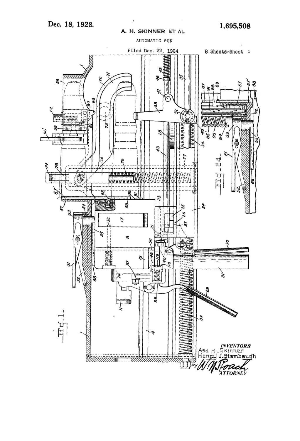
Fig. 1 is a longitudinal sectional view 85
through the rear end of the cradle showing
the breech block in right side elevation and
in the feed position; . .
. Fig. 2 is a rear end view with the maga-
zine open, the cradle broken away to show 70
the breech block in the feed position;
Fig. 3 is a transverse sectional view taken
through the breech block in the feed position
and showing a rear fragmentary view of the
magazine in raised position; 75
Fig. 4 is a horizontal sectional view
through the rear end of the gun, the breech
block in the feed position ;
Fig. 5 is a transverse sectional view
through the cradle and magazine, the breech 80
bloek shown in front elevation and in the
feed position;
Fig. 6 is a fragmentary longitudinal sec-
tional view through the cradle, the barrel
shown in right side elevation and in battery; 85
Fig. 7 is a plan view of the breech end of
the barrel in battery, one of the barrel, exten-
sions partly broken away to show the rela-
tion between the barrel .and the automatic
latch; 90
Fig. 8 is a transverse, sectional view
through the cradle, the barrel in rear eleva-
tion and the cartridge support in the raised
position;
Fig. 9 is a view in right side elevation of 95
the breech block held in the feed position by
the automatic latch;
Fig. 10 is a plan view partly in section of
the barrel and block in battery, the firing
post adjusted for automatic firing; 100
Fig. 11 is a right side elevation partly in
section showing the barrel and block in bat-
tery ;
Fig; 12 is a transverse sectional view
through the barrel and block in battery; the 105
locking members shown in the open or op-
erative position and the cartridge support
lowered;
2
1,605,508
5
10
15
20
25
30
35
40
45
50
55
GO
Fig. 13 is a fragmentary sectional view
taken on the line 3—3 of Fig. 12;
Fig. 14 is a fragmentary longitudinal sec-
tion through the breech block in the feed
position, the firing pin retracted by the lock-
ing members and the sear in operative po-
sition;
Fig. 15 is a fragmentary horizontal section
through the cradle, breech block, and firing
mechanism housing, the tiring post set in the
safe position and the slide shown in the po-
sition it would assume with the firing pin
cocked and the gun in battery;
Fig. 16 is a. similar view with the firing
post adjusted for single shot firing and the
firing rod in the forward or released posi-
tion ;
Fig. 17 is a view similar to Fig. 16 with
the firing rod retracted, the slide shown in
the position it would assume after discharge
of a round and return of the block to bat-
tery ;
Fig. 18 is a similar view with the tiring post
in the automatic adjustment, the position of
the slide and block shown just before arriv-
ing in battery;
Fig. 19 is a fragmentary transverse sec-
tion through' the cradle showing the ratchet
wheel in front elevation ;
Fig. 20 is a. detail sectional view through
the magazine partition showing the latch for
holding the round during loading of the
magazine;
Fig. 21 is a fragmentary sectional view
through the breech block in the feed position,
the tumbler holding the incoming round in
place;
Fig. 22 is a similar view with the breech
block in battery, the plunger collapsed by
the stud on the barrel;
Fig. 23 is a similar view to Figure 21, the
plunger again extruded after ejection of the
empty case and the tumbler about to receive
the incoming round;
Fig. 24 is a detail view of the mechanism
for retaining the breech block in the feed
position when the last round from the maga-
zine has been positioned in the feed opening;
Fig. 25 is a detail view partly in plan and
partly in section of the firing rod and the
firing post adjusted for automatic- tiring;
Fig. 26 is a sectional view on the line 6—6
of Fig. 25:
Fig. 27 is a fragmentary plan view of the
adjusting handle showing the bayonet slot;
Fig. 28 is a fragmentary view of the right
side of the cradle;
Fig. 29 is a plan view of tl.e rear end of
the cradle, the magazine shown in section
and in position above the feed opening;
Fig. 30 is a sectional view of the rear end
plate of the magazine;
Fig. 31 is a detail sectional view of the
firing post assembly.
Referring to the drawings by numerals of 65
reference:
In carrying out the invention, there is pro-
vided a frame or cradle 1 in which recipro-
cates a barrel 2 being guided by ribs 3 pro-
vided on the barrel near the breech end there- To
of and working in guides 4 (Fig. 3) on Hie
inner faces of the sides of the cradle. Sur-
rounding the barrel and enclosed by the cra-
dle is a spring 5 (Figs. 6, 10 and 11) com-
pressed during recoil for returning the bar- 75
rel to battery, the return movement of the
band being eased or retarded by a butler
mechanism (not shown) on a buffer rod 6
connected to the barrel and reciprocating in
a cylinder 7 on the cradle (Fig. 6). 80
The breech end of the barrel 2 is squared
(Fig. 8) and embodies vertically disposed
extensions 8 (Figs. 7, 8 and 10) between
which is received the forward portion of an
axially movable breech block 9 formed with 85
ribs 10 disposed in the guides 4 (Fig. 2).
The block is provided with the usual tiring
pin 11 and tiring pin spring 12, the pin be-
ing automatically retractable to cocked posi-
tion on recoil by means of a laterally extend- 60
ing cocking lever 13 (Figs. 2, 4 and 10) piv-
oted in the firing mechanism housing 14 on
the rear of the block and adapted to be swung
upon its pivot striking a cocking plate 15
(Figs. 10 and 11) secured to the left side of 05
the cradle. The firing pin is retained in the
cocked position by a sear 16 (Fig. 14) mount-
ed in the housing 14.
To provide for releasably locking the
breech block and barrel in the firing position, 100
there is mounted in a recess in the block a
pair of members 17 on a fulcrum 18 and
movable to open or locked position as shown
in Figure 12 when the members are engaged
in sockets 8' in the barrel extensions 8 and to 105
the closed or unlocking position as shown in
Figure 3 when the members are completely
withdrawn within the block, suitable grooves
being made in the members to accommodate
the point'end of the firing pin 11. The rear 110
face of each locking member is formed with
a semi-conical depression 19 (Figs. 10 and
12) whereby the breech lock in moving to
closed position contacts the enlarged head 20
of the firing pin to force the, already cocked 1]5
firing pin an additional distance to the rear
as seen in Figures 4 and 14. The breech lock
therefore functions as a safety mechanism
permitting release of the firing pin only " lien
the block is fully home and locked to the 120
barrel.
As shown in Figures 1, 2, 3, and 13. the
breech block is formed on its underside with
an extension 21 having ribs 22 disposed in
guides in the uprights 23 of a slide 24. the 125
slide being capable of limited movement
under tension relative to the extension as in-
dicated in Figures 1 and 11. Thereafter the
1,696,608 3
ed a cartridge support 38 moved by its springs
39 to the raised position (as showri in Fig.
1) when the bloek is in the feed position
and held in the vertical by stops 40 engaging
the slide 24 (Figs. 1, 5 and 8). - When the 70
breech bloek is returning to battery the studs
41 on the support engage cam plates 42 on the
underside of the barrel (Figs. 6,8 and 11) and
the support is swung downwardly to the low-
ered position as shown in Fig. 11. 75
For the purpose of retaining the block in
the feed position (Figs. 1 and 9) and separat-
ing the block from the barrel there is pro-
vided an automatically operated latch mecha-
nism consisting of a rod 43 mounted in 80
brackets 44 secured to the left side of the
cradle (Figs. 1, 2, 3 and 6) and urged rear-
wardly by a spring 45 confined between the
front bracket and a collar 46 on the rod. The
front extremity of the rod is provided with a 83
bent arm 47, which, as shown in Figures 6
and 7, is engaged by the rib 3 on the lefi
side of the barrel,-preventing rearward move-
ment of the rod until the barrel moves in re-
coil. The rod is then free to move to the 90
rear until the arm is brought up against
the front bracket, this movement being suffi-
cient, however, to elevate a bell crank lever 48
pivoted to the cradle and having its lower
arm disposed in a slot in the rear end of the 93
rod, as clearly seen in Fig. 9. During the
final movement of the breech block to the full
recoil position, the bevel portion 49 of the
block temporarily depresses the lever 48
which is immediately re-elevated into posi- 100
tion to arrest the block in counterrecoil by en-
gaging the forwardly facing shoulder 50 of
the block, the barrel consequently continuing
independently into battery.
As the barrel approaches battery, the rib 105
3 reengages the bent arm 47 on the rod 43
drawing the rod forward to lower the lever
48 and allowing the block to return to battery.
During the interval between the latching and
unlatching of the breech block a cartridge is no
fed to the block as will be described herein-
after.
For the purpose of retaining the breech
block in the feed position when it has manu-
ally retracted as previously outlined, there is П5
provided on the. top of the cradle a hand
latch 51 (Figs. 1,2, 9, 24 and 29) pivoted to a
raised frame 52 integral with the cradle and
adapted when raised to depress a notched
bolt 53 against the tension of a return spring ’-0
54. The bolt when depressed engages a lug
55 on the breech block and holds the block in
the feed position (Fig. 1) during initial
feeding of a round to the block and also dur-
ing replenishment of the magazine (Fig. 24) 12°
until the hand latch is manually pressed.
The upper face of the cradle is formed with
a rectangular feed opening 56 (Fig. 29) de-
fined by raised walls, the rear wall 57 (Fig.
1) provided with grooves 57' for receiving 130
slide 24 and breeeh block are constrained to
be moved in unison by means of transverse
slides 25 disposed in a recess in the underside
of the extension and passing through open-
6 ings in the uprights 23 of the slide 24. The
transverse slides are provided with depend-
ing pins 26 disposed in cam slots 27 in the
slide 24 (Figs. 3,12 and 13) and are formed
with apertures 25' in their overlapping ends
10 for the reception of the lower portions of the
locking members 17 whereby the breech lock
may be opened or dosed as the transverse
slides are reciprocated.
Referring to Figures 3,10 and 12, the sides
15 of the cradle are provided with cam plates 28,
which, during recoil and after the cocking
lever 13 has retracted the firing pin, force the
transverse slides 25 inwardly to disengage the
locking members from the barrel. This ac-
20 tion also causes the slides 25 through their
pins 26 to retract the slide 24 with respect to
the extension 21 of the breech block. The
same result may be attained in initial loading
of the gun by manual operation of the rear
25 lever 29, retracting the firing pin, and the
front lever 30 retracting the slide 24, the
movement of the slide 24 operating reverse-
ly through its cam slots 27 and the pins 26 to
force the transverse slides 25 inwardly to dis-
30 engage the locking member 17 from the bar-
rel. The function of the slide 24 is again
manifested after the breech block has re-
turned to battery when it serves by reason of
its additional movement to actuate the trans-
35 verse slides 25 which in turn control the
breech lock 17—17. To provide for manu-
ally retracting the breech block in initially
loading the piece and in correcting stop-
pages there is secured to the housing 14 a grip
40 31 located between the front and rear levers.
In order to insure retention of the locking
members 17—17 in the closed or unlocked po-
sition at such times when the slides 25 are
not in engagement with the cam plates 28
45 there is provided in the breech block in rear
of the breech lock recess (Figs. 1, 4, 5 and 10)
a pair of plungers 32, which when the block
is unlocked from the barrel are free to be
moved forwardly in the path of rotation of
50 tlie locking members to hold the members in
the closed position (Fig. 4). These plungers
are formed with an offset base 33 adapted to
engage the barrel extensions 8 (Fig. 10) when
the block runs into battery to retract the
plungers and permit the locking members to
open outwardly. The slide 24 mounted in
guides of the cradle (Fig. 12) is retractable
with the breech block during recoil to com-
press springs 34 on rods 35 stationarily car-
co ried by the cradle, the springs serving to re-
turn the slide 24 and block to battery inde-
pendently of the barrel.
The arms of the slide 24 are formed at
their forward ends with ears 36 (Figs.
65 4 and 5) carrying pins 37 on which is mount-
4 1,696,608
and guiding a cartridge to grooves 58 in the
front face of the breech block when the block
is in the feed position (Figs. 1 and 5). The
cartridge is normally held in the position
5 shown in Figure 1, by means of a ratchet
wheel 59 transversely mounted in an exten-
sion 60 (see Figs. 19 and 29) on the left wall
of the opening and positioned to engage and
support the cartridge at a point on its rotat-
j0 ing band. The ratchet wheel is held against
rotation by a catch 61 (Fig. 19) on a plunger
62 (Fig. 5) housed in the extension 60. Ob-
viously, when the plunger is depressed the
ratchet wheel is free to rotate allowing, the
13 cartridge in the feed opening to be forced
downwardly into position on the breech
block, as shown in dotted lines in Figure 1,
the forward portion of the round resting on
the support 38.
2o The under side of the plunger 62 pivotally
carries a rocker 63 (Fig. 1) having a slot 64
in which an element of the plunger 62 is so
disposed that the rocker may idle past the
lug 65 on the barrel on recoil (Figs. 6, 7 and
25 8) but is tripped thereby on counterrecoil to
depress the plunger thereby releasing the
ratchet wheel and the cartridge.
In preparing the gun for firing, the initial
round is preferably forced downward by
So hand but when the barrel recoils after dis-
charge of a round, the feeding operation is
automatically performed through the agency
of the counterrecoiling barrel cooperating
with elements mounted in the cradle. Refer-
35 ring to Figures 6, 8,10,11 and 29, the breech
block is provided with plates 66 overhanging
the upper surface of the barrel and formed
with cam slots 67 in which are disposed the
lugs 68 of laterally movable plungers 69
40 housed in the barrel. When the breech block
and barrel move rearwardly en masse the
plungers 69 are held in the “in” position but
upon separation of the barrel for independent
return to battery the plungers are cammed
45 outwardly where they are held by the plunger
springs 70. As the barrel approaches bat-
tery, the plungers enter grooves 71 in the
feed levers 72 (Fig. 1) and in traveling along
the curved forward terminals of the grooves
50 rock the levers on their pivots 73.
The rear ends of the levers 72 (Figs. 1, 5
and 19) are disposed in slots in the under
side of vertically sliding feed arms 74 and
are loosely mounted on pins 75 so that, when
55 the levers are rocked the feed ariiis will be
forced downwardly, compressing springs 76
in housings 77 on the cradle (Figs. 4 and 5)
and through their fingers 78 lowering the
next round (the ratchet wheel 59 having been
co released) into the grooves 58 on the breech
block in position to enter the chamber of
the barrel. When the plungers 69 in the bar-
rel clear the feed levers 72, the springs 76
will return the feed arms 74 to the up or nor-
66 mal position, the finger 78 coming in contact
with the succeeding round, being rotated out-
wardly, and then returned to normal posi-
tion by reason of the action of the plungers
79 on the pins 79' to engage said succeeding
round when the feed aTms have reached the 70
limit of their upward movement.
The loaded round is retained on the face
of the breech-block by a tumbler 80 piv-
oted in a plunger 81 housed in the block, as
shown in Figure 21. With the breech block 75
locked to the barrel (Fig. 22) the round is
in its chamber and supported by the barrel,
the plunger 81 being collapsed by a stud 82
on the rear face of the barrel and the upper
arm of the tumbler coming in contact with 80
the rear face of the flange of its cartridge
case. If the empty case has not already
fallen from the block when the block is again
in the feed position, the action of the feed of
the incoming round across the face of the 85
block will eject the empty case. As soon as
the empty case has cleared the plunger 81, the
plunger will again be extruded by its spring,
the tumbler holding the incoming round in
position, as shown in Figure 23, while a 00
plunger 83 (Fig. 1) engages the upper por-
tion of the cartridge rim to hold the round
against rebound.
Hingedly mounted on the right hand side
of the cradle (see Figs. 2 and 5) is a redan- 05
gular magazine 84, open at one end to receive
rounds of ammunition when in the lowered
position and to discharge the • rounds into
the feed opening 56 when in the raised po-
sition. The rear end plate 85 (Figs. 29 and 100
30) is provided with a partition 86 formed
on its forward face with grooves 87 for re-
ceiving the flange of the cartridges and also
formed with a central grooved slot (Figs. 1,
5, 24 and 30) in which is disposed a slide 88 105
having a curved projection or hook 89 for
engaging the first round placed in the mag-
azine, the round being held in position by a
latch 90 (Figs. 5 and 20) mounted in the
partition. As the slide is moved downward 110
(Figs. 2 and 24) in loading the magazine,
it causes the lazy tongs 91 to be folded by
reason of the connecting pin 92 and the tongs
in turn, through a connection 93 with a slide
94, compress a feed spring 95 disposed in a 115
cylindrical housing 85' (Figs. 2 and 3) on
the rear face of the end plate 85. The rounds
on being inserted in the magazine are held
in a horizontal position by means of spacers
96 mounted in the magazine and when the 120
magazine is raised a similar spacer 96' on
the cradle is brought into operation. When
the loaded magazine is swung to the raised
position, the latch 90 strikes the rear wall
57 of the feed opening and is moved to inop- 125
erative position, the rounds in the mao-azine
then being supported by a round previously
placed in the feed opening and held by the
ratchet wheel.
When the last round from the magazine 130
1,696,608 5
5
10
15
20
25
30
35
40
45
50
55
00
05
has been fed into the grooves 57' on the rear
wall 57 of the feed opening, the feed mech-
anism will be in the position shown in Fig-
ure 24, the slide 94 forced by. the feed spring
95 to depress the notched bolt 53 into the
path of the lug 55 on the breech block. Dur-
ing recoil of the block the bolt rides over
the bevel face 55' of the lugZand is again
depressed to engage the lug and hold the
breech block in the feed position until manu-
ally released after the magazine has been re-
plenished.
For the purpose of depressing the sear to
release the firing pin, there is mounted in the
firing mechanism housing 14 (Figures 1 and
2) a Dell crank lever 97, one arm of which is
disposed in a slot in the .sear and the other
arm in a slot in a transverse slide 98 which
is adapted to be moved laterally to rock the
lever through an adjustably positioned firing
post 99 which in turn is moved laterally by
a firing rod 100 (Figs. 3, 5 and 25). The
firing rod 100 normally urged forward to in-
operative position- by a spring 101 is sup-
ported in brackets 102 and may be oper-
atively ’ connected to any suitable trigger'
mechanism (not shown) conveniently mount-
ed on the end or side plates of the cradle.
Referring to Figures 4 and 31, the shank
of the firing post 99 is mounted in a hollow
handle 103 with which it is constrained to
be rotated’by means of a pin 104 disposed in
a slot 105 in the handle while permitting in-
dependent longitudinal movement of the han-
dle against the action of a spring 106. The
handle may be turned to selectively position
the post in the safe, automatic, or single shot
adjustment (Fig. 28) and is locked in place
by means of a stud 107 mounted in a housing
108 (Fig. 26) and which respectively engages
in recesses 109,110 and 111 of a bayonet slot
112 in the handle (Fig. 27). The inner ex-
tremity of the stud 107 is disposed in an
annular groove 113 ip the shank of the firing
post (Figs. 26-and 31) whereby the post is
laterally reciprocated when a stud 114 on
thejiring rod 100 working in a cam slot 115
(Figs. 3 and 25) on the under face of the
housing moves the housing during retraction
and release of the firing rod.
The firing post is formed with an irregular
head 99' shown in the-vertical position in
Figure 15 when adjusted to the safe posi-
tion and having projecting portions with in-
clined walls оп'|parallel planes, one portion
116 formed with a curved undercut wall and
shown to the rear in the automatic setting in
Figure 18 and the other portion 117 formed
with a beveled overcut wall and shown to
the rear in the single shot setting in Figures
16 and 17.
When the post is adjusted for automatic
firing (Figs. 10, 18 and 31) and the firing
rod retracted to move the housing and post
laterally outward the beveled face 98' of the
slide 98 will, as the breech block runs into
battery, engage the under cut portion 116
of the post and be cammed outwardly to rock
the lever 97 and release the firing pin. This
action is repeated in sustained firing, the 70
trigger being held pressed and the firing post
maintained in the armed position. With the
gun loaded and -in battery, however’, the
slide is constrained to be moved with the fir-
ing post assembly by reason of the engage- 75
ment of the projecting portion 116 with the
plunger 119 (Figs. 10 and 31).
When the post is adjusted for single shot
firing (Fig. 16) the breech block may return
to battery without any movement of the slide 80
98 taking place, the portion 117 of the firing
post head fitting in a curved face 118 (Fig.
17) of the slide 98 and engaging the inner
face of the plunger 119 in the slide. Re-
traction of the firing rod moves the firing 85
post head outward carrying with it, through
the plunger 119 the slide 98 and the firing
pin is released as previously set forth. How-
ever, should the trigger be held- under com-
pression to retain the firing post in the out- oo
ward or armed position, the slide 98 on re-
turn of the breech block to battery will be,
as shown in Figure 17, in its inward or in-
operative position. When the trigger is re-
leased, the firing rod through its spring will' 05
be urged forwardly, the firing post head in
returning to its normal position (Fig. 16)
collapsing the plunger 119.
It will be understood that any suitable
buffer mechanism for absorbing the surplus 100
energy of recoil may be provided on the end
plate of the cradle.
In operation, assuming the gun to be clear
of rounds and in battery with the magazine
open, the gunner seizes the grip 31, the pres- 105
sure on the rear lever 29 cocking the firing pin
11 while the pressure on the front lever 30
retracts the slide 24 against the action of the .
springs 34, the transverse slides 25 (Figs.
11, 12 and 13) being moved thereby to dis- 110-
engage the locking members 17—17 from the
barrel and the movement of the locking mem-
bers in turn forcing the cocked firing, pin
an additional distance to the rear (Figs. 4
and 14). The locking members are held in 115
this position by the plunger 32 and subse- .
quently indirectly held by the cam plates 28
against which the transverse slides 25 are in
contact on continue^ recoil. The breech
block is then drawn to the rear further com- 120
pressing the recoil, springs 34 and is held in
the feed position by means of the hand latch
51 (Fig. 1).
A loaded round is placed in the feed open-
ing 56 (Fig. 1) the plunger 62 manually de- 125
pressed to free the ratchet wheel 59 and the
round forced down on to the breech block
until arrested by the tumbler 80 and the sup-
port 38. A second round is £hen positioned in
the feed opening and supported by the ratchet 130
6
1,605,508
wheel 59. After the magazine has been
loaded and swung to position about the feed
opening, the breech block may be released,
by pressing the hand latch 51, to load the first
round into the chamber. During the return
to battery, and after the round has been par-
tially inserted in the chamber, the front sup-
port 38 is folded to the position shown in
Figure 11, while on arriving in battery the
plungers 32 are collapsed when their oft'set
portions 33 (Fig. 10) strike the barrel ex-
tensions 8. With the block in battery, the.
slide 24 under the influence of the recoil
springs 34 moves forward an additional .dis-
tance, forcing by means of the transverse
slides 25, the locking members into the re-
cesses of the barrel extensions, which move-
ment allows the firing pin to move forward
into engagement w’ith the sear 16.
) With the gun loaded and in battery, the
firing pin may now be released to prime the
cartridge by adjusting the firing post 99 for
either automatic or single shot firing and by
retracting the firing rod 100 causing lateral
5 movement of the firing post and through it
the slide 98 which rocks the bell crank lever
97 to depress the sear and release the firing
pin.
When’ a round is discharged, the block and
° barrel move together in recoil, at first inter-
locked and then unlocked, the block being
energized, to subsequently ram a round into
the barrel. In the first phase of recoil, the
cocking lever 13 strikes the plate 15 to cock
J5 the firing pin, the enlarged head 20 of the
pin being withdrawn a sufficient distance to
permit the breech locks 17—17 to be closed
by the action of the cam plates 28 on the
transverse slides 25. The inward movement
0 of the slides 25 also retracts under tension
the slide 24 with respect to the breech block
’ so that the slide 24 may mutually restore
the slides 25 to normally locking position
after the breech block is in battery.
ir> Also during recoil, the rod 43 is free to
be moved to the rear under influence of its
spring so that the lever 48 may be rocked to
engage in the slot 50 thereby restraining the
counterrecoiling breech block in the feed
50 position, while the barrel separates there-
from and continues into battery.
In separating from the breech block the
plungers 69 on the barrel are extruded
through the instrumentality of the overlap-
55 ping breech block plates 66 and the plunger
springs 70 so that they may' rock the feed
levers 72 to depress the feed arms 74, which
through their fingers 78 lower the cartridge
from the feed opening into position on the
60 face of the breech block. Prior to this action
of the feed levers and arms the cartridge sup-
port 38 is free to be elevated by its spring 39
to support the incoming round and the lug
65 on the barrel trips the rocker 63 to lin-
es latch the ratchet wheel 59.
It will be understood that extraction of
the empty case is accomplished by reason of
its retention in the grooves 58 of the breech
block and the case is ejected by the incoming
round if it has not already dropped from the 76
block when cleared by the connterrecoiling
barrel.
Final movement of the barrel into battery
causes the rod 43 to be. drawn forward by
reason of the bent arm 47 being engaged by 75
the rib 3 of the barrel (Fig. 7) the consequent
loweringiof the lever 48 releasing the breech
block to carry the round into the chamber.
When the block is fully home the additional
forward movement of the slide 24 actuates 80
the breech lock as previously described in
hand operation.
With the firing post adjusted for auto-
matic firing, the bevel face 98' of the slide 98
contacts the undercut portion 116 of the post 85
and the slide is cammed outwardly to rock the
lever 97 and depress the sear; consequently,
the firing pin is only restrained by the breech
lock which in moving to locking- position re-
leases the pin to prime the cartridge. 90
Provision for stopping the action of the
gun when the last round from the magazine
has been fed into the feed opening 56 in-
cludes (Figs. 1 and 24) the hand latch 51,
which is automatically depressed by the slide 95
94 in the magazine to engage the lug 55 on
the breech block whereby to retain the block
in the feed position until the magazine is re-
plenished.
While in the foregoing there has been illus- 100
trated and described such combination and
arrangement of elements, as constitute the
preferred embodiment of our invention, it
is nevertheless desired to emphasize the fact
that interpretation of the invention should 105
only be.conclusive when made in the light of
the subjoined claims.
We claim:
1. The combination of a cradle, a barrel
mounted to reciprocate freely therein, an no
axially movable breech block for the barrel,
said block having cartridge grooves and
adapted to be energized by the barrel in re-
coil, a firing pin reciprocally mounted in the
block, means for either automatically or 115
manually cocking the pin, a sear for holding
the pin in cocked position, breech locking
members mounted in the block, mutually re-
ciprocating slides movable with the block for
automatically locking and unlocking said 120
members, means for manually actuating one
of the slides to unlock the members, said
members in moving to unlocked position
adapted to further retract and hole! the al-
ready cocked firing pin, means mounted on 125
the cradle and controllable by the barrel in
recoil and counterrecoil for respectively
latching the block in the feed position and re-
leasing it for independent return to battery to
ram a round into the chamber, a pivoted 130
1,605,508
7
cartridge support carried by one of the slides,
normally elevated when clear of the barrel
and adapted to be lowered by the barrel as the
block runs into battery, means carried by
5 the cradle for holding a round in position to
be fed to the block, feed mechanism mounted
in the cradle, means on the barrel operable
during counterrecoil for successively releas-
ing the round and actuating the feed mecha-
10 nism to lower it into position on the block,
means normally projecting from the block for
stopping- the rim of the incoming round,
means on the barrel for rendering said afore-
said means inoperative when the round has
15 been driven home whereby to subsequently
permit ejection of the empty case by the in-
coming round, a firing post slidably mounted
in the cradle and adjustable to either safe,
automatic, or single shot position, means for
20 moving said post outwardly, a transverse
slide in the block adapted to be moved by said
post when the post is in firing adjustment,
a lever pivoted to the block and operable on
outward movement of the slide to depress the
25 sear, a magazine on the cradle, a manually
operable latch on the cradle for holding the
block in feed position, means in the magazine
for automatically actuating said latch when
the last round from the magazine has been
30 moved in position to be fed to the block, and
a grip for manually retracting the block.
2. The combination of a cradle, a barrel
mounted to reciprocate freely therein, an
axially movable breech block for the barrel,
35 said block having cartridge grooves and
adapted to be energized by the barrel in re-
coil, a firing pin reciprocally mounted in the
block, means for either automatically or
manually eoeking the pin, a sear for holding
,0 the pin in eocked position, a breech lock car-
ried by the block and adapted when in un-
locked position to prevent release of the fir-
ing pin, means for either automatically or
manually unlocking the breech lock, means
45 for latching the block in the feed position
while the ban-el continues into battery, said
latching means adapted to be tripped by the
barrel as it arrives in battery to release the
block, a feed mechanism actuated by the
50 counterrecoiling barrel to lower a round on-
to the block, the action of the incoming round
serving to eject the empty case, means asso-
ciated with the block for supporting the
round, cooperating means on the cradle and
55 block for depressing the sear to release the
firing pin, a magazine on the cradle, a manu-
ally operable latch on the cradle for holding
the block in feed position, means in the maga-
zine for automatically actuating said latch
во when the last round from the magazine has
been moved in position to be fed to the block,
and a grip for manually retracting the block.
3. The combination of a cradle, a barrel
mounted to reciprocate freely therein, an ax-
65 ially movable breech block for the barrel,
said block formed with cartridge grooves and
adapted to be energized by the barrel in re-
coil, a firing pin reciprocally mounted in the
block, means for cocking the pin during re-
coil, a sear for the pin, a breech lock carried 70
by the block and adapted when in unlocked
position to prevent release of the firing pin,
means for latching the block in the feed po-
sition while the barrel continues into battery,
said latching means adapted to be tripped 75
by the barrel arriving in battery to release
the block, a feed mechanism actuated by the
counterrecoiling barrel to lower a round onto
the block, the action of the incoming round
serving to eject the empty case, means asso- 80
elated with the block for supporting the
round, cooperating means on the cradle and
block for depressing the sear to release the
firing pin, a magazine on the cradle, and co-
operating means on the magazine and cradle 85
for automatically holding the block in the
feed position when the last round from the
magazine has been moved in position to be
fed to the block.
4. The combination of a cradle, a barrel 90
mounted to reciprocate freely therein, an ax-
ially movable breech block, a firing pin recip-
rocally mounted in the block, means for un-
locking the block and barrel during recoil
and locking them when both are in battery, 95
means for latching the block in the feed posi-
tion while the barrel continues into battery,
said latching- means adapted to be tripped
by the barrel arriving in battery to release
the block, a feed mechanism actuated by the loo
counterrecoiling barrel to lower a round onto
the block," the action of the incoming round
serving to eject the empty case, means asso-
ciated with the block for supporting the in-
coming round, means for depressing the sear 105
to release the firing pin, a magazine on the
cradle, and means associated with the maga-
zine and cradle for holding the block in the
feed position- when the last- round from the
magazine has been moved into position to be i id
fed to the block.
5. The combination of a cradle, a barrel
mounted to reciprocate freely therein, an ax-
ially movable breech block, a breech lock,
means for actuating the lock, means whereby 115
the block is retained in feed position while
the barrel continues into battery, means for
feeding a round to the block, the action of
the incoming round ejecting the empty case, .
means for supporting the incoming round. 120
means for automatically releasing the block
to ram home the round, a firing pih in the
block adapted to be cocked during recoil,
means for releasing the pin, a magazine on
the cradle, and means for retaining the block 125
in the feed position tvhen the last round
from the magazine has been moved into po-
sition to be fed to the block.
6. The combination of a cradle, a barrel
therein having a divided breech formed with 130
&
1,606,508
sockets, a separable axially moving breech
block adapted, to be energized by the barrel
on recoil for independent return to battery,
"a breech lock including a pair of locking
5 members pivoted in the block and adapted to
lit in the barrel sockets, transverse slides for
actuating the members in opening and clos-
ing, a longitudinal slide having relative
movement under tension with respect to the
10 block and constrained to move therewith
through the transverse slides, cooperating
means on the transverse and longitudinal
slides whereby they are mutually recipro-
cated, means on the cradle for moving the
15 transverse slides inwardly during recoil to
disengage the locking members from the bar-
rel, and the forward relative movement of
the longitudinal slide when the block is in
battery serving to return the transverse slides
20 to actuate the locking members to engage the
barrel.
7. The combination of a cradle, a barrel,
therein having a breech formed with sockets,
a separable axially moving breech block
25 adapted to be energized by the barrel on re-
coil for independent return to battery, a
breech lock including a pair of locking mem-
bers pivoted in the block and adapted to fit
in the barrel sockets, and mutually recipro-
30 eating slides movable with the block for ac-
tuating the breech lock to disengage the bar-
rel during recoil and engage the barrel after
the barrel and block have returned to battery.
8. The combination of a cradle, a barrel
35 therein having a breech formed with sockets,
a separable axially moving breech block
adapted to be energized by the barrel on re-
coil for independent return to battery, a
breech lock including a pair of locking mem-
40 bers pivoted in the block and adapted to
fit in the barrel sockets, and mutually recip-
rocating slides movable with the block for
actuating the breech lock in opening and
closing.
45 9. The combination of a cradle, a barrel
therein having a breeclr formed with sockets,
a separable axially moving breech block
adapted to be energized by the barrel during
recoil for independent return to battery, a
50 breech lock.including a pair of locking mem-
bers pivoted in the block and adapted to fit
in the barrel sockets, and means for actuating
the breech lock in opening and closing.
10. The combination of a cradle, a barrel
55 therein having a breech formed with sockets,
a movable breech block for the barrel, a
breech lock including a pair of locking mem-
bers pivoted in the block and adapted to fit
in the barrel sockets, and mutually recipro-
60 eating slides movable with the block for actu-
ating the breech lock in opening and closing.
11. The combination of a cradle, a barrel
therein having a breech formed with sockets,
a movable breech block for the barrel, a
65 breech lock including a pair of locking mem-
bers- pivoted in the block and adapted to fit
in the barrel sockets, and means for actuat-
ing the breech lock in opening and closing.
12. The combination of a cradle, a barrel
therein, an axially movable breech block for 70
the barrel adapted to return independently
to battery, a firing pin in the block, means
for cocking the pin during recoil, a breech
lock in the block, means for actuating the
lock to disengage the block after the firing 75
pin has been cocked, auxiliary means car-
ried by the block and operable on separation
of the block and barrel for holding the breech
lock in unlocked position, said means adapted
to be rendered inoperative only after the 80
block has returned to battery, and means op-
erable when the block is in battery to actuate
the breech lock to reengage the barrel.
13. The combination of a cradle, a barrel
therein, a breech block for the barrel, a firing 85
pin in the block, means for cocking the pin
during recoil, a sear for the pin, a breech lock
in the block, means for actuating the lock to
disengage the block after the firing pin has
been cocked, the lock during this operation 90
serving to retract the already cocked firing
pin, and means operable when the block has
returned to battery to actuate the breech lock
to reengage the barrel and permit the firing
pin to be released to cocked position. 95
14. The combination of a cradle, a barrel
therein, an axially movable breech block for
the barrel adapted to return independently
to battery, said block formed with cartridge
guides, a plunger mounted in the block, a 100
tumbler associated with said plunger and nor-
mally in extruded position to support the base
of a cartridge, a pivoted support movable
with the block and normally in elevated po-
sition when the block and barrel are separated 1()5
to support the forward end of the cartridge,
means on the barrel whereby the forward sup-
port is lowered as the block approaches bat-
tery, and means on the barrel for positioning
the. tumbler in rear of the cartridge as the
block arrives in battery whereby to subse-
quently permit ejection of the empty case.
15. The combination of a cradle, a barrel
therein, an axially movable breech block for
the barrel adapted to return independently 115
to battery, said block formed with cartridge
guides, means mounted in the block and nor-
mally in position to support the base of a
cartridae, means movable with the block and
normally in position to support the forward 120
end of the. cartridge, and means on the barrel
for controlling the movement of the rear and
front supports to inoperative position.
16. The combination of a cradle, a barrel
therein, an axially movable breech block for I25
the barrel adapted to return independently
to battery, said block formed with cartridge
guides, cartridge supports associated with
the block and normally in operative position,
and means on the barrel for controlling the iso
1,695,608
9
movement of the supports to inoperative po-
sition.
17. The combination of a cradle, a barrel
therein, an axially movable breech block for
5 the barrel adapted to return independently
to battery, feed mechanism for moving a
round across the face of the block, and a col-
lapsible support normally in round receiving
position for stopping the incoming round in
10 line with the chamber.
18. The combination’of a cradle, a barrel
therein, an axially movable breech block for
the barrel adapted to return independently
to battery, said block formed with cartridge
15 guides, means associated with the block for
supporting the incoming round in line with
the chamber, and means for preventing re-
bound of the incoming round.
19. The combination of a cradle, a barrel
20 therein, an axially movable breech block for
the barrel, a firing pin in the block, a breech
lock mounted in the block, a grip for manu-
ally retracting the block, manually operable
means for retaining the block in retracted
25 position, a rear and front lever for respec-
tively cocking the pin and unfastening the
breech lock, said levers mounted to be in-
cluded in the grasp of the operator when
seizing the grip.
30 20. The combination of a cradle, a barrel
therein, an axially movable breech block for
the barrel, a firing pin in the block, a breech
lock, grouped means for manually cocking
the pin, unfastening the lock and retracting
35 the block, and manually operable means for
retaining the block in retracted position.
21. The combination of a cradle, a barrel
having ribs disposed in guides of the cradle,
an axially movable breech block for the bar-
40 rel adapted to be energized by the barrel on
recoil'for independent return to battery, a
rod mounted on the cradle, a spring for urg-
ing the rod rearwardly, a bell crank lever
pivoted to the eradle and operatively con-
45 nected to the rod, a bent arm on the forward
extremity of the rod and disposed in front
of one of the ribs of the barrel whereby on
recoil of the barrel the rod is free to be moved
rearwardly to elevate the lever in position to
Ы) restrain the block on counterrecoil, and said
arm reengageable by the rib as the barrel ap-
proaches battery for lowering the lever to
release the block.
22. The combination of a cradle formed
with a feed opening, a barrel in the cradle,
plungers mounted in the barrel, a separable
breech block for the barrel adapted to be
energized by the barrel for independent re-
turn to battery, means for automatically and
(•u releasably holding the block in feed posi-
tion, cam plates on the block for extruding
the plungers on separation of the block and
barrel, means carried by the cradle for hold-
ing a round in the feed opening, means con-
«& trollable by the barrel on counterrecoil for re-
leasing the round, feed levers pivoted to the
cradle and formed with curved cam grooves
whereby the levers are rocked by the ex-
truded plungers during counterrecoil of the
barrel, feed arms mounted in the cradle for 70
vertical sliding movement under tension and
operatively connected to the levers, feed fin-
gers pivoted to the feed arms and normally
engaging the round in the feed opening
whereby to lower the round onto the block 75
as the levers are rocked to depress the arms,
and means associated with the fingers for
restoring them to round engaging position
when the feed arms have returned to their
normal up position. 80
23. The combination of a cradle formed
with a feed opening, a barrel in the cradle,
plungers mounted in the barrel, an axially
movable breech block for the barrel adapt-
ed to be energized by the barrel for inde- 85
pendent return to battery, means for either
manually or automatically holding the block
in feed position, means on the block for con-
trolling the in and out movement, of the
plungers, means carried by the cradle for 90
holding, a round in the feed opening, means
for either manually or automatically releas-
ing the round, feed levers pivoted to the
cradle and formed with curved cam grooves
whereby the levers are rocked by the ex- 95
truded plungers on counterrecoil of the bar-
rel, and means operatively connected to the
levers for lowering a round into the path of
the block as the levers are rocked.
24. The combination of a cradle formed 100
with a feed opening, a barrel in the cradle,
plungers mounted in the barrel, an axially
movable breech block for the barrel adapt-
ed to be energized by the barrel for inde-
pendent return to battery, means for releas- 105
ably holding the block in feed position, means
on the block for controlling the in and out
movement of the plungers, means carried by
the cradle for holding a round in the feed
position, me.ans for releasing the round dur- 110
ing counterrecoil of the barrel, feed arms
mounted for vertical sliding movement in
the cradle and normally engaging the round
in the feed opening, and means operatively
connected to the feed arms and adapted to llfi
be actuated by the extruded plungers on coun-
terrecoil of the barrel to lower the round
into the path of the block.
25. The combination of a cradle formed
with a feed opening, a barrel in the cradle, 120
an axially movable breech block for the bar-
rel adapted to be energized by the barrel for
independent return to battery, means for re-
leasably holding the block in feed position,
means carried by the cradle for holding a 125
round in the feed opening, means for releas-
ing the round during counterrecoil of the
barrel, feed levers pivoted to the cradle, feed
arms operatively connected to the levers and
normally engaging the round in the feed 130
IO
1,696,608
opening, means on the barrel for rocking the
levers on counterrecoil to lower feed arms,
and means on the block for controlling the
movement of the aforesaid means to opera-
5 tive and inoperative position.
26. The combination of a cradle formed
with a feed opening, a barrel in the cradle,
an axially movable breech block for the barrel
adapted to be energized by the barrel for in-
fl dependent return to battery, means for re-
leasably holding the block in feed position,
means carried by the cradle for holding a
round in the feed opening, means for releas-
ing the round during counterrecoil of the
15 barrel, feed levers pivoted to the cradle, feed
arms operatively connected to the levers and
normally engaging the round in the feed
opening and means on the barrel for rocking
the levers on counterrecoil to lower the feed
20. arms.
27. The combination of a cradle, a barrel
therein, a breech block for the barrel, a firing
pin and sear in the1 block, a transverse slide
in the block, a bell crank lever pivoted to the
25 block and connected to the sear and slide, a
housing slidably mounted in the cradle, said
housing normally in inoperative position
and adaptbd to be moved laterally outward on
retraction of a .trigger rod, a firing post mov-
30 able with the housing, said post having op-
posite undercut and overcut projecting por-
tions respectively in the automatic and single
shot adjustment when positioned to the rear
and in the safe adjustment when positioned
35 vertically, njeans for adjusting the post, an
element in the slide whereby the post when
in either firing adjustment and moving out-
ward with the block in battery actuates the
slide while with the post held outward in
40 single shot adjustment and the block running
into battery the slide is not actuated, said
element adapted to permit return of the post
to inoperative position with the block in bat-
tery, and said slide formed with an inclined
45 forward face whereby when the post in auto-
matic position is held outward the slide will
be actuated thereby as the block runs into
. battery.
28. The combination of a cradle, a barrel
60 therein, a breech block for the barrel, a firing
pin and sear in the block, a transverse slide in
the block, abell crank lever pivoted to the
block and,Connected to the sear and slide,
means slidably carried by the cradle and
55 adapted to be adjusted to safe, automatic, or
single shot position, mechanism for recipro-
cating said means, said means when in either
firing adjustment and the block in battery
adapted in moving outward to actuate the
60 slide and when held outward as the block runs
into battery respectively actuating and not
actuating the slide accordingly as said means
is adjusted for automatic or single shot firing.
29. The combination of a cradle, a barrel
65 therein, a breech block for the barrel, a firing.
pin and sear in the block, a transverse slide
in the block, a bell crank lever connecting the
sear and slide, a movable firing post in the
cradle adjustable for automatic or single shot
firing, an element in the slide through which 70
the slide is actuated to depress the sear when
the firing post is moved outward with the gun
at rest, and said slide adapted to be directly
moved by the post as the breech block runs
into battery. 75
30. The combination of a cradle, a barrel .
therein, a breech block for the barrel, a firing
pin and sear in the block, means on the block
for depressing a sear to release the pin,
means movably carried by the cradle and 80
adapted to actuate the aforesaid means
for either automatic or single shot firing,
and an element carried by said first men-
tioned means whereby in single shot firing
the block may run into battery without re- 85
lease of the pin.
31. The combination of a cradle, a barrel
therein, a breech block for the barrel, a firing
pin and sear in. the block, a transverse slide
in the block, a bell crank lever pivoted to the 00
block and connected to the sear and slide1, and
adjustable means mounted in the cradle
whereby the slide may be actuated in either
automatic or single shot firing.
32. The combination of a cradle, a movable 05
breech block, a firing pin and sear in the block,
a sear actuating mechanism, a housing slid-
ably mounted in the cradle, means for recipro-
cating said housing, a firing post movable
with the housing and adapted to actuate said. 100
mechanism, said post having opposite under-
cut and overcut projecting head portions re-
spectively in the automatic and single shot ad-
justment when positioned to the rear and in
the safe adjustment when positioned verti- 105
cally, and means for adj usting the post.
33. The combination of a cradle formed
with a feed opening, means for holding a
round in the opening, a magazine for succes-
sively feeding rounds into position in the 110
opening, a barrel in the cradle, a separable
breech block for the barrel, a manually op-
erable latch on the cradle for holding the
block in feed position, and means associated
with the magazine for automatically actuat- 115
ing said latch when the last round from the
magazine has been discharged into the feed
opening.
34. The combination of a cradle, a barrel
therein, a breech block for the barrel, manu- 120
ally operable means for holding the block in
feed position, a magazine on the cradle, and
means in the magazine for automatically ac-
tuating said latch when the last round from
the magazine has been moved into position to 125
be fed to the block..
35. A gun barrel, a breech block separable
from the barrel, breech locking members in
the block, means for actuating the breech lock-
ing members, and means carried by the block 130
1,695,608
11
and releasable on separation of the block and
barrel in the path of movement of the locking
members.
36. A gun barrel, a breech block separable
5 from the barrel., a breech lock in the block,
means for actuating the breech lock and
means operable on separation of the block and
barrel for holding the lock in unlocked posi-
tion.
10 37. A gun barrel, a breech block separable
from the barrel, a breech lock in the block,
means for actuating the breech lock and
means carried by the block for holding the
lock in unlocked position.
15 38. A cradle having a feed opening, a bar-
rel reciprocal on the cradle, a breech block
formed with cartridge guides and adapted to
be energized for independent return to bat-
tery, means for releasably holding the block
in feed position, and means for preliminarily 20
holding a released cartridge in the feed open-
ing in position to be guided to the guides on
the breech block.
39. A cradle having a feed opening, a bar-
rel reciprocal on the cradle, a breech block 23
formed with cartridge guides and adapted to
be energized for independent return to bat-
tery, means for releasably holding the block
in feed position, and means for preliminarily
holding a released cartridge in the feed open- 30
ing.
ASA H. SKINNER.
HENRY J. STAMBAUGH.