/


Теги: weapons military affairs patent
Год: 1933

Текст
May 2, 1933.
1,907,163
J. C. WHITE
AUTOMATIC GUN
Filed Nov. 23, 1931 7 Sheets-Sheet 1
May 2, 1933.
1,907,163
J. C. WHITE
AUTOMATIC GUN
Filed Nov. 23, 1931
7 Sheets-Sheet 2
May 2, 1933
1,907,163
J. C. WHITE
AUTOMATIC GUN
May 2, 1933.
1,907,163
J. C WHITE
AUTOMATIC GUN
Filed Nov. 23, 1931
7 Sheets-Sheet 4
May 2, 1933.
1,907,163
J. C. WHITE
AUTOMATIC GUN
Filed Nov. 23, 1931
7 Sheets-Sheet 5
May Z, 1933.
1,907,163
J. C. WHITE
AUTOMATIC GUN
Filed Nov. 23, 1931
7 Sheets-Sheet 6
May 2, 1933.
1,907,163
J, C. WHITE
AUTOMATIC GUN
7 Sheets-Sheet 7
Filed Nov. 23, 1931
Patented May 2, 1933
1,907,163
UNITED STATES PATENT OFFICE
JOSEPH C. WHITE, OP WAKEFIELD, MASSACHUSETTS, ASSIGNOR TO WHITE AUTOMATIC
GUN CORPORATION, OP PORTLAND, MAINE, A CORPORATION OP MAINE
AUTOMATIC GUN
Application filed November 23, 1931. Serial No. 573,333.
My present invention relates to guns, and
more particularly to military rifles adapted
for firing from the shoulder, and aims to
provide an improved service weapon, illus-
5 trated as of the semi-automatic, gas-oper-
ated type, but various features of the in-
vention may be useful in other guns. In
some respects the invention of this applica-
tion presents improvements over that of my
10 со-pending application Serial No. 419,318,
filed January 8, 1930 as a refiling, as to
certain subject matter, of previous applica-
tions therein named, and in other respects
it is generic to that of said application
15 Serial No. 419,318.
Referring to the drawings showing one
illustrative embodiment of the invention, by
way of example,
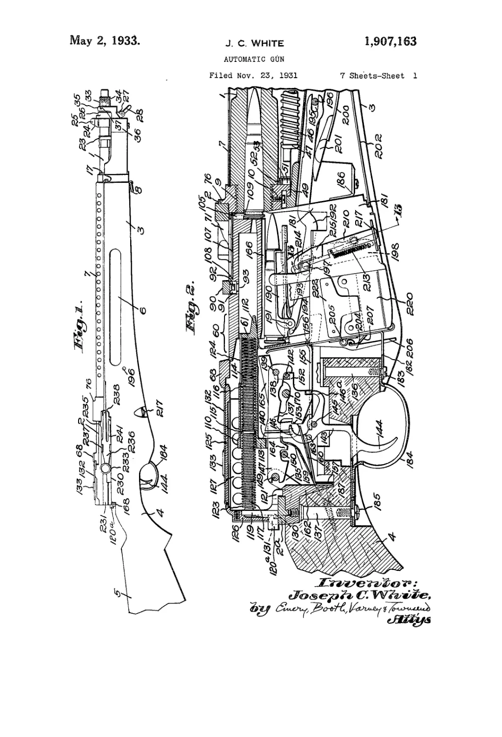
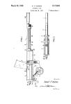
Figure 1 is a right side elevation of the
20 assembled rifle substantially in its entirety;
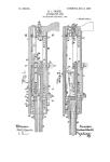
Fig. 2 is a vertical, longitudinal section
through the receiver and associated parts,
the breech being closed and the firing pin
cocked;
25 Fig. 3 is a vertical section substantially
in prolongation of Fig. 2 but also including
the cartridge chamber;
Fig. 4 is a section corresponding to Figs.
2 and 3 through the forward portion of the
30 barrel and the gas mechanism;
Fig. 5 is a vertical transverse section on
the line 5—5 of Fig. 3;
Fig. 6 is a horizontal section on the line
6—6 of Fig. 3 shoiving details of the rear
35 support for the action spring guide;
Fig. 7 is a vertical transverse section on
the line 7—7 of Fig. 4 showing the barrel,
gas piston and ports;
Fig. 8 is a detail view of right side eleva-
40 tion and upon a larger scale of the front
fastening of the hand guide as in Fig. 1;
Fig. 9 is a vertical longitudinal section
corresponding generally to Fig. 2 but with
the parts in fired position and the breech
45 open;
Fig. 10 is a substantially vertical cross
section on the line 10—10 of Fig. 9;
Fig. 11 is a plan of the breech cap;
Fig. 12 is a front elevation of the same,
50 viewed from the front;
Fig. 13 is a substantially vertical cross
section on the line 13—13 of Fig. 2 showing
the breech catch and associated parts;
Fig. 14 is a horizontal cross section sub-
stantially in the plane of the axis of the 55
bore, taken through the receiver and breech
block, the latter in closed and locked posi-
tion, and the firing pin being cocked;
Fig. 15 is a plan view of the receiver
alone; eo
Fig. 16 is a vertical longitudinal section
through the receiver, on the line J.6—16 of
Fig. 15;
Fig. 17 is a cross section through the re-
ceiver, substantially on the line 17—17 of 65
Fig. 16 but with the breech block assembled
with it;
Fig. 18 is a cross section through the rear
portion of the receiver, substantially on the
line 18-—18 of Fig. 16, a portion ot the ac- 70
tion slide being shown in dotted lines;
Fig. 19 is a detail horizontal sectional
view on an enlarged scale through the firing
pin spring mounting;
Fig. 20 is a plan view of the gas fork or 75
action slide;
Fig. 21 is a right side elevation corre-
sponding to Fig. 20;
Figs. 22 and 23 are right side elevations
of the action slide and associating means for 80
operating the same manually, showing the
parts respectively in normal forward posi-
tion and in position as retracted manually;
Fig. 24 is a bottom plan view of the hand-
pull or manual operating means; 85
Figs. 25, 26 and 27 are respectively ver-
tical cross sections on the lines 25—25,
26—26 and 27—27 of Fig. 22;
Figs. 28, 29 and 30 are right elevations
of the breech block, lock and rear portion 90
of the action slide, including also the ver-
tically movable saddle or connector between
the breech block and the action slide, show-
ing the parts respectively in forward closed
and locked position in readiness for firing 95
(Fig. 28), in full open or retracted posi-
tion (Fig. 29), and in an intermediate po-
sition wherein the block is forward and
closed, but is unlocked, the lock being out
of locking position (Fig. 30), the latter fig-
1,907,163
lire representing the parts either just prior
to locking of the breech, near the end of
the return action, or just after unlocking
of the. breech following firing, at the start
5 of the rearward action;
Fig. 31 is a plan of the breech lock;
Figs. 32, 33 and 34 are respectively a front
elevation, a right side elevation and a rear
elevation of the breech lock of Fig. 31;
Ю Figs. 35, 36 and 37 are respectively a rear
elevation, a top plan and a right side ele-
vation of the breech block and the sliding
connector carried thereby;
Fig. 38 is a vertical cross section through
16 the block on the line 38—38 of Fig. 37, look-
ing forwardly;
Fig. 39 is a front elevation of the breech
lock;
Figs. 40 and 41 are respectively a plan
20 view and a left side elevation of the firing
mechanism assembly, the parts being in the
same relative positions in Fig. 41 as in
Fig. 2;
Figs. 42, 43 and 44 are corresponding
26 views of the trigger, scar, connector and
safety showing these parts respectively in
fired position but with the trigger still
pulled and the breech block yet closed, Fig.
43 showing the parts of Fig. 42 after the
30 breech block has opened, the trigger still
being pulled, and Fig. 44 showing the same
parts with the safety “on”;
Fig. 45 is a right side elevation of the
firing mechanism frame;
35 Fig.46 is a perspective of the sear;
Fig. 47 is a vertical cross section of the
firing mechanism assembly, on the line
47—47 of Fig. 41;
Fig. 48 is a left side elevation of the safe-
40 ty; and *'
Fig. 49 is a plan of the single triple-action
spring of the firing mechanism.
Referring to the drawings and first to
Fig. 1, the barrel is indicated at 1, the re-
45 ceiver or frame at 2, and the stock, as a
whole, by the numeral 3, the latter includ-
ing a pistol grip 4 and a butt 5. Finger
channels 6 may be conveniently provided iu
50 the forestock. Above the forestock, the
major portion of the barrel is preferably
covered by a ventilated guard 7. A ring
for attaching one end of the usual sling is
seen at 8.
55 The barrel desirably has removable
threaded connection with the receiver, as
indicated at 9, Figs. 2, 3, 14 and 16, being
locked therein as by the set screw 10. The
barrel and receiver are readily removable
60 from the stock, as will be apparent from
the further description.
Muzzle structure and gas m.echamism,
While various features of the invention
65 are applicable to other types of firearms or
ordnance than gas-operated, the invention
includes novel gas-operating mechanism.
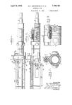
Referring now to Figs. 3 and 4, which
are slightly overlapping views in prolonga-
tion of each other, the barrel has a gas-port
15 in its fore portion and desirably at about
three-quarters the distance from the car-
tridge chamber to the muzzle. The port
proper is herein formed in a replaceable
bushing 16 tapped into the barrel and adapt-
ed to be replaced bv similar members, which
may have ports of different diameters, for
the purposes of adjustment to various con-
ditions. Other factors being the same, the
size of the gas port is inversely propor- 80
tional to its distance from the muzzle. The
gas port 15—16 is in registry with a collar
or port-housing 17 surrounding and pinned
or otherwise secured to the barrel, as in-
dicated at 18. Said port-housing includes 86
a depending portion 19 serving as one sup-
port for the gas tube 20 within which the
hollow sliding piston 21 operates.
The gas tube 20 is further supported in
advance of the port-housing 17 in a ring 22 00
extending downwardly from a sleeve 23
fitted over the barrel and affording a base
24 for the front sight 25. In advance of
the sleeve 23 is a supplemental removable
front sleeve 26 having an upper annular por- 06
tion surrounding the barrel and a depend-
ing collar 27 to which is pivoted the stack-
ing swivel 28. Said front sleeve 26 is held
in proper angular relation with the sleeve
23 as by means of the lock screw 29. 1°°
The fore end of the gas tube 20 abuts
the inner face of said depending collar por-
tion 27 of the front sleeve, and is threaded
as at 30 to receive the front cap 31 which
is thereby adjustably related to the gas tube 105
and forms the front closure therefor. Said
cap 31 may readily be turned for the pur-
poses of adjustment or removal, as by the
wing 32 thereon.
The muzzle of the barrel is desirably fur- 110
nished with a muzzle nut 33 having a series
of substantially radial ports 34, open to at-
mosphere. These ports are preferably so ar-
ranged that a somewhat greater proportion
of gas is liberated upwardly, the muzzle nut 115
thus serving as an anti-climb device, as well
as to lessen the recoil. It may be locked in
place as by means of a finger 35, Fig. 1,
formed as a forwardly and upwardly pro-
jecting portion of the U-shaped strap 36 120
at the fore end of the stock and having an
inwardly projecting detent 37 adapted to
engage in a slot in the muzzle nut, in the
completely assembled position of the latter.
Referring again to Fig. 4, the port-hous- 1Я5
ing 17 is apertured in registry with the bar-
rel port 15, as is also the gas tube 20. The
piston 21 within the latter is an elongated
tubular member, hollow throughout sub-
stantially its entire length and having a rel- 130
1,007,163
б
10
16
20
2В
30
35
40
45
50
55
60
65
atively thin wall, so that there is provided
within the piston a gas chamber of sub-
stantial capacity. The bore of the gas tube
cap 31 is preferably the same or approxi-
mately the same diameter as that of the gas
chamber in the piston, forming in effect a
forward extension thereof. In Fig. 4, the
pistpn is seen in its normal or forward posi-
tion, prior to firing. In this position a gas
port 21a in the piston registers with the
barrel port 15 and the communicating aper-
tures in the port housing 17 and gas tube 20.
As seen in both Figs. 3 and 4, the piston
21 is positively but disconnect ably coupled
to the fore end of the action spring housing
40 which in turn is secured to and consti-
tutes the fore part of the breech-actuator, ac-
tion slide or gas fork 41; see also Figs. 20
and 21. Interengageable hook-lugs 42 and
43 on the piston and the fore part of the
action slide or spring housing 40, respec-
tively, serve to couple said members but may
be disconnected when desired by a slight
relative tilting and turning.
The piston and action slide have a recip-
rocating movement in the course of a firing
cycle from their forward full line position
as in Figs. 3 and 4 to the rearward or fired
position as shown in dotted lines in Fig. 3,
and return. In the fully retracted position
the gas port 21a of the piston conies oppo-
site and is exposed by an aperture 20a at the
rear of the gas tube 20 and the piston inte-
rior is then also opened to atmosphere by
a slot 20Z> in the gas tube which is just un-
covered by the open front end of the re-
tracted piston. It will be noted that at the
beginning of the back stroke the piston port
21a is immediately closed by the gas tube.
It remains so covered until near the end of
the back stroke and until exposed by said
recess 20a, at which latter time the major
portion of all gas in the piston is exhausted
to atmosphere, a quick exhaust being further
aided by said slot 20b which is uncovered by
the. piston front end substantially simultane-
ously or an instant before the port 21a is
uncovered. On the forward stroke a reverse
operation takes place, the piston port re-
maining closed substantially until the piston
again reaches its full forward position of
Fig. 4, while the gas tube slot 20?> remains
covered by the piston itself. Thus a quan-
tity of air with perhaps a small portion of
spent gas is trapped within the piston and
compressed, serving to cushion the return
movement of the piston and associated mech-
anism. This compressed air is released
through the piston port and the barrel port
when these again come into registry, pro-
ducing a scavenging and cooling effect at
the muzzle.
In operation, when a bullet has passed
the barrel-port 15, high-pressure live gas en-
ters the piston 21 through this port and the
then registering port 21a in the piston. As
the gas in the piston reaches a pressure suffi-
cient to overcome the resistance of the ac-
tion-spring 46 and the reciprocating parts,
the piston moves rearwardly, closing the 70
barrel-port. The gas is thus trapped in the
piston and the gas tube, where it expands,
actively, causing a continued smooth rear-
ward movement of the piston. This steady
expansive action of the gas continues 75
throughout the major portion of the action
stroke of the piston and connected parts.
Before the full travel of the piston has tak-
en place, however, the slot 20b in the gas
tube is uncovered by the front end of the 80
piston and the piston port 21a comes into
registry with the aperture 20a at the rear
of the gas tube, and is uncovered. A large
and sudden drop of gas pressure therefore
occurs, with resultant slowing down of the 86
piston.
On the reaction or forward stroke of the
piston, effected by the expansion of the ac-
tion spring which was compressed during
rearward travel of the piston, the air and 80
any remaining gas in the gas-tube are com-
pressed, thus cushioning the rapid reaction
stroke of the parts, until the piston port
21a again registers with the barrel-port 15,
when the compressed air and spent gas in 96
the tube escape into the barrel, serving to
cool the bore and to drive out any residue.
The described gas-mechanism affords a
safe, and positive means for operating the
breech-closure, particularly one of the ex- 100
treme lightness as herein disclosed. The gas
is utilized expansively rather than by way
of a violent initial impulse or hammer-like
blow characteristic of known gas systems
employing a free or continuously open port. 105
The parts are caused to move back under
control rather than to be blown back by the
initial gas impulse. By the described means
I trap in the piston or expansion chamber a
quantity of live, expanding gas sufficient, at 110
its initial pressure, to over-balance the vari-
able resistance to the breech opening effort,
and at its final pressure adequate to have
completed the rearward stroke of the piston
and other reciprocating parts. By thus con- 115
trolling the admission of gas from the bar-
rel, automatically taking a load-compen-
sating quantity, irrespective of variations
in such load or resistance to breech-opening
effort, I avoid the chief objections of the 120
usual open-port system, the violent and pre-
mature breech-opening effort or the neces-
sity of heavy reciprocating parts to store
enough energy from a violent initial gas
impulse to complete the full stroke after the 123
pressure has dropped.
It will be understood that the described
piston, in functioning to drive the breech
mechanism, controls the inflow and outflow
of gas, on the rearward stroke, and acts as 130
4
1,007,163
10
15
20
25
30
35
40
45
50
55
60
65
a reducing valve to check the piston speed
as it approaches the limit of its rearward
travel. On the return or forward stroke
it traps and compresses air, checking the
forward speed ami affording adequate time
for cartridge feed, reducing the likelihood
of jamming and of abrasions on the shoul-
der of the cartridge case. The compressed
air charge, being released only through the
barrel port, serves to scavenge and cool the
bore.
The compensating action of the described
gas mechanism provides for proper, uniform
breech action despite variations not only in
the resistance to breech-opening effort but
also in explosion-chamber pressures. If
greater opening effort is needed, more gas
is automatically taken. If abnormally high
gas pressures are developed, the inflow of
gas is automatically more quickly cut off
and less gas is taken. Full functioning of
the mechanism may be obtained with cham-
ber pressure varying as widely as between
20,000 pounds below and 20,000 pounds
above that of standard army ammunition.
The smoothness of operation of the gas
mechanism and its freedom from violence
is largely dependent upon the described com-
pensating action of the hollow piston and
the relatively large capacity of the gas
chamber in the piston and housing cap.
This chamber is particularly proportioned
with respect to the cubic content of the bar-
rel bore. I have determined that it should
be at least 35% and desirably between 50%
and 100%, or more of the bore volume, and
in the illustrated example is approximately
70% of the latter. The described results
are further contributed to by reason of the
described position of the gas port with re-
spect to the muzzle, the ratio between the
size of the gas port and its distance from
the muzzle, and by the shortness of the gas
passage between the barrel and the piston.
Action-slide and breech-closure
The action-slide or gas fork 41 is shown
separately, in plan and in right elevation
respectively, in Figs. 20 and 21. Its tubular
fore part or spring housing 40 is guided in
its movement by a bearing 44 depending
from and mounted on the barrel by means
of a band 45. Rearwardly of the spring
housing is the slide or fork proper, which is
of an elongated saddle-like form, compris-
ing the two slide or fork portions spaced
to straddle the feed and firing mechanisms;
see also Fig. 18.
The action spring 46, referring again to
Fig. 3, is received within the spring hous-
ing 40, being confined between the front
Avail of the latter and a shoulder 47 at the
rear of the tubular spring guide-rod 48.
The rearward pressure on said shoulder 47
is taken by a depending lug 49 at the fore
part of the receiver 2. The guide-rod 48
is removably held in position as by a pair
of pins 50 having enlarged intermediate
portions 51 and the opposite ends of which, 70
as best seen in Fig. 6, are received in re-
cesses provided respectively in said receiver
lug 49 and in the rear end of the guide-rod.
These pins are anchored in a removable lu-
bricating and dirt-excluding pad 52 as by 75
means of a clip 53, the pad being shaped to
conform to the overlying portion of the
barrel.
It will be seen that the action spring 46
and its guide-rod 48 may be demounted 80
merely by forcing the guide-rod forwardly
sufficiently to disengage its rear end from
the pins 50. For convenience in disassembl-
ing, a pin or heavy wire of suitable size may
be inserted through the registering apertures 85
40a in the spring housing, through corre-
sponding apertures in the guide-rod, and be-
tween adjacent coils of the spring, thus con-
fining the spring between the inserted pin
and the shoulder 47 at the rear of the guide- 90
rod and retaining it in position on the latter.
The action slide has formed near the rear
end of each fork portion an upstanding lug
54, Figs. 20 and 21, each having a longi-
tudinal rib 55 slidably received and guided 95
in corresponding grooves 56 in the side walls
of the receiver; see Figs. 16 and 18.
The breech block, and its lock, to be de-
scribed, and their relation to the action slide
in different positions of the latter are illus- 100
trated in Figs. 28 to 39. Referring to said
figures, the breech block is indicated as a
whole by the numeral 60. It is a substan-
tially symmetrical, elongated, rectangular
element having an approximately axial bore i0f
for the reception of a firing pin 61. The
breech block is actuated by the action slide,
and is so associated with the latter that at
certain times it travels with the slide while
at other times the slide is permitted to move 110
relatively to the block.
In addition to the previously mentioned
upstanding lugs 54 on the slide forks the
latter also have, rearwardly thereof, a sec-
ond pair of upstanding lugs 62. On the 115
opposite side faces of the block at their
lower rear portions, are projections 63, re-
spectively received between the lugs 62 and
54 on the corresponding fork of the action
slide. The spacing of the lugs 62 and 54 is 120
greater than the extent of the block projec-
tions 63 lengthwise the gun, said excess spac-
ing representing the relative longitudinal
movement between the block and the action
slide which occurs during locking and un- 125
locking of the block.
In Fig. 28 the block and slide are shown in
forward and locked position. In Fig. 30
they are seen in the same forward position,
but with the block unlocked from the receiv- 130
1,907,168
Б
er. By comparison of said figures it will
be noted that in Fig. 30 the action slide has
moved rearwardly with respect to the block
to the full extent of the relative movement
6 permitted between them, carrying the rear
lugs 62 out of contact with the block pro-
jections 63, from the previously contacting
position shown in Fig. 28, into a position
wherein the forward lugs 54 of the action
10 slide engage said block projections, in read-
iness to carry the block to the rear, to open
the breech. In said initial rearward move-
ment of the action slide, the rear faces of
said lugs 62 engage corresponding portions
15 of the head 113 of the firing-pin 61 and
thereby retract the firing-pin within and rel-
atively to the block, into the relative posi-
tion with respect to the block corresponding
to that shown in Fig. 9.
20 The breech block 60 is guided in its move-
ments in the receiver, in addition to the
guiding contributed by the ribs 55 already
mentioned, by the longer ribs 64, one at each
side, slidable in ways 65 in the opposite
25 inner faces of the receiver, see Figs. 16 and
17, and also by means of its flanged top por-
tion 66 which moves upon the inwardly ex-
tending ribs 67 on the upper side walls of
the receiver, see Fig. 15, and below the cross
30 portion 68 of the receiver. The firing-pin
head 113 also has lateral guide portions, see
Fig. 9, in alignment with the ribs 64 oi the
block and the ways 65 of the receiver.
At the forward end of the block are a
35 plurality of locking lugs 70, herein four,
substantially symmetrically disposed about
its axis, there being upper and lower lugs
at each side, whereby the block is positively
held in closed position for firing.
40 For positively locking the breech block 60
in breech-closing position I have provided,
in cooperation with its locking lugs 70, a
transversely, and herein vertically, movable
lock 71. As best seen in Figs. 28 to 34, this
45 lock is a solid metal element of general U
form as viewed in plan; see particularly
Fig. 31. The forward portion of the re-
ceiver 2, see particularly Figs. 14 and 15, is
formed to receive this lock and support it for
50 transverse or vertical movement while re-
taining it against movement lengthwise the
receiver. Said lock 71 has on its opposite
outer rear portions the heavy locking ribs
72, 72 slidably received in correspondingly
55 shaped and proportioned locking grooves 73
in the side walls of the receiver. At the up-
per fore portion of the lock, at the base of
the U, is a forwardly projecting shoulder 74,
the under face of which constitutes a stop
60 to determine the lowermost or locking posi-
tion of the lock, in which position said shoul-
der 74 seats on a correspondingly shaped
ledge 75 at the front of the receiver; again
see Fig. 15. In the form illustrated the top
65 fore portion of the receiver is provided with
an upstanding wall or rim 76 which en-
closes the upper portion of the lock, exclud-
ing dirt and protecting the parts.
The lock 71 is provided internally with
locking members 77, 77 etc., see Figs. 32 and .70
34, in like number and similarly disposed
as the locking lugs 70 of the block 60. The
upper pair of lugs 77 of the lock are spaced
above the lower pair sufficiently to permit
the corresponding lugs of the block to move 75
forwardly between them, while the lower
lugs 77 of the lock are likewise spaced above
the ledges 78 at the opposite inner faces of
the lower main portion of the lock ade-
quately to receive the lower lugs 70 of the 80.
block 60. In the closing movement of the
breech block 70 it is carried forward by the
action slide 41 until its locking lugs are in
advance of the corresponding lugs 77 of the
lock 71. The latter is then caused to move 85
transversely, herein downwardly, bringing
the respective lugs into longitudinal align-
ment thus securely and symmetrically lock-
ing the block ahead of the lock and through
it to the receiver, as in Fig. 28. The lock 90
71 includes a pair of downwardly projecting
legs 79 receivable between the two side mem-
bers of the fork action slide, and having out-
turned toes 80 at their lower portions adapt-
ed to serve as stops to limit the upward 95
movement of the lock.
For effecting the transverse, vertical lock-
ing and unlocking movements of the lock 71,
suitable cam connections with the action
slide are provided. Referring particularly 100
to Figs. 28 to 34, in the present instance
the lock has integrally formed at its outer
lower side portions the cam lugs 81, 81 each
having an inclined rear or locking face 82
and a similarly inclined forward or un- 105
locking face 83. These lugs cooperate with
similarly formed cam formations or recesses
84 in the outer faces of the respective fork
portions of the action slide.
By reference to Fig. 29 it will be seen that 110
the intermediate and forward parts of the
action slide forks have a height correspond-
ing to the distance between the underfaces
of the cam lugs 81 of the lock and the toes
80 at the lower portion of the latter. Dur- 115
ing opening and closing movements of the
breech mechanism by the action slide, the
lock 71 is elevated as seen in Fig. 29 also
in Fig. 30, during which times the lock seats
on the upper edges of the fork sides. The 120
locking cam faces 85 of the cam formations
84 of the action slide project upwardly be-
yond the intermediate height of the action
slide forks. Assuming now that the breech
mechanism is moving from its open position 125
of Fig. 29 to its intermediate or prelocking
but full forward position as in Fig. 30, it
will be seen by reference to said Fig. 30
that the upper portion of the locking cam
faces 85 of the slide take against the rear 130
в 1,007,108
s
10
16
20
25
30
35
40
45
50
55
60
Об
locking faces 82 of the cam lugs 81 of the
lock, and that continued forward movement
of the slide will cause the lock 71 to be
drawn down into locking position, as in Fig.
28, since the lock is restrained from longi-
tudinal movement.
Reversely, in unlocking subsequent to fir-
ing, starting from the full closed and locked
position of Fig. 28, the lower forward un-
locking cams 86 of the action slide cam
formation 84 abut the unlocking cam faces
83 of the cam lugs 81 of the lock, whereby
rearward movement of the slide lifts and
frees the lock from the block 60.
To effect the described locking and un-
locking movements of the lock, it will be
understood that a relative movement takes
place between the action slide and the block
proper at the beginning of the rearward or
recoil action and again at the close of the
return forward or counter-recoil action. As
previously noted, the extent of this relative
movement is indicated by the excess spacing
of the lugs 62 and 53 of the action slide
above the length of the side lugs 63 on the
block.
To permit this relative movement, and to
cause it to occur at the desired times, I have
provided a releasable operative connection
between the slide and the block. For this
purpose I herein employ a latch or action
connecting element or action plate' 90 of
general yoke shape which straddles and
seats on the block and is guided in recesses
therein for transverse vertical movement
relative to the block. In its down position,
as in Figs. 29 and 30, the top or cross por-
tion of said latch is received in a cross re-
cess 91 in the upper face of the block; see
Fig. 2. The latch may be further posi-
tioned by a pin 92 projecting downwardly
from its cross portion, and, in the down po-
sition of the latch, extending through a cor-
responding aperture 93 into the bore of the
block, where it cooperates with the firing
pin in a manner to be explained.
The arms of the latch 90 have at their
lower portions lateral projections 94 each
formed with an upper cam surface 95, for
positively drawing down the latch, and a
lower front-facing cam surface 96 for lift-
ing it, at the proper times. The two forks
of the action slide have notches 97 in their
upper portions, (see also Fig. 21) to the rear
of the lock-operating cam formations 85, 86,
said notches having front cam walls 98, see
Fig. 37, similarly inclined as and cooperat-
ing with the lifting cam faces 96 of the latch.
The rear walls 99 of said slide notches 97
are adapted to abut the lower rear faces of
the latch projections 94, as in Fig. 29.
When the latch 90 is in down position as
in Figs. 29 and 30, the action slide and
block are operatively connected for move-
ment together; when the latch is elevated
as in Fig. 28, being lifted out from the
notches 97 of the slide, the' block is discon-
nected from the slide, permitting the latter
to move relatively to it. It should be noted,
however, that in opening the block the ac- 70
tion slide transmits the opening effort di-
rectly to the block, through the direct en-
gagement of the lugs 54 on the slide with
the lugs 63 on the block, in which position
said parts are shown in Fig. 30, in readiness 75
for retraction of the block.
Assuming now that the breech mechanism
is closed and locked, as in Fig. 28, the latch
being elevated and seating upon the under-
lying top surfaces of the action slide, the 80
latter first moves rearwardly relative to the
block, which is held by the lock. During
said relative movement the unlocking cam
faces 86 of the action slide engage the un-
locking or forward faces 83 of the lock cam 85
81, thus lifting and unlocking the lock. The
block is now free to move rearwardly. Dur-
ing the immediately following first portion
of the rearward movement of the block the
upper cam surfaces 95 of the latch, which 80
latter is still elevated, engage beneath cor-
respondingly inclined forwardly facing-
cams 100 on the receiver, see Figs. 15, 16
and 17 and particularly Fig. 16, formed at
the adjacent fore portions of the bottom 85
walls 65a of the receiver ways 65. This co-
operative engagement of the surfaces 95
and 100 causes the latch to be positively
depressed into the notches 97 on the action
slide forks. The lateral projections 94 of the 108
latch 90 are then received and guided below
said bottom walls 65a of the ways 65 in the
receiver; again see Figs. 16 and 17. In this
manner the latch 90 is held in its depressed
position, to be ready to connect the action 105
slide and block, during their subsequent re-
turn movement, until the return of the parts
to a position generally corresponding to
that of Fig. 30.
In the full open position of the breech 110
closure, as in Fig. 29, the operating lugs 63
of the action slide remain in engagement
with the side lugs 54 of the block, similarly
as in Fig. 30, representing the start of the
opening action, after the unlocking. Refer- 115
ring again to Fig. 29, it will be understood
that, were it not for the latch 90 connecting
the block and action slide, the latter, on
starting its return or counter-recoil stroke,
would immediately move forward relative 120
to the block, leaving no room for subsequent
relative movement to effect the locking of
the block at the end of the closing action.
The desired relative movement between the
slide and block, at the end of the return 12i
stroke and for the purpose of effecting lock-
ing, is thus in effect delayed by the latch 90
until the proper time, namely, when the
block has been carried fully forward. The
forward or closing movement of the block is 138
1,007,1вЙ
7
transmitted to it from the action slide
through the latch, by the engagement of the
rear walls 99 of the slide notches 97 with
the lower rear portions of the latch. Thus
5 it is only during the spring-closing of the
block that the latch is called upon to per-
form any work. At the extreme end of the
closing travel of the block the lateral pro-
jections 94 of the latch ride out from under
10 the receiver portions 65a, permitting the
latch to rise under the cooperative camming
action between the front or cam walls 98 of
the slide notches 97 and the cam faces 9'6
on the latch. Thus the action slide is then
15 free to move forward relative to the block,
and in doing so simultaneously draws down
the lock to its locking position of Fig. 28,
in readiness for firing.
The forward or return movement of the
20 action slide, under the influence of its re-
turn spring, is limited by the stops 101, one
on each fork of the slide, see particularly
Figs. 20 and 21, which bring up against
corresponding abutments 102 at the lower
25 fore part of the receiver.
Extractor; firing pin; breech cap
Suitable extracting means is provided,
herein carried by the breech block. Ke-
30 ferring to Figs. 2, 9, 36 and 39 the extractor
105 as illustrated comprises a substantially
rectangular piece vertically movable in
fuides 106 in the front face of the Hock,
t is normally held down by the overlying
35 front end of the extractor spring 107 seated
in a longitudinal recess in the top of the
block and having its rear end releasably an-
chored beneath a U-shaped flange 108 over-
hanging the rear part of said recess. The
40 extractor spring may readily be removed by
sliding it forwardly sufficiently to disengage
its rear portion from beneath said flange 108.
The extractor is desirably offset slightly to
one side of the axis of the block, herein to-
45 ward the right side of the gun, as seen in
Fig. 39, whereby, in cooperation with the
ejector, to be described, the empty shell is
thrown out -upwardly and to one side. The
lower part of the extractor is formed with
50 an arcuate lip 109 having a beveled front
edge, adapted to engage over the head of a
cartridge and in the channelure thereof.
In the present instance I have provided a
55 firing member in the form of a pin receiv-
0 able within the breech block and adapted
for longitudinal movement relative thereto.
Referring particularly to Figs. 2, 9, 14 and
15, the pin 61 is an elongated hollow mem-
00 ber receivable in the correspondingly formed
bore 111 of the breech block and having a
nose 112 for detonating the cartridge primer.
At the rear of the firing pin is a substan-
tially rectangular head, seen in plan in Fig.
65 14. The lower portion of said head 113 is
engageable behind the sear, to be described,
in the manner shown in Fig. 2, to hold the
firing pin cocked.
The spring means for advancing the firing
pin to fire the gun, as best seen in Figs. 2 70
and 14, herein comprises a two-part coil
spring, the forward spring 114 bearing be-
tween the front wall of the firing pin and
a collar 115 on a floating sleeve 116 received
by an elongated stationary stud 117 in the 75
manner best seen in Fig. 19. The front end!
of said stud is threaded as at 118 for pas-
sage through the rear wall of the sleeve 116,
which threaded means retains these two
parts against longitudinal separation with- 80
out intentional unscrewing of the sleeve from
the pin. The stud 117 projects forwardly
from an arm 119 rising from a plate 120
which seats on the rear cross portion 2a
of the receiver 2 and has at its front portion 85
a pair of depending hooks 121 which engage
over the front edge of said receiver por-
tion 2a, releasably. anchoring the plate in
position thereon, assisted by a pin 122 pro-
jecting up from the receiver portion 2a, see 80
Figs. 15 and 16, and seating in a recess in
the under face of the plate.
The second or rear portion 123 of the fir-
ing pin spring surrounds the horizontal stud
117 and the rear part of the sleeve 116, bear- 83
ing between the collar 115 of the latter and
the arm 119 of the plate 120. The described
firing pin assembly is readily dismounted,
after removal of the breech cap, to be de-
scribed, merely by tilting and moving for- 108
wardly the plate 120 by its thumb piece 120a
to disengage it from the receiver portion 2a,
whereupon the entire pin assembly may be
withdrawn from the gun. In such dismount-
ed condition, the two springs normally re- 105
main upon the sleeve 116, and the latter is
retained in engagement with the pin 117 by
reason of the threads 118 thereof, but these
parts may readily be completely disengaged
when desired. 110
The firing pin 61 has a slot 124 in its top
wall, into which the pin 92 of the yoke-like
latch 90 on the block, previously described,
is received; see Fig. 9. This pin and slot
arrangement, in addition to aiding to guide H5
and center the pin and prevent turning
thereof serves as a safety feature to prevent
premature firing of a cartridge if for any
reason'the breech block should not be com-
pletely closed and locked, under which con- 120
ditions the latch 90 would be down, as in
Fig. 9, its pin 92 then preventing full ad-
vance of the firing pin, by engagement with
the rear end of the slot 124.
The rear of the receiver is completely I23
closed in by a removable receiver cap 125,
seen in Figs. 2, 9, 11, 12 and 14. As seen
separately in Figs. 11 and 12, the receiver
cap is a substantially flat plate-like mem-
ber having a down turned rear wall 126 130
8
1,007,168
5
10
16
20
26
30
35
40
45
60
55
60
65
herein affording a rear sight base 126a, and
also having side walls 127. At its front end
is a lip 128 receivable beneath the rear
edge of the breech portion 68 of the le-
ceiver, as in Figs. 2 and 9. Ears 129 at (he
cap front co-operate with adjacent upright
portions of the receiver walls to position
the cap transversely.
At the base of the back wall 126 of the
receiver cap is a rearwardly disposed shoul-
der or ledge 130 adapted to seat beneath
the upstanding hook members 131 rising
from the frame 135 of the trigger mecha-
nism, to be described; see Figs. 40, 41 and
42, in addition to Fig. 2. On the top face
of the receiver cap is a T-shaped spring
metal member 132 removably held thereon
beneath opposed overhanging ribs 133.
In assembling, the front edge of the re-
ceiver cap is hooked beneath the receiver
bridge 68, and the cap is swung down in a
pivotal manner, while pressing it forwardly
against the firing pin springs, thus moving
the firing pin spring seat or plate 120
slightly forwardly, until the shoulder 130 of
the cap is. brought below the stationary
hooks 131. Release of the forward pressure
on the cap then permits the spring seat or
plate 120 to return rearwardly and engage
the shoulder 130 of the cap beneath said
hooks. At the same time the T-shaped
spring member 132 at the top of the cap
rides down off the receiver bridge 68, by
which it has previously been held elevated,
into abutting position behind the latter,
thus preventing forward movement of the
cap and securely anchoring it in closed po-
sition. Removal of the receiver cap is read-
ily effected by a reverse procedure, first lift-
ing the front of the T-member 132 from
behind the receiver bridge 68. Wi h the
cap opened or removed the brceeh-clo.sure
unit is bodily removable from the receiver,
the receiver and barrel being then wholly
exposed at the rear in direct prolongation
of the axis of the bore.
Firing and safety meeJianinn.
Suitable means is provided for control-
ling the firing of the piece, herein arranged
for semi-automatic or single-shot opera ion,
as generally desirable for infantry pur-
poses, my present invention being particu-
larly useful as a military weapon. It will
be understood, however, that features of the
present invention are applicable to other
than semi-automatic rifles and that th? gnu
as herein described may readily be adapted
for full-automatic or other firing.
The firing mechanism is seen in cocked
position, in its relation with the gun as a
whole, in Fig. 2, and in fired position in
Fig. 9. Detail and assembly views appear
in Figs. 40 to 49 inclusive.
Referring to said figures, and first to
Fig. 45, the trigger assembly or firing mech-
anism as a whole constitutes a unit struc-
turally independent of other parts. It is
self-contained upon a frame 135 adapted to 7o
be removably anchored in the gun stock by
means of a front post 136 and a rear post
137. The sear 138 is pivoted at the front
part of the frame, as at 139. As seen sepa-
rately in Fig. 46, it has at its rear end a 75
U-shaped spring nose. 140 adapted to engage
in front of the firing piii head to cock the
same, as in Fig. 2. At the front part of the
sear, beneath its pivot point, is a lateral lug
141, the real’ face of which is engaged by 80
the means to be described, to swing the sear
downwardly to draw down its nose 140 and
release the firing pin. Downward move-
ment of the sear is limited by a pin 142.
The trigger 143 having a finger piece 144 85
is pivoted on the frame as at 145. It in-
cludes an upwardly and forwardly extend-
ing dog 146, to the rear of its pivot, and a
front finger 146a.
Intermediate the trigger and the sear is no
a connector 147 adapted operatively to con-
nect or disconnect said parts, tt herein
comprises an elongated member having an
open bearing 148 at its rear whereby it is
fulcrumed upon a stud 149 at (he rear of 95
the frame 135. The connector also rests
upon a second cross stud 150 in the frame
and has a notch 151 seating over said stud
and of a length to permit the. desired longi-
tudinal movement of the connector. 100
At its lower front end the connector is
formed with a forward projection 152 adapt-
ed to engage behind the lug 141 of the sear,
when the parts are in position for firing,
as in Figs. 2 and 41. The connector also 105
has a rearwardly disposed shoulder 153
which, at the time last mentioned, lies im-
mediately in advance of the trigger dog
146. Accordingly, with the parts positioned
as in Fig. 41, a rearward pull upon the no
trigger causes its dog 146 to engage the
shoulder 153 of the connector 147, moving
the latter bodily forward. The front projec-
tion 152 of the connector presses forward
the lug 141 of the sear, drawing down the 115
latter and releasing the firing pin.
Means is preferably included to prevent
a “repeat” action, even though the trigger
be held “pulled”, and which makes it neces-
sary first to release the trigger before the 120
gun can again be fired, as well as preventing
operation of the trigger mechanism to fire
the gun while the breech is open. As seen
in Figs. 42, 43 , 44 and particularly in Fig.
43, the connector 147 has a depending step- 125
like portion 154 from which a spring metal
arm 155 extends forwardly. On this arm is
a cam 156 which is engaged and depressed by
the action slide 41 as the latter comes back
during opening of the breech. This causes 130
1,907,103
9
the connector 147 to be lowered, substan-
tially into the position shown in Fig. 43,
in which its front projection 152 is out of
line with the sear lug 141 and its rear
8 shoulder 153 cannot be operatively engaged
by the trigger dog 146. The relation be-
tween the cam 156 and the action slide is
such that the connector is thus held de-
pressed at all times when the breech is open
5® or partly open.
Upon release of the finger pressure upon
the trigger, the latter, and the connector
147 are returned to their normal position,
assuming the breech is closed. In the pres-
2S ent instance, the entire spring means of the
firing mechanism is comprised in a single
spring element, seen separately in Fig. 49
as a triple spring member 157. One outer
leaf of this spring, at the bottom in Fig.
2® 49, forms the trigger spring 158, the center
leaf 159 acts on the connector, while the
opposite outer leaf 160 constitutes the sear
spring. The spring as a whole includes a
down turned rear portion received in a seat
28 161 in a foot 162 depending from the frame
135; see Figs. 41 and 45, also Figs. 2 and 9.
The trigger spring 158 bears downwardly at
its forward end upon a pin 163 projecting
laterally from the trigger, thus tending to
30 move the trigger dog 146 downwardly and
rearwardly and to swing its operating or
finger piece 144 forwardly to its position as
in Fig. 41. The sear spring 160 bears up-
wardly beneath the sear nose 140, as well
35 seen in Figs. 2, 9 and 41. The connector
spring 159 presses upwardly and rearwardly
against the front face of a downwardly ex-
tending shoulder 164 on the connector, thus
tending both to elevate it and to move it
40 rearwardly, as does also the trigger spring
158, through engagement of the front finger
146a of the trigger with a notch 154a in the
depending portion 164 of the connector.
The ejector 165, as herein illustrated, is
46 formed as a part of the connector; see Figs.
41, 43 and 44, and also Figs. 2 and 9. It
consists of an integral upwardly projection
or nose at the fore end of the connector.
A correspondingly shaped slot 166 is formed
60 in the bottom of the breech block to permit
the latter to ride over the ejector. As the
breech block comes back after firing the ex-
tractor 105 draws out the empty shell from
the firing chamber, carrying it rearwardly
65 until it strikes the ejector 165, which causes
the shell to be kicked out upwardly and
sidewise substantially as shown by the dotted
lines in Fig. 9. This ejecting action also
affords a positive rearward or return move-
60 ment for the connector 147.
In conjunction with the described firing
mechanism positive safety means is desirably
employed, by which the operative relation
between the trigger and sear may be inter-
86 rupted, and so held, herein in a similar
manner as it is automatically done by the
engagement of the action slide 41 with the
cam 156 on the connector. Said safety means
herein also positively locks the sear in cock-
ing position, allowing the gun to be safely 70
carried in such condition, even with a car-
tridge in the firing chamber.
Referring still to Figs. 40 to 48,' this
safety means comprises a one-pie'ce mem-
ber 167, seen separately in Fig. 48. At one 76
end, the right in Fig. 48, said safety mem-
ber 167 is formed with a lateral finger-piece
168 projecting externally of the gun suffi-
ciently to be engaged by the operator’s
finger to move the safety member length- 80
wise, thereby to apply or release the safety.
At its opposite end is an inwardly extend-
ing boss 169 centrally of which is a reduced
portion or cam 170 extending inwardly
through a key-hole slot 171 in the firing 86
mechanism frame 135, see Fig. 45, across
beneath the sear 137 and into a cam and
locking recess 172 in the connector 147. By
reference to Fig. 40 it will be noted that the
outer part of the boss 169 of the safety, ad- 80
jacent the body of the latter, is also of re-
duced diameter, corresponding to that of
the cam 170, thus permitting the safety to
be entered through the larger portion of the
slot 171 in the frame 135, Fig. 45, and sub- 88
sequently to be moved lengthwise along the
frame.
The cam member 170 of the safety is
formed with a rearwardly facing cam sur-
face 173, see Fig. 48, and the lower wall of 1®®
the recess 172 in the connector is provided
with a cooperable cam 174, Figs. 42, 43 and
44. In Fig. 44 the parts are shown in
“safe” position, that is with the safety “on”.
By comparison with Fig. 43 it will be seen 105
that the safety member 167 has been drawn
rearwardly, causing the cam face 173 of the
safety cam 170 to engage the cam 174 of
the connector, depressing the latter into the
position of Fig. 44, wherein the safety cam 110
170 lies in the reduced rear portion of the
connector slot 172, thus positively locking
the connector in down or inoperative posi-
tion. It will also be seen in Fig. 44 that
the boss 169 of the safety directly underlies 11G
and is in contact with the sear 137, thus
also positively locking this member up in
cocking position, preventing discharge of
the gun by jarring or the like.
Means may be provided for releasably 12®
holding the safety 167 in “off” or “on” posi-
tion. Referring to Fig. 48, such means
herein comprises a depending finger 175 at
the front of the safety, having a detent 176
adapted to snap into one or the other of a 12S
pair of adjacent grooves 177 in the firing
mechanism frame 135; see Fig. 45. Seat-
ing of the detent 176 in the forward groove
177, that at the right in Fig. 45, locates and
holds the safety in “off” position, while the 130
io 1,907,103
rear or left hand groove 177 in said figure
serves similarly for the “on” position.
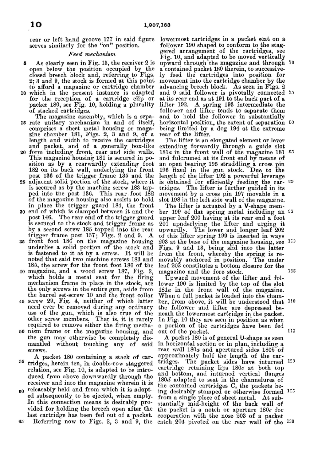
Feed mechanism
В As clearly seen in Fig. 15, the receiver 2 is
open below the position occupied by the
closed breech block and, referring to Figs.
2; 3 and 9, the stock is formed at this point
to afford a magazine or cartridge chamber
10 which in the present instance is adapted
for the reception of a cartridge clip or
packet 180, see Fig. 10, holding a plurality
of stacked cartridges.
The magazine assembly, which is a sepa-
16 rate unitary mechanism in and of itself,
comprises a sheet metal housing or maga-
zine chamber 181, Figs. 2, 3 and 9, of a
length and width to receive the cartridges
and packet, and of a generally box-like
20 form including front, rear and side walls.
This magazine housing 181 is secured in po-
sition as by a rearwardly extending foot
182 on its back wall, underlying the front
post 136 of the trigger frame 135 and the
25 adjacent solid portion of the stock, where it
is secured as by the machine screw 183 tap-
ped into the post 136. This rear , foot 182
of the magazine housing also assists to hold
in place the trigger guard 184, the front
30 end of which is clamped between it and the
post 146. The rear end of the trigger guard
is secured to the stock and trigger frame as
by a second screw 185 tapped into the rear
trigger frame post 137; Figs. 2 and 9. A
35 front foot 186 on the magazine housing
underlies a solid portion of the stock and
is fastened to it as by a screw. It will be
noted that said two machine screws 183 and
185, the screw for the front foot 186 of the
40 magazine, and a wood screw 187, Fig. 2,
which holds a metal seat for the firing
mechanism frame in place in the stock, are
the only screws in the entire gun, aside from
the barrel set-screw 10 and the front collar
45 screw 29, Fig. 4, neither of which latter
need ever be removed during any ordinary
use of the gun, which is also true of the
other screw members. That is, it is rarely
required to remove either the firing mecha-
50 nism frame or the magazine housing, and
the gun may otherwise be completely dis-
mantled without touching any of said
screws.
A packet 180 containing a stack of car-
55 tridges, herein ten, in double-row staggered
relation, see Fig. 10, is adapted to be intro-
duced from above downwardly through the
receiver and into the magazine wherein it is
e0 releasably held and from which it is adapt-
ed subsequently to be ejected, when empty.
In this connection means is desirably pro-
vided for holding the breech open after the
last cartridge has been fed out of a packet.
65 Referring now to Figs. 2, 3 and 9, the
lowermost cartridges in a packet seat on a
follower 190 shaped to conform to the stag-
gered arrangement of the cartridges, see
Fig. 10, and adapted to be moved vertically
upward through the magazine and through 70
a contained packet 180 therein, to successive-
ly feed the cartridges into position for
movement into the cartridge chamber by the
advancing breech block. As seen in Figs. 2
and 9 said follower is pivotally connected 75
at its rear end as at 191 to the back part of a
lifter 192. A spring 193 intermediate the
follower and lifter tends to separate them
and to hold the follower in substantially
horizontal position, the extent of separation co
being limited by a dog 194 at the extreme
rear of the lifter.
The lifter is an elongated element or lever
extending forwardly through a guide slot
181a in the front Avail of the magazine 181 C5
and fulcrumed at its front end by means of
an open bearing 195 straddling a cross pin
196 fixed in the gun stock. Due to the
length of the lifter 192 a powerful leverage
is obtained for efficiently feeding the car- co
tridges. The lifter is further guided in its
movement by a cross pin 197 movable in a
slot 198 in the left side wall of the magazine.
The lifter is actuated by a V-shape mem-
ber 199 of flat spring metal including an C5
upper leaf 200 having at its rear end a foot
201 upnderlying the lifter and urging it
upwardly. The lower and longer leaf 202
of this lifter spring 199 is inserted in ways
203 at the base of the magazine housing, see 133
Figs. 9 and 13, being slid into the latter
from the front, whereby the spring is re-
movably anchored in position. The under
leaf 202 constitutes a bottom closure for the
magazine and the fore stock. ic3
Upward movement of the lifter and fol-
lower 190 is limited by the top of the slot
181a in the front wall of the magazine.
When a full packet is loaded into the cham-
ber, from above, it will be understood that 110
the follower and lifter are depressed be-
neath the lowermost cartridge in the packet.
In Fig. 10 they are seen in position as when
a portion of the cartridges have been fed
out of the packet. 113
A packet 180 is of general U-shape as seen
in horizontal section or in plan, including a
rear wall 180a and apertured sides 180& of
approximately half the length of the car-
tridges. The packet sides have inturned 129
cartridge retaining lips 180c at both top
and bottom, and inturned vertical flanges
180«rZ adapted to seat in the channelures of
the contained cartridges C, the packets be-
ing desirably stamped or otherwise formed 123
from a single piece of sheet metal. At sub-
stantially mid-height of the back wall of
the packet is a notch or aperture 180c for
cooperation with the nose 203 of a packet
catch 204 pivoted on the rear wall of the 130
1,007, led
11
magazine as at 205, Figs. 2 and 9, and hav-
ing a finger piece 206. A leaf spring 207
attached at its lower end to the base of the
magazine housing tends to throw the nose
5 of this latch forwardly, into its holding
position as in Fig. 9. A packet as described,
with its load of cartridges, may be inserted
either end foreinostj the catch aperture 204
being c operable with the packet catch in
io either position, and since there is an even
number of cartridges, and they are loaded
into the packet, at the arsenal or elsewhere,
with the stack at the same selected side of
the packet uppermost, depending on the for-
15 niation of the follower 190, the lowermost
cartridges accordingly will always seat
properly on the follower. In a related ap-
plication I disclose and claim lifter and fol-
lower means operable with packets loaded
with the top cartridge either at the left or
at the right.
It will be understood that a full packet
is loaded into the magazine from above and
depressed until the catch 204 snaps into the
£5 packet aperture 180e. The packet and con-
tents are thus held down in the chamber or
magazine, but a full or partly emptied pack-
et map readily be removed by inverting the
gun and releasing the catch by manipulation
co of its finger piece 206, whereupon the packet
and any contained cartridges may be
dropped out or withdrawn in the reverse
manner from which they are inserted.
The described feed mechanism preferably
S5 also includes means whereby the breech is
held open after the last cartridge has been
fed from the packet and fired. Referring
to Figs. 2 and 13, I have provided for this
purpose a breech catch 210 slidably sup-
40 ported at the outer face of one side wall of
the magazine housing 181, as by means of a
slot 211, herein in the right hand wall of the
latter, and a cooperating stud 212 on the
breech catch. A relatively light coil spring
45 213 secured at its lower end to the maga-
zine and at its upper end to the breech catch
tends to hold the latter down, in its position
substantially as in said Figs. 2 and 13. At
its upper end the breech catch 210 is formed
60 with a rearwardly directed hook 214 which
lies above and in the path of the cross pin
197 of the lifter 192.
In Fig. 2 a single cartridge remains to
be fed from the packet. When the lifter
55 reaches its uppermost position, attendant
upon feeding out of this last cartridge, it
rises into contact with the hook 214 of the
breech catch and bodily lifts the latter. This
causes a shoulder or catch proper 215, Figs.
’Э 2 and 13, on the breech catch to be raised
into the path of the action slide, where it
will engage in the notch 216, see Figs. 21
and 23, in the bottom of one fork, herein the
right fork, of the action slide, as the latter
. comes back into breech opening position.
The slide and breech are thus automatically
caught and held back by the elevated catch
member 215. The breech catch desirably is
provided with a lateral operating piece 217,
by manual depression of which the slide 70
and block may be released to allow them to
close.
In the illustrated construction the empty
packet is ejected, through the bottom of the
magazine, in the process of inserting a fresh 75
packet. The bottom of the magazine is open
below the packet but, as best seen in Figs.
2 and 10, is normally closed by a pair of
opposed spring doors or flaps 220. One such
flap or packet-ejection door is mounted on 80
each side of the magazine housing, as by the
pins 221 projecting from the latter and re-
ceived in corresponding apertures in the
doors. These doors are held in closed posi-
tion, as shown by the full lines in Fig. 10, 85
by flat spring members 222 fastened upon
the outer sides of the magazine and overly-
ing the upper portions of the doors as clear-
ly seen in Fig. 2. The doors may be bodily
removed from the magazine housing merely 00
by turning them outwardly sufficiently to
disengage them from the pins 221.
As a fresh packet is thrust down into the
magazine, it automatically pushes out and
ejects the empty packet, which cams open 05
the ejection doors 220 in the manner indi-
cated by the dotted lines at the bottom of
Fig. 10, and is expelled. The doors immedi-
ately spring closed, sealing the bottom of
the magazine against entrance of dirt and ICO
the like. It will be seen by reference to
Figs. 9 and 10 that the underleaf 202 of the
lifter spring extends rearwardly through
substantially the entire length of the maga-
zine and forms in effect a bottom or closure Ю5
therefor, except for the relatively narrow
areas at each of its rear sides necessary for
the downward passage of the packet sides,
which openings are effectively closed by the
spring doors 220. no
Hand operating maechaniem,
The gun as above described is semi-auto-
matic in its operation, automatically open-
ing, loading and closing so long as a car- П5
tridge remains in the packet in the maga-
zine, requiring only a pull of the trigger to
effect successive shots up to the capacity of
the pocket, or, if desired, plus one cartridge
carried in the firing chamber. As previous- l-0
ly noted, it may be adapted for full auto-
matic operation, including actual firing, if
desired. In addition, means is desirably
provided whereby the gun may be operated
manually, in the manner of the ordinary I2j
Springfield rifle, should the gas mechanism
for any reason become disabled or if it is
desired to dispense with the latter, and also
to provide for manual opening of the breech
when required. 130
12
1,907,163
Б
10
16
20
26
30
35
40
45
50
55
60
65
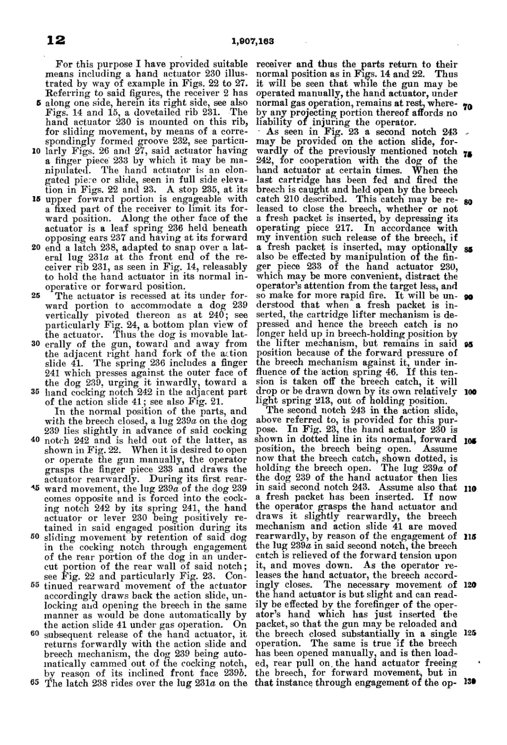
For this purpose I have provided suitable
means including a hand actuator 230 illus-
trated by way of example in Figs. 22 to 27.
Referring to said figures, the receiver 2 has
along one side, herein its right side, see also
Figs. 14 and 15, a dovetailed rib 231. The
hand actuator 230 is mounted on this rib,
for sliding movement, by means of a corre-
spondingly formed groove 232, see particu-
larly Figs. 26 and 27, said actuator having
a finger piece 233 by which it may be ma-
nipulated. The hand actuator is an elon-
gated piece or slide, seen in full side eleva-
tion in Figs. 22 and 23. A stop 235, at its
upper forward portion is engageable with
a fixed part of the receiver to limit its for-
ward position. Along the other face of the
actuator is a leaf spring 236 held beneath
opposing ears 237 and having at its forward
end a latch 238, adapted to snap over a lat-
eral lug 231a at the front end of the re-
ceiver rib 231, as seen in Fig. 14, releasably
to hold the hand actuator in its normal in-
operative or forward position.
The actuator is recessed at its under for-
ward portion to accommodate a dog 239
vertically pivoted thereon as at 240; see
particularly Fig. 24, a bottom plan view of
the actuator. Thus the dog is movable lat-
erally of the gun, toward and away from
the adjacent right hand fork of the action
slide 41. The spring 236 includes a finger
241 which presses against the outer face of
the dog 239, urging it inwardly, toward a
hand cocking notch 242 in the adjacent part
of the action slide 41; see also Fig. 21.
In the normal position of the parts, and
with the breech closed, a lug 239a on the dog
239 lies slightly in advance of said cocking
notch 242 and is held out of the latter, as
shown in Fig. 22. When it is desired to open
or operate the gun manually, the operator
grasps the finger piece 233 and draws the
actuator rearwardly. During its first rear-
ward movement, the lug 239a of the dog 239
comes opposite and is forced into the cock-
ing notch 242 by its spring 241, the hand
actuator or lever 230 being positively re-
tained in said engaged position during its
sliding movement by retention of said dog
in the cocking notch through engagement
of the rear portion of the dog in an under-
cut portion of the rear wall of said notch;
see Fig. 22 and particularly Fig. 23. Con-
tinued rearward movement of the actuator
accordingly draws back the action slide, un-
locking and opening the breech in the same
manner as would be done automatically by
the action slide 41 under gas operation. On
subsequent release of the hand actuator, it
returns forwardly with the action slide and
breech mechanism, the dog 239 being auto-
matically cammed out of the cocking notch,
by reason of its inclined front face 239Z».
The latch 238 rides over the lug 231a on the
receiver and thus the parts return to their
normal position as in Figs. 14 and 22. Thus
it will be seen that while the gun may be
operated manually, the hand actuator, under
normal gas operation, remains at rest, where-
by any projecting portion thereof affords no
liability or injuring the operator.
As seen in Fig. 23 a second notch 243 -
may be provided on the action slide, for-
wardly of the previously mentioned notch yg
242, for cooperation with the dog of the
hand actuator at certain times. When the
last cartridge has been fed and fired the
breech is caught and held open by the breech
catch 210 described. This catch may be re- go
leased to close the breech, whether or not
a fresh packet is inserted, by depressing its
operating piece 217. In accordance with
my invention such release of the breech, if
a fresh packet is inserted, may optionally go
also be effected by manipulation of the fin-
ger piece 233 of the hand actuator 230,
which may be more convenient, distract the
operator’s attention from the target less, and
so make for more rapid fire. It will be un- go
derstood that when a fresh packet is in-
serted, the cartridge lifter mechanism is de-
pressed and hence the breech catch is no
longer held up in breech-holding position by
the lifter mechanism, but remains in said 05
position because of the forward pressure of
the breech mechanism against it, under in-
fluence of the action spring 46. If this ten-
sion is taken off the breech catch, it will
drop or be drawn down by its own relatively 100
light spring 213, out of holding position. ~
The second notch 243 in the action slide,
above referred to, is provided for this pur-
pose. In Fig. 23, the hand actuator 230 is
shown in dotted line in its normal, forward до
position, the breech being open. Assume
now that the breech catch, shown dotted, is
holding the breech open. The lug 239a of
the dog 239 of the hand actuator then lies
in said second notch 243. Assume also that no
a fresh packet has been inserted. If now
the operator grasps the hand actuator and
draws it slightly rearwardly, the breech
mechanism and action slide 41 are moved
rearwardly, by reason of the engagement of 115
the lug 239a in said second notch, the breech
catch is relieved of the forward tension upon
it, and moves down. As the operator re-
leases the hand actuator, the breech accord-
ingly closes. The necessary movement of 120
the hand actuator is but slight and can read-
ily be effected by the forefinger of the oper-
ator’s hand which has just inserted tbe
packet, so that the gun may be reloaded and
the breech closed substantially in a single 125
operation. The same is true if the breech
has been opened manually, and is then load-
ed, rear pull on. the hand actuator freeing
the breech, for forward movement^ but in
that instance through engagement of the op- 13»
1,907,163 IS
erator dog in the front cocking notch 242 of
the action slide. When the second notch 243
is used in the manner described, the lug 239a
of the dog 239 is automatically moved back
6 out of said notch, to allow the action slide
to move forward to its closed position as in
Fig. 22, by engagement of the inclined front
face 239& of said lug with an appropriate
cam 244 on the receiver; Figs. 14 and 15.
My invention is not limited to the partic-
ular embodiment thereof herein shown and
described, its scope being pointed out in the
following claims.
I claim:
15 1. In an automatic gun having a receiver,
a barrel and breech mechanism, in combina-
tion therewith, a gas port in the fore part
of the barrel, a piston, an enclosing housing
in which the piston is reciprocable, and
20 means mechanically connecting the piston
and the breech mechanism, said piston hav-
ing a hollow gas-receiving portion for sub-
stantially its entire length and being open
at its front end, and having a gas port at
26 approximately mid length registering with
the barrel port in the forward or firing posi-
tion of the parts, said piston port being
opened to atmosphere at or near the rear or
fired position of the piston, and said hous-
30 ing having a port normally closed but
opened to atmosphere by the passage of the
piston to the rear thereof, during or just
prior to the opening of said piston port, the
cubic content of the hollow piston portion
35 being at least one-half that of the bore of the
barrel.
2. In an automatic gun, a receiver, a bar-
rel, breech mechanism, and gas-operable ac-
tuating means mechanically associated with
40 the breech mechanism, including a hollow
elongated piston ported at its mid-length
portion to receive gas from the fore part
of the barrel and having a cubic content not
less than approximately one-half that of the
45 barrel bore.
3. In an automatic gun, a receiver, a bar-
rel, breech mechanism, and gas-operable ac-
tuating means mechanically associated with
the breech mechanism, including a hollow
piston to receive gas from the fore part of
the barrel and having a cubic content not
less than approximately one-half that of
the barrel bore, and provisions for exhaust-
ing the gas from the piston substantially
E5 simultaneously at longitudinally spaced
points as the piston approaches its fired
position.
4. In a firearm, a ported barrel, a gas-
tube adjacent the barrel, having a port
60 adapted to connect with the barrel port, a
piston mechanically associated with the
breech mechanism, and having a gas-port
and a relatively large expansion-chamber,
said piston adapted to coact with the gas-
65 tube so as to provide, approximately at the
end of its rearward stroke, a substantially
complete exhaustion of the gas from the
piston chamber.
5. In an automatic gun, in combination
with a receiver, a barrel and breech mech- TO
anism; a gas tube, a hollow piston mov-
able in the gas tube, having a port for the
intake of gas from the fore part of the bar-
rel, a removable front cap for the gas tube,
an action slide connected with the breech TO
mechanism, and interengageable lugs at the
adjacent ends of the action slide and piston
disconnectable by relative movement of the
slide and the piston, whereby the latter is
mechanically engaged with the action slide 80
but may be dismounted upon removal of said
gas tube front cap, without disturbing other
parts. >
6. In an automatic gun, in combination
with a receiver, a barrel and breech mech- 86
anism; a gas tube, a hollow piston movable
in the gas tube, having a port for the intake
of gas from the fore part of the barrel, a
removable front cap for the gas tube, an
action slide connected with the breech mech- 00
anism, and interengageable lugs at the
adjacent ends of the action slide and piston,
whereby the latter is mechanically engaged
with the action slide but may be dismounted
upon removal of said gas tube front cap, 06
without disturbing other parts, the gas tube
a^so being readily demountable, and the gun
being hand-operable in the absence of the
piston and/or the gas tube.
7. In a gun, a receiver, a non-rotary 10®
breech block longitudinally movable therein,
a lock movable transversely but held against
longitudinal movement in the receiver, sets
of locking lugs operable between the receiv-
er and the lock and between the latter and 105
the block, an action slide, cam connections
between the slide and lock to shift the latter
to unlocking and to locking position re-
spectively at the beginning of the rear move-
ment and at the end of the forward move- 110
ment of the slide, and means operatively
intermediate the slide and block to effect
longitudinal movement of the latter, includ-
ing a latch movable with the block and also
slidable relatively thereto to permit rela- 116
tive longitudinal movement between the slide
and block during said shifting of the lock
but interconnecting the slide and block for
movement in unison at other times.
8. In a gun having a receiver and barrel, 120
a longitudinally movable non-rotary breech
block, guides for the block on the receiver
and adapted to hold the block against trans-
verse movement, a transversely movable
lock held against longitudinal movement in 126
the receiver, an actuating element adapted
to move the lock transversely and to move
the block longitudinally, a yoke-like ele-
ment movaby associated with the block, and
co-operating means on the receiver for mov- 130
14
1,907,163
10
15
20
25
SO
35
40
45
50
55
60
65
ing said yoke-like element operatively to
connect and disconnect the block and the
actuating element for movement in unison
or relatively to each other respectively.
9. In a gun having a receiver and barrel,
a longitudinally movable non-rotary breech
block, guides for the block on the receiver
and adapted to hold the block against trans-
verse movement, a transversely movable lock
held against longitudinal movement in the
receiver, an actuating element adapted to
move the lock transversely and to move
the block longitudinally, and a transversely'
shiftable connecting and disconnecting ele-
ment operatively intermediate the block and
the actuating element, the block and said
transversely movable lock having a like plu-
rality of substantially rectangular cooperat-
ing locking lugs symmetrically disposed
thereon and of major dimension and mass
lengthwise the barrel, to resist shearing
action.
10. In a gun having a receiver and barrel,
a longitudinally movable breech block, an
actuator therefor, a connecting element on
and movable both with and relatively to the
breech block operatively to connect and dis-
connect the block and actuator at certain
times, a firing pin longitudinally movable in
the block, and interengageable means be-
tween said connecting element and the firing
pin.
11. In a gun of the class describedy in
combination, a receiver, a barrel, a recipro-
cating breech block, an automatically op-
erated actuator element for controlling and
operating the breech block, cartridge feed-
ing means, a breech catch to hold open the
breech when the last cartridge has been fired,
a manual lever having a normal inoperative
position but adapted to operate said actua-
tor element, means whereby the breech catch
may be released from breech-holding posi-
tion by manipulation of said manual lever
when a fresh cartridge supply has been in-
serted in the gun, and other means to re-
lease the breech catch.
12. In a gun of the class described, firing
mechanism including a frame, a sear piv-
oted thereon, a trigger pivoted on the frame,
a connector having connecting and discon-
necting positions with respect to the trigger
and sear, and cartridge ejector means at the
fore part of the connecter,
13. In a gun of the class described, firing
mechanism including a frame, a sear pivoted
thereon, a trigger pivoted on the frame, and
an elongated substantially horizontally dis-
posed connector operatively interposed be-
tween the sear and trigger, said connector
having rear and intermediate points of sup-
port on the frame and having a fore part
engageable with the sear to actuate the same
when in line therewith, the connector and
its support being constructed and arranged
to provide for bodily longitudinal move-
ment of the connector for sear-actuating
purposes, and vertical movement thereof for
disconnecting purposes.
14. In a gun of the class described, in 70
combination with a breech block’, actuating
means therefor, and a firing pin movable in
the breech block, a sear to hold the firing
pin cocked, a pivoted trigger, an elongated
substantially horizontal connector element 76
intermediate the sear and trigger operative-
ly to connect or ’ disconnect them, said ele-
ment supported for longitudinal sliding
movement by the trigger to effect release
of the sear and also for vertical swinging 80
movement, to disconnecting or connecting
position, means compelling the trigger to be
released to effect operative positioning of
the connector and sear after each actuation,
and automatic means associated with the 86
breech actuating means to retain the connec-
tor element in disconnecting position dur-
ing opening and closing of the breech.
15. In a gun of the class described, in com-
bination with a breech block, actuating 90
means therefor, and a firing pin movable
in the breech block, a sear to hold the firing
pin cocked, a pivoted trigger, a connector
element intermediate the sear and trigger
operatively to connect or disconnect them, 05
said element supported for longitudinal slid-
ing movement by the trigger to effect release
of the sear and also for vertical swinging
movement, to disconnecting or connecting
position, means compelling the trigger to be 100
released to effect operative positioning of
the connector and sear after each actua-
tion, automatic means associated with the
breech actuating means to retain the connec-
tor element in disconnecting position during 105
opening and closing of the breech, and means
whereby automatic opening of the breech in-
sures return of the connector to its original
position longitudinally of the gun.
16. In an automatic gun, in combination :1°
with a receiver and barrel, a magazine
adapted to receive a packet holding a plu-
rality of cartridges, feed mechanism to move
the cartridges successively from the packet
for firing, and a packet ejection formation
and closure means therefor arranged nor-
mally to close the ejection formation and
openable for the passage of an empty packet
upon insertion of a fresh packet.
17. In a gun of the class described, in ~20
combination with a receiver, a barrel, and
breech mechanism, a chamber adapted to
receive a plural-cartridge packet from above,
a down exit for the emptied packet, and
means normally closing said exit but open- 125
able by depressing the emptied packet to
eject it.
18. In a gun of the class described, in com-
bination with a receiver, a barrel, and breech
mechanism, a chamber adapted to receive a 130
1,907,163
15
5
10
15
20
25
30
35
40
45
50
СЭ
CJ
plural-cartridge packet from above, a down
exit for the emptied packet, means normally
closing said exit but openable by depressing
the emptied packet to eject it, and means
automatically reclosing said exit.
19. In a gun of the class described, in com-
bination with a receiver, a barrel, a stock
and breech mechanism, a chamber adapted
to receive a plural-cartridge packet from
above, a down exit for the emptied packet,
and spring-pressed closure means for said
packet exit, said chamber, exit, and closure
means contained within the stock.
20. In a gun of the class described, in
combination with a receiver, a barrel, and-
breech mechanism, a chamber adapted to
receive a plural-cartridge packet from above,
a down exit for the emptied packet, and
manually operable exit closure means nor-
mally spring closed.
21. In a gun of the class described, in com-
bination with a stock, a receiver and breech
mechanism, a magazine chamber below the
fore part of the receiver, a cartridge fol-
lower vertically movable in said chamber,
an elongated lifter-arm for the follower
extending forwardly through the front wall
of the magazine chamber and having an
open bearing at its fore end, a pin in the
stock providing a fixed pivot for said bear-
ing, and spring means for said lifter-arm
forwardly of the magazine chamber.
22. In a gun of the class described, in com-
bination with a stock, a receiver and breech
mechanism, a sheet-metal casing below the
fore part of the receiver providing a cham-
ber for a double stack of cartridges, a ver-
tically movable follower in said casing, an
elongated lifter pivoted at its rear end to
said follower and projecting forwardly
through a front opening in said casing, a
fixed pivot for the fore end of said lifter
substantially forward of the casing, guide
means on the casing and a cooperating guide
portion on the lifter, and a lifter spring in
advance of the casing.
23. In a gun of the class described, in
combination with a stock, a receiver and
breech mechanism, a sheet-metal casing be-
low the fore part of the receiver providing
a chamber for a double stack of cartridges,
a vertically movable follower in said cas-
ing, an elongated lifter pivoted at its rear
end to said follower and projecting for-
wardly through a front opening in said cas-
ing, a fixed pivot for the fore end of said
lifter substantially forward of the casing,
guide means bn the casing and a cooperating
guide portion on the lifter, and a lifter
spring in advance of the casing, said spring
being removable and affording access to the
fore part of the lifter, and said lifter and
follower being demountable as one unit and
said casing and supporting parts as a sec-
ond unit.
24. In a gun of the class described, in com-
bination with a stock, a receiver and breech
mechanism, a sheet-metal casing below the
fore part of the receiver and open at the
top for the loading reception of a clip con-
taining a plurality of stacked cartridges,
said casing having a bottom opening for
the ejection of an emptied clip, laterally
yieldable closure means for said bottom
opening, and spring means normally hold-
ing said means closed.
25. In a gun of the class described, in
combination with a stock, a receiver and
breech mechanism, a sheet-metal casing be-
low the fore part of the receiver and open
at the top for the loading reception of a clip
containing a plurality of stacked cartridges,
said casing having a bottom opening for
the ejection of an emptied clip, closure mem-
bers on the casing movable toward and
away from each other to close or to expose
said bottom opening, and spring means urg-
ing said members into closing position.
26. In a gun of the class described, in
combination with a stock, a receiver and
breech mechanism, a sheet-metal casing be-
low the fore part of the receiver and open
at the top for the loading reception of a
clip containing a plurality of stacked car-
tridges, said casing having a bottom open-
ing for the ejection of an emptied clip, mov-
able closure means for said bottom opening,
and spring means normally holding said
means closed, said closure means constructed
and arranged to be opened by and to release
an emptied clip in the operation of insert-
ing a fresh clip.
27. In a firearm, in combination, a re-
ceiver, a barrel, a reciprocating breech-bolt
for the barrel, an automatically actuated re-
ciprocating member for controlling and
operating the breech-bolt, a manual lever
wherewith to operate said member, said le-
ver slidably supported on the receiver and
being movable into an operatively engaged
position or into a normal disengaged posi-
tion wherein it remains at rest during auto-
matic operation of the firearm, and means
positively retaining said lever in engaged
position during operative sliding movement
thereof.
28. In a firearm, in combination, a barrel,
a reciprocating breech-block for the barrel,
a reciprocating member for controlling and
operating the breech-block, and a manual
lever wherewith to operate said member,
said lever being guided for reciprocating
movement and having an operative position
and a normal inoperative position, and
means automatically to return it to inopera-
tive position at the end of a breech opening
and closing movement thereof.
29. In a gun of the class described, a re-
ciprocable breech closure including a block
and operating means therefor, a magazine
70
76
80
86
90
95
100
105
110
115
120
125
130
1,907,163
-1 gs
л. О
below the path of the block, a Cartridge
loader or packet receivable in the magazine,
lifter means to feed cartridges from the
loader into the path of the block, a nor-
6 mally inoperative breech catch to hold the
closure open, means on said lifter means to
pdsition the breech catch for holding en-
gagement with the closure when the last
cartridge has been fed out of the loader or
10 packet, said means constructed and arranged
to leave the breech catch in said holding en-
ч gagement after insertion of a fresh loader
or packet, and independent manual means
to release said catch at the will of the opera-
15 tor.
30. In, a gun of the class described, a bar-
rel, a receiver therefor, a breech-closure unit
including a reciprocating block carrying a
firing-pin, an extractor and extractor spring
20 and an action-connecting element movable
relatively to the block, an openable receiver
cap adapted to close the rear portion of the
receiver, said breech-closure unit being bod-
ily removable from the receiver in the open
25 position of said cap, the receiver and barrel
being then wholly exposed at the rear in
direct prolongation of the axis of the bore,
for cleaning and inspection purposes.
31. In a gun having a receiver and a bar-
сэ rel, a longitudinally reciprocable breech
block, actuating means therefor, an element
movably carried by the block and having
different positions relative to it, as controlled
by sajd actuating means, in closed and non-
closed positions of the block, a firing pin
longitudinally movable in the block, and a
lateral projection on said block-carried ele-
ment adapted to be engaged with or disen-
z gaged from the firing pin in non-closed and
*э closed positions of the block respectively, to
prevent fire-effecting advance of the firing
pin in a non-closed position of the block.
. 32. In a gun of the class described, re-
ciprocating breech closure mechanism in-
eluding a breech block having a firing-pin
longitudinally movable therein, a sear en-
gageable with the firing-pin for holding it
cocked or releasing it, a trigger, a discon-
nector element between the sear and trigger
,'э for operatively connecting or disconnecting
them, and safety means for moving said
disconnector element to and holding it in
disconnecting position, and for simultane-
r_ ously locking the sear in cocking position
with respect to the firing-pin.
In testimony whereof, I have signed my
name to this specification.
rn JOSEPH C. WHITE.
65