/


Теги: weapons military affairs patent
Год: 1907


Текст
No. 862,384.
PATENTED AUG. 6, 1907.
M. L. BRISTOL.
AUTOMATIC GUN.
No. 862,384.
PATENTED AUG. 6, 1907.
M. L. BRISTOL.
AUTOMATIC GUN.
APPLICATION Filed NOV. 1, 1904.
4 SHEETS-SHEET 2.
No. 862,384.
PATENTED AUG. 6, 1907.
M. L. BRISTOL.
AUTOMATIC GUN.
APPLICATION FILED NOV. 1, 1904.
4 SHEETS-SHEET 3.
пввеев
Inventor
No. 862,384.
PATENTED AUG. 6, 1907.
M. L. BRISTOL.
AUTOMATIC GUN.
APPLICATION FILED NOV. 1, 1904.
4 SHEETS—SHEET 4.
UNITED STATES PATENT OFFICE.
MORTIMER L. BRISTOL, OF WEST HARTFORD, CONNECTICUT, ASSIGNOR TO COLT’S PATENT
FIRE ARMS MANUFACTURING COMPANY, OF HARTFORD, CONNECTICUT, A CORPORATION
OF CONNECTICUT.
AUTOMATIC GUN.
No. 862,384. Specification of Letters Patent. Patented Aug. 6,1907.
Application filed November 1,1904. Serial No. 230,939.
б
10
15
20
25
30
35
40
45
50
To all whom it may concern:
Be it known that I, Mohtimeh L. Bristol, a citizen
of the United States, residing at West Hartford, in the
county of Hartford and State of Connecticut, have in-
vented certain new and useful Improvements in Auto-
matic Guns, of which the following is a specification,
reference being had to .the accompanying drawings,
forming a part hereof.
This invention relates to improvements in that class
of automatic guns known as “recoil-operated guns”.
In the arms of this class the pressure of the gases gen-
erated in the barrel by the explosion of the powder-
charge of a cartridge, expended in forward direction in
the propulsion of the bullet through and from the bore
of the barrel, is in rearward direction utilized to pro-
duce the rearward movement of the breech-block, and,
the barrel being at the time of firing interlocked there-
with, of the barrel. During the rearward movement,
or recoil, of these parts, the excess of energy of recoil
is stored in suitable means which yieldingly support
the breech-block and the barrel in their forward posi-
tion, and at the end of their recoil return these parts to
their forward, firing position. During this reciprocat-
ing movement of the barrel and the breech-block the
entire cycle of functions of the breech-mechanism is
automatically performed; the breech is opened, the
empty cartridge-case is extracted from the chamber and
ejected from the gun, a charged cartridge is presented
in position for introduction into the chamber of the bar-
rel, the firing mechanism is cocked, the charged car-
tridge is thrust into the chamber, the breech is closed
and securely locked and the firing mechanism is re-_
leased to explode the cartridge. The energy of recoil
is thus prevented from exerting itself disturbingly upon
the gun and its mount by being absorbed and utilized
in effecting the operations of the breech-mechanism
of the arm, and in automatically producing rapid suc-
cessive firing; it being only necessary to furnish a sup-
ply of cartridges, to thrust in and fire the first cartridge
by hand in the gun, which then automatically contin-
ues the operations so long as cartridges are supplied.
The object of this invention is to produce a gun pro-
vided with a simple and efficient mechanism to be ac-
tuated by the gas-pressure in the barrel, to interlock
the barrel and the breech-block of the arm in their fir-
ing position, to support and guide them while recoiling
still locked together, to unlock them at the end of the
recoil, to return them separately to their forward posi-
tion, and during the return movement to open the breech
and to perform all of the functions preparatory to firing
another shot, and finally, at will, to fire the gun.
Another object of this invention is to produce an au-
tomatic gun provided with reliable means for at all
times controlling the rapid automatic firing of the arm
by at will interrupting the operations of not only the 55
cocked firing-mechanism, as has been heretofore the
usual arrangement for this purpose in the arms of this
class, but by at will interrupting the operations of the
breech-mechanism at the time when the breech is fully
opened and before a charged cartridge has been thrust 60
into the barrel. This arrangement positively averts
the serious danger of uncontrollable firing continuing
unchecked even though the operations of the fifing
mechanism are arrested, which danger exists in guns
in which the control of firing depends upon at will re: 65
leasing the cocked firing mechanism so as to allow it to
strike upon the primer of the cartridge in the barrel the
igniting blow, or at will preventing the ignition by re-
taining the firing mechanism in cocked position. By
continued rapid firing the barrel of a gun becomes 70
heated to such a degree that the powder chaige of a car-
tridge inserted therein will be ignited by the heat trans-
mitted to it, and the fifing will be continued even
though no .percussion upon the primer occurs. In
order to positively control the firing even under these 75
conditions, so as to be able to stop the firing and also to
start it again without delay, it is required to prevent at
will the thrusting of a charged cartridge into the heated
barrel, but yet to hold a cartridge in the gun ready to
be thrust in and to be exploded. To entirely cut off 80
the supply of cartridges from the gun would not result
in the desired control, because, while this would arrest
the firing, it, would also prevent the firing from being
instantly recommenced at will, as some time and man-
ual operations would be required to again supply car- 85
tridges to the gun and to carry the first cartridge in the
gun forward to the position where it is presented ready
to be thrust into the chamber of the barrel.
The invention consists in certain improved construc-
tions, more particularly set forth in the claims herein- 90
after following and forming a part of this specification,
and in the combination of parts and mechanisms and
their operations hereinafter described and illustrated
in the accompanying drawings in which—
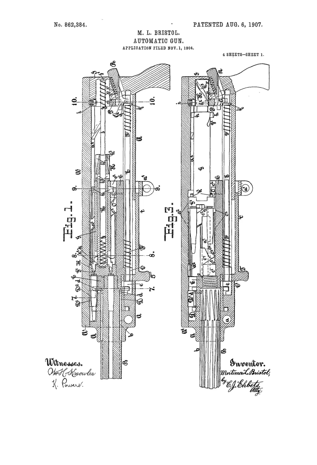
Figure 1 is a longitudinal, vertical section of the rear 95
portion of the gun, showing the breech-mechanism in
the closed position. Fig. 2 is a section similar to Fig. 1,
but showing the barrel and the breech-mechanism in
the rearmost position which they have at the end of
their recoil, and before.the barrel is returned forward. 100
Fig. 3 is a section similar to Fig. 1, but showing the
barrel and the inner frame returned to the forward po-
sition, and the breech-block in the rearmost position.
Fig. 4 is a vertical, transverse section of the gun on the
line 7—7 of Fig. 1, looking forward, showing the feed- 105
wheel and the feed-belt in rear-view. Fig. 5 is a verti-
cal, transverse section on the line 8—8 of Fig. 1, looking
forward. Fig. 6 is a vertical, transverse section on the
809,304
5
10
15
20
25
30
35
40
45
50
55
60
65
line 9—9 of Fig. 1, looking forward. Fig. 7 is a vertical,
transverse section on the line 10—10 of Fig. 1, looking
forward, Showing the vertical cam-pins in rear-view.
Fig. 8 is a vertical, transverse section on the line 11—11
of Fig. 2, lookthg forward. Fig. 9 is a detached per-
spective view of the rear portion of the barrel and of the
inner frame. Fig. 10 is a detached perspective view of
the breech-block, showing the breech-bolt and the rear
end of the bolt-tube. Fig. 11 is a detached perspec-
tive view of the head of the breech-bolt, showing the
front face and one side of it. Fig. 12 is a partial, longi-
tudinal section on the line 15—15 of Fig. 6, showing the
firing mechanism. Fig. 13 is a partial, horizontal sec-
tion on the line 16—16 of Fig. 12, showing a plan of the
firing mechanism. Fig. 14 is a detached front-view of
the hammer and sear, and of the vertical stud of the
bolt-tube. Fig. 15 is a rear view of the gun. Fig. 3a,
represents a partial-longitudinal section of the casing,
cover and receiver, similar to Fig. 3, but with the
breech-bolt and the rod E left away, to show more clearly
the passage c° and the exit a7 for the ejection of the
cartridge-cases. Fig. 4° is a vertical, transverse sec-
tion showing the lower part of the barrel, feed-wheel,
casing and the rod E, similar to Fig. 4, but on an en-
larged scale. Fig. 41’, represents a side view and a top
vjew of the forward portion of the rod E detached, the
lowest two radial arms of the feed-wheel being shown
in section in the top view. Fig. a11. is a cross-section of
the casing, cover and receiver, similar to Fig. 5, but on
a line just in rear of the overhanging projection c7, and
with the breech-bolt left away, to more clearly show
the passage cG and the exit a7. Fig. 11“ is a longitudinal
section of the head of the breech-bolt, in the plane
through the axis of the pistons </
Similar letters refer to similar parts throughout the
several views.
The gun represented in the drawings as an embodi-
ment of the invention consists, in its Construction, of
four principal parts, the outer frame or casing A, the
barrel B, the inner frame or barrel-extension C and the
breech-mechanism. Of these the outer frame is sta-
tionary or non-recoiling, being provided with loops a,
a1, for its attachment upon the usual gun mount of a
gun-carriage or tripod.
The barrel В is firmly attached to the inner frame C
which thus forms a rearward extension of the barrel,
both the barrel В and the inner frame C are entered
from the rear into the casing A which securely sup-
ports and carries them, but in which they are fitted to
slide longitudinally, their movement being limited in
forward direction by the solid front end of the casing
A, and in rearward direction by the rear-plate I,'which
is removably secured in the casing, closes the same
and binds together its side walls. The central open-
ing in the front of the casing is surrounded by a circu-
lar boss through which the barrel extends and in which
the cylindrical rear portion of the barrel is guided.
The form of the casing A is that of a cylinder from the
top of which a segment has been removed in its entire
length, to give access to its interior. The parti-cylin-
drical cover A1 is fitted to the top of the casing and at-
tached thereto by the hinge and longitudinal hinge-
pin a3, on the right, and by a similar locking-pin a4 on
the left side. The cover A1 closes and strengthens the
casing being interlocked with both its side walls.
From the barrel rearward the left side of the cover A1
forms a tube-shaped seat in which the locking pin a4
is carried, and the left edge of the casing A has a lon-
gitudinal recess for its.reception, at, both ends the tube
-entirely incloses the locking-pin, but at intermediate 70
places of its length an outer segment of the tube and
the pin is cut away and the recess in the casing is
shaped to fit the remaining hook-shaped projection of
the cover and the flattened locking-pin, Figs. 5, 6 & 7.
On the rear end of the locking-pin a turn-button a5 is 7 5
fixed, which projects from the rear of the cover, by
upward pressure against this button the locking-pin is
turned on its longitudinal axis until the flattened part
of the pin clears the edge of the casing and releases the
cover, which then may be raised and turned^ to the 80
right, to open the gun-casing. When the turn-button
a6 is turned down the rotation' of the locking pin a4
causes1 it to enter a segmental recess in the left side wall
of the casing and thereby to securely lock the cover to
.the casing, Figs. 5, 6 & 7. To keep the turn-button 85 ‘
!a6 in the lower position, a small piston a° is fitted into
the cover over the turn-button and a spiral spring
presses the piston downward against the turn-button
and thus yieldingly holds the button and the locking-
pin in the locked position, Fig. 8. 90
In the casing A, between its front end and that of the
inner frame C, the cartridge-feed-wheel D is mounted
upon the barrel B, it consists of a cylinder having a
flange at each end in which a series of semi-circular
longitudinal grooves is cut. each groove separated 95
from the next by a radial projection. The seat for the
feed-wheel in the casing is open at the top, thc lower
portion forming a recess into which the feed-wheel D
. is introduced from above and wherein it is held by the
barrel passing through it, so that the feed-wheel may 100
revolve upon the barrel, but is prevented from moving
lengthwise by its forward flange fitting the recess in the
casing.
As shown in Fig. 4 the sides of the casing are cut
down at the feed-wheel and with the corresponding 105
under side of the cover form a transverse channel D1
through the gun, which extends some distance forward
and rearward .of the feed-wheel, excepting the open-
ing through the right side-wall of the casing which is
only as long as is the space between the flanges of the 110
feed-wheel. This channel serves for the1 introduction
of cartridges to the gun. The cartridges are contained
-in the pockets of the feed-belt D2 which inclose the
central part of them and from which both ends of the
cartridges project. The feed-belt is introduced into 115
the gun from the left side, led over the feed-wheel, and
out through the right side-opening in the casing. On
the feed-wheel the feed-belt occupies the space be-
tween the flanges, the projecting ends of the cartridges
fitting into the grooves in the flanges, so that by the 120
stepwise rotation of the feed-wheel from the left to the
right side the belt and the cartridges are drawn into the
gun, and, the topmost cartridge being withdrawn into
the receiver during each step of the rotation, the empty
feed-belt is ejected from the right side of the gun, Fig. 125
4. This construction of the feed-wheel and feed-belt
being a wellknown one, as applied to guns of this class,
it does not require to be further-specified.
The stepwise rotation of the feed-wheel is actuated
by the reciprocating movement of the barrel. For 130
86й,384
в
5
10
15
20
25
30
35
40
45
50
55
GO
65
this purpose a series of cam-grooves b, b, is cut in the
surface of the barrel upon which the feed-wheel is
mounted and two substantially opposite radial pins
<7. d, fixed in the feed-wheel project inward into the
cam-grooves of the barrel, the number of the cam-
grooves being equal to the number of grooves in the
flanges of the feed-wheel. As seen in Figs. 3 and 9,
each of the cam-grooves b, b, consists of two communi-
cating portions, of which one extends from near the
rear end of the barrel forward for some distance to a
point where it unites with the other portion of the
groove which extends further forward. The remain-
ing, uncut surface of the barrel between the grooves
b, b, forms two series of tongues or lands, one extending
from the rear and one from the front between the
grooves, and separating the same. Looking from the
rear towards the front of the barrel, the left hand edge
of each of these tongues, in the forward series as well as
in the rear series, is parallel to the axis of the barrel,
and the right hand edge of each tongue is inclined.
The right hand edges of the tongues in the rear series
incline’.forward and to the left side, while the right
hand edges of the tongues in the forward series incline
forward and to the right side, and the pointed front ends
of the rear tongues stand midway between the pointed
rear ends of the forward tongues, as shown in Figs. 3
and 9. From this description it will be plain, that,
when the cam-pin d stands in the rear end of one of the
grooves b, b, and the barrel is moved rearward through
the feed-wheel D, the cam-pin will not be moved lat-
erally while the left parallel edge of the rear tongue
passes by the pin, but when, during the rearward move-
ment of the barrel, the cam-pin enters the forward por-
tion of the cam-groove, it will be engaged by the in-
clined right edge of the forward tongue and the con-
tinued rearward movement of the barrel will move the
cam-pin d towards the right side, and thus rotate the
feed-wheel D from the left to the right side of the gun;
during the forward, return movement of the barrel the
cam-pin stands still while the left parallel edge of- the
forward tongue passes it, but when the point of the rear
tongue reaches it, the cam-pin will enter the rear por-
tion of the next groove to the right, and the inclined
right edge of the rear tongue will move the cam-pin d
to the right, thus further rotating the feed-wheel D to
the right side. When the barrel recoils the action of
the cam-grooves in its circumference on the cam pins
of the feed-wheel'causes the feed-wheel to be rotated
from the left to the right side about one-half of the dis-
tance between two successive grooves in the flanges,
and on the return or forward movement of the barrel
the feed-wheel is rotated in the same direction suffi-
ciently to complete one step; so that by each complete
rear and’ forward movement of the barrel the succeed-
ing cartridge on thc.'foecl-whecl is earned to the top-
most position, bringing its rearward projecting head
into the receiver and into the reach of the head of the
breech-block by which it will be grasped and the car-
tridge withdrawn rearward into the receiver and in-
troduced into the barrel.
The inner frame C also is cylindrical in form,-its for-
ward end incloses the breech-end of the barrel and a
lug C1 projects from the inner frame into a central lon-
gitudinal recess in the bottom of the casing A, and
servos to guide the barrel and inner frame during the
rear and forward movement therein and to prevent
their rotation. The forward end of the inner frame
surrounds the breech-end of the barrel, but from the
barrel rearward a segment has been removed from the
top of the inner frame, laying open the interior which 7 0
is fitted to receive the breech-block and to support and
guide it in its movements.
In the groove in the bottom of the casing the longi-
tudinal rod E is arranged for a limited rear and forward
movement, the forward end of the rod E is enlarged to 75
form the head e. The head e is cylindrical, concentric
with the rod E and fits into the groove in the bottom of
the casing. From the forward end- of the head e the
upper portion has been removed, the remaining seg-
ment fills the groove and its top surface corresponds 80
with the interior surface of the casing, so that it clears
the path of the radial arms or projections on the feed-
wheel D and does not interfere with the rotation of the
same, Figs. 4 & 4й. On this surface the head e carries
two projections e1 & e2, the front one e1 located at the 85
right and the rear one e2 at the left side of the axis of the
rod and head, as seen when looking forward, Figs. 4я,
& 4b; the width between the exterior sides of the pro- .
jections e1 & e2 on the head is equal to the distance be-
tween two contiguous arms of the feed-wheel, and the 90
width between the interior sides of the projections e1
& e2, is .equal to the width of each one of the radial
arms. When the rod E stands in its forward position,
as shown in Figs. 1 & 3, the two lowest radial arms of
the feed-wheel stand one at each side of the head e and 95
in line with the rear projection e2 of the head, so that
the right side of the left radial arm rests against the
exterior side of the projection e2, as shown in Figs. 4“ &
4b, thereby preventing backward rotation of the feed-
wheel; in Fig. 4b a top view of the head e is represented 100
and the two arms of the feed-wheel are indicated in
section in this position.
Before the rod E is moved to the rear, the rotation for
half a step of the feed-wheel has carried the radial arm
from the right side of the head e towards the left, (the 105
direction of the movement being the reverse from that
at the top of the feed-wheel,) until the radial arm
stands vertically over the axis of the head c, and
against the right side of the projection e2. The rear-
ward movement of the rod E now carries back the for- 110
ward projection e1 until it stands in line with and at the
right side of this radial arm, as indicated in dotted
lines in the top view in Fig. 4b, thereby preventing
backward rotation of the feed-wheel. Before the rod
E is returned forward, the feed-wheel is rotated an- 115
other half step, which carries the radial arms to the left
until an arm again stands at each side of the head e and
the right arm against the projection e1, then the for-
ward movement of the head returns the projection c2 to
the position at the right of the left radial arm.- Thus 120
the head c permits but limits the steps of rotation of the
feed-wheel in one direction, while it prevents its rota-
tion in the opposite direction.
In rear of the head e the rod E is flattened on both
sides for some distance and passes through the lug C1 125
depending from the inner frame C, this lug C1 is bifur-
cated by a vertical slot just wide enough to allow the
lug to clasp the flattened portion of the rod E. On the
rod E the spiral re-action-spring F is mounted, its front
end resting against the lug C1 of the inner frame, the 130
80S,384'
rear end against a washer f, which is held in place by
the rear plate I of the casing A; the spring F thus exerts
its tension to yieldingly support the inner frame and
the barrel in their forward position, and when these
5 are moved rearward, as by the recoil,, the spring F is
compressed and the lug Cl during the last of the rear-
ward movement strikes the shoulders formed on the
sides of the rod E at the end of the flattening, and forces
the rod E rearward for a short distance; during the.last
10 of the return or forward movement of the inner frame
and barrel under the action of the spring F, the lug C1,
striking the head e returns the rod E to its forward posi-
tion. This reqr-and forward movement of the rod
causes the head e of the rod to clear in succession the
15 radial projections of the feed-wheel and to allow the
latter to be intermittently rotated in one direction;
but the head e at all times prevents the feed-wheel
from being rotated in the opposite direction, as herein
above explained.
20 From the barrel rearward the interior of the inner,
.frame C forms the receiver in which the breech-block
is securely locked in the firing position and guided
while opening and closing the breech. The breech-
block consists of two parts, the breech-bolt G and the
25 bolt-tube H. The breech-bolt G1 is a cylinder pro-
vided at its front end with an integral head G’, form-
ing a vertical cross-head the ends of which project
above and below the outside of the cylindrical body,
at right angles to the axis, and the width of which be-
30 tween its parallel sides is somewhat less than the exte-
rior diameter of the body. From the front of the head
G1 projects a small pivot g and the top and bottom of
the head are concentric with the pivot g and with the
cylindrical body.
35 In the front wall of the innef frame C above the
breech-end of the barrel a small hole c provides a seat
for the pivot g and in the forward position of the breech-
bolt the pivot g sealed in the hole e centers and supports
the front end of the breech-bolt and allows it to rotate
40 on the pivot g.
On the top and on the bottom of the breech-bolt-head
are longitudinal ribs g3, p3, which fitting into corre-
sponding grooves c2 in the bottom of the receiver and
a2 in the under side of the cover A1, serve to guide the
45 breech-bolt-head in its reciprocating and rotary move-
ments in the receiver, Fig. 5.
A semi-cylindrical recess in the rear wall of the inner
frame and a siniliar recess in the under side of the cor-
responding part of the cover form a bearing for the body
50 of the breech-bolt which may freely move longitudi-
nally and rotate therein, Fig. 6.
The breech-bolt G is bored out to receive the bolt-
tube H which entering from the rear extends through
the entire length of the body and a short distance into
55 the head of the breech-bolt. The bolt-tube II moves
rear-and forward with the breech-bolt, but has a lim-
ited independent longitudinal movement therein, and
it projects at the rear some distance from the breech-
bolt. Two radial studs h, h, on the bolt-tube project
60 at right angles to its axis, and in the rear part of the
breech-bolt are two spiral cam-grooves g1, gl, in which
the studs Л, h, fit and beyond which they extend above
and below the breech-bolt-body and project into guide-
grooves in the inner frame and in the cover of the cas-
65 ing, these grooves serve to guide the studs and to pre-
vent rotation of the bolt-tube while the studs are in the
grooves. By this construction the independent longi-
tudinal movement of the bolt-tube H in the breech-
bolt G produces, by the action of the studs in the spiral
grooves, a partial rotation of the breech-bolt. 70
The projecting rear portion of the bolt-tube is larger
in diameter than that contained in the breech-bolt and
has two straight longitudinal grooves hl, h1, opposite
to each other in the top and bottom, these grooves are
of greater depth in rear than in front, .their bottoms in- 75
clining outward and forward, and at the front end of
each groove is a hole h2, h2, in diameter equal to the
width of the grooves, but deeper than any part of the
grooves; Figs. 1 and 10. From each of the holes h2, h2,
a left-handed spiral groove h3 extends rearward and up- 80
ward, connecting each hole with the opposite straight
groove into the deeper rear end of which the spiral
groove leads. The forward end of each spiral groove'
h3 is of less depth than is the hole № where it starts, and .
the rear end of each spiral groove is of less depth than 85
its.forward end, the bottoms of the spiral grooves h3, ft3,
inclining outward and rearward, so that a shoulder is
formed by the deeper straight groove at the place where
the spiral groove ends therein; and similarly a shoulder
is formed where the shallow forward part of each 90
straight groove ends in a hole of much greater depth,
Fig. 10.
In rear of the bolt-tube the rear-plate I has a recess
into which the bolt-tube projects during the last of its
recoil, Figs. 2 & 3. 95
In the top of the rear-plate I a small piston i is fitted
in a vertical seat, being held therein by a transverse
pin and a shoulder on the flattened rear side of the pis-
ton, a spiral spring mounted on its reduced upper end
presses the piston г downward. The reduced lower 100
end of the piston г forms the cam-pin which projects
into the path of the bolt-tube, and during the last of the
rearward movement of the bolt-tube the cam-pin г en-
ters into the straight grooved1 in the top of the bolt-tube.
The cam-pin i being fixed in every other direction but 105
held yieldingly in vertical direction, enters into the
grooves /d and ii3 to their full depth, but yields outward
when passing over the inclined bottom through the
shallower parts of the grooves. By the action of the
cam-pin in the straight grooves, the bolt-tube during the 110
last of its rearward movement is held against rotation,
but during the first of each forward movement the cam-
pin i is forced, by the shoulder in rear of it, to enter into
the spiral groove h3, and the bolt-tube is thereby turned
through half a rotation on its axis from the right to the 115
left side.
The inside of the bolt-tube H, open at the rear, pro-
vides a seat for the breech-block-re-action-spriug J,
which rests in front against the closed end of the bolt-
tube and in rear against a collar J1 supported by the 120
rear-plate. Compressed by' the recoil of the breech-
bolt and bolt-tube the spring I exerts its.tension to re-
turn the bolt-tube and breech-bolt to their forward,
closed position. To guide the spring I and to keep it
straight a rod j is provided which extends through the 125
spring from the rear-plate I forward into the bolt-tube,
and on the rear end of the rod j the collar j1 is fixed, so
that the rearward pressure of the spring against the col-
lar holds the rod j in its bearing in the rear-plate T.
To clearly show the rod j a central portion of the spring 130
862,384
J is represented in Fig. 1 as being broken away, and in
Figs. 1 & 3 a portion of the lower spring F is similarly
broken away, and in Fig. 2 the rear end of the spring r
is represented as broken away to expose to -view the
5 location of the pin s in the rear-plate of the casing.
The inner frame C and the barrel В are concentric-
ally seated in the outer frame or casing A, but the seat
for the breech-block is partly in the inner frame and
partly in the cover A1 of the casing, Figs. 5 & G, and the
1C axis of the breech-block in its seat lies in a horizontal
plane parallel to and considerably above that in which
the axis of the barrel lies, as is indicated by the position
in the receiver above the barrel of the seat c for the cen-
tral pivot g on tire face of the breech-bolt, Figs. 9 & 11.
15 This arrangement brings the lower part of the head G1
of the breech-bolt into line with the bore of the barrel,
and when the breech-block is in the forward position
the lower part of the head G1 closes the chamber of the
barrel and supports the cartridge therein, while the up-
20 per part of the head G1 projects above the barrel and in-
ner frame and stands in rear of the topmost cartridge in
the feed-belt on the feed-wheel D. The heads of both
cartridges, of that on the feed-wheel and of that in the
chamber of the barrel, extend rearward into the re-
25 ceiver sufficiently to expose the annular groove in the
cartridge-case beyond the end of the barrel; the front
wall of the feed-channel D1 in the casing guiding the up-
per cartridge, while the chamber in the barrel holds the
lower one in that position. The head G1 of the breech-
30 bolt has on its face the. central boss g2 which occupies
the space between the projecting heads of the two car-
tridges, and the parti-circular ribs g5 on the outer edges
of its face fills the spaces outside of the cartridge-heads
and between these and the cover A1 at the top and the
35 inner frame at the bottom. The upper and lower edges
of the central boss g2 and the opposite inner edges of the
ribs <j>5, gs, are undercut, and between the boss and the
ribs are formed-On the face of the breech-bolt-head G1
an upper and a lower section of a circular T-shaped
40 channel or flange-way, concentric to the axis of the
breech-bolt; the heads of the cartridges fit into the
wider rear part of this channel, and the overhanging
edges at the front of the channel are adapted to enter
the annular grooves in the cartridge-cases and thus to
45 grasp the heads of the cartridges.
During the movements of the breech-bolt in the in-
ner frame while opening and closing the breech, the
cross-head G1 is erect, but not quite vertical, the rib
gs on its top being guided in the groove a2 in the cover
50 A1 at the right side of the vertical center-line, and the
lower rib g3 in the groove c2 in the receiver on the left-
side of the center-line, Fig. 5. When the breech-bolt
has been moved fully forward the cross-head G1 is
pressed against the rear of the barrel under the forward
5 5 pressure of the re-action-spring J in the bolt-tube, trans-
mitted to the breech-bolt by the studs ft, h, on the
bolt-tube, which during the forward movement stqnd
near the rear end of the spiral grooves g1, g1, in the
breech-bolt-body, Fig. 3, and above and below this are
60 guided and held against rotation in the straight grooves
in the cover A1 and in the inner frame C, Fig. 6. The
cross-head G1, which until, then also was prevented
from turning by being guided in the straight grooves
a2 and c2, now finds in rear of the barrel in the receiver
65 the recess c1 at the right of its lower arm, and, under
the continued forward pressure of the spring J, the
breech-bolt is rotated, the lower arm of its head is
turned to the right into the recess c’, by the action of
the studs h, h, in the'spiral grooves д', д', the studs
moving to the front ends of the grooves as they turn 70
the breech-bolt, Figs. 1 & 5. In rear of the recess c1
the receiver C has an inward projection c3, Figs. 5 & 9,
which forms a strong, abutment against which the lower
arm of the breech-bolt-head rests when in the recess
c1, and this abutment securely locks the head of the 75
breech-bolt against rear-ward movement and rigidly
supports it and confines the cartridge in the chamber
of the barrel.
The support of the locked breech-bolt-head by the
abutment c3 while on one side only, is so closely in 80
rear of and so nearly in line with the base of the car-
tridge that it alone would be strong enough to safely
withstand any stress liable to be brought upon it by
the firing of even excessive charges in the chamber of
the barrel, but to further insure the absolute safety of 85
the gun a support of the breech-bolt on the left side
• also has been provided. The breech-bolt-head has on
each side a lateral projection gl, the diameter of the
outer edges of which is equal to the diameter of the
cylindrical body of the breech-bolt and in the left- 90
side of the receiver, in rear of the barrel, is a corre-
sponding recess c4 and an abutment in rear of it. The
partial rotation of the breech-bolt by which the lower
arm of its cross-head G1. is turned into the recess c1,
turns the lateral projection g4 on the left side of the 95
head from above downward into the recess c4, so that
the head of the breech-bolt is locked and supported in
both sides of the receiver.
In rear of the abutment c3 is a passage c8 in the right
side of the receiver, Figs. 3, 3a, 5, 5a, & 9, which leads 100
laterally and upward, the forward portion passing un-
der an overhanging projection c7 to the top of the right
side wall of the inner frame which at this place is cut
down in height and, when the inner frame is in its
normal position in the casing, corresponds with the 105
lower edge of the opening a7 in the casing through
which the cartridge cases are ejected from the gun. In
Fig. 5a the passage c6 and the opening a7 are clearly
shown, and several cartridge-cases are represented in
dotted lines to indicate the path of their ejection. 110
To prevent the cartridge held in the .grasp of the
head of the breech-bolt from being displaced by the
rapid rotation of the breech-bolt, and to assist in hold-
ing the cartridge in the .position for being thrust into
the barrel, two small pistons g8, g3, may be set into 115
the head of the breech-bolt to have a limited move-
ment therein and to be yieldingly held forward by
small spiral springs placed in rear of said pistons. The
ends of the pistons project slightly from the face of
the breech-bolt-head and press against the cartridge 120
in its grasp. In Fig. 11 the front ends of the pistons
are indicated, and Fig. 11"- shows the pistons g3, gr‘,
and the springs as arranged in the breech-bolt-head.
In Fig. 5 the head of the breech-bolt is represented
as locked in the forward firing position, with the lower 125
arm turned to the right into the recess c1 in front of
the abutment c3 and the lateral projection g4 turned
into the recess c4. -
The partial rotation of the breech-bolt on its axis
turns the top of the cross-head G1 to the left and causes 130
862,384
5
10
15
20
25
30
35
40
45
50
55
60
65
side being in the hinge-tube of the cover A1, the recess
on the left side in the inner surface of the button a5 on
the locking-pin a4. The length of the pins s, 's, is such
that either their lower ends project into the cylinder R,
when their upper ends are flush with the tops of their
seats, or the upper ends of the pins project into the
hinge and into the button a5 respectively, when their
lower ends clear the cylinder R.
When the cylinder R is pressed forward, the recesses
therein move away from underneath the pins s, s, and
these are locked in the raised position, in which the top
of the pin in the left side stands in the recess in the
button a5 and positively locks it against being turned,
until the cylinder R is returned to its normal position,
and the recess therein allows the pin to yield to the
movement of the button a5. By raising the cover A1
the right-hand pin is forced down into the cylinder R and
locks it, until the recess in the hinge is returned to the
top of the right pin by the closing of the cover, and the
recess in the button to the top of the left pin by the
locking of the cover.
On the under side of the casing A a sliding, handle T
is provided, a loop t extends upward from the handle
through a longitudinal slot in the bottom of the casing
to the lug C1 on the inner frame, the loop t being hung
upon a boss projecting from the front of the lug C1;
from the handle T a flat rod t1 extends rearward into a
corresponding opening in the base of the loop a1 of the
casing, the rod t1 covers the slot in the bottom of the
casing and serves to hold in place and to guide the han-
dle T. By drawing the handle T rearward the inner
frame, barrel and the breech-block may be brought to
their rearmost position, and, when the handle is re-
leased, the return movement of the inner frame, by the
re-action-spring F, also carries the handle forward.
The automatic recoil of the inner frame does not affect
the handle T, the opening in the loop t being large
enough to allow the head e on the rod E, which nor-
mally stands in front of the loop t, to partly enter into it
when the last of the recoil carries the rod E a short dis-
tance rearward, and at the end of the forward move-
ment the head e and the rod E are returned forward by
the boss on the lug C1 reentering into the loop t. By
this arrangement the hand of the operator is protected
against receiving the shock of recoil, even if it grasps
the handle during the automatic operation of the gun.
From the foregoing description in detail of the con-
struction of the several parts of the improved gun and
their operations, the operation of the mechanism of
the gun as a whole will be readily understood. Car-
tridges are supplied to the gun by passing the end of
a loaded feed-belt from the left to the right side through
the feed-channel D1, the first cartridges in the feed-
belt finding their seats in the grooves of the feed-
wheel D. By then drawing rearward the handle T
the inner frame, barrel and the breech-block firmly
interlocked, and the rod E are carried to their rear-
most position, in which the bolt-latch takes its hold
upon the bolt-tube, and both the re-action-springs F
and J are compressed, the parts being changed from the
positions shown in Fig. 1 to those shown in Fig. 2, ex:
cepting that there is as yet no cartridge 'in the grasp
of the breech-bolt in the receiver. The hammer L also
is carried to its rearmost position by the lower firing-
pin in 'the breech-bolt, the sear in the inner frame
being kept away from the hammer by the iowor stud h
of'the bolt-tube which remains in the Same relative
position in which it removes the sear from the path of
the hammer. By the rearward movement of the
barrel ,the feed-wheel is rotated and carries the feed- 70
belt and the cartridges therein a part of a step into the
feed-channel. On releasing the handle T ,the barrel
and the inner frame are at once returned to their forward
position by the re-action-spring F, the fdcd-wheql,
being thereby rotated, carries the cartridges forward 75
in the feed-channel to complete one step. The breech-
bolt remaining interlocked with the barrel in the inner
frame, the forward movement of the inner frame draws
the breech-bolt forward, the bolt-tube, however, is
firmly fixed in its rearmost position by the bolt-latch 80
P which, as specified, cannot be depressed to release the
bolt-tube even by the operation of the button R while
the rod E remains at the rear, the forward movement
of the breech-bolt, while the bolt-tube remains fixed,
causes the breech-bolt to draw away from the bolt- 85
tube, retracts the firing-pins and, by the action of the
spiral grooves of the breech-bolt on the studs of the
bolt-tube, partially rotates the breech-bolt and, turn-
ing its head in the inner frame, unlocks the breech-
bolt from the barrel and inner frame, which thus re- 90
leased move forward and open the breech. The parts
change from the positions shown in Fig. 2 to those
shown in Fig. 3, and the studs h, h, of the bolt-tube
are changed to the position near the rear end of the
spiral grooves in the breech-bolt. The straight groove 95
in the cover by which the head of the breech-bolt is
guided, is at the proper place intersected by a spiral
groove which allows the partial rotation. By the for-
ward movement ano partial rotation of the breech-bolt,
which unlocks it and releases the inner frame, the 100
shoulder of the firing-pin is laterally withdrawn from .
in front of the hammer, but a shoulder Z1 provided on
the rear end of the hammer-tube stands in rear of the
lower stud h, which thus keeps the hammer in its rear-
most position. After the barrel, the inner frame, the 105
handle T and the rod E have returned to then’ forward
position, pressure upon the button R in the rear-plate
will depress the bolt-latch and release the bolt-tube,
and under the tension of the re-action-spring J, the
breech-bolt and bolt-tube as a whole will be moved 110
forward. During the first of their forward movement,
by the action of the cam-pin and the top of the bolt-
latch in the spiral grooves of the bolt-tube, the entire
breech-block, breech-bolt and bolt-tube together, will
be turned one-half of a revolution on its axis, from the 115
right to the left side, the guide-grooves in the receiver
and in the cover for the breech-bolt-head having cor-
responding spiral portions for the passage through them
of the ends of the breech-bolt-head, and a similar
spiral portion of the groove in rear in the cover allowing 120
the studs Zi, Л, of the bolt-tube to interchange positions.
This semi-rotation of the bolt-tube withdraws the
lower stud from in front of the shoulder Z1 on the rear
end of the hammer and the hammer is moved forward
by the main-spring until arrested in the full-cock posi- 125
tion by the sear in the inner frame which enters the
cock-notch. After interchanging by the semi-rotation
the upper and lower parts, the breech-block as a whole
continues its forward movement in the straight guide-
grooves, until the breech-bolt-head is brought up T30
862,384
*7
tube; but I prefer to provide the upper cam-pin and
thus' to utilize both the opposite sets of straight and
spiral grooves for holding and for rotating the breech-
block.
5 The bresch-bolt is longitudinally interlocked with
the bolt-tube by the studs h, h, in the spiral grooves
g\ д', and also by the firing-pins which are locked to
the breech-bolt by the cross-pin and to the bolt-tube
by their tails in the annular recess therein, and, there-
10 fore, the raised bolt-latch P prevents the breech-bolt
as well as the bolt-tube from being returned forward,
and keeps the re-action-spring J fully compressed in
the bolt-tube.
The lower part of the bolt-latch P is bifurcated and
15 a vertical slot in the rear-plate, below and in rear of
the bolt-latch P, provides a seat for the bell-crank
lever p pivotally mounted therein, the upper arm of
the lever extends into a recess in the bojt-latch P
while the- lower lever-arm depends into an inclining
20 hole cut through the rear-plate I. In this hole the
cylinder R is seated, the checked end of which pro-
jects in rear in form of a push-button from the rear-
plate in a convenient position to be operated by the
thumb of the hand grasping the grip at the bottom of
25 the rear-plate. In a recess in the upper side of the
cylinder R the spiral-spring r is fitted, to rest in front
against the depending arm of the lever p, and in rear
against the end of the recess in the cylinder R, so that
the tension of the spring r is. exerted through the lever
30 p to yieldingly hold the bdlt-latch P in its raised posi-
tion, and also to yieldingly keep the cylinder R in its
rearmost position. The recess in the top of the
cylinder R allows "the cylinder to move forward with-
out coming into contact with the lever p.
35 Between the cylinder R and the bolt-latch P an
intermediate slide Q is provided in the vertical slot
in the rear-plate, the straight top of the slide Q is
T-shaped in cross-section, having a rib on each side,
in the lower forward part of the cylinder R is a corre-
40 spondingly- T-shaped seat into which the slide Q is
fitted. While the cylinder R is held and guided in
the rear-plate with its axis inclining downward and
forward, the T-shaped seat-therein is horizontal, par-
allel to the axis of the gun, and guides the slide Q
45 with its top parallel thereto. Forward of the cylinder
R the slide. Q extends through the bifurcated lower
part of the bolt-latch P, through the vertical slot in
which it passes, the upper-part of the slot in the bolt-
latch P is increased in width, the sides of the slot~are
50 recessed to form a T-shaped opening into which the
slide Q fits, Figs. 1, 3 & 7, The ribs on the slide Q
do not extend to the front of the slide, but terminate
in the bolt-latch P, the forward ends of the ribs incline
downward and rearward. Between the top of the T-
55 shaped slot in the bolt-latch P and the top of the slide
Q there is a considerable clearance, the shoulders at
the bottom of the recesses in the sides of the slot in
the bolt-latch P are inclined downward and rearward
parallel to the ends of the ribs on the slide Q. In the
60 normal position of these parts, Figs. 1 & 3, the inclined
ends of the ribs of the slide Q rest upon the inclined
bottoms of the recesses in the bolt-latch P, and if the
cylinder R is moved forward and downward, as by
pressure against its projecting rear-end, it carries
65 down the slide Q, and this depresses the bolt-latch I1,
withdraws its top from the bolt-tube and releasee the
breech-block from its rearmost position, allowing it to
be moved forward by the spring J. On releasing the
cylinder R the spring т returns it to the rear and
through the lever p raises the bolt-latch P into the 70
path of the bolt-tube.
On its lower side the slide Q has a projection q which
depends into a vertical recess in the rod E in the bottom
of the casing, the projection q fills the recess longitu-
dinally, but it is free to move vertically therein. 75
When the rod E is moved to the forward position by the
lug C1 on the inner frame, the slide Q is carried forward
by the rod -until the inclined front ends oi the ribs
thereon rest against the inclined bottoms of the recess
in the bolt-latch P, Figs. 1 & 3, in which position for- 80
ward pressure upon the cylinder R will cause the re-
sulting downward movement of-the slide Q to be com-
municated to the bolt-latch P.and to withdraw it out
of the bolt-tube, thereby releasing the breech-block for
forward movement. When,, however, by the recoil 85
of the breech-block, inner frame and barrel, the lug C1
has carried the rod E rearward, Fig. 2, the rod carries
the slide Q to the rear and the ribs thereon are brought
so far to the rear that, when the slide Q is moved down-
ward by forward pressure upon the cylinder R, the ribs 90
do not come into contact with the bolt-latch P and do
not draw it out of the bolt-tube; so that unless the bar-
rel and inner frame are in their normal forward posi-
tion the breech-block cannot be released by pressure
upon the cylinder R. Moreover,'if the cylinder R is 95
kept continuously pressed forward and the slide Q is
kept thereby in its lower position, the bolt-latch P is
not drawn down but retains the breech-block as ’Ong as
the rod E and the slide Q are in the rearward position;
but when the last of the return movement of the barrel 100
and inner frame to their forward position, under the.
pressure of the re-action-sprihg F, carries the rod E for-
ward, the slide Q is carried forward by the rod ftnd the
ribs thereon are moved forward against the inclines in
the bolt-latch and draw down the bblt-Iatch. The 105
return of the barrel and inner frame to their normal po-
sition thus automatically releases the breech-bleck
and controls the closing of the breech, whenever con-
tinuous pressure is exerted upon the cylinder R.-
Fig. 8 illustrates the parts of a safety-device by 110
which the cover of the casing is kept locked so that it
cannot be released and opened while the button ‘R is
pressed forward; andjry which the act of releasing and
of opening the cover locks the button R and keeps it
locked while the cover of the casing remains open. 115
Through the rear-plate, adjacent to its rear face, two
diagonal holes are bored which cross the seat of the cyl-
inder R at substantially right-angles to each other and
at degrees to the vertical plane through the nxie of
the gun. In the upper part of each hole a pin s is 120
loosely seated, the upper end of each- pin is slightly
reduced in diameter and the holes are correspondingly
shouldered, so that after the pins are introduced from
below into their seats and the cylinder R is placed in
the rear-plate, the pins are.free to move in their seats 125
but cannot escape- therefrom. The cylinder R has
two slight recesses in its surface which correspond with
the seats of the pins when the cylinder R is in the nor-
al rearward position, and similar recesses correspond
.nth the upper ends of the seats, the recess on the right .130
80S, 3S4
the upper section of the fla-nge-way on its face to slide ;
over the rear end of the top-most cartridge in the feed-
, belt on the feed-wheel, and the overhanging edges of the
ribs to enter the groove in the cartridge-case and to
5 grasp the head of the cartridge; the feed-wheel being
locked against rotation to the left side, holds the car-
tridge in position to be grasped.
The head of the breech-bolt is provided, with two
firing-pins К, K, one in each of its arms, and so situated
10 that only when the breech-bolt is turned and locked in
the firing position are the firing-pins brought into the
vertical plane through the axis of the barrel, and the
lower firing-pin is brought into line with the cartridge
in the chamber of the barrel; in all other positions of
15 the breech-bolt, as the lower arm of the head in being
unlocked is turned to the left side in the receiver, the
firing-pin therein is carried laterally out of line with the
cartridge in the barrel, thus positively preventing pre-
mature firing of the gun.
20 The firing-pins К, K, extend through the head of the
breech-bolt and are held therein for a limited longi-
tudinal movement by a cross-pin k, which running
diagonally through the head G1 from the top to the bot-
tom, partially cuts through the seat of both firing-pins,,
25 these are correspondingly flattened, and the cross-pin
passing between the resulting shoulders on the firing-
pins, locks them in their seats; in the head of the
breech-bolt. In Figs. 1 and 2 the shoulders on the
lower firing-pin are exposed to view and a central por-
30 tion of the diagonal cross-pin к is shown in section.
In rear of the head G1 each firing-pin has an external
shoulder kl and a rearward extension which is seated in
a slot in the body of the breech-bolt and a tail of which
projects inward into the bolt-tube, an annular recess in
35 the bolt-tube near its front end being provided for the
tails of the firing-pins, Figs. 1, 2 & 12. When the bolt-
tube is in its forward position in the breech-bolt, the
shoulders formed by the annular recess are not in contact
with the firing-pins and these are free to be moved for-
40 ward; but when the bolt-tube is moved rearward in the
breech-bolt, the shoulder at the forward end of the
annular recess in the bolt-tube is brought against the
tails of the firing-pins and these are retracted, and their
points withdrawn into the head G1 of the breech-bolt.
45 Below the breech-bolt the hammer or striker L is ar--,
ranged, the solid head at its front end resting in the
groove c5 in the bottom of the inner frame in which the
lower stud h of the bolt-tube is guided during the last of
the forward movement, the groove being deepened and
50 extended forward to allow the hammer to move therein
without interfering with the stud h above it, Figs. 6 &
12. From the head rearward the hammer forms a tube
1 in which the spiral main-spring M is seated on a guide-
rod N, the rear end of which is supported in the rear-
55 plate I of the casing, Fig. 12. On the right side of the
hammer the sear О is pivoted on a vertical pin о in the
inner frame and a spring o1 presses the sharp inner rear
comer of the sear into the cock-notch in the side of the
hammer-tube 1 in rear of the head of the hammer.
60 When the locked breech-bolt moves rearward the pro-
jecting shoulder k' of the lower firing-pin being in line
with the hammer moves it rearward and compresses the
main-spring M. During the return or forward move-
ment of the breech-bolt and bolt-tube the hammer is
65 retained in rear by the sear engaging the cock-notch,
until the last of the forward movement of the bolt-tube
turns and locks the breech-bolt arid carries the lower
stud h to the side of the sear O. The lower end of the
_stud h clears the hammer-tube, but the top of the scar
projects above the hammer-tube and the rear corner of 70
the sear turned inward into the cock-notch stands in the
path of the stud h, which, in the last of its forward
movement, engages this corner of the sear and turns the
sear on its pivot out of the cock-notch, thereby releasing
the hammer, which under the tension of the main- 7 5
spring is thrown forward against the shoulder of the
lower firing-pin.
Fig. 12 is a longitudinal section of the casing, inner
frame and breech-bolt in the plane through the' axis of
the studs h, h, of the bolt-tube on the line 15—15 of Fig. 80
6, showing a section of the hammer and an elevation of
the bolt-tube, Fig. 13 is a part-section • of the inner
frame, representing a top-view of the forward part of the
hammerand of the sear, and a section of the stud h.. In
Fig. 14 a front end-view of the hammer, sear and stud h 85
is shown. In each of these three figures the hammer,
sear and stud are represented in the position they have
when the stud Л has turned the sear out of the cock-
notch and released the hammer, but before the hammer
has been thrown forward. 90
In the rear-plate I of the casing A the retainer dr
bolt-latch P is arranged, it consists of a cylindrical
piston fitted for a limited movement in a vertical seat
below the recess in the rear-plate occupied by the end
of the bolt-tube-in its rearmost position. The axis of 95
the retainer P in its seat coincides with that of the
piston and cam-pin i above the recess, and the upper
end of the retainer P is reduced to a diameter equal to
that of the cam-pin i, a small bell-crank lever p, piv-
oted in rear of the retainer yieldingly raises it into 100
the recess. As the two sets of straight and spiral
grooves in the bolt-tube are on opposite sides thereof,
the end of the retainer P, enters and operates in the
lower grooves at the same time and with the same
result as does the cam-pin i in the upper grooves; the 105
semi-rotation of the bolt-tube during the first of its
forward movement interchanges the opposite grooves
so as to be alternately engaged by the cam-pin i and
the retainer P. While the retainer P thus operates in
the grooves as an opposite duplicate of the cam-pin i, 110
it also performs another important independent func-
tion. The reduced top of the retainer P is longer than
the cam-pin i, a bevel on its front side allowing it to
enter the lower groove in the bolt-tube, and while
the cam-pin i cannot project into the bolt-tube be- 115
yond the depth of the grooves h1 and h3, the longer top
of the.retainer, at the end of the rearward movement
of the bolt-tube, enters the hole h2 in front of the
lower straight groove Л1 in the bolt-tube, and, pro-
jecting into it beyond the depth of the spiral groove 120
h3, the retainer P locks the bolt-tube against longitu-
dinal and rotary movements, and retains the bolt-
tube in its rearmost position, Figs. 2, 3 & 7. The re-
tainer or bolt-latch P when fully raised operates to
hold the bolt-tube retracted, and when drawn down 125
it engages the grooves in the bolt-tube and operates
in them as a duplicate cam-pin; in fact, the upper
cam-pin i may be entirely dispensed with, and the
bolt latch P alone may be depended on to perform
the function of the cam-pin in the grooves of the bolt- 130
862,384
5
10
15
20
25
30
35
40
45
50
55
60
65
against th« barrel, when, by the last of the forward
movement of the bolt-tube, the head of the breech-bolt
is turned into the locking recesses in the receiver and
securely locked me barrel, by the action of the studs
in the spiral grooves-of the breech-bolt. The locking
movement causes the breech-bolt-head to grasp the
topmost cartridge on the feed-wheel, and finally releases
the hammer from the sear. On drawing the handle T
once more to the rear, „the parts are again retracted,
but now the head of the breech-bolt having grasped the
topmost cartridge on the feed-wheel, on moving rear-
ward draws this cartridge out of the feed-belt into the
receiver, Fig. 2. After completing the rearward move-
ment, the barrel and inner frame are at once returned
forward, the breech-bolt being paltially rotated and.
unlocked during the first of their return movement, is
retained until released by the operation of the button
R. The released breech-block moves fqrward and,
being turned through a semi-rotation, the upper part
of the breech-bolt-head is' carried down, the cartridge
in its grasp is thereby brought into line with the cham-
ber of the barrel, and by the completed forward move-
ment of the breech-bolt is Thrust into the chamber and
confined therein by the locking of the breech-bolt in
the inner frame. The last of the locking movement
of the breech-bolt automatically releases the hammer
which striking against the firing-pin explodes the car-
tridge in the barrel. The pressure of the powder-gases
generated by the explosion causes the breech-block,
inner frame and barrel to recoil, and automatically
performs the same operations which were before man-
ually performed, with the addition that the lower part
of the breech-bolt-head now extracts the empty car-
tridge-case from the chamber of the barrel, while
the upper part draws the next cartridge from the feed-
belt into the receiver. On the forward movement of
the breech-block, after the return forward of the barrel
and inner frame, the rapid semi-rotation of the breech-
block by which the cartridge is carried into line with
the barrel, carries the empty cartridge-case laterally
to the right and upward under the overhanging pro-
jection c7 into the passage c“ in rear of the abutment in
the receiver and through it into the exit in the right
side of the casing, and ejects it from the gun. The over-
hanging projection c7 standing radially inside of the
path of the cartridge-case in which the same is carried
upward and forward by the semi-rotation and forward
movement of the breech-bolt, it insures the entrance
of the forward end of the cartridge-case into the passage
с»,- and the lateral projections д', g4, on the breech-
bolt-head extending in front as well as radially into
the path of the cartridge-head in the flange-way on the
face of the breech-bolt, one of these projections alter-
nately imparts to the head of the cartridge-case a final,
rapid upward impulse which carries the case upward
into the passage c° and causes it to impinge against the
closed top of the passage, by which the cartridge-case
is reflected and ejected through the exit a7 in the casing.
These operations are. repeated so long as cartridges are
supplied to the gun, and by retaining the button R in
its forward position a number of shots are fired in rapid
succession, while single shots will be fired if the button
is pressed forward and at once released.
The hammer being automatically released by the
last of the locking movement of the breech-block, the
gun does not require a trigger, in the generally ac-
cepted sense of this term, but the button R positively
controls the firing of the gun.
When by continued firing the barrel has become
heated and the firing is at will interrupted by. the re- 70
lease of the button R, the breech of the guu remains
fully open, in the most favorable position for the cooling
of the barrel, aud the cartridge in the receiver is held in
a position out of line with the barrel and so far in rear
of it that its charge cannot be ignited by heat trans- 75
mitted to it, making unintentional firing impossible.
By pressing upon the button R the operations and
firing of the gun may be at once recommenced.
It is evident that in carrying out the invention some
changes'from the construction herein described and 80
shown may be made, and also that one’ or more of the
several features of the improvements as described
herein may be embodied in other forms of fire-arms
so far as applicable. I, therefore, do not limit myself
to the exact construction shown and described, but 85
hold myself at liberty to make such departures there- ’
from as fairly fall within the spirit and scope of my
invention.
Having fully described my invention what I claim
as new and desire to secure by Letters Patent is: 90
1. The combination of the casing having longitudinal
upper and lower guide-grooves, the barrel and its receiver
having a guide-lug which enters the lower groove 4n the
casing and a guide-groove opposite to the upper guide-
groove in the casing, and the breech-bolt adapted to slide 95
in the said receiver and having a cross-head projecting
upward into the upper guide-groove in the casing and
downward into the guide-groove in the receiver, by which
the receiver and tile breech-bolt are both kept in and
guided by the grooves in the easing and mutually support 100
each other.
2. In a machine-gun, the combination of the casing, the
barrel and its receiver and means for moving the same
lengthwise through the casing, a cartridge-feeding device
for moving cartridges transversely into line with and above 105
the barrel, the breech-liblt arranged for reciprocating and
rotary movements in the receiver and having a Cross-head
projecting upward above the barrel and the receiver, and
downward to the rear of the barrel, and adapted to grasp
the cartridge in the feeding device and the cartridge In the UQ
barrel, connections whereby the movements of the barrel
operate the cartridge-feeding device, means for unlocking,
the breech-bolt from the barrel and receiver, for retaining
it during their forward movement and for releasing the
breech-holt on their return forward, and means for return- Щ
Ing the breech-bolt forward, and during its forward move-
ment to turn the breech-bolt through a seml-rotatlon, and
after its return forward to lock the breech-bolt to the bar-
rel by a partial rotation, substantially as and for the pur-
pose specified. 120
3. In a breech-loading gun, a breech-bolt having a trans-
versely projecting crcss-bead, provided with a firing-pin in
each of the arms thereof, and a boit-tube movably mounted
in said breech-bolt.
4. In a breech-loading gun, a breech-bolt having a trans- 125
versely projecting cross-head, and provided on the face
thereof with opposite sections of a flange-way adapted to
grasp the heads of cartridges, and a bolt-tube movably
mounted in said breech-bolt.
5. In a breech-loading gun, a breech-bolt having a trans- 139
versely projecting cross-bead carrying a firing-pin in each
of the arms thereof and provided on its face with opposite
sections of- a flange-way adapted to grasp and to hold car-
tridges, and a bolt-tube movably mounted in said breech-
bolt. 135
0. In a breech-loading gun, the combination of the
breech-bolt having a transversely projecting cross-head
and carrying a firing-pin locked for a limited movement in
each of the arms thereof, and llie lioll-iubo movably mount
3.0
862,304
ed in the said breech-boit and having an annular shoulder,
the said firing-pins constructed with Inward projections in
rear of the said shoulder, whereby the-breech-bolt and the
bolt-tube are interlocked, and the firing-pins are retracted
5 by the relatively rearward movement of the bolt-tube, sub-
stantially as described.
7. In a breech-loading fire-arm, the combination of the
casing, the han-el and the. receiver, and the breech-boit
having the transversely projecting cross-head carrying a
10 firing-pin in each of the arms thereof, and provided on
its face with opposite sections of an annular fiange-way,
the casing and the receiver constructed for holding and
guiding the breech-boit for reciprocating and rotary raove-
ments, with the axis of £he breech-boit eccentric to that
15 of the barrel, whereby the axis of either of the said firing-
pins may be alined with the axis of the barrel, and one of
the sections of the flange-way-will'be moved to grasp the
cartridge in the barrel by a' partial rotation of the breech-
bolt.
20 8. In a machine-gun, the combination of the casing, the
barrel and the receiver, a cartridge-feeder or magazine
holding a cartridge above and parallel with the barrel, and
the breech-boit having the transversely projecting cross-
, head carrying a firing-pin in each of tlie arms thereof and
25 provided on its face with opposite sections of an annular
flange-way, the casing and the receiver for holding and
guiding the breech-boit for reciprocating and rotary move-
ments, with the axis of the breech-boit eccentric to that of
the barrel, whereby the axis of either of the said firing-
30 pins may be alined wilh the axis of the barrel, and the
said sections of the flange-way will be moved to grasp the
cartridge in the said magazine and that in the barrel, by
a partial rotation of the breech-holt.
9. In a 'breech-loading fire-arm, the combination of the
35 casing, ihe barrel and its receiver, and the bl’eech-boit ar-
ranged for reciprocating and rotary movements in the
receiver and having a transversely projecting crossdmad,.
guide-grooves iu the casing and In the receiver for. the
opposite arms of the said cross-head, yrhereby the breech-.
40 bolt is adapted, on being moved forward and rotated, to
interchange the arms of said cross-head relatively to the
said grooves and to the barrel! >.
10. In a breech-loading'fire-arm, the combination of the
barrel and its receiver and the breech-boit arranged for
45 reciprocating and rotary-movements in the receiver and
having a transversely projecting cross-head, a guide-groove
in the receiver for an arm of said cross-head^ whereby the
breech-boit is adapted, on being moved .forward and ro-
tated, to interchange the arms’of the cross-head relatively
50 to their position to Ihe barrel.
11. In-a breech-loading gun, the combination of the cas-
ing. the ‘barrel and its receiver and the breech-boit ar-
ranged for reciprocal ing and rotary movements in the re-
ceiver, and having a transversely projecting cross-head,
55 guide-grooves /in the casing and in the receiver for the
arms of the said .Cross-head, • and an. abutment in the
receiver, whereby the breech-boit is adapted on having
forward and rotary movement imparted to- it, to inter-
change the arms of the .said cross-head relatively to the
60 barrel, and, at the end of the forward movement, to be
locked to the barrel by ihe turning of the arm in the
receiver in front of the said abutment.
12. In a breech-loading fire-arm, the combination of the
casing, the barrel and its receiver and the breech-boit ar-
65 ranged for reciprocating and votary movements in the
receiver and having a transversely projecting cross-head
carrying lateral projections and a central pivot, guide-
grooves in the casing and in the receiver for the arms of
the said cross-head, a pivot-seat above the barrel and abut-
70 men is in roar of it In the receiver, whereby the breech-boit
is adapted, on having forward and rotary movement im-
parted to it, to interchange the arms of the said cross-
head relatively to the barrel, and at the end of the for-
ward movement to be locked to the barrel by the pivot
75 entering the said seat and by the lower arm of the cross-
head and a lateral projection thereon being turned In front
of the said abutments on both sides of the receiver.
13. In a machine-gun, the combination of the casing,
the barrel and its receiver, and means for moving the bar-
80 rd and receiver lengthwise through the casing, the breech-
boit arranged for reciprocating and rotary movements in
the receiver and provided with a transversely projecting
cross-head and with cam-grooves, the bolt-tube in the
breech-boit and extending therefrom, studs on the bolt-
tube projecting through the said cam-grooves, and opposite 85
straight and spiral grooves in the said bolt-tube, guide-
grooves in the casing and in the receiver for the arms of
the said-cross-head and for the studs of the bolfc-tube, and
an abutment in the receiver, a spring-pressed cam-pin
and bolt-latch held in the casing in the path of the bolt- 90
tube, a spring for moving the bolt-tube. forward and a ,
controller for releasing the said bolt-latch from the bolt-
tube, whereby during the rearward movement of the barrel
and receiver the breech-boit remains locked thereto, on
their forward movement the breech-boit is, unlocked and 95
retained to open the breecli, and on their return forward
the breech-boit Is released and returned forward, during
its forward movement the arms of the cross-head are inter-
changed .relatively ’to the barrel, and at the end of its
forward movement the breech-boit is locked to the barrel Ю0
by an arm of the cross-head being turned in front of the .
abutment.
14. In a machine-gun, the combination of the casing,
the barrel and the receiver, and means for moving the
same lengthwise through the casing, the breech-boit having 105
the transversely projecting cross-head and the cam-grooves,
and the bolt-tube having radial studs projecting through
the cam-grooves, guide-grooves in the casing and in the
receiver for the arihs of the cross-head and for the said
studs, a lockingu’ecess In tht receiver for an arm of the 110
cross-head, and means for moving the said bolt-tube length-
wise in the receiver, a bqlt-latch engaging the bolt-tube
to hold It retracted, a bolt-latch-controller, and operat-
ing connections between the bolt-latch- and the receiver,
whereby, when said controller Is kept in operative position,' llfl
the' forward movement of the receiver releases the bolt-
latch'1 substantially as described. •
•15.'In a. machine-gun, the combination of tfie cas’ng,
the barrel and the receiver and means for moving the
same lengthwise through the casing, the breedh-bolt hhving 120
the transversely projecting cross-head and having the
cam-grooves, the , bolt-tube haying the radial studs‘ pro-
jecting through the said cam-grooves and having the oppo-
site straight grooves and spiral grooves, guide-grooves In
.the casing and in the receiver for the arms of the cross- 125
head and for the said studs, the locking-recess and the
abutment in the receiver, and means for moving the bolt;
tube lengthwise through the receiver, the spring-pressed
combined cam-pin and bolt-latch in the casing, the said
bolt-latch engaging the bolt-tube' to hold it retracted, a 130
bolt-latch-controller, and operating connections between
the bolt-latch and the receiver, whereby, when said con-
troller is kept in operative position, the forward movement
of the receiver releases the bolt-latch and adapts the same
to operate as a cam-pin in the grooves of the boLt-tube, 135
substantially as described.
16. In a machine-gnn, the combination of the casing,, the
barrel and the receiver and means for moving the same
lengthwise through the casing, the breech-boit having the
transversely projecting cross-head and having the cam- 140
grooves and* the firing-pin in each arm of the cross-head,
the bolt-tube having the radial studs projecting through
the said cam-grooves, and having the opposite straight
grooves and spiral grooves, guide-grooves in the casing and
in the receiver for the arms of the cross-head and for the 145
said studs, the locking-recess in the receiver, and means
for moving the bolt-tube lengthwise through the receiver,
the spring - pressed combined bolt-latch and cam - pin in
the casing to engage the said boi^-tube and hold it re-
tracted, and on the release of the bolt-latch to operate in 150
the grooves of the said bolt-tube, and means to release the
bolt-latch whereby during the forward movement of the
said brcecli-bolt and bolt-tube the arms of the said cross-
head and the firing-pins therein are interchanged rela-
tively to the barrel, and at the eud of the forward move- 155
meat an arm of the cross-head is turned into the locking-
recess in ihe receiver and the firing-pin in- the said arm is
alined with the axis of ihe barrel, substantially as de-
scribed.
IV In a machine-gun, the combination of the easing, the 160
862,384
XI
5
10
15
20
25
30
35
40
45
50
55
60
65
70
75
80
barrel and the receiver, and means for moving the same
lengthwise through the casing, the breech-bolt having the
transversely projecting, cross-head and having the cam-
grooves, and carrying a firing-pin in each arm of the cross-
head, the bolt-tube having the radial studs projecting
through the said cam-grooves and having the opposite
straight grooves and spiral grooves, and means for moving
the holt-tube through the receiver, guide-grooves in the
casing and in the receiver for the arms of the cross-head
and for the said studs, the locking-recess in the receiver,
and means for moving the bolt-tube lengthwise through
the receiver, the spring-pressed bolt-latch and cam-pin in
the casing and moans to release the bolt-latch, the hammer
and the main-spring mounted in the casing and in the re-'
ceiver In alinement with the axis of the'barrel, the spring-
pressed sear pivoted in the receiver, whereby during the
rearward movement of the bolt-tube and the breech-boit
the hammer is retracted, during the forward movement of
the breech-bolt the arms of the cro&s - head are inter-
changed, the hammer is kept retracted by the sear, and
the firing-pin is kept out of alinement with the hammer,
and at the end of the forward movement of the bolt-tube
the breech-bolt is locked, the firing-pin is carried into
alinement with the hammer and the sear is operated to re-
lease the hammer, substantially as described.
18. In a machine-gun, the combination of the casing, the
barrel and the receiver, the breech-bolt arranged for recip-
rocating and rotary movements in the receiver, having a
transversely projecting cross-head carrying a firing-pin in
each of the arms thereof, and the cam - grooves in the
breecli-bolt, the bolt-tube having the radial studs project-
ing through the said, cam-grooves, guide-grooves in the cas-
ing and in the receiver for the arms of the cross-head and
for the said studs, and the locking-recess in the receiver,
whereby forward movement imparted to the bolt-tube will
move the breech-bolt forward and keep the firing-pin in the
lower arm of the cross-head out of alinement with the axis
of the barrel, and the last of the forward movement of the
bolt-tube will turn the said arm of the cross-head Into
the locking recess and carry the firing-pin therein into
alinement with the axis of the barrel, substantially as de-
scribed.
If). Tn a machine-gun, the combination of the casing, the
barrel and the receiver, the breech-bolt having the trans-
versely projecting cross-head carrying a firing-pin in each
of the arms thereof, and the, cam-grooves in the breech-
bolt, fin? bolt - tube having the radial studs projecting
through the said cam-grooves, and means for moving the
bolt'-tube lengthwise through the receiver, guide-grooves in
the casing and in the receiver for the arms of the cross-
head and for the said studs, and the locking recess in the
receiver, the hammer and the main-spring mounted in the
casing and in the receiver in alinement with the axis
of the barrel, and the spring-pressed sear pivoted in the
receiver, whereby, during the rearward movement of the
bolt-tube and the breech-bolt the hammer is retracted, and
during the forward movement of the breech-bolt the ham-
mer is kept retracted by the sear, and at the end of the
forward movement of the bolt-tube the breech-bolt is locked,
llic firing-pin is carried into alinement with the hammer
and the scar is moved to release the hammer, substantially
as specified.
20. Tn a machine-gun, the combination of the casing, the
barrel and the receiver and means for moving the some
longlhwiso in the casing, the breech-bolt having the trans-
versely projecting cross-head and the cam-grooves, and the
bolt-lube having the radial studs projecting through the
cam-grooves, guide-grooves in the easing and in the re-
ceiver for the cross-head and for the said studs, the lock-
ing-recess in the receiver and means for moving the bolt-
lulu4 lengthwise in the receiver. Hie bolt-latch engaging the
bolt-tube to hold it refracted, the controller-button and the
spring connected with it and with the bolt-latch and yield-
ingly holding the latch and the button in their normal po-
sitions,, lhe intermediate slide carried and guided in the
controller - but ion and extending into the bolt - latch,
whereby (ho forward movement of the controller-button
release's the bolt-latch, substantially as and for the pur-
pose described.
21. In a machine-gun, the combination of the casing, the
barrel and the receiver, and means for moving tbo same
lengthwise through the casing, the breoch-bolt having the
transversely projecting cross-head anti the cam-grooves,
and the ЬокЧиЬе having the radial studs projecting through
the cam-grooves, guidc-greovcs in the casing and in the re- 85
ceiver for the cross-head and for the said studs, the lock-
ing-recess in the receiver, aud mcanjs for moving the bolt-
tube lengthwise in the receiver, the bolt-latch engaging the
bolt-tube to hold it retracted, the controller-button and the
spring connected with it and with the bolt-latch, the inter- 90
mediate slide carried and guided in the controller-button
and extending into the bolt-latch,and operating connections
between tlie intermediate slide and the receiver, whereby,
when the controller-button ,is held in its forward, operative
position, the forward movement of the receiver releases 95
the bolt-latch and the rearward movement of the receiver
retracts the intermediate slide to prevent the release of
the bolt-latch, substantially as specified.
22. In a machine-gun, the combination of the casing, the
barrel and the receiver, the handle for moving the same 100
rearward, and the spring for moving the same forward in
the casing, the shouldered rod in the casing and the lug on
the receiver clasping the rod, the breech-bolt having the
transversely projecting cross-head and the cam-grooves,
and the bolt - tube having the radial studs projecting 105
through the said cam-grooves, guide-grooves in the casing
and in the receiver for the cross-head and for the said
studs, the locking-recess in the receiver, and the spring for
moving tiie bolt-tube forward in the receiver, the bolt-latch
engaging the bolt-tube to hold it retracted, the controller- Ц0
button and the spring connected with it and with the bolt-
latch, the intermediate slide carried and guided in the con-
troller-button and extending into the bolt-latch and into
the shouldered rod, whereby, when the controller-button is
held In its operative, forward position, the forward move- 115
ment of the receiver releases the bolt-latch, and the
rearward movement of the receiver retracts the intermedi-
ate slide and prevents the release of the bolt-latch, sub-
stantially as specified.
23. lu a machine-gun, the casing having the cover at- 120-
tached to its sides and means for locking it In the’ closed
position, the barrel, the receiver and the breech-block in
the casing, and means for reciprocating the breech-block
in the receiver, the boit-latch engaging the breech-block
and holding it retracted, and the controller-button for re- 125
leasing the bolt-latch, the safety-device in the casing be-
tween the cover and the controller-button, whereby op-
eration of the controller-button keeps the cover locked,
the unlocking of the cover locks the controller-button
against operation and the opening of the cover keeps 130
the controller-button locked, all combined and substan-
tially as described.
24. In a breech-loading gun, the combination of the cas-
ing having the movably attached cover carrying the rod
and the turn-button for locking it in closed position, the 135
barrel, the receiver, and the reciprocating breech-block,
the bolt-latch for holding the breech-block retracted, and
the thumb-piece for releasing the bolt-latch, the recesses
in the cover, in the turn-button and in the thumb-piece,
and the pins in the casing between the said recesses, 140
whereby the operation of the thumb-piece keeps the cover
locked, and the operation of the turn-button locks the
thumb-piece, and the opening of the cover keeps- the
thumb-piece locked.
25. In a recoil-operated gun, the combination of the cas- 14 5
ing and the cover constructed to inclose the recoiling
members of lhe breech-mechanism, means for locking and
for releasing the said cover, springs for returning the
recoiled members ol the breech-mechanism forward in
thecasing, a latch for holding the breech-mechanism open 150
and the controller for releasing the said latch, operating
connections between the controller and the cover, whereby
the unlocking and opening of the said cover locks and
keeps locked the controller- against operation, and the
operation of the controller keeps the cover closed and 155
locked, substantially as described.
26. In a recoil-operated gun, the combination of the cas-
ing, the recoiling barrel and its receiver, bre'ech-bolt and
bolt-tube, the casing and the receiver constructed to form
the seat for the breech-bolt in its lengthwise and rotary 160
la
862,384
movements, the breech-holt having a transversely pro-
jecting cross-head and cam-grooves, and the bolt-tube hav-
ing radial studs projecting through the cam-grooves,
guide-grooves in the casing and in the receiver for the
5 arms of the cross-head and for the said studs, a locking-
recess in the receiver, separate springs for moving the
barrel and the bolt-tube, the bolt-latch for holding the
bolt-tube retracted, the bolt-latch-controller, and operat-
ing connections between the bolt-iatch and the receiver,
10 whereby, when said controller Is kept in operative posi-
tion, the forward movement of the barrel releases the
bolt-latch, all substantially as described.
27. In recoil-operated gun, the combination of the cas-
ing having a longitudinal recess, the recoiling barrel and
15 receiver, breech-boit and bolt-tnbe, the receiver having a
lug guided In the said recess,' and the casing and the re-
ceiver constructed to form the seat for the breech-bolt in
its lengthwise and rotary movements, the breech-bolt hav-
ing the transversely projecting cross-head and the cam-
20 grooves, and the boit-tube having radial studs projecting
through the cam-grooves, guide-grooves In the casing and
in the receiver for the arms of the cross-head and for the
said studs, a locking-recess in the receiver, a spring in the
said recess In the casing for moving the barrel and a
25 shouldered rod clasped by the said lug, a spring for mov-
{ g the bolt-tube, the bolt-latch In the casing for holding
bolt-tube retracted, the bolt-iatch controller, and an
intermediate slide between the bolt-latch and the said rod,
whereby, when said controller Is kept In operative posl-
3-0 Hon, the forward movement of the receiver releases the
boit-Iatch, substantially as specified.
28. In a recoll-operated gun, the combination of the cas-
ing, the recoiling barrel and receiver, breech-bolt «and bolt-
tube, a cartridge-feed in the casing operated by the move-
35 ments of the barrel to hold a cartridge above and alined ,
with the barrel, the breech-bolt having the transversely
projecting cross-head and the cam-grooves, and provided
on its face with opposite sections of a flange-way, the
boit-tube having the radial studs projecting through the
40' said cam-grooves, and having the opposite straight grooves
। and spiral grooves, the guide-grooves in the casing, and in
the receiver for the arms of the cross-head and for the said
studs, the locking-recess and abutment, the overhanging
rearward extension, the lateral passage In the receiver
45 and the exit fn the casing, separate springs for moving the
barrel and receiver and the boit-tube forward, the spring-
pressed bolt-iatch and cam-pin in the easing, and the con-
: troller for releasing the said bolt-iatch, whereby the bar-
rel and receiver after recoiling are returned forward,
50 the bolt-tube is held' retracted, the breech-bolt is unlocked
and retained, extracting the cartridge from the said car-
tridge-feed and the cartridge-case from the barrel, and,
on the release of the said bolt-latch, the breech-bolt and
the bolt-tube are moved forward and rotated, alining the
55 cartridge with the bore of the barrel and ejecting the
cartridge-case through the exit, and at the end of the
forward movement the breech-bolt is locked in the re-
ceiver, the said sections of the flange-way holding the
cartridge in the barrel and engaging the cartridge in the
60 cartridge-feed, substantially as specified.
29. In a recoil-operated gun, the combination of the
easing, the recoiling barrel and receiver, breech-boit and
bolt-tube.' the cartridge-feed-wheel in1 the casing operated
by the movements of the barrel to hold a cartridge above
65 and alined with the barrel, the breech-bolt having the
transversely projecting cross-head and the cam-grooves,
and provided on its face with opposite sections of a flange-
way for engaging cartridges and carrying a firing-pin
in each arm of the cross-head, the bolt-tube connected with
70 the said firing-pins and having radial studs projecting
through the said cam-grooves and having the opposite
straight grooves and spiral grooves, the guide-grooves in
the casing and in the receive]1 for the cross-head and for
the said studs, the locking recess and the ejecting passage.
75 in the receiver and the exit in the casing, the hammer and
main-spring mounted in the casing and in the receiver,
and the spring - pressed sear pivoted In the receiver,
separate springs for moving the barrel nnd receiver and
I he bolt-tube forward, the spring-pressed .cam-pin and the
30 holt-latch- in tlie casing and the controller for releasing
the bolt-iatch, a handle for moving the barrel and receiver,
whereby tfte barrel and receiver, breech-bolt and bolt tube
are moved rearward interlocked, the barrel and receive*
are returned forward, the bolt-tube Is held retracted, фе
hammer is cocked, and the breech-boit is unlocked and 85
retained, extracting the cartridge from the feed-wheel and
the cartridge-case from lhe barrel, and on the release of
the bolt-latch the breech-boit and bolt-tube are returned
forward, ejecting the cartridge-case and moving the car-
tridge into the barrel, and, at the end of the forward move- 90
ment, the breech-boit is locked and the hammer released,
substantially as specified.
30. In a recoil-operated gun, the combination of the
casing, the recoiling barrel .and receiver, breech-boit and
bolt-tube, the cartridge-feed-wheel In the casing operated 95
by the movements of the barrel to hold a cartridge above
and alined with the barrel, the breech-boit having the
cross-head and.cam-grooves, and provided on its face with
sections of a flange-way for engaging cartridges, and carry-
ing a firing-pin in each arm of the cross-head, the bolt- 100
tube having radial studs projecting through/he said cam-
grooves and having the opposite straight grooves and
spiral grooves, the casing having a recess and the receiver
having a lug guided In the said recess, the casing and the
receiver having guide-grooves for the cross-head and for 105
the said studs, the locking-recess, the overhang and the
passage in the receiver and the exit in the casing for the
ejection of cartridge=cases, the hammer and main-spring
mounted in the casing and in the receiver, and the spring-
pressed sear pivoted in the receiver, a spring for moving 110
the barrel and receiver forward, and a spring for moving
the bolt-tube forward,, the spring-pressed 'cam-pin- and
bolt-iatch for guiding and for rotating the bolt-tube and
for holding the same retracted, and a controller for re-
leasing the bolt-tube, a shouldered rod moved by the move- 115
ments of the receiver to control the movement of the feed-
wheel, and connected with the bolt-iatch and controller to
prevent the release of the bolt-iatch by the controller
unless the barrel and receiver are in the forward position,
and to release the bolt-latch by the forward movement of 120
the receiver, substantially as and for the purpose specified.
31. Tn a.machine-gun, the combination, with the recipro-
cating barrel, of a reciprocating and rotating breech-mech-
anism, a firing-mechanism,- and a manually operable con-
troller to determine the successive operations of said 125
breech-mechanism and of said firing-mechanism, substan-
tially as described.
32, In a machine-gun. the combination of the recipro-
cating barrel and breech-block, the firing-mechanism op-
erable by the breech-block, a latch to engage and to hold 3 30
the said breech-block and a .manually operable controller
for operating said latch to release said breech-block, and
to effect the operation of said firing-mechanism, substan-
tially as specified.
33. In a machine-gun, the combination, with the reclp- 135
roeatlng barrel, of a reciprocating and rotating breech-
block, a firing-mechanism, a latch to engage and retain
said breech-block, and a manually operable controller for
moving said latch to release said breech-block and to effect
the operation of the firing - mechanism, substantially as 140
specified.
34. Tn a machine-gun, the combination, with the recipro-
cating barrel, of the reciprocating breech-mechanism, com-
prising the rotating breech-boit and the rotating bolt-tube,
firing-mechanism operated by the breech-mechanlsvn, and a 145
manually operable controller ,to determine the operation
of said breech-mechanism, and the operation of the firing-
mechanism, substantially as described.
35. In a machine-gun, the combination, with the recipro-
cating barrel, of the reciprocating and rotating breech- 150
bolt, the reciprocating and rotating bolt-tube movably
mounted in said hreech - bolt, firing; mechanism operable
solely by the movements’ of said breech-boit and bolt-tube,
and a manually operable controller fp determine the suc-
cessive operations of said breoeh-boh ^nd bolt-tube, and of 155
said firing-mechanism, substantially as specified.
36. In a machine-gun. the combination of the recipro-
cating breech-block carrying a plurality of firing-pins, the
firing-mechanism operated by the breech-block to actuan-
in succession each of said firing-pins, and a manually op- 160
862,384
5
10
15
20
25
30
35
40
45
erable controller to determine the operation of said breech-
block, substantially as described.
37. In a machine-gun. the combination of the reciprocat-
ing breech-block/provided with p. plurality of firing-pins,
the firing-mechanism operated by the breech-block to actu-
ate in succession each of said firing-pins, a latch to engagc-
and hold said breech-block, and a manually operable con-
troller for said latch, substantially as specified.
38 Tn a machine-gun in combination with the recipro-
cating breech-block having a transversely projecting cross-
head and carrying a firing-pin in each of the arms thereof,
the firing-mechanism operated by the breech-block to actu-
ate in succession each of said firing-pins, and a manually
operable controller to determine the operation of said
breech-block, substantially as described.
39. Tn a machine-gun, in combination with the recipro-
cating breech-block having a transversely projecting cross-
head and carrying'a'firing-pin in each of the arms thereof,
(he firing-mechanism operated by the breech-block to actu-
ate in succession each of the said firing-pins, a latch to en-
gage and hold said breech-block, and a manually operable
controller for said latch, substantially as specified.
40. Tn a machine-gun, the combination of a reciprocat-
ing barrel, cartridge-feeding mechanism operated by the
reciprocation of the barrel, a receiver carried by the bar-
rel, a breech-block mounted to reciprocate in said receiver,
and a connector between the cartridge-feeding mechanism
and said receiver, operated by the. movements of said re-
ceiver to limit the movement of said feeding mechanism
in one direction and to prevent movement of the same in
the opposite direction, substantially as described.
41. -In a machine-gun, the combination of the casing, the
barrel mounted for reciprocation in the casing, cartridge-
feeding mechanism operated by the reciprocation of the
barrel, a receiver carried by the barrel, a breech-block
mounted- to reciprocate in said receiver, and a connector
located in the casing, operated by the movements of the
lecelver, and provided with projections engaging said feed-
ing mechanism, to limit the movement of the same in one
direction and to prevent movement of the same In the op-
posite direction, substantially as specified.
42. In a machine-gun, the combination of a Casing, a
movable cover therefor, a reciprocating breech-mechanism,
and a safety-device tos prevent operation of said breech-
mechanism, and operated by the closing of said cover to
release said breech-mechanism for operation, substantially
as described.
43. Tn a machine-gun, the combination of a casing, a
18
movable cover thefefor, a reciprocating breech-mechanism,
a manually-operable controller to determine the operation 50
of said breech-mechanism, and a safety-device to prevent
operation of said controller, and operated by the closing
of said cover to release said controller, substantially as
specified.
44. In a machine-gun, the combination of a casing, the 55
movable cover therefor, a reciprocating breech-block, a
latch to engage and hold said breech-block, a manually op-
erable controller for said latch, and a safety-device to pre-
vent operation of said controller and operated by the clos-
ing of said cover to release said controller,'substantially 60
as described.
45. In a machine-gun, the combination of a casing, a
movable cover therefor, a locking-device for said cover, a
reciprocating breech-<nechanism, and a safety-device to
prevent operation of said breech-mechanism, and operated 65
by the locking of said cover to release said breech-mechan-
ism for operation, substantially as described.
46. In a machine-gun, the combination -of a casing, a
movable cover therefor, a locking-device for said cover, a
reciprocating breech-mechanism, a manually operatie-con- 70
troller to determine the operation of said breech-mechan-
ism. and a safety-device to prevent operation of said con-
troller, and operated by the locking of said cover to re-
lease said controller, substantially as specified-
47. In a machine-gun, the combination of a casing, a 75
movable cover therefor, a locking-device for said cover, a*
reciprocating breech-block, a latch to engage and hold said
breech-block, a manually operable controller for said latch,
and a safety-device to prevent operation of said controller,
and operated by the locking of said cover to release said 80
controller, substantially as specified.
48. In a machine-gun, the combination of the casing, the
recoiling barrel and receiver, the reciprocating breech-
block, means for rotating said breech-block to lock the
same in the receiver, firing?meehanism cocked by the re- 85
ciprocation and released by the rotation of the said breech-
block, a latch to engage an^’Tiold said breech-block, and a
manually operable controller for said latch, substantially
as specified.
This specification signed ада witnessed this twenty- go
ninth day of^Qctober, A. D. 1904-
MORTIMER L. BRISTOL.
In the presei^e of—
C. J. Ehbets,
K. Powers.