/
Теги: weapons military affairs revolvers
Год: 1941
Текст
*ГМ:9-12б8
*ТМ 9-1295
TECHNICAL MANUAL) WAR DEPARTMENT,
No. 9-1295 ) Washington, December 29, 1941.
ORDNANCE MAINTENANCE
PISTOLS AND REVOLVERS
Prepared under direction
of die
Chief of Ordnance
Paragraphs
Introduction--------------------------’------------ 1
Distinguishing characteristics -------------------- 2
Inspection of the pistol -------------------------- 3
Inspection of the Smith and Wesson revolver, M1917 4
Inspection of the Colt revolver, M1917 ------------ 5
Inspection report ----------------------------------------- 6
General Instructions for maintenance ---------------------- 7
Instructions for repair of parts -------------------------- 8
List of references----------------------------------------- 9
*This pamphlet supersedes TR 1400-45A, Ordnance Maintenance
Infantry and Aircraft Armament, December 13, 1927.
(TH 9-1295)
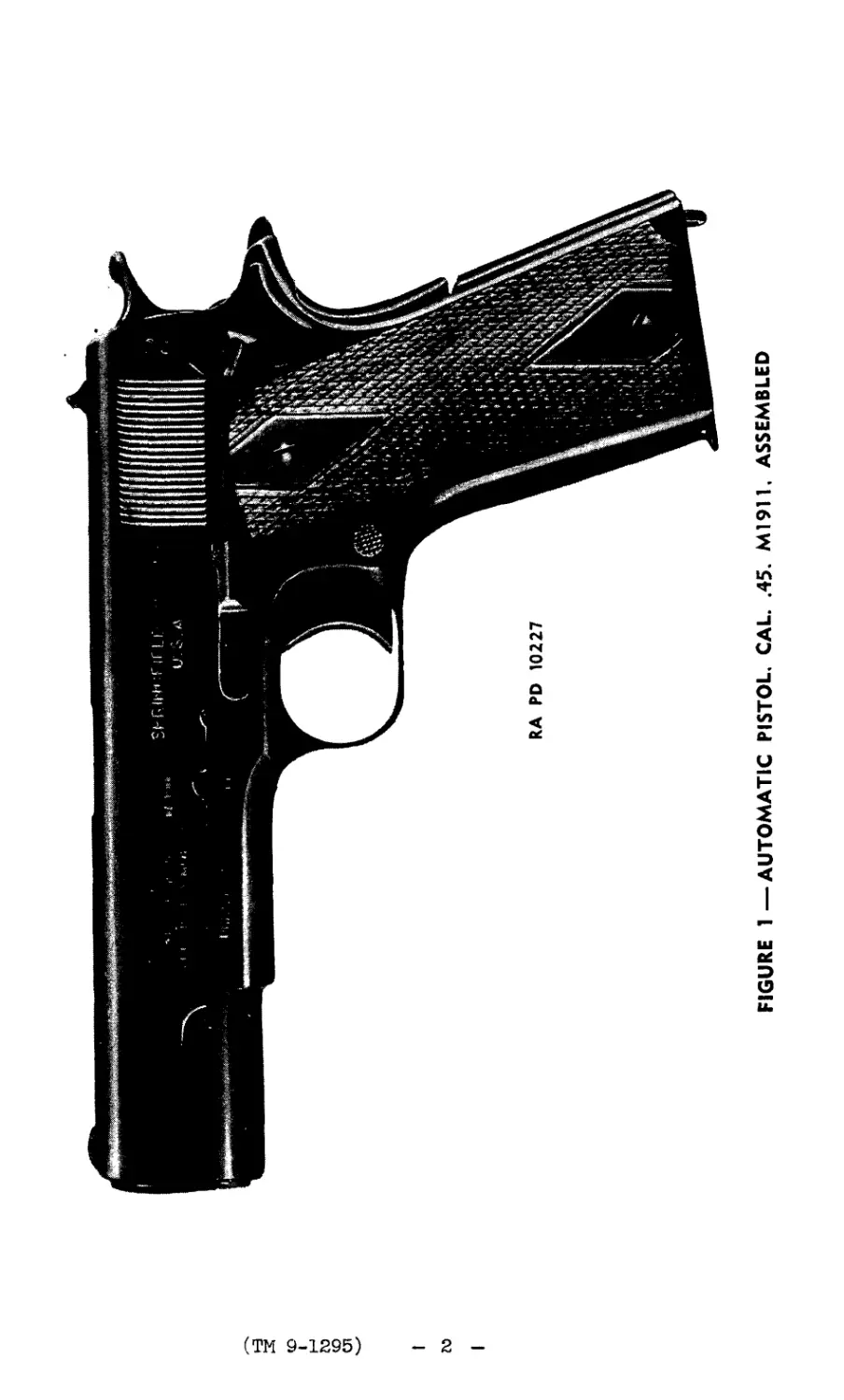
FIGURE 1—AUTOMATIC PISTOL. CAL. .45. М19И. ASSEMBLED
(ТМ 9-1295)
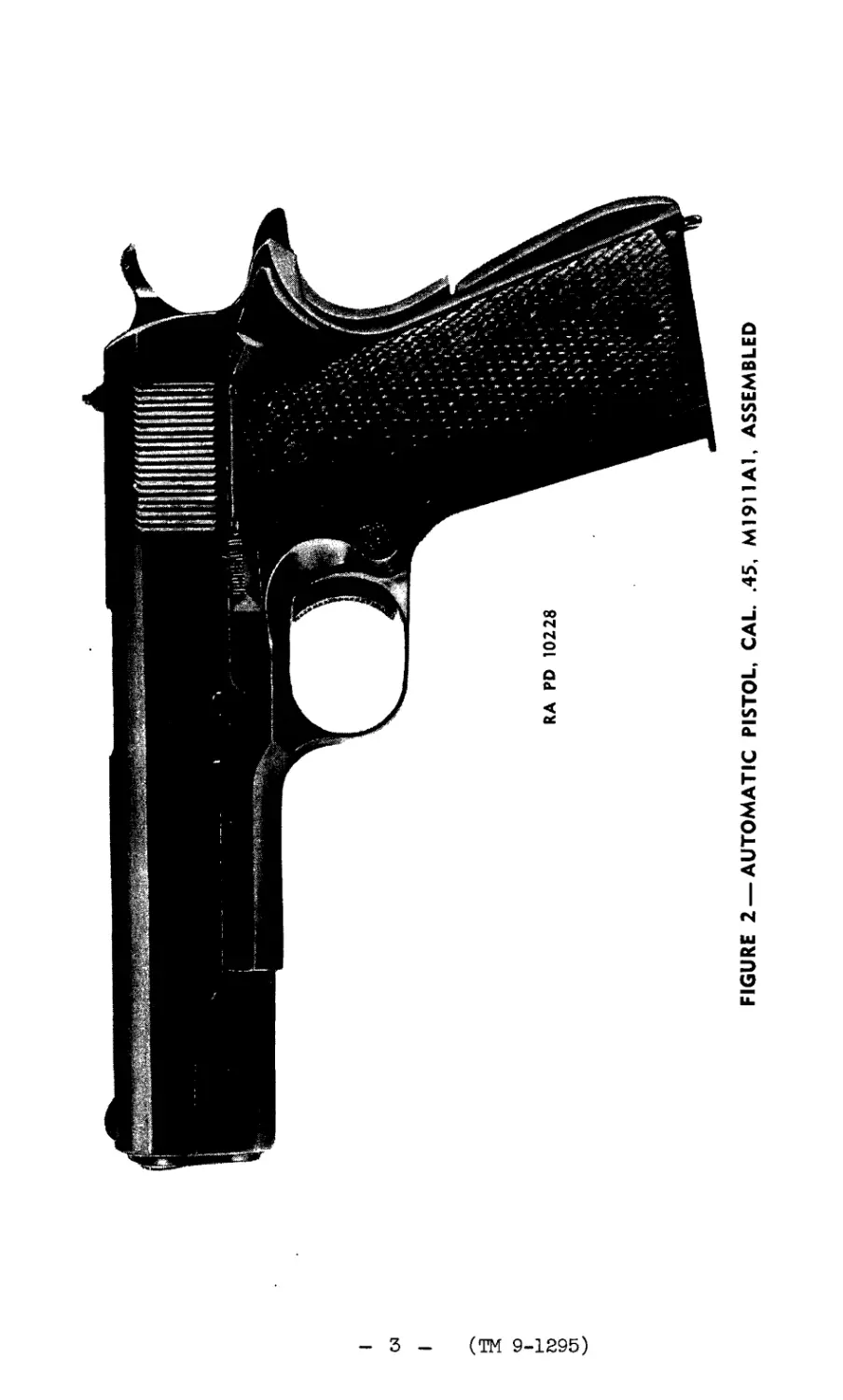
FIGURE 2— AUTOMATIC PISTOL, CAL. .45, M1911A1, ASSEMBLED
(ТМ 9-1295)
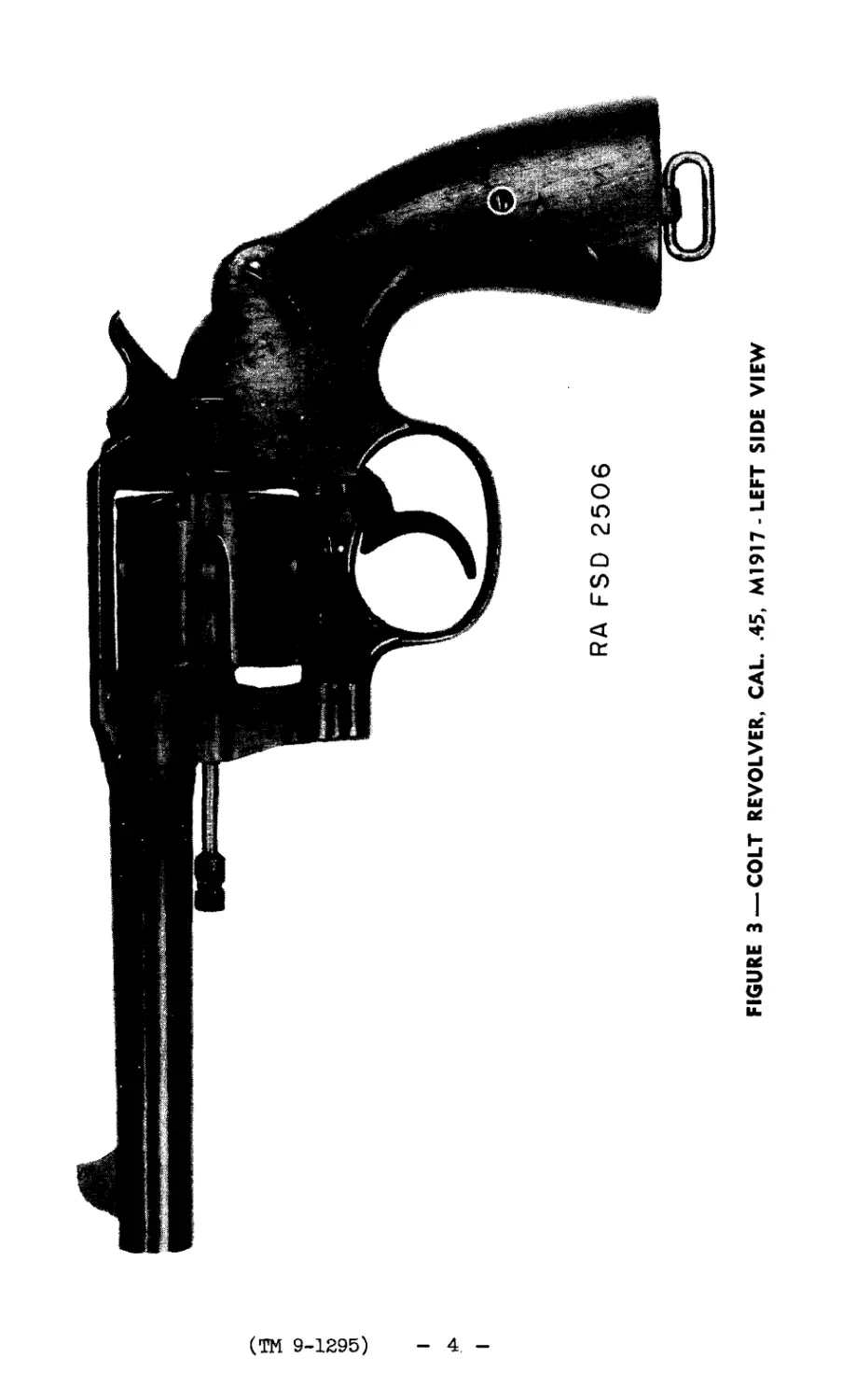
FIGURE 3 — COLT REVOLVER, CAL. .45, M1917-LEFT SIDE VIEW
(ТМ 9-1295)
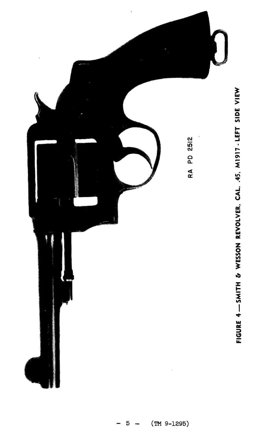
FIGURE 4—-SMITH & WESSON REVOLVER, CAL. .45, M1917-LEFT SIDE VIEW
9-129S
1-3
тм
ORDNANCE MAINTENANCE
1. INTRODUCTION. - This manual Is published for the Infor-
mation and guidance of ordnance maintenance personnel. It con-
tains Instructions for inspection» disassembly, assembly, main-
tenance and repair of the automatic pistol, cal..45, M1911 and
M1911A1; Colt revolver, cal..45, M1917; and Smith and Wesson
revolver, cal..45, M1917, supplementary to the Information con-
tained In the references of paragraph 9. Additional descriptive
matter and illustrations are Included to aid in providing a com-
plete working Knowledge of the materiel.
2. DISTINGUISHING CHARACTERISTICS. - The differences
between the Щ911 and M1911A1 automatic pistols do not affect
the maintenance of the weapons. Organizations called upon to
repair ML911A1 pistols will make reference to the automatic
pistol, cal..45, M1911. 3. INSPECTION OF THE PISTOL. -
Parts to be Inspected, In order of Inspection a. The pistol as a Points to be observed a. General appearance, ac-
unit. b. Barrel bushing. tion of slide, smoothness of op^ eratlon, function of safety lock, grip safety, slide stop, and mag- aglne catch. Alinement of sights, split stocks, missing stock screws. Trigger pull. b. Burrs.
c. Recoil spring. d. Main-spring housing. e. Sear spring. f. Sear. g. Hammer. h. Disconnector. 1. Trigger. c. Tension. d. Burrs, tension of main spring. e. Tension and broken leafs. f. Worn nose. g. Worn sear notch, bro- ken hammer strut. h. Burred or worn. 1. Burred or bent.
2- Receiver. k. Slide. 1. Firing pin. J. Burrs, loose ejector. Defaced markings. k. Burrs on recoil guide- ways and locking recesses. 1. Short or worn.
6
TM 9-1296
3-4
PISTOLS AND REVOLVERS
Parts to be Inspected,
in order of inspection Points to.be observed
m. Firing-pin spring. m, Tension.
n. Extractor. n. Broken claw, weak.
o. Barrel. o. If the barrel Is free
from pits and bulges, and lands
are sharp and distinct, it is
serviceable. If the barrel is
pitted but free from bulges and
has sharp lands, It is still ser-
viceable and will be sufficiently
accurate. This condition, how-
ever, implies that the barrel
has not been given proper care.
If the lands are pitted and have
lost their sharpness, the barrel
will be inaccurate and should be
replaced. This condition Is al-
ways due to neglect. If the
lands are worn down, due to ex-
tensive firing, and therefore
are no longer sharp, pits are to
be expected as they are character-
istic of a worn-out barrel which
should be replaced. If the bar-
rel has a bulge discernible to
the eye when sighted through at
a string held 2 or 3 feet In
front of the barrel, even though
otherwise In good condition, It
should be replaced. Burrs on
muzzle.
2* The magazine as ja. Burrs and dents.
a unit.
£• Magazine spring. £. Kinks and tension.
r. Magazine follower. r. Burrs.
4. INSPECTION OF THE SMITH AND 'WESSON REVOLVER, M1917. -
Parts to be Inspected,
in order of Inspection Points to be observed
a. The Smith & Wesson a. General appearance,
revolver as a unit. smoothness of operation. Func-
7
ТМ 9-1295
4-5
ORDNANCE MAINTENANCE
Parts to be Inspected,
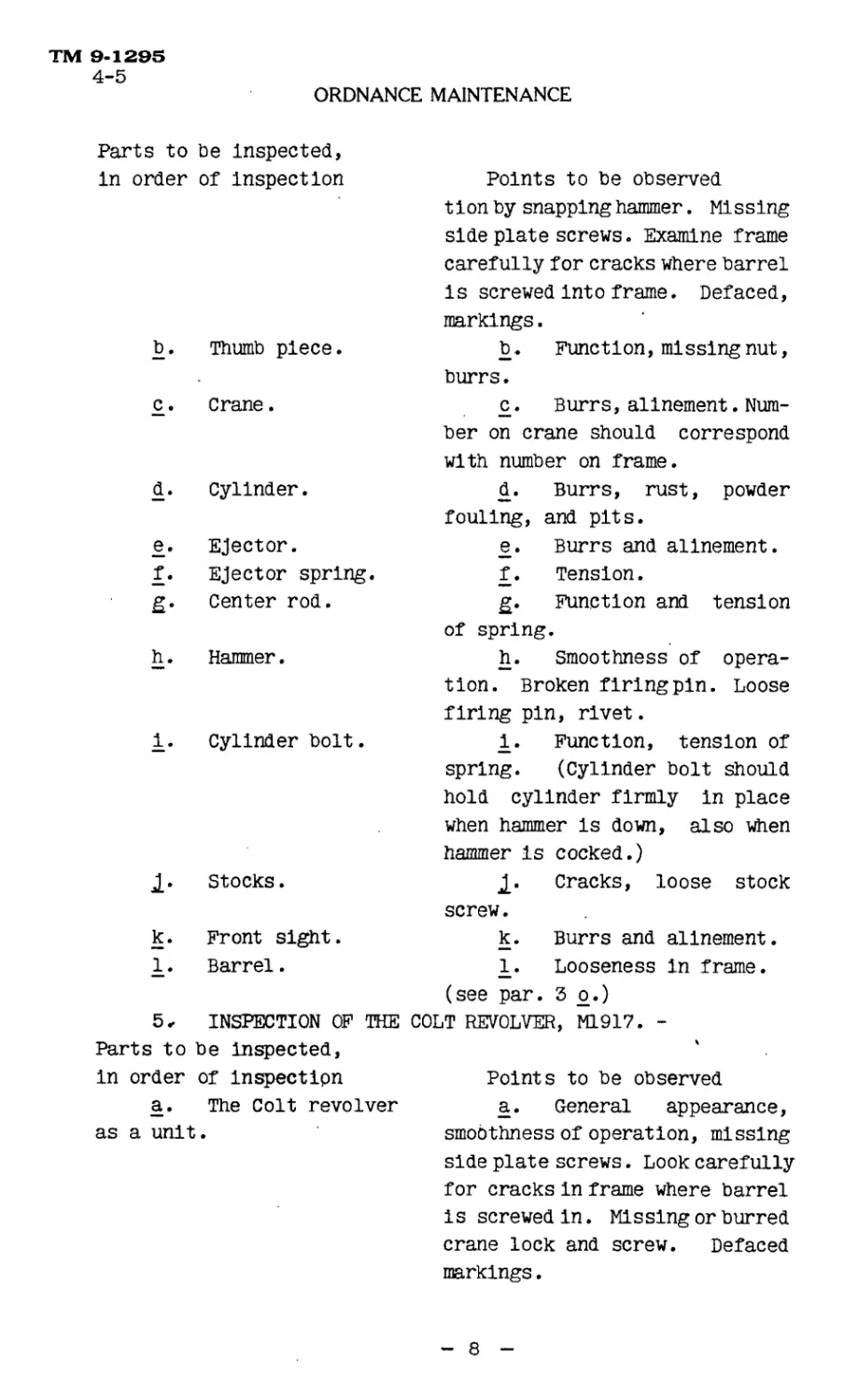
in order of inspection Points to be observed 11 on by snapping hammer. Missing side plate screws. Examine frame carefully for cracks where barrel is screwed into frame. Defaced, markings.
b. Thumb piece. b. Function, missing nut, burrs.
£. crane. c. Burrs, allnement. Num- ber on crane should correspond with number on frame.
d. Cylinder. d. Burrs, rust, powder fouling, and pits.
e. Ejector. e. Burrs and allnement.
f. Ejector spring. f. Tension.
£• Center rod. g. Function and tension of spring.
h. Hammer. h. Smoothness of opera- tion. Broken firing pin. Loose firing pin, rivet.
1. Cylinder bolt. 1. Function, tension of spring. (Cylinder bolt should hold cylinder firmly in place when hammer is down, also when hammer is cocked.)
1- Stocks. 2- Cracks, loose stock screw.
k. Front sight. k. Burrs and allnement.
1. Barrel. 1. Looseness in frame, (see par. 3 o.)
5, INSPECTION OF THE COLT REVOLVER, ML917. -
Parts to be Inspected, 4
in order of inspection Points to be observed
a. The Colt revolver a. General appearance,
as a unit. smoothness of operation, missing
side plate screws. Look carefully
for cracks In frame where barrel
is screwed in. Missing or burred
crane lock and screw. Defaced
markings.
8
TM 9-129S
5-6
PISTOLS AND REVOLVERS
Parts to be Inspected,
In order of Inspection Points to be observed
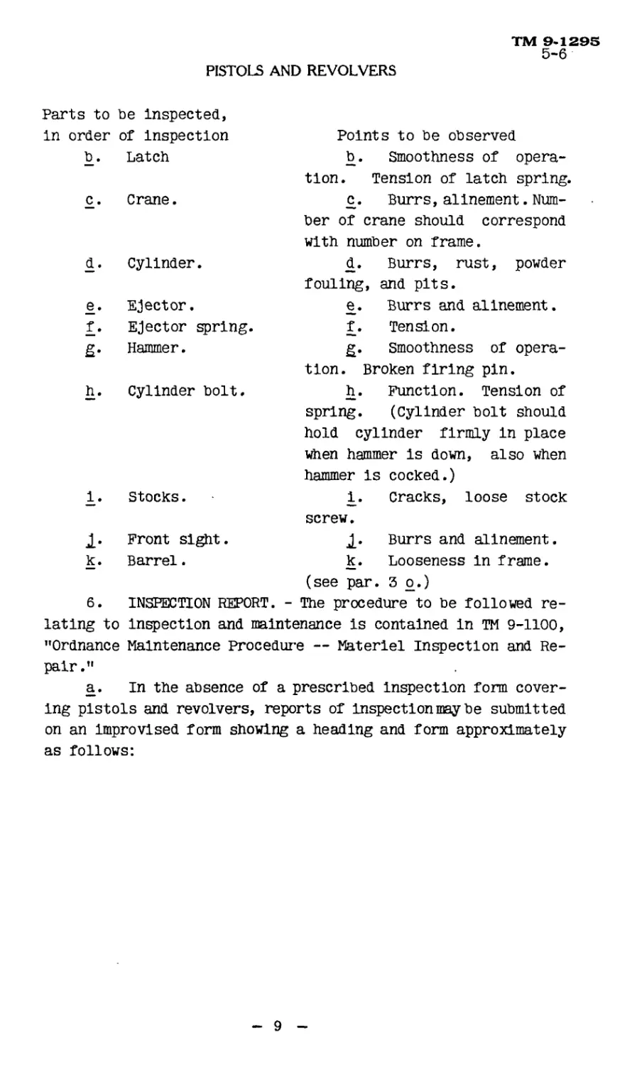
b. Latch b. Smoothness of opera- tion. Tension of latch spring.
c. Crane. £. Burrs, allnement. Num- ber of crane should correspond with number on frame.
d. Cylinder. d. Burrs, rust, powder fouling, and pits.
e. Ejector. e. Burrs and allnement.
f. Ejector spring. f. Tension.
£• Hammer. g. smoothness of opera- tion. Broken firing pin.
h. Cylinder bolt. h. Function. Tension of spring. (Cylinder bolt should hold cylinder firmly In place when hammer is down, also when hammer Is cocked.)
1. Stocks. 1. Cracks, loose stock screw.
1- Front sight. 2» Burrs and allnement.
k. Barrel. k. Looseness In frame, (see par. 3 o.)
6. INSPECTION REPORT. - The procedure to be followed re-
latlng to inspection and maintenance is contained in TM 9-1100,
"Ordnance Maintenance Procedure — Materiel Inspection and Re-
pair."
a. In tile absence of a prescribed Inspection form cover-
ing pistols and revolvers, reports of Inspection may be submitted
on an Improvised form showing a heading and form approximately
as follows:
9
ТМ 9*1295
6
ORDNANCE MAINTENANCE
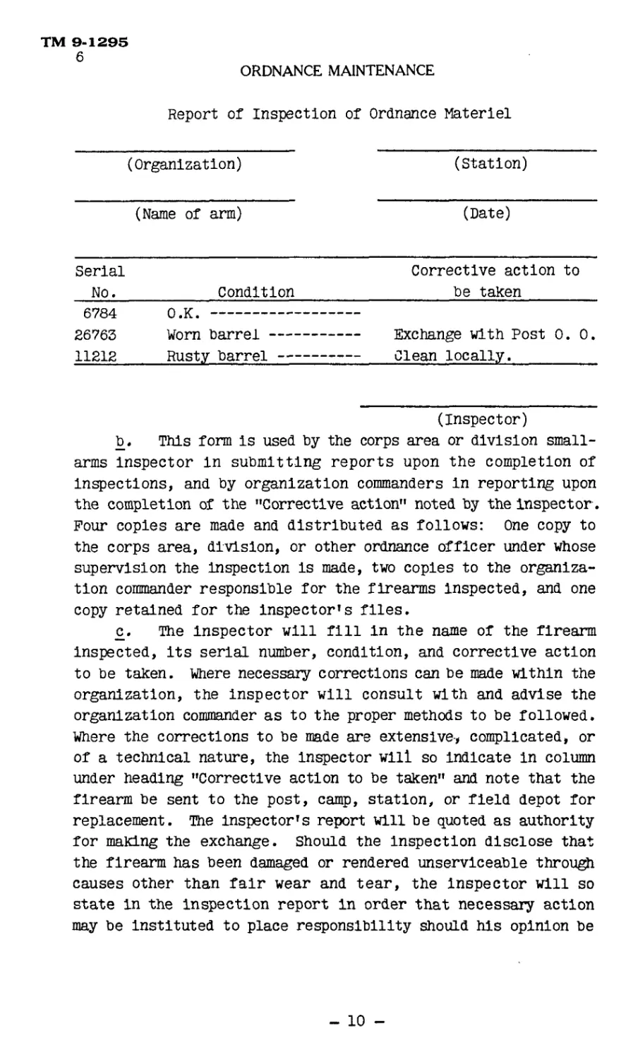
Report of Inspection of Ordnance Materiel
(Organization) (Station)
(Name of arm) (Date)
Serial No. Condition Corrective action to be taken
6784 O.k.
26763 Worn barrel Exchange with Post 0. 0.
11212 Rusty barrel Clean locally.
(Inspector)
b. This form is used by the corps area or division small-
arms Inspector In submitting reports upon the completion of
Inspections, and by organization commanders in reporting upon
the completion of the "Corrective action" noted by the Inspector .
Four copies are made and distributed as follows: One copy to
the corps area, division, or other ordnance officer under whose
supervision the inspection is made, two copies to the organiza-
tion commander responsible for the firearms inspected, and one
copy retained for the Inspector’s files.
c. The Inspector will fill in the name of the firearm
Inspected, Its serial number, condition, and corrective action
to be taken. Where necessary corrections can be made within the
organization, the Inspector will consult with and advise the
organization commander as to the proper methods to be followed.
Where the corrections to be made are extensive-, complicated, or
of a technical nature, the Inspector will so indicate in column
under heading "Corrective action to be taken" and note that the
firearm be sent to the post, camp, station, or field depot for
replacement. The inspector’s report will be quoted as authority
for making the exchange. Should the inspection disclose that
the firearm has been damaged or rendered unserviceable through
causes other than fair wear and tear, the Inspector will so
state in the inspection report in order that necessary action
may be Instituted to place responsibility should his opinion be
- 10 -
TM 9-1295
6-7
PISTOLS AND REVOLVERS
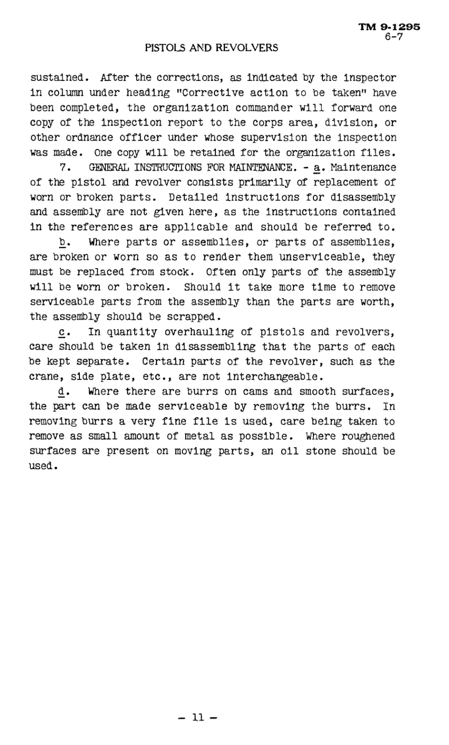
sustained. After the corrections, as indicated hy the Inspector
in column under heading "Corrective action to he taken" have
been completed, the organization commander will forward one
copy of the inspection report to the corps area, division, or
other ordnance officer under whose supervision the Inspection
was made. One copy will be retained for the organization files.
7. GENERAL INSTRUCTIONS FOR MAINTENANCE. - a. Maintenance
of the pistol and revolver consists primarily of replacement of
worn or broken parts. Detailed instructions for disassembly
and assembly are not given here, as the instructions contained
in the references are applicable and should be referred to.
b. Where parts or assemblies, or parts of assemblies,
are broken or worn so as to render them unserviceable, they
must be replaced from stock. Often only parts of the assembly
will be worn or broken. Should it take more time to remove
serviceable parts from the assembly than the parts are worth,
the assembly should be scrapped.
c. In quantity overhauling of pistols and revolvers,
care should be taken in disassembling that the parts of each
be kept separate. Certain parts of the revolver, such as the
crane, side plate, etc., are not Interchangeable.
d. Where there are burrs on cams and smooth surfaces,
the part can be made serviceable by removing the burrs. In
removing burrs a very fine file is used, care being taken to
remove as small amount of metal as possible. Where roughened
surfaces are present on moving parts, an oil stone should be
used.
11 -
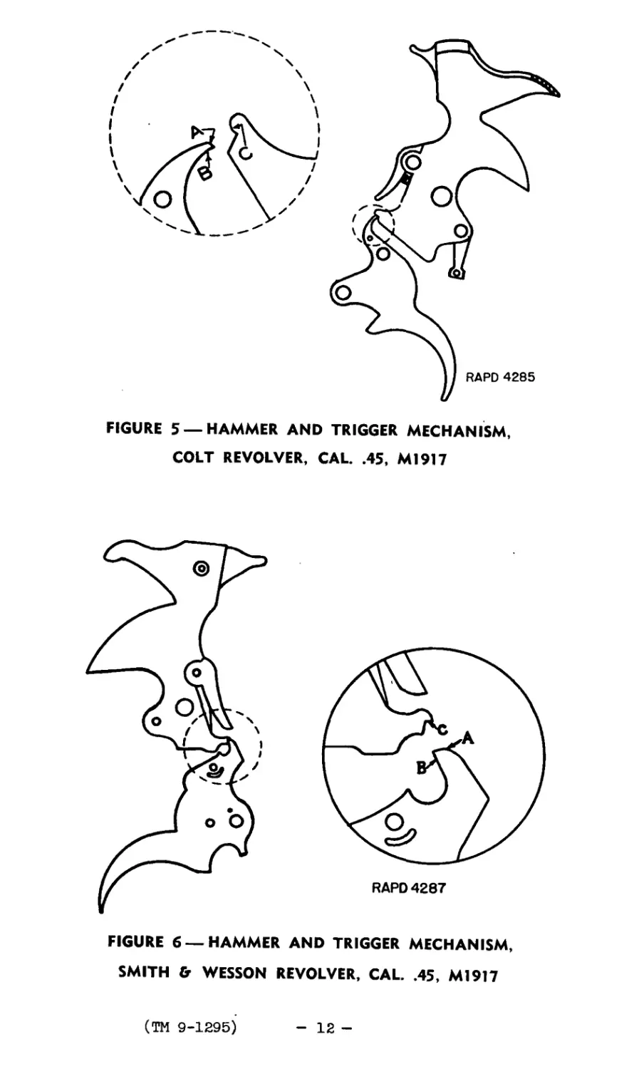
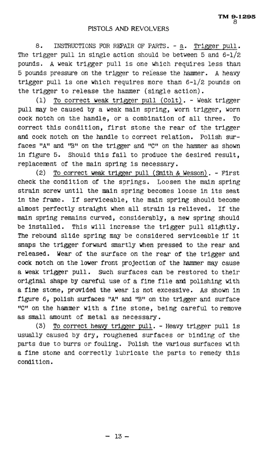
FIGURE 5 —HAMMER AND TRIGGER MECHANISM,
COLT REVOLVER, CAL. .45, M1917
FIGURE 6 —HAMMER AND TRIGGER MECHANISM,
SMITH & WESSON REVOLVER, CAL. .45, Ml917
(TH 9-1295)
12 -
TM 9-1295
8
PISTOLS AND REVOLVERS
8. INSTRUCTIONS FOR REPAIR OF PARTS. - a. Trigger pull.
The trigger pull in single action should be between 5 and 6-1/2
pounds. A weak trigger pull is one which requires less than
5 pounds pressure on the trigger to release the hammer. A heavy
trigger pull Is one which requires more than 6-1/2 pounds on
the trigger to release the hammer (single action).
(1) To correct weak trigger pull (Colt). - Weak trigger
pull may be caused by a weak main spring, worn trigger, worn
cock notch on the handle, or a combination of all three. To
correct this condition, first stone the rear of the trigger
and cock notch on the handle to correct relation. Polish sur-
faces "A" and "B” on the trigger and ”C" on the hammer as shown
In figure 5. Should this fall to produce the desired result,
replacement of the main spring Is necessary.
(2) To correct weak trigger pull (Smith & Wesson). - First
check the condition of the springs. Loosen the main spring
strain screw until the main spring becomes loose In Its seat
In the frame. If serviceable, the main spring should become
almost perfectly straight when all strain is relieved. If the
main spring remains curved, considerably, a new spring should
be installed. This will Increase the trigger pull slightly.
The rebound slide spring may be considered serviceable if it
snaps the trigger forward smartly when pressed to the rear and
released, wear of the surface on the rear of the trigger and
cock notch on the lower front projection of the hammer may cause
a weak trigger pull, such surfaces can be restored to their
original shape by careful use of a fine file and polishing with
a fine stone, provided the wear is not excessive. As shown In
figure 6, polish surfaces "A” and ”B" on the trigger and surface
”C" on the hammer with a fine stone, being careful to remove
as small amount of metal as necessary.
(3) To correct heavy trigger pull. - Heavy trigger pull Is
usually caused by dry, roughened surfaces or binding of the
parts due to burrs or fouling. Polish the various surfaces with
a fine stone and correctly lubricate the parts to remedy this
condition.
13 -
TM 9-129Б
8
ORDNANCE MAINTENANCE
С В A
RAPO 4286
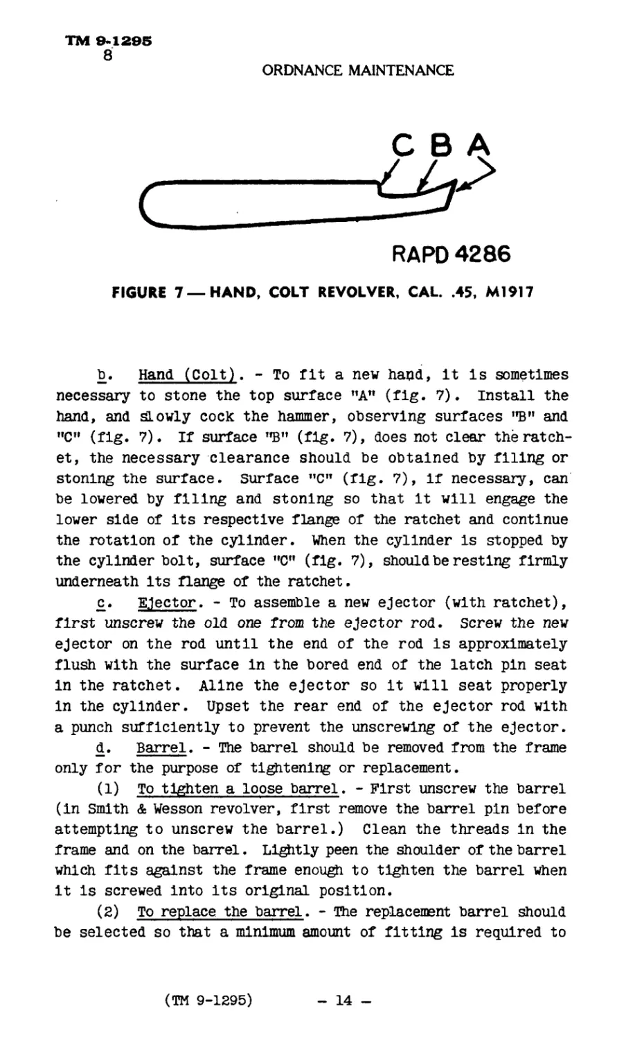
FIGURE 7 —HAND, COLT REVOLVER, CAL. .45, M1917
b. Hand (Colt). - To fit a new hand, It Is sometimes
necessary to stone the top surface "A” (fig. 7). Install the
hand, and slowly cock the hammer, observing surfaces "B" and
"C" (fig. 7). If surface ”B” (fig. 7), does not clear the ratch-
et, the necessary clearance should be obtained by filing or
stoning the surface, surface ”C” (fig. 7), If necessary, can
be lowered by filing and stoning so that It will engage the
lower side of its respective flange of the ratchet and continue
the rotation of the cylinder. When the cylinder Is stopped by
the cylinder bolt, surface "C" (fig. 7), should be resting firmly
underneath Its flange of the ratchet.
c. Ejector. - To assemble a new ejector (with ratchet),
first unscrew the old one from the ejector rod. screw the new
ejector on the rod until the end of the rod Is approximately
flush with the surface In the bored end of the latch pin seat
In the ratchet. Aline the ejector so it will seat properly
in the cylinder. Upset the rear end of the ejector rod with
a punch sufficiently to prevent the unscrewing of the ejector.
d. Barrel. - The barrel should be removed from the frame
only for the purpose of tightening or replacement.
(1) To tighten a loose barrel. - First unscrew the barrel
(In Smith & Wesson revolver, first remove the barrel pin before
attempting to unscrew the barrel.) Clean the threads in the
frame and on the barrel. Lightly peen the shoulder of the barrel
which fits against the frame enough to tighten the barrel when
it Is screwed into Its original position.
(2) To replace the barrel. - The replacement barrel should
be selected so that a minimum amount of fitting is required to
(TM 9-1295)
- 14 -
TM 9-1295
8
PISTOLS AND REVOLVERS
obtain proper allnement. If necessary, a small amount ef metal
may be removed from the shoulder of the barrel with a fine file
or by lathe to draw it up to allnement. When replacing the
barrel, if necessary the rear end should be stoned to obtain
the proper clearance between the rear end of the barrel and the
front end of the cylinder. This clearance should be between
.002 In. and .006 In.
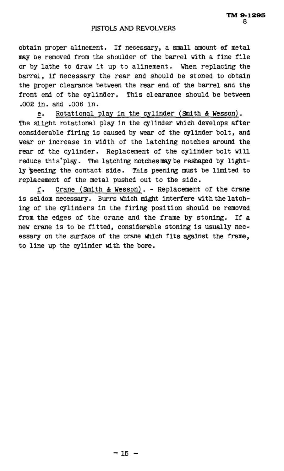
e. Rotational play in the cylinder (smith & Wesson).
The slight rotational play In the cylinder which develops after
considerable firing is caused by wear of the cylinder bolt, and
wear or Increase In width of the latching notches around the
rear of the cylinder. Replacement of the cylinder bolt will
reduce thls*play. The latching notches may be reshaped by light-
ly peening the contact side. This peening must be limited to
replacement of the metal pushed out to the side.
f. Crane (Smith & Wesson). - Replacement of the crane
is seldom necessary. Burrs which might interfere with the latch-
ing of the cylinders in the firing position should be removed
from the edges of the crane and the frame by stoning. If a
new crane is to be fitted, considerable stoning is usually nec-
essary on the surface of the crane which fits against the frame,
to line up the cylinder with the bore.
- 15
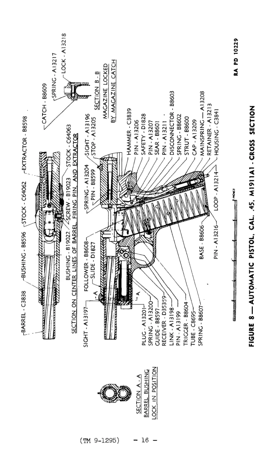
r-BARREL - C3838 -BUSHING - B8596 -STOCK - C64062 /-EXTRACTOR - B8598
> / \ '
*
BUSH 1 NG - 819022 /^SCREW - В19023 'x STOCK - C64063
SECTION ON CENTER LINES OF BARREL, FIRING PIN, AND EXTRACTOR
(ТМ 9-1295)
SPRING - A13204 SIGHT-A13196
\vPIN-B8599 STOP-Al 3205
' SECTION А-А
Si BARREL BUSHING
I LOCK IN POSITION
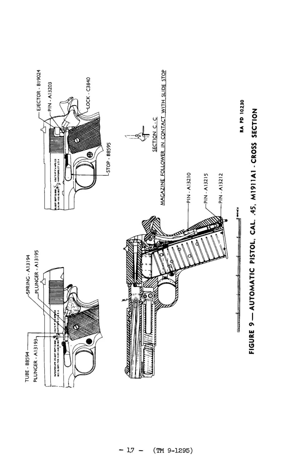
SIGHT -A13197
FOLLOWER - В8608-
SLIDE-D1827 \
BASE - B8606
LOOP-A13214
PIN - A13216
PLUG- Al 320H
SPRING - Al 3200—'/
GUIDE - B8597 —
RECEIVER - D35359
LINK-A13198
PIN - A13199
TRIGGER - B8604
TUBE - C8695
SPRING - B8607
* < * f J1*”™
CATCH - B8609
SPRING -A13217
LOCK - Al 3218
SECTION В - В
MAGAZINE LOCKED
BY MAGAZINE CATCH
HAMMER - C3839
PIN - Al3206
SAFETY - DI828
PIN - Al3207
SEAR - B8601
PIN-A13211 •
DISCONNECTOR - B8603
SPRING - B8602
STRUT - B8600
CAP - Al 3209
MA INSPRI NG — A13208
RETAINER - Al3213
HOUSING - C3841
RA PD 10229
FIGURE 8 —AUTOMATIC PISTOL, CAL. .45, Ml911 Al - CROSS SECTION
I
I
(TH 9-1295)
f i 4 t
KA PD 10230
FIGURE 9 —AUTOMATIC PISTOL, CAL. .45, M1911A1 - CROSS SECTION
(TM 9-1295) - 18
5
6
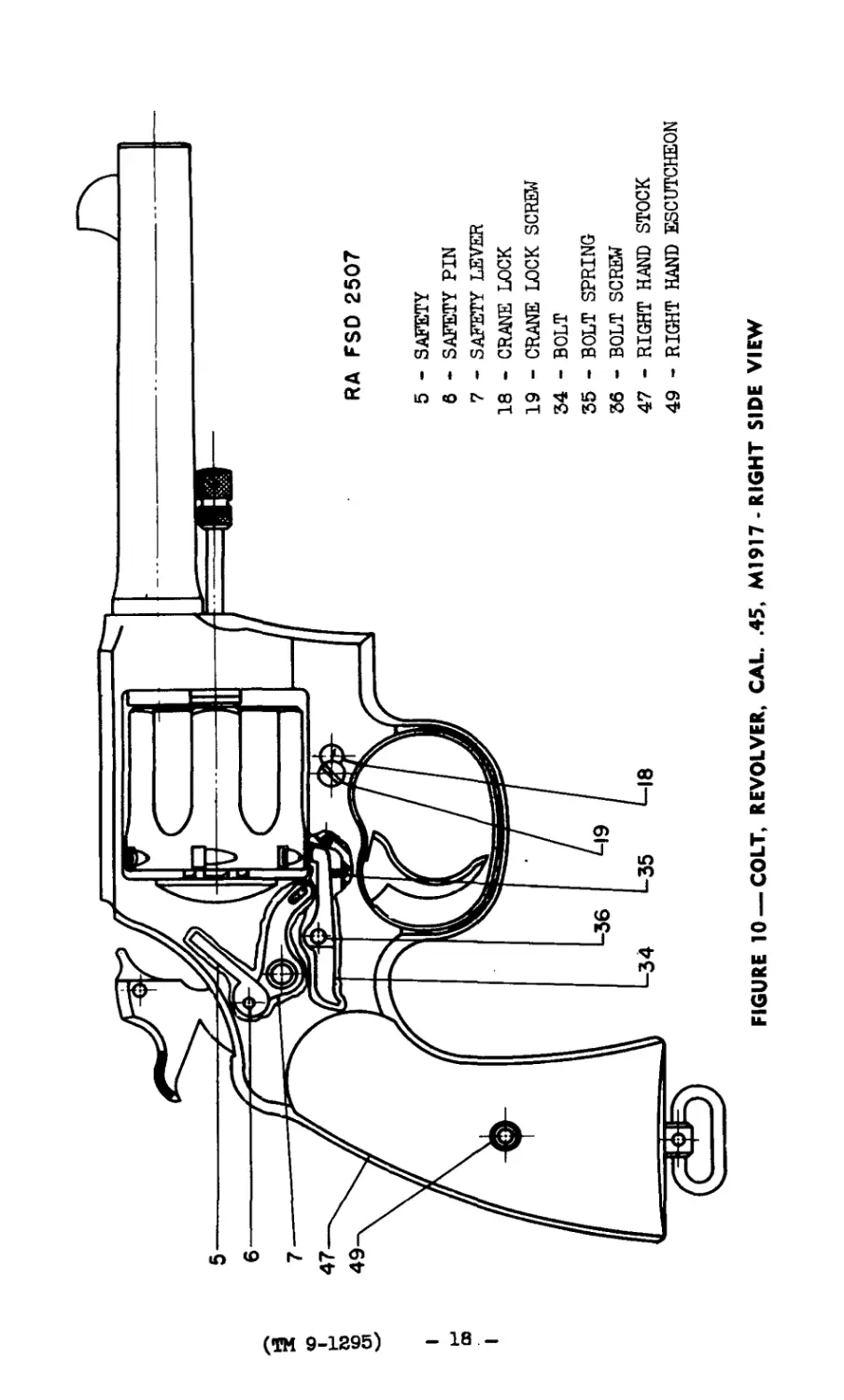
RA FSO 2507
5 - SAFETY
6 - SAFETY PIN
7 - SAFETY LEVER
18 - CRANE LOCK
19 - CRANE LOCK SCREW
34 - BOLT
35 - BOLT SPRING
36 - BOLT SCREW
47 - RIGHT HAND STOCK
49 - RIGHT HAND ESCUTCHEON
FIGURE 10 —COLT. REVOLVER, CAL. .45, M1917 -RIGHT SIDE VIEW
I
<o
I
(TH 9-1295)
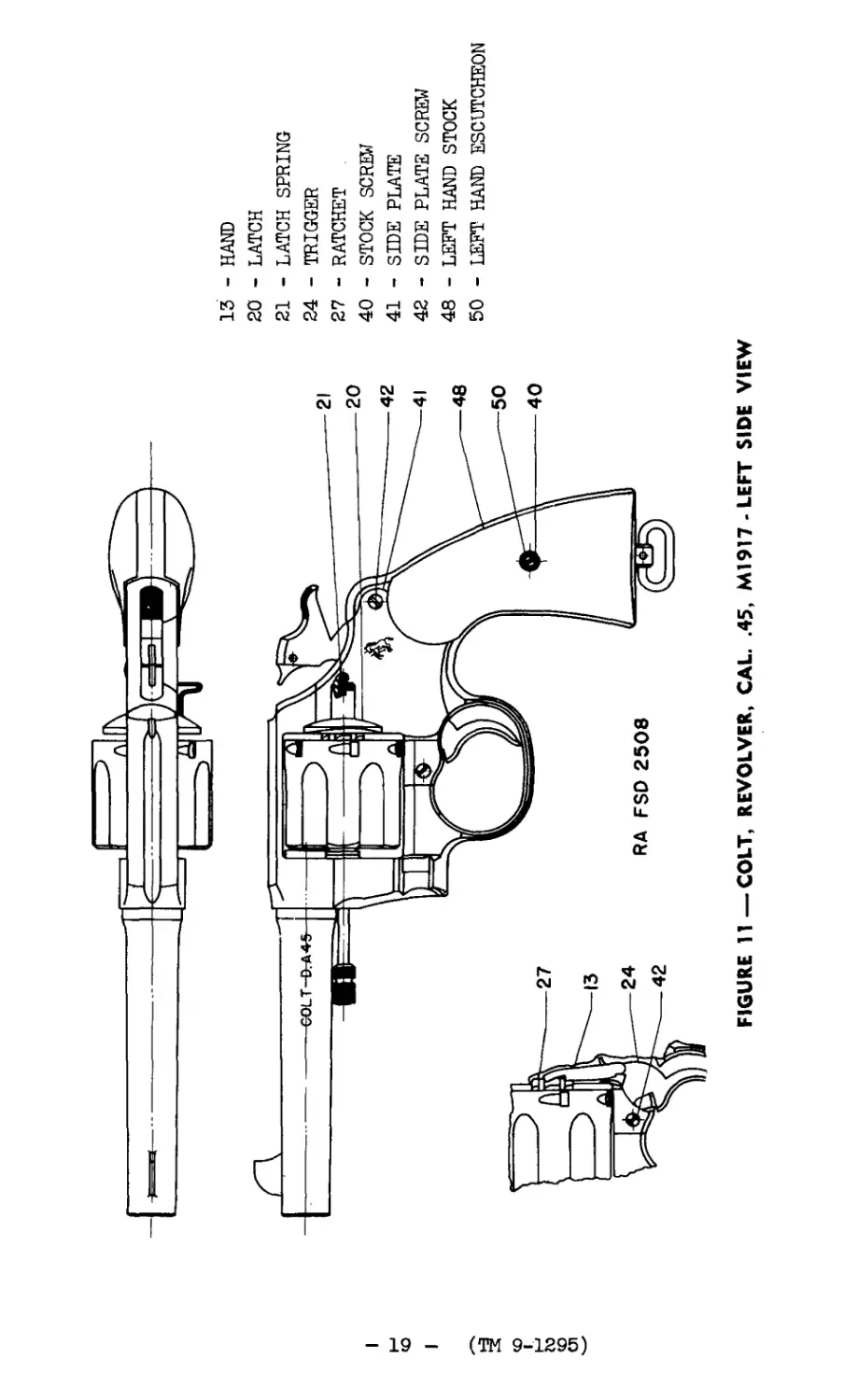
FIGURE 11—COLT, REVOLVER, CAL. .45, M1917-LEFT SIDE VIEW
13 - HAND
20 - LATCH
21 - LATCH SPRING
24 - TRIGGER
27 - RATCHET
40 - STOCK SCREW
41 - SIDE PLATE
42 - SIDE PLATE SCREW
48 - LEFT HAND STOCK
50 - LEFT HAND ESCUTCHEON
(TM 9-1295)
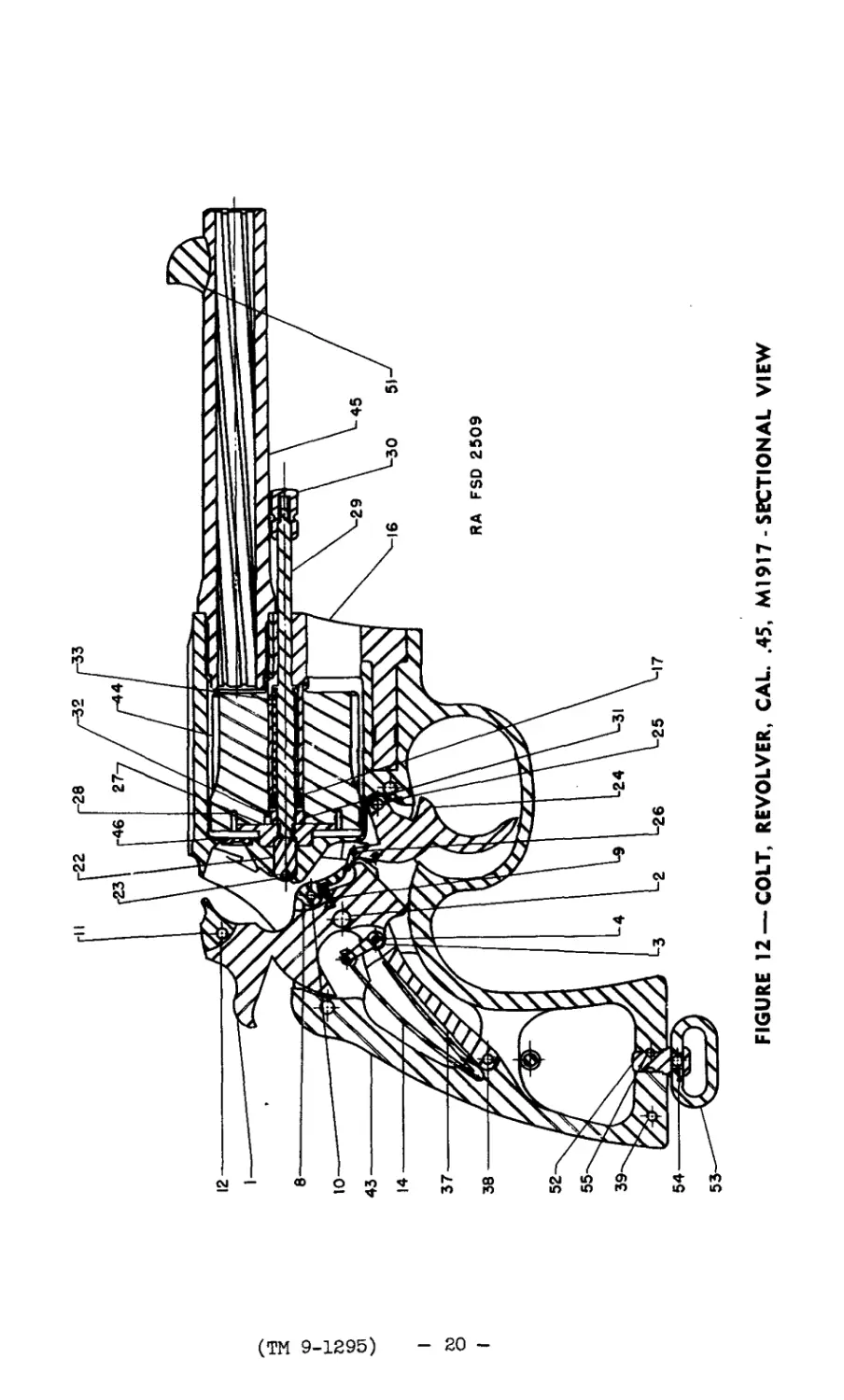
FIGURE 12 —COLT, REVOLVER, CAL. .45, M1917 - SECTIONAL VIEW
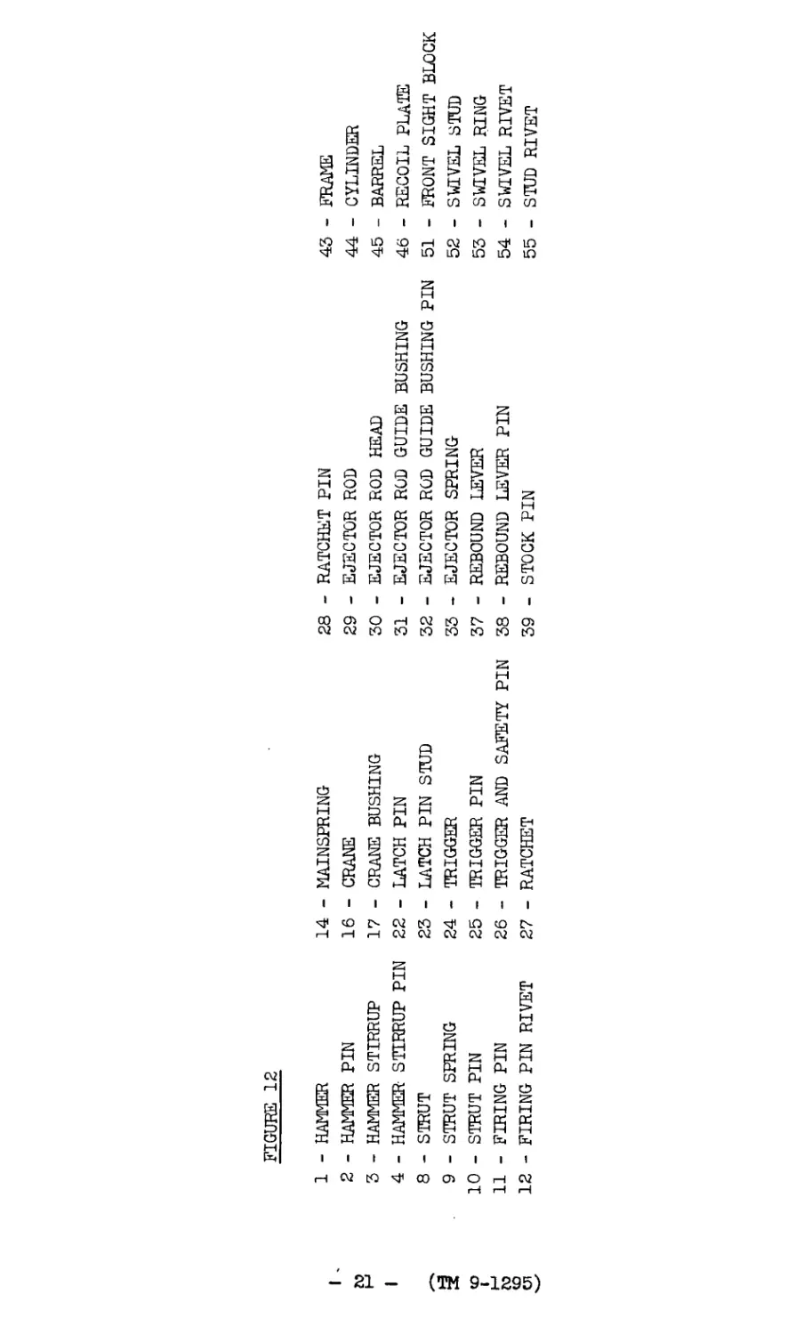
FIGURE 12
1 - HAMMER 14 - MAINSPRING 28 - RATCHET PIN 43 - FRAME
2 - HAMMER PIN 16 - CRANE 29 - EJECTOR ROD 44 - CYLINDER
3 - HAMMER STIRRUP 17 - CRANE BUSHING 30 - EJECTOR ROD HEAD 45 - BARREL
4 - HAMMER- STIRRUP PIN 22 - LATCH PIN 31 — EJECTOR ROD GUIDE BUSHING 46 - RECOIL PLATE
8 - STRUT 23 - LATCH PIN STUD 32 — bJbCTOR ROD GUIDE BUSHING PIN 51 - FRONT SIGHT BLOCK
9 - STRUT SPRING 24 - TRIGGER 33 - EJECTOR SPRING 52 - SWIVEL STUD
10 - STRUT PIN 25 - TRIGGER PIN 37 - REBOUND LEVER 53 - SWIVEL RING
11 - FIRING PIN 26 - TRIGGER AND SAFETY PIN 38 - REBOUND LEVER PIN 54 - SWIVEL RIVET
12 - FIRING PIN RIVET 27 - RATCHET 39 - STOCK PIN 55 - STUD RIVET
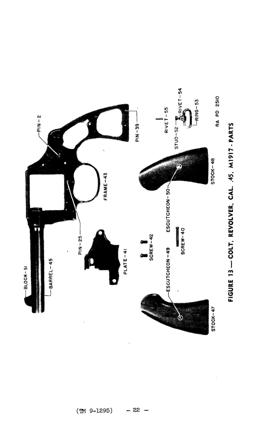
BLOCK-51
BARREL-45
PIN-2
(ТМ 9-1295)
PIN-25
FRAME—43
PLATE-41
ESCUTCHEON-49
STOCK-47
V t
SCREW-42
SCREW-40
ESCUTCHEON-50
STOCK-48
PIN-39
RIVET-55
k-RIVET-54
L RING-53
RA PO 2510
FIGURE 13 —COLT, REVOLVER, CAL. .45, M1917-PARTS
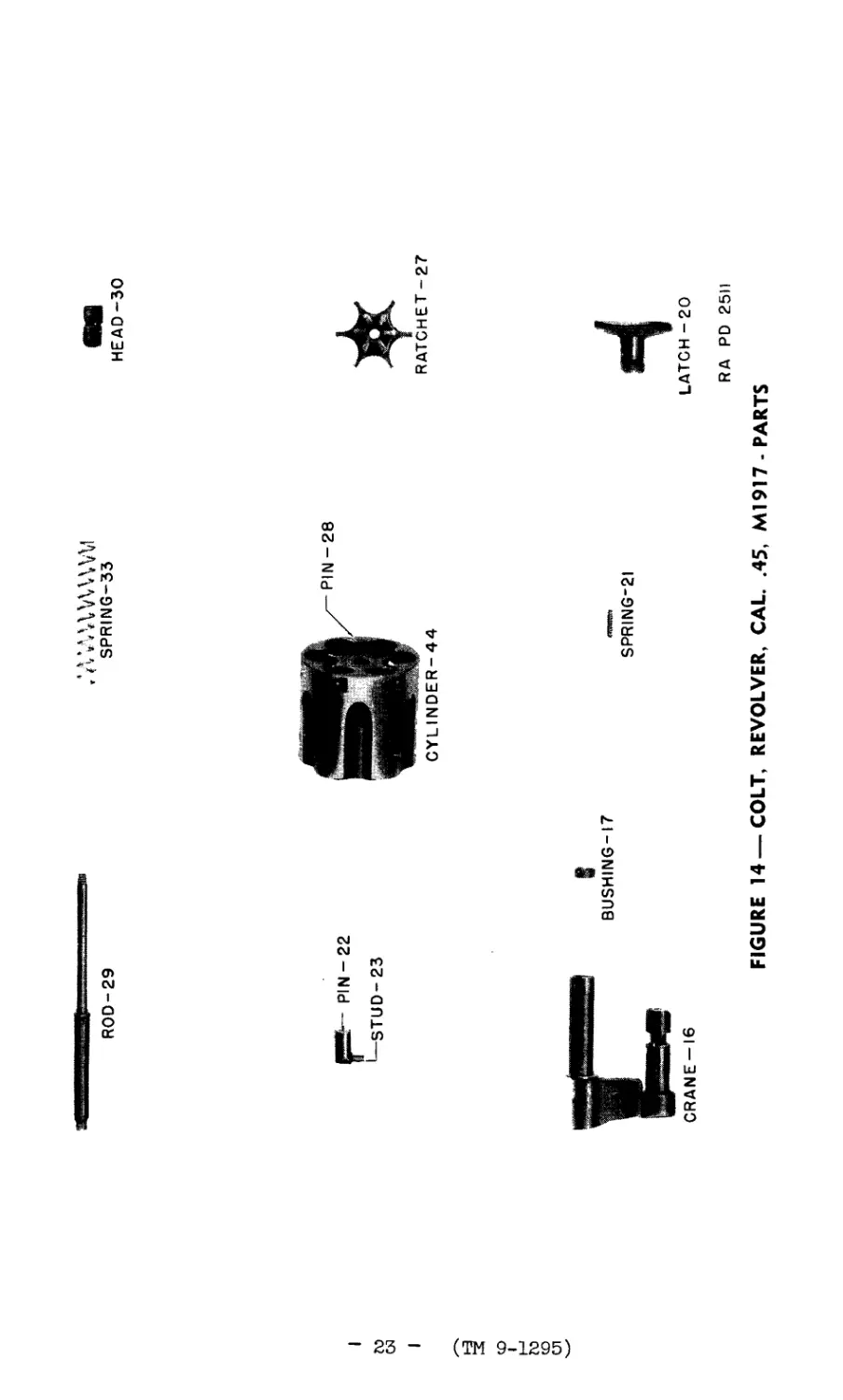
HEAD-30
ROD-29
SPRING-33
Г0
w
(TM 9-1295)
PIN-22
STUD-23
CYLINDER-44
RATCHET-27
CRANE-16
t
BUSHING-17
SPRING-21
J
I
LATCH -20
RA PD 25П
FIGURE 14 —COLT, REVOLVER, CAL. .45, M1917- PARTS
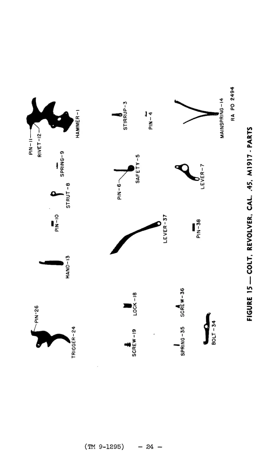
TRIGGER-24
PIN-26
HAND-13
PIN-10
PIN—II —
RIVET-12
I SPRING-9
STRUT-8
HAMMER-1
(TM 9-1295)
SCREW-19 LOCK-18
I
£
I
SPRING-35 SCREW-36
PIN-38
STIRRUP-3
PIN- 4
BOLT-34
RA PD 2494
FIGURE 15 —COLT, REVOLVER, CAL. .45, M1917 -PARTS
I
к
и
I
(TH 9-1295)
SCREW
PIECE
PIECE NUT
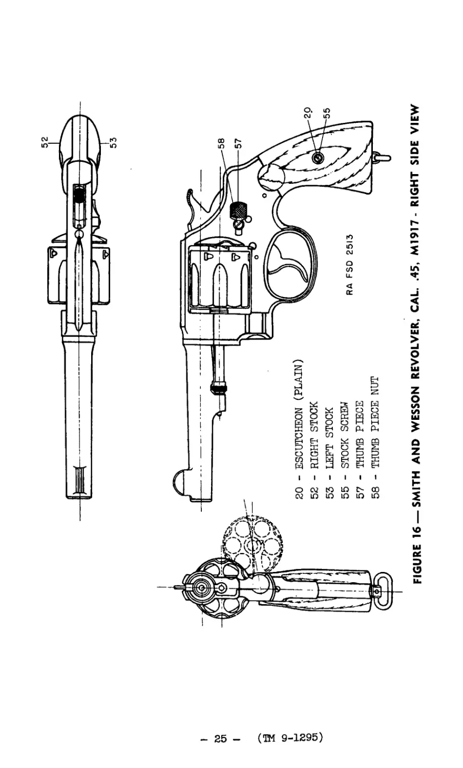
- ESCUTCHEON (PLAIN)
- RIGHT STOCK
- LEFT STOCK
- STOCK
20
52
53
55
57 - THUMB
58 - THUMB
FIGURE 16 —SMITH AND WESSON REVOLVER, CAL. .45, M1917- RIGHT SIDE VIEW
20
55
(ТМ 9-1295)
I
м
о»
I
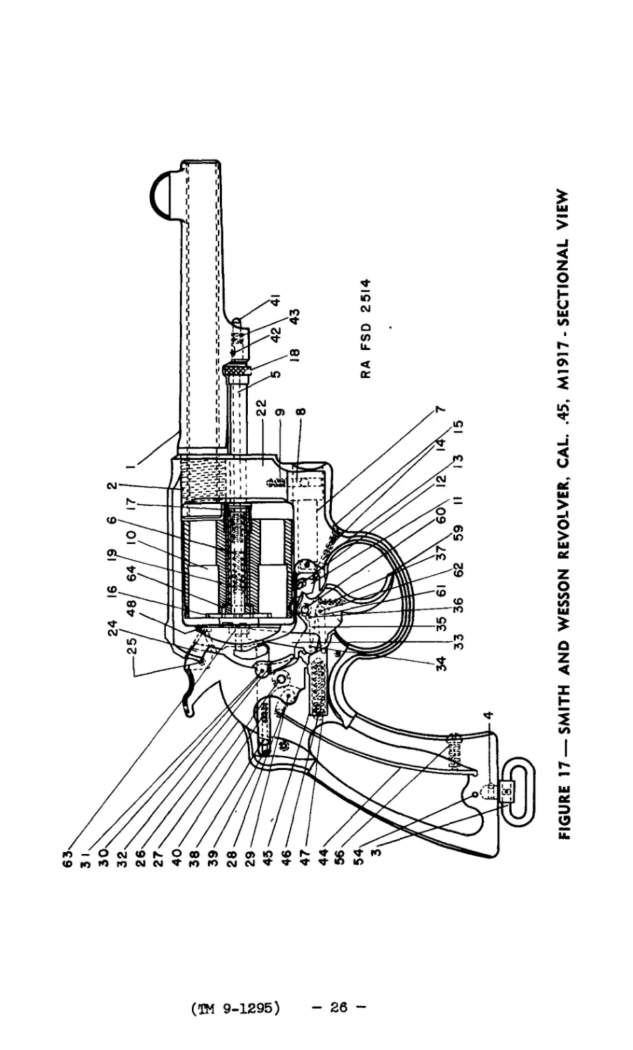
FIGURE 17 —SMITH AND WESSON REVOLVER, CAL. .45, Ml917 - SECTIONAL VIEW
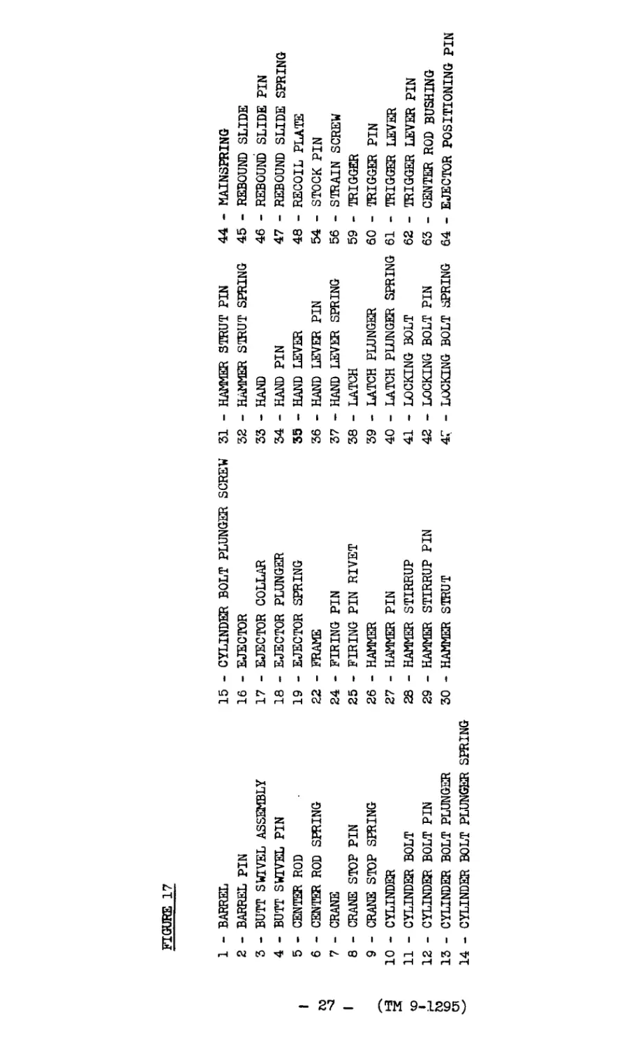
FIGURE 17
1 - BARREL 15 - CYLINDER BOLT PLUNGER SCREW 31 — HAMMER STRUT PIN 44 - MAINSPRING
2 — BARREL PIN 16 — EJECTOR 32 — HAMMER STRUT SPRING 45 — REBOUND SLIDE
3 — BUTT SWIVEL ASSEMBLY 17 — EJECTOR COLLAR 33 — HAND 46 — REBOUND SLIDE PIN
4 — BUTT SWIVEL PIN 18 — EJECTOR PLUNGER 34 — HAND PIN 47 — REBOUND SLIDE SPRING
1 to 5 — CENTER ROD 19 — EJECTOR SPRING 35 — HAND LEVER 48 — RECOIL PLATE
6 — CENTER ROD SPRING 22 — FRAME 36 — HAND LEVER PIN 54 — STOCK PIN
7 — CRANE 24 — FIRING PIN 37 — HAND LEVER SPRING 56 — STRAIN SCREW
1 8 — CRANE STOP PIN 25 — FIRING PIN RIVET 38 — LATCH 59 TRIGGER
9 — CRANE STOP SPRING 26 — HAMMER 39 — LATCH PLUNGER 60 — TRIGGER PIN
s 10 — CYLINDER 27 — HAMMER PIN 40 — LATCH PLUNGER SPRING 61 — TRIGGER LEVER
11 — CYLINDER BOLT 28 — HAMMER STIRRUP 41 — LOCKING BOLT 62 — TRIGGER LEVER PIN
i 12 — CYLINDER BOLT PIN 29 — HAMMER STIRRUP PIN 42 — LOCKING BOLT PIN 63 — CENTER ROD BUSHING
to <0 13 — CYLINDER BOLT PLUNGER 30 — HAMMER STRUT 47 — LOCKING BOLT SPRING 64 — EJECTOR POSITIONING PIN
14 — CYLINDER BOLT PLUNGER SPRING
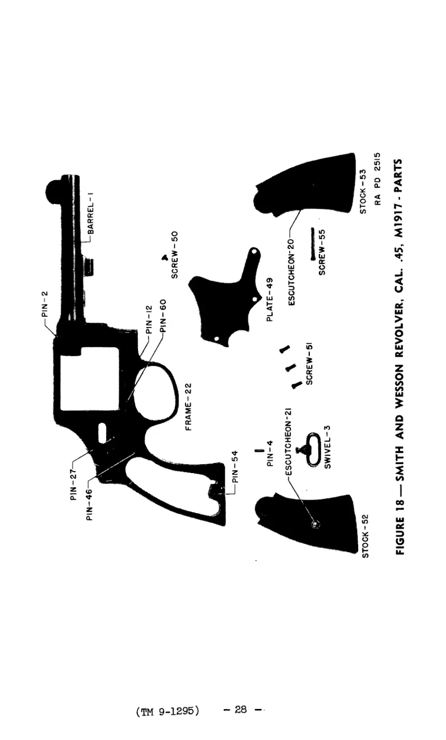
PIN-27-
PIN-46
PIN-2
BARREL-I
(ТМ 9-1295)
FRAME-22
PIN-12
PIN-60
SCREW-50
I
00
PIN-54
PIN-4
ESCUTCHEON-21
SWIVEL-3
STOCK-52
PLATE-49
ESCUTCHEON"20
SCREW-51
SCREW-55
STOCK-53
RA PD 2515
FIGURE 18 —SMITH AND WESSON REVOLVER, CAL. .45, M1917-PARTS
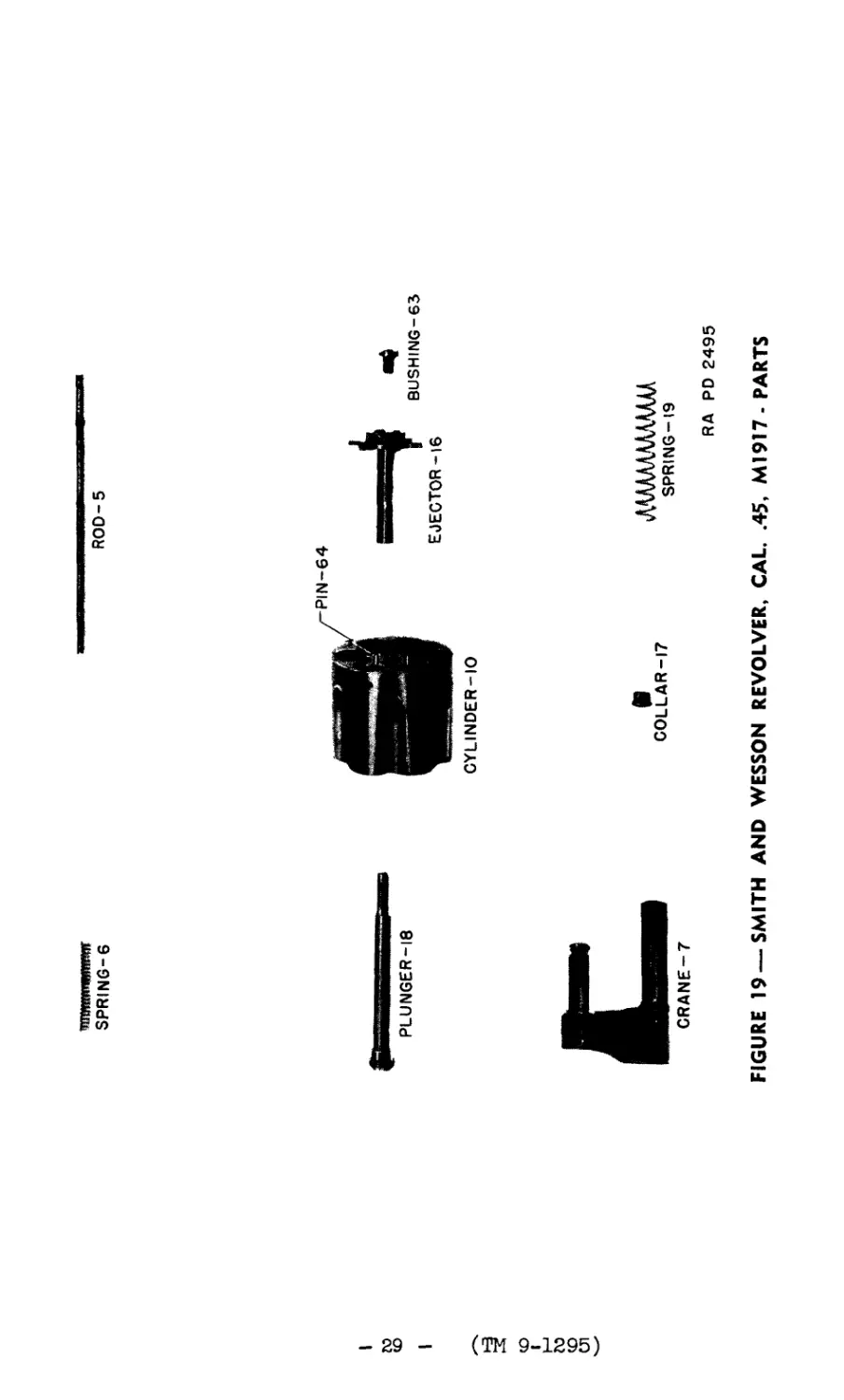
SPRING-6
ROD-5
to
co
CYLINDER-10
(TN 9-1295)
CRANE-7
COLLAR-17
лшшшш
SPRING-19
RA PD 2495
FIGURE 19 —SMITH AND WESSON REVOLVER, CAL. .45, MI917- PARTS
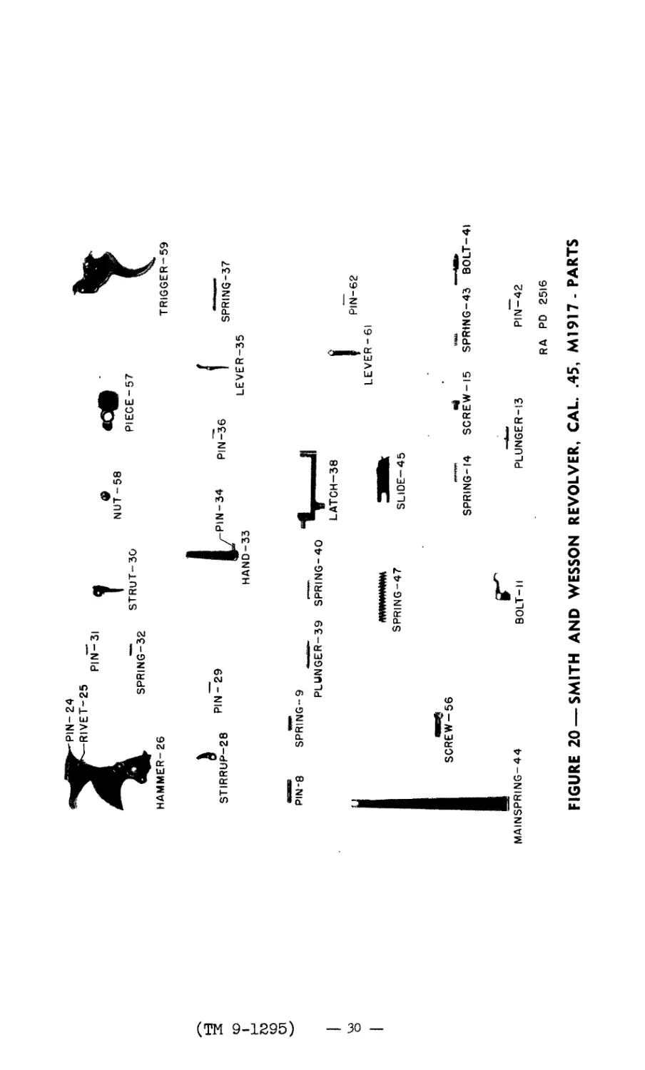
PIN-24
RIVET-25
PIN-31
NUT-58
PIECE-57
HAMMER-26
SPRING-32
STRUT-30
TRIGGER-59
(ТМ 9-1295)
STIRRUP-28
PIN - 29
PIN-34
PIN-36
SPRING-37
PIN-8
SPRING-9
PLUNGER-39
SCREW-56
MAINSPRING-44
FIGURE 20
HAND-33
LEVER-35
SPRING-47
BOLT-11
SMITH AND WESSON
SPRING-40
LATCH-38
LEVER-61
PIN-62
SLIDE-45
SPRING-14
«e
SCREW-15
PLUNGER-13
—Мв*
SPRiNG-43 BOLT-41
PIN-42
RA PD 2516
REVOLVER. CAL. .45, M1917- PARTS
ТМ 9-1295
9
PISTOLS AND REVOLVERS
9. LIST OP REFERENCES. - a. Standard Nomenclature Lists.
Pistol, automatic, cal..45, M1911 and M1911A1------ SNL B-6
Revolver, Colt, cal..45, M1917; Revolver,
Smith and wesson, M1917----------------------------- SNL B-7
Tools, special repair, small and hand arms, and
pyrotechnic projectors------------------------------ SNL B-20
Truck, small arms, repair, Ml --------------------- SNL G-72
Cleaning, preserving and lubricating materials,
recoil fluids, special oils, and similar Items
of Issue-------------------------------------------- SNL K-l
Soldering, brazing and welding materials, gases
and related items----------------------------------- SNL K-2
Current Standard Nomenclature Lists are as tabulated
here. An up-to-date list of SNL’s is maintained as
the "Ordnance Publications for Supply Index"-------- OPSI
b. Field Manuals. -
Automatic pistol, cal..45, M1911 and M1911A1------- FM 23-35
Revolver, Colt, cal..45, M1917, and revolver,
Smith and Wesson, cal..45, M1917-------------------- FM 23-36
c. Technical Manuals. -
Cleaning and preserving materials------------------ TM 9-850
Materiel Inspection and repair--------------------- TM 9-1100
(AG 062.11 TM 9-1295 (12-8-41)PC-C)
BY ORDER OF THE SECRETARY OF WAR:
G. C. MARSHALL,
Chief of Staff.
OFFICIAL:
E. S. ADAMS,
Major General,
The Adjutant General.
DISTRIBUTION:
D(2); 1ВП 9(2); IC 9(4)
PUBLICATIONS DEPARTMENT---RARITAN ARSENAl
- 31 -