/


Теги: military affairs mines
Год: 1943


Текст
ТМ -9-194(
★RESTRICTED
+ Dissemination of restricted matter — The information conSSSBBtf' Л1 1B-^
stricted documents and the essential characteristics of restricted materiel
may be given to any person known to be in the service of the United States
and to persons of undoubted loyalty and discretion who are cooperating in
(government work, but will not be communicated to the public or to the press
except by authorised military public relations agencies. (See also paragraph
IS b, AR 380-5, 28 September 1942.)
TECHNICAL MANUAL)
No. 9-1940 I
*ТМ 9-1940
★ RESTRICTED
WAR DEPARTMENT
Washington, 15 My 1943
LAND MINES
CONTENTS
Ptorofrvpli
Section L Introduction.................................. 1 2
IL General.............................. 2- 9
Ш. Antitank mines and fuzes............. 10-15
IV. Antipersonnel mines................. 16-22 23-36
V. Fuzes and firing mechanisms....... 23-28 37-48
VL References ...................... 29-30
Index....................................
50-51
★ Disaeminatioa of restricted matter—The information contained in restricted
docaments and the essential characteristics of restricted materiel may be firen
to any person knom to be in the service of the United States and to persons
of -undoubted loyalty end discretion who are cooperating in Government work,
but will not be comonmicated to the public or to the press except by authorised
military pdilic relations agencies. (See also paragraph 18 b, AR 380-5, 28 Sep-
tember 1942.)
♦Supersedes ТВ 1940-1, dated 24 September 1942; ТВ 1940-2, dated 24
September 1942; ТВ 1940-3, dated 8 October 1942; ТВ 1900-10, dated 5 January
1943; TM 9-1900, paragraphs 65 to 70; TC 12, 1942; and TC 75, 1942, para-
graphs 5, 7, 8, and 9.
ТМ 9-1940
1
LAND MINES
Section I
INTRODUCTION
Mrofropll
Purpose and scope
1. PURPOSE AND SCOPE.
a. The purpose of this manual is to impart information of a tech-
nical nature concerning land mines and related items, such as may
be necessary for their intelligent care, handling, and use.
b« This manual describes:
(1) Antitank mines.
(2) Antipersonnel mines.
(3) Bangalore torpedoes.
(4) Demolition materials.
(5) Fuzes and firing mechanism.
c. The information covers:
(1) Identification.
(2) Care, handling, and preservation.
(3) Fuzing and unfuzing.
(4) Authorized assembly and disassembly.
(5) Packing and marking.
2
TM 9-1940
2-4
Section II
GENERAL
РагодорЬ
Description ................................................. 2
Classification ............................................. 3
Identification ............................................. 4
Care and precautions in handling ........................... 5
Storage and preservation.................................... 6
Destruction of unserviceable material and duds............... 7
Packing and marking for shipment............................. 8
Field report of accidents.................................... 9
2. DESCRIPTION.
a. All types of land mines consist of a charge of high explosive
and a device for detonating this charge under the proper conditions.
In general, land mines are of the trap type; they rely on some action
of the enemy for initiation. Some types are of complicated design, as
the bounding mine which projects a shell 6 to 8' feet above the
ground and explodes it there. Most types are simple, consisting only
of a container of high explosive and a firing mechanism.
3. CLASSIFICATION.
a. Land mines qre classified according to the use for which they
are designed as antitank and antipersonnel. However, either type
may, on occasion, be used for the other and both types may be used
for demolitions, just as either type may be improvised from demoli-
tion materials.
b. Antitank mines are also classified as high-explosive, practice,
or dummy.
4. IDENTIFICATION.
a. General. Ammunition is identified by means of the painting
and marking on the item itself and all containers. Complete identi-
fication is furnished by:
(1) Standard nomenclature which includes type, sise, and model
(2) Lot number, which includes manufacturer’s lot number, man-
ufacturer's initials or symbol, and date of loading.
b. Standard Nomenclature. Standard nomenclature is established
in order that each item supplied may be specifically identified by
name. Its use, for all purposes of record, is mandatory except as
noted in subparagraph c, below.
c. Ammunition Identification Code. To facilitate reporting, req-
uisitioning, and record keeping in the field, each complete round
and each item of issue is assigned a five-character code symbol
3
ТМ 9-1940
4-5
LAND MINES
These symbols and information concerning their use may be found
in Standard Nomenclature Lists and OFSB 3-14.
d. Mark or Model. To distinguish a particular design, a model
number is assigned when the design is adopted. This designation be-
comes an essential part of the nomenclature of the item. It consists of
the letter “M” followed by an Arabic numeral. Modifications of the
original model are indicated by adding the letter “A” and the ap-
propriate Arabic numeral to the model designation. Formerly, the
word “Mark” was used. This was abbreviated “Mk.” and followed
by a Roman numeral.
e. Ammunition Lot Numbers. When ammunition is manufac-
tured, an ammunition lot number is assigned in accordance with
pertinent specifications. The lot number is marked or stamped on
every item (unless the item is too small) and on all containers of
the ammunition. Its use is required for all purposes of record, in-
cluding reports on condition, function or accidents.
* f. Painting. Ammunition is painted to prevent rust, to provide,
by the color, an aid to concealment, and for identification as to type.
Service land mines are painted lusterless olive-drab with marking
in black. However, where к will not affect the concealment qualities,
there is an area painted in accordance with the ammunition identifi-
cation color scheme: yellow, high-explosive; blue, practice; black,
dummy or drill.
g. Marking. When the size of the item permits, each item of
ammunition is marked with the type, size, model, and lot number
of the item. Each container is marked with the same information.
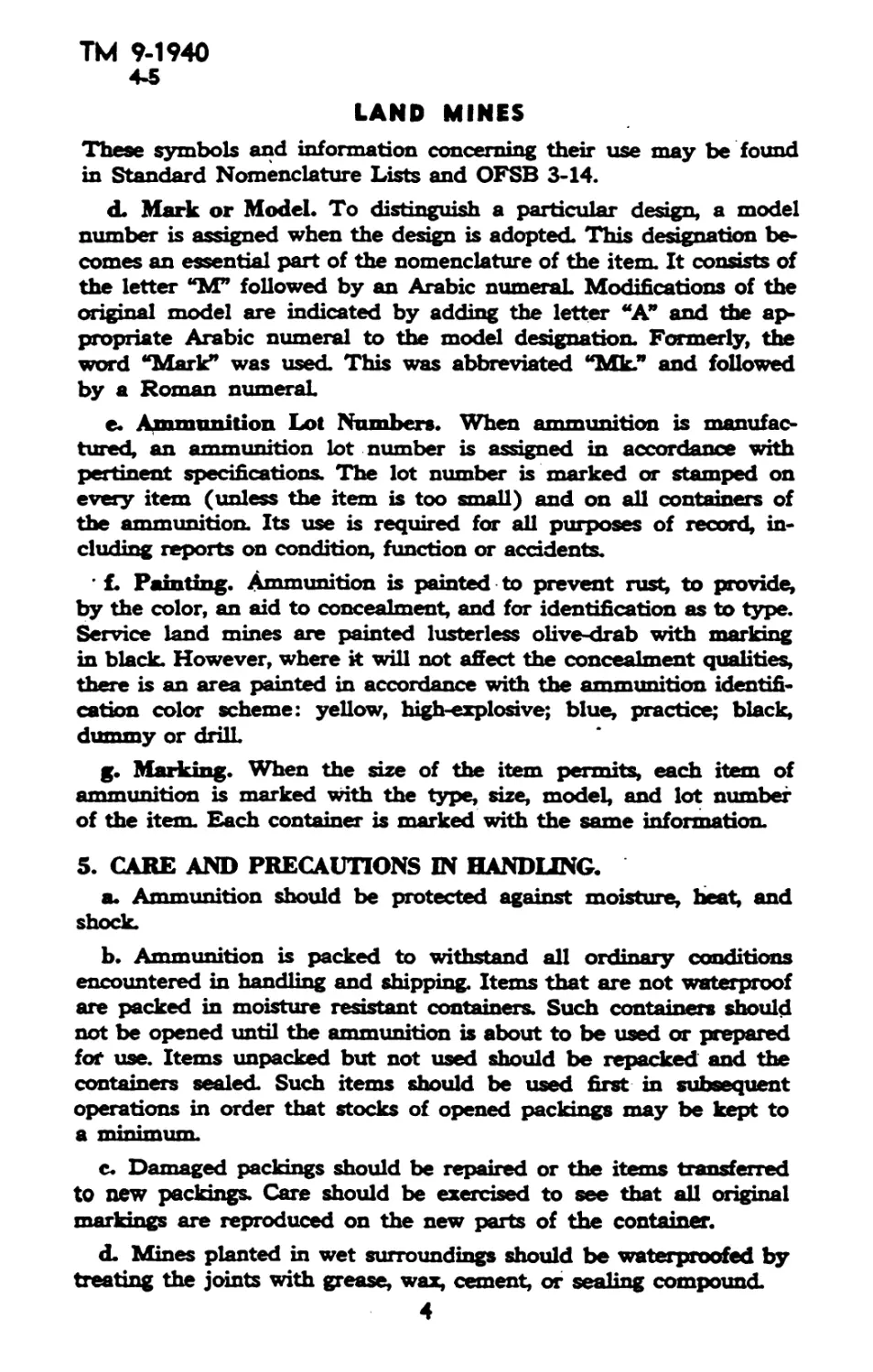
5. CARE AND PRECAUTIONS IN HANDUNG.
a. Ammunition should be protected against moisture, heat, and
shock.
b. Ammunition is packed to withstand all ordinary conditions
encountered in handling and shipping. Items that are not waterproof
are packed in moisture resistant containers. Such containers should
not be opened until the ammunition is about to be used or prepared
for use. Items unpacked but not used should be repacked and the
containers sealed. Such items should be used first in subsequent
operations in order that stocks of opened packings may be kept to
a minimum
c. Damaged packings should be repaired or the items transferred
to new packings. Care should be exercised to see that all original
markings are reproduced on the new parts of the container.
d. Mines planted in wet surroundings should be waterproofed by
treating the joints with grease, wax, cement, or sealing compound.
54
GENERAL
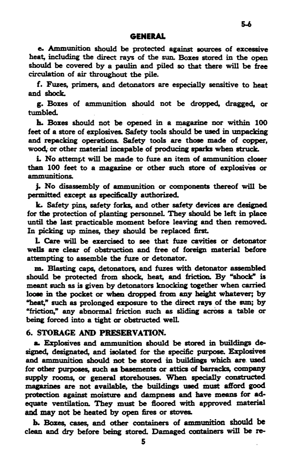
e. Ammunition should be protected against sources of excessive
heat, including the direct rays of the sun. Boxes stored in the open
should be covered by a paulin and piled so that there will be free
circulation of air throughout the pile.
f. Fuzes, primers, and detonators are especially sensitive to heat
and shock.
g. Boxes of ammunition should not be dropped, dragged, or
tumbled.
h. Boxes should not be opened in a magazine nor within 100
feet of a store of explosives. Safety tools should be used in unpacking
and repacking operations. Safety tools are those made of copper,
wood, or other material incapable of producing sparks when struck.
L No attempt will be made to fuze an item of ammunition closer
than 100 feet to a magazine or other such store of explosives or
ammunitions.
j. No disassembly of ammunition or components thereof will be
permitted except as specifically authorized.
k. Safety pins, safety forks, and other safety devices are designed
for the protection of planting personnel. They should be left in place
until the last practicable moment before leaving and then removed.
In picking up mines, they should be replaced first
L Care will be exercised to see that fuze cavities of detonator
wells are clear of obstruction and free of foreign material before
attempting to assemble the fuze or detonator.
m. Blasting caps, detonators, and fuzes with detonator assembled
should be protected from shock, heat, and friction. By “shock” is
meant such as is given by detonators knocking together when carried
loose in the pocket or when dropped from any height whatever; by
“heat,” such as prolonged exposure to the direct rays of the sun; by
“friction,” any abnormal friction such as sliding across a table or
being forced into a tight or obstructed well.
6. STORAGE AND PRESERVATION.
a. Explosives and ammunition should be stored in buildings de-
signed, designated, and isolated for the specific purpose. Explosives
and ammunition should not be stored in buildings which are. used
for other purposes, such as basements or attics of barracks, company
supply rooms, or general storehouses. When specially constructed
magazines are not available, the buildings used must afford good
protection against moisture and dampness and have means for ad-
equate ventilation. They must be floored with approved material
and may not be heated by open fires or stoves.
b. Boxes, cases, and other containers of ammunition should be
clean and dry before being stored. Damaged containers will be re-
5
ТМ 9-1940
6
LAND MINES
paired or replaced before storing, but the repairs or change of
container will not take place in or within 100 feet of a magazine
containing explosives. Powder dust or particles of explosive material
from broken containers will be carefully taken up as soon as spilled.
All work will be suspended until this has been done. Ammunition
containers should not be opened in a magazine nor should they be
stored after having been opened unless they have been closed
securely. No nails or tacks will be driven into a container of explo-
sives or ammunition. Cases should be handled with care. Cases should
not be dragged across the floor in magazines as this practice has re-
sulted in starting fires where there was powder dust present.
с.ь Loose rounds or components will not be kept in a magazine.
No empty container, no excess dunnage nor tools, should be per-
mitted to remain in a magazine. No oily rags, paint, turpentine, etc,
will be left in a magazine containing ammunition or explosives.
d. Ammunition should be piled by lot numbers in stable piles
which are so arranged that the individual containers are accessible
for inspection and offer no obstacle to the free circulation of air. The
tops of ammunition piles will be below the level of the eaves to
avoid the heated space directly beneath the roof. The bottom layer
should be raised off the floor about 2 inches. Dunnage should be
level; if necessary, shims or wedges should be used. Stacks should
not be so high that ammunition or its containers in the lower layers
will be crushed or deformed. Partly filled boxes should be fastened
securely, marked, and kept on the top of the pile.
e. Magazines should be built on well drained ground.
f. It is essential that explosives and ammunition be segregated in
an area specifically set aside for their exclusive storage. This area
need not be large, but it is important that it be segregated from
inhabited buildings, public highways, and railroads. Individual mag-
azines must be separated by distances adequate to prevent propa-
gation of an explosion from one to another. Such distances are
given in TM 9-1900.
g. Vegetation should be controlled and dry leaves, grass, and
rubbish removed from the magazine area and burned.
h. Accumulation of trash, empty boxes, scrap lumber, or any such
inflammable material should not be permitted.
L A 50-foot firebreak should be established around each above-
ground magazine.
j. Smoking, the carrying of matches, and the use of lights other
than approved electric lights in magazines or explosives storage areas,
are forbidden.
6
IIV1 7-17-rv
6-7
GENERAL
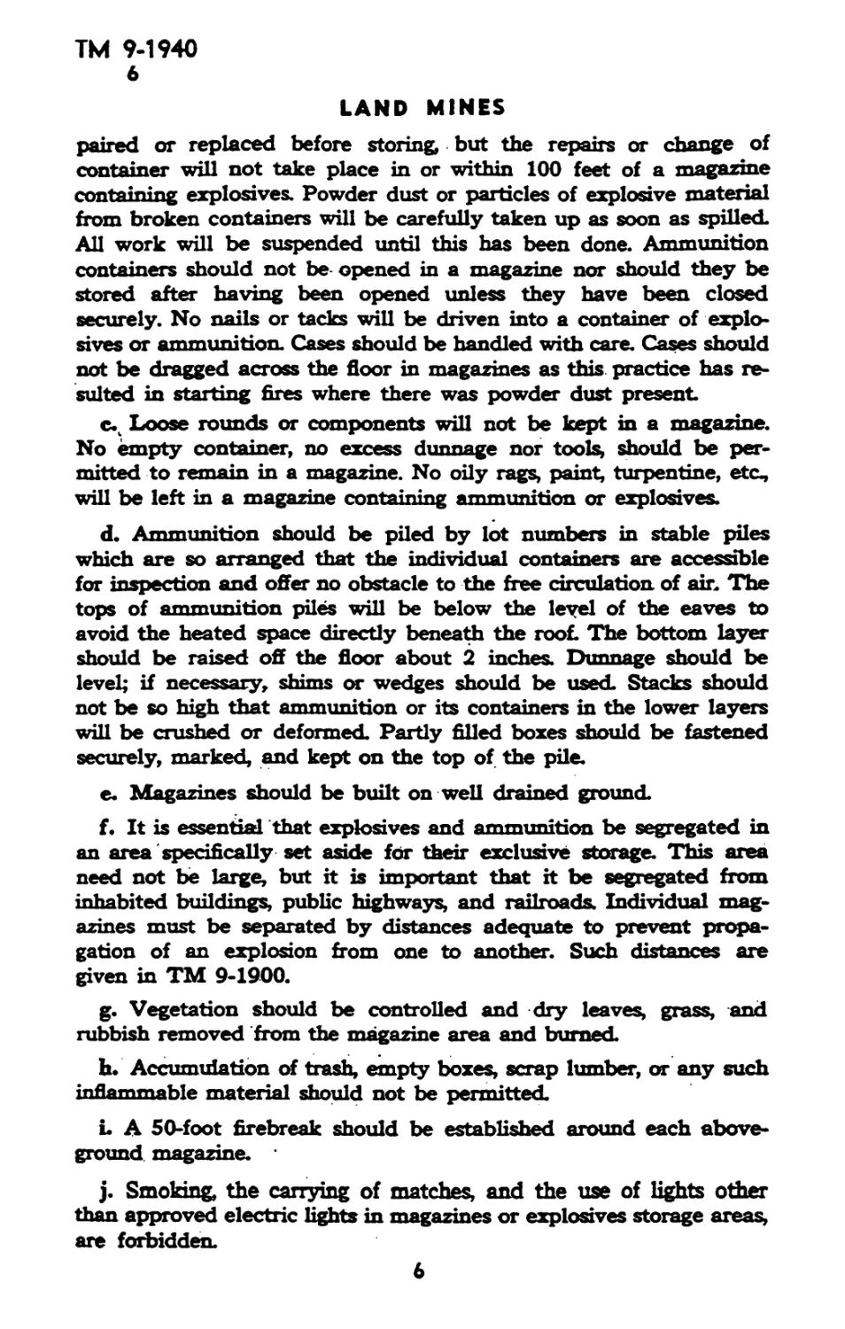
k. Interiors of magazines should be dean. Paint, oils, gasoline,
waste, rags, and other inflammable material should not be left in
magazines.
1. Except when they are issued in one packing, mines and fuzes
will not be stored in the same magazine. This applies to the detonat-
ing element of fuzes such as detonators, blasting caps, and the like,
and not to metal parts of fuzes or firing mechanisms when the de-
tonating element is not assembled thereto.
7. DESTRUCTION OF UNSERVICEABLE MATERIAL AND
DUDS.
a. General. Unserviceable material and duds will be destroyed
only by authorized and experienced personnel. Safety precautions
such as those laid down in TM 9-1900 and in Ordnance Safety
Manual OO No. 7224, will be observed.
b. Burning. Unconfined explosives such as demolition blocks may
be destroyed by spreading out thin on a layer of combustible material
and burning. Small components may be burned in a covered trench
or pit by preparing the fire, placing a quantity of the item to be
destroyed on the pile, and igniting from a distance by such means
as a train of excelsior. Larger items such as the FUZE, antitank mine,
Ml, may be burned in a covered pit by feeding one at a time down
a baffled chute from behind a barricade.
c. Detonation.
(1) Larger items will be destroyed by detonation at safe distances
from buildings, inhabited areas, and magazine areas.
(2) Thin-walled such as< the 'antitank .-minepr bangalore
torpedo, will need only one demolition block to detonate a pile but,,
becausethe thin-walled mines contain such a-large percentage of.
explosive, care must be exercised to limit the number destroyed at
a blast
(3) Thick-walled mines, such as the antipersonnel mines, will need
correspondingly more explosive and greater barricading to limit
(4) Blasting caps inserted in the fuze cavity or detonator well
may be used to destroy an item, instead of using the cap and a
block of demolition explosive.
d. Duds. Any land mine which failed to explode when its fuze or
firing mechanism was operated and any unexploded mine that shows
signs of having been operated (such as an antitank mine with vehicle
tracks over its location or a mine with a half-pulled detonator wire)
will be regarded as a dud. No attempt will be made to disarm,
unfuze, or take up a dud. It will be destroyed in place with explosive.
7
TH 9-1940
8-9
LAND MINES
8. PACKING AND MARKING FOR SHIPMENT.
a. Packing data for land mines and their components are given
in Table L
b. In addition to nomenclature and lot number, packings offered
for shipment are marked with the Interstate Commerce Commission
name or classification of the article, the names and addresses of con-
signor and consignee, volume and weight, and the code symbol.
TABLE 1
Item Qaeafft) Dimeasioas r (la.) Й Ca. Weight
H. (lb.)
BLOCK, demolition, М2 and 16 21% x!4%x7% 2.16 132 62
М3 .
BLOCKS, demolition, chain, Ml 2 21%xl4%ex7% 2.16 132 62
CAP, blasting, tetryl, 500 22x15x9% 2.29 131 54
electric
CAP, blasting, tetryl, 5,000 19x16x8 2.11 1.40 65
electric
EXPLOSIVE, nitroetardr, rectangular 50 PH- Quantities and dimensions may vary with different manufacturers
EXPLOSIVE, TNT, rec- 108 17% x 12x9 L48 Lil 65
tangular
FUZE, mine, antitank, 100 27% x М^хв2^ 233 2.06 96
HE^MlAl
FUZE, mine, antitank, practice, Ml 100 27%x14%x82%2 233 2.06 162
MINE, antipersonnel, М2 10 32xl3%ex9i%2 2.93 231 93
and M2A1
MINE, antipersonnel, М3 6 17%x8%x9%2 1.08 31 72
MINE, antitank, HJL, Ml 5 . 26%x9%x101%2 L77 135 68
MINE, antitank, H.E., M1A1 5 26%x9%x101%2 L77 135 71
MINE, antitank, ELE^ M4 5 26% x 10x10% 13 13 68
MINE, antitank, H3, M5 4 26%xll%xl2% 234 238 78
MINE, antitank, practice, Ml 5 26%x9%x101%2 1.77 135 64
MINE, antitank, practice, 5 26% x 10x10% L8 13 37
M1B1
TORPEDO, bangalore, Ml 10 63%xl5%x5% 6.99 3.13 168
8
IM У-1vw
10-11
Section III
ANTITANK MINES AND FUZES
РмгофорЬ
General.................................................... 10
Antitank mines........................................... 11
Practice antitank mines.................................. 12
Dummy antitank mines.................................... 13
Antitank mine fuzes........................................ 14
MINE, antitank, nonmetallic, HJL, MS, and FUZE, mine, anti-
tank, chemical, M5........................................ 15
10. GENERAL.
a. An antitank mine is any charge of explosive concealed or laid
where it may be passed over and exploded by vehicle. In addition to
the standardized types described below, antitank mines can be im-
provised from bangalore torpedoes (par. 19) and demolition blocky
(pars. 20, 21, and 22).
11. ANTITANK MINES.
a. General. This type of mine is shown with principal dimensions
and marking in figures 1, 2, 3, and 4. The complete round consists
of three components: the mine body, the spider, and the fuze.
b. Description. The min* body is a squat cylindrical container of
light steel, filled with high explosive. The bottom is plain and the
side has a carrying handle attached. The top extends beyond the
side to form a. grooved flange for the attachment of the spider. In
the center of the top there is an opening for the fuze cup and to the
side there is a capped fillixig hole. The fuze is described in para-
graph 14. The spider is in the shape of a wheel and has four hooks
attached to the rim for assembling the spider to the flange on the
mine body. When assembled, the hub of the spider rests on the
striker head of the fuze. As shipped, the spider is nested to the
bottom of the mine body.
e. Fuzing. The following steps are required to assemble the com-
plete round:
(1) Remove the spider from the bottom of the body.
(2) Insert fuze in fuze cup. Push the fuze down until it latches.
When thus assembled, the upper surface of the fuze body is flush
with the upper surface of the mine.
«*- NOTE: Before inserting fuze, be sure that the fuze cup is clear,
that is, no foreign matter present; in the Mine M1A1 or M4, be sure
the booster is in the bottom of the fuze cup.
(3) Assemble spider. To assemble the spider, aline two adjacent
hooks with the two notches in the flange of the body. Engage the
11
LAND MINES
OLIVE DRAB (MARKING IN BLACK)
--------S.03 MAX.--------
SAFETY FORK - CADMIUM PLATED
OLIVE DRAB
YELLOW —
RA PO БЗМОА
Figure 1 MINE, Antitank, H.E., Iff. Feted
10
ТМ 9-1940
11
ANTITANK MINES AND FUZES
SPIDER-I RAPD 53881
I
2— MINE. Antitank, Ml, as Shipped
Figure 3 — MINE, Antitank, H.E., MIA 1, as Shipped
other two hooks over the flange on the body; next press the first two
hooks through the notches; then rotate the spider approximately
one-eighth turn in either direction to secure the spider to the body.
(4) Plant mine.
< (5) Pull safety fork, thereby arming fuse. If the mine is buried
spider down, the safety fork will have to be removed before the
mine is buried. The safety fork should be left beside the mine at-
tached to its cord, never between the body and the spider.
11
TM 9-1940
11
LAND MINES
OLIVE DRAB (MARKING IN BLACK»
-----------8.03 MAX.-----------
OLIVE DRAB
RA PD «9105
Figure 4 MINE. Antitank, H.E., M4.
12
IM 7-I74U
11
ANTITANK MINES AND FUZES
<L Unfuzing. Mines may be disarmed and taken up by reversing
the steps in subparagraph c, above.
^e. Precautions.
(1) The safety fork will not be removed except when it is in-
tended to arm the fuze. The fork should not be removed until after
the mine has been planted, unless the mine is planted spider down.
Should the mine be taken up, the safety fork will first be replaced.
CAUTION: Care will be exercised that no undue load is acci-
dentally brought to bear on the spider, especially the rim, after the
safety fork has been removed. A load of approximately 250 pounds
on the rim of the spider will actuate the firing mechanism. These
figures refer to static loads; a sharp blow from a much smaller weight
will operate the fuze. In the case of the Ml, the fuze is a shear-pin
type, hence a blow or series of blows, while not causing the fuze to
operate, will nick the pins and make the fuze more sensitive so that
it will operate from much lighter loads than those specified above.
(2) To prevent sympathetic detonation of part or all of a mine
field, mines laid singly on the ground should be 3 feet or more apart;
if planted flush, 2 feet or more apart. Should it be required to give
a more powerful blast, the mines may be buried one on top of
another, or side by side, planted flush, or laid on the surface. If
planted flush, adjacent mines should be in contact; if laid on the
surface, they may be as much as 18 inches apart Such planting will
insure that all mines in the group will detonate, when any one
detonates. To prevent sympathetic detonation of part or all of the
groups in a mine field, the distances given above should be corres-
pondingly increased.
f. Packing. Antitank mines are packed five in a wooden box
which also contains five fuzes. The box is made up with a set of
plywood separators and two sets of grooves. As shipped, the fuzes
are placed in a fuze container which occupies one compartment of the
box; the five mines, with spiders nested to the bottoms, are packed,
carrying ring up, one in each of the other five compartments. For
convenience in carrying fuzed mines in the field, the same box, but
with the partitions moved to the second set of grooves, may be used.
The box with five high-explosive mines and fuzes weighs approxi-
mately 71 pounds.
g. Models. MINE, antitank, H. E, Ml, is the original model, which
has since been modified. J¥hen assembled in complete round the
Mine M1A1 is essentially'the same as the Ml. The difference lies
in the method of issuing the components (compare figs. 2 and 3).
In the case of the Mine Ml and Fuze Ml, the booster is assembled
as an integral part of the fuze, while in the case of the Mine M1A1,
the booster is issued assembled in the fuze cup of the mine, the
13
ТМ 9-1940
11-13
LAND MINES
balance of the fuze being issued separately as the Fuze М1А2
(fig. 5). The Mine M4 (fig. 4) is similar to the Mine Ml Al except
that there is no detonator cavity in the booster, as the detonator is
incorporated in the body of the fuze (fig. 6), and the spider is the
one-piece type (shown with the Practice Mine M1B1, fig. 8).
h. Painting. Antitank mines are painted as follows:
(1) The bottom and three-quarters of an inch of the side are
painted yellow.
(2) The balance of the surface and the spider are painted luster-
less olive-drab.
i. Marking. The top of the mine is marked in black with:
(1) Type and model of mine.
(2) Lot number.
(3) Manufacturer’s initials or symbol.
(4) Date loaded.
II.I 0,1
12. PRACTICE ANTITANK MINES.
a. MINE, Antitank, Practice, Ml.
(1) General. This mine with principal data and markings is
shown as a complete round assembly in figure 7. The complete round
consists of three components, an empty mine body, the spider, and
a fuze.
(2) Body and Spider. These parts are similar in construction to
the corresponding parts of the high-explosive mine except that the
body has five 1-inch holes equally spaced around the side.
(3) Fuzes. Fuzes are described in paragraph 14.
(4) Assembly (Fuzing and Arming). The practice mine is as-
sembled in the same manner as the service mine, described in para-
graph 11 c.
(5) Disassembly (Disarming and Unfuzing). See paragraph
11 d.
(6) Packing and Marking. Practice mines are packed in a box
similar to that of the high-explosive mine, except that the fuze com-
partment is empty. Practice fuzes are issued in a separate packing.
Practice mines are painted blue and marked in white.
b. MINE, Antitank, Practice, M1B1. This model is made of sheet
metal and resembles the service mine except that the filling hole is
in the bottom of the mine body. The mine is sand-filled to weight
before it is issued for use in practice.
13. DUMMY ANTITANK MINES.
a. In contrast to other types of ammunition where “DUMMY”
signifies drill ammunition, dummy antitank mines are defined as
14
ТМ 9-1940
13-14
ANTITANK MINES AND FUZES
simulated mines laid to deceive and confuse the enemy. They are
improvised in the field as the situation requires.
M. ANTITANK MINE FUZES.
a. FUZE, Mine, Antitank, H. E., Ml. This fuze, which contains
the booster as an integral part, is used only in the High-explosive
Mine Ml. It consists essentially of. a striker assembly and a body
which contains the primer, detonator, and booster, The striker assem-
bly, on the outer end of which is a 2-inch diameter head, protrudes
approximately % inch beyond the body of the fuze. The firing
mechanism, contained within the striker assembly, is restrained from
firing when in the armed condition (safety fork withdrawn) by the
collar just below the head and two shear pins. A force of approxi-
mately 500 pounds on the striker head is required to actuate the
firing mechanism. A weight of 10 pounds dropped 24 inches will
operate the fuze. When the fuze is assembled to the mine with the
spider in place, these figures are materially reduced. For safety in
shipping and handling, a safety fork, attached to the striker head by
a cord, is fitted over the collar between the striker head and the top
of the fuze body. The safety fork will not be removed except when
it is intended to arm the fuze. The striker head of the fuze is painted
yellow and the side is marked in black with:
(1) Designation of the fuze.
(2) Loader’s lot number.
(3) Loader’s initials. .
(4) Date loaded.
NOTE: When not packed with the mine, this fuze is packed 100
per box
b. FUZE, Mine, Antitank, H. E., M1A1. This fuze differs from
the Ml, described above, in that the booster forms a separate as-
sembly and is assembled to the mine body as issued. The detonator
assembly protrudes from the bottom of the fuze. Upon assembly of
the complete round, the detonator enters a mating cavity in the
booster.
c. FUZE, Mine, Antitank, H. E., M1A2. This fuze (fig. 5) is
identical in outward appearance to the Fuze Ml Al. The detonator
is more powerful to insure a high order explosion.
d. FUZE, Mine, Antitank, H. E., M4. This fuze (fig. 6) func-
tions on the “cricket” or “oilcan” principle. This means that the firing
pin spring consists of a convex metal diaphragm, which when de-
pressed under a weight of approximately 500 pounds, snaps down-
ward with sufficient force to detonate the fuze. The detonator is
assembled within the body of the fuze.
15
ТМ 9-1940
14
LAND MINES
ANTITANK MINES AND FUZES
ТМ * >40
14
LAND MIN
BLUE (MARKING IN WHITE)
IA PD 3884A
Rg re 7 MNE Antitank. Practice. Ml
18
TH 9-1940
14
ANTITANK MINES AND FUZES
-BLUE
RA PD 49104
Figure 8 MINE. Antitank, Practice. Ml Bl
19
ТМ 9- 940
Н
LAND MINE
Figure 9 FUZE, Mine Antitank, Che lee MS
Figure 1 MINE, Antitank, NonmetaHie, MS
20
ТМ 9-1940
14-15
ANTITANK MINES AND FUZES
e. Practice Fazes.
(1) FUZE, Mine, Antitank, Practice, Ml. This fuze is similar
in form and operation to FUZE, mine, antitank, H. E, Ml described
above, except that it contains a smoke-puff charge in place of the
booster element
(2) FUZE, Dummy (Practice Antitank Mine). This item of
drill ammunition is completely inert It is made of metal or plastic
to simulate the Service Fuze Ml and has a removable safety fork.
(3) These fuzes are used with the practice mine body for train-
ing and practice.
Crl
15. MINE, ANTITANK, NONMETALLIC, H. E., M5, AND FUZE,
ГйПЕП
a. General. This round (figs. 9 and 10) is manufactured without
the use of materials which would betray its presence to an enemy
using an electromagnetic mine detector. The mine body consists of
a ceramic bowl containing 5.6 pounds of high explosive and a ceramic
plate which acts as the spider. These components are separated by
a cushion of rubber or similar material and enclosed in a hard paper
container. There is a threaded opening in the top of the mine for
assembly of the fuze and a bakelite plug, in the bottom, which may
be removed for the attachment of an antiremoval device. Because
of its construction, this mine may be buried without fear of stones
or dirt jamming the firing mechanism and, being waterproof, it may
be installed under water or in swampy ground. The fuze consists of
a cylindrical body attached to a threaded plug. Instead of a metal
safety pin, a bakelite cap is screwed on the base of the fuze body.
This cap must be removed before the fuze can be assembled to the
mine. In addition to this safety cap, which restrains the firing pin,
there is a safety ring around the fuze body against the flange of the
plug, which prevents the fuze being screwed home into functioning
position in the mine.
b. Fuzing.
(1) The mine may be fuzed by the following steps. NOTE: The
outer hard paper container of the mine body will be left in place.
(X) Remove the adhesive cover of the fuze cavity and examine
the cavity to insure that it is free of all foreign material.
Fromm* the fuze to insure that it is serviceable and that
the safety ring and safety cap are in place.
(c) Remove the safety cap.
(d) Insert the fuze, with safety ring in place, into the mine and
screw down handtight.
(e) Plant the mine.
21
ТМ 9-1940
15
LAND MINES
(f) Remove the safety ring. If necessary, back the fuze out one
turn.
(g) Screw the fuze in handtight in a clockwise direction.
c. Unfuzing. The mine may be taken up by reversing the steps in
subparagraph b, above.
d. Antiremoval Devices. Any of the firing devices described in
section V may be attached to this mine by removing the plastic plug
in the bottom of the mine and attaching as described in the para-
graph on the device used. It should be borne in mind, however, that
die use of a metallic firing device tends to defeat the purpose of
designing this mine and fuze with no metal parts.
e. Precautions. In addition to the general precautions to be ob-
served in handling antitank mines and fuzes, care should be exer-
cised in arming the mine to screw the fuze in no more than handtight
and, when taking up the mine, to turn the fuze in a counterclockwise
direction.
f. Marking. MINE, antitank, nonmetallic, H. E, M5, is painted
lusterless olive-drab and marked in yellow.
g. Packing. MINE, antitank, nonmetallic, H. E^ M5, and FUZE,
mine, antitank, chemical, M5, are packed four of each to the box
(par. 8).
22
TM 9-1940
16-17
Section IV
ANTIPERSONNEL MINES
Paragraph
General ..................................................... 16
MINE, antipersonnel, М2 ..................................... 17
MINE, antipersonnel, М3 ..................................... 18
TORPEDO, bangalore, Ml ...................................... 19
Demolition materials ........................................ 20
Blocks, demolition, chain, Ml................................ 21
Demolition blocks.......................................... 22
16. GENERAL.
a. All antipersonnel mines depend for initiation upon some action
of the enemy. In general, as enemy personnel will not have the re-
strictions of vision that are imposed upon the driver of an armored
vehicle, it is important that full advantage be taken of every oppor-
tunity for concealment. Therefore, antipersonnel mines and firing
mechanisms used therewith will receive special attention to the main-
tenance of the neutral color and finish.
b. In addition to standardized antipersonnel mines, this section
also describes other items of demolition material from which antitank
or antipersonnel mines may be improvised. Firing mechanisms are
described , in section V.
17. MINE, ANTIPERSONNEL, М2.
a. MINE, antipersonnel, М2 (figs. 11 and 12), is similar to a
small mortar. It projects a shell about 6 feet in the air, where it
explodes. Designed for use against personnel, it has an effective radius
of about 30 feet The shell weighs approximately 3 pounds, of which
12 percent is high explosive. The shell fuze, which is ignited by the
propelling charge, contains a delay element that delays detonation
of the shell until it has attained an effective height This mine is
fired by the action of a pull wire or a pressure device.
b. Description.
(1) The mine (figs. 11 and 12) consists of a base plate, a length
of thin-walled steel tubing riveted (М2) or soldered (M2A1) to the
base plate and serving to contain and project the loaded and fuzed
shell, and a ^4-inch pipe nipple, threaded to the base plate and
serving as a connection for the firing mechanism. The cavity in the
base plate contains the propelling charge, which consists of 20 grains
of black powder assembled in a small bag. The tube, containing the
fuzed shell, is sealed with a metal cap. Attached to the pipe nipple
is a coupling into which is fitted the primer and igniter assembly.
The primer is protected during handling and shipment by a hex-
23
ТМ 9-1940
17
LAND MINES
Figure 11
MINE, Antipersonnel, М2
24
ТМ 9-1940
17
ANTIPERSONNEL MINES
*A П 4959SC
Figure 72 — MINE, Antipersonnel. М2 Al
25
ТМ 9-1940
17
LAND MINES
agonal cap. FUZE, mine, antipersonnel, М2, is shipped separately
in a tube, in the same box with the mine.
(2) The fuze issued with this mine consists of the Combination
Firing Device Ml (par. 24) with ah igniter cap attached. The base
and igniter are assembled to the mine and the firing pin assembly is
supplied, disassembled, in the same carton. It is a simple type firing
mechanism containing a spring-loaded firing pin. It may be fired by
means of a trip wire connected to the release pin ring or by pressure
applied to the pressure cap (fig. 11). A pressure of 20 to 40 pounds
on the pressure cap or tension of 3 to 6 pounds on the release pin
will cause release of the firing pin and detonation of the mine.
Lengths of wire packed with the mines are for connecting to the re-
lease pin ring and making tripping devices. The wire supplied with
some mines is olive-drab; that supplied with others is sand colored.
c. Operation. To assemble the mine, remove the hexagonal cap
from the primer and, after making sure that the locking screw and
safety pin are in place, screw the firing pin assembly onto the primer.
(1) To Plant or Prepare for Action (par. 24 c).
(a) Be sure the locking screw and safety pin are in place.
(b) Place the mine on a firm foundation.
(c) Remove the hexagonal cap from the primer and screw on the
firing pin assembly.
(d) Attach trip wire or install the pressure trip on the pressure
cap.
(e) Check to see that the trip wire is not too tight or that there
is not too much weight on the pressure cap.
(f) Remove the locking screw.
(6) Remove the safety pin. If the safety pin tends to bind, the
device is unsafe and should not be used.
(h) Special Safety Precaution. This device may fire if the release
pin is rotated after the locking screw is loosened or removed and
the safety pin is removed. Do not adjust the position of the release
pin unless the safety pin and locking screw are securely in place.
(2) To Pick Up or Recover.
(a) Replace safety pin and screw .the locking screw in place.
(b) Cut the trip wire or remove the pressure tripping device from
the pressure cap.
(c) Take up the mine.
(d) Remove fuze, screw on the hexagonal cap, and return the mine
and components to original packing.
d. Precautions.
(1) No attempt will be made to disassemble the mine (except to
26
TM 9-1940
17-18
ANTIPERSONNEL MINES
remove the firing pin assembly when the mine is picked up). Mines
with loose caps or primers will not be used until inspection by
ordnance personnel shows that the igniter and propelling charge
have not been damaged by moisture, and the mine cap and primer
assembly have been resealed.
(2) When mines are being planted, place the hexagonal cap from
the primer and the locking screw and safety cotter pin near the body
of the mine, in a position where they may be readily found if it is
necessary to pick up or recover the mines.
(3) While this mine is water resistant, it should not be expected
to function after prolonged submergence in water.
e. Marking and Packing.
(1) The mine and the fuze are painted lusterless olive-drab, ex-
cept for the flange of the mine base, which is painted yellow. Sten-
ciled on the flange is the type and model of the mine, the lot number,
manufacturer’s symbol, and date of loading.
(2) The mine is packed one per corrugated paper carton. The
carton also contains the firing pin assembly and 1 spool of four
26-foot lengths of wire. Ten such containers are packed in a wooden
box. The boxes are marked «OLIVE DRAB* or “SAND COLOR*
to indicate the color of the wire packed therein (par. 8).
ZiX-z— I
l^MINE, ANTIPERSONNEL, М3.
a. General. The MINE, antipersonnel, М3, is a fragmentation
type of land min* intended primarily for use against personnel The
complete round consists of the min*, a hollow cast-iron block contain-
ing TNT, and FUZE, min*, antipersonnel, М3. It has an effective
radius against personnel of 10 yards when fired at the surface of
the ground. The effective radius is slightly increased when the mine
is used several, feet above ground level, and is decreased when the
mine is buried in the ground. Fragments of the mine may be thrown
more than 100 yards and suitable protection should be provided for
friendly personnel within this radius.
b. Description.
(1) The MINE, antipersonnel, М3, is shown with principal dimen-
sions in figure 13. The cast-iron casing is filled with a 0.90-pound
charge of flaked TNT. In two opposite sides and one end, there are
holes below which are cap wells. Any one of these holes may be
used. As shipped, the holes are closed with plastic plugs. In the end
opposite the well is a filling hole which is closed with a metal disk.
(2) FUZE, mine, antipersonnel, М3 (fig. 14), consists of a special
blasting cap (U. S. Army blasting cap, type A) crimped to the
Combination Firing Device Ml (par. 24) for use with this mine.
The firing device contains a spring-loaded firing pin and a primer.
27
OLIVE DRAB ----------------
FUZE WELL CLOSING PLUG
5.375
CLOSING DISK I YELLOW I
8 68 APPROX
RA PD 49595
Figure 13 — MINE. Antipersonnel. М3. Complete
TM 9-1940
18
ANTIPERSONNEL MINES
Figure 14 — FUZE, Mine, Antipersonnel, М3
It may be fired by means of a cord or. wire connected to the release
pin ring, or by pressure applied to the pressure cap. A pressure of
20 to 40 pounds on the pressure cap, or a tension of 3 to 6 pounds
on the release pin, will release the firing pin and detonate the primer.
Wire is furnished for connecting to the pull ring for making tripping
devices. A safety pin located in a hole in the firing pin, and a locking
screw bearing on a groove in the firing pin, protect the firing device
from accidental functioning during shipping and handling. The firing
device is issued unassembled to the mine.
c. Operation. To assemble the mine, it is only necessary to re-
move the closing plug* from the desired fuze hole and to screw in
the firing device firmly. Be sure that the well is clear of foreign
material and that the detonator enters freely.
(1) To Plant or Prepare for Action (par. 24 c).
(a) Remove the closing plug. Use the wrench packed with the
mines.
(b) Assemble the fuze to the mine.
(c) Attach a trip wire to the release pin ring, or install a pressure
trip on the pressure cap.
(d) Check to see that the trip wire is not too tight, or that there
is not too much weight on the pressure cap.
(e) 'Remove the locking screw and safety pin. If the safety pin
tends to bind, the fuze is unsafe and should not be used.
(f) Special Safety Precaution. This device may fire if the release
pin is rotated after the locking screw is loosened or removed, and
the safety pin is removed. Do not adjust .the position of the release
pin unless the safety pin and locking screw are securely in place.
29
TM 9-1940
18
LAND MINES
(2) To Pick Up or Recover.
(a) Replace the safety pin and screw the locking screw in place.
(b) Cut the trip wire or remove the pressure tripping device from
the pressure trip.
(c) Take up the mine.
(d) Remove the fuze from the mine and replace the closing plug.
(e) Repack the components in their original packing. The fiber
case in which the fuze is packed should be resealed.
d. Precautions.
(1) No attempt will be made to disassemble the mine or com-
.ponents, except to remove or replace the fuze hole closing plug and
assemble or remove the fuze.
(2) Do not remove the locking screw or safety pin from the fuze
until the mine is placed and the installation is checked to see that
there is not too much tension on the pull ring, or too much pressure
on the pressure cap.
(3) Protect the fuze from shock, heat, and friction.
(4) When the mines are being planted, place the fuze hole plug,
locking screw, and the safety pin in a position where they may be
readily found if necessary to pick up and recover the mines.
(5) Exposure to moisture will not affect the operation of the
mine. However, the mine is not waterproof, and should not be planted
in positions where it will be immersed in water for more than a
few days.
e. Marking and Packing.
(1) Marking. The mine body and the fuze are painted olive-drab
with markings in black. On one side are marked the type and model
of the mine, metal parts manufacturer’s lot number, and date of
manufacture. The opposite side is marked with the type and model,
loader’s lot number, and date of loading. The closing disk is painted
yellow.
(2) Packing. Six mines are packed in a wooden packing case,
which also contains six fuzes. The fuzes are packed in sealed cylin-
drical fiber containers which, in turn, are packed in compartments
in one end of the packing box. Packed in the box is a small wrench
which fits the square holes in the plastic plugs in the mine and is
used for unscrewing them prior to assembling the fuzes. Six spools
of wire for making tripping devices are also packed in the box. Each
spool has four 26-foot lengths of wire. The boxes are marked “OLIVE
®RAB” or “SAN® CQL®R” to indicate the color of the wire packed
therein (par. 8).
30
TM 9-1940
19
ANTIPERSONNEL MINES
J9, TORPEDO, BANGALORE, Ml.
a. Description.
(1) The bangalore torpedo (fig. 15) is a tube or pipe filled with
high explosive, primarily used for blasting an opening through wire
entanglements or for clearing mine fields. The TORPEDO, bangalore,
Ml, consists of a steel tube 5 feet in length and 2 Vs inches in diameter
which is grooved and capped at each end. The tube is filled with
amatol, with about 4 inches of TNT at each end. The weight of ex-
plosive charge is about 9 pounds. Each end of the tube is capped
and contains a recess or Well to accommodate a detonator or blast-
ing cap attached to any of the standard firing devices described in
section V. A nose sleeve which fits on the end of the torpedo, and
connecting sleeves for assembling the torpedoes in multiple lengths,
are provided. The torpedoes and accessories are painted lusterless
olive-drab.
(2) In addition to clearing wire entanglements and mine fields,
this torpedo may also be used as an antitank mine or antipersonnel
mine. Because of its high percentage of explosive charge, it may also
be used for demolition purposes.
b. Components and Accessories. The following parts are used
for detonating the torpedoes or placing them in multiple assembly.
(1) Detonator.
(a) Electric or nonelectric blasting cap may be used to detonate
the torpedo. If commercial blasting caps are used, a combination
(tetryl) detonator, equivalent to a No. 8, or stronger, blasting cap
should be used.
(b) Primacord may be used by inserting primacord in the well
and wedging it in place.
(2) Nose Sleeve. This is a rounded point which fits over the
end of a torpedo (fig. 15). It contains a single clip which holds it
in place. The nose sleeve is provided for ease in pushing the torpedo
through obstacles such as heavy brush or barbed wire. It is not neces-
sary for the proper functioning of the torpedo.
(3) Connecting Sleeve. The connecting sleeve (fig. 15) is a
short tube into which the ends of two torpedo tubes will fit and be
held by three spring clips. It is used when assembling the torpedoes
in multiple lengths.
c. Assembly. The sleeves and torpedo are alined and forced to-
gether until the spring clips on the sleeve snap into the groove on
the end of the torpedo.
(1) Assembly in Multiple Lengths. To assemble in multiple
lengths, fit a nose sleeve over the leading end of the torpedo. Then
fit a connecting sleeve on the other end and fit another torpedo into
31
г
RA FD 69106
Figure 15 — TORPEDO, Bangalore, Ml
TM 9-1940
19-21
ANTIPERSONNEL MINES
the sleeve. Add additional sleeves and torpedoes until the desired
length is obtained. One detonator in the cap well at the end will
detonate the entire line of- torpedoes.
d. Packing. TORPEDO, bangalore, Ml, is packed 10 in a box,
which also contains 10 connecting sleeves, and 1 nose sleeve (par. 8).
20. DEMOLITION MATERIALS.
a. Explosives. Half- and quarter-pound blocks of compressed
TNT and nitrostarch, respectively, are supplied for demolitions and
like purposes. These may be used either by themselves with any of
die firing mechanisms (sec. V) equipped with a detonator, or may
be used to augment any of the mines described herein.
NOTE: Nitrostarch is more sensitive than TNT, consequently
nitrostarch blocks will not be crushed or broken.
b. Primacord. Primacord consists of a flexible tube filled with
high explosive. It is ordinarily used to transmit a detonation from
a blasting cap to a charge of high explosive or from one charge of
high explosive to another without requiring the use of a second cap.
In addition to its function of transmitting a detonation, primacord
contains enough high explosive so that it may be used as the main
charge of a booby trap by making a fiat coil about 3 inches in
diameter of 12 to 20 feet of primacord and taping nails, empty
cartridge cases, or other metal fragments around it
6/
21. BLOCKS, DEMOLITION, CHAIN, Ml.
a. General. BLOCKS, demolition, chain, Ml, assembly (figs. 16
and 17), consists of eight 2- by 2- by 11-inch blocks of tetrytol
strung on a 16-foot length of primacord (par. 20 b) and packed- in
a haversack. The assembly is provided primarily for demolition pur-
poses and is designed for ease in use and handling. The entire chain,
or any part of the chain, may be used laid out in a line, wrapped
around an object or as packed in the haversack.
b. Description. Each block is rectangular in shape and is en-
closed in a crinkle kraft paper bag. Printed on the bag in at least
one place, is the designation: “DEMOLITION BLOCKS, Ml (TET-
RYTOL). MUST BE DETONATED BY CORPS OF ENGINEERS,
U. S. ARMY, BLASTING CAP. ONE BLOCK - SIX Уг-LB. TNT
BLOCKS.” The blocks are cast in place on the primacord with 8
inches between blocks and 2 feet of primacord free at each end.
They consist of tetrytol, which is 75 percent tetryl and 25 percent
TNT, with a cylindrical pellet of tetryl cast in each end of each
block. The dimensions of the haversack are approximately 12 % by
9 by 44 inches, and its weight, packed, is 223 pounds.
c. Characteristics. Tetrytol is more powerful and more brisant
than TNT: hence these blocks are more effective in cutting steel
33
£
£
£
HAVERSACK FOR DEMOLITION BLOCKS Ml AND М2
BLOCKS, DEMOLITION, CHAIN, Ml
KA ГО 69107
Figure 16 SLOCKS, Demolition, Ch» iln, M
m
<л
------------ II"-------------
OLIVE DRAB (MARKED IN BLACK)
Figure 17 Demolition Blocks
RA PD 69108
TM 9-1940
21-22
LAND MINES
and in demolition work. If necessary, each block may be broken
within its bag, but care should be exercised not to break the prima-
cord. The blocks and primacord are comparatively insensitive to
shock, but the assembly, that is, with tetryl pellet, is slightly more
sensitive than TNT.
d. Use. It is necessary to detonate the primacord by means of
a blasting cap or detonator in order to fire the entire chain. Sympa-
thetic detonation of unconnected blocks can be obtained when they
are separated by as much as 10 inches of air.
is a rectangular block of tetrytol 2 by 2 by 11 inches, with a
detonator well in each end. At the outer end of each well there is an
adapter threaded to receive any of the standard firing devices. At
the inner end of each well, there is a tetryl pellet cast in the block
to act as a booster. Each block is wrapped in olive-drab paper on
which is printed «BLOCK, DEMOLITION, М2” and “EQUIVA-
LENT TO SIX %-POUND TNT BLOCKS”. This block, except for
the replacement of the primacord by detonator wells, is similar to
BLOCKS, demolition, chain, Ml. It is packed in the same manner and
has the same properties and uses.
b. BLOCK, Demolition, М3. BLOCK, demolition, М3, is a rec-
tangular 2^4-pound block of plastic explosive 2 by 2 by 11 inches.
It is packed in a cardboard box which is marked:
HIGH EXPLOSIVE
Composition C-2
“One block is equivalent to six Vi-pound TNT blocks.”
(1) This plastic explosive can be moulded by hand into any
desired shape or position and is very efficient as a result of the
good contact thus obtained combined with its high power. The ex-
plosive is plastic at temperatures ranging from 20 F below to 125 F
above zero and is resistant to the action of water. BLOCK, demoli-
tion, М3, is packed in a cardboard box, eight such boxes per haver-
sack, two haversacks per box.
c. BLOCK, Demolition, M4. BLOCK, demolition, M4, is a Vi-
pound block of high-explosive composition C 2, packed in a card-
board box 6.75 by IS by 1 inch. These are packed without haver-
sack, about 52 pounds per wooden box
36
TM 9-1940
23-24
Sectioa V
FUZES AND FIRING MECHANISMS
General............................................... 23
Combination firing device Ml.......................... 24
Pull firing device Ml................................. 25
Pressure firing device Ml ............................ 26
Release firing device Ml.............................. 27
Blasting caps......................................... 28
23. GENERAL.
a. Any of the firing mechanisms described herein may be used,
with the appropriate detonator or igniter, with any of the devices
described in the preceding section.
COMBINATION FIRING DEVICE Ml.
a. Description. This is a nonelectric mechanism designed for use
with a trip wire or a pressure arrangement The device (figs. 18 and
19) consists of a head, body, and base (figs. 11, 12, and 14). The
base, containing the primer, has an extension to which an igniter от
a detonator may be attached. The base is threaded below to screw
into a mine or demolition block, and above to receive the body
housing. The body contains a spring-loaded firing pin which passes
through the head. The firing pin is grooved to receive the locking
screw and release pin as it passes through the head and is drilled to
receive the safety pin above the head.. The pressure cap fits over
the top of the firing pin.
b. Function. When the locking screw and safety pin are removed,
the release pin, tfhich bears in the groove in the firing pin, holds it
against the firing pin spring. A pull of 3 to 6 pounds on the ring
attached to the outer end of the release pin releases the firing pin.
Also a force of 20 to 40 pounds on the pressure cap forces the release
pin back, thus releasing the firing pin. Driven by the firing pin spring,
the pin strikes the primer which explodes, sending a spurt of fire
through the extension in the base, initiating the igniter or detonator
attached thereto.
c. Installation.
(1) In Antipersonnel Mines М2 and М3. As issued with Anti-
personnel Mine М2 the firing device has an igniter attached to the
base. The base is separated from the body of the firing device and
assembled to the mine. The firing pin assembly, designated FUZE,
mine, antipersonnel, М2, is supplied with the mine but not assembled
to it As issued for the Antipersonnel Mine М3 the device is complete
37
Figure 18 Firing Devices
Figure 19»— Combination Firing Device MJ
RA PD 49597A
TM 9-1940
24
LAND MINES
and has a blasting cap assembled. This assembly is designated FUZE,
mine,- antipersonnel, М3. In tins case the fuze is packed separately,
but in the same packing box with the mine. For installation, see
paragraphs 17 and 18.
(2) For Installation in Other Charges.
(a) Prepare and place the mine charge. In addition to the standard
mines supplied, the mine charge may be a fragmentation hand gre-
nade, primacord, bangalore torpedo, or any explosive which can be
detonated by the Army special nonelectric cap or by primacord. The
procedure to be followed is the same as for the placing of any dem-
olition charge where a nonelectric cap is used. If the firing device
and the charge are not to be placed together, primacord may be used
to connect them, by taping or tying three turns around a demolition
block or inserting the end of the primacord into a fuze hole and
wedging it there with a twig or piece of wood. The other end of the
primacord is formed into a short loop and taped securely to the
blasting cap on the firing device. Necessary waterproofing arrange-
ments should be made where the charge is exposed to the weather.
If severe weather conditions are anticipated, or the installation is
expected to be subjected to weather for a long period, it is necessary
to take additional steps to seal the connection between the firing de-
vice base and the blasting cap. A small amount of heavy grease, wax,
cap-sealing compound, or any other suitable waterproofing material
which is available should be applied in making all joints,
(b) Remove the base containing the primer, leaving the safety
screw and safely pin in place.
(c) "Remove the cardboard protector tube from the tip.
(d) Slide the open end of a nonelectric cap over the projection on
the base and crimp, using cap crimpers. This should be done carefully
as only a tight crimp will result in a waterproof joint between the
base and the blasting cap.’
(e) Screw the base, with blasting cap attached, to the device.
(i) Insert the blasting cap into the charge or tape primacord to
the cap.
(3) For Use As a Pull Type Firing Mechanism.
(a) Anchor the firing device as close to the mine charge as possible.
(b) Install the trip wire. Always start from the far end. Fasten the
trip wire to a peg, bush, or other anchor, and then lay it out toward
the mine. There should be no tension on the trip wire. Bef ore connect-
ing the trip wire to the firing device, step off to the side and inspect
to see that the wire is not visible. Rearrange it, if necessary, so that
it is not visible.
(c) Attach the trip wire to the firing device. It must place no
tension on tire device.
40
ТМ 9-1940
24-25
FUZES AND FIRING MECHANISMS
(4) For Use As a Pressure Firing Mechanism (par. 26).
(л) Prepare the pressure trip installation, making sure that there
is a firm attachment for the firing mechanism and that the pressure
trip does not bear too heavily on the pressure cap.
(b) Attach blasting cap and prime charge as above.
(c) Install mechanism and pressure trip. Make sure that the
installation is not detectable.
(5) The final operation is to remove the locking screw while
the safety pin is in place. If there is too much pressure or tension
on the firing device the safety pin will tend to bind and the installa-
tion should be checked. If the safety pin does not bind, gently re-
move it and leave both safety pin and locking screw concealed near
the mine in case it should be necessary to disarm and take up the*
mine.
25. PULL FIRING DEVICE Ml.
a. Description. The Pull Firing Device Ml (procured from Corps
of Engineers) is a nonelectrical mechanism, designed primarily for
use with a trip wire, for firing mines or other explosive charges. A
direct pull of from 3 to 5 pounds applied to the trip wire releases the
firing pin, which is driven by the compression spring into a percussion
cap fitted in the base. This percussion cap fires a nonelectric blasting
cap, attached to the base, which in turn detonates the explosive
charge. The device (figs. 18 and 20) measures approximately 4%
inches long by % inch diameter. It consists of a head, a housing tube,
and a base. The head contains a release pin, a safety pin, and a
loading spring. The housing tube contains the firing pin, the firing
pin compression spring, and a second safety pin which passes through
the body between the firing pin and the percussion cap. The base
contains a recess into which a percussion cap is placed, and a pro-
jection to which a nonelectric blasting cap is crimped when the firing
device is loaded. The firing mechanism consists of a firing pin, a
compression spring, a release pin assembly, and a loading spring.
The split head of the firing pin is forced against pressure of the com-
pression spring through a small opening or well, in the housing.
The release pin enters into and expands the split head of the firing
pin spindle against the sides of the well, thus preventing its return,
although the striker is under pressure from the compression spring.
The release pin is held in position by the loading spring. Holes in
the main head and in the release pin allow insertion of safety pins,
thus preventing accidental movement of the release pin to fire the
cap. A soldered joint is made between the main head and the housing
tube, so that this part of the device cannot be taken apart A short
piece of flexible wire terminating in a loop is attached to the housing
tube at this joint This is to be used as an anchorage for the firing
41
ТМ 9-1940
25
LAND MINES
RA PD 69075
Figun 20 — Pall Firing Device Ml
device. The ring on the release pin facilitates fastening the trip wire
to the device. The safety pin through the body positively restrains
the firing pin from striking the percussion cap.
b. Functioning. When the safety pins are removed, a pull of
from 3 to 5 pounds applied through a distance of about fa inch is
sufficient to overcome the resistance of the loading spring and cause
the tapered end of the release pin to be withdrawn from within the
42
TM 9-1940
25-26
FUZES AND FIRING MECHANISMS
split: head of the firing pin. The split head of the spindle, being no
longer forced against the well, slips through under the influence of
the compression spring. This forward movement of the firing pin
continues until it strikes the head of the percussion cap contained
in the base of the device. The percussion cap is thus fired, and
detonates a nonelectric cap crimped to the base.
c. Installation. This device is installed in a manner similar to the
combination firing device (par. 24) except that the safety pin through
the body is removed last, after all other preparations have been
made and tested.
d. Packing. Pull firing devices are packed in boxes, each box con-
taining five devices complete with percussion caps and two 80-foot
spools of light trip wire. The boxes measure 4% by 4% by 1%
inches. Each full box weighs 1 pound 3 ounces.
26. PRESSURE FIRING DEVICE Ml.
a. Description. The Pressure Firing Device Ml (procured from
Corps of Engineers) is a nonelectrical device designed to cause the
detonation of antipersonnel mines or other explosive charges when
the device is subjected to a pressure of 30 pounds or more. The
device (figs. 18 and 21) is mounted on a rectangular metal base
plate, measuring 2% by 1% inches, and is composed of a barrel,
head, and base. The barrel contains the firing mechanism and a
safety pin. The head, permanently joined to the barrel, contains the
trigger assembly. The base, which screws into the barrel, contains
a recess into which a percussion cap fits and a projection over which
a nonelectric blasting cap is crimped. (The base and percussion cap
are identical with those used on the Pull Firing Device Ml.) The
firing mechanism consists of a striker assembly, a striker spring, a
trigger assembly, and a trigger spring. The striker assembly consists
of a round spindle, with a groove three-eighths of an inch from the
end opposite the striker, the striker head, and a firing pin mounted
on the striker head. The trigger unit consists of a large, flat head
mounted on a trigger pin extending through the side and down into
the barrel The trigger pin has a pear-shaped hole in it The small
section of the spindle fits in the small end of a pear-shaped hole
so that the striker spring is unable to cause movement of the striker
and firing pin. A safety dip extends around the trigger pin, between
the barrel and the trigger head. No appreciable movement of the
trigger pin against the action of the trigger spring is possible until
the safety clip is removed. The firing pin is restrained from striking
the percussion cap until the safety pin through the body is removed.
b. Functioning. When the safety clip is removed, a force of from
25 to 35 pounds applied to the trigger head through a distance of
three-sixteenths of an inch is sufficient to overcome the resistance of
43
ТМ 9-1940
26
LAND MINES
Figure 21 Pressure Firing Device Ml
the trigger spring and cause the trigger pin to move into the barrel,
permitting the striker and firing pin to be driven forward and strike
the percussion cap. The percussion cap detonates a nonelectric blast-
ing cap crimped to the projection on the base.
c. Installation. To install the Pressure Firing Device Ml, the pro-
cedure is as follows:
(1) Prepare and place the mine charge as for the combination
firing device (par. 24).
(2) Keeping the safety clip in position on the firing device, re-
move the base containing the percussion cap.
(3) Place the firing device in position at the location where it
is to be used. Be sure that it has solid footing. Place the pressure
44
ТМ 9-1940
26*27
FUZES AND FIRING MECHANISMS
device in place and see that it does not bear too heavily on the
trigger head.
(4) Slide the open end of the nonelectric cap around the pro-
jection on the base, and crimp, using the cap crimper.
(5) Screw the base, blasting cap attached, to the device.
(6) Prime the charge. When primacord is used, tape the looped
end of the primacord to the blasting cap in the proper manner and
run the other end to the charge. If primacord is not used, insert the
blasting cap into a block of explosive.
(7) Next remove the safety clip gently. The safety clip should
pull off very easily; a sudden jerk may cause the device to fire pre-
maturely. If the safety clip does not pull off easily, check the in-
stallation to make sure that there is no pressure on the trigger pin.
(8) The final operation, after all parts of the installation have
been checked, is to remove the safety pin. When the device is
firmly anchored, it is good practice to remove safety clip and safety
pin from a safe distance, using a string or length of wire for the
purpose.
(9) When the firing device is employed with the Fragmentation
Hand Grenade Mk. П, unscrew the grenade fuze assembly without
removing the safety pin. Utilize the fiber washer under the fuze head
assembly by placing it under the flange of the firing device base.
Screw the firing device base, with nonelectric blasting cap attached,
back into the grenade in place of the fuze assembly. Place the
grenade, with firing device attached, and carefully camouflage the
installation.
<L Packing. These firing devices are packed in boxes containing
five devices each, complete with percussion caps. A full box weighs
1 pound 14 ounces, and measures 4% by 1% inches.
27. RELEASE FIRING DEVICE Ml.
a. Description. The Release Firing Device Ml is a nonelectrical
firing device designed to operate when a restraining load is removed
from it The device (fig. 22) measures approximately 2% by 1%
inches, and consists of a cube-shaped body containing the lever,
spring, and firing pin, mounted on a nailing bracket The end of the
body is provided with a female connection to take the standard
firing device base used in the other types of firing device. The firing
mechanism consists of the latch, spring lever, spring, and firing pin.
The latch normally is held in position by the safety pin. Two %e-inch
diameter holes are provided on the sides to permit the insertion of
a nail or stiff wire to act as an auxiliary safety device by blocking
the spring lever from striking the firing pin. When cocked, the device
is restrained from firing as long as there is at least a 2-pound load
45
г
PD 3543$
ffgur 2
leaie Devi MI
ТМ 9-1940
27-28
FUZES AND FIRING MECHANISMS
on the top face of the latch. A nailing bracket is provided by a thin
plate % of an inch wide by 4 inches long, spot-welded to the bottom
of the body.
b. Functioning. In order to remove the safety pin, a weight of at
least 2 pounds must be applied to the exposed surface of the latch.
After the safety pin is removed, the removal of the load on the latch
automatically frees the spring lever which, propelled by the spring,
swings through and strikes the firing pin at the end of its flight,
firing the percussion cap and detonating a nonelectric cap crimped
to the base.
c. Installation. Prepare and place the mine charge as for the other
firing devices (par. 24 c (2)).
(1) Slide the open end of a nonelectric cap over the projection
on the base and crimp, using cap crimpers. This should be done care-
fully to insure a tight crimp and a waterproof joint between the base
and the blasting cap.
(2) Provide a level, solid foundation on which the device is to
rest If a board is available, utilize it as a foundation and nail die
device to it
(3) Be sure the safety pin is in place. Insert a nail or wire through
the side holes as an additional safety device.
(4) Screw the base with the blasting cap attached, into the device.
(5) Insert the blasting cap in the charge.
(6) Place the restraining load (antitank mine, heavy, book, etc.)
on the exposed surface of the latch.
(7) Remove the safety pin and then the additional safety device
(nail or wire). Be careful not to disturb the restraining load.
28. BLASTING CAPS.
a. Blasting caps consist, in general, of a copper tube containing
a charge of detonating explosive, usually tetryl, and a smaller charge
of initiating explosive which on initiation by an electric current
(electric caps) or a flame (nonelectric caps) detonates the larger
charge. A current of at least 0.5 ampere each is necessary to insure
the detonation of electric caps (fig. 23).
47
£
CAP. BLASTING. NON-ELECTRIC
>
Z
О
Z
z
m
и
$
CAP, BLASTING, ELECTRIC
RA PD 53890
Figure 23 Blasting Cap»
TM 9-1940
29-30
Section VI
REFERENCES
Paragraph
Standard nomenclature lists ................•..... 29
Explanatory publications ......................... 30
29. STANDARD NOMENCLATURE LISTS.
a. Ground mines and fuzes, demolition material for
use in policing target ranges, and ammunition
for simulated artillery and grenade fire... SNL R-7
Current Standard Nomenclature Lists are tabu-
lated here. An up-to-date list of SNL’s is
maintained as the “Ordnance Publications for
Supply Index” ............................ OPSI
30. EXPLANATORY PUBLICATIONS,
a. Ammunition, general...................... TM 9-1900
b. Engineer field manual: Engineer antimechanized
measures.............................. FM 5-30
c. Engineer field manual: Explosives and demoli-
tion ...................................... FM 5-25
d. Ordnance safety manual ................ OO No. 7224
49
ТМ 9-1940
LAND MINES
INDEX
A Po«« No.
Accessories and components of
bangalore torpedo................. 32
Ammunition identification code.. 3-4
Ammunition lot numbers............ 4
Antipersonnel mines
blocks, demolition, chain, Ml. 33—36
demolition blocks ............... 36
demolition materials............. 33
mine, antipersonnel, М2.......23-27
mine, antipersonnel, М3 .... 27-30
torpedo, bangalore, Ml .... 32-33
Antitank mines and fuses
antitank mine fuzes........... 15-21
antitank mines .................9-14
dummy antitank mines.......... 14—15
mine, antitank, nonmetallic,
H. E. MS, and fuze, mine,
antitank, chemical, M5... 21-22
practice antitank mines ....... 14
Assembly
antitank mines ............. 9-11
torpedo, bangalore, Ml .... 32-33
Poe* No.
release firing device Ml .... 45-47
torpedo, bangalore, Ml ........ 32
Destruction of unserviceable ma*
terial and duds ............. 7
Detonation of unserviceable ma*
terial ...................... 7
Disassembly of antitank mines.. 13
Dummy antitank mines.......... 14-15
F
Field report of ammunition ac*
cidents.......................... 8
Functioning or release firing de-
vice Ml .................... 47
Fuzes and firing mechanisms
blasting caps ................. 47
combination firing device Ml 37—42
pressure firing device Ml... 44-45
pull firing device Ml ...... 42—44
release firing device Ml .... 45—47
Fuzing antitank mines..........9—11
В
Identification of ammunition ... 3-4
Blasting caps, description.........47
Blocks, demolition, chain, Ml
characteristics................33-36
description ..................... 33
use.............................. 36
c
Characteristics of blocks, demoli-
tion, chain, Ml.................33-36
Classification of land mines.... 3
Combination firing device Ml
description and functioning ... 37
installation ..................37-42
D
Demolition blocks.................. 36
Demolition materials .............. 33
Description and functioning
antitank mines ................... 9
blocks, demolition, chain, Ml.. 33
combination firing device Ml.. 37
mine, antipersonnel, М2 .... 23-26
mine, antipersonnel, М3 •. • 27-29
pressure firing device Ml .... 44
pull firing device Ml....... 42
50
L
Land mines
care and precautions in han-
dling ..............................4-5
classification .................... 3
description ....................... 3
destruction of unserviceable ma-
terial and duds .............. 7
field report of accidents........ 8
identification................... 3-4
packing and marking for ship-
ment ......................... 8
storage and preservation ........5-7
M
Mine, antipersonnel, М2
description ..................... 23-26
installation of firing device in 37-40
operation......................... 26
packing and marking.............. 27
precautions.....................26-27
Mine, antipersonnel, М3
description ......................27-29
installation of firing device in 37—40
TM 9-1940
INDEX
M—Cont'd f«w м».
Mine, antipersonnel, М3—Cont’d
marking and packing ......... 30
operation........... .... 29-30
precautions................... 30
Marking
ammunition ................... 4
antitank mines................ 14
Few No.
Nonmetallic antitank mine
fuzing .......................21-22
packing and marking............ 22*
О
Operation
mine, antipersonnel, М2 ........ 26
mine, antipersonnel, М3 ... 29-30
P
Packing (See also Packing and
marking)
antitank mines ................... 13
pressure firing device Ml...... 45
pull firing devices..........43-44
torpedo, bangalore, Ml ........ 33
Packing and marking
ammunition for shipment .... 8
mine, antipersonnel, М2........ 27
mine, antipersonnel, М3........ 30
Painting
ammunition ...................... 4
antitank mines ................ 14
Precautions in handling
ammunition .......................4-5
antitank mines.................. 22
mine, antipersonnel; М2 ______26-27
mine, antipersonnel, М3.......... 30
Pressure firing device Ml
description and functioning_______ 44
installation .. .............. 44-45
packing ......................... 45
Primacord, description.............. 33
Pull firing device Ml
description ...................... 42
functioning .....................42M3
installation ..................... 43
packing.........................43-44
Release firing device Ml
description ...................45—47
functioning and installation ... 47
s
Storage and preservation of am-
munition ........................ 5-7
T
Torpedo, bangalore, Ml
assembly.......................32-33
components and accessories ... 32
description ..................... 32
packing....................... 33
N
R
A.G. 300.7 (30 Jan. 1943)
O.O. 461/27157 RA. (15 JuL 1943) J
By order of the Secretary of War:
G. C. MARSHALL,
Chief of Staff.
Official:
J. A. ULIO,
Major General,
The Adjutant General.
Distribution: IR 5(5); R 9(4); IBn 5(5); Bn 2, 4, 6, 7, 9, 17, 18,
and 44(2); IC 5(10); C 9(8)
(For explanation of symbols, see FM 21-6)
RAPD1UUL44— 17MR 51
PUBLICATIONS DEPARTMCNT - RARITAN ARSCNAL
TM 9-1940
*c 1
RESTRICTED
TECHNICAL MANUAL
LAND MINES
Changes
No. 1
WAR DEPARTMENT,
Washington 26, D. C., 7 August 1944.
TM 9-1940, 15 July 1943, is changed as follows:
1. PURPOSE AND SCOPE.
d. (Added.) Tactical information on this materiel may be found
in FM 5-31.
8. PACKING AND MARKING FOR SHIPMENT.
TABLE I
Nm (taaritty Пвмйм (ta.) Caft Wdtfctflk)
* * * ♦ ♦ ♦ ♦
CAP, blasting, фееШ electric 500 22x18x91/2 2a 99 L81 54
CAP, blasting, special neneiecMe EXPLOSIVE, anaeaium nitrate (cratering charge) ♦ ♦ * 5,008 19x18x8 In commerchl rise containers ♦ ♦ ZU ♦ LOO 85 *
MINE, antipersonnel М2, M2A1, M2A3, M2A3B1. aad M2A3B2 MINE, antipersonnel, MS MINE, antitank, H. E„ M1A1 MINE, antitank, H. E„ M4 10 • • • 82 x 13 3/16 x 9 15/32 • • • 2.93 • • • Z81 93
MINE, antitank, H. E., MS MINE, antitank, practice Ml MINE, antitank, practice, M1B1 4 • • 12 8/25 x 25 11/25 x 25 8/5 • Z54 • Z58 78
MINE, antitank, H. E^ hsnvy. TSE1 1 13 3/8x133/8 x 44 1/2 L23 .480 30
MINE, antitank. H. E^ light, T7 8 7 1/2x11 x 19 1/2 L48 .92 52
COVER, mine, antitank, H. E^ M1A1 and M4 and practice Ml (alee peeked with anti» tank mines) 50/bwndlee, 40/bwndtes (2000 wire b—nd bale) 85 1/2x27 xl< 8.57 5.47 104
TORPEDO, bangalore, M1A1. Kit/ 10 883/8x157/8 Х5 3/Б 8.99 Z13 188
в«/ 10 €4 2/25 x 15 3/8 x 5 2/5' C81 4.83 205
•These changes supersede ТВ 9-1940-4, M January 1944, and ТВ 9-1940-4,34 February 1944.
GO 542C 395303—«—! RECD S. 0. D. JUN 6 1951 T
ТМ 9-1940
С 1 LAND MINES
11. METALLIC ANTITANK MINES.
« ******
c. Fuzing.
« • «*•••
(2) Insert fuze in * ♦ ** of the mine.
NOTE: Before inserting fuze * ♦ ♦ the fuze cup. Inspect
the hooks of the spider io make certain that all four fit snugly over
the flange of the mine body. If they do not, they should be bent
forward as far as necessary to fit securely.
« ******
Figure 1, Mine, antitank, H. E., Ml, fuzed, is rescinded.
Figure 2, Mine, antitank, H. E., Ml, as shipped, is rescinded.
(5) Pull safety fork, thereby arming fuze. If the mine is buried
spider down, or in a mine cover, the safety fork will be removed just
before the mine is planted.
*******
e. Precautions.
(1) The safety fork * • * arm the fuze. The fork should
not be removed until after the mine has been planted, unless the mine
is planted spider down or in a mine cover. Should the mine * * *
first be replaced.
CAUTION: Care will be * * ♦ the firing mechanism. These
figures refer to static loads; a sharp blow from a much smaller weight
will operate the fuze.
*******
g. Models. MINE, antitank, H. E., M1A1, is issued with the
booster assembled in the fuze cup of the mine, the balance of the fuze
being issued separately as the Fuze M1A2 (fig. 5). (The Mine M4
♦ ♦ • M1B1, fig. 8).
* * * * * * *
11.1 MINE, ANTITANK, H. E., LIGHT, T7 (M7). (Added.)
a. General. The T7 mine is a metallic lightweight, quart-size
antitank mine. It may also be used as an antipersonnel mina The
complete mine consists of three components: the loaded mine body,
the pressure plate, and the fuze (fig. 4.1).
b. Description.
(1) The mine body is a rectangular container (approximately 7 by
4X by 2K inches) filled with a high explosive charge of tetiytol. The
fuze well is located in the center of the top surface and at one end is
an activator well that will accommodate any standard firing mech-
2
▲GOM2C
TM 9-1940
c i
LAND MINES
anism. The pressure plate is shaped to the contour of the mine body
and is slotted so that it may be guided by rivets in the sides of the
mine body, into position over the fuze. A small circular pad on the
under side of the pressure plate bears against the head of the fuze.
(2) The fuze issued with this mine is FUZE, chemical mine anti-
tank, T9. A brass piston protrudes from the fuze body through a
circular opening in a steel spring. A safety key straddles the com-
Figure 4.1. MINE, antitank, H, E., light, T7.
pression sleeve which is located between the fuze body and piston
head. A force of approximately 300 to 400 pounds on the pressure
plate is required to activate the fuze.
c. Fuzing.
(1) Lift pressure plate and insert fuze, first being sure the well is
free of any foreign matter.
(2) Remove safety key.
(3) Slide pressure plate into position over the fuze. Center the
plate so the rivets in the sides of the mine are located in the vertical
slots of the pressure plate.
AGOIM2C
3
ТМ 9-1940
С 1 LAND MINES
(4) Plant mine. Pressure plate side may be up or down.
d. Defuzing. This mine may be defuzed by reversing the steps in
c above.
e. Antiremoval Devices.
(1) Any standard firing mechanism with a Corps of Engineers
blasting cap crimped to it, may be inserted in the activator well.
For methods of installation, refer to paragraphs 24'to 26, inclusive.
(2) The mine may be disarmed as follows:
(a) Replace all safety devices.
(b) Cut pull or trip wires.
(c) Unscrew the firing mechanism from the activator well.
(d) Unscrew the base from the firing mechanism. Store these two
items separately.
CAUTION: DO NOT ATTEMPT TO REMOVE THE BLAST-
ING CAP FROM THE BASE.
Figurt 4.2. MINE, antitank, H. E., heavy, T6E1 showing pressure plate
plug in SAFE position.
4
AGOM2C
TM 9-1940
C 1
LAND MINES
11.2 MINE, ANTITANK, H. E., HEAVY, T6E1. (Added.)
a. General. The complete mine (fig. 4.2) consists of the loaded
mine body, the fuze, and the pressure plate plug. In addition to the
fuze well, two threaded activator wells are located in the mine body,
one in the bottom and one on the side.
b. Description.
(1) The round steel mine body has a base diameter of 13 inches and
is loaded with approximately 12 pounds of TNT. It is painted olive-
drab, with markings stenciled in yellow. Both activator wells are
threaded to receive the Ml activator (fig. 4.5). The carrying handle
is attached to the bottom of the mine. Assembled to the mine body
is a round pressure plate, 7% inches in diameter, containing the re-
versible pressure plate plug which covers the fuze well. The pressure
plate is supported internally by circular (Belleville) springs. The
Figure 4.3. MINE, antitank, H. E., heavy, T6E1 showing pressure plate
plug in ARMED position.
AGOM2C
5
ТМ 9-1940
с 1
LAND MINES
maximum height of the mine is 3% inches. This mine is not affected
by stones, dirt, or moisture.
(2) Upon issue the pressure plate plug is screwed in the pressure
plate in SAFE position (fig. 4.2). When the plug is unscrewed and
removed, the fuze retaining spring is exposed at the top of the fuze
well. After the fuze is inserted, the plug is reversed and inserted so
Figvrt 4.4. FUZE, cfttmiMl, mint, antitank, TBE1.
that the solid center portion of the plug rests directly over the top of
the fuze. The plug will then be in ARMED position (fig. 4.3). Pres-
sure of 350 pounds or more on the pressure plate, with the plug in
ARMED position, will cause the fuze to function and detonate the
mine.
(3) FUZE, chemical, mine, antitank, T8E1 (fig. 4.4), is armed for
firing when the safety key is withdrawn. The safety key will not be
removed except immediately before placing the fuze in the fuze well.
6
AGO M2C
TM 9-1940
C 1
LAND MINES
(4) ACTIVATOR, Ml (fig. 4.5), is a plastic adaptor approxi-
mately 2 inches long. It has a threaded plug in the head and a tetryl
booster charge in the cylindrical cup at the opposite end. The plug
and cork gasket are removed from the head to accommodate any
standard firing mechanism. The base is threaded to fit into the
side or bottom activator well of the mine. This activator must be
used to assemble a firing mechanism to the mine. When fired, the
primer of the firing mechanism ignites the activator booster charge
which detonates the mine.
Figure 4.5. ACTIVATOR Ml.
e. Fuzing of the Mine.
(1) Remove pressure plate plug.
(2) Inspect fuze well to be certain it is dear of any foreign matter.
(3) Remove safety key from fuze.
(4) Insert fuze in well with head up. Avoid pressure directly on
top of fuze head. Push fuze down until retaining spring clicks around
top of fuze body.
(5) Replace pressure plate plug in the mine in ARMED position
(fig. 4.3). Screw plug in handtight.
NOTE: Functioning of the fuze may be prevented by installing the
pressure plate plug in SAFE position.
d. Defuzing. To defuze the mine, proceed as follows:
(1) Remove pressure plate plug by unscrewing it in a counter-
clockwise direction.
AGO542C
TM 9-1940
С 1 LAND MINES
(2) Loop a piece of wire under the fuze spring (fig. 4.4). With-
draw fuze and replace safety key. The fuze may also be removed
by grasping the edges of the spring with long-nosed pliers.
(3) Replace pressure plate plug in SAFE position (fig. 4.2), and
screw in handtight.
e. Antiremoval Devices.
(1) Installation. Any standard firing mechanism may be at-
tached to this mine, after the mine is fuzed. Use the Ml activator
as described below. CAUTION: Fuze the mine (see c above) before
installing any antiremoval devices. Be sure the pressure plug plate
is in ARMED position during this installation.
(a) Remove tape and shipping sleeve from activator well.
NOTE: Care must be exercised not to exert pressure on the pres-
sure plate.
(6) Inspect well to be certain it is free of foreign matter.
(c) Remove plug and cork gasket from head of activator. Screw
activator handtight into well.
(d) Screw firing mechanism handtight into activator.
(e) Plant the mine and arm firing mechanism in accordance with
type used (pars. 24, 25).
(2) Removal. If the mine is to be picked up, all antiremoval
devices must be disarmed and removed as follows:
(a) Replace all safety devices in the firing mechanism.
(5) Cut trip or anchor wires.
(c) Unscrew firing mechanism from activator.
(d) Remove activator. Replace plug and gasket in head of acti-
vator.
(e) Defuze mine (see d above).
f. Packing. Each mine is packed separately in an olive-drab
square metal crate. A metal can containing one T8E1 is packed in the
crate with the mine. The crate is 13К» inches square and 4X inches
high. The complete pack weighs 30 pounds.
14. METALLIC ANTITANK MINE FUZES.
a. FUZE, Mine, Antitank, H. E., M1A1. This fuze consists es-
sentially of a striker assembly and a body which contains the primer
and detonator. The striker assembly, on the outer end of which is a
2-inch diameter head, protrudes approximately % inch beyond the
body of the fuze. The detonator assembly protrudes from the bottom
of the fuze. The firing mechanism, contained within the striker
assembly, is restrained from firing when in armed condition (safety
fork withdrawn) by the collar just below the head and two shear pins.
8
AGO542C
ТМ 9-1940
LAND MINES С 1
Upon assembly of the complete round, the detonator enters a mating
cavity in the body of the mine. A force of * * * 100 per box.
b. FUZE, Mine, Antitank, H. E., M1A1.—Rescinded.
e. FUZE, Chemical, Mine, Antitank, T9.
(1) This fuze issued with the T7 light antitank mine operates under
a load of 300 to 400 pounds. This force moves the piston into the
fuze under the resistance of the spring and sleeve. The sleeve is
crushed by the force, then allowing the piston to break an ampoule
in the fuze. A liquid contained in the ampoule detonates the primer
mixture and activates the mine.
(2) The fuze is marked in yellow with its designation, loader’s lot
number, loader’s initials, and date loaded.
f. FUZE, Chemical, Mine, Antitank, T8E1. This fuze is similar in
outward appearance and functioning to the T9 fuze. The spring on
the top of the fuze is cut away at either side, and the perforations in
the sleeve are larger so that the fuze alone may be activated by a
force of 190 pounds. When inserted in the T6E1 mine, a force of
300 to 400 pounds is required to overcome the resistance of the
Belleville spring in the mine.
CAUTION: The T8E1 fuze must never be used with the T7 mine.
g. Practice Fuzes.
(1) FUZE, Mine, Antitank, Practice, Ml. This fuze con-
tains a smoke-puff charge and is similar in form and operation to
FUZE, mine, antitank, H. E., М1А1.
14.1. COVER, MINE, ANTITANK, H. E. (Added.)
a. General. Protective bag covers are provided for the Ml Al,
and M4, H. E. mines, and for the Ml, and M1B1 practice mines.
Their purpose is to prevent dirt, sand, stones, or other foreign matter
from working between the spider and the mine body, thereby causing
the mine to fail to function properly. The cover (fig. 10.1) is cylin-
drical in shape, 8.75 inches in diameter, 9 inches high, and open at
one end. It is made of moisture-resistant, mildewproof fabric.
b. Packing. Covers are supplied in bulk for the M1A1 and M4
H. E. mines and for the Ml and M1B1 practice mines. In the case
of mines of current manufacture, covers are packed, one cover per
mine, in the box with the mines.
AGO M2C 5Я5ЯОЗ*—<4-----2
LAN M :n
TM 9-1940
Figur 0 MINE ^H. Л45 e</.
1
54
TM 9-1940
О 1
LAND MINES
17. MINE, ANTIPERSONNEL, М2 AND MODIFICATIONS.
a. MINE, antipersonnel, М2 (figs. 11, 12, and 12.1), is similar
to a small mortar. It projects a shell * * * a pressure device.
The standard and alternate standard models of the М2 antipersonnel
mine are MINE, antipersonnel, M2A3, and MINE, antipersonnel,
M2A3B1, and MINE, antipersonnel, M2A3B2.
Figure 10.1. COVER, mine, antitank, H. E., M1A1, M4 and practice.
Ml, M1B1.
b. Description.
(1) The mine (figs. 11, 12, and 12.1) consists of a base, a length
of thin-walled steel tubing riveted (М2) or soldered (M2A1) or coined
(M2A3) to the base and serving to contain and project the loaded
and fuzed shell. A %-inch pipe nipple, threaded to the base serves as
a connection for the firing mechanism. The M2A3B1 mine is a
modification in which tube, base, and nipple are cast in one piece.
The M2A3B2 mine is a combination of the M2A3 and M2A3B1. It
has a cast base with the tube and nipple coined. The cavity in the
base contains the propelling charge, which consists of 20 grains of
AGO542C
11
Figure 12,1. MINE, antipersonnel, M2A3.
12
А «4ПЛ
ТМ 9-1940
LAND MINES С 1
black powder m a small bag. The tube, containing * ♦ * with
the mine.
(2) The fuze issued with the М2 and M2A1 antipersonnel mines
consists of the Combination Firing Device Ml (par. 24) with an
igniter cap attached. The base and * * * is sand colored.
(3) (Added.) The fuze issued with the M2A3 and M2A3B1 anti-
personnel mines is the FUZE, mine, combination, М2 or FUZE, mine,
combination, M6 (fig. 19.1). The M6 fuze consists of a firing mech-
anism with a three-pronged head (par. 24.1) and an igniter. As
issued, the igniter is assembled to the mine and the firing mechanism
is packed separately in the same container. A pull of 6 to 10 pounds
on the pull ring or a load of 10 to 20 pounds on all three prongs or
10 to 30 pounds on one prong will operate this fuze.
c. Operation. To assemble the mine, remove the hexagonal cap
from the primer and, after making sure that all safety devices are in
place, screw the firing mechanism onto the primer.
(1) To Plant or Prepare for Action with the М2 Fuze (par.
24c).
*******
(2) To Plant or Prepare for Action with the M6 Fuze (par.
24.1).
(a) Be sure both safety pins are in place.
(b) Place the mine on a firm foundation.
(c) Remove the hexagonal cap from the primer and screw on the
firing pin assembly.
(d) Attach trip wire. If desired, install the pressure trip on the
three-pronged top.
(e) Check to see that the trip wire is not too tight, or that there is
not too much weight on the three-pronged top.
(f) Remove the lower safety pin which is through the release pin.
(g) Remove the top safety pin (between the three prongs) which
is through the firing pin. If the safety pin binds or is tight against
the top of the fuze, the device is unsafe and will not be used.
(h) SPECIAL SAFETY PRECAUTION: Do not remove either
safety pin until all trip wires are connected and checked to make
certain they are not too tight
(3) To Pick Up or Recover.
(a) Replace all safety devices.
(6) Cut the trip wire or remove the pressure tripping device from
the pressure cap or three-pronged top.
*******
AGOS42C
13
TM 9-1940
С 1
LAND MINES
d. Precautions.
(2) Rescinded.
17.1 . MINE, ANTIPERSONNEL, PRACTICE, T4 (Added).
a. General. MINE, antipersonnel, practice, T4 is similar in
appearance and operation to the М2 A3. Obsolete bodies of М2 and
M2A1B1 mines, with the bases painted blue and the marking “T4
Practice” on them, are utilized. This mine does not contain a pro-
pelling charge in the base as does the standard H. E. mine. The
propelling charge for projecting the cardboard projectile into the air
is'contained in the igniter charge on the base of the fuze. The pro-
jectile contains a 12-gauge shotgun charge loaded with black powder.
The explosion of the shotgun shell simulates a live mine The primer
and igniter, which has an approximate 5-second delay, is activated
by FUZE, mine, combination T14E1. This fuze is a three-pronged
firing device similar to FUZE, mine, combination M6 (par. 24.1).
b. Packing. Two mines with fuzes and twenty replaceable parts
are packed in one box. The twenty replaceable parts consist of
twenty projectiles, twenty propelling charges and twenty spotting
charges in two containers, and twenty igniter assemblies in two
containers.
18. MINE, ANTIPERSONNEL, М3.
a. General. The MINE, antipersonnel, М3 • * * use against
personnel. The complete round consists of the mine, a hollow cast-
iron block containing TNT, and FUZE, mine, antipersonnel, М3, or
FUZE, mine, combination M7. It has an * * * within this
radius.
b. Description.
«»*«•**
(3) (Added.) FUZE, mine combination, M7 consists of a firing
mechanism with a three-pronged head and a special blasting cap (par.
24.1). A pull of 6 to 10 pounds on the pull ring, or a load of 10 to 20
pounds on all three prongs or of 10 to 30 pounds on one prong will
activate this fuze.
c. Operation.
(1) To Plant or Prepare for Action WITH THE М3 FUZE.
«•*•** *
14
AGO M2C
TM 9-1940
C 1
LAND MINES
(2) To Plant or Prepare for Action With the M7 Fuze.
After removing the dosing ping from the mine, install the fuze as
directed in paragraph 17c (2).
(3) To Pick Up or Recover.
(a) Replace the safety devices.
(6) Cut the trip wire or remove the pressure tripping device from
the pressure trip or pronged top.
««****•
Figure 14. FUZES for mine, antipersonnel, М3.
19. TORPEDO, BANGALORE, M1A1.
a. Description.
(1) The bangalore torpedo * • * clearing mine fields. The
TORPEDO, bangalore, M1A1, consists of a steel tube 5 feet in length
and 2M inches in diameter which is grooved and capped at each end.
The tube is ♦ ♦ ♦ lusterless olive-drab.
AGOW2C
15
TM 9-1940
О 1
LAND MINES
b. Components and Accessories.
*******
(2) Nose Sleeve. This is a rounded point which fits over the
end of the torpedo. It contains a * * * of the torpedo.
«*•*•*•
d. Packing. TORPEDO, bangalore, M1A1, is packed 10 in a box,
which also contains 10 connecting sleeves, and 1 nose sleeve (par. 8).
КА ГО «0*05
Figure 15.1. EXPLOSIVE, ammonium nitrate (cratering charge} in metal
container.
16
AGO542C
ТМ 9-1940
LAND MINES О 1
20. DEMOLITION MATERIALS.
c. Cratering Charges (Added). Charges of 40 pounds of ammo-
nium nitrate, sensitized with TNT, are furnished for blasting craters in
roadways and for similar demolition work. The charge (fig. 15.1) is
inclosed in a metal or paper container 8.5 inches in diameter. The
metal container is 17 inches long; the paper container is 17.5 inches
long. Clips for securing blasting cape or primacord are attached to
the container. Cratering charges are packed in individual wooden
boxes; the box for the metal container is 1.55 by 0.80 by 0.80 feet; that
for the paper packed charge is 1.89 by 0.81 by 0.80 feet.
24.1. FUZE, MINE, COMBINATION, M6 and M7 (Added).
a. Description.
(1) Fuze, mine, combination M6 and M7 consist of a firing mecha-
nism with a 3-pronged head and base to which is assembled an igniter
(M6) or a blasting cap (M7).
(2) The fuze consists of a head and a case crimped together, which
contain a trigger pin, a release pin, and a firing pin, each with a spring.
A small groove in the firing pin is held in the narrow part of a keyhole
slot in the release pin. The release pin is provided with a ring for
attaching pull wires. When the release pin is moved to one side the
firing pin is allowed to pass through the large opening of the keyhole
slot in the release pin. The trigger pin has three 1-inch long prongs of
stiff steel wire projecting from its head. A wedge is provided on the
bottom of the trigger pin which enters a slot in the release pin, and
when sufficient pressure is applied to one or more of the prongs, the
release pin is moved aside and the firing pin passes through the large
opening of the keyhole slot. Two safety pins are provided with this
fuze. The top safety pin, which is inserted through a hole in the firing
pin, is located between the three prongs. This pin has a crimp on one
side to prevent it from sliding out. The lower safety pin passes
through the release pin opposite the release pin ring.
(3) The base is a hollow cylinder which contains the primer. It is
threaded above for attachment of the firing mechanism and below for
assembly of the fuze to the mine. A tubular projection serves for
attachment of the igniter or detonator.
b. Data.
(1) FUZE, mine, combination, M6 is 6.62 inches in length. The
threaded portion of the base is X inch long. The charge of the igniter
consists of approximately 10 graine of black powder. A pull on the
AGO542C
17
ТМ 9-1940
С 1
LAND MINES
release pin ring of 6 to 10 pounds, moving it fa inch, or a load on 4
three prongs of 10 to 20 pounds, or on one prong of 10 to 30 pounac,
moving the trigger pin fa inch, will release the firing pin and operate
the fuze.
(2) FUZE, mine, combination, M7 is 7.13 inches in length. The
threaded portion of the base is % inch long. The detonator consists
of CAP, blasting, U. S. Army special, type A. A pull on the release
pin ring of 6 to 10 pounds, moving it fa inch, or a load on the three
prongs of 10 to 20 pounds, or on one prong of 10 to 30 pounds, moving
the trigger pin fa inch, will release the firing pin and operate the fuze.
TRIGGER PIN
RA PD 15122B
Figure 19.1. FUZE, mine, combination, M6 and M7.
[A. 0.300.7(4 Apr 44).j
By order of the Secretary of War:
G. C. MARSHALL,
Chief of Staff.
Official:
J. А. ЦЫ0,
Major General,
The Adjutant General.
Distribution:
As prescribed in paragraph 9a, FM 21-6, R 9(4); IR 5(5);
Ibn 5(5); Bn 2, 4, 6, 7, 9,17,18,44(2); IC 5(10); C 9(8);
IR 5: T/O 5-171, T/O & E 5-192.
IBn 5: T/O 5-225, 5-455; T/O & E 5-215, 5-415.
IC 5: T/O & E 5-17, 5-387, 5-417, T/O 5-216, 5-226. ।
For explanation of symbols, see FM 21-6.
18
AGO542C
U. S. GOVERNMENT PRINTING OFFICE: -944