/


Теги: space aeronautics technical reference book nasa
Год: 2022
Похожие


Текст
NOT MEASUREMENT
SENSITIVE
NASA TECHNICAL HANDBOOK
Office of the NASA Chief Engineer
NASA-HDBK-1009
Approved: 2022-11-14
NASA SYSTEMS MODELING HANDBOOK FOR SYSTEMS
ENGINEERING
Trade names and trademarks are used in this NASA Technical Standard for identification only. Their
usage does not constitute an official endorsement, either expressed or implied, by NASA.
APPROVED FOR PUBLIC RELEASE – DISTRIBUTION IS UNLIMITED
NASA-HDBK-1009
DOCUMENT HISTORY LOG
Status
Baseline
Document
Revision
Change
Approval Date
Number
2022-11-14
Description
Initial Release
APPROVED FOR PUBLIC RELEASE – DISTRIBUTION IS UNLIMITED
2 of 44
NASA-HDBK-1009
FOREWORD
This NASA Technical Handbook is published by the National Aeronautics and Space
Administration (NASA) as a guidance document to provide engineering information; lessons
learned; possible options to address technical issues; classification of similar items, materials, or
processes; interpretative direction and techniques; and any other type of guidance information
that may help the Government or its contractors in the design, construction, selection,
management, support, or operation of systems, products, processes, or services.
This Handbook is approved for use by NASA Headquarters and NASA Centers, including
Component Facilities and Technical and Service Support Centers. This language applies to the
Jet Propulsion Laboratory (a Federally Funded Research and Development Center), other
contractors, recipients of grants, cooperative agreements, or other agreements only to the extent
specified or referenced in the applicable contracts, grants, or agreements.
This Handbook establishes how system modeling using the Systems Modeling Language™
(SysML®) can be integrated with the NASA Systems Engineering processes in NPR 7123.1, NASA
Systems Engineering Processes and Requirements. The systems engineering products covered in this
Handbook are Concept of Operations (ConOps), Requirements, and Verification and Validation.
This Handbook contains sections on model planning, setting up the model including model
organization, the metamodel used to demonstrate the system modeling elements and
relationships, a section on model building that provides example SysML® models following the
metamodel, and a section on generating diagrams and tables from the system model to support
ConOps, Requirement, and Verification and Validation products.
Requests for information should be submitted via “Email Feedback” at
https://standards.nasa.gov. Requests for changes to this Handbook should be submitted via
MSFC Form 4657, Change Request for a NASA Engineering Standard.
Original Signed by Adam West for
November 14, 2022
_______________________________
Ralph R. Roe, Jr.
NASA Chief Engineer
__________________________
Approval Date
APPROVED FOR PUBLIC RELEASE – DISTRIBUTION IS UNLIMITED
3 of 44
NASA-HDBK-1009
TABLE OF CONTENTS
DOCUMENT HISTORY LOG ..................................................................................................... 2
FOREWORD ........................................................................................................................... 3
TABLE OF CONTENTS ............................................................................................................. 4
LIST OF FIGURES .................................................................................................................... 6
NASA SYSTEMS MODELING HANDBOOK FOR SYSTEMS ENGINEERING .................................... 7
1.
2.
SCOPE ............................................................................................................................ 7
1.1
Purpose .............................................................................................................................7
1.2
Applicability.......................................................................................................................7
REFERENCE DOCUMENTS ............................................................................................... 8
2.1
General..............................................................................................................................8
2.2
Government Documents ....................................................................................................8
2.3
Non-Government Documents .............................................................................................8
2.4
Additional References ........................................................................................................9
2.5
Order of Precedence ..........................................................................................................9
3.
ACRONYMS, ABBREVIATIONS, AND DEFINITIONS............................................................ 9
4.
MODEL-BASED SYSTEMS ENGINEERING (MBSE) OVERVIEW .......................................... 10
4.1
NASA Systems Engineering Process Overview ................................................................... 10
4.2
MBSE and the NASA Systems Engineering Process ............................................................ 11
4.3
Three Aspects of MBSE..................................................................................................... 11
4.3.1
Modeling Language ..............................................................................................................................11
4.3.1.1
SysML® Diagram Types ..............................................................................................................11
4.3.1.2
Modeling Pillars of SysML®........................................................................................................12
4.3.2
Modeling Methodology ......................................................................................................................13
4.3.3
Modeling Framework ..........................................................................................................................15
5.
MODEL PLANNING ....................................................................................................... 17
6.
SETTING UP THE MODEL............................................................................................... 18
7.
THE METAMODEL......................................................................................................... 19
8.
BUILDING THE MODEL .................................................................................................. 22
8.1
Requirements Diagram of Needs, Goals, and Objectives (NGOs) ........................................ 22
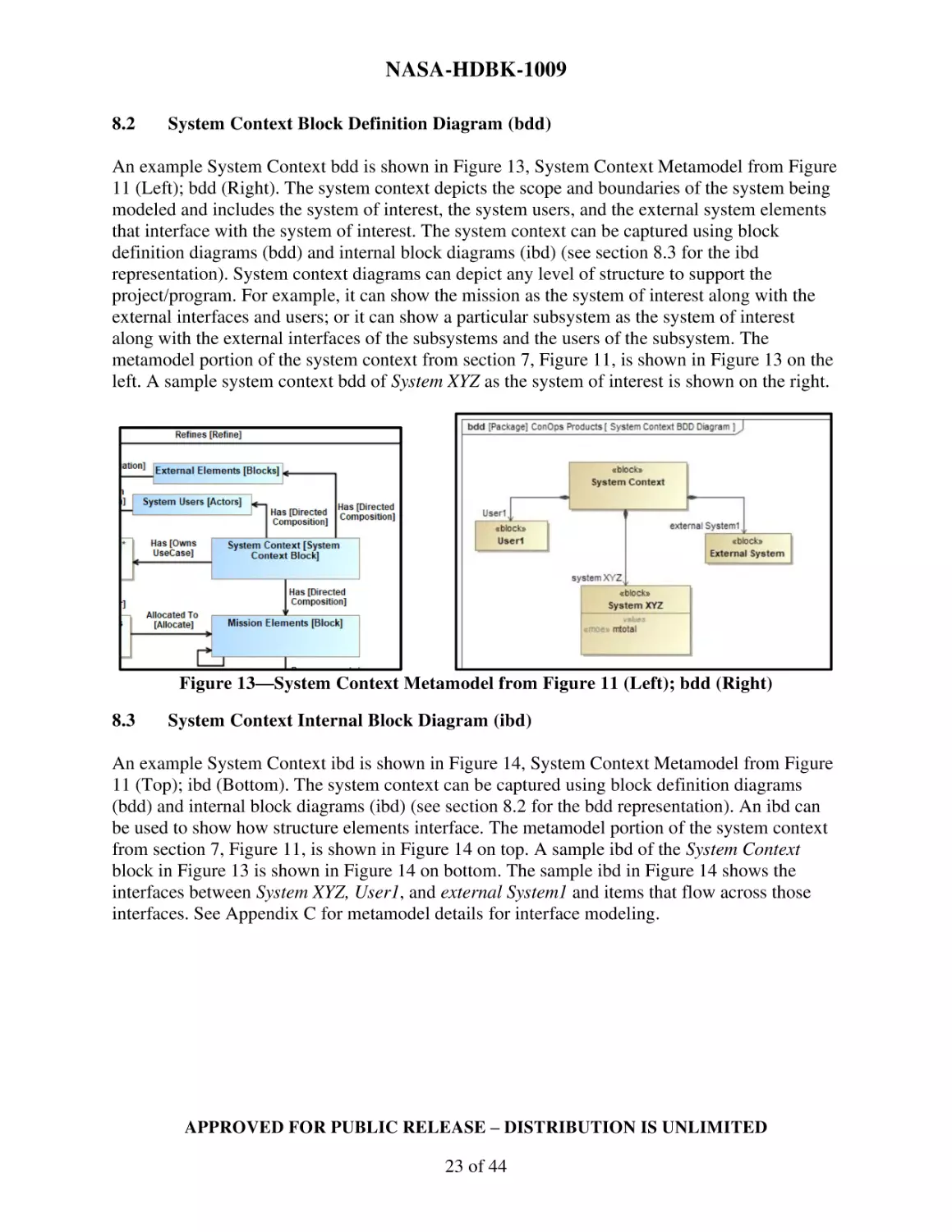
8.2
System Context Block Definition Diagram (bdd) ................................................................ 23
8.3
System Context Internal Block Diagram (ibd) .................................................................... 23
APPROVED FOR PUBLIC RELEASE – DISTRIBUTION IS UNLIMITED
4 of 44
NASA-HDBK-1009
8.4
System Use Case (uc) Diagram .......................................................................................... 24
8.5
Activity Diagram (act) Supporting Use Case ...................................................................... 25
8.6
Structural Decomposition Block Definition Diagram (bdd) ................................................ 26
8.7
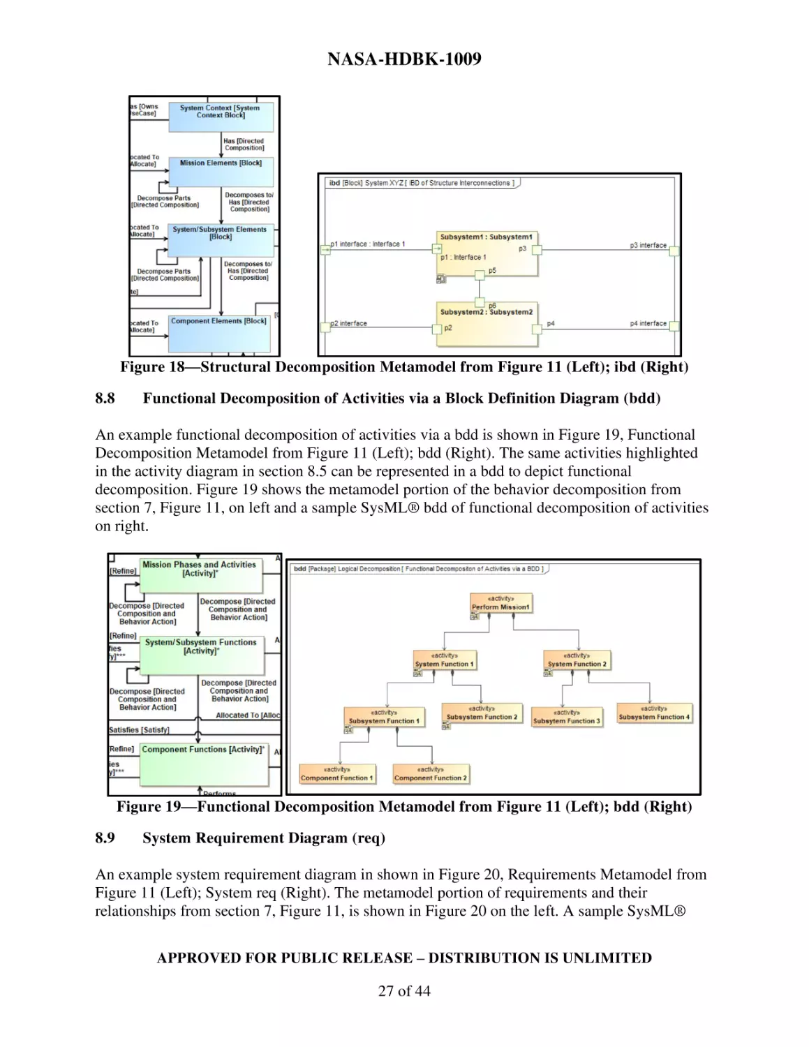
Internal Block Diagram (ibd) of Structure Interconnections ............................................... 26
8.8
Functional Decomposition of Activities via a Block Definition Diagram (bdd) ..................... 27
8.9
System Requirement Diagram (req) .................................................................................. 27
8.10
System Requirements Table ............................................................................................. 28
8.11
Requirements Diagram (req) with Satisfy Relationships .................................................... 29
8.12
Requirement Diagram (req) with Verification Attributes ................................................... 30
8.13
Requirements Table with Satisfy Relationships ................................................................. 30
8.14
Requirement Verification Tables ...................................................................................... 30
9. GENERATING DIAGRAMS AND TABLES FROM THE MODEL TO SUPPORT SYSTEMS
ENGINEERING PRODUCTS .................................................................................................... 31
9.1
Generating SysML® Diagrams and Tables for Concept of Operations (ConOps) Products .... 31
9.2
Generating SysML® Diagrams and Tables for Requirements Products ................................ 33
9.3
Generating SysML® Diagrams and Tables for Verification and Validation (V&V) Products ... 33
APPENDIX A ........................................................................................................................ 35
APPENDIX B......................................................................................................................... 36
B.1
REQUIREMENTS MODELING .................................................................................... 36
B.2
SCENARIO MODELING .............................................................................................. 36
B.3
SYSTEM SPECIFICATION MODELING ..................................................................... 37
B.4
VERIFICATION MODELING ...................................................................................... 37
APPENDIX C ......................................................................................................................... 39
APPENDIX D ........................................................................................................................ 40
D.1
ACRONYMS AND ABBREVIATIONS ......................................................................... 40
D.2
DEFINITIONS ............................................................................................................... 41
APPROVED FOR PUBLIC RELEASE – DISTRIBUTION IS UNLIMITED
5 of 44
NASA-HDBK-1009
LIST OF FIGURES
Figure 1—NASA Systems Engineering Engine ..............................................................................................................10
Figure 2—SysML® Diagrams ........................................................................................................................................12
Figure 3—Four Pillars of SysML® .................................................................................................................................13
Figure 4—OOSEM System Development Workflow .....................................................................................................14
Figure 5—System Design Process Interactions and Flows ...........................................................................................14
Figure 6—MBSE Grid Framework and Traceability .....................................................................................................15
Figure 7—MBSE Grid with Diagram Call-Outs .............................................................................................................16
Figure 8—MBSE Grid Metamodel ................................................................................................................................16
Figure 9—Processes in the NASA SE Engine that can Represent Rows in the Grid ......................................................17
Figure 10—Sample Model Organization Relating to the NASA SE Engine ...................................................................18
Figure 11—Metamodel Based on NASA Systems Engineering (SE) Elements and Relationships ................................20
Figure 12—NGO Metamodel from Figure 11 (Left); req of NGOs (Right) ....................................................................22
Figure 13—System Context Metamodel from Figure 11 (Left); bdd (Right) ................................................................23
Figure 14—System Context Metamodel from Figure 11 (Top); ibd (Bottom) ..............................................................24
Figure 15—System Use Case Metamodel from Figure 11 (Left); uc (Right) .................................................................24
Figure 16—Activity Elements Allocated to Structure Elements Metamodel from Figure 11 (Top); act of Perform
Mission 1 Use Case (Bottom) .......................................................................................................................................25
Figure 17—Structural Decomposition Metamodel from Figure 11 (Left); bdd (Right) ................................................26
Figure 18—Structural Decomposition Metamodel from Figure 11 (Left); ibd (Right) .................................................27
Figure 19—Functional Decomposition Metamodel from Figure 11 (Left); bdd (Right) ...............................................27
Figure 20—Requirements Metamodel from Figure 11 (Left); System req (Right) .......................................................28
Figure 21—Requirements Metamodel from Figure 11 ................................................................................................28
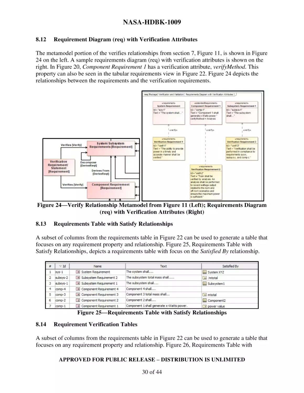
Figure 22—System Requirements Table ......................................................................................................................29
Figure 23—Requirements Metamodel from Figure 11 (Top); req with Satisfy Relationships (Bottom) ......................29
Figure 24—Verify Relationship Metamodel from Figure 11 (Left); Requirements Diagram (req) with Verification
Attributes (Right) .........................................................................................................................................................30
Figure 25—Requirements Table with Satisfy Relationships .........................................................................................30
Figure 26—Requirements Table with Verify Relationships ..........................................................................................31
Figure 27—Verification Requirements/Statement Table .............................................................................................31
Figure 28—Diagrams and Tables to Support Concept of Operations (ConOps) Product .............................................32
Figure 29—Diagrams and Tables to Support Requirements Products .........................................................................33
Figure 30—Diagrams and Tables to Support Verification and Validation (V&V) Products .........................................34
Figure 31—NASA Systems Engineering (SE) Competency Model ................................................................................35
Figure 32—Scenario Modeling Pattern Structure ........................................................................................................37
Figure 33—Example Block Definition Diagram (bdd) of Another Modeling Approach for Requirements, Scenario,
System Specification, and Verification .........................................................................................................................38
Figure 34—Metamodel of Functional and Structural Interfaces .................................................................................39
APPROVED FOR PUBLIC RELEASE – DISTRIBUTION IS UNLIMITED
6 of 44
NASA-HDBK-1009
NASA SYSTEMS MODELING HANDBOOK FOR SYSTEMS
ENGINEERING
1.
SCOPE
1.1
Purpose
This Handbook shows how system modeling using the Systems Modeling Language™ (SysML®)
can be integrated with the NASA Systems Engineering processes in NPR 7123.1, NASA Systems
Engineering Processes and Requirements. The systems engineering products covered in this
Handbook are Concept of Operations (ConOps), Requirements, and Verification and Validation
(V&V). This Handbook contains sections on model planning, setting up the model including
model organization, the metamodel used to demonstrate the system modeling elements and
relationships, model building that provides SysML® model examples, and generating diagrams
and tables from the system model to support ConOps, Requirement, and Verification and
Validation products. The content of this version includes these three products based on a survey
conducted through the NASA Agency MBSE Community of Practice.
The system modeling method in this Handbook is tool-agnostic. The modeling approach selected
leverages NASA modeling practices but does not reflect all NASA modeling methods. If readers
have their own modeling approach, they can use the metamodel to trace back to their modeling
approach to generate ConOps, Requirement, and Verification and Validation products.
1.2
Applicability
1.2.1 This Handbook is applicable to system modelers using Object Management Group®
(OMG®) SysML® version 1.5. These modelers include individuals who have varying levels of
experience with the SysML® modeling language, and knowledge of how systems engineering is
conducted at NASA, which should include the efficient and effective application of NPR 7123.1 and
NASA/SP-2016-6105, NASA Systems Engineering Handbook.
1.2.2 This Handbook is applicable to NASA Headquarters and NASA Centers, including
Component Facilities and Technical and Service Support Centers. This language applies to the Jet
Propulsion Laboratory (a Federally Funded Research and Development Center), other contractors,
recipients of grants, cooperative agreements, or other agreements only to the extent specified or
referenced in the applicable contracts, grants, or agreements.
1.2.3 References to “this Handbook” refer to NASA-HDBK-1009; references to external
documents state the specific document information.
1.2.4 This Handbook, or portions thereof, may be referenced in contract, program, and other
Agency documents for guidance.
APPROVED FOR PUBLIC RELEASE – DISTRIBUTION IS UNLIMITED
7 of 44
NASA-HDBK-1009
1.2.5 The following terms are used in this Handbook: “may” denotes a discretionary privilege
or permission, “can” denotes statements of possibility or capability, “should” denotes a good
practice and is recommended but not required, “will” denotes expected outcome, and “is/are”
denotes descriptive material.
2.
REFERENCE DOCUMENTS
2.1
General
This section provides references supporting the guidance in this Handbook. Utilize the latest
issuances of reference documents unless specific versions are designated. Access reference
documents from the NASA Technical Standards System at https://standards.nasa.gov, links
provided or obtain documents directly from the Standards Developing Body or other document
distributors.
2.2
Government Documents
NASA
2.3
NPR 7123.1
NASA Systems Engineering Processes and Requirements
NASA-STD-7009
Standard for Models and Simulations
NASA-HDBK-7009
NASA Handbook for Models and Simulations: An
Implementation Guide for NASA-STD-7009
NASA/SP-2016-6105
NASA Systems Engineering Handbook
Non-Government Documents
Friedenthal, S.; Moore, A.; and Steiner, R. (2014). “A Practical Guide to SysML: The
Systems Modeling Language,” 3rd ed. Boston: Morgan Kaufmann.
INCOSE - International Council on Systems Engineering. (n.d.). Retrieved October 4,
2022. “INCOSE Initiatives”. INCOSE. (https://www.incose.org/incose-memberresources/initiatives)
ISO/IEC 19514: 2017(E)
Information Technology – Object Management Group
Systems Modeling Language (OMG SysML®)
Karban, R.; Crawford, A.G.; Trancho, G.; Zamparelli, M.; Herzig, S.; Gomes, I.; Piette,
M.; Brower, E. (2018). "The OpenSE Cookbook: A Practical, Recipe Based Collection
of Patterns, Procedures, and Best Practices for Executable Systems Engineering for the
Thirty Meter Telescope.” (https://trs.jpl.nasa.gov/handle/2014/48358)
APPROVED FOR PUBLIC RELEASE – DISTRIBUTION IS UNLIMITED
8 of 44
NASA-HDBK-1009
Morkevicius, A.; Aleksandraviciene, A.; Mazeika, D.; Bisikirskiene, L.; & Strolia, Z.
(2017). “MBSE Grid: A Simplified SysML‐Based Approach for Modeling Complex
Systems.” INCOSE International Symposium (Vol. 27, No. 1, pp. 136-150).
(https://onlinelibrary.wiley.com/doi/10.1002/j.2334-5837.2017.00350.x)
Object Management Group (OMG). (2019). “System Modeling Language (SysML),
Version 1.6.” (https://sysml.org/sysml-specs/)
Object Management Group (OMG). (2022). “What is SysML?” OMG SysML.
(https://www.omgsysml.org/what-is-sysml.htm)
Parrott, E., and Weiland, K. (2017). “Using Model-Based Systems Engineering to
Provide Artifacts for NASA Project Life-Cycle and Technical Reviews,” AIAA SPACE
and Astronautics Forum and Exposition. (https://doi.org/10.2514/6.2017-5299)
SEBoK Editorial Board. (2022). “The Guide to the Systems Engineering Body of
Knowledge (SEBoK),” v. 2.6, R.J. Cloutier (Editor in Chief). Hoboken, NJ: The
Trustees of the Stevens Institute of Technology. Accessed 9/6/2022.
(www.sebokwiki.org). BKCASE is managed and maintained by the Stevens Institute
of Technology Systems Engineering Research Center, the International Council on
Systems Engineering, and the Institute of Electrical and Electronics Engineers Systems
Council.
Tolbert, Mary. (2020). “OOSEM Process Baseline (1/2020)”. Eclipse Process
Framework. (https://www.incose.org/docs/default-source/working-groups/objectoriented-se-method-wg/oosem_process_baseline_20200110.zip?sfvrsn=80f79cc6_0)
2.4
Additional References
Model-Based System
Engineering, NEN
2.5
https://nen.nasa.gov/web/mbse
Order of Precedence
2.5.1 The guidance established in this Handbook does not supersede or waive existing
guidance found in other Agency documentation.
2.5.2 Conflicts between this Handbook and other documents will be resolved by the delegated
Technical Authority.
3.
ACRONYMS, ABBREVIATIONS, AND DEFINITIONS
See Appendix D.
APPROVED FOR PUBLIC RELEASE – DISTRIBUTION IS UNLIMITED
9 of 44
NASA-HDBK-1009
4.
MODEL-BASED SYSTEMS ENGINEERING (MBSE) OVERVIEW
The purpose of this Handbook is to show how system modeling using SysML® can be integrated
with the NASA systems engineering (SE) processes in NPR 7123.1, NASA Systems Engineering
Processes and Requirements. This section will provide background information about NASA’s
systems engineering processes and system modeling.
4.1
NASA Systems Engineering Process Overview
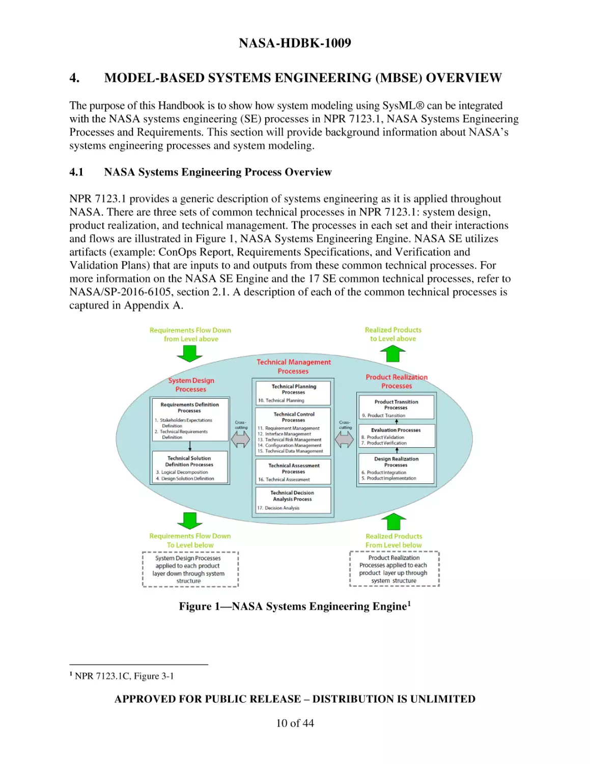
NPR 7123.1 provides a generic description of systems engineering as it is applied throughout
NASA. There are three sets of common technical processes in NPR 7123.1: system design,
product realization, and technical management. The processes in each set and their interactions
and flows are illustrated in Figure 1, NASA Systems Engineering Engine. NASA SE utilizes
artifacts (example: ConOps Report, Requirements Specifications, and Verification and
Validation Plans) that are inputs to and outputs from these common technical processes. For
more information on the NASA SE Engine and the 17 SE common technical processes, refer to
NASA/SP-2016-6105, section 2.1. A description of each of the common technical processes is
captured in Appendix A.
Figure 1—NASA Systems Engineering Engine1
1
NPR 7123.1C, Figure 3-1
APPROVED FOR PUBLIC RELEASE – DISTRIBUTION IS UNLIMITED
10 of 44
NASA-HDBK-1009
4.2
MBSE and the NASA Systems Engineering Process
The International Council on Systems Engineering (INCOSE) has defined MBSE as follows:
“Model-Based Systems Engineering (MBSE) is the formalized application of modeling to
support system requirements, design, analysis, verification and validation activities beginning
in the conceptual design phase and continuing throughout development and later life-cycle
phases.”2
In terms of the NASA SE Engine, MBSE supports the common technical SE processes by using
system models to capture the definitions and relationships of the system of interest. From the
system models, SE products are generated to implement the SE processes and to support
technical reviews for programs and projects.
4.3
Three Aspects of MBSE
MBSE has three aspects: the modeling language, the modeling methodology, and the modeling
framework. These are described in detail in the following subsections.
4.3.1 Modeling Language
An implicit requirement to author a model is a modeling language, much like how programming
utilizes a programming language and human communication utilizes a natural language to
represent concepts and pass information. The modeling language facilitates the description of the
system of interest using graphical constructs. INCOSE recognizes the SysML® modeling
language for specifying, analyzing, designing, and verifying complex systems. This Handbook
uses SysML® as the modeling language.
4.3.1.1
SysML® Diagram Types
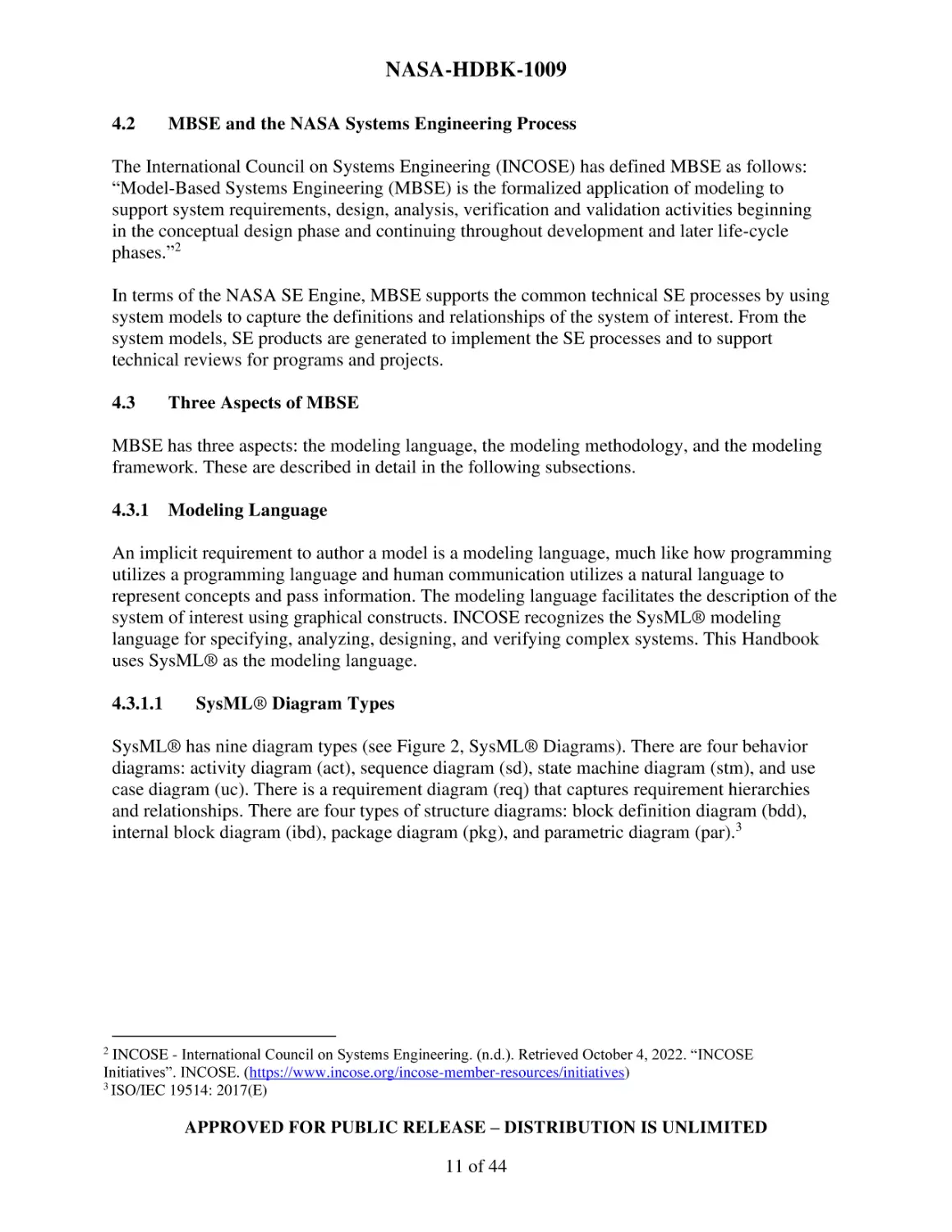
SysML® has nine diagram types (see Figure 2, SysML® Diagrams). There are four behavior
diagrams: activity diagram (act), sequence diagram (sd), state machine diagram (stm), and use
case diagram (uc). There is a requirement diagram (req) that captures requirement hierarchies
and relationships. There are four types of structure diagrams: block definition diagram (bdd),
internal block diagram (ibd), package diagram (pkg), and parametric diagram (par).3
INCOSE - International Council on Systems Engineering. (n.d.). Retrieved October 4, 2022. “INCOSE
Initiatives”. INCOSE. (https://www.incose.org/incose-member-resources/initiatives)
3
ISO/IEC 19514: 2017(E)
2
APPROVED FOR PUBLIC RELEASE – DISTRIBUTION IS UNLIMITED
11 of 44
NASA-HDBK-1009
Figure 2—SysML® Diagrams4
4.3.1.2
Modeling Pillars of SysML®
SysML® diagrams are often grouped within four modeling pillars: structure, behavior,
requirements, and parametrics (see Figure 3, Four Pillars of SysML®). Each pillar supports the
common SE activities used to define a system in a model to develop an SE product. The structure
pillar supports realized logical and physical layers such as systems, subsystems, components, and
interfaces. The behavior pillar supports domains like system functionality, system interactions,
system response, and system information and data flow. The requirements pillar supports
specifications and Verification and Validation. The parametric pillar supports constraints and
mathematical statements. Together, the pillars build a collective context across the entire
SysML® model, integrating model elements and diagrams to support SE product generation.
Object Management Group (OMG). (2022). “What is SysML?” OMG SysML. (https://www.omgsysml.org/whatis-sysml.htm)
4
APPROVED FOR PUBLIC RELEASE – DISTRIBUTION IS UNLIMITED
12 of 44
NASA-HDBK-1009
Figure 3—Four Pillars of SysML®5
4.3.2
Modeling Methodology
A modeling methodology contains a road map for consistency and common end points in a
modeling environment. While modeling languages like SysML® provide enhanced structure and
rigor to SE constructs for capturing information in the model, the step-by-step processes to build
a model and to support data output is not provided.
The modeling methodology in this Handbook follows the NASA SE Engine with additional
model-specific steps not included in the NASA SE Engine. Model Planning and Setting Up the
Model are model-specific steps that have been added to supplement NPR 7123.1, as detailed in
sections 5 and 6. These additional model-specific steps were leveraged from an INCOSE
standard called Object-Oriented Systems Engineering Method (OOSEM). OOSEM is a systemslevel development method that combines object-oriented concepts with traditional systems
engineering practices. Figure 4, OOSEM System Development Workflow shows the top-level
OOSEM process in blue and secondary level processes in white. The OOSEM System
Development Workflow shows the Update Modeling Plan and Setup Model process steps.
Object Management Group (OMG). (2022). “What is SysML?” OMG SysML. (https://www.omgsysml.org/whatis-sysml.htm)
5
APPROVED FOR PUBLIC RELEASE – DISTRIBUTION IS UNLIMITED
13 of 44
NASA-HDBK-1009
Figure 4—OOSEM System Development Workflow6
In the NASA SE Engine, Model Planning occurs in Technical Process 10, Technical Planning
(see Figure 1). Setting Up the Model occurs in the System Design Processes (see Figure 1).
Figure 5, System Design Process Interactions and Flows, shows the System Design Process steps
from the NASA SE Handbook; These steps in Figure 5 are similar to the steps in the ‘Specify
and Design System’ process in the OOSEM workflow in Figure 4.
Figure 5—System Design Process Interactions and Flows7
Adapted from Tolbert, Mary. (2020). “OOSEM Process Baseline (1/2020)”. Eclipse Process Framework.
(https://www.incose.org/docs/default-source/working-groups/object-oriented-se-methodwg/oosem_process_baseline_20200110.zip?sfvrsn=80f79cc6_0)
7
NASA/SP-2016-6105, Revision 2, Figure 4.0-1
6
APPROVED FOR PUBLIC RELEASE – DISTRIBUTION IS UNLIMITED
14 of 44
NASA-HDBK-1009
4.3.3
Modeling Framework
A modeling framework provides the approach to organizing the system elements and
relationships within the model.
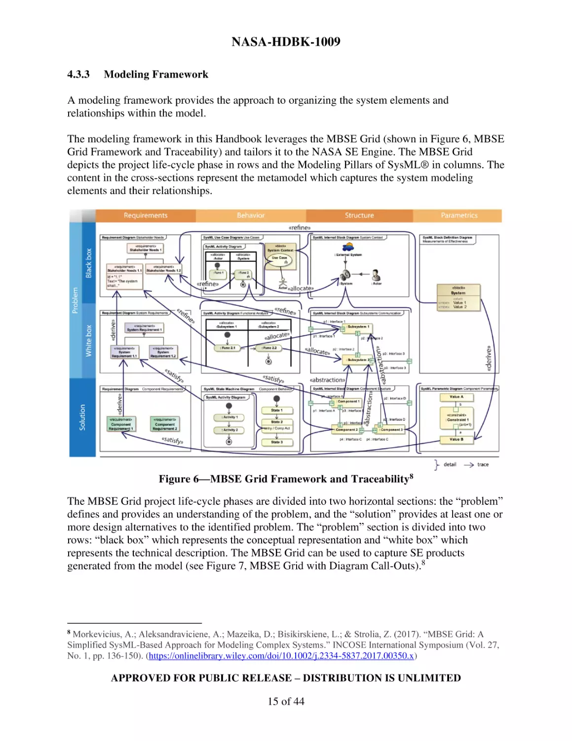
The modeling framework in this Handbook leverages the MBSE Grid (shown in Figure 6, MBSE
Grid Framework and Traceability) and tailors it to the NASA SE Engine. The MBSE Grid
depicts the project life-cycle phase in rows and the Modeling Pillars of SysML® in columns. The
content in the cross-sections represent the metamodel which captures the system modeling
elements and their relationships.
Figure 6—MBSE Grid Framework and Traceability8
The MBSE Grid project life-cycle phases are divided into two horizontal sections: the “problem”
defines and provides an understanding of the problem, and the “solution” provides at least one or
more design alternatives to the identified problem. The “problem” section is divided into two
rows: “black box” which represents the conceptual representation and “white box” which
represents the technical description. The MBSE Grid can be used to capture SE products
generated from the model (see Figure 7, MBSE Grid with Diagram Call-Outs).8
Morkevicius, A.; Aleksandraviciene, A.; Mazeika, D.; Bisikirskiene, L.; & Strolia, Z. (2017). “MBSE Grid: A
Simplified SysML‐Based Approach for Modeling Complex Systems.” INCOSE International Symposium (Vol. 27,
No. 1, pp. 136-150). (https://onlinelibrary.wiley.com/doi/10.1002/j.2334-5837.2017.00350.x)
8
APPROVED FOR PUBLIC RELEASE – DISTRIBUTION IS UNLIMITED
15 of 44
NASA-HDBK-1009
Figure 7—MBSE Grid with Diagram Call-Outs9
Figure 8, MBSE Grid Metamodel, shows a one-diagram representation of the model elements
and relationships from Figure 6; [ ] are used to capture the SysML® language-specific element
or relationship type (e.g., requirement, block, activity, refines, derives, etc.)
Figure 8—MBSE Grid Metamodel
Morkevicius, A.; Aleksandraviciene, A.; Mazeika, D.; Bisikirskiene, L.; & Strolia, Z. (2017). “MBSE Grid: A
Simplified SysML‐Based Approach for Modeling Complex Systems.” INCOSE International Symposium (Vol. 27,
No. 1, pp. 136-150). (https://onlinelibrary.wiley.com/doi/10.1002/j.2334-5837.2017.00350.x)
9
APPROVED FOR PUBLIC RELEASE – DISTRIBUTION IS UNLIMITED
16 of 44
NASA-HDBK-1009
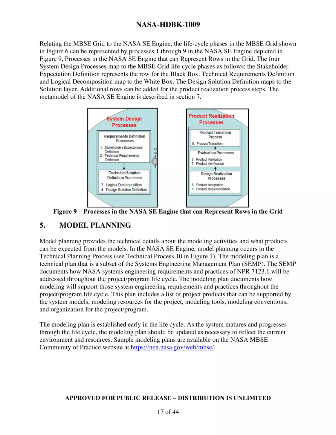
Relating the MBSE Grid to the NASA SE Engine, the life-cycle phases in the MBSE Grid shown
in Figure 6 can be represented by processes 1 through 9 in the NASA SE Engine depicted in
Figure 9, Processes in the NASA SE Engine that can Represent Rows in the Grid. The four
System Design Processes map to the MBSE Grid life-cycle phases as follows: the Stakeholder
Expectation Definition represents the row for the Black Box. Technical Requirements Definition
and Logical Decomposition map to the White Box. The Design Solution Definition maps to the
Solution layer. Additional rows can be added for the product realization process steps. The
metamodel of the NASA SE Engine is described in section 7.
Figure 9—Processes in the NASA SE Engine that can Represent Rows in the Grid
5.
MODEL PLANNING
Model planning provides the technical details about the modeling activities and what products
can be expected from the models. In the NASA SE Engine, model planning occurs in the
Technical Planning Process (see Technical Process 10 in Figure 1). The modeling plan is a
technical plan that is a subset of the Systems Engineering Management Plan (SEMP). The SEMP
documents how NASA systems engineering requirements and practices of NPR 7123.1 will be
addressed throughout the project/program life cycle. The modeling plan documents how
modeling will support those system engineering requirements and practices throughout the
project/program life cycle. This plan includes a list of project products that can be supported by
the system models, modeling resources for the project, modeling tools, modeling conventions,
and organization for the project/program.
The modeling plan is established early in the life cycle. As the system matures and progresses
through the life cycle, the modeling plan should be updated as necessary to reflect the current
environment and resources. Sample modeling plans are available on the NASA MBSE
Community of Practice website at https://nen.nasa.gov/web/mbse/.
APPROVED FOR PUBLIC RELEASE – DISTRIBUTION IS UNLIMITED
17 of 44
NASA-HDBK-1009
6.
SETTING UP THE MODEL
Setting up the model includes establishing modeling conventions, standards, and model
organization. As described in section 4.3.2, setting up the model occurs in the beginning of the
System Design Processes (see Figure 1).
Modeling conventions include establishing naming conventions for model element and package
names.
Modeling standards include establishing standard profiles and other modeling standards based
off the needs of the project/program.10
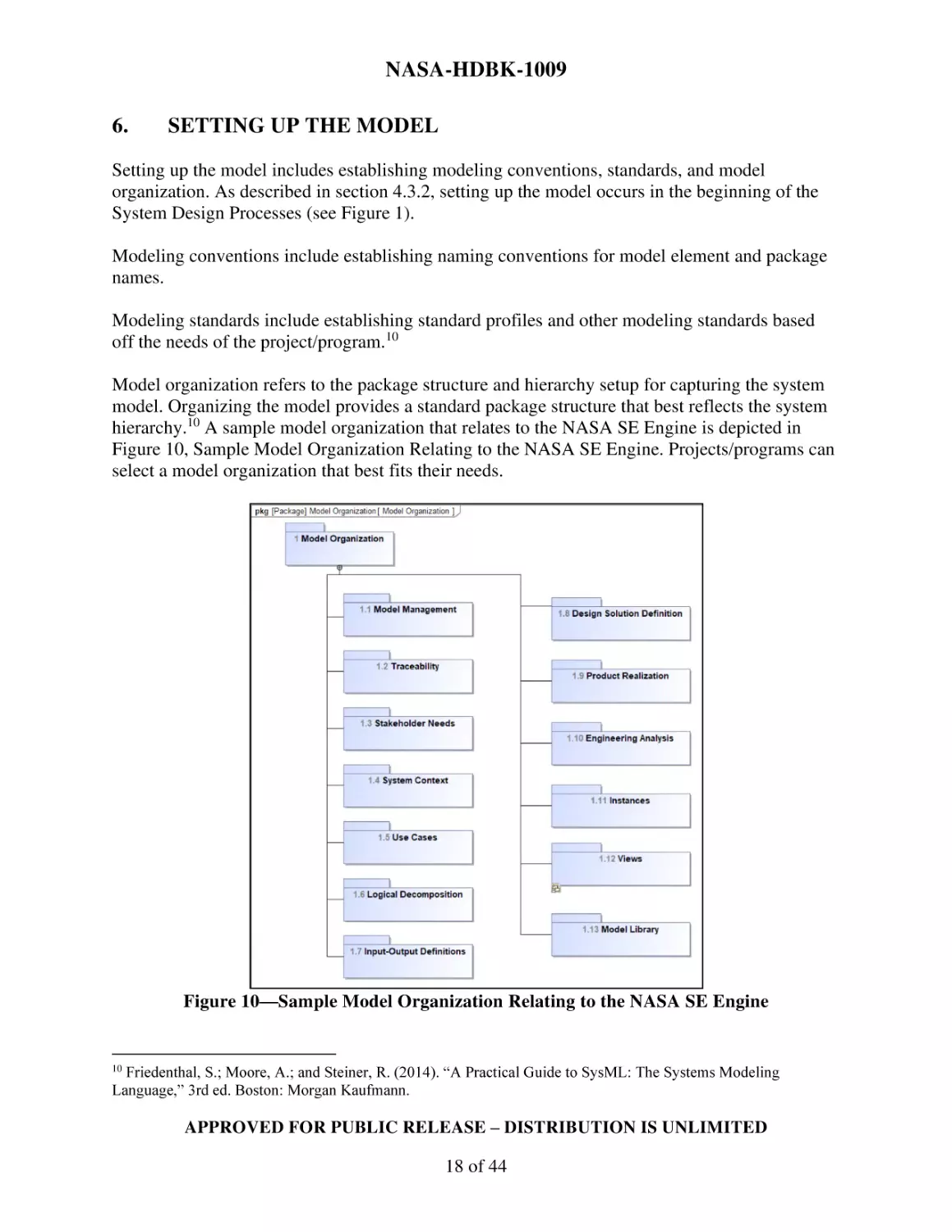
Model organization refers to the package structure and hierarchy setup for capturing the system
model. Organizing the model provides a standard package structure that best reflects the system
hierarchy.10 A sample model organization that relates to the NASA SE Engine is depicted in
Figure 10, Sample Model Organization Relating to the NASA SE Engine. Projects/programs can
select a model organization that best fits their needs.
Figure 10—Sample Model Organization Relating to the NASA SE Engine
Friedenthal, S.; Moore, A.; and Steiner, R. (2014). “A Practical Guide to SysML: The Systems Modeling
Language,” 3rd ed. Boston: Morgan Kaufmann.
10
APPROVED FOR PUBLIC RELEASE – DISTRIBUTION IS UNLIMITED
18 of 44
NASA-HDBK-1009
The results of establishing modeling convention, metamodel, modeling standards, and model
organization are documented in the Modeling Plan.
7.
THE METAMODEL
A metamodel is a depiction of the system modeling elements and their relationships. Figure 11,
Metamodel Based on NASA Systems Engineering (SE) Elements and Relationships, shows the
metamodel for system modeling based on NASA SE elements and relationships described in
NPR 7123.1. In the metamodel, [ ] are used to capture the SysML® language-specific element or
relationship type (e.g., requirement, block, activity, refines, derives, etc.).
If readers have their own modeling approach, they can use the metamodel to trace back to their
modeling approach to generate ConOps, Requirement, and Verification and Validation products.
The metamodel and any assumptions should be documented in the modeling plan for a given
project/program (see section 5, Model Planning for more details).
Differences between the MBSE Grid Framework metamodel in section 4.3.3 and the metamodel
based on NASA SE elements and relationships in Figure 11 include:
•
•
•
•
•
•
•
•
Explicit call out of goals and objectives traced from the stakeholder needs.
Addition of mission-level behavior and structure elements.
Addition of validation requirements/statements that trace to objectives.
Addition of verification requirements/statements that trace to technical requirements.
Updates to the refines relationships to trace between requirements and behavior elements
at the same level of decomposition.
Addition of allocations between requirements and structure pillars.
Addition of a decompose relationship to the component level behavior and structure
elements from the level above it.
Addition of Measure of Performances (MOP) and Technical Performance Measures
(TPM) value property types.
APPROVED FOR PUBLIC RELEASE – DISTRIBUTION IS UNLIMITED
19 of 44
NASA-HDBK-1009
Figure 11—Metamodel Based on NASA Systems Engineering (SE) Elements and Relationships
Notes on the Metamodel:
*Notes on Requirements Pillar Elements:
- In many cases requirements can be satisfied by a block; however, requirements can also be satisfied by behavior elements and value
APPROVED FOR PUBLIC RELEASE – DISTRIBUTION IS UNLIMITED
20 of 44
NASA-HDBK-1009
properties when the requirements are a performance requirement of a functional requirement (A value property can satisfy a
performance requirement. A function can satisfy a functional requirement).
- Stakeholders can influence requirements at any level, hence the trace can exist at any level (Stakeholder trace is shown to a Need for
simplicity)
**Notes on Behavior Pillar Elements:
- Behaviors and interactions at all levels can use any of the SysML® Behavior Diagrams (uc, act, sd, and stm); These diagrams can be
decomposed at each level to better articulate the expected behavior and interactions. For example, State Machines are applicable at
each level (including at the Mission Level); however, they are shown at the component level for simplicity. Use Cases are shown at
the Mission level for simplicity yet are applicable at each level.
- The association between the "Mission Use Case" and "Mission Phases and Activities" is OOSEM and MBSE Grid Supported; To
support use case traceability, a stronger relationship can be used, for example, Dependency or Trace or Refine.
***Notes on the Structural Pillar Elements:
- From System to Component, decomposition happens in the same manner. Decompose to whatever level is needed for the project; do
not go further than needed. Systems may decompose to additional Systems, Subsystems may decompose to additional Subsystems,
and there may be an assembly level, etc.
****Notes on Parametric Pillar Elements:
- Parametric Diagrams are applicable at other levels of decomposition not just at the component level.
- Technical performance measures (TPMs) refine the performance requirements (this relationship is not depicted in the metamodel)
similar to how the measures of effectiveness (MOEs) refine the objectives.
- Other structure blocks can contain MOEs as well (for example, Subsystem elements.)
APPROVED FOR PUBLIC RELEASE – DISTRIBUTION IS UNLIMITED
21 of 44
NASA-HDBK-1009
The metamodel in Figure 11 is one approach to modeling in support of the NASA SE Engine.
Within NASA, there are varying approaches to implement the metamodel. For example, the
Property-Based Requirements (PBR) can be applied to represent numerical requirements (see
Appendix B.1). Another example of a variation to the metamodel is how relationships to
subsystems are captured (example representations include reference properties or abstraction
relationships). The intent is to have a method in this Handbook to support the objectives of
generating SE products and enable tailoring of the metamodel to the program/project modeling
methods as needed.
8.
BUILDING THE MODEL
This section provides example SysML® diagrams and tables following the metamodel depicted
in section 7, Figure 11. The diagrams and tables can be modeled in any order to support the SE
activities on a program/project. SE activities can start at various points on the NASA SE Engine;
For more information on the NASA SE Engine and NASA SE Processes, refer to NPR 7123.1
and NASA/SP-2016-6105. Section 9 provides details on diagrams and tables that can be used to
support the ConOps, Requirements, and Verification and Validation Products. 11
8.1
Requirements Diagram of Needs, Goals, and Objectives (NGOs)
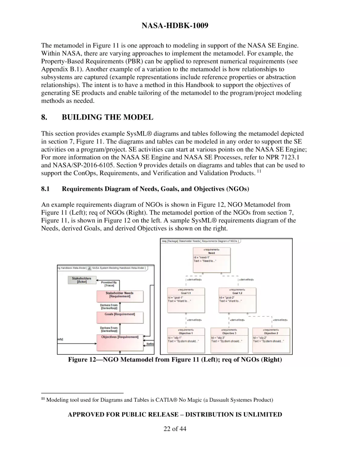
An example requirements diagram of NGOs is shown in Figure 12, NGO Metamodel from
Figure 11 (Left); req of NGOs (Right). The metamodel portion of the NGOs from section 7,
Figure 11, is shown in Figure 12 on the left. A sample SysML® requirements diagram of the
Needs, derived Goals, and derived Objectives is shown on the right.
Figure 12—NGO Metamodel from Figure 11 (Left); req of NGOs (Right)
11
Modeling tool used for Diagrams and Tables is CATIA® No Magic (a Dassault Systemes Product)
APPROVED FOR PUBLIC RELEASE – DISTRIBUTION IS UNLIMITED
22 of 44
NASA-HDBK-1009
8.2
System Context Block Definition Diagram (bdd)
An example System Context bdd is shown in Figure 13, System Context Metamodel from Figure
11 (Left); bdd (Right). The system context depicts the scope and boundaries of the system being
modeled and includes the system of interest, the system users, and the external system elements
that interface with the system of interest. The system context can be captured using block
definition diagrams (bdd) and internal block diagrams (ibd) (see section 8.3 for the ibd
representation). System context diagrams can depict any level of structure to support the
project/program. For example, it can show the mission as the system of interest along with the
external interfaces and users; or it can show a particular subsystem as the system of interest
along with the external interfaces of the subsystems and the users of the subsystem. The
metamodel portion of the system context from section 7, Figure 11, is shown in Figure 13 on the
left. A sample system context bdd of System XYZ as the system of interest is shown on the right.
Figure 13—System Context Metamodel from Figure 11 (Left); bdd (Right)
8.3
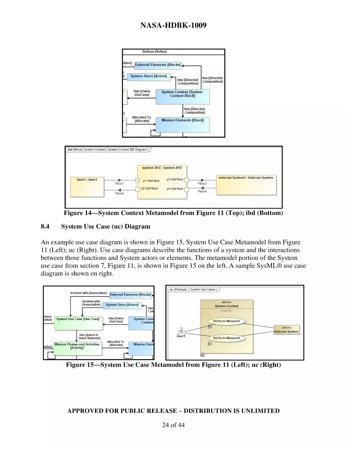
System Context Internal Block Diagram (ibd)
An example System Context ibd is shown in Figure 14, System Context Metamodel from Figure
11 (Top); ibd (Bottom). The system context can be captured using block definition diagrams
(bdd) and internal block diagrams (ibd) (see section 8.2 for the bdd representation). An ibd can
be used to show how structure elements interface. The metamodel portion of the system context
from section 7, Figure 11, is shown in Figure 14 on top. A sample ibd of the System Context
block in Figure 13 is shown in Figure 14 on bottom. The sample ibd in Figure 14 shows the
interfaces between System XYZ, User1, and external System1 and items that flow across those
interfaces. See Appendix C for metamodel details for interface modeling.
APPROVED FOR PUBLIC RELEASE – DISTRIBUTION IS UNLIMITED
23 of 44
NASA-HDBK-1009
Figure 14—System Context Metamodel from Figure 11 (Top); ibd (Bottom)
8.4
System Use Case (uc) Diagram
An example use case diagram is shown in Figure 15, System Use Case Metamodel from Figure
11 (Left); uc (Right). Use case diagrams describe the functions of a system and the interactions
between those functions and System actors or elements. The metamodel portion of the System
use case from section 7, Figure 11, is shown in Figure 15 on the left. A sample SysML® use case
diagram is shown on right.
Figure 15—System Use Case Metamodel from Figure 11 (Left); uc (Right)
APPROVED FOR PUBLIC RELEASE – DISTRIBUTION IS UNLIMITED
24 of 44
NASA-HDBK-1009
8.5
Activity Diagram (act) Supporting Use Case
An example activity diagram is shown in Figure 16, Activity Elements Allocated to Structure
Elements Metamodel from Figure 11 (Top); act of Perform Mission 1 Use Case (Bottom). The
activity diagram (act) is one of the four behavior diagrams used to describe a system’s behavior.
In this example, the activity diagram is used to further explain the details of the use case example
“Perform Mission1” (see section 8.4 on use case diagrams). Activities can be captured in activity
diagrams showing interactions between activities and allocations to structure elements (see
Appendix C). The metamodel portion of activity elements and their relationships from section 7,
Figure 11, is shown in Figure 16 on top. A sample SysML® activity diagram using swim-lanes
to allocate activity elements User Activity 1 and 2, System Function 1 and System Function 2,
and External System Activity 1 to structure elements User1, System XYZ, and External System is
shown on bottom. Note: Use of the ':' in the action name of the activity diagram indicates the
activity typing of the action; Without the colon, the action only exists within this diagram.
Figure 16—Activity Elements Allocated to Structure Elements Metamodel from Figure 11
(Top); act of Perform Mission 1 Use Case (Bottom)
APPROVED FOR PUBLIC RELEASE – DISTRIBUTION IS UNLIMITED
25 of 44
NASA-HDBK-1009
8.6
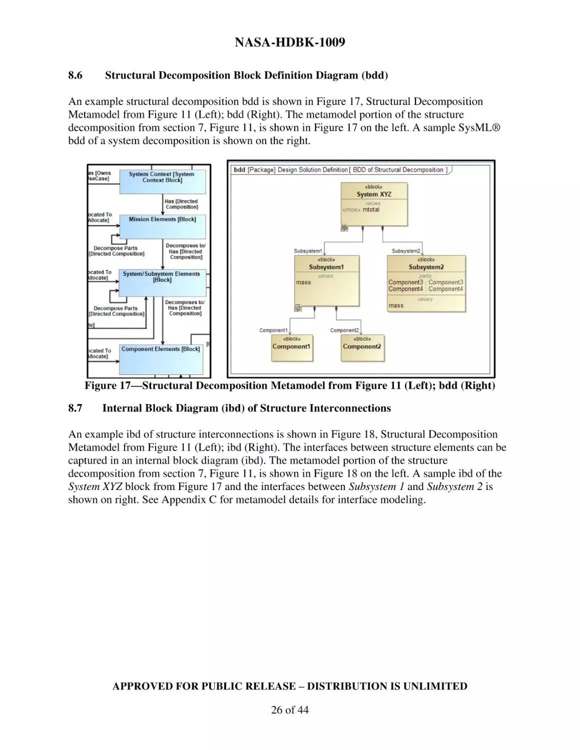
Structural Decomposition Block Definition Diagram (bdd)
An example structural decomposition bdd is shown in Figure 17, Structural Decomposition
Metamodel from Figure 11 (Left); bdd (Right). The metamodel portion of the structure
decomposition from section 7, Figure 11, is shown in Figure 17 on the left. A sample SysML®
bdd of a system decomposition is shown on the right.
Figure 17—Structural Decomposition Metamodel from Figure 11 (Left); bdd (Right)
8.7
Internal Block Diagram (ibd) of Structure Interconnections
An example ibd of structure interconnections is shown in Figure 18, Structural Decomposition
Metamodel from Figure 11 (Left); ibd (Right). The interfaces between structure elements can be
captured in an internal block diagram (ibd). The metamodel portion of the structure
decomposition from section 7, Figure 11, is shown in Figure 18 on the left. A sample ibd of the
System XYZ block from Figure 17 and the interfaces between Subsystem 1 and Subsystem 2 is
shown on right. See Appendix C for metamodel details for interface modeling.
APPROVED FOR PUBLIC RELEASE – DISTRIBUTION IS UNLIMITED
26 of 44
NASA-HDBK-1009
Figure 18—Structural Decomposition Metamodel from Figure 11 (Left); ibd (Right)
8.8
Functional Decomposition of Activities via a Block Definition Diagram (bdd)
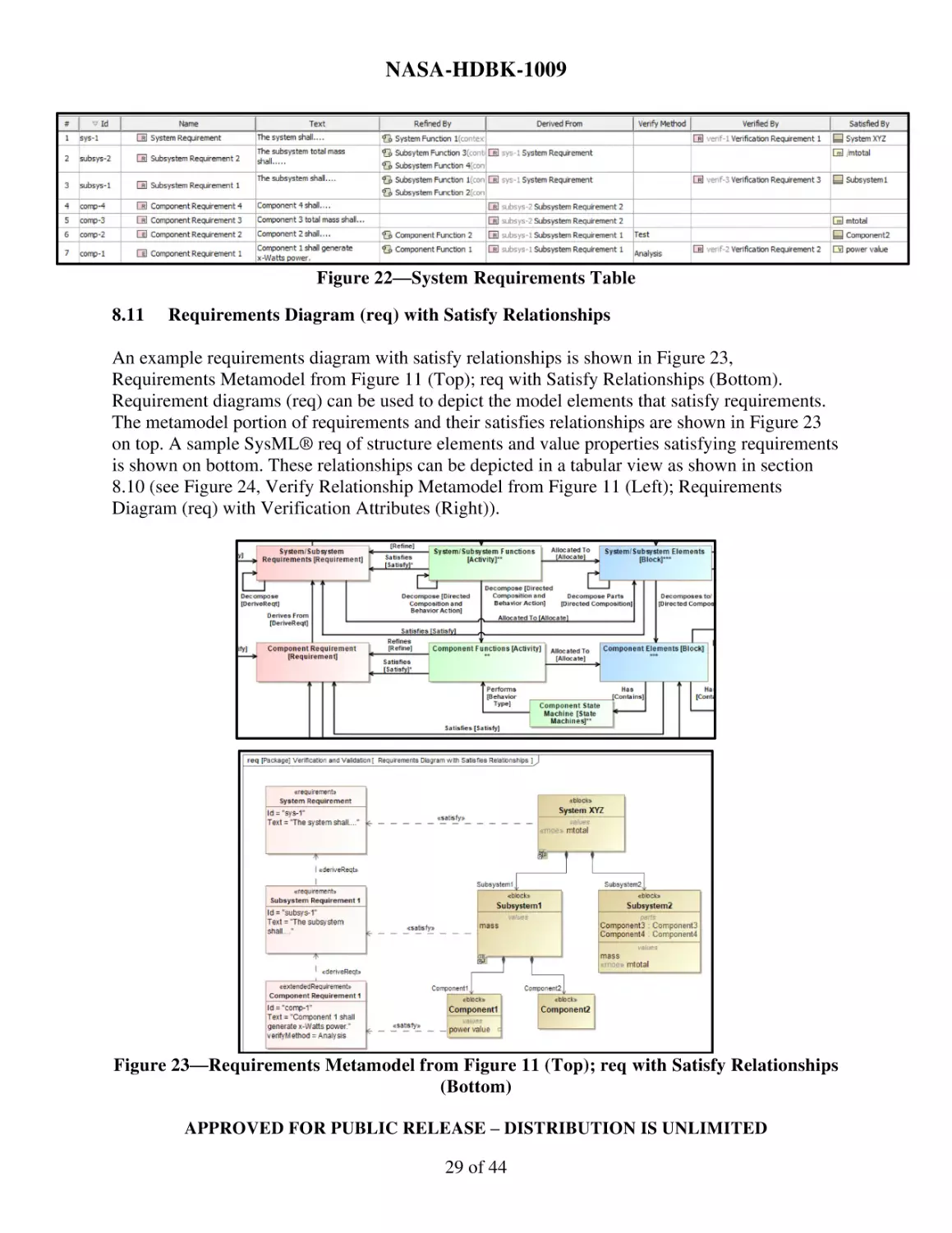
An example functional decomposition of activities via a bdd is shown in Figure 19, Functional
Decomposition Metamodel from Figure 11 (Left); bdd (Right). The same activities highlighted
in the activity diagram in section 8.5 can be represented in a bdd to depict functional
decomposition. Figure 19 shows the metamodel portion of the behavior decomposition from
section 7, Figure 11, on left and a sample SysML® bdd of functional decomposition of activities
on right.
Figure 19—Functional Decomposition Metamodel from Figure 11 (Left); bdd (Right)
8.9
System Requirement Diagram (req)
An example system requirement diagram in shown in Figure 20, Requirements Metamodel from
Figure 11 (Left); System req (Right). The metamodel portion of requirements and their
relationships from section 7, Figure 11, is shown in Figure 20 on the left. A sample SysML®
APPROVED FOR PUBLIC RELEASE – DISTRIBUTION IS UNLIMITED
27 of 44
NASA-HDBK-1009
requirements diagram of the system requirements decomposition and flow-down using derived
requirement relationship is shown on the right.
Figure 20—Requirements Metamodel from Figure 11 (Left); System req (Right)
8.10
System Requirements Table
A Requirements Table is a tabular format used to represent requirements, their properties, and
relationships12. The metamodel portion of requirements and their relationships from section 7,
Figure 11, is shown in Figure 21, Requirements Metamodel from Figure 11. The tabular view of
the requirements, their properties, and relationships are shown in Figure 22, System
Requirements Table.
Figure 21—Requirements Metamodel from Figure 11
Object Management Group (OMG). (2019). “System Modeling Language (SysML), Version 1.6.”
(https://sysml.org/sysml-specs/)
12
APPROVED FOR PUBLIC RELEASE – DISTRIBUTION IS UNLIMITED
28 of 44
NASA-HDBK-1009
Figure 22—System Requirements Table
8.11
Requirements Diagram (req) with Satisfy Relationships
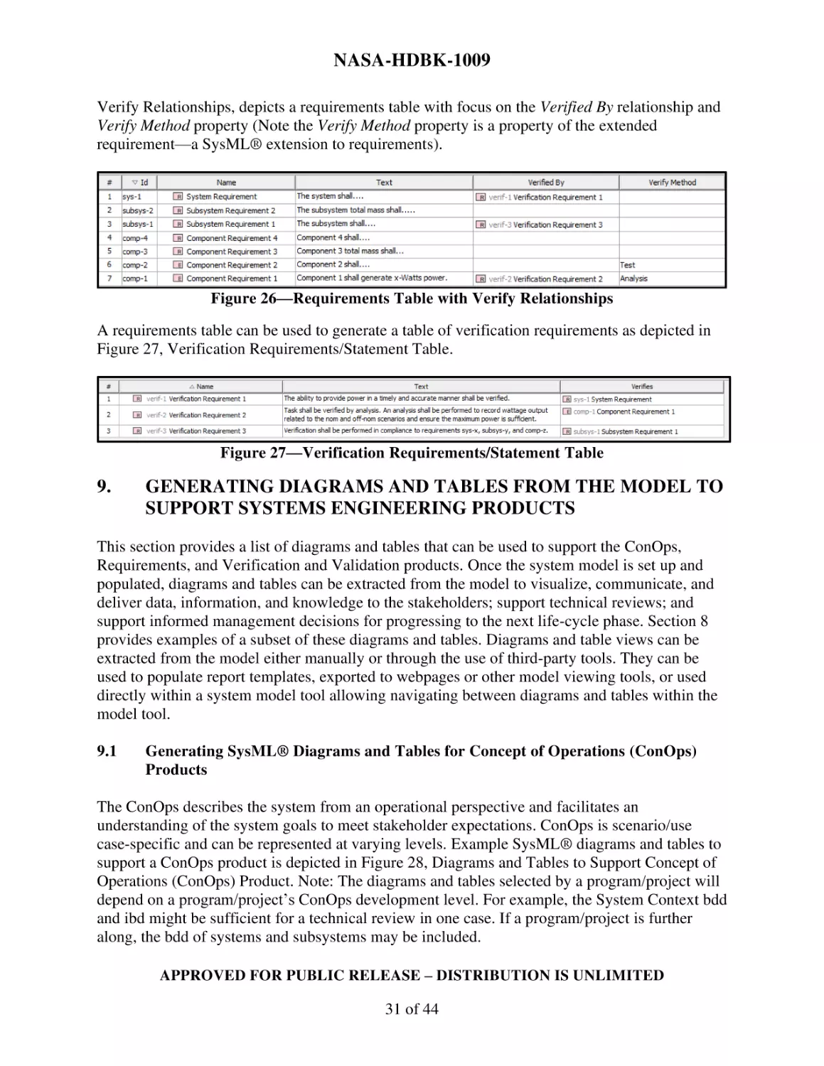
An example requirements diagram with satisfy relationships is shown in Figure 23,
Requirements Metamodel from Figure 11 (Top); req with Satisfy Relationships (Bottom).
Requirement diagrams (req) can be used to depict the model elements that satisfy requirements.
The metamodel portion of requirements and their satisfies relationships are shown in Figure 23
on top. A sample SysML® req of structure elements and value properties satisfying requirements
is shown on bottom. These relationships can be depicted in a tabular view as shown in section
8.10 (see Figure 24, Verify Relationship Metamodel from Figure 11 (Left); Requirements
Diagram (req) with Verification Attributes (Right)).
Figure 23—Requirements Metamodel from Figure 11 (Top); req with Satisfy Relationships
(Bottom)
APPROVED FOR PUBLIC RELEASE – DISTRIBUTION IS UNLIMITED
29 of 44
NASA-HDBK-1009
8.12
Requirement Diagram (req) with Verification Attributes
The metamodel portion of the verifies relationships from section 7, Figure 11, is shown in Figure
24 on the left. A sample requirements diagram (req) with verification attributes is shown on the
right. In Figure 20, Component Requirement 1 has a verification attribute, verifyMethod. This
property can also be seen in the tabular requirements view in Figure 22. Figure 24 depicts the
relationships between the requirements and the verification requirements.
Figure 24—Verify Relationship Metamodel from Figure 11 (Left); Requirements Diagram
(req) with Verification Attributes (Right)
8.13
Requirements Table with Satisfy Relationships
A subset of columns from the requirements table in Figure 22 can be used to generate a table that
focuses on any requirement property and relationship. Figure 25, Requirements Table with
Satisfy Relationships, depicts a requirements table with focus on the Satisfied By relationship.
Figure 25—Requirements Table with Satisfy Relationships
8.14
Requirement Verification Tables
A subset of columns from the requirements table in Figure 22 can be used to generate a table that
focuses on any requirement property and relationship. Figure 26, Requirements Table with
APPROVED FOR PUBLIC RELEASE – DISTRIBUTION IS UNLIMITED
30 of 44
NASA-HDBK-1009
Verify Relationships, depicts a requirements table with focus on the Verified By relationship and
Verify Method property (Note the Verify Method property is a property of the extended
requirement—a SysML® extension to requirements).
Figure 26—Requirements Table with Verify Relationships
A requirements table can be used to generate a table of verification requirements as depicted in
Figure 27, Verification Requirements/Statement Table.
Figure 27—Verification Requirements/Statement Table
9.
GENERATING DIAGRAMS AND TABLES FROM THE MODEL TO
SUPPORT SYSTEMS ENGINEERING PRODUCTS
This section provides a list of diagrams and tables that can be used to support the ConOps,
Requirements, and Verification and Validation products. Once the system model is set up and
populated, diagrams and tables can be extracted from the model to visualize, communicate, and
deliver data, information, and knowledge to the stakeholders; support technical reviews; and
support informed management decisions for progressing to the next life-cycle phase. Section 8
provides examples of a subset of these diagrams and tables. Diagrams and table views can be
extracted from the model either manually or through the use of third-party tools. They can be
used to populate report templates, exported to webpages or other model viewing tools, or used
directly within a system model tool allowing navigating between diagrams and tables within the
model tool.
9.1
Generating SysML® Diagrams and Tables for Concept of Operations (ConOps)
Products
The ConOps describes the system from an operational perspective and facilitates an
understanding of the system goals to meet stakeholder expectations. ConOps is scenario/use
case-specific and can be represented at varying levels. Example SysML® diagrams and tables to
support a ConOps product is depicted in Figure 28, Diagrams and Tables to Support Concept of
Operations (ConOps) Product. Note: The diagrams and tables selected by a program/project will
depend on a program/project’s ConOps development level. For example, the System Context bdd
and ibd might be sufficient for a technical review in one case. If a program/project is further
along, the bdd of systems and subsystems may be included.
APPROVED FOR PUBLIC RELEASE – DISTRIBUTION IS UNLIMITED
31 of 44
NASA-HDBK-1009
Figure 28—Diagrams and Tables to Support Concept of Operations (ConOps) Product
The diagrams and tables depicted in Figure 28 are:
1.
2.
3.
4.
5.
6.
7.
8.
9.
10.
11.
12.
13.
14.
15.
16.
System Context BDD Diagram (see section 8.2 for an example).
System Context IBD Diagram (see section 8.3 for an example).
Requirements Diagram of NGOs (see section 8.1 for an example).
Requirements Table of NGOs.
BDD of System/Subsystem Blocks with MOEs (see section 8.6 for an example).
Requirements Table with Objectives and Refined MOEs.
BDD of Blocks with TPMs.
Requirements Table with Requirements and Refined TPMs.
System Use Cases (see section 8.4 for an example).
Table of Actors traced to Activities and Use Cases.
Activity Diagrams to Support ConOps Use Cases (see section 8.5 for an example).
Table of Activities with Allocated Elements.
BDD of Structural Decomposition (see section 8.6 for an example).
IBD of Structure Interconnections (see section 8.7 for an example).
Functional Decomposition of Activities via a BDD (see section 8.8 for an example).
Validation Requirements/Statement Table.
APPROVED FOR PUBLIC RELEASE – DISTRIBUTION IS UNLIMITED
32 of 44
NASA-HDBK-1009
9.2
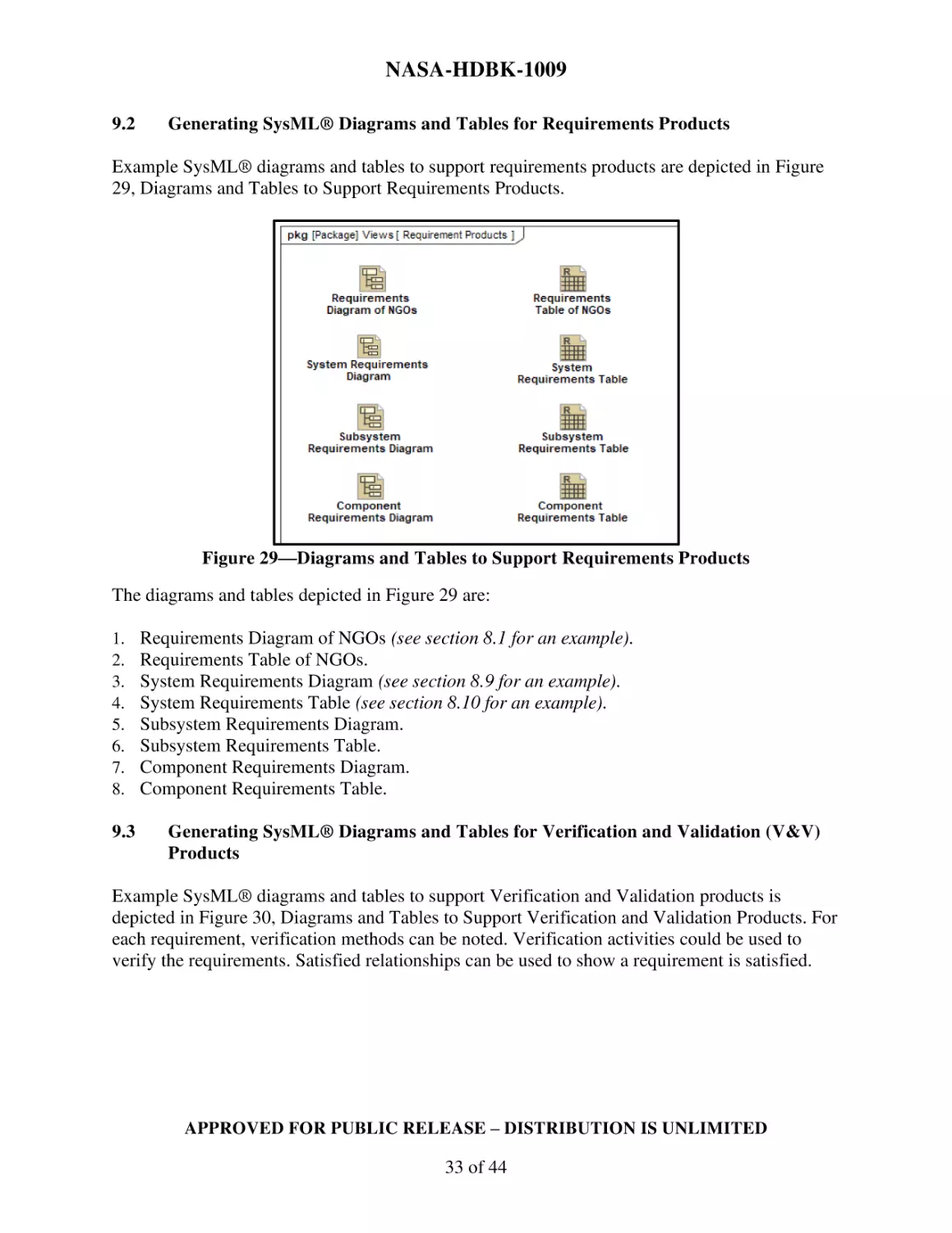
Generating SysML® Diagrams and Tables for Requirements Products
Example SysML® diagrams and tables to support requirements products are depicted in Figure
29, Diagrams and Tables to Support Requirements Products.
Figure 29—Diagrams and Tables to Support Requirements Products
The diagrams and tables depicted in Figure 29 are:
1.
2.
3.
4.
5.
6.
7.
8.
9.3
Requirements Diagram of NGOs (see section 8.1 for an example).
Requirements Table of NGOs.
System Requirements Diagram (see section 8.9 for an example).
System Requirements Table (see section 8.10 for an example).
Subsystem Requirements Diagram.
Subsystem Requirements Table.
Component Requirements Diagram.
Component Requirements Table.
Generating SysML® Diagrams and Tables for Verification and Validation (V&V)
Products
Example SysML® diagrams and tables to support Verification and Validation products is
depicted in Figure 30, Diagrams and Tables to Support Verification and Validation Products. For
each requirement, verification methods can be noted. Verification activities could be used to
verify the requirements. Satisfied relationships can be used to show a requirement is satisfied.
APPROVED FOR PUBLIC RELEASE – DISTRIBUTION IS UNLIMITED
33 of 44
NASA-HDBK-1009
Figure 30—Diagrams and Tables to Support Verification and Validation (V&V) Products
The diagrams and tables depicted in Figure 30 are:
1. Requirements Diagram with Verification Attributes (see section 8.12 for an example).
2. Requirements Table with Verification Attributes (see section 8.14 for an example).
3. Requirements Diagram of Verification Requirements/Statements (see section 8.12).
4. Verification Requirements/Statement Table (see section 8.14 for an example).
5. Requirements Diagram of Validation Requirements/Statements.
6. Validation Requirements/Statement Table.
7. Requirements Diagram with Satisfies Relationships (see section 8.11 for an example).
8. Requirements Table with Satisfies Relationships (see section 8.13 for an example).
9. Requirements Table with MOEs and Satisfied Traceability.
10. Requirements Diagram with MOE Traceability.
APPROVED FOR PUBLIC RELEASE – DISTRIBUTION IS UNLIMITED
34 of 44
NASA-HDBK-1009
APPENDIX A
NASA SYSTEMS ENGINEERING COMPETENCY MODEL
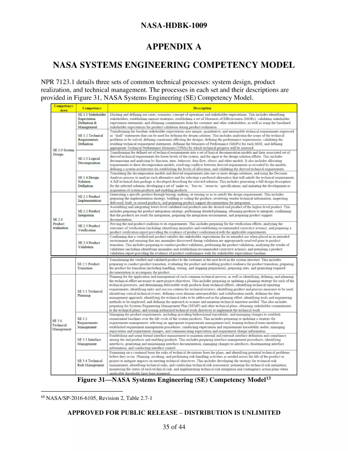
NPR 7123.1 details three sets of common technical processes: system design, product
realization, and technical management. The processes in each set and their descriptions are
provided in Figure 31, NASA Systems Engineering (SE) Competency Model.
Figure 31—NASA Systems Engineering (SE) Competency Model13
13
NASA/SP-2016-6105, Revision 2, Table 2.7-1
APPROVED FOR PUBLIC RELEASE – DISTRIBUTION IS UNLIMITED
35 of 44
NASA-HDBK-1009
APPENDIX B
OTHER MODELING APPROACHES
As mentioned in section 7, the metamodel presented in this Handbook is one approach to
modeling in support of the NASA SE Engine. Within NASA, there are varying modeling
approaches to implement the NASA SE elements and relationships. Some of these modeling
efforts are focused on modeling for additional engineering disciplines and enhancing model
verification and simulations. This Appendix describes some of these efforts, providing another
approach to requirements modeling, an extension to the behavior modeling, an addition to
structure modeling, and approach for verification analysis.
B.1
REQUIREMENTS MODELING
The Property-Based Requirement (PBR) modeling approach classes allow for requirements with
structure, numerical attributes, and constraints to support requirements analysis.14 The PBR
model element is an extension of the SysML® AbstractRequirement, extendedRequirement, and
Block15. Relating this method to the metamodel in section 7, Figure 11, all the elements in the
Requirements Pillar would be typed as [PBR Requirement].
B.2
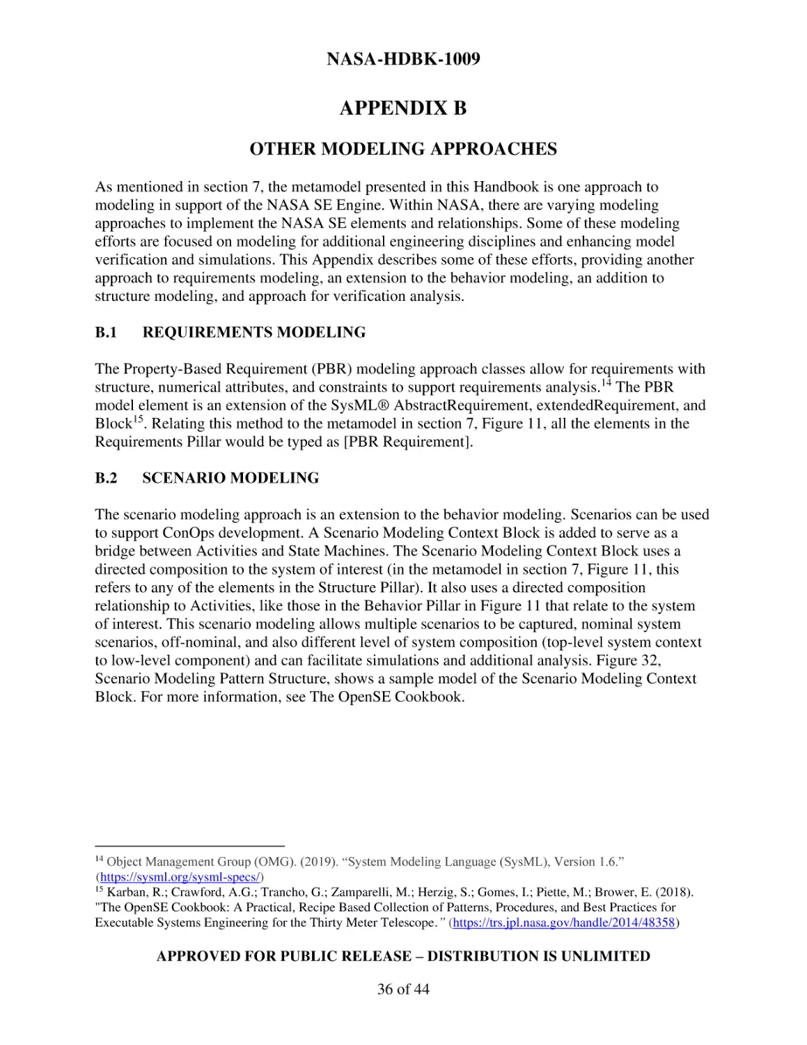
SCENARIO MODELING
The scenario modeling approach is an extension to the behavior modeling. Scenarios can be used
to support ConOps development. A Scenario Modeling Context Block is added to serve as a
bridge between Activities and State Machines. The Scenario Modeling Context Block uses a
directed composition to the system of interest (in the metamodel in section 7, Figure 11, this
refers to any of the elements in the Structure Pillar). It also uses a directed composition
relationship to Activities, like those in the Behavior Pillar in Figure 11 that relate to the system
of interest. This scenario modeling allows multiple scenarios to be captured, nominal system
scenarios, off-nominal, and also different level of system composition (top-level system context
to low-level component) and can facilitate simulations and additional analysis. Figure 32,
Scenario Modeling Pattern Structure, shows a sample model of the Scenario Modeling Context
Block. For more information, see The OpenSE Cookbook.
Object Management Group (OMG). (2019). “System Modeling Language (SysML), Version 1.6.”
(https://sysml.org/sysml-specs/)
15
Karban, R.; Crawford, A.G.; Trancho, G.; Zamparelli, M.; Herzig, S.; Gomes, I.; Piette, M.; Brower, E. (2018).
"The OpenSE Cookbook: A Practical, Recipe Based Collection of Patterns, Procedures, and Best Practices for
Executable Systems Engineering for the Thirty Meter Telescope.” (https://trs.jpl.nasa.gov/handle/2014/48358)
14
APPROVED FOR PUBLIC RELEASE – DISTRIBUTION IS UNLIMITED
36 of 44
NASA-HDBK-1009
Figure 32—Scenario Modeling Pattern Structure
B.3
SYSTEM SPECIFICATION MODELING
The System Specification modeling approach details a modeling method to relate elements in the
Structure Pillar to the Requirements Pillar. In the system specification pattern, block additions
for Logical Design, Logical Node Design, and Physical Design are added and trace to Systems,
Subsystems, and Components (in the metamodel in section 7, Figure 11, this refers to any of the
elements in the Structure Pillar) via a directed composition relationship. Another addition is the
System Specification Block. This block is used to relate the structure blocks (Logical Design,
Logical Node Design, and Physical Design) to the requirements. The System Specification Block
uses a generalization to the structure elements and a directed composition to the requirement
elements (that use a PBR requirement). For additional information, reference The OpenSE
Cookbook. See the System Specification Block in Figure 34 for details on the relationships
between requirements and the structure elements.
B.4
VERIFICATION MODELING
The OpenSE Cookbook details a requirements verification pattern. This Requirement
Verification Pattern is structured to provide a platform to aid in Verification and Validation
simulation. This pattern uses a Verification Context Block to relate the System Context element
(similar to the one depicted in the metamodel in section 7, Figure 11) and a parametric diagram
owned by the Verification Context Block. The System Context element has a part property that is
used to define the scope of the verification analysis. The scope can include the System
Specification Block described in the previous section, the Scenario Modeling Context Block
described earlier, or any other structure pillar element shown in Figure 11. See The OpenSE
Cookbook for additional information. Figure 33, Example Block Definition Diagram (bdd) of
APPROVED FOR PUBLIC RELEASE – DISTRIBUTION IS UNLIMITED
37 of 44
NASA-HDBK-1009
Another Modeling Approach for Requirements, Scenario, System Specification, and
Verification, shows the Verification Context as it relates to the System Context.
Figure 33—Example Block Definition Diagram (bdd) of Another Modeling Approach for
Requirements, Scenario, System Specification, and Verification
APPROVED FOR PUBLIC RELEASE – DISTRIBUTION IS UNLIMITED
38 of 44
NASA-HDBK-1009
APPENDIX C
INTERFACE METAMODEL
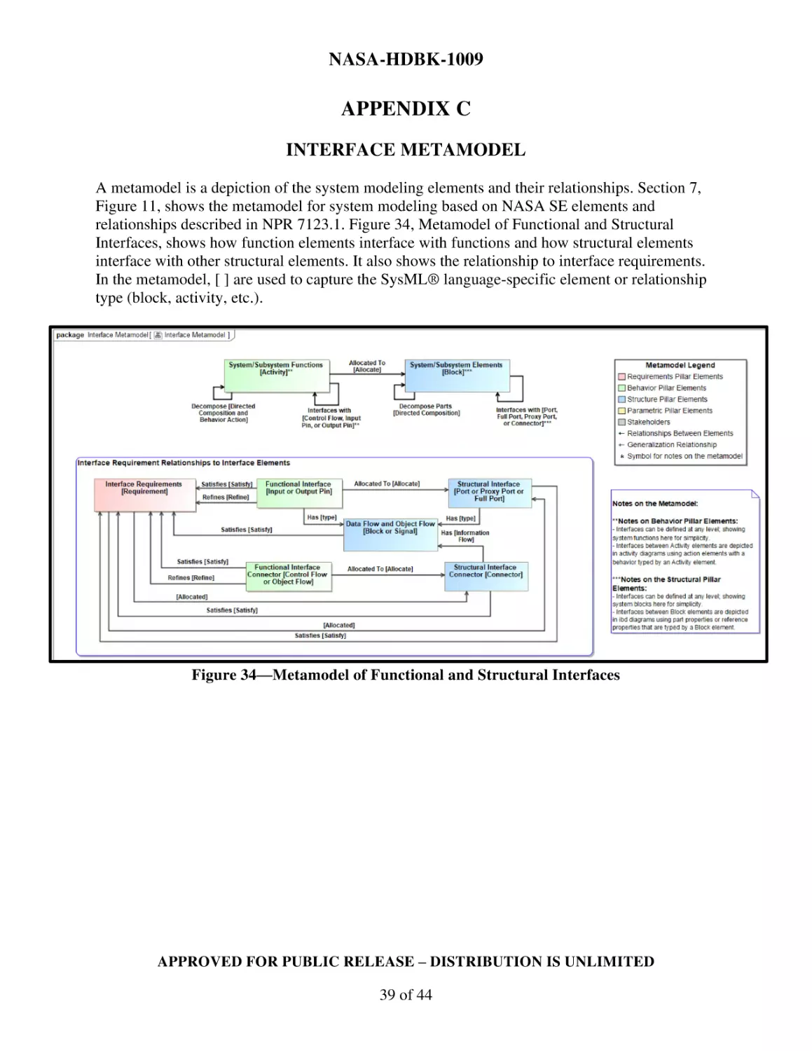
A metamodel is a depiction of the system modeling elements and their relationships. Section 7,
Figure 11, shows the metamodel for system modeling based on NASA SE elements and
relationships described in NPR 7123.1. Figure 34, Metamodel of Functional and Structural
Interfaces, shows how function elements interface with functions and how structural elements
interface with other structural elements. It also shows the relationship to interface requirements.
In the metamodel, [ ] are used to capture the SysML® language-specific element or relationship
type (block, activity, etc.).
Figure 34—Metamodel of Functional and Structural Interfaces
APPROVED FOR PUBLIC RELEASE – DISTRIBUTION IS UNLIMITED
39 of 44
NASA-HDBK-1009
APPENDIX D
ACRONYMS, ABBREVIATIONS, AND DEFINITIONS
D.1
ACRONYMS AND ABBREVIATIONS
act
bdd
ConOps
HDBK
ibd
IEC
INCOSE
ISO
MBSE
MOE
MOP
MSFC
NASA
NEN
NGO
NPR
OMG®
OOSEM
par
PBR
pkg
req
sd
SE
SEMP
SP
STD
stm
SysML®
TPM
uc
UML®
V&V
activity diagram
block definition diagram
concept of operations
Handbook
internal block diagram
International Electrotechnical Commission
International Council on Systems Engineering
International Organization for Standardization
Model-Based Systems Engineering
measure of effectiveness
measure of performance
Marshall Space Flight Center
National Aeronautics and Space Administration
NASA Engineering Network
needs, goals, and objectives
NASA Procedural Requirements
Object Management Group®
Object-Oriented Systems Engineering Method
parametrics diagram
property-based requirement(s)
package diagram
requirement diagram
sequence diagram
systems engineering
Systems Engineering Management Plan
Special Publication
standard
state machine
Systems Modeling Language™
technical performance measures
use case diagram
Unified Modeling Language
verification and validation
APPROVED FOR PUBLIC RELEASE – DISTRIBUTION IS UNLIMITED
40 of 44
NASA-HDBK-1009
D.2
DEFINITIONS
Abstraction: The process of simplifying, focusing, or transforming aspects of a real-world
or referent system represented in models and simulations. (Note: Simplifying includes selecting
aspects of the real-world or referent system to reduce in complexity in, or exclude from, the
model. Focusing includes either emphasizing or deemphasizing certain aspects of the real-world
or referent system when including them in the model. Transforming includes any change in the
appearance, character, composition, configuration, expression, or structure of aspects of the realworld or referent system (when including them) in the model (e.g., Rotation, Translation,
Mapping, Scaling, Mathematics). Any modeling abstraction carries with it the assumption that it
does not significantly affect the intended uses of the models and simulations. (Source: NASAHDBK-7009)
Activity: A set of tasks that describe the technical effort to accomplish a process and help
generate expected outcomes. (Source: NASA/SP-2016-6105, Revision 2)
Analysis: (a) In SE, use of mathematical modeling and analytical techniques to predict the
compliance of a design to its requirements based on calculated data or data derived from lower
system structure end-product validations. (Source: NASA/SP-2016-6105, Revision 2); (b) In the
design process, the examination of a situation or problem to understand the item in question and
make appropriate recommendations. (Source: NASA-HDBK-7009)
Artifact: Any product produced by the project team, e.g., requirements, documents, help
systems, code, executables, test documentation, test results, records, and diagrams. (Source:
NASA-STD-7009)
Behavior: The effect produced when an instance of a complex system or organism is used
in its operational environment. (Source: SEBoK)
Concept of Operations (ConOps): Describes the overall high-level concept of how the
system will be used to meet stakeholder expectations, usually in a time-sequenced manner.
(Source: NASA/SP-2016-6105, Revision 2)
Constraint: A condition dictated by external factors such as orbital mechanics, an existing
system that must be utilized (external interface), a regulatory restriction, state of technology, or
result of the overall budget environment that is to be met. It typically cannot be changed based on
trade-off analysis.
Design Solution Definition Process: A process that translates the outputs of the Logical
Decomposition Process into a design solution definition that is in a form consistent with the
product life-cycle phase and product layer location in the system structure and that will satisfy
phase success criteria. (Sources: NPR 7123.1 and NASA/SP-2016-6105, Revision 2).
Logical Decomposition Process: A process used to improve understanding of the defined
technical requirements and the relationships among the requirements (e.g., functional,
APPROVED FOR PUBLIC RELEASE – DISTRIBUTION IS UNLIMITED
41 of 44
NASA-HDBK-1009
behavioral, performance, and temporal) and to transform the defined set of technical
requirements into a set of logical decomposition models and their associated set of derived
technical requirements for lower levels of the system and for input to the Design Solution
Process. (Sources: NPR 7123.1 and NASA/SP-2016-6105, Revision 2)
Measure of Effectiveness (MOE): A measure by which a stakeholder's expectations are
judged in assessing satisfaction with products or systems produced and delivered in accordance
with the associated technical effort, deemed critical to both acceptability of product by
stakeholder and operational/mission usage, typically quantitative in nature or not able to be used
directly as a design-to requirement. (Source: NPR 7123.1)
Measure of Performance (MOP): A quantitative measure that, when met by the design
solution, will help ensure that an MOE for a product or system will be satisfied. MOPs are given
special attention during design to ensure that the MOEs with which they are associated are met.
There are generally two or more measures of performance for each MOE. (Source: NPR 7123.1)
Metamodel: A model of a model that describes the concepts in the modeling language,
their characteristics, and interrelationships. (Source: Friedenthal, S.; Moore, A.; and Steiner, R.
(2014). “A Practical Guide to SysML: The Systems Modeling Language,” 3rd ed. Boston:
Morgan Kaufmann.)
Model: A description or representation of a system, entity, phenomena, or process. (Note:
A model may be constructed from multiple sub-models; the sub-models and the integrated submodels are all considered models. Likewise, any data that go into a model are considered part of
the model.) (Source: NASA-HDBK-7009)
Model-Based Systems Engineering (MBSE): The formalized application of modeling to
support system requirements, design, analysis, verification, and validation activities beginning in
the conceptual design phase and continuing throughout development and later life-cycle phases.
(Source: INCOSE - International Council on Systems Engineering. (n.d.). Retrieved October 4,
2022. “INCOSE Initiatives”. INCOSE. (https://www.incose.org/incose-memberresources/initiatives)
Modeling: (a) The act of creating a system representation (i.e., the act of creating a
model); (b) The act of utilizing a system representation (i.e., utilizing a model) as an approach
for analyses. (Source: NASA-HDBK-7009)
Object Management Group® (OMG®): An international non-profit technology standards
consortium that helped design modeling standards such as SysML®. (Source: OMG®,
https://www.omg.org/about/index.htm)
Object-Oriented Systems Engineering Method (OOSEM): A systems-level development
method that combines object-oriented concepts with traditional SE practices. (Source: INCOSE,
https://www.incose.org/incose-member-resources/working-groups/transformational/objectoriented-se-method)
APPROVED FOR PUBLIC RELEASE – DISTRIBUTION IS UNLIMITED
42 of 44
NASA-HDBK-1009
Pattern: A documented and structured scalable and reusable essence of good practice that
seeks to address a problem or a group of problems.
Process: A set of activities used to convert inputs into desired outputs to generate
expected outcomes and satisfy a purpose. (Sources: NPR 7123.1 and NASA/SP-2016-6105,
Revision 2)
Program: A strategic investment by a Mission Directorate (or mission support office)
that has defined goals, objectives, architecture, funding level, and a management structure that
supports one or more projects. (Source: NPR 7123.1)
Project: A specific investment having defined goals, objectives, requirements, life-cycle
cost, a beginning, and an end. (Sources: NPR 7123.1 and NASA/SP-2016-6105, Revision 2)
Requirement: The agreed-upon need, desire, want, capability, capacity, or demand for
personnel, equipment, facilities, or other resources or services by specified quantities for specific
periods of time or at a specified time expressed as a "shall" statement. (Sources: NPR 7123.1 and
NASA/SP-2016-6105, Revision 2)
Scenario: The description or definition of the relevant system and environmental
assumptions, conditions, or parameters used to derive the course of events during the analysis
of a model. (Source: Modified from NASA-HDBK-7009)
Simulation: The imitation of the behavioral characteristics of a system, entity,
phenomena, or process. (Source: NASA-HDBK-7009)
Specification: An element that prescribes completely, precisely, and verifiably the
requirements, design, behavior, or characteristics of a system or system component, usually in
the form of a requirement. (Source: Modified from NPR 7123.1)
Stakeholder: A group or individual who is affected by or has an interest or stake in a
program or project. (Source: NPR 7123.1)
Stakeholder Expectations Definition Process: A process used to elicit and define use
cases, scenarios, concept of operations (ConOps), and stakeholder expectations for the applicable
product life-cycle phases and product later. (Sources: NPR 7123.1 and NASA/SP-2016-6105,
Revision 2)
System: The combination of elements that function together to produce the capability
required to meet a need. The elements include all hardware, software, equipment, facilities,
personnel, processes, and procedures needed for this purpose. (Sources: NPR 7123.1)
Systems Engineering (SE): NASA SE is a logical systems approach performed by
multidisciplinary teams to engineer and integrate NASA’s systems to ensure NASA products
meet the customer’s needs. Implementation of this systems approach will enhance NASA’s core
APPROVED FOR PUBLIC RELEASE – DISTRIBUTION IS UNLIMITED
43 of 44
NASA-HDBK-1009
engineering capabilities while improving safety, mission success, and affordability. This systems
approach is applied to all elements of a system (i.e., hardware, software, and human) and all
hierarchical levels of a system over the complete program/project life cycle. (Source:
NPR 7123.1)
Systems Engineering (SE) Engine: The SE model that provides the 17 technical processes
defined in NPR 7123.1 and their relationships with each other. (Source: NPR 7123.1)
Systems Modeling Language™ (SysML®): A general-purpose modeling language
developed by OMG® for specifying, analyzing, designing, and verifying complex systems that
may include hardware, software, information, personnel, procedures, and facilities. In
particular, the language provides graphical representations with a semantic foundation for
modeling system requirements, behavior, structure, and parametrics, which is used to integrate
with other engineering analysis methods. (Object Management Group (OMG). (2022). “What
is SysML?” OMG SysML. (https://www.omgsysml.org/what-is-sysml.htm))
System of Interest: The system whose characteristics are under consideration regardless
of where it lies in the product hierarchy. (Source: NPR 7123.1)
Tailoring: The process used to seek relief from SE NPR requirements consistent with
program or project objectives, allowable risk, and constraints. (Source: NPR 7123.1)
Technical Performance Measures (TPM): A set of performance measures that are
monitored by comparing the current actual achievement of the parameters with that anticipated at
the current time and on future dates. (Source: NPR 7123.1)
Technical Requirements: The requirements that capture the characteristics, features,
functions, and performance that the end product will have to meet stakeholder expectations.
(Source: NPR 7123.1)
Technical Requirements Definition Process: A process used to transform the
stakeholder expectations into a complete set of validated technical requirements expressed as
"shall" statements that can be used for defining a design solution for the PBS model and related
enabling products. (Sources: NPR 7123.1 and NASA/SP-2016-6105, Revision 2)
Validation (of a Product): The process of showing proof that the product accomplishes
the intended purpose based on stakeholder expectations and the Concept of Operations. May be
determined by a combination of test, analysis, demonstration, and inspection. (Source: NPR
7123.1)
Verification (of a Product): Proof of compliance with requirements/specifications.
(Source: NPR 7123.1)
APPROVED FOR PUBLIC RELEASE – DISTRIBUTION IS UNLIMITED
44 of 44