/


Теги: military affairs engineering design handbook
Год: 1972
Похожие


Текст
JTMCPAMPHLET
AM СР 706-203
ENGINEERING DESIGN
HANDBOOK
HELICOPTER ENGINEERING
PART THREE
REPRODUCED ВТ
NATIONAL TECHNICAL
information service
U S DEPARTMENT OF COMMERCE
SPRINGFIELD, VA.22161
QUALIFICATION ASSURANCE
HEADQUARTERS, U.S. ARMY MATERIEL COMMAND
APRIL 1372
Paragraph
Page
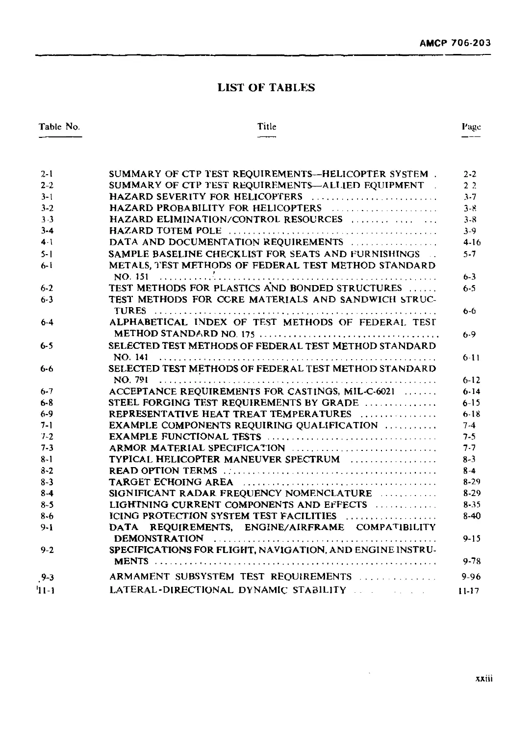
LIST OF ILLUSTRATIONS ............................. xxi
LIST OF TABLES .................................... xxiii
FOREWORD........................................... xxiv
PREFACE ............................ .............. xxv
CHAPTER 1
INTRODUCTION
CHAPTER 2
AIRWORTHINESS QUALIFICATION PROGRAM REQUIREMENTS
2-1 INTRODUCTION ...................................................... 2-1
2-2 AIRWORTHINESS QUALIFICATION SPECIFICATION (AQS) ................... 2-1
2-2.1 GENERAL ........................................................... 2-1
2-2.2 AIRWORTHINESS QUALIFICATION" SPECIFICATION REQUIRE-
MENTS 2-2
2-2.2.1 System Safety .................................................. 2-3
2-2.2.2 ’ Design Reviews and Release of Drawings ......................... 2-3
2-2.2.3 Mock-ups ....................................................... 2-3
2-2.2.4 Procurement and Process Specifications ......................... 2-3
2-2.2.S Component Teats 2-4
2-2.2.5.1 Prequalification Bench Tests ................................... 2-4
2.2.2.5.1 Qualification Tests ............................................ 2-4
2-2.2.5.3 Tiedown Tests .................................................. 2-4
2-2.2.5.4 Reliability Bench Tests ........................................ 2-4
2-2.2.5.5 Component and Subsystem Inspections ............................ 2-4
2-2.2.5.6 Electrical and Electronic Components ........................... 2-4
2-2.2.6 System Surveys ................................................. 2-5
2-2.2.7 Formal Contractor Demonstrations ............................... 2-5
2-2.2.7.1 Demonstration Sites ............................................ 2-6
2-2.2Л.2 Helicopter Configuration for Demonstrations .................... 2-6
2-2.2.7.3 Contractor Pilot Approval ...................................... 2-6
2-2.2.7.4 Helicopter Flight Approval ..................................... 2-6
2-2.2.7.5 Test Conference ................................................ 2-6
2-2.2.7.6 Specific Demonstration Requirements ............................ 2-6
2-2.3 TEST SEQUENCING ................................................... 2-7
2-2.4 TEST COORDINATION ................................................. 2-8
2-2.4.1 Test Coordinator ............................................... 2-8
2-2.4.2 Test Witness ................................................... 2-8
2-2.4.3 Cognizant Service Plant Activity ............................... 2-9
2-2.4.4 Test Witnessing Procedures ..................................... 2-9
2-2.5 AIRWORTHINESS QUALIFICATION SUBSTANTIATION REPORT .. 2-9
Reproduced From
Best Available Copy
АМСР 706-203
TABLE OF CONTENTS (Continued)
Paragraph Page
CHAPTER 3
SYSTEM SAFETY
3-1 INTRODUCTION ................................................ 3-1
3-1.1 OBJECTIVES ................................................ 3-1
3-1.2 SYSTEM SAFETY PROCESS ..................................... 3-1
3-1.2.I Known Precedent (Block A, Fig. 3-2) ....................... 3-4
3-1.2.2 System Delineation (Block B) .....................-........ 3-4
3-1.2.3 System Hazard Analyses (Block C) .......................... 3-4
31.2.4 Hazard Identification (Block D) ........................... 3-4
3-1.25 Hazard Categorization and Evaluation (Block Ej ............ 3-4
3-1.2.6 Action(s) to Eliminate oi Control Hazard(s) (Block F) ..... 3-4
3-1.2.7 Modification of System Element(s) (Block G) ........... 3-4
3-1.2.К Effectiveness Evaluation of Action Taken (Block H) ........ 3-4
3-1.2.9 Accident/Incident Analysis (Block I) ...................... 3-4
3-1.2.10 Component/System Test and Demonstration (Block J) ..... 3-5
3-1.2.11 Increased Safety Assurance (Block K) ..................... 3-5
3-1,2.12 Airworthiness Qualification (Block L) ..................... 3-5
3-1.3 ANALYTICAL METHODOLOGY ............................ 3-5
3-1.4 KNOWLEDGE OF HAZARDS ................................... 3-5
3-1.5 CLASSIFICATION OF HAZARDS ........................... 3-5
3-1.6 RESOLUTION OF HAZARDS .................................. 3-6
3-1.7 SUBSTANTIATION OF HAZARD RESOLUTION .................... 3-6
3-2 SYSTEM SAFETY PROGRAM PLAN (SSPP) ........................... 3-6
3-2.1 GENERAL ................................................ 3-6
3-2.2 SAFETY ANALYSIS AND HAZARD EVALUATION PROCEDURES . 3-6
3-2.2.1 System/Subsystem Hazard Analysis .......................... 3-8
3-2.2.2 Fault Tree Analysis ....................................... 3-9
3-2.2.3 Failure Mode and Hazardous Effect Analysis (FMHEA) ........ 3-9
3-2.3 SAFETY TESTS .............................................. 3-Ю
3-2.4 DATA ..................................................... 3-10
REFERENCES ................................................ 3-10
CHAPTER 4
DATA AND DOCUMENTATION PROCEDURES AND
REQUIREMENTS
4-1 INTRODUCTION ................................................ 4-1
4-2 APPLICABLE DOCUMENTS ........................................ 4-1
4-3 DATA REQUIREMENTS ........................................... 4-2
4-4 PROGRAM PLANS ............................................... 4-2
4-5 DESIGN REVIEWS .............................................. 4-2
4-5.1 DESIGN DRAWING REVIEWS .................................... 4-2
4-5.2 DA Г A FOR DESIGN REVIEWS ................................. 4-2
4-6 MOCK-UPS .................................................... 4-3
4-7 ENGINEERING DATA ............................................ 4-3
4 7.1 AERODYNAMIC AND FLUTTER INVESTIGATION PROGRAM RE-
PORT .................................................................... 4-3
4-7.2 AERODYNAMIC STABILITY AND CONTROL REPORTS ................. 4-3
ii
АМСР 706-203
TABLE OF CONTENTS (Continued)
Paragraph Page
4-’’.2.1 Digital and Analog Computer Program Report 4-3
4-7 2.2 Flight Simulator Program Report .................................. 4-4
4-7.2.3 Aerodynamic Stability and Control and Flying Quality Reports...... 4-4
4-7.3 CHARACTERISTIC AND PERFORMANCE DATA .............................. 4-4
4-7.3.1 Basic Aerodynamic Data ........................................... 4-4
4-7.3.2 Substantiation of Performance Data Report . ...................... 4-5
4-7 3.3 Standard Aircraft Characteristics (SAC) Charts ................... 4-5
4-7.4 WEIGHT AND BALANCE DATA .......................................... 4-5
4-7.5 STRUCTURAL DESIGN, ANALYSIS, AND TEST DATA ....................... 4-5
4-7.6 HUMAN FACTORS ENGINEERING DATA ................................... 4-5
4-7.7 SYSTEM SAFETY DATA ............................................... 4-6
4-7.8 RELIABILITY AND MAINTAINABILITY DATA ............................. 4-6
4-7.9 SUBSYSTEM DESIGN APPROVAL DATA ................................... 4-6
4-7.9.1 General Arrangement Drawings .................................. 4-6
4-7.9.2 Inboard Profile Drawings ...................................... 4-6
4-7.9.3 Rotor(s) and Propeller(s) Drawings ............................ 4-6
4-7.9.4 Stabilizing/Control Surface Drawings .......................... 4-7
4-7.9.5 Wmg (Compound Helicopters) Drawings ........................... 4-7
4 7.9.6 Body Drawings ................................................. 4-7
4-7.9.7 Hull Drawings ................................................. 4-7
4-7.9.8 Landing Gear (Wheel-type) ..................................... 4-7
4-7.9.9 Landing Gear (Skid-type) ...................................... 4-8
4-7.9 10 Landing Gear (Float-type) ..................................... 4-8
4-7.9.11 Landing Gear (Ski-type and Bear Paws) ......................... 4-8
4-7.9.12 Engine (Mpin and APU), Transmission, and Drives 4-8
4-7.9.13 Flight Controls and Stability Augmentation Systems ............ 4-9
4-7.9.14 Electrical Loads .............................................. 4-9
4-7.9.15 Hydraulics and Pneumatics ..................................... 4-9
4-7.9.16 Avionics ...................................................... 4-9
4-7.9.17 Instrumentation and Navigational Equipment ...................... 4-10
4-7.9.18 Crew Stations, Furnishings, and Equipment ....................... 4-10
4-7.9.18.1 Seats ......................................................... 4-10
4-7.9.18.2 Survival Systems .............................................. 4-10
4-7,9.18.3 Environmental Control System .................................. 4-10
4-7.9.18.4 Equipment ..................................................... 4-11
4-7.9.19 Armor and Armament .............................................. 4-11
4-7.9.20 Miscellaneous ................................................... 4-11
4-7.10 PHOTOGRAPHS ..................................................... 4-12
4-7.11 CONTRACT DETAIL SPECIFICATION REVISION PAGES .................... 4-12
4-7.12 HELICOPTER INVENTORY RECORD ..................................... 4-12
4-7.13 TEST PLANS AND QUALIFICATION TEST REPORI'S ............... 4-13
4 7.U FORMAL DEMONSTRATION PLANS AND REPORTS ................ 4.|4
4-7.1'i ENGINEERING MANUFACTURING DRAWINGS AND CON-
SOLIDATED DRAWING LIST ......................................... 4-15
4-7.15. i Preparation of Drawings ......................................... 4-15
4-7.15.2 Consolidated Drawing List ....................................... 4-15
4-7.16 SUMMARY OF DATA AND DOCUMENTATION ............................... 4-15
4-8 REPORTS AND DATA ................................................... 4-15
4-8.1 DATA SUBMITTAL, INSPECTION, AND ACTION .......................... 4-15
АМСР 706-203
TABLE OF CONTENTS (Continued)
Paragraph Page
4-81.1 Submittal .................................................. 4-20
4-8.1.2 Inspection ................................................. 4-20
4-8.1.3 Actions .................................................... 4-20
4-8.2 REVISION OF DATA AND DOCUMENT ATION ........................ 4-21
4-9 MODIFICATION OF REQUIREMENTS ................................ 4-21
APPENDIX A- GENERAL ARRANGEMENT DRAWINGS .................... 4-22
CHAPTER S
MOCK-UPS
5-1 INTRODUCTION .................................................. 5-1
5-2 MOCK-UP DEMONSTRATION REQUIREMENTS ............................ 5-2
5-2.1 FUSELAGE .................................................... 5-2
5-2.1 1 Flight Crew Stations ........................................ 5-2
5-2.12 Other Crew Stations, and Passenger and Cargo Compartments ... 5-3
5-2.1.3 Propulsion and Power System Mock-up ........................ 5-3
5-2.1.4 Electrical/Electronic System Mock-up ........................ 5-4
5-2.1.5 Hydraulic and Pneumatic System Mock-ups .................... 5-4
5-2.1.6 Armament and Armor Mock-ups ................................. 5-4
5-2 2 ROTOR HUBS AND BLADES ....................................... 5-4
5-2.3 LANDING GEAR .............................................. 5-5
5-2.4 LIGHTING MOCK-UP .............................................. 5-5
5-2.4.1 Interior Lighting .............................................. 5-6
5-2.4.2 Exterior Lighting .............................................. 5-6
5-3 MOCK-UP REVIEW AND APPROVAL ................................... 5-6
5-4 MOCK-UP DISPOSITION ........................................... 5-8
5-5 OTHER SUBSYSTEM MOCK-UPS ...................................... 5-8
REFERENCE .................................................... 5-8
CHAPTER 6
PROCUREMENT AND PROCESS SPECIFICATIONS
6-1 INTRODUCTION ........................................ 6-1
6-1.1 GENERAL ........................................... 6-1
6-1.2 MAKE-OR-BUY PLAN-PROCUREMENT ...................... 6-1
6-1.3 END-ITEM COMPONENT SPECIFICATIONS ................. 6-1
6-1.4 PURCHASE SPECIFICATIONS ........................... 6-i
6-1.5 PROCESS SPECIFICATIONS ............................ 6-1
6-L6 QUALITY ASSURANCE PROGRAM ...................... 6-2
6-2 FERROUS MATERIALS ................................... 6-2
6-2.1 GENERAL.......................................... 6-2
6-2.2 RECEIVING INSPECTION AND TEST ..................... 6-2
6-3 NONFERROUS METALLIC MATERIALS ....................... 6-2
6-3.1 GENERAL ........................................... 6-2
6-3.2 RECEIVING INSPECTION AND TEST ..................... 6-3
6-4 NONMETALLIC MATERIALS ............................... 6-3
iv
АМСР 706 203
TABLE OF CONTENTS (Continued)
Paragraph Page
6-4.1 GENERAL .................................................. 6-3
6-4.2 RECEIVING INSPECTION AND TEST .............................. 6-3
6-4 2.1 Plastics ................................................... 6-3
6-4.2.2 Elastomers ................................................. 6-4
6-4.2.3 Glass and Other Ceramic Materials 6-4
6-4.3 PROCESS SPECIFICATIONS ..................................... 6-4
6-5 COMPOSITES ................................................... 6-4
6-5.1 GENERAI..................................................... 6-4
6-5.2 RECEIVING INSPECTION AND TEST ........................... 6-4
6-5.2.1 laminates 6-4
6 5 2.2 Filament-wound Structures ................................. 6-5
6-5.2.3 Honeycomb and Sandwich Structures ........................ 6-6
6-5.2.4 Armor Materials ............................................ 6-7
6-5.2.5 Advanced Composites ...................................... 6-7
6-5.2.6 Special Requiremi nts ...................................... 6-7
6-6 ADHESIVES .............................................. 6-7
6-6.1 GENERAL .............................................. 6 7
6-6.2 RECEIVING INSPECTION AND TEST ........................... 6-7
6-6.3 PROCESS SPECIFICATIONS .................................. 6-8
6-7 PAINTS AND FINISHES ......................................... 6-10
6-7.1 GENERAL ................................................... 6-10
6-7.2 RECEIVING INSPECTION AND TEST ............................. 6-11
6-7.3 PROCESS SPECIFICATIONS .................................... 6-11
6-8 LUBRICANTS, GREASES, AND HYDRAULIC FLUIDS............... 6-11
6-8.1 GENERAL ................................................... 6-11
6-8.2 RECEIVING INSPECTION AND TEST ............................. 6-11
6-9 CASTINGS, FORGINGS, AND EXTRUSIONS ...................... 6-12
6-9.1 GENERAL................................................... 6-12
6-9.2 RECEIVING INSPECTION AND TEST ............................. 6-12
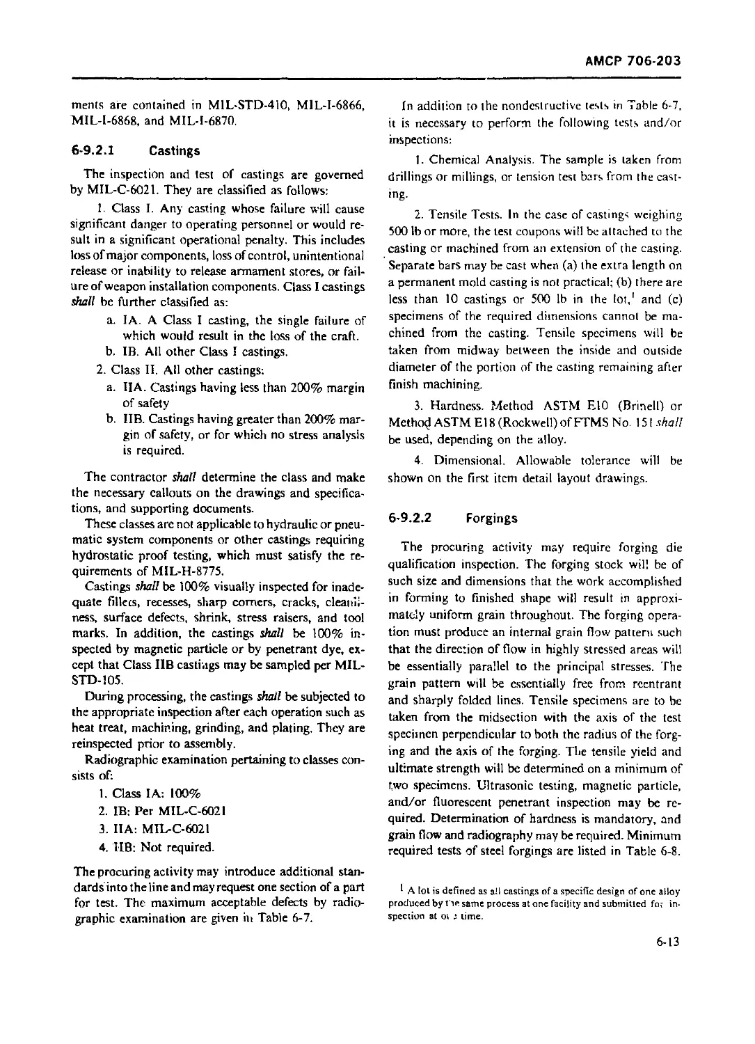
6-9.2.1 Castings .................................................. 6-13
6-9.2.2 Forgings .................................................. 6-13
6-9.2.3 Extrusions ................................................ 6-15
6-10 SHEET METAL FORMING ......................................... 6-15
6-10.1 GENERAI................................................... 6-15
6-10.2 RECEIVING INSPECTION AND TEST ............................. 6-15
6-10.3 PROCESS SPECIFICATIONS .................................. 6-15
6-11 MACHINING OPERATIONS ..................................... 6-15
6-11.1 GENERAL ................................................... 6-15
6-11.2 RECEIVING INSPECTION AND TEST ........................... 6-16
6-11.3 PROCESS SPECIFICATIONS .................................... 6-16
6-12 JOINING OPERATIONS .......................................... 6-16
6-12.1 GENERAL ................................................... 6-16
6-12.2 RECEIVING INSPECTION AND TEST ........................... 6-16
6-12.2.1 Welding ................................................. 6-16
6-12.2.2 Brazing ................................................... 6-17
6-12.2.3 Soldering ................................................. 6-17
6-12.2.4 Riveting .................................................. 6-17
612.2.5 Swaged Joints and Cables .................................. 6-17
6-13 HEAT TREATMENT ............................................. 6-17
v
АМСР 706 203
TABLE OF CONTENTS (Continued)
Paragraph Page
6-13.1 GENERA1........................... . . 6-17
6-13.2 RECEIVING INSPECTION AND TEST .............................. 6-17
6-13.3 PROCESS SPECIFICATIONS .................................... 6-18
6-13.3.1 Steels .................................................. 6-18
6-13 3.2 Aluminum Alloys ........................................ 6-18
6-13.3.3 Copper Alloys . . ....................................... 6-18
6-13.3.4 Titanium ................................................ 6-19
6-14 PEENING ...................................................... 6-19
6-14 1 GENERA1.................................................... 6-19
6-14.2 RECEIVING INSPECTION AND TEST .............................. 6-19
6-14.3 PROCESS SPECIFICATIONS ..................................... 6-19
6-15 TOOL CONTROL ................................................ 6-19
6-15.1 GENERAI..................................................... 6-19
6-15.2 RECEIVING INSPECTION AND TEST ............................. 6-2.0
6-15.3 PROCESS SPECIFICATIONS ..................................... 6-20
6-15.4 INSPECTION, QUALITY CONTROL, AND CONFIGURATION CON
TROL ....................................................... 6-20
CHAPTER 7
COMPONENT TESTS AND QUALIFICATION
7-1 INTRODUCTION 7-1
7-2 QUALIFICATION REQUIREMENTS ................................ 7-1
7-2.1 FUNCTIONAL TESTS ............................................ 7-1
7-2.2 STRUCTURAL TESTS ............................................ 7-1
7-2.3 ENDURANCE TESTS ............................................. 7-2
7-2.4 ENVIRONMENTAL TESTS ......................................... 7-2
7-3 QUALIFICATION PROCEDURES ................................... 7-2
7-3.1 TEST SPECIMENS .............................................. 7-2
7-3.2 TEST PLANS .................................................. 7-3
7-3.3 QUALIFICATION BY SIMILARITY ................................. 7-3
7-3.3.1 Fieviously Qualified Contractor-furnished Equipment (CFE) .. 7-3
7-3.3.2 Previously Qualified Government-furnished Equipment (GEE) .. 7-3
7-4 QUALIFICATION TESTS ....................................... 7-3
7-4.1 TYPES OF COMPONENTS ......................................... 7-3
7-4.2 TYPES OF TESTS .............................................. 7-4
7-4.2.1 Functional Tests ........................................... 7-4
7-4.2.2 Structural Tests ......................................... 7-5
7-4.2.2.1 Component Static Load Tests .............................. 7-5
7-4.2.2.2 Component Fatigue Tests .................................. 7-8
7-4.2.2.2.1 Fatigue Test Requirements ................................ 7-8
7-4.2.2.2.2 Test Specimens ........................................... 7-9
7-4.2.2.2.3 Frequency of Loading .................................... 7-9
7-4 2.2.2.4 Verification of Test Fixtures ............................ 7-9
7-4 2.2.2.5 Use of Tested Parts ...................................... 7-9
7-4.2.3 Endurance Tests .......................................... 7-9
7-4.2.4 Environmental Tests ..................................... 7-10
vt
АМСР 706-203
TABLE OF CONTENTS (Continued)
Paragraph Page
7-4.2.4.1 Laboratory Environmental Simulation .................... 7-10
7-4.2.4.1.1 Shock ................................................. 7-10
7-4.2.4.1.2 Vibration ........................................ . . 7-10
7-4.2.4.13 Sand and Dust .......................................... 7-11
7-4.2.4.1.4 Salt Spray ............................................. 7-11
7-4.2.4.1.5 Extreme Temperature .................................... 7-11
7-4.2.4.1.6 Rain ................................................... 7-11
7-4.2.4.1.7 Humidity ............................................... 7-12
7-4.2.4.2 Altitude ............................................... 7-12
7-4.2.4.3 Other Environments 7-12
7-5 TRANSMISSION AND DRIVE SYSTEM COMPONENTS ................ 7-12
7-5.1 TRANSMISSION AND GEARBOX BENCH TESTS ................... 7-12
7-5.2 CLUTCHES .................................................. 7-13
7-5.3 BRAKES .................................................... 7-14
7-5 4 SHAFTING, COUPLINGS, AND BEARINGS ...................... 7-15
7-5.4.1 Shafting and Couplings ................................... 7-15
7-5.4.2 Bearings 7-16
7-5.5 ACCESSORIES .......................................... 7-16
7-6 DOCUMENTATION ............................................. 7-18
REFERENCE ................................................. 7-18
CHAPTER 8
HELICOPTER SURVEYS
8-0 LIST OF SYMBOLS ............................................ 8-1
8-1 INTRODUCTION .............................................. 8-1
8-2 FLIGHT LOAD SURVEY ......................................... 8-1
8-2.1 GENERAI..................................................... 8-1
8-2.2 FLIGHT LOAD SURVEY PLAN .................................... 8-2
8-2.3 TEST REQUIREMENTS .......................................... 8-2
8-2.4 INSTRUMENTATION AND DATA ANALYSIS ...................... 8-3
8-2.5 DOCUMENTATION ......................................... 8-5
8-3 ENGINE VIBRATION SURVEY .................................... 8-5
8-3.1 GENERAL .................................................... 8-5
8-3.2 ENGINE VIBRATION SURVEY PLAN ........................... 8-5
8-3.2.1 Airframe Manufactuier Requirements ...................... 8-5
8-3.2.2 Engine Manufacturer Coordination ........................ 8-5
8-3.3 TEST REQUIREMENTS .......................................... 8-5
8-3.3.1 Ground Tests ............................................ 8-5
8-3.3.2 Flight Tests ............................................ 8-5
8-3.4 INSTRUMENTATION AND DATA ANALYSIS...................... 8-6
8-3.5 DOCUMENTATION .............................................. 8-7
8-4 PROPULSION SYSTEM TEMPERATURE SURVEY ....................... 8-9
8-4.1 GENERAL ................................................. 8-9
8-4.2 PROPULSION SYSTEM TEMPERATURE SURVEY PLAN ............... 8-9
8-4.3 TEST REQUIREMENTS ....................................... 8-9
8-4.3.1 Ground Tests ............................................ 8-9
8-4.3.2 Flight Tests ............................................ 8-9
8-4.4 INSTRUMENTATION AND DATA ANALYSIS ...................... 8-10
vii
АМСР 706-203
TABLE OF CONTENTS (Continued)
Paragraph
8-4.5
8-5
8-5.1
8-5.2
8-5.3
8-5.3.1
8-5.3.2
8-5.3.3
8-5.4
8-5.5
8-6
8-6 1
8-6.2
8-6.3
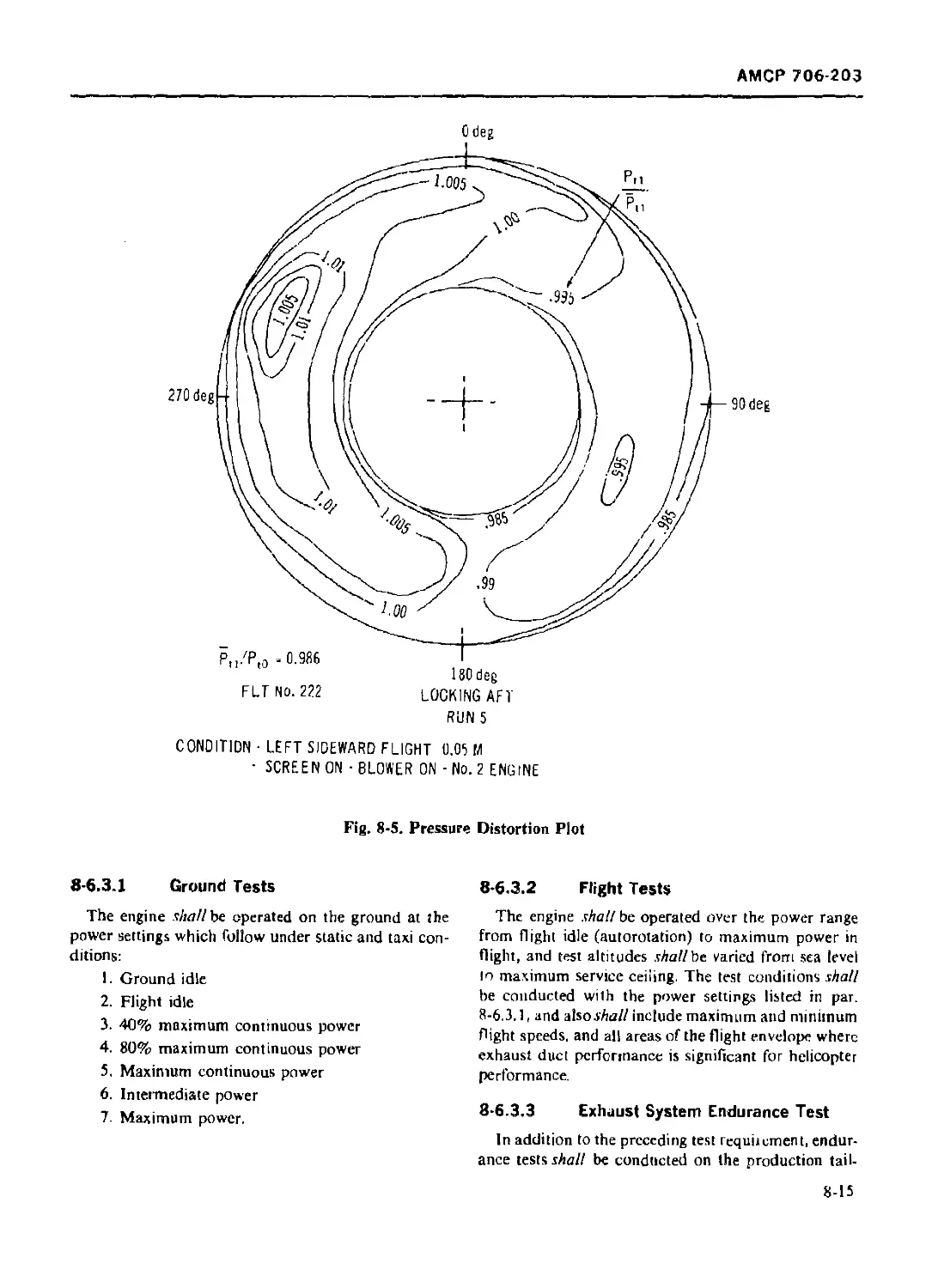
8-6.3.1
8-6.3.2
8-6.3.3
8-6.4
8-6.5
8-7
8-7 1
8-7.2
8-7.2.1
S-7.2.2
8-7.3
8-7 4
8-7.5
8-8
8-8.1
8-8.2
8-8.3
8-8.3.1
8-8.3.2
8-8.3.3
8-8 4
8-8.5
8-9
8-9 1
8-9.2
8-9.2.1
8-9.2.1.1
8-9.2.I.1.1
8-9.2.1.1.2
8-9.2.1.1.3
8-9.2.1.2
8-9.2.(.2.1
8-9.2.1.2.2
8-9.2.1.2.3
DOCUMENTATION ............................
ENGINE AIR INDUCTION SYSTEM SURVEY .....................
GENERAL ..............................................
ENGINE AIR INDUCTION SYSTEM SURVEY PLAN ..............
TEST REQUIREMENTS ....................................
Ground Tests
Flight Tests ........................................
Effect on Engine Performance ........................
INSTRUMENTATION AND DATA ANALYSIS ....................
DOCUMENTATION ........................................
ENGINE EXHAUST SYSTEM SURVEY ...........................
GENERAL .................................. ...........
ENGINE EXHAUST SYSTEM SURVEY PLAN ....................
TEST REQUIREMENTS ............................ .......
Ground Tests .......................... .............
Flight Tests ........................................
Exnaust System Endurance Test .......................
INSTRUMENTATION AND DATA ANALYSIS ....................
DOCUMENTATION ........................................
TOTAL SYSTEM VIBRATORY SURVEY ..........................
GFNERAI...............................................
GROUND VIBRATION TESTS ...............................
Airframe Vibration
Rotor System Vibration ..............................
FLIGHT TESTS .........................................
INSTRUMENTATION ......................................
DOCUMENTATION ........................................
CREW ENVIRONMENTAL SURVEY ..............................
GENERAL ..............................................
CREW ENVIRONMENTAL SURVEY PLAN ...........
TEST REQUIREMENTS ....................................
Ground Tests ........................................
Flight Tests ........................................
Climatic Hangar Tests ...............................
INSTRUMENTATION AND DATA ANALYSIS ....................
DOCUMENTATION ........................................
HELICOPTER SYSTEM SURVEYS ..............................
GENERAL ..............................................
INFRARED (IR) RADIATION AND COUNTERMEASURE SYSTEM
SURVEY ..............................................
Passive IR Countermeasure Tests .....................
Airframe/IR Suppressor Compatibility Tests ........
Ground Tests ......................................
Flight Tests ......................................
Instrumentation and Data Analysis .................
IR Signature Survey ...............................
Ground and Hovering Conditions ....................
Fly-by Test Condition .............................
Instrumentation and Data Analysis .................
Page
8-10
8-10
8-10
8-11
8-11
8-11
8-1 I
8-11
8-12
8-13
8-13
8-13
8-14
8-14
8-15
8-15
8-15
8-16
8-17
8-17
8-17
8-17
8-17
8-18
8-18
8-20
8-20
n-2G
8-20
8-20
8-20
8-21
8-21
8-21
8-21
8-23
8-24
8-24
8 24
8-24
8-74
8-24
8-24
J -5
8-25
8-26
8-26
8-26
viii
АМСР 706 203
Paragraph
TABLE OE CONTENTS (Continued)
Page
8-9 2.1.3 Qualification Tests.................... ............................. 8 2s
8-9.2.2 Active 1R Conntermeasiire System........................................ 8-28
8-9.2.2.1 blight Test Conditions ................................................. 8-28
8-9.2.2.2 Instrumentation and Data Analysis..................................... 8-28
8-9.2.3 Documentation ........................................................ 8-28
8 9 3 RADAR REFLECTIVITY SURVEY.......................................... 8 2 -
8-9.3.1 Radar Reflectivity Survey Plan ........................................ 8-30
8-9.3.? Scale Model Techniques .................................................. 8-30
8-9 2.3 Test Requirements .... . . ....... 8-30
8-9.3.4 Instrumentation and Data Analysis ...................................... 8-3(1
8-9.3.5 Documentation .................. 8-31
8-9.4 LIGHTNING PROTECT ION SURVEY ........................................... 8-31
8-9.4.1 Lightning Protection Survey Plan ........................................ 8-33
8-9.4 2 Lightning Laboratory Tests 8-33
8-9 4-3 Lightning Checklist .......................... 8 35
8-9.4.4 Documentation ........................................................... 8-37
8-9.5 ICING SURVEY ............................................................... 8-37
8-9.5. | Icing Survey Plan ....................................................... 8-37
8-9.5.2 Test Requirements 8-37
8-9.5.2.1 Ictng T unnel Tests ..................... . . ......................... 8-38
8-9.5.2.2 Clear, Dry Air Flight Tests ............................................ 8-38
8-9.5.2.3 Simulated Icing Flight Vests ............................................ 8-38
8-9.5.2.4 Natural Icing Flight Tests .............................................. 8-39
8 9.5.3 Instrumentation and Data Analysis ....................................... 8-39
8-9.5,3.1 Photographic Recording .................................................. 8-39
8-9.5.3.2 Recording of Icing Conditions ......................................... 8-39
8-9.5.3.3 System Performance and Power Recording .............................. 8-39
8-9.S.4 Documentation ......................................................... 8-41
8-9 6 ACOUSTICAL NOISE SURVEY (INTERNAL AND EXTERNAL) .............. 8-41
8-9.6.1 Acoustical Noise Survey Plan ...................................... 8-41
8-9.6.2 Test Requirements ....................................................... 8-41
8-9.6.2.1 Internal Noise .......................................................... 8-42
3-9.6.2.1.1 Helicopter Operational Modes ............................................ 8-42
8-9.6.2.1.2 Instrumentation ......................................................... 8-4?
8-9.6.2.1.3 Noise Measurement ....................................................... 8-»2
8-9.6.2.1.4 Weapon Noise Measurement 8-43
8-9.6.2.1.5 Intelligibility Tests ................................................... 8-43
8-9.6.2.2 External Noise .......................................................... 8-44
8-9.6.2.2.1 Helicopter Operational Modes ............................................ 8-44
8-9.6.2.2.2 Instrumentation ......................................................... 8-44
8-9.6.2.2..3 Noise Measurement ....................................................... 8-45
8-9.6.3 Data Analysis ........................................................... 8-46
8-9.6.4 Documentation ........................................................... 8-46
8-9.7 CLIMATIC LABORATORY SURVEY ................................................. 8-47
8-9.7.1 Climatic Laboratory .................................................. 8-47
8-9.7.? Climatic Laboratory T ests .............................................. 8-48
8-9.7 2.1 Test Requirements........................................................ 8-49
8-9.7 2.2 Instrumentation and Data Analysis ....................................... 8-49
8-9.7.3 Documentation .......................................................... 8-50
REFERENCES ................................................................... 8-50
ix
АМСР 70» ^03
TABLE OF CONTENTS (Continued)
Paragraph Page
CHAPTER 9
HELICOPTER SYSTEM DEMONSTRATIONS
9-0 LIST OF SYMBOLS ...................................................... 9-1
9-1 INTRODUCTION ......................................................... 9-1
9-2 STRUCTUR AL INTEGRITY DEMONSTRATION ........................... 9 2
9-2.1 GENERAI................................................................... 9-2
9-2.2 STATIC TEST PROGRAM ...................................................... 9-2
9-2.2.1 Test Requirements .................................................... 9-2
9-2.2.2 Instrumentation and Data Analysts .................................... 9-4
9-2.2..3 Documentation .................................................... 9-5
9-2.3 LANDING GEAR DROP TESTS .................................................. 9-5
9-2.3.1 Test Requirements ................................................ 9-5
9-2.3.11 Wheel Gear ....................................................... 9-0
9-2.3.11.1 Test Procedures ................................................. 9-6
9-2.3.1.1.2 Instrumentation and Data Analysis .............................. 9-6
9-2.3.1.2 Skid Gear ........................................................ 9-7
9-2.3.1.2.1 Test Procedures ................................................. 9-7
9-2.3.1.2.2 Instrumentation and Data Analysis .............................. 9-7
9-2.3.2 Documentation .................................. ................. 9-8
9-2.4 STRUCTURAL DEMONSTRATION ................................................. 9-8
9-2.4.1 Test Requirements .................. ............................. 9-9
9-2.4.1.1 Test Maneuvers ................................................. 9-9
9-2.4 12 Instrumentation and Data Analysis ................................. 9-10
9-2.4.2 Documentation ....................................................... 9-11
9-3 PROPULSION AND POWER SYSTEM DEMONSTRATION ............................... 9-11
9-3.1 GENERAL ................................................................. 9-11
9-3.2 ENGINE/A1RFRAME COMPATIBILITY TESTS ..................................... 9-12
9-3.2.1 Test Requirements ................................................... 9-12
9-3.2.1.1 Ground Tests ...................................................... 9-13
9-3.2.1.1.1 Propulsion Controls . ............................................... 9-13
9-3.2.1,1.1.1 Power Lever Controls ................................................ 9-13
9-3.2.1.1.1.1.1 Engine(s) Stopped ................................................ 9 14
9-3.2.1.1.1.1.2 Engine(s) Running ................................................... 9-14
9-3.2.1.1.1.2 Starting and Acceleration to Ground Idle ............................ 9-14
9-3 2.1.1.1.3 Acceleration and Deceleration Tests ................................. 9-14
9-3.2.1.1.1.4 Gas Generator Control and Power Turbine Governor Sensitivities ...... 9-16
9-3.2.1.1.1.5 Power Control Anticipator and Droop Cam Characteristics 9-16
9-3.2.1.1.2 Rotor Controls ...................................................... 9-16
9-3.2.1.1.2.1 Helicopter Dynamic System—Engine Compatibility ...................... 9-16
9-3.2.1.1.2.2 Alignment and Output Shaft Unbalance ....... 9 16
9-3.2.1.2 Flight Tests ........................................................ 9-16
9-3.2.1.21 Propulsion Controls ................................................. 9-16
9-3.2.1.2.1.1 Altitude Restarts ................................................... 9-lb
9-3.2.1.2.1.2 E\Jne Acceleration and Deceleration Tests ........................... 9-17
9-3.2.1.2.1.3 Gas Generator Fuel Control ....................................... 9 17
9-3.2.1.2.1.4 Power Turbine Governor and Speed Response Time ...................... 9-17
9-3.2.1.2-1.5 Power Control Anticipator and Droop Compensation Cam Characteristics 9-17
АМСР 706 203
TABLE OF COM EM S (Continued;
Paiagt aph
9 3.? 1 ?.l <i I st.iblislmt,’i*l ol Minimum .mil Maximum I’owst littbinc Spicdx ... 9 p
0 3.2.1 2.2 11elicopiet Contiols ..................................................... 9 p
9 3 2.1 2.2 1 1 lehcoptei Dsn.nine Sssictii 1 iignu- I oinpdtibilns .................... 9 IS
9-t.2.1 2 2 2 A lignmcm and Output Shaft Uiib.ilaucs- .... 9 Is
9-3 2.1.3 1 ngine slatting Tests ................................... ............... 9 Is
9-3 2 I 3.1 Ground lists ............................................................. "-1X
9-3 2 I 3.1 I Ainbient 1 cmpcratiiie lasts . 9 1s
9 3.2.1 3.1 2 I an niupei-.'tiite Tests ................................................ о pi
9.3 2.1.3.1-3 High tetnpei atilli- 1 axis .................................. 9 |9
9-3 2 13 14 Giound Powet ''Ambient 1 empetatiue lasts ..................................... 9-p>
9-3.2.1 3.2 Flight Tests . 9-19
9 3-2.1 3.3 lllsti iinicrit.itiuii .........................-.............................. 9-19
9-3.2.1 4 1 ubrica’ion Tests ....................................................... 9 |9
9-3.2.1.5 Secondary Powei System Tests 9-|9
9..3.2 2 Documentation . . . . . 9-19
9-3 .3 TRANSMISSION AND DRIVES ........................................................... 919
9-3.3.1 Test Requirements ............................................................ 9-2(1
9-3.3.| 1 Ihcqualilicntioii Tests ..................... 9-2(1
9-3.3.1-2 Qualification Tests............................................................ 9-21
9-3 3.1 3 Tiedown Tests ................................................................ 9-21
9-3.3.2 Instrumentation .............................................................. 9-21
9-3 3.3 Disassembly ................................. 9 22
9-3.3.4 Inspection .................................................................... 9-22
9-3.3.5 Retest ........................................................................ 9-22
9-3.3 6 Clutches anil Brakes .......................................................... 9-22
9-3.3.7 Shafting. Couplings, and Bearings .......................................... 9-22
9-3.3.S Accessories ................................................................... 9-23
9-3.4 LUBRICATION AND FUEL SUBSYSTEM DEMONSTRATION ...................................... 9-23
9-3 4 1 Lubrication Subsystem Demonstration ........................................... 9-24
9-3.4.1 I Test Requirements ............................................................. 9-25
9-3.4.1.1.1 Measurement of Usab1-. Oil .................................................... 9-25
9-3.4.1.1.2 Measurement of Oii Tank Expansion Space ....................................... 9-25
9-3.4.1.1.3 Oil l ank Pressure Test ...................................................... 9-25
9-3.4.1.1.4 Oil System Bypasx Demonstration ............................................... 9-25
9-3.4.1.1.5 Oil Vent System Test .......................................................... 9-25
9-3.4.1.1.6 Oil Tank Quantity Calibration ................................................. 9-26
9-3.4.1.1.7 Oil Cooling ................................................................... 9-26
9-3.4.1.1.7 1 Hover Cooling ................................................................. 9-26
9-3.4.1.1.7.2 Climb Cooling ................................................................. 9-26
9-3.4 1.1.7.3 Cruise Cooling ................................................................ 9-26
9-3.4.1.1.7.4 Other Flight Conditions ....................................................... 9-26
9-3.4.1.17.5 Additional Cooling Tests ...................................................... 9-26
9-3.4.1.1.7.6 Determination of Cooling Margins ................................... . . 9-26
9-3.4.1.1.7.7 Chip Detector Demonstration ................................................... 9-26
9-3.4.2 Fuel Subsystem Demonstration .................................................. 9-26
9-3.4.2.I Internal and External Fuel Tank Capacities .................................... 9-27
9-3.4.2.1.1 Tank Capacity ................................................................. 9-27
9-3.4.2.1.2 Available Fuel .............................................................. 9-27
9-3.4.2.1.3 Sump Capacity ........................................................................... 9-27
xi
АМСР 706-203
TABLE OF CONTENTS (Continued)
Paragraph Page
9-3.4.2 1.4 Residual Fuel ............................................. . ...... 9-27
9-3 4 2 I 5 Expansion Space 9-27
9-3.4 2 I.fi Auxiliary Fuel Provisions ............................................ 9 27
9-3.4.2.1.7 Low-level Fuel Warning System ............................................. 9-27
9-3.4 2.1 .8 Fuel Quantity Gaging Subsystem fests ...................................... 9-28
9-3 4.2.2 Refueling and Deluding Tests .............................................. 9-28
9 3 4 2.2.1 Refueling ............................................................ 9-28
9-3.4.2.2 2 Surge Pressure Test ....................................................... 9-28
9-3 4.2.2.3 Defuebiig Test ............................................................ 9-28
9-3.4.2 2.4 Closed Circuit Refueling Sysieni Tests .................................... 9-28
9-3.4.2.2.5 Siphoning Tests ........................................................... 9-28
9 3.4.2.2.6 Center-of-gravity <CG) Travel Test 9-28
9-3.4 2 3 Boost and Transfer Pump Failure Tests ..................................... 9-28
9-3.4 2 3.1 Ground Tests .............................................................. 9-29
‘ 3.4.2.3.2 Flight Tests .............................................................. 9-29
9-3.4.2.3.3 Vapor/Liquid Ratio Tests .................................................. 9-29
9-3.4.2.4 Fuel Supply and Fuel Transfer Tests ....................................... 9-29
9-3.4 2.4.1 Fuel Supply Tests 9-29
9-3.4 2 4 2 Internal Tank Switchover and Fuel Transfer Rates .......................... 9-29
9-3.4.2.4.3 External Tank Fceaout ..................................................... 9-29
9-3.4.2.4.4 Fuel Jettison ............................................................. 9-29
9 3.4.2.5 Fuel and Vent System Tests ................................................ 9-29
9-3.4.2 5.1 Pressurization and Fuel Vent System Tests ................................. 9-29
9-3.4 2 5.2 Vent Outlet Icing Tests ................................................... 9-30
9-3.4 2 5.3 Vent System Failure Tests ............................................... 9-30
9-3.4 2 6 Fuel lank Purge (it applicable) ......................................... 9-30
9-3.4 2 6.1 Ground Tests .............................................................. 9-30
9-3.4.2.6 2 Flight Tests .............................................................. 9-30
9-3 4 2.7 Crashworthy Fuel System ................................................... 9-30
9-3.5 ROTORS AND PROPELLERS .................................................... 9 30
9-3.5.1 Rotor System Demonstration ................................................ 9-30
9-3.5.1.1 Rotor Whirl Tests ....................................................... 9-30
9-3.5.1.2 Preliminary Fligh’ Approval lest .......................................... 9-30
9-3.5.1.3 150-lu Tiedown Test ....................................................... 9-31
9-3 5.2 Pi. peller System Demonstrations .......................................... 9-31
9-3.5.2.1 Test Requirements ......................................................... 9-31
9-3.5.2.1.1 Ground Te-ts .............................................................. 9-32
9-3.5 2.1.2 Flight Tests .............................................................. 9-32
9-3 5.2.2 Special 1 ests ............................................................ 9-33
9-3.5.2.2.1 Whirl Flutter ............................................................. 9-33
9-3.5.2.2.2 Balance ................................................................... 9-33
9-3.5.2.3 Instrumentation .......................................................... 9-3.3
9-3.5.2.4 Documentation ............................................................. 9-34
9-3.6 ENGINE VIBRATION DEMONSTRATION ................................................ 9-36
9-3.6.1 Engine Vibration Demonstration Plan 9-37
9-3.6.2 Test Requirements ......................................................... 9-37
9-3.6.2.1 Ground Tests ................................................... .... 9-37
9-3.6.2.2 Flight Tests .............................................................. 9-38
9-3.6 3 Instrumentation and Data Analysis ......................................... 9-39
xii
АМСР 706-203
TABLE OF CONTENTS (Continued)
Paragraph Page
9-3.64 Documentation ..................................................... 9-39
9-3.7 PROPULSION SYSTEM TEMPERATURE DEMONSTRATION ........................... 9-39
9-3.7.1 Propulsion System Temperature Demonstration Plan .................. 9-39
9-3 7.2 Test Requirements ............................................. 9-39
9-3 7.2.1 Ground Tests ...................................................... 9-39
9-3.7.2.2. Flight Tests ...................................................... 9-39
9-3.7.3 Instrumentation and Data Analysis ................................. 9-39
9-3.7.4 Documentation .................................................... 9-39
9-3.8 ENGINE AIR INDUCTION SYSTEM DEMONSTRATION ............................. 9-39
9-3.8.1 Engine Air Induction System Demonstration Plan .................... 9-40
9-3.8.2 Test Requirements ................................................. 9-40
9-3.8.2.1 Ground Tests ...................................................... 9-40
9-3.8.2.2 Flight Tests ...................................................... 9-40
9-3.8.2.2.1 Inlet Pressure Recovery ......................................... 9-40
9-3.8.2.2.2 Inlet Temperature Level ........................................... 9-40
9-3.8.2.2.3 Other Inlet Pressure and Temperature Distortion Effects ........... 9-40
9-3.8.3 Instrumentation and Data Analysis ................................. 9-41
9-3.8.4 Documentation ................................................... 9-42
9-4 DYNAMIC INSTABILITY DEMONSTRATION ..................................... 9-42
9-4.1 GENERAL ............................................................... 9-42
9-4.2 GROUND RESONANCE ...................................................... 9-42
9-4.2.1 Test Requirements .... ............................................ 9-42
9-4.2.2 Documentation .............................................. . 9-43
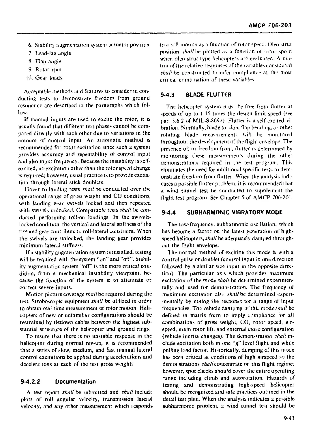
9-4.3 BLADE FLUTTER ......................................................... 9-43
9-4.4 SUBHARMONIC VIBRATORY MODE ......................... 9-43
9-5 AERODYNAMIC DEMONSTRATION ............................................. 9-44
9-5.1 GENERAI................................................................ 9-44
9-5.2 PERFORMANCE SUBSTANTIATION ............................................ 9-44
9-5.2.1 Test Requirements ............................................... 9-44
9-5.2.1.1 Level Flight Performance .......................................... 9-44
9-5.2.1.2 Climb Performance ................................................. 9-45
9-5.2.1.3 Hover Performance ................................................. 9-46
9-5.2.1.4 Autorotational Performance ........................................ 9-46
9-5 2.1.5 Airspeed Calibration ............................................. 9-48
9-5.2.16 Determination of Power Available .................................. 9-48
9-5.3 FLYING QUALITIES DEMONSTRATION .................................. 9-49
9-5.3.1 Test Requirements ................................................. 9-49
9-5.3.1.1 Static Longitudinal Stability ..................................... 9-49
9-5.3.1.2 Stalic Lateral-directiunal Stability .............................. 9-49
9-5.3.1.3 Sideward and Rearward Flight ...................................... 9-50
9-5.3.1.4 Trim Requirements ................................................. 9-50
9-5.3,1.5 Controllability ................................................... 9-50
9-5.3.1.6 Dynamic Stability ................................................. 9-50
9-5.3.1.7 Maneuvering Stability ............................................. 9-50
9-5.3.1.8 Roll Characteristics .............................................. 9-51
9-5.3.1.9 Autorotation Entnes ............................................... 9-51
9-5.3.1 10 Stability Augmentation System Failures ............................ 9-51
9-5.3.1.11 Qualitative Pilot Evaluation ...................................... 9-51
9-5.3.2 Documentation ..................................................... 9-51
xiii
АМСР 706 203
TABLE OF CONTENTS (Continued)
Paragraph Page
9-6 ELECTRICAL DEMONSTRATION ................................................ 9-52
9-6.1 GENERAI.................................................................. 9-52
9-6.2 ELECTRICAL ANALYSIS REPORT ......................................... 9-53
9-6.3 ELECTRICAL SYSTEM AIRWORTHINESS QUALIFICATION TESTS 9-53
9-6.3.1 Ground Tests ......................................................... 9-53
9-6.3.1.1 Electrical Load Measurements ......................................... 9-53
9-6.3.1.2 Primary Power System Tests ....................................... 9 54
9-6.3.1.2.1 AC Primary Electrical System Tests ................................. 9-54
9-6.3.1.2.2 DC Primary Electrical System Tests ................................... 9-54
9-6.3.1.3 Conversion Power Tests ............................................... 9-54
9-6.3.1.4 Emergency Power Tests ................................................ 9-54
9-6.3.1.5 Fault Protection and Detection ....................................... 9-55
9-6.3.1.6 Electrical System Installation ....................................... 9-55
9-6.3 17 Electrical Engine-starting System Tests .............................. 9-55
9-6.3.2 Flight Tests ......................................................... 9-55
9-6.4 DOCUMENTATION ........................................................... 9-56
9-7 AVIONIC DEMONSTRATION ................................................... 9-56
9-7.1 GENERAL ................................................................. 9-56
9-7.2 AVIONIC AIRWORTHINESS QUALIFICATION ........................... 9-56
9-7.2.1 Avionic Airworthiness Qualification Test Ground Station .............. 9-56
9-7.2.2 Production Tests ..................................................... 9-56
9-7.2.3 Avionic Test Specifications 9-57
9-7.2.4 Electrical Power Verification ....................................... 9-57
9-7.3 ANTENNA PERFORMANCE SUBSTANTIATION .......................... 9-57
9-7.3.1 Scale Model Antenna Test Program ..................................... 9-57
9-7.3.2 Antenna Subsystem Qualification ...................................... 9-57
9-7.3.3 Antenna Performance Tests ............................................ 9-58
9-7.3.4 Ground Tests ......................................................... 9-58
9-7.3.5 Flight Tests ......................................................... 9-58
9-7.3.5.1 Antenna Pattern Tests ................................................ 9-58
9-7.3.5.2 Maximum Range Tests .................................................. 9-58
9-7.3.6 Operational Tests .................................................... 9-59
9-7.3.7 Documentation ........................................................ 9-59
9-7.4 COMMUNICATION EQUIPMENT ................................................. 9-60
9-7.4.1 Component Tests ...................................................... 9-60
9-7.4.2 Avionic Subsystem Ground Tests ..................................... 9-60
9-7.4 2.1 Test Requirements ................................................... 9-60
9-7.4.2.2 Airworthiness Qualification Ground Tests ............................. 9-60
9-7.4.2.2.1 Visual Inspection .................................................... 9-60
9-7.4.2.2.2 Cooling Tests ........................................................ 9-60
9-7.4.2.2.3 RF Output Power and VSWR Tests .................................... 9-61
9-7.4.2.2.4 Transmitter Modulation Checks ........................................ 9-61
9-7.4.2.2 5 Operational Tests .................................................... 9-6i
9-7.4.2.2.6 Maintainability Tests ................................................ 9-61
9-7.4.2.2.7 Rejection Criteria ................................................... 9-61
9-7.4.3 Production Ground Tests .............................................. 9-61
9-7.4.3.1 Visual Inspection .................................................... 9-61
9-7.4.3.2 RF Output Power and VSWR Tests .................................... 9-61
9-7.4.3.3 Operational Tests .................................................... 9-61
xiv
AMCP 70t
TABLE OF CONTENTS (Continued)
Paragraph P.i;
9-7.4.3.4 Rejection Criteria .................................................. 9-0
9-7.4.4 Avionic Subsystem Flight Tests ...................... 9-tri
9-7.4.41 Airworthiness Qualification Flight Tests ............................. 9-61
9-7.4.4.1.1 Antenna Patterns ......................................................... 9-6?
9-7.4.4.12 Range Tests .............................................................. 9-62
9-74.4.1.3 Performance Tests ..................................................... 9-62
9-7.4.4.1.4 Vibratory Tests .......................................................... 9-62
9-7.4.4.1.5 Cooling Tests ........................................................... 9-63
9-7.4.4.2 Production Flight Tests ................................................. 9-63
9-7.4.4.2.1 Test Requirements . .................................................... 9-63
9-7.4.4.2.2 Operational Tests ...................................................... 9-63
9-7.4.4.2.3 Rejection Criteria ...................................................... 9-63
9-7.5 NAVIGATION EQUIPMENT ............................................. 9-63
9-7.5.1 Component Tests ....................................................... 9-6.3
9-7.5.2 Navigation Subsystem Ground Tests ..................................... 9-63
9-7.5.2.1 Test Procedures .......................................................... 9-63
9-7.5,2.2 Avionic Airworthiness Qualification Ground Tests ......................... 9-63
9-7.5.2.2.1 Visual Inspection ...................................................... 9-64
9-7.5.2.2,2 Cooling Tests ............................................................ 9-64
9-7.5.2.2.3 Operational Tests ...................................................... 9-64
9-7.5.2.2.3.1 VOR Systems ............................................................. 9-64
9-7.5.2.2.3.2 ADF Systems ............................................................. 9-64
9-7.5.2 2.3.3 Gyromagnetic and Standby Compass Systems .............................. 9-64
9-7.5.2.2.4 Rejection Criteria ....................................................... 9-65
9-7.5.2.3 Production Ground Tests .................................................. 9-65
9-7.5.3 Navigation Subsystem Flight Tests ....................................... 9-65
9-7.5.3.1 Airworthiness Qualification Flight Tests ................................ 9-65
9-7.5.3.1.1 Test Requirements ........................................................ 9-65
9-7.5.3.l.l.l VOR Systems .............................................................. 9-65
9-7.5.3.1.1.2 ADF Systems .............................................................. 9-65
9-7.5.31.1.3 Gyromagnetic and Standby Compass Systems ............................... 9-65
9-7.5.3.1.14 Vibration Tests .......................................................... 9-66
9-7.5.3.I.1.5 Cooling Tests ............................................................ 9-66
9-7.5.4 Production Flight Tests ................................................. 9-66
9-7.6 ELECTROMAGNETIC COMPATIBILITY (EMC) .......................................... 9-66
9-8 HYDRAULIC AND PNEUMATIC SUBSYSTEM DEMONSTRATION ... 9-66
9-8.1 GENERAL ...................................................................... 9-66
9-8.2 HYDRAULIC SUBSYSTEM .......................................................... 9-67
9-8.2.1 Ground Tests ............................................................ 9-67
9-8.21.1 Hydraulic Subsystem Mock-up .............................................. 9-67
9-8,2.1 2 System Provisions ........................................................ 9-67
9-8.2.1.3 Contamination Protection ................................................. 9-68
9-8.2.1.4 Test Requirements ........................................................ 9-69
9-8.2.1.4.1 Peak Pressure ............................................................ 9-69
9-8.2.14.2 System Temperature Determination ......................................... 9-69
9-8.2.1.4.3 Subsystem Cycling ....................................................... 9-69
9-8.2.1.4,4 Minimum Reservoir Level and Pressure ..................................... 9-70
9-8.2.1.4.5 Auxiliaty Pump Operation ................................................. 9-70
9-8.2.1.4.6 Starting Systems ......................................................... 9-70
xv
АМСР 706-203
TABLE OF CONTENTS (Continued)
Paragraph Page
9-8.2.1.4.7 Brake Subsysiem Tests (Wheel and Rotor) .......................... 9-70
9-8.2.2 Flight Tests ....................................................... 9-70
9-8.22.1 Servicing .......................................................... 9-70
9-8.2.2.2 Instrumentation ................................................. 9-71
9-8.2.2.3 Preflight Tests .................................................... 9-71
9-8.2.2.3.1 Ground Tests ....................................................... 9-71
9-8.2.2.3.2 Taxi and Hover Tests ............................................... 9-72
9-8.2.2.4 Flight Tests ....................................................... 9-72
9-8.2.2.4.1 Flight Control System Flight Test .................................. 9-72
9-8.2.2.4.2 Utility Subsystem Flight Test ...................................... 9-72
9-8.3 PNEUMATIC SUBSYSTEM DEMONSTRATION ..................................... 9-72
9-8.3.1 Ground Tests ...................................................... 9-72
9-8.3 1.1 High-pressure Pneumatic Subsystems ................................. 9-73
9-8.3.1.2 Low-pressure Pneumatic and Vacuum Subsystems ....................... 9-75
9-8.3.2 Flight Tests ....................................................... 9-76
9-8.3.3 Documentation ...................................................... 9-77
9-9 INSTRUMENT DEMONSTRATION .............................................. 9-77
9-9.1 GENERAL ............................................................... 9-77
9-9.2 QUALIFICATION TESTS ................................................... 9-77
9-9.3 ACCEPTANCE TESTS ...................................................... 9-77
9-9.4 ENVIRONMENTAL TESTS ................................................... 9-79
9-9.5 INSTALLATION TESTS .................................................... 9-80
9-9.5.1 Shock and Vibratory Qualification .................................. 9-80
9-9.5.2 Functional Tests ................................................... 9-80
9-9.5.3 Maintainability Qualification ...................................... 9-80
9-10 FURNISHING AND EQUIPMENT DEMONSTRATION ................................ 9-80
9-10.1 GENERAL ............................................................... 9-80
9-10.2 PERSONNEL ACCOMMODATIONS .............................................. 9-80
9-10.2.1 Personnel Visibility ............................................... 9-80
9-10.2.1.1 Side-by-side Pilot Helicopter ...................................... 9-81
9-10.2.1.2. Single Pilot/Tandem Pilot or Observer .............................. 9-8!
9-10.2.2 Crew Station Environmental Control System (ECS) .................... 9-81
9-10.2.3 Internal Acoustical Environment 9-81
9-10.2.4 Toxicology ......................................................... 9-82
9-10.2.5 Seating/Fumishings ................................................ 9-82
9-10.2.6 Ingress and Egress ................................................ 9-82
9-10.2.7 Emergency Evacuation .............................................. 9-83
9-10.3 CARGO PROVISIONS ...................................................... 9-83
9-10.3.1 Cargo Compartment Floors ........................................... 9-83
9-10.3.2 Tiedown Fittings and Devices ....................................... 9-83
9-10.3.3 Cargo Doors and Ramps ............................................ 9-83
9-10.3.4 Winch Systems ...................................................... 9-83
9-10.3.5 Conveyors and Tracks .............................................. 9-84
9-10.3.6 Hoist Systems ...................................................... 9-84
9-10.3.7 Cargo Hook Systems ................................................. 9-85
9-10.3.8 Inflight Demonstration ............................................. 9-85
9-10.4 ENVIRONMENTAL CONTROL SYSTEMS ......................................... 9-85
9-10.4.1 Heating, Ventilating, and Air-conditioning Systems ................. 9-85
9-10.4.2 Defogging, Defrosting, and Anii-icing/Deicing Systems .............. 9-86
xvi
АМСР 706-203
TABLE OF CONTENTS (Continued)
Paragraph Page
9-10.4.3 Oxygen System ........................................................ 9-87
9-1 I ELECTROMAGNETIC COMPATIBILITY (EMC) DEMONSTRATION . . 9-87
9-11.1 GENERAL ............................................................... 9-87
9-11.2 HELICOPTER ELECTROMAGNETIC COMPATIBILITY PROGRAM . 9-88
9-11.3 ELECTROMAGNETIC COMPATIBILITY BOARD ..................................... 9-88
9-11.4 SUBSYSTEM INTERFERENCE CONTROL .......................................... 9-88
9-11.4.1 Applicable Specification ............................................ 9-88
9-11.4.2 Interference Control Plan ............................................ 9-88
9-11.4.3 Subsystem Test Plan ................................................ 9-88
9-11.4.4 Laboratory Test 9-88
9-11.4.5 Subsystem Test Report .............................................. 9-89
9-11.5 INSTALLATION OF EQUIPMENT IN HELICOPTERS ................................ 9-89
9-11.6 HELICOPTER SYSTEM COMPATIBILITY .................................. 9-89
9-11.6.1 Applicable Specification (System) ................................... 9-89
9-11.6.2 Helicopter System Test Plan ......................................... 9-89
9-11.6.3 System Test .......................................................... 9-90
9-11.6.4 System Test Report ................................................... 9-90
9-12 ARMOR AND ARMAMENT SUBSYSTEM DEMONSTRATION .............................. 9-90
9-12.1 GENERAL ................................................................. 9-90
9-12.2 ARMOR DEMONSTRATION ..................................................... 9-90
9-12.2.1 Test Program ......................................................... 9-91
9-12.2.2 Test Requirements .................................................... 9-91
9-12.2.2.1 Helicopter Performance Tests ....................................... 9-91
9-12.2.2.2 Armor Compatibility .......................................... 9-91
9-12.2.2.3 Ballistic Test:. ................................................... 9-92
9-12.2.3 Validation .......................................................... 9-92
9-12.2.3.1 Survivability .................................................... 9-92
9-12.2.3.2 Vulnerable Area Determination ...................................... 9-92
9-12.2.3.3 Penetration Data ................................................... 9-93
9-12.2.4 Survivability Analysis Report ........................................ 9-93
9-12.3 ARMAMENT SUBSYSTEM DEMONSTRATION ........................................ 9-94
9-12.3.1 Test Requirements .................................................... 9-95
9-12.3.1.1 Failure Analysis ................................................... 9-95
9-12.3.1.2 Ground Tests ....................................................... 9-95
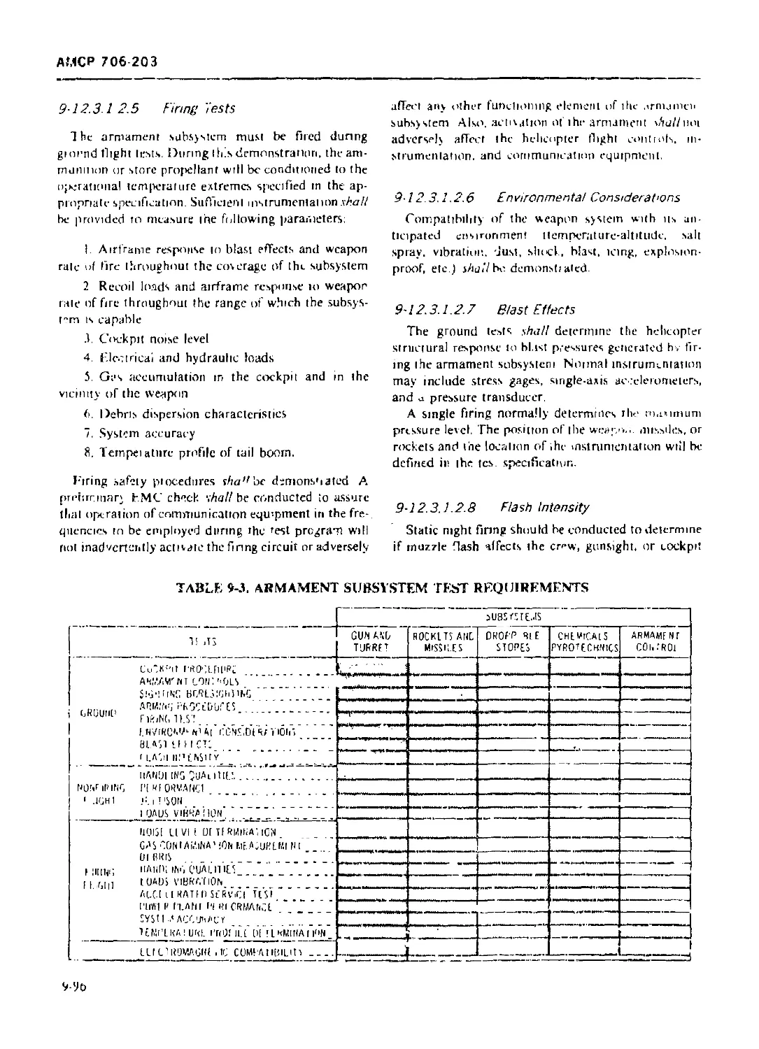
9-12.3.1.2.1 Cockpit Procedures ................................................. 9-95
9-12.3.1.2.2 / -mament and/or Fire Controls ..................................... 9-95
9-12.3.1.2.3 Sighting and Boresighting .......................................... 9-95
9-12.3.1.2.4 Arming Procedures .................................................. 9-95
9-12.3.1.2.5 Firing Tests ....................................................... 9-96
9-12.3.1.2.6 Environmental Considerations ....................................... 9-96
9-12.3.1.2.7 Blast Effects ...................................................... 9-96
9-12.3.1 2.8 Flash Intensity .................................................... 9-96
9-12.31 3 Flight Tests ....................................................... 9-97
9-12.3.1.3.1 Nonfiring Flight Tests ............................................. 9-97
9-12.3.1.3.1.1 Handling Qualities and Perfoimance ................................. 9-97
9-12.3.1.3.1.2 Jettison ........................................................... 9-97
9-12.3.1.3.1.3 Loads and Vibration ................................................ 9-97
9-12.3.1.3.2 Firing Flight Tests ................................................ 9-97
9-12.3.1.3.2.1 Noise Level Determination .......................................... 9-97
xvit
АМСР 706-203
TABLE OF CONTENTS (Continued)
Paragraph Page
9-12.3.1.3.2.2 Gas Contamination Measurement ..................................... 9-97
9-12.3.1.3.2.3 Debris Dispersion ....................................... .. 9-97
9-12.3.1.3.2.4 Handling Qualities ................................................ 9-98
9-12.3.1.3.2.5 Loads and Vibration ..................................... . . 9-98
9-12.3.1.3.2.6 Accelerated Service Tests ......................................... 9-98
9-12.3.1.3.2 7 Engine Performance ................................................ 9-98
9-12.3.1.3.2.8 Temperature Profile Determination for Armament Subsystem Controls . 9-98
9-12.3.1.3.2.9 System Accuracy ................................................... 9-98
9-12.3.1.4 Electromagnetic Compatibility (EMC) Tests ......................... 9-98
9-12.3.2 Documentation .............................................. 9-98
9-13 EXTERNAL STORE SEPARATION DEMONSTRATION .............................. 9-98
9-13.1 GENERAL ....................................................... 9-98
9-13.2 SEPARATION CHARACTERISTICS .................................... 9-99
9-13.3 JETTISON REQUIREMENTS ......................................... 9-99
9-13.4 RELEASE SYSTEMS ............................................... 9-99
9-13.5 RECOVERY OF STORES ............................................ 9-99
9-13.6 FAILURE MODE .................................................. 9-99
9-13.7 TEST REQUIREMENTS ............................................. 9-99
9-13.7.1 Weight and CG Locations .................................... 9-99
9-13.7.2 Speed Envelope ............................................. 9-99
9-13.7.3 Altitude ......................................................... 9-100
9-13.7.4 Attitude ......................................................... 9-100
9-13.7.5 Flight Modes ................................................... 9-100
9-13.8 DOCUMENTATION ....................................................... 9-100
9-14 HELICOPTER ENDURANCE TEST ........................................... 9-101
REFERENCES ....................................................... 9-101
CHAPTER 10
RELIABILITY AND MAINTAINABILITY
10-0 LIST OF SYMBOLS ...................................................... 10-1
10-1 RELIABILITY .......................................................... 10-1
10-1.1 RELIABILITY MATHEMATICAL MODELS ............................... 10-1
10-1.1.1 Success Criteria .................................................. 10-1
10-1.1.2 Reliability Block Diagrams ........................................ 10-2
10-1.1.3 Model Construction and Combining Reliabilities .................... 10-2
10-1.2 INITIAL APPORTIONMENTS ............................................... 10-3
10-1.3 RELIABILITY PREDICTIONS .............................................. 10-3
10-1.4 RELIABILITY ANALYSIS—DEVELOPMENT AND TEST PHASES ... 10-4
10-1.4.1 Ttpt Plans ........................................................ 10-4
10-1.4.2 Reliability Considerations for Development Testing ................ 10-5
10-1.4.3 Reliability Demonstration ......................................... 10-5
10-2 MAINTAINABILITY ...................................................... 10-6
10-2.1 MAINTAINABILITY CRITERIA ............................................. 10-6
10-2.1.1 Maintainability Analysis .......................................... 10-6
10-2.1.2 Maintenance Policy ................................................ 10-6
10-2.1.3 Maintenance Engineering Analysis Data System (MEADS) ... 10-6
10-2.2 MAINTAINABILITY DEMONSTRATION ........................................ 10-6
xviii
АМСР 706-203
TABLE OF CONTENTS (Continued)
Paragraph Page
10-2.2-1 Change Approval Policy ........................................... 10-6
10-2.2-2 Contractor Component Verification ................................ 10-7
10-2.2.2.1 Component Repair ................................................. 10-7
10-2.2.2.2 Component Overhaul ............................................... 10-7
10-2.2.3 Vendor and Subcontractor Maintainability ......................... 10-7
10-2.2.4 Mock-up .................................................... 10-7
10-2.2.4.1 System Verification .......................................... 10-7
10-2.2.4.2 Configuration Review ............................................. 10-7
10-2.2.5 Category I Tests (Contractor) .................................. 10-7
10-2.2.5.1 Preventive Maintenance (PM) ...................................... 10-8
10-2.2.5.2 Corrective Maintenance ........................................... 10-8
10-2.2.6 Category II Tests (Government Test Agency) ..................... 10-8
10-2 2.6.1 Task Selection .................................................. |(>-8
IG-2.2.6.2 Contractor Maintainability Demonstration ......................... 10-8
10-2.2.6.3 Contract Compliance Demonstration ................................ 10-8
10-2.3 TRANSPORTABILITY ................................................... 10-9
10-2.3.1 Transportability Criteria ........................................ 10-9
10-2.3.2 Transportability Demonstration ................................... 10-9
REFERENCE ............................................................ 10-10
CHAPTER 11
GOVERNMENTAL TESTING
11-0 LIST OF SYMBOLS ...................................................... 11-1
11-1 INTRODUCTION ......................................................... 11-1
11-1.1 COORDINATED TEST PROGRAM (CTP) ..................................... 11-1
11-1.2 GENERAL TEST REQUIREMENTS .......................................... 11-2
11-1.2.1 Contractor’s Development and Airworthiness Qualification Tests ... 11-2
11-1.2.2 Army Preliminary Evaluations (APE) 11-2
11-1.2.3 Endurance Tests ................................................. 11-2
11-1.2.4 Airworthiness and Flight Characteristic Tests .................... 11-2
11-1.2.5 Climatic Tests ................................................. 11-3
11-1.2.6 Service Tests .................................................... 11-3
11-2 ARMY PRELIMINARY EVALUATION (APE) .................................... 11-3
11-2.1 APE PREREQUISITE ................................................... 11-3
11-2.2 DETAILS OF TEST .................................................... 11-4
11-2.2.1 Functional Tests .................................................. 114
11-2.2.2 Handling Qualities ............................................... 11-4
11-2.2.3 Performance ...................................................... 11-4
11-2.3 SUBSEQUENT ARMY PRELIMINARY EVALUATIONS ............................ 11-4
11-2.4 ARMY PRELIMINARY EVALUATION REPORTS ................................. Ill
11-3 FINAL AIRWORTHINESS AND FLIGHT CHARACTERISTIC TESTS . . 114
11-3.1 GENERAL ............................................................ 11-4
11-3.2 TEST PROGRAM ....................................................... 11-5
11 3.2-1 Performance Tests ................................................ li-5
11-3.2.2 Stability and Control Tests ...................................... 11-5
11-3.2.3 Miscellaneous Tests .............................................. 11-6
11-3.2 3.1 Vibratory Test Surveys ........................................... 11-6
11-3.2.3.1.1 Test Requirements ................................................ 11-6
xix
АМСР 706-203
TABLE OF CONTENTS (Continued)
Paragraph Page
11-3.2.3.1.2 Instrumentation ....................................................... 11-6
11-3.2.3.1.3 Documentation ......................................................... 11-7
11-3.2.3.2 Static Longitudinal Stability Tests ................................... 11-7
11-3.2.3.2.1 Test Requirements ..................................................... 11-8
11-3.2.3.2.2 Instrumentation ....................................................... 11-8
11-3.2.3.2.3 Documentation ......................................................... 11-8
11-3.2.3.3 Dynamic Longitudinal Stability Tests .................................. 11-8
11-3.2.3.3.1 Test Requirements ..................................................... 11-9
11-3.2.3.3.1.1 Short Period Mode ..................................................... 11-9
11-3.2.3.3.1.2 Long Period Mode .......................................................... 11-10
11-3.2.3.3.2 Instrumentation ............................................................ 11-10
11-3.2.3.3.3 Documentation .............................................................. 11-10
11-3.2.3.4 Maneuvering Stability Tests .. 11-10
11-3.2.3.4.1 Test Requirements .......................................................... 11-10
11-3.2.3.4.1.1 Symmetrical Pullups ........................................................ 11-12
i 1-3.2.3.4.1.2 Stabilized Turning Flight .................................................. 11-12
11-3.2.3.4.2 Instrumentation ............................................................ 11-12
11-3.2.3.4.3 Documentation .............................................................. 11-13
11-3.2.3.5 Static Lateral-directional Stability Tests ................................. 11-13
11-3.2.3.5.1 Test Requirements .......................................................... 11-13
11-3.2.3.5.2 Instrumentation ............................................................ 11-14
11-3.2.3.5.3 Documentation .............................................................. 11-14
11-3.2.3.6 Dynamic Lateral-directional Stability Tests .............................. 11-14
11-3.2.3.6.1 Test Requirements .......................................................... 11-15
11-3.2.3.6.2 Instrumentation ........................................................... 11-16
11-3.2.3.6.3 Documentation .............................................................. 11-16
11-3.2.3.7 Controllability Tests .................................................... 11-16
11-3.2.3.7.1 Test Requirements ......................................................... 11-17
11-3.2.3.7.1.1 Longitudinal Controllability ........................................... 11-17
11-3.2.3.7.1.2 Lateral and Directional Controllability .................................... 11-19
11-3.2.3.7.2 Instrumentation ............................................................ 11-19
11-3.2.3.7.3 Documentation .............................................................. 11-19
11-3.2.3.7.4 Control Harmony ............................................................ 11-20
11-4 CLIMATIC TESTS .................................................................... 11-21
11-5 DOCUMENTATION ..................................................................... 11-21
GLOSSARY .............................................. G-l
LIST OF ABBREVIATIONS.................................. L-l
SPECIFICATIONS AND STANDARDS, AND OTHER GOVERNMENTAL
DOCUMENTS ............................................. M-l
BIBLIOGRAPHY .......................................... B-l
INDEX ................................................... 1-1
xx
АМСР 706-203
LIST OF ILLUSTRATIONS
Fig. No. Title Page
3-1 System Safety Milestones in Engineering Development ..................... 3-2
3-2 System Safety Process 3-3
6-1 The Load Characteristics of Five Types of Destructive Tests for Adhesives ... 6-10
6-2 Master Tooling Coordination .................................................. 6-21
7-1 Protection Criterion ..................................................... 7-6
7-2 Vibratory Tolerance Criteria ................................................. 7-17
8-1 Helicopter Configurations ................................................ 8-7
8-2 Data Flow for Engine/Airframe Vibration Evaluation ..................... 8-8
8-3 Test Instrumentation ......................................................... 8-13
8-4 Inlet Recovety vs Flight Speed ............................................... 8-14
8-5 Pressure Distortion Plot 8-15
8-6 Example Summary of Test Points ............................................... 8-16
8-7 Typical Plots of Rotor Natural Frequency vs Operating Speed .................. 8-19
8-8 U.S. Army Psychrometric Chart ................................................ 8-22
8-9 Grid for Typical Helicopter Fly-by of Missile Simulator...... . 8-27
8-10 Flight Test Demonstration Methods ............................................ 8-32
8-11 High-voltage Long-arc Test Arrangement ....................................... 8-36
8-12 Component Sparking and Induced Voltage Test Arrangement ...................... 8-36
8-13 Climatic Laboratory, Main Hangar, Eglin AFB, Florida ......................... 8-48
8-14 Engine-starting Characteristics ............................................. 8-51
8-15 Starter Performance .......................................................... 8-52
8-16 Engine and Transmission Oil Systems During Starts ............................ 8-53
8-17 Summary, Engine Oil Temperature and Pressure ................................. 8-54
8-18 Summary, Windshield Defog Temperature ........................................ 8-55
8-19 Windshield Defog Temperature Survey ...................................... 8 56
8-20 Heater System Temperature and Pressure Survey ................................ 8-57
8-21 Summary, Cockpit Inlet Temperature and Pressure .............................. 8-58
8-22 Summary, Cockpit Temperature ................................................. 8-59
8-23 Cockpit Temperature Survey, Bleed Air Heater ................................. 8-60
8-24 Summary, Control Breakout Force: Rotors Stationary, Friction Off ............. 8-61
8-25 Summary, Control Breakout Force: Rotors Turning, Hydraulic Boost On, Friction
and Force Trim Off ......................................................... 8-61
8-26 Summary, Engine Temperature Survey ........................................... 8-62
9-1 Attitude of Skid Gear for Drop Conditions II and III .................... 9-7
9-2 Engine Transient Torque Responses to a Step Demand for Torque Change . . . 9-13
9-3 Data Reduction (Determination of Damping Ratio and Frequency from Time
History Recordings) ........................................................ 9-20
9-4 Typical Lubrication Subsystem ............................................... 9-24
9-5 Typical Propeller Vibratory Survey Instrumentation ........................... 9-34
9-6 Oscillograph Recording ..................................................... 9-35
9-7 Recording Instrumentation in Aircraft .................................. 9-36
9-8 Propeller Stress Survey Strip Chart .......................................... 9-37
9-9 Vibratory Stress Survey Summary .............................................. 9-38
9-10 Effect of Pressure Recovery on Engine Performance ............................ 9-41
9-11 Example of a Cloverleaf Flight Plan, 30-deg Intervals ........................ 9-59
9-12 System Setup and Instrumentation ........................................... 9-68
9-13 Airborne Compressor-charged System .................................. 9-74
9-14 Low-pressure Pneumatic Supply ................................................ 9-75
xx i
АМСР 706-203
LIST OF ILLUSTRATIONS (Continued)
Fig. No. Title Page
9-15 Low-pressure Pneumatic Subsystem .............................................. 9-75
9-16 Test Apparatus Schematic ...................................................... 9-76
9-17 Typical Vacuum Subsystem ...................................................... 9-76
9-18 Side-by-side Helicopter Vision Plot ........................................... 9-81
9-19 Single Pilot/Tandem Pilot Helicopter Vision Plot .............................. 9-82
9-20 Winch System Angular Displacement ............................................. 9-84
9-21 Winch System Operational Demonstration ................................... 9-84
9-22 Typical Format for Specifying Vulnerable Areas ................................ 9-93
9-23 Vulnerable Area vs Weight .................................................... ' 9-94
9-24 Jettison Envelope Calculation ............................................ 9-100
11-1 Vibratory Level ................................................................ 11-7
11-2 Static Longitudinal Collective Fixed Stability ................................ .4-9
11-3 Static Longitudinal Hovering Stability ......................................... 11-9
11-4 Forward Longitudinal Pulse ................................................... 11-11
11-5 Aft Longitudinal Pulse ....................................................... 11-11
11-6 Maneuvering Stability ........................................................ 11-12
11-7 Static Lateral-direction Stability ........................................... 11-14
11-8 Right Lateral Pulse .......................................................... 11-18
11-9 Normal Acceleration Development During Sudden Control Displacement .... 11-18
11-10 Damping Characteristics vs Frequency ......................................... 11-19
11-11 Longitudinal Control Sensitivity Summary .................................... 11-20
11-12 Longitudinal Control Sensitivity ............................................ 11-21
11-13 Longitudinal Control Response Summary ....................................... 11-22
11-14 Longitudinal Control Response, Level Flight ................................. 11-22
11-15 Longitudinal Control Power .................................................. 11-22
xxii
АМСР 706-203
LIST OF TABLES
Table No. Title Page
2-1 SUMMARY OF CTP TEST REQUIREMENTS—HELICOPTER SYSTEM . 2-2
2-2 SUMMARY OF CTP TEST REQUIREMENTS—ALLIED EQUIPMENT 2 2
3-1 HAZARD SEVERITY FOR HELICOPTERS ..................... 3-7
3-2 HAZARD PROBABILITY FOR HELICOPTERS ................ 3-8
3 3 HAZARD EL1MINAT1ON/CONTROL RESOURCES ................ 3-8
3-4 HAZARD TOTEM POLE ................................. 3-9
41 DATA AND DOCUMENTATION REQUIREMENTS ............... 4-16
5-1 SAMPLE BASELINE CHECKLIST FOR SEATS AND FURNISHINGS . 5-7
6-1 METALS, TEST METHODS OF FEDERAL TEST METHOD STANDARD
NO. 151 .......................................... 6-3
6-2 TEST METHODS FOR PLASTICS AND BONDED STRUCTURES ..... 6-5
6-3 TEST METHODS FOR CORE MATERIALS AND SANDWICH STRUC-
TURES ........................................................ 6-6
6-4 ALPHABETICAL INDEX OF TEST METHODS OF FEDERAL TEST
METHOD STANDARD NO 175............................. 6-9
6-5 SELECTED TEST METHODS OF FEDERAL TEST METHOD STANDARD
NO. 141 ......................................... 6 11
6-6 SELECTED TEST METHODS OF FEDERAL TEST METHOD STANDARD
NO. 791 ......................................... 6-12
6-7 ACCEPTANCE REQUIREMENTS FOR CASTINGS, MIL-C-6021 ... 6-14
6-8 STEEL FORGING TEST REQUIREMENTS BY GRADE .......... 6 15
6-9 REPRESENTATIVE HEAT TREAT TEMPERATURES ............. 6-18
7-1 EXAMPLE COMPONENTS REQUIRING QUALIFICATION ........ 7-4
7-2 EXAMPLE FUNCTIONAL TESTS .......................... 7-5
7-3 ARMOR MATERIAL SPECIFICATION ...................... 7-7
8-1 TYPICAL HELICOPTER MANEUVER SPECTRUM .............. 8-3
8-2 READ OPTION TERMS . ............................... 8-4
8-3 TARGET ECHOING AREA ................................ 8-29
8-4 SIGNIFICANT RADAR FREQUENCY NOMENCLATURE ........... 8-29
8-5 LIGHTNING CURRENT COMPONENTS AND EFFECTS ........... 8-35
8-6 ICING PROTECTION SYSTEM TEST FACILITIES ............ 8-40
9-1 DATA REQUIREMENTS, ENGINE/AIRFRAME COMPATIBILITY
DEMONSTRATION .................................... 9-15
9-2 SPECIFICATIONS FOR FLIGHT, NAVIGATION, AND ENGINE INSTRU-
MENTS ............................................ 9-78
9-3 ARMAMENT SUBSYSTEM TEST REQUIREMENTS ............... 9-96
'11-1 LATERAL-DIRECTIONAL DYNAMIC STABILITY 11-17
xxtii
АМСР 706-203
FOREWORD
The Helicopter Ennineerinn Handbook forms a part of the Engineering Design
Handbook Series which presents engineering data for the design and construction of
Army equipment.
This volume,' AMCP 706-203. Qualification Assurance, is Part Three of a three-
pan Engineering Design Handbook titled Helicopter Engineering. Along with AMCP
706-201, Preliminary Design, and AMCP 706-202, Detail Denina, ihis part is inten-
ded to set forth explicit design standards for Army helicopters, to establish
qualification requirements, and to provide technical guidance to helicopter designers
in both the industry and within the Army.
The first volume of the handbook. AMCP 706-201, discusses th? characteristics
and subsystems which must be considered during preliminary design of a helicopter.
Additionally, possible design problems encountered during helicopter design are
discussed and possible solutions suggested.
AMCP 706-202 deals with the evolution of the vehicle from an approved
preliminary design configuration. As a result of this phase, the design must provide
sufficient detail to permit construction and qualification of the helicopter in com-
pliance with the approved detail specification and other requirements. Design
requirements for all vehicle subsystems also are included in AMCP 706-202.
This volume, AMCP 706-203, defines the requirements for airworthiness
qualification of the helicopter and for demonstration of contract compliance, and also
describes the test procedures accomplished by the Army. The volume is divided into
11 chapters, and is organized as described in Chapter 1, the introduction to the
volume.
XXIV
АМСР 706-203
PREFACE
This volume, АМСР 706 203, Qualification Assurance, is the final section of a
thiee-part engineering handbook, Helicopter /•'ngineering. in the Engineering Design
Handbook senes. It was prepared by Forge Aerospace, Inc., Washington, DC., under
subcontract to the Engineering Handbook Office, Duke University. Ihirhain. N. C
The Engineering Design Handbooks fall into two basic categories, those approved for
release and sale, and those classified for security reasons. The Army Materiel Command
policy is to release these Engineering Design Handbooks to other IX)D activities and their
contractors, and other Government agencies in accordance with ctirren: Arniy Regulation
70-31, dated 9 September 1966. It will he noted that the majority of ihese Handbooks
can be obtained from the National Technical Information Service (NT1S). Procedures for
acquiring these Handbooks follow
a. Activities within AMC, DOD agencies, anil Government agencies other than DOD
having need i'oi the Handbooks should direct their request on an official form to:
Commanding Officer
letterkenny Army Depot
AT I N: AMXLE-ATD
Chambersburg, Pennsylvania 17201
b. Contractors and universities must forward lheir requests to:
National Technical Information Service
Department of Commerce
Springfield, Virginia 22151
(Requests for classified documents must be sent, with appropriate “Need-to-Know"
justification, to Letterkenny Army Depot.)
Users of the handbook are encouraged to contact USAAVSCOM, St. Louis, Mo.,
Flight Standards and Qualification Division (AMSAV-EF1). with their recommendations
and comments concerning the handbook. Comments should be specific and include
recommended text changes and supporting rationale. DA Form 2028, Recom-
mended Changes Co Publications (available through normal
publications supply channels) may be used for this purpose.
A copy of the comments should ba sent to the Commanding
General, AMC, ATTN: AMCRD-TV, Washington, DC 20315.
Revisions to the handbook will be made on an as-required basis and will be
distributed on a normal basis through the Letterkenny Army Depot.
xxv
АМСР 706 203
CHAPTER 1
INTRODUCTION
АМСР 706-201, Helicopter Engineering. Par! One,
Preliminary Design, is the first volume of the Helicopter
Handbook Series and discusses the preliminary design
phase and contract definition procedures, including the
roles and applications of weight and performance esti-
mation; flying quality predictions; and system safety,
reliability, and maintainability considerations. At the
conclusion of the preliminary definition period, a heli-
copter configuration will have been selected and its
general characteristics and capabilities defined in pro-
curement specifications. Data required during contract
definition, in response to a Request for Proposal (RFP)
or a Request for Quotation (RFQ), have been defined
in Chapter 14 of AMCP 706-201.
Ihe same disciplines and procedures continue in
greater detail throughout design and qualification.
AMCP 706-2.02, Helicopter Engineering. Part Ewo. De-
tail Design, the second volume, describes the follow
on detail (or engineering development) phase in terms
of design requirements, criteria, and procedures for the
total system and its subsystems. The system and sub-
system.-, are re-examined, refined, and defined as the
design and optimization process continues. The specifi-
cation requirements and qualification plans are trans-
lated into hardware layouts, with appropriate investi-
gations, analyses, and exploratory testing. Detail
drawings, re-analyses, and qualification testing follow.
This volume, AMCP 706-203, includes the require-
ments and procedures for substantiation of the airwor-
thiness of the vehicle through proof of compliance with
contractual design requirements and performance guar-
antees.
Airworthiness, as defined in AMCR 70-33, is "a
demonstrated capability of an aircraft, or aircraft sub-
system or component to function satisfactorily when
used within the prescribed limits”.
It is the intent of this volume to delineate the lespon-
stbilitics of hoth the procuring activity and the contrac-
tor in the planning and execution of the airworthiness
qualification program for a new model helicopter. The
helicopter systems to which such a program is applica-
ble may be completely new, or may be the result of
major modification of a previously qualified system.
For simplicity, the internal workings of the Govern-
ment are not discussed. Governmental responsibilities
are always related to only the procuring activity.
Although dependent ultimately upon specific tests
and demonstrations of the complete helicopter system,
airworthiness qualification is a continuing process
which begins with the initiation of system development.
Included are design reviews, during both the initial sub-
system definition phase and the final detail design of
assemblies and installations. The construction and in-
spection of a full-scale mock-up by experts is a special-
ized design review. Conducted as er ly in the program
as possible, the mock-up review pe. nits evaluation of
the relationship and interaction between all required
subsystems in a manner which is impossible when using
only two-dimensional layouts and drawings.
During the design and initial fabrication phase, prior
to the availability of components or complete systems
for test, analyses are performed to substantiate subsys-
tem configurations and performance. Also during this
period detailed plans are prepared for the testing of
components, subsystems, and the complete helicopter
as required to verify compliance with applicable design
and performance requirements. The preparation of
these analyses and plans by the contractor and their
review and approval by the procuring activity arc sig-
nificant elements of the airworthiness qualification pro-
gram.
Qualification of a new model helicopter includes
qualification of components, of subsystems, .«nd finally
of tlie complete helicopter system. Each of these efforts
is described in the chapters which follow. Also included
is a discussion of Governmental testing, which is con-
ducted to confirm that system performance complies
with contract requirements. This testing includes that
required to obtain the data necessary for verifying safe
helicopter operation for follow-on Governmental test-
ing and for the preparation of operational and service
manuals for the system. Following completion of the
helicopter qualification and preparation by the procur-
ing activity of the Airworthiness Qualification Substan-
tiation Report, Governmental testing continues, in the
form of Service Tests, to insure operational suitability
1-1
AMCP 706-203
and to determine to whal degree the helicopter meets
the characteristics stated in the requirement document.
However, discussion of these efforts beyond airworthi-
ness qualification is not within the scope of this hand-
book.
Throughout this volume, the mandatory qualifica-
tion requirements have been identified with the con-
tractual language which makes use of the imperative
word "shall". To assist in the use of this document in
the planning of a qualificalion program, the word
"shall' has been italicized in the statement of each such
requirement.
Since the qualification requirements for individual
programs may vary from the level of detail described
in this volume, the procuring activity will specify in its
Request for Proposal the extent to which these require-
ments are applicable to the qualification of a given
helicopter. Deviations from this handbook not specifi-
cally included in the RFP will be considered when
adequately substantiated in the contractor’s response to
the RFP. This handbook will not be incorporated in a
contract by reference in whole or in part. However, the
handbook may be furnished to contractors as a basis for
establishing contract requirements to be included in the
Airworthiness Qualification Specification (Chapter 2).
1-2
АМСР 706-203
CHAPTER 2
AIRWORTHINESS QUALIFICATION PROGRAM REQUIREMENTS
2-1 INTRODUCTION
The Coordinated Test Program (CTP) is the pri-
mary development planning document used to des-
cribe the formal, comprehensive program for test-
ing. The CTP is required by AR 70-10 for all re-
search and development projects entering engineer-
ing development. The CTP for helicopters normally
is prepared by the Army Project Manager, and has
the following objectives:
1. To serve as a management tool to insure that the
necessary elements of a test program are addressed
2. To insure that adequate coordination is effected
among the agencies which require test data
3. To insure that adequate testing is planned for
arriving at type classification and a production decision
4. To provide justification for the number of proto-
types to be used during testing.
The CTP also must provide the justification for com-
bining tests, for conducting them concurrently, or for
eliminating them in an effort to avoid duplicate and
unnecessary testing.
Helicopters and allied equipment are developed un-
der a specific analytical process to substantiate that
they are airworthy. The total of all elements in this
analytical process is the Airworthiness Qualification
Program (AQP). The program is described fully in
the CTP and is an element of the Request for Proposal
(RFP) or Request for Quotation (RFQ).The AQP pro-
vides general guidance on engineering analyses, formal
inspections, design reviews, safety assessments, con-
tractor demonstrations, and all contractor and Govern-
mental qualification tests essential to defining and im-
plementing the procurement of any major Army air
item and/or its allied equipment. This general informa-
tion then will provide the hasis for the Airworthiness
Qualification Specification (AQS), which is Written by
the contractor. Inherent in the AQS is the dissemina-
tion of data necessary tc demonstrate proof of compli-
ance with the system description or detail specification.
The AQS is designed to insure that the necessary infor-
mation is obtained to permit the issuance of the Safety-
of-Flight Releases and/or Interim Statements of Air-
worthiness Qualification required during engineering
development. It also permits the issuance of a State-
ment of Airworthiness Qualification, and Army publi-
cation of an Airworthiness Qualification Substantiation
Report, upon the completion of the program. Lastly,
the AQS will adhere to the policies, objectives, defini-
tions, and procedures specified in.
1. AR 70-10, Test and Evaluation During Research
and Development of Materiel
2. AMCR 70-32, Aeronautical Design Standards
(ADS) for U.S. Army Aircraft Systems and
Subsystems
3. AMCR 70-33, Airworthinejt Qualification of
U.S. Army Aircraft Systems and Subsystems.
The types of tests which comprise the CTP, as well
as the test agency, test hardware, and test objectives for
a complete helicopter system and allied equipment, arc-
summarized in Tables 2-1 and 2-2. These tests normally
should be conducted in the sequence shown in the ta-
bles, especially where test results are required prior to
further testingand in those situations where extreme
climatic conditions will be encountered. Concuirent
and integrated test phasing will be used when justified
by fund and time limitations.
2-2 AIRWORTHINESS
QUALIFICATION SPECIFICATION
(AQS)
2-2.1 GENERAL
As noted in the previous paragraph, the contractor's
airworthiness qualification test plan is the key element
in the overall coordinated plan for development of new
helicopters.
For each helicopter system subject to qualification or
requalification because of major modifications, a
qualification specification will be prepared to establish
2-1
AMCP 706 203
those engineering tests or analyses which are essential
ro the airworthiness substantiation of the system. This
work is divided into those l-sts to be performed under
an engineering development contract, or any other ap-
propriate procurement action such as a product im-
provement contract.
2-2.2 AIRWORTHINESS QUALIFICATION
SPECIFICATION REQUIREMENTS
The Airworthiness Qualification Specification will
be prepared by the prime system contractor in response
TABLE 2-1. SUMMARY OF CTP TEST REQUIREMENTS—HELICOPTER SYSTEM
TYPE TEST" TEST AGENCY" ” TEST HARDWARE TES’ OBJECTIVE >
CONTRACTOR'S AIRWORTHINESS QUALIFICATION -TESTS (AQT 1 ARMY PRELIMINARY EVALUATIONS (APE) contractor — MATERIEL DEVELOPER (AVSCOMi MODELS MUCK UPS COMPONENTS SUBSYSTEMS ALLIED EQUIPMENT PROTOTYPE SYSTEM — —— PROTOTYPE SYSTEM O£VELOPl.l£ NT PROVE OUT ASSEMBLIES COt.lPONE N'S. ANO i HE TOTAL HEcICOI’EER QUALIFICATION DETERMINE DESIGN L ‘Ml Г S ANU FLIGHT ENVELOP! DEMONSTRATION OF ADEQUACY OF HELlCOPltH TO FUNCTION SAFELY WITHIN FLIGHT ENVELOPE VERIFICATION Of Fl IGHT ENVELOPE AND PRELIMINARY COMPACT COMPLIANCE PROVIDE QUANTITATIVE ANO QUALITATIVE FLIGHT TEST DATA DETECTION OF DEFICIENCIES ANO EVALUATION Or CORRECTIONS PROVIDE PRELIMINARY OPERATIONAL USE DATA
AIRWORTHINESS A NO FLIGHT CHARACTERISTICS MATERIEL DEVELOPER (AVSCOM; PROTOTYPE SYSTEM FINAL VERIFICATION OF FL CHF ENVELOPE AND CONTRACT COMPLIANCE ACHIEVEMENF OF APPLICABLE MILITARY SPECIFICATIONS | DETAILED STABILITY, PERFORMANCE. ANO HANDLING CHARACTERISTICS OPERATIONAL CHARACTERISTICS FOR TECHNICAL MANUALS ADEQUAC'.’ OF THE SYSTEM. SUBSYSTEMS. ANO ALLIED EQUIPMEhi UNDER EXTREME TEMPERA!UKt CONDITIONS
ENDURANCE CONTRACTOR INDE PE NDt NT TEST AGENCY (TECOM/TEST BOARDlS)) PROTOTYPE SYSTEM DETERMINATION OF ENDURANCE AtIO RELIABILITY Of BASIC DESIGN DETERMINATION OF ADEQUACY OF DESIGN CHANGES TO CORRECT DEFICIENCIES REVEALED DURING PRIOR TESTS.
OPERATIONAL SERVICE TESTS COSTI PROTOTYPE SYSTEM I DETERMINATION OF THE DEGREE T 0 WHICH THf. SYSTEMMFETS THE CHARACTERISTICS OF THE REQUIREMENTS DOCUMENT DETERMINATION OF INSPECTION CYCi.lS DEVELOPMENT OF OPERATING AND MAINTFHAfTE COSTG Of TERMINATION OF COMPONENT SERVICE 1 IF £ ANO QUICK CHANGE KITS REFINEMENT OF MANPOWER. EQUIPMENT, SUH LS. AND TRAINING REQUIREMENTS
TABLE 2-2. SUMMARY OF CTP TEST REQUIREMENTS-ALJ.IED EQUIPMENT
TYPE TEST TEST OBJECTIVES Rt LA t ION TO SYSTEM TEST
ENGINEERING DESIGN TESTS (EOT) DETERMINATION OF THE INHERENT STRUCTURAL. MECHANICAL. ELECTRICAL. AND PHYSICAL PROPERTIES DETERMINATION OF HUMAN ANO SAFETY IMPLICATIONS CONTRACI OR DEVELOPMENT AND AIRWORTHINESS QUALIFICATION TESTS
CONTRACTOR DEMONSTRATION ICO) DEMONSTRATION OF PERFORMANCE AGAINST CONTRACT SPECIFICATIONS DETERMINATION GF HUMAN PERFORMANCE REQUIREMlNTS CONTRACTOR KVE LOPMENT ANO AIRWORTHINESS QUALIFICATION TESTS
RESEARCH AND DEVELOPMENT ACCEPTANCE TESTS(RDAT) DETERMINATION THAT SPECIFICATIONS 0е DEVELOPMENT CONTRACT HAVE BFEN FULFILLED SERVES AS BASIS FOR ACCEPTANCE OR REJECTION PROTYPES ARMY PFELlMlNAHY EVALUATIONS
ENGINEERING TESTS (ET) DETERMINATION Of TECHNICAL PERFORMANCE, ‘'.LIABILITY,. MAINTAINABILITY. ENDURANCE. AND SAFETY CHARACTERISTICS 01 THE ITEM ANO ITS MAINTENANCE PACKAGE DETERMINATION OF HUMAN FACTOR IMPLICATIONS OF DESIGN AND MATERIALS AIRWORTHINESS Aril) F-..ЙНТ CHARACTERISTIC TEST
OPERATIONAL SERVICE TESTS (OST) DETERMINATION OF THE MILITARY WORTH OF THf ITEM determination of the degree THAT THE ITEM MEETS 1HE CHARACTERISTICS OF THF REQUIREMENTS DOCUMENT OPERATIONAL SLI’ViCt TLST -
2-2
AMCP 706-203
to the requirements established by the procuring ac-
tivity in the RFP. Elements of the AQS include:
1 System Safety
2 Design Review and Release of Drawings
3 , Mock-ups
4 Procurement and Process Specifications
5 . Component Tests
6 . System Surveys
7 . Forma) Contractor Demonstrations.
These elements are described in ihe paragraphs
which follow.
2-2.2.1 System Safety
As pari of the Airworthiness Qualification Specifica-
tion, the contractor will establish the means by which
the results of the System Safety Program (SSP) are to
be applied in the airworthiness qualification of the sys-
tem. The provisions and requirements of the System
Safety Program Plan (SSPP) are stated in par. 3-2. This
program produces data and information leading to as-
surances that the optimum degree of hazard elimina-
tion or control has been attained in the design of the
system. The contractor will include two areas which
ultimately combine to form the basis for the System
Safety portion of airworthiness qualification: (1) in-
terim/fmal safety statements and (2) system specifica-
tion compliance. In addition, the contractor will in-
sure that all components tests, system surveys, and
formal demonstrations are planned and conducted in
close coordination with the System Safety Program.
Hazard analysis will be an integral and essential factor
in all such tests and demonstrations to insure that these
activities are conducted with minimum risk.
2-2.2.2 Design Reviews and Release of
Drawings
Design reviews will be conducted on an as-required
basis. This portion of the AQS will outline the contrac-
tor’s procedures for conducting such reviews. Specific
requirements are not presented in this volume because
each contractor usually has his own review procedures
and drawing approval process. Il is not considered fea-
sible to try to standardize these areas. Participation in
the design reviews docs not limit or restrict other ele-
ments of the procuring activity from the responsibility
of insuring that the drawings conform to the lequire-
ments of MIL-D-1000 through normal contract chan-
nels.
Design review of detailed drawings is required for
each subsystem. Basic reasons for the inclusion of these
reviews in the qualification program of helicopters are
delineated as follows:
1. To insure that there a.e no obvious conflicts
with design criteria
2 To insure that there are no obvious design pit-
falls in disciplines such as safely, reliability, and main-
tainability.
3. To maintain a positive record of the configu-a-
non which is being proposed for analysis and testing
4. To establish a basis for updating and identifying
parts which pass or fail the qualification tests
5. To provide a foundation for an audit trail of all
airworthiness substantiating actions.
2-2.2.3 Mock-ups
The specifications for the mock-ups required by the
RFP will be included in the AQS. See Chapter 5 for a
detailed d' CUssion of mock-ups.
2-2.2.4 Procurement and Process
Specifications
In order for the procuring activity to maintain cogni-
zance over the detail configurations for which airwor-
thiness substantiation is desired, review of certain perti-
nent drawings and approval of procurement
specifications of contractor-furnished equipment
(C'FE) components are essential. To insure adequate
structural integr,.y, material and process specifications
also must be subjected to the approval of the procuring
activity.
This section of the AQS should list those procure-
ment and process specifications which must be sub-
jected to approval by the procuring activity
Typical examples of the key procurement and proc-
ess specifications (drawings defined in MH.-D-I000) to
be submitted are:
1. Specification control
2. Source control
3. Interface control
4. Installation control
5. Installation
6. Control
Specification control drawings or source control
drawings which constitute contractor procurement
specifications should be included automatically in the
AQS. Details of procurement and process specification
requirements are described in Chapter 6.
2-3
АМСР 706-203
2-2.2.5 Component Tests
The objectives of component testing are to make a
preliminary determination whether the reliability re-
quirements for component life will be met by the
hardware under test and to insure adequate integrity
for use in higher level assemblies in ground and flight
tests. This section of the AQS will define complete test
requirements.
2-2.2.5.1 Prequalification Bench Tests
Prequalification bench tests are not classified as
“must-pass” tests. The primary objective of prequalifi-
caiion testing is to uncover any defect or design defi-
ciency and to detect any fatigue-critical component or
part. In addition, the program will be used for the
incorporation and evaluation of “fixes” and, in general,
to refine the component or subsystem design. The
prequalification test time and severity will be specified
and funded as part of the contract.
2-2.2.5.2 Qualification Tests
The objective of the qualification tests is to demon-
strate formally that the prequalification testing has de-
tected any defects or fatigue-limited parts in the com-
ponent or subsystem. Establishment of initial time
between overhauls (TEO) will be made by the procur-
ing aciivity at the completion of the testing outlined in
par. 2-2.2.5.1 and revised periodically depending on
service or additional bench test experience. The length
and severity of the qualification tests will be specified
by the procuring activity and funded as part of the
contract.
2-2.2.5.3 Tiedown Tests
The total propulsion system—including all gear-
boxes, engine(s), shafting, rotor systems, brakes, clutch-
es, accessories, and controls—will be installed on the
ground test vehicles arid subjected to qualification test-
ing in accordance with a test procedure approved by
the procuring aciivity. The first test period will be the
preliminary flight approval test (PFAT) and must be
completed satisfactorily before first flight. The procur-
ing activity will determine satisfactory completion of
the test. Retesting may be required, depending on the
nature and severity of the failures.
2-2.2.5.4 Reliability Bench Tests
Additional bench testing will be required by the pro-
curing aciivity to enhance the prequalification status of
selected components or subsystems. The test schedule
should be similar to that used in par. 2-2,2.5.1, utilizing
as much of the original hardware as possible. Duration
of the test will be determined by the procuring activity.
2-2.2.5.5 Component and Subsystem
Inspections
As a minimum, formal military qualification tests of
components and subsystems will include:
1. Engines
2. Main transmissions
3. Main rotor and tail rotor subsystems, including
hub and blades
4. Propeller and propeller gearboxes
5. Tail rotor gearboxes
b. Intermediate gearboxes
7. Flight controls
S. Fuel systems
9. Landing gear
10. Electrical.
These tests will be followed by a disassembly inspection
accomplished in the presence of representatives of the
contractor, the procuring activity, and the Army Com-
modity Commands, if applicable. The inspections will
be performed to determine if the components and sub-
systems have successfully passed the qualification tests
defined in the AQS.
The inspection of mechanical and hydromcchanical
components is divided into two phases. The first in-
volves inspection of all parts immediately after disas-
sembly, the second inspection involves a review of the
results of the initial inspection. Data should be made
available to the inspection team for both phases.
All mechanical and hydromcchanical components
and assemblies will be subjected to a complete analyti-
cal disassembly and inspection. Inspection techniques
may include, but not be limited to: (I) visual, (2) di-
mensional, (3) magnetic particle, (4) fluorescent pene-
trant, (5) X iay, and (6) ultrasonic.
Photographic coverage of all items of significance is
required during inspections for later utilization in the
qualification test report.
2-2.2.5.6 Electrical and Electronic
Components
In general, less sophisticated inspections will be con-
'ducted on electrical and electronic components at the
'end of component testing than those specified for me-
chanical and hydromcchanical components in the
previous paragraphs. Appropriate inspection reports
will be prepared. A description of component test re
quircments is given in Chapter 7.
2-4
AMCP 706-203
2-2.2.6 System Surveys
System surveys include all tests designed to deter-
mine system characteristics and demonstrate satisfac-
tory system operation within the normal flight en-
velope as well as to determine conformance with
airframe unit design requirements. In determining sys-
tem characteristics, account will be taken of the influ-
ence of all subsystems, fixed and movable, and expected
operating environments. The requirements of par. 2-
2.2.7 also will apply to the system surveys specified
here.
System surveys should include, but not be limited to:
1. Flight Load Survey. Flight loads will be ob-
tained throughout the flight envelope for all critical
components Sufficient data will be obtained to allow a
preliminary estimate of fatigue lives and to determine
if resonant frequencies of critical components are tuned
to the frequencies of the primary exciting forces (see
par. 8-2).
2. Engine Vibratory Survey. Might and ground
vibratory surveys will be conducted to verify that en-
gine vibrations do not exceed the allowable vibratory
limit specified in the engine model specification (see
pai. 8-3).
3. Propulsion System Temperature Survey. Flight
and ground temperature surveys will be conducted to
verify that the engine(s), engine accessories, engine
fluids, airframe structure, transmission system, gear-
boxes, heat exchangers, etc., do noi exceed their allow-
able temperature limits (see par. 8-4).
4. Engine Air Induction System Survey. Flight
and ground engine inlet surveys will be conducted to
verify proper inlet pressure recovery and distortion pat-
terns (see par. 8 5).
5. Engine Exhaust Survey. Flight and ground en-
gine exhaust subsystem surveys will be conducted lo
evaluate operation and performance (pressure survey)
and ejector cooling performance, if applicable (see par.
8-6).
6. Total System Vibratory Survey. These tests are
required to demonstrate compliance with vibratory
comfort requirements and to demonstrate that the heli-
copter is free from excessive vibrations, or roughness
affecting its structural integrity or its capability to per-
form its mission. Vibratory measurement instrumenta-
tion will be installed at the required locations. Quan-
titative data should be collected during unaccelerated
and accelerated flight over the full range of the flight
envelope and of allowable rotor sjtceds (see par. 8-7).
7. Crew Environmental Survey. A survey should
be performed to demonstrate compliance with crew
environmental requirements under all specified operat-
ing conditions and modes (see par. 8 8).
8. Infrared (IR) Radiation and Countermeasure
System Survey. An IR radiation and countermeasure
system survey should be performed, if applicable, to
demonstrate that the IR signature has been reduced to
acceptable levels. The survey will include documenta-
tion of all trade-offs made in minimizing the signature
(see par. 8-9.2),
9. Radar Reflectivity Survey. A survey should be
performed to demonstrate that the radar reflectivity is
minimal and absorption is maximum. The survey will
include a detailed report of techniques to minimize
radar reflectivity (see par. 8-9.3).
10. Lightning Protection Survey. A survey will be
performed to establish a high degree of confidence that
the helicopter system can survive a lightning strike. As
a minimum, the survey will demonstrate that the fuel
system meets Federal Aviation Admimstralion AC 20-
53. Further, the bonding concepts of M1L-B-5O87
should be demonstrated as capable cf surviving light-
ning strikes (see par. 8-9.4).
II. Acoustical Survey. An acoustical survey will
be performed, if applicable, to demonstrate that ihe
acoustical signature meets the appropriate require-
ments. This survey will be performed under ail speci-
fied operating conditions and inodes (see par. 8-9.6).
2-2.2.7 Formal Contractor Demonstrations
This portion of the airworthiness qualification
specification will contain the specific Army require-
ments for the formal demonstration of the helicopter to
show its capability to comply with requirements of the
helicopter detail specification.
The purpose of the formal contractor demonstra-
tions is:
1. To demonstrate that the helicopter can be op-
erated safely by Army pilots during the procuring ac-
tivity's test program to limits consistent with the con-
tract design limits without excessive malfunctions,
failures, or other unsatisfactory conditions
2. To demonstrate those specification require-
ments which will riot be substantiated during the pro-
curing activity test program. These contractor demon-
strations are usually "pass-fail” tests of a specific
design requirement.
3. To obtain quantitative information on safe flight
hmils for operation by Army pilots
2-5
АМСР 706-203
4. То verify I hat the helicopter has completed con-
tractor tests and is ready for delivery to the procuring
activity for Governmental test.
2-2.2.7.1 Demonstration Sites
The demonstration normally is conducted at the con-
tractor’s flight test facility; other flight test facilities
may be used with prior Governmental approval. Tests
involving the carrying and release of guided missiles,
explosives, and armament should be performed at a
location specified by the procuring activity.
2-2.2,7.2 Helicopter Configuration for
Demonstrations
Helicopters used for the performance of formal
demonstrations should be identical, within production
tolerances, to helicopters which are to be delivered or
have been delivered for Governmental tests or opera-
tional use. For those demonstrations in which engine
power is a critical parameter, calibrated engines will be
utilized.
2-2.2.7.3 Contractor Pilot Approval
For formal demonstrations, all contractor test pilots
will be approved, by name, by the procuring activity.
Contractors should instruct demonstration pilots
thoroughly concerning the design, aerodynamic and
structural features, and/or other unusual characteris-
tics of the demonstration helicopters.
2-2.2.7.4 Helicopter Flight Approval
Demonstration helicopters should not be operated
by contractor pilots without a Safety-of-Flight Release
issued by the procuring activity.
2-2.2.7.5 Test Conference
Prior to the development of detail test plans for the
formal demonstration progtam, one or more test plan-
ning conferences should be held between the contractor
and the procuring activity to insure that the require-
ments of the formal demonstration programs are un-
derstood and to expedite the conduct of the program by
resolving any questions or ambiguities that may exist.
Additional test conferences may be held as required
2-2.2.7.6 Specific Demonstration
Requirements
Demonstration requirements will be developed dur-
ing contract definitions, and generally will include the
following:
1. Structural Demonstration. Structural demon-
stration should consist of quantitative flight test mee-
2-6
suretnents of all combinations of gross weight, configu-
ration, center of gravity (CG). altitude, airspeed, load
factor, and control motions required to demonstrate
compliance with the helicopter detail specification
Structural requirements (see par. 9-2).
2. Engine/Airframe Compatibility Test. Both
ground and flight tests of engine/airframe compatibil-
ity are conducted to verify engine, engine control, drive
train, and rotor subsystem dynamic matching, (tor-
sional stability) characteristics (see par. 9-3.2)
3. Lubrication Subsystem Demonstration A lu-
brication subsystem demonstration is conducted to de-
termine if the engine oil system(s) and transmission oil
system(s) operate satisfactorily, maintain the required
oil pressure, and are free from excessive oil discharge
at the breathers; and to demonstrate the adequacy of
the oil cooling and bypass system. The oil cooling test
may be conducted during the engine temperature sur-
vey (see par. 9-3.4 1)
4. Fuel Subsystem Demonstration. A fuel subsys-
tem demonstration is conducted to determine the
capacity of the fuel tank(s) of the helicopter and
amount of unusable fuel, fuel vent system adequacy,
the operational characteristics of the fuel supply system
under various boost pump failure conditions, the tem-
perature safety limits of fuel system equipment, and the
fuel system operational capabilities under actual ser-
vice conditions. In addition, the satisfactory operation
of the fuel supply under extreme operating conditions
should be demonstrated (see par. 9-3.4.2).
5 Dynamic Instability Demonstration. The con-
tractor will demonstrate that the helicopter is free of
mechanical instability at all operating conditions, at the
entire range of gross weights, and throughout the ex-
treme temperature range (see par. 9-4).
6. Flying Quality Demonstration. The flying qual-
ity demonstration will consist of quantitative flight test
measurements demonstrating compliance with the re-
quirements of the handling quality specification. This
compliance will be demonstrated throughout the final
flight envelope in both powered and aiitoro'ative flight,
and should include demonstration of a height-velocity
curve (see par. 9-5.3).
7. Electrical Demonstration. The contractor will
demonstrate the performance of the complete electrical
system. The demonstration, consisting of ground anil
flight tests, will be adequate to determine the capability
of the system to perform the functions requued by the
applicable specifications (see par. 9-6).
8. Avionic Demonstration. The contractor will
demonstrate the performance of the complete avionic
installation. The demonstration, consisting of ground
AMCP 706-203
and flight tests, should verify the capability of the sys-
tem to perform the functions dictated by the applicable
specifications (see par. 9-7).
9. Electromagnetic Compatibility (EMC)Demon-
stration. The contractor will demonstrate that the vari-
ous subsystems function properly in any possible elec-
tromagnetic environment that can be generated by
operation of onboard equipment The contractor also
will demonstrate that no single subsystem operates as
a possible source of electromagnetic energy that can
cause other onboard equipment to malfunction (see
par. 9-7.6).
10. Hydraulic Subsystem Demonstration. The
contractor will demonstrate the performance of the
complete hydraulic subsystem. The demonstration,
consisting of ground and flight tests, should be suffi-
cient to determine the capability of the subsystem to
perform adequately the functions required by the appli-
cable specifications (see par. 9-8.2).
11. Furnishing and Equipment Demonstration.
All specified equipment actually installed in, or spe-
cifically required for, the demonstration helicopter will
be demonstrated satisfactorily on the ground and/or in
flight, as applicable (see par. 9-10).
12. Armament Demonstration. The contractor
will demonstrate the performance of the complete ar-
mament system. The demonstration, consisting of
ground and flight tests, will be adequate to determine
the capability of the system to perform the functions
required by the applicable specifications. Sufficient
tests will be performed', to prove the structural integ-
rity and functional performance of all armament sub-
systems (see par. 9-12).
13. External Store Demonstration. The contractor
should define and demonstrate an external store sepa-
ration envelope for all external stores required to be
carried by the helicopter. Separation envelopes will be
demonstrated for both powered and autorotative flight
(see par. 9-13).
2-2.3 TEST SEQUENCING
This handbook does not attempt to regulate the se-
quence of either the analyses or tests essential to air-
worthiness qualification of a new model helicopter. The
scheduling of these activities is largely a function of the
extent to which the helicopter design includes new or
novel features, the availability of equipment, economic
considerations, and delivery constraints.
An airworthiness qualification program includes
tests conducted by both the contractor and the procur-
ing activity. With the exception of Army Preliminary
Evaluations (APE), the testing performed by the pro-
curing activity follows the contractor’s qualification
and demonstration program. In fact, service testing, as
the name implies, includes tests performed with opera-
tional helicopters. Therefore, this test phase normally
will continue past the publication of the Airworthiness
Qualification Substantiation Report (AQSR) by the
procuring activity.
In the preparation of the AQS, the contractor should
propose a schedule which will result in a logical se-
quence of the required analysis and test efforts in order
to minimize the risks involved in the qualification pro-
gram. During formal contract negotiations, the impact
of economic constraints and designated dates for com-
pletion of qualification on this schedule can be ad-
dressed.
A qualification program subject to minimum risk
would require that all components be well developed
prior to commencement of subsystem testing, that sub-
systems be qualified individually prior to total heli-
copter system testing, and that all operational condi-
tions for the helicopter be carefully tested oti the
ground prior to first flight. Also, each of the lest phases
would be preceded by sufficient analyses to assure that
design requirements have been met, and that successful
completion of subsequent tests is probable. Such a pro-
gram will be unreasonably long, particularly if the
manufacture and'assembly of production helicopters
are not undertaken concurrent with the qualification
program.
Although subject to change in accordance with the
RFP for a given model helicopter, certain minimum
test precedence requirements will normally apply. A
preliminary flight approval test (PFAT) of the power
and propulsion system should have been completed on
the ground (par. 2-2.2.5.3) prior to first flight of the
new model helicopter. This test, using either a tied-
down helicopter or a simulated vehicle containing all
required subsystems, will include a minimum of 50 hr,
with 150 hr preferred. Also, the structural static test
program (par. 9-2) should have demonstrated the
adequacy of the airframe for design limit loads. In-
cluded in this requirement is landing gear drop testing
which, as a minimum, will have demonstrated a normal
landing at design limit touchdown speed Further, suf-
ficient component fatigue test data should be available
to assure that the service life of fatigue-critical compo-
nents is adequate for initial flignt testing (minimum of
200 hr under conservatively assumed loadings).
Prior to initiation of the ground tiedown test, main
transmissions, other gearboxes, and principal compo-
nents of the drive system should have completed a
minimum of 200 hr of bench testing. The major portion
2-7
АМСР 706 203
of this testing must have been at maximum rated torque
and speed, but pertinent transient condition., also
should have been tested
Demonstration requirements for individual subsys-
tems, as defined by pertinent Military Specifications, in
several cases include lhe stipulation that an analysis of
system capability and performance be submitted for
approval, together with appropriate subsystem draw-
ings and descriptions, prior to test initiation. Although
apparently a sequence requirement, such stipulations
normally will not affect qualification schedules Phe
analyses required are performed routinely in the design
of the subsystem and must, theiefore, be completed
well in advance of subsystem testing.
The RFP for a specific model helicopter will indicate
the number of helicopters to be assigned to test and
qualification programs. Should these guidelines not in-
clude specific assignments—such as structural, flying
qualities and performance, avionics, and armament—
the contractor will include utilization of the assigned
helicopter in the proposed schedule. In addition to
iriiiiiiiiurn risk to the qualification program, overall
program cost—in both dollars and calendar time—
must be considered in the preparation of such a
proposal.
2-2.4 TEST COORDINATION
A test coordination system will be established and
executed by the procuring activity. This system will be
responsive to all informational requirements dictated
by the CTP. Sufficient manpower for onsite test coordi-
nation will be provided by the procuring activity.
Proposed operating procedures for this coordination
are described in the paragraphs which follow.
2-2.4.1 Test Coordinator
The duties and responsibilities of the test coordinator
are:
1. To maintain liaison with the contractor to deter-
mine start and completion dates and duration of each
test. He will keep this information current by means of
log books, schedules, and milestone displays.
2. To develop a procedure for rapid and timely
witness/observer notification of tests, cancellations,
and/or rescheduling.
3. To design and distribute test witnessing forms.
4. To provide witnesses/observers with written
data and information, such as plant procedures, de-
tailed test procedures, and forms on which to record
test data and observations.
2-8
5. To brief each witness/observer on the status of
the test, including preceding and subsequent tests. The
reasons for past failures and retesting requirements
should be included, if applicable. Interfaces with other
equipment tests also should be described.
6. To forward completed witness reports and com-
ments to the procuring activity. He will take further
action on reports and provide additional information as
required.
7. To insure that the witness signs off the contrac-
tor’s test report in accordance with Mil.-STD-831.
The test coordinator will outline the status of the
test(s) to be conducted, recent changes in the test plans
(if any), an orientalion on the facilities to be used, and
pertinent safety considerations including special equip-
ment, protective clothing to be used, communication
channels, and any necessary restrictions.
8. To perform as the test witness when an author-
ized witness has not been appointed or is absent.
2-2.4.2 Test Witness
The witness is responsible for reviewing the plans of
test(s) contract requirements (system specifications,
etc.), and for familiarizing himself with all aspects of
the test(s) to be witnessed. As the Government's repre-
sentative, he is responsible for verifying the contrac-
tor's test report, which is prepared in accordance whh
MIL-STD-831. As early as possible, he will inform the
test coordinator of his special requirements in the areas
which follow (if applicable):
1. Specif'c documentation and data (e.g., plans,
reports, drawings) which he will use in his witnessing
activities
2. Specia' briefings unique to his areas of interest
3. Portion of the test he desires to witness.
The test witness will review and countersign the test
report prepared by the contractor This constitutes
verification of the scope and details of the test, and that
the test was conducted with or without deviations from
the rjovernment-approved test plans. It does iy.it neces-
sarily indicate concurrence in the conclusions pre-
sented. The witness/observer provides his evaluation of
the test to the test coordinator and discusses with him
atiy requirements for special witnessing repoits.
The test witness/observer will turn in to the test
coordinator any test documentation and equipmem or
clothing issued to him for the conduct of ihe test. l est
witnessing reports will be submitted as required.
To insure .. . effective test witnessing program, the
following statement should be included in the appropri-
ate segments of the contract:
AMCP 706-203
“Before conducting any required test, the lo-
cal representative of the procuring activity
(test coordinator) will be notified by the con-
tractor in sufficient time in order that he or
his representative may witness the test to cer-
tify and approve the Jesuits and observations
obtained during the test. If the test is such
that interpretation of the behavior of the arti-
cle under test is likely to require engineering
knowledge and experience, the test coordina-
tor will be so notified in advance".
2-2.4.3 Cognizant Service Plant Activity
The Cognizant Service Plant Activity (CSPA) is an
on-site representative of the procuring activity respon-
sible for contract administration and quality control,
and will monitor the efforts of the contractor to the full
extent of the CSPA's capability. Because it is unpracti-
cal for the CSPA to assemble engineering talent equal
to the technical expertise available throughout the
AMC Commodity Commands, it will be necessary for
the activity to rely heavily on the Commodity Com-
mands for assistance.
2-2.4.4 Test Witnessing Procedures
The test coordinator will be responsible for insuring
that a qualified Arnty witness, generally from outside
the CSPA, is present during the important phases of a
test program. For tests which are considered a signifi-
cant part of the qualification program, the test wit-
ness(es) generally will be provided by the procuring
activity. In these instances, the CSPA will furnish a test
observer to inform the contractor of any objections the
test witness(es) voices about the test setup and/or pro-
cedures. Members of the CSPA will serve as test wit-
nesses when the Flight Standards and Qualification
Division of AVSCOM fails to provide a witness and the
test coordinator is unavailable.
2-2.5 AIRWORTHINESS QUALIFICATION
SUBSTANT IATION REPORT
An AQSR will be prepared and published by the
procuring activity upon successful completion of the
airworthiness qualification program. This report will
contain, but not be limited to, the following:
1. A summary of the qualification program, in-
cluding helicopters involved, hours flown, ground tests
accomplished, the start and end dates of tests, basts for
qualification, and number and type of rounds fired if
armament subsystems arc qualified for use on the heli-
copter system.
2. A discussion of the degree of compliance wnh
the system description on a paragraph-by-paragraph
basis with emphasis on performance guarantees.
3. A discussion of the degree of compliance with
specification design criteria which niay not be included
in the helicopter detail specification.
4. A description of the operating instructions and
flight limitations. This will include documentation of
all flight envelope limitations, mandatory retirement
lives of fatigue-entieal components, and cautions and
warnings to be included in the Operator's Manual and
other appropriate training and service manuals. Tech-
nical justification for all such instructions or limitations
will be included.
5. An index of all data used in qualification ap-
proval, including all contractor reports, specifications,
drawings, and Governmental test reports.
An adequate file will be maintained by the procuring
activity for retention of the complete qualification pro-
gram. Copies of pertinent documents will be furnished
to the cognizant engineering project office within
USAAVSCOM, the Project Manager, and the Defense
Documentation Center, as appropriate.
2-9
AMCP 706-203
CHAPTER 3
SYSTEM SAFETY
3-1 INTRODUCTION
System safety ts defined as “the optimum degree of
hazard elimination and/or control within the con-
straints of operational effectiveness, time, and cost at-
tained through the specific application of management,
scientific, and engineering principles throughout all
phases of a system life cycle".
A System Safety Program (SSP; is a formal approach
to the elimination of hazards through engineering de-
sign and analysis, management, and supervisory con-
trol of conditions and practices. The SSP encompasses
the accomplishment of system safety management, re-
search, and engineering tasks, and is an essential ele-
ment of the airworthiness qualification cf the system.
The normal helicopter engineering process is illus
trated in Fig. 3-1. Milestones or checkpoints for system
safety within the engineering process must be estab-
lished at the outset of a helicopter development pro-
gram. Typical milestone tasks delineated in MIL-STD-
882 are shown in Fig. 3-1 opposite the equivalent tasks
in the helicopter engineering process. (These milestones
are only considered typical and not necessarily com-
plete in number.) The system activity starts early in the
preliminary design stage of helicopter design and con-
tinues throughout the entire process. The safety system
process described subsequently is applied in an iterative
manner as the program progresses.
S;, tern safety requirements throughout »!<“ entire
helicopter life cycle are beyond the scope of ’hi., Hand-
book. Only the periods from contract definition
through the airworthiness qualification are included.
Toward this end, appropriate portions of MIL-STD-
882 shall apply to all Army airworthiness qualification
programs.
3-1.1 OBJECTIVES
The ultimate objective of a System Safety Program
is to maintain the highest level of operational mission
effectiveness through the conservation of human and
materiel resources by the early identification, evalua-
tion, and correction of system hazards. This objective
is obtained by insuring that:
I. Safe features consistent with mission require-
ments are designed into the system from the beginning
of the design process
2. Hazards ., sociated with each system, each sub-
system, and allied equipment are identified, evaluated,
and eliminated or controlled to an acceptable level
3. Control is established over hazards that cannot
be eliminated by design selection to protect personnel,
equipment, and property
4. Minimum risk is involved in the acceptance and
use of new materials and new production and testing
techniques
5. Retrofit actions required to correct hazardous
conditions are minimized through the timely applica-
tion of safety criteria from the preliminary design
through qualification phases of a system
6. Retrofit actions taken to improve performance,
maintainability, reliability, or other functions are con-
sidered from the standpoint of safety with respect to
interfacing subsystems or allied equipment
7. The historical safety data generated by similar
system programs and operational experience are used
to preclude the incorporation of previously identified
hazards into the new system.
3-1.2 SYSTEM SAFETY PROCESS
The system safety process is shown graphically in
Fig. 3-2, and described subsequently. This process
shows a logical approach to attaining the system safety
objectives specified in par. 3-1.1 The process is re-
peated as necessary in an iterative fashion at every level
of complexity in the design of a system until the requi-
site assurance of the system hazard level is attained.
The SSPP shall reflect how the contractor plans to
apply this process in the conduct of his System Safety
Program.
3-1
АМСР 706-203
PRELIMINARY hazard
ANALYSS
SUBSYSTEM HAZARD
ANALYSIS
SYSTEM HAZARD
ANALYSIS
operating HAZARD
ANALYSIS
DESIGN/MOCK-UP
REVIEW
UPDATE ALL ANALYSIS
DESIGN I’ROIOIYPE
REVIEW
update all analyses
UPDATE AIL ANALYSES
FEEDBACK OF INFORMATION
FOR CORRECTIVE PURPOSES
MA IN FLOW OF WORK
, AND INFORMATION
Fig. 3-1. System Safety Milestones in Engineering Development
3-2
AMCP 706-203
(ITERATION)
Fig. 3-2. System Safety Process
-(AS REQUIRED)
3-3
AMCP 706-203
3 1 2.i Known Precedent (Block A, Fig.
3 k)
Fun!»!tie beginning. a Sysi-in Safely Piogrant must
be based on the experience and knowledge gained from
pies n»is operations m correcting <jr. uni features which
have resulted tn the accidental loss or damage to
materiel or injuries or death to personnel. Those design
features winch have not show'll unacceplac'e hazards
also are identified It is essential that the designer?, of
future helicopters benefit from ail previous experience
which affects safe o|x?ration.
3 1.2 2 System Delineation (Block B)
1 hr boundaries uf the system under consideration
and its constituent elements arc defined clearly as early
;o possible and revised as required during the system
life cycle Such delineation establishes the limits for
succeeding steps in the process and reduces complex
systems to manageable parts Any entity can be labeled
a "system" provided it is accurately defined.
2 1.2.3 System Hazard Analyses (Block C)
1 he h'X't of the system safety process is the analysis
of a system and its elements in a comprehensive and
in.-ihcxjma) manner Beginning with preliminary haz-
ard analyses of design concepts and continuing through
an integrated hazard analysis of the complete system,
this analytical process distinguishes system safety from
other separate, but closely interfacing, disciplines. The
contractor will select tlie methodology and techniques
for hazard analysis best suited for the particular system
element under consideration and for the applicable
level of detail in design.
3-1.2.4 Hazard Identification (Block D)
(using the systematic hazard analyses, the designer/
engineer identifies those features of a system which
potentially may cause damage, loss, or injury. Such
identification assists the designer in his initial efforts by
calling attention to undesirable features which either
can lie eliminated or controlled efficiently early in the
design process. As design processes, additional hazards
are identified throughout the system safety process.
3-1.2.5 Hazard Categorization nd
Evaluation (Block F)
11 tf. impractical to elirninaie all hazards identified in
a system The appropraee action to be taken as a result
of hazard identification depends on the iiafzre and de-
gitv or seventy of the hazard. Categorization of haz-
ard'. according t' crilena specified by the procuring
activity verves to guide collective action based upon
degree of severity. Evaluation of identified hazards re-
quires relating a hazard to rts impact on mission effec-
tiveness, system performance, and program success.
This categorization and evaluation are essential parts
of the decision-making process as to appropriate correc-
tive action.
3-1.2.6 Action(s) to Eliminate or Control
Hazard(s) (Block F)
The system safety process produces no useful result
until some action is taken to eliminate or control identi-
fied hazards. The effect of alternative courses of action
to ti’e design process and trade studies to eliminate or
control identified hazards should be considered. Thus,
management is presented with a tool by which deci-
sions can Le made in the light of other program con-
straints.
3-1.2.7 Modification of System Element(s)
(Block G)
Any action taken n Block F necessarily will result
in the modification of sonic element or elements of the
helicopter system. As a result, the delineation of the
system (Block B) must be revised accordingly. The
system safety process then is lepeated as required until
such time as no unacceptable additional hazards are
generated by the system modification. This step insures
thr.t a new hazard is not inadvertently introduced into
the system while another hazard ts eliminated.
3-1.2.8 Effectiveness Evaluation o* Action
Taken (Block H)
Actions taken to correct hazards as a result of the
..ystem safety process me evaluated for their effective-
ness tn accomplishing the system safety objective. A
satisfactory evaluation results in increased assurance in
the level .if safety of the system (Block K).
3-1.2,9 Accident/lncident Analysts (Block
•)
The occurrence of an accident or incident, of course,
leads to an unsatisfactory evaluation. The analysis of
such accident or incident experience should reveal any
deficiencies tn the conduct of the system safety pro-
gram and direct corrective action to the appropriate
step in the process.
3-4
AMCP 706-203
3-1.2.10 Con.ponent/System Test and
Demonstration (Block J)
Analytical techniques alone will not be sufficient to
adequately identify system hazards. This inadequacy is
determined in Block H. Tests and deymmsttations nor-
mally conducted as a part of a helicopter development
program are planned and conducted m reveal and cor-
rect such inadequacies. In addition, these tests and
demonstrations serve to vei ify the results of the system
safely process and contribute to the assurance desired.
Should system testing reveal additional problems, cor-
rective action is applied at the appropriate step in the
process.
3-1.2.11 Increased Safety Assurance (Block
к) ;i
The assurance that the objectips of system safety are
being met is cumulatively inctyased as the program
progresses and contributes increased knowledge for
subsequent cycles of the process (Block A).
3-1.2.12 Airworthiness Qualification (Block
L> 4
Ultimately, the system safety nsicess results in data
and information which serve as kn essential element of
airworthiness qualification. Methods and procedures to
be followed are prescribed in the Airworthiness Qualifi-
cation Specification.
Analytical techniques shell be described fully tn the
Systtm Safety Ptogram flat’ (SSPP).
3-1.4 KNOWLEDGE OF HAZARDS
The system safety analyst must have з thorough
knowledge of not only helicopter engineering but also
of hazardous conditions.
For exampie, major helicopter configurations—such
as the type of rotor (e g . hinged or rigid), the method
for directional control, and the projected approach for
overcoming gyroscopic precession—have inherent
safety implications. The trade-offs utilized to reach a
decision regarding these configurations must include
system safety considerations. In addition, hazards are
mote likely to be present at interfaces between subsys-
tems than within a single subsystem. Some examples of
possible interrelationships which could lead to hazards
are the height of the main rotor above the ground and
the location of the pilot relative to the rotor path.
The system safety analyst also must be aware of
those conditions which have been proven by past ex-
perience to be hazardous for helicopters. And the con-
sideration of hazards must not be limited to those con-
ditions involving only haidwarc. The interactions of
the helicopter with personnel who operate . nd main-
tain it, and between personnel and the environment in
which the helicopter is utilized, provide potentially
hazardous conditions which must be considered during
design.
3 1.3 ANALYTICAL METHODOLOGY
Hazard analysis is the haart of the system safety
process Trie primary emphasis in analysis is on induc-
tive thought. Deductive reasoning also is employed but
to a lesser degree.
The ultimate purpose of hazard analysis is to aid
management in reaching the determination that the
objectives discussed in par. 3-1.1 have been achieved
within the constraints of theparticular helicopter devel-
opment program. In addition these analyses <brm a
baseline which can be evaluated objectively by someone
other than a system safety analyst to measure the effec-
tive influence of subsequent design changes.
There are several types of widely used analyses for
system safety. Selection of analytical method-
ology or techniques to be used in a given program
is the responsibility of the contractor nod depends upon
the. level of detail required by program phases, require-
ments for quantitative or qualitative results, and the
particular capabilities developed by the contractor.
3 1.5 CLASSIFICATION OF HAZARDS
Since it is impossible to eliminate and/or control all
possible hazards, they are usually ranked in degree of
severity (ire , consequence in operation of the heli-
copter). Four hazard levels ranging from negligible to
catastrophic are defined and established in MIL-STD-
SS7. These ar-, listed in Table 3-1. However, this is nor
the only acceptable way to classify hazards. Besides the
consequence of the hazards, the probability and re-
sources required to eliminate and/or control them
must be considered before the piocuring activity can
authorize expenditure of resources to resolve the haz-
ards. The contractor shall develop a procedure to
categorize hazards which is compatible with the pro-
gram requirements. One possible range of values for the
three parameters—consequence, probability, reid re-
quired resources—is listed in Tables 3-1,3-2, and 3-3.
Table 3-1 is ar. example of how the four hazatd levels
of MIL-STD-882 could be interpreted specifically tor
the helicopter of interest. In this case, each hazard level
is interpreted in term; of system objectives, functional
3-5
АМСР 706-203
capability, and personnel safety. All possible hazards in
the helicopter could be graded for severity against these
four levels, and one of the four code letters in Table 3-1
assigned to each hazard.
Table 3-2 provides a range of probabilities for any
given hazard occurrence. The same code letter proce-
dure could be used.
Table 3-3 involves an intermedtale conversion of
various resources (c.g., policy, procedures, manpower)
into a dollar equivalence before a code letter can be
selected. ,
Once three code letters have been assigned to each
possible hazard, they are combined to form one index
of significance. The Hazard Totem Pole of Table 3-4 is
one way to list these code combinations in order of
importance or significance.
3-1.6 RESOLUTION OF HAZARDS
MIL-STD-882 discusses the methods of resolving
hazards. The first, and most desirable method, is to
eliminate an identified hazard by selection of a design
in which the hazard does not appear. If elimination of
a hazard is impossible or uneconomical, the next step
is to make the system tolerant of the hazard.
Three ways of making a design tolerant of identified
hazards are stipulated in MIL-STD-882 in a descend-
ing order of desirability. The first alternative is to
reduce the significance of a hazard through the use of
appropriate safety devices. Ideally, such devices should
not require human interventionbut should operate auto-
matically if the specified hazardous condition arises.
The next choice is to place warning devices in the
system to make known to the crew the existence of a
hazardous condition. These devices would require hu-
man intervention to respond to the warning produced.
Audio or visual indicators are commonly used in this
respect, but there is a limit on the number of such
devices that can be effectively employed tn a system
design. Such features must be coordinated closely with
the human factors engineering function.
The final, and least desirable, choice is to prepare,
disseminate, and enforce special operating procedures
regarding an identified hazardous condition. However,
these procedures are a weak link in the achievement of
system safety because of the inability to verify com-
munication of the procedure to the person who must
operate in accordance with such procedures.
3-1.7 SUBSTANTIATION OF HAZARD
RESOLUTION
Once each possible hazard has been analyzed for its
3-6
significance and the resolution of the hazard is deter-
mined. there is need for assurance that proper correc-
tive action has been taken. This can be accomplished by
inspections, additional analyses, and design reviews.
A particular type of design review which is effective
for system safety is the mock-up review (see par. 5-3).
The helicopter mock-up also can become an excellent
method of identifying additional potential hazards. Ad-
ditionally, the mock-up brings the subsystems together
at an early stage, before interface problems become too
expensive to change
3-2 SYSTEM SAFETY PROGRAM
PLAN (SSPP)
3-2.1 GENERAL
The detailed controlling document of the System
Safety Program is the System Safety Program Plan
(SSPP). This plan shall constitute a detailed description
of the contractor's approach to system safety and re-
lates the methods to be employed to satisfy the require-
ments of a Request for Proposal (RFP) or a Request for
Quotation (RFQ).
The purpose of the SSPP is io provide a basis of
understanding between the contractor and the procur-
ing activity as to how the system safety program will
be incorporated into the development effort. It must
contain the necessary details for determining adequacy
and measurability; a definition of the safety effort to be
made; an outline of the management structure through
which the plan will be enforced; and an identification
of the milestones by which it can be monitored. The
plan shall define the safety analysis techniques to be
employed, the degree of design review participation,
and the safety data reporting system. Past accident
experience serves as an important safety design consid-
eration and the method of utilization of these data must
be discussed in the SSPP. Furthermore, the safety inter-
face between contractors and subcontractors, including
Government-furnished equipment (GFE) suppliers,
such as engine manufacturers, must be defined.
Only the requirements for the portion of the SSPP
needed to support the system acquisition program from
contract definition through completion of airworthi-
ness qualification are included in the paragraphs which
follow.
3-2.2 SAFETY ANALYSIS AND HAZARD
EVALUATION PROCEDURES
There are several safety analysis and hazard evalua-
tion techniques which may be used, depending on the
АМСР 706-203
TABLE 3-1. HAZARD SEVERITY FOR HELICOPTERS
CODE MIL STD-882 HAZARD LEVEL EFFECT ON SYS ТЕМ OBJECTIVES EFFECT ON FUNCTIONAL CAPABILITY EFFECT ON PERSONNEL SAFETY
A CATASTROPHIC AIRLIFT RENDERED . IMPOSSIBLE- MISSION IS LOST NO PORTION OF THE HELI- COPTER CAN BE SALVAGED FOR USE ELSEWHERE --TOTAL LOSS PERSONNEL SUFFtR-DEATH OR MULTIPLE INJURIES BY FACTORS IN CODE 8
В CRITICAL AIRLIFT IMPAIRED SERIOUSLY-- MISSION ACCOMPLISHED ONLY BY AUXILIARY METHODS TWO OR MORE MAJOR SUB- SYSTEMS OF HELICOPTER ARE DAMAGED-- THIS CON- DITION REQUIRES DEPOT-LEVEL MAINTENANCE PERSONNEL INJURED EITHER: (1) OPERATING THE HELI- COPTER.(2) MAIN- TAINING THE HELICOPTER . (3) BEING AIR- LIFTED BY HELICOPTER , OR (4) BEING IN VICINITY OF THE HELICOPTER
c MARGINAL AIRLIFT IS POSSIBLE BY UTILIZING AVAILABLE REDUNDANT OPERATIONAL OPTIONS NO MORE THAN ONE COMPO- NENT OR SUB- SYSTEM DAMAGED. THIS CONDITION IS EITHER REPAIRABLE OR REPLACEABLE WITHIN ONE HOUR ON SITE PERSONNEL- INJURING FACTORS IN CODE В CAN BE CONTROLLED BY EITHER AUTO- MATICDEVICES, WARNING DE- VICES,OR SPECIAL OPERATING PROCEDURES
0 NEGLIGIBLE NO MEASUR- ABLE EFFECT ON AIRLIFT MISSION NO APPARENT DAMAGE TO HELICOPTER NO INJURY TO PERSONNEL
3-7
AMCP 706-203
requirements of the technical data package and the
Airworthiness Qualification Plan (AQP) generated for
the helicopter system. Selection of the best technique
will permit efficient use of existing data and relate the
safety analysis to the other engineering disciplines. The
depth of documentation also is dependent upon the
complexity of the system and the requirements of the
AQP. A necessary criterion for depth and adequacy of
the technique employed is traceability, i.e., cause to
effect or effe.ct to cause. Analy sis techniques to be con-
sidered m the SSPP may include, hut are not limited to,
those discussed in pars. 3-2.2. i through 3-2.2.3.
3-2.2.1 System/Subsystent Hazard Analysis
Hazard analyse: ts a qualitative technique used
primarily to assess the operational safety level of the
helicopter system/subsystem. Its product is a hazard
TABLE 3-2, HAZARD PROBABILITY FOR HELICOPTERS
CODE DESCRIPTION OF SITUATION
J HAZARD OF INTEREST WILL OCCUR WITHIN 10 CUMULATIVE HOURS OF OPERATION
К HAZARD OF INTEREST WILL OCCUR WITHIN 100 CUMULATIVE HOURS (4 CUMULATIVE DAYS) OF OPERATION
L HAZARD OF INTEREST WILL OCCUR WITHIN 1000 CUMULATIVE HOURS (41 CUMULATIVE DAYS) OF OPERATION
M HAZARD OF INTEREST WILL. OCCUR WITHIN 10,000 CUMULATIVE HOURS (14 CUMULATIVE MONTHS) OF OPERATION
TABLE 3-3. HAZARD ELIMINATION/CONTROL RESOURCES
CODE CALCULATED DOLLAR EQUIVALENCE*
P LESS THAN $1000 REQUIRED TO ELIMINATE/ CONTROL THIS HAZARD
Q $1000 - 10,000 REQUIRED TO ELIMINATE/CONTROL THIS HAZARD
R $10,000 - 100,000 REQUIRED TO ELIMINATE/ CONTROL THIS HAZARD
S OVER $100,000 REQUIRED TO ELIMINATE/ CONTROL THIS HAZARD
‘CALCULATED DOLLAR VALUE OF All RESOURCES (REVISION OF POL-
ICY, PROCEDURES, MANPOWER, DOLLARS, TECHNOLOGY. FACILITIES .
MATERIALS. ANO SCHEDULE) REQUIRED TO EITHER ELIMINATE OR CON-
TROL THE HAZARD OF INTEREST,
3-8
АМСР 706-203
analysis summary which documents the following:
1. A brief description of the function being
analyzed
2. The hazard involved classified to the appropri-
ate level as specified in MII.-STD-882
3. A statement concerning the hazard effects
4. A r'ccoinmcndcd corrective action
5. A icinarks column noting the status and/or
accomplishment of the corrective actions.
The hazard analysis is based on an operational se-
quence chart in which specific tasks are defined and
their interrelationships shown. This analysis also can
be effective when used to assess the safety posture and
TABLE 3-4. HAZARD TOTEM POLE
' Because ihercan- 4 codes for each of rhe 3 hazard parameters,
the haiard intern pole musi contain 64 code combinations, i.e..
4x4x4. The ordering or ranking of the code combination*. in this
example is such that lhe first combination (AJP) is lhe most signifi-
cant and code combination DMS is least significant to helicopter
design management This ordering can be eaded depending on thr
criteria :me sets for relative significance among hazard severity,
probability, and resources, tn lhe ordering illustrated, all ihree
pa rameters were equally weigh ted but pi eference was given first io
severity, then probability, and finally resources Both wetgAring
and preference codes should be ctlab'ishcd prior to prepar.ng a
hazatd totem pole.
2
The codes being combined are those from Tables 3-t, 3-2, and
3-3
to document corrective actions for operations that are
planned divergencies from the normal operational
mode. This technique requires the safety analyst to he
familiar with the detailed functional systems of Inc
helicopter.
3-2.2.2 Fault Tree Analysis
The purpose of fault tree analysts is to establish the
probability of occurrence of the hazard Fault tree anal-
ysis i.s primarily quantitative and utilizes detailed com-
ponent failure probabilities to calculate overall proba-
bility of the undesired event (Refs. I, 2, and .3).
However, it also can be usedquail!atively to identify the
conditions which may need further accident prevention
work. In this application as a safety tool, the decision
as to whether remedial action is required is based upon
a comparison of the output probabilities to the safety-
level deemed acceptable, (lie fault tree analysis is a
statistical hazard-oriented model. At the apex of the
tree, the undesired event is identified. Working from
this apex a net of all events which contribute to the
hazardous condition is constructed. Each event that
may cause such a condition is assigned to a failure rate
and an ''Undetected Fault Time", which is the duration
of the time a fault condition exists undetected in a
system. Failure rate need not be a constant value hut
varies with the activity being performed or the stress
levels encountered. For example, an engine is subject to
more failures at maximum power than at idle.
A situation where one or more events will result in
a specific fault is represented on the Fault Tree as an
“OR-gate”. When all input events must take place
simultaneously before the output event will occur, this
is represented on the Fault Tree as a:t "AND-gate”.
3-2.2.3 Failure Mode and Hazardous Effect
Analysis (FMHEA)
T he purpose of FMHEA is to avoid costly modifica-
tions. 1 his is accomplished by detecting design and
operational deficiencies in early design and testing
phases, which assures a high level of safety before the
initiation of quantify production. An additional objec-
tive is the determination of the critical failure inodes
which have a serious effect on ihc successful com-
pletion of a mission and on the safety of the crew. The
analysis consists of an independent critical review of
the system, coupled with a systematic examination of
all conceivable failures, and an evaluation of the effects
of these failures on the mission capability of the system.
The system is described in a functional block die.-
giam showing the critical functions which constitute
the system. A “critical function" is one that must be
3-9
AMCP 706-203
performed if the system is to operate. In this diagram,
the blocks are connected to each other by lines which
represent the "inputs’’ and "outputs” of each function
A failure is now defined as a break in an output line
If each output line is in turn systematically cut, either
alone or in critical combination with other failures, all
possible functional failures in the system will be cov-
ered. Each critical function is reviewed for failure prob-
ability based upon two questions. The first is, how can
this assumed functional failure actually occur, i.e.,
what pieces of hardware would have to fail first to
result in this functional failure? It is not necessary for
the analyst to identify all possible hardware failures; if
he can only identify one or two, he can establish some
probability of system failure. Secondly, how can this
failure mode be removed, i.e., must this be designed this
way?
3-2.3 SAFETY TESTS
Safety tests shall be integrated into appropriate test
plans. Partial verification of safety characteristics or
procedures may be demonstrated by laboratory tests,
functional mock-ups, or model simulation, when ap;
proved by the procuring activity. The detailed test
plans for all tests shall be reviewed to insure that:
I. Safety is demonstrated adequately.
2. The testing will be earned out in a safe manner.
J. All additional hazards introduced by testing
procedures, instrumentation, test hardware, etc., are
properly identified and minimizes).
3-2.4 DATA
Safety data requirements during the development
phase will be incorporated into those from other phases
of the system life cycle and specified in the Contract
Data Requirement:, List (DD Form 1423). System
safety data acquisition and acceptance will be in ac-
cordance with MI1.-STD-882.
REFERENCES
1. J. Feutz and J. Tracy, Fault Tree for Safety,
D6-5713, The Boeing Co. January 1966.
2. J. Feutz and T. A. Waldeck, The Application
of Fault Tree Analysis to Dynamic Systems,
The Boeing Co., presented at the System
Safety Symposium, Seattle, War;h„ June 1965.
3. J. B. Peller, Fault Tree Analysis as a Tool for
System Safety Engineering, Report
X5- 1002/319, North American Aviation/
Autonetics, Anaheim, California, January
1965.
3-10
AMCP 706-203
CHAPTER 4
DATA AND DOCUMENTATION PROCEDURES AND REQUIREMENTS
4-1 INTRODUCTION
This chapter discusses the data and documentation
requirements, from thebeginning of engineering devel-
opment until all necessary elements and characteristics
of the configuration and helicopicr system have been
defined, investigated, and qualified for production. The
data discussed subsequently are intended to be a com-
posite list of data which could be made available to the
Government by the contractor. The data requirements
for a specific program should be tailored within this
list. Subsequent chapters discuss the need, use, and
required content of specific i'ems of data.
DD Form 1423 is the only contractual instrument
for the purchase of data and documentation. Therefore,
data needs will be converted from those listed herein
into the items on the authorized data list, TD-3, and
then entered on DD Form 1423. The need for each item
must have thorough justification for its needs. Data
may be informative only, or for review, approval, or
other action. When drawings are required, the appro-
priate sections of MIL-D-1000 will apply. The DOD
Index of Data Item Descriptions, TD-3, provides usage
guidelines and references for submittal of data.
The contractor shall provide the procuring activity
(to the extent specified by DD Form 1423) with various
types of data—such as test plans, test reports, technical
analyses, specifications, drawings, and other reports—
during the helicopter system development. These data
serve several functions, including configuration control
and documentation of design and test data. Data are
provided at strategic milestones during the qualifica-
tion program, oonsistent with the information system
of the procuring activity. An "audit trail” is established
that each milestone of system development may be
monitored throughout the development process. Data
inputs should be sufficient to allow the procuring ac-
tivity to assess achievement of design requirements and
to determine problem areas requiring modification.
4-2 APPLICABLE DOCUMENTS
Government specifications, standards, and
aeronautical standard drawings applicable to Army
helicopter developments will be in accordance with
those cited in USAAVSCOM Pamphlet No.
70-1, the approved List of Military Specifications,
Standards, and Aeronautical Standard Drawings. The
document governing requirements in this handbook
will be those issues in effect at the time of formal solici-
tation of proposals.
The contractor will use the specifications and stand-
ards in the order of precedence established by MIL-
STD-143. This Standard prescribes the criteria which
govern and control the selection of material and parts
when such selection criteria have not been specified.
Such documents, when listed in USAAVSCOM Pam-
phlet No. 70-1, may be used without further approval.
However, in some applications, selection of a specifica-
tion or standard in this order of precedence may result
in "overdesign”, with unnecessarily increased costs or
a degradation of performance of the total system. In
these cases, a new or improved specification or stand-
ard, or a manufacturer's specification, is required. If, in
the opinion of the contractor, the optimum specifica-
tion or standard for a specific application is not listed,
an alternate should be submitted to the procuring ac-
tivity for the required approval, before use.
Justification for using the alternate specification or
standard, with supporting evidence of its suitability,
will be submitted with a request for approval. Contrac-
tors should submit such requests for approval when use
of the specification or standard is being contemplated
in order to avoid potential delays in ihe qualification
progress.
Contractor documents shall not be changed without
prior consent of the approving authority. Approval of
contractor documents is given on an individual con-
tract basis; it is the contractor's responsibility to re-
quest and obtain approval for continued usn of such
documents.
4-1
AMCP 706 203
In addition, satisfactory operation of equipment pro-
cured under any specification or standard is the respon-
sibility of the contractor. The use of such specifications
or standards, whether listed or approved by the procur-
ing activity, is not an automatic acceptance of the fin-
ished product or its acceptability for lhetotal helicopter
system. Acceptance or proof of compliance shall be
accomplished in accordance with the procedures of the
approved AQS.
Copies of Government Specifications, Standards,
and aeronautical standard drawings referenced in this
handbook may be obtained by the procedure specified
in USAAVSCOM Pamphlet No. 70-1.
4-3 DATA REQUIREMENTS
Data and documentation shall be submitted in ac-
cordance with the requirements of DD Form 1423.
Potential data requirements are sumt-anzed in Ta-
ble 4-1 ( page 4-16).
4-4 PROGRAM PLANS
The helicopter test and demonstration plans include:
I. Airworthiness Qualification Specification, pars.
2-1 and 2-2
2. Electromagnetic Compatibility Control Plan,
par. 9-11
3. System Safety Program Plan, par. 3-2
4. Reliability Plan, par. 10-1.1
5. Maintainability Plan, par. 10-2.2
6. Human Factors Engineering Plan, MIL-H-
46855
7. Weight and Balance Control and Management
Program Plan, to meet the requirements of M1L-W-
25140.
The contractor shall maintain and periodically up-
date the preceding plans to reflect changes or expan-
sions and to reflect configuration changes of the heli-
copter system and its subsystems. Revised and
additional pages shall be furnished as required by the
contract data package.
4-5 DESIGN REVIEWS
Design reviews provide technical program control
throughout the design phase. They allow for timely
application of experience gained on previous programs,
and result in savings of both time and money when
4-2
changes are introduced before fabrication has pro-
gressed to a significant stage.
A design review of the schematic drawings for each
subsystem is required to insure that the conceptual
design meets the specification requirements and that
unsafe conditions or unreasonable maintainability fea-
tures are not inherent in the subsystem designs.
Design reviews will be conducted by the procuring
activity as required so as to adhere to the contractor's
schedule.
4-5.1 DESIGN DRAWING REVIEWS
A design review of detail drawings for each subsys-
tem is required to.
1. Insure that there are no obvious conflicts with
design criteria
2. Insure that there are no obvious design deficien-
cies in disciplines such as system safety, maintainabil-
ity, and reliability
3. Maintain a positive record of the configuration
which is being recommended for analysis and test
4. Establish a basis for updating and identifying
components which fail the qualification tests
5. Provide a foundation of documentation for an
audit trail of all airworthiness substantiating action.
Procuring activity participation in design review
does not relieve the contractor from the responsibility
of insuring that the drawings conform to the require-
ments of MIL-D-1000, before their final acceptance.
4-5.2 DATA FOR DESIGN REVIEWS
The contractor shall prepare, assemble, and provide
appropriate data packages for the design reviews sched-
uled in the AQS. The packages will define areas to be
reviewed and will include an agenda coordinated with
the procuring activity prior to the review. Data shall be
provided from which the procuring activity may assess
the compliance of the design with the contractual re-
quirements, the adequacy of the design, and the prog-
ress made in the configuration definition and qualifi-
cation program defined by the AQS. In addition, a
summary shall include the status and results of anal-
yses and tests, and system safety, reliability, and main-
tainability programs, and conclusions drawn, status of
procurement and process specifications; schematics
and drawings (Consolidated Drawing List, par. 4-7.
15); and current predictions compared with contrac-
tual weight and mission performance. Problem areas
and remedial action must be highlighted, and support-
ing detail data made available.
AMCP 706-203
4-6 MOCK-UPS
Mock-ups meeting the requirements of Chapter 5
shallbe provided. Also, the mock-up photographs re-
quired by par. 5-3 shall be provided.
The contractor shall furnish reference material, of-
fice facilities, and administrative assistance ro facilitate
conduct of the Mock-up Review. Mock-up data and
inspection checkoff lists shall be provided, in accord-
ance with par. 5-3.
4-7 ENGINEERING DATA
Since the data which follow arc not always required,
and the extent to which they are required is mentioned
in DD Form 1423, no use is made of the inipctuuve
verb ‘'shall” as in other sections of the handbook.
4-7.1 AERODYNAMIC AND FLUTTER
INVESTIGATION PROGRAM REPORT
A report will be submitted showing the planned
aerodynamic and flutter investigation program and
schedule. This report, amplifying the overall program
and schedule of the AQS, will outline the purpose and
scope of each proposed investigation; indicate the test
facilities to be employed, and test dates and occupancy
time required; describe the scale and type of models to
be constructed and tested; and present the ranges of test
variables to be investigated. The requirements of MIL-
A-8870 will apply to wind tunnel flutter model investi-
gations.
Where use of Governmental facilities is planned, the
contractor will make preliminary contact with the
facility to determine feasibility nd desirability of con-
ducting the proposed investigations and to obtain ten-
tative confirmation of availability. If the tests are to be
conducted in a privately operated facility, a detailed
description of tests to be conducted plus specific test
objectives will be submitted. Following approval of
the report, a formal request detailing the specific test
programs will be made to the test facility.
When aerodynamic and flutter models are required,
the model design will be suitable for carrying out the
investigation program, including scale ratio and
strength and installation features, and for utilization in
the maximum practical number of suitable alternate
Governmental and private test facilities. Approval of
the model design by the operator of the test facilities
to be utilized is required prior to model construction.
Model drawings should be made available to the pro-
curing activity on request. For dynamic and free-fhghi
model investigations, weight, inertia, and other perti-
nent design information must be furnished for simula-
tion of full-scale conditions in the construction testing
of the model.
Data from aerodynamic and flutter investigations
will be kept current by prompt submittal of pertinent
reports which include.
I. Interim Letter Reports These will be submitted
immediately following completion of each facility oc-
cupancy; they will cover items such as tests con-
ducted, scope, contractor's observations of the. te^'s
including any difficulties encountered, significant re-
sults. and any conclusions or recommendations based
on inspection of the available preliminary test results.
2. Aerodynamic Test Data Reports. These will
present the basic aerodynamic data and test results
obtained from the investigations conducted in contrac-
tor-furnished and private test facilities. Aerodynamic-
test data obtained from Governmental facilities will be
provided by the facility. The reports should identify the
configurations tested, any differences from the configu-
ration tested and reported on previously, and from the
current helicopter configuration Graphic presentation
is desired with reference {if possible,) to axes consistent
with the stability and control and estimated flying qual-
ity report required in par. 4-7.2 3. Tabulated detailed
data are not desired unless specifically requested.
.3. Flutter Model Test Report. A report of the flut-
ter model investigation conducted in accordance with
MIL-A-8870 will be submitted.
4. Flutter Analysis Reports. Preliminary and final
(if required) flutter and divergence analysis reports will
be submitted. These reports will be prepared in accord-
ance with MIL-A-8870 and will compare the flutter
and divergence limit speeds for the rotor blades and for
the fixed lifting and control surfaces of the helicopter
with the requirements of MIL-S-8698. Subject to the
approval of the procuring activity, freedom from flutter
or divergence may be substantiated analytically, with
no flutter testing required.
4-7.2 AERODYNAMIC STABILITY AND
CONTROL REPORTS
4-7.2.1 Digital and Analog Computer
Program Report
If the helicopter response characteristics are to be
simulated analytically on digital and/or analog com-
puters, a report will be submitted outlining rhe pro-
gram and providing for later revisions. Results ob-
4-3
AMCP 706-203
tamed from the computer will be submitted, preferably
in graphic form.
4-7.2.2 Flight Simulator Program Report
If a piloted simulator to assist the development is
planned, a report will be submitted outlining the pro-
gram and providing for later revisions. Results ob-
tained from the simulation studies should be submitted
by Interim Letter Reports similar to those required in
par. 4-7.1(1).
4-7.2.3 Aerodynamic Stability and Control
and Flying Quality Reports
An initial report containing complete information on
the aerodynamic stability and control characteristics
and resultant flying qualities wiH be submitted. This
report should be updated with revised pages tc reflect
the development progress of the helicopter design, par-
ticularly the latest and most applicable results of the
contractor’s analytical and investigative programs and
any major configuration changes. The report will con-
tain all the data necessary to define the aerodynamic
configuration and its control system characteristics,
together with relevant data on center of gravity (CG),
weight, and moment and product of inertia. In a sepa-
rate section of the report, all aerodynamic data neces-
sary to deft ie the stability and control characteristics
throughout the design envelope will be submitted with
documentation references, including inputs such as
aeroelasticity, power (thrust), exhaust wake effects, ex-
ternal stores, and ground effect, as applicable. Where
applicable data ex’st, the stability and control parame-
ters will be converted into flying quality characteristics,
including the effects of automatic stabilization and con-
trol devices, and must be compared with the require-
ments in Chapter 6 of AMCP 706-201 and in the detail
specification. The methods and procedures used for
this conversion should be illustrated. Where applicable,
available flight test results will be presented to substan-
tiate the data.
In addition, a complete and updated report reflecting
the initial flight configuration and data outlined previ-
ously will be submitted. This report will detail compli-
ance with the requirements in Chapter 6 of AMCP
706-201 and in the detail specification.
A complete description of the helicopter to be deliv-
ered to the procuring activity for stability and control
tests will be furnished. The descriptive data will be
sufficient to describe the design configuration and de-
tail characteristics affecting the helicopter flying quali-
ties. External details such as aerodynamic surfaces, lift,
drag, and flow control devices, and external stores may
4-4
be shown on three-view drawings or other sketches.
The data will include details of the control systems
(including feel and power systems) such as the type of
controls, aerodynamic and mass balances, gearing and
boost ratios, trim and feel devices, mechanical advan-
tage changes, capacities and operating pressures for
boosted systems, description of artificial stability de-
vices, and recommended gain and follow-on settings.
4-7.3 CHARACTERISTIC AND
PERFORMANCE DATA
4-7.3.1 Basic Aerodynamic Data
The contractor will submit all baste aerodynamic
data used in the calculation of the helicopter perform-
ance; the geometric characteristic data defining the
helicopter configuration, and the documents and/or
references showing the derivation of these data (draw-
ings, analyses, substantiating calculations, tests). If the
basis is wind tunnel or flight test data, the procedures
followed in adjusting these data for differences in con-
figuration, Reynolds number, surface conditions, and
regimes must be explained. Revision pages will be sub
mitted to reflect significant changes. The types of data
which follow will be included, as applicable:
1. Drag analysis itemized by helicopter compo-
nents such as rotor hubs, fuselage, wing, stabilizing
surfaces, and landing gear to derive a parasite drag
coefficient.
2. Sectional lift, drag, and moment coefficients as
functions of angle of attack and airspeed for each new
section. If standard NASA/NACA airfoils are used,
these data may be referenced. Wing efficiency factor
“e” as a function of wing lift coefficient will be re-
ported.
3. Incremental drag coefficients for drag devices;
each required external stores, tank, pod, etc.; or combi-
nations of these, as appropriate, for the helicopter con-
figuration and loading capabilities.
4. Nondimensional hover and forward flight per-
formance curves (thrust and torque coefficients, and,
for forward flight, advance ratio).
5. Rotor blade stall and compressibility limits.
6. Ground effects at appropriate wheel heights.
7. Net thrust, power available, and fuel flow varia-
tions versus appropriate altitudes, temperatures (stand-
ard, tropical, and hot days in accordance with MIL-
STD-210), and speeds. Data also are required for both
rated engine power and partial thnist/power opera-
tions, with all losses (filtering, induction system, noz-
zles, bleeds, accessory drives and power extractions,
АМСР 706-203
transmission losses, efficiencies, etc) and tail rotor
power? indicated.
8. Complete aerodynamic description of main ro-
tor(s) and antitorque rotor including parameters such
as radius, number of blades, chords, effective solidity
ratio, twist, taper, hinge offsets, airfoil and tip geome-
try, and hovering tip speed; wing and control surface
areas and geometry; wetted area of components and the
helicopter; overlap and projected disk area for tandems.
4-7.3.2 Substantiation of Performance Data
Report
This report will be submitted, along with a copy of
the currenl General Arrangement Drawing (see par.
4-7. 9.1) to substantiate the performance shown on
each issue of the Standard Aircraft Characteristics
Charts described in par. 4-7.3.3. The aerodynamic data
of par. 4-7.3.1 will be included, using the format and
general content in accordance with applicable require-
ments of MlL-C-5011. Revisions to the previous report
will be submitted whenever changes in helicopter con-
figuration, engine(s), or baste aerodynamic data result
in significant performance changes.
4-7.3.3 Standard Aircraft Characteristics
(SAC) Charts
The First, Second, and Third SAC Charts will be
prepared in accordance with MIL-C-5011. The First
Chart will be submitted based on the aerodynamic data
required in par. 4-7.3.1 and as accepted by the procur-
ing activity. The Second and Third Charts, reflecting
current performance status; will be submitted—based
On Government flight tests, contractor flight tests, or
calculations—in the order of preference available at the
time these charts are requested by the cognizant pro-
curing activity.
4-7.4 WEIGHT AND BALANCE DATA
The contractor must establish a system of weight
control and reporting in accordance with MIL-W-
25140 and the proposed Weight Control Plan (par.
10-1 of AMCP 706-201) approved by the procuring
activity. Data to be submitted during the development
include:
1. Weight and Balance Control and Management
Program Plan. This report provides data on intent,
approach, and methods to be used to insure minimal
weight and balance variations within constraints of
specification design requirements, program cost, and
schedule.
2. Estimated weight and balance report, when
specifically requested by the procuring activity
3. Weight and balance status reports
4. Calculated weight report
5. Sample Charts A and E in AN 01-1B-40
6. Actual weight reports and appendices. Prior to
releasing the helicopter for flight, the Cognizant Ser-
vice Plant Activity (CSPA) will insure that it has been
weighed to determine actual weight and CG. The con-
tractor will insure that loadings employed for initial
flights do not jeopardize safety of flight from a strength
or flying quality standpoint, and that more critical
loadings for subsequent flights are approached gradu-
ally. Weight and balance data for test helicopters will
have been submitted and accepted prior to conducting
demonstrations
7. Approved Charts A and E and revisions in AN
01-1B-40
8. Post design weight analysis report, when
specifically requested by the procuring activity. This
report will be submitted not later than six months after
delivery of the first helicopter, and will contain the
following information:
a. A brief discussion of the weight design
philosophy, the procedures and methods for
implementing weight control objectives, and
the organizational structure of the weight
group
b. Graphic plots of the predicted and guaran-
teed empty weight, and the primary mission
gross weight versus time
c. Tabulations of the original group weights,
and subsequent changes through major
change points, as shown on Item 8 b, to the
final weights
d. Brief description or identification of the ma-
jor changes for each weight group in Item 8c.
4-7.5 STRUCTURAL DESIGN, ANALYSIS,
AND TEST DATA
These data and reports should be submitted in ac-
cordance with the requirements of Chapters 2 and 8
and pars. 4-7.9 and 4-7.13.
4-7.6 HUMAN FACTORS ENGINEERING
DATA
Reports will be submitted in accordance with M1L-
H-46855, and the appendix thereto, as implemented by
4-5
AMCP 706 203
the contractor’s approved Human Factors Engineering
Plan (par. 4-4(6)). Included are:
1. Human factors engineering (HFE) test plan
2. HFE progress report
3. Operator task load analysis
4. Operator/maintainer position planning data
5. Work and crew station layouts
6. Internal and external noise survey data
7. Final HFE report (see par. 4-7.13 for human
factors engineering verification plans and reports)
8. Aircrew station vision report.
4-7.7 SYSTEM SAFETY DATA
The data to be submitted include:
1. Hazard analyses, in accordance with M1L-
STD-882 and the approved System Safety Program
Plan (par.3-2.2)
2. System safety specifications for the system and
each contract end-item (par. 3-2.4).
4-7.8 RELIABILITY AND MAINTAINABILITY
DATA
Contractor data requirements will include:
1. Reliability and maintainability reports, in ac-
cordance with MIL-STD-1304 and MIL-STD-470, in-
cluding analyses and summaries to show quantitative
interrelationships and trade-offs between reliability and
maintainability (pars. 10-1.1 and 10-2.1). (See par.
4-7.13(17) for reliability test plans and reports.)
2. Maintenance engineering analyses, in accord-
ance with TM 38-703-3 (par. 10-2.1.3).
3. Logistic support reports, in accordance with the
Maintainability Plan (par. 4-4(5)), covering areas such
as development and implementation of the mainte-
nance philosophy, handbooks, maintenance trainers
and training, provisioning, and GFE.
4-7.9 SUBSYSTEM DESIGN APPROVAL
DATA
These data—including drawings, schematics, and as-
sociated substantiating analyses, calculations, and de-
tailed information for airframe and propulsion, and
drive systems and equipment subsystems—will be sub-
mitted to the procuring activity for review during the
detail design phase. The drawings should be the layouts
or first drawings normally prepared by the contractor,
which show the required information. Legibility of the
drawings must be such that all lines are distinct and
4-6
appear in tbeir entirety and (hat all numbers, lettering,
and other characters are clear Where applicable, the
drawings will ine'lude all references to specifications
required for materials, processes, etc. Drawings re-
quired by pars. 4-7.9.3 to 4-7.9.7 will show the major
structural design features including all important fit-
ting attachments, carry-through structures, joints,
splices, load-carrying doors, cutouts and other discon-
tinuities, typical sections through load-carrying mem-
bers, materials employed and heat treatment, types of
riveting, types of welding, and other methods of attach-
ment of important parts. The contractor must indicate
clearly on all required drawings any authorized or re-
quested deviations from detail or other applicable de-
sign specification requirements m order to facilitate
Governmental review. The attention of the reviewer
should be drawn to such deviations by clear markings
on the drawing in colored crayon or other suitable
means (par. 4-2). All drawings will be submitted as
promptly as practical and will not be delayed until
complete follow-on assembly, installation, or engi-
neering drawings have been prepared (par. 4-8.1.3).
The drawings and associated data listed subsequently
will be submitted.
4-7.9. X General Arrangement Drawings
These drawings will include the applicable informa-
tion specified in Appendix A of this chapter.
4-7.9.2 Inboard Profile Drawings
These drawings, consisting of side elevation and plan
views, and including the necessary cross sections,
should show to a practical degree major structure; en-
gine drive system and gearboxes; equipment; arma-
ment; useful load items; normal entranceways, emer-
gency exits, and escape hatches; and location of ctew,
passengers, and their equipment. Each item will be
labeled plainly. The elevation view may be on one sheet
and the plan view on another. The outlines of the main
structure will be in dashed lines and the system installa-
tions in full lines. The information shown must be in
agreement with the weight and balance data required
in par. 4-7.4(2). The reference lines for horizontal and
vertical arms used in the weight and balance data will
be shown.
4-7.9.3 Rotor(s) and Propeller(s) Drawings
Drawings of non-GFE rotor(s) and propeller(s) will
include: a plan view showing centerlines of all main
members; general distribution of the main structural
material together with typical cross sections in the
chordwise direction including sections through the
АМСР 706-203
:.par; typical joints between spar and ribs, typical view
of the hub; and viev,1 of dampers, restrainers, and typi-
cal attachment fittings.
4-7.9.4 Stabihzing/Controi Surface
Drawings
<
These drawings will include plan views of the sur-
faces and control surfaces showing centerlines of all
members; tab installations; general distribution of main
structural material and typical cress sections in the
chordwise direction, including sections through the
mein oeams; typical joints between beams and ribs or
bulkheads, method ot skin reinforcement; sbueturab
anangement around major discontinuities; typical
views of fuselage attachment; and, where folding is
required, essential features of the hinge and fold mech-
anism
4-7.9.3 Wing (Compound Helicopters)
Drawings
These drawings will show the typical information
outlined for stabilizing surfaces, including applicable
vii ws of landing gear, engine mount, tacking and/or
hoisting sling attachment fittings and carry-through,
and locations of equipment installed tn the wing.
4-7.9.6 Body Drawings
These drawings will include ? plan and elevation
view of the fuselage structure showing centerlines of all
main members; general distribution of main structural
material with typical cross sections of stringers, bulk-
heads, and frames; and typical views of rotor py'tons,
masts, stabilizing surfaces, booms, landing gear, engine
mount, and jacking and/or hoisting sling attachment
fittings and carry-through structures, and installation
and assembly of fixed and movable sections of cockpit
or cabin enclosures, including all operating and emer-
gency controls. The drawings must be in sufficient de-
tail to show the method and materials employed ir=
reinforcing and mounting transparent components and
hinges, tracks, rollers, guides, lift assemblies, and other
components of movable section mechanisms; the
method of latching movable sections in open, closed,
and intermediate positions; and the method of emer-
gency operating of jettisoning movable sections. If
power operation is used, the drawing should be accom-
panied by calculations indicating the power and time
required for both normal and emergency actuation un-
der critical loading conditions.
4-7.9.7 Hull Otawings
"These drawings will include dc.tgn load waterhrir,
total displacement, location of CG and a mbit.- of c.tf-
c.ets; calculations for total volume of the hull, and cal-
culations to determine the lequtred bulkhead loc.->’;ons
and heights, including data to show the ma'gin against
upsetting (turno'er angle) under the worst condition,
ncluding flooded and unflooded compartments; carves
representing the variation in drat:, trim, and center of
buoyancy for a range o! horizontal C?G .alites between
the recommended helicopter forward and aft limits,
ano gross weights w’th successive pairs of adjacent
compartments flooded- and a sketch (to scale) show ing
the location of each watertight bulkhead, waterline ob-
tained with successive pairs of compartments flooded
(at normal load and corresponding CG), and location
at each hatch and enclosure, using lhe bow and l.eei as
the datum line for dimensions. (Note. These daia may
be obtained by appropriate tank testing of ч scale dis-
placement model of suitable size, in which case a de-
tailed description including phutograp', s of the equip-
ment should be included.)
4-7.Э.8 landing Gear (Wheel-type)
The contractor will submit;
1. A general arrattgemem drawing of the landing
gear, showing the side view elevation relationship of
landing gear to fuselage structure, and to the most
forward and most aft CG locations. Information re-
quired in Appendix A of this chapter—pars. 2, 3, 7. Sa,
8d, 9b, 9c, lOd, and 10k—must bs shown, as applicable.
2. Three-view drawing(s) of the main and auxili-
ary gear showing principal members, if the gear is
retractable, it will be shown in the fully extended ard
retracted positions, and the most critical clearance di
mensions of t’ne wheel well between structural members
and other equipment will be identified. The principal
members of the gear will include outlines of the shock
strut drag brace, tension strut, torque arms, jack-
points, towing and tiedown fittings, wheels (and brack-
ets if used), retraction and extension linkages, aclua-
lors, shrink linkages, steering and/or shimmy damper,
uplocks, and downlocks. Wheel and tire toe-in and/or
camber angles in relation to the axle or strut wi’l be
indicated. Outline of door linkages will be shown in
relation tu gear linkages and functions. Type ot
material and heat treatment information should be
listed or indicated for all principal members of the gear.
3. Nose steering, towing, and turnover angle draw-
ing, consisting of a plan view showing the tread and
wheelbase of landing gear and distance between dual
4-7
AMCP 700-203
wheels; maximum nose steering angle and correspond-
ing minimum turning radius about the main gear; max-
imum auxiliary gear swivel angle for towing using tow-
ba. and minimum turning radius about the main gear;
and turnover angle with the most critical CG location.
4. Tiedown arrangement drawing, consisting of a
p'.m view showing the complete tiedown configuration;
attachments to helicopter gear; fuselage, wing, and tail
fittings; and angles er.tending’o ground tiedown points.
5 Helicopter jacking dr: wing, showing location of
jacks and helicopter jackpoints including all fuselage
and/or wing points, and wheel axle and/or strut points.
6. Landing gear deign report, including the infor-
mation and calculations specified in Chapter 12 of
AMCP 706-202.
7. Landing gear specification or specification con-
trol Drawings, as applicable, for the:
a. Nose or tail wheel
b. Nose cr tail wheel tire
c. Note shock strut
d. Nose gear steering and shimmy damper
г. Solid tail and/or bumper wheel
f. Bumper wheel tire
g. Main wheti and brake assembly
h. Main wheel tire
i. Main wheei shock strut
j. Antiskid brake control system
к Main and nose gear actuators
1. Ski installations and/or emergency flotation
gear
m. Rotor brake
n. Steering and damper.
4-7.9.9 Landing Gear (Skid-type)
The contractor will submit drawings, a landing gear
design report, and landing tea* specification or specifi-
cation control drawings similar to those cited in par.
4-7 9.8 and as applicable to components cf the skid gear
configuration, including ground handling wheels.
4-7.9.10 Landing Gear (Flcat-type)
Drawings and data required should include:
1. General arrangement drawing of the lanaing
gear, showing the side and front v’ew elevation rela-
tionships of the floats and the center of buoyancy in
static attitude to the most forward, most aft, and most
lateral CG locations. Water clearances of critical heli,
copter structure, stores, and propeller to float clearance
will be shown.
Float line drawings and sketch similar tc those
specified for the hull (par. 4-7.9.7).
4-8
3. Buoyancy calculations and curves similar to
those specified for the hull (par. 4-7.9.7).
4 7.9.11 Landing Gear (Ski-type and Bear
Paws)
Drawings, a landing gear design report, and landing
gear specification o: specification control drawings,
similar to those cited in par. 4-7.9.8 as applicable tQ
components of the ski gear configuration, wi'l be sub-
mitted.
4-7.9.12 Engine (Main and APU).
Transmission, and Drives
Data suomittai requirements will include:
1. Propulsion system schematic drawings showing
a functional arrangement of the location and identifica-
tion of all pertinent components of the systems and
elements: lubrication, fuel, air induction, cooling,
power transmission, auxiliary power, engine inlet anti-
icing filtering or particle separator, accessory drives,
firewalls, infrared radiation suppression, exhaust, con-
trols, and smoke abatement. For lurbine engines, tn
accordance with MIL-D-17984, a report of the calcula-
tion of duct losses will be submitted with the induction
system schematic drawing. An analysis of the propul-
sion system cooling and exhaust systems will be pro-
vided, showing temperature ano pressure design limits
for fuselage and components, required airflow, and
heat units (BTU) and will be submitted with schematic
drawings of tnese systems.
2. Propulsion system installation drawings, ex-
cluding fuel and oil tanks, detaihng the location,
mounting, vibratory isolation, and access for inspection
and maintenance of all systems ano elements: engine,
auxiliary power plant, fuel, lubrication, air induction,
exiling, starting, propulsion controls, engine inlet anti-
icing, filtering or particle separator, accessory drives,
infrared radiation suppression, power transmission,
and smoke abatement. For power transmission sys-
tems, including gearboxes, drawings alto will include
lubrication system, bearings, and gearing; typical views
of transmission housing including mounting provi-
sions; typical cross '.ections and details of clutch mech-
anism, free-wheeling devices, rotor brake, shaftings and
shaft supports, and torque-limiting devices.
3. A separate and complete list of all contractor-
furnished components used in each applicable system
will be cuhmitted. This list need ncn include fuel and oil
tanks, lines and fittings, and instrumentation Compo-
nents will be handled under a surveillance system rw
follows. A schemadc diagram will be submitted for
AMCP 7G6-203
approval with a design report. After approval, repre-
sentatives of the procuring activity, the CSPA, and the
contractor will survey the system and classify each
component as either “surveillance” (complex modified
and/or devc.opmental units) or “nonsurveillance”
(other modified or off-the-shelf items). Sui veillance
items will require full transmittai of al! design data
documents for release by the cognizant review activity
prior to contractor procurement action. Surveillance
items to be approved will be accompanied by detail
assembly drawings showing installation and mounting
provisions, internal d<^sign details, materials, and per-
formance characteristics. Nonsurveillance items will
require the same data as sur/eillance items but will not
be submitted for release. Instead, the contractor should
maintain a file of the data on nonsurrfillance items
subject to the procuring activity of CSPA inspection at
any ame. In event of disagreement as to surveillance
category, the procuring activity’s decision will be final.
4. Design data and installation details of internal
and external fuel tanks, lubricating oil tanks, and re-
spective system piping will be submitted with a com-
plete list of all piping and fittings (including tank fit-
tings) for the fuel and lubricating oil systems.
Nonstandard pans will be marked and itemized sepa-
rately.
5/A complete performance and functional per-
formance and functional analysis report will be submit-
ted including all pertinent data, i.e., flow rates, pres-
sure, frictional loads, and power consumption, and
torque requirements for all applicable propulsion sys-
tems.
4-7.9.13 Flight Controls and Stability
Augmentation Systems
The contractor will submit drawings, engineering
data, and calculations for the flight control system in
accordance with MIL-F-18372. Also to be submitted
are drawings which include an engineering layout
showing location of system components, range of
movement of controls and control surfaces, diagrams,
and engineering data for the system as appropriate, and
in accordance with MIL-C-18244.
4-7.9.14 Electrical Loads
Data requirements will include-.
1. AC and LX? electrical load analyses in accord-
ance with MIL-E-7016. Letters of transmittal will com-
ment on the adequacy of the power supply. These
analyses are:
a. Preliminary load analysis, which will form
the basis for selecting power generation
equipment and lor design of generation and
distribution system
b. Intermediate load analyses incorporating sig-
nificant load or power source changes subse-
quent to the submitul of the preliminary load
analysis
c. Final corrected load analysis, which will be
marked ‘ Final Corrected” and will include
all changes incorporated in the complete heli-
copter. If no changes have been made to data
previously submitted, a new cover sheet will
be submitted which states this. The values
entered in this analysis will be measured val-
ues.
2. Wiring diagrams in accordance with the re-
quirements of MIL-W-5088. These diagrams will in-
clude sufficient equipment internal circuitry to allow
for understanding the system function. A brief descrip-
tion of any system or equipment not having readily
recognizable operating functions will be included with
the following diagrams:
a. Preliminary wiring diagrams, consisting of
both elementary, single-line functional dia-
grams and schematic functional diagrams of
the power distribution and lighting systems
b. Master wiring diagrams, consisting of instal-
lation schematic wiring diagrams giving in-
formation of interconnection of components.
This will include identification of wires, con-
nectors, junction points, terminal blocks, and
equipment.
3. General arrangement drawings of the electrical
equipment installation showing the location of all ma-
jor items of electrical equipment
4. Exterior light installation drawings showing lo-
cation and visibility characteristics. Any deviations
from the requirements of M1L-L-6730 must be in-
dicated.
5. Nonstandard electrical equipment specifica-
tions and substantiating data in accordance with
MIL-E-7080.
4-7.9.15 Hydraulics and Pneumatics
The contractor will submit engineering data, draw-
ings, and calculations in accordance with M1L-H-544O
and MIL-P-5518, respectively, for hydraulic and pneu-
matic subsystems.
4-7.9.16 Avionics
Contractors will submit:
1. General arrangement drawings of avionic
4-9
AMCP 706-203
equipment installations showing the location of all ma-
jor items of electronic equipment, the exterior arrange-
ment of electronic controls for crew members including
console and control panels, and the location of exterior
equipment. Drawings or photographs of the console
mount and control panels will show clearly the location
of each control panel in relation to other control panels
in each compartment. Each control panel will be identi-
fied using Military Standard nomenclature where ap-
plicable.
I. Antenna system drawings, model data, and
specification and engineering reports, in accordance
with MIL-A-7772
3. Radome engineering data, defining the radome
and its characteristics, including overall transmissibil-
ity curves, boresight shatt characteristics, radar track-
ing noise, effects of equipment located in or affixed to
the radome, and changes to electrical characteristics
resulting from radome heating.
4 CFE avionic design data, in accordance with
MIL-D-i8300, when CFE electronic equipment or sys-
tems, or modification of GFAE, are required.
4-7.9.17 Instrumentation and Navigational
Equipment
The contractor will submit:
1. Arrangement drawings of instruments and
navigational equipment described in MIL-I-18373
These drawings will include ail supports, panels, or
mounts; all electrical connectors; all pitot and static
connection fittings; ail fluid connection fittings- and all
interfaces such as hose, tubing, and wiring necessary
for proper installation and operation. Sketches will be
furnished showing the location of external airframe
stores in relation to pitot or static sensors whose opera-
tion or removal may cause a change in air mass meas-
urement indication.
2. A block diagram showing all components and
i'unctionallv identified circuits of the entire instrumen-
tation system. This block diagram will identify, by
Governmental nomenclature, each component of the
system, and will include the functional relationships
and purposes of the components.
3. CFE design data in accordance with MIL-D-
18300, when CFE instrumei >s and navigational equip-
ment or systems, or modification of GFE, are required.
4-7.9.18 Crew Stations, Furnishings, and
Equipment
4-7.9.18.1 Seats
The contractor will furnish drawings of all seat as-
semblies and installations for crew, passengers, and
troops, and litters for medical evacuees. If applicable,
these drawings must show range of adjustment and
include all safety belt, shoulder harness, or other re-
straint installations and controls; parachute provision
takeup mechanisms/devices; tracks; catapults/rockets
motors, rails, operating gear, stabilizing and personnel
parachutes; limb restraint systems; and other com-
ponents/subassemblies required for ejectable seats by
MIL-S-18471. The sequence of emergency escape oper-
ations using the ejectable seats must be indicated.
4-7.9.18.2 Survival Systems
Contractor requirements will include:
1 Escape mechanism drawings (other than for
ejectable seats) showing installation and indicating se-
quence of emergency escape operations, including
stowed and mechanically ejected life raft installations
2. Drawings and data for fire detector, suppres-
sion, and prevention systems installation including
hand, engine, and auxiliary power unit fire extinguish-
ers
3. Drawings for oxygen system installation in ac-
cordance with MIL-I-8683 or MIL-I-19326, as applica-
ble, showing (tn phantom) any adjacent armor, miscel-
laneous crew equipment, and fluid systems such as fuel,
oil, or hydraulic
4. Drawings and data for carbon monoxide detec-
tion, in accordance with MIL-STD-800.
4-7.9.18.3 Environmental Control System
Drawings and data which follow will be furnished:
1. Heating and ventilating system installation
drawings and data in accordance with MIL-H-18325
2. Thermal insulation installation drawings
3. Cabin pressurization installation for pressurized
helicopters, in accordancewithMIL-E-18927, including
heating, cooling, and ventilating provisions
4. Engineering data for air-conditioning and press-
urization systems which cover the helicopter profile
should include an air supply for cooling and demon-
strate that moisture does not condense within elec-
tronic components. In addition, the means used for
eliminating entrapped moisture should be indicated.
5. Installation drawings and data of acoustical in-
4-10
AMCP 706 203
sulation in accordance wi(h MIL-S-6144 and M1L-A-
8806
6. Anti-icing and/or deicing, defogging, and de-
frosting installation data as follows: wing and empen-
nage anti-icing system (in accordance with MIL-D-
8804 for pneumatic boot systems and with
M1L-T-186O7 for thermal anti-icing systems), all tran-
sparencies requiring protection in accordance with
MIL-T-5842 (with MIL-I-18259 for fluid systems), and
systems for protection of periscope lenses, fuel vents,
radomes, antennas, and stores
7. Analytical report of the anti-icing of engine air
induction and related equipment showing compliance
with the detail specification. The report will contain a
description of the operation of the inlet anti-icing sys-
tem.
8. Drawings of the windshield and other transpar-
ent components of wiper, washing, degreasing, and air
blast system installations, as applicable
9. Drawings, test reports, specification control
drawings, and other engineering data applicable to
nonstandard parts in environmental control systems.
4-7.9.18.4 Equipment
Diawing and data requiiements will include:
I. Constant speed drive system detail specification
based on the requirements of MIL-T-7101, system and
installation drawings, and substantiating calculations
snowing adequacy of the system to fulfill its operating
requirements
2. Rescue hoist installation drawings
3. Cargo hoisting and handling installation draw-
ings
4. Drawings of photographic equipment installa-
tions showing caniera combinations and components
and mounting arrangements including relationships of
cameras, heiicop’er structure, and camera windows. A
system wiring diagram will be included.
5. Engineering data for external tanks (CFE), in
accordance with MIL-T-18847; installation drawings;
detail specification for the tank(s); load and stress anal-
ysis report, in accordance with MIL-S-8698 or MIL-A-
8860, as applicable; and procedures and time for instal-
lation or removal of the tank(s) and removal and
replacement of functional components of the tank(s)
b. Drawings of the aerial refueling system (as
tanker and/or receiver); 1/40 scale drawings showing
tanker with drogue trailed and the areas of rotor down-
wash and engine exhaust wake, and receiver, with
probe extended, if retractable; а герои covering air
refueling capability data such as aerial refueling en
velcpe of altitude versus true airspeed, fuel transfer rate
versus pressure at the reception coupling or receiver
nozzle; and tanker package and component descrip-
tion. with design data and installation details such as
hose reels and mechanization, procedure, and time to
install.
4-7.9.19 Armor and Armament
Drawings and data will be furnished according to the
list which follows:
1. Functional diagrams showing all items of the
entire armament system. These diagrams will identify,
by Governmental nomenclature, each item of the sys-
tem, and will include, the functional relationships and
purposes of the items. The interconnection to systems
such as hydraulic, pneumatic, and elcctricai will be
shown.
2. Equipment installation and arrangement draw-
ings showing the location of all major items of arma-
ment equipment for which provision has been made,
and the location of exterior equipment. Drawings of the
console mount and control panels will show the loca-
tion of each control panel in relation to all other control
panels in each compartment.
3. Helicopter armament characteristic report
4. CFE armament design data tn accordance with
MIL-D-18300, when CFE armament equipments or
systems, or modification of GFE, are required
5. Installation drawings showing (in phantom) ex-
tent, shape, thickness, and type of armor equipment,
and structure in the vicinity; and installation and re-
moval features for removable armor and other features
in compliance with the requirements of MIL-I-8675.
Ballistic capability of the armor in terms of caliber,
velocity, and obliquity must be indicated.
6. Survivability analysis report tn accordance with
par. 14-2 of AMCP 706-202
7. Splash-spall protection analysis report in ac-
cordance with par. 14-2 of AMCP 706-202.
4-7.9.20 Miscellaneous
Drawings and data will be furnished as listed subse-
quently:
1. A list of all cartridge actuated devices used in
any system, such as canopy jettisoning, hoist cable guil-
lotine, flight refueling hose guillotine, and emergency
escape door actuation. The list should show clearly the
type, quantity, and system in which the devices are
used.
2. Engineering data for each mechanical, hydrau-
lic, and pneumatic nonstandard part. These parts,
4-11
АМСР 706-203
which do not conform to any approved standard in
Groups I and II of MIL-STD-143, or to a contractor
standard which has been approved previously by the
procuring activity for continued use, include: bearings,
bolts, cable connecting fittings, power transmission
chains, loop clamps, eyelets, fasteners, quick release
fasteners, grommets, hinges, hose connecting fittings,
hydraulic and pneumatic tube connecting fittings,
thread inserts, keys, lubrication fittings, nuts, pins,
quick release pins, spring pins, collar-locked headed
pins, preformed packings and gaskets, pulleys, retain-
ing rings, rivets, blind rivets, screws, springs, studs,
turnbuckles, universal joints, and W’shers. These data
will include:
a. The reasons an approved standard part can-
not be used to perform the functions required
by the application or design problem
b. The specific materials from which the part is
manufactured
c. The specific platings, coatings, or surface
treatments, if applicable, should be com-
pletely described.
d. Values for the physical and mechanical prop-
erties, or the performance requirements
specified for the part
e. A drawing of the part, with the dimensions
necessary to completely define the geometri-
cal limits of the part.
(For the test specification describing test methods and
procedures to be used to determine if a product con-
forms to the specified requirements, see par. 4-7.13.)
3. A finish specification, in accordance with MIL-
F-7179, and a three-view drawing, in accordance with
both MIL-I-18464 and MIL-C-18263. Paragraph num-
bers of the specification will correspond with those in
MIL-F-7179. This specification and forwarding letter
will indicate all desired deviations from MIL-F-7179
and other applicable specifications.
4. Special material part lists including:
a. Structural adhesive bonding list, composed of
sandwich construction and, if not obvious
from the titles, a brief description of the parts
and their locations. Information will be in-
cluded identifying the specific adhesives and
adherents used, including the facing and core
materials of sandwich construction.
b. List of lubricants and any supplemental data
submitted in accordance with MIL-STD-838.
5. Report of material and processes development
and evaluation, consisting of a summary technical de-
scription of materials and processes research, develop-
4-12
ment, and evaluation work which has been conducted
or planned under the development contract. If a com-
ponent containing a radioactive element requiring a
license from the Atomic Energy Commission is used in
the helicopter, the procuring activity must be notified
of the need for a license as soon as the design has been
sufficiently defined.
6. Procurement and process specifications, con-
sisting of subsystem, end-item, part, assembly,
material, process, and purchase specifications (Chapter
6). All contractor prepared specifications for subsys-
tems and equipment to be furnished by the contractor
as required by the applicable helicopter detail specifica-
tion should be included. The specification will be in
accordance with MIL-STD-490 unless otherwise speci-
fied. Specification revision pages will be in accord-
ance with applicable requirements of MIL-STD-490.
7. An interchangeability and ieplaceability list in
accordance with MIL-I-8500.
8. Nomenclature and nameplate data in accord-
ance with MIL-N-18307. Referenced in that specifica-
tion is MIL-STD-196 which defines the type designa-
tion system used for electrical and electronic
equipment. It is also referenced in MIL-STD-875
which defines the type of designation system used for
aeronautical and aeronautical support items. Type
designations for photographic items are discussed in
MIL-STD-155. Item identification data submittals, dis -
cussed in FED-STD-5B, will be in accordance with
MIL-N 18307.
4-7.10 PHOTOGRAPHS
Photographs measuring 8 in. by 10 in. will be re-
quired, and should show the complete helicopter and
the maximum amount of detail in at least six positions:
forward, rear, port, starboard, three-quarters front, and
three-quarters rear with wheel, skid, ski, and/or float
landing gear.
4-7.11 CONTRACT DETAIL SPECIFICATION
REVISION PAGES
-Revised pages for the detail specification should be
submitted in accordance with MIL-STD-490.
4-7.12 HELICOPTER INVENTORY RECORD
An inventory record will be furnished in accordance
with MIL-R-9441.
AMCP 706-203
4-7.13 TEST PLANS AND QUALIFICATION
TEST REPORTS
Component and equipment qualification test plans
and procedures will be submitted in accordance with
the requirements of Chapters 2 and 7, and as imple-
mented specifically in the AQS foe the developmental
program. These plans and procedures will be designed
to demonstrate compliance of the components and
equipment with (1) all applicable design (including en-
vironmental and service life) and procurement specifi-
cations or specification control drawings, and (2) relia-
bility and maintainctbility factors reflected in the
reliability and maintainability program reporting re-
quired in pars. 4-4 ('*). 4-4 (5), and 4-7.8. After
approval of these test plans and procedures and the
consummation of the testing, qualification test reports
verifying compliance wirn applicable requirements will
be submitted. Plans and reports will be submitted for
components and equipment (represe.native of produc-
tion hardware) listed subsequently, and also for appro-
priate subsystems, when formal demonstration and re-
ports of total subsystem compliance are. not specifically
required in par 4-7.14.
The components and equipment include:
1. Structural, including dynamic, components, in
accordance with MtL-S-8698 (par. 4-7.5)
2. Surface controls, in accordance wilh MIL-F-
18372
3. Rotor braking devices, in accordance with ap-
proved specification or specification control drawings
(par. 4-7.9.8(7))
4. Landing gear components, in accordance with
•the approved specification or specification control
drawings required in par. 4-7.9.8(7), 4-7.9.9, and 4-
7.9.11; including wheels, consisting of a complete stress
analysis for all fatigue and static loads on all major
components of the test wheel or wheel and brake as-
sembly. This analysis may be accomplished by either
analytical or test strain data. The analysis will be gov-
erned by the requirements defined in MIL-A-8868.
5. Engines (main and APU), transmissions, and
drives, in accordance with the approved specification
or specification control drawings required in par. 4-
7.9.12(3)
6. Fuel system, in accordance with MIL-F-38363
and M1I.-G-7940
7. Oil dilution system, in accordance with MIL-0-
19838
8. Fuel tanks, in accordance with MlL-T-5578 for
self-sealing tanks, MIL-T-18847 for external auxiliary
tanks; and MIL-T-27422 for crash-resistant tanks
9. Oil tanks, in accordance with MIL-T-5578 for
self-sealing tanks
10. Electrical subsystem components, in accord-
ance with the contractor’s test plans approved by the
procuring activity
11. Avionic subsystem components aS follows:
a. CFE electronic equipment, in accordance
with МП..-1-87ОО and M1L-T-5422; AV-
2000, Section 4, for reliability; AR 70-10 for
maintainability; MIL-T-23103 for thermal
design; and MEL-I-6181 for radio interfer-
ence
b. Engineering approval tests, in accordance
with MIL-I-8700. Bonding resistance tests
are specified in Item 17.
12. Instrument and navigation subsystem compo-
nents as foliows:
a. GFE instruments, in accordance with the ap-
plicable Military Specifications for the items
included
b. CFE instruments, in accordance with the ap-
proved test plans
c. All instruments installed in accordance with
MIL-I-18373
d. Integral instrument lighting, in accordance
with MIL-L-25467 (red lighting) or MIL-L-
27160 (white lighting); post or eyebrow light-
ing on instrument panels, in accordance wilh
MIL-L-5057
13. Seats, automated crew escape systems, and as-
sociated crew furnishings as follows:
a. Fixed seats and manual egress (crash and in-
flight) structural and functional tests, in ac-
cordance with the approved test plans
b. Automated escape systems, in accordance
with MIL-A-23I2I, Mil S-18471, M1L-A-
9426, and MIL-STD-810, as applicable
14. Survival subsystem components and equipment
as follows:
a. Escape mechanisms (other than ejectable
seats) including stowed and mechanically
ejected life raft installations, in accordance
with the approved test plans
b. Fire detector, suppression, and prevention
systems, including hand, engine, and auxili-
ary power unit fire extinguishers, in accord-
ance with approved test plans and M1L-E-
22285 and MIL-F-7872, as applicable
4-13
АМСР 706-203
с. Oxygen system, in accordance with MIL-I-
8683 or MJL-I-19326, as applicable
15. Environmental controi subsystem components
and equipment as follows:
a. Heating and ventilating, in accordance with
MIL-H-18325
b. Cabin pressurizat'on, in accordance, with
MIL-E-18927
c. Anti-icing, defogging, and defrosting, in ac-
cordance with M1L-T-18607 for thermal and
MIL-D-8804 for pneumatic heat systems,
and with MIL-I-18259 for fluid systems
d. Wiper, washing, degreasing, and air blast rain
removal, in accordance with approved test
plans
16. Componentsand equipment, in accordance with
approved test plans as follows:
a. Cargo hoisting and handling, including doors
and rar.tps
b. Rescue hoist
c. Constant speed drive
d. Photographic
e. Aerial refueling
f. CFE external fuel tanks
g. Armament
h. Armor ballistic tests, in accordance with
Chapter 7
i. Cartridge-actuated devices
j. Nonstandard parts
17. Additional reporting requirements, including
a. Human engineering design verification, in ac-
cordance with M1L-H-46855 (par. 4-7.6)
b. Reliability, in accordance with MIL-STD-
1304 and MIL-STD-470 (par. 4-7.8)
c. Watertightness, in accordance with MIL-W-
6729, for the helicopter; and with MIL-H-
8661, for hulls and main and auxiliary floats
d. Exhaust system endurance, t’.i accordance
with par. 8-6.3.3
e. Bonding and lightning protection, as follows:
(1) A report of the bonding resistance measure-
ments required by MIL-B-5087. This report
should show the measurement results which
indicate compliance with MIL-B-5087, and
will attempt to justify cases failing to com-
ply. A new report will be submitted when-
ever new measurements are required by a
change in design or construction methods
which materially affects bonding. Minor
bonding changes may be measured and a
revision or addendum to, the original report
supplied.
(2) A report describing the details of lightmng
protection analysis and design, including the
results of the lightning protection tests re-
quired by MIL B-5087. This report will in-
clude a plan view and profile and detail
drawings. A new report must be submitted
whenever a major change in the lightning
protection system results in the need for ad
ditional lightning protection tests. Minor
changes not requiring retesting may he cov-
ered by a revision of, or addendum to, the
original report.
f. Hydraulic and pneumatic subsystem and
component tests, in accordance with M1L-H-
5440, MIL-P-5518, MIL-T-5522, and MIL-
H-8775, as applicable.
4 7.14 FORMAL DEMONSTRATION PLANS
AND REPORTS
Formal demonslration ground and flight test plans,
surveys, and procedures, including instrumentation
and in accordance with the requirements in Chapter 9,
must be submitted for approval by the procuring ac-
tivity. These plans and procedures should be designed
to meet the objectives of the subsystem arid overall
helicopter tests specified tn Chapters 7 and 9, including
inputs to the overall reliability and maintainability re-
ports. Following approval of these plans and proce-
dures, test progress reports and final reports verifying
compliance with the applicable subsystem and total
helicopter design requirements will be submitted. Plans
and reports are required for the subsystem:; and the
total helicopter in the areas which follow, representa-
tive of the production hardware:
1. Instrumentation
2. Mechanical instability
3. Aerodynamics
4. Structural
5. Propulsion and power system
6. Avionics
7. Electrical
8. Instruments
9. Electromagnetic compatibility
10. Armament
1 1. External stores
I 2. Fuet system
13. Hydraulics and pneumatics
4-14
AMCP 706-203
14 Lubrication
15. Furnishings and equipment
16. Ground support equipment
17. Engine starting
18. Total system surveys
19. Maintainability.
4-7.15 ENGINEERING MANUFACTURING
. DRAWINGS AND CONSOLIDATED
DRAWING LIST
4-7.15.1 Preparation of Drawings
Drawings and referenced documents wili be pre-
pared with complete descriptions of the equipment arti-
cles to be delivered under the contract, excluding Gov-
ernment-furnished component.',. The term "equipment
articles" includes all contraclor-furnished, design-engi-
neered, material articles; the contract end-items, con-
tractor-furnished components, and parts; contractor-
furnished support equipment, and spares and repair
Darts. Drawings and associated data will be prepared in
accordance with MIL-D-1000 and MIL-STD-100, and
will contain information sufficient for the intended use
categories of MIL-D-1000 specified in the AQS. Appli-
cable drawings prepared previously for other applica-
tions but meeting these requirements will not be re-
drawn. Drawings will be prepared and/or revised to
reflect Class I design changes (as defined in MJL-STD-
480 and MIL-STD-481) CSPA-designated Class II de-
sign changes in sufficient time to permit delivery of
microfilm copies at least 30 days prior to delivery of the
first equipment article affected by the change. They will
be revised to reflect all other Class II changes (1) when
a maximum of five such changes per drawing is
reached, or (2) within 30 days following delivery of the
last article in the production block to which the draw-
ings apply, whichever occurs first.
4-7.15.2 Consolidated Drawing List
A complete, consolidated list of engineering draw-
ings will be developed and maintained by the contrac-
tor as the detail design progresses. This list must be
complete in order to define the current configuration in
depth, and to provide an audit trail of the helicopter
system. Revisions to the list will reflect periodic addi-
tions or revised drawings resulting from design reviews
or testing in the sequential airworthiness qualification
steps. The current list, periodically revised as agreed
upon by the contractor and the CSPa, will be furnished
to the CSPA and at all design reviews. In final form the
list will serve as a base for configuration management
of subsequent production helicopters.
4-7,16 SUMMARY OF DATA AND
DOCUMENTATION
The contractor will submit a complete list in report
form of the estimated dates for submittal of design data
required in par. 4-3. This report will consist of the titles
and submittal dates of all design data and titles of other
applicable data previously submitted. This list will ref-
erence contractor letters by which data have been sub-
mitted and the letters by which data have been ac-
cepted, and will show estimated submittal dates for
data not yet submitted. The summary should list each
paragraph in the applicable AQS, and should reference
the transmittal letters accompanying data submitted
under that paragraph.
4-8 REPORTS AND DATA
Reports will be prepared in accordance with M1L-
STD-811, except as specified herein A Table of Con
tents should be provided when necessary to facilitate
ready use. The source of all engineering data used in the
reports will be referenced, and configurations will be
defined clearly to provide the desired audit trail. Re-
ports and data wi4 be typewritten and in accordance
with MIL-D-5480; nonreproducible copies will be in
accordance with Type 1 Class 1 and re/ reducible copies
in accordance with Type I Class 2. Nonreproducible
drawings will be in accordance with MIL-D-5480,
Type II Class 1.
Classified data and drawings will contain the proper
security classification on each page of reports, specifi-
cations, photographs, etc., and on each drawing in ac-
cordance with the existing security regulations.
4-8.1 DATA SUBMITTAL, INSPECTION, AND
ACTION
Quantities, distribution, and submittal dates of re-
quired data and documentation will be as specified in
Table 4-1 and in DD Form 1423. Where data and
documentation are generated by the contractor as the
result of the suggestions of the Helicopter Engineering
Handbook Series, and where no specific requirements
are prescribed for submittal to the procuring activity,
the contractor should retain copies in his files for infor-
mation and review by the procuring activity during
design reviews or other milestone points which may be
desired.
4-15
AMCP 706-203
TABLE 4-1. DATA AND DOCUMENTATION REQUIREMENTS
III il II к «г,*;-? » 2 i’J’i-’ f*i’i-*j4i TITLE OF DATA NIOGRAM PLANS ___ AIRWORTHINESS C/UAl iPILAUON SHC u’tCtHOMAGNLTIC COMPATlBll ITY CONTROL И AM SYSTEM Safety progaam_₽i,an REl 1 ARH ITT 1'1 AN _ _ _ MAINTAINABILITY Pl AN HUMAN 1 АСТ<Ж (-NG1NCEHING PLAN ACTION APPROVAL APPROVAL APPROVAL approval approval APPROVAL kind of copies NQNREPRUDUGlBl E_ NOMUPROOuCiBLl NONRERRODuClft Г NONRFPRDOUC Ifal F NUNRFPRODUCiBLl NUNRLPRODuCiBlE 1 TFPE uf REPORT " 4 curbing KcuRRiNG ; RECURRING ’ RECURRING RLCURR’NG RECURRING SUBMITTAL DATE _ .... iNiTlAi H A\<. NIT '.ATER IHAN ЗЭ DAYS AF ТЕИ NOTIFICATION OF CONTRACT AWARD UPDATING PtRIODIC.Al it Ю REFLECT CHANGES EXPANDED DETAILS AND SI FPS AS GENERATED HW DEIA-l PROGRAM PLANNING. DETAILED DESIGN Qi SYS- TEMS ANO SUBSYSTEMS AND GOVERNMENT TtST FT AN irjPjjTS | _
4-5.1 DES'GN R[ VitWS__ DESIGN DRAWING REVIEWS REVIEW REVIEW NQNRIPftODuClBlE NONRl PRODUCIBLE NONRECURRING NONhfCUKHING NOT LAlEP ThAN SCHEDULED DAlE for ТЩ PAPTiCtH A/l R£\ IEA
4-6 _ __ 4-6 HELICOPTER MOCK-1/1 HELICOPTER M0CK.UP PHOTOGRAPHS APPROVAL _ REVIEW NONREPRODuC. i6Lr. NOS-RECURRiNU PRINTS “ | NONRECURRING _ __ 1 MOCK UPS NOf LATfP THAN УнС*>Ц10 В» CAOS AND RETAINED AT CON’RAl.TOP S Plan; FOR MOCK IIP BOARD AC DON PmQTOS NO> 1 ater than 15 Days aFTFr mock ея inspection
4’C MOCK-UP REFERENCE DATA REVIEW NONREPFUDuClBlt NONRECURRING nut laier Than date of mOCk-uf
4-7 ENGINEERING DATA
4-) I V/.l ' AERODYNAMIC ANU FLUTTER INVESTIGATION _PftOG!<A’J flg>QRT PROPOSED tJGRAMS EOR iNvESTiGAUDNS AT GOVERNMENT FACILITIES AfPlipVAx APPROVAL 1 r<iNRrpnoou(jft_t i F^URRJNG„—_ WNREPRODUCIBLF I NONKCURRING 1 Э0 DAYS after CuMHACT AWARD BUT 1Л DAYS BEICPE. START OF TEST
4-7.1 PMjPOSEO PROGRAMS FQ« «NvEST'GMIDNS AT OTHER PRIVATELY OPERATED 1 ACU iTHS APPRO VAj NONRcJ'ftODuClBLl nonrecurring 1 ~ _
4-7.1 AERODYNAMIC AND H LiTTFR MODE! DRAWINGS AND DATA ACCEPTANCE NONREPTODULIBLE j NDNRbGuRRING 90 DAYS PRIOR TO SI ARI OF TEST
4-7.1 AtftODrNAMiC AND FLUTTER INVESTI- GATION REPORTS DURING TEST AND'DR UF'ON COMPLETION DE A
4-7 Uli INTERIM LEtier REPOhU 4 VIE V W.W.rRODUCISLL RECURRING Significant phase of fest
4.).l(?i "4.?. I<3!_ 4.7.1*41 4.7.2 AERODYNAMIC TEST DATA .'<f PORTS ItUTTER MODEL HST REPORT _ IIIJl .ER ANAI TSIS REPQHTtbi _ __ AERODYNAMIC STABILITY Artjj CONTROL REPORTS REvg.. REVIEW __ AFT4UVAL ACCEPTANCE NOHPEPRQDUCIBIF NONRlRRODUyBLE NONHtpHUvuCiplE NONRD’RODUCiaLE RtuURRING nonrecurring' RECURRING 90 DAYS after COMPl ETION GF INVESTIGATIONS. 1?? DAYS PP!Q° ro<T.4Rrrjt ground km 60 DAYS PRiQR TO INITIATION OF PROGRAM
4.7.2.1 "4.7 2.2 2Z' "4.7 2.3 'Л.7.2.3 _4‘77.3 4-7.2.Л DIGITAL AND ANALOG COMPUTER PROGRAM REPORT F( 1GHT SIMLA ATOR PROGRAM REPORT aerodynamic stabh'uy and control AND TLYING O!JAIIT\REPOR1§ INITIAL REPORT UPDATED REPORT DFSCRiPnvt DATA Ri’QUIRED WITH STABILITY ANO CONTROL 1EST ROTURLRAI Г AC'.LPFANCE ACCIPTANCF REVIEW REV’EW REVIEW NONREPRODUOBLE NCNHEPFODUCI01F NONREPRODUCiaF NONRERRODUCIBLL NONREPRDDliCIUE W CUWNG rez.urring_ nonrecurring RECURRING 1TECUFHING 60 DAYS PRIOR TO INlHAfiON OF PROGRAM 60 DAYS PRIOR TO INlUATiOW 0* PROGRAM INITIAL REPORT 1H0 DAYS АИЕЯ"AWARD OF CON- TRACTOR _ 1?) DATS PRIOR TU FIRST FLIGHT^ QUARTERLY 1X7 DAYS PRIOR TO FIRST FLIGHT
4-7.3 “4-/.З.1 4.7.3.2 '4-7.3.3 "*4-1.4 CHARACUrtlSIlC Al ID PERFORMANCE Data Basic aerodynamic DATA " SUBSTANTIATION OF PERFORMANCE DATA REPORT standard aircraft characteristics CHARTS . weighF and balance data APPROVAL APPROVAL _ APPfipVAk.- NONREPROULK ible NONilf PRODUCIBLE nonreprqducibie NQNR£CURRING_ RECURRING NONRECURRING t ~ NOT LAiER THAN IZj DAYS Ah ГЕ» AWARD Ur CON- TRACT FOR INITIAL DATA REVISIONS QuARTEft Y .. .. J .
--J Ш- -J -G -4 LU ii i 1 : WEIGHT AND BALANCE CQN1BOL AND MANAGEMENT PROGRAM PLAN ESTIMATED WEIGHT AND BALANCE REPJTRi WE.GHT AND 0AJ ANCE STATUS REPORTS CALCULATED WEIGHT REPORT SAMPLE CHARTS A AND E FQR HANDBOOK AN OI-1fl.4O ACTUAL WEIGHT REPORTS AND APPENDICES APPROVED CHARTS A AND Г. PND H:VISIONS POST DESIGN WEIGHT ANALYSIS REPORI APPROVAL APPROVAL APPRO VAl’ APPROVAL approval APPROVAL APPROVAL APPROVAL NON REPRODUCIBLE NONRLF'HODUClBlE NON REPRODUCIBLE NWRERRODUClBl_E_ REPRODUCIBLE REPRODUCIBLE FtPRODuClBl F NONREP nODUCIBLL NONRECURRING NONRECURRING RECURRING RECURRING RECURRING RFCUHRlNb RECURRING NONRECURRING PRIOR TO SIGNING CONTRACT. 30 DAYS AF1ER CONTRACT Al ‘llast Bl monthly AS REQUIRED BY CONTRACT DATA HtOSJ. 1ST _ _____ 30 DAYS PRIOR TQ FIRST Fl IGHT 30 Days PRIOR TO HRST н 1GHI WITH OPERA’DR'S HANDBOOK 15 DAYS AF h.R DELIVERY OF FIRST AIRCRAFT FOR FLIGHT TES1
u * * s’ * * *' 2 2 Л 0 c* 2 JT * <2? — । i Jj . 11 ! i HUMAN FACTORS ENGINEERING DATA HUMAN FACTORS ENGINEERING (HF£} TEST Pl AN HUMAN FACTORS ENGINEERING PROGRESS REPORT OPERATOR TASK LOAD ANALYSIS OPERAtOR/MAlNTAlNER POSITION PLANNING DATA WOW_AND CREW STATION LAYOUTS INTERNAL AND EXTERNAL NOISE SURVEY DATA /APPROVAL .. ACCEPTANCE APPROVAL APPRDVAI APPROVAL _ APPROVAL NONHEPROpUClBLE NONREP WlDUClBU NONRE PRODUCIBLE NONRFPHOP ICIN E RtPRODuClBlE UONREPRODUCIBLE nonrt-cuhring NONRECURRING RECURRING NQNHFCURRING RECURRING NONRECURRING 30 days a.'-teh award of cqniract QUARTERLY 90 DAYS AFTER C0NTRAC1 33 DAYS AFTtH TASKlOAD ANALYSIS UPON COMPLETION PRELIMINARY DFSJGN IN ACCORDANCE Wi’.H TEST SCHEDULE SUBMHIED by contractor
4-7 0(71 FINAL HUMAN FACTORS ENGINEERING RLPORT APPROVAL HONREPAOOUCIBIE NONRECURRING PP.IOR TO COMPLETION OF CONTRACT
<-7Лв) 4-7.7 4~7.7(1) 4.7.7(21 AIRCREW STATION VISION REPORT SYSTEM SAFETY DATA ilEVHW NgfiREBHopyciat F<ON RECURRING PRIOR TO COWLF-FlON DF dONtftACT
HAZARD ANAL YSES SYSTEM SAFETY ^EDIFICATIONS REVIEW APPROVAL NC'NKEPRODUria.E REPRODUCiaE RFClWlNG _ RECURRING CONIINUOUS UPDATE 1
4-16
АМСР 706-203
TABLE 4-1. DATA AND DOCUMENTATION REQUIREMENTS (Cont.)
PARAGRAPH । 4-7.8 __ '4-7 8<h 4*7.8(2) 7 4-7.&3) _ _J '4-7.9 ! 4.7.9.1 4.7. 9.2 ‘ “J 4-7.9.3 "'*! -4.7.9,4 _ : 4.7. 9,5 4-7. 9.6 TITLE Of ВАГА RFl.lA8H.ITY AND MAlNTAlNAflll UY QAlA RELIABILITY AND MAINTAINABILITY REPORTS» MAINTENANCE ENGINEERING ANALYSES I OGlSTiC SUPPORT FEpCRTS ______ SUBSYSTEM DESIGN APPROVAL DATA GfNfRAl ARRANGEMENT DRAWINGS __2 INBOARD PROFILE DRAWINGS ROICH’Si AND PfiOPEl.L^FttS. DRAWINGS STABILISING CONTROL SURFACES DRAWINGS WING 1 COMPOUND RQTQRCRAF Г) DRAWINGS. BODY DRAWINGS ACTION ' Я REVIEW PEVIEW ‘_2 REVIEW APPROVAL APPROVAL APPROVAL approval APPROVAL APPROVAL KIND OF COPIES NONREPRODuCiSLE NONREPRODUCIftt nonreproduc J flLE REPRODUCIBLE ’72 REPRODUCIBLE REPRODUCIBLE _“ REPRODUCIBLE ’ REPRODUCIBLE J REPFODUCiELE OF «£K*T__ | RECURRING RECUPfliNG _ RECURRING, recurring ~~~ RECURRING RECURRING ' RECURRING RECURRING RECURRING “ SUS» OA 90 DAYS OF CONTRACT 90 Days OF CONTRACT 90 DAYS OF CONTRACT IT AL ТЕ AWARD' ~~2 AWARD " AWAfCj
4 7 9.7 _7 "4.7 9.8 4 7 Э.'бИНМ HULL DRAWINGS LANDING GEAH (WHEEL iYPEj '22 DRAWINGS APPROVAL- APPROVAL HEPRODyClELF REPRODUCIBLE ~~~ RECURRING “1 f4CURA:‘NG’ ' — —
4 7 9.8,6) 4 7 9 ft 7') landing GE.AP DESIGN ЯЕР0Я1 LANDING GEAR SPECIFICATION OR SPEC- IF1CAT1ON CONTROL DRAWINGS APPROVAL APPRO VAJ. ЙЕРЙООиСЙЛ — REPRODUCIBLE RECURRING — RECURRING —
4.7 19 __ 1 landing Gear tSKip type^ '4 7 9.9 ~1 DRAWINGS * 7 99 J LANDING GEAR DESIGN REPORT "4-7 9?9 | LANDING GEAR SPfClFlCAtiDN OR л SPECIFICATION CONTROL DRAWINGS 4 7 9 10." 1 LANDING GEAR |FlOAT. TYPE»" " _4.7 9.10Hh2i J C*AW:NGb “ " . .. "_32 4-7 9.10(3) J 8LJ(JYANCY CAI CUlAUQNS — APPROVAL APPROVAL APPROVAL 2 approval — REPRODUCIBLE ftEFROPUClBlE “РЕРАОбисГвСЕ _7." PEPfCOjClfaLE " J' “1 RECURRING RECURRING 'RECURRING RECURRING _ Г" J 1 11 i d 1 i ' i 1 i II' J
47 9.1’ ’4.7 9.11 LANDING GtAAjStMTPE AND ВГA»_r^jjrG) DRAWINGS approval BOTOQUCiBLE RECURRING —
_47 9.11 । LANDING GEAR PES GN REPORT 4-7 9.11 [ | ANDI NG GFAR SPECiHCAIiGN OR SPEC) 1 Я CAPON CCNiRDI ^"AAiNui 5-7 9.12 i ENGINE (MAIN AND APQf TRANS AND DR. <7 9.12llH2) 1 uRAWINGS ~4.7'9.12ЙГ ~~T I 1ST ПТ CONTRACTOR "rU.PNlSHED COW) - 1 NCHT5 *4 ? 9.12j4|" _ DESIGN DA? A. TANnS AND PIPING *4.7 9,12(5j' ] PERFORMANCE A.ND FuNCTiQNAL ANALYSIS _ I REPORT '4-7 9.13 ””1 FLIGHT CONTROLS AND AUTOMATIC CDNTRO 1 ANO SIABILIZATjDN APPROVAL — apprqval_ a°proval " APPROVAL __ APPROVAL.-' APPROVAL REPRODUCIBLE J RECURRING 1 1 REPRODUCIBLE [ RECURRING REPRODUCIBLE' '’~l RECURfirNG ’1 5 - .— REPRODUCIBLE J «CURRlNG REPRODUCIBLE "J RECURRING _ REPRODUCIBLE j RECURRING , 1 GENERAl A4»ANGLM£‘.T FOR PROPOSAL EVALUAT SPECIFICATIONS AND D TO GOVERNMENT WlTNE ANAf.YSIS AND REPORTS FIRST FLIGHT. C^AWU-iG» ARE KtQU(K€D ' ON DETAILED DRAWING.- ATA ARE REQUIRED PRIOR S3 OF TESTS. DESIGN . ARE REQUIRED PRIOR TO
4-7 9. )3 *7.9.13 - '4 7 9 14 DRAWINGS ANQ DATA • R IQMT CONTROL SYSTEM DRAWINGS AND DATA AyTQMATlC CONTRO ANO STABILIZATION SYSTEM _ _ ELECTRICAL "EQUIPMENT “1 APPROVAL APpHOVAC reproducible fgpRQTXJCIflLE RECURRING RECUHHJNG _ —
4 7 9. 144 4 J 4 7 9."(4(3) ' AC ANU DC ELECTRICAL LOAD ANALYSIS WIRING DIAGRAMS _ 2 "elECTRIl'AC EQUIPMENT INSTALL a"tiQN DRAWING^ APPROVAL APPROVAL APPROVAL REPRODUCIBLE. REPRODUCIBLE REPRODUCIBLE RECURRING _ .AECywNS RECURRING —
4 7 9. )4(4| 4-7 9.14(6) EXTERIOR LIGHT INSTALLATION DRAWINGS NONSTANDARD e'LECTRlCALEQUIPMENT’ SPECIFICATIONS AND SUBSTANTIATING Data APPROVAL APPROVAL REPRODUCIBLE REPRODUCIBLE RECURRING RECURRING — —
4 7 9.1b _4 7~9.16 22 4 7 9ЛЙ1) ‘ HYDRAULIC AND PN'El.MATiC ENGINEERING DATA. DRAWINGS AND CAI CULAHONS APPROVAL _ AVIONICS 1 EQUIPMENT INSIALLATiON GENERAL ARRANGE MFNT DRAWINGS APPROVAL REPRODUCIBLE FlFPHODUCIRLE RECURRING RECURRING — —
4-7.9.16(2) ~4 7 9.16131 ANTENNA SYSTEM DRAWINGS pATA SPECIFICATION and ENGINEERING REPORTS— RADOME ENGINEERING DATA APPROVAL _ APPROVAL REPBODUCIBLE "reproducible RECURRING RECURRING —
Д7 316t4> 4.7 9J7 CFE AVIONIC DESIGN DATA INSTRUMENTATION AND NAVIG’ATIONAt EQUIPMENT APPAQ VAC REPRODUCIBLE RECURRING — —
4 7 9.17(1) ~7 9J7(2) INSTRUMENTS AND NAVIGATIONAL EQUIP MENT ARRANGEMENT DRAWINGS block diagram APPROVAL _ APPROVAL JtfPfpDUCIBLE REPRODUCIBLE _R£CURR]NG recurring —
4 7 9.17|3) CFF design data APPfiQvAL REPRODUCIfiLE RECURRING
47 9.W -2 4 7 3.18.2 CREW STATIONS. FURNISHINGS. AND EQUIPMENT ___ SEATfS) DRAWINGS SURVIVAL SYSTEM APPROVAL _ REPRODUCIBLE RECURRING —
4-7 9.18.7(1) ESCAPE MECHANISM DRAWINGS APPROVAL REPRODUCIBLE RECURRING
4-17
AMCP 706-203
TABLE 4-1. DATA AND DOCUMENTATION REQUIREMENTS (Cont.)
PARAGRAPH TITLE OF DATA .rr«rw 1 KIND OF ACr,0N 1 COPIES TYPE OF REPORT RECURRING SUB* D «1TTAL aye
4 > 9.18.2(2) FiRE DETECTOR SUPPRESSOR AM ’RE VENTION SYSTEM INSTALLATiON DRAWINGS ano data APPROVAL REPRODUCIBLE
4 7 9.1B.2i3) OXYGEN SYSTEM INSTALLATION DRAWINGS APPROVAL REP RO DUG i3.E RECURRING
4 7 9.18.2(4) CARSON MONOXIDE PROTECTION DRAWINGS ANO Data APPROVAL REPRODUCIBLE RECURRING
4 ? 9.18 3i I) ENVIRONMENTAL CONTROi SYgTfM
4 1 9,18,3(2) HEATING AND VF NT IL AT lON S’SHM INSTALLATION DRAWINGS AND DATA APPROVAL REPRODUCIBLE RECURRING
4-7 9 18 3i?> 4.? 9.18.3(31 '4-7 9,’g 3(4) THERMAL INSUlAllON INSTALLATION DRAWINGS Cabin pressurization INS!allation DRAWINGS AND DATA ENGINEERING DATA fOR AiR-CONDlTfONlNG AND PRESSuRiZAT.ON SYSTEMS approval _ APPROVAL approval _ . . REPRODUCIBLE _ REPRODUCIBLE REPRODUCIBLE RECURRiNG RECURRING RECURRING — _ —
4.7 9.ifl 3(5) ACOUSTICAL INSULATION INSTALLATION DRAWINGS AND DATA APPROVAL REPRODUCIBLE RECURRING
4-7 9.1B.3|t>) ANTi lCiNG DEPOGGlNG. DEfROSTLNG installaiiOn Data approval REPRODUCIBLE RECURRING
4-7 9.IB 3(7) ANJ|.ICIN-G OF ENGINE iNLET ANO RELATED EQUIPMENT ANALYSIS REPORT APPROVAL ^PRODUCIBLE HE CUWiNG
4.7 9 18 VP; 1 wirp h«,'lW nFCPCASiNG ‘ND AIR BLAST AND PAIN REMOVAL SYSTEM INSTALLATION DRAWINGS APPROVAL FEPRODUCIBLE RECURRING
4.7,9.18.3(91 DRAWINGS. TEST REPORTS SPECIFICATION CONTROL DRAWCCS AND OTHER ENGI- NEERING DATA KJR LCS NONSTANDARD PARTS APPROVAL FEPAODUCIBLE RECURRING
47 9 IB 4 4 7 9.1B.« П 4 7 9.18.4(2) EQUIPMENT CONSTANT SPEED DRIVE SYSTEM DETAIL ' cp[rii tCAYiQN S*STFU and iNSTiL LATION DRAWINGS AND SUBSTANTIATING CALCULATIONS RESCUE HOIST INSTALLAhON “TAWINGS APPROVAL APPROVAL REPRODUCIBLE REPRODUCIBLE RECURRING REUUFHING GENERAL ARRANGSMEN FOR PROPOSAL EVA-.uA Г.°ЕГ1ГICAT.'CNS. AND 7D GOVERNMENT W(T7 ANALYSIS AND REPORT FIRST FLIGHT. DRAWINGS ARE REQUIRED TiQN. DETAILED DRAWING. DATA APE "cQsjiftiD 3RiDA 1ESS OF TESTS. DESIGN S ARE REQUIRED PRIOR TO
4-7 9.10.4(3) CARGO HOISTING AND HANDl NQ INST A'. tAriON Drawings APPROVAL REPRODUCIBLE RECURRING
4-7 9.18.4(41 PHOTOGRAPHIC EQUIPMENT INSTALLATION DRAWINGS AND SYSTEM WIRING DIAGRAM APPROVAL REPRODUCIBLE recurring
4-7 9.10.4(5» 4-7 9.15.4(6) - EXTERNAL FUEL TANKS iCFEi ENGINEERING DATA INSTALLATION DRAWINGS AN( DETAIL »-ECIFlCATiQN AIR REFUELING SYSTEM DRAWINGS AND DATA APPROVAL APPROVAL REPRODUCIBLE REPRODUCIBLE RECUfflINb _ RECURRING — —
4-7 9.19 ARMOR AND AJWAMENT
4 ) 9.19th EUNCTfONAI DIAGRAMS APPROVAL REPRODuCiBLE RECURRING
4 7 9.19(2) EQUIPMENT INSTALLATION AND ARRANGE* went drawings APPROVAL REPRODUCIBLE RECURRING
4 ? 9.19'3) 4 7 9.19(4) 4.7 3*19(5) *4 ! 9 19161 HELICOPTER ARMAMENT CHARACTERISTIC REPORT C/E ARMAMENT DESIGN DATA * ARMOR INSTALLATION DRAWINGS SURVIVABILITY ANALYSIS REPORT RCVIEW APPROVAL APPROVAL APPROVAL “ NONREP ROOUClOU NONREPRODUCIBLE REPRODUCIBLE nonrep‘roducible p. . . R-.CURRING NONRECURRING "" —
4-7 9.1Э7) 5PLASH S’ALL PROTECTION ANALYSIS REPORT APPROVAL NONREPRODUCIBLE NONRECURRING
4-7 9,20 MISCELLANEOUS
4-7 9.20(1) LIST QF CARTRIDGE -ACTUATED DEVICES REVIEW NONREPRODUCIBLE nonrecuRAing
4-7 9.20)2) ENGINEERING DATA FOR NONSTANDARD PARTS APPROVAL REPRODUCIBLE «curbing
4-7 9.20(3) FINISH SPECIFICATION APPROVAL REPRODUCIBLE RECURRING
4.7 9.2014) special material part list APPROVAL REPRODUCIBLE RECURRING
4.7 9.20(5) MATERIAL ANU PROCESS DEVELOPMENT AND EVALUATION REPORT APPROVAL TONPXPRQDUClOlE NONRECURRING
4-7.9.20(6) PROCUREMENT AND PROCESS 5FEClF(UATlON5 APPROVAL Re»aOLXJC'BLf. RECURRING
4-7 9.20i7) INTERCHANGEABILITY AND FlPLACEABlLITV LIST .APPROVAL «PRODUCIBLE RECURRING
4-7 9.20181 4-7 10 NGMENCL AiuRE AND NAMEPLATE DATA PHOTOGRAPHS REVIEW _ PE/iEw «PRODUCIBLE NONREPRODUCIBLE RECUWING NONRECURRING AS REQUIRED —
4.7 И CONTRACT DETAIL SPECIFICATION «VISION PAGES APPROVAL NONREPRODUCIBLE NONRECURRING 90 DAYS PRIOR TO COMPLETION OF CONTRACT NEGOTIATION.
4-7.12 HELICOPTER INVENTORY RECORD ACCEPTANCE RffAODUCIBLE RECURRING ACCEPTANCE OF EACH PRODUCTION AIRCRAFT
4-18
AMCP 706-203
TABLE 4-1. DATA AND DOCUMENTATION REQUIREMENTS (Cont.)
PARAGRAPH TITLE OF DATA ACTION KIND OF COPIES 1Ж OF REPORT
4.7. n “4.7 130*1 TEST PlANS AND DUAL 14CATION test 1 «PORTS _ . SIRuCTijRAL APPHOVAl NONFlEPfWUClBLE 2 ’ RECURRING "2?
J.7 1121 4.7 13(3) I surface controls 4 ROTOfi BRAKING-DEVICE APPRuVAi APPROVAL NUNREPRODuCiBLE 1 RECURRING NUNREPROOl'CIBlE Z^RFCuRRiNG
APPROVAL
APPROVAL
NONREPAQOuC.iRLE _^RLCURHING
NONREP RODuCIBLE URRINU
SUBMITTAL
OAR
4'7 13(bi
JI-7 13l91
4 7 1J0Oi
H'i
—
—
—
___. LANDING GE Aft СРМГ UNENTS _
I W.IEEL STRESS DATA _____
I ENGINE TRANSMISSIONS AND
___[ CRIVE £ ____________
~^UEL~ SYSTE M '___________2____
_2_i O1! DI LUI IQN.SYSUM___________
___I FUEL 'ANKS_____________________
I Oil’JAN<S
(iJCTWCAl 9.JB4YSTFM COMPONENTS_______[ APPROVAL
AVIONIC SUBSYSTEM COMPONENTS ' APPROVAL
INSTRUMENT AND NAVtGAllON SUBSYSTEM ;
COMPONENTS I APPROVAL
□EMS automated aircrew escape sTs Г"
TEMS. AND ASSOCIATED CREW FURNISHINGS: APPROVAL
"SURVIVAL SUBSYSTEM COMPONENTS AND ।
___ EQUIPMENT____________________J. APPROVAL Д
ESCAPE MECHANlSt.'. , .212 ^TOVAL ' ’
J FIRE DETECTOR SUPPRESSION. ANO PRE-
I VENT (ON sysums_____________________
I OXYGEN SYSTEM _______ ________
1 ENVIRONMENTAL LUNTRUL SUBSYSTEM COM-
I PQNENJS AND EQUIPMENT________________
^HEATING ANO VLNTlLMiNG _______________
! CABIN PRESSURI7.AT lpN_ ____
f’+'ANTl ICING. BEFOGGING. AND DEFROSTING_J APPROVAL
WIPER WASHING DEGREASING ANO AIR
0LA$T RAIN REMOVAL_ _ _
MlSCEL I ANFOiJS COMPONENTS AND EOUlP "
*4 7 13<12j
4 7 T3l I3l
4-7 1314)
± 1 131141
4 7 13 IS)
_4-7 13И51.
\2_pn5f
"4-7 13П51
4-7 13(15)
NONRE₽RODljClBL.t j RELUKRiNb
1 .WNWRQQuCiBLE I RECURRING.
RECURRING
RECURRING
__ _ RECURRING.
NOnREPAOGuCBLE 2 5.-
NONREPOOUC4M.E | RECURRING
APPROVAL
APPROVAL _________
APPROVAL 221 NONREPRybuCj_BLC
APPROVAL | NONRJPWinijQRL-E
.APPROVAL 2] NONREPRODUCIBLE
NONf’EPFODuCiB'.E
NCWHEPRGDUCIBLE '
h*3N RE PRODUCIBLE
NONREPRODUCIBLE
RECuRR'NG
HLC JRRiNG
HfcCljRRiNG
relurrIng
APPROVAL
APPROVAL?
APPROVAL.
APPROVAL
APPROVAL
NONREPRODUClBlt
NONREPRODuC<BlE
RfcUURKiNu
RECLMRiNG
— ,
NONREPRODUCIBLE RECURRING
NDNRtPRODllClBLE NONREPAOOuCiaE RECURRING _ RECURRING
test plans must be submit if d and approved
IaT LEAST 30 DAYS PR:QP TO START 01 TEST
(Qualification re₽or1smuST 6t approved
4 prior TO cdmpiete Qualification and or
„I CONTRACT COMPLETION
d.7 1 Ц 16> '
4-7. 13115) CARGO HCiSTING AND HANDLING
4-7 13061 P-FSCUt HGiST
4-7 13И6) 1 CONSTANT SPEED DRIVE
4-7.1306) । PHOTOGRAPHIC
4-7 130<>1 1 AERIAI REFLS7LI.VG
4.7 B(16| j СГЕ EXTERNAL FUEL TANKS
4-7.13(161 1 ARMAMENT
A-7 13(16) 1 ARMOR SALlISVC TEbTS
4.7 13(l6i j CARTRIDGE .ACTUATEDDEVICES AND
CARTRIDGES
APPROVAL
APPROVAL
APPROVAL
APPROVAL"
APPROVAL
approval" '
АРРА07А1_ J
APPFb'VAL _
‘approval ________-
'APPROVAL I ' NONRE'P~RODUCIBLE~
NONREPRODUCIBLE j RECURRING *"
-----------------1 ---------
J4ONREPRODUC_IBLE_ j _RECURRl NG
NUNku'iTuLju'-iBlC ’
NONREPRODUCIBLE
nonreproducible
NONREPRODUCIBLE
NONREPRODUCiOL£
nonreproducible
’NONREPRODUCIBLE’
“NONRCPRODuC i 91 E~
RECURRING
RECURRING
RECURRING
RECURRING
RECURFhNG
RF.CURRiNG
"RECURRING 22
RECURRING
APPftDVAL
NQNRF.PRDOUCIBlE
RECURRiNG
4.7.131?! HUMAN ENGINEERING DESIGN VERIFICATION
.4-1.13~ 2j HELiABILlTY _ _____________________
4.7.13(17) WAIERTlGHlNESS ’* _ .
4.7.131Т» I EXHAUST SYSTEM ENDURANCE P1 ANS AND
_____ REPORTS ____
4-7.1'307) “] BONDING AND LIGHTNING PROTECTION________
APPHQVAl
'APPROVAL “
APPROVAL
NQNREPROPUC Ift F
” NONREPRODUCIBLE
NQNRLPROOUC lOL C
RECURRING
recurw’ng’ "
fiECuRRFNG
APPROVAL
. WJNU.I4O K1XL/ Liun I 1111ЧЧ > IIVZ > с V. I >VZI1 _ APPROVAL
I iWdRAULICANO PNEUMATIC SUBSYSTEMS
NONREPRODUCIBLE
NONREPRODUCIBLE
RECURRING
RECURRING
~4-7 14<?'
47 14(3)
~4.7 14(41
4 7 14|5)~
4'7 j 4|6I
jl-J i«i7i_____
J»-7 *14(8)"
4 7 14И)
COMPONENIS _____
FQRMAL DEM0N5TRAII0N________
INSTRUMENTATION Rt.PQRT_____
• ^MECHANICAL INSTABILITY____
] AERODYNAMICS________2_______
structural’
1 PROPULSION AND POWER SYSTEM
AVIONICS.___________________
-ElECTRilAi"_________________
"instruments
f ELECTROMAUNEHC COMPATIBILITY
APPROVAL
NQNRfcPRODUClUE
—
—
—
47 t4|ll)______I EXTERNA^ STORES _ ____
л Uib," ! FuEL"syS-TEM
HYDRAUl"ICS AND PNE1 JMAflCS
LUBRICAlk'lN ___
FURNISHINGS AND EQUIPMENT*
GROUND SUPPORT EQUIPMENT
Engine'starting’ _____________
TOTAL systemJsurvEys__________
MAINTAINABILllY _
ENGINEERING manufacturing drawings'
ANO CONSOLIDATED C*AWiNG U$T
4-7 14(131 2
_4.7 _!4(_lb|
4"? 14(16)
4-7 I’ijJTj
-4_7 4|1BI
____ APPROVAL NONRD RODUCIEUJ
2 APPRO VAI : -------- '
APPROVAl __
“ ’ APPROVAL
| APPROVAL-*
J APFROVA? '
~TAPPROVAL*
__ I APPROVAL
j APPROVAL
APPROVAl
~j APPROVAL^
22_ APPROVAL
_____ APPROVAL
APPROVAL
___“ APPROVAL _
____2 APPROVAL
____APPROVAL *
_____ APPHOVAl
J ACCEPTANCE
№NREPR0DUCl5LE
NDNRffRODUdBl.E
‘NONREPRODUCIBLE
NONREPRUblJU® E
2nonrepty'-d'uci^_e
NONREPRODUCIBLE
NONREPRODUCIBLE
NONREPftODUCiaE
NONREPRODUCIBLE
NONREP FpOydBLE
NONREPRDDUCia.E
NONRfPRpDuC.lfiLE J
NONREPRODUCIBLE
NONRFPRDDUCIBLF
NONREPRODUCIBLE
NONRfPRODUCIBLE i
NONREPRODUCIBLE.
REPRODUCIBLE
ACCEPTANCE REPRODUCIBLE
’4-7 16
SUMMARY ЦТ DAT A AND DOCUMENT AT lUN 2 ACCEPTANCE "PEPRQQUCiBLE
RECURRING
NONRFCllRR'NG
NONRrCl)RR'NU
NONRECURRING
NONRECURRING .
NONRECURRING ;
NONRECURRING _________________________________________
NONRLCURRlNG , ~____ _ . . _ ________
NCNRECURfilNG j TEJT ptANb SURVEYS. PROC EDL'RES AND 1NSTRU-
NONRECURRING ^MENTATION must BE SUBMIT IEO ANO APPROVED
NONRECURRING j 30 DAYS PRIOR TO STAR] OP TEST.
NONRECURRING j ______________ I _____________________
NONRECURRING 1 _____ _ _ __ ___________
NONRECURFiNG.’ ___*______’ ' _______'
nonrecurring 4 _ ___________ ____________________
NONRECURRING J 2"ILL_ J
NONRECURRING •_______________________________________
NONRECURRING * 2’__________2___Z ___________2______-
nonrecurri.ng, _________________2 _________________
RECURRING j ______
RECURRING
RECURRING
iNitPaI SUBMITTAL 30 DAYS PRIOR TO FIRST
ARTICLE DEMONSTRATION REVISIONS FDR EACH
APPROVED CLASS I ECP’S ANO FOR 5 CLASS li
_ ГСР S ЮП EACH DRAWING ______
2 j PRIOR CONTRACT COMPLETION______________
4-19
АМСР 706-203
Maintaining the planned helicopter development
schedule and delivery dates for Governmental tests in
accordance with the AQS in order to insure timely
completion of fhe development program, is one of the
contractor’s responsibilities. Therefore, the contractor
must make every effort to expedite submittal of data
and documentation for review, acceptance, and release,
and to proceed with the follow-on development and
submittal schedule in anticipation of prompt review
and approval actions by the procuring activity. The
contractor tnust allow reasonable and commensurate
time for adequate Governmental review of submitted
data and for the potential impact of revision generated
by withheld releases or acceptances.
The procedure which follows may be employed to
accomplish expeditious release of drawings and da-
ta—when it is considered necessary by the Cognizant
Service Plant Activity (CSPA) and the contractor
—and is subject to approval by the procuring activity.
Drawings and substantiating data should be submit-
ted to the CSPA for provisional release; copies should
be sent concurrently to the procuring activity for re-
view and release. These drawings and data may be
considered finally released or accepted 30 days after the
date of the CSPA endorsement, or such longer interval
as may be mutually agreed upon, unless otherwise ad-
vised by the reviewing activity within that period. The
words “For Approval Within — Days”, or similar leg-
end, should be prominently displayed in the transmittal
letter accompanying the drawings and data in accord-
ance with this paragraph. The contractor may issue
limited purchase orders for long lead-time items as well
as drawings for shop fabrication upon provisional re-
lease by the CSPA of such drawings.
4-8.1.1 Submittal
Data and documentation should be submitted to the
procuring activity via the CSPA in the quantities speci-
fied in DD Form 142.3. All letters forwarding such
material, and other correspondence relative to such
material when submitted previously, also will be fur-
nished in triplicate to the CSPA. Unrelated subject
matter, to be reviewed by the Government, will be
submitted under separate forwarding letters for ease
and promptness in distribution, review, act-on, and fil-
ing by the reviewing activities. Consultation with the
CSPA on detail arrangements is encouraged. Ship-
ments of data and documents will be made at the con-
tractor’s expense.
4-20
4-8.1.2 Inspection
The CSPA will examine all data submittals for enm-
pleteness, and for compliance with the appl--able
specifications and contractual requirements. Data not
conforming to applicable requirements will be returned
to the contractor for revision, prior to submittal to the
procuring activity designated in DD Form 1423 and
prior to release for manufaciure. All CSPA comments
will be endorsed on the contractor's forwarding letter.
4-8.1.3 Actions
Action taken on engineering design, analysis, draw-
ings, and test data and documentation will be by re-
lease, approval, acceptance, or review (information
only) as designated and summarized iti Table 4-1. Engi-
neering data submitted for review (information only)
need not be acknowledged; however, the action activity
may notify the contractor of any design features which
would not be satisfactory for future production heli-
copter. Actions will be designated for Army review and
approval activities on the applicable DD Form 1423
furnished with the RFP. Such actions may be redele-
gated to the CSPA, or otherwise revised or redelegated
for particular cases. Such revisions will be indicated in
the specified data and documentation requirements, as
tailored in the applicable AQS and DD Form 1423.
The CSPA will review the Summary of Data and
Documentation required in par. 4-7 for agreement with
the records of his office, and comment accordingly
when forwarding the summaries and revisions thereof.
After the acceptance of approved drawings, the
CSPA will release all drawings necessary for manufac-
ture which do not conflict with or change the accepted
configuration. The intent of this requirement is that,
once the basic line configuration of the design has been
approved, the manufacturing drawings will be devel-
oped and released expeditiously.
In the release, approval, or acceptance of data and
documentation, the contractor assumes responsibility
for accuracy or completeness of details, or for any
deviations from applicable detail or design specification
requirements. Also, such release, approval, or accept-
ance shall not be construed as approval or acceptance
of nOn-Govemmental specifications or standards refer-
enced therein. All authorized deviations, or requests
for deviations, from the contract detail specification
and other applicable specifications must be brought to
the attention of the procuring activity by the contractor
or by the CSPA in his forwarding endorsement request-
ing approval for new deviations, in accordance with the
procedure in par 4-2.
АМСР 706 203
In releasing manufacturing drawings for fabrication
of parts, the CSPA docs not assume responsibility for
the accuracy, completeness of detail, or proper form,
fit, and functioning of contractor-constructed parts or
assemblies. The responsibility for satisfactory construc-
tion and functioning of parts, subsystems, and the total
helicopter system, and satisfactory weight, perform-
ance, and flying qualities, etc., in accordance with the
governing contract documents, will rest entirely with
the contractor.
4 8.2 REVISION OF DATA AND
DOCUMENTATION
Data and documentation requiring revision and
resubmitta! for release, approval, or acceptance must
have all corrections marked so that they may be identi-
fied and found readily. Dataand documentation—once
released, approved, or accepted—will not be changed
without written authorization by .he reviewing activity
and, when so authorized, will be furnished to all ad-
dressees on the original distribution list.
4 9 MODIFICATION OF
REQUIREMENTS
For programs involving minor or major modifica-
tions of a previously qualified helicopter, time, funding,
and common sense considerations indicate the desira-
bility of tailoring these requirements l;i >uit the needs
of the particular case. Such action, or guidance- for such
action, normally would he initiated by the procuring
activity in its RFP bui also could be initiated by the
contractor in either his response io a RFP or his sub
rr-ttal of an unsolicited proposal.
Such tailoring should insure that all necessary proce-
dures, investigations, analyses, test:, demonstrations,
and associated data and documentation are accom-
plished and furnished. This information must be suffi-
cient to provide documented proof of compliance of a
configuration with its objectives and to assure savings
m manpower, time, and funds afforded by omission of
duplicate requirements. Deviations from the AQS are
subject to procuring activity concurrence regarding ap-
plicability of prior data, and approval of the revised
AQS.
Where applicable helicopter engineering data exist—
and such data are acceptable to the Army and have
been furnished in accordance with the requirements
specified in Table 4-1—the contractor will submit only-
revised title pages These pages will note the applicabii-
ity, revisions, or additions, and the revised or additional
pages and appendices necessary to reflect the differ-
ences between the prototype and a production design.
Procuring aciivity concurrence with such applicability,
and the extent of data and documentation coverage,
would in such cases be reflected in its approval of the
proposed AQS (par. 4-2).
4-21
AMCP 706-203
APPENDIX A
GENERAL ARRANGEMENT DRAWINGS
The general arrangement drawings required in par
4-7.9.1 will consist of fully dimensional front elevation,
side elevation, and plan views of the helicopter, accu-
rately portraying the external configuration including
stores, lights, surfaces, antennas, and other visible fea-
tures. The scale of the drawings will he l/?Oth unless
otherwise specified in the applicable AQS The draw-
ings wili show at least the following information, as
applicable.
1 . Reference lines for establishing horizontal and
vertical distances The vertical reference line may be
the centerline of the fuselage, the hull deck line, etc.
The horizontal reference line may be the rotor thrust
itne, leading edge root chord, fuselage station zero,
firewall, or other convenient reference perpend1. Jar to
the vertical reference.
2 Main and auxiliary landing gear ground vuniacl
component (wheels and tires, skis, amphibious gears,
skid geats, ground handling wheels, as applicable) in
solid lines for the normal, three-point static attitude ai
design gross weight condition; the outlines of the land-
ing gear strut, position of doors and fairings for retract-
able gea ‘, tail bumpers; tail rotor guards; arid scuff
plates for skid gear The ground contact components
also will be shown in dotted lines in fully retracted
position, and in the no-load position (fully extended/
skis trailing)and the fully deflated/flat tire positions as
necessary tn establish the ground lines noted in Item 3b
which follows:
3 Ground lines as follows:
a With static deflections of shock absorbers,
tires, or skid
(1) Normal thicc-point/skid attitude
(2) Maximum tail down
(3) Vertical reference line level Identify angles
to ground hues 3a(I) and 3a(2), and 3h.
b. With critical combination of no-load and
fully deflated sluxrk absorbers and/or tires, or
fully deflected skids to establish minimum
propeller or tilted rotor ground clearances or
Sd
4. Dimensions and data, as applicable, and suita
bly tabulated for clarity, where necessary as follows.
a. Overall helicopter length, height, and span
for:
(1) Level and static positions (on wheels, skis,
skids, and amphibious gear)
y2) Folded (rotors, propellers, tails, wings, or
blades removed if removable)
(3) Height over fuselage and tail in static posi-
tion, and overall height in hoisting attitude
(top of sling to lowest point gear extended)
b. Main and tail rotor(s, and propeller(s):
(1) Diameter
(2) Distance between centerlines at hubs
(3) Overlap
(4) Effective disk area
(3) Total blade area
(6) Location and angle of thrust line relative to
reference lines
5 Wing(s), and stabilizing and tail surfaces
a. Span
b Chords, including location, length, and inci-
dence of all construction chords
c. Dihedral, from horizontal to leading edge of
chord plane
d. Sweep back, of leading edge or constant per-
centage chord line
e. Designation of airfoil section
f. Horizontal and vertical distances from refer-
ence lines to the leading edge mean aerody-
namic chord, and lhe length and incidence of
the mean aerodynamic chord
g. Horizontal distance from reference line to
elevator and rudder hinge hnes
h. Stabilizer incidence
i. Angle between cei о lift axis of wing and pro-
peller axis
4-22
АМСР 706-203
j. Angle beiween level landing ground line and
ground lints corresponding to 50%, 75%,
and 90% Ct of wings
m a v
k. Areas
6. Miscellaneous surfaces, such as ailerons, spoil-
ers, flaps, slats, speed brakes, and labs
a. Type
b. Spanwise location and span
c. Chord
d. Hinge axis location
e. Angular movement
f. Areas
7. Landing gear, including ground handling
wheels
a. Tread
b. Wheelbase and location of axle of main
wheels horizontal reference line (static posi-
tion)
c. Tire sizes
d. Flat tire rolling radii
e. Skid length
f. Tail bumper location
8. Clearances
a. Static ground line to:
(1) Roior(s) tip(s) in static ,ped, and zero
and fully coned positio,
(2) Tail bumper and tail rotor guards
(3) Propeller tips
b. Minimum critical tip clearance of the rotor(s)
and propellet(s) from the fuselage, tail boom,
oi other parts of the helicopter
c. Clearances between disks on multirotor/
propeller helicopter
d. Minimum critical propeller or tilted rotor tip
clearances attainable by no load, static, or
fully deflated shock absorbers and/or tires
and fully deflected skids, including flat tires
on main or auxiliary gear. Ground line to
which measured shall be identified or defined,
9. Center of Gravity
a. Horizontal and verticil distances from refer-
ence lines of Item 1 to normal gross weight
CG
b. Side elevation angle between a line joining the
CG with the point of contact of nu . wheels
and a noimai to the static three-point attitude
ground line of Item 3a( 1) for nose wheels, or
the vertical reference line level ground line of
Item 3a(3) for tail w heels
c. Front elevation angle between a line joining
the CG with the point of contact of main
wheels, or skid tubes, and a normal to the
horizontal ground line
10. For float and hull helicopters, the following ad-
ditional data:
a. Gross displacement of hull, each mam float,
and each auxiliary float (in pounds of sea
waler at M Ib/ft')
b. Maximum draft and corresponding weight
empty, normal gross weight, and maximum
overload gross weight
c. Load waterline for design gross weight
d Ground line with helicopter on amphibious
gear, static deflections, and minimum draft
required for amphibious gear extension
e. Length, beam, and height of hull, main boats,
and auxiliary floats
f. Angle between vertical reference line and the
following: hull or float deck, thrust line, for-
ward keel at main step, after keel at main
step, and load waterline
g. Vertical distance from reference line to load
waterline at main step
h. Distance from bow to each step <if hull and
floats and depth of each step
i. Location of center of buoyancy for design
gross weight condition and height from cen-
ter of buoyancy to CG
j. Clearance of auxiliary float above load water-
line and propeller clearance above waterline
or float
k. Applicable data (Item 7) for wheeled portion
of amphibious gear.
4-23
AMCP 706-203
CHAPTER 5
MOCK-UPS
5-1 INTRODUCTION
At an early stage in the development cycle, a full-
scale helicopter mock-up should be fabricated by the
contractor to function as a design tool in determining
the optimum helicopter configuration. This mock-up
should provide a full-size representation of the physical
arrangement in sufficient detail to permit demons,rat-
ing compatibility of the handling, maintaining, loading,
and operating requirements of the helicopter and its
equipment. Particular regard must be given to crew and
passenger stations, cargo and weapon provisions,
equipment arrangement, and propulsion system instal-
lations. Visibility for the flight crew, lighting, effective
clearances, and personnel safety also must be consid-
ered. Individual subsidiary mock-ups may be required
for specific areas such as special landing gear, flight
control systems, engine compartments, and crew sta-
tions. Approval of the mock-up will enable the contrac-
tor to continue with the design of the actual helicopter
with reasonable assurance that the general arrange-
ment and the equipment installations will be satisfac-
tory.
The full-scale mock-up may be used to assist in pack-
aging and in arrangement trade-off studies for selected
components. Such a mock-up offers a threedimen-
sional presentation for other engineering disciplines—
such as maintainability, reliability, producibility. and
system safety—to evaluate and plan subsequent test
demon' trations. The mock-up should be used as a de-
sign tool to establish effective arrangements or to re-
solve subsystem interface problems as they affect form,
fit, and function.
The use of poduction materials in the construction
of the full-scale mock-up is not required. The fuil-scale
structure can be fabricated from inexpensive materials
such as plywood, plastic, or foamcore; and should
represent the external aerodynamic configuration as
well as lite internal space considerations.
When required by appropriate procurement action,
the mock-up shall represent accurately the size and
location c* r'ructural members in areas which affect
vision and critical clearances. Major subsystem compo-
f.ents, wiring, cables, tubing, piping, and structural
members shall be mocked up (where relevant) to show
the accessibility of inspection and maintenance. The
items mocked up need not be of actual material or
weight (unless otherwise specified); however, they shall
be of actual size and shape to depict mounting points
and limits of all control movements. The strength of the
mock-up structure shall be sufficient to support all
mock-up equipment and the weight of inspection per-
sonnel, and shall accommodate any loading or unload-
ing demonstrations or trials required in par. 5-2 or
which might fie appropriate during development of the
configuration
The strength of the mock-up structure also shall be
sufficient to enable personnel to perform simulated
maintenance tasks with appropriate tools and test
equipment. All items not readity identifiable shall be
marked clearly with the appropriate designation and
descriptive name. Items subject to relocation such as
fire extinguishers, map cases, or first aid kits shall not
be permanently installed but shall be attached to the
structure in a manner which will permit evaluation of
alternate sites. Items having both an installed and
stowed location shall be placed in the installed position.
The stowage provision for items such as removable
copilot/observer flight controls, weapon sights, ground
handling wheels, protective covers, and removable
seats also shall be mocked up. Provisions for mainte-
nance, lubrication, and other servicing of equipment
and airframe elements such as the propulsion and
avionic subsystems, gearboxes, and fuel system shall be
mocked up and their access openings identified.
Items of Government-furnished equipment—such as
arctic clothing, protective helmets, and standard tool
kits—which are reuuired for mock-ups and are not
available at the contractor’s facility should be requisi-
tioned from the procuring activity in sufficient time so
that they may be on site at least 60 days prior to the
date of official mock-up inspection.
5-1
АМСР 706-203
5-2 MOCK-UP DEMONSTRATION
REQUIREMENTS
l he internal and external shape and size of the heli-
copter mock-up shall duplicate the dimensions of the
engineering design in order to permii the assessment of
general configuration suitability for the loading and
unloading of crew, troops, cargo, weapons, ammuni-
tion, and fuel; for the performance of crew functions,
and for post-crash escape The maintainability features
of the helicopter with respect to component accessibil-
ity, adequacy of builtin work platforms, and ground
crew requirements to perfoim scheduled and un-
scheduled maintenance also shall be demonstrated.
Other design features which shall be demonstrated
on the mock-up include the accessibility to doors, cargo
compartment, and fueling locations. Tl ? operation of
doors, windows, hatches, emergency exits, controls,
and functional equipment such as retractable landing
gear or retractable steps also shall be demonstrated.
The mock-up shall be configured to allow the actual
installation of any equipment which will alter its ex-
terior shape or size. Flexibly mounted equipment—
hoists, external auxiliary fuel stores, weapon racks, 01
battlefield illumination devices— shall be capable of
traversing their full range of movement.
In areas where there is mechanical motion vf compo-
nents, the helicopter skins may be replaced locally with
see-through panels to facilitate observation and demon-
stration of systems.
The mock-up shall incorporate all the steps, ladders,
handholds, access hatches, and work platforms defined
in the helicopter design. Environmental devices, such
as windshield wipers and deicer boots, which may af-
fect the external configuration of the helicopter also
shall be part of the mock-up.
The external markings for the helicopter ishall'be
shown, including the insignia, the size and location of
special equipment items, and instructions such as
'BATTERY”. “NO STEP", and “NO HAND
HOLD”. The location of fuel filler necks and single-
point fueling attachments shall be shown in relation to
personnel requirements and to permit evaluation of
required operations such as removal of filler caps or the
insertion of the pressure-fueling probe.
5-2.1 FUSELAGE
The fuselage mock-up sfte/f include the crew sta-
tions, passenger and/or cargo compartments, and
equipment compartments. All doors, hatches, win-
dows, escape areas, access ways, hand grips, steps, tie-
5-2
down provisions, and jacking provisions shall be
mocked up. The fuselage mock-up may be used to de-
termine routing of items such as cables and lines. Ac-
cess points for maintenance and repair of helicopter
equipment shall be included in the mock-up.
The size and location of escape hatches and enter
gency provisions for both crew and passengers shall N-
mocked up. All escape hatches and emergency provi-
sions must be operational, including removable panels.
Photographs and motion films of a simulated emer-
gency evacuation should be provided for a slow-speed
evaluation of potential hazards to the occupants from
controls, equipment, or structure. The mock-up should
be flexible enough to allow subsequent installations or
simulations of equipment for evaluation in the heli-
copter.
5-2.1.1 Flight Crew Stations
Cockpits) shall be completely mocked up and
'shall include flight controls, propulsion controls, con-
trols for retractable landing gear, electrical consoles
and controls, armament equipment and electronic
controls, instruments and navigation equipment,oxygen
subsystem, normal and emergency controls for canopy
and/ordoor actuation (including jettisoning), and cock-
pit furnishings and equipment, includi ig mirrors,micro-
phones, headphones, etc. All furnishings and equip-
ment shall duplicate the production articles as closely
as possible in size, shape, and location. Actual safety
belts, shoulder harnesses, parachutes, emergency kits,
life rafts, seat pads, and back pads shall be installed,
when applicable Seats shall he of exact size and shape
and, if applicable, crew seats shall be capable of adjust-
ment. Ti e crew design eye position, seat reference
point, and measurement techniques related to vision,
controls, and displacements shall be identified in ac-
cordance with MIL-STD-850, MIL-STD-1333, and
MS 33575. All flight controls shall be operable through
their normal envelope, although they need not operate
their respective rotors or surfaces. Control friction de-
vices shall be mocked up, and stops shall be installed
to limit all control movements to those anticipated fur
the actual helicopter. The neutral positions of the cyclic
control shall be simulated. Control locks, when appli-
cable, and means for adjusting the directional control
and brake pedals shall be included in the mock-up.
Cockpit canopies (including framing), hatches, win-
dows, etc., .t tail be mocked up in sufficient detail that
the overa: field of view from the cockpit is depicted
accuratel. . Use of mirrors for viewing external cargo
shall be demonstrated, if applicable. Provisions shall be
made for not less than three persons to stand outside
AMCP 706-203
the mock-up on each side of the cockpit by use of
removable platforms and walkways.
To the extent possible, transparencies provided
within the mock-up should be within the optical quality
limits established for the helicopter. Radii of curvature,
thickness of panels, and framing widths for windshields
and other transparencies in the cockpit shall simulate
those of the actual helicopter. Adverse weather and/or
night vision aids sh,ll be mocked up Individual paper,
cardboard, plastic, or metal dials representing all re-
quired instruments shall be mocked up. The individual
dials and panels as a whole shall be capable of easy
relocation. Extra panels, with dials that can be relo-
cated easily also should be provided apart from the
mock-up.
Unless otherwise specified, the size, clearance, reach
distance, etc.,of any crew station shall be demonstrated
to accommodate for each dimension, the 5th to 95th
percentiles of U.S. Army aviators, as defined in Ref. 1.
Allowances shall be made for increased size and bulk
due to flight clothing, body armor, helmets, gloves,
etc., as well as for any restrictions in range or force of
movement due to clothing, equipment, or maneuver of
the helicopter. Unless required hy the detail specifica-
tion or system descriptions, the use of parachutes by
crew members need not be considered.
The mcck-up demonstration shall be patterned after
Appendix 2 of MIL-M-8650. The crew compartment
mock-up(s) should permit a realistic evaluation of typi-
cal crew visual tasks, including identification and
monitoring of controls and displays, out-the-window
viewing, normal compartment ingress/egress, onboard
equipment controls and servicing, and emergency es-
cape. All furnishings and equipment essential to per-
forming these tasks shall be available in the mock-up
for demonstration purposes.
5-2.1.2 Other Crew Stations, and
Passenger and Csrgu
Compartments
The sealing arrangement in the passenger compart-
ment shall be completely mocked up, using actual seats
and belts when they are available. This section of the
mock-up should be used to demonstrate the adequacy
of compartment size, headroom, aisle width, and other
physical characteristics. When the helicopter is to be
used for assault, the troop loading/unloading sequence
and timing should be demonstrated. Rearrangement of
compartment doors and/or seating arrangement for
minimum loading/unloading times may result, as well
as elimination of hazards such as a step edge which may
trip an entrant or an obstacle which may catch loose
clothing or equipment.
The interior of the passenger compartment shall
simulate as closely as possible the configuiation of the
actual helicopter. Items of interest include interior
lighting, lighting controls, and intercommunication
stations (with headsets), microphones, and controls.
Passenger compartment doors, windows, and emer-
gency exits shall be included in lhe mock-up.
By removing the seats, the passenger compartment
of some helicopters may be converted to a cargo hold.
If this is the case, the compartment tiedown accommo-
dations shall duplicate those on the helicopter to estab-
lish compatibility with standardized loading and un-
loading procedures. Also, the adequacy of the doors
and compartment to receive/dischargc cargo efficiently
will be demonstrated at the mock-up by conducting
actual loading/unloading sequences.
The mock-up shall permit evaluation of several im-
portant environmental constraints upon aft compart-
ment design features. These, include night operation;
constraints of winter clothing and personal field gear as
they reduce personnel agility, mobility, and dexterity;
and, to the extent practicable, the degrading effects of
an abnormal helicopter position on cargo/personnel
loading end unloading.
Other special operational work stations (e g., weapon
operator, communica'iou operator, winch operator,
observer, medical attendant, litter, and/oi internal
cargo compartments including associated support
equipment) shall be demonstrated by means of the full-
scale mock-up(s).
In the case of mullipurpose helicopters, a significant
feature to be demonstrated is the ability of the typical
ground crew to effect the conversion, e g , from a gun-
ship to a medical evacuation configuration. For this
reason a fu4-fuselage mock-up is mors economical than
several partial mock-ups.
5-2.1.3 Propulsion and Power System
Mock-up
The propulsion and power system mock-up shall
include the engine(s). Auxiliary Power Unit APU(s),
engine compartment components, transmissions,
gearboxes, drive shafts, couplings, rotor brakes,
and the starting, cooling, lubrication, and fuel
subsystems. The contractor shall prepare an
inspection checklist oi this system utilizing
Appendix 3 of MlL-M-8650asaguide.
The propulsion and power system mock-up will be
fabricated in sufficient detail to perform all required
maintenance and servicing functions. The system com-
5-3
АМСР 706 203
ponenis may be macle of wood or may be a prototype
representation of the production propulsion system.
The engine compartment or nacelle group shall be
completely mocked up including propellers (if applica-
ble), engine mounts, engine cowl(s), baffles, air intakes,
alternate doors, built in work platforms, firewalls,
shrouds, and maintenance and servicing access doors.
Accessories such as particle separators (if specified)
shall be mocked up to determine component arrange-
ment and effects on the external configuration or com-
partments. All inlet ducting shall be mocked up to
allow evaluation of susceptibility to foreign object dam-
age (FOD), the. exhaust system niock-up shall permit
evaluation of infrared protection devices.
The lubrication system shall be mocked up to include
dummy tanks, filler units, oil coolers, oil reservoirs,
piping, valves, fittings, drains, and disconnects.
The fuel system shall be mocked up, including
dummy tanks (with auxiliary tanks, internal and/or
external), filler units, piping, important valves, fittings,
drains, disconnects, dummy aerial refueling probe, and
fuel dump outlet, as appropriate.
The APU shall be completely mocked up and shall
be comparable in detail with the propulsion system
installation.
5-2.1.4 Electrical/Electronic System
Mock-up
All items of the electrical power system shall be
mocked up, including control panels, generators
and/or alternators, batteries, voltage regulators, trans-
formers, and inverters. Cooling and/or lubricating sys-
tems for electrical power components shall be
completely mocked up, including ducts, piping, tanks,
and valves.
Electrical distribution and control equipment shall
be mocked up. This shall include wiring, cabling, con-
nectors, junction and terminal panels, relays, contac-
tors, switches, ciicuit breakers, fuses, and meters. Criti-
cal wire runs (power feeders, electrically unprotected
wires, and congested area wires) shall be mocked up, as
well as representative wiring to illustrate installation
techniques and hardware.
All items of electronic equipment, including com-
munication and navigation systems, shall be mocked
up, including panels and console structure, antennas,
masts, and lead-ins. Cabling need be simulated only in
the vicinity of the terminating equipment.
5-4
5-2.1.5 Hydraulic and Pneumatic System
Mock-ups
All major items of the,hydraulic and pneumatic sys-
tems shall be mocked up, including main and emer-
gency pumps, reservoirs, accumulators, fillers, con-
trols, and sufficient piping \p show clearances.
5-2.1.6 Armament and Armor Mock-ups
The armament installation shall be completely
mocked up including fixed and movable weapons and
accessories; turrets; rockets, guided missiles, and acces-
sories; fire control subsystems, internal or external
stores as applicable (including racks, supports, shack-
les, sway bracing, ejectors, etc.); dummy armor plate
and bullet-resistant glass; and hoisting provisions, as
applicable. The fixed and movable weapons, turrets,
and fire control equipment shall permit the full range
of movement. Particular attention should be given to
showing all armament installations in such detail that
clearances (both ground and structural) and physical
arrangement can be readily checked. The arrangement
shall be such that loading and unloading of gun ammu-
nition and removal and installation of guns may be
demonstrated. Missile-launching mechanisms shall be
completely mocked up and capable of movement
through the normal operating travel.
If armor protection is specified, the mock-up shall
include the armor protection of the engine(s), APU(s),
controls, wiring, and liquid-carrying lines, as well as
flight crew stations.
5 -2.2 ROTOR HUBS AND BLADES
If rotor hub and blade mock-ups are required, they
.shall permit demonstration of adequate structural
clearances for all mechanical motions and lhat limits of
movements established by stops are suitable for the
design. The mock-up also shall portray the location of
hydraulic reservoirs, sight gages, lubrication fittings,
and other features, thus permitting the maintainability
of the overall rotor assembly to be evaluated. An in-
dividual rotor blade section should be available during
the mock-up review of the hub and root blade assem-
bly.
It is impractical to construct a full-diameter mock-
up of the main rotor(s) because the strength required
of a mock-up bub to support the weight of the full-scale
rotor would prohibit lhe use of conventional mock-up
materials and complicate construction. Therefore, a
completely detailed, full-size mock-up of the hub with
representative blade-root sections attached will suffice
AMCP 706-203
for most requirements except blade folding. However,
scale models may be used.
For those helicopters for which blade folding is re-
quired, the mock-up shall demonstrate compatibility of
rotor and hub components during the complex geomet-
ric manipulations generally associated with the folding.
Blade folding may be manual or may be powered by
any of the available secondary power systems. The fold-
ing operation, security of locks, and functioning of the
“SAFE-UNSAFE” indicator shall be demonstrated
with an operable mock-up which duplicates the exact
motions of the blades. Actual components shall be used
in the powered system,if possible.
For a rotor designed for manual blade folding, the
mock-up need not be made in the detail required for the
powered folding rotor. However, the blade locking
provisions shall be accurately detailed to allow for the
evaluation of the folding procedures and provisions for
rhe fail-safe security of the locks.
The mock-up of the hub and rotor blades shall in-
clude all previsions for controlling the rotor; i.e., the
swash plate, control rods, and pitch horn connect,..ns to
the blades. The available range of motions shall simu-
late those actually used on the helicopter.
Gearboxes with appropriate shafting aie used to
transmit mechanical power to the tail rotor. Such gear-
boxes, along with their associated couplings and drive
shafts, sometimes are subjected to frequent inspection
or maintenance. The adequacy of the design for visual
inspection and maintenance accessibility shall be
shown in the tail group mock-up. Oil-level sight gages
and appropriate access doors shall be configured for
verification of accessibility and inspection. The ar-
rangement of control bell cranks and tubes may suggest
clear, nonstructural panels for visibility of operation in
the mock-up. The tail rotor shall be mocked up com-
pletely, including full-length blades.
Helicopters whicit have tail booms and tail rotors
usually have some type of ground contact device at the
extreme end of the tail group. This may be a part of the
primary landing gear and shock absorption system or
simply a guard to prevent inadvertent contact of the
structure or antitorque rotor with the ground. If the
member is a part cf the basic landing gear system, it
shall be part of the actual mock-up, in accordance with
the considerations of par. 5-2.3. If it is a simple guard
to protect against structural ground strikes, it may be
exhibited on the mock-up without regard to the materi-
als. The primary concents here are to allow evaluation
of the possible obstructions to personnel and tail rotor
protection, plus the suitability of the retraction system
kinematics, if applicable.
Any movable aerodynamic control surfaces within
the tail group shall be mocked up to demonstrate their
normal movements.
5-2.3 LANDING GEAR
Landing gear mock-ups may not always be essenlial.
If they are required, they shall conform to the require-
ments of this paragraph. The mock-up of a fixed land-
ing gear- -including brakes, swiveling features, and ac-
cessories such as floats, bear paws, etc.— shall permit
evaluation of accessibility to the helicopter for person-
nel and cargo loading/unloading and the effect of the
gear on the maintainability of the helicopter.
Retractable landing gear mock-ups shall demon-
strate the operation of the retraction mechanism, fair-
ing doors, and the positive lock provisions. The kine-
matics of the retraction linkages shall be operative in
order to allow evaluation of possible interferences with
doors, hatches, or special exterior equipment while in
any of the intermediate landing gear positions during
the retraction or extension cycle. The mock-up shall
include a representation of all equipment in the wheel
well in order to determine possible interferences and
environmental problems. The flexure of the lines and
hoses for landing gear retraction, brakes, and drive
power shall be demonstrated in the mock-up. The addi-
tion of transparent panels to the mock-up structure will
aid in determining the suitability of the wheels-stowed
configuration and assist in determining possible design
faults.
An alternate means of supporting the mock-up at the
static gross weight of ground position should be em-
ployed for helicopters incorporating retractable land-
ing gear. The size and shape of shock absorption de-
vices are important in the evaluation of landing gear
clearance and operation. Howevei, simulation of the
landing gear spring rate or load deflection characteris-
tics is not warranted or desired because of the disparity
of loads and weights which would be imposed on the
mock-up structure.
5-2.4 LIGHTING MOCK-UP
A full-scale mock-up of the interior and exterior
lighting shall be constructed. The lighting mock-up
inspection should be conducted as soon as possible after
approval of the helicopter mock-up. The full-scale
mock-up shall be employed for exterior lighting inspec-
tion and may be employed for crew stations (except for
the cockpit), passenger stations, cargo compartments,
and equipment compartments. An actual helicopter
cockpit or cockpit section shall be provided, when
5-5
АМСР 706 203
practical, for inspection of cockpit lighting If an actual
cockpit or cockpit section cannot be employed for the
cockpit lighting mock-up, the cockpit may be simu-
lated The framing, windows, windshields, bulkheads,
and other cockpit sections which are visible to the pitot
and/or copilot shall duplicate those of the production
helicopter. Soft metals, plastics, and wood suitably
coated to represent the production article may be used.
The contractor shall develop an iiiterror/exterior light-
ing system mock-up checklist utilizing Appendix 9 of
MIL-M-8650 as a guide. Particular attention will be
paid to the electrical power provided to insure that the
power available to the mock-up docs not exceed that of
an actual helicopter.
5-2.4.1 Interior Lighting
Complete interior lighting, with glare shields, shall
be mocked up. Provisions shall be made for viewing the
mock-up in a completely darkened room or by simulat-
ing complete darkness in trj mock-up itself. Either a
darkened i oom or red goggles shall be provided for at
least a 30-min dark adaptation. Passage from the cock-
pit lighting mock-up to any other I'.ghting mock-up
station or compartment in the helicopter shall not re-
quire readapting observers to darkness. The mock-up
shall be illuminated with all instrument lights operative
and shall be provided with equipment identical to that
to be installed in the operational helicopter. In the case
of instruments and console controls, the equipment to
be installed or simiiar equipment (not paste-ups) shall
be used. Where controls for energizing indicator lights
cannot be actuated in the mock-up, the indicator lights
shall be energized by switches external to the mock-up
or by internal switches not normally employed for the
mock-up inspection. Adjustable dimming shall be
provided for all lights to allow the light intensity to be
varied for the evaluation of night operations and the
effects of glare. A simulated rotor disk shall be prov-
ided to permit representative reflections to be eval-
uated.
Provision shall be made for inspection of the actual
helicopter cockpit or cockpit section m daylight (bright
sunlight) to determine adequacy of warning lights, cau-
tion lights, etc.
5-2.4.2 Exterior Lighting
The location of exterior lighting shall be included in
the mock-up. Provision shall be made by the contractor
for viewing the exterior lighting mock-up in a reason-
ably darkened area. Provisions shall bemadeforviewitig
the effects of external lighting on cockpit interiors
(glare, etc.). Navigation lights, formation lights, land-
5-6
ing and taxi lights, anticollisioii beacons, and high-
intensity strobe lights shall be demonstrated for visibil-
ity, light intensity, and flash frequency at the required
azimuths and elevation angles. Structural interferences
with lighting patterns may be determined, and correc-
tive measures taken, either by relocating the light or
moving the obstructing appendage on the airframe,
5-3 MOCK-UP REVIEW AND
APPROVAL
The contractor shall present the mock-up to the pro-
curing activity in a suitable demonstration facility. He
shall furnish reference material, office facilities, and
clerical assistance to the Mock-up Review Board. In-
cluded shall be provision for maintenance of Mock-up
Cliangc Status.
The contractor shall provide a data package to the
procuring activity at least two weeks prior to the re-
view. These data shall consist of, but not be limited to,
the following:
1. Development history, purpose, and mission of
the helicopter system as it may be related to the appro-
priate mock-up inspections
2. Recommended checklists prescribed by the pro-
curing activity, e.g., the sample baseline checklist for
seats and furnishings shown in Table 5-1
3. Appropriate crew/passenger compartment lay-
out drawings and helicopter subsystem and hardware
drawings, photographs, and illustrations
4. Description of features requiring demonstra-
tions of the compatibility of the helicopter with military
personnel, and with assigned missions
5. External vision plot, illustrating the field of
vision around the helicopter from the crew’s normal eye
position, per the AitofTs Equal Area projeciion vision
plots defined in MIL-STD-850
6. Photometric data, as appropriate, prior to the
lighting mock-up inspection.
Copies of the detail specification, preliminary draw-
ings, and other material considered necessar or re-
quested by the Board chairman should be m . avail-
able to the inspection team.
The procuring activity will prepare a mock-up re-
view plan which will identify the Mock-up Review
Board members and other evaluators, the planned du-
ration of the mock-up review, the checklist to be used
by the evaluators, and other pertinent data.
Specific evaluation procedures to be employed by lhe
Mock-up Review Board will be established prior to an
official mock-up demonstration. Such procedures will
include definition of any objective scoring techniques
and necessary tools or devices si ;h as stop watches,
AMCF 706-203
TABLE 5-1. SAMPLE BASELINE CHECKLIST FOR SEATS AND FURNISHINGS
CREW SEATS 1. IS THE VERTICAL AND FORE AND AFT ADJUSTMENT ACCOMPLISHED SEPARATELY (VERSUS INTEGRATED OPERATION)’ 2. IN WHAT INCREMENTS CAN THE ADJUSTMENT BE MADE’ 3. WHERE IS THE ADJUSTMENT CONTROL LOCATED’ 4. IS THE LOCATION SATISFACTORY’ 5. IS THE SEAT DESIGNED FOR THE PROPER EQUIPMENT’ 6. IS THE SEAT EQUIPPED WITH A CORRECTLY MOUNTED INERTIAL REEL WITH A "STALOCK'’ FEATURE’ 7. IS THERE AN INDICATOR OR REFERENCE POINT PROVIDED SO THAT THE CREW CAN DETERMINE THE CORRECT EYE LEVEL’
PASSENGER ACCOMMODATIONS 1. ARE THE PASSENGER SEATS PROVIDED APPROPRIATE TO THE PASSENGERS TO BE CARRIED’ 2. IS ADJUSTMENT PROVIDED FOR THE SEATS’ 3. ARE SATISFACTORY SAFETY BELTS PROVIDED’ 4. ARE SHOULDER HARNESS AND INERTIAL RttLS PROVIDED’ 5. ARE SEATS DESIGNED FOR THE APPROPRIATE MISSION EQUIPMENT’ 6. IF LITTERS ARE PROVIDED, CHECK TO SEE THAT THE FOLLOWING ARE satisfactory: a. VERTICAL DISTANCE BETWEEN LITTERS b. HEIGHT OF TOPMOST LITTER ABOVE AN IN-FLIGHT STABLE SURFACE c. AISLE SPACE BETWEEN LITTERS
motion picture photographs, special lighting, and
evaluation check sheets. The evaluation procedures
will be based on an operational sequence analysis or
other task analyses performed earlier during contractor
system definition studies (see MIL-H-46855).
The mock-up inspection team will convene at the
contractor's plant for inspection of the mock-up on the
date established by the procuring activity.
Standardized design and mission suitability check-
lists will be used by the Mock-up Review Board to
augment and/or provide guidelines for the evaluation
of the mock-up. The inspection team should have suffi-
cient time to review the mock-up, take measurements,
review necessary criteria documents, and prepare com-
ments prior to the critique.
Mock-up review team members will observe person-
nel in the 5th to the 95th percentiles who ere wearing
Army flight clothing, Arctic clothing, and survival
equipment, and are performing mission functions, in-
cluding ingress and egress, under night lighting condi-
tions. Measurements will be made of seat, panel, con-
trol, and other spatial relationships within the
crew/passenger compartment to determine specifica-
tion compliance.
An evaluation of the alternate uses of certain areas
of the fuselage for various operational functions may be
desirable, e.g., the operation of weapons from the doors
or elsewhere through blisters or cutouts in the passen-
ger compartment. The size of the hatches, particularly
for the crew, may be influenced strongly by the access
routes to the hatches within the crew compartment.
Internal equipment obstruction will be evaluated
together with the possibility of using the console, in-
strument panel, and seat bottoms or seat backs as steps
to facilitate rapid egress from the compartment.
Evaluation of the mock-up will identify any changes
needed to assure that the emergency escape paths are
not compromised by external fuselage projections s.ich
as pitot heads or antennas which might injure the per-
sonnel or impede their exit from the helicopter.
Each evaluator will provide the mock-up review
chairman with copies of the completed checklists and
with appropriate documentation of specification com-
pliance. The specifications, standaids, and other docu-
5-7
АМСР 706-203
merits referenced in the helicopter detail specification
will be the criteria upon which judgments of contrac-
tual compliance are made. Design areas which do not
comply witn the detail specification or system descrip-
tion and other problem areas will be documented as
either deficiencies or shortcomings per AR 310-25, on
the form prescribed by the procuring activity. If it is
practical, recommended design solutions to mock-up
problem areas should be incorporated into the mock-up
during the inspection.
After completion of the mock-up inspection, the pro-
curing activity will submit a status report to the con-
tractor. Mock-up approval will be granted upon the
contractor’s compliance with the required changes
and/or approved deviations, as specified by the procur-
ing activity. The contractor shall provide photographs
of the approved mock-up.
5-4 MOCK-UP DISPOSITION
Mock-ups shall be retained by the contractor until
the actual helicopter has been finally accepted. Final
disposition of the mock-ups shall be specified by the
procuring activity. Permanent changes shall not be
made to the approved mock-up unless specifically au-
thorized by the procuring activity; removal of articles
intended for installation in the actual helicopter may be
authorized by the procuring activity after approval of
the mock-up.
5-5 OTHER SUBSYSTEM MOCK-UPS
Functional subsystem mock-ups may be required to
substantiate the design. Such mcck-ups and their re-
quirements are discussed individually in Chapter 8.
REFERENCE
1. Robert W. White, Natick Laboratories Re-
port, No. EP-150, Headquarters Quartermas-
ter Research and Engineering Center, Envi-
ronmental Protection Research Center,
Natick, Mass., June 1961.
5-8
АМСР 706-203
CHAPTER б
PROCUREMENT AND PROCESS SPECIFICATIONS
6-1 INTRODUCTION
6-1.1 GENERAL
Procurement and process specifications are designed
to assure manufacturing and fabrication repeatability
within defined parameters regardless of the selected
source. Therefore, these documents serve as a means of
providing structural reliability and safety of the heli-
copter throughout its useful life.
Material and processing variables that affect the
long-term performance of hardware are presented in
this chapter. Where adequate existing specifications are
available, they are referenced; when they at e notjavail-
a ble, the considerations necessary for their preparation
are discussed. New specifications or standards shall be
developed inaccordancewith USA AVSCOM Pamphlet
No.70-1 and MIL-STD-143. These documents shall
define the specific manufacturing and fabrication pro-
cesses and methods of control required to demonstrate
proof of compliance.
6-1.2 MAKE-OR-BUY PLAN—PROCUREMENT
The contractor shall develop a make-or-buy plan and
submit it to the procuring activity for approval prior to
the release of any procurement documents. This plan
shall include all of the details necessary to insure the
delivery of a complete system of hardware. M1L-STD-
885 may be used as a guide in preparing the plan.
6 1.3 END-ITEM COMPONENT
SPECIFICATIONS
The contractor shall provide End-item Component
Specifications to establish the requirements for per-
formance, design, test, and qualification of end-item
equipment. The end-item specification shall cite all ap-
plicable documents, establish the performance require-
ments, detail the quality assurance provisions, and es-
tablish the delivery and acceptance provisions.
End-item specification preparation and coordination
shall be in accordance with MIL-STD-490.
6-1.4 PURCHASE SPECIFICATIONS
The contractors shall provide a purchase specifica-
tion for each class of material employed and shall de-
fine the performance requirements and acceptance
tests.
Because contract provisions take precedence over
any specification provisions, cognizance of the contract
provisions must always be present when selecting a
specification. Purchase specifications are divided into
two groups. MIL-STD-143, which provides a guide to
the selection of specifications, describes Group I as
Standards and Specifications listed individually in the
DOD Index of Specifications and Standards. These are
Federal and Military Standards and Specifications,
Air Force • Navy Standards, and Air Force -Navy
Design Standards. Group II includes industry stan-
dards and specifications. All helicopter specifications
fall under Group I unless specifically approved by the
procuring activity. ANA Bullelin No. 147 provides a list
of Aerospace Material Specification (AMS) numbers
that can be used without prior approval in the absence
of Military Specifications-
Purchase of tools and parts shall be in accordance
with a detailed layout drawing relating each dimension-
ally to the overall tool system and permitting configu-
ration control of subsequent engineering changes.
A process specification may be required along with
the purchase specification to define items such as parts,
castings, and forgings that are partially or fully pro-
cessed by the supplier. These items are detailed in the
paragraphs which follow.
6-1.5 PROCESS SPECIFICATIONS
The contractor shall prepare a deta.led description of
the manufacturing or assembly process and methods of
control of manufacturing variables in the fi m of a
titled, numbered, and dated process specification. Re-
gardless of whether the specification governs a supplier
6-1
AMCP 706-203
or an in-house operation, the objective of the specifica-
tion is to define parameters within which the subcon-
tractor can demonstrate contract compliance. The
specification and purchase order will be accompanied
by a production drawing, bill of materials (BOM), parts
list (PL), and a detailed work sheet. In many cases an
existing process specification can be referenced, eg.,
MIL-A-9067. In the paragraphs which follow, specific
kinds of processes will be discussed, and in each case
existing process specifications will be cited. In the event
that a process specification does not exist or is inade-
quate for a required process, it is the responsibility of
the contractor to generate the process specification and
obtain the approval of the procuring activity before
contracting for procurement or employing the process
in-house.
6-1.6 QUALITY ASSURANCE PROGRAM
The quality assurance program shall be conducted in
accordance with MIL-Q-9858. The program must as-
sure adequate quality throughout all areas of contract
performance such as manufacturing, processing, as-
sembly, inspection, test, packaging, and shipping. All
supplies and services under the contract, whether
manufactured or performed within the contractor’s
plant or at any other location, must be controlled by the
requirements of MIL-Q-9858 in order to assure confor-
mance to contractual requirements. The program will
provide for the prevention and ready detection of dis-
crepancies and for timely and positive corrective ac-
tion.
For each specification, the contractor will provide a
system of inspection, controls, and tests so that the
material, the process, the part, or the end-item will be
qualified to the satisfaction of the contractor and the
procuring activity. The contractor shall establish and
maintain a system of calibration for ail test equipment
in accordance with MIL-C-45662. Test reports and
records include the following information:
1. Identification of the program and Governmen-
tal agency
2. Supplier of the material and contract data
3. Material specification or purchase specification
number
4. Identification of the material
5. Type and dimensions of the specimen
6. Position of the specimen
7. Environmental conditions
8. Individual test method data
9. Additional data required by the specification
6-2
10. Test apparatus, including data of last calibra-
tion
11. Test results, including action indicated.
Records shall be available for the duration of the con-
tract, or as specified by the procuring activity.
In the subsequent paragraphs, quality control as-
pects of specific materials and processes are detailed,
and numerous guiding specifications cited. Military
Specifications of particular help in inspection, controls,
and tests are MIL-STD-109, MIL-I-6870, Mll.-D-
1000, MIL-1-45208, MIL-C-45662, MIL-STD-105,
and MIL-STD-414.
6-2 FERROUS MATERIALS
6-2.1 GENERAL
The types of ferrous materials most commonly used
in helicopter development are carbon and alloy steels,
corrosion-resistant steel, and maraging steel. Applica-
tion and selection of these materials are discussed in
AMCP 706-202. The purchase and manufacturing con-
trols of the selected material are discussed in the subse-
quent paragraphs.
6 2.2 RECEIVING INSPECTION AND TEST
The contractor shall inspect and test ferrous materi-
als in accordance with Federal Test Method Standard
No. 151 as required in the purchase specification. The
tests are listed in Table 6-1. If the material has been
certified by the supplier, it shell be verified in accor-
dance with the contractor's approvedquality assurance
plan.
6-3 NONFERROUS METALLIC
MATERIALS
6-3.1 GENERAL
The types of nonferrous metallic materials most
commonly used in helicopters are aluminum alloys,
magnesium alloys, titanium and titanium alloys, cop-
per and copper alloys, and nickel and nickel alloys. The
use of aluminum and magnesium requires special con-
trols for detecting and controlling corrosion. Special
packaging, handling, and storage requirements may be
required in order to maintain acceptable material.
АМСР 706-203
TABLE 6-1. METALS, TEST METHODS OF FEDERAL TEST METHOD STANDARD NO. 151
METHOD TEST ?»'E TH CD t
DEFINITIONS OF TERMS MAGNETIC TEST FOR LOCAL COATING THICKNESS A . ! */ A : •*
ELECTROMAGNETIC TESTING ASTM E 268 CHEMICAL DROPPING TEST FOR LOCAL COATING
LIQUID PENETRANT INSPECTION ASTM E 210 THICKNESS 4 J I « - . .
MAGNETIC PARTICLE INSPECTION ASTM E 26? ELECTRICAL
MECHANICAL TESTING ASTM E 6 RESISTIVITY TEST OF ELECTRICAL
METALLOGRAPHY ASTME 1 CONDUCTOR MATERIAL 4 . H 1
MICROSCOPY ASTME 175 HEAT TREAT RESPONSE
RADIOGRAPHY ASTM E 52 ENO-QUENCH HARDENABILITY TEST AST7 A.-:'.
COMPOSITION CORROSION
CHEMICAL ANALYSIS (1) SALT SPRAY TEST AS’?/, si:;
SPECTROCHEMICAL ANALYSIS 112 SYNTHETIC SEh-WATER SPRAY TEST S12
MECHANICAL PROPERTIES INTERGRANULAR-CORROSION TEST FOR
TENSION TEST ASTM E 8 CORROSION-RESISTANT AUSTENITIC STEELS ASTM A = 93
CHARPY IMPACT TEST ASTME 23 INTERGRANULAR-CORROSION TEST FOR
COLD BENOING TEST ASTME 290 ALUMINUM ALLOYS 822
HARDNESS CONVERSION TABLE FOR STEEL ASTME 140 STRESS-CORROSION TEST FOR ALUMINUM
BRINELL HARDNESS TEST ASTME 10 ALLOY PLATE EXTRUSIONS. ANO
ROCKWELL HARDNESS TEST ASTM E 18 FORGINGS!BY ALTERNATE IMMERSION) 32 3
DIAMOND PYRAMID HARDNESS TEST ASTM E 92 MERCUROUS NITRATE TEST FOR
STRENGTH OF BRAZED JOINTS AWSC3.2 COPPER ALLOYS ASTM 8 t54
METHOD & DEFINITIONS FOR MECHANICAL RADIOGRAPHIC
TESTING OF STEEL PRODUCTS ASTM A 370 RECOMMENDED PRACTICE FOR RADIOGRAPHIC ASTM E 94
METALLOGRAPHIC TESTING
AUSTENITE GRAIN SIZE IN STEEL ASTME 112 CONTROLLING QUALITY OF RADIOGRAPHIC ASTM E 142
GRAIN SIZE IN WROUGHT COPPER ASTME It2 TESTING
MACRO ETCH TEST FOR STEEL ASTM A 3t 1 MAGNETIC ASTME 109
LEAK TESTING DRY POWDER MAGNETIC PARTICLE INSPECTION
LEAK TESTING lHELIUM MASS SPECTRОМЕТЕR1 441 WET MAGNETIC PARTICLE INSPECTION ASTM. E 133
LEAK TESTING rPRESSURIZEO GAS> 442 LIQUID PENETRANT
LEAK TESTING IVACUUM1 443 LIQUID^PENETRANT INSPECTION ASTM E 165
COA'i INGS ULTRASONIC
WEIGHT AND COMPOSITION OF COATING ON ULTRASONIC TESTING BY THE RESONANCE METHOD ASTME 113
LONG TERNE SHEETS ASTM A 309 ULTRASONIC TESTING BY THE REFLECTION METHOD ASTM E 114
WEIGHT DF ZINC COATING ASTM A 90 ULTRASONIC CONTACT INSPECTION DF WELDMENTS ASTM E 164
WEIGHT OF COATING ON HOT DIP TIN ULTRASONIC INSPECTION OF LONGITUDINAL AND
PLATE ANO ELECTROLYTIC TIN PLATE 513 SPIRAL WELDS OF WELDED PIPE AND TUBING ASTM E 273
WEIGHT AND COMPOSITION OF COATING ON INCLUSION CONTENT
SHORT TERNE PLATE iFOR MANUFACTURING DETERMINING INCLUSION CONTENT OF STEEL ASTM E45
PURPOSES AND FOR ROOFING) 514 PREMIUM AIRCRAFT QUALITY STEEL
ELECTRONIC TEST FOR LOCAL COATING CLEANLINESS MAGNETIC PARTICLE INSPECTION
THICKNESS 520 PROCEDURE AMS 2300
MICROSCOPIC TEST FOR LOCAL COATING AIRCRAFT QUALITY STEEL CLEANLINESS.
THICKNESS ASTM A 219 MAGNETIC PARTICLE INSPECTION PROCEDURE AMS 2301
6-3.2 RECEIVING INSPECTION AND TEST
The contractor shall.inspect and test nonferrous me-
tallic materials in accordance with FTMS No. 151 as
required in the purchase specification. The tests are
listed in Table 6-t. If the material has been certified by
the supplier, it shall be verified in accordance with the
contractor's approved quality assurance plan.
6-4 NONMETALLIC MATERIALS
6-4.1 GENERAL
The most common types of nonmetallic materials
utilized in the helicopter include glass and other
ceramic materials, thermoplastic and thermosetting
materials, natural and synthetic elastomers, and fluoro-
plastics. The design uses are discussed in Chapter 16 of
AMCP 706-202. The procurement, inspection, and
process controls of these materials will depend upon
their design application. As a result, the contractor
may be required to develop special manufacturing pro-
cesses in order to meet the design requirements.
6-4.2 RECEIVING INSPECTION AND TEST
The contractor shall inspect and test nonmetallic
materials as required in the purchase specification.
Tests will be in accordance with FTMS No. 406 and
No. 601, where applicable. The tests for FTMS No. 406
are listed in Table 6-2. If the material has been certified
by the supplier, it shall be verified in accordance with
the contractor’s approved quality assurance plan with
the approval of the procuring activity.
6-4.2.1 Plastics
Plastic materials shall, be tested in accordance with
the applicable methods specified in FTMS No. 406.
The number and frequency of tests shall be determined
by the contractor.
6-3
AMCP 706-203
6-4.2.2 Elastomers
Elastomers shall be tested in accordance with the
applicable methods specified in FTMS No. 601. The
number and frequency of tests shall be determined by
the contractor with the approval of the procuring ac-
tivity.
6-4.2.3 Glass and Other Ceramic Materials
Glass and other ceramic materials shall be tested in
accordance with the requirements of the purchase
specification. The number and frequency of tests shall
be determined by the contractor with the approval of
the procuring activity.
6-4.3 PROCESS SPECIFICATIONS
The contractor shall provide detailed precess specifi-
cations which, whenever possible, shall conform to the
applicable Military Speciftations.
6-5 COMPOSITES
6-5.1 GENERAL
It is convenient to group composite materials as
laminates, filament-wound structures, honeycomb and
sandwich structures, armor materials, and advanced
composites. Design applications of these material are
described in Chapter 16 of AMCP 706-202.
The properties of a composite material, the manner
of forming, and the use requirements of an item fab-
ricated of composite materials are used to determine
the type of analysis or test that will most effectively
provide quality assurance concerning the acceptance of
raw material, of processing during manufacturing, and
acceptability of the item. The inspection procedures
and the actual tests applied may cover a wide range—
from physical tests to mechanical and chemical tests—
depending on the application involved. The process
controls and verification procedures shall be developed
by the contractor and approved by the procuring ac-
tivity. The test methods of FTMS No. 175 are listed in
Table 6-4. Test methods for plastics are given in Table
6-2 and taken fromFTMS No-405. Additional tests for
composites, taken from MIL-STD-401, are given in
Table 6-3. Tests for metallic components and processes,
which are listed in Table 6-1, are taken from FTMS No.
151. The reader is referred to these tables for identifica-
tion of the specific tests referred to in the discussion
which follows.
6-5.2 RECEIVING INSPECTION AND TEST
The contractor will inspect and test male- sis enter-
ing into the fabrication of composite materials in ac-
cordance with the test procedures applicable to the
class of materials involved. Test procedures will be
those detailed in the applicable Military Specification
or in one of the ASTM tests. Applicable tests are given
in the paragraphs which follow. If these are not ade-
quate, tests suggested by the supplier and approved by
the procuring activity will be employed. The sampling
procedures shah conform to MIL-STD-105 and MIL-
STD-114.
6-5.2.1 Laminates
Laminated material is widely used in electrical ap-
plications such as instrument panels, printed circuits,
and parts of instruments. In these applications electri-
cal factors such as bulk resistance, dielectric constant,
loss tangent, and moisture permeability become impor-
tant tests. Resistance to weathering may be important
in some applications. In these cases, it is necessary to
determine the effect of sunlight, atmospneric contami-
nants, industrial dusts, and fungus and bacterial attack.
Laminates also are used for structural members such
as rotor blades, fuel cells, and helicopter skin. For these
applications, mechanical property tests such as tensile
strength, shear strength, fatigue life, and environmental
(resistance to moisture, temperature, and salt spray,
etc.) tests are of primary importance.
Laminates fabricated in-house shall be controlled by
the procedure detailed in Chapters 16 and 18 of AMCP
706-202. The laminate usually is made from fabrics
pre-impregnated with resin. Tests of such pre-impreg-
nated fabrics shall include determination of the resin
content, volatiles, gel time, “B” stage, shelf life, and
cure. These properties are discussed in Chapter 16 of
AMCP 706-20?. The most effective evaluation, how-
ever, is to prepare test bars and determine the mechani-
cal properties, including tensile strength, flexural
strength, and interlaminar shear. Lay-up procedures
and the time-tcmperature-pressure relations in cure
and post-cure must be monitored carefully. Finally, for
examination of the completed laminate part, visual and
dimensional inspection will be supplemented with ul-
t rasonic examination to detect voids or debonded areas.
Test tabs laid up and cured along with the work piece
are evaluated to verify mechanical properties and.
when justified by the number of parts made, a pan can
be cut up and the pieces tested.
Important characteristics of flexible laminates are
wear-resistance and resistance to oils, solvents, dust,
6-4
AMCP 706-203
TABLE 6-2. TEST METHODS FOR PLASTICS AND BONDED STRUCTURES
FEO. ASTM METHOD ND. | TITLE OF METHOD ! FED. SPEC. METHOD NO. A j । V METHOD NO
TITLE jF METHOD SPEC METHOD NO.
AbRAS'ON '«EAR * LOSS IN ЛЕ ЮНТ 109! IZOD IMPACT STRENGTH 1071 <0256 I METHOD A
ACCELERATED SERVICE TESTS 6011 LIGHT DIFFUSION 3031
।TEMPERATURE AND WID1TY LINEAR THERMAL EXPANSION 2031 D696
EXTREMES * (FUSED QUARTZ TUBE METHOD) 5041
ACCELERATED WEATHERING TEST 6022 MACHINABILITY
CARBON ARC WITHOUT FILTERS i MAR RESISTANCE 1093 D673
'ALTERNATE NAVY TESTi MODIFIED SALT-SPRAY TEST GOT?
ACCELERATED WEATHERING TEST 6023 lALTERNATE NAVY TEST)
SOAKING. FREEZING DRYING ULTRA- OPTICAL UNIFORMITY ANO 3041 0637
VIOLET CYCLE DISTORTION
lALTERNATE NAVY TEST) POROSITY 5021
ACCELERATED WEATHERING TEST 6021 POWER FACTDR ANO DIELECTRIC 4021 0150
(SUNLAMP FOG TYPE i CONSTANT
ACETONE EXTRACTION TEST (FOR 7021 D4M PUNCHING QUALITY 5031 0617
DEGREE OF CURE OF PHENOLICS! RESIN IN ORGANiC-FILLEO PLASTICS 7061
ARC RESISTANCE 4011 0495 ROCKWELL INDENTATION 1081
BEARING STRENGTH 1051 HARDNESS TEST
BLOCKING 1)31 D884 SALT-SPRAY TEST 6071
BONDING STRENGTH till 0229 SHATTERPROOFNESS 1073
BRITTLENESS TEMPERATURE BY 2051 D746 SHATTERPROOFNESS 1075
IMPACT (GAGE WINDOWS)
CHEMICAL RESISTANCE 7011 D543 SHEAR STRENGTH(DOUBLE SHEAR) 1041
COLORFASTNESS TO LIGHT 6031 0520 SHOCKPRDOFNES-S 1072
COMPRESSIVE PROPERTIES OF 1021 D695 SHORT-TIME STABILITY TO ELEVATED 7051
RIG'O PLASTICS TLMPiRATURES OF PLASTICS
COMPRESSIVE STRENGTH OF ELEC• 1022 0649 CONTAINING CHLORINE
TRICAL INSULATING MATERIALS SPECIFIC GRAVITY BY 5011
CONSTANT-STRAIN FLEXURAL 1061 DISPLACEMENT OF WATER
FATIGUE STRENGTH SPECIFIC GRAVITY FROM WEIGHT 5012
CONSTANT STRESS FLEXURAL 1062 AND VOLUME MEASUREMENTS
FATIGUE STRENGTH SURFACE ABRASION (SCRATCHING) 1092
CRAZING RESISTANCE UNDER STRESS 3053 SURFACE STABILITY. OPTICAL 2351
DEFORMATION UNDER LOAD ] tot 0621 TEAR RESISTANCE OF FILM 1121 DI 004
DELAMINATION 6041 AND SHEETING
DIELECTRIC STRENGTH 4031 D149 TENSILE PROPERTIES OF PLASTICS 1011 D638
DRYING TEST (FOR WEIGHT LOSS) 7041 TENSILE PROPERTIES OF THIN 1013 0882
ELECTRICAL RESISTANCE (INSU- 4041 0257 SHEETS ANO FILMS
LATlON. VOLUME. SURFACE) TENSILE STRENGTH OF MOLDED I or D651
ELECTROSTATIC CHARGE 405! ELECTRICAL INSULATING MATERIALS
FALLING BALL IMPACT TEST Ю74 TENSILE-TIME-FRACTURE ANO CREEP 1063
FLAMt RESISTANCE 2 023 THERMAL EXPANSION TEST 2032
FLAMMABILITY OF PLASTICS 0.050 2022 0568 (STRIP METHOD)
HI. ANP UNDER IN THICKNESS FLAMMABILITY OF PLASTICS OVER 2 02! 0635 VISIBLE LIGHT TRANSMISSION ANO HAZF 302! D672
C.050 in. IN THICKNESS FLEXURAL PROPERTIES OF PLASTICS FLOW-TEMPERATURE TEST FOR THER- 1031 2041 D790 D569 VISIBLE LIGHT TRANSMISSION AND HAZE (INTEGRATING SPHERE METHOD) 3022 /01003 «METHOD A
MDPLASTIC MOLDING MATERIALS HEAT DISTORTION TEMPERATURE 2011 0648 VOLATILE LOSS WARPAGE 6081 UI203
HOT OIL BATH TEST INDEX OF REFRACTION 6061 зон D542 ' WATER ABSORPTION TEST (FOR WEIGHT AND 7031 0570
INTERNAL STRESS IN TRANSPARENT PLASTICS 3052 DIMENSIONAL CHANGES) WATER VAPOR PERMEABILITY 7032 DG3?
and abrasion, as well as damping characteristics. Lami-
nates of this type are subjected to peel, tear, tensile, and
elongation tests; solvent stress crack tests; and evalua-
tions for abrasion resistance and fatigue.
6-5.2.2 Filament-wound Structures
Frequently, the resin for filament winding is applied
during the winding process. It is important to main-
tain control over volatiles, percentage of curing agent,
gel time, “B” stage, and cure. The glass filament, or
tow, shall be tested prior to receipt; the most critical
aspect here is control of tension, lay-up pattern, and
relative humidity. Suitably configured test pieces
formed during the lay-up shall be subjected to mechani-
cal and physical tests in accordance with the contrac-
tor’s test plan.
The finished product usually is subjected to ultra-
sonic and radiographic inspection, and then function-
ally tested to loads one-third greater than the peak
operational loads. Items such as rotor blades shall be
subjected to vibratory and fatigue tests. Such tests, are
6-5
АМСР 706-203
properly part of end-item specifications rather than
pan of procurement and process specification.
6-5.2.3 Honeycomb and Sandwich
Structures
Any procurement and process specifications must
take into account the need for verification and/or con-
trol of all the component parts of honeycomb and sand-
wich structures, and the relation of these parts to each
other. A significant factor is the geometric configura-
tion of the sandwich.
The tests applied to the materials used in honeycomb
and sandwich structures shall be the same as those
applied to the class of materials involved. Control of
the structure involves careful monitoring of the several
stages of manufacture, with test specimens being
formed at the same time that the assembly is being laid
up. These tests shall include, but not be limited to. the
following:
1. Tensile Shear. The sandwich is pulled with par-
allel shear stresses on the opposite faces.
2. Flatwise Tensile. The sandwich is pulled normal
to the faces.
3. Tensile. The sandwich is pulled in longitudinal
tensile stress.
4. Compressive Strength. The sandwich is crushed
normal to the faces.
5. Edgewise Compression. The sandwich is
crushed parallel to the faces.
6. Flexural Strength. The sandwich is stressed on
a bridging span.
These tests are listed in Table 6-2; MIL-C-8073 lists
additional tests.
Other important parameters include the fillet or
bond between the face material and the honeycomb,
adhesion to the face material, and integrity of the
honeycomb, inserts, fillers, and other sandwich materi-
als. In addition to the mechanical tests, the structural
specimens may be subjected to thermal, electrical, or
other physical tests—depending on the intended use of
the part. Finished parts are examined visually, and are
inspected using ultrasonics, radiography, and other
nondestructive testing techniques, with special empha-
sis on detecting delamination and areas with poor fil-
lets.
TABLE 6-3. TEST METHODS FOR CORE MATERIALS AND SANDWICH STRUCTURES
ASTM METHOD TITLE
C 177 METHOD OF TEST FOR THE THERMAL CONDUCTIVITY DF MATERIALS - GUARDED HOT PLATE
C 236- METHOD OF TEST FOR THE THERMAL CONDUCTIVITY AND TRANSMITTANCE
C 27t METHOD OF TEST FOR THE DENSITY OF CORE MATERIALS
C 272 METHOD OF TEST FOR THE WATER ABSORPTION OF CORE MATERIALS
C 273 SHEAR TEST IN FLATWISE PLANE
C297 METHOD OF TEST - TENSION - FLATWISE PLANE
C 363 METHOD DF TEST - DELAMINATION STRENGTH
C 364 METHOD OF TEST - EDGEWISE COMPRESSION
C 365 METHOD OF TEST - FLATWISE COMPRESSION
C393 METHOD OF TEST - FLEXURE TEST
C394 METHOD OF TEST - SHEAR FATIGUE
0 1781 METHOD OF TEST - CLIMBING DRUM PEEL TEST
6-6
АМСР 706-203
6-5.2.4 Armor Materials
Verification of the properties of the materials com-
prising the armor sample is accomplished by tests ap-
plicable to the class of material employed. For example,
in the case of carbide plates dispersed in nylon, it is
important to determine the number and distribution of
the plates and their frangibility. The number and distri-
bution may be determined using radiography, and fran-
gibility by using a drop hammer impact test. Hardness
shall be verified on a hardness tester. The nylon
shall be tested for its usual fabric properties, but also
shall be subjected to high strain-rate impact. The test
specimens of armor first are evaluated in high strain-
rate impact and then on actual firing range, using the
type of projectile against which the armor is designed
to be effective. A detailed discussion of armor materials
is contained in Chapter 16 of AMCP 706-202.
6-5.2.5 Advanced Composites
Advanced composites may be evaluated by the same
mechanical and physical tests employed for other rein-
forced composites, generally using test specimens pro-
duced during manufacture of the parts. The parts are
subjected to dimensional, ultrasonic, radiographic, and
other nondestructive tests prior to functional tests.
6-5.2.6 Special Requirements
Helicopters are subjected to environmental and oper-
ational conditions which are particularly severe for
some composite materials. Rain and dust are especially
severe on radomes, leading edges, and rotor blades.
Protection against rain and dust is often provided by an
elastomeric coating, usually polyurethane, which is
sprayed, brushed, or taped. However, as operating
speeds and temperatures increase, polyurethane fails to
withstand the increased impact and shear stresses. An
alternative protective device is a thin metal strip adhe-
sively bonded.
Flammability and flame propagation tests are refer-
enced in Table 6-2. Test specimens are exposed to
flames of controlled dimensions and temperature in
atmospherically controlled chambers. The times of
char, flame, and rate of flame or combustion propaga-
tion are measured. Nonflammable and self-extinguish-
ing material shall be required.
6-6 ADHESIVES
6-6.1 GENERAL
Since there is no adequate method of classifying
adhesives functionally (although it is often useful to
talk about “high-temperature” or "metal-bonding"
adhesives), they commonly are classified by the chemi-
cal compostion of the binder employed. On this basis,
any adhesive may be classified as one of six chemical
types:
1. Natural. Vegetable- and animal-based materials
and some inorganics. Examples: casein, starch, bone
glue, or sodium silicate.
2. Ceramic. Primarily used with metals, must be
fired at high temperatures, usually brittle. Example:
“sauereisen".
3. Elastomeric. Flexible cements used for rubber,
plastic, films, metal foil, paper, and cloth. High peel
strength. Examples: natural rubber, neoprene, or
butadiene-styrene.
Thermoplastic. Primarily used with porous
materials such as wood, paper, cloth, and leather. Tem-
perature-sensitive, resistant to moisture and organic
solvents. Examples: polyvinylacetate or cellulose ace-
tate'.
5. Thermosetting. Powerful bonding agents used
for all bonding applications. Have high shear but often
low impact strength. Examples: phenolic-epoxy, mela-
mine, or cyanoacrylates.
6. Alloy. Blended adhesives containing binders
from two or more different chemical groups. Special
formulations have high shear, high impact strength,
high resistance to special environmental conditions.
Example: phenolic-polyvinyls, epoxy-silicone, or
polyester-nitrile.
6-6.2 RECEIVING INSPECTION AND TEST
The contractor shall inspect and test adhesives in
conformance with FTMS No. 175. These tests are
listed in Table 6-4. If this is not sufficient, tests sug-
gested by the supplier and acceptable to the procuring
activity will be employed. The sampling procedures
shall conform to MIL-STD-105.
The shelf-life of adhesives is highly variable from one
type to another and normally prescribed methods of
storage shall be specified by the manufacturer . The
accepted period for retest is “half-life” of the material.
If found to be acceptable on retest, the material may be
used for a period of time not exceeding twice the shelf-
6-7
АМСР 706-203
life specified by the manufacturer. Further test meth-
ods are found in Part 16 of the ASTM Standards.
The most frequently employed tests are.-
1. Climbing Drum Peel Test For Adhesives, ASTM
D1781. The peel strength for many adhesives is less
than 5 Ib/in. but may approach 100 Ib/in. for
certain elastomeric and alloy adhesives.
2. Impact Strength of Adhesives, ASTM D95O. The
impact strength of adhesives depends largely on their
flexibility and the rigidity of the adherends. For most
adhesives the value is less than 2 ft-lb/in.2 but may be
as much as 50 ft-lb/in.2 for alloy adhesives.
3. Shear Strength Properties of Adhesives by Ten-
sion Loading. ASTM D1002. Good shear strengths are
about 2000 psi, but particular adhesives may exhibit
shear strengths of 7000 psi.
4. Tensile Properties of Adhesive Bonds, ASTM
D897. Tensile strengths of most adhesives are below
500 psi, but special adhesives may have tensile
strengths of 15000 psi.
5. Shear Strength Properties of Adhesives by Flexur-
al Loading, ASTM DI 184. The flexural strength, a
measure of shear and cleavage strength, s/ш// fall be-
tween the tensile and shear strengths.
The tests listed in Table 6-4 are by no means all-
inclusive. Other tests have been devised to evaluate
particular properties for specific applications. The spe-
cific test depends on the materials to be bonded, the use
requirements of the bonded part, and the environmen-
tal and functional loads to which the bond may be
exposed. A bond requiring high thermal conductivity
shall be tested thermally and one requiring permeabil-
ity to ultra high-frequency electromagnetic waves shall
be tested by electronic means.
The load characteristics of the five types of mechani-
cal tests listed are illustrated in Fig. 6-1. In each test, the
dimensions and configuration of the specimen must be
defined closely in order to provide a known area of
adhesive bond (known width of bond in the case of the
peel test); a standardized adherend is employed. The
tests must be made with equipment that can provide a
controlled rate of loading. The load at failure must be
determined and, preferably, the stiain (percentage
elongation or deformation) and strain rate should be
measured.
Mechanical properties may be evaluated as a func-
tion of environmental conditions. In the course of sys-
tem and subsystem qualification acceptance, those sys-
tems containing adhesive bonds may be subjected to th?
conditions of MIL-E-5272.
6-8
In addition to the evaluation of incoming materials,
the tests of Table 6-4, and particularly the five previ-
ously listed, are used to provide process control in the
bonding step. For this purpose, the pan may be de-
signed to provide a flange or other area of excess
material that can be cut into specimens. Alternatively,
specimens, called control tabs, may be laid up and
cured along with the work piece. Testing of these con-
trol tabs provides a measure of the effectiveness of the
process employed on a piece-to-piece, step-by-step ba-
sis. No quality assurance program s/шН be considered
without conducting some destructive testing as de-
scribed in Fig. 6-1. Ideally, the test specimen should be
a precise copy of the assembly it represents. However,
properly chosen standard test specimens will be satis-
factory. If practical, the test should subject the speci-
men to the anticipated service environment, under the
anticipated service load, and measure the time to fail-
ure. However, the procedure employed must yield re-
sults that have a strong correlation with results ob-
tainedin full-scale tests.
After bonding has been completed and the pan
removed from the fixture, the part is inspected as a
purchased part. All parts shall be inspected visually, In
addition, the part may be subjected to tapping, ultra-
sonic tests, button tensile tests, and proof loading.
In the case of proof loading, the part is subjected to
the same type of stress—such as tension, compression,
shear,or peel—as that anticipated in service; stress ailso
should be greater than the service load, but less than
the design failure load of the assembly.
Sealing compounds do not have a load-bearing func-
tion, and are subjected to somewhat different tests.
Sealants are tested in accordance with MIL-S-7124 and
MIL-S-7502, as appropriate. These tests also are fully
described in FTMS No. 175.
6-6.3 PROCESS SPECIFICATIONS
The contractor shall provide detailed process specifi-
cations which conform to MIL-A-9067. Wherever
possible, these shall conform to the applicable Military
Specifications.
Cleaning and surface preparation are of primary im-
portance in obtaining a satisfactory adhesive bond. For
this reason, a process specification is required to detail
the complete processes and treatments for preparing
the metal faying surfaces prior to their bonding.
AMCP 706-203
TABLE 6-4. ALPHABETICAL INDEX OF TEST METHODS OF FEDERAL TEST METHOD
STANDARD NO. 175
PART I PART H
TITLE FEDERAL ASTM
ADHESIVES FOR BRAKE LINING AND OTHER FRICTION MATERIAL 01205
AMYLACEOUS MATTER IN ADHESIVES 01485
APPLIED WEIGHT PER UNIT AREA OF DRIEO ADHESIVE SOLIOS D898
APPLIED WEIGHT PER UNIT AREA OF LIQUID ADHESIVE D899
ASH CONTENT OF ADHESIVES 4032
BLOCKING POINT OF POTENTIALLY ADHESIVE LAYERS DI 146
BRUSHING PROPERTIES OF ADHESIVES 3021
CLEAVAGE STRENGTH OF METAL-TD-METAL ADHESIVES D1062
CLEAVAGE STRENGTH OF METAL-TO-METAL ADHESIVE BONDS 01062
COPPER CORROSION BY ADHESIVES 4031
CLIMBING DRUM PEEL TEST FOR ADHESIVES Dt781
CONDUCTING CREEP TESTS FOR METAL-TO-METAL ADHESIVES, 01780
RECOMMENDED PRACTICE FOR
CONSISTENCY OF ADHESIVES 01084
DELAMINATION 2021
DENSITY OF ADHESIVE IN FLUID FORM DI875
DETERMINING THE EFFECT OF MOISTURE AND TEMPERATURE DI 151
ON ADHESIVE BONOS
EFFECT OF MOISTURE AND TEMPERATURE ON ADHESIVE BONDS DI 151
FATIGUE STRENGTH OF ADHESIVES 1061
FILLER CONTENT OF PHENOL. RESORCINOL, AND MELAMINE
ADHESIVES > DI579
FLEXIBILITY OF ADHESIVES 1081
GRIT OR LUMPS (OR UNDISSOLVED MATTER) IN ADHESIVES 4041
HYDROGEN ION CONCENTRATION OF DRY ADHESIVE FILMS DI583
IMPACT STRENGTH OF ADHESIVES D950
IMPACT STRENGTH OF ADHESIVE BONDS D950
IMPACT VALUE OF ADHESIVES D950
NONVOLATILE CONTENT OF AQUEOUS ADHESIVES 01489
ODOR TEST FOR ADHESIVES 4051
PEEL OR STRIPPING STRENGTH OF ADHESIVE BONDS D903
PEEL OR STRIPPING STRENGTH OF ADHESIVES 0903
PEEL STRENGTH OF ADHESIVES (CLIMBING DRUM APPARATUS) D178I
PEEL RESISTANCE OF ADHESIVES (T-PEEL TEST) 01876
pH OF ADHESIVES AND BONDED ASSEMBLIES DI 583
RESISTANCE OF ADHESIVE BONDS TO CHEMICAL REAGENTS 0896
RESISTANCE OF ADHESIVE BONDS TO WATER (WET STRENGTH) DI 151
RESISTANCE OF ADHESIVES FOR WOOD TO CYCLIC LABORATORY Dll83
AGING CONDITIONS
RESISTANCE OF ADHESIVES TO CYCLIC LABORATORY AGING
(CONDITIONS D1183
RUBBER CEMENTS 0816
SHEAR STRENGTH PROPERTIES OF ADHESIVES BY COMPRESSION
(LOADING D905
SHEAR STRENGTH PROPERTIES OF ADHESIVES BY FLEXURAL
(LOADING D1I84
SHEAR STRENGTH PROPERTIES OF ADHESIVES BY TENSION
(LOADING 01002
SHEAR STRENGTH PROPERTIES OF ADHESIVES DETERMINED
WITH SINGLE LAP CONSTRUCTION BY TENSION LOADING 01002
SHEAR STRENGTH PROPERTIES OF ADHESIVES IN PLYWOOD-TYPE
CONSTRUCTION BY TENSION LOADING 0906
STRENGTH PROPERTIES OF ADHESIVES IN SHEAR BY TENSION
LOADING (METAL-TO-METAL) 01002
TENSILE PROPERTIES DF ADHESIVES 0897
TENSILE PROPERTIES OF ADHESIVE BONDS 0897
TENSILE PROPERTIES OF ADHESIVES FOR RUBBERLtKE D816
^MATERIALS
TOTAL SOLIDS CONTENT PROCEDURE A USE 0553
PROCEDURE В USE DI489
VISCOSITY AND TOTAL SOLIDS CONTENT OF RUBBER CEMENTS D553
6-9
AMCP 706-203
6-7 PAINTS AND FINISHES
6-7.1 GENERAL
Paints and finishes are materials and processes used
for protection of metal parts, as well as for the applica-
tion of the required color and markings of the complete
helicopter. Included are processes such as anodizing of
aluminum parts and plating of steel parts. Application
of finishes shall be in accordance with the contractor’s
finish specification for the specific model helicopter.
The first, and often most critical, step in the process
is the cleaning of the surfaces to be finished. Regardless
of the surface, the materials must be free of unwanted
residue such as grease, dust, and corrosion. The pro-
cessing must be monitored constantly, analyzed, and
maintained at the proper compositions and conditions.
Each step, if not controlled, can contaminate the next
bath or work area. The use of deionized rinse water,
thorough rinse, and complete drying with clean air are
among the more critical stages in any of the processes.
Other quality control problems in the finishing opera-
tions are.
1. Inadequate masking of the areas not to be af-
fected by the finishing step
2. Use of the wrong masking material
3. Improper mixing of coating material
4. Improper control of application
5. Improper control of the drying step
6. Contamination before the next operation.
Fig. 6-1. The Load Characteristics of Five Types of Destructive Tests for Adhesives
6-10
АМСР 706-203
6-7.2 RECEIVING INSPECTION AND TEST
The contractor must inspect and test materials enter-
ing into the finishing program in accordance with the
test procedure applicable to the class of materials in-
volved. Test procedures shall be those detailed in the
applicable Military Specifications or in one of the
ASTM tests. Some of these are included in a summary
of the more frequently used FTMS No. 141 tests given
in Table 6-5. If the tests described are not adequate,
tests suggested by the supplier and approved by the
procuring activity shall be used. The sampling proce-
dure shall conform to MIL-STD-105 and MIL-STD-
414.
6-7.3 PROCESS SPECIFICATIONS
The contractor shall provide detailed process specifi-
cations. Wherever possible, these shall conform to the
applicable Military Specification.
The parts being processed must be inspected visually
at several stages, and the test tabs processed along with
the part shall be subjected to tests such as flexibility,
impact flexibility, salt spray corrosion, and accelerated
weathering. Nondestructive tests applied to the work
piece include adhesion and strippability, hardness, and
dry film thickness using a magnetic gage. In the case
of metal coatings, one or more of the tests listed in
Table 6-1 may be used. Metal test tabs must be sec-
tioned to determine coating thickness and continuity.
The tabs shall be examined for blister, peel, and pitting;
and subjected to the bend test.
6-8 LUBRICANTS, GREASES, AND
HYDRAULIC FLUIDS
6-8.1 GENERAL
Appropriate lubricants and greases are required dur-
ing the assembly of mechanical components of the heli-
copter as well as for the servicing of aircraft used in the
contractor’s ground and flight tests. Hydraulic fluids
are used in the primary hydraulic system of the heli-
copter as well as in applications such as hydraulic
dampers, landing gear, shock absorbers, and brakes.
The lubricant used in each application shall be in ac-
cordance with the contractor's component and final
assembly drawings.
TABLE 6-5. SELECTED TEST METHODS OF
FEDERAL TEST METHOD STANDARD NO.
141
TEST 141 NO. ASTM NO.
ABRASION RESISTANCE (TABOR) 6112
ACCELERATED WEATHERING 6151 0-822
ADHESION AND STRIPABILITY DRY FILM THICKNESS 6317
(MAGNETIC TYPE GAGE) 6181 0-1186
EXPOSURE TESTS 6160
GLOSS, SPECULAR 6101 D-523
HUMIDITY 6071 D-2247
FLEXIBILITY-COLD CRACKING 6223
- % ELONGATION 6222
HIDING POWER 4122
IMPACT FLEXIBILITY 6226
KNIFE TEST 6304
RUSTING RESISTANCE 6451 D-610
RING AND BALL SOFTENING 4495 E-28
SALT SPRAY (FOG) TEST 6061 B-117
SPRAYING PROPERTIES 4331
STORAGE STABILITY 3022
VEHICLE SOLIDS 4051
VISCOSITY 4287
VOLATILE AND NONVOLATILE 4041
VOLUME PERCENT PIGMENT 4312
6-8.2 RECEIVING INSPECTION AND TEST
The contractor shall inspect and test lubricants,
greases, and hydraulic fluids in accordance with the
test procedures in the applicable Military Specifica-
tions. Representative methods of FTMS No. 791 are
listed in Table 6-6. The test methods for most of the
lubricating and hydraulic fluid materials covered by
Military Specifications are detailed in the applicable
specification. Additional methods, given in the ASTM
Standards, Part 17, are tests for physical and chemical
properties, functional service, and engine performance.
Those listed in Table 6-6 are more frequently used for
receiving and acceptance of lubricating materials and
hydraulic fluids. Many of the other tests are used to
qualify products for conformance to one of the specifi-
cations dealing with an end-use requirement. Of the
tests listed in Table 6-6, the flash and fire points and
pour point readily identify deviations from specifica-
tions. The viscosity, viscosity index, and low-tempera-
ture stability further verify the materials, and are in-
dicative of the suitability of the lubricant to perform a
particular lubricating job under specific environmental
and operating conditions. Important tests for hydraulic
fluids are shear stability and particulate contamination.
Color, dirt content, neutralization number, and oxida-
tion resistance are all indicative of the functional per-
6-11
AMCP 706-203
formance and contamination of lubricants, and readily
indicate degradation under use or in storage. They also
alert the user of potential hazards to equipment. If the
tests outlined previously are not adequate, tests sug-
gested by the supplier and approved by the procuring
activity shall be used. The sampling procedure shall
conform to MIL-STD-105 and MIL-STD-414. For ad-
ditional information on hydraulic fluids, refer to
AMCP 706-123.
6-9 CASTINGS, FORGINGS, AND
EXTRUSIONS
6-9.1 GENERAL
Castings, forgings, and extrusions constitute a sig-
nificant portion of the empty weight of a helicopter.
These components are used in a number of critically
loaded areas: gears and shafts, hubs, landing gear, and
major load-bearing beams. Other applications include
control levers and links, gearbox housings, structural
fittings, and frames. The parts produced range from the
smallest parts of instruments to large forgings for rotor
hubs. The materials employed in these processes in-
clude cast iron, steels, high-performance alloys, copper,
magnesium, aluminum, titanium, and zinc. Sand, in-
vestment, centrifugal, permanent mold, and die cast-
ings are the common methods used to produce castings.
6-9.2 RECEIVING INSPECTION AND TEST
The contractor shall inspect and test materials enter-
ing into the in-house production of castings, forgings,
and extrusions, andtAaf/.inspect and test castings, forg-
ings, and extrusions in accordance with the test proce-
dures applicable to the class or grade of part involved.
Some of the test methods are listed in Table 6-1.
Further tests are found in the ASTM Standards. If the
tests listed are not adequate, those suggested by the
supplier and approved by the procuring activity shall
be used. The sampling procedure shall conform to
MIL-STD-105 and MIL-STD-414. Laboratories and
personnel required to conduct certain of the tests listed
in Table 6-1 must be certified. Certification require-
TABLE 6-6. SELECTED TEST METHODS OF FEDERAL TEST METHOD STANDARD NO. 791
TEST 791B METHOD ASTM METHOD
ASTM COLOR OF PETROLEUM PRODUCTS 102 01500
CONTAMINATION, PARTICULATE, IN HYDRAULIC FLUIDS 3003
COPPER CORROSION BY PETROLEUM PRODUCTS (COPPER STRIP TEST) 5325 0130
DENSITY AND SPECIFIC GRAVITY OF LIQUIDS BY LIPKIN BICAFlLLARY
PYCNOMETER 402 0941
DIRT CONTENT OF GREASE 3005
EVAPORATION LOSS OF LUBRICATING GREASES AND OILS
(HIGH TEMPERATURE) 350
FLASH AND FIRE POINTS BY CLEVELAND OPEN CUP 1103 992
LOW TEMPERATURE STABILITY 3458
ANALYSIS OF LUBRICATING GREASE 5412 0128
NEUTRALIZATION NUMBER 5106 D664
OXIDATION RESISTANCE 5308
POUR POINT 201 097
SHEAR STABILITY (SONIC OSCILLATION) 3471
VISCOSITY OF TRANSPARENT AND OPAQUE LIQUIDS
(KINEMATIC AND DYNAMIC VISCOSITIES', 305 0445
CALCULATING VISCOSITY INDEX 9111 02270
WEAR LIFE OF DRY, SOLID FILM LUBRICANTS 3807
OSCILLATION TEST OF GREASE IN HELICOPTER BEARINGS 6516
6-1
AMCP 706-203
merits are contained tn MIL-STD-410, MIL-I-6866,
MIL-I-6868, and MIL-I-6870.
6-9.2.1 Castings
The inspection and test of castings are governed
by MIL-C-6021. They are classified as follows:
1. Class I. Any casting whose failure will cause
significant danger to operating personnel or would re-
sult in a significant operational penalty. This includes
loss of major components, loss of control, unintentional
release or inability to release armament stores, or fail-
ure of weapon installation components. Class I castings
shall be further classified as:
a. IA. A Class I casting, the single failure of
which would result in the loss of the craft.
b. IB. All other Class I castings.
2. Class II. All other castings:
a. IIA. Castings having less than 200% margin
of safety
b. ПВ. Castings having greater than 200% mar-
gin of safety, or for which no stress analysis
is required.
The contractor shall determine the class and make
the necessary callouts on the drawings and specifica-
tions, and supporting documents.
These classes are not applicable to hydraulic or pneu-
matic system components or other castings requiring
hydrostatic proof testing, which must satisfy the re-
quirements of MIL-H-8775.
Castings shall be 100% visually inspected for inade-
quate fillers, recesses, sharp comers, cracks, cleanli-
ness, surface defects, shrink, stress raisers, and tool
marks. In addition, the castings shall be 100% in-
spected by magnetic particle or by penetrant dye, ex-
cept that Class IIB castings may be sampled per MIL-
STD-I05.
During precessing, the castings shall be subjected to
the appropriate inspection after each operation such as
heat treat, machining, grinding, and plating. They are
reinspected prior to assembly.
Radiographic examination pertaining to classes con-
sists of:
1. Class I A: 100%
2. IB: Per MIL-C-6021
3. IIA: MIL-C-6021
4. IIB: Not required.
The procuring activity may introduce additional stan-
dards into the line and may request one section of a part
for test. The maximum acceptable defects by radio-
graphic examination are given in Table 6-7.
In addition to the nondestructive tests in Table 6-7,
it is necessary to perform the following tests and/or
inspections:
1. Chemical Analysis. The sample is taken from
drillings or millings, or tension test bars from the cast-
ing.
2. Tensile Tests. In the case of castings weighing
500 lb or more, the test coupons will be attached to the
casting or machined from an extension of the casting.
Separate bars may be cast when (a) the extra length on
a permanent mold casting is not practical; (b) there are
less than 10 castings or 500 lb in the lot,1 and (c)
specimens of the required dimensions cannot be ma-
chined from the casting. Tensile specimens will be
taken from midway between the inside and outside
diameter of the portion of the casting remaining after
finish machining.
3. Hardness. Method ASTM E10 (Brinell) or
Method ASTM E18 (Rockwell) of FTMS No. 151 shall
be used, depending on the alloy.
4. Dimensional. Allowable tolerance will be
shown on the first item detail layout drawings.
6-9.2.2 Forgings
The procuring activity may require forging die
qualification inspection. The forging stock will be of
such size and dimensions that the work accomplished
in forming to finished shape will result in approxi-
mately uniform grain throughout. The forging opera-
tion must produce an internal grain flow pattern such
that the direction of flow in highly stressed areas will
be essentially parallel to the principal stresses. The
grain pattern will be essentially free from reentrant
and sharply folded lines. Tensile specimens are to be
taken from the midsection with the axis of the test
specimen perpendicular to both the radius of the forg-
ing and the axis of the forging. The tensile yield and
ultimate strength will be determined on a minimum of
two specimens. Ultrasonic testing, magnetic particle,
and/or fluorescent penetrant inspection may be re-
quired. Determination of hardness is mandatory, and
grain flow and radiography may be required. Minimum
required tests of steel forgings are listed in Table 6-8.
I A lol is defined as all castings of a specific design of one alloy
produced by tie same process atone facility and submiued for in-
spection at ot : Lime.
6-13
AMCP 706-203
TABLE 6-7. ACCEPTANCE REQUIREMENTS FOR CASTINGS, MIL-C-6021
STEEL CASTINGS
DEFECT RADIOGRAPHIC REFERENCE MAXIMUM PERMISSIBLE RADIOGRAPH PER ASTM E7t
GRACE A OR CLASS I A HIGH STRESS AREAS GRADE BUR CLASS 1 A LOW STRESS AREAS. CLASS I В HIGH STRESS AREAS GRADE C OR CLASS 1 В LOW STRESS AREAS. CLASS 11 A HIGH STRESS AREAS GRADE D DR CLASS 1 LOW STRESS AREAS
GAS AND BLDWHOLES A NONE 1 2 3
SAND SPOTS ANO INCLUSIONS В NONE 1 2 3
INTERNAL SHRINKAGE C NONE 1 2 3
HDT TEARS 0 NONE NONE NONE NONE
CRACKS E NONE NONE DWG.TOL. DWG.TOL.
vJFUSEQ CHAPLETS Г NONE NONE 1 2
INTERNAL CHILLS G NONE NONE NONE 1
ALUMINUM CASTINGS
DEFECT RADIOGRAPHIC REFERENCE MAXIMUM PERMISSIBLE RADIOGRAPH PER NAVAER KM5PC-5W OR ASTM E98
GRADE A OR CLASS 1 A HIGH STRESS AREAS GRADE В OR CLASS i A LDW STRESS AREAS, CLASS 1 В HIGH STRESS AREAS GRADE C OR CLASS 1 В LOW STRESS AREAS, CLASS П A HIGH STRESS AREAS GRADE D DR CLASS 1 LOW STRESS AREAS
GAS HOLES Li NONE 2 4 6
GAS POROSITY (ROUND) 1.21 NONE I 2 5
GAS POROSITY (ELONGATED) U2 NONE -> 1 3 5
SHRINKAGE CAVITY 2.1 NONE " t 3 4
shrinkage porosity OR SPONGE 2.2 NONE I 3 5
FOREIGN MATERIAL [LESS
DENSE MATERIAL) 3.11 NONE 1 3 5
FOREIGN MATERIAL (MORE
DENSE MATERIAL) 3.12 NONE NONE 1 2
SEGREGATION 3.2 NONE . NONE 1 1
HOT CRACKS LI NQNF NONE NONE NONE
COLD CRACKS 92 •(ONE DWG.TOL. QWG.TDL. DWG.TOL/
COLD SHUTS 4.3 NONE DWG.TOL. DWG.TOL. DWG.TOL.
SURFACE IRREGULARITIES 5.1 NONE DWG.TOL. DWG.TOL. DWG.TOL.
MISRUNS 5.2 NONE DWG.TOL. DWG.TOL. DWG.TOL.
CORE SHIFT 5.3 NONE DWG.TOL. DWG.TOL. DWG.TOL.
MAGNESIUM CASTINGS
DEFECT RADIOGRAPHIC REFERENCE MAXIMUM PERMISSIBLE RADIOGRAPH PER NAVAER И-15РС-5О4 OR ASTM E 98
GRADE A OR CLASS 1 A HIGH STRESS AREAS GRADE В OR CLASS 1 A LOW STRESS AREAS, CLASS 1 В HIGH STRESS AREAS GRADE C OR CLASS 1 В LOW STRESS AREAS, CLASS IIA HIGH STRESS AREAS GRADE D OR CLASS HA LOW STRESS AREAS
GAS HOLES l.l NONE 1 2 3
GAS POROSITY (ROUND) U NONE NONE 1 2
SHRINKAGE CAVITY 2.1 NONE NONE I 2
MKRD-SHR1NKAGE 2.3 t 2 3 6
FOREIGN MATERIAL (LESS DENSE MATERIAL) З.П 1 2 3 5
FOREIGN MATERIAL (MORE DENSE MATERIAL) 3.12 1 1 2 2
HOT CRACKS 4.1 NONE NONE NONE NONE
COLD CRACKS U NONE DWG.TOL. DWG.TOL. DWG.TOL.
COLD SHUTS 4.3 DWG.TOL. DWG.TDL. ' DWG.TOL. DWG.TOL.
SURFACE IRREGULARITIES 5.1 OWG.TDL. DWG.TOL. DWG.TOL. DWG.TOL.
MISRUNS 52 DWG.TOL. DWG.TOL. DWG.TOL. DWG.TOL.
0) WHEN TWO 0Я MORE TYPES OF DEFECTS ARE PRESENT TO AN EXTENT EQUAL TO OR NOT
SIGNIFICANTLY BETTER THAN THE ACCEPTANCE STANDARDS FOR RESPECTIVE
DEFECTS. THE PARTS SMALL BE REJECTED.
(2J WHEN TWO OR MORE TYPES OF DEFECTS PRESENT AND THE PREDOMINATING DEFECT
is not significantly better than the acceptance standard, the part small be
CONSIDWED BORDERLINE.
(3) BORDERLINE CASTINGS WILL RE CONSIDERED ACCEPTABLE UPON REVIEW BY COMPETENT
ENGINEERING PERSONNEL ANO GOVEWiMENT QUALITY CONTROL.
(41 GAS HOLES OR SAND SPOTS AND INCLUSIONS ALLOWED BY THIS TABLE SHALL BE CAUSE
FOR REJECTION WHEN CLOSBl THAN TWICE THEIR MAXIMUM DIMENSION TO AN EDGE OR
EXTREMITY OF A CASTING.
(Si DWG.TOL. IS DEFINED AS MINIMUM THlCKNLSS OF MATERIAL AFTER DEFECT IS REMOVED
BY MACHINING.
6-14
АМСР 706-203
6-9.2.3 Extrusions
Extrusions are subjected to essentially the same tests
as forgings. A first article detail layout and inspection
shall be tequired.
The detail layout shall illustrate the billet to be ex-
truded, the die, and the extruded product. The layout
must include the grain flow lines; the required contour
and cross section; and the grain structure, hardness,
and tensile strength in the longitudinal, lateral, and
transverse directions, as well as the location of the test
specimens. First article inspection will be used to verify
the contour and dimensions. The test specimens shall
be used to verify the grain structure, flow lines, hard-
ness, and tensile strength in the longitudinal, lateral,
and transverse directions.
6-10 SHEET METAL FORMING
6-10.1 GENERAL
Accepted forming practices utilized in the fabrica-
tion of helicopters include hydroforming, stretch press
forming, drop hammer forming, and explosive forming.
In each of these techniques the material is stretched or
compacted, which results in varying thicknesses. Meth-
ods and techniques for controlling these thickness
variations are required in order to assure repeatability
of the qualified design. These are discussed in the subse-
quent paragraphs.
6-10.2 RECEIVING INSPECTION AND TEST
The contractor shall inspect and test materials used
in the fabrication of sheet metal products in accordance
with the test procedure applicable to the class of
materials involved. Test procedures will be those de-
TABLE 6-8. STEEL FORGING TEST
REQUIREMENTS BY GRADE
GRADE
TEST A В c
TENSILE X X
HARDNESS X X X
MAGNETIC PARTICLE OR PENETRANT OYE X X
GRAIN FLOW X
CHEMICAL ANALYSIS X X
tailed in the applicable specification or in one of the
ASTM tests. If the tests described are not adequate,
tests suggested by the supplier and approved by the
procuring activity shall be employed. The sampling
procedures shall conform to MIL-STD-105 and M1L-
STD-414.
6-10.3 PROCESS SPECIFICATIONS
The contractor shall provide detailed process specifi-
cations, defining materials, machines, ideas, inspection
stages, and tests. The procuring activity may require a
Erst article detail layout of certain parts.
Inspection and test requirements for parts formed by
hydroforming, stretch press forming, drop hammer
forming, or explosive forming are identical. The proce-
dures and tests used are dependent on the size, configu-
ration, and material of the part ramer than on the
process used. Most inspection of sheet metal parts is
visual in order to discover defects and to make a dimen-
sional check of the formed part. Machine forming oper-
ations require examination of the parts on a preplanned
sampling basis (MIL-STD-105). This examination in-
cludes verification of the weight and dimensions, suit-
able tensile tests, and penetrant dye and/or magnetic
penetrant inspection to detect cracks. Metallurgical -x-
amination of grain structure may be required to investi-
gate unsatisfactory test results. A very useful test for
materials subjected to drawing is the Erichsen test,
which determines the deep-drawing qualities of sheet
metal. Blanks of metal are placed in the small press and
sealed with a holder so that a certain amount of inward
flow is allowed under the action of the punch. Ex-
perienced operators are able to judge average grain size
of the sample by the roughness of the formed dome.
The roughness or surface texture of the formed part can
be estimated or measured. The type of fracture is in-
dicative of the structure and directional properties of
the metal. Thickness of the stretched and drawn
material is determined by using suitable micrometers.
6-11 MACHINING OPERATIONS
6-11.1 GENERAL
The machining operation normally is the last process
preceding final inspection, followed by finishing, paint-
ing, assembly, and shipping. For this reason, all possi-
ble quality defects will be cumulative to this point.
Defects and rejects in this area, as well as other areas,
6-i5
AMCP 706-203
wiii be documented and parts dispositioned in accord-
ance with approved procedures.
6-11.2 RECEIVING INSPECTION AND TEST
The contractor shall inspect and test materials enter-
ing into the machining operations in accordance with
the test procedures applicable to the class of materials
involved. The test procedures shall be those detailed in
the applicable Military Specification, an approved non-
Governmental specification, or one of the ASTM tests.
Applicable tests have been listed in Table 6-1 of
par. 6-2.2, which presents the metal test methods of
FTMS No. 151. The sampling procedure shall con-
form to MIL-STD-105 and MIL-STD-414. No mate-
rial is to be issued for machine operations without
a record of receiving inspection and test.
6-11.3 PROCESS SPECIFICATIONS
Machining process specifications may relate to the
use of the machine, use of the material, or special in-
structions for a particular part. The specifications also
shjll define the inspection requirements.
The first step in inspection and test is examination of
a part to verify that the operation performed is the one
scheduled, in the correct sequence, and in conformance
to the drawing, specifications, and shop instructions.
Further verification of compliance with the drawing is
then determined by test.
Inspection of machining operations is concerned
with dimensions, particularly where close tolerances
are involved. Very precise instruments are required and
the measurements must be made under “standard con-
ditions”.
An increasing number of machines are being de-
signed to handle optical profile projection and auto-
matic inspection functions. Special tools often are re-
quired to serve as masters to verify large parts or
complex assemblies. These are discussed in par. 6-15.
In addition to these dimensional inspections, any or
all of the tests referred to in the preceding paragraphs
may be employed in the several stages of processing.
This is particularly true of hardness tests after heat
treating.
6-12 JOINING OPERATIONS
6-12.1 GENERAL
The joining systems discussed herein are welding,
brazing, soldering, riveting, and swaging. The equip-
6-16
ment as well as personnel involved in the process may
require certification in order lo meel specified require-
ments. The system for controlling these operations is
discussed in the paragraphs which follow.
6-12.2 RECEIVING INSPECTION AND TEST
The contractor shall inspect and test materials enter-
ing into the fabrication of joined parts in accordance
with the test procedures applicable to the class of
materials involved. Test procedures shall be those de-
tailed in the applicable Military Specification, one of
the approved non-Govemmental specifications, or an
ASTM test.
Verification of the materials to be joined and of the
materials employed in joining is to be accomplished
by means of one or more of the test methods listed in
Table 6-1.
The materials to be employed for joining operations
often are tested by actually welding, brazing, or solder-
ing samples; observing the performance of the materi-
als; and destructively testing the specimens. The proce-
dures for qualifying the materials shall be the same as
those for qualifying the parts.
6-12.2.1 Welding
The welding procedure shall be qualified in accor-
dance with the requirements of MIL-STD-248.The op-
erator shall be certified to the requirements of MIL-T-
5021.
The initial weld inspection is visual. Some of the
defects readily detected visually are porous welds, poor
penetration, warping, undercutting, distortion, cracked
welds, poor appearance, poor fusion, spatter, and mag-
netic flow. Any of these may be cause for rejection of
a part. A series of gages provides a means of checking
the size and contour of beads and fillets.
Other nondestructive tests used for inspection pur-
poses are:
1. Magnetic Particle Test. Detects surface or near
surface cracks, porosity, or other discontinuities.
2. Penetrant Dye Test. Detects surface flaws,
cracks or cold shuts, partial weld or lap, pits, and
norosity.
3. Ultrasonic Inspection. Detects deep-seated
flaws, cracks, voids, and porosities.
4. Radiographic Inspection. Detects deep-seated
flaws, cracks, voids, and porosities even in thick, com-
plex specimens.
АМСР 706-203
Destructive tests employed are tensile test, bend test,
Charpy impact, chemical analysis, metallography, and
hardness.
6-12.2.2 Brazing
Brazing shallbe performed in accordance with MIL-
B-7883. There are two grades of brazed joints:
I. Grade A. Joints for critical fittings and struc-
tural applications, lhe single failure of which would
cause danger to personnel, loss of major components,
or loss of control.
2. Grade B. Joints for noncritical fittings and non-
critical structural applications.
Both A and В grades are examined for porosity. One
pinhole which has a diameter no greater than 0.015 in.
per linear inch; fine porosity not exceeding 50% of the
braze fillet width and not more than one per linear
inch; and linear surface porosity not exceeding 3/16 in.
or one per linear inch are permitted. Also, the braze
must be free of blisters and residual flux. The joint
should be examined for excess braze material, un-
melted brazing alloy, and penetration; i.e., the brazing
alloy must appear on all edges of the joint.
Grade A joints must not have more than 20% of the
faying surface unbrazed for aluminum or 15% for all
other metals. No single unbrazed area is to exceed 20%
of the overlap area. Grade A joints are to be subjected
to radiographic examination.
Ultrasonic examination and penetrant dye inspec-
tion also may be useful in the evaluation of brazed
joints, and the destructive tests may be applied as deter-
mined by the requirements of the application.
6-12.2.3 Soldering
Soldering shall be accomplished in accordance with
MIL-S-45743. The visual methods of inspection for
solder joint are similar to those for brazed joints. Be-
cause of the requirements for electrical continuity or
for complete sealing against fluids normally applicable
to soldered joints, no porosity is tolerated. The surfaces
must be completely wet and the bead or fillet smooth.
Dirty solder surfaces or dirty faying surfaces must not
be tolerated.
Nondestructive tests normally are not used for solder
joints, but the destructive tests and proof testing of
cables and conduits are often required on a sampling
basis.
6-12.2.4 Riveting
The inspection of riveted joints is primarily visual
with particular attention directed to the set and flare of
the rivet; contact between the faying surfaces; absence
of cracks or strain lines; buckling or warp; and presence
of primer, adhesive, or sealer where required. Attention
also is directed to detecting any separation due to misa-
lignment or failure to deburr the holes before riveting.
The riveted joint shall be checked dimensionally for
conformance to the riveting pattern.
The primary nondestructive test is radiographic,
which detects cracks and distortions that may be pres-
ent in heavier assemblies not easily inspected visually.
Penetrant dye may reveal cold working cracks that are
not readily visible, and vibration may reveal areas of
seams that have not been set with adequate compres-
sion.
Riveted specimens or sections from riveted parts
may be subjected to tensile testing io verify strength
requirements.
6-12.2.5 Swaged Joints and Cables
The inspection of swaged joints is primarily visual
with particular attention directed to the set of the swag-
ing cleat or joint, absence of cracks or strain lines, and
the presence of proper flare. The primary nondestruc-
tive test is radiographic, which may detect cracks and
distortions that are present in heavier assemblies. Pene-
trant dye may reveal surface stress and cold working
cracks that are not readily visible. A hardness profile
near large, swaged joints may be required. Swaged
parts and cables may be subjected to proof testing to
verify load-bearing capacity.
If the tests described are not adequate, tests sug-
gested by the manufacturer and approved by the pro-
curing activitv shall be employed. The sampling
procedure shall conform to MIL-STD-105 and
MIL-STD-414.
6-1 я HEAT TREATMENT
6-13.1 GENERAL
Heat treat equipment and operations must be
demonstrated to be capable of producing the combina-
tions of mechanical properties in the various metals
defined by appropriate material specifications and de-
sign drawings.
6-13.2 RECEIVING INSPECTION AND TEST
The contractor shall inspect and test materials enter-
ing into the heat treating processes, and shall inspect
and test parts that have been heat treated in accordance
6-17
AMCP 706-203
with lhe procedures applicable to the class of materials
involved. Test procedures shall be those detailed in the
applicable Military Specification, or in one of the
ASTM tests. Some of these test methods are listed in
a summary of FTMS No. 151 in Table 6-1. If the tests
described are not adequate, tests suggested by the sup-
plier and approved by the procuring activity shall be
employed. The sampling procedures shall conform to
MIL-STD-105 and MIL-STD-414.
G-13.3 PROCESS SPECIFICATIONS
The contractor shell provide detailed process specifi-
cations which shall conform to the requirements of
Chapter 18 of AMCP 706-202, wherever possible.
The requirements for temperature uniformity in the
heat treatment of all engineering metals are much the
same and will be illustrated by ti.c requirements for
steel. The design and the capacity of the heating equip-
ment must be such that the temperature at any point
in the working zone does not exceed the maximum of
the respective range specified for the process and does
not vary more than 25°F (15°F for tempering or aging)
from the desired heat treating temperature after the
charge has been brought up to temperature. Represen-
tative heat treat temperatures for various metals are
shown in Table 6-9.
6-13.3.1 Steels
Heat treatment of steels shall be performed in ac-
cordance with the requirements of MIL-H-6875. The
siitability of the equipment and processes selected shall
be confirmed by tests on materials heat treated by the
contractor. Processed specimens shall be examined for
surface contamination, and tested for mechanical prop-
erties. The microstructure shall be examined metal lur-
gically, although routine quality control may utilize
only hardness tests.
6-13.3.2 Aluminum Alloys
Heat treatment of aluminum alloys shall be accom-
plished in accordance with MIL-H-6088. All parts for
any charge for which the specified mechanical proper-
ties are not obtained shall be rejected. When eutectic
melting or high-temperature oxidation occur, the lot
shall be rejected.
When a lot is rejected, the equipment and procedure
must be requalified. Parts in which eutectic melting,
high-temperature oxidation, or diffusion through the
cladding are found may not be reprocessed. Other re-
jected parts with a thickness of less than 0.25 in. may
be reprocessed once; parts thicker than 0.25 in. may be
reprocessed twice.
6-13.3.3 Copper Alloys
Heat treatment of copper alloys shall be performed
in accordance with MIL-H-7199.
Acceptance of the heat treating process and related
equipment for production use shall be dete, mined by
the results of tensile and grain size tests made on pro-
duction material. A minimum of two samples shall be
selected from each of the types of materia! in a batch
(plate, bar, formed parts, etc.) and tested according to
ASTM E8 and ASTM El 12 of FTMS No. 151. The
samples shall meet the grain size, tensile strength, yield
strength, and elongation requirements for the applica-
TABLE 6-9. REPRESENTATIVE HEAT TREAT TEMPERATURES
TEMPERATURE IN °F FOR:
METAL SOLUTION H T ANNEALING FURNACE COOL. NORMALIZE AIR COOL HARDEN QUENCH TEMPER QUENCH 3 TRESS RELIEF AIR COOL
STEEL-4140 1525- 1575 1600 - 1700 1525 -IbOO 1075 1600 - 1700
TITANIUM 4AL-3MO-1V 1620 - 1700 900 - 975 900 - 1100
COPPER -BE ALLOY NO.175 1700 900
ALUMINUM 2024 900 - 930 370 - 380
MAGNESIUM AZ91C 775 - 790 400 - 425
6-18
АМСР 706-203
hie alloy and temper designation as shown in the
material specification. Failure to meet requirements in-
dicates improper heat treatment; the lots represented
by the tests shall be rejected, and no further material
processed until the equipment and procedure have been
«qualified. Reprocessing of overheated material is not
permitted, although other materials may be repro-
cessed-
6-13.3.4 Titanium
Heat treatment of titanium and titanium alloys shall
be accomplished in accordance with M1L-H-81200.
The suitability of equipment and the heat tteating
process for titanium shall be determined by the result-
ing mechanical properties, microstructure, and con-
tamination level of hydrogen, oxygen, and nitrogen. A
minimum of nine tensile, nine Charpy impact, and nine
bend tests shall be made each month on specimens
from a production load. The tensile yield, ultimate ten-
sile, and Charpy impact strengths, and the elongation
and reduction in area must not be less than those speci-
fied in the procurement specifications. There shall be
no evidence of metal separation or cracking in the bend
test. When tests indicate improper heat treatment, all
material processed in, and subsequent to, the batch
tested shall be rejected, and the equipment and the
process requalified. Rejected materials may be repro-
cessed by beginning with annealing or solution heat treat
in an acceptable furnace.
6-14 PEENING
6-14.1 GENERAL
Shot-peening frequently is used to improve the
fatigue character is! tes of helicopter components. The
peening process is used for local hardening, and surface
and subsurface stressing.
Materials and processes employed in shot-peening
shall be performed in accordance with the require-
ments of MlL-S-13165.
6-14.2 RECEIVING INSPECTION AND TEST
The contractor shall inspect and test materials enter-
ing into the peening operations in accordance with the
test procedure detailed in the applicable Military
Specification, an approved non-Govemmental specifi-
cation, or in one of the ASTM tests. The sampling
procedure shall confoim to MIL-STD-105 and MIL-
STD-414.
6-14.3 PROCESS SPECIFICATIONS
The contractor shall provide detailed process specifi-
cations to govern the peening processes io be employed.
There shall be separate specifications for each type of
peening: cleaning, stress relief, prestressing, and form-
ing. Material, equipment, and operator safeguards Shall
be defined clearly. The specifications must provide for
material uniformity, for equipment, and for operator
certification, and shall contain the peening safeguards
outlined in Chapter 18 of AMCP 706-202.
The composition and particle size of shot and glass
beads shall be verified by chemical analysis and screen-
ing. For cleaning operations, visual inspection usually
is adequate. For stress relief, randomly selected parts
may be sectioned and examined metallurgical^ and a
hardness, or micrchardness, profile detei mined. For
larger parts, a hardness profile may be run on the area
processed on each part. In prestressing for fatigue re-
sistance and for hardening, and in forming by shot-
peening. it is customary to use lest strips of the same
composition and temper as the metai being worked.
The test strips should be subjected to the same peening
operations as the metal being worked; i.e., the same
shot, air pressure, angle of incidence, number of passes,
and time of application. The test strips then should be
tested mechanically (e.g., tensile, fatigue, and bending);
should be tested for surface hardening; and then should
be sectioned to determine metallurgieally the depth of
working. Contour-formed parts should be checked op-
tically, by templates or against mold masters. The mag-
netic particle, penetrant dye, or radiographic tests may
be applicable, depending on the part being worked.
6-15 TOOL CONTROL
6-15.1 GENERAL
One of the critical functions in assuring repeatability
in the manufacturing and assembly cycle is tool con-
trol. The tools utilized in the manufacturing and fabri-
cation cycle must have the capacity to reproduce each
detail, subassembly, and assembly in accordance with
the accepted design configuration. As engineering de-
sign changes are proposed, it is essential that they be
reviewed for impact on applicable tooling. These
changes also must be monitored for impact on subcon-
tractors. The subsequent paragraphs discuss the system
and procedures essential in controlling tools for the
complete system manufacturing cycle.
6-19
AMCP 705-203
6 15.2 RECEIVING INSPECTION AND TEST
The contractor shall inspect and test materials enter-
ing into the fabrication of tools in accordance wi’h the
test nroeedures applicable to the class of materials in-
volved. The sampling procedures shall conform to
MIL-STD-105 and MIL-STD-414. Purchased parts
and tools shall be inspected for compliance to the detail
layout drawing.
6-15.3 PROCESS SPECIFICATIONS
The contractor shall provide a detailed process
specification covering the fabrication of tools to be em-
ployed in the manufacture and assembly of the helicop-
ter. The contractor also shall provide detailed process
instructions for the use of the tools in production, for
recheck and/or recalibration, and for inspection of the
parts produced by the tool.
6-15.4 INSPECTION, QUALITY CONTROL,
AND CONFIGURATION CONTROL
Control of design, tooling, production, and qualifica-
tion is .'.ccompitshed by configuration management.
Elements of identification are contract end-item
Specification numbets, serial numbers, drawing and
pa't numbers, and change and code identification num-
bers. Elements of change are drawing change notices.
Recording ard verification aie achieved by engineering
release and change incorporation records Physical
configuration '-ontrol is achieved by means of continu-
ous inspection at all stations, by periodic audit and
recalibration of all tools, and by programmed reference
to master tools, dies, or templates.
The evolution of master tooling is illustrated in Fig.
6-2. Master tool control normally is the only practical
method of coordinating tooling and insuring inter-
changeability The accuracy and ease with which mat-
ing assemblies fit or are individually interchangeable
are dependent on the control of size, shape, and match-
ing condition at attachment points. The subcontracting
of assemblies and detail parts makes control of each
assembly more critical. The concept of master tooling
employs a patent or master tool which establishes and
maintains all critical points, planes, and surfaces, and
is used in making manufacturing, assembly, and inspec-
tion tools.
The contractor shall prepare a program of inspection
and tool verification to be employed in the manufacture
of the contract end-item. This program then becomes
part cf a comprehensive configuration controi plan.
6-20
WOOD OlE MODEL
i£»E E’K-BG 1
Fig. 6-2. Master Tooling Coordination
AMCP 706-203
АМСР 706-203
CHAPTER 7
COMPONENT TESTS AND QUALIFICATION
7-1 INTRODUCTION
Many individual components used in helicopter sub-
systems must be qualified separately in addition to be-
ing qualified in the subsystem installation. As with the
helicopter system, component qualification involves
demonstration of compliance with specific design re-
quirements. The methods of qualification and types of
testing vary greatly since the requirements differ sig-
nificantly among subsystems and among components.
For those components directly affecting safety of flight
—such as the engine, transmission, rotor and drive
shafting—qualification essentially must be completed
prior to the first flight of the helicopter or sufficient
testing shall have been conducted to justify limited
flight testing. Although qualification of helicopter en-
gines is beyond the scope of this handbook, transmis-
sion and drive shafting qualification is discussed.
Because of the diversity of components within a heli-
copter, and the great variety of applicable qualification
requirements, this chapter cannot provide detailed in-
formation rn component qualifications. However, the
types of components included in a night VFR heli-
copter and the types of tests which shall be performed
in each category of component are identified. Also,
reference is made to all applicable specifications
wherever possible.
In several cases, where applicable specifications do
not provide sufficient information for the preparation
of an appropriate plan or the conduct of an adequate
program, additional information ts presented. This is
particularly true of transmission and drive system com
ponents. Experience has indicated the need for a signifi-
cant amount of testing prior to formal qualification.
Although not outlined by the applicable design or test
specifications, this prequalification testing is required
to assure satisfactory performance and to verify the
suitability of the component for helicopter installation.
Although prequalification testing is not required for
other types of components, failure to obtain early as-
surance that the design complies with qualification re-
quirements can have serious impact on program cost
and schedule commitments because procurement of
production quantities often cannot be withheld per.ding
completion of component qualification. In these cases,
sufficient testing to identify deficiencies in design or
operational requirements can avoid extensive and
costly rework.
7-2 QUALIFICATION REQUIREMENTS
Component qualification testing consists of four
basic types: (1) functional; (?.) structural; (3) endur-
ance; and (4) environmental.
7-2.1 FUNCTIONAL TESTS
Qualification of helicopter components includes the
demonstration of specified functional or operationa1
characteristics. In the case of components furnished by
the contractor, the operational design performance re-
quirements shall be specified m the contract end-item
or procurement specification prepared by the contrac-
tor and approved by the procuring activity. Examples
of some operational requirements for several types of
components are:
1. Fuel or Hydraulic Pumps. Flow rale and pres-
sure at design input speed and torque
2. Avionic Components. Signal strength and fre-
quency at design input voltage
3. Instruments. Accuracy of indication over de-
sign range, using calibrated source.
7-2.2 STRUCTURAL TESTS
Numerous components cannot be qualified for in-
stallation on a helicopter until demonstration of their
structural integrity has been achieved. Included are
items such as castings which form a part of the primary
structure, armor components, fuel and oil tanks, and
transparent areas (i.e., windshields and canopies). For
critical dynamic components, determination of service
life based on fatigue loads is the basis for qualification.
In the case of fuel, oil, and hydraulic system compo-
7-i
AMCP 706-203
ne.nts, proof pressure and burst pressure tests are an
important qualification requirement.
The airframe static test portion of the structural
demonstration (par. 9-2.4) includes the tests of trans-
parent areas since they cannot be tested realistically
tndf. endent of their support structure. Many other
components also are tested during the airframe static
test but some, such as engine mounts and control sys-
tem components, also are subjected to separate fatigue
tests.
7-2.3 ENDURANCE TESTS
In the case of components subject to wear and/or
deterioration, qualification shall include an appropriate
endurance test. For example, MIL-F-8615 prescribes
an endurance test for fuel system components equiva-
lent to at least 1200 hr of aircraft operation. These lets
must cover the design envelope of altitude and temper-
ature under the most severe operating conditions.
When operation in the helicopter may be expected to
include a dry or nonlubricated condition, a portion of
the endurance test shallbe performed with the compo-
nent running dry After completion of the endurance
test the component shall demonstrate an acceptable
level of operation.
Hydraulic system components may be subjected to
repeated cycles of pressure variation, i.e., impulse test-
ing, in order to demonstrate their endurance capabili-
ties.
7-2.4 ENVIRONMENTAL TESTS
Qualification of some components 5/ia//include envi-
ronmental test conditions representative of actual oper-
ations. Procurement specifications for the various types
of components identify the environmental tests to
which each type shall be subjected. The method of
performing the tesi also may be included directly, or by
reference to specifications and/or standards, such as
MIL-STD-810, MIL-E-5272, or MIL-T-5422. To the
maximum extent possible, combined environments
should be employed and the equipment should be
operating during the test.
7-3 QUALIFICATION PROCEDURES
7-3.1 TEST SPECIMENS
Each component to be tested shall be of the produc-
tion design configuration and shall be .subjected to
quality assurance inspections to insure that i, meets'
design and acceptance criteria. The use of a component
7-2
tn the qualification lest s.hieh is not identical i.t the
proposed production components shall be approved by
the procuring activity.
In some cases, preproduciton tests will he required.
The component configuration shall be recorded includ-
ing all deviation from the proposed production configu-
ration, whether in terms of malerial, process, or dimen-
sions. If it is acceptable to the procuring activity,
significant changes may be incorporated into compo-
nent design during tne qualification test program as
deficiencies are discovered. In these cases, the compo-
nent configuration used tor each of the test specimens
tn each portion of the qualification test shall be re-
corded. Once a final configuration is obtained, a rerun
of some of the tests may be required by the procuring
activity.
If il is necessary to remove ot replace any hardware
on the test specimens during any of the tests, the reason
for removal shallbe recotded, along with an accurate
determination of the amount and type of testing that
the replaced item had undergone. If the item replaced
was a normal maintenance or overhaul item which was
not expected to last the life of the test component, then
the qualification shallproceed as planned On the other
hand, if the item replaced was one that normally should
not fail in service, then the design of the item shall be
reviewed and an analysts made to deternvne if redesign
and retesting will be necessary. When retesting is neces-
sary to qualify a redesigned item, then the amount of
testing shall be dependent on the reasons for the origi-
nal failure. If a complete retest is to be conducted using
the same basic test component upon which the failure
occm red, the chances for failure of some other item in
the component undergoing qualification testing are in-
creased and this shall be taken into account if other
component part failures are encountered.
The number of specimens of each component to be
used in the qualification program shall be in accord-
ance with the appropriate general specification (e.g.,
MIL-F-8f>15, MIL-E-54OO), or shall be as proposed by
the contractor and approved by the procuring activity.
Normally one specimen of each component is used for
qualification testing. But, in some cases, additional
components and tests may be required in order to ob-
tain statistical data, or to cover all necessary test condi-
tions. For example, crashworthy fuel system compo-
nents or armor components are tested to desttuction;
therefore, the number of specimens is at least equal to
the number of performance test conditions. Also,
fatigue tests to determine service lives of dynamic com-
ponents require sufficient samples to define endurance
limits.
AMCP 706-203
7 3.2 TEST PLANS
Qualification test plans shall be prepared for the
components requiring qualification testing. These test
plans sAa//state in specific terms the component design
parameters which will be monitond during the test, the
number of specimens to be tested, the tests which will
be conducted on each specimen, ihe duration and se-
verity of each test, the procedure tor accomplishing
each test including a test setup description, and identifi-
cation of the success or failure criteria, as appropriate.
When environmental tests (vibration, humidity, sand
and dust, etc.) are a part of the qualification procedure,
a functional test of the component shall he required
both before and after the environmental tests to deter-
mine if there has been any significant degradation in
operation This functional test shall be the s ime as the
quality assurance test given to each production compo-
nent.
7-3.3 QUALIFICATION BY SIMILARITY
7-3.3.1 Previously. Qualified
Contractor-furnished Equipment
(CFE)
In some cases, it is possible to use on a new model
helicopter systems or components which have been
used on a previously qualified helicopter. These sys-
tems or components may be used in their off-the-shelf
configuration, or with some minor modifications to
make them compatible with the new model.
If an off-the-shelf component (including the Quali-
fied Products List (QPL)) is used on the new heli-
copter, and the design requirements are the same as, or
less severe than, those for the previous installation,
then the component shall be considered qualified and
no new tests will be necessary, On the other hand, if the
design requirements and/or operating conditions are
more severe, requalification of the component shall be
performed. Howevei, this requalification shall encom-
pass only those tests necessary to show that the compo
nent will perform adequately under the new require-
ments.
For components which require minor changes of
configuration with no change in operational require-
ments, the necessity for requalification depends on the
nature and extent of the modification. Changes such as
the relocation of an electrical connector, substitution of
a noncritical bearing, or alteration oi a part on a hy-
draulic component probably require no retest. Altera-
tions such as the mounting method of a vibration-sensi-
tive component elimination of dust shields, or changes
in the circuitry of an electronic component require
requalilicaiion of the coinponenl 1 he type and amount
of retesting necessary depends upon the specific modifi-
cation.
Components which have both minor design changes
and changes in operational requirements fodow the
same general rules with regard to qualification. If lhe
design changes are noncritical and the new operational
requirements are less severe, no requalificaiion is re-
quired. Since each case is different, no definite require-
ments can be stated herein for the amount of requahfi-
catiim necessary. The contractor shall propose a
requalification test program, subject to approval by the
procuring aciivuy.
7-3.3.2 Previously Qualified
Government-furnished Equipment
(GFE)
Government-furnished equipment (GFE) will have
been qualified by trie manufacturer for its intended
function prior to delivery to the Government. Minor
alterations in the configuration of GFF. components
may be required for use in a new model hencopter The
operating environment also may be different from that
for which the equipment was qualified originally.
Therefore, pariial oi complete requalification may be
required. Modifications to GFE shall not be made,
however, without approval of the procuring activity.
The requirements for requalification of modified
GFF. components generally are the same as those for
contractor-furnished equipment (CFE) An exception
may occur where it is not possible to obtain detailed
reports of the previous qualification, and there is some
question about how the modification will affect opera-
tion of the component during environmental tests. In
this case, it may be necessary to perform a complete
requalification lest to determine the effects of auy
modifications or changes in operating environments.
The contractor shall propose a requalification test pro-
gram, to be approved by the procuring activity.
7-4 QUALIFICATION TESTS
7-4.1 TYPES OF COMPONENTS
Many components must be qualified formally prior
to installation in a helicopter. The qualification require-
ments for each type of component are generally similar.
The types of components to be considered, with ex-
amples of each, are shown in Table 7-1.
7-3
АМСР 706-203
7-4.2 TYPES OF TESTS
Qualification of any component requires demonstra-
tion of compliance with the design and operational
criteria pertinent to its installation and use in the heli-
copter. The categories of tests required for such qualifi-
cation are discussed in par. 7-2. Within each category,
the type, or types, of test performed vanes with the type
of component.
7-4.2.1 Functional Tests
Table 7-2 shows the types of functional tests required
for example components of the types shown in Tahle
7-1.
This listing is not complete; only a few examples are
g’ven. Functional test requirements for other compo-
nents are stated in general specifications for the type of
component being considered—e.g.. MlL-F-8615 for
fuel system components, MlL-H-8775 for hydraulic
system components, and MII.-E-54OO for avionic com-
ponents - or may be defined by the contractor, based
upon the subsystem design criteria.
TABLE 7-1. EXAMPLE COMPONENTS REQUIRING QUALIFICATION
COMPONENT TYPES EXAMPLE COMPONENTS
1. STRUCTURAL (INCLUDING DYNAMIC COMPONENTS) ROTOR BLADES DRIVE SHAFTS CASTINGS (CLASS A) WINDSHIELD ARMOR FUEL CELLS CREW SEATS
2. ELECTROMECHANICAL GENERATOR OR ALTERNATOR FUEL BOOST PUMP TRIM ACTUA FOR (CONTROL SYSTEM) OIL COOLER FAN POWER TURBINE GOVERNOR BEEP ACTUATOR
3. HYDROMECHANICAL LANDING GEAR OLEO STRUT FLIGHT CONTROL ACTUATOR ROTOR BRAKE LANDING GEAR RETRACT.ON CYLINDER
4. MECHANICAL ROTOR HUBS TRANSMISSIONS AND GEARBOXES FUEL SHUTOFF VALVE (DIRECT) OVERRUNNING ClUTCH
5. INSTRUMENT FUEL QUANTITY INDICATOR ENGINE INSTRUMENTS. TEMPERATURE TORQUEMETER ATTITUDE INDICATOR
6. ELECTRICAL VOLTAGE REGULATOR ANTI-ICING.DElCtNG ELEMENT
7. AVIONICS RADIO' INTERCOM’ FIRE CONTROL COMPUTER’
'PRESENTAT ION OF QUALIFICATION TEST PLANS FOR ANY OF THESE
COMPONENTS IS BEYOND THE SCOPE OF THIS HANDBOOK
7-4
АМСР 706 203
TABLE 7-2, EXAMPLE FUNCTIONAL TESTS
I EXAMPLE COMPONENT
PERFORMANCE f UNCI IQNAL US]
Г V.'INDSIUE LL1
GENt hATOR
j ROTOR BRAKE ”
FUEL SHUTOFF VALVE
ENGINE TORQUEMETER
OPIICAl PIS T OR T ION WITHIN ACCi i'lABI E i
REQUIRED VOLTAGE ANO CURRENT OtlTDU' ””j
AND ACCEPTABLE TEMPERATURE R'SI WITH I
RATED INPUT SHAFT SPEED ANO TORQUE.
REQUIR'e'd’ENERGY ABSORPTION FROM RATED ;
_ SPEED. WITH RATED SUPPLY PRESSURE .
RATED FLOW WITH ACCEPTABLE" rarsiuRE
DROP OPEN OPERATING TORQUE WIT HIN
ALLOWABLE TOLERANCE ANU LEAKAGE A'
RATED SUPPLY PRESSURE WITHIN TOLERANCt i
WHEN CLOSED.___________ 1
ACCURACY WITHIN REQUIRED LtM1TS. WITH I
CALIBRATED SIGNALS ______|
in most cases, functional testing for qualification
must be repeated after endurance tests and environ-
mental tests in order to demonstrate that these tests
have not adversely affected the operational capacity of
the component. In some cases, endurance testing con-
stitutes functional testing for extended periods of time.
The functional testing of components should be con-
ducted under conditions which duplicate service condi-
tions as closely as possible. Test parameters such as
electrical power (both voltage and current), hydraulic
or pneumatic power (pressure and flow rate), and me-
chanical power (rotational speed and torque) shall be
monitored.
7-4.2.2 Structural Tests
Almost all component qualifications include demon-
stration of structural integrity, either by analysts or
testing. In some cases, the requirement is to assure
adequacy of the mounting provisions, as with a genera-
tor or alternator, or with instrument or avionic compo-
nents. In the case of structural components, the demon-
stration of adequate structural integrity is the principal
qualification requirement. For such components, the
criteria may be static strength, fatigue strength, deflec-
tion, or a combination of all of these,
7-4.2.2.1 Component Static Load Tests
Static load tests may be conducted to limit loads,
ultimate loads, or failing loads, according to MIL-T-
8679. A failing load test is advantageous when the
location, type, or other details of the failure, or when
knowledge of the growth potential of the component,
is desired. Since a test to limit loads is inherent in the
other loading conditions, it usually is not specified for
qualification unless it is important that lhe test speci-
men not be destroyed or unless a check for yielding is
all that is desired. The static load test of many compo-
nents is conducted tn conjunction with the static test of
the airframe, which is discussed in par. 9-2.
Testing of components not discussed in par. 9-2 shall
be conducted as follows (for a’l components listed, lhe
critical load condition(s) shall be determined; subse-
quent testing must include the critical load condi-
tion^)):
1. Rotor Blades. The main and tail rotor blades (if
applicable), or portions of the large main blade, shall be
tested for flapwise and ciiordwise buckling or bending.
Spar, nose cap, trailing edge, and box section compo-
nents should be tested individually in order that the
strength properties and methods of failure may be de-
termined.
2. Rotor System Dynamic Components. Although
fatigue is more critical to these components, static load
tests lurnish useful information on strength properties
and load distribution, Examples of dynamic compo-
nents are pitch links and arms, swashplates, drive link,
fixed Imk, rotor hub, mast, and the pitch housing.
3. Control System Components. The basic test for
the flight control components—including collective,
cyclic, amitorque, and eleva'or (if applicable) controls
—is the proof load and operations test which demon-
strates that the systems will not deflect excessively,
bind, or otherwise interfere with each other, with other
components, or with the airframe, while operated
throughout the full range of travel and under design
limit loads. Both the pilot’s and copilot’s controls shall
1-5
AMCP 706-203
be loaded and the applied loads shall be reacted a!
the blades and control surfaces. The controls shallbe
cycled through their full range of travel with the limit
loads applied, and the number of times cycled shallbe
kept to a minimum because of the danger of low cycie
fatigue. Hydraulic systems shall be fully operative dur-
ing the test to simulate actual operating conditions.
Additional tests shall be conducted as described in par.
9-2.2.
4. Actuators. Rotor and control system actuating
cylinders shall be subjected to proof pressure tests for
leaks, loosening of components, and permanent defor-
mation. In addition, limit and ultimate column loads,
tension loads, and compression loads shall be applied
to the actuating cylinder at the output, while hydraulic
pressure is applied to the actuating cylinder at the out-
put, and inlet ports. Column load tests are accom-
plished with the cylinders in the most critical position.
The actuators shall be inspected for static and dynamic
leakage after the limit load tests. A burst pressure test
also shall be performed.
5. Transmission and Gearbox Housings. For some
designs, the transmission top case is the principal sup-
port for the main rotor mast; the case also may be
subject to loads from dynamic components such as
swashplate supports or idler link. Static testing of gear-
box housings shall include ultimate load for critical
nontlight te.g., crash) conditions and failing load for
the critical flight condition.
6. Castings. Class 1A castings shall be static tested
to failure for critical loading conditions for which a
casting factor less than 1.33 is shown. Due to the un-
reliability of castings and the inherent scatter of casting
test results, three casting specimens shall be tested
(usually the least acceptable on -s) and a minimum cast-
ing factor of 1.25 shall be demonstrated at the ultimate
load. Calculated margins of safety for Class IA castings
shall not be less than 0.33 for limit and ultimate calcu-
lations using minimum guaranteed properties from
MIL-HDBK-5. The primary purpose of classifying
castings is to establish inspection and testing require-
ments. MIL-C-6021 does not specify static tests for all
castings. Castings used as nonstructural connections in
fuel systems shall be subjected to pressure proof tests.
7. Crashworthy Fluid Systems. Breakaway valves
and couplings shall be tested statically and dynamically
in all applicable breakaway modes (i.e., tension, com-
pression, shear, and bending). Crashworthy fuel cells
shallbe tested in accordance with MIL-T-27422. All
other components of crashworthy systems shall be sub-
jected to static and dynamic load tests. Ref. 1 describes
7-6
typic.il lest ptocediiies lor ciashworiliv fluid system
components.
H. Armor В dlistic evaluations musl be conducted
on lightweight armor materials lor use as windshield,
canopy utility components. passive armor, structural
armor, etc l ightweight armor provides resistance to
a Penetration by projectiles
b. Penetration by fragments.
Resistance to penetration by projectiles is the most
prevalent evaluation required for ininrniunt weight ar-
mor. The ballistic limit method is employed for this
purpose The protection ballistic limit f ts defined as
the striking velocity of a ptojectile at which the ptoba-
bility of a complete penetration is 50%. The ballistic
limit is defined as the average of six fair impact veloei -
tics composing the thiec lowest velocities resulting m
complete penetration and the three highest velocities
resulting in partial penetration A maximum spread of
150 fps shall be permitted between the lowest and the
highest velocities employed in determining the P50 bal-
listic limit. Partial and complete penetrations are
judged on the basts of results shown in Fig. 7-1.
A double s< i cf velocity screens should be used, and
the velocity measurements cheeked against each other.
Whenever these measurements do not agree within 10
fps, the round will be disregarded. The average of the
two velocities should be used in ballistic limit determi-
nations.
0.00? in ALUMINUM FOIL (MIL A 148)
WITNESS P1ATE
<7
.0
PARTIAL PENETRATION PP (P)
THE PENETRATION CRITERION
IS BASED UPON
PENETRATION.'NONPENE .'RATION
OF THE WITNESS PLATE
BY FRAGMENT OF IMPACTING
PROJECTILE OR ARMOR
» .COMPLETE PENETRATION CP (Pt
u St 20
Fig. 7-1. Protection Criterion
AMCP 706 203
TABU 7-3 ARMOR MATERIAL SPECIFICATION
NdMi’f R 111 Li
MH. S IchiO ARMOR, I’l Al 1., WR0UCH1, HilVJGF RE OUS COMiJA1 VI HllLL 1 YF'L NO. G TO о in., INCl OLIVE
MH. 5 46100 S'iEI.1 ARMoR i’l All . WROUGHT HIGH HARDNESS
Mil S-I135C SIS F i ARMOR, CAST, HOMOGENEOUS COMBAT VI HfCLL 1 YI’t NO. h 10 liTi',.. INCLLISIVL
MH S-4ii09r; Sil 1 I ARMOR PL Al 1 . ROLL BOLDED. DUAL HARDNESS
MIL “A 4GD53 A! UMINUM ALLOY ARMOR PLATE. HEAT IRC Al ABLE . IVl 1 LIABLE
MH.-A 461IB aluminum alloy armor 2:19. roli.fd plate and DIE FORGEDSHAPES
Mil. -A -4 6 021 ALUMINUM ALLOY ARMC.n PLATE , WELLABLE 5083 AND 5456
MIL-1 -46077 111ANIUM ALLOY ARMOR PLATE, WELDABLE
MIL-G-5485 ARMOR LAMINATED. FLAT. BULLET RESISTANT
MIL-A 46108 ARMOR. TRANSPARENT LAMINATED. GLASS PACED. I LASUC COMPOSITE
MIL-A 46103 ARMOR. LIGHTWEIGHT. CERAMIC bACEO COMPOSITE, f’RUCLDIJKi REQUIREMENTS
A summary of material specifications which include
armor acceptance testing is provided in Table 7-3.
In the case of fragment simulator projectiles (M1L-
P-46593), hardness of the projectiles is a critical factor.
These projectiles are required to be held at a hardness
level between 29 and 31 Rockwell C All projectiles
should be inspected, if possible, after impact with a
target lo determine the effect oi the impact on the
projectile and whether the projectiles are performing
consistently.
In a ballistic limit determination, it is necessary to
change propellant weight on successive rounds to ob-
tain a 25 to 50 fps difference in velocity. The propellant
charge should be decteased by this amount after ob-
taining a complete penetration, and increased by this
amount after a partial penetration. Once a change from
complete to partial, or partial to complete, penetration
has been confirmed, the propellant weight change can
be reduced to provide a smaller difference in velocity
between rounds. The velocity difference between com-
plete and partial penetrations should be no greater than
25 fps.
With most armor targets, there is a zone of mixed
results within which both complete and partial penetra-
tions will be obtained over some range of velocity.
When the zone of mixed results is greater than 50 fps,
it is desirable to base the PBL. on five comple.e and
five partial penetrations within a spread of 125-150 fps
io improve the accuracy of the evaluation. If the zone
of mixed results is 300 fps oi mote, as it may be for
some heterogeneous armor arrangements, complete
penetiations can xcur at velocities of 150 fps or more
below the P5tl PBL. Ballislic limits or meri; rating com-
parisons tn such cases may be misleading. It is better
in these casii. to select lhe velocity at which protection
is desired and fire sufficiein ;ounds (preferably 20) at
that velocity and deter'iine the percentage of rounds
defeated.
The testing of personnel armor is affected by most of
the same factors that influence other lightweight armor
tests. Presently, the standard test for personnel armor
employs the caliber .22 fragment-simulating projectile.
Due to the poor flight characteristics of this projectile,
the distance of the test panel from the weapon shall be
in accordance with MIL-STD-662, which requires 12.5
ft. The ballistic limit for personnel armor is based on
the average of the velocities for 10 fair impacts consist-
ing of t he five lowest velocities giving complete penetra-
tion and the five highest velocities giving partial pene-
7-7
AMrp 706-203
trillion, lhe velncity spread tor the 10 rounds used
shall not Ire greater than 125 fps. If a greatei velocity
spread ts obtained, seven complete and seven partial
penetrations are used in die ealculaitons.
7-4.?.2.2 Component fatigue Tests
A large number of helicopter components are
fatigue-critical This means that their structural
adequacy is based tin a stated service life when sub-
jected to repeated cycles of alternating loads, lather
than on a positive margin of safety under critical static
loads. Qualification of a fatigue criti al component re-
quires determination of its service life, ei’hei tiniti or
infinite, or demonstration of acceptable fail safe char-
acteristics
Determination of the service lives of laiigtie-critieal
components is discussed in Chapter 4 of AMCP 706-
201.
Fatigue testing shall be performed on all critical,
primary, structural load-carrying components. The re-
quired testing shall be sufficiently extensive to provide
data adequate for service life determination or to dem-
onstraie acceptable fail-safe characteristics. Compo-
nents to be tested include;
I. Main Rotor System. In the main rotor system,
the components are ontained from the critical areas, the
number of which is dependent on the rotor configura-
tion. Critical area components include the hub-to-mast
attachment, actuators, swash piates hub-to-blade root
attachment, centrifugal tension-torsion strap (if appli-
cable), and a basic blade section. Additional areas of
testing in the main rotor blade may be required, due to
concentrated mass areas such as a tip weight or an-
tinode weights which provide rapid changes in section
properties with resultant local stress concentrations.
Each area of the maifrtklor system shall be considered
thoroughly in the design stages to include the critical
areas in the'test program.
2. Antitorque Rotor System (if applicable). This
"system is similar to the main rotor system and the
components selected for fatigue testing should be based
on the identified critical areas. Fatigue testing shall be
conducted on the hub, blade root end, tension-torsion
reaction system, and basic blade sections.
3. Main Rotor Control System. Fatigue testing of
the control system components forward of the boost
system (if ir.stalled) usually is not required, since such
as system isolates the oscillatory loads which originate
in the rotor system. Fatigue testing shall be performed
on all components from the control system boosters up
to and including the main rotor pitch control arm. In
the absence of a control boost system, all control sys-
7-8
tent components subject to ci 11 K-.-iI fatigue loading sluiil
be fatigue tested
4. A iihtorquc Rotor t. ontrol S;, stem 1 his sisk in
is sinulat to lhe n nut rotor couuol system l.itigne
testing shall he performed on all components in ап the
booster system to the pitch control atm. ot on all com-
ponents subject to critical langue loath) g
5. Power Drue Systems. I .itigtic testing of the
power tmiri drive system components shall he accom-
plished and sbc ild include the mam ююг mast, trans-
mission input shaft, mttitorqin- rotot drtie shaft, mis-
cellaneous power taheolf shafts tjf critical), and gear
flanges.
6. Tr.ttisinissum and Gearbox I loiismgs (if appli-
cable). Fatigue testing of the baste transmission case or
other critical gearb. x housings muf/be accomplished,
including the local transmission or gearbox housing
support structure.
7. Engine Mount. Any pot nous of the engine
mounting system, including airiT.itiie-tiiounteil attach-
ments determined to be fatigue-critical during the flight
load survey, shall be fatigue tested
8 either Components, f atigue tests shall be con-
ducted on any other structural components for which
fatigue loads are found to be critical. Attachments and
mountings—such as for horizontal and vertical stabil-
izers, lauding gear, and armament—should be investi-
gated during the Hight load survey to determine the
need for additional fatigue tests. Particulat attention
must be given to identifying analytically the mountings
located in the vicinity of antinodes of the fundamental
fuselage mode?. Locations of such mountings then shall
be confirmed by vibration test.
7-4.2.2.2.1 Fatigue Fest Requirements
The laboratory fatigue test of helicopter components
can be accomplished in various ways. The methods
used most often are spectrum and S-N testing (i.e.,
testing which results in curves of stress versus number
of cycles to failure).*?4! spectrum fatigue testing, inflight
loading conditions are reproduced es closely .i., possi
ble. The relative magnitude and dislrtbutton of lhe test
loads shall be Uised on measured flight loads. In view
of the fact that the flight load survey may not have been
completed when the fatigue test program is initiated,
the' first tes'ts may be started with loading conditions
based on computed loads or the flight loads measured
on prototype hardware.
The test parts shall be instrumented with stram gage
locations identical to those used in flight test. Strain
gages are not required if the test loads applied to the
coniponent(s) can be verified with acceptable accuracy
AMCP 706-203
by other means Oscillator} Kinds .v/w/Zbe applied to
each specimen in incrrments of the measured Hight
loads; the load distiibunon \hall be representative of all
fligln conditions Iti some cases, it may be nicest,ary to
superimpose gust loads on the fatigue loading spec-
trum.
The preferred method of fatigue testing is the S-N
technique, since service lives can be determined from
S-N data for any load condition. The procedures for
S-N testing are well documented and therefore are not
repeated herein. However, variables which significant I)
influence the lest results—nun,her of specimens, meth-
ods of applying loads, data scatter limits, etc—must be
approved by the procuring activity. As a minimum Die
requirements of MlL-T-8670shall apply
Since spectrum testing invo' -es reproducing tn the
laboratory load amplitude and frequency distributions
directly proportional (equal io or greater than) to those
encountered in flight, it may be considered a more
exact basis for ihc initial determination of service life.
However, it is not possible to determine whether altera-
tion of mission profiles or of the frequency of alternate
missions, or any other significant change in the heli-
copter flight spectium, ha.-, ar, effest upon compouent
service lives without •eiesting in accordance with the
altered spectu'm Spectrum testing, therefore, гАя//Ье
employed only when specifically approved by the pro-
curing activity,
7-4.2.2.2 2 lest Sped vens
Fatigue test specimens shallbe of production eon-
figuiation and qua1:.^. Th ; number of specimens to be
tested shall be proposed by the contractor and ap-
proved by the procuring activity.
7-4.2.2.2.3 Frequency of Loading
Comparison of available fatigue test data with the
effect of loading frequency on metulli" materials indi-
cates that tests conducted within a frequency lange
factor of 10 give similar results. ~est load frequency of
application, therefore, shallbe kept within a faclor of
10 of the normal operating frequency of application.
For the main rotor, normal operating frequency (one
per rev) is dependent on the rotor rpm, and usually
ranges from 4 to 8 Hz,. The tail rotor operating fre-
quency (also one per rev) usually is in the range from
15 to 30 Hz.
Special care should be exercited in selecting load
application frequencies for laminated and bonded
structures to insure that there is no excessive buildup
of temperature leading to premature bond line failutes.
7-4.2.2P4 Verification ot Test Fixtures
I’.ich t.itiguv tC'.t setup has unique features based on
llie design charactcrrstivs of the hehcoplcr Rotoi svs
t .m components, for example, may be subjected to four
loads (ceiiinlugal force, tlupwise and eliordwisc bend-
ing. and torsion) simultaneously I oudings shall be
verified by analysis and by .he ns,- of strain gages in-
stalled on the component as appropriate Force and
moment distributions shall be verified during testing
and compared with design and Highi distributions.
Most et 11 ical areas arc located al joints or transit ions
Sitiitti gages, however, should be located iti relatively
uinforrn section: Installations adjacent to joints and-
/or rapid changes of section shall be avoided, since
these local stress concentrations will influence the
strain gage output and result m improper readout.
Tse of experimri.ral stiess analysts techniques such
as stress coat, photo stress, and plastic models should
be encouraged These techniques arc not used for de-
tailed analysis but to determine rapidly the critical
areas and approximate strain magnitudes. The loading
of these critical aicas then can be checked with appro-
priately ’ rated strain gages on both the flight test
hardware :r,id laboratory component.
l oad cells and integral test equipment shallbe cali-
brated to comply with M1I.-Q-9858 and MIL-C-45662.
Strain gages shall be calibrated to known external
forces and montetits.
7-4.2.2.2.5 Use of Tested Parts
Any parts subjected to structural static tests above
design limit load or parts that have been subjected to
fatigue testing shall not be used on any Hight articles.
Obsolete parts o. p.arts that Irve been subjected to
static or fatigue testing shall be:
1. Intentionally damaged and disposed of as scrap
2, Prominently identified as not for flight use
Components such as transmissions, gearboxes, and
blade sections may be used as training aids. Additional
sections of fatigue-tested blades may be ised to develop
repair procedures for damaged blade sections.
7-4.2.3 Endurance Tests
Many types of components shallbe subjected to en-
durance tests—particularly electromechanical, hy-
dromechanical, and mechanical components
Endurance tests are required to demoristtate that
wear resulting from normal use will not result in unac-
ceptable performance degradation during a reasonable
period of hchcopter operation. For this reason, formal
7-9
AMCP 706-203
qualification of components of new design is not com-
menced until an extensive prequahficaiinn lest pro-
gram has been completed satisfactorily
Prequi'hficauon tests include investigation of abnor-
mal operating conditions: overspeed, ovenorque, and
overpressure Failure or excessive wear of shafts, bear-
ings, seals, gears, impellers, armatures, and similar
items during these tests usually will be cause for design
impiovemeiits and further testing.
Endurance testing of transmissions and gearboxes,
both as components and as parts of the power transmis-
sion system, shall bt in accordance with M1L-T-5955
and MlL-T-8679 Qualification of the drive system is
described m par. 9-3.3. Endurance test requirements
for rotor systems <botIt main and antitorque) also are
given in MILT-8679. Endurance test requirements for
some other components are given in MIL-C-5503,
MIL-S-7780, МИ.-М-86О9, M1L-F-86I5, MIL-C-
88J8, MII.-G-21480, MII.-P-26366, and MIL-S-26547.
/-4.2.4 Environmental Tests
Environmental testing shall be performed to demon-
strate that components will function satisfaCtoiily in
the design operational environments or after exposure
to these environments.
Since a duplication of actual environmental condi-
tions is not practical, standard laboratory procedures
have been established for simulation ot crilical environ-
ments for test purposes. Existing test methods may be
modified or new ones written when required. The test
procedure to be followed must be clear and detailed,
and must specify methods and conditions which are
attainable tn the laboratory, so that results can be du-
plicated.
7-4.2,4.1 Laboratory Environmental
Simulaton
Laboratory environmental tests are conducted under
simulated single or combined environmental condi-
tions.
Single-environmen' testing is the exposure of the
component to each of the tc-quired environmental con-
ditions one at a time. The decision to conduct a single
environmental test must be based on the conclusion
that the selected environment does not interact with
other environments; that the interaction is small
enough to be neglected; or that the test furnishes a
reliable prediction of component performance in the
range of interaction that will occur in service This
method permits isolation of the cause of failure and also
makes it relatively simple to attain and control the
environment. Since the interaction of two environmen-
tal elements cannot be checked directly, the sequence
of tests must be caiefully chosen To obtain as much
data as possible from a single component, the tests shall
be run in order of increasing damage potential. Sug
gested test sequences are given in M11.-STD-810,
MU.-E-5272, M1L-T-5422, and M1L-F-8615.
Combined-environment testing is the simulation of
two or more environments simultaneously, e.g., shock
and extreme temperature, or vibration and dust. Two
advantages of combined testing are the savings in the
time required for the test program and a better correla-
tion of test data to actual service data. Disadvantages
include the- difficulty of establishing cause of failures,
and the increase in test equipment cost.
An important consideration in environmental test
planning is whether the component under test should
be operating duun£ the test. In general, if the labora-
tory environment involved tn the test is an operating
service environment, the component shall be operating.
If the laboratory environment represents a storage or
transportation condition, then operation of the compo-
nent is nol required.
The subsequent paragraphs describe various envi-
ronnietitx and the laboratory methods which shall be
employed.
7-4.2.4.1.1 Shock
A shock test is conducted to demonstrate that com-
ponents will withstand the dynamic shock environment
to which they may be subjected during handling, trans-
portation, or service use.
The equipment generally used in performing a shock
test is a free-fall machine wilh a guided drop carriage
and an impact base which controls the deceleration of
the drop carriage. The machine can be one of a number
of commercially available units, or it can be con-
structed per the detail drawings given in MIL-STD-
202. Alternative methods, for application of the re-
quired acceleration, that are acceptable for some
components include pulse inputs to an electrodynamic
shaker and vertical acceleration tests, e.g., H"ge Tester.
The shock pulse wave shape shall be either the saw-
tooth pulse or the half-sine pulse specified in MIL-
STD-202 and MIL-STD-810. The procuring activity
shall approve the shock test plan.
7-4.2.4.1.2 Vibration
The vibratory test is used to determine the effects of
vibration on the physical and operational characteris-
tics of components. The vibratory frequencies, magni-
tudes, and wave shapes are specified in Method 514 of
MIL-STD-810,
7-10
AMCP 706-203
Vibration testing can be accomplished in many ways,
some of which arc mechanical eccentric displacements,
rotating eccentric masses, servo controlled hydraulic
actuators, and electrodynamic shakers. Each has ad-
vantages and disadvantages. The eccentric masses pro-
vide an inexpensive and simple approach to obtaining
high sinusoidal forces, but there is no provision fot
keeping force or displacement constant during fre-
quency sweeps. With the closed-loop, servo-hydraulic
actuators, large forces and amplitudes are possible and
can be controlled during sweeps. However, the cost is
increased significantly and the frequency is limited to
a maximum of about 400 Hz. Electrodynamic shakers
which have high force capabilities with high frequen-
cies are available, but the displacement amplitudes are
limited and the cost for the larger shakers and control
systems is quite high.
The vibratory levels required by MIL-STD-810 shall
be applied to each of three mutually perpendicul ir axes
of the test component. Test procedures shall be as
specified by MIL-STD-810, unless otherwise required
by the procuring activity. The test component should
be operated before and after each of the vibratory peri-
ods to note any degradation of performance.
7-4.2.4.1.3 Sand and Dust
The sand and dust test is used to determine the abil-
ity of the test component to resist the effects of a sand-
and dust-laden atmosphere. This test simulates the ef-
fect of sharp-edged sand and dust particles on the per-
formance <vf mechanical and electrical apparatus, and
is applicable to all mechanical, electrical, electronic,
electrochemical, and electromechanical devices which
may be exposed to a dry, dust-laden service atmos-
phere. Not included in this test method are the condi-
tions which may cause erosion of items such as rotor
blades.
The chamber used foi the sand and dust test must
control dust concentration and the velocity, tempera-
ture, and humidity of the circulating air. MILE-5272
provides acceptable design standards for this type of
chamber. The sand and dust size and chemical charac-
teristics, as well as the dust concentrations, air temper-
atures and humidities, and test times are detailed in
MIL-STD-202 and MIL-STD-810.
In conducting the test, the component is placed in
the environmental chamber and subjected to the test
conditions stated in Method 110 of MIL-STD-202 or
Method 510 of MIL-STD-810. Measurements and/or
operational checks shallbe taken before testing begins
and at the conclusion of tests to indicate the effect of
the environment on the test component.
7-4.2.4.1.4 Salt Spray
The salt spray (salt fog) test is conducted to deter-
mine the resistance of equipment or components to the
effects of a salt atmosphere. This test is intended only
as an indicator to give relative results, i.e., to determine
uniformity of protective coatings of different lots of the
same product, once some standard has been estab-
lished. There arc several important limitations of this
test;
1. Withstanding this test successfully does not
guarantee that the test item will prove satisfactory un-
der all corrosive conditions.
2. The salt fog used in the test (MIL-STD-810)
does not duplicate the effects of a marine atmosphere.
3. It is doubtful that a direct relationship exists
between salt fog conosion and corrosion due to other
media.
4. This test generally is unreliable for comparing
the corrosion resistance of different materials or coat-
ings or for predicting their comparative service life.
The test proc .lure is detailed in Method 10IC of
MIL-STD-202 or Method 509 of MIL-STD-810. In
both cases, the procedure involves subjecting the com-
ponent to a finely atomized spray of sodium chloride
solution of a definite concentration and specific gravity.
The chamber is maintained at an elevated temperature
and the test is run continuously for a minimum of 48
hr.
7-4.2.4.1.5 Extreme Temperature
High- and low-temperature tests are conducted to
deteimine the resistance of components to the max-
imum or minimum temperature conditions anticipated
during storage or service. Differential expansion or
contraction of mating parts causing binding, perma-
nent set or loss of resiliency of packings and gaskets,
and loss or congealing of lubricants are only a few of
the difficulties which may be encountered at extreme
temperatures.
Test chambers for high-temperature tests can be con-
vective or radiant heated. The low-temperature cham-
ber can be cooled by normal refrigeration or by dry ice
if the required temperature is not too low, the test
duration too long, or the test specimen too large.
Test procedures shall follow the requirements of
MIL-STD-8'0 and Methods 501 and 502 for the high-
and low-temperature tests, respectively.
7-4.2.4.1.6 Rain
R dn tests are conducted to determine the efficiency
of protective covers or cases. The test is applicable to
7-11
АМСР 706-203
all items which may be exposed to rain under service
conditions. This test method excludes conditions where
rain-induced erosion might occur on items such as ro-
tor blades.
The test is conducted in a chamber having provisions
for producing falling rain of a specific drop size and
intensity. Also required are provisions for a horizontal
wind with a minimum velocity of 40 mph.
The test shall be conducted according to Method 506
of MIL-STD-810, except that the rainfall rates and
drop size may be changed according to the climatic
extremes given in MIL STD-210.
7-4.2.4.1.7 Humidity
This test is performed to evaluate the influence of a
warm, highly humid atmosphere (tropical) on materi-
als used in the test components. However, the test also
is applicable for components designed for operation in
other than tropical regions.
It is conducted in a chamber incorporating tempera-
ture and humidity controls for obtaining temperatures
of 160°F minimum and up to 95% relative humidity.
Testing shall be conducted according to Method 507 of
MIL-STD-810 or Method 103B of MIL-STD-202.
7-4.2.4.2 Altitude
Altitude tests are conducted to remonstrate satisfac-
tory operation over the altitude range anticipated in
service. Therefore, the component must be in operation
during the test.
The altitude test should be conducted in accordance
with Method 500 of MIL-STD-810. However, the max-
imum altitude shallbe, 30,000 ft for helicopter compo-
nents.
7-4.2.4.3 Other Environments
Additional environments for which certain types of
components must be qualified are sunshine, thermal
shock, fungus, fuel oil, corrosion, erosion immersion,
explosion, and icing. Icing tests may be required to
demonstrate either continuous operation in such an
environment, or to demonstrate the start of operation
following storage under icing conditions. Procedures
for these tests are given in MIL-STD-202, MIL-STD-
810, MIL-E-5272, MIL-T-5422, or MIL-F-8615. The
applicable military or procurement specifications also
may dictate special environmental test requirements to
be conducted.
7-12
7-5 TRANSMISSION AND DRIVE
SYSTEM COMPONENTS
Qualification of transmission and drive system com-
ponents is accomplished in two stages: prequahfication
and qualification. This paragraph details the prequalifi-
cation and qualification bench tests for these compo-
nents in particular because they are the principal ones
for which the airframe contractor is responsible. The
final system qualification is conducted during the
transmission and drive sys’em demonstration (par. 9-
3.3).
7-5.1 TRANSMISSION AND GEARBOX
BENCH TESTS
Flight power and loading parameters are simulated
in test transmissions by means of regenerative loop
arrangements, which require only a fraction of normal
input horsepower, or by an open loop system, which
requires a full input power and a full power load ab-
sorber. The system is driven at normal operating speed
by an electric motor, hydraulic motor (or motors), or
other suitable prime mover.
In a regenerative loop test stand, the installation may
consist of the test transmission, a dummy transmission,
appropriate connecting gearboxes, and shafting and
couplings to link like power input shafts, main rotor
shafts, and power takeoff shafts into a continuous loop.
Torque is applied to the loops by one of a number of
methods, of which the following are examples:
I. Through the shaft couplings during installation
2. By rotating a stationary ring gear in the dummy
gearbox
3. By rotating the entire dummy gearbox, or com-
mercial reduction gearbox
4. By hydraulic pressure displacing helical gearing
in the axial direction
5. By hydraulic cylinder and cam arrangement
twisting a connecting shaft.
The last four methods permit change of torque while
the rig is in operation. In addition, thrust loads and
moments representative of flight are applied to the
main rotor shaft of the test transmission.
Intermediate and tail rotor transmissions generally
are integrated in a common ng with a single loop. The
principle <s the same as previously described, utilizing
test and dummy gearboxes.
A transmission-mounted lubrication pump shall be
mounted on the transmission for all tests required by
AMCP 706-203
MIL T-5955 and M1L-T-8679. This is necessary be-
cause the compatibility ot the transmission-mounted
lubrication pump and the transmission must be estab-
lished early enough in the program to preclude interfer-
ence with the flight program.
Transmission prequaliftcation testing should include
determination of major modes of failure, and demon-
strating that the failure/malfunctions are noncatas-
trophic and fail-safe, and can be detected by the inspec-
tion and detection techniques. Prequaliftcation testing
also verifies design criteria by insuring proper lubrica-
tion, gear meshing, etc., prior to formal qualification.
The preceding objectives can be accomplished by an
overstress bench test on the initial transmission, at take
off rating or slightly above. A portion of the test shall
be conducted at lower power levels to check, lubrication
and vibration. Based on experience, the operation of the
gearbox at powers of more than 120% of the maximum
operating conditions can produce results that are not
meaningful.
A gearbox containing two primary drive systems—
such as the rotor and propeller drive trains found on
some compound helicopter—shallbe subjected to ac-
celerated or overstress testing in each operational
mode. Each test phase shall include operation at or
above the maximum rated power for each drive system,
with the time distributed tn proportion to the an-
ticipated proportion of service operation in each flight
mode, However, a conservative approach should be
applied, i.e., more test time should be applied to each
dnve train than is anticipated for service operation.
The use of several test gearboxes to account for vari-
ables in interfaces, strength, manufacturing tolerances,
etc., is desirable and will aid greatly in uncovering
major problem areas. The prequalification testing of
four or more transmission units is preferable; testing of
two units shallbe mandatory.
While much attention has been given to bench test-
ing as a transmission development tool, tiedown or
flight test programs also are essential to examining the
interface problems between engines, transmissions, ro-
tors, controls, and airframe system. Many vibratory,
cooling, lubrication, and operational problems cannot
be solved until that phase of the qualification program
is begun.
A minimum of two test gearboxes shallbe subjected
to the prequalification tests described in the paragraphs
which follow.
A 200-hr overstress prequaliftcation test shall in-
clude 75% of the test time at maximum takeoff
power or greater, 15% at 110% of maximum takeoff
power1 or greater, and the remaining 10% at normal
cruise power Speeds v/icri/be varied from 90% to 110%
of normal operating speed All other required time,
such as for cooling tests, shall not be credited toward
the total 200 hr. The test objectives are to determine the
modes of failure, detectability of failures, and extent of
fail-safe features. In addition, the program shall be used
for the incorporation and evaluation of fixes and in
general to “debug’' the transmission. The requirement
is not to ‘‘pass" this test but to evaluate the design and
compare its performance with the design requirements.
Upon completion of the initial 200-hr overstress
prequalification test, which may be interrupted by ma-
jor malfunctions, another 200-hr overstress bench test
shall be conducted on a second gearbox which incorpo-
rates all modifications suggested by the initial test. The
fabrication of fixes and improved items shall be ini-
tiated while the first test program is in progress, with
the power schedule for the second gearbox test the
same as for the initial test.
A 200-hr official qualification bench test shall be
conducted in accordance with the contractor’s test
plan, approved by the procuring activity. The objective
of this test is to verify that the prequalification testing
has eliminated all of the weaknesses in the transmis-
sion. Successful completion of this test will establish a
configuration baseline suitable to commit to produc-
tion. All components in this test transmission shallbe
considered as having zero time. This does not neces-
sarily mean that they have to be new parts; however,
any parts which fail during this test shallbe subjected
to rerun during a penalty test. The length of this pen-
alty test shallbe determined by the procuring activity,
based on the nature and severity of the failure. It may
be as high as 200 hr.
7-5.2 CLUTCHES
As components of the power train, overrunning clut-
ches shall be tested with either the engine or the drive
system(s). In either system, the test requirements shall
represent service conditions as closely as possible.
Therefore, the dynamic response of the test system(s)
also must be representative of the flight system(s).
The flight modes of loading of a clutch are difficult
to reproduce within a bench test stand due to problems
of matching dynamic characteristics and load buildup.
Generally, the first multiple loading modes approach-
i The power levels indicated for the bench tests refer io itans-
mission ratings. These ratings are not necessarily the same и the
engine ratings for lhe helicopter.
7-13
AMCP 706-203
ing the service spectrum are those imposed on the clut-
ches as a result of compliance with MIL-T-8679. This
specification defines the ground testing of components
peculiar to helicopters and includes engagement/disen-
gagement operation (see par. 9-3.3.6). The'tests out -
lined are those needed to substantiate or qualify the
drive system. Details of the clutch qualification pro-
gram, including bench, ground test vehicle, and flight
testing, shall be proposed by the contractor and ap-
proved by the procuring activity.
As a minimum, the test program shall demonstrate
that the clutch is capable of 200 engagements without
adjustment and 2400 engagements without replace-
ment. An endurance test also shall be conducted. The
objective is to demonstrate a potential mean time be-
tween removals (MTBR) of at feast 1200 hr based on
the root mean cubic torque for the design mission.
The contractor test program shall include proce-
dures/techniques for measuring progressive wear,after
acceptable wear patterns have been defined. The meas-
urements and patterns, plus wear limits developed by
the vendor, shall provide a basis for evaluating proba-
ble clutch life.
The substantiation of the clutch test program shall
consist of the summation of all tests performed. Each
bench and ground test sAa//contribute an evaluation of
the operational characteristics at certain modes of load-
ing. However, only the inspection of the components
from flight vehicles at progressive time periods shall
provide final substantiation of the overrunning
clutc.h(es).
7-5.3 BRAKES
Operation of the power train braking systems must
be demonstrated during a vehicle liedown or in an
integrated dynamic facility terst. Preceding these vests,
detailed analysis and braking tests shall be accom-
plished through energy simulation techniques by the
brake vendor or by the contractor. The initial data from
these programs shall provide the limitations to be ap-
plied to operation on the first flight vehicles.
The qualification program proponed by the contrac-
tor and approved by the procuring activity shall con-
tain the conclusions of a detailed analysis of the energy
absoqption/thermal characteristics of the brake and en-
ergy simulation tests which will demonstrate the char-
acteristics of the brake system. Energy simulation tests
shall be conducted in a test facility which duplicates the
mass moment of inertia of the vehicle dynamic system
that is to be stopped by the brake.
The energy simulation test program shall include a
period during which the brake shall be applied 10 times
7-14
at an interval representing lhe minimum interval be-
tween applications ptojccted for the vehicle. l ocal tem-
peratures shall be measured to determine the effect of
temperature buildup and to demonstrate adequately
that temperatures will not exceed contractor-estab-
lished limits within critical zones. The data shall fur-
ther demonstrate that the application rate will not pro-
duce structurally damaging loads in any of the
components of the dynamic systems.
The operating procedure for the simulated load test-
ing of the brake requires that the rotating surface of the
brake assembly shall be brought io ihe maximum brake
application speed. Then the brake shall be applied to
bring the system to a complete stop. This procedure
shall be continued until the cyclic life of the brake
assembly has been satisfactorily demonstrated. At peri-
odic intervals, the wear pattern and amount of progres-
sive wear shallbe measured. At the completion of the
test, the brake shall be disassembled for a detailed in-
spection for mechanical wear.
An analysis shall be submitted which substantiates
that the location of the brake disk with relation to the
transmission does not produce a dynamically unstable
system. The analysis shall show that no critical vibra-
tory mode exists within ± 10% of an operating speed
over the operating speed range of the power train.
The requirement for system demonstration appears
within the vehicle ground endurance test of M1L-T-
8679 (see par. 9-3.3). However, the effect that faulty
operation will have on the endurance program suggests
that £ brake system functional test precede the endur-
ance progrum. This test is to demonstrate that inter-
locks, indicators, and safety devices are adequate to
preclude inadvertent pilot operation of the brake under
ground or flight conditions. The functional test also
should demonstrate that any system failure is fail-safe.
As a minimum, the endurance test shall be adequate to
demonstrate I hut the brake system is capable of accom-
plishing 400 stops under conditions specified in the
helicopter model specification without the replacement
of any part being required. A minimum of 400 stops is
required by the Army in lieu of 300 required by MIL-T-
8679.
The brake auscmbly installed on the ground test vehi-
cle (GTV) also.tArz/i' be used for a functional and relia-
bility evaluation on a continuing basis throughout the
ground run tenting. Initial tests shall include tempera-
ture measure-men is at critical points in the system to aid
in establishing normal opeution limitations. During
initial running of lhe ground test vehicle, a satisfactory
technique shall be developed for making brake engage-
ments compatible with the propulsion system. Brake
en^igements shall be made at an appropriate rotor
АМСР 706 203
speed to bring the rotor to rest with the engine at either
ground idle or shutdown.
Sufficient operational cycles shall be accumulated to
develop wear patterns and to extrapolate expected wear
life of brake components. Applied force shall be of
sufficient level to produce operational verification that
system pressure limit devices are operating.
The initial evaluation on the GTV shall serve as the
basis for a preliminary operating procedure. Verifica-
tion of the utilization procedures shall require pilot
demonstration on an operational vehicle, including
evaluation of caution placards for visibility of location
and significance of content.
7-5.4 SHAFTING, COUPLINGS, AND
BEARINGS
Shafting, couplings, and bearings are those compo-
nents external to the main transmission(s) and other
gearboxes which constitute the mechanical intercon-
nect between the power train subsystems. These com-
ponents are subject to diverse dynamic loading and,
therefore, shall be adequately analyzed and tested prior
to incorporation on a vehicle. These components shall
be verified operationally in conjunction with the drive
train during the vehicle ground endurance test.
MIL-T-5955 serves as the basis for qualification of
the components, whereas MIL-T-8679 requires assur-
ance that components comply with demonstration re-
quirements. Adequate testing and analyses shall be
conducted to demonstrate that there are no Category
III (critical) or Category IV (catastrophic) hazard lev-
els present which will affect the safety of the helicopter
system. Such levels are defined by MIL-STD-882 (see
Chapter 3).
7-5.4.1 Shafting and Couplings
Short shafts usually are supported by couplings only,
and long shafts by a combination of couplings and
rolling element bearings in bearing mount assemblies.
Within the bearing assembly, the mount will be the
primary element influencing the dynamics of the sys-
tem. Therefore, shafting and couplings are mutually
inclusive mechanically, and any analysis or system
simulation of loads or dynamic behavior also shall con-
sider the shaft and mating couplings as integral sys-
tems.
MIL-T-5955 provides that, prior to qualification
testing, the contractor shall submit empirical or
analytical data to show that excessive vibration will not
occur within the shafting system. Vibration is defined
as excessive when the. dynamically induced load pro-
duces cycles structurally damaging to the drive sys.em
or associated support structure. The analysis also shall
establish that there are no whirling critical speeds
within 10% of any operational speed, and that shafts
operating above the first critical speed will not experi-
ence damaging loads or damage-inducing excursions
when passing through the ±10% band about the criti-
cal speed. If shaft dampers are incorporated into a
shafting system, it shall be demonstrated that loss of
damping will not induce catastrophic failure in the
drive system.
Unless manufacturing tolerances are shown to be
adequate for maintaining satisfactory balance, all rotat-
ing parts of the drive system shall be subjected to bal-
ancing by a dynamic balance machine which shall
measure the magnitude of the unbalance and the angu-
lar position where correction is to be applied.
The criteria used to determine satisfactory balance
are generally a function of a contractor's engineering
experience. In general, the criterion for a smooth sys-
tem is if the bearing displacement from an unbalanced
load does not exceed 0.001 in. peak-to-peak at 1000
rpm and 0.0001 in. peak-to-peak at 10,000 rpm.
Unbalance of the rotating parts of the drive system
is created by the following:
1. Dissymmetry
2. Nonhomogeneous material
3. Distortion at operating speeds
4. Eccentricity
5. Misalignment of bearings
6. Thermal gradients
7. Hydraulic or aerodynamic unbalance
Shafting unbalance will result in a reduction of bear-
ing and coupling life as well as a detrimental load input
into the vehicle structure. Thus balancing is a critical
consideration from the design phase through design
substantiation. The contractor sW/include the balanc-
ing method to be employed, the rotational speed for
balancing, and the particular point in the manufactur-
ing cycle at which the balancing procedure is to be
accomplished. If balancing is to be performed by a
supplier, then the contractor shall evaluate carefully
the supplier's understanding of and capability for such
work.
Excess shaft misalignment can result in excessive
coupling wear or failure and may induce shaft failure;
therefore, the contractor shall establish the misalign-
ment limits at each shaft interface- Since couplings gen-
erally are supplier-furnished, the contractor shall re-
quire data which demonstrate the required life under
the spectrum of misalignment and predicted loads.
7-15
AMCP 706-203
Where data are not available, the contractor shall con-
sider the requirement of a bench test program for simu-
lation of operating conditions. In addition to coupling
tests, a “closed-loop" regenerative stand can be used to
verify bearing life and balance criteria.
MIL-T-8679 further requires that a mechanical in-
stability rev-up test be performed to demonstrate the
freedom from mechanical instability of the vehicle, in-
cluding the shafting and coupling installation (see par.
9-3.3,7). Sufficient monitoring and local measurements
io substantiate safe operation under all conditions shall
be required.
The procedures for the vehicle vibratory test shall be
described in the mechanical instability rev-up test plans
submitted to the procuring activity. This report shall
contain a description of the procedures for measuring
and identifying the frequency modes of the shafting.
Consideration shallbe given to identification of axial
inodes of shafts suspended between axially soft cou-
plings. The results of the test shallbe reported in the
mechanical instability test report.
The measurement of the dynamic characteristics of
the shafting shall contain sufficient information to
verify the balance procedure. Measurements shall be
obtained horizontally and vertically in a radial plane at
representative bearing and end supports. These vibra-
tory levels will provide a measure of suitability of bal-
ance.
There is no simple relationship between unbalance
and vibratory level since factors such as the proximity
of resonant frequencies, tolerance, and fits also influ-
ence the composite vibratory level. Therefore, inplace
vibratory amplitude measurements will not directly in-
dicate an absolute standard for permissible vibratory
levels. However, the first rotational speed vibratory
component will provide an indication of the state of
unbalance.
Fig. 7-2 presents a composite of ratings of acceptable
vibratory levels. The figure shows a family of curves
which desenbes the bearing motion as subjective judg-
ments. However, those levels lying in the region above
“unsatisfactory” will produce some form of accelerated
mechanical wear. Qualification of the shafting includes
satisfactory completion of the transmission and drive
system demonstration (par. 9-3.3.7).
7-5.4.2 Bearings
This discussion is restricted to the bearings support-
ing the interconnect shafts of the drive train. Since
bearings arc subcontracted for by the prime contractor,
the bearing life ratings are based on test: performed by
the subcontractor. The term “life” can be defined basi-
7-16
cally as that period of operation limited by fatigue
phenomena. The evaluation of the adequacy of the
fatigue life shall be based on the capability of the in-
dividual bearings to exceed the conti actor-specified op-
erational time in 90% of the cases.
Neither M1L.-T-5955 nor MIL-T-8679 provides any
specific requirement;; for the shafting bearings. How-
ever, they are included and are subjected to the require-
ments of the specifications as components of the drive
train.
Bearing selection shallbe substantiated analytically
for the required life by industry-accepted methods or
by a technique which has been demonstrated as pro-
ducing realistic life predictions. The contractor shall
prepare, and submit to the bearing supplier detail
specifications which define specific criteria to be used
for acceptance of the bearings. If the bearings are to be
incorporated into an assembly by a supplier, then the
supplier acceptance procedures shall be approved by
the contractor.
7-5,5 ACCESSORIES
The requirements discussed within these paragraphs
apply only to those accessories installed on or driven by
the transmission(s). Typical of these accessories are
cooling fan drives, lubrication pumps, generators/al-
ternators, hydraulic/pneumatic purr.ps, and tachome-
ter generators.
The primary specifications covering the transmission
and drive system (MIL-T-5955 and MIL-T-8679) do
not detail requirements for the transmission-mounted
accessories. However, par. 3.7.1.1.6 of MIL-T-8679
states that either actual accessories or suitable loading
devices shall be installed on all accessory drives and
operated at normal loading conditions during transmis-
sion tests. Thus these specifications primarily are con-
cerned with the effect of accessory loads on the trans-
mission drives. Specific requirements for many
accessories are given in individual specifications (e.g.,
MIL-P-7858, MIL-P-19692, MIL-G-21480, and MIL-
G-5413). In the absence of appropriate specifications,
the contractor shall submit proposed specifications for
approval by the procuring activity.
The contractor .rAc/fp repare a proctuernent specifi-
cation which defines the qualification and quality as-
surance requirements with which the accessories must
comply. The specification shall reflect the extremes of
operational and environmental conditions to insure
adequate, trouble-free service operation and shall es-
tablish a bench test load spectrum which is representa-
tive of operation on the vehicle. The spectrum may be
synthetic, but it must include the characteristics of the
АМСР 706-203
real vehicle system. This is particularly significant for
transient loads, which shall have the proper rise time,
amplitude, and wave shape. The number of transient
cycles required shall be defined by the contractor for
each system. In addition, the bench test shall substanti-
ate structural integrity during a continuous duty over-
speed condition.
The accessories shall be capable of operating under
the environmental conditions to which the transmis-
sion will be subjected, as defined by MIL-T-5955.
The contractor shall provide an analysis of the vibra-
tory characteristics of each accessory installation
which establishes that there shall be no resonant condi-
tion in the accessory installation over the operating
speed and accessory load range of the transmission
system. For the case of no-load on an accessory system
(system failure), there shall be no detrimental vibratory
excitation of the accessory or transmission for continu-
ous duty operation al any speed within the operating
speed range. The analysis j/ia//include data to substan-
tiate that the maximum rate of acceleration or decelera-
tion of the power train will not subject the accessories
or the transmission to structurally damaging loads
The accessory supplier sW/submit to the contractor
a test plan detailing the procedures for qualifying the
accessory. The contractor shall review and approve the
plan prior to initiation of the accessory qualification
program. Previous qualification of an accessory is ac-
ceptable, provided that the previous requirements were
the same as, or more severe than, the requirements of
the new installation. A change in accessory supplier is
a cause for requalification of the accessoty.
The supplier must notify the contractor of the test
schedule, and it will be the responsibility of the contrac-
tor to notify the procuring activity, and to monitor the
qualification program.
The contractor also jAof/appiove the procedures for
teardown inspection, which must be included in the test
plan. After completion of the qualification tests, the
components shall be completely disassembled and in-
spected visually, dimensionally, and by magnetic and-
/or fluorescent particle techniques to ascertain
the mechanical condition of the components. The
7-17
AMCP 706-203
qualification of electrical components shall be deter-
rmtcd by measurements which will identify electrical/-
magnetic breakdown. All the tests specified in the test
plan shallbe completed without failure, excessive wear,
or other damage to any parts of the accessory. Acces-
sory qualification shall be achieved prior to initiation of
the 150-hr tiedown tests of MIL-T-8679.
7-6 DOCUMENTATION
Documentation requirements for the qualification of
helicopter component' begin with the definition of de-
sign requirements. Overall system requirements are
contained in the helicopter detail specification. Subsys-
tem and component specifications shall be prepared by
the contractor, as appropriate, and approved by the
procuring activity. The design requirements stated by
these specifications shall be compatible with the system
requirements, and with such additional detail in terms
of performance, structural integrity, reliability, and en-
vironmental capability as will assure the compliance of
the helicopter with all mission and design require-
ments.
Each component specification also shall include
demonstration or qualification test requirements. This
is particularly important for those specifications which
will be used for procurement. It shall be clearly stated
which demonstrations shall be the responsibility of the
subcontractor or component supplier and which shall
be conducted by the contractor.
Prior to initiation of formal qualification tests, a test
plan shall be prepared by the subcontractor or contrac-
tor and approved by the contractor or by the procuring
activity. The test plan shall describe the procedure for
the conduct of each test; the test setup, including all
subsidiary test equipment required to supply power,
apply loads, control test conditions, etc.; the in-
strumentation and data recording e4uipment; and all
required pre- and post-test inspections. The test plan
also shall specify the number of specimens to be tested
and the proposed test schedule.
Notification by the contractor or the procuring ac-
tivity, as appropriate, of approval of the test plan
should include identification of official witnesses for
any part of the proposed testing.
Upon completion of qualification testing of a compo-
nent, a detailed test report shallbe prepared and sub-
mitted to the procuring activity for approval. This re-
port shall include the results of any prequalification
testing, particularly design changes which may have
been made to correct deficiencies found during this
testing. The specimen(s) tested shall be described in
detail, including appropriate bills of materials or part
lists. For those components of the transmission and
drive subsystem for which qualification testing is
completed in phases, a detailed report shallbe submit-
ted upon completion of the bench test phase and an
addendum submitted upon completion of the heli-
copter tiedown test phase.
For those fatigue-critical components for which
qualification consists of demonstration of an acceptable
service life, the test report may only present the fatigue
test results in the form of an S-N curve. In accordance
with the procedures discussed in Chapter 4 of AMCP
706-201, service lives shallbe determined based on
these test results, the helicopter maneuver spectrum,
and the flight load survey data.
REFERENCE
1. S. Harry Robertson, Development of a Crash-
resistant Flammable Fluids System for the UH-
1A Helicopter, TR 68-82, USAAVLABS,
January 1969.
7-18
АМСР 706-203
CHAPTER 8
HELICOPTER SURVEYS
8-0 LIST OF SYMBOLS
A -a a, ft2
a = radius of a small sphere, ft
b — number of blades, dimensionless
I. = length of a cylmder, ft
MGT— measured gas temperature, °C
gas generator speed, rpm
Nj, = power turbine speed, tpm
Г free stream total pressure, (absolute), psi
Рц— mean total pressure (absolute) at engine inlet
face, psi
Plt = local total pressure (absolute) at engine mlet
face, psi
Ver - cruise aiispeed, kt
VDl = design limit airspeed, kt
Уц = maximum level flight speed at the basic design
gross weight,1 using intermediate power or as may
be limited by blade stall or compressibility, kt
VMt;— airspeed not to be exceeded, kt
V-j- - true airspeed kt
в — ratio of ambient tetnperatuie °R to sea level
standard temperature ° R, dimensionless
X = wave length, cm
8-1 INTRODUCTION
Verification of the adequacy of the helicopter to per-
form its assigned mission requires testing which in-
cludes all anticipated operating conditions. This testing
can be divided into two categories: surveys and demon-
strations.
Surveys, discussed in this chapter, are tests of actual
hardware, components, subsystems, or systems. Sur-
veys gather information about the equipment under
test over a wide range of conditions. Test data can be
accumulated within and/or beyond the hardware de-
sign limiting conditions,
A survey is primarily not a go/no-go test although
a few demonstration points may be obtained during a
survey tn reduce the cost of testing For example, an
engine vibration survey may be conducted over a wide
range of flight conditions measuring vibration at many
points in the power plant area. Several specific loca-
tions for a few flight conditions may be required for the
demonstration of not-to-excccd vibration levels. These
data coulo be obtained during the routine conduct of
the survey Surveys provide information concerning
one or both of the following conditions:
1. Actual Conditions, Preliminary design or
prototype hardware is evaluated to determine the rela-
tionship between design requirements or goals and the
actual hardware The widest range of parameters possi-
ble is usually tested, including test points outside of the
design limits.
2. Interrelationship Conditions. Components and
subsystems first are bench tested; then a system survey
is made after the components and subsystems a,c as-
sembled into a system. A survey can be conducted to
determine the interrelationship characteristics between
components and/or subsystems for parameters such as
temperature, airflow, vibration, etc. Since fhese param-
eters are difficult, if not impossible, to predict to the
required accuracy throughout the entire operating en-
velope, the component and subsystem bench tests may
not have been conducted under conditions sufficiently
representative of their operational environment. Al-
though emphasis has been placed on accumulation of
general test data, thts should not be construed to mean
that survey data cannot be used to show proof-of-com-
phance with individual specification requirements. In
fact, in the interest of financial and schedule economy,
this may be advisable. If a specification data point is
attained and properly witttessed during a survey test, it
may be permissible to use this information to substanti-
ate qualification.
8-2 FLIGHT LOAD SURVEY
8-2.1 GENERAL
A flight load survey is conducted to obtain data
8-1
AMCP 706-203
which сап be correlated with design loads or stresses
for each flight condition in the maneuver spectrum
defined for the helicopter Accordingly, a comprehen-
sive flight load survey shallbe accomplished to deter-
mine the component stress levels (mean pins oscilla-
tory) resulting from each condition in the operational
maneuver spectrum and over the operational range of
gross weight, airspeed, CG, and altitude. Data from the
survey shallbe used in fatigue life calculations.
8-2.2 FLIGHT LOAD SURVEY PLAN
The contractor shallprepare a flight load survey plan
which will:
I. Set forth, in accordance with the detail specifi-
cation, the tentative flight envelope for the helicopter,
as defined by the relationship of gross weight to
(design limit airspeed) and CG
2. Define ground and flight conditions to be exam-
ined
3. Define instrumentation for the tests
4. Define data analysis methods and reporting
criteria.
The flight load survey shall encompass all normal
operating limits anticipated for the helicopter, includ-
ing engine and transmission limits, maximum gross
weight, rotor speed, operating altitudes, , and CG
limits, as well as any other applicable limits such as
load factor, blade stall, or vibration level.
Flight conditions applicable to all types of assigned
missions such as internal and external cargo operations
a., j armed configurations shall be included. The order
in which the maneuvers are performed should be logi-
cal and allow the data to be recorded in the least possi-
ble time A spectrum showing examples of flight ma-
neuvers is presented in Table 8-1.
8-2.3 TEST REQUIREMENTS
The pilot techniques and the description of any spe-
cial manuevers which pertain to specific mission re-
quirements shall be approved by the procuring activity.
The in-ground effect (IGE) maneuvers should be
flown in normal wind conditions. Although calm winds
are no* required, wind velocities above 15 kt are unac-
ceptable. Hovering turns should be executed at a turn
rate of approximately 30 deg/sec. Control reversals in
hovering flight should have an amplitude of approxi-
mately ±1 in. at a frequency of 1.0 to 2.0 Hz.
Level flight and dive conditions should be stabilized
8-2
at each airspeed using the power required for each
condition of rotor rpm, pressure altitude. CG, etc
Accelerations along the flight path are started from
IGF. hover. Power is applied rapidly, and constant alti-
tude maintained. Normal rotor rpm transients are per-
mitted to occur. As soon as practical, the rotor speed
is stabilized at the desired value. The acceleration is
terminated at 0.8 {Vu — inaxir.'.uni level flight
speed at intermediate power).
The deceleration is initiated at 0.8 V,,, using the
power required for this airspeed. A rapid cyclic flare is
executed and the power is reduced. Normal rotor rpm
transients are permuted to occur. As soon as practical
the rotor rprn is stabilized at the desired value. The
airspeed is permitted to decrease at constant altitude
until a hover condition is attained.
Normal turns are entered from the desired trim air-
speed and power. The turn is initiated at a roll rate
determined to be appropriate for the vehicle being
tested and aft cyclic is applied, with fixed collective
position, until a normal CG load factor of approxi-
mately 1.4-1.5 g’s is attained A visual “g” meter
shallbe used to aid the pilot. The rollout of the turn
should be executed in the same manner as the rollm.
Gunnery or other special mission turns should be ex-
ecuted using a technique and peak load factor accepta-
ble to the procuring activity.
Symmetrical pullups and pushovers are entered from
lhe required airspeed and power. The cyclic control is
applied at the rate necessary to obtain load factors of
1.4 to 1.5 g’s for pullups and 0.5 to 0.6 g's fot the
pushovers.
Transition to autorotation is entered at the desired
trim airspeed and power. Simultaneously, collective
pitch is reduced and the throttle rolled off at a normal
rate. Both cyclic and directional control throttle are
applied to obtain the flight path necessary to achieve
stabilized descent at the airspeed for minimum r?te of
descent. Transition from autorotation to powered flight
is the reverse of this technique.
Control reversals at high forward airspeed are ac-
complished by moving the appropriate control at a
frequency of 1.0 to 2.0 Hz. The magnitude of the con-
trol inputs should be appropriate for the trim airspeed
In general, the amplitude should be limited to the vatue
which will not change the airspeed or the helicoptet
attitude.
Landing maneuvers should be executed from the
trim approach airspeed and rate of descent using tech-
niques appropriate to the specific helicopter and land-
ing gear configuration.
AMCP 706-203
8-2.4 INSTRUMENTATION AND DATA
ANALYSIS
The dynamic components to be strain-gaged and the
location of these gages shall be specif ied in the lest plan.
In addition to the strain-gaged components, other per-
formance parameters—such as airspeed, altitude, load
factor, rotor rpm, engine powet, vibration accelera-
tions, and control positions—shallbe measured so that
acceleration, load, or stress data can be correlated with
the maneuver or operating condition which produced
them. The discussion which follows will deal only with
the strain-gaged ^dynamic components since the other
flight parameter^ are not used directly in the determi-
nation of the component service life.
Each sensor and strain-gage assembly utilized for the
flight load survey should be calibrated individually to
insure accuracy of lhe recorded data over the expected
range.
Fatigue-critical components, known or potential,
shallbe strain-gaged. As a minimum, the main rotor
blades, rotor hub assembly, controls, tail rotor and/or
propeller (if applicable), and dTectional controls shall
be strain-gaged. Additional components may be strain-
gaged when a helicopter incorporates new or unique
design concepts Sometimes, kinematic relationships
are used to determine the loads in a noninstrumented
component. For example, only one component in a
TABLE 8-1. TYPICAL HELICOPTER MANEUVER SPECTRUM
SE SINGLE ENGINE ТЕ TWIN ENGINE DENSITY ALTITUDE (11X10 ’) 0 TC 414 TO 8|8 TO 12 COMPOSITE.
40 0 t TIME 50.0 too
MANEUVER
I. LOITER AS 18.55 17.7b 17.51 18.05
2. LEVEL FLIGHT 0 6 VNE 1.53 2.88 2.71 2.32
3. LEVEL FLIGHT 0.7 VNE 1.94 1.93 1.78 1 92
< CRUISE 0.8 V„t III fc 01 4 0? 7 (.Я
5. CRUISE 0.9 VNE 29.42 .17.71 12.23 21.85
6. HIGH-SPEED VNE 7 24 23.07 31.1) 17 54
7. IGE HOVER 324 • • • « «•
8. OGE HOVER 0.21
9. FLAT PITCH 2.92
10 NORMAL START 2.59
11. NORMAL SHUTDOWN t.29
12. IGE TURNS 0.26
13. IGE CONTROL REVERSALS 0.0?
IL IGE SIDEWARD FLIGHT 0.Ю
15. IGE REARWARD FLIGHT 0.03
16. VTOT0 40 U andaccfl. 0.18
If. NORMAL TAKEOFF ANO ACCEL. 0.37
18. slide takeoff and accel. 0.09
19. ТЕ SLIOEON LANDING 0.11
20. ТЕ APPROACH AND LANDING 0.48
21. SE APPROACH AND LANDING 0.01
22. St AFRCH.WITHTE RCVY. IGE o.ot
23. ТЕ CLIMB 4.36
24. SE CLIMB 0.04
25. ACCEL.CLIMB AS TO CRUISE t.62
26. OGE TURNS 2.19
27. OGE CONTROL REVERSALS 0.06
28. CYCLIC PULL-UPS 0.03
29. OF.CEL.TO DESCENT AS 2.02
30. ТЕ DESCENT 4.84
31. SE DESCENT 0.05
32. ТЕ TCSE TRANSITION IN CLIMB o.ot
33. ТЕ TOSE TRANSITION IN CRUISE 0.01
34. $E TO ТЕ TRANSITION o.o;
35. SLING LOAD LIFTOFF 0.02
36 SLING LOAD 1 ANOIRG 0.02
37. MIN.PWR.APRCH.-PWR.RCVY. IGE 0.50
38. FIRE SUPPRESSION PUSHOVER 0.17
39. FIRE SUPPRESSION DIVE 1.21
40. FIRE SUPPRESSION PULL-UP 0.86
41. FIRE SUPPRESSION HlGH' s"TURNS 0.66
TOTAL 100* - — —IDO»
* THIS COLUMN IS [HE COMPOSITE SPECTRUM 10 BE USED IN
LIFE DETERMINATION.
•’ THE VALUES OF №.. 7 THROUGH No. 41 ART IDENTICAL TO
THOSE LISTEO FOR 0 TO 4000 fl.
8-3
АМСР 7U6-203
senes of control linkages need be instrumented; the
loads in the other linkages are calculated from their
geoineluc relationships.
In general, the location of the strain gages on a par-
ticular component is the responsibility of the fatigue
analyst. Two sources of information are available upon
which io base this judgment. In the case of components
utilizing new geometry, material, or manufacturing
techniques, a logicai evaluation of the critically stressed
area should be made to determine the location and
distribution of the strain gages. Tools available to assist
tn this determination are holography, photoelastic
techniques, and analysis procedures. In the case of
components similar to previous designs, data compiled
from fatigue testing of these components plus service
experience can be used to determine proper locations
for, and distributions of, strain gages. When differences
in components e.' ist, no matter how subtle, these differ-
ences should be given adequate consideration since the
mechanism of fatigue can be affected drastically
The loads or stresses in all criucal dynamic compo-
nents occurring during the flight conditions discussed
in par. 8-2.3 must be recorded in order to permit a
comprehensive analysis. For maneuvers other than
level flight, the record should be initiated during an
initial stabilized condition, continued throughout the
maneuver, and discontinued after a stabilized flight
condition is once again attained. For example, if a right
turn is executed from siamlized level flight, the record
would be started before initiation of the turn. Record-
ing would continue until the right turn has been com-
pleted and the helicopter has returned to straight and
level flight. In the case of stabilized flight conditions
such as hover and level flight, the record should cover
enough revolutions of the rotor to permit any possible
harmonic phenomena with respect to rotor natural fre-
quencies to be identified.
The data recoided during the flight load survey will
be reduced in accordance with the appropriate Read
Option from Table 8-2. These options are described
subsequently. From the results of this survey and sup-
porting fatigue analysis and tests, the contractor
shall define the critical component service lives, using
the methods described in Chapter 4 of AMCP 706-201.
The term "Read Option” means the criterion to be
employed in determining which cycle or cycles of data
should be read within each record and in what manner.
Table 8-2 lists the read options which may be used
during data analysis.
Read Option No. 1, the most important of the op-
tions, is applicable to all data which originate from a
load or stress transducer—such as a bending bridge on
a rotor blade, an axial load gage on a control tube, or
8-4
a stress bridge on a honeycomb panel The record is
scanned and the maximum value of oscillatory loads
(±, or single amplitude) read, together with the corre-
sponding mean value. The magnitude of the mean and
oscillatory load thus obtained then are assumed to have
occurred throughout the entire maneuver for w hatever
number of cycles were recorded during that maneuver.
The magnitude of load, together with the number of
cycles recorded during the maneuver, are the data used
in the computation of fatigue damage at the critical
location on the component. Since the peak load is as-
sumed to have occurred throughout the maneuver, the
fatigue damage computed for the component will be
greater than if each cycle had been treated individually.
(Most maneuver loads build up and decay gradually.)
Thus, the analysis should yield conservative values of
fatigue damage.
In certain cases, however, it may be necessary to
treat each cycle within a record on an individual basis.
For instance, when an abnormally high load occurs
(much larger than any other cycle in the record) as a
result of aerodynamically induced transients, accelera-
tions, or a similar phenomenon, the record should be
read cycle by cycle. For example, one cycle from a
bending bridge on a rotor blade may be several times
larger than the next cycle in the same record. This
could result from a blade natural frequency being ex-
cited by an unusually large wind gust. Obviously, it
would be unrealistic to consider this high load to have
acted throughout the maneuver. Thus, each cycle
TABLE 8-2. READ OPTION TERMS
OPTION No. DESCRIPTION
1 READ THE MAXIMUM OSCILLATORY AND CORRESPONDING MEAN LOAD RECORDED IN DATA RECORD REGARDLESS DF LOCATION WITHIN THE RECORD.
2 READ THE MAXIMUM POSITIVE OR NEGATIVE MEAN VALUE AND COR- RESPONDING OSCILLATORY VALUE RECORDED IN THE RECORD.
3 READ BOTH MEAN AND OSCILLATORY VALUE APPLICABLE TO EACH DATA RECORD.
4 READ THE MEAN VALUE APPLIC- ABLE TO THE DATA RECORD.
AMCP 706 203
within the maneuver should be evaluated individually
for possible fatigue damage
Read Option No. 2 is applicable to parameters which
are used to uesertbe the maneuver being flown Perti-
nent parameters include items such as . ccclerations.
control positions, pressures, and flow rates The laigest
positive or negative mean value and corresponding os-
cillatory load cycle would tie read within each record.
Read Option No. 3 is applicable to airspeed, altitude,
and rotor rpm. The mean and oscillatory values for
each record are read while the recording is being made.
Read Option No. 4 is used primarily to read parame-
ters when very little variation in magnitude occurs with
respect to time Examples of such parameters are out-
side air temperature, engine inlet temperature, and ex-
haust temperature.
8-2.5 DOCUMENTATION
A report of the results of the survey shall be pre-
pared. All operating conditions, on the ground and tn
flight, will be summarized and survey data shall be
presented. Performance of the subsystems will be re-
viewed, and any voitfiguiation changes made as a result
of the survey shall be discussed. Any helicopter operat-
ing limitations resulting from inability of the subsys-
tems to meet stated requirements throughout the re-
quired range cif environmental and performance
parameters shall be identified. Reccmmendations for
changes to the subsystem configuration and additional
testing shall be included.
8-3 ENGINE VIBRATION SURVEY
8-3.1 GENERAL
An engine vibration survey shall be conducted to
determine the engine vibration environment in the heli-
copter. To establish that no significant vibration prob-
lems exist, experience with similar installations, anal-
yses, and engineering judgment should be applied.
8-3.2 ENGINE VIBRATION SURVEY PLAN
8-3.2.1 Airframe Manufacturer
Requirements
The airframe manufacturer shall prepare an engine
installation vibration test plan which will include, but
not be limited to, the following:
1. A list of primary parameters to be recorded—
such as amplitude, frequency, acceleration, torque,
force, stress, and displacement measurements—as well
as other pertinent system p,u,i>neieis including tmor
speed, airspeed, altitude. outside an temp, i.it.ne,
weight, and helicopter r.’G local.ou
2. Tests to be conducted
a Ground tests in accordance with par 8-3.3.I
b Fhgbt icsts in accordance with par 8-3 3 2
3. Instrumentation requirements
4. Pertinent data analyses and documentation re-
quirements
5. Allowable vibration limits.
a Steady stale
h. Transient
b. Engine torque and rptn stability, response to
power demand, and h ad sharing if applicable.
8-3,2.2 Engine Manufactuier Coordination
The engine manufacturer will establish the location
and direction of vibration sensors. The sensor localtoris
will be common to both th-‘ engine lest cell and >iic
aircraft installation test mcust .ements.
The engine manufacturer will define acceptable in-
stallation violation limits by amplitude and applicable
frequency for each sensor location. The engine manu-
facturer will describe the sensors, data acquisition sys-
tem, and data analysis methods which may be used.
8-3.3 TEST REQUIREMENTS
8-3.3.1 Ground Tests
Ground tests shallbe conducted to record data for
the most critical engine vibration conditions. These
conditions include:
1. Idle rpm
2. Siow sweep from idle rpm io maximum power-
on rotor speed at low collective pitch
3. Continuous operation at rotor speed specified
for engine warmup, if applicable
4. Steady-state operation at any rotor speed of
Item 2 at which the engine responds significantly and
at which the helicopter can be operated continuously.
8-3.3.2 Flight Tests
Flight tests of the engine installation(s) shall cover
those extremes of the flight envelope which induce the
highest vibrations.
Prior to acquisition of the engine vibratoiy data, an
analytical evaluation of the imbalance of all rotors and
the drive shafting, and of the track of the lifting rotor(s)
shallbe made. The maximum acceptable unbalance or
8-5
АМСР 706-203
on! of f rack condition shall be included in defining the
determining engine vibration levels.
The discussion which follows rentes a ..ample proee-
dure which may be Used Io evaluate the vibratory envi-
ronment.
For a clean helicopter, the flights presented on Table
8-1 for the range of helicopter configurations illustrated
in Fig. 8-1 may be conducted This flight spectrum is
derived from analysis, experience, and mission profile.
The flight conditions er maneuvers which typically
produce the highest wbrations, and constitute 20% of
the flight spectrum, are noted in Table 8-1.
The full spectrum rnay be flown with a typical mis-
sion loading at the gross weight/CG configuration.
Data should be acquired at the normal rotor speeds
The data from all sensors for each of the configurations
should then be evaluated statistically to determine the
critical gross weight and CG combination; a complete
flight spectrum should be completed at this gross
weight and CG combination if different from the first
loading configuration.
Special intake or exhaust duct configurations or
other kit which significantly change the engine vibra-
tory characteristics should be evaluated in those
regimes, which, based upon the baseline data and cal-
culation estimates, will produce the highest vibrations.
8-3.4 INSTRUMENTATION AND DATA
ANALYSIS
Instrumentation requirements for the engine vibra-
tory survey include:
I. Sensors (acceleration, velocity, and displace-
ment)
2. Signal conditioning equipment
3. Recording equipment
4. Data acquisition system frequency range, dy-
namic range, overall accuracy, and calibration methods
and procedures for Items 1 thtough 3.
The airframe manufacturer shall specify in the test
plan data analysis procedures which will be used io
compare the measured data with the allowable vibra-
tion limits.
The final data presentation specified in the test plan
shall be in a form which provides direct comparison
with the installation vibration limit:. For example, the
allowable vibration limits will be specified by the engine
manufacturer in terms of:
I. Engine displacements yrigid body motion, and
torsional and bending modes)
2. Overall vibration (peak, rms, average)
3. Narrow-band and wide band analyses (discrete
frequency)
4. Specifier combinations of Items I through 3.
The lest plan shall include details such as filter char-
acteristics, sweep raies, sampling rates, and the total
number of samples per data point, as applicable.
The procedure for vibratory evaluation of lhe en-
gtne/airframe which follows is acceptable unless the
procuring activity directs otherwise or approves devia-
tions. lhe flow of data is shown in Fig. 8-2.
1. The engine manufacturer will determine the ef-
fective engine masses, inertias, and stiffnesses and their
required distribution, and shall conduct an analysis to
obtain the engine’s natural frequencies and bending
modes of the engine.
2. The engine manufacturer should conduct a free-
free vibrator; test oi'tht engine to obtain the frequency
response chu aeteristics, natural frequencies, and mode
shapes. These results will be compared with the anal-
ysis in Item I, and a determination will be made of the
modifications of parameters required to achieve rea-
sonable agreement between calculated and measured
values.
3. The airframe manufacturer s/ia//conducl a fre-
quency analysis of the engine installation, taking into
account the significant fuselage contributions, to deter-
mine the fundamental rigid and flexible body natural
frequencies in the plane(.>) of predominant rotor excita-
tions.
4. The airframe manufacturer shall tabulate and
identify the inherent airframe excitation sources and
their variations with rotor speed. The excitation fre-
quencies shall be identified at idle, maximum placard
power-on rotor speed, and minimum placard power-on
rotor speed.
5. The engine manufacturer will review the results
from Items 3 and 4, and will identify potential problem
areas in accordance with par, 8-3.3.
6. The ail frame manufacturer shall draft a test
plan in accordance with par. 8-3.2.
7. The engine manufacturer will review the test
plan and either approve the plan or recommend modifi-
cations to the procuring activity.
8. The procuring activity will approve the test plan
or request a modification.
9. The airframe manufacturer shall conduct the
testing defined in the test plan. The airframe manufac-
turer shall write a final report which will be submitted
in accordance with par. 8-3.5.
10. Th. engine manufacturer will review the final
8-6
AMCP 706 203
FORWARD_____ aft
CG CG
NEUTRAL
CG
CENTER OF GRAVITY
Fig. 8-1, Helicopter Configurations
report and recommend either approval of the report or
modification of the installation.
11. The procuring activity will approve the report
or request modification of the installation.
12 The airframe manufacturer will conduct any re-
quired modification and retesting, and submit addi-
tional data as an addendum to the final report.
8-3.5 DOCUMENTATION
A final report shallbe published by the irframe
manufacturer, and submitted to the procuring activity
and the engine manufacturer. The engine manufacturer
should write a critique of the report to be supplied to
the procuring activity and to the airframe manufac-
turer. Final evaluation and directives for corrective ac-
tion shall be made by the procuring activity.
The final report shall document the ground and
flight programs, and shall include, but not be limited
to, description of test vehicle and engine installation,
test equipment and procedures, flight log, test data, test
results, conclusions, and recommendations.
Specifically, the final report shall define the engine
rigid body and flexible body modes for the installation
and compare these with the helicopter excitation
sources.
The test results shall define the selection method of
the critical helicopter gross weight/CG configuration
and shall show the relationship of the measured data to
the applicable criteria. If some data exceed the specified
limits, the frequency of occurrence of the exceedance
shall be specified based on the flight spectrum distribu-
tion (Table 8-1). The test results shall describe the
predominant frequencies of response:shall show engine
mode shapes at these predominant frequencies; and
shall present time histories; overall, octave band, or
discrete frequency analyses; and mode shape plots for
the cruise flight condition and for the condition or
conditions producing the highest vibratory levels.
8-7
8'8
%.
AMCP 706-203
8-4 PROPULSION SYSTEM
TEMPERATURE SURVEY
8-4.1 GENERAL
The propulsion system temperature survey is con-
ducted to determine that the propulsion system instal-
lation provides satisfactory cooling. Included in the
propulsion system temperature survey shall be the
determination of:
I. Engine, transmission, and gearbox oil inlet and
outlet temperatures
2. Temperatures of major engine components
3. Temperatures of airframe mounted accessories
such as gearboxes, transmissions, APU’s, and genera-
tors
4. Critical temperatures of engine compartment
structure
5. Heat exchanger inlet and outlet temperatures
for both the hot and cold fluids.
8 4.2 PROPULSION SYSTEM TEMPERATURE
SURVEY PLAN
An analysis shall be performed to substantiate
proper propulsion system compartment and сопцю-
nent cooling, and shall be presented to the procuring
activity prior to the start of testing. Sample testing
transfer and cooling airflow calculations shall be in-
cluded for the installation. The analysis shall include,
but not be limited to, the following analytical data:
1. Pressure drop versus airflow for cooling air
ducts, engine air induction system, and engine com-
partment
2. Heat exchanger performance curves (i.e., effec-
tiveness versus cooling airflow and hot fluid flow)
3. Component, accessory, and fluid temperature
trends for the ground and flight conditions which result
in the most critical cooling
4. Pressure recovery curves for the engine and heat
exchanger air induction systems
5. Heat rejection rates for engine, transmissions,
and gearboxes
6. Engine case surface temperature distributions
7. Ejector or cooling fan performance curves.
The propulsion system temperature survey plan shall
include (I) a definition of ground and flight test re-
quirements, (2) the instrumentation requirements, and
(3) the data analysis and documentation requirements.
8-4.3 TEST REQUIREMENTS
Tests shallbe conducted to investigate ad’ srse con-
ditions with regaid to the cooling characteristics of the
aircraft structure and of the helicopter and engine-
mounted components, consistent with the mission.
Critical cooling—such as that associated with the use
of auxiliary power units, heavy gross weight operation,
inflight refueling, engine or component malfunction,
and cooling airflow null points—shallbe investigated
as applicable. Operation of special features in the cool-
ing system—such as suckin doors, blowout doors or
panels controllable air inlets, and cooling air
ejectors—shall be demonstrated. The test requirements
outlined herein will provide general guidance from
which detail test plans may be formulated based upon
mission requirements and the helicopter systems in-
volved.
8-4.3.1 Ground Tests
Ground cooling tests shall be conducted at ambient
temperatures corrected as specified in par. 8-4.4 with
•he helicopter positioned with the left side, right side,
nose, and tail to the wind, with true wind velocities not
exceeding 10 kt. For multiengine installations, the test
engine shallbe on the downwind side of ’.he fuselage.
Helicopter configuration shall be with accessory and
blowin doors positioned as normally prescribed for
ground operation. The engine shall be run at the listed
engine ,-owers until 5 min after temperatures stabilize
or to the power time limitations of the helicopter. Any
engine operation limitations shallbe noted. Tempera-
ture stabilization is attained when the temperature in-
crease or decrease is less than 2’F/min. Data shallbe
recorded at 30-sec intervals for all tests and shall be
recorded for 15 min following engine shutdown. The
following conditions shallbe tested:
I. Ground idle power
2. Flight idle power (if applicable)
3. 49% maximum continuous power
4. 80% maximum continuous powei
5. Maximum continuous power
6. Intermediate ]X)wer (30-min rating)
7. Maximum power (10-inin rating)
8. Ground idle power
9. Shutdown.
8-4.3.2 Flight Tests
A takeoff and climb to the service ceiling altitude (or
maximum allowable altitude within existing design
8-9
АМСР 706-203
limitations) shall be conducted using maximum power
and best rate of climb airspeed. Data shall be recorded
at ICOO-ft intervals if practical. This test shall be re-
peated using intermediate power.
The level flight runs listed subsequently shall be con-
ducted at selected altitude intervals up to service ceil-
ing. Each run shall be for the time necessary to obtain
approximate structural temperature stabilization or for
the maximum time within applicable limitations,
whichever is shorter. Data shall be recorded at 30-sec
intervals and 5 min after temperature stabilization (if
possible), except where continuous recordings are
necessary, The level flight runs to be conducted are;
1. Hover out-of-ground effect (OGE)
2. Hover in-ground effect (IGE)
3. Flight at minimum power required s -ecd
4. Maximum continuous power
5. Intermediate power
Ъ. Maximum power.
0-4.4 INSTRUMENTATION AND DATA
ANALYSIS
The detailed instrumentation requirements must be
determined for each helicopter on ar individual basis.
Generally, thermocouples are employed as tempera-
ture-sens:ng devices because of simplicity, cost, and
required data accuracy. Other temperature-sensing
methods such as thermistors and temperature-sensitive
paint are highly inaccurate in determining tempera-
tures and may be used only to add confidence that
overheating does not exist, e.g., in ar. ares, vtashed by
the exhaust gas or on relatively hot areas of the engine
installation.
A general list of the required temperature data fol-
lows:
1, Critical engine component temperatures deter-
mined by the engine manufacturers
2. Exhaust gas temperature (minimum of four
thermocouples)
3. Ambient temperature
4, Accessory temperatures
5. Generator temperatures
6. Critical structural temperatures determined by
the contractor and pvocu.ing activity
7. Engine cottipartrnent air inlet and outlet tem-
peratures
8. Engine and gearbox oil inlet and outlet tempera-
tures
9. Compressor iniet temperature
10. Heat, exchanger inlet and outlet temperatures.
«10
To evaluate properly that adequate cooling is ob-
tained. other parameters require measurement. These
include
1. Pressure altitude
2. Airspeed
3. Time
4. Engin-:: rpm (both gas generator and power tur-
bine) aud torque
5. Wmd velocitv and direction relative to the heli-
copter
6. Engine compartment airflow rate.
For all test conditions, temperature data shall be
corrected to hot atmospheric conditions on a one-
to-one basis. Hot atmospheric air temperatures are
22’F warmer than the temperatures in Table Ill of
MIL-STD-210. Applicable cooling data shall be pre-
sented for the flight conditions tested for all individu-
ally cooled accessories along with the manufacturer’s
specified cooling requirements Temperature limits
shallbe those specified in the applicable helicopter de-
sign specifications or those established with Army ap-
proval by the engine or component manufacturer.
8-4-5 DOCUMENTATION
A report of the results of the survey shall be pre-
pared. All operating conditions, on the ground and in
flight, shall be summarized and survey data shall be
presented. Performance of the subsystems shallbe re-
viewed, and any configuration changes made as a result,
of the survey sha!l be discussed. Any helicopter operat-
ing limitations resulting from inability of the subsys-
tems to metit stated requirements throughout the re-
quired range of environmental and performance
parameters, shall be identified. Recommendations foi
change*! to the subsystem configuration and additional
testing rnay be included.
8-5 ENGINE AIR INDUCTION SYSTEM
SURVEY
8-5.1 GENERAL
The engine air induction system survey is conducted
to determine the engine airflow conditions and to relate
tltqse quantities to free stream conditions. Particular
requitenu-.nts arc for detailed measurements of air tem-
perature and total and static pressures at the engine
inlet, from which mean pressures and pressure varia-
tions across the engine inlet face can be established.
AMCP 706 203
The air pressure and temperature at the engine inlet
have ;i direct bearing on the power output and fuel
consumption of the installed engine. Gradients which
exceed the allowable limits defined by the engine manu-
facturer have an adverse effect on operation of the
engine and may cause compressor stall or surge. In
demonstrating compliance with the prescribed engine
inlet operating limits, emphasis shallbe placed on in-
strumentation requirements, test procedures, analysis
techniques, and the determination of overall perform-
ance effects.
8-5.2 ENGINE AIR INDUCTION SYSTEM
SURVEY PLAN
The engine air induction system plan shall define
ground and flight test programs which will investigate
conditions to be expected throughout the operating en-
velope. Because of the many combinations of gross
weight (power required), flight speed, maneuver, alti-
tude, and ambient temperature, it is desirable to per-
form this suivey in conjunction with other flight tests
to reduce the number of flights needed for the survey.
Special consideration shallbe given to evaluating all
features associated with the induction system and the
possible operating combinations that might occur dur-
ing normal operation or following the failure of a sys-
tem. Such systems may include an inlet sand and dust
separator with a secondary scavenge system, an inlet
screen, or an inlet barrier filter with a bypass system.
Operations shall be considered with and without
screens, with and without secondary scavenge air, and
with bypass closed and open. Each system may have a
restricted operating regime, perhaps at takeoff, hover,
and landing; however, it is important that all operating
anomalies be uncovered. In a configuration where hot
anti-icing air is discharged into the induction system,
additional data shallbe obtained. This hot airstream
may have an adverse effect on the compressor due to
temperature gradients and local reparation in the duct.
8-5.3 TEST REQUIREMENTS
8-5.3.1 Ground Testa
Ground tests, both crosswind and tail wind, shall in-
clude the following requirements:
1. Ballast helicopter to prevent liftoff.
2. Run a power sweep, from ground idle to 80%
maximum continuous power, to maximum continuous
powei, and to maximum power.
3. Run up each engine, in turn, for multiengine
helicopters.
8-5.3.2 Flight Tests
For acceptable results, all flights should be per-
formed in smooth air, and at least two data records
should be taken at each condition. The flight condition
shallbe steady to provide representative records. In
addition to recording inlet pressures and temperatures,
it will be necessary to record basic flight and engine
data, including pressure altitude, flight speed, outside
air temperature (OAT), gas generator speed, engine
measured gas temperature, engine torque, and rotor
speed.
Flight test requirements are:
I. Hover (both IGE and OGE):
a. Establish hover flight both in and out of
ground effect at the highest possible power
(high gross weight).
b. Establish hover with each engine, in turn, at
maximum power for multiengine helicopters;
* the remaining engine(s) provide only the ad-
ditional power required to maintain the stable
condition.
c. Establish hover with all engines at equal
power for multiengine helicopters.
d. Establish rearward level flight with all en-
gines at equal power.
2. Level flight speed sweep:
a. Operate at flight speeds between minimum
power speed and V„ with emphasis on nor-
mal operating speeds and speeds critical to
the proposed helicopter usage
b. Use matched and mismatched powers for
multiengine helicopter, to provide a power
spectrum at each flight speed.
3. Climb. Ballast helicopter to normal gross
weight and perform intermediate power climb.
4. Sideward flight and sideslips:
a. Establish level flight speed at a steady state
yaw angle.
b. Establish sideward flight using ground fea-
tures or a pace vehicle as a speed reference.
A single flight will not suffice for the complete air
induction survey program because testing must be per-
formed at several gross weights.
8-5.3-3 Effect on Engine Performance
Induction system losses shall be included when using
the engine specification to calculate power available
and engine fuel flows. These effects vary with flight
condition, ambient condition, and power setting, and
usually are governed by a limiting engine parameter
8-11
AMCP 706-203
such a, engine measured gas temperature, gas genera-
tor speed, or fuel flow. However, it ts common practice
to develop a representative overall power loss and/or
fuel flow increase for generat application in determin-
ing performance, thus simplifying flight manual prepa-
ration and pilot use.
8 5.4 INSTRUMENTATION AND DATA
ANALYSIS
The instrumentation required for the inlet survey is
prescribed in MIL-T-25920. In some cases, the installa-
tion may dictate the need for instrumentation addi-
tional to the minimum required in the specification. In
others, the engine manufacturer may define special in-
strumentation requirements for that particular engine
installation. In addition, the engine manufacturer may
supply special instrumentation peculiar to his design,
or provide an instrumented engine inlet section. Fig
8-3 shows a typical inlet instrumentation arrangement.
Total pressure probes are installed as rakes. A mini-
mum of four such rakes shall be installed in accordance
with MIL-T-25920. For convenience, ihe probes are
located on centers of equal annular area in the engine
inlet, to provide for simple averaging of measured pres-
sures, so that the arithmetic mean of the pressures
reflects the true mean (Fig. 8-3).
Static pressure in the duct may be measured using a
stream static probe on each rake and/or flush wall
statics in the same plane as the rakes. When instrumen-
tation locations are defined in the applicable engine
mode) specifications, the same locations sW/apply to
the helicopter installation (MIL-T-25920).
Total and static pressures may be recorded on mag-
netic tape or an oscillograph recorder via an instrument
such as a "scannivalve". The scannivalve cycles, selects
each pressure probe in turn, and applies it to a pressure
transducer which is referenced to the helicopter static,
system, The static system reference should be a known
reference pressure source. For most pressure record
ings, it will be advantageous to record the reference
pressure at the beginning and the end of each data cycle
for ease of identification. Inlet pressure instrumenta-
tion sAa// have a flat frequency response from 5 to 100
Hz (MIL-T-25920). The complete system shall be cali-
brated against known pressures applied to each probe.
At least two inlet temperature probes shallbe used
(MIL-T-25920), They shallbe located tn, or close to,
the plane of the pressure probes, and their recovery
factor must be known.
Installations where hoi. gas ingestion from the engine
or other sources is suspected will dictate the use of
additional probes,
8-12
The inlet total temperature probes should be bal-
anced against a free stream probe of known recovery
factor in the same bridge circuit; in this way, a more
direct reading of temperature increase is obtained.
Probits exposed io solar healing or other radiation
should be shielded (Fig. 8-3). The cockpit outside air
temperature (OAT) gage should not be used as the
datum for inlet temperature measurement because it
will noi provide the required accuracy. Generally, inlet
total temperature increase may be expected to be small
(0-2’F) for ducted inlets. For plenum chamber inlets,
the tempetature increase will be >arger because inlet air
may be heated by component:, within the engine com-
partment.
Pressure recovery is defined as the mean total pies-
sure (absolute) Л, , at ihe engine inlet face divided by
the absolute free stream total pressure (absolute)
Рю The pressure recovery of the air induction system
Л/Рк>тау exceed unity at low forward speed due to
the influence of the rotor's downwash component.
Pressure recovery may be plotted against TAS for ihe
inlet variations in each operating mode. A typical plot
of test results is shown in Fig. 8-4.
I he method used to show compliance with piessure
distortion limits dictated by the engine manufacturer
will depend upon the definition provided in the engine
specification. It may vary from a simple statement of
percent pressure variation about the mean pressure, to
a complex evaluation of the period and amplitude of
the pressure variation around ihe engine inlet face. Re-
gardless of the definition used, a convenient method of
snowing pressure distortion is to plot isobars over the
inlet annulus, mapping lines of constant Pn/Pn From
these plots, peaks and troughs are easily identified rela-
tive to the mean pressure level in the duct. Such a plot
is shown in Fig. 8-5.
The typical plot shown in Fig. 8-5 illustrates regions
of minimum and maximum pressure of a current en-
gine inlet In this case the low pressure area in the lower
portion of the map is caused by a sand and dust separa-
tor upstream in the air induction duct.
Inlet temperature usually is greater than free stream
static temperature due to converting kinetic energy to
heat and to the heat added by other sources inherent in
the design.
Although inlet temperature distortion limits usually
are not identified in the engine specification, it is
recommended that a distortion of 10’F be reported to
the procuring activity. Among sources of additional
heat to be considered are ingestion of exhaust gases
from main engines, auxiliary power units, and guns.
AMCP 706-203
SHIELDED TOTAL
TEMPERATURE PROBE
6 EQUALLY SPACED
AIR FLOW
INNER WALL
CENTERS OF EQUAL AREA ANNULAR RINGS
Fig. 8-3. Test Instrumentation
ENGINE INLET
TYPICAL SAND AND DUST
SEPARATOR INLET
8-5.5 DOCUMENTATION
The engine air induction survey report shall include
a description of the iesi, equipment, and data reduction
methods, together with j f.uininary of the results. The
report shall include cornpari'ions with applicable
specification values supplied by the engine manufac-
turer, test instrumentation, summary of test points,
curves of inlet recovery versus flight spewJ and condi-
tion, curves of power and fuel flow effects under vari-
ous conditions, cni-ii pressure distortion p/lot (where dis-
tortion it печ ft f.roblctn, only sample 'ЛхГ.гмт
conditions need be addressed).
Raw test data and data reduction sheets need not be
included in the report unless specifically required. An
example of test points is shown in Fig. 8-6.
Й-6 ENGINE EXHAUST SYSTEM
SURVEY
S-6.1 GENERAL
The engine exhaust survey is conducted to verify the
design t.'f the. exhaust system.
8-13
АМСР 706-203
8-6.2 ENGINE EXHAUST SYSTEM SURVEY
PLAN
The contractor’s engine exhaust system survey plan
shall include:
I. A definition of the ground and flight conditions
to be investigated
2. A definition of instrumentation and data anal-
ysis requirements. Further, engine exhaust system anal-
yses shall be submitted to the procuring activity prior
to the start of testing, in accordance with Chapter 8 of
AMCP 706-201 These analyses shall present the engi-
neering work conducted to substantiate the design of
the exhaust system. Calculations shall be presented to
include turbine exit pressures, exhaust gas flow, in-
stalled ejector performance curves, installed horse-
power losses, and pertinent heat transfer analyses for
the standard tailpipe or the infrared radiation suppres-
sors and surrounding structure (see par. 8-9.2).
8-6.3 TEST REQUIREMENTS
All auxiliary systems which extract air from the en-
gine, the inlet duct, or the engine compartment shall be
operated normally during the tests. The tests specified
herein shall be conducted with the production schedul-
ing of variable geometry of inlet and exhaust, if applica-
ble, and the production exhaust duct configuration,
except where specifically noted otherwise. For heli-
copters employing an. infrared radiation suppressor
which is not part of the standard configuration, tests
shall be conducted for both the standard configuration
and the suppressor installation. The effect of the infra-
red radiation suppressor will be compared with the
baseline configuration.
INLET PRESSURE RECOVERY
SEPARATOR INLET - SCAVENGE BLOWER ON
NO SCREENS
Fig. 8-4. Inlet Recovery vs Flight Speed
8-14
АМСР 706-203
RUN 5
CONDITION • LEFT SIDEWARD FLIGHT 0,05 M
• SCREEN ON - BLOWER ON No. 2 ENGINE
Fig. 8-5. Pressure Distortion Plot
8-6.3.1 Ground Tests
The engine shall be operated on the ground at the
power settings which follow under static and taxi con-
ditions:
1. Ground idle
2. Flight idle
3. 40% maximum continuous power
4. 80% maximum continuous power
5, Maximum continuous power
6. Intermediate power
7. Maximum power.
8-6.3.2 Flight Tests
The engine shall be operated over the power range
from flight idle (autorotation) to maximum power in
flight, and test altitudes shall be varied from sea level
to maximum service ceiling. The test conditions shall
be conducted with the power settings listed in par.
8-6.3.1, and also shall include maximum and minimum
flight speeds, and all areas of the flight envelope where
exhaust duct performance is significant for helicopter
performance.
8-6.3.3 Exhaust System Endurance Test
In addition to the preceding test requirement, endur-
ance tests shall be conducted on the production tail-
8-15
AMCP 706-203
pipe. The endurance rest schedule shall consist of 20
cycles of operation as follows:
1. 10 min, ground idle
2. 5 min, maximum power
3. 30 min, intermediate power
4. 60 min, 60% maxin um continuous power
5. 60 min, 90% maximum continuous power
6. 60 min, maximum continuous power
7. 5 mm, maximum power
8. 10 mm, 60% maximum continuous power
9. 30 min, intermediate power
10. 3 hr, maximum continuous power. '
Equivalent flight tests may be substituted for this
150-hr tiedown test if approved by the procuring ac-
tivity.
8-6.4 INSTRUMENTATION AND DATA
ANALYSIS
Data acquisition and reduction systems, calibration
techniques, location and installation of instrumenta-
tion, general test procedures, and other pertinent infor-
mation influencing the validity of the test datas/iatY be
presented in the detail test plan.
The following data shallbe measured:
1. Pressure altitude
2. Airspeed
3. Time
4. Engine rpm (both gas generator and power tur-
bine) and torque
5. OAT
6. Engine inlet temperature
7. Engine inlet pressure
8. Exhaust pressure (static and total)
9. Exhaust temperature
10. Bleed airflow, temperature, and pressure
I 1. Fuselage temperatures affected by exhaust gas
heating.
A minimum of four pressure probes each shall be
installed for the measurement of the static and total
exhaust pressure and the engine inlet pressures.
Exhaust duct coefficients shall be determined and
compared with the eng'ne manufacturer's reference
ducts. Secondary and ter'iary airflow, as applicable,
INLET PRESSURE SURVEY (WITH SCREENS)
FLIGHT No. 3 A/C TAB 23 NOMiflAL G.W. 20.000 Io
RUN NO. CONDITION IAS PRESSURE OR PRESSURE ALTITUDE % TORQUE PRESSURE RECOVERY V,//T 8 t SYMBOL BLOWER BLOWER
NO. 1 NO. 2 No. 1 No. 2 ON OFF
5 POWER CHECK (tyi) 94% 0 14.696 psia 62 0.995 0 О
6 " Np к 0 62 0.995 0 □
7 " ^'4 'ж Ng 0 77 0.994 0 О
*•* ' J
8 "98% No 0 77 0.994 0 □
9 ' '%" 190% Ng 0 85 0.994 0 о
10 4 100.8% Ng 0 85 0.994 0 □
11 " '-Л' " 94% Ng 0 58 0.994 c о
IAS - INDICATED AIRSPEED
GR - GROUND RUN
Ng . CAS GENERATOR SPEED
Fig. 8-6. Example Summary of Test Points
8-16
AMCP 706-203
shallbe determined. Included in this test will be the
measurement of turbine outlet pressure, exhaust gas
temperature, tailpipe surface temperatures, exhaust
duct outlet pressure, exhaust gas fiow, ejector inlet
pressure and airflow, and the structural temperatures
affected by the exhaust wake. If infrared radiation sup-
pression devices are incorporated, the power losses
created by the installation compared to the standard
tailpipe shallbe determined, in addition to the effects
on engine compartment cooling and exhaust gas tem-
perature (EGT). Data furnished shall show the follow-
ing:
I. Flight speed
2. Angle of attack and yaw
3. Altitude and ambient pressure
4. Ambient temperature
5. Compressor air bleed and power extraction
6. Power setting
7. Installed power and specific fuel consumption
of the helicopter.
8-6.5 DOCUMENTATION
A report of the results of the survey shall be pre-
pared. All operating conditions, on the ground and in
flight, shall be summarized and survey data shall be
presented. Performance of the subsystems shallbe re-
viewed, and any configuration changes made as a result
of the survey shallbe discussed. Any helicopter operat-
ing limitations resulting from inability of the subsys-
tems to meet stated requiiements throughout the re-
quired range of environmental and performance
parameters shall be identified. Recommendations for
changes to the sub; /Stem configuration and additional
testing shall be included.
8-7 TOTAL SYSTEM VIBRATORY
SURVEY
8-7.1 GENERAL
Both ground and flight vibratory survey require-
ments are covered in the paragraphs which fellow. The
ground vibratory tests are required to confirm mode
shapes and natural frequencies of major struciural
items and installed subsystems and components of the
helicopter. These frequencies will have been predicted
by analysis, and appropriate changes will have been
made in the design configuration so that natural fre-
quencies do not coincide with the helicopter excitation
frequencies in the normal operating range of rotor
speeds.
The flight vibratory survey is requited to determine
whether vibratory levels at crew and personnel stations
are within acceptable levels and also to investigate vi-
bratory levels occurring at principal equipment loca-
tions. Unless otherwise specified by the procuring ac-
tivity, the vibratory requirements of MIL-H-85OI shall
apply.
8-7.2 GROUND VIBRATION TESTS
8-7.2.1 Airframe Vibration
The principal modes of motion of the airfratne shall
be investigated to confirm the mode shapes and to de-
termine natural frequencies relative to the anticipated
excitation frequencies during normal operation For
these tests, which shall be performed at both minimum
and maximum gross weight, the main rotor hlades shall
be replaced by equivalent concentrated rigid weights.
The helicopter shall be suspended so that its vertical
natural frequency is less than one-half normal mam
rotor operating speed. Excitation shall be applied along
each axis (vertical, longitudinal, and lateral) one at a
time, at each main rotor hub operating at realistic
phase and frcq-tcuey
Accelerometers are used to record the response to
the applied excitation. For vertical excitation, lhe ac-
celerometers (eight or more) are arranged along the
fuselage centerline to record vertical accelerations.
Should the configuration include external stores, ac-
celerometers shall be installed at the forward and aft
ends of each store. Vertical, lateral, longitudinal, and
torsional accelerations should be recorded at appropri-
ate locations, e.g., pylons, seats, controls, ramps, doors.
Additional accelerometers shall be installed on the
wing and empennage. In a typical test, the excitation
source, whether electromagnetic or mechanical, is
swept automatically at a slow rate over the range from
just above the natural frequency of the suspended heli-
copter to at least 50 Hz. During such a sweep, mobility
(rnotion/force) or impedance (force/motion) is plotted
automatically for one accelerometer taking the ratio of
signals output from the tracking filter. Simultaneously,
all signals are being recorded on magnetic tape, unfil-
tered. Thus, the test can be stopped to play back the
other accelerometers; however, such playback usually
awaits a convenient break in the test.
The mode shape information gathered during such a
test varies, depending on the objective. In some cases,
all accelerometers are recorded on a direct writing os-
cillograph at frequencies of interest, including natural
8-17
АМСР 706-203
and rotor excitation frequencies. Mode shape diagrams
arc made by using one acceleration vector as a phase
reference and locating all others simultaneously, in
many cases, only a sketch of a local motion is made,
such as the cou[ led motion of a rocket pod and the
store boom. Frequently, such a sketch suggests the
nature of a problem and its solution as effectively as
does a measured mode shape.
Most vibratory testing to date has covered the range
below 50 Hz, with most of the interest in the 3- to
30-Hz range. Conducting routine tests above 50 Hz
should be avoided because of the complexity of the
response caused by banging and chucking of compo-
nents such as dtive shafts, beli cranks, and control
tubes. Oscillograph recordings of these responses are
difficult or impossible to interpret; however, magnetic
tape and appropriate filters produce usable informa-
tion.
For those helicopters for which mechanical instabil-
ity, or ground resonance, may be critical (i.e.., lowest
main rotor inplane natural frequency equal to or less
than normal operating rotor speed), additional vibra-
tory testing shall be performed to determine the effec-
tive hub mass and damping as well as hub natural
frequency. For these tests, the helicopter shall rest un-
restrained upon its landing gear on a surface which is
equivalent to, or closely simulates the type of surface
from which the helicopter is intended to operate when
equipped with that type of landing gear. Should the
helicopter be intended for normal use with alternate
landing gear configurations, the testing shall be re-
peated with each different configuration. For any land-
ing gear utilizing pneumatic tires or floats, the tire or
float pressure shall be that intended for normal use.
This investigation of effective hub frequency, mass,
and damping shall include the rational estimation of
the variations, if any, of these parameters throughout
the range of temperatures between the temperature ex-
tremes specified in the helicopter detail specification.
Should it appear that the value of any of these parame-
ters will be more critical with respect to mechanical
instability at some temperatures other than those at
which the testing was performed, the procuring activity
may require repetition of these tests at the more critical
temperature(s).
8 7.2.2 Rotor Sy--.«em vibration
Nonrotating natural frequencies, both in and out of
the plane of rotation (chordwise and flapwise), shall be
determined for all rotor blades. Where applicable, the
rotor blades shall be mounted in the hub which shall
be so suspended that the vertical natural frequency of
the suspended rotor system shall be less than One-half
the calculated value of the lowest natu.al frequency
being investigated. For these tests, the excitation may
be applied either to the hub or to a point on the blade
appropriate to the mode under investigation. Plots of
the computed coupled natural frequencies versus oper-
ating speed shall be prepared. Typical plots are shown
in Fig. 8-7.
8-7.3 FLIGHT TESTS
An inflight vibratory survey of the helicopter shall be
conducted. The vibration levels at all crew and passen-
ger stations shall be measured in order to demonstrate
compliance with the applicable requirements. Vertical
and horizontal (both lateral and longitudinal) vibration
levels shall be obtained. The location of the accelerome-
ters shallbe selected carefully to give a realistic repre-
sentation of what the cabin occupants feel. This should
be accomplished by placing triaxial accelerometers on
the seats and on the instrument panel and center con-
sole Longitudinal and lateral vibrations at the top of
the cyclic control column, normal vibrations at the end
of the collective control, longitudinal vibrations at the
rudder pedals, and vertical vibrations at the crew sta-
tion heel trough'" also shall be obtained during this
survey. Passenger seat vibratory levels shall be obtained
at forward, mid, and aft passenger compartment loca-
tions as a minimum. The vibration measured at the
crew station and pilot’s seat should be analyzed hat-
monically and shown on a common time-line with
other vibrations.
MIL-H-8501 states that the vibration level at the
pilot, crew, passenger, and litter stations for frequen-
cies below 32 Hz shall not exceed +0.15 g for steady
flight speeds from 30 kt rearward up to Vcr or ±0.20
g for speeds above Vcr (cruise speed) and frequencies
below 36 Hz. Generally, this requirement represents
the limiting vibratory comfort levels. Often the b har-
monic of the main rotor ( b = number of blades) pro-
duces most of the airframe vibrations and, for most
helicopters, this frequency is below 32 Hz.
Helicopter crew and passengers usually are sensitive
to the frequency vibrations. In fact, vibration levels
considerably below those permitted by MIL-H-8501
have been found to be both annoying and distracting.
The excitations in this range usually are either out-of-
track or out-of-balance main rotor blades.
In maneuveringflight—slow or rapid linear accelera-
tion or deceleration from any speed to any other speed
within the design flight envelope—MIL-H-8501 re-
quires that the vibration levels below 44 Hz shall not
8-18
AMCP 706-203
О COUPLED FLAPWJSE NATURAL FREQUENCY
О COUPLED INPLANE NATURAL FREQUENCY
— UNCOUPLED NATURAL FREQUENCY
3RD FLAPWISE
Fig. 8-7. Typical Plots of Rotor Natural Frequency vs Operating Speed
exceed ±0.3 g at pilot, ciew, passenger, or litter sta-
tions.
Generally, it is assumed that the levels specified in
MIL-H-8501 pertain to the vibrations at discrete fre-
quencies, obtained by harmonic analysis. For complex
vibrations, consisting of the superposition of many fre-
quencies, higher frequencies often are obscured by
lower ones; e.g., a ±0.35 g vibration at 30 Hz is hardly
detectable when superimposed on a ±0.15 g vibration
at 10 Hz. When not combined with this lower fre-
quency, the 30-Hz vibration is quite noticeable.
For frequencies in the 32- to 150-Hz tange, human
tolerance to acceleration is significantly higher than in
the 2- to 32-Hz range, and the cabin limits are related
to amplitude rather than “g” level. Applicable limits
are given by MIL-H-8501
While high-frequency main rotor harmonics (usually
above the sixth or seventh) will fall within the fre-
quency range to which these limits apply, the predomi-
nant sources of vibration usually will be the tail rotor
harmonics, drive system shaft unbalance, and engine
unbalance.
8-19
AMCP 706-2C3
Frequencies above 1‘i) Hz are seldom, if ever, felt in
the cabin ar er. unless a high-frequency source is at-
tached to the cabin floor or roof. Human response to
• lies» freqiietn ies is greatly attenuated, cxeepi when the
vibrations are manifested as sound.
Vibration levels are a function of gross weigh1, CG,
rotor speed, airspeed, maneuvering loads, and loading
conditions. The load (internal or external) sometimes
introduces its own natural frequency and may affect
Cab’.n vibrations noticeably. Although the ideal situa-
tion is to eliminate vibrations under all conditions, a
more practical approach is to require that vibratory
levels meet the specification at two typical miss.on con-
ditions
During the vibratory surveys, the sensitiv’ty to mam
and tail rotor out-of-balance and oul-of-track condi-
tions shall be investigated; procedures should be estab-
lished to balance and track these rotors.
T he vibratory survey on a new helicopter also shall
include the fuselage outside the cabu area. This is al-
ready necessary for engine-airframe compatibility (par
9-3.2) but is also required for environmental informa
(ion for radios, weapons, external stores, vic. Sufficient
pickups shall be used along the fuselage, wings and
empennage, and transmission or mam rotor mounting.
These vibratory levels must be evaluated to assure not
only that they do not affect the c< pability of the heli-
copter i о perform its mission, but also that they do not
affect structural integrity To this extent, the flight vi-
bratory survey must be coordinated with the flight load
survey (par. 8 2).
Areas of high vibration level should be subjected to
strain gage measurements, fatigue testing, and fatigue
analysis to assure struct ral integrity. Special attention
should be paid to equipment and components which
are cantilever-mounted.
8-7.4 INSTRUMENTATION
Accelerometers are suitable transducers over a wide
frequency range (0-1000 Hz or more) warn recording
on magnetic tape; however, velocity pickups are more
suitable for recording over a wide fre щепсу range
when recording with an oscillograph.T. a>’ accelerome-
ter is used with an oscillograph, the trace sensitivity
which produces a reasonable high-frequency output on
the paper results in a low-frequency output which is
unreadable.
87.5 DOCUMENTATION
A report of the results of the survey shall be pre-
pared. АГ. operating conditions, on the ground and tn
8-20
flight, shall he summarized and survey data shallbe
presented Performance of the subsystems shall be re-
viewed, and any configuration changes made as a result
of the survey shall be discussed. Any helicopter operat-
ing limitations resulting from inability of the subsys-
tems to me-t stated requirements throughout the re-
quired range of environmental and performance
parameters shall tie identified. Recommendations for
changes to the subsystem configuration and additional
les1 ag shall be included.
8-8 CREW ENVIRONMENTAL SURVEY
8-8.1 GENERAL
The crew environmental survey is conducted to
verify that the crew station environmental control sys-
tem (ECS) is adequate to control the cabin environ-
ment and also to assuie minimum human performance
degradation within the operating environment and mis-
sion flight profile of the helicopter This generally w’ll
he demonstrated by climatic hangar, ground, and flight
tests, as appropriate. The suitability of the crew station
environment must be verified under the extremes of the
projected mission environment
Aircrew environmental test criteria deserioed subse-
quently have been established as the maximum accept-
able environmental limits before serious crew perfor-
mance decrements are likely to occur.
8-8.2 CREW ENVIRONMENTAL SURVEY
PLAN
Economic considerations require the development of
test plans, schedules, and operations which simultane-
ously test as many environmental control system opera-
tions as practical. In this regard, environmental tests
frequently can be conducted concurrently with other
surveys. Coordinated test operations are required dur-
ing the climatic laboratory evaluation, where sea level
ECS operational characteristics are established. Opera-
tional flight characteristics are established at the re-
spective cold and tropic or desert test sites where near-
design climatic conditions exist.
8-8.3 TEST REQUIREMENTS
Experience has shown that aircrews generally are
unable to estimate accurately the thermal stress to
which they are being subjected (Ref. 1), and therefore
are unlikely to provide consistently valid assessments of
the crew station’ECS. Therefore tests shall be struc-
AMCP 706-203
:ured to give quantitative results wh .-never possible.
Environmental parameters lor crew siations are:
1. Crew station surface and amble-' temperature
distribution
2. Airflow velocity, particularly at each crew and
passenger station
3. Air supply toxicity and contamination
4. Emergency smoke removal
5. Temperature and airflow measurements relative
todefogging and deicing of crew station windshield and
window areas
6. Wet Bulb Temperature, °F
7. Solar radiation black globe temperature, °F
8. Dry Bulb Temperature, °F.
Items 6 7, and 8 will be used to determine Wet Bulb
Globe Temperature (W’BGT), which is the heat stress
index preferred by the Army. The Wet Bulb Tempera-
ture is measured using only ambient convection for
evaporation and the Dry Bulb Temperature is mea-
sured with a shaded thermometer. The Solar Radiation
Black Globe thermometer measures the temperature at
the center of a 6-i„. diameter copper sphere whose
erterior surface has been painted flul black. Detailed
procedures and equipment requirements are defined
ii ТВ MED Bulletin No. 175 (Ref. 2).
8-8.3.1 Ground Tests
Compliance with the ECS requirements shallbe es-
tablished during flight test operations. Certain ground
tests not normally conducted at the Climatic Hangar at
Eglin Air Force Base, Florida, also shall be performed.
Tests to determine compartment contamination lev-
els shall be performed during ground operation with all
engines operating and the helicopter stationed in a
wind heading most likely to ingest contaminants into
thecabin airsupply. Compartment contamination shall
not exceed the limits specified in Ref. 3 and MIL-STD-
800.
8-8.3.2 Flight Tests
Test operations shallbe conducted to evaluate the
controllability and the capacity of each environmental
control system throughout the flight spectrum. Specifi-
cally, airflow velocity conditions at cruise altitudes
shall be established. Temperature control response
characteristics shallbe determined by manually reset-
ting the temperature control adjustment above and be-
low the design setting. Helicopters equipped with com-
bustion heaters shall be tested at flight and atmospheric
conditions which require intermittent or low output
neating operations Fail-safe charaeteriMicv of ihc епч-
ronmental control systems shall be demonstrated by
simulating failures of the power source supplied t< the
temperature or airflow controls Healing, cooling, anil
ventilation system capacity shallbe verified by operat-
ing the helicopter at the most critical design speed and
altitude
Heating system flight tests shall be conducted at
night to eliminate solar effects, with minimum electri-
cal and personnel loads within the compartment Air-
conditioning and ventilation (cooling) tesis should be
conducted in conditions as close as possible Io the out-
side design curve on Fig. 8-8, with solar radiation and
simulated maximum personnel and electrical heal
loads.
Contamination characteristics of the compartment
air supply shallbe established during fueling and fuel
jettison operations and weapon firing. Air samples
should be collected with the ECS in normal operation.
'Tests shallbe conducted to demonstrate satisfactory
flight procedures for smike removal. Test personnel
and crews should be equipped with suitable masks dur-
ing this program.
8-8.3.3 Climatic Hangar Tests
Climatic hangar tests of the hehcopier crew com-
partment are conducted to determine performance
compliance of each environmental system. Normal and
extreme temperature ranges are evaluated at static sea
level conditions. Climatic conditions, including varying
humidity levels, can be simulated at a temperature
range of from -65’to 160°F. Heavy and/or freezing rain
can be simulated at the required temperature condi-
tions for evaluating transparent area anti-icing, defrost-
ing, defogging, and rain removal systems. The operat-
ing capability of all ECS equipment can be
demonstrated tn the Eglin hangar at the r .-quired I6O°F
limit, including solar radiation effects. Air-condition-
ing and ventilation system tests and compartment air-
flow, temperature, and contamination surveys can be
performed at design atmospheric conditions. Heating,
ventilation, compartment temperature distribution,
and anti-icing/deicing conditions of related transpar-
ent areas can be established at varying low-temperature
conditions in this facility. (Sec pars. 8-9.7 and 11-4 for
a detailed discussion of this subject.)
8-8.4 INSTRUMENTATION AND DATA
ANALYSIS
The test helicopter shall be instrumented and
equipped wilh data acquisition systems that will with-
8-21
АМСР 706-203
ENTHALPY h, BTUZ lb OF DIIV AIR
Fig. 8-8. U.S. Army Psychrometric Chart
8-2?
АМСР 706-203
stand flight test environments. Measurements shallbc
recorded automatically to define transient and steady-
state conditions for comparison with human perform-
ance standards. Crew compartments .'.hall be instru-
mented to measure ambient air temperature gradients
from foot to head levels. Simultaneously, ambient air
temperature external to the crew station shallbe mea-
sured for a base line data comparison. Similarly, wall,
floor, and ceiling surface temperatures shall be deter-
mined, including air outlets and exposed ducting. Air-
flow velocity patterns shall be measured within the
compartment, and at the head, chest, and leg locations
of the crew stations. The WBGT parameters should be
measured at each crew station at approximately chest
level. Temperatures of interior and exterior surfaces of
transparent areas shall be measured to determine the
heal flux for anti-icing evaluations.
Crew station ambient temperature measurements
used to compute the WBGT Index can be taken con-
veniently with thermistors. These should be positioned
midway between the cabin roof and floor, as close as
possible to the crew member without inteifeting with
movement or vision. Shielded thermocouples which
mask extraneous temperature effects are necessary
where temperature measurements for surfaces or air-
flow determinations are required. Surface temperatures
are exceptionally difficult to establish; therefore, the
recommended iliermococple installation techniques
described in Ref. 4 should be used.
Temperatures of interior and exterior surfaces of
transparent areas should be determined from calibrated
thermocouple installations which will describe the heat
flux for anti-icing evaluations. The laboratory calibra-
tion should be at conditions of surface velocities and
cabin airflow conditions that will be experienced in
flight. Hot-wire anemometers or velometers should be
used to establish airflow velocity. Positions of the in-
struments or probes which indicate maximum velocity
readings determine flow direction.
Cleanliness and toxicity levels of the air supplied to
the occupied compartments arc determined by ap-
proved and established laboratory analysis methods
specified in Ref. 3. Evacuated containers are used to
collect the samples. Colorimc.iic detection devices ena-
ble a quick visual determinalion of dangerous carbon
monoxide concentrations within an area. In addition,
continuous gas monitors of laboratory quality may be
used to sample and record various air toxicity levels, if
they are reliably read during flight within the accuracy
required by lhe reference cited pien.-usly.
The following measurements shallbe recorded dur-
ing all ECS and ventilation system tests:
I. Ground ambient Dry Bulb Temperature, °F
2. Gi ound ambient Wet Bulb Temperature (ambi-
ent airflow), °F
3. Ground ambient Globe Temperature, °F
4. Outside air temperature (inflight), °F
5. Dry Bulb Temperature, pilo'./copilot statton at
chest level, °F
6. Wet Bulb Temperature, pilot/copilot station at
chest level, °F
7. Globe Temperature, pilot/copilot station at
chest level, °F
8. Air velocity, pilot/copilot station (foot level),
fpm
9. Air velocity, pilot/copilot station (chest level),
fpm
10. Air velocity, pilot/copilot station (head level),
fpm
11. Temperatures of any surfaces in the crew sta-
tion which feel hot to the touch from causes other than
solar radiation, °F
12. Internal and externa! surface temperatures of
the windshield measured at the top, middle, and bot-
tom of the transparent area at centerline of pilot and
copilot (deicing and defogging tests only), °F
13. Air velocity at each cooling or ventilation an
discharge, fpm
14. Passenger compartment Dry Bulb Tempera-
ture, ‘r*
15. Passenger compartment Wet Bulb Tempera-
ture, °F*
16. Passenger compartment Globe Temperature,
°F*.
(*Note: These measurements shall be taken at ID-ft
intervals, at head height, along the helicopter center-
line.)
8-8.5 DOCUMENTATION
A report of the results of the survey shall be pre-
pared. All operating conditions, on the ground and in
flight, .shall be summarized and survey data .shall be
presented. Performance of the subsystem shall be re-
viewed, and any configuration changes made as a result
of the survey shallbe discussed. Any helicopter operat-
ing limitations resulting from inability of the subsys-
tems to meet .stated requirements throughout the re-
quired range of environmental and performance
parameters shall be identified. Recommendations for
8-23
AMCP 706 203
changes to the subsystem configuration and additional
testing shall be included.
8-9 HELICOPTER SYSTEM SURVEYS
8-9.1 GENERAL
Helicopter system surveys will be conduced to
verify those additional characteristics of the helicopter
system necessary for its achieving optimum mission
effectiveness. Included are factors pertinent to the op-
erational environment, both natural and combat-
induced; i.e , radar reflectivity, infrared radiation sup-
pression, lightning protection, icing protection,
acoustical noise (both internal and external!, and cli-
matic condition
8-9 2 INFRARED (IR) RADIATION AND
COUNTERMEASURE SYSTEM SURVEY
8-9,2.1 Passive IR Countermeasure Tests
8-9.2.1.1 Airframe/IR Suppressor
Compatibility Tests
Prior to installation testing of an IR suppressor unit,
certain analyses must be performed to verify good de-
sign practices and flight safety. The analyses required
include:
1. Calculations to verify structural integrity of the
installation
2. Vibratory analysis to verify that no resonant
conditions exist for lite suppressor installation
3. Heat transfer calculations to verify adequate
cooling airflow and an estimate of pertinent surface
temperatures. The cooling fan calibration data ob-
tained from the component tests of Chapter 7 are re-
quired to determine cooling airflows at various condi-
tions.
4. Calculations of estimated horsepower losses lor
the IR suppressor installation.
Compatibility tests with the IR suppressor installed
on the rotorcraft shall be accomplished prior to the IR
signature measurements. However, this testing shall be
limited to obtaining a Safety-of-Flighi Release and de-
termining performance degradation. Complete qualifi-
cation testing will follow the IR signature testing. Since
the signature testing may indicate that the suppressor
is not acceptable, qualification testing prior to this test
is not justified. Prior to any airframe compatibility
tests, the component qualification tests (required in
Chapter 7) of the IR suppressor unit and the cooling
air fan shallhfve been completed. These qualification
8-24
icM< shall include endurance tests, hot and cold flow
testing, piessure drop testing, and the applicable envi-
ronmental tests required by Mll.-S I D-810.
8- 9.2.1.1.1 Ground Tests
The following ground tests shall be performed to
demonstrate IR suppressor compatibly:
1. With the helicopter lied down, perform a senes
of gas generator rpm (Л,) accelerations and decelera-
tions over the operating range of ihe engine f’-0 min).
2. Perform a ground run using power variations
from ground idle to maximum power (30 min).
3. Perform a ground run at maximum continuous
power (30 min).
4. Perform a ground run at maximum continuous
power with the crxihng fan shut off, i.e., no cooling to
the IR suppressor (30 min).
At ihe completion of this testing, the IR suppressor
installation should be inspected for cracks in welds,
structural failure, overheating, etc.
8-9.2.1.1.2 Flight Tests
The flight tests described are those required lor the
IR suppressor whether it is a kit configuration or e part
of the basic aircraft. Load data acquisition, and per-
formance and handling qualities data acquisition are
rherefore included. The exact structure of the test pro-
gramsxAu// be developed and submitted by the contrac-
tor for approval by the procuring activity.
The following flight tests shallbe conducted:
1. Hover IGE at maximum continuous power un-
til temperatures stabilize.
2. Maintain level flight at maximum continuous
power (airspeed determined by the procuring activity)
at three pressure altitudes (to be determined by the
procuring activity) until tempcratutes stabilize. Repeat
with intermediate and maximum power conditions un-
til temperatures stabilize or power condition time limit
is reached.
3. Allow temperatures to stabilize in flight at set
level and perform climb at maximum continuous power
to service ceiling.
4. Perform speed/power polar. The test shall be
run to determine the maximum airspeed attainable in
level flight at several power settings throughout the
engine power range (vary gross weight and altitude).
5, Perform the following additional maneuvers to
quantitatively verify helicopter stability and controlla-
bility:
a. Maximum g turns
b. ( limb at maximum rate
AMCP 706-203
c. Rearward flight
d. I^vel flight at V„
e. Left and right sideslips
f. Induced disturbance to verify dynamic stabil-
ity.
8-9.2.1.1.3 Instrumentation and Data Analysis
The following instrumentation lequirements are ap-
plicable to the testing conducted to verify Safety-of-
Flight and provide data to determine helicopter per-
formance degradation:
1. The IR suppressor shall be instrumented with a
minimum of 10 thermocouples to measure interior and
exterior surface temperatures which are affected by lhe
exhaust gas. The contractor shall determine the ther-
mocouple locations subject to approval by the procur-
ing activity.
2. Thermocouples shall be installed to measure
temperatures at the critical tailpipe fairing and fuselage
locations which are affected by exhaust gas heating.
3. A minimum of 10 static pressure probes shall be
equally spaced radially at the exhaust inlet of the IR
suppressor. Measurements shall be taken to indicate
the turbine back pressure created by the IR suppressor
installation.
4. Static pressure probes shall be installed to meas-
ure the static pressure rise across the cooling fan and
to determine proper operation for the helicopter instal-
lation. These data can be compared with the laboratory
bench tests in order to determine the amount of cooling
air delivered by the fan.
5, Temperature probes shall be installed in the
suppressor plenum chamber or suppressor inlet to
measure the coolant air temperature.
6. The engine compartment shall be instrumented
with thermocouples in accordance with par. 8-4.4, in
order to measure specified engine and structural tem-
peratures.
7. If the IR suppressor cooling air inlet and a heat
exchanger cooling air inlet are combined, then temper-
ature probes shall be provided to measure the hot fluid
inlet and outlet temperatures of the heat exchanger.
These data are required to verify that the IR suppressor
does not deprive the heat exchanger of cooling air.
8. Accelerometers shall be installed to measure
vertical, lateral, fore, and aft accelerations at all sup-
pressor attachment locations and all other critical loca-
tions. The locations shall be determined by the contrac-
tor and approved by the procuring activity.
9. Strain gages shallbe installed io measure loads
at all engine and/or fuselage attachment locations for
the IR suppressor.
10. Suitable recording devices shallbe provided to
record the cockpit control panel readout parameters:
(1) measured gas temperature (MGT), (2) torque, (3)
gas generator rpm (Лх), (4) power turbine rpm (Np),
(5) outside ambient temperature (OAT), and (6) ambi-
ent pressure.
11. Instrumentation such as accelerometers, trans-
ducers, and gyro's shall be installed to measure control
stick positions, angles, rates, and accelerations in roll,
yaw, and pitch. See par. 9-5.3 for detailed instrumenta-
tion requirements.
A compatibility test report shall include the follow-
ing:
1. Plots of the temperature time histories for the
various ground and flight conditions performed
2. Plot of torque versus true airspeed and a plot of
SHP versus true airspeed
3. SHP losses created by the IR suppressor instal-
lation
4. Coolant fan SHP requirements
5. Weight and CG changes due to IR suppressor
installation
6. Analysis of vibratory data and a comparison
with frequencies of other helicopter systems to verify
that no resonant conditions exist
7. Any backup data requited to aid in verifying
structural integrity
8. Coolant airflows as a function of helicopter oper-
ating condition (i.e., exhaust pressure, airspeed, OAT,
ambient pressure)
9- Graphical presentation of the control position
(longitudinal, lateral, pedal, and collective) versus true
airspeed for all level, rearward, and sideward flight
conditions
10. Graphical presentation of the angle of pitch and
roll and control positions versus sideslip angle (for the
sideslip conditions)
11. Graphical presentation of the angle, rate, and
acceleration in pitch, roll, and yaw, and control posi-
tions versus time following the disturbance.
3-9.2.1,2 IR Signature Survey
Three test inodes are required to determine the IR
signature of a helicopter and the subsequent effective-
ness of a countermeasure device against an IR missile
threat: (1) ground operation, (2) hovering operation,
and (3) a fly-by.
8-25
АМСР 706-203
Spectral data shall be taken al all test conditions with
a spectrometer. In addition, thermovision imaging
shall be conducted during the ground and hoveting
tests as a means of determining all primary and second-
ary ‘‘heat" sources. Current analytical methods utilize
the spectral data obtained during the ground/hovering
tests to derive the helicopter acquisition range for a
particular 1R missile. Fly-by testing is conducted with
missile simulators as a means of verifying the predic-
tions.
fl-9.2.1.2.1 Ground and Hovering Conditions
The spectral data shall be measured at 15-deg incre-
ments while the helicopter is rotated through 360 deg
on the ground. The distance between the helicopter and
the spectrometer shall be determined by the test
facility, with consideration given to obtaining the best
passible resolution.
To measure the spectral data at varying aspect an-
gles, altitudes, and slant ranges, hover readings are
required at a series of altitude and slant ranges:
I. Slant range, 200 ft; altitude, 20 ft
2. Slant range, 280 ft; altitude, 200 ft
3. Slant range, 600 ft; altitude, 60 ft
4. Slant range, 2000 ft, altitude, 200 ft
5. Slant range, 6000 ft; altitude, 600 ft,
It is desil able to measure the data in 15-deg incre-
ments. However, since this poses difficulties for the
pilot, the helicopter shall be rotated through 360 deg in
2-5 min. This procedure will be repeated at least two
times to insure that sufficient data have been obtained.
In addition to obtaining spectral data, thermovision
imaging of the helicopter shah be obtained-
8-9.2.1.2.2 Fly-by Test Condition
The fly-by testing shall be conducted employing a
missile simulator which measures radiometric data. A
flight grid shall be determined based on the capabilities
of the test facility and the size of the helicopter.
The purpose of measuring the radiometric data is to
determine the acquisition and lock-on ranges of the
pertinent missile seeker and to verify the analytical
method employed in determining the acquisition
ranges from the spectral data taken during the ground
and hovering modes.
Spectra) data measurements permit the evaluation of
the helicopter against any missile threat. The rauiomet-
ric measurements taken with missile simulators cur-
rently being used only permit evaluation of the threat
due to a missile operating in the specified wave length
of the REDEYE missile. An example of the flight grid
is presented in Fig. 8-9.
8-26
The helicopter is flown in both directions along a
number of parallel s ectors. One vector is directly over
the missile simulator, while the others are offset, to
obtain a polar plot of aspect angles (the lock-on for
each vector flown results in a different reading). The
altitude and slanl range are determined by the test
facility.
IR signature testing for helicopters currently is being
evaluated against ground-to-air missile protection only.
If air-to-air missile protection is required, the pertinent
data would have to be measured by a chase aircraft.
8-9.2.1.2.3 Instrumentation and Data Analysis
During the spectral measurements, separate spectral
atmospheric attenuation measurements shallbe taken
to verify the particular atmospheric models to be em-
ployed. The test will be perfoimed with a minimum of
direct solar illumination. That is, for ground and hover-
ing conditions, the data shall be measured with the
instrumentation facing away from the sun and a sweep
shallbe made of the background periodically during
the test to measure background radiation and subtract
ir from the basic data.
To evaluate fully the spectral and radiometric data,
the following parameters shallbe measured:
1. Engine parameters: MGT, Nt, Np
2. Ambient temperature
3. Ambient pressure
4. Ambient humidity
5. Tailpipe or IR suppressor surface temperatures
6. Pertinent fuselage temperatures affected by ex-
haust or secondary IR sources such as heat exchanger
locations.
The engine power setting for all tests shallbe max-
imum continuous power. This condition shallbe used
due to the time required to complete each test (i.e., if
maximum power were utilized, engine limitations may
be exceeded for certain tests). The procuring activity
may, however, request spectral data at maximum MGT
conditions. It is extremely important that, for all test-
ing (suppressed and unsuppressed or the effectiveness
testing of two IR suppressors), the MGT be held con-
stant since this parameter determines the IR signature
levei.
The instrumentation available to measure spectral
and radiometric data may vary at different test facili-
ties However, the following types of instrumentation
are required:
J. Spectrometer covering the IR region of interest
with an adjustable field of view sufficient to focus on
the entire helicopter
AMCP 706-203
2. Thermovision camera
3. Missile seekers to perform as radiometers
4. A test setup which contains all the necessary
calibration, recording, and support equipment. This
includes instruments to measure humidity, tempera-
ture, and pressure; ladar to track the helicopter posi-
tion; and an oscilloscope which provides a visual indi-
cation of the spectral and radiometric patterns.
All measurement equipment shall be calibrated prior
to and after each test segment.
The measured spectral data taken shall be compiled
and the background data subtracted in order to obtain
the absolute signature data. Then, the spectral data
shall be analyzed by computer techniques to determine
the acquisition ranges of the missiles. All parameters
must be corrected to apply to the same atmospheric
and helicopter conditions (i.e., same temperature, hu-
midity, and MGT). The acquisition ranges obtained
from the fly-by tests, will be compared with those ob-
tained by use of computer techniques.
The following data will be submitted in the final
report;
1. Spectral radiant intensity versus wavelength
plots for the various azimuths, aspect angles, and slant
ranges. The ambient conditions shall be specified on
each plot.
2. The parameters—azimuth, spectral radiant in-
tensity, ambient temperature, MGT, Ng, Np and engine
torque—shall be presented in tabular form for the con-
ditions mentioned in Item I.
3. Integrated radiant intensity plot for the unsup-
pressed and suppressed helicopter. Specify range and
aspect angle, and ambient conditions on the plot.
4. Radiometric missile radiant intensity polar plot.
5. Acquisition range envelopes for two specified
signal-to-noise ratios computed for missile spectral
bands with the radiometric fly-by data acquisition
ranges superimposed for comparison of computer
method accuracy. Specify ambient conditions, MGT,
altitude, signal-to-noise ratio, and vehicle velocity and
superimpose the inner and outer kinematic launch
boundaries on the polar plots.
6. Thermovision gray scale images as a function of
azimuth, aspect angle, and slant range.
7. Polar plots of suppression effectiveness for mis-
sile spectral bands.
X. Spectral plots of atmospheric attenuation for all
conditions tested.
8-27
AMCP 706-203
8-9.2.1.3 Qualification Tests
The testing required in par. 8-9.2. I I and this para-
graph comprises the qualification of an IR suppressor.
At the completion of these tests, the feasibility of the
use of an IR suppressor and its installation can be
evaluated properly. When two or more IR suppressors
are being evaluated, the optimum suppressor can be
determined by a trade-off analysis which considers IR
signature reduction and horsepower losses.
At the successful completion of the airframe compat-
ibility and IR signature survey, the installed IR sup-
pressor configuration shallbe subjected to the Engine
Exhaust Survey requirements in par. 8-4. As a mini-
mum, the following tests also shallbe conducted:
1 Endurance test to verify its compatibility with
the service requirements
2. Sand and dust test
3. Rerun of certain airframe/IR suppressor com-
patibility tests, as a result of any engineering changes
resulting from previous tests.
8-9.2.2 Active IR Countermeasure System
The qualification of active IR countermeasure sys-
tem components is the responsibility of the U.S. Army
Missile Command. Therefore, the only testing to be
accomplished u.der the auspices of the U.S. Army
Aviation Systems Command involves installed flare
dispenser/airframe interface compatibility. The IR sig-
nature survey described in par. 8-9.2.1.2 is, however,
applicable to an active IR countermeasure system since
the helicopter baseline IR signature determines the de-
sign parameters lor the flares. Flight testing shallbe
conducted to determine the following items for the flare
installation;
1. Performance
2. Stability and control
3. Vibrational and structural criteria
4. Jettison envelope.
8-9.2.2.1 Flight Test Conditions
As a minimum, the following individual flight tests
shallbe conducted:
1. Perform speed/power polar. This test shall be
conducted at a minimum of two gross weights at alti-
tudes varying from sea level to helicopter service ceil-
ing. The maximum airspeed attainable in level flight at
several power settings throughout the engine power
range shall be determined.
2. Perform the following maneuvers to verify heli-
copter controllability and stability.-
8-28
a. Level flight of Item 1
b. Maximum “g” turns
c. Climb at maximum rate
d. Rearward flight
e. Level flight at V„
f. Left and right sideslips
g. Induced disturbance to verify dynamic Stabil-
ity.
i
8-9.2.2.2 Instrumentation and Data Analysis
The helicopter shall be instrumented with accele-
rometers located at the flare dispenser attachments and
other critical locations determined by the contractor
and the procuring activity which will verify that no
resonant vibrational conditions exist. Strain gages also
shallbe installed at the attachment locations to meas-
ure the structural loading. The vibrational and struc-
tural data shallbe measured for all flight conditions.
Other instrumentation requirements include equip-
ment such as transducers, onboard recorders, and all
necessary instrumentation required to measure and re-
cord stick positions (longitudinal, lateral, collective,
and pedal), true airspeed, angle of pitch and roll, side-
slip angle, and angle rate, and acceleration in pitch,
roll, and yaw directions.
The specific data requirements for each test to verify
control and stability are.
1. Measure airspeed, control stick positions, and
time for all test conditions.
2. Measure angle of pitch, roll, and sideslip for
maximum “g” turns and sideslip conditions.
3. Measure angle, rate, and acceleration of pitch,
roll, and yaw for the dynamic stability condition.
The following data shallbe included with the flight
test program:
1. Graphical presentation of the control position
(longitudinal, lateral, pedal, and collective) versus true
airspeed for all level, rearward, and sideward flight
conditions
2. Graphical presentation of the angle of pitch and
roll and control positions versus sideslip angle (for the
sideslip conditions)
3. Graphical presentation of the angle, rate, and
acceleration in pitch, roll, and yaw, and ir. the control
position versus time following the disturbance.
8-9.2.3 Documentation
Two reports shallbe submitted to the procuring ac-
tivity, one on airframe/IR suppressor compatibility
and other installed testing, and the second on the sur-
AMCP 706-203
vey and IR suppressor effectiveness. The required con-
tents of the latter report are discussed in par. 8-9.
2.1.2.3. These separate reports are required since,
normally, the contractor «erforms the installation tests
and an independent agency conducts the IR signature
survey and evaluation. Also, in many cases the contrac-
tor does not have a need-to-know for the IR missile
thieat data. The IR signature survey and analyses re-
port will be classified.
8-9.3 RADAR REFLECTIVITY SURVEY
The radar reflectivity survey will determine, the ra-
dar cross section of the helicopter and aid in the defini-
tion of techniques to minimize radar reflectivity.
The radar cross section measured in square units is
defined as 4rr times the ratio of the power per unit solid
angle scattered back toward the transmitter to the
power per unit area striking the target. For large com-
plex structures and short wave lengths, the values vary
rapidly with aspect angle. The effective areas of several
important configurations are listed in Table 8-3,
The frequency range of the searching radar must be
taken into consideration. At the present time, radar
techniques exist from the 100-MHz range (UHF) to
more than 36,000 MHz and include the laser (visible
coherent light). In general, the conventional radar
range lies between UHF and super HF. Table 8-4 corre-
lates the nomenclature with the frequency.
Radar illuminates the helicopter much as a point
source of light does. If a helicopter is ;l,uminated by a
point source of light in the absence ot ,tier light, only
TABLE 8-3, TARGET ECHOING AREA
REFLECTOR CROSS SECTION
TUNED >2 DIPOLE 0.22 лг
SMALL SPHERE WITH RADIUS a, WHERE а.'л tS LESS THAN 0.15 а2 (2>,а/л14
LARGE SPHERE WITH RADIUS - a. WHERE a/л -1 -a2
CORNER REFLECTOR WITH ONE EDGE - a (MAXIMUM) <-а4/(Зл2)
FLAT PLATE WITH AREA - A (NORMAL INCIDENCE) 4»А2/л2
CYLINDER WITH RADIUS a, LENGTH - L (NORMAL INCIDENCE) ^L2a/A
SMALL METAL FIGHTER AIRCRAFT 200 ft
LARGE AIRPLANE (DC-8 TYPE) 800 ft 2
4-WAVE. LENGTH
TABLE 8-4. SIGNIFICANT RADAR
FREQUENCY NOMENCLATURE
LETTER DESIGNATION FREQUENCY. GHz WAVELENGTH, cm
P 0.225 0 39 133.3 76.9
L 1.12 1.70 26 7 •17.7
LS 1.70 2.60 17.7 •11 5
S 2.60 3.95 11 5 • 7.6
C 3.95 5.85 7 6 5.15
XN 5.4 8.2 5.6 • 3 69
XB 7 05 10.0 4.25 • 3 0
X 8.2 12.4 3 65 2.42
К 12.4 36.0 2.4? - 0.834
the highlights arc seen by the observer. This, to a large
degree, is true of a scanning radar. If, then, a shiny
sphere were to be illuminated by a point source of light
in the absence of other light, only one point of light
would strike the observer’s eye. The same is true for a
coherent radar. In theory, a sphere would be the ideal
configuration for minimum reflectivity.
By contrast, for an ideal maximum reflectivity ob-
ject, a right-angled metallic box would reflect best. This
is not exactly true for a known narrow-band situation.
A paraboloid of revolution, with its primary axes aimed
directly at the source, will throw the maximum amount
of energy back to the source. This is true of light and
of electromagnetic energy of any frequency. However,
the major and minor axes are critical, and one set of
dimensions satisfies only one frequency. A comer re-
flector has a broader bandwidth and is a more common
device in evaluations of radar reflectivity.
The geometry and the material from which the heli-
copter is constructed determine the target size pre-
sented to a given radar (i.e., of a given frequency, an-
tenna beam width, pulse width, repetition rate, and
receiver sensitivity). The helicopter will present a target
of a different size when scanned from different aspect
angles. For example, most helicopters will present a
much smaller target when viewed from the front than
when viewed from the side. This is a function of the
area and the shape exposed to the incident electromag-
netic waves and the aspect angle viewed, as well as the
scanning radar frequency, radar type, polarization, and
other radar characteristics.
'The helicopter differs from a fixed-wing aircraft as a
radar target primarily because of the presence of large
rotating mechanism(s). The main rotor(s) of a heli-
copter present a constantly varying view to the radar.
In this process, the rotor Can act as a variable geometry
8-29
АМСР 706-203
radar reflector which covers a wide frequency spec-
trum.
The changing dimensions of a rotor system, as a
result of control system inputs, vary the physical
geometry and, therefore, alter the electrical resonances
of the conductive parts. In some cases, reinforcement
of radat signals will result, and in others, cancellation.
The radar thus sees a target which appears alternately
larger and smaller. This is one form of scintillalion.
Also, there are Doppler effects due to differences in
velocity along’the length of the rotors. These affect the
radar reflections detected by Doppler radar.
Helicopters are made tip of angles, dipoles, stubs,
and dispersion configurations with many resonant fre-
quencies. Dimensionally, they are extremely complex
and from a practical standpoint, cannot be analyzed
theoretically.
8-9.3.1 Radar Reflectivity Survey Plan
The contractor’s radar reflectvity survey plan shall
define:
1. Ground and flight test conditions to be investi-
gated
2. Instrumentation and data analysis require-
ments.
8-9.3.2 Scale Model Techniques
In order to determine the radar reflectivity of a heli-
copter design, mode) studies must be conducted. This
technique is satisfactory when the model itself is large
and the radar frequency low. Model techniques have
been used in the infrared frequency range with some
success. Consideration should be given to utilizing co-
herent light techniques as the state of the art advances.
The scaling technique has long been used for antenna
pattern range work and is considered to be valid within
the measurement technique constraints. An example of
this technique is the use of a 1/20 scale model. Equiva-
lent reduction of the wavelength requires multiplica-
tion of the radar frequency by 20. Because so much of
the radar spectrum is in the frequency range of 10 MHz
and above, the required frequency multiplication raises
problems of suitable equipment.
This technique is mentioned as a means of roughly
predicting results for a full-size helicopter. As new
high-frequency techniques become available in the mil-
limeter wave and coherent fight region, these should be
utilized for frequency scaling.
However, the modeling method produces gioss re-
sults, at best, and in certain cases will produce mislead-
ing information. The ultimate test results can be ob-
tained only from a full-scale model.
8-30
8-9.3.3 Test Requirements
The radar spectrum is wide, and a test which covers
the full spectrum, using spherical coordinates and in-
cluding cross-polarization requirements, is economi-
cally unsound because of its complexity. If the heli-
copter is to be used only for training or rear support,
testing should be minimal. Forward area tactical,
night-day helicopters shall undergo careful scrutiny,
although even this must be limited. Test considerations
are:
I. What is the helicopter utilization?
2. Where is the area of operation?
3. Will ii encounter enemy radar’
4. What type of enemy radar will it encounter?
5. What is the mission profile?
From these considerations, the contractor and the
Army can develop a test plan. The test p'an shall in-
clude the following:
I. Radar frequencies to be used
2. Type of electrical test (spherical coordinates;
vertical-horizontal polarization, cross-polarization
tests, inflight or tower tests)
3. Type of flight tests (hovering or forward flight
cloverleaf)
4. Maximum acceptable reflectivity
5. Reflectivity standard.
The three commonly accepted comparison standards
are the sphere, the corner reflector, and flat plate. When-
ever possible, the sphere will be used as a standard for
several reasons. Both the corner reflector and flat plate
are frequency-sensitive. Alignment of both the plate
and the corner reflector is critical, and the reflectivity
will vary with the geometrical layout. One of the disad-
vantages of a flat plate reflector is the precision to
which it must be constructed. Also, the plate presents
a handling problem because, in order to minimize er-
ror, each edge must taper to a knife edge. Therefore, the
recommended method of testing is to utilize the sphere.
Standard spheres are available for several frequency
ranges. Usually, the sphere is suspended in air beneath
a device which enables the sphere to be scanned with-
out extraneous interference. Nylon monofilament is
suggested as a suspension medium.
8-9.3.4 Instrumentation and Data Analysis
Because of minor imperfections inherent in the
sphere, it must be calibrated a number of times both
prior to and after the hJicopter tests. A minimum of
five determinations (a better sample is 10) of radar
AMCP 706-203
reflection ciiefficients of a given sphere shall be made.
The variables which can occur during the testing are:
1. Radar transmitter output
2. Radar receiver sensitivity
3. Geotnetrical variations of the sphere
4. Attenuation characteristics of the atmosphere
5. Ambient electromagnetic interference.
After the characteristics of the sphere are deter-
mined, the characteristics of the helicopter must be
obtained. The ideal actuation would be to suspend the
helicopter with a noninterfering device, but this is im-
practical. However, because most helicopters have
good hovering characteristics, the best flight test proce-
dure is to hover the helicopter in a level attitude and
rotate it slowly while a reflectivity curve is plotted from
the ground radar receiver. Safe autorotation altitude
must be maintained in case of engine failure during the
test. This altitude, to a large degree, dictates the dis-
tance between the radar and the helicopter. For a hov-
ering altitude of h ft, the distance between the radar
and the helicopter should be 10Л ft. For instance, if safe
autorotation hover height is 500 ft, the distance be-
tween the radar and the helicopter should be 5000 ft.
In this case, the tangent of the angle included is small,
and a horizontal spherical cut is made. Conical cuts of
the bottom hemisphere can be made all the way to -90
deg in this manner.
One of the problems which must be resolved in this
process is determination of the relative helicopter head-
ing from the radar under these conditions. A crude, but
effective, method is to plot the output of the receiver on
a linear chan while an observer is keying a 10- or
15-deg marker from an airborne transmitter. A more
sophisticated method is to couple, by telemetry, the
compass heading of the helicopter to the ground station
and to slave a polar plotter to the telemetry data. This
will result in an analog synchronized signal with little
additional data reduction required.
Of prime importance is the monitoring of the varia-
bles in the ground station radar transmitter and re-
ceiver. These include changes to the output power and
to receiver sensitivity, and atmospheric attenuation,
which varies with changes in humidity. As with any
other type of calibration, it is extremely important to
minimize variables.
If the helicopter cannot hover, then the multilegged
cloverleaf must be used. The height-versus-distance
formula shall be maintained, but the cloverleaf йа// be
flown over a fixed landmark in level flight. A 36-legged
cloverleaf will result in a plot of reflectivity every 10
deg. This is a discrete angular plot and cannot be con-
strued to mean an analog plot, because of the extreme
sharpness of the lobes. However, it will provide an
overall picture of the test helicopter reflectivity.
Another method may be employed, but practical ex-
perience has shown less consistent results than those
achieved with the prior two patterns. The third flight
pattern consists of making two small-diameter, 360-deg
turns (diameter must be less than 1/ 10th of the radar
distance) in each direction while flying as close to
‘‘wings level” as practicable. The radar return is then
averaged and plotted as an analog. The three flight
patterns are shown in Fig. 8-10.
After the flight tests are completed, the ealibration
tests utilizing the sphere shallbe repeated, and all test
parameters and variables again considered carefully.
All plots shallbe reduced to decibels, which then can
be referenced directly to the sphere as a ratio of decibel-
to-decibcl. A reflection coefficient, which has no di-
mensions, may be obtained.
8-9.3.5 Documentation
Л report of the results ot the survey shall be pre-
pared. All operating conditions, on the ground and in
flight, shallbe summarized and survey data shall be
presented. Performance of the subsystems shallbe re-
viewed, and any configuration changes made as a result
of the survey shall be discussed. Any helicopter operat-
ing limitations resulting from inability of the subsys-
tems to meet stated requirements tnroughout the re-
quired range of environmental and performance
parameters shallbe identified. Recommendations for
changes to the subsystem configuration and additional
testing shallbe included.
8-9.4 LIGHTNING PROTECTION SURVEY
The lightning protection survey is conducted to as-
sess the helicopter susceptibility to lightning strikes,
and to define techniques and procedures to minimize
system vulnerability. Lightning problems on helicop-
ters are expected to increase because of the greater use
of plastics and conductive composite materials which
are more vulnerable than metals to lightning damage,
and because helicopters are being flown more often in
instrument weathei. Experience in aircraft operation
during recent years has initiated intensive lightning
survey work. As a result, test equipment and commer-
cial laboratory facilities for making lightning protec-
tion surveys are now available. As a minimum, heli-
copter Г let systems and rotor blades must be checked
with artificial lightning discharge currents to assure
that neither can be damaged to the extent that comple-
8-31
АМСР 706-203
Fig. 8-10. Flight Test Demonstration Methods
8-32
AMCP 706-203
tion of the mission will be prevented. Additional areas
are outlined in the lightning checkl'.sl defined subse-
quently.
The effects of lightning include pitting, melting, and
puncture of generally limited extc q in inetnl skins;
moderate size holes in dielectric composite materials;
slightly greater areas of damage in conductive compos-
ite materials; and explosive effects where aics are per-
mitted to develop for any substantial distances inside
structures of either meta) or plastic as discussed in the
following paragraphs.
8-9.4.1 Lightning Protection Survey Plan
The contractor's lightning protection survey plan
shell define as a minimum:
1. The test conditions to be investigated
2. The items to be included on the lightning pro-
tection survey checklist.
8-9.4.2 Lightning Laboratory Tests
Laboratory discharges have demonstrated nearly to-
tal destruction of some Fiberglas blade designs, indicat-
ing the need for at least minimum artificial lightning
discharge tests of all helicopter blade designs.
In particular—where metallic components such as
control rods, tain erosion coatings, and trailing edge
tabs are used—internal arcs which can produce explo-
sive effects may develop. Other areas of concern in-
clude metallic conductive paths and metal-to-metal
joints such as bearings, where lightning arcs can pro-
duce a variety of effects from total welding of small ball
bearings in the races to pit marks on larger liearings,
with subsequent fatigue or corrosion-induced failure.
Equally important is the helicopter fuel system in
which explosions can develop with relatively small en-
ergies. A complete evaluation includes review oi i'ems
such as fuel filler caps, fuel tank access doors (plastic
and metal), fuel pumps, fuel drain valves, and fuel
quantity probes. All lightning-mduced sparking within
a tank area must be suppressed. Particular care must be
taken with systems using JP-4 fuel since it is flammable
near 32°F (0°C), the temperature at which most light-
ning strikes occur.
An additional problem is that of electromagnetic
pulse coupling into the helicopter electrical and elec-
tronic circuits. Failures of several basic types can re-
sult, including:
1. Direct explosive damage of components or sys-
tems from lightning strikes strongly coupled into the
interior of the vehicle
2. Damage to components, particularly semicon-
ductor devices which are particularly vulnerable to
low-energy, high-voltagc-mduccd surge''
3. Lightning electromagnetic pulse-triggered dis-
charges in the electrical power circuits which result in
power failure arcs. These effects can be produced by
either electrical or magnetic fields from nearby light-
ning discharges or by lightning discharges contacting
remote sections of the helicopter, and also through
conductively coupled surges into the vehicle interior
from lightning current passage through the exterior
skin.
To sin; late these effects, at least two artificial light-
ning generator' are required. These include:
1 High-voltage impulse generators to produce
long arc discharges winch can puncture dielectrics, in-
duce electrical streamering off unshielded electrical
components, and demonstrate the paths by which the
natural lightning discharge will pass through the vehi-
cle. These generators are of the Marx type, in which a
bank of capacitors is charged in parallel and discharged
in a series by spark-gap switching.
2. High-current artificial lightning discharges
which simulate the magnetic force effects, blast effects,
high-current sparking of joints, and lightning stroke
shock waves. These generators essentially are parallel
or series-parallel capacitor hanks without switching.
Complete lightning test facilities include additional
equipment such as:
I Slow-wave current generators with higher ener-
gies but intermediate currents and time durations
which simulate the effects of intercloud or intracloud
natural lightning discharges in the melting of lightning
conductors, and generation of gas pressures in enclosed
sections th ough vaporization of plastic resins or small
metallic conductors. The gas pressures can be amplified
by the presence of liquids. These generators consist of
large parallel capacitor banks.
2. Long-duration, low-current generators for re-
producing the metal-erosion effects of the continuing
components in the natural lightning discharge which
may exist for periods of up to a second. They are
primarily responsible lor thv. metal erosion which oc-
curs on the trailing edge sections of blades or aft por-
tions of the helicopter. These generators consist of a
bank of batteries or a DC generator. A more detailed
outline of current components and effects is shown in
Table 8-5.
Because of the complexity of the natural lightning
current components on various portions of the heli-
copter, the general approach has been to utilize a single.
8-33
АМСР 706-203
severe, htgh-curreni test wave which reproduces most
of these effects as defined in M1I.-B-5087, Although it
ts not specifically stated, MIL-B-5087 also implies the
need for high-voltage long arc discharge testing in re-
quiring that the components or vehicle be tested with
discharges approaching from all normal directions or
lightning stroke approaches. Thus, the requirements of
MIL-B-5087 can be approximat' ’ by using a high-
voltage generator for producing tong arc discharges
and determining the lightning stroke penetration path
through the vehicle, and a high-current impulse gener-
ator to reproduce mi.ot of the damage effects. The exact
requirements of current rise time and waveform require
more elaborate lightning geneiation facilities which
generally are available only in major laboratories.
Because of the expense of setting up cot plete artifi-
cial lightning discharge facilities, simple, low-energy
facilities can be used at least for development and rou-
tine quality assurance testing, which, while not meeting
MIL-B-5087 wave form requirements, can provide full,
200,000-A currents. However, the use of these facilities
does not replace the need for full qualification tests.
Basic tests shall include, as a minimum:
1. High-”olt?.ge tests to determine stroke contact
points and paths through the component
2. High-current tests to determine possible result-
ant damage
3. Tests of electrical surges induced in critical wir-
ing circuits
4. Simple bonding tests to check for possible
precipitation static radio interference generation from
lightning protection hardware
5. Artificial lightning discharge tests of the full-
scale helicopter.
Illustrative examples of each are given subsequently.
For checking dielectric components, two test se-
quences generally are used. Initial high-voltage tests
arc made to determine the contact points and paths
through the dielectrics. High-current discharges are
used after thepath has been identified todetemiinewhat
damage would be produced. The test discharges can be
produced as a single multiple discharge; however, the
severe damage which could occur tends to obscure the
basic damage mechanisms, thus reducing lhe value of
the testing. For this reason high-voltage and high-cur-
rent tests are generally recommended.
An example of high-voltage impulse testingot dielec-
tric or composite structures is illustrated in Fig. 8-11.
Tests of plastic helicopter blades (both chotd and
span) shall be conducted to demonstrate the ability to
withstand natural lightning discharges. Such cats
8-34
should be made after humidity cycling of the blades
because trapped water vapor can produce explos’ve
effects inside the blades Full-size production or pre-
production bl? ’es shall be tested to assure that the
blades hemg tested rAa//duphcate as closely as possible
the blades going into service. Slight changes in compo-
nent designs to facilitate production can result either in
greatly reduced hazards or in characteristics which cre-
ate greater danger when exposed io lightning discharge
currents.
A typical test foi all common helicopter fuel tank
components is illustrated in Fig. 8-12. The test arrange-
ment consists of high -energy artificial lightning current
bank of capacitors which ts connected through low
inductance connections and a simple paddle switch to
the test object; a simulated fuel tank m which the com-
ponents are mounted to permit instrumentation and
cameras and for recording of possible sparking; and
suitable measurement equipment to verify that the cur-
rents being used meet the requirements MIL-B-5087.
The usual procedure is to mount the component be-
ing tested into the test chamber wall, to set up cameras
(with at least an f4.7 lens and using 3000 ASA speed
film) for photographing possible sparking, and to in-
stall oscilloscopes for surge voltage measurement on
the inside of the test chamber. Then, artificial lightning
discharges are fired to the external fuel tank compo-
nents, and the interior of the tank is monitored for any
possible sparking of components. If sparking occurs,
the component has failed the test. In general, fuels are
not used in the testing of special components except
where sparking would not be observable from the cam-
era position. In this case, stoichiometric fuel mixtures
are contained in a clear plastic bag near the component
inside the test chamber to assist in verification of possi-
ble sparking by ignition of the fuel. Actual production
prototype components are used for these tests.
Tests for lightning electromagnetic surge penetration
also use the shielded chamber with the components
mounted on the exterior wall. In this case, both cam-
eras and oscilloscopes are used inside the chamber »o
measure possible voltage pulse coupling. Considerable
caution must be taken in making these tests because
poorly designed components may produce voltages suf-
ficiently high to damage oscilloscopes. The components
are mounted to the test chamber and the normal wiring
is installed with load terminations the same as those
used in the helicopter. Actual wiring length' shall be
used to assure that pulse reflection effects will be du-
plicated property in the tests. Tht. discharges are fired
to the components and, after verification that the volt-
ages do not exceed safe levels (by use of neon bulbs, for
example), the oscilloscope probes are attached directly
AMCP 706-203
TABLE 8-5. LIGHTNING CURRENT COMPONENTS AND EFFECTS
EFFECTS HIGH VOLTAGE FAST ELECTRIC FIELD CHANGE HIGH CURRENT FAST MAGNETIC FIELD CHANGE INTERMEDIATE CURRENT LONG DURATION CURRENT
DIELECTRIC PUNCTURE X X
ELECTRICAL SURGES X X X X
MAGNETIC FORCES X
SPARKING OF JOINTS X
SHOCK WAVES X X
SLOW RISING PRESSURES X
METAL PUNCTURE X
METAL EROSION X
to the component wiring to measure voltage penetra-
tion.
One important associated problem of lightning pro-
tection development is the precipitation static interfer-
ence which may be produced by the protective hard-
ware. Electrically floating metal parts can charge
through frictional contact with atmospheric panicles
and then spark over and produce severe UHF/VHF
radio interference. Measurements of electrical con-
tinuity shall be made with an ohmmeter to assure that
all meta! parts are connected electrically to the air-
frame or blade. This should be determined after blade
vibration and weathering tests have been performed.
Through flexure or erosion, these tests could produce
cracks in metal foil or conducting paint, which in turn,
could produce electromagnetic interference.
Although much can be accomplished with prelimi-
nary tests of components in the simulated helicopter
fuel tank skin, the complexity suggests that tests are
mote effective if performed on a full-size vehicle.
8-9.4.3 Lightning Checklist
A checklist of major items which shall be reviewed
for lightning tests includes the following:
1. Rotor blades (see MIL-B-5087):
a. Metal
b. Metal and nonmeta) combinations
c. Ali-plastic
2. Fuel system components mounted in the outer
Skin (see MIL-C-38373):
a. Fuel filler caps
b. Fuel access doors
c. Fuel quantity probes
d. Fuel vents
e. Fuel jettison tubes
f. Fuel pumps
g. Plastic fuel tank wall sections
h. Wiring attached to Items 2a through 2g
3. Personnel safety, i.e., shielding from induced
shocks (see MIL-B-5087)
4. Navigation and collision lights
8-35
AMCP 706-203
Fig. 8-11. High-voltage I.ong-arc Test Arrangement
Fig. 8-12. Component Sparking and Induced Voltage Test Arrangement
«-36
АМСР 706-203
5. Aniennas (see MIL-A-9094)
6. Wiring, if connected to flight critical circuitry
(see MIL E-6O5I)
7. Active discharger heads and sensors
8. External stores and pods.
8-9.4.Д Documentation
A report of the results of the survey shall be pre-
pared. All operating conditions, on the ground and in
flight, shall be summarized and survey data shallbe
presented. Performance of the subsystems shallbe re-
viewed, and any configuration changes made as a result
of the survey shall be discussed. Any helicopter operat-
ing limitations resulting from inability of the subsys-
tems to meet stated requirements throughout the re-
quired range of environmental and performance
parameters shall be identified. Recommendations for
changes to the subsystem configuiation and additional
testing shallbe included.
8-9.5 ICING SURVEY
The ice protection survey is conducted to verify the
operating capability of the helicopter in conditions con-
ducive to ice formation. Certain helicopter systems and
components need special equipment to protect against
the effects of ice formation. Other systems may not
require special protection but the operating capability
of the total helicopter in icing conditions shall nonethe-
less be verified. Possible effects of ice formation are
decreased controllability, power loss, engine flameout,
reduced visibility, engine damage, and decreased effec-
tiveness of auxiliary systems that depend on airflow as
a heat transfer medium. Other effects of excessive ice
accumulation include decreased lift capability and in-
creased drag characteristics.
8-9.5.1 Icing Survey Plan
The contractor’s icing survey plan shall define;
1. Actual and simulated test conditions to be in-
vestigated
2. Instrumentation and data analysis require-
ments.
8-Э.5.2 Test Requirements
The icing tests shall determine;
1. Increase in power required to maintain given
flight conditions as a function of accreted ice thickness
2. Capability of the engine air induction system to
maintain airflow for full engine power capability and
insure that tee ingestion will not occur
3. Capability of the windshield system to maintain
visibility requirements
4. Helicopter controllability
5. Hea'^transfer system performance of the anti-
icing or deicing system
6.
shed
Possibilities of structural damage when ice is
7. Vibration levels during deice system cycling
8. Proper Operation of all tee protection system
equipment and controls.
Ice protection systems shall be subjected to the test
operations which follow to establish verification of de-
sign and performance;
I. king tunnel tests
2. Clear, d’y air flight tests
3. Simulated icing flight tests
4. Natural icing flight tests.
Previous helicopter icing tests have shown that selec-
tion of the test site and the prediction of consistent
natural icing conditions present major difficulties.
Often, these difficulties lead to a costly and lengthy test
program. Simulated icing flight tests are extremely dif-
ficult to establish because of the dependence on ambi-
ent conditions (temperature, wind velocity and gust
factor) which affect liquid water content and droplet
size. In addition, no simulated environment has pro-
duced conditions that can subject a medium-to-heavy
helicopter to icing conditions in a single complete test.
Clear, dry air testing of ice protection systems de-
monstrates that proper airflows and air temperature
are attained, and verifies the structural integrity and
proper design of lhe component or system (i.e., no
leakage, or thermal or pressure damage). Also, the ef-
fect on the system/component of a nonicing condition
is demonstrated (e.g., higher structural surface temper-
atures result under such conditions). This dry air test-
ing also demonstrates system flight safety and other
effects such as power loss and drag while operating in
a nonicing atmospheric condition. Laboratoiy or simu-
lated icing conditions verify proper system functioning
in icing conditions. Tunnel testing of the anti-tcing/de-
icing system components provides the most closely
controlled icing tests. It also provides an opportunity
to reduce results to significant engineering terms (liq-
uid water content, droplet size, surface temperature,
altitude, and airspeed).
8-37
AMCP 706-203
8-9.5.2.1 Icing Tunnel Tests
Ring tunnel tests allow evaluation of systems under
icing conditions and permit optimization of the design
prior to flight Icing conditions can be simulated in the
tunnel at the desired flight or ground operating condi-
tion. During these tests, power density, hot airflow, hot
air temperature requirements, bleed air requirements,
and anti-icing fluid requirements for ice protection of
various aerodynamic shapes such as airfoils, air induc-
tion systems, and windshields shallbe established.
In general, full-scale mode) sections of the surfaces
being investigated shallbe tested to establish maximum
ice impingement limits and accretion rates. These char-
acteristics shallbe established at the most severe atti-
tudes anticipated in toe mission profile. Subsequent
tests on models incorporating ice protection systems
will permit establishment of the power or heat flux
density levels necessary to protect the surface. The use
of development models allows independent control of
heat flux or power distribution for selected surface
areas. Final designs shallbe tested to verify operational
and control characteristics.
Test conditions on helicopter engine air induction
systems shall reflect the downwash characteristics and
effects obtainable with the particular helicopter con-
figuration. Tests on components (in the laboratory or
in flight) shallbe conducted over the full spectrum of
icing condition parameters (particularly temperature
and liquid water content) to insure that engine per-
formance requirements are met, that down wash im-
pingement does not introduce special problems, and
that no hot spots exist which could cause system fail-
ure. Cold spots which may permit ice accretions, which
then can detach and cause engine damage, also shall be
evaluated.
Generally, an acceptance test duration of 30 min
with full performance compliance shall be required at
each condition. To minimize rhe possibility of damage,
preliminary, short-duration tests usually will be con-
ducted to perform visual checkout prior to the accept-
ance test.
Heat transfer characteristics of the windshield or
canopy can be established at simulated flight condi-
tions. Complete systems can be evaluated, and wind-
shield wiping, washing, and defbgging operations can
be developed or demonstrated in the icing tunnel. Tests
shallbe conducted to demonstrate that visibility.re-
quirements across the airspeed and icing spectrum are
met. In addition, tunnel tests shall identify hot spots
which can result from airflow stagnation and cause
system failure. In general, 30 min of compliance testing
8-38
at the conditions defined in M1L-T-5842 \hall be neces-
sary for acceptance.
8-9 5.2.2 Clear, Dry Air Flight Tests
Functional, safety, and performance characteristics
of each ice protection system tn the helicopter shallbe
demonstrated. Therefore, test procedures shall con-
sider maximum operational capability of each system,
and its controls and protective devices. Flight evalua-
tion tests shallbe conducted throughout the full range
of power, altitude, and speed conditions expected dur-
ing the mission profile to determine the adequacy of the
ice protection system. Testing techniques shall be devel-
oped to evaluate the effect of each ice protection sys-
tem on helicopter performance during cruise, loiter,
and maneuvers.
The effects of operating hot air systems (on both
power consumed and on conditions of protected sur-
face) shall be determined, particularly at the descent or
low engine power settings, and at altitude.
Data on electrothermal ice protection systems shall
be obtained during sea level hover and high-speed con-
ditions, inasmuch as electrical power availability is not
significantly varied by altitude Operation. These data
then can be compared with dry air tunnel data.
Distribution and control of ice protection systems
using a freezing point depressant liquid shallbe estab-
lished. Fluid coverage of protected areas or chalked
surfaces shall be determined using dyes to permit
photographic recording. Although design flow rates of
the system can re verified, adequate performance
shallbe established in actual icing tests.
Helicopter flying qualities and handling characteris-
tics shallbe evaluated at various flight conditions for
inflated and deflated pnermatic boot systems (if used).
Particular emphasis shall be placed on landing ap-
proaches to assure that safety of flight is not impaired,
Effects on helicopter peiformance and handling
characteristics of icing of unprotected areas can be eval-
uated by simulating ice shapes and weights on these
surfaces. Flutter and stall characteristtcs, particularly
during landing approaches or climb operations, sW/ be
evaluated, as well as drag effects for mission range
determinations. The results of this testing shall be used
to aid in identifying the need for adding ice protection.
8-9.5.2.3 Simulated Icing Flight Tests
Simulated icing flight test operations are used as an
expedient The U.S. Air Force’s converted water-
tanker aircraft are capable of generating cloud forma-
tions from a tail boom spray rig. The technique can be
used to subject the total helicopter or selected portions
to inflight icing conditions- Cloud characteristics can
AMCP 706-203
be controlled and varied in progressive stages, as re-
quired. The accreted ice formations and the water
droplet sizes developed by the tanker aircraft do not
duplicate those created by natural environments. How-
ever, this technique may be considered for tests to ob-
tain pilot observations on visibility, control, and icing
buildup during hover and low-speed maneuvers.
In the case of rotor blades, tests shallbe conducted
throughout the ice condition spectrum to insure correct
operation, determine cycling time, determine impinge-
ment surface limits, and detect ice thickness. An op-
timum system will insure that:
1. No runback and refreezing of melted ice occurs
2. The deiced accretion will not cause structural
damage or loss of perfotmance when shed
3. Any cycling time requirements as a function of
ice accretion are established
4. Ice buildup and shedding do not introduce
unacceptable levels of vibration.
With the rotor blade deice system turned off, the
increased power required to maintain given flight con-
ditions versus accreted icc thickness also shall be deter-
mined. This can be demonstrated by hovering in an
artificial snow cloud created by a snowmaking ma-
chine.
Table 8-6 is a partial listing of available icing test
facilities which can be used for simulation testing. Test
area size and conditions are shown.
8-9.5.2.4 Natural Icing Flight Tests
Flight tests shall be conducted in natural atmos-
pheric snow. Wet snow is the most critical type; while
dry, powdery snow usually is handled by the conven-
tional anti- and/or deicing protection systems. Of pri-
mary importance for wet snow tests are engine air in-
duction systems. Particle separators, especially, have a
tendency to accumulate snow, which may break loose
and pass through the engine in large pieces.
Initially, short periods of flight shall be conducted
into icing clouds to obtain data on ice protection sys-
tems, power loss, and flying qualities. Flight time in
icing conditions shall be increased progressively to ob-
tain full performance data. Extreme care shall be exer-
cised to insure that excessive ice that would constitute
an unacceptable hazard is not allowed to accumulate
on the helicopter during testing.
8-9.5.3 Instrumentation and Oata Analysis
Test instrum-imaiion can be placed tn three catego-
ries for the icing survey:
Photographic recording
2. Icing condition recording
3. System performance and power recording
Each subsystem under test shall be equipped with
instrumentation to establish qualification test compli-
ance and allow extrapolation of test data for compari-
son with icing criteria. Test data may be recorded au-
tomatically; on magnetic tape, oscillographs, and photo
panels; or manually.
8-9.5.3.1 Photographic Recording
Photographic recording of ice protection surfaces is
used extensively during test opeiation. Both movie and
still cameras and/or closed circuit television are in
common use.
For helicopter testing, cameras may be positioned for
fuselage and engine inlet and air induction system
monitoring, and rotor hub-mounted for rotor blade
monitoring.
8-9.5.3.2 Recording of Icing Conditions
Special instrumentation is necessary to measure at-
mospheric water vapor content and droplet size. In-
strumentation scheduled for flight test shell he cali-
brated and used in the same manner as in the icing
tunnel test. A variety of instruments has beer, devel-
oped for such purposes, Ti i. most widety .ised has been
the rotating mulricylinder oc’ ice. Others are fixed cyl-
inders, sooted slides, capillary collectors, and rotating-
disk meters, in addition to higt.-specd pnotcgraphic
methods. Standard ic<_ detection devices and airfoil
shapes also shall be calib.ated to determine, the atmos-
pheric parameters.
The minimum uata to be collected for the helicopter
or subsystem under test are.
1. I iciuid water content, g/m3
2. Droplet size, microns
3. Icing rate, in./hr
4. Temperature, T-,
8-9.5.3.3 System Performance and Power
Recording
Instrumentation suitable for flight operation.rAo// be
used to measure the energy supplied to ice protection
systems. Electrical energy can be determined using
voltage and current measurements. Liquid flow meas-
urements can be obtained using turbine-powered
flowmeters, rotometers, or volume-time measurements
with a calibrated tank arrangement. The preferred
method of determining hot airflow rates is to use static
pressure and temperature measurements of the airflow
al calibrated, sections of the installed pneumatic duct
8-39
АМСР 706-203
ICING TUNNELS AND ENGINE. ICING CHAMBERS
NASA LEWIS RESEARCH CENTER CLEVELAND. OHIO SIZE 6 И/St' SPEED OTO 240 kl TEMPERATURE DOWN TO-20° f LIQUID WATER CONI ENT 0 TO 2.0 (GRAMS CUBIC METER) DROPLET SIZE (MICRONS, 10 TO 30
NAVAL AIR PROPULSION TEST CENTER TRENTON, NEW JERSEY SIZE 23 И X 23 tl TWO ENGINE TEST CHAMBERS (SEA LEVEL, SPEED 0 TO MACH 0.9 TEMPERATURE To -< F LIQUID WATER CONTENT 1.0 TO 2.0 (GRAMS CUBIC METER) DROPLET SIZE (MICRONS) IS TO 25
NAVAL AIR PROPULSION 1ES) CENTER TRENTON. NEW JERSEY SIZE 17 It DIAMETER ONE ENGINE TEST CHAMBER (ALTITUDE) SPEED OTO MACH 2.4 TEMPERATURE .23 TO-4 F LIQUID WATER CONTENT 1 0 TO 2.0 (GRAMS CUBIC METER) DROPLET SIZE (MICRONS) 15 TO 75
NA'.'Al AIR PROPULSION TEST CENTER TRE'ITON. NEW JERSEY SIZE 14.5 tt CiAMETER TWO ENGINE TEST CHAMBERS (ALTITUDE) SPEED OTO MACH 2.4 TEMPERATURE .23 TO-4 F LIQUID WATER CONTENT 1.0 TO 2.0 (GRAMS,CUBIC METER) DROPLET SIZE (MICRONS) 15 TO 25
naval air PROPULSION TEST CENTER (AED) PHILADELPHIA. PENNSYLVANIA SIZE 7 ft DIAMETER SPEED 70TO75MPH TEMPERATURE DOWN TO-22 F LIQUID UAi'ER CONTENT O.t TO 3.0 (GRAMS/CUBIC METER) DROPLET StZE (MICRONSI 15 TO 50
LOCKHEED CALIFORNIA BURBANK. CALIFORNIA SIZE 2.511X4011 SPEED 50 TO 185 M TEMPERA,URE DOWN TO-5 F LIQUID WATER CONTENT 0.7TQ4.U (GRAMS/CUBIC MET ER) DROPLET SIZE'MICRONS). 7 10 35
uOCKHEED CALIFORNIA BURBANK. CALIFORNIA SIZE 2.5 fl X 2.5 ft SPEED 50 TO 210 kl TEMPERATURE DOWN TO -2 F LIQUID WATER CONTENT: 0.7 TO 4.0 (GRAMS/CUBIC METER) DROPLET SIZE (MICRONS)' 7 70 35
THE BOEING COMPANY SEATTLE, WASHINGTON SIZE' И nt X 20 ill SPEED: OTO 200 kt TEMPERATURE: .150 TO-30 F LIQUID WATER CONTENT: DOWN TD 5.0 (GRAMS-CUBIC METER) DROPLET SIZE (MICRONS): 15 TO 25
TABLE 8-6. ICING PROTECTION SYSTEM TEST FACILITIES
ICING TUNNELS AND ENGINE ICING CHAMBERS (CON Ti
NATIONAL RESEARCH COUNCIL Oc CANADA OTTAWA. CANADA SIZE t It X 1 II .SPEED 0 10 0.9 MACH TEMPERATURE DOWN TO -40 F LIQUID WATER CONTENT 0 TO 3.0 (GRAMS CUBIC METER) DROPLET SIZE (MiCRONS) 15 TO 60
NATIONAL RESEARCH COUNCIL OF CANADA OTTAWA, CANADA SIZE 4.5 fix 4.5 It SPEED QT0 700 MPII TEMPERATURE DOWN To ,t3 F LIQUID WATER CONTENT 0 TO 3.0 (GRAMS/CUBIC METER) DROPLET SIZE (MICRONS) |5 TO 60
NATIONAL RESEARCH COUNCIL OF CANADA 1 OTTAWA. CANADA size 5 m.x в in. SPEED OTOSOOMPH lEMPERATURE. DOWN TO-13 F LIQUID WATER CON1EHT: C TO 3.0 (GRAMS.CUBIC METEE: DROPLET SIZE (MtCRONI) 30 T0 60 — , .........
NATURAL ICING HE LICOPTFR SPRAY RIG
SIZE 5511 X 1011
NATIONAL HELICOPTERS TO 55 f| DIAMETER
RESEARCH COUNCIL SPEED: HOVER
OF CANADA TEMPERATURE. LOCAL AMBIENT
OTTAWA, LIQUID WATER CONTENT OTO 0.9
CANADA (GRAMS/CUBIC METER'
DROPLET SIZE (MICRONS) 30 TO 60
tanker aircraft
WRIGHT- PATTERSON AIR FORCE BASE DAYTON. OHIO AIRCRAFT MODEL: SPEED: TEMPERATURE LIQUID WATER CONTENT: (GRAMS/CUBIC METER) DROPLET SIZE (MICRONS). C-13Q UP TO 150 XI AMBIENT 0.1 TO l.l 80 TO ISO
WRIGHT- AIRCRAFT MODEL: SPEED: KC-135 UP TO 500 kt
PATTERSON TEMPERATURE: AMBIENT
AIR FORCE BASE LIQUID WATER CONTENT. O.t TO l.l
DAYTON, OHIO (GRAMS/CUBIC METER) DROPLET SIZE (MICRONS). 80 TO JOO
CLIMATIC HANGAR AND iCINU SPRAY RIG
" SIZE 30 II X 30 It
EGLIN AIR FORCE. SPEED’ 0
BASE FLORIDA TEMPERATURE: .30' TOO’F
LIQUID WATER CONTENT. 0.5 TO 2.0
(GRAMS CUBIC METER) DROPLET SIZE (MICRONS) ts TG 90
8-40
AMCP 706-203
system. The use of calibrated venturis and orifices is
undesirable because of their effects on system pressure
loss and flow rate.
System outputs are gaged by the temperature or fluid
flow patterns generated on the protective surface area.
Depressant system flow patterns and distribution can
be recorded photographically using dyed fluids and/or
chalked surfaces. Measurement of surface temperature
distribution may require a number of thermocouples
with a suitable recording system. Thermocouple instal-
lation methods specified in Section 3 of Ref. 4 will be
followed whenever possible.
The minimum instrumentation to be provided for
the powered subsystems includes:
1. Electrothermal Systems:
a. Input power (voltage and current)
b. Cyclic rote (if cyclic system installed)
c. Element “on-time” and “off-time"
d. System or component temperature (ther-
mocouples and/or temperature-sensitive
paint)
2. Fluid Systems:
a. Flow rate
b. Flow pressure
c. Flow time
d. Flow dispersion pattern (utilizing colored
fluids, chalked surfaces, or fluid-sensitive
paint)
3. Hot Pneumatic Systems:
a. Flow rates
b. Input temperature
c. Pressure drop
d. Pitot probes
e. Anti-iced surface temperatures (thermocou-
ples and/or temperature-sensitive paint)
f. Cyclic or *’on-time”
4. Pneumatic Boot Systems:
a. Boot pressure
b. Cyclic time.
The instrumentation method used for the icing sur-
vey shall be compatible with the data acquisition sys-
tem specified for the test helicopter, whether it consists
of a photo panel, an onboard digital data acquisition
console, or radio telemetry-ground station data acquisi-
tion and “on-time” data reduction.
Test data obtained during flight operations shall be
extrapolated to the design requirements to verify com-
pliance with the ice protection objectives. System oper-
ating parameters developed from icing tunnel and dry
air flight tests shall be used. Analytical techniques can
be developed from the icing accretion and/or thermal
balance.
8-9.S.4 Documentation
A report of the results of the survey shall be pre-
pared. All operating conditions, on the ground and in
flight, shall be summarized and survey data shall be
presented. Performance of the subsystems shallbe re-
viewed, and any configuration changes made as a result
of the survey shall be discussed. Any helicopter operat-
ing limitations resulting from inability of the subsys-
tems to meet stated requirements throughout the re-
quired range of environmental and performance
parameters shall be identified. Recommendations for
changes to the subsystem configuration and additional
testing shall be included.
8-9.6 ACOUSTICAL NOISE SURVEY
(INTERNAL AND EXTERNAL)
The acoustical noise survey is conducted to provide
data which will assist in establishing an accurate defini-
tion of the helicopter internal and external acoustical
fields. These data are used to substantiate that specifi-
cation requirements have been adequately met. Heli-
copter configurations and flight conditions which give
the “worst case” measurements are covered.
8-9.6.1 Acoustical Noise Survey Plan
The contractor’s acoustical noise survey plan shall
define:
i. External and internal noise conditions to be in-
vestigated
2. Instrumentation and noise measurement re-
quirements
3. Test schedule
4. Data analysis requirements,
8-9.6.2 Te*t Requirements
There are two types of noise measurements: prognos-
tic and diagnostic. Prognostic measurements determine
the acoustical environment with respect to established
criteria such as annoyance, distraction, speech interfer-
ence, hearing damage, and external detectability. Diag-
nostic measurements locate and determine the charac-
teristics of individual noise sources; they also assist in
deciding the means for and amount of noise reduction
required, and in determining when the desired reduc-
tion has been attained.
This paragraph will discuss only the prognostic
measurements, which are of two types, internal and
external. Although the equipment used for both types
8-41
AMCP 706-203
of measurements is similar, the instrument configura-
tions are quite different.
8-9.6.2.1 Internal Noise
The internal noise survey is conducted to obtain data
which can be used for determining compliance with an
established limit on the amount of noise permitted
within the helicopter. The limit may be based on hear-
ing, speech communication requirements, effects of
crew performance, and/or comfort level as stated in the
detail specification (see par. 3.1.6 of MIL-A-8806).
8-9.6.2.1.1 Helicopter Operational Modes
As both intensity and duration of noise contribute to
the noise exposure, it is necessary to determine the
noise intensity for all operational modes of the heli-
copter. The sound levels for each mode, used in con-
junction with the time spent in each mode, enable the
noise exposure to be calculated for a given mission
profile. This is then compared with the limiting expo-
sure permitted.
There are four categories of operational modes, each
with several conditions:
1. Flight Condition:
a. Hover
b. Maximum performance takeoff and climb
c. Crui e
d. Normal letdown to landing
e. Maneuvers
2. Helicopter Configuration:
a. Front and rear doors on
(1) Window vents fully open (if applicable)
(2) Window vents fully closed (if applicable)
b. Rear doors off
c. All doors off
3. Weapons:
a. Inactive
b. Active (only with Items 2a, 2b, 2c, as applica-
ble)
4. Noise Control Means:
a. Absent
b. Installed.
These modes combine to require 110 measurement
conditions. In any specific measurement task the com-
binations should be scanned to determine which are the
important ones, so that the measurement task can be
reduced to acceptable dimensions. These data will then
serve as a guide for concentrating measurements on the
significant modes of operation.
8-42
8-9.6.2.1.2 Instrumentation
The test equipment complement should permit both
delayed (tape-recorded) and real-time (onsite) meas-
urement of the noise. The minimum equipment and the
performance requirements should be.
1. An instrumentation-quality microphone which
is designed for measurements in a diffuse sound field
without use of incidence corrections or accessories.
When a precision sound level meter (SLM) with free-
field microphone is used, a quality random incidence
corrector microphone is required.
2. Calibration equipment for SLM to assure +0.2
dB accuracy
3. Octave band analyzer (OBA) filter set, in ac-
cordance with ANSI Standard Sl.l 1-1966, octave, half
octave, and third octave band filter sets
4. Battery-operated tape recorder, with a 0.5 hr
minimum recording time; frequency range of from 20
to 11,000 Hz within ±2 dB; signal-to-noise ratio of at
least 40 dB; and single audio/signal track
5. Environmental instruments, including hygrom-
eter and thermometer
6. Means for determining helicopter altitude,
velocity, power settings, and positions of controls at
time of measurement
7. Signal cabling that will not generate spurious
signals caused by vibration and electrical fields.
8-9.6.2.13 Noise Measurement
The noise measurement procedure described in the
paragraphs that follow illustrate a proven and accepta-
ble means of acquiring the needed noise data. It is
recognized that current industry-wide emphasis on
noise research will bring about continuing improve-
ments in procedures and equipment. These more effi-
cient procedures, if available, should be included in the
contractor test plans for approval by the procuring
activity.
A representative microphone location shall be estab-
lished in the empty passenger compartment (MD) with
all doors on, window vents closed, and no weapon fir-
ing. An extension cable on the SLM microphone
should be used, and the microphone should be fastened
to a long wand. In this way the area may be probed
rapidly without undue acoustical interference from the
body of the observer. The slow А-scale of the SLM
should be used, the microphone kept at expected pas-
senger ear level, and the readings noted on a plan of the
passenger area. For precise measurements, representa-
tive points should be selected in those areas for which
the long-time average levels differ by more than 3 dB
AMCP 706-203
from average levels in adjacent areas. A rough-level
contour map of the area will aid in this, and can be
prepared from the survey measurements.
In the pilot area, the measurement point .shallbe at
ear wilh the latest approved American Standards As-
sociation (ASA).
The extension cable to the SLM should be used for
all microphone positions. The plane of the microphone
diaphragm should be horizontal, and the microphone
suspended to minimize pickup of vibration. A conven-
ient suspension uses weak individual rubber bands, so
that the weight of the microphone and cord stretches
the rubber bands to at least 2 in. Au alternative is to
use the long wand, held loosely by an observer whose
body serves as the vibration isolator.
The SLM, the tape recorder, and octave band
analyzer (OBA) should be vibration-isolated. The
amount of isolation depends on the sensitivity of the
individual instrumenis. A simple test for excessive vi-
bration effects is to replace the microphone with a
shielded capacitor having the same electrostatic capaci-
tance as that of the condenser microphone capsule used
in the SLM. Any residual output indication is then due
to internal noise, electrical and magnetic pickup; the
interna) noise is known from laboratory evaluation and
verification of instrument performance. The overall sig-
nal-to-noise ratio, with all noise sources active, should
be greater than 40 dB.
Upon establishing the test configuration and micro-
phone locations, a tape recording of the noise is made
for analysis in the laboratory where the signals can be
repeated as often as necessary.
The tape recorder should be operated without undue
excursions beyond its normal operating range, The re-
cordings, which must be made for all measurements,
must contain information from which the absolute val-
ues of the levels can be recovered. The most widely used
scheme for doing this involves the SLM, which pro-
vides the input to the tape recorder. It is a characteris-
tic of the output from the SLM that the magnitude of
the signal delivered depends only on reading the meter
for steady signals, and not on its attenuator setting. The
acoustical calibrator is applied to the SLM micro-
phone, and the SLM (on wideband) is adjusted to read
the calibration value (suitably corrected for barometric
pressure). With the SLM output connected to the tape
recorder, and knowing the calibration of the tape re-
corder level control, that control should be set so that
overload on the SLM and tape recorder will occur
concurrently. Data for this should have been developed
already by laboratory tests on the SLM and tape re-
corder. After 10 sec of calibration tone have been re-
corded, the calibrator must be removed. Appropriate
data such as that pertaining to the date, time, environ-
ment, calibration tone, and setting of controls on SLM
and tape recorder should be transferred verbally into
the voice data microphone befoie calibration tone re-
cording. If settings of any of the tape recorder controls
are changed during the taping, it will be necessary to
repeat the calibration tone recording procedure.
In recording the noise on tape, the widest poss:ble
SLM response, often denoted as “linear", should be
used. For steady noise, a minimum tecordir.g time of
10 sec will suffice; for unsteady noise, a recording that
will encompass the extremes of noise level experienced
and provide data on the time durations of each signifi-
cant noise event should be made.
8-9.6.2.1.4 Weapon Noise Measurement
Measurements of weapon noise can be performed
with a SLM equipped with peak-detector modifications
and instrumentation-quality tecorder. An unmodified
SLM is not designed to handle the fast rise times and
high peaks of impulse noise. In addition, a normal
audio tape recorder will not measure impulse noise
successfully. The recording of impulse noise can most
easily be recorded by FM recording with a minimum
bandwidth of 0-40 kHz.
It is important to note that weapon firing is highly
nonlinear. Therefore, on-the.-ground and inflight noise
measurements with weapon firing must be evaluated
empirically for each situation. The peak sound pressure
level (SPL) and duration of the noise required to corre-
late with the hearing hazard can be measured best by
using an oscilloscope and photographically recording
the pressure versus time history of the weapon firing.
8-9.6.2.1.5 Intelligibility Tests
The intelligibility of the helicopter communication
system shall be tested using phonetically balanced (PB)
word lists, American National Standards Institute
Method S3.2-1960, or Modified Rhyme Test (MRT)
word lists. The more precise PB lists are preferred, but
they also require considerable training prior to actual
tests, while the MRT lists require little prior training.
When the helicopter radio system is being tested, the
lists will be put on magnetic tape and the modulation
of the RF signal will be adjusted to 70%. The level of
the RF signal fed to the antenna will be the minimum
specified for the radio being used. The helicopter inter-
com system will be tested in a similar manner except
that the word lists will be read on the helicopter instead
of played back from a tape recorder so that the headset
microphone also is evaluated. If it is operationally feasi-
ble, the copilot and two passengers will act as subjects
and conduct the intelligibility test in round-robin fash-
8-43
AMCP 706-203
ion. Flight conditions will include normal cruise, and
also the “worst case” noise condition found during the
internal noise measurements. Ordinarily the "worst
case” condition will be weapon firing, unless the firing
is of very short duration.
8-9.6.2.2 Externa) Noise
The external noise survey will determine the external
sound pressure levels produced by helicopters in vari-
ous flight conditions. The data collected will be used to
determine peak noise levels, and spectral content and
sound directivity, and will be sufficient to allow estima-
tion of the probability of aural detection of the heli-
copter.
A subsidiary purpose of this survey is to assess the
hearing damage risk experienced by a ground crew
working in the helicopter external noise field. The test
program shallbe planned with both detectability and
hearing damage risk in mind.
Because detectability depends on more than acousti-
cal factors, the survey results should be regarded as
applicable only to the particular situation. The initial
surveys should be regarded as preliminary findings.
8-9.6.2.2.1 Helicopter Operational Modes
The intensity, spectral content, and direction of
sound mediations, and, to some extent, the direction of
noise depend upon the operational mode. There are at
the least nine combinati >ns of operational modes neces-
sary for the external de ectability noise survey:
1. Flight Condition:
a. Hover
b. Cruise
c. Dash
2. Altitude:
a. Minimum terrain clearance
b. Medium altitude
c. Maximum norma* operating altitude.
For ground crew noise exposure measurements, only
the hover and letdown modes are of interest. This con-
dition ordinarily persists for a somewhat longer period
of time than takeoff. For the hearing damage risk as-
sessment, the duration of the noise exposure is an im-
portant parameter. Because these measurements are
relatively easy to make, the discussion primarily will
deal with the detectability measurement.
8-9.6.2.2.2 Instrumentation
The three types of equipment needed in the survey
are used for (1) noise data acquisition and analysis, (2)
meteorological data, and (3) electronic tracking, loca-
tion, communication, and guidance of the helicopter.
8-44
The test site is an important consideration in the
noise data acquisition system. Effects of terrain and
weather will have a profound effect on detectability.
Thus an early decision must be made concerning use of
idealized or real-life data. In the idealized site, a per-
fectly reflective plane surface with a stable, windless
atmosphere is desired, e.g., a calm day over a large
inland lake. Presumably, the results then can be used
to predict the noise fields in a variety of nonideal situa-
tions. However, the conceptual framework does not
now exist for making predictions, such as for the fluc-
tuating sound field received through a turbulent, unsta-
ble atmosphere over rollingjungle terrain. Therefore, it
is recommended that the surveys use sites that simulate
those of real-life interest in terrain, ground cover, and
weather.
The penalty is that the results apply to only one
situation. Therefore, the equipment complement for
the initial measurements of acoustical and meteorologi-
cal parameters should be capable of acquiring detailed
information. This will permit eventual selection of the
important parameters that can satisfactorily character-
ize a given situation. Present experience indicates that
these parameters, taken along the acoustical path, are:
1. Noise source strength and radiation
2. Temperature and wind velocity gradients
3. Relative humidity
4. Scale and intensity of turbulence
5. Terrain geography
6. Character and density of ground cover
7. Location of listening instrument.
The acoustical system will use microphones, amplifi-
ers, calibration equipment (pistonphones), seven-chan-
nel tape recorder, multichannel time code generator.
The system will be based on a straight-line array of
equally spaced, outdoor-type condenser microphones.
The number of microphones and their spacing should
provide teasonable assurance that sideline noise char-
acteristics are adequately described and any unusual
terrain or ground feature is taken into account. There
is little evidence that the effects of surface air turbu-
lence are minimized if the source elevation is greater
than 15 deg above the observer. To include effects that
cause fluctuations in received level, it is recommended
that a penultimate microphone subtend crowns, eleva-
tion angle vf 1.' deg as the helicopter, at maximum
altitude condition, passes over the center of, and at
right angles to, the microphone array.
If the microphones are in open terrain, they should
be located 4.92 ft (1.5 m) above the ground. Nearby
obstacles should-have only a small effect, and no major
AMCP 706-203
transverse dimension of an obstacle should be greater
than one wavelength of the lowest frequency of interest.
Such obstacles should be greater than five wavelengths
from the microphone. This means that a compact ob-
stacle should subtend a solid angle of no more than
0.002 steradian at the microphone.
It is desired that the earth surface at the test sight be
uniform with a low sound absorbing ground cover.
Dusty earth does not fulfill this condition, nor does
grass over 6 in. high, or dense, leafy shrubbery. Hard-
packed earth usually is acceptable, as is asphalt or con-
crete paving.
If the microphones are located in a jungle, their sites
should be similar to those for detectors that might be
placed specifically for listening. The microphones
should be soft-suspended to reduce vibration-induced
output. It is best to avoid leafy tree crowns, where the
local ambient noise from leaf rustle may become exces-
sive'in even a light breeze. It may be necessary to mount
the microphones above the crowns, to simulate what
might be done by someone seeking to detect helicopter.
Pistonphones or other suitable means of calibration
should be used to set levels for the whole system. When
the microphone positions do not permit rapid calibra-
tion in place, the calibration should be checked daily.
Results should be suspected whenever a sudden shift in
system sensitivity occurs. Once a pistonphone calibra-
tion has been obtained, an insert voltage calibration
using a microvoker should be employed for rapidly
monitoring the electronics,
Since the noise signature of the moving helicopter
varies with distance from the field microphone position
on the ground, all the data must be taped for later
analysis under laboratory conditions. A convenient
center for the field gear is a van or recording module
that can be airlifted. This should have humidity control
for the inside air and preferably full air conditioning.
For flyover recording, the extraneous contributors to
ambient noise may have to be shut down during the
critical data acquisition stage. If electrical power is
supplied by a motor generator set, the motor generator
must not raise the ambient noise in any octave band
when in operation.
There must be preamplifiers and line amplifiers at
the microphones to deliver the proper signa! level
through hard wire lines to the van. Monitoring and
voltage insertion facilities will be needed at the micro-
phone ends of the lines.
The recording system must be able to handle the
frequency range of from 20.0 to 11,200 Hz, within ±2
dB. FM recording probably will be necessary. The sig-
nal-to-noise ratio should be at least 40 dB, and may
require prefiltering of the signal into two or three
bands, providing preemphasis, and recording the con-
ditioned signals. The Dolby noise-reducing device used
in sound recording may be useful, if modified lor the
expected spectrum
The output of и time-code generator should be added
on an edge band of the tape The generator will be tied
in with the tracking and locating devices, so that, at
each instant of time on the tape, the helicopter position
and velocity are known.
Meteorological conditions should be determined
along the whole acoustical path. If ihe terrain is rela-
tively flat, with minimum ground cover, it is sufficient
to make measuremenis at one point only. This will
ordinarily be near the recording van. using a meteoro-
logical tower at least 130 ft (40 m) high. Instruments
will be placed at various levels for reading and record-
ing temperature (on strip chart recorders), vector air
velocity, relative humidity, precipitation, barometer
pressure, and turbulence scale and intensity. It is ex-
pected that turbulence will be especially intense in the
region up to about 33 ft (10 m) above the ground.
The time variation of the meteorological variables
probably will be slow. Therefore, standard strip chart
recorders should be sufficient. Event markers will indi-
cate the flyover instant on the charts
The third equipment group will indicate the position
of the helicopter, and correlate it with the tape record-
ing of the time code and the noise signal. Ground-based
radar and communications equipment will furnish the
chief inputs. The use of a time-code generator to con-
nect all events has already been noted.
8-9.6.2.2.3 Noise Measurement
The helicopter should be flown at right angles to and
over the center of the line array of microphones for all
flight conditions and altitudes. Some flights may also
be scheduled over one end (or even beyond the end) of
the array, if terrain features or ground cover create a
new situation. Because of the direction of noise from
the rotors, the pilot should keep the pitch angle as
constant as possible.
Due to ihe effects of meteorological conditions, it is
not expected that results will be duplicated. Hence
some real-time means of rapidly indicating steadiness
of the tesults is needed. This can be supplied by bodg-
ing an А-weighted SLM across the ground zero micro-
phone. The readings at the closest point of approach
provide a rough indication of uniformity. As rioted
earlier, the number of flights for one speed condition
and altitude should roughly equal the extreme range of
the А-weighted readings, in dB. Such data, plus com-
munications and other information, can be placed ver-
8-45
AMCP 706-203
bally on a lower performance tape recorder, together
with the time code.
The need for constant suspicion of delicate field in-
strumentation cannot be overemphasized. Pistonphone
calibration cf the whole system should be carried out
whenever possible, and insert voltage checks should be
made before and after each run. If the weather is rough,
condenser microphones may develop wind noise, low
internal resistance, or bad frequency response from
moisture, cables may fray, especially at connectots, and
flexing cables may generate noise.
The initial measurements will provide data for select-
ing the more meaningful measurements which eventu-
ally will be used, as with the internal noise survey.
8-9.6.3 Data Analysis
When the data are to be used to assess detectability
by the ear of an observer, the helicopter signal often
exists in a background of continuous ambient noise. In
this situation the ear detects the helicopter with respect
to the periodicity of the signa! and to critical bands of
noise. In frequency ranges important for ear detection,
these bands average close to third-octave (lOth-decade)
bands; thus the taped data should be examined with a
third-octave analyzer.
When electronic detection schemes are used, atten-
tion often is focused on periodic components of the
signal. The blade passage rates of the rotors, tail propel-
ler, and ’urbine engine compressor provide such com-
ponents. Hence the taped date also must be subjected
to narrow-band analysis. An integration time sufficient
to reduce the fluctuation of readings to within accepta-
ble limits established by the total system accuracy shall
be used.
The helicopter acoustical signal contains characteris-
tic components, of which blade slap is perhaps the most
prominent. Until pattern recognition devices have been
perfected, detection by a trained ear remains necessary.
Narrow-band analysis is as close as the state of the art
permits for objective approaches.
At large distances the received signal will exhibit
large fluctuations especially at higher frequencies. If a
lull in the ambient noise occurs along with a signal
maximum, then the probability of detection is in-
creased greatly momentarily. Although it is difficult to
quantify this effect, the implication is that some meas-
ure of the rate and extent of the fluctuations should be
presented for each third-octave band, along with the
mean value of the sound pressure level. The fluctua-
tions are principally a function of turbulence and re-
fraction in the transmitting medium, and are character-
istic only of the particular test situation. Nevertheless,
8-46
to understand and quantify the problem, a large num-
ber of well-documented and coordinated acoustical and
meteorological measurenv nts are required.
Because of the mass of data that must be reduced, an
automated and computerized system should be em-
ployed. However, the components and requirements
for a hybrid system that can be utilized include:
1. A time code receiver to control the tape play-
back machine, enabling quick shuttling to any prese-
lected time. The measurement log book should list the
interesting events.
2. Post-equalizers to complement pre-equalizers
that may have been used in the recording. These will
not be necessary if the Dolby noise control system is
employed.
3. A bank of standard parallel third-octave filters,
covering i he range from 12.5 to 16,000 Hz
4. An analog-to-digital converter, multiplexed to
the outputs of the filters
5. Digital rms presentation of at least 50 dB dy-
namic range
6. Adjustable integration times covering the range
from belnw the pulse integration time of the ear (about
100 msec) to above the period of fluctuations due to
atmospheric effects (about 32 sec). The times should be
independently adjustable for each analysis band.
7. An incremental tap, recorder, to store data for
possible final format processing, including spectra ver-
sus time
8. Analog digital processing and outputting (print-
out and graphic) of A-, B-, and C-scale sound levels;
accepted measures of annoyance as perceived noise,
decibels (PNdB), effective perceived noise, decibels
(EPNdB), and Zwicker and Stevens loudness.
8-9,6.4 Documentation
A report of the results of the survey shallbe pre-
pared. All operating conditions, on the ground and in
flight, shall be summarized and survey data shall be
presented. Performance of the system shall be re-
viewed, and any configuration changes made a» a result
of the su-vey shall be discussed. Any helicopter operat-
ing limitations resulting from inability of the subsys-
tems to meet stated requirements throughout the re-
quired range of environmental and performance
parameters shall be identified. Recommendations for
changes to the subsystem configuration and additional
testing shallbe included,
АМиР 706-203
8-9.7 CLIMATIC LABORATORY SURVEY
as part of the qualification test cycle, the entire heli-
copter shall be tested in a laboratory under controlled
conditions which include environmental elements such
as temperature, shock, vibration, icing, sand and dust,
and salt spray (see Chapter 7 for component testing
under these conditions). This is necessary to insure that
the systems, subsystems, and components can function
satisfactorily throughout the range of climatic ex-
tremes, and that there ate no undesirable interactions.
The climatic laboratory survey is an essential step in
evaluating the effect of climatic conditions on:
1. Airframe and dynamic system operation and
strength
2. Engine operation and performance
3. The operating characteristics of;
a. Transmissions
b. Avionic and control systems
e. Auxiliary power units (APU’s)
d. Fuel, electrical, and hydraulic systems
e. Heating, ventilating, and air conditioning
f. Windshield, engine, and rotor blade anti-
icing
g. Maintenance procedures
h. The handling and firing of external stores and
weapons (if required)
4. Pilot capabilities.
There is no climatic laboratory available which can
reproduce accurately al! environmental extremes to
which the helicopter may bn exposed in service. There-
fore, the climatic laboratory test shallbe followed by
testing under actual climatic conditions during the
Contractor Airworthiness Qualification Tests and/or
by the Category II test activities (see par. 11-4).
8-9.7.1 Climatic Laboratory
The primary Governmental test facility located at
Eglin Air Force Base is an insulated hangar 250 ft wide
and 200 ft deep, with a maximum height of 70 ft in the
center sloping to 35 ft at the sides (Fig. 8-13). The
temperature range is from +165“ to —65’F, with a
maximum cooling rate of 60°F in 24 hr. The relative
humidity control is from 10% to 95% (i5%). An
airflow rate of 650 Ib/sec at — 65“F is available with
accurate control. A. spray frame is located in tne center
of the chamber for creating icing conditions, Icing of
engines is accomplished by using portable icing equip-
ment altered for each requirement. Snow-making
equipment can produce approximately 700 ft'/hr.
Rain, from a light nn.it to 15 nt 'hr, can be produced
by an overhead spray system.
The testing periods for the Climatic 1 aboratoiy
Main Chamber are set up according to predetermined
time-temperatu. c dates and arc published as regular
and special test cycles. Four test periods per year are
scheduled, and the laboratory is held for one week at
each of the following temperatures: -t 165', + 12/,
+ 70°, O', —25°, and — 45'F. This is usually followed by
two weeks at - 65°F. The remainder of the quarter is
available for installation and removal of lhe helicopter.
Since other helicopters and/or equipment may be
tested concurrently, the normal procedure is to change
the laboratory temperature on the predetermined date
regardless of whether or not an individual contractor
has completed all his required testing. Pretest planning
reviews are conducted including the Climatic Labora-
tory personnel, the lest activity, and ,he contractor—
particularly to resolve the interfaces among tiedown
restraints, removal ot exhaust from the Main Chamber,
power, fuel, oil, instrumentation, data handling, and
support equipment.
Either the Department of Defense or the procuring
activity must make the request to use the Climatic
Laboratory; no action can be taken on requests received
directly from the contractor.
The request for testing shall contain tlie following
information:
1. Description of the helicopter, including dimen-
sions and weight
2. Any safety hazards associated with handling or
operating the helicopter
3. Radio frequencies associated with tbe heli-
copter equipment which mighi require authorization
4. Description of the test procedures
5. Total floor area (square feet) ti be occupied by
the test, this is divided into:
a. Area occupied by helicopter
b Area occupied by support equipment
c. Area adjacent to helicopter for physical work
operations of test personnel
6. List of military and civilian personnel who will
be present to conduct test
7. Date helicopter will arrive at Climatic Labora-
tory
8. Priordy of test (DOD)
9. Security classification of helicopters) test pro-
gram, and test results
10. Support required, including:
a. Fuel, oil, and lubricants
b. Ground support equipment
8-47
АМСР 706-203
с. Ins!hiincnta'ion design and fabrication
d. Insiallahon of exhaust duels
e. Required spray rigs
f Chemical laboratory services
g Still and motion picture coverage
h. Cold wealher clothing
t. Electrical power services
j Machine and instrument shop services
k. Storage space
I. Office space and equipment.
8-9.7.2 Climatic Laboratory Tests
In the qualification testing of a new helicopter de-
sign. testing in the Climatic Laboratory should be ex-
tensive enough to evaluate both the operation of the
helicopter and special support equipment, and compre-
hensive maintenance procedures, including major com-
ponein removals Currently, there is no Military
Specification which defines requirements for climatic
testing of the total helicopter Therefore, the tests shall
be designed to duplicate actual operational conditions
as closely as possible.
1 lie helicopter shall be restrained ai lhe transmis-
sions and landing gea, attachments in a tiedown system
capable of absorbing the rotor thrust at the maximum
uchcopter operating power.
T he primary and redundant tiedown ng is designed
by the airframe manufacturer and approved by U.S.
Army Aviation Systems Test Activity (USAASTA)
and U.S Air Force Armament Development and
Test Center (AD I C). The support structures normally
are oestgned and fabric-aied by ADTC and consist of
appropriate crosspit members and frame boxes of steel
"I" beams anchored and weighted to the chamber
floor Extreme care must be exercised by the prime
airframe manufacturer io assure that the restraining
system does not place the helicopter in a ground reso-
nance condition. The prime airframe manufacturer is
responsible for the adequacy of t.ie ground restraint.
F.xnaust gases from the auxiliary power units and
cabin heaters shall be vented outside the Climatic
Laboratory tn minimize the effect of helicopter opera-
tion on the laboratory ambient temperature. Electrical
load banks are required to develop maximum generat-
ing capacity from the electrical system
Я 4Я
F*g. 8-10 Climatic laboratory, Main Hangar, Eglin AFB, Florida
AMCP 706-203
A typical test sequence should involve “.soak" (usu-
ally 4K hr) at the programmed ambient temperature
followed by standard prefhghi maintenance and inspec-
tion procedures. Prior tc> startup of the helicopter num
power units, rhe operation of the A PH's and rhe equip-
ment which can be operated on auxiliary power should
be checked.
Following engine start, a predetermined rest se-
quence гЛи// be followed to simulate, by varying power
levels, control movements and systems operation, rhe
helicopter takeoff, climb, cruise, descent, and landing
The tiedown test requirements of Mll.-l -8679 provide
a guide to this type of simulated mission profile.
Inspections are performed on the airframe, engines,
rotor blades, actuators, lines, and connectors fir evi-
dence of cracks and leakage of oil, fuel, or hydraulic
fluid. All controls, latches, and mechanisms arc oper-
ated to insure proper functioning and provide a basis
for evaluating the protective coverings The hydraulic
and elecirical subsystems, and starting characteristics
are determined using the APU when applicable. Special
attention is given to the problem areas arising from
battery starts. All systems are operated in a sequence
consistent with the existing operating procedures. Dur
ing rotor operation, a simulated mission consisting of
climb, crutse, maneuver, and descent is performed. Em-
phasis is placed on operation of ihe rotors, transmis-
sion, engine, flight controls, weapon, and heating-venti-
lation systems. Tests are repeated as often as possible
at each ter ’lure to define problems encountered
and to detc ,e if these problems could be corrected
by improved mainienance techniques or quality con-
trol, or will necessitate a design change.
8-9.7.2.1 Test Requirements
During the environmental tests, a simulation of the
actual operating conditions encountered during opera-
tional flight should be conducted. However, due to the
complex interaction of loads, tempei attire, and vibra-
tion with the total system, actual conditions can be
approached only by simulation on individual compo-
nents
While the effect of ambient temperature on the heli-
copter can be evaluated under actual conditions of vi-
bration, load transfer, and temperature gradient within
the system, certain limitations should be recognized.
These are-.
1. Tiedown restrain is on the helicopter which may
modify load and vibration paths from those normally
present in flight
2. Changes in flow and recirculation patterns
around the helicopter due tooperation at high engine/
rotor powers while in ground effect (a condition not
normally encountered under actual upet.iiiomil condi-
1 Hills)
3. Mod’fic.ition .>1 tlieens ironriicni within the Cli-
matic l aboratory when operating a luge In hcoptu
(40,000 lb GW ;чц, above) due io the high downwash
velocities and high heat generation when operating at
high power
8-9 7.2.2 Instrumentation and Data Analysis
Sensitive instrumentation, consisting primarily of
temperature and pressure sensors, should be installed
in the helicopter in accordance with the requirements
in МП.-1-5289 and the USAAS1 A Flight Fevt In-
sirumeniaiion Specification for Chrntutc Laboratory
Te'l. Critical parameters are monitored visually and
recorded photographically and on magnetic tape dur-
ing the testing.
Sufficient instrumentation should be installed so that
problems can be isolated to specific subsystems or com-
ponents. This necessitates, as a minimum, instrumenta-
tion both upstream and downstream of each major
component in each helicopter. The instrumentation
provides quantitative information on the performance
of the system <tr subsystem that may be used as a basis
tor recommendations for specific design changes.
The data acquisition system for the climatic test is
installed partly in the helicopter (sensors) and partly in
a heated test control booth (signal conditioning and
recording equipment). A cable harness from the heli-
copter to the test control booth is used to convey data
and system control signals; the record system should be
controlled by the pilot in the helicopter. An intercom
nnunication system, separate from the helicopter sys-
tem, is used to transmit data from the helicopter to the
control booth and laboratory control room.
Data parameters to be recorded will vary according
to the particular helicopter. A typical data package
should include;
1. Pressures and Temperatures.
a. Engine and Transmissions. Oil pressure to
bearing, pumps, filters, etc. Air pressure in
combustor, engine discharge, and anti-icing
-ystems. Fuel pressures at engine manifold,
filters, and auxiliary power units. Tempera-
tures at same locations as pressures plus heat
exchangers and engine components
b. Hydraulic Systems. Flight control and utii'iy
system at pumps, filters, stability system ac-
tuators, engine starters, control actuators,
etc.
c. Component and air temperature of electrical
8-49
АМСР 706-203
power generating systems, electrical and
avionic components and compartments
d. Ambient air temperatures at crew stations
and in main cabin
2. Positions. Engine fuel control actuators; engine
condition levers; and actuators and valves in the fuel,
hydraulic, and flight control systems. Rotor blade con-
trol and damping parameters
3. Loads and Vibrations. Loads in rotor shafts,
blades, actuators, and dynamic system components.
Engine-mount loads and vibrations. Crew station and
cabin vibrations
4 Miscellaneous. Rotor and engine speeds, electri-
cal system voltage, frequencies and current, test cham-
ber ambient temperature, performance (e.g., fuel flow),
and rotor or engine torque.
The recording systems used may consist of any com-
bination of;
1. Climatic Laboratory Data System. A high-
speed, low-signal 'evel digital data system used for re-
cording low-frequency response parameters. On-site
computer processing produces identified, time-cot -
related tabulations in engineering units on magnetic
tape
2, Oscillograph or Magnetic Tape. Used for medi-
um- to high-frequency response parameters
3. Photo Recorders. For position, speed, pressure,
and temperature data
4. Temperature Recording Systems.
Since the data acquisition system essentially is an
airborne system, laboratory standard accuracies will
not be attained. Assuming selection of optimum re-
cording system for specific parameters, normal accura-
cies of airborne systems are:
1. Temperatures ±2°
2. Pressures ±5% full scale
3. E..eternal power ±3-5%; full-scale frequency
7_1%
4. Rotor speed 4.3.25% (frequency recorded with
frequency reference)
5. Engine speed ± 1 %
6. Positions ±3-5% full-scale
7 Loads (strain gaged; ±3-5% full-scale
<L Vibration ±8% full-scale.
For a larg,e data pai kage involving complex process-
ing, the analog-to-digital computer, which is compati-
ble with the magnetic tape system, Is the most versatile,
accurate, s»nd efficient system.
8-50
A detailed log of daily operations shall be made to
correlate the test runs and results. This should include:
1. Climatic Laboratory temperature
2. Run number, time, and duraiion
3. Component and system changes
4. Helicopter ,'i), fuel, and air pressures during
servicing operations
t; . Helicopter battery voltage
6. Auxiliary power unit and engine start times.
Processed data.rAo// be shown gencrall-' as time his-
tones for the entire test period under laboratory condi-
tions or for specific runs or portions of the run, such
as engine start and system operation. The attained val-
ues are compared with predicted or predetermined safe
values for compliance or satisfactory performance.
Since test time is limited, a “quick look” data-scanning
procedure shallbe. used to identify potential deficien-
cies.
Since the Climatic Laboratory test time at a given
temperature is limited, it will not be possible to correct
major deficiencies on site. Those deficiencies involving
minor system rework or component changes may be
corrected when working on an expedited basis. Nor-
mally, however, if the deficiency cannot be corrected in
less than three days, the test program will proceed,
provided a '‘work around” or change to the test plan
can be made to negate the effect of the deficiency. The
contractor shall institute design changes to correct the
deficiency and then test the component and/or subsys-
tem in an environment-controlled test facility.
Once the laboratory test has shown that the defi-
ciency has been corrected, the design cnanges should be
incorporated in a test helicopter for a repeat test in the
Climatic Laboratory; if this is not possible, a facility
possessing the natural climatic conditions should be
selected. The repeat testing shall be conducted to show
that all deficiencies have been corrected prior to the
Category II climatic tests.
8-9.7.3 Documentation
A test report shall be written at the conclusion of the
test. This report includes qualitative and quantitative
data, recommendations for improvements and/or de-
sign changes, and graphical data. Typical results are
shown in Figs. 8-14 through 8-26.
REFERENCES
1. S. Moreland and J. A. Barnes, Exploratory
Study of Pilot Performance During High Ambi-
ent Temperatures/Humidity, TM 6-70, U.S.
Army Human Engineering laboratories,
AMCP 706-203
Aberdeen Proving Ground, Maryland, March
1970.
2. ТВ MFD Bulletin No. 175, The Etiology, Pre-
vention, Diagnosis, and Treatment of Averse Af-
fects of Heat.
3. U.S. Air Force. Specification Bulletin No 526,
Contaminants. Cabin Air, Maximum Allowa-
ble Concentration of.
4. Aerospace Applied Thermodynamics Manual,
Society of Automotive Engineers.
Fig. 8-14. Engine-starting Che meteristics
8-51
AMCP 706-203
STARTER POWER AT MAXIMUM
MAXIMUM N %
NOTES. 1. SHADED SYMBOLS INDICATE SUCCESSFUL STARTS,
OPEN SYMBOLS INDICATE NO START.
2. SINGLE-FLAGGED SYMBOLS INDICATE 70° F BATTERY
USED. DOUBLE-FLAGGED SYMBOLS INDICATE APU
USED, AND NO FLAG INDICATES AMBIENT-SOAKED
BATTERY USED.
Fig. 8-15. Starter Performance
8-52
AMCP 706 203
Npi TRANSMISSION OIL ENGINE SCAVENGE OUT ENGINE OIL INLET ENGINE OIL INLET
%,pm PRESSURE. PSig TEMPERATURE. °F TEMPERATURE, °F PRESSURE, psig
TRANSMISSION OIL Ngl ENGINE OIL SCAVENGE ENGINE OIL PUMP
TEMPERATURE, F % (pm PRESSURE, psig OUT PRESSURE, psig
NOTE: AMBIENT BATTERY
Fig. 8-16. Engine and Transmission Oil Systems During Starts
8-53
AMCP 706-203
SCAVENGE PUMP
OIL TANK INLET OIL OUTLET ENGINE OIL INLET
i__i _i—i__i__।—-j___।__।__।__ 01°"
-80 -40 0 49 80 120 ” ‘ =J
PRESSURE’, psig OILOUTLET PUMP OUTLET
PRESSURE, psig PRESSURE, psig
AMBIENT TEMPERATURE, °F
Fig. 8-17. Nummary, Engine Oil Temperature and Pressure
8-54
Fig. Pi 8. Summary, Windshield Def. Temperature
- NORMAL VENTILATION
= BLEED AIR HEATER
-COMBUSTION HEATER
LEFT BOTTOM
WINDSHIELD
TEMPERATURE, °F
LEFT CENTER
WINDSHIELD
TEMPERATURE, °F
LEFT TOP
WINDSHIELD
TEMPERATURE, °F
>
s
о
и
о
СП
ю
о
ш
RIGHT BOTTOM WINDSHIELD RIGHT CENTER WINDSHIELD
TIME, min
NOTE: ALL TEMPERATURES RECORDED AT ^-in. OFFSET-
TORQUE,
)b-fi TEMPERATURE, °F TEMPERATURE,
I—* b— *“» H—
LEFT BOTTOM WINDSHIELD LEFT CENTER WINDSHIELD
TEMPERATURE, °F TEMPERATURE, °F
RIGHT TOP WINDSHIELD
LEFT TOP WINDSHIELD
TEMPERATURE, °F
AMCP 706-203
AMCP 706-203
TORQUE, HEATER OUTLET BLEED AIR INLET AMBIENT AIR INLET
lb-ft TEMPERATURE, °F TEMPERATURE, °F TEMPERATURE, °F
100
HEATER OUTLET BLEED AIR INLET AMBIENT AIR INLET
PRESSURE, psig PRESSURE, psig PRESSURE, psig
8-57
AMCP 706 203
□ = BLEED AIR HEATER
A= COMBUSTION HEATER
AMBIENT TEMPERATURE, °F
Fig. 8*21. Summary, Cockpit Inlet Temperature and
Pressare
8-58
PILOT FOOT LEVEL PILOT WAIST LEVEL PILOT HEAD LEVEL
TEMPERATURE, °F TEMPERATURE, °F TEMPERATURE, °F
Fig. 8-22. Summary, Cockpit Temperature
* »—» bo
= NORMAL VENTILATION
-BLEED AIR HEATER
-COMBUSTION HEATER
COPILOT FOOT LEVEL COPILOT WAIST LEVEL COPILOT HEAD LEVEL
TEMPERATURE, °F TEMPERATURE, °F TEMPERATURE, °F
>
г
о
и
о
hj
о
u>
ОС
8
AMCP 706-203
Fig. 8-23. Cockpit Temperature Survey, Bleed.Air Heater
PILOT FOOT LEVEL
TEMPERATURE, °F
PILOT HEAD LEVEL
TEMPERATURE, ?
PILOT WAIST LEVEL
TEMPERATURE, °F
TORQUE,
Ib-ft
COPILOT FOOT LEVEL
TEMPERATURE, °F
COPILOT HEAD LEVEL
TEMPERATURE, °F
COPILOT WAIST LEVEL
TEMPERATURE, °F
AMCP 706 203
COLLECTIVE CONTROL LATERAL CYCLIC
FORCE, lb FORCE. >b
O= AFT, RIGHT, AND UP
□ -FORWARD, LEFT. AND DOWN
AMBIENT TEMPERATURE, "F
Fig. 8-24. Summary, Control Breakout Force:
Rotors Stationary, Friction Off
140
•30
TO
10
• 0
o= aft. RIGHT, ANO UP
□ : FORWARD, LEFT, AND DOWN
AMBIENT TEMPERATURE, F
Fig. 8-25. Summary, Control Breakout Force:
Rotors Turning, Hydraulic Boost On, Friction and
Force Trim Off
LONGITUDINAL tail ROTOR PEDAL
CYCLIC FORCE,'t FORCE, lb
8-61
AMCP 706-203
AMBIENT EXHAUST GAS
TEMPERATURE TEMPERATURE
COOL AIR TEMPERATE AT VOLTAGE AT EXHAUST
START GENERATOR. C REGULATOR. F STACK OUTLET.'
л 800
AMBIENT TEMPERATURE,Y
CASE TEMPERATURE AMBIENT TEMPERATURE H’BiENT MEASURED GAS
START/GENERATOR. £ AT INVERTER,Y TEMPERATURE AT TEMPERATURE,
START.GENERATOR.Y
llg H-lb. Summary, Engine Temperature Survey
t U'
AMCP 705-203
CHAPTER 9
HELICOPTER SYSTEM DEMONSTRATIONS
9-0 LIST OF SYMBOLS
Л - rotor disk area, ft
-- projected area of the n-iri part, fi
Л,,.,мЛ,.,, -• projected area of the masked part, ft'
Л, = vulnerable area. Ir'
A,.. — vuIr!eгаhIe area of lhe t-tb part, ft
A. - vu'nerable area of masked part, tt
dt,,,,,*,,, -- vulnerable area ot the masking part, ft-
A, vulnerable area of lhe target. It
C — lumped constant =/(healing installation)
= power coefficient, dimensionless
(. I = thrust coeflnient. dimensionless
<1 vet deal component of massj11ave I alter
gear contact, in
h = free dr ip hctghi, in
//, ~ indicated height, ft
//,( = tapeltne altitude. It
Л, = lolling mass moment ot inertia ot
helicopter, slug it'
1„ = pitching mass n.-.ntent of inertia ot
helicopter, slugfi
Kf. — powci faciot, d-meiisionliss
An = wcighi factor, diniensn ntess
I. = ratio ot the assumed rotoi tut to the
he!.copter weight, dimensionless
N - tearing speed, rpm
Лр - power turbine speed. rpm
л ~ helicopter CG load • actor, dimensionless
zi, — drop test fixti-re In,ie >ас1ог.dimensionless
zi, = limit load faciot. g
zi^ — normal load factor, g
P = probability of at'aining a hit
“ probability ot damage to ti e masked part
when it is hit through a masking pert
lf. “• probability of damage to the mask ing part
when it is hit
t’„ ~ probability ot damage j>e> hi’ int the ч th
part
(К/С), = indicated tale ot cliinh, (pin
(!</(.'), -- test rate of climb, ipm
ж ,csl tapcl'tic late ol climb, tpm
indicated rate ol di-sccni. fpm
(R'llJll - test tapeltne raie ssf descent. fpn>
SHPsjt) - siandard shaft horsepower
SHP' — test shaft horsepower
7 = bearing temperaiure. T
Ts = test ambient temperature. °R
7sr{1 = standard ambient tc.mpi-ratu re. CR
: — Il me sec
f iu = desi-.n limit speed, kt
I'h — maximum level flight speed, kt
= maximum airspeed lor stabilized
autototaiion. kt
1 rnax/CC — a|rspeed tor maximum rate ol climb, kl
I т = true airspeed, к 1
И = effective weight on gear Imam, nose,
or tailkas determined by design cr.teria
tor the test toad condition, lb
sn> ~ standard test weight, lb
H(. = cflective weight to be used in the drop 1
test, ib
b( -• test weight, lb
d = sideslip angle, deg
p = advance ratio, itintensionless
P, = test an density, slug ft'
О = f’ank angle, deg
SiA — rotor up speed, fps
f — damping ret.o. dimensionless
cj = frequency, r.ui sec
cu,. = natural frequency, rad sec
9-1 INTRODUCTION
Airworthiness qi.-d-fication of a new model heli-
copter is depz-iv’ent upon ас.mms.ration of compliance
with '.lie ;q ,tents of the contract and the detail
spccificati. ". Si... “ many requirements are applicable
to nidi--1>hr’! ; zjystciitv of the helicopter, it is appro
priatc that i'.- adequacy of the major subsystems be
clcmunsriatc i ,.idividually If* h of the required
hionstratiims is r .srtibed it this chapter.
Although lie qviMihuitiun program consists uf sep.<
rate dt .on«t aliens, i: i> no’ intctidr.'l that sepai.’te
testing l.c conducted Urmduct of tr.i- reqt. rcd d'mon
91
АМС° 706 203
s'rations shall be in accordance with ihe approved
AQS This document, prepared in accordance with ihe
guidelines provided by the procuring activity ;n the
RFP. sAn/Zindicate rhe utilization of test helicopters in
the demonstration program (see par 2-2 3) Specific
helicopters open are assigned to individual demonstra-
tions, particularly when testing must rx performed at
different tesi sires Also the instrumentation require-
menis for certain demonstrations are so extensive as io
preclude concurrent conduct of other rests The struc-
tural flight demonstration is the obvious example of
such a consideration
Each demonstration consists of both ground and
flight tests Although it is not required that ail tests be
performed on the sam>- ’ ’Ircopter, the program nor-
mally can be performer. i efficiently in that manner,
since the test instrumentation required need be rti
stalled in only one resi vehicle However, substantial
portions of the propulsion and power sys'tni denioti
stratum shall be conducted on a vehicle specifically
assigned to groiu.d test Owing to the Juration and
seventy of the survey and demonstration testing to be
performed on the ground test vehicle, it oil! mi: be
qualified for flight Conduct of survey tests (Chapter \i
on this vehicle probably will require instrumentation
both necessary icr, and sufficient for. the ground rest
portion of several subsy item demonstrations The vehi-
cle upon which such tests are perft rmed shall be as
indicated in the AQS
9 2 STRUCTURAL INTEGRITY
DEMONSTRATION
9-2.1 GENERAL
The discussion which follows details the demonstra-
tion procedures and test requirements necessary tt.
prove the structural integrity of the helicopter, and to
insure that the airframe design is structurally adequate
for the required design loads and that the landing gear
is capable of meeting the design standard
9-2.2 STATIC TEST PROGRAM
The static test program shallbe developed and con-
ducted in accordance with par. 3.2 of MIL-T-8679
The static lest program requires demonstration of
compliance with prescribed structural design criteria
such is no failure at ultimate loads and no yielding at
limit loads In addition, the following vital information
is obtained:
9-2
I. Verification tha. io.id patj-.s r-.l Mnw .ire as
p is. ted
2 Identification of poor structural design del nh
to alleviate and prevent (where possible) future vi'iii.-
iunj maintenance difficulties
9-2.2,1 Test Requirements
The static tesi article shall be a complete airframe
and 5ha//duphcate the structure of ih<- flight article in
all I'ui two case* The*,. exceptions are
1. The prnissior. ( ! ,’tvOf. -f fixed equipment and
their support struciur- is permissible, provided that
-.hi-, does, not significarilI), etfec' ihe Ioj , and slrevs
distributions, and th • yncigrti de’l-s n. e: b-’h, ot
the stain* lest article lien.-- wi.c, n л, f„‘ u--.-.- IS
category include turn'i-ii.-i-.igs, chxtr.cai s ni hydtauov
systems, aiion.’ev. a.td wheels and/;?,- 'yj./.o-..
2 fh<* u.e vuhbt-WJc ;-.tn-, v.JA'i t-.v f.M-«r.*s
tv permn-*..-.i, oio'sjc-y ih;,- J.-cy icir,-,«.tic •.hies
of the p:-.ri> f«o.n Ле standpoint U t.ne-'qph «illness,
mass •ehanx.K-WrvS. »r*d i-wd *.a •istmtial However,
the s'ruciitral rnt-. jiity N the partv for which substi-
tutes are tr ade -r.*i.7 ix dr- oonstratcJ by separate 1*
Items vv;i,..h fa)'- u.,'-- Jus coteg.ry include rvU"' sys-
tems. power p'.-.i.s .nid accessories and inirismissi.m
systems
In orde- io demonstrate the adequacy of rhe airfrarnc
structure, rhe static test article 'hall
'. Svnnort Itnut roads without detrimental or
inanenr deformation At any load upto hnu’ t-sids. ,*He
deformation st.ali r.oi interfere with safe operation of
the helicopter
2 Suppu.'i ultimate loads without failure lor at
’.east 3 sec However, where рпхи of strength is shown
by dy namic tests simulating actual load 'renditions, i he
3-sec limit does not apply
Where structural Flexibility tv such that an, rare <>f
load appli-'ation likely to occur i i the operating condi-
tions might produce trar.sicr, stresses appreciably
higher than those cor rest*’itduq; to staitc load',, Ine
effects of the rate of applica.K-n shat/br considered in
the s.aiic test program at any load up to limit Ir-wi
An trytriwnentftj test article shall Ik- iii.'cnicnm.’lv
loaded frii.n no lo;*d to the maximum required load in
increments nut io exceed 10% of the design limit load
or 6.7% of the maximum ><:q*atred lend. Jo insure the
detection of structural failures, the h-Ji.zi-'ter strn-. inre
shallbe inspected afier each test loan incrertu’itvl ap-
plication The lest setup.,hall simuh.le tlic iibist critical
design loaas on Ihe wing, eiupr linage, «iw, fuwlage
АМСР 706-203
(including transparent areas), and landing gear result-
ing front all critical flight and ground-handling condi-
tions. Theimal environmental effects shall be s.mulated
along with load application where operational environ-
ments impose significant effects. The thermal environ-
mental effects may be simulated by the application of
the operational thermal gradient (utilizing heating or
cooling), or by increasing sufficiently the applied load-
ing to the affected structure in order to account for
••eduction in allowable strength of materials due to tem-
perature.
The sequence n applying the loading conditions
shallbe seiened so that structural damage occurring nr
one condition shall not affect the results obtained in the
others. After each failure condition, the airframe struc-
ture shall be inspected and repaired as required to per-
mit further testing. If repairs and reinforcements are
incorporated in the test article to satisfy airframe
strength and/or rigidity requirements, they shall be
representative of those which will be incorporated in
the Hight article. Additional structural substantiation
t est- on the reinforced structure shallbe. conducted as
deemed necessary by the procuring activity
Fur helicopters whose configurations differ
markedly from those for which past experience is avail-
able, the stahc test program shallbe expanded to in-
clude any new or unusual design features and test con-
ditions.
In addition to substantialing static strength, the
static lest vehicle also siall be used to substan'iate
fail-sift capability. Where fad-safe design is provided
by the use of redundant aitaehineo'.s and/or members,
a tyrcentage of redundancy shallbe agreed upon by
thu procuring act.-my. The structure shallbe tested to
the critica' fail-j.aiir. loading condition by removing
r лЬ.5 c' a‘'8chmen!s to simulate failure and in-
crea-’.ig the load levels. lhe term "fail-safe”, as applied
ic ’ helicopter or its members, means that the structure
remaining—or a portion of the original structure—can
sustain a percentage os iia design load wthout catas-
trophic failure ot ercesstve structural deformation fol-
lowing the initiation of any fracture or crack.
In each static tr ,t 'equired, all parts which are criti-
cal to fhe pertinent cesign condition shall be tested and
loaded simultaneously, if practicable. To achieve this
end, aerodynamic ground, thrust, control inertia, and
other loadings sh:iJ be simulated. The l<x;ations of the
loading fixtures shall be selected to provide the best fit
for the o‘-’rail desired shear, moment, and torsional
distributions. Hard points and other natural load
points can be selected <n order to preclude overloading
of any local structure.
Balanced helicopter loads shall be applied for each of
the conditions. The tests shallbe earned to limn, nltt-
mate, and fading loads; lhe failure cciiditinris shall be
applied to the static fest article after the completion of
all ultimate tests. The following are examples of test
conditions which shallbe tested
1. Fuselage. Test the fuselage foiebody, nudbody,
and aftbody for entieal downbending, upbending. side-
bending, torsional, and shear conditions Test the afi-
body to failure for the most critical bending and/or
torsional and/or shear condition
2. Wing and Carry-through Structure lest to ulti-
mate loads for critical downbendtng. upbending.
chotdwise bending, and torsional conditions. Test
landing condition (vertical impact) to failure.
3. Horizontal Tad and Carry through Structure
Test upbending and uusymmetnea! dowribending con-
ditions to ultimate, lest to downbending condition
failure.
4. Vertical Tail, Tail Landing Gear, and Carry-
through Structure, lest critical towing and pushing
and side load flight and ground conditions to ultimate
loads. Test landing condition (vertical impact) to fail-
ure.
5. Main Landing Gear and Carry-through Struc-
ture. Test to ultimate loads for critical unsyminetncal
landing Tumtng. skidding oscillation, and towing con-
ditions will be investigated for wheel gears
6. Nose landing Gear and Carry-through Struc-
ture. Test cntical unsymmetncal landing condition,
and critical ground-towing condition to ultimate loads
7. Control System Test to failure the critical cy-
clic pitch control, collective pitch control, and tad rotor
control conditions.
8. Engine Mounts and Carry-through Structure
Test longitudinal crash and critical uoiifhght conditu-n
to ultimate loads and/or crash loads. Test io fading
loads for the most critical design condition
9. Transmission and Main Rotor Mount1., and
Carry-through Structure lest tn ultimate leads loi
longitudinal crash, vertical crash, and side crush condi-
tions. In addition, rest lhe most critical design corid)
tion to failing loads.
10. Tail Rotor Support and Carry-through Struc-
ture Test to ultimate loads the cntical upload, down-
load, and sideload conditions and maximum thrus;
cone 'turn.
11. Seats and Carry-through Slrucfure Conduct
failure tests on each typical seat and carry-through
structure for the cntical condition.
12. Cockpit Enclosure. Test the critical u.isyiiiuict-
9-3
АМСР 706-203
rical flight condition to ultimate loads and the most
critical of the unsymmetrical or symmetrical flight con-
ditions to failure.
13 External Slore Structure. Test to ultimate loads
for the critical condition on the basic structure and
attachment fittings for external armament or fuel
tanks. The loads shall be applied to the mounting struc-
ture.
14. Moisting Sling and Rescue Hoist Installation.
Test to failure loads for critical condition.
15. Doors, Fairings, and Removable Sections. Con-
duct ultimate flight load tests for critical flight condi-
tions for those items not previously tested.
16. Fittings. Test to failure for critical condition
where the ultimate strength has not been demonstrated
by other tests.
17. Main Ribs, Bulkheads, and Frames. Test to fail-
ure for the cntical conditions whi-re ability to with-
stand ultimate load has not been del onstrated by other
tests.
18. Gun Recoil and Blast Tests. Conduct recoil fir-
ing and blast tests which will adequately prove the
structural integrity of the helicopter for the critical
limit loads resulting from the firing of guns, rockets,
ATO units, etc., mounted on the fuselage and/or wing.
The majority of the critical loads and reactions to the
helicopter structure from flight and ground-handling
conditions are generated by the pilot, rctor, power
plant, transmission, external stores, landing gear, etc.
In the static test program these loadings may be app’.ed
through representative substi'ute parts and/or test fix-
tures.
Where substitute parts are used, the final configura-
tion attachments or mountings shall be used to in-
troduce their respective loads into the fuselage struc-
ture. The substitute parts must duplicate the stiffness
characteristics of the final configuration parts.
The application of the test loads for the substantia-
tion of the structural integrity of the static test article
shall be such that the magnitude, distribution, and se-
quencing of the loads duplicate the specified load distri-
bution as closely as practicable. The equipment used to
apply and to measure the magnitude of the test loads
should be ar approved by the procuring activity.
Fuselage loads can be applied by using nydrauhe
jacks through loading frames located at specific fuse-
lage stations.The loading frames should be designed to
distribute the load to the fuselage so that local deforma-
tions or failures do not occur because of the method of
load application
Wing loads can be applied by using hydraulic jacks
through loading frames located at specific wing sta-
tions. These loading frames should extend chordwise
along the upper and lower wing surfaces, contacting
the front and rear beams through felt-faced pads, or the
equivalent. The frames are connected by bolts located
forward of the front beam and aft of the rear beam.
Similar loading frame installations should be used on
the vertical and horizontal stabilizers, if required.
Main and nose or tail landing gear loads (for wheel
gears) can be applied by using hydraulic jacks through
loading fittings attached io the axles. These finings
should provide the capability for applying the simu-
lated landing gear loads experienced during the various
design conditions.
The static test program does not demonstrate, fully
the structural adequacy of the helicopter for the design
flight envelope. The structural demonstration and the
flight load survey isec p. rs 9-2 and 8-2) also arc re-
quired in order to prove lhe structural integrity of the
helicopter by (I) a flight demon- trilion of criiii.a: de-
sign conditions, and (2) a comprehensive measurement
of flight loads for comparisoi- of actual loads with those
assumed in design and used for laboratory testing.
9 2 2.2 Instrumentation and Data Analysis
The instrumentation must be capable of measuring
the magnitude of trie com en'.ra'ed loads applieii
through the various loading components. Л typical
load-measuring device is a load :?ll, or load transducer,
located between the loading jack and the component
load station. The load cells shallbe calibrated against
known loads.
Prior to the start of testing, axial and shear strain
gages shall be installed on the wing, fuselage, rotor
system horizontal and verlhuil stabilizes, and landing
gear. The number mid location of these gages shah be
sufficient t - determine that load paths s,id stres'r. ire
as predicted. The stall' test strain and load inst't; .en-
tation shallbe located in the san e manoet the flight
load and structural demonstration instrumentation.
Deflection gages shall be located on the exterior sur-
faces of the tt.tr article for measurement rf strucura!
deflections. The strain gage and deflnsti-m gage shall be
monitored during the application of the to'< loadtsns ro
detect the rapid buildup of stresses or def ections prior
io possible catastrophic results. Det lee* ion and 'tiain
measurements shall be obtained at a sutficient 'lumber
of lo.'sd incremet ts below limit or i,iarimui:> design
landing !o?d tn establish the rate of delieclion, strain,
and permanent set. If it. change ip r.»te occurs, the
r.ubseque/i. iucrementas/ta// be sufficiently srntll m de-
AMCP 706 203
termire if this change ts linear or curvilinear Deflec-
tion and strain measurements may be discontinued
after design ultimate load has been reached, unless rhe
purpose of the test is to determine the maximum practi-
cal strength (growth potential) of the structural compo-
nent being tested.
Individual loading apparatus applying each test load
shallbe monitored. The applied load and strain gage
and deflection datasAa// be recorded at each increment.
The transparent areas of the helicopter, such ar the
windshield canopy or pilot enclosure, which are sub-
jected primarily to pressure loadings require special
consideration. The proper application of the magnitude
and dis'nuution of these presumes is required for the
subsUntiarion of the strurtuia? integrity of these areas
Two means of achieving this ar-, a nr^run s-stem
which conforms to the shape of the area to be tested,
or a tension pad-whiffle tree arrangement. Uniform
pressures can be applied over the entire area and peak
pressures с; n be applied at critical locations.
The information which follow.; shallbe recorded for
each static test condition demonstrated;
I. Shear and Momeni Distributions The applied
shear and bending and torsional moment distribution'
versus station shall be plotted together wilh desired
distributions. These data shall be provided for each
component, such as tutelage, wing, and stabilizer,
1. Individual Jack Loads
3. Strain Gage Readings and Corresponding Stress
levels at Fach I icremcnt
4. Deflection at Each increment.
AH instrument.; used to obtain test data shallbe cali-
brated in compliance with MIL-Q-9858 and MIL-C-
45662.
In the event of equipment malfunction, safety de-
vices shall be provided to preclude overloading the test
article. These safety devices may be electrical, hydrau-
lic, and/or mechanical. The electrical system normally
consist ! of solenoid valves- in the circuit between the
jack ports and the servo- valve. Electrical power is inter-
rupted whsii lhe differential signal driving the servo-
vrlve exceeds a preset limn. This retails tn "locking
up” the hydraulic jack at the load level existing at the
time of vnlve tkisure, The servo loops should be con-
nected electrically so that all loading jacks lock up
smii/itanex.uJy in the event of malfunction in any one
loop The hydraulic safety system usually consists of
load limirer valves in the hydraulic circuit between the
jack ports and the servo-valve. Giese valves are set to
bypass oil flow at a jack port pressure just above lhe
nut.i iinum anticipated jack load. The mechanical safety
system consuls of’jack stops", winch limit ihe deflec-
tion of the test article by '.uniting the travel of the jack
piston in iu;, t above the maximum anticipated jack load
posinon.
9-2.2.3 Documentation
The static test program shall be c jiidueied m accord-
ance with the contractoi 3 approved test plan, l he р; 'П
shall define ihe loading methods and schedules to be
followed and the inst'mnentatioi- to iк- provided, and
rha/fidcniify the critical loading conditions ror all com-
ponents to be tested.
At the conclusion of the static les,' program, th< cst
resul's snails reported. The maigriis of safety for all
t^sts ,o failure shallbe reported, and any large discrep-
ancies between the nia.gin; of safety established by
analysis and those determined bv v. st shall be ex-
plained.
9-2.3 LANDING С-2АГ DROP TESTS
The normal landing load iactor and the reserve ener-
gy-absorption capacity of the land’ng gear shot' be
demonsfated by conducting drop tests on 'he landing
gear. These tests shallbe conducted to determine Jie
dynamic load charrcteristics over a representative
range of h elicopter weights, angles of attack, and sink-
ing speeds, as applicable to the landing gear type, and
shall include, for wheel-type landing gear, sufficient
wheel spin-up to simulate critical wheel contact veloci-
ties.In addition, the shock-absorption performance of
the gear shallbe evaluated with the initial metering
configuration and with any changes that will improve
ove-al) landing performance characteristics.
9-2.3.1 Test Requirements
The drop tests shallbe developed and conducted as
specified in par. 9-2.3.1.1 for wheel landing gear and in
par. 9-2.3.1.2 for skid gear.
The rotor lift throughout the drop tests shall not
exceed two-thirds of the design gross-weight. If consid-
ered, the specified rotor lift shall be introduced into lhe
drop test by appropriate energy-absorbing devices or by
the use of an effective mass. The effective mas method
of simulating rotor lift in the drop test provides that the
energy-absorption requirements impeded on the land-
ing gear by a dead weight test fixlure are the same as
would be implied if the aircraft wer: di opped ai the
required weight, CG angle, and height with a specified
value of lift being applied simultaneously at touch-
down.
9-5
AMCP 706-203
When an effective mass meihod is used and rotor lift
is to be simula’ed in fret drop tests, effective drop
weight may he determined ov Eq. 9-1 (see ivlIL-T-
6053).
tk, = W ‘ j (9-1)
where
Wr - effective weight to be used in
the drop test, i't
IF = effective weight .,i gear (main,
nose, or tail) as determined by
design criteria for the test load
condition, lb
h = free drop height, in.
L — ratio of the assumed rotor lift
to the helicopter weight,
dimensionless
a = vertical component of mass
travel after gear contact, in.
9-2.3.1.1 Wheel Gear
In accordance tvith pars. 3.3.2 through 3.3.3.2 of
MIL-T-8679, the drop conditions shallbe expanded, as
required, to insure thai a representative range of drop
weights, contact velocities, and attitudes have been cov-
ered adequately for the gear being tested.
Tht wheel gear drop tests shallbe conducted o.i the
complete helicopter or on landing gear assemblies
which include shock absorbers, wheels, tires, brakes (or
inertial simulation, both rotational and translational, of
the brakes), and other structural members used on the
helicopter landing gear. Backup structure also may be
simulated in these tests. Components unnecessary to
the drop test evaluations may be deleted from the as-
sembly. in addition, the test assembly mass and inertial
characteristics shall be representative of the actual heli-
copter.
The drop tests specified in pars. 3.3.2 and 2.3.3 of
MIL-T-8679 shallbe conducted to include the gross
weights and weight distributions specified, and arc
with alternate combinations of internal and external
loads that may be structurally critical by virtue of tran-
sient effects. For these specified and alternate combina-
tions of loads, the mass, CG position, and method of
support of all internal and external equipment and
stores shall be accurately simulated, hi addition, st
lesi.'.t one drop lest shall be conducted at the sinking
speed, gross weight, and weight distribution at winch
analysis indicates fuselage bottoming first occurs.
9-2.3.1.1.1 ~et>; Procedures
In performing drop tests on wheel gear assemblies
ar.d utiliz.ng rhe free drop method of impact lesiing,
the test assembly is hoisted, then falls freely irorn a
height which will result tn the desired sinking speed at
wheel contact. The w heels s/ia//be spinning in a reverse
direction ai the time of platform contact tn order to
simulate the effect of spii.-uo drag loads (as an alter-
nate, an inclined reaction plane is sometimes used) A
steel grating or other suitable surface srtall be installed
on the reaction platform in the contact area in coder to
provide a friction coefficient of least 0.55 or sufficient
to prelum tl.e required design drag leads. The steps in
conducting a given drop test are;
1. Selection of drop weight, sinking speed, aod
wheel speed
2. Preparation of rotor lift simulation rys-tem
3 Positioning of the drop carriage to the , equired
drop height to develop tut desired contact velocity
4. Prerotapon of the wheel to the desired equiva-
lent landing speed
5. Energizing of the data acquisition system
6. Release of the drop carriage.
9-2.3.1.12 Instrumentation and Data Analvsis
The information which follows or equivalent data
shallbe recorded for each drop test perfoimed:
1. Platform vertical reaction load
2. Platform drag reaction load
3. Gear drag strut load
4 Rotor tift load
5. Shock absorber stroke
6. Tire deflechun normal to reacting surface (И
applicabl)
7. Mass travel (vertical displacement of ~atriage
assembly)
8. Mas,: acceleration (drop test load factor nt)
9. Hydraulic pressure, if applicable.
Reais 1 and 2 ere not applicable to drop tests usl <g th?,
reduced mass method.
The instrumentation used in obtaining these data
shall include, but not be limited to, load transducers,
deflection gages, and strain gages. The accuracy ot’ all
instrumentatic/n need ,;n dies? tcsiS shall be in accord-
ance vith M1L-Q-98S8 and MIL-G-'AjM, ands/>.t//be
calibrated against stunk rds traceable to фе National
Bureau of Standards.
АМСР 706 203
9-2.3.1.2 Skid Gear
The skid gear drop tests shallbe performed at the
baste design gross weight and design alternate gross
weight at their critical CG locations for the following
three conditions:
1. Condition 1. Level landing with vertical leac-
tion.
?.. Condition II. Level landing with 'ongitudinally
inclined reaction. The vertical ground loads shall be
combined with a rearward acting drag force equal to
one-half the total vertical ground reaction.
3. Condition III. Level landing with laterally in-
clined reaction. The vertical ground toads shall be com-
bined with a laterally acting drag force equal to one-
fourth of the total vertical ground reaction.
Limit and reserve energy drop tests shall be con-
ducted for each of conditions described. In addition,
the yield sinking speed shallbe determined, utilizing
Condition I, by dropping a skid gear assembly in incre-
ments of sinking velocity until a permanent set cfO.2%
is obtained.
The skid gear drop tests shall be conducted on the
complete helicopter or on complete landing gear assem-
blies mounted to a test fixture. The test fixture shall
simulate within _t5% the actual helicopter pitching
maw moment of inertia , rolling mass' moment of
inertia !xx, and effective weight IT,.The test fixture
ihallle designed so that variations of mass morneois of
inert,a, effective weigh's, and CG locations could be.
obtained through minor adjustments of ballast weights.
Tr ; reouirements of Condition II (illustrated in Fig.
9 1), which specific: a forward reaction equal to one-
half ot ttic. vertical reaction at ’round contact, can be
sv'.ianed by providing inclined guide rails to guide the
test isrcmbiy during the drops.
The requirements of Condition HI (Jlu.-.trated in Fig.
9--). which specifies a lateral drop reaction equal to
one-fourth of tne vertical reaction, can be satisfied by
constructing a stoped plaifo.m to provide the larira!
reaction. The plit'orwi should be high enough to pro-
vide an a.igk of 14 deg (tangent of !4<ieg 0.25) from
the hcrzonlal for i line drawn between the points of
ground contact of each skid rail. lhe platform should
be long enough to provide support for the entire length
of the szid rail.
2 Г. .7,1.2.1 7 es ? Procedures
’.n p»rronr;wig drop tests on <k’d gear and using a
drop test fixture that simulates 'he helicopter, ’he fix-
ture is first balanced Ly die adjustment of t' e ballas'
weigh’s to obtein Ле desired moments of inertia, CC
DROP CONDITION III
Fig. 9-1. Attitude of Skid Gear fvr Drop Conditions
II and III
location, and effective weight. The fixture is then
hoisted to the drop height, an-J, when it is allowed to
tall freely, the result will be the desired sinking speed
at skid contact The data acquisition system shall In-
activated at the instant of test fixture release. Drcps
shall be made-for vertical and inclined condibons a' the
dcs;gn limit sinking speed and at the rese.ve energy-
sinking speed. A new skid gear assembly shall be used
in determining the gear yield sinking speed in at cord-
ance with the procedutes specified in p<-r 9-2.3 i.2.
The limit and reserve energy drop test exults will be
considered satisfactory if the gear dePct’iion ts such
that the simulated heliconie-- fuselage minimum
ground clearance point dees contact the ground
and if no yield is noted during the limit drop test.
9-2.3.1.2-2 Instrumentation and C'ata Analysis
At lezst tl.e information which follows or enuivaleut
data shallbe i receded or comput'd for tach drop le.-t
performed:
1, Verlical, drag, and lateral reaction lissds
2. Polar lift load
3. I.ine-',r and angub-. component of mass travel
9-7
AMCP 706-203
4. Vertical, longitudinal, and lateral acceleration
at the helicopter CG
5. Pitching, rolling, and yawing angular accelera-
tion at the helicopter CG
6. Drop test fixture load factor nt and helicopter
CG load tactor n.
In addition, physical measurements of the skid gear
with reference to the ground level and the skid gear
fuselage attachment points shallbe made both before
and after each drop. These measurements shall be used
to identify skid gear deformations.
Electrical resistance strain gages mounted on the
skid gear assembly shall be used to measure the induced
strain for determination of the yield point.
The ins’rumentation used it. obtaining these data
shall include linear and angular accelerometers, posi-
tion indicators, anti strain gages. The accuracy of all
irstrumentation used in these tests shallbe calibrated
io standards traceable to theNational Bureau of Stand-
ards. Instrumentation shall meet the requirements of
M1L-Q-9858 and MIL-C-45662.
9-2.3.2 Documentation
The data which follow shallbe prepared from the
recorded measurements:
1. Time history records for all measurements ob-
tained in the gft.r drop tests
2. Cross piots of vertical load verses strut stroke
for gear drop tests except fo; gears which do not use
oleos
3. Tabulation of peak values of load, acceleration,
and displacement from measurements obtained during
the drop tests. The tabulation shall also include values
of overall permanent set which may occur during the
reserve energy tests, and notes of significant occur-
rences and observations.
The test report shall include:
1. Suitable calibration data
2. A sketch or drawing showing the full details of
the final shock absorber metering arrangement
J. A drawing or sketch showing attitudes of the
gear with respect to the ground t-nd the test jig for level
lanuing, nosedown, and taildown attitude drops
4. All pertinent calculations made for determina-
tion of test conditions and in redaction of test data
5. An inspection analysis of the condition of the
gear assembly after the completion of the ptescribed
tests.
9-2.4 STRUCTURAL DEMONSTRATION
The structural integrity of the helicopter shall be
proved by:
1. Demonstration of safe operation of the heli-
copter at maximum obtainable operating limits consist-
ent with design
2. Inflight verification that ioads used in the struc-
tural analyses and applied to the static test article are
not exceeded during operation of the helicopter to the
limits of the flight envelope.
The structure of the structural demonstration air-
craft shall be representative of the proposed production
aircraft structure, from the standpoint of both materi-
als and tolerances. The addition of necessary ballast io
attain specified CG locat.ons and the installation of
special test instrumentation are required during the
tests. Dummy equipment having the proper shape and
mass properties may be used to simulate externally
mounted equipment if service equipment is not availa-
ble. No special installation or deletion of any kind shall
be made without written Governmental approval. Dis-
tribution of required ballast shal!be approved by the
procuring act'vity.
The general requirements for the structural demon-
stration discussed herein may be modified and ampli-
fied for specific helicopter models.
The following data shallbe required to support the
structural demonstration:
1. Stress analysis
2. Flight loads
3. Ground loads
4. Effect, ot weapon delivery (if applicable)
5. Structural description
6. Operating restrictions
7. Flutter analysis
8. Mechanical instability analysis
9. Airframe static tests
10. Landing gear drop tests.
Although the information listed previously is re-
quired in the formal reports (Chapter 4), the intent of
this paragraph is to indicate the type of data necessary
prior to initiation i_f tin: structural demonstration flight
test. These data may be submitted in preliminary form
since formal reports covering these areas may not be
available when ths structural demonstration is per-
formed.
All combinations of gross weight, airspeed, altitude,
load factor, rotor speed, CG position, and control mo-
С» Q
AMCP 706-203
tions should be investigated by the contractor, for each
helicopter configuration so the most critical combina-
tion will be demonstrated. These data .r/iu//be used to
determine flight envelope limits and to oefine the criti-
cal conditions of helicopter strength and rigidity, and
operating limitations. During these flights, the limits of
the flight envelope shallbe approached in gradual in-
crements compatible with flight safety. The contractor
shall perform all ground and flight tests within the
established flight envelope prior to the formal struc-
tural demonstration in order to establish the structural
safety of the helicopter system. Compliance with the
requirements to demonstrate the critical limits shall
have been accomplished when any one, or combination,
of the limits which follow has been attained and ap-
proved by the procuring activity:
I, Limit load factor at design gross weight
2 Rotor blade stall
3. Excessive rates or attitudes of pitch, roll, or yaw
4. Excessive vibratory levels
5. Specified control rates oi displacements
6. Control rate as limited by control system
7. Feedback loads in control system
8. Limit forward speed
9. Maximum and minimum rotor speeds
10. Maximum power available to rotor
11. With limits adjusted by altitude, temperature,
and turbulence.
9-2.4.1 Test Requirements
There are many parameters involved in the attain-
ment of critical conditions, and each must be consid-
ered carefully during the structural demonstration
tests. Among these arc:
1. Rate and Sequence of Control Input. More
rapid control inputs usually generate higher loads, and
the sequence of control inputs can affect loads signifi-
cantly. For this reason, the maneuvers shall be per-
formed by appropriate movement of the cyclic, collec-
tive, and directional controls in not tnore than the time
required by par 3-2.1.3 of MIL-S-8698 to the required
displacements. Except for Class I helicopters, the time
required for co1 roi movement shall not exceed 0.3
sec. The coni чл shall be held for the lime required to
obtain the specified load factor, and shall be returned
in not mere than the time previously referenced to the
position required for level coordinated flight.
Frequently, the attninincrit of maximum load factor
is achieved by initiating the maneuver with cyclic
pitch control displacement, quickly followed by
collective pitch control displacement.
2. Loading Configuration for the Test Helicopter
Gross Weigh: and CG Location. Most test conditions
will be conducted at basic design gross weight, design
alternate gross weight, and/or maximum gross weight
Techniques for performing demonstration tests for a
clean configuration helicopter also shall be used foi a
vehicle configured w ith external stores. The CG of the
test helicopter shallbe at the most critiea1 location for
the test condition Heine investigated. The appropriate
external configuration shall be duplicated for the
weights and CG’s tested.
3. Atmospheric Conditions. All flights shall be
conducted in smooth air. A severe gust upset while
performing a maneuver al or near the maximum test
conditions could be catastrophic.
4 Trim conditions for the test maneuvers shallbe
as follows:
a. The helicopter shall be trimmed tn steady,
unaccelerated flight at the required test air-
speed ± 5 kt.
b. The test altitude shallbe ihe minimum safe
(or higher) altitude for the test condition.
c. Rotor rpm shallbe the maximum power-on
or maximum power-off rotor rpm, as applica-
ble, unless the contractor has demonstrated
that an alternate is more critical.
9-2.4.1.1 Test Maneuvers
The following maneuvers shall be required:
1. Symmetrical Pullout. Accomplish at the limit
load factor nt, at airspeeds of 0.4fw, 0.7 V/h and
k^.at critical CG, and at maximum design gross
weight.
Note:
Vn = maximum level flight speed at
ihe basic design gross weight,
using intermediate power, or as
may be limited by blade stall
or compressibility, kt
k'of — design limit speed, kt
2. Rolling Pullout From a bank angle of at least
45 deg, roll the helicopter in a direction which will
reduce the angle of bank. Should the maneuver produce
a more critical loading if initiated from stabilized level
flight, the alternate method of performing the rolling
pullout shallbe employed. The maneuver shallbe per-
formed to both the left and right. Ihe load factor at-
tained shall be at leastO8/»t at airspeeds of 0.6 l'n and
The test shall be conducted at minimum rotor rpm
and at maximum gross weight (i.e., maneuver is entered
at maximum rpm but data are recorded at minimum
rpm).
3. Climbing Turn (Chandelle). Perform an abrupt
9-9
AMCP 706-203
steep climbing turn using the helicopter momentum to
achieve a faster rate of climb. Heading shall have
changed at least 180 deg while accomplishing the ma-
neuver. The load factor attained shall be at least
0.8 fl, at airspeeds of 0.8 Hi and
4. Pushover. Perform a cyclic pullup followed by
a pushover with fixed collective, or an abrupt down-
ward placement of the collective from the trim condi-
tion. The limit negative shall be attained at air-
speeds of 0.8 V/i and не or the airspeed required
to generate limit negative n The test shallbe per-
formed at maximum design gross weight.
5. Autorotative Pullout. With the rotor rpm at
maximum or the collective pitch at the minimum at-
tainable and with the vertical and forward airspeeds
stabilized, apply maximum power concurrently with
the movement of the controls io obtain maximum
л/. The test shall be conducted at airspeeds of
0.2 , 0.6 Гл/Л, and Тл/ A at maximum design gross
weight. The maneuver at the minimum airspeed shall
be accomplished at 0.2 1'mA or at the minimum air-
speed at which the pilot can obtain a stable aii speed
indication, whichever is greater In no case shall the
airspeed be less than 35 kt. (Note that may not
be less than the smaller of V н or 1.2 times the speed
for maximum glide distance.)
' 6. Jump Takeoff. From the minimum collective
pitch setting, displace the collective pitch control and
hold. The collective pitch displacement shall be held
until the maximum load factor has been attained.
7. Steady Sideslip. Displace the directional control
until the limit of the airspeed versus sideslip envelope
or full displacement is reached. The test shallbe per-
formed at airspeeds of Vh and FZ)/, at the critical CG,
and to both the left and right.
8. Dynamic Yaw. Apply directional pedal, left and
right, until the maximum overswing angle of sideslip is
attained for the test airspeed. The maneuver is per-
formed by yawing in one direction and then applying
full pedal for opposite yaw. The test shall be conducted
at airspeeds of 0.5 Vlt, 0.8 F/f,and F/1( at design gross
weight.
9. Turn Reversals. From a stabilized 45-deg bank
(left and right), initiate a turn reversal in the opposite
direction. During this maneuver, maximum bank an-
gles and roll rates will be attained. The tests shallbe
conducted at airspeeds of 0.6 0.8 F/Z, and
10. Quickstop. From a level approach at an air-
speed of Ир displace the controls to bring the heli-
copter to a hover in the shortest possible distance. The
altitude shall not change more than 10 ft.
9-10
1 I. Landings. Demonstrate both hover and run-on
landings to the limit rate of descent. Forward speed
shall include the maximum allowable for landing gear
design. Instrumentation shall be used to document
demonstrated rates of descent.
These demons! rut ton test oitdittoiis may be tailored
to any specific helicopter type. Details of each test
condition shall be described in detail in the contractor's
approved sttuctural demonstration test plan.
9-2.4.1.2 Instrumentation and Data Analysis
Evidence of compliance with the lest requirements or
prior attainment of one of the critical limits of par.
9-2.4 shallbe furnished by oscillograph records and/or
photopanel films delineating the parameters pertinent
to each demonstration maneuver. Telemetering of criti-
cal parameters is essential because it provides instan-
taneous load information, thereby increasing flight
safety and expediting test progress. Prior to procure-
ment and installation of instrumentation, the contrac-
tor must consider:
I. Compatibility of proposed instrumentation and
telemetering equipment with the Advanced Instrumen-
tation and Data Analysis Systems (AIDAS) equipment
at the U.S. Army Aviation Systems Test Activity
( USA ASTA). If possible, existing equipment should lie
modified to be compatible, and new systems to be pur-
chased shall be compatible
2. Incorporation of backup power source to assure
continuity of transmission of telemetered data in the
event of power failure
3. Redundant sources of data for critical parame-
ters, where practical, to prevent loss uf a data flight due
to instrumentation malfunction
4. The extent to which telemetering will be em-
ployed during the structural demonstration tests wit-
nessed by the procuring activity.
In addition to telemetering, every practical effort
should be made for protection and recovery of the on-
board insiruinentation records in the event of heli-
copter loss
The instrumentation package shall include the capa-
bility to measure and record all parameters necessary
lo dixnment ihe compliance with the demonstration
requirements and to substantiate the structural integ-
rity of the vehicle. As a minimum, instrumentation
shall record:
1. Vertical acceleiation (pilot and helicopter CG)
2. Stick positions (longitudinal and lateral)
3. Directional pedal |>osition
АМСР 706-203
4. Collective stick position
5, Attitudes (roll, pitch, and yaw)
6. Rates (roll, pitch, and yaw)
7. Airspeed
8. Altitude
9. Engine(s) parameters
10. Clock
11. Event marker
12. Record number indicator
13. Main rotor and tail rotor blade bending (flip-
wise and chordwise at critical locations)
14. Actuators or boost tube loads
15. Pitch link, drive arms, drag links, and lift link
loads (as applicable)
16. Mast torque
17, Mast bending
18. Rotor azimuth
19. Airframe stress (critical beam caps, floor webs,
struts, support fittings, engine mounts, tail boom, con-
trol tubes)
20. Landing gear stress
21. Elevator and/or vertical fin stresses (if applica-
ble)
22. Stability augmentation system actuator position
(if applicable)
23. Miscellaneous pressures.
The complete instrumentation package should be
tailored to fit the specific nelicopter.
In addition to the telemetering requirements stated
previously, the structural demonstration shall include
motion picture coverage of the helicopter during com-
pliance tests. Also, chase vehicles shall be used for
inflight monitoring of the test helicopter during the
entire structural demonstration test program.
9-2.4.2 Documentation
As required by par. 4-7.14(1), the instrumentation
report shall indicate the adequacy of the instrumenta-
tion package to document fulfillment of the demonstra-
tion requirements. This report should include the in-
strumentation ranges and accuracies. As a minimum,
the structural demonstration report shall include time
histories, a discussion of pilot technique used in each
maneuver, a summary table showing the maximum
measured load for each structural component, a com-
plete table of maneuvers with applicable flight data,,
and the flight log.
9-3 PROPULSION AND POWER
SYSTEM DEMONSTRATION
9-3.1 GENERAL
The tests specified herein shall be performed to dem-
onstrate the operational and performance characteris-
tics of the helicopter propulsion system both on the
ground and in flight. The flight tests shall be performed
on a single helicopter unless otherwise specified by the
procuring activity. Demonstration of the adequacy of
the entire propulsion and power system shall include
assurance of engtne/aiiframe compatibility, and proof
of the suitability of the drive system, the lubrication
system, and the rotors and propellers
The contractor test plans for the engine qualification,
transmission bench test, ground test vehicle, and flight
test programs shall include a section describing the
tests to be perfoi med on the helicopter lubrication sub-
system during the respective test programs. Govern-
mental approval of these plans is required.
Any deviation from the tests which are described
subsequently shall be approved by the procuring ac-
tivity. Such deviations shallbe described briefly, and
sufficient data shallbe subnutted to permit compari-
sons with the standard procedures.
Operation of a complete prototype propulsion sub-
system shall be the first integrated evaluation require-
ment. The test set-up shall be assembled so that all
components are arranged in the proper spatial relation-
ship. Instrumentation shall be installed to measure per-
tinent parameters such as pump rpm, pressures, lubri-
cant temperature, and flow rates. The performance of
each of the components shallbe evaluated relative to
the supplier specifications. Any deviations must be in-
vestigated.
Following successful operation of the subsystem
components in the bench tests, the subsystem perform-
ance shallbe. evaluated in the ground test vehicle and,
finally, in a flight vehicle. Prior to first flight, sufficient
ground operation shallbe accumulated to assure safe
flight operation The performance of the subsystems
shallbe satisfactory under all modes of operation and
compliance with the applicable requirements of MIL-
T-25920 shallbe attained
The results of the tests shall be submitted tn the
respective test reports, and the subsystem will be con-
sidered qualified when the substantiating data have
been approved by the Government.
9-11
AMCP 706-203
9 3.2 ENGINE/AIRFRAME COMPATIBILITY
TESTS
Compatibility of the engine and airframe shall be
demonstrated during steady-state and transient opera-
tion. Generally, compatibility includes considerations
such as steady state and transient response characteris-
tics of the engine and engine control in combination
with the rotor drive system and rotor(s). The most
significant compatibility consideration is torsional sta-
bility.
The airframe manufacturer shall define require-
ments and all demonstration tests required to verify
compatibility. Although these requirements can be in-
cluded in the model specification, detailed maneuver or
pilot control movements need not be defined. Instead,
data recorded in early ground and flight testssAa/f form
the basis for compatibility demonstrations.
9-3.2.1 Test Requirements
The essential engine/airframe compatibility require-
ment is to insure that no self-sustaining torsional oscil-
lations shall occur. Therefore, the engine should damp
any torsional oscillations above a specified frequency,
while the helicopter damping system should prevent
excessive rotor shaft/transmission oscillations.
Details of propulsion system stability test require-
ments are not included in current Military Specifica-
tions, but are recognized as being dependent on the
specific operating characteristics of the helicopter. This
lack of information requires that detailed test require-
ments be defined by the airframe manufacturer. For
instance, the rotor shaft/transmission system will be
subjected to torsional oscillations due to rotor dynam-
ics, and acceptable levels of these oscillations will de-
pend upon the size and design of the particular heli-
copler, Factors which shall be considered in
determining an acceptable level of these o.cillatiotls
are;
1. Structural Integrity. The physical endurance of
a transmission system having marginal vibratory levels
shallbe demonstrated in accordance with par. 3-4.3 of
MIL-T-5955.
2. Pilot Control and Comfort. The effect of trans-
mission torsional oscillations on cockpit vibratory and
noise level shall not lesult in vibratory levels which
exceed those in MIL-H-8501, or noise levels which
exceed those in MIL-A-8806. The torsional oscillations
shall not cause excursions beyond limits specified by
MIL-H-8501.
In military helicopters where engiu. rotor transient
requirements specify large power changes over a short
time period (par. 3.3.11, MII.-E-8593), rapid power
response to pilot demands may be essenlial This rapid
response requires a htgh-gain/shoit tmie-c< iistant en-
gine. This combination is more likely to lead 'o tran-
sient lorsional oscillations than one with a slow re-
sponse. Therefore, consideration shallbe given to the
response of the engine to input signals at different fre-
quencies. The engine should respond to input signals at
different frequencies. The engine should respo 3 rap-
idly to very low frequency signals, such as pilot de-
mand, and should show little or no response to higher
frequency signals, such as excitations at the natural
frequency of the rotor system. For torsional stability
purposes, the engine/airframe response at the natural
frequency of the rotor system is of mapr concern. The
damping or attenuation of perturbations at this fre-
quency is specified as a stability requirement
Fig. 9-2 shows three possible engine transient torque
responses io a step demand for torque change. In each
case, the torque rises to the demanded level in a rela
lively- shciit time (dependent on engine response rate)
and then oscillates about that level at the natural fre-
quency of the rotorsystent. Fig. 9-2tA) shows a pertur-
bation time history having a damping ratto greater than
0.11. This damping ratio is considered a design goal tor
engine response because the amplitude of the oscilla-
tion decays by more than haT during the first cycle.
The perturbation shown in Fig. 9-2(B), having a damp-
ing ratio of approximately 0.064, may not be consid-
ered acceptable. The undamped oscillation of Fig. 9-
2(C) is unacceptable.
Verification of engine/airframe compatibility shall
be conducted analytically prior to ground testing, as
specified by MIL-T-5955, and by testing during ground
and flight tests. The ground and flight tests shad in-
clude the evaluation of propulsion and rotor controls,
and shall demonstrate:
i. That propulsion control units function satisfac-
torily under all normal conditions of operation of the
helicopter and provide acceptable engine acceleration
and deceleration.
2. That the fuel management system, air induction
and exhaust system, installation effects, local aimos-
pheric conditions, or vibratory environment do not ad-
versely aTect engine power regulation.
3. Satisfactory sensitivity of the gas generator cen-
irol and the power turbine governor over the range (if
flighl and ground operating ccnditons.
4. Satisfactory operation of the control functions
listed:
9-12
АМСР 706 203
a. Rotor speed (rpm) change
b. Governing
c. Mechanical stops
d. Collective pitch change
5. Accessibility and effectiveness of al) propulsion
control system field adjustments
b. Altitude starts and restarts
7. Optimum alignment and the effect of misalign-
ment and output shaft unbalance.
All engine and rotor components shall be installed
during the test program. The engine and intor configu-
ration shall be as specified in the engine and helicopter
model specifications and include any design changes
effective at the time tests are conducted.
Included in MIL-T-5955 are requirements fo; anlyti-
cal predictions of the natural frequencies and mode of
vibration of the entire engine/rotor drive system. Also
required is an analytical demonstration of the torsionai
stability of the engine and engine fuel control in combi-
nation with the rotor drive system and rotor(s). To
comply with these requirements, a Holzer analysis (?.n
iterative technique) is suggested for determination of
(8) DAMPING RATIO « 0.0S4
Fig. 9-2, Engine Transient Torque Responses to a
Step Demand for Torque Change
natural frequencies and modes of v ihration, and л Bode
frequency response analysis is recommended fe-r deter-
mination of torsional stability The Bode arid Holzer
methods are discussed in pari 5-2 and 5-3, respec-
tively, of AMCP 706-201.
9-3.2.1.1 Ground Tests
Engine/anframe compatibilny shall be evaluated
during helicopter ground tests conducted tn accord-
ance with MIL T-8679. The ground demonstrations to
be conducted shall include both the propulsion and
rotor controls. The basic purpose of the test is to coiled
data which will provide evidence to verify torsional
stability. During ground tests the engine and airframe
shall be subjected to excitations at several different
frequencies simultaneously.
Useful data for assessing stability are powcr/speed
perturbations at various average power levels and col-
lective pitch or speed select changes. If the helicopter
incorporates power management or power change an-
ticipation devices, which can be operated in an ”on” or
"oft” mode, or if the helicopter ts designed to be oper-
able when these devices have faded, stability shall be
evaluated with the helicopter in each of these modes.
9-3.2.1.1.1 Propulsion Controls
9-3.2.1.1.1.1 Power Le^er Controls
Plus and minus limits shallbe specified for:
1. Lost motion between twist grip and engine
power control
2. Lost motion between the actuator and power
turbine governor or engine power cont 'I
.3. The force required to move the twist grip linked
to the power turbine governor or the engine power
control
4. The force required to move the actuator linkage
to the power turbine governor or the engine power
control
5 Time of motor actuation and engine power con-
trol lever and engine power turbine governor lever re-
sponse time.
Friction devices or positive locks in the control sys-
tem shallbe adjusted to obtain a minimum resistance
to motion when the controls are moved throughout
their full range. Secure means of locking the levers on
.he fuel contrcl(s) shall be provided. Engaging and
disengaging of the tock(s) while the engine is running
are required.
The test instruments required include
1. Indicators to designate position of motor-
9-13
AMCP 706-203
operated or twist grip-operated eng.ne power control
lever and engine power turbine governor control lever.
2. Devices for measuring the force applied to the
actuator linked to (he power turhine governor and to
the twist grip or actuator linked to the engine power
control. The point of application shall be the attach-
ment point of the beep actuator linkage and/or lhe
center of the twist grip, respectively
3. Time recording devices such as oscillographic
equipment, tape recorders, and strip charts.
9-3.2.1.1.1.1.1 Engine(s) Stopped
Prior to the initiation of actual ground tests,
I. The engine power lever lock(s) shallbe disen-
gaged The power lever shallbe placed at positions of
10- to 20-deg increments of lever movement through
the entire operating range from cutoff ti. intermediate
(30 mm) power, and the fore and aft forces required to
move the power lever shallbe recorded.
2 The power turbine governor control lock
shallbe disengaged. The power turbine governor con-
trol shallbe placed at 10- to 20-deg increments of con-
trol movement through the entire operating range, and
the fore and aft force necessary to move the linkage
shall be recorded.
3 The engine power lever lock(s) shallbe engaged
with the power lever at approximately midposinon.
The lost motion at the top of the power lever handle or
at the twist grip shall be measured when 150% of the
maximum fore and aft forces found in Item 1 arc ap-
plied in the fore and aft directions, respectively, to the
power lever handle or at the twist grip.
4. The power turbine governor control lock shall
be engaged with the control at approximately midposi-
tion. The lost motion at the beep actuator shall be
measured when 150% of the maximum fore and aft
forces found in Item 2 are applied in the fore and aft
directions, respectively, to the beep actuator linkage.
5. The time of motor actuation and engine power
control lever and engine power turbine governor lever
response time, during full upbeep and full downbeep,
shallbe determined. At an intermediate position during
an upheep and during a dowr.teep, any engine power
turbine governor lever or power control lever move-
ment after cun-ent to the actuator motor has gone to
zero shallbe noted. On muitispeed or adjustable-speed
motors, these times sha’l be determined for each speed.
The listed test procedures shall be repeated in manual
control mode. To time lhe sequence of events, a switch
from automatic engine control to manual engine con-
9-14
trol and from manual engine control to automatic en-
gine control shallbe performed.
9 3.2 1.1.1.1.2 Erigine(s) Running
Following completion of the remaining ground tests
i Utlined n par. 9-3.2.1 1, the tests which follow- shall
be completed with the engine.-, running.
I. The procedure of par. 9-3.2.1.1.1.1.1, Items I
and 2 cited previously shallbe repeated.
2. The procedure of par. 9-3.2.I.I.I.1.I, Item 4
shall be repeated using 150% of the force found in par
9-3.2.I.I.1.1 I (I).
3. The procedure of par. 9-3.2.1.1.1.1.1, Item 5
shallbe iepeated.
9-3 2.1.1.1.2 Starting and Acceleration to
Ground Idle
A start and acceleration shall be conducted normally
using the starting procedure prescribed by the applica-
ble technical orders or as approved by the piccurittg
activity.
9-3.2.1.1.1.3 Acceleration and Deceleration
Tests
Engine gas generator acceleration and deceleration
tests shallbe accomplished with and without contrac-
tor-installed air bleed and with aui unanc. and manual
engine power control. All tests using the automatic
engine power -.ontiol shallbe run without moving the
power turbine governor beep switch to control engine
output shaft speed. All power increase and decrease
tests shallbe performed at the maximum acceleration
fuel flow schedule, and at minimum deceleration fuel
flow schedule, respectively, as provided by the engine
power control. The pilot’s methods of increasing or
decreasing power shallbe specified for each test. Data
shallbe plotted as a time history in accordance with
Table 9-1, f. jm prior to increasing or decreasing power
until steady state data are obtained. Specific notations
on the time history are required to teveal governor
transient response characteristics, torque overshoot or
undershoot, transient droop or steady state droop, gov-
ernor stability, and pilot corrective action, if required.
Engine gas generator acceleration and deceleration
tests shall include:
1, Increase power from flight idle gas generator
speed to 95% maximum engine power.
2. Decrease power from 95% maximum engine
p« с to flight idle gas generator speed.
АМСР 706 203
TABLE 9-1. ПАТА REQUIREMENTS, FNGINE/AIRFRAMF, COMPATIBILITY DEMONS I RATION
N gas generator sf'EED. rpm
Np W, POWER TURBINE SPEED, rpn,
FLrfl ELOW. 10/nr
MG 7 ENGINE GAS TEMPERATURE C
e( COLLECTIVE STICK POSITION. Ueg
Qp ENGINE OUTPUT SHAFT TORQUE, lb It
ft, GAS GEN. LEVER
POWER TLWB. LEVER
g ENGINE VIBRATION, g s
V AIRSPEED, kt
t TIME, sue
ft MA(N ROTOR SPEED, rpm
Hr PRESS. ALTITUDE, Il 4W ft*!*!
L AMBIENT AIR TEMP., <
Psi ENG. FUEL INLET PRESS, nsia
PS3 COMPRESSOR DISCH PRESS, psia
BEEP SWITCH CURRENT, amp
PILOTS POWER LEVER, deg L—
3. Increase power from 70% transmAsion takeoff
torque limit to 160%; transmission takeoff torque limit
or from 70% intermediate engine power to intermedi-
ate engine power, whichever is lower.
4, Decrease power from transmission takeoff
torque limit to 70% transmission takeoff torque limit
or from intermediate engine power to 70% intermedi-
ate engine power, whichever is lower.
5. Increase power from transmission continuous
torque limit to transmission takeoff torque limit or
from intermediate engine power to maximum engine
power, whichever is lower.
6. Decrease power from transmission takeoff
torque limit to transmission continuous torque limit or
from maximum engine power to intermediate engine
power, whichever is lower.
7. Increase power from ground idle to maximum
power position; adjust torque, if required, to maximum
transient value without exceeding engine limits.
8. Decrease power from maximum power to
ground idle.
9. Return gas generator control to the “off” posi-
tion to demonstrate satisfactory operation of fuel cutoff
provisions.
9-15
AMCP 706-203
9-3.2.1.1.1.4 Gas Generator Control and Power
Turbine Governor Sensitivities
Steady-state engine data shall be recorded at each
10-deg increment of travel of the gas generator control,
with the collective pitch held full down. Data shallbe
plotted as a function of the gas generator control lever
position.
With the gas generator eontro’ in maximum posi-
tion, the power turbine governor sensitivity shallbe
determined within five increments of power turbine
governor travel and within the allowable rotor speed
range at three power positions: full down collective
pitch, mid-position collective pitch, and maximum
gearbox torque position. Data shall be plotted as a
function of the power turbine governor lever position.
9-3.2.1.1.1.5 Power Control Anticipator and
Droop Cam Characteristics
Ground tests shall be conducted to record the droop
compensation cam characteristics without actuation of
the power turbine speed beeper switch or control actua-
tor (see par. 9-3.2.1.2.1.5 for flight tests). The steady-
state and transient droop characteristics shall be ob-
tained for the range of collective pitch positions from
full down to midposition and from midposition to max-
imum gearbox torque position.
9-3.2.1.1.2 Rotor Controls
9-3.2.1.1.2.1 Helicopter Dynamic
Sys tern—Engine Compa tioility
Dynamic system/engine compatibility shall be
demonstrated at a minimum of nine combinations of
vehicle rotor speed and engine power settings. These
nine combinations shall include three vehicle rotor
speeds, e.g., 85%, 100%, and 115%; and three powet
settings, e.g., flight idle, engine ' topping", and a power
setting approximately midway between these two. At
each o( these nine conditions, the pilot’s collec-
tive control shall be cycled manually at the
critical oscillation frequencies of the dynamic
systein(s) and two frequencies, within 0.1 Hz of
critical, on each side of critical. Data shall be
plotted as a time history, in accordance with
Table 4-1. The time response of the test instru-
mentation for this test shall be specified.
9-3.2.1.1.2.2
Alignment and Output Shaft
Unbalance
Conditions of optimum alignment and balance, max-
imum allowable, misalignment, and maximum allowa-
9-16
ble output shaft unbalance shall be demonstrated Daia
x/w/fbc obtained tiom minimum to maximum allowa-
ble rotor speed, a< four power settings from flighi idle
to maximum power Each speed selling tot the demon-
stration selected shall be run with the configurations of
alignment and output shall unbalance which follow .
1. Optimum alignment between engine ansi ।unpin
shaft with optimum output shaft balance
2. Maximum allowable misalignment betsveeu en-
gine and output shaft with opt'inum output shaft bal-
ance
5. Maximum allowable misalignment between en-
gine and output shaft with maximum ailossahle out pin
shaft unbalance
4. Optimum alignment between engine and output
shaft with maximum allowable output shaft unbalance.
9-3.2.1.2 Flight Tests
Engine/airframe compatibility flight demonstration
tests are defined in the paragraphs which follow. Data
collected in these tests may reveal instability not de-
tected in the ground tests, and the engine/airframe
system may be subjected to excitations at hequcitcies
not encountered previously. Data shallbe collected and
reduced in the same mannei as for the ground tests to
verify stability.
9-3.2.1.2.1 Propulsion Controls
9-3.2.1.2.1.1 Altitude Restarts
At selected altitude intervals, altitude restarts of the
engine shall be conducted using the procedure pre-
scribed by the applicable opeiining institution.
Air starts should not be attempted until uiitorota-
tive or one-engine-inoperative landing tecltn hi lies
have been developed and demons' luted by the
particular test p.ilot. Fests should be conducted
over terrain which permits sale landings, l or
single-engine helicopters, the test shall be con-
ducted at the recommended best glide speed, oi
alternately, at the air start airspeed recommend-
ed by the applicable Technical Order. I’m irnjlti-
enginc helicopters, the tests shall be conducted
using two additional, higher airspeeds ai each
altitude. Also, for rnuliiengine helicopters, air
Sturts may he demonstrated with one engine in-
operative and may be repeated for each engim .
Data shall be plotted as a time history in accoi-
dance with Table9-1
AMCP 706-203
9-3.2.1.2.1.2 Engine Acceleration and
Deceleration Tests
The engine gas generator acceleration and decelera-
tion tests which follow shat! be performed with and
without air bleed, with automatic and manual engine
power control at 5000-ft increments of altitude between
sea level and maximum altitude over a range of practi-
cal airspeeds, and with the gas generator control in
maximum position. In each of thee tests, the pilot's
collective stick shal1 be moved, without the use of the
power turbine governor beep switch to control engine
output shaft speed, from initial to final positions at a
rate to provide maximum acceleration fuel flow
schedule or minimum deceleration fuel flow schedule
as allowed by the engine power control. For the altitude
gas generator accelerations, the airspeed prior to accel-
eration should be for a minimum rate of descent condi-
tion. The flight speed prior to gas generator decelera-
tion shall be consistent with minimizing scattei of data
which could be attributed to pilot-handling techniques.
The pilot's method of increasing or decreasing power
shall be specified in the test plan. Data.r/ia7 be plotted
from prior to control movement until steady-slate en-
gine conditions are again obtained. Acceleration and
deceleration time shall be plotted as a function of pres-
sure altitude.
The tests shall include:
1. Application of power from autorotation (engine
flight idle) to 95% maximum engine power.
2. Decrease of power from 95% maximum engine
power to flight idle engine power.
3. Increase of power from 70% transmission take-
off torque limit to 100% transmission takeoff torque
limit, or from 70% of intermediate engine power to
intermediate engine power, whichever is lower.
4. Decrease of power from transmission takeoff
torque limit to 70% transmission takeoff torque limit,
or from intermediate engine power to 70% intermedi-
ate engine power, whichever is lower.
5. Increase of power from transmission continu-
ous torque limit to transmission takeoff torque limit, or
from intermediate engine power to maximum engine
power, whichever is lower.
6. Decrease of power from transmission takeoff
torque limit to transmission continuous torque liirnt oi
from maximum engine power to intermediate engine
power, whichever is iower.
7. Increase of power from ground idle to max-
imum power and adjust torque, if icquiicd, to max-
imum transient value without exceeding engine limits.
X. Decrease of power from maximum power to
ground idle, and adjust collective <ir controls as re-
quired to enter autorotation from transmission torque
limit climb condition.
9. Return of the gas generatoi control ’o the ’’otT'
position to demonstrate saiisfiutory operation of fuei
cutoff provisions and to simulate flameout. This test
may be followed by an altitude restart or by an au-
torotative landing.
9-3.2.1.2.1.3 Gas Generator Fuel Control
At maximum gross weight and at three specified
altitude conditions, steady-state engine data shallbe
recorded at each 10-deg increment of gas generator
control (twist grip rotation or pilot's power lever) and
also at three power turbine speeds (minimum, inter-
mediate, and maximum) for each 10-deg increment.
Data shallbe plotted as a function of position.
9-3.2.1.2.1.4 Power Turbine Governor and
Speed Response Time
Time response of the power turbine governor/beep
motor combination .s7iu7'be detei mined. At three speci-
fied gross weights under three flight conditions (at
hover OGE and at two specified flight speeds), a power
turbine speed response time test shallbe run. This test
shallbe performed during acceleration from minimum
to maximum operational power turbine speed and dur-
ing deceleration from maximum to minimum opera-
tional power turbine speed at specified gas generator
speeds (minimum of three) at altitudes from sea level
to 15,000 ft. Each test point shall record the lag or
response time for initial power turbine speed change
after beep switch actuation. Data shallbe recorded at
each 5000 ft of density altitude and presented as a
function of time. Power turbine speed response time
shall be plotted as a function of density altitude.
9-3.2.1.2.1.5 Power Control Anticipator and
Droop Compensation Carn
Characieristics
Flight tests shallbe conducted at two gross weights
to record the droop compensation cam characteristics
without actuation of the power turbine speed beeper
switch or control actuator. The steady-state and tran-
sient droop characteristics shall be obtained. At sea
level and at preselected altitudes in 5000 ft increments
t'tsi uugii i j,00u ft, the gas generator and power turbine
speeds shall be ptesei at fixed values. These fixed
9-17
АМСР 706-203
values shall be the same at each altitude. Collective
pitch (both up and down) vAo//then be applied in incre-
ments within one second, The resulting plus/minus
droop (underspeed or overspeed) in power turbine
speed shall be recorded and plotted. The change tn
rotor speed versus shaft horsepower shall be plotted for
each altitude as a time history.
9-3.2.1.2.1.6 Establishment of Minimum and
Maximum Power Turbine Speeds
Minimum and maximum power turbine operational
speeds shall be established within piiot reaction time
limits to prevent overspeed or underspeed. This test
shallbe run at three specified gross weights, at a mini-
mum of three gas generator speeds each under flight
conditions of hov. r IGE, hover OGE, and two speci-
fied flight speeds a' 5000-ft increments of density alti-
tude from sea level to 15,(XX1 ft. Pilot corrections in
power turbine speed shall be accomplished during
simulated undershoots and overshoots. Steady-state
and transient data shallbe recorded at each point and
shall be plotted as a time history.
9-3.2.1.2.2 Helicopter Controls
9-3.2.1.2.2.1 Helicopter Dynamic
System—Engine Compatibility
At a safe altitude, with the gas generator control in
full open position, hover flight conditions at three
Np (power turbine) speeds shall be demonstrated
within the flight limits of the rotor. The time response
of the test instrumentation for this test shallbe speci-
fied. Data shallbe. plotted as a time history, in accord-
ance with Table 9-1.
To provide three power conditions, the testing shall
be conducted at maximum, minimum, and one inter-
mediate gross weight. At each of these conditions, the
pilot’s power lever (t.e., collective control, etc.) shall be
cycled manually at the critical frequencies of the dy-
namic system(s) and at two frequencies, within 0.1 Hz.
of critical, on each side of critical. Oscillation within
acceptable limits shallbe demonstrated. The effect of
compressor stall on the dynamic system shall be deter-
mined.
5-3.2.1.2.2.2 Alignment and Output Shaft
Unbalance
Tests outlined in par. 9-3.2.1.1.2.2 shallbe repeated
at three specified altitudes.
9-18
9-3.2.1.3 Engine-starting Те jts
Engine-starting tests are conducted to demonstrate
the capability of ihe engine and its components to start
within the flight envelope of the helicopter and to deter-
mine the adequacy of the engine shutdown and starting
procedures in the helicopter operator's manual. The
individual components shallh-ave been tested function-
ally to assure compliance with their individual specifi-
cation requirements and Chapter 7 requirements prior
to flight testing. The functioning of the engine-starting
system initially may be verified by a laboratory test
setup, using the starting system components specified
for the production vehicle. In lieu of the engine, a
programmed dynamometer simulating the engines may
be used. After selection of the test configuration Гог the
laboratory tests, a simulated engine start shah be
demonstrated under the conditions which follow:
I. Temperature (60°-90°F)
2. Humidity (normal to test site)
3. Battery (fully charged at beginning of test cycle)
4. Reservoirs (hydraulic or pneumatic) at full
pressure volume at beginning of test cycle.
Prototype test conditions shall be specified in the
helicopter detail model specification. The ground and
flight tests which follow shall be repeated five times
(ground starts will be repeated only two times) to as-
sure validity of the results. However, they do not re-
place enviionmcntal hangar tests, which are covered
in par. 8-9.7.
9-3.2.1.3.1 Ground Tests
1 The tests described subsequently shall demonstrate
compliance with component and system specification
requirements, installation compatibility, and environ-
mental engine-starting requirements.
9-3.2.1.3.1.1 Ambient Temperature Tests
These tests shall consist of two phases:
1. Initiation of the start cycle, noting;
a. Start rpm
b. Adequate voltage at exciter/vibrator
c. Lightoff rpm within time limit
d. Let-go rpm within time limit
e. Adequate engine torque/rpm.
2. Determination of the number of starts possible
without recharging or repressurizing the starter system
power source. The engine should be allowed to cool
approximately 3 min between cycles.
AMCP 706-203
9-3.2.1.3.1.2 cow-temperature Tests
These tests shall consist of (1) soaking equipment in
a low-temperature environment until all parts have sta-
bilized at the specified temperature, and (2) repetition
of the tests specified tn par. 9-3.2.1.3.1.1 using the
specified low-temperature, engine-starting procedure.
9-3.2.1.3.1.3 High-temperature Tests
These tests shall consist of (1) soaking the equipment
nt a high-teniperature environment until all parts have
stabilized at the specified temperature, and (2) repeti-
tion of the tests specified tn par. 9-3.2.1.3.1.1 using the
specified high-temperature engine-starting procedure.
9-3.2.1.3.1.4 Ground Power/Ambient
Temperature Tests
The tests specified in par. 9-3.2.1.3 1.1 shallbe per-
formed using the helicopter power system and ground
power equipment.
9-3.2.1.3.2 Flight Tests
These tests shall demonstrate (1) altitude estaiiiug
capability, as detailed in the helicopter model specifica-
tion, and (2) the adequacy of the airborne engine shut-
down and altitude restart procedures as specified in the
Operator’s Manual.
Abitude restarts shall be performed al a minimum of
three altitudes from sea level to service ceiling, using
the procedure prescribed by the applicable Operator’s
Manual. For single-engine helicopters, the test shall be
conducted at the recommended best glide speed or,
alternately, at the applicable Operator's Manual air-
start airspeed. For multiengine helicopters, an addi-
tional test shallbe conducted using maximum single-
engine airspeed for level flight at each altitude.
9-3.2.1.3.3 Instrumentation
Instrumentation for starting tests shallbe adequate
to determine at least the following:
1. Starter temperature
2. Sh.rter rpm
3. Statler current or agent flow, depending on the
system
4. Starter terminal voltage or pressure, depending
on the system
5. Battery tctniinal voltage or pressure, depending
on the system
6. Time
7. Voitage and current to exciter or vibrator
8. Torque output ofstartei (if on a uyn nnori let cr)
9-3 2.1.4 Lubrication Tests
The lubrication demonstration requirements shall be
as specified in par 9 4.1
9-3.2.1.5 Secondary Power System Tests
The demonstration of secondary power systems shall
be conducted in accordance uith the requirements in
pars. 9-b and 9-X.
9-3,2.2 Documentation
Technical data shallbe recorded in aceord tnce wuh
Table 9-1 and, unless othe-’W'se specified, shall be plot-
ted as a time history. Transient engine torque and en
gine speed data shall be reduced by the method
ou dined in Fig. 9-3.
The test report shallbe submitted at the conclusion
of all tests specified in the approved tc-si plan and shall
be prepared in accordance with M1L-STD-831
9-3.3 TRANSMISSION AND DRIVES
In contrast to the freedom of change allowed tn the
preqnalification tests in par. 7-5, the configuration of
all components and systems shallbe established fnmly
prior to initiating any official qualification test.
M1L-T-5955 outlines the general requirements for
transmission systems used in applying primary power.
In this specification, the power transmission system is
defined as all parts between the engine(s) and the main
or auxiliary rotor hubs. This includes gearboxes, shaft-
ing, universal joints, coupling, rotor brake assembly,
overrunning clutches, support bearing for shafting, and
any attendant accessory pads or drives.
The specification sets forth the general design re-
quirements for power train components and covers offi-
cial qualification bench and acceptance (quality con-
trol) test requirements.
M1L-T-8679 covers the ground testing of helicopters
and the components peculiar to helicopters. The test
requirements for the transmission system are outlined
in par. 3 7 of that document. The tests are tiedown tests
and include:
1. 50 hr of preliminary flight approval
2. 150 hr of preproduction
3. 250 hr of ground (when required by the procur-
ing activity).
These tests are those required for the substantiation
or qualification of the transmission system, i.e., the
minimum requirements that must be achieved.
9-19
АМСР 706-203
For any helicopter, the test program shall demon-
sttate that the design requirements for performance,
safety, reliability, and maintainability are met.
The essential methods used to meet this objective
are:
I . The use of multiple specimens to account for the
variabilities. a.->six.iat<-d with interfaces, strength, manu-
tacturing, and environments
2 The use of overstress testing *o:
a. Uncover modes of failure eaily a;-d demon-
strate that they are noncatastiophic and fail-
safe by the inspection and detection tech-
niques used in service
b. Verify fixes quickly
3. The conduct of official qualification test(s) to
verify that the design objectives are met
4. The establishment of logical test scheduling so
that there is a high probability that the transmission
will be free of major problems before entering higher
levels of testing. The ultimate goal is to verify that the
design requirements for reliability and maintainability
have been achieved by the time helicopters are de-
ployed.
The flight test program shall be designed to complete
the contractor’s helicopter handling qualities, perform-
ance, and structural buildup programs m a minimum
number of flight hours and in the shortest possible
calendar time. Drive system components must be in an
advanced stage of development hy this time so as not
to delay 'he flight test program
Data obtained ftoin these ground and flight testscan
be used to verify the design mission spectrum and to
verify the operation and maintainability of the dynamic
and airframe components under conditions approach-
ing actual service operation.
9-3.3.1 Test Requirements
9-3.3.1.1 Prequalification Tests
Prequalifica'ton tests shall precede any attempts to
formally qualify helicopter components or systems.
Since failures are to be expected during prequalification
testing, allowances for delays must be taken into con-
sideration in establishing schedules.
Helicopter transmission prequalification test pro-
grams shall be designed to uncover problem areas. The
major portion of this testing will be accomplished by
bench testingof individual components (par. 7-5.1). Ini-
tial operation of the complete propulsion system—
comprised of the powerplant, transmission, and rotor
systems—also is classed as prequalification testing.
DAMPING RATIO < = ^^(a/bi ~ -J—^^(b/c)
2 77 2 77
FREQUENCY w = 2тт/г rad/sec
2n
NATURAL FREQUENCY
Fig. 9-3, Data Reduction (Determination of Damping Ratio and Frequency from Time History Recordings)
9-20
AMCP 706 203
Whether coiidtieted on a ground trst helicopter or
dynamically similar test stand (“iroti bird"), this test-
ing will investigate component and system compatibil-
ity prior to formal surveys and demonstrations.
1 be tiedown and dynamic test facilities are effective
and necessary tools in determining the dynamic re-
sponse and interface problems between the transmis-
sion and other helicopter systems; i, e.. control, rotor,
engine, and airframe.
9-3.3.1.2 Qualification Tests
A 200-hr official qualification bench test shat! be
conducted in accordance with the contractor's test
plan, approved by the procuring activity. The objective
of this test is to verify that the prequalification testing
tias eliminated all of the weaknesses in the transmis-
sion. Successful completion of this test will establish a
configuration baseline suitable lo commit to produc-
tion. All components in the qualification lest transmis-
sion shallbe considered as having zero time. This does
not necessarily mean that they have to be new parts;
however, any parts which fail during this test shall be
subjected to rerun during a penalty test. The length of
this penalty test shallbe determined by the procuring
activity, based on the nature and severity of the failure.
It may be as high as 2tX) hr.
9-3.3.1.3 Tiedown Tests
The total propulsion system—including all rotors,
gearboxes, enginefs), shafting, rotor brake, clutches,
accessories, and controls—shall be subjected to at least
the tests which follow, using either a test bed or the
complete tied-down helicopter. A minimum of 50 hr of
tiedown testing shallbe completed prioi to first flight
of the helicopter. The ratio of ground test time to flight
time on any one flight test vehicle shall be at least 2:1
during the prescribed ground test program. This will
increase the safety of the flight test program by the
accumulation of service experience and time on compo-
nents and systems.
These tiedown tests may be conducted in accordance
with the MIL-T-8679 power schedule (par. 3.6.3.3) or
with the schedule which follows.
A flight approval lest of 50 hr with 50% of the test
time at maximum takeoff power, 10% of the time at
110% of maximum takeoff power (within engine lim-
its), and the remaining 40% at maximum continuous
power. The test shallbe divided into five 10-hr cycles
with one cycle at 110% of the maximum continuous
speed (or maximum possible within engine limits) and
four cycles at maximum continuous speed. During the
maximum continuous power portion of the test, the
main rotor controls and directional controls shallbe
operated a minimum of 15 cycles per hour in accord-
ance with par. 3.0.3.3(e) of MI1.-T-8674 utilizing es-
timated control movements so .is to not exceed ihe
estimated loads to be encountered in Hight oi ground
operation.
The tiedown test of МП -T -8ti7M does not consider
special power ratings and operating conditions that
may exist on multienginc helicopters. Therefore, where
special multiengine conditions exist, a tiedown test
proposal shall be submitted by the contractor and ap-
proved by the procuring activity io include these spe-
cial ratings.
The objective of this test is to denuinsliate that the
helicopter propulsion system is safe for £ight. The re-
quirement for this test is to demonstrate the absence of
catastrophic failure modes and the fail-safe features -f
the dynamic components.
A 150-ht foimal qualification test \hull be conducted
in acCQrdance with par. 3.6.5 of MII.-T-K679. The ob-
jective of this test is to demonstrate the adequacy of
modifications developed for ary problems encountered
during the 50-hr shakedown ground test and initial
flight tests, and to assure reasonable opei ating intervals
without failures».
An additional 250-hr ground lest may be required by
the procuring activity (par 3.6.2.3 of MIL-T-8679).
9-3.3.2 Instrumentation
The test instrumentation required is used ti> measure
or record the following parameters:
1. Speed
2. Torque (power)
3. Oil temperature in and out of each gearbox
4. Oil pressure in and out of each gearbox
5. Component temperatures
6. Gearcase pressures
7. Vibration (including noise)
8. Main rotor(s) cyclic and collective pitcii posi-
tion
9. Antitorque rotor pitch position.
Other parameters may be dictated by the test results or
in order to define specific problem areas.
High-speed drive shafts often require stringent
balancing requirements and special monitoring systems.
Recorded data should include those derived from the
normal instrumentation plus the following (and per-
haps others):
1. Time
2. Ambient temperature
3, Oil consumption
9-21
АМСР 706 203
4. Test events
5. Parts requiring replacement
6. Test personnel.
9-3.3.3 Disassembly
Each period of testing shallbe followed by disassem-
bly of the component to the smallest indivisible pan
The disassembly shall be conduced in a suitable area,
reasonably protected from contamination, and shall in-
sure that parts are accessible for inspection.
Disassembly shall be in the presence of an observer
designated by the procuring activity unless it is specifi-
cally stated otherwise. This observer shall h:\se access
to all test data and logs, and shall be unrestricted in his
examination of components.
9-3.3.4 Inspection
The inspection shall be divided into iwo periods. 1 he
first shall involve a "dirty" inspection of al) parts im-
mediately after disassembly, while the second shallbe
a “clean” inspection following die contractor’s de-
tailed, analytical inspection.
During the “dirty” inspection, the following data
shallbe made available to the procuring activity:
I. Disassembly inspection forms filled out by the
contractor listing all observed deficiencies
2. Detailed configuration list of the component or
.-./stem tested
3. Test logs and list of test events
4. Spectrographic oil analysis report
5. Tabulation of ail parts replaced during the test
6. Tabulation of all parts found deficient after
disassembly.
After the “clean” inspection, the contractor shall
present to the procuring activity representative all re-
sults of nondestructive tests and recommendations for
modification or redesign of deficient parts.
9-3.3.5 Retest
Retest criteria shall apply only о “must-pass”
qualification tests. The length of a retest shallbe deter-
mined by the procuring activity, depending on the ex-
tent or severity of the failure. All factors shallbe con-
sidered. However, any pails installed for a “must-pass”
test shall be considered as zero-time parts regardless of
previous test history. Any arguments stemming from
high-time parts failing during an official qualification
test shall be disallowed.
9-22
1 f a failure is severe enough or if the test rrsolis have
bvcn compromised by improper test procvduies, the
entire test shall be rerun
9-3.3.6 Clutches and Brakes
Par. 3.6.3 I of M1I.-1-N6 79 defines minimum re-
quirements for clutch and brake engagement during the
tiedown testing of the transmission system. As men-
tioned in Chapter 7, qualification of these components
is not complete mini the transmission system testing
has been satisfactorily completed
9-3.3.7 Shafting, Couplings, and Bearings
Production configuration shafting, couplings and
bearings shallbe install.-d fot the ground tiedown tests
of the transmission system. Since the limit for operation
of a bearing is generally a funcnon of its temperature,
a temperature measurement of each representative
shaft bearing shall be a requirement. Monitored tem-
perature measurements plus the vibratory measure-
ments to establish the dynamic characteristic of the
shafting system shall piovide sntncient data to substan-
tiate that the bearings will not impose a restriction on
vehicle operation.
During the initial vehicle runups, lhe steady-state
temperature of these bearings should be recorded at an
idle speed. These values can be extiapolated to operat-
ing speed to identify any possible excess tempeiature
problems. The temperature of a bearing is a function of
a number of variables but, for a particular installation,
can be simply related to speed. The relationship is 7 —
C/V‘” in which 7 is temperature in ‘F, C is a lumped
constant and a function of the installation, and Л' is the
speed in rpm. This may be plotted as a straight line on
a log-log graph. A measured temperature al idle speed
will establish the value of the constant (' and provide
the means to extrapolate to the maximum operating
speed. Since load will induce a relatively low temper..-
ture increase, the extrapolation will be accurate enough
to identify marginal installations for which close moni-
toring is required. Additional points plotted at succes-
sively higher speeds will provide verification of the
trends.
At each of the scheduled teardown inspection peri-
ods of the ground vehicle endurance program, the cou-
plings and bearings shall be examined for signs of
deterioration. Approval for disassembly prior to the
scheduled teardowns, except for servicing, shall first be
obtained from the procuring activity.
During prequalification tests, no case of failure shall
be considered an “isolated case”; therefore, each failure
shallbe cause for corrective action. The shafting, con-
AMCP 706 203
phngs. and bearing'. shall have sattsfai to;ii\ compleied
the endurance test when the presetibed test period has
been completed wnh no endenct of distiess
Since a detailed si inly of ihe appearance of a failed
coupling or beating generally will indicate the cause of
failure, all case' of distress shall be examined by know I
edgeable c.iniractoi personnel and 'ech'iic.d represent-
atives of the supplier, as appriipr.alc Following
evaluation, corrective action shall tie nicorpotated
prior to continued testing 1 his procedure will be re-
peated until each coupling and bearing has completed
the program satisfactorily
During the endurance program, lhe procedures tin
bearing lubrication s/ii.7/ be monitored to establish ap-
plicability to the planned service piograni These
procedures shall be published for field use and shall
include any precautionary conditions 1 his should in-
clude restrictions such as incremental speed increases
following greasing to assure proper "channeling" and
preclusion of hearing overlieanng due to grease churn-
ing
The contractor shall review the results of service
operation of the bearings to check for flaws in the
acceptance procedures and to incorporate changes in
lhe servicing procedure.
9-3.3.8 Accessories
' Vehicle ground and flight tests v/iui7include tests of
the accessory-powered subsystems. These tests will de-
termine the compatibility of the components and the
capacity of the system to fulfill the performance re-
quirements. Thus, the accessory performance shall be
evaluated during these tests. The contractor's test pro-
gram shall include all subsystem lest requirements. The
performance of all accessories shall be evaluated
primarily by the ground tiedown tests. As appropriate
pertinent environmental data such as temperature, vi-
bratory level, and lubrication shall lie monitored. Date
accumulated shall be compared with the accessory
supplier lest data for verification of loans, capacities,
and, where appropriate, reserve capacity for growth.
Any discrepancies shall be investigated. The ground
tests shall be followed by sufficient flight tests to verify
the ground test results and to insure satisfactory opera-
tion throughout the flight regime.
9 3.4 LUBRICATION AND FUEL SUBSYSTEM
DEMONS TRA1 ION
The lubrication subsystem demonstration shallbe
conducted to assure that the system provides adequate
lubrication and cooling for the helicopter. The demon-
stration shall include evaluation of the lubiivatmn -q v
tcin fit e.ich geatbnx The contractoi may pioposi- a
common Inbticaiioti system as an alieinanve to the
separate system for each gearbox required by Mil 1
5955. 1; shall then he necessary to provide vubst.mti.i
lion that flight Safety with tin- common system a'll be
equivalent to that of a si-paitlle xyster.', installation
The lubrication subsystem includes aft components
whose primary fumlion is to supply, sense, and control
lubricant to the engine, irai’siinsston. generator, ot
gearboxes. A typical subsystem is depicted in f-’ig. 9-4
The demon:nation sh ill verify that the oil systems of
the engine, transmission, and gearbox operate satisfac-
torily, i.e., that they maintain necessary oil pressure
and oil coobng and that they ate free from excessive
discharge at lhe breather
Fuel subsy stem tests shall tie conducted to demon-
strate the operating characteristics of the system both
on the ground arid throughout the flight envelope
l he demonstration tests shall determine the follow-
mg:
1. l ank capacities, available fuel, sump capacity,
residual fuel, and expansion space lor the internal and
external fuel tanks
2. Satisfactory operation of die fuel quantity gag-
ing system
3. Satisfactory operation of the fuel system in the
fueling and defuehng conditions
4. Surge pressure during refueling modes
5. Satisfactory operation of the closed circuit te-
fueling system, if applicable
6. Siphoning characteristics of rhe fuel system
7. Effects (if both internal and external fuel on ihe
CG
R. Operating cbaracteristics of the fuel supply sys-
tem under various txxist pump and transfer pump fail-
ure conditions
9. Vapor-to-liquid ratio with boost pumps inoper-
ative
10 Eroper operation of the fuel supply and transfer
system under specific helicopter operating conditions
11 Acceptable performance of the fuel vent subsys-
tem
12. Fuel jettisoning characteristics
13. Lack of impingement of fuel or fumes on the
helicopter from any source
14. Satisfactory fuel lank purging subsystem opera-
tion
15. Aerial refueling operation, if applicable
9-23
AMCP 706-203
16. I lic opera!ion.il elTeets ofclmniiic conditions on
fu<l system components or subsystems.
9 3.4.1 Lubrication Subsystem
Demonstration
lite compatibility of the subsystem components shall
be established by sufficient testing to assure safety of
flight. MIL-T-5955 and M11.-T-8679 primarily define
design parameters to winch the lubrication subsystem
shall be substantiated. To assure compliance with these
requirements, the subsystem shall be evaluated
progressively.
The iarge components of the subsystem-such as a
fan. the heat exchaugei. ч-.tsi die oil p’.nnp - \halt bo
tested by the component supplier prior lo d' Incry ti-
the conlrafor. The tests shall include vetiftc.nion el
heat cscbangei efficiency. fan performance. pump per-
formance, and lubricant tank expansion space.
Prior to installation in the ground tiedown vehicle,
the engine anil transniisf.on lubrication c i.iling
capabilities .>7,j//have been evaluated on a component
basts during the engine qualification and tranvnusvioii
bench test, respectively T hese cooling systems shall be
rechecked on the ground tieiiov н and (light vehicles
in accordance with the 'pphcable portions of М11.-Г-
Fig. 9-4. Typical Lubrication Subsystem
9-24
АМСР 706-203
25920 to confirm system-to-vchicle compatibility tit the
actual operatiti,1’ environment.
9-3.4.1.1 Test Requirements
An actual vehicle lubrication subsystem sha-'lbe sub-
stituted for the transmission and/ot engine bench test
hibiication subsystem as early in the program(s) as
possible. As a minimum, the following information
shallbe obtained:
1. Pressure measurements to evaluate line and
component pressure drops and effect on the subsystem
operating characteristics
2. Dry lubrication pump priming characteristics
aad scavenge pump capability under all modes of oper-
ation
3. System lubricant quantity requirements and
development of servicing instructions
4. Temperature measurements to establish the
heat dissipation characteristics of the heat exchanger.
Any discrepancies or adverse characteristics shall be
corrected until the subsystem responds to the specifica-
tion requirements.
Data gathered from the bench tests shall provide
baselines for the development and subsequent inte-
grated tests of the lubricant coohng and temperature
control on the ground test vehicle. Demonstration re-
quirements for ground test and flight vehicle lubrica-
tion subsystems shall be as follows:
1. Measurement of quantity of usable oil
2. Measurement of oil tank expansion space
3. Oil tank pressure test
4. Oil system bypass demonstration
5. Oil vent system test
6. Oil tank quantity calibration
7. Oil cooling demonstration.
9-3.4.1.1.1 Measurement of Usable OU
l he determination of usable oil is initiated with the
lubricant tank filled to spillover. The helicopter is
flown in a manner to produce the maximum atti’udes
for normal maneuvers, and the oil pressure is observed
tor pressure fluctuations. Ine oil level is successively
lowered by removal of oil until fluctations are observed.
Then, e small quantity of oil is added gradually until
the fluctuations cease. During this test the oil tempera-
ture should be maintained at the maximum continuous
level. The usable oil quantity is equal to the net amount
of oil removed.
9 3.4.1.1.2 Measurement of Ou Tank
Expansion Space
The expansion space shall be meisk'cd by filling il..:
tank to spillover and then adding additional oil lliroug.i
tne lank vent system The quantity ol oil added ts .’hi
expansion space The test oil temperature and spi-ciiic
gravity shallbe recorded. The expansion space d'u//b-
cither 10% of the tank capacity or 0 3 gal, whichevci
is greater. Calculations shallbe submitied to seruy
adequate expansion space *oi maximum oil tempera-
ture. If the lest method used dilTe-.i from that defned
in this handbook, il shall be approved by the procuring
activity.
9-3.4.1.1.3 OU Tank Pre. sure Tes,
Each conventional nictal tank, each noi nieiall.c
tank with walls that aie not supported by the h hcoper
structure, and each integral tank shall be subjected to
a pressure of 5 psig unless the pressure developed dur-
ing maximum limit acceleration or emergency deceler-
ation with a full lank exceeds this value. However, the
pressure need not exceed 5 psig on surfaces not exposed
to the acceleration loading.
9-3.4.1.1.4 OU System Bypass Demonstration
This test shall demonstrate lhe proper operation of
the engii ; and transmission oil -ooler bypass system.
It also shall show that inadvei.cnt bypass operation
cannot occur. The test should be conducted with the
engine operating at military cruise and maximum
power conditions for maximum gross weighi.
Oil is drained from the oil cooler until the bypass
warning light is illuminated to indicate actuation of the
bypass system. The quantity of oil remaining in the oil
system, and the rate of change of oil temperature fol-
lowing bypass actuation, should be determined. During
this test the oil shall not exceed the oil temperature
limits (whethet transient or steady-state) as defined in
the engine model specification.
The test for inadvertent actuation of the bypass sys-
tem shallbe conducted inflight with lhe helicopter oil
level reduced to the minimum. Oil sloshing shall not
cause inadvertent operation of the bypass system dur-
ing any normal maneuver or extreme flight attitude
peculiar to the maneuver envelope of the particular
helicopter design.
9-3.4.1.1.5 Oil Vent System Test
The oil vent system shall be tested by providing a
means of capturing any oil that flows out of the oil tank
breather vent. Flight tests shall be performed simul-
taneously with the oil cooling tests in par. 9-3.4.1.1.7,
9-25
АМСР 706-203
;ind sAv//consist of the execution of all flight maneu-
vers and ..Xtn-'ii.1 flight attitudes required for ihe oil
cooling and fuel system dcm-'nisliath’ns Ihe oil dis-
charge front the vent shall not affect materially the
qranlity of consumable oil
9-3 4.1 1.6 03 Tank Quantity Cniibration
The o,l tank dtpstick shall be calibrated between the
"add oil" mark and the "full ’ mark tn increments of
one quart. The oil level.r/iu// meet the “add oil" mark
•when the lank liohls three-fourths of the usab.e ml
quantity determined in par. 9-3.4.1.1.1. The dipsiiik
shall indicate "full" when the tank is filled Io spillover,
as /и the expansion space tests or as tn par. 9 3.4.1.1.1.
9-34.11.7 Oil Cooling
The adequacy of the oil crailing system shall be
demonstrated for al) ciihcal flight modes. These tests
may be jxtrformed tn conjunction with the propulsion
system temperature demonstration (par 9-3.7). All
tempeiatures shall be stabilized (re., temperature
change is lew than 2'T/min) for a pi'ninium of 5 mtn.
All dula.rAaf/bc corrected to the maximum ambient air
temperature stipulated tn the detail specification If
such a limit is not defined, a temperature 2TF warmer
than those temperatures specified in Table III of MIL-
SI 1T2 iO shall be used
The temperature measurement equipment shall be
calibrated in accordance with proper test procedures.
The corrected data shallnot exceed ihe engine manu-
facturer’s prescribed limitations.
9-3.4.1.1.7.1 Hover Cooling
O1, cooling during hover shall be checked, using the
power available for the maximum ambient air tempera-
lute. Data shall be recorded both in and out of ground
effect. I he wind velocity for these tests shall be 8 kt or
lower.
9-3.4.1.1.7.2 Climb Coating
The oil temperatures shall be stabilized during hovet
in ground effect at maximum gross weight. A climb at
maximum power shall be initiated at best climb air-
speed. If a power time limit exists, the power should be
reduced io the intermediate and/or maximum continu-
ous rating at the proper ttme(s). The power settmg shall
be the power available for the maximum ambient air
ten;; -..ai> e. The climb should continue to the service
ceiling.
9-26
9-3.4.1.1.7.3 Cruise Cooling
The helicopter shall perforin level Hight ai maximum
gross weigh, and maximum continuous puwei for the
maximum ambient air temperature at sea level, 5000 ft,
10,000 ft, and I5.LXXJ ft Airspeed limits shall not be
exceeded. The oil temperatures shall be stabilized for 5
nnn at each test altitude.
9-3.4 1.1.7.4 Other Flight Conditions
Oil -.'oohng capability shall be cheeked at flight con-
ditions other than hover, chmb, and cruise which ar-
expected to be critical for oil cooling Kxarnpli-s of
other flight conditions that may be critical for oil catt-
ing are pullups and transition flight.
9 3.4.1.1.7.5 Additional Cooling Tests
If the specific design of the oil cooling system or the
operational envelope of rhe helicopter is such that ope-
rating conditions other than those discussed previously
may be critical additional tests shall be conduced io
investigate these conditions.
9-3.4.1.1.7.6 Determination of Cooling Margins
The maximum stabilized oil temperatur- for the
hover and cruise modes and the peak oil temperature
for the climb mode shall be corrected to the maximum
ambient air temperature for ihe pertinent test altitude.
'This correction is equal to the numerical difference
between the test ambient air temperature and ihe max-
imum ambient air temperature specified for the test
altitude. Il is added algebraically to the stabilized .na>-
imum oil temperature read at that altitude for each
flight mode tested.
9-3.4.1.1.7.7 Chip Detector Demonstration
The chip shall be removed from its recep-
•acle and the magnetic terminals shorted together. 7 he
cockpit indicator iight(s) shall function properly.
9-3.4.2 Fuel Subsystem Demonstration
The fuel subsystem configuration shall be in accord-
ance with the requirements specified in the engine and
helicopter detail specifications plus any requirements
imposed by approved design changes effective at the
time tests are conducted.
All tests outlined for the fuel subsystem shall be
conducted using the type and grade of fuel specified in
the applicable engine model specification. Laboratory
АМСР 706-203
tests may be used to supplement or replace helicopter
ground or flight testing, whenever adequate simulation
can be attained. However, these laboratory tests shall
be approved by the procuring activity. The operational
characteristics of the fuel subsystem shall be verified
for the fuel temperature range of -65" to 135°F for the
helicopter operational altitudes. The contractor shall
submit a proposed test plan for approval by the procur-
ing activity. The most critical elements involved in the
fuel subsystem test are described in the paragraphs
which follow.
9-3.4.2.1 Internal and External Fuel Tank
Capacities
9-3.4.2.1.1 Tank Capacity
The capacity of each internal and externa! fuel tank
shall be determined and compared with the design
capacity. The tanks sAa//be filled at the normal ground
atti'ude. The amount of fuel added to fill the tanks shall
bv measured during the refueling operation. In addition
to the gallon measurement, fuel temperatures and spe-
cific gravity shall be taken before, during, and after the
capacity check. The fuel weight in pounds shall then be
determined.
9-3.4,2.12 A vailable Fuel
Ground tests shall be conducted to determine the
quantity of fuel available an the engine at the maximum
continuous power fuel flow rate. After the fuel tanks
have been filled, fuel shall b? pumped out of the tanks
by the boost pumps until flow stops. The fuel removed
from the system subsequent to initial flow fluctuations
shallbe considered available fuel. Both internal and
external fuel tanks shallbe evaluated for this test re-
quirement at the following helicopter attitudes;
I. Normal ground
2. Takeoff
3. Normal flight attitude (low gross weight, low
airspeed, low altitude"!
4. Landing (touchdown)
5. 10 deg greater angle than land'ng
6. Left and right roll attitudes.
The remaining fuel, which consists of the sump
capacity and any residual fuel, shall be considered una-
vailable fuel.
9-3.4.2.1.3 Sump Capacity
The sump capacity of each internal and external fuel
tank shall be obtained by measuring the fuel drained
from the sump after all fuel possible has been pumped
from the fuel system by the aircraft boost pumps. The
internal and external fuel tank sump ca?>aciiies shall be
determined at the normal ground attitude condition.
This determination shall assure:
1. That the capacity meets applicable design re-
quirements specified in MiL-F-38363
2. That all tanks may be satisfactorily drained on
the ground.
9-3.4.2.1.4 Residua! Fuel
The residual fuel, i.e., the fuel remaining after the
tanks and sumps are drained, shallbe determined for
the internal and external fuel tanks in conjunction with
the requirements of pur. 9-3.4 2.1.2.
9-3.4.2.1.5 Expansion Space
Tests shall be conducted to demonstrate that the
internal and external fuel systems ha- e adequate ex-
pansion space. The helicoptei shallbe fud°d to normal
capacity, then measured fuel snail be added until the
expansion space ts filled. Special provisions may be
required. An analysis shallbe provides! with the test
report indicating the adequacy of the exnansion space
when initial tank fuel temperature is 60Т and when it
is increased to 110’’.
9-3.4.2.1.6 A uxitiary Fuel Provisions
Auxiliary fuel provisions shall be verified. Proper
installation interface with the helicopter futl system
shall be established by msunng that the auxiliary tanks
fit properly in the installation, that the fuel is delivered
from the auxiliary tanks to the main tanks or to the
engine and that the fuel capacity gage accurately indi-
cates fuel level (par. 9-3.4.2.I.8).
Tests to be conducted for auxiliary fuel systems are:
I. The auxiliary fuel tanks (as installed) shall be
filled with fuel at the normal helicopier attitude. The
amount of fuel added shall be measured in addition to
the fuel temperature and specific gravity.
2. A ground teat shall be performed at idle-to-
maximum power to measure the fuel flowing to the
engine and from the auxiliary tank to the main tank.
3. The flow test shall be conducted until the auxili-
ary fuel tanks are empty. The fuel depletion schedule
shell be compared with the design depletion schedule.
4. Flight testing to jettison the tanks also shall be
conducted (if applicable) in accordance with the re-
quirements of par. 9-13.
9-3.4.2.1.7 Low-ieve! Fuel Warning System
The minimum amount of fuel available at time of the
"Low-level Fuel Warning Light" actuation will be de-
termined. The fuel boost pumpsrAm/ be operated until
9-27
AMCP 706-203
the warning light is activated. The available fuel re
ntaining in the systeni .r/ta/Zthen be determined. Atti-
tudes to be evaluated are normal ground, level flight
(landing pattern), and landing attitude (touchdown).
This test shallbe conducted in conjunction with the
available fuel tests of par. 9-3.4.2.1.2.
9-34.2.1.8 Fuel Quantity Gaging Subsystem
Tests
The system calibration tests shall be conducted in
accordance with M1L-G-7940. These tests shallnot he
conducted until the procuring activity has approved
the engineering report required in MIL-G-Z94O.
9-3.4 2.2 Refueling and Defueling Tests
9-3.4 2.2.1 Refueling
Tests shallbe conducted to determine th» tir.ie re-
quired to service all tanks and to establish compliance
with design filling requirements. The time required to
refill the tanks through the single point receptacle (if
applicable) and the individual tank idler caps (if appli-
cable) shall be recorded. The testing shall be conducted
at refueling nozzle inlet pressures ot 20, 30, 40, 50. and
55 psig. Refueling rates and service tmesshall compare
with those specified ir. the helicopter detail specifica-
tion and of MIL-F-38363. If results are unacceptable,
a redesign shall be initiated and a retes. conducted.
9-3.4.2.2.2 Surge Pressure Test
The refueling manifold or helicopter-mounted
adapter shallbe instrumented to dete*mine surge pres-
sure encountered during refueling operations. There
shallbe a minimum of one pressure probe at each fuel
level control valve and each refueling connection. The
surge pressures shall not exceed the fuel cell design
criteria specified in the de'aii specification, the contrac-
tor procurement specification, or MIL-F-38363. The
surge pressures shallbe measured under the following
conditions while refueling through rhe refueling con-
nection with a nozzle pressure of 50 ± 5 psig:
1. Maximum flow—all fuet control valves closed
simultaneously
2. Maximum flow—fuel control valves closed sin-
gly
3. Maximum flow—all fuel control valves closed
as a result of filling to capacity.
9-3.4.2.2.3 Defueling Test
Internal fuel pumps shall be utilized to defuel the
helicopter. The time required to defuel the intenial fuel
tanks shall be determined for the maximum discharge
flow rate. The maximum fuel flow and fuel remaining
9-28
iti the helicopter after deluding diall be lecorded, and
the results compared with the requirement stated in the
detail specification and MlI.-F-383&3.
9-3.4,2.2.4 Closed Circuit Refueling System
Tests
Helicopter refueling shall be conducted for the
closed circuit refueling system to demonstrate confer us-
ance to design requirements and satisfactory opera-
tion of the system. The tests (if applicable; may be
conducted in conjunction with the refueling tests of
par. 9-3.4.2.2.1. The following shall be determined and
shallmeet the requirements of the detail specification:
1. Fuel flow rates and nozzle inlet pressings at the
time of automatic fuel shutoff
2. Pressure differential across helicopter receiver
diaphragm
3. Tank pressures in conjunction with refneimg
and vent testing
4. System operation under shutoff failure mode
(i.e., leakage past float, tank, and vent pressures)
9-3.4.2.2.5 Siphoning Tests
After normal fueling, the helicopter shallbe placed
at normal flight attitude, and the quantity of fuel d.s-
charged (if any) from the fuel vent opening shallbe
measured. After normal fueling at ground attitude, fuel
shall be pumped into the fuel system until a steady
stream of fuel is discharged from the fuel vent opening.
Then, the fuel being pumped into the system shall be
shut off and the amount discharged from the vent open-
ing, after shutoff, shall be recorded.
9-3.4.2.2.6 Center-of-gravity (CG) Travel Test
Fuel system CG travel tests shall be conducted for
the normal flight attitude with normal operation of
engine fuel feed. The data shall illustrate the effects of
all external and auxiliary tank fuel as well as total
internal fuel. The helicopter shall be positioned at nor-
mal ground altitude, and refueled to normal capacity.
The helicopter then shallbe positioned in the normal
flight attitude, and the reactions at the scales under the
landing skids or landing gear recorded- All available
fuel shall be removed from the helicopter in 50-lb incre-
ments, and CG recorded at each increment of fuel level.
9-3.4.2.3 Boost and Transfer Pump Failure
Tests
Tests shall be conducted to determine the unavaila-
ble fuel quantities resulting from various fuel boost
pump and transfer pump failures. If inteinal tank
pressurization is used to supplement the boost pump
supply system or if tank pressurization constitutes the
AMCP 7(j6 203
primary supply system, testing to explore the intent of
the test conditions described subsequently shall be con-
ducted by disabling the pressurization system tn con-
junction л и h appropriate combinations of inoperative
boost and transfer pumps,as applicable (see MIL.-F-
38,163 for acceptance ern'ena).
9-3.4.2.3.1 Ground Tests
The engine(s) shall be operated <n intermediate
power at normal helicopter ground attiiusie to deter-
mine the following conditions:
1 The quantity of unavailable fuel with the boost
pumps which normally supply the engine inoperative
2, The amount of fuel which is unavailable with
each fuel transfer pump rendered, inoperative
3. The amount of unavailable fuel with significant
combinations of fuel boost or transfer pumps made
inoperative
4. The effects on fuel system operation of fuel filter
blockage, as applicable
5. Helicopter landing approach attitude with in-
termediate power fuel flow rates (by operating en-
gtne(s) or by an external pump) and the quantity of
unavailable fuel with inoperative boost pumps which
normally supply the engine from the sump fuel tank.
9-3 4.2.3.2 Hight Tests
The maximum altitude at which intermediate and
maximum power operation can be maintained on suc-
tion feed shau be determined by continuous recording
of fuel flow rates, temperatures, pressures at engine
inlet, fuel specific gravitv, ahitude, atmospheric pres-
sure, and temperature data. The temperature of the fuel
and a fuel sample for Reid vapor pressure determina-
tion shall be taken before and after the flights. The
temperature of the fuel shallbe as close to 135’F as
possible before takeoff The tests to be conducted are:
i A normal takeoff and climb to minimum safe
altitude. Turn off all booster and transfer pumps.
Climb at intermediate power at best climb speed to
service ceiling, until 10% power loss occurs, or until
objectionable engine surge occurs.
2 Repetition of Item I using maximum power.
9-3.4.2.3.3 Vagor/Liquid Ratio Tests
With a fuel temperature of 135’F and the boost
pumps inoperative, the vapor/liquid ratio forming
characteristics of the fuel system shallbe determined
for intermediate and maximum engine power fuel flow.
The vz.por/liquid ratio shall be measured per SAE
ARP 492 at 2000-ft increments from sea level to the
altitude which result-, in a vapor/hquid ratio in excess
of the capability of the engine fiiel pump
9-3.4.2.4 Fuel Supply and Fuel Transfer
Tests
9-3.4.2.4.1 Fuel Supply Tests
The satisfactory operation (per MII.-F-3836.3 and
the engine model specification) of the fuel supply sys-
tem shall be demonstrated tn the flight test portion of
the vent system testing,
9-3.4.2.4.2 Internal Tank Switchover and Fuel
Transfer Rates
Internal fuel tank manual switchover provisions
shall be demonstrated as applicable. Internal fuel tank
transfer rate capabilities shallbe demonstrated under
conditions which the contractor considers most critical
for the helicopter. Surge pressure resulting fnim feed
and transfer flow fluctuation shall be measured and
recorded (see MIL-F-38363).
9-3.4.2.4.3 Externa! Tank Feedout
The externa! tank feedout iale characteristics shall
be investigated under level flight conditions at service
ceinng and during maximum power climbnut after
takeoff.These tests shallbe consistent with the mission
of the helicopter and the intended use of the external
tanks. Fuel flow rate and fuel pressure (i.e., boosi pump
exit) data shallbe recorded at one-minute intervals.
9-3.4.2.4.4 Fuel Jettison
Fuel jettison tests shall be performed to establish the
quantify offuel which cannot be jettisoned and average
jettison rate, as applicable (see MIL-F-38363 for re-
quirements).
9-3.4.2.5 Fuel and Vent System Tests
9-3.4.2.5.1 Pressurization and Fuel Vent
System Tests
The vent system shall contain a pressure probe at
each vent outlet, tn each tank, and between each blad-
der tank and tank cavity. The pressure data and other
data such as rate of climb, rate of dive, altitude, and
quantity of fuel shall be recorded in sufficient quantity
to demonstrate satsifactory operation of the vent sys-
tem (see MIL-F-38363). Dyed fluid shall be used dur-
ing the indicated test and maneuver conditions to mark
any fuel impingement on the helicopter. The vent sys-
tem shallbe evaluated under the following conditions
and maneuvers:
1. Maximum rate of climb to service ceiling fol-
9-29
АМСР 706-203
lowed by maximum practical rate of descent dive to
minimum safe altitude
2. Sideward flight, left and right
j. Hover
4. Rearward flight
5 Autorotation
6, Level flight at Vh
7. Ground taxi, takeoff, and landing with fuel
tanks full to demonstrate no spillage
8. Inverted or negative “g” flights, if applicable.
9-34.2.52 Vent Outlet Icing Tests
The vent outlets shall be observed after the heli-
copter icing tests to determine the extent of ice accumu-
lation or blockage around the vent outlet. The ice ac-
cumulation shall be photographed. Par. 8-9.5 describes
detail requirements of the icing tests.
9-3.4.2.5.3 Vent System Failure Tests
Failure of components of the fuel system shall be
simulated to cause fuel to flow from lhe vent outlets.
Any impingement of the fuel on the helicopter shall be
recorded.
9-3.4.2.6 Fuel Tank Purge (if applicable)
9-3.4.2.6.1 Ground Tests
A ground run shall be conducted at maximum con-
tinuous power for 5 min to determine that the functions
of each component of the purge system are accom-
plished satisfactorily. Data shall be recorded at 30-sec
intervals (see MIL-P-5902).
Three samples of purge medium in the cells shall be
taken during the run to determine the oxygen level.
9-3.4.2.6.2 Flight Tests
Flight tests shall be conducted to investigate the
most criticsl conditions for which the purge system was
designed consistent with the missions of the helicopter.
Data, as required in MIL-P-5902, shall be recorded at
intervals sufficient to demonstrate satisfactory opera-
tion of the system. A purge medium sample shallbe
taken near the end of each test.
9-3.4.2.7 Crashworthy Fuel System
Crashworthy fuel tanks, either self-sealing or non-
self-sealing, shall be tested in accordance with MIL-T-
27422. These tests determine the crash-resistant fea-
tures, material acceptance, and gunfire resistance of the
crash-resistant fuel tanks. The fuel valves, lines, and all
other fuel system components and features shall be
tested to determine compliance with crashworthy re-
quirements. The procuring activity shall specify all
9-30
crashworthy requirements io be attained by lhe con-
tractor.
9 3.5 ROTORS AND PROPELLERS
Although the operating conditions of rotors and pro-
pellers are similar in some respects, significant differ-
ences exist. The airflow through a rotor assembly has
a relatively large component in the plane of rotation. In
the case of a propeller the inplane component of motion
usually is relatively small; but since the axial flow is
high, a small inplane component can still produce
l.trge, inplane airflows. On the other hand, varying an-
gles of inflow cause oscillating bending moments in
rotor blades and hubs that are relatively larger than
those which occur in propellers. Another difference is
that the blades of a rotor are usually slender, and their
deflections have a considerable influence on the loads.
Furthermore, rotor blades may be attached to the hub
through hinges, and their pitch is controlled cyclically
as well as collectively
In both lotors and propellers, a large amount of
kinetic energy is stored in the assembly when it is rotat-
ing at operating speed This makes a complete failure
catastrophic. While this emphasizes the importance of
qualification tests, it also makes these tests difficult and
possibly hazardous to perform.
Demonstration of rhe compliance of these systems
with all applicable requirements is accomplished by
means of analysis and test. In the paragraphs which
follow, the test requirements applicable to rotor sys-
tems and to propellers are described.
9-3.5.1 Rotor System Demonstration
9-3.5.1.1 Rotor Whirl Tests
Rotor system whirl tests shall be conducted prior to
first flight of the helicopter. These tests shall be per-
formed in accordance with the contractor’s test plan,
approved by the procuring activity. The test conditions
and durations shall be in accordance with MIL-T-8679.
As a minimum, the aerodynamic calibration of main
rotor static thrust performance and the stress and mo-
tion surveys over the design range of combinations of
collective and cyclic pitch and -otor speed shall be
completed prior to start of the 50-hr preliminary flight
approval test (par. 9-3.5.1.2). The 1 IC-hr rotor qualifi-
cation whirl test (MIL-T-8679) shall be completed
prior to first flight of the helicopter.
9-3.5.1.2 Preliminary Flight Approval Test
A 50-hr preliminary flight approval test (ground tie-
down test) shall be completed prior to first flight of the
AMCP 706-203
helicopter. This test is performed to demonstrate that
the rotor and propulsion systems are qualified for
flight, and therefore constitutes a portion of the trans-
mission and drive system demonstration (par. 9-3.3). A
stress and motion survey of the rotor hub(s), blades,
and other critical components shall be conducted dur-
ing the 50-hr tiedown test.
Following completion of the 50-hr test, the rotor
system shall be completely disassembled for examina-
tion in accordance with MIL-T-8679.
9-3.5.1.3 150-hr Tiedown Test
Each new helicopter model shall be subjected to a
150-hr tiedown lest in accordance with MIL-T-8679.
This test also constitutes a portion of the transmission
and drive system demonstration (par. 9-3.3).
Following completion of the 150-hr tiedown test, the
rotor system shall be completely disassembled for ex-
amination in accordance with MIL-T-8679.
9-3.5.2 Propeller System Demonstrations
While there are many useful analytical techniques
(such as those described in par. 5-8.2 of AMCP 706-
202) for determining during the design stages that pro-
peller system dynamics will probably be satisfactory,
dynamic behavior is still difficult to predict accurately.
For this reason, and because of the importance of pro-
peller structural integrity to airworthiness, the qualifi-
cation of propeller system dynamics is mainly experi-
mental. This paragraph describes only the kinds of tests
that must be performed for qualification.
The primary goal is to assure that the structural
integrity of the propeller is satisfactory, that it meets
the specification requirements to withstand certain
operating conditions continuously, and to endure speci-
fied transient conditions for a given service life A sec-
ondary goal is to acquire background information that
can be used to guide future designs and to help qualify
similar installations in the future with a minimum of
testing.
In propeller system dynamic testing, the initial step
is a review of the analytical predictions made during
design, the pertinent experimental be Aground data,
and the specified performance and life requirements.
From this study the test program will be established
and the instrumentation selected. The testing must in-
clude enough stress and vibratory mot'on measure-
ments to define satisfactorily the dynamic behavior of
the propeller and sufficient additional measurements to
define the pertinent O) erating conditions of the engine
and the helicopter. Finally, the test results shall be
monitored so that appropriate additions or changes can
be made to the test program to accommodate unex-
pected developments.
For all propeller applications it shall be demon-
strated, either by actual test or by comparison with
tests of similar installations, that dynamic characteris-
tics are satisfactory.
MIL-P-26366 describes design requirements for pro-
peller dynamics and the necessary qualification tests,
and requires tnat fatigue stress levels be satisfactory at
the design condition of maximum aerodynamic, one-
cyck-per-revolution excitation. It also requires that
there be no destructive vibration at rated operating
conditions, and that the propeller be free from flutter
under static conditions up to 120% of the rated engine
speed at a specified power level In addition, both MiL-
P-26366 and FAR Part 35 call for a specific program
of endurance testing on an engine test stand.
Military and civilian requirements include flight vi-
bration surveys of the type described subsequently.
MIL-P-26366 lists detailed suggestions for measure-
ments and operating conditions to be included in the
vibratory stress surveys. MIL-S-8698 and FAR Parts
27 and 29 contain inf ormation on helicopter flight con-
ditions to be investigated iti such surveys. These are
discussed in detail in par. 8-2.
9-3.5.2.1 Test Requirements
Propeller vibratory stress surveys on whirl rigs or
engine test stands have two purposes. One purpose is
to assure that the propeller is qualified for installation
on the aircraft for ground and flight testing. The other
is to obtain data relevant to the ultimate flight applica-
tion. Though aerodynamic excitations in test stands are
not representative of flight, appropriate information
can be learned about stress distributions, critical speed
locations, and the boundary of incipient stall flutter.
The two types of test stands are:
1. Whirl Rigs. An electric motor rig can have the
flexibility of speed and power required foi finding the
operating limitations of a propeller. Runs are com-
monly made at constant blade angle in increments of
not more than 5 deg. At each blade angle, data are
taken at increments of 50-100 rpm, as appropriate, up
to 120% of maximum rated speed and within horse-
power limits specified for the piopeller. Smaller incre-
ments ere used to define stress peaks. If incipient stall
flutter is detected, the boundary shallbe determined.
Because the propeller shaft mounting provisions on
a whirl rig may be different from the final engine instal-
lation, the whirl rig test may require a modified method
for blade angle control. If so, the significance of the
9-31
АМСР 706-203
modification to blade torsional behavior should be con-
sidered, since the flutter boundary also may be affected.
2. Engine Test. When a propeller is to be driven
directly by an engine (rather than by remote shafting),
their combined dynamic compatibility shallbe. investi-
gated prior to flight. Test stands for this purpose may
be located indoots or outdoors, but they should simu-
late the dynamics of the flight installation.
The test conditions selected depend on the particular
characteristics of the engine, so they cannot be tabu-
lated here. In general, the conditions shall cover all the
normal operating conditions of the engine, plus devia-
tions from normal such as overspeed and underspeed.
Throttle bursts, reversals, and other significant tran-
sients shall be included.
Propeller vibratory stress surveys on helicopters are
programmed to encompass all significant service oper-
ating conditions, with adequate allowance for variabil-
ity and, where possible, for future change and growth.
Much of the preliminary vibration data can be obtained
during tests performed for other purposes during the
normal testing of a new helicopter. The formal propel-
ler vibratory stress survey shall be performed during
the helicopter flight load survey (par. 8-2). As with
engine tests, installations vary; accordingly, a compre-
hensive general set of test conditions cannot be given
here, but the comments which follow will be a guide.
9-3.5.2.1.1 Ground Tests
The propeller shall be inc'uded in the helicopter tie-
down testing specified in pars. 9-3.2 and 9-3.3. These
tests shall include all conditions of normal ground run-
ning, including preflight runup and check conditions.
Other variables to be considered are ground winds,
the slipstream effects of other rotors, and, for multi-
propeller helicopters, the selection of which installation
to be tested.
Running in ground winds from several directions as
well as in calm air should be included. The turbulence
of crosswinds sometimes can cause vibratory stresses
severe enough to require an operating limitation at cer-
tain rotational speeds. If necessary, ground wind test-
ing may be performed in the slipstream of another
aircraft.
9-3.5.2.1.2 Flight Tests
In addition to the mission profile and normal flight
conditions of lhe helicopter, a flight vibratory stress
survey (par. 8-2) shall include significant investigations
of the extremes of the operating envelope. Also in-
cluded are transient maneuvers such as takeoffs, throt-
tle bursts, roller-coasters, fishtail yaws, and control ex-
9-32
tremes—if the propeller is used for helicopter control,
and landings with reversals.
In fixed-wing aircraft the most significant variables
for a propeller vibratory stress survey in flight are-
1. Power and propeller speed
2. Airspeed
3. Altitude
4. Gross weight and CG location
5. Vertical acceleration
6. Yaw angle
7. Position of flaps and other aerodynamic de-
vices.
In helicopters, the significant variables depend on
how the propeller is incorporated into the overall con-
figuration. Therefore, in addition to the significant
variables listed for fixed wing aircraft, consideration
should be given to testing a compound helicopter with
various yaw rates itt hover and with various combina-
tions of main rotor horizontal thrust and propeller
thrust, or antitorque rotor thrust and propeller thrust
The primary goal of these tests is to assure satisfac-
tory structural integrity for the specified requirements.
But it also is important to consider the results in the
context of appropriate background data and with ade-
quate allowance for future changes—such as growth of
power, airspeed, and gross weight—as well as service
wear that can cause dimensional blade changes. With
such consideration, then, the test results are compared
with material fatigue strength.
The fatigue strength characteristics of propeller
components are determined by laboratory tests similar
to those performed with rotor system components (par.
7-4.2.2.2). Service lives of propeller component' also
are determined by the methods described in Chapter 4
of AMCP 706-201. For continuous operating condi-
tions, or steady-state flight conditions, ti c alternating
stress levels shall be below the endurance limit estab-
lished for the component.
Stress amplitudes, natural frequencies, cri’ical
speeds, and flutter boundaries established by test also
should be compared with design predictions. By such
a review unsuspected stress mechanisms should be
avoided, and analytical and design techniques can be
improved.
In most cases, the test results will show that the
propeller installation is satisfactory for unrestricted op-
eration Sometimes, however, operating limitations
must be imposed. These may be based on either limiting
the vibratory excitation or controlling the response.
On the ground excitation may be limited by avoiding
severe crosswinds. In flight a minimum climb speed or
AMCP 706 203
<r maximum gross weight and speed relationship may
have to be established to limit aerodynamic excitations.
Response, may be controlled by avoiding critical speeds.
By taking into account appropriate allowances for ta-
chometer error and critical speed shifts, typical width
of a propeller speed range restriction is about 10% of
takeoff speed.
9-3.5.2.2 Special Tests
9-3.5.2.21 Whirl Hutter
Before flight of a new helicopter system, the absence
of whirl flutter shall be assured by design analysis and,
if necessary, by model tests. The models often are 1/8
to 1/10 scale dynamically similar models of the heli-
copter, and they are run in wind tunnels at velocity
ratios equal to the square root of the model size ratio.
With models, overlimit speeds and installations with
intentionally damaged mounts can be investigated un-
der controlled conditions without the danger of catas-
trophic failure...
9-3.5.2.2.2 Balance
Propeller balance is not considered in propeller sys-
tem dynamics because the propeller is involved as a
nearly rigid body. Also, dynamic balance tests are not
routinely performed. Customarily, propeller balance is
achieved in production by static tests on knife edge of
bubble balance stands, which usually is satisfactory.
When there is a balance problem, it is usually the
result of a helicopter installations being peculiarly sen-
sitive to excitations at the If frequency. In this case it
shall be necessary to perforin dynamic balancing,
sometimes with measurements in flight to include the
geometric effect of blade angle changes and the aerody-
namic effect of high-speed flight. The instrumentation
for such tests consists merely of a vibratory pickup on
the propeller gearcase, or elsewhere, and a meter. With
several trial applications of balance weights, the magni-
tude and location of the necessary correction can be
determined. An alternative procedure requires the ad-
dition of a 12 phase pulser and a meter to measure the
phase between the vibration pickup output and propel-
ler rotation. With this instrumentation, the number of
runs to achieve balance can be reduced.
9-3.5.2.3 Instrumentation
The instrumentation for propeller dynamic testing is
similar to that required for rotor system testing (pai
8-2.4) and consists of transducers, signal transmission
equipment, signal conditioning equipment, and record-
ers An instrument setup typical of a propeller vibra-
tory stress survey is shown schematically in Fig. 9-5.
Vibratory stresses are measured on the blades and at
other locations such as on the propeller shaft, known
from experience to require measurement analysis.
(Steady stresses on propellers seldom are measured,
because they are reliably predictable and need to be
known with less accuracy than vibratory stresses.)
Metal foil resistance strain gages are used, connected
electrically in a Wheatstone bridge circuit, with a half-
bridge arm for each measurement and a single, fixed,
half-bridge reference arm. Customarily, gages are
placed on the blade shank and at intervals along the
blade, oriented parallel to the blade centerline to nieas
ure bending. A pair rtf gages, both wired into one half-
bridge circuit in push-pull fashion, is placed at blade
station of maximum anticipated shear stress, oriented
at 45 deg to the centerline. Careful attention must be
given to cements and coalings necessary for proper
adhesion and protection of strain gages on the surface
of a propeller blade.
The strain-gage lead wires often are run down thr-
camber side trailing edge for the least aerodynamic
disturbance. Two or more blades customarily aie in-
strumented.
When there are more gage locations than can be
hooked up and recorded at any one time, it is necessary
to arrange the gages in several hookup groups and
repeat certain test conditions with additional hookups.
On the propeller gearcase or bearing support and
elsewhere, accelerometers and velocity pickups are
located so as to measure vibratory displacement. These
instruments shall be installed and used during the total
system vibratory survey (par. 8-7).
In addition to the transducers used directly to inves-
tigate propeller system dynamics, a number of trans-
ducers are used for the measurement and recording of
propeller, engine, and helicopter operating conditions.
On the rotating portion of the propeller, these trans-
ducers include a potentiometer, pulley-driven by a
blade shank to measure blade angle, and both a one-
per-revolanon pulser and a multitooth wheel to pro-
duce rotational speed and phase refetc-nce signals.
Other operating condition measurements include en-
gine, torque and speed, altitude, airspeed, vertical accel-
eration, pitch and yaw angles, and others required for
special purposes. The transducers selected for these
measurements depend on whether the data arc to be
telemetered, recorded with a photopanel camera, or
with an oscillograph (or other recorder) used for the
strain gages. The typical setup shown in Fig. 9-5 in-
cludes a photopanel correlated with the other instru-
ments by a time code generator.
Signals from the strain gages or other rotating trans-
ducers are transmitted to the recording instruments
9-33
AMCP 706-203
through slip rings. These rnay be attached to the front
of the propeller for testing on the ground or on a whirl
rig but, for flight use, they shall be located between the
propeller and its gearcase. A typical slip ring assembly
includes as many as 20 channels, with a number of
leaf-spring brushes for each channel riding on silver
surfaces, in order to obtain the best possible signal
reliabilities.
Many types of signal-conditioning and calibration
methods may be selected, as appropriate, to match the
types of transducers and equipment available. Some of
the functions that may be involved are filtering, balanc-
ing, conversion to frequency modulation, multiplexing,
and preamplification. Measuring channels are cali-
brated by bridge shunting, by use of a controlled frac-
tion of the bridge excitation voltage, or by a controlled
voltage separately supplied.
Two methods of recording aie commonly used, oscil-
lographs and magnetic tape recorders. A typical oscil-
lograph recording from a propeller vibratory stress sur-
vey is shown in Fig. 9-6. On the left is a calibration
record, and on the right a test record with eight vibra-
tory stress channels and a IT speed-phase pulse. The
test record is 0.3 sec long.
As mentioned previously, the measurements of en-
gine and helicopter operating conditions, which do not
contain high-frequency information, may be displayed
on a photopanel and recorded with an automatic se-
quence camera.
A setup of recording instruments (complete except
for the photopanci) as it is installed in an aircraft is
shown in Fig. 9-7.
9-3.5,2.4 Documentation
When data from a vibratory stress survey have been
recorded on oscillograph film, the first step in reducing
Fig. 9-5. Typical Propeller Vibratory Survey Instrumentation
9-34
AMCP 706 203
CALIBRATION
RECORD
TEST
' IP
SPEED/PHASE
PULSE
STRESS
RECORDS
the data to more manageable form is to measure the
total vibratory stiess amplitude and draw up work-
sheets or detail curves. These curves will show plots ol
vibratory stress against the most pertinent variables—
such as propeller speed, airspeed, power, or time. At
key points, the frequency components present in the
total stress recording are determined by visual analysis.
From the detail curves of all the recordings, the most
significant data are chosen for presentation on sum-
mary curves. These curves usually are selected to show
the highest stresses in the tip, the mid-blade, ana the
shank regions of the blade. '
When the data are on magnetic tape, they may be
processed by semi-automatic equipment. The usual
first step is to play the tape back through peak stress
converters and make a strip chart of total vibratory
stress amplitude. A portion of such a chart—with three
stress channels, blade angle, and propeller speed—is
shown in Fig. 9-8. The dark blobs between the channels
form a binary-coded-decimal time indication. The
chart length shown in Fig. 9-8 represents about 2.5 min
of recording time.
For wave analysis of frequen'/ content, tape-
recorded data may be played throi\,h * arrow-bandpass
filters, either fixed frequency or Lequency tracking.
Curves of stress versus some other recorded parameter,
such as propeller speed, may be made with an x-y
plotter. If visual analysis is required, tape-recorded
data may be rerecorded on an oscillograph.
An example of a vibratory stress survey summary
curve is presented in Fig. 9-9.
The reports depend on the nature of the test and the
test installation. For vibratory stress surveys of wholly
new propeller installations the report shall be full and
9-35
АМСР 706-203
formal. For tests run to approve modification:, to estab-
lished installations, the report may be nt the form 01 a
brief memorandum or Idler.
For propeller qualification, Mil.-P-26366 calls for
reports, properly certified by a Governmental represen-
tative. on each test or group of tests. At the completion
of all qualifica'ion tests, a summary report shall be
required.
A propeller dynamic lest report a/w//conl.iin certain
vital material. There shallbe a statement of purpose,
complete documentation of the item being tested, de-
tailed description of the test installation, and a sum-
mary of the instrumentation. The test itself shall be
described, including comments on de- lanotis liom I he
intended test program A summary of rhe significant
results shall be presented and discussed, and appropri-
ate conclusions and recommendations stated. The re-
port r/io//serve not only to support lhe qualification of
the propeller being tested, bul also to docunient valua-
ble information tor future installations.
9-3.6 ENGINE VIBRATION DEMONSTRATION
An engine vibration dcmoiistiation shallbe con-
ducted to determine the engine vibration environment
in the helicopter.
Fig. 9-7. Recording Instrumentation in Aircraft
9-36
AMCP 706-203
[(STRESS traceI
Fig. 9-8. Propeller Stress Surrey Strip Chart
9-3.6.1 Engine Vibration Demonstration
Plan
The airframe manufacturer shall prepare an engine
installation vibration test plan which will include the
same information required in par. 8-3.2. The coordina-
tion required of the engine manufacturer as specified in
par. 8-3.2.2 also shall apply to the engine vibration
demonstration.
The engine manufacturer will define acceptable in-
stallation vibration limits by amplitude and applicable
frequency for each sensor location. These vibration lim-
its will reflect considerations of frequency of occur-
rence of vibration magnitudes which are representative
of both steady-state and transient flight within atypical
helicopter mission spectrum. The test cell vibration
limits for engme acceptance will be identified and com-
pared with the installation vibration limits over the
applicable frequency range. The engine manufacturer
will describe the sensors, data acquisition system, and
data analysis methods which may be used.
9-3.6.2 Test Requirements
9-3.6.2.1 Ground Tests
Ground tests shallbe conducted to record data for
the most critical engine vibration conditions. The same
conditions specified for the vibration survey are appli-
cable for this demonstration and are:
1. Idle rpm
9-37
АМСР 7(И 203
2, Slow sweep from idle rpm to maximum power-
on rotor speed at low coll-ctive pitch
3. Coininuous operation at rotor speed specified
for engine warmup, if applicable
4 Steady-state operation at any rotor speed of
Item 2 at which the engine responds significantly and
at which the helicopter can be operated continuously.
The ground tests shall be conducted for the final
design configuration at mis ton gross weight and at
midrange CG unless otherwise specified. The effects of
any kits or other configuration variations shall be
evaluated.
9-3.€.2.2 Flight Tests
Flight tests of the engine installation(s) shall cover
specific extremes of the flight envelope—to be specified
in the test plan—which induce the highest vibrations.
These tests should include ihe combinations of gross
weight, CG, external stores, power, and flight coiidi-
tioiis for which the helicopter is to be qualified.
The procedure to evaluate the vibratory env ironnu nt
specified in par. 8-3.3.2 also may apply for this demon-
stration. Fora clean helicopter, the flights presented in
Table 8-1 for the range of helicopter configurations
illustrated in Fig. 8-1 also may apply here
The full spectrum may be flown with typical mission
loading at a gross weight/CG configuration estimated
generally to produce the highest engine vibrations (see
Table 8 1). Data should be acquired at the normal,
maximum, and minimum rotor speeds The 20<^ of the
total flight spectrum which produces the h'ghest vibra-
tions should then be repeated at three other gross
weights and CG extremes (Fig. 8-1).
The qualification of special intake or exhaust duct
configurations or other kits which inur.t be qualified
and which significantly change the engine vibratory
1830 t8t0 1900 1910 1910 prim
Fig. 9-9. Vibratory Stress Survey Summary
9-38
АМСР 706-203
eharacterislics shall be evaluated in those regimes
v hich, based upon the baseline data and calculation
estimates, will produce the highest vibrations.
9-3.6.3 Instrumentation and Data Analysis
Instrumentation requirements for the engine vibra-
tory demonstration are the same as those for the survey
specified in pa.-. 8-3 4.
9-3.6.4 Documentation
As with the engine vibration survey (par 8-3.5), a
final report shallbe published by the airframe manufac-
turer, and submitted to the procuring activity and the
engine manufacturer. The engine manufacturer should
write a critique of the report to be supplied to the
procuring activity and to the airframe manufacturer.
Final evaluation and directives for corrective action
will be made by the procuring activity. The engine
vibration survey report and the demonstration report
may be combined into a single volume when permitted
by timely test reporting
9-3.7 PROPULSION SYSTEM TEMPERATURE
DEMONSTRATION
A propulsion system temperature demonstration
shall be conducted to determine the temperature re-
quirements specified.
9-3.7.1 Propulsion Sy stem Temperature
Demonstration Plan
When a separate de' tonstration plan is required,, it
sAa/fincludc, as a minimum, the items specified in par.
8-4.2. Specific temperature cooling margins shallbe
required for demonstration of each propulsion system
installation qualification. The determination of such
margins may actually have been made during lhe pro-
pulsion system temperature survey (par. 8-4). If such is
the case, testing need not be repeated for demonstration
purposes.
9-3.7.2 Test Requirements
Tests shall be conducted to investigate the cooling
characteristics of the helicopter structure and of the
helicopter and engine-mounted components, for cer-
tain critical conditions. Critical cooling—such as that
associated with the use of auxiliary power units, heavy
gross weight operation, inflight refueling, engine or
component malfunction, and cooling airflow null
points—shall be investigated as applicable. Operation
of special features in the cooling system—such as suck-
in dixuv, flowout Poors or panels, controllable an in-
lets, and cooling air ejectors —shall be demonstrated.
9-3.7 2.1 Ground Tests
Ground cooling demonstration tests shall he con-
ducted at lhe same conditions as specified io par 8
4.3.1
9-3.7.2.2 Flight Tests
The flight test demonstration shallbe conducted m
accordance with the requirements in par. 8-4 5 2.
9-3.7.3 Instrumentation and Data Analysis
1 he. detailed instrumentation requirements of par.
8-4.4 also apply for this demonstration. Generally,
thermocouples are used as temperature-sensing dev ices
because of their simplicity, low cost, and accuracy.
Other temperature-sensing methods such as thermis-
tors and temperature-sensitive paint are highly inaccu-
rate tn determining temperatures and may be used only
to add confidence that overheating does not exist, c.g.,
in an area washed by the exhaust gas.
This propulsion system temperature demonstration
should be conducted in conjunction with the lubrica-
tion system cooling demonstration (par.9-3.4 I) and
the exhaust system survey (par. 8-6 3) since much of
the data is pertinent to all of them.
As for the engine temperature survey, for all test
conditions, temperature data shallbe corrected to hot
atmospheric conditions. Hot atmospheric air tempera-
tures are 22’F warmer than the temperatures in Table
III of MIL-STD-210. Applicable cooling data shall be
presented for the flight condition' tested for al1 in-
dividually cooled accessories along with the manufac-
turer’s specified cooling requirements. Allowable oper-
ating temperature limits shall be those specified in the
applicable helicopter design specifications or those es-
tablished with Army approval by the engine ur compo-
nent manufacturer.
9-3.7.4 Documentation
A report of the results of the demonstration shall be
prepared in accordance with the reports of par 8-4.5.
When the demonstration is accomplished in conjunc-
tion with the temperature survey, a single test report is
desired.
9-3.8 ENGINE AIR INDUCTION SYSTEM
DEMONSTRATION
The engine air induction system demonstration is
conducted to determine the engine airflow conditions
and to relai s these quantities to free stream conditions.
9-39
AMCP 706-203
Particular rcquiremenis are for detailed measurements
of an temperature and total and static pressures at the
engine inlet, from which mean pressures and pressure
variations across the engine inlet face can be estab-
lished.
9-3.8.1 Engine Air Induction System
Demonstration Plan
The engine air induction system demonstration plan
shalldefine ground and flight test programs which will
investigate conditions to be expected throughout the
operating envelope. Because of the many combinations
of gross weight (power required), flight speed, maneu-
ver, altitude, and ambient temperature, it is desirable to
perform this demonstration in conjunction with other
flight tests to reduce the number of flights needed for
the demonstration.
Special consideration shall be given to evaluating all
features associated with the induction system and the
possible operating combinations that might occur dur-
ing normal operation or following the failure of a sys-
tem. Such systems may include an inlet sand and dust
separator with a secondary scavenge system. Opera-
tions shall be considered with and without screens,
with and without sei .mdary scavenge air, and with
bypass closed and open. Barrier filters should be tested
in a clean and a simulated dirty condition. Each system
may h^ve a restricted operating regime, perhaps at take-
off, hover, and landing; however, it is important that
ail operating anomalies be uncovered throughout the
flight envelope. In a configuration where hot anti-icing
air is discharged into the induction system, additional
data shall be obtained. This hot air may have an ad-
verse effect on. the compressor due to temperature
gradients and local separation iti the duct.
9-3.8.2 Test Requirements
9-3.8.2.1 Ground Tests
Ground tests shallbe conducted in accordance with
the requirements in par. 8-5.3.1
9-3.8.2.2 Flight Tests
For acceptable results, all flights should be per-
formed in smooth air, and at least two data records
should be taken al each condition. The flight condition
shall be steady to provide representative records, ’n
addition to recording inlet pressures and temperatures,
it will be necessary to record basic flight and engine
data, including pressure altitude, flight speed, outside
air temperature (OAT), gas generator speed, engine
measured gas temperature, engine torque, and rotor
speed.
9-40
Flight test requirements arc as specified in par S-
5.3.2.
9-38.2.2.1 Inlet Pressure Hero very
Determination of pressure loss is most important a!
the performance guarantee condition or conditions
Fig. 9-10 shows the effects of pressure loss on power
ar.d fuel flow at various forward speeds
This illustration is typical of a rated power condition
(with an engine measured gas temperature limit) and
shows an approximately 2% drop in power and a I' i
drop in fuel flow for a I''I inlet pressure loss. In the
case of a fuel flow-limited engine (derated or flat-rated).
the effect would be a loss ot approximately 0.5?! tn
power for a 1% pressure loss In this case, gas genera-
tor speed and engine measured gas temperature can
increase, providing a partial restoration of power At
partial power, the effect of pressure loss is an increase
in fuel flow foi a given power, which shall be consid-
ered in range calculations.
It is useful to note that inlet pressure loss results tn
a drop tn both airflow (on a one-for-one basis) and
overall engine pressure ratio.
9-3.8.2.2.2 Inlet Temperature Level
Engine performance is based on the total lempeia-
ture at the engine inlet. The free stream lota' empera-
ture cannot be used in performance determinations due
to an increase (usually) in the total temperature oflhe
air as it flows through the induction system. The result-
ing change in available power depends mi the relation-
ship among limiting parameters such as gas generator
speed, fuel flow, and measured gas temperature. Al
partial power, or when engine output is restricted by
either helicopter or engine limitations on torque or
power, there is nodegradation of power output, and the
effect of inlet temperature on specific fuel consumption
should be negligible.
9 3.8.2.2.3 Other Inlet Pressure and
Temperature Distortion Effects
In general, pressure and tempi rature gradients at the
engine face will affect governing characteristics of the
engine. Compressor stall may be induced, and the en-
gine may or may not recover from this condition, de-
pending upon its characteristics. In extreme cases of
distortion, steady-state stall may be induced. Also,
compressor or turbine blades may be excited by the
pressure pulses and experience stress levels that are
higher than allowable.
AMCP 706-203
P , = MEAN TOTAL ABSO1UTE PRESSURE AT ENGINE INLET FACE
T1
P = FREE STREAM TOTAL PRESSURE
to
Fig. 9-10. Effect of Pressure Recovery on Engine Performance
9-3.8.3 Instrumentation and Data Analysis
The instrumentation required for the inlet demon-
stration is prescribed in MIL-T-25920, and is the same
as required for the inlet survey of par. 8-5. In some
cases, the installation may dictate the need for in-
strumentation additional to the minimum required in
the specification. In others, the engine manufacturer
may define special instrumentation requirements for
that particular engine installation, tn addition, the en-
gine manufacturer may supply special instrumentation
peculiar to his design, or provide an instrumented en-
gine inlet section.
Installations where hot gas ingestion from the engine
or other sources is suspected will dictate the use of
additional probes.
The inlet total temperature probes should be bal-
anced against a free stream probe of known recovery
factor in the same bridge circuit.
Pressure recovery is defined as the mean total pres-
sure (absolute) P,, at the engine inlet face divided by
the free stream total pressure (absolute) P,u.
Free streatn total pressure usually is obtained from
an instrument boom sensing free stream conditions
(ahead of the helicopter). The pressure recovery of the
air induction system P,,/P,omay exceed unity at low
forward speed due to the influence of the rotor’s down-
wash component.
The method used to show compliance with pressure
distortion limits dictated by the engine manufacturer
will depend upon the definition provided in the engine
specification. It may vary from a simple statement of
percent pn-ssure variation about the mean pressure to
a complex evaluation of the period and amplitude of
the pressure variation around the engine inJet face. Re-
9-41
АМСР 706-203
gardless uf (fie definition used, a convenient method of
showing pressure distortion is to plot isobars over the
inlet annulus, mapping lines of constant P,J Pn. From
these plot:,, peaks and troughs are easily identified rela-
tive to the mean pressure level in the duct. Such a plot
is shown in Fig 8-5 of Chapter 8.
The typical plot shown in Fig. 8-5 illustrates regions
of miii'inum and maximum pressure of a current en-
gine inlet
Inlet tempeiatnre usually is greater than free stream
static tentperao.re due to converting kinetic energy to
heat and tr, the heat added by other sources inherent in
the design
Although intei-teniperaiure distortion limits usually
arc not identified in the engine specification, it is
recommended that a distortion of 10T be reported to
the ptocuiing activity. Among sources of additional
heat lo be considered are ingestion of exhaust gases
from main engines, auxiliary power units, and guns.
9-3.8.4 Documentation
The engine air induction system demonstration shall
be prepared in accordance with par. 8-5.5 and may be
combined with the engine air induction system survey
when permitted by timely test completion.
9-4 DYNAMIC INSTABILITY
DEMONSTRATION
9-4.1 GENERAL
Par. 0-4 covers demonstration procedures necessary
to insure freedom from instabilities in the helicopter
system throughout the flight envelope. The instabilities
to be considered include unstable, self-excited vibra-
tions which, once triggered, require iio periodic force to
maintain the vibration level. The prime examples of
this type.of instability are ground resonance and blade
flutter. A subharmonic vibratory mode also has
become an instability factor with the advent of high-
performance helicopters.
9-4.2 GROUND RESONANCE
Ground resonance is a self-excited vibratory mode
which involves a coupling between the lead-lag motion
of the rotor blades and the motion of the helicopter on
its landing gear. When the frequency of the lead-lag
motion approaches that of the natural frequency of the
landing gear spring system and inadequate damping is
present, a violent unstable '. scillation cati occur. Heli-
copters with oleo gear historically have been most sus-
9-42
ceptible to ground resonance; however, it is possible
that helicopters with the skid gear might encounter this
violent oscillation. Accordingly, all helicopters with
lead-lag motion of the main rotor blades shall demon-
strate freedom from instability if the frequency of ibis
mode is below operating rotor speed.
It is advisable to employ devices and design features
which prevent or control ground resonance The incut-
poration of lead-lag dampers on the rotor blades and
air-oil shock struts with damping valves in the landing
gear are methods of providing a combined energy dissi-
pation capacity which is sufficient to prevent instability
from occurring under most conditions. Design consid-
erations for preventing ground resonance are discussed
in Chapter 5 of AMCP 706-201.
9-4.2.1 Test Requirements
Because mechanical instability involves a rotating
system coupled with a senes of springs, the tests to
demonstrate freedom from this instability must include
all combinations of operational variables of the rotating
and landing gear spring systems.
The rotating paiameter which has the most pro-
nounced effect is the rotor speed. All other parametric
changes should be evaluated through a rotor speed
sweep. The entire rotor speed range should be consid-
ered, including the low speeds associaied with starting
and the maximum governing rotor speed.
The variables comprising the landing gear spring
system should be evaluated individually for all types of
helicopters. When applicable, the oleo sti ut pressure
shallbe varied throughout the normal servicing lange.
Also, the tire pressures shallbe varied throughout the
service range, including the case of a flat tire. The tests
shall demonstrate that the helicopter is free from objec-
tionable mechanical instability for all weight and CG
configurations.
Extremes of terrain also must be considered because
of the differences in effective spring constants. Initial
runs shallbe conducted on concrete or asphalt, and a
check run then made on sand and/or turf. Each run
shallbe conducted to determine the effect of the run-
way on the frequency response of the helicopter for that
particular configuration.
The following is a list of parametets which, if appli-
cable, should be measured during testing:
1. Gear oleo position
2. Thrust lever position
3. Longitudinal stick position
4. Lateral stick position
5. Directional pedal position
AMCP 706-203
6. Stability augmentation system actuator position
7. Lead-lag angle
8. Flap angle
9. Rotor rpm
10. Gear loads.
Acceptable methods arid features to consider in con-
ducting tests to demonstrate freedom from ground
resonance are described in the paragraphs which fol-
low.
If manual inputs are used to excite the rotor, it is
usually found that different test phases cannot be com-
pared directly with each other due to variations in the
amount of control input. An automatic method is
recommended for rotor excitation since such a system
provides accuracy and repeatability of control input
and also input frequency. Because the instability is self-
excited, no excitation other than the rotor speed change
•s required; however, usual practice is to provide excita-
tion through lateral stick doublets.
Hover to landing tests shallbe conducted over the
operational range of gross weight and CG conditions,
with landing gear swivels locked and then repeated
with swivels unlocked- Comparable tests shall be con-
ducted performing roll-on landings. In the swjvels-
locked condition, the vertical and lateral stiffness of the
tire and gearcontributc to roll-lateral consliaint. When
the swivels are unlocked, the landing gear provides
minimum lateral stiffness.
If a stability augmentation system is installed, testing
will be required with the system ‘‘on’’ and “off". Stabil-
ity augmentation system “off’ is the more critical con-
dition, from a mechanical instability viewpoint, be-
cause the function of the system is to attenuate or
correct severe inputs.
Motion picture coverage shall be required during the
test. Stroboscopic equipment shall be utilized in order
to obtain real time measurement of rotor motion. Heli-
copters of new or unfamiliar configurations should be
restrained by tiedown cables between the highest sub-
stantial structure of the helicopter and ground rings.
To insure that there is no unstable response in the
helicopter during normal rev-up, it is recommended
that a series of slow, medium, and fast manual lateral
control excitations be applied during accelerations and
dccelerr ions ai each of the test gross weights.
9-4.2.2 Documentation
A test report shall be submitted and shall include
plots of roll angular velocity, transmission lateral
velocity, and any other measurement which responds
to a roll motion as a function of rotor speed. Oleo strut
position shall be plotted as a function of-otor speed
when oleo strut-ly|>e helicopters are evaluated A ma-
trix of rhe relative responses of the variables considered
shall be constructed to infer compliance at the most
critical combination of these variables.
9-4.3 BLADE FLUTTER
The helicopter system must be free from flutter at
speeds of up to 1.15 times the design limit speed (see
par. 3.6.2 of M1L-S-869.-I) Flutter is a self-excited vi-
bration. Normally, blade torsion, flap bending, or other
rotating blade measurements will be monitored
throughout the development of the flight envelope. The
presence of, oi freedom from, flutter is determined by
monitoring these measurements during the other
demonstrations required in lhe test program, This
eliminates the need for additional specific tests to dem-
onstrate freedom from flutter. When the analysis indi-
cates a possible flutter problem, it is recommended that
a wind tunnel test be conducted to supplement the
flight test program. See Chapter 5 of AMCP 706-201.
9-4.4 SUBHARMONIC VIBRATORY MODE
The low-frequency, subharmonic oscillation, which
has become a factor on he latest generation of high-
speed helicopters, shall be adequately damped through-
out the flight envelope.
lhe normal method of exciting this mode is with a
control pulse or doublet (control input in one direction
followed by a similar size input in the opposite direc-
tion). The particular axis which provides maximum
excitation of the mode shall be determined experimen-
tally and used for demonstration. The frequency of
maximum excitation also shallbe determined experi-
mentally by noting the response tor a tange of input
frequencies. The vehicle damping of thL mode. shall be
defined in matrix form to imply compliance for all
combinations of gross weight, CG, rotor speed, air-
speed, main rotor lift, and external store configuration
(vehicle inertia changes). The demonstration shall in-
clude excitation both in one “g" level flight and while
pulling load factor. Historically, damping of this mode
has been critical at conditions of high airspeed so the
demonstrations shall concentrate on this flight regime,
however, spot checks should cover the entire operating
-ange including climb and autorotation. Hazards of
testing and demonstrating high-speed helicopter
should be recognized and safe practices outlined in the
detail test plan. When the analysis indicates a possible
subharmonic problem, a wind tunnel test should be
9-43
AMCP 706-203
conducted to supplement the flight test program. These
tests are discussed in Chapter 5 of AMCP 706-201.
9-5 AERODYNAMIC
DEMONSTRATION
9 5.1 GENERAL
Par. 9-5 covers the demonstration procedures and
test requirements necessary to substantiate the aerody-
namic performance of the helicopter, and includes the
performance substantiation and the flying quality
demonstration.
9-5.2 PERFORMANCE SUBSTANTIATION
The performance flight testing conducted by the air-
frame contractor normally is less than that accom-
plished by the Ar. iy in both formally substantiating
guaranteed performance and gathering data for inclu-
sion in the operating handbooks. However, it is impor-
tant for the contractor to gather valid performance data
early in the program in order to assure the validity of
the configuration. Also, the practical and operational
value of early definition of best climb and autorota-
tional speeds, airspeed system position error, and other
performance parameters is obvious for the conduct of
stability and control and structural tests. In recognition
of these requirements, the paragraphs which follow will
discuss accepted methods of gathering and normalizing
helicopter flight test performance data AMCP 706-204
should be used as a guide for data reduction and for-
mats for data presentation. Data shallbe normalized to
the standard day atmosphere defined in the U.S. Stand-
ard Atmosphere, 1962.
9-5.2.1 Test Requirements
The importance of testing in calm, stable air cannot
be overemphasized. Testing under turbulent conditions
can result in significant errors. The accurate measure-
ment of power is the key to performance testing. Power
measurements shallbe made with a calibrated engine
with the torquemeter dynamically calibrated at the
time of engine calibration. Strain gage measurements of
main rotor and tail rotor shaft torsions also are useful,
both as a check on engine power and to define the
power distribution. During the performance tests, en-
gine performance should be tracked by using referred
parameters to insure that no shift or change has oc-
curred in the power measurement system. Post-test
calibration of the engine may be required for lengthy
tests.
Additional instrumentation required should be of
flight test quality, and calibrated before and after the
tests. The free-air temperature probe should be cali-
brated to obtain an adiabatic temperature rise recovery
factor. USAASTA Pamphlet 700-1, Standard Practice
and Piocedures for Instrument Calibration, may be
used as a guide.
9-5.2.1.1 Level Flight Performance
The most widely accepted method of defining the
level flight performance of helicopters is a density-alti-
tude technique which is based on the fact that rotor
performance can be ttniq"ely described in iiondtmen-
sional form with thrust and power coefficients and ad-
vance ratio. This method is reliable within the normal
helicopter flight envelope However, when compressi-
bility effects or rotor blade stall are encountered, the
data may become inconsistent. If compressibility is a
factor, testing should be accomplished at several con-
stant advancing tip Mach numbers
Each speed-power polar is flown at a constant thrust
coefficient Cr, shown in Eq. 9-2 as
_И'Г_
(9-2)
where
— test weight, lb
p, — test air density, slug/ft’
A — rotor disk area, ft1
HR rotor tip speed, fps
This involves selecting a mid-test target weight and
density altitude, and then maintaining the tatio of
weight to density constant by increasing density alti-
tude between test points as fuel is consumed. Sufficient
level flight airspeed points should be chosen to define
adequately the speed-power polar. A minimum of five
polars (five values of thrusi coefficient) is required to
define the vehicle performance. As wide a range of
thrust coefficients as possible should be selected. In
addition to weight and density altitude, rotor speed can
be varied to increase the thrust coefficient spread.
The power required for each test point is converted
to the nondimensional power coefficient Cr
550 SHP,
r~ 'p,A(W
(9-3)
9-44
AMCP 706-203
where
SHPt — test shaft horsepower
The power coefficient then is plotted against the ad-
vance ratio p.
test tapefine rate of climb (P/C)it is obtained front
the expression
(T
(P-IClri. “ 'WO. у
(9-5)
1.687814
flR
(9-4)
where
P, = true airspeed, kt
for each polar flown. A cross plot then is prepared by
obtaining the appropriate values of thrust and power
coefficients at constant values of advance ratio. This
summary plot of power coefficient versus thrust coeffi-
cient along lines of constant advance ratio will describe
the vehicle level flight performance. Л level-flight,
power-required curve can be constructed from this
curve by selecting any gross weight, density altitude,
and rotor speed combination, and then solving for the
power required to maintain a selected airspeed
The power-required curves thus obtained, when in-
tersected with the power-available curves, will deter-
mine performance pamtneters such as maximum air-
speed and speed at maximum continuous power. The
engine model specification will be used fur installed fuel
flow data at the selected conditions for the calculation
of range, endurance, etc. This procedure for level flight
performance measurement becomes inappropriate for
values of advance ratio below approximately 0,15. For
measurements in the range of flight speeds
0<p<0.I5, appropriate procedures are described in
the AGARD flight test manual (Ref. I).
9-5.2.1.2 Climb Performance
Airspeeds for best rate and angle of climb and max-
imum rate of climb and the service ceiling shall be
determined during climb tests.
The tests normally are conducted using the sawtooth
climb technique. A gross weight (normally design gross
weight), a power setting, and a density altitude are
selected. A series of climbs at different airspeeds is
conducted through an increment of altitude bracketing
the selected altitude. Suw’ooth climbs should be con-
ducted through at least three altitudes. The helicopter
should be flown at 90 deg to the prevailing wind, witn
reciprocal headings flown on alternate points to mini-
mize the significant energy changes associated with
wind gradients. The observed (indicated) rate of climb
(R/C), is obtained for each airspeed from the faired
slope of a curve of pressure altitude versus time. The
where
7’4Tp — standard ambient temperature,
rR
Тл - test ambient temperature, R
The test data shallbe corrected for the installed en-
gine model specification power available on a standard
day at the test density altitude, and also for individual
test point gross weight variances from the standard
gross weigh' selected. An acce; ted method for accom-
plishing these corrections is the semi-empirical К factor
method, where the power K,. and weight A\ factors
are obtained in partial derivative fashion from flight
test data, or specifically
p 33,000 Г Д57/Р,
(9-6)
where
MR/C}n. = (R/C)TI., - ГЛ/Ог,.2
SSHP, = SHPh - SHP',
_ ^1. * Ю. (^RlC)r?
H 33,000 SHP, sw.
(9-7)
where
А И; = tf,, - Wh
Once the A factors a-e determined, Eqs. 9-6 and 9-7,
rewritten in Eqs. 9-Й and 9-9, can be used to determine
the increments of rate of climb attributable to devia-
tions m pewet 7/. and weight MK/C)a- from
standard.
A(R/(. (R/f)aio - lRK)i
A',- x 33,000 x bSHP
(9-8)
where
&SHP = SHPstd - SHP,
9-45
АМСР 706-203
URIC), = fK,C)s7ll - fR/C\ (9-9)
К и у 33,000 х SHP х ДИ7
fT.srn х W,
where
ЛИ7-- W, - JTW,
The addition of these corrections to the test tapeline
rate of climb results in the definition of the climb per-
formance ar the lest densitv altitude and true airspeed
ar standardized weight and power.
Cross plotting the optimum rate of climb and air-
speed for best rate of climb against altitude will permit
determination of service ceiling, maximum sea level
rate of climb, and an optimum climb airspeed schedule.
The selected standardized go. ,s weights reflect the fuel
bumoff expected during a climb from sea level.
9-5.2.1.3 Hover Performance
An accepted method for defining the hover perform-
ance of helicopter makes use of the nondimcnsional
thrust coefficient CT, Eq. 9-2, and power coefficient
C,., Eq. 9.3, which define the hover performance at a
given rotor height above the ground. Out-of-ground
effect data should be obtained at a height of at least two
rotor diameters above the ground. The importance of
obtaining hover data under calm wind conditions can-
not be overstated. Even light winds can cause signifi-
cant errors in performance evaluation. If testing is con-
fined to one altitude, the test gross weights and rotor
speeds snould be chosen to result in as large a spread
of thrust coefficient as possible. Historically, oul-of-
ground effect hover, without ground reference, has
provided unreliable data.
There are two widely used techniques for gathering
test data. The first technique involves hovering at sev-
eral exact heights above the ground. A weighted cord
is used to fix the height above ihe ground, with a
ground obsciver talking the pilot into the exact height.
Data nonnally are recorded for three rotor speeds at
each height on a given flight. Tests then are repeated
at a different gross weight to obtain the desired thrust
coefficient spread. The second technique involves hov-
ering a: a selected height above the ground while the
helicopter is tethered to a load cell on the ground. A
wide range of rotor thrust coefficients can be obtained
with this technique using a single test merely by chang-
ing ihe rotor thrust with collective pilch. The effective
rotor thtust is the sum of the vehicle and tethering
equipment weights and the load cell output
The data from both test techniques are reamed in
the same maimer. The power and rotor thrust arc con-
verted into coefficient form using the test rotor speeds
and measured ambieni conditions All dam arc summa-
rized on a plol of power coefficient versus i hr list coeffi-
cient along lines of constant height above the ground.
Once constructed, this plot will permit the defimtton of
power required as a function of height above the
ground foi any combination of vehicle weight, rotor
rpm, pressure altitude, and tree air lempemt'iie. The
maximum gross weight ai which hover can be accom-
plished at a selected wheel/skid height and al selected
atmospheric conditions can be determined by calculat-
ing the power coefficient from the installed engine
power available at the selected atmospheric conditions.
The nondiniensional plot is entered at this power coeffi-
cient and at the selected wheel height to obtain a thiusi
coefficient. The maximum gross weight at which hover
at the selected conditions can be accomplished then is
calculated from the thrust coefficient.
By use of these reduction techniques, useful sum-
mary plots of maximum hover gross weighl versus
pressure altitude along lines ot constant temperature
can be prepared. Each plot will be valid for one hover
height, rotor speed, and engine powtr raring. As in
forward flight performance testing, if compressibility is
a factor, it will be necessary to perform testing at sev-
eral constant advancing tip Mach numbers.
9-5.2.1.4 Autorotational Performance
There are three considerations in evaluating the pow-
er-off characteristics of a helicopter. The first is steady-
state autorotative performance as a function of rotor
speed, airspeed, density altitude, and gross weight. The
second ts the height-velocity envelope outside of which
an entry to autorotation, followed by a power-off land-
ing, can be safely accomplished without exceptional
pilot skill or damage to the helicopter. The resulting
height-velocity curve is derived not only from perform-
ance aspects, but also is strongly influenced by vehicle
handling qualities and structural considerations. The
third is partial power descents.
At low forward speeds in descent with partial power,
there may be a condition of disturbed flow through the
rotor which manifests itself in two ways: (1) the sink-
ing speed may not be directly related to the power
setting, and (2) control effectiveness is poor. The boun-
daries of this condition should be determined as a "re-
g,on of roughness” to be avoided in landing and to be
considered when establishing the height-velocity rela-
tionship for safe landing after power failure.
9-46
AMCP 706-203
The steady-state autorotation performance normally
is established by use of the sawtooth descent test tech-
nique, which involves descending through an incre-
ment of altitude at each of several airspeeds. Test
should be flown at 90 deg to the wind, with reciprocal
headings flown on alternate points to minimize the
significant energy changes associated with wind gradi-
ents. It is important that the engine-transmission clutch
be disengaged for these tests because ,. relatively sma'l
engine power increment has a targe effect on autorota-
tion performance. On many turbine engine installa-
tions, clutch disengagements can be facilitated by set-
ting the engine idle to the low side of the t ecommended
range.
A technique for conducting the autorotation saw-
tooth test is to fly al each airspeed with the collective
lever at the downstop, accepting the resulting rotor
speed. At the airspeed for minimum rate of descent,
several higher collective settings are tested through the
same increments of altitude to determine the change of
rate of descent with respect io rotor speed. In an alter-
nate technique, the pilot varies the collective setting at
each airspeed to maintain the design rotor speed. This
method is satisfactory only on vehicles with positive
rotor speed control; otherwise, the pilot will end up
"chasing" the rotor speed while trying to stabilize at
the design value.
The combination of air peed and collective setting
recommended for operational use will not necessarily
be that for minimum rate ol descent, but will consider
additional factors such as Pare energy available at the
end of the descent, ability to increase rotor speed in the
flare, and pilot visibility. Ordinarily, these tests are
conducted at the lightest and heaviest norma1 service
loadings at an altitude near sea level, and are repeated
near the service ceiling at the heavier gross weight. The
lightweight condition at low altitude normally will be
critical with resjtect to obtaining a safe operating rotor
speed with full down collective The heavy-weight,
high-altitude condition will be critical with respect to
possible overspeed of the rotor at full down collective.
The descent should bt reduced to an observed (in-
dicated) rate of descent (R/D)i from the slope of a
faired curve of altitude versus time. The test tapeline
rate of descent (R/D)n rs obtained from the expres-
sion
/ 7\ \
<RU>hi. ~<RU)h U- - (9-10)
1 ’ sr/t I
Historically, weight corrections to autorotation per-
formance data have proved unreliable, so the data nor-
mally are presented at the average test gross weight.
Plots of tapebne rate of descent versus true airspe. .j are
prepared which are valid for the tesi density-altitude
and test average gross weight. An additional plot of
rate of descent as a function of rotor speed is prepared
at the airspeed tor minimum rate of descent
Since the determination of the height-velocity c .rve
historically has been a most dangerous helicopter
demonstration test, a very conservative buildup to each
final point is required. In order to make the height-
velocity curves more meaningful for the average pilot
and to reduce the danger inherent tn the demonstra-
tion, the curves as developed should represent opera-
tional envelopes. An adequate margin of safety for
variations in pilot proficiency should be included rather
than having the envelopes represent maximum heli-
copter performance and maximum pilot proficiency
Calm air conditions are required for testing The test is
conducted by initially entering autorotation at a safe
height above the ground, delaying corrective action for
2 sec, establishing autorotation, and landing at max-
imum ground speed. The initial point normally is m
level flight al the recommended autorotational air-
speed. The height above the ground is determined by
a ground observer using a visual theodolite. The pilot
is guided by the ground observer to successively lower
heights above the ground until some limiting condition
establi'hes a point on the height-velocity curve. The
shape of the high side of the height-velocity curve is
established by repeating this same procedure for
progressively higher altitudes and lower airspeeds. The
shape of the lower portion of the diagram also is devel-
oped in a buildup fashion, initially, power chops are
made while hovenng at increasing wheel/skid height*,
until some limit is reached. The test is repeated at
increasing forward speeds until the entire airspeed
range has been covered
Generally, the definition of the high altitude side of
the curve requires acceleration to the best autorotation
airspeed and then execution of the landing. In the low
altitude portion of the curve, forward velocity of the
vehicle and the rotational energy of the main rotor are
used to decelerate the vehicle to an acceptable touch-
down speed. In addition to the autorotation from level
flight, the height above the ground required for a safe
landing following an engine failure in a climb at the
best climb speed, also should be determined. The
height-velccity curve should be defined at the heaviest
rronnal service loading at both sea level and high alti-
tude test sites.
9-47
АМСР 706-203
The height-velocity data from these tests may be
obtained with a flight analyzer or a similar type of
camera. Height above the ground at the power chop is
presented as the ordinate and true airspeed as the ab-
scissa. The touchdown speed for the landing from each
point is also noted next to the plotted point. A curve
is faired through the data, using pilot comments and
structural load criteria (c.g, touchdown sink rate) as
the basis for the fairing of the recommended height-
velocity diagram
9-5.2.1.5 Airspeed Calibration
The production airspeed indication system shallbe
calibrated to define the installation position error for all
steady-state flight conditions.
Presently available standard airspeed systems are
inaccurate and unreliable in the lower airspeed range.
Therefore, a test boom airspeed system (incorporating
a swiveling pitot-static head) normally is installed on
the test helicopter. The swiveling feature makes the
boom system position error independent of sideslip an-
gle and angle of attack up to angles of about 30 deg.
Calibrated airspeed values during flight tests are deter-
tmned from the boom system, if it is installed. Depend-
ing on the location of the test boom, the airflow charac-
teristics at the standard system ports may be affected
by the boom installation. Accordingly, calibration of
the helicopter standard airspeed system should be per-
formed with the test txiom removed.
The accepted method of v-dibrating a helicopter air-
speed system below 80 kt is by using tne ground speed
cm:rse method, which involves flying a constant, in-
dicated airspeed along a measured giound course. The
time to cover a known distance will determine the true
airspeed. The test is conducted in reciprocal directions
at each airspetci to average out wind effects. The true
airspeed, averaged for the reciprocal heading runs, is
converted to an equivalent calibrated airspeed using the
measured free air temperature and pressure altitude.
Tnis calibrated airspeed, when compared to the in-
dicated airspeed corrected for indicator error, will de-
termine the position error. The ground speed course
.Iso is a reliable method of calibrating the airspeed
system at higher airspeeds.
There are other methods of calibrating airspeed sys-
tems at higher airspeeds:
1. T he trailing bomb or cone method involves an
aerodynamically shaped body containing a pilot-static
system (or sometimes only a static system) of known
position error which is towed from the vehicle and its
indication of calibrated airspeed is compared with the
indicated airshed corrected for indicator error of the
vehicle to determine its aiispeed position error. The
9-48
trailing bomb also is valuable for static pressure source
determination, altimeter calibration, and climb calibra-
tion. The cable of the trailing bomb may 1ч unstable at
some speeds and should be checked carefully to pre-
clude whipping the bomb into the rear rotor.
2. An aircraft with a calibrated pitot-staiic system
is flown in close formation with the vehicle to be cali-
brated, with the calibrated airspeed of the pacer aircraft
compared with the indicated airspeed of the vehicle io
determine the position error.
3. The altitude depression method involves Hying
the vehicle at a constant indicated airspeed and altitude
near the ground. The lapcline altitude //n , in feet, of
the vehicle is obtained by using optical or photographic
methods. This tapeline height above the ground is con-
verted to altimeter indicated height Д/Z, above the
ground from the equation
= (9-11)
This height increment plus the measured ground pres-
sure altitude will result in a calibrated pressure altitude
which, when compared with the vehicle altimeter, will
result in the vehicle altimeter position error. The altim-
eter position error then can be converted into an
equivalent airspeed position error. This method is relia-
ble only at the higher airspeeds. This method also as-
sumes all of the position error originated at the static
source and none at the pitot head, so a cross-check with
another calibration technique is mandatory to verify
this assumption.
The airspeed calibration data normally are presented
as position error plotted versus instrument corrected
indicated airspeed. The position error should be de-
fined throughout the speed range in level flight, climb,
and autorotation. Variation of position eriot with side-
slip angle also should be determined. TIAS versus IAS
also sbonid be pbned.
9-5.2.1.6 Determination of Power Available
The basis for all power available shallbe the "paper''
engine mathematically described in the engine manu-
facturer’s model specification. This engine represents
the minimum guaranteed performance. Experience has
shown that the typical new engine has better perform-
ance than the engine model specification requires
Power available and fuel consumption for performance
data purposes shall be determined by applying mea-
sured installation, accessory, and bleed air losses to a
AMCP 706-203
computer program furnished by the engine manufac-
turer which mathematically models the specification
engine. Installation losses—including compressor inlet
pressure recovery losses, compressor inlet temperature
rise, and exhaust pipe pressure losses—shall be mea-
sured on the vehicle. The magnitude of the accessory
and bleed air losses to be used in the determination of
power available normally will he as proposed by the
contractor and approved by the procuring activity.
These losses will be based on secondary power require-
ments for normal missions. By use of the inputs previ-
ously mentioned, maps of maximum, intermediate, and
maximum continuous power available and fuel flows
are constructed to cover all combinations of airspeed,
altitude and free air temperature. Installation losses
also can be measured by reproducing the installation
and by calibrating an engine in the engine manufac-
turer’s test cell.
9-5.3 FLYING QUALITIES DEMONSTRATION
The discussion which follows defines the procedures
necessary to substantiate and verify the flying qualities
and handling characteristics of the helicopter system.
Included are the normal loading and flight conditions
for each demonstration, and the techniques employed
for evaluation of flying qualities for all possible combi-
nations of gross weight, altitude, rotor rptn, and CG
location.
In order to minimize testing and still provide proof
of compliance throughout the flight envelope, the
procedure which follows is recommended.
9-5.3..1 Test Requirements
A baseline configuration of weight (normally design
gross weight), CG (normally forward and aft limits),
rotor rpin (design value), and altitude (normally near
sea level) will be chosen. The required tests will be
conducted initially at these conditions, with the effects
of the parameters evaluated individually by changing
cine variable at a time. The stability derivatives then can
be treated as partial derivatives and plotted against the
parameter being varied to impty compliance through-
out the envelope (e.g., the effect of CG on static lon-
gitudinal lability could be shown by plotting the par-
tial derivative of longitudinal cy clic stick position with
respect to airspeed against CG position for the range of
loadings evaluated). External stores or cither allied
equipment, if applicable, rlio’jjd be sdded as variables,
and their effect on stability and control should be eval-
uated using a similar logic. There is no specific number
of tests required to define the effect of any configura-
tion change on handling qualities. However, the limit
conditions for the configuration change being investi-
gated should be explored.
9-5.3.1.1 Static Longitudinal Stability
The apparent static longitudinal stability indicated
by the gradients of longitudinal stick position and force
with respect to airspeed shall be positive about the trim
conditions specified. Control position stability is of sec-
ondary importance to control force stability This
derivative normally is critical at the most aft CG load-
ing. Rotor rpm, gross weight, and altitude usually have
a lesser effect, although their effect should be eval-
uated Changes in configuration and loading can have
a marked effect on the static longitudinal stability.
Therefore, investigations conducted with the helicopter
in its clean configuration must be repeated for the criti-
cal configuration- and loadings.
The vehicle should be trimmed at the specified flight
condition. Altitude for each trim condition should be
adjusted slightly to maintain a constant thrust coeffi-
cient. Without altering collective position, trim setting,
or throttle setting, the vehicle should be stabilized at
incremental airspeeds both above and below the trim
airspeed, using the cyclic and directional controls as
required Any resulting rate of climb or descent should
be accepted. The cyclic control should be released
slowly at both the upper and lower untrimmed air-
speeds to evaluate the tendency of tfie vehicle, to return
tc the trim condition.
To defn e the hysteresis loop of the control sjstem
and/or control force system, both the disturbance from
and return to trim airspeed should be accomplished in
increments of airspeed, stabilizing at each airspeed.
Care should be taker, not to reverse the direction of
application of control force during either the disturb-
ance from, or the return to, trim. This hysteresis loop
will show the tendency of the vehicle to return to the
trim condition.
9-5.3.1.2 Static Lateral-directionai Stability
Satisfactory lateral-directional handling qualities
will require the demonstration of positive stability for
the following:
1. Directional stability (slope of pedal position and
force versus sideslip angle)
2. Effective dihedral (slope of lateral stick position
and force versus sideslip angle,
3. Sideforce characteristics (slope of bank angle
versus sideslip angle)
4. Longitudinal trim change (slope of longitudinal
stick position versus sideslip angle). Although there is
9-49
AMCP 706 203
no specified requirement for this trim change, the lon-
gitudinal stick position/sideslip angle gradient should
be evaluated with respect to both excessive trim change
with sideslip and control margin.
Ordinarily, these apparent stability detivalives (I
through 3) are only slightly affected by CG loading and
rpm, with demonstration at the aft CG loading suffi-
cient to show compliance. For static lateral directional
characteristics, critical lateral CG position(s) also must
be demonstrated. External stores can have significant
effect on these derivatives.
The vehicle should be stabilized and trimmed in zero
sideslip flight. The vehicle then will be stabilized—
without retrimming, or changing throttle, or collective
settings—at incremental sideslip angles to both the left
and the right using the controls as required to maintain
constant headings. The airspeed should be maintained
constant during this test with any resultant climb or
descent rale being accepted.
9-5.3.1.3 Sideward and Rearward Flight
The ability of the helicopter to hover in winds is
simulated by flying sidewards and rearwards to the
specified speeds. The control requirements and margins
are clearly stated in Chapter 6 of both AMCP 706-201
and -202. These characteristics normally are critical at
the heaviest gross weight at the most forward CG load-
ing.
The effect of altitude and lateral CG location also
shall be evaluated.
The demonstration should include sufficient
azimuth angles of relative wind to insure that compli-
ance has been demonstrated for the most critical wind
direction.
The helicopter should be stabilized at incremental
speeds in left and right sideward flight and rearward
flight using a calibrated ground pacer vehicle for a
speed reference. The helicopter will be trimmed in a
hover and the controls will be used as required to stabil-
ize on each speed while maintaining a constant height
above the ground.
9-5.3.1.4 Trim Requirements
The intent of the trim requirement is that the pilot
shall be able to trim all control forces to zero for any
sustained flight condition. No “stick jump" or othet
undesirable transients should occur during the trim
procedure. Compliance shall be shown over the entire
weight and CG envelope, and for all airspeeds, alti-
tudes, and power settings. The pilot uses hit, trim con-
trols for “hands-off flight” at each specified flight con-
dition.
9-50
9-5.3.1.5 Controllabiliiy
Par. G-3.1 of AMCP 706-201 defines the controllabil-
ity design requirement:;. The control power and damp-
ing requiremcnis pertain primarily to hover. However,
the response of the vehicle to step control inputs shall
be demonstrated throughout the flight envelope. In or-
der to allow precise, rapid step inputs, an adjustable
and quickly removable inflight control stop fixture
should be used. External stores, particularly those
which significantly change the vehicle inertia, can have
a sizable effect on the controllability characteristics.
The specified hover requirements shall be demon-
strated at a high altitude as well as at sea level.
The pilot shall rapidly apply and maintain a step
input at each specified condition in one control direc-
tion. The other controls shall wA be moved. Recovery
shallbe made when a steady-state late is reached or an
excessive attitude is being approached. Ordinarily, four
inputs of different magnitudes should be made in each
direction about each control axis.
9-5.3.1.6 Dynamic Stability
Satisfactory vehicle handling qualities require that,
following a gust disturbance, forces are set up so the
vehicle tends to return to trim. These stability require-
ments (par. 6-3.4 of AMCP 706-201) normally are
critical at combinations of aft CG loadings and high
altitude. However, compliance should he demonstrated
throughout the airspeed envelope for climb, level flight,
and autorotation.
The pilot will simulate external disturbances by ap-
plying a rapid pulse control input about a single axis.
The vehicle controls then are held at the trim position
until the vehicle motion damps out or recovery
becomes necessary. A minimum of three pulses of dif-
ferent magnitudes in each direction and about each
control axis is required to examine adequately the dy-
namic stability.
The phugoid mode is evaluated by slowing the vehi-
cle from trim approximately 10 kt using the longitudi-
nal control, then slowly returning the control to its trim
position and holding it fixed, using an appropriate con-
trol jig, and noting the ensuing vehicle motions. A time
history of airspeed, altitude, and pitch attitude iollow-
ing the return of the longitudinal control to trim will
define the phugoid mode.
9-5.3.1.7 Maneuvering Stability
The precision flying requirements of Army missions
necessitate positive gradients of longitudinal stick posi-
tion and force with respect to load factor. These ma-
neuvering stability requirements normally will be criti-
АМСР 706 203
cal at combinations of high altitude and aft CG
loadings. However, the maneuvering stability should be
demonstrated throughout the airspeed range, with em-
phasis on high speed, at load factors up to the max-
imum allowable
The tests for '‘pitch-up” are accomplished in a man-
ner similar to the controllability tests described previ-
ously (par. 9-5.3.1.5). However, several rates of lon-
gitudinal control motion are used. The control is
deflected, held fixed for at least 1 зес, and then returned
to its initial position. 1 he elasped time for start to
return should vary from I ю 6 sec. The maneuvering
stability characteristics are best obtained using the
wind-up tum test technique. The vehicle is stabilized
and trimmed in 1-g level (light; then, without changing
power or rets imming, the vehicle is rolled into bankcu
turns (both left and right) and stabilized at incremental
load factors up to the maximum for the helicopter. The
airspeed and rotor speed are maintained constant dur-
ing these maneuvers, and altitude is allowed to vary.
9-5.3.1.8 Roll Characteristics
Specification requirements for roll handling charac-
teristics are described in par. 6-3 of AMCP 706-201.
Satisfactory roll characteristics are particularly impor-
tant on gunnery missions and precision “nap-of-the-
earth" flying. Although no minimum roll rate is speci-
fied, the roll-rate-per-inch of stick displacement should
be documented for use in mission analysis. These char-
acteristics should be demonstrated throughout the air-
speed range. If external stores are involved, those
which result in the highest lateral inertia will be the
most critical.
The roll characteristics should be evaluated by
abruptly rolling from at least a 30-deg bank angle tn
one direction to approximately a 30-deg bank angle in
the opposite direction. As a minimum, ihree lateral
step inputs of different magnitudes should be used in
each direction. The directional control pedals should
remain fixed during these maneuvers to demonstrate
the adverse yaw characteristics. The maximum magni-
tude input should then be repeated using pedal position
changes as reouired to coordinate the maneuver.
9-5.3.1.9 Autorotation Entries
Pars. 6-2.5 and 6-3 of AMCP 706-201 require satis-
factory handling quality and safe rotor decay charac-
teristics following engine failure. Simulated engine fail-
ure shall be demonstiated throughout the flight
envelope at all combinations of flight conditions and
power settings in order to substantiate that safe transi-
tion is possible under the conditions which follow.
For each entry condition to be demonstrated, the
pilot shall make a rapid power reduction (ihioitle
chop) io simulate engine failure. Following initiation of
the simulated engine failur., collective pitch control
motion shall be delayed 2.0 sec. The delay time tor all
other controls shall be 1.0 sec except for control uses
where disturbances from trim exceed 5 deg/sec within
0.3 sec following the simulated failure. The delay time
for the controls associated w ith these axes shall be 0.5
sec. If an engine failure warning system ts installed, rhe
delay for all controls shall be the system reaction time
plus 0.5 sec.
9-5.3.1.10 Stability Augmentation System
Failures
When stability augmentation systems are included,
the contractor shall demons! rate augmentation system
disengagement and engagement, stability augmenta-
tion systems "oft” flight, and simulated stability aug-
mentation system failures Applicable requirements of
MIL-H-8501 will be applied. Stability augmentation
system tests should be performed in level flight, climbs,
descents, turns, sideward and rearward flight, and take-
offs and landings throughout the Hight envelope.
9-5.3.1.11 Qualitative Pilot Evaluation
The importance of qualitative evaluation by the pilot
cannot be overemphasized. Flight characteristics shall
be investigated thoroughly by both pilot evaluation and
instrumented engineering flight tests. Fuot evaluation
shall encompass all modes of operation: taxi, ground
handling, mechanical insiability characteristics, takeoff
and landing characteristics (including hover, sideward
and rearward flight, climbont, and transition), climb,
cruise, maneuvering, descent and autorotation, buffet,
vibration and noise, normal and emergency operating
techniques and procedures, and smooth and rough air
characteristics.
9-5.3.2 Documentation
Data shall be presented in the form of time histones
of the transient control forces and motions, helicopter
motions, load factors, and similar parameters for the
Maneuvers for which qualitative pilot evaluations are
presented.
Longitudinal cyclic stick positions and force should
be plotted as a function of calibrated airspeed for each
trim condition evaluated, with the return to trim points
marked. A summary plot of the changes of longitudinal
stick force and position with respect to airspeed as a
function of CG loading and thrust coefficient should be
prepared for each condition evaluated. This plot will
allow a prediction of the stick-fixed and stick-free neu-
9-51
AMCP 706-203
Iral points, or iheCG loading at which neutral position
and force gradients can be expected, if the thrust coeffi-
cient was held constant. Longitudinal slick position
and force, lateral stick position and force, pedal posi-
tion and force, and bank and pitch angles also should
be plotted as a function of sideslip angle for each of ihe
specified conditions. The slopes of these curves directly
reflect compliance with specification requirements.
All control positions and forces as well as bank and
pitch attitudes should be plotted against sideward or
rearward flight velocity. The control travel limits
should be shown clearly on the plot.
The control positions for tnm should be plotted as
a function of calibrated airspeeds for all required load-
ings and flight conditions. This plot should include
fuselage pitch attitude as a function of calibrated air-
speed The available trim should be shown clearly on
each plot. An analysis of these data also will show
compliance with the tnm change requirement; i.e., at
a given airspeed, altitude, and loading, the longitudinal
control for trim shall not change more than 3 in. and
the lateral control more than 2 in. when the collective
pitch lever is varied through the available range. Time
histories of control positions, vehicle rates, vehicle atti-
tudes, normal CG acceleration and, if possible, angular
accelerations of the vehicle should be prepared for rep-
resentative step inputs. The vehicle control response
rate is best shown by plots of attitude change after I sec
(0.5 sec for roll inputs), steady-state rates, and max-
imum angular accelerations as a function of control
step displacement from trim. Time histories of control
positions, vehicle rates, vehicle attitudes, and CG accel-
eration following pulse inputs shall be prepared and the
motion compared with specification damping require-
ments.
Time histories of control positions, vehicle rates, and
CG acceleration following each type of longitudinal
control inpul should be prepared. The maneuvering
stability can be presented best by plots of longitudinal
control position and force versus load factor. The par-
tial derivatives of longitudinal stick position and force
with respcci to load factor can be plotted as a function
of CG position to deiermme the maneuvering neutral
points or the CG loading at which neutral maneuvering
stability can be expected.
The roil performance can be summarized best by
plots of the steady-state roll rate, maximum angular
acceleration, and maximum sideslip angle. The time
from control input to attainment of these values should
be shown as a function of the lateral control deflection
from trim. Summary plots can be prepared showing
how these parameters vary with airspeed, gross weight,
or lateral inertia for each inch of control travel.
Time histories of autorotation entries should include
airspeed, altitude, rotor speed, engine power, control
positions and forces, vehicle rates and attitudes, and
CG normal acceleration.
9-6 ELECTRICAL DEMONSTRATION
9-6.1 GENERAL
The contractor vA,,demonstrate the performance of
the helicopter electrical system, including all compo-
nents and interconnecting circuitry provided for the
generation, regulation, storage, control, conversion,
and distribution of elec.rieal power. Electrical compo-
nents will include the generators, regulators, control
panels, batteries, conversion equipment, motors, gener-
ator cutout relays, power receptacles, wiring, resistors,
rheostats, switches, meters, lighting, and circuit protec-
tive devices. If an onboard auxiliary power unit (APT)
is specified, the tests discussed subsequently also shall
be conducted The test helicopter, with the electrical
system and all utilization equipment installed, will be
identical in design, construction, and configuration to
the production vehicle. Utilization equipment is de-
fined as any device, unit, or complete system which
uses electrical power to accomplish its functions. The
demonstration shall consist of ground and flight tests,
and shall determine the capability of the system to
perform adequately the functions directed by the re-
quired missions.
The contractor must include a demonstration of the
accessibility of units for test, adjustment, removal, and
handling for servicing. It must be demonstrated that
the installation meets the general and specific require-
ments of MIL-E-7O8O, unless otherwise specified by the
detail specification or contract.
The contractor also shall demonstrate:
That the operating temperatures of all electrical
pow.r and conversion equipment are within the specifi-
cation design limitations. Operating temperatures shall
be determined at the full rated output of the equipment
or with loads which the contractor is applying to the
equipment, whichever temperature is greater.
2. That the prime mover has adequate capacity to
maintain rated generator loads and overloads to the
limits defined in the applicable specifications
3. The generation and conversion of adequate elec-
trical power. This shall be accomplished under all en-
gine speeds from minimum ground idle to maximum
rpm.
4. That voltage regulation, frequency regulation,
9-52
AMCP 706 203
transient pei foimalice, and wave form of lhe AC sys
tern are within specified hunts ol MH -STD-704
5. That the voltage regulanon and the amount of
ripple voltage present in the DC system are within the
h nits specified nt MIL-STD-704. These parameters
лЛи// be recorded at the power input terminals of repre-
sentative utilization equipment.
6. That the emergency power available and that
the alternate and emergency electrical circuits are satis-
factory under all flight conditions. This demonstration
shall include performance for voltage regulation, fre-
quency regulation, and waveform of the AC system,
and voltage regulation and ripple voltage content for
the DC system.
7. Satisfactory performance of the fault protection
system and detei ‘ion equipment under specified fault
conditions.
Additionally, the generator vibrational environment
(both frequency and amplitude) on the three major axes
shallbe measured and recorded. The vibrational pick-
ups shallbe installed on the generators as far from the
mounting pad as practical; their weight shall not ex-
ceed one percent of the generator weight.
9-6.2 ELECTRICAL ANALYSIS REPORT
The contractor shall prepare an electrical analysis
data report and submit it to the procuring activity 30
days prior to the start of the electrical system airworthi-
ness qualification tests. The report(s) will incluje:
1. An up-to-date copy of all electrical wiring dia-
grams showing cable designations and lengths
2. A description of the electrical system operation
during normal, emergency, and abort procedures
3. An electrical load analysis (AC and DC) com-
piled in accordance with MIL-E-7OI6, and a descrip-
tion of the instrumentation and procedures used in
conducting the analysis and measurements
4. Data, methods, and instrumentation pertaining
to the contractor’s flight and ground evaluations of the
capabilities of the total electrical system. These reports
must contain a comprehensive d^ 'nssion of the results
obtained and emphasize any operational limitations
imposed by the system design.
9-6.3 ELECTRICAL SYSTEM
AIRWORTHINESS QUALIFICATION
TESTS
Electrical system airworthiness qualification tests
shall consist of ground and flight tests.
(hound tests shall includv .'ll electrical system per.
formanee tests and demonstrations which can be per-
formed satisfactoi:ly with the helicopter on the ground.
These tests shall include, as a minimum:
I. Installation compliance
2 Electrical load measurements
3. Primary power system tests
4. Conversion power tests
5. Emergency pi wer tests
6. Fault protection and detection
7. Engine-starting system tests
8. Auxiliary powei unit tests.
With prior approval of the proeurin^ activity, the
electiical load measurements and fault protection and
detection can be substantiated by electrical system
mock-up tests.
Flight tests shallbe conducted to demonstrate the
performance of the electrical system in flight through-
ou' the various regimes and conditions existing during
a typical mission. The objectives io be mcon plished
during the flight tests are:
1. To obtain the operating iem(x?ratures of electri-
cal power generating and c.nverston equipmem fur
typical flight regimes and conditions
2. To demonstrate the adequacy of the electrical
power and conversion equipment under actual flight
conditions, including altitude
3. To demonstrate the capability of the prime
mover to maintain the required generator loading
4. To determine the vibrational environment of
each generator during flight conditions, with each of
the three major axes of each starter-generator moni-
tored for vibrational amplitudes and vibrational fre-
quency.
9-6.3.1 Ground Tests
9-6.3.1.1 Electrical Load Measurements
The electrical load imposed on the powe. system by
each individual electrical system or unit shallbe mea-
sured, and the total load on each electrical power sys-
tem determined. With prior approval of the р^к jring
activity, the load measurements can be made on an
individual bus rather than on individual units. Any
system or unit with more than one mode of operation
must be operated in eac1- mode, or in the mode requir-
ing maximum power. The power requirement must be
the steady-state demand for the particular mode being
considered.
Primary power s? tern total load will include the
input power ro conversion equipment. The conversion
9-5.3
AMCP 706-203
(or secondary) power will be supplying its normal loads
when its input power is determined. Each individual
load imposed on the conversion power system shallbe
measured, and the total load on the conversion equip-
ment determined.
Emergency and alternate power system loads shall
be identified and individually measured. The total load
on each emergency power source i/ш// be determined.
Each DC load shall be measured in terms ol' voltage
tnput and amperes of current flow, or watts consumed;
each AC load shallbe measured in terms of phase-to-
nenmal input voltage, amperes of current flow, and
either power factor (phase angle) or volt-amperes.
9-6:3.1.2 Primary Power System Tests
The primary electrical power system may be either
an AC or DC system. An AC primary power source is
normally an AC generator or alternator driven by the
engine or transmission of the helicopter. A DC primary
po’vcr source may be an engine or transmission-driven
DC generator, or a battery.
The primary electrical system tests shall demon-
strate the operational features and the performance
capabilities of the system.
The tests shall also determine that the power system
characteristics meet the criteria established in MIL-
STD-704.
9-6.3.1.2.1 AC Primary Electrical System
Tests
The contractor shall demonstrate that the design,
operation, and performance of the AC primary electri-
cal system meets the requirements established by the
detail specification and contract documents. These
teste must be designed to demonstrate any special oper-
ational and design characteristics that may differ from
other helicopter models. The tests shall demonstrate:
1. Single generator operation and capability
2. Multiple generator operation and capability
3. Load equalization capability
4. Power transfer capability
5. Ixia-1 transfer capability
6. Su, rvisory and control functions
7 Operational temperatures
8. Any snecial features.
It shall be demonstrated that the AC primary electri-
cs! system and utilization equipment power character-
istics ?re within the specified limits of MIL-STD-704.
Unless not applicable to the particular system under
test, these characteristics shall\ne\ ide:
1. Steady-state voltage, individual phase
2. Steady-stale voltage, three phase
.3 . Phase displacement
4. Unbalance
5. Wave-form:
а. Сгеч factor
b. Total harmonic content
c. Individual harmonic content.
6. Steady-state frequency
7. Transient performance.
9-6.3.1.2.2 DC Primary Electrical System
Tests
The contractor shall demonstrate that the design,
operation, and performance of the DC primary electri-
cal system meets the requiiements established by the
detail specification and contractual documents. In ad-
dition to demonstrating any special operational and
design,characteristics, the tests shall demonstrate, if
applicable:
1. Single generator operation and capability
2 Multiple generator operation and capability
3. Generator load capability
4. Load equaL .at ion capability
5. Power transfer capability
6. Load transfer capability
7. Switching and control functions
8. Operational temperattties.
It shall be demonstrated that the DC primary electrical
system and utilization equipment power characteristics
also shall be within the specified limits of MIL-STD-
704, including:
1. Steady-state voltage
2. Ripple amplitude
3. Ripple frequency components
4. Transient performance.
9-6.3.1.3 Conversion Power Tests
Conversion of secondary power is accomplished by
transforming or converting the primary power to
another type in order to supply the particular needs of
utilization equipment. Conversion power is entirely de-
pendent upon a primary power source.
The contractor shall demonstrate any peculiar de-
sign, control or operational features of the conversion
power system by appropriate rests.
9-6.3.1.4 Emergency Power Tests
An emergency or alternate source of power is pro-
vided when the primary system is unable to supply ade-
9-54
АМСР 706-203
qui te electncal power It shall be demonstrated that
the available emergency power and the emergency cir-
cuits are satisfacicry for all required flight operating
conditions of the helicopter. Emergency power tests
л W/prove compliance with the requirements of MIL-
STP-704, including voltage regulation, frequency regu-
lation, and waveform of an AC system, and voltage
regulation and ripple voltage content of a DC system.
If the emergency DC source is a battery, adequacy
of the battery to provide ine required power to the
emergency circuits for a specified time period must be
demonstrated.
9-6 3.1 5 Fault Protection and Detection
The satisfactory performance of the fault protection
and detection systems and devices shall be demon-
strated.
The demonstration will normally con-Jst of intro-
ducing an rctuel or a simulated fault into the electrical
system and observing the reaction of the protection and
detection system or device. These devices and systems
include, but are not limited to;
1. Individual load circuit protection
2. Circuit fault protection
3. Overvoltage protection
4. Undervoltagc protection
5. Reverse current protection (cutout)
6. Primary power failure detection
7. Conversion power failure detection
8. Reversed polarity detection
9. Reversed phasing detection
10. External power protection.
Note; Not all of these devices or system11 normally are
present on any one helicopter.
9-6.3.1.6 Electrical System Installation
A complete installation environmental test is re-
quired to be conducted on prototype or early produc-
tior helicopters. Installation testing can prevent later
problems 'vhich could require an expensive field
modification.
Installation surveys should be conducted with the
complete helicopter starter generator system, and shall
inciude the following demonstrations:
1. Voltage Regulator Control Frequency. The
steady-state or transient voltage regulator control fre-
quency should not be coincident with the calculated
torsional natural frequency of the starter generator
shaft.
2. Starter Drive Shafi Torsional Test. To insure
that the starter shaft is not operating in torsionrl reso-
nance condition in either the starter or generator mode,
a complete torsional test should he conducted. Strain
gage instrumentation should be installed on the starter
drive shaft so that both steady-state and oscillatory
torque values can be measured. A slip ring device is
required on the starter shaft for signal transmittal Os-
cillatory torque conditions will exist in a complicated
drive system such as the combination of lhe engine
accessory drive train system and the starter drive shaft
system. A reasonable maximum oscillatory torque limit
is 10% of the engine Starter pad maximum static torque
limit. The strain gage instrumented starter would be
very useful in measuring starter performance i.i combi-
nation with measuring starter input voltage and amper-
age.
9-6.3.1.7 Electrical Engine-starting System
Tests
The eapaoility and adequacy of the electrical starting
system and installed starting power sources of the heli-
copter shallbe demonstrated to show that the starting
power capability meets the requirements of the detail
specification (see the discussion in par. 9-3.2.1.3 foi
additional details).
9-6.3.2 Flight Tests
The test helicopter will be prepared for complete
flight readiness i.i accordance with the established pre-
flight and flight test procedures, including operational
checks on all electncal and electronic equipment. In-
stalled instrumentation shall be checked functionally
and calibrated prior to flight.
The parameters which follow shallbe monitored and
their values recorded by appropriate instrumentation
throughout the flight regimes and altitudes of a typical
mission and as required by the detail specification. The
recorded data shallbe adequate for obtaining plots of
the time histories of these parameters, which include:
I. Rpm of each engine
2. Rpm of each primary electrical power source
(generator or alternator)
3. Operating temperatures of each primary electri-
cal primary source
4. Vibrational amplitudes and frequencies on each
of the three major axes for each primary power source
5. Voltage output of primary electrical power
source
6. Current output of primary electrical power
source
7. Frequency of primary source power (if AC)
8. -Voltage output of conversion equipment
9-55
AMCP 706 203
9. Current output of conversion equipment
10. Frequency of conversion power (if AC)
11. Operating temperatures of each conversion
power source
12. Output voltage of emergency (or alternate)
power source
13. Output current of each emergency (or alternate)
power source
14. Frequency of emergency power (if AC)
15. Operating temperatures of each emergency
power source
16. Current supplied to each load circuit bus
17. Outside air temperature
18. Equipment compartment and/or individual
component temperatures (if required)
19. Altitude
20. Airspeed
21. Pressurization of battery installation.
Sufficient flights must be conducted and data ob-
tained to demonstrate the performance and capabilities
cf the electrical system in flight and to meet the objec-
tives cited in par. 9-6.3. The helicopter will be flown
through the various flight regimes, conditions, and alti-
tudes that can reasonably be expected to occur during
the performance of the missions required by the detail
specification and contract.
9-6.4 DOCUMENTATION
Electrical system test reports, including all pertinent
results, shall be submitted to the procuring activity. A
flight test report, including all pertinent results, shall be
written after the electrical system tests are completed
and shallbe submitted to the procuring activity. M1L-
STD-831 defines the format and content criteria for the
preparation of the test reports.
9-7 AVIONIC DEMONSTRATION
9-7.1 GENERAL
The demonstration requirements necessary to insure
that the helicopter avionics (classified as either com-
munication or navigation equipment) perform the
functions specified in thecontract will be defined in this
paragraph. Specific avionic demonstration tests are the
airworthiness qualification, antenna performance,
communication and navigation equipment, and elcc-
tro^’gr.ctic compatibility tests.
9-7.2 AVIONIC AIRWORTHINESS
QUALIFICATION
The avionic tests shallbe conducted on a production
helicopter, preferably the first. The test helicopter shall
include all completely provisioned avionic equipment.
The tests are conducted to demonstrate that the design
of the installation is satisfactory, and that the avionic
performance meets the minimum requirements and
performs in a manner commensurate with the tactical
capabilities of the equipment. For most military con-
tracts the basic criteria for avionic airworthiness
qualification tests are established by Mil.-1-8700, and
consist of both ground and flight tests. All avionics
shallbe given a bench test in accordance with an ap-
proved test procedure before being installed on the test
helicopter. The ground or preflight tests shall include
voltage standing wave ratio (VSWR), system perform-
ance. and maintainability The avionic airworthiness
qualification flight tests sAaf/include antenna pattern,
range, system performance, vibration, and cooling. The
system performance, vibratory, and cooling tests shall
be accomplished to evaluate the design parameters of
the system during actual inflight conditions under all
flight regimes.
9-7.2.1 Avionic Airworthiness Qualification
Test Ground Station
The type of ground station antenna and the antenna
ground plan will be described, and the height of all test
station antennas stipulated in the contractor’s aw.iimc
test plan. The characteristics of the ground station
transmitters and receivers will be detailed, particularly
the power output of the transm'lterj, and the sensitivity
of the receivers. For performance testing of communi-
cation equipment, it is desirable to use the same type
of receiver-transmitter for the ground test station as is
being tested on ihe helicopter.
9-7.2.2 Production Tests
The production bench and preflight tests shall be
conducted on e;:ch system and helicopter to be deliv-
ered under the contract. These tesl s tnay be abbreviated
but will b*. thorough enough to control the integrity of
the design. Production flight tests a>so will be con-
ducted on each helicopter bui generally will not require
quantitative checking of antenna patterns, interference
levels, and maximum ranges. The production flight
tests are performance tests to demonstrate that the
avionic system in the. helicopter has not been degraded
through inadequate production or installation tech-
niques. Sufficient data shallbe recorded during these
9-56
AMCP 706-263
production acceptance tests io make judgments of sys-
tem acceptability.
9-7.2.3 Avionic Test Specifications
The avionic lest specifications, prcparwf by the eo.i-
Iraciiir, include bench, preflighi, production flight, and
avionic airworthiness qualification test procedures.
These test specifications shall include minimum re-
quirements and must be submitted to the procuring
activity for approval. In those cases where a military
test specification is not available, ihe contractor shall
prepare rhe procedures for any required test and incut-
porale them into the avionic test .specification for ap-
proval by the procuring activity.
9-7.2.4 Electrical Power Verification
The electrical power required by each avionic system
shall be rneastireu to verify power consumption,
thereby partially evaluating the helicopter power gen-
eration and distribution system. The procedures and
requirements described in par. 9-6 will be followed to
complete the evaluations.
9 7.3 ANTENNA PERFORMANCE
SUBSTANTIATION
An antenna subsystem, as defined in MIL STD-877,
is the complete interconnection of the antenna, the
transmission line (coaxial line and connectors),
radome, and all parts which serve to match, tune, iso-
late, erect, interconnect, and protect the subsystem.
From the standpoint of design and operational charac-
teristics, the ierm "antenna subsystem" also includes
the entire flight vehicle since ihe helicopter is a.i essen-
tial portion of that subsystem and may contribute to its
characteristics, particularly to the distribution of RF
energy. From the standpoint of location and installa-
tion, the term “antenna subsystem'' will include only
the pai.s and modification added to ihe Hight vehicle
to provide satisfactory avionic system operation.
9-7.3.1 Scale Model Antenna Test Program
In order to substantiate thai the antenna design crit-
eria have been met and that the optimum polarization
locations and efficiency' have been selected for the heli-
copter antennas, antenna model studies shall be re-
quired during the early development of the subsystems.
The size of the scale model, unless dictated by the
detailed antenna subsystem specification, shall be de-
termined by the contractor.
In general, reduced scale dimensions cf the mixiel
should not diffei by more than 2% or 1/16 ii,., which-
ever is greater, from ihe eorreci dimension. Modeling
de'aiL, Mich as exii.rit.ji stores and canopy construc-
tions. should be similar enough io full-scale details io
permit ine-tsuremcnt of reasonably accurate radiation
patterns.
All other aniennas in the ini medial e vicinity of the
model aiitcmia under test shall be installed and ter
muiaied properly to insure that normal coupling effects
are reflected ill ihe pattern data.
T he type of const ruction and metallic surfacing
should pct mi! maximum versatility for testing new an-
tenna locations.
As par> of ihe model program, sufficient analytical
studies shall be performed to supplement the design
approach for each .in'eiimi system. T he study shah
include propagation analysis, required gam, isolation
vequ'rements. and effects ;>f rotors (mam and tail,1
throughout ihe operational :anpe. An integral set of
patterns in the proposed location shallbe required for
each antenna element used separately, and for an an-
tenna system utilizing two or more antenna elements.
When the Inner is the case, it is necessary to measure
the patterns of each, using the .same gain setting of the
pattern-measuring equipment. When not defined by the
detailed anemia subsystem specification, test frequen-
cies shallbe chosen in increments to give a good repre-
sentative coverage acioss the antenna operational
range. Impedance plots lor the antenna system be
provided.
Л rest plan, including detailed p.ocedures and meth-
ods for conducting all necessary tests, shall be prepared
by the contractor and submitted to the procuring ac-
tivity for approval. Antenna model patterns, analytical
studies, and othei engineering data mall be docu-
mented as test results and submitted ro the procuring
activity for approval. In addition, the test results shall
include photographs and dimensional draw'ngs of the.
model used in the test.
9-7.3.2 Antenna Subsystem Qualification
In addition to the scale model test,-., each antenna
shallbe qualified to the individual specification cover-
ing that a.itenna. Required tests shall include, but noi
be limited to, the following;
I. Electrical performance
2. Voltage standing wave ratio (VSWR,
3 Mechanical performance
h Environmental tests
5. Radiation patterns
6. Lightning protection.
9-57
АМСР 706-203
Particular attention will be given lo qualifying the
antenna in its operational environment. Mll.-STD-877
should be used as a guide but the contractor must
demonstrate satisfactory performance of each specific
antenna application tn lhe operational environment
s|>ecified. Test resultsof lhe antenna subsystem qualifi-
cation tests shallbe documented and submitted to the
procuring aciivity for approval.
9-7.3.3 Antenna Performance Tests
Helicopter performance tests s/nz//demonstrate that
the antenna design and location are satisfactory, and
that all contractual antenna specifications have been
met.
.,-7.3.4 Ground Tests
Ground tests of antenna systems will be limited be-
cause of reflections and ground effects. However, tests
such as VSWR, electrical bonding, mutual interfer-
ence, impedance, and limited operational tests are re-
quired. In the ease of navigation antennas, such as an
automatic direction finding (ADF) sense antenna,
impedance measurements are necessary to verify that
proper matching has been accomplished. Each antenna
shallbe checked, as a minimum, at the low, middle, and
high end of its operational range for compliance with
the specified performance requirements.
9-7.3.5 Flight Tests
The antenna flight tests to be conducted on the heli-
copter shall consist of radiation pattern, range, and
operational tests; the radiation pattern and range tests
shall be performed on several frequencies across the
operational range of the antenna.
9-7.3.5.1 Antenna Pattern Tests
Antenna pattern tests shall be conducted on ,hc heli-
copter to substantiate the preproduction model an-
tenna radiation patterns and insure that there are no
undesiied nulls.
Patterns may be measured by flying a cloverleaf
flight plan, as shown in Fig. 9-11, or by flying a flat,
360-deg flight turn (circular pattern). The advantage of
the cloverleaf flight plan ir the radial accuracy of the
different headings flown during the test. The disadvan
tage is that a signal null might exist between two of the
selected headings and would not be detected. By flying
a circular pattern, a continuous monitoring of the an-
tenna signal can be accomplished. If the circular pat-
tern is used, the dinmetei must be small compared with
the distance to the measuring station, e.g., a ratio of I
to 20. On some helicopters a 360-deg pedal turn can be
9-58
performed, reducing the diameter lo almost zero. Il is
also important that the center of the helicopter circle
be maintained over a known geographical point. Unless
the contrail specifics otherwise, horizontal patterns
shallbe flown during lhe test program. The altitude Of
the helicopter al ive the ground must be as low as ts
necessary to maintain line of sight and good signal
reception.
For airborne transmitter antenna1,, lhe signal-receiv-
ing and -measuring equipment may be installed at the
ground station. However, fur antennas lo lx- used with
receivers, it may be necessary to install lhe signal-
receiving and -measuring equipment on the helicopter
it the power-handling capability of the antenna is less
than the output power of the test transmitter.
The most desirable and informative amentia patterns
arc those plotted from continuously recorded data for
the entire 360-deg turn. This can be achieved by con-
necting the x-axis of an x-y plotter to the output of the
field intensity receiver and meter The x-axis of the x-y
plotter must be fed with a signal proportional to the
helicopter heading so lhai lhe antenna signal stiengih
recorded at the у-axis is related lo the nose of the
helicopter. After the x-y plot of the antenna pattern is
recorded, it should be convened to polar coordinates
and presented in dH above one microvolt per meter,
and in microvolts per meter. The antenna pattern max-
imum and minimum signal level points can then be
compared. In most eases, to receive continuously the
signal through the entire 360-deg turn, it is necessary
to use a test receiver with a dynamic range of about 40
dH.
9-7.3.5.2 Maximum Range Tests
A test shall lie conducted to determine the outbound
and inbound range.
Also, acceptable performance is inquired during an
entire 360-deg turn. This will give a piactical demon-
stration of the maximum performance and, in addition,
will show what effect the null points of the antenna
pattern have cm the opeialing range of the helicopter
antenna. Since al! frequencies above 30 MHz are de-
pcndablc only out lo the radio line-of-sight range, the
line-of-sight tange for the altitude being flown is ac-
ceptable as the maximum obtainable range.
Since receive'! signals at frequencies below 30 MHz.
may be a combination of space waves, surface wave-,,
and lonosphcrically reflected waves, range tests should
be carefully planned to minimize the uncertainty re-
sulting from this multimode propagation.
AMCP 706-203
ADJOINING LEG PATHS SHOWN
SEPARATED FOR CLARITY OF
ILLUSTRATION
POINT ON THE GROUND O''ER
WHICH CLOVERLEAF IS CENTERED
If)
эо*
///
C) //
(П)
60*
Z4Q*
t5)
2 7о»
(Ю)
330
<8)
HELICOPTER
COMPLETING
LAST LEG
LEG NO.
TRUE MAGNETIC
BEARING
DISTANCE OF GROUND STATION A TO
POINT В-20.x DIAMETER OF CLOVER-
LEAF PATTERN
A/T
NOTE THE ENTIRE PATTERN
SHALL BE FLOWN OVER
REASONABLY LEVEL
TERRAIN (SUBJECT TO
THE APPROVAL OF THE
PROCURING ACTIVITY)
GROUND STATION
Fig. 9-11. Example of a Cloverleaf Might Plan, 30-deg intervals
S-7.3.6 Operational Teats
The required operational tests shallbe conducted as
part of the Avionic Airworthiness Qualification Tests,
and shailbe designed to check adequately the electrical
and mechanical design parameters of the antenna sys-
tem. Criteria for acceptable operational antenna per-
formance shall be satisfactory inflight performance of
the associated subsystem.
9-7.3.7 Documentation
The test plan for the helicopter antenna perfot mutter
tests may be included as part cf the Airworthiness
Qualification Test specification for the avionics of the
helicopter, described in par 9-7.2. The p’an shall in-
clude ah required performance criteria and methods to
be used in conducting the test, and shallbe submitted
to the procuring activity for approval. 1 cst results shall
Uc reported as part of the Avionic Ai worthiness
9-59
АМСР 706-203
Qualification Test results and .eW/be submitted to the
procuring activity for approval. In addition to the an-
tenna patterns land engineering data, the test results
sAtf/Zinclude photographs and drawings of the installa-
tion.
9-7.4 COMMUNICATION EQUIPMENT
This paragraph sets forth lhe general test criteria
required to substantiate the performance of helicopter
communication equipment. Radio equipment used
primarily for the purpose of transmitting and receiving
information by voice or code is classed herein as com-
munication equipment. These include: HF radio sets,
VHr/AM radio sets, VHF/FM radio sets, UHF/AM
radio sets, interphone equipment, and related antennas.
It also s/w//include identification friend or foe (IFF)
equipment. The contractor shall satisfactorily demon-
strate any IFF equipment and modes, utilizing appro-
priate ground facilities in accordance with the selected
system specification
9-7.4.1 Component Tests
Component tests shallbe conducted in accordance
with lhe requirements in Chaplet 7.
9-7.4.2 Avionic Subsystem Ground Tests
Communication equipment ground tests arc in-
cluded in both the airworthiness qualification and pro-
duction tests. The airworthiness qualification ground
test program consists of a basic preflight test, plus those
tests that arc necessary to establish that the avionic
syst-rm installa’ion design is satisfactory for the airwor-
thiness qualification flight tests and for the system
maintainability requirements. The production ground
tests, in general, are preflight tests and arc performed
to insure that there arc no malfunctions due to equip-
ment handling, that the equipment has been installed
properly, and tha! the overall system |>erfonnance is iti
accordance with the eslabhshed criteria
9-7,4.21 Test Requirements
A ground test procedure shall be written for each
communication set and submitted to the procuring ac-
tivity for approval. All military test specification re-
quirements covered in the contract will be included in
the ground test procedure. The procedure shall include
all required test equipment, necessary performance lim-
its, and all subsystem ground test criteria discussed
in ihis paragraph. Test results and engineering data
shallbe reported as part of the Avionic Airworthiness
9-60
Qualification Test results and shall be submitted to the
procuring activity for approval.
9-7.4.2.2 Airworthiness Qualification Ground
Tests
The aii worthiness qualification test helicopter shall
be fully configured as specified in the helicopter con-
tract and detail specification unless deviations are ap-
proved by the procuring activity. Airworthiness
qualification ground tests shall include
1. Visual inspection
2. Cooling
3. RF (radio frequency) output power and VSWR
4 Transmitter modulation
5. Operation
6. Maintainability
7. Rejection criteria.
The bonding of the avionic components and amentia
systems shallbe checked in accordance with MII.-B-
5087 or other applicable specifications, prior to begiti-
ning the airworthiness qualification tests.
9-7.4.2.2.1 Visual Inspection
Prior to the operational preflight tests, a visual in
.spection shallbe made to insure that each component
is properly installed and properly fastened, and that the
interconnect cable assemblies arc properly mated and
secured.
9-7.4 2.2.2 Cooling Tests
Tests shallbe conducted to establish the maximum
temperature obtainable in the compartment lot each
communication set under test during service condi-
tions. (This test shall be repeated during flight.) If air
conditioning or external ctxiling air is prosided to
avionic equipment, the testing shall include operation
of the avionics with sunul-'-t' d failures of the air-condi-
tioning equipment and/or blowcis. In addition, the
outside air temperature (OAT), cockpit ambient tem-
perature, and the compartment temperature shall be
t ecorded as a time history. The latter shallbe recorded
during an acceptable duly cycle of the communication
set with the helicopter stationed on a runway and with
the equipment turned on and then olT. The:,-: tempera-
ture readings are necessary to establish that the actual
operating and storage temperatures of the helicopter do
not exceed tiic design limits of the conuni nication set
under test. In order that a comparison niay l>e made,
the temperature data shallbe corrcelid to the max-
imum helicopter operating ambient design tempera-
trie. Operating capability of the communication equip-
AMCP 706-203
ment under conditions of maximum helicopter
operating temperatures shallbe verified.
9-7.4.2.2.3 RF Output Power and VSWR Tests
The forward RF output and reflected power shallbe
measured at all frequencies to be used during the per-
formance flight test. These measurements shall be
taken as close as possible to both the transmitter and
the antenna in order to obtain the power loss of the
transmission line, trie VSWR at the antenna element,
and the VSWR of the entire antenna subsystem. It is
necessary to measure the power on all of the flight test
frequencies for comparison of the maximum operating
range with actual power output of the transmitter. The
test specifications shall stipulate the VSWR require-
ment.
9- 7.4.2.2.4 Transmitter Modulation Checks
The transmitter modulation shall be checked for spe-
cific tolerances by using a normal speaking voice into
each microphone from each control station If the
modulation percentage does not meet the specified tol-
erance at any control station, the cause will be deter-
mined and corrected to insure that the design of audio
input circuits to the transmitter is correct. If the audio
input to the transmitter is the same from all conncl
stations, and the modulation percentage is out of toler-
ance, the bench test procedure will be changed to incor-
porate the modulation adjustments
9-7.4.2 2.5 Operational Tests
Operational tes’s shall be performed to demonstrate
reliable and satisfactory .wo-way communications on
all flight test frequencies. The communication quality
and signal strength shall be recorded during communi-
cation with the test ground station that is to be used
during the airworthiness qualification performance
flight tests. If the communication subsystem contains
retransmission capabilities, the retransmission per-
formance quality and levels also shall be determined
9-7,4.2.2.6 Maintainability Tests
Maintainability tests shallbe conducted as specified
in par. 10-2.
9 7.4.2.2.7 Rejection Criteria
The performance limits shallbe included in the test
procedure, and any subsystem or component not suc-
cessfully meeting these requirements shallbe rejected.
9-7.4.3 Production Ground Tests
The production ground preflight tests shallbe con-
ducted on each helicopter and shall consist of the fol-
lowing checks:
1. Visual inspection
2. RF output power and VSWR
3. Operations.
9-7.4.3.1 Visual Inspection
Prior to production preflight tests, a visual inspec-
tion will be performed as in par. 9-7.4.2.2.1.
9-7.4.3.2 RF Output Power and VSWR Tests
RF output forward and reflected power shall be mea-
sured at several frequencies. When the number of fre-
quencies is not given in a military test subsystem
specification, the power measurements shall be taken at
the low, middle, and high portions of tbe subsystem
frequency range. The exact frequencies to be used on
both preflight and flight tests must be requested and
obtained through the applicable Governmental agen-
cies. The subsystem test specifications shall stipulate
the VSWR requirement. The VSWR is determined
from the forward to reflected power ratio.
9-7.4.3.3 Operat'onal Tests
Operational tests shall be performed to demonstrate
satisfactory two-way communications on the assigned
production flight test as in par. 9-7.4.2.2.5.
9-7.4 3.4 Rejection Criteria
Rejection criteria shallbe as set forth in par. 9-7,-
4.2.2.7.
9-7.4.4 Avionic Subsystem Flight Tests
Communication subsystem flight tests shallbe. con-
ducted for both the airworthiness qualification and
production tests The airworthiness qualification tests
shall be conducted on a helicopter in the production
configuration, preferably the first. The production
flight tests shallbe conducted on all production heli-
copters for al) installed subsystems.
9-7.4.4.1 Airworthiness Qualification Flight
Tests
The airworthiness qualification tests shall be con-
ducted with equipment installed and operating on one
helicopter representative of the production vehicle un-
less otherwise specified ip the contract.
An avionic airworthiness qualification flight test
procedure shall be written for each communication set
and submitted to the procuring activity for approval.
9-61
AMCP 706-203
All test specification requirements stipulated in (he
contract shallbe included in the test procedure, which
shall comprise all required test equipment, ground sta-
tion requirements, necessary performance limits, and
all subsystem performance and antenna pattern test
criteria. Test results and engineering data shallbe re-
ported as part of the Avionic Airworthiness Qualifica-
tion Test results and shallbe submitted to the procur-
ing activity for approval.
9-7.4.4.1.1 Antenna Patterns
Antenna pattern tests shall be conducted for all new
antenna installations on helicopters. Antenna pattern
te t requirements are stated in par. 9-7.3.5.1. Antenna
pattern tests shallbe performed on several frequencies
across the required frequency range of each antenna. If
anomalies are observed in comparing developmental
model antenna patterns, it may be necessary to check
antenna characteristic impedance over its operating
bandwidth. The pattern test results shallbe converted
to polar coordinates and presented in dB above one
ini .revolt pci meter and also in microvolts per meter.
If the subsystem design criteria have not been met, then
it may be necessary to relocate the antenna or use other
means to fidi'.n the contractual requirements.
9 7.4.4.1.2 Range Tests
A test of the complete subsystem shall be conducted
to determine the maximum outbound and inbound
range. AU performance parameters shall already have
been determined through analytical calculation and
measurements during ihe ground checks. Ground sta-
tion parameters, as defined in par. 9-7.2.1, shallbe
considered in the analyses which are used to calculate
the capabilities of the subsystem.
Acceptable performance is required during an entire
360-deg turn or a cloverleaf. This will give a practical
demonstration of the maximum performance and, in
addition, will show what effect the null points of the
antenna pattern have on the operating range of the
helicopier communication system As al) frequencies
above 30 MHz are dependable only out to the radio
line-of-sight range, the iinc-of-sight range for the alti-
tude being flown is acceptable as the maximum obtain-
able range.
Since received signals at frequencies below 30 MHz
may be a combination of space waves, surface waves,
and ionospherically reflected waves, range tents shallbe
planned to minimize the uncertainty resulting from this
multimode propagation.
9-62
9- 7.4.4.1.3 Performance Tests
Performance flight tests of communication equip-
ment shall include measurements of communication
quality and signal strength over a specified range and
altitude to demonstrate that reliable two-way com-
munication can be maintained to all points of the
azimuth. Quality and signal strength levels are de-
scribed as follows-.
I. Quality
a. Unreadable
b. Barely readable
c. Readable, occasionally difficult
d. Readable, no difficulty
e. Perfectly readable.
2. Signal Strength:
a. Faint to very weak
b. Weak to fair
c. Fair to good
d. Good to medium, strong
e. Strong to extra strong.
Speech intelligibility by using phonetically balanced
monosyllabic word lists and other similar techniques
also shall be measured. The contractor r.'tall define the
test approach to be used.
Satisfactory performance of the communication sub-
systems shall be demonstrated in all flight regimes, i.e.,
takeoff, hover, normal flight (line-of-sighi ranges ver-
sus altitudes), and landing. A 3Kr deg turn shall be
made near maximum range, so that the effect of rotor
modulation on the signal quality can be recorded. Coni-
munication performance levels for systems with re-
transmission capabilities aba shall be performed utiliz-
ing ground communication stations with the helicopter
acting as a relay link. Retransmission performance
parameters shall be determined as a f unction of range,
altitude, and frequency spacing.
9-7.4.4.1.4 Vibratory Tests
Vibratory tests shall be conducted on each communi-
cation component during typical operating conditions
(startup, hover, takeoff, normal flight at several typical
altitudes, landing, and shutdown) at two or more typi-
cal gross weights. The components to be tested will be
instrumented for the vertical, longitudinal, and lateral
planes Helicopter vibration generally extends to lower
frequencies and to greater amplitude at these low fre-
quencies than that of conventional aircraft. Therefore,
test resultfl will be obtained in this area to ascertain that
the subsystem is compatible with the helicopter.
AMCP 706 203
9-7.4.4.1.5 Cooling Tests
A temperature survey shall be conducted to establish
the maximum temperature obtainable in the compart-
ment for each communication component during typi-
cal operating conditions. The temperature readings re-
quired during ground tests (see par. 9-7.4.2.2.2)s6a// be
recorded in flight.
9-7.4.4.2 Production Flight Tests
Production flight tests shall be conducted on each
helicopter to be delivered under a contract but, gener-
ally, quantitative checking of areas such as antenna
patterns and maximum ranges is not required. Produc-
tion flight tests of communication subsystems will be
conducted to establish that the performance in produc-
tion has not been degraded.
.9- 7.4.4.2.1 Test Requirements
Production flight test procedures for communication
subsystems shall be as detailed in par 9-7.2.2.
9-7.4.4.2.2 Operational Tests
The main function of operational flight tests for com-
munication subsystems is to demonstrate reliable and
satisfactory two-way communications during a typical
flight on the assigned production flight test frequencies.
Procedures shallbe as detailed in par. 9-7.4.2.2.5.
9'7.4.4.2.3 Rejection Criteria
Rejection criteria shall be based on the standard de-
tailed in par. 9-7.4.2.2.7.
9-7.5 NAVIGATION EQUIPMENT
The tests required to qualify a navigation system are
an extension of those performed on communication
systems. In many cases the tests will be accomplished
concurrently since the equipment performs both com-
munication and navigation functions. Generally, how-
ever, navigation tests will be more quantitative than
communication tests. Also, a greater variety of signal
sources and types of ouiputs are utilized in airborne
navigation. This results in a greater variation in test
procedures from system to system than is found among
communication systems.
The three types of tests required to demonstrate
thoroughly the qualification of an airborne navigation
system are bench, prcflight, and flight tests.
The bench tests, which are checks of the operational
status of the system components, are discussed in
Chapter 7. The preflight tests are required to assure the
adequacy of the installation. The ability of a system to
perform a particular mission can be determined only by
flight test, which both simulates operational usage of
the system and allows the collection of accurate per-
formance data. Environmental tests also are required to
determine the adaptability of the equipment to its area
of installation.
Types of helicopter navigation systems to be consid-
ered include VHF omnidirectional range (VOR) re-
ceiving systems, low-frequency ADF systems, FM
homing systems, and gyromagnetic compasss systems.
9-7.5.1 Component Tests
Component tests shall be conducted in accordance
with the requirements in Chapter 7.
9-7.5.2 Navigation Subsystem Ground
Tests
Navigation equipment ground tests shall be included
in both the airworthiness qualification and production
tests. The airworthiness qualification ground tests con-
sist of a basic preflight test plus those additional tests
necessary to establish that the navigation system is
satisfactory for the airworthiness qualification flight
tests and that system maintainability requirements can
be met. The production ground tests normally are pre-
flight testsand are performed to insure that there are no
malfunctions due to handling of the equipment, that
the equipment has been properly installed, and that the
overall system performance meets established criteria.
9-7.5.2.1 Test Procedures
A ground test procedure shallbe written for each
navigation set and submitted to the procuring activity
for approval. All military test specification require-
ments defined by the contract shallbe included in the
ground test procedure. Either a separate procedure
should be written for the airworthiness qualification
and production tests or it should be made clear which
tests are for the airworthiness qualification test only.
The procedure will be complete, including all required
test equipment, necessary performance limits, and all
subsystem ground test criteria discussed in this para-
graph.
9-7.5.2.2 Avionic Airworthiness Qualification
Ground Tests
The avionic airworthiness qualification test heli-
copter shall be fully configured as specified in the heli-
copter contract and detail specification unless devia-
tions are approved by the procuring activity. The
following tests are included in the airworthiness qualifi-
cation ground tests:
9-63
АМСР 706-203
1. Visual inspection
2. Cooling
3. Maintainability
4. Operation
5. Rejection criteria.
9- 7.5.2.2.1 Visual Inspection
A visual inspection shall be made prior to the opera-
tional preflight tests. Each component of the installed
system will be checked to insure that it is properly
installed and properly fastened. A check also will be
made for proper mating of the interconnect cable as-
semblies to the equipment and to insure that they are
properly secured.
9- 7.5.2.2.2 Cooling Tests
Tests shallbe conducted to establish the maximum
temperature obtainable in the compartment for each
navigation set under test during service conditions, i.e.,
with the engine running and the equipment operating.
(This test shallbe repeated during flight.) If air condi-
tioning or external cooling air is provided to avionic
equipment, the cooling tests shall include operation of
the avionics with simulated failures of the air-condi-
tioning equipment and/or blowers. In addition, the
OAT and cockpit ambient temperature will be re-
corded. The temperatures will be recorded as a time
history, and during an acceptable duty cycle of the
navigation set — with the helicopter stationed on a
runway and with the equipment turned on and then off.
These temperature readings are necessary to establish
that the actr il opera'ing and storage temperatures of
the helicopter do not exceed the design limits of the
navigation set under test. In order that a comparison
may be made, the temperature data shallbe corrected
to the maximum helicopter operating ambient design
temperature.
9- 7.5.2.2.3 Operational Tests
Airworthiness qualification ground operational tests
shall be performed to determine that the helicopter
navigation systems are operational prior to flight. In
addition, the compass system shallbe swung as a part
of the ground procedure. The procedures required for
each system are given in the paragraphs which follow.
9-7.5.2.2.3.1 VOR Systems
Ground tests of a VOR system shall include the
following parameters:
1. Bearing accuracy (manual and automatic)
2. "To-from” flag operation
3. Warning flag operation
4. Audio quality and control.
These tests will be performed using a signal radiated
from the ramp test set, thus also checking the integrity
of the VOR antenna system. Hearing accuracy tests w ill
be performed with at least three simulated VOR bear-
ings from the test sei and on at least two trequencies in
the 108.0 to 118.0 MHz range.
9- 7.5.2.2.3.2 A DF Systems
ADF system ground tests shallbe performed utiliz-
ing local radio stations as test sources, rather than us-
ing a test set. The minimum tests required shall consist
of:
1. Sense antenna matching
2. Reception using sense antenna
3. Frequency accuracy
4. Beat frequency oscillator (BFO) operation
5. Tune meter operation
6. Manual loop operation
7. Aural null in manual mode
8. Appropriate indication action in automatic
(ADF) mode.
Neither Test 6 nor Test 7 may be used to check
bearing accuracy, but needle action will be checkeu lor
firm and positive response. Frequency and pointing
tests shall be performed using a! least three ground
stations spread in both fttquency and bearing. Care
will be exercised during the running of Test I to insure
that the effects of ground proximity to the sense an-
tenna are properly accounted for.
9- 7.5.2.2.3.3 Gyromagnetic and Standby
Compass Systems
Gyromagnetic compass ground tests consist of a gen-
eral operational check and the swinging (compensa-
tion) procedure. Operational checks shall include at
least synchronization, slaving, and warning flag opera-
tion.
Compass swinging shallbe accomplished on a sur-
veyed compass rose in a manner conforming to the
intent of MIL-STD-765. Standby magnetic compasses
shallbe compensated for at the same time as the gyro-
matic compass system. However, air swinging of the
standby compass may be required.
Residual compass errors remaining after compensa-
tion will be recorded on compass calibration cards to
9-64
AMCP 706-203
be displayed in the helicopter near the compass indica-
tors.
9-7.5.2.2.4 Rejection Criteria
The necessary performance limits shallbe included
in the test procedure, and any subsystem or component
not successfully meeting these requirements shall be
rejected.
9-7.5.2.3 Production Ground Tests
The production ground preflight tests vAa//be con-
ducted on each helicopter and Khali consist of the tests
of par. 9-7.5.2.1 except for those contained in pars.
9-7.5.2.2.2 and 9-7.5.2.2.3, and the ADF sense antenna
matching tests.
The necessary performance limits shallbe included
in the test procedure, and any subsystem or component
not successfully meeting these requirements shall be
rejected.
9-7.5.3 Navigation Subsystem Flight Tests
Navigation subsystem flight tests are necessary for
both the airworthiness qualification and production
tests. The airworthiness qualification tests shall be con-
ducted on a production helicopter, preferably the first.
The production flight tests shall be conducted on all
production helicopters for all installed subsystems.
9-7.5.3.1 Airworthiness Qualification Flight
Tests
The avionic airworthiness qualification tests shall be
conducted on one helicopter representative of the pro-
duction helicopter, unless otherwise directed by the
contract. All installed and completely provisioned
avionic equipment shallbe included in the airworthi-
ness qualification tests for newly designed helicopters.
9-7.5.3.1.1 Test Requirements
An airworthiness qualification flight test procedure
shallbe written for each navigation set and submitted
to the procuring activity for approval. All contractually
stipulated military test specification requirements shall
be included in the test procedure. The procedure will
be complete, including all required test equipment,
ground station requirements, necessary performance
limits, and all subsystem performance test criteria dis-
cussed in this paragraph. Test results and engineering
data shallbe reported as part of the Avionic Airworthi-
ness Qualification Test results and shall be submitted
to the procuring activity for approval.
9-7.5.3.1.1.1 VOR Systems
Airworthiness qualification flight tests of VOR sys-
tems shall consist of the checks winch follow, to be
performed at a range and altitude determined by the
detailed system performance requirements.
I. Manual bearing accuracy
2. Automatic bearing accuracy
3. “То-from” operation
4. Warning flag operation
5 Audio quality
6. Rotor modulation effects.
Each of the listed items shallbe checked throughout
a 360-deg turn on at least low-, mid-, and high-band
frequencies. Rotor modulation tests shall be performed
over the entii - operational rotor rpm range.
9-7.5-3.1.1.2 ADF Systems
Airworthiness qualification flight tests for ADF sys-
tems consist of loop compensat ion data flights and tests
to prove acceptable performance.
The following tests shallbe performed in the order
given:
1. ADF bearing accuracy without loop compensa-
tion
2. ADF bearing accuracy with loop compensation
installed
3. ADF performance flight test at range and alti-
tude
4. Over-station passage accuracy.
During flight tests to evaluate ADF performance,
bearing pointer accuracy shallbe determined for rela-
tive bearings of 0 to 360 deg in steps not to exceed 30
deg. Data to be determined include accuracy, stability,
bearing tracking, and audio quality Range tests shall
be performed in all modes of the ADF set. Over-station
passage tests shallbe run in ADF mode.
Flights to determine the required loop compensa-
tion, and to check accuracy after compensation, may be
performed using only one ground facility but range
tests shallbe repeated on al least three different fre-
quencies.
9-7.5.3.1.1.3 Gyromagnetic and Standby
Compass Systems
Airworthiness qualification flight tests of the gyro-
magnetic compassrfw// include as a minimum free gyro
9-65
AMCP 706-203
drift, slaved mode accuracy, and system settling. Air
swinging of the standby compass may be required.
9-7 5 3.1.1.4 Vibration Tests
Vibration tests shallbe conducted for each naviga-
tion component during typical operating conditions
— start up, hover, takeoff, normal flight at several
typical altitudes, landing, and shutdown. These tests
should be performed at two or more typical gross
weights. The components to be tested will oe instru-
mented for the vertical, longitudinal, and lateral planes.
The vibi ition of helicopters generally extends to lower
frequencies and to greater amplitude at these low fre-
quencies than that of fixed-wing aircraft. Therefore,
test results will be obtained in this area to ascertain that
the subsystem component is compatible with the heli-
copter.
9-7,5.3.1.1.5 Cooling Tests
Tests shallbe conducted to establish the maximum
temperature obtainable in the compartment for each
navigation component during typical operating condi-
tions for ground temperature tests. In addition, the
outside air temperature and cockpit ambient tempera-
ture will be recorded. The temperatures shall be re-
corded as a t.rne history and during an acceptable duty
cycle of each navigation set under test with the heli-
copter in flight. If air conditioning or external cooling
air is provided to the avionic equipment, the test
shall include operation of the avionics with simulated
failure of the air-conditioning equipment and/or blow-
ers. These temperature readings are necessary to estab-
lish that the actual operating and storage temperatures
of the helicopter do not exceed the design limits of the
navigation set under test. In order that a comparison
may be made, the temperature data shallbe corrected
to the maximum helicopter operating ambient design
temperature. The data shallbe reported as part of the
airworthiness qualification test results.
9-7.5.4 Production Flight Tests
Production flight tests shall be conducted On each
helicopter to be delivered under a contract. Production
flight tests, in general, do not require quantitative
checking of antenna patterns, maximum ranges, etc.
Navigation subsystem production flight tests are con-
ducted to establish that the subsystem performance in
production has not been degraded.
A complete production flight test procedure shall be
written for each navigation subsystem and submitted to
the procuring activity for approval. Al) military test
9-66
specification requirements defined in the contract shall
be included in the test proLedtire.
The main function of operational flight tests foi navi-
gation subsystems is to demonsiraie reliable and satis-
factory navigation performance during a typical pro-
duction acceptance flight.
The necessary performance limits shallbe. included
in the test procedure, and any subsystem or component
not successfully meeting these requirements shall be
rejected.
9 7.6 ELECTROMAGNETIC COMPATIBILITY
(EMC)
Electromagnetic compatibility tests shall demon-
strate control of the electronic interference environ-
ment. These tests also shalldemonstrate that perform-
ance will not be compromised when the equipment is
subjected to the combined electromagt etie environ-
ment produced by the simultaneous operation of the
onboard electrosystems.
Detail requirements for these tests shallbe specified
in the contractor’s control and lest plan (sec par. ч.| ]
for a discussion of the helicopter system EMC demon-
stration requirements).
9-8 HYDRAULIC AND PNEUMATIC
SUBSYSTEM DEMONSTRATION
9-8.1 GENERAL
The guidelines discussed herein will satisfy the re-
quirements of MIL-T-5522. Hydraulic and pneumatic
system testing is necessary to qualify the installation, to
verify the performance capability of the components
operating together as a system, and to demonstrate
proof of compliance with the design functions. This
testing shall follow logically component prequalifica-
tion and qualification testing. This assures at least some
confidence that the components are ready to be assem-
bled together and tested as a system, and that the com-
ponent interactions and compatibility can be evaluated.
Ifa component does not meet design requirements dur-
ing the component tests required in Chapter 7, it proba-
bly would be a weak point in the system if it were
subjected to system tests.
Also, conducting system tests after at least a portion
of the component qualification test has been performed
assures ihat the system qualification represents the fi-
nal design as nearly as possible. This minimizes the
possibility of repetition of many tests and provides
more knowledge pertinent to the final configuration.
АМСР 706-203
The hydiau’tic arid pneuma;-: system test programs
consist of both ground and Hight tests, (around testing
on a hydroniKthanical/striicU'ral mock-up shall be
planned and initiated First. The data can then be ie-
duced, and necessary design changes made The valid-
ity of the changes can be confirmed prior '<i initiation
of flight tests. Ground testing permit:, considetabl;
more monitoring of system parame'ers as veil as ease
of making changes and/or modifications.
Flight testing allows determination of system per-
formance under actual conditions and environments.
Although many simulated conditions and tnt>dcs of
operation can be provided during ground testing, there
aic interactions in lhe system which can be proven onij
in an actual Hight.
Fot a detailed discussion of hydraulic fluids, refer to
AMCP 706-123.
Pneumatic subsystem installations normally are veri-
fied by ground tests with subsequent demonstrations
used to verify operation of the subsystem Pneumatic
subsystems operating as emeigency backups for other
s 'bsystems also may require flight testing. Generally,
alt of these tests are to determine that the installation
functions properly under adverse conditions and does
not exceed the specified maximum 'eakage .ate, peak
pressure, and temperature. The system temperature
should be determined during ground tests.
9 8.2 HYDRAULIC SUBSYSTEM
9-8.2.1 Ground Tests
Ground testing is discussed in four pans: (1) hydrau-
lic subsystem mock-up, (2) system provisions, (3) con-
tamination protection, and (4) the specific test require-
ments and desired objectives.
9-8.2.1.1 Hydraulic Subsystem Mock-up
The actual system installation shall be simulated in
a mock-up. This mock-up shall incorporate the hydrau-
lic system components with associated plumbing. Hy-
draulic plumbing shall approximate actual helicopter
requirements in terms of lengths, diameters, bends, and
fittings: “production run” lines and hoses shall be used.
Cyclic, collective, and directional control actuators
shall b; installed with provisions to simulate both the
load and no-load operations. The mechanical linkages,
levers, and cabling of the control system shall be pro-
vided to allow inputs from cyclic stick, collective lever,
and tail rotor pedals. The use of production hardware
is mandatory. Since these control functions operate
continuously and require synchronization and re.-
sponse, the test mock-up shall include a multichannel
oscillograph with the associated pressure, flow, and
temperature nans/ucers necessaiy to allow monitoring
o-'transient conditions during testing. The mstrunien
taiion resr >nsc shallbe: flat to a imnimum of 1000 Hz.
The mock up also shall include provisions for testing
armament or urility functions such as weapon turret or
clctauon, cargo hot’.l, doors, and landing gear How-
ever, since the utility functions are discrete, noncon-
tinuous and relatively independent of other hydraulic
system functions, they nisy he evaluated with a less
complex test than the flight control and other mission
systems
Fig. 0-12 shows a typical system schematic setup for
ground i- sting w .h pressure ar'<t temperature noi”tor-
ing points included. Temperature-monitoring capabil-
ity should be inc rporated at 'he:
1. Pump outlet
2. Pump case drain outlet
3. Pump auction
4 Reservoir return
5. Actuator supply
6. Actuator return
Other temperature-sensing locations may be desira-
ble, especially if a system heat exchange! is lequired as
part of the system design.
Pressure transducers should be provided at appropri-
ate circuit locations. Ii desirable lo avoid major
changes in system plumbing. Key points for monitoring
pressure include:
1. Reservoir bootstrap pressure
2. Reservoir return
3. Pump suction
4. Pump outlet
5. Branch circuit supply at using component
6. Branch circuit return at using component
7. Accumulator charge.
Installation of flowmeters as a part of '.he original
setup may be difficult bccaus : they must be in-line and
hence are added restrictions. Also, different flowmeters
may be required at a single location because of varia-
tions of flow rate in dtfferen’ test sequences. Flowme-
ters, therefore, aie hest utilized as lequired- -incor-
porated at specific points and removed as ocmanded by
the test objectives.
9-8.2.1.2 System Provisions
The hydraulic system pumps shall be connected to
the system in a manner which closely approximates the
actual helicopter installation, insuring the shortest
possible distance between the pump and the system.
The pump(s) shat! be equal in type and quantity to
9-67
AMCP 706-203
those to be installs 1 or. the lielicoptei itself. Theyv/ia//
be driven by eler.inc variable speed motors equipped
with tachometers. This permits simulation of reduced-
power and reduced-speed operating conditions.
The setup shall include evaluation of various mainte-
nance functions such as:
I. Adjustment of mechanisms and linkages
. 2. Lubrication
3. Reservoir servicing and bleeding
4. Accumulator charging
5. Filter draining and cleaning.
In addi'lon, rhe test setup should be elevated, sup-
potted, and flc-ed—through the use of suitable scaf-
folding, structure, and jacks—to simulate relative
movement of the helicopter structure. This support and
adjustment structure shall take into account static and
dynamic loads imposed by various test conditions to be
applied as well as the static ioad of the system, >est
instrumentation, and personnel
Pressure relief and/or pressure compensation and
reservoir pressurization shallbe representative of the
actual system design, but may bo accomplished by
simulation.
Simulated loading of flight control surfaces may be
by any meanr, but shall be capable of calibration.
9-8.2.1.3 Contamination Protection
All components of ihe test system shallbe cleaned
thoroughly prior to installation. Before or after use ir
the test setup, tubing and hoses shallbe cleaned and
dried internally, and shrink fit end coverings or end
caps used. Components, wnen not installed or con-
nected in the system, shall have fluid ports capped.
External connections and quick disconnects shallbe
kept clear and capped when not in use. Hydraulic fluid
introduced into the system via ground carts can be the
Fig. 9-12. System Setup and Instrumentation
9-68
AMCP 706 203
source of considerable contamination. Such carts shall
incorporate filters equal to or better than the system.
Hydraulic cart filters shall be cleaned O’ changed on a
regular schedule. However, cleaning and reuse of paper
elements should be avoided.
In no сазе shill test system filtration be better than
that required by the actual design requirements. In a
typical system, filters snail be located at the pump pres-
sure outlet, at the pump case drain line, at the entrance
to servo valves, and in the main return line upstream
of the reservoir. Fig. 9-12 shows fibers and associated
drain locations. In addition, MIL-H-5440 requires
that:
I. Pump ptessure outlet filter shall be incor-
porated downstream of the ground test ptessure con-
nection points.
2. Filters shall protect all vent openings.
3. Where pressure drop indicator button-type fil-
ters are used, they shall be installed so that the indica-
tor is readily visible to servicing personnel.
4. When a protective filter is provided internally
or in close proximity to a component, provisions shall
be made for removal for cleaning or replacement.
5. Sintered or depth-type elements shall not be
used. These requirements shall be adhered to in the
setup to insure that the provisions do exist and to allow
revisions as necessary.
Evaluation of system filtration and measurement of
contamination generated shall be a part of the ground
test evaluation to determine the inherent cleanliness of
the system configuration. Several methods may be used
for counting, grading, and/or weighing contaminants.
ARP 598 can be used to determine contaminants of 5
microns or latger. Various types of automatic particle
counters are available which make counting and meas-
uring easiei. However, these counters can only be eval-
uated against the ARP 598 procedure. This procedure
is known to give imprecise results. The counters corre-
late with ARP 598 results within ±20% at each parti-
cle size leve.l.
Other tests such as those specified in M1L-F-8815
and MIL-F-27656 may be used to measure degree of
filtration. In these tests, a known weight of contami-
nant is added to the test fluid. After the fl uid is forced
through the filter, the effluent is strained through a
membrane to determine the weight of the contaminant
which passed through the filter.
Another method is the bubble point test. This repre-
sents a quick and easy method of determining the larg-
est pore of a filter medium. Results of the bubble point
test can be correlated to »l.e size of the largest bead
passed.
9-8 2.1.4 Test Requirements
The functional mick-up shall be subjected to the
tests outlined in the subsequent paragraphs to deter-
mine system performance. Emergency and auxiliary
functions as well as rt.rmal modes of opetation shall be
tested. These tests 'hallbe conducted prior tn the first
flight of rhe heiicopter.
9-8.2.1.4.1 Peak Pres sure
Peak pressures resulting from any phase of cy;tem
operation shallbe in eccordance with the requirements
of pars. 3.5.5.1 and 3.5.5.2 ol MIL-H-5440. The peak
pressures can be generated by water hammer effects
due to fast-closing valves, assisting external loads, ac-
tuators with a relatively high area unbalance ratio (2:1
or more), and inadequate pump response to “stop flow"
signals. The test procedure shah specify the specific test
points and techniques to be used in checking for peak
hydraulic pressures. Also, “standing waves" shall be
considered, and additional transducers cons'd.-red
necessary shall be installed to locate the peak points. At
least three cycles for each test point shallbe recorded.
9-82.1.4.2 System Temperature
Determination
The system temperatures shall be determined and
converted to the standard day conditions in accordance
with MIL-T-5522. The stabilized temperatures shall be
determined for steady-state null flight control and
utility system conditions. The system cooling shall du-
plicate that of the helicopter configuration as neatly as
possible.
The flight control system characteristics can be de-
fined further by cycling continuously at 1/4, 1/2, and
maximum rate until system temperatures stabilize.
Utility functions identical to flight control systems may
be evaluated in a similar manner.
9-8.2.1.4.3 Subsystem Cycling
The performance of ail systems end subsystems snail
be evaluated and compared with design reouirc1 vents.
Confol system rates under maximum, no-load, and
intermediate loads shall be determined. Normal utility
functions shall be cyckd at no-load and maximum
loads to determine parameters such as operating imes.
Emergency operation modes aiso.s/ia// be evaluated ir.
a similar manner. Critical ]»oii.ts such as lo* tempera-
ture operation shallbe included in the test wa’uaiion
program.
9-69
AMCP 706-203
Three cycles of operalion foi each design evaluation
point shallbe recorded and analyzed. Failures shallbe
simulated and their effects evaluated. Single-system op-
eration in a dual system, and failure of one or more
hydraulic pumps in a m-.dttpump system, shallbe eva-
luated.
9-8.2.1.4.4 Minimum Reservoir L e vet and
Pressure
The reservoir shat! be positioned at its minimum
acceptable takeoff atutude, fuel level, and pressuriza-
tion. Selected critical test points shall then be recorded
and analyzed. This effort may include service ceiling
ambient pressures and operation al specified minimum
fluid temperatures. Again, the results >hall be com-
pared with the design objectives. Significant deficien-
cies may result in system redesign.
9-8.2.1.4.5 Auxiliary Pump Operation
Where auxiliary hydraulic pumps are a pari of the
system, their function shall be evaluated, and selected
critical design points recorded and analyzed. Also, low
fluid temperature operation may be quite critical. The
most efficient means of evaluating this ..nd other sub-
functions may involve use of a test setup separate from
the complete helicopter hydraulic system mock-up.
9-8.2.1.4 6 Starting Systems
Evaluation of hydraulic starting system capability
probably will require a separate test setup because en-
gine inertia and/or required torque parameters requir-
ing simulation do not lend themselves to normal mock-
up simulation.
High-, intermediate-, and low-temperature starts
shall be recorded and analyzed. Where accumulators
are involved, the precharge associated with minimum
pressure anticipated in service shallbe simulated and
evaluated. The starting system demonstration is dis-
cussed in par. 9-3.2.
S-8.2.1.4.7 Brake Subsystem Tests (Wheel
and Rotor)
Means of simulating the system inertia and loads
shall be incorporated into the mock-up. The critical
performance points shallbe defined, simulated in test,
and recorded for analysis.
9-8.2.2 Flight Tests
The primary objective of the flight test program is to
confit... the theoretical analysis and ground test i suits.
For the (light control systems this is jierformed in con-
junction with the evaluation of the handling qualities of
the helicopter described in par. 9-5.3. Although the
9-70
ground tests may have included load simulation,
evaluation under actual operational conditions is still a
potentially critical final step prior to general service
Usage
The load effects, sys’eni operating characteristics,
ambient and fluid thermal characteristics, pilot-system
interaciions, and performance in the total flight or mis-
sion envelope shallbe evaluated.
Pressure transients are important and the loan effects
can be evaluated in a final manner. Performance
parameters such a- adequacy of control rates shall be
checked, including the operation at minimum pump
rpm's.
The time of operation or rate of utility functions
under normal ..nd emergency conditions shallbe eval-
uated. The emergency modes include less of pumps tn
a multipump system.
Altitude effec's shall be evaluated with emphasis on
the pump suction pressure-tlow characteristics.
The impact on flight safety should be emphasized;
the added instrumentation, oariicularly pressure trans-
ducers, must be completely assessed. Foi full-power
(no manual reversion), redundant flight control sys-
tems, safety considerations may demand that at least
one system at a time is not instrumented.
9-82.2.1 Servicing
The hydraulic system servicing shallbe in accord-
ance with the appropriate manuals for the helicopter
being tested. In addition to flight test instrumentation
(par. 9-8.2.2.2), items such as subsystem rigging ano
travel must be checked and modified, if necessary. The
system fluid level and air content shall be checked,
additional oleed and filling accomplished, and the ac-
cumulator precharge checked and serviced, as neces-
sary. Areas such as rod-end bearings shall be inspected
and lubricated as necessary .'The system shall be pressur-
ized, by using a ground cart, and checked for external
leaks. Any leaks shallbe corrected. Operation of sub-
systems shallbe accomplished in an orderly sequence
and pertinent data recorded on the log-checkout proce-
dure prepared previously. The travel, time of operation,
function of normal system instrumentation (lights,
gages), and any other pertinent information required
shall be observed and recorded. Items such as flight test
instrumentation and recording equipment and pilot-
operated switches also shallbe checked for proper op-
eration. The flight test instrumentation shallbe cali-
brated and adjusted as necessary, and the resistance
calibration and any other pertinent information ob-
served ard recorded.
AMCP 705 203
9-82.2.2 Instrumentation
The flight test instrumentation shall be tn exactlv the
same location and of lhe same type .is that used m ihe
ground test survey conducted on the mock-up 1 his is
required for adequate correlation between ground and
flight test results Addit'onal instrumentation may be
required to evaluate the vibration characteristics of the
system and the associated or adjacent structure.
This is likely to be the first time that the system
support structure is similar to the helicopter. Vibiatioit
pickups are requited at lhe components and the adja-
cent mourning structure. In addition, the fluid trans-
mission lines and the structure adjoining the support
points, particularly any suipected critical areas, shall
be adequately instrumented.
The number of points at which insirnmentation is
desired, including ah parameters may be beyond the
capability of airborne simultaneous recording. There-
fore, recording in a senes (on different flights) may be
necessary.
The response characteristics of rhe instrumentation
are very importam, particularly where system and per-
formance dynamics are involved. All channels requir-
ing ..ignificantly high response such as pressure, vibra-
tion, and position information should have no
significant attenuation out to at least 1000 Hz. Temper-
ature pickups usually need not be as responsive because
the rate of change of temperature is quite slow. This
may apply to other system performance characteristics
as well. For these parameters the recording of the out-
puts ir. sequence at discrete time intervals, in seconds
or minutes, will be adequate.
Adequate system information for analysts and com-
parison includes the parameters or system characteris-
tics which follow:
1. Power measurement (in current and voltage)
may be required for electocally operated or controlled
components, and is particularly important for electric
motor operated components and those items associated
wirii primary fligb’ control functions.
2. System temperature pickups, which are re-
quired at the following points:
a. Reservoir
b. Heat exchanger (inlet and outlet, if applica-
ble)
c. Pump (outlet, inlet, case drain outlet)
d. Adjacent structure for points considered
critical (primary consideration here is possi-
ble heat sources)
e. Components (inlet and outlet). In special
cases component wall temperatures also m.u
be desirable
f. Ambient air in clo.ed compartments or ihe
vicinity of heat sources
3. System pressure instrumentation required at.
a Pump outlet section
b. Pump cs.se drain
c. Inlet a.id outlet ports of each flight control
cylinder
d Inlet and outlet pans of utility system cylin-
ders nr actuators.
The reservoit also shall be instrumented; if it is г
boolstrap-type, it shallbe instrumented at the pressuri-
zation port ni addition to the lowp-essure side. If a heat
exchanger is used, it shallbe instrumented to ascertain
tf return transients are excessive or higher than the
design requirement If standing waves have been dis-
covered as a result cl ground tests, the specific poniis
defined shallbe instrumented for flight test evaluation.
Control surface or subsystem output shall have aie-
quate instrumentation evaluation of system rate and
response capability.
Flight safety is a primary consideration in the in-
strumentation of flight comrot systems. Installation of
pressure transducers in particular probably will involve
system modification by installation of special fittings or
the use of additional bosses on components. Extra seals
and their possible adverse effects on fatigue life and
structural integrity are of pnmary concern. If both
portions of a dual system are instumented identically,
a weak point in both systems possibly could fail in flight
and result in the loss of the helicopter.
The preceding discussion emphasizes the need for a
thorough consideration of dual instrumentation The
minimum approach is to keep the instrumentation in-
stallation dissimilar. The recommended approach is the
“series” installation and flight test of the system; i.e.,
the instrumentation, and flight test shall be accom-
plished on one flight control system and the instrumen-
tation removed prior to the evaluation of a companion
system.
9-8.2.2.3 Preflight Tests
9-8.2.2.3.1 Ground Tests
Prior to flight, a performance check of the helicopter
systems and subsystems is required. In general the sys-
tems will be checked using a ground can. In the case
of a starting system, a; least three starts shall be made
to record instrumentation output. If accumulators are
used, the precharge may be set to simulate the mini-
mum expected in service due to temperature, and at
9-71
АМСР 706-203
least one start demonstrated under thi' condition. Ob-
viously, checkout of lhe flight controls must precede
flight. At this point, the instrumentation circuits and
output shall be checked to ascertain that the vehicle
operational and vibration en^itonments do not ad-
versely affect their capability.
9-8.2.2.3.2 Taxi and Hover Tests
These tests shallbe secondary to those covering con -
trol system dynamics and staoility. and hover handling
quality tests. The pressure, temperature, vibration, and
position transduce' outputs shall be recorded during
the hover testing. The vibration data tnay be significant
and, therefore, shallbe analyzed closely to ascertain
that there are no obvious problems. Since the max-
imum rate capability of the system will not be checked
al this titre, the pressure data probably will not indicate
any problem s. The severity of the ground test makes
unanticipated problems highly unlikely. However, tem-
perature data could be significant since the actual vehi.
cle can have a much different thermal environment
than the operation of the ground test setup.
9-8.2.2.4 Flight Tests
As mentioned previously for the flight control func-
tions associated with dual systems, each system should
oe evaluated in a “series” during the flight test pro-
gram. Initial flight tests after the hover program shall
be conducted at altitudes which provide a safe margin
for recovering from inadvertent maneuvers.
9-8.2.2.4.1 Flight Control System Flight Test
A significai t pait of the hydraulic, flight control sys-
tem evaluation shall be a pail of the stability and con-
trol flight program as discussed in par 9-5.3, including
the collective, cyclic, and directional control functions.
The pressure, temperature, position, and vibration
transducer readouts shall be recorded and analyzed.
The evaluation shallbe conducted in accordance with
a detailed flight test procedure developed prior to
initiation of the flight test program. This procedure
shall conform to the requirements of MIL-T-5522.
In this procedure the critical points of the flight
envelope shallbe defined, and various stick rap tech-
niques and maximum rate cycling outlined. The follow-
ing points shallbe evaluated: maximum actuator rate
(no-load or near no-load), maximum load, and at least
two intermediate loads. In addition, performance at
altitude s/м//include service ceiling, cinise altitude, at
2000 fl, and at any other critical points. The system
performance shallbe evaluateo at maximum, normal,
and minimum speeds of the hydraulic pump. Simulated
failure effects of one system in a dual system and/or
9-72
one or more pumps m a ninltipump sysiem shall be
evaluated at all test conditions.
For each test point developed, al least three test
cycles shallbe recorded for evaluation and analysis, tn
addition to the basic performance evaluation, the sys-
tem test resnltv.r/ia//be evaluated for conformance with
the applicable specifications including M11.-H-5440.
9-8.2.2.4.2 Utility Subsystem I'iight Test
TLe utility subsystem flight tests shallbe similar to
the flight control system flight test program previously
outlined in par. 4-5,3. A I) utility functions used :n flight
shall be evaluated during this phase— incluilnig landing
gear, door, winch, armament, wheel brake sy stems, and
any other functions In addition, any emergency
backup functions—manual release and pneumatic,
pyrotechnic, and hydraulic operations— shall be eval-
uated relative to the specified performance require-
ments.
Tne pressure, temperature, position, and vibration
transduce’ readouts shallbe. recorded and analyzed.
T he flight test program shall be conducted in accoid-
ance with a detailed flight test procedure to be devel-
oped prior to flight testing This procedure shall in-
clude at least the test points specified and conform to
the requirements of MIL-T-5522. In this procedure the
cntical points of the flight envelope shallbe defined.
The various helicopter altitudes, and forward, vertical,
and side velocities at the start of each cycle shallbe
specified. Any special techniques shall be outlined and
submitted to the procuring activity for review and ap-
proval.
The following points shallbe evaluated;
I. Performance of the maximum, intermediate,
and no-load or near no-load, points at the cntical alti-
tudes specified, including service ceiling, cruise alti-
tude, and at 2000 ft unless otherwise specified
2. Performance at maximum, normal, and mini-
mum at hydraulic pump power (s|>eed) points (if the
speed is variable)
3. Simulated failure effects of one or more pumps
in a multipump at all points
4. Emergency modes of operation for all design
attitudes and altitudes.
9-8.3 PNEUMATIC SUBSYSTEM
DEMONSTRATION
9-8.3.1 Ground Tests
To make the ground tests as realistic as possible,
MIL-T-5522 specifies that the test stand or apparatus
shallbe connected to the helicopter system in a manner
AMCP 706-21
which approximates the actual system installation. All
special test equipment shall be installed, and any ap-
proved system modifications completed. The pneu-
matic subsystems shall be properly lubricated, wiih all
system components and attached linkages and mech-
anisms properly adjusted. The helicopter shallbe suita-
bly elevated, if necessary, and safely anchored in place
to permit full operation of all pneumatically operated
subsystems.
The following basic test equipment may be needed in
the ground tests:
1. An air compressor equal to that installed on the
helicopter
2. Clean, dry compressed air supply capable of
charging the system io the maximum operating pres-
sure
3. Calibrated pressure gages (mechanical or elec-
t.onic as necessary)
4. Suitable jacks and/or scaffolding to support the
helicopter in an elevated position
5. External electrical iiower supply equivalent to
the helicopter supply
6, Air shutoff valves as required
7, Hydraulic test stand.
Other devices or equipment may be used in addition
to those just specified, provided the equivalent lesulrs
are obtained.
If artificial loading of any subsystem is necessary,
adequate provision to f ccomplish such loading shall be
installed and calibrated. For normal system testing,
nominal system pressure shall be applied to the whole
installation, and each selector valve and control valve
shall be operated for at least two complete cycles. Dur-
ing this operation, inspection shall be made to deter-
mine whether:
1. The various functions are accomplished satis-
factorily in accordance with MIL-P-5518, M1L-T-
5522, and MIL-P-8564.
2. The movement of all components is smooth and
positive.
3. Relief valves, automatic devices for terminating
an operation, pressure controls, switches and signals,
audible or other warning devices, and similar installa-
tions function as intended. Relief valves need not blow
off but shall not bypass air during normal operation of
any component.
4. All indicating devices function and synchronize
with the movement of the respective component as
specified.
5. The specified functioning pressures are con-
trolled and not exceeded. This may need to be dcio
mined at only one or at numerous locations m th
system, but should not receive major consideration ,r
any point where u.nreal'stic pressures are obtained on
ground test as compared wilh entirely different pres-
sures in flight, unless the unrealistic pressures will ad-
versely affect the systems during operational use. Pres-
sures mav be obtained by normal system pressute
gages, or electronic equipment as applicable.
6. A11 tubing and fit ting joints and component ex-
ternal seals are free from leai'S.
7. All lines, fittings, and components are free from
excessive movement and chafing.
8. There :s full engagement of mechanical locks
and catches.
9. The clearance for afi moving parts throughout
the entire range of movement is .'.uch that fouling of
adjacent parts cannot occur. Particular attention shall
be given to flexible connections to insure that pinching
or stretching does not occur.
10. All pneumatically operated doors and closures
are flush with surrounding surfaces within limits speci-
fied
II. Simulated normal flight operating conditions,
or any possible inadvertent operations, will not cause
system malfunctions.
12. Ambient temperatures are within permissible
limits.
All emergency operations shall be tested on all sub-
systems normally operated by the pneumatic system or
operated by the system during the emergency. Each
subsystem shallbe inspected for smooth, continuous
operation during the changeover from normal to emer-
gency operation.
9-Б.3.1.1 High-pressure Pneumatic
Subsystems
High-pressure pneumatic subsystems requiring
ground tests arc of the airborne compressor-charged
and ground-charged storage bottle types. Hot gas sub-
systems normally are not reusable (at least not without
refurbishment) and are considered a "one-shot” opera-
tion, in which case verification is accomplished
through qualification and acceptance testing on a com-
ponent basis. Another high-pressure pneumatic source
is a sealed gas storage bottle which can be used as an
emergency backup system; but this is also a “one-shot”
operation. This type of sealed gas storage bottle is veri-
fied to contain its correct pressure by periodic weigh-
ing, as loss of pressure would be indicated by a decrease
in weight.
9-73
AMCP 706-203
Ground testing of the integrity of an airborne com-
pressor-charged system (Fig. 9-13) requires a prelimi-
nary flushing of the system with cleat; dry air. Manual
shutoff valves may be installed in each subsystem pres-
sure line. With a high-pressure pneumatic external
snurce connected to the ground charging valve, ec,ch
shutoff valve is left open until .’here is evidence that no
foreign matter is exhausting from the subsystem. Com-
ponents such as subsystem pressure regulators and a>
’uators must be bypassed or disconnected during the
flushing operation. If an excessive amount of oil is
exhausting from a shutoff valve, all lines and compo-
nent.; in the circuit shall be removed, inspected, and
cleaned or replaced. Air storage boltle drain valves
should be opened until all foreign material and mois-
ture have been discharged, then closed. During the
flushing period, the system also may be checked for
leaks. With the bleed lines closed, relief cracking and
reseat pressures may be verified by raising the source
pressure. After the flushing procedure ts completed,
components that were removed or bypassed shall be
properly reinstalled in the system.
With the helicopter positioned for testing, an exter-
nal source of clean, dry air shallbe connected to the
ground charge valve. A manual bleed valve and an
accurately calibrated pressure gage should be installed
near the ground charge valve. With the air source pres-
sure regulator set to deliver the nominal system operat-
ing pressure, each subsystem shallbe operated i:> verify
operation. A leak check shallbe made. During charg-
ing of the pneumatic syr.tc.rn, the pressure gage on the
insi rument panel shall bi compared with the external
calibrated ptessure gage The system pressure gage
located near the ground charge valve (Fig. 9-13) also
shal'be verified for accuracy. A detailed ground test
proo-vures/ia// be established for each subsystem with
maximum regard for safety to test and maintenance
personnel.
For tests using the helicopter airborne a'r compres-
sor, all ex.'emal pneumatic power shall be removed.
The system may be charged to a pressure slightly below
the compressor “cut-in" pressure before removal of the
external p, es.sure source. Electrical and hydraulic
powei (if the compressor is hydraulic motor-driven)
shall be cont ected to the external power connectors.
The pressure at ’which the compressor "cuts out" shall
be recorded. The pressure shallbe bled down slowly
through the bleed valve atid the "cut-in" pressure of the
compressor recorded. This test should be repeated for
five cycles with the accuracy of the cockpit gage also
checked. When the compressor shuts down, there
should be condensate drainage from the moisture
AIR
SIQRAGE
UOriLE.
EXTERNAL I MANUAL BLLED
SOURCE \ VALVE
INTERFACE GROUND
CHARGING
VALVE
Fig. 9-13. Airborne Compressor-charged System
9-74
AMCP 706-203
separator. Lack of drainage indicates a malfunction.
External power sources then shall be disconnected.
To pressure leak test the system, ground charge it to
the maximum operating pressure and disconnect the
ground charge supply. The permissible leakage rate
shall not exceed that specified, which usually is mea-
sured over a one-hour period. During the test, the am-
bient air temperature should be kepi constant, 'i he
temperature of the air inside the system usually is
higher than the ambient air temperature due to the
reverse Joule-Thompson effect (i.e.. the air neats up
when charged through a valve). The cooling of this air
may result tn a pressure decline, and therefore give a
false leak indication. Consequently, a temperature
pickup shallbe attached <o the skin of the air bottles
or the system.
Ground-charged air bottle subsystems are tested in
the same manner as the airborne compressor-charged
subsystem.
9-8 3.1.2 Low-pressure Pneumatic and
Vacuum Subsystems
Low-pressure pneumatic and vacuum subsystems
commonly are supplied by bleed air from the engine
compressor (see Fig. 9- i4). The bleed air is normally at
a very high pressure when exiting the compressor and,
by necessity, the ducting is insulated.
Extreme caution should be exercised by personnel
in handling these subsystems. Safety precautions shall
be outlined by the contractor.
A typical low-pressure pneumatic subsystem is
shown in Fig. 9-15. This is representative of supplying
pressure for an air-conditioning system, pressurizing a
hydraulic reservoir or any desired low pressure pneu-
matic system. The bleed air ргеглиге of the helicopter
engine is regulated to the desired operating pressure
with a pressure regulator. Ground testing normally re-
LOW PRESSURE
PNEUMATIC
Fig. 9-14. Ixiw-pressurc Pneumatic Supply
TO PNEUMATIC SUBSYSTEM
Fig. 9-ls. I ли-pressure Pneumetic Subsystem
RELIEF
VALVE
quires disconnecting the helicopter electrical power
from the pressure regulator. External electrical power
a id hydraulic power (for bydraulie-reiated subsys-
tems) tire required.
An external pneumatic source shall be connected to
the bleed air connector of the inlet. The outlet pressure
of the source shallbe regulated to the maximum design
bleed air pressure into the subsystem pressure regula-
tor. A schematic of the required test apparatus is
shown in Fig. 9-16.
The test shutoff valve normally is closed By opening
the shutoff valve, pressure is allowed to enter the sub-
system, and a check for leakage and pressure drop can
be made. To verify relief valve operation, the subsystem
pressure regulator must be bypassed to allow the higher
pressure to the downstream subsystem. Specified relief
valve cracking pressure and reseat pressure shall be
verified, leakage is verified by pressuring the subsys-
tem io the maximum operating pressure and discon-
necting the pneumatic supply. Acceptable pressure
drops shall be specified in the test procedures. The
bleed valve is used for removing system pressure before
disconnecting the test apparatus
A typical vacuum subsystem is shown in Fig. ’i-l 7.
Bleed air is ported through the pressure regulator, and
through the air ejector and overboard.
The air passing through the air ejector provides a
vacuum at its secondary port. Air is drawn through the
vacuum regulator as it regulates the vacuum pressure
in the vacuum subsystem. As the air from the pressure
regulator enters the air ejector outlet nozzle, the air is
accelerated to supersonic velocity, inducing a vacuum
at the secondary port. A test procedure and apparatus
similar to that described for the low-pressure pneu-
matic subsystem may be utilized. With the ground
pneumatic source connected to the bleed air connector,
the inlet pressure shall be regulated at its minimum and
then its maximum pressure. A calibrated gage shall be
placed in the vacuum subsystem line to verify the pres-
9-75
АМСР 706-203
sure. Afier testing. all tesi components shall be
removed, the normal helicopter components rein-
stalled, and till interfacing systems reconnected.
9-8.3.2 Flight Tests
The satisfactory completion of ground testing shall
be followed by flight testing, in accordance with MIL-
T-5522. The helicopter shall be instrumented to meas-
ure and record (manually or automatically, as applica-
nt;) all necessary pressures, ambient air and system
temperatures, component time of operation, and other
data required on any individual system. The system(s)
shall be properly serviced for adjustments. All neces-
sary special components shallbe installed and checked
for proper and safe function. With the engine running,
all pneumatic subsystems operating from engine bleed
air or the airborne air compressor system shall be oper-
ated to insure proper operation. In flight, each pneu-
matic normal operating subsystem shall be operated
three times at required altitudes with the helicopter
flying at the maximum speed for the subsystem. For
these conditions, the helicopter should be flown until
system temperatures have stabilized prior to testing.
All necessary operating pressures—such as the air-
borne pneumatic compressor inlet, outlet, and regulat-
ing pressures—shallbe verified. The temperature of lhe
compressor outlet shall be instrumented along with
inlet temperatures of the air bottles. All instrumenta-
tion shall be calibrated according to the test proce-
dures. It shallbe demonstrated that the temperatures
do not exceed those to which the components are de-
signed, with consideration given to the percentage of
operating time to be encountered at various tempera-
tures and conditions.
All pneumatically operated services shall be checked
to ascertain the number of consecutive full cycles of
operation possible before the air bottle(s) are dis-
charged to a pressure below which operation is impossi-
ble. For airborne compressor-charged air bottles, the
time required to recharge the air bottle(s) to cutout
pressure shall be verified.
The operation of ali pneumatic control valves shall
be checked for possible malfunctions. Any possible
inadvertent operation should be checked to determine
any malfunctioning which could be encountered.
There shallbe at least one operation of each pneu-
matic emergency system. These operations shall be
Fig, 9-16. Test Apparatus Schematic
VACUUM
SUBSYSTEM
Fig. 9-17. Typical vacuu.n Subsystem
9-76
AMCP 706-203
made at applicable altitudes and speeds. Necessary
pressure and elapsed time of operation shall be deter-
mined.
All auxiliary systems snallbe suitably tested with the
applicable features of tests herein employed for verifi-
cation.
9-8.3.3 Documentation
Detailed data shall be supplied in accordance with
МП..-Р-5518, while test reports shallbe furnished ac-
cording to MIL-STD-831.
9-9 INSTRUMENT DEMONSTRATION
9-9.1 GENERAL
Par. 9-9 defines the instrumentation system substan-
tiation requirements. The verification requirements de-
fined herein include each of the following types of in-
strumentation:
I. Flight
2. Communication
3. Navigation
4. Engine
5. Warning systems
6. Armament/weapon delivery
7. Environment.
The inspection and testing of all helicopter instru-
ments shallbe classified as either qualification or ac-
ceptance tests.
Each of these tests is described in detail in the basic
Military Specification written for that instrument (see
Table 9-2). The individual tests normally are used to
determine performance acceptability. Items such as
electrical nulls, proper calibration, oscillation damping,
sensitivity, followup rate and accuracy, and power
warning all are part of the individual tests. Equivalent
tests shall be required for the qualification of new in-
struments for which no Military Specification is appli-
cable.
Demonstration of the adequacy of the instrument
installation is required to verify that all instruments
perform satisfactorily in the helicopter, and that neces-
sary maintenance and servicing of the instruments can
be performed without undue difficulty.
9-9.2 QUALIFICATION TESTS
The qualification testing shall include three instru-
ments and all the items tested under acceptance tests
(primarily environmental conditions and performance
requirements) plus reliability and mr.an-time-between-
failure (MTBF) tesis and demotistiations. These tests
are detailed in the basic Military Specification which
covers the particular instrument.
If the instrument has heen previously qualified
and is on the Qualified Products List (QPL). the
qualification testing need not be repeated unless ad-
ditional requirements have been imposed on the ba-
sic specification (see Chapter 7). Qualification test-
ing may include a longevity test, in which one indi-
cator that has already met the basic reliability test
shall continue to be tested for an additional period
of time. The purpose of this additional testing is to
gain data on the wcarout period of parts which ma\
not be affected by the normal MTBF.
The qualification tests shall consist of:
1. All tests specified under "Individual tests", in
par. 9-9.3
2. All tests specified under "Sampling Plans A and
B”, in par. 9-9.3
3. Reliability and M TBF
4. Longevity.
9-9.3 ACCEPTANCE TESTS
Acceptance tests consist of individual tests, and sam-
pling plans and tests.
1. Individual Tests:
a. First series: Each indicator shallbe subjected
to a series of tests as follows:
(1) Examination of product
(2) Starting
(3) Pitch and bank zero
(4) Pitch trim
(5) Zeroing adjustments
(6) Sensitivity
(7) Followup rate
(8) Followup accuracy
(9) Gimbal freedom
(10) Leak rate
(11) Power warning indicator
9-77
AMCP 706-203
TABLE 9-2. SPECIFICATIONS FOR FLIGHT, NAVIGATION, AND ENGINE INSTRUMENTS
TYPE INSTRUMENT SPECIFICATION
FLIGHT ATTITUDE INDICATOR 1ND-A5-UH-1 MIL-I-38258 MIL-I-27680 MIL-l-27710 MlL-l-83188
TURN AND SLIP INDICATOR MIL-I-25941
INDICATED AIRSPEED INDICATOR MlL-l-39135 MIL-I-5417 MIL-1-5721
TRUE AIRSPEED INDICATOR MIL-I-27673
BAROMETRIC ALTIMETER MIL-A-23395 MIL-A-19679 MIL-A-83212
ELECTRONIC ALTIMETER MlL-A-23887
ALTITUDE RATE INDICATOR MIL-1-5098 MIL-1-18804 MIL-I-58067
ANGLE OF ATTACK INDICATOR MIL-I-83117 iD-1351
NAVIGATION RADIO MAGNETIC INDICATOR (RMl)
BEARING-DISTANCE-HEADING INDICATOR . Ш-1-38357 MIL-I-22075
HORIZONTAL SITUATION INDICATOR MIL-I-83034 MlL-l-23366
DISTANCE MEASURING EQUIPMENT (DME) MIL-1-8692
ENGINE TACHOMETER (GAS GENERATOR) MlL-G-9398 MIL-I-27202
TACHOMETER (POWER TU. BINE AND ROTOR) MIL-I-23832 MIL-1-8580 MS-18099
TORQUEMETER INDICATOR MlL-l-27683 MIL-I-22126 MS-90323
MEASURED GAS TEMPERATURE (MGT) Mil . /6 MIL-l-27552
OIL PRESSURE INDICATOR MIL-I-38133 MIL-T-5790 MIL-T-7748 MIL-T-38230 MIL-1-8138
OIL TEMPERATURE INDICATOR MlL-T-7990 MIL-I-7071 MIL-1-25852
VERTICAL SCALE PROPULSION INSTRUMENTS M1L-E-27669 MIL-E-27675
9-78
АМСР 706-203
(12) Fogging
(13) Lighting.
selected at random from the first 15 items
produced on the contract or order and sub-
jected to the following tests.
b. Second series:
(1) Examination of product
(2) Case leakage
(3) Diaphragm capsule leakage
(4) Scale error at room temperature
(5) Friction
(6) Other tests specified in MIL-L-25467 or
MIL-L-27160.
2. Sampling Plans and Tests:
a. Sampling Plan A: One indicator shall be se-
lected at random from each 100 or less pro-
duced on the contract or order and subjected
to the following tests:
(I) Individual tests
(2) Power consumption and weight
(3) Power variation
(4) Followup operation (except damping)
(5) Magnetic effect
(6) Acceleration (with power applied)
(7) Dielectric strength
(8) Vibration error
(9) Horizontal line and bank index null position
shift
(10) Low-temperature operation
(11) High-temperature operation
b. Sampling Plan B: Three indicators shall be
(1) Sampling Plan A tests
(2) High temperature exposure
(3) High altitude-low temperature
(4) Temperature-shock
(5) Humidity
(6) Fungus
(7) Rain
(8) Salt fog
(9) Dust
(10) Vibration failure
(11) Acceleration (without power applied)
(12) Pressurization
(13) Electromagnetic Compatibilty in accord-
ance with MIL-STD-461
(14) Damping.
3. Reliability and MTBF Tests. Procedures for
reliability and MTBF tests are discussed in par. 10-1.
4. Longevity Tests. Longevity tests normally
are imposed in those instruments which have pre-
viously passed qualification testing but which have
undergone significant design changes in materials
(rather than concept). Longevity tests can be expected
for design changes such as the use of solid state display
components (light emitting diode (LED), electrolumin-
escence (EL), neon, etc.) to replace electromechanical
counters and DC versus AC systems.
9-9.4 ENVIRONMENTAL TESTS
Requirements for environmental testing of compo-
nents ar.e discussed in Chapter 7.
9-79
AMCP 706-203
9-9.5 INSTALLATION TESTS
There are few quantitative requirements which help
in defining the substantiation procedures for helicopter
instrument installations. The portions of individual in-
strument specifications dealing with installation re-
quirements usually are confined to shock and vibration
requirements but do not cover a group of instruments.
Consequently, they have little application to a system
configuration such as an entire helicopter instrument
panel.
9-9.5.1 Shock and Vib.atory Qualification
When normally mounted (with vibration isolators in
place, if applicable), panel-mounted instruments should
operate satisfactorily when subjected to vibration
within the frequency range and amplitude of Curves III
or IV of MIL-E-5400. Due to the characteristics of
their rotor/transmission systems, most helicopters
have significant vibrations so that vibration isolators
frequently are placed on the entire instrument panel. In
such cases, the instrument panel and related instru-
ments can be considered as a unit for analysis of the
vibration environment.
Shock tests and requirements also are specified in
applicable individual instrument specifications as well
as in M1L-E-54O0. In MIL-E-5400, shock require-
ments are stated as a resistance to damage when sub-
jected to three shocks in opposite directions along each
of the three axes. These impact shocks are at 15 g’s for
11 i 1 msec. Such requirements apply only to the
individual instruments: and shocks imposed by hard
landings, which are amplified by dynamic loading, are
not considered. In most cases, the aforementioned vi-
bration analysis takes into consideration the necessary
dynamics of the helicopter so that damage to panei-
and console-mounted instruments is minimum.
Э-9.5.2 Functional Tests
Functional tests on all Government-furnished flight,
propulsion, and miscellaneous instruments and systems
shallbe conducted according to the applicable proce-
dures and tolerances set forth in MIL-I-5949.
9-9.5.3 Maintainability Qualification
Maintainability qualification shall be in accordance
with par. 10-2.
9-10 FURNISHING AND EQUIPMENT
DEMONSTRATION
9-10.1 GENERAL
This demonstration is intended to insure that the
crew can accomplish all required functions necessarj
for the accomplishment of assigned helicopter mis-
sions. The demonstration ^hall include personnel ac-
commodations and cargo provisions. For an early de-
sign review of normal operational conditions, a wooden
mock-up which is an accurate three-dimensional repre-
sentation of the crew compartment and all displays,
controls, seats, support equipment, etc., can be used.
The mock-up is discussed in detail in Chapter 5. While
wearing worst condition equipment and clothing,
which normally would be body armor and Arctic cloth-
ing, seated at each normal flight station, and with
shoulder harness and seat belt fastened, a man who is
in the 5th percentile in seated height and in reach, as
well as a man who is in the 95th percentile in seated
height and in reach, must be able to perform all func-
tions required. A complete mock mission shall be con-
ducted, including execution of all tasks for normal
flight. All emergency and escape procedures also.t/iu//
be performed in simulation.
Demonstration tests for helicopter cargo provisions
shall confirm operational procedures and envelopes,
and assure system compatibility. Qualification of in-
dividual components and subsystems, as required by
their governing specifications, are to have been com-
pleted before demonstration tests are begun. Such
qualification tests include necessary load, endurance,
and environmental tests for the components, and need
not be repeated during the demonstration tests.
Strength tests of attachments of cargo furnishings and
fittings to the helicopter structure are to be completed
prior to demonstration tests. These normally are ac-
complished by laboratory bench tests or on the static
test helicopter. It afso shall be demonstrated that cargo
loading provisions maintain the helicopter CG position
within the approved limits, and that CG movement
associated with cargo air drop is within limits.
9-10.2 PERSONNEL ACCOMMODATIONS
9-10.2.1 Personnel Visibility
MIL-STD-850 outlines the general requirements for
aircrew station vision for military helicopters and shall
apply to Army helicopters.
9-80
АМСР 706-203
AtTOFF 5 EQUAL AREA PROJECTION Of THE SPHERE
RADIUS OF PROJECT ED SPHERE EQUALS ONE DECIMETER
Fig. 9-18. Side-hy-side Helicopter Vision Plot
9-10.2.1.1 Side-by-side Pilot Helicopter
Although MIL-STD-850 applies in total, some of the
more important requirements applicable to side-by-side
pilot/observer helicopters are included here for em,Thu
sis. These are given relative to the longitudinal fuselage
reference line.
Confols, consoles, and instrument panels shat! be
located so that they do i.ot restrict vision with particu-
lar emphasis on adequate over-the nose visibility. In-
spectors will insure that mounting and reinforcing
frames or strips which divide transparent areas and
form obstructions to vision are not more *han 2 in. wide
when projected onto a plane perpendicular to a line
between the structure and the pilot’s eyes al the design
eye position. Such ohs’ructioas should be located tc
avoid the critical vision, areas.
The contractor shall demonstrate that the minimum
angles of unimpaired vision illustrated in Fig 9-18 are
available to the pilot from the design eye position.
The particular helicopter and mission requirements
may necessitate external vision angles greater than
those specified in M1L-STD-850 due to approaches
over critical barriers, confined autorotations, etc. If
greater angles are required, it should be slated in the
individual contract requirtnents.
9-10.2.1.2 Single Pilot/Tandeni Pilot or
Observer
The forward cockpit position, if occupied by other
than the primary pilot, also sW/comply with the re-
quirements cited previously. In addition, the minimum
angles of unimpaired vision illustrated in Fig. 9-19 shall
be available to the pilot from the design eye position.
Visibility in elevation of at least 90 deg shall be pro-
vided. The restrictions on horizontal structure of not
more than 2 in in width along or above the elevation
boundary, and vertical structural members of not more
than 2 in. in width located as defined in par. 9-10.2.1.1
also rAaf/ apply to the single/tandem pilot arrangement
helicopter.
9-10.2.2 Crew Station Environmental
Control System (ECS)
The qualification of the crew staoon environmental
controi system may be demonstrated during the crew
environmental survey described in par. 8-8.
9-10.2.3 Internal Acoustical Environment
The noi»e within the crew compartments shall not be
in excess cf the maximum allowable levc’s prescribed
in H3L Standaiu S-I-63, MIL-STD-740, or MiL-A-
9-81
AMCP 706-2C3
8806. as applicable. The acoustical noire survey re-
quirements are specified in par. 8-9.6.j. I.
9-10.2.4 Toxicology
Sliori-terrn, high-concentration toxic elements can
be generated by materials aboard the helicopter such as
fuel, lubricants, or armament: or as a result of external
concentrations tn the atmosphere surrounding the heli-
copter during enemy actions.
There should l>e a comprehensive investigation of the
materials used to construct the helicopter to determine
the existence of txrssible toxic elements. Consideration
shall 1 e given to the removal and the detection of any
toxic elements which may enter into or be generated
within the crew compartments or the cockpit. Further,
the contractor shall demonstrate that the toxic ele-
ments do no, exceed the limit specified in U.S. Air
Force Specification Bulletin 526.
9-10.2.5 Seating/Fitrntshings
Evaluation of the seating and furnishings of the heli-
copter shall be accomplished insofar as is possible
through detailed mock-up evaluation. Chapter 5 details
the mock-up requirements. Structural integrity is
demonstrated through engineering tests which involve
stress analysis, laboratory tests (shake table, etc ), and
any destructive letting required by ihe procuring ac-
tivity The structural integrity demonstration is dis-
cussed in pai 9-2. Further considerations io be eva-
luated are.
1. Escape provisions
2. Comfort features
3. Restraint system
4. Adjustment features
5. Passenger accommodations as they vary from
pilot and crew accommodations
6. Protective armor, if applicable.
Guidelines appropriate to the furnishing require-
ments are found in Military Specifications which in-
clude MIL-S-5822. МЧ.-М-8650, MII.-S-l 847 I, М11,-
S-18619, MIL-S-25073, MIL-S-78J2, and MII.-S-9479.
9-10.2.6 Ingress and Egress
Ingress and egress for crew members and passengers
should be effected with minimum difficulty and with
minimum probability of damage to or fouling of the
equipment, clothing, etc. of personnel and must be
demonstrated to be satisfactory. Doors and hatches
should be tested, with the possibility of jamming being
shown to be remote. Personnel participating shall wear
AITOFF'S EQUAL ARFA PROJECTION OF THE SPHERE
RADIUS OF PROJECTED SPHERE EQUALS ONE DECIMETER
Fig. 9-19. Single Pilot/Tandism Pilot Helicopter Vision Plot
9-82
AMCP 706-203
the heaviest clothing and carry the maximum equip-
ment consistent with the mission (if the helicopter.
9-10.2.7 Emergency Evacuation
Demonstration of emergency evacuation procedures
shall include:
1. General Considerations:
a. Simplicity. Is the simplest escape mode, con-
sistent with safe у and effectiveness, pro-
vided?
b. Evacuatmn Time. Is emergency evacuation
hy all crew members after crash landing pos-
sible within 20 sec, using only one-half the
exits? Can all passengers and crew members
be evacuated within 45 sec after crash landing
using only one-half the exits?
c. Cutaway Areas. Are areas of the vehicle
structure which can be chopped through in
emergencies clearly marked? Arc axes prov-
ided and adequately labeled?
d. Movable Articles. Has provision been made
for securing movable article., within the vehi-
cle prior to a crash landing?
e. Contact With Exterior Vehicle Protrusions.
Do the escape sysiem and provisions for es-
cape preclude personnel contact with exterior
vehicle protrusions during emergency
evacuation?
f. Evacuation Aids. In the case of the large heli-
copter in an unusual attitude, if hatches or
door sills are more than 72 in. above the
ground, are evacuation aids provided? Are
handholds which will accommodate person-
nel wearing gloves or mittens provided in or-
der to assist escape after crash land in
ditching?
g. Are doorways, hatches, etc., obstructed by
seats, cargo, nr eqi 'potent during normal op-
erations?
2. Escape Exits:
a. Lighting. Has emergency lighting been prov-
ided at or near each emergency exit?
b. Doors and Hatches. Are doors and hatches
quick-opening and easily operated, require no
more than 30 lb force to operate, and are they
operable with either hand with no more than
two distinct and different motions? Are han-
dles and controls protected from inadvertent
contacts? Are openings smooth-edged and
free of obstructions?
c. Survival Requirements. Has survival equip-
ment been provided?
9 10 3 CARGO PROVISIONS
9-10.3.1 Cargo Cordpartmfcnt Floors
A proof test of the cargo compartment floor io limit
loads is required. Design limit loads, both distributed
and concentrated, are to be applied to walkways, tread-
ways, and general cargo and passenger area floors.
Static tests are discussed in par. 9-2.2.
9-10.3.2 Tiedown Fittings and Devices
Proper operation of all tiedown fittings and dr ices
shall be demonstrated Representative demonstration
cargos shallbe made up and secured in the helicopter
using the procedures that are defined in the Operator's
Manual. Particular emphasis is to be placed on accessi-
bility and ease of operation of tiedown provisions.
9-10.3.3 Cargo Doors and Ramps
All cargo doors and ramps shallbe demonstrated
through six complete operations tn the normal mode;
e.g.. manual, electrical, or hydraulic. Alternate modes,
or procedures to be followed in emergencies, shallbe
demonstrated through one operation. All control de-
vices, tnc'uding Imiit switches and overload sensor,
shallbe operated. Procedures contained in the Opera-
tor’s Manual shallbe followed.
Doors and ramps that are used as cargoways during
loading and unloading operation . shallbe subjected to
proof tests at limit loads Design limit loads, both dis-
tributed and concentrated, are to be applied to any
areas that are used for walkways, treadways, or cargo-
ways (see par. 9-10.3.8 for flight demonstration re-
quirements).
9-10.3.4 Winch Systems
Winch systems shall be demonstrated through a
minimum of six operations at maximum rated capacity.
Wtnch opem’ion at the limits of acceptable angular
displacement of the load from the drum or sheave shall
be included in the demonstration (sec Fig. 9-20).
Compliance with the detail specification require-
ments for winch speeds also is required. A minimum of
four load/soeed combinations is to be demonstrated,
namely minimum or zero load, 50%, 75%, and max-
imum rated load.
The demonstration is to cover all normal and emer-
gency modes of operation. Proper functioning of all
control devices, limit switches, and overload sensors
used in the system shall be demonstrated. Quick dis-
connect devices arid cable cutters in the winch system
are to be actuated at 25%, 50%,75%, and maximum
9-83
АМСР 706 203
rated load. Devices or methods of operation lo increase
the. mechanical advantage of the winch also shallbe
demonstrated fsee Fig. 9-21).
The winch shall be operated from each station from
which it can be controlled. Procedures contained in the
Operator’s Manual are to be followed during the
demonstration.
9-10.3.5 Conveyors and Tracks
AH conveyors and tracks installed in the helicopter
shallbe. subjected to proof tests. Limit loads and con-
centrated loads shall be applied, and the loads shallbe
moved along the conveyor or track at maximum per-
missible speed. Proof tests also shallbe conducted at
any other critical load/speed combinations.
9-10.3.6 Hoist Systems
Hoist systems shall be demonstrated through a mini-
mum of six operations at maximum rated capacity. The
demonstration is to cover all normal and emergency
modes of operation; e.g., hydraulic, electrical, or
manual. The hoist is to be manipulated from each oper-
ating station from which it can be controlled.
An inflight demiirtsir-trcn of the hoist system is re-
quired for helicopters designed to carry loads exter-
nally on the hoist. The vehicle is to be flown to lhe
extremes of the applicanle maneuver flight envelope
and all conditions which are critical to strength, ma-
neuverability, stability and control, or any other factor
affecting airworthiness are to be included. Maximum
hoist system rated load is to be used for these tests,
unless a lesser load is more critical fot dynamic stabil-
ity.
A minimum of four load/specd combniations also
shall be demonstrated to determine compliance wnh
the helicopter detail specifications. Speeds at minimum
or zero load, 50%, 75%, and maximum rated load are
to be used.
The demonstration shall include operation ofall con-
trol devices, iimit switches, and overload sensors used
in the. hoist system. Quick disconnect devices and cable
cutters shall be actuated at the most cntical load condi-
tion.
Operating procedures defined in the Operator's
Manual shall be followed throughout the demonstra-
tion.
Fig. 9-20. Winch System Angular Displacement
Fig. 9-21. Winch System Oper&uonal Demonstration
9-84
AMCP 706-203
9-10.3.7 Cargo Hook Systems
The cargo hook .shallbe demonstrated with the heli-
copter in flight. Automatic and semi-automatic hook
engagements of a load shall be made. All release modes
including normal, automatic touchdown, manual,
ground, and emergency .shall be shown. Emergency
release .shall be demonstrated during turns at max-
imum allowable bank angle and speed, and while carry-
ing hoist system maximum rated loads. These tests may
be earned out jointly with tests of the hoist system (see
par. 9-10.3.6).
Relatch features are to be operated, and proper oper-
ation of safety or warning devices such as unlatched
load beam indicator lighis are to be verified. The
demonstration shall follow procedures defined in the
Operator’s Manual.
9-10.3.8 Inflight Demonstration
All cargo doors and ramps intended for airborne
operation shall be demonstrated in flight. The outer
limits of the operational flight envelope of the cargo
door and ramp shall be demonstrated as well i'S any/'
other critical points within the envelope. /
The demonstration shall cover all normal modes of
operation as well as emergency procedures. poors and
ramps that are blown off or otherwise ejejzted or lost
from the helicopter in an emergency ne£d not be in-
cluded in this demonstration. However, it shall be
demonstrated that door or ramp separation from the
helicopter does not result in additional hazard such as
a separated object or debris striking the tail rotor, or
adverse aerodynamic loading as a result of the new
external aerodynamic configuration. All control de-
vices, including limit switches and overload sensors,
are to be exercised. The procedures in the Operator’s
Manual shall be used.
9-1.0.4 ENVIRONMENTAL CONTROL SYSTEMS
9-10.4.1 Heating, Ventilating, and
Air-conditioning Systems
Cabin heating, ventilating, and air-conditioning sys-
tems shall meet the requirements of par. 3-1.4 of
AMCP 706-202 or the helicopter detail specification.
Ground and flight demonstrations shallbe conducted
using procedures defined in MIL-H-18325 ana MIL-T-
18606.
Suitable instrumentation shallbe to meas-
ure the system airflcw (pounds пег minute), the tem-
perature differentia) and the pressure drop across each
major component of the system, including the elec-
tronic equipment and equipmenl bays. The accuracy of
these measurements should be within ±5%.
System performance tests shallbe conducted with a
minimum of 75% of the passenger and crew accommo-
dations occupied during cooling tests, and a maximum
of 10% of the passenger accommodations occupied
during heating tests. Instrumentation shall be provided
to determine the temperature distribution within all
occupied spaces of the helicopter, all electronic equip-
tnent bays, and compartments. Instrumentation shall
be provided to determine the velocities of flow in all
occupied compartments under all flight conditions.
An investigation of the cleanliness of air supplied to
the cabin shallbe made by collecting air samples in an
evacuated container and by analyzing the contents in
a laboratory. Sufficient samples shall be obtained to
cover all flight conditions under which contamination
may exist. The moisture content of the air in both crew
and passenger compartments also shall be determined.
Test^shall be conducted to demonstrate safe and satis-
factory performance of the system and component
Equipment under the following conditions;
I. Climb
2. Descent
3. Level flight
4. Maneuvering flight
5. Hover (IGE and OGE).
Smoke or gas removal procedures shall be demon-
strated to prove conclusively that proposed methods
are adequate to clear all areas occupied by passengers
and crew of hazardous concentrations of smoke or gas
within a safe period of time. The removal of odors from
sanitation areas shall be demonstrated during actual
use of these facilities.
Tests on ventilating and cooling systems shall be
conducted during the daytime to determine the capabil-
ity of the system with the full effect of solar radiation
and with the maximum daylight electrical load in use
within the helicopter crew compartment.
Nighttime tests of he. ting systems shall be con-
ducted to demonstrate the adequacy of the system in
the absence of solar radiation and with minimum elec-
trical load applied within the helicopter cabin.
If the flights cannot be made under the most critical
design atmospheric temperatures, sufficient test data
shallbe obtained and an accurate extrapolation made
to the design condition. Critical design temperatures
shallbe specified in the helicopter detail specification.
The moisture content for the standard hoi "tinesphere
shallbe taken as 0.019 lb of water per pound of dry air
at all altitudes until saturation value is reached, aft.e,
9-85
AMCP 706-203
which it shall be the. saturation value corresponding to
the design atmospheric temperature Thedcsign atmos-
pheric conditions in par. 3.9 ol'MIL-T-5842 shall apply
to flight testing of defogging and defrosting systems.
Sections of duct in the normal duct system, as cali-
brated for the helicopter installaiion, shall be used to
determine the airflow in each component part of the
air-conditioning system wherever possible. Calibrated
orifices or venturis may be used in duct systems where
added pressure drop does not affect distribution or re-
strict airflow. If calibrated sections of the duct or ori-
fices cannot be used, the use of calibrated pitot-static
tubes is permissible. Icing of the pitot heads may occur
if this type of instrumentation is located downstream of
the refrigeration units, in which case erroneous data
may result. All pressures, referred to as standard pres-
sure, shallbe recorded simultaneously at regular inter-
vals.
All true air temperatures shall be measured by the
use of thermocouples. Cabin temperatures shall be de-
termined by using both shielded and unshielded ther-
mocouples in order to exclude and include, respec-
tively, the effect of solar radiation. Duct and surface
temperatures shallbe determined with shielded ther-
mocouples to minimize the effect of radiation. All tem-
peratures shall be recorded at regular intervals, and
thermocouples shallbe located so as to determine all
temperatures necessary for evaluation of the system
operation.
For pressure measurements, all pressure taps shall be
located so as to minimize the effect of turbulence
caused by valves, elbows, or orifices in the system, and
to determine all pressures required for a complete
evaluation of system operation. Humidity measure-
ments shall be taken within the cabin ai regular inter-
vals, using a reliable type of psychrometer.
Air velocities shall be determined by using a suitable
vclometer in passenger and crew compartments. Air
velocities across the cabin thermostat-sensing element
and temperature-indicating instrument (if the latter is
installed) also shallbe determined.
Time histories of temperature and pressure shall be
recorded so that the rates of temperature and pressure
changes and time intervals required to obtain stabilized
conditions can be noted. All test results, measurements,
and instrumentation descriptions shall be submitted for
approval to the procuring activity.
9 10.4.2 Defogging, Defrosting, and
Anti-icing/Deicing Systems
The defogging and anti-icing systems shall be in-
spected to determine compliance with the requirements
9-86
specified in MIL-T-5842 and M1L-T-I8607, including
a visual inspection of the general construction and ser-
viceability of the system.
Prior to the installation of an anti-icing/deicing de-
frosting, or defogging system, the contractor shall sub-
mit to the procuring activity for approval a report
showing a schematic drawing of the proposed system(s)
and all design data necessary for compliance with re-
q"irements. These data shall be detailed and.s/m/fshow
the methods used in arriving at the necessary capacity
of the system(s), an explanation or description of sys-
tem operation, the heat requirements and the heat dis-
tribution and airflow considering various altitudes,
conditions of flight and ground oper ation, and effect on
personnel comfort as outlined in MIL-T-5842. The re-
port also shall include items such as an outline of the
type and location of the instrumentation, conditions of
test, and methods of tests. Test instrumentation shall be
adequate to determine heat flows through the area, to
determine the dew point at each transparent area, and
to insure that any area will not be overheated. The
windshield anti-icing tests shall ccnsisi of laboratory
and flight tests which demonstrate compliance with the
heating requirements specified by par. 3.7.1 of MIL-T-
5842. The quantity of heat applied to the windshield
shallbe checked in flight to insure that the quantity
required (determined during laboratory tests) actually
is available. An accepted method of determining heat
flow is to measure the inside and outside surface tem-
perature of the transparent area and measure the effect
of the OAT. If the thermal properties of the transparent
area are known, the heat flow then can be determined.
Accuracy ot this method will depend upon the availa-
ble temperature differential, the external heat transfer
coefficient, and the ice accumulation rate, and if
Steady-state conditions have been attained.
When ducting is used in any part of the system(s), it
shallbe tested for flow rates, temperature drops, pres-
sure drops, and duct leakage; and the methods and
instrumentation used by the contractor shall be out-
lined. A report required for final approval of the instal-
lation system(s) shall consist of a compilation of the
flight test and laboratory test data, and a comparison
of these data with the theoretical information com-
piled.
For tests of wing and empennage thermal anti-
icing/deicing equipment, a representative item of each
type of equipment shallbe used to indicate suitability
of the design for the mission. These tests shall be in
accordance with the manufacturer-appro.ed equip-
ment specificutio.is, oxidshal' include fife and perform-
ance tests plus the appkcaole environmental tests re-
quhed by MIL-E-5272. Wherever possible, i; is
АМСР 706-203
desirable lo conduct prototype tests on ground mock-
ups to preclude damage io the helicopter.
Ground and flight tests shall be conducted to demon-
strate proper operation of the temperature sensors,
overheat warning and control, distribution of available
airflow, and to demonstrate general security and safety
of the system for flight testing. As a minimum, flight
conditions shall include normal takeoff and climb to
operating altitude, normal descent and landing, level
flight, and hover.
Instrumentation shallbe installed to determine the
quantity and temperature of air from each heat source,
and the temperature and quantity of airflow tn all main
distribution ducts. Appropriate surfaces shall be instru-
mented to provide a chordwise prof'le of exterior and
interior skin tempeiatures as wel' temperature drop
and airflow through the double skin passages. The sur-
faces to be instrumented shall be subject to approval of
the procuring activity.
Sufficient structural temperatures shallbe measured
to insure that overheating does not occur Shielded
thermocouples shallbe used to measure air tempera-
tures at locations where there is a substantial difference
between air temperature and the surrounding metal. If
there are discontinuities in the heated areas, sufficient
temperature measurements to determine the effect of
the heat flow from the heated to the unheated area.',
shall be made. Instrumentation results and layout shall
be submitted for approval by the procuring activity,
9-10.4.3 Oxygen System
The oxygen system, if required, normally will be
Type A-2, and installed, tested, and demonstrated in
accordance with MIL-1-8683, except as amended by
par. 13-1.4 of AMCP 706-202 or the helicopter detail
specification. The system shall be tested during simu-
lated tactical operations at its minimum and maximum
altitudes. The oxygen system and all material entering
into its manufacture shall be subjected to inspection by
the procuring activity to insure compliance with Mili-
tary Specifications and Standards.
Functional tests shall be in accordance with par. 6 of
MIL-I-8683, including checks of pressure reducers,
line blockage, emergency valve turnoff, and operation
tn both “100% oxygen” and “normal” positions of the
system control.
Leakage tests shall be conducted to insure proper
system efficiency The maximum allowable leakage is a
function of the helicopter's oxygen endurance, and has
been established in terms suitable for use in testing for
leakage by the pressure drop method.
Resislance lo flow tests shallbe performed on Type
A-2 reduced pressure systems to demonstrate that,
when the oxygen pressure in the reduced pressure side
of the distribution system is 60 Ib/in.! at the pressure
reducer, the flow thiough any outlet—without the
diluter demand regulator installed—shall not be less
than IOO liters per minute and the outlet pressure not
less that 56 Ib/in.2 Measurements of flow pressure shall
be made at each outlet by using a suitable flowmeter
and pressure gage.
Flight tests on the oxygen system of the first flying
model of any helicopter design or modification involv-
ing the oxygen system shall be conducted to determine
visually the proper functioning of all oxygen equip-
ment. In addition, the suitability of the arrangement of
the items—from the standpoint of accessibilify, visibil-
ity, and convenience to all crew members during their
combat or flight duties—shallbe determined.
Results of pressure flow, pressure drop, and leakage
tests shall be submitted for approval to the procuring
activity ir. the form of a test report. Installation inspec-
tion test results also should be included in this report.
9-11 ELECTROMAGNETIC
COMPATIBILITY (EMC)
DEMONSTRATION
9-11.1 GENERAL
The EMC demonstration is a means of insuring that
a maximum effort has been made to reduce the suscep-
tibility of the helicopter electrical, electronic, and ar-
mament subsystems to electromagnetic interference
and of insuring compatible operation of these subsys-
tems. Moreover, it demonstrates safety and assures op-
timum subsystem and helicopter system operation and
efficiency. EMC demonstration also serves to insure a
minimum level of radiated interference. EMC testing,
including development and qualification, shallbe con-
ducted on components, subsystems, and systems within
the helicopter. The EMC testing capability for the heli-
copter should be mobile to permit fteld tests at remote
locations, and where the ambient electromagnetic lev-
els do not interfere with the tests to be conducted. EMC
testing of components and subsystems of the helicopter
shallbe performed in a shielded enclosure to examine
interference with the parameters by electromagnetic
sources. The shielded enclosure also can generate elec-
tromagnetic environments within the enclosure for
testing of the component's and subsystems. To obtain
optimum performance for ail electrical and electronic
9-87
AMCP 706-203
systems of a helicopter, an EMC master plan is re-
quired for controlling the electromagnetic environment
and the testing of all components and subsystems that
are part of the total electromagnetic environment.
Mil.-STD-461, -462, and -463 shallbe used for the
component and subsystem requirements, and MIL-E-
6051 shallbe used to demonstrate that the components
and subsystems, which have ntet their individual inter-
ference requirements, are compatible within the total
helicopter system
For additional information, see AMCP 706-235.
9-11.2 HELICOPTER ELECTROMAGNETIC
COMPATIBILITY PROGRAM
The helicopter prime contractor designatea in the
contract shall establish an overall integrated electro-
magnetic compatibility program for the helicopter.
This overall program shall include the necessary ap-
proach, planning, technical criteria, demonstration,
and management controls, and shallbe based on the
specifications and requirements described in the state-
ment of work, helicopter specification, and other appli-
cable contract documents.
9-11.3 ELECTROMAGNETIC COMPATIBILB ¥
BOARD
An electromagnetic compatibility board, composed
of EMC engineers, shall provide the means of expedit-
ing solutions to problems and shall establish high-leve,
channels of coordination. The details of operation and
proposed membership for the board shall be included
in the helicopter system EMC control plan. Typical
members of the board shall include the contractor, in-
vited subcontractors, and the procuring activity. The
board shall insure that each participating associate,
subcontractor, and vendor establishes an individual ef-
fort for compliance with the overall EMC objectives.
EMC program design reviews shallbe scheduled peri-
odically, and deficiencies noted in these reviews cor-
rected.
911.4 SUBSYSTEM INTERFERENCE
CONTROL
9-1 л.4.1 Applicable Specification
MIL-STD-461 shall govern subsystem interferei ce
control. This standard encompasses the requirements
and test limits for the measurement and determination
of the electromagnetic interference characteristics of
electronic, electrical, and electromechanical equip-
ments. The equipment shallbe designed to meet the
9-88
requirements set forth in MIL-STD-4h|. When the
contractor is considering the use of commercial, off-
the-shelf equipment or equipment certified Io FAA
Technical Standard Orders, all applicable tests re-
quired by MIL-STD-461 shallbe performed. The test
data shall be submitted to the procuring activity foi
determination of the (electromagnetic interferciice)
EMI/F.MC suitability in the helicopter system. If the
equipment has met other emission and susceptibility
requirements, the test procedures and reports may be
submitted for evaluation by the procuring activity as
evidence of meeting equivalent portions of MIL-STD-
461.
When production equipment designed prior to the
implementation of MIL-STD-161 and certified to
supersede specifications or standards is used, the equip-
ment shall meet the appropriate requirements of the
Appendix of MIL-STD-461.
The impact of these requirements on helicopter effec-
tiveness, cost, and weight will be considered fully.
9-11.4.2 Interference Control Plan
The interference control plan shall outline in detail
the interference control or reduction program, and the
engineering design procedures and proposed tech-
niques that will be used to determine conformance with
the requirements of MIL-STD-461 and will enable the
equipment to perform its operational function without
interference from its parts or subassemblies. Approval
of the control plan and compliance shall not relieve the
contractor of the responsibility of meeting the applica-
ble requirements set forth in MIL-STD-461.
9-11.4.3 Subsystem Test Platt
Prior to testing a subsystem to the requirements of
MIL-STD-461, a plan detailing the lest methods used
to verify compliance with the requirements of the
standard shall be submitted to the procuring activity
for approval. The test plan shall describe the frequen-
cies to be checked on equipment wnere selected fre-
quencies are required, such as radio receivers and
transmitters. Test setups shall comply with the require-
ments of MIL-STD-462. All test methods shall comply
with MIL-STD-462 in order that correlation can be
accomplished if additional testing is required by
another agency at some future date.
9-11.4.4 Laboratory Test
The interference test on equipment, which shallbe
accomplished after the approval of the test plan, shall
demonstrate compliance with the requirements of
MIL-STD-461 when uJng the appropriate methods
АМСР 706-203
outlined in MIL-STD-462. During the tests, complete
log sheets describing the test performed, date of test,
test results and anomalies, and names of individuals
involved with the tests shall be recorded.
9-1 1.4.5 Subsystem Test Report
lhe test report shall contain the factual data com-
piled during the testing program. The report format
shall follow the outline in MIL-STD-831, other than
the exceptions specified in MIL-STD-*61. A graphical
presentation of data is preferred to tabulated listings of
test results because suet a display of the interference
levels with specification limits superimposed makes
possible immediate interpretation ot test results. Photo-
graphs showing the test setup will be included in the
test report for information purposes.
9-11.5 INSTALLATION OF EQUIPMENT IN
HELICOPTERS
Очсл the subsystems hfve met the requirements of
their individ ial specifications, they wdl be installed in
the helicopter Proper installation—which includes
bonding area selection, and wire routing—is -xtremely
important a.' this stage of the EMC program because
equipment that meets the requirements of MIL-STD-
461 may be degraded if improperly installed it. the
helicopter (see Chapter "/ of AivfCP 706-202).
9-11.6 HELICOPTER SYSTcM COMPATIBILITY
Testing of the complete helicopter as a system for
electromagnetic compatibility shall verify that all EMI
precautions, design criteria, and individual subsystem
requirements were adequately imposed Her compati-
bility tests to he realistic, the test procedures and imple-
menting instrumentation will be designed to comple-
ment, and be compatible with, both the helict pter
system and data requirements of the test program. Test
plans and monitoring equipment will permit the heli-
copter to be operated as an integrated system through
an operational sequence that reflects the intended tacti-
cal operation as much as possible.
9-11.6.1 Applicable Specification (System)
MIL-E-6O5I establishes the compatibility require-
ments for a weapon system, based primarily on unac-
ceptable response, no malfunction, and margin of
safety criteria. Unlike requirements in other Military
Specifications dealing with contiol of electromagnetic
interference, the test prxedures and instrumentation
necessary to conduct realistic electromagnetic compati-
bility tests зге not defined hy MIL-E-6O5I but are in-
stead the responsibility of the helicopter system con-
tractor.
9-1 i.6.2 Helicopter System Test Plan
The test plan shall encompass al! testing required to
show conformity to the overall electromagnetic com-
patibility requirement of the helicopter. The test plan
shall include diagrams, schematics, and wiring dia-
grams in sufficient detail to evaluate test adequacy. The
electromagnetic compatibility requirements of Mil.-F,
6051 essentially are that all elements of a helicopter
system operate properly, individually and collectively,
with a signal-to-noise ratio of 2:1 (6 dB) in the electro-
magnetic interference resulting from the operation of
the total helicopter system. There are two basic
approaches that may be followed in setting up com-
patibility demonstration rests, namely;
1. Injecting interference at critical system points at
a level of 6 dB higher than predetermined system levels.
Appropriate system points are then monitored for mal-
function.
2. Sensitizing the system to raise its susceptibility
level to interference by 6 dB while monitoring for mal-
functions.
The test plan shall include helicopter support equip-
ment where such equipment is capable of contributing
to the electromagnetic environment. The test plan also
shall encompass the total operational profile of the heli-
copter system and insure that all loops and subsystems
are ехе-v..icd through their total dynarmc range. The
les, pian will specify the sequence of tests to be per-
formed, the applicable frequency ranges and set fre-
quencies, and a list of all instrumentation to be used.
The iest plan should be divioed tnto three categories:
ground test with auxiliary power, ground test with heli-
copter power, and flight test.
The electromagnetic compatibility test shall demon-
strate all combinations of frequencies (fundamental
and hennonic) which are common to equipment in-
stalled on the helicopter; i.e., transmitter, kF output,
Oscillators, multiplier stages, audio, etc.
As a minimum, the following ExMC tests shall be
performed;
1. Interreact ion of the electrical systems and
equipment on the helicopier flight instrume
2. Intetreaction within the helicopter intercom-
munication system. These tests will verify the compati-
bility of cross talk levels between the various voice
cricuits and intercommunication stations.
9-89
AMCP 706 203
3. Interreaction of the various flight instruments
with each other
4. Interreaction of the electrical systems and
equipment on the various navigation and communica-
tion receivers
5. Interreaction of the navigation and communica-
tion receivers
6. Interreaction of communication and other
transmitters with flight instruments
7. In'erreaction of communication and other
transmitters with navigation and communication re-
ceivers
8. Interreaction of the communication and other
transmitter outputs
9. Interreaction of special avionics with the equip-
ment types listed in Items I through 8. Other tests shall
be added as necessary to verify the helicopter system
compatibility.
9-11.6.3 System Test
Prior to beginning the formal EMI/EMC demon-
stration, the contractor shall verify, by testing, that the
test vehicle, all equipment, and all subsystems have
been bonded in accordance with M1L-B-5087. The
bonding data shallbe submitted to the procuring ac-
tivity as part of the EMI/EMC demonstration.
The testing sequence shallbe as specified in the test
plan. Test methods and procedures shall be compatible
with the instrumentation and the helicopter under test.
Instrumentation calibration shall be specified in the
test plan indicating the pretest and post-test calibration
requirements. In some cases, helicopter system ele-
ments shall be monitored for the effects of noise, rather
than the noise itself (in effect using system elements as
noise detectors), thus achieving maximum realism and
minimum disturbance to the system under test. The test
site for such testing shall be in an area which is as free
as possible from extraneous interfering signals. Tests
shall not be conducted in an area or at any time when
the electromagnetic environment at the test site would
affect the validity of the tests. Prior to starting the
formal EMI/EMC demonstration, the electromagnetic
environment at the test site shall be measured. The
ambient electromagnetic levels shall be recorded and
the site survey submitted to the procuring activity for
approval. Photographs should be made showing the
test equipment setups and the general configuration of
the test. In many cases a photograph of a test sc’up or
configuration eliminates much conflict in after-the-fact
discussions.
9-11.6.4 System Test Report
At the conclusion of EMC tesling a complete test
report describing the electromagnetic compatibility test
shallbe written. The test report shallbe in accordance
with MIL-STD-831 and s/ta//contain the complete in-
formation on all applicable tests and other pertinent
information thai is required. Complete records and
photographs kept during the EMC testing shallbe in-
cluded in the test report in the format outlined by
MIL-STD-831. Any comments concerning the operat-
ing conditions or events during the testing processes by
the test report author shallbe included with the test
data. Test reports shall be submitted as required by the
contract.
912 ARMOR ANO ARMAMENT
SUBSYSTEM DEMONSTRATION
9-12.1 GENERAL
When the helicopter configuration includes armor
and/or armament subsystems, the contractor shall
demonstrate that the armor is adequate to assure mis-
sion completion in the event of impact by specified
projectiles, and that the armament subsystem will meet
the design requirements of operations and safety as
defined in the design specification.
These tests will include determinations of helicopter
performance degradation as well as personnel and envi-
ronmental considerations. Safety considerations shall
be paramount in the evaluation and demonstration of
the armor and the armament subsystems.
9-12.2 ARMOR DEMONSTRATION
There are a number of helicopter components which
must be able to continue to function when a helicopter is
impacted by small arms fire. Armor is installed to as-
sure that the mission can still be accomplished. For
example, vulnerable hardware such as engines, fuel
cells and pumps, hydraulic and pneumatic compo-
nents, transmissions, and controls must be armored
since they frequently cannot be masked or protected by
less vulnerable components. A certain amount of armor
will be used even though some degradation of heli-
copter performance results. However, in order to mini-
mize this performance degradation, the quantity of ar-
mor shall be limited, with protection being provided
only for vital areas. Consideration also should be given
to the design of redundant systems in lieu of armor
9-90
AMCP 706-203
plate. The selection and placement of artnnr require
that attention be paid to the relation between vulnera-
ble areas and survivable performance for any mission
and threat.
Helicopter damage from ground fire has been de-,
fined according to the following categories:
1. “K”-damage that causes loss of control immedi-
ately (usually taken as 30 sec or less)
2. “A"-damage that causes the helicopter to
become uncontrollable in 5 min or less
3. “B"-damage that requires the mission be ter-
minated and the helicopter be landed as soon as possi-
ble
4. “C”-damage that reduces ability to perform the
assigned mission.
9-12.2.1 Test Program
The qualification of the armor selected in the design
phase of the helicopter system development should in-
clude a careful study and analysis for any defined threat
level. Such a qualification program shail provide quick
and inexpensive verification, while also providing the
ability for upgrading to a higher threat level. The
procedures to be used arc:
1. State-of-the-art graphical data:
a. Range versus velocity of enemy ordnance
b. Armor material protection ballistic limit
(V,ePBL) areal density
c. Bullet splash patterns
d. Spall patterns
e. Ballistic equivalent of vrlnerable components
to aluminum
f. Ricochet
g. Residual velocity
h. Normal penetration nomographs
i. Oblique penetration nomographs
2. Analytical studies:
a. Areal density versus aspect angle
b. Trade-off study of weight, cost, and threat
3. Model of helicopter (mock-up):
a. Scale mode) of helicopter with all compo-
nents, structure, etc., scaled and color-coded
b. Photographs to establish projected vulnerable
areas. The color-coded vulnerable compo-
nents will be easily identified.
c. Planimeter measurement of projected area at
each of the 18 aspect angles. Select 45-deg
segments about each coordinate axis for a
total of 18 views. (Eight 45-deg segments are
required for the 360 deg of one coordinate
axis. Three axes with eight views each, less
repetitions along the axes, totals 18 views.)
d. Verification of the masking of “A”-, “K"-,
and “B"- type damage for vulnerable compo-
nents. From line of sight trajectories, com-
pute penetration, bullet splash, armor spall,
and damage to the helicopter.
e. Verification of the armor protection design
for 3a
f. Improvement of the masking of vulnerable
components through relocation
g. Improvement of the armor protection of vul-
nerable components and minimization of the
effects of bullet splash and armor spall
4. Preparation of armor installation specification
for helicopter
5. Gunfire tests for final system qualification
6. Review of proof testing and final verification.
The discussion of Items 1 and 2 of the plan for quali-
fying the armor installation as it relates tn the sur-
vivabihty/vulnerability design requirement for the heli-
copter is provided in Chapter 14 of AMCP 706-202.
Additional information can be found in AMCP 706-
170 and Ref. 2. Qualification of armor components is
described in Chapter 7.
9-12.2.2 Test Requirements
9-12.2.2.1 Helicopter Performance Tests
The effect of the armor installation on the helicopter
performance shall be included in the demonstrations of
the helicopter set forth ir this chapter and in the sur-
veys described in Chapter 8.
9-12.2.2.2 Armor Compatibility
The armor installation shall not interfere with the
operation of the heltcopter or its systems. The armur
a\sa shall be integrated with the life support equipment
and shall not contribute to aircrew discomfort or re-
strict the ability of the crew to perform their required
tasks.
The initial evaluation of tl • armor installation shall
be conducted with the mock-up. Armor then shallbe
installed in an early flight vehicle. During the flight test
program the installation shallbe inspected for interfer-
ence of armor with flight systems; for wear on cables
passing through holes in the armor plate; for wear of
equipment components (e.g., gears, gearbox housings,
links) which have been fabricated from armor materi-
als; and for interference with air circulation. The in-
spection shall also include examination of a'.l armor
9-91
AMCP 706-203
attachment fittings to establish that none are loosened
due to vibration or other flight conditions.
9-12.2.2.3 Ballistic Tests
The armor installation should be demonstrated to
provide the required level of protection to the critical
components by gunfire tests on a complete helicopter.
If required, this testing will be performed by the pro-
curing activity (see Chapter 11).
9-12.2.3 Validation
Validation of the armor installation, with respect
both to the ballistic protection required to achieve the
required survivability and to the integration of the ar-
mor installation into the overall helicopter system,
shall be demonstrated to the procuring activity through
a series of tests and reports.
9-12.2.3.1 Survivability
The probability of a kill on a helicopter is equal to
the probability of receiving a hit multiplied by the prob-
ability that the hit tesults in a kill. Armoring compo-
nents alters the probability that a hit from any particu-
lar weapon will result in a kill. This paragraph
considers only the armor effects on the terminal ballis-
tic vulnerability of the vehicle.
Careful analysis is required for the estimation of the
terminal ballistic parameter. Restraint must be exer-
cised in the adoption of simplified damage laws until
the extent of their reliability is established. The analysis
or demonstration tests of vulnerability can be based
partially upon empirical relationships for the vulnera-
bility of the major helicopter components.
9-12.2.3.2 Vulnerable Area Determination
A scale model or rnock-up of the helicopter shallbe
fabricated. All component parts—including structure,
enginefs), gearbox(es), fuel cells and lines, and
controls—shall be built of wood, plastic, or some other
inexpensive material. All parts of the model will be
color-coded; e.g.. aircrew red, fuel cells orange, engines
black, structure white. The model shall be assembled
and color photographs taken of the helicopter at every
45 deg, for a total of 18 views. Color coding will permit
the identification of both masked (protected) and un-
masked components.
Vulnerability values for a helicopter may be pre-
sented in several forms. One may present the probabil-
ity that a hit at random on the presented area of Che
target results in a “B”, “A”, or “K” kill for a given line
of fire, projectile, and striking velocity. However, it will
be convenient to pre mt vulnerability in terms of to-
tal vulnerable area (Л^)”.
9-92
For impacting projectiles, the vulnerable area is sim-
ply the presented area times the probability that a hit
on the area is a kill. A slight modification is required
for consideration of vulnerable areas of components.
For example, the vulnerable area of a pilot to an im-
pacting, high explosive projectile may be larger than
the presented area of the pilot. Another modification is
required when the presented areas of two components
overlap.
Thus, if the target were replaced by an area which is
totally vulnerable, this area would be the vulnerable
area. When one considers the auto correlation of im-
pacts from guns with high rates of fire, it may not be
totally correct simply to add the vulnerable areas of the
respective components. The geographical arrangement
of components is important in calculating the various
hit probabilities. This is one reason why it is necessary
to calculate the vulnerable areas for the respective ma-
jor components of the tai get plane. These vulnerable
areas also are required for the proper combination of
probabilities where there are duplicate components.
In the case where the whole item consists of a single
part, the total vulnerable area is merely that of the part,
and is defined as z4t.- pA where pis the probability of
obtaining the type of damage being considered, assum-
ing a hit has been scored on the part, and A is the
projected area of the part.
In the case where the whole target consists of non-
overlapping parts, the vulnerable area of the target, as-
suming it has been hit, is simply the sum of the vulnera-
ble areas of the nonovei lapping parts, or Eq. 9-12
Аы = Р1Л + ргА2 +............pnAn (9-12)
= X Р.Л = £ Ли
<=i i=i
where
Л,., — vulnerable area of the target
An = projected area of the л-th part
pn — probability of damage per hit
on the л-th part
Avt = vulnerable area of the Ath part
In the case where the target consists of one part
completely masking another, the additional vulnerable
area contributed by the masked part is
— ( । PmatKbig) (PmaikedA masked) (9-13)
АМСР 706-203
where
Pm.uAri»» "= probability of damage to the
masking part when it is hit
Pmu«sr<i = probability of damage to the
masked part when it is hit
through the masking part
Ипшн-рл = projected area of the masked
part
Hence, the vulnerable area of the target in this
case would be
~ A i- maxkinu + Pmnf/clny) (P iraikedA milikpd )(9-14)
_ j , j _ rffwijAfrt ^mnskinv
" 'таякто "Tr imixkrd д
** г rnti.fkl'Pj
where
dli mnckm» ~ vulnerable area of the masking
part
It should be noted that where a part a masks only
a portion of part 3 then the masking part equals a and
the masked part equals that portion of (J masked by a.
The A „of this combination is then added to the vulner-
able area of that portion of Д not masked by a.
Vulnerable areas will be obtained for a single hit by
any of the given ammunition types. However, the heli-
copter may have redundant components, more than
one of which must be destroyed in order to disable the
helicopter. The fuel cells and airframe structure of the
helicopter usually are singly vulnerable.
9-12 2.3.3 Penetration Data
Determination of probabilities of kill or given cate-
gory of damage must be based upon knowledge of the
ability of the impacting projectile to penetrate. The
penetration of components and the velocity degrada-
tion of bullets upon passing through various structures
and components should be verified by gunfire te“ts. In
the absence of gunfire tests, the methods described in
Chapter 14 of AMCP 706-202 can be used.
9-12.2.4 Survivability Analysts Report
A comprehensive survivability analysis shallbe sub-
mitted for acceptance to the procuring activity upon
completion of the helicopter design. If the procuring
activity subsequently approves a change in component
location and such a change alters the results of the
survivability analysis, the analysis report shallbe up-
dated as required.
The survivability analysis report shall include, but
not be limited to:
I. Total vulnerable area for each threat specified
by the procuring activity (see typical format in Fig.
9-22)
2 Priority listing of tne individual vulnerable
areas, by critical component, that constitute the total
3. List of components, normally critical, that are
no longer considered critical due to use of improved
materials and/or design considerations
4. Ballistic test data to support Item 3
5. Total weight of armor required
6. Material(s) selected and their location witiiin
the helicoptei
Fig. 9-22. Typical Format for Specifying Vulnerable Areas
9-93
AMCP 706-203
7. Presentation of five (5) allocations of armor by
weight of material and position:
a. One-quarter (1/4) of the total armor weight
b. One-half (1/2) of the total armor weight
c. Three-quarters (3/4) of the total armor
weight
d. The total armor weight
e. No armor added.
The cost and survivability against the specified
threat for the five (5) allocations of armor should be
shown (see Fig. 9-23 for a typical graphical presenta-
tion). Methods other than ballast for maintaining the
CG should be provided, but in any case the effect upon
helicopter empty weight CG of the four increments of
armor shall be indicated.
Fig. 9-23. Vulnerable Area vs Weight
9-12.3 ARMAMENT SUBSYSTEM
DEMONSTRATION
The armament demonstration is conducted to deter-
mine the ability of the weapon system to perform the
functions required by the detail specification and shall
include ground and flight testing of the complete
weapon system to demonstrate compliance with the
requirements of the detail specification. The complete
weapon system is defined as a prototype or production
model helicopter equipped with a complete installation
of the armament subsystem to be tested. The armament
subsystem installation is to be configured as nearly as
possible to the production installation including all
functioning elements of ihe subsystem as well as fair-
ings and any other nonfunctioning element of the sub-
system.
The test program shall include provisions for the
following determinations:
1. Accuracy:
a. System boresighting
b. Dispersion at maximum effective range
2. Arming or Rearming Time
3. Environmental Compatibility:
a. Temperature
b. Salt fog
c. Sand and dust
d. Vibration
e. Shock
f. Blast overpressure
g Icing
h. Toxic gases
J. Noise levels
j. Explosive atmosphere
4. System Safety:
a. Provision of adequate safety devices for
ground crew protection and inflight opera-
tional safety
b. Jettison
c. Electromagnetic compatibility (par. 9-11)
5. Flight Handling Qualities, Performance
6. Maintenance Requirements, Reliability.
In addition to the foregoing requirements the con-
tractor sAa//demonstrate the structural integrity of the
armament subsystem throughout the operating regime
of the helicopter.
The test program is to include any or all of the
following:
1. Static Test (par. 9-2)
2. Ground Test:
a. Vibratory survey
b. Electromagnetic energy survey
c. Arming/rearming time and motion study
d. Firing tests
e. Environmental tests
3. Flight Test:
a. Handling qualities (par. 9-5.3)
b. Nonfiring load survey
c. Firing load survey
d. Jettison (par. 9-13)
e. Vibratory survey (data gathered during 3a,
3b, and 3c testing.
All armament subsystem tests required shallbe per-
formed unless the procuring activity concurs that the
9-94
AMCP 70d-203
requirement has been demonstrated on an identical or
dynamically similar armament subsystem. Any arma-
ment subsystem change which represents a departure
t'rom the existing design, or which embodies major fea-
tures not previously tested, shallbe tested to demon-
strate compliance with the requirements of this hand-
book or the detail specification.
Armament subsystems are classified in four catego-
ries: (I) gun installation, fixed and flexible; (2) missile
and rocket installat'ons; (3) droppable chemical, pyro-
technic, and miscellaneous (armament) store installa-
tion; and (4) fire contiol systems and/эг armament
controls.
9-12.3.1 Test Requirements
Ground and flight test requirements for armament
subsystems installed in the helicopter are described in
the paragraphs which follow. This series covers the full
Svope of testing requires for all subsystems listed previ-
ously. General test requirements for specific armament
subsystems are shown in Table 9-3. The final test re-
quirements will be included in a test specification for
each subsystem to be prepared by the contractor and
approved by the procuring activity.
In addition, lhe test specification for system qualifi-
cation should list specific instrumentation for the tests
required. However, general parameters are listed with
each test in pars. 9-2 and 9-5.
The development agency for each armament subsys-
tem should submit to the procuring activity a safety
statement, in accordance with AMCK 385-12, which
should include the Technical Characteristics and re-
sults of qualification tests of the subsystems. This infor-
mation will be provided to the contractor for his use ir
the design and qualification of the subsystem installa-
tion.
The armament subsystem test safety requirements
should include provisions to prevent collision of explo-
sive projectiles in the proximity of the helicopter and to
demonstrate adequate clearance between both fired
projectiles and expended materials and the helicopter.
Proper functioning of the cockpit safe/arming controls
and indicators, flash suppression devices for night oper-
ations, and laser safely provisions must be demon-
strated. In addition, provisions for the safe ingress/
egress of the crew when the armament is in an armed
position must be demonstrated.
9-12.3.1.1 Failure Analysis
A failure analysis shall be made, wh'ch will consider
each of the functioning elements of the armament sub-
system; its test history, its reliability, and the potential
hazard resulung from .is failure or malfunction (in-
cluding malfunction of the ammunition and links, etc ).
This analysis may pniduce recommendations for addi-
tional ground or bench testing to support ihe flight test
program and safe practices ti> be followed while lhe
testing is under way. These recommenduiions may viiry
greatly, depending on the complexity of the sub vstem,
the potential hazard, and the extent of testing already
conducted.
9-12.3.1.2 Ground Tests
9-12.31.21 Cockpit Procedures
The armament subsystem shall be installed
placed in simulated operation withoit firing or n-eas-
ing the munition. Cockpit procedures will be demon-
strated, including cockpit switching, safety, and all pi-
lot-gunner interactions.
9-12.3.1.2.2 Armament and/or Fire Controls
Armament subsystem controls such as cockpit con.
trols, switches, instruments, sights, control junction
boxes, control heads, etc., which are pan of the subsys-
tem must be subjected to the demonstration and qualifi-
cation requirements for that subsystem. These require-
ments also must include an evaluation of cockpit
systems and their interactions, to ascertain that manual
or automatic interaction controls are logical, reliable,
and adequate tn account for all possible .anables
9-12.31.2.3 Sighting and Boresighting
Boresighting p'oeedures shall Ik demonstrated tit
accordance with (he appropriate, procedures. Any spe-
cial tools or devices required to accomplish boresight
ing will be used in the demonstration Boresighting will
be rechecked periodically throughout the firing lests to
determine if boresight alignment is retained and it the
contractor's design and procedures are adequate
9-12.3.1.2.4 A rming Procedures
Procedures for the loading of ammunition ot stores
shallbe demonstrated, as well as the safety procedures
to be followed during tne loading process The time
require i to rearm must be determined and dccu-
mented. Operational ground band'ing equmment or
other special equipment must be used in rhe demiMstia-
tion, which also must include ground maintenance and
system troubleshooting procedures
9-95
А.МСР 706 203
9-12.31 2.5 Firing i'es ts
Ihe armament subsystem must be fired during
gi oi'nd flight tests. During I h's demonstration, the am-
munition or store propellant will be conditioned to the
o;ieraticiiial temperature extremes specified in the ap-
propriate specification. Sufficient instrumentation shall
be provided to measure the following parameters;
1. Airframe response to blast effects and weapon
rate of fire throughout the coverage of the subsystem
2 Recoil loads and airframe response io weapon
rale of fire throughout the range of which the subsys-
tem is capable
.1. Cockpit noise level
4. Electrical and hydraulic loads
5 Gas accumulation in the cockpii and in the
vicinity of the weapon
6. Debris dispersion characteristics
". System accuracy
8. Ternpeiatnrc profile of tail boom.
Firing safety piocedures sha't'oc demons'iated A.
preliminary EMC check •;hal! be conducted to assure
that operation of communication equipment in the fre-
quencies to be employed during the rest program will
not inadvertently activate the firing circuit or adversely
affect any other funclioning element of the arnijmcn
subsystem Also, activation of ihe armament \hall not
adversely affect the helicopter flight controls, in-
strumentation. and communication equipment.
9-12.3.1.2.6 Environmental Considerations
Compatibility of the weapon system with its an-
ticipated environment ttempcrature-altitudc, salt
spray, vibration, dust, shock, blast, icing, explosion-
proof, etc.) shallbe. demonstialed.
9-12.3.1.2.7 Blast Effects
The ground tests shall determine the helicopter
structural response to blast pressures generated bv fir-
ing the armament subsystem Noimal instrumentation
may include stress gages, single-axis accelerometers,
and a pressure transducer.
A single firing normally determines rhe m.oimum
pressure level. The position of the wwpe.. missiles, or
rockets and the location of ihe instrumentation will be
defined in the tes specification.
9-12.3.1.2.8 Flash Intensity
Static night firing should be conducted to determine
if muzzle flash affects the crew, gunsight, or cockpit
TABLE 9-J. ARMAMENT SUBSYSTEM TEST REQUIREMENTS
. — iU8SrjIE..IS —
11 ,TS GUN AUG TURRET ROCKLTS ANC missiles DROEP 41E STOPES CHEMICALS PYROTECHNICS ARMAMENT COl.TROl
LiZKf'H frttXiniiPL
AWZM'NT COfK '<OLS
<<_?’ UNC BGRL3!GhIlhG
лпм;г<'; f-hOCcbbiTS ’ FlftiNG TEST
I.NVtRQXiA ni Al ilC-NS.Ot SI TIOhT 1
blast ttii ct;
1 |.Л',П II.'1 Г hSl г v
HANOI ING HU
TWiPlNG p[ Rf QWAHCI
' JGHl iI’iON
1 PAUS VIHRAIION
I10I5I LI VI I Of If ftl/lliA’, 1CN
CAS “ON 1 Ai.'lNA' !0h hlr. AbUKLMI N 1
01 UUli
I'Iiiui: HAiill; IN., C’UALIIIL1
11 lf,in tOADS VIBRATION Л1.С.1 It RATH) SlRViCt ft SI
I'trni 1' I’l.AMI I'f Hl CRMAtiCE
EYStl .'ACCjnAcr
ItMl’LKAIUKL 1’1(1)! 11.1 111 Tl KMIttA 1 l"N _ .1 1 1ГГГПГ1 • 1- , t . , x —
LLICTHQMAGRf.tr; COMt'A t Hill 111 — k-2- —
9-9b
АМСР 706 203
instrument lighting. I holographs of the crew and cock-
pit inr 'intent lighting are desirable to determine flash
intensity. Muzzle flash alsc should be photographed
when possible.
9-12.3.1.3 Flight Tests
9-12.3.1.3.1 Non firing F/igh t Tests
The complete armament subsystem installation, in-
cluding dummy munitions, shall be required for the
tests listed subsequently.
9-12.3.1.3.1.1 Handling Qualities and
Performance
The helicopter.i7ia/f be flown throughout its full oper-
ating envelope to determine the effect of the armament
subsystem on handling qualities; to identify any restric-
tion Jtnncsed by the subsystem; and to ascertain if the
subsystem has any effect upon helicopter performance
characteristics (see par. 9-5 3 for handling quality and
performance test).
912.3.1.3.1.2 Jettison
The jettison envelope shallbe established, based on
factors such as store clearance and helicopter response
characteristics. All possib.e store loadings and stabil-
ized flight attitudes mus' be considered in defining the
jettison envelope. Ground and flight tests should be
conducted. Jettison instrumentation normally consists
of airframe-mounted motion picture cameras for clear-
ance studies, but also can include jettison release or
firing signal information for true delay studies as in the
case of sequenced, multiple-store jettisons or deliveries
(see par. 9-13 for jettison test).
9-12.3 1.3.1.3 Loadsand Vibration
Flight-induced loadssha// be measured on any inrn-
Ixr or component that may be affected by the subsys-
tem installation. Sufficient flight conditions must be
evaluated to assure structural integrity thronghoui tn<
operating envelope of the helicopter for the critical
mass of the armament subsystem. The vibration envi-
ronment of lhe armament subsystem will be evaluated
(sec pars. 8-?. and 8-7 for flight load and vibratory
tests).
l.xxnd and vibration tesi instrumentation may include
the following:
I. Strain gages for loads, moments, stresses, and
frequency of occurrence studies
2. Accelerometers for dynamic environment stud-
ies in conjunction w ith the si rain gages
3. Pressure transducers for blast and exhaust pres-
sures
4. Airframe-mounted cameras and position poten-
tiometers for clearance studies and system accuracy.
9-12.3.1.3.2 Firing Flight Tests
Live firing of the armament subsystem shallbe con-
ducted in flight Demonstration requirements include
the tests w hich follow.
9-12.3.1.3.2 1 Noise Level Determination
The noise level in the cockpit and cabin areas shall
be measured during live firing tests These tests shall be
conducted in a hover, and with those doors removed
and windows open as are permitted du'ing flight (see
par. 8-9.h for acoustical test ,i Peak impact overall and/
or frequency-coni rolled noise press levcis should be
recorded. Noise pressure levels in the vicinity of tne
crew- stations also should be recorded
912.3.1.3 2.2 Gas Contamination Measurement
The level of explosive or toxic gas accumulation in
the cockpit and cabin area a nd any other enclosed area
subjected to such accumulation shall be measured
while firing tests are being -conducted The amount of
-mmunit ton to be expended will be defined in the Tech
nical Characteristics of lhe armament subsystem The
effects of gas on engine and other cntical component
operations shallbe determined /see par 9-1 2 3 1.3.2 7
for effects of gas on power plant oi drive system per-
formance).
9-12.3.1.3.2 3 Debris D.spnrsion
Dispersion patterns ol ai; debris (links, carir'uges,
casings, dispensed munitions laiinc-b motor exhaust,
etc.) shallbe documented phot.sgrapficidly during fil-
ing throughout the operating envelope of the ln-hcoptir
to assui c that safe clearance margins, exist -o; airf:?me.
rotois, and control surfaces 'Debris dis’Hisicm pat-
terns, frem launch motor and rocket c.’haijsiv arc deter-
mined during ground firing only ) f ft,- ly;* and rVutl
of rct’irdiiig dejsend tin the individual nisuifaiion
9-97
AMCP 706-203
9-12.3.1.3.2.4 Handling Q'tahties
The effect of armament subsystem firing on heli-
copter handling qualities shallbe documented (see par.
9-5.3 for handling quality tests)
^12.3.1.3.2 5 Loads and Vibration
Ixiads hall be measured on all components of the
armament subsystem and the helicopter that may '.x.
affected b/ firing. Firing will be conduced under (‘'e
critical i‘elicopter/arnian..:nt subsystem flight condi-
tions. The critical condition for lateral response on the
helicopter u.-ing a flexible sufsy .i?ni normally is firing
at a 90-deg azimuth to the left o' right a^d ') deg eleva-
t.on. The critical condition for vertical icsoonseon the
helicopter using a flexible weapon s^asysretn it 0 deg
azimuth and maximum depression or ?|evati-~n. Suffi-
cteni data points must he obta red during nr- ,gs to
assure structural integrity throughout the operationa’
envelope of the helicopter and the armament subsys-
tem. The effects of loads on the орйрчюп of tl.e arma-
ment also shall be determined The vibratory cnvr-.on-
ment of sensitive c-.mponents will be tncasureu during
firing (see pars. 8-2 ').
9-12.3.1.3.2.6 Accelerated Service Tests
An accelerated program foi live f’nrg flight tests will
be conducted on the complete production armament
subsystem. Testing will be conducted under realiffk.
tactical conditions and must continue for a sufficient
iiurnlx.-!' of rounds to identify and correct any system
discrepancies that might occur, and to verify a mean-
round- ю-stoppage (MRTS) value The test require-
ments shallbe detailed in the test specification.
912.3.1.3.2-7 l.ngine Performance
The temperaiure of the engineshalf be recorded dur-
ing the firing tests to assure that allowable transient
over-temperature conditions are not exceeded. There
must be no evidence of compressor stall, foreign object
damage, adverse ingestion of gun gases, in engine
flameout. Engine performance instrumentation may in-
clude engine inlet pressure and teinperatute distribu-
tions, compartment zone temperature, and engine and
drive system exiling.
S’-12.3.1.3.2. ?? 1 emg!, rah ire Pi r'hlc
Oete m ma .'ion ‘or
A rmarr..Subsysifin Comrols
if the armaniem cont.nl bn or mhi-t weapon con-
trols are located in me tali tocn;, the .r.niperaiii'e : nv i-
ronment experienced by .'he armair.en’ centroi hoi
shil. be de'ermined. This test should be performed at
a higtt ambient temperature. ,
9-12.3.1.3.2.9 C/Hc-m Accuracy
The accuracy of the аппатг.-ч subsystem mus, K-
demonstrated during flight. Tne -ange utude flight
maneuvers, rtnd accuracy measurem < i will nc fur-
rished in the detail test plan.
S-12.3.i .4 Elentromagn-itic Compatibility
(CMC) Tests
A complete el.-.uromagn.uic cempat ihrbt у I..--, s.'-v.',1
be conducted with the e I'ne pivdii.-iimi anrmr'.--in
subsystem inst illed and functioning ЛГ con o’un c-,
tioi. equipment must be operated ihrou/iout ns fre-
quency range i<: assure against mad; cn-.ni actuation
or deacto. a.K'n of t/ie -rniarn- subsy'..-.'n: Antsn..-
paitei.is and radio communn.-iaun nius' i-e .heel-c
with the at.natr<nt subsystem fuiut'or.mn .n erne,
assure i ;y. ad'quae voice t*’aii..ni’.w",i'vi.’.r- > ior.i.n-
tamed vze par. 9-7,b for FMs' test s)
3 12 3.2 Ufcutn-f ncatioti
- The arm z. ient svvsysttm rt shall kfl-i? :hc re,-nr
Ct ^uirements and ,e->. criteria for the x.-7, t sebsys-
ten; re- >
9-13 EXTERNAL STOHE >EPARATIOf!
DEMONSTRATION
9-13, J GENERAL
Flight tests shallbe conducted to demonstrate the
separation characteristics of all droppable external
stores. Where several configurations of external stores
may be used, all feasible combinations should be tested.
Testing should be conducted un 'er all appropriate
combinations of operating conditions.
A droppable external store shall be defined as ary
item that is tiol an essential part of the baste helicopter
and is affixed outside the airframe with pro-'isions for
quick release. Droppable external stores may in-
clude—but ate ii.it limited to—bombs, nunc dispens-
ers, torpedoes, rocket pods, fuel .anks, pyrotechnic de
9-9R
АМСР 706-203
vices, grenades and grenade launchers, or other poddec
weapons.
9-13.2 SEPARATION CHARACTERISTICS
Satisfactory separation characteristics shall ce de-
fined by the minimum criteria which follow and other
criteria which nay be specified:
I. Immediate operation of the jettison device
2. No damage to the helicoptet during or follow-
ing actuation rf the jettison device
3. A jett: ,on trajectory clear of the helicoptet
4. No inherent instability of the jettisoned store
while in proxim.y to the hchcop.er
5. No adverse or uncontrollable helicopter reac-
t'ons at the time of jettison
t. . friability and control characteristics after jetti-
son nonr’stent with MiL-.-i-8501 and other appropriate
military lying qualities specifications
7. ilo unusv.nl degradation of the helicopter per-
formance characteristics after jettison.
3 13.3 JETTif REQUIREMENTS
Complete j .'tisor. of all external stoies shall be
demonstrated at sufficient combinations of flight con-
ditions to establish and \erify a jettison envelope for
wh tyne of externa» sure configuration. Complete
j<f t.-ic-o i he .i;:t.nis.’:iiil si tullaneou', c. nearly simul-
tanc-u.t, rel-zse of a.d stores in a preset sequence, nor-
mal);. to achieve safer epera’ion in an emergency situa-
tion. oelu’ive jeriison of stores shallbe demonstrated
.or th >.e vondittons which mey result in adverse opera-
tional characteristics of the helicopter and remaining
external stores Selective jettison is the intentional re-
lease, normally at op’imum jettison conditions, of spe-
cific sto.ej of a tob! store con-iguratio., no-mally to
diurense with portions of the store con.'igurat'on no
longer required fen the пелсор.ег mission.
9-13.4 RELEASE SYSTEMS
All jettisons shalli.s-. 'Ju rek.ir.e i.J’. J prtvtucd,
except ha! each available secontpry c* , .-fondant re-
lease system should re utilized at 1е..л1 once during
these demonstrations.
9 13.5 RECOVERY OF STORES
Where possible, jettisoned store.; should be recovered
anti reused Before reuse of any store, sufficient exam
nation should be made todetermine that the mass pro .
erties of the store have not changed and that any dam-
age to the store incurred during jettisc.il or ground
contact is marked and recorded previous to tense
Provisions may be included for a parachute delnery
system to minimize damage due to ground contact
Such a system may ioi change the aerodynamic or
mass properties of rhe basic store and may only be
actuated after the slcr. is well clear of the helicopter
9-13.6 FAILURE MODE
A failure analysis of the jettison systemjs,' shall be
performed to show that any single failure of the sys-
tem(s) will not result m an unsatisfactory flight charac-
teristic. For system failures resulting .n asymmetric
loading conditions, the helicopter shall be shewn to
meet the appropriate portions of Ml 1.-H-85OI. All sys-
tem failures .гла/ialso be shown to not adversely affect
the helicopter characteristics or the jettison capability
of remaining stores
9-13.7 TEST REQUIREMENTS
The flight conditions for jettison demonstrations
shallbe as agreed upon between the helicopter contrac-
tor and the procuring activity foi each helicopter and
store configuration. Maximum use should be made of
previously available test data to help define the flight
conditions required, to determine the crit’cal stores
configurations, ano to minimize testing of comparable
store configurations. The requirements in the para-
graphs which follow are ot'ered us guidelines.
tf-13.7,1 Weight and CG Locarions
Ac demonstrations shall be conducted al the ex-
treme or critical combinations o> weight and longitudi-
to' and lateral CG coiidit. ins within the helicopter
mission. 'A'hei external stores contain dispensable
l.nois s>;ch as rockets, the demonstration should be
conducted al intermediate loadings from full to emp'y
ar the exiterite or critical weight and conditions. Suffi-
cient demonstration shall be perfoimed ki verify that
partial ute of dispensable ilenis does not errate unsatis-
factory separation characteristics.
9-13.7.2 Speed Envelope
jettison demonstrations shuHtx performed at suffi-
cient airspeeds to establish rhe airspeed restrictions for
satisfactory separation characteristics The maximum
end minimum airspeed limns for safe separation shall
be determined. The initial envelope of sideslip as a
function of airspeed shallbe determined from the ,.le-
9-99
АМСР /ио-203
force siabiiity parameter <ty/dp (where ф is bank angle
and £ is sideshp angle) and ihe sideforce required to
recognize ur coordinated flight. The sideforce stability
parameter is obtained during stability and control test-
ing as a function of calibrated airspeed. The sideforce
required to ’eccgnize uncoordinated flight is deter-
mined during initial testing. The sideforce requirement
fixes an .quualent bank angle which, when applied to
. the sideforce stability par,.meter, yields a limit sideslip
angle as a function of coJibrated arspeed (see Fig. 9-
24).
9-13.7.J Altitude
Jenison demonstrations shallbe performed at alti-
tudes consistent with tl.e operational envelope of the
helicopter and with the maneuvering ipqutrements
necessary to overcome any adverse effects of the jetti-
son.
9-13.Z.4 Attiiuoo
Jettisor demonstrations shall be performed from ail
helicopter attitudes appropriate to no.Tnal operational
usage. Where thi attitudes of external stores with re-
spect to the helicopter may be vanec I’ e most critical
attitude consistent with operational usage Mall be
deinonstrated.
9-13.7.5 plight Modes
Jettison demonstrations shall be perform eu in diftei-
ent flight modes. As a minimum, jettisons shall be
demonstrated ut the pxiwer for level flight and during
autorotative flight. Other fligi’.r modes may bj specified
if considered critical to jettison requirements.
9-13.8 DOCUMENTATION
Suitable documentation of alt demonstrated separa-
tion characteristics shall be provided.
This docutnen'ai ion should include but iiO'. he lim-
ited to—photographic documeutat.on ot each jettison,
q’ antitative data and qualitative comments for each
jettison, an analysis of the separation cha ac’erisitcs for
each condition tested, and information suiaole for ;.’i-
clusioti in the appropriaie TechnicJ Manuals on each
helicoptei/Store configuraiion.
' \ - BANK ANGLE COhjTANT
SlDEt-LlP AhCl.c n.deg
CAL'BFiA lfl) Alft^EEP M
Fig. 9-24, Jettison Envelop Calculation
9-109
АМСР 706-203
High-sj-ccd motion picture photography shall be
used to document the external separation characteris
tics of all external store configurations tested. Sufficient
stiil photograph} shall be used to document the loca-
tion, shape, and method of attachment of all external
store configurations. All damage to the helicopter
caused by store jettison and any coincident damage to
the jettisoned store (if recoverable) shall be docu-
mented by still photography.
Data shallbe recorded during each jettison test for
analysis and as historical information for future jettison
testing. As a minimum, the data acquisition system
should contain those instruments necessary for basic
stability and control testing, the cameras required to
fulfill the photographic documentation requirements,
and other instrumentation which may be useful in fur-
ther defining the separation characteristics of jettisoned
stores.
The separation characteristics of each store configu-
ration shallbe examined to determine if any common
conditions or trends exist. Empirical relationships de-
scribing the t>, jectory of the jettisoned store shallbe
derived if possible. General conditions resulting in un-
safe separation characteristics shallbe determined.
The result of the store jettison demonstrations shall
be documented in a technical report containing qualita-
tive comments, tabulation of quantitative data, and
analysis and discussion of the data. This report should
cor.tain the information necessary :o develop jettison
envelope information on each store configuration
tested. 1 his envelope information should be included in
the appropriate Technical Manuals.
9-14 HELICOPTER ENDURANCE TEST
After completion of all other demonstrations re-
quired to be performed, an endurance test shall be
conducted by the contractor. The purpose of this test
is io provide an early indication of the endurance and
the reliability of the helicopter. The test vehiele r/ij// be
representative of the production aircraft, including all
design changes necessary to correct deficiencies re-
vealed during the development and airworthiness
qualification tests. The test shall be conducted on an
accelerated basis and shall consist of a minimum of 300
flight hours. The contractor shall prepare an endurance
test plan for approval by the procuring activity prior to
commencement of the test. The plan will include a
detailed description of the proposed test vehicle, the
identification of all data to t»e recorded during the test,
and an outline of the test report.
REFERENCES
I. AGARD Flight 7'est Manual, Volume f.
Performance, Pergammon Press Ltd., Oxford,
England, and Long Island City, N.Y., 1968.
2. NW'C-TP-4532, Ballistic Dynamics of AP Pro-
jectiles, China Lake, California, 1967.
9-101
AMCP 706-203
CHAPTER 10
RELIABILITY AND MAINTAINABILITY
10-0 LIST OF SYMBOLS
e = Naperian logarithmic base,
2.71828
P(A) probability of event A
occurring
P(B) = probability of event В occuiring
P(B/A) = conditional probability of event
В occurring, g’ven that event A
already has occurred
P(BA) -- joint probability of both A ano
В occurring
R(A) = reliability of component A
R(B) = reliability of component В
R(C) — reliability of component C
R(T) ~ reliability of total system
R(t) ~ point estimate of component
reliability, for time t
t = mission duration
X — component failure rate
10-1 RELIABILITY
The overall reliability requirements <>f th<" helicopter
will be specified by the procuring activny, while the
requirement' fo- the subsystem elements will be in-
cluded in end-item s.peciftcatiinis. Those values not es-
tablished by the procuring activity shall be established
by the conirac-w at contractually specified control
points prior to dr tail design, as described in MlL-STb-
785. Achieve.ner.i -si minimum acceptable hardware
teliability requirements shall be demonstrated by the
contractor through teste and analyses required by the
contract and defined in the reliability plan developed in
accordance with MIL-STD-785. The procuring ac-
tivity sluui define the documentation required to sub-
stantia1" the reliability of prototype and production
helicopter, in the contract data package
The contractor’s reliability analysis shall be initiated
at the start of the contractual effort. A reliability plan
shall *>e developed to define the contractor’s program
to achieve the required reliability. This plan shall in-
clude provision for preparation of a mathematical
model.
10-1.1 RELIABILITY MATHEMATICAL
MODELS
A reliability mathematical model is an equation stat-
ing the probabilistic relationship of t tie reliability of the
helicopter as a whole, to the reliabilities of its subsys-
tems and components.
The modei, constructed by the contractor, will be
used for the following purposes:
I. Allocation of helicopter reliability contractual
requirements to the. subsystems and components
2. Prediction of helicopter reliability based on
analysis of subsystem designs
3. Measurement of anticipated helicopter reliabil-
ity based on component and subsystem test results.
The contractor’s reliability program shall include
model inputs, mode) outputs, modei updating, and uti-
lization of the model for apportionment and prediction,
m accordance with the detailed requirements of MIL-
STD-7S5, MIL-STD-1304, and MIL-STD-756.
10-1.1.1 Success Criteria
System reliability is defined as the probability of suc-
cessfully performing a specified function or mission
under a specified condition for a specified time. In this
definition, a key word is “successfully". Formulation of
a meaningful mathematical model requires a precise
definition of what constitutes success.
In helicopter applications, two types of success cri-
teria hrve received emphasis. The first, operational
readiness, involves the probability of completing all
icquired maintenance prior to the nex’ helicopter
flight. The second, mission reliability, is the probability
that a helicopter declared "ready” will be abL- io start
and complete its mission without a delayed or cancelled
takeoff, unscheduied landing, ot turnback due ,o one or
more malfunctions. Mission reliability, therefore, is the
measure of success for the system when it is operational
10.1
AMCP 706-203
ai the start of an assigned mission. Operational readi-
ness, on the other hand, requires that, at any point m
time, the system either be operational or he capable of
being made so within a given wanting period However,
tt doe;, not imply successful mission completion
Regardless of the criterion selected, a clear definition
of lhe mission tunes and profiles, system performance
requirements, equipment essentialities, duty cycles, and
critical failure modes must be accomplished by the con-
tractor before the mathematical models can be; con-
structed.
10-1.1.2 Reliability Block Diagrams
An essential step in constructing the reliability math-
ematical models for the helicopter is the preparation of
the reliability block diagrams by the contractor. The
diagrams reflect the. equipment elements which are es-
sential io “success" during each phase of the mission.
Further, ihe block diagram shows any alternate success
paths (redundant components) that allow the mission
*o be accomplished after failure of a normally essential
component. Details of constructing a reliability block
diagram are discussed in Mil. STD-756 and MIL-
HDBK-217.
The reliability block diagrams and the mathematical
models shall be revised as the design is refitted.
10-1.1.3 Model Construction and Combining
Reliabilities
A basic concept in the study of probability is the
defi nition of conditional probability. The conditional
probability of event B, given that event A has occurred,
:j equal tc the probability of events!? and A occurring,
divided by the probability of evenf A. occurring. Sym
bohciiliy,
P\R.4) PiR'A) Fi -li dO-2)
Another fundamental concept in probability study ь
the concept of independence, which is described as.
PlBIA)- F(#i (10-3)
и'here
P(B} — piobabilily of event r? occurring
That is, event В is just as likely to occur when event
A occurs ns whien even! A does nri occur. If events A
arid В are independeni, the probability of zi and 5 both
occurring is derived from
P<AB; = P(AIB> PtB) (Ю-4)
Sir.ce
PIAIB) - Pl A), then (10-5)
PIAB) - P(A) P(B) (10-6)
PtB A) •=
f IB .5)
Л4)'
(iO-r.l
where
PfR/A) coaditionai probability of event
В occurring, given that event A
already has occurred
P(BA) -• Joint probability of both A and
В occurring
Г(А) -- probability of event A
occurring
by algebraic operation this cun he rewritten
Here we have the rudiments of a reliability math-
ematical model. If component:-A and В must operate
for system C to sat,siy the success Cfieria, arid opera-
tion of each is independent of the other then the fol-
lowing mathematical model is appniprictft:
R(C) .41A j • RIB) (Ю-7)
where
BIA) — rr liability of component .4
10-2
АМСР 706 203
RIB) reliability of component В
R(C) -- i eliability of sy stem C
Extending iln-, concept ion compotienls, the reliability
R(T) of the total system T is
RID HI) RM,; (10-8)
Many systems do not require that all elements operate
in order for the system to successfully accomplish its
intended function. Section 3.0 of MI1.-HDBK-217 de-
scribes the construction of mathematical models for
systems requiring all components to operate for suc-
cess, and for systems that contain alternate success
paths (t.c., where some components may fail without
causing the system to fail).
10-1.2 INITIAL APPORTIONMENTS
Allocation of the helicopter numerical reliability de-
sign objectives or contractual requirements to the sub-
system and component level is referred to as “reliability
apportionment". It is accomplished by ihe contractor
to provide detail design targets for suppliers and sub-
system designers, and to facilitate evaluation of varia-
tion.. in detailed designs.
The process of apportionment requires utilization of
the mathematical model. During the design and devel-
opment phases, the helicopt-r reliability contractual
requirements are held constant. The apportionment of
hese values may vary to reflect changes in concept,
configuration, and detail design.
The first step in apportionment is to rationally subdi-
vide the helicopter using a hardware breakdown struc-
ture, in accordance with par 5.1.1 of M1I.-STD-I3O4.
A reliability bloc! diagram and mathematical model
are constructed to reflect the success criteria, as dis-
cussed in par.10-1. LJ Initial apportionment of the reli-
ability requirements for the helicopter then is accom-
plished by usinp historical data from similar aircraft
and considering advances within the state of the art in
design. Subsequent reapportionments, performed as de-
tail design progresses, reflect the adjustments of appor-
tioned values deemed necessary to provide compatibil-
ity with iiie reliability predictions for the design.
10 1.3 RELIABILITY PREDICTIONS
A reliability prediction is a mathematical estimate of
rebabil’ty resulting from an engineering analysts of the
design and developed in accordance with Mil SI D
75o. These analyses shall be performed repetitively dur-
ing the design phase by the contractor, at intervals
specified by the procuring activity, to establish the de-
gree to which a design salisfie, the reliability require-
ments and to identify those areas requiring reliability
improvement It specified by the contract, the predic-
tion may be used in lieu of a demonstration that reli-
ability lequiremeiit.s have been satisfied.
The process of prediction is one of combining previ-
ously identified component reliabilities and, using the
reliability block diagram and resulting mathematical
model, io obtain reliability estimates for the subsystems
and, finally, the helicopter Ideally, these component
failure data come from previous usage in similar heli-
copter environments. Useful sources for these data in-
clude M1I.-HDBK-5 and the Inlerservice Data Ex-
change Program (IDFP). Where no such data exist,
data from relatively smiilar components in other
environments are used- These data customarily
are extrapolated to reflect the effect on reliability
of the anticipated helicopter environment Where
Government-furnished equipment is to be used, the
necessary reliability shall be furnished by the prtx'unng
activiiу. When failure rate data are not available, these
data must be developed through part testing. The; test-
ing specifications end procedures of Military Spec:rtca
lions for similar parts shall be used, as defined in MIL-
STD-785.
Data sources normally provide component failure
rates expressed as average events pei unit of time. Dur-
ing the decign phase n is customary to assume that the
failures are distributed exponentially with time, allow-
ing use of the following expression to calculate compo-
nent reliability:
“ (Ю-9)
where
e - Napertan logarithmic base,
2.7)828
X = component failure rate, failures
per ilight hour
r — mission miration, flight hours
R(tj - point estimate of component
reliability, fo,- time l
The initial reliability prediciion for the Helicopter
may be compared with the helicopter reliability re-
quirement by the contractor. If the value predicted is
10-3
AMCP 706-203
substantially better than the required value. major
hardware redesign will not be required. I he predicted
value may tall short of satisfying the requirement. in
which case a comparison of subsystem predictions and
apportionments becomes appropriate to identify pofen
lial problem areas Prior to actual hardware redesign,
however, it is advisable io revise the apportionment.
This revision by the contractor requires using the
predicted subsystem failure probabilities to update the
subsystem failure contribution percentages so that a
more accurate reliability apportionment may be per-
formed The comparison of the revised apportionment
vnlues with the predicted values then forms a solid base
for indicating which subsystems require further efforts
li assure that the reliability requirement will be met.
These efforts generally fall into one of the following
thtee categories:
I. Hardware and/or system redesign lo improve
system reliability, e.g., redundancy and higher quality
parts
2. System redesign w hich does not reduce failure
probability, but prevents failures from affecting system
operation, e.g., safety devices
>. In-depth evaluation of the matheinatii al model
and failure data to confirm that the analytical lesuits
accurately reflect a “real life” problem For example,
if only certain modes of component failure are critical
to “success’', the failure rate for this component should
be adjusted lo reflect only the frequency of the critical
inode. An analytical tool that identifies critical failure
modes and their consequences is the failure mode and
effect analysis.
An integral part of these evaluations is the verifica-
tion nf the assumed mathematical model. As early as
possible in the design, the validity of the model shall
be ascertained through tests of hypotheses, as in Ref. 1.
Efforts in all three categories are followed by further
analysts and predictions until the design evolves to ihe
point that not only does the prediction meet the re-
liability requirement, but also the contributions of com-
ponents at a sufficiently low level of subsystem break-
down are included to provide a high degree of
eng ncering confidence in the predicted reliability Fur-
ther detailed information on reliability prediction may
be found in MII,-STD-75b.
Critical reliability items—whose failure significantly
affects the ability of the helicopter to perform its func-
tion--are identified through reliability predictio' and
failure mode and effect analysis. The contrac u shall
include in his reliability program plan the establish-
ment of a program to identify, control, and provide
10-4
special handling ofcrnnal items from design through
final .icccfit nice
(.'ontracior design reviews shall include review- of
ciirreiit reliability estimates derived from reliability
analyses, failure mode ,;nd eflcct mitilysts results, and
[otemi.il problem areas idemifieil through reliability
analysis.
10-1.4 RELIABILITY ANALYSIS-
DEVELOPMENT AND TEST PHASES
10 1.4.1 Test Plans
Testing accomplishes three major reliability func-
tions:
1 Confirmation of the uoneriiieality of certain
Components and failure modes
2. Identification of unsuspected or “hidden" fail-
ure modes
5. Generation of a data base which allows predic-
tion of helicopter reliability with a measure of statisti-
cal confidence in that prediction.
The reliabilny test plan, an integrated lest and
demonstration plan, shall be prepared by the contrac-
tor and submitted for approval by the procuring ac-
tivity. Ihe contractor shall have a closed loop system
for collecting, analyzing, and recording all failures that
occur during tests prior to final acceptance of the heli-
copter by the procuring activity. The contractor shall
describe his proposed system for initiating failure re-
ports, analysis of failures, and feedback of corrective
action as a part of the program plan T he contractor's
failure reporting system shall be compatible with the
procuring activity's data collection system The con-
tractor shall submit failure report summaries as speci-
fied in the contraci by the procuring activity (MIL-
STD-7H5 and MII.-STD-1304(AS)).
In oruer to assure thai these functions shall be per-
formed adequately, ihe following should be considered;
1. Identification of assumed noncritical failure
modes to be inserted into the system for confirmation
of effect
2. Identification of operational conditions such as
environmental and system states for which the likeli-
hood of system failure is unknown or uncertain and
thus are likely to reveal hidden failure modes
3. Idcniification nl those Ust procedures which are
mandatory if customer reliability testing requirements
are to be met
4. Determination of producer and consumer risks
for each test proposed in accordance with MIL-STD-
AMCP 706-203
781, and lest durations necessary to reduce these risks
to acceptable levels
5. Identification of test data collection require-
ments essential to prediction of helicopter reliability
with a measure of statistical confidence—e.g., number
of elements, number of tests, test time accumulated on
nonfailed elements, time of failure for each failed cle-
ment, mode or type of failure, and test conditions.
10-1.4.2 Reliability Considerations for
Development Testing
Development tests allow evaluation of lhe reliability
of the parts which will actually be used on the heli-
copter Thus. complex interaction factors automatically
tire included in the prediction. Further, many develop-
ment tests are conducted under simulated helicopter
environmental conditions which allow confirmation of
the effect of helicopter environment on reliabilities. Fi-
nally, although analytical predictions give an estimate
of reliability, they give no indication of the amount of
variability of that estimate. The use of development test
data gives noi only an estimate of reliability but also an
interval of likely variation above and below the basic
estimate.
In order to accomplish the reliability requirements,
the following contractor activities should be included
in development programs:
1. Recording data required for statistical evalua-
tion of tested item reliability
2. Evaluation and classification, in terms of effect
on complete helicopter, of test failures for inclusion in
reliability estimates
3. Calculation of item reliability estimates using
test data as an input to ihe mathematical model, and
comparison with prediction to evaluate reliability
growth
4. Prediction and subsequent evaluation of the im-
pact upon reliability of design changes and cht.nges in
operational requirements which occur during develop-
ment testing
5. Periodic reliability reports on these activities
during the course of development testing
6. Final reliability status report at the conclusion
of developmental testing, as required by Mll.-STD-
1304.
10-1.4.3 Reliability Demonstration
The purpose of a reliability demonstration is to pro-
vide evidence that the complete helicopter system
meets its reliability requirement. This objective nor-
mally is obtained by conducting a series of tests on the
complete hehcopici system and calculating Iteltcoplei
reliability solely on the basis of the results ot'l hose tests.
1 he specifi-: criteria for termination of testing may
vary, but the basic intention is to reduce the producer
and consumer risks (pat 10-1.4.1(4)) to an acceptably
low level. For some programs, the cost, schedule, and
other constraints may not allow adequate testing at lhe
complete helicopter level. I n this case, a number of tests
al a lower level of assembly or analysis may be com-
bined to estimate complete helicopter reliability . The
latter technique should be avoided since there is no
industry standard for this technique, and both the engi-
neering and mathematical implications of such a com-
bining technique are not well understood.
The contractor shall prepare, for procuring activity
approval, a plan for formal demonstration of achieved
reliability al specified milestones. Tins plan will reflect
the following elements, which normally are specified by
the procuring activity:
1. Number of lest articles
2. Specified numerical reliability
3. Discrimination intio or associated confidence or
risk levels
4. Test levels and test plans (per Mil.-ST D-781}
5. Ground rules for reducing or tightening test
seventy for production demonstration
6. Requirements for retest
7. Disposition of test articles
8. Degree to which analyses can represent demon-
stration.
The plan also will reflect the following, which nor-
mally are proposed by the contractor, for procuring
activity approval:
1. Milestone at which demonstration shall be ini-
tialed
2. Parameters to be measured and frequency of
measurement
3. Definition of failure
4. Standards for item bura-tn
5. Standards for replacement of deteriorated items
6. Detailed test procedures, including duty cycle,
tempcrature/vibration/voltage cycling, and standards
for preventive maintenance
7. Accept-reject-eontinuc decision points
8. Corrective action requirements
9. Standards for excluding events
10. Maximum and minimum test times
11. Use of results from related testing and opera-
tional use
10-5
АМСР 706 203
12. Records and reporting
I 3. Relationship of subsystem level test f ailures to
helicopter system failure
14. Mathematical model used to combine subsys-
tem level data lo estimate helicopter system data.
10-2 MAINTAINABILITY
10-2.1 MAINTAINABILITY CRITERIA
Maintainability is diaracteristic of equipment
which is expressed as t,probability that an item will
be retained in, or restored to, a specified condition
withm a given period of time, when the maintenance is
performed tn accordance with prescribed procedures
and resources Achievement of the required level of
maintainability shall be demonstrated iti accordance
with the contractor’s approved plan. Preparation of
this plan shall include consideration of the items dis-
cussed in the paragraphs which follow.
The procuring activity shall provide the contractor
with the operational information necessary' to establish
the maintenance and support concept. This informa-
tion also provides the basis for the quantitative main-
tainability requirements for the helicopter. These data
shall include, but no* be limited to:
1. Planned deployment (type of units, quantity,
and mission assigned)
2. Desired turnaround or servicing time require-
ments
3. Reaction time requirements
4. Mission reliability requirements (expressed with
respect to mission and environment)
5. Availability (operational readiness) rate re-
quirements
6 Operational and maintenance environment
7, Duration of mission
8. Utilization
9. Maintenance capability
10. Hi itorical data on similar systems
1I. Maintenance man-hour-per-flight-hour require-
ments
12. Maintenance personnel skill level
10-2.1.1 Maintainability Analysis
Maintainability analyses accomplished during the
proposal and/or definition phase shall serve as the
starting point for maintainability design and result iti
the allocation of specific maintainability quantitative
10-6
factors and basic design criteria of systeni/componcnts.
Rased on the icsuhs of analyses, trade-offs, anil the
design, the support concept defines the maintenance
policy.
10-2.1.2 Maintenance Policy
The procuring activity shall establish the frequency
of maintenance needs, level of maintenance support,
facility and publication requirements, and the required
quantity and type of maintenance personnel. The con-
tractor shall furnish maintenance task requirements,
spares, support equipment, and tool requirements; and
the definition of maintenance procedures, in accord-
ance with Chapter 4.
10-2.1.3 Maintenance Engineering Analysis
Data System (MEADS)
Within the given parameters, the contractor shall
perform a maintenance analysis for each identified task
utilizing MEADS (see TM 38-703-3). This system con-
stitutes a .systematic evaluation of the relationship of
each component to the quantitative maintenance re-
quirement established by the procuring activity.
10-2.2 MAINTAINABILITY DEMONSTRATION
The objective of the maintainability demonstration is
the verification of the portion of the quantitative goal
which has been applied to each task. These goals apply
to tasks assigned to the prime or subcontractor compo-
nents as an entity (see pars. 10-2.2.2 to 10-2.2 3); as a
segment of a system utilizing the mock-up (pars. 10-
2 2.4 to 10-2.2.4.2); and as the portion of the opera-
tional helicopter (pars. 10-2.2.5 to 10-2.2.6.3).
10-2.2.1 Change Approval Policy
If a significant difference exists between predicted
and measured data, corrective action shall be recom-
mended by the contractor and submitted to the procur-
ing activity.
Conditions for acceptance of the corrective action by
the procuring activity should consul oi the following
1. Written approval by the procuring activity of
the corrective recommendations ano the impact state-
ment
2. Implementation of the change in the component
mock-up or helicopter by the contractor
3 Verification of the stated effect of th, change on
the total system maintainability by utilizing the mi>ck-
up If verification cannot be performed on the mod -
up, one of the Category 1 test helicopter shall be used.
AMCP 706 203
10-2.2.2 Contractor Component Verification
Initial verification of the component shall begin prior
to its integration into the system.
10-2.2.2.1 Component Repair
The eontractoi shall perform each maintenance ac-
tion which has been established on the component as
early as possible tn its development. The customer-
defined facilities and requirements, man hours, elapsed
time, skill level, tools, publications, and parts required
for shop checkout, malfunction verification, fault loca-
tion, repair, or part i eplacemem and final checkout
shall be recorded and assessed relative to the mainte-
nance analysis allocation. The results shall he provided
to the procuring activity If a significant difference be-
tween predicted and measured data exists, the submit-
tal to the procuring activity shall include a description
of the action necessary lo reconcile these data. Ap-
proval and verification shall be completed before the
component can be qualified (sec par. 10-2.2.1). Actions
may include, be; arc not limned to, one or more of the
following:
1. Change to the published instruction:! and/or
procedures
2. Change to the required skill level and/or repair
level
3. Change, to the special tools and support equip-
ment
4. Change to the design of the component
5. Change to 'he mainte.лисе concept
6. Determine the effect on system maintainability.
10-2.2.2.2 Component Overhaul
Subsequent lo the repair and checkout evaluations,
a simulated i.r actual overhaul shall ire performed.
Data submitted to the procuring activity shall be the
same as tn par. 10-2.2.2.1.
10-2.2.3 Vendor and Subcontractor
Maintainability
The prime contractor shall have established and con-
trolled the maintainability efforts of vendors and sub-
contractors as an integral part of the maintainability
program. Initial procurement spec.fications to the ven-
dors and subcontractors shall have contained the ap-
propiiate maintainability requirements.
Compliance with the requirements for component
verification is under the cognizance of the prime con-
tractor and is monitored by the procuring activity. Suc-
cessful demonstration of checkout, repair, and over-
haul by comparing predicted and measured
requirements shall be made a requirement for qualifica-
tion of tiie component Justification lb: acceptance or
rejection shall be documented and submitted to the
procuring activity. Data subrnif'cd on a component
which is accepted with a deviation from the predicted
data shall include a statement of impact on the total
maintainability program.
If a significant difference between picd’cled and
measured data exists, the submill d shall include a de-
scription of the action necessary to reconcile these data
Approval and verification shallbe completed before the
component can receive qualification (see par. IO-2.2.1).
10-2.2.4 Mock-up
The nexi phase of the niamtainabilitv demonstration
and verification shall take place on the full-scale mock-
up, w here three-dimensional analysis, including physi-
cal sve, access, and clearances resulting from the inte-
gration of the component into the system can be
examined. From examination and analysis, an area of
congestion or complexity either may be evident or can
be anticipaied so that expeditious res-ilutie.n of difficul-
ties can be initialed and implemented prior to the pro-
duction configuration.
10-2.2.4.1 System Verification
Successful mock-up demonstration of al! servicing,
removal, installation, adjustment, and repair tech-
niques shall be documented and submitted to the pro-
curing activity.
If a significant difference between predicted and
measured data existr, the mock-up demonstration re-
port shall include a description of the action necessary
to resolve thi differences through improved techniques
and/oi design (see par. iO-2.2 I)
10-2.2.4.2 Configuration Review
After the contractor has defined the final configura-
tion and modified the mock-up, and afte. approval of
all changes, the procuring activity shall review the heli-
copter maintainability characteristics. Al this review,
the contractor shall be prepared to present the analysis
of each system and demonstrate those items which
were requested by the procuring activity. Demcnstra
lion requests shall be submitted to the contractor no
less than two weeks prioi to the review. Al! demonstra-
tions shall be finii'ed by ihe capability of the mock-up.
10-2.2.5 Category I Tests (Contractor)
The maintenance, support of rhe Category I flight test
provides the first opportunity to evaluate the maintain-
ability of an actual flight helicopter. Consideration
10-7
AMCP 706-203
shall he given in downlink and man-hours expended
because- el' the experimental flight test environment,
i.e , instrumentation. engineering inspections, more
stringent tolerances, and levels of acceptance
lhe man-hours required io maintain lhe helicopter
Shall he nion11oreil by the contractor and evaluated
against the established goals.
10 2.2.5.1 Preventive Maintenance (PM)
The servicing and inspection tasks pel formed during
the flight test program shall be monitored and data
recorded that will allow a direct comparison with the
maintenance analyses of the task. These data will in-
clude, but not be limited to, the following:
1. Task element description and justification
2. Elapsed time to complete by task element
3. Men required by task element
4. Skill level of individuals
5 Requirement for special training
6. Standard tools required
7. Support equipment and/or special tools re
quired
8. Facilities utilized
9. Publications utilized and adequacy
10. Frequency of the task
11 Part utilization.
Accumulated data shall be compared with the
maintenance analysts as a means of verifying the time
estimates and the support requirements.
Results of the comparisons and change recommen-
dations shall be submitted to the procuring activity as
the evaluation of each major inspection is completed.
Resolution of differences shall be directed by the pro
curing activity.
10-2.2.5.2 Corrective Maintenance
Corrective maintenance tasks shall be monitored
only as failures and malfunctions occur During the
initial phases of Category I flight test, demonstration.;
of specific items snail not be required The data :'e
HUnts recorded in par 10-2.2.4.1 ,.re necessary for ca 'h
of ihe steps which follow in the correction of an actual
malfunction:
I. Indication of problem
2. Fault isolation procedure sequence and effec-
tiveness of diagnostics
3. Verification
4. Checkout and return to service.
The recorded d.il.i shall be . чнр.сеч a' h tile
ni.nnteiiaiicc .in.dys.s lot ca,h i.i-k. .is л тело ot > c: ।
tying the lime estimuies and the mi) | -oi I i eqim .nients
10-2.2.6 Category II Tests (Government
Test Agency)
Compliance with conl.-.ici teqineiiieim. shall he
demonstrated dining tins phase
10-2.2.6.1 Task Selection
h he c.mtra.-lor shall use Ml 1 -SI 11-471 as tin guide
for selection of maintenance lasks to be Jemonsti.iled
This method provides a teptesent.itivc sample ol' the
total population of tasks
Tile cortc'Clive action foi large number of die s<
lecled tasks will be the removal ol a specified сотри-
lien! and replacement of U with a like sen ice,Pile Helu
On these components, the repair and/or ovet haul also
s/iall be demonstrated The eotitractoi shall perform
the detailed scheduling and planning of thts phase, but
all tasks shall be completed prior to the end of Category
II tests. All preventive maintenance-, servicing, and
mission reconfiguration tasks shall be veiTied during
the demonstration.
Appendix U of M ll .-STD-47 I outlines six test meth-
ods for determination of achievement of specific quan-
titative maintainability requirements The choice of a
particular method shall be made by the procuring ac-
tivity, with primary consideration given to the specified
maintainability parameters and goals and secondary
considerations for time, cost, and risks.
10-2.2.6-2 Contractor Maintainability
Demonstration
After ihe corrective maintenance tasks and the
method of evaluation have been identified, the contrac-
tor shall be provided sufficient time to perform each
task before the formal demonstration for contract com-
pliance The purpose of this effort is to verify that the
tasks ean be accomplished within the defined parame-
ters (MEADS) and to determine the inherent maintain-
ability of the helicopter. The procuring activity shall
monitor this demonstration
10-2.2.6.3 Cor.tract Compliance
Demonstration
The contractor shall use MIL-STD-471, pars 4 I
and 4.2, us the guide for preparation and s-ibmittal ot
the demonstration proposal This demonstration shall
be performed by personnel from the procuring activity.
Therefore, the demonstration may be initial.d subse-
quent to the approval of the proposal and concurrence
by the contractor and the procuring activity in order
10-8
АМСР 706 203
that the training of the personnel who will perform the
tasks is satisfactory.
Л number of conditions of the demonstration shall
be given particular consideration:
1. The environment shall be representative of rhe
working conditions, tools, GFE, and publications that
would be expected during normal operation at that
maintenance level
2. Each item shall be checked for condition, prior
to inducement of the failure.
3. Secondary failures inherently caused by the pri-
mary failure are considered a part of the repair time to
be demonstrated.
4. Appropriate test equipment, tools, spares, and
publications shall be available in the test area; however,
their presence shall not assist in fault isolation by
prematurely identifying work to be done. Test time
includes obtaining this equipment only from the work
area.
5. Resources shall be the same as those used in the
opeiational environment, or a reasonable substitute
that is acceptable to both the contractor and the pro-
curing activity.
6. For GFE components, the contractor is respon-
sible fordetermining the maintainability characteristics
and values applicable to his system and for assuring
that they are not downgraded unless compensated for
by the demonstrated characteristics and values for
other equipment. The procuring activity shall be made
aware of any areas which cannot be compensated for,
and shall have resolved the situation prior to the
demonstration.
7. All work required to prepare for the simulation
of maintenance tasks shall be accomplished by the con-
tractor.
8. Refurbishment of the equipment used in the
induced failure portion of the maintainability demon-
stration shall be accomplished by the contractor or
subcontractors, as applicable.
9. The contractor shall monitor the demonstration
for the purpose of providing technical guidance, identi-
fying areas of additional training requirements, and
assuring that proper maintenance procedures and tech-
niques are practiced.
Retest requirements shall be in accordance with the
demonstration proposal.
102.3 TRANSPORTABILITY
10-2.3.1 Transportability Criteria
The procuring activity will provide the contractor
with the operational deployment information upon
which he bases the transportability goals.
10-2.3.2 Transportability Demonstration
The contractor shall consider the modes listed:
1. Self-deployment (ferry). Total distance, length
of longest leg, equipment, and personnel to be carried,
and availability of inflight replenishment
2. Acnal Movement. Type of aircraft and whether
the helicopter will be transported internally or exter-
nally
3. Land Movement. Designation by model of vehi-
cles available, area of operation (military, commercial,
or combination), and maximum distance
4. Sea Movement. Designation by model of ships
available, size and location of area available (above or
below deck), and length of time onboard.
The procuring activity shall define the minimum size
component which will receive special consideration.
Information listed in par. 10-2.2.2 shall be provided as
applicable to the components.
The co- tractor shall insure that the helicopter and
its components are designed, engineered, and con-
structed so they can be effectively transported by the
modes defined by the procuring activity.
A detailed analysis shall bi performed to determine
the specialized materials, tasks, tools, and equipment
necessary to disassemble, transport, reassemble, and
check out the helicopter. Special instructions shall be
provided if required.
The procuring activity shall provide actual vehicles
for demonstration when items exceed the 80% load
capability. Demonstration of those items wnh critical
ance may be performed on the actual helicopter or
on a mutually agreed-upon mock-up or simulation of
the helicopter.
All demonstrations shall be monitored by a represen-
tative of the procuring activity. If a demonstration is
unsuccessful, the contractor shall submit the corrective
action; i.e., changes to the item, to the disassembly
procedure, or to the loading procedures. Final disposi-
tion and retest requirements shall be made by the pro-
curing activity.
10-9
АМСР 706-203
REFERENCE
I. Л. H. Bowker and G. J. Lieberman, Engineer-
ing Stausucs. Prentice Hall, 1959.
10-10
АМСР 706 203
CHAPTER 11
GOVERNMENTAL TESTING
11-0 LIST OF SYMBOLS
— design positive limit load factor
Or = magnitude of peak overshoot
% of steady-state, or
magnitude of second peak to
first peak, % of firs' peak
JI — time to reach specified
threshold value in pr 'per
direction
/3 = angle of sideslip
т •- time to reach 63% of
steady-state value initially or
time to reach 63% of initial
peak for oscillatory modes
initially with a period longer
than 3 sec
f = damping ratio
11-1 INTRODUCTION
The concepts, objectives, policies, and techniques of
Governmental development testing are specified in AR
70-10. The objectives of Governmental testing are:
1. To determine the degree to which a component
meets the specification and performance necessary to
its application in the proposed system
2 To determine on a timely basis whether or not
design and development of critical components are pro-
gressing satisfactorily
3. To determine the degree to which new materiel
for Army use meets each characteristic of an approved
requirement document
4 To provide a preliminary investigation of the
compatibility of the new materiel with current doc-
trine, basis of issue, organization, and tactics
5. To provide a complete maintenance evaluation
of the materiel and its maintenance test package (AR
750-6) to include maintainability of the equipment, va-
lidity of the maintenance support concept, and the
adequacy of logistic support planning as exemplified in
the maintenance test package
6. To determine if any changes arc required io
make new or existing materiel safer or more suitable for
Army use prior to item production
7. To investigate the validity of provisions for hu-
man factors and requirements used to develop training
and maintenance support plans, and qualitative and
quantitative personnel p'ans
8. To evaluate and specify equipment characteris-
tics (or functional constructed facility) in order to pro-
vide a basis for preparing individual and unit training
objectives, methods and plans, for developing training
aids and devices, for formulating maintenance con-
cepts, and for preparing documentation
9. To provide for the evaluation and refinement of
task description, qualitative and quantitative personnel
requirements (QQPR1), training objectives, instruc-
tional methodology, training aids/devices, and training
course content to insure an effective training program
upon the fielding of new equipment
10. To provide data to be used in the determina-
tion of the overall military worth of developmental
materiel at appropriate times in the development cycle
11. To ascertain if value engineering proposals are
feasible.
11-1.1 COORDINATED TEST PROGRAM (CTP)
AR 70-10 requires a Coordinated Test Program (see
par. 2-1) for each development project or task initiated
to satisfy a stated requirement. This program will list
and discuss the objectives of all tests intended to be
performed on the helicopter. Tests are ne t a ways per-
formed separately and may be combined or omitted as
appropriate. The CTP will note the omitted or com-
bined tests and will specify which tests will serve the
objectives of those that have been omitted. The CTP
will include the lest objectives established by all agen-
cies (industrial or Governmental) within their appro-
priate areas of responsibility
11-1
AMCP 706-203
Test design will be based on ihe objectives specified
for the system, its intended operational use, the opera-
tional availability tn be achieved, special design fea-
tures of the item, scientific testing methodology, the
cost of the system, and the urgency for deployment.
11-1.2 GENERAL TEST REQUIREMENTS
Although the test cycle for Army helicopters gener-
ally follows that for other Army equipment, the special
characteristics of helicopters require that testing follow
a different pattern ai several places during develop-
ment. A CTP similar in concept to that described previ-
ously is prepared and includes the test programs de-
fined subsequently.
11-1.2.1 Contractor’s Development and
Airworthiness Qualification Tests
Tests are conducted by the contractor, normally at
his facilities, on a prototype sample. The development
portion of the tests is used to prove out the individual
parts, components, subsystems, and total aircraft sys-
tems including separately developed allied equipment.
The qualification portion of these tests is used to dem-
onstrate to the Army the adequacy of the aircraft to
function satisfactorily when used within prescribed lim-
its. The objective of the contractor’s tests is to dem-
onstrate a flight envelope and determine operational
limitations. For onboard allied equipment being sepa-
rately developed, and for which working samples are
unavailable, a correctly positioned load of proper
weight and cube representative of this equipment will
be aboard the aircraft for contractor tests. Governmen-
tal witnessing/monitoringof the tests will be conducted
and ajoint contractor/Govcrnmental effort is required
for flight envelope expansion testing. This joint partici-
pation effort will insure maximum usage of all available
flight test data and thereby reduce/eliminate any du-
plicator test requirements. The contractor's detailed
test plans for accomplishment of this qualification pro-
gram will be Government-approved in accordance with
specific requvs'.s of appropriate contract(s).
ll- t.2.2 Army Preliminary Evaluations
(APE)
Army Preliminary Evaluation tests usually are con-
ducted on the prototype sample in the early stages of
the development to:
1. Provide quantitative and qualitative engineering
flight test data
2. Serve as a basis for an estimate of ihe degree to
which the helicopter is suitable for its intended mission
11-2
3. Assist in determining ihe fl chi envelope m ho-
used by Army pilots for future tests and for fight oper-
ations
4. Detect and allow for early cnrreclion of defi-
ciencies
5. Provide a basis for evaluation of chutes In»»-
porated to correct deficiencies
6. Provide preliminary helicopter performance
data for operational use.
These evaluations may be conducted in various
phases until the procuring activity determines ihat the
helicopter is acceptable for commencement of service
tests. These APF.’s are equally effective in achieving the
same objectives when conducted on already-developed
helicopters which are undergoing significant modifica-
tions.
The scope of the APE will depend on the type of
system being evaluated, the period of time alloted for
the test, the stage of development of ihe material, and
the helicopter itself (prototype or production model).
Testing normally is performed at the contractor's facili-
ties.
11-1.2.3 Endurance Tests
Endurance tests are conducted by the contractor,
normally at his facility, on a prototype sample or pro-
duction helicopter. This test will be on an accelerated
basis, encompassing a minimum of 300 flight hours, for
the purpose of determining the endurance and reliabil-
ity of the basic design and to determine the adequacy
of design changes to correct deficiencies revealed dur-
ing the other tests. Monitoring or participation by the
Government may be required.
11-1.2.4 Airworthiness and Flight
Characteristic Tests
Airworthiness and flight characteristic tests are con-
ducted initially on prototype aud laier on production
helicopters, usually at Governmental facilities.The Ob-
jective of these tests is similar to engineering tests and
preproduction tests for nonair items. The objectives of
the airworthiness and flight characteristic tests are to
obtain final determination of:
1. Contract compliance in appropriate areas
2. Compliance with the Military Specifications
and/or the Helicopter Engineering Handbook
3. Detailed information on performance, stability
and control, handling characteristics, structures, and
integrated system characteristics
4. Feasibility of operational techniques for inclu-
sion in technical manuals and other publications.
АМСР 706-203
11-1.2.5 Climatic Tests
Controlled eirironmeiit climatic lesb are conducted
on development prototypes or production helicopters
by the Government or by the contractor (under Gov-
ernmental supervision) (see pars. 11-4 and 8-9.7)
These tests are performed at extreme environmental
conditions, prinia. у those of temperature and humid-
ity, often beyond the normal operating limits. These
qualification tests demonstrate to the Army the
adequacy of the total helicopter system, component
parts, and subassemblies to function satisfactorily
throughout the full range of the required operations
environment; further, they establish the limits of safe
operatii i at unusual temperatures. The climatic
laboratory test is a prerequisite for arctic service tests.
11-1.2.6 Service Tests
Service tests are conducted on either development or
production prototypes under simulated or actual oper-
ational conditions to determine to what degree the heli-
copter meets the characteristics stated in the require-
ment document. These tests also will include the
maintenance portion of service tests outlined in AR
750-6. Iti addition, the service test will include certain
other tests designed to facilitate the gathering of data
to aid the following:
1. Determination of component service life and the
development of inspection cycles
2. Development of quick-change kits and modifi-
cations
3. Determination of refinement of manpower,
equipment, skill, and training requirements
4. Development of repair part consumption data
for use. during provisioning and supply control
5. Verification of source coding and refinement of
supply authorization document;.
6. Development of maintenance and operating
costs.
11-2 ARMY PRELIMINARY
EVALUATION (APE)
11-2.1 APE PREREQUISITE
Prior to an APE the contractor stuill demonstrate to
the procuring activity—with the results of ground,
fatigue, and vibration tests and with other analytical
data—that, within the allowable flight envelope, the
helicopter is aerodynamically, structurally, and func-
tionally safe for an evaluation by Army test pilots. The
contractor shall configure the test helicopter to be as it
was during the contractor’s flight test program or as
specified by the procuring activity. Recording in-
strumentation shall not be changed from that used by
the contractor unless specifically requested by the pro-
curing activity. The contractor shall furnish such ser-
vices, materials, and logistical support necessary to
keep the helicopter in satisfactory operation during the
evaluation; instructions will be provided on the Opera-
tion of equipment, operating techniques, handling
qualities, emergency procedures, and oth-.тinformation
necessary to insure safe operation. For new helicopters,
sufficient flight instruction shall be provided to satisfy
lest pilot training requirements for rests of this type.
Prior to the start of the APE, a Safety-of-Flight Re-
lease must be issued by the E'.S. Army Aviation Sys-
tems Command (USAAVSCOM) to establish the flight
envelope and other operating instructions for the test.
This release will be based upon the determination of
contractor compliance with demonstration require-
ments and any appropriate information derived by the
Army during the contractor’s program.
The test activity will prepare a test plan based on
APE test objectives and specific objectives defined in a
test directive. The test plan will be submitted for ap-
proval no later than 60 days prior to the start of the test.
Not later than four weeks prior to the start of the
APE, a preevaluation conference will be held with
representatives from the procuring activity, the test
activity, the contractor, and any other Governmental
organizations concerned with the program. The pur-
pose of the conference is to-.
1. Review the extent to which preevaluation, re-
quirements have been completed
2. Review the contractor's recommended flight
envelope (this may differ from the approved envelope
in the Safety-of-Flight Release)
3. Verify the helicopter configuration
4. Finalize contractor support requirements, coor-
dinate data reduction facility needs, define office space
requirements, and define other services and supplies to
be provided by the contractor.
A complete preevalualion inspection of the heli-
copter will be performed prior to the APE by qualified
maintenance and instrumentation technicians from the
test activity. Representatives of the military office
charged with plant cognizance at the contractors
facility should participate. The primary purpose of this
inspection is to locate and correct any safety-of-flight
11-3
AMCP 706-203
discrepancies in the test helicopter (emphasis is placed
on inspection of special lest installations).
11-2.2 DETAILS OF TEST
11-2.2.1 Functional Tests
Functional checks of all subsystems and opcrating
equipment in the lest helicopter (engine, flight controls,
and hydraulic, electrical, and other major systems) will
be conducted to determine conformance with the appli-
cable specifications. An evaluation of the cockpit and
cabin, including equipment installation and crew in-
gress/egress, will be performed.
11-2.2.2 Handling Qualities
The first APE normally will concentrate on evalua-
tion of longitudinal, lateral, and directiona1 stability
and control at design gross weight. Center-of-gravity
(CG) locationswill be selected to achieve normal mis-
sion operating conditions within the flight envelope
and investigate the effects of CG variations. The fol-
lowing characteristics normally will be investigated:
1. Ground handling and ground resonance
2. Takeoff, landing, hovering, and sideward and
rearward flight
3. Climb, cruise, maneuvering, and descent, in-
cluding the effects of power and configuration changes,
and acceleration, deceleration, and autorotation
4. Low and high speed, including stall, compressi-
bility, and instability effects
5. Buffet, vibration, and noise in steady unac-
celerated flight in increments throughout lhe speed
range of the helicopter
6. Control, with alternate and/or emergency sys-
tems in operation
7. Other characteristics determined to be appro-
priate.
11-2.2.3 Performance
The second APE usually will consist of sufficient
testing to provide preliminary performance date for
operational use and to enable an estimate of contract
guarantee compliance. Evaluation normally will be
conducted at the design gross weight and mid-CG for:
1. Hover performance both in and out of ground
effect
2. Climb performance,including service ceiling
3. Level flight performance, including maximum
cruise speed at normal rated power and determination
of the maximum level flight airspeed as limited by
11-4
power available, structural consideration, or other fac-
tors.
4. Engine inoperative performance (muliiengine
helicopter)
5. Autorotational descent performance
6. Other characteristics determined to be appro-
priate.
11-2.3 SUBSEQUENT ARMY PRELIMINARY
EVALUATIONS
Subsequent APF's normally will be considered as
necessary to accomplish:
1. Evaluation of mission-essential equipment not
previously tested such as weapons, navigation system,
night vision system, etc.
2. Evaluation of characteristics which were not
satisfactorily investigated or fully evaluated during the
initial APE
3. Reevaluation of characteristics affected by
changes or modifications installed since the conipleiion
of the initial APE.
11-2.4 ARMY PRELIMINARY EVALUATION
REPORTS
Reporting requirements will be specified in the test
directive and should include:
1. Upon completion of the testing a TWX report
will be sent to the procuring activity specifying the
major conclusions and recommendations.
2. Within two weeks after completion of rhe test-
ing, an interim report containing preliminary data and
discussion to substantiate conclusions and recommen-
dations will be forwarded to the procuring activity, and
a debriefing scheduled for the contractor.
3. A final report should be prepared to incorporate
results of all APE’s conducted on the helicopter unless
the test directive requires separate reports.
J1-3 FINAL AIRWORTHINESS AND
FLIGHT CHARACTERISTIC TESTS
11-3.1 GENERAL
The final airworthiness and flight characteristic tests
are conducted as directed by the procuring activity on
prototype or production helicopters to obtain final
determination of:
1. Contract compliance as applicable
АМСГ- 706-203
2. Compliance With the applicable Military
Specifications
3. Detailed information on performance, stability
and control, power plant operation, and integrated sys-
tem characteristics
4. Feasibility and development of operation tech-
niques for technical manuals and other publications
5. Adequacy of the helicopter systems and subsys-
tems including separately developed allied equipment
under extreme temperature conditions
6. Verification of the recommended flight en-
velope for other ensuing test and operational use
The procuring activity will issue a test directive to
the test activity al the earliest possible date. The test
directive will specify the objectives, define the scope,
and outline the required and available resources. The
test directive will establish the test equipment to be
used, the required schedule, and the lest site location
The test activity will develop a suitable test plan to
show the testing necessary to achieve the objectives. A
detailed schedule will be established and milestones
specified. Estimates will be made of costs, material, and
support requirements. This test plan will be approved
by the procuring activity and published by the test
activity.
Special test instrumentation will be provided to ac-
cumulate the precise quantitative data essential to the
accomplishment of the test objectives. Provisions will
be made for the inflight measurement and recording of
basic flight parameters such as pressure altitude, ambi-
ent temperature, and airspeed. In addition, measure-
ments and recordings will be made for engine power
parameteis (rpm, temperatures, pressures, torques), ro-
tor speed, angles of attack and sideslip, control forces
and positions, helicopter attitudes, rates, angular and
linear accelera ions about all three axes, vibration
transducers, noise-measuring equipment, and other
pertinent parameters. All instrumentation will be cali-
brated prior to the start of the test and at regnlar inter-
vals during the program.
11-3.2 TEST PROGRAM
The test program will consist of performance tests,
stability and control tests and any other tests which
may be required to evaluate compliance with contract
specifications which have not previously been demon-
strated.
In general, data are obtained under carefully con-
trolled flight conditions and at a selected atmospheric
environment. Engineering flight test techniques, data
to be recorded, methods of data reduction, and typical
daia presentation are contained ui AMCP 70h-2i)4 and
are outlined herein for other tesis normally eonduued.
11-3.2.1 Performance Tests
Testing will be conducted to determine the hch
copier performance charactensiics throughoul the
flight envelope. Specific tests will be included to assure
positive determination of compliance with all stated
contract performance guarantees. Such guarantees may
vary, depending on the design mission, hut normally
include items such as maximum speed, cruise speed,
range, endurance, hover ceiling, service ceiling, and
rate of climb. Tests will be conducted at various alti-
tudes and gross weights to include the maximum and
minimum obtainable In addition, ihe following per-
formance characteristics will be determined quantita-
tively to provide a basis for the preparation of Chapter
14 of the Flight Manual:
1. Hover
2. Takeoff
3. Climb
4. Speed, range, and endurance
5. Autorotational descent
6. Landing (both iionnai and autorotational)
7. Turning
8. Acceleration and deceleration.
11-3.2.2 Stability and Control Tests
These tests are conducted to verify compliance with
MIL-H-8501, quantitatively define handling qualities,
identify shortcomings and deficiencies, if present, and
develop operational techniques. Normally, all deficien-
cies (i.e., those items which make the helicopter unsuit-
able to perform its intended mission) require correction
prior to service use whereas shortcomings can be cor-
rected with desirable changes. These tests are con-
ducted at altitudes and gross weights throughout the
operational envelope as wetl as at the CG limits. The
specific mission may dictate cettain unique tests which
must be conducted but, as a minimum, the following
characteristics are determined:
1. Static trim
2. Static longitudinal stability
3 Static lateral-directional stability (including
dihedral effect)
4. Dynamic stability
5. Maneuvering stability
6. Controllability
7. Trim changes associated with configuration or
power changes
11-5
АМСР 706-203
X, Autorotational entry
9. Sideward and rearward flight
10. Control system mechanical characteristics
I I. Failure modes of stability and control augmen-
tation devices.
11-3.2.3 Miscellaneous Tests
In addition to the performance and stability and con-
trol tests listed previously, other tests may be con-
ducted. Depending on the helicopter mission, some or
all of the following tests may be conducted:
1. Pitot static system calibrations (see AMCP 706-
204)
2. Vibratory surveys
3. Internal and external noise level surveys
4. Sling load operations
5. Weapon firings
6. Store jettisons.
11-3.2.3.1 Vibratory Test Surveys
Helicopter vibratory testing is conducted primarily
to determine the magnitude and waveform of the rotor-
induced vibrations in order to evaluate their effect On
pilot and passenger comfort, engine/air frame compati-
bility, structural integrity, etc. The predominant fuse-
age vibrations caused by the rotor are vertical; inplane,
rotor-induced vibrations also occur and primarily
cause lateral fuselage vibrations. Longitudinal fuselage
vibrations are usually small. MIL-H-85OI limits for the
vibrations at the contrc s, the pilot’s station, and the
passenger stations usually are made specification re-
quirements.
The source of low-frequency vibrations in the heli-
copter is the rotor. Forces transmitted to the rotor hub
are at frequencies which are integral multiples of the
number of rotor blades. Thus, for a three-bladed rotor,
the vibrations transmitted to the controls and fuselage
oceur at frequencies of three cycles per rev, six cycles
per rev, nine cycles per rev, etc. Significant rotor-
induced vibrations can occur up to the 10th harmonic
order. Generally, low-frequency vibrations for a two-
bladed rotor, on the order of two per rev or four per rev,
are found to be the most annoying to the pilot and
passengers.
11-32.3.1.1 Test Requirements
Parameters which must be recorded for vibration
tests include vibratory accelerations, amplitudes, fre-
quencies, pressure altitude, airspeed, free air tempera-
ture, rotor rpm, gross weight, and mass distribution.
11-6
The magnitude of the vibrations is determined
primarily by romr specd/airspeed, load factor, mass
distribution and CG, and gross weight The mass distri-
bution is determined hy the configuration, fuel weight
and location, and cargo or ballast weight and location.
Vibratory levels usually increase as airspeed ami load
factor are increased. Rotor rpm affects both the magni-
tude and the frequency of the vibrations. Changing the
mass distribution while keeping the gross weighl con-
stant can cause significant changes in the vibratory
levels. This is particularly important in large helicop-
ters which have more loaning configurations and more
fuselage elasticity than smaller models.
Vibratory data usually are recorded during stabilized
flight conditions throughout the flight envelope. Typi-
cally, data would be recorded in level flight at ap-
proximately l()-kl intervals from to
level riighi’ in d'ves to in maximum power
climbs from H,lf iiltlil,lb to Fr,lllsc cll,„b and in
minimum power descents from 1ZM,„ 41„k R1„. to
^ое„<n.de o.v.eee Vibratory levels usually are less signifi-
cant in a hover. However, vibration in translation from
or to a hover often is a severe vibration ..rea. The effect
of changing gross weight, rotor rpm (if there is an
allowable range of rotor rpm for power-on flight), and
mass distribution for different configurations and dif-
ferent types of cargo loads should be investigated
The effect of load factors can be investigated by first
stabilizing at the desired airspeed in level flight. The
helicopter then can be put into a constant load factor
coordinated turn with airspeed kept constant by losing
altitude. Data are recorded when the helicopter is sta-
bilized in the turn.
11-3.2.3.1.2 instrumentation
Accelerometers usually are used to record vibratory
data. The accelerometers, which must have a response
covering the frequency range of interest, are mounted
on a fixture and oriented to sense vibrations along the
vertical and lateral axes since the major vibrations oc-
cur on these axes, if measurements of longitudinal vi-
brations are desired, three accelerometers can be
mounted in a group, or triaxial accelerometers can be
used. It is usually desirable to use a cutoff filter on the
acceleiometer output to eliminate higher frequency vi-
brations from those of interest. This simplifies the data
analysis by limiting the frequency range which needs to
be analyzed.
Data can be recorded on an oscillograph run at high
speed or on a magnetic tape recorder.
AMCP 706-203
11-3.2.3.1.3 Documentation
The objective of the data reduction is to determine
the vibratory spectrum by finding the amplitudes and
frequencies oi each of the several harmonic waveforms
present in the acceleration trace.
Since it is assumed that vibratory data are harmonic
and that the frequencies are integral multiples of the
number of rotor blades, some type of harmonic analysts
technique should be used. It is possible to reduce the
data graph’ .ally from a time history trace of the accel-
eration. Digital Fourier analysts techniques are used
with data recorded on magnetic tape; oscillograph data
can be digitized, and also can be analyzed by Fourier
analysts. Automatic spectral analysis equipment ac-
cepts the magnetic tape data and determines the fre-
quencies and amplitudes composing each waveform.
The data usually are presented as the peak of levels
occurring at the frequencies which are integral multi-
ples of the number of rotor blades. For example, there
might be a two per rev at 0.12g for a particular condi-
tion in a two-bladed rotor helicopter. The data are
presented as a plot of *'g” level versus true airspeed for
a constant frequency, gross weight, rotor, altitude, and
mass distribution as shown in Fig. 11-1. However, the
“g” level or frequency can be plotted versus a^.y of the
other independent variables.
1 l-o.2.3.2 Static Longitudinal Stability Tests
Static longitudinal stability characteristics are deter-
mined by recording the control positions necessary to
balance pitching moment about the helicopter CG.
This pitching moment is caused by forces and moments
developed on various components of the helicopter in
flight. Flight lests are conducted to determine whether
this moment is stabilizing or destabilizing as a fun :tion
of airspeed.
Two types of static stability related to pitching mo-
ments produced on the helicopter are speed stability
and angle-of-attack stability. Speed stability is as-
sociated with pitching moments resulting from a
change in forward speed. Normally, an increase in for-
ward speed produces a noseup moment on single-rotor
helicopters. The resulting attitude tilts the rotor thrust
rearward, tending to decrease the forward speed back
to trim. This indicates the rotor possesses positive sta-
bility with speed. However, the fuselage makes an un-
stable contribution. Often, the unstable fuselage contri-
bution will override the stable rotor contribution tn the
higher forward speed regime. In these cases, horizontal
stabilizers may be provided to make a stable contribu-
tion to speed stability.
Acting in the same manner as a single rotor, the
individual rotors of a tandem rotor tend to produce
speed stability. However, variation of rear rotor thrust
with speed due to the downwash from the front rotor
causes an unstable moment. Therefore, the tandem ro-
tor arrangement is usually unstable with speed.
Angle-of-attack stability is associated with the pitch-
ing moment resulting from a change in angle of attack.
The helicopter rotor is unstable with angle of attack.
An additional contribution is made by the fuselage
which also is unstable with angle of attack.
The instability with angle of attack of a tandem rotor
is due to the rear rotor operating in the downwash field
of the front rotor. An increase in angle of attack results
in less thruct increase in the rear rotor which 1.» in-
fluenced by the increased downwash of the front rotor.
The result is a noseup, or unstable, moment about the
helicopter CG.
Control position stability reflects the combined ef-
fects of speed stability and angle-of-attack stability. It
11-7
AMCP 706-203
>•, .illecicd bv ;il! •.<ниrihuiions in the pitching moment
about the Iiefis >>| ter CG. Contii>1 posinon st.il'tlity ini-
plies ,i (h-tinite icl.llton between control po.ition and
tliptil speed Positive control position stability is dis-
played by a positive variation of pitching moment with
lot ward speed An increase in pitching moment will
leqnne foi w aid movement of the longitudinal control.
A tiiitli.il giadient implies that the helicopter re-
quites tio inniining alter a speed change in order to
maintain the speed Control forces associated with the
increase or decrease in airspeed from tnm are more
unpin taut than ihe control position investigation of the
static stability, Forces are what the pilot feels and are
the real guide, whereas he has little indication of the
control position. These factors become of prime impor-
tance tn the part they play in rhe overall flying quality
in csligalion from a mission standpoint.
Unstable longitudinal static stability characterized
by a negative gradient implies a more rearward control
trim position fin increased forward airspeed atid a more
furwaid control trim position for decreased forward
speed. The problem from the standpoint of the pilot is
apparent. Also, any disluibaiice ftorn trim which is not
compensated for by the pilot results in a divergent
response.
Aside tioni the need for positive control position
stability, acceptable control forces associated with con-
trol displacements are important. Proportionality l>e-
tween the control force required and the control dis-
placement trom trim position is desirable. A stable
force gradient indicates that the control tends to return
to the trim position if released after a control input.
This gives the pilot a continuous indication in steady
flight by control pressure whether he is faster oi slower
than trim speed Breakout forces, friction, and asym-
metric and/or nonlinear gradients also are important
factors affecting control forces.
11-3.2.3.2.1 Test Requirements
Parameters which must be recorded during the static
longitudinal stability test include indicated airspeed,
longitudinal control position and control force, outside
air tempera!ur,, rotor speed, engine torque, vertical
speed, pitch attitude, pressure altitude, and fuel rate.
The general procedure for forward flight static lon-
gitudinal stability testing is as follows:
1. Stabilize the helicopter for a selected trim air-
speed.
2. Fix the collective position.
3. Inciease indicated tirspeed 5 10 kt with lon-
gitudinal control siablitzc the liclicopici without
i ef riniining
4 Record the data.
\ Repeat Ititns .< and 4 until the desired tipper
speed range is completed.
6. Decrease indicated airspeed 5-10 kt below trim
speed with longitudinal control, and stabilize the heli-
copier without relrimmitig
7. Record the data.
3. Repeat Items b and 7 until the desired lower
speed range is completed.
11-3.2.3.2.2 Instrumentation
Test instrumentation required to conduct the static
longitudinal stability test includes airspeed, altitude,
OAT, rotor rpm, fuel counter, engine toi qne, longitudi-
nal stick position and force, pitch attitude, and vertical
speed.
11-3.2.3.2.3 Documenta t/on
Typical results front data obtained during the static
longitudinal stability test may be presented tn the for-
mat shown in Figs. 11-2 and 11-3.
1 1-3.2.3.3 Dynamic. Longitudinal Stability
Tests
There are two longitudinal modes of free motion of
helicopters in flight: the short period and the long
period, or phugoid, mode. The short period mode de-
scribes the response of the helicopter to a sharp edge
pulse control displacement or to a gust. The long period
mode describes the response to an out-of-trini condi-
tion or step input.
For helicopters in hovering flight, the short pen.al
mode is usually heavtly damped and nonoscilLtory,
and the long period mode divergent and oscillatory. In
forward flight, the short period mode is heavily
damped and hard to investigate. Effects from the rotor,
fuselage, and horizontal tail offer varying contributions
affecting stability.
In a short period mode, the longitudinal response to
a gust may cause a helicopter to pitch up. Rotor forces
during gust provide additional forces which add to the
pitching moment. The effect of these moments upon
the attitude and airspeed is apparent. If the degree of
gust is minute, the corresponding change in attitude
and airspeed may be unnoticed by the pilot. If the pitch
tesponse to a gust is very rapid, damping provided by
longitudinal stability augmentation may be required.
Similarly, damping in the form of aClgmcntation may be
11-8
AMCP 706 203
с, ployed io cope with lhe main rotor contribunon
The effect of gust in hovering flight may he measured
by the extent to which lh'- helicopter is upset front trim,
and the ease with which ihe pdot is able to restore itie
initial attitude. In foiward flight. the analysis of the
response Io gusts includes x et licaI gu-i- as well as hott
Zotltal gcsi'
Long period responses may be shown .is nine l-.istc-
rn-s <>f parameters denoting the hehcop’et attitude T he
fundatnenl.il characteristics of the long period response
may be indicated by the control position information
acquired during static stability tests Positne static st.i
bility generally tnd'calcs .1 cotivcigenl oscillatory re
spouse. Neganxe static stability usually indicates a pei i
odic divergence 1 ong period responses are no, always
Sinusoidal. Stability angniernation corn । ibulcs to many
of the nonstnusoidal responses
J J -3 2 3.3 I Tert Requirements
Parameters which musi be icsoriled lor both lire long
period and short period modes during the dynamic
longitudinal stability test include longitudinal contiol
position, collective control position, normal accelera-
tion. airspeed, pitch attitude, rate and acceleration, and
elapsed time.
NOTES: 1. FULL CONTROL TRAVEL.
LONGITUDINAL = 14 in
2 SOLID SYMBOLS DENOTE
TRIM POINTS
Fig. Li-2, Static longitudinal Collective Fixed
Stability
11-3.2.3 3 l-l Short Period Mode
The longitudinal response to gust m hoxcring flight
is evaluated by trimming the hovering heheopter and
leeording conditions. The longitudinal control position
is recorded Holding the collective control arid power
fixed, the helicopter is stabilized tn forward flight ai 5
bias. The longitudinal control position is recorded W'.th
reference to the amount of displacement from the hov-
ering position. The helicopter is returned to a hover and
retrimmed. With the oscillograph active, a n-aiward
longitudinal control input of rhe same displacement as
NOTES. 1. FULL CONTROL TRAVEL LONGITUDINAL 14 in.
2. SOLID SYMBOLS DENOTE TRIM POINTS
I 1 1----1--1 —------1—т 1
INCREASING REARWARD INCREASING FORWARD
CALIBRATED AIRSPEED, kt
Fig. 11-3. Static Longitudinal Hovering Stability
АМСР 706 203
I. ч h ч v. .11(1 llij-bt |\ made I he input I in i. is а!к>111 I six
oi the approptUte |ч t iod ii the gust. I )u js.-tllogtaph
is dcacltv iled alfei -.evriai cycles of the long pcimd
ii’sp.nise arc experienced l lns lest nun be repeated
with a eonti’ii displacement nn.iv.ircd foi a greater
!.<i wd speed rc|>iesentnig a larger tmigniiiidv of'gust.
"I lie response fo gust ill foi W ald flight is cv.11lliited by
tritintnng the helicopter .11 a stabilized test condition
With rhe teeoidtng equipment on, a measured jfi I.in
gdudiii.il eonirol input is made. After the effect of the
King period response is experienced, lhe rcenrdrig
equipment may be turned off Gust response in forward
flight max lie wuluaicd by pulsing lhe collective con-
trol rn inlror.'t.ce a 0.25 g normal acceleration input
lhe short period control evaluation is made by at-
taining a stabilized lest condition, ai d recording with
.in oscillograph the rearward control displacement
against the force gradient followed by control release,
lhe test then is conducted tri a similar manner with a
forward control displacement.
11-3.2.3.3.1.2 I.ong Репсю' Mode
1 he long period fest is accomplished by stabilizing at
iesi conditions and applying trim. The lune period re
spoiisc- is excited by displacing the longitudinal control
to dci tease the airspeed 5 kt and ret liming the control
to trim. Considerable effort may be required to excite
the long period response properly. The control-free
long period test is conducted in the same manner as the
previously mentioned test except the control is not held
fixed during the long period lesnonse. Particular atten-
tion is given to movement of the control after release,
•since the long period response will differ from the con-
trol-fixed response if free movement is detected.
11 3.2.3 3.2 instrumentation
llislrmnentalton required for ’lie dynamic longitudi-
nal stability tests includes oscillograph or magnetic
tape, control position indicators, accelerometers, sensi-
tive airspeed indicator, and pitch indicator.
11-3.2.3.3.3 Documenta tion
Data reduction is accomplished using standard con-
version and calculation methods. Typical results of the
tests are presented in Figs. 11-4 and 11-5.
11-3 2.3.4 Maneuvering Stability Tests
Because present-day helicopters are capable of high
load factors at high speeds, the stability characteristics
during maneuvering flight have become as important as
11-10
those of fixed w nig ,m< I .-if I I hts о especially li ne u nh
the itinodiicti.m oi'.irmco’ attack helicopters
T о insui e adequate in.inei>ietmg stability. flight tests
<ne eonducfed to deteiminc the Ion git t ilui.il control
force oi co uro! posit ion displacement requited io dcicl-
op ;i steady state accelct.itton oi pitch rule in a level
pnllnp I he same data also arc uvqinicd dining steady
turning fhgfu 1 ilins to lhe right may produce very
duTcretil cItaractciisttcs than turns to the left so пм
ncuvet ,ng steady slate stability must be checked in boi |i
directions
The ch.iractcnsl:-s deter n lined may depend on the
control system and the stability augliiclllalton system
installed In lielicopters havtug artificial force systems,
a lon’.roi force is provided as a function of control
displacement from trim icgardk's.s of the normal ;KCel-
eration acting on the helicopter. (Theicfore, a control
force per "g” characteristic is present, but is affected by
the control system breakout, friction, control displace-
ment per “g", arid conf r<»l forces i
Maneuvering the helicopter also is greatly affected
by the Iransie-.: longitudinal response characteristics.
These characteristics often will determine the degree of
difficulty in accurately controlling pilch rate and nor-
mal acceleiation. The conttol power and sensitivity
variation with airspeed and stick force per “g" charac-
teristics can determine the usefulness of the helicopter
as a weapon pladbrnt.
In addition, several phenomena associated with ma-
neuvering flight have been experienced with Army heli-
copters. These include lateral stick migration with load
factor, lift-roll coupling, rpm buildup with noseup
pitch attitude, and transient torque surge accompany-
ing left roll rates. Maneuver flight testing should be
comprehensive enough to identify the existence and
characteristics of any of these phenomena.
11-3.2.3.4.1 Test Requirements
The following parameters should be recorded:
1. Indicated airspeed
2. Pressure altitude
3. Ambient air temperature
4. Fuel
5. Rotor speed
0. Engine torque or power parameter
7. Longitudinal control displacement and force
8. Lateral, directional, and collective control dis-
placement
9. Lateral and directional control foice
10. Angle of sideslip
AMCP 706-203
ANGLE OF ATTACK
NOSE UH 2Q
FUSELAGE ANGLE
OFmTTACK. 0
deg
0
NUSf UH 1 0r- piTf-ц
PITCH ATTITUDE,
deg 0 \
Nu5L DOAN 10*-
ROLL
ATTITUDE
deg
K; uH 1
YAW
YAW
ATTITUDE, deg
LEE-T 5r
ROLL RATE.
deg/sec 1 ~
hight 5
HlGHl J 0 n"
YAW RATE.
deg/sec О'-
ROLL
YAW
PITCH
1 f] NOSI Ul'
PITCH RATE,
° deg sec
lUNObl EVAN
IS LONGITUDINAL
--------------------- STICK POSITION
FROM FULL
TIME, sec '^-——INCREASING 4 FORWARD.m
Fig. 11-4. Forward l ongitudinal Pulse
RIGHT
YAW ATTITUDE.
deg
itu
YAW
KIGHT jj
YAW RATE,
deg/sec
i ei т 10
Nl-'-C O' 1 o
PIT rH RATE,
deg/sec
NOSE LOWN IQ
I____I____I-____J____I----1----1-----\----1----
0 TIME, sec -------INCREASING
10 NOSE III’
PITCH ATTITUDE.
0 deg
10 leu
ROLL RATE,
deg/sec
10 HIGHT
LONGITUDINAL
y STICK POSITION
1 FROMFUi-L
5 FORWARD , Hl
Fig. 11-5. Aft Longitudinal Pulse
11-11
AMCP 706-203
1 I. Normal acceleration al pilot station and rotor
CG
12 Rale of elinib/deseei:i in turns
13 . Pitch and roll attitudes
14 . Pitch, roll, and yaw rates.
11-3.2.3.4.1.1 Symmetrical Pullups
Data from symmetrical pullups and stabilized turn-
ing flight can be used to evaluate lhe longitudinal char-
acteristics during maneuvering flight. I he symmetrical
pulllip tests are performed by establishing a level flight
trim airspeed, altitude, and powei setting. Without dis-
turbing lhe trim settings, a cyclic climb to a slightly
higher altitude is initiated. Following the climb, apush-
over to trim airspeed allows the helicopter to be ma-
neuvered so that it is level at the trim altitude and
airspeed, with some amount of normal acceleration,
depending upon the amount of aft cyclic originally ap-
plied. Tests are conducted for each trim airspeed over
a range of normal acceleration values. Applicable to
both symmetrical pullup and turning flight, the ma-
neuvering control force per “g” should be between
35 л, — I and 60 nL — 1 with a target of 50 — I
for all hehcopteis (n; is used, here as design positive
limit load factor). The slope (of the curve of control
force per "g”) should be essentially linear through-
out the maneuvering envelope; however, the slope
may be as much as 50% greater than 0.8 nL and
(positive and negative лД
11-3.2.3.4.1.2 Stabilized Turning Hight
Execution of the test requires trimming level at as-
signed airspeed as well as at the power required for
level flight. Trim point data should be recorded. With
longitudinal control force trimmed to zero, a constant
airspeed descending turn is executed at 15-deg bank
angle increments up to a bank angle of 60 deg, or onset
of bLde stall. When the desired bank angle >s estab-
lished, it is held and control position and force are
recorded. To have positive stick force per *‘g”, the stick
force should increase as the normal acceleration is in-
creased. If a push force for forward control motion is
required, the helicopter ts unstable. A plot of typical
data required is presented in Fig. 11-6 representing
stick-fixed (control position) and stick-free (control
force) maneuvering stability. Data should be recorded
in both left and right turns.
The effect of airspeed and power changes on the stick
force per “g” gradient also should be investigated dur-
ing turning flight. These changes become evident dur-
ing maneuvers such as a high-speed turning pullout in
11-12
which airspeed is traded for altitude ai the same nme
that power is added. If the helicopter exhibits positive
static speed stability, decreasing airspeed as the load
factor is increased lull result in an increase tn the slope
of stick force versus “g"; i.e., more aft stick will be
required for a given load facior. The test technique
utilized to determine airspeed effects requires holding
constant power and allowing indicated airspeed to de-
crease with each incremental increase in bank angle.
The resulting data are presented in the same manner as
stabilized turning flight.
Increasing power by increasing load factor can pro-
duce considerable change in the stick force per “g"
characteristics. This is caused by the trim changes re-
quired by power changes The lest technique for deter-
mination of power effects requires both holding the
indicated airspeed constant and increasing power to
maintain constant altitude for each incremental in-
crease in stabilized bank angle.
11 -3.2.3.4.2 Instrumentation
In addition to a special boom which is installed for
measuring airspeed, altitude, angle of sideslip, and an-
gle of attack; the instruments which follow are required
for the maneuvering stability tests: airspeed indicator,
altimeter, ambient temperature indicator, rotor ta-
Fig. 11-6, Maneuvering Stability
AMCP 706-203
chometer, fuel totalizer, power measurement indicator,
potentiometers, strain gages, attitude gyros, rate gyros,
and normal accelerometers.
11-3.2.3.4.3 Documen ta tion
Standard data reduction methods and practices are
employed. Typical results of these tests are presented iti
Fig. 11-6.
11-3.2.3.5 Static Later d-directional Stability
Tests
Three characteristics discussed tn conjunction with
static lateral-directional stability are dihedral effect,
directional stability, and sideforce. Dihedral effect is
reflected by the lateral cyclic displacement required to
maintain a steady heading sideslip. Directional stability
is reflected by the pedal displacement required to main-
tain a steady heading sideslip. Static lateral-directional
stability flight tests are designed to determine the varia-
tion of lateral control position, directional control posi-
tion, and helicopter bank angle as functions of sideslip
angle.
Lateral moments result from several rotor and air-
fiarnc characteristics. As the rotor gains lateral speed,
a rotor sideforce develops in opposition to the direction
of motion. The rotor sideforce can be approximated by
a force passing through the rotor hub. The lateral rotor
drag force, then, produces an airframe rolling moment
away from the sideslip To maintain a steady heading
sideslip, lateral control displacement into the sideslip is
necessary, tilting the rotor thrust and balancing the
airframe rolling moment. The tail rotor thrust also can
contribute a rolling moment if the helicopter is not in
a level attitude.
The geometry of most helicopters is such that the
lateral center of aerodynamic pressure is below the CG.
When the helicopter experiences lateral motion to the
right, a fuselage rolling moment develops which tends
to roll the helicopter to the right. This unstable roll into
the sideslip is described as a negative dihedral effect.
Static directional moments are produced by the tail
rotor. Normally the geometry of the tail rotor is such
that an increase in lateral velocity from the right
reduces the tail rotor force, while an increase in lateral
velocity from the left increases the tail rotor thrust. The
variation in tail rotor thrust is such that the tail rotor
will return to its initial equilibrium position, a charac-
teristic of a stable moment in the absence of pilot pedal
inputs. The fuselage contribution to the static di,ec-
tional stability of the helicopter may be either stabiliz-
ing or destabilizing-
Tandem helicopters must depend on the fuselage lor
static directional stability. In many cases the fuselage,
and therefore the helicopter, is unstable. Iti such cases
stability augmentation is used to cause the helicopter io
appear to be stahle to the pilot.
For a helicopter with a horizontal stabilizer, tne an-
gle of sideslip also affects longitudinal moments Righi
sideslips cause a noseup attitude and left sideslips cause
a nosedown attitude. The horizontal stabilizer can
become ineffective in countering ihe longitudinal mo-
ments if it is masked by sideslip. The bank angle neces-
sary to maintain a specific sideslip angle is indicative of
the lateral fuselage drag and the tad rotor or side forces.
It should be emphasized that sideslips can cause a
substantial airspeed position error. 11 is important that
the proper corrections are made during flight testing
The use of a swiveling, pitot-static source mounted
ahead of the helicopter on a boom normally will elimi-
nate the change in position error.
11 -3.2.3.5.1 Test Requirements
Parameters which must be measured during the
static lateral-directional stability test include indicated
airspeed, ambient air temperature, rotor speed, engine
power, vertical speed, pressure altitude, longitudinal
control force and control position, lateral control force
and control position, pedal force and position, sideslip
angle, roll attitude, pitch attitude, yaw attitude, and
fuel used.
For steady heading sideslips, the following maneu-
vers will be conducted:
1. Stabilize the helicopter at the assigned cali-
brated airspeed and note the standard system indicated
airspeed (IAS) as well as the boom airspeed
2. Record the trim conditions, including inherent
sideslip.
3. Yaw the helicopter to one direction in 3- to
5-deg increments with directional control, and bank the
helicopter into the required sideslip.
4. As soon as a Steady heading sideslip has been
established and the helicopter stabilized, record all con-
trol positions, indicated airspeed, rate of descent, rotor
speed, attitude, and sideslip angle.
5. Repeat Items 3 and 4 until the required incre-
ments have been obtained.
6. Return to near original trim, retrim, and repeat
the test in the opposite direction.
11-1?
AMCP 706-203
11 -3.2.3.5.2 Instrumentation
Test instrumentation includes equipment suitable for
measuring and recording the parameters listed in par.
11-3.2.3.5.1,
11-3.2.3.5.3 Documentation
Standard data reduction practices and methods are
used. Typical results from data obtained during static
lateral-directional stability tests are presented in Fig.
11-7.
CG STATION, in_____GROSS WEIGHT, lb________
DENSITY ALT. ft CONFIGURATION
ROTOR SPEED, tpm
65 kt CALIBRATED AIRSPEED NOTE SHADED SYMBOLS
DENOTE TRIM
Fig, 11-7. Static lateral-direction Stability
11-3.2.3.6 Dynamic Lateral-directional
Stability Tests
The dynamic and maneuvering lateral-directional
stability is investigated to determine helicopter
response to gust disturbances and to evaluate the
general flying qualities associated with lateral-direc-
tional control. This requires a study of the characteris-
tics of the three laieral-direcnonal modes of motion: the
Dutch roll, roll, and the spiral. The effects of these
characteristics on turning maneuvers, on the dynamic
coupling of the mam rotor thrust, and on longitudinal,
lateral, and directional control arc of particular inter-
est.
One of the more noticeable oscillatory lateral-direc-
tional flying qualities is the Dutch roll, particularly in
cases where the Dutch roll is easily excited and/or
lightly damped. The Dutch roll mode consists of oscil-
lations in roll and yaw. The frequencies generally are
identical, but roll follows yaw by a finite phase angle.
The ratio of magnitude of the roll oscillation to yav
oscillation is known as the roll-to-yaw ratio. Phasing
between the roll and yaw mixing, and the ratio of roll
to yaw arc dependent upon lhe effective dihedral and
the static directional stability as well as the inertia of
both axes of motion. A: a general rule, large roll-to-yaw
ratios are undesirable since pilots tend to have more
trouble controlling roll than yaw.
The Dutch roll can be excited by either gusts or
helicopter maneuvering When the damping of the
Dutch roll is adequate, the oscillations excited by gusts
do not require any action by the pilot. Also during
maneuvering flight the pilot may damp the Dutch roll
through control inputs, even though he may not be
aware that he is doing so. The lightly damped case,
where precise turning maneuvers become difficult to
accomplish and require additional attention, is the
most objectionable to the pilot. The frequency of the
Dutch roll also is important in influencing lhe pilot’s
opinion of the helicopter. The low-frequency range is
the most objectionable and requires the pilot to de wee
considerable attention to heading control. Because of
the slow initial response of the helicopter to deliberate
heading changes, the pilot may experience considerable
difficulty in determining the final magnitude of the
heading change. This lack of predictability makes rapid
and precise heading changes virtually impossible.
The helicopter roll response to lateral cyclic input is
another important factor influencing a pilot’s opinion
of a helicopter because heading changes normally are
accomplished by rolling to a desired bank angle, hold-
ing the bank angle until the desired heading change
occurs, and rolling back to level attitude. Except for a
helicopter equipped with an attitude hold type of au-
topilot, the lateral cyclic control essentially is a roll rate
control; i.e., a given lateral cyclic deflection from trim
commands a certain roll rate. Using such a control, the
pilot displaces the cyclic control as required to achteve
the desired roll rate, holds the cyclic control in the
11-14
AMCP 706-203
displaced position until the desired bank angle is
achieved, and then returns the lateral cyclic control io
the tnm position. The initial roll acceleration following
a lateral cyclic input, the maximum roll acceleration,
the final steady-state roll rate, and lhe time required to
achieve a steady-state roll rate resulting from a given
lateral cyclic deflection all are important factors gov-
erning the pilot's opinion of the roll control of lhe
helicopter. If the roll acceleration is too slow, the pilot
probably will resort to pulsing the controls to get the
roll started and stopped. Such a piloting technique re-
quires additional effort and pilot compensation to
achieve the desired helicopter response to a cjntrjl
input.
A third factor influencing a pilot’s opinion of the
helicopter laical-directional dynamic stability is the
spiral stability or trim holding characteristics. If the
trim bank angle is disturbed, one of three things will
occur: the helicopter will return to the original trim
(stable), it will remain at the new bank angle (neutral),
or its bank angle will diverge further from the original
trim (unstable). For maneuvering flight in visual condi-
tions, a moderate degree of spiral instability is accept-
able to apilot because ilic tendency to diverge from trim
is masked by control inputs. However, this instability
may be highly objectionable to the same pilot when he
is cruising, particularly in instrument flight conditions.
A stable spiral mode generally contributes to desirable
instrument flight characteristics, provided the stability
is not too high.
Other characteristics which are of interest in the
dynamic lateral-directional flying qualities are direc-
tional divergency, lateral-control-only turns, adverse/
proverse yaw, collective-to-yaw coupling, and engine-
to-yaw coupling. The directional divergence can occur
in tandem-rotor helicopters with weak or negative di-
rectional stability in forward flight. In single-rotor heli-
copters, it can occur if the fuselage contribution is de-
stabilizing at high forward airspeeds. The significance
of dynamic directional stability should be obvious as far
as safety of flight. Suitabilit/ of helicopters dynamically
unstable in yaw depends on the rate of divergence, the
control moment available, and the pilot’s ability to trim
the vehicle in the directional .axis. The ability to enter
and sustain a banked turn using only lateral and lon-
gitudinal control is an indication of the helicopter’s
directional stability. Adverse yaw refers to the yaw
attitude change in a direction opposite to the direction
of roll during a lateral-contrcl-only roll. Proverse yaw
is in the direction of the roll The magnitude of the yaw
is dependent upon the late of control displacement.
Excessive adverse yaw will reduce, the turning perform-
ance of a helicopter. Other characteristics which can
degrade the lateral-directional flying qualities are col-
lective-to-yaw or engine-to-yaw .oupling. The impor-
tance of this coupling is dependent upon the maneuver
being considered and ths severity of the control motion
applied. Rapid collective motions or power changes
during emergency maneuvers can produce severe cou-
pling. Helicopters being evaluated for instrument flight
rule (1FR) maneuvers may be degraded significantly by
even small amounts of collective- or engine-to-yaw cou-
pling. During low rate turns at small bank angles, a
small change in power could cause the helicopter to roll
into a sideslip causing an increase in bank.
J1-3.2.3.6.1 Test Requirements
Measurement and recording of the following data
parameters are required:
1. Indicated airspeed
2. Pressure altitude
3. Ambient air temperature
4. Fuel quantity
5. Rotor/engine speed
6. Torque ot manifold pressure
7. Collective control position
8. Longitudinal control position and force
9. Lateral control position and force
10. Directional control position and force
11. Pitch, roll, and yaw attitudes
12. Pitch, roli, and yaw rates
13. Sideslip and bank angles
14. Time.
In addition to these quantitative data, pilot qualita-
tive comments relating to the ease or difficulty of per-
forming typical mission tasks should be included. Such
comments are best obtained by having the pilot fly
simulated mission tasks under conditions that dupli-
cate the operational environment of the helicopter as
closely £□ possible. Pilot opinions, formed in flight dur-
ing the day in good weather with smooth air, may differ
significantly from those formed flying at night, in bad
weather, or in turbulence.
The Dutch roll response is obtained by trimming at
the desired airspeed and altitude, and recording the
trim conditions. After the oscillograph or other record-
ing device is turned on, the Dutch roll motion is excited
by a suitable technique. Some techniques are release
from a sideslip, collective pulse, lateral control pulse,
directional control pulse, lateral control doublet, or
directional control doublet. Generally, a directional
control doublet applied at the correct frequency is the
11-15
AMCP 706-203
most effective. Once the motion is excited, all controls
are returned to trim and data are recorded while the
motion subsides.
The helicopter roll response to lateral control inputs
is determined by stabilizing the helicopter at the
desired airspeed atid altitude. An abrupt lateral control
input of a given size is made and held while a time
history of roil rate is tecorded until the resulting bank
angle approaches a maximum safe limit. Recovery
from the maneuver is then made. To eliminate the inac-
curacies introduced by the fact that the control input
requires a finite time to accomplish, control reversal
may be used. Using this technique, an input is made in
the opposite direction to start a roll rate in that direc-
tion. The control then is rapidly returned to the desired
position for the input. Thus, the control input is com-
pleted while the roll rate is in the opposite direction.
The test is repeated for different size control inputs.
Testing is conducted both to the left and to the right.
Spiral stability testing is conducted by carefully trim-
ming the helicopter in a wings-level attitude at the
desired airspeed and altitude. After recording the trim
conditions and turning the recording devices on, the
helicopter is placed in a bank in either direction (the
magnitude of the bank angle required will vary as a
function of the nature of the spiral mode). When the
helicopter is stabilized at the desired bank angle, the
controls arc returned to trim in a manner that mini-
mizes excitation of Dutch roll and a time history of
bank angle is recorded. Because of the influence of
airspeed on lateral-directional trim, longitudinal con-
trol must be utilized as requited to maintain trim air-
speed during the maneuver
The characteristics of dynamic directional stability,
adverse/proverse yaw, and collective- or engine-to-yaw
coupling normally are observed and recorded with the
pilot comments.
11-3.2.3.6.2 Instrumentation
Control positions, helicopter attitudes, helicopter
motions, and sideslip angle are recorded best by oscillo-
graph or magnetic tape, either aboard the helicopter or
by telemetry. Recording the remaining data manually
from cockpit instruments is generally satisfactory. A
swivelirg pitot-static source with a yaw vane normally
is mounted on a boom aitached to the helicopter to
provide sideslip angle and inputs to the airspeed indica-
tor and altimeter.
11-16
11-3.2.3.6.3 Documen ta tion
Data reduction of the Dutch roll mode is best accom-
plished from time histories of bank angle and sideslip
angle. The period, frequency, damping, and roll-to-yaw
ratios are analytically determined from these traces.
The time and number of cycles required for the oscilla-
tion to subside to half amplitude also can be determined
from these same time histories. Data may be presented
in tabular form, shown in Table 11-1, or by annotation
of the bank angle and sideslip angle time histories,
presented in Fig. 11-8. If sufficient testing is accom-
plished to establish a significant variation of the various
Dutch roll characteristics as functions of some other
parameter such as airspeed, altitude, or gross weight,
this variation may be presented graphically.
The roll rate response to lateral cyclic input is
analyzed from roll rate time histories. The peak roll
acceleration, time to peak roll acceleration, roll rate
after one second, bank angle change after one second,
peak or steady-state roll rate, and time to 63% peak roll
rate are determined analytically and presented graph-
ically as functions of the magnitude and direction of the
control input.
The spiral stability is determined from the bank an-
gle time history. The time required to achieve one-half
the initial bank angle, if the motion is stable, or the time
to double the initial bank angle, if the motion is unsta-
ble, is determined analytically. If the degree of spiral
stability varies significantly as a function of some other
variable, the time to double or half the amplitude may
be presented graphically as a function of the other vari-
able.
If the pilot encounters difficulty performing some
mission task, a time history of the helicopter motion
and the control motions required would be appropriate
for presentation along with the pilot qualitative com-
ments.
Typical results from data obtained during the dy-
namic lateral-directional stability test are shown in Fig.
11-8.
11-3.2.3,7 Controllability Tests
Controllability about the longitudinal, lateral, and
directional helicopter axes is treated in three parts: sen-
sitivity, response, and control power. Sensitivity is de-
fined as the maximum angular acceleration
(deg/sec) of the helicopter per inch of deflection of
cockpit control. Time to reach the maximum accelera-
tion is also of interest. Response ts defined as the max-
imum angular ".elocity (deg/sec) of the helicopter per
inch of deflection of the cockpit control. Time to reach
the maximum rate is recorded. Control power is the
АМСР 706-203
TABLE 11-1. LATERAL-DIRECTIONAL DYNAMIC STABILITY
CONFIG AUG GW, It) AVG AlT It AVG LONG CG, hi SCAS 0 8VH (LEVEL F LT1 v„ iLE’/EL F LI ,C :vE AH C U$A S/r.
wd c DESCRiP AIRSPEED, CAS c DESCRIP airspeed w.. CE SC Rip A'RSPtEC. :.r>
Clean Skid FAIRINGS OFF oti?0 3700 199 5 'Ar'Ti ON 0 20 1 1 HEAVILY CAMPED 110 0'1 1 6 heavily DAMPED из NA NA DE AC BEAT 165 bl 5/J?
OFF NF NF 0 29 -01 UN- DAMPED 0 29 0 I UN • DAMPED
CLEAN 7300 1100 ?01 iAFT i ON os? 1 8 HEAVILY damped 106 NA NA dead BEAT 142 0 44 1 5 hEA,-.ly DAMPED 160 ’15695
OFF 0 19 06 HEAVILY CAMPED 0 25 0 1 LIGHTLY CAMPED 0 2? 0 1 L »GH I L Y DAMPED
directional coni и; AVG G’.V, ,l> AVG ЛН. II LONG CG, hl SCAS 0 8VH (LEVEL F LIGHT i VH II.[VE L F UGH T ’ V, UIVE AH IG USA S/N
c DESCRIP AIRSPEED, cos c DESCRIP AIRSPEED. C.lS DESCRIP AIRSPEED, C.K
Clean sko FAIRINGS Off 6550 зло 199 5 fAFTi ON NA NA HEAVILY DAMPED 115 0 ?9 0.5 HEAVILY damped |4j 0 41 0 i HEAVILY DAMPED 155 615247
OFF 025 -0 1 UN- DAMPED 0 25 -0 2 UN- DAMPED NF NF
CLEAN 72)0 4200 201 (AFT 1 ON NA NA DEAD BEAT 107 0 29 05 HEAVILY DAMPED 133 0/1 09 HEAVlLf DAMPED 180 715695
OFF 0 27 02 LIGHTLY DAMPED 0’7 0 NEUTRAL damped 021 0 NEUTRAL DAMPED
NuTtS i ?. 3 4. oi,i IS T ht uAMPEu NATuRAl FklUUlNCY IN Hz Z, DAMPING RA hO NA OENOTES THAT u,,, AND t, ARE NOT AVAILABLE Nl i LNOTtS THAI THE CONDITION WAS NOT FLOWN 5 DESCRIPTION DENOTES DEGREE 01 DAMPING cASFD ON THE FOLLOWING DEFINITIONS г DEAD BEAT if? 1 Ji t> HEAVILY DAMPED (£ -0 5 TO i 8. c LIGHTLY DAMPED 0 1 TO 04i 6 NEUTRALLY DAMPED (£.-Oi e UNDAMPED < Oi
attitude change 1 sec after a 1-in. control displacement.
The control deflections used to achieve these reactions
are sudden, step inputs. The step input is made by
rapidly displacing the control from trim, using a me-
chanical fixture to insure precise inputs. The input is
maintained until maximum acceleration is reached or
recovery is necessary. A controlled program of increas-
ing step inputs is conducted to avoid dangerous recov-
ery positions.
71 -3.2.3.7.1 Tes t Requirements
The parameters which follow should be recorded:
1. Indicated and boom airspeeds
2. Pressure altitude
3. Ambient air temperature
4. Fuel
5. Rotor
6. Collective position
7. Control positions (longitudinal, lateral, and di
rectional)
8. Control forces (longitudinal, lateral, and direc-
tional)
9. Helicopter attitude (pitch, roll, and yaw)
10. Helicopter rates (pitch, roll, and yaw)
11. Helicopter accelerations (pitch, roll, and yaw)
12. Normal accelerations
13. Angle of sideslip.
11 -3.2.3.7.1.1 Longitudinal Controllability
The dynamic response of the helicopter to a sudden
pullup is investigaied to determine safety-of-fiight mar-
gins and the characteristic shape of the normal acceler-
ation/piich rate response time history. MIL-H-8501
requires that the time histories of normal acceleration
and angular velocity shall become concave downward
within 2 sec and remain until attainment of maximum
acceleration. To induce the development of normal ac-
celeration, the longitudinal control is displaced rear-
11-17
AMCP 706-203
right
30 ANGLE
OF SIDESLIP.
0
NOSE UP
!0 PITCH
0 ALTITUDE,
deg
HIGHT
100 YAW RATE,
10 deg/sec
LEFT
NOSE UP
LATERAL 6 г /---------------< ________________ _______________
STICK POSITION
FROM FULL LEFT. 3C TIME sec -------INCREASING
in.
PITCH RATE,
deg/sec
Fig. 11*8. Right Lateral Pulse
ward which produces a change in rotor angle of attack
before the helicopter develops any significant pitch rate
response. The initial normal acceleration developed
then becomes a function of the vertical damping of the
rotor system. The initial response is a combination of
the initial normal acceleration developed due to the
control displacement and the normal acceleration
which follows as a result of the pitch rau. An example
of this initial response is presented in Fig. 11-9, which
showsan initial peak in normal acceleration followed
by a temporary decrease and an increase.
The increase in normal acceleration is developed as
the helicopter starts to achieve an angular displacement
with time. Additional development of normal accelera-
tion will be due to further increase in angle of attack
produced by growth of pitch rate. MIL-H-8501 re-
quires that the response of the helicopter to motion of
the longitudinal control shall be such that the resulting
normal acceleration always increases with time until
the maximum acceleration is appronchH, except that
a decrease not perceptible to the pilot may be permit-
ted.
The maximum normal acceleration produced by an
aft step input may be greater than the normal accelera-
tion produced during a symmetrical pullup. After the
step input, the helicopter decelerates and the speed
stability characteristics become effective and cause the
normal acceleration to decrease toward 1 g. The re-
T
* - nz DUE TO CONTROL
/ DISPLACEMENT
0*-f
0.8
SUM TOTAL nz
EXPERIENCED
DURING ENTRY
TIME,sec
Fig. 11-9. Normal Acceleration Development During
Sudden Control Displacement
n, DUE TO PITCH RATE
11-18
AMCP 706-203
quirements for response characteristics after abrupt
control inputs of various magnitudes sufficient to cover
up to 80% design flight envelope limits are:
1. T, < 0.4 sec to reach 0.5 deg/sec pitching or
0.01 g (target, 0.1 sec)
2. r between 0.1 and 1.0 sec (target, 0.3 sec)
3. O, = 30% except that with input for O.Rrj , the
normal acceleration overshoot shall not exceed
where
1, = time to reach specified
threshold value in proper
direction, sec
r = time to reach 63% of
steady-state value initially or
time to reach 63% of initial
peak for oscillatory modes
initially with a period longer
than 3 sec
О — magnitude of peak overshoot
% of steady-state, or
magnitude of second peak to
first peak, % of first peak
л; — limit load factor for a given
loading, based on structural
considerations (normally at
design gross weight),
dimensionless.
4. Meet where possible the damp ig characteris-
tics shown on the “Target” curve of Fig. 11-10. How-
ever, the damping for normal flight shall never be less
than that indicated by this curve.
11-3.2.3.7.1.2 Lateral and Directional
Controllability
Lateral and directional coturollability is investigated
in the same manner as longitudinal controllability. Re-
quirements for lateral transient and maneuver charac-
teristics are as follows:
I. Lateral
a. 1, < 0.3 sec to reach 0.5 deg/sec rolling
velocity (target, 0.1 sec)
b. т between 0 1 and 1.3 sec (target, 0.25 sec)
с. O,. = 30% (target, 5%)
d. £ as required by Fig. 11-10.
2. Directional
a. T, < 0.3 sec to reach 1.0 deg/sec, or 0 — 0.5
deg, whi'.jc ver comes fust, where 0 = angle
of sideslip, deg
b. r between 0.1 and 1 5 sec (target, 0.5 sec)
c. Q. = 30%
d. 4 as required by Fig. 11-10.
Fig. 11-10. Damping Characteristics vs Frequency
11 -3.2.3.7.2 Instrumentation
Test instrumentation will include all equipment
necessary to measure and record the parameters listed
in par. 11-3.2.3.7.1,
11-3.2.3.7.3 Documen tation
Standard data reduction practices and methods are
used. Controllability data about all axes are presented
ir the same manner. Representative plots are shown in
Figs. 11-11 through 11-15. Control power information
is presented with response data as well as a summary
plot of control power as a function of airspeed in Fig.
11-15.
Time histories which provide an example of the typi-
cal or most interesting response should be presented.
11-19
AMCP 706-203
11-3.2.3.7.4 Control Harmony
Harmony of control in a helicopter is achieved when
the forces and effectiveness of the controls are such that
all normal maneuvers can be performed without the
pilot being aware of using markedly different effort on
any one of the controls required to execute the maneu-
ver. Because a pilot is capable of applying considerable
force with his legs, the rudder forces should be higher
than those he exerts with his hand. Further, his capabil-
ity in the longitudinal plane is greater than that in the
lateral direction. For this reason, “harmony" will he
achieved when the lateral torces required are less than
the longitudinal requirements.
In addition, the pilot is able to apply pull forces of
greater magnitude than he can push This is in keeping
with his capability and the tolerance of negative and
positive accelerations of the helicopter. In a lateral di-
rection, the pilot’s physical conformation permits a
greater force to be applied to the left than to the right.
Actual values of the ratio of the longitudinal lateral and
rudder forces have been established. These values are
not realistic unless applied to a specific maneuver.
because the deflections (and consequently the forces)
are a function of the stability and control characteris-
tics of the helicopter. Because of this, it is considered
that ihe ideal harmony ratio should be applicable to
only one maneuver, the rolling pulloui.
Another facet of the control harmony investigation
is the consideration of the relationship of friction force
Io breakout force in a given control. In an airerafi
where friction force is low and breakout force relatively
high, the pilot encounters unexpectedly high forces
when executing maneuvers, and eventually resorts to
the aggravating technique of continuously reirintniing
during maneuvers. Consequently, the control harmony
investigation should include tests to determine ihe ratio
of friction force to breakout force.
The control harmony of a helicopter will be most
noticeable during thtf period in which the pilot is check-
ing out in th" helicopter. For this reason, control har-
mony should be evaluated in the early stages of the
flying qualities lest program, and repeated at a later
stage of the project to check the pilot's ability to
become accustomed to th-, ratio of forces present.
CG STATION, in.
ROTOR SPEED, ipm
Fig. 11-11. Longitudinal Control Sensitivity Summary
11-20
AMCP 706-203
11-4 CLIMATIC TESTS
Climatic tests will be peformed under simulated con-
ditions (engineering tests) and in actual climatic zones
(service tests). During the engineering tests, both envi-
ronmental and helicopter operations will be carefully
controlled, monitored, and recorded by sensitive in-
strumentation. The climatic service test is basically
qualitative, due to limited instrumentation, and is sub-
ject to the weather conditions existing during the test
period.
The climatic engineering tests, which are a prerequi-
site for the climatic service tests to be conducted by
various climatic boards (arctic, tropic, etc ), will be
conducted in the development cycle of prototype or
preproduction helicopters. When it is warranted, these
tests may be repeated for production items. Helicopter
system tests will be conducted to evaluate total effec-
tiveness and operational procedures throughout a
predetermined range of conditions. The subsystem ef
fectiveness and operation will be evaluated al the same
conditions, and the results used to (1) demonstrate ade-
quate safety of operalion so thai airworthiness releases
may be issued for climatic service tests; (2) determine
compliance with applicable specifications; and (3) for-
mulate necessary recommendations for design changes
to maintain acceptable performance standards
throughout the operating range.
The most suitable facility for simulating environ-
mental test conditions is the Climatic Laboratory ai
Eglin Air Force Base, Florida. The prime airframe con-
tractor has the overall responsibility for the climatic
laboratory engineering test. The procuring activity pro-
vides test pilots and engineers for active participation
in the tests. Major subsystem contractors (i e , engine,
armament) also will provide pai (imputing personnel
When required, climatic laboratory recvaluation or
retests will he performed by the procuring activity,
probably without prime contractor or subsystem con-
tractor participation.
The requirements for the Climatic Laboratory sur-
vey are contained in par. 8-9.7.
11-5 DOCUMENTATION
A final report is published by the test activity at the
completion of these tests. Data are corrected by suit-
able procedures and presented graphically in dimen-
sional or nondimensional form. Appropriate analyses
and discussions of test results are presented, and spe-
cific conclusions and recommendations are included.
GROSS WEIGHT, lb DENSITY ALT. ft
AIRSPEED, kt CG STATION, in. ROTOR, rpm
LONGITUDINAL CONTROL DISPLACEMENT
FROM TRIM , in.
Fig, 11-12. Longitudinal Control Sensitivity
11-21
AMCP 706-203
CG STATION, in
ROTOR SPEED, rpm
GROSS WEIGHT, lb DENSITY ALT, ft
15
Fig. 1113. Longitudinal Control Response Summary
GROSS WEIGHT, lb CG STATION, :n. ROTOR SPEED, ipm
LONGITUDINAL CONTROL DISPLACEMENT
FROM TRIM, in.
Fig. 11-IS. Longitudinal Control Power
Fig, 11-14. Longitudinal Control Response, Level Flight
11-22
AMCP 706 203
GLOSSARY
Airworthiness. A demonstrated capability of .an air-
craft or aircraft subsystem or component io
function satisfactorily when used within the
prescribed limits.
Availability. The probability that a system or equip-
ment used under stated conditions shall oper-
ate satisfactorily at any given time. Availabil-
ity can be achieved, inherent, or operational.
Achieved availability pertains to an ideal sup-
port ensironment (i.e., available tools, pans,
etc.). Inherent availability is without consider-
ation for any scheduled or preventive mainte-
nance in an ideal support environment. Opera-
tional availability prevails in an actual supply
environment.
Composite construction. A combination of two or
more materials joined by bond to provide an
efficient structural unit; e.g., honeycomb,
sandwich, etc.
Confidence level. A concept of statistics which states,
as a percentage, the probability that a true
value of a quantifiable parameter is to be found
between prescribed limits (termed confidence
limits) in relation to a quantitative evaluation
of a statistical sample. Obviously, the higher
the confidence level, the wider the span be-
tween confidence limits.
Crashworthiness. The quality of a helicopter design
which aims at assuring the safety of pilot and
passengers in the event the vehicle encounters
a condition of abnormally high sinking speed,
or ar. extreme attitude at landing impact.
Environment. The aggregate of external condition.,
and influence which surround and offset a heli-
copter system or subsystem. It includes natural
phenomena—temperature, humidity, solar
radiation, etc.—and conditions introduced by
the operation of the system—vibration level,
and other outside influences such as nuclear
radiation.
Erichsen test. A quality assurance test conducted on
sheet metal specimens to check deep drawing
qualities.
Eail-safe. A design principle to assure continued safe
operation following failure of a structural com-
ponent until lhe failure is detected and cor-
rected.
Failure Mode and Hazardous Effect Analysis
tFMHF.A). A largely qualitative analysis de-
signed to isolate those components of a system
or subsystem which offer the greatest probabil-
ity of failure.
Fatigue-critical component. A structural component
or part which, upon failure due to physical or
mechanical deterioration caused by randorr or
periodic repeated loading, will critically limit
operational capability of the helicopter or
cause injury to pilot or passenger.
Fatigue life. The cumulative number of cycles (or
hours of operation) for which a structural sys-
tem or component can sustain prescribed
fatigue loads without failure.
Fault Tree Analysis. A quantitative analysis which
establishes the probability that a given safety
hazard will occur when a helicopter system or
subsystem is operated in a prescribed set of
conditions.
Fire control. That subsystem of a helicopter which
consists of elements—other than the pilot and
basic vehicle—which contribute to the aiming,
release, and guidance of airbome weapons in-
cluding guns, rockets, and missiles to their tar-
gets.
Flight idle. The gas generator speed established au-
tomatically by the engine control to hold gov-
erned power turbine speed under no-load con-
ditions (zero torque).
Flight load survey. The instrumented structural flight
tests which are used to determine structural
component stiess levels resulting from opera-
tional flight conditions. These data are used in
calculation of fatigue life.
Flight spectrum. A descriptive array, including esti-
mates of the frequency of occurrence, of each
maneuver type which a given helicopter design
is expected to perform in onerational use.
Flight test. Category I. Those flight tests conducted
on the production helicopter design, by the
contractor.
G-l
АМСР 706 203
/'light test. Category II. Those flight tests conducted
on a production helicopter design by a Gov-
ernmental agency.
Flutter An oscillatory motion of an elastic testrained
subsystem (e.g., rotor blade) or surface of a
helicopter resulting from aerodynamic driving
forces acting in conjunction with elastic and
inertial restoring forces.
Functional diagram. A graphic and descriptive dis-
play which portrays the purposes of and inter-
relationships among several components of a
mechanical, hydraulic, pneumatic, or electri-
cal system.
Functional tests. Tests performed to demonstrate that
a helicopter system, subsystem, or component
will perform its intended purpose within pre-
scribed environmental and operating require-
ments.
Ground idle. The control lever spindle position used
for ground starting and the operating condi-
tion that is consistent with satisfactory power
transients and at which the output power is
substantially zero under siaiic conditions.
Ground resonance. A self-excited vibratory mode re-
sulting from a coupling between the lead-lag
motion of the rotor bladefs) and the motion of
the helicopter on its landing gear.
Human factors engineering (HFE). That portion of
the human factors science which deals with the
design of e ,uipment to achieve optimum
man/machine integration and utilization.
HFE includes consideration of operator insk
load; maintenance task load; work crew station
layout; anthropometric influences on control
positioning and work space requirements; sen-
sory and perceptual capacities; motor skills
coordination and muscle strength; information
handling; group communication, and human
performance under conditions of stress, fa-
tigue, and abnormal environments, and speeds.
Intermediate engine power. The highest power which
the engine will deliver consistently at specific
ground or flight conditions for an incremental
duration of at least 30 min, and for the total
duration specified in the engine model specifi-
cation for demonstration during qualification
or preliminary flight rating tests.
Load factor. The ratio of a given load to the weight
of the structural element which serves as the
load reference.
Load, limit. The maximum static or dynamic load
that may be placed on a helicopter system,
G-2
subsystem, or coniponeni as specified for the
design.
Load, ultimate. The limn load multiplied by the de
sign ultimate factoi of safety.
.Maintainability A quatiniative expression of design
and installation which describes the probabil-
ity that a helicopter system or subsystem can
lie retained in. or restored to, a specific opera-
tional condition within a given period of time,
when maintenance is performed in accordance
with prescribed procedures and resources.
Margin of safety. The ratio of the maximum allowa-
ble unn stress to the unit stress due to ultimate
design load, minus I 0. If the maximum allow-
able unii stress is the larger in the ratio, the
margin of safety will be positive and the mem-
ber is satisfactory.
Mathematical model. A quantifiable representation
of a system operating in a prescribed context.
A mathematical model generally can be ex-
pressed by a set of equations where lhe known
factors are constants, the independent varia-
bles are inputs, and the data sought are the
dependent or output variables.
Maximum engine power. The highest power which
lhe engine will deliver consistently at specific
ground or flight conditions for the durations
(incremental and total) specified in the model
specification for demonstration during the
qualification or preliminary flight rating tests.
Mechanical instability. A self-excited mode of vibra-
tion of helicopter rotor blades coupled with
rotor hub deflections in the plane of rotation
(see Ground resonance).
Mock-up. A model, often full-scale, of an aircraft sub-
system or installation constructed to .xpose its
physical arrangements for study, testing, or
training.
Off-the-shelf component. Only those components ap-
plicable to a new helicopter design which have
been employed successfully on a previously
qualified helicopter system.
Preliminary Flight Approval Fests (PFA T). Tests con-
ducted by the contractor to demonstrate the
suitability of the helicopter for limited use in
development testing.
Prequaliftcadon tests. Tests conducted to evaluate the
potential of a helicopter system, subsystem, or
component to meet qualification requirements.
The objective of the prequalification test is to
evaluate the design rather than prove that the
design has met the requirements.
AMCP 706-203
Qualification tests. Tests including ground and flight
test of structural and performance require-
rniiits to demonstrate compliance of a heli-
copter system, subsystem, or component with
design specifications
Reliability A quantitative expression of probability
that a:, ncm or system of items will perform its
mtendcc function for a specified duration un-
der stated conditions.
Reliability apportionment. The process of allocating
quantitative reliability goals io components or
subsystems of a system. The process is used to
control the attainment of the quantitative reli-
ability objective for the total system design.
Service life. A specified period of time during which
a helicopter system, subsystem, or component
is to remain in service without deterioration
when maintained in accordance with pre-
scribed procedures.
Service tests. The tests which simulate sustained oper-
ational usage of the helicopter
S-N curve. The term normally applied io the form of
presentation of fatigue test results. The curve
displays failure stress level S plotted against
number of cycles to failure N and is used to
establish the service life of the test item.
System life cycle. A quantitative estimate, usually ex-
pressed in years beyond the delivery of the first
production unit, of the expected or intended
period of opeiation of a helicopter system.
Temperature, Dry Bulb. f. temperature measured
with a shaded thermometer.
Temperature, Wet Bulb, A temperature which is mea-
sured using only ambient convection for
evaporation.
Thermometer, Black Globe. A thermometer at the
center of a 6-in. diameter copper sphere whose
exterior surface has been painted flat black
Transmission continuous torque limits. The max-
imum torque a transmission can tolerate con
ttnuously without risk of exceed- ig component
fatigue endurance limits while maintaining
temperatures within operating limns. This
limit may be different from engine eonti'iuous
limit.
Transmission takeoff torque limn. Usually the same
as continuous torque limit. However, lempera-
tures could build to never-exceed limits under
certain torque/amhieni temperature condi-
tions. This limit is dependent on specific trans-
mission characteristics; if required, the limit is
staled in terms of time, usually from 10 nun io
30 mm.
Transportability. A characteristic of a helicopter de-
sign which maximizes the efficiency with
which the helicopter ma; be transported over
railway, highway, airway waterway, or ocean
by means of a carrier, towing, or self-propul-
sion.
Turnaround time. The time required to service a heli-
copter for prescribed maintenance icquiie-
ments and resources.
Vulnerability. The probability that a hit of a pre-
scribed helicopter target area will sustain a kill
when hit by a projectile from a prescribed
weapon striking at a specified direction with a
specified velocity.
Vulnerable area. The product of a designated geomet-
ric area of a helicopter or part multiplied by
the probability that that area would sustain a
given level of damage when hit by a designated
projectile.
G-/,
AMCP 706-203
LIST OF ABBREVIATIONS
Abbreviations and Acronyms AWS — American Welding Society
BDH1 — bearing- distance-heading
AC —advisory circular indicator
AC - alternating current BFO — beat frequency oscillograph
ADS -Aeronautical Design Standard ADF —automatic direction finder BOM - Bill of Materials
ADTC --Armament Development and BTC — British thermal unit
Test Center cas — calibrated airspeed
AFB — Air Force Base CD —contractor demonstration
AGARD —Advisory Group Aeronautical CFE -contractor-furnished equipment
Research & Development CG — center of gravity
(NATO) CL — center line
AIDAS —Advanced Instrumentation and CP — complete penetration
Data Analysis Systems CSPA — Cognizan irvice Plant Activity
AM —amplitude modulation CTP — Coordinated Test Program
AMB —ambient dB - decibel
AMC —Army Materiel Command DBT — Dry Bulb Temperature
AMCP —AMC Pamphlet DC — direc* cinrent
AMCR —AMC Regulation DL — design limit
AMS —Aerospace Material Specification DME -distance-measuring equipment
AN —Air Force-Navy DOD — Department of Defense
ANA —Air Force-Navy-Aeronautica) DWG — drawing
AND —Air Force-Navy Design ECS — environmental control system
ANSI —American National Standards EDT — Engineering Design Tests
Institute EGT — exhaust gas temperature
APE —Army Preliminary Evaluation EL. — electroluminescence
APU —auxiliary power unit EMC —electromagnetic compatibility
AQP —Airworthiness Qualification EMI — electromagnetic interference
Program ENG — engine
AQS —Airworthiness Qualification ENGRG — engineering
Specification EP —environmental protection
AQSR —Airworthiness Qualification EPNdB -effective perceived noise, decibels
Substantiation Report ET — Engineering Tests
AQT — Airworthiness Qualification FAA — Federal Aviation Administration
Tests FAR — Federal Aviation Regulation
AR —Army Regulation FED — federal
ARP —Aerospace Recommended FM — frequency modulation
Practice FMHEA —Failure Mode and Hazardous
ASA —American Standards Association Effect Analysis
ASTM —American Society for Testing FDD — foreign object damage
Materials FTMS — Federal Test Method Standard
A TO —assisted takeoff FWD — forward
AVG —average g — acceleration due to gravity
AVLABS —Aviation Materiel Laboratories GFAE — Government-furnished
AVSCOM —Aviation Systems Command aeronautical equipment
L-l
АМСР 706-203
GFE —Government-furnished prpm - propeller rpm
equipment QA — quali'y assurance
GR —ground run QPL - Qualified Products List
GTV —ground test vehicle QQPRI — Qualitative and Quantitative Per-
GW —gross weight sonnel Requirements information
HDBK -handbook R/C — rate of climb
HEL —Human Engineering Laboratories R/D — rate of descent
HF —high frequency RDAT — Research and Development
HFE —human factors engineering Acceptance Tests
HS1 -horizontal situation indicator RF — radio frequency
I —inertia RFP — Request for Proposal
IAS —indicated airspeed RFQ — Request for Quotation
IDEP — Interservice Data Exchange RM1 — radio magnetic indicator
Program RMS — root mean square
IFF -identification friend or foe SAC — Standard Aircraft
IFR —instrument flight rules Characteristics
IGE —in-ground effect SCAS — stability and control
IR —infrared augmentation system
kcas —knots calibrated airspeed SE — single engine
kias —knots indicated airspeed SHP — shaft horsepower
ktas —knots true airspeed SL — sea level
LED -light-emitting diode SLM -sound level meter
MAX —maximum S/N — serial number
MEADS —Maintenance Engineering S-N — stress-number of cycles
Analysis Data System SPEC — specification
MED —medical SPL — sound pressure level
MGT —measured gas temperature SSP — System Safety Program
MIL —military SSPP --System Safety Program Plan
MIN —minimum STD — standard
MRT —Modified Rhyme Test STOL — short takeoff and landing
MRTS —mean rounds to stoppage ТВ — Technical Bulletin
MS —Military Standard TBO — time between overhaul
MTBF —mean"time between failures TD — Technical Document
MTBR —mean time between removals ТЕ -twin engine
NACA —National Advisory Committee ТЕСОМ — Test and Evaluation Command
for Aeronautics TIAS — true indicated airspeed
NASA —National Aeronautics and Space TR — Technical Report
Administration TWX — Teletype Exchange Service
NATO —North Atlantic Treaty UHF —ultra high frequency
Organization USAASTA — U.S. Army Aviation Systems
NAVAER —Naval aeronautical Test Activity
OAT —outside air temperature USAAVSCOM — U.S. Army Aviation Systems
OBA — octave band analyzer Command
OGE —out-of-ground effect USAF — United States Air Force
OST —Operational Service Tests VFR — visual flight rules
PB - phonetically balanced VHF — very high frequency
PBL —Protection Ballistic Limit VOR -VHF omnidirectional range
PFAT —Preliminary Flight Approval VSWR — voltage standing wave ratio
Test VTO — vertical takeoff
PL —parts list VTOL — vertical takeoff and landing
PM —preventive maintenance WBGT — Wet Bulb Globe Temperature
PNdB —perceived noise,decibels WUT —Wet Bulb Temperature
pp —partial penetration WT — weight
L-2
AMCP 706-203
SPECIFICATIONS AND STANDARDS. AND OTHER
GOVERNMENTAL DOCUMENTS
The listed Governmental documents are referenced
in the text.
MILITARY SPECIFICATIONS
1. MIL-A-148, Aluminum Foil
2. MIL-D-1000, Drawings, Engineering and As-
sociated Data
3. MIL-C-501 I, Charts, Standard Aircraft Char-
acteristics and Performance, Piloted Aircraft
(supersedes 40749)
4. MIL-T-5021, Tests, Aircraft and Missile Weld-
ing Operators' Qualifications
5. MIL-L-5057, Lights, instrument. Individual,
General Specification f>'
6. MIL-B-5087, Bonding, Electrical, and Light-
ning Protection, for Aerospace Systems
7. MIL-W-5088, Wiring, Aircraft, Installation
of
8. MIL-I-5098, Indicator. Rate of Climb
9. MIL-E-5272, Environmental Testing, Aero-
nautical and Associated Equipment, Gen-
eral Specification for
10. MIL-I-5289, Instrumentation Installation for
Climatic Test of Aircraft, General Specification
for
11. MIL-E-5400, Electronic Equipment, Airborne,
General Specification for
12. MIL-G-5413, Generator, Tachometer, Four-
pole
13. MIL-I-5417, Indicator, Indicated Airspeed, 40-
400 Knots
14. MIL-T-5422, Testing, Environmental, Aircraft
Electronic Equipment
15. MIL-H-5440, Hydraulic Systems, Aircraft
Types I and II, Design, Installation, and Data
Requitemems for
16. MIL-D-5480, Data, Engineering and Techni-
cal, Reproduction Requirements far
17. MIL-G-5485, Glass, Laminated, Flat, Bullet-
resistant
18. MIL-C-5503, Cylinders, Aeronautical, Hy-
draulic Actuating, General Requirements for
19. MIL-P-5518, Pneumatic Systems, Aircraft, De-
sign, Installation, and Data Requirements for
20. MIL-T-5522, Test Procedure for Aircraft Hy-
draulic and Pneumatic Systems, General
21. M1L-T-5578, Tank. Fuel, Aircraft, Self-
sealing
22. MIL-I-5721, Indicator, Indicated Airspeed, Pi-
tot Static, 20-250 Knots
23. MJL-T-5790, Transmitter, Pressure, Oil, Syn-
chro, 0-200 Psi 320-Degree Movement, 26 V,
Single Phase, 400 Cycles (A>g)
24. MIL-S-5822, Seat, Pilots' Adjustable, Short
Range Aircraft Types A-8, A-9, A-/0, and
A-IJ
25. MIL T-5842, Transparent Areas, Anti-icing,
Dtfrosring and Defogging Systems, General
Specifications for
26. MIL-P-5902, Purging Gas Systems, Aircraft
Fuel Tanks, Internal and External, General
Specification for
27. MIL-I-5949, Instrument, Flight and Engine,
Aittraft. Functional Test and Tolerances of
28. MIL-T-5955, Transmission Systems, I'TOL-
STOL, General Requirements for
29. MIL-C-6021, Castings, Classification and In-
spection of
30. M1L-E-6O51, Electromagnetic Compatibility
Requirements, Systems
31. MIL-T-6053, Tests, Impact, Shock Absorber,
Landing Gear, Aircraft
32. MIL-H-6088, Heat Treatment of Aluminum
Alloys
33. MIL-S-6144, Sound and Thermal Insulation
for Aircraft, General Specification for the In-
stallation of
34. MIL-I-6181, Interference Control Require-
ments, Aircraft Equipment
35. MIL-W-6729, Watertight ness of Aircraft, Gen-
eral Specification for Testing
36. MIL-L-6730, Lighting Equipment,}Exterior,
Installation of Aircraft (General Specifi-
cation)
37. MIL-I-6866, Inspection, Penetrant Method of
38. MIL-I-6868, Inspection Process, Magnetic
Particle
39. MIL-I-6870, Inspection Requirements, Nonde-
structive, far Aircraft Materials and Parts
M-l
AMCP 706-203
40. MIL-H-6875, Heat Treatment of Steels (Air-
craft Practice, Process for)
41. MIL-E-7016, Electrical Load and Power
Source Capacity. Aircraft, Analysis of
42. MIL-I-7071, Indicator, Temperature, Ther-
mocouple Hermetically Sealed, General Speci-
fication for
43. MlL-E-7080, Electrical Equioment, Aircraft
Selection and Installation of
44. MIL-T-7101, Transmission, Power, Constant
Speed. General Specification (Aircraft Use)
41. MIL-S-7124, Sealing Compounds, Elasto-
meric, Accelerator Required. Aircraft Structure
46. MIL-F-7179, Finishes and Coatings: General
Specification for Protection of Aerospace Weap-
ons Systems. Structures and Parts
47. MIL-H-7199, Heat Treatment of Wrought
Copper-Beryllium Alloys. Process for
48. MIL-T-7378, Tanks, Fuel, Aircraft, External,
Auxiliary, Removable
49. MIL-S-7502, Sealing Compound. Integral Fuel
Tanks and Fu.! Cell Cavities, High Adhesion,
Accelerator Required
50. MIL-T-7748, Transmitter, Pressure, Synchro,
Aircraft, 320-Degree Movement, High Tem-
perature, General Purpose
51. MIL-A-7772, Antenna Systems. Airborne,
General Specifications for the Design, Location,
and Installation of
52. MIL-S-7780, Starter, Electric, Constant Cur-
rent, DC
53. MIL-S-7832, Seats, Pilots' Adjustable, Short
Range Aircraft
54. MIL-P-7858, Pump, Hydraulic, Power Driven,
Fixed Displacement
55. MIL-F-7872, Fire and Overheat Warning Sys-
tems, Continuous, Aircraft, Test and Installa-
tion of
56. M1L-B-7883, Brazing of Steels, Copper, Copper
Alloys, Nickel Alloys, Aluminum and Alumi-
num Alloys
57. MIL-G-7940, Gage, Liquid Quantity. Capaci-
tor Type, Installation and Calibration of
58. MIL-T-7990, Transmitter, Temperature, Elec-
trical Resistance, -70
59. MIL-C-8073, Core Material, Plastic Honey-
comb, Laminated Glass, Fabric Base, for Air-
craft Structural Applications
60. MIL-I-83) ^.Indicator чPressure, Synchro, Dual,
0-35 Scale (Asg)
61. MIL-1-8500, Interchangeability and Replace-
M-2
ability of Component Parts for Aircraft and
Missiles
62. MIL-H-8501, Helicopter Flying and Ground
Handling Qualities, General Requirements
for
63. MIL-P-8564, Pneumatic System Components,
Aeronautical. Genera! Specification for
64. MIL-I-8560, Indicator. Tichomeier,Helicopter,
0-4000 Rpm. Type MA-1
65. MIL-E-8593, Engine, Aircraft, Turboprop,
General Specif cation for
66. MIL-M-8609, Motors,Direct-current, 28-V Sys-
tem, Aircraft, General Specification for
67. MIL-F-8615, Fuel System Components, Gen-
eral Specif cations for
'4IL-M-8650, Mockups, Aircraft, Construction
of
69. MIL-H-8661, Hulls, Auxiliary Floats and
Beaching Gear (Aircraft), Design and Con-
struction of
70. MIL-I-8675, Installation, Aircraft Armor
71. MIL-T-8679, Test Requirements, Ground.
Helicopter
72. MIL-L8683, Installation of Oxygen Equip-
ment in Aircraft
73. MIL-I-8692, Indicator Range ID-3I0/ARN
74. MlL-S-8698, Structural Design Requirements,
Helicopters
75. MIL-I-8700, Installation and Test of Elec-
tronic Equipment in Aircraft, General Specifi-
cation for
76. MIL-H-8775. Hydraulic Systems Components,
Aircraft and Missiles, General Specification
for
77. MIL-D-8804, De-icing System. Pneumatic
Boot, Aircraft. General Specification for
78. M1L-A-88O6, Acoustical Noise Level in Air-
craft, General Specification for
79. MIL-F-8815, Filter and Filter Elements, Fluid
Pressure, Hydraulic, Line, 15 Micron Absolute,
Type II Systems
80. MIL-C-8838, Cylinder, Pneumatic Actuating,
Aircraft Utility System, General Specification
for
81. MIL-A-8860, Airplane Strength and Rigidity,
General Specification
82. MIL-A-8868, Airplane Strength and Rigidity,
Data and Reports
83. MIL-A-8870, Airplane Strength And Rigidity
Vibration, Flutter, And Divergence
84, MIL-A-9067, Adhesive Bonding. Process and
Inspection Requiretnet is for
АМСР 706-203
83. M1L-A-9O94, Arrester, Lightning,Genera! Speci-
fication for Design of
86. MIL-G-9398, Generator. Tachometer, Two-
pole, High Temperature, Aircraft
87. MIL-E-9426, Escape System Testing. Ejection
Seat Type, Ground and Flight Tests, General
Specification far
88. MIL-R-9441, Record, Aircraft Inventory
89. MIL-S-9479, Seat System, Upward Ejection,
Aircraft. General Specification for
90. M1L-Q-9858, Quality Program Requirements
9] . MIL-S-11356, Steel Armor, Cast, Homogene-
ous, Combat-vehicle Type (1/4 To 12 Inches,
Inclusive)
92. M1L-S-1256O, Steel Armor. Plate. Wrought,
Homogeneous. Combat-vehicle Type (1/4 to 6
in. Inclusive)(U)
93. MIL-S-13165, Shot Peening of Meial Parts
94. MIL-D-17984, Data Presentation Require-
ments, Installed Engine Performance and Air
Induction Systems
95. MIL-C-18244, Control and Stabilization Sys-
tems, Automatic, Piloted Aircraft, Genera'
Specification for
96. MIL-I-18259, Installation of Window Anti-
icing, De-greasing, and Washing Systems, Gen-
eral Specification for
97. M1L-C-18263, Colors, Exterior, Naval Air-
craft, Requirements for
98. MIL-D-18300, Design Data Requirements for
Avionic Equipment
99. MIL-N-18307, Nomenclature and Nameplates
for Aeronautical Electric and Associated Equip-
ment
КУ'. MIL-H-18325, Heating and Ventilation Sys-
tems, Aircraft, General Specification for
101. MIL-F-18372, Flight Control Systems'Design,
Installation and Test of Aircraft, General
Specification for
102. MIL-1-18373, Instruments and Navigation
Equipment, Aircraft: Installation of
103. MIL-H-18325, Heating and Ventilating Sys-
tems, Aircraft, General Specification for
104. MIL-I-18464, Insignia Markings for Naval
Weapons Systems
105. MIL-S-18471, Seal Ejectable, Aircraft, Gen-
eral Specification for
106. MIL-T-18606, Test Procedures far Aircraft
Cabin Pressurizing and Airconditioning Sys-
tems
107. MIL-T-18607, Thermal Anti-icing Equipment,
Wing and Empennage
108, MIL-S-18619, Seat, Pilot, Adjustable, Long-
range Airplane
109. MIL-F-18802, Fuel and Oil Lines, Aircraft, In-
stallation of
110. M1L-I-18804, Indicator, Vertical Speed, 0-
6000 Fpm. 2-inch
111. MIL-7-18847, Tank, Fuel Aircraft, Auxiliary
External, Design and Installation of
112. MIL-E-18927, Environmental Systems, Pres-
surized Aircraft, General Requirements for
113. MIL-1-19326, Installation and Test* of Liquid
Oxygen Systems in Aircraft (General Specifica-
tion for)
114. MIL-A-19679, Altimeter, Pressure, Counter-
pointer
i 15. MIL-P 19692, Pumps. Hydraulic, Variable
Delivery, General Specification for
116. MIL-0-19838, Oil Systems, Aircraft, Installa-
tion and Test of
117. M1L-G-2I480, Generator System, Single Gen-
erator. Constant Frequency Alternating Cur-
rent, Aircraft, Class C, General
118. MIL-I-22075, Indicator, Bearing-distance-
heading ID-663/U
119. MIL-I-22126, Indicator, Torquemeter, Engine,
Turboprop
120. MIL-E-22285, Extinguishing System, Fire,
Aircraft, High-rate Discharge Type, Installa-
tion and Test of
121. MIL-T-23103, Thermal Performance Evalua-
tion, Airborne Electronic Equipment, General
Requirement for
122. MIL-A-23121, Aircraft Environmental, Escape
and Survival Cockpit Capsule System, General
Specification for
123. MIL-1-23366, Indicator, Horizontal Situation
ID-1013(*)/a
124. MIL-A-23395, Altimeter, Pressure, Counter-
pointer, Type MC-3 And MC-4
125. MIL-I-23832, Indicator, Tachometer, Triple
Pointer, Helicopter
126. MIL-A-23887, Altimeter Set, Electronic
AN/APN-1411V)
127. MIL-I-25026, Indicator, Temperature, Ther-
mocouple, Engine Exhaust, Type MJ-4
128. MIL-S-25073, Seat, Aircraft
129. MIL-W-25140, Weight and Balance Control
Data (for Airplanes and Helicopter)
130. MIL-L-25467, Lighting, Integral, Aircraft In-
strument, General Specification for
131. MIL-I-25852, Indicator. Temperature, Ther-
mocouple EHU-4-A
M-3
AMCP 706-203
132. MIL-1-25920, Test, Ground and Flight, Air-
craft Gas Turbine Propulsion System Instal-
lation
133. MIL-I-25941, Indicator, Turn And Slip. 2-inch
Size, Integrally Lighted
134. MIL-P-26366, Propeller Systems, Aircraft, Gen-
eral Specification for
135. MIL-S-26547, Starter-generator Engine STU-
6A
136. MIL-L-27160, Lighting. Instrument, Integral,
White. General Specification for
137. MIL-I-27202, Indicator, Electrical Tachome-
ter ERU-6/A 0-110 Percent Rpm, 2-inch Size,
Integrally Lighted
138. MIL-T-27422, Tank,Fuel, Crash-resistant, Air-
craft
139. MIL-I-27552, Indicator, Temperature, Ther-
mocouple EHU-15A/A, Potentiometer Type,
White Lighted
140. MIL-F-27656, Filter Unit, Fluid, Pressure
MXU-408/M, Absolute 5 Micron, Hydraulic
141. MIL-E-27669, Engine Instrumentation Sys-
tem, Airc-aft A/245-11
142. MIL-I-27673, Indicator, True Airspeed AVU-
I5/A
143. M1L-E-27675, Engine Pressure Ratio System,
Turbofan Engine A/A24J-13
144. MIL-I-27680, Indicator, Attitude ARU-12/A,
R emote
145. MIL-I-27683, Indicator, Torquemeter AEU-
3/A, Engine. Dual
146. MIL-I-27710, Indicator, Attitude. Remote
147. MIL-1-38133, Indicator, Pressure, Oil
148. MIL-I-38135, Indicator, Indicated Airspeed
AVU-I9/A, Standby
149. MIL-T-38230, Transmitter, Pressure TRU-
66/A Oil, Variable Reluctance
150. MIL-I-38258, Indicator, Attitude ARU-18/A,
Director
151. MIL-l-38357,Indicator,Bearing-distance-head-
ing ID-HQ3/ARN
152. MIL-F-38363, Fuel System, Aircraft. Design,
Performance, Installation, Testing, and Data
Requirements, General Specification for
153. MIL-C-38373, Cap. Fluid Tank Filler
154. MIL-I-45208, Inspection System Require-
ments
155. MIL-C-45662, Calibration, System Require-
ments
156. MIL-S-45743, Soldering, Manual Type, High
Reliability, Electrical Connections, for Missile
Systems, Procedures for
157. M1L-A-46027, Aluminum Alloy Armor Plate,
Weldable. 5083 And 5456
158. M1L-A-46063, Aluminum Alloy Armor Plate,
Heal-treatable, Weldable
159. MIL-T-46077, Titanium Alloy Armor Plate,
Weldable
160. MIL-S-46099. Steel Armor Plate, Roll-bonded,
Dual Hardness
161. M1L-S-46100, Steel Armor Plate, Wrought.
High-hardness
162. MIL-A-46103, Armor, Lightweight, Ceramic-
faced Composite, Procedure Requirements
163. MIL-A-46108, Armor, Transparent, Lami-
nated Glass-faced Plastic Composite
164. MIL-A-461 18, Aluminum Alloy Armor, 2219.
Rolled Plate And Die Forged Shapes
165. MIL-P-46593, Projectile. Calibers .22, .30, .50.
and 20 mm Fragment-simulating
166. MJL-H-46855, Human Engineering Require-
ments for Military Systems, Equipment and
Facilities
167. MIL-I-58067, Indicator, Vertical Velocity,
Ropid Response, Acceleration Sensitive
168. MIL-H-81200, Heat Treatment of Titanium
and Titanium Alloys
169. MIL-1-83034, Indicator, Horizontal Situation
AQU-6/A
170. MIL-I-83117, Indicator, Angle of Attack. 115
Volts 400 Hz
171. MIL-I-83188, Indicator, Attitude Standby
A R U-22/A, Self-con tain ed
172. MIL-A-83212, Altimeter, Pressure AAU-
27/A
MILITARY STANDARDS
1. MIL-STD-100, Engineering Drawing Prac-
tices
2. MIL-STD-105, Sampling Procedures and Ta-
bles for Inspection by Attributes
3. MIL-STD-109, Quality Assurance Termsand
Definitions
4. MIL-STD-143, Standards and Specifications,
Order of Preference for the Selection of
5. MIL-STD-155, Joint Photographic Type Desig-
nation System
6. MIL-STD-196, Joint Electronics Type Desig-
nation System
7. MIL-STD-202, Test Methods for Electronic
and Electrical Component Parts
8. MIL-STD-210, Climatic Extremes for Military
Equipment
9. MIL-STD-248, Welding and Brazening Proce-
dure and Performance Qualification
M-4
AMCP 706-203
10. Mil.-STD-401, Sandwich Construction and
Core Materials, General lest Methods
II. M1L-STD-4IG, Qualification af Inspection
Personnel (Magnetic Particle and Penetrant)
12. MIL-STD-414, Sampling Procedures And To-
bies For Inspection Ry Variables For Percent
Defective
13. MIL-STD-461, Electromagnetic Interference
Characteristics, Requirements for Equipment
14. MIL-STD-462, Electromagnetic Interference
Characteristics, Measurements of
15. MIL-STD-463, Definition and System of Units,
Electromagnetic Interference Technology
16. MIL-STO-470, Maintainability Program Re-
ouirements for Systems and Equipments
17. MIL-STD-471, Maintainability Demonstration
18. MIL-STD-480, Configuration Control-Engi-
neering Changes, Deviations and Waivers
19. M1L-STD-48I, Configuration Control-Engi-
neering Changes, Deviations and Waivers
20. MIL-STD-490, Specification Practices
21. yAVLSV'D-ffilJBallistic AcceptanceTest Method
for Personal Armor Material
22. MIL-STD-704, Electrical Power, Aircrafi.Char-
ucteristics and Utilization of
23. MIL-STD-740, Airborne and Structureborne
Noise Measurements and Acceptance Criteria
of Shipboard Equipment
24. MIL-STD-756, Reliability Prediction
25. MIL-STD-765, Compass Swinging. Aircraft,
Genera! Requirements for
26 MIL-STD-781, Reliability Tests, Exponential
Distribution
27. M1LSTD-785, Reliability Program for Sys-
tems and Equipment Development and
Production
28. MIL-STD-800, Procedure for Carbon Monox-
ide Detection and Control in Aircraft
29. MIL-STD-810, Environmental Test Methods
30. MIL-STD-831, Test Reports, Preparation of
31. MIL-STD-838, Lubrication of Military Equip-
ment
32. MIL-STD-850, Aircrew Station Vision Re-
quirements for Military Aircraft
33. MIL-STD-875, Type Designation System for
Aeronautical and Aeronautical Support Equip-
ment
34. MIL-STD-377, Antenna Subsystems, Airborne,
Criteria for Design and Ixxation of
35. MIL-STD-882, System Safety Program for
Systems and Associated Subsystems and Equip-
ment: Requirements for
36. MIL-STD-885, Procurement Data Package
37. MIL-STD-1304, Reliability Reports
38. MH.-STD-1333, Aircrew Station Geometry for
Military Aircraft
39. MS 18099, Indicator. Tachometer, Triple
Pointer, Helicopter
40. MS 33575, Dimension. Basic. Cockpit, Heli-
copter
41. MS 90323, Indicator, Torquemeter. Engine,
Turboprop
MILITARY HANDBOOKS
!. MIL-HDBK-5, Metallic Materials and Ele-
ments for Aerospace Vehicle Structures
2. M1L-HDBK-217, Reliability Stress and Fail-
ure Rate Data for Electronic Equipment
AMCP’s
1. AMCP 706-123, Engineering Design Hand-
book, Hydraulic Fluids
2. AMCP 7O6-170(C), Engineering Design
Handbook, Armor and Its Application (U)
3. AMCP 706-201, Engineering 1 esign Hand-
book, Helicopter Engineering, Pari One, Pre-
liminary Design
4. AMCP 706-202, Engineering Design Hand-
book, Helicopter Engineering, Part Two,
Detail Design
5. AMCP 706-204, Engineering Design Hand-
book, Helicopter Performance Testing
6. AMCP 706-235, Engineering Design Hand-
book, Hardening Weapon Systems Against RF
Energy
MISCELLANEOUS
1. ANA Bulletin No. 147, Specifications and
Standards of Non-Government Organizations
Released fcr Flight Vehicle Construction
2. American National Standards Institute
Method S3.2-1960
3. American National Standards Institute Bulle-
tin SI .11-1966
4. FAR, Part 27, Airworthiness Standards: Nor-
mal Category Helicopter
5. FAR, Part 29, Airworthiness Standards: Trans-
port Category Helicopter
6. FAR, Part 35, Airworthiness Standards; Pro-
pellers
7. American Society for Testing Materials,
Standards, Part 16, Structural Sandwich Con-
structions; Wood; Adhesives
8. American Society for Testing Materials,
Standards, Part 17, Petroleum Products, Fuels,
M-5
АМСР 706-203
Solvents, Lubrication Oils, Cutting Oils, Grease
and Hydraulic Fluids
9. American Society for Testing Materials,
Standards, D897, Tensile Properties of Adhe-
sives, Tensile Properties of Adhesive Bonds
10. American Society for Testing Materials,
Standards, D950, Impact Strength of Adhe-
sives, Impact Strength of Adhesive Bonds, Im-
pact Value of Adhesives
II. American Society for Testing Materials,
Standards, D1002, Shear Strength Properties of
Adhesives by Tension Loading
12. American Society for Testing Materials,
Standards, DI 184, Shear Strength Properties of
Adhesives by Flexweal Loading
13. American Society for Testing Materials,
Standards, DI 781, Peel Strength of Adhesives
(Climbing Drum Apparatus)
14. Federal Test Method Standard No. 141, Paint,
Varnish, Lacquer and Related Materials,
Methods of Inspection, Sampling and Testing
15. Federal Test Method Standard No. 151, Met-
als, Test Methods
16. Federal Test Method Standard No. 175, Adhe-
sives, Methods of Testing
17. Federal Test Method Standard No. 406, Plas-
tic, Methods of Testing
18. Federal Test Method Standard No. 601, Rub-
ber, Sampling and Testing
19. Federal Test Method Standard No. 791, Lu-
bricant, Liquid Fuel and Related Products,
Method of Testing
20. AMCR 70-32, Aeronautical Design Standards
(ADS) for U.S. Army Aircraft Systems
21. AMCR 70-33, Airworthiness Qualification of
U.S. Army Aircraft Systems
22. AMCR-385-12, Verfication of Safety of
Materiel from Development Through Testing,
Production, and Supply to Disposition
23. FED-STD-5, Standard Guides for Preparation
of Item Descriptions by Government Suppliers
24. USAAVSCOM Pamphlet No. 70-1. List of
Military Specifications, Standards, and
Aeronautical Standard Drawings
25. AR 70-10, Test and Evaluation During Re-
search and Development of Materiel
26. AR 310-25, Dictionary of U.S. Army Terms
27. AR 750-6, Maintenance Support Planning.
Maintenance of Supplies and Equipment
28. USAHEL Standard S-l-63, Maximum Noise
Level for AMC Equipment
fi). ТВ MED Bulletin No. 175, Etiology, Preven-
tion, Diagnosis, and Treatment of Adverse Ef-
fects of Heat
30. TM 38-703-3, Integrated Logistic, Support
Maintenance Engineering Analysis Data Sys-
tem
31. TD-3, DOD Index of Data Item Descriptions
32. DD Form 1423, Contract Data Requirements
List
33. FAA AC 20-53, Protection of Aircraft Fuel
Systems Against Lightning, October 1967
34. USAF SB No. 526, Contaminants, Cabin Air,
Maximum Allowable Concentration of
35. SAE ARP 492, Aircraft Engine Fuel Pump
Cavitation Endurance Test
36. SAE ARP 598, Procedure for the Determina-
tion of Particle Contamination of Hydraulic
Fluids by the Particle Count Method
37 SAE ARP 1168, Aerospace Applied Thermody-
namics Manual
38. AV-2000, Format for Preparation of Military
Specifications, General Requirements Avionic
Equipment
39. AN01-1B-40, Handbook, Weight and Balance
Data
M-6
AMCP 706-203
BIBLIOGRAPHY
Igor Bazovsky, Reliability Theory, and
Practice, Prentice-Hall, Inc., New Jersey,
1961.
Conover, Jaeckel, and Kippola, Simulation of
Field Loading in Fatigue Testing, Automotive
Engineering Congress, Detroit, Mich., Janu-
ary 1966.
R. C. Dorshimer, Aircraft Propeller Vibration
Measurement System, FAA Report No. NA-
69-23, Hamilton Standard Division, Windsor
Locks, Conn., May 1966.
O. L. L. Fitzwilliams, "Vibration Problems
Associated with the Helicopter’’, The Journal
of the Heocopter Association oj Great Britain,
(June 1957).
A. M. Freudenthal, Aspects of Cumulative
Damage in Fatigue Design, AFML-TR-67-
112, April 1967.
J. E. Fuller and M. L. Marquis, Heavy Lift
VTOL Effect of Weight and Size on Produc-
tivity, SAE Paper No. 782, May 1969.
A. Gcssow and G. C. Myers, Jr., Aerodynam-
ics of the Helicopter, T,,e Macmillan Co., New
York, 1952.
J. P. Den Hartog, Mechanical Vibrations,
McGraw-Hill Book Co., New York, 1947,
Chapter 6.
С. M. Harris and С. E. Crede, Eds., Shock
Vibration Handbook, Volume 3: Engineering
Design and Environmental Conditions,
McGraw-Hill Book Co., New York, 1961,
Chapter 39.
Lloyd Kaechele, Review and Analysis of
Cumulative Fatigue Damage Theories, Memo-
randum RM-365O-PR, The Rand Corpora-
tion, prepared under USAF Contract AF
49(638)-700, August 1963
G. B. Litchford and J. T. Saganowich, Heli-
copter Landing Systems, in IEEE International
Convention Record, 1967.
Robert G. Loewy, Review of Rotary-Wing
V/STOL Dynamic and Aeroelastic Problems,
AIAA Paper 69-202, 1969.
J. N. McDufFand J. R. Cui reri, Vibration Con-
trol, McGraw-Hill Book Co., New York, 1958,
Chapter 8
Angel F. Madayad, Ed., Metal Fatigue: Theory
and Design. John Wiley and Sons, Inc., New
York, 1969.
Newman, Robb, and Stahmann, Lightning
Electrical Hazards to Flight Vehicles, AFAL-
TR-68-163, 1968, pp. 27-30.
Newrnan, Robb, and Stahmann, Lightning
Electromagnetic Environment and Labo.atory
Reproduction Techniques, AFAL-TR-64-341,
LTRI No. 425, 1965.
A. Palmgren, Ball and Roller Bearing Engi-
neering, S.H. Burbank 4 Co., Philadelphia,
Pa., Third Edition, 1959.
R. Pegg, Calculating Changes in the Helicopter
Height-Velocity Diagram with Changes in Den-
sity Attitude and Gross Weight. Thesis Submit-
ted to the University of Virginia, May 1965.
Reed, Gabel, and Henderso-, Pilot and Pas-
senger Vibration Environment Sensitivity,
Proceedings of the Joint AHS/AIAA/UTA in
Symposium on Environmental Effects of VTOL
Designs, Arlington, Texas, November 1970.
Reliability Training Text, The Institute of Ra-
dio Engineers, Inc., New York, 1960.
M. J. Rich, An Energy Absorption Safety Land-
ing Gear for Helicopter and VTOL Aircraft,
IAS Paper No. 62-16, January 1962.
H. A. Rothbart, Ed., Mechanical Design and
Systems Handbook, McGraw-Hill Rook Co.,
New York, 1964, Section 13;
H. G. Smith and J. M. McDermott, Designing
for Crashworthiness and Survivability, in Pro-
ceedings of the 24th Annua! National Forum of
the American Helicopter Society, Washington,
D.C., May 1968.
H. G. Smith and R. J. Sullivan, Rotor Blade
Design for a Fan-Jet Powered Heavy-Lift Heli-
copter, Society of Automotive Engineers
(SAE) Paper No. 690685, October 1969.
S. R. Swanson, Random Load Fatigue Testing:
A State of the Art Survey, 70th Annual Meeting
of the American Society for Testing Materials,
Boston, Mass., June 1957.
B-l
AMCP 706-203
Thomas, Hotz, and Ach, In-Flight Acoustic
and Vibration Data from UH-1F Helicopter,
AFFDL Dynamics Data Report FDD-66-3,
July 1966.
Wigdortchik, An Assessment of the Flight Vi-
bration Characteristics of the S-51 Helicopter,
British European Airways R.S.D. Report No.
18.
Wilson, Kidd, Balke, and Wernicke, Recent
Advances in Helicopter Vibration Control, in
26th Annual National Forum of the American
Helicopter Society, Washington, D.C., June
1970
U.S. Army Aviation Test Activity Report Pro-
ject, No. 68-22, Advanced Methodology Pro-
gram to Establish Flight Envelope Require-
ments for the Jettison of External Stores from
Rotary-wing Vehicles, November 1968.
Aerospace Applied Thermodynamics Manual,
SAE, Second Edition, October 1969.
USAAVLABS Technical Report 70-22, Crash
Survival Design Guide. Revised, August 1969.
WADD TR 60-483, Dynamics of Landing
Gear Impact, Rebound and Runout, April
1962.
U.S. Army Aviation Test Activity Report,
Project No. 64-25, Engineering Flight Test of
the VH-1В Helicopter Equipped with the Model
540 Rotor System-Phase D, December 1968.
U.S. Army Aviation Test Activity Report,
Project Nos. 65-12 and 66-9, Engineering
Flight Test of the UH-IC Helicopter Equipped
with the MS Grenade Launcher and the XM-
158 or XM-I59 Airborne Rocket Launcher
Pads Suspended from the XM-156 Multiarma-
ment Mount, February 1967.
USAAVNTA Report, Project No. 66-26, En-
gineering Flight Test of the YCH-47B Heli-
copter, Army Preliminary Evaluation I, II, and
III, January 1969.
U.S. Army Aviation Test Activity Report.
Project No. 66-05, Engineering Test (Airwor-
thiness and Performance Tests) of UH-1C' Heli-
copter with Cluster Canister, Riot Control CS,
130, LB, E-I59. January 1967.
Federal Aviation Administration (FAA) TN
ADS-4, Engineering Summary of Airframe Ic-
ing Technical Data, March 1964.
ANC-2, Ground Loads, October 1952.
WADD-TR 60-734, Helicopter Structural De-
sign Criteria Analytical Solutions of Flight and
Landing Maneuvers, June 1962.
AFAL Technical Report 68-290, Proceedings,
Lightning and Static Electricity Conference,
Part II, AD-693135, December 1968.
FAA AC 20-53, Protection of Aircraft Fuel
Systems Against Lightning. October 1967.
U.S. Army Aviation Systems Test Activity,
Project No. 68-22, Rotary-wing Vehicle Exter-
nal Stores Jettison Envelope Pilot Established
Requirements, August 1970.
Defense Documentation Center, Document
401813, U.S. Standard Atmosphere, 1962.
Maj. E. Fiske, An Investigation of Some Meth-
ods of Hazard Analysis and Their Future Use
in the Air Force, Institute of Aerospace Safety
and Management (IASM), University of
Southern California, June 1967.
Kazuo Kanda, Subsystem Safety Analysis
Techniques, Volume 4, Annals of Reliability
and Maintainability, Spartan Books, Washing-
ton, D.C., 1965.
Herbert J. Kolodner, “The Quantification of
Safety”, The ASSE Journal, (March 1965.)
AFSC DH 1-6, System Safety, U.S. Air Force
Systems Command.
AFSC DH 1-1, General Index and Reference,
U.S. Air Force Systems Command.
AFSCM 127 1, System Safely Management,
U.S. Air Force Systems Command.
В-2
АМСР 706-203
INDEX
А Airflow, 4-8, 8-9, 8-21, 8-23, 3-38, 9-85
Abrasion, 6-5 resistance, 6-5 AC system, 4-9, 9-53 tests, 9-54 Acceleration, 8-2, 9-8, 9-12, 11-17 tests, 9-14, 9-17 to ground idle tests, 9-14 Accelerometers, 8-20, 9-8, 11-6, 11-10 Acceptance tests, 9-77 Access ways, 5-2, 5-4 Accessibility, 5-2, 5-5, 9-52, 9-82 Accessories, 5-4, 7-16, 9-21, 9-23 Accessory drives, 4-12 Accretion, 8-38 Accumulators, 5-4 Accuracy, 7-1 armament, 9-94 Acoustical insulation, 4-10 Acoustical noise survey, 8-41 plan, 8-41 Acoustical signal, 8-46 Acoustics, 9-81 Actuator, 7-6, 7-11, 9-13 ADF systems, 9-64, 9-65 Adherends, 6-8 Adhesion, 6-6, 6-11 Adhesive, 6-7, 6-17 bonding, 4-12, 6-8 Advanced composites, 6-4, 6-7 Aerial refueling, 4-11, 4-14 Aerodynamic balance, 4-4 Aerodynamic data, 4-4, 4-5 Aerodynamic demonstration, 9 J4 Aerodynamic surfaces, 4-4 Aerodynamic unbalance, 7-15 Aeroelasticity, 4-4 Aerospace Material Specification, 6-1 Aftbody, 9-3 AIDAS, 9-10 Ailerons, 4-22 Air blast, 4-15 Air bottles, 9-76 Ait-conditioning, 4-10, 9 -85 Air induction, 4-8, 8-37, 8-38, 9-12 Air intakes, 5-4 Air-oil shock struts, 9-42 Air start airspeed, 9-16 velocity, 8-21 Airfoil, 4-22, 8-38 Airframe, 4-6 components, 9-20 design, 9-2 vibration, 8-17 Airspeed, 8-20, 9-8 calibration, 9-48 Airworthiness flight characteristics test, 11-2 Airworthiness qualification, 9-1 flight tests, 9-61 ground tests, 9-60 program (AQP) requirements, 2-1 specification (AQS), 2-1, 2-2, 2-7, 4-3, 4-13, 4-15, 4-20, 4-21, 9-2 AitofTs Equal Area, 5-6 Alignment, 9-16 Alloy, 6-7, 6-12, 6-17 adhesives, 6-7, 6-8 Alternators, 5-4 Altitude, restart, 9-13, 9-16, 9-19 starts, 9-13 tests, 7-12 Aluminum, 6-12, 6-17 alloys, 6-18 parts, 6-10 AMCP 706-123, 6-12, 9-67 AMCP 706-170, 9-91 AMCP 706-201, 4-8, 4-9, 7-18, 8-14, 9-42, 9-50, 9-51 AMCP 706-202, 4-12, 6-4, 6-18, 6-19, 9-31, 9-50, 9-85, 9-87, 9-89, 9-91, 9-93 AMCP 706-235, 9-88 AMCR 385-12, 9-95 AMCR 70-32, 2-1 AMCR 70-33, 1-1, 2-1 American National Standards Institute, 8-43 Ammunition, 5-4 Amphibious gear, 4-21, 4-23 ANA Bulletin No. 147, 61 Analytical predictions, 10-5 Angle of attack, 9-48, 11-5 Angular velocity, 11-17 Annealing, 6-19 Anodizing, 6-10 1-1
AMCP 706-203
INDEX (Continued)
Antenna(s), 4-10, 4-21, 5-7, 8-37 beam, 8-29 flight tests, 9-58 ground tests, 9-58 model studies, 9-57 operational tests, 9-59 pattern range, 8-30 patterns, 9-5 performance substantiation, 9-57 Anti-icing, 4-15, 4-18, 8-21, 8-37, 8-38 tests, 9-86 Anti-icing/deicing, 9-86 Antinodes, 7-8 Antitorque controls, 7-5 Antitorque rotor, 4-5, 5-5. 7-8 controls, 7-8 drive shaft, 7-8 thrust, 9-32 APE, 11-2 APU(s), 5-3, 5-4, 8-9 AQSR, 2-9 AR 310-25, 5-8 AR 320-5, 5-8 AR 70-10, 2-1, 4-13 Armament, 4-11, 4-14, 7-8 accuracy, 9-98 control box, 9-98 controls, 5-2, 9-95 ground tests, 9-95 loads and vibration, 9-98 subsystem demonstration, 9-90, 9-94 system accuracy, 9-96 Armatures, 7 -10 Arming, 9-94, 9-95 Annor, 4-10, 4-11, 7-6 Armor, body, 5-3 compatibility, 9-91 components, 7-1, 7-2 materials, 6-4, 6-7 plate, 5-4, 9-91 protection, 5-4, 9-82 structural, 7-6 subsystem demonstration, 9-90 test program, 9-91 test requirements, 9-91 ARP 598, 9-69 Artificial force, 11-10 Aspect angle, 8-26, 8-29 Assemblies, 6-20 1-2 ASTM tests, 6-4, 6-8, 6-11, 6-12, 6-15, 6-16, 6-18, 6-19 Atmospheric temperature, 9-86 ATQ’s, 9-4 Attachment, 4-7, 7-8 points, 6-20 Attenuation, 8-31, 9-12 Attitude hold, 11-14 Attitudes, 9-6, 11-7 Autopilot, 11-14 Autorotation, 8-2, 8-31, 9-17, 9-47, 9-50, 9-51, 9-100, 11-4 performance, 9-46 pullout, 9-10 sawtooth test, 9-47 AV-2000, 4-13 Availability, 10-6 Avionic subsystems, 4-13 Avionic test specifications, 9-57 Avionic tests, 9-56 airworthiness qualification, 9-56 bench, 9-56 demonstration. 9-56 ground station, 9-56 production, 9-56 subsystem ground tests, 9-60 Avionics, 4-9, 4-14, 7-1, 7-4 Axial flow Axial flow, 9-30 Axial gages, 9-4 Axial modes, 7-16 Axis, lateral, 8-17 longitudenal, 8-17 Axle, 4-7, 4-8, 4-22 В "В" stage, 6-4 Back pads, 5-2 Backup structure, 9-6 Bacteria, 6-4 Baffles, 5-4 Balance, mass, 4-4 Balance tests, 9-33 Balancing, 7-15 Ballast, 9-7 Ballistic(s), 4-11, 4-14 limit method, 7-6 tests, 9-92 Bank angle, 9-9, 9-51, 9-100
AMCP 706-203
INDEX (Continued)
Batteries, 5-4, 8-49, 9-52
Battlefield illumination, 5-2
Beacons, 5-6
Beads, 6-16
Beams, 4-7
Bear paws, 4-8, 5-5
Bearing pointer, 9-65
Bearings, 4-12, 7-10, 7-15, ,-16, 8-33, 9-22
Beep actuator. 914
Been motor, 9-17
Be., :r switch, 9-16
Bell cranks, 5-5
Belts, 5-3
Bench test load spectrum, 7-16
Bench tests, 2-„ 7-12, 7-13, 7-14, 7-16, 7-17, 8-25,
9-1 1 9-25, 9-95
Bend test, 6-11, 6-17, 6-19
Bending,
bridge, 8-4
mode, 8-6
Bill of materials, 6-2
Billet, 6-15
Black Globe Temperature, 8-21
Bladefs), 8-2, 8-17, 8-18, 8-33, 8-34, S-35, 8-39
angle control, 9-31
area, 4-22
flutter. 9-42, 9-43
folding, 5-5
locking, 5-5
natural frequency, 8-4
root end, 7-8
slnp, 8-46
stall, 4-4, 8-2, 9-9
taper, 4-5
torsion, 9-43
twist, 4-5
Blast effects, 8-33, 9-96
Blast overpressure, 9-94
Blast tests, 9-4
Blisters, 6-11, 6-17
Bode analysis, 9-13
Bombs, 9-98
Bond, 6 6
line failures, 7-9
Bonding, 4-13, 4-14, 6-8
protection, 4-14
tests, 8-34
Booms, 4-11, 9-48
Boost pump failure test, 9-28
Boost system, 4-8, 7-8
Boresighting, 4-14, 9-95
Bow, 4-7
Brackets, 4-7
Brakefs), 4-12, 4-17, 5-5, 6-11, 7-14, 9-2, 9-6, 9-22
assembly, 4-12, 7-it
disk, 7-14
engagements, 7-14
pedals, 5-2
simulation tests, 7-14
subsystem tests, 9-70
Brazing, 6-17
Breakaway modes, 7-6
Breakaway valves, 7-6
Brinell hardness test, 6-13
Bubble balance stands, 9-33
Bubble po.nt test, 9-69
Buckling. 6-17
Buffet, 11-4
Bulkhead. 4-11, 5-6, 9-4
Bullet splash patterns, 9-91
Burst pressure tests, 7-2, 7-6
Bypass system, 8-11
C
Cabin pressurization, 4-10, 4-14
Cable cutters, 9-83
Cabling, 5-2, 5-4
Calibration tests, 8-31
Camber angles, 4-7
Canopy, 5-2, 7-6, 8-38, 9-5
controls, 5-2
jettisoning, 4-15
Capacitors, 8-33
Caps, 8-35
Carbide plates, 6-7
Carbon monoxide detection, 4-10
Cargo, 8-2
compartment, 5-2, 5-3, 5-5
compartment floors, 9-83
door, 9-83, 9-85
handling, 4-11, 4-14
hold, 5-3
hook, 9-85
provisions, 9-80, 9-83
ramp, 9-83, 9-85
Carry-through structure, 4-6, 9-3
Cartridge-actuated devices, 4-11, 4-14
Cartridges, 9-97
Casings, 9-97
Castings, 6-1, 6-12, 7-1, 7-6
Catapults, 4-10
Catastrophic failure, 7-15, 9-3
1-3
AMCP 706-203
INDEX (Continued)
Category I tests, 10-7
Category II tests, 10-8
Caution lights, 5-6
Caution placards, 7-15
Center of buoyancy, 4-7, 4-8, 4-23
Center of gravity, 4-4, 8-2, 9-6, 9-38, 9-49, 11-5
Centrifugal force, 7-9
CFE, 4-10
Change approval policy. 10-6
Change incorporation records, 6-20
Charpy impact, 6-17
tests, 6-19
<. hecklists, 5-6
Chemical analysis, r-13, 6-17
Chemical tests, 6-4
Chordwise betiding, 7-5, 7-9
Chordwise buckling, 7-5
Chordwise moi.on, 8-18
Circuit protective devices, 9-52
Circuitry, 4-9, 8-33
Cladding, 6-18
Classified data, 4-19
Clean configuration, 9-49
Cleai; dry air tests, 8-38
Climatic hangar, 8-21
Climatic Laboratory, 8-47, 11-21
survey, 8-47
tests, 8-48
Climatic tests, 11-21
Climb, 9-9, 9-26, 9-45, 11-5
cooling, 9-26
performance, 9-4j
Closed circuit refueling, 9-28
Closed-loop stand, 7-16
Clothing, 5-7
Clouds, 8-38
Cloverleaf, 8-31
flight plan, 9-58
Clutches, 4-8, 7-13, 9-19
disengagements, 9-47
overrunning, 7-14
Coatings, 4-12, 7-jl, 8-33
Cockpit, 4-7, 5-2, 5-5, 9-3, 11-4, 11-16
instrument lighting, 9-96
procedures, 9-95
Coefficient,
drag, 4-4
lift, 4-4
moment, 4-4
Cogni.ant Service Plant Activity, 2-9, 4-S, 4-13, 4-15
Coherent radar, 8-29
1-4
Cold spots, 8-38
Collective controls, 7-5, 8-18
Collective pitch, 8-2, 9-13, 9-16
control, 9-3
Collective position, 9-49
Column load tests, 7-6
Combined-environment tests, 7-10
Communication equipment, 9-60
Communication operator, 5-3
C mpass, 9-64
Compatibility tests, 8-28
Compliance demonstration, 10-8
Component(s),
failure, 10-3
load station, 9-4
qualification, 7-1
reliability, 10-3
repair, 10-7
test plans, 4-13
tests, 2-4, 7-1, 7-5, 8-24, 8-38
Composites, 6-4
Compressibility, 9-9, 11-4
limits, 4 4
Compression, 6-8
loads, 7-6
Com] ressive strength, 6-6
Conductive paths, 8-33
Conductivity, 6-8
Conductors, 8-33
Configuration control plan, 6-20
Configuration management, 6-20
Configurption review, 10-7
Console, 4-10, 4-11, 5-4, 5-7, 9-81
Consolidated Drawing List, 4-15
Constant speed drive, 4-11, 4-14
Contact velocities, 9-5, 9-6
Contamination, 6-4, 6-18, 8-21, 9-68
Contract end-item specification numbers, 6-20
Contractor flight tests, 4-5
Contractor pilot approval, 2-6
Controllability, 8-37, 9-50, 11-16
Control(s), 4-11, 5-2, 5-7, 8-39, 9-18, 9-21, 9-81
9-90, 11-8
breakout, 11-10
deflections, 11-17
devices, 4-4, 9-83, 9-85
displacement, 11-10
forces, 11-8, 11-10
heads, 9-95
inputs, 8-2, 9-9, 9-50
junction boxes, 9-95
AMCP 706-203
- INDEX (Continued)
levers, 6-12 /
linkages, S-4
locks, 5-2
motions, 9-8
panels, 4-10, 5-4, 9-52
rates, 9-9
reversal, 8-2, 11-16
rods, 5-5, 8-33
surface, 4-5, 5-5
system, 4-4, 7-2, 7-5, 9-3
Conversion power test, 9-54
Cooling, 4-8, 5-4, 8-9, 8-21, 9-85
Cooling fan drives, 7-16
Cooling margins, 9-26
Cooling test, 9-60
Copper, 6-12
alloys, 6-18
Corrosion, 6-10, 7-11
Coupling(s), 5-3, 5-5, 7-6, 7-15, 9-19, 9-22
life, 7-15
tests, 7-16
Crashworthy fuel system, 7-2, 7-6, 9-30
Crew, 4-6, 5-3, 11-4
accommodations, 9-85
compa'trnent, 5-7
environmental survey, 8-20
environmental survey plan, 8-20
equipment, 4-10
escape systems, 4-13
furnishings, 4-13
station, 4-14, 5-2, 8-18
CTP, 2-1
Cyclic control, 5-2, 7-5, 8-2, 8-18, 9-3, 9-9
D
Damage (ground fire) categories, 9-91
Damping, 4-7, 4-8, 6-5, 6-11, 8-18, 8-50, 9-12, 9-50,
11-14
Data,
performance, 4-4
radiometric, 8-26
requirements, 4-1
speci al, 8-26
wind tunnel, 4-4
DC system, 4-9, 9-53
tests, 9-54
DD Form 1423, 4-5, 4-20
Debonded areas, 6-4
Deceleration, 8-2, 9-12
tests, 9-14, 9-17
Defogging/defrosting, 4-14, 8-21, 8-38, 9-36
Defueling, 9-28
Deicing, 5-2, 8-21, 8-37
Delamination, 6-6
Demonstration sites, 2-6
Demonstrations,
formal contractor, 2-5
Design eye position, 5-2, 9-81
Design reviews, 2-3, 4-2
Destructive testing, 6-8, 6-10, 6-17, 7-2, 7-6
Detectability, 8-44
Deviations (from specifications), 4-20
Die,
castings, 6-12
qualification, 6-13
Dielectric constant, 6-4
Dihedral, 4-22, 9-49, 11-13
Discharge tests, 8-33
Dispersion,
ammunition, 9-94
configurations, 8-30
debris, 9-97
Displacements, 9-9, 9-83
Dissymmetry, 7-15
Distortion, 6-16, 7-15
Divergence rate, 11-15
Documentation, 4-1
DOD Index of Specifications and Standards, 6-1
Dolby device, 8-45
Doors, 4-11, 4-14, 5-2, 9-4, 9-82
Doppler radar, 8-30
Drag, 4-4
Drain valves, 8-33
Drains, 5-4
Drawing(s), 4-4, 4-10, 4-15, 4-21, 5-6
armor and armament, 4-11
avionics, 4-9
body, 4-7
change notices, 6-20
consolidated drawing list, 4-15
crew stations, furnishings, and equipment, 4-10
electrical loads, 4-9
environmental control, 4-10
equipment, 4-11
flight controls, 4-9
general arrangement, 4-6
hull, 4-7
hydraulics, 4-9
inboard profile, 4-6
instrumentation and navigational equipment,
4-10
landing gear, 4-7
1-5
AMCP 706-2G3
INDEX
manufacturing, 4-15
pneumatics, 4-9
release of. 2-3
rotor(s) and propeller(s), 4-6
seats, 4-10
stability augmentation systems, 4-9
stabilizing/control surface, 4-7
Standard Aircraft Characteristics Charts, 4-5
survival systems, 4-10
three-view, 4-4
wing, 4-11
Drive system, 4-6, 5-3, 7-1, 7-12, 9-11, 9-20
Droop cam, 9-16
Drop carriage, 9-6
Drop conditions, 9-7
Drop hammer forming, 6-15
Drop tests, 9-5
Dry Bulb Temperature, 8-21
Duct system, 5-4, 8-9, 9-86
dust, 6-7, 6-10, 9-94
tests, 7-11
Dutch roll, 11-14
Dynamic components, 7-1, 9-20
Dynamic system tests, 9-2, 9-16, 9-18, 9-31
E
Eccentric masses, 7-11
Eccentricity, 7-15
Effective mass method, 9-5
Effective perceived noise decibels (EPNdB), 8-46
Eglin Air Force Base, 8-21
Egress, 4-13, 5-3, 5-7, 9-82, 11-4
Elastomeric adhesives, 6-7
Elastomers, 6-4
Electrical engine-starting system tests, 9-55
Electrical equipment, 4-12
Electrical fields, 8-33
Electrical power, 7-5
system, 5-4
Electrical safety devices, 9-5
Electrical system(s), 4-13, 6-6, 8-30, 8-49, 9-2, 11-4
flight tests, 9-53
ground tests, 9-53
installation, 9-55
Electronic equipment, 4-10, 4-12, 8-46
EMC, 4-14, 9-66, 9-88, 9-89,
board, 9-88
demonstration, 9-87
test plan, 9-89
tests, 9 88, 9-90, 9-98
Emergency controls, 4-7
1-6
(Continued)
Emergency escape, 4-10, 5-2, 5-7, 9-83
Emergency power tests, 9-54
EMI, 8-31, 9-88
End-item specifications, 6-1
Endurance tests, 7-2, 7-5, 7-9, 8-15, 8-28, 9-23, 9-101
Energy absorption, 9-5
Energy simulation tests, 7-14
Engine, 4-8, 5-3, 7-1, 8-49, 9-21, 9-90, 11-4
air induction, 4-11
air induction system demonstration plan, 9-37
air induction system survey, 2-5, 8-10
air induction system survey plan, 8-11
cooling, 8-17
data requirements, 4-8
drive system, 4-6
exhaust survey, 2-5, 8-13, 8-28
failure, 8-31. 9-51
fuel control, 9-13
mount, 5-4, 7-2, 7-8, 9-3
performance, 9-98
shutdown, 7-15, 9-18
starting instrumentation, 9-19
starting tests, 9-18, 9-55
surge, 9-29
torque, 9-18
unbalance, 8-19
vibration demonstration, 9-36
vibration demonstration plan, 9-36
vibration survey, 2-5, 8-5
vibration survey plan, 8-5
Engine/airframe compatibility tests, 9-12
Engineering,
data, 4-3
inspections, 10-8
tests, 11-21
Engine/rotor drive system, 9-13
Environmental capability, 7-18
Environmental chamber, 7-11
Environmental considerations, 9-96
Environmental control, 4-11, 4-14
system, 8-20, 9-85
test instrumentation, 9-85
Environmental tests, 7-2, 7-5, 7-10, 7-12, 8-49, 9-79
Equipment,
compartments, 5-2, 5-5
qualification test plans, 4-17
Erichsen test, 6-15
Erosion, 7-12, 8-35
Escape provisions, 5-2, 9-82
Eutectic melting, 6-18
Excitation, 8-6, 8-17, 9-12, 9-31
AMCP 706-203
INDEX (Continued)
Exhaust,
duct coefficients, 8-16
gas temperature, 8-10, 8-17
launch motor, 9-97
system endurance test, 8-15
system mock-up, 5-4
Explosive forming, 6-15
External stores, 4-4, 4-14, 5-4, 8-17, 8-20, 8-37, 9-4,
9-50
separation demonstration, 9-98
Extrusions, 6-12, 6-15
F
FAA AC 20-53, 2-5
Fabrication, 6-20
Fail-safe,, 7-13, 8-21. 9-3, 9-20
Failure analysis, 9-95, 9-99
Failure data, 10-3
Failure mode, 7-13, 9-99, 10-4
FAR Part 27, 9-31
FAR Part 29, 9-31
FAR Part 35, 9-31
Fatigue,
damage, 8-4
loads, 4-13, 7-1
resistance, 6-19
strength, 7-5
stress levels, 9-31
tests, 6-5, 6-19, 7-8
Fault detection, 9-55, 10-7
Fault tree analysis, 3-9
Fiberglas, 8-33
Filament-wound structures, 6-5
Finishes, 6-10
Fire,
control subsystems, 5-4
detector, 4-10
extinguishers, 4-10, 4-13
points, 6-11
subsystems systems, 9-95
Firing tests,
accelerated service tests, 9-98
engine performance, 9-98
flight, 9-97
safety procedures, 9-96
Fittings, 6-12, 6-17, 9-4
Flameout, 9-17
Flammability, 6-5, 6-7
Flapwise bending/buckling, 7-5, 7-9, 9-43
Flapwise motion, 8-18
Flash frequency, 5-6
Flash suppression, 9-9*5
Flexure, 6-4, 6-6, 6-8, 8-35
Flight controls, 5-2, 7-5
system flight test, 9-72, 11-4
Flight load survey, 7-8, 7-18, 8-1, 9-4
Flight load survey plan, 8-1
Flight test data, 4-4, 4-14
Flight tests, 8-5, 8-9, 8-11, 8-15, 8-18, 8-21, 8-24,
8-30, 8-32, 9-9, 9-12, 9-16, 9-19, 9-20, 9-21,
9-29, 9-38, 9-39, 9-40, 9-52, 9-55, 9-70, 9-72,
9-76, 9-85, 11-7, 11-10, 11-13
Flotation gear, 4-8, 4-23, 5-5, 8-18
Flow rate, 4-9, 7-1, 7-5
Fluorescent penetrant inspection, 6-13
Flutter, 9-8, 9-43
Fly-by, 8-25
Flying qualities, 4-8, 9-49
FMHEA, 3-9
Foreign object damage, 5-4
Forgings, 6-1, 6-12
Formal demonstration plans and reports, 4-14
Forming, 6-15
Fourier analysis, 11-7
Free drop tests, 9-6
Free stream conditions, 8-10
Frequency,
regulation, 9-53
spectrum, 8-30
Friction,
coefficient, 9-6
devices, 9-13
loads, 4-9
FTMS No. 141, 6-11
FTMS No. 151, 6-3
FTMS No. 175, 6-4, 6-7, 6-8
FTMS No. 601, 6-4
FTMS No. 406, 6-3, 6-7, 6-11, 6-18
FTMS No. 791, 6-11, 6-12,
Fuel system, 4-8, 4-13, 4-14, 7-1, 7-4, 7-6, 8-33, 8-35
auxiliary, 9-27
cells, 9-90
dump outlet, 5-4
filler caps, 8-33
flow, 4-4, 8-11, 9-14, 9-17
jettison, 8-21, 9-29
management system, 9-12
pumps, 7-i, 8-33, 8-35
quantity gaging subsystem, 9-28
stores, 5-2
supply tests, 9-29
system subsystem demonstration, 9-26
1-7
AMCP 706-203
INDEX (Continued)
tank, 8-34, 9-3, 9-98
transfer rate, 4-11, 9-29
vent system tests, 9-29
Functional tests, 7-1, 7-4, 11-4
Fungus, 6-4, 7-12
Furnishings and equipment, 4-15, 5-2, 5-7, 9-2, 9-82
demonstration, 9-80
Fuselage, 4-7, 9-2
Fuses, 5-4
G
Gages, 6-16, 9-4, 9-6
Gas contamination, 9-97
Gas generator control, 9-16
Gas pressures, 8-33
Gas removal, 9-85
Gearboxes, 4-12, 5-3, 5-5, 6-12, 7-6, 7-8, 7-10, 8-9,
9-19
Gel time, 6-4
Generators, 5-4, 7-5, 7-16, 8-9, 8-33, 9-52
GFE, 4-10
Glare, 5-6
Glass, 5-4, 6-4, 6-19
Gloves, 5-3, 9-83
Governmental facilities,
use of, 4-3
Gradient(s), 8-11, 11-8
Grain structure, 6-15
Grease, 6-10
Grenade launchers, 9-99
Grinding, 6-13
Ground resonance, 8-18, 9-42, 11-4
Ground tests, 4-14, 7-14, 8 5, 8-9, 8-1 i, 8-15, 8-17,
8-21, 8-24, 9-9, 9-11, 9-12, 9-14, 9-18, 9-19,
9-29, 9-37, 9-39, 9-40, 9-52, 9-71, 9-87
GSE, 4-15
Guide rails (landing gear), 9-7
Gun recoil tests, 9-4
Gunfire tests, 9-91, 9-92, 9-93
Guns, 5-4, 9-4
Gunship, 5-3
Gunsight, 9-96
Gust, 9-9, 11-8, 11-10, 11-14
H
Hand grips, 5-2, 9-83
Handling characteristics, 8-38, 9-20
Handling qualities, 9-97, 11-4
Hands-off flight, 9-50
Hard points, 9-3
Hardness, 6-11, 6-13, 6-15, 6-17, 6-19
Harmonic frequency, 8-19, 9-89
1-8
Harnesses, 5-2
Hatches, 4-7, 5-2, 5-5, 5-7, 9-82, 9-83
Hazard analysis, 3-4, 3-5, 3-6, 3-8, 3-9, 4-10, 7-15
Hazard Totem Pole, 3-9
Hazards, 5-3, 6-12
Heat exchanger, 9-24
Heat stress index, 8-21
Heat transfer, 8-14, 8-37
Heat treat, 6-13
Heaters, 8-21
Heating, 9-85
system, 4-10, 4-18, 8-21
Height-velocity envelope, 9-46
Helical gearing, 7-12
Helmets, 5-3
High-voltage tests, 8-34
Hinges, 4-7, 4-16
Hoist systems, 9-84
Hoisting, 4-7, 5-2, 5-4, 9-4
Hologiaphy, 8-4
Holzer analysis, 9-13
Honeycomb, 6-6
Horizontal stabilizer, 7-8, 9-4, 11-7, 11-13
Horizontal tail, 9 3
Hot spots, 8-38
Hover, 8-11, 8-31, 8-39, 11-8
cooling, 9-26
IGE, 8-2, 8-10
in wind, 9-50
OGE, 8-10
performance, 9-46, 11-4
performance curves, 4-4
tests, 9-72
tip speed, 4-9
turns, 8-2
Hub, 4-11, 6-12, 7-8, 8-2, 8-17, 8-18, 9-19
Hull, 4-11, 4-18, 4-23
deck line, 4-21
Human factors engineering plan, 4-2, 4-6
Humidity, 6-5, 7-12, 8-31, 8-34
tests, 7-12
Hydraulic and pneumatic subsystem, 4-14
Hydraulic(s), 4-14
components, 9-90
fluids, 6-11
ground tests, 9-67
jack, 9-5
motors, 7-12
power, 7-5
pressure, 7-6
pumps, 7-1, 7-16
AMCP 706-203
INDEX (Continued)
reservoirs, 5-4, 9-18
safety devices, 9-5
starting system, 9-70
subsystem, 5-4, 6-11, 6-13, 7-1, 7-4, 8-49, 9-2,
11-4
subsystem, demonstration, 9-66
subsystem, flight tests, 9-70
subsystem, ground tests, 9-71
subsystem, mock-up, 9-67
subsystem, pumps, 9-67
subsystem, servicing, 9-70
subsystem, starting tests, 9-70
unbalance, 7-15
Hydroforming, 6-15
Hydrogen, 6-19
Hydromechanical components, 7-9
Hydrostatic proof testing, 6-13
I
Icing, 9-86, 9-94
buildup, 8-39
survey, 8-37
survey plan, 8-37
tests, 7-12, 8-39
Idler link, 7-6
IGE, 8-2, 8-10, 8-24
Impact flexibility, 6-11
Impact strength, 6-8
Impact test, 6-7
Impedance, 8-17
Impellers, 7-10
Impulse generators, 8-33
Impulse noise, 8-43
Incipient stall flutter, 9-31
Induced disturbance, 8-25
Induction system, 4-12
losses, 8-11
Inertial simulation, 9-6
Inflight replenishment, 10-9
Infrared countermeasure system, 8-28
Infrared (IR) radiation, 4-12, 8-17
survey, 8-24
tests, 8-24
Infrared protection, 5-4
Infrared signature survey, 8-24
Ingestion, 8-37
Ingress, 5-3, 5-7, 9-82, 11-4
Inlet,
ports, 7-6
pressures, 8-11
temperatures, 8-11, 9-40
Inplane component of motion, 9-30
Input speed, 7-1
Inspection , 2-4, 4-20, 6-13
Instability, 4-14, 7-16, 8-18, 9-8, 9-42
Instrument,
environmental tests, 9-80
Instrument demonstration, 9-77
Instrument lights, 5-6
Instrument panel, 5-7, 6-4, 9-81
Instrumentation, 4-10, 4-14, 5-2, 7-1, 7-5, 8-2,
8-6, 8-10, 8-16, 8-20, 8-30, 8-34, 8-39,
8-42, 8-44, 8-49, 9-39, 9-41, 9-71, 9-77,
9-79, 10-8, 11-6
dynamic lateral-directional stability tests, 11-16
dynamic longitudinal stability tests, 11-10
maneuvering stability tests, 11-12
static lateral-directional stability tests, 11-14
static-longitudinal stability tests, 11-8
vibration tests, 11-6
Instrumentation; climatic laboratory survey, 8-49
Instrumentation; crew environmental survey, 8-21
Instrumentation; engine exhaust system survey, 8-16
Instrumentation; engine vibration demonstration,
9-39
Instrumentation; engine vibration survey, 8-6
Instrumentation; external noise survey, 8-44
Instrumentation; flight load survey, 8-2
Instrumentation; icing survey, 8-39
Instrumentation; inlet demonstration, 9-41
Instrumentation; inlet surveys, 8-12
Instrumentation; internal noise survey, 8-42
Instrumentation; lightning protection survey, 8-34
Instrumentation; radar reflectivity survey, 8-30
Instrumentation; system vibratory survey, 8-20
Instruments,
functional tests, 9-80
individual tests, 9-77
installation tests, 9-80
sampling plans and tests, 9-79
Insulation, 4-14
Intelligibility tests, 8-43, 9-62
Interchangeability, 6-20
Intercommunication, 5-3
Interference, 8-35, 9-91
control plan, 9-88
Interim letter reports, 4-4
Interlocks, 7-14
Interservice Data Exchange Program, 10-3
1-9
АМСР 706-203
Inventory record, 4-16
Inverters, 5-4
Iron, 6-12
Iron bird, 9-21
J
Jack ports/stops, 9-5
Jacking, 4-11
provisions, 5-2
Jamming, 9-82
Jettison, 4-11, 8-28, 9-97, 9-99
demonstrations, 9-99
envelope, 9-97
loads and vibration, 9-97
Joining operations, 6-16
Joints, 4-6, 4-12, 6-17, 7-9, 8-33
Joule-Thoiiipson effect, 9-75
JP-4, 8-33
Jump takeoff, 9-10
Junction panels, 5-4
К
К factors, 9-45
Keel, 4-7
Kinematics, 8-2
L
Laboratory tests, 8-33, 8-43
Laminated structures, 7-9
Laminates, 6-4
Landing,
angles, 4-22
conditions, 9-3
gear, 4-4, 4-7, 4-12, 4-21, 5-5, 6-11, 7-8, 8-18,
9-2
gear assemblies, 9-6
gear controls, 5-2
gear spring systems, 9-42
speed, 9-6
Lateral reaction, 9-7
Lead-ins, 5-4
Lead-lag motion, 9-42
Leakage, 7-6
tests, 9-87
Level flight, 8-2, 8-11, 9-50
performance, 9-44
Life raft, 4-10, 4-17, 5-2
Lighting, 4-13, 4-21, 5-6, 9-52, 9-83
controls, 5-3
exterior, 4-13, 5-5
interior, 5-3, 5-5
mock-up, 5-5
I-10
INDEX (Continued)
Lightning arcs,
checklist, 8-35
generators, 8-33
protection, 4-14, 9-57
protection survey, 2-5, 8-31
protection survey plan, 2-5, 8-33
tests, 8-33
Limit switches, 9-83
Line blockage, 9-87
Line-of-sight, 9-58
Links, 6-12, 9-97
Litter, 4-10, 5-3, 8-18
Load-bearing beams, 6-12
Load-carrying components, 7-8
AC/DC, 9-54
Load(s), 4-9, 5-2, 7-5, 7-15, 8-21, 8-50, 9-2, 9-6, 9-83
cells, 7-9
distribution, 7-9
factor, 8-2, 9-5
paths, 9-2
recoil, 9-96
reports, 4-15
stresses, 9-2
tests. 7-14
transducer, 9-4
transmittal, 9-2
Local motion, 8-18
Longevity test, 9-77
Lubricants, 4-12, 6-11, 7-11
Lubrication, 4-8, 4-15, 7-13
fittings, 5-4
pump, 7-13, 7-16
subsystem demonstration, 9-23
M
Machining, 6-15
Magnesium, 6-12
Magnetic and/or fluorescent particles, 7-17
Magnetic fields, 8-33
Magnetic particles, 6-13, 6-16
Main ribs, 9-4
Main rotor, 4-5, 4-22, 7-8, 8-20, 8-29, 9-32
hubs, 9-19
mast, 7-6
mounts, 9-3
Maintainability, 4-13, 5-2, 5-5, 9-20, 9-63, 9-80, 10-1
analysis, 10-6
demonstration, 10-6, 10-8
plan, 4-6
program, 10-7
Maintenance,
AMCP 706-203
INDEX (Continued)
corrective, 10-8
Maintenance engineering analyses, 4-6
Make-or-buy plan, 6-1
Malfunction verification, 10-7
Maneuvering stability, 9-50
tests, 11-10
Manifold, 9-28
Margin of safety, 7-8
Markings, 6-10
Masking, 6-10, 9-91
Maskings, 5-2
Mass, 7-14, 8-18, 9-2, 9 6
Mast, 7-5
Master tooling, 6-20
Materials, 6-2
Mathematical model, 10-3,
Mating assemblies, 6-20
MEADS, 10-6
Mean aerodynamic chord, 4-22
Mechanical components, 7-9
Mechanical eccentric displacements, 7-11
Mechanical instability,
analysis, 9-8
Mechanical properties, 6-17
Mechanical test, 6-4, 6-6, 6-8
Medical evacuation, 5-3
Metal erosion, 8-33
Metal parts, 6-10
Metallography, 6-17
Microhardness,
profile, 6-19
Microphones, 5-2
Midbody, 9-3
MIL-D-1000, 2-3, 4-2, 4-15, 6-2
MIL-T-1884, 4-13
MIL-I-4508, 6-2
MIL-C-5011, 4-5
MIL-L-5057, 4-13
MIL-B-5087, 2-5, 4-14, 8-34, 8-35, 9-60, 9-90
MIL-W-5088, 4-9
MIL-E-5272, 6-8, 7-2, 7-10, 7-11, 7-12, 9-86
MIL-I-5289, 8-49
MIL-E-5400, 7-2, 7-4, 9-80
MIL-G-5413, 7-16
MIL-T-5422, 4-13, 7-2, 7-10, 7-12
MIL-H-5440, 4-9, 4-14, 9-69, 9-72
MIL-D-5480, 4-15
MIL-G-5485, 7-7
MIL-C-5503, 7-10
MIL-P-5518, 4-9, 4-14, 9-73, 9-77
MIL-T-3522, 4-14, 9-66, 9-69, 9-72, 9-73, 9-76
MIL-T-5578, 4-13
MIL-S-5822. 9-82
MIL-T-5842, 4-11, 8-38, 9-86
MIL-P-5902, 9-30
MIL-I-5949, 9-80
M1L-T-5955, 7-10, 7-13, 7-15, 7-16, 7-17, 9-12, 9-13.
9-19, 9-23, 9-24
MIL-C-6021, 6-13, 7-6
MIL-E-6051, 9-88, 9-89
MIL-T-6053, 9-6
MIL-H-6088, 6-18
MIL-S-6144, 4-11
MIL-I-6181, 4-13
MIL-W-6729, 4-14
MIL-L-6730, 4-9
MIL-1-6866, 6-13
MIL-I-6868, 6-13
MIL-I-6870, 6-2, 6-13
MIL-H-6875, 6-18
MIL-fe-7016, 4-9, 9-53
MIL-E-7080, 4-9. 9-52
MIL-T-7101, 4-15
MIL-S-7124, 6-8
MIL-F-7179, 4-12 *
MIL-H-7199, 6-18
MIL-S-7502, 6-8
MIL-A-7772, 4-10
MIL-S-7780, 7-10
MIL-S-7832, 9-82
MIL-P-7858, 7-16
MIL-F-7872, 4-13
MIL-B-7883, 6-17
MIL-G-7940, 4-13, 9-28
MIL-C-8073, 6-6
MIL-I-8500, 4-12
MIL-H-8501, 8-17, 8-18, 9-12, 9-51, 9-99, 11-6,
11-17
MIL-P-8564, 9-73
MIL-E-8593, 9-12
MIL-M-8609, 7-10
MIL-F-8615, 7-2, 7-4, 7-10, 7-12
MIL-M-8650, 5-3, 5-6, 9-82
MIL-H-8661, 4-14
MIL-I-8663, 9-87
MIL-I-8675, 4-11
MIL-T-8679, 7-5, 7-10, 7-13, 7-14, 7-15, 7-16, 7-18,
8-49, 9-2, 9-6, 9-13, 9-19, 9-21, 9-22, 9-24
MIL-I-8683, 4-10, 4-14, 9-87
MIL-S-8698, 4-13, 9-9, 9-31, 9-43
MIL-I-8700, 4-13, 9-56
1-11
AMCP 706-203
INDEX (Continued)
MIL-H-8775, 4-14, 6-13, 7-4 MIL-D-8804, 4-11, 4-14 MIL-A-8806, 4-11, 9-12 MIL-P-8815, 9-69 MIL-C-8838, 7-10 MIL-A-8860, 4-11 MIL-A-8868, 4-13 MIL-A-8870, 4-3 MIL-A-9067, 6-2, 6-8 MIL-A-9094, 8-37 MIL-A-9426, 4-13 MIL-R-9441, 4-12 MIL-S-9479, 9-82 MIL-Q-9858, 6-2, 7-9, 9-5, 9-6, 9-8 MIL-S-13165, 6-19 MIL-D-17984, 4-8 MIL-C-18244, 4-9 MIL-I-18259, 4-11, 4-14 MIL-C-18263, 4-12 MIL-D-18300, 4-10, 4-11 MIL-N-18307, 4-12 MIL-H-18325, 4-10, 4-14 MIL-F-18372, 4-9, 4-13 MIL-I-18373, 4-10, 4-13 MIL-I-18464, 4-12 MIL-S-18471, 4-10, 4-13, 9-82 MIL-T-18606, 9-85 MIL-T-18607, 4-11, 4-14 MIL-S-18619, 9-82 MIL-T-18847, 4-11 MIL-E-18927, 4-10, 4-14 MIL-I-19326, 4-10, 4-14 MIL-P-19692, 7-16 MIL-O-19838, 4-13 MIL-G-21480, 7-10, 7-16 MIL-E-22285, 4-12 MIL-T-23103, 4-13 MIL-A-23121, 4-13 MIL-S-25073, 9-82 MIL-W-25140, 4-5 MIL-L-25467, 4-13, 9-79 MIL-T-25920, 8-12, 9-11 MIL-P-26366, 7-10, 9-31, 9-36 MIL-S-26547, 7-10 MIL-L-27160, 4-13, 9-79 MIL-F-27656, 9-69 MIL-F-38363, 4-13, 9-27, 9-28, 9-29 MIL-C-38373, 8-35 MIL-C-45662, 6-2, 7-9, 9-5, 9-8 MIL-G-45662, 9-6 MIL-S-45743, 6-17 1-12 MIL-A-46027, 7-7 MIL-A-46063, 7-7 MIL-T-46077, 7-7 MIL-S-46099, 7-7 MIL-S-46100, 7-7 MIL-A-46103, 7-7 MIL-A-46108, 7-7 MIL-A-46118, 7-7 MIL-P-46593, 7-7 MIL-H-46855, 4-2, 4-14, 5-7 MILrH-81200, 6-19 MIL-HDBK-5, 10-3 MIL-HDBK-217, 10-2, 10-3 MIL-STD-100, 4-15 MIL-STD-105, 6-2, 6-4, 6-7, 6-11, 6-12, 6-13, 6-15, 6-16, 6-17, 6-18, 6-19, 6-20 MIL-STD-109, 6-2 MIL-STD-143, 4-1, 6-1 MII.-STD-155, 4-12 MIL-STD-196, 4-12 MIL-STD-202, 7-10, 7-11, 7-12 MIL-STD-210, 4-4, 7-12, 8-10 MIL-STD-248, 6-16 MIL-STD-401, 6-4 MIL-STD-406, 6-4 MIL-STD-410, 6-13 MIL-STD-414, 6-2, 6-4, 6-11, 6-12, 6-15, 6-16, 6-17, 6-18, 6-19, 6-20 MIL-STD-461, 9-88 MIL-STD-462, 9-88 MIL-STD-463, 9-88 MIL-STD-470, 4-6, 4-14 MIL-STD-471, 10-8 MIL-STD-480, 4-15 MIL-STD-481, 4-15 MIL-STD-490, 4-12, 6-1 MIL-STD-662, 7-7 MIL-STD-704, 9-53, 9-54 MIL-STD-756, 10-1, 10-2, 10-3, 10-4 MIL-STD-765, 9-64 MIL-STD 781, 10-5 MIL-STD-785, 10-1, 10-4 MIL-STD-800, 4-10 MIL-STD-810, 4-13, 7-2, 7-10, 7-11, 7-12, 8-24 MIL-STD-831, 2-8, 4-15, 9-19, 9-56, 9-77 MIL-STD-838, 4-12 MIL-STD-850, 5-2, 5-6, 9-80 MIL-STD-875, 4-12 MIL-STD-877, 9-57, 9-58 MIL-STD-882, 3-1, 3-5, 3-6, 3-9, 4-6, 7-15 MIL-STD-885, 6-1
AMCP 706-203
INDEX (Continued)
MIL-STD-1304, 4-6, 4-14, 10-1, 10-4, 10-5
MIL-STD-1333, 5-2
Mine dispensers, 9-98
Mirrors, 5-2
Misalignment, 7-15, 9-13
Miscellaneous tests, 11-6
Missile(s), 9-96
launching mechanisms, 5-4
simulators, 8-26
Mission duration, 10-3
Mission profile, 7-9, 8-6
Mission reliability, 10-1, 10-6
Mock-up(s), 2-3, 4-3, 5-1, 5-4, 9-80, 9-82, 9-91, 9-92,
10-7
checklists, 5-6, 5-7
demonstration requirements, 5-2
disposition, 5-8
inspection, 5-7
Review Board, 5-6
verification, 10-7
Models, 8-30, 8-38
design, 4-3
tests, 4-7, 9-33
Modes of motion, 8-17
Modified rhyme test (MRT), 8-43
Motion films, 5-2
Motors, 7-12
MS 33575, 5-2
Munitions, 9-97
Muzzle flash, 9-96
N
NASA/NACA airfoils, 4-4
National Bureau of Standards, 9-6, 9-8
Natural discharges, 8-33
Natural frequencies, 8-6, 8-17, 9-13
Natural icing flight tests, 8-39
Natural load points, 9-3
Navigation airworthiness qualification ground tests,
9-63
Navigation antennas, 9-58
Navigation equipment, 5-2, 9-63
Navigation lights, 5-6
Navigation subsystems, 4-13
flight tests, 9-65
ground tests, 9-63
Neutralization number, 6-11
Night vision aids, 5-j
Nighttime tests, 9-85
Nitrogen, 6-19
Noise, 8-42, 9-97, 11-4
effects, 9-90
levels, 9-94, 9-97
measurement, 8-41
signature, 8-45
tests, 9-96
weapon, 8-43
Noncatastrophic tests, 7-13
Noncritical structural applications, 6-17
Nondestructive tests, 6-11, 6-16, 6-17
Nonfiring flight tests, 9-97
Nonhomogeneous material, 7-15
Nonreproducible copies (data), 4-15
Nonstandard equipment, 4-9
Nonstandard parts, 4-9, 4-11, 4-14
Nose cap, 7-5
Nose landing gear, 9-3
Null points, 8-9
Nylon, 6-7
О
Oblique penetration, 9-91
Obliquity, 4-11
OGE, 8-10, 8-11
Ohmmeter, 8-35
Oil(s), 6-4
coolers, 5-4
cooling, demonstration, 9-25
pump, 9-24
reservoirs, 5-4
system, 4-13, 7-1
system bypass demonstration, 9-25
tank expansion space, 9-25
tank pressure test, 9-25
temperature limits, 9-25
vent system test, 9-25
Operating temperatures, 9-52
Operational degradation, 7-3
Operational readiness, 10-1
Operational tests, 7-5, 9-61
Ordnance, 9-91
Oscillating bending moments, 9-30
Oscillatory load, 7-8, 8-4
Oscillograph, 9-34
Overlimit speeds, 9-33
Overload sensor, 9-83, 9-85
Overloading, 9-5
Overpressure, 7-10
Overspeed, 7-10, 7-17
Overstress testing, 9-20
1-13
AMCP 706-203
INDEX (Continued)
Overtorque, 7-10
Oxidation, 6-18
resistance, 6-11
Oxygen, 6-19
subsystem, 4-10, 4-14, 5-2, 9-87
P
Packings, 7-11
Paints, 6-10
Panels, 4-10, 5-4, 5-5, 5-7
Parachute(s), 4-10, 5-2, 5-3
delivery, 9-99
Parametric changes, 9-42
Parasite drag, 4-4
Particle separator, 4-8, 5-4
Particulate contamination, 6-11
Parts list, 6-2
Passenger(s), 4-14, 8-18
accommodations, 9-82, 9-85
compartment, 5-2, 5-3, 5-7
station, 5-5, 8-18, 8-21
Passive armor, 7-6
Peel, 6-5
strength, 6-8
test, 6-8
Peening, 6-19
Penetrant dye, 6-13, 6-17
inspection, 6-15, 6-17
test, 6-16, 6-19
Penetration, 6-16, 6-17, 9-91
Perceived noise decibels, 8-46
Performance, 7-18, 9-20, 9-97
data report, 4-5
degradation, 7-9
substantiation, 9-44
tests, 9-85, 11-4
Periscope lenses, 4-11
Permeability, 6-4, 6-8
Personnel accommodations, 9-"''
Personnel armor, 7-7
Personnel loads, 8-21
Personnel visibility, 9-80
Photo stress, 7-9
Photoelasticity, 8-4
Photographs, 4-7, 4-10, 4-11, 4-12, 4-14, 4-15, 5-2,
5-6, 5-8, 8-34, 8-38, 8-39, 9-89, 9-90, 9-91,
9-97, 9-101
Phugoid mode, 9-50
Physical tests, 6-4, 6-6
Pitch,
arms, 7-5
control arm, 7-8
horn, 5-5
housing, 7-5
links, 7-5
Pitch-up, 9-51
Pitching moment, 11-7
Pitot heads, 5-7
Pitot-static source, 11-13
Pitot-static system, 9-48
Pitot-static tubes, 9-86
Pitting, 6-11
Plane of rotation, 9-30
Plastic models, 7-9
Platforms, 5-3, 9-7
Platings, 6-10, 6-13
Pneumatic,
boot, 4-11, 8-38
components, 9-90
heat systems, 4-14
power, 7-5
'pumps, 7-16
reservoirs, 9-18
subsystems, 5-4, 6-13
subsystems demonstration, 9-66, 9-72
subsystems flight tests, 9-76
Polar plotter, 8-31
Polarization, 8-29
Polyurethane, 6-7
Porosity, 6-16, 6-17
Position indicators, 9-8
Positive control, 11-8
Positive locks, 9-13
Pour point, 6-11 -
Power,
auxiliary, 4-12, 9-52
available, 4-4
coefficient, 9-44.
consumption, 4-13
control anticipator, 9-16, 9-17
density, 8-38
distribution systems, 4-13
drive systems, 7-8
feeders, 5-4
generation, 4-9
lever controls, 9-13
lever lock(s), 9-14
load absorber, 7-12
losses, 8-17
plants, 9-2
primary system, 9-53
receptacles, 9-52
1-14
AMCP 706-203
INDEX (Continued)
reduction, 9-51
response, 9-12
schedule, 9-21
supply, 4-9
system demonstration, 9-11
system mock-up, 5-3
takeoff shafts, 7-8
transmission, 4-8
turbine governor, 9-12, 9-14, 9-16, 9-17
Powered folding, 5-5
Precision flying, 9-50
Preevaluation inspection, 11-3
Prequalification testing, 7-1, 7-10, 7-12, 7-18
Pressure,
bag, 9-5
design limits, 4-8
distortion, 9-40
drop, 8-9, 9-86
loadings, 9-5
measurements, 9-25
peak, 9-5, 9-69
proof tests, 7-6
recovery, 8-12
reducers, 9-87
standard, 9-86
Pressurization tests, 9-29
Prestressing, 6-19
Preventive maintenance, 10-8
Primer, 6-17
Process specifications, 2-3, 4-12, 6-1
Procurement specifications, 2-3, 4-12, 6-1, 7-1
Product of inertia, 4-4
Projectile, 6-7, 9-92
hardness, 7-7
Proof loading, 6-8, 7-5
Proof testing, 6-17, 7-2, 7-6, 9-84
Propellant charge, 7-7
Propellant weight, 7-7
Propellers),
axis incidence angle, 4-22
balance, 9-33
dynamic test instrumentation, 9-33
flight tests, 9-32
gearcase, 9-33
ground tests, 9-32
qualification tests, 9-30
structural integrity, 9-31
system demonstrations, 9-31
thrust, 9-32
tip clearance, 4-22
vibratory stress surveys, 9-31
Propulsion,
controls, 4-8, 5-2, 9-13, 9-16
demonstration, 9-11
system, 4-4, 4-8, 4-9, 4-14
system cooling, 8-9
system mock-up, 5-3
system temperature survey, 2-5, 8-9
system temperature survey plan, 8-9
Protective coatings, 7-11
Prototype hardware, 7-8
Provisioning, 4-6
Pulse, 8-29
coupling, 8-33, 8-34
integration, 8-46
Pumps, 5-4, 9-70, 9-90
Purchase specifications, 4-12, 6-1
Pyrotechnic devices, 9-98
Q
Qualification bench tests, 7-12, 7-13, 9-21
Qualification test plans, 7-3
Qualification tests, 2-4, 8-28, 9-77
Quick disconnect, 9-83
Quickstop, 9-10
R
Radar,
reflection coefficients, 8-30
reflectivity survey, 2-5, 8-29
reflectivity survey plan, 8-30
Radiation patterns, 9-57
Radioactive elements, 4-12
Radiographic examination, 6-5, 6-13, 6-16
Radiographic tests, 6-19
Radios, 8-20
communication, 9-98
interference, 4-13
Radome, 4-10, 4-11, 6-7
Rails, 4-10
Rain,
removal, 4-14, 8-21
tests, 7-11
Ramp separation, 9-85
Ramps, 4-14
Range tests, 9-58, 9-62
Raw material, 6-4
Reaction platform, 9-6
Read option, 8-4
Rearming time, 9-94
Rearward flight, 8-11, 9-50
Recovery, 11-17
1-15
AMCP 706-203
INDEX (Continued)
stores, 9-99
REDEYE, 8-26
Reduction gearbox, 7-12
Redundant attachments, 9-3
Redundant components, 10-2
Reflectivity, 8-29
Refueling,
and defueling tests, 9-28
nrobe, 5-4
rates, 9-28
Regenerative loop test stand, 7-12, 7-16
Reid vapor pressure, 9-29
Release systems, 9-99
Reliability, 4-13, 4-14, 7-18, 9-20, 9-77, 9-94, 10-1,
10-5
analyses, 10-4
and maintainability data, 4-6
apportionments, 10-3
bench tests, 2-4
confidence levels, 10-5
demonstration, 10-5
diagrams, 10-2
estimates, 10-5
mathematical models, 10-1
numerical, 10-5
plan, 10-1, 10-4
prediction, 10-1, 10-3, 10-4
program plan, 10-4
success criteria, 10-1
Removable sections, 9-4
Reports,
acoustical noise survey, 8-46
aerodynamic stability and control, 4-7
airworthiness qualification substantiation, 2-9
Army Preliminary Evaluations, 11-4
compatibility tests, 8-25
crew environmental survey, 8-23
electrical analysis, 9-53
electromagnetic compatibility test, 9-89
engine air induction survey, 8-13
engine exhaust system survey, 8-17
flight load survey, 8-5
flight simulator program, 4-8
flutter analysis, 4-3
flutter model test, 4-3
icing sur-’ey, 8-41
IR survey, 8-28
lightning protection survey, 8-37
logistic support, 4-6
maintainability, 4-6
propulsion system temperature demonstration,
9-39
propulsion system temperature survey, 8-10
radar reflectivity survey, 8-31
reliability, 4-6
stress, 4-15
substantiation of performance data, 4-5
survivability analysis, 9-93
system vibratory survey, 8-20
test plans, etc., 4-13
weight analysis, 4-9
Reproducible copies (data), 4-15
Rescue hoist, 4-11, 4-14, 9-4
Reserve energy, 9-7
absorption, 9-5
tests, 9-8
Reservoir(s), 5-4, 9-18
level, 9-70
Residual flux, 6-17
Residual fuel, 9-27
Residual velocity, 9-91
Resins, 6-4
Resonances, 8-30
Resonant frequencies, 7-16
Restraint system, 4-7, 4-10, 9-82
Retractable landing gear, 4-21, 5-2, 5-5
Reynolds number, 4-4
RF output power, 9-61
Ripple voltage, 9-53
Rise time, 7-17
Riveting, 4-6, 4-16, 6-17
Rockct(s), 5-4, 9-4, 9-96, 9-99
motors, 4-10
pod, 8-18, 9-98
Rockwell hardness test, 6-13, 7-7
Rod-end bearings, 9-70
Roll,
oscillation, 11-14
rate response, 11-14, 11-16
Roller-coasters, 9-32
Rolling pullout, 9-9
Root attachment, 7-8
Root chord, 4-21
Rotational speed, 7-5
Rotor(s), 9-11, 9-21, 9-30
assembly, 5-4, 9-30
blade(s), 5-4, 6-5, 6-7, 7-5, 7-12, 9-36
blade(s), erosion, 7-11
blade(s), section, 7-8
blade(s), stall, 9-9
brake, 4-8, 4-13, 5-3, 9-19, 9-21
1-16
AMCP 706-203
INDEX (Continued)
controls, 9-12, 9-16 decay, 9-51 downwash, 4-11 excitation, 9-43 forces, 11-8 ground clearances, 4-22 hubs, 4-4, 5-4, 7-5, 9-19, 9-30 lift, 9-5 pylons, 4-7 qualification tests, 9-30 rpm, 7-9, 9-9 shaft/transmission system, 9-12 speed, 7-14, 8-20, 9-8 system dynamic components, 7-5 system vibration, 8-18 whirl tests, 9-30 Rotor/transmission systems, 9-80 Run-on landings, 9-10 Runups, 9-22 Shaft(s), 7-15 supports, 4-12 unbalance, 8-19, 9-13, 9-16 wear, 7-10 Shear, 6-A 6-8, 9-3, 9-5 gages, 9-4 stability, 6-11 strength, 6-8 Shedding, 8-39 Sheet metal forming, 6-15 Shelf-life, 6-4, 6-7 Shimmy damper, 4-7 Shtyk, absorbers, 4-21, 5-5, 6-11, 9-5 pulse, 7-10 strut, 4-7 tests, 7-10, 9-80 waves, 8-33 Shot beads, 6-19
S Shoulder harness, 4-10 Shrink linkages, 4-7
S-N curve, 7-18 SAE ARP 492, 9-29 Safe-unsafe indicator, 5-5 Safety, analysis, 3-8 belt, 4-tO, 5-2 devices, 7-14, 9-5, 10-4 of flight, 2-1, 2-6, 4-5, 7-1 tests, 3-10 Salt fog corrosion, 7-11 Sand, 7-11 Sandwich construction, 4-12, 6-4, 6-6 Scanning radar, 8-29 Scannivalve, 8-12 Scintillation, 8-30 Sealer, 6-17 Seams, 6-17 Seat(s), 4-10, 4-13, 5-2, 5-7, 8-18, 9-3, 9-82 pads, 5-2 reference point, 5-2 side-by-side, 9-81 tandem, 9-81 Sensors, 4-10, 8-37 Separation characteristics, 9-99 Service life, 7-1, 7-8, 7-11, 7-18 Service tests, 11-21 arctic, 11-3 Servicing requirements, 10-6 Servo-valve, 9-5 Shackles, 5-4 Shrouds, 5-4 Sidebending, 9-3 Sideforce, 9-49, 11-13 stability, 9-99 Sideslip, 8-11, 9-48, 9-99 Sideward flight, 8-11, 9-50 Sight gages, 5-4 Sighting, 9-95 Simultaneous release, 9-99 Single-environment tests, 7-19 Sinking speed, 9-5, 9-7, 9-48 Sinusoidal forces, 7-11 Siphoning, 9-28 Skid gear, 4-21, 9-3, 9-5, 9-7 Skis, 4-8, 4-21 Slant ranges, 8-26 Sling attachment, 4-7, 4-11 Slipstream effects, 9-32 Small arms fire, 9-90 Smoke, abatement, 4-8 removal, 8-21, 9-85 Solar radiation, 8-21, 9-85 Soldering, 6-17 Solidity ratio, 4-5 Sound level meter, 8-42 Spall patterns, 9-91 Spar, 4-6, 7-5 Sparking, 8-33 Spatter, 6-16
1-17
AMCP 706-203
INDEX (Continued)
Specific fuel consumption, 8-17
Specific gravity, 7-11
Spectrographic oil analysis, 9-2z
Spectrum testing, 7-9
Speed brakes, 4-22
Speed(s).
cruise (k,8-18
design limit ( 8-2. 9-9
flutter ai.d divergence limit, 4-3, 9-43
level flight ( Ия), 8-2, 8-11, 9-9
maximum level flight, 11-4
maximum raie-of-climb, 9-i0, 9-45
maximum rate-of descent, 9-47
maxii mm stabilized autorotation <kW/(), 9-10
minimum power, 8-11
never exceed l'-6
Spherical coordinates, 8-30
Spoilers, 4-22
Stability, 8-25, 9-14, 11-9
and control tests, 9-49, 11-5, 11-7, 11-13
devices, 4-4
Stability augmentation, 9-43, 9-5 I, li-8, ii-13
Stabilized turning flight. 11-12
Stabilizer incidence, 4-22
Stabilizing surfaces, 4-4, 4-7, 4-22
Standard Aircraft Characteristics Charts, 4-5
Standard atmosphere, 9-85
Standby compass, 9-64
Start cycle, 9-18
Starter drive shaft, 9-55
Starter generator system, 9-55
Starter system, 9-18
Starting,
tests. 9-14
Statement of Airworthiness Qualification, 2-1
Static ground line, 4-22
Static pressure, 8 -12
Static strength, 7-5
Static test, 7- 2
article, 9-2, 9-8
instrumentation, 9-4
Steady sideslip, 9-10
Steady-state droop, 9-14
Steady-state flight, 9-37
Steels, 6-2, 6-12, 6-18
Stevens loudnes.., 8-46
Stoichiometric fuel, 8-34
Stores, 4-8, 4-10, 4-21, 9-78
boom, 8-18
jettison, 9-101
Strain gage, 7-8, 9-4, 9-33
1-18
Strain lines, 6-17
Strain rate, 6-8
Stress,
analysis, 4-13, 9-8
bridge, 8-4
concentrations, 7-8
distributions, 9-31
motion, 9-31
raisers, 6-13
relief, 6-19
thermal, 8-20
Stretch press forming, 6-15
Strobe lights, 5-6
Structural design data, 4-5
Structural failures, 9-2
Structural flexibility, 9-2
Structural integrity, 7-18, 8 24, 8-37, 9-2, 9-12. 9-97
Structural substantiation tests, 7-1, 7-5, 9-3
Strut(s), 4-7, 4-21
pressure, 9-42
Subharmonic vibratory mode, 9-43
Substitute parts, 9-4
Subsystem cycling, 9-69
Subsystem desigr approval data, 4-6
Subsystem interference control, 9-88
Sump capacity, 9-27
Surfaced), 4-21
controls, 4-13
defects, 6-13
hardening, 6-19
treatments, 4-12
Surge, 8-11, 8-33
pressure test, 9-28
Survivability, 9-92
analysis report, 9-9.3
Survival subsystem, 4-13
Swaging, 6-16
Swashplate, 5-5. 7-5
supports, 7-6
Sway bracing, 5-4
Switches, 5-4, 5-6, 9-52
Symmetrica) pullout, 9-9
Symmetrical puliups, 8-2, 11-12
System safety, 2-3, 3-1
data, 4-6
plan, 4-6
program plan (SSPP), 3-6
Program (SSP), 3-1
System surveys, 2-5, 8-17, 8-24
AMCP 706 203
INDEX (Continued)
T
Tachometer generators, 7-16
Tail boorn, 4-22, 5-5, 9-98
Tail landing gear, 9-3
Tail rotor,
control, 9-3
force, 11-13
guards, 4-21, 4-22
support, 9-3
Tail surfaces, 4-22
Tail wheel, 4-8
Takeup mechanisms, 4-10
Tandem helicopters, 11-13
Tandem rotors, 4-5, 11-15
Tank(s), 4-9, 4-11, 4-13, 4-14, 5-4, 7-1, 9-4, 9-25
capacity, 9-27
self-sealing, 9-30
Target, 8-29
Taxi lights, 5-6
Taxi tests, 9-72
Teardown inspection, 7-17, 9-22
Telemetry «-31
Temperature,
atmospheric, 9-86
control response, 8-21
extreme, 7-10
measurements, 9-22
monitoring, 9-67
sensing, 9-67
tests, 7-11, 9-18
true air, 9-86
Templates, 6-19, 6-20
Tensile, 6-6
properties, 6-8
shear, 6-6
specimens, 6-13
strength, 6-4, 6-15, 6-18
test, 6-8, 6-17,
yield, 6-13, 6-19
Tension,
strut, 4-7
test bars, 6-13
torsion reaction system, 7-8
Terminal blocks, 4-9
Terminal panels, 5-4
Test(s),
articles, 10-5
bed, 9-21
conference, 2-6
coordination, 2-8
sequencing, 2-7
specimens, 6-15, 7-2, 7-6, 7-9, 7-18
with engine(s) running, 9-14
with engine(s) stopped, 9-14
witnessing, 2-8, 2-9
Thermal effects, 9-3
Thermal gradient, 7-15, 9-3
Thermal tests, 6-6
Thermistors, 8-10
Thermocouples, 8-10, 8-23
Thermoplastic, 6-7
Thermosetting, 6-7
Thermovision, 8-26
Throttle, 8-2
bursts, 9-32
chop, 9-5 I
setting, 9-49
Tiedown,
fittings, 4-7, 9-83
points, 4-8
provisions, 5-2
tests, 2-4, 7-13, 7-14, 7-18, 8-16, 8-48, 9-21
Tip geometry, 4-5
Tipover angles, 4-22
Tire(s), 4-8, 4-21, 4-22, 8-18, 9-6
deflection, 9-6
pressures, 9-42
toe-in, 4-7
Titanium, 6-19
TM 38-703-3, 4-6
Toe-in, 4-7
Tool control, 6-19
Torpedoes, 9-98
Torque, 4-8, 4-9, 7-1, 7-5, 7-12, 7-14, 9-12
arms, 4-7
overshoot, 9-14
undershoot, 9-14
Torsional, 7-9, 9-3
mode, 8-6
moment distributions, 9-5
oscillations, 9-12
stability, 9-12
Towbar, 4-8
Toxicity, 8-21, 8-23, 9-94
Toxicology, 9-82
Tracks, 4-7, 4-10, 9-84
Trailing edge, 7-5, 8-33
Training aids, 7-9
Transfer pump failure tests, 9-28
Transient droop, 9-14
Transient loads, 7-17
1-19
AMCP 706-203
INDEX (Continued)
Transient response, 9-12
Transient stresses, 9-2
Transmissibility curves, 4-10
Transmission(s), 4-8, 7-1, 7-10, 7-12, 8-9, 8-20, 8-49,
9-19, 9-90
disassembly, 9-22
housings, 7-6, 7-8
input shaft, 7-8
mounts, 9-3
systems, 9-2
test instrumentation, 9-21
tests, 7-13, 9-20
Transmitter, 8-31
modulation checks, 9-61
Transparent areas, 7-1, 9-5
Transportability, 10-9
demonstration, 10-9
Tread, 4-7, 4-22
Treadways, 9-83
Trim, 4-4, 4-7, 8-2, 9-49, 11-8
airspeed, 9-49
bank angle, 11-15
conditions, 9-9
holding, JI-15
setting, 949
Tubing, 4-10, 5-5, 8-35
Turn reversals, 9-10
Turnbuckles, 4-12
Turning, 9-3
maneuvers, 11-14
radius, 4-8
Turnover angle, 4-7
Turrets, 5-4
U
Ultimate column loads, 7-6
Ultimate loads, 7-5, 9-2, 9-3
Ultimate strength, 6-13
Ultimate tensile, 6-19
Ultra-high frequency, 6-8, 8-35
Ultrasonic examination, 6-4, 6-5, 6-6, 6-7, 6-16, 6-17
Unbending, 9-3
Undercutting, 6-16
Universal joints, 9-19
Uplocks, 4-11
USAASTA, 9-10
Utility subsystem flight test, 9-72
V
Valves, 5-4, 9-5
Vaporization, 8-33
Vapor/liquid ratio, 9-29
Vent outlet icing tests, 9-30
Vent system failure tests, 9-30
Ventilating, 9-85
Ventilation, 8-21
Vents, 8-35
Venturis, 8-41, 9-86
Vertical acceleration, 9-8
Vertical axis, 8-17
Vertical reaction, 9-6, 9-7
Vertical stabilizer, 7-8, 9-4
Vertical.tail, 9-3
Very high frequency, 8-35
Vibration, 6-5, 7-10, 7-13, 7-15, 8-37, 8-39, 8-50, 9-9,
9-94, 9-97, 9-98, 114
isolr.tors, 9-80
level, 8-2
tests, 7-8
total system survey, 2-5
Vibratory excitation, 7-17, 9-32
Vibratory frequencies, 7-10
Vibratory isolation, 4-12
Vibratory magnitudes, 7-10
Vibratory measurements, 9-22
Vibratory motion, 9-31
Vibratory tests, 7-10, 7-16, 8-17, 9-62, 11-6
Vibtatory tolerance criteria, 7-17
Viscosity, 6-11
index, 6-11
Visibility, 5-6, 8-38, 8-39, 9-81, 9-87
Vision plot, 9-81
Visual inspection, 5-5, 7-17
Volatiles, 6-4, 6-5
Voltage regulation, 9-53
Voltage regulators, 5-4
Voltage standing >/ave ratio, 9-57, 9-61
VOR systems, 9-64, 9-65
Vulnerable areas, 9-91
W
Wake effects, 4-8
Walkways, 5-3, 9-83
Wall, 8-23
Warning lights, 5-6
Warp, 6-16, 6-17
Washers, 4-J 6
Waterline, 4-11, 4-23
Wave shape, 7-17
Waveform, 8-34, 9-53
Wavelength, 8-30
Weapons, 5-4, 5-7, 8-20
delivery, 9-8
1-20
AMCP 706-203
INDEX (Continued)
firing, 8-21, 8-44
noise measurement, 843
operator, 5-3
racks, 5-2
rate of fire, 9-96
system compatibility, 9-96
Weathering, 6-11
Weight,
actual, 4-5
analysis, 4-5
and balance data, 4-5, 4-e
basic structural design gross, 9-9
calculated, 4-5
control plan, 4-5
design alternate gross, 9-7
design gross, 4-22, 9-5, 9-7, 9-49, 114
effective, 9-6
effective drop, 9-6
empty (predicted and guaranteed), 1-5
gross, 8-2, 8-7, 8-20, 9-49
maximum gross, 8-2
maximum overload gross, 4-23
minimum gross, 8-17
normal gross, 4-23
primary mission gross, 4-5
test, 9-44
Welding, 4-6, 6-16
Wet Bulb Globe Temperature, 8-21
Wetted area, 4-4
Wheatstone bridge circuit, 9-33
Wheel,
landing gear, 9-5
Wheelbase, 4-7, 4-22
Wheels, 4-7, 4-13, 4-21, 4-22, 9-2, 9-6
Whirl flutter, 9-33
Whirl rigs, 9-31
Winch operator, 5-3
Winch systems, 9-83
Wind tunnel, 44
test, 9-43 1
Wind-up turn, 9-51
Window(s), 5-2, 5-3, 5-6, 8-21
Windshield(s), 4-11, 5-3, 5-6, 7-6, 8-21, 8-37, 8-38,
9-36
Wing(s), 4-4, -7, 4-8, 4-22, 8-20, 9-2, 9-3, 9-4
anti-icing system, 4-11
compound helicopters, 4-7
efficiency factor, 44
lift coefficient, 4-4
loads. 9-4
stations, 94
surface, 4-5
Wiper, 4-11, 4-14, 5-2
Wiring, 4-9, 4-10, 5-4, §-34, 8-35, 9-52
Work platforms, 5-2, 54
X
X-y plotter, 9-58
Y
Yaw, 8-10, 8-17, 9-9, 9-32, 11-14
attitude, 11-15
oscillation, 11-14
Yield strength, 6-18
Z
Zero-time parts, 9-22
Zinc, 6-12
Zwicker loudness, 846
I-2I
AMCP 706-203
(AMCRD-TV)
FOR THE COMMANDER:
CHARLES T. HORNER, JR.
Major General, USA
Chief of Staff
OFFICIAL:
’ J. PHILLIPS
Colonel, GS
Chief, HQ Admin Mgt Ofc
DISTRIBUTION:
Special
* U, S. GOVERNMENT PRINTING OFFICE: i<)72 и 400-5И(60-«5л)
ENGINEERING DESIGN HANDBOOKS
Avdiid’lv ‘o activities, DOC* agencies, and Government agenc’es fror Letterkenny Imy Оери, Chambersburg, PA 17?oi
A.ji lat le to contractors and universities from National lecnnical |nf rmation Service Jtt’IS), department of Селегее,
‘jp, i»yf ie Id. VA 22151 EXCEPT WHERE NOTED.
No Tick
АЧ P ?0u-
.\’U .'('$ gn GviJa^ce for Produc 11‘i 111>
’•‘1 Vd 1 vi' [ n z inppr i ng
1 • ilerrnts ot Arna^-nt ng in^c 1 ng, Pjrt Ont,
Source' of Inergy
.и?» E i""f'r ..s of Armament tng-r.eering, fart L i,
bdllijti'i
lub' tlunents 0* A'irwnent [r ginpprin^. Part Thyee,
Wt-apor. Sysb-ms лпр Coirpone* ’*>
b’9 Tdl'k-s if ( । (umu'jtivf 3ini)mi ‘ Probat* 11 * >•’•
Ни 1е|>сг1лч.1п‘л1 S.z. Iist’tA , iMio-* 1. &a*ic Си--
cepts □-.! Ana • .s is o< Keas .r^nent
HI 1 «rPr»nv_-n.<jI j*jcis(ics. Se-ctiJf- Anal 'S o«
I"ui'erat !»> <<iC LlasS'ii. ‘Ig , Data
IM I jjM-rwiental Sta li'-t les , $!•<.: in 3. f'dlrnng
,«nj rul,-.r (»Г i .''pa • c t к | aPi rirx'iits
113 .'.ipor ir jrt Statistics. Ч'Поп 4, Special
Tct’OS
i -4 L [•» -inw.»nr J1 Sla.T.fK-. lUlUOn T, Jbl-s
1 ‘b 5 n j 11pni,a, Part (irc , Aos • I.11 ren
1 }'• tor . r Trar.ipC’t ••>d Air.jup ol Mate- el
h,1 ***• 1 r tend.nc e t ngin^r ing
1 jj *m 3 -.-.a •capi 11 ’ у ligintan-q ’POi/ t ’<3 3ri''ice
I ?4 Ma 1 n ia • .dl 111 ty Ji »oe .‘or 0> ч gi
1 j, I ‘’ven! icn >, i'aterts flnd Ptlafi-d Pjiti-ry
136 Si ' .'0,4 “id n ' S , Sntic-n 1, ireory
1.5? Sr’*vHtindni, St t'on ?. Vasurervnt лги
□ • с,- j ut iver’c*»
13b Svr^u-’i'Crc»'jib , Si'itinr, ,1, Art'll/’', t*?r
>j9 Ser Sirs , S'G’-M 4, Fo ?» Eie.’vU'. dud
Sv-,r о O.-svjn
1*13 Irj )i'-tA-.с*., O’ f ferv.i1 i 11 L.'fc'tls. dn<l Oat.
Tpr Proper ‘ ’ It s
151 fnte 'Dr Нл’-'.tics oi Qins
IbCiii-l* llfncnt' Qf Темпла! Rd ’ 11 s (• c <• । Par| One, kill
Mor< a, i sms a .□ Vu hicr^f. 11 11 • (U)
lt>l(Sr’ Е'гт’ли c- re-miiiAi Raili tic.. Part iwo,
Co I icc 11 uo and Analysis cf Oat* Concerning
Targes ’Ll)
1621jRO)< (lymer.ts of Formniai Ballistic;, Part Three,
A~p 11 • jt ’-.n to Missile «'ir Space 1am?t$ (U)
’.ib t iqvid-> 111 cd Project!* De;’gn
)?0i .!• **A ncr ar, ', is Appl i ations (II)
l/Ъ» Solid P rO|.»i ‘ an t •. . Tarv One
17f FC)» Sol' i Propel la it., °ar. Tw. (U)
17.’ Proper.IcS of ixplo.ivt's of Military li’?rect
i?B(Ci ’Properties of ixplosives of Military lii(nrtst,
Scc‘"»i (U) (RtPiACI Q Bf -17?)
'.'4" •*Lx) l ,y.-"Q Trait,<
U'G r.'in ц-lev o' IapIosivc Behavior
1Л 4»!'Osion$ in ..и, Part One
182 IS )» *1 »р!с» ’ом', it. Aii , ₽art Two (Ui
ItS* Military Py।ntechnict, Pa-l One, Ttnory and
A |1O I Hit i on
1Я6 Military Pyrotn.nnics, Part two, Safety,
P uc-eciures and Glossary
lb'» Military Pyrotecbn cs, Part Three, Properties
Of Materials used in PyrOtrcHiiC Compos>11uiis
IF-.B* “Military Pyrotechnics, Part Four, Oesign of
Ammuiiiiiun for Pyrotechnic Effects
149 Military Pyrotechnic$, Part Five, Bibliography
19b *Army weapon System Analysis
Sys ten. Analysis and Cost-Effectiveness
195 “Development Guide fur Reliability, Part One,
Introdui tion, Ba-.kground, and Planning for
Army Materiel NeouirenenU
•L'evelotment Guide for Reliability, Pert Two.
Design *or Reliab:lily
I’/? “DoveIopment Guide For Reliability, Psrt Three,
Peliabi1ity Predlctiun
19b “development Guide for Reliability, Part Four,
Rel iatn Hi/ Measurement
199 “Development Guide for Reliability, Part Five,
Conlractlng #or Reliability
г';и •Development uufde for Reliability. Part Su,
Mathematical Appendix and Glossary
•UM)XR PR(PARAI|W--not available
♦OBSDLt T( --out of stuck
••RCVIMUN UfiDI R mPARATICN
*hDT AVARABLf FROM MIS
no. Title
SMCP 706-
?0i
202
2' >
2G4
2CC
219
г. 1. G •
: i2(Si*
?1 j S)*
21'(SJ*
?i :c.*
2 3?
2?ii
p; 1
?4'- S)«
24<
244
2C5(C)«
?4b
>4?»
240
24y
J$G
..II
2У
25 ’
гас
tzo
•. so
•li?HCOtt°r Eng ‘ nce-i ng, Fart On»?, Preliminary
Des > gn
'nelicor •.e*- Engineering рдг-t '»□, Detail Design
Helicopter Engineering, P.rt Tftree, Qualifica-
tion -ssjrar.ee
•vei i copter Perfo» .тупее 'est'ng
•Timing Systems an) Cnmpoients
Fuies
luaes, Proiintv, Uecrritdl. part Ono (u)
Fuies . • roxim.t» . Electrical, Part "w^ !U)
Puces, Pronmity, Electrical. Part Trree (ь)
Fuies, Prjrimity, E1 c:tгн.а1, Part four 't)
Fuies, ProAin.fv, Eli ftrica1 , Part Fw ;u)
hardening я‘еар**1 iystens Aga’-'St RF Energy
•Peco’lltss К f : weai-on '/--ters
•S*all Anns wediion Sys1
Grenade-i (U)
DeS'Tn for Control c‘ r'rojec’i’< Flight
C’-a-actcristics F₽'.\t<ES -24uj
fijrTi.r • 11 on, Sec осп I, A't’lle.) Arrruni tion--
Genet jl, with Tai k- i f Contents, Glossary,
anc i- 'on 5ie$
Аггч.г’Г'пп, Sec* on 2, Osi j' fui Terminal
[f{nCf,
♦ Arq^jni 11 on , Sect'on 3, Des gn f4- Control of
Fl.gh, OaractC-iSt'C* 'A'EM.A'ES RY -242)
Anvrucn. Action 4. . ыдг» r’or Projection
• Arrr.’ ni .io-, '.nct-oc i.’„p’ct’O»i Aspects of
f f. 1. ,r 7 Arjinr 4 ।on O.-s ’ s :
.Vruritu 1, St-<1 on t>, Мип. ’*асtui*e of Metallic
С» .-о. ''ents of Ar».111 cry Aimuainon
•Muni •• Genera I
\ Hirne Devices
Mun 1vC‘es
•Eireetn Mec’-ahiim Oes qn
5>>«ctra in9- at up» i$t ict qf Mizzle Flash
Au’.orytic m pe»ns
••Pripei (ant Ac'uatio Ocvces
Design c‘ A*ro;iynar.icaIly Stabilized Free
be kets
7BHSRD)* ipdn System E »n-c t«veness (U)
<8? 'Provision and Propellants (REPLACED By 285)
4.i Av Od-namics
284(c;» fra*ertcJ’"S (U)
2‘\ Elements of A.rcraft ai»c Missile Propulsion
(R[4l.'.'.S -282)
28b Strut’ i/er.
’9,J(C,a w», r»e. d5--Grneral FU)
.91 Sur.ace-to-Air Missiles, Part One, System
:• reqrat ion
292 Suriace-»o-Air Missiles, Part Two, Weapon
Controi
29л Surface-to-Air Missiles, Part Three, Conputers
295(5)* Surface-to-Aif Missiles, tart Four, Mtsill?
Armament (Ul
?9‘-'$)* Surfaue-tu-Ai r Missiles, Part Five, counter-
measures (U)
296 Surface-to-Air Missiles. Part Six, Structures
and Power Sources
29?(S)» Surface-to-Air Miss 1 les। Part Seven, Sample
Problem tul
32? Fire Control Systems--Genera)
329 Fire Control Conpufiug Systems
331 Compensating Elements
J3b(SRO)#*Oe‘ign Engineer! ‘ Nuclear tffe.ts Manual,
Volume I, *iinitions and Weapon Systems (U)
33b(SRO)f’Design Engineers' Nuclear effects Manual.
Volume 11, f.l-’dionic Systems and Logistical
Systems (Ul
33?(SRD)#*lJes igii Engineers* Nuclear fffects Manual,
Volume 111, Nuclear Environment (U)
3 38( SKDJfDe# igri Engineers' Nuclear Effects Manual,
Volume lv, Nuclear Effects (U)
34|i Carriages and Mounts--General
14; Cradles
342 Recni1 Systems
343 Top Carriages
344 Poltom carriages
346 Equi1iOrators
346 Elevating Mechanisms
341 Traversing Mechanisms
350 Wheeled Ampniblan$
355 The Autoactive Assembly
356 Automotive Suspensions
357 Autorrtiy* Bodies am Hills
160 •Military Vehicle Electrical Systems
445 *Sabot Technology Engineering